Cisco Crosswork NSO Telemetry Traffic Collector Function ...
Upload
independentCategory
view
0download
0
Renewable and Sustainable Energy Reviews 21 (2013) 59–83
Contents lists available at SciVerse ScienceDirect
Renewable and Sustainable Energy Reviews
1364-03
http://d
n Corr
E-m
fatih.by
arif.hep
journal homepage: www.elsevier.com/locate/rser
Energetic and exergetic aspects of solar air heating (solar collector) systems
Hakan F. Oztop a,n, Fatih Bayrak b, Arif Hepbasli c
a Department of Mechanical Engineering, Technology Faculty, Fırat University, TR-23119 Elazig, Turkeyb Department of Mechanical Education, Technical Education Faculty, Fırat University, TR-23119 Elazig, Turkeyc Department of Energy Systems Engineering, Faculty of Engineering, Yas-ar University, 35100 Bornova, Izmir, Turkey
a r t i c l e i n f o
Article history:
Received 18 April 2011
Received in revised form
22 October 2012
Accepted 21 December 2012
Keywords:
Solar energy
Solar air heater
Exergy
Heat transfer enhancement
Renewable energy
21/$ - see front matter & 2012 Elsevier Ltd. A
x.doi.org/10.1016/j.rser.2012.12.019
esponding author. Tel.: þ90 424 237 0000x4
ail addresses: [email protected] (H.F. Ozto
[email protected] (F. Bayrak),
[email protected] (A. Hepbasli).
a b s t r a c t
Solar air heating (solar collector) is a renewable heating technology and provides heat using solar energy.
With fuel costs and other factors, solar air heaters (SAHs) are getting more attention. The energetic and
exergetic performance of SAHs is influenced by a number of factors. The present study reviews the
previously conducted studies and applications in terms of design, performance assessment, heat
transfer enhancement techniques, experimental and numerical works, thermal heat storage, effective-
ness compassion and recent advances. It may be concluded that energy analysis method has been used
in a number of studies while exergy analysis method has been applied to the relatively low numbers of
systems. Energy efficiencies of solar air collectors reviewed varied from 47% and 89%. It is expected that
this comprehensive study will be very beneficial to everyone involved or interested in the energetic and
exergetic design, simulation, analysis, test and performance assessment of SAHs.
& 2012 Elsevier Ltd. All rights reserved.
Contents
1. Introduction . . . . . . . . . . . . . . . . . . . . . . . . . . . . . . . . . . . . . . . . . . . . . . . . . . . . . . . . . . . . . . . . . . . . . . . . . . . . . . . . . . . . . . . . . . . . . . . . . . . . . . . 59
2. Historical development of solar air collectors . . . . . . . . . . . . . . . . . . . . . . . . . . . . . . . . . . . . . . . . . . . . . . . . . . . . . . . . . . . . . . . . . . . . . . . . . . . . 60
3. Classification of solar air collectors . . . . . . . . . . . . . . . . . . . . . . . . . . . . . . . . . . . . . . . . . . . . . . . . . . . . . . . . . . . . . . . . . . . . . . . . . . . . . . . . . . . . . 60
4. Brief theory on solar air collector performance . . . . . . . . . . . . . . . . . . . . . . . . . . . . . . . . . . . . . . . . . . . . . . . . . . . . . . . . . . . . . . . . . . . . . . . . . . . 61
5. Surface enhancement techniques . . . . . . . . . . . . . . . . . . . . . . . . . . . . . . . . . . . . . . . . . . . . . . . . . . . . . . . . . . . . . . . . . . . . . . . . . . . . . . . . . . . . . . 62
6. Double pass solar collectors . . . . . . . . . . . . . . . . . . . . . . . . . . . . . . . . . . . . . . . . . . . . . . . . . . . . . . . . . . . . . . . . . . . . . . . . . . . . . . . . . . . . . . . . . . 67
7. Computational studies on solar air collectors. . . . . . . . . . . . . . . . . . . . . . . . . . . . . . . . . . . . . . . . . . . . . . . . . . . . . . . . . . . . . . . . . . . . . . . . . . . . . 69
8. Energy and exergy analysis of solar air collectors . . . . . . . . . . . . . . . . . . . . . . . . . . . . . . . . . . . . . . . . . . . . . . . . . . . . . . . . . . . . . . . . . . . . . . . . . 71
8.1. Energy analysis. . . . . . . . . . . . . . . . . . . . . . . . . . . . . . . . . . . . . . . . . . . . . . . . . . . . . . . . . . . . . . . . . . . . . . . . . . . . . . . . . . . . . . . . . . . . . . . 71
8.2. Exergy analysis. . . . . . . . . . . . . . . . . . . . . . . . . . . . . . . . . . . . . . . . . . . . . . . . . . . . . . . . . . . . . . . . . . . . . . . . . . . . . . . . . . . . . . . . . . . . . . . 74
9. Recent advances in flat plate photovoltaic/thermal (PV/T) solar collectors. . . . . . . . . . . . . . . . . . . . . . . . . . . . . . . . . . . . . . . . . . . . . . . . . . . . . . 78
10. Energy and exergy analysis of PV/T air collectors connected in series . . . . . . . . . . . . . . . . . . . . . . . . . . . . . . . . . . . . . . . . . . . . . . . . . . . . . . . . . 79
11. Conclusions . . . . . . . . . . . . . . . . . . . . . . . . . . . . . . . . . . . . . . . . . . . . . . . . . . . . . . . . . . . . . . . . . . . . . . . . . . . . . . . . . . . . . . . . . . . . . . . . . . . . . . . 80
Acknowledgments . . . . . . . . . . . . . . . . . . . . . . . . . . . . . . . . . . . . . . . . . . . . . . . . . . . . . . . . . . . . . . . . . . . . . . . . . . . . . . . . . . . . . . . . . . . . . . . . . . . . . . 80
References . . . . . . . . . . . . . . . . . . . . . . . . . . . . . . . . . . . . . . . . . . . . . . . . . . . . . . . . . . . . . . . . . . . . . . . . . . . . . . . . . . . . . . . . . . . . . . . . . . . . . . . . . . . . 80
1. Introduction
The simplest and most efficient way to utilize solar energy is toconvert it into thermal energy for heating applications using solar
ll rights reserved.
222; fax: þ90 424 236 7024.
p),
collectors. Solar air heaters (SAHs) are cheap and have been widelyused for years because of their inherent simplicity. They are a kind ofheat exchangers that transform solar energy into heat. Most advan-tages of these systems are freezing or boiling of the fluid does notoccur. Disadvantages are, however, the low density, the low thermalcapacity and the small heat conductivity of air. The main applicationsof SAHs are space heating, seasoning of timber, curing of industrialproducts, and these can also be effectively used for curing/drying ofconcrete/clay building components. The SAH occupies an important
Nomenclature
Ac surface area of the collector (m2)Cp specific heat of air at constant pressure (kJ/kg K)_E energy rate (kW)_EX exergy rate (kW)h enthalpy (kJ/kg)I solar radiation (W/m2)I _P rate of improvement potential (kW)_m mass flow rate (kg/s)
M mass (kg)P fluid pressure (Pa)R universal gas constant (J/kg K)R regression coefficients (dimensionless)_Q c heat rate (kW)
s entropy (kJ/kg K)_S entropy generation rate (kW/kg K)T temperature (1C)U heat loss coefficient (W/m2
1C)_W work rate or power (kW)
W uncertainty in the measurement (%)IT incident solar energy per absorber area unit (kW m�2)Nu Nusselt number¼hDh=k
f fanning friction factorp reflectivity of the absorbert transmissivity of the absorberta effective product transmittance–absorptance
Greek letters
a absorptivity (dimensionless)ZI thermal efficiency (dimensionless)ZII exergetic efficiency (dimensionless)Zo optical yield (dimensionless)c specific exergy (kJ/kg)
Subscripts
a airave averageC collectorD dimensionlessc convectiondest destroyedf fluidin inletm meanout outletp plater radiations sun, sun temperature, smooth ductG glass
H.F. Oztop et al. / Renewable and Sustainable Energy Reviews 21 (2013) 59–8360
place among solar heating system because of minimal use ofmaterials and cost [1,2]. The applications of solar energy to heatthe fluids can include drying vegetables, fruits, meats, eggsincubation, and other industrial purposes [3]. SAHs are alsointegrated with photovoltaic (PV) systems to produce boththermal energy and electricity, which are called as PV/T collec-tors [4]. Some important advantages of solar thermal systems areas follows: they work on noiseless environment, do not produce anyunwanted waste such as radioactive materials and are one of cleantechnologies. They do not produce any toxic waste or radioactivematerial and are highly credible systems with life span expectationbetween 20 and 30 years. They are also low maintenance systems.Non-uniform cooling – need innovative absorber design, payback –less efficiency, longer payback period, production and installationcost-expensive and high cost, not suitable for integration with presentroof system and need larger space for separate systems (hot waterand electricity production) are some disadvantages of solar systems.
SAHs are also used to heat spaces, especially during autumnand spring seasons. As stated above that their efficiencies are stilllower compared to other systems. Thus, there are many studieson heat transfer enhancement technique of SAHs such as surfacetreatment, attaching of different shaped baffles or fins, changingof flow directions etc. in the literature. In the recent years, manystudies have focused on enhancement of heat transfer in SAHsand constructing of high efficiency collectors. Various studieshave been undertaken using numerical and experimental meth-ods, while results obtained have been used to calculate energyand exergy efficiency of SAHs.
2. Historical development of solar air collectors
Solar energy has been used since time immemorial to dryagricultural products, to provide space heat in cold seasons or tocreate ventilation in homes, applications, which are still used in
many developing countries. More than two thousand years ago,Heron of Alexandria constructed a simple water pump drivenby solar energy, and in 214 B.C., Archimedes of Syracuse usedconcentrating solar mirrors to set fire to Roman ships [5]. By1870, John Ericsson, one of the most influential and controversialU.S. engineers of the nineteenth century, had developed what heclaimed to be the first solar-powered steam engine. There arerecords of solar collectors in the United States dating back tobefore 1900, comprising a black-painted tank mounted on a roof.In 1896 Clarence Kemp of Baltimore, USA enclosed a tank in awooden box, thus creating the first ‘batch water heater’ as theyare known today. Although flat-plate collectors for solar waterheating were used in Florida and Southern California in the 1920sthere was a surge of interest in solar heating in North Americaafter 1960, but specially after the 1973 oil crisis.
By the mid-1980s, contemporary solar engineers determinedthat for sunny areas, tracking parabolic troughs were the bestcompromise because they exhibited superior cost/power ratios inmost locations. In 1978, studies on research and development ofthe line focus parabolic trough concentrator were begun [6]. Thefirst Commercial solar power plants have been in operation inCalifornia since the mid-1980s, providing the 354 MW of theworld’s lowest-cost solar power [7]. Interest in commercializingconcentrating solar technologies has been rejuvenated, after afirst phase of success in the late-1980s [8].
3. Classification of solar air collectors
SAHs are classified according to collector cover, absorbermaterials, shape of absorbing surface, absorber flow pattern, flowshapes, hybrid collectors and their applications. All challengeshave focused on heat transfer enhancement inside the SAHs. Aclassification of SAHs is given in Fig. 1 where each group is dividedinto sub-classifications.

Fig. 1. Classification of collectors.
Fig. 2. Schematic diagram of the air solar collector [10].
H.F. Oztop et al. / Renewable and Sustainable Energy Reviews 21 (2013) 59–83 61
4. Brief theory on solar air collector performance
Calculation of the solar collector efficiency according to thefirst law is defined as the ratio of the energy gain to the solarradiation incident on the collector plane as follows [9]:
Z¼_Q c
_Q s
ð1Þ
where _Q c is the rate of heat transfer to a working fluid in the solarcollector, and _Q s the solar energy absorbed by the solar collectorsurface, as given below:
_Q s ¼ IT ðtaÞAc ð2Þ
where IT is the rate of incidence of radiation per unit area of thetilted collector surface, Ac the collector area, and ta the effectiveproduct transmittance–absorptance. Value of ta represents thefraction of the solar radiation absorbed by the collectors anddepends mainly on the transmittance of the transparent coversand on the absorbance of the absorbent. The effective producttransmittance–absorptance can be evaluated using
tað Þ ¼ ta1� 1�að Þ
rG ð3Þ
Eq. (1) gives the results of a first law analysis of flat plate solarcollectors because all energy fluxes are treated equally, regardlessof their potential usefulness. The absorption heat-transfer rate by

H.F. Oztop et al. / Renewable and Sustainable Energy Reviews 21 (2013) 59–8362
the solar collectors, _Q c , can be estimated from
_Q c ¼ _maCpa Ta,out�Ta,in
� �ð4Þ
5. Surface enhancement techniques
Efficiency of SAHs is still low to produce enough thermalenergy. Thus, some active and passive heat transfer enhancementtechniques are applied to SAHs. Alvarez et al. [10], studied on thethermal performance of an air solar collector with an absorberplate made of recyclable aluminum cans. The absorber surface,which is the most important part of the solar air collector,consisted of eight circular cross sections air flow channels madeof 128 Recyclable Aluminum Cans (RACs) painted in black. Theirresults showed that the efficiency increase of air solar collectorusing recyclable aluminum cans was technically and economic-ally feasible if an adequate design was applied (Fig. 2) while acomparison of thermal efficiencies given by various authors isillustrated in Fig. 3 as given Ref. [10]. From this figure, the RAC airsolar collector shows an intercept increase of 26.2%.
A novel solar air collector of pin-fin integrated absorber wasdesigned by Peng et al. [11] to increase the thermal efficiency.Through analyzing the experimental results, the heat transfercoefficients on pin-fin arrays collectors and flat-plate collectorwere obtained under an air volume flow rate of 19 m3/h and a
Fig. 3. Comparison between the thermal efficiency of the RAC air solar collector
and the reported ones [10].
Fig. 4. Calculated efficiencies of pin-fin and
heat transfer coefficient of PZ3-11.25 pin-fins collector can reachthree times than that of the flat-plate collector, as illustrated inFig. 4. From Ref. [11]
An equation for this type of collector is given as
Nu ¼ C Ren Prm ð5Þ
Fig. 4 also makes a comparison between pin-fin and flat-platecollectors [11]. Garg et al. [12] investigated the effect of therectangular ducts through which air flows in SAHs on the airheater performance for laminar, transitional and turbulent flows.Caner et al. [13] compared the two types of solar air collectors(Zigzagged absorber surface and Flat absorber surface) and fromtheir performance point of view. They used artificial neural networkmodel to estimate the thermal performances of solar air collec-tors. As seen from Fig. 5, they constructed two different solar aircollectors using same properties of materials. They called thesemodels as absorbing surface model (Fig. 5(a)) and straight surfacemodel (Fig. 5(b)) [13].
Esen [14] presented a paper on energy and exergy analysis fora novel flat plate solar air collector with or without obstacles. Themain aim of his study was to enhance the performance of solar aircollector by enhancing heat transfer surface. They found that thelargest irreversibility occurred at the flat plate (without obstacles)collector in which collector efficiency was smallest. Some picturesof these collectors are shown in Fig. 6(a)–(d) at Ref. [14].
The chevron pattern of fold structure produced using arecently developed continuous folding technique was consideredfor the first time in the application of solar air collectors byEl-Sawi et al. [15]. The chevron pattern was found to have higherperformance, reaching up to 20% improvement in thermal effi-ciency and an increase of 10 1C in outlet temperature at someranges of mass flow rates. They designed two collector frames andmanufactured to test both absorber plate configurations simulta-neously to assure identical climate conditions at the time of thetest as given in Fig. 7 from [15]. The effect of the mass flow rateon the outlet temperature as well as the efficiency of the solarcollector is presented in Fig. 8 from [15]. As seen in the figure, theoutlet temperature tended to decrease as the mass flow rateincreased, where it was evident that the efficiency of the twocollectors increased at slowing rate.
Ucar and Inallı [16] made an experimental work to enhanceheat transfer by inserting short plates inside to the SAH. Theyindicated that one of the main disadvantages of solar air collec-tors in practical applications was their relatively low efficiency. Intheir experimental investigation, the shape and arrangement ofabsorber surfaces of the collectors were reorganized to providebetter heat transfer surfaces suitable for the passive heat transfer
flat-plate collectors by Peng et al. [11].

Fig. 5. (a) Zigzagged absorbed surface type and (b) flat absorber surface [13].
Fig. 6. Four types of plates in solar air heater (a) type I, (b) type II, (c) type III, and (d) type IV [14].
Fig. 7. Schematic of two types of collectors: (a) flat plate and (b) chevron plate [15].
H.F. Oztop et al. / Renewable and Sustainable Energy Reviews 21 (2013) 59–83 63

H.F. Oztop et al. / Renewable and Sustainable Energy Reviews 21 (2013) 59–8364
augmentation techniques. It was found that the largest irreversi-bility occurred at the conventional solar collector in which collectorefficiency was smallest. Their models are shown in Fig. 9 from [16].
Karsli [9] studied the performance analysis of four types(Fig. 10) of air heating flat plate solar collectors: a finned collectorwith an angle of 751, a finned collector with an angle of 701, acollector with tubes, and a base collector. In his study, the first
Fig. 8. Outlet temperature and efficiency vs. mass flow rate at Ti¼42 1C, Ta¼38 1C
from Ref. [15].
Fig. 9. Cross-sectional views of the tested solar air collectors (a) T
and second laws of efficiencies were determined for the collectorsand comparisons were made among them. They made a compar-ison of the collectors on the basis of first law and second lawefficiencies in Fig. 11(a) and (b) from Ref. [9]. It was observed thatthe first law of efficiency changed between 26% and 80% forcollector-I, between 26% and 42% for collector-II, between 70%and 60% for collector-III, and between 26% and 64% for collector-IV. The highest collector efficiency and air temperature rise wereachieved by the finned collector with angle of 751, whereas thelowest values were obtained for the base collector.
Karim and Hawlader [17] studied on performance of v-groovesolar air collector for drying applications, as shown in Fig. 12(a)and (b). Experimental results indicated better thermal efficienciesfor a v-corrugated collector compared to a flat plate collector.Effects of operating variables on the thermal performance wereinvestigated. The results showed that the temperature of the fluidat the exit of the collector decreased with flow rate resulting in anincrease of efficiency due to the decreased thermal losses to theenvironment.
Experimental and analytical results indicated a good thermalperformance of a v-groove collector. Satisfactory qualitative andquantitative agreement between experimental and analyticalresults was achieved.
Moummi et al. [18] carried out a work to improve the thermalperformances of the solar air collector for some applications.Their configuration is presented in Fig. 13 as given in Ref. [18].Initially, to improve the efficiency factor of these solar collectors,they created an increasingly turbulent flow between the absorber
ype A, (b) Type B, (c) Type C, (d) Type D, and (e) Type E [16].

Fig. 10. Experimental setup [9].
Fig. 11. Comparison of collectors on the basis of (a) first and (b) second law
efficiencies [9].
H.F. Oztop et al. / Renewable and Sustainable Energy Reviews 21 (2013) 59–83 65
and the back wooden plate. For that, they used obstacles ofvarious forms. In this study, they utilized rectangular plate finsinserted perpendicular to the flow. The results were comparedwith those obtained with a solar air collector without fins, usingtwo types of absorbers selective (in copper sun) or not selective(black-painted aluminum). In Fig. 14, volumetric flow rate wasfixed at 35 m3/h m2, the enhancement of the efficiency was 30%for a collector provided with a selective absorber plate and 29%for a collector with a nonselective absorber plate [18].
Lalji et al. [19] made experimental work for generation of heattransfer and friction data for flow in a packed bed solar air heaterat different mass flow rates of air for various porosities andshapes of matrices. On the basis of this investigation on heattransfer characteristics in packed bed solar air duct, it is con-cluded that the packed bed solar air heater having lower porosityperforms better than higher porosity due to greater turbulence.
Objective of this paper is to review various studies, in whichdifferent artificial roughness elements are used to enhance theheat transfer coefficient with little penalty of friction factor [20].On the basis of correlations developed by various investigators forheat transfer coefficient and friction factor, an attempt has beenmade to compare the thermohydraulic performance of roughenedsolar air heater ducts.
Sethi et al. [21] investigated experimental correlations forsolar air heater duct with dimpled shape roughness elements onabsorber plate. This study has been carried out for a range ofsystem and operating parameters in order to analyse the effect ofartificial roughness on heat transfer and friction characteristics insolar air heater duct which is having dimple shaped elementsarranged in angular fashion (arc) as roughness elements on

Fig. 12. Detail configuration of the test collector: (a) isometric view of the collector and (b) cross sectional view [17].
Fig. 13. (a) Detail in air channel duct and (b) collector with finned system on the back wooden plate [18].
Fig. 14. Collector efficiency factor vs. the air volume flow rate for different configurations of collectors [18].
H.F. Oztop et al. / Renewable and Sustainable Energy Reviews 21 (2013) 59–8366
absorber plate. The experimental data have been used to developNusselt number and friction factor correlations as a function ofroughness parameters and operating parameters.
Karim and Hawlader [22] made an experimental study of threetypes of solar air collectors, namely flat plate, finned and v-cor-rugated, towards achieving an efficient design of air collectorsuitable for a solar dryer as given in Fig. 15. The v-corrugatedcollector was found to be the most efficient collector and the flat
plate collector the least efficient. Double pass operation of thecollector resulted in further improvement of the efficiency com-pared to the single pass of operation. The improvement inefficiency for the double pass mode was most significant inthe flat plate collector and least in the v-groove collector. Theoptimum operating conditions with respect to efficiency and theoutlet temperature were determined for all three collectors givenin Table 1 as given in Ref. [17]. The results indicated that for

Fig. 15. Collector frame and three type of absorbers: (a) cross sectional view, (b) finned absorber, and (c) flat plate absorber [22].
Table 1Optimum conditions of three collectors studied by Karim and Hawlader [17].
Collector type Flow rate (kg/m2 s) Outlet temperature (1C) Efficiency (%)
V-Groove 0.031 53 68.5
Finned 0.029 50 65.0
Flat plate 0.030 48 62.0
H.F. Oztop et al. / Renewable and Sustainable Energy Reviews 21 (2013) 59–83 67
drying purposes, the designed air flow rate would be in the rangeof about 0.025–0.035 kg/m2 s. This range of flow rate gave anoutlet temperature suitable for most agricultural drying applications,and the corresponding efficiency was considered reasonable. Studieson heat transfer enhancement techniques can be found in Mittal andVarshney [23], who investigated the performance of SAHs theoreti-cally while Hans et al. [24] analyzed the solar air collectors, whichincluded v-shaped bars for 8 different types. They also developed acorrelation between heat transfer and friction factor. Other studiesrelated with heat transfer enhancement techniques in solar aircollectors can be found in Refs. [25–80].
As indicated above that drying process is the most applicationarea for solar air collectors. For some products, solar air collectorsmay be a single heat source or may assist in the drying process, asreported in Refs. [22,81–87].
6. Double pass solar collectors
Double pass counter flow solar air collector with porousmaterial in the second air passage is one of the important andattractive design improvements that have been proposed toimprove the thermal performance [88]. In this context, effects ofvarious parameters on the thermal performance and pressuredrop characteristics were discussed by Ramani et al. [88]. Theirmodel is plotted in Fig. 16 [88]. They made both experimental andtheoretical analysis. Comparison of the results indicated that thethermal efficiency of double pass solar air collector with porousabsorbing material was 20–25% and 30–35% higher than that ofdouble pass solar air collector without porous absorbing materialand single pass collector respectively.
It was reported that the thermal efficiency of double pass solarair collector with porous material was higher than that of doublepass solar air collector without porous material and conventionalsingle pass collector. As a similar study, evaluation of thermalefficiency of double-pass solar air collector with porous–nonporousmedia was made by Sopian et al. [89]. The addition of the porousmedia in the second channel of the double-pass solar air collectorincreased the performance of the collector. This type of collectorhad a higher thermal performance compared to the conventionalsingle-pass solar collector.
Ho et al. [90] studied the collector efficiency of upward-typedouble-pass flat plate SAHs with fins attached and external recyclewas investigated theoretically, as shown in Figs. 17 and 18 [90].The double-pass device was constructed by inserting the absorbingplate into the air conduit to divide it into two channels. Thedouble-pass device introduced here was designed for creatinga solar collector with heat transfer area double as well as theextended area of fins between the absorbing plate and heated air.The double-pass type SAHs was proposed in their study. They hadthe extended heat transfer area and the strengthened convectiveheat transfer coefficient, leading to improved thermal performanceon the new device. It was shown that the desirable effect ofincreasing the fluid velocity using the recycling operation toovercome the undesirable driving force decreased (temperaturedifference) for heat transfer due to remixing at the inlet. Yeh andHo [91] made another theoretical work on downward-type SAHswith internal recycle. They indicated that the performance in a SAHoperated with internal recycle overcame that in the same sizedevice operated with external recycle [92]. Effect of collectoraspect ratio on the collector efficiency of upward type baffledSAHs was investigated by Yeh et al. [93]. In this case, althoughthe collector efficiency of baffled SAHs was larger than that offlat plate heaters without fins and baffles, the improvement ofcollector efficiency by increasing the collector aspect ratio wasreverse.
The double pass-finned plate SAH was investigated theoreti-cally and experimentally by El-Sebaii et al. [94]. Comparisonsbetween the measured outlet temperatures of flowing air, tem-perature of the absorber plate and output power of the doublepass-finned and v-corrugated plate SAHs were presented. Theeffect of mass flow rates of air on pressure drop, thermal andthermohydraulic efficiencies of the double pass finned andv-corrugated plate SAHs were also investigated. The resultsshowed that the double pass v-corrugated plate SAH was 9.3–11.9% more efficient compared to the double pass-finned plateSAH. It was also indicated that the peak values of the thermo-hydraulic efficiencies of the double pass-finned and v-corrugatedplate SAHs were obtained when the mass flow rates of the flowingair equal 0.0125 and 0.0225 kg/s, respectively. As seen in Fig. 19[91], the thermal efficiencies of DPFIPSAH and DPVCPSAH were 58%and 65.3%, respectively.
The thermal performance of a double-glass double-pass SAHwith a packed bed (DPSAHPB) above the heater absorber platewas investigated experimentally and theoretically by Ramadanet al. [95]. Limestone and gravel were used as packed bedmaterials. It was inferred that for increasing the outlet tempera-ture Tf lo of the flowing air after sunset, it was advisable to use thepacked bed materials with higher masses and therefore withlow porosities. The thermohydraulic efficiency ZTH was found toincrease with increasing _mf until a typical value of 0.05 kg/s
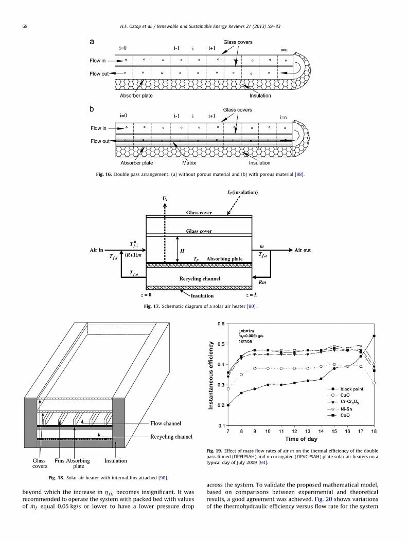
Fig. 17. Schematic diagram of a solar air heater [90].
Fig. 18. Solar air heater with internal fins attached [90].
Fig. 16. Double pass arrangement: (a) without porous material and (b) with porous material [88].
Fig. 19. Effect of mass flow rates of air _m on the thermal efficiency of the double
pass-finned (DPFIPSAH) and v-corrugated (DPVCPSAH) plate solar air heaters on a
typical day of July 2009 [94].
H.F. Oztop et al. / Renewable and Sustainable Energy Reviews 21 (2013) 59–8368
beyond which the increase in ZTH becomes insignificant. It wasrecommended to operate the system with packed bed with valuesof _mf equal 0.05 kg/s or lower to have a lower pressure drop
across the system. To validate the proposed mathematical model,based on comparisons between experimental and theoreticalresults, a good agreement was achieved. Fig. 20 shows variationsof the thermohydraulic efficiency versus flow rate for the system

Fig. 21. Schematic diagram of the air solar collector [96].
Fig. 22. Schematic views of absorber plates: (a) with the triangular type obstacles,
(b) with leaf type obtacles, (c) with rectangular type obstacles, and (d) without
obstacles [97].
Fig. 20. Effect of mass flow rate of air _mf on the thermohydraulic efficiency ZTH
without and with 50 kg limestone and gravel [95].
H.F. Oztop et al. / Renewable and Sustainable Energy Reviews 21 (2013) 59–83 69
without and with gravel and limestone as packed bed [95]. Asseen in the figure, the efficiency was strongly related withflow rate.
El-Sebaii et al. [96] studied the double pass flat and v-corru-gated plate SAHs theoretically and experimentally. Experimentalset-up is presented in Fig. 21 from Ref. [96]. Comparisonsbetween the measured outlet temperatures of flowing air, outputpower and overall heat losses of the flat and v-corrugated plateSAHs were presented. The effect of mass flow rates of airon pressure drop, thermal and thermo-hydraulic efficienciesof the flat and v-corrugated plate SAHs were also investigated.The results showed that the double pass v-corrugated plate SAHwas 11–14% more efficient compared to the double pass flatplate SAH. It was indicated that the peak values of the thermo-hydraulic efficiencies of the flat and v-corrugated plate SAHs wereobtained when the mass flow rate of the flowing air was 0.02 kg/s.As given in their earlier study [96], the thermo-hydraulic effi-ciency of the DPVCPSAH was 14% higher than that of theDPFPSAH.
Akpinar and Koc-yigit [97] experimentally investigated the perfor-mance analysis of a new flat-plate SAH with several obstacles(Types I–III) and without obstacles (Type IV) as given in Fig. 22 asgiven in Ref. [97]. Experiments were performed for two air massflow rates of 0.0074 and 0.0052 kg/s. The first and second lawsof efficiencies were determined for SAHs and comparisons weremade among them. The values of first law efficiency varied between20% and 82%. The values of second law efficiency changed from8.32% to 44.00%. The highest efficiency were determined for theSAH with Type II absorbent plate in flow channel duct for alloperating conditions, whereas the lowest values were obtained forthe SAH without obstacles (Type IV).
Chamoli et al. [98] studies include the design of double passsolar air heater, heat transfer enhancement, flow phenomenonand pressure drop in duct. This paper presents an extensive studyof the research carried out on double pass solar air heater. Basedon the literature review, it is concluded that most of the studiescarried out on double pass solar air heater integrated with porousmedia and extended surfaces. Mathematical models based onenergy analysis of some configurations of solar air heater havebeen discussed.
7. Computational studies on solar air collectors
Computational Fluid Dynamics (CFD) is an effective tool toobtain heat transfer, flow field and temperature distribution in anenergy system. It can also be used to simulate air flows inside thesolar air collectors.

Fig. 25. Thermo-hydraulic performance parameter as a function of Reynolds
H.F. Oztop et al. / Renewable and Sustainable Energy Reviews 21 (2013) 59–8370
Layek et al. [99] analyzed the effect of chamfering on heattransfer and friction characteristics of SAH having absorber plateroughened with compound turbulators as shown in Fig. 23 fromRef. [100]. These boundary conditions corresponded closely tothose found in SAHs. Six roughened plates were tested by placinga 601 V-groove at the center line in between two consecutivechamfered ribs. The ribs’ top were chamfered having chamferangles of 51, 121, 151, 181, 221 and 301, while relative roughnesspitch (P/e) and relative roughness height (e/Dh) of the ribs werekept constant having values of 10 and 0.03 respectively. The flowReynolds number of the duct varied in the range of approximately3000–21,000, most suitable for SAH. The effects of chamfer angleon Nusselt number and friction factor were discussed and theresults were compared with the square rib-grooved and smoothduct under similar flow conditions to investigate the enhance-ment in Nusselt number and friction factor. The conditions for themaximum enhancement of Nusselt number and friction factor
Fig. 24. (a) square rib, (b) chamfer 121, (c) chamfer 181, and (d) chamfer 301 [99].
number [99].
Fig. 23. Roughness geometry [99].
were determined. It was found that the thermo-hydraulic perfor-mance of the SAH provided with such roughness was consider-ably enhanced. Fig. 24 illustrates the streamlines for differentgeometries while thermohydraulic performance (Eq. (6)) fordifferent Reynolds numbers is indicated in Fig. 25 as in Ref. [99].It was found that the value of performance parameter increasedwith increase in Reynolds number and the rate of increase of theperformance parameter was very sharp for the values of Reynoldsnumber below of about 8000.
Z¼Nu=Nus
� �f=f s
� � ð6Þ
Saim et al. [100] presented a computational analysis on theturbulent flow and heat transfer in solar air collector withrectangular plate fins absorber and baffles, which were arrangedon the bottom and top channel walls in a periodically staggeredway. Their model is given in Fig. 26. They made a numericalanalysis using finite volume methods. They used low Reynoldsnumber k–e model as turbulence model. The velocity and pres-sure terms of momentum equations are solved by the SIMPLEalgorithm. They found that increasing the Reynolds number willincrease the efficiency of the solar panel which is an expectedresult.
Fig. 26 presents the upward type SAH under consideration.The physical domain was between two parallel plates [100]. Theouter surface of the top wall of the channel was uniformlyheated while the outer surface of the bottom wall was thermallyinsulated.
The temperature contours in the solar collector with bafflesand fins are plotted in Fig. 27 as given in Ref. [100]. The plotshows that the fluid temperature in the vortex region wassignificantly high as compared to that in the same region of nobaffle region. In the region downstream of the two baffles,recirculation cells with low temperature were observed. In theregions between the tip of the fins and the channel wall, thetemperature increased. Due to the changes in the flow directionproduced by the presence of the singularity of obstacles, thehighest temperature value appeared behind the lower channelwall with an acceleration process that starts just after the first finand the second baffle.
Ammari [101] developed a mathematical model for computingthe thermal performance of a single pass flat-plate solar aircollector. The influence of the addition of the metal slats on theefficiency of the solar collector was studied. The effects of volumeair flow rate, collector length, and spacing between the absorberand bottom plates on the thermal performance of the present SAH

Fig. 26. Schematic model of a solar air heater proposed by Saim et al. [100].
Fig. 27. Temperature (K) distribution in the solar collector (m¼20 kg/h, L/B¼3/2, I0¼1043 W/m2, R¼16 cm) [100].
Fig. 28. Comparison of efficiency between present and commonn type solar air heaters [101].
5060708090100
(%)
H.F. Oztop et al. / Renewable and Sustainable Energy Reviews 21 (2013) 59–83 71
were investigated. Furthermore, a numerical comparison of thepresent design with the most common type of SAHs was con-ducted. The results of the comparison indicated that betterthermal performance was obtained by the modified system, asgiven in Fig. 28 as shown in Ref. [101] Karmare [114] made acomputational analysis of different types of solar collectors.
010203040
[14]
[92]
[95]
[96]
[102]
[110]
[112]
[113]
[114]
[116]
[118]
[120]
[122]
[153]
AUTHORS
Fig. 29. Variation of energy efficiency by various investigators.
8. Energy and exergy analysis of solar air collectors
8.1. Energy analysis
The theoretical model employed for the study of the solarcollector that operates in unsteady state is made using a thermal

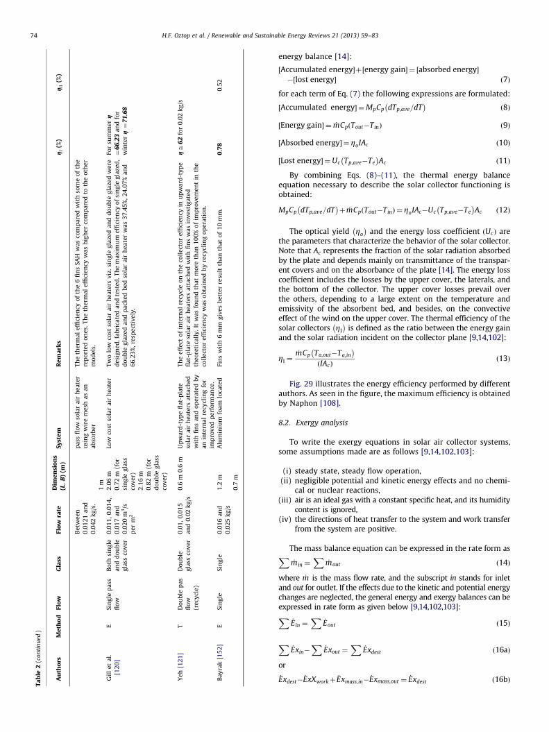
Table 2List of some earlier works.
Authors Method Flow Glass Flow rateDimensions(L, B) (m)
System Remarks gI (%) gII (%)
Esen [14] E Double pass
flow
Single glass
cover
0.015 kg/s 1.25 Experimental energy and
exergy analysis of a
double-flow solar air
heater having different
obstacles on absorber
plates
Test results always yield higher efficiency values for Type III than for Type
I (without obstacles) flat plate collector. The obstacles ensure a good air
flow over and under the absorber plates, create the turbulence, and
reduce the dead zones in the collector.
g ¼65, State II, Type
III, 0.025 kg/s
g¼60.97,
State II,
Type III,
0.025 kg/s
0.02 kg/s 0.8
0.025 kg/s
Yeh and Ho
[92]
T Single
(recycle)
pass flow
Single glass
cover
0.01 kg/s 0.6 Effect of external recycle
on the performance of flat-
plate solar air heaters with
internal fins attached
It is found that considerable improvement in collector efficiency is
obtainable if the operation is carried out with an external recycle, where
the desirable effect overcomes the undesirable effect. The enhancement
increases with increasing reflux ratio, especially for operating at lower air
flow rate with higher inlet air temperature.
g¼61.11, T¼288 K,
R¼5, _m¼0.02
0.015 kg/s 0.6
0.02 kg/s
Yeh and Ho
[91]
T Single pass
flow
Double
glass cover
0.01 kg/s 0.6 Downward-type solar air
heaters with internal
recycle
It is found that considerable improvement in collector efficiency is
obtainable if the operation is carried out with an internal recycle, where
the desirable effect of increasing fluid velocity to decrease the heat
transfer resistance compensates for the undesirable effect of decreasing
the driving force (temperature difference) of heat transfer, due to the
remixing effect at the inlet by recycle operation
g ¼62, Tfi¼298 K,_m¼0.02
0.015 kg/s 0.6
0.02 kg/s
Yeh et al.
[93]
T Single pass
flow
Double
glass cover
– L B Effect of collector aspect
ratio on the collector
efficiency of upward type
baffled solar air heaters
It is obtained same results with flat plate solar air heaters without fins
and baffles. Although the collector efficiency of baffled solar air heaters is
larger than that of flat plate heaters without fins and baffles, the
improvement of collector efficiency by increasing the collector aspect
ratio is the reverse.
g ¼68, L¼1.8 for
B¼0.3
1.8 0.3
0.9 0.6
0.6 0.9
0.3 1.8
El-Sabii and
Al-Snani
[94]
T Single pass
flow
Double
glass cover
0.00117 kg/s 1 Effect of selective coating
on thermal performance of
flat plate solar air heaters
To improve the heater performance, effect of using absorber plates coated
with various selective coating materials on the heater performance was
also investigated. The best performance was achieved using nickel–tin as
a selective coating material with a daily average of the instantaneous
efficiency of 0.46.
g ¼48, Ni–Sn for
0.005 kg/s
0.005 kg/s 1
Ramadan
et al. [95]
E–T Double
(countrary)
pass flow
Double
pass flow
0.0105 1 Thermal performance of a
packed bed double-pass
solar air heater
Limestone and gravel were used as packed bed materials. The thermo-
hydraulic efficiency ZTH was found to increase with increasing _mf until a
typical value of 0.05 kg/s beyond which the increase in ZTH becomes
insignificant. To validate the proposed mathematical model, comparisons
between experimental and theoretical results showed that good
agreement was achieved.
The daily average
values of ZTH are
obtained as 57.2%
with gravel
0.02 1
0.04y0.0.14
Akpinar and
Koc-yigit
[97]
E Single pass
flow
Single glass
cover
0.0074 kg/s 1.2 Experimental investigation
of thermal performance of
solar air heater having
different obstacles on
absorber plates
The optimal value of efficiency was determined for the solar air heater
with Type II absorbent plate in flow channel duct for all operating
conditions and the collector supplied with obstacles appears significantly
better than that without obstacles
Type II, 0.074 kg/s,
g¼82
0.0052 kg/s 0.7
H.F.
Ozto
pet
al.
/R
enew
ab
lea
nd
Susta
ina
ble
En
ergy
Rev
iews
21
(20
13
)5
9–
83
72

Ammari
[101]
T Single pass
flow
Single glass
cover
12.5 L/s 6 A mathematical model of
thermal performance of a
solar air heater with slats
A numerical comparison of the present design with the most common
type of solar air heaters is conducted. The results of the comparison have
indicated that better thermal performance was obtained by the modified
system
V¼50 L/s, Re¼4200,
gffi71
125 L/s 1
Alta et al.
[107]
E Single pass
flow
Doubleand
single glass
cover
25?5
m3/m2h
0.63 Experimental investigation
of three different solar air
heaters: Energy and exergy
analyses
Based on the energy and exergy output rates, heater with double glass
covers and fins (Type II) is more effective and the difference between the
input and output air temperature is higher than of the others.
30?100 m3/m2 h,
ZI¼39.05
0?100
m3/m2 h,
ZII¼0.834
0?100 0.315
El-Sabii et al.
[109]
E–T Double pass
flow
Double
glass cover
0–0.06 Thermal performance
investigation of double
pass-finned plate solar air
heater
The results showed that the double pass v-corrugated plate solar air
heater is 9.3–11.9% more efficient compared to the double pass-finned
plate solar air heater.
gffi67, 0.05 kg/s
v-corrugated
g ¼57.70.0225 kg/s
v-corrugated
El-Sabii et al.
[110]
E–T Double pass
flow
Double
glass cover
0–0.06 Investigation of thermal
performance of-double
pass-flat and v-corrugated
plate solar air heaters
The results showed that the double pass v-corrugated plate solar air
heater is 11–14% more efficient compared to the double pass flat plate
solar air heater. It is also indicated that the peak values of the thermo-
hydraulic efficiencies of the flat and v-corrugated plate solar air heaters
are obtained when the mass flow rate of the flowing air is 0.02 kg/s.
g ¼67, 0.05 kg/s
v-corrugated
g ¼57v-corrugated
Gao et al.
[111]
E–T Single pass
flow
Single glass
cover
0.1 kg/m2 s 2 Analytical and
experimental studies on
the thermal performance
of cross-corrugated and
flat-plate solar air heaters
All the analytical and experimental results show that, although the
thermal performance of the type 2 heater is just slightly superior to that
of the type 1 heater, both of these cross-corrugated solar air-heaters have
a much superior thermal performances to that of the flat-plate one.
Exp. Case 4, Type 2,
g ¼73.18 analytical
case 4, type 2 gffi75
1
Naphon
[112]
T Double pass
flow
(counter)
Single glass
cover
Max. 0.1 kg/s 2.4 Effect of porous media on
the performance of the
double-pass flat plate solar
air heater
The results obtained from the model are validated by comparison with
experimental data of previous researchers. There is reasonable agreement
between the present model and experiment.
gffi89
1.2
Ozgen et al.
[113]
E Double pass
flow
Single glass
cover
0.03 kg/s Experimental investigation
of thermal performance of
a double-flow solar air
heater having aluminum
cans
In the first type (Type I), cans had been staggered as zigzag on absorber
plate, while in Type II they were arranged in order. Type III is a flat plate
(without cans). Also, comparison between the thermal efficiency of the
SAH tested in this study with the ones reported in the literature had been
presented, and a good agreement had been found.
Type I, 0.05 kg/s,
gffi72
0.05 kg/s
Akpinar and
Koc-yigit
[115]
E Single pass
flow
Single glass
cover
0.0074 kg/s 1.20 m Energy and exergy analysis
of a new flat-plate solar air
heater having different
obstacles on absorber
plates
The highest efficiency were determined for the SAH with Type II
absorbent plate in flow channel duct for all operating conditions, whereas
the lowest values were obtained for the SAH without obstacles (Type IV).
Type II, 0.0074 kg/s,
g¼82Type II,
0.0074 kg/s,
g ¼44
0.0052 kg/s 0.7 m
Omojaro and
Aldabbagh
[116]
E Single and
double pass
flow
Single glass
cover
0.012 kg/s 1.5 m Experimental performance
of single and double pass
solar air heater with fins
and steel wire mesh as
absorber
Maximum efficiency obtained for the single and double pass air heater
was 59.62% and 63.74% respectively for air mass flow rate of 0.038 kg/s.
0.038 kg/s,
gsi¼59.62,
gd¼63.74
0.038 kg/s 1 m
Assari et al.
[117]
E–T Single pass
flow
Single glass
cover
Between 0.02
and 0.14 kg/s
1.94 Experimental and
theoretical investigation of
a dual purpose solar
collector
High temperature and high performance can be obtained using dual
purpose solar collector (DPSC) compared to single water or air collector.
g ¼60, 0.02 kg/s
rectangular fin
0.94
Yang et al.
[118]
E Single pass
flow
Single glass
cover
2 Experimental analysis on
thermal performance of a
solar air collector with a
single pass
Based on the results, decreasing the heat transfer resistance in the air
flow channel had the most significant effect on thermal efficiency
enhancement.
g ¼38.3 for type E
1
El-khawajah
et al. [119]
E Single pass
flow
Double
glass cover
1.5 m The effect of using
transverse fins on a double
g ¼85.9 for 6 fins to
0.042 kg/s
H.F.
Ozto
pet
al.
/R
enew
ab
lea
nd
Susta
ina
ble
En
ergy
Rev
iews
21
(20
13
)5
9–
83
73
Ta
ble
2(c
on
tin
ued
)
Au
tho
rsM
eth
od
Flo
wG
lass
Flo
wra
teD
ime
nsi
on
s(L
,B
)(m
)S
yst
em
Re
ma
rks
gI
(%)
gII
(%)
Be
twe
en
0.0
12
1a
nd
0.0
42
kg
/s.
pa
ssfl
ow
sola
ra
irh
ea
ter
usi
ng
wir
em
esh
as
an
ab
sorb
er
Th
eth
erm
al
effi
cie
ncy
of
the
6fi
ns
SA
Hw
as
com
pa
red
wit
hso
me
of
the
rep
ort
ed
on
es.
Th
eth
erm
al
effi
cie
ncy
wa
sh
igh
er
com
pa
red
toth
eo
the
r
mo
de
ls.
1m
Gil
le
ta
l.
[12
0]
ES
ing
lep
ass
flo
w
Bo
thsi
ng
le
an
dd
ou
ble
gla
ssco
ve
r
0.0
11
,0
.01
4,
0.0
17
an
d
0.0
20
m3/s
pe
rm
2
2.0
6m
0.7
2m
(fo
r
sin
gle
gla
ss
cov
er)
2.1
6m
0.8
2m
(fo
r
do
ub
leg
lass
cov
er)
Low
cost
sola
ra
irh
ea
ter
Tw
olo
wco
stso
lar
air
he
ate
rsv
iz.
sin
gle
gla
zed
an
dd
ou
ble
gla
zed
we
re
de
sig
ne
d,f
ab
rica
ted
an
dte
ste
d.T
he
ma
xim
um
effi
cie
ncy
of
sin
gle
gla
zed
,
do
ub
leg
laze
da
nd
pa
cke
db
ed
sola
ra
irh
ea
ter
wa
s3
7.4
5%
,2
4.0
7%
an
d
66
.23
%,
resp
ect
ive
ly.
For
sum
me
rg
¼6
6.2
3a
nd
for
win
terg¼
71
.68
Ye
h[1
21
]T
Do
ub
lep
as
flo
w
(re
cycl
e)
Do
ub
le
gla
ssco
ve
r
0.0
1,
0.0
15
an
d0
.02
kg
/s
0.6
m0
.6m
Up
wa
rd-t
yp
efl
at-
pla
te
sola
ra
irh
ea
ters
att
ach
ed
wit
hfi
ns
an
do
pe
rate
db
y
an
inte
rna
lre
cycl
ing
for
imp
rov
ed
pe
rfo
rma
nce
.
Th
ee
ffe
cto
fin
tern
al
recy
cle
on
the
coll
ect
or
effi
cie
ncy
inu
pw
ard
-ty
pe
fla
t-p
late
sola
ra
irh
ea
ters
att
ach
ed
wit
hfi
ns
wa
sin
ve
stig
ate
d
the
ore
tica
lly
.It
wa
sfo
un
dth
at
mo
reth
an
10
0%
of
imp
rov
em
en
tin
the
coll
ect
or
effi
cie
ncy
wa
so
bta
ine
db
yre
cycl
ing
op
era
tio
n.
gffi
62
for
0.0
2k
g/s
Ba
yra
k[1
52
]E
Sin
gle
Sin
gle
0.0
16
an
d
0.0
25
kg
/s
1.2
mA
lum
iniu
mfo
am
loca
ted
Fin
sw
ith
6m
mg
ive
sb
ett
er
resu
ltth
an
tha
to
f1
0m
m.
0.7
80
.52
0.7
m
H.F. Oztop et al. / Renewable and Sustainable Energy Reviews 21 (2013) 59–8374
energy balance [14]:
½Accumulated energy�þ½energy gain� ¼ ½absorbed energy�
�½lost energy� ð7Þ
for each term of Eq. (7) the following expressions are formulated:
½Accumulated energy� ¼MpCp dTp,ave=dT� �
ð8Þ
½Energy gain� ¼ _mCp Tout�Tinð Þ ð9Þ
½Absorbed energy� ¼ ZoIAc ð10Þ
½Lost energy� ¼Uc Tp,ave�Te
� �Ac ð11Þ
By combining Eqs. (8)–(11), the thermal energy balanceequation necessary to describe the solar collector functioning isobtained:
MpCp dTp,ave=dT� �
þ _mCp Tout�Tinð Þ ¼ ZoIAc�Uc Tp,ave�Te
� �Ac ð12Þ
The optical yield Zo
� �and the energy loss coefficient Ucð Þ are
the parameters that characterize the behavior of the solar collector.Note that Ac represents the fraction of the solar radiation absorbedby the plate and depends mainly on transmittance of the transpar-ent covers and on the absorbance of the plate [14]. The energy losscoefficient includes the losses by the upper cover, the laterals, andthe bottom of the collector. The upper cover losses prevail overthe others, depending to a large extent on the temperature andemissivity of the absorbent bed, and besides, on the convectiveeffect of the wind on the upper cover. The thermal efficiency of thesolar collectors ZI
� �is defined as the ratio between the energy gain
and the solar radiation incident on the collector plane [9,14,102]:
ZI ¼_mCp Ta,out�Ta,in
� �IAcð Þ
ð13Þ
Fig. 29 illustrates the energy efficiency performed by differentauthors. As seen in the figure, the maximum efficiency is obtainedby Naphon [108].
8.2. Exergy analysis
To write the exergy equations in solar air collector systems,some assumptions made are as follows [9,14,102,103]:
(i)
steady state, steady flow operation, (ii) negligible potential and kinetic energy effects and no chemi-cal or nuclear reactions,
(iii) air is an ideal gas with a constant specific heat, and its humiditycontent is ignored,
(iv) the directions of heat transfer to the system and work transferfrom the system are positive.
The mass balance equation can be expressed in the rate form asX_min ¼
X_mout ð14Þ
where _m is the mass flow rate, and the subscript in stands for inletand out for outlet. If the effects due to the kinetic and potential energychanges are neglected, the general energy and exergy balances can beexpressed in rate form as given below [9,14,102,103]:X
_Ein ¼X
_Eout ð15Þ
X_Exin�
X_Exout ¼
X_Exdest ð16aÞ
or
_Exdest�_ExXworkþ
_Exmass,in�_Exmass,out ¼
_Exdest ð16bÞ

H.F. Oztop et al. / Renewable and Sustainable Energy Reviews 21 (2013) 59–83 75
Using Eq. (16b) the rate form of the general exergy balance canbe expressed as follows:
X1�
Te
Ts
� �_Q s�
_W þX
_mincin ¼_Exdest ð17Þ
Where
cin ¼ hin�heð Þ�Te Sin�Seð Þ ð18Þ
cout ¼ hout�heð Þ�Te Sout�Seð Þ ð19Þ
If Eqs. (18) and (19), are substituted in Eq. (17), it is arrangedas below:
1�Te
Ts
� �_Q s� _m hout�hinð Þ�Te Sout�Sinð Þ
� �¼ _Exdest ð20Þ
where _Q s is the solar energy absorbed by the collector absorbersurface and it is evaluated with the expression given below[9,14,102]:
_Q s ¼ IðtaÞAc ð21Þ
Fig. 31. Flat plate PV/T collector classifi
0
10
20
30
40
50
60
70
[14] [110] [116] [153]
(%)
AUTHORS
Fig. 30. Variation of exergy efficiency by various investigators.
The changes in the enthalpy and the entropy of the air at thecollector are expressed by [9,14,102,103]
Dh¼ hout�hin ¼ Cp Tf ,out�Tf ,in
� �ð22Þ
Ds¼ sout�sin ¼ Cp lnTf ,out
Tf ,in�R ln
Pout
Pinð23Þ
By substituting Eqs. (21)–(23), into Eq. (20) the equation belowcan be derived [9,14,102]:
1�Te
Ts
� �I tað ÞAc� _mCp Tf ,out�Tf ,in
� �þ _mCpTe ln
Tf ,out
Tf ,in� _mRTe ln
Pout
Pin¼ _Exdest
ð24Þ
The exergy destruction or the irreversibility may be expressedas follows [9,14,102]:
_Exdest ¼ Te_Sgen ð25Þ
The exergy efficiency of a solar collector system can becalculated in terms of the net output exergy of the system orexergy destructions in the system. The exergy efficiency of SAHsystem has been evaluated in terms of the net output exergyof the system. The second law efficiency is calculated as follows[103]:
ZII ¼_Exout
_Exin
¼_m½hout�hin�Te Sout�Sinð Þ�
1� Te=Ts
� �� � _Q s
ð26Þ
When dealing with the exergy of a process component, thedifference between exergy losses and destruction should benoted. Exergy losses consist of exergy flowing to the surroundingswhereas exergy destruction indicates the loss of exergy withinthe system boundary due to irreversibility [100]. Phrasing itanother way, the exergy destruction is the actual change inexergy for the irreversible process minus the change in exergythat would have occurred if the process had been reversible.
cation (modified from Ref. [122]).

Fig. 33. The directions of air movement in both the channels along with the depths of the upper and lower channels are shown in the supplement diagrams of Fig. 1(a) and
(b) from Ref. [124].
Fig. 34. The thermal efficiency, electrical efficiency, total equivalent thermal efficiency and the rise in the air and cell temperatures for a solar PV/T system with and
without fins [124].
Fig. 32. Cross-section of unglazed PV/T air (a): (i) with tedlar and (ii) without tedlar and (b): (i) glazed with tedlar and (ii) without tedlar [123].
H.F. Oztop et al. / Renewable and Sustainable Energy Reviews 21 (2013) 59–8376

H.F. Oztop et al. / Renewable and Sustainable Energy Reviews 21 (2013) 59–83 77
The exergy destruction due to the irreversibility generates whenchemical reaction, heat transfer, pressure drop and mixing pro-ceed in the process [104,105].
The dimensionless exergy destruction or loss is the result ofdividing Eq. (25) by the energy gain value of Eq. (9) [103]
EXD ¼_EXdest
_Q c
ð27Þ
Van Gool [106] has also proposed that maximum improve-ment in the exergy efficiency for a process or system is obviouslyachieved when the exergy loss or irreversibility Exin�Exout isminimized. Consequently, he suggested that it is useful to employthe concept of an exergetic ‘‘improvement potential’’ when analyzingdifferent processes or sectors of the economy. This improvementpotential in the rate form is denoted by Refs. [106,115]
I _P ¼ ð1�ZIIÞð_Exin�
_ExoutÞ ð28Þ
Fig. 35. (a) Monthly variation of thermal energy gain by considering a, b, c, d type
weather conditions of New Delhi. (b) Monthly variation of electrical energy
gain by considering a, b, c, d type weather conditions of New Delhi. (c) Monthly
variation of exergy gain by considering a, b, c, d type weather conditions of New
Delhi [143].
All physical properties of air were selected according to thefollowing bulk mean temperature:
DTm ¼Tin�Toutð Þ
2ð29Þ
In this context, Alta et al. [107] compared three different typesof designed flat-plate SAHs, two having fins (Types II and III) andthe other without fins (Type I), one of the heater with a fin hadsingle glass cover (Type III) and the others had double glass covers(Types I and II). The energy and exergy output rates of theSAHs were evaluated for various air flow rates (25, 50 and100 m3/m2 h), tilt angle (01, 151 and 301) and temperature condi-tions versus time. The efficiencies of the finned collectors (col-lector Types II and III) is higher than that of the collector withoutfin (Type I). The largest irreversibility occurs at Type I (withoutfins) in which collector efficiency is smallest, and the lowestirreversibility was found at Type II (with fins). Results for energyand exergy are shown in Table 2. As seen from the table, meanhighest exergy efficiency (0.8340%) and the mean lowest exergyloss (99.166%) for Type II were found at air flow rate of 100 m3/m2 hand 01 tilt angle.
Ozturk and Demirel [108] made an experimental investigationof the thermal performance of a SAH having its flow channelpacked with Raschig rings. They observed that the energy andexergy efficiencies of the packed-bed SAH increased as the outlettemperature of heat transfer fluid increased. Akpinar and Koc-yigit[115] experimentally studied the new flat-plat SAH with severalobstacles and without obstacles for different air flow rate. Theyperformed the first and second laws of efficiencies for SAHs andcomparisons were made among them. They indicated that thevalues of first law efficiency varied between 20% and 82% andsecond law efficiency changed from 8.32% to 44.00%.
Bayrak [152] made an experimental analysis of solar air heaterwith porous obstacles. In this experimental work, porous baffleswith different thicknesses are used as a passive element insidethe SAH. Closed-cell aluminum foams are chosen as porousmaterials. These porous materials are 6 mm and 10 mm inthickness and have a surface area of 50 cm2. They were placedsequent and staggered into the SAH. Six SAHs were tested at twoair mass flow rates of 0.016 and 0.025 kg/s. The performances ofthe heaters were assessed using energy and exergy analysismethods. The highest collector efficiency and air temperaturerise were achieved by SAHs with a thickness of 6 mm and an airmass flow rate of 0.025 kg/s, whereas the lowest values wereobtained for the SAH without obstacles.
Fig. 30 shows the energy efficiency performed by differentauthors. As seen from the figure, the maximum efficiency isobtained by Esen [14].
Fig. 36. Annual gain in energy, exergy and electrical energy for five different cities
of India by considering a, b, c, d type weather conditions [143].

H.F. Oztop et al. / Renewable and Sustainable Energy Reviews 21 (2013) 59–8378
9. Recent advances in flat plate photovoltaic/thermal (PV/T)solar collectors
Flat plate photovoltaic/thermal (PV/T) solar collector producesboth thermal energy and electricity simultaneously. Flat platephotovoltaic/thermal (PV/T) solar collector produces both ther-mal energy and electricity simultaneously. The state-of-the-art onflat plate PV/T collector classification, design and performanceevaluation of water, air and combination of water and/or air basedwere presented Ibrahim et al. [122]. Different design features and
Fig. 37. Schematics of the various PV/T models
performance of flat plate PV/T solar collectors were compared anddiscussed. Future research and development (R&D) works wereproposed.
In conclusion, the PV/T can be improved further based on fewsuggestions, such as:
�
alon
New design of absorber collector to improve efficiency ofthe PV.
� Replacing the roofing material with new material that willincrease the efficiency of the system and at the same time
g with heat transfer coefficients [144].

H.F. Oztop et al. / Renewable and Sustainable Energy Reviews 21 (2013) 59–83 79
reduces the payback period—attractive in case the availableroof surface is limited.
� Payback—proposed system that gain pay back in less than10 years.
� Production and installation cost—new method to integrate thesystems into one product with value added production.
� Sustainable energy—ensure that the energy produced by thesystem is sustainable with zero CO2 emissions.
�Fig. 38. Variation of daily thermal efficiency with air specific mass rate for PV/T
collectors I–IV [144].
Esthetics—integration rather than ‘‘bolt on roof’’ gives betterarchitectural look.
Classification of PV/T collectors is presented in Fig. 31 as given[122]. Tiwari and Sodha [123] found that the glazed hybrid PV/Twithout tedlar gave the best performance compared to all con-figurations being evaluated in Fig. 32.
Kumar and Rosen [124] studied the performance evaluationof a double pass PV/T SAH with and without fins. They provideduseful insights into the thermal and electrical behavior of adouble-pass air heater with vertical fins in the lower air channelsand the relevance of fins with absorber surface in the overallperformance enhancement of PV/T collectors. The model isshown in Fig. 33 and efficiencies are shown in Fig. 34. Tonuiand Tripanagnostopoulos [125] and Sukamongkol et al. [126]investigated the thermal and electricity production performancefor three types of collectors. Then, Tonui and Tripanagnostopoulos[127,128] made similar analysis for 6 different collectors.Other studies related with PV/T collectors can be found inRefs. [129–142].
Fig. 39. (a) Electrical, thermal and total exergy and exergy efficiency for January at
Srinagar. (b) Electrical, thermal and exergy and exergy efficiency for June at
Srinagar [4].
10. Energy and exergy analysis of PV/T air collectorsconnected in series
Energy and exergy analysis of PV/T air collectors connected inseries have been studied by different authors. These analysesare complex due to complex structure of the collectors. In thiscontext, Dubey et al. [143] showed the detailed analysis ofenergy, exergy and electrical energy by varying the number ofcollectors and air velocity considering four weather conditions (a,b, c and d type) and five different cities (New Delhi, Bangalore,Mumbai, Srinagar, and Jodhpur) of India. It was found that thecollectors fully covered by PV module and air flows below theabsorber plate gave better results in terms of thermal energy,electrical energy and exergy gain as seen from Figs. 35 and 36.Hegazy [144] made an extensive investigation of the thermal,electrical, hydraulic and overall performances of flat plate photo-voltaic/thermal (PV/T) air collectors. Four popular designswere considered with the air flowing either over the absorber(Model I) or under it (Model II) and on both sides of the absorberin a single pass (Model III) or in a double pass fashion (Model IV).The effects of air specific flow rate and the selectivity of theabsorber plate and PV cells on the performances were examined.It was found that under similar operational conditions, theModel I collector had the lowest performance, while the othermodels exhibited comparable thermal and electrical output gains.Nevertheless, Model III collector demanded the least fan power,followed by Models IV and II. As a conclusion, the design ofCase I was efficient at higher air velocity and for one collector.However, the design of Case II was efficient for lower airvelocity and higher number of collectors connected in series(Figs. 37 and 38). Joshi and Tiwari [4] studied energy and exergyefficiencies of a hybrid photovoltaic–thermal (PV/T) air collec-tor. The performance of a hybrid PV/T parallel plate air collectorwere investigated for four climatic conditions and then exergyefficiencies were carried out. It was observed that an instanta-neous energy and exergy efficiency of PV/T air heater varied
between 55–65% and 12–15%, respectively (Fig. 39). Sarhaddiet al. [145] evaluated the PV/T solar air collectors from theexergy point of view (Table 3).

Table 3List of some studies conducted on PV/T collectors.
Investigators Method System Remarks
E (Exp.) T (Theory)
Tiwari and
Sodha [123]
E T Parametric study of various configurations
of hybrid PV/thermal air collector:
Experimental validation of theoretical
model
Numerical computations have been carried out for composite
climate of New Delhi and the results for different configurations
have been compared. The thermal model for unglazed PV/T air
heating system has also been validated experimentally for
summer climatic conditions. It is observed that glazed hybrid
PV/T without tedlar gives the best performance.
Othman et al.
[146]
E Development of advanced solar assisted
drying systems
The use of solar dryers will enhanced the environment, wealth
creation and nation building as well as sustainable
development for the country.
Garg and
Adhikari
[147]
T Conventional hybrid photovoltaic/thermal
(PV/T) air heating collectors: steady-state
simulation
A simulation model is developed and various performance
parameters are calculated for single-glass and double-glass
configurations. Result are presented to show the effect of
various design and operational parameters on the performance
of a system. It has also been observed that for larger values of
duct depth the percentage decrease in performance of the
double-glass configuration is smaller than for the single-glass
configuration.
Solanki et al.
[148]
E T Indoor simulation and testing of
photovoltaic thermal (PV/T) air collectors
An indoor standard test procedure has been developed for
thermal and electrical testing of PV/T collectors connected in
series. Comparison between experimental and theoretical
results were also been carried out. The thermal and electrical
efficiency of the solar heater is 42% and 8.4%, respectively.
Sarhaddi et al.
[149]
T An improved thermal and electrical model
for a solar photovoltaic thermal (PV/T) air
collector
It is also found that the thermal efficiency, electrical efficiency
and overall energy efficiency of PV/T air collector is about
17.18%, 10.01% and 45%, respectively, for a sample climatic,
operating and design parameters
Alfegi et al.
[150]
T Transient mathematical model of both side
single pass photovoltaic thermal air
collector
A mathematical model and solution procedure of a single pass
photovoltaic thermal air collector (PVT) with Compound
Parabolic Concentrator (CPC) and fins with both sides of the
absorber for predicting the thermal and combined
photovoltaic thermal performance of the system is presented.
Results at solar irradiance of 400 W/m2 show that the
combined PV/T efficiency is increasing from 26.6% to 39.13% at
mass flow rates varies from 0.0316 to 0.09 kg/s.
Alfegi et al.
[151] cc
E Experimental investigation of single pass,
double duct photovoltaic thermal (PV/T)
air collector with CPC and fins
An experimental investigation of a solar air heater with
photovoltaic cell located at the absorber with compound
parabolic collector (CPC) and fins have been developed and
tested. Results at solar irradiance of 400 W/m2 showed that
the combined PV/T efficiency is increasing from 27.50% to
40.044% at mass flow rates various from 0.0316 to 0.09 kg/s
H.F. Oztop et al. / Renewable and Sustainable Energy Reviews 21 (2013) 59–8380
11. Conclusions
A review has been performed on experimental and numericalstudies of SAHs for the last 40 years. The main conclusions, whichmay be drawn from the results of the present study, are listed below:
(a)
Solar air collectors can be used to enhance the temperature ofair used in different systems. The SAHs have become a verypopular subject on which many researchers have focused inthe recent years.(b)
Studies conducted mostly focused on the enhancement ofheat transfer in solar air collectors by using passive heat transferenhancement techniques.(c)
In any cases, body added (V-groove, fin etc.) SAHs have moreefficiency than that of flat plate collectors.(d)
Both theoretical and experimental analyses done were muchin numbers. It was also observed that Computational FluidDynamics (CFD) methods can be used to analyze the effi-ciency of SAHs systems.(e)
Energy analysis method has been used in a number of studieswhile works conducted on exergy analysis were very low innumbers. Energy efficiencies of solar air collectors reviewedchanged between 47% and 89%.(f)
SAHs systems become more efficient when they are used for bothspace heating and electricity generation via PV/T systems.(g)
Exergy analysis is also an effective way to analyze theeffectiveness of PV/T systems.Efficiencies are strongly depended on the SAH material such ascover, absorber etc. Single or double pass collectors also play animportant role in terms of efficiency.
Acknowledgments
The authors gratefully acknowledge the financial supportprovided by the Firat University Scientific Research Unit (FUBAP)under the project no. TEKF.10.01.
References
[1] Close DJ. Solar air heaters. Solar Energy 1963;7:117–29.[2] Varun, Saini RP, Singal SK. A review on roughness geometry used in solar air
heaters. Solar Energy 2007;81:1340–50.[3] Alkilani MM, Sopian K, Sohif M, Alghol M. Output air temperature predic-
tion in a solar air heater integrated with phase change material European.Journal of Scientific Research 2009;27:334–41.
[4] Joshi AS, Tiwari A. Energy and exergy efficiencies of a hybrid photovoltaic–thermal (PV/T) air collector. Renewable Energy 2007;32:2223–41.
[5] Vanderhulst P, Lanser H, Bergmeyer P, Foeth F, Albers R. Solar energy: smallscale applications in developing countries. Amsterdam, Holland: StichtingTool; 1990.

H.F. Oztop et al. / Renewable and Sustainable Energy Reviews 21 (2013) 59–83 81
[6] John Perlin. Solar evolution—the history of solar energy. California SolarCenter.
[7] /http://en.wikipedia.org/wiki/Solar_water_heating#cite_note-CSC-2S.[8] Pitz-Paal R. Concentrating solar technologies—the key to renewable elec-
tricity and prosee heat for a wide range of applications. In: CD-proceedingsof the World Renewable Energy Congress VII (WREC 2002). 2002.
[9] Karsli S. Performance analysis of new-design solar air collectors for dryingapplications. Renewable Energy 2007;32:1645–60.
[10] Alvarez G, Arce J, Lira L, Heras MR. Thermal performance of an air solarcollector with an absorber plate made of recyclable aluminum cans. SolarEnergy 2004;77:107–13.
[11] Peng D, Zhang X, Dong H, Lv K. Performance study of a novel solar aircollector. Applied Thermal Engineering 2010;30:2594–601.
[12] Garg HP, Datta G, Bhargava AK. Some studies on the flow passage for solarair heating collectors. Energy Conversion and Management 1984;24:181–4.
[13] Caner M, Gedik E, Kec-ebas- A. Investigation on thermal performancecalculation of two type solar air collectors using artificial neural network.Expert Systems with Applications 2011;38:1668–74.
[14] Esen H. Experimental energy and exergy analysis of a double-flow solar airheater having different obstacles on absorber plates. Building and Environ-ment 2008;43:1046–54.
[15] El-Sawi AM, Wifi AS, Younan MY, Elsayed EA, Basily BB. Application offolded sheet metal in flat bed solar air collectors. Applied ThermalEngineering 2010;30:864–71.
[16] Ucar A, Inallı M. Thermal and exergy analysis of solar air collectors withpassive augmentation techniques. International Communications in Heatand Mass Transfer 2006;33:1281–90.
[17] Karim MA, Hawlader MNA. Performance evaluation of a v-groove solar aircollector for drying applications. Applied Thermal Engineering 2006;26:121–30.
[18] Moummi N, Ali SY, Moummi A, Desmons JY. Energy analysis of a solar aircollector with rows of fins. Renewable Energy 2004;29:2053–64.
[19] Lalji MK, Sarviya RM, Bhagoria JL. Exergy evaluation of packed bed solar airheater. Renewable and Sustainable Energy Reviews 2012;16:6262–7.
[20] Kumar A, Saini RP, Saini JS. Heat and fluid flow characteristics of roughenedsolar air heater ducts—a review. Renewable Energy 2012;47:77–94.
[21] Sethi M, Varun, Thakur NS. Correlation for solar air heater duct withdimpled shape roughness elements on absorber plate. Solar Energy 2012;86:2852–61.
[22] Karim MA, Hawlader MNA. Development of solar air collectors for dryingapplications. Energy Conversion and Management 2004;45:329–44.
[23] Mittal MK, Varshney L. Optimal thermohydraulic performance of a wiremesh packed solar air heater. Solar Energy 2006;80:1112–20.
[24] Hans VS, Saini RP, Saini JS. Heat transfer and friction factor correlations for asolar air heater duct roughened artificially with multiple v-ribs. SolarEnergy 2010;84:898–911.
[25] Prasad SB, Saini JS, Singh KM. Investigation of heat transfer and frictioncharacteristics of packed bed solar air heater using wire mesh as packingmaterial. Solar Energy 2009;83:773–83.
[26] Rene T. A review of the mathematical models for predicting solar air heaterssystems. Renewable and Sustainable Energy Reviews 2009;13:1734–59.
[27] Jannot Y, Coulibaly Y. The evaporative capacity as a performance index for asolar-drier air-heater. Solar Energy 1998;63:387–91.
[28] Togrul _IT, Pehlivan D, Akosman C. Development and testing of a solar air-heater with conical concentrator. Renewable Energy 2004;29:263–75.
[29] Karmare SV, Tikekar AN. Experimental investigation of optimum thermo-hydraulic performance of solar air heaters with metal rib grits roughness.Solar Energy 2009;83:6–13.
[30] Togrul _IT, Pehlivan D. Effect of packing in the airflow passage on theperformance of a solar air-heater with conical concentrator. Applied ThermalEngineering 2005;25:1349–62.
[31] Gupta MK, Kaushik SC. Performance evaluation of solar air heater havingexpanded metal mesh as artificial roughness on absorber plate. Interna-tional Journal of Thermal Sciences 2009;48:1007–16.
[32] Bansal NK. Solar air heater applications in India. Renewable Energy 1999;16:618–23.
[33] Yamalı C, Solmus- _I. Theoretical investigation of a humidification–dehumidification desalination system configured by a double-pass flatplate solar air heater. Desalination 2007;205:163–77.
[34] Esen H, Ozgen F, Esen M, Sengur A. Modelling of a new solar air heaterthrough least-squares support vector machines. Expert Systems with Applica-tions 2009;36:10673–82.
[35] Bopche SB, Tandale MS. Experimental investigations on heat transfer andfrictional characteristics of a turbulator roughened solar air heater duct.International Journal of Heat and Mass Transfer 2009;52:2834–48.
[36] Kumar A, Bhagoria JL, Sarviya RM. Heat transfer and friction correlations forartificially roughened solar air heater duct with discrete W-shaped ribs.Energy Conversion and Management 2009;50:2106–17.
[37] Forson FK, Nazha MAA, Rajakaruna H. Experimental and simulation studieson a single pass, double duct solar air heater. Energy Conversion andManagement 2003;44:1209–27.
[38] Karwa R, Chauhan K. Performance evaluation of solar air heaters having v-downdiscrete rib roughness on the absorber plate. Energy 2010;35:398–409.
[39] Sun W, Ji J, He W. Influence of channel depth on the performance of solar airheaters. Energy 2010;35:4201–7.
[40] Gupta MK, Kaushik SC. Exergetic performance evaluation and parametricstudies of solar air heater. Energy 2008;33:1691–702.
[41] Bhushan B, Singh R. A review on methodology of artificial roughness used induct of solar air heaters. Energy 2010;35:202–12.
[42] Mittal MK, Varun, Saini RP, Singal SK. Effective efficiency of solar air heatershaving different types of roughness elements on the absorber plate. Energy2007;32:739–45.
[43] Gao W, Lin W, Liu T, Xia C. Analytical and experimental studies on thethermal performance of cross-corrugated and flat-plate solar air heaters.Applied Energy 2007;84:425–41.
[44] Saini RP, Verma J. Heat transfer and friction factor correlations for a ducthaving dimple-shape artificial roughness for solar air heaters. Energy2008;33:1277–87.
[45] Karwa R, Karwa N, Misra R, Agarwal PC. Effect of flow maldistribution onthermal performance of a solar air heater array with subcollectors inparallel. Energy 2007;32:1260–70.
[46] Ho-Ming Y, Chii-Dong H. Effect of external recycle on the performances offlat-plate solar air heaters with internal fins attached. Renewable Energy2009;34:1340–7.
[47] Bhagoria JL, Saini JS, Solanki SC. Heat transfer coefficient and friction factorcorrelations for rectangular solar air heater duct having transverse wedgeshaped rib roughness on the absorber plate. Renewable Energy 2002;25:341–69.
[48] Pramuang S, Exell RHB. The regeneration of silica gel desiccant by air from asolar heater with a compound parabolic concentrator. Renewable Energy2007;32:173–82.
[49] Hegazy AA. Optimum channel geometry for solar air heaters of conven-tional design and constant flow operation. Energy Conversion and Manage-ment 1999;40:757–74.
[50] Nwosu NP. Employing exergy-optimized pin fins in the design of anabsorber in a solar air heater. Energy 2010;35:571–5.
[51] Kumar S, Saini RP. CFD based performance analysis of a solar air heater ductprovided with artificial roughness. Renewable Energy 2009;34:1285–91.
[52] Aldabbagh LBY, Egelioglu F, Ilkan M. Single and double pass solar air heaterswith wire mesh as packing bed. Energy 2010;35:3783–7.
[53] Chaube A, Sahoo PK, Solanki SC. Analysis of heat transfer augmentation andflow characteristics due to rib roughness over absorber plate of a solar airheater. Renewable Energy 2006;31:317–31.
[54] Gupta MK, Kaushik SC. Performance evaluation of solar air heater forvarious artificial roughness geometries based on energy, effective and exergyefficiencies. Renewable Energy 2009;34:465–76.
[55] Naphon P. Effect of porous media on the performance of the double-passflat plate solar air heater. International Communications in Heat and MassTransfer 2005;32:140–50.
[56] Hatami N, Bahadorinejad M. Experimental determination of natural con-vection heat transfer coefficient in a vertical flat-plate solar air heater. SolarEnergy 2008;82:903–10.
[57] Sahu MM, Bhagoria JL. Augmentation of heat transfer coefficient by using901 broken transverse ribs on absorber plate of solar air heater. RenewableEnergy 2005;30:2057–73.
[58] Kasayapanand N, Kiatsiriroat T. Optimized mass flux ratio of double-flowsolar air heater with EHD. Energy 2007;32:1343–51.
[59] Ho CD, Yeh HM, Cheng TW, Chen TC, Wang RC. The influences of recycle onperformance of baffled double-pass flat-plate solar air heaters with internalfins attached. Applied Energy 2009;86:1470–8.
[60] Wazed MA, Nukman Y, Islam MT. Design and fabrication of a cost effectivesolar air heater for Bangladesh. Applied Energy 2010;87:3030–6.
[61] Varun, Siddhartha, Thermal performance optimization of a flat plate solarair heater using genetic algorithm, Applied Energy, 2010;87:1793-1799.
[62] Al-Kamil MT, Al-Ghareeb AA. Effect of thermal radiation inside solar airheaters. Energy Conversion and Management 1997;38:1451–8.
[63] Layek A, Saini JS, Solanki SC. Effect of chamfering on heat transfer andfriction characteristics of solar air heater having absorber plate roughenedwith compound turbulators. Renewable Energy 2009;34:1292–8.
[64] Jaurker AR, Saini JS, Gandhi BK. Heat transfer and friction characteristics ofrectangular solar air heater duct using rib-grooved artificial roughness.Solar Energy 2006;80:895–907.
[65] Esen H, Ozgen F, Esen M, Sengur A. Artificial neural network and waveletneural network approaches for modelling of a solar air heater. ExpertSystems with Applications 2009;36:11240–8.
[66] Hegazy AA. Performance of flat plate solar air heaters with optimumchannel geometry for constant/variable flow operation. Energy Conversionand Management 2000;41:401–17.
[67] Enibe SO. Thermal analysis of a natural circulation solar air heaterwith phase change material energy storage. Renewable Energy 2003;28:2269–99.
[68] Toure S. Characteristic temperatures in a natural convection solar airheater. Energy Conversion and Management 2001;42:1157–68.
[69] Flores-Irigollen A, Fernandez JL, Rubio-Cerda E, Poujol FT. Heat transferdynamics in an inflatable-tunnel solar air heater. Renewable Energy 2004;29:1367–82.
[70] Saini SK, Saini RP. Development of correlations for Nusselt number andfriction factor for solar air heater with roughened duct having arc-shapedwire as artificial roughness. Solar Energy 2008;82:1118–30.

H.F. Oztop et al. / Renewable and Sustainable Energy Reviews 21 (2013) 59–8382
[71] Ben-Amara M, Houcine I, Guizani AA, Maalej M. Efficiency investigation of anew-design air solar plate collector used in a humidification–dehumidificationdesalination process. Renewable Energy 2005;30:1309–27.
[72] Karagiorgas M, Galatis K, Tsagouri M, Tsoutsos T, Botzios-Valaskakis A. Solarassisted heat pump on air collectors: a simulation tool. Solar Energy2010;84:66–78.
[73] Romdhane BS. The air solar collectors: comparative study, introduction ofbaffles to favor the heat transfer. Solar Energy 2007;81:139–49.
[74] Bilgen E, Bakeka BJD. Solar collector systems to provide hot air in ruralapplications. Renewable Energy 2008;33:1461–8.
[75] Zhai XQ, Dai YJ, Wang RZ. Experimental investigation on air heating and naturalventilation of a solar air collector. Energy and Buildings 2005;37:373–81.
[76] Luna D, Jannot Y, Nadeau JP. An oriented-design simplified model for theefficiency of a flat plate solar air collector. Applied Thermal Engineering2010;30:2808–14.
[77] Khedari J, Mansirisub W, Chaima S, Pratinthong N, Hirunlabh J. Fieldmeasurements of performance of roof solar collector. Energy and Buildings2000;31:171–8.
[78] Ahmad NT. Agricultural solar air collector made from low-cost plasticpacking film. Renewable Energy 2001;23:663–71.
[79] Lin W, Gao W, Liu T. A parametric study on the thermal performance ofcross-corrugated solar air collectors. Applied Thermal Engineering 2006;26:1043–53.
[80] Abdullah AH, Abou-Ziyan HZ, Ghoneim AA. Thermal performance of flatplate solar collector using various arrangements of compound honeycomb.Energy Conversion and Management 2003;44:3093–112.
[81] Abene A, Dubois V, Ray ML, Ouagued A. Study of a solar air flat platecollector: use of obstacles and application for the drying of grape. Journal ofFood Engineering 2004;65:15–22.
[82] Ekechukwu OV, Norton B. Review of solar-energy drying systems III: lowtemperature air-heating solar collectors for crop drying applications.Energy Conversion and Management 1999;40:657–67.
[83] Roman F, Nagle M, Leis H, Janjai S, Mahayothee B, Haewsungcharoen M, etal. Potential of roof-integrated solar collectors for preheating air at dryingfacilities in Northern Thailand, Renewable Energy, 2009;34:1661-1667.
[84] Jain D, Jain RK. Performance evaluation of an inclined multi-pass solar airheater with in-built thermal storage on deep-bed drying application.Journal of Food Engineering 2004;65:497–509.
[85] Hawlader MNA, Rahman SMA, Jahangeer KA. Performance of evaporator-collector and air collector in solar assisted heat pump dryer. EnergyConversion and Management 2008;49:1612–9.
[86] Janjai S, Tung P. Performance of a solar dryer using hot air from roof-integrated solar collectors for drying herbs and spices. Renewable Energy2005;30:2085–95.
[87] Abene A, Dubois V, Le Ray M, Ouagued A. Study of a solar air flat platecollector: use of obstacles and application for the drying of grape. Journal ofFood Engineering 2004;65:15–22.
[88] Ramani BM, Gupta A, Kumar R. Performance of a double pass solar aircollector. Solar Energy 2010;84:1929–37.
[89] Sopian K, Alghoul MA, Alfegi EM, Sulaiman MY, Musa EA. Evaluation ofthermal efficiency of double-pass solar collector with porous–nonporousmedia. Renewable Energy 2009;34:640–5.
[90] Ho CD, Yeh HM, Chen TC. Collector efficiency of upward-type double-passsolar air heaters with fins attached. International Communications in Heatand Mass Transfer 2011;38:49–56.
[91] Yeh HM, Ho CD. Downward-type solar air heaters with internal recycle.Journal of the Taiwan Institute of Chemical Engineers 2011;42:286–91.
[92] Yeh Ho-Ming, Ho Chii-Dong. Solar air heaters with external recycle. AppliedThermal Engineering 2009;29:1694–701.
[93] Yeh HM, Ho CD, Lin CY. Effect of collector aspect ratio on the collectorefficiency of upward type baffled solar air heaters. Energy Conversion andManagement 2000;41:971–81.
[94] El-Sebaii AA, Al-Snani H. Effect of selective coating on thermal performanceof flat plate solar air heaters. Energy 2010;35:1820–8.
[95] Ramadan MRI, El-Sebaii AA, Aboul-Enein S, El-Bialy E. Thermal performanceof a packed bed double-pass solar air heater. Energy 2007;32:1524–35.
[96] El-Sebaii AA, Aboul-Enein S, Ramadan MRI, Shalaby SM, Moharram BM.Investigation of thermal performance of-double pass-flat and v-corrugatedplate solar air heaters. Energy 2011;88:1727–39.
[97] Akpinar EK, Koc-yigit F. Experimental investigation of thermal performanceof solar air heater having different obstacles on absorber plates. Interna-tional Communications in Heat and Mass Transfer 2010;37:416–21.
[98] Chamoli S, Chauhan R, Thakur NS, Siani JS. A review of the performance ofdouble pass solar air heater. Renewable and Sustainable Energy Reviews2012;16:481–92.
[99] Layek A, Saini JS, Solanki SC. Second law optimization of a solar air heaterhaving chamfered rib–groove roughness on absorber plate. RenewableEnergy 2007;32:1967–80.
[100] Saim R, Abbouidi S, Benyouucef B. Computational analysis of transientturbulent flow and conjugate heat transfer characteristics in a solarcollector panel with internal, rectangular fins and baffles. Thermal Science2010;14:221–34.
[101] Ammari HD. A mathematical model of thermal performance of a solar airheater with slats. Renewable Energy 2003;28:1597–615.
[102] Kurtbas I, Durmus A. Efficiency and exergy analysis of a new solar air heater.Renewable Energy 2004;29:1489–501.
[103] Cengel YA, Boles MA. Thermodynamics: an engineering approach. 5th edNew York: McGraw-Hill; 2006.
[104] Chan SH, Low CF, Ding OL. Energy and exergy analysis of simple solid-oxide fuelcell (SOFC) power systems. Journal of Power Sources 2002;103:188–200.
[105] Ishihara A, Mitsushima S, Kamiya N, Ota K-i. Exergy analysis of polymerelectrolyte fuel cell systems using methanol. Journal of Power Sources2004;126(1–2):34–40.
[106] Van Gool W. Energy policy: fairly tales and factualities. Innovation andtechnology 1997 pp. 93–105.
[107] Alta D, Bilgili E, Ertekin C, Yaldiz O. Experimental investigation of threedifferent solar air heaters: energy and exergy analyses. Applied Energy 2010;87:2953–73.
[108] Ozturk HH, Demirel Y. Exergy-based performance analysis of packed-bedsolar air heaters. International Journal of Energy Research 2004;28(5):423–32.
[109] El-Sebaii AA, Aboul-Enein S, Ramadan MRI, Shalaby SM, Moharram BM.Thermal performance investigation of double pass-finned plate solar airheater. Applied Energy 2011;88:1727–39.
[110] El-Sebaii AA, Aboul-Enein S, Ramadan MRI, Shalaby SM, Moharram BM.Investigation of thermal performance of double pass-flat and v-corrugatedplate solar air heaters. Energy 2011;36:1076–86.
[111] Gao W, Lin W, Lu E. Numerical study on natural convection inside the channelbetween the flat-plate cover and sine-wave absorber of a cross-corrugated solarair heater. Energy Conversion and Management 2000;41:145–51.
[112] Naphon P. On the performance and entropy generation of the double-pass solar air heater with longitudinal fins. Renewable Energy 2005;30:1345–57.
[113] Ozgen F, Esen M, Esen H. Experimental investigation of thermal perfor-mance of a double-flow solar air heater having aluminium cans. RenewableEnergy 2009;34:2391–8.
[114] Karmare SV, Tikekar AN. Analysis of fluid flow and heat transfer in a rib gritroughened surface solar air heater using CFD. Solar Energy 2010;84:409–17.
[115] Akpinar EK, Koc-yigit F. Energy and exergy analysis of a new flat-plate solarair heater having different obstacles on absorber plates. Applied Energy2010;87:3438–50.
[116] Omojaro AP, Aldabbagh LBY. Experimental performance of single anddouble pass solar air heater with fins and steel wire mesh as absorber.Applied Energy 2010;87:3759–65.
[117] Assari MR, Tabrizi HB, Jafari I. Experimental and theoretical investigation ofdual purpose solar collector. Solar Energy 2011;85:601–8.
[118] Yang M, Wang P, Yang X, Shan M. Experimental analysis on thermal perfor-mance of a solar air collector with a single pass. Building and Environment2012;56:361–9.
[119] El-khawajah MF, Aldabbagh LBY, Egelioglu F. The effect of using transversefins of on a double pass flow solar air heater using wire mesh as anabsorber. Solar Energy 2011;85:1479–87.
[120] Gill RS, Single S, Singh PP. Low cost solar air heater. Energy Conversion andManagement 2012;57:131–42.
[121] Yeh HM. Upward-type flat-plate solar air heaters attached with fins andoperated by an internal recycling for improved performance. Journal of theTaiwan Institute of Chemical Engineers 2012;43:235–40.
[122] Ibrahim A, Othman MY, Ruslan MH, Mat S, Sopian K. Recent advances in flatplate photovoltaic/thermal (PV/T) solar collectors. Renewable and Sustain-able Energy Reviews 2011;15:352–65.
[123] Tiwari A, Sodha MS. Parametric study of various configurations of hybridPV/thermal air collector: experimental validation of theoretical model. SolarEnergy Materials and Solar Cells 2007;91:17–28.
[124] Kumar R, Rosen MA. Performance evaluation of a double pass PV/T solar airheater with and without fins. Applied Thermal Engineering 2011;31:1402–10.
[125] Tonui JK, Tripanagnostopoulos Y. Improved PV/T solar collectors with heatextraction by forced or natural air circulation. Renewable Energy 2007;32:623–37.
[126] Sukamongkol Y, Chungpaibulpatana S, Limmeechokchai B, SripadungthamP. Condenser heat recovery with a PV/T air heating collector to regeneratedesiccant for reducing energy use of an air conditioning room. Energy andBuildings 2010;42:315–25.
[127] Tonui JK, Tripanagnostopoulos Y. Air-cooled PV/T solar collectors with lowcost performance improvements. Solar Energy 2007;81:498–511.
[128] Tonui JK, Tripanagnostopoulos Y. Performance improvement of PV/T solarcollectors with natural air flow operation. Solar Energy 2008;82:1–12.
[129] Shahsavar A, Ameri M. Experimental investigation and modeling of a direct-coupled PV/T air collector. Solar Energy 2010;84:1938–58.
[130] Charalambous PG, Maidment GG, Kalogirou SA, Yiakoumetti K. Photovoltaicthermal (PV/T) collectors: a review. Applied Thermal Engineering 2007;27:275–86.
[131] Kostic LjT TM, Pavlovic ZT. Optimal design of orientation of PV/T collectorwith reflectors. Applied Energy 2010;87:3023–9.
[132] Othman MY, Yatim B, Sopian K, Bakar MNA. Performance analysis of adouble-pass photovoltaic/thermal (PV/T) solar collector with CPC and fins.Renewable Energy 2005;30:2005–17.
[133] Zondag HA. Flat-plate PV-Thermal collectors and systems: a review. Renew-able and Sustainable Energy Reviews 2008;12:891–959.
[134] Tiwari A, Sodha MS, Chandra A, Joshi JC. Performance evaluation ofphotovoltaic thermal solar air collector for composite climate of India. SolarEnergy Materials and Solar Cells 2006;90:175–89.

H.F. Oztop et al. / Renewable and Sustainable Energy Reviews 21 (2013) 59–83 83
[135] Aste N, Chiesa G, Verri F. Design, development and performance monitoringof a photovoltaic-thermal (PVT) air collector. Renewable Energy2008;33:914–27.
[136] Sandnes B, Rekstad J. A photovoltaic/thermal (PV/T) collector with apolymer absorber plate. Experimental study and analytical model. SolarEnergy 2002;72:63–73.
[137] Zondag HA, de Vries DW, WGJ van Helden, van Zolingen RJC, van Steenho-ven AA. The yield of different combined PV-thermal collector designs. SolarEnergy 2003;74:253–69.
[138] Gaur MK, Tiwari GN. Optimization of number of collectors for integratedPV/T hybrid active solar still. Applied Energy 2010;87:1763–72.
[139] Lazarov V, Schaeffer C, Shishkov M, Ivanova M. Hybrid solar collector.Journal of Materials Processing Technology 2005;161:229–33.
[140] Assoa YB, Menezo C, Fraisse G, Yezou R, Brau J. Study of a new concept ofphotovoltaic–thermal hybrid collector. Solar Energy 2007;81:1132–43.
[141] Saitoh H, Hamada Y, Kubota H, Nakamura M, Ochifuji K, Yokoyama S, et al.Field experiments and analyses on a hybrid solar collector. Applied ThermalEngineering 2003;23:2089–105.
[142] Fujisawa T, Tani T. Annual exergy evaluation on photovoltaic-thermalhybrid collector. Solar Energy Materials and Solar Cells 1997;47:135–48.
[143] Dubey S, Solanki SC, Tiwari A. Energy and exergy analysis of PV/T aircollectors connected in series. Energy and Buildings 2009;41:863–70.
[144] Hegazy AA. Comparative study of the performances of four photo-voltaic/thermal solar air collectors. Energy Conversion and Manage-ment 2000;41:861–81.
[145] Sarhaddi F, Farahat S, Ajam H, Behzadmehr A. Exergetic performanceassessment of a solar photovoltaic thermal (PV/T) air collector. Energyand Buildings 2010;42:2184–99.
[146] Othman MY, Yatim B, Sopian K, Bakar MNA. Performance studies on afinned double-pass photovoltaic-thermal (PV/T) solar collector. Desalina-
tion 2007;209:43–9.[147] Garg HP, Adhikari RS. System performance studies on a photovoltaic/
thermal (PV/T) air heating collector. Renewable Energy 1999;16:725–730.
[148] Solanki SC, Dubey S, Tiwari A. Indoor simulation and testing of photovoltaic
thermal (PV/T) air collectors. Applied Energy 2009;86:2421–8.[149] Sarhaddi F, Farahat S, Ajam H, Behzadmehr A, Adeli MM. An improved
thermal and electrical model for a solar photovoltaic thermal (PV/T) aircollector. Applied Energy 2010;87:2328–39.
[150] Alfegi MEA, Sopian K, Othman MYH, Yatim BB. Transient mathematicalmodel of both side single pass photovoltaic thermal air collector. ARPN
Journal of Engineering and Applied Sciences 2007;2:22–6.[151] Alfegi MEA, Sopian K, Othman MYH, Yatim BB. Experimental investigation
of single pass, double duct photovoltaic thermal (PV/T) air collector with
CPC and fins. American Journal of Applied Sciences 2008;5:866–71.[152] Bayrak F. Performance analysis of solar air heater with porous obstacles.
Master’s thesis. 2010.
Copyright © 2022 FDOKUMEN