Numerical investigation of nanofluids forced convection in circular tubes
This article appeared in a journal published by Elsevier. The attachedcopy is furnished to the author for internal non-commercial researchand education use, including for instruction at the authors institution
and sharing with colleagues.
Other uses, including reproduction and distribution, or selling orlicensing copies, or posting to personal, institutional or third party
websites are prohibited.
In most cases authors are permitted to post their version of thearticle (e.g. in Word or Tex form) to their personal website orinstitutional repository. Authors requiring further information
regarding Elsevier’s archiving and manuscript policies areencouraged to visit:
http://www.elsevier.com/authorsrights
Author's personal copy
Augmentation of natural convection heat transfer in triangular shape solar collector byutilizing water based nanofluids having a corrugated bottom wall☆
M.M. Rahman a,b,⁎, S. Mojumder c, S. Saha c, S. Mekhilef a, R. Saidur d
a Department of Electrical Engineering, Faculty of Engineering, University of Malaya, 50603, Kuala Lumpur, Malaysiab Department of Mathematics, Bangladesh University of Engineering and Technology, Dhaka 1000, Bangladeshc Department of Mechanical Engineering, Bangladesh University of Engineering and Technology, Dhaka 1000, Bangladeshd Department of Mechanical Engineering, Faculty of Engineering, University of Malaya, 50603 Kuala Lumpur, Malaysia
a b s t r a c ta r t i c l e i n f o
Available online 6 November 2013
Keywords:NanofluidSolar thermal collectorSolid volume fractionCorrugated wallFinite element method
Nanofluids have been introduced for the enhancement in the heat transfer phenomena in the last few years. In thispaper a corrugated bottom triangular solar collector has been studied introducing water based nanofluids insidethe enclosure. The corrugated bottom is kept at a constant high temperature whereas the side walls of the trian-gular enclosure are kept at a low temperature. Three types of nanoparticles are taken into consideration: Cu,Al2O3, and TiO2. The effect of solid volume fraction (ϕ) of the nanoparticle of nanofluid has been studied numeri-cally by Galerkin weighted residual method of finite element for a wide range of Grashof number (Gr) 104–106.Calculations are carried out forϕ = 0, 0.05, 0.08, and 0.1 and dimensionless time, τ = 0.1, 0.5, and 1. For the spec-ified conditions streamlines and isotherm contours are obtained and detailed results of the interaction betweendifferent parameters are studied using overall Nusselt number. It has been found that both Grashof number andsolid volume fraction have significant influence on streamlines and isotherms in the enclosure. It is also foundthat heat transfer increased by 24.28% from the heated surface as volume fraction ϕ increases from 0% to 10% atGr = 106 and τ = 1 for copper water nanofluid.
© 2013 Elsevier Ltd. All rights reserved.
1. Introduction
A prodigious importance has been given to the natural convectionheat transfer phenomena as it has a very wide range of application inheat exchangers, solar collector, electronics cooling, desalination pro-cess and so on [1–4]. However the conventional fluid used such as air,water, ethylene glycol etc. for the natural convection has a very lowthermal conductivity and cannot fulfill the demand of high thermal con-ductivity of fluid which is a desired property of fluid nowadays. To en-hance the thermal conductivity in addition to the heat transfer rate forthe last few years a new advanced technique has been deployed bymixing nanosized (less than 100 nm) particles such as metal, metaloxide and carbon materials etc. in the base fluid. And this fluid is callednanofluid which has a very good characteristic of thermal conductivitywhich canmeet the challenge of higher heat transfer rate inmodern en-gineering application. Basically nanosized particle suspension in thebase fluid enhances the heat transfer rate but still there are controver-sies over whether heat transfer is increased due to the nanoparticle ornot. Numerous research works have been carried out on this regardwhich show both positive and negative results.
Khanafer et al. [5] have investigated numerically the effect ofnanofluid assuming that the nanofluid is in single phase and reportedthat heat transfer rate has been improved due to the increase of nano-particle. Similar work has been carried out by Ozotop and Abu-Nada[6], Tiwari and Das [7], Aminossadati and Ghasemi [8], Ghasemi andAminossadati [9] and they concluded that heat transfer rate increaseswith an increase of the nanoparticle. Kim et al. [10] found that with anincrease of density and heat capacity of nanoparticle thermal conductiv-ity and the shape factor decrease. Xuan and Li [11] experimentallywitnessed that copperwater based nanofluid enhances the heat transferrate.
Hwang et al. [12] investigated Benard convection and found the ad-verse effect of using nanofluid. Santra et al. [13] also reported that nano-particle decreases the heat transfer rate. Details review on the nanofluidcan be found inWang andMujumdar [14]. Shape of the enclosure playsa vital role in convection, though the shape depends on practicalapplication. Different types of enclosure filled with nanofluid are stud-ied in recent years. Most of them are rectangular, square, triangularand trapezoidal enclosures. Square and rectangular shape enclosuresare mostly studied. Related studies are presented in these literatures[15–28].
Triangular cavities are not studied in a great extent yet. Zi-Tao et al.[29] inspected the effect of nanofluids in a bottom heated isosceles tri-angular enclosure in transient buoyancy driven condition. Rahmanet al. [30,31] studied the convection which was laminar mixed in an
International Communications in Heat and Mass Transfer 50 (2014) 117–127
☆ Communicated by W.J. Minkowycz.⁎ Corresponding author at: Department of Electrical Engineering, Faculty of Engineering,
University of Malaya, 50603 Kuala Lumpur, Malaysia.E-mail addresses: [email protected], [email protected] (M.M. Rahman).
0735-1933/$ – see front matter © 2013 Elsevier Ltd. All rights reserved.http://dx.doi.org/10.1016/j.icheatmasstransfer.2013.10.008
Contents lists available at ScienceDirect
International Communications in Heat and Mass Transfer
j ourna l homepage: www.e lsev ie r .com/ locate / ichmt
Author's personal copy
inclined triangular enclosure filled with water based Cu nanofluid andfound that the angle of inclination plays a significant role along withthe nanofluid in the heat transfer. Billah et al. [32] studied unsteadybuoyancy-driven heat transfer enhancement of nanofluids in an in-clined triangular enclosure. Corrugated bottom walls are also availablein different physical phenomena and play a significant role in the heattransfer. Rahman et al. [33] show the effect of corrugated bottom on atriangular cavity for a double diffusive buoyancy induced flow.
In the previous work triangular enclosure gets a very little attentionalong with the corrugated bottom surface. In this paper a numericalstudy has been performed for a triangular shape solar collector with acorrugated bottom and the enclosure is filled with the copper–waternanofluid. As in solar thermal collector higher heat transfer rate is re-quired, introducing nanofluid can be a possible solution of this problem.Different nanofluids such as TiO2–water, Al2O3–water, Cu–water etc. areavailable nowadays. This paper also shows that Cu–water nanofluid is
the best nanofluid for the augmentation of heat transfer due to itsthermophysical properties. Enhancements of heat transfer with the in-crease of solid volume fraction are also shown.
2. Problem formulation
2.1. Physical model
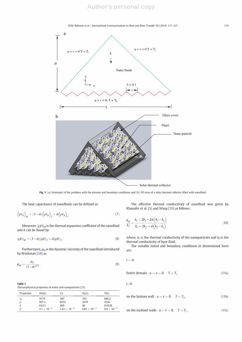
The detail of the physical model is presented in Fig. 1(a) alongwith its specified co-ordinate system and boundary conditions. Inthis model a triangular type solar collector with a corrugated bottomis shown in Fig. 1(b). The enclosure is filled with the nanofluidswhich are Cu–water, Al2O3–water and TiO2–water. The height ofthe cavity is H and the length of the cavity is L. The effect of the grav-ity is shown in the negative Y axis. Here the cavity is formed by thetwo inclined glass covers where the horizontal base plate is corru-gated and acts as an absorber plate. The absorber plate has a constanthigher temperature than the inclined glass cover.
2.2. Thermophysical property of nanofluid
For this numerical study Cu, Al2O3 and TiO2 are taken as the nano-particle and water is taken as the base fluid. Different experimentshave been carried out by different researchers. Different nanofluidssuch as TiO2–water, Al2O3–water, and Cu–water are recently available.The data used for the numerical simulation [23] is given in Table 1.
2.3. Mathematical modeling
The governing equations which define the system behavior are con-servation of mass, energy and momentum. The thermophysical proper-ties of the nanofluid are presumed to be constant excluding the densityvariation in the buoyancy force, which is established on the Boussinesqapproximation. Cu–water, Al2O3–water and TiO2–water nanofluids filledthe free space of the enclosure and which are modeled as a Newtonianfluid. The flow is assumed to be unsteady, laminar and incompressible.Thermal equilibrium between the base fluid and nanoparticles is consid-ered, and no slip arises between the twomedia. In the light of these sup-positions stated above, the continuity, momentum and energy equationsin two-dimensional form can be written as [15]:
∂u∂x þ
∂v∂y ¼ 0 ð1Þ
∂u∂t þ u
∂u∂x þ v
∂u∂y ¼ − 1
ρnf
∂p∂x þ
μnf
ρnf
∂2u∂x2
þ ∂2u∂y2
!ð2Þ
∂v∂t þ u
∂v∂xþ v
∂v∂y ¼ − 1
ρnf
∂p∂y þ μnf
ρnf
∂2v∂x2
þ ∂2v∂y2
!þ ρβð Þnf
ρnfg T−Tcð Þ ð3Þ
∂T∂t þ u
∂T∂x þ v
∂T∂y ¼ αnf
∂2T∂x2
þ ∂2T∂y2
!ð4Þ
where, the effective density ρnf of the nanofluid is described by
ρnf ¼ 1−ϕð Þρ f þ ϕρs ð5Þ
andϕ is the solid volume fraction of nanoparticles. Furthermore, the ther-mal diffusivity αnf of the nanofluid is specified by:
αnf ¼knf
ρcp� �
nf
: ð6Þ
Nomenclature
cp specific heat (J kg−1 k−1)g gravitational acceleration (ms−2)Gr Grashof numberH enclosure height (m)k thermal conductivity (Wm−1 k−1)L length of the enclosure (m)Nu Nusselt numberp dimensional pressure (kg m−1 s−2)P dimensionless pressurePr Prandtl numberT fluid temperature (K)t dimensional time (s)u horizontal velocity component (ms−1)U dimensionless horizontal velocity componentv vertical velocity component (ms−1)V dimensionless vertical velocity componentx horizontal coordinate (m)X dimensionless horizontal coordinatey vertical coordinate (m)Y dimensionless vertical coordinate
Greek symbolsα thermal diffusivity (m2 s−1)β thermal expansion coefficient (K−1)ϕ solid volume fractionμ dynamic viscosity (kg m−1 s−1)ν kinematic viscosity (m2 s−1)τ dimensionless timeθ non-dimensional temperatureρ density (kg m−3)ψ stream functionλ wave lengthΓ general dependent variable
Subscriptsav overallh hotc coldf fluidnf nanofluids solid nanoparticlemax maximummin minimum
118 M.M. Rahman et al. / International Communications in Heat and Mass Transfer 50 (2014) 117–127
Author's personal copy
The heat capacitance of nanofluids can be defined as
ρcp� �
nf¼ 1−ϕð Þ ρcp
� �fþ ϕ ρcp
� �s: ð7Þ
Moreover, (ρβ)nf is the thermal expansion coefficient of the nanofluidand it can be found by
ρβð Þnf ¼ 1−ϕð Þ ρβð Þ f þ ϕ ρβð Þs: ð8Þ
Furthermore, μnf is the dynamic viscosity of the nanofluid introducedby Brinkman [34] as
μnf ¼μ f
1−ϕð Þ2:5 : ð9Þ
The effective thermal conductivity of nanofluid was given byKhanafer et al. [5] and Wasp [35] as follows:
knfk f
¼ks þ 2kf−2ϕ kf−ks
� �ks þ 2kf þ ϕ kf−ks
� � ð10Þ
where, ks is the thermal conductivity of the nanoparticles and kf is thethermal conductivity of base fluid.
The suitable initial and boundary conditions in dimensional formare:
t ¼ 0
Entire domain : u ¼ v ¼ 0; T ¼ Tc ð11aÞ
tN0
on the bottom wall : u ¼ v ¼ 0; T ¼ Th ð11bÞ
on the inclined walls : u ¼ v ¼ 0; T ¼ Tc: ð11cÞ
g
L
H
u = v = 0, T = Th
x
y
u = v = 0 T = Tc
λ = 0.1
u = v = 0 T = Tc
Solar thermal collector
Nano particle
Fluid
Glass coverb
a
Nano fluids
Fig. 1. (a) Schematic of the problem with the domain and boundary conditions and (b) 3D view of a solar thermal collector filled with nanofluid.
Table 1Thermophysical properties of water and nanoparticles [23].
Properties Water Cu Al2O3 TiO2
cp 4179 385 765 686.2ρ 997.1 8933 3970 4250k 0.613 400 40 8.9538β 2.1 × 10⁻⁴ 1.67 × 10⁻⁵ 0.85 × 10⁻⁵ 0.9 × 10⁻⁵
119M.M. Rahman et al. / International Communications in Heat and Mass Transfer 50 (2014) 117–127
Author's personal copy
Eqs. (1)–(4) are nondimensionalized using the following dimen-sionless variables:
X ¼ xL; Y ¼ y
L; τ ¼ α f t
L2;U ¼ uL
α f;V ¼ vL
α f; P ¼
pþ ρ f gy� �
L2
ρnf α f2 ; θ
¼ T−Tcð ÞTh−Tcð Þ : ð12Þ
By employing Eq. (12) the resulting dimensionless equations are re-duced to:
∂U∂X þ ∂V
∂Y ¼ 0 ð13Þ
∂U∂τ þ U
∂U∂X þ V
∂U∂Y ¼ −∂P
∂X þ Pr
1−ϕð Þ þ ϕ ρs=ρ f
� �h i 11−ϕð Þ2:5 ∇
2U ð14Þ
∂V∂τ þ U
∂V∂X þ V
∂V∂Y ¼ −∂P
∂Y þ Pr
1−ϕð Þ þ ϕ ρs=ρ f
� �h i 11−ϕð Þ2:5 ∇
2V
þ ϕρsβs þ 1−ϕð Þρ fβ f
1−ϕð Þρ fβ f þ ϕρsβ fGrPr2θ
ð15Þ
∂θ∂τþ U
∂θ∂X þ V
∂θ∂Y ¼ 1þ 2ϕð Þks þ 2 1−ϕð Þkf
1−ϕð Þks þ 2þ ϕð Þkf
1
1−ϕð Þ þ ϕ ρcp� �
s= ρcp� �
f
� �∇2θ: ð16Þ
Here the Prandtl number and Grashof number are defined as
Pr ¼ ν f =α f and Gr ¼ gβ f L3 Th−Tcð Þν f
2
initial and boundary conditions in the dimensionless form for the pres-ent problems become
τ ¼ 0
Entire domain : U ¼ V ¼ 0; θ ¼ 0 ð17aÞ
τN0
on the bottom wall : U ¼ V ¼; θ ¼ 1 ð17bÞ
on the inclined walls : U ¼ V ¼ 0; θ ¼ 0: ð17cÞ
The overall Nusselt number at the heated surface of the enclosurecan be expressed by
Nuav ¼ −knfk f
Z10
∂θ∂Y dX: ð18Þ
The fluid motion is displayed by means of the stream function ψ ac-quired from velocity components U and V. The relationships amongstream function and velocity components from Batchelor [36] for twodimensional flows are
U ¼ ∂ψ∂Y ; V ¼ −∂ψ
∂X : ð19Þ
3. Numerical methods
3.1. Numerical scheme
Finite element method was employed to solve non-dimensionalform of the governing Eqs. (14)–(16) subject to the initial and boundaryconditions (17). The Galerkin weighted residual scheme is applied to
discretize the equations. A non-uniform triangular element is locatedover the enclosure. For each element the dependent variables are esti-mated using interpolation function. A set of algebraic equation hasbeen formed by the governing equation to lessen the continuum areainto the discrete triangular regions. Then the algebraic equation issolved using the iteration technique. The iteration has been done tillthe solution becomes convergent. |Γm + 1 − Γm| ≤ 10−6 where m isthe number of iteration and Γ is the general dependent variable.
3.2. Grid independency test
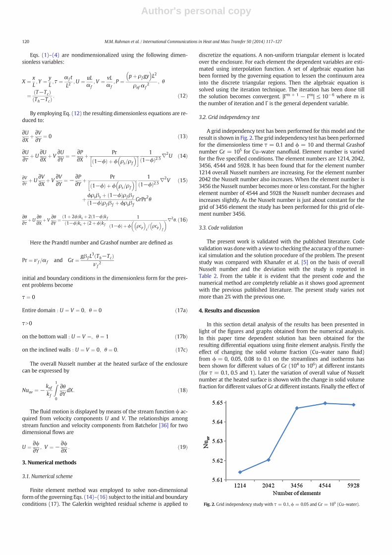
A grid independency test has been performed for this model and theresult is shown in Fig. 2. The grid independency test has been performedfor the dimensionless time τ = 0.1 and ϕ = 10 and thermal Grashofnumber Gr = 105 for Cu–water nanofluid. Element number is variedfor the five specified conditions. The element numbers are 1214, 2042,3456, 4544 and 5928. It has been found that for the element number1214 overall Nusselt numbers are increasing. For the element number2042 the Nusselt number also increases. When the element number is3456 the Nusselt number becomesmore or less constant. For the higherelement number of 4544 and 5928 the Nusselt number decreases andincreases slightly. As the Nusselt number is just about constant for thegrid of 3456 element the study has been performed for this grid of ele-ment number 3456.
3.3. Code validation
The present work is validated with the published literature. Codevalidationwas donewith a view to checking the accuracy of the numer-ical simulation and the solution procedure of the problem. The presentstudy was compared with Khanafer et al. [5] on the basis of overallNusselt number and the deviation with the study is reported inTable 2. From the table it is evident that the present code and thenumerical method are completely reliable as it shows good agreementwith the previous published literature. The present study varies notmore than 2% with the previous one.
4. Results and discussion
In this section detail analysis of the results has been presented inlight of the figures and graphs obtained from the numerical analysis.In this paper time dependent solution has been obtained for theresulting differential equations using finite element analysis. Firstly theeffect of changing the solid volume fraction (Cu–water nano fluid)from ϕ = 0, 0.05, 0.08 to 0.1 on the streamlines and isotherms hasbeen shown for different values of Gr (104 to 106) at different instants(for τ = 0.1, 0.5 and 1). Later the variation of overall value of Nusseltnumber at the heated surface is shown with the change in solid volumefraction for different values of Gr at different instants. Finally the effect of
Fig. 2. Grid independency study with τ = 0.1, ϕ = 0.05 and Gr = 105 (Cu–water).
120 M.M. Rahman et al. / International Communications in Heat and Mass Transfer 50 (2014) 117–127
Author's personal copy
different commonly used nanofluids such as TiO2–water, Al2O3–waterand Cu–water is discussed on the light of overall Nusselt number.
4.1. Effect of solid volume fraction on streamlines varying the dimensionlesstime
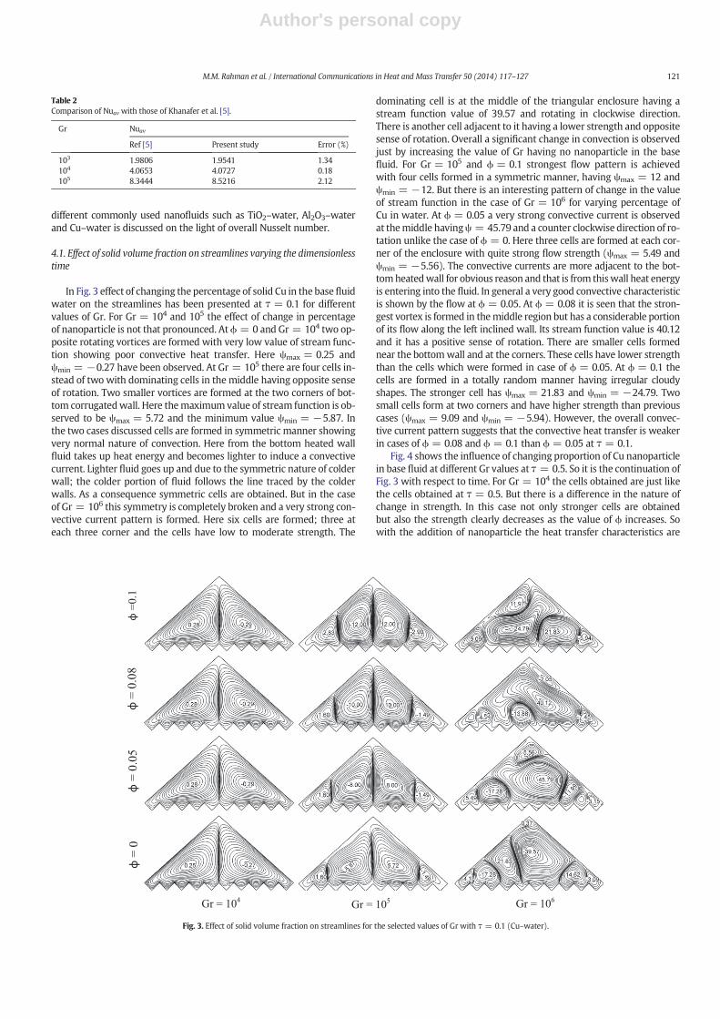
In Fig. 3 effect of changing the percentage of solid Cu in the basefluidwater on the streamlines has been presented at τ = 0.1 for differentvalues of Gr. For Gr = 104 and 105 the effect of change in percentageof nanoparticle is not that pronounced. Atϕ = 0 and Gr = 104 two op-posite rotating vortices are formed with very low value of stream func-tion showing poor convective heat transfer. Here ψmax = 0.25 andψmin = −0.27 have been observed. At Gr = 105 there are four cells in-stead of two with dominating cells in the middle having opposite senseof rotation. Two smaller vortices are formed at the two corners of bot-tom corrugatedwall. Here themaximum value of stream function is ob-served to be ψmax = 5.72 and the minimum value ψmin = −5.87. Inthe two cases discussed cells are formed in symmetric manner showingvery normal nature of convection. Here from the bottom heated wallfluid takes up heat energy and becomes lighter to induce a convectivecurrent. Lighter fluid goes up and due to the symmetric nature of colderwall; the colder portion of fluid follows the line traced by the colderwalls. As a consequence symmetric cells are obtained. But in the caseof Gr = 106 this symmetry is completely broken and a very strong con-vective current pattern is formed. Here six cells are formed; three ateach three corner and the cells have low to moderate strength. The
dominating cell is at the middle of the triangular enclosure having astream function value of 39.57 and rotating in clockwise direction.There is another cell adjacent to it having a lower strength and oppositesense of rotation. Overall a significant change in convection is observedjust by increasing the value of Gr having no nanoparticle in the basefluid. For Gr = 105 and ϕ = 0.1 strongest flow pattern is achievedwith four cells formed in a symmetric manner, having ψmax = 12 andψmin = −12. But there is an interesting pattern of change in the valueof stream function in the case of Gr = 106 for varying percentage ofCu in water. At ϕ = 0.05 a very strong convective current is observedat themiddle havingψ = 45.79 and a counter clockwise direction of ro-tation unlike the case of ϕ = 0. Here three cells are formed at each cor-ner of the enclosure with quite strong flow strength (ψmax = 5.49 andψmin = −5.56). The convective currents are more adjacent to the bot-tomheatedwall for obvious reason and that is from thiswall heat energyis entering into the fluid. In general a very good convective characteristicis shown by the flow at ϕ = 0.05. At ϕ = 0.08 it is seen that the stron-gest vortex is formed in themiddle region but has a considerable portionof its flow along the left inclined wall. Its stream function value is 40.12and it has a positive sense of rotation. There are smaller cells formednear the bottomwall and at the corners. These cells have lower strengththan the cells which were formed in case of ϕ = 0.05. At ϕ = 0.1 thecells are formed in a totally random manner having irregular cloudyshapes. The stronger cell has ψmax = 21.83 and ψmin = −24.79. Twosmall cells form at two corners and have higher strength than previouscases (ψmax = 9.09 and ψmin = −5.94). However, the overall convec-tive current pattern suggests that the convective heat transfer is weakerin cases of ϕ = 0.08 and ϕ = 0.1 than ϕ = 0.05 at τ = 0.1.
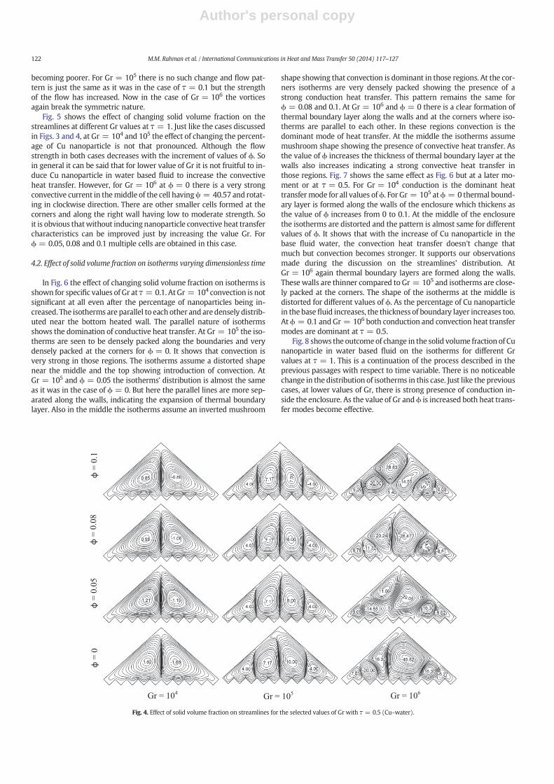
Fig. 4 shows the influence of changing proportion of Cu nanoparticlein base fluid at different Gr values at τ = 0.5. So it is the continuation ofFig. 3 with respect to time. For Gr = 104 the cells obtained are just likethe cells obtained at τ = 0.5. But there is a difference in the nature ofchange in strength. In this case not only stronger cells are obtainedbut also the strength clearly decreases as the value of ϕ increases. Sowith the addition of nanoparticle the heat transfer characteristics are
Table 2Comparison of Nuav with those of Khanafer et al. [5].
Gr Nuav
Ref [5] Present study Error (%)
103 1.9806 1.9541 1.34104 4.0653 4.0727 0.18105 8.3444 8.5216 2.12
Fig. 3. Effect of solid volume fraction on streamlines for the selected values of Gr with τ = 0.1 (Cu–water).
121M.M. Rahman et al. / International Communications in Heat and Mass Transfer 50 (2014) 117–127
Author's personal copy
becoming poorer. For Gr = 105 there is no such change and flow pat-tern is just the same as it was in the case of τ = 0.1 but the strengthof the flow has increased. Now in the case of Gr = 106 the vorticesagain break the symmetric nature.
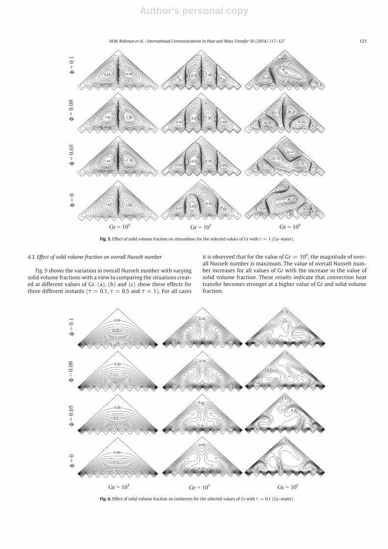
Fig. 5 shows the effect of changing solid volume fraction on thestreamlines at different Gr values at τ = 1. Just like the cases discussedin Figs. 3 and 4, at Gr = 104 and 105 the effect of changing the percent-age of Cu nanoparticle is not that pronounced. Although the flowstrength in both cases decreases with the increment of values of ϕ. Soin general it can be said that for lower value of Gr it is not fruitful to in-duce Cu nanoparticle in water based fluid to increase the convectiveheat transfer. However, for Gr = 106 at ϕ = 0 there is a very strongconvective current in themiddle of the cell havingψ = 40.57 and rotat-ing in clockwise direction. There are other smaller cells formed at thecorners and along the right wall having low to moderate strength. Soit is obvious thatwithout inducing nanoparticle convective heat transfercharacteristics can be improved just by increasing the value Gr. Forϕ = 0.05, 0.08 and 0.1 multiple cells are obtained in this case.
4.2. Effect of solid volume fraction on isotherms varying dimensionless time
In Fig. 6 the effect of changing solid volume fraction on isotherms isshown for specific values of Gr at τ = 0.1. AtGr = 104 convection is notsignificant at all even after the percentage of nanoparticles being in-creased. The isotherms are parallel to eachother and aredensely distrib-uted near the bottom heated wall. The parallel nature of isothermsshows the domination of conductive heat transfer. At Gr = 105 the iso-therms are seen to be densely packed along the boundaries and verydensely packed at the corners for ϕ = 0. It shows that convection isvery strong in those regions. The isotherms assume a distorted shapenear the middle and the top showing introduction of convection. AtGr = 105 and ϕ = 0.05 the isotherms' distribution is almost the sameas it was in the case of ϕ = 0. But here the parallel lines are more sep-arated along the walls, indicating the expansion of thermal boundarylayer. Also in the middle the isotherms assume an inverted mushroom
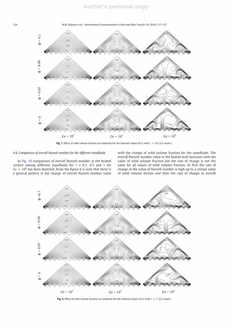
shape showing that convection is dominant in those regions. At the cor-ners isotherms are very densely packed showing the presence of astrong conduction heat transfer. This pattern remains the same forϕ = 0.08 and 0.1. At Gr = 106 and ϕ = 0 there is a clear formation ofthermal boundary layer along the walls and at the corners where iso-therms are parallel to each other. In these regions convection is thedominant mode of heat transfer. At the middle the isotherms assumemushroom shape showing the presence of convective heat transfer. Asthe value of ϕ increases the thickness of thermal boundary layer at thewalls also increases indicating a strong convective heat transfer inthose regions. Fig. 7 shows the same effect as Fig. 6 but at a later mo-ment or at τ = 0.5. For Gr = 104 conduction is the dominant heattransfermode for all values ofϕ. For Gr = 105 atϕ = 0 thermal bound-ary layer is formed along the walls of the enclosure which thickens asthe value of ϕ increases from 0 to 0.1. At the middle of the enclosurethe isotherms are distorted and the pattern is almost same for differentvalues of ϕ. It shows that with the increase of Cu nanoparticle in thebase fluid water, the convection heat transfer doesn't change thatmuch but convection becomes stronger. It supports our observationsmade during the discussion on the streamlines' distribution. AtGr = 106 again thermal boundary layers are formed along the walls.These walls are thinner compared to Gr = 105 and isotherms are close-ly packed at the corners. The shape of the isotherms at the middle isdistorted for different values of ϕ. As the percentage of Cu nanoparticlein the base fluid increases, the thickness of boundary layer increases too.At ϕ = 0.1 and Gr = 106 both conduction and convection heat transfermodes are dominant at τ = 0.5.
Fig. 8 shows the outcomeof change in the solid volume fraction of Cunanoparticle in water based fluid on the isotherms for different Grvalues at τ = 1. This is a continuation of the process described in theprevious passages with respect to time variable. There is no noticeablechange in the distribution of isotherms in this case. Just like the previouscases, at lower values of Gr, there is strong presence of conduction in-side the enclosure. As the value of Gr andϕ is increased both heat trans-fer modes become effective.
Fig. 4. Effect of solid volume fraction on streamlines for the selected values of Gr with τ = 0.5 (Cu–water).
122 M.M. Rahman et al. / International Communications in Heat and Mass Transfer 50 (2014) 117–127
Author's personal copy
4.3. Effect of solid volume fraction on overall Nusselt number
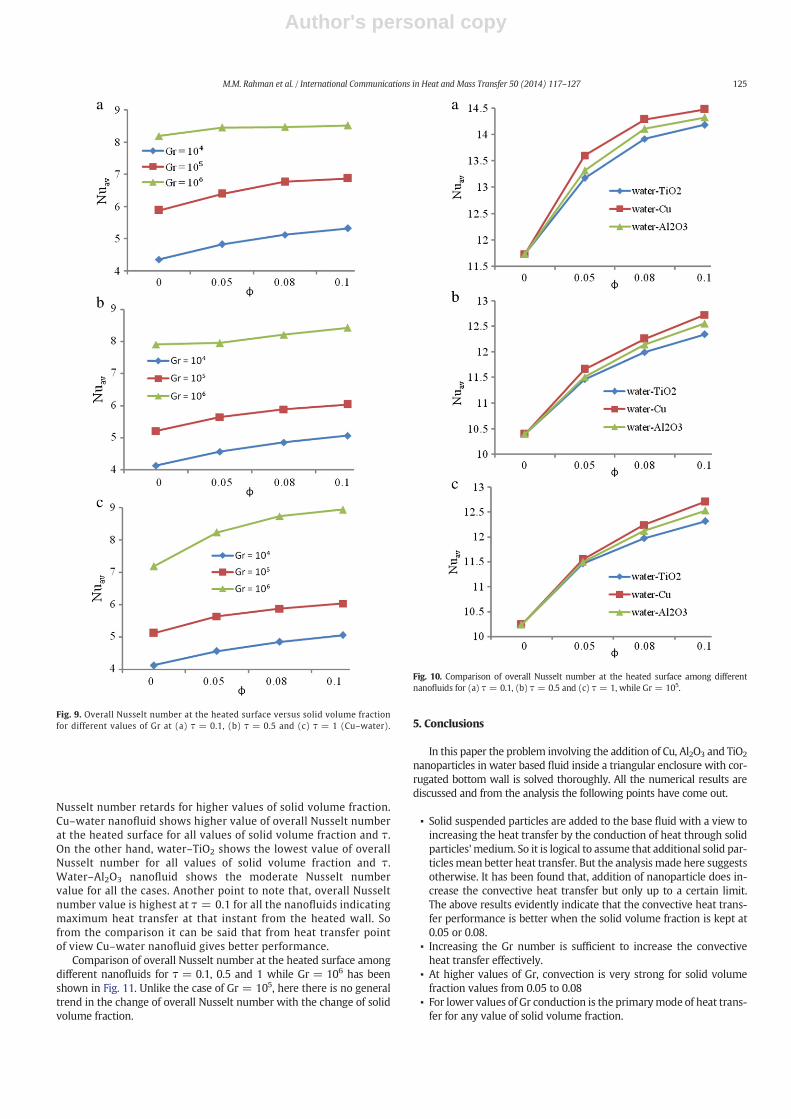
Fig. 9 shows the variation in overall Nusselt number with varyingsolid volume fractions with a view to comparing the situations creat-ed at different values of Gr. (a), (b) and (c) show these effects forthree different instants (τ = 0.1, τ = 0.5 and τ = 1). For all cases
it is observed that for the value of Gr = 106, the magnitude of over-all Nusselt number is maximum. The value of overall Nusselt num-ber increases for all values of Gr with the increase in the value ofsolid volume fraction. These results indicate that convection heattransfer becomes stronger at a higher value of Gr and solid volumefraction.
Fig. 5. Effect of solid volume fraction on streamlines for the selected values of Gr with τ = 1 (Cu–water).
Fig. 6. Effect of solid volume fraction on isotherms for the selected values of Gr with τ = 0.1 (Cu–water).
123M.M. Rahman et al. / International Communications in Heat and Mass Transfer 50 (2014) 117–127
Author's personal copy
4.4. Comparison of overall Nusselt number for the different nanofluids
In Fig. 10 comparison of overall Nusselt number at the heatedsurface among different nanofluids for τ = 0.1, 0.5 and 1 forGr = 105 has been depicted. From the figure it is seen that there isa general pattern in the change of overall Nusselt number value
with the change of solid volume fraction for the nanofluids. Theoverall Nusselt number value at the heated wall increases with thevalue of solid volume fraction but the rate of change is not thesame for all values of solid volume fraction. At first the rate ofchange in the value of Nusselt number is high up to a certain valueof solid volume faction and then the rate of change in overall
Fig. 7. Effect of solid volume fraction on isotherms for the selected values of Gr with τ = 0.5 (Cu–water).
Fig. 8. Effect of solid volume fraction on isotherms for the selected values of Gr with τ = 1 (Cu–water).
124 M.M. Rahman et al. / International Communications in Heat and Mass Transfer 50 (2014) 117–127
Author's personal copy
Nusselt number retards for higher values of solid volume fraction.Cu–water nanofluid shows higher value of overall Nusselt numberat the heated surface for all values of solid volume fraction and τ.On the other hand, water–TiO2 shows the lowest value of overallNusselt number for all values of solid volume fraction and τ.Water–Al2O3 nanofluid shows the moderate Nusselt numbervalue for all the cases. Another point to note that, overall Nusseltnumber value is highest at τ = 0.1 for all the nanofluids indicatingmaximum heat transfer at that instant from the heated wall. Sofrom the comparison it can be said that from heat transfer pointof view Cu–water nanofluid gives better performance.
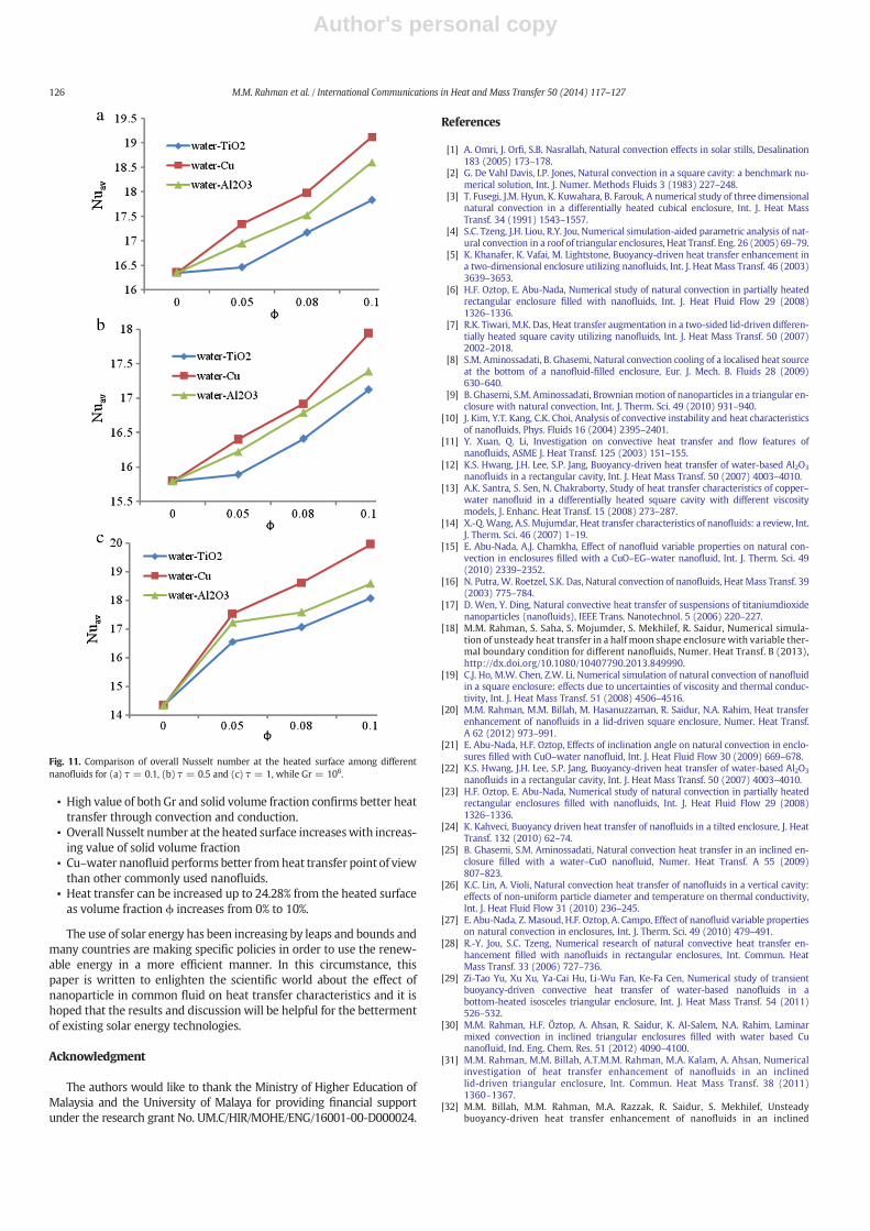
Comparison of overall Nusselt number at the heated surface amongdifferent nanofluids for τ = 0.1, 0.5 and 1 while Gr = 106 has beenshown in Fig. 11. Unlike the case of Gr = 105, here there is no generaltrend in the change of overall Nusselt number with the change of solidvolume fraction.
5. Conclusions
In this paper the problem involving the addition of Cu, Al2O3 and TiO2
nanoparticles in water based fluid inside a triangular enclosure with cor-rugated bottom wall is solved thoroughly. All the numerical results arediscussed and from the analysis the following points have come out.
▪ Solid suspended particles are added to the base fluid with a view toincreasing the heat transfer by the conduction of heat through solidparticles' medium. So it is logical to assume that additional solid par-ticlesmean better heat transfer. But the analysis made here suggestsotherwise. It has been found that, addition of nanoparticle does in-crease the convective heat transfer but only up to a certain limit.The above results evidently indicate that the convective heat trans-fer performance is better when the solid volume fraction is kept at0.05 or 0.08.
▪ Increasing the Gr number is sufficient to increase the convectiveheat transfer effectively.
▪ At higher values of Gr, convection is very strong for solid volumefraction values from 0.05 to 0.08
▪ For lower values of Gr conduction is the primarymode of heat trans-fer for any value of solid volume fraction.
Fig. 9. Overall Nusselt number at the heated surface versus solid volume fractionfor different values of Gr at (a) τ = 0.1, (b) τ = 0.5 and (c) τ = 1 (Cu–water).
Fig. 10. Comparison of overall Nusselt number at the heated surface among differentnanofluids for (a) τ = 0.1, (b) τ = 0.5 and (c) τ = 1, while Gr = 105.
125M.M. Rahman et al. / International Communications in Heat and Mass Transfer 50 (2014) 117–127
Author's personal copy
▪ High value of both Gr and solid volume fraction confirms better heattransfer through convection and conduction.
▪ Overall Nusselt number at the heated surface increaseswith increas-ing value of solid volume fraction
▪ Cu–water nanofluid performs better fromheat transfer point of viewthan other commonly used nanofluids.
▪ Heat transfer can be increased up to 24.28% from the heated surfaceas volume fraction ϕ increases from 0% to 10%.
The use of solar energy has been increasing by leaps and bounds andmany countries are making specific policies in order to use the renew-able energy in a more efficient manner. In this circumstance, thispaper is written to enlighten the scientific world about the effect ofnanoparticle in common fluid on heat transfer characteristics and it ishoped that the results and discussion will be helpful for the bettermentof existing solar energy technologies.
Acknowledgment
The authors would like to thank the Ministry of Higher Education ofMalaysia and the University of Malaya for providing financial supportunder the research grant No. UM.C/HIR/MOHE/ENG/16001-00-D000024.
References
[1] A. Omri, J. Orfi, S.B. Nasrallah, Natural convection effects in solar stills, Desalination183 (2005) 173–178.
[2] G. De Vahl Davis, I.P. Jones, Natural convection in a square cavity: a benchmark nu-merical solution, Int. J. Numer. Methods Fluids 3 (1983) 227–248.
[3] T. Fusegi, J.M. Hyun, K. Kuwahara, B. Farouk, A numerical study of three dimensionalnatural convection in a differentially heated cubical enclosure, Int. J. Heat MassTransf. 34 (1991) 1543–1557.
[4] S.C. Tzeng, J.H. Liou, R.Y. Jou, Numerical simulation-aided parametric analysis of nat-ural convection in a roof of triangular enclosures, Heat Transf. Eng. 26 (2005) 69–79.
[5] K. Khanafer, K. Vafai, M. Lightstone, Buoyancy-driven heat transfer enhancement ina two-dimensional enclosure utilizing nanofluids, Int. J. Heat Mass Transf. 46 (2003)3639–3653.
[6] H.F. Oztop, E. Abu-Nada, Numerical study of natural convection in partially heatedrectangular enclosure filled with nanofluids, Int. J. Heat Fluid Flow 29 (2008)1326–1336.
[7] R.K. Tiwari, M.K. Das, Heat transfer augmentation in a two-sided lid-driven differen-tially heated square cavity utilizing nanofluids, Int. J. Heat Mass Transf. 50 (2007)2002–2018.
[8] S.M. Aminossadati, B. Ghasemi, Natural convection cooling of a localised heat sourceat the bottom of a nanofluid-filled enclosure, Eur. J. Mech. B. Fluids 28 (2009)630–640.
[9] B. Ghasemi, S.M. Aminossadati, Brownianmotion of nanoparticles in a triangular en-closure with natural convection, Int. J. Therm. Sci. 49 (2010) 931–940.
[10] J. Kim, Y.T. Kang, C.K. Choi, Analysis of convective instability and heat characteristicsof nanofluids, Phys. Fluids 16 (2004) 2395–2401.
[11] Y. Xuan, Q. Li, Investigation on convective heat transfer and flow features ofnanofluids, ASME J. Heat Transf. 125 (2003) 151–155.
[12] K.S. Hwang, J.H. Lee, S.P. Jang, Buoyancy-driven heat transfer of water-based Al2O3
nanofluids in a rectangular cavity, Int. J. Heat Mass Transf. 50 (2007) 4003–4010.[13] A.K. Santra, S. Sen, N. Chakraborty, Study of heat transfer characteristics of copper–
water nanofluid in a differentially heated square cavity with different viscositymodels, J. Enhanc. Heat Transf. 15 (2008) 273–287.
[14] X.-Q. Wang, A.S. Mujumdar, Heat transfer characteristics of nanofluids: a review, Int.J. Therm. Sci. 46 (2007) 1–19.
[15] E. Abu-Nada, A.J. Chamkha, Effect of nanofluid variable properties on natural con-vection in enclosures filled with a CuO–EG–water nanofluid, Int. J. Therm. Sci. 49(2010) 2339–2352.
[16] N. Putra, W. Roetzel, S.K. Das, Natural convection of nanofluids, Heat Mass Transf. 39(2003) 775–784.
[17] D. Wen, Y. Ding, Natural convective heat transfer of suspensions of titaniumdioxidenanoparticles (nanofluids), IEEE Trans. Nanotechnol. 5 (2006) 220–227.
[18] M.M. Rahman, S. Saha, S. Mojumder, S. Mekhilef, R. Saidur, Numerical simula-tion of unsteady heat transfer in a half moon shape enclosure with variable ther-mal boundary condition for different nanofluids, Numer. Heat Transf. B (2013),http://dx.doi.org/10.1080/10407790.2013.849990.
[19] C.J. Ho, M.W. Chen, Z.W. Li, Numerical simulation of natural convection of nanofluidin a square enclosure: effects due to uncertainties of viscosity and thermal conduc-tivity, Int. J. Heat Mass Transf. 51 (2008) 4506–4516.
[20] M.M. Rahman, M.M. Billah, M. Hasanuzzaman, R. Saidur, N.A. Rahim, Heat transferenhancement of nanofluids in a lid-driven square enclosure, Numer. Heat Transf.A 62 (2012) 973–991.
[21] E. Abu-Nada, H.F. Oztop, Effects of inclination angle on natural convection in enclo-sures filled with CuO–water nanofluid, Int. J. Heat Fluid Flow 30 (2009) 669–678.
[22] K.S. Hwang, J.H. Lee, S.P. Jang, Buoyancy-driven heat transfer of water-based Al2O3
nanofluids in a rectangular cavity, Int. J. Heat Mass Transf. 50 (2007) 4003–4010.[23] H.F. Oztop, E. Abu-Nada, Numerical study of natural convection in partially heated
rectangular enclosures filled with nanofluids, Int. J. Heat Fluid Flow 29 (2008)1326–1336.
[24] K. Kahveci, Buoyancy driven heat transfer of nanofluids in a tilted enclosure, J. HeatTransf. 132 (2010) 62–74.
[25] B. Ghasemi, S.M. Aminossadati, Natural convection heat transfer in an inclined en-closure filled with a water–CuO nanofluid, Numer. Heat Transf. A 55 (2009)807–823.
[26] K.C. Lin, A. Violi, Natural convection heat transfer of nanofluids in a vertical cavity:effects of non-uniform particle diameter and temperature on thermal conductivity,Int. J. Heat Fluid Flow 31 (2010) 236–245.
[27] E. Abu-Nada, Z. Masoud, H.F. Oztop, A. Campo, Effect of nanofluid variable propertieson natural convection in enclosures, Int. J. Therm. Sci. 49 (2010) 479–491.
[28] R.-Y. Jou, S.C. Tzeng, Numerical research of natural convective heat transfer en-hancement filled with nanofluids in rectangular enclosures, Int. Commun. HeatMass Transf. 33 (2006) 727–736.
[29] Zi-Tao Yu, Xu Xu, Ya-Cai Hu, Li-Wu Fan, Ke-Fa Cen, Numerical study of transientbuoyancy-driven convective heat transfer of water-based nanofluids in abottom-heated isosceles triangular enclosure, Int. J. Heat Mass Transf. 54 (2011)526–532.
[30] M.M. Rahman, H.F. Öztop, A. Ahsan, R. Saidur, K. Al-Salem, N.A. Rahim, Laminarmixed convection in inclined triangular enclosures filled with water based Cunanofluid, Ind. Eng. Chem. Res. 51 (2012) 4090–4100.
[31] M.M. Rahman, M.M. Billah, A.T.M.M. Rahman, M.A. Kalam, A. Ahsan, Numericalinvestigation of heat transfer enhancement of nanofluids in an inclinedlid-driven triangular enclosure, Int. Commun. Heat Mass Transf. 38 (2011)1360–1367.
[32] M.M. Billah, M.M. Rahman, M.A. Razzak, R. Saidur, S. Mekhilef, Unsteadybuoyancy-driven heat transfer enhancement of nanofluids in an inclined
Fig. 11. Comparison of overall Nusselt number at the heated surface among differentnanofluids for (a) τ = 0.1, (b) τ = 0.5 and (c) τ = 1, while Gr = 106.
126 M.M. Rahman et al. / International Communications in Heat and Mass Transfer 50 (2014) 117–127

Author's personal copy
triangular enclosure, Int. Commun. Heat Mass Transf. (2013), http://dx.doi.org/10.1016/j.icheatmasstransfer.2013.09.006.
[33] M.M. Rahman, R. Saidur, S. Mekhilef, M.B. Uddin, A. Ahsan, Double-diffusivebuoyancy induced flow in a triangular cavity with corrugated bottomwall: Ef-fects of geometrical parameters, Int. Commun. Heat Mass Transf. 45 (2013)64–74.
[34] H.C. Brinkman, The viscosity of concentrated suspensions and solutions, J. Cryst.Growth 20 (1952) 571.
[35] F.J. Wasp, Solid–Liquid Slurry Pipeline Transportation, Trans. Tech., Berlin,1977.
[36] G.K. Batchelor, An Introduction to Fluid Dynamics, Cambridge University Press,London, 1993.
127M.M. Rahman et al. / International Communications in Heat and Mass Transfer 50 (2014) 117–127
Copyright © 2022 FDOKUMEN