Executive Summary - City of Sumner
230
City of Sumner General Water Plan Update - DRAFT November 2017 1 Executive Summary The 2018 Sumner Water System Plan has been developed in compliance with the requirements set forth by the Washington State Department of Health (DOH), including the applicable Washington Administrative Code (WAC) 246-290 Sections and the Municipal Water Law of 2003. This summary is intended to provide a brief description of the key elements discussed in the Plan. Service Area The Sumner water utility service area is situated in the Puyallup/White River basin and is adjoined by the water service areas of the City of Bonney Lake, Mountain View-Edgewood, the City of Puyallup, Valley Water District, the City of Auburn, Tacoma Water, and the City of Pacific. The Sumner water system has interties with both the Pacific and Puyallup water systems. These interties are for use during emergencies only and do not provide additional water for daily demands. The future Sumner water service area, which is discussed in Section 1.2, is consistent with the Pierce County Coordinated Water System Plan and is located entirely within the Urban Growth Area Boundary established by Pierce County. Water System Inventory Sumner’s water system infrastructure consists of approximately 90 miles of transmission mains ranging from 2-inch diameter to 18-inch diameter. The City currently has the rights to utilize up to eight potable water sources, including four springs (Sumner Springs, County Springs, Weber Springs, and Elhi Springs) and four wells (South Well, Central Well, Dieringer Well, and West Well). The physical capacities of the City’s potable water sources are presented as Table ES-1. Table ES-1 Sumner Potable Water Sources DOH ID Number Source Name Source Type Source Capacity (mgd) Water Right (mgd) SO 1 Sumner Springs Free-Flowing Spring 1.15 1 4.04 SO 2 Weber Springs Free-Flowing Spring Flow and water rights are combined with Sumner Springs and County Springs. SO 3 Elhi Springs Free-Flowing Spring 0.13 2 0.52 SO 4 County Springs Free-Flowing Spring 0.79 1 1.15 SO 5 4 West Well Artesian Well 0.36 3 0.36 SO 6 South Well Artesian Well 1.01 3 1.44 5 SO 7 Dieringer Well Artesian Well 0.36 3 0.14 SO-CW Central Well Artesian Well 1.51 3 0.43/1.51 6 DRAFT
-
Upload
khangminh22 -
Category
Documents
-
view
3 -
download
0
Transcript of Executive Summary - City of Sumner

City of Sumner General Water Plan Update - DRAFT
November 2017 1
Executive Summary The 2018 Sumner Water System Plan has been developed in compliance with the requirements set forth by the Washington State Department of Health (DOH), including the applicable Washington Administrative Code (WAC) 246-290 Sections and the Municipal Water Law of 2003. This summary is intended to provide a brief description of the key elements discussed in the Plan.
Service Area The Sumner water utility service area is situated in the Puyallup/White River basin and is adjoined by the water service areas of the City of Bonney Lake, Mountain View-Edgewood, the City of Puyallup, Valley Water District, the City of Auburn, Tacoma Water, and the City of Pacific. The Sumner water system has interties with both the Pacific and Puyallup water systems. These interties are for use during emergencies only and do not provide additional water for daily demands. The future Sumner water service area, which is discussed in Section 1.2, is consistent with the Pierce County Coordinated Water System Plan and is located entirely within the Urban Growth Area Boundary established by Pierce County.
Water System Inventory Sumner’s water system infrastructure consists of approximately 90 miles of transmission mains ranging from 2-inch diameter to 18-inch diameter. The City currently has the rights to utilize up to eight potable water sources, including four springs (Sumner Springs, County Springs, Weber Springs, and Elhi Springs) and four wells (South Well, Central Well, Dieringer Well, and West Well). The physical capacities of the City’s potable water sources are presented as Table ES-1.
Table ES-1 Sumner Potable Water Sources
DOH ID Number
Source Name Source Type Source Capacity
(mgd) Water Right
(mgd)
SO 1 Sumner Springs
Free-Flowing Spring
1.151 4.04
SO 2 Weber Springs Free-Flowing
Spring Flow and water rights are combined with
Sumner Springs and County Springs.
SO 3 Elhi Springs Free-Flowing
Spring 0.132 0.52
SO 4 County Springs Free-Flowing
Spring 0.791 1.15
SO 54 West Well Artesian Well 0.363 0.36
SO 6 South Well Artesian Well 1.013 1.445
SO 7 Dieringer Well Artesian Well 0.363 0.14
SO-CW Central Well Artesian Well 1.513 0.43/1.516
DRAFT

City of Sumner General Water Plan Update - DRAFT
November 2017 1
Notes: 1) Source capacity based on historic station meter readings. 2) Source capacity based on City records; Elhi Springs is typically not being utilized. 3) Source capacity based on well pump capacity. 4) The West Well is currently utilized primarily for irrigation. 5) Source pumping capacity is less than the City's Water Rights. 6) The City obtained a Temporary Water Right to use the Central Well as an additional
point of withdrawal for the South and West Well water rights. Combined instantaneous withdrawal from the Central, South, and West Wells is not to exceed 1.8 mgd.
The City’s water system currently has a physical source capacity of approximately 5.31 mgd and a storage capacity of approximately 5.40 million gallons.
Demand Projections Water demand projections were developed based on historic water usage per resident and employee and the projected population growth within the water service area during the 6-year, 10-year, and 20-year planning periods. Population growth within the City’s water service area is projected to increase based on information provided by the Puget Sound Regional Council (PSRC) as described in Section 3.2 of this Plan. Using water consumption records from 2014 to 2017, the City’s single family residential usage rate was estimated to be 189.6 gpd resulting in a total of 8,774 existing Equivalent Residential Units (ERUs). Consumption records from 2015 to 2017 indicate per capita usage rates of 72.73 gpd/resident and 25.28 gpd/employee for the City’s main water system. Consumptions records from the same years for the Viewpoint pressure zone indicate per capita usage rates of 106 gpd/resident. These values were used to develop the City’s water demand projections, provided as Table ES-2.
Table ES-2 Water Demand Projections
Year Residential Population
Employees Irrigation1
(gpd)
Unclassified Consumption2
(gpd)
DSL3
(gpd) ADD
(mgd) MDD (mgd)
2015 9,584 14,303 238,999 36,134 263,214 1.69 3.32
2016 10,805 15,745 254,450 23,226 328,254 1.72 3.02
2017 10,925 17,332 227,172 22,740 196,780 1.70 3.29
2018 11,044 16,563 229,443 26,334 268,299 1.77 3.36
2024 11,793 17,792 258,390 29,657 188,608 1.81 3.52
2028 12,321 18,150 268,882 32,102 183,988 1.87 3.64
2038 13,343 19,269 268,882 38,522 196,102 1.99 3.89 Notes:
1) Assuming growth per year reduces from 2 percent per year between 2018 and 2024, to 1 percent per year between 2025 and 2028, to 0 percent per year between 2029 and 2038.
2) Assuming a 2 percent per year Unclassified Consumption Growth Rate. 3) Assumes DSL reduces from the current 3-year average of 14 percent to the WLCAP
goal of 10 percent by 2025.
DRAFT

City of Sumner General Water Plan Update - DRAFT
November 2017 1
The Sumner water system has a current operational source capacity of approximately 3.59 mgd, defined in Chapter 5 as operational Scenario A. Based on water demand projections, the instantaneous capacity of the existing City sources may be insufficient to meet the projected maximum day demand by the year 2028 if the City does not receive approval of the additional water rights for the Central Well to allow for the increased source capacity of 1.01 mgd of operational Scenario B.
Water Resources The Sumner potable water sources have a combined instantaneous water right of approximately 7.94 mgd, including rights for Weber Springs No. 1 and No. 2 and including a combined 1.8 mgd for the Central, South, and West Wells as allowed under the current temporary water right.
Water Quality The City’s sources produce very high-quality water and conformance with water quality rules and regulations is generally not an issue. Water quality regulations recently implemented, or currently under development, that will likely be applicable to the City of Sumner are summarized as follows:
Lead and Copper Rule: The EPA proposed changes to the existing Safe Drinking Water Act (SDWA) regulations. These changes include modifying the definition of lead free plumbing products to conform to the statute enacted by Congress that prohibits a lead content level above 0.25%, as well as labeling requirements that allow users of these products to identify plumbing devises that meet the new “lead free” definition. Manufacturers also must certify that they are meeting these new requirements. If these changes are enacted, modifications to the City’s Development Standards may be required for new construction.
Perchlorate: The EPA has determined that perchlorate meets the SDWA criteria for regulation as a contaminant; the rulemaking process is in the peer review period for establishing a MCLG for perchlorate. When established, the City will be required to include perchlorate into their source water testing.
Per- and Polyfluoroalkyl Substances (PFAs): The Washington State Board of Health began a rulemaking process for PFAs regulation in late 2017, which is expected to be a two-year process. If and when PFAs regulation is promulgated, the City will be required to test their source water and treat to below established MCLs. The City should actively be surveying local industry and fire department activities to identify and implement appropriate means of source control.
Capital Improvement Plan (CIP) The CIP presented in this plan includes approximately $14.3 million in capital improvements over the 20-year planning period tied to the City’s distribution system, sources of supply and storage facilities, and operations and maintenance of the water system. Capital improvements in each of these categories are classified as either existing infrastructure deficiencies or as improvements needed to accommodate projected growth. The CIP is presented in the plan as Table 8-1 and provides a comprehensive capital improvement list, including opinions of probable construction cost (OPCCs) and implementation schedule.
DRAFT

City of Sumner General Water Plan Update - DRAFT
November 2017 1
Financial Review The water utility fund revenues expected during the 6-year planning period were estimated based on the City’s actual budget for 2009–2010. The biennial revenues and expenses were increased by 3.5 percent to account for City growth and an additional 3.1 percent for inflation. Based on the existing and projected financial data, it appears that the existing monthly fees and system development charges (SDC) will be insufficient to cover both the existing expenditures and the future expenditures proposed in the Capital Improvement Plan. Future fund revenues will continue to be increased through a combination of monthly fee/SDC increases and low interest loans. A detailed rate study will be conducted to determine the extent of monthly fee/SDC increases required to enable the City to continue to meet the water utility’s financial obligations
DRAFT

City of Sumner General Water Plan Update - DRAFT
April 2018 1-1 BHC Consultants, LLC
Service Area Location and Boundaries
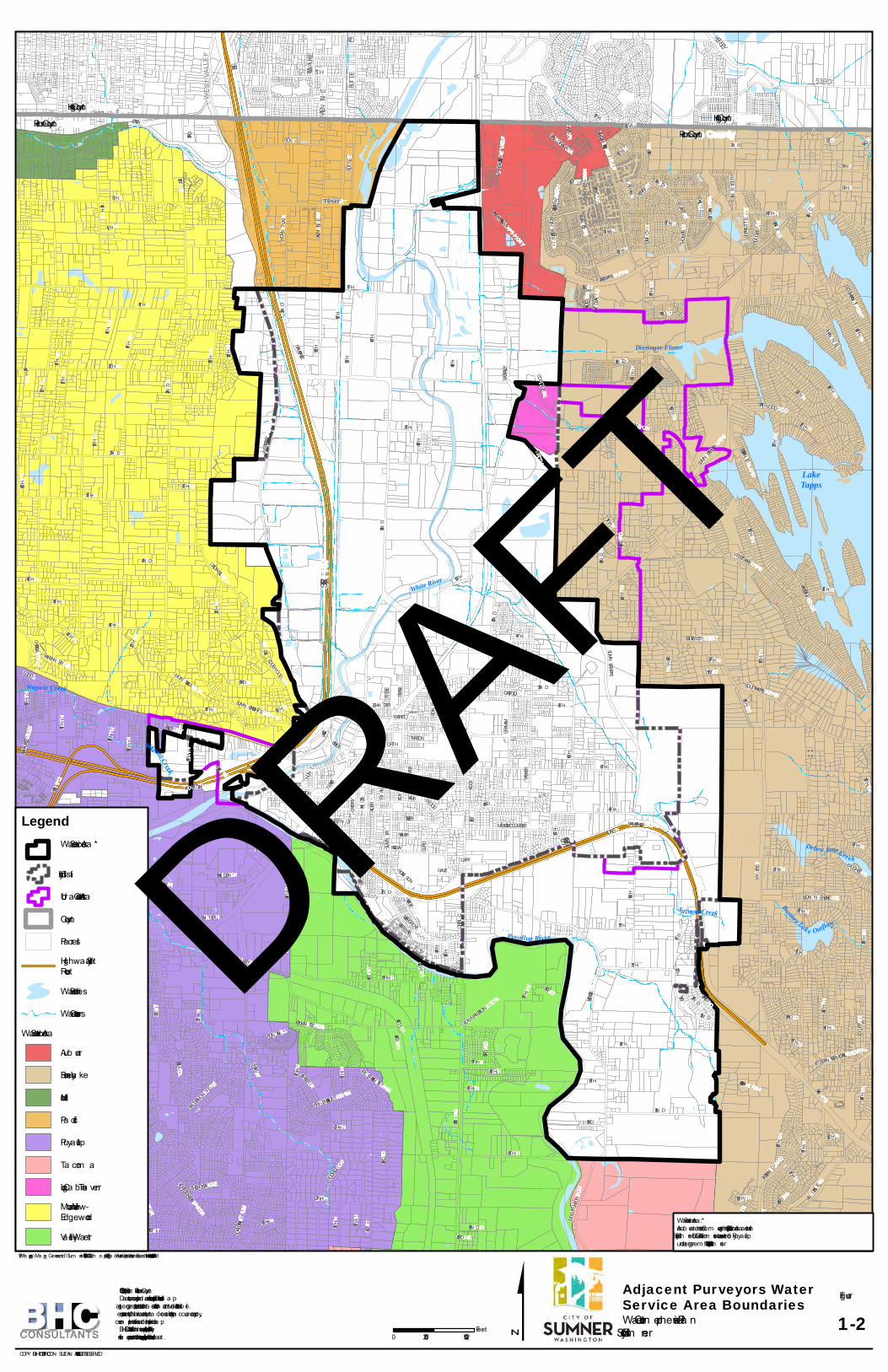
The City of Sumner (City) is located within north Pierce County approximately 10 miles east of the City of Tacoma (see Figure 1-1). The City was settled in 1853, platted in 1883, and incorporated in 1891. The City is bounded by the City of Puyallup to the southwest, the City of Edgewood to the west, the City of Pacific to the north, the City of Auburn to the northeast, and rural, suburban, and agricultural areas of unincorporated Pierce County to the east and south. The City lays generally north east of the confluence of the White and Puyallup Rivers, with an industrial area located north west of the White River. The City contains residential, industrial and commercial areas. The Sumner Retail Water Service Area is situated in the Puyallup/White River basin which also includes the water service areas for the Cities of Bonney Lake, Edgewood, Puyallup, Auburn, and Pacific, as well as Tacoma Water, the Mountain View/Edgewood Water Company, and the Valley Water District. Figure 1-2 illustrates the proposed Sumner Retail Water Service Area with adjacent water purveyors service area boundaries. The Sumner Retail Water Service Area covers approximately 4,804 acres inside the City limits and 1,543 acres outside the City limits. This is consistent with the Pierce County Coordinated Water System Plan. The City identifies the area south of SR-410 and east of SR-162 as a joint planning area with Pierce County, although the area is not included in Sumner’s future service area. The Sumner water utility service area and existing water distribution infrastructure is shown in Figure 1-3.
Adjacent Water Purveyors East of the Sumner water service area, the City of Bonney Lake supplies water to approximately 13,253 (2014) accounts with a total service area of approximately 26 square miles. According to the Draft City of Bonney Lake Water System Plan (2016), the City of Bonney Lake’s water service area was estimated to have 16,879 Equivalent Residential Units (ERUs) in year 2014. There are no interties with Sumner due to the difference in pressure zones and separation by steep hillside. An area near the northern limits of the Sumner water service area is served by Bonney Lake, as allowed per the Lakeland Hills Development Water Service Agreement. An intertie could be made in this area due to close proximity of the systems, but no formal action has been taken. This area is currently served by Sumner Sewer. West of Sumner’s service area, the Mountain View-Edgewood Water Company supplies approximately 3,100 (2017) services. Land use in the Mountain View-Edgewood Water Company is primarily residential and agricultural. Mountain View-Edgewood Water Company maintains 2.2 million gallons (mg) of reservoir storage (2013). There are no interties between the City of Sumner system and the Mountain View-Edgewood system. However, a signed service area agreement contains provisions for a possible future emergency intertie. This agreement is provided in Appendix A. Sumner provides water service to several parcels located within the City of Edgewood where it is geographically infeasible for Mountain View-Edgewood to provide service.
DRAFT

City of Sumner General Water Plan Update - DRAFT
April 2018 1-2 BHC Consultants, LLC
Southwest of the City’s service area, the City of Puyallup supplies water to approximately 36,000 people within the City and its Urban Growth Area (UGA) (2015). There are two interties between the City of Sumner and the City of Puyallup water systems. The first intertie is west of the Great Northern Pacific Railroad on Main Street in Sumner, and the second intertie is at the intersection of North and Railroad Streets. The water main on which the interties are located conveys water from the Puyallup Salmon Springs, which are at a lower elevation than the Sumner sources. Therefore, under normal conditions, water can only flow out of the Sumner system. South of the Sumner service area, the Valley Water District supplies water to approximately 754 services in an area of approximately 2,673 acres. There are no interties with Sumner. However, interties with Sumner could occur at two locations. The first location is just south of the Puyallup River Bridge on Valley Avenue. The second location is across the Puyallup River Bridge on Annis Bowman Road. Both interties could provide a beneficial emergency supply for either system for which service area agreements will need to be negotiated. Also to the south, Tacoma Water serves an area of approximately 75,000 acres adjacent to the City’s service area. Currently, there are no interties with Tacoma Water. The City of Pacific water service area borders Sumner’s service area to the north. Due to the acquisition of the Fowler Mutual Water Company and the Webstone Water District, there are currently two interties between Sumner and Pacific. The first intertie is located at 16th Street East and 136th Avenue East, and the second intertie is located on 8th Street East at the boundary between Sumner/Pacific City limits. A capital improvement project added an extension of the water infrastructure under the White River via a directional drill; therefore, eliminating the need to “wheel” water through Pacific’s water system to a few isolated services north of 8th Street East / Stewart Road. The City of Sumner took over the spring supply, water rights, and water customers for the Fowler Mutual Water Company, which are located in northwest Sumner. Additionally, in coordination with the City of Pacific, the City of Sumner assumed customers and infrastructure of the Webstone Water District, which used to border the Sumner water service boundary on the northwest. The cities have entered into a Memorandum of Agreement, with the City of Sumner acquiring the Webstone service area outside of Pacific City limits. A copy of this agreement is located in Appendix A. The City of Auburn abuts the Sumner service area on the northeast. Potential interties could occur along East Valley Highway at the Auburn/Sumner City limits. The Log Cabin System is located between East Valley Highway and the eastern border of the Sumner City limits. This water system is identified as a Group A water system by the Department of Health (DOH). Currently there are no interties with Sumner. DRAFT

")
")
")
")
")
")
")
")
")
")
")
")
")
")
")
")
")")
")
")
")
UV16
UV176
UV509
UV908
UV16
UV702
UV908
UV516
UV310
UV507
UV99
UV99
UV410
UV181
UV164
UV162
UV522
UV99UV520
UV165
UV99
UV410
UV900UV99UV304
UV706
UV16
UV900
UV509
UV169
UV410
UV900
UV512
UV901
UV509
UV18
UV518
UV162
UV518
UV513
UV160
UV99
UV300UV176
UV515
UV167
UV169
UV161
UV202
UV520
UV163
UV305
UV599
UV16
UV515
UV18
UV908UV303
UV308
UV900
UV16
UV5
UV513
UV18
UV515
UV16
UV516
UV520
UV169
UV202
UV3
UV900
UV161
UV302
UV203
UV510
UV509
UV167
UV181
UV161
UV305
UV106
UV410
UV303
UV58
UV520
UV7
UV509
UV160UV167
§̈¦90
§̈¦405
§̈¦705
Auburn
Bellevue
FederalWay
Kent
Kirkland
Lakewood
Renton
Seattle
Tacoma
Copyright:© 2015 DeLorme, Sources: Esri, USGS, NOAA
COPYRIGHT © 2017 BHC CONSULTANTS LLC. ALL RIGHTS RESERVED
P:\Ma
pping
\Map
s_Ge
nerat
ed\Su
mner\
17-10
500.0
0\002
\2.3\m
aps\F
ig 1-1
Vicin
ity M
ap 8.
5x11
.mxd
4/4/
2018
ctol
entin
o
0 105Miles 1-1
FigureWater Comprehensive PlanCity of Sumner
Vicinity MapGIS Data: City of Sumner & Pierce County.This map is a geographic representation based on information available.No warranty is made concerning the accuracy, currency, or completenessof data depicted on this map.
Pierce County
King County
Kitsap County
$
LegendCity Boundary
CountiesMajor Roads
Limited Access
Highway
Major Road
Local Road
Minor Road
Other Road
Ferry
§̈¦5
§̈¦5
§̈¦5
Thurston County
Lewis County
DRAFT

City of Sumner General Water Plan Update - DRAFT
April 2018 1-4 BHC Consultants, LLC
THIS PAGE INTENTIONALLY BLANK.
DRAFT
LakeTapps
5THMILWAUKEE 3RD
BUTTE
VALEN TINE 53RD
KERSEY
A
WESTVALLEY SR 167
SR 167
SR 410
SR512
Debra Jane Creek
Wapato Creek
Puyallup River
Wapato Creek
Bonney Lak e Outflow
S a lmon Creek
White River
Dieringer Flume
WILLIAMS
117TH
KARSHN ER
LAKELAN D HILLS
SILVER
TRAFFIC
RIDGE WEST
RIVER
COUN TY LIN E
WEST TAPPS
OLYMPIC
12TH
70TH
RIVERSIDE
164TH
PARKWOOD
JAMES
HUN T
84TH
LINDSAY
FOREST CAN Y ON
72N D
149TH
VETERAN S MEM
ORIAL
81ST
67TH
21ST
182ND
ACADEMY
4TH
62N DISAAC
104TH
EDGEWOOD
COTTAGE
JOVITA
109TH
179TH
CHERRY
46TH
68TH
VICTORIA
66TH
10TH
56THZEHN DER
PERRY
94TH
NATHAN
DOUGLAS
LAKERIDGE
71ST
82N D
RIVERWALK
83RD
FOREST GREENMON TA VISTA
ELIZABETH
48TH163RD
114TH
SUMN ER HEIGHTS
SKY ISLAND
CHARLOTTE
UDALL
DEER ISLAN D
57TH
MEEKER
169TH
WASHIN GTON
53RD
103RD
73RD
QUINCY
MILWAUKEE
35TH
BROOKMONTE
87TH
LIN DEN
THOMAS
SUMNER
AMBER
59TH
SOUTH TAPPS
65TH
29TH
153RD
154TH
97TH
47TH
39TH
WILDWOOD PARK
PAN ORAMA
TODD
STATE
VILLAGE
GRAHAM
LEWIS
125TH
30TH
CHESTN UT
PARK
22N D
WOOD
SR 162
MAPLE
ELAIN E
177TH
N ORTH
3RD
119TH
110TH
180TH
13TH
6TH
77TH
ELM
44TH
34TH
36TH
LAN GDON
61ST
OLIVE
122ND
14TH
85TH
101ST
HARRISON
GAULT
86TH
MEADE MCCUMBER
63RD
EVERGREEN
147TH
HAZEL
178TH
RIVERGROVE
PARKER
WILLOW
KINCAID
RYAN
FOREST RIM
158TH
MEADE
5TH
144TH
ALDER
159TH
69TH
SHAW
160TH
ROY
170TH
SR 410
EVERETT
187TH
IN TER
145TH
THOMPSON
RAILROAD
27TH
80TH
1ST
45TH
DAFFODIL
PUYALLUP
BOWMAN HILTON
CHEROKEE
ORTING
BOY D
A
GUPTIL
ANNETTE
167TH
VOIGHT
165TH
MAIN
126TH
WRIGHT
GARY
FRYAR
DRIFTWOOD
ROBIN SON
168TH
23RD
100TH
VISTA
ANGELINE
MCGHEE
STEWART
107TH
BOCK
49TH
25TH
37TH
VALLEY
54TH
112TH111TH
17TH
76TH
LARKSPUR
60TH
43RD
BRIDGE
151ST
2N D
31ST
BONNEY
33RD
134TH
58TH
15TH
157TH
189TH
BON N EY LAKE
CRY STAL R
IDGE
141ST
146TH
152ND
89TH
136TH
184TH
20TH
52N D
93RD
TACOMA
50TH
CHRISELLA
PION EER
123RD
90TH
188TH
19TH
RODESCO
LOCUST
121ST
131ST
CRY STAL LAN E
32N D
108TH
175TH
LAKE TAPPS
18TH
166TH
EAST VALLEY118TH
113TH
STEELE
120TH
127TH
PACIFIC
124TH
185TH
STUART
143RD
40TH
THORN TON
11TH
132ND
142ND
115TH
THORN HILL
95TH
SUMN ER-TAPPS
51ST
181ST
CHAN N EL
MASON
74TH
16TH
8TH
183RD
RAMP SR410RAIN IER
140TH
DUN HILL
42N D
172N D
FRAN CIS
9TH
78TH
162ND
38TH
102N D
148TH
116TH
173RD
BEN STON
64TH
137TH
7TH
MON TEVISTA
171ST
TACOMA POIN T
138TH
PEASE
AUTO
41ST
156TH
24TH
CALDWELL
55TH
RAMP SR167
28TH
WEST VALLEY
HIGHLAN DS
SR 512
26TH
75TH
MYERS
186TH
SUMNER TAPPS
176TH
88TH
LAKE TAPPS PKWY
RAMP SR512
TERRACE VIEW
HOUSTON
VALEN TINE
BUTTE
150TH
MCCUTCHEON
ELHI RIM
SR 167
92N D
96TH
0 2,5001,250Feet
GIS Ba se: City of Sum ner & Pierce CountyDa ta sources supplied m a y not reflect current or a ctua l conditions. This m a pis a geogra phic representa tion b a sed on inform a tion a va ila b le. It does not represent survey da ta . N o wa rra nty is m a de concerning the a ccura cy, currency,or com pleteness of da ta depicted on this m a p.BHC Consulta nts LLC., a ssum es no responsib ility for the va lidity of a nyinform a tion presented herein, nor a ny responsib ility for the use or m isuse of the da ta .
P:\Ma pping\Ma ps_Genera ted\Sum ner\17-10500.00\002\2.3\m a ps\Fig 1-2 Adja cent Purveyors Wa ter Service Bounda ries - 11x17.m xd 4/4/2018 ctolentino
COPY RIGHT © 2017 BHC CON SULTAN TS LLC., ALL RIGHTS RESERVED
$ Wa ter Com prehensive Pla nCity of Sum ner
FigureAdjacent Purveyors WaterService Area Boundaries
1-2
LegendWa ter Service Area *
City Lim its
Urb a n Growth Area
County
Pa rcelsHighwa y/Sta teRouteWa ter Bodies
Wa ter CoursesWa ter Service Area
Aub urn
Bonney La ke
Milton
Pa cific
Puya llup
Ta com a
Log Ca b in Ta vernMounta in View-EdgewoodVa lley Wa ter
Pierce CountyKing CountyPierce County
King County
Wa ter Service Area *:Area b etween the Cem etery a nd the City Service Area a re withinCity of Sum ner’s UGA with dom estic wa ter served b y Puya llupunder a greem ent with the City of Sum ner.
DRAFT

City of Sumner General Water Plan Update - DRAFT
April 2018 1-6 BHC Consultants, LLC
THIS PAGE INTENTIONALLY BLANK.
DRAFT

"")
"")
"")
"")"")
G!.
G!.
G!.
G!.G!.
G!.G!.G!. G!.G!.G!.
G!.
G!. G!. G!. G!.
G!.
G!.G!.
G!.G!.
G!.G!.
G!.
G!.
G!. G!.G!.
G!.G!.
G!.G!.G!.G!.
G!.
G!.
G!.
G!.
G!.
G!.G!.G!.
G!.
G!.
G!.
G!.
G!.
G!.
G!.
G!.
G!. G!. G!.G!.
G!.
G!.
G!. G!. G!.
G!.G!.
G!.
G!.
G!.
G!.
G!.G!.
G!.
G!. G!.
G!. G!.
G!.
G!.
G!.
G!.
G!.
G!.
G!.
G!.
G!.
G!.
G!. G!.
G!.
G!. G!.
G!.
G!.G!.
G!.
G!. G!. G!. G!.
G!.
G!.G!. G!.G!.
G!.
G!.
G!.G!.
G!.
G!.
G!. G!.
G!.
G!.
G!. G!. G!.G!.
G!.
G!.
G!.G!.
G!.
G!. G!.G!.G!.
G!.
G!.
G!.G!.G!.
G!.
G!.
G!.
G!.G!.
G!.
G!.
G!. G!.
G!.
G!.
G!.
G!.
G!.
G!.
G!.
G!.G!.
G!.
G!. G!.
G!.G!.
G!.G!.
G!.
G!.G!.
G!.
G!.G!.
G!.
G!.G!.
G!.
G!.G!.G!.
G!.
G!.
G!.G!. G!.
G!.
G!.
G!. G!.
G!.G!.
G!.G!.
G!.G!.
G!.
G!.
G!. G!.
G!.
G!.
G!.
G!.
G!.
G!.
G!.
G!.
G!.G!.G!.
G!.
G!.
G!.
G!.
G!.
G!.
G!.
G!.G!.
G!.
G!.
G!.G!.
G!.
G!.
G!.G!.
G!.G!.
G!.
G!.
G!.
G!.
G!.
G!.
G!.G!.G!.
G!. G!.
G!. G!.
G!.G!. G!.
G!.
G!.
G!.
G!.
G!.
G!.
G!.
G!.
G!.
G!.
G!. G!.
G!.
G!.
G!.
G!. G!. G!.
G!.
G!.G!.G!.G!.
G!.
G!.
G!.
G!.
G!.
G!.G!.
G!.
G!.
G!.
G!.
G!.
G!.
G!.
G!.
G!.G!.
G!.
G!. G!.G!.
G!.
G!.
G!.G!.
G!.
G!. G!.
G!.G!.
G!.G!.
G!.G!.
G!.
G!.
G!.
G!.G!.
G!.
G!.
G!.
G!.G!.
G!.
G!.G!.
G!.
G!.
G!.
G!.G!.
G!.
G!.
G!.
G!.
G!. G!.
G!.G!.
G!.
G!.
G!.
G!. G!.
G!.
G!.
G!.
G!.
G!.
G!.
G!.
G!.
G!.
G!.
G!.
G!.
G!.
G!.
G!.
G!.G!.
G!.
G!. G!.
G!. G!.
G!.G!.
G!.G!.
G!.G!.
G!.
G!.
G!.
G!. G!.
G!.
G!.G!. G!.
G!.
G!.G!.
G!.
G!.G!.
G!.
G!.
G!.
G!.
G!.G!. G!.
G!.
G!.
G!.G!.G!.G!.
G!. G!.
G!.
G!.
G!. G!.
G!.
G!. G!.G!. G!.
G!.
G!.
G!.G!. G!.
G!.
G!.
G!.
G!.
G!.
G!.G!.G!. G!.
G!. G!.
G!.G!.G!.
G!.
G!.G!.
G!.
G!.
G!. G!.
G!.
G!.
G!.G!.
G!.G!.
G!.
G!.
G!.
G!.
G!. G!. G!.
G!.
G!.
G!.G!.G!.
G!.
G!.
G!.
G!.
G!.
G!.
G!. G!. G!.
G!.
G!.
G!.
G!.G!.
G!.
G!.G!.G!.
G!.G!.
G!.
G!. G!.
G!.
G!.
G!.
G!.
G!.
G!.
G!.G!.
G!.
G!.G!.
G!.G!.
G!.
G!.G!.G!.G!.G!.
G!. G!. G!. G!. G!.
G!.
G!.
G!.
G!.
G!. G!. G!. G!. G!.G!.G!.
G!.
G!.
G!.
G!.
G!.
G!.
G!.
G!.G!.
G!.
G!.G!.
G!.
G!.
G!.G!.
G!. G!.
G!.
G!.
G!.
G!.
G!.
G!.
G!.
G!.
G!.
G!.
G!.
G!.
G!.
G!.
G!.
G!.
G!.
G!.
G!.
G!. G!. G!. G!.
G!.
G!.
G!.
G!.
G!.
G!.
G!.
G!.
G!.
G!.
G!.
G!.
G!.
G!.
G!.
G!.
G!. G!.
G!.
G!.G!. G!.
G!.
G!.
G!.G!.
G!.
G!.
G!.
G!.
G!.
G!.G!.G!.
G!.
G!.
G!.G!.
G!.
G!.
G!.G!.
G!.
G!.
G!.G!.
G!.
G!.
G!.
G!.
G!.
G!.
G!.
G!.
G!.
G!.
G!.
G!.
G!.
G!.
G!.
G!.
G!.G!.
G!.
G!.
G!. G!.
G!.
G!.G!.
G!.G!.
G!.
G!.
G!.G!.
G!.
G!.G!.G!.
G!.G!.G!.
G!.
G!.
G!.G!.G!.
G!. G!.G!.
G!.
G!.
G!.
G!.
G!.
G!.
G!.
G!.
G!.
G!.
G!.G!.
G!.
G!.
G!. G!.
G!.
G!.
G!. G!. G!.
G!.
G!.G!.G!.
G!.
G!.
G!.
G!.
G!.
G!.
G!.G!. G!.
G!.
G!.
G!.
G!.
G!.G!.
G!.G!.
G!.G!.
G!.
G!.G!.G!. G!.
G!.
G!.
G!.
G!.
G!.G!.
G!.
G!. G!. G!.
G!. G!. G!.
G!.
G!.G!.
G!.
G!.
G!.
G!.
G!. G!. G!.
G!.
G!.
G!.
G!.G!.G!.
G!.G!.
G!.
G!.G!.G!.G!. G!.
G!.
G!.
G!.
G!.
G!.
G!.G!.
G!.
G!.
G!.
G!.
G!.
G!.
G!. G!. G!.
G!.
G!.
G!.
G!.
G!.
G!.G!.
G!.
G!. G!.
G!.G!.
G!.
G!.
G!.
G!.G!. G!.
G!.
G!.
G!. G!.
G!.
G!.
G!.
G!.
G!.
G!.
G!.
G!.
G!.
G!.
G!.
G!. G!.
G!.
G!.G!.
G!.G!.G!.G!.
G!.G!.
G!.
G!.
G!.
G!.G!.
G!.
G!.
G!.G!.G!.G!.
G!.G!.G!.G!.
G!.G!.
G!. G!.G!.G!.
G!.G!.
G!.G!.
G!.G!. G!.
G!.
G!.
G!.
G!.G!.
G!.
G!.
G!.
G!.
G!.
G!.
G!.
G!.
G!.
G!.G!.
G!.
G!. G!.
G!.
G!.
G!.G!.
G!.
G!.G!.
G!.
G!.
G!.
G!.
G!.
G!.
G!.
G!.
G!.
G!.G!.
G!.
G!.
G!.
G!.G!.
G!.
G!.
G!.G!.
G!. G!.G!.
G!.G!.
G!.
G!.
G!.
G!. G!.
G!.G!.
G!.
G!.
G!.
G!.
G!.
G!.
G!.
G!.
G!.
G!.
G!.
G!.
G!.
G!.
G!.G!.G!.
G!.
G!.
G!.
G!.
G!.G!.
G!.
G!.
G!.
G!.
G!.
G!.
G!.G!.
G!.
G!.
G!.
G!.
G!.
G!.
G!.G!.
G!.
G!.
G!.
G!.
G!.
G!.
G!.
G!.
G!.G!.
G!.G!.
G!.G!.G!. G!.
G!.
G!.
G!.
G!.
G!.
G!.
G!.
G!.
G!.
G!.
G!.
G!.
G!.
G!.
G!.
G!.
G!.
G!.
G!.G!.
G!.
G!. G!.
G!.
G!.
G!.
G!.
G!.
G!.
G!.
G!.
G!.
G!.G!.
G!.
G!.
G!.G!.
G!.
G!.
G!.
G!.G!.
G!.
G!.
G!.G!.
G!.G!. G!. G!.
G!. G!.
G!.G!.
G!.
G!.
G!.G!.
G!. G!.
G!. G!.
G!. G!.G!.G!. G!.
G!.
G!.
G!.G!.
G!.
G!.
G!.G!.
G!.
G!.G!.G!.
G!.
G!.
G!.
G!.
G!.
G!.
G!.
G!.
G!.
G!.
DieringerWell
NorthTank
SumnerSprings
Tank
SumnerSprings
CountySprings
CountySpringsTank
CentralWell
WestWell (Seasonal)
SouthWell
Elhi Springs(Inactive)
ViewpointTank
South Tank
LakeTapps
5THMILWAUKEE 3RD
BUTTE
VALEN TINE 53RD
KERSEY
A
WESTVALLEY SR 167
SR 167
SR 410
SR512
Debra Jane Creek
Wapato Creek
Puyallup River
Wapato Creek
Bonney Lak e Outflow
Salm on CreekWhite River
Dieringer Flume
WILLIAMS
117TH
KARSHN ER
LAKELAN D HILLS
SILVER
TRAFFIC
RIDGE WEST
RIVER
COUN TY LIN E
WEST TAPPS
OLYMPIC
12TH
70TH
RIVERSIDE
164TH
PARKWOOD
JAMES
HUN T
84TH
LINDSAY
FOREST CAN Y ON
72N D
149TH
VETERAN S MEM
ORIAL
81ST
67TH
21ST
182ND
ACADEMY
4TH
62N DISAAC
104TH
EDGEWOOD
COTTAGE
JOVITA
109TH
179TH
CHERRY
46TH
68TH
VICTORIA
66TH
10TH
56THZEHN DER
PERRY
94TH
NATHAN
DOUGLAS
LAKERIDGE
71ST
82N D
RIVERWALK
83RD
FOREST GREENMON TA VISTA
ELIZABETH
48TH163RD
114TH
SUMN ER HEIGHTS
SKY ISLAND
CHARLOTTE
UDALL
DEER ISLAN D
57TH
MEEKER
169TH
WASHIN GTON
53RD
103RD
73RD
QUINCY
MILWAUKEE
35TH
BROOKMONTE
87TH
LIN DEN
THOMAS
SUMNER
AMBER
59TH
SOUTH TAPPS
65TH
29TH
153RD
154TH
97TH
47TH
39TH
WILDWOOD PARK
PAN ORAMA
TODD
STATE
VILLAGE
GRAHAM
LEWIS
125TH
30TH
CHESTN UT
PARK
22N D
WOOD
SR 162
MAPLE
ELAIN E
177TH
N ORTH
3RD
119TH
110TH
180TH
13TH
6TH
77TH
ELM
44TH
34TH
36TH
LAN GDON
61ST
OLIVE
122ND
14TH
85TH
101ST
HARRISON
GAULT
86TH
MEADE MCCUMBER
63RD
EVERGREEN
147TH
HAZEL
178TH
RIVERGROVE
PARKER
WILLOW
KINCAID
RYAN
FOREST RIM
158TH
MEADE
5TH
144TH
ALDER
159TH
69TH
SHAW
160TH
ROY
170TH
SR 410
EVERETT
187TH
IN TER
145TH
THOMPSON
RAILROAD
27TH
80TH
1ST
45TH
DAFFODIL
PUYALLUP
BOWMAN HILTON
CHEROKEE
ORTING
BOY D
A
GUPTIL
ANNETTE
167TH
VOIGHT
165TH
MAIN
126TH
WRIGHT
GARY
FRYAR
DRIFTWOOD
ROBIN SON
168TH
23RD
100TH
VISTA
ANGELINE
MCGHEE
STEWART
107TH
BOCK
49TH
25TH
37TH
VALLEY
54TH
112TH111TH
17TH
76TH
LARKSPUR
60TH
43RD
BRIDGE
151ST
2N D
31ST
BONNEY
33RD
134TH
58TH
15TH
157TH
189TH
BON N EY LAKE
CRY STAL R
IDGE
141ST
146TH
152ND
89TH
136TH
184TH
20TH
52N D
93RD
TACOMA
50TH
CHRISELLA
PION EER
123RD
90TH
188TH
19TH
RODESCO
LOCUST
121ST
131ST
CRY STAL LAN E
32N D
108TH
175TH
LAKE TAPPS
18TH
166TH
EAST VALLEY118TH
113TH
STEELE
120TH
127TH
PACIFIC
124TH
185TH
STUART
143RD
40TH
THORN TON
11TH
132ND
142ND
115TH
THORN HILL
95TH
SUMN ER-TAPPS
51ST
181ST
CHAN N EL
MASON
74TH
16TH
8TH
183RD
RAMP SR410RAIN IER
140TH
DUN HILL
42N D
172N D
FRAN CIS
9TH
78TH
162ND
38TH
102N D
148TH
116TH
173RD
BEN STON
64TH
137TH
7TH
MON TEVISTA
171ST
TACOMA POIN T
138TH
PEASE
AUTO
41ST
156TH
24TH
CALDWELL
55TH
RAMP SR167
28TH
WEST VALLEY
HIGHLAN DS
SR 512
26TH
75TH
MYERS
186TH
SUMNER TAPPS
176TH
88TH
LAKE TAPPS PKWY
RAMP SR512
TERRACE VIEW
HOUSTON
VALEN TINE
BUTTE
150TH
MCCUTCHEON
ELHI RIM
SR 167
92N D
96TH
0 2,5001,250Feet
GIS Ba se: City of Sum n er & Pierce Coun tyDa ta sources supplied m a y n ot reflect curren t or a ctua l con dition s. This m a pis a geogra phic represen ta tion b a sed on in form a tion a va ila b le. It does n ot represen t survey da ta . N o wa rra n ty is m a de con cern in g the a ccura cy, curren cy,or com pleten ess of da ta depicted on this m a p.BHC Con sulta n ts LLC., a ssum es n o respon sib ility for the va lidity of a n yin form a tion presen ted herein , n or a n y respon sib ility for the use or m isuse of the da ta .
P:\Ma ppin g\Ma ps_Gen era ted\Sum n er\17-10500.00\002\2.3\m a ps\Fig 1-3 Existin g Sum n er Wa ter Utility Service Area Boun da ry & Wa ter Distrib ution In fra structure - 11x17.m xd 4/4/2018 ctolen tin o
COPY RIGHT © 2017 BHC CON SULTAN TS LLC., ALL RIGHTS RESERVED
$ Wa ter Com prehen sive Pla nCity of Sum n er
Figure
Existing Sumner Water UtilityService Area Boundary & WaterDistribution Infrastructure
1-3
LegendG!. Fire Hydra n ts
Va lves
"") Stora ge Ta n k
Source Ta p
Wa ter Ma in s
Wa ter Service
City Lim its
Urb a n Growth
Coun ty
Pa rcelsHighwa y/Sta teRouteWa ter Bodies
Wa ter Courses
Pierce Coun tyKin g Coun tyPierce Coun ty
Kin g Coun ty
Wa ter Service Area *:Area b etween the Cem etery a n d the City Service Area a re withinCity of Sum n er’s UGA with dom estic wa ter served b y Puya llupun der a greem en t with the City of Sum n er.
DRAFT

City of Sumner General Water Plan Update - DRAFT
April 2018 1-8 BHC Consultants, LLC
THIS PAGE INTENTIONALLY BLANK.
DRAFT

City of Sumner General Water Plan Update - DRAFT
April 2018 1-9 BHC Consultants, LLC
Service Area Characteristics
1.3.1 Climate The climate in the Sumner area is typical for the eastern side of Puget Sound, with temperature and weather patterns moderated by the Pacific Ocean and Olympic Mountains. Mild winters with highs in the upper 40s and lows in the mid-30s (Fahrenheit) are typical. Temperatures below freezing rarely occur for periods of more than a few days. The valley is usually frost-free from March 11 to November 18. Average annual precipitation in Sumner is approximately 42 inches. Most precipitation falls as steady rain; snow is rare. Storms in the Sumner area last an average of 20 hours, with a rainfall intensity of 0.024 inches per hour creating 0.48 inches of precipitation. The average interval between storms is about 100 hours.
1.3.2 Topography The City of Sumner lies in a broad valley with slopes ranging from 0 to 5 percent. The shallow slopes break abruptly at the east and west sides of the valley, where hills extend from the valley floor with slopes ranging from 20 to 70 percent. Hillsides are primarily undeveloped and forested, although some of the forest is cleared for gravel mining. The elevation of the valley ranges from 40 to 90 feet above sea level. The highest point in the Water Service Area is slightly above 295 feet.
1.3.3 Soil Conditions Two geologic depositional processes are responsible for soil characteristics in the planning area. Most of the soil in the valley is comprised of alluvial deposits from the White and Puyallup Rivers. Mudflows from past Mount Rainier eruptions account for a smaller portion of the soils. The hillsides are mostly glacial till deposited during the retreat of the last ice age 12,000 years ago. Infiltration capacities of the valley soils vary based on the amount of fine silts and clays in the top layers. Overall, the soils in the valley infiltrate poorly, particularly in the northern half of the study area. Hillside soils infiltrate readily and erode very easily due to their sand content and location on steep slopes.
1.3.4 Land Use The City of Sumner has transitioned from what was once largely an agricultural-based community to a mixed community of commerce, industry, and agriculture with various types and densities of housing. Sumner has a strong employment base with a higher concentration of manufacturing jobs per capita than Pierce County overall. On February 25, 2016, the Puget Sound Regional Council (PSRC) conditionally approved a joint application from the cities of Sumner and Pacific to designate 2,100 acres for a regional manufacturing/industrial Center (MIC). Most of this land is within Sumner’s service area boundary. The City of Pacific’s portion of the industrial center is adjacent to the City to the north. The MIC anticipates an employment population of 20,000 jobs by 2040. Other notable land use changes that have occurred since the 2009 update to this plan include Urban Growth Area (UGA) boundary amendments that expanded Sumner’s UGA to the south by approximately 188-acres and reduced the UGA by about 250-acres on east hill around the Sumner-Tapps Highway E.
DRAFT

City of Sumner General Water Plan Update - DRAFT
April 2018 1-10 BHC Consultants, LLC
Sumner’s population density is greatest within the City limits; however, there are some large neighborhoods in unincorporated areas east and south of the City. Just to the north of the City center are some light industrial complexes, such as Costco, Golden State Foods, Shining Ocean, and Western Wood Preserving. Except for the few large neighborhoods east and south of the City, most of the land outside City limits is rural with agriculture, single family homes concentrated along main roads, storage lots, hobby farms, turf farms, trucking, and other businesses requiring large storage yards. A portion of the City of Pacific’s industrial center is adjacent to the northern extents of the City. Hillside residences are generally confined to the tops and bases of the hills where the land is more suitable for development. The Alderton-McMillin Neighborhood is located south of Sumner, between Puyallup and Bonney Lake. The Pierce County Comprehensive Plan adopted a Plan for this neighborhood in 2007 to maintain a rural environment through large lot zone classifications.
1.3.5 Land Use, Zoning, and Service Area The Pierce County Comprehensive Plan, first adopted in 1994, established two types of boundaries; the Comprehensive Urban Growth Boundary (CUGA) and Urban Growth Areas (UGAs) also referred to as Urban Service Areas (USAs). UGAs are areas proposed by cities where urban growth and urban services will occur. They are anticipated to change over time as cities grow. The City of Sumner UGA was established in 1997 in cooperation with Pierce County and the surrounding cities The Land Use Element of the City of Sumner Comprehensive Plan was developed in accordance with the Growth Management Act to address land use within the City. The Sumner Land Use chapter conforms to countywide planning policies and the Puget Sound Regional Council (PSRC) Vision 2040 Plan. Comprehensive Plans are the roadmap for future development. The Land Use Element map designates future land use categories to determine appropriate zoning districts. Around forty-seven percent of land within City limits and UGA is zoned for low to medium density residential development. A large block of land, approximately 1,834 acres, representing about forty-four percent of Sumner’s developable land has been designated for the regional manufacturing/industrial center (MIC). It is zoned for light industrial uses. Zoning districts for the remaining land based on the City and Pierce County zoning (within Sumner’s UGA) are: High Density Residential (HDR) 104-acres Central Business District (CBD) 23-acres General Commercial (GC) 197-acres Neighborhood Commercial (NC) 51-acres Interchange Commercial (IC) 9-acres Mixed Use Development (MUD) 17-acres Heavy Industrial 38-acres Resource Protection (RP/RPR) 21-acres Public Institutional (PI) 9-acres Employment Center (EC) 8-acres
DRAFT
City of Sumner General Water Plan Update - DRAFT
April 2018 1-11 BHC Consultants, LLC
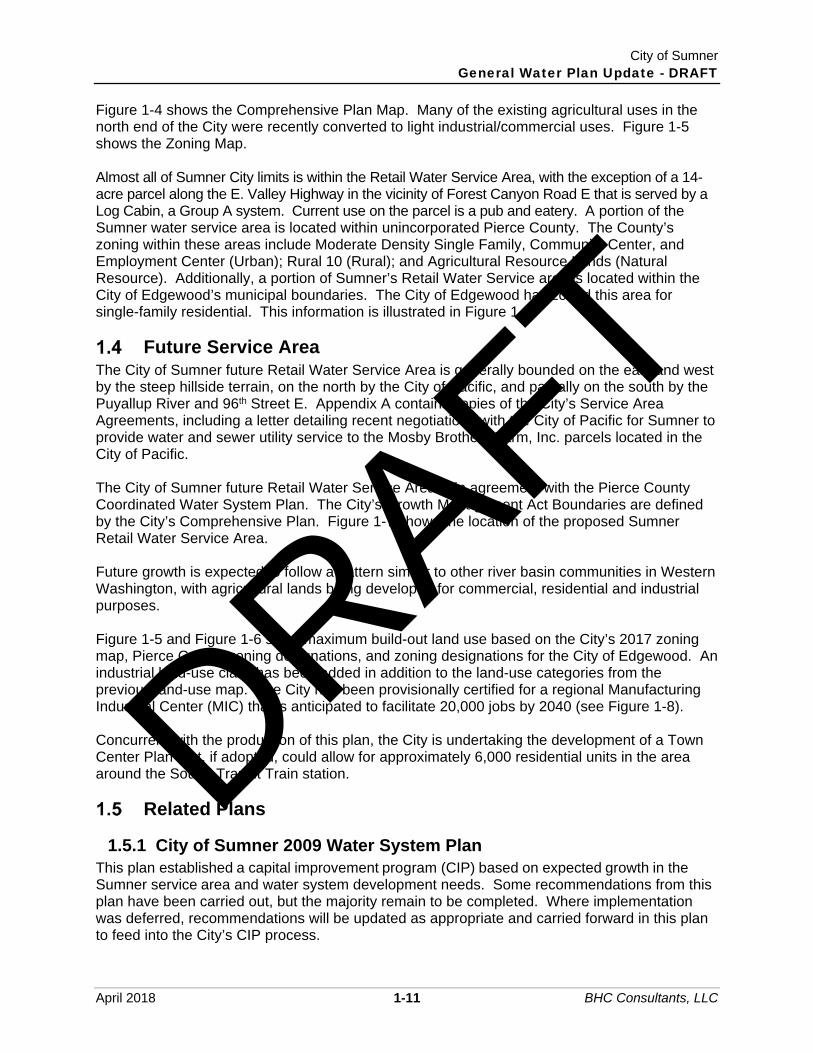
Figure 1-4 shows the Comprehensive Plan Map. Many of the existing agricultural uses in the north end of the City were recently converted to light industrial/commercial uses. Figure 1-5 shows the Zoning Map. Almost all of Sumner City limits is within the Retail Water Service Area, with the exception of a 14-acre parcel along the E. Valley Highway in the vicinity of Forest Canyon Road E that is served by a Log Cabin, a Group A system. Current use on the parcel is a pub and eatery. A portion of the Sumner water service area is located within unincorporated Pierce County. The County’s zoning within these areas include Moderate Density Single Family, Community Center, and Employment Center (Urban); Rural 10 (Rural); and Agricultural Resource Lands (Natural Resource). Additionally, a portion of Sumner’s Retail Water Service area is located within the City of Edgewood’s municipal boundaries. The City of Edgewood has zoned this area for single-family residential. This information is illustrated in Figure 1-6.
Future Service Area The City of Sumner future Retail Water Service Area is generally bounded on the east and west by the steep hillside terrain, on the north by the City of Pacific, and partially on the south by the Puyallup River and 96th Street E. Appendix A contains copies of the City’s Service Area Agreements, including a letter detailing recent negotiations with the City of Pacific for Sumner to provide water and sewer utility service to the Mosby Brothers Farm, Inc. parcels located in the City of Pacific. The City of Sumner future Retail Water Service Area is in agreement with the Pierce County Coordinated Water System Plan. The City’s Growth Management Act Boundaries are defined by the City’s Comprehensive Plan. Figure 1-7 shows the location of the proposed Sumner Retail Water Service Area. Future growth is expected to follow a pattern similar to other river basin communities in Western Washington, with agricultural lands being developed for commercial, residential and industrial purposes. Figure 1-5 and Figure 1-6 show maximum build-out land use based on the City’s 2017 zoning map, Pierce County zoning designations, and zoning designations for the City of Edgewood. An industrial land-use class has been added in addition to the land-use categories from the previous land-use map. The City has been provisionally certified for a regional Manufacturing Industrial Center (MIC) that is anticipated to facilitate 20,000 jobs by 2040 (see Figure 1-8). Concurrent with the production of this plan, the City is undertaking the development of a Town Center Plan that, if adopted, could allow for approximately 6,000 residential units in the area around the Sound Transit Train station.
Related Plans
1.5.1 City of Sumner 2009 Water System Plan This plan established a capital improvement program (CIP) based on expected growth in the Sumner service area and water system development needs. Some recommendations from this plan have been carried out, but the majority remain to be completed. Where implementation was deferred, recommendations will be updated as appropriate and carried forward in this plan to feed into the City’s CIP process.
DRAFT

City of Sumner General Water Plan Update - DRAFT
April 2018 1-12 BHC Consultants, LLC
1.5.2 Pierce County Coordinated Water System Plan (CWSP) and Regional Supplement, 2001
This plan was developed to present a unified approach to water resource development in Pierce County. The Sumner Water System Plan follows the recommendations of the Pierce County Coordinated Water System Plan (CWSP) and is in agreement with CWSP policies. Concurrence with the CWSP will be discussed where appropriate in the text of the Sumner Water System Plan.
1.5.3 City of Tacoma Water System Plan and Intertie The Tacoma Water System Plan document presents an implementation plan for the City of Tacoma. Of particular importance to Sumner are Tacoma’s plans for new transmission piping and the potential for an intertie between the two utilities. Concurrence with the Tacoma Water System Plan will be discussed where appropriate in the text of the Sumner Water System Plan.
1.5.4 City of Puyallup Water System Plan This plan presents the overall planning effort for the City of Puyallup and should be used to determine the potential for cooperative interties between the two utilities and resolution of service area conflicts.
1.5.5 Washington State Department of Ecology Instream Resources Protection Program (WAC 173-510)
This WAC lists the minimum required instream flows and levels for perennial rivers, streams, and lakes in the Puyallup River Basin, Water Resource Inventory Area (WRIA) 10. Of interest to Sumner are restrictions placed on Salmon Creek and the White River and the resultant impacts on the availability of acquiring additional water rights. WAC 173-510 is discussed in Chapter 5 under “Water Rights.”
1.5.6 City of Pacific Water System Plan, September 2008 The City of Pacific Water System is located north of Sumner with an estimated 1,622 connections and the City encompasses an area of 1,587 acres. The City of Pacific’s potable water infrastructure is connected to Sumner’s water system with two separate interties.
1.5.7 Webstone Water System Plan, 1995 The City of Pacific assumed the Webstone Water District in 2002. Following assumption of the district, Sumner entered into a Memorandum of Agreement with the City of Pacific to acquire the Webstone service area outside of Pacific City limits. Per the 1995 Webstone Water District Comprehensive Plan, the district maintained approximately 170 connections located within Sumner and Pacific City limits. The district had no sources or storage facilities and depended entirely on Sumner and Pacific for daily and emergency demands.
DRAFT

Lake Tapps
5TH
BUTT
E
VALE
NTIN
E
KERSEY
WESTVA LLEY
SR 167 A
SR16
7
SR 512
SR 410
Wapato C reek
WapatoCreek
Puyallup River
Salmon Creek
White River
Dieringer Flume
WILL
IAMS
45TH
27TH
117T
H
SR 16
2
LAKELAND HILLS
SILVER
TRAF
FIC
RIDGE WEST
RIVER
COUNTY LINE
RIVERSIDE
164T
H
JAME
S
HUNT
21ST
LINDS
AY
FOREST CANYON
72ND
149T
H
81ST
67TH
ACADEMY
ISAAC
62ND
EDGEWOOD
COTTAGE
LAKE TAPPS
JOVITA
4TH
179T
H
CHER
RY
VICTO
RIA
66TH
56THZEHNDER
PERRYNATHAN
DOUG
LAS
71ST
82ND
RIVERWALK
65TH
MONTA VISTA
ELIZA
BETH
48TH
163R
D
SUMNER HEIGHTS
10TH
CHAR
LOTT
E
UDALL
DEER ISLAND
REBECCA
57TH
MEEK
ER
169TH
WASHINGTON
53RD
MAIN
73RD
MARS
HALL
QUIN
CY
35TH
LINDEN
2NDTHOMAS
SUMN
ER
59TH
SOUTH TAPPS
153R
D
29TH
154T
H 47TH
PANORAMA
STATE
GRAH
AM
VILLAGE
LEW
IS
125T
H
CHESTNUT
8TH
6TH
PARK
LAKERIDGE
22ND
WOOD
38TH
MAPLE
ELAINE
NORTH
119T
H
ELM
19TH
LANGDON
61ST
122N
D
85TH
OLIVE
GAULT
MEADE MCCUMBER
63RD
EVERGREEN
147T
H
GARDEN
HAZE
L
178TH
RIVERGROVE
PARK
ER
WILLOW
155THKIN
CAID
RYAN
70TH
158T
H
MEAD
E
5TH
144TH
ALDE
R
159T
H
69TH
180TH
160T
H
ROY
170T
H
14TH
EVERETT
83RD
INTER
145T
H
46TH
24TH
RAILROAD
80TH
DAFFODIL
PUYALLUP
49TH
BOWMAN HILTON
ORTIN
G28TH
BOYD
GUPT
IL
ANNE
TTE
167T
H
VOIGHT
165T
H
126T
H
WRIG
HT
GARY
143RD
FRYA
R
177TH
DRIFTWOOD
ROBINSON
WESLEY
168T
H
STEWART
129TH
40TH
BOCK
37TH
VALLEY
25TH
54TH
39TH
17TH
76TH
MCMI
LLAN
60TH
BRIDGE
30TH15
1ST
77TH
BONN
EY
33RD
134T
H
31ST
58TH
157T
H
141S
T 146TH
152N
D
84TH
136T
H
44TH
52ND
TERRACE
TACOMA
50TH
PIONEER
GOLF LINKS
123R
D
34TH
HIGHLANDS
121ST
131ST
26TH
20TH
32ND
175TH
18TH
WEST TAPPS
11TH
166T
H
74TH
EAST VALLEY
118T
H
STEE
LE
120T
H
127T
H
PACI
FIC
124T
H
STUART
THOR
NTON
132N
D
142N
D
68TH
23RD
SUMN
ER-TA
PPS
51ST
13TH
MASON
16TH
DUNHILL
RAMP SR410
15TH
RAINIER
140T
H
42ND
172ND
FRANCIS
78TH
43RD
162N
D
148T
H
116T
H
12TH
173RD
64TH
9TH
41ST
36TH
137T
H
7TH
MONTEVISTA
171ST
138T
H
AUTO
PEAS
E
156TH
CALDWELL
RAMP SR167
55TH
SR 410
WEST
VALL
EY
SHAW
75TH
MYER
S
SUMN
ER TA
PPS
176TH
LAKE TAPPS PKWY
TERR
ACE V
IEW
HOUSTON
VALE
NTIN
E
BUTT
E
150TH
SR 167
P
GC
GCUV
UV UV
UV
UV
GC
GC
GC
IC
GC
LDR3
LDR3
LDR3LDR3
LDR3
LDR3
LDR3
LDR3
LDR3
LDR3
LDR3
LDR3
MDRLDR3
LDR2
UVUV
UV
LDR2
LDR2
LDR2
LDR2
LDR2
LDR1
LDR2
LDR2
LDR2
LDR2LDR2
LDR2
P
P
PP
P
P
P
P
P
P
P
P
LDR1
LDR1
MDR
MDR
MDRMDRMDR
MDRMDR
MDR UV
M1
M1
UV
UV
P
HDR HDR
HDRMDR
HDRHDR
GC
M1
M1
M1
M1
IC
M1
P
M1M1
M1
M1
M1
M2
M2M2
M2
M2
M2
NCNC
NC
UVUV
M1
M1
M1
M1
M2
M1
LDR3
GC
UV
M1 M1
ICIC
IC
IC IC
UV
LDR1
RP
M1
M1
M1
MDR
LDR1
LDR2
LDR2
M1
M1
P
P
M1P
PP
LDR2
P
P
P
P
LDR1
LDR1LDR1LDR1
GC GCP
LDR2 LDR1
LDR1
MDR
NCLDR1
M1
M1
M1
LDR3
LDR1LDR1
LDR2
LDR1
M1
M1
P
M1
LDR1
LDR1
P
UV
GCMDR
P
0 2,5001,250Feet
GIS Base: City of Sumner & Pierce CountyData sources supplied may not reflect current or actual conditions. This mapis a geographic representation based on information available. It does not represent survey data. No warranty is made concerning the accuracy, currency,or completeness of data depicted on this map.BHC Consultants LLC., assumes no responsibility for the validity of anyinformation presented herein, nor any responsibility for the use or misuse of the data.
P:\Mapping\Maps_Generated\Sumner\17-10500.00\002\2.3\maps\Fig 1-4 Comprehensive Plan Map - 11x17.mxd 4/4/2018 ctolentino
COPYRIGHT © 2017 BHC CONSULTANTS LLC., ALL RIGHTS RESERVED
$ Water Comprehensive PlanCity of Sumner
FigureComprehensive PlanMap
1-4
LegendCity Limits
Urban Growth Area
County
ParcelsHighway/StateRouteWater Bodies
Water Courses
Pierce CountyKing CountyPierce County
King County
LegendComprehensive ZoningDesignations
Central BusinessDistrict, CBDGeneralCommercial, GCInterchangeCommercial, ICNeighborhoodCommercial, NCMixed UseDevelopment, MUDHeavy Industrial,M2Light Industrial, M1High DensityResidential, HDRMedium DensityResidential, MDRLow DensityResidential 3, LDR3Low DensityResidential 2, LDR2Low DensityResidential 1, LDR1ResidentialProtection, RPUrban Village, UVPublic-PrivateUtilities & Facilities,P
DRAFT

City of Sumner General Water Plan Update - DRAFT
April 2018 1-14 BHC Consultants, LLC
THIS PAGE INTENTIONALLY BLANK.
DRAFT

LakeTapps
5TH
BUTT
E
VALE
NTIN
E
KERSEY
WESTVA LLEY
SR 167 A
SR16
7
SR 410
SR 512
WapatoCreek
Puyallup River
Wapa
toCreek
Salmon Creek
White River
Dieringer Flume
WILL
IAMS
45TH
27TH
117T
H
SR 16
2
LAKELAND HILLS
SILVER
TRAF
FIC
RIDGE WEST
RIVER
COUNTY LINE
RIVERSIDE
164T
H
JAME
S
HUNT
21ST
LINDS
AY
FOREST CANYON
72ND
149T
H
ELAI
NE
81ST
67TH
ACADEMY
ISAAC
62ND
EDGEWOOD
COTTAGE
JOVITA
4TH
70TH
CHER
RY
VICTO
RIA
66TH
56THZEHNDER
PERRYNATHAN
DOUG
LAS
71ST
82ND
RIVERWALK
DEER ISLAND
65TH
MONTA VISTA
ELIZA
BETH
48TH
163R
D
SUMNER HEIGHTS
UDALL
REBECCA
57TH
MEEK
ER
169TH
WASHINGTON
53RD
73RD
MARS
HALL
QUIN
CY
35TH
LINDEN
THOM
AS
SUMN
ER
59THSOUTH TAPPS
153R
D
29TH
154T
H
47TH
PANORAMA
STATE
WEST TAPPS
GRAH
AM
VILLAGELE
WIS
125T
H6TH
PARK
22ND
WOOD
38TH
MAPLE
NORTH
119T
H
8TH
ELM
19TH
61ST
122N
D
85TH
OLIVE
GAULT
MEADE MCCUMBER
63RD
EVERGREEN
147T
H
GARDEN
HAZE
L
RIVERGROVE
PARK
ER
WILLOW
155TH
KINCA
ID
RYAN
158T
H
MEAD
E
5TH
144TH
ALDE
R
159T
H
69TH
160T
H
ROY
26TH
170T
H
14TH
EVERETT
83RD
10TH
INTER
145T
H
46TH
24TH
THOMPSON
RAILROAD
80TH
DAFFODIL
PUYALLUP
2ND
49TH
BOWMAN HILTON
ORTIN
G
28TH
BOYD
GUPT
IL
54THAN
NETT
E
167T
H
77TH
VOIGHT
165T
H
126T
H
GARY
143RD
FRYA
R
177TH
DRIFTWOOD
178TH
ROBINSON
WESLEY
168T
H
STEWART
129TH
40TH
BOCK
37TH
VALLEY
25TH
39TH
17TH
CHAR
LOTT
E
76TH
MCMI
LLAN
60TH
BRIDGE
30TH15
1ST
BONN
EY
33RD
134T
H
31ST
58TH
15TH
157T
H
141S
T 146TH
152N
D
84TH
136T
H
44TH
52ND
TERRACE
TACOMA
50TH
PIONEER
GOLF LINKS
123R
D
34TH
HIGHLANDS
121ST
131ST
20TH
32ND
175TH
18TH
166T
H
74TH
EAST VALLEY
MAIN
118T
H
STEE
LE
120T
H
127T
H
PACI
FIC
124T
HSTUART
THOR
NTON
11TH
132N
D
142N
D
68TH
115T
H
114TH
23RD
SUMN
ER-TA
PPS
51ST
13TH
MASON
16THLAKE TAPPS
DUNHILL
RAMP SR410RAINIER
140T
H
42ND
172ND
FRANCIS
78TH
43RD16
2ND
148T
H
116T
H
12TH
173RD
64TH
9TH
41ST
36TH
137T
H
7TH
MONTEVISTA
171ST
138T
H
AUTO
PEAS
E
156T
H
179TH
CALDWELL
RAMP SR167
55TH
SR 410
WEST
VALL
EY
SHAW
75TH
MYER
S
SUMN
ER TA
PPS
176THLAKERIDGE
LAKE TAPPS PKWY
TERR
ACE V
IEW
HOUSTON
VALE
NTIN
E
BUTT
E
150TH
SR 167
RPR
GC
GCGC
GC GC
GC
GC
GC
GC
GC
GC
IC
GC
M1
LDR-6
LDR-6
LDR-6
LDR-6
LDR-6
LDR-6
LDR-6
LDR-6
MDR
LDR-6
LDR-85
LDR-85
LDR-85
LDR-85
LDR-85
LDR-85
LDR-85LDR-85
LDR-12
LDR-12
LDR-12
LDR-12
LDR-12
LDR-12
LDR-12LDR-12
LDR-12
LDR-12
LDR-12
MDR
MDR
MDRMDRMDR
MDRMDR
MDR
MDR
M1
HDR
HDR HDR
HDRHDR
HDRHDR
GC
M1
M1
M1
M1
IC IC
M1
M1
M1
M1
M1
M1
M1
M2
M2M2
M2
M2
M2
NCNC
NC
M1
M1
M1
M1
M2
M1
M1 M1
ICIC IC
IC
IC IC
GC
LDR-12
LDR-12
RP
M1
M1
M1
MDR
LDR-85
LDR-72
LDR-4
M1
M1
M1
M1
LDR-6
LDR-85
HDRNC
HDR
LDR-12
CC
EC
NC
PI
MSF
MSFMSF
MSFMSF
MSF
0 2,5001,250Feet
GIS Base: City of Sumner & Pierce CountyData sources supplied may not reflect current or actual conditions. This mapis a geographic representation based on information available. It does not represent survey data. No warranty is made concerning the accuracy, currency,or completeness of data depicted on this map.BHC Consultants LLC., assumes no responsibility for the validity of anyinformation presented herein, nor any responsibility for the use or misuse of the data.
P:\Mapping\Maps_Generated\Sumner\17-10500.00\002\2.3\maps\Fig 1-5 Zoning Map - 11x17.mxd 4/4/2018 ctolentino
COPYRIGHT © 2017 BHC CONSULTANTS LLC., ALL RIGHTS RESERVED
$ Water Comprehensive PlanCity of Sumner
FigureZoning Map
1-5
LegendCity Limits
Urban Growth Area
County
ParcelsHighway/StateRouteWater Bodies
Water Courses
Pierce CountyKing CountyPierce County
King County
LegendCity Zoning
Central BusinessDistrict, CBDGeneralCommercial, GCInterchangeCommercial, ICNeighborhoodCommercial, NCMixed UseDevelopment, MUDHeavy Industrial,M2Light Industrial, M1High DensityResidential, HDRMedium DensityResidential, MDRLow DensityResidential 12000,LDR-12Low DensityResidential 8500,LDR-85Low DensityResidential 7200,LDR-72Low DensityResidential 6000,LDR-6Low DensityResidential 4000,LDR-4ResourceProtection, RPRResidentialProtection, RP
UGA ZoningCommunity Center,CCEmploymentCenter, ECNeighborhoodCenter, NCModerate DensitySingle Family, MSFPublic Institutional,PI
DRAFT

City of Sumner General Water Plan Update - DRAFT
April 2018 1-16 BHC Consultants, LLC
THIS PAGE INTENTIONALLY BLANK.
DRAFT

Lake Tapps
MILW
AUKE
E
360TH
ELLINGSON
3RD
M
I-5
RAMP
AUBURN
MILITARY
R
SR 18
375TH
ENCHANTED
29TH356TH
348TH
SKIN
NER
28TH
BUTT
E
349TH
A
37TH
ALGO
NA
FRON
TAGE
53RD
21ST
MILTON
1ST
CAMPUS
KERSEY
373RD
C
114TH
WES
T VAL
LEY
RHODES LAKE
70TH
LAKE TAPPS
SHAW
94TH
ORTIN
G
SR 161
SR 162
72ND
166T
H
TRAFFIC
86TH
118TH
84TH
SOUTH TAPPS
39TH
152ND
54TH
31ST
SUMNER-TAPPS
8TH
WOOD
LAND
PACIFIC
FRUI
TLAN
D
128TH
182N
D
MERI
DIAN
92ND
19TH
SR167
JOVITA
5TH
66TH
24TH
112TH
MAIN
YUMA
111TH
2ND
48TH
44TH
65TH
VALLEY
CHRISELLA
EAST
VALL
EY
EDGEWOOD
16TH
HOUSTON
136TH
122N
D
CANY
ON
62ND
NORTH LEVEE
26TH
160TH
64TH
58TH
126T
H
MYER
S
RIVER
145TH
SR 410
PIONEER
156TH
68T H
144TH
9TH
ANGE
LINE
50TH
56TH
TAYLOR
104TH
43RD
STEWART
90TH
78TH
LOCU
ST
20TH
80TH
RESERVOIR
BROOKDALE
FOREST C ANYON
LEVEE
7TH
RIVERSIDE
96TH
MCCUTC
HEON
FREE
MAN
110T
H
BINGH
AM
36TH
76TH
4TH
32ND
SUNRISE
FRYA
R
CASCADIA
18TH
WEST TAPPS
98TH
74TH
V AL E
NTINE
BE NSTON
12TH
NORP
OINT
RAMP I5
142N
D
23RD
52ND
158TH
SR 512 RAM PSR
512
ALEX
ANDE
R
25TH
I5
SR 509
MARINE VIEW
SR 410
SR 16
7
SR 512
SR 509
Hylebos Creek
ClarksCr eekPuyallup River
Wapato Creek
West Hyle
bos C
reek
Wapa to Creek
SimonsCreek
Wood
la ndC
reek
SalmonCreek
White Riv er
Dieringer Flume
AC
ARL
ARL
ARL
ARL
ARLARL
ARLARL
ARLARL
ARL
ARLARL
ARL
ARLARL
ARL
ARL
ARL
ARL
ARL
ARL ARL
ARL
ARL
ARL
ARL
ARL
ARLARL
ARL
CC
CC
CC
CC
CE
CE
ECEC
EC
EC
EC
EC
HRD
HSF
HSF
HSF
HSF
HSFHSFHSF
HSFHSF
HSF
MHR
MHR
MSFMSF
MSF
MSF
MSF
MSF
MSFMSF
MSF
MSF
MSF
MSF
MSF
MSF
MSF
MSF
MSFMSF
MSF
MSF
MUC
MUD
MUDMUD
MUD
NC
NC
NC
NC
NC
NC
PI
PI
PR
PR
PR
PR
PR
PR
PR
R10R10
R10
R10
R10 R10R10
RF
RF
RF
RFRF
RF
RF RF
RF
RF
RFRFRFRF
RF
RFRF
RFRFRF RFRFRF
RF
RFRF RF RF
RF RF
RF RF
RFRFRF
RFRFRF
RIC
RNC
RNC
RNCRNC
ROC
ROC
ROC
RR
RR
RR
RSep
R5
R5
SF
UV
RF
RF
R10
PR
MSF
EC
R10
MSF
MSF
EBPC
R5
PR
R10
R10
R10MSF
MSF
RSep
RSep
R10R10
R10
R10
R10
R10
R10 R10R10
R10
R10
R10R10R10
R10 R10 R10R10 R10
R10
R10
R10
0 4,5002,250Feet
GIS Base: City of Sumner & Pierce CountyData sources supplied may not reflect current or actual conditions. This mapis a geographic representation based on information available. It does not represent survey data. No warranty is made concerning the accuracy, currency,or completeness of data depicted on this map.BHC Consultants LLC., assumes no responsibility for the validity of anyinformation presented herein, nor any responsibility for the use or misuse of the data.
P:\Mapping\Maps_Generated\Sumner\17-10500.00\002\2.3\maps\Fig 1-6 Pierce County and City of Edgewood Zoning - 11x17.mxd 4/4/2018 ctolentino
COPYRIGHT © 2017 BHC CONSULTANTS LLC., ALL RIGHTS RESERVED
$ Water Comprehensive PlanCity of Sumner
FigurePierce County andCity of Edgewood Zoning
1-6
LegendWater Service Area*
City Limits
Urban Growth Area
CountyHighway/StateRouteWater Bodies
Water Courses
EdgewoodCity Zoning
Single Family-2
Single Family-3
Single Family-5
Mxed Residential-1
Mixed Residential-2Mixed UseResidentialCommercial
Town Center
Business Park
Public
Industrial
LegendPierce County Zoning
Employment CenterECCommunityEmployment CEPublic InstitutionalPIMajor UrbanCenters MUCActivity Center ACCommunity CenterCCUrban Village UVNeighborhoodCenter NCMixed Use DistrictMUDResidential/Office-Civic ROCHigh DensityResidential DistrictHRDModerate- HighDensity ResidentialMHRHigh Density SingleFamily HSFModerate DensitySingle Family MSFSingle Family SFResidentialResource RRMaster PlannedCommunities MPCEmployment BasedPlanned CommunityEBPCRural IndustrialCenter RICRural NeighborhoodCenter RNC
Rural SeparatorRsepRural 10 R10
Rural 5 R5
Rural Farm RFPark & RecreationPRAgriculturalResource Land ARL
DRAFT

City of Sumner General Water Plan Update - DRAFT
April 2018 1-18 BHC Consultants, LLC
THIS PAGE INTENTIONALLY BLANK.
DRAFT

G!.
G!.
G!.
G!.G!.
G!.G!.G!. G!.G!.G!.
G!.
G!. G!. G!. G!.
G!.
G!.G!.
G!.G!.
G!.G!.
G!.
G!.
G!. G!.G!.
G!.G!.
G!.G!.G!.G!.
G!.
G!.
G!.
G!.
G!.
G!.G!.G!.
G!.
G!.
G!.
G!.
G!.
G!.
G!.
G!.
G!. G!. G!.G!.
G!.
G!.
G!. G!. G!.
G!.G!.
G!.
G!.
G!.
G!.
G!.G!.
G!.
G!. G!.
G!. G!.
G!.
G!.
G!.
G!.
G!.
G!.
G!.
G!.
G!.
G!.
G!. G!.
G!.
G!. G!.
G!.
G!.G!.
G!.
G!. G!. G!. G!.
G!.
G!.G!. G!.G!.
G!.
G!.
G!.G!.
G!.
G!.
G!. G!.
G!.
G!.
G!. G!. G!.G!.
G!.
G!.
G!.G!.
G!.
G!. G!.G!.G!.
G!.
G!.
G!.G!.G!.
G!.
G!.
G!.
G!.G!.
G!.
G!.
G!. G!.
G!.
G!.
G!.
G!.
G!.
G!.
G!.
G!.G!.
G!.
G!. G!.
G!.G!.
G!.G!.
G!.
G!.G!.
G!.
G!.G!.
G!.
G!.G!.
G!.
G!.G!.G!.
G!.
G!.
G!.G!. G!.
G!.
G!.
G!. G!.
G!.G!.
G!.G!.
G!.G!.
G!.
G!.
G!. G!.
G!.
G!.
G!.
G!.
G!.
G!.
G!.
G!.
G!.G!.G!.
G!.
G!.
G!.
G!.
G!.
G!.
G!.
G!.G!.
G!.
G!.
G!.G!.
G!.
G!.
G!.G!.
G!.G!.
G!.
G!.
G!.
G!.
G!.
G!.
G!.G!.G!.
G!. G!.
G!. G!.
G!.G!. G!.
G!.
G!.
G!.
G!.
G!.
G!.
G!.
G!.
G!.
G!.
G!. G!.
G!.
G!.
G!.
G!. G!. G!.
G!.
G!.G!.G!.G!.
G!.
G!.
G!.
G!.
G!.
G!.G!.
G!.
G!.
G!.
G!.
G!.
G!.
G!.
G!.
G!.G!.
G!.
G!. G!.G!.
G!.
G!.
G!.G!.
G!.
G!. G!.
G!.G!.
G!.G!.
G!.G!.
G!.
G!.
G!.
G!.G!.
G!.
G!.
G!.
G!.G!.
G!.
G!.G!.
G!.
G!.
G!.
G!.G!.
G!.
G!.
G!.
G!.
G!. G!.
G!.G!.
G!.
G!.
G!.
G!. G!.
G!.
G!.
G!.
G!.
G!.
G!.
G!.
G!.
G!.
G!.
G!.
G!.
G!.
G!.
G!.
G!.G!.
G!.
G!. G!.
G!. G!.
G!.G!.
G!.G!.
G!.G!.
G!.
G!.
G!.
G!. G!.
G!.
G!.G!. G!.
G!.
G!.G!.
G!.
G!.G!.
G!.
G!.
G!.
G!.
G!.G!. G!.
G!.
G!.
G!.G!.G!.G!.
G!. G!.
G!.
G!.
G!. G!.
G!.
G!. G!.G!. G!.
G!.
G!.
G!.G!. G!.
G!.
G!.
G!.
G!.
G!.
G!.G!.G!. G!.
G!. G!.
G!.G!.G!.
G!.
G!.G!.
G!.
G!.
G!. G!.
G!.
G!.
G!.G!.
G!.G!.
G!.
G!.
G!.
G!.
G!. G!. G!.
G!.
G!.
G!.G!.G!.
G!.
G!.
G!.
G!.
G!.
G!.
G!. G!. G!.
G!.
G!.
G!.
G!.G!.
G!.
G!.G!.G!.
G!.G!.
G!.
G!. G!.
G!.
G!.
G!.
G!.
G!.
G!.
G!.G!.
G!.
G!.G!.
G!.G!.
G!.
G!.G!.G!.G!.G!.
G!. G!. G!. G!. G!.
G!.
G!.
G!.
G!.
G!. G!. G!. G!. G!.G!.G!.
G!.
G!.
G!.
G!.
G!.
G!.
G!.
G!.G!.
G!.
G!.G!.
G!.
G!.
G!.G!.
G!. G!.
G!.
G!.
G!.
G!.
G!.
G!.
G!.
G!.
G!.
G!.
G!.
G!.
G!.
G!.
G!.
G!.
G!.
G!.
G!.
G!. G!. G!. G!.
G!.
G!.
G!.
G!.
G!.
G!.
G!.
G!.
G!.
G!.
G!.
G!.
G!.
G!.
G!.
G!.
G!. G!.
G!.
G!.G!. G!.
G!.
G!.
G!.G!.
G!.
G!.
G!.
G!.
G!.
G!.G!.G!.
G!.
G!.
G!.G!.
G!.
G!.
G!.G!.
G!.
G!.
G!.G!.
G!.
G!.
G!.
G!.
G!.
G!.
G!.
G!.
G!.
G!.
G!.
G!.
G!.
G!.
G!.
G!.
G!.G!.
G!.
G!.
G!. G!.
G!.
G!.G!.
G!.G!.
G!.
G!.
G!.G!.
G!.
G!.G!.G!.
G!.G!.G!.
G!.
G!.
G!.G!.G!.
G!. G!.G!.
G!.
G!.
G!.
G!.
G!.
G!.
G!.
G!.
G!.
G!.
G!.G!.
G!.
G!.
G!. G!.
G!.
G!.
G!. G!. G!.
G!.
G!.G!.G!.
G!.
G!.
G!.
G!.
G!.
G!.
G!.G!. G!.
G!.
G!.
G!.
G!.
G!.G!.
G!.G!.
G!.G!.
G!.
G!.G!.G!. G!.
G!.
G!.
G!.
G!.
G!.G!.
G!.
G!. G!. G!.
G!. G!. G!.
G!.
G!.G!.
G!.
G!.
G!.
G!.
G!. G!. G!.
G!.
G!.
G!.
G!.G!.G!.
G!.G!.
G!.
G!.G!.G!.G!. G!.
G!.
G!.
G!.
G!.
G!.
G!.G!.
G!.
G!.
G!.
G!.
G!.
G!.
G!. G!. G!.
G!.
G!.
G!.
G!.
G!.
G!.G!.
G!.
G!. G!.
G!.G!.
G!.
G!.
G!.
G!.G!. G!.
G!.
G!.
G!. G!.
G!.
G!.
G!.
G!.
G!.
G!.
G!.
G!.
G!.
G!.
G!.
G!. G!.
G!.
G!.G!.
G!.G!.G!.G!.
G!.G!.
G!.
G!.
G!.
G!.G!.
G!.
G!.
G!.G!.G!.G!.
G!.G!.G!.G!.
G!.G!.
G!. G!.G!.G!.
G!.G!.
G!.G!.
G!.G!. G!.
G!.
G!.
G!.
G!.G!.
G!.
G!.
G!.
G!.
G!.
G!.
G!.
G!.
G!.
G!.G!.
G!.
G!. G!.
G!.
G!.
G!.G!.
G!.
G!.G!.
G!.
G!.
G!.
G!.
G!.
G!.
G!.
G!.
G!.
G!.G!.
G!.
G!.
G!.
G!.G!.
G!.
G!.
G!.G!.
G!. G!.G!.
G!.G!.
G!.
G!.
G!.
G!. G!.
G!.G!.
G!.
G!.
G!.
G!.
G!.
G!.
G!.
G!.
G!.
G!.
G!.
G!.
G!.
G!.
G!.G!.G!.
G!.
G!.
G!.
G!.
G!.G!.
G!.
G!.
G!.
G!.
G!.
G!.
G!.G!.
G!.
G!.
G!.
G!.
G!.
G!.
G!.G!.
G!.
G!.
G!.
G!.
G!.
G!.
G!.
G!.
G!.G!.
G!.G!.
G!.G!.G!. G!.
G!.
G!.
G!.
G!.
G!.
G!.
G!.
G!.
G!.
G!.
G!.
G!.
G!.
G!.
G!.
G!.
G!.
G!.
G!.G!.
G!.
G!. G!.
G!.
G!.
G!.
G!.
G!.
G!.
G!.
G!.
G!.
G!.G!.
G!.
G!.
G!.G!.
G!.
G!.
G!.
G!.G!.
G!.
G!.
G!.G!.
G!.G!. G!. G!.
G!. G!.
G!.G!.
G!.
G!.
G!.G!.
G!. G!.
G!. G!.
G!. G!.G!.G!. G!.
G!.
G!.
G!.G!.
G!.
G!.
G!.G!.
G!.
G!.G!.G!.
G!.
G!.
G!.
G!.
G!.
G!.
G!.
G!.
G!.
G!.
LakeTapps
5THMILWAUKEE 3RD
BUTTE
VALEN TINE 53RD
KERSEY
A
WESTVALLEY SR 167
SR 167
SR 410
SR512
Debra Jane Creek
Wapato Creek
Puyallup River
Wapato Creek
Bonney Lak e Outflow
S a lmon Creek
White River
Dieringer Flume
WILLIAMS
117TH
KARSHN ER
LAKELAN D HILLS
SILVER
TRAFFIC
RIDGE WEST
RIVER
COUN TY LIN E
WEST TAPPS
OLYMPIC
12TH
70TH
RIVERSIDE
164TH
PARKWOOD
JAMES
HUN T
84TH
LINDSAY
FOREST CAN Y ON
72N D
149TH
VETERAN S MEM
ORIAL
81ST
67TH
21ST
182ND
ACADEMY
4TH
62N DISAAC
104TH
EDGEWOOD
COTTAGE
JOVITA
109TH
179TH
CHERRY
46TH
68TH
VICTORIA
66TH
10TH
56THZEHN DER
PERRY
94TH
NATHAN
DOUGLAS
LAKERIDGE
71ST
82N D
RIVERWALK
83RD
FOREST GREENMON TA VISTA
ELIZABETH
48TH163RD
114TH
SUMN ER HEIGHTS
SKY ISLAND
CHARLOTTE
UDALL
DEER ISLAN D
57TH
MEEKER
169TH
WASHIN GTON
53RD
103RD
73RD
QUINCY
MILWAUKEE
35TH
BROOKMONTE
87TH
LIN DEN
THOMAS
SUMNER
AMBER
59TH
SOUTH TAPPS
65TH
29TH
153RD
154TH
97TH
47TH
39TH
WILDWOOD PARK
PAN ORAMA
TODD
STATE
VILLAGE
GRAHAM
LEWIS
125TH
30TH
CHESTN UT
PARK
22N D
WOOD
SR 162
MAPLE
ELAIN E
177TH
N ORTH
3RD
119TH
110TH
180TH
13TH
6TH
77TH
ELM
44TH
34TH
36TH
LAN GDON
61ST
OLIVE
122ND
14TH
85TH
101ST
HARRISON
GAULT
86TH
MEADE MCCUMBER
63RD
EVERGREEN
147TH
HAZEL
178TH
RIVERGROVE
PARKER
WILLOW
KINCAID
RYAN
FOREST RIM
158TH
MEADE
5TH
144TH
ALDER
159TH
69TH
SHAW
160TH
ROY
170TH
SR 410
EVERETT
187TH
IN TER
145TH
THOMPSON
RAILROAD
27TH
80TH
1ST
45TH
DAFFODIL
PUYALLUP
BOWMAN HILTON
CHEROKEE
ORTING
BOY D
A
GUPTIL
ANNETTE
167TH
VOIGHT
165TH
MAIN
126TH
WRIGHT
GARY
FRYAR
DRIFTWOOD
ROBIN SON
168TH
23RD
100TH
VISTA
ANGELINE
MCGHEE
STEWART
107TH
BOCK
49TH
25TH
37TH
VALLEY
54TH
112TH111TH
17TH
76TH
LARKSPUR
60TH
43RD
BRIDGE
151ST
2N D
31ST
BONNEY
33RD
134TH
58TH
15TH
157TH
189TH
BON N EY LAKE
CRY STAL R
IDGE
141ST
146TH
152ND
89TH
136TH
184TH
20TH
52N D
93RD
TACOMA
50TH
CHRISELLA
PION EER
123RD
90TH
188TH
19TH
RODESCO
LOCUST
121ST
131ST
CRY STAL LAN E
32N D
108TH
175TH
LAKE TAPPS
18TH
166TH
EAST VALLEY118TH
113TH
STEELE
120TH
127TH
PACIFIC
124TH
185TH
STUART
143RD
40TH
THORN TON
11TH
132ND
142ND
115TH
THORN HILL
95TH
SUMN ER-TAPPS
51ST
181ST
CHAN N EL
MASON
74TH
16TH
8TH
183RD
RAMP SR410RAIN IER
140TH
DUN HILL
42N D
172N D
FRAN CIS
9TH
78TH
162ND
38TH
102N D
148TH
116TH
173RD
BEN STON
64TH
137TH
7TH
MON TEVISTA
171ST
TACOMA POIN T
138TH
PEASE
AUTO
41ST
156TH
24TH
CALDWELL
55TH
RAMP SR167
28TH
WEST VALLEY
HIGHLAN DS
SR 512
26TH
75TH
MYERS
186TH
SUMNER TAPPS
176TH
88TH
LAKE TAPPS PKWY
RAMP SR512
TERRACE VIEW
HOUSTON
VALEN TINE
BUTTE
150TH
MCCUTCHEON
ELHI RIM
SR 167
92N D
96TH
0 2,5001,250Feet
GIS Ba se: City o f Sum ner & Pierce Co untyDa ta so urces supplied m a y no t reflect current o r a ctua l co nditio ns. This m a pis a geo gra phic representa tio n b a sed o n info rm a tio n a va ila b le. It do es no t represent survey da ta . N o wa rra nty is m a de co ncerning the a ccura cy, currency,o r co m pleteness o f da ta depicted o n this m a p.BHC Co nsulta nts LLC., a ssum es no respo nsib ility fo r the va lidity o f a nyinfo rm a tio n presented herein, no r a ny respo nsib ility fo r the use o r m isuse o f the da ta .
P:\Ma pping\Ma ps_Genera ted\Sum ner\17-10500.00\002\2.3\m a ps\Fig 1-7 Pro po sed Sum ner Reta il Wa ter Service Area - 11x17.m xd 4/4/2018 cto lentino
COPY RIGHT © 2017 BHC CON SULTAN TS LLC., ALL RIGHTS RESERVED
$ Wa ter Co m prehensive Pla nCity o f Sum ner
FigureProposed SumnerRetail Water Service Area
1-7
LegendG!. Fire Hydra nts
Va lves
Wa ter Ma insWa ter Service Area *
Pro po sed Sum nerReta il Wa terService AreaCity Lim its
Urb a n Gro wth Area
Co unty
Pa rcelsHighwa y/Sta teRo uteWa ter Bo dies
Wa ter Co urses
Pierce Co untyKing Co untyPierce Co unty
King Co unty
Wa ter Service Area *:Area b etween the Cem etery a nd the City Service Area a re withinCity o f Sum ner’s UGA with do m estic wa ter served b y Puya llupunder a greem ent with the City o f Sum ner.
DRAFT

City of Sumner General Water Plan Update - DRAFT
April 2018 1-20 BHC Consultants, LLC
THIS PAGE INTENTIONALLY BLANK.
DRAFT

LakeTapps
5T HMILWAUKEE 3RD
BUTTE
VAL ENTINE 53RD
KERSEY
A
WESTVALLEY SR 167
SR 167
SR 410
SR512
Debra Jane Creek
Wapato Creek
Puyallup River
Wapato Creek
Bonney Lak e Outflow
S a lmon Creek
White River
Dieringer Flume
WIL LIAMS
117TH
KARSHNER
LAKEL AND HIL L S
SIL V ER
T RAFFIC
RIDGE WEST
RIV ER
COU NT Y L INE
WEST TAPPS
OLY MPIC
12T H
70T H
RIV ERSIDE
164TH
PARKWOOD
JAMES
HUNT
84T H
LINDSAY
FOREST CANY ON
72ND
149TH
V ET ERANS MEM
ORIAL
81ST
67T H
21ST
182ND
ACADEMY
4T H
62NDISAAC
104T H
EDGEWOOD
COT TAGE
JOV ITA
109TH
179TH
CHERRY
46T H
68T H
VICTORIA
66T H
10TH
56T HZ EHNDER
PERRY
94T H
NAT HAN
DOU GL AS
L AKERIDGE
71ST
82ND
RIV ERWAL K
83RD
FOREST GREENMONTA V ISTA
ELIZ ABET H
48T H163RD
114T H
SU MNER HEIGHT S
SKY ISL AND
CHARLOT TE
U DAL L
DEER ISL AND
57T H
MEEKER
169T H
WASHINGT ON
53RD
103RD
73RD
QUINCY
MILWAUKEE
35T H
BROOKMONT E
87T H
L INDEN
THOMAS
SUMNER
AMBER
59TH
SOU T H TAPPS
65T H
29T H
153RD
154TH
97T H
47T H
39TH
WIL DWOOD PARK
PANORAMA
T ODD
STAT E
VIL L AGE
GRAHAM
L EWIS
125TH
30T H
CHEST NU T
PARK
22ND
WOOD
SR 162
MAPL E
ELAINE
177T H
NORT H
3RD
119TH
110TH
180TH
13TH
6T H
77T H
EL M
44T H
34T H
36T H
L ANGDON
61ST
OLIVE
122ND
14TH
85T H
101ST
HARRISON
GAU L T
86T H
MEADE MCCU MBER
63RD
EVERGREEN
147TH
HAZ EL
178TH
RIV ERGROV E
PARKER
WIL L OW
KINCAID
RYAN
FOREST RIM
158TH
MEADE
5T H
144T H
ALDER
159TH
69T H
SHAW
160TH
ROY
170TH
SR 410
EV ERET T
187T H
INT ER
145TH
T HOMPSON
RAIL ROAD
27T H
80T H
1ST
45T H
DAFFODIL
PU Y AL L U P
BOWMAN HILT ON
CHEROKEE
ORTING
BOY D
A
GUPTIL
ANNETTE
167TH
V OIGHT
165TH
MAIN
126TH
WRIGHT
GARY
FRY AR
DRIFT WOOD
ROBINSON
168TH
23RD
100T H
VISTA
ANGEL INE
MCGHEE
ST EWART
107T H
BOCK
49T H
25TH
37T H
V AL L EY
54T H
112TH111TH
17TH
76T H
L ARKSPU R
60T H
43RD
BRIDGE
151ST
2ND
31ST
BONNEY
33RD
134TH
58T H
15T H
157TH
189TH
BONNEY L AKE
CRY STAL R
IDGE
141ST
146T H
152ND
89T H
136TH
184TH
20T H
52ND
93RD
TACOMA
50T H
CHRISEL L A
PIONEER
123RD
90T H
188TH
19T H
RODESCO
LOCUST
121ST
131ST
CRY STAL L ANE
32ND
108TH
175T H
L AKE TAPPS
18T H
166TH
EAST VAL LEY118TH
113TH
STEEL E
120TH
127TH
PACIFIC
124TH
185T H
ST U ART
143RD
40T H
T HORNTON
11T H
132ND
142ND
115TH
T HORNHIL L
95T H
SU MNER-TAPPS
51ST
181ST
CHANNEL
MASON
74T H
16T H
8T H
183RD
RAMP SR410RAINIER
140TH
DU NHIL L
42ND
172ND
FRANCIS
9TH
78T H
162ND
38T H
102ND
148TH
116TH
173RD
BENST ON
64T H
137TH
7T H
MONT EV ISTA
171ST
TACOMA POINT
138TH
PEASE
AU T O
41ST
156T H
24T H
CAL DWEL L
55T H
RAMP SR167
28T H
WEST VAL LEY
HIGHL ANDS
SR 512
26T H
75T H
MYERS
186T H
SUMNER TAPPS
176T H
88T H
L AKE TAPPS PKWY
RAMP SR512
T ERRACE VIEW
HOU ST ON
VALENTINE
BUT TE
150TH
MCCUT CHEON
EL HI RIM
SR 167
92ND
96T H
0 2,5001,250Feet
GIS Base: City of Sum ner & Pierce CountyData sources supplied m ay not reflect current or actual conditions. T his m apis a geographic representation based on inform ation available. It does not represent survey data. No warranty is m ade concerning the accuracy, currency,or com pleteness of data depicted on this m ap.BHC Consultants L L C., assum es no responsibility for the validity of anyinform ation presented herein, nor any responsibility for the use or m isuse of the data.
P:\Mapping\Maps_ Generated\Sum ner\17-10500.00\002\2.3\m aps\Fig 1-8 Manufacturing & Industrial Center (MIC) Boundary - 11x17.m xd 4/4/2018 ctolentino
COPY RIGHT © 2017 BHC CONSU L T ANT S L L C., AL L RIGHT S RESERV ED
$ Water Com prehensive PlanCity of Sum ner
FigureManufacturing & IndustrialCenter (MIC) Boundary
1-8
LegendWater Service Area*
City L im its
U rban Growth AreaManufacturing &Industrial CenterBoundary (MIC)County
ParcelsHighway/StateRouteWater Bodies
Water Courses
Pierce CountyKing CountyPierce County
King County
Water Service Area*:Area between the Cem etery and the City Service Area are withinCity of Sum ner’s U GA with dom estic water served by Puyallupunder agreem ent with the City of Sum ner.
DRAFT

City of Sumner General Water Plan Update - DRAFT
April 2018 1-22 BHC Consultants, LLC
THIS PAGE INTENTIONALLY BLANK
DRAFT

City of Sumner General Water Plan Update - DRAFT
April 2018 1-23 BHC Consultants, LLC
1.5.1 Pierce County Comprehensive Plan Update, 2015 This plan was developed in response to the requirements of the Washington State Growth Management Act. The City of Sumner provides water service to unincorporated Pierce County. Compliance with policies outlined in the Pierce County Comprehensive Plan and applicable Pierce County codes is required when providing water service within Unincorporated Pierce County limits.
1.5.2 City of Edgewood Comprehensive Plan, 2015 The City of Edgewood created a Comprehensive Plan to establish clear intent and policy base to develop and interpret City regulations. The City of Sumner supplies water service to portions of incorporated City of Edgewood. Compliance with the City of Edgewood Comprehensive Plan, policies, and applicable City ordinances is required when providing service within Edgewood City limits.
DRAFT

City of Sumner General Water Plan Update - DRAFT
April 2018 1-24 BHC Consultants, LLC
THIS PAGE INTENTIONALLY BLANK
DRAFT

City of Sumner General Water Plan Update - DRAFT
April 2018 2-1 BHC Consultants, LLC
Chapter 2 Service Area Policies This chapter establishes procedures and policies that affect growth of the Sumner Water System. Conditions of service are given, and all new facilities shall be in accordance with City of Sumner Municipal Code Chapters 13.24, 13.28, 13.30, and 13.40, City of Sumner Development Specifications and Standard Details, and the Pierce County Coordinated Water System Plan (2001). The Sumner Municipal Code and Development Specifications will govern over the CWSP. Sumner Municipal Code Chapter 13.24 is related to general water system regulations, Chapters 13.28 and 13.30 are related to water infrastructure extensions and new water main installation requirements, and Chapter 13.40 is related to reimbursement agreements for infrastructure installation. Applicable Sumner Municipal Code Chapters are provided in Appendix B. There have been several changes in the Washington State Department of Health (DOH) requirements since the City Ordinance and CWSP were amended in 2017 and 2001, respectively. Recommended changes to these documents are identified below: Section 13.24.020, “Definitions,” of the Sumner Municipal Code (SMC) should be revised
to include a definition for “unit.” SMC Section 13.24.290, “Service connection – No main in street,” appears to conflict
with SMC Section 13.28.020, “Size and expense of water mains and sewer trunk lines.” The City Attorney should review and revise these SMC sections as necessary.
The SMC should have a section added explicitly prohibiting the private use of fire hydrants by anyone not authorized by the director or a member of the fire or public works department.
Chapter 3 of the Sumner Development Specifications should include a section titled “Storage”, inclusive of a requirement that reads “Sizing of storage facilities shall be adequate to provide for equalizing storage, standby storage, and fire storage.”
In addition, an evaluation of the following subjects and a determination of whether to incorporate them in the ordinance should be made: Satellite System Management: The Sumner service area is surrounded by other
purveyors. In the future, there may be areas that could be more easily and cost effectively served through a satellite-system procedure rather than connecting the new area to the existing system. These requirements should be established prior to a satellite system approaching the City.
Sections 2.1, 2.2, and 2.3 below list the provisions of City of Sumner Municipal Code Chapters 13.24, 13.28, 13.30, and 13.40 and the Pierce County Coordinated Water System Plan to aid prospective customers in identifying requirements and conditions of service.
2.1 General Provisions
2.1.1 General Design Standards Except as otherwise superseded in these standards, water system design, installation, modification, and operation are subject to the Group A Public Water Supplies, Washington State Department of Health, WAC 246-290.
DRAFT
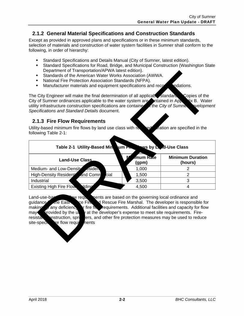
City of Sumner General Water Plan Update - DRAFT
April 2018 2-2 BHC Consultants, LLC
2.1.2 General Material Specifications and Construction Standards Except as provided in approved plans and specifications or in these minimum standards, selection of materials and construction of water system facilities in Sumner shall conform to the following, in order of hierarchy: Standard Specifications and Details Manual (City of Sumner, latest edition). Standard Specifications for Road, Bridge, and Municipal Construction (Washington State
Department of Transportation/APWA latest edition). Standards of the American Water Works Association (AWWA. National Fire Protection Association Standards (NFPA). Manufacturer materials and equipment specifications and recommendations.
The City Engineer will make the final determination of all applicable standards. Copies of the City of Sumner ordinances applicable to the water system are contained in Appendix B. Water utility infrastructure construction specifications are contained in the City of Sumner Development Specifications and Standard Details document.
2.1.3 Fire Flow Requirements Utility-based minimum fire flows by land use class with required duration are specified in the following Table 2-1:
Table 2-1 Utility-Based Minimum Fire Flows by Land-Use Class
Land-Use Class Minimum Rate
(gpm) Minimum Duration
(hours)
Medium- and Low-Density Residential 1,000 2 High-Density Residential and Commercial 1,500 2 Industrial 3,500 3 Existing High Fire Flow Buildings 4,500 4
Land-use-based fire flow requirements are based on the governing local ordinance and guidance by the East Pierce Fire and Rescue Fire Marshal. The developer is responsible for making up any deficiency for fire flow requirements. Additional facilities and capacity for flow may be provided by the utility at the developer’s expense to meet site requirements. Fire-resistant construction, sprinklers, and other fire protection measures may be used to reduce site-specific fire flow requirements DRAFT

City of Sumner General Water Plan Update - DRAFT
April 2018 3-1 BHC Consultants, LLC
Chapter 3 Historic and Projected Water Demand 3.1 Introduction The objective of this chapter is to develop future population and land use projections for water-demands within the City of Sumner’s Retail Water Service Area.
3.2 Historical and Projected Population Population in the City of Sumner has increased from 2,816 residents in 1950 to an estimated 9,584 residents in 2015, according to the US Census American Community Survey 5-year estimates, 2006-2010. This represents the City’s residential population. Table 3-1 shows historic populations for Sumner and the average annual growth rates.
Table 3-1 City of Sumner Population
Year City
Population Population
Change per Decade Annual Population Growth
(%)
1950 2,816 – – 1960 3,155 339 1.2 1970 4,325 1,170 3.7 1980 4,936 611 1.4 1990 6,459 1,523 3.1 2000 8,504 2,045 3.2 2010 9,451 947 1.1
In 2015, the population of Sumner was estimated at 9,584. The population has grown at an average annual rate of 1.9 percent since 1990. The Puget Sound Regional Council (PSRC) reports that population in the four-county Puget Sound region is growing in every county. The population change in Pierce County from 2014-2015 is 1.1 percent compared to the four-county region at 1.6 percent. The City’s 2015 Comprehensive Plan projected 15,964 residents and 22,108 employees within the City and its UGA by 2035. The PSRC provides population and employment projections based on the PSRC Land Use Vision and UrbanSim model. PSRC maintains and develops the LUV and UrbanSim to project policy-based growth based on regional growth strategies, adopted local growth targets, and the City’s Comprehensive Plan land use and zoning. Table 3-2 displays residential population and employment projections for the City of Sumner’s proposed Retail Water Service Area through the year 2038. Residential population and employment assumptions for the City’s Retail Water Service Area apply the PSRC LUV/UrbanSim projections.
DRAFT

City of Sumner General Water Plan Update - DRAFT
April 2018 3-2 BHC Consultants, LLC
Table 3-2 City of Sumner Retail Water Service Area Residential Population and Employment Projections
Year Population Annual
Population Growth (%)
Employment Annual Job Growth (%)
2018 11,044 -- 16,563 2024 11,793 1.1 17,712 1.2 2028 12,321 1.1 18,064 0.5 2038 13,343 0.8 19,096 0.6
3.3 Historical Water Consumption
3.3.1 Service Meters Service meters have been installed on most customer water connections in the Sumner water system. At the time this plan is being produced, there are still two industrial sites at which the City is working to get meters installed. Customers are divided into nine separate classes: residential (with subclasses for single family residential and multifamily residential), commercial, schools, industrial, church, City services, hotels, irrigation, and unclassified. The multifamily category includes both duplexes and apartments. The overall category of “Residential” is defined as the sum of the use from the single family and multifamily residential accounts. “Non-Residential” is defined as the sum of the accounts for commercial, schools, industrial, churches, City services and motels. “Irrigation” and “unclassified” are kept as their own categories. Table 3-3 lists the annual billed water use for the Residential, Non-Residential, Irrigation, and Unclassified Consumption customer classes, as well as the calculated Distribution System Leakage (DSL) between 2015 and 2017. DSL is further explained in Section 3.4. Figure 3-1 2015 to 2017 Average Water Use by Category shows the annual average water use of each customer class and usage type as a percentage of the total water delivered to the system (metered and un-metered). This figure also includes the system’s DSL percentage. The historical annual source production, graphically shown in Figure 3-2 Annual Source Production to the System (2015 to 2017), was observed to increase between 2015 and 2016. This could be attributed to the hotter than usual temperatures.
3.3.2 Master Meters In addition to service meters at most customer connections, the City of Sumner has a number of “master” flow meters located where source flow enters the distribution system. Annual source production to the water system is shown in Table 3-4.
3.3.3 Station Meters Station meters are located at metering vaults upstream of the storage tanks at Sumner and County Springs. Station meters utilize weir flow with head measured with transducers to record total spring flow (spring production) and spring bypass (bypass). The difference in these measured parameters is the spring flow to the system (system demand).
DRAFT

City of Sumner General Water Plan Update - DRAFT
April 2018 3-3 BHC Consultants, LLC
Spring Production - Bypass = System Demand Instantaneous system demand flow readings from the station meters do not accurately reflect instantaneous system demands, as the reservoirs fill and empty regularly. System flow values from the station meters are considered less accurate than the system flow values derived from master meters.
Table 3-3 Annual Use Record Summary 2015-2017
Year Residential Non-
Residential Irrigation
Unclassified Consumption1 DSL
Total Annual Use
(mg/year) (mg/year) (mg/year) (mg/year) (mg/year) (mg/Year)
2015 273.1 142.2 91.4 13.2 91.0 610.9 2016 263.4 137.0 97.8 8.5 113.4 620.1 2017 292.4 156.6 87.3 8.3 65.4 610.0 Notes:
1) Unclassified consumption is an estimate of water used that doesn’t fit within another category. It is typically water taken from hydrants for construction and maintenance uses.
Figure 3-1 2015 to 2017 Average Water Use by Category
Single Family Residential
31.1%
Commercial/City14.8%
Schools1.3%
Industrial6.0%
Multi-Dwellings14.2%Church
0.5%
Hotel/Motel0.8%
Irrigation14.3%
Unclassified Consumption
2.4%DSL
14.7%
DRAFT
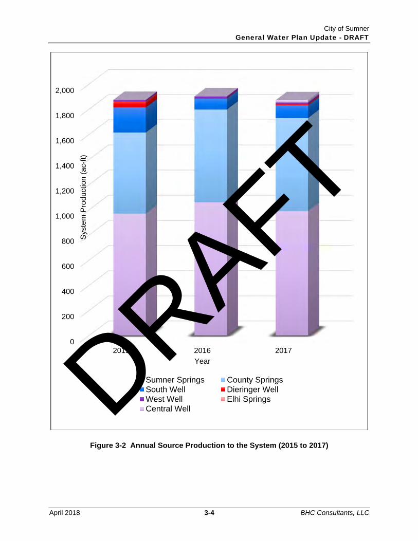
City of Sumner General Water Plan Update - DRAFT
April 2018 3-4 BHC Consultants, LLC
Figure 3-2 Annual Source Production to the System (2015 to 2017)
0
200
400
600
800
1,000
1,200
1,400
1,600
1,800
2,000
2015 2016 2017
Syst
em P
rodu
ctio
n (a
c-ft)
Year
Sumner Springs County SpringsSouth Well Dieringer WellWest Well Elhi SpringsCentral WellDRAFT

City of Sumner General Water Plan Update - DRAFT
April 2018 3-5 BHC Consultants, LLC
Table 3-4 Annual Source Production to the System
Year Sumner Springs
County Springs
South Well Dieringer
Well West Well
Elhi Springs
Central Well Total
(ac-ft) (ac-ft) (ac-ft) (ac-ft) (ac-ft) (ac-ft) (ac-ft) (ac-ft) 2015 971 645 199 47 13 0 NA 1,875 2016 1,060 738 87 3 15 >0 NA 1,903 2017 991 739 101 9 14 0 18 1,872
Average ('15-'17)
1,007 707 129 20 14 >0 18 1,883
DRAFT

City of Sumner General Water Plan Update - DRAFT
April 2018 3-6 BHC Consultants, LLC
3.3.4 Top Water Users The City’s top water users are included in Table 3-5. The annual average day demand for each user is shown. The largest single user of water in the system is Shining Ocean TWC, Inc.
Table 3-5 City of Sumner - Year 2016 Top 10 Water Users
Rank Customer 2016 ADD (gpd)
1 Shining Ocean TWC, Inc. 30,193 2 City of Sumner 27,133 3 Summerville Estates 21,768 4 Rainier Manor Homeowners 19,534 5 GRE River Grove LLC 18,313 6 Prologis LP 17,936 7 Sumner School District 320 17,125 8 YMCA of Pierce & Kitsap Counties 15,953 9 Costco 15,667
10 City of Sumner - STP 14,157
3.4 Authorized Consumption and Distribution System Leakage (DSL)
Table 3-6 and Table 3-7 are comparisons of the most recent three years of annual source production to the system data from master meters and demand data from service meters for the City’s main system and for the Sumner Viewpoint pressure zone, respectively. For Sumner Viewpoint, the most recent three years of data is 2014 to 2016. The difference between production and demand provides the amount of Distribution System Leakage (DSL) in the system. Metered/Authorized consumption includes billed usage, hydrant flow meters (typically water taken from hydrants for maintenance and construction uses), flushing, residual analyzers, and flushing dead end mains. DSL can be attributed to leaks, main breaks, unmetered connections or uses, and possible miscalibration of meters used to collect information. Table 3-6 and Figure 3-3 show that the percent of DSL in the system has been decreasing for the most part, though it has leveled off in the last three years. The DSL for the main portion of the system has decreased since 2010 from 31.8 percent to 20.9 percent demonstrating that Sumner’s Water Loss Control Plan is working. Long periods of record are desirable to increase the expected accuracy of the DSL. Short periods of overlapping data have error associated due to different schedules of reading the meters. This analysis is highly dependent on the accuracy of both source and service meters.
DRAFT

City of Sumner General Water Plan Update - DRAFT
April 2018 3-7 BHC Consultants, LLC
Table 3-6 Source Production to the System Versus System Demand
Year Production (MG) Billed and Authorized
Consumption (MG) DSL (MG) DSL
2015 611 519 92 15.6% 2016 620 507 113 19.1% 2017 610 545 65 11.5%
Table 3-7 Source Production to Sumner Viewpoint Versus System Demand
Year Production (MG) Billed and Authorized
Consumption (MG) DSL (MG) DSL
2014 5.60 3.65 1.95 35% 2015 6.36 5.44 0.92 15% 2016 7.31 5.81 1.50 20%
Figure 3-3 Main System Average Yearly Distribution System Leakage (DSL)
0%
5%
10%
15%
20%
2015 2016 2017
DSL
(%)
Year
System Average Yearly Distribution System Leakage (DSL)
DRAFT

City of Sumner General Water Plan Update - DRAFT
April 2018 3-8 BHC Consultants, LLC
Figure 3-4 Sumner Viewpoint Average Yearly Distribution System Leakage (DSL)
3.4.1 Water Loss Control Action Plan (WLCAP) The City’s three-year DSL average (from 2015 to 2017) of 14.7 percent in the overall system is above the DSL threshold of 10 percent designated by DOH’s Water Use Efficiency Program, and therefore, requires the City to implement a Water Loss Control Action Plan (WLCAP). The plan, initially established in 2008, was updated in 2017. The City updated their Water Use Efficiency Plan in April 2017 (Appendix C). This plan advocates implementation of demand side and supply side actions to help meet the single goal of reducing the City’s three-year running average DSL to 10 percent or less by 2025. Demand side actions include eliminating unmetered connections and preventing unauthorized water withdrawal from fire hydrants. Supply side actions include improvements to instrumentation and telemetry for added accuracy in water production calculations and water main replacements for eliminating distribution system leaks. Components of the 2017 WLCAP include: An implementation schedule for the control methods to be implemented. A budget that demonstrates how the control methods will be funded. Technical and economic concerns which may affect the City’s ability to implement a
program or comply with the standard including past efforts and investments to minimize leakage.
Address the data accuracy and data collection methods used to determine distribution system leakage.
In May 2017, the following additional actions were proposed to the City Council: Develop and implement a program approved by the Fire Marshall to identify and
eliminate unauthorized withdraw of water from fire hydrants.
0%
5%
10%
15%
20%
25%
30%
35%
2014 2015 2016
Sumner Viewpoint Average Yearly Distribution System Leakage (DSL)
DRAFT

City of Sumner General Water Plan Update - DRAFT
April 2018 3-9 BHC Consultants, LLC
Work with property owners to install metering devices at commercial properties that do not currently meter City water entering the premises.
Provide customers with information on how to conserve water, efficient irrigation techniques, and the benefits of low use fixtures and appliances.
These actions will be ongoing and continue until (and likely after) the City reaches an allowable DSL average based on a 3-year period.
3.5 Equivalent Residential Units Equivalent residential units (ERUs) are defined as the amount of water consumed by a typical single-family residence. The water use per ERU was determined by taking the average daily use per single family residential connection using meter reading data and factoring out accounts with meter reads for part of the year, or no recorded consumption. The accounts with the top 0.5% of total annual consumption were also removed from the analysis as this higher usage pattern appeared indicative of non-single-family usage patterns. The analysis was done using a four-year data set covering the years 2014 to 2017. The average single family residential rate for the four years was 189.6 gpm. A memorandum provided by the City summarizing the calculations for the average single family residential consumption rate is provided as Appendix D. A comparison with the average single family residential usage reported by the City of Pacific to be between 152 to 167 ERUs is in line with the consumption rate calculated for the City of Sumner given the similar geological features between the two cities. Bonney Lake reported an ERU of 218 gpd (2014) in their 2016 Water System Plan. Although this is significantly higher than Sumner’s overall rate, recalculating the ERU rate for the single-family residences within the Sumner Viewpoint area yields an ERU rate of 320.6 gpd. Given the topography being more similar to Bonney Lake’s service area the higher ERU rate is considered reasonable.
DRAFT

City of Sumner General Water Plan Update - DRAFT
April 2018 3-10 BHC Consultants, LLC
A summary of the City’s existing water system ERUs by category is provided as Table 3-8. These ERUs are calculated based on the same four-year period of data from 2014 to 2017.
Table 3-8 City of Sumner Total ERUs (2014 to 2017)
Service Classification Annual ADD (gpd) Total ERUs
Single-Family Residential 504,797 2,665 Sumner Viewpoint1 17,599 44
Multi-Family Residential 238,977 1,263 Non-Residential 390,946 2,064
Irrigation 231,414 1,224 Un-Classified 26,334 139
DSL 258,570 1,376 Calculated System ERUs 8,775
Notes: 1) Sumner Viewpoint annual ADD and total ERUs shown were calculated from the
available data from 2014 to 2016.
3.6 Per Capita Residential Usage Rate The per capita residential water usage is calculated by dividing the combined metered use from the residential (single family plus multifamily) ERUs by the residential population in the Retail Water Service Area boundary for each of years 2015 through 2017. The resulting average per capita residential water usage for the three years is 72.73 gpd/resident. This was used for residential demand projections. An average population rate of 2.64 capita per ERU can be calculated using a similar methodology.
3.7 Per Employee Usage Rate The per employee water usage is calculated by dividing the combined metered use from the non-residential ERUs by the employment population in the Retail Water Service Area boundary for each of years 2015 through 2017. The resulting average per employee water usage for the three years is 25.28 gpd/employee. An average employee rate of 7.61 employees per ERU can be calculated using a similar methodology.
3.8 Projected Water Demand
3.8.1 Average Daily Demand Projected water demands are calculated based on the per capita usage rates of the residential and employment population. Irrigation, Un-classified, and DSL are kept separate from the per capita calculations and escalated or decreased over time at a rate agreed on by the City. A system-demand increase based on the population projections presented in Section 3.2 was used to estimate future water demands. The projected water demands through the year 2038 planning period are included in Table 3-9 for the City’s main system. Water demand projections for Sumner Viewpoint are provided as Table 3-10. A final row with a City-generated year 2068 projection is added for the purposes of evaluating the City’s sources of supply and long-term water rights needs (see Chapter 5), as modifications to the latter are currently being negotiated.
DRAFT

City of Sumner General Water Plan Update - DRAFT
April 2018 3-11 BHC Consultants, LLC
Table 3-9 Water Demand Projections with Water Use Efficiency
Year Residential1 Employment1 Irrigation2 Unclassified
Consumption3 DSL4
Total Annual
Use (ADD)
(gpd) (gpd) (gpd) (gpd) (gpd) (mgd) 2018 803,251 418,670 229,443 26,334 268,299 1.75
2019 812,086 423,694 234,032 26,861 255,869 1.75 2020 821,019 428,779 238,713 27,398 243,365 1.76 2021 830,050 433,924 243,487 27,946 230,781 1.77 2022 839,181 439,131 248,357 28,505 218,113 1.77 2023 848,412 444,401 253,324 29,075 205,358 1.78 2024 857,745 449,733 258,390 29,657 188,608 1.78
2025 867,180 451,982 260,974 30,250 178,932 1.79 2026 876,719 454,242 263,584 30,855 180,600 1.81 2027 886,363 456,513 266,220 31,472 182,285 1.82 2028 896,113 458,796 268,882 32,102 183,988 1.84
2038 970,438 487,079 268,882 38,522 196,102 1.96
20685 1,232,491 582,826 268,882 61,635 238,426 2.38
Notes: 1) Assuming demand increases proportional to population projections. 2) Assuming growth per year reduces from 2 percent per year between 2018 and 2024,
to 1 percent per year between 2025 and 2028, to 0 percent per year between 2029 and 2038.
3) Assuming a 2 percent per year Unclassified Consumption Growth Rate. 4) Assumes DSL reduces from the current 3-year average of 15 percent to the WLCAP
goal of 10 percent by 2025. 5) The total annual use (ADD) projection for 2068 generally assumes maintenance of a
10 percent DSL, 2 percent unclassified consumption, and constant residential and employment growth rates from 2038 of 1.1 and 0.8 percent, respectively.
DRAFT

City of Sumner General Water Plan Update - DRAFT
April 2018 3-12 BHC Consultants, LLC
Table 3-10 Sumner Viewpoint Water Demand Projections with Water Use Efficiency
Year Residential1 DSL2 Total Annual Use (ADD)
(gpd) (gpd) (gpd) 2018 22,262 5,565 27,827
2019 22,438 5,320 27,759 2020 22,616 5,077 27,693 2021 22,796 4,835 27,631 2022 22,977 4,595 27,572 2023 23,159 4,357 27,516 2024 23,322 4,116 27,437
2025 23,852 3,802 27,654 2026 24,394 3,485 27,879 2027 24,948 3,162 28,111 2028 25,442 2,827 28,269
2038 29,682 3,298 32,980
20683 48,736 5,415 54,151
Notes: 1) Assuming demand increases proportional to population projections. 2) Assumes DSL reduces to the WLCAP goal of 10 percent by 2025. 3) The total annual use (ADD) projection for 2068 generally assumes maintenance of a
10 percent DSL and a constant residential growth rate from 2038 of 1.67 percent.
3.8.2 Maximum Daily Demand Maximum daily demand utilizes a peaking factor that is the ratio of maximum daily production to the average daily production. DOH has a minimum peaking factor of 2.0 to be used in evaluating water systems. Maximum day demands were measured from the master meters from 2010 to 2015. Due to lack of available maximum day demand data for 2016 and 2017, the most recent three-year average maximum day demand peaking factor was taken from 2013 through 2015 and is equal to 2.05. This exceeds the DOH required minimum factor of 2.0. Table 3-9 includes the maximum daily production for the year compared with the annual average-day demand for the year. A peaking factor of 2.05 as shown in Table 3-11 was used for future maximum-day-demand estimates. Irrigation is included in the calculation for maximum-to-average peaking factor but has a different pattern as there are several months with much lower flows. Peak day irrigation usage could be 3.5 to 4.0 times the annual average due to its concentrated use during warmer months. The amount of DSL was not included in the peaking factor since the DSL is not expected to increase at the max day demand. The annual average DSL was instead added to the total max day demand.
DRAFT

City of Sumner General Water Plan Update - DRAFT
April 2018 3-13 BHC Consultants, LLC
Table 3-11 Historical Maximum-Day Demands
Year Total Maximum Day Production
(mgd)
Maximum Daily Production Minus
DSL (mgd)
Average Daily Production (mgd)
Maximum-to-Average Factor
2010 3.07 2.54 1.14 2.24 2011 3.42 3.14 1.14 2.76 2012 2.55 2.37 1.19 1.99 2013 2.82 2.52 1.23 2.04 2014 2.83 2.57 1.30 1.98 2015 3.28 3.02 1.41 2.14
Average Maximum-to-Average Factor ('13 - '15): 2.05
3.8.3 Off-Peak Average and Maximum Daily Demand The City currently has a temporary water right that allows for different instantaneous groundwater supply rates during the peak (July, August, and September) and off-peak months. An estimate of the maximum demand during the off-peak months is necessary to ensure the City can meet projected demands utilizing the water available during the off-peak months. Daily City production records for all sources were totaled, trended and evaluated for off-peak months from 2015 through 2017 to establish an existing off-peak 2018 ADD of 1,000 gpm (1.44 mgd). Although the daily trends show very small percentages of deviation from these numbers, a peaking factor of 1.5 is assumed to establish off-peak MDD that allows for unanticipated system demands that might arise from main breaks, extended flushing operations, or other abnormal uses. Future projections will retain the same existing average annual to off-peak average percentage and the 1.5 peaking factor. The off-peak MDD projections that are needed to assess source of supply water rights are included in Table 3-12.
3.8.4 Peak Hourly Demand Due to unavailable meter data that would indicate maximum instantaneous water use, the DOH Water System Design Manual (WSDM) suggests using the following equation to calculate the peak hour demand (PHD).
PHD = MDD/1,440 x [(C)(N) + 225] + 18 Where: PHD = Peak Hour Demand (gpm)
MDD = Maximum daily demand (gpd/ERU) C = Coefficient associated with the number of ERUs (1.6) N = Number of ERUs
Table 3-12 summarizes the projected system demands from year 2017 through year 2037. The table includes the average-day-demand, maximum-daily-demand, off-peak season maximum-daily-demand, and peak-hour-demand calculations.
DRAFT

City of Sumner General Water Plan Update - DRAFT
April 2018 3-14 BHC Consultants, LLC
Table 3-12 Projected Max Day Demand and Peak Hour Demand with DSL
Year ADD (mgd) MDD (mgd) Off-Peak MDD
(mgd) PHD (mgd)
2018 1.77 3.36 2.16 5.42 2024 1.81 3.52 2.21 5.73 2028 1.87 3.64 2.27 5.92 2038 1.99 3.89 2.43 6.32 2068 2.44 4.76 2.97 7.75
DRAFT

City of Sumner General Water Plan Update - DRAFT
April 2018 4-1 BHC Consultants, LLC
Chapter 4 Water System Description This chapter includes a brief history of the Sumner water system that provides a historical perspective to past improvements and provides insight into the logical progression of future improvements. Following that, there is a discussion on the components of the water system and a summary of relevant physical features, including sources, storage, and transmission. The relationship among the system components is provided, and the effectiveness and condition of the facilities are addressed where lacking.
4.1 History of the Water System In 1883, George H. Ryan recorded a deed to the timbered hills approximately ½ mile northeast of the present City. Ryan built a sawmill and constructed a gravity water supply system. The water supply at Ryan’s Mill was conveyed to the town through logs approximately 15 inches in diameter and 15 feet long with a 2.5-inch hole bored through the length of each log. On December 24, 1889, the Sumner Light and Water Company was incorporated and assumed management of Ryan’s Sumner Lumber Company water system. Ryan later became the Town’s first mayor in 1892. In 1893, the water system was sold to A. Brier Wood. The town government wanted to purchase the water system but was unable to finance the purchase as a public utility. It was not until 1905 that the town voted to purchase the water system with a bond issue of $7,000. The first drinking water ordinance was passed February 1907, which provided for the creation of a water department, appointment of a superintendent, and fixed water rates. Soon, the Town began to industrialize. Lake Tapps was created by enlarging five lakes on the plateau east of Sumner. Puget Power and Light installed a power generation station. Fleischmann’s Yeast, Northern Board and Paper Company, and several other large manufacturing companies established facilities in the northern factory district. By 1920, the wooden-stave, turn-of-the-century water system was inadequate. In May of 1921, the Town authorized a bond issue of $45,000 to rebuild the system, again using wood-stave pipe. In July 1928, newly elected officials took office. This event marked a great change in policy and operations of the water department. The new mayor, Frank B. Weick, was a civil engineer from Tacoma who resided in Sumner. Mayor Weick made a very emphatic address to the new town council urging the discontinuation of using water department funds to keep the tax levy down. He proposed instead to use the revenues to provide a better water distribution system as well as fire protection to the factory district, which was outside the corporate limits at that time. Mayor Weick proposed to gradually replace the wooden water mains with longer-life pipes. The Town council gave the mayor its support, and 2,760 linear feet of pipe was laid in 1929 in the factory district with fire hydrants spaced to conform to the recommendations of the underwriters. The factory district was incorporated into the Town limits, and several months later Sumner qualified to become a City.
DRAFT

City of Sumner General Water Plan Update - DRAFT
April 2018 4-2 BHC Consultants, LLC
The schedule for replacement of wooden water mains began in 1930 and was faithfully maintained throughout the Depression years. By the time of maturity of the last bonds (1941) from the 1920 issue, the last of the wooden mains were replaced by cast iron or asbestos cement pipe. Over the years the system has been expanded further, including expansion north along 142nd Avenue East with a 14-inch diameter ductile iron main, a system developed to serve the eastern residential portions of the City and the REI complex near 45th Street East. Additional expansion included construction of a 2.0 MG reservoir in the north end of Sumner east of the East Valley Highway, and 12-inch-diameter to 16-inch-diameter ductile iron extensions north on West Valley Highway and East Valley Highway. Weber and Ritter, Inc. was a private water system that was developed to the south of Sumner. Weber and Ritter first acquired the County and Elhi Springs before the City of Sumner purchased Weber, County, and Elhi Springs in 1968. The City of Sumner acquired all Fowler Mutual Water Company assets, water service area, and water customers on July 2, 2001 through a Water Service Agreement. A copy of this agreement is provided as Appendix A. On September 4, 2001, the City of Sumner adopted Resolution No. 1045, supporting the City of Pacific’s assumption of the Webstone Water District and the transfer of the portion of Webstone Water District’s service area within Sumner’s UGA to the City of Sumner. The City of Pacific adopted Ordinance No. 1518 on March 4, 2002 authorizing the City of Pacific to begin dissolution of the Webstone Water District and to assume ownership of said district, including all assets, service area, and responsibilities. The Webstone Water District has been completely absorbed by the City of Pacific and City of Sumner systems.
4.2 Past Spring and Watershed Improvements In 1889, the spring headworks of the Sumner Light and Water Company consisted of 17.8 acres of forested hillside northeast of the City. In 1934, Sumner purchased another 30 acres. At that time, the headworks of the Puyallup Springs were located to the north. To the south, four or five private water systems were developed (Weber and Ritter, County, etc.). The headworks were fenced in 1937. In 1938 and 1939, the federal Works Project Administration (WPA) drove tunnels into the hillside to intercept a greater portion of the four largest springs of the Sumner system. These tunnels extended from 50 to 120 feet, and interception facilities with large culverts carried the spring water to a head house. From the head house, a 14-inch water main leads to the City. Prior to the WPA work on the springs, the flow was approximately 2.0 million gallons per day (MGD). After completion of the improvements, the flow weir at the head house showed approximately 3.0 MGD. From the time of the WPA improvements until 1980, the springs required few changes. Passage of the Safe Drinking Water Act in 1974 precipitated efforts by the City to protect and improve their water supply sources. Water system plans in 1975, 1980, and 1985 identified a need to capture a greater portion of the springs and improve their sanitary condition. The 1985 Water System Plan made the following recommendations (Parametrix 1985):
▪ Chlorination at Sumner and County Springs. ▪ Watershed fencing for protection from vandalism and unlawful entry.
DRAFT

City of Sumner General Water Plan Update - DRAFT
April 2018 4-3 BHC Consultants, LLC
▪ Repair of spring taps and collection boxes to collect a greater portion of the spring flow and protect surface runoff from entering the collection works.
▪ Predesign engineering report detailing needed improvements. A predesign engineering report addressing the fourth bullet, titled “Water Supply Improvements, Spring Protection and Chlorination”, was completed the following year (Parametrix 1986). This report identified in greater detail needed improvements to Sumner, Weber, and County Springs. No improvements were outlined for Elhi Springs in the predesign engineering report. All recommendations in the predesign report were completed by 1989, although watershed fencing was limited to access points and those areas adjacent to roads and highways. Source improvements for each system were as follows:
▪ Sumner Springs: o Chlorination facilities added. o New flow metering system added. o Broken pipes slip lined and repaired. o Surface drainage improved. o Watertight access doors placed on all collection/tap boxes.
▪ Weber Springs No. 1: o New spring tap with Hypalon liner provided. o System tied into Sumner Springs.
▪ Weber Springs No. 2: o Existing holding tank abandoned. o Existing pipes abandoned. o Spring taps improved. o Surface drainage improved. o Watertight access doors placed on all collection/tap boxes. o New spring tap with Hypalon liner provided. o System tied into County Springs.
▪ County Springs: o Chlorination facilities added. o 68,000-gallon chlorine contact tank installed. o New flow metering system added. o Broken pipes slip lined and repaired. o Surface drainage improved. o Watertight access doors placed on all collection/tap boxes. o New spring tap with Hypalon liner provided.
▪ Entire Sumner/Weber/County Spring System: o Fenced along Sumner-Tapps Highway and at access points along the valley. o Gates installed at all vehicle access points.
In 2018 the City of Sumner implemented security improvements in the Sumner, Weber, and County Spring watersheds that included installing security fencing around the spring tap. The City of Sumner completed source improvements at Elhi Springs in 2003. Source improvements included:
▪ Chlorination facilities added, including continuous chlorine residual monitoring equipment and instrumentation/control.
DRAFT

City of Sumner General Water Plan Update - DRAFT
April 2018 4-4 BHC Consultants, LLC
▪ Chlorine contact tanks added. ▪ Booster pump added to raise the hydraulic grade line of the Elhi Springs to match the
rest of the Sumner potable water sources. ▪ Abandonment of the water storage reservoir and repurposing the structure to serve as a
building pad for the chlorination and (proposed) fluoridation facilities. Elhi Springs is currently not utilized in routine operations due to the difficulty in providing adequate chlorine contact time between the source and the first service.
4.3 Water System Overview The location of major water system facilities is shown in Figure 1-3. The hydraulic profile for the City of Sumner’s Water System is provided as Figure 4-1. The system currently consists of a primary pressure zone with a hydraulic grade line of approximately elevation 234 and a second pressure zone supporting the Sumner Viewpoint development at approximately elevation 393. Table 4-1 lists the capacity of water supply sources in the Sumner water system.
Table 4-1 Sumner Potable Water Source Capacities
DOH ID Number
Source Name Source Type Source Capacity
(mgd) Water Right (mgd)
SO 1 Sumner Springs
Free-Flowing Spring 1.151 1.15
SO 2 Weber Springs Free-Flowing Spring
Flow and water rights are combined with Sumner Springs and County Springs.
SO 3 Elhi Springs Free-Flowing Spring 0.132 0.52
SO 4 County Springs Free-Flowing Spring 0.791 0.79
SO 54 West Well Artesian Well 0.363 0.36
SO 6 South Well Artesian Well 1.013 1.445
SO 7 Dieringer Well Artesian Well 0.363 0.13
SO-CW Central Well Artesian Well 1.513 0.43/1.516
Notes: 1) Source capacity based on historic station meter readings. 2) Source capacity based on City records; Elhi Springs is typically not being utilized. 3) Source capacity based on well pump capacity. 4) The West Well is currently utilized primarily for irrigation. 5) Source pumping capacity is less than the City's Water Rights. 6) The City obtained a temporary Water Right to use the Central Well as an additional
point of withdrawal for the South and West Well water rights. Combined instantaneous withdrawal from the Central, South, and West Wells is not to exceed 1.8 mgd.
DRAFT

HY
DR
AU
LIC
GR
AD
E (
FT
)
HY
DR
AU
LIC
GR
AD
E (
FT
)
LEGEND
NORMALLY CLOSED VALVE
NORMALLY OPEN VALVE
METERING LOCATION
BOOSTER PUMP STATION
TANK RESERVOIR
WELL
SPRINGS TAP
M
M
M
SUMNER
CEMETERY
CITY OF
PUYALLUP
INTERTIE
M
1.0 MG
SUMNER SPRINGS
TANK
M
68,000 GAL
COUNTY SPRINGS
CHLORINE CONTACT TANK
M
234 ZONE
CITY OF SUMNER
CITY OF
PACIFIC INTERTIE
2.0 MG
SOUTH TANK
DIERINGER
WELL
WEST WELL
(SEASONAL)
SOUTH WELL
MM
M
0.33 MG
SUMNER VIEWPOINT TANK
393 ZONE
SUMNER VIEWPOINTSUMNER
SPRINGS
WEBER
SPRINGS
COUNTY
SPRINGS
2.0 MG
NORTH TANK
M
CENTRAL WELL
ST-5ST-6 W2-4
W2-3
W2-1B
W2-1A
ST-4
ST-3
ST-2
ST-1
ELHI SPRINGS
M
VALLEY CREST
Hydraulic Profile
Sumner Water System Plan 4-1
Figure
COPYRIGHT © 2018 BHC CONSULTANTS, LLC. ALL RIGHTS RESERVED
Pa
th:
S:\
Ca
d\S
um
ne
r\1
7-1
05
00
Wa
ter
Syste
m P
lan
\ F
ile
na
me
: F
17
-10
50
0.0
0_
Fig
4-1
P
lot
da
te:
Ap
r 0
4,
20
18
-01
:28
:59pm
C
AD
User:
psim
on.
Xre
f F
ile
na
me: |
DRAFT

City of Sumner General Water Plan Update - DRAFT
April 2018 4-6 BHC Consultants, LLC
THIS PAGE INTENTIONALLY BLANK.
DRAFT

City of Sumner General Water Plan Update - DRAFT
April 2018 4-7 BHC Consultants, LLC
Construction of the Sumner Viewpoint development created a separate pressure zone within the Sumner water system at approximately elevation 393. This development is located outside of Sumner City limits, but within the Retail Water Service Area off SR 410. The development includes a booster station at the South Tank site that pulls potable water from the South Tank supply line and pumps it to a 330,000-gallon reservoir located at the Sumner Viewpoint site. This establishes an approximate hydraulic grade line of 393 feet. The pump station and reservoir were sized to accommodate a maximum build-out of 120 ERUs in the Sumner Viewpoint development. Analysis of supply, storage and pump station design requirements within Chapter 5 confirm the adequate sizing of these facilities. The City supplies water to a water distribution system owned and maintained by the Valley Crest Maintenance Association. This Maintenance Association serves 14 properties located on 171st Avenue Court East. This system has a booster pump station operated and maintained by the association. The approximate hydraulic grade line of the system is unknown. Each of the properties has a meter installed at the service line to the property and the City bills the residents at each property for the water consumed in accordance with the City’s published utility rates. 4.4 Distribution Network The distribution system consists of approximately 1,017 sections of pipe ranging in size from 2-inch diameter to 18-inch diameter. The approximately 90 miles of pipe also vary in age and material. Detailed maps of the distribution network are maintained and updated by the City. These water system maps show pipe diameters, pipe materials, locations of hydrants, valves, and abandoned pipes, and give the year of installation for most pipes. The approximate length and percentage of each pipe size in the distribution network is listed in Table 4-2.
Table 4-2 Distribution Network Inventory (August 2017)
Pipe Sizes (inches) Length (feet) Percentage
2 6,706 1.4 3 2,739 0.6 4 6,198 1.3 6 104,199 22.0 8 165,270 34.8
10 6,889 1.5 12 160,116 33.7 14 11,338 2.4 16 6,246 1.3 18 4,903 1.0
Total: 474,603 100.0
DRAFT

City of Sumner General Water Plan Update - DRAFT
April 2018 4-8 BHC Consultants, LLC
4.5 Spring Collection Works
4.5.1 Sumner Springs
The current Sumner Springs collection works are shown on Figure 4-2, Figure 4-3, and Figure 4-4. There are five spring taps. The spring taps feed into collection boxes, which pass the flow on to the downstream collection box through a common header pipe. All tap boxes may be manually bypassed in the event a single spring tap becomes contaminated or otherwise undesirable. From the header pipe, the spring flow passes into a metering vault where the flow is split between wastage to Salmon Creek and water for distribution. An access road, which turns into a footpath, parallels the spring taps. Surface water is collected and diverted away from the spring taps via perforated pipes and culverts. In general, the Sumner Springs collection works appear to be in good condition. Section 5.6, “Minimum Sanitary Control Area Survey,” will discuss Sumner Springs in further detail. Operational information for Sumner Springs is discussed in Chapter 10, “Operations Program.”
4.5.2 Weber Springs
The current Weber Springs collection works are shown on Figure 4-5 and Figure 4-6. Figure 4-5 shows Weber Springs No. 1, which feeds into spring tap ST-6 of the Sumner Springs system. Figure 4-6 shows Weber Springs Taps W2-1A, W2-1B, W2-3 and W2-4, which feed into the metering vault of the County Springs system. There is one spring tap at Weber Springs No. 1 and four spring taps at Weber Springs No. 2. For the purpose of this document, the Weber Springs is not evaluated as a separate source but is considered to be part of Sumner and County Springs. As with Sumner Springs, the spring taps feed into collection boxes, which pass the flow downstream to the next collection box through a common header pipe. All tap boxes may be manually bypassed in the event a single spring tap becomes contaminated or otherwise undesirable. Surface water is collected and diverted away from the spring taps via perforated pipes and culverts. The abandoned holding tank from the old Weber system is shown on Figure 4-5. An access road parallels the spring taps. In general, the Weber Springs collection works appear to be in good condition. Section 5.6, “Minimum Sanitary Control Area Survey,” will discuss Weber Springs in further detail. Operational information for the springs is discussed in Chapter 10, “Operations Program.”
4.5.3 County Springs
The current County Springs collection works are shown on Figure 4-7. One spring tap flows into the metering vault, where it merges with the flow from Weber Springs No. 2. The metering vault may be manually bypassed in the event of contamination of Weber Springs No. 2 or County Springs. Spring flow from the metering vault is split between wastage to Salmon Creek and water for distribution. An access road leads to the spring tap from the south. Surface water is collected and diverted away from the spring tap via perforated pipes, culverts, and walls. In general, the County Springs collection works appear to be in good condition. Additional information on County Springs is included in Section 5.6, “Minimum Sanitary Control Area Survey.” Operational information for the springs is discussed in Chapter 10, “Operations Program.”
DRAFT

City of Sumner General Water Plan Update - DRAFT
April 2018 4-9 BHC Consultants, LLC
4.5.4 Elhi Springs
Elhi Springs collection works are shown on Figure 4-8. Elhi Springs was upgraded in 2000 to 2001, and again in 2003. The following improvements were made:
▪ Greater spring flow collection with the addition of three spring taps and collection vaults. ▪ Conversion of settling tank to a spring overflow collection and diversion facility. ▪ Better channelization of surface water to prevent surface water entering collection works. ▪ Installation of a metering vault. ▪ Replacement and addition of piping to transport spring flows to the holding tank. ▪ Removal of old collection station. ▪ Installation of a chlorination facility including continuous chlorination residual monitoring
and instrumentation/control. ▪ Installation of chlorine contact tanks. ▪ Installation of a booster pump to increase the hydraulic grade line of Elhi Springs to
match the remainder of the potable water sources. ▪ Abandonment of the water storage reservoir and repurposing the structure to serve as a
building pad for the chlorination equipment and booster pump. Elhi Springs requires a high dosage of chlorine in order to provide adequate CT time before the first service connection. This high chlorine dosage presents an undesirable outcome at the first service. For this reason, field staff typically do not utilize Elhi Springs unless required to meet system demands.
DRAFT

City of Sumner General Water Plan Update - DRAFT
April 2018 4-10 BHC Consultants, LLC
THIS PAGE INTENTIONALLY BLANK.
DRAFT

TA
NK
DR
AIN
TO
DIS
TR
IBU
TIO
N
12" D
I
14" D
I
14" DI
SEISMIC
BUTTERFLY VALVE
FLOWMETER
Sumner Springs
Sumner Water System Plan 4-2
Figure
COPYRIGHT © 2018 BHC CONSULTANTS, LLC. ALL RIGHTS RESERVED
Pa
th:
S:\
Ca
d\S
um
ne
r\1
7-1
05
00
Wa
ter
Syste
m P
lan
\ F
ile
na
me
: F
17
-10
50
0.0
0_
Fig
4-2
P
lot
da
te:
Ap
r 0
4,
20
18
-01
:30
:01pm
C
AD
User:
psim
on.
Xre
f F
ile
na
me: |
Source: Parametrix, May 2010 DRAFT

City of Sumner General Water Plan Update - DRAFT
April 2018 4-12 BHC Consultants, LLC
THIS PAGE INTENTIONALLY BLANK.
DRAFT

Sumner Springs
Sumner Water System Plan 4-3
Figure
COPYRIGHT © 2018 BHC CONSULTANTS, LLC. ALL RIGHTS RESERVED
Pa
th:
S:\
Ca
d\S
um
ne
r\1
7-1
05
00
Wa
ter
Syste
m P
lan
\ F
ile
na
me
: F
17
-10
50
0.0
0_
Fig
4-3
P
lot
da
te:
Ap
r 0
4,
20
18
-01
:32
:44pm
C
AD
User:
psim
on.
Xre
f F
ile
na
me: |
Source: Parametrix, May 2010 DRAFT

City of Sumner General Water Plan Update - DRAFT
April 2018 4-14 BHC Consultants, LLC
THIS PAGE INTENTIONALLY BLANK.
DRAFT

Sumner Springs
Sumner Water System Plan 4-4
Figure
COPYRIGHT © 2018 BHC CONSULTANTS, LLC. ALL RIGHTS RESERVED
Pa
th:
S:\
Ca
d\S
um
ne
r\1
7-1
05
00
Wa
ter
Syste
m P
lan
\ F
ile
na
me
: F
17
-10
50
0.0
0_
Fig
4-4
P
lot
da
te:
Ap
r 0
4,
20
18
-01
:33
:54pm
C
AD
User:
psim
on.
Xre
f F
ile
na
me: |
Source: Parametrix, May 2010 DRAFT

City of Sumner General Water Plan Update - DRAFT
April 2018 4-16 BHC Consultants, LLC
THIS PAGE INTENTIONALLY BLANK.
DRAFT

Weber Springs No. 1
Sumner Water System Plan 4-5
Figure
COPYRIGHT © 2018 BHC CONSULTANTS, LLC. ALL RIGHTS RESERVED
Pa
th:
S:\
Ca
d\S
um
ne
r\1
7-1
05
00
Wa
ter
Syste
m P
lan
\ F
ile
na
me
: F
17
-10
50
0.0
0_
Fig
4-5
P
lot
da
te:
Ap
r 0
4,
20
18
-01
:34
:53pm
C
AD
User:
psim
on.
Xre
f F
ile
na
me: |
Source: Parametrix, May 2010 DRAFT

City of Sumner General Water Plan Update - DRAFT
April 2018 4-18 BHC Consultants, LLC
THIS PAGE INTENTIONALLY BLANK.
DRAFT

Weber Springs No. 2
Sumner Water System Plan 4-6
Figure
COPYRIGHT © 2018 BHC CONSULTANTS, LLC. ALL RIGHTS RESERVED
Pa
th:
S:\
Ca
d\S
um
ne
r\1
7-1
05
00
Wa
ter
Syste
m P
lan
\ F
ile
na
me
: F
17
-10
50
0.0
0_
Fig
4-6
P
lot
da
te:
Ap
r 0
4,
20
18
-01
:35
:50pm
C
AD
User:
psim
on.
Xre
f F
ile
na
me: |
Source: Parametrix, May 2010 DRAFT

City of Sumner General Water Plan Update - DRAFT
April 2018 4-20 BHC Consultants, LLC
THIS PAGE INTENTIONALLY BLANK.
DRAFT

County Springs
Sumner Water System Plan 4-7
Figure
COPYRIGHT © 2018 BHC CONSULTANTS, LLC. ALL RIGHTS RESERVED
Pa
th:
S:\
Ca
d\S
um
ne
r\1
7-1
05
00
Wa
ter
Syste
m P
lan
\ F
ile
na
me
: F
17
-10
50
0.0
0_
Fig
4-7
P
lot
da
te:
Ap
r 0
4,
20
18
-01
:36
:50pm
C
AD
User:
psim
on.
Xre
f F
ile
na
me: |
Source: Parametrix, May 2010 DRAFT

City of Sumner General Water Plan Update - DRAFT
April 2018 4-22 BHC Consultants, LLC
THIS PAGE INTENTIONALLY BLANK.
DRAFT

Elhi Springs
Sumner Water System Plan 4-8
Figure
COPYRIGHT © 2018 BHC CONSULTANTS, LLC. ALL RIGHTS RESERVED
Pa
th:
S:\
Ca
d\S
um
ne
r\1
7-1
05
00
Wa
ter
Syste
m P
lan
\ F
ile
na
me
: F
17
-10
50
0.0
0_
Fig
4-8
P
lot
da
te:
Ap
r 0
4,
20
18
-01
:38
:08pm
C
AD
User:
psim
on.
Xre
f F
ile
na
me: |
Source: Parametrix, May 2010 DRAFT

City of Sumner General Water Plan Update - DRAFT
April 2018 4-24 BHC Consultants, LLC
THIS PAGE INTENTIONALLY BLANK.
DRAFT

City of Sumner General Water Plan Update - DRAFT
April 2018 4-25 BHC Consultants, LLC
4.6 Wells
4.6.1 South Well
The South Well was constructed in 1975 to a depth of 304 feet. The well has a 16-inch diameter casing with a stainless steel screen installed from 304 feet to 280 feet. The South Well is currently utilized as a permanent domestic source and is equipped with a three-stage vertical turbine well pump. The well is operated at a pumping rate of 700 gpm to minimize sand production. The Well is controlled automatically to turn on when the water level in the South Tank drops below an operator selected elevation.
4.6.2 West Well
The West Well was constructed in 1975 to a depth of 285 feet. The well has a 10-inch diameter casing with a 10-foot screen length. This well is equipped with a four-stage vertical-turbine pump with an approximate 250 gpm capacity. The West Well has previously been used to meet peak demands during drier months, but it is currently used primarily for irrigating the Sumner Cemetery landscaping. Operation of system valves allow the West Well to be connected to the system to meet seasonal demands when necessary.
4.6.3 Dieringer Well
The Dieringer Well was constructed in 1954 to a depth of 408 feet. The well was constructed with 12 inch-diameter casing from 0 feet to 240 feet and 10-inch casing from 240 feet to 408 feet. Per the well log, the 12-inch casing was perforated from 215 feet to 238 feet, and the 10-inch casing was perforated from 245 feet to 386 feet. The Dieringer Well was initially constructed to service the Dieringer School and was later utilized by Peterson Brothers. The City of Sumner acquired the well and associated water rights and began using the source in 1998. Final acquisition of the Dieringer Well was completed in December 2003. In 2004, well improvements were completed to allow the City of Sumner to fully utilize the Dieringer Well as a permanent potable water source. Video investigation conducted during the well rehabilitation revealed that the actual casing perforations were not as extensive as indicated on the initial well log. Subsequently, the existing well casing was re-perforated between 258 feet and 305 feet, gravel backfill material was installed from 315 feet to 400 feet, and a 6-inch stainless steel screen was installed from 210 feet and 310 feet. Filter pack material was installed from 200 feet to 315 feet. This well is equipped with a seven-stage vertical-turbine pump with a capacity of approximately 250 gpm. The Dieringer Well control is automated such that the well turns on when the level in the North Tank drops below an operator selected, preset elevation. Water Rights granted for this well limit use to 95 gpm and 6.25 acre-feet per year.
4.6.4 Central Well
Construction of the Central Well was completed in 2008 to a depth of 407 feet. The well was constructed with 20-inch diameter casing set down to 304 feet and a 16-inch diameter casing set down to 407 feet. There are two 12-inch diameter well screens from 402 to 417.5 feet deep and 429.5 to 460.5 feet deep. A 12-inch diameter pressure relief screen was installed from 397 to 402 feet deep. A 12-inch diameter riser extends from the pressure relief screen within the internal well casing up to 343 feet below the existing ground surface. The well is equipped with a 6-stage vertical-turbine pump with a capacity of approximately 1,050 gpm. Water withdrawn from the Central Well is chlorinated on site and flows through greensand/pyrolusite pressure filters to remove manganese and granular activated carbon filters to remove organic taste and odor precursors before distribution.
DRAFT

City of Sumner General Water Plan Update - DRAFT
April 2018 4-26 BHC Consultants, LLC
The Central Well has been granted a temporary authorization by the Department of Ecology (DOE) to withdraw 1,050 gpm during the months of July, August, and September; average withdrawal from October through June is not to exceed 110.9 gpm. Under the temporary water right granted by the DOE, the well is also required to be used during these non-peak demand months in order to increase the diversion rate at the Springs sources. This provides mitigation for impacts to the White River from the dry weather pumping. Combined instantaneous withdrawal from the Central, South, and West Wells cannot exceed 1,250 gpm under this authorization. The City uses the Central Well as a primary point of withdrawal throughout the year. The City has an application for permanent water rights submitted to the DOE (application G2-30524A) for withdrawal of 1,580 acre-feet per year at an instantaneous rate of 2,250 gpm from the Central Well.
4.6.5 Well Information
Table 4-3 lists system well information. Operation of wells is discussed further in Chapter 10, “Operations Program.”
Table 4-3 Well Information
Name (type)
Capacity (gpm)
Pump Head1 (feet)
Speed (rpm)
Horsepower (hp)
Casing Depth (feet)
Casing Diameter (inches)
Bowl Depth (feet)
Screen Length (feet)
Static Water
Surface South Well 700 155 1,760 50 304 16 100 26 Minus
5 feet West Well 250 170 1,760 30 285 10 50 10 Minus
7 feet Dieringer Well 250 264 3,450 30 408 12/10 165 90 Plus
9 feet Central Well 1,050 252 1,785 100 407 20/16 100 15.5/31 Plus 6
to 8 feet Notes:
1) At capacity.
4.7 Chlorination Facilities
4.7.1 Sumner Springs, County Springs, and South Well
Structural and mechanical relationships between the Sumner and County Springs chlorination facilities and spring collection works are shown on Figure 4-4 and Figure 4-7, respectively. Each of these chlorination buildings, for the Sumner and County Spring sources, contain five chlorine cylinders (two online, three standby or empty), two chlorinators, two injectors, two injector pumps, residual analyzers, metering control equipment and charts, leak detection equipment, alarm facilities, and ventilation equipment. In general, both chlorination facilities are in very good condition and contain adequate safety equipment and controls.
DRAFT

City of Sumner General Water Plan Update - DRAFT
April 2018 4-27 BHC Consultants, LLC
South Well contains one chlorine cylinder, chlorinator, injector, injector pump, residual analyzer, metering control equipment and charts, leak detection equipment, alarm facilities, and ventilation equipment. In general, the chlorination facility is in fair condition and contains adequate safety equipment and controls. Chlorine dose is based on flow-rate telemetry information from the metering vaults. The chlorine gas is metered in proportion to flow into distribution, injected into solution, and fed to the transmission lines feeding Sumner and County Springs Tanks, respectively. The South Well is connected to the distribution system. Operation of the chlorination facilities is discussed in Chapter 10, “Operations Program.” Chapter 8 describes some planned improvements to the South Well, which will increase the chlorine contact time and improve the building and facilities on-site.
4.7.2 Dieringer Well, West Well, and Elhi Springs
The chlorine injection assemblies at the Dieringer, West Well, and Elhi Springs consist of a single drum of 12.5 percent sodium hypochlorite with a solenoid diaphragm dosing pump. The discharge side of the pump is equipped with an atmospheric vacuum breaker to prevent siphoning, a back-pressure check valve to keep positive pressure against the dosing pump, and an injection assembly with an integral ball check to prevent siphon and backwash. The suction side of the pump is equipped with a foot valve to keep the suction line primed and a graduated cylinder to allow pump calibration. The Dieringer Well and Elhi Springs chlorination systems are installed with continual chlorine residual analyzers.
4.7.3 Central Well
The chlorine injection assembly at the Central Well consists of an on-site sodium hypochlorite generation system that uses a prepared salt solution to generate a low strength 0.8 percent sodium hypochlorite liquid disinfectant. Similar metering pumps and suction/discharge side valving are used to pump the disinfectant solution into the treatment process stream, with a higher feed rate required to achieve the target disinfection residual levels (because of the lower solution strength). Pre-filtration chlorination is also performed at this site to assure that breakpoint chlorination is achieved within the treatment facilities for potential control of ammonia levels. Operations staff must periodically add bulk dry salt to the solution tank in order to continually generate the sodium hypochlorite solution, as well as periodically clean and maintain the electrolytic cells used to generate the disinfectant solution. As with the other sources, a chlorine residual analyzer is used to establish an appropriate solution injection rate to meet the ammonia oxidation needs and maintain the target disinfectant residual within the distribution system.
4.7.4 Chlorine Contact Time Product
WAC Section 246-290-451 states that groundwater sources required to disinfect shall provide a minimum CT Product of 6.0 at or prior to the first customer. CT (C x T) Product is defined as the combination of free chlorine residual (C) in mg/L and the contact time (T) in minutes. The initial CT is then corrected for the baffling configuration by applying a Baffling Factor. For pipes, the Baffling Factor is 1.0. A summary of CT Product for each source at flows equaling physical source capacity and instantaneous water right is depicted in Table 4-4. CT Product Calculations are contained in Appendix E.
DRAFT

City of Sumner General Water Plan Update - DRAFT
April 2018 4-28 BHC Consultants, LLC
Table 4-4 Source CT Product
Source Name (type) CT @ Source Capacity CT @ Source Instant
Water Right
Sumner Springs1 60.0 (mg/L)(min) @ 0.45 mg/L Cl Residual
16.1 (mg/L)(min) @ 0.45 mg/L Cl Residual
Elhi Springs2 6.0 (mg/L)(min) @ 1.42 mg/L Cl Residual
2.4 (mg/L)(min) @ 0.92 mg/L Cl Residual
County Springs3 6.6 (mg/L)(min) @ 0.45 mg/L Cl Residual
6.0 (mg/L)(Min) @ 0.63 mg/L Cl Residual
West Well4 13.2 (mg/L)(min) @ 0.45 mg/L Cl Residual
13.2 (mg/L)(min) @ 0.45 mg/L Cl Residual
South Well5 6.0 (mg/L)(min) @ 0.49 mg/L Cl Residual
6.0 (mg/L)(min) @ 0.49 mg/L Cl Residual
Dieringer Well6 9.5 (mg/L)(min) @ 0.3 mg/L Cl Residual
24.9 (mg/L)(min) @ 0.3 mg/L Cl Residual
Central Well7 28.2 (mg/L)(min) @ 0.45 mg/L Cl Residual
28.2 (mg/L)(min) @ 0.45 mg/L Cl Residual
Notes: 1) Source Capacity = 800 gpm; Instantaneous Water Right = 800 gpm. 2) Source Capacity = 92 gpm; Instantaneous Water Right = 360 gpm 3) Source Capacity = 550 gpm; Instantaneous Water Right = 550 gpm. 4) Source Capacity = 250 gpm; Instantaneous Water Right = 250 gpm. 5) Source Capacity = 700 gpm; Instantaneous Water Right = 1,000 gpm. 6) Source Capacity = 250 gpm; Instantaneous Water Right = 95 gpm. 7) Source Capacity = 1,050 gpm; Instantaneous Water Right = 1,050 gpm
The City of Sumner target chlorine residual within the conveyance and distribution system is 0.45 mg/L free chlorine. As shown above, a majority of the sources currently being operated are able to provide a minimum CT of 6 while dosing to maintain a free chlorine residual of 0.45 mg/L. The exceptions are Elhi Spring and the South Well, both of which are sources typically used during the dry summer months. The City currently does not withdraw from Elhi Springs because it is difficult to meet the CT requirements without a high residual at the first service connection.
4.8 Fluoridation Facilities On October 22, 2002, the Tacoma Pierce County Board of Health (TPCBH) adopted Resolution 2002 3366A 2, which required all Pierce County water systems serving a population of 5,000 or greater to initiate a fluoridation program. A Pierce County Superior Court confirmed TPCBH’s authority to order fluoridation of public and private water systems on February 19, 2003. The City of Sumner entered into a Fluoridation Program Grant Agreement with the Tacoma Pierce County Health Department (TPCHD) on April 10, 2003. This agreement stated that the City of Sumner would implement a fluoridation program with construction completed no later than November 30, 2003 and start up completed no later than December 31, 2003. In return, the TPCBH would partially reimburse the City of Sumner for engineering, construction, and start-up costs associated with developing and implementing the fluoridation program.
DRAFT

City of Sumner General Water Plan Update - DRAFT
April 2018 4-29 BHC Consultants, LLC
The City of Sumner developed the construction documents and Project Report for the fluoridation program and received TPCHD approval on December 29, 2003. Construction of the fluoridation facilities at each of the Sumner potable water sources began soon after TPCHD approved the project report and construction documents. On May 13, 2004, the Washington State Supreme Court reversed the earlier Superior Court ruling, deciding that the TPCHB cannot mandate implementation of fluoride programs for public and private water purveyors. The basis of the reverse ruling was that the resolution conflicts with RCW 57.08.012, which gives water districts the power to control the content of their water systems and, with that power, the authority to fluoridate their water. In light of the Supreme Court ruling, and to satisfy complaints and concerns associated with fluoridation expressed by citizens of Sumner, the City of Sumner scheduled a Public Hearing on July 19, 2004, to measure public opinion. Citizens attending the meeting were overwhelmingly against implementing a fluoridation program in the City of Sumner. As a result, on August 2, 2004, the Sumner City Council ruled that fluoridation would not be implemented in the City of Sumner.
4.9 Storage The City of Sumner currently operates five storage tanks in the water system. Table 4-5 summarizes system storage facility information. Sumner and County Springs Tanks are gravity fed by Sumner and County Springs, respectively. All storage tanks in the main pressure zone are at the same hydraulic grade. The South Tank and North Tank water surface elevations float up and down with the system hydraulic grade. The South Tank is equipped with a PAX Water Mixer to provide circulation and prevent thermal stratification. There is a seismic isolation valve installed on the Sumner Springs Tank outlet to the distribution system. Figures 4-4 and 4-7 show the orientation of Sumner and County Springs Tanks with the spring collection and chlorination facilities. The fifth tank, located in the Sumner Viewpoint development, is fed by a pump house located adjacent to the South Tank and operates at a higher hydraulic grade than the rest of the system. Figure 4-1 shows the elevation of the tanks with respect to the rest of the system. All tanks are in good condition. Operation of the tanks is discussed in Chapter 10, “Operations Program.”
Table 4-5 Storage Information
Name Function(s) Total Volume
Working Volume1
Dimensions (diameter)
Height (feet)
Overflow Elevation
(feet)
Floor Elevation
(feet) Condition
Sumner Springs Tank
Storage, Chlorine Contact
1.0 MG 1.0 MG 81 feet 26.00 234.00 208.0 Good
County Springs Tank
Primarily Chlorine Contact
0.068 MG
0.066 MG 20 feet 28.00 234.00 207.0 Good
South Tank Storage 2.0 MG 2.0 MG 104 feet 32.00 234.00 202.0 Good
DRAFT

City of Sumner General Water Plan Update - DRAFT
April 2018 4-30 BHC Consultants, LLC
Table 4-5 Storage Information
Name Function(s) Total Volume
Working Volume1
Dimensions (diameter)
Height (feet)
Overflow Elevation
(feet)
Floor Elevation
(feet) Condition
North Tank Storage 2.0 MG 2.0 MG 120 feet 24.23 234.23 210.0 Good
Sumner Viewpoint
Storage, higher pressure zone
0.33 MG
0.194 MG 26 feet 85.00 392.00 310.0 Good
Notes: 1) To overflow elevation.
4.10 Meters Service meters were installed at all customer connections starting in 1975, and installation continued through the early 1980s. System meters include two station meters and six master meters. Master meters are located at the distribution system connection points for Sumner Springs, County Springs, and Elhi Springs. Master meters are also located at all four wells. Station meters, nicknamed “system meters,” are located in the metering vaults upstream of Sumner and County Springs storage tanks. Table 4-6 lists system meter information. Meters are further discussed in Chapter 10, “Operations Program.”
Table 4-6 System Meter Information
Meter Type Size Flow Measurement
Sumner Springs Station Ultrasonic Weir Spring Flow, Bypass Flow, Total
System Flow (calculated) Sumner Springs Master Magnetic 8-Inch Flow from Sumner Springs Tank
into Distribution System County Springs Station Ultrasonic Weir Spring Flow, Bypass Flow, Total
System Flow (calculated) County Springs Master Magnetic 8-Inch Flow from County Springs Tank
into Distribution System
Elhi Springs Master In-Line Turbine 2-Inch Flow from Elhi Springs into Distribution System
South Well Master In-Line Turbine 10-Inch Flow from South Well into Distribution System
West Well Master In-Line Turbine 10-Inch Flow from West Well into Distribution System
Dieringer Well Master In-Line Turbine 4-Inch Flow from Dieringer Well to
North Tank
Central Well Master Magnetic 8-Inch Flow from Central Well into Distribution System
Sumner Viewpoint Flow to the Sumner Viewpoint Pressure Zone
DRAFT

City of Sumner General Water Plan Update - DRAFT
April 2018 4-31 BHC Consultants, LLC
4.11 Valves The system contains hundreds of isolation valves that have been assigned a number on the City’s water system maps. There are two air-release valves, several pressure-reducing valves (within the Sumner Viewpoint development on individual services and one 8-inch pressure reducing valve at the Sumner Viewpoint booster pump that connects the Sumner Viewpoint tank to the South Tank for emergency use only). Valves are exercised on a regular basis.
4.12 Hydrants The system contains approximately 1,052 hydrants. All hydrants have been assigned a number on the City’s water system maps.
4.13 Emergency Backup Power Systems Emergency power hookups are available at Sumner Springs, County Springs, Elhi Springs, South Well, Dieringer Well, West Well, and Central Well facilities. The South, Dieringer, and West Wells do not have permanent emergency power sources. The booster pump station between the South Tank and the Sumner Viewpoint Tank contains an emergency power hookup, but the City has never utilized this connection due to the specialty nature of the connection.
4.14 Interties The Sumner water system interties with the Puyallup water system. The valves remain closed except in emergencies. Figure 4-1 shows the location (schematically) of the Puyallup intertie. The portion of the Sumner water system previously owned by Webstone connects the Sumner and Pacific water systems with two interties normally closed. Existing and potential interties are discussed in further detail in Section 1.2, “Adjacent Water Purveyors.”
4.15 Telemetry and Controls The City’s tanks and sources are all connected to the monitoring and control system at the City Shops building via a radio telemetry system. In 2017, the water telemetry system was modified to make it independent from the radio telemetry system used to monitor the sanitary sewer collection system. The system operates using radios on a wireless monitoring network that report to a central system utilizing Wonderware software and WIN911 for alarm monitoring and reporting.
4.16 Asset Management The water utility assets are cataloged in a geospatial database maintained by a GIS Specialist in the City’s public works department. Asset inventories and condition assessments are continuously updated based on input from field staff. New facilities are incorporated into the database from record drawings compiled as part of the City’s project acceptance process. Table 4-7 lists the data management system, attributes, and evaluation measures for several City water system assets.
4.17 Water Utility Computing Systems The City of Sumner’s adopted vision statement of “setting the standard of excellence for a progressive small city” has led to the implementation of many computer software platforms that allow the City to manage the assets entrusted to it, automate the functionality of the City
DRAFT

City of Sumner General Water Plan Update - DRAFT
April 2018 4-32 BHC Consultants, LLC
services, and increase the efficiency of City personnel. The myriad of software and hardware systems utilized by the water utility require that the City prioritize the maintenance and security monitoring of these system. It is also vital that City personnel are understanding of how each of the systems interact. Figure 4-9 illustrates the most prominent software resources currently being deployed along with a rudimentary depiction of how they are networked together.
DRAFT

Backflow Device TrackingTOKAY
Device InventoryAnnual Notices
Asset MappingERSI ARCGISUtility AssetsParcel Data
Sensitive AreasZoning
Web Accessible MapsCONNECTGIS
Public Map Viewer
Field Staff ResourcesMOBILE 311Work Orders
Field Staff Expenditures
Pavement ManagementPAVER
Road Condition Ratings
Staff Map ViewerGOOGLE EARTH
Utility Asset Viewer
Field GIS Data CollectionTRIMBLE TERRASYNC
Data CollectionPostprocessing
Water System ModellingINFOWORKS
Hydraulic ModellingFireflow Estimates
Sewer System ModellingINOVYZE
Hydraulic Modelling
Computer Aided DraftingAUTOCAD
Standard DetailsOffice Cubical Layouts
Civil Design
Tree ManagementARBOR PRO
Tree Inventory
Record Drawing\CDPW\Address FileProperty Records
Project As‐built Archives
Consultant Software
Utility Rate ModelFCS Rate Model
Capital ImprovementsUtility Rates
Supervisory Data AcquisitionWONDERWARE INTOUCH
Data StorageWONDERWARE HISTORIAN
Alarm NotificationWIN 911 Interactive
AB Radio
North Tank Derringer Well
Sumner Springs
County Springs
South Well
South Tank Viewpoint Tank
Central Well Central Well Security Alarm
Elhi Springs
?
Supervisory Data AcquisitionWONDERWARE INTOUCH
Data StorageWONDERWARE HISTORIAN
Alarm NotificationWIN 911
PS01 ‐ TacomaPS02 ‐ Puyallup
PS03 – Van TasselPS04 ‐ Jansen
PS06 ‐ Siebenthaller
MOSCAD
PS09‐ 160thPS10 ‐ 142nd Shops
PS11 ‐ 16th EastPS12‐16TH West
Esteeem
PS13 ‐ Old CanneryPS14 ‐ Forest Canyon
Supervisory Data AcquisitionWONDERWARE INTOUCH
Data StorageWONDERWARE HISTORIAN
Alarm NotificationWIN 911 Headworks
Clarifiers
Dryer
Biosolids
UV
WWTP MaintenanceKEEPTRACK
Service HistoryWork Orders
Lab Operations____________
Lab Records and Certification
Pretreatment Agreements____________
Lab Records and Certification
Fiber Network
WWTP Operations
WatchGuardDSL
?
Wi‐Fi NetworkSumnerWa.GOVDevice Connection
WatchGuardDSL
?
Operator Tablets
WatchGuardDSL
Wi‐Fi NetworkSumnerWa.GOVDevice Connection
WIN911 Mobile App
PS15 ‐ NorthPS16 ‐ Mastro
PS07 ‐ Cherry
PS08 ‐ Mt. Circle
PS05 ‐ Parker
Sewer Collections
Water OperationsCity of Sumner’s Public Works Software Systems Map
POTS
POTS
POTS
?
Remote DesktopRADMIN VIEWER
Remote DesktopRADMIN VIEWER
Remote DesktopRADMIN VIEWER
I&I AnalysisExcel Spreadsheet Twyla
Version 2.0, Printed 3/22/2018
Utility PermittingINTERGOV
Permit Tracking
Plan ReviewBLUEBEAM /
ADOBE ACROBATPlan comments
Planning
Trend AnalysisExcel Spreadsheet
DRAFT
ssifferman
Text Box
Figure 4-9

City of Sumner General Water Plan Update - DRAFT
April 2018 4-34 BHC Consultants, LLC
THIS PAGE INTENTIONALLY BLANK.
DRAFT

City of Sumner General Water Plan Update - DRAFT
April 2018 4-35 BHC Consultants, LLC
Table 4-7 Asset and Data Management Inventory
Asset Data Management
Evaluation Measures System Source* Recorded Attributes
System Piping
GIS E ▪ Physical data ▪ Age, material
Work Order Database O ▪ Flushing, leak detection, repairs
▪ Failure history ▪ Water quality history
System Model E ▪ Pressures, flows, velocities ▪ Hydraulic capacity adequacy
System valves GIS E ▪ Physical data ▪ Age
Work order database O ▪ Exercising program ▪ Full open/close capability
System hydrants
GIS E ▪ Physical data ▪ Adequacy of port configuration for water utility/fire department
Work order database O, F ▪ Flushing program ▪ Retained functionality ▪ Fire flow capacity
System model E ▪ Water availability ▪ Fire flow adequacy
Source of supply facilities
Engineering database E ▪ Planning/design/construction documentation ▪ Capacity, water quality criteria
SCADA O ▪ Pumping, treatment, water quality
▪ Communications reliability ▪ Production capability ▪ Regulatory compliance
Work order database O ▪ Equipment servicing ▪ Retained operational functionality
Storage facilities
Engineering database E ▪ Planning/design/construction documentation
▪ Capacity criteria ▪ Seismic compliance
Work order database O ▪ Inspection, cleaning, coating ▪ Condition assessment
SCADA O ▪ Temperature, water quality ▪ Degree of stratification ▪ Chlorine demand
DRAFT
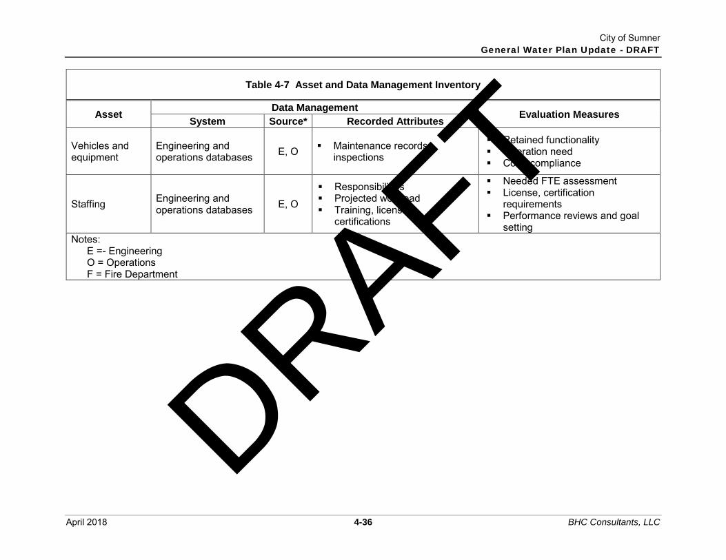
City of Sumner General Water Plan Update - DRAFT
April 2018 4-36 BHC Consultants, LLC
Table 4-7 Asset and Data Management Inventory
Asset Data Management
Evaluation Measures System Source* Recorded Attributes
Vehicles and equipment
Engineering and operations databases E, O ▪ Maintenance records,
inspections
▪ Retained functionality ▪ Operation need ▪ Code compliance
Staffing Engineering and operations databases E, O
▪ Responsibilities ▪ Projected workload ▪ Training, licensing,
certifications
▪ Needed FTE assessment ▪ License, certification
requirements ▪ Performance reviews and goal
setting Notes:
E =- Engineering O = Operations F = Fire Department
DRAFT

City of Sumner General Water Plan Update - DRAFT
April 2018 5-1 BHC Consultants, LLC
Chapter 5 Water Resources This chapter provides information on the City’s water resources, including an evaluation of the adequacy of current source and storage and projected requirements for new source and storage based on future water demands. Additionally, water rights, an updated Water Use Efficiency (WUE) program, water reclamation, and source sanitary control programs are summarized.
5.1 Source Evaluation Since the 2009 WSP, the City of Sumner has spent considerable effort to develop an additional well source, the Central Well. With recent peak demand seasons progressively taxing the production capabilities of Sumner’s sources of supply; the Central Well currently provides an additional point of withdrawal for existing groundwater rights shared by the South and West Wells. Operation of the Central Well allows Sumner to achieve needed instantaneous production levels allowable under the existing rights. The Central Well is anticipated to ultimately expand system production capabilities to meet future demands upon the approval of a pending application for additional water rights. Based on groundwater modeling and evaluation of the potential impacts to rivers within the Puyallup basin from withdrawals that include these three wells, Sumner received a temporary approval from the Department of Ecology (DOE) in June 2017 to utilize the Central Well as a primary groundwater source of supply during the summer peak demand season. The combined average and instantaneous withdrawals of the South, Central, and West sources under the temporary approval are still restricted to the existing rights granted for the South and West Wells, and the Central Well use must adhere to an agreed upon use pattern during off-peak months. DOE’s June 23, 2017 letter approving a temporary water right for the Central, with conditions, is attached in Appendix F. Existing and future source capacities are presented in Table 5-1. WAC 246-290-222 requires that source capacity is sufficient to provide water equal to or exceeding the MDD, which is calculated in Chapter 3 and summarized as Table 5-2. Existing source capabilities are evaluated based on the authorized production rates of the South, Central, and West wells during peak demand season under the DOE temporary approval, in addition to Dieringer Well and springs source capacities. Due to the curtailed use of the South, Central, and West wells under the temporary approval, existing source capacity during off-peak months (October through June) is also compared with the ADD anticipated during these periods of the year. This chapter will evaluate the capacity of the system under the following four scenarios: Scenario A: Current capacity of the existing sources operating within the water rights
presently allocated to the City. Scenario B: Current capacity of the existing sources operating within the existing water
rights with the addition of water rights for the Central Well. Scenario C: Existing sources and water rights as identified in Scenario B with the
addition of the full buildout of the Central Well to the ultimate instantaneous production rate.
Scenario D: All existing sources expanded to fully utilize existing water rights and the requested water rights for the Central Well.
DRAFT

City of Sumner General Water Plan Update - DRAFT
April 2018 5-2 BHC Consultants, LLC
For the Scenarios B, C and D, it is assumed that the City will gain approval of a pending water rights application to increase the cumulative instantaneous withdrawal from the South, Central, and West Wells from 1,250 gpm (1.8 mgd) to 2,250 gpm (3.24 mgd), and to increase the total annual quantity of water rights from 2,882.25 acre-feet/year to 4,462.25 acre-feet/year. City intent for these sources in the future is to increase use of the Central Well to its designed ultimate production and treatment capacity of 3.02 mgd, use the South Well as needed up to allowable instantaneous withdrawal rights, and reserve the West Well for the supply of irrigation water at the City Cemetary. In Scenario A, the South Well production rate is discounted to reflect operation only when the Central Well is not in use.
Table 5-1 Instantaneous Source Analysis
Source
Scenario A Scenario B Scenario C Scenario D
Existing Water Rights (Peak)
Existing Water Rights
(Off-Peak)
Existing Water Rights with
Current Central Well Rights
Existing Water Rights with Central
Well Buildout
Fully Utilized Water Rights
Sumner Springs Capacity (mgd) 1.37 1.37 1.37 1.37 4.01
County Springs Capacity (mgd) 0.94 0.94 0.94 0.94 1.15
Elhi Springs Capacity (mgd) 0.13 0.13 0.13 0.13 0.52
Weber Springs (mgd) 0.00 0.00 0.00 0.00 0.29
South Well Capacity (mgd) 0.00 1.01 1.01 1.01 1.44
Dieringer Well Capacity (mgd) 0.14 0.14 0.14 0.14 0.14
West Well Capacity (mgd) 0.00 0.00 0.36 0.36 0.36
Central Well Capacity (mgd) 1.51 0.16 1.51 3.02 3.02
Total Source Capacity (mgd) 4.09 3.75 5.46 6.97 10.93
The total source capacities shown for each scenario in Table 5-1 are different that the total operational capacity of the City’s sources. The operational capacities will be used for the source of supply analyses in this Chapter; assumptions are summarized as follows: Use of the West Well and Ehli Springs is discounted due to the water quality issues
which cause them to typically be off-line under normal operating circumstances. The operational capacity of Sumner Springs is 1.15 mgd. The operational capacity of County Springs is 0.79 mgd.
DRAFT

City of Sumner General Water Plan Update - DRAFT
April 2018 5-3 BHC Consultants, LLC
Under peak Scenario A, the City will operate the Central Well at capacity in order to not exceed the combined 1.8 mgd allowed between the West, Central, and South Wells during peak months under the temporary water authorization (see Appendix F).
Under off-peak Scenario A, the City will operate the Central Well at capacity as needed, but limit its use to not exceed the 0.47 mgd allowed between the West, Central, and South Wells during off-peak months under the temporary water authorization (see Appendix F). As a result, the full 1.51 mgd instantaneous capacity of the Central Well is counted towards the total operational capacity of off-peak Scenario A.
Table 5-2 Source Capacity Analysis by Scenario
Year Projected
MDD (mgd)
Projected Off-Peak
MDD (mgd)
Projected Residential and
Commercial ERU’s(2)
Source Capacity Surplus (Deficiency) by Scenario (mgd)
A (Peak)
A (Off-
Peak) B C D
3.59 3.59 4.60 6.11 6.11 2018 3.36 2.16 6,353 0.23 0.23 1.24 2.75 2.75 2024 3.52 2.21 6,798 0.07 0.07 1.08 2.59 2.59 2028 3.64 2.27 7,045 -0.05 -0.05 0.96 2.47 2.47 2038 3.89 2.43 7,578 -0.30 -0.30 0.71 2.22 2.22
2068(1) 4.76 2.97 9,439 -1.17 -1.17 -0.16 1.35 1.35 Notes:
1) 2068 MDD projection developed by the City and used for ongoing water rights negotiations with local agencies.
2) Residential and commercial ERU’s were calculated by dividing the projected population for each planning year as shown in Chatper 3 by the population per ERU value of 2.75 residents per ERU and 7.69 employees per ERU, respectively. These values are 3-year averages from 2015 to 2017.
Subtracting instantaneous source capacity from projected MDD yields source surplus/deficiency for each planning year. The current source capacity provides an approximate surplus of 0.23 mgd during 2018 MDD conditions, but would result in a 0.30 mgd deficiency at the 20-year planning horizon year 2038. Under the current water rights, the operational source capacity will become deficient before 2028. The source deficiency shown at the 50-year planning horizon, a common milestone to consider when negotiating and attempting to secure sufficient long-term source water rights, provides justification for Sumner’s additional water requests under Scenarios B, C and D. In addition to meeting WAC requirements of supplying MDD, Chapter 5 of the DOH WSDM provides reliability recommendations for sources of supply in a water system that might result in a more dependable and adequate water supply, includes meeting the following criteria: Sources can replenish depleted fire suppression storage within 72 hours while supplying
MDD. Source capacity is capable of meeting MDD within 18-hour period. Sources can provide ADD with largest source out of service.
DRAFT

City of Sumner General Water Plan Update - DRAFT
April 2018 5-4 BHC Consultants, LLC
The City’s sources are evaluated under these criteria in Table 5-3 through Table 5-5.
Table 5-3 Source Analysis Replenish FSS in 72 Hours with MDD
Scenario A
(Peak) A
(Off-Peak) B C D
Total Operational Supply (mgd) 3.59 3.59 4.60 5.10 5.10
FSS Replenish Demand(1) (mgd) 0.36 0.36 0.36 0.36 0.36
Allowable MDD(2) (mgd) 3.23 3.23 4.24 5.75 5.75
Planning Year that the allowable MDD would be exceeded <2018 <2018 2050 >2068 >2068
Projected Residential and Employment ERU’s at Planning Year 6,104 6,104 8,416 11,419 11,419
Notes: 1) FSS replenish demand calculated using largest required fire flow of 4,500 gpm for 4
hours, or 1,080,000 gallons divided by 3 days (72 hours). 2) Allowable MDD is equal to the total operational supply capacity minus the FSS
replenish demand.
Table 5-4 Source Analysis Meet MDD with 18 Hours of Pumping
Scenario A
(Peak) A
(Off-Peak) B C D
Total Operational Supply with 18 Hours of Pumping (mgd)(1) 3.52(2) 3.52(2) 4.02(3) 5.16(3) 5.16(3)
Allowable MDD (mgd) 3.52 3.52 4.02 5.16 5.16
Planning Year that the Allowable MDD would be Exceeded 2024 2024 2043 >2068 >2068
Projected Residential and Employment ERU’s at Planning Year.
6,798 6,798 7,991 10,243 10,243
Notes: 1) Assumes all pumped well sources operate for 18 hours, springs sources maintain 24
hour production due to gravity feed to the system. 2) The South and West Wells are assumed to be operational for the 6 hours per day that
the Central Well is not operational. 3) The West Well is assumed to be operational for the 6 hours per day that the Central
and South Wells are not operational.
DRAFT

City of Sumner General Water Plan Update - DRAFT
April 2018 5-5 BHC Consultants, LLC
Table 5-5 Source Analysis Meet ADD with Largest Source Offline
Scenario A – Peak
Scenario B – Off Peak
Scenario B
Scenario C
Scenario D
Supply Without Largest Source(1) (mgd) 3.45 3.45 3.45 3.45 3.45
Allowable ADD (mgd) 3.45 3.45 3.45 3.45 3.45
Projected Planning Year that the MDD is exceeded. >2068 >2068 >2068 >2068 >2068
Estimated Residential and Employement ERU’s at Projected Planning Year
13,316 13,316 13,316 13,316 13,316
Notes: 1) Assumes the Central Well is out of service, but the South and West Wells would be
operated at their production capacities of 700 and 250 gpm. With the addition of the full source capacity of the Central Well under Scenario B, the City’s sources meet the DOH reliability recommendations for the 20-year planning period. Until that point, evaluation of reliability criteria suggests that the City would have difficulty replenishing storage volume associated with an occurrence of the highest rated fire during summer MDD conditions. Failure to obtain the increased water rights of 2,250 gpm for the Central/South/West Wells results in a current source of supply deficiency of 0.66 mgd (458 gpm) additional water supply to resolve through 2038. In the short term, improvements to the South Well could allow the City to more effectively produce the 1,250 gpm capacity of existing water rights on a reliable operational basis. However, if it appears that the increase in those water rights to 2,250 gpm might be imperiled, a combination of improvements to interties and the springs sources will become necessary to meet the demands of the 20-year planning horizon without the addition of new sources.
5.2 Storage Evaluation According to the DOH WSDM, the following five components shall be considered in sizing required storage volume for a public water system: Operational storage (OS); Equalizing storage (ES); Standby storage (SB); Fire suppression storage (FSS); and Dead storage (DS), if any.
The tank located in the Sumner Viewpoint development is fed by a pump house located at the South Tank and operates at a higher hydraulic grade than the rest of the system. Because this tank functions on a higher grade line and serves the Sumner Viewpoint development (which includes a relatively small number of residential connections), its volume is not included in the total storage capacity calculations of the main system. A separate storage analysis was done for the Sumner Viewpoint pressure zone.
DRAFT

City of Sumner General Water Plan Update - DRAFT
April 2018 5-6 BHC Consultants, LLC
Operational Storage (OS) Per the 2009 WSDM: “OS is the volume of the reservoir devoted to supplying the water system while, under normal operating conditions, the sources of supply are in “off” status (WAC 246-290-010). This volume will vary according to two main factors:
1. The sensitivity of the water level sensors controlling the source pumps. 2. The configuration of the tank designed to provide the volume required to prevent
excessive cycling (starting and stopping) of the pump motor(s). OS is in addition to the other storage components. When the reservoir is full, OS provides a safety factor beyond that provided by the ES, SB, and FSS.” The City of Sumner Water System utilizes spring sources that in normal operation have constant bypass. This means that the reservoirs are constantly being filled to overflow. When the reservoir is full, the excess flow is diverted to the spring bypass; therefore, the City of Sumner’s main pressure zone tanks do not have measurable operational storage (OS) requirements. The Viewpoint BPS supply to the Viewpoint tank is called on when the water level drops four feet below full. Therefore, the Viewpoint tank has an OS equivalent to four feet of tank depth.
Equalizing Storage (ES) Equalizing storage (ES) is used to help meet demand requirements during peak hours of the day. Peak hours often demand water at a rate faster than the source can provide, so equalizing storage is called upon to make up the difference during those hours. Later, the source can catch up and replenish this storage when demand is low. The total water produced by the source during a day should equal total demand for that day. ES acts as a buffer and helps balance the demand on the source. When figuring the necessary ES for a water system, several factors must be considered: peak system demand, diurnal variations in the system demand, the production rate of the source facility, and how the production facility operates (i.e., continuous production or production during daily shifts). ES must provide adequate volume to meet the periodic hourly peak demands and allow the supply facility a reasonable amount of time to supply total daily demand. A recommended equation for determining equalizing storage, as provided by DOH, is as follows:
ES = (PHD - Qs)*(150 min.), but in no case less than zero Where: ES = Equalizing storage component, in gallons PHD = Peak hourly demand, in gpm, as defined earlier Qs = Sum of all installed and active supply source capacities except emergency
supply, in gpm.
DRAFT

City of Sumner General Water Plan Update - DRAFT
April 2018 5-7 BHC Consultants, LLC
Standby Storage (SB) Standby storage (SB) refers to an emergency or reserve storage supply. The DOH Sizing Guidelines for SB are based upon the maximum-day demand, the duration of a possible emergency, the supply capacity to the system, and the number of connections in the water system. This supply of water shall be available to all connections with a minimum pressure of 20 psi. The recommended equation for determining standby storage is as follows:
SBTSS = (2 days)(ADD)(N) – tm (Qs – QL) Where: SBTSS = Total standby storage for a single source water system, in gallons ADD = Average day demand for the design year, in gpd/ERU N = Number of ERUs Qs = Sum of all installed continuously available source of supply capacities, except
emergency sources, in gpm. QL = The largest capacity source available to the system, in gpm. tm = Time that remaining sources are pumped on the day when the largest source is
not available, in minutes (generally assumed to be 1,440 minutes). SB is used to provide water service during an emergency occurring somewhere within the water system. Such an emergency could be a pump going out, an interruption in the water supply, fire flow, a critical valve or pipeline going out of service somewhere in the distribution system, etc. DOH also recommends that standby storage should not be less than 200 gpd/ERU. This value will be used to calculate a separate standby storage volume that will be included in the storage analyses in Table 5-6 and Table 5-7.
Fire Suppression Storage (FSS) Per the 2009 WSDM: “The local fire protection authority or county fire marshal determines a fire flow requirement for water systems. This fire suppression storage (FSS) level depends on the maximum flow rate and duration. Water systems must build and maintain facilities, including storage reservoirs, capable of meeting fire flow requirements while maintaining 20 psi pressure throughout the distribution system (WAC 246-290-221(5)). Water systems in areas governed under the Public Water System Coordination Act of 1977 (chapter 70.116 RCW), must meet the minimum flow rates and durations for residential, commercial, and industrial developments specified in the Water System Coordination Act (see Section 10.1) (WAC 246-293-640). The local fire protection authority, county fire marshal, or a locally adopted coordinated water system plan, may specify greater FSS requirements.”
DRAFT

City of Sumner General Water Plan Update - DRAFT
April 2018 5-8 BHC Consultants, LLC
The following equation expresses the required FSS:
FSS = (FF)(tm) Where: FF = Required fire flow rate, expressed in gpm, as specified by the fire protection
authority or the Coordination Act, whichever is greater tm = Duration of FF rate, expressed in minutes, as specified by fire protection
authority or the Coordination Act, whichever is greater The SB or the FSS storage components, whichever volume is smaller, can be excluded from the total storage requirement of a water system per WAC 246-290-235(4) provided that such practice is not prohibited by:
1. A locally developed and adopted Coordinated System Plan 2. Local ordinance 3. The local fire protection authority or County Fire Marshal
This prevents unused water stagnating in oversized tanks. Calculations for FSS are shown below. The FSS is based on the largest required fire flow rate and duration within each pressure zone of the City’s service area. Sumner:
FSS = (4,500 gpm)*(4 hours)*(60 min/hr) FSS = 1.08 Million Gallons
Sumner Viewpoint: FSS = (1,000 gpm)*(1 hour)*(60 min/hr) FSS = 0.06 Million Gallons
Dead Storage (DS) Per the 2009 WSDM: “Dead storage (DS) is the volume of stored water not available to all consumers at the minimum design pressure (WAC 246-290-230(5) and (6)). The reservoir- and water system-capacity analysis should clearly identify the DS volume.” DS (effective only to provide adequate pressure) is the volume of stored water not available to all consumers at the minimum system design pressure. DS volume is excluded from the volumes provided to meet operational, equalizing, and fire suppression storage requirements. The City of Sumner’s main pressure zone is served at a hydraulic grade line of 234 feet. The minimum system pressures within the system are normally at 50 psi. The height of the reservoirs varies, but is approximately 25 feet. A pressure drop of 11 psi (25 feet) results in minimum system pressure of 38 psi, which is above the minimum allowed pressure. Therefore, a majority of the system does not include dead storage.
DRAFT

City of Sumner General Water Plan Update - DRAFT
April 2018 5-9 BHC Consultants, LLC
The highest service elevation in the second pressure zone, served exclusively by the Sumner Viewpoint tank, is at approximately 298 feet. A hydraulic grade line of 344 feet is required to provide 20 psi residual pressure during a fire flow scenario at this service; this results in approximately 34.2 feet or 136,000 gallons of dead storage.
Storage Summary The City’s excess reservoir capacity serves as storage for peak-hour demands. Based on the required storage calculations, the City had an existing excess storage capacity of 3.509 million gallons and will have an estimated excess of 2.96 million gallons in year 2038, assuming that no improvements are made to existing sources and no additional sources are acquired to improve instantaneous system capacity. It was estimated that the Viewpoint pressure zone has an existing excess of 0.105 million gallons of storage and will have an excess of 0.112 million gallons. From an operational standpoint, however, there is a greater surplus, as some FSS volume would be supplied from the 234 pressure zone, due to the booster pumps in the Viewpoint BPS contributing a flow rate greater than the Viewpoint zone’s MDD when they are on. A summary of the storage analysis for the City’s main system and the Viewpoint pressure zone is provided as Table 5-6 and Table 5-7, respectively.
Table 5-6 Sumner 234 Zone Storage Analysis
Existing 2018 2024 2028 2038
Average Day Demand (mgd) 1.699 1.746 1.784 1.840 1.961Max Day Demand (mgd) 2.976 3.299 3.461 3.580 3.816Operational Storage (MG) 0.000 0.000 0.000 0.000 0.000Equalizing Storage (MG) (1) 0.125 0.170 0.097 0.000 0.000Fire Suppression Storage (MG) 1.080 1.080 1.080 1.080 1.080Standby Storage (MG) (1) 1.209 1.414 0.482 0.000 0.000Standby Storage (MG) (2) 1.435 1.877 1.918 1.978 2.108Total Required Storage (MG) (3) 1.559 2.046 2.015 1.978 2.108Total Available Storage (MG) 5.068 5.068 5.068 5.068 5.068(Deficit) or Surplus Storage (MG) 3.509 3.022 3.053 3.090 2.960Notes:
1) Calculated standby storage using Equation 9-3 from the 2009 WSDM. The capacity of sources of supply were assumed to increase in 2024 for equalizing and storage calculations, consistent with receiving additional groundwater rights.
2) Calculated standby storage using DOH recommended value of 200 gal/ERU. 3) Fire Suppression Storage and Standby Storage assumed to be nested for all years.
The largest value resulting from the two calculated methodologies was used for the Standby Storage component.
DRAFT

City of Sumner General Water Plan Update - DRAFT
April 2018 5-10 BHC Consultants, LLC
Table 5-7 Sumner Viewpoint 392 Zone Storage Analysis
Existing 2018 2024 2028 2038
Average Day Demand (mgd) 0.020 0.028 0.027 0.028 0.033Max Day Demand (mgd) 0.035 0.063 0.060 0.061 0.071Operational Storage (MG) 0.016 0.016 0.016 0.016 0.016Equalizing Storage (MG) (1) 0.013 0.000 0.000 0.000 0.000Fire Suppression Storage (MG) 0.060 0.060 0.060 0.060 0.060Standby Storage (MG) (1) 0.037 0.056 0.055 0.057 0.066Standby Storage (MG) (2) 0.010 0.017 0.017 0.017 0.020Dead Storage (MG) 0.136 0.136 0.136 0.136 0.136Total Required Storage (MG) (3) 0.225 0.212 0.212 0.212 0.218Total Available Storage (MG) 0.330 0.330 0.330 0.330 0.330(Deficit) or Surplus Storage (MG) 0.105 0.118 0.118 0.118 0.112
Notes: 1) Calculated standby storage using Equation 9-3 from the 2009 WSDM. The capacity of
sources of supply were assumed to increase in 2024 for equalizing and storage calculations, consistent with receiving additional groundwater rights.
2) Calculated standby storage using DOH recommended value of 200 gal/ERU. 3) Fire Suppression Storage and Standby Storage assumed to be nested for all years.
The largest value resulting from the two calculated methodologies was used for the Standby Storage component.
The City has a projected storage surplus of 2.96 MG and 0.112 MG through 2038 in the main system and Viewpoint pressure zone, respectively. The DOH WSDM also provides the following recommendations for distribution storage reliability: More than one gravity storage tank exists and can be isolated without interruption to
service. Storage can meet standby capacity of at least two times the ADD while ensuring that fire
suppression service will be available at 20 psi minimum residual pressure. A minimum of 200 gpd per residential connection of standby volume is provided. An alarm system notifies operators of overflows or when storage drops below equalizing
storage volume. The Sumner water system has more than one gravity storage tank, and all can be isolated without interruption to service. Alarm systems are installed at each reservoir and notify operators of overflow scenarios or when equalizing storage is depleted. The remaining criteria are evaluated and summarized as Table 5-8 through Table 5-11. Sumner has adequate storage capacity to meet all criteria for the 20-year planning horizon. The storage components within the City’s tanks are illustrated in Figure 5-1 and Figure 5-2.
DRAFT

City of Sumner General Water Plan Update - DRAFT
April 2018 5-11 BHC Consultants, LLC
Table 5-8 234 Zone Storage Analysis – Provide FSS plus Two Times ADD
Existing 2018 2024 2028 2038
Two Times ADD (MG) 3.398 3.492 3.568 3.680 3.922FSS (MG) 1.080 1.080 1.080 1.080 1.080Total Recommended Storage (MG) 4.478 4.572 4.648 4.760 5.002Total Available Storage (MG) 5.068 5.068 5.068 5.068 5.068(Deficit) or Surplus Storage (MG) 0.590 0.496 0.420 0.308 0.066
Table 5-9 392 Zone Storage Analysis – Provide FSS plus Two Times ADD
Existing 2018 2024 2028 2038
Two Times ADD (MG) 0.040 0.056 0.055 0.057 0.066FSS (MG) 0.060 0.060 0.060 0.060 0.060Total Recommended Storage (MG) 0.100 0.116 0.115 0.117 0.126Total Available Storage (MG) 0.330 0.330 0.330 0.330 0.330(Deficit) or Surplus Storage (MG) 0.230 0.214 0.215 0.213 0.204
Table 5-10 234 Zone Storage Analysis – Provide 200 gpd/ERU of SB
Existing 2018 2024 2028 2038
ERUs 8666 9095 9589 9888 10539Total Required SB (MG) 1.733 1.819 1.918 1.978 2.108Total Available SB(1) (MG) 3.863 3.818 3.891 3.988 3.988(Deficit) or Surplus Storage (MG) 2.130 1.999 1.973 2.010 1.880 Notes:
1) Available SB volume is calculated as the total available storage minus operational, equalizing, fire and dead storage components. Nesting of fire and standby allows additional surplus.
DRAFT

City of Sumner General Water Plan Update - DRAFT
April 2018 5-12 BHC Consultants, LLC
Table 5-11 392 Zone Storage Analysis – Provide 200 gpd/ERU of SB
Existing 2018 2024 2028 2038
ERUs 108 145 143 147 172Total Required SB (MG) 0.022 0.029 0.029 0.029 0.034Total Available SB(1) (MG) 0.105 0.118 0.118 0.118 0.118(Deficit) or Surplus Storage (MG) 0.084 0.089 0.090 0.089 0.084Notes:
1) Available SB volume is calculated as the total available stroage minus operational, equalizing, fire and dead storage components. Nesting of fire and standby allows additional surplus.
DRAFT

207.0'
SOUTH TANK
2.0 MG
202.0'
223.3'
233.4'
Overflow El 234.0'
FSS/SB
ES
COUNTY TANK
0.068 MG
223.3'
233.4'
Overflow El 234.0'
FSS/SB
ES
208.0'
SPRINGS TANK
1.0 MG
223.3'
233.4'
Overflow El 234.0'
FSS/SB
ES
210.0'
NORTH TANK
2.0 MG
223.3'
233.4'
Overflow El 234.0'
FSS/SB
ES
NOTES:
1. THERE IS NO OPERATING STORAGE SINCE THE
TANKS ARE SUPPLIED BY SPRINGS AND ARE
CONSTANTLY FILLED TO OVERFLOW.
LEGEND
OS = Operational Storage
ES = Equalizing Storage
FSS = Fire Suppression Storage
SB = Standby Storage
Sumner 234 Zone
Water Storage FacilitiesSumner Water System Plan 5-1
Figure
COPYRIGHT © 2018 BHC CONSULTANTS, LLC. ALL RIGHTS RESERVED
Pa
th:
S:\
Ca
d\S
um
ne
r\1
7-1
05
00
Wa
ter
Syste
m P
lan
\ F
ile
na
me
: F
17
-10
50
0.0
0_
Fig
5-1
P
lot
da
te:
Ap
r 0
4,
20
18
-01
:39
:13pm
C
AD
User:
psim
on.
Xre
f F
ile
na
me: |
DRAFT

City of Sumner General Water Plan Update - DRAFT
April 2018 5-14 BHC Consultants, LLC
THIS PAGE INTENTIONALLY BLANK.
DRAFT
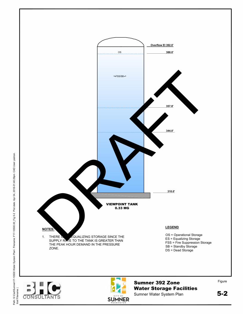
310.0'
357.8'
388.0'
Overflow El 392.0'
VIEWPOINT TANK
0.33 MG
NOTES:
1. THERE IS NO EQUALIZING STORAGE SINCE THE
SUPPLY RATE TO THE TANK IS GREATER THAN
THE PEAK HOUR DEMAND IN THE PRESSURE
ZONE.
FSS/SB
OS
DS
344.0'
Pa
th:
S:\
Ca
d\S
um
ne
r\1
7-1
05
00
Wa
ter
Syste
m P
lan
\ F
ile
na
me
: F
17
-10
50
0.0
0_
Fig
5-2
P
lot
da
te:
Ap
r 0
4,
20
18
-01
:40
:29pm
C
AD
User:
psim
on.
Xre
f F
ile
na
me: |
FigureSumner 392 Zone
Water Storage FacilitiesSumner Water System Plan
5-2
LEGEND
OS = Operational Storage
ES = Equalizing Storage
FSS = Fire Suppression Storage
SB = Standby Storage
DS = Dead Storage
DRAFT

City of Sumner General Water Plan Update - DRAFT
April 2018 5-16 BHC Consultants, LLC
THIS PAGE INTENTIONALLY BLANK.
DRAFT

City of Sumner General Water Plan Update - DRAFT
April 2018 5-17 BHC Consultants, LLC
5.3 Booster Pump Station Evaluation The DOH WSDM also includes required criteria for a booster pump station that pumps to an open system (one that has storage and a free water surface level). These criteria are summarized as follows and evaluated in Table 5-12 and Table 5-13: BPS meets the MDD for the pressure zone. BPS meets the ADD for the pressure zone with the largest pump out of service.
Table 5-12 Viewpoint BPS Analysis – Meet MDD
Existing 2018 2024 2028 2038
Viewpoint MDD (gpm) 29.7 43.5 41.9 42.2 49.3BPS Supply (gpm) 700.0 700.0 700.0 700.0 700.0(Deficit) or Surplus Supply (gpm) 670.3 656.5 658.1 657.8 650.7
Table 5-13 Viewpoint BPS Analysis – Meet ADD Without Largest Pump
Existing 2018 2024 2028 2038
Viewpoint ADD (gpm) 13.9 19.3 19.1 19.6 22.9BPS Supply Without Largest Pump (gpm) 700.0 700.0 700.0 700.0 700.0(Deficit) or Surplus Supply (gpm) 686.1 680.7 680.9 680.4 677.1
The Viewpoint BPS has two pumps that operate in a lead-lag pattern to supply the Viewpoint tank, but are redundant due to their capacity. There is not a deficit in the BPS capacity through 2038. Additionally, the WSDM recommends the following criteria are met for BPS reliability: Multiple pumps installed with capacity to provide MDD of the service area with largest
pump out of service. At least 20 psi is provided at the intake of the pumps under PHD or fire flow plus MDD
conditions. An automatic shut-off is in place for when the intake pressure drops below 10 psi. Power connections are available to two independent primary public power sources or
there is a provision for in-place auxiliary power. The Viewpoint BPS is located at an elevation of approximately 202 feet and is supplied by the South tank and main pressure zone with a hydraulic gradient of 234 feet. Thus, there is not typically 20 psi provided at the intake of the pumps. Intake pressure is monitored, and automatic shutoff is provided. There is an existing backup generator plug on site and the power must be manually transferred to the backup source. A new automatic transfer switch, control panel, and onsite backup generator are included in the recommended improvements for the BPS as summarized in Table 5-14. The Valley Crest Booster Pump Station maintained by the Valley Crest Maintenance Association was not assessed in this report since it is maintained independently from the utility.
DRAFT

City of Sumner General Water Plan Update - DRAFT
April 2018 5-18 BHC Consultants, LLC
5.4 Field Condition Assessments
5.4
Site walkthroughs and condition assessments with City engineering and operations staff were performed at each of the well, springs, and reservoir sites in August 2017. Recommended improvements for each facility are summarized as Table 5-14. Additional discussion of the recommended improvements for each facility is provided in Chapter 8.
Table 5-14 Recommended Improvements per Facility
Facility Recommended Improvements
North Tank
Replace interior ladder in tank Install PAX mixing system for added water quality while
Dieringer Well is off Install emergency generator Recalibrate existing Cla-Val on tank supply pipe to operate
as a shutoff valve for flow spikesSprings Tank Recoat exterior of tank County Tank Recoat exterior of tank
South Tank
Complete seismic retrofit of tank Install seismic valve on combined inlet/outlet pipe of tank as
part of seismic retrofit project Repaint tank exterior as part of seismic retrofit project
Viewpoint Tank Install detention pond downstream of tank drain Install seismic valve on tank outlet pipe
Dieringer Well Install ball check valve on treatment supply Install intake and outtake louvers on existing building Install surge protectors for radio jumper line
South Well
New well building including replacement of radio and controls and building structure; existing mechanical and chemical addition items to remain
Modify or replace existing metering vault for required pipe lengths upstream and downstream of magnetic flowmeter
Install VFD to allow for throttled supply rate Include flexible fitting in discharge piping between the
wellhouse and meter vault
West Well Conduct flushing and water quality testing Replace supply pipe and fittings in well house
Central Well None
Sumner Springs Install chain-link fence around perimeter of complex Install vent on weir vault to eliminate siphoning from the
Springs Tank
County Springs Install permanent generator Replace existing building gutters
Viewpoint Booster Pump Station
Purchase and store spare pump; includes cost for a VFD Install new automatic transfer switch and control panel Purchase and Install backup power generator.
DRAFT

City of Sumner General Water Plan Update - DRAFT
April 2018 5-19 BHC Consultants, LLC
5.5 Water Rights Evaluation This section provides an overview of water resources laws and regulations that relate to the City’s present and future water supplies. The section was developed for the 2009 WSP and is largely repeated here, except where updates are briefly described.
Water Rights Laws Rights to use water in Washington State are established under water rights laws and regulations administered by the Washington State Department of Ecology (Ecology). Water rights in the state of Washington are only allowed through the following legal sources: Surface water code (Chapter 90.03 RCW). Groundwater code (Chapter 90.44 RCW). Pre-Code Claims based on one of the following common law or statutory doctrines:
o Prior Appropriation; Riparian Rights. o Federal Trust (Winters Doctrine) Water Rights. o Federal Treaty Rights.
The City’s water rights derive from the surface and groundwater codes and pre-code prior appropriation claims, which are discussed briefly below.
Prior Appropriation Washington statutes and case law recognize the common law prior appropriation doctrine as a means of creating a water right based on the principal of “first in time; first in right.” Initially, anyone desiring to appropriate public water for beneficial use had to post a notice at the proposed point of diversion and record a copy of that notice with the local county auditor. Construction of the diversion facilities and putting the water to beneficial use, with due diligence, perfected the right in the amount of the beneficial use. Until such rights are confirmed by a court’s general adjudication of water rights, these rights are generally referred to as “claims to vested right.” In order to preserve the validity of a pre-code water right claim, the claim had to be filed and registered with Ecology or its predecessor water rights agency, the Department of Water Resources, during the period from July 1, 1969, through June 30, 1974, pursuant to the water right claim registration requirements of Chapter 90.14 RCW. An additional claims filing period was authorized by the legislature for September 1, 1997, to June 30, 1998, pursuant to RCW 90.14.068. Two of the City’s water sources, County Springs and Elhi Springs, have associated pre-1917 “vested rights.” The City filed claims for these rights in 1998 to protect the rights from relinquishment.
Surface Water Code (Chapter 90.03 RCW) Laws were enacted in 1917 that recognized and protected pre-existing rights, provided a process for establishing rights to surface waters after that date, and set up a three-step procedure for acquiring water rights. The procedure includes: Application: A filing must be submitted to the state (now Ecology) requesting permission
to appropriate water for beneficial use. Following a process of publication of legal notice, evaluation of protest (if any), field examination, and consulting other agencies, Ecology either approves, approves with modification, or rejects the application. To approve an application, Ecology must find: o The proposal is a “Beneficial Use” as defined in the Code. o Water is available for appropriation in the amount requested.
DRAFT

City of Sumner General Water Plan Update - DRAFT
April 2018 5-20 BHC Consultants, LLC
o The proposed use will not impair existing rights. o The proposed use will not be detrimental to the public interest, having due regard to
the highest feasible development of the use of the waters belonging to the public. Permit: Assuming approval of the application, a permit is issued. The permit is
authorization to proceed with construction of facilities and use of water consistent with the time schedule and other provisions of the permit.
Certificate: Once a project is completed and water fully utilized, the Certificate of Water Right is issued. This document is recorded with the local county auditor and in Ecology records. The right embodied in a certificate is perpetual and not subject to renewal.
Once a right is established in either of the above three categories, it is fixed in: Source. Priority. Quantity. Purpose of use. Period of use. Point of diversion. Place of use.
There is provision in the laws to change the purpose of use, place of use, and point of diversion/withdrawal. However, to make such changes, an application must be filed with Ecology and a Certificate of Change granted.
Groundwater Code (Chapter 90.44 RCW) Laws were enacted in 1945, which extended the provisions of the 1917 Surface Water Code to the appropriation and use of groundwater. There were, however, two key differences: First, withdrawals of less than 5,000 gpd were exempt from the permit requirement. Second, a 5 year period was allowed for “declaring” rights to groundwater existing prior to 1945. An application/certificate process was provided during this period. The application essentially constituted a claim of right, which, if verified by the state, was confirmed by issuing a “declaration” certificate. The application/permit/certificate process discussed above for surface water is essentially the same for groundwater. There is, however, an additional criterion Ecology must consider in acting on new applications for groundwater permit. RCW 90.44.070 provides in part that “No permit shall be granted for the development or withdrawal of public groundwaters beyond the capacity of the underground bed or formation in the given basin, district, or locality to yield such water within reasonable or feasible pumping lift in case of pumping developments, or within a reasonable or feasible reduction of pressure in the case of artesian developments…”
Primary and Supplemental Water Rights Some terminology used in water rights documents, such as “supplemental,” has created confusion and led to conflicting interpretations of water right quantities. Ecology issued program policy POL-1040 in 2006 in order to clarify terms used in water right documents and the relationship between certain water rights. As a result of POL-1040, Ecology no longer uses the term “supplemental” and clarifies that most water rights using that term are “non additive” according to the definition and example set forth below. The City currently has one water right that is identified as being partially “supplemental.” Future rights may be designated as “non-
DRAFT

City of Sumner General Water Plan Update - DRAFT
April 2018 5-21 BHC Consultants, LLC
additive.” Therefore, for general background understanding, an explanation and example of “non-additive” rights from POL-1040 is copied as follows:
Scenario 2
Staff is reviewing the Town of Turnip’s first Comprehensive Water System Plan. The Town has two water rights. Water Right G3-11111 issued in 1960 for 300 gpm and 448 ac-ft from the Town Well No. 1. In 1980, the Town received a second water right, G3-22222 for Well No. 2 for 500 gpm and 627 ac-ft from the Town Well No. 2. Certificate G3-22222C describes these quantities as supplemental to existing rights. Staff reviews the complete water right record to determine the correct terms to use. The ROE for G3-11111 describes the intent of the project as serving a population 500 people by 1980 at 800 gallons per capita day (gpcd). The ROE for G3 22222 was written in 1979 and describes 350 people living in the Town in 1979 using approximately 314 ac-ft, and the Town is planning for 700 people by the year 2000. The ROE for G3-22222 indicates that a total of 500 gpm and 627 ac-ft are needed to serve the 2000-year projection. Based on the review of the record in this case, staff concludes that the Town’s water rights should be interpreted as follows.
Water Right
Source GPM (Qi) Ac-Ft/Year (Qa)
Comment Additive
Non-Additive
Additive Non-
Additive
G3-11111 Well 1 300 448
G3-22222 Well 2 200 300 179 448 Alternate to G3-22222
Total: 500 627
The Town of Turnip is authorized to produce 500 gpm and 627 acre-feet per year from these alternate water rights. Well 1, however, contains lower Qi and Qa limitations under G3-11111 than Well 2 does under G3-22222. The system could file a change application on G3-22222 to add well 1 if additional source flexibility on Well 1 were desired (e.g. pumping Well 1 at 500 gpm instead of 300 gpm), and provided the statutory tests for change are met.” [emphasis original]
Using this example, the City of Sumner’s South Well water right, Certificate G2-23281C, would be interpreted as “additive” for 542 acre-feet and “non-additive” for 258 acre-feet because of language in the documents that states, “In no instance shall the total annual quantity withdrawn/diverted under all existing and/or claimed rights exceed 2,450 acre-feet for municipal supply.” The 2,450 acre-foot limitation was based on the South Well application’s population projection of 12,500 and a per capita demand of 175 gallons daily. The City then had rights totaling 1,908 acre-feet, so the first 542 acre-feet of Certificate G2-23281C is additive, and the balance of the 800 acre-foot allocation is non-additive. This is reflected in Table 5-15 (page 5-23). Non-additive quantities are listed separately as “NA” and not included in the total annual quantity.
DRAFT

City of Sumner General Water Plan Update - DRAFT
April 2018 5-22 BHC Consultants, LLC
Instream Flow Laws and Stream Closures The maintenance and protection of certain specified flows in rivers and streams has been provided, for the most part, by three statutes: RCW 75.20.050, which established the policy “that a flow of water sufficient to support
game fish and food fish populations be maintained at all times in the streams of the state…” The policy was carried out by conditioning permits or rejecting applications for new water rights based on recommendations from the Directors of Fisheries or Game (now Wildlife).
Minimum Water Flows and Levels Act (Chapter 90.22 RCW). Water Resources Act (Chapter 90.54).
The last two statutes establish a state policy that sufficient flows are to be retained in perennial rivers and streams to protect fish, game, wildlife, and other resources and values. Chapter 90.22 RCW refers to “minimum flows” and Chapter 90.54 RCW to “base flows.” Ecology has established “minimum instream flows” through the process of adoption of state regulations. Once minimum instream flows are established, all new permits using or impacting the same source are issued subject to these flows, and are generally referred to as “interruptible.” As a matter of law, a new appropriation cannot be exercised when instream flows are not being met, in the absence of an approved mitigation plan. Water rights established prior to establishment of instream flows are not affected. When Ecology determines that a stream has no available capacity for additional consumptive appropriations of water, it can “close” the stream, or segment thereof, to further appropriation. Stream closures in the Puyallup-White watershed were listed in the regulation described below. An application for a new groundwater appropriation in continuity with a closed stream must be denied if it would have any effect on the flow of the stream, unless that flow is mitigated.
Puyallup Watershed Regulations Chapter 173-510 WAC is the comprehensive regulation establishing instream flows and stream closures for the Puyallup River Basin, Water Resource Inventory Area (WRIA) 10. The purpose of this regulation is to retain perennial rivers, streams, and lakes in the Puyallup River Basin with instream flows and levels necessary to provide protection for wildlife, fish, scenic-aesthetic, environmental values, recreation, navigation, and to preserve high water quality standards (WAC 173 510-020). This rule established instream flow levels for the Puyallup River and the Carbon River, and listed stream closures for several streams including all tributaries of the Unnamed Stream (Strawberry Creek) and Salmon Creek, and the tributary to White River near NE 1/4 SE 1/4, Section 13, T20N, R4E. All Sumner’s source springs are tributary to these streams. The regulation affects new groundwater development, as well as changes to existing water rights in the vicinity of regulated or closed streams. WAC 173-510-050 reads in part, “In future permitting actions relating to groundwater withdrawals, particularly from shallow aquifers, a determination shall be made as to whether the proposed withdrawal will have a direct and measurable impact on stream flows in streams for which closures and instream flows have been adopted…” The courts have held that Ecology can use new technology, including computer models, when evaluating the effect of a new or changed water right on stream flow. However, Ecology has not officially interpreted how “direct and measurable effect” applies with the use of groundwater modelss, and currently takes the position that “any effect” on instream flows
DRAFT

City of Sumner General Water Plan Update - DRAFT
April 2018 5-23 BHC Consultants, LLC
requires mitigation or denial of groundwater applications. If Ecology finds that a new appropriation would affect the flow of a closed stream or impair a regulated instream flow, the application must be rejected unless there are adequate mitigation conditions to protect the instream flows or prevent effects to closed streams. In a 2015 decision of the Washington Supreme Court, Foster v. Dept. of Ecology and City of Yelm, the Court found that Ecology had no statutory authority to allow out-of-kind mitigation for “legal impacts” to instream flow water rights and interpreted the “overriding considerations of public interest” (OCPI) statute as applying only to temporary water uses. As a result, the issuance of new municipal water rights and water right changes often depends on finding year-round water rights available to purchase for mitigation in all areas of a basin that are potentially impacted by a groundwater withdrawal. Expensive storage and engineered aquifer recharge options may be needed to offset small flow impacts that may not otherwise impede the environmental functions of regulated streams, instead of allowing habitat or aquatic function mitigation for impacts to fish habitat and other aquatic values.
City of Sumner Water Rights The water rights of the City of Sumner have been reviewed by water rights attorney Thomas M. Pors. Water rights certificates and claims are provided in Appendix F. A summary of this review is shown in Table 5-15 (page 5-23). The City’s water usage appears to be within total annual authorization under existing rights of 5,511 gpm and 2,882.25 acre-feet per year for public water supply purposes. In September 2005, the City of Sumner filed an application to change its Dieringer School District water right from domestic supply to municipal, and to change the place of use to include the City’s entire water service area. Ecology investigated the history of beneficial use of this water right, and concluded that only 90 gallons per minute and 6.25 acre-feet of the right had been put to beneficial use and was eligible to be changed. The application was approved on April 12, 2006. The reduced water right quantities are reflected in Table 5-15 (page 5-23). In October 2009 the City filed application G2-30534 to increase the allowable instantaneous withdrawal rate and average annual withdrawal volume from the City’s previously permitted water rights. This application is still under DOE review, which includes ongoing analysis of potential impacts to the Puyallup Basin’s surface waters through the use of a regional groundwater flow model that is being developed by the U.S. Geological Survey. The City has acquired several mitigation assets in anticipation of forming a mitigation plan for this application to offset impacts to instream flows. In January 2018, the state enacted Engrossed Substitute Senate Bill 6091 (ESSB 6091) addressing Water Availability. ESSB 6091 created a joint legislative task force on water resource mitigation to develop and recommend a mitigation sequencing process and scoring system to address water appropriations. That bill also granted Ecology the authority to issue permit decisions for up to five water resource mitigation pilot projects utilizing a mitigation sequence contained in the text of the bill. Sumner meets the criteria for one of the pilot projects and anticipates having its central well application considered under the mitigation sequence contained in ESSB 6091.
DRAFT

City of Sumner General Water Plan Update - DRAFT
April 2018 5-24 BHC Consultants, LLC
City of Sumner Temporary Water Rights The City of Sumner submitted five applications for change of its existing water rights to the Department of Ecology in late May 2004. The intent of these change applications was to add new and existing City wells to several of the other existing water rights in order to allow more security and operational flexibility, especially in the event of a catastrophic loss of one or more water sources. Three of the applications for the City’s existing surface water rights were withdrawn after Ecology adopted a new procedural policy requiring “direct and substantial continuity” between a surface water source and aquifer as a prerequisite for any surface to groundwater change application (POL-2010, adopted February 15, 2007). The City later amended the remaining change applications to add the Central Well to the South Well and West Well water rights. Due to complications from changing legal standards and disputes regarding groundwater modelling, the City tabled consideration of the change applications until the USGS regional groundwater model is completed, and accepted a temporary water right for the Central Well until application G2-30534 is approved for permanent additional water rights. The June 23, 2017 letter is provided in Appendix F. The temporary water right allows the City to withdraw 1050 gpm from the Central Well during the peak season and 110.9 gpm during the non-peak season, with mitigation requirements described in the letter. A tabulation of the City’s current water rights is presented as Table 5-15.
DRAFT

City of Sumner General Water Plan Update - DRAFT
April 2018 5-25 BHC Consultants, LLC
Table 5-15 City of Sumner Water Rights Tabulation
Certificate Name Current Name Point of Diversiona Water Right Certificate No. Instantaneous Maximumd
Annual AFc,d Comments gpm cfsb mgd
Well Dieringer Well 20N05E-07 2151-A 95 0.21 0.14 6.25 This water right was changed to municipal supply purposes pursuant to an application that was approved in the April 12, 2006, Report of Examination. (See Appendix F).
Salmon Springs Sumner Springs 20N05E-18P and Q 7838 2,244 5.0 3.23 1,008 These two water rights relate to the combined spring area development referred to as “Sumner Springs.” Salmon Springs Sumner Springs S2-21979C 561 1.25 0.81 900
Well South Well 20N05E-30R G2-23281C 1,000 2.23 1.44 542 258 (NA)
Report of Examination identified projected need for “Area served by City of Sumner” to be 2,450 acre-feet per year for municipal supply by the year 1995. Therefore, 258 acre-feet of the authorized 800 acre-feet per year is non-additive to existing rights and is not included in totals.
Well Central Well 20N04E-24 CG2-21980 and CG2-23281
1,050 (NA) 2.34 (NA) 1.51 (NA) 560.7 (NA)
This is a temporary water right until approval of application G2-30534 for the Central Well. Values shown for instantaneous maximum and annual production are in accordance with the temporary water right’s proposed pumping regime.
Well West Well 20N04E-23P G2-21980C 250 0.56 0.36 100
This right was issued for irrigation of 50 acres (Sumner Cemetery) and has a period of use from May 1 to October 1 of each year, but is eligible for use throughout the city water system. .e
Crystal Springs Weber Springs No. 1 20N05E-19B 2266 112 0.25 0.16 181
These two certificates were issued to Weber and Ritter, Inc., and the place of use is described as the Van Tassell Garden Tracts; E 1/2 of NW 1/4; E 1/2 of SW 1/4 of Section 19, T20N, R.5E.W.M. An annual quantity was not identified on either right and is assumed to be based on continuous usage at the maximum instantaneous quantity. The annual quantity is considered “additive” and is included in the total because the service area and connections in the Weber and Ritter system were not considered in Ecology’s review of future water right demand in the ROE for G2-23281C.
Unnamed Springs Weber Springs No. 2 20N05E-19B 2267 90 0.20 0.13 145
These two certificates were issued to Weber and Ritter, Inc., and the place of use is described as the Van Tassell Garden Tracts; E 1/2 of NW 1/4; E 1/2 of SW 1/4 of Section 19, T20N, R.5E.W.M. An annual quantity was not identified on either right. The annual quantity is considered “additive” and is included in the total because the service area and connections in the Weber and Ritter system were not considered in Ecology’s review of future water right demand in the ROE for G2-23281C.
Elhi Springs Elhi Springs 20N05E-29L S2-300571CL 360 0.80 0.52 100(NA)
Water Right Claim. The annual quantity of these claims is not included in the total because of language in Ecology’s ROE for the South Well water right, which limited the City’s total annual quantity to 2,450 acre-feet “including claims to vested rights.”
DRAFT

City of Sumner General Water Plan Update - DRAFT
April 2018 5-26 BHC Consultants, LLC
Table 5-15 City of Sumner Water Rights Tabulation
Certificate Name Current Name Point of Diversiona Water Right Certificate No. Instantaneous Maximumd
Annual AFc,d Comments gpm cfsb mgd
County Springs County Springs 20N05E-19B S2-300572CL 799 1.78 1.15 675(NA)
Water Right Claim. The annual quantity of these claims is not included in the total because of language in Ecology’s ROE for the South Well water right, which limited the City’s total annual quantity to 2,450 acre-feet “including claims to vested rights.”
Totals 5,511 12.28 7.94 2,882.25 Notes:
a. The location of the point of diversion is given by township, range, section, and 40-acre tract (e.g., NW 1/4 SW 1/4) within the section. For example, in the location, 20N05E-30R, the part preceding the hyphen indicates Township 20 North, Range 5 East Willamette Meridian. The number following the hyphen indicates the section (30) and the letter (R) gives the 40-acre tract within the section as shown in the schematic on the right
b. cfs = cubic feet per second. c. AF = acre-feet. d. Total instantaneous maximum shown includes a combined 1,250 gpm for the Central, West, and South Wells as allowed under the current
temporary water right. Current operational constraints may limit total instantaneous maximum shown. An (NA) following acre-feet/year means the right is non-additive to prior existing right to that extent; therefore, the quantity is not included in the annual AF total.
e. This water right meets the definition of “municipal water supply purposes” in RCW 90.03.015(4), and is eligible for use as a municipal supply throughout the Sumner water service area.
D C B A E F G H M L K J N P Q R
(e.g., R is the SE 1/4 of the SE 1/4 of section.)
DRAFT

City of Sumner General Water Plan Update - DRAFT
April 2018 5-27 BHC Consultants, LLC
5.6 Water Use Efficiency (WUE) Program The Municipal Water Law was passed in the 2003 legislative session. It requires municipal water suppliers to more efficiently use their water supplies. The WUE rules required by the municipal water law are being implemented by DOH and DOE. The water use efficiency rules establish: Planning requirements for WUE programs for municipal water suppliers. A distribution system leakage (DSL) standard. Requirements and processes for water use efficiency goal setting. Requirements for water use efficiency annual performance reporting.
Sumner first developed WUE goals and measures in 2008. These initial WUE program elements were focused on the reduction of single family residential use through public education and retrofit opportunities, as well as the commencement of efforts to identify and correct sources of unaccounted for use. The goals and measures were replaced with the adoption of a complete WUE program included within the City’s WSP update in 2009. The program’s goals expanded desired average residential and ERU demand reduction, as well as adopted the state DSL standard of achieving a 3-year running average below 10 percent. Several discretionary and required WUE measures, including enhanced billing history information, introduction of conservation rate structures, and comprehensive supply and demand side metering, were added to maintain compliance with state requirements. Sumner has been submitting annual performance reports to DOH since the 2009 WUE program was adopted. Concurrent with the development of this plan, the City has recently updated its WUE program to both assess the effectiveness of measures implemented to date, as well as establish a new WUE goal and associated measures through the required public process. These efforts were formalized through a series of City Council utility committee and general public meetings. The new WUE program was adopted by City Council on May 1, 2017, and is included in its entirety as Appendix C. Highlights of plan include: Adoption of a singular goal to meet the 3-year running average DSL standard of 10
percent or less by 2025. Continuance of the discretionary and required WUE measures that were adopted with
the 2009 plan, as they have largely resulted in reduced and efficient customer use that has fulfilled past goals on a cost-effective basis.
A water loss control action plan (WLCAP) that details demand side actions to eliminate potential unauthorized connections associated with two commercial/industrial properties and to reduce unauthorized withdrawals from City fire hydrants.
WLCAP supply side actions that include upgrades to the City’s instrumentation and telemetry system (which ultimately is used to quantify water production totals) and funding of a water main replacement program that will target suspected leaking mains. The suspected mains have been identified through continuing leak detection surveys performed for the City.
The contents of this 2017 WUE program serve to meet the recently updated third addition of the DOH Water Use Efficiency Guidebook, published in January 2017.
DRAFT

City of Sumner General Water Plan Update - DRAFT
April 2018 5-28 BHC Consultants, LLC
5.7 Water Reclamation Per RCW 90.46.120, public water systems serving 1,000 or more connections must evaluate opportunities for reclaimed water “when it is available or proposed for use under a water supply or wastewater plan”. Expansion and improvements to the Sumner wastewater treatment plant (WWTP) were recently completed to provide capacity for the City of Sumner through a projected year 2043. A further facility expansion to accommodate growth within the City of Bonney Lake, which also discharges the entirety of its sewer collection system to this location for treatment, is likely to occur. Master planning for the WWTP continues to include provisional space to allow construction of a future effluent filtration process that would serve as the first step in enabling the production of reclaimed water. This construction would need to be accompanied by a UV disinfection system upgrade to produce the highest quality of reclaimed water defined by the state (Class A), which coincides with the largest range of potential permissible beneficial uses. WWTP planning documents have discussed an initial reclaimed water production capacity of 1.5 mgd and an ultimate potential capacity of 3.0 mgd. There are no near-term plans to proceed with WWTP upgrades to produce reclaimed water, which would offset potable water demand used for purposes such as irrigation, industrial process water, or local WWTP maintenance. When comparing the cost to construct the additional WWTP facilities and an associated conveyance system to potential end users, the potential water resource and revenue benefits remain low from an invested cost/benefit perspective. However, a summary description of a few previously identified potential uses is offered in the ensuing paragraphs. The 50 acre cemetery site has a water right for 100 acre-feet of annual consumption for irrigation of the cemetery property. The West Well presently primarily serves the cemetery. This water right could be better used for general municipal use. With the construction of approximately 9,300 feet of 4-inch force main from the WWTP to the cemetery, the cemetery may be irrigated with reclaimed water. The development of directional boring has made this a potentially feasible scenario. A 4-inch high-density polyethylene line may be bored under the rivers and SR 167 in a fairly direct line to the cemetery. An identified potential use for reclaimed water identified in the 2009 WSP was the City golf course on the east side of the White (Stuck) River south of Stewart Road. The golf course is no longer operational and there are plans for redevelopment of the property to light industry, similar to surrounding businesses, by private owners. Although there may be several opportunities to consider reclaimed water use by the City’s current industrial businesses located in this north end area (including those that historically have been the largest water consumers), industrial process water can often have other water quality requirements not typically met through treatment to Class A standards. A conveyance system in excess of two miles, through some of the City’s busiest and most utility-laden rights-of-way, would also be required to reach the industries closest to the WWTP. Potential reclaimed water uses in proximity to the WWTP, which would minimize the costs associated with conveyance, might include in-plant uses such as washdown and supplemental chemical system supply water. Adjacent City-owned property to the southeast of the WWTP might also offer field, park and right-of-way median irrigation opportunities.
DRAFT

City of Sumner General Water Plan Update - DRAFT
April 2018 5-29 BHC Consultants, LLC
The reclaimed water projects described above have not been studied in any further detail than described.It is unlikely that reclaimed water will be available to the City before the next WSP update is performed, at which time it could be reconsidered..
5.8 Minimum Sanitary Control Area Survey Per WAC 246-290-135, a minimum sanitary control area, defined as 200 feet and 100 feet radiuses for springs and well sources, respectively, must be maintained to prevent introduction of potential contamination sources. Land activity within these areas is legally restricted by the City, who must have a protection program and conduct periodic evaluation activities. A sanitary survey was conducted by DOH with Sumner water operations staff in the summer of 2016 to observe source control. A copy of the Water System Sanitary Survey Report is included in Appendix G.
Sumner, Weber, and County Springs Collection, transmission, treatment, and storage works at the Sumner, Weber, and County Springs are in good condition and protect the spring sources from normal routes of exposure to contamination. Facility features implemented to help prevent contamination include: Waterproofing of lids on all tap boxes and diversion box lids. Routing surface drainage around collection works. Filter fabric installation near spring taps. Slip lining leaking pipes. The recent DOH sanitary survey report noted the need to add fine mesh screen to vent
piping on spring boxes and site reservoirs. The City has since addressed this by ….. Poor drainage and development uphill of the springs poses a potential problem of increased volumes of runoff, which could potentially aggravate the occurrences of mass wasting and slope failures above the spring taps. Surface water diversion will help reduce this potential, but some bank stabilization may also be needed. If uphill conditions are observed to degrade, the City will consider a geologic investigation to determine slope stability near the Sumner, Weber, and County Springs, and that appropriate measures be taken to reduce the likelihood of bank failure.
Elhi Springs Elhi Springs was last upgraded in 2003, during which the existing holding tank was converted into a treatment building with an entryway and stairs installed on the east side of the tank to allow access. A chlorine-injection system, including chlorine contact chambers and a chlorine-residual monitor, was installed in the retrofitted holding tank. The existing collection facilities are in good condition, but the source is seldom used for potable water production because of the high chlorine dosage needed to meet disinfection requirements before reaching the first customer. When used, customer complaints typically occur. As noted in the recent DOH sanitary survey report, a surge pipe vent in the old reservoir building lacked screening. The City has since addressed this by installing a screen on the surge pipe vent.
DRAFT

City of Sumner General Water Plan Update - DRAFT
April 2018 5-30 BHC Consultants, LLC
South Well The pump and pump house for the South Well are in fair condition, due to the general deterioration with age of building facilities and signs of corrosion appearing on interior equipment. The pump base is encased in concrete within the pump house. The pump house is surrounded by a chain-link fence. The wellhead is above the 100 year floodplain of the Puyallup River. In general, the immediate vicinity of the well is protected. No comments were noted for this facility in the recent DOH sanitary survey report, but potential sources of contamination remain within the minimum sanitary control area that should be monitored: A large creek (Van Ogles Creek) flows south of the well. Van Ogles Creek is believed to
be subject to high suspended-solids loadings from surrounding farms. A variety of agricultural pollutants may be present.
Riverside Road to the north is subject to truck traffic carrying a variety of cargoes. Potential use of chemical fertilizers and insecticides in the field to the east.
Outside of the sanitary control area within 100 yards of the well, the following potential sources of pollution remain: Livestock facilities and grazing activities in proximity to Van Ogles Creek. Knutson farm packaging facility.
These potential polluting activities must be monitored and could affect the risk classification of the well under the Groundwater Disinfection Rule and Wellhead Protection Program.
Dieringer Well This well is located on the Peterson Brothers property (a local contractor), the perimeter of which is fenced and gated to prevent illegal entry. The pump and pump house are in good condition. The DOH approved a Sanitary Control Area variance for the Dieringer Well in 1998, allowing the control-area radius to be reduced from 100 feet to 42 feet. Potentially contaminating activities observed within the required sanitary control radius include: Parking lot. Equipment and vehicle operation.
The Dieringer Well is a deep well that, based on aquifer testing and available hydrogeological information, draws from a deep confined aquifer. Therefore, it seems unlikely that activities resulting in surface water or shallow aquifer contamination within the 42-foot sanitary control-radius area would adversely affect water quality within the well. The recent DOH sanitary survey report noted the need to add a required raw water sample tap at the well. However, the Dieringer wellhead facility currently allows the City to sample raw water before chlorination.
DRAFT

City of Sumner General Water Plan Update - DRAFT
April 2018 5-31 BHC Consultants, LLC
West Well The pump and pump house for the West Well are in fair condition, due to the general deterioration with age of building facilities. The west well is currently used exclusively for irrigation of the cemetery. Operations staff has manually closed valves from this source to prevent normal contribution of the well to the potable water distribution system, primarily due to increasing water quality concerns and customer complaints received when it is allowed to circulate. No fencing is provided around the pump house. A variety of potentially contaminating activities exist within the minimum sanitary-control radius of the West Well. These include: Hobby farms with horses. Vehicle maintenance shop. Parking lot. Storage of chemicals.
The recent DOH sanitary survey report noted the need to add a required raw water sample tap at the well. However, the West wellhead facility currently allows the City to sample raw water before chlorination.
Central Well The Central Well pump and pump house are in new condition. No potentially contaminating activities were observed within the minimum sanitary-control radius during the recent DOH sanitary survey.
5.9 Watershed Survey
Protected City of Sumner Watersheds The City of Sumner owns and exercises control over two protected watersheds. The northern watershed encompasses the Sumner, Weber, and County Springs. The southern watershed encompasses Elhi Springs. Both watersheds are steeply sloped; heavily forested with fir, cedar, and deciduous trees; and are relatively undisturbed. Access to the watersheds is controlled by locked gates. The Parker Road entrance to the northern watershed allows vehicular access to the Sumner Springs tank and chlorination facility. The Van Tassel Road entrance to thecentral watershed allows access to the County Springs tank and chlorination facility. A forest trail of varying width connects the Sumner Springs tank and County Springs tank allowing foot traffic to pass by all spring taps in the Sumner, Weber, and County Springs systems. The other access to the northern watershed off Sumner-Tapps Highway is rarely used. There is only one entrance from Highway 410 to the southern watershed and Elhi Springs. The northern and southern watersheds are protected with fences that run along the western side of Sumner-Tapps Highway and the northern side of SR 410, respectively. The entire perimeter of the watersheds is not fenced, however, all source production facilities have been independently fenced off in entirety. The City has plans to add entry alarming to all structures in the near future, with video surveillance also provided to critical facilities where it is feasible.
DRAFT

City of Sumner General Water Plan Update - DRAFT
April 2018 5-32 BHC Consultants, LLC
Unprotected Tributary Drainage Areas Surface runoff from upstream drainage areas can migrate to the protected portions of the watershed via overland flow. The northern tributary drainage area is more than twice as large as the protected area of the watershed. The southern tributary drainage area is less than half the size of the protected area of the watershed. The tributary drainage areas have experienced residential development. The abundance of new houses and subdivisions in the northern tributary drainage area indicates most development is recent. The southern drainage area has seen similar types of residential development, although it has been on a smaller scale.
Groundwater A 1965 geologic report speculates that the sources of groundwater for the Sumner Springs system are precipitation on the upland east of the springs and possibly from Lake Tapps. The springs flow out from a geologic contact where a permeable gravel layer overlies a less permeable layer of older glacial drift. The permeable gravel layer is itself overlain by another layer of younger glacial drift. The younger glacial drift is thin in some places, and surface drainage could penetrate to the water-bearing gravel layer from which the springs flow. The absence of visible surface channels in the younger glacial drift is evidence that much of the runoff may be subsurface flow.
Potential Sources of Groundwater Contamination Based on the geology of the area around the springs, it can be speculated that surface-water infiltration from the area between Lake Tapps, Bonney Lake, and the springs could contribute to replenishment and recharge of the spring aquifer. Outside of the tributary drainage areas, runoff would first have to penetrate the upper layer of glacial drift and travel as groundwater to enter the spring aquifer. Filtering through the soil and traveling the distance to the springs would likely remove Giardia, viruses, particulates, and colloidal particles from the groundwater. Therefore, these contaminants are not of primary concern outside the tributary drainage areas. However, dissolved substances such as oils, solvents, fertilizers, pesticides, and other contaminants can travel with the groundwater to the springs. Since most development above the springs is residential, large quantities of hazardous chemicals are unlikely to enter the aquifer that feeds the springs. Nevertheless, the City will carefully monitor development and activities above the spring sources outside the watershed.
Potential Sources of Surface Water Contamination Runoff from the tributary drainage areas may not have the benefit of filtration. Surface water is a potential avenue of contamination if it reaches the spring collection areas. The City of Sumner can reduce the potential for water supply contamination from surface runoff by maintaining the Sumner, County, Weber, and Elhi Springs, and exercising control of the tributary drainage areas above the protected watersheds. Exercising control could involve annexing these portions of the watershed into the city, interlocal agreements with Pierce County on types and magnitude of development, or funding projects in these areas to divert and contain runoff. On-site sewage systems should be monitored to ensure adequate function. Development in these areas should be restricted to single- or double-family rural housing. Unwarranted activities include livestock tending, farming, medium-to-large hobby farms, industry, gravel-mining operations, large parking lots, and nonfunctional on-site sewage disposal.
DRAFT

City of Sumner General Water Plan Update - DRAFT
April 2018 5-33 BHC Consultants, LLC
5.10 Source Water Protection The Safe Drinking Water Act requires that public water system wells be protected from potential sources of contamination. DOH has complied with this requirement by establishing a Wellhead Protection Program. A Wellhead Protection Program has been completed for all current sources, including the recently constructed Central Well. See Appendix H for the Wellhead Protection Program and information. Appendix H also includes data for the susceptibility assessment, the protection area information, an inventory of containment sources, and samples of letters distributed to businesses that may impact water quality. A contingency plan for replacement of water sources has not been formally developed. The City of Sumner will be forced to locate additional sources of water in the event that the existing sources are contaminated. Documentation for spill response planning is included in Chapter 10, “Operations Program.”
DRAFT

City of Sumner General Water Plan Update - DRAFT
April 2018 5-34 BHC Consultants, LLC
THIS PAGE INTENTIONALLY BLANK.
DRAFT

City of Sumner General Water Plan Update - DRAFT
April 2018 6-1 BHC Consultants, LLC
Chapter 6 Water Quality The City of Sumner must comply with water quality regulations on both the federal and state level. State regulations enforced by the Washington State DOH may be the same as or more stringent than the federal regulations. DOH regulates water quality of public water systems under the State Drinking Water Regulations, WAC 246-290-300 through 320. The DOH also has enforcement responsibility for federal regulations included in primacy agreements with the United States Environmental Protection Agency (EPA). Water quality regulations are currently evolving, and will continue to evolve, becoming more stringent due to implementation of the Safe Drinking Water Act and other state and federal legislation. This chapter outlines the current water quality requirements within the City of Sumner and upcoming water quality regulations that may be applicable to the City’s water system.
6.1 Current Regulations Table 6-1 shows the current state-regulated chemical contaminants and physical properties applicable to the City of Sumner water system. As the table shows, the state has defined each contaminant as either a primary or secondary standard. Primary standards refer to those contaminants or physical properties associated with chronic, nonacute, or acute human health effects. Secondary standards refer to those contaminants or physical properties associated with problems other than health effects, such as the general aesthetic quality of the water.
Table 6-1 Primary and Secondary Maximum Contaminant Limits (MCL)
Parameter Units MCL Detection
Limit Comments
Inorganics/Primary Antimony (Sb) mg/L 0.006 0.002 Arsenic (As) mg/L 0.01 0.01 a
Asbestos 1 E6 fibers/L 7 (> 10 um) Barium (Ba) mg/L 2.0 0.1
Beryllium (Be) mg/L 0.004 0.002 Cadmium (Cd) mg/L 0.005 0.002 Chromium (Cr) mg/L 0.1 0.01 Copper (Cu) mg/L b 0.2 a
Cyanide (HCN) mg/L 0.2 0.05 Fluoride (F) mg/L 4.0 0.2 Lead (Pb) mg/L b 0.002 a
Mercury (Hg) mg/L 0.002 0.0005 Nickel (Ni) mg/L 0.1 0.04
Nitrate (as N) mg/L 10.0 0.2 Nitrite (as N) mg/L 1.0 0.2
Selenium (Se) mg/L 0.05 0.005 Sodium (Na) mg/L b 5 a
DRAFT

City of Sumner General Water Plan Update - DRAFT
April 2018 6-2 BHC Consultants, LLC
Table 6-1 Primary and Secondary Maximum Contaminant Limits (MCL)
Parameter Units MCL Detection
Limit Comments
Inorganics/Secondary Thallium (Tl) mg/L 0.002 0.001 Chloride (Cl) mg/L 250.0 –
Fluoride mg/L 2.0 0.2 Iron (Fe) mg/L 0.3 0.03
Manganese (Mn) mg/L 0.05 0.01 Silver (Ag) mg/L 0.1 0.01
Sulfate (SO4) mg/L 250.0 – Zinc (Zn) mg/L 5.0 0.05
Physical Characteristics/Secondary Color Color Units 15 5.0b At 25°C
Hardness mg/L CaCO3 None N/A Specific Conductivity µmhos/cm 700 –
TDS mg/L 500 – b
Disinfection By-Products/Primary Total Trihalomethanes
(TTHM) mg/L 0.080 –
Haloacetic Acids mg/L 0.060 – Bromate mg/L 0.010 - Chlorite mg/L 1.0 -
Pesticides Endrin mg/L 0.0002 0.00001
Lindane mg/L 0.004 – Methozychlor mg/L 0.1 0.0001 Toxaphene mg/L 0.005 0.001
2, 4-D mg/L 0.1 – 2, 4, 5-TP Silvex mg/L 0.01 –
Radionuclides/Primary Uranium µg/L 30.0
Combined Radium–226 and Radium-228 PCi/L 5.0
Gross Alpha Particle PCi/L 15.0 Beta/Photon Emitters Mrem/yr 4.0
Volatile Organic Chemicals/Primary Vinyl Chloride mg/L 0.002 0.0005
Benzene mg/L 0.005 0.0005 Carbon Tetrachloride mg/L 0.005 0.0005 1, 2-Dichloroethane mg/L 0.005 0.0005 Trichloroethylene mg/L 0.005 0.0005
DRAFT

City of Sumner General Water Plan Update - DRAFT
April 2018 6-3 BHC Consultants, LLC
Table 6-1 Primary and Secondary Maximum Contaminant Limits (MCL)
Parameter Units MCL Detection
Limit Comments
Volatile Organic Chemicals/Primary Para-Dichlorobenzene mg/L 0.075 0.0005 1, 1-Dichloroethylene mg/L 0.007 0.0005
1, 1, 1-Trichloroethane mg/L 0.2 0.0005 Cis-1, 2-Dichloroethylene mg/L 0.07 0.0005
1, 2-Dichloropropane mg/L 0.005 0.0005 Ethylbenzene mg/L 0.7 0.0005
Monochlorobenzene mg/L 0.1 0.0005 o-Dichlorobenzene mg/L 0.6 0.0005
Styrene mg/L 0.1 0.0005 Tetrachloroethylene mg/L 0.005 0.0005
Toluene mg/L 1 0.0005 Trans-1, 2-Dichloroethylene mg/L 0.1 0.0005
Xylenes (total) mg/L 10 0.0005 Dichloromethane mg/L 0.005 0.0005
1, 2, 4-Trichlorobenzene mg/L 0.07 0.0005 1, 1, 2-Trichloroethane mg/L 0.005 0.0005
Synthetic Organic Compounds/Primary Alachlor mg/L 0.002 0.0004 Aldicarb mg/L 0.003 0.001
Aldicarb sulfoxide mg/L 0.004 0.0018 Aldicarb sulfone mg/L 0.002 0.0007
Atrazine mg/L 0.003 0.0002 Carbofuran mg/L 0.04 0.002 Chlordane mg/L 0.002 0.0004
Dibromochloropropane mg/L 0.0002 – 2, 4-D mg/L 0.07 0.0002
Ethylene dibromide mg/L 0.00005 – Heptachlor mg/L 0.0004 0.00008
Heptachlor epoxide mg/L 0.0002 0.00004 Lindane mg/L 0.0002 0.00004
Methoxychlor mg/L 0.04 0.0002 Polychlorinated biphenyls mg/L 0.0005 –
Pentachlorophenol mg/L 0.001 0.00008 Toxaphene mg/L 0.003 0.002 2, 4, 5-TP mg/L 0.05 0.0004
Benzo[a]pyrene mg/L 0.0002 0.00004 Dalapon mg/L 0.2 0.002
DRAFT

City of Sumner General Water Plan Update - DRAFT
April 2018 6-4 BHC Consultants, LLC
Table 6-1 Primary and Secondary Maximum Contaminant Limits (MCL)
Parameter Units MCL Detection
Limit Comments
Synthetic Organic Compounds/Primary Di (2-ethylhexyl) adipate mg/L 0.4 0.0013
Di (2-ethylhexyl) phthalate mg/L 0.006 0.0013 Dinoseb mg/L 0.007 0.0004 Diquat mg/L 0.02 –
Endothall mg/L 0.1 – Endrin mg/L 0.002 0.00004
Glyphosate mg/L 0.7 – Hexachlorobenzene mg/L 0.001 0.0002
Hexachlorocyclopentadiene mg/L 0.05 0.0002 Oxamyl (Vydate) mg/L 0.2 0.004
Picloram mg/L 0.5 0.0002 Simazine mg/L 0.004 0.00015
2, 3, 7, 8-TCDD (Dioxin) mg/L 3E-8 – Notes:
a. Although the state board of health has not established MCLs for copper, lead, and sodium, there is sufficient public health significance connected with these elements to require inclusion in inorganic chemical and physical source monitoring. For lead and copper, EPA has established distribution system related levels at which a system is required to consider corrosion control. The levels, called “action levels,” are 0.015 mg/L for lead and 1.3 mg/L for copper and are applied to the highest concentration in 10 percent of all samples collected from the distribution system. EPA has also established a recommended level of 20 mg/L for sodium as a level of concern for those consumers with restricted diets of daily sodium intake.
b. Required only when specific conductivity exceeds 700 µmhos/cm. Table 6-2 indicates the approximate locations and frequency for each type of water quality monitoring.
Table 6-2 Water Quality Monitoring Parameters
Sample Type Sample Location Frequency
Bacteriological At representative points throughout the distribution system.
Monthly
Inorganic Chemical and Physical At the source, after treatment, before entry to disinfection system.
Every 36 months1
Radionuclides At the source. Every 6 years
Volatile Organic Chemical (VOC) At the source, after treatment, before entry to disinfection system.
Every 6 years
DRAFT

City of Sumner General Water Plan Update - DRAFT
April 2018 6-5 BHC Consultants, LLC
Table 6-2 Water Quality Monitoring Parameters
Sample Type Sample Location Frequency
Synthetic Organic Chemical (SOC) At the source, after treatment, before entry to disinfection system.
Every 36 months
Lead and Copper At selected homes throughout the distribution system, at the source.
Every 36 months
Disinfection By-Products At location within the distribution that represents the maximum residence time before mixing for source treatment plant.
Every 12 months
Disinfectant Residual At bacteriological routine and repeat monitoring locations.
Monthly
Water Quality Parameters (Treated Source)
At the source. Monthly
Notes: 1) This sampling frequency was required prior to the City’s waiver from DOH allowing
reduced monitoring. Reduced monitoring allows for one sample every 9 years. The next deadline for the City’s reduced monitoring samples is December 2019.
Lead and Copper Rule Lead is a highly toxic metal now banned for use in new public water system pipes, flux, and solder. Infants and pregnant women are especially susceptible to lead poisoning. Lead causes central and peripheral nervous system damage, hindering development in small children. The presence of lead in older facilities is a nationwide concern. All new pipes, fittings, solder, or flux used in the installation or repair of public water systems must now be lead-free (WAC 246-290-230). Lead-free is defined in the state regulations as no more than 8 percent lead in pipes and pipe fittings and no more than 0.2 percent lead in solder and flux. Copper is both a primary and secondary drinking water standard. Copper is associated with stomach distress, Wilson’s disease, and staining of porcelain. The EPA lead and copper action levels are 0.015 mg/L and 1.3 mg/L, respectively. Lead and copper are being regulated through the Lead and Copper Rule, which is currently being implemented at the state level.
Monitoring The City of Sumner has records dating back to 1992 for monitoring of lead and copper. Lead and copper monitoring is performed at the consumer’s tap. In 1992, the City of Sumner was required to collect lead and copper samples from 40 locations within the distribution system every 6 months. The DOH allowed Sumner to initiate a reduced monitoring program, requiring 20 samples once every year, in 1994 after all samples were below the Action Level for both lead and copper for four consecutive sampling periods. The City of Sumner is currently required to collect lead and copper samples from 20 locations within the water system every 3 years. The City has continued to maintain compliance through 3-year monitoring cycles most recently performed in September of 2016.
DRAFT

City of Sumner General Water Plan Update - DRAFT
April 2018 6-6 BHC Consultants, LLC
Sample Sites Each public water system must identify an available supply of targeted sampling sites that represent high-risk locations, such as homes with lead solder installed after 1982, homes with lead pipes, and homes with lead service lines. Sampling is voluntary, and the homeowners may later decide to discontinue participation.
Sample Collection All samples for lead and copper are collected as first-drawn samples, consisting of one liter of water that has stood motionless within the plumbing system for at least 6 hours. Sampling is conducted at a cold-water interior tap that is typically drawn for consumption. The system’s staff may collect first-drawn samples, or the system may allow residents to collect samples after proper procedure instruction. However, if residents are allowed to collect samples, the system may not challenge the accuracy of sampling results based on alleged errors in sampling collection.
Action Level Exceedance No samples have included lead and copper levels that exceed the action level. Both lead and copper levels exceed the state reporting level.
Rule Revisions In October 2011, short term revisions to the Lead and Copper Rule (LTR-STR) went into effect. The monitoring plan and frequency of monitoring requirements were unchanged with the revisions, but additional framework was added that included: Water systems must provide notification of sample results to water users where lead and
copper samples are collected. Sumner has complied with this requirement in the lead and copper testing cycles that have been completed since 2011.
Systems must submit written documentation to DOH prior to the addition of a new source or any long-term treatment change. The documentation must include an evaluation of the potential impacts on the corrosivity of the finished water. DOH must review and approve any addition or change before implementation. This evaluation was performed and documented during the design phase of the City’s new Central Well source, which has now been placed in production.
The LCR-STR refines when compliance and monitoring periods begin and end. For systems monitoring annually or less frequently for lead and copper, the monitoring period is limited to the warmest time of the year between June and September. The LCR-STR also further defines the timing of actions following a lead or copper action level exceedance; the timing of monitoring activities related to reduced monitoring schedules; and reporting requirements. Sumner has not exceeded action levels but has complied with these revisions by performing monitoring between June and September.
Systems must provide public education within 60 days after the monitoring period in which they exceed the lead action level. To date, Sumner has not had to initiate this required public education process. The revisions require all community water systems to provide information in their CCRs on lead in drinking water. Previously, only water systems that detected lead above the action level in more than five percent of the homes
DRAFT

City of Sumner General Water Plan Update - DRAFT
April 2018 6-7 BHC Consultants, LLC
sampled had to include a short informational notice about lead in their CCR. Sumner has added this information.
The new rule adds a requirement for utilities to reconsider previously "tested-out" lines when resuming lead service line replacement programs. Sumner has not had a lead service line replacement program.
Total Coliform Rule and Revised Total Coliform Rule Coliform bacteria, though not necessarily disease-causing themselves, can be indicators of organisms that can cause gastroenteric infections, dysentery, hepatitis, typhoid fever, cholera, and other infectious diseases. Coliform bacteria reside in the intestinal tracts of warm-blooded mammals and are excreted in large numbers with feces. Fecal coliforms are a subset of total coliforms and are generally a better indicator of direct fecal contamination. Escherichia coli (E. coli) is a subset of fecal coliforms and is an even better indicator of fecal contamination. Coliforms can be found in sewage, soils, surface waters, and vegetation. The numerical water quality standard criterion for coliform bacteria is based on the following arguments: The number of coliforms in domestic water supplies far outnumbers the number of pathogenic microorganisms, since fecal coliforms are contributed by the entire population, while pathogens are contributed only from persons with enteric illnesses. The die-off rate of pathogenic bacteria is greater than the death rate of coliforms outside the intestinal tract of animals; thus, exposure to treatment and residence in water reduce the number of pathogens relative to coliforms. Based on these premises, water that meets the state standards is, statistically speaking, safe for human consumption because of the improbability of ingesting pathogens. Unfortunately, comparable protection against viruses is unclear. Available information indicates that viruses can survive considerably longer than coliform bacteria outside the human host and that the infectious dose may be a very small number (Viessman and Hammer, 1985). The Coliform Rule, WAC 246-290-310, is based on a presence/absence of total coliforms in routine samples. Revisions to the rule became effective in 2016, resulting in some changes to the way sampling and follow-up actions are to be performed. If coliforms are detected in a routine sample, the sample must be analyzed for E. coli and three repeat samples collected. The first repeat sample is collected at the site of the sample with coliform presence. The second repeat sample is collected within five active service connections upstream of the sample with coliform presence. The third repeat sample is collected within five active service connections downstream of the site with coliform presence. Other follow-up actions are stipulated in WAC 246-290-320, including department notification, public notification, and correction procedures. The process of determining an E. coli MCL violation is as follows: If coliforms are detected in a routine sample, the sample must first be analyzed for E.
coli and three repeat samples collected. The first repeat sample is collected at the site of the sample with coliform presence. The second repeat sample is collected within five active service connections upstream of the sample with coliform presence. The third repeat sample is collected within five active service connections downstream of the site with coliform presence. Additionally, a raw water sample from each source that was operational on the day of the positive routine sample is collected and analyzed.
DRAFT

City of Sumner General Water Plan Update - DRAFT
April 2018 6-8 BHC Consultants, LLC
An E. coli MCL violation of the RTCR occurs when: o A total coliform present repeat sample follows an E. coli present routine sample. o An E. coli present repeat sample follows a total coliform present routine sample. o The lab fails to test a total coliform present repeat sample for E. coli. o A system fails to take three repeat samples following a E. coli present routine
sample. The RTCR also identifies treatment technique triggers that require follow-up system assessments be performed within 30 days of the trigger occurrence. The assessment findings, and sanitary defects corrected, must be submitted to DOH within the same time frame. DOH provides templates to guide a water utility through the assessment process and record its findings and corrections. Treatment technique triggers for a basic Level 1 Assessment include any of the following: Systems taking less than 40 samples during the month have more than one sample with
coliform presence. (Sumner currently takes ten samples per month). Systems taking 40 or more routine samples per month have more than 5 percent with
coliform presence in routine and repeat samples. Failure to collect three repeat samples for every coliform present routine sample.
Treatment technique triggers for a complex Level 2 Assessment include any of the following: An E. coli MCL violation. A second Level 1 treatment technique trigger occurring within a rolling 12-month period.
Table 6-3 includes a summary of bacteriological data between 2010 and 2016. All samples from the public system have been negative for coliform counts.
Table 6-3 Summary of Bacteriological Data
Year Number of Distribution
Samples Required per Month Number of
Samples Collected Results
2010 10 120 Coliforms absent 2011 10 120 Coliforms absent 2012 10 120 Coliforms absent 2013 10 120 Coliforms absent 2014 10 120 Coliforms absent 2015 10 120 Coliforms absent 2016 10 120 Coliforms absent
Samples included for determining acute and nonacute compliance include routine samples and repeat samples. Samples not included in determining acute and nonacute compliance include special purpose samples and invalid samples. Circumstances invalidating a sample occur when: Presence/absence technique cultures are turbid in the absence of an acid reaction. Multiple tube technique cultures are turbid without appropriate gas production.
DRAFT

City of Sumner General Water Plan Update - DRAFT
April 2018 6-9 BHC Consultants, LLC
There are confluent growth patterns or growth of too numerous to count (TNTC) colonies without a surface sheen using a membrane filter analytic technique.
There is excess debris in the sample. The analyzing laboratory establishes that improper sample analysis occurred. DOH determines a domestic or nondistribution system problem is indicated by repeat
samples collected at the same location that also have coliform presence, and all other samples in the set of repeat samples are free of coliform.
The department determines a coliform presence is due to a circumstance or condition that does not reflect water quality in the distribution system.
Coliform Monitoring Plan All public water systems are required to collect samples for coliform bacteria analysis by the State Board of Health Drinking Water Regulations (Chapter 246-290 WAC). For Group A systems, coliform bacteria sample collections are based upon a written monitoring plan. The sampling sites and monitoring frequency indicated in the plan represent the water throughout the distribution system. Coliform monitoring plans are subject to review and to revision as directed by the DOH. The plan is kept on file with the water system and made available to the DOH at the time of any routine Comprehensive System Evaluation or special site visit. The City collects ten samples at locations throughout the distribution system every month; results of the sampling are reported to and stored on the DOH database.
Groundwater Disinfection Rule The purpose of disinfection is to destroy organisms that cause disease. Without appropriate disinfection, a water supply can be susceptible to contamination. Two types of disinfection (primary and secondary) are normally practiced. Primary disinfection is applied at the source. This is usually accomplished by maintaining a disinfectant residual in a tank for a period of time necessary to kill pathogenic organisms. Secondary disinfection is maintained in the distribution system. This is accomplished by assuring disinfectant residual remains after primary disinfection to kill pathogenic organisms that may be introduced after the source through cross connections, subsequent growth, etc. A secondary disinfection residual could also be used to trace contamination in the system, since any oxidizable substances would reduce or eliminate the disinfectant residual and could be easily measured. Primary disinfection for the Sumner water system sources is provided by chlorine injection. Per WAC 246-290-250, all non-GWI (groundwater under the influence of surface water) groundwater sources shall have continuous disinfection consistent with the following requirements: The combination of free chlorine residual concentration (Cmg/L) and chlorine contact
time (Tminutes) CT product (C x T) shall be greater than or equal to 6 prior to the first water customer.
A free chlorine residual, measured as total chlorine, combined chlorine, or chlorine dioxide, shall be detectable throughout all active portions of the distribution system (Note: A system with a heterotrophic plate count of 500 organisms/ml or less is considered to have a detectable chlorine residual).
The DOH may require increased chlorine residual concentrations, increased contact times, or additional treatment as necessary to protect public health.
DRAFT

City of Sumner General Water Plan Update - DRAFT
April 2018 6-10 BHC Consultants, LLC
Stage 2 Disinfectants and Disinfection By-Products Rule Amendments to the SDWA in 1996 required the EPA to develop rules to balance the risks between microbial pathogens and disinfection by-products. In December 1998, EPA promulgated the Stage 1 Disinfectants and Disinfection By-Products Rules (Stage 1 D/DBPR) as one of the first set of rules under the 1996 SDWA amendments. In January 2006, Stage 2 D/DBPR was promulgated under the and remains the current regulation. While effective in controlling many microorganisms, disinfecting chemicals commonly react with natural and organic matter in water to form disinfection by-products. Recent epidemiology studies have suggested a weak association between certain cancers and reproductive/development effects and exposure to chlorinated water. Further, disinfection by-products such as bromodichloromethane, bromoform, dichloroacetic acid, and bromate are shown to be carcinogenic in lab animals. The Stage 2 D/DBPR updated and superseded the Stage 1 regulations, providing additional Maximum Contaminant Level Goals (MCLGs) that comprise the TTHM and HAA5 substances already defined under Stage 1. Most impactful, compliance was changed from meeting system-wide running annual average contaminant levels for all sampled locations to being compliant at every location. The City of Sumner is a community water system utilizing chlorine to disinfect their groundwater and springs sources, and therefore was required to begin sampling for disinfection by-products and disinfectant residuals in the year 2004.
Disinfection By-Products Water systems using only groundwater not under the direct influence of surface water, utilizing chemical disinfectant, and serving a population greater than 10,000, are required to collect one sample per “treatment plant” per quarter (40 CFR 141.132). Samples for each “treatment plant” need to be collected at the point in the system representing the maximum residence time for that particular plant. Per discussions with DOH personnel, systems are required to sample for disinfection by-products for each “treatment plant” if the source associated with that “treatment plant” is in operation at least 15 days during the calendar quarter. The disinfection by-products to be sampled and their associated MCLs allowable and MCLGs are shown in Table 6-4.
Table 6-4 Disinfection By-Products
Disinfection By-Product MCL (mg/L) MCLG (mg/L)
Total Trihalomethanes (TTHMs)1 0.080 • Chloroform – 0.070 • Bromodichloromethane – Zero • Dibromochloromethane – 0.060 • Bromoform – Zero
Haloacetic Acids (five) (HAA5)2 0.060 – • Monochloroacetic Acid – 0.070
DRAFT

City of Sumner General Water Plan Update - DRAFT
April 2018 6-11 BHC Consultants, LLC
Table 6-4 Disinfection By-Products
Disinfection By-Product MCL (mg/L) MCLG (mg/L)
• Dichloroacetic Acid – Zero • Trichloroacetic Acid – 0.2 • Bromoacetic Acid – – • Dibromoacetic Acid – –
Notes: 1) Total trihalomethane is the sum of the concentrations of chloroform,
bromodichloromethane, dibromochloromethane, and bromoform. 2) Haloacetic acids (five) are the sum of the concentrations of mono-, di-, and
trichloroacetic acids and mono- and dibromoacetic acids. Multiple sources that draw water from a single aquifer can be considered a single “treatment plant” in determining the minimum number of TTHM and HAA5 samples required to be collected.
TTMH/HAA5 MCL Compliance
Under the Stage 2 D/DBPR, systems conducted an evaluation of their distribution systems, known as an Initial Distribution System Evaluation (IDSE), to identify the locations with high disinfection byproduct concentrations. These locations were then established as the sampling sites for Stage 2 D/DBPR compliance monitoring. A system could fulfill the IDSE requirements by certifying that all individual TTHM and HAA5 monitoring results for compliance with the Stage 1 D/DBPR were less than or equal to 0.040 mg/L for TTHM and 0.030 mg/L for HAA5 during a prescribed 2-year time period. This is commonly known as “40/30 Certification.” In addition, the system must not have had any Stage 1 D/DBPR monitoring violations for TTHM and HAA5 during the same period. The City’s 40/30 certification was submitted in 2007 and 40/30 certification was approved in a letter from EPA on September 20, 2007. Monitoring under Stage 1 compliance continued until additional sampling under Stage 2 began in October 2013. The City has retained compliance under Stage 2 at individual monitoring locations, and is now under a reduced monitoring schedule that includes an annual sample taken at one distribution system location.
Disinfectant Residual The City of Sumner uses both sodium hypochlorite and chlorine gas for disinfection. Therefore, in addition to the daily chlorine residual monitoring currently conducted by the City, compliance with Stage 2 D/DBPR requires that additional chlorine residual samples be collected at the same time and location as routine and repeat coliform sampling collection. The allowable MRDL and MRDLG for free chlorine residual are shown in Table 6-5.
Table 6-5 Disinfection Residuals
Disinfectant Residual MRDL (mg/L) MRDLG (mg/L)
Chlorine 4.0 as Cl2 4
DRAFT

City of Sumner General Water Plan Update - DRAFT
April 2018 6-12 BHC Consultants, LLC
The City collects disinfection byproduct samples at locations throughout the distribution system. The City has remained compliant on all disinfectant residual levels.
Revised Radionuclides Rule Radionuclides are compounds that emit radioactive particles, which essentially “destabilize” nearby cells. Resulting cell “destabilization” in humans and animals is thought to result in increased likelihood of cancer and/or birth defects. The 1986 Safe Drinking Water Act (SDWA) Amendments required the EPA to promulgate a revised radionuclide rule by June 1989. EPA did not meet the Congress mandated deadline and consequently a lawsuit was filed against them, the result of which was that the EPA entered into a series of consent agreements that required them to issue non-radon radionuclides regulations by November 21, 2000. In 1991, the EPA proposed new regulations for uranium and revisions to the existing radionuclides regulations. The revised Radionuclides Rule establishes an MCL for uranium while retaining the existing MCLs for combined radium-226/228, gross alpha particle, and beta particle/photon radioactivity listed under the EPA National Primary Drinking Water Regulations, establishing MCLG of zero for all ionizing radiation, and establishing new radionuclide monitoring requirements. The MCLs/MCLGs proposed in the revised rule are shown in Table 6-6.
Table 6-6 Revised Radionuclide Rule MCLs
Regulated Radionuclide MCL MCLG
Beta/Photon Emitters 4 mrem/yr Zero Gross Alpha Particle 15 pCi/L Zero Combined Radium-226–228 5 pCi/L Zero Uranium 30 ug/L Zero
Systems determined initial compliance with the revised rule by collecting four consecutive quarterly samples at each entry point to the water distribution system. Compliance is determined based on the annual average of the quarterly samples. Systems exhibiting annual average radionuclide concentrations below the MCL will be eligible for reduced monitoring as follows: If an entry point’s annual average concentration for gross alpha, uranium, and combined
radium-226/228 is below the detection limit, the system will be allowed to reduce monitoring to one sample every 9 years at that entry point (40 CFR 141.26[a][3][i]).
If an entry point’s annual average concentration for gross alpha, uranium, and combined radium-226/228 is at or above the detection limit, but at or below one-half the MCL, the system will be allowed to reduce monitoring to one sample every 6 years at that entry point (40 CFR 141.26[a][3][ii]).
If an entry point’s annual average concentration for gross alpha, uranium, and combined radium-226/228 above one-half the MCL, but at or below the MCL, the system will be allowed to reduce monitoring to one sample every 3 years at that entry point (40 CFR 141.26[a][3][iii]).
DRAFT

City of Sumner General Water Plan Update - DRAFT
April 2018 6-13 BHC Consultants, LLC
Systems that exhibit an average radionuclide concentration exceeding the MCL will be required to continue sampling and coordinate with DOH to develop treatment strategies. Sumner is now under a reduced monitoring plan for all radionuclides.
Groundwater Rule The SDWA 1996 amendments require the EPA to develop regulations requiring groundwater source disinfection as needed to protect public health. The Final Groundwater Rule (GWR) was published in the Federal Register on November 8, 2006, and GWR compliance was required on December 1, 2009. The GWR is based on the need to protect against disease-causing microorganisms found in systems that serve groundwater as drinking water. The GWR establishes protective measures and target systems to identify water systems at high risk for contamination. The proposed GWR is based on the ideas of the following regulations: Total Coliform Rule (TCR). Surface Water Treatment Rule (SWTR). Interim Enhanced Surface Water Treatment Rule (IESWTR). Stage 1 Disinfectants and Disinfection Byproducts Rule (D/DBPR). Underground Injection Control Program. Source Water Assessment and Protection/Wellhead Protection Program.
The requirements of the GWR are outlined below. Each aspect of the rule is covered in greater detail in the following sections of this Plan: Regular sanitary surveys of the public water systems to look for significant deficiencies
in key operational areas. Triggered source water monitoring when a system that does not sufficiently disinfect
drinking water identifies a positive sample during its Total Coliform Rule monitoring and assessment monitoring (at the option of the state) targeted at high-risk systems.
Implementation of corrective actions by groundwater systems with a significant deficiency or evidence of source water fecal contamination to reduce the risk of contamination.
Compliance monitoring for systems that are sufficiently disinfecting drinking water to ensure that the treatment is effective at removing pathogens.
Sanitary Surveys The state shall conduct sanitary surveys on all community water systems every 3 to 5 years. During the survey, the state will compile a list of observed system deficiencies to be provided to the system prior to 30 days following the survey completion. The codification of the groundwater rule will provide the state with the authority to enforce all corrective action required to remedy all system deficiencies defined during sanitary surveys. A sanitary survey is a review conducted by the state that looks at critical components of a public water system. The sanitary survey provisions build on existing state programs established under the 1989 Total Coliform Rule and the Interim Enhanced Surface Water Treatment Rule and states the authority to define both outstanding performance and significant deficiencies. The groundwater rule defines eight specific components that must be reviewed during a survey (to the extent applicable to the individual water system being surveyed):
DRAFT

City of Sumner General Water Plan Update - DRAFT
April 2018 6-14 BHC Consultants, LLC
1. Source. 2. Treatment. 3. Distribution system. 4. Finished water storage. 5. Pumps, pump facilities, and controls. 6. Monitoring, reporting, and data verification. 7. System management and operation. 8. Operator compliance with state requirements.
The latest DOH Water System Sanitary Survey Report was completed in 2016 and is included in Appendix G.
Hydrological Sensitivity Assessment The state shall perform a one-time assessment of sensitivity for all systems that are unable to maintain a minimum 4-log removal (virus inactivation through disinfection). A system that is determined to be hydrologically sensitive must be monitored monthly as outlined under “Source Water Monitoring.”
Source Water Monitoring Groundwater systems that are determined to be located within sensitive aquifers shall conduct monthly sampling for fecal indicators. The sampling frequency may be reduced after a consecutive 12 months of negative results. Table 6-3 showed the results of the City’s history of coliform monitoring, which is a key indicator for fecal coliforms. Additionally, if routine coliform sampling within the distribution system yields coliform-positive results, then the system shall, as a supplement to the additional sampling required in the TCR, collect a source water sample and monitor for fecal indicator. A groundwater system is subject to triggered source water monitoring if it does not already provide treatment to reliably achieve at least 99.99 percent (4-log) inactivation or removal of viruses. If a system receives notice of a total coliform-positive distribution system sample collected under the Total Coliform Rule (TCR), it must take a source water sample within 24 hours. The system does not have to take a source water sample if the state can determine that the positive sample was due to an issue in the distribution system and not the source. If any initial triggered source water sample is fecal indicator-positive, the system must collect an additional five repeat source water samples over the next 24 hours for each of the sites that was initially fecal indicator-positive. States can also require immediate corrective action to address contamination at those sites. The GWR also allows states to require systems that do not provide sufficient disinfection treatment to remove 99.99 percent of viruses to conduct optional assessment source water monitoring at any time and require systems to take corrective action. States may evaluate the need for assessment monitoring on a case-by-case basis. EPA recommends that the following risk factors be considered by states in targeting high-risk systems:
1. High population density combined with on-site wastewater treatment systems. 2. Aquifers with restricted geographic extent, such as barrier island sand aquifers. 3. Sensitive aquifers (e.g., karst, fractured bedrock and gravel). 4. Shallow unconfined aquifers. 5. Aquifers with thin or absent soil cover.
DRAFT

City of Sumner General Water Plan Update - DRAFT
April 2018 6-15 BHC Consultants, LLC
6. Wells previously identified as having been fecally contaminated. For those systems that already treat drinking water to reliably achieve at least 99.99 percent (4-log) inactivation or removal of viruses, the rule requires regular compliance monitoring to ensure that the treatment technology installed is reliably removing contaminants. Table 6-3 showed the results of the City’s history of coliform monitoring, which is a key indicator for fecal coliforms. Sumner has maintained compliance with coliform monitoring at all groundwater sources.
Corrective Actions If a system is notified by the state that a significant deficiency is present within the distribution system or that fecal indicator is present within the system, then corrective action must be taken within 90 days of notification. If corrective action includes treatment implementation or expansion, then the system must monitor to ensure that a 4-log inactivation is maintained. When a system has a significant deficiency or a fecal indicator-positive groundwater source sample (either by the initial triggered sample, or positive repeat sample, as determined by the state), the groundwater system must implement one or more of the following corrective action options:
1. Correct all significant deficiencies (e.g., repairs to well pads and sanitary seals, repairs to piping tanks and treatment equipment, control of cross-connections);
2. Provide an alternate source of water (e.g., new well, connection to another PWS); 3. Eliminate the source of contamination (e.g., remove point sources, relocate pipelines
and waste disposal, redirect drainage or run-off, provide or fix existing fencing or housing of the wellhead); or
4. Provide treatment that reliably achieves at least 4-log treatment of viruses (using inactivation, removal, or a state-approved combination of 4-log virus inactivation and removal).
These actions are presented formally in Section 10.4, Emergency Response Program.
Compliance Monitoring Compliance monitoring applies to all water systems that disinfect as a corrective action or to avoid source water monitoring. As written, disinfection system monitoring must be conducted as outlined in Table 6-7 below.
Table 6-7 GWR Compliance Monitoring Requirements
System Size Monitoring Frequency
<3,300 Daily disinfection treatment monitoring. >3,300 Continuous disinfection treatment monitoring.
If said monitoring shows the disinfection concentrations within the distribution system to be below the required level, then the system must notify the state or restore the required disinfection level within 4 hours.
DRAFT

City of Sumner General Water Plan Update - DRAFT
April 2018 6-16 BHC Consultants, LLC
6.2 Upcoming Regulations The SDWA of 1974 directs the United States Environmental Protection Agency (EPA) to establish minimum national drinking water standards, setting limitations on the amounts of various substances allowed in drinking water. In 1996, Congress passed a set of amendments expanding the protection provided by the SDWA. The authorization of the 1996 SDWA amendments requires the EPA to develop and implement several new health-related drinking water regulations. Congress prefers that individual states take on the responsibility for implementation of the new programs. Washington State has the primary responsibility for implementing and enforcing the SDWA. The state DOH is the lead agency with authority to permit, regulate, and enforce the state water quality regulations. The proposed upcoming regulations, and their potential applicability to the City of Sumner, are discussed in the following sections.
Lead and Copper Rule Revisions The EPA is considering a long-term revision counterpart to the short-term revisions that were made rule requirements in 2011. A National Drinking Water Advisory Council (NDWAC) Lead and Copper Rule (LCR) Working Group was convened beginning in March 2014 to provide advice to EPA in addressing the five issues listed below: Sample site selection criteria; Lead sampling protocols; Public education for copper; Measures to ensure optimal corrosion control treatment; and Lead service line replacement.
In December 2015, the NDWAC issued final recommendations for the long-term revisions to the LCR. A proposed implementation schedule has not yet been established, but the following is excerpted from the EPA webpage for the rule:
The following update on this proposed rule is taken from the United States Environmental Protection Agency’s webpage for drinking water regulations under development or review: “Section 1417 of the Safe Drinking Water Act (SDWA) establishes the definition for “lead free” as a weighted average of 0.25% lead calculated across the wetted surfaces of a pipe, pipe fitting, plumbing fitting, and fixture and 0.2% lead for solder and flux. The Act also provides a methodology for calculating the weighted average of wetted surfaces. The Act prohibits the “use of any pipe, any pipe or plumbing fitting or fixture, any solder, or any flux, after June 1986, in the installation or repair of (i) any public water system; or (ii) any plumbing in a residential or non-residential facility providing water for human consumption, that is not lead free.” Additionally there is a prohibition on introducing a pipe, any pipe or plumbing fitting or fixture, any solder, or any flux that is not lead free into commerce; unless the use is for manufacturing or industrial purposes. The SDWA includes several exemptions from the lead-free requirements, specifically for plumbing devices that are used exclusively for nonpotable services, as well as a list of specific products: toilets, bidets, urinals, fill valves, flushometer valves, fire hydrants, tub
DRAFT

City of Sumner General Water Plan Update - DRAFT
April 2018 6-17 BHC Consultants, LLC
fillers, shower valves, service saddles, or water distribution main gate valves that are 2 inches in diameter or larger. EPA proposes to make conforming changes to existing regulations based on the Reduction of Lead in Drinking Water Act (RLDWA) and the Community Fire Safety Act enacted by Congress. The proposed regulation would modify the definition of lead free plumbing products (e.g., pipes, fittings and fixtures) to conform to the statute enacted by Congress that prohibits a lead content level above 0.25%. The proposal also includes labeling requirements that will allow users of these products to identify plumbing devices that meet the new “lead free” definition. Labeling will reduce the likelihood that non-lead-free products are used in plumbing that is intended for drinking water use. Additionally, the proposal includes requirements for manufacturers to certify that they are meeting these new requirements. EPA requested comments on the proposal during the comment period which ended on May 17, 2017.”
Depending on the details of this rule, if and when it is promulgated, modifications to Sumner’s Development Standards might be required for new construction, which would be enforced through the Building Official.
Perchlorate The following update on this proposed rule is taken from the EPA’s webpage for drinking water regulations under development or review:
“Perchlorate is a naturally occurring and manufactured chemical anion that consists of one chlorine atom bonded to four oxygen atoms (ClO4-). Perchlorate is commonly used as an oxidizer in rocket propellants, munitions, fireworks, airbag initiators for vehicles, matches and signal flares. It is naturally occurring in some fertilizers. On February 11, 2011, EPA determined that perchlorate meets the Safe Drinking Water Act criteria for regulation as a contaminant. The Agency found that perchlorate may have an adverse effect on the health of persons and is known to occur in public drinking water systems with a frequency and at levels that present a public health concern. Since that time, EPA has been reviewing the best available scientific data on a range of issues related to perchlorate in drinking water including its health effects, occurrence, treatment technologies, analytical methods and the costs and benefits of potential standards.”
The rulemaking process is currently in a peer review period soliciting feedback on the proposed approach of establishing a MCLG for perchlorate. Various states where presence of perchlorate has been more predominant have already established screening values or cleanup goals for perchlorate in drinking water and groundwater, using these goals to discuss and implement cleanup actions with industries that might be traced as a source of the pollutant. Washington State has not established these values to date. Future impacts to Sumner that might result from the establishment of an MCL or MCLG would include the addition of perchlorate into required source water testing. Treatment and removal of perchlorate has proven to be an expensive endeavor in states where its history is more established, typically resulting in water utilities attempting to trace the sources to an industry that they may defer the cleanup and removal costs to.
DRAFT

City of Sumner General Water Plan Update - DRAFT
April 2018 6-18 BHC Consultants, LLC
Per- and Polyfluoroalkyl Substances (PFAs) PFAs are a large group of chemicals that have been used since the 1950s in the manufacturing of consumer products such as food packaging, outdoor clothing, ski and snowboard waxes and carpets. Their role is to aid in the creation of stain and water resistant or non-stick surfaces. PFAs have also been used in some forms of firefighting foam. They do not easily break down within the environment, and have been detected in air, soil, water and food. Perfluorooctanoic acid (PFOA) and perfluorooctyl sulfonate (PFOS) are the most commonly known PFAS chemicals, and their use by manufacturers has been significantly curtailed over the last 15 years. If ingested over periods of time, the accumulation of PFAs are suspected through human and animal studies to have the following potential health effects: Lower infant birth weight Increased cholesterol levels Immune suppression Liver and thyroid problems Increased risk of some types of cancer
No national drinking water standards or MCLs for PFAs currently exist. In 2016, EPA released health advisories for PFOA and PFOS, recommending that combined levels exceeding 70 parts per trillion (ppt) in drinking water was unsafe to consume. PFOA and PFOS were contaminants that were added to required water utility source testing in 2012 under the Unregulated Contaminant Monitoring Rule (UCMR3). The data developed from this testing will play a role in determining if EPA moves forward with the development of national primary drinking water regulation for PFAs. At the state level, the Washington State Board of Health began a rulemaking process for PFAs regulation in late 2017. It is expected to be a two-year process, and that DOH will adopt this regulation for water utility compliance. Both the state Department of Ecology (DOE) and DOH have funded and initiated a testing programs, including the volunteer participation of representative Group A water systems. PFAs have been detected in aquifers around Sammamish and Issaquah, with the latter now providing treatment (activated carbon pressure filtration) to remove PFOS and PFOA to levels below the EPA advisories. During investigations, contaminated soils were found at the facilities of the local fire department. If and when PFAs regulation is promulgated, Sumner will be required to test their source water and treat to below established MCLs. The City should actively be surveying local industry and fire department activities to identify and implement appropriate means of source control. Source water testing should also be commenced to develop a database and prepare for action on any sources that develop patterns of detection. As a note, the City’s new Central Well treatment facility has implemented activated carbon filtration within its treatment process, primarily for taste and odor control. It might be anticipated that some level of PFOA and PFOS removal would occur from these filters if the contaminants were to be present within the well source.
DRAFT

City of Sumner General Water Plan Update - DRAFT
April 2018 7-1 BHC Consultants, LLC
Chapter 7 Hydraulic Analysis A computerized water system model was developed and used for analysis as part of this Water System Plan. Computer simulations were performed to locate deficiencies in the existing pipe network and to size future transmission and distribution mains. The methodology, assumptions, scenarios modeled, and simulation results are presented in this chapter.
7.1 Hydraulic Model The computer model is a useful tool for analyzing water systems, allowing many different demand conditions and system configurations to be simulated in a short timeframe. The computer program used for analysis of the Sumner water system is InfoWater Suite 12.3, a product owned and supported by Innovyze, Inc. The program uses the Hazen-Williams formula to calculate pipe head loss, flows, and velocities with associated node pressures. InfoWater offers additional modeling capabilities that allow analyzing efficiencies, including the following: Operates within a GIS framework, leveraging the use of the City’s GIS datasets and
County data such as Lidar-based topography. Changes system demands globally, by domain (group), or node by node for each
customer class. By batch run, calculates available fire flows throughout a system when given specified
minimum residual pressures. Allows simple addition, removal, replacement or deactivation of pipes, nodes, pumps,
PRVs, reservoirs, and sources. Simulates changing operational conditions, such as shutting down sources, changing
storage tank levels, valve closures, and fluctuating demands.
7.2 Performance and Design Criteria Sources used to determine deficiencies in the City’s water system include performance requirements and design criteria from the DOH WSDM guidelines, SMC, and WAC 246-290. These criteria are summarized as follows: System pressures shall not be less than 30 psi at all nodes during PHD scenarios. System pressures shall not be less than 20 psi at all nodes during MDD plus fire flow
scenarios. Flow velocities in distribution system mains should not be more than 8 feet per second. Commercial, industrial, and apartment use districts have a maximum fire hydrant
spacing of 400 feet. Fire flow requirements were based on land use and guidance by the East Pierce Fire and Rescue Fire Marshal. In general, minimum fire flow rate requirements are summarized as follows: 1,000 gpm for 2 hours – Medium- and low-density residential 1,500 gpm for 2 hours – High-density residential and commercial 3,500 gpm for 3 hours – Light industrial 4,500 gpm for 4 hours – Heavy industrial and several existing buildings
DRAFT

City of Sumner General Water Plan Update - DRAFT
April 2018 7-2 BHC Consultants, LLC
The 2001 Pierce County Coordinated Water System Plan requires 1,500 gpm for high-density residential and commercial areas. Industrial areas require 3,500 gpm based on the Fire Marshal’s recommendations for fire-resistant construction. The REI complex, which utilized fire-resistive construction, such as automatic fire suppression sprinklers, early warning detection, Type III-n noncombustible construction, and major setbacks from adjacent property lines, requires 3,750 gpm. The Fire Marshal has recommended 4,500 gpm fire flows for specific individual services located within City industrial areas. The required fire flows, designated within the system model by overlaying GIS land use data for each node and confirming source locations with high fire flow requirements, are illustrated in Figure 7-1.
7.3 Model Approach The current hydraulic model was updated in June of 2017. The model reflects the most recent information available from the City’s GIS and pipe network data. The hydraulic model was used to determine areas where system deficiencies exist, or are likely to develop, under various system demand and source of supply conditions. These deficiencies include areas of high or low pressure, areas with high flow velocities in pipelines, and areas with insufficient fire flow availability.
7.3.1 History The water model was first created in 1993. The data for the 1993 Model was derived from existing City of Sumner water system maps showing pipe materials, diameters, and locations. The maps were digitized into AutoCAD to set up the 1993 model and to determine the lengths of each pipe section. The model was then updated in 2004. Data used to update the water model was taken from as-built drawings for developments constructed between 1993 and 2004. The as-builts included road alignments, water line size and length, and spot elevations using the City datum. Ground elevations were assigned to each node using Pierce County Public Works Comprehensive Drainage Program maps, which show contours and spot elevations throughout the service area. The model was updated for the City’s previous WSP in 2009. Changes to the model were made based on updates to GIS data, flow tests, and general pipe updates provided by the City. Water system infrastructure was added to the model based on as-built drawings for developments constructed between 2004 and 2008. Ground elevations were assigned to each new node using existing model elevations and planimetric data from Sumner aerial photographs.
7.3.2 Setup The model for the 2009 WSP used the WaterCAD Version 8 software platform, a Haestad product owned and supported by Bentley Systems, Inc. A model file from that planning effort was obtained from the previous consultant via a format exported to the public domain software EPANET. The current hydraulic model was created by importing the 2009 model from EPANET into InfoWater. The coordinates of every pipe and node in the EPANET file were globally edited to match the spatial coordinate system of the City’s GIS data. The locations of the pipes and nodes in the model network were then matched to the locations of the GIS layer. Model configuration, substantially the same as the previous model, was updated based on a review of the physical layout by City Operations staff and consistency with current GIS data. Ground elevations for all nodes were interpolated from City contours (NAD83 HARN), generated from Pierce County Lidar data.
DRAFT

City of Sumner General Water Plan Update - DRAFT
April 2018 7-3 BHC Consultants, LLC
Figure 7-1 Sumner Water System Required Fire Flows
DRAFT

City of Sumner General Water Plan Update - DRAFT
April 2018 7-4 BHC Consultants, LLC
THIS PAGE INTENTIONALLY BLANK.
DRAFT

City of Sumner General Water Plan Update - DRAFT
April 2018 7-5 BHC Consultants, LLC
The pump curves for the well supply pumps and Viewpoint Booster Pump Station were imported from the previous model and checked against current supply records for accuracy. The design point of the South Well pump was adjusted to reflect the 700 gpm typical supply output. The Central Well pump was added to the model and assigned its design curve. No other changes were made to pump curves in the hydraulic model. After physical components and operational settings were updated in the model, system demands were evenly distributed between nodes of like customer category within their respective pressure zones. Large individual demands were identified from City water use records and separately assigned to appropriate locations in the City. Separate demands scenarios were created for the Average Daily Demand (ADD), Maximum Daily Demand (MDD), and Peak Hour Demand (PHD) for each planning year. The total demands for each scenario for the City’s main pressure zone were taken from Table 3-7 in Chapter 3. Total demands for the Sumner Viewpoint pressure zone were calculated and distributed in the model separately to reflect the higher consumption rate in the Viewpoint development.
7.3.3 Calibration A hydrant flow testing plan was performed in the field as part of model calibration efforts in 2009. The field tests included measuring the static pressures and residual pressures from opened fire hydrants at five locations throughout the water system. The demands in the computer model were set so that the total demand equaled the actual source demand during the field tests. The model was determined to be calibrated when all of the computer model pressures were within 5 percent of the measured pressures. As the current distribution system configuration remains largely the same as it was in 2009, and the well looped system network remains a predominantly simple single pressure zone (excluding the Viewpoint area), the calibrated parameters from the 2009 model were accepted as the starting point for the analysis performed within this plan. However, additional calibration checks were performed using hydrant flow test data accrued as part of availability requests made between 2012 and 2017. Flow tests used as part of the additional calibration checks are summarized as Table 7-1. Ideally, pressure drops between static and open hydrant residual conditions would have greater differential, but the degree of looped piping within the system makes this difficult at most locations. Consistency in comparative pressure drops between these two conditions in both field-measured and modeled simulations, however, lends confidence that the model is more than adequately calibrated for performing system analysis. The modeled pressures were shown to be slightly lower than field measured pressures at a couple locations; minor increases were made to the Hazen-Williams coefficients for selected pipes in those areas to retain the same levels of accuracy achieved in 2009. Coefficients were also assigned to new pipes added to the water system since 2009. Table 7-2 summarizes the “C factor” friction coefficient ranges for existing pipes and the values used for new pipes within the model. DRAFT

City of Sumner General Water Plan Update - DRAFT
April 2018 7-6 BHC Consultants, LLC
Table 7-1 Field Flow Tests Used for Model Calibration
Date Location Flow Rate
(gpm)
Measured Pressure (psi)
Modeled Pressure (psi)
Static Residual Static Residual
10/24/2012 132nd Ave. E &
16th St. E 1,455 72 70 74 71
4/23/2013 160th Ave. E &
64th St. E 1,325 68 66 69 66
4/23/2013 Zehnder St. & Steele Ave.
1,325 68 66 68 66
11/19/2013 6616 166th
Ave. E 940 68 66 69 67
8/25/2015 Main St. &
Graham Ave. 1,250 70 68 68 67
Table 7-2 Hazen-Williams Coefficients for Modeled Pipes
Pipe Material 2009 WSP
Coefficient Range Coefficient Range After Calibration
Coefficient for New Pipes
Asbestos Cement 108 117-130 140 Cast Iron 90 90-99 100
Ductile Iron Pipe 108-117 108-130 140 Polyvinyl Chloride (PVC) 117 117 150
7.4 Existing System Modeling
7.4.1 Assumptions The following assumptions were made for the simulations of the existing system: The South Tank, North Tank, Sumner Springs Tank, County Springs Tank, Sumner
Viewpoint Tank, Viewpoint Booster Pump Station, Central Well, and Dieringer Well were operational in accordance with Scenario A (peak months), as described in Chapter 5. Additionally, the West Well, Elhi Springs, and interties with Pacific and Puyallup were represented in the model but closed. The South Well remained out of service, recognizing the constraints of allowable instantaneous groundwater withdrawal between the Central, South, and West Wells under the temporary pumping regime approved by DOE (also discussed in Chapter 5).
The PHD analysis was conducted with the equalizing storage volume depleted in all tanks. Consistent with the operational setpoints in the City’s reservoirs that are used to turn on sources, one of the two Viewpoint Booster Pump Station pumps was turned on for this scenario, in addition to the Central Well and Dieringer Well.
The MDD plus fire flow analysis was conducted with the fire suppression volume depleted assuming a 4-hour, 4,500 gpm fire flow scenario in the main pressure zone and a 2-hour, 1,000 gpm fire flow in the Viewpoint pressure zone. Consistent with the
DRAFT

City of Sumner General Water Plan Update - DRAFT
April 2018 7-7 BHC Consultants, LLC
operational setpoints in the City’s reservoirs that are used to turn on sources, one of the two Viewpoint Booster Pump Station pumps was turned on for this scenario in addition to the Central Well, Dieringer Well and the South Well (only in simulated years 2024 and 2038, when full groundwater rights are assumed).
7.4.2 System Demand Conditions Modeled Two types of scenarios were modeled to test the performance of the existing system, both used to locate undersized pipes as determined by the maximum head loss and velocity criteria, as well as locate areas that fall below minimum pressure requirements as follows:
Minimum of 30 psi to all services within the system under PHD conditions Minimum of 20 psi to all services within the system under MDD plus fire flow conditions
7.4.3 Results Analysis results for the existing PHD scenario are illustrated in Figure 7-2. The analysis indicated no areas of deficient pressure or excessive flow velocity or pressure. The minimum system pressure under the existing PHD is approximately 44 psi at the first services downstream from the Viewpoint tank; this is above the 30 psi requirement. The maximum pressure in the Viewpoint pressure zone is 85 psi, and the typical pressure range is between 55 and 80 psi. The minimum pressure in the main pressure zone is at the intake to the Valley Crest Maintenance Association’s booster pump station serving the properties on 171st Avenue Court and is approximately 26 psi. However, these homes are served by a small booster pump that increases the pressure above the 30 psi requirement. The maximum pressure in the main pressure zone is 78 psi, and the typical pressure range is between 60 and 78 psi. Fire flow availability under existing MDD conditions is illustrated in Figure 7-3. The figure includes specific fire flow rates that could be delivered to node locations with a 20 psi residual, as well as general fire flow availability contours across the service area, based on 500 gpm intervals. The results show that there are fire flow deficiencies at dead-end/non-looped lines and at small diameter pipes less than 6 inches in diameter. Several of these deficiencies were identified in the 2009 WSP and are currently being addressed through an ongoing CIP project. The results also show a deficiency in supplying fire flow to the 171st Avenue Court area. Though the booster pumps owned by the Valley Crest Maintenance Association would be relied on to provide adequate 20 psi pressure and downstream transmission capacity for a 1,000 gpm residential fire, Sumner’s responsibility for providing adequate volume and pressure at that flow rate to the booster pump station for proper functioning is unclear. Due to the decommissioning of the water reservoir at the Elhi Springs site and the fact that source is not typically utilized because of the water quality considerations, the 1,900 linear feet of 6-inch diameter water main from the lower valley floor to the 171st Avenue Court booster pump intake would be relied on to furnish all of the water supplied to the 171st Avenue Ct. booster pump. Flow rates that include fire protection quantities travelling up the side of the valley through this pipeline result in negative modeled pressures at the 171st Avenue Court homes. Elhi Springs, even if it were actively being used as a water source, does not have adequate volume or storage capacity to appreciably change the fire flow analysis.
DRAFT

City of Sumner General Water Plan Update - DRAFT
April 2018 7-8 BHC Consultants, LLC
Existing CIP projects from the previous WSP that have not been completed were combined with new capital improvement projects to correct all existing system deficiencies found in the model. The updated CIP is further detailed in Chapter 8.
DRAFT

City of Sumner General Water Plan Update - DRAFT
April 2018 7-9 BHC Consultants, LLC
Figure 7-2 Existing Peak Hour Demand Hydraulic Analysis
DRAFT

City of Sumner General Water Plan Update - DRAFT
April 2018 7-10 BHC Consultants, LLC
THIS PAGE INTENTIONALLY BLANK.
DRAFT

City of Sumner General Water Plan Update - DRAFT
April 2018 7-11 BHC Consultants, LLC
Figure 7-3 Existing Max Day Demand Available Fire Flow Contours
DRAFT

City of Sumner General Water Plan Update - DRAFT
April 2018 7-12 BHC Consultants, LLC
THIS PAGE INTENTIONALLY BLANK.
DRAFT

City of Sumner General Water Plan Update - DRAFT
April 2018 7-13 BHC Consultants, LLC
7.5 Future System Modeling
7.5.1 Future System Setup Several changes were made to the water system to best represent the system in planning years 2028 (10-year planning period under which this plan would be approved) and 2038. Demands were increased to match those projected in Chapter 3. Additionally, the following assumptions were made in modeling the future system: Anticipated future growth trends and associated system demand increases occur in a
manner similar to the methodologies that are used for the basis of population and demand projections in Chapter 3. Large proportions of future flows were not dispersed to the outer limits of Sumner’s distribution system, as much of the short-term City growth is anticipated to occur through redevelopment and increased densities within the downtown core area.
The water system will operate under source of supply Scenario C as described in Chapter 5. This Scenario allows the Central Well to be fully operational at an expanded capacity, in addition to continued operation of Sumner Springs, County Springs, the South Well, and Dieringer Well. The West Well, Elhi Springs, interties with Pacific and Puyallup, and a future potential intertie with Mountain View-Edgewood remained closed for future modeling scenarios. The Central, South and West Wells were modeled to not exceed the instantaneous combined withdrawal rate of 2,250 gpm anticipated with full water right authorization.
7.5.2 Projected System Demand Conditions Modeled Future planning years were modeled under the same scenarios as the existing hydraulic analysis. PHD and MDD/fire flow conditions were modeled to locate undersized pipes as determined by the head loss and velocity criteria, and areas were identified that fall below the minimum pressure requirements for each scenario. Nodes were tested at MDD in representative areas of similar building classes to find areas that do not meet the specified fire flow requirements.
7.5.3 Results PHD system pressures and fire flow availability for years 2028 and 2038 are illustrated in Figure 7-4 through Figure 7-7. There were no additional system deficiencies created from these scenarios.
7.6 Additional Modeling Scenarios
7.6.1 Town Center The City is considering rezoning an area around Traffic Avenue and Maple Street known as the Town Center Area. Growth projections have not been sufficiently established for this area yet. An additional model run was performed with approximated demands from this potential redevelopment and no additional deficiencies were created. When more accurate growth projections are developed, the model can be updated to verify that there is sufficient pressure.
DRAFT

City of Sumner General Water Plan Update - DRAFT
April 2018 7-14 BHC Consultants, LLC
7.6.2 No Central Well A separate hydraulic analysis was conducted for years 2028 and 2038 with the Central Well supply turned off to model the potential scenarios that either the City’s largest source is out of service, or the full combined water right for the Central, South and West Wells is not obtained by these years. Both PHD and MDD plus fire flow scenarios were modeled under this condition. The West Well and Elhi Springs were closed, while all other sources remained open. Though system sources of supply would become deficient under this supply scenario, no additional distribution system deficiencies were created under the different future year system demand scenarios. PHD system pressures and fire flow availability for this scenario are provided as Figure 7-8 through Figure 7-11.
7.6.3 No South Well An additional hydraulic analysis was conducted for years 2028 and 2038 with the South Well supply turned off and the Central Well operating at full expanded capacity of 2,100 gpm. This scenario assumes the full water withdrawal authorization is in place, where the combined allowed withdrawal from the South, Central, and West Wells is 2,250 gpm. Both PHD and MDD plus fire flow projected demands were modeled under this condition with the West Well and Elhi Springs sources also closed. No additional distribution system deficiencies were created under this scenario. PHD system pressures and fire flow availability are provided as Figure 7-12 through Figure 7-15.
7.7 Summary Overall, the water distribution system performs very well under existing and the proposed 2028 and 2038 conditions. There are a few locations in the existing system that cannot meet the fire flow requirements, in addition to the fire flow supply deficiency identified in the 171st Avenue Court area. Most of these deficiencies are minor and are either being actively addressed by City capital projects in progress or will be resolved by implementing other CIP recommendations. CIP projects to replace, upsize or loop existing infrastructure are identified in Chapter 8.
DRAFT

City of Sumner General Water Plan Update - DRAFT
April 2018 7-15 BHC Consultants, LLC
Figure 7-4 2028 Peak Hour Demand Hydraulic Analysis
DRAFT

City of Sumner General Water Plan Update - DRAFT
April 2018 7-16 BHC Consultants, LLC
THIS PAGE INTENTIONALLY BLANK.
DRAFT

City of Sumner General Water Plan Update - DRAFT
April 2018 7-17 BHC Consultants, LLC
Figure 7-5 2028 Maximum Day Demand Available Fire Flow Contours
DRAFT

City of Sumner General Water Plan Update - DRAFT
April 2018 7-18 BHC Consultants, LLC
THIS PAGE INTENTIONALLY BLANK.
DRAFT

City of Sumner General Water Plan Update - DRAFT
April 2018 7-19 BHC Consultants, LLC
Figure 7-6 2038 Peak Hour Demand Hydraulic Analysis
DRAFT

City of Sumner General Water Plan Update - DRAFT
April 2018 7-20 BHC Consultants, LLC
THIS PAGE INTENTIONALLY BLANK.
DRAFT

City of Sumner General Water Plan Update - DRAFT
April 2018 7-21 BHC Consultants, LLC
Figure 7-7 2038 Maximum Day Demand Available Fire Flow Contours
DRAFT

City of Sumner General Water Plan Update - DRAFT
April 2018 7-22 BHC Consultants, LLC
THIS PAGE INTENTIONALLY BLANK.
DRAFT

City of Sumner General Water Plan Update - DRAFT
April 2018 7-23 BHC Consultants, LLC
Figure 7-8 2028 PHD: No Central Well Hydraulic Analysis
DRAFT

City of Sumner General Water Plan Update - DRAFT
April 2018 7-24 BHC Consultants, LLC
THIS PAGE INTENTIONALLY BLANK.
DRAFT

City of Sumner General Water Plan Update - DRAFT
April 2018 7-25 BHC Consultants, LLC
Figure 7-9 2028 MDD: No Central Well Available Fire Flow Contours
DRAFT

City of Sumner General Water Plan Update - DRAFT
April 2018 7-26 BHC Consultants, LLC
THIS PAGE INTENTIONALLY BLANK.
DRAFT

City of Sumner General Water Plan Update - DRAFT
April 2018 7-27 BHC Consultants, LLC
Figure 7-10 2038 PHD: No Central Well Hydraulic Analysis
DRAFT

City of Sumner General Water Plan Update - DRAFT
April 2018 7-28 BHC Consultants, LLC
THIS PAGE INTENTIONALLY BLANK.
DRAFT

City of Sumner General Water Plan Update - DRAFT
April 2018 7-29 BHC Consultants, LLC
Figure 7-11 2038 MDD: No Central Well Available Fire Flow Contours
DRAFT

City of Sumner General Water Plan Update - DRAFT
April 2018 7-30 BHC Consultants, LLC
THIS PAGE INTENTIONALLY BLANK.
DRAFT

City of Sumner General Water Plan Update - DRAFT
April 2018 7-31 BHC Consultants, LLC
Figure 7-12 2028 PHD: No South Well Hydraulic Analysis
DRAFT

City of Sumner General Water Plan Update - DRAFT
April 2018 7-32 BHC Consultants, LLC
THIS PAGE INTENTIONALLY BLANK.
DRAFT

City of Sumner General Water Plan Update - DRAFT
April 2018 7-33 BHC Consultants, LLC
Figure 7-13 2028 MDD: No South Well Available Fire Flow Contours
DRAFT

City of Sumner General Water Plan Update - DRAFT
April 2018 7-34 BHC Consultants, LLC
THIS PAGE INTENTIONALLY BLANK.
DRAFT

City of Sumner General Water Plan Update - DRAFT
April 2018 7-35 BHC Consultants, LLC
Figure 7-14 2038 PHD: No South Well Available Fire Flow Contours
DRAFT

City of Sumner General Water Plan Update - DRAFT
April 2018 7-36 BHC Consultants, LLC
THIS PAGE INTENTIONALLY BLANK.
DRAFT

City of Sumner General Water Plan Update - DRAFT
April 2018 7-37 BHC Consultants, LLC
Figure 7-15 2038 MDD: No South Well Available Fire Flow Contours
DRAFT

City of Sumner General Water Plan Update - DRAFT
April 2018 7-38 BHC Consultants, LLC
THIS PAGE INTENTIONALLY BLANK.
DRAFT

City of Sumner General Water Plan Update - DRAFT
April 2018 8-1 BHC Consultants, LLC
Chapter 8 Capital Improvement Plan 8.1 Introduction The Capital Improvement Plan (CIP) has been developed to plan for system-wide improvements. These projects have been selected to not only meet the anticipated needs of a growing system, but also to improve the infrastructure of the existing system. The locations of the projects are illustrated on Figure 8-1. Table 8-1 (located at the end of this chapter) summarizes the recommended CIP projects based on the type of project, the project cost, and the proposed implementation/construction schedule. The detailed project cost estimates for each project are included in Appendix I, listing scheduled completion date. Cost estimates are prepared for each project in 2018 dollars and at the expected time of completion. The improvements are classified in the following manner: Distribution System (D Improvements). Source Improvements (S Improvements). Storage Improvements (ST Improvements). Operations and Maintenance Improvements (O&M Improvements).
8.2 Completed or In-Progress Improvements The City has completed three projects from the 2009 CIP Schedule, summarized as follows: D2 – Rainier Street Replacement: Replaced approximately 370 linear feet of existing 2-
inch diameter galvanized pipe on Rainier Street with 6-inch diameter ductile iron pipe. D5 – West Valley Highway: Installed approximately 510 linear feet of 12-inch diameter
ductile iron pipe to loop the dead-end water mains on West Valley Highway. D11 – 8th Street East: Installed approximately 1,500 linear feet of 12-inch diameter
ductile iron pipe from the intersection of 8th Street East and 142nd Avenue East towards East Valley Highway.
S3, S7, S8 – Central Well: Successfully drilled a well into the Deep Aquifer System hydrogeologic unit, constructed and commissioned production and treatment facilities to a capacity of 1,050 gpm, continued pursuit of modifying existing water rights to allow use of the new well, and pursuit of additional water rights for the well from the Cascade Water Alliance (water rights efforts are not yet finalized).
ST2, ST3 – Reservoir Mixing and Seismic Retrofitting: These programs are ongoing, but seismic retrofitting and a water quality mixing system installation has been completed at the Sumner Springs Reservoir.
O&M1 through O&M5 – Replacement and Upgrade Programs: These programs are ongoing, but the City has substantially completed service meter and hydrant replacement, source meter calibration, and telemetry upgrade projects. Additionally, the WUE program has recently been updated with actions to achieve the 10 percent DSL standard.
8.3 Distribution System Improvements
8.3.1 Deficiencies The City plans to continue to expand the water system as development occurs. The City also has existing pipes that need replacement due to age, disrepair, or lack of capacity.
DRAFT
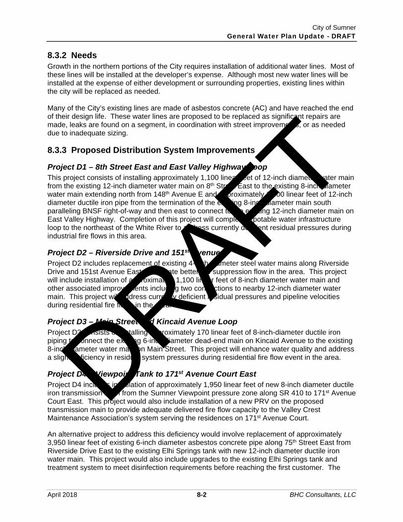
City of Sumner General Water Plan Update - DRAFT
April 2018 8-2 BHC Consultants, LLC
8.3.2 Needs Growth in the northern portions of the City requires installation of additional water lines. Most of these lines will be installed at the developer’s expense. Although most new water lines will be installed at the expense of either development or surrounding properties, existing lines within the city will be replaced as needed. Many of the City’s existing lines are made of asbestos concrete (AC) and have reached the end of their design life. These water lines are proposed to be replaced as significant repairs are made, leaks are found on a segment, in coordination with street improvements, or as needed due to inadequate sizing.
8.3.3 Proposed Distribution System Improvements
Project D1 – 8th Street East and East Valley Highway Loop This project consists of installing approximately 1,100 linear feet of 12-inch diameter water main from the existing 12-inch diameter water main on 8th Street East to the existing 8-inch diameter water main extending north from 148th Avenue E and approximately 1,900 linear feet of 12-inch diameter ductile iron pipe from the termination of the existing 8-inch diameter main south paralleling BNSF right-of-way and then east to connect to the existing 12-inch diameter main on East Valley Highway. Completion of this project will complete a potable water infrastructure loop to the northeast of the White River to address currently deficient residual pressures during industrial fire flows in this area.
Project D2 – Riverside Drive and 151st Avenue Project D2 includes replacement of existing 4-inch diameter steel water mains along Riverside Drive and 151st Avenue East to facilitate better fire suppression flow in the area. This project will include installation of approximately 1,100 linear feet of 8-inch diameter water main and other associated improvements including two connections to nearby 12-inch diameter water main. This project will address currently deficient residual pressures and pipeline velocities during residential fire flows in the area.
Project D3 – Main Street and Kincaid Avenue Loop Project D3 consists of installing approximately 170 linear feet of 8-inch-diameter ductile iron piping to connect the existing 6-inch diameter dead-end main on Kincaid Avenue to the existing 8-inch diameter water main on Main Street. This project will enhance water quality and address a slight deficiency in residual system pressures during residential fire flow event in the area.
Project D4 – Viewpoint Tank to 171st Avenue Court East Project D4 includes installation of approximately 1,950 linear feet of new 8-inch diameter ductile iron transmission main from the Sumner Viewpoint pressure zone along SR 410 to 171st Avenue Court East. This project would also include installation of a new PRV on the proposed transmission main to provide adequate delivered fire flow capacity to the Valley Crest Maintenance Association’s system serving the residences on 171st Avenue Court. An alternative project to address this deficiency would involve replacement of approximately 3,950 linear feet of existing 6-inch diameter asbestos concrete pipe along 75th Street East from Riverside Drive East to the existing Elhi Springs tank with new 12-inch diameter ductile iron water main. This project would also include upgrades to the existing Elhi Springs tank and treatment system to meet disinfection requirements before reaching the first customer. The
DRAFT

City of Sumner General Water Plan Update - DRAFT
April 2018 8-3 BHC Consultants, LLC
opinion of probable project cost (OPPC) for this alternative is approximately $520,000 more expensive. It is not identified as the preferred solution to address this deficiency.
Project D5 – Water Main Replacement Program Project D5 does not consist of any one specific water main replacement or upgrade, but instead anticipates that existing aging water mains not identified in this CIP will be replaced in the future as part of street improvement projects, or as needed due to deterioration, failure or other emergency condition. This program includes all existing asbestos concrete and small steel pipes in the City’s water system. A biennial allocation of $300,000 is included for utility planning and budgeting purposes. The proposed distribution main projects have been prioritized by anticipated growth and needs and are included in Table 8-1 located at the end of this chapter.
8.4 Source Improvements
8.4.1 Deficiencies The proposed source and storage improvement projects address the reliability of the City’s sources and storage facilities. The projects also address source and storage site improvements as summarized in Table 5-18 in Chapter 5.
8.4.2 Needs Although the current source capacity can meet maximum day demands through the 20-year planning period, new sources are required to satisfy the criteria for source reliability as summarized in Chapter 5. An estimated 0.57 mgd of additional source capacity is required within the 20-year planning period to accommodate these recommendations. It is likely that a combination of alternative existing source improvements will be required to reliably meet future water demands for the City. Each of the sources will be evaluated for applicable health standards, quantity of available water, reliability, costs, benefits, environmental effects, flexibility for changes, implementation, life expectancy, and risks.
8.4.3 Proposed Source Improvements
Project S1 – Additional Water Rights Acquisition The City of Sumner’s existing source water rights capacity is sufficient to meet the projected MDD through 2038. The City has filed application G2-30534 to increase the approved combined withdrawal rate from the West, South, and Central Wells from 1,250 gpm to 2,250 gpm. Pending approval of this application by 2024, the City will have sufficient production capacity to meet the source reliability criteria summarized in Tables 5-2 through 5-7 in Chapter 5. This project includes coordination and assistance with City attorneys required during the application review and approval process.
Project S2 – Central Well Treatment Capacity Expansion The City plans to double the production capacity of the Central Well from 1,050 gpm to 2,100 gpm by expanding the existing treatment facilities at the Well site and upgrading well pumping capacity. This project is pending the acquisition of the additional water rights from application G2-30534, as detailed in Project S1.
DRAFT

City of Sumner General Water Plan Update - DRAFT
April 2018 8-4 BHC Consultants, LLC
Project S3 – South Well Improvements The South Well has an instantaneous water right of 1,000 gpm. The City currently operates the well at a maximum capacity of 700 gpm to minimize the impacts of sand intrusion. Current deficiencies at the well include deteriorated structural, mechanical, electrical and chemical system condition, rigid piping connection between wellhouse and meter vault, lack of operational capacity flexibility to maximize water rights, and insufficient pipe manifolding to promote accurate meter readings. A new well house and metering vault, with upgraded mechanical and electrical systems to provide production capacity flexibility, is included with these improvements. The South Well could be evaluated for the ability to increase capacity to the full water right. If the well capacity was increased, approximately 230 linear feet of 36-inch-diameter pipe would need to be installed out of the south well to allow adequate disinfection before the first customer while maintaining a maximum free chlorine residual of 0.45 mg/L. A new well house and metering vault will also be constructed to address the deteriorated systems and operational flexibility, but tentatively not include enhanced capacity, as described in Table 5-18.
Project S4 – Dieringer Well Improvements Project S4 involves improvements to the Dieringer Well facility to address current condition deficiencies as detailed in Table 5-16, including installation of a ball check valve on the treatment supply, modifications to the existing well building, and electrical system upgrades.
Project S5 – West Well Improvements This project involves improvements to the West Well facility to address current condition deficiencies detailed in Table 5-16, including flushing and water quality testing and replacement of aging and deteriorating pipe and fittings in the well building. These improvements will provide the City with a more reliable seasonal source of supply for designated demand purposes.
Project S6 – Sumner Springs Improvements This project includes installation of a new vent on the bypass discharge pipeline from the weir vault at Sumner Springs and installation of a chain-link fence around the perimeter of the complex. The new vent will eliminate the potential for creating a vacuum from the hydraulic jump when excess water is bypassing the metering vault. The fence will provide added security to the facility.
Project S7 – County Springs Improvements This project includes installation of a permanent onsite generator at the County Springs treatment building and subsequent electrical improvements. This project will also include replacement of the existing building gutters that are aging.
8.5 Storage Improvements
8.5.1 Deficiencies and Needs The City of Sumner has adequate storage capacity projected through 2038. Storage improvement projects detailed herein are not related to storage capacity, but address tank site and functionality improvements.
DRAFT

City of Sumner General Water Plan Update - DRAFT
April 2018 8-5 BHC Consultants, LLC
8.5.2 Proposed Storage Improvements
Project ST1 – Earthquake Control Valves and Foundation Improvements The existing reservoirs may be subject to draining in the event of a large earthquake in the valley floor. This project is for the installation of a seismically actuated control valve at each of the South Tank and the Viewpoint Tank. The valve installations are scheduled to be completed in different planning years. Additionally, improvements to the foundation of the South Tank are included in this project. Foundation improvements will include strapping the existing steel tank to a new, reinforced concrete foundation. Reservoir recoating is also required as part of the foundation improvements.
Project ST2 – Viewpoint BPS Improvements This project includes improvements to the Viewpoint BPS located on the South Tank site, including purchase of a spare booster pump, onsite backup generator, replacement of the existing automatic transfer switch (ATS), and upgrading the pump control panel to allow for installation of variable frequency drives (VFDs) for the pump motors. The cost for the VFDs are included in this project.
Project ST3 – North Tank Improvements The City plans to retrofit the North Tank with a reservoir mixer. A PAX mixing system is recommended to mix the North Tank to eliminate stratification and short circuiting and help promote better quality water within the system. This project also includes replacement of the interior tank ladder, installation of an emergency generator onsite, and recalibration of the existing Cla-Val control valve on the tank supply pipe.
Project ST4 – Viewpoint Tank Detention Pond Project ST3 includes construction of a detention pond at the daylight location of the Viewpoint Tank drain in order to provide erosion and sedimentation control in the event the tank must be drained. This project will likely involve modifications to the existing tank drain to be routed to the new detention pond.
8.6 Operations and Maintenance Improvements
8.6.1 Deficiencies Although the City continues to operate and maintain the system, additional projects have been identified to increase the operational effectiveness of the system. The Water Use Efficiency Program also implements requirements for additional operations and maintenance projects.
8.6.2 Needs In addition to anticipated expansion, the City’s water system will continue to age and need continued maintenance and upkeep. The O&M improvements are intended to provide additional system reliability and provide a more efficient method to either reduce system costs or increase revenues through accurate meters.
DRAFT

City of Sumner General Water Plan Update - DRAFT
April 2018 8-6 BHC Consultants, LLC
8.6.3 Proposed Operation and Maintenance Projects
Project O&M1 – Hydrant and Isolation Valve Upgrades – 20 Years Some of the City’s existing fire hydrants are near the end of their useful life or are no longer compatible with City and fire district standards. The City plans to allocate a number of these hydrants for replacement per year. Valves identified as inoperable or damaged during exercising will be scheduled for replacement.
Project O&M2 – Source Meter Calibration Part of the City’s WLCAP states that the City’s source meters should be checked for accuracy and calibrated on a frequent basis. A source meter calibration program has been implemented, and the City plans on conducting ongoing meter calibration.
Project O&M3 – Increased Telemetry Maintenance The City’s system telemetry will continue to require maintenance and upgrade as the water system expands. The goal of this program is to continue to provide the level of service they are accustomed to with increased telemetry maintenance in concurrence with system growth.
Project O&M4 – Water Use Efficiency Program/WLCAP The City will work to implement the actions defined in their WLCAP as discussed in Section 5.6 to reduce the 3-year running average DSL below 10 percent by 2025. WUE reports are due to DOH on a yearly basis by July 1st of the year following the reporting year. While compiling the reports, the City has the opportunity to review all production and consumption numbers, calibrate source meters, discuss additional WUE measures that could be implemented, and discuss demand projections and upcoming CIP projects. Another aspect of the WLCAP is expanding the leak detection program. Sumner plans on increasing their leak detection schedule throughout the system to locate and fix leaks within the distribution system.
DRAFT

City of Sumner General Water Plan Update - DRAFT
April 2018 8-7 BHC Consultants, LLC
Table 8-1 Capital Improvement Plan Schedule (1)
Project Number - Description Total Cost
Year Year of Completion
2018 2018 2019 2020 2021 2022 2023 2024 2025 2026 2027 2028 2029-2038 Seattle Construction Cost Index (Increases by 3.5% per year) 10939 10939 11158 11381 11609 11841 12078 12320 12566 12817 13074 13335 13602
Distribution System Improvements D1 - 8th Street East and East Valley Highway Loop $1,290,000 $1,315,800
D2 - Riverside Drive and 151st Avenue $510,000 $510,000 D3 - Main Street and Kincaid Avenue Loop $110,000 $110,000 D4 - Viewpoint Tank to 171st Avenue Court East $1,040,000 $1,090,000
D5 - Water Main Replacement Program $3,125,000 $125,000 $0 $300,000 $0 $300,000 $0 $300,000 $0 $300,000 $0 $300,000 $1,500,000 Subtotal $6,075,000 $745,000 $1,315,800 $1,390,000 $0 $300,000 $0 $300,000 $0 $300,000 $0 $300,000 $1,500,000
Source Improvements S1 - Additional Water Rights Acquisition $2,000 $2,000 $2,000 $2,000 $2,000 $2,000 $2,000 $2,000 S2 - Central Well Treatment Capacity Expansion $2,630,000 $1,423,000 $1,452,000
S3 - South Well Improvements $770,000 $817,000 S4 - Dieringer Well Improvements $100,000 $110,000 S5 - West Well Improvements $16,000 $18,000 S6 - Sumner Springs Improvements $63,000 $70,000 S7 - County Springs Improvements $500,000 $271,000 $276,000
Subtotal $4,081,000 $2,000 $2,000 $2,000 $819,000 $1,696,000 $1,928,000 $2,000 $0 $0 $0 $0 $0 Storage Improvements ST1 - Earthquake Control Valves and Foundation Improvements $2,400,000 $2,400,000
ST2 - Viewpoint BPS Improvements $200,000 $225,232 ST3 - North Tank Improvements $400,000 $424,483 ST4 - Viewpoint Tank Detention Pond $550,000 $619,389
Subtotal $3,550,000 $2,400,000 $0 $0 $424,483 $0 $0 $844,622 $0 $0 $0 $0 $0 Operations and Maintenance Improvements O&M1 - Hydrant and Isolation Valve Upgrades - 20 Years $244,832 $80,000 $81,600 $83,232
O&M2 - Source Meter Calibration $111,400 $5,000 $5,100 $5,300 $5,400 $5,500 $5,600 $5,700 $5,800 $5,900 $6,000 $6,100 $50,000 O&M3 - Increased Telemetry Maintenance $34,000 $34,000 $34,700 $35,400 $36,100 $36,900 $37,600 $38,300 $39,100 $39,900 $40,700 $41,500 $340,000 O&M4 - Water Use Efficiency Program/WLCAP $182,000 $16,000 $16,000 $13,000 $13,000 $12,000 $12,000 $9,000 $9,000 $10,000 $10,000 $62,000 $14,000
Subtotal $572,232 $135,000 $137,400 $136,932 $54,500 $54,400 $55,200 $53,000 $53,900 $55,800 $56,700 $109,600 $404,000 TOTAL WATER FUND $14,278,232 $3,282,000 $1,455,200 $1,528,932 $1,297,983 $2,050,400 $1,983,200 $1,199,622 $53,900 $355,800 $56,700 $409,600 $1,904,000
Notes: 1) All OPCCs shown are in 2018 dollars. Project OPCCs not shown in the year 2018 are estimated in 2018 dollars and escalated by the percent increase in Construction Cost Index, assumed to increase at a rate of 2%
per year.
DRAFT

City of Sumner General Water Plan Update - DRAFT
April 2018 8-8 BHC Consultants, LLC
THIS PAGE INTENTIONALLY BLANK.
DRAFT

"")
"")
"")
"")"")
G!.
G!.
G!.
G!.G!.
G!.G!.G!. G!.G!.G!.
G!.
G!. G!. G!. G!.
G!.
G!.G!.
G!.G!.
G!.G!.
G!.
G!.
G!. G!.G!.
G!.G!.
G!.G!.G!.G!.
G!.
G!.
G!.
G!.
G!.
G!.G!.G!.
G!.
G!.
G!.
G!.
G!.
G!.
G!.
G!.
G!. G!. G!.G!.
G!.
G!.
G!. G!. G!.
G!.G!.
G!.
G!.
G!.
G!.
G!.G!.
G!.
G!. G!.
G!. G!.
G!.
G!.
G!.
G!.
G!.
G!.
G!.
G!.
G!.
G!.
G!. G!.
G!.
G!. G!.
G!.
G!.G!.
G!.
G!. G!. G!. G!.
G!.
G!.G!. G!.G!.
G!.
G!.
G!.G!.
G!.
G!.
G!. G!.
G!.
G!.
G!. G!. G!.G!.
G!.
G!.
G!.G!.
G!.
G!. G!.G!.G!.
G!.
G!.
G!.G!.G!.
G!.
G!.
G!.
G!.G!.
G!.
G!.
G!. G!.
G!.
G!.
G!.
G!.
G!.
G!.
G!.
G!.G!.
G!.
G!. G!.
G!.G!.
G!.G!.
G!.
G!.G!.
G!.
G!.G!.
G!.
G!.G!.
G!.
G!.G!.G!.
G!.
G!.
G!.G!. G!.
G!.
G!.
G!. G!.
G!.G!.
G!.G!.
G!.G!.
G!.
G!.
G!. G!.
G!.
G!.
G!.
G!.
G!.
G!.
G!.
G!.
G!.G!.G!.
G!.
G!.
G!.
G!.
G!.
G!.
G!.
G!.G!.
G!.
G!.
G!.G!.
G!.
G!.
G!.G!.
G!.G!.
G!.
G!.
G!.
G!.
G!.
G!.
G!.G!.G!.
G!. G!.
G!. G!.
G!.G!. G!.
G!.
G!.
G!.
G!.
G!.
G!.
G!.
G!.
G!.
G!.
G!. G!.
G!.
G!.
G!.
G!. G!. G!.
G!.
G!.G!.G!.G!.
G!.
G!.
G!.
G!.
G!.
G!.G!.
G!.
G!.
G!.
G!.
G!.
G!.
G!.
G!.
G!.G!.
G!.
G!. G!.G!.
G!.
G!.
G!.G!.
G!.
G!. G!.
G!.G!.
G!.G!.
G!.G!.
G!.
G!.
G!.
G!.G!.
G!.
G!.
G!.
G!.G!.
G!.
G!.G!.
G!.
G!.
G!.
G!.G!.
G!.
G!.
G!.
G!.
G!. G!.
G!.G!.
G!.
G!.
G!.
G!. G!.
G!.
G!.
G!.
G!.
G!.
G!.
G!.
G!.
G!.
G!.
G!.
G!.
G!.
G!.
G!.
G!.G!.
G!.
G!. G!.
G!. G!.
G!.G!.
G!.G!.
G!.G!.
G!.
G!.
G!.
G!. G!.
G!.
G!.G!. G!.
G!.
G!.G!.
G!.
G!.G!.
G!.
G!.
G!.
G!.
G!.G!. G!.
G!.
G!.
G!.G!.G!.G!.
G!. G!.
G!.
G!.
G!. G!.
G!.
G!. G!.G!. G!.
G!.
G!.
G!.G!. G!.
G!.
G!.
G!.
G!.
G!.
G!.G!.G!. G!.
G!. G!.
G!.G!.G!.
G!.
G!.G!.
G!.
G!.
G!. G!.
G!.
G!.
G!.G!.
G!.G!.
G!.
G!.
G!.
G!.
G!. G!. G!.
G!.
G!.
G!.G!.G!.
G!.
G!.
G!.
G!.
G!.
G!.
G!. G!. G!.
G!.
G!.
G!.
G!.G!.
G!.
G!.G!.G!.
G!.G!.
G!.
G!. G!.
G!.
G!.
G!.
G!.
G!.
G!.
G!.G!.
G!.
G!.G!.
G!.G!.
G!.
G!.G!.G!.G!.G!.
G!. G!. G!. G!. G!.
G!.
G!.
G!.
G!.
G!. G!. G!. G!. G!.G!.G!.
G!.
G!.
G!.
G!.
G!.
G!.
G!.
G!.G!.
G!.
G!.G!.
G!.
G!.
G!.G!.
G!. G!.
G!.
G!.
G!.
G!.
G!.
G!.
G!.
G!.
G!.
G!.
G!.
G!.
G!.
G!.
G!.
G!.
G!.
G!.
G!.
G!. G!. G!. G!.
G!.
G!.
G!.
G!.
G!.
G!.
G!.
G!.
G!.
G!.
G!.
G!.
G!.
G!.
G!.
G!.
G!. G!.
G!.
G!.G!. G!.
G!.
G!.
G!.G!.
G!.
G!.
G!.
G!.
G!.
G!.G!.G!.
G!.
G!.
G!.G!.
G!.
G!.
G!.G!.
G!.
G!.
G!.G!.
G!.
G!.
G!.
G!.
G!.
G!.
G!.
G!.
G!.
G!.
G!.
G!.
G!.
G!.
G!.
G!.
G!.G!.
G!.
G!.
G!. G!.
G!.
G!.G!.
G!.G!.
G!.
G!.
G!.G!.
G!.
G!.G!.G!.
G!.G!.G!.
G!.
G!.
G!.G!.G!.
G!. G!.G!.
G!.
G!.
G!.
G!.
G!.
G!.
G!.
G!.
G!.
G!.
G!.G!.
G!.
G!.
G!. G!.
G!.
G!.
G!. G!. G!.
G!.
G!.G!.G!.
G!.
G!.
G!.
G!.
G!.
G!.
G!.G!. G!.
G!.
G!.
G!.
G!.
G!.G!.
G!.G!.
G!.G!.
G!.
G!.G!.G!. G!.
G!.
G!.
G!.
G!.
G!.G!.
G!.
G!. G!. G!.
G!. G!. G!.
G!.
G!.G!.
G!.
G!.
G!.
G!.
G!. G!. G!.
G!.
G!.
G!.
G!.G!.G!.
G!.G!.
G!.
G!.G!.G!.G!. G!.
G!.
G!.
G!.
G!.
G!.
G!.G!.
G!.
G!.
G!.
G!.
G!.
G!.
G!. G!. G!.
G!.
G!.
G!.
G!.
G!.
G!.G!.
G!.
G!. G!.
G!.G!.
G!.
G!.
G!.
G!.G!. G!.
G!.
G!.
G!. G!.
G!.
G!.
G!.
G!.
G!.
G!.
G!.
G!.
G!.
G!.
G!.
G!. G!.
G!.
G!.G!.
G!.G!.G!.G!.
G!.G!.
G!.
G!.
G!.
G!.G!.
G!.
G!.
G!.G!.G!.G!.
G!.G!.G!.G!.
G!.G!.
G!. G!.G!.G!.
G!.G!.
G!.G!.
G!.G!. G!.
G!.
G!.
G!.
G!.G!.
G!.
G!.
G!.
G!.
G!.
G!.
G!.
G!.
G!.
G!.G!.
G!.
G!. G!.
G!.
G!.
G!.G!.
G!.
G!.G!.
G!.
G!.
G!.
G!.
G!.
G!.
G!.
G!.
G!.
G!.G!.
G!.
G!.
G!.
G!.G!.
G!.
G!.
G!.G!.
G!. G!.G!.
G!.G!.
G!.
G!.
G!.
G!. G!.
G!.G!.
G!.
G!.
G!.
G!.
G!.
G!.
G!.
G!.
G!.
G!.
G!.
G!.
G!.
G!.
G!.G!.G!.
G!.
G!.
G!.
G!.
G!.G!.
G!.
G!.
G!.
G!.
G!.
G!.
G!.G!.
G!.
G!.
G!.
G!.
G!.
G!.
G!.G!.
G!.
G!.
G!.
G!.
G!.
G!.
G!.
G!.
G!.G!.
G!.G!.
G!.G!.G!. G!.
G!.
G!.
G!.
G!.
G!.
G!.
G!.
G!.
G!.
G!.
G!.
G!.
G!.
G!.
G!.
G!.
G!.
G!.
G!.G!.
G!.
G!. G!.
G!.
G!.
G!.
G!.
G!.
G!.
G!.
G!.
G!.
G!.G!.
G!.
G!.
G!.G!.
G!.
G!.
G!.
G!.G!.
G!.
G!.
G!.G!.
G!.G!. G!. G!.
G!. G!.
G!.G!.
G!.
G!.
G!.G!.
G!. G!.
G!. G!.
G!. G!.G!.G!. G!.
G!.
G!.
G!.G!.
G!.
G!.
G!.G!.
G!.
G!.G!.G!.
G!.
G!.
G!.
G!.
G!.
G!.
G!.
G!.
G!.
G!.
DieringerWell
NorthTank
SumnerSprings
Tank
SumnerSprings
CountySprings
CountySpringsTank
CentralWell
WestWell (Seasonal)
SouthWell
Elhi Springs(Inactive)
ViewpointTank
South Tank
D1
S4
ST3
S6
S7
S2
D3
S5
D2
S3D4
ST4ST2
ST1
LakeTapps
SR 167
SR 410SR
512
Debra Jane Creek
Wapato Creek
Puyallup River
Wapato Creek
Bonney Lak e Outflow
Salm on CreekWhite River
Dieringer Flume
WILLIAMS
45TH
SR 162
SILVER
TRAFFIC
RIVERSIDE
HUN T
72N D
149TH
ACADEMY
70TH
CHERRY
67TH
ZEHN DER
46TH
146TH
82N D
RIVERWALK
65TH
HOUSTON
16TH
73RD
MEEKER
WASHIN GTON
MAIN
SUMNERLINDEN
153RD
152ND
29TH
154TH 47TH
STATE
VILLAGE
GRAHAM
STEWART
LEWIS
CHESTN UT
PARK WOOD
MAPLE
N ORTH
ELM
LAN GDON
HARRISON
GAULT
86TH
MEADE MCCUMBER
63RD
147TH
RIVERGROVE
PARKER
WILLOW
KINCAID
RYAN
158TH
MEADE
30TH
ALDER
160TH
38TH
170TH
VALLEY
EVERETT
145TH
24TH
58TH
THOMPSON
RAILROAD
DAFFODIL
PUYALLUP49TH
ORTING
BOYD
GUPTIL
62N D
27TH
77TH
50TH
VOIGHT
WRIGHT
GARY
FRYAR
48TH
ROBIN SON
BOCK
57TH
53RD
90TH
54TH
56TH
141ST
76TH
55TH
60TH
BRIDGE
151ST
164TH
BON NEY
8TH
84TH
89TH
136TH
52N D
93RD
TACOMA
166TH
74TH
STEELE
PACIFIC
132ND
142ND
MASON
20TH
RAMP SR410RAIN IER
140TH
172N D
156TH
78TH
SUMN ER-TAPPS
148TH
32N D
173RD
64TH
137TH
171ST
138TH
PEASE
AUTO
162ND
RAMP SR167
SR 410
WEST VALLEY
88TH
75TH
EAST VALLEY
150TH
92N D
0 2,5001,250Feet
GIS Data: City of Sum n er & Pierc e Coun tyData sourc es supplied m a y n ot reflect c urren t or a c tua l con dition s. This m apis a geographic represen tation b a sed on in form ation a va ila b le. It does n ot represen t survey data. N o warra n ty is m a de con c ern in g the a c c ura c y, c urren c y,or com pleten ess of data depicted on this m ap.BHC Con sulta n ts LLC., assum es n o respon sib ility for the va lidity of a n yin form ation presen ted herein , n or a n y respon sib ility for the use or m isuse of the da ta.
P:\Ma ppin g\Ma ps_ Gen era ted\Sum n er\17-10500.00\002\2.7\m a ps\Fig 8-1 Proposed Wa ter System Im provem en t Projec ts - 11x17.m xd 4/4/2018 ctolen tin o
COPYRIGHT © 2017 BHC CON SULTAN TS LLC., ALL RIGHTS RESERVED
$ Wa ter Com prehen sive Pla nCity of Sum n er
Figure
Proposed WaterSystem ImprovementProjects
8-1
Legend³³±# CIP N o
CIPG!. Fire Hydra n ts
"") Stora ge Ta n k
Sourc e Tap
Water Ma in sWater Servic e Area *
City Lim its
Urb a n Growth Area
Coun ty
Parc elsHighwa y/StateRouteWater Bodies
Water Courses
Pierc e Coun tyKin g Coun tyPierc e Coun ty
Kin g Coun ty
Water Servic e Area*:Area b etween the Cem etery a n d the City Servic e Area are withinCity of Sum n er’s UGA with dom estic water served b y Puya llupun der a greem en t with the City of Sum n er.
DRAFT

City of Sumner General Water Plan Update - DRAFT
April 2018 8-10 BHC Consultants, LLC
THIS PAGE INTENTIONALLY BLANK.
DRAFT

City of Sumner General Water Plan Update - DRAFT
April 2018 10-1 BHC Consultants, LLC
Operations Program This chapter serves to satisfy the requirements for an operations program as outlined within the DOH Planning Handbook for Water System Plans and current Washington State Drinking Water Regulations (WAC 246-290-415). The City of Sumner has an established operations program, with staff and equipment to adequately manage and control the program, protect water quality, and provide a safe and reliable supply of drinking water to all customers. This operations program is divided into five sections: Organization Structure/Responsibilities. System Operation and Control. Water Quality Monitoring. Emergency Response Program. Cross Connection Control Program.
For each component of the operations program, current practices are discussed and recommended changes or improvements are included.
Organization Structure/Responsibilities The City of Sumner Water Utility is overseen by the Public Works Department, which is operated and maintained by the Public Works Director. Figure 10 1 on the following page shows the City of Sumner departmental organization chart. The Public Works staff includes many personnel that are flexible and can work on water system projects when the need arises due to emergencies, new construction, or increased monitoring. Currently, only the Water Field Supervisor and one operator have sole responsibilities to the water utility. Table 10-1 shows key responsibilities of water system staff.
Table 10-1 Key Responsibilities of Water System Staff
Responsibility Staff Member
Normal Day-to-Day Operations Operations Superintendent, Water Field Supervisor Preventive Maintenance Water Field Supervisor, Utility Operators Field Engineering Public Works Director, City Engineer Water Quality Monitoring Water Field Supervisor, Utility Operators Troubleshooting Water Field Supervisor, Utility Operators
Emergency Response Public Works Director, Operations Superintendent, Water Field Supervisor, Utility Operators
Cross Connection Control City Engineer, Engineering Technicians Capital Improvement Development Public Works Director, City Engineer
New Construction City Engineer System Upgrade and Expansion City Engineer, Engineering Technicians Budget Formulation Public Works Director, approved by Mayor and City Council Response to Complaints Water Field Supervisor, Utility Operators Public/Press Contact Public Works Director
DRAFT

City of Sumner General Water Plan Update - DRAFT
April 2018 10-2 BHC Consultants, LLC
Figure 10 1 City of Sumner Organizational Chart
10.1.1 Certification Chapters 70.119 RCW and 246-292 WAC require all community water systems to have a certified operator. In addition, specialty certification is required for treatment plant operation, backflow device testing, and asbestos cement pipe handling. Table 10-2 shows current certifications of the Public Works staff, including specialty licenses.
DRAFT

City of Sumner General Water Plan Update - DRAFT
April 2018 10-3 BHC Consultants, LLC
Table 10-2 Staff Certification List – Street/Utilities Division (2008)
Employee Title WDM CCCS BAT AC Pipe Handling
WISHA WWC
Confined Space
CPR/FA
Pat Clerget Operations Superintendent IV X X III X X
Gary Lucas Field Supervisor II X II X X Daron Uphaus Field Supervisor II X X III X X John Wells Field Supervisor II X II X X Darren Young Operator II II X II X X
Shaun Piper Water Field Supervisor II X X X II X X
Kevin Babic Water Operator II II X X X II X X Dave Ellingson Operator II I X I X X Lester Reedy Operator II II X I X X Casey Stumpt Operator II I X I X X Beau LaCrosse Operator II I X I X X Monty Brant Operator II II X X II X X Darren Hoberg Operator II I X I X X Josh Keller Operator I X X Kevin Mast Operator I Hunter Hoberg Operator I Brian Akana Operator I X DRAFT

City of Sumner General Water Plan Update - DRAFT
April 2018 10-4 BHC Consultants, LLC
Table 10-2 Staff Certification List – Street/Utilities Division (2008) (Continued)
Employee Pest/Herb License
Flagging Cert
Traffic Signal Tech
IMSA
Sign Marking
IMSA
CDL A License
ICS 100/700
WTPO CESCL
Pat Clerget X X X X Gary Lucas X II I X X Daron Uphaus X X X X John Wells X X X X X Darren Young X X X X Shaun Piper X X X I Kevin Babic X I II X X I Dave Ellingson X I I X X Lester Reedy X II X X Casey Stumpt X X X X Beau LaCrosse X X X Monty Brant X X X X I X Darren Hoberg X X X Josh Keller X X Kevin Mast X Hunter Hoberg Brian Akana X
Source License Agency Source License Agency WDM I Water Distribution Manager I DOH BAT Backflow Assembly Tester DOH WDM II Water Distribution Manager II DOH CDL "A" Commercial Driver's License- Endorsement Class A HLS WDM III Water Distribution Manager III DOH ICS Incident Command System DOE WDM IV Water Distribution Manager IV DOH WWC I Wastewater Collection I WWCPA DOE – Department of Ecology WWC II Wastewater Collection II WWCPA DOH – Department of Health WWC III Wastewater Collection III WWCPA HLS – Homeland Security WTPO I Water Treatment Plant Operator I DOH IMSA – International Municipal Signal Association CCCS I Cross Connection Control Specialist I DOH WISHA – Washington Industrial Safety and Health Act WWCPA – WA Wastewater Collections Personnel Assoc
DRAFT

City of Sumner General Water Plan Update - DRAFT
April 2018 10-5 BHC Consultants, LLC
All operator certifications must be renewed annually. Evidence must be presented to the board that the operator has demonstrated continued professional growth in the field. Accumulation of three college credits or continuing education units every 3 years is considered satisfactory evidence of professional growth (WAC 246-292-095). The City of Sumner fosters professional growth and certification level advances. Staff members are hired in accordance with the City of Sumner Personnel Policies and Procedures Manual kept on file at the Public Works Department.
Water Distribution Manager Certification Water Distribution Managers (WDMs) are responsible for the administration and operation of the water distribution system. Table 10-3 shows the required certification level for population ranges from WAC 246-292.
Table 10-3 Water Distribution System Certification Requirements
Certification Level Population City Status
Group S Less than 251 – Group I 251 to 1,500 – Group II 1,501–15,000 Current through 2038 Group III 15,001–50,000 N/A Group IV Greater than 50,000 N/A
The City of Sumner is projected to serve a population of between 11,000 and 14,000 during the 20-year planning horizon of this plan, which requires a Group II certification level of the lead operator. There are one Group IV WDM, eight Group II WDMs, and four Group I WDMs in the City Public Works Department, satisfying current certification requirements.
Water Treatment Plant Operator Certification Water Treatment Plant Operator (WTPO) certification is based on a total point scale per WAC 246-292-040 as follows:
Classification Total Points Assigned Certification Requirement
Group I Less than 31 BTO Group II 31 to 55 WTPO II Group III 56 to 75 WTPO III Group IV Greater than 75 WTPO IV
Points are accumulated based on level of complexity in the treatment process and source water quality, as determined by the DOH ABC Purification Plant Criteria Worksheet. With the addition of a manganese treatment and removal system associated with the City’s new Central Well source, more complexity has been added to the groundwater treatment process than has been practiced at other City well sources in the past. Project documentation associated with construction of the Central Well performed the ABC worksheet calculation and established a point total of 28 for this treatment facility at an ultimate capacity of 2100 gpm (its current treatment capacity is 1050 gpm). Table 10-4 shows the breakdown of points for Sumner’s two
DRAFT

City of Sumner General Water Plan Update - DRAFT
April 2018 10-6 BHC Consultants, LLC
primary source facilities (Central Well and springs), with point totals assessed to reflect anticipated facilities and service area growth through the 20-year planning period of 2038.
Table 10-4 Purification Plant Certification Level
Item Central Well Points
Assigned Springs Sources
Points Assigned
System Size Maximum Population Served 2 2
Peak Month Production (average day)
Ultimate Capacity = 2100 gpm 3
Largest Source = 799 gpm (Sumner
Springs) 1.5
Water Supply Sources Type Groundwater 0 Surface Water 10
Water Quality Subject to Elevated
Taste/Odor3 Excellent 0
Chemical Treatment/Addition Process
Chlorine Disinfection Sodium Hypochlorite 5 Gaseous Chlorine 8
Filtration Process Pressure or Greensand Filtration Tonka System 5 None 0
Taste and Odor Mitigation
GAC Pressure Filtration 3 None 0
Residuals Disposal Discharge to Sanitary Sewer Yes 3 No 0
Facility Characteristics SCADA to provide data and moderate process control
4 4
Total:Certification Level:
28 25.5 Group I Group I
This analysis shows the required WTPO certification level for this planning period to be Group I. The City currently has three Group I WTPOs among operations personnel, satisfying certification requirements. Additionally, one of the City’s licensed engineers within the Public Works department has a Group II WTPO certification.
Distribution System Specialists Certification is also available on a voluntary basis to individuals interested in Water Distribution Specialist (WDS) and Cross Connection Control Specialist (CCCS). The WDS classification is recommended for any person engaged in a specialized phase of water works operation such as main repair, meter repair, pump maintenance, service installation, chlorination process
DRAFT
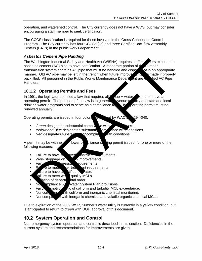
City of Sumner General Water Plan Update - DRAFT
April 2018 10-7 BHC Consultants, LLC
operation, and watershed control. The City currently does not have a WDS, but may consider encouraging a staff member to seek certification. The CCCS classification is required for those involved in the Cross-Connection Control Program. The City currently has four CCCSs (I’s) and three Certified Backflow Assembly Testers (BATs) in the public works department.
Asbestos Cement Pipe Handing The Washington Industrial Safety and Health Act (WISHA) requires staff members exposed to asbestos cement (AC) pipe to have certification. A moderate portion of the Sumner transmission system contains AC pipe that must be handled and disposed of in an appropriate manner. Old AC pipe may be left in the trench when future improvements are made if properly backfilled. All personnel in the Public Works Maintenance Department are Certified AC Pipe Handlers.
10.1.2 Operating Permits and Fees In 1991, the legislature passed a law that requires all Group A water systems to have an operating permit. The purpose of the law is to generate revenue to carry out state and local drinking water programs and to serve as a compliance tool. The operating permit must be renewed annually. Operating permits are issued in four colors, as defined by WAC 246-294-040: Green designates substantial compliance with no conditions. Yellow and Blue designates substantial compliance with conditions. Red designates substantial noncompliance with conditions.
A permit may be withheld, or lower compliance ranking permit issued, for one or more of the following reasons: Failure to have approved construction documents. Work stoppage on system improvements. Failure to meet pressure requirements. Failure to meet water treatment requirements. Failure to have a certified operator. Failure to meet water quality MCLs. Violation of departmental order. Noncompliance with Water System Plan provisions. Failure to notify public of coliform and turbidity MCL exceedance. Noncompliance with coliform and inorganic chemical monitoring. Noncompliance with inorganic chemical and volatile organic chemical MCLs.
Due to expiration of the 2009 WSP, Sumner’s water utility is currently in a yellow condition, but is anticipated to return to green with DOH approval of this document.
System Operation and Control Non-emergency system operation and control is described in this section. Deficiencies in the current system and recommendations for improvements are given.
DRAFT

City of Sumner General Water Plan Update - DRAFT
April 2018 10-8 BHC Consultants, LLC
10.2.1 Reference Materials The following reference materials supplement this operations program and are highly recommended for inclusion in the Public Works Department library. American Water Works Association. Denver, Colorado. 1980–2017. Manuals of Water
Supply Practices. Pacific Northwest Section, American Water Works Association. Seventh Edition (2012).
Accepted Procedure and Practice in Cross Connection Control Manual. Washington Administrative Codes, Department of Health.
o WAC 246-290.Group A Public Water Supplies. o WAC 246-292. Waterworks Operator Certification. o WAC 246-294. Drinking Water Operating Permits.
APHA - AWWA - WEF 23rd Edition. Washington, D.C., 2017. Standard Methods: For the Examination of Water and Wastewater.
City of Sumner Public Works Department, Sumner, Washington 2011.Development Specifications and Standard Details.
United States Environmental Protection Agency Second Revision 2010. Revised Public Notification Handbook 816-R-09-013.
Washington State Department of Health Third Edition 2017. Water Use Efficiency Guidebook.
City of Sumner Public Works Department. Updated continuously. Water System Maps. American Public Works Association, Washington State Chapter 20016. Standard
Specifications for Road, Bridge, and Municipal Construction. Operations and maintenance manuals for individual system components are kept at the chlorination buildings in the telemetry cabinet for most source facilities. For the Central Well, they are kept in the laboratory room. As-builts and another set of operation and maintenance manuals are kept at the City Shops.
10.2.2 System Overview Chapter 4 of this WSP discusses and shows existing water system components, including spring collection works, wells, storage tanks, chlorination facilities, booster pump station, transmission and distribution facilities, hydrants, watersheds, and interties. The distribution system is shown in greater detail on the Water System Maps created by the Public Works Department. These maps are updated continuously by the City’s GIS/CAD Analyst to illustrate the as-built water system including hydrants, pipe sizes, pipe material, and isolation valves. The City of Sumner water system is supplied by four springs and four wells. The primary sources of water are Sumner and County Springs. Spring flow is chlorinated prior to entering storage facilities that serve the distribution system. Central Well, South Well, Dieringer Well, and West Well are typically used only when maintenance and repairs interfere with normal supply from the springs and during peak demand season. As discussed in Chapter 5, due to the combined operational production rate of the Central, South, and West Wells being more than the current allowable instantaneous withdrawal rights shared between them, the South Well is the only groundwater source of the three that is brought on automatically during summer peak demand periods. The South and West Well would need to be turned on manually, and only after the Central Well is offline. Additionally, manual valve adjustment is necessary to allow the West Well, which has water quality concerns,
DRAFT

City of Sumner General Water Plan Update - DRAFT
April 2018 10-9 BHC Consultants, LLC
to send produced water to the distribution system (it is currently configured solely to supply the cemetery irrigation system). Currently, there are five storage tanks maintained in the Sumner water system. Four of the five tanks are at the same hydraulic grade. Sumner Springs and County Springs Tanks are gravity fed by their respective springs. County Springs Tank is used primarily for chlorine contact (0.068 mg). Sumner Springs’ tank is used for chlorine contact and storage (1 mg). The North and South Tanks are floating reservoirs used for storage (2 mg each). The North Tank provides fire flow for the north end of the city. The fifth tank, at the Sumner Viewpoint development, is supplied by a booster pump station at the South Tank and has a capacity of 330,000 gallons. This tank operates at a higher hydraulic grade line than the other tanks and serves only the Sumner Viewpoint development.
10.2.3 Spring Collection Works
Routine Operations Spring taps, collection boxes, plumbing, metering vaults, surface water diversion structures, and other spring collection works are shown in Chapter 4. Sumner and County Springs are gravity fed into metering vaults. From the metering vaults, the water is either diverted to a storage tank or allowed to overflow to Salmon Creek.
Alternate Operating Modes Peak Use – During peak water use, all water is transferred from the metering vaults to the tanks with no diversion to Salmon Creek. Source Bypass – Individual spring taps, or the entire Sumner and County Springs collection works, can be bypassed from the system by closing isolation valves and directly spilling to Salmon Creek. Elhi Springs may also be bypassed. Isolation valves are shown on figures included in Chapter 4.
Preventive Maintenance
Item Frequency
Check Spring Flow Daily Check Meter Readings Daily Change Strip Charts, Pens Daily as needed Inspect Metering Vaults Weekly Inspect Spring Taps, Collection Boxes, and Plumbing; Check for Siltation, Surface Water Drainage, Evidence of Vandalism, Leaks, and Surface Films (requires walking along access road)
Biweekly
Exercise Spring Tap Isolation Valves Biannually Calibrate Flow Meters Biannually Clean Spring Tap Boxes and Repair as Needed Annually
DRAFT

City of Sumner General Water Plan Update - DRAFT
April 2018 10-10 BHC Consultants, LLC
Evaluation Any deficiencies in the system should be corrected immediately. Reduced maintenance can cause water quality impairment. Problems should be noted on damage report forms. Valve exercising and maintenance should be recorded on valve report forms or a maintenance schedule database.
10.2.4 Chlorination Facilities
Routine Operations There are seven chlorination facilities in the system, one each at Sumner Springs, County Springs, Elhi Springs, Central Well, South Well, Dieringer Well, and West Well. A majority of the source chlorination facilities are equipped with dual dosing pumps for redundancy. Where chlorine gas is used for disinfection (Sumner Springs, County Springs, and South Well), chlorination buildings are separated into two rooms. Chlorine cylinders are housed separately from chlorinators and pumps. Structural and mechanical relationships between the Sumner and County Springs chlorination facilities and spring collection works are shown on figures included in Chapter 4. Chlorine dose at County and Sumner Springs is based on flow rate telemetry information from the metering vaults. The chlorine gas is metered in proportion to water flow, injected into solution, and fed to the transmission lines feeding the storage tanks. Liquid sodium hypochlorite at West Well, and Dieringer Well is injected directly into the well discharge lines in proportion to flow. Onsite liquid sodium hypochlorite, which is generated at the Central Well facility at a lower strength than that delivered to the other wells, plays a role as an oxidant in the treatment process and is fed both before the greensand/pyrolusite (IMAX) pressure filters that remove manganese and the GAC polishing filters that mitigate taste and odor potential. Dosing concentrations at the injection points are operationally established to facilitate appropriate oxidation of ammonia, as well as maintain adequate disinfectant residual concentrations within the distribution system (after the chlorine demand required by the treatment process is consumed). Chlorine residuals are tested daily and used as a basis for any chlorine dosage adjustment. For all sources excluding Elhi Springs and South well, chlorine residual is typically kept in a range of 0.3 mg/ℓ to 0.45 mg/ℓ. The online chlorinator is rotated annually at each facility. Free chlorine residual concentration required at or before the first customer for each source is listed in Chapter 4, Table 4-4.
Equipment Failure
Since each facility contains redundant chlorination injection equipment, standby equipment is ready to use in case of on line system equipment failure. DRAFT

City of Sumner General Water Plan Update - DRAFT
April 2018 10-11 BHC Consultants, LLC
Preventive Maintenance
Item Frequency
Check Cylinder/Drum Depletion, Rotate as Needed Daily Inspect Chlorine Leak Detector Daily Check Injector Pump Pressure Daily Check mg/Dosage versus mg/Residual Daily Add Salt to Onsite Generation Tank Weekly Check/Clean/Replace Onsite Generation Cells and Other Equipment Quarterly or as needed Calibrate Chlorine Scales Quarterly Calibrate Residual Analyzers Quarterly Check Ultrasonic Flow Meters and Calibrate Quarterly Check Telemetry Instrumentation and Lubricate Quarterly Check or Test Fire Extinguisher, Shower, Leak Detector and Ventilation Fan Quarterly
Change Electrolyte As Needed Rotate Chlorinators/Drums Annually Rebuild Chlorinators, Injectors, Injector Pumps, Alarm Panel, and Other Equipment Annually or as needed
Evaluation System performance is checked by comparing residual settings to the residuals maintained as determined by field monitoring. Any safety deficiencies should be corrected immediately. Inside each gas chlorination building’s control room doors are respirators, eye protection, and other personnel protection equipment to be used in case of a chlorine leak. If the alarm goes off, the chlorination building should not be entered until the room is well ventilated. Operators should be trained to handle a chlorine leak emergency. Contingency plans are discussed in the Emergency Response Plan.
10.2.5 Storage Tanks
Routine Operations There are currently five storage tanks in the Sumner water system with a total storage capacity of 5.07 mg. Sumner and County Springs Tank dimensions and elevations are shown on figures included in Chapter 4. Sumner Springs Tank (1 mg) is gravity fed by the Sumner Springs metering vault. County Springs Tank is gravity fed by the County Springs metering vault. The primary purpose of the County Springs Tank (68,000 gallons) is to provide chlorine contact. Disinfection performance for both Sumner and County Springs Tanks is discussed in Chapter 6, “Water Quality.” During average day demands, Sumner and County Springs tanks are full to their overflow elevations (234 feet). Normal operations of the South Tank (2 mg) and the North Tank (2 mg) are similar. Both are floating tanks with water levels riding up and down depending on system supply and demand.
DRAFT

City of Sumner General Water Plan Update - DRAFT
April 2018 10-12 BHC Consultants, LLC
The Sumner Viewpoint Tank (0.33 mg) is supplied by a booster pump station at the South Well. It operates at a higher hydraulic grade line than the rest of Sumner’s water system. Disinfection at this tank can be accomplished via a chlorination facility built into the pump house.
Alternate Operating Modes
Peak Use
During peak water use, one-third of the storage at South Tank is allowed to deplete before the Central Well pump is automatically turned on. During recent drought conditions, the County Springs Tank was observed to lower more quickly than the Sumner Springs Tank. This may be in part due to the larger, shorter transmission pipe (18-inch diameter) from the County Springs tank versus the smaller, longer transmission pipe from Sumner Springs Tank (14-inch diameter). This condition should be recognized in calculating chlorine contact times.
Tank Cleaning
During periods of low demands, tanks may be drained and cleaned, provided chlorinated water is dechlorinated prior to entering Salmon Creek.
Preventive Maintenance
Item Frequency
Check Water Level Hourly Check Overflow Pipe Weekly Check for Leaks Weekly Check for Surface Films Weekly Check Locks and Fence (South Tank) Weekly Check for Vandalism Weekly Check Accuracy of Level Gauges Quarterly Check Ladders Quarterly Check Access Hatches Quarterly Check Condition of Exterior and Interior Paint (look for deposits on walls and bottom) Annually
Check Foundation and Structural Conditions Annually Operate all Valves Annually Clean Tank Annually
Evaluation Changes in water quality found to be attributed to the tank should be addressed immediately. Wall and floor deposits, structural corrosion, and painting should be addressed during the annual tank cleaning and inspection.
10.2.6 Wells
Routine Operations The City of Sumner operates Central, South Well, Dieringer Well, and West Well. Typically, these wells are turned on only when system demand exceeds the production of the springs and
DRAFT

City of Sumner General Water Plan Update - DRAFT
April 2018 10-13 BHC Consultants, LLC
storage tanks are drawn down by one-third. The South Well is automatically turned on by telemetry when tank level drops below predefined elevation. The Dieringer Well is operated based on the level of the North Tank. When the tanks are full or demand has decreased below spring production, the wells are shut off. The Central Well serves as the next standby to be called on when the South Well is off line or provides insufficient capacity during peak periods, and can be put in an automated call on mode if the South Well is anticipated to be off line for an extended period. The West Well is a seasonal source and is operated manually to irrigate the cemetery, or assist in distribution system demand during times of extremely high demand. Well production is recorded by totalizers. The totalizer reading is relayed via telemetry to the City Shops. Within the next several years, an expansion of production and treatment capacity at the Central Well facility is anticipated with additional water rights being sought. While operation of the well sources is likely to remain similar, the additional water rights might allow the City the latitude to place the South Well back into an automated call on mode, if preferred due to lower production and treatment costs.
Alternate Operating Modes
Spring Repairs/Shutdown
The South Well and Dieringer Well are automatically controlled to maintain water level(s) in the South Tank and North Tank, respectively. The Central Well would be the first standby groundwater source brought into operation if the South Well needed to be taken off line. The West Well is typically used for cemetery irrigation during the summer, and is not normally discharged to the distribution system unless the emergency is extreme.
Preventive Maintenance
Item Frequency
Check Pump Equipment and Operation Daily (when in use) Check for Unusual Vibration, Noise, Temperature Daily (when in use)
Record Meter Reading Daily, Start–Up, and Shut Down (when in use)
Record Hours of Pump Operation From Start-Up to Shut-Down Record Suction and Discharge Pressure Weekly Inspect Gate, Locks, Doors Weekly Monitor Activities in Minimum Sanitary Radius (fill out Inspection Report) Weekly
Backwash IMAX greensand removal filters (automated) Multiple Weekly Backwash GAC filters (automated) Weekly Check Activities in Wellhead Protection Zone (fill out Inspection Report) Monthly
Record Well Water Level Monthly Grease Motor Bearings Monthly Check Oil Level in Motors Monthly Calibrate Flow Meter Quarterly
DRAFT

City of Sumner General Water Plan Update - DRAFT
April 2018 10-14 BHC Consultants, LLC
Item Frequency
Check Amperage Draw and Brake Horsepower Annually Clean pressure filters, recondition/replace filter media Annually Conduct Pump Drawdown Test (Pump until drawdown stabilizes, then record time to static water level recovery. Record water level at intervals during test.)
Annually
Evaluation All manufacturer-recommended performance criteria should be met, including discharge head, amperage draw, temperature, and motor rpm. Well static and residual water levels should be tracked to determine any changes in aquifer replenishment. Unwarranted activities in the wellhead protection zone should be prohibited. Any vandalism or equipment malfunction should be repaired as soon as possible, since it is unknown when the well may need to be put in operation. Well evaluation forms should be completed for each inspection, or inspection findings should be catalogued in a well maintenance database. In case of power failure, all wells should have the ability to run off a portable generator. When well sources are used more often due to increasing demands, a telemetry link should be installed with necessary equipment to read chlorine residual, flow rate, and hours of operation.
10.2.7 Distribution Network
Routine Operations The distribution network consists of approximately 90 miles of pipe ranging in size from 2 to 18 inches. Pipes vary in age and material. The City Shops are prepared to fix leaks as they occur and remove and repair short lengths of pipe. Dead-end mains are flushed regularly, and an annual main replacement program is in place to replace pipes that are either old or susceptible to failure.
Alternate Operating Modes
System Repairs
Isolation valves are shut to repair portions of the system.
Preventive Maintenance
Item Frequency
Flush Dead-End Mains Rotating Annual Schedule
Check Corrosion of Representative Pipes in the System (based on age and material)
Rotating Annual Schedule
Optimize Corrosion Control As Needed Conduct Leak Detection Tests Annually
DRAFT

City of Sumner General Water Plan Update - DRAFT
April 2018 10-15 BHC Consultants, LLC
Evaluation Results of leak detection tests should be used to assess the integrity of the system and any needed repairs. An accelerated rate of corrosion in pipes can be indicative of corrosive water. Dead-end mains should be flushed on a rotating schedule throughout the year. More isolation valves and looping are needed so disruption of service will be minimized when repairs are made.
10.2.8 Valves
Routine Operations The system contains hundreds of isolation valves and three air release valves. All valves are assigned a number on the City’s water system maps, which are kept on file at the City Shops and Public Works Department. Valve exercising is done on an annual basis and missing, buried, inoperable, or leaking valves are located and repaired or replaced by the City Shops. No maintenance on air-release valves takes place unless there is a problem.
Alternate Operating Modes
System Repairs
Isolation valves are shut when repairs are required on portions of the system.
Preventive Maintenance
Item Frequency
Visually Inspect Each Valve Box Rotating Annual Schedule Clean Valve Box Rotating Annual Schedule Raise Valve Box to Grade as Needed Rotating Annual Schedule Replace Valve Box Lid as Needed Rotating Annual Schedule Operate Valve to Fully Closed and Back to Fully Open Rotating Annual Schedule Record Number of Turns to Fully Operate Valve Rotating Annual Schedule Record Depth to Valve Nut Rotating Annual Schedule
Evaluation The purpose of the inspection is to assure all valves can be operated in an emergency. This includes knowing the location of each valve, depth to nut, and number of turns necessary to fully engage the valve. Valve locations should be identified on the City GIS base maps. The GIS database should include information such as installation date, maintenance schedule, etc.
10.2.9 Meters
Routine Operations There are two system meters located at the following locations: Upgradient of the Sumner Springs Tank. Upgradient of the County Springs Tank.
DRAFT

City of Sumner General Water Plan Update - DRAFT
April 2018 10-16 BHC Consultants, LLC
There are seven master meters at the following locations: Bottom of hill beneath Sumner Springs Tank. Bottom of hill beneath County Springs Tank. Within Elhi Springs Control Building after the chlorine contact tanks. Central Well. South Well. Dieringer Well. West Well.
Routine operations consist of daily system and master meter readings. An ongoing Individual service meter replacement program is allowing Sumner to take automated readings without visual recording by staff. Service meter readings are made every 2 months.
Alternate Operating Modes Meters may fall out of calibration. Care should be taken to calibrate and read all meters correctly.
Preventive Maintenance
Item Frequency
Calibrate System and Master Meters Semiannually Audit a Representative Sample of Service Meters Rotating Annual Schedule
Evaluation Meter function and accuracy is important for tracking system supply and demand. Installation and repair cards should be kept on file for all meters, or a database pertaining to meter repair should be maintained at the City Shops.
10.2.10 Hydrants
Routine Operations Hydrants are checked for proper operation by the Fire Department, and problems are reported to the Public Works Department. Flow tests are conducted periodically by the Fire Department and kept on file at the Public Works Department. All hydrants are assigned a number on the City’s water system maps, which are kept on file at the City Shops and Public Works Department.
Alternate Operating Modes
Fire
A separate hydrant should be opened for each 2,000 gpm required. In several locations, the hydrant spacing is too great for this allowance.
DRAFT

City of Sumner General Water Plan Update - DRAFT
April 2018 10-17 BHC Consultants, LLC
Routine Maintenance
Item Frequency
Complete Hydrant Flow Test Rotating Biannual Schedule Lubricate Hydrant Ports Biannually Operate Hydrant Valve and Tee Valve Biannually Clear Vegetation Around Hydrants As Needed Paint Hydrants (color coding based on available flow) Rotating 2-Year Schedule Hydrant Replacement Program Annually
Evaluation Hydrants should be accessed easily and opened quickly to respond to fires. Hydrant maintenance records and flow test results should be compiled on a maintenance database maintained at the City Shops. Sumner is in the midst of an ongoing hydrant replacement program to replace older style hydrants that have inadequate port configurations for use by both the fire department and the City.
10.2.11 Watershed
Routine Operations Northern and southern watersheds encompassing Sumner, County, and Elhi Springs are described in Chapter 5, “Water Resources.” Routine operations involve inspecting gates and fences for signs of illegal entry or vandalism. However, not all activities in the watershed can be monitored since fencing is only complete along Sumner-Tapps Highway (Sumner and County Springs) and SR 410 (Elhi Springs) and fenced access points. Staff members routinely walk along the vehicle and foot trails paralleling the springs in the northern watershed. Vegetation is cleared periodically around spring collection works.
Alternate Operation Modes
Increased Surveillance
When evidence of vandalism or other unlawful entry to the watershed is observed, it may be necessary for the Police Department to patrol the area more frequently. Signs can be posted notifying trespassers of consequences. DRAFT

City of Sumner General Water Plan Update - DRAFT
April 2018 10-18 BHC Consultants, LLC
Preventive Maintenance
Item Frequency
Check All Fences, Gates, and Locks Weekly
Examine Slope Stability Above Collection Works Biweekly (more often during heavy rains)
Check Surface Water Drainage During and After Large Storms Channelize Surface Water Away from Spring Taps As Needed Look for Frequently Used Paths of Entry (human and animal); Post Warning Notices Annually
Top Trees in Danger of Falling on Collection Works Annually Monitor Activities in Tributary Drainage Areas Continuous
Evaluation Potential sources of surface and groundwater contamination should be eliminated from the watershed and tributary drainage areas. Long-term slope movement should be recorded to aid in predicting slope failures. Watershed inspection report forms should be completed for the items identified above. Any changes to the watershed and other observations should be kept in a database on file at the Public Works Department.
10.2.12 Equipment, Supplies, and Chemical Inventory The City Public Works Department stocks and maintains (in the City Shops) all equipment, supplies, and replacement parts necessary for continued operation of the water system. Most commonly used parts are kept on stock at the City Shops. Basic maintenance supplies including recording paper, pens, gaskets, pressure/vacuum regulator kits, and tubing for the chlorinators are kept in the chlorination buildings. Vehicles available for water system use include a backhoe, utility truck, and pickup trucks. Personnel protection equipment (including respirators and clothing) is kept at the City Shops and in the chlorination buildings. The City uses 150-pound chlorine gas cylinders at the rate of 9 to 12 per year depending on system demand. There are five chlorine cylinders each at Sumner and County Springs, one cylinder at South Well, and two drums of 12.5 percent liquid sodium hypochlorite each at the Dieringer Well and West Well. Due to the low strength of the generated sodium hypochlorite at the West Well, health hazards associated with exposure to the stored solution do not exist. Two chlorine cylinders are on-line at any time at the springs, and three are held in reserve (chained to the wall). Chlorinator kits are not kept in stock, because the standby chlorinator at each station is operational and ready to use should the on-line chlorinator fail. Table 10-5 lists the names and addresses of all regular suppliers and manufacturers of equipment supplies and chemicals used for water system operation and maintenance. Specific suppliers for individual components can be found in the equipment operations and maintenance manuals on file at the City Shops and chlorination facilities.
DRAFT

City of Sumner General Water Plan Update - DRAFT
April 2018 10-19 BHC Consultants, LLC
Table 10-5 Frequently Contacted Manufacturers and Suppliers
Item Manufacturer and/or Supplier
Chlorine Gas Jones Chemicals, Inc. 1919 Marine View Drive Tacoma, WA 98422 (253) 274-0104
Water Distribution Parts H. D. Fowler, Inc. 1417 Thornton Ave SW Pacific, WA 98047 (253) 863-8600
U.S. Filter 602 Valley Avenue NE Puyallup, WA 98372 (253) 840-8558
Chlorination Repair Kits and Supplies
TMG Services 3216 E. Portland Avenue Tacoma, WA 98404 (800) 562-2310
Central Well Tonka Filters Beaver Equipment Company 1300 John Adams Street, Suite #108 Oregon City, Oregon 97045 (425) 398-8082
Recorder Charts, Pens, and Parts Johnson Yokogawa 4 Dart Road Shenandoah Industrial Park Newnan, GA Local Representative: Brett-Ross, Inc. (425) 576-9123
Miscellaneous Parts and Supplies Grainger 2808 Pacific Hwy. E Fife, WA 98242 (253) 922-2268
McLendon Hardware, Inc. 1111 Fryar Avenue Sumner, WA 98390 (253) 863-2264
Calibration of Sparling Meters and Miscellaneous Telemetry Equipment
S & B, Inc. 13200 A SE 30th Street Bellevue, WA 98005 (425) 644-1700
DRAFT

City of Sumner General Water Plan Update - DRAFT
April 2018 10-20 BHC Consultants, LLC
10.2.13 Record Keeping Table 10-6 lists records compiled and maintained by the City Public Works Department. These records should be supplemented with new information suggested in this operations program.
Table 10-6 Routine Operations and Maintenance Records on File
Item Frequency of Data Collection
Sources Total Flow – County Springs Continuous (Telemetry) System Flow – County Springs Continuous (Telemetry) Bypass Flow – County Springs Continuous (Telemetry) Total Flow – Sumner Springs Continuous (Telemetry) System Flow – Sumner Springs Continuous (Telemetry) Bypass Flow – Sumner Springs Continuous (Telemetry) Master Meter – County Springs Continuous (Telemetry) Master Meter – Sumner Springs Continuous (Telemetry) Master Meter – South Well Continuous (Telemetry) Master Meter – Central Well Continuous (Telemetry) Master Meter – Dieringer Well Continuous (Telemetry) Master Meter – West Well Daily (when is use) (Manually) Master Meter – Elhi Springs Daily (when is use) (Manually) Chlorine Usage (All Sources When in Operation) Chlorine Dosage (lb/day) Daily Chlorine Dosage (mg/�) Daily Chlorine Residual (mg/�) Continuous (Telemetry) Cylinder/Drum Weight Daily Injector Pump Pressure Daily Water Quality Coliform Monitoring Reports 10 Samples/Month Lead and Copper Every 36 Months Primary and Secondary Inorganic Chemicals included with: Every 36 Months a
Groundwater Turbidity Physical Characteristics (color, TDS, etc.)
Pesticides Every 36 Months or waiver Volatile Organic Chemicals Every 36 Months
Chlorine Residual 8 Samples/Month (with Coliform Sampling)
Disinfection By-Products Every 36 Months Hydrants Hydrant Flow Pressure Tests (on file with the Public Works Department)
Approximately Biannually or As Needed
DRAFT

City of Sumner General Water Plan Update - DRAFT
April 2018 10-21 BHC Consultants, LLC
In addition to the above records, inspection and repair reports for all system components are on file. It is recommended that the City standardize inspection and maintenance frequencies and all forms to create a uniform, low-maintenance database for the utility.
Water Quality Federal and state regulations specify minimum water quality monitoring requirements for community water systems. The Washington State Department of Health has the responsibility for enforcing these regulations. The City of Sumner is responsible for collecting water samples, submitting samples to laboratories, and notifying the public of any water quality violations. Water quality samples are collected by the utility foreman per DOH instructions and submitted to one of the following laboratories: Tacoma-Pierce County Health Department 3629 South D Street Tacoma, WA 98418 (253) 798-6470
Water Management Laboratory 1515 80th East Tacoma, WA 98404 (253) 531-3121
Water Management Laboratory currently performs all lab work for the City. Water quality reports are kept on file at both the City Hall and City Shops. Monitoring requirements, maximum allowable contaminant levels, and required actions for MCL exceedance are presented in this chapter. Interpretation of water quality analysis results, recommendations for improvement, and existing and upcoming regulations are discussed in Chapter 6, “Water Quality.”
10.3.1 Primary and Secondary Contaminants, Toxicants Drinking water contaminants have been divided into several classifications. Primary contaminants are those that directly affect public health. Secondary contaminants affect aesthetic features of the water such as taste, color, and odor. Pesticides, polychlorinated biphenyls (PCBs), disinfection by-products, and volatile organic and other synthetic compounds are classified as primary contaminants.
10.3.2 Bacteria On April 1, 2016, the City started required compliance with the Revised Total Coliform Rule (RTCR) that was published by the United States Environmental Protection Agency in 2014. This rule replaced the Total Coliform Rule of 1989. The revisions did not affect the number, location, and frequency of routine samples taken, but do change the protocol and actions for responding to a positive result that occurs during routine monitoring. The process of determining an E. coli MCL violation is as follows: If coliforms are detected in a routine sample, the sample must first be analyzed for E.
coli and three repeat samples collected. The first repeat sample is collected at the site of the sample with coliform presence. The second repeat sample is collected within five active service connections upstream of the sample with coliform presence. The third repeat sample is collected within five active service connections downstream of the site with coliform presence. Additionally, a raw water sample must be analyzed from each source that was in use during the day that the positive routine sample was collected.
DRAFT
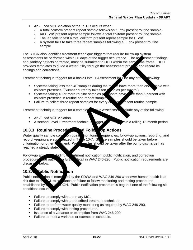
City of Sumner General Water Plan Update - DRAFT
April 2018 10-22 BHC Consultants, LLC
An E. coli MCL violation of the RTCR occurs when: o A total coliform present repeat sample follows an E. coli present routine sample. o An E. coli present repeat sample follows a total coliform present routine sample. o The lab fails to test a total coliform present repeat sample for E. coli. o A system fails to take three repeat samples following a E. coli present routine
sample. The RTCR also identifies treatment technique triggers that require follow-up system assessments be performed within 30 days of the trigger occurrence. The assessment findings, and sanitary defects corrected, must be submitted to DOH within the same time frame. DOH provides templates to guide a water utility through the assessment process and record its findings and corrections. Treatment technique triggers for a basic Level 1 Assessment include any of the following: Systems taking less than 40 samples during the month have more than one sample with
coliform presence. (Sumner currently takes ten samples per month.) Systems taking 40 or more routine samples per month have more than 5 percent with
coliform presence in routine and repeat samples. Failure to collect three repeat samples for every coliform present routine sample.
Treatment technique triggers for a complex Level 2 Assessment include any of the following: An E. coli MCL violation. A second Level 1 treatment technique trigger occurring within a rolling 12-month period.
10.3.3 Routine Procedures and Follow-Up Actions Water quality sample collection points, monitoring frequencies, follow-up actions, reporting, and record keeping are summarized in Table 10-7. Source samples should be taken before chlorination or other treatment. Well samples should be taken after the pump discharge has reached a steady state. Follow-up actions, including department notification, public notification, and correction procedures, are outlined in further detail in WAC 246-290. Public notification requirements are discussed below.
10.3.4 Public Notification Public notification is mandated by the SDWA and WAC 246-290 whenever human health is at risk due to an MCL exceedance or failure to follow monitoring and testing procedures established by the state DOH. Public notification procedure is begun if one of the following six conditions occur: Failure to comply with a primary MCL. Failure to comply with a prescribed treatment technique. Failure to perform water quality monitoring as required by WAC 246-290. Failure to comply with testing procedures. Issuance of a variance or exemption from WAC 246-290. Failure to meet a variance or exemption schedule.
DRAFT

City of Sumner General Water Plan Update - DRAFT
April 2018 10-23 BHC Consultants, LLC
Because some violations are more serious than others, three tiers of public notification should be established in accordance with WAC 246-290, Part 7, Subpart A and the referenced 40 CFR Part 141, Subpart Q. The EPA Revised Public Notification Handbook (EPA Publication 816-R-09-013, March 2010) is recommended as a reference when creating public notices.
DRAFT

City of Sumner General Water Plan Update - DRAFT
April 2018 10-24 BHC Consultants, LLC
Table 10-7 Water Quality Monitoring Routine Procedure and Follow-Up Actions
Contaminant Collection Point Monitoring Frequency MCL Exceedance Follow-Up Actions
Report to DOH a Record
Keeping b Bacteriological (coliform, fecal coliform, enterococci coliform)
From representative points throughout collection system
10 sampling points once a month.
See Section 10.3.2. Coliform in Sample: 10 days.
Acute MCL violation: within 24 hours.
Level 1 or 2 assessment complete: within 30 days
5 years
Primary Inorganic Chemicals and Groundwater Turbidity
At sources after chlorination and before entry into distribution system (springs-metering vault)
One complete scan every 36 months a
Collect three additional samples from the same source within 30 days. If the average of the four samples exceeds MCL, violation is confirmed.
From nitrate, immediately take one additional sample from the same source, if the average of the two samples exceeds MCL, violation is confirmed.
Violation of MCL: 48 hours
Failure to Comply with Primary Standards: 48 hours
Monitoring Failure: 48 hours
As long as system is in operation.
Secondary Inorganic Chemicals and Physical Characteristics
At source after chlorination and before entry into distribution system (springs-metering vault)
One complete scan every 36 months. a Sulfate and TDS monitoring required only if specific conductivity exceeds: 700 µmhos cm
Collect three additional samples from the same source within 30 days. If the average of the four samples exceeds MCL, violation is confirmed.
Violation of MCL: 48 hours
Monitoring Failure: 48 hours
As long as system is in operation. DRAFT

City of Sumner General Water Plan Update - DRAFT
April 2018 10-25 BHC Consultants, LLC
Table 10-7 Water Quality Monitoring Routine Procedure and Follow-Up Actions
Contaminant Collection Point Monitoring Frequency MCL Exceedance Follow-Up Actions
Report to DOH a Record
Keeping b Disinfection By Products
Point in system representing maximum residence time for source
Every 36 months. Notify public and DOH. Coordinate with DOH to
develop compliance plan
Violation of MCL: 48 hours
As long as system is in operation.
Chlorine Residual Same time and location as coliform monitoring
Monthly. Notify public and DOH. Coordinate with DOH to
develop compliance plan if required.
Violation of MCL: 48 hours
As long as system is in operation.
Chlorine Residual Source Continuous. None None As long as system is in operation.
Pesticides At source before treatment (spring-metering vault)
Every 36 months (collect when pesticide contamination is most likely to occur), or waiver.
Although monitoring is not a requirement for groundwater sources, it is suggested to help determine groundwater under the influence of surface water (GWI).
Take action as specified by DOH.
Violation of MCL: 48 hours
As long as system is in operation.
Radionuclides At source (spring-metering vault)
Once every 36 months. If results are <1/2 MCL, take a single sample once every 48 months.
Take action as specified by DOH.
Violation of MCL: 48 hours
As long as system is in operation.
Lead and Copper Initially, at 40 high-risk sites with lead and copper solder or pipes. 20 Sites
Discontinued if optimum corrosion control is met. Action Levels met 3 consecutive years Monitoring reduced to once every 3-year period.
Monitor for corrosion control parameters (pH, alkalinity, calcium, conductivity, and temperature).
Water treatment for optimum corrosion control if violation continues.
Action Level Exceedance: 7 days
As long as system is in operation. DRAFT

City of Sumner General Water Plan Update - DRAFT
April 2018 10-26 BHC Consultants, LLC
Table 10-7 Water Quality Monitoring Routine Procedure and Follow-Up Actions
Contaminant Collection Point Monitoring Frequency MCL Exceedance Follow-Up Actions
Report to DOH a Record
Keeping b Volatile Organic Chemicals
At source, after treatment and before entry points to distribution system (master meters).
Once every 36 months No VOCs have been detected in initial screening of springs. South well should have a comprehensive scan for List 1 and List 2 VOCs.
Can composite up to five sources to reduce laboratory costs, restrictions apply – see WAC 246 290–300(d).
Provide one-time notification to water users of availability of initial screening results (within 3 months).
List 1 VOC > Detection Limit: Sample source once every 3 months for at least 3 years, and make lab results available to consumers within 3 months.
List 1 VOC > MCL: Submit strategy for gathering additional data and informing public. Sample as above.
Running Total List 1 VOC > MCL: Submit action plan according to WAC 246 290 320. Sample as above. Implement action plan.
Initial Screening VOC. Samples: 90 days after DOH contact.
List 1 VOC > MCL: 7 days.
Running Total List 1 VOCs > MCL; 7 days.
List 2 or 3 VOC > Detection Limit: 7 days.
List 2 or 3 VOC > SAL: 7 days.
As long as system is in operation.
DRAFT

City of Sumner General Water Plan Update - DRAFT
April 2018 10-27 BHC Consultants, LLC
Table 10-7 Water Quality Monitoring Routine Procedure and Follow-Up Actions
Contaminant Collection Point Monitoring Frequency MCL Exceedance Follow-Up Actions
Report to DOH a Record
Keeping b List 2 or List 3 VOC >
Detection Limit: Sample as above.
List 2 or List VOC > State Advisory Level (SAL): Sample as above. Submit strategy for gathering additional data and informing public (within 6 months).
Notes: a. All test measurements and analytic reports are to be given to DOH within the 10th day of the following month unless specified otherwise. b. Other measurements should be kept at least 5 years, including C�2 residual, quantity of chemicals used, and flow records. Records of
action taken by system to correct violation of primary regulations and public notifications should be kept 3 years.
DRAFT

City of Sumner General Water Plan Update - DRAFT
April 2018 10-28 BHC Consultants, LLC
Content of Notices Public Notices should be written in a clear, concise manner, emphasizing the following basic information: Who? (City of Sumner Water Utility: 253-863-8300) What? (Simple explanation of violation including discussion of potential adverse health
effects and any segment of the population that may be at higher risk.) When? (The time of the violation or date when a variance and/or exemption was
granted.) Consumer Actions. (List of steps the consumer should take, including advice on seeking
an alternative water supply if necessary.) Purveyor Actions. (List of steps the purveyor has taken or is planning to take to remedy
the situation.) Authority Involved. (EPA, DOH or Ecology, and Applicable Administrative Code)
Mandatory health effects information and language will also be required when a violation involves: A primary VOC MCL. An acute coliform MCL. A nonacute MCL. Granting or continuation of exemption or variance. Failure to comply with a variance or exemption schedule.
Specific language is contained in the DOH guideline titled “Health Effects Language for Drinking Water Public Notification.” The District Engineer should be contacted prior to issuing notices. A copy of the completed notices should be sent to DOH.
Volatile Organic Compounds Notification All those served by the water system, including wholesale buyers, should be notified of the availability of new VOC results. This notification is only required once. Notification should be provided in the first set of water bills or by direct mail after the receipt of results. If a List 1 VOC (see WAC 246-290) is confirmed at a concentration greater than the MCL, or the department confirms that a List 2 or List 3 VOC is at a level greater than a State Advisory Level (SAL), then the consumer should be notified of the following: Name and level of VOC detected. Location where VOC was detected. Any health effects that the VOC could cause at its present concentration. Plans for follow-up activities. Phone number to call for further information.
Emergency Response Program All water systems experience emergencies. Pipes break, hydrants rupture, and short-term power outages occur. These emergencies are anticipated by the utility and are handled by the Public Works staff without significant difficulty.
DRAFT

City of Sumner General Water Plan Update - DRAFT
April 2018 10-29 BHC Consultants, LLC
Less frequently, water utilities must deal with natural and man-made disasters of greater proportions. These include earthquakes, watershed fires, hazardous materials spills, vandalism, extended sub-zero weather, extended droughts, flooding, major power outages, and windstorms. Less extensive emergencies include chlorine leaks, injury of water system staff, and large mechanical failures. The City of Sumner Water Utility should be prepared for these types of disasters and be able to circumvent serious public health consequences and wide-scale disruption in water service and firefighting capabilities. This chapter presents an emergency response plan to direct action for a variety of potential disasters. A contingency plan for each emergency situation is presented following a discussion of general emergency preparedness. Common to many contingency plans is the Water Shortage Response Plan, which is a step by-step approach for rationing water during emergency periods. Finally, at the end of the chapter, a Comprehensive Emergency Call-Up List is presented. This list should be readily available to all water system operations personnel, local police, and fire departments. As a measure to coordinate and share valuable water utility resources during an emergency, the City is a member of the Pierce County Regional Water Cooperative, members of which are in communication with each other via a reserved radio system.
10.4.1 General Emergency Preparedness To establish an effective emergency response program, all Public Works, Police, and Fire Department staff must be trained and assigned specific duties. Assignments of duties in each type of emergency situation should be specific, but not so rigid that another member on the staff could not also perform the function. All staff should be made aware of each other’s assignments in case: An operator is absent or injured and unable to attend to his/her duties. A disaster does not fall into the prepared-for category. More than one staff member is needed for a response for which only one was
anticipated. General emergency preparedness should be common to all personnel. General emergency preparedness is the greatest single emergency response action that can be taken, even though it occurs well before the emergency situation presents itself. The following subsections list activities and measures that should be undertaken as part of emergency preparedness. These include staff training and preparation, assuring repair material availability, routine inspections, and hardening of facilities.
Personnel Training and Preparation Provide all personnel involved in the emergency response program with a copy of the
Water System Staff and Emergency Call-Up Lists. Train all personnel for hazardous spill response and fundamentals in emergency water
treatment. Water quality is the foremost concern in any emergency situation. Emergency water treatment includes substance detection, manual chlorine addition, and filtration.
Conduct annual mock emergencies to find flaws in the current Emergency Response Plan.
Provide pagers and/or radios to all foremen at all times.
DRAFT

City of Sumner General Water Plan Update - DRAFT
April 2018 10-30 BHC Consultants, LLC
Assign general emergency response duties to all personnel. All personnel should know who is responsible for each of the following: o Alerting personnel and assigning specific duties. o Assessing overall water system damage. o Coordinating and or directing Police and Fire Departments. o Testing the communication system. o Informing public of health dangers or water shortages. o Placing and starting auxiliary power supplies. o Recruiting volunteers. o Acquiring additional emergency repair equipment. o Isolating damaged facilities from the system. o Coordinating logistics and obtaining supplies from City Shops and local
suppliers/merchants. o Monitoring water quality. o Applying treatment chemicals to water supply. o Turning on pumps. o Opening interties. o Monitoring water tank levels.
Material Availability Keep extra fuel at City Shops for chainsaws, electric generators, and vehicles. Keep keys, bolt cutters, saws, axes, crowbars, water main shutoff wrenches, and other
water system access parts in all maintenance vehicles. Assure repair materials are available from local suppliers and merchants on short notice
(see Emergency Call-Up List). Arrange with local suppliers for access to stored chemicals, tools, repair parts, etc.,
which may be required immediately after the emergency. Determine the need to relocate materials to outlying sites. As a suggestion:
o Keep personnel protection equipment and operations and maintenance manuals at facilities where they will most likely be needed.
o Keep all electrical parts needed to quickly set up an electric generator at all electric powered facilities.
o Keep granular activated carbon, lime, and extra chlorine at all treatment facilities for emergency treatment.
o Keep spare flashlights and radios at key locations for easy access. o Keep fire extinguishers in all buildings.
Routine Inspection Check automobiles, auxiliary electric power, and pumping units in periods of nonuse. Periodically check emergency communications equipment. Maintain emergency rations of food, water, and bedding at Fire Station and City Shops.
Facilities Hardening Keep alternate routes open to all water system facilities. Sumner and County Springs
should have clear access roads from both the valley and the top of the hill. Keep all gates locked. Install fences around all facilities subject to human interference. Reinforce and stabilize slopes in the watersheds that may be prone to slide. Harden damage-prone facilities with seismic retrofits, storm windows, and other
appropriate measures. Buried facilities are able to better withstand most disasters.
DRAFT

City of Sumner General Water Plan Update - DRAFT
April 2018 10-31 BHC Consultants, LLC
10.4.2 Public Notification In the event of an emergency, the public should be quickly notified to prevent adverse health effects. This is currently accomplished by the utility crew knocking on doors to inform residents. If the residents are not home, door hangers describing the nature and extent of the emergency are placed on the doorknobs. Immediate notification can also be made through local radio and television stations. The Emergency Call-Up List gives the numbers of several local radio, television stations, and newspapers to contact for quick public notification. Public notifications should contain the following types of information, depending on the seriousness and nature of the emergency: Water system components affected. Nature of threat to public health. Water utility and local agency efforts to restore water supply. Any curtailment measures or rationing imposed. Location of temporary water supply if needed:
o Will bottled water be distributed? o Will wells be directly tapped? o Will a tanker truck be parked at City Hall? o Will water be provided by Puyallup, etc.?
Treatment measures to make water suitable for human consumption (e.g., boiling, adsorption on activated carbon, adding bleach, etc.).
10.4.3 Contingency Plans Each disaster or emergency will have particular effects on different parts of the system depending on location, magnitude, and extent of disaster as well as many unforeseen factors. Damage to one part of the system may affect other parts of the system; the combination of effects is impossible to predict. The greatest single action the utility can take is preparedness. However, there are contingency operation plans that can be implemented to continue providing safe reliable water in the event of disaster. These contingency operation plans are contained in Appendix J.
10.4.4 Water Shortage Response Plan The Water Shortage Response Plan (WSRP) is a tool to manage a major water use reduction during extreme water-short periods. The WSRP is based on demand management techniques and conservation including voluntary restrictions, mandatory restrictions, water curtailment, and development of long-term water supply, storage, and distribution systems. This WSRP considers water shortages for two different scenarios. Trigger criteria and specific City actions are identified for both short-term emergency (line break, loss of well) and long-term (drought) conditions. Table 10-8 provides a summary of the Sumner Water Shortage Response Plan.
DRAFT
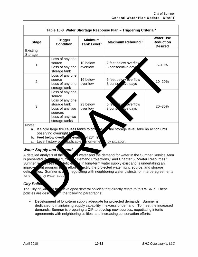
City of Sumner General Water Plan Update - DRAFT
April 2018 10-32 BHC Consultants, LLC
Table 10-8 Water Shortage Response Plan – Triggering Criteria a
Stage Trigger
Condition Minimum
Tank Level b Maximum Rebound c
Water Use Reduction
Desired Existing Storage
1
Loss of any one source Loss of any one storage tank
10 below overflow
2 feet below overflow 3 consecutive days 5–10%
2
Loss of any one source Loss of any one storage tank
16 below overflow
5 feet below overflow 3 consecutive days 10–20%
3
Loss of any one source Loss of any one storage tank Loss of any two sources Loss of any two storage tanks
23 below overflow
5 feet below overflow 3 consecutive days 20–30%
Notes: a. If single large fire causes tanks to drop below fire storage level, take no action until
observing overnight filling. b. Feet below overflow elevation of 234 feet. c. Level history only applicable to non-emergency situation.
Water Supply and Demand A detailed analysis of the supply of water and the demand for water in the Sumner Service Area is presented in Chapter 3, “Water Demand Projections,” and Chapter 5, “Water Resources.” Sumner recognizes that deficiencies in long-term water supply exist and is undertaking an improvement program in an effort to rectify the projected water right, source, and storage deficiencies. Sumner is also negotiating with neighboring water districts for intertie agreements for emergency water supply.
City Policies The City of Sumner has developed several policies that directly relate to this WSRP. These policies are described in the following paragraphs: Development of long-term supply adequate for projected demands. Sumner is
dedicated to maintaining supply capability in excess of demand. To meet the increased demands, Sumner is preparing a CIP to develop new sources, negotiating intertie agreements with neighboring utilities, and increasing conservation efforts.
DRAFT

City of Sumner General Water Plan Update - DRAFT
April 2018 10-33 BHC Consultants, LLC
Sumner recognizes the need to maintain and upgrade their supply, storage, and distribution systems and is undertaking a CIP, which will include new source, a new storage tank, and various distribution system improvements. This commitment to system improvements is an ongoing activity.
An ongoing leak detection and curtailment program will be an operational priority during all conditions of water availability.
Conservation and water use education will be a continual process with general information mailed to the customer quarterly and available at the Sumner City Hall at all times. Specific information will be mailed to all customers during the early stages of a water shortage (see Example Public Announcements found later in this chapter).
The rate structure will promote conservation by charging for the amount of water used. Increased unit charges during times of water shortage may be considered by the City Council. The decision to utilize a rate change and size of rate change will be determined by the Council based on the estimated severity, potential longevity of the shortage, and the best interests of the customers.
Residential and commercial customers will be treated alike, with restrictions placed on all customers without regard to classification.
Conservation Actions Determination of Water Shortage Stage and specific actions to be taken depends on the anticipated longevity of the shortage. The City of Sumner will utilize the meeting of trigger criteria to begin specific actions outlined below as well as performing an analysis of the impacts of the deficit in water supply and how long it will be in place. The ability to place the city in a higher response level if additional water savings are required is an integral part of this WSRP. This determination will take on less importance following construction of new wells and storage scheduled in the near future. The loss of any one source or storage tank will impact a smaller percentage of the system and will require less demand reduction to compensate. The triggering criteria are summarized below.
Water Shortage Stage 1
Water Shortage Condition: Minor. Consumption Reduction Goal: 5 to 10 percent.
Triggering Criteria Loss of any one source for greater than 24 hours. Loss of any one storage tank for greater than 24 hours. Water level in storage tanks (i.e., tank used to control pumps) falls to a level 10 feet
below overflow and returns overnight to a level no greater than 2 feet below overflow for 3 consecutive days.
Public Information Actions Prepare and distribute a letter mailed to all customers describing the water shortage
condition. Make published technical conservation material available from DOH readily available to
all customers. Locate copies in the City Hall.
DRAFT

City of Sumner General Water Plan Update - DRAFT
April 2018 10-34 BHC Consultants, LLC
Prepare a press statement concerning the shortage. Example announcement is included in this WSRP.
City of Sumner Actions Public Works Director makes determination if cause for water shortage is long-term and
will require savings in excess of 10 percent. If determination justifies greater savings, move to Water Shortage Stage 2.
Fire hydrants limited to use only during firefighting operations. Promote intensive leak detection and repair program. Perform no system maintenance that requires the use of extensive amounts of water
such as tank maintenance requiring drainage and flushing of distribution lines.
User Restrictions Implement voluntary user restrictions.
Enforcement None.
Pricing None.
Water Shortage Stage 2
Water Shortage Condition: Moderate. Consumption Reduction Goal: 10 to 20 percent.
Triggering Criteria Stage 1 storage tank criteria plus loss of any one source for greater than 24 hours. State 1 storage tank criteria plus loss of any one storage tank for greater than 24 hours. Water level in storage tank reaches a level 16 feet below overflow and returns overnight
to a level no greater than 5 feet below overflow for 3 consecutive days.
Public Information Actions Continue public information program defined in Stage 1, with an additional letter mailed
to all customers describing the nature of the water shortage and describing the restrictions to be imposed.
City of Sumner Actions Continue actions from Stage 1, including determination by Public Works Director of
status of shortage. Evaluate the consumption of water on a customer-by-customer basis using the latest
meter readings to identify high use customers. Begin consideration of buying water from other utilities through existing interties.
User Restrictions Institute mandatory water conservation activities such as odd/even day watering. Institute ban on excessive exterior uses of water (car washing, driveway cleaning, etc.).
DRAFT

City of Sumner General Water Plan Update - DRAFT
April 2018 10-35 BHC Consultants, LLC
Enforcement Notify all customers who show use in excess of appropriate amounts that water use is to
be decreased. Representative of Sumner to visit house if found in violation of restriction.
Pricing None.
Water Shortage Stage 3
Water Shortage Condition: Severe. Consumption Reduction Goal: 20 to 40 percent.
Triggering Criteria Stage 2 storage tank criteria plus loss of any one source for greater than 24 hours. Stage 2 storage tank criteria plus loss of any one storage tank for greater than 24 hours. Water level in storage tank falls to a level 23 feet below overflow and returns overnight to
a level no greater than 5 feet below overflow for 3 consecutive days. Loss of any two sources for greater than 24 hours. Loss of any two storage tanks for greater than 24 hours.
Public Information Actions Continue public information program defined in Stage 1, with an additional letter mailed
to all customers describing the nature of the water shortage and describing the restrictions to be imposed.
City of Sumner Actions Continue actions from Stage 2, including determination by Public Works Director of
status of shortage. Notify DOH and Pierce County Health Department. Assign a “Water Cop” to tour the service area to look for violations of restrictions. Commission interties for everyday supply, if available. Inspect operation and settings on all pumps and instruments to verify efficient use. Institute personal customer contact and inspect houses for leaks.
User Restrictions Mandatory curtailment of all water usage except for domestic potable use.
Enforcement One warning for unnecessary water usage. Termination of service following repeat warning. Fine for excessive use.
Pricing Institute modified rate structure with higher unit prices. New prices and timing of
increase to be determined by City Council.
DRAFT

City of Sumner General Water Plan Update - DRAFT
April 2018 10-36 BHC Consultants, LLC
Example Public Announcements Every potential water shortage is unique; therefore, specific announcements prepared in advance are not a part of this WSRP. However, it is wise to have several example announcements available that can be modified to fit the circumstances. The following paragraphs list several example public announcements Sumner can use in the case of a water shortage.
Sample I – Stage 1 Water Shortage
The City of Sumner is experiencing unusually high water demand and is having difficulty maintaining adequate reservoir reserves. Drawdown of reservoirs during the day is not being offset by the overnight refilling capabilities. Residents of the city are requested to reduce water consumption and to avoid wasting water wherever possible. The problem is expected to be temporary in nature, and a public announcement will be made when normal water consumption can be resumed.
Sample II – Stage 1 Water Shortage
The City of Sumner is experiencing a major loss of its water production capacity. The City’s customers are requested to reduce their water usage and to avoid wasting water. It would be particularly helpful if homeowners will make every effort to reduce lawn irrigation. The problem is expected to be temporary in nature, and a public announcement will be made when normal water consumption can be resumed.
Sample III – Stage 2 Water Shortage
The City of Sumner has experienced a major loss in water production and storage capacity, and, therefore, is unable to maintain normal water deliveries. It is mandatory that certain water usage activities be curtailed. This includes the imposition of alternate day lawn watering restrictions on all customers and a complete ban on other nonrequired outside uses of water such as car washing and driveway cleaning. Your cooperation is urgently requested. The City is doing everything possible to restore the water system to normal operations. You will be notified of any change in the situation.
Sample IV – Stage 3 Water Shortage
The City of Sumner has experienced a major loss of its water production capacity. Immediate mandatory curtailment of all water usage except for in-house domestic use is hereby imposed. Your cooperation is urgently requested. Failure to comply with the restrictions may result in termination of service with possible fines being imposed. The City is doing everything possible to restore the water system to normal operations. You will be notified of any change in the situation.
Supply Augmentation A number of options are available to Sumner for the short-term augmentation of water supply. Sumner currently has interties with the City of Puyallup and Pacific. Sumner has also recently added the Central Well as a new source. Potential existing source improvements that increase operational yield, and new sources/interties will continue to be evaluated as needed to meet future demands. A conservation and water use education program is in place.
DRAFT

City of Sumner General Water Plan Update - DRAFT
April 2018 10-37 BHC Consultants, LLC
Sumner is also involved in a long-term program to improve the efficiency of the existing facilities. The City participates in a continual program of leak detection and maintenance of pipes, wells, and storage facilities and is upgrading and adding new pipelines to enable more efficient distribution of the existing supplies.
Schedule and Funding Sumner’s public awareness program is under way. The City has prepared generic water shortage notices that can be used as a basis for public announcements if water shortages occur. Sumner is currently negotiating with neighboring water districts for intertie agreements. Sumner is also preparing a CIP, part of which includes improvements to existing sources to maximize source capacity. Funding for this construction program will be through the use of general revenue funds, developer participation, ULIDs, and grants and loans available from the federal, state, and local governments. A financial plan for improvements is included in the Water System Plan and will be implemented through annual budget revisions. Sumner performs an annual review of water rates that considers the changing maintenance and operation costs as well as proposed improvement projects.
Monitoring Program Sumner has several mechanisms already in place that can be used to monitor the effectiveness of this WSRP. The City maintains continuous readings on the flow from the springs and wells and the water level in the storage tanks. An expandable telemetry system is being installed. By utilizing this information, Sumner will be immediately informed of the available supply of water. Sumner meters all flow at two locations – the source and as it is discharged to a user. Use of this information will enable Sumner to identify and locate major leaks in a timely manner. Sumner is committed to the development of new source, storage reservoirs, and interties and will watch the construction effort and keep it on schedule. Sumner will periodically review this WSRP and upgrade it as needs arise. This WSRP reflects what Sumner feels to be a sound implementation WSRP based on fact, professional opinion, comparison with other programs, public expression, and future supply and demand.
10.4.5 Water Main Break/Localized Pressure Loss In the event of a suspected water main break within Sumner’s water distribution system, the City’s response protocol will generally follow the procedures outlined within DOH publication 331-583 (a copy of which is included as Appendix K).
10.4.6 Emergency Call-Up List The following pages provide emergency telephone numbers for easy access during an emergency. The Water System Personnel Priority Call-Up List is on file at the City Public Works Department and Fire Department. DRAFT

City of Sumner General Water Plan Update - DRAFT
April 2018 10-38 BHC Consultants, LLC
CITY OF SUMNER EMERGENCY CALL UP LIST
City of Sumner
Water System Personnel Priority Call-Up List (Business Hours) City Hall Maintenance Facility
253-299-5700 253-299-5740
Water System Personnel Priority Call Up List (After Hours – Police Department)
253-863-6384 or 911
Police Department 253-863-6384 or 911 East Pierce County Fire and Rescue 253-863-1800 or 911
Adjacent Water Purveyors
Pierce County Public Works 253-798-4020 Pierce County Emergency/After Hours 253-798-7470 City of Puyallup Public Works 253-841-5505 City of Puyallup Water Superintendent 253-841-5503 City of Puyallup Emergency/After Hours 253-841-5415 City of Bonney Lake Public Works 253-862-8602 Mt. View – Edgewood Water District 253-863-7348 Mt. View – Edgewood Emergency/After Hours 253-591-0613 Valley Water District 253-841-9698 City of Pacific 253-929-1110
Utilities
Puget Sound Energy New Construction, Repairs, Power Outage Underground Utilities Location Service
888-321-7779 800-424-5555
Washington Natural Gas Co 206-622-6767 Qwest Communications 253-451-5350
Department of Health
State Office General Information (Drinking Water Information)
800-525-0127 360-236-3100
Pierce County Emergency Management 253-798-6595 Northwest Regional Office 253-395-6750 Community Health Systems 800-236-2833 Hazardous Waste Information and Response 206-296-4692
DRAFT

City of Sumner General Water Plan Update - DRAFT
April 2018 10-39 BHC Consultants, LLC
CITY OF SUMNER EMERGENCY CALL UP LIST
Washington Emergency Management Division (24-Hour Regional Coordination); and Chemical Spills (State Duty Officer)
800-258-5990
DOH – Public Health Laboratory 206-418-5400
State/Federal Assistance Agencies
Washington State Department of Ecology (24-Hour Emergency, Including Spill Response) (OIL ONLY)
425-649-7000 800-645-7911
Washington Department of Fish and Wildlife (Olympia Office) Department of Natural Resources – Forest Fire Reports
360-902-1000 800-562-6010
National Weather Service U.S. Army Corps of Engineers (Seattle)
206-526-6087 206-764-3742
Police Agencies/Civil Disorder
Washington State Patrol 253-536-6210 or 911 Washington National Guard (Puyallup) Washington National Guard (Tacoma)
253-840-4686 253-597-4150
Equipment Rental/Supplies
Emergency Chemical Supplies Jones Chemical, Inc.
253-274-0104
Water Treatment Equipment, Service and Supplies ATEC Systems Associates, Inc. (Longview) Beaver Equipment Company (Kenmore)
360-414-9223 425-398-8082
Water Works Equipment and Supplies H. D. Fowler, Inc. (Pacific) U.S. Filter (Puyallup)
253-863-8600 253-840-1141
Safety Equipment and Clothing Excel Supply Co. (Fife) Western Fire and Safety Company, Inc. (Seattle)
253-896-1195 206-782-7825
Water Main Contractor Don Olson Construction, Inc. (Renton)
425-228-4282
Chain Saws, Dewatering, Tools, Vehicles Bunce Rental, Inc. (Puyallup)
253-845-7527
Generators United Rentals (Tacoma) Sunbelt Rentals (Tacoma)
253-383-1515 253-922-6995
DRAFT

City of Sumner General Water Plan Update - DRAFT
April 2018 10-40 BHC Consultants, LLC
CITY OF SUMNER EMERGENCY CALL UP LIST
Contractors’ Equipment Aggreko, Inc. (Pacific) Star Rentals (Tacoma) Aeberg’s Tool and Equipment Rental (Tacoma)
206-498-2350 253-474-0577 253-272-1138
Federal Emergency Management Agency
Regional Office Disaster Assistance Programs Flood Insurance Programs Natural and Technical Hazards News Desk Holidays, Weekends, and Evenings
425-487-4600 800-621-3362 800-427-4661 800-621-3362 202-646-3272 800-621-3362
Radio Stations, Television Stations, Newspapers
KOMO AM 1000 KIRO AM 710 Newsradio KONP AM 1450 KISS FM 106.1 KISW FM 99.9 KUBE FM 93.3
206-404-4000 206-728-7777 360-457-1450 206-494-2000 206-577-8600 206-494-2000
KCPQ Channel 13 KIRO Channel 7 KOMO Channel 4 KING Channel 5 CW Channel 11
206-674-1313 206-728-7777 206-404-4000 206-448-5555 206-861-8814
Tacoma News Tribune Pierce County Herald
253-597-8742 715-273-4334
Cross Connection Control Program The City of Sumner has a responsibility to protect its water system from contamination due to cross connections. Cooperation among all agencies involved in cross connection control is required, including the state Department of Health, the City’s Public Works Department, City Attorney, the local health officer, the local plumbing and building code authority, and the Fire Department. This chapter outlines a comprehensive cross connection control program for the City of Sumner. First, a generalized description of a cross connection is given, followed by a discussion of health hazard assessment and a description of cross connection control methods. Finally, an implementation program for the City of Sumner outlining present and recommended practices is given.
DRAFT

City of Sumner General Water Plan Update - DRAFT
April 2018 10-41 BHC Consultants, LLC
10.5.1 Regulatory Framework Regulatory framework for cross connection control is through the Safe Drinking Water Act, whose intent is to assure safe, potable water for all U.S. citizens. State regulations pertaining to cross connection control are found in Washington State statutes and “State of Washington Drinking Water Regulations,” Chapter 246-290-490 WAC. The City may be held legally liable for adverse health effects caused by unprotected or inadequately protected cross connections including cost associated with disinfection and/or replacement of piping to remove toxic substances from the water supply system. The most recently published edition of the Manual of Cross Connection Control (10th Edition 1993) must be used as a resource to establish: Minimum cross connection control operating policies. Backflow prevention assembly installation practices. Backflow prevention assembly testing procedures. Enforcement authority.
Several other manuals in addition to Accepted Procedure and Practice in Cross Connection Control and WAC 246-290-490 should be kept with the cross connection control program document library for ready reference. These include: AWWA 2004, Recommended Practice for Backflow Prevention and Cross Connection
Control. DOH 2008 Backflow Prevention Assemblies Approved for Installation in Washington
State. City of Sumner Ordinance 13.24.270, “Backflow Prevention Devices.” The Operation Program Section of the Water System Plan.
These six documents and all records of inspection and testing are an integral part of the City of Sumner Cross Connection Control Program.
10.5.2 What is a Cross Connection? A cross connection is any unprotected actual or potential connection or structural arrangement between a public or a consumer’s potable water system and any other source or system through which it is possible to introduce into any part of the potable system any used water, industrial fluid, gas, or substance other than the intended potable water with which the system is supplied. Cross connections usually take the form of either back pressure or back siphonage.
Back Pressure Back pressure can occur whenever a potable system is connected to a nonpotable supply operating under a higher pressure by means of a pump, boiler, elevation difference, air or steam pressure. There is a high risk that nonpotable water may be forced into the potable system whenever these interconnections are not properly protected.
DRAFT

City of Sumner General Water Plan Update - DRAFT
April 2018 10-42 BHC Consultants, LLC
Back Siphonage Back siphonage can occur when there is a negative or reduced pressure in the supply piping. Under normal conditions, the pressure in the distribution system is sufficiently high to create a positive flow to all taps. However, if system pressures are reduced due to fire demands, pipe breakage, or other cause, water may flow from higher elevations into lower parts of the system or vacuum pressure may draw water from service connections. A cross connection occurs when nonpotable water is drawn back through the supply line. Elevated piping at a reduced pressure relative to the system at street level is especially susceptible. The suction side of booster pumps may also cause reduced pressures and create a higher backflow potential.
10.5.3 Classification of Risk Cross connections are classified into health and nonhealth hazards. A health hazard is posed by any cross connection or potential cross connection involving any substance that could, if introduced to the water system, cause death, illness, spread of disease, or have a high probability of causing such effects. A nonhealth hazard is posed by any cross connection involving any substance that generally would not be a health hazard, but would constitute a nuisance, or be aesthetically objectionable, if introduced into the potable supply. Classification of risk must consider the potential that piping may be changed, equipment may be used incorrectly, or negligence on the part of the consumer may result in a backflow condition. In general, risk increases both as a function of the hydraulic probability of backflow and the toxicity of the substance that may introduced into the potable supply. When choosing a backflow prevention method, the toxicity of the substance that may be introduced into the potable supply is the governing factor. General health and nonhealth classifications of risk for various types of cross connection and facilities are presented in Table 10-9 and Table 10-10, reproduced here from Recommended Practice for Backflow Prevention and Cross Connection Control (AWWA 2004). Table 10-10 identifies the same severe and high health cross-connection hazard premises that are listed with Table 9 of WAC 246-290-490. Objectionable material and routes of contamination from a variety of commercial and industrial establishments are presented in Recommended Practice for Backflow Prevention for Backflow Prevention and Cross Connection Control (AWWA 2004).
Table 10-9 Assemblies for Internal Protection
Description of Cross Connection Assessment
of Hazard Recommended
Assembly at Fixture a Aspirator (medical) Health AVB or PVB Bedpan Washers Health AVB or PVB Autoclaves Health RPBA Specimen Tanks Health AVB or PVB Sterilizers Health RPBA Cuspidors Health AVB or PVB Lab Bench Equipment Health AVB or PVB Autopsy and Mortuary Equipment Health AVB or PVB Sewage Pump Health AG Sewage Ejectors Health AG
DRAFT

City of Sumner General Water Plan Update - DRAFT
April 2018 10-43 BHC Consultants, LLC
Table 10-9 Assemblies for Internal Protection
Description of Cross Connection Assessment
of Hazard Recommended
Assembly at Fixture a Fire-Fighting System (toxic liquid foam concentrates) Health RPBA
Connection to Sewer Pipe Health AG Connection to Plating Tanks Health RPBA Irrigation Systems with Chemical Additives or Agents Health RPBA
Connection to Saltwater Cooling System Health RPBA Tank Vats or Other Vessels Containing Toxic Substances Health RPBA
Connection to Industrial Fluid Systems Health RPBA Dye Vats or Machines Health RPBA Cooling Towers with Chemical Additives Health RPBA Trap Primer Health AG Steam Generators Nonhealth b RPBA Heating Equipment: Commercial Nonhealth b RPBA
Domestic Nonhealth b DCVA Irrigation Systems Nonhealth b DCVA, AVB, or PVB Swimming Pools: Public Nonhealth b RPBA or AG
Private Nonhealth b PVB or AG Vending Machines Nonhealth b RPBA or PVB Ornamental Fountains Nonhealth b DCVA or AVB or PVB Degreasing Equipment Nonhealth b DCVA Lab Bench Equipment Nonhealth b AVB or PVB Hose Bibs Nonhealth b AVB Trap Primers Nonhealth b AG Flexible Shower Heads Nonhealth b AVB or PVB Steam Tables Nonhealth b AVB Washing Equipment Nonhealth b AVB Shampoo Basins Nonhealth b AVB Kitchen Equipment Nonhealth b AVB Aspirators Nonhealth b AVB Domestic Space-Heating Boiler Nonhealth b RPBA Notes:
AG = Air Gap; AVB = Atmospheric Vacuum Breaker; DCVA = Double Check Valve Backflow-Prevention Assembly; PVB = Pressure Vacuum Breaker; RPBA = Reduced-Pressure Principle Backflow-Prevention Assembly. a. AVBs and PVBs may be used to isolate health hazards under certain conditions, that
is, back siphonage situations. Additional area or premises isolation may be required. b. Where a greater hazard exists (due to toxicity or other potential health impact),
additional area protection with RPBAs is required.
DRAFT

City of Sumner General Water Plan Update - DRAFT
April 2018 10-44 BHC Consultants, LLC
Table 10-10 Assemblies for Premises Isolation
Description of Premises Assessment of
Hazard Recommended Assembly
on Water Service Pipe
Hospitals, mortuaries, clinics, laboratories Health RPBA Plants using radioactive material Health RPBA Petroleum processing or storage facilities Health RPBA Premises where inspection is restricted Health RPBA Sewage treatment plant Health RPBA Sewage lift stations Health RPBA Commercial laundry Health RPBA Plating or chemical plants Health RPBA Docks and dockside facilities Health RPBA Food and beverage processing plants Health RPBA Pleasure boat marina Health RPBA Tall buildings (protection against excessive head of water) Nonhealth DCVA
Steam plants Nonhealth RPBA Reclaimed water systems Health RPBA Notes:
DCVA = Double check valve backflow-prevention assembly. RPBA = Reduced-pressure principle backflow-prevention assembly.
10.5.4 Cross Connection Control Methods When cross connections cannot in good faith be eliminated, several methods of cross connection control through approved backflow prevention devices are available. In general, the more serious the health hazard, the greater the complexity and cost of the required backflow prevention device. Discussed in this section are the five most commonly used devices for cross connection control. In general order of increasing cost and complexity, these include: Approved Air Gap (AG). Pressure Vacuum Breaker (PVB). Atmospheric Vacuum Breaker (AVB). Double Check Valve Assembly (DCVA). Reduced Pressure Principal Backflow-Prevention Assembly (RPBA).
Each backflow device is briefly described below.
Approved Air Gap (AG) An approved air gap is the unobstructed vertical distance through free atmosphere between the lowest point of a water supply outlet and the flood rim of the fixture or assembly into which the outlet discharges. These vertical separations must be at least twice the diameter of the water supply outlet, but never less than 1 inch.
DRAFT

City of Sumner General Water Plan Update - DRAFT
April 2018 10-45 BHC Consultants, LLC
In theory, an approved air gap is the best means of protection against backflow; however, it is not always practical and is vulnerable to bypass arrangements, such as connecting a hose between a water tap and its basin.
Pressure Vacuum Breaker (PVB) A pressure vacuum breaker assembly consists of an independently operating, internally loaded check valve and an independently operating loaded air inlet valve located on the discharge side of the check valve. Under normal flow conditions, the internally loaded check valve remains open, and the air inlet valve is closed. When back siphonage conditions develop, the internally loaded check valve closes. And, if this check valve is not fouled, it precludes the back siphonage of water from the PVB body and downstream piping. However, if the check valve is fouled, the air inlet valve opens with the cessation of normal flow and allows air to enter the supply pipe through the fouled check valve, thus breaking the vacuum and not permitting back siphonage from the downstream piping. The PVB is effective against backflow caused by back siphonage only and should not be used if back pressures could develop. The PVB should be installed in a vertical position at least 12 inches above all downstream piping and the highest fixture flood level rim, outlet, or highest point of water use.
Atmospheric Vacuum Breaker (AVB)
The atmospheric vacuum breaker is an assembly that performs similarly to the PVB. The AVB consists of a float check, a check seat, and an air inlet port. During normal flow conditions, the float within the AVB seals against the air inlet. When a back siphonage condition develops, the cessation of normal flow permits the float to drop, thus opening the air inlet valve. If the float seals against the check seat, there is no back siphonage from the AVB body or downstream piping. However, if the float check is fouled, then the air entering through the air inlet valve dissipates the vacuum through the fouled check valve, thus preventing back siphonage into the supply piping. The AVB is effective against backflow caused by back siphonage only, and should not be used if back pressure could develop. The AVB should be used for protection against nonhealth hazards. Like the PVB, if used to isolate a health hazard, additional area or premises isolation may be required. The AVB should be installed in a vertical position at least 6 inches above all downstream piping and the highest fixture flood level rim, outlet, or highest point of water use.
Double Check Valve Assembly (DCVA)
The DCVA consists of two internally loaded check valves, either spring-loaded or internally weighted. During normal operation, the check valves open. If backflow conditions occur, the check valves will close tightly. The DCVA is effective against backflow caused by back pressure and back siphonage and is used to protect the water system from pollutants that would not constitute an actual health hazard but that might be objectionable to the water supply.
DRAFT

City of Sumner General Water Plan Update - DRAFT
April 2018 10-46 BHC Consultants, LLC
Reduced-Pressure Principle Backflow Prevention Assembly (RPBA)
The approved reduced-pressure principle backflow prevention assembly consists of two independent action, approved check valves together with a hydraulically operating, mechanically independent pressure differential relief valve located between the check valves and below the first check valve. During normal operation, the first internally loaded check valve creates a reduced-pressure zone between the two check valves; and under normal flow conditions, both check valves are open. The relief valve is held tightly closed by the supply pressure acting on a diaphragm within the relief valve. In a no-flow or static-pressure condition, both check valves will close, and the supply pressure will hold the relief valve shut. If the supply pressure drops, the relief valve will maintain a minimum pressure in the zone between Check Valve 1 and Check Valve 2 of 2 psi lower than the supply pressure by releasing sufficient water to maintain the required difference in pressure. If the supply pressure becomes less than 2 psi, the relief valve opens, discharging the material in the reduced pressure zone to the atmosphere. In the event that pressure increases downstream of the assembly, tending to reverse the direction of flow, both check valves in the assembly should close tightly to prevent backflow. However, if the second check valve does not close tightly, leakage into the reduced pressure zone will increase the pressure, which will cause the relief valve to open. If the supply pressure drops to atmospheric pressure, or within 2 psi of the reduced pressure zone, the relief valve will open, creating an internal air gap. Any leakage past the second check valve would then be discharged through the open relief valve. The RPBA is effective against backflow caused by back pressure and back siphonage. The RPBA is used to isolate health hazards and is used in locations where an approved air gap is impractical.
10.5.5 Selection of Backflow Prevention Device Table 10-9 and Table 10-10 can be used as guides in selecting the appropriate backflow devices for individual cross connections and those needed for premises isolation. Premises isolation is needed in addition to individual equipment isolation when high-risk substances could backflow. WAC 246-290-490 places the following limitations on backflow prevention devices: If a cross connection cannot be eliminated, then:
o An AG, RPBA, or reduced-pressure principal detector backflow prevention assembly (RPDA) shall be installed if the cross connection creates an actual or potential health threat or system hazard.
o An AG, RPBA, RPDA, DCVA, or double-check detector backflow prevention assembly (DCDA) shall be installed if the cross connection is objectionable, but does not pose an unreasonable risk to health.
o A PVB or an AVB may be installed where the substance that could backflow is objectionable, but does not pose an unreasonable risk to health and where there is no possibility of back pressure in the downstream piping.
DRAFT

City of Sumner General Water Plan Update - DRAFT
April 2018 10-47 BHC Consultants, LLC
o Backflow prevention assemblies appropriate for the degree of hazard, or air gaps, and in some cases both, shall be installed at the service connection or within the following facilities, unless in the judgment of the water purveyor and the department, no hazard exists: Hospitals, mortuaries, clinics, laboratories, piers and docks, sewage treatment plants, food and beverage processing plants, chemical plants using water process, metal plating industries, petroleum processing or storage plants, radioactive material processing plants or nuclear reactors, car washes, facilities having a nonpotable auxiliary water supply, and others specified by the department.
Any uncertainty in type of backflow prevention device required should be verified in the Accepted Procedure and Practice in Cross Connection Control Manual or through DOH. All installed RPBAs, RPDAs, DCVAs, DCDAs, PVBs, and AVBs must be approved models included on the current list of backflow assemblies, approved for installation in Washington State, and maintained and published by DOH. Directions on how to acquire the most recent list are provided in Appendix L. Backflow prevention assemblies in service, but not listed, can remain in service provided they were on the current cross connection control list at the time of installation, are properly maintained, are appropriate for the degree of hazard, and are tested and successfully pass the test annually. The unlisted assemblies cannot be moved or require more than the minimum maintenance or be subject to replacement with a currently approved model.
10.5.6 Implementation Program The cross connection control implementation program at the City of Sumner consists of the following elements: Cross connection control staff. Inventory of cross connections. Installation inspections. Backflow prevention device testing. Cross connection control ordinance. Public education and notification.
The current program and recommended improvements to each of these elements are discussed in the following paragraphs.
Cross Connection Control Staff The City of Sumner Cross Connection Control Program is administered by the Public Works Department and supervised by the Public Works Director. The City’s engineering staff reviews building permits and plans for cross connection control applicability. The City Engineer assesses risks and hazards associated with cross connections and recommends backflow prevention devices to be installed as a prerequisite for building construction approval. Currently, the City has four licensed CCCSs who implement the program (see Table 10-2). It is recommended that all applications for building permits be reviewed by a CCCS in addition to the City Engineer.
DRAFT

City of Sumner General Water Plan Update - DRAFT
April 2018 10-48 BHC Consultants, LLC
Inventory of Cross Connections In 1988, the City began keeping detailed installation records of backflow prevention devices. All new industries and commercial establishments are required to install backflow prevention devices suitable for the health hazard. As each device is installed, it is entered into a backflow prevention database. Columns in the database are provided for the establishment name, address, type of backflow device installed (RPBA, RPBD, etc.), model, size, serial number, manufacturer, location on premises, date installed, and date last tested.
Installation Inspection Under the City’s current program, the property owner is required to hire a Certified Backflow Prevention Device Tester to test all units after installation. One of the City’s cross connection control specialists witnesses and inspects the arrangement for compliance with all applicable codes and standards. Installation records are kept in the City’s Cross Connection Control Database.
Backflow Prevention Device Testing All backflow prevention devices in the City database are tested annually to assure proper operation. Devices should be inspected more frequently if test indicate repeated failures or the assembly was recently repaired. Procedure is as follows: The owner is notified in their water bill of the need for testing the backflow prevention
device. The owner must hire a certified Washington State Backflow Prevention Device Tester to
perform the test in accordance to manufacturers’ standards and state codes. A list of certified testers is kept on file at DOH.
Test results are sent to the City Public Works Department. The performance of the backflow prevention assembly is clearly noted as well as the certification status of the Tester.
The reports are checked for adequacy, the database is updated, and the test reports are filed.
Cross Connection Control Ordinance The City of Sumner has enforcement authority for cross connection control through City of Sumner Ordinance 13.24.270, which states:
“Backflow prevention devices shall be installed by the owner of the property being served when in the judgment of the city engineer the nature and extent of activities on the premises, or the materials used in connection with the activities, or materials stored on the premises would present an immediate and dangerous hazard to health should a cross connection occur, even though such cross connection does not exist at the time the backflow prevention device is required to be installed. The type of protection device, its installation and periodic testing, shall conform to the provisions of the rules and regulations of the state Board of Health regarding public water supplies as set forth in WAC 248-54-500.” (currently WAC 246-290-490).
DRAFT

City of Sumner General Water Plan Update - DRAFT
April 2018 10-49 BHC Consultants, LLC
A revised ordinance may be necessary to define in more detail the responsibilities of the City and the responsibilities of the customer. A new ordinance should have at minimum the following sections: Definitions Purpose Regulated Cross Connections Backflow Prevention Assembly Requirements Installation Requirements Access to Premises Annual Testing and Repairs Responsibility for Cost Termination of Service Effective Date
At a minimum, the following provisions should be added to Ordinance 13.24.270 or to any new cross connection control ordinance: All tests, repairs, overhauls, and/or replacements of backflow prevention devices shall
be at the expense of the building and premises owners. Reports on all testing and maintenance of backflow prevention assemblies shall be filed with the City of Sumner Public Works Department. If malfunctioning assemblies are not promptly repaired or replaced, the City of Sumner may deny or discontinue water service to the premises.
Authorized employees of the City of Sumner with proper identification shall have free access at reasonable hours of the day to all parts of a premises or within buildings to which water is supplied, for the purposes of determining hazards due to cross connections, inspection, testing, or maintenance of backflow prevention devices. Water service may be refused or terminated to any premises for failure to allow employee access.
All installed RPBAs, RPDAs, DCVAs, DCDAs, PVBs, and AVBs shall be approved models included on the current list of backflow assemblies approved for installation in Washington State and maintained and published by the Department of Health.
Backflow prevention assemblies in service, but not listed, can remain in service provided the backflow prevention assemblies are listed on the cross connection control list current at the time of installation, are properly maintained, are appropriate for the degree of hazard, and are tested and successfully pass the test annually. When unlisted assemblies are moved or require more than the minimum maintenance, the unlisted assemblies shall be replaced by an assembly listed on the current approved model list.
Public Education and Notification As an aid in the inventory program, forms can be prepared for each customer class encouraging identification and elimination of cross connections. Results of the inventory can be used to assess program effectiveness and identify possible cross connections and health hazards without entering the premises. Inventory forms are especially useful for single and multifamily residences. Owners for this customer class should be requested to identify potential cross connections, which include:
DRAFT

City of Sumner General Water Plan Update - DRAFT
April 2018 10-50 BHC Consultants, LLC
Hot tubs. Underground sprinkler systems. Auxiliary water supplies such as:
o Wells. o Swimming pools. o Solar systems. o Swamp coolers. o Threaded faucets over utility sinks. o Boilers.
Any place where a potentially harmful chemical or other substance is used in conjunction with the drinking water plumbing such as: o End of garden hose antifreeze flush kits. o Substances such as weed killers or fertilizers.
The customer should be informed of the purpose of cross connection control and the City’s requirement and authority to prevent cross connections. Methods of notification include newspapers, bill stuffers, direct mailing, information distribution in schools and libraries, and on bulletin boards. Sumner public works staff intends to identify an appropriate annual agenda item at one City Council Public Works Committee to review the status of the City’s CCC Program, including necessary resolution for any high hazard premises within the system that don’t have adequate protection.
DRAFT