EVERYDAY - World Radio History
74
EVERYDAY L =CTRONICS JANUARY 1992 1 NMI MI= INCORPORATING ELECTRONICS MONTHLY £1 .60 STEPPING MOTOR DRIVER/INTERFACE Xt !hal+ .et 4r7.0./iVr.C//eAriniNf ..." 001;j4 ,L4 . . :. , - - - v. 4. !. =. fir .L. 'T * .L1 /''' I.1 L.., ,// 1.. .../ .4.l 11 1.-_. "r ...., '. =574 -.AAP fo. 7, L-. V---..- .-- '11P aiL' -. 1",/..'''''' -'.--ii,-._ ___,,,..'. c_._,-ILA-7176_:li ki---1"- -rLo i 441711--: -17f:Ori 4 II -L.:-.: -8"....1 A hrr-- --"\-Alk l'--- "T"r% paq- "1":-...-j. 11.4 1 1111-11$ I t ilr=4.11 RANSI _r. ELECTRONICS S C O SWD oi HE No. NDEPENDEN. T MAGAZINE for ELECTRONICS, TECHNOLOGY and COMPUTER 444 44. - = r-- - rar- r1dr.- 1-m"'0% = git \\\ 9 262171 1 361 7 01 PROJECTS
-
Upload
khangminh22 -
Category
Documents
-
view
0 -
download
0
Transcript of EVERYDAY - World Radio History

EVERYDAY
L =CTRONICSJANUARY 1992
1
NMIMI=
INCORPORATING ELECTRONICS MONTHLY £1 .60
STEPPING MOTORDRIVER/INTERFACE
Xt !hal+
.et 4r7.0./iVr.C//eAriniNf ..." 001;j4 ,L4
. . :. ,- - -
v. 4. !.
=.
fir .L.'T *.L1 /''' I.1L.., ,// 1.. .../.4.l 11
1.-_."r
....,'. =574-.AAP fo. 7, L-. V---..- .--'11P aiL' -. 1",/..'''''' -'.--ii,-.____,,,..'. c_._,-ILA-7176_:li ki---1"- -rLo i 441711--: -17f:Ori 4 II -L.:-.: -8"....1 A hrr-- --"\-Alk l'--- "T"r%
paq-
"1":-...-j.
11.4
1 1111-11$
I tilr=4.11
RANSI
_r.ELECTRONICS SC O SWDoi
HE No. NDEPENDEN.T MAGAZINE for ELECTRONICS, TECHNOLOGY and COMPUTER
444 44. -
=
r-- -rar- r1dr.-1-m"'0%=
git
\\\
9 262171 1361 7
01
PROJECTS

VOL 21 No. 1 JANUARY 1992
EVERYDAYrRoNies
INCORPORATING ELECTRONICS MONTHLY ABC
The No 1 Magazine for Electronic & Computer Projects
ISSN 0262 3617PROJECTS ... THEORY ... NEWS ...COMMENT ... POPULAR FEATURES
Wimborne Publishing Ltd 1991. Copyright in alldrawings, photographs and articles published inEVERYDAY ELECTRONICS I. fully protected, andreproduction or imitations in whole or in part areexpressly forbidden.
Proj'atxTRANSISTOR CHECKER by Steve Knight 12Check out unmarked or suspect semiconductorsMICRO -SENSE ALARM by Jason Sharpe 18Protect your test gear and valuables with this novel alarmSTEPPER MOTOR DRIVER/INTERFACE by Mark Stuart 34Stand-alone demonstration board, with computer interface facilityMIND MACHINE PROGRAMMER by Andy Flind 42Part Two: Capture your best mood, and take the strain out of your brain!
SIMPLE MODEL SERIES7- BISHOP ROCK LIGHTHOUSE by Owen Bishop 55Simulated model of this famous shipping landmark
INFORMATION TECHNOLOGY AND THE NATIONALCURRICULUM by T. R. de Vaux-BalbirniePart Three: Information StorageINTERFACE by Robert PenfoldThe spot for all computer enthusiasts - Improved Temperature SensorMAGNETIC RECORDING by Vivian CapelPart Four: Head Driver CircuitsAMATEUR RADIO by Tony Smith G4FAIAlbanra's Back; USA Bombshell; RA Annual Report
featurex
22
50
52
61
EDITORIAL 11
EUROPEAN SHOW REPORT by Barry Fox 28Barry unearths some of the latest trends and thinking at Europe's largesthome entertainment show in BerlinCROSSWORD/WORDSEARCH by Malcolm Argent 32A "simple" puzzle with an electronic theme for Christmas amusement
EVERYDAY NEWS 40What's happening in the world of electronicsSHOPTALK with David Barrington 40Product news and component buyingSIMPLE MODELS SERIES SPECIALEASIWIRE OFFER 54
DIRECT BOOK SERVICE 62Selected technical books and all the EE books by mail order
PRINTED CIRCUIT BOARD SERVICE 66P.C.B.s for EE projects
FREE WITH THIS ISSUECRICKLEWOOD ELECTRONICS COMPONENTS1992 CATALOGUE Banded to all copies
ADVERTISER'S INDEX 72
Our February 'P2 Issue will be published onFriday, 9 January f 992. See page 1 for details.
Everyday Electronics, January /992
Readers Services Editorial and Advertisement Departments 11

HARD DISC DRIVES
20 Mb ( IDE - CONNER )
20 Mb ( MFM )
40 Mb ( IDE100 Mb ( IDE - CONNER )
£ 79£ 79£ 140£235
MOUNTING KIT £MOUNTING KIT (RAILS ONLY) £ 5
HARDCARDS20 Mb AT £105
20 Mb XT £12540 Mb AT £170
40 Mb XT £185100 Mb AT £265
100 Mb XT £285 IDEAL FOR 1512 / 1640 COMPUTERS
FLOPPY DISC DRIVES
31/2" 1.44M INTERNAL £ 4031/2" 720K INTERNAL £ SS61/2" 1.2M INTERNAL E 45
CONTROLLER CARDSIDE - AT 18BIT-2HDD/2FDD £ 17IDE - AT 18131T-2HDD/2FDD/25/1P/IG £ 26IDE - 8 BIT -XT E 29
IDE - 8 BIT -SLAVE / 1ST OR 2ND HDD £ 39 IDE - i.S ABOVE 18 BIT WORKS WITH MFM £ 45
XT - MFMAT RLL -
AT MFM -AT RLL -
8 BIT 2 HDD ONLY
2 x HOD
2x HOD / 2 x FDD
2x HDD / 2 x FDD
£ 38£ 25£ 44£ 40
I IDEAL FOR 1512 / 1640 COMPUTERS
END OF LINES
MONITORS
TILT & SWIVEL BASES ON ALL MONITORS
14" SVGA+ I XVGA COLOUR £ 2350.28 DOT PITCH - 1024 x 76f
12" VGA PAPER WHITE £ 75
MOTHERBOARDS
* COMPLETE WITH I Mb MEMORY *
286 - 16 L/S 21 MHz £ 105
286 - 20 L/S 25 MHz E 125386SX - 25 L/S 31 MHz £ 225386SX - 25 WITH 64K CACHE £ 298386DX - 33 WITH 64K CACHE £ 407486DX - 33 WITH 64K CACHE E 786
COMPUTER CASESWITH 200W P.S.0 AND L.E.D.DISPLAY
FLIP -TOP
DESKTOP
MINI TOWERMIDI TOWERFULL TOWER
WITH 3 BAYS
WITH 4 BAYS
WITH 5 BAYS
WITH 5 BAYS
WITH 6 BAYS
£ 60£ 80£ 70£ 95£ 107
LET 4013BYKIT QUOTE FOR
YOUR COMPUTER SYSTEM
KEYBOARD I MICE
AT 102 KEY - UK - IBM CLICK £24MOUSE - 3 BUTTON / MAT / ADAPTOR £15
OTHER 386 / 486 MOTHERBOARDS - PLEASE CALL
SPECIAL OFFER286 -16 SYSTEM
FEATURES INCLUDE 286-16 VS 21M11Z) 1 Mb ON BOARD MEMORY 20 Mb HARD DISC IDE Sr 1.44M FLOPPY OD FDD CONTROLLER IS I IP I IG VGA CARD (256K) KEYBOARD (102 KEYS) MINI TOWER CASE CHOICE OF MONITOR
12" VGA PAPER WHITE £ 46014" VGA COLOUR £ 54514" SVGA+I XVGA COLOUR £ 640
D 0 S SYSTEMS
MS DOS 5.0
DR DOS 6.0
65
E 65
MODEMS - V22 BIS - 2400 BPSAUTO DIAL / REDIAL / ANSWER FULL DUPLEX
TONE & PULSE DIAL - BT & BABT APPROVED
SUPPLIED WITH EAZILINK COMMS PACKAGE
MC2400 - INTERNAL £ 65
fs" - 720K EXTERNAL FLOPPY
DISC DRIVE - NEW - GREY CASE E 26
fi" -1.44 M INTERNAL FLOPPY
DISC DRIVE - NEW - BLACK ONLY 35
5%" - 360K INTERNAL FLOPPY DISC
DRIVE - NEW - GREY OR BLACK £ 24
CGA CARD - FULL LENGTI4COMPOSITE & TTL £ 12
60 MEG TAPE STREAMERDC600 - 51/4-" TRAY
PRICE :
MI ALL PRICES
INCLUDE V A T IMOACCESSORIES
5'4" ADAPTOR KIT FOR 3'." FDD E f.005:" TRAY FOR 3 FDD E 5.50POWER LEAD FOR 3;" FDD 3.00I DC PIN TO EDGE CONNECTOR PCB 4.00SNORT F D D CONTROLLER CABLE 2' E 4.00LONG F D D CONTROLLER CABLE 4' E 7.00POWER SPLITTER E 4.50HARD DRIVE CABLES (MFM/RLD £ 6.00IDE HARD DRIVE CABLE ( 2 DRIVES ) E 6.00KEYBOARD EXTENSION CABLE 3.00
ADD ON CARDS1 x FDD CONTROLLER - XT/AT - ALL FORMATS EV
4 x FDD CONTROLLER - XTIAT - ALL FORMATS i3c1
VGA CARD - f OR 16 BIT - 256K E43SUPER VGA -16611- 5I2K £60
1 SERIAL I I PARALLEL I I GAMES PORT £16
110linurCREDIT CARD HOTLINE
081- 205 7485UNIT lq CAPITOL INDUSTRIAL PARK
CAPITOL WAY. LONDON. NWq 0E0
FAX NUMBER : Oil - 205 0603
FDD EXTERNAL CASESMETAL GREY CASE SUITABLE FOR EXTERNALMOUNTING OF FLOPPY DISC DRIVES, HARD DISC
DRIVES, TAPE STREAMERS, CD ROMS ETC
51/4" CASE ONLY
53/4" CASE + LEADS FOR F D D
3,1" CASE ONLY
311" CASE LEADS FOR F D D
ifif£ 20
3 STATION NETWORK SYSTEM
ALL PARTS FOR 3 STATIONS SUPPLIED -
DRIVER SOFTWARE AND DATA. USES TWISTEDPAIR CABLE - EXPANDABLE - IMb TRANSFERRATE - EASY INSTALLATION. E 57
PLEASE ADD 3.00 TO ALL
ORDERS TO COVER POSTAGE
Everyday Electronics, January 1992

40P
SPINNINGHEART
A novelty circuit to impress your loved one onSi. Valentines day. Novelties to tell yoursweetheart how you feel are often expensive.Here is a clever liffle circuit that is bound to getthe message over and impress the one you love.The spinning heart consists of 24 red le.d.sarranged M the shape of a love heart. The lightsappear to move around the heart giving aspinning effect which looks very effective.
TELESOUNDIf you find your personal hi-fi is a little toopersonal at times -in a hotel for instance. Thenthis little gadget is for you. The Telesound plugsinto your personal stereo and into the aerialsocket of a TV set and hey presto! your tapes canbe played through the TV set
PROGRAMMABLE TIMERA simple, easy to construct unit that will give time periods from microseconds to hours. The timer
has unlimited uses such as; TV sleep timer; alarm bell duration timer; lamp flasher; process orcooking timer etc.
ELECTR NIFEBRUARY ISSUE ON SALE FRIDAY 3rd JANUARY 1992.
Everyday Elecironics, January 1992 3

n 4 r 1
.4 n. '. . I V lEANCOM740074010 0.8674/4074067 3.32701074075 0317414014094 ON740074318 0.117411074351 1.04704014510 1.114
74/409611 11.14740074514 1.657444074545 1.007411714516 1.06748774520 0.0074/4074539 1.0274/1017007 0257411777046A 3.007040140102 1.4474810740103 1.4874+10740104 1.8274117140105 1.40
BC54713 0078G547C 007BC548 0.078C5440 0.07BC549 0.07BC549B 0.07BC550 ON5055013130550C
9.870.N
BC558 5.01BC5584 0.058755613 0.0080557 0.07005579 0.078C658 0.075C5534 0.078755813 0.07575594 0.078C55913 0.07BC5604 0.07BC5807 0.077 :3- .-1-- -.-0097, 0.300D,3, 0.6280735 0.42602416 0.005D2427 0.3250243 0.50B05 15 0.7180675 0 St50676 0.5200679 0.54Bow SSGB0743C 1.10130785 1.12805878 2.7880596 3.04BF 19S-7 0.07BF199 0.2213F200 0.168F25613 0348F2560 0.38BF259 0.408F324 0.3413F424 0.12BF450 0.30BF454 0.22BF 494 0.18BF,* 0.211BF004 0008F9151 0.90ElF962 0.00BFG65 579BF991 0.112BFWI 0 IllN X48 0.40
1447234 0.24144735/4 0.341447384 0.24N47404 0241447434 0.34147446 0.24N47564 0.24NsnN52328 0.00ea
o.00
N523413 00014533713 0.00143498 0.480453520 0.41053570 0.41N53658 0.489453068 0.481453708 0.44053600 0.405* 01105402 0111182874 1.54',17, 1.40104825 1.40174627 1.40155252 0.205062-2800 0.411
5082-2010 1.405002.2E435 0.4446449 0.0466144 0.7244216 045BAVIO 0075AV45 2.105644462 0.0084816 0.0488204 0.321113212 2.10
864058 0.22
1313809 140135179 0.4281260200 3.00135261.200 3.011
00026 100 0.7807V32-50 1.80000205 0.4005160 0.405151404 15.90515209 1.2006200 0.1004202 0.200647 0.140490 0.140491 0.11P44(E364 OAS9348474 0.00
3000000 8.9932 COCOO 1.2148 00001) 1.615 868200 140
CAN 14033/3Freq. - MHz
0 204800 11.23
0 307200 6. 116
1 000000 3.961 843200 1712 000000 4.652 097152 3.712 457800 1.922 500000 1.123000000 2.25
CAN 410441/11441Frog 4143
3.276800 1.965.038000 2.26151720 1416 000000 1.111000000 2.211
,1 05920 2.8012 00000 1.1414 00000 2.2516 00000 1.1420 00800 1.5224 00000 1.10
CAM 1444Fr411. -54113
0.000404 2.258 192000 2.021000000 2.25II 00200 2.2512 amp 2.0015 00000 2.261000000 2.110
2000000 2.2321 00000 2.2524 00000 2.8647 73441 2.00
CRYSTALS 111110.Fre9. - WM
042200 0.40MINI CYL0032760 0.02WATCH
L iNt AR
36308:"'"3580A
3.403 70
47433 0 GO
5541526 2.50555 0.205817460 11.08
60136 110881139 17593134137 654961028C 3.40*0202.45 42.004020425 33.454323220 4.5540231.114 5.4360215.94 6.16A023804 4.726024621 15.74
605246D 16.304'35384J0 7875A D548.414 1.53AD553.1N 20.066057420 24.2040501214 5.40413555A0 23.646135904(01 9.1260592014 14.116059440 2.58AD595/40 4.046059560 10.8040625.10 9.526064420 2.41
60654.10 7.416070544 1.746070720 2.346070620 5.454071120 1.886071220 2.516D71344 9.8340724544 10.07607248214 10.176073620 9.71*074100 0.024137523294 4.07A075231444 6.110
60753720 21.0040754120 MINIA0754200 11.40*0754720 24.17A0758944 11.20607576204 9.48413757111481 2448A0759004 18.014078211411 18.64443752134(0 21.40407040/0 21.01407845.111 159140790.174 MOO40132744 14.11401344411 8.7040647.114 6.0460(448.144 8.04606484114 49444000161(04 13.04A0193613KN 22.4040008011.00 27.1061301032701 8.36A0001334004 6.87400313380034
11.04600002300004
11.36
A00000310413.306000641704 7.144017011041CN 7.118
A0008041.011147.54
ACC.0100701 1.874000817006
2396ACC0111000V 0.111ADON4400N
12.N4001031010 17.21MX1038010 16.40*00044(0.10 12.5040/4091/411 1.90407912149 18.30*0035017074
21.8741302014604 3.804134320114544
10.71600907004 1.0041401503 17.254112131.0290 TM414261431041 1.35/4420/53190 1.38451261.532A09*
16641412111533400
3.1144242913697 2.41451298260C 3.22451873890 54049.491132CPC 1.8601191141303143
5.2045495510C 9.98A7-3-1270 3.09A7-5.1013 3.59A7 -5-1013A 82445-5.1136 0461346100 1.811
8A0206 108846251 2.108441505 1.000414.5118 0.31CA14589 0.827A30264 1.7eCA3045 8.30C43046 0.74043033 1.57CA3064 0.04CA2058 1.20CA3076AT 3.42CA3079 OMCAXOCE 0.70CA3081 ONCA3002 1.3274,3083 1.32CANON 4.80CA3067E 1.107A30044/ 2.01CA1014160 2.1110430670 2.48043100E 1.1111
CA311E 040CA3127E 2.020A3130131 13.200113130E 1.10
TEL 081 471 9338 TLX 929709 VICOM G. FAX 081 552 0946DIGITAL INTEGRATED CIRCUIT SPECIALISTS
MiCalldiallin40008 0.10400003 0.114001A 011400113 0.104031UB 0.12400213 0.1140068 0.304007U13 0.11400813 0.3140094E 0,10400938 0.1040109 0.1040110 0.1140111.43 0.1240128 0.1140138 0.1740148 0.2840155 0.3140168 0.10401713 0.2540188 0.2640108 0.3410208 0.440216 0.3240228 0.3240238 0.114023U5 0.1740248 0.2140258 0.1140260 0.5740273 0.1040288 0.2140298 0.3040308 0.1040310 0.N40328 0.4140338 0.50403413 0.7240358 0.34403613 1.75403613 0.4340398 1.7840400 0.2540418 0.3240420 0.264043/3 0.3240448 0.3240458 0.61404613 0.30404713 0.41404613 0.2340498 0.1040494113 0.1740508 0.1040518 0.34405213 0.3140538 0.31405413 0.49405.35 00140568 0.4840408 3.4340006 030401338 544401160 8.1640670 1.1640488 0.1140011143 ON40708 0.11407113 0.1140728 0.1140730 0.1140758 0.1140768 0.3540770 0.1140708 0.11406113 01040628 0.1140658 0.32401368 0.2540898 0.71
45798452084521845220452684527645288452984530845315453:T45344536453845394541454345444547454984551045535455413455584556845510455884560134561045620456684568134580E44572B4572354500845810456204583845848450584597134555845588472064720547235472484731094737VP4730VP4752VP4753VP4754VP400054009740008401004010140102401034010540106401074010040110401144011640117401474016040145140162401634017440175401924019340195402404024440245
0.240.340.120.720.400.446.460.1131.488110.743.111
1.000.570020.040.621.441.711
4.241.00142AU9151.441.91148LW1.162.85248UM2.14OM0.94
8.411/
2.98IN0.570.440144.4114.443.81LIS5875.991.390.91
23.2024.4537.9611.8811111LMOMSAS1.140.76OM5931.N4.408.141.441.201.4$8.1411.081.411
0.520.420.520.620.540.540.820.820.751.361.351.38
741 520 0.12741_521 0.12741522 0.12741524 0.33741526 0.12741527 0.12741525 4.12741.530 4.12744.532 0.13741533 0.13-11537 0.14741530 0.13741540 0.13741542 0.23741.547 0.50741548 006741.549 00274551 0.11741554 0.1174/555 0 13741573 02074/5734 0.20741574 0167415744 01074/575 021741576 0.22744.5764 0.24744477 0027415784 0.227(533 0.3474/5634 0.37741565 0.3474/586 0.22741590 0.24741591 0.74741.592 0.29741593 0.24744.595 0.31744446 0.44744.5107 0.25744.51074 0.287485109 0.25741.11094 0.247418112 0.25741.81124 0.277415113 0.4474151114 0.46744.5114 0.4474151144 0.46744.5122 0.337415123 0.33741.5125 0.28744.51254 0.307415120 0.287415128A 0.217415132 0.217415133 0.287415138 0.24744.5137 0.827415138 0.367415130 0307415145 8.112
741.5147 0.167414148 0.7274.5151 0.257415153 0.24745154 0.74744.5156 0.347414150 0.34741.0157 0207415158 0.2574/5180 0 3474141804 0 40741.5161 0.36744.51614 00074151824 0.407444163 0.34741.51634 0.307(5104 0.34741.5185 0.4874/5146 0.537415106 0.51
74/5347 0.007415348 1.187415352 0.797414353 0.116
741.5363 1.317415364 1.387415365 024744.53654 0267415368A 0.327415367 0.2674'_,S",.- '1774153686 1.327414373 0.42741.5374 0.427444375 0.447415377 0.707415178 0407415379 0.847415381A 3 OS741.53115 2 227415308 0 4174/5300 0.397415303 0.34744-5305 0.017415.1954 064741_5396 1 227415309 0047415481A 4.977414480 4117415490 0.107415502 2.4074/5540 0.91744.5547 0.71744.5546 4.437444566 1.6274/5569 1.147414590 4.114
741.5593 4.92744.5595 3.307415597 3.3874142' 1.711
7415622 1.10741.5623 1.311
7415624 2.107415625 2.397415826 2.187444627 2.337415628 2.10741.5629 0437415640 0.1474/5641 0.8674156411 1.2474.5642 0027415542.1 2.417415643 0.147415614 04474156401 2.487415845 0.0074156451 1.287415648 5.587415061 SW7415862 5.115
74154468 8.827415869 11.118
7415870 OM7415873 2.807415674 3.5074/5682 1.71745683 1/17415664 1.7174146135 1.717415886 2.707415887 2.4274154111 1.70741-51189 1.70741.5043 3.00744.5794 3167414796 122741.57911 1.227415797 1327415641 1.34
744371607414016170101627411016374H014474001115741401136
7017173701717470171757,1!10'!!74817182741401110
70401917040112704019370171947414019570402217040237741172311
74872407481024174/4024274/72437414244740024574/40251741402537400257741472587040259741402667411C273748477797040290707263701029674110299741/732374871547480356701036574873037040367741403367400373741173747411037574/1037774140306741403407481739374404237411752174147533740053470405407017541701058370/056470/057370405734741105747444051074147590704059274110513374005957040567704062074147823741405337040540741106437400645741.406467414446701066174440352741408587617693
0430430.430.430.430.550.340.510376171 1:0.400.800.540.520400 450450.620.490.500470.440640.00.430.478.340.150.360600.510.440.410.340.400.400.001041.070.370.440.130.360.330350.450.470.510.510.190.490.460.140.640.640.00OM0.0CIOON
84IN6410
.048012
II7104
.09
.011
10115
N.191955N0202
740070043 1.3474/C7000 1.0874007032 5.5074$C7074 1.3474/407075 1.3474877078 2-647400721313 0.0470477202 0.7770/77234 0.7774/4740102 9.4111
- ' '-',`" - 0.84'444040 ,,"5 100
111041154212.14M
7400100 02274110702 0.227040103 0.227410104 0 2274140706 0227487710 02274147711 0.2274140114 0.24704C520 0.2074140121 01674447127 0.2274147150 0.227487132 0.2274110042 0.4674*10773 0.3674417174 0.2474744"175 034741-10165 0 0074071416 0.347487793 0.51747477707 040741-171709 0.4274005112 042746,71,23 0.64746,01125 0.54741101126 0.3014/477 132 0.5074H07137 052741-405436 0.34741407139 005741401447 0.54741101151 0.12741107153 004744407454 /II74871,57 0.4470 -CT IN 0.44741-07460 ON74877181 0.311
741407162 0.5470177153 0.5474007164 0.5270107165 0.32701771138 0.52743107173 0.5270107174 0.52744407175 04274007181 2.4070107182 0.00741107190 004741407191 0.14744107192 0.1474107143 5.5414801194 0.91741407195 0.7870107221 0.N741107237 0.10741.77238 OAS741407240 0.82741107241 0.8274007242 0.741
741107243 0.6470401244 04374/07245 0.62741401251 0.114
748171253 0.34744107257 0 41741177254 044
w, ON VS,.I
041447 74 A 4000Swim Including2.4.. M°.°114,.1.' . .
2472194 0.212812222 0202022224 0.22202243 0.70202369 0.24204236434 024202464 032202994 0712742005 01227429086 0.322112007 0.302029074 0.30202923 0302143053 0-342743055 008203441 1.202143553 0.98203684 1612743702 0.10203704 0102113706 0.10203725 0.742943759 2.10203010 0.542943006 1.2021431204 0112143905 0.122143906 0.102943958 2.122144037 0.4274405 2302144062 0.32204091 8782044,23 0 102144124 0.202144125 0.1121141211 0.322042216 2.90204236 3.72274001 0.182144403 0.102144921 1.402115401 01e2145415 0.73205449 008205459 0.1321454835 0.441
2745876 1.332140034 023200037 0.732146050 3.12200051 3.002146054 2.20206056 1.0421415037 2.2421480138 2-06206100 0.7$846125 2.16206304 0 le206517 0.34208519 014269860 1.452800 0.752147061 9.992581294 544251(2445 53535K45 15535805 9.6940406 1.0040873 2.4497140-18 5.495014601 GM87149 54557151 0.3457138 034BC 169C 014137179 0.04e014.2 0.04541824 0.048718213 0038011521. ON001821.5 0.0750183 0.079011137 007801034. 0 07BC 154 0.075716413 0.07801641 0078C1841C 0.0090212.18 0 OS
BC2124 0.078021213 0.07872121 0078027218 0011BC213 007502131 0.07130214 00180214/ 01050237 0.04
07307 0.497327 0.079C325 0.07BC33' 0.0780331.25 00080409 6248700 03000576 0.22
94517 0.20
07546 0.067306464 ON0754813 0.0607547 0.071305474 0.07
11164/1614116
SOLDER TAIL
6 91-1/0 3 0.068 Pno) 3 0.0414 P1490 3 0.0516 Pin/0 3 0.1015 Pin/03 0.1120 9141/0 3 0.1222 975/0 3 0.1424 Pln/0 3 0.1124 Pvn/0 6 0.1428 544/0 6 0.1632 Pin/06 0.2240 Pin/0 6 0.22
TURNED PINGOLD
6 P,n/0 3 0.188 P77770 3 9.11114 Po400 3 0.3116 Pon/0 3 53316 Pon/0 3 5.3020 Pon/0 3 44522 Pon/0 3 CM24 Pon/0 3 9.1424 Pe7790 8 01426 Pin/0.6 SAN32 5 rt/0 6 8.9640 Pon/0 6 0.7040 Pon/0 6 8.0464 Pon/0 75 2.1064 Pon/0 9 2.00
BF X85 5.58430020 0.30
i
BFxse 1.14OF150 0.34gp552 0.34BF 590 OW85107 0.2885170 0.48135250 0.52135F460 OAS85520 0.3865021 0.4805061 1.96871315134 1.10BUNN 3.15Buz, 1 14013U2114 to8122476 11.19
IRF214 1.14iRF220 1.772113 0302175 IIIMJ270 88224104 11.49000070, 1.1414JE13070 1.10m J03,0 5.545436350 1.105*36520 0.061419530311 11.18upg005 0.154.494413 9.1214P5403 0.32408092 8.34MP5409 2.21147913P011 3.110
07147 Lep0019 1.860745 4650072 0.900075 0,50main 0.00002112 0.02P70643 0 11
525930755 2.0082593015 2.06BZY93C1101 2.08B2593C20 2.10132593024V 2.16525930338 2.116
8.27030120 SAOE120131C13/2 0.0982 X61C24V 0.00
ZENER 010038400011
2.41/ to 75VP17. 14 owch
ZENEA 0100E5500414
2.411 to 200991444 844 each
1311/4010100451.3 WATT
2.71/ 10 2009Pnce 10p peek
MAWR 0100313.0 WATT
7.51142701914* Op sweR
=414 POOLS5.0 WATT
3.3910 20VPr .ce 44444/414
ZENER momsSTUD MOUNT
20 WATT7 59 10 7511
E.,., t3.10
764301349 1.157805 0.3070054 5.36780504 0.417008 4307808 0.307809 4.387512 0.34178124 8.107815 4397818 4.367824 CU70105 11-2111
701054 CU78112 11.35
711.12A 53078115 57/71124 11.261
701.513 III756.805 8.45706606A 614705412 0.487961124 11.411
7854134 ILO716.815 SY7906 tall7905A ILO7905FA SN7908 LSO7812 Lae7912A 6.11079129A 9.117915 9-197918 LW7924 SU791.124 5.48794405 4.1157914084 0.81798405/4 5.85795412 6.114
7914124 ILO1543178 3.1511413177 5541.1113206412 Lie4.54320740 2.381163307-12 2.34103201-15 2.111
043401-5.0 4.441143401-12 0.461_143407.15 OM
40038 018 40257 1.48 7415109 0.53 MM.= 74140534 02 741407292 0.7140648 00040058 0.6440968 0.0040975 1.2240960 0.4010998 0.3841048 0.7441088 0.5841008 0.11041618 014416313 0.0441745 0.9841758 OM419413 1.1044109 12.464411P ISIS4412FP 27.9944121/0 12.1044161 10.7444109 4.4442119P 4.96442998 5.0044339 11.0444439 11.95444791 OM446791 4.1444009 22.15440017 1.16441239 15244649 4.81144059 41244099 1L0045008 13643011113 0.2145025 03245038 0.4245048 1.3745058 3.404.5061.15 11.88
45068 0.73451013 0.2845118 0.4045128 030451313 2.4451413 54445158 0.1645158 0.3345179 0.004511313 0.35
40373 1.4040374 1.4045000P MU45026 4.2045027 5.75AWN 4.0845040 7.4445041 1.0445106 53645100 3.011
45138 1.4845151 15.0845152 1112111
45156 134845157 11.384
45150 11.9445150 1010454013 2.1045407 11..04
45411 13.2645428 18.7245440 14.064411P 16.4044424/P 13.504412FP 27.0444900 1.110
44949 4.0044950 4.2044999 LSO45000 5.36
IIMPWCIIIM741 SOL, 0.10741501 0.10141 502 0.10741 503 0.10741504 0.19741505 0.10741506 0.73741507 0.3574506 0.1074509 0.12741 510 0.10741 511 2.10741512 0.107(513 0.1874/514 on741515 0.13
7414170 0.007415173 0.5474151734 0.90745174 0.20744175 0.307451131 547414182 1.N7415183 LW7410106A 1.00741.6190 0.44741.5191 0.417415192 0.397415193 03974/51544 0.437414195A 0.4274/5198 0.447414197 000744.5221 0.437414240 043741.5241 0.407(5242 0.417415243 0.407415244 018745245 038745247 0307(5246 0347415249 0N7415251 0.727410253 0.34741_5256 0.50744.5257 0.3074152574 0.34741.52534 0.3874/5259 0487415260 0.2074/5286 010741.5273 0627415275 8.107415279 0.317415280 0.867415283 0.07415290 0.147415293 0.24144.52954 0.847415298 0.83741-5299 1.117415321 3.777415322A 1157413323 1.7/
704000 11.13
704002 0.1170067 0.13704004 011170404204 0.19704005 0.147411008 0.17701010 4.15744401 i 11.13748714 OM7414C144 436701020 4.147411021 11111
748727 6.11704730 1117441432 11.19
74/4042 ILO7411061 0.107441056 8.311704073 11187481074 0.27748075 0.27704076 0.277411077 0.34741045 0.32740,04 0.207040107 0.277480100 0.277040112 0.277400113 0.277040121 0.3474117125 0.317017128 0.127040131 0.3574117132 0.3274/171331 0.327400137 0.517417138 0.127487139 8.2174117141 54174140147 5417400148 8.377487151 0 317040153 0 317017154 0.987040156 0.477400157 0.3370401513 8.22
76401657414011707040377741176715
70408607010642741401847410081111
741405110 11074140991 1.007414002 1.111
74140603 1.1074H008e 1.887400507 115746001 14674440190 1.087647113027414040157414040167444401774919.402074140402274817402470104028741040407047-4046 1.30741404044741474050740,40517414C4052.470404033 11.74
741404063A70/04090 11.0174/104051 1.7070104011170174036A 11.347414040727414040757410107137047/094747/7451174404614 141074H0461574110451874004520 Illa7410,4631174/40454370107001748407002
027455Oa
5564
2.08.79
0.240 720000300.400.38033030033
0.370.370.810.74
574
CU
5498.31CM5.48WM
1.195.54
5740.74SNCO
74007273 0.1111
74001203 0.9870407203 5.6870147290 1.4470407354 0.N741177358 0.074877165 0.54741147385 0.6474007337 0.1470407363 0.114
74007373 0.38104CT374 0.5474007377 0.64741107300 ON744407342 0.01741101521 0.N74444015214 1.10744477533 9.1111
70407534 WM701471540 1184741477541 064741107583 CS74877584 1855741407573 5.8474H01574 ON70407361 1.387411071340 La70101043 OM701071545 4.70741107646 1.3874007644 1.211
7444771451 1107007352 1.10741407870 1.1474007673 1.10748771613 1.10748774002 0.26701074015 0747414074018 0 5270074017 01174/014020 0.747411774024 0.547431C14040 0.7074/4044046 1107414010046A 2.107411710351 0.4114
7414014052 044744014053 0.847414014060 0.14
TICINO 971TiCP2O9D 0.1171051060 0.34719115 058119121 0.00TIP145 1.3711P2955 1.12TIP30 seTIP3056 1.38
71931 5447/11324 amT1P47 sov2751A13 tin1340,000 5004042460$13 1.18
V149048 2.96080404.043 50219040042 9.0019010643 4.0275212 tier43,237 els275300 0102103131_ 0.24275320 0.30
27%510 0.10
27%454 0.24
27)(551 5.34
789450159_ 444
1 843200 1.822 000300 1.082 457000 IAN3 276800 6.9111579545 1.141088400 1.144.000000 1.104 000030 1.194 194304 1.144 433819 1.104.804040 1.044.915200 1395.000000 1.145.004900 1.185 242/380 1.300 000003 1.108144030 1.106 400003 1045567000 1.217372030 0.70110300133 1100047230 1.349.630000 1.311000000 1.1510130600 1.90imi. 11 00000 1.14
012986118 18.209438131 2.041431397/4 CMN4001 .54144002 444144003 ..4144006 G.G.
144007 ...,144146 GAG914149 us44150 0.011144446 0.011
12 00000 1.151317030 2.4814.00000 14414 31018 9-1e1474500 1.1815.03003 1.191600004 1.11118.43200 1.1119 WOW 14020 00000 1.1122.11840 1152400000 1.0027 64100 1.36
4 Everyday Electronics, January 1992

CA31406 SPCA31416 1.42CA31466 1.1104311104 1.35CA31616 1.41
CA.11326 6.30CA31826 1.30043111126 1.11CA32406 1.34CA3246 0.44C63210E 1.NCA32906 4.11
CL8211CPA 2.34CL8212CPA 1.10ICl/171701PG 7.001014720741PC 61010472071PD 6,76C14711141PL 4.00101472114141PL 4.911
CM721241.11PL 4.611C447216412 2772CM721741PI 1.1810647217812 111421CM7217111 10.42
L1411111 4.74LM11711 20.70L4411141 20.26L1411911 17.061.34112.1 22.931.241262 24.101.1141242 3.63L M I2CLK 1115LM131/1 20.14LM13411 10.11L0413061 10.00LM1340014 144
11435011L 6360ZL11438014
13434074LA4361613434314-100L1437674LM3776163006LM3805 14L24313074-8LUNN AN
5.834.347729134.844.001.311531.002 it2.10565
M70081 1.42MAX232CPE 3.90MA X232EWE ,5340 11.116MA X359CP6 6.10MAX452CPA 5.3414010103P 1.2412C1360P 3.10401377 4.93MC1413P 0.741.401441146 3.40114C1454085 2.63MC 14.85P 0.40
519520P 7.2556751074N 1.57567510785 5.575675104844 2.1056751004N 2.46567511066 1.575/4751126 4.105447511304 427SN7S112N 1175575115N 1.3156751166 3.110
56751246 2.42
6380306 11106502 3.4065026 3.811
65020 1066520P 3.106522 3.6065224 7.911
6551 1.1065514 2.6165012142 6.6165CO2P3 19565010292 0.40
SC626748037440 10.245C6267413C47440 1425C5261314C1624 11.13
SC71201314C1626 11.111
50626514C11440 5165074211114C1424 4112SC7428914C1425 SUSTOW 1.311
S765224 3.10576551 /40TMP110854P.2 3.697445347761 12.19
622564.6-12 4.0662256LP-10 4.16CO2461164E3 510C04251176E3 5.6561/414116.5 2.55544341164 3.151414111(16-2 2101414811636-3 2.40/025117161 3.1076482256LP.12 7.6014146204AL6.12 4.20014825445P-20 320
c415116r2 9.23 1CM7216412 141 131137006 133 L3138114 4.53 INC 145P 0.32 56751366 3.10 65C22P2 5.07 TM577c,0144L 2.20 140402676.35 sCAME 0.21 106472111C1J1 11.41 12113962 1605 143837 434 MC148111. 1.44 S4475,385 4.41 6.5C5161 3.116 7/4599001L 36.49 1415321161.640 25.50
CA3420E 117 1G34721110U1 441 LL4 1 Mu 3.31 1143645 4.57 MC 14011P 0.58 56751406 3.11 65G51E2 4.445 045060551 7.22 14140112011,17 23.20
CANOE GU K44172111EUL 10.10 L14145611 229 143654.6.12 2.00 14014894 010 514751506 1.12 68000CP 10 5.02 TMS990244141. 7.91 1816n60A1P.10 4.N
CA556C6 621 4047224163. 11.14 L4145854 1.06 1143654.P-2 5 LOS 1.4C14430P 11.41 56751516 522 60000CP 12 7.72 7145900641. 7.34 1.14811413.101. 220
CA741C$ 111 10117221211611. 3$30 L3412566 4.46 LM30664.1 2 2.11 MC15501 In 574755521 0.311 68000GP1 4.N TUNG i 4.4741. 50.40 45444646-1S 5.14
001112C554 OM 1061722761111 11.14 14146.2 16.18 14534445.1/5450 5.416 45033016 41.011 55751546 1.91 640380610 7.70 71.4590204744. 179 MCM2114P45 2 00
0745313 0.44 1CM723201166. 7.72 114149641 2.30 11/131366 1.72 1.1C33026 0.14 SN75155P 1.34 610080.15 5.16 14559995./131. SIM 14621024N-21 214
C311205 DAN 1CM72421PA IAA L AI 155844 5.75 1436614.5 1.43 mG3479P 7.92 574751576 1.11111 55029 2.47 u m 52G218. 10 CIO M5M21141-3115 220
DAC/SEP 2.79 1CM72491DM 1442 L 1,4 , 5515.1 5.73 1M3866 311 ../^....,,,, 44 .8:19 98 2C574 5.10 P211441.2 2.00
DACOICP in 42M7560015A 1.47 114157801 20.43 11439766 1.27 MC352342 3.161 SN 151596 5.77 6505E26 9.11 u M (.AUG244,2 4.111 P211461-4 2.10
DACONCACN 3.49 ICM75561PA 0.64 L141155.114 15.40 LM31176 3.15 1.4040246 614 55751001574 7.35 6610P 2.41 uM C62C218.12 4.111 65.1351010 3.110
DAG011031GN 2.11 105475561P0 1.30 1415811 UM 1030811-1 2.41 4C4044P 535 557510146 9.31 86219 1.13 162862120 314 IMM20164P-10 3.10
DAGONOLCN 12.3$ 4C171041609L 31.111 L1.116171 14.33 11239006 0.72 1AC12 ON 56751621144 11.71 6640P 3.10 5/615528440 310 156021 1410-5 110
DA001132LGN 7.13 ICU MOCK 11.79 1.5116016 2.42 LM360074 216 1410701 1.15 56751726 4.56 5444P 17.31 UP1521211C LOS U5604018C. I 330
0A01000106 1110 1C17107CPL 11111 1.41117754 7.13 1123131114 316 143453285 3111 55751735 4.14 68451. GM 1.110701040-1 11.111 UP134016G-5 3.00
DAC1008LCN 1111111 0171090P1. 6.011 1.1.1188164 UN LM39141 3.61 141.451516745 13.32 55751745 3.25 68456 111.10 (360701060.10 9.111 1AC/13256A34j 10L
DAC 10011LGN WM 1GL 7116GPL 11.3$ 1.5118516N 419 14301574 620 45A45417446 14.52 56751755 129 6645SP 6.93 UP070115C4 11.21 22DAC1020LCN 1157 1C17126CPL 135 L21180414 4.14 163111174 4.10 1465827485 11.10 SN75176454 140 564.006 7.02 5560701160.10 12.01 15613432560-12 5.10
DAC1201KPV 14.30 101 74064.64 17.81 16193411 111.157 L63226 1.54 446/58274C5 6.30 5575176436 2.20 66400P 7.63 1161372014G SAO 1104364G- 15 2.00
130200C2 414 1GL 7611DGPA 1.33 L4519314 1111 L1230346 1.42 MP0007C11 2.62 567517786 2.74 1564216 1.13 UP07201C ea00201443 4.37 1C4.7621DCPA 1.111 LM194459S 315 1243036 0.40 MUX03-EP 4.52 51475179E16 2.0 16.4406 413 06076640 0.42 MI.11.1=.11133201AGJ 3.72043201C.J 171
1GL 71152130,0 543X17160C.PA 1.40
L M2014/4 41111.420711 4.17
L1A303PLAUNCH
070147
MV1501DP 3.3144826401 3.111
557511214 2.10567551535 100
66414.506 2.13649036 16.25
UPD40066G-2 4.90UP013065.441C-2 GAS 27C 12125 3.00
DG211 2.16 ICL75162C.0.4 0.34 L45240A1 10.17 LMNICN 4.14 14650306 8.24 56751665 0.40 688096' 0.15 UP040C.39.1C ON 27044615 3.74
D43212C.1 1.31 ICL71573CPA 1.14 1142016 574 L45394H 10.35 98553214 0.72 567511111474 0.14 688216 4.29 11 L16040G.4041G 1314 27C256 15F 4 3.96
0.0303603 4.111 10.1101900S0 2.19 11421171 5.54 LM3131102 2.77 14655346 1.19 557511595 0.14 66821P 3.14 UP0624.314G 3.115 D27256 4.36
0050002 4.44 1C1110800C343 LW 11.421171 16.76 1439971 6.38 665568 0.20 567543746E 3 26 68640P 122 1560.6251460 5.75 111.12701010.20 15.40
DG15004C4 11.34 10.901310C/11 1.41 1.74224J 3.14 14425004 2.22 985660 0.111 5675451 02 888456 9.92 U1.062530.2 3,33 H14/27G10204G,0
DPW 52N 3.111 10/2 i IC.P4 LBO LM22451 111 LM42502 6.36 1965566 0.40 5575451136 0 99 4800286-12 NOP uP138253G -5 3.32 37 SO
06630486 1.49 CL/212C.P4 1.14 L1423 IN 911 13443140Z 0.40 665665 1.16 567545286 044 411.49050GOG 4.116 UPOO2SSAC.2 3.20 H5270454F P.201 0.14
051221 0.44 4267170063 7.05 1142303.1 4.23 L15556C45 141 985445 1.14 54475453E16 0.9 41.49050GPC 4.40 UPI:4255AG -5 3.20 552704546-15 420
01.1228 3.10 1067207160 170 LM230N 1.21 L4555C6 OAS 9856771 0.05 567545406 0.00 041253 311 15606250AC 3.34 104270640-20 3 SO
051231 4.44 10472114111. 425 LM2481 7.72 L14455404 1.111 HEWN 310 544754626 1 52 CA800158 4.110 UP05259AC.2 3.119 404462532 450
051231-20 4.44 CM72114141PL 4.119 1425751-12 6.31 L4556.4 9.35 9857061 2.75 55754636 1.52 coe2045 tea UP002790-5 3.40 064825326 360
DS1232 370 1C147212AMIPL 4.01 L4525757.15 4.311 1.141567CN 1.3$ HEWN 3.2 SN754450 4.33 0062041611-5 9.74 U606741613 1310 4144627160 3 40
DS 1471616 0.81 1C/4721640 27/2 1425751-5 .0 031 LM1304CN 4.14 985627414 0.92 56754826 4.33 CG10002116 12 411.01 060674911C 11.15 117448271280-25 455
05148065 0.311 10672176161 cm 11425751403 7.16 LM007G61 2.10 71.45445560 0.00 514754729 1.119 0040020816 11/11 V20-62410 sgs 41'44627640 3.14
0514431114 139 1C472170 1443 14525777.12 717 L1461104 2.117 14.0446565 8.156 5575477 2.10 06254-2 1343 V20.101.04: um 111153C25615-80 310
135140111304 1.011 42647258 (J) LIN L M25777-15 7.97 134612511 1191 6245455500 0.811 5675512E15 4.71 08282 4.39 V304/419 100 HV6264LP.10 2.40
051403614 1.15 10472111048 014 LM257TVAD2 7.76 13461384 LSI 14.11.445585 0.00 567SC1886 1.43 122646 3.91 V34.181112 1340 42716161 2.15
05140814N 114 106472180U! LIS L14257511 6.28 16014071 4.91 145164501 50.42 SN75C111/4CN 1.43 08266 4.44 /110 -DMA 4.41 45512712133 5.00
0514C4126 1.15 1064721861.11 1919 11825765 357 11462136 6.06 0607.CP 2.311 SPINCOP 110 0620216-11 5.35 280-910 1211 245127326 440
053486/4 1.91 101417224164. 1.34 1/425791 52.41 11462186 111.01 061 5506 4.311 576414117 4.74 04741114 14.1111 21110A -CPU 1.35 45/27646 3.30
0534675 110 10/472266161 45.04 1420015 110 11.162114 9.14 09227-07 10.01 516415211 7.75 06031114 GU 2113ACTC 1.72 1493427C 126-25 ILM
05340066 2.10 105722741P1 11.10 1429026 000 11462215 7.111 0627.86 229 1.472156 7.20 D5500032-12 NM 2/04-0ART Lis 4151427C256.25 110
06340876 2.80 10675551PA OAS 1629036 0 60 1346225N LSI 690351302 GM 167256P 2.10 6600036 4.01 2262.P10 121 14154527C256-30 110
0575150N 1.21 102175561P0 1.34 1429045 0.00 1642641 17.35 6613352303 US 1A75266 2.60 666276 1.31 210346-81040 3.411 NMC27C160-45 4.01
0575154N 141 1L074 114 11429075 541 166266/4 4.3111 911372446 7311 1A78005AP I.44 74063216 lab 111015 -CPU 1.10 66.4G.27G2560.25 3.95
067518046 5.91 164101HP 911 1M29170 5.20 14636114 310 P00e0038-IIP 7.114 146450K 4.20 040634656532 32.111 2106-C7C 3.111 7434C270540-25 3.30
135751614N 114 145825074 131311 14291751 3.14 Lmeolkw LOS PCD3311P 4.111 TIM 120S 0.00 110639030P 11.15 7.1106-0ART LIN 10572560-25 5.40
05751766N 312 1S0102 719 13423251 4.33 1146751 737 P0033126 4.73 761112054 1.2 040054556 5.91 100115610 tail 1655251621-45 4 54
06753515 2.11 15074 1391 16294001.5 0 1 20 16703041 179 P0685636 711 7114540 1.64 1.13668219 42/ 7.11011-510 410 71452712512.-25 4.50
06754516 0.82 L272 2.16 L1421141CT 3.40 167011074 1.116 0MV1158P5 730 186570 6.90 1.156413205624 440 210016-062 1.50 13/52712641:24 4.61
05754526 0.62 12939 346 14206401 3.00 114710041 118 00.IV113061 110 71341100 0.64 1.1413403.5111 -6P 3.14 280,13006vS0 435 154S2711UL-46 4.40
0675453N III L2936 4.111 11130146 040 111471005 1.114 014V24C 174 18482051 111 MA15803541P-6P 3.50 uP13272560/21V 4121
08754010 095057540214 1.611
1297 13112976 4.110
11430465 2004.4306604 6 10
1671061671501
4.11129
0655622041 11.111
R013614 US1B4920 I SO
TBANO 1.0045A/3803941 1,P 5.001.40,46e05E07 cue
441.5co 96004 55o/t
uP027324.4214 4.4406027021141315 1411
0875404 2.00 129861 11.31 11430504 2.39 1672301 112 804207614 134 1054152046 1.29 1.10436029 2.47 u9027C5120-15 110
05461044 0.01 1480601/ 2.31 11.430744 0.50 16723031 11/1 ricAssec GAO T041063 2.10 MC66216 1.00 645957,200 0.00 UP027C440.25 315
0885416 2.111 1411005 2.411 11.130806 2.40 1.1472361 SAO 0C455151.1/ SAID OM 11361065A 2.40 . suacc3sa 5 tie *4595116-030 48.30
D8463174 1.15 1487 3.15 11130866 1.111 1472501 1330 6045586 5.77 70410640 7.30 1451.4110C1154 314 13002137-10/161 12729 111.1111.1.105402764 2.11 14040 3.14 145305* 2.03 11472404 910 8E60701 1.63 11341151 1.10 1.151.480C454.2 346 0302.27-2,1NT 112.68
06910901 114 170211 2.12 143084.1 7.54 114733004 1113 0EF0, HP 2.16 T11113 0.61 1.1SM80C21 7.110 0026761/167 127.00 A124C256-1500 45.110
015140.206 1372 1722 6.79 1430066 2.59 14733014 5.40 RE FO2CP 1.30 111117 1141 4551481055 4.00 902128701A51 127.10 4126064-25 940
11412017 1.64 L 71011CV OM 11130611 179 1674101 191 RE FCQGP 110 111.119 0 NI MSM612C514 344 Al2C64-15 9815
6613426 11.115 19132016 7.1111 1113086 1.111 1.111741014 5.111 REFO3GP 1.1111 T11311 11.20 14544620532 3.90 10.1215C256-20 SILO
44091.2231 16.31 195320214 7.11 1431011 4.51 1.21741614 215 RE F 252 1.12 71.03006 1 22 1.451282C53-5 3.11 104200256-55 47.10
14CPL-2002 110 19133334 729 1631011 2.30 11474111 4.41 6202052 4111 11064006 0.0 1.1SM82054-2 4.31 10.420064-25 515
HCPL-2030 415 16134080 1161 1431151 2.72 1.147412 1.01 SAA 1CQ7 2.14 11.11111GP 0.35 14520520596-2 3.111 1164-10 1.45 0281660. 11.12
mak -1730 3.01 L.F15506 01.44 L M3512-8 3.70 11474705 sae 544,0436 7.14 11.011206 0.0 4534820644 3.61 416412 1.10 X21666-25 11.70
HCPL.2731 3.111 4.615601 912 11131111 GU 1457471 4.111 54160250 6.41 TL014C14 0.74 5452415201124-2 315 4'2464 IN 3246446-36 12.24
11CPL -4200 616 1655791 9.61 162116-74 2.1$ 14744051 329 SAA1002A 10.45 11331CP 1.23 1.153482068 52.85 41256-10 1.00
HCPL -n00 4.311 1925641 7.21 13431114 0.77 1.147411071 1.13 sksseos 3.40 TLC272CP 5.30 6516550A66 1590 4125612 140
/1664754VP 1212 1631111 7.12 1.1131211 4.00 124751011 4.71 SA55705 1111 TLC556CP 0.14 600516/4 11A. 41464-12 215
1111-0201-5 LW 16147971 6.74 11431714 1123 LM750CP 3.75 SFC2741DC 4.111 11.058605 114 P4052674/BASIC 2.44 4146410 PUS
101-0508.5 12.10 (.634754 1128 L45317KC SAN 1677000CP LN S112510P 1244 1151521 050 040806 Ile 4402566210 195 roc -12 4.16
5111-0507-5 12.11 163511.1 COI 11431712 1.14 11.477606 351 011452 6.21 14307126064 3 50 P80854-2 3.00 440256-8 5.10 4342148-4500 624
/111-05065 014 1636164 6.43 1.44431746 1.71 14575(06 112 5114520P 1611 1507135CP! 500 P0365411-2 3.30 51100665 GM A4527518160 3.61
5111-06094-5 9.79 1536314 5.45 112317T 0.11 111.4781.05A02 139 14.145406 11.111 15076/0064 120 61008 ,,,00 X44151666-15 AN 10771304 A 100P 12.42
1113-0201.5 3a 1636501 325 143111114 314 1 M 764.401GP 1.47 54.145606 11.64 1.110168 4.92 61004464. .2 11.10 5454841646.20 425 01171324 A l COP 14.42
14557441 1119 193656 1.01 1.3431131-11 6.28 LM7912CT 0.11 511612CDP 103 LOOM 2.44 0615641 3.00 57E151185-85 4.40 10171325-1030 14.42
1C1232CPE 410 163648N 3.35 13431614 1.25 11479150/ CM 511151310.6 3.15 04224060 1.40 P81115 11A 44541256A6.12 1.14 1.4136414E 6.15
1C1232CPE 4.93 16356/1 310 143146 125 1.1463314 2.10 SL 1640CDP 714 UA701CP 1.40 911.205 2.N 10.444C258AZ 10 114 40344027603 110
ICA.7106CPL 171 1635614 Lill 1453115 SU 11,48375 172 SL 164 1 COP 7.11 04723074 11.1111 P6212 La 45141164254 2.75 582512646 1.61
ia.7107CPL 1.10 163565 MIS 1.45.1112.1 723 1MC55.1C74 1.114 41.23530045 13.73 0671301 SAM P6226 2.0 5444564N-15 1.16 642S 153N 6.110
1CL7109CPL 6.111 1635713/4 919 1M31914 1.44 LMG.003CN 1.78 512304000 1131 55741 0.16 66228 Les 141.40376414-15 110 66231616 6.10
10171100691 421 1.635706 1.75 1432466 2112 1140182001 20.21 61.1364006 419 557411106 032 66257 am Tm1.4411548,11.15 1.7$ 5MC6504J-9 3.01
1C1.712110P1 /35 163575 1.10 145324.1 IN 1340152017 1196 513011C4 13.11 5574110 0.52 P82514 Las 75454164120. 110 01A1C930604 1.11
0171150.4 11.13 1630110 2.71 1643245 GU 16640016-103 5.41 51.3127006 2.711 627136.11200 00 P6253 2_20 UP0412510-15 110 P51011.1 300
1017115061 132 1931011 7.111 1453255 419 L694009250 141 51.314500P 3.74 UN636AGP 1.00 P62554-5 2.44 156041464-12 3.11 1EIP10.503064 1.76
1CL7606CJN 1712 1630014 376 14433026 1.64 1461700114.100 117 51314501AP 4111 U49637A1C 1.36 P6250 Los 1110414640.15 3.91 16624.51074 2.49
1075110036 LIN 1541104 lab 1433146 11.08 1MF6000144-50 11.45 5131300C45 13.111 U496310P 1.16 P62504 375 4 06041640-3 1.11 1892454106 2.05
101761100.64 1.39 16412601 1411 1543316 716 162051405 443 S13620C4 MN U496300P IN Pe274 9.26 456134160-2 3.46 1065016 11.111
10761148066 3.43 1641204 116 1343342 1.411 1,3156 1.3$ s141106 195 1.101481164 1.61 P0275 2.3$ 10041163 316 1055044P-2 340
CL761200PA 1.71 16441401 4N 1453352 1.11 1.132441 1.30 SLAM 2211 ULA 1111020E1 4.011 P6279-5 La 0604400.1 210 1055161.1. .15 4.39
1C1.762190P6 179 16441014 CM 114336160 3.33 LP33944 132 51.521CC0,I 12.11 53./4200144 016 P6282 1.1141055174P-2 4.61
1C17621008A LN 1644204 1.45 1143362-2 5 1.31 163002 139 5/432C0.2.1 1111 U144204246 P1296 2.110 TC5666P1-15 3.44IIIMIIIMI1C../ 7621 ()CPA 115 1944404 LOS 1143362.5 0 1.21 1.6038.216 129 813
0.111
01620034 .41 P15267 4.15 1441.420610-45 510
C.L7642ECPD 311 1110002014 21.17 1143372 3.30 Ls2o4ce 1.34 541 Nib01541000
04.6200366 0.48 002094 414 2114-31 2.20 1345401420L 3.40
1C170406090 4.49 1600020N 11121 114336K 6.00 LS28541 1.95 st_seocc5.4 11.93 ULN2004AN 1.40 P132C54-2 us 82641.P.10 210 71454014SL 2.91
1017662190PD 522 L/032107( 4111 1.1433116 STEEL 7.96 152111113 1.110 51.51CCDP 2.11 U16261034 1.10 PC684461 414 62641.14-12 2.40 T14540161561 2.110
IC171.15211C90 7.39 110022011 16.29 4.4331066 IN L5404C8 138 415000.0 16.14 116200466 1.31 P0665736 4.01
104.71110084 3.11103710:CPA 1.49
1/813210/1 30.101/1003200 4115
14331.1 22411433014 0.36
LT 1004CLP-1 21110040194 5
371179
SL 561GGP 4.1351111100021 910
0545101 311XR2206CP 3.95
PC665746 411160645616 LOS
1X171111011066 2.74101.7012066 3.14
111004101 111.17
1/10042011 11.12144340A1-12 IN11434341 7.16
111001066111007CP
2.111
4.1754.611004 94151012004 910
Z14425E4 6.91IN4266-11 3.63
6650266 5.1056520P 230
We stock DIN 41462,I0176121110.16 3.13 1110062CH 57.57 163466 3.10 LT 103009 179 S1.621CCIA 11N 754427E-1 14.95 86522 3-39 IDC & 'D' Connectors,10-7111131104A 112 14123110 21.17 11434009 111 LT1014 OM 5182750 2.71 Z642914 130 5652246 7.15
101711110151064 314 LIU° I FP 9.1111 1143.162 3114 LT 133001 311 5162700045 435 2114726-8 2.111 66500292 LM PCB Pin Headers,10/7064006* 3.98 4.45101411 4.43 4.4340/4 OAS 111032044 410 5162700011 2.75 Z144356 7.44 515507263 115
icosseacm 4.43 161014.1 9.411 L543402 4.34 LT 103706 4.57 SL6270MP UM 514439E8 724 60602262 157 LEDs, LCD Displays,101.74858409A 4.73101.78157064 1.111
111410611 9.411
1M1075 4.42111350/1) 411EL 11.111453001 LM
1110520931.11064
7171
GM5115310013/3 41751.6.31000P 1.34
2/4447E 10.442144486 7.M
SCC2855213C14440 7116SC.142641CC1N24 un Relays. Also Resistors
10176100096 174 4.4106101 21.49 1A4352404 1.71 11107000/ 1321 5163100446 LA Z144496 4.74 SC/42651CC11420 91111
101.7673066 1.12 1.311084111 LIS 11435766 2.01 LT1071CKV 11354 51 641CCM 10.111 211450CP 4.57 507426.52602040 1112 and Capacitors,icLecoricam 4.71 11410611 12.30 1435646 1.10 LTIOS3CP 1116 5164430036 4.39 SC6213614C111221 374
101105240P0 1216101110118A020 13.411
1.311005 1121165100151 1.41
112351114 11.21
1143546 11.71LT1064CKK1.104860446
1514IN
518801C00 0.17516630MP 14.33
SC14206 H3G 1N28 LSISG02155,CG ,44211 1.9
including Surface
3I0.20800030 LM 16100171 171 14534054 344 4552186 014 51865200 12.30 SC6267213C31440 114 Mount.10311011913C80 2.111 4.1610061 11.31 LIMON 111.59 145220 8.711 51665514P 30.43 63216 124 5052673904540 8.43
101110111100566 1.111 16111371 171 1143602 7.14 14545476 110 516700006 1.47 634650632/53413 MN 50142137320.9140 ICU11
VIIILINCONI ELECTRONICS PLEASE ADD 85p P&P and then 17.5% VAT. OFFICIAL ORDERS from Govt. & Educational
77 UPPERTON ROAD WEST Establishments are accepted OVERSEAS orders, postage AIR/SURFACE charged at cost. VATnot applicable for EXPORT orders. Stock items by return of post.
PLAISTOVV, LONDON E13 9LT N.B. Prices subject to change without notice & stock availability.
PLEASE PHONE/WRITE FOR ITEMS NOT LISTED Retail Shop: 139 New City Road, Plaistow, London El 3 9PX
Everyday Electronics, January 1992 5

SURVIILLANCEPROFESSNMIL 0131LITY KITS
No. I or KitsWhether your requirement for surveillance equipment is amateur, professional or you are just fascinated by this unique area ofelectronics SUMA DESIGNS has a kit to fit the bill. We have been designing electronic surveillance equipment for over 12 yearsand you can be sure that all of our kits are very well tried, tested and proven and come complete with full instructions, circuitdiagrams, assembly details and all high quality components including fibreglass PCB. Unless otherwise stated all transmittersare tuneable and can be received on an ordinary VHF FM radio.
UTXUttre-wietetwe Ream TransmitterSmallest room transmitter kit in the world! Incredible 10mm x 20mm including mic. 3-12V operation. 500m range £16.45
AM MIcrenlelatwe Mem TransmitterBest-selling micro -miniature Room TransmitterJust 17mm x 17mm including mic. 3-12V operation. 1000m range £13.45
$TX 1110-perhoremens Maim Tram/AttarHi performance transmitter with a buttered output stage for greater stability and range.Measures 22mm x 22mm including mic. 6-12V operation, 1500m range £15.45
11500 hop -ewer Rem TransmitterPowerful 250mW output providing excellent range and performance. Size 20mm x40mm. 9-12V operation. 3000m range £16.45
VXT Voice Activated TrammentsrTriggers only when sounds are detected. Very low standby current. Variable sensitivityand delay with LED indicator. Size 20mm x 67mm. 9V operation. 1000m range £19 45
MIMS Males hoaxed Mem TramemnterConnects directly to 240V AC supply for long-term monitoring. Size 30mm a 35mm.500m range £19.45
SCRX Sencenter Sermsbiad Ono Tramming'Scrambled output from this transmitter cannot be monitored without the SCDM decoderconnected to the receiver. Size 20rnm x 67mm. 9V operation. 1000m range f22 95SCLX Silicarrn Tslephens TransmitterConnects to telephone line anywhere, requires no batteries. Output scrambled sorequires SCDM connected to receiver. Size 32mm x 37mm. 1000m range £23 95
ICON Ssimarrier Seceder Mt ter SCXXConnects to receiver earphone socket and provides decoded audio output toheadphones Size 32mm x 70mm 9-12V operation £22.95
ATM Micre Sin Tinning ilecerdisa MenaceConnects between telephone line (anywhere) and cassette recorder. Switches tapeautomatically as phone is used. All conversations recorded. Size 16mm x 32mm.Powered from line £13.45
*** Specials ***111.ThOUL1 Rolle Castel SWIMRemote control anything around your home or garden, outside lights, alarms, pagingsystem etc System consists of a small VHF transmitter with digital encoder and receiverunit with decoder and relay output, momentary or alternate, 8 -way dil switches on bothboards set your own unique security code. TX size 45mm x 45mm. RX size 35mm a90mm. Both 9V operation Range up to 200mComplete System (2 kits) £50.95Individual Transmitter DLTX £19.95Individual Receiver DLRX £37 95
MIX -1 111 -Fl Micro lireatigaiterNot technically a surveillance device but a great ideal Connects to the headphone outputof your Hi-Fi, tape or CD and transmits Hi-Fi quality to a nearby radio. Listen to yourfavourite music anywhere around the house, garden, in the bath or in the garage andyou don't have to put up with the DJ's choice and boring waffle. Size 27mm x 60mm9V operation 250m range £20.95
SUMADESIGNS
U111 Uttranialatgre Telephone TransmitterSmallest telephone transmitter kit available. Incredible size of 1mm x 20mm! Connectsto line (anywhere i and switches on and ott with phone use. All conversation transmitted.Powered from line 500m range £15.95
T1X700 MIcrenlelatgre Tonnes' TnemeitterBest-selling telephone transmitter Being 20mm x 20mm it is easier to assemble thanUTLX Connects to line (anywhere) and switches on and off with phone use. Allconversations transmitted Powered from line 1000m range £13.45
MX Nigh-perfenemace Teinneme Trim/AfterHigh performance transmitter with buffered output stage providing excellent stabilityand performance. Connects to line (anywhere) and switches on and oft with phone use.All conversations transmitted. Powered from line. Size 22mm x 22mm.1500m range £16.45
MISS Sigmailleg/Trackled TransmitterTransmits a continous stream of audio pulses with variable tone and rate. Ideal forsignalling or tracking purposes High power output giving range up to 3000m Size25mm a 63mm 9V operation £22.95
CMS Pocket Sea IletecterAncaterLED and piezo bleeper pulse slowly, rate of pulse and pitch of tome increase as youapproach signal. Gain control allows pinpointing of source. Size 45mm x 54mm. 9Voperation £30.95
CONS Prefeniessi Ono SetecterflecaterMulticolour readout of signal strength with variable rate bleeper and variable sensitivityused to detect and locate hidden transmitters Switch to AUDIO CONFORM mode todistinguish between localised bug transmission and normal legitimate signals such as
.pagers, cellular, taxis etc Size 70mm 100mm 9V operation .£50 95
STX11111 Crystal Canned Seem TransmitterNarrow band FM transmitter for the ultimate in privacy Operates on 180 MHz andrequires the use of a scanner receiver or our ORX180 kit (see catlogue). Size 20mm x67mm. 9V operation. 1000m range £40.95
013111111 Crystal Controlled Tonnes* TransmitterAs per OTX180 but connects to telephone line to monitor both sides of conversations.20mm x 67mm. 9V operation 1000m range £40.95
CMOS Use Powered Crystal Castrelled Mese Damns'As per OLX180 but draws power requirements from line. No batteries required. Size32mm x 37mm Range 500m £35.95
05111111 Crystal Cannoned FM ReceiverFor monitoring any of the '0' range transmitters. High sensitivity unit. All RF sectionsupplied as a pre -built and aligned module ready to connect on board so no difficultysetting up Outpt to headphones. 60mm x 75mm. 9V operation /60.95
A build-up service Is available on all our kits ItUK customers please send cheques, POs or registered cash. Please add£1.50 per order for P&P. Goods despatched ASAP allowing for chequeclearance. Overseas customers send sterling bank draft and add £5.00 perorder for shipment. Credit card orders welcomed on 0827 714476.
OUR LATEST CATALOGUE CONTAINING MANY MORE NEWSURVEILLANCE KITS NOW AVAILABLE. SEND TWO FIRSTCLASS STAMPS OR OVERSEAS SEND TWO IRCS.
DEPT. EETHE WORKSHOPS, 95 MAIN ROAD,
BAXTERLEY. NEAR ATHERSTONE,WARWICKSHIRE CV9 2LE
VISITORS STRICTLY BY APPOINTMENT ONLY
0827 714476
6 Everyday Electronics, January 1992

1992 CATALOGUE + 48 PAGE BARGAIN LIST - OUT NOW!TIMER SWITCH25174 Superb geared mains motor 1 revper 12 hrs with cam operated switches- 2 c/o rated 16A 250V Size60 - 54 - 43mm. OnlyE3.00 100 1.50
LOW COST SOUND CHIPSum3481 1A Melody generator.Price 11.20 100 0.75uM35112 3 gun sound generator.Price 75p 100+ 0.38Um66 3 chrlstmas carols 75p 100 + 0.38All supplied with a typical circuit
BRIDGE RECT CLEARANCE22547 4A 200V in linePrices 6 El 100 0 09 1 k 0 06
PC KEYBOARDS28948 Standard 102 key keyboard madeby Cherry with Spin Din connector toplug straight Into your PC! (switchablebetween MF/AT/X11 Oh yes, nearlyforgot - the keys have a Russiancharacter set un addition to English) soyou can practice a bit of perlstrolkalPeke Only £25.00181154 AT/XT switchable, FrenchCharacter set. £20.0023955 AT/XT swItchable, Germancharacter set. £20.00
NICAD BATTERIES22349 Mead Battery Pack. Brandnew, intended for use In Zonephones,
comprising 4 ' ,A size cells each rated1 2V 0 45Ah size 16 1mm dia 28mmDP E9 92Our price E2.00 100 - 1 00 1k - 0 70
24150 Ex mobile radio battery56 . 63 33mm case (sometimesdamaged) contains 8 AA sizerechargeable Nicads These can beremoved by breaking the case open.Each cell rated 1 25V 600mA £3.007.4149 As above but 84 - 66 . 33mmThere are again 8 cells but they arelonger than AA size, being 73mm long.Each cell rated 1 25V 900mA £4.50
HIGH VALUE CAPACITORScode value Volts Mze Price24343 2200 40 45.26 60pZ4419 3300 25Z5147 4700 1007.4345 10,000 40Z5146 10,000 10024346 15.000 25
MODEMS
50. 26 40p105 51 E3.0056 - 41 E2.50105 64 E4.0056 - 41 £2.50
213936 Buzzbox DSL 21 CCITT V21 modem(300 baud) made by DaCom SystemsComplete, new and boxed External PSU,5 pin DIN plug, and instructionsvery simple to use, only 4 wiresemployed Originate and answer modeselectable. E24.9528937 One to One 21/23 IAD CCITTV21/23 auto answer modem 300,1200/75, 75/1200 baud full duplex 1200baud half duplex Tx, or Rx Made byMaster Systems Ltd Complete, newand boxed modem suitable for usewith micro computers wtth RS232CInterfaces Comprehensive 76 pagemanual external power supply and 25pin D standard DCE connector £75.00Z5123 Modem. Fully functional brandnew and boxed. Standard 160 100mmEurocard with DIN41612 connector.Only 300 baud, but at the price we reasking represents superb value formoney!! Supplied complete with wiringdetails needs 12V Only E14.95
VARIABLE PSU KITK642 Simple kit utiiiising our Z660 powersupply to give a 10 watt variable outptfrom 4.20V, fully stabilised. Only needs 2components added! input must be atleast 3V above max required output.Circuit features overload/Short circuitprotection and thermal cut-out. Input725V DC, 1.5A; Output 420V DC variable10 watts Max; Size 50 x 50 x 21mm.
`'lice 13.95
132 Pages ofElectronic, Hobbyand Craft materials- Tools, Audio, Videoand Test Equipment!!+ 48 pages of SurplusBargains!Only £2.00 Inc post.Why not subscribe tothe next 6 bargainlists at approxmonthly intervals?Only £2 Inc post.
ZONEPHONE TERMINALTx/Rx In plastic case with logic control all inside steel case withI/P and 0/P sockets, 8V 3.8Ah sealed lead acid battery. All thisInside another steel case 480 x 300 x 150 with 2 whip aerials ontop.Price £29.95
OPTO BARGAINS22171 24 character 2 lines LCD byOptrex. High quality display with 192character ROM, easily interfaced witheither 4 or 8 bit uP s Suppliedwith data Characters are 5 7 dotarrays with separate cursor. Module size118 35mm. DP around £30.00.Our price £10.0022172 40 character 1 line LCD byOptrex (Japan). Double height displaywith 192 character ROM; othercharacters can be displayed bygeneration In RAM, easily interfacedwith either 4 or 8 bit uP s Supplied withdata Characters are 5 .12 dot arraysmeasuring 3 2 - 10mm. Module size220 40mm. DP over (50.00.Our price £15.0023096 16 character .1 line. verysimilar to our 21814 but slightly largercharacter 6 3 . 3.15 (8 5 dots) TypeLCDM16166 by Refac. Supplied withdata Uses Hitachi HD44780A00 chip(supplied) £8.007.4148 LCD as 24115 but 6 digit, 50 pins.Trade price £10.86.Prke MOO
181/11 Communications LCD. This large1140 40mm) display (made for Marconi)has 110 pins and shows a variety Ofsymbols and power levels used in radiocommunication, includes a bargraphdisplay. NO further info and only limitedappeal, hence the very low price.Price Just £2.0024115 8 digit 12.7mm high LCD andholder. These are 14 segmentdevices allowing alphanumeric display.Normally costing over (15.00 we areoffering these for just £4.5071637 LCD Display direct orate 3Y, digitwith Lo -Batt. 12.7mm high digits. Opvoltage 4.12 RMS 32Hz type. Consumesonly 25,,A with all segments on. Tradeprice E7.97 each Supplied with data.but no edge connectorPrices £1.00 25 0.65 100 0.5022163 4 Digit multiplexed LCD,50 30mm probably for an electronicbalance -symbols include balance pens, 5stage bar graph, lb s and kg s etc. Digitheight 12mm Self adhesive pad onbaCk. 13 pin PCB connector.Pelee CIAO
SWITCH MODE POWER SUPPLIES
26921 Apricot PSU - beautiful unit160 . 110 55mm with IEC switchedmode Inlet. Made by Astec. ModelBM43024 120/240V Input. Outputs:- 5V 2.5A; +12V 2A. £12.95
AA12351 Partially cased. Overall size160.104 45mm Input and outputsare on flying leads, all colour coded.There is also an additional IEC socket toextend mains to another unit.Input 115/230V. 50/60M7Outputs +5y 5A, +12V 0.15ATotal Wattage 50WPrice £6.95 25 - 5.43 100+ 4.53
Conversion KleK725 rnis kit converts the AA12531PSU into a much more versatilesupply, giving 5V , 2 5A: 12V , 2A,12v,, 1A -5v , 0 55AComplete kit of parts and fullInstructions.Price £3.50
N)40BM41012 Astec, totally enclosed steelcased unit 175. 136 65mm, withswitched and fused IEC mains Inlet PCB
160 80mm with output pins andconnector.Input 115/230V, 50/60HzOutputS + 5V 3.75A. + 12V 1.5A, 12V 0.4ATotal Wattage 65WPrice nem 25+ 11.70 100+ 9.752I1923 Intelligence 514080 80 watt unit180 110 x 57mm. 120/240V Input, andunusually 4 outputs: Max rating peroutput quoted total load must notexceed 80W). + 5V 6A; - 12V 2A;
+ 25V(a 5A; -12Vo. 500MA.£22.95
All off prices Include VAT, quantity prices do not PIP£2.50 per Order min Credit Card E12 Official ordersfrom Education welcome. min invoice charge (15.00.Payment is accepted by cheque. postal order, cash
GREENWELD IinClJding foreign currency bank notes) booktokens. Access. Visa. ConnectOur stores have enormous stocks ofcomponents and our trade counter Is openfrom 9-5.30 Mon -Sat Come and see us!
Tel: (07031236363 Fax: (0703)236307
ELECTRONICCOMPONENTS
27D PARK ROAD, SOUTHAMPTON, SOI 3TB
SURFACE MOUNTK5101 Presets cermets In wide rangefrom 10R to 1M Peck of 50 £3.00K51 0 2 Transistors - a dozendifferent types Including BCF29/30BCW 29/71/72/81 etc. Peck of 100 £3.00
CABLE TV UNIT
23939 Two tone brown case containsPCB 192 - 195mm with easily removedUHF modulator made by Labgear (Soundand Vision). video pre -amp; stabilisedpower supply and all the decodingcircuitry 19 transistors and TBA673 chip).On the front of the case is a cable/off airswitch and 5 push buttons (5 channelsand on/off mains switch). There are 4cables coming from the rear The casecan easily be utilised for other purposes -the dark brown Inserts on the frontare both easily removable, If required.Please note the low price we are askingIn no way reflects their true worth -
they're taking up a lot of space, so weneed to shift them quickly!' Suppliedwith circuit diagramPrice £6.95 100 3.50 1k 2 50
COMPUTER INTERFACE
28957 Versatile mains poweredswitching unit and power supply Idealfor controlling up to 5 separate circuitsvia BBC user port. Supplied with 6program listings and full InstructionsCan also be used with PC - detailsincluded Relay contacts are SPCO rated10A. There's also 2 auxiliary DC outputs,12V .1.5A aid 5V , 1A. £14.95
HIGH QUALITY NICADCHARGER
25136 Wad switched mode batterycharger for charging 6 x AA, C or D cells.70mA 16 hour rate, 700mA 1 5 hourrate 25mA float charge automaticallyswitched In when battery reachescorrect charge level. Outputs for fastand slow charging simultaneously ifnecessary both on timers to preventover charging £12.95
STEPPERMOTOR 48,
Z5054 Superb little 12V motor by Airpax.35mm dia 21mm deep with a 16 tooth9.5mm dia gear wheel mounted on the2mm dia spindle Fixing centres 42mm
48 step. 100 - price is £9.04Supplied with data sheetPrices CS each 100 2.00
EASIWIREThe easy to use no -soldering wiring toolwhich makes construction of smallelectronic projects so simple! AllIncluded In the kit are. Wiring pen;Utility tool, Punched wiring board, Selfadhesive sheet. Spring loaded terminalsand jacks; Spare spool of wire; ExcellentInstruction book Catalogue price(15.00.Price
Everyday Electronics, January 1992 7

ELECTRONICS LTDSWITC.1
MAIL ORDER AND SHOP
EE116
135 Hunter StBurton -on -TrentStaffs, DE14 2ST
Tel: 0283 65435Fax: 0283 46932
All prices include VAT at 17'6%Shop open 9-5 Mon -Fri,9-2 SaturdayOfficial orders welcome
Add £2p&p to
all orders
!STEPPING MOTOR DRIVER/INTERFACE
EE Jan '92A single board. stand alone, stepping motor driver withbuilt- in oscillator for variable low speed. high speed. andacceleration control Suitable for all Magenta's four -phaseunipolar motors and most others up to 35V and 1 5A be,phase Half step, Full step and Wave -drive modes - switc-selectable L E D mimic display. and connector forcomputer portKit includes MD35 motor
KIT REF 843 £29.95OR BUILT £44.95
D.C. MOTOR GEARBOXES
Ideal for Robots and Buggies. A miniature plasticreduction gearbox coupled with a 1.5-4.5 Voltmini motor. Variable gearbox reduction ratiosare obtained by fitting from 1 to 6 gearwheels(supplied) Two types available:SMALL UNIT TYPE MGS £4.08Speed range 3-2200 rpm Size 37 x43x25mm
LARGE UNIT TYPE MGL f4.65Speed range 2-1150 rpm Size 57 x43 x29mm
Supplying Electronicsfor Education,
Robotics, Music,Computing and much,
much more!CATALOGUE
AVAILABLE PRICE£1.00 INC. P&P
STEPPING MOTORS
A range of top quality stepping motors suitablefor driving a wide range of mechanisms undercomputer control using simple interfacingtechniques.ID36 PERMANENT MAGNET MOTORT48 steps Per rev £1 6.86
MD200 HYBRID MOTOR -200 steps per rev £17.10MD35 1/. PERMANENT MAGNET MOTOR -48 steps per rei. £1 2.98MD38 PERMANENT MAGNET MOTOR-48 steps Per rev
EVERYDAY ELECTRONICS KIT PROJECTSALL KITS HERE HAVE BEEN FEATURED IN EE AND ARE SUPPLIED WITH MAGAZINE ARTICLE REPRINTSSEPARATE REPRINTS ALSO AVAILABLE PRICE 80p EACH INCLUSIVE P&P KITS INCLUDE CASES. PCB'sHARDWARE AND ALL COMPONENTS (UNLESS STATED OTHERWISE) CASES ARE NOT DRILLED OR LABELSSUPPLIED UNLESS STATEDRefU3 STEPPING MOTOR DRIVER/INTERFACE
Jan 92 (29.96or built f44.95
842 PORTABLE ULTRASONIC PEsT SCARERAug '91 £22 56
841 DIGITAL LCD THERMOSTAT May 91with punched and printed case f29 95
840 DIGITAL COMBINATION LOCK Mar 91with drilled case £19 86
839 ANALOGIC TEST PROBE Jan 91 £13.23
838 MICROCONTROLLER LIGHT SEQUENCERDec 90 With drilled and labelled case E57 17
835 SUPERHET BROADCAST RECEIVER Mar 90With drilled panels and dial E17.16
834 QUICK CAP TESTER Feb 90 £10 39
833 EE 4 CHANNEL LIGHT CHASER Jan 90 £32 13
815 EE TREASURE HUNTER Aug 89 Full Kit £45 95814 BAT DETECTOR June 89 f21 44812 ULTRASONIC PET SCARER May 89 £14.81
800 SPECTRUM EPROM PROGRAMMER Dec 88 £30 60
796 SEASHELL SYNTHESISER Nov 88 £28 55
790 EPROM ERASER Oct 88 £28 51
769 VARIABLE 25V -2A BENCH POWER SUPPLYFeb 88 f56 82
744 VIDEO CONTROLLER Oct 87 E33 29
740 ACOUSTIC PROBE Nov 87 £20.01
739 ACCENTED BEAT METRONOME Nov 87 £23 94734 AUTOMATIC PORCH LIGHT Oct 87 £19 62
730 BURST -FIRE MAINS CONTROLLER Sep 87 £15.50
728 PERSONAL STEREO AMP Sep 87 £16 34
724 SUPER SOUND ADAPTOR Aug 87 £43.86
722 FERMOSTAT July 87 (13.88719 BUCCANEER I B METAL DETECTOR July 87 £30 22
718 3 -BAND 1 6-30MHz RADIO Aug 87 £30.30715 MINI DISCO LIGHTS June 87 C14.39
707 EQUALIZER (IONISER) May 87 E17 75
700 ACTIVE I .R BURGLAR ALARM Solar 87 £40.74
Price Ref
584
581
569
561
560
559
556
544
542
528
523
513
512
497
493481
464
461
455
444
392
387
386
362
337
263
242
240
108
106
101
SPECTRUM SPEECH SYNTH (no case)Feb 87
VIDEO GUARD Feb 87
CAR ALARM Dec 86LIGHT RIDER LAPEL BADGE Oct 86
LIGHT RIDER DISCO VERSION Oct 86
LIGHT RIDER 16 LED VERSION Oct 86
INFRARED BEAM ALARM Sep 86TILT ALARM July 86
PERSONAL RADIO June 86
PA AMPLIFIER May 86
STEREO REVERB Apr 86
BBC MIDI INTERFACE Mar 86MAINS TESTER & FUSE FINDER Mar 86
MUSICAL DOOR BELL Jan 86DIGITAL CAPACITANCE METER Dec 85SOLDERING IRON CONTROLLER Oct 85
STEPPER MOTOR INTERFACE FOR THE BBCCOMPUTER less case Aug 851035 STEPPER MOTOR EXTRAOPTIONAL POWER SUPPLY PARTS
CONTINUITY TESTER July 85
ELECTRONIC DOORBELL June 85
INSULATION TESTER Apr 85
BBC MICRO AUDIO STORAGE SCOPEINTERFACE Nov B4
MAINS CABLE DETECTOR Oct 84
DRILL SPEED CONTROLLER Oct 84
VARICAP AM RADIO May 84
BIOLOGICAL AMPLIFIER Jan 84
BUZZ OFF Mar 83
INTERCOM no case July 82
EGG TIMER June 82
IN SITU TRANSISTOR TESTER June 78
WIERD SOUND EFFECTS GEN Mar 78
ELECTRONIC DICE Mar 77
Price
£23 90
£9 59£1424(11 65f 22 41
£15 se£32 39£8.94
(13.17f30.80f30.21f31.93f10.07£21 41
f49.96£6.25
£960E9.15C5.138
£708£863
f22.37
(40.82£6.31
£991E15 02
f27 69£6.49£6.50f 7 85
(10 76£8.94
£715
HAMEG HM 203- 7 OSCILLOSCOPE
New model lust arrived High quality reliable instrumentmade in W Germany Outstanding performanceFull two year parts and labour warranty20MHz 2 channels lmV sensitivityEasy to operate and high performance f59 15 VAT
Next Day Delivery E10.00cheques must be cleared)
£338
EDUCATIONAL BOOKS &BOOK PROJECTS
ADVENTURES WITH ELECTRONICSThe classic Easy to Follow book suitable for all ages. Idealfor beginners. No soldering, uses an S -DEC breadboardGives clear instructions with lots of pictures 16 projects -including three radios, siren, metronome, organ, intercom,timer, etc. Helps you learn about electronic componentsand how circuits work. Component pack includes an S -DECbreadboard and all the components for the series.
ADVENTURES WITH ELECTRONICS E5.75COMPONENT PACK (less book) E22 83
FUN WITH ELECTRONICSFrom the USBORNE Pocket Scientist series -An enjoyableintroduction to electronics. Full of very clear full colourpictures accompanied by easy to follow text. Ideal for allbeginners -children and adults. Only basic tools areneeded. 64 full colour pages cover all aspects - soldering- fault finding - components (identification & how theywork) Also full details of how to build 6 projects - burglaralarm, radio, game, etc. Requires soldering -4 pagesclearly show you how.The components supplied in our pack allows all the projectsto be built and kept. The book is available separately.
FUN WITH ELECTRONICS Book (2 95COMPONENT PACK (less book) E17 93
30 SOLDERLESS BREADBOARD PROJECTSA book of projects by R. A. Penfold covering a wide range ofinterests. All projects are built on a Verobloc breadboard.Full layout drawings and component identificationdiagrams enable the projects to be built by beginners. Eachcircuit can be dismantled and rebuilt several times using thesame components. The component pack allows all projectsin the book to be built one at a time.Projects covered include amplifiers, light actuated switches,timers, metronome, touch switch, sound activated switch,moisture detector, M.W. Radio, Fuu unit, etc.
30 SOLDERLESS BREADBOARDPROJECTS Book 1COMPONENT PACK
E2 95£27 74
ENJOYING ELECTRONICSA more advanced book which introduces some arithmeticand calculations to electronic circuits. 48 chapters coveringelements of electronics such as current, transistor switches,flip-flops, oscillators, charge, pulses, etc An excellentfollow-up to Teach -in or any other of our series Extremelywell explained by Owen Bishop who has written manyexcellent beginners' articles in numerous electronicsmagazines.
ENJOYING ELECTRONICS BookL14£143 6602COMPONENT PACK
Note -A simple multimeter is needed to fully follow thisbook. The M102 82 is ideal E13 98
A FIRST ELECTRONICS COURSEA copiously illustrated book that explains the principles ofelectronics by relating them to everyday objects. At the endof each chapter a set of questions and word puzzles allowprogress to be checked in an entertaining way. An S -DECbreadboard is used for this series - soldering is not required.
A FIRST ELECTRONIC COURSE BOOK (4 99PACK (22 83
8 Everyday Electronics, January 1992

INSULATIONTESTER
EE APRIL 85
A reliable electronic tester which checksinsulation resistance of wiring appliances etc., at500 volts. The unit is battery powered simple andsafe to operate. Leakage resistance of up to 100Megohms can be read easily. One of our owndesigns and extremely popular
KIT REF 444
3 BAND
INialVeh..-`41R4:5 4miok. -
MUMS% //1 1111M1111r11IM1111n11t
1111WM III VI I%MP I SIN/.tit
SHORT WAVE RADIOEE AUG 87Covers 1.6-30 MHz in 3 bands using modernminiature coils. Audio output is via a built-inloudspeaker. Advanced design gives excellentstability, sensitivity and selectivity. Simple tobuild.
KIT REF 718
PORTABLE ULTRASONICPEsT SCARER
EE AUG '91
A powerful 23k Hz Ultrasonic generator ina compact hand-held case A MOSFEToutput drives a weatherproof transducerat up to 300V peak to peak via a specialtuned transformer Sweeping frequencyoutput requires no setting up oralignment. Kit includes all components,PCB. transducer and case.KIT REF 842 f 22 56
EE
EQUALISEREE MAY '87A mains powered Ioniser with an output ofnegative ions that give a refreshing feeling to thesurrounding atmosphere. Negligible currentconsumption and all -insulated constructionensure that the unit is safe and economical inuse. Easy to build on a simple PCB.
KIT REF 707
LIGHT RIDERSEE OCT '86Three projects under one title -all simulations ofthe Knight Rider lights from the TV series. Thethree are a lapel badge using six LEDs, a largerLED unit with 16 LEDs and a mains versioncapable of driving six main lamps totalling over500 watts.
KIT REF 559 CHASER LIGHT £15.58
KIT REF 560 DISCO LIGHTS £22.41
KIT REF 561 LAPEL BADGE (11.66
PETSCAREREE MAY 89Produces high power ultrasound pulses. L.E.D.flashes to indicate power output and level.Battery powered (9V -12V or via Mains Adaptor).
KIT REF 812Mains Adaptor f2 02 £14.81
DIGITAL COMBINATIONLOCKEE MAR '91Digital combination lock with a 12 key keypad 4 digitcode operates 250V -16A SPCO relay A specialanti -tamper Circuit allows the relay to be mountedremotely from the keypad without any loss of securityCan be operated in many modes (latching 'unlatching.manual/automatic setting. continuous momentaryoutput etc ) Article describes operation as VehicleImmobilising security system Low current drainIN includes do/led case
KIT REF 840
ACOUSTICPROBEEE NOV '87A very popular projectwhich picks up vibrations bymeans of a contact probeand passes them on to a pairof headphones or anamplifier. Sounds from engines, watches andspeech travelling through walls can be amplifiedand heard clearly. Useful for mechanics,instrument engineers and nosey parkersi
KIT REF 740
£19.86
AM,
(rfdi
£20.01
MICROCONTROLLERL/GHTSEQUENCEREE DEC '90A superb kit with pre drilled painted and silk screenprinted case for a really professional finish This kituses a microcontroller I C to generate 8 -channellight sequences Sequences are selected by keypadfrom over 100 stored in memory Space for 10 userprogrammed sequences up to 16 steps long alsoavailable 1000 watts per channel, zero voltswitching, inductive load capability Opto isolatedfor total safety Many other featuresComplete kit includes case PCBs.all components and hardware
KIT REF 838
EE TREASUREHUNTEREE AUG '89A sensitive pulse inductionMetal Detector. Picks upcoins and rings etc., up to xr.i
20cms deep. Low 'ground'effect". Can be used with t-^search -head underwater.Easy to use and build, kitincludes search -head, handle, case, PCB and allparts as shown.KIT REF 815
Including headphones
<,(1'
£45 95
DIGITAL LCDTHERMOSTATEE MAY '91A versatile thermostat with LCD read out MIN MAXtemperature recording clock and individually settableupper and lower switching points Covers 10 to 110degrees Celsius. accurate to within 0 1 degreesSubmersible probe on 3 meter lead Kit includespunched and printed case Save on energy bills byimproved control of your hot water system Also ideal forgreenhouse soil temperature and aquarium controlComplete kit includes thermostat and probe mainspower supply and relay output. PCB s and punched andprinted caseKIT REF 841
MOSFET
£29 95
.VARIABLE I' I'BENCH 25V 2.5A:;.POWER SUPPLYEE FEB 88
A superb design giving 0.25V and 0-2.5A. Twinpanel meters indicate Voltage and Current.Voltage is variable from zero to 25V. A Toroidaltransformer MOSFET power output device, andQuad op -amp IC design give excellentperformance.
KIT REF 769
4 CHANNELLIGHTCHASER
EE Jan '90A 1000W per channel chaser with zero voltswitching, hard drive, inductive load capability,mic sound sensor and sophisticated 'beat'detector Chase steps to music or auto whenquiet Variable speed and Inc sens LED mimicon front panel Switchable for 3 or 4 channelsP552 output Ideal for rope lights pin spots, discoand display lighting
KIT REF 833
£56.82
ERASER
£32 13
EE OCT '88Safe low-cost unit capable of erasing up to fourEPROM's simultaneously in less than twentyminutes. Operates from a 12V supply. Safetyinterlock Convenient and simple to build anduse
KIT REF 790
SUPERHET BROADCASTRECEIVEREE MAR '90At last. an easy to build SUPERH ET A M radiokit Covers Long and medium Wave bands builtin loudspeaker with 1 watt output Excellentsensitivity and selectivity provided by ceramic I.Ffilter Simple alignment and tuning withoutspecial equipment Kit available less case. or withpre-cut and drilled transparent plastic panels anddial for a striking see-through effect
KIT REF 835£17.16
Everyday Electronics, January 1992 9

oP'1c.-
6.04P
Finally...an exceptional PCB and Schematic CAD
system for every electronics engineer!
BoardMaker 1 is a powerful software tool whichprovides a convenient and professional methodof drawing your schematics and designing yourprinted circuit boards, in one remarkably easy touse package. Engineers worldwide havediscovered that it provides an unparalleled priceperformance advantage over other PC- basedsystems.
BoardMaker 1 is exceptionally easy to use - itssensible user interface allows you to use thecursor keys, mouse or direct keyboardcommands to start designing a PCB orschematic within about half an hour of openingthe box.
HIGHLIGHTSHardware:II IBM PC, )0", AT or 100% compatible. MSDOS 3.x. 640K bytes system memory. HGA, CGA, MCGA, EGA or VGA display. Microsoft or compatible mouse recommended.
Capabilities Integrated PCB and schematic editor. 8 tracking layers, 2 silk screen layers.11 Maximum board or schematic size - 17 x 17
Inches. 2000 components per layout. Symbols can be
moved, rotated, repeated and mirrored.II User definable symbol and macro library facilities
including a symbol library editor. Graphical library browse facility.II Design rule checking (DRC)- checks the
clearances between Items on the board.MI Real-time DRC display - when placing tracks you
can see a continuous graphical display of thedesign rules set.
Placement grid - Separate visible and snap grid -7 placement grids In the range 2 thou to 0.1 inch.
Auto via - vios are automatically placed whenyou switch layers - layer pairs can be assigned bythe user.
Blocks - groups of tracks, pads, symbols and textcan be block manipulated using repeat, move,rotate and mirroring commands. Connectivitycan be maintained if required.
IN SMD - full surface mount components andfacilities are catered for, including the use of thesame SMD library symbols on both sides of theboard.
II Circles - Arcs and circles up to the maximumboard size can be drawn. These can be used togenerate rounded track corners.
Ground plane support - areas of copper can befilled to provide a ground plane or large copperarea. This will automatically flow around anyexisting tracks and pads respecting design rules.
Output drivers :NI Dot matrix printer -
IN Compensated HP laser printer111 PostScript output. Penplotter driver (HPGL or DMPL). Photoplot (Gerber) output. NC (ASCII Excellon) drill output.
:101
11
16)07
.1.1 13AI 11
ERMI
RSO1 RS 1
RaCC0cc,3
1,511-c
COCO
VS5
171;177----I 10K-4:10K1 t
r ,Cc la,
J3 1'1 +
Produce clear, professional schematics forinclusion in your technical documentation.
Imm.mmmomimismO
la 0
PCB layout editor provides full analogue, digital and surfacemount support - ground and power planes (hatched orsolid)- 45 degree, arced and any angle tracks.
£95Despite its quality and performance,BoardMaker 1 only costs £95.00. Combinethis with the 100% buy back discount if youupgrade to BoardMaker 2 or BoardRouterand your investment in Tsien products isassured. Price excludes carriage and VAT.
Don't take our word for it. Call us today for aFREE demonstration disk and judge for yourself.
Tsien (UK) LimitedCambridge Research Laboratories181A Huntingdon RoadCambridge CB3 ODJTel 0223 277777
tsien Fax 0223 277747
All trade marks acknowledged
l0 Everyday Electronics, January 1992

EVERYDAY
I INCORPORATING ELECTRONICS MONTHLY
Editorial Offices:EVERYDAY ELECTRONICS EDITORIAL.6 CHURCH STREET, WIMBORNE.DORSET BH21 1JHPhone: Wimborne (0202) 881749
Fax: (0202) 841692. DX. Wimborne 45314.See notes on Readers' Enquiries below - we regretthat lengthy technical enquiries cannot be answered overthe telephone.
Advertisement OfficesThe No.1 Magazine for Electronic & Computer Projects EVERYDAY ELECTRONICS ADVERTISEMENTS,
HOLLAND WOOD HOUSE, CHURCH LANE,GREAT HOLLAND, ESSEX C0130JSPhone (0255) 850596VOL. 21 No. 1 JANUARY '92
COMMITMENTA recent visit to Philips at Southampton (see our news pages) made me realise
just what level of financial commitment is now necessary for the developmentof "consumer electronics" chips. What is perhaps even more interesting is thelevel of development that takes place in the UK, and the importance of Philipsin the world market for i.c.s and consumer electronics in general.
We all know the brand name but what is perhaps less obvious is the vastnumber of Philips chips that appear in equipment made by a wide range ofother manufacturers from all over the world. Worldwide semiconductor salesare dominated by American and Japanese companies with Intel and Philipskeeping the European flag flying. If you just look at dedicated consumer i.c.sPhilips are the third largest supplier behind Toshiba and Sanyo and during1990 (1991 figures are not yet available) they gained ground on both of them.
MADE IN JAPANWe tend to think of consumer electronics products as coming mainly from
the Far East, it is good to know that much of that product contains chips thatwere designed, developed and made (but often not packaged) in Europe.
With the gradual overlapping of consumer, electronic data processing andcommunications markets the development of "consumer" electronics has agreater impact on the overall electronic product market. Home computers arenow virtually the same machines as those used in industry and communicationssystems are no longer obviously for just home or office use. So while IBM (thelargest electronics company in the world - based on sales in financial terms)are very much an electronic data processing market manufacturer many ofthe smaller companies are finding their consumer electronics base is spreadingmore and more into traditional "business" equipment areas.
DEVELOPED IN THE UKMany of the innovative products that we will be buying in the future marked
"Made in Taiwan" will be based on the technology and chips that were "in-vented", designed and developed - in association with their manufacturers -UK engineers working in Southampton. This is thanks to an investment of £6.8million and one of the largest single concentrations of electronic engineeringexpertise in the UK.
SitSUBSCRIPTIONS
Annual subscriptions for delivery direct to anyaddress in the UK: £18.50. Overseas: £23(£40.50 airmail). Cheques or bank drafts (insterling only) payable to Everyday Electronicsand sent to EE Subscriptions Dept., 6 ChurchStreet, Wimborne, Dorset BH21 1JH Tel: 0202881749 Subscriptions start with the next
U
MliirVORY11.111==ELECTIZONN:15
MIND MACHINEAUD10.11111UAL ENTRAINMIPIT UNIT
SIGNAL GENERATORo IN/ IO 1004oir.SOIL TOWNETN/NMI
4s PAG!
available issue. We accept Access (Master-Card) or Visa payments, minimum credit cardorder £5.
BACK ISSUESCertain back issues of EVERYDAY
ELECTRONICS are available price £1 80 (E2 30overseas surface mail) inclusive of postage andpacking per copy - sterling only please. Visaand Access (MasterCard) accepted. minimumcredit card order f5 Enquiries with remittance.made payable to Everyday Electronics, should besent to Post Sales Department, EverydayElectronics, 6 Church Street, Wimborne, DorsetBH21 1JH Tel 0202 881749. In the event ofnon -availability one article can be photostattedfor the same price Normally sent within sevendays but please al/ow 28 days for delivery Wehave sold out of Jan. Feb, Mar, Apr, June,Oct, & Dec. 88, Mar & May 89 & Mar 90.
BINDERSBinders to hold one volume (12 issues) are
available from the above address for £5 95(£6.95 to European countries and £9.00 toother countries, surface mail) inclusive of postand packing. Normally sent within seven daysbut please allow 28 days for deliveryPayment in £ sterling only please. Visa andAccess (MasterCard) accepted, minimumcredit card order £5. Tel: 0202881749
Editor: MIKE KENWARD
Secretary: PAMELA BROWN
Deputy Editor: DAVID BARRINGTONBusiness Manager: DAVID J. LEAVER
Editorial: WIMBORNE (0202) 881749
Advertisement Manager:PETER J. MEW, Frinton (0255) 850596
Classified Advertisements:Wimborne (0202) 881749
READERS' ENQUIRIESWe are unable to offer any advice onthe use, purchase, repair or modificationof commercial equipment or the incor-poration or modification of designs pub-lished in the magazine. We regret that wecannot provide data or answer querieson articles or projects that are more thanfive years old. Letters requiring a per-sonal reply must be accompanied by astamped seirTiddressed envelope or aself addressed envelope and interna-tional reply coupons.
All reasonable precautions are taken toensure that the advice and data given toreaders is reliable. We cannot howeverguarantee it and we cannot accept legalresponsibility for it.
COMPONENT SUPPLIESWe do not supply electronic com-
ponents or kits for building the projectsfeatured, these can be supplied by adver-tisers
We advise readers to check that all partsare still available before commencing anyproject in a back -dated issue
We regret that we cannot provide dataor answer queries on projects that aremore than five years old.
ADVERTISEMENTSAlthough the proprietors and staff
of EVERYDAY ELECTRONICS takereasonable precautions to protect theinterests of readers by ensuring as far aspracticable that advertisements are bonafide, the magazine and its Publishers cannotgive any undertakings in respect ofstatements or claims made by advertisers,whether these advertisements are printed aspart of the magazine, or are in the form ofinserts
The Publishers regret that under nocircumstances will the magazine acceptliability for non -receipt of goods ordered, orfor late delivery, or for faults in manufac-ture. Legal remedies are available in respectof some of these circumstances, and readerswho have complaints should first addressthem to the advertiser
TRANSMITTERS/BUGS/TELEPHONEEQUIPMENTWe would like to advise readers that cer-
tain items of radio transmitting and tele-phone equipment which may be advertisedin our pages cannot be legally used in theU K Readers should check the law beforeusing any transmitting or telephone equip-ment as a fine, confiscation of equipmentand/or imprisonment can result from illegaluse. The laws vary from country to country;overseas readers should check local laws.
Everyday Electronics. January 199211

Constructional Project
TRANSISTORCHECKERSTEVE KNIGHTCheck out your, collection of "suspect" andunmarked transistors, including f.e.t.s,with this tester.
TRANSISTORS. both of the bipolarand field-effect varieties, particularlywhen they have been used over and
over again in experimental set-ups, (andschools and colleges are in the forefront ofsuch situations) are apt to find themselvesin circuit systems where the operatingconditions are not always to their liking.Reversed and excessive applied voltagesare old established favourites on the roadto ruin, and eventually there arrives theday when a box or a drawer full ofassorted devices of dubious antecedenceare left for the pupil or the student to takehis or her pick, and (when the experimentdoesn't do what it should) ruminate onwhether the trouble is due to theirincompetence, the circuit design or thebits they are using.
Some transistors pack up completely andit doesn't take too long to spot the cause ofthe trouble. However the main problemusually arises from those transistors thatgive the appearance of working but have infact poor gain or excessive leakage, so thatthings half function and the circuit designer(if he is being followed) gets a lot of unwar-ranted stick.
But dubious devices apart. it is fre-quently necessary to select transistors fromperfectly good collections for, perhaps,high gain, or to pick out pairs having closegain and current figures for matching pur-poses, and so on. A transistor checker isthen a useful piece of test equipment.
REQUIREMENTSWhat is needed is not a complicated box
of tricks which will provide us with everyparameter a transistor possesses, most ofwhich the amateur experimenter wouldhave no use for, anyway, but a simplechecker that will provide, in a few secondsflat, those reassuring functional checks ondiodes and transistors before they areincorporated into equipment.
There have been a number of simpletesters published in magazines over theyears since the transistor put in an appear-ance, but I have not seen any which caterfor field-effect devices (f.e.t.$) as well as the"ordinary" bipolar types. The circuit to bedescribed will cater for all diodes and bothsorts of small -signal transistors as well as.of course, differentiating between npn andpnp bipolars and n- and p -channel f.e.t.s.
BASICPRINCIPLES
The bipolar transistor can usually besummed up for acceptance or rejection bythe basic measurements of its leakage(saturation) current and its current gain. Inthe case of the f.e.t. the parameters ofimportance are the pinch-off .voltage (Vp).the value of the drain current (IDss) with thegate voltage (Vg) set to zero, and the mutualtransconductance (gm). Diodes, of course.can be checked simply by noting theeffectual forward and reverse resistance.
COMMON EMITTERStarting with bipolar transistors, the effect
of leakage becomes most important whenthe transistor is used in the common -emitterconfiguration. Suppose in Fig. I that an npntransistor is connected to collector and base
HOLEMOVEMENT
-Ieso
IELECTRON
I
FLOWCB0
(eisaisel
Fig. 1. The effect of leakage current.
Fig. 3 Method of measuring static cur-rent gain.
supplies but has its emitter (e) left open -
circuited.A meter included in the collector circuit
might be expected to record zero collec-tor current, but actually a small leakagecurrent will flow across the collector -basejunction even though it is reverse biased.This leakage is composed of minority car-riers (holes in this case) which move acrossthe junction in the direction collector -to-base. But such a movement of holes fromcollector to base inside the device is equiv-alent to a movement of electrons (as re-corded. outside the device) in the directionbase -to -collector.
This current therefore shows itself in theexternal circuit as an addition to the collectorcurrent I which will flow normally when theemitter is reconnected. This unwanted partof k is designated Icy, and is temperaturedependent. In a silicon transistor it amountsto only a few nanoamps under normal con-ditions, but can be considerably higher in agermanium device.
If a transistor is now connected as shownin Fig. 2. this time with the base (b) leftopen, the leakage current 4 -Bo which still
Fig. 2 How leakage is amplified bytransistor action.
I et usiv I
Fig. 4. Method of measuring transcon-ductance.
12 Everyday Electronics, January 1992

flows, will he treated as a base input signaland will be amplified by the transistor togive a collector current expressed as kEo.This current may well be several hundredtimes the value of kw) and hence maybe significant in determining the thermalstability of an amplifier when it becomes anunwanted part of the main collector current.
The checker will measure ki30 and the ef-fect of its amplification in the common -emit-ter configuration, that is. the value of kE0The kE0 is simply measured by using thebasic circuit of Fig. 2.
The transistor under test has its base con-nection left "open circuit" and the amplifiedleakage is shown on a microammeter MEI(protected to full scale deflection (f.s.d.) byresistor RI)wired into the collector circuit.In a good silicon device the current, eventhough amplified, will normally be negligiblebut in a poor example it may run to severalmicroamps.
Germanium transistors have relativelyhigh kBo's even when perfectly good, andkEo's up to 100µA are not uncommon,particularly in some of the older types.Anything over this figure should certainly berejected.
CURRENT GAINTurning now to the measurement of cur-
rent gain, the d.c. gain of a transistor (or itsstatic common -emitter amplification factorhFE) is a figure indicating how many timesthe base current is effectually contained inthe collector current. In other words, howwell is it amplifying?
This is determined by measuring the changein collector current resulting from a knownchange in base current. Fig. 3 shows a com-mon method (there are others); here resis-tor RI is selected so that when switch SI isoperated, the current flowing through RI intothe base is some precise figure. say. 10p.A.
By suitable scaling, the collector current asmeasured on the meter MEI will indicate adirect value for the current gain. This gainfigure is for purely d.c. conditions: the a.c.gain or dynamic gain figure (hEE) when aload resistor is used in the collector circuit, isalways less than the static gain, in generalabout 10 per cent smaller.
CHECKING FE. T.13For the f.e.t., the diagram of Fig. 4
shows the basic circuit arrangement for themeasurement of /Dss and gm. With switch SIin the position shown, the gate (g) of thef.e.t. is "earthed" and the milliammeterMEI gives a direct reading of /Dss. Whenthe switch is changed over, the gate (g) isbiased by - I V and the drain current falls.
The mutual transconducante gm is a
measure of the change in drain currentdivided by the change in gate voltage. Sincethe gate change is one volt, the change in themeter current gives a direct indication of gm,that is, so many milliamps-per-volt or, as it isusually expressed, so many milli-siemen.
A close approximation to the pinch -offvoltage is obtained from a simple relation-ship between /Dss and gm which will be givenlater.
The above descriptions have been madeassuming npn transistors and n -channelf.e.t.s. For pnp transistors and p -channelf.e.t.s. all supply voltage polarities aresimply reversed. We are now ready tocombine these basic systems into thecomplete checker.
CIRCUIT DETAILSThe complete circuit diagram of the Tran-
sistor Checker is shown in Fig. 5, and this
contains all the forms of the basic systemsdiscussed earlier under Fig.2, Fig.3 and Fig.4.
The amount of switching might seem off-putting at first sight, but provided the workis approached in a logical way, things arenot so fraught as they might appear. Thereare two main switch assemblies involved;SI having three wafers each of 2 -pole. S-way, and S2 made up of two wafers, eachalso 2 -pole, 5 -way.
One of the poles on S2 is not used. Forboth these switches, 2 -pole, 6 -way wafersare used but the mechanism is stopped offat the 5 -way position.
The only other components are sevenresistors, a preset potentiometer, a
capacitor. a 500µA moving coil meter MEI.diode DI. a biassed toggle switch and apush -to -make push button switch S3. plus
Fig. 5 Complete circuit diagram for thethe N-FET position and S2 in the ICE°dotted lines are mounted on the p.c.b.circuit board
coloured terminals and knobs. Most of theresistors go on to a simple circuit board forconvenience and this is fitted directly to theterminals of the meter.
The whole assembly is consequently builton to a single aluminium panel which fitsinto a small "console" type ABS plastic casemeasuring I 59mm by 9Imm by 6Imm. Anyalternative style of case may of course beused proided it has adequate space.
POLARITYSWITCHING
The first wafer of switch SI, that is, S I aand SI b, are simply reversing switches forthe meter MEI. The meter terminals arechanged over to suit the polarity wheneither npn or pnp (or n- or p -channel f.e.t.$)are being tested.
Transistor Checker Switch S1 is shown in-- Diode position. Components enclosed inCircled letters refer to connections on the
r
L_
CI
T
RI R2667k 3(1.9
ISEE TEXT I
53
Sic
VRI22k
_ _
lEtusao I
2
R63k3
R76k8
_ _ J
O
Stn
Ir
Sib L
gibto
Sic
°. 51e
o SI f
MEI
1
500pA
Everyday Electronics. January 1992 ) 3

N - FET
NPN
BIPOLAR OFF
PNP
P-FET
ttuoc
ICED- DIODE
0-500
hFE
toss
gm
(6)
Fig. 6. Front panel legends (full size)required at 30 degrees indexing forPolarity switch (top) and Functionswitch (above).
COMPONENTSResistors
R1 867k (820k + 47k,(see text)
R2, R4 3129 (2 off)R3 39R5 100R6 3k3R7 6k8
All 0.25W 5% carbon or better
SeeSHOPTALKPage
PotentiometerVR1 22k min skeleton preset
CapacitorsCl 0µ1 ceramic disc
MiscellaneousM E1 500µA Altai type T23S1 6 -pole 5 -way, three wafers
each 2 -pole 5 -wayS2 3 -pole 5 -way, two wafers
each 2 -pole 5 -wayS3 Push -to -make pushbutton
switchS4 Min. changeover toggle,
biased one sidePlastic ABS console type case,
161 mm x 96mm x 61mm/39mm; 1mmwander plug and socket, 1 green, 2 redand 2 black; miniature crocodile clips(3 off); 9V battery, type PP3; 1.5Vcell; 19mm (34in.) collet knobs, 2 off;various colours of connecting wire;solder pins (12 off); solder etc.
Printed circuit board available from EEPCB Service, code EE781.
Similarly, the second wafer. Slc and Sid.reverses the polarity of the 9V supply (bat-tery B I) for the same reason. Wafer S I e andSI f also reverses the polarity of the f.e.t.gate supply battery B2 when f.e.t.s are beingchecked.
The relevant functions of the switch posi-tions are indicated in Fig. 6(a). Use this asyour lettering guide on the front panel.
FUNCTION SWITCHSwitch S2 selects the various measuring
modes after SI has been set to suit the type ofdevice being tested. Looking at the circuitdiagram, in the position shown (/CEO Diode),the meter is connected in series with presetpotentiometer VR I (wired as variable resis-tor) and the transistor (or diode) under test.
For a transistor, the base connection is anopen -circuit and hence the meter will readthe leakage current 1cBo. For a diode, theforward conduction will be indicated.
The second and third positions of S2 givean indication of current gain, hFE, after themanner shown earlier in Fig. 3. On thesecond position resistor R2 shunts the meterand converts it to read 5000pA (5mA) f.s.d.;in the third position the meter is left un-shunted.
When the pushbutton switch S3 is pressed,10µA flows through resistor RI into the base(b) of the test transistor, hence the meter in-dicates either a maximum hFE of 500 (posi-tion 2) or 50 (position 3). This last sensitiveposition should only be used for cases of hFEwhich fall below 50 on the 500 range.
The fourth and fifth positions of theswitch are reserved for f.e.t. testing; on thefourth position less is shown on the meter(now shunted by resistor R3 to read 50mAf.s.d.). If the reading is very small, anauxiliary switch S4 converts the f.s.d. to5mA; this switch is normally biassed to theleast sensitive position.
The fifth switch position (as per Fig. 4.earlier) puts a IV potential of appropriatepolarity, derived from the 1.5V cell B2 viathe resistor divider chain R6, R7. on to thegate of the f.e.t. and hence, by the changenoted in loss. provides an indication of gm.The legends required on the front panel forthis switch are given in Fig. 6(b)
CONSTRUCTIONThe front panel drilling measurements are
given in Fig. 7. These measurements suit theoriginal panel which is I 55mm by 90mm. Thehole size for the meter also suits the specifiedmeter; the holes for this can be marked outusing the packing piece as a guide.
All the front panel lettering should beadded after drilling but before any of thecomponents are mounted. The switch posi-tions are indexed out at 30 degrees intervalson a radius from the fixing hole which suitsthe knobs you are going to use. Collet.19mm (' 4in.). type knobs were found to bebest as there is then no problem with thealignment of the pointer -mark when they arefitted and no precise orientation of theswitches on the panel is necessary.
SWITCH WIRINGIt is best to wire up the wafers of switches
SI and S2 before fixing them to the frontpanel. If each wafer is wired up systemati-cally and interconnections made wherenecessary between the wafers, there is noreal problem about the job; all that is neededis a logical progression from each wafer tothe next.
If you look again at the main circuit dia-gram Fig. 5, there are connections from thewipers (w) of each of the three wafers of SIwhich go to: (i) the meter, (ii) the 9V battery,(iii) the 1.5V cell. Solder distinctive colouredwires on the switch wipers for easy iden-tification.
Again looking at the diagram, notice thatthere are only four leads which actuallycome from these wafers to connect with theremainder of the circuit; these are indi-cated by the letters W, X. Y, Z. Once theinterconnections between wafers have beenmade, the switch can be mounted on thefront panel.
The same procedure applies to switch S2;most of the outgoing wires (in this caseshown as circled letters on the circuit dia-gram) go off to a small printed circuit board(p.c.b.) which will be describedAgain, the use of coloured leads will avoidconfusion.
The pushbutton switch S3 and thebiassed changeover switch S4 aremounted immediately below the meter,while the input test sockets are fitted onthe right of the panel as the photographsshow. The group of three sockets are forbipolar and field-effect transistors and aremarked D -C. G -B and S -E, representingeither drain, gate, source or collector,base, emitter inputs respectively. The twolower sockets are for diode testing and aremarked + and - (plus and minus)respectively.
The terminals used are I mm type colouredsockets which are bought together withmatching I mm plugs. You can use spring
Fig. 7 Front panel drilling details. The meter hole drilling depends on unit used
ALL DIMENSION IN mm
1 HOLE AT A 36mmI1i IDIAM.LHOLES AT B SEE TEXT2HOLES AT C 6mm1 IcIAM2HOLES AT D 9 5mmIlIDIAMLHOLES AT E DIAM
10
C
T1_30_1_25_1
4520
OVERALL PANEL SIZE 1SS 9OrnApprox cost £35guidance onlybans.
14
(Emu() I
Everyday Electronics, January 1992

R6
C)
OA OB ®C
I
ry
V
/R1\0=-4
a24
R3
0-t 1-* CDRG
1-* '
13 1
+0 -S 1 w. Sib A.
EE 781
L L,Fig. 8. Printed circuit component layout and full size copper foil master pattern. Resistor R5 and capacitor Cl are wireddirectly between switch wafer and output sockets.
type terminals as an alternative but watchthe available space.
The method of connecting transistorsadopted by the author utilises three mini-ature crocodile clips connected by shortflexible leads to the Imm plugs which thengo into the appropriate sockets. Some of theolder transistors had leads sufficiently longto plug directly into the sockets but these arenow few and far between; using croc' clipswill accommodate practically every style oftransistor output configuration.
CIRCUIT BOARDApart from the switches and sockets.
most of the remaining discrete componentsare mounted on a small printed circuitboard; the exception being resistor R5 andcapacitor Cl. This board is available fromthe EE PCB Service, code EE78 I .
The p.c.b. is screwed directly on to themeter's rear terminals and carries all theresistors except R5 which, along withcapacitor Cl. is hard wired directly betweenswitch wafer S2c wiper or pole contact andthe appropriate sockets. The full size coppertrack layout and component dispositions aregiven in Fig. 8 where the lettering refers tothat shown on the circuit diagram; thismakes the interwiring from the switch leads
and the connections to switches S3 and S4relatively easy.
Preset potentiometer VRI should at thispoint be set to its maximum resistance posi-tion. fully anticlockwise. It is important tonote in passing that the values of the shuntresistors R2, R3 and R4 apply only to thespecified meter and will have to be modifiedif you use an alternative meter.
Resistor RI is actually made up from an820k in series with a 47k; we need 100 toflow into a transistor base when switch S3 ispressed but the base -emitter voltage drop isdifferent for silicon and germanium devices.Assuming the battery p.d. is 9V. then about8.4V is available for a silicon device andabout 8.75V for a germanium one.
Hence, to get 100 to flow a compromiseis necessary in the value of resistor RI. So867 kilohms seems reasonable, though thereis not much point in being pedantic aboutthis, bearing in mind the tolerance of theresistors, and the variation in the potentialbarrier voltage of different transistors.
The two battenes are located beneath andto either side of the circuit board. Theyare fixed to the front panel with double -sided sticky pads. The 9V supply battery ispositioned nearest the wafer switches, seephotographs.
With the simple p.c.b. used here, it is noproblem to use either etch -resistant transfersor a Dalo pen to map out the tracks. Theonly critical spacing is that for the meterfixing holes which must be exactly 25.4mm(I in.) apart. Use solder pins as the connect-ing points for the incoming wires.
SETTING UPWith the project assembled and with the
batteries in place, a quick preliminary checkcan be made. This is quite simple as onlypreset VRI needs adjustment to give themeter a full-scale reading on the availablebattery voltage.
With SI set to OFF and S2 set to icE0Diode, short out the input sockets C and E.Then switch SI to either the npn or pnp posi-tion and adjust VRI to provide a full-scalereading on the meter.
This completes all that is strictly necessaryfor the operation of the tester but you can ifyou wish check on the accuracy of the metershunting for the hFF ranges. To do this, con-nect a 47 kilohms (or thereabouts) variablepotentiometer. resistance fully in, across theC -E terminals.
Switch SI to either npn or pnp and switchS2 to the hFE 0-50 range. Adjust the potcarefully to give f.s.d.. then turn switch S2 to
Components mounted on the rear of the frontpanel The switch wafers are pre- wired beforemounting on the switch mechanism.
Everyday Electronics, January 199215

471)_RANSISTOR _TESTIS
lass re"ye Test
A.- 0050mA
Bupolor
Front panel layout and lettering.
the 0-500 range. Check that the meter nowreads 50 on this 0-500 range. For any seriouserror, say, a reading outside 45-55, resistorR2 will need adjusting.
OPERATIONHere is a brief summary of the procedures
for testing diodes, bipolar and field-effecttransistors. Always start with the instrumentswitched OFF and with the Function switchset to icEo-Diode.
DiodesTo check a Diode: Connect the marked end
of the diode (the cathode (k I) to the negativeterminal and the anode (a) to the positiveterminal. With S2 on IcED-Diode, switchSI to the PNP position; the meter shouldthen indicate the forward conduction of thediode, generally close to a full scale reading.
Switch now to the NPN position onSI. The meter will now indicate the diodereverse leakage which for a good diodeshould be undetectable.
D CG B
E
TransistorsTo check a bipolar transistor: Assuming an
npn device, connect the collector (c). base(b) and emitter (e) leads to the appropriateterminals. Set the function switch to 'CEO -Diode and the polarity switch to NPN.
The meter will now indicate the open -baseleakage current /CEO on a 500p.A full-scaledeflection. For a good silicon transistor thisreading should be negligible but for a ger-manium transistor a current of 100p.A mightnot be unusual, particularly for some of theolder types.
To check the gain, switch to the hFE 0-500position and press the Test button S3. Themeter will indicate the static current gain di-rectly; if the reading is less than 50, switch tothe 0-50 position.
In cases where the leakage is appreciable,make a note of the meter reading beforepressing Test switch S3: deduct this readingfrom that obtained when S3 is pressed to geta true value for hFE. It is the change in thecurrent which matters.
To determine whether a transistor is npn
or pnp use can be made of the diodeterminals. Put the collector lead into the +socket (plus) and the combined emitter andbase leads, shorted together, into the -socket (minus). Switch the function switchalternately to PNP and NPN; then theposition which produces the full-scale read-ing (or very close to it) is that which suits thetype of transistor under test.
Field EffectTransistors
he( A a Led.. Assuming an n- channelf.e.t. connect the drain (d), gate (g) andsources (s) leads to the appropriate ter-minals. Set the Function switch to IDss andthe polarity switch to N-FET.
The meter will now indicate (on a 50mAf.s.d. range) the drain current for zero gatevolts. If the reading is below 5mA, operatethe biassed switch S4 to give a 5mA f.s.d.range. Note this reading.
Switch now to gm; the previous /Dss read-ing will decrease, a bias of 1 V now being ap-plied to the gate. The change in the currentwill give an indication of gm either in mA/Vor millisiemen.
To evaluate Vp (the pinch -off point) use thesimple relationship:
Vp = 2Imsgm
Thus, for example, if /Dss = 4mA and gm =I .5mA /V (or 1.5 millisiemen) then:
Vp = - 2 x 4 = -5.3V1.5
PRECAUTIONSAt all times, when carrying out tests, make
sure that the clips to the "transistor undertest" do not short together before switchingthe unit on; failure to do this could lead tothe meter "cracking" over and the resultcould be a bent pointer. Always returnswitch SI to OFF before connecting orremoving a transistor.
Most small -signal type transistors andf.e.t.s can be checked on this instrument, ascan most small power silicon types: highpower types cannot be tested accuratelybecause of the low collector currents used.
The completed tester showing the two batteries secured (with double -sided sticky pads) beneath the circuit board The resistorR5 and capacitor Cl can just be seen on the left
16 Everyday Electronics, January 1992

POWER AMPLIFIER MODULES-TURNTABLES-DIMMERS-LOUDS E KE 19 INCH STEREO R CK
- e V - ' SERVICE LARGE (A4) S.A.E., 50p STAMPED FOR CATALOGUE
OMP MOS-FET POWER AMPLIFIERSHIGH POWER, TWO CHANNEL 19 INCH RACK
THOUSANDS PURCHASEDBY PROFESSIONAL USERS
THE RENOWNED MXF SERIES OF POWER AMPLIFIERSFOUR MODELS:- MXF200 (100W - 100W) MXF400 (200W - 200W)
MXF600 (300W - 300W) M X F900 (450W - 450W)ALL POWER RATINGS R.M.S. INTO 4 OHMS, BOTH CHANNELS DRIVEN
FEATURES: *Independent power supplies with two toroidal transformers Twin L E D Vu metersLevel controls Illuminated on off switch XLR connectors Standard 77SmV inputs Open and short circuitproof Latest Mgt-Fets for stress free power delivery into virtually any load High slew rile Vary lowdistortion * Aluminium cases MXF600 8 MXF900 fan cooled with D C loudspeaker and thermal protection.
USED THE WORLD OVER IN CLUBS, PUBS, CINEMAS, DISCOS ETC.
SIZES:- MXF200 WI9 sH3' (2U)xD11 'MXF400 W19 )015' (3U)a1312*MXF600 W1 (3U)aD1 3MXF900 W1 g MS' (3U)sD14'
PRICES:- MXF200 C175.00 MXF400 C2 3 3.85MXF600 C329.00 MXF900 C449.15SPECIALIST CARRIER DEL E12 50 EACH
* Manual arm * Steel chassis * Electronic speedcontrol 33 8 45 R.P.M. Van pitch control * Hightorque servo driven DC motor * Transit screws *12 die cast platter * Neon strobe a Calibratedbalance weight * Removable head shell *cartridge fixings * Cue lever* 220/240V 50/60Hz* 390x305mm Supplied with mounting cut-outtemplate
PRICE C61.30 03.70 P&P12111.1j-IIIM-UVAIIITODTTIFTrirel-*4 STANTON AL500uk11 GOLDRING G950
PRICE C16.95 50P P&P PRICE C7.16 50P P&P
:11 -I *I .114.1*11..l).41 :11.111I414...,
STEREO DISCO MIXER with 2 a 7 bandL 8 R graphic equalisers with bar graphLED Vu meters MANY OUTSTANDINGFEATURES, including Echo with repeat &speed control, DJ Mic with tone control
talk -over switch, 7 Channels withindividual faders plus cross fade, CueHeadphone Monitor. Useful combination ofthe following inputs, 3 turntables (mag), 3mics, 5 Line for CD, Tape, Video etc.
Price £134.99 £5.00 P&P
* WITH ECHO *
SIZE: 482 240 a 1 2 Omm
SUPPLIED READY BUILT AND TESTED.These modules now enjoy a worldwide reputation for quality reliability and porlornmnc I a realistic price Fourmodals are available to suit the needs of the professional and hobby marks', Industry Leisure Instrumental and 141Fietc When comparing prices NOTE met all models include toroidal power supply integral heal sink glass fibre P C B anddrive circuits to power a cornplible Vu meter All rnodeis are open and V,011circull proof
THOUSANDS OF MODULES PURCHASED BY PROFESSIONAL USERSOMP/MF 100 Mos-Fet Output power 110 wattsR.M.S. into 4 ohms. frequency response 1Hz - 100KHz-3dB. Damping Factor 300. Slew Rate 45VIuS,T.H.D. typical 0.002°,. Input Sensitivity 500mV, S.N.R.-110 dB. Size 300 123 x 60mm.PRICE C40.85 03.50 P&P
OMP/MF 200 Mos-Fet Output power 200 wattsR.M.S. into 4 ohms. frequency response 1Hz - 100KHz-3dB. Damping Factor 300. Slew Rate 5OVluS.T.H.D. typical 0 0010.. Input Sensitivity 500mV, S.N.R.-110 dB. Size 300 x 155 x 100mm.PRICE C84.35 C4.00 P&P
OMP/MF 300 Mos-Fet Output power 300 wattsR.M.S. into 4 ohms. frequency response 1Hz - 100KHz
-3dB. Damping Factor 300. Slew Rate 60V/uS.T.H.D. typical 0 001' c. Input Sensitivity 500mV. S.N.R.-110 dB. Size 330 x 175 x 100mm.PRICE C81.75 C5.00 P&P
OMP/MF 450 Mos-Fet Output power 450 wattsR.M.S. into 4 ohms. frequency response 1Hz - 100KHz-3dB. Damping Factor 300. Slew Rate 75V/uS.T.H.D. typical 0001°°, Input Sensitivity 500mV. S.N.R.-110 dB. Fan Cooled. D.C. Loudspeaker Protection. 2Second Anti -Thump Delay. Size 385 x 210 x 105mm.PRICE C132.85 - C5.00 P&PNOTE. MOS-FET MODULES ARE AVAILABLE IN TWO VERSIONS:STANDARD - INPUT SENS 500mV, SAND WIDTH 100PIIM.PEC (PROFESSIONAL EOUI COMPATIBLE) INPUT SENS775n1V, BAND WIDTH SOKIle. ORDER STANDARD OR PEC.
Vu METER Compatible with our four amplifiers detailed above A very accuratevisual display employing 11 L E.D.s (7 green. 4 red) plus an additional onioffindicator. Sophisticated logic control for very fast rise and decay times Toughmoulded plastic case. with acrylic tinted front. Size 84 a 27 a 45mm.PRICE C8.70 50p P&P
IL 4 . - 0
Join the Piezo revolution! The low dynamic mass Inc voice coil) of a Piezo tweeter produces an improvedtransient response with a lower distortion level than ordinary dynamic tweeters As a crossover is not requiredthese units can be added to existing speaker systems or up to 100 wads (more it two are put in series FREEEXPLANATORY LEAFLETS ARE SUPPLIED WITH EACH TWEETER.
TYPE 'A' (KS141036A) 3 round with protective wire mesh Ideal forbookshelf and medium sized Hi-Fi apeakers Price C4.90 50p P&P.TYPE '8' (KSNI005A) 3' super horn for general purpose speakers.disco and P A systems etc Price C5.99
- SOp P&P.TYPE 'C' (KSN 1016A) 2 x5 wide dispersion horn for quality Hi-Fi systems and quality discos etc. Price C6.99 50p P&P.TYPE '0' (KSN1025A) 2 x6 wide dispersion horn. Upper frequencyresponse retained extending down to mid -range I2KHz) Suitable for highquality HiFi systems and quality discos Price C9.99
- SOp P&P.TYPE 'E' (K5N1038A) 3°. horn tweeter with attractive silver finish trim.Suitable for Hi-Fi monitor systems etc Price C5.99 50p PAP.LEVEL CONTROL Combines on a recessed mounting plate. level controland cabinet input jack socket 85x85mm Price C4.10 50p P&P.
THE VERY BEST IN QUALITY AND VALUE
Made eSpec,a y !ca ! today s ,eed to, compactness .1^ " 4" outputsound levels. finished in hard wearing black vynicle with protectiveCorners gene and carrying handle Each unit ncorporates a driverplus high frequency horn for a lull frequency range of 45112-20K14z.Both models are 8 Ohm impedance. Size. H2O s W15 D12
CHOICE OF TWO MODELS
POWER RATINGS QUOTED IN WATTS RMS FOR EACH CABINET
OMP 12-1 00WATTS (100dB) PRICE C1 6 3.50 PER PAIROMP 12-2 00WATTS (20 Od13) PRICE C214.55 PER PAIR
SPECIALIST CARRIER DEL 012 50 PER PAIR
LOUDSPEAKER LARGE SELECTION OF SPECIALIST LOUDSPEAKERSAVAILABLE, INCLUDING CABINET FITTINGS, SPEAKERGRILLES, CROSS-OVERS AND HIGH POWER, HIGHFREQUENCY BULLETS AND HORNS, LARGE (A4) S.A.E.(50p STAMPED) FOR COMPLETE LIST.P From McKenzie Professional SeriesS . From McKenzie Studio Series
.',11:14:f.41d121:411:111!.I4Z11.111:1111111]6Y1011411*ALL McKENZIE UNITS 8 OHMS IMPEDANCE8 100 WATT P C8 -1000P GEN. PURPOSE LEAD GUITAR. EXCELLENT MID. DISCORES FREO 80Hz FRED RESP TO 7KHz. SENS %dB PRICE 031.45 C2.00 P&P10 100WATTS C1 0-100GP GUITAR. VOICE. KEYBOARD. DISCO. EXCELLENT MIDRES FRED '2Hz. FRED RESP TO 6KHz. SENS97dB PRICE C38.89 C2.50 PAP10 200WATTS C10-200GP GUITAR. KEYB D. DISCO, EXCELLENT HIGH POWER MIDRES FREO 69Hz FREO RESP TO SKHz. SENS 97dB PRICE C53.21 C2.50 PAP12 100WATT P CI 2-100GP HIGH POWER GEN PURPOSE. LEAD GUITAR. DISCORES FRED 49Hz FREO RESP TO 7KHz. SENS 98dB. PRICE C40.35 C3.50 P&P12 1 00WATT P C12- t 00TC (TWIN CONE) HIGH POWER. WIDE RESPONSE. P.A.. VOICE. DISCORES FREO 45Hz. FREO RESP TO 12KHz. SENS 97dB. PRICE C41.39 C3.50 P&P12 200WATTS CI 2-200B HIGH POWER BASS. KEYBOARDS. DISCO. P ARES FREO 45Hz. FREO RESP TO 5101z. SENS 99dB PRICE C71.91 03.50 PAP12 300WATTS CI 2-300GP HIGH POWER BASS LEAD GUITAR. KEYBOARDS. DISCO ETCRES FREO 49Hz. FREO RESP TO 7KHz. SENS 100dB PRICE C95.66 C3.50 P&P15 1 OOWATT P CI 5-1 GOBS BASS GUITAR. LOW FREQUENCY. P A. DISCORES FREO 40Hz. FREO RESP TO SKHz. SENS 98dB PRICE C 59.05 - [4.00 PIP15 200WATT P CI 5-200BS VERY HIGH POWER BASSRES FREO 40Hz. FREO RESP TO 3kHz, SENS 9801315 2SOWATT S CI 5-250BS VERY HIGH POWER BASS.RES FREO 39Hz. FREO RESP TO OKHz. SENS 99dB PRICE C90.23 C4.50 PAP15 400WATT S CI 5-400BS VERY HIGH POWER. LOW FREQUENCY BASSRES FREO 40Hz FREO RESP TOO KHz. SENS 100dB PRICE 01 05.46 - C4.50 P&P18 500WATT S C18-50065 EXTREMELY HIGH POWER. LOW FREQUENCY BASSRES FRED 27Hc FREO RESP TO 2KHz. SENS 98dB PRICE C174.97 C5.00 PAP
1:1-14A.14;i4ELIE1111.1iiIIDII1111.11*E1:11*I*
PRICE 080.57 - C4.00 P&P
ALL EARBENDER UNITS 8 OHMS lEscept E13[150 a E13,0,50 which are dual inmedano tapped 4 A a ohm)BASS, SINGLE CONE, HIGH COMPLIANCE, ROLLED SURROUND8 SOwatt EB8-50 DUAL IMPEDENCE, TAPPED 4.8 OHM BASS. HI-FI. IN -CARRES FREO 40Hz. FREO RESP TO 7KHz SENS 97dB PRICE C8.90 C2.00 P&P10 50WATT EBI 0 -SO DUAL IMPEDENCE. TAPPED 4/8 OHM BASS. HI -Fl. INCARRES FREO 40Hz. FREO RESP TO 5KHz. SENS 9946 PRICE C13.65 02.50 PAP10 1 00WATT EB1 0-1 00 BASS. HI-FI. STUDIO.RES FREO 35Hz FREO RESP TO 3KHz. SENS %dB PRICE C30.39 03.50 PAP12 1 00WATT EB1 2-100 BASS. STUDIO. HI -Fl. EXCELLENT DISCORES FRED 26Hz. FREO RESP TO 3 KHz. SENS 93413. PRICE 042.12 £3.50 PAPFULL RANGE TWIN CONE, HIGH COMPLIANCE, ROLLED SURROUND5'. 60WATT EB5-60TC (TWIN CONE) HI -Fl. MULTI -ARRAY DISCO ETCRES FREO 63Hz. FREO RESP. TO 20KHz. SENS 92013 PRICE C9.99 C1.50 P&P6' 60WATT EB6-6 OTC (TWIN CONE) HI-FI, MULTI -ARRAY DISCO ETCRES FREO 38Hz. FREO. RESP. TO 20KHz. SENS 94dB PRICE C10.99 1.50 PIP8 60WATT EB8-60TC (TWIN CONE) HI -Fl. MILTI-ARRAY DISCO ETCRES FREO 40Hz. FRED RESP TO 18KHz. SENS 89dB PRICE £12.99 £1.50 PAP10 60WATT EB10-60TC (TWIN CONE) HI-FI. MULTI ARRAY DISCO ETCRES FREO 35Hz. FREO RESP TO 12KHz. SENS 98dB. PRICE C16.49 C2.00 P&P
PRICES: 1 SOW 049.99 250W C99.99400W 0I09.95 P&P C2.00 EACH
THREE SUPERB HIGH POWERCAR STEREO BOOSTER AMPLIFIERS150 WATTS 175 75) Stereo. 150WBridged Mono250 WATTS (125 125) Stereo. 250WBridged Mono400 WATTS (200 200) Stereo. 400WBridged MonoALL POWERS INTO 4 OHMSFeatures:* Stereo. bridgable mono Choice ofhigh 8 low level inputs L 8 R levelcontrols Remote on -off Speakerthermal protection
PROVEN TRANSMITTER DESIGNS INCLUDING GLASS FIBREPRINTED CIRCUIT BOARD AND HIGH QUALITY COMPONENTS
COMPLETE WITH CIRCUIT AND INSTRUCTIONS3W TRANSMITTER 110-1011Mhz VARICAP CONTROLLED PROFESSIONALPERFORMANCE RANGE UP TO 3 MILES SIZE 30 s 123rnrn SUPPLY 125 . 0 SAMP
PRICE [14.85 C1.00 PAPFM MICRO TRANS./MTV 100.1010AH2 VARICAP TUNED COMPLETE WITHVERY SENS FET MIC RANGE 100-300m SIZE 56 a 46mrn SUPPLY 9V BATTERY
PHOTO: 3W Fla TRANSMITTER
B.K. ELECTRONICSPOSTAL CHARGES PEP ORDER C1.00 MINIMUM. OFFICIALORDERS FROM SCHOOLS, COLLEGES, GOVT. BODIES, PLC. ETC.PRICES INCLUSIVE OF V A T SALES COUNTER. VISA AND
ACCESS ACCEPTED BY POST, PHONE OR FAX
UNITS 1 & 5 COMET WAY, SOUTHEND-ON-SEA,ESSEX. SS2 BTR.
Tel.: 0702 - 527572 Fax.: 0702 - 420243
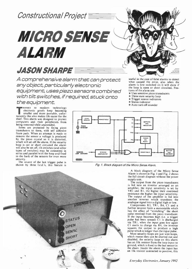
Constructional Project
MICRO SENSEALARMJASON SHARPEA comprehensive a/arm that can protectany object, particularly electronicequipment, uses piezo sensors combinedwith tilt switches, if required, stuck ontothe equipment.
THANKS to modern technologyelectronic goods keep becomingsmaller and more portable, unfor-
tunately this also makes life easier for thethief. This alarm was designed to protectcomputers and their peripherals frombeing removed while unattended.
Items are protected by fixing piezotransducers to them, with self adhesivefoam pads. When an attempt is made toremove the sensor a voltage is producedby the piezo crystal as it is distorted,which will set off the alarm. If the securityloop is cut or short circuited the alarmwill also be set off, tilt switches (and othertypes of switches) may be connected inseries and parallel with the loop and fixedto the back of the sensors for even moresecurity.
The source of the last trigger pulse isshown by three I.e.d.'s, this feature is
useful in the case of false alarms to detectwhat caused the error, also when thealarm is first switched on it will show ifthe loop is open or short circuited. Fea-tures of the alarm are:* Uses sensitive piezo transducers* Three state security loop* Trigger source indicators* Status indicator* Auto turn off sounder
ENE20=3T SOUNDER
SENSINGLOOP SWITCHES COMPARATOR
oT
03
BUFFERSAND
NOKATORS
POmERCN
FES,T
MONOS TABLEBUFFERAND
SOUNDER
Fig. 1. Block diagram of the Micro Sense Alarm.
A block diagram of the Micro SenseAlarm is shown in Fig. 1 and Fig. 2 showsthe full circuit diagram without the powersupply unit.
The output from the piezo transducersis fed into an inverter arranged as anamplifier, the input sensitivity is set byVR I and RI, the higher their combinedresistance the higher the input sensitivity.The output of the amplifier is fed intoanother inverter which translates theanalogue signal into a digital high or low.
Components R3, TR I, R4, CI and afurther inverter form a monostable whichhas the affect of "stretching" the shortpulse received from the piezo transducer.If the input becomes high (i.e. a triggerpulse has been sensed) CI is dischargedvia TR I , when the input goes low againCI starts to charge via R4, the invertersquares the output to produce a highpulse which is longer than the input pulse.
Most security loops are just wire loops,which means they can be shorted out anddisabled, the security loop on this alarmhas an 18k resistor from the loop input toground, which is fixed to the last sensor inthe chain. Inside the alarm the input hasan 18k resistor connected to positive, this
Everyday Electronics. January 1992

AMSTRAD PORTABLE PC'S FROM 1149 (PPC1512SD).£179 (PPC1512DD). £179 (PPC1640SD). 1209(PPC1640DD). MODEMS £30 EXTRA.NO MANUALS ORPSU.
HIGH POWER CAR SPEAKERS. Stereo pair output 100w each4ohrn impedance and consist rig of 6 12 woofer 2' mid range and1* tweeter deal to work withthe amplifier descnbed above Pnce perpair C30 00 Order ref 30P7R2KV 500 WATT TRANSFORMERS Suitable for high voltageexpenments or as a spare for a microwave oven etc 250v AC input£1000 ref 10P93RMICROWAVE CONTROL PANEL Mains operated with touchswitches Complete with 4 digit display, digital cock. and 2 relayoutputs one for power and one for pulsed power (programmable)Ideal for ali Sorts of precision Amer applications etc £6 00 ref 6P18RFIBRE OPTIC CABLE.Stranded optical fibres sheathed in blackPVC Fire metre length £700 ref 7P29R12V SOLAR CELL 200mA output ideal for trickle aircharging etc 300 mm square Our price £15 00 ref -
15P42RPASSIVE INFRA -RED MOTION SENSOR.Complete with daylight sensor, adjustable lightson tuner (8 Secs -15 mins) 50 range with a 90deg coverage Manual ovende facikty Com.plete with wall brackets bulb holders etc Brandnew and guaranteed £25 00 ref 25P24RPack of two PAR38 bulbs for above unit £1200ref 12P43RVIDEO SENDER UNIT Transmit both audio and video signalsfrom either a video camera video recorder or computer to anystandard TV set within a 100' ranger (tune TV to a spare channel)12v DC op £1500 ref 15P39R Suitable mains adaptor £500 ref5P191FtFM TRANSMITTER housed in a standard working 13A adapter(bug is mains driven) £26 00 ref 26P2RMINATURE RADIO TRANSCEIVERS A parr ofwalkie talkies with a range of up to 2 kilometres Units BIZ ameasure 22x52a155rnm Complete with cases £3000 ,ref 30P 12R
FM CORDLESS MICROPHONE.Small hand held unitwith a 500' ranger 2 transmit power levels regs PP3 battery Tun.cable to any FM receiver Our price £15 ref 15P42AR12 BAND COMMUNICATIONS RECEIVER.9 shortbands FM AM and LW DX local switch tuning eye mains tt.ff.or battery Complete with v Icier strap and mans leadNOW ONLY £19.00!' ' 19P14R.WHISPER 2000 LISTENING AID.Enables you to near soundsthat would otherwise be inaudible, Complete with headphonesCased £5 00 ref 5P179RCAR STEREO AND FM RADIOLow cost stereo system giving5 watts per channel Signal to nose ratio better than 45db wow andflutter less than 35°. Neg earth £25 00 ref 25P21RLOW COST WALIKIE TALKIESPair of battery °per- 1
ated units with a range of about 200 Our price £8 00 apair ref 8P5OR RIO7 CHANNEL GRAPHIC EOUAUZEFklus a 60 wattpower amp, 20-21KHZ 4-8R 12.14v DC negatve earth Cased C25ref 25P14RNICAD BATTERIES. Brand new top quality 4 x AA's 24 00 ref4P44R 2 a C s £4 00 ref 4P73R 4 a DA 0900 ref 9P12R 1 xPP3C6 00 ref 6P35RTOWERS INTERNATIONAL TRANSISTOR SELECTORGUIDE. The ultimate equivalents book Latest edition £20 00 ref20P32RCABLE TIES. I42mm . 3 2mrn white nylon pack of 100 E3 00 ref3P104R Bumper pack of 1 000 ties Etas 00 ref 14P6AI
1992 CATALOGUE AVAILABLE NOWIF YOU DO NOT HAVE A COPY PLEASE REQUEST ONE
WHEN ORDERING OR SEND US A 6TX9T SAE FOR A FREECOPY.
GEIGER COUNTER KIT.Complete with tube PCB and all compo-nents to build a battery operated ginger counter £39 00 ref 39P1 RFM BUG KIT.New design with PCB embedded cal Transmits toany FM redo 9v battery req'd £500 ref 5P158RFM BUG Built and tested supenor 9v operation £1400 ref 14P3RCOMPOSITE VIDEO KITS.These convert composite video intoseparate H sync V sync and video 12v DC re 00 ref 8P39RSINCLAIR C5 MOTORS 12v 29A (full load) 3300 rpm 6".4" 1 4"OP shaft New 20 00 ref 20P22RAs above but with fitted 4 to 1 inlme reduction boa (80Orpm) andtoothed nylon ben dnve cog C40 00 ref 40P8RSINCLAIR C5 WHEELSIT or 16" dia including treaded tyre andinner tube Wheels are black spoked one piece poly carbonate 13"wheel C6 00 ref 6P20R 16" wheel £600 ref 6P21RELECTRONIC SPEED CONTROL KITIor c5 motor PCB and allcomponents to build a speed controller (0-95% of speed) Usespulse width modulation £1700 ref I 7P3RSOLAR POWERED NICAD CHARGER.Charges 4AA nicads in 8 hours Brand new and cased £600 ref6P3R
12 VOLT BRUSHLESS FANS 12- square brand new ideal forboat car caravan etc rs co ref 5P206ACORN DATA RECORDER ALF503 Made for BBC computerbut suitable for others Includes mains adapter leads and bookC15 00 ref 15P43RVIDEO TAPES. Three hour supenor quality tapes made underlicence from the famous JVC company Pack of 10 tapes £20 00 ref20P20RPHIUPS LASER. 2MW HEUUM NEON LASER TUBE.BRAND NEW FULL SPEC £40.00 REF 401310R. MAINSPOWER SUPPLY KIT £20.00 REF 20P33R READY BUILTAND TESTED LASER IN ONE CASE C75.00 REF 75P4R.6V 10AH LEAD ACIDsealed battery by yuasha ea equipment butin excellent con6tion now only 2 for f10 00 ref 10P95R12 TO 220V INVERTER KITAs supplied it will handle up to about15w at 220v but with a larger tra nsformier it will handle 80 watts Basiclot E12 00 ref 12P17R Larger transformer £12 00 ref 12P41R
VERO EASI WIRE PROTOTYPING SYSTEMIdeal for design-ing projects on etc Complete with tools, wire and reusable boardOur once E6 00 ref 6P33RMICROWAVE TURNTABLE MOTORS. Ideal for window dm-PAys etc £5 00 ref 61,166RSTC SWITCHED MODE POWER SUPPLY220y or 110v inputgiving Sy at 2A, .24v at 0 25A.+12y at 0 15A and .90yatO 4A £6 00ref 6P 59RHIGH RESOLUTION 12" AMBER MONITOR 2v 1.5A Hercules compatible ( TT L input) new and cased £22.00 ref 22P2RVGA PAPER WHITE MONO monitors new and cased 240NAC. £59.00 ref 59P4R25 WATT STEREO AMPLIFIERc STK043 WM the addition ofa handful of components you can build a 25 watt amplifier £400 ref4p6919 (Circuit dia included)UNEAR POWER SUPPLY Brand new 220v input .5 at 3A. .12at IA -12 at 1 A Short circuit protected C12 00 ref 12P21RMINI RADIO MODULE Only 2" square with fernte aerial and tunerSupeMet Reg s PP3 battery CI 00 ref BD716RBARGAIN NICADS AAA SIZE 200MAH 1.2V PACK OF 10£4.00 REF 4P92R. PACK OF 100 £30.00 REF 30P16RFRESNEL MAGNIFYING LENS 83 x 52mm £1 00 ref BD827RALARM TRANSMITTERS. No data available but nicely madecomplex transmitters 9v operation 24 00 each ref 41.81RUNIVERSAL BATTERY CHARGER.Tekes AA's. C's, DA andPP3 nicads Holds up to 5 banenes at once New and cased, mansoperated £600 ref 6P36RASTEC SWITCHED MODE POWER SUPPLY8Omm a 165mm(PCB size) gives .5 at 3 75A .12 at 1 5A 12 at 0 4A Brand new£12 00 ref 12P39RVENTILATED CASE FOR ABOVE PSUNith IEC filtered socketand power switch C5 00 ref 5P19ORIN CAR POWER SUPPLY. Plugs into agar socket and gives3 4.5 6.7 5 9 and 12v outputs at 800rnA Complete with universeseder plug £5 00 ref 5P167RRESISTOR PACK.10 x 50 values (500 resistors) all 1,4 watt 2%metal tom £5 00 ref 5P170RCAPACITOR PACK 1.100 assorted non electrolytic capacitorsC2 00 ref 2P286RCAPACITOR PACK 2. 40 assorted electrolytic capacitors C2 00
QUICK2ICPK28C7RUPPA? t2v immersion heater with lead and cigar lighterplug £3 00 ref 3P92RLED PACK .50 red Ws. 50 green *is and 50 yellow lads all 5mm£8 00 ref 8P52RFERRARI TESTAROSSA. A true 2 channel radio controlled carwits forward reverse 2 gears plus turbo Working headlights£22 00 ref 22P6RWASHING MACHINE PUMP.Mains operated new pump Noise',pc rryng 25 00 ref 5P18RIBM PRINTER LEAD.(D25 to centroracs plug) 2 metre parallel
5 00 ref 5P186RCOPPER CLAD STRIP BOARDI7" x 4" of 1- ptch "vivo' board£4 00 a sheet ref 4°625 or 2 sheets for £7 00 ref 7P22RSTRIP BOARD CUTTING TOOLC2 00 ref 2P352R50 METRES OF MAINS CABLE £3.00 2 core black precut -nconvenient 2 rn lengths Ideal for repairs and projects ref 3P91R4 CORE SCREENED AUDIO CABLE 24 METRES C2.00Precut into convenient 1 2 rn lengths Ref 2P365RTWEETERS 21:4" DIA 8 ohm mounted one smart metal platefOreasy lining £200 ref 2P366RCOMPUTER MICE Originally made for Future PCs but can beadapted for other machines Swiss made £800 ref 8P57R Atari STconversion kit £2 00 ref 2P362R6 1/2- 20 WATT SPEAKER Bon in tweeter 4 ohm £500 ref5P205RADJUSTABLE SPEAKER BRACKETS Ideal for mountingspeakers on internal or external corners. uneven surfaces etc 2 for£500 ref 5P207RPIR UGHT SWITCH Replaces a standard light switch in secondslight operates when anybody comes within detection range (4m) andstays on for en adjustable time (15 secs to 15 mins) Complete withdaylight sensor Unit also functions as a dimmer switch' 200 wattmax Not suitable for flourescents £1400 ref 14P1ORCUSTOMER RETURNED 2 channel full functon radio controlledcars only C8 00 ref 8P200RWINDUP SOLAR POWERED RADIO! FM AM radio takes re-chargeable batteries complete with hand charger and solar panel14P2OOR
240 WATT RMS AMP KIT Stereo 30-0-30 psu required £40 00 ref40P200R300 WATT RMS MONO AMP KIT 055.00 Psu required ref55P200ALARM PIR SENSORS Standard 12v alarm typo sensor will inter-lace to most alarm panels £1600 ref 16P200ALARM PANELS2 zone cased keypad entry, entry salt time delayetc £1800 ref t8P200MODEMS FOR THREE POUNDS!!Fully cased UK modems designed for dial up system (PSTN) no dataor info but only £3 CO ref 3P1 45RTELEPHONE HANDSETSBargain pack of 10 brand new handsets with mac and speaker only£300 ref 31.146RBARGAIN STRIPPERSComputer keyboards Loads of switches and components excellentvalue at £1 00 ref CD4ORPC POWER SUPPUESThese units are new but need attention complete with case, fan IEC
BULL ELECTRICAL250 PORTLAND ROAD HOVE SUSSEX
BN3 SOT TELEPHONE 0273 203500MAIL ORDER TERMS: CASH PO OR CHEQUEWITH ORDER PLUS £2.50 POST PLUS VAT.
PLEASE ALLOW 7 - 10 DAYS FOR DELIVERY
NEXT DAY DELIVERY £9.00
FAX 0273 23077
input plug disc dove and mother board fly leads Our pricers C5 00(less than the fan alone would cost') ref 5P208RHIGH VOLTAGE CAPACITORSA pack or 20 500P F 10K V capacitors ideal for ionizers TV reps rs andhigh voltage experiments etc Pnce is C2 00 ref 2P378RDATA RECORDERSCustomer returned mans battery units built in mac ideal for Computeror general purpose audio use Pnce is C4 00 ref 4P1OORSPECTRUM JOYSTICK INTERFACEPlugs into 48K Spectrum to provide a standard Atari type joystickporn Our price 24 00 ref 4P1OIRATARI JOYSTICKSOk for use with the above interface our once £4 00 ref 4P102RBENCH POWER SUPPUESSuperbly made fully cased (metal) giving 12v at 2A plus a 6V supplyFused and short circuit protected Forsale at Nssthan the cost of thecase, Our once is £400 ref 4P103f1SPEAKER WIREBrown twin core insulated cable 100 feet for C2 00 REF 2P79RMAINS FANSBrand new 5' x 3" complete with mounting plate quite powerful' andquite Our price Cl 00 ref CD41RDISC DRIVESCustomer retu mod units mined capecit es (up tot 44M) We have notsorted these so you just get the next one on the shelf Pnce is only£700 ref 7P1 R (worth it even as a stnpper)HEX KEYBOARDSBrand new units approx 5" a r only £1 00 each ref CD42RPROJECT BOX512" r 317 . 1" black ABS with screw on lid £1 00 ref C043RSCART TO SCART LEADSBargain pnce leads at 2 for E3 00 ref 3P147RSCART TO D TYPE LEADSStandard Scart on one end Hi density D type on the other Pack often leads only 0700 ref 7P2ROZONE FRIENDLY LATEX250ml bottle of 'quid lubber sets in 2 hours 'dealt°, mounang PCBsfixing wires etc £2 00 each ref 2P379RQUICK SHOTSStandard Alan compatible hand controller (same as joysticks) ouronce is 2 for E2 00 ref 2P38ORVIEWDATA SYSTEMSBrand new units made by TANDATA complete with 1200'75 built inmodem infra red remote controlled qwerty keyboard BT appprovedPrestel compatible. CentrcnicSpnnter port RGB COlOu r a nd compos-ite output (works with ordinary television) complete with powerSupply and fully cased Our pnce is only E20 00 ref 20PIR3 INCH DISCSIdeal for Amstrad PCW and Spectrum .3 machines pack of 10 disciis £12 00 ref 12P1RAC STEPDOWN CONVERTORCased units that convert 240v to 110v 3" a 2" with mains input leadand 2 pn Amencan output socket (suitable for resistive loads only)our price f2 00 ref 2P381RSPECTRUM +3 UGHT GUN PACKcomplete with software and instructons E8 DO ref 8P58RCURLY CABLEExtendsfrom 8' to6 feet, D connector on one end, spade connectorson the other deal for joysticks etc (6 core) Cl 00 each ref CD44RCOMPUTER JOYSTICK BARGAINPack of 2 joysticks only C2 00 ref 2P382RMINI MONO AMPUFIER PACK4 amplifiers for f 2 OCV 3 watt units 9-12v operation ideal for *spin-monis etc £2 00 ref 2P383RBUGGING TAPE RECORDERSmall hand held cassette recorders that only operate when there issound then turnoff 6 seconds after so you could leave it in a room atday and just record any thingthat wassaid Pncroisf20 00 ref 20P3RIEC MAINS LEADSComplete with '3A plug our price is only £3 00 for TWO, ref 3P148RCOMPUTER SOFTWARE BARGAIN10 cassettes with games for commodore 64. Spectrum etc Ourbargain pnce one pound, ref CD44RNEW SOLAR ENERGY KITContains 8 solar cells, motor, tools fan etc plus educational bookletIdeal for the budding enthusiast, Pnce is £12 00 ref 12P2RFUSE PACK NO 1Fifty fuses 1 1A" long (glass) quick blow 10 popular values E2 00 ref2P384RFUSE PACK NO 2Fifty fuses 20mm long (glass) quick blow 10 popular values £2 00 ref2P385RPOTENTIOMETER PACK NO 130 pots for C3 00' ideal for projects etc Ref CD45R
286 AT PC286 MOTHER BOARD WITH 640K RAM FULL SIZE METALCASE, TECHNICAL MANUAL, KEYBOARD AND POWER SUP-
LY C139 REF 139P1 (no o cards or drives included)
35MM CAMERAS Customer returned units with bull in flash and28mm lens 2 for C8.00 ref 8P200STEAM ENGINE Standard Mamod 1332engine complete with boiler piston etc 130ref 30P200TALKING CLOCKLCD display. alarm, battery operatedClock will announce the sme at thepush C4 a button and when thealarm is due The alarm is switchablefrom voice to a cock crow nigIC14 00 ref 14P200 RHANDHELD TONE DIALLERSSmall units that are designed to hold over the mouth piece of atelephone to send MF dialling tones Ideal for the remote control ofanswer machines C5 00 ref 5P209RCOMMODORE 64 LICRODRIVE SYSTEMComplete cased brand new doves with disc and software 10 timesfaster than tape machines works with any Commodore 64 setupThe orgi na I once for these was E49 00 but we can offer them to youat only £25 COI Ref 25P1RUSED SCART PLUGSPackof 10 plugs suitable for making up leads only C5 00 ref 5P209RC CELL SOLAR CHARGERSame sty le as our 4. AA charger but holds 2C cells Fully cased withflip top lid Our puce £6 00 Ref 6P79R
SOME OF OUR PRODUCTS MAY BE UNLICENSABLE IN THE UK

COPPER COLOURED DISC
SILVERED DISC
'I 111 INSULATION BOOT!COVERED BY
WIRES JOINED
SENSOR WIRING
rairr. ail
NC MECUR YTI LT SWITCH
011110al
AT IONTS
JtsSENSOR FIT TEDWITH TILT SWITCH(NORMALLY CLOSEDI
INSULAT4BOOT
LAST SENSORIN THE CHAIN
NEFN
Fig. 4. Construction and wiring of the sensors.
Fig. 5 Wiring of the p.s. u. stripboard.
105
0
0
A
IC IS '7
3 0 0 0 LAMBt Wilt 'ff-XIiI11. ZEM:1 rIZIII111M10000000000ooCZ o o o o o. . ..000 000 X -I MI
Eiwir iir lumm ratmx.xixim
cable of required length, and a chain ofpiezo transducers to the other, solder thecopper outside part of the transducer tothe cable screen and connect other wiresas shown in Fig. 4. Be careful not to get
To OTT the sensor to hot, especially the silveredTo on disc as this will begin to desilver if it gets
to hot.The last sensor in the chain should have
an 18k resistor soldered between thesecurity loop wire and ground (outerdisc). When the unit has been tested (seeTesting section) the sensors can be givenextra protection by applying silicon rub-ber on the solder side of the sensors.
CONSTRUCTIONThe Veroboard layout for the power
supply is shown in Fig. 5. construction isquite simple, but check the polaritiesof the capacitors and diodes. In theprototype IC5 (7805) was used to fix theboard into the box, and was mounted on aheatsink insulator.
When the case has been drilled thetransformer can be fixed in place. and themains lead connected (the Earth of themains cable should be connected to thecase), the output leads can then be con-nected to the power supply board which isfixed in place by means of a screw throughthe regulator tag.
COMPONENTSResistors
R1 100kR2 1MR3 6k8R4 27kR5. R6, R8R7, R13R9. R10R11R12, R15 to R19R14R20 to R22R23R24 680R25 220
All '4VV ± 10% carbon film.
SeeSHOPTALKpees
18k (3 off)2k2 (2 off)4k7 (2 off)47k10k (6 off)2M2390 (3 off)100
PotentiometersVR1 2M2 skeleton presetVR2 500 multiturn preset
CapacitorsC1 2p2 tantalum 35VC2, C3 3n3 poly. layer (2 off)C4, C8 1n poly. layer (2 off)C5 47µ radial elect. 1 6VC6, C9,
C11, C12,C14 Opt ceramic (5 off)
C7 47p tantalum 10VCl 0 100p radial elect. 16VC13 2,200p radial elect. 16VC1 5 1p tantalum 35VCl 6 22p radial elect. 1 6V
SemicondutorsIC1 4069UBE Hex inverterIC2 LM393 voltage
comparatorIC3 555 timerIC4 4042 quad clocked
D -latchIC5 7805 + 5V 1 A voltage
regulatorTR1 to
TR5 BC548 npnsilicon(5 off)
D1 to D4,D12
D5 to D7
D8 toD10
D11
1N4148 (5 off)high brightness red
I e d (3 off)
1N4001 1A 50V rec.(3 off)
tn-colour I.e.d.
MiscellaneousS1 s.p.s t. microswitchS2 s.p.s t. key operated switchX1 to Xn piezo transducers number
as requiredT1 9V -0-9V 20VA mains
transformerB1 6V 1AH sealed lead acid
batteryStereo jack plug and socket as
required to connect sensors; I.e.d.mounting clips: 14 pin d.i I., 16 pinchi. and 8 pin d.i.l. (2 off) i.c. sockets;metal case approx 102mm x 102m x180mm; p c.b. available from the EEPCB Service. order code EE783; strip -
board, 9 strips by 17 holes; sticky padsas required for sensors; tilt switches asrequired - see text.
Approx costguidance only £28
Excluding batten y
Everyday Electronics, January 1992

EXPANSIONINPUT
ril=41rC9
PIEZO 0 N3SENSORS vRI
(I) TR1c
RI e.
LOOPINPUT
P
CCl?
RS
R9
7
-BHA 2 IRII03
R14CIO
1C3m C6
CPC5
O. +C6
C7
TR 407
*Cry
TR3
0
R22
0D6-521
5
RI R20 R5(110-.-e.ov
ob2j TR2
RIS
R16
Fig. 6. PC. B. layout and wiring for the Micro Sense Alarm.
P.S.U. WARD0 ON P.C.II Fte
E17
R25
RED
S2
ON PCB
GREEN 0 0 0011 05 06 07
MOUNTED ON PC B
P S UBOARD "7
{/476".
EARTHTAO
MAINSVIA IAFUSEDPLUG
24 v
Cm IC NI W T C I t
P.S.U.
BOARD017
JACK SOCKET FOR\4,...ONNECT ION OF SENSORS
FRONT PANEL
WD1OV
O
PS UBOARDF115
B1
Fig. 7 Interwiring of the off -board components in the alarm.
Internal layout of the prototype alarm. The lead acid battery Si has been removedto show the p.s.u. board and transformer
ALARM BOARDAssembly of the p.c.b. is quite
straightforward (Fig. 6), insert the i.c.sockets and link first, then the diodes andresistors, and then the transistors,capacitors and Veropins. Before insertingthe I.e.d.'s place insulation boots (orinsulation stripped from some wire):4:2.5cm long onto their leads and insertthem into the p.c.b., also solder the largetag (screen) of the stereo socket firmly tothe OV pin (between the loop and senseinputs), connect the other leads and thebuzzer.
After testing the board may be fixedinto the case (see Fig. 7 for wiring infor-mation). The case used for the prototypewas made of steel and is not recom-mended as it is quite hard to work with,cases of similar style made of aluminiumare generally available.
POWER SUPPLYTESTING
When the power supply has been as-sembled in the box, you should check thatthe case is connected to earth, using anohmmeter. When the mains is connectedto the unit the output from the boardshould be set to 6.8 volts, by adjustingVR2.
Connect the sensors to the alarm board,and also a power supply (:4 5V). Try con-necting the security loop input to ground,and also disconnecting the wire from theinput, both of these actions should causethe alarm to sound and the appropriateI.e.d.s to light, to reset the alarm removeand reconnect the power (NOTE: whentesting the alarm it might be a good ideato cover the hole in the sounder with tapeto lower the sound level slightly).
Tapping the piezo sensors with a smallmetal object should also set the alarm off.Adjust the sensors to the required sen-sitivity using VRI. When the unit hasbeen tested it can then be installed in thedrilled case as shown.
Switch SI is a microswitch arranged sothat it is held closed when the case is fixedtogether. Thus anyone opening the casewill trigger the alarm. The unit is nowready for use.
Everyday Electronics, January 1992 21

Special Series
INFORMATIONTECHNOLOGY
AND THE NATIONAL CURRICULUM
R. de 1411/X BALBIRNIEis the third article in a 12 -part series
I concerning Communication, Informa-tion Storage and related matters in theScience National Curriculum. Readers whohave not been following the series areadvised to read the first article (in Novem-ber's issue) - this gives some backgroundinformation which will be found useful.This month we will look at the topic ofInformation Storage.
Children should know that informationin the form of number, text, pic-
tures (graphics) and sound may be
stored electronically using various every-day devices such as tape recorders andcomputers.
STORAGE OFINFORMATION
It often happens that information is onlyuseful for a short while. For example, aninvitation to a party the following day isunlikely to be of much value in a month'stime. However, there are times when in-formation needs to be preserved so that itmay be retrieved at a later date. If you havemoney in the bank, the amount you haveneeds to be stored and the information up-dated whenever some is taken out or moreis put in.
In ancient times, people stored informa-tion in the only way they knew how - bymaking drawings on the cave walls wherethey lived. Animals and everyday objectsof the time were depicted painstakinglyand in great detail. Man always seems tohave had an urge to preserve the things inhis daily life for others to see. Perhaps hesaw this as a type of diary.
When man learnt to read and write, a farmore versatile means of storing (by writ-ing) and retrieving (by reading) informa-tion became possible. Some of the earliestwriting has been found on clay tablets anddates from around 4000 BC. Later, largeamounts of information were stored in theform of books.
The earliest books had to be written byhand using quill pens, usually by monks orscribes, and were only seen and used bythe educated few. The work in producingthem was so slow that only a few copies ofa book could ever be made. Books couldbe collected together in libraries, much as
they are today, to give access to massiveamounts of information. One of the sad-der stories concerns the burning of all thebooks in the Great Library of Alexandriaby the Muslims in 642 AD. The loss to theworld caused by this single act cannot becalculated.
PRINTINGThe invention of the printing press
allowed many copies of books to be maderelatively cheaply and this put large-scaleaccess to information into the hands ofmore people. There had been some earlyattempts at printing - the ancient Chinesemade wood -cuts of characters, inked them,and pressed them on to paper. It was thenpossible to make several copies of thesame small piece of information relativelyquickly and easily. However, for somethingas large as a book this would have been
very difficult.The first printed books were, in fact,
scrolls dating from 896 AD and the firstfolded page books, from 949 AD. No oneknows exactly who invented "real" print-ing - and there certainly were some veryearly printed books. However, JohannesGutenberg in the 15th century is accreditedwith producing the first practical print-ing press using moveable type. He mademoulds for each letter of the alphabet and,from these, pieces of type were cast inmetal. The type was placed in rows on aflat bed to make words and sentences.
By careful design, all the pieces of typewere made the same height so they couldbe inked, gently pressed on to paper and ahigh -quality copy of a whole page madein one operation. His greatest task wasto print the Bible in Latin - the "Guten-berg Bible" - this consisted of over 1200two -column pages of 42 lines each (seephotograph). Two hundred copies of theGutenberg Bible were printed in 1456.
Gutenberg's basic printing methodremained more or less unchanged for 400years. Although of great importance, it wasstill relatively slow and not well suited toprinting newspapers and other materialwhich needed to be produced quickly. Evenso, single news sheets - the forerunner ofthe newspaper - were produced in theearly 16th century using this method and
' PART 3in 1622 the first commercial newspaper -The Weekly News - was printed using a flatbed printing press.
In the early 19th century, an automaticpress using steam power was invented andthis greatly speeded up the printing ofsheets of newsprint - The Times was
produced in this way. However, it was
still slow by today's standards becausethe paper had to be manipulated in themachine sheet by sheet.
In the mid -19th century, the rotary print-ing press was invented and this, in modifiedform, is still used today - here the type isnot set out on a flat bed as in the Guten-berg press but formed on the surface of acylinder instead. The paper is in the form ofa large roll. As the cylinder rotates, thepaper rolls over it producing one copyafter another very rapidly. The paper isthen cut into sheets and folded. This isbasically how newspapers (and magazineslike EE) are printed today but modern tech-nology has revolutionised the actual as-sembly of information before presenting itfor printing.
t
w Si611,=Mks
tr1=Yam vp: mom
ammOg ims
dkilm..1.1 11111111Wm. 8. 011114 111.moon. ft...M.0W r- =ei==
dania....1110÷....
101.,
'tort ite
s.
N1 ...1._map.. .111 P.P.
'bloomgo= 0....,.WM. =...,..Y.=ma....=
...1.116. i
ON= el:=Waft 01.71=on 4.1 teem
4.0.1coomMI tollo, so0-e gos maw mmilloaimpim admam..=11 Waftme mop w.p.m.:a =171
C
ee,
at
The Gutenberg Bible(Photo courtesy of The British Museum)
22 Everyday Electronics, January 1992

BOOKSBooks, of course, remain a vital form
of information storage and modem tech-nology has not reduced the importanceof the printed word. The advantage of abook is that it is convenient, does notneed a power supply and the informationmay be retrieved (by reading it) more orless anywhere. Moreover, once a personhas learned to read, the whole world ofbooks is available. No further specializedknowledge is needed.
This may be compared with informationstored on a computer. A person must firstlearn to be computer literate but, unlike read-ing, this literacy needs to be constantlyupdated as new equipment becomes avail-able. On the other hand, books are largecompared with the amount of informationstored. A complete set of telephone di-rectories - about 100 books - for theUnited Kingdom is extremely bulky. Thissame information may be stored using acomputer database in a very much smallerspace. Moreover, the use of a databasewould enable you to find the telephonenumber you wanted far more quickly.
With books, it may be difficult carry-ing a large amount of information fromone place to another. Also, the weight ofa book may mean that the informationwould be costly and time-consuming tosend long distances - by post.
Books are versatile in that they can storetext, images (pictures and diagrams), num-bers and music (in the form of a score).Until fairly recently banking was carriedout manually by writing down all thedetails of deposits and credits in thevarious accounts in a ledger. This job isnow done electronically using computers.Computers do the job faster, far moreaccurately and with the support of fewerpeople.
Most important of all, the informationcan be turned into electrical signals andsent along telephone wires from one com-puter to another. Money (in the form ofelectrical signals) may then be deposited orwithdrawn automatically. Since a completetelephone network already exists, the sig-nals may be sent from one bank to another- even in another country - convenientlyand in practically no time at all.
STORING PICTURESPhotography enables man to store ac-
curate visual information -a scene, person,etc. Previously, these had to be drawn orpainted by hand. Painting was not alwaysaccurate - the painter often flattered theclient because he or she was paying the fee!Like printing, no one actually inventedphotography - there had been severalearly experiments using chemicals whichdarken when light shines on them.
Joseph Niepce produced a successfulphotograph in 1826 but Henry Fox Talbot(1800-77), a British botanist and physicist,invented a photographic process using anegative which would be recognized byphotographers today.
This experiment shows that chemicalscontaining silver darken when light shineson them and this can be used to produce
Making a shadow photograph (top) and the finished result (bottom).
a simple form of photograph called a
"shadow photograph". Note that this experi-ment should not be performed by youngchildren and should be demonstrated. Sincesilver nitrate is poisonous and causes stainingof the skin, rubber gloves should be wornthroughout.
You will need a small amount (about10ml) of freshly made 2 per cent silvernitrate solution, a small artist's paintbrushand some writing paper. You will also needsome scrap paper to work on. Keepingaway from bright light, "paint" the silvernitrate solution on to the writing paper tomake a 10cm square. Place the paper in awarm, dark place to dry. When it is dry,arrange some flat objects such as paperclips, scissors and a plastic rule on it.
Carefully carry the paper with the ob-jects on it to a place where bright light -preferably sunlight - can shine on it. Donot allow the objects to move during theexposure. The paper will darken to a deepbrown colour but the paper beneath theobjects will remain white. This will hap-
pen in a few seconds in bright sunlight butmay take several hours in weak daylight. Ifthe objects are removed in a dim part ofthe room, their outlines will be clearly seen(see photograph). Unfortunately, the paperwill darken all over and the images willfade in time.
MOVING PICTURESTo make moving pictures was an early
dream of man. Some simple inventionsappeared to show birds flying and othersimilar things by flashing drawings rapidlybefore the eye. The Zoetrope (see
photograph) had a paper cylinder with aseries of pictures painted on the innersurface. When the cylinder was rotated,and the pictures viewed through slits in thebody of the device, the subject seemed tobe moving naturally. However, this wasnothing more than a toy.
Movie film (cinematography) remained aproblem. Again, there was no oneinventor but the French Lumieredeveloped a camera and projector
Everyday Electronics, January 1992
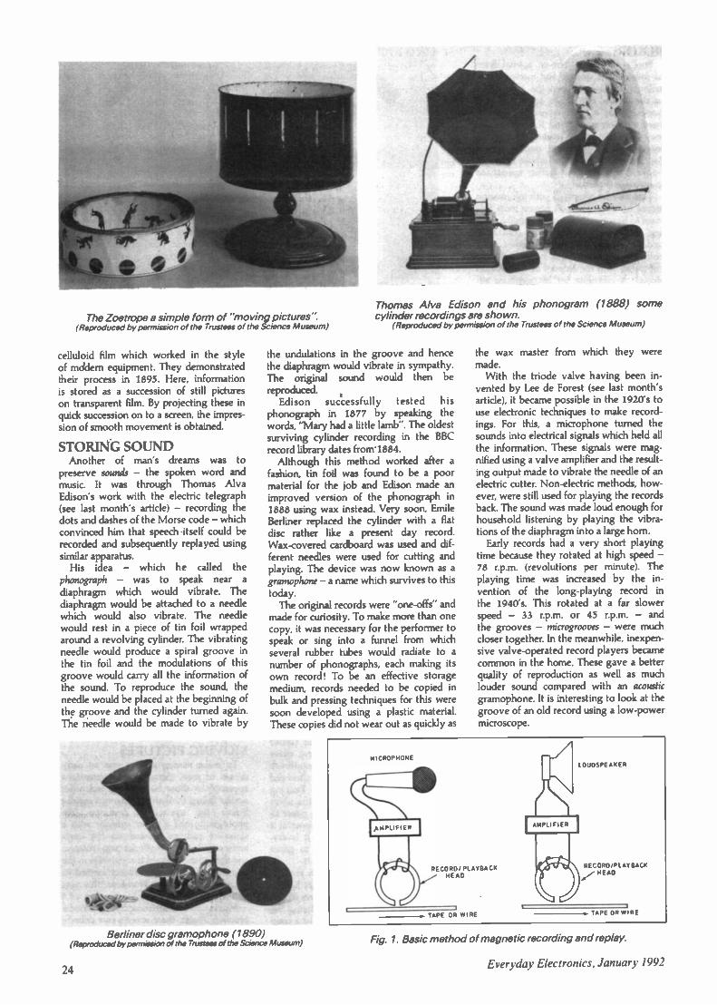
The Zoetrope a simple form of "moving pictures".(Reproduced by permission of the Trustees of the Science Museum)
celluloid film which worked in the styleof mcidem equipment. They demonstratedtheir process in 1895. Here, informationis stored as a succession of still pictureson transparent film. By projecting these inquick succession on to a screen, the impres-sion of smooth movement is obtained.
STORING SOUNDAnother of man's dreams was to
preserve sounds - the spoken word andmusic. It was through Thomas AlvaEdison's work with the electric telegraph(see last month's article) - recording thedots and dashes of the Morse code - whichconvinced him that speech itself could berecorded and subsequently replayed usingsimilar apparatus.
His idea - which he called the
phonograph - was to speak near a
diaphragm which would vibrate. Thediaphragm would be attached to a needlewhich would also vibrate. The needlewould rest in a piece of tin foil wrappedaround a revolving cylinder. The vibratingneedle would produce a spiral groove inthe tin foil and the modulations of thisgroove would carry all the information ofthe sound. To reproduce the sound, theneedle would be placed at the beginning ofthe groove and the cylinder turned again.The needle would be made to vibrate by
Thomas Alva Edison and his phonogram (1888) somecylinder recordings are shown.
(Reproduced by permission of the Trustees of the Science Museum)
the undulations in the groove and hencethe diaphragm would vibrate in sympathy.The original sound would then be
reproduced.Edison successfully tested his
phonograph in 1877 by speaking thewords, "Mary had a little lamb". The oldestsurviving cylinder recording in the BBCrecord library dates from' 1884.
Although this method worked after afashion, tin foil was found to be a poormaterial for the job and Edison made animproved version of the phonograph in1888 using wax instead. Very soon, EmileBerliner replaced the cylinder with a flatdisc rather like a present day record.Wax -covered cardboard was used and dif-ferent needles were used for cutting andplaying. The device was now known as agramophone -a name which survives to thistoday.
The original records were "one -offs" andmade for curiosity. To make more than onecopy, it was necessary for the performer tospeak or sing into a funnel from whichseveral rubber tubes would radiate to anumber of phonographs, each making itsown record! To be an effective storagemedium, records needed to be copied inbulk and pressing techniques for this weresoon developed using a plastic material.These copies did not wear out as quickly as
Berliner disc gramophone (1890)(Reproduced by permission of the Trustees of the Science Museum)
the wax master from which they weremade.
With the triode valve having been in-vented by Lee de Forest (see last month'sarticle), it became possible in the 1920's touse electronic techniques to make record-ings. For this, a microphone turned thesounds into electrical signals which held allthe information. These signals were mag-nified using a valve amplifier and the result-ing output made to vibrate the needle of anelectric cutter. Non -electric methods, how-ever, were still used for playing the recordsback. The sound was made loud enough forhousehold listening by playing the vibra-tions of the diaphragm into a large horn.
Early records had a very short playingtime because they rotated at high speed -78 r.p.m. (revolutions per minute). Theplaying time was increased by the in-
vention of the long-playing record in
the 1940's. This rotated at a far slowerspeed - 33 r.p.m. or 45 r.p.m. - andthe grooves - microgrooves - were muchcloser together. In the meanwhile, inexpen-sive valve -operated record players becamecommon in the home. These gave a betterquality of reproduction as well as muchlouder sound compared with an acousticgramophone. It is interesting to look at thegroove of an old record using a low -powermicroscope.
MICROPHONE
AMPL IFIFR
RECORD/ PLAYBACKHEAD
TAPE OR WIRE
AMPLIFIER
LOUDSPEAKER
RE C ORO /PL AY BACK4r., HEAD
TAPE OR WIRE
Fig. 1. Basic method of magnetic recording and replay.
24Everyday Electronics, January 1992

RECORD EXPERIMENTThis experiment needs an old "useless"
record and a sewing needle or pin. Theneedle is threaded through a small piece ofpaper to act as a diaphragm and heldgently between the fingers of one child.Using a pencil or pen in the centre hole,another child turns the record steadily. Theneedle is now rested in the groove. Thesound will be heard and the paper felt to bevibrating. This non -electric method clearlyshows how the record groove producesvibrations which reproduce the originalsound.
MAGNETIC RECORDINGA more recent advance is making sound
recordings on tape. This method is widelyused today - almost every home has acassette recorder often combined with aradio. This method developed from earlyexperimental recorders using steel wirewhich were tried at the turn of the century.In these, sound was picked up by a
microphone and the electrical signals passedthrough a coil of wire wound on an ironcore with a narrow gap (see Fig. 1).
The iron core was magnetized and thestrength of its magnetization followed thepattern of the original sound. Steel wire waspassed across the iron core and this pickedup the magnetization. Steel - unlike iron,retains it magnetism so along the lengthof the wire was a magnetic imprint whosestrength followed the sound pattern.
To replay the recording, the wire wasrewound to the beginning and passed overthe iron core again. Now the coil producedan electrical signal which reproduced theoriginal sound in an earphone. This inven-tion was ahead of its time and was waitingfor Lee de Forest to invent the triode valve.This enabled the weak electrical signals tobe amplified and fed to a loudspeaker.
Steel wire was found to be a poormaterial for the job and specially made tapewas later used. Early magnetic tape used apaper base but this was easily damaged andlater tape used a plastic material. In animproved form this is still used today. Thebase material is coated with a very thinlayer of iron oxide (or similar magneticmaterial) which behaves like the steel wiredescribed earlier.
Tape recorders began to appear in the1940's in the home, for entertainment, andin offices as dictation machines. Theoriginal machines used spools of tape (openreel recorders) and similar open reelmachines are still used by professionaloperators. Cassette recorders are moreconvenient and have largely replaced openreel recorders for household and semi-professional use but the principle ofoperation and type of recording tape usedis the same.
One advantage of tape recording is theease with which the recording may beerased and the tape used again (unlike discrecordings). Also, with open reel equip-ment, editing may be carried out - the tapecut in places, parts spliced in or removed,re -arranged, etc. Thus, a radio interviewcan have all the hesitations and mistakesremoved before broadcasting it.
SOUND MOVIESIt is interesting to see how the two
techniques - film making and soundrecording came together to make soundmovies. In some early films, the sound wasrecorded on a large diameter disc.However, it was difficult to keep accuratesynchronization between the sound andpicture (the lip movement and words fellout of step). Also, if the needle jumped orwas knocked, synchronization was lost.This often happened and caused greatamusement in the audience. Sometimes theonly way to proceed was to start the reelof film again from the beginning!
Warner Brothers kept to this systemeven after optical sound recording hadbeen perfected. Good quality optical soundrecording was the invention of Lee deForest (the inventor of the triode valve)
Fig. 2. An optical sound track runningdown the side of a film.
and he demonstrated his system in 1923although there had been some unsuccessfulattempts using similar methods previously.
In his system, the sound track ran alongthe edge of the film itself. This meant thatthere were no synchronization problemsand the quality of the sound was muchbetter. Fig. 2 shows the appearance of anoptical sound track.
When the film was projected, light froma separate small lamp - the exciter lamp -shone through the sound track. The lightpassing through would then flicker insympathy with the original sound. Thislight was picked up using a light-sensitivecell which produced varying electrical sig-
nals. The result was fed into the inputof a valve amplifier and hence to a
loudspeaker. In this way, the original soundwas reproduced. Using this method TheJazz Singer was shown in 1928 and was aninstant success.
Today, sound is stored using magneticstripes on the film itself (see underMagnetic Recording).This has severaladvantages. Firstly, the quality is muchbetter. Also, by using more than one track,stereophonic sound can be recorded andplayed back through more than oneloudspeaker. With modem wide-screenfilms the sound will then appear to comefrom the actors themselves as they moveacross the screen. Loudspeakers all aroundthe auditorium add even greater realism.
With the development of television,film-makers found themselves in competi-tion with it and many improvements -some of them merely gimmicks - wereused in an attempt to lure the audiencesback to the cinema. Colour films succeededbecause these could be shown in thecinema before colour television was avail-able at home. Also the quality and breadthof the sound coupled with the large screenmade the experience more realistic.
There were even attempts at 3D (three-dimensional) films. These involved theaudience wearing special pairs of glasseswithout which the picture was simply ajumble; these were not popular.
VIDEO RECORDINGIn the late 1950's special tape recorders
succeeded in recording not only sound in-formation but television pictures too. Fortechnical reasons this is a difficult job andwas waiting for more advanced technologyto be developed. Before then, televisionprogrammes had to be made "live" and anyrecording made on film.
With video recording the programmecould be recorded several times as neces-sary to produce a perfect result. Also, thetape could be edited like audio tape. Thismade programme production much simplerbecause all the scenes at one particularlocation could be made in one recordingsession, videotape editors could then as-semble the whole programme in the rightorder and this is the technique used today.Now, videocassette recorders are familiarpieces of equipment.
A recent storage medium is the CompactDisc. This is usually thought of as being asound storage medium. However, it may beused to store text and pictures too. In thefuture it will be used for much bulk storageof information - for example, maps andtelephone directories. Unfortunately, theinformation stored on it cannot be updated- it is a read only medium at the moment.The Compact Disc is an important advancebecause it uses digital technology. The mean-ing of this will be explained in a futurearticle.
CLOCKS AND WATCHESA further modem device using digital
technology is the electronic watch or clock.This is set with the correct information -the day, date, time and so on and thisis updated automatically. The information
Everyday Electronics, January 1992 25

may be retrieved by looking at the display(for the time) and by pressing various but-tons (to recall the day, date, etc).
It would be useful for children to usea digital stop clock or watch for simpletiming operations. You will probably findthat they are better at setting these devicesthan you are!
STORING INSTRUCTIONSSometimes the information we wish to
store is a set of instructions for a machine tofollow. The most powerful way of doingthis is by using a computer as we shallsee later. However, it is worth mentioning"punched card" systems which are still inuse today. Anyone who has looked aroundthe back of an old fairground "steam- or-gan will have noticed that the music isstored in the form of holes punched in card.This rolls through the machine.
Today, we would call the information onthe card a program since it tells the playingmechanism what to do and when to doit. Some Victorian table -top organs storedsimilar information on discs where raisedprotrusions on the surface pressed keysand allowed air to blow the pipes inside.Punched cards were used by Joseph Jac-quard in the early 1800's to control thepattern of weave in his loom.
Today, car -wash machines often use aform of punched card which is fed into themachine and provides the instructions forexactly what kind of wash has been paidfor. Early cash dispensers outside banksused punched cards. Today, these havebeen replaced by cards with magneticstriping. Here, information about the ac-count is read from the card using a devicesimilar to a tape recorder.
Today, a computer (the hardware) needsinstructions (the software) to tell it what todo. We often store these instructions as aprogram on a magnetic disc. We shall belooking at some simple examples of thisnext month.
CALCULATORAs well as text (writing), pictures and
sound, we often need to store and workwith numbers. We can enter a number in anelectronic calculator and that number willremain in the calculator's memory. How-ever, to use a calculator simply to store anumber is a waste of a calculator's power.The same job could be done by writing itdown on a piece of paper.
The advantage of a calculator is thatas well as storing numbers, it can per-form calculations on them too. Calculationswhich would be too time consuming for ahuman to do can now be done easily by anelectronic calculator and with much lesslikelihood of error.
The first calculator was an abacus andalthough this has been around for some5000 years it is still commonly used inChina, the Middle East and Japan. It is
likely that the abacus developed from theidea of making marks in a tray of sandwith the finger. In use, beads are slid upand down rods.
In the most common type of abacus,the Chinese suan pan, there are severalcolumns of beads with a cross piece to
26
1110
g g
o E
o
A Chinese abacus - these are still usedin China.
divide them into columns of two beadsabove and five below (see Fig. 3). In theright-hand column, the lower five beadsrepresent units and those above the divi-sion fives. The next column represents tensand fifties and so on. By sliding the beadson the rods, a skilled operator can add andsubtract numbers more quickly than byusing an electronic calculator.
In 1642, Pascal invented a calculatbngmachine where numbers could be addedtogether by entering them on dials at thefront of the machine. In 1617 Leibnitzproduced a calculator which could per-form multiplication using toothed wheels.This type of technology was used untilrelatively recently. William Oughtred in-vented the slide rule which is still some-times used today. This has a cursor whichcan move along the various scales on theruler to perform multiplication and divi-sion. Someone is certain to have one ofthese at home.
These devices have the advantage ofneeding no power supply. However, thereare many types of calculation which arenot well suited to them, especially wherevery large or very small numbers areinvolved and the inexpensive electroniccalculator is much faster and a great dealmore versatile.
Calculators can only deal with numbersbut computers can deal with text, images(graphics) and sound. In reality, a com-puter can only store numbers. Even whenyou think it is storing text or pictures itis really storing numbers. Every letterof the alphabet, upper and lower case,
also punctuation marks and so on, areturned into a code of numbers and it is
really these which the computer is stor-ing. When we recall the words we arerecalling the numbers and the computerturns them back into letters of the al-phabet. When storing a picture, it breaksthe image into thousands of small squares(pixels) and stores these as numbers.
COMPUTERSThe first designs for machines which
could be called true computers weremade by the English mathematicianCharles Babbage (1791-1871). In 1833 hedesigned his "Difference Engine No. l-and in 1847 his "Difference Engine No.2". He went on to design other machines- notably the "Analytical Engine".Unfortunately, none of his machines wereever completed because of the limitationsof machine tool technology at that time.
Although the machines would today beclassed as computers, they were designedlong before the electronics age and wereto be purely mechanical devices. TheSecond Difference Engine has recentlybeing constructed using the original plansat the Science Museum in London.This uses 4,000 (excluding the printingmechanism which has not been built)parts and weighs approximately 3 tonnes.The total cost of building the machine andmounting a six month exhibition is
£500,000. This exhibit demonstrates thatthese machines would have worked had itbeen possible to build them in Babbage'sday.
Similar but simpler mechanical deviceswere used until fairly recently for suchcalculations as insurance premiums andbetting odds for dog races. By today'sstandards, mechanical computers arecomplicated, relatively slow, expensive,heavy and bulky. Also, because they weremechanical, parts would wear out so
constant maintenance was required.
Next month we shall complete this topicby looking in more detail at the computeras a storage medium and also explore therange of microelectronic devices whichare now found in everyday life.
Babbages Second Difference Enginebeing demonstrated at the ScienceMuseum.

ESR ELECTRONIC COMPONENTSStation Road, Cullercoats,Tyne & Wear NE30 4PQTel 091 251 4363 Fax. 091 252 2296
PCB FOUIPMFNTUV EXPOSURE UNIT - 229 x 159rnm
working area, built in timer. 2 x 8wtubes £62.57
PHOTO RESIST BOARD - single sidedpre -sensitised FR4 glass fibre board3 x 4 in. f0.864 a 6 in [1 .626 x 6 in £2.41
PLASTIC DEVELOPING TRAY £1.35FERRIC CHLORIDE (0.5Kg) £2.45TIN PLATING POWDER (90g) E8.33STRIPBOARD 0.1 pitch 64 x 127mm
Cl .3064 x 431mm E4.03 95 x127mm [1 .52 95 x 95mm £1 .3395 x 431mm C5.27
BREADBOARD 81 x 60mIn 390TP£2.98175 x 42mm 640TP E3.40175 a 67mm 840TP £6.34.203 x75mm 840TP E7.00
inc plate & 4mm posts
KITSComplete with screen printed & soldermask board, components and fullinstructionsCAR ALARM voltage drop £12.99200W CAR BOOSTER 12/24V
CD/line/speaker input.inc housing. £91.88
ELECTRONIC DICE (dual) f9.15SOUND GENERATOR 10 tunes.
line & speaker output £19 112.5W UNIVERSAL AMPLIFIER £6.86AF SIGNAL INJECTOR/TRACER
adjustable o/p & i/p £8.39DIGITAL CODE LOCK 4 digit
code flip/flop or latch o/p £19.11AC MOTOR/DRILL CONTROLLER
carbon brush 24 240Vac 5A £15.28
D CONNECTORSPlug
9 pin £0.2915 Pin £0.3915 Pm H D £0.8125 Pin £0.48
9 Way plastic cover15 Way plastic cover25 Way plastic cover
Socket£0.30£0.39£0.90£0.50
£0.30£0 33£0 36
Sill DE RING IRONSAntex Soldering ironsM 12 WattC 15WanG 18WattCS 17WattXS 25WattST4 STANDNew PORTASOL HOBBY
35 Wan gas ironDESOLDER PUMPANTISTATIC PUMP22SWG 0 5Kg Solder18SWG 0.5Kg Solder1mm 3 yds Solder
£7 11£7.11E730£7.21£7 30£2.75
f11 17£300£4.30f 7 40£6.60£0.50
AUDIO CONNECTORSPHONO PLUG inc strain relief
Red or BlackPHONO PLUG right angle.
Red or Black £0 23PHONO Chassis Socket £0.166 35mm Plastic Mono Plug
with strain relief £0 25As above but Stereo £0.456 35mm Chews Socket, switched
Mono £0.36. switched Stereo E0.493 5mm Mono Plug COI 73.5mm Stereo Plug £0.293.5mm Mono line skt £0.243.5mm Stereo line skt 0.29PLASTIC DIN PLUGS
2 pin MI5, 5/380 E0.27, 3 pin£0.24.6 pin EOM. 4 pin £0.297 pin (0.33. 5 /180E0.26. 8 DinE0.45, 5 /240 £0.30
XLR Chassis SocketXLR Chassis PlugXLR Line SocketXLR Line Plug
£017
E1.66El 32(1.45£1 .36
HARDWAREPCB Nylon Stand- offs clip into board
screw from base5mm spacing (0.24/10 .88/10010mm spacing (0.26/10 (1.82/10013mm spacing 0.30/10 f2.10/100
SELF TAPPING SCREWS Pan headNo x 6 4mm £13.14/10 £0.88/100No 6 x 9 5mm C0.12/10 (0.78/100No 6 a 13mm C0.13/10 (0.85/100No 6 x 19mm 00.16/10 C1.04/100
T2 Box 75 x 56 x 25mmT3 Box 75 x 51 x 25mmT4 Box 111 a 57 x 22rnmM81 Box 79 x 61 x 40mmM82 Box 100 x 76 x 41mrnM83 Box 118 x 98 x 45mmM85 Box 150 x 100 x 60mrn
£0.76C0.7200 92f1 38£1 48£1 72f 2 36
REGULATORS78105. 78L12. 78L1579105, 79L12, 79L157805, 7812, 78157905, 7912, 7915LM317T I 5A 1 2-37V1M723 150mA 2-375
£0.24£0.28£0.28£0.38£0.44£0.29
DIODESZener Diodes 2V7 -33VBZY88 400rnWBZX851 3W1N4001 -1N40051N4006 -1N40071N5400 -1N54021 N5404 - I N54061N5407 -1N54081 N4148 Signal0/1.90 Signal0A91 Signal
THYRISTORS & TRIACSP0102AA 0 8A 100V
SCRTIC106D 5A 400V SCRTIC2060 4A 400V TriacBTA08-400BW 8A iso
£0.22£0.40E0.116E1,74
VELLEMAN KITSStockists of the bud range ofVelleman kits Catalogueavailable upon request
RESISTORS0 25W 5% CF El 2 Series
(0.60/1000 5W 5% CF El 2 Series
(0.95/1000 25W 1% MF E24 Series
11.72/100POTS Log or Lie 470R -IMO
25mm die 0 25in shaft £0.40PRESETS Enclosed Horzor Vert 100R - 1 MO015W £0.16
PRESETS Skeleton Horzor Ven 100R -IMO01W £0.11
CAPACITORSCeramic Disc 100V 10pF to
100nF £0.07Ceramic Plate 100 & 83V
1 OpF to 12nF1 pF-1nF £0.06. 1n2 -2n7£0.09, 3n3 -4n7 £0.12.lOn & 12n C0.06
Polystyrene 160V 5% 47pFto 10nF47p. 2n2 £0.09. 2n7 -10n£0.12
HEI AYS6V SPDT 6A12V SPDT 6A6V DTDP 6A
ELECTROLYTIC RADIAL CAPACITORSuF 16v 25V 63V 100V
0 47 £005 £00710 £0.05 £00822 CO 05 f0 0647 £005 £00810 £006 £006 £0.06 C0.0822 C006 £005 £00947 £006 £006 f 0 11100 CO 06 £009 £0 11220 £0 09 £012 £031470 £015 £0.19 £0.571000 £0 22 £0292200 £0 37 £0 574700 El 11
CO.70£0.70E1.96
DIE
SOC. KF TS
8 Pin14 Pin16 Pin18 Pin20 Pin24 Pin28 Pin40 Pin
E0.07£0.11£0.16£0.15(0.18£0.19£0.22£0.26
£008£0.14£0.07£0.08£0.09£0.110.15E0.05£0.07£0.10
TEST & MEASUREMENTHM103S ANALOGUE METER19 ranges (Inc 10Adc). fuse & diodeprotection, battery test, shock resistanttilted case, mirrored scale, supplied withbattery, leads & instructionsDim 154 x 77 it 43mm £11.47
HC20205 ANALOGUE METER20 Ranges (inc 10Adc). fuse & diodeprotection, transistor & diode tester, polarityreverse switch, high impact shock resistantcase Supplied with battery, leads. standinstructionsDim 150 a 102 a 45mm £18.45
HYTO7 LOGIC PROBETTL & CMOS, displayed in light & sound.pulse enlargement. pulse detection down to25nsec. max freq 20MHz Supplied withlull instructions £7.72
MX190 DIGITAL METER19 ranges, 3 5 digit 1 2mm LCD, signaliniector, diode test, fuse protection, autopolarity & zero, supplied with battery. leads& instruction manualDim 126 a 70 x 24mm (14.73
M231511 DIGITAL METER17 Ranges (inc 10Adc), 3 5 digit 12mmLCD diode test, buzzer, auto polarity &zero over range Ili low bat indication,supplied with battery. leads & instructionsDim 130 z 72 A 33mm .£23.40
RE CONNECTORSBNC Solder Plug8NC Crimp PlugBNC Solder SktBNC Chassis SktPL259 5.2mmPL259 llmmRND UHF socketSOR UHF socketF Plug RG58F Plug RG6N Plug RG8
INE AR ICsTL071 CPTL072CPTL074CNTL081TL082CPTL084CNTBA1205LM301ACA311ECA324LM348NLF351NLM358NLM377LM380NLM381LM386LM387LM392NLM393NCA555NE556NNE587NUA733CA7410ELM748CNTBA810STBA820MLA11458ULN2004TDA2030CA3046CA3080CA3130CA3140CA3240LM3900LM3914LM3915MC4558NE5532ICL7621
CO 85£0.68£1.0800 78£0.58£0.58£0.48C0.40£0.27£0.27£1.64
£032£034£0.48£0.29£0.34£0.46£0.60£0.25£028£0.23£0.31£0.36£0.27£2.57£1.12£2.70£0.48£1.60£079£0.28£0.22C0.36
0.36£0.64£018£0.31£0.68[0.39[0.26£0.48£1.35£0.37£0.72£0.98£0.44[1.22E0.72E2.70£2.70(0.36£0.80f 1 70
SWITCHESSPST Toggle f 0 58SPDT Toggle £0.54SPDT CO Tog £0.62DPDT Toggle £068DPDT CO Toggle £0.74DPDT mini slide (0.16Rotary Water 1P -12W.
2P -6W. 3P -4W,4P -3W £0.78
Key Switch SPOT £2.40Push to make £0.25Push to break E0.24Latching Push SqrPCB Tact 6 x 6mm £0.25
ADAPTORS
BNC Plug - PHONO SktBNC Plug - BNC PlugBNC Skt BNC SktBNC Plug - UHF SktBNC Pita) -2 x BNC SktBNC Skt -2 x BNC SktUHF Plug - BNC SktF Socket -F Socket3 5mrn Plug -2 a Skt3 5mm Plug - 25in Skt0 25in Plug - 3 5rnm
.11.IDIA1311
£0.78El .96£1.00£1.38E1.89C1.89£1.59£0.33[1.20£0.157£0.67
400Hz 75dB 9.20V450Hz 80d8 9-12V4KHz 90d8 3-15V2 8KHz 100dB pulsed3 5KHz 75dB 240Vac4KHz 80r1B 30V pk pk
1/10005 SA Sp.W02 1 5A 200V8R32 3A 200VBR62 6A 200V1004 10A 400V
(0.72£1.14£0.92£1.90£1.22f 0 58
E0 19£0.20£0.38EV.64C1.39
4000 Series400040014002400640074008401040114013401440154016401740184022402440254026402740294030403340354040404240464047404940514052405340554060406340664069407240754076407740824089409340944095451045114515452045214534453845414572458445854010640174
£0.20£0.17£0 .19CO 32£0.20f 0 31£019£0.16£0.17£0 .30£0.31£0.18£025£0.27£0.32£0.21£0.15£0.40COI 8£0.27£0.17£0.56£0.31£0.29£0.22£0.31£0.25£0.20£0.26£0.25£0.24£0.30£0.31£0.29£0.18£0.20£0.17£0.17£0.30£0.15£0.17£0.55£0.15£0.31£0.56£0.26C0.29C0.78£0.26£0.84£2.48£0 37£0 31CO25CO 24£0.48£024£034
TRANSISTORSBC107BC108ABC109CBC177BC1788C179BC182LBBC183LBEIC1841BC212LBC212LBBC213LC8C214BC327BC328BC337BC338BC527BC5288C537BC538BC547CBC548CBC549CBC557CBC558CBC559CBDX33CBDX34C8 FY50BFY51BEY52TIP29CTIP30CTIP31 CTIP32CTIP33CTIP41ATIP42C2N22222N290542N37042N37052N37062N37712N37722N37732N39042N39052N3906
CONNECTORSCROC CLIPS 33mm
Red or Black £0.12CROC CLIPS 45mm
Red or Black £0.20PP3 Battery
Snap EO 10PP9 Battery
Snap £0.144mm BANANA
PLUG Red orBlack £0.09
4mm BUNCH PINPLUG Redor Black £0.30
4mm BINDINGPOST Red orBlack C0.54
SCART PLUG £0.80SCART PCB Skt £0.78SCART LINE
Skt 0.35IEC LINE
SOCKET E0.78IEC CHASSIS
PLUG C0.72IEC CHASSIS Slit £0.54CAR AERIAL
PLUG £0.19CIGAR LIGHTER
PLUG (0.30
£0.14£0 12£015E0 16CO 16C016£00900.09C0.11£0.09£0.09CO 09CO 11CO 12(0.10£0.12E008CO 24£0 2410 24f0.24C009£008£0.10£0.09E0.09£009£0 46£054£0.24(0 24(0 24C0 33£0 33£033£0.34C1.02£0.36CO28f0 16£0 28£009C0.09(009Cl 22Cl 2811 88£0.10£010(0.09
74LS Serif,74LS00741501741502741503741504741506741508741S09741510741511741512741S20741_521741S267415307415327415377415427415517415867415927415937415107741510974151237415125741513374151387415153741_51547415157741S1647415165741_5175741.5191741519374153677415374
£0.14£0.17E0.1111£0.17£0.14C0.17£0.17E0.17£0.17£0.17E0.18E0.16OA 6E0.10£0.17£0.17£0.18C0.26£0.19E0.20£0.40£0.26£0.300.27E0.40E0.21E0.22£0.24£0.29£0.90£0.21£0.26£0.63£0.24E0.24(0.2410.21L-0.32
ORDERING INFORMATIONAll prices exclude VAT
Please add 85p carriage to all orders and VAT (17 5%)
No minimum order charge
Please send payment with your orderPO/Cheques made payable to
ESR Electronic ComponentsAccess & Visa cards accepted
Office' orders from schools & colleges welcome
CALL IN OPEN. MON 8 30 5 00 SAT 10 00-5 00
Everyday Electronics, January 1992

'ANAT CDNIALAU 1-0 and
Barry Fox reports from Berlinon the latest trends in homeentertainment on show at theFunkausstellung '91 exhibition.
EVERY two years since 1924, with only the war yearsmissing, the city of Berlin has staged a radio show orFunkausstellung. The radio show has now become an
international "world of consumer electronics" exhibition takingin TV, video, satellite, telecommunications, computers, games,hi fi and electronic gadgetry.
Manufacturers from all round the world now see the In-ternationale Funkausstellung, or IFA, as the prime pad forlaunching new products into Europe. This year IFA was biggerthan ever, with 571 exhibitors from 29 countries spread through25 enormous exhibition halls. Despite an entry fee to the publicof 15 German marks (around £5 pounds) the organisersexpected nearly a million visitors during the ten day show.
For the first time since 1961, visitors came over from the East.Where the Berlin wall once stood, there is now just a strip ofland with not a trace of the concrete obscenity which for thirtyyears split the city in two. In fact the only trace of the wallare the pieces of rubble which street merchants now sell off assouvenirs
Significantly, satellite aerials are now sprouting over the drabconcrete appartment blocks and old housing (some still bomb -damaged and shell -pocked) in the Eastern sector.
IFA saw the usual crop of electronic novelties, and the emer-gence of several distinct trends in the consumer electronics in-dustry.
Whats Up MacIn the run-up to opening -day all eyes had been on Philips
and Sony who were due to try and build confidence in theirnew home digital recording systems, Digital Compact Cassetteand Mini Disc. There was also clearly a row brewing betweenthe satellite broadcasters, such as BSkyB, who want to con-tinue transmitting in PAL, and European electronics companieswho have invested heavily in the development of MAC and highdefinition MAC technology. As the show opened a temporarytruce between Philips and Sony collapsed and the simmeringbitterness between the PAL and MAC factions flared into openwarfare.
By 1992 the Eureka 95 team of 1000 engineers will havespent over £500 million pounds on an HDTV system to broad-cast the Olympics to 1000 HDTV sets across Europe. The HDTVsystem is a 1250 line version of the 625 line MAC systemdeveloped for satellite. If MAC fails, so does HD -MAC. Most
Widescreen TV set from Nokia' ITT
satellite broadcasters, like Rupert Murdoch's BSkyB, are scorn-ing MAC and using the terrestrial PAL system.
In Berlin Peter Bogels, President of the EU-95 HDTV di-rectorate, blamed the European Commission for leaving PALloopholes in its 1986 MAC Directive.
"There was a flaw, a hole in the law, that let people start PALtransmissions", said Bogels. Despite the magnitude of the EC'smistake no one in the HDTV directorate can say who in the ECwas responsible.
EC Telecommunications Commissioner, Filippo Maria Pan-dolfi recently met Rupert Murdoch in Brussels and joined Ger-man Telecommunications Minister, Christian Schwarz -Schillingin Berlin to announce the EC's latest plan. This doubles, to 1 BnECUs, the European tax payers' money available for simul-taneously broadcasting PAL programmes in MAC until January1994. Any new broadcaster now starting in PAL must switch toMAC in 1994 and will not be paid the sweetener to simulcast.
Pandolfi has now asked a Working Group to report by 15September on whether there will be enough satellite transmit-ters in orbit to cope with simulcasting.
Eight German broadcasters (ARD, ZDF, RTL Plus, Sat I, Pro7, Tele 5, Premiere and VPRT) issued a statement saying "No"to the proposal because "it is not fair for the EC to make this lawand not friendly for the consumer or for owners of satellites orreceivers in Europe".
Although demonstrations of the 1250 line HD MAC systemat Berlin were impressive, parallel demonstrations intended toshow how HDTV signals can also be received on 625 line MACsets were disappointing.
Although this was due to technical defects in the cable relaysystem used on the enormous exhibtion site, no one told themillion visitors expected. Whereas the ditigal circuits in a full-blown HDTV set can compensate for spurious echo signals,other sets cannot.
The first demonstration of a wide screen PAL system, PALPlus, which Grundig, Nokia, Philips, Thomson and Europeanbroadcasters have been developing in parallel with HDTV, gavebetter pictures than the MAC demonstrations. To avoidundermining MAC's credibility, the PAL Plus designers stressthat their system isintended only forterrestrial use. Butthey admit it couldequally well beused by satellites.
To transmit PALPlus, the broad-caster feeds a 625or 1250 line widescreen picture sig-nal through a digi-
The HK33 LDmulti -media laser -disc .system fromSharp brings all thefun of "Koraoke"into the home. Thesystem is claimedto allow anyoneto "sing -along"with the videoclips of theirfavourite stars.
Everyday Electronics, January 1992

tal filter. This reduces the number of picture scanning lines by aquarter. The remaining three quarters appear on a conventional4:3 aspect ratio PAL TV set as a letterbox picture, with blackborders at the top and bottom.
The filtered information is converted into a digital "helper"signal like teletext. This helper is buried in the black borders ofthe letterbox picture as a signal which conventional TV sets treatas pure black. So the helper code is invisible on conventionalsets. A PAL Plus receiver decodes the helper to rebuild a 625line picture which fills the full area of a 16:9 wide aspect screen.Demonstrations given at Berlin prove that the "helped" signal isclearer than the orginal.
Behind Closed DoorsPre -show leaks had Philips and Sony doing a cross-licencing
deal on their new, rival, home digital recording systems, DigitalCompact Cassette (Philips) and Mini Disc (Sony). There wereno such deals. And both companies badly fumbled their pitch. Itis a measure of the strength of DCC that the format still lookslikely to prevail over MD.
The show opened with no sign of MD or DCC on Sony'spublic stand. Upstairs, in a closed room behind a wall ofbureaucratic security the trade and press could see MD, withdescriptive plackards and literature round the room. A DCCplayer (one of the many hand -built models made by Philips) saton a shelf, without any descriptive material, like an unwelcomecorpse.
The was no sign of DCC or Mini Disc on the Philips standeither. This in itself was a surprise bearing in mind theconsiderable amount of advance publicity which DCC hasgenerated. Upstairs, and behind similarly bureaucratic security,Philips demonstrated DCC in a studio room and had four unitsin a glass case. The top end DCC-900 will be launched in thespring, the mid -range DCC-300 in the late summer along withthe DCC-180 "portable personal", and a car player due towardsthe end of 1992.
At Sony's press conference Kozo Ohsone, Senior ManagingDirector of Sony and Jack Schmuckli, Chairman of Sony'sEuropean operations, claimed that Mini Disc was being "en-dorsed by major players in the software industry such as EMI,Warner and Sony's own CBS group". Sony also distributed adocument which clearly promised that Sony, EMI, Warner, Vir-gin and BMG "will support Mini Disc". A question and answersession proved this to be pure wishful fantasy.
Said Christian Jorg, BMG's Manager of New Technologies(representing RCA, Ariola and Arista), "We are interested inMini Disc. We would like to evaluate it. But we are quite a wayfrom introducing it. It does not have our full support at thispoint. No decision has yet been made about it and when we willrelease material on Mini Disc".
BMG's Chairman Michael Dornemann had already written toMichael Schulhof, President of Sony Software, CBS. "ClearlyBMG needs more information on Mini Disc before we can beginto consider marketing and manufacturing preparations".
A spokesman for EMI was equally vague. "We have an openmind to every carrier Geoff Holmes, Senior Vice Presidentof Time Warner, (Warner, Elektra and Atlantic) was equallyreserved. "It is too early to talk. We are evaluating MD". Theman from Virgin never showed up.
Back in London Virgin confirmed there had been no deal withwith either Philips or Sony.
"If the public wants it we will sell it" said Virgin.
No EndorsementPrior to the show there had been agreement between Philips
and Sony that each would exhibit each other's format. "I don'tknow what they've done with ours", admitted Schmuckli. Infact Philips had sent it straight to Eindhoven for technicalevaluation.
Around 500 people attended the Philips' press conferenceand many left bitterly disappointed. Completely misreading thepredominantly technical environment at Berlin, Philips sailed inwith a patronizing presentation that centred round a clumsy -audio -visual show anchored by Peter McCann, described byPhilips Audio MD Wim Wielans as from the BBC's Tomorrow'sWorld. As a matter of record, McCann left TW in June.
Both McCann and Wielans repeatedly used the slogan"everybody is supporting DCC". Even with the qualificationwhich McCann later added, "by which we mean everyone inthe whole chain of the music industry who is of importance",this claim is patently and blatantly untrue.
BASF are committed to tape production. For hardware,Grundig, B&O, Thomson, Sanyo, Sharp and Yamaha are onboard with Matsushita (Panasonic/Technics) and Tandy.
Everyday Electronics, January 1992
Philips has much stronger software support than Mini Disc,but missed the trick of bringing this out at the press conference;there was no Question and Answer session.
Whole strings of Japanese electronics companies, includingSony, Pioneer, JVC, Denon, Mitsubishi, Akai, Trio- Kenwoodand Toshiba have not yet signed to support DCC. Neither havetape companies TDK or Maxell.
The rest of the industry may very well back DCC in the future,but at present for Philips to say that "everybody is supportingDCC"is as inaccurate and foolhardy as the origial sloganPhilips coined for CD, -perfect sound for ever". As proved bythe poor quality of early CD players and the scare over discswhich failed because the air got to the aluminium reflectivelayer, nothing is perfect and nothing lasts for ever.
Mobile LibraryAlthough Philips looks likely to win the battle for a new de -
facto home digital audio standard with DCC, Sony is surelyonto a winner with Data Discman, launched last July in Japan.Tagged "Tomorrow's Mobile Library-, this is a portable CDplayer with an LCD screen and small Qwerty keyboard. It plays8cm CD-ROM discs which contain reference works, text books,foreign language dictionaries and encyclopaedias. The 8cm dischas a storage capacity of 200 megabytes. Although this is onlyone-third the storage capacity of a full size, 12cm CD-ROM, it ismore than enough to hold several volumes of an encyclopaedia.
Data Discman has been a success in Japan with over130,000 units sold and 35 disc titles now available. TheDiscman ROM discs are incompatible with existing CD-ROMcomputer systems and with the CD -Interactive system to belaunched next year. Also, although the portable unit can beconnected by video lead to a TV screen for clearer display thereis no socket for connection to a computer. This is deliberatepolicy It prevents users downloading text or data from anelectronic book. This restriction has encouraged publishers tosupport the format.
Data Discman will go on sale in Germany this November,for around 1000 DM (around £350) with 14 electronic booksincluding Langenscheidt's English/German dictionary and theBertelsmann Universal Lexicon. Sony plans a launch in the UKearly next year with English language titles.
Data Discman could finally make electronic publishing areality. Although many electronic books and databases are al-ready available on 12cm CD-ROM, a mish-mash of standardsrequires that the set-up for a Personal Computer with CD-ROMdrive must be fine-tuned to run each CD-ROM in turn, with theset-up for one disc not working for another. By creating a newstandard for Data Discman Sony guarantees the user buy -and -play simplicity, while protecting the publisher from piracy.
Travelling LightEvery year it seems that manufacturers cannot possibly make
video camcorders any lighter or any smaller. Virtually all nowuse a tiny solid state image sensor (CCD chip, less than 1cm insize) behind the lens instead of the bulky tube sensors usedin early video cameras. But every year the rival manufacturersmanage to shave off a few more grams and centimetres. Thisbrings its own penalties. Panasonic now builds an electronicimage stabilizer into its Palmcorder, a VHS -C camcorder with12:1 zoom lens weighing 700 grams. The image stabilizer com-pensates for the unsteadiness in pictures shot with a light cam-corder that fits in the palm of a hand.
Sony now claims the record for the smallestand lightest camcorder in the world. Thenew Traveller TR-705 weighs just 590grams and will sell for under £1000.The remarkable feature of theTraveller is that itis a Hi -8 recorder,the 8mm videoequivalent ofSuper VHS.
The VHS -CNV -35Palmcorderfrom Panasonicweighs in atonly 700grams.

Pictures are better than broadcast quality. The Traveller alsorecords sound in stereo.
Hitachi is now introducing new technology which will letcamcorders get even smaller and lighter in the future. Its new8mm models VM -23 and VM -25 convert the analogue signalwhich comes from the image sensor into digital code. All theprocessing work which must be done on the picture signalbefore it is recorded can now be in the digital domain. Thisreduces the amount of circuitry needed because it much easierto integrate digital systems into a single chip than analoguesystems. Witness the way watches and claculators have gotsmaller and cheaper, with more and more facilities.
W MouseNokia/ITT is already selling table -top VCRs with a system
called ASO (Active Sideband Optimum) which gives clearerpictures from poor recordings, e.g. old tapes. ASO works bycleaning up the f.m. video signal which comes off the tapebefore it is demodulated and processed by all the conventionalcircuitry in a VHS recorder. Now Nokia has developed ASOPlus, which goes one stage further.
ASO Plus continually monitors the condition of the f.m. sig-nal coming off tape and applies only the amount of clean-upprocessing that the signal needs. So the recorder gets the bestpossible picture from any tape, whether old and worn or brandnew.
Japanese company Sanyo uses ASO, but probably only be-cause Sanyo makes Nokia's VCRs under subcontract in Japan.So far no other Japanese company has taken up Nokia's system.Nokia's new slogan is, "The sharpest image VHS video ever hadto offer". But JVC, inventor of the VHS video system is notimpressed and has no plans to use ASO.
Nokia may have more success with a clever new remotecontrol for a TV set or VCR. It works like a computer mouse. Theviewer just presses a couple of buttons to display a cursor onscreen and then tilts the control from left to right or up anddown to move the cursor and select options from a menu. Thecontrol has a tiny roller ball, like a ball bearing, hidden inside.The ball rolls between infra -red diode light sources and lightsensors to generate an electrical signal which indicates thephysical position of the controller. This signal is then translatedinto a control signal which moves the cursor on screen.
CD PhotosOver the last ten years portable video recorders and camcor-
ders have completely killed the small gauge, home movie filmindustry. Kodak no longer even makes Standard 8 movie filmand Super 8 cartridges are increasingly hard to find in the shops.Now there is a trend towards electronic still imaging. Kodakargues that electronic still cameras can never match the resolu-tion of 35mm camera slide film and is committed to the hybridsystem called Photo CD. At Berlin Kodak confirmed plans tolaunch this new system in the UK next June.
Photographers will shoot pictures with conventional camerasand conventional film and have it processed in the usual way.Then they will pay a Photo CD centre to convert the picturesinto digital code and transfer up to 100 onto a 12cm CD. ThisPhoto CD will play on a Photo CD player, looking like a CDplayer, which displays the pictures on the screen of any TV set.
The images stored on the disc are of a far higher quality thanany TV screen can display (four times the resolution of a highdefinition TV picture and fifteen times the resolution of a con -
The new VHS cassettefrom BASF has a slidingrecord' save tab.
Breakdown of the NokiaTV Mouse controllershowing the roller ballbetween the Led. sensors.
ventional TV picture) so photographers can use their Photo CDsas a storage and quick display medium. They will then pay thePhoto CD centre to make high quality paper prints of selectedimages.
Philips will make Photo CD players for Kodak to sell underthe Kodak brand name. Other manufacturers will be able to buya circuit board which performs all the vital functions. Kodakhopes that this will encourage other firms to start selling theirown -brand Photo CD players.
Unlike all other new formats Photo CD has the advantagethat it is not dependent on pre-recorded software. Photog-raphers are in effect creating their own Photo CD software.
The big question mark is over price. Kodak may well be ableto meet the promised price tag of around £300 for a player(which also plays audio discs) but the predicted prices fortransferring snapshots to Photo CD look very over -optimistic.At Berlin Kodak reiterated its pledge that the Photo CD Centrewill charge less than £10 to transfer 24 pictures from film todisc. Having in mind the heavy capital investment in transferequipment (up to £100,000) the cost of blank record -capableCDs (currently around £30 each) and the cost of labour tocontrol the transfer process, it is hard to swallow the El 0 pricepromise.
Kodak says that volume production of discs will drasticallyreduce their price. But I now have a bet (one pint of beer) withKodak's head of public relations and legal affairs in Europe, Dr.Karl Steinorth. At Berlin I bet him that the cost of transferring 24pictures will be higher than the 25-30 DM (well under £10) hepledged at Berlin.
In Japan both Sony and Canon sell electronic still picturecameras which record 50 images on a 5cm (2in.) magneticfloppy computer disc. Both companies launched in the USA butsales were slow. Sony never launched its Mavica system inEurope but Canon went ahead with the Ion. Sales of the Ionhave been slow too, for one very simple reason. People like tocarry snapshot prints around in their wallets to show to friends.An electronic still camera must be connected to a TV set todisplay images.
New TrendsAt Berlin Panasonic announced a video printer which can
connect to a video recorder, or electronic still camera, and makea paper print from the video image. But the Panasonic MoviePrinter, which goes on sale this winter, will cost at least £1000,with blank paper as costly as photographic paper.
To solve the cost problem Canon unveiled its "Ion print serv-ice" at Berlin. Canon says that by the end of 1992 over 1000 hifi, video and camera shops throughout Europe will have in-stalled a video printer. Photographers will take electronic snap-shots on an Ion camera and then take the floppy disc to theirnearest Ion service centre. There they will tell a sales assistantwhich of the 50 images on the disc they want printed. Eachcolour print will take around two minutes to make, and costaround 75p. The printer is controlled by a Commodore Amigacomputer, which allows some manipulation of the image beforeprinting. Although the system works well print quality is franklypoor - generally inferior to a Polaroid instant picture print.
BASF has a neat idea for a new range of VHS cassettes. It isborrowed from the 8mm video format. On audio cassettes usersprevent accidental erasure or over -recording by breaking off asafety tag on the rear edge of the cassette. The same system isused for VHS. The only way then to record on a protected cas-sette is to stick Sellotape over the gap left by the broken tag,which is inelegant.
Video 8 cassettes have a sliding tag, similar to the sliding tagon 3.5in. computer floppy discs. Now BASF has made a VHScassette with a sliding tab instead of the usual breakable tag.First prototypes use a red tag but BASF will change it to green,reasoning that it makes more sense to have a "green for go"signal.
Now that wide screen 16:9 aspect ratio TV sets are coming onthe market (from Thomson/Ferguson, Nokia/ITT and Philips),manufacturers are looking at ways of using home video as asource of wide screen material. JVC in Japan already sellsan anamorphic lens adaptor for its camcorders. This opticallysqueezes a wide screen image into the conventional 4:3 picturearea, just like a Cinemascope cinema film camera. The tapeis played back on a conventional VCR, and for viewing isprojected onto a screen with an anamorphic lens over it.
The more elegant approach is to squeeze and unsqueezethe image electronically, without the use of extra lenses. Thisis done by altering the speed at which the picture lines arescanned. A standard already exists for doing this.
At Berlin JVC announced that it will soon start selling a
30Everyday Electronics, Januart 1992

Super VHS recorder which will electronically compress a widescreen image for replay on wide screen TV sets. The HR -S4700 also has circuitry which automatically detects whether theimage recorded on tape is of conventional 4:3 size or com-pressed 16:9 wide screen format. It then decodes the picturedepending on aspect ratio.
Initially the HR -S4700 will be of most use for playing backpre-recorded tapes of wide screen films made in compressedformat. Thomson/Feguson already has plans to subsidise theduplications of widescreen movie tapes. But the logical nextstep is a camcorder with the ability to record electronicallycompressed wide screen images. Although there is so far noVHS camcorder which plays this trick, Hitachi showed thepre -production prototype of an 8mm camcorder which canshoot in either wide screen or conventional 4:3 format.
This Hitachi camcorder has a CCD image sensor which haswide screen, 16:9 aspect ratio. For wide screen filming, the fullarea of the CCD is used, with the picture electronically com-pressed into 4:3 format for recording onto tape. For 4:3 shoot-ing, the camera uses only part of the CCD image sensor area.Electronic compression is made easier because the camcorderuses Hitachi's digital signal processing circuitry.
The widescreen pictures shown at Berlin on a wide formatback projection screen were very impressive. This must surely bethe way amateur video movie making goes in the future.
CinevisionBerlin was seen by the European TV manufacturers as the
launch pad for widescreen TV sets, with an aspect ratio of 16:9.The manufacturers have now coined the neat name tag "Cinevi-sion".
There is mounting confusion over just what the various newwidescreen sets offer, and what compromises they adopt. To tryand clear the air I put together a short summary in the simplestwords I could find and then got all three manufacturers, Philips,Nokia/ITT and Thomson/Ferguson to check it for accuracy.
Conventional 625 line TV in Europe displays 50 images asecond, each made up from 312.5 lines, vertically staggered sothat they interlace to create the illusion of twenty five 625 linepictures a second.
Philips and Grundig are already building 100Hz circuitry intotheir large screen 4:3 TV sets. Some people, especially if used to
The new Photo CD discs and player from Kodak. The latestPhilips widescreen T1" can he seen in the background.
North American NTSC TV which has a picture rate of 60Hz, findwide area flicker very noticeable on European 50Hz TV sets. At100Hz flicker disappears completely.
The Ferguson Space System 16:9 wide screen set, and alsoNokia's, doubles the line structure from 625 to 1250 but retainsan interlaced structure and retains the 50Hz field rate. So thereare 50 images a second, each made up from 625 lines staggeredto interlace on screen as a 50Hz, 1250 line picture.
The Philips widescreen set retains the 625 line interlacedstructure, but doubles the field rate from 50Hz to 100Hz. Sothere are 100 images a second, each made up from 312.5 lines,staggered to create the illusion of fifty, 625 line pictures.
Philips will move next to 625 line "progressive" scan at 100Hz, with 100 images a second each made up from a full 625lines.
WINTER 1991/1992 CATALOGUE
OUT NOW! 100's of price reductions
throughout the catalogue 200 pages Latest new products LEE's worth of discount
vouchers On sale from 14th November
at most large newsagentsor directly from cid&
£1.70
Cirkitplus 30p postage
CIRKIT DISTRIBUTION LTDPark Lane Broxbourne Hertfordshire EN10 7NQ
Telephone (0992) 444111 Fax (0992) 464457
Everyday Electronics, January 1992 ; I

Across2 Some call a servant, a shining light,
It's straight and narrow, all right?6 Very tiny, but just the same,
A thousand micro's this contains.7 A useful amp, that 741,
So Pam Perkins now has one.9 Electric pressures rule the game,
1 x R equals the same.10 The initial start I want to see,
Of a rival to EE.11 Likewise of 10 across.
This time the BEST - the Boss!12 Current is limited. there's no chance.
But Oh Mum! She has resistance.14 Transistor's are all the same, some moan,
But this one's in a field of its own.15 Some words reversed have a value of none,
This little gem is worth a million.18 Such a variable device, my dear.
To measure one's potency. we hear.19 Let there be light, and resistance low.
What is it, initially, I want to know.20 Although not manual, this feedback is able,
It's in my bag contents and keeps me stable.21 A large source of energy, it can't be seen,
The MP holds it, if you see what I mean.23 Not NOT, nor NOR, this gate can be,
But any high input, a high output you'll see.25 No connection, but there should be,
It is a fault? It could be.27 "Hear this!" he said "The answer's within."
It will provide a thorough grounding.29 On the end of a 'scope lead, to prod so willing,
But first stop Robert, he holds it within.30 Electric, water or gas, it could be,
Most likely 240 volts a.c.31 Is this a golf course, we hear?
Just short connections from there to here.
Down1 Digital electronics isdhe order of the day,
Initially, it's an uncommitted logical array.2 Far from dead, this brown wire be,
Potentially dangerous, go carefully!3 A burning riled that won't melt your heart,
A bit too hot to handle this part.4 One by any other name, but so appealing,
This holds wires in the ceiling.5 A memory so lecherous, we hear,
It's random and without Visa. Oh dear!6 A sound where left and right compare.
Fine if you only have one ear.8 A male connection and that's a fact,
Just gulp backwards to make contact.
1 2 4. ..,,
9
10 1 1
12
18
19
14
11
1 -
1
21,,23 24
26 27
11130
31
13 Swinging needle or LCD,It'll measure the same with accuracy.
15 It's a good yardstick for some,And sounds just like 13 down.
16 All inputs up switch and output too,This clever gate hides in sand for you.
17 This is motivation initially.Applied to electronic circuitry.
19 Freed from darkness but still in clamps,This shining example might draw amps.
22 Some good contacts must be found,They'll be a snip, the other way round.
24 For wire or solder this can be,It sounds genuine enough to me.
25 As 12 Across, but plural you see.A James Bond Movie, initially.
26 It's not paper, you can't write to this,But you can read, only memory it is.
28 Noah led his animals with this direction,This i.c. socket will make the connection.
EE WORD SEARCHE
G
A
L
T
V
L
S
0
R
T
L
T
U
N
K
H
R
I
E
M
B
IY
L
I
I
M
IE
M
Y
M
T
R
N
L
P
I
P
P
L
E
E
E
N
T
F
D
E
E
E
P
K
R
R
M
C
S
R
D
I
P
S
R
0
0
A
A
A
R
U
H
N
E
T
I
E
E
R
G
E
C
S
E
T
S
T
L
S
C
D
R
T
K
E
L
F
IN
E D
Y
E
I
E
R
E
D
L
E
S
M
E
A
S
E
T
T
M
M
F
E
T
D
C
S
R
D
P
P
R
E
C
N
S
P
E
A
E
K
EE
CR
SW
S
RD
L)ttfiort,
grrrting,9 fnall ourrrahrrii
These puzzles are for funonly. See page 51
for solution.
All the words in this Word Search are to do with electronics.When all the words are found, the remaining letters, startingfrom the top left hand corner, will spell out a familiar title and aname associated with it. Every letter is used.
The words to find are:
ADCAGCAMPEREASTABLECHOKEDIODEEMFINFRA REDLAMPLEDLINEARMOSFETOHMOP AMPPHASEPINSPLUG
POTENTIOMETERPOWER SUPPLYRADARREELRESISTORRIPPLESCALESOFTWARESOLDERSPEAKERSWITCHTESTTRACKTIMERTOOLSVOLTAGEWIRE
32 Everyday Electronics, January 1992

MARCOJANUARY SPECIAL OFFERGKIT
ritTRADING woON LYINCORPORATING EAST CORNWALL COMPONENTS
ELECTRONIC COMPONENTS
VISA& EQUIPMENT
own MAIL ORDERS WHOLESALERETAIL
SEND ORDERS TO - DEPT 1
MARCO TRADINGTHE MALTINGS. HIGH STREET. WEM
SHROPSHIRE SY4 5ENTel: (0939) 32763 Telex: 35565
Fax: (0939) 33800ELECTRICAL & ELECTRONIC
COMPONENT SUPPLIERS
24HR ANSAPHONE
VISIT
SUPERTBONICSTel 02.666 6504
65 HURST STREETBIRMINGHAM 135
4TE
WALTONSTer 0902 22039
56A WORCESTER 5'WOLVERHAMPTON
rA2 G.
LATEST 1992CATALOGUE* Velleman Kit Catalogue* Free pre -paid envelope* Many new lines* Pages of special offers* Free gifts
rxrrt.rmr
TWIN FLUORESCENT LAMP -12V
A very attractive twin tube iampholder withtwo 12V OW fluorescent tubes While pies-lic Casa wilt, clear plastic ribbed diffuserand ON/OFF switch Supplied with Nuns01 twin lie. tor connect.," to 1/0 batteryIRed shit. to positive) Ideal for caravansboats vans etcOverall dimensions 370 x65 x 41mmORDER CODE Opto TFL 12
1 10 SO
Price £6.50 5.00 £5.25SINGLE FLUORESCENT LAMP -12Videntica to .Dove u, but single tube 120dc 8 Watts Dims 360 62 x 37mmORDER CODE Opto SL £5.50
SPARE TUBESReplacement tube for above Timm andSingle Hourescent lamps Fits most 12Vfluorescent lamps Philips etc Tubetenon appro. 300mm linc Pine)ORDER CODE Opto Tube
£1.50 ea, 10 for £12PORTABLE FLUORESCENT LAMP -126
Free-standing or nenging wan 1511 cableterminating in cigar lighter plug For use inCar boat van or home emergency I2v dcEVEN FLOATS IN WATER,Overall dimensions 430 11 30rnmORDER CODE 1. IC.Price £6.50 6.00 £5.25
FULL RANGE OFBABANI BOOKS IN OUR
1992 CATALOGUE
F-'
POST & PACKINGIS NOW
£2.25ALL PRICES
INCLUDE
1 7 Y2% VAT
TO81 B VIDEO LIGHT KITA semi professional video light kit com-prising 100W halogen lamp remote 12Vdc 7Ah sealed lead acid battery in carry-ing case with shoulder strap 220/240Vac operated battery charger and cam-corder power supply adaptor
T08011 CAMCORDER BATTERYCHARGERKITA universalcamcorder
charger powersupply kitconsisting ofthe chargercigar lightersocketconnectinglead cam-corder power lead 4 adaptor plugs and a pouchCompatible with the majority of 6 7 2 and 9V camcordebatteries £22
COMPUTER GRADE CAPACITORS47000 1000 Max Ripp 6 4 at tooth: 83-CDIMS 115 x 50rnrn List price is over C '4 eaCmReis. Not from us I 10 ORDER COOS SO/COMG £3.50 £3.00
QUARTZ -HALOGEN SPOTLIGHTTHIS UNIT SUBJECT TO DESIGNCHANGE Hand neld or nang-ing HeM resistant poly.,borate housing highiy polishedreflector Protective lens cover 't rJdoubles as base stand WithOn/Off switch and 12ft curlycable terminating in cigar lighterplug Produces 250 000 candlePower - 5 times the intensity oraverage car headlampsPower 125 Pc 4 5A 55WDims 160. 88 I lOrnm Price £5.75
AUTOMATIC LIGHT SWITCHPlug- r sw turns tantan e ampsradios etc two to 500Wrn.I when H.e ambientlight level falls belt. apre -sat level switching Offagain when the light ieveirise,Power 2202405 ac 5004:Dims 145.65.42mm
FULL RANGE OF ICS ANDSEMI CONDUCTORS IN
OUR LATEST 1992CATALOGUE
BT APPROVEDMaster Sof e.Master SOckeI ,SuffaceSecondary Socket diushlSecondary Socket (surface)B T Cable Ipor moln. I
15 199M 4 Core15 199M 6 Core
Line Jack Core with PlugE Lead 5 metros
El 30£325£225E2 15
t5pE1200£1700
£220E2 75
CAMCORDER BAG
1089ACAMCORDER BAG £16.99Sok dallied carncorcier cog snouiaer sttacOne sterna pocket and tour z-pped externs pock-et BlaCh r --- '.c. a
CD PLAYER G060 (CDP 10)
*3 r semi-cOndu, Er 1, a, . programmable , ee99 Track search arid index
System Compact diN digital audio system(*Huai 0.0,P 3 -beam urn -conductor ampError COrreCtiOn
',Quer*,D A conversionFate,F requencT '"PC"'"14arrnoriK distortionSN ratioChannel 901Nra"nMae output cottagePowerOrns
Digits line,
CHIC41 11./
Skit linear active law
2040000Sb0 Or.
`.80,713 700132vrms
240V Etc IOW35C ti 90 . 290mm
VIDEOLIGHT30W
NEW
NEW
30W video cameralight with not shoetilling and poweron oh switch Ac-cepts 6V 1700mAhbattery pack (SonyNPSS and NP77tY0,callyt £15.99
MAXELLTAPES
. HS JVC UDI-903 HOUR 90 MINS
£1.99 each £7.5010 for
£1.75 each 10
BSR TURNTABLES ...We have lust taken delivery of another large quantity ofBSR Turntables which this time are mounted on a plinthfinished in black They really lOOk good Plinth is ' chip-board for easy drilling etc Supplied complete with car!ridge and stylus and drive beltMotor rating 12V 0 06A Complete with arm lift leverPlastic arm speed selector 33145rpm 1 10 -
t1 2.50 £11.00ORDER CODE SO BSR P
COMPONENT SPEAKERSPEAKER SYSTEM8020 (TC8500) PRICE £25.752 s 3 way component speaker system Comprising two e 5 woofers two4 -midrange .0 2 25 tweeters anew! leads l.. pOrng screw.Finished In black with black mean grills FULL RANGE OFMal ,mum power 8088/sideFrequency response 60-20000aqSpeaker sizes 6 5 woofer
4 midrange 2 5 !rattertrn ance 411
EMINENCE CARSPEAKERS AND
LOUD SPEAKERS INo
SOLDER 18 & 22 SWG 500rir1 REEL1 10-r
18swg C4 95 fa 7022 swig C4 99 C4 75Remember Our antes INCLUDE VATI
RESISTOR KITS- each value
Individually packed%Ws.. 10 each value Ell- 106 to 11.1 610 pieces%W pm* S each value E 12 - 1018 to 11.1 305 pieces%W gods Popular - tOR to 10M 1000 pieces%Maack 10 each value El2 - 262 to 2M2 730 pieces'AW peck 5 each value El? - 262 to 2M2 365 pieces'/.W peck Popular - 2R2 to 'OM 1030 pieces11N pack S each E 2 - 2R2 to 1M 365 piecesMaack Sewn value Ell - IOR is 2542 317 pieces
E5 toEl 75£6 9908 750540
CIO 75C1525En 00
ADDITIONAL KITSDisc ceramic 50v 125 pieces C3 99Zener Diodes Sea 55 pieces C3 99Electrolytic, cape
radial 100 pieces C8 50Fuses 0 blow 20mm SO pieces C4 75Fuses T delay 20mm 80 pieces C8 50Pre-set pots Hor 120 pieces C7 75Pre-set pots Vert 120 pieces E7 75Polyester 100V 110 pieces C5 00Nuts 8 Bolts 800 pieces C5 99
YUASA SEALED LEAD ACID BATTERY
VUASA
YUASA CODE H
HP10-8 101
NP24-1213 125
1 - SUPER PRICE!f10.50
Two for C19.00
C35.00Two for C60.00PM
DIMENSIONSW
X 151 X
X 186 X
111108144-411 ItsIIMIERMOSOORIEW.
CHARGE VOLTAGEMax Initial Cyclic Standby
D Charge Current 2 5VICell 2.3V/C011SOrnm 2.5A 7.5 6.11
17Smm 6.0A 15 13.1
Weights NP10-6 2 2Kg NP24-126 22 7Kg NP24-12B NIS bolt style terminals
Charges AA. AAA.NI Cads 4.99240V AC
NI CAD RECHARGEABLEBATTERIES
PRICE1 -
AAA £1 50AA 95p
0195C
C200D
PP3 £310
NumberOf
Celle3
6
EACH10 -f 1 30
85pC1 80C1 85
75
MedlinPrice
C17.95(59.95
NP10-6 is spade styie
CLOSED CIRCUIT TELEVISION SYSTEM'.CAMERA I X CASIERA BRACKET
W. i
£120 £7.75
Complete price£185
Plus C10 carr,
NEW
FM TRANSMITTERMade in U K
Very non dual ty Mini Bug - ideal forbaby alarm etc.' A very good range isobtainable - we have Obtained Over '
mile but it does depend on conditionsSimply remove Cover - infer battery -
and you r ready to go Reception canbe obtained on any FM radioFrequenCy 105-109MH: FM
FM KITFor n.ose of you whoenjoy building kits -we now Offer tn. abovetransmitter in kit formIdeal la PM spin.r
supplied compielewith full easy to followrstrucbmws 14o. NOTINCLUDED - See ourBOXES Section forsuitable housing
ORDER CODE SEC. FMB!ORDER CODESEC flaw
PRICE: £9.99 ems £7.5011:3MX121210222/32131.=
I n, I.de5* Optima Alarm Control Pane E eternal Red Bell Bo.* 2 .1 Internal Passive! R* 2 e Door Contacts* Siren for ball bo.* 100 mtrs cable and clips Full lining instructions
ONLY £1 30
BACK-UP LEADACID BATTERY
12V 1 SAN
£15.27LEAD ACIDCHARGER
£19.99
Everyday Electronics, January 1992 33

Constructional Project
STEPPING MOTORDRIVER/INTERFACEMARK STUARTAn explanation of stepping motoroperation plus a stand-alonedemonstration/driver board which alsoallows computer drive.
SUPPING motors have alwaysprovided one of the simplest ways ofproducing controlled movement in a
wide range of hobby, commercial, andindustrial applications. Although mechani-cally very simple, their electrical driverequirements are more complicated,requiring special driver i.c.s which are inturn driven from a computer.
For many applications the computerprogramming is simple, providing no morethan a measured pulse train to the driveri.c. In these circumstances an excessiveamount of computer time can be wastedjust running the motor to evaluate itsmechanical performance. Where computeraccess is limited, as in a teaching environ-ment, any means of saving computer timeis valuable.
This project allows stepping motors tobe operated and demonstrated withouttying up a computer, but also includes acomputer interface which allows full com-puter control when required. It is an idealmeans of testing and evaluating steppingmotor applications and projects, and al-lows excellent classroom demonstrations.The design is the result of many requestsfrom teachers, and others, over the pastfew years and it is hoped that it meetsmost of their requirements.
FEATURESThe circuit can drive almost any stan-
dard four phase unipolar stepping motorin Full Step, Half Step, or One Phasemode, with variable speed and accelera-tion, and with continuous I.e.d. monitoringof the winding energisation sequences. Twopreset speed controls allow instantaneousStart/Stop operation for low speeds andlow inertia loads, and Ramp Up/RampDown operation for high speeds and highinertia loads.
A third control allows the ramp time tobe adjusted to match the load. The low andhigh speed controls can be used together togive instant starting to low speed followedby ramped acceleration and deceleration toand from a higher speed.
A separate power supply is required; I2Vat IA is sufficient for most small motorsbut up to 35 volts and I.5A can be handledby the output driver i.c. which has built inthermal protection. An on -board voltage
regulator provides a 5 volt supply from themain motor supply for the low power sec-tion of the circuit.
The main driver i.c.'s inputs are all ac-cessible via a single -in -line eight way plugon the board which allows direct computercontrol without having to change any linksor switches.
STEPPING MOTORPRINCIPLES
The operation of stepping motors is bestexplained by means of Fig. I which showsa diagram of an elementary motor with asingle permanent magnet for a rotor andtwo pairs of electromagnetic poles for thestator. This motor would have only foursteps per revolution, but operates on ex-actly the same principle as one with 48 or200 steps. The main difference is that boththe rotor and stator have several pairs ofmagnetic poles instead of the few shown so
+VE
MAGNETISEDROTOR
f tE3432.1
Fig. 1. Principle of operation of a step-ping motor.that they can align in 48 or 200 differentpositions.
If the rotor of the simple motor wererotated by hand, it would tend to "notch"into one of four preferred positions withthe magnet aligned either way round witheach pair of poles. This effect is shownby ordinary stepping motors which have avery "notchy" feel when rotated. Countingthe notches gives the number of steps perrevolution in Full Step mode.
34 Everyday Electronics, January 1992

U
13:12
2
ES
C (s pal
r 1
4
Fig. 2 Wave Drive magnetising sequence.
E WAVE DRIVE(ONE PHASE)
Table 1: Wave -Drive Sequence
Half Step = L, One Phase = H
Step A
PRO ON OFF OFF OFF
1 ON OFF OFF OFF
2 OFF ON OFF OFF
3 OFF OFF ON OFF
4 OFF OFF OFF ON
6J4 bi Ld Ll.
11 N1 rl 19
2 3
Fig. 3. Full Step or Two Phase drive sequence.
FULL STEP(TWO PHASE)
Table 2: Two -Phase Drive Sequence
Half Step = L, One Phase = LStep A
PRO ON OFF OFF ON1 ON OFF OFF ON
2 ON ON OFF OFF
3 OFF ON ON OFF
4 OFF OFF ON ON
23 rN1 HALF STEP
1§-1
NI E- 11 E
P1 P1 r5 6 6
Fig. 4. Half Step mode magnetising sequence.
Table 3: Half Step Drive Sequence
Half Step = H, One Phase = LStep A
PRO ON OFF OFF OFF1 ON OFF OFF OFF
2 ON ON OFF OFF
3 OFF ON OFF OFF
4 OFF ON ON OFF
5 OFF OFF ON OFF
6 OFF QFF ON ON
7 OFF OFF OFF ON
8 ON OFF OFF ON
To energise the simple motor, terminalsA, C. D. and B are connected individuallyor in combinations to the negative terminalof the motor power supply. If terminal A isconnected, then current flowing from themotor supply through the winding mag-netises the associated iron core in one di-rection. Connecting terminal C instead ofA magnetises the core in the opposite direc-tion.
If terminals A and C are connected tonegative together, then the two currents'magnetising effects oppose one anotherand the core is not magnetised at all. Thesame effects apply when connecting pointsB and/or D to negative, the magnetisationof the associated core follows a similarpattern. Note that the two cores, with theirwindings. operate entirely separately fromone another.
WAVE DRIVEThe simplest way to drive the motor is
called Wave Drive. Fig. 2 shows the statormagnetising sequence and the correspond-ing rotor positions, and Table I showswhich terminals are connected to negativefor each step. Ignore for now the otherinformation in the tables which refer toother connections of the driver i.c. Therelevant information is in the columnsmarked A to D and rows I to 4.
In Wave Drive. as each winding is
energised. the magnetic rotor moves toalign with the electromagnetised poles. Byswitching in the correct sequence themagnetic rotor moves to each position inturn, rotating fully after four steps. Byenergising the windings in the reversesequence, the rotor can be made to revolvein the opposite direction.
Wave Drive is the simplest method todescribe but is not a very efficient way torun a stepping motor. This is because onlyone winding is used at a time and so onlyhalf of the winding wire and space, and thestator core material is utilised. To improveupon this Two Phase or Full Step drive isused.
FULL STEPFull Step (or Two Phase) drive involves
a similar four step sequence to Wave Drivebut two windings are energised at each step.Fig. 3 and Table 2 show the rotor positionsand the winding energisation patterns.
Note that the rotor aligns with thestronger magnetic field between the twosets of poles. The torque is increasedsubstantially over Wave Drive as twowindings now provide the magnetic fieldinstead of one.
HALF STEPA third method of operation is Half Step
mode. This is a combination of the twoprevious ones and takes advantage of therotor's ability to align alternately with thestator poles and between them, to doublethe number of steps available from themotor. Fig. 4 and Table 3 show the rotorpositions and winding energisation pat-terns.
In this mode the torque varies up anddown with each half step as the motormoves alternately between Wave Drive andFull Step modes. This would seem to be adisadvantage, but it is not a serious one. Asthe motor does not have to move so farwith each step the varying torque does notreduce performance significantly, and theincreased smoothness of running due totwice the number of steps being used givesbig reductions in noise and vibration levels.
Everyday Electronics, January. 1992 35

a
cc".In 2
0
Co0 0-
0
U.1
4
r - - --1
to
.0 -
0uo
ace
ai
0-0
oJ
0u W
an Cr0
I
um
0000.
0 0
In most practical stepping motor applications FullStep or Half Step operation are used. Wave Drive isinefficient and often a smaller (and cheaper) motor canbe used driven in Full Step mode than would be possiblewith Wave Drive. Other more sophisticated methods ofdrive are used in industry.
One such method is Microstepping, where the currentin each winding is not just switched on and off, but in-creased and decreased in a series of steps so that therotor can take up many intermediate positions betweenthe poles. With the necessarily complicated circuits thismethod gives very high accuracy smooth movement.
SPEEDThere is no lower speed limit to stepping motor opera-
tion. One step every week is quite acceptable. At theopposite end of the spectrum however the maximumspeed is limited by many things.
The main limit is determined by the inductance of thewindings which reduces the rate at which the windingcurrent can rise. Above a certain speed the winding cur-rent reduces until the torque becomes too small to be anyuse. This limit can be pushed up effectively by increasingthe motor drive voltage at high speeds, but there is still alimit, and stepping motors can only be considered as lowspeed drives.
Switching of the windings is normally carried outelectronically by power transistors. To use mechanicalswitches such as relays is impractical because of theoperating speed required. In this design a special i.c. isused which contains four Darlington power transistorsand all of the logic to switch them in the correct sequenceto give all three modes of operation described.
The i.c. is driven by various logic inputs which selectthe stepping mode, direction etc. In addition a variablefrequency pulse train is provided to drive the "Step" in-put of the i.c. For each pulse received the i.c. outputsadvance one step in the selected sequence. The faster thepulse rate, the faster the motor rotates.
CIRCUITThe full circuit diagram of the controller is shown in
Fig. 5. The motor driver and interface i.c. (ICI) is theM5804. The inputs to ICI are pins 9, 10, I I, 14, and 15.These are driven with logic levels provided by SI to S4and the output of IC3a which provides a pulse train forthe Step input.
The four i.c. outputs are Darlington transistors con-nected to pins I, 3, 6, and 8. The internal blockschematic of ICI is shown in Fig. 6 and the outputDarlington transistors are shown individually in moredetail in Fig. 7. Each output device is fitted with aparallel reverse protection (ground clamping) diode anda flyback (supply clamping) diode. These prevent anyhigh voltages from appearing across the transistors asthe inductive motor windings are switched on and off.
Though the transistors are each rated at 35 volts and1.5 amps, the total output that can be provided by thei.c. is limited in practice by the package temperature rise.To allow, the maximum dissipation the i.c. has a thickcopper lead frame which allows heat to pass down thepins to the circuit board tracks. The printed circuitboard layout has been designed to allow plenty of trackarea around the ground pins (4, 5, 12, and 13) to act as aheatsink.
The flyback diodes are connected to pins 2 and 7 of thei.c. These are normally connected to the highest (posi-tive) voltage point in the circuit. In this application theseconnections have been made via wire links to the motorsupply positive rail. Alternative connections are possible(for example via Zener diodes) but for most applicationsdirect links to the motor positive supply are preferred.
Plenty of space has been allowed on the board forcurrent limiting resistors. These (marked RM) are usedwhen the application demands especially quick responsetime and improved torque at high speeds. How thisworks is explained later. For most applications theseresistors can be omitted and replaced with short circuit-ing links.
On the input side the i.c. is almost a standard CMOSdevice. The only difference being that the logic supplymust not exceed 7 volts. There are five input pins whichfunction as follows:
36 Everyday Electronics, January 1992

OUTPL' e
KBD EOUT PuT E
GROUND
GROUND C
OUTPUTc
K AC
OUT PUT A
Itli.324 I
I
ESUPPLY
OUTPUT
EDIRECTIONLc, c
EGROUND
t-E GROUND
tt STEP INPUT
EHALF STEP
EONE -PHASE
Fig 6 Internal schematic of IC1
IC1 PINS 9 & 10 TRUTH TABLE
TWO-PHASEONE -PHASEHALF-STEPSTEP-INHIBIT H
PIN 9LHL
PIN 10LLHH
Pin 9 - One PhaseThis pin sets the i.c. in One Phase step-
ping mode when it is set to logic I.Pin 10 - Half StepThis pin sets the i.c. in Half Step mode
when it is set to logic 1.Note that when pins 9 and 10 are both
at logic 0 the i.c. is in Full Step mode,and when they are both set to logic 1 thei.c. ignores incoming Step pulses ( StepInhibit mode). This latter function canbe useful under computer control as itallows the motor to be stopped with-out interfering with the Step pulse input.Table I shows this more clearly.
Pin 11 - Step InputWhen this pin changes from logic 1
to 0 (negative transition) the motor ex-ecutes one step. The actual winding ener-gisation sequence depends on which stepmode is selected.
Pin 14 - Direction InputThis sets the direction of rotation
of the motor by reversing the step-ping sequence. The selected sequenceprogresses down the table when the pinis set to logic 0, and up the table when setto logic 1. To ensure correct sequencesare followed, this pin, and pins 9 and 10,should only be switched when Pin I 1
(Step Input) is at logic 0.Pin 15 - Output EnableAll outputs are turned off when this pin
is held at logic I. This is useful for powersaving in advanced applications by allow-ing the outputs to be pulsed on and off(Chopped). For most applications it is
tied to logic 0. This pin does not affect thestepping sequences in any way.
The rest of the circuit is concerned withproviding ICI with input pulses and logiclevels to determine the mode of operation.and indicators to monitor the output. Fourinput control pins to ICI (pins 2. 3. 7. and8 on PL2) are normally held at OV bymeans of 100k resistors RIO to RI4. To setthese pins to 5V (logic I) they are pulled upthrough resistors R5 to R8 via the four-way s.p.s.t. switch SI to S4. As the direc-tion control switch is likely to get a greatdeal more use than the others an additionalswitch (S5) is also fitted. this is a morerobust p.c.b. mounted switch that will savewear and tear on S3.
The main input to ICI is the STEP inputwhich is at pin 6. This is driven withpositive pulses from a voltage controlledoscillator made up from IC3a, and b, andIC4a. The frequency of this oscillator iscontrolled by d.c. voltages supplied viaIC4b from IC4c and d. These in turn arefed from the two speed control potentio-meters VR3 and VR4 via push to makeswitches S6 and S7.
OSCILLATORThe oscillator is best explained if it is first
assumed that C4 is fully discharged andtherefore has no voltage across it. If a slowspeed has been set by VR4, and S7 is beingpressed, a d.c. voltage will be present at theoutput of IC4. C4 begins to charge fromthis voltage via R18 and VRI. IC4 com-pares the voltage across C4 with a referencevoltage (approximately 0.5V) which is gen-erated by a potential divider consisting ofVR3 and VR4 in parallel in its upper sec-tion, and R22 in its lower section.
At first the voltage on C4 is small andwell below the 0.5 volts across R22 andso the output of IC4a stays close to OV.
As soon as the voltage on C4 rises abovethe reference voltage, the output of IC4rises swiftly to nearly 5V, and triggers themonostable formed by IC3a, and b. Theoutput from IC3a is a positive pulse whichdrives the STEP input of ICI via R15 andturns on TRI via R17. As TRI turns on itimmediately discharges C4 which begins tocharge again via RI8 and VRI at the endof the monostable pulse, and so the cyclecontinues.
The higher the voltage on the output ofIC4b, the higher the charge current and sothe quicker the voltage across C4 rises. Inthis way the frequency of the output pulsesis proportional to the applied voltage.
The use of a voltage controlled oscillatoris necessary because stepping motors can-not be driven at full speed from a standingstart. The two push switches allow this tobe demonstrated because the SLOW speedswitch (S7) applies the control voltageinstantaneously whilst the FAST speedswitch (S6) allows the control voltage toramp gently up to the set speed at a ratedetermined by C5 and VR2.
FAST SETTINGThe Fast speed setting voltage is buffered
by IC4c which has a voltage gain of I.It has a very high input resistance andso does not load VR3 which provides itwith a d.c. voltage input corresponding tothe required speed. The voltage from IC4cis applied to the input of another bufferamplifier (IC4b) via the ramp control VR2and shunt capacitor C5. The other end ofC5 is held at constant voltage by IC4dwhich is set to the reference voltage via R20when S7 is open, or to the Slow speed selectvoltage from VR4 when S7 is closed.
As S6 is closed the voltage from VR3
slider immediately appears on the outputof IC4c. C5 then charges via VR2 so thatthe voltage at the input to IC4b slowlychanges to match that at the output ofIC4c. In this way the voltage controllingthe pulse frequency ramps slowly up (anddown) to the required level. The setting ofVR2 and the value of C5 set the ramp ratewhich can be adjusted so that the finalspeed is reached in a time between a fewmilliseconds and several seconds.
The Slow speed setting control does nothave a ramp facility and the pulse fre-quency changes immediately to the re-quired setting. This is achieved by applyingthe voltage from VR4 to the lower end ofC5 via IC4d and to the upper end viaIC4c. This means that C5 does not haveto charge or discharge as the voltageACROSS it does not change, and so thepulse frequency changes instantly.
This method is known as bootstrapping,and is used in many other types of circuit,especially to reduce the effect of undesiredcapacitances. Its application here is less
common but it does an admirable job asit allows both fast and slow controls towork independently and together withoutany unwanted interaction.
The power supply for the logic sectionof ICI and the pulse generating circuits isderived from the motor supply via D9 andIC2 with decoupling capacitors CI and C2.
INDICATORSFour I.e.d.s (1)5 to D8) are provided to
monitor the states of the output drivers.these are protected from reverse voltagesby DI to D4 and have their supply cur-rent limited by RI to R4. These are usefulfor demonstrating the various operatingmodes, and light with or without a motor
Spaces are allowed on the board forseries limiting resistors "RM" which areused with lower voltage motors or highersupply voltages. For most applicationsthese should be replaced with wire linksand the motor supply voltage should matchthe motor rating.
It is advantageous to use series resistorsand to increase the supply voltage abovethe motor rating when very high perfor-mance is required . The resistor values arechosen to limit the motor current to themaximum allowed for the motor. This hasthe effect of increasing the rate of riseof motor current and allows faster step-ping rates and higher acceleration to beachieved without overheating.
CONSTRUCTIONConstruction is relatively simple as the
entire circuit is built on a single printedcircuit board (available from the EE PCBService code EE782), and there isn't anywiring to off -board components. Fig. 8shows the component layout and the cop-per track pattern.
Before fitting any components check thatthe three potentiometers fit correctly intothe large holes in the board and that all ofthe other holes are clear of solder.
Fit the resistors and diodes first andsolder them in. Resistors RIO to R14 are ina single -in -line network which has its com-mon pin at one end marked with a dot. Theboard has been drilled to accept 8 or 9 pinnetworks. Some of the pins are unused butdo not need to be cut off as they onlyconnect harmlessly to the negative supply.Preset VR1 should be fitted with care as itis an open type and prone to damage.
Everyday Electronics, January 199237

CO
CO
MP
ON
EN
TS
Res
isto
rsR
1 to
R4
330
(4 o
ff)R
5 to
R8
10k
(4 o
ff)R
922
R10
to R
14 1
00k
8 or
9 p
inS
OO
sing
le in
-lin
esH
orne
twor
kR
1510
kT
ALK
R16
to R
18 1
0k (
3 of
f)P
ogo
R19
100k
R20
150k
R21
1M5
R22
1kR
MT
o su
it m
otor
and
sup
ply
(see
text
)A
ll 0.
25W
5%
car
bon
film
exc
ept R
10 to
R14
Pot
entio
met
ers
VR
147
0k p
rese
t, lin
VR
247
0k r
otar
y ca
rbon
, lin
.V
R3,
VR
4 22
k ro
tary
car
bon,
lin.
(2
off)
Cap
acito
rsC
168
p ra
dial
ele
ct.,
35V
C2
100µ
rad
ial e
lect
., 10
VC
310
n ce
ram
ic, 5
0V (
5mm
)C
410
0n p
olye
ster
, 100
V (
5mm
)C
5lu
mul
tilay
er c
eram
ic, 5
0V(5
mm
)C
6, C
71n
cer
amic
pla
te 5
0V (
2 of
f)S
emic
ondu
ctor
sD
1 to
D4
1N41
48 s
igna
l dio
de (
4 of
f)D
5 to
D8
Red
3m
m I.
e.d.
(4
off)
D9
1N40
01 1
A 5
0V r
ec d
iode
ICI
M58
04 s
tepp
ing
mot
or d
river
IC2
78L0
5 +
5V
100
mA
vol
tage
reg
IC3
4001
qua
d C
MO
S N
OR
gat
eIC
4LM
324
quad
op.
amp.
TR
1B
C18
3B n
pn tr
ansi
stor
Mis
cella
neou
sS
I to
S4
4 -w
ay s
.p.s
.t d.
i.l. s
witc
hS
5p.
c.b.
slid
e sw
itch
(opt
iona
l)S
6, S
7p.
c.b.
mou
ntin
g s.
p.s.
t.pu
sh -
to -
mak
e sw
itch
(2 o
ff)P
rinte
d ci
rcui
t boa
rd a
vaila
ble
from
EE
PC
BS
ervi
ce, c
ode
EE
782;
PL1
6 -
pin
0.1
in m
atrix
p.c.
b. h
eade
r; P
L2 8
-pi
n 0.
1 in
mat
rix p
.c.b
.he
ader
; mot
or to
sui
t, se
e te
xt; 2
-w
ay p
.c.b
.te
rmin
al b
lock
; con
nect
ing
wire
; sol
der,
etc
.
App
rox
cost
guid
ance
onl
y£3
0
DS
(:)
Cy.
) D
7(:)
De© I
1rt
.R
1R7
TT
IS
EE
TE
XT
L-
r RM
R3
- 1
R4
D9
U
R9
R1O
-R14
ICI
S5
PL
L
CO
M
1/P
4cjil
/P+
() I
C2
0
51 -
541r
r111
,-
0 0
0 0
RS
-11
R6
R7
R8
IrT
iA-2
--
.61
{:1
R15
R16
1c3
ppp
VR
1 O a t,
R18
r
R"
IQ
60"
TR
1
SE
E T
EX
T
CS
C7
T13
19
rII
11
6W
W
Jr1
N,
11
'4;
II
R2
2
R21
T
V/
w 0 1333 0
0..C
heol
o
fe
O°m
om*
com
mo
omm
inim
m..0
toie
rnsm
aggr
rmal
ts
Or
cnIt..--
..-.0,_0_,-.0
zM
ILO
=
I
iI
ICOTh1
m!a
l)0 , 3, A
°/
/4,
3ri
d141
:18
1S1:
13
0
MO
1S

Next fit ICI directly into the board. Asexplained earlier this i.c. uses its pins toconduct heat away to the printed circuitboard tracks, a socket is not recommendedas it seriously reduces the flow of heat tothe board and would reduce the i.c. currentrating. The M5804 has proved to be veryreliable and so it is unlikely ever to needunsoldering. 1C3 and IC4 can be fitted insockets as this will help with fault-findingshould any be required. IC2 should be sol-dered directly into the board.
Apart from Cl and C2 the capacitors canbe fitted either way round. Two spaceshave been provided for C5 so that itsvalue can be doubled by adding anothercapacitor in parallell to give a prolongedramp time.
Switches SI to S4 are in an 8 -pin d.i.l.package and could be fitted into a socket ifpreferred. If heavy use is expected it is
better not to use a socket, as the constantmovement could cause intermittent con-tact. S5 must be soldered straight into theboard. In order to keep the switch uprightit is helpful first to solder just one pin. Theswitch position can then be adjusted bymelting the solder, and the other pins canbe soldered when the correct position hasbeen obtained. This process is also usefulwhen fitting PL I and PL2 and the I.e.d.s allof which need to be fitted upright on theboard.
A number of wire links are required.These can be made from insulated or baretinned copper wire and should be bentneatly before insertion into the board.Fit two more wire links in the positionsmarked RM unless resistors are to be used.
The two push -to -make switches havesmall plastic pips on their undersides whichmust be removed so that the switches fit flaton the board.
When everything else has been done thepotentiometers should be fitted. Bend thetags forward so that they fit into the holesfrom the track side of the board with theirspindles passing through to the componentside. Fit the nuts first and tighten thembefore soldering the tags.
Once assembly is complete, carefullycheck the soldering for dry joints andbridges, and ensure that all components arecorrectly placed and the right way roundwhere necessary. Time spent at this stagecan save a great deal of time later findingsimple faults.
TESTINGThe entire circuit should be tested before
connecting a motor. D5 to D8 indicate thestate of the outputs from ICI.
Apply a current limited supply of be-tween 8 and 15 volts to the Motor Supplyterminals. A convenient type of currentlimit is a small bulb, such as a I2V 2.2Watt type wired in series with the positivesupply. Alternatively a resistor of 10 ohmsor so could be used. A bulb is preferable,as it lights to indicate excessive currentdrain.
As S6 and S7 are open circuit thereshould not be any drive pulses to ICI and astatic pattern of one or two I.e.d.s shouldbe present provided SI is set to the OFFstate. Set S2, S3, and S4 to OFF as well sothat ICI is set into the Full Step or TwoPhase mode.
Now set VRI to mid position, and VR2,VR3, and VR4 fully anticlockwise. andpress S7. Whilst holding S7 rotate VR4clockwise and check that the pattern ofI.e.d.s begins to change and speeds up asVR4 is rotated further. Release S7 and
check that the I.e.d.s stop. Repeat theprocess this time using S6 and VR3 andnote the effect of VR2 on the speeding upand slowing down of the pattern. If all iswell so far adjust VRI and check that thishas an overall effect on the speed range ofboth controls. Note also that the speedrange is the same for VR3 and VR4. theonly difference being that the ramp affectsonly S6 and VR3.
If any of the I.e.d.s will not light checkthe polarity and the associated resistor anddiode.
If the oscillator section is not operatingproperly check that the voltage from IC2 is5V and that the voltage across R22 is ap-proximately 0.5V. Measure the voltage onthe sliders of VR3 and VR4 and check thatit can be adjusted from 0.5V to 5V. IC3c,and d are buffer amplifiers and so their out-puts should follow their inputs over mostof the range between 0.5V to 4V. Similarlythe output of IC4b should also follow itsinput.
The output of IC4a should be low mostof the time, pulsing positive only verybriefly. Without an oscilloscope this will beimpossible to see and so a multimeter willsimply read OV. It should be possible to getthis section of the circuit working by simplechecks and careful inspection as there arenot many components involved.
The correct operation of switches SI toS5 can be checked by a multimeter on thepins of ICI or PL2. Setting a switch to ONwill raise the voltage from zero to 4.5V.Note that as S3 and S5 are in parallelclosing either of them will have the sameeffect, and both must be open to get OV.
The various operating modes of ICI canbe inspected by operating the switches andsetting the lowest possible speed with VR3or VR4. With the correct setting it is
possible to single-step the circuit so that themotor drive sequences can be followed.The truth table and motor drive sequencetables should be referred to and eachcombination checked.
MOTORCONNECTIONS
Once it is established that the circuit isworking correctly, a motor can be con-nected to PL I. The Magenta MD35 has aconnector attached already that matchesthese connections and can be plugged ineither way round. All Four phase unipolarmotors have two separate centre -tappedwindings which are interchangeable. Aslong as the two centre taps are correctlyidentified, and the corresponding windingends are connected either side, the motorwill run. Reversing either of the windings
will change the direction of rotation, butwill not have any other effect.
Whichever motor is used it is essentialto have a power supply that can deliverenough current to supply two windings to-gether without dropping below 8V. If thesupply falls further the voltage regulatorIC2 will run out of headroom and its out-put will drop. causing no damage, but withunpredictable results to the rest of the cir-cuit.
It is possible to operate lower voltagemotors by having a separate 5 volt supplyfor the logic circuits and removing linkLK I. Motors can then be driven from aslow as 3 volts, but the I.e.d. indicatorswill not function properly. PL2 allows aseparate 5V supply to be connected for thispurpose, and it can be conveniently derivedfrom a computer supply as only 30mA orso is required. Resistor R9 protects thecomputer in case of short circuits.
COMPUTEROPERATION
All inputs to ICI are available at PL2 forconnection to a computer output port. Formany applications it will only be requiredto connect the Negative, Step, and Direc-tion pins. The rest can be pre-set by theswitches. Most computer ports will easilyoverride the switch settings which are fed toICI via Resistors R5 to R8. These resis-tors should prevent any conflict and givethe computer automatic priority.
Programming is simply a matter of set-ting the output port line connected to theStep input High and Low alternately eachtime a step is required. More advancedprogramming will allow the motor to beaccelerated and run at different speeds. Upto four boards and motors can be operatedfrom a single port if sufficient program-ming skill is available, and only Step andDirection commands are required to beunder program control.
IN USEAs a demonstration tool this board is
excellent. The three modes of motor drivecan be run and their characteristics ob-served. The effect of inertial loads on theacceleration and motor stability can also beinvestigated. For practical applications themotor can be run from the board and anymechanical problems sorted out before em-barking on computer control. Two boardsand motors provide the basis of a computercontrolled X - Y positioning system whichcould be operated from just four lines of acomputer port. All in all the board is aneffective and inexpensive way to put step-ping motors to work.
The prototype p.c.b., the final version has been modified slightly.
Everyday Electronics, January 1992 39

TALKwith David Barrington
TRANSISTOR CHECKERRunning through the list of components
required to build the Transistor Checker wewere not expecting any supply problems tobe encountered when ordering parts Wewere surprised to find that the two majorcomponents, namely the rotary switchmechanism/wafers and the meter. are notso widely stocked as first anticipated.
The 0-500µA moving coil meter used inthe model is an Altai T23 type and hasan internal resistance of 360 ohm Thismeter is currently listed by Greenweld(code Y200, some with mirrored scale),Henry's Audio Electronics (code Y200)and Electrovalue (code T23)
Other meters can be used of courseprovided they have identical electricalcharacteristics The size of case may need tobe changed to accommodate the meterused One such meter is available fromGreenweld (Code Y183) at about half theprice
The miniature rotary wafer switchassembly is usually listed in cataloguesunder such sub -headings, within switchsections, as "Maka- Switch" types andconsists of the mechanical mechanism andvarious combinations of wafers. Thespindle rotation limit stop of the mechanicalassembly is adjusted to stop at position fiveA number of 2 -pole 5 -way (Electrovalue-- RA series) or the more common2 -pole 6 -way wafers (MaplinFH46A-mech, FH48C-wafer), (Crickle-wood Electronics WSM1 -meth,WS26 -wafer) are mounted on themechanical assembly to form suitableswitches for this application
The single -sided printed circuit board isavailable from the EE PCB Service, codeE E781 (see page 66)
STEPPING MOTORDRIVER/INTERFACE
The M5804 stepping motor driver i c.specified in the 'comp list" for the Step-ping Motor Driver, Interface is only avail-able from Magenta Electronics. Theyalso list a range of suitable stepping motorsfor use with this stand-alone or computerlinked circuit.
A complete kit of parts (£29.95), in -
eluding p c b and their MD35- % motor,is available from Magenta Electronics,Dept EE, 135 Hunter Street, Burton -on -Trent, Staffs, DE14 2ST (1116 028365435) Add £2 for post and packing
The printed circuit board is available fromthe EE PCB Service code E E782
MIND MACHINE PROGRAMMERSome of the semiconductor devices
called up for the Mind Machine Pro-grammer, an add-on board for last month'sproject, will certainly cause local sourcingproblems and take some finding
The only source we have been able tolocate for the LP2951 CN micropower voltage regulator is from Electromail0536 204555), code 648-578
Double checking current cataloguesand advertisement listings for theDAC0832LCN D/A converter chip, the onlysource of supply appears to be fromViewcom Electronics (lip 081 4719338) They are also able to supply theAnalogue to Digital Lc ADC0804LCN andthe static RAM
The rest of the semiconductors seem tobe generally available and should not causeconcern. Most of them are listed in thelatest components catalogue from Crick-lewood
However when placing your order forparts, make sure your supplier understandsthat you want the BC184 transistor andNOT one with the letter L (BC184L) Al-though it is the same transistor. it has differ-ing leadout arrangements according to let-ter code If you are stuck with a BC184L,the leads can be carefully bent to fit on thecircuit board
The printed circuit board for the Pro-grammer is available from the EE PCB Serv-ice, code EE780. Finally, it is very importantthat ALL constructors and possible users ofthe unit pay special attention to the warn-ing at the start of the article
BISHOP ROCK LIGHTHOUSE -SIMPLE MODEL SERIES
The miniature solder terminals shown inuse on the "circuit boards- for the BishopRock Lighthouse, this month's SimpleModel Series project, are the p.c.b. eyelettype. These consist of a looped wire with
the resulting two end leads separated by acoloured ceramic bead and are usually usedto establish test points on circuit boards
The eyelet terminals should be readilyavailable from advertisers and are normallysold in packs of ten, each of differentcolour, for about £1 per pack. The rest ofthe components are standard items, but thelighthouse "rocks- or base must be able toaccommodate the loudspeaker
The speaker must be rated at 64 ohmsbut physical size will depend on the finalmodel The one used in our "cut out" light-house is a miniature 38mm diameter type.
The model and electronic circuit is builton printed white card which can beobtained from the EE Editorial Offices forthe sum of £1 50 (including postage) Thewiring up of the circuit card is ac-complished by the use of the Vero Easiwire"no soldering" wire -wrapping system
To help with assembly special arrange-ments have been made with Green -weld Electronic Components (lib 0703236363) and Bull Electrical (ip 0273203500) to supply a complete kit, includ-ing cards, for the sum of £5 95 plus £1postage They are also making a specialoffer on Easiwire wirewrap kits - see"Special Offer' page 54MICRO -SENSE ALARM
We do not expect any component pur-chasing problems to be encountered whenbuying parts for the Micro Sense A/armThe piezoelectric sounders used in themodel are, in fact, the elements only.
Because of the dangers of possible dam-age during soldering it might be wise topurchase elements which have leads alreadyattached to them These leads can be cutshort and the specified two -core screenedcable soldered to the shortened leads.
If you are going to use tilt switches foradditional security, the miniature metal en-capsulated mercury types should be pur-chased These are fairly widely stocked andshould not be a problem
You could use the miniature, mercuryloaded, metal cased vibration switch or theminiature glass encapsulated tilt switchThe glass type are fairly fragile and wouldcertainly need to be well protected asmercury is a poisonous substance.
The 6V battery used in the unit should bea rechargeable sealed lead -acid type Theseappear to be available from the larger com-ponents stockist On special offer at themoment is a 6V 10AH version from MarcoTrading which, although slightly more ex-pensive, will give a much longer "standbylife" This will mean a larger case The printedcircuit board is obtainable from the EE PCBService, code EE783 (see page 66)
EVERYDAYUK IC DESIGN
The Integrated Circuit & Application Centre at Southampton, the firstof its kind to be established within Philips Semiconductors, was formallyopened by Kevin Kennedy, Chairman and Managing Director, PhilipsElectronics (UK), on Tuesday 22 October 1991.
Employing some 360 staff, the majorityof whom are graduate engineers orequivalent, it represents an investment byPhilips of some £6.8m and is one of thelargest single concentrations of electronicengineering expertise in the UK.
The centre combines on one site thedesign, marketing and logistics operationsfor microchips used in all types of con-sumer electronics equipment - televisionsets, VCRs, compact disc players etc. Italso looks at how new developments inchip technology will improve the perfor-mance of such equipment.
StartextAt Southampton engineers are develop-
ing the chips for the products of thefuture. Just reaching the retail shops areVCR's with Startext or PDC (ProgrammeDelivery Control), this is the best system ofprogramming a VCR we have so far seen.
The user simply calls up the Teletextprogramme schedule page, selects therequired programme with a cursor and therest is automatic. If the programme isdelayed (or broken with a news bulletin)the VCR will still record it and not theinterruptions. It will record every episode
of a series or mini series but it will notrecord films designated 18 without a
security code. In addition to this it puts atitle and time on the start of the recordingso your tape is easily identified. Thesystem is not "local time- dependent thuseliminating the problem associated with a24 hour clock, summertime changes,different time zones (on satellite broad-casts) etc.
Channel 4 are already transmitting thenecessary Startext codes and others arelikely to follow soon. Philips say that thesystems is so simple even an adult canprogram the video.
Other developments at Southampton in-clude Teletext for Far Eastern countrieswhere ideographic systems of writing are usedi.e. in Chinese; closed captioning for hearingimpaired on US television, as required to befitted to most TVs sold in the USA by 1993,Digital Compact Cassette chip sets, continu-ing development of chips for NICAM stereoand compact disc, plus HDTV developmentswith D2 -MAC chips etc.
40 Everyday Electronics, January 1992

2 x 220 watt MOSFET AMPLIFIERA top -of -the -rangeperformer thatwill satisfy themost demandingaudio enthusiast Ifyou're lookingfor an amplifierto power yoursubwoofer. theSPARKOMATIC is all you II need' Highlysophisticated MOS-FET technology dramaticallyextends frequency response. separate inputsensitivity controls. built-in protection circuitry foroverheat and short circuit with I e d indication.output power: 2 x 220 watt maximum and 2 x 110watt at 01°/s THD. Bridged 440 watt monomaximum and 220 watt mono at 0 5°, THD£164.50 plus E3.50 P&P
100 watt x 4 CLASS A AMPLIFIERFOR CARSDelivers 4 x 100 watt into 4 woofers or with the aidof its built in active cross over delivers 200 watt ofBass via sub -woofer output and 2 x 100 watt,full range into 2 speakers, thus giving you allthe power you require to make even traffic jamsa positive pleasure SPECIFICATION 4 x 100W(40). 2 X 200w Bridged. THD 08%. S/N RATIO 790db, RESPONSE 10Hz-50KHz, LOW PASS FILTERSWITCHED 75Hz 150Hz. INPUT 4 x PHONO 100-3Volts. INPUT x 4 HIGH LEVEL 20K0. SIZE 240mm x50mm x 400mm£118.50 postage £4.50
75 watt x 2 CLASS A AMPLIFIERFOR CARSSmall but powerful, high efficiency amplifier,suitable for a number of hidden mountinglocations Easy connection through phono andhigh level input capability. SPECIFICATION 2 x 75watts 4Q. 1 x 150 watt Bridged. THD 0 190, S/NRATIO 7 85 dB. RESPONSE 20Hz-30KHz. INPUTS.2 X PHONO 100mV-3 VOLT 2 X HIGH LEVEL 2 X20k0 SIZE 240mm X 50mm X 140mm
£48.50 postage £3.50
11 BAND COMPONENT GRAPHICEQUALIZER FOR CARS
This neat unit connects between the line output ofyour car stereo and your power amplifiers so youare able to adjust the sound as in a studio com-pensating for soft furnishing and sound reflec-tions from glass, also it has a sub -woofer out-put to drive a separate amplifier for that extradeep bass sound FEATURES 2 channel inputs4 channel outputs via phono sockets. CD inputvia 3 5mm jack 11 band graphic. SPECIFICATIONRANGE 20Hz-60KHz THD 0 05°.. S/N RATIO 85c113EQ FREQUENCIES 60HZ, 120Hz. 250Hz. 380 Hz,500 Hz. 750 Hz. 1 KHz. 2KHz. 4KHz. BKHz, 16KHz(Boost cut of I 12 dB) SIZE 178mm x 25mm x140mm
£32.70 postage £1.80.
EMINENCE 40 PROFESSIONALUSA MADE IN CAR CHASSISSPEAKERSAll units are fitted with big magnets "NamesVoice coils NOT ALUMINIUM. "Names" is verylight and can stand extremely high temperatures.this mixture makes for high efficiency and longlasting quality of sound.V6 6 '/," 200W Max Range 50Hz-3KHz £34.40V8 8" 300W Max Range 45Hz-3KHz £39.35V10 10" 400W Max Range 33Hz-4KHz £44 45V12 12" 400W Max Range 35Hz-3KHz £45.95BOSS 15" 800W Max Range 35Hz-4KHz f79.90KING 18" 1200W Max Range 20Hz-1KHz P.O A
Postage £3.55 per speaker.
AUDAX JBL 40-100 watt CARTWEETERSThese state of the art advanced technology. highperformance 10 mm dome tweeters are Ferrofluidcoded and are active horn -loaded for high disper-sion of sound with very low distortions Ideal fortuning up your dull sounding in -car system.SPECIFICATION IMP4S/ 40 watts at 5KHz. 100 wattat 10KHz. MAGNET. SIZE 5mm x 30mm, VOICECOIL SIZE 10 5mm EIFFICIENCY 92 8 dB SIZE51mm x 51mm x 16 5mm RECOMMENDED 5k.1st ORDER CROSSOVER. VALUE 1 50-2 2u1 sup-plied E7.50pair plus 90p post.
MAIL ORDER£1 BARGAIN PACKSBUY 20 GET 1 FREEPlease state pack(s) required
No.BPOISBH P017
Pry per packI 30W dome tweeter Size 90x66m11 JAPAN made1 33000yF 16V d c electrolytic high qualny can
purer grade UK modeRPO 19 211 20 ceramic trimmersRP020 4 Tuning capacitors 2 gang dielectric a m typeFIP021 10 3 position. 8 tag slide switch 3 amp rated 125V
a c made In USABP022 5 Push button switches push on push off 2 pole
changeover PC mount JAPAN madeBP023 6 2 pole 2 way rotary switchBP024 2 2 Right angle. PCB mounting rotary switch. 4
pole. 3 way rotary switch UK made by LOR-LIN
13P025 4 3 pole 3 way miniature rotary switch with oneextra position on lopen frame YAXLEY type/
8P026 4 4 pole 2 way rotary switch UK made by LORLINB P027 30 Mixed control knobs10029 6 Stereo rotary potentiometersBP030 2 10k wire wound double precision poten
tiometers UK madeB P032 4 UHF vancap tuner heads. unboxed and untested
UK mad* by PHILIPSBP03.3 2 FM stereo decoder modules with diagram UK
made by PHILIPSBP033A 4 6- zit,' High grade Ferrite rod UK made81,034 3 AM IF modules with diagram PHILIPS UK
MADE8P034A 2 AM FM tuner head modules UK made by Mui
lard1003413 I HiF, stereo pre -amp module inputs for CD
tuner tape magnetic cartridge with diagramUK made by MUL LARD
BP035 6 All metal co axial serial plugsBP036 6 Fuse holders panel mounting 20mm type8P038 20 5 pin din 180' chassis socketBP039 6 Double phono sockets. Paxolin mountedBP041 3 2 8m lenghts of 3 core 5 amp mains lies10042 2 Large VU meters JAPAN made8p043 30 4V miniature bulbs wire ended new untestedBP1144 2 Sonotone stereo crystal cartridge with 78 and LP
styli JAPAN madeBP045A 2 Mono Cassette Record and play headsBP046A 2 606 Mains transformers PCB mounting Size
42x33x35BP047A I
25v DC 150mA mains adaptor in Mace plasticcase with flying input and output leads newunits made for famous sound mixer manulactiger Size 80x55x47
BP049 III 0C44 transistors Remove Paint from top and itbecomes a photo electric cell (ORP 12) UKmad by MUL LARD
13P050 30 Low signal transistors n p n p n p types81.051 6 14 watt output transistors 3 complimentary pairs
in 1066 case (Ideal replacement lo( AD161and 162s)
BP052A I Tape deck pre -amp IC with record replayswitching No LM1 81 8 with diagram
5P053 5 5 watt audio I Cs No TBA800 (ATE!)BP054 10 Motor speed control ICs as used with most cas-
sette and record player motorsBP055 i Digital DVM meter I C made by PLESSEY as
used by THANDAR with diagramBP056 4 7 segment 0 3 LED display (red)8P057 x Bridge rectifiers I amp 24V111058 200 Assorted carbon resistorsBP059 I Power supply PCB with 30V 4V/A transformer
MC781 8CT IC & bridge rectifier Size 4
10061 5 6 35mm Mono jack plugsBP063 5 6 35mm stereo switched lack sockets13P064 I Coax chassis mount sockets10065 I 3mtr Euro-mains lead with chassis socket
Postage £3 per orderROADSTAR OF SWITZERLAND. QUALITY 13cm40 watt CAR SPEAKERS. Fitted with dualpolypropylene cone and foam rubber surroundLarge 70mm magnet for good bass and trebleresponse Supplied complete with grills, fixingscrews and cable
OFFER PRICE £11.70 pairThey weigh nearly 1 5kg Postage f3 15 each2 pairs for £22 POST PAID UK ONLY
UNDER Y. PRICE OFFER
AUSTIN ROVER MINI MAYFAIR. 15 watt PODSPEAKERS Moulded in a black housing for verticalor horizontal use Fitted with a good mains 10cmspeaker
£4.95 pair plus £3 pp or2 pairs for £10.50 post paid UK only
BSR STEREO RECORD PLAYER DECKManual auto operation 3 speed 178 45 33',1. 240Vopertion unused but store soiled£10.50 ea P&P £3.75 2 for £18.00 P&P £3.75
RADIO AND TV COMPONENTS ACTON LTD
323 EDGWARE ROAD LONDON W2 1BN
rail ORDER 'Ests1S POST+, OSII:0415 CKOUES -
Phone 071 723 8432 or 081 992 8430
IILOFAX.PERSONAL ORGANISER
RADIO/CALCULATORSolar PoweredCalculator
Eight DigitDisplay
Imperial,MetricConversionTables
BatteryPoweredAM Radio
High/LowVolume Control
Earphone providedPunched with 6 holes to fit loin all personal organisers
1.110 price MIS OUR PRICE £8.95 plus 75p pap
30 4- 30 WATT AMPLIFIER KIT
An easy to build amplifier with a good specifica-tion All the components are mounted on thesingle PCBwhich is already punched and back -
30W x 2 (DIN 4 ohm) CD/Aux, tape I, tape II, tuner and phono in-
puts Separate treble and bass Headphone jackSize (H W D.) 74 x 400 x 195mmKit enclosed' case PCB, all components, scaleand knobs £40.00 -4- E3.50 pp(Featured project in Everyday Electronics, April1989 issue). Reprint Free with kit
MULTIBAND RADIOVHF 54-176MHz + AM CB BANDS 1-80
Listen to AIR TRAFFIC CONTROL.
£17.95 AIRCAFT,PUBLRIC UTILIRADAR,TIES,
POSTAGE RADIO AMATEURS AND£2.85 MANY MANY MORE
SQUELCH CONTROLAERIAL_sat'
ROSS PUSH BUTTON RADIOMains and battery operatedHigh quality VHF/FM,Medium and Long Wave reception6 push button selectedpreset stationsFully retractable telescopicaerialHeadphones earphonelack socketSize 230H x 150W x 650Ref RE -5500Brand newListed price over f 30 00OFFER £15.00+ (2 80 pp
VIDEO SENDERWith this handy unit you can transmit the output of your home video, video camera or satel-lite equipment over -the -air to a receiving televi-sion within a range of 100f1 Simply connect thevideo and audio output of your equipment intothis unit and a 10-1 3 8V dc power supply extra£3.75 size 122 x 70 x 21 mm
£11.60 +E2 pp
VHF RADIO TRANSMITTERS100mW mini bug Built on a neat little fibre glasspcb with condenser mic Fully tunable over theFM band 9V DC £5.75 + E0 90 pp2 Watt transmitter kit, supplied with fibre glasspcb, all components, diagrams, ready for you tobuild 12-24V DC £7.50 + CO 70 pp25 Watt Transmitter kit Fully tuneable over theFM band Kit comprises double sided pcb dia-grams and all components, including heat sinkSupply voltage 1 2-18V DC £67 +E1 ppTransmitters listed OR this page are nor licensablein the UK
SPECIAL OFFER
DTMF TONE DIALLERSuitable for remote controlof telephone answeringmachines, videos. appliances
etc requiring DTMFsignals overtelephone lines
Neas add 75p p&p wnen ordo,ng
E8.95
. .
awieCerirearm lam oil.
Please add 2.2% to all our prices due to theincrease of the VAT rate to 17 5°0
Everyday Electronics, January 1992 4

Constructional Project
MINDMACHINEPart 21 PROGRAMMER BOARD
ANDY FUNDLearn to re/ax with this sophisticatedprogrammable Entrainment unit.
CONSTRUCTORS of last month's MindMachine will probably have foundthat the best way to use it is to start at
a fairly high frequency, reduce it gradually,then, when the session is drawing to a close,slowly bring it back up. The snag with doingthis manually is that it requires concentra-tion which, however small, prevents the userreally "letting go" and enjoying the deeprelaxation the instrument can induce.
A fixed frequency could be used, but thebrain appears to adapt to steady stimula-tion, reducing the effect. A programmablecontroller for the Mind Machine is thereforea highly desirable addition to this project.
PROGRAMMINGWhen the programming part of the design
was first tackled it seemed simple, which justproves how wrong one can be! The idea atleast is uncomplicated. The existing "Fre-quency" control is used to program thedesired frequency pattern over about thirtyseconds, then this is replayed over fifteen,thirty or forty-five minutes. The circuit hasonly to store the control sequence andreproduce it at the slower speed.
It soon became clear that the best methodwould be conversion of the control voltage to
a stream of 8 -bit digital words for storage in aRAM. These would then be read back at theslower rate and restored to the voltage.
The block diagram of Fig. 1. shows thatthe system consists of an analogue -to -digital(A/D) converter, the RAM, and a digital -to-analogue (D/A) converter for the output. A"clock" oscillator motivates it, an "addressgenerator" tells the RAM where to store thebits, some switching and timing controls itall and a counter halts it when the sequenceis complete. For anyone who hasn't actuallydesigned this sort of circuit however, life isfull of exciting surprises!
STORAGEThe 6264 CMOS RAM was chosen for
storage. With a capacity of just over eightthousand 8 -bit words and a micropowerstandby mode, it seemed ideal. The firstpitfall was that when "enabled" for datatransfer, it proved quite thirsty.
It must be given a valid address,"selected" briefly and written to or readfrom, then returned to the standby state toconserve power. The current eight bits ofdata must therefore be copied into aneight -bit latch before conversion toanalogue.
Fig. 1. Block diagram of the programming system for the Mind Machine.
tNPuTO DATA US ftt0/A
CONVERSIONIDAC01532LCNI
t DIRECT
READPu SE
WRITES GENERATION
EE14.31.01
RAMSTORAGE(62641
ADDRESSBUS
ST P
ALDRE SSE'+ERATON
END OF SEQUENCEINDICATION
OUTPUT
PROGRAMMED
The A .D and D/A converters, chosen fortheir low operating current, are both in-tended for use with microprocessors andhave connections that must be tied high orlow to achieve the desired operation. Likethe RAM they must be told when to performtheir functions, and their inputs must bevalid before this happens, leading to somefairly complex timing circuitry.
Finally, the analogue output from theD/A chip is a current, not a voltage, whichshould flow into negative supply potential.To convert this to the original voltagerequires an op -amp able to operate belownegative supply, so an extra, lower voltagenegative supply rail is needed.
CIRCUITDESCRIPTION
The full circuit of the Mind MachineProgrammer appears in Fig. 2. Starting withthe "clock", this is constructed from in-ternal oscillator gates in IC4, a CMOS4060B. Switches Sla and SI b determine thefinal output frequency by selecting the ap-propriate oscillator speed and division ratio.
This is further divided by four in the4024B divider IC6, the final "clock" appear-ing at pin II of this chip. The frequencieshere are approximately 270Hz for the 30 -second programming sequence; 9.1 Hz fora fifteen minute session; 4.6Hz for thirtyminutes, and 3Hz for forty-five minutes.
Moving to the address generator, theRAM address bus has thirteen bits, the firstof these being taken from the next stage ofIC6 at pin 9. This is also applied to the inputof the twelve -stage divider IC7, a 40408,which generates the remaining twelve ad-dress hits.
WARNING NOTICEPhotic stimulation at Alpha frequencies can causeseizures in persons suffering from Epilepsy. Forthis reason such people MUST NOT try thisproject.
A user who is not a known epileptic, but whenusing the "Mind Machine" begins to experiencean odd smell, sound or other unexplained effect,should turn it off immediately and seek profes-sional medical advice.
Because of the above possibility the MindMachine should not be used while on your own.
YOU MUST TREAT THIS UNIT WITH DUERESPECT
42 Evervday Electronics, January 1992

R3
2206
R4 21k
017
510
oY
1 A
MI
P1'
100k
INP
UT
C.-
/\"-1
11.-
-.
+12
0
IC11
0
!DIR
EC
T
+5V
re
060
PR
OO
Qt\.
_15
m0
301d
o51
PO
SIT
ION
S45
80
010
IC4
4060
8on 00
a
C16
EL
100n
GN
D
C21
50y
RIB
106
*SS
Ur
2IC
12A
DC
0130
1.
DI
CLS
1M
80
122
02
C11
TL
064C
1111
ILE
IC14
DA
C 0
832
or
lour
o
14
I.If
1112
li
RA
M +
5V
080
OS
DI
07D
OD
I 02
Oa
C
IC13
6 2
6 4
ri27
MO
13I
1141
1A
lkJ
AS
7 11
4om
o
lour
2T
AF
F
995
+ 5
0
53O
UT
PU
T
PROGRAMMEDI
10 12
GN
0
R21 47
6
11
107
24Is
+5V
R5
22k
Sib
O
IC5a
4011
9
2
D6
1144
146
14RB
100k
52 RLS
E
C17
1011
89 16
IC6
,40
248
1001
.
ICSc
a40
11 8
n E
n.R
1010
k
S111
07,7
I, 1
0
1C7
4040
8
IC8a
4'82
811
4111
1=11
16
ICB
b40
628
018
100p
R11
1206
C19
470p R
15 106
IC9a
4093
8
IC9b
4093
8
IC9d
4093
8
HD
10
C21
100p
IC10
a40
938
IC10
b40
9313
614
12 0
k
R16
TR
18C
164
ON
O
GN
D
0 C
ET E
ND
IND
ICA
TIO
N(9
81)
2 C
ompl
ete
circ
uit d
iagr
am fo
r th
e M
ind
Mac
hine
Pro
gram
mer
sec
tion.
The
pow
er s
uppl
yvo
ltage
reg
ulat
ion
circ
uit i
s sh
own
in F
ig.
4.

COMPONENTS
ResistorsR, R2. R7, R8, R17R3R4, R5R6, R10, R15, R18R9, R16R11, R12, R13, R14R19, R20, R21All 0.6W 1% metal film
CapacitorsC1, C4, C7, C9, C15, C16C2C3C5, C11, C12, C17C6, C8,C10C13C14C18, C21C19C20C22, C24C23
SemiconductorsD1, D2, D3, D4, D5, D6TR1IC1IC2IC3.1C9, IC10IC4
IC5IC6IC7IC8IC11IC12IC13IC14
MiscellaneousS1
S2
PROGRAMMER
100k (5 off)220k22k (2 off)10k (4 off)1k (2 off)120k (4 off)47k (3 off)
100n ceramic disc, 50V (6 off)100p radial elect., 25V10n miniature polyester layer10p radial elect. 50V (4 off)100p radial elect., 10V (2 off)2p2 radial elect., 50V470p polystyrene1 n polystyrene100p ceramic plate (2 off)470p ceramic plate1 n ceramic plate100n miniature polyester layer (2 off)150p ceramic plate
SHOPTALKhes
1N4148 signal diode (6 off)BC184 npn silicon transistorLP2951 CN 5V micropower voltage regulatorICL7660 negative voltage converter4093B, CMOS quad Schmitt NAND gate (3 off)4060B CMOS 14 -stage counter,
with internal oscillator4011 B CMOS quad NAND gate40248 CMOS 7 -stage counter4040B CMOS 12 -stage counter4082B CMOS dual 4 -input AND gateTL064C low power quad op -ampADC0804LCN 8 -bit A/D converter6264 64K CMOS static RAMDAC0832LCN 8 -bit double buffered D/A converter
3 -pole 4 -way rotary switchMiniature push -to -make, release -to -break,
pushbutton switchS3 Miniature s.p.d.t. toggle switchWD1 PBN2720 piezoelectric transducer element, with leadsPrinted circuit board, available from EE PCB Service, code EE780; 8 -pin socket (2
off); 14 -pin socket (7 off); 16 -pin d i socket (2 off); 20 -pin d.i.l. socket (2 off);28 -pin di I. socket, AAA alkaline cells (3 off); ribbon cable, connecting wire; solder etc.
ResistorsR1
R2Both 0 6W 1% metal film
CapacitorsCl
SemiconductorsD1 D2. D3TR1TR2
MiscellaneousT1
CHARGER
1210k
470p radial elect , 25V
1N4007 1A 1000V rect diode (3 off)BC214L pnp silicon transistorBFX30 pnp silicon transistor
Mains transformer, 240V primary;15V -0V -15V 100mA secondary
Stripboard 0.1 in. matrix, size 10 strips x 20 holes, miniature 240V mains chassis mount-ing plug and "free" socket; plastic bracket for mounting stripboard; mains rated wire;connecting wire etc.
Approx costguidance only C44,50
These thirteen bits are applied directly tothe RAM, IC13. The last seven also go toIC8, a 4082B dual 4 -input AND gate. Whenthe output of this goes high, after 8128cycles, it stops the clock by taking IC4's (pin12) "reset" input high. When the output ofIC8 goes high it also turns on transistor TRIto indicate the end of the sequence tothe user. Resistor R16 is connected to thetop of the Brilliance control, VRI of the"sound light board", so that when TRI isbiased on, it dims the glasses.
Pressing the Reset switch S2 takes the"resets" of 1C4, IC6 and IC7 high, reset-ting the whole counter. When the circuit isswitched on, capacitor C17 resets it asthough switch S2 had been operated.
The output from switch Slc is normallypulled low by resistor R6 except whenset to "Program", which connects it to+ 5 volts. This enables the circuit to reada sequence into the RAM and activatethe circuit around IC5, which generatesone -second "bleeps" during programming.There are exactly thirty-one bleeps, countingthem helps the user to time the programpattern as it is entered.
PULSE CONTROLThe timers and gating built with IC9
and ICIO determine whether data is "writ-ten" or "read" to IC 13, by providing theappropriate sequence of control pulses toIC12, IC13 and IC14. The address incre-ments each time IC6 pin I I goes low, whilstcontrol pulses are produced as it goes high,so there is always a valid address whencontrol pulses appear.
Each time the clock goes high, the RAM isactivated by a 100µS pulse from IC9c to it's"chip enable" input, pin 20. If switch Slc isin the "Program" position, a 10µS pulsefrom IC9a causes A/D converter IC12 tostart a conversion. At the same time IC12'soutputs are enabled by a 100µS pulse fromIC10c, so the data resulting from the conver-sion appears at them.
Note that IC9a and ICI Oc are bothenabled by the positive signal from switchSlc. In "replay" positions this signal is
"low" so input conversion does not takeplace and IC I2's outputs are effectively opencircuit.
The analogue input at resistor RI7 is buff-ered by ICI la before going to IC12. Manualor "Direct" operation is possible throughswitch S3, which transfers this buffered in-put directly to the output, bypassing thedigital process.
A delay of about 45µS is produced byIC9b, following which IC10b, also enabledby switch Slc, sends a lOpS pulse to the"write enable" (pin 27) of RAM IC13. This
Everyday Electronics, January 1992

causes it to read the data from 1C12 into thecurrent address.
A similar pulse from IC 10a is sent to theWTT pin (2) of the D/A converter IC14,causing it to copy data at it's input tointernal latches, where it is converted to acurrent at "lout", pin II. IC9d inverts thesignal from S lc and so inhibits ICIOd,preventing an "output enable" signal goingto the RAM.
The D/A converter IC14 contains an in-ternal chain of switchable resistors, fed froma reference voltage, with a feedback resistorfor use in an inverting op -amp circuit. Thedesigner has to supply the op -amp, in thiscase ICI Ic, and the output of this is invertedand restored to the original value by ICI Id.
The reference for the resistor chain is 2.5Vin this design. Conveniently, this appears atpin 9 of IC12, derived from the 5volt sup-ply rail. Not so conveniently, the input toIC14 has a low impedance, so it is bufferedby ICI lb.
During "replay", the signal from Slc islow, disabling IC9a and IC I Oc, so IC12 doesnothing. ICIOd is now enabled, however. Asthe clock goes positive and the RAM is ac-tivated, ICIOd tells it to output data fromthe current address.
As before, a delayed 10µS pulse fromICI0a initiates copying of data to the in-ternal latches of IC14 for analogue conver-sion. When the RAM enabling pulses endand it's outputs go open -circuit, the dataremains in IC14's latches and the analogueoutput remains valid. The timing for all thisis shown in the diagram of Fig. 3.
VOLTAGEVoltage regulation for the circuit, shown
in Fig. 4, is on the same board. Raw battery+ 12V is decoupled by capacitors CI andC2, and supplied to IC11 and IC14. ICIprovides regulated + 5V through diode DIfor everything else except the RAM, which ispowered through diode D2.
Placing diode DI between the output pinI and sense pin 2 of ICI causes automaticcompensation for the drop across this diodeand D2. When the power is off, the +4.5Vbackup battery supplies the RAM throughdiode D3 to retain the program, with diodeD2 isolating it from the rest of the circuit.
The error output, at ICI pin 5, is normally
WRITE SEQUENCE
_JCLOCKINITIATES SEQUENCEON POSITIVE EDGE
AID CS. 1C12 PIN 3TRIGGERS A CONVERSION
100p.AID 051. IC12 PIN 2r 7 CAUSES OUTPUT OFRESULT OF A/C CONVERSION
10001
rRAM Ci7.1C13 PIN 20-ENABLES. RAM,READY FOR USE
10msRAM v7E.IC13 PIN 27CAUSES RAM TO READ ANCSTORE DATA ON BUS
DA W151, 1C14 PIN 2...I0p CAUSES 0/A TO READ
DATA ON BUS INTOINTERNAL LATCHES.FROM WHERE IT ISCONVERTEDTO OUTPUT
NOTE 24RLET MAECSTE fie NL TOZIL INPUTS
READ SEQUENCE
CArCY:CRITE SEQUENCE
RAMASNYRITESEQUENCE
RAM YU 1C13 PIN 22CAUSES RAM TO OUTPUT DATAFROM CURRENT ADDRESS It BUS
D/A WISAS SEQUENCE. BUTDATA IS NOW FROM RAM
Fig. 3. Timing diagrams forthe write and read sequences.All control inputs are'active low"
high but goes low if the output falls by fiveper cent. It needs a pull-up resistor, in thiscase R I.
When the circuit is switched on and thisoutput indicates a healthy supply, resistorR2 and capacitor CIO introduce a briefdelay before the RAM can be activated.When it is switched off', the RAM is disabledimmediately.
This arrangement prevents it beingenabled and connected to other parts of thecircuit whilst they are in "non -valid" states.
Finally, as ICI Ic's output must be able toswing below negative rail, an auxiliary - 5Vsupply for ICI I is generated by theconverter IC2.
CONSTRUCTIONThe Programmer and Supply Regulator
circuits are both built up on the sameprinted circuit board (p.c.b.). This board isavailable from the EE PCB Service,codeEE780.
The printed circuit board component lay-
The mains trans-former and chargerboard mountedon the chassis plate. The "commonearth" point can be seen on the right
+12V0
SUPPLYBATTERY
CI100n
O
I EE I. lEG )
SIN
SUN .t
I C 1LP2951C.,
F/1
51111 Elio
0110
8 ; 4:4'2414'Or
1N44C1)361"
RI10011
c2100p
T
C4 =I C5
T'"
MEN OPTBAT ERYBACK- UP
4V 5
dr''T T'°
IC 3a4093B
it D11
IC 3b4093B
10
R2100k
CIO
IC3c4093B
C9'00n
1000
Fig. 4. Supply voltage regulation circuit diagram.
cei .LT IC 2
ICL 660
C11100
It
C12
T'"
IC3d40938
CIRCUIT0 +12V
CIRCUIT+51i
"13.
RAM IIC131+5V
RAM -CE2.(PIN 26 TC31
CIRCUITGROUND
CIRCUIT0 _s
Everyday Electronics, January 1992 45
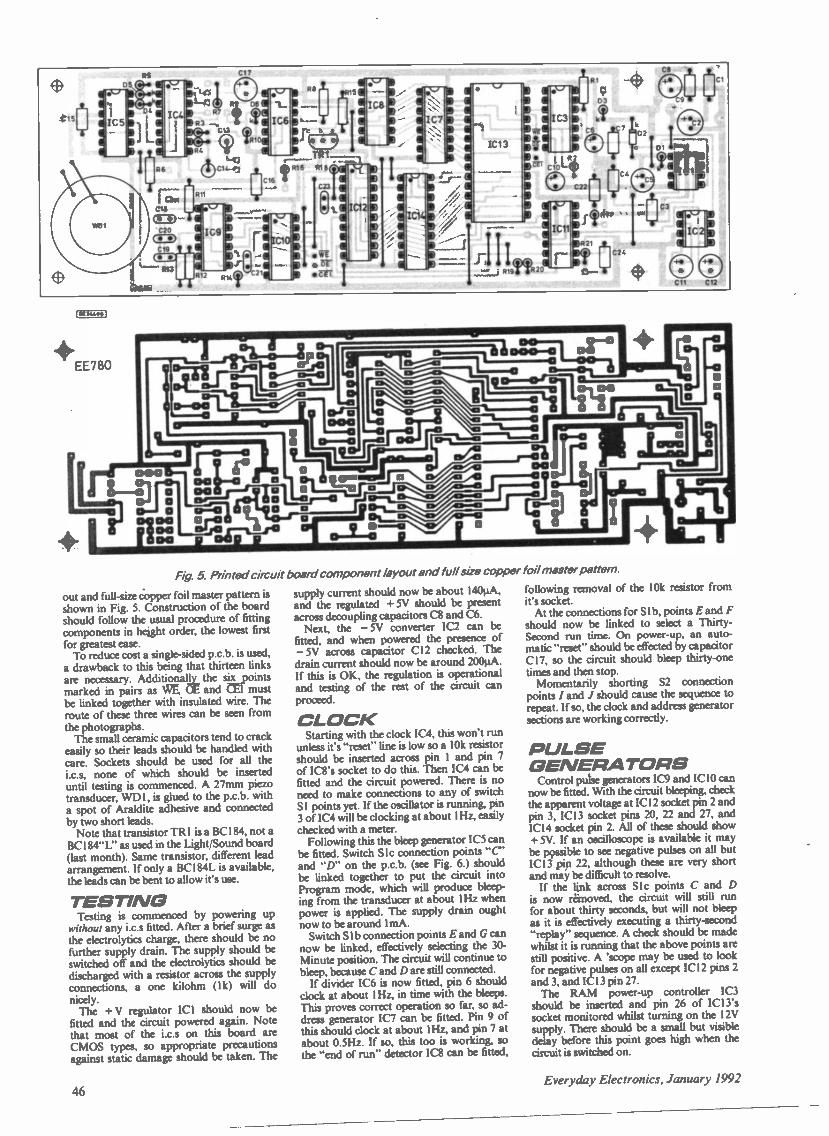
RI
03
C6052
4817
521
C24
Fig. 5 Printed circuit board component layout and full size copper foil master pattern.
out and full-size copper foil master pattern isshown in Fig. 5. Construction of the boardshould follow the usual procedure of fittingcomponents in height order, the lowest firstfor greatest ease.
To reduce cost a single -sided p.c.b. is used,a drawback to this being that thirteen linksare necessary. Additionally the six pointsmarked in pairs as WE C and CET mustbe linked together with insulated wire. Theroute of these three wires can be seen fromthe photographs.
The small ceramic capacitors tend to crackeasily so their leads should be handled withcare. Sockets should be used for all the
i.c.s, none of which should be inserteduntil testing is commenced. A 27mm piezotransducer, WD1, is glued to the p.c.b. witha spot of Araldite adhesive and connectedby two short leads.
Note that transistor TR1 is a BC184, not aBC184"L" as used in the Light/Sound board(last month). Same transistor, different leadarrangement. If only a BC184L is available,the leads can be bent to allow it's use.
TESTINGTesting is commenced by powering up
without any i.c.s fitted. After a brief surge asthe electrolytics charge, there should be nofurther supply drain. The supply should beswitched off and the electrolytics should bedischarged with a resistor across the supplyconnections, a one kilohm (1k) will donicely.
The +V regulator ICI should now befitted and the circuit powered again. Notethat most of the i.c.s on this board areCMOS types, so appropriate precautionsagainst static damage should be taken. The
supply current should now be about 140µA,and the regulated + 5V should be presentacross decoupling capacitors C8 and C6.
Next, the - 5V converter IC2 can befitted, and when powered the presence of-5V across capacitor C12 checked. Thedrain current should now be around 200µA.If this is OK, the regulation is operationaland testing of the rest of the circuit canproceed.
CLOCKStarting with the clock IC4, this won't run
unless it's "reset" line is low so a 10k resistorshould be inserted across pin I and pin 7of IC8's socket to do this. Then IC4 can befitted and the circuit powered. There is noneed to make connections to any of switchSI points yet. If the oscillator is running, pin3 of IC4 will be clocking at about 1Hz, easilychecked with a meter.
Following this the bleep generator IC5 canbe fitted. Switch Slc connection points "C'and "D" on the p.c.b. (see Fig. 6.) shouldbe linked together to put the circuit intoProgram mode, which will produce bleep-ing from the transducer at about 1Hz whenpower is applied. The supply drain oughtnow to be around ImA.
Switch Slb connection points E and G cannow be linked, effectively selecting the 30 -Minute position. The circuit will continue tobleep, because C and D are still connected.
If divider iC6 is now fitted, pin 6 shouldclock at about I Hz, in time with the bleeps.This proves correct operation so far, so ad-dress generator IC7 can be fitted. Pin 9 ofthis should clock at about I Hz, and pin 7 atabout 0.5Hz. If so, this too is working, sothe "end of run" detector iC8 can be fitted,
following removal of the 10k resistor fromit's socket.
At the connections for SI b, points E and Fshould now be linked to select a Thirty -Second run time. On power -up, an auto-matic "reset" should be effected by capacitorC17, so the circuit should bleep thirty-onetimes and then stop.
Momentarily shorting S2 connectionpoints / and J should cause the sequence torepeat. If so, the clock and address generatorsections are working correctly.
PULSEGENERATORS
Control pulse generators IC9 and ICIO cannow be fitted. With the circuit bleeping, checkthe apparent voltage at IC12 socket pin 2 andpin 3, IC13 socket pins 20, 22 and 27, and1C14 socket pin 2. All of these should show+ 5V. if an oscilloscope is available it maybe pgssible to see negative pulses on all butIC13 pin 22, although these are very shortand may be difficult to resolve.
If the link across S lc points C and Dis now removed, the circuit will still runfor about thirty seconds, but will not bleepas it is effectively executing a thirty-second"replay" sequence. A check should be madewhilst it is running that the above points arestill positive. A 'scope may be used to lookfor negative pulses on all except IC12 pins 2and 3, and IC13 pin 27.
The RAM power -up controller IC3should be inserted and pin 26 of 1C13'ssocket monitored whilst turning on the I2Vsupply. There should be a small but visibledelay before this point goes high when thecircuit is switched on.
46Everyday Electronics, January 1992

A/0 -0/ACONVERTERS
With power supplies, clock, address gener-ator and control pulses all running, at lastthe interesting part has been reached! TheA/D converter IC12 can be inserted. Pin 19is an interne "clock" output and shouldhave an ave. .ge d.c. level of about 2.5V. Itmay be checked with a 'scope, it runs atabout 350kHz.
Reference output pin 9 should be at 2.5Vd.c. The supply current should by now be2.5mA to 3.0mA.
Next, ICII, the TL064 quad op. amp,should be fitted. The circuit input, point Q,should be connected to "ground" (negativerail). This ought to result in OV at ICI 1 pin14, the input buffer. Pin one should be at2.5V, and the total supply current should beabout 4.1mA.
The D/A converter IC14 can be insertednext, and S lc points C and D shorted againto put the circuit into Program mode. Whilstthe circuit is running (and bleeping), the out-put, from point R, should equal the input,since data conversion and transfer betweenthe A/D and D/A chips should be takingplace.
If a ten kilohm linear potentiometer isconnected across the 5V supply (acrosscapacitor C8) and the wiper (centre tag)taken to the input, a meter will show theoutput tracking the input during the pro-gramming period. When the sequence ends,the output should remain at it's final value.
RAM CHECKFinally, the RAM chip IC13 can be fitted.
A programming sequence should be ex-ecuted with a varying voltage applied to theinput, then the short across Slc connectionsremoved, and the sequence triggered againby linking S2's connections briefly.
The programmer board "stalked" above the Lights/Sound p.c.b.
This should result in a replay of thevoltage pattern just entered, this time ob-tained from the RAM. It will run for onlythirty seconds of course, since for testing thisperiod is still selected at SI b's connections.
This completes the board checks, so it cannow be fitted to the Mind Machine projectfor fully automated operation. The totalsupply current taken by this board whenrunning should be about 5.OmA.
ASSEMBLYThe Programmer board fits above the ex-
isting Mind Machine Lights/Sound board,
RROG/DIRECT
53
SOUND AND LIOHT..._.....BOARD INPUT
-,,,,,SWITCH\ S1
o12 ,4AC 0
2 1 0
o 9....B
BRILLIANCE)
vR I
6 jo o
All4.0
-IV
0
TO WIPER OF 4,e0FREQUENCYCONTROL
(VR4)
R
N. 3 LINKS
t
K
elPL)Sri ei,7TC...."---71H
...----.......TO BACK UPBATTERY E
NEDAT I VE /GROUND
+12 VOLTS FROM COMMON POINT ,-,42POWER SWITCH IOW
TO 'GROUND COMMONPOINT ON CHASSIS BATTERY HOLDER
ge
4\V.IP METAL CHASSIS PLATE
OMV.
(trUti I
Fig. 6. Interwiring from the circuit board to off -board components.
on the four screws projecting from the chas-sis plate. It faces the opposite way to theSound/Lights board, all the i.c.s pointingaway from the front panel.
The board is longer than the first board,one end projecting beyond the mounting.The back-up battery "pack" fits beneath thisprojection.
Connection into the Mind Machineproject is straightforward. The trickiest partis the bunch of wires connecting switch SI,but with some ribbon cable to keep thingsneat this shouldn't cause any real difficulties.All connections are shown in Fig. 6.
The lead from the wiper of Frequencycontrol VR4 is disconnected from theoriginal p.c.b. and taken instead to theinput, point Q, of the Programmer board. As.p.d.t. S3 switch selects Programmed (pointR) or Direct (point N) output from the
programmer and feeds it to the originalboard's input. S2 is a miniature press -to -make switch for program restarting.
The + I 2V supply is taken from theexisting on -off switch to point S on theboard, whilst negative, point T, is connectedto the common "Earth" on the chassis. Thebackup battery consists of three alkalineAAA cells, taped and soldered together tomake a 4.5V pack and fastened to thechassis with cable ties. This semipermanentinstallation is fine since they should lastvirtually for their shelf life, a couple of yearsat least.
The "end of run" output, point M, is sol-dered to the existing lead on the top endof Brilliance control VR1. When transistorTR I turns on it reduces the voltage acrossthis potentiometer to about a tenth of it'snormal value, causing marked dimming ofthe lights.
RELAXIn normal use, switch SI is set to Program,
S3 to Programmed, and the Reset button S2pressed. Programming begins as soon as it isreleased, and the desired pattern is enteredwith the frequency control, the bleeps beingcounted so that the point in the program isknown. The author normally starts at aboutI4Hz, falling to 7Hz to 8Hz over the firsttwo or three bleeps, holding this briefly, thendropping slowly to 4Hz, then back up to
Everyday Electronics, January' /99247

Rear view (above) of components mounted on the front paneland (below) front panel lettering on the completed unit.
General layout of components inside the Mind Machine
21.0V
T1
15-0-15v 1N4100710OrnA
(1114424 I
R112
about 7Hz, with some brief (one -bleep) excursions to 12Hz, thenover the last two or three bleeps returning smoothly to 14Hz-I6Hz.
Following program entry, SI is set to 15, 30 or 45 minutes andS2 pressed to repeat the sequence over this period. It is possible torelax far more deeply with the automatic control sequence, in factit is all too easy to fall asleep as delta frequencies are approached!This doesn't seem to detract from the beneficial effects, though.
Once a satisfactory program pattern has been found, it can beused repeatedly. There is no need to reprogram as it will beretained in the RAM when the machine is switched off. Onpower -up a "reset" is performed automatically, so it is onlynecessary to don glasses and phones and switch on to enjoy asession.
Switch S3 permits manual frequency control, though if the se-quence has ended the lights will be dimmed. This is easily over-come by pressing Reset.
BUILT -111 CHARGERThe project can be powered by ordinary batteries. However, to
save case dismantling for battery changes, the prototype is fittedwith Ni-Cads and a built-in charger.
This is a simple transformer, rectifier and constant -current ar-rangement connected permanent/v to the battery pack. A mini-ature three -pin chassis plug mounted on the case rear panel ac-cepts mains input to the charger.
The charger circuit diagram is shown in Fig. 7. The mainstransformer TI has a 15V -0V -15V secondary winding, with theoutput rectified by diodes DI and D2 and smoothed by capacitorCI. Transistors TR1 and TR2 form a simple constant -currentcircuit, the output from this going to the battery pack throughdiode D3 to prevent any "back -feeding" when it is not operating.
This little circuit was assembled on a scrap of 0.Iin. stripboard.The breaks in the underside copper strips and the topside com-ponent layout appear in Fig. 8.
Transistor TR2 may warm up a little in use so a clip -on heat -sink should be fitted. Testing is simple, just check that a voltageappears across capacitor CI when the transformer is poweredand that the output into the batteries is around 50mA-60mA.
There is just room inside the case for the transformer and boardbehind the p.c.b.s, alongside the battery pack, as can be seen inthe photographs. The board is mounted vertically on a bracketcut from a piece of plastic.
The mains Earth is connected to the chassis plate, and allconnections to the rear of the plug are sleeved for safety. Thewiring for this part of the project is shown in Fig. 9. The MindMachine can be used whilst on charge, although the batteriesmust be connec ed.
TR2BF% 30
TO BATTERYPOSITIVE
TO GROUND
REAR OF MAINSCHASSIS SOCKET
TRANSFORMER
PLASTICBRACKET
TO CHASSISCOMMON POINT
CONSTANT CURRENTBOARD
TO BATTERY POSITIVE
TO CHASSIS COMMON POINT
(E1341. 0
Fig. 7 (left). Circuit diagram for the in-ternal charger
Fig. 8 (below). Charger stripboardcomponent layout and details of un-derside breaks in copper strips.
Fig. 9 (below left). Interwiring of thecharger components.
0
0
3
rrrirrrn
10
1.12C1D. . . 0 0 0 0. O0 0 C 0 0 0 LBEZ.Mi00 00 0 0 000 000 0 0 0
00 00 00 000004100 0 0 0000 000 0 0 0 0 00 0 0000 0 O 0 000 0 0 00 0
1.01DXIDIF 0
48 Everyday Electronics, January 1992

HART AUDIO KITS -YOUR VALUE FORMONEY ROUTE TO ULTIMATE HI-FI
HART AUDIO KITS give you the opportund, tc sudd thevery best engineered hifi equipment there designed bythe leaders in their field, using the best components thatare availableEvery HART KIT is not lust a new equipment acquisitionbut a valuable investment in knowledge. giving you guidedhands-on experience of modern electronic techniquesIn short HART is your friend in the trade giving you, as aknowledgeable constructor, access to better equipment atlower prices than the man in the StreetYou can buy the reprints and construction manual for anykit to see how easy it is to build your own equipment theHART way The FULL cost can be credited against yoursubsequent kit purchaseOur fist will give you fuller details of all our Audio Kits.components and special offers
AUDIO DESIGN so WATT POWER AMPLIFIER.
This fantastic John Linsley Hood designed amplifier is theflagship of our range. and the ideal powerhouse for yourultimate hifi system This kit is your way to get LK perfor-mance for a few tenths of the cost, Featured on the frontcover of Electronics Today International this completestereo power amplifier offers World Class performanceallied to the famous HART quality and ease of construc-tion John Linsley Hood's comments on seeing a completeflit were enthusiastic - The external view is that of a
..ioroughly professional piece of audio gear. neat elegantand functional This impression is greatly reinforced bythe internal appearance. which is redolent of quality, bothin components and in layout Options include a stereoLED power meter and versatile passive front end givingswitched inputs using ALPS precision. low -noise volumeand balance controls A new relay switched front end op-tion also gives a tape input and output facility so that for usewith tuners. tape and CD players, or indeed any other 'flatinputs the power amplifier may be used on its own, withoutthe need for any external signal handling stages 'Slave'and monobloc versions without the passive input stageand power meter are also available All versions fit withinour standard 420 x 260 x 75mm case to match our 400Series Tuner range ALL six power supply rails are fullystabilised. and the complete power supply using a toroidaltransformer, is contained within a heavy gauge aluminiumchassis/heatsink fined with IEC mains input and outputsockets All the circuitry is on professions grade printedcircuit boards with roller tinned finish and green solderresist on the component ident side. the power amplifiersfeature an advanced double sided layout for maximumperformance All wiring in this kit is pre- terminated. readyfor instant use.RLH11 Reprints of latest articles Cl 80K1100CM HART Construction Manual DI 50
LINSLEY HOOD SHUNT FEEDBACK R.I.A AMOVING COIL & MOVING MAGNET PICKUP
PREAMPLIFIER
Modern, ultimate sound systems are evolving towards abuilt-in RIAA preamplifier within the turntable unit, keep-ing noise pickup to a minimum This new circuit by JohnLinsley Hood uses latest generation integrated circuits inthe sonically preferred shunt feedback configuration to givean accurate and musical sound. with the ability to use bothmoving magnet and moving coil cartridges Power comesfrom two 9v PP3 size batteries or a mains power supplyThis HART kit is exceptionally easy to build with detailedinstructions and all the specially selected components fit-ting directly on to the roller tinned fibreglass printed circuitboard Even the gold plated phono sockets mount directlyOn the boardThis Kit now comes with latest generation low -noise frontend IC and onboard power stabilisers for any DC input volt-age between 9v and 30vK 1500 Special Discount Price for complete Kit 167 99
ALPS PRECISION LOW -NOISE STEREO POTS.
To fulfil the need for higher quality controls we are nowimporting an exciting new range of precision audio pots invalues to cover most quality amplifier applications Allin 2 -gang stereo format, with 20mm long 6mm dia steelshafts Now you can throw out those noisy ill -matchedcarbon pots and replace with the real hi-fi componentsOnly used selectively in the very top flight of World classamplifiers. The improvement in track accuracy and match-ing really is incredible giving better tonal balance betweenchannels and rock solid image stability Motorised versionshave 5v DC Drive motor.2 -Gang 100K Lin CI3 862 -Gang 10K. wit 100K Log C9 602 -Gang 10K Spacial Balance C10 712 -Gang 20K Log MOTORISED C19 202 -Gang 10K Special Balance. MOTORISED, zerocrosstalk and < 10% centre loss with nearLog/Antilog Tracks)... .. C1998
HIGH QUALITY REPLACEMENTCASSETTE HEADS
Do you tapes lack treble', A worn head could be theproblem For top performance cassette recorder headsshould be replaced every 1,500 hours Fitting one of ourhigh quality replacement heads could restore performanceto better than new' Standard inductances and mountingsmake fitting easy on nearly all machines (Sony are special.see below) and our TC1 Test Cassette helps you set theazimuth spot on As we are the actual importers you getprime parts at lower prices compare our prices with othersuppliers and see' All our heads are suitable for use withany Dolby system and are normally available ex stock Wealso stock wide range of special heads for homeconstruction and industrial usersHM120 Standard Mono R/P Head C3 51HC15 Standard Quality Stereo RIP Head C2 49HC66 High Quality Stereo RIP Head Permalloy C7 98HS16 Sendust Alloy Stereo Head C16 85HC80 NEW RANGE High Beta Permalloy Stereo headModern space saver design for easy fitting and lowercost Suitable for chrome metal and ferric tapes.truly a universal replacement head for everythingfrom hi-li decks to car players and at an incredibleprice too. £6.30H0551 4 -Track RECORD &Play Permalloy Head forauto -reverse car players or quadraphonic recording £14.90H524 Standard Erase Heed £1.90H581 Hi Field Erase Head for METAL Tapas £3.49HRP373 Downstream Monitor StereoCombination Head £47.90
Many other SPECIAL cassette Heads instock, see our LIST.
REEL TO REEL HEADS999R 214 Record/Play 110mH Suits Stuart TapeCircuits E13.649986 214 Erase Heed Universal Mount.Suits Stuart £11.11
TAPE RECORDER CARE PRODUCT*HART TC1 TEST CASSETTE Our famous triplepurpose test cassette Sets tape azimuth. VUlevel and tape speed 05.36DEMI Mains Powered Taps Head Demagnetizer,prevents noise on playback due to residualhead magnetisation £4 48DEMI 15 Electronic, Cassette Type. demegnenzer C8 91
COMPUTER CORNERThe following an selection of our new range of VERY compell-tlytoly priced. HIgh Duality computer systems. Din to our longxparianc of Importing we have thst necessary contacts in Si..Far East to buy at very advantageous prices and can pass Si.sayings on to you. All hard disc machines ordered with DOS Sr.fully formatted and ready to use.
HART MODEL AT-211/16WP COMPUTERFully fledged AT286 machinecheap enough to use as thefastest wordprocessor in thewest, Only a few years agothe AT -286 machine was thefastest standard office com-puter known Now we can offerthe superfast 16MHz versionteenier ones were only 10 or12MHz) at such an incrediblylow price that it can be usedin any office or home Notonly that but ours comes withultrafast memory so thatthe machine can run inzero wait state
Advanced features are -Full 1MB of memory (Ex-pandable to 4ME11, 102key UK keyboard, compact desktop case. 1 2MB 5'. HighDensity Disk Drive and interface card for extra drive.Graphics/Printer Card, built in Hard Disk InterfaceHART AT -286/ 16WP ONLY £277.2514" FST Hercules monitor, Amber 13314' Paper White Hercules Monitor. (Both have T/SBase) C86Trust Writer W/P Software U1141111Nfordster commands C19 50
NOG AT,O111/111U13 Hard Dint ComputerSpecification as above but with 45MB 25ms hard disk. VGAColour Graphics Card with 512K RAM. parallel printer port. 2serial ports. 1 game port 1.523 5014' VGA Mono Monitor. Amber £86.70 Paper While UN
w_
HART 40111111AT-316/1611X EL
Entry level 386 machine for demanding applications atmoderate cost Spec as our AT286/16WP with 1MB Drammemory, Mini Tower case 45MB 25ms hard disk drive. VGAColour Graphics Card with 256K RAM40M8 AT-386/16SX EL is ONLY C634 30 (Ex Vat)
HART 521N1 AT -316/206X UG
Luxury version of the above with higher processor speed andamazing 9 millisecond access time hard disk 2MB SIMMRAM. Compact Tower Case, VGA 1024 s 768 card with 512KRAM. upgradeable to 1MB of Video memory40MB AT-386/20SX UG ONLY C853 10
OPTIONAL EXTRASHART Computers can be 'custom made' to ht your personal
Send or 'phone for your copy of our List (50p) of Mese and many other Kits & Components Enquiries from Overseascustomers are equally welcome, but PLEASE send 2IRCs if you want a list sent surface post or 5 for Airmail
Ordering is easy Just write. telephone on tax your requirements to sample the friendly and en tc ent HARTservice Payment by cheque. cash or credit card. A telephoned or faxed order with your credit card number will
get your order on its way to you THAT DAYPlease add part cost of carriage and insurance as follows -INLAND Orders up to U0 - [1.50Orders over C20 - C3.50 Express Courtier, next working day. C10 (For safety all computer partsare eel sent b tour V RSEA Plea I Informal n with r
MANUFACTURERS OF QUALITYAUDIO KITS AND COMPUTERS
24 hr SALES LINE(0691) 652894
Fax: 0691 662864
requirements, at NO extra cost, Simply select the options yourequire If replacing any item in the standard specification forthat model then deduct Miscast of the part not needed.
SOFTWAREMS-DOS 5 Latest Release. Full version. 3.5" or 5.25' C59DR DOS 6 C77
Microsoft Windows 3 3 5" or 5.25- Disks £65MONITORS
SM1421 AM TU Hercules Mono with FST Tube and Stand.Amber DOSM1421 PW TU As Above but Paper White Screen 06SM1416A VGA Mono Moniezr chi UR and swivel stand.Amber .1311.70SM1416W As Above. Paper while noSM 1465-00 Super VGA Mulbsync Colour Monitor. 26" Oatpitch. 50MHz Bandwidth. up to 1024 x 768. thy stand E236
KEYBOARD.K261 102 Key Enhanced UK Layout. Tactile click AT/XTSwitchable with dual slope feet (Standard Keyboard suppliedwith systems) C31
K 108 Similar to above, single slope MIA Alps SVASChea- E38K86153A As above but with heavy mail base C44
VO and GRAPHIC CAROBAT Super I/O Card 2 a MD. NIDE. 2 Aerial. 1 Parallel. 1 GamePorts C21 2(,Hercules Mono Grapthe II Printer card C11 'I16 -Bit VGA Card. 2350. C46 5CTrident 8900 VGA Card. 5121( C67 34Trident 8900 VGA Card will 1Mb CM 9C
MK MMUS5.25. 1 2Mb Floppy Diak Drive3.S- 1 44Mb Floppy Disk Drive. C41
Adapter to fit 3.5'l drive In Ur WM. c./w power adarnar £`"45MB 25ms Hard Disk Drive C16552MB Quantum Hard Disk. Lightning Fan erns ACCesstime E28,
CAMSWE 611P Desktop Cage. Pip Top. 203W Pal £56.40WE727P Mini TOMS, Caw 200W MU DM. 70108MP Mini Tower Can. COMpact Style C89CT107 Midi Tower Gee C10e,
111071111111BOARINIAT -286/160K RAMAT-386-16SX OK RAM C195AT-386-20SX OK. RAM 0245
PLEASE NOTE THAT ALL fTEMS IN THISSECTION ARE PRICED EX VAT.
AUDIO KIT PRICES are VATINCLUSIVE. COMPUTERPRICES EXCLUDE VAT
Everyday Elecironies, January 1992 49

INTER CRobert PenfoldN LAST month's Interface article aIsimple eight bit Analogue to Digital
Converter was described, together with asimple temperature sensor. This month wecontinue on the same theme, with animproved temperature sensor circuit. Thisprovides greater resolution and a widertemperature range.
SIGNAL PROCESSINGThe main problem with the basic design
described last month is that it provides aresolution of only one degree Centigrade.Over a temperature range of 0 to 100 or110 degrees, it is actually possible to ob-tain a much more useful resolution of 0.5degrees using an 8 -bit converter.
A second problem with the originaldesign is that it lacks accuracy at lowtemperatures. This is partially due tolimitations of the temperature sensor, andpartially due to problems in removing theslight zero offset of the converter.
The circuit diagram for the ImprovedTemperature Sensor is shown in Fig. 1.
Like the original circuit, this is based onthe LM35DZ temperature sensor (ICI),which is usable over a 0 to 100 degreeCentigrade temperature range. If the moreexpensive LM35CZ is used, the upper endof the range is extended to 110 degreesCentigrade.
The LM35 provides an output volt-age that is equal to 10 millivolts perdegree Centigrade, with no d.c. offset.This matches the 10 millivolt resolutionof the Analogue to Digital Converter (lastmonth), giving the one degree resolu-
hon. Simply amplifying the output fromthe LM35 by a factor of two booststhe output voltage to 20 millivolts perdegree, and gives 0.5 degree resolution.With a maximum temperature of 100 or110 degrees Centigrade, this gives a max-imum output potential of 2.0 or 2.2 volts,which is still within the 2.56 volt maxi-mum of the converter.
CIRCUITComponent IC2 is a simple non -invert-
ing amplifier which is d.c. coupled and hasa voltage gain of two times. Its gain mustbe set very precisely at this figure in orderto obtain accurate results. The gain hastherefore been made adjustable, and VR2is used to trim it to precisely the correctfigure.
Potentiometer VR1 is an offset nullcontrol. Conventionally an offset nullcontrol is used to compensate for offsetvoltages in the operational amplifier'sbiasing. It will do so in this case, but it canalso be used to compensate for any slightoffsets in the analogue to digital con-verter, or in the temperature sensor.
Note that the output of this circuit mustconnect directly to the analogue input ter-minal of the ZN448E in the converter cir-cuit. The input attenuator and zero adjust-ment circuits of the converter should beomitted.
SOFTWARETaking readings from the interface is
achieved in much the same way as for theoriginal temperature interface. First out -
101 = LM35DZV+ 102 = CA3140E
IC 1Out 3
C1
Gnd 2 54 R24k 7
VR110k
VR2101
R1
S1O0kR310'
IC2T 100n
o 5V
+ 5 V
Out0
o OV
Fig 1. Circuit diagram for the Improved Temperature Sen-sor Interface.
put a dummy value to in/out address 768in order to initiate a reading. After a delayof at least nine microseconds, the con-verter is read at input/output address 768.Simply divide the returned values by twoin order to convert them into readings indegrees Centigrade.
I have assumed here that the converteris at the base address of the thirty twoaddress "prototype card" block. If the unitis placed elsewhere in the input/outputmap, then obviously the appropriate ad-dress must be used instead of address 768.
The accompanying Listing.1 is for aprogram that takes readings at one secondintervals. It displays the current tempera-ture on the screen, together with maxi-mum and minimum readings.
This program is useful for testing andcalibration purposes, as well as for usewhen utilizing the system for temperaturemonitoring. It is suitable for the QuickBASIC compiler, or the QBASIC inter-preter supplied with MS/DOS 5.0. Itmight work with other PC BASICs, but ifnot it should certainly be quite easy toconvert it to work with other PC BASICs.
CALIBRATIONThe original temperature interface cir-
cuit does not require any calibration, butit does not exactly offer the ultimate inaccuracy. This version can provide muchbetter accuracy, but only if it is calibratedaccurately.
Calibration requires two accurate tem-peratures, and one of these can be icedwater at 0 degrees Centigrade. The other
SCREEN 0WIDTH 40, 25CLS 2
Tmax = 0
Tmin = 127
ft = "fif.£1,"
LOCATE 8, 6
PRINT "Temp."LOCATE 8, 18PRINT "Max"LOCATE 8, 31
PRINT "Min"LOCATE 15, 1
PRINT "Press
Listing One:TemperatureReading
SPACE BAR to exit"
WHILE INKEYS <> " "
OUT 768, 0SLEEP 1Tnow = INP(768) / 2
IF Tnow > Tmax THEN Tmax = TnowIF Tnow < Tmin THEN Tmin = TnowLOCATE 10, 5
PRINT USING ft; TnowLOCATE 10, 17
PRINT USING fl; TmaxLOCATE 10, 30PRINT USING ft; Tmin
WEND
50 Everyday Electronics, January 1992

temperature must be much higher, andthis could be water at about 50 degreesCentigrade or so. A good quality ther-mometer should be used to accuratelymonitor the precise temperature of thewater.
The calibration process is verystraightforward. Start with both VR1 andVR2 set at roughly the centres of theiradjustment ranges. Place ICI in the icedwater and adjust VRI for a reading ofzero. Next place ICI in the hot water, andadjust VR2 for the correct reading. Repeatthis procedure a few times until no furtheradjustment is necessary. The unit shouldthen work with good accuracy over thefull temperature range.
When calibrating and using the unit,bear in mind that ICI should not be di-rectly immersed in liquids. It must bemounted inside a container of some kind,such as a small test-tube, so that no liquidcomes into contact with its leadout wires.
It is a good idea to use some silicongrease to give a good thermal contact be-tween the container and IC1. Even so,the response time will not be particularlyfast. It will take the sensor several secondsto respond to large and rapid changes intemperature. Be careful to allow sufficientadjustment time when calibrating the unit.
NEGATIVE TEMPERATURESThe LM35CZ can handle negative
temperatures down to - 40 degreesCentigrade. Unfortunately, these negativetemperatures provide negative outputvoltages which the converter can nothandle. One way around this difficulty isto use VR1 to provide an offset, so thatthe output voltage from IC2 is alwayspositive.
For example, suppose that the unit mustmeasure temperatures down to - 10 de-grees Centigrade. With ICI at this tem-perature, VRI would be adjusted for areading of zero. With ICI then set atthe higher calibration temperature, VR2would be adjusted for a reading ten de-grees higher than the actual calibrationtemperature.
In order to obtain readings in de-grees Centigrade, the software would first
have to divide readings by two, andthen deduct ten to compensate for thedeliberate offset. This would give a usabletemperature range of - 10 to - 110
degrees Centigrade.Some initial experiments would suggest
that a 10 degree offset can be handledwith no significant degradation in ac-
curacy. This might not be the case withthe full 40 degree offset needed to readdown to the - 40 degree minimum of theLM35CZ.
However, if you need to read downto such low temperatures it might beworthwhile experimenting along theselines. VR1 certainly seems to be able tohandle a 40 millivolt input offset. Ofcourse, if the unit is made to read rightdown to - 40 degrees, you have toaccept some loss of coverage at the otherend of the range. The maximum in-put voltage of the converter would bereached at a temperature of 87.5 degrees.
There is plenty of scope for experimen-tation with a unit of this type. Withsuitable software you can do such thingsas monitoring heating systems, the out-side temperature, etc. Most PCs havegood graphics capability these days, andit should not be too difficult to producesoftware to log readings and then displaythem as graphs.
PC INCOMPATIBILITIESThere are hundreds of different PC
expansion cards, monitors, etc. currentlyavailable, and with a few provisos, theyshould all work perfectly well together. Inreality there seems to be the occasionalproblem, which I suppose is inevitablewith so many products being produced byso many different companies around theworld. This means that you need to be alittle careful when buying PC hardware.
Possibly I have been unlucky, buthave encountered numerous PC com-patibility problems over the last fewyears. The worst case was a 12MHz ATmotherboard which only seemed to workwith about one -in -two expansion cards!With some swapping around of cardsbetween various computers I did even-tually managed to produce a complete
computer based on this motherboard, butwhy did some cards refuse to work with itwhile others were fine?
More recently I have had problemswith non -Intel maths co -processors whichworked in some computers but not inothers, and a monitor which worked withsome VGA cards in all modes, but refusedto respond to others when used in the800 x 600 super VGA mode.
In the case of the monitor the problemseemed to be due to differences in thescan rates of VGA cards. The super VGAmodes are not properly standardised,and this clearly leaves room for incom-patibility problems. Many VGA cardsnow have a configuration switch whichenables you to select between two sets ofscanning frequencies. A lower set thanany super VGA monitor should be able tohandle, and a higher one for "flicker -free -viewing on suitable monitors.
The expansion card problem and (pos-sibly) the co -processor one seems to besomething more fundamental. Modernmotherboards and expansion cards arelargely devoid of TTL chips, and insteaduse a variety of LSI chip technologies.This seems to result in occasional conflictswhere two sets of chips do not agreeabout what constitutes valid logic 0 andlogic I voltages. This usually results inthe computer completely hanging up, orcrashing soon after switch -on.
There also seems to be problems withdrive currents, with some chips simplynot having sufficiently powerful outputs.This factor seems to be responsible forsome computers being unable to drivesome printers via their parallel ports.
It would seem to be a good idea, wherepossible, to check that PC hardware willwork properly with your system beforehanding over any money. Alternatively,make sure that you can return the equip-ment for a refund if there are any incom-patibility problems.
Next month: We will continuewith PC interfacing, and the subjectof digital to analogue converterswill be covered.
Crossword Solution E *ELBA T S A OP AMPE
G I N F R A RED 0
WA U N A G C W S S
0 T W L E D EDEWF 0R L
IPA A R IME L0 A R RS T E 0 T SDV m I E U C R P D P
U
S SNIPPHASEAME TE L P P 0 L E D C A i
A OHMLK R EEL L T K 0R 0 Y E R A W T F OS E NC TIMEROTSISERRH RETEMOITNETOP *
The familiar title is EVER% DA'. ELECTRONICS The usomated name is %Ina KENNARD
Everyday Electronics. January 1992 5I

Special Series
MAGNETICRECORDINGPart 4; HEAD DRIVE
CIRCUITS
VIVIAN CAPELIr MAY may seem that all we need to do tomake a magnetic recording on tape is toconnect a recording head to an amplifier
and a biasing system, and pass the tape atuniform speed across it. As may be ex-pected, there is rather more to it than that.
Our first consideration is that of headimpedance, it should be of the optimumfor the required function. Just as with themagnetic characteristics we discussed lastmonth, the electrical requirements for therecording and playback heads are quitedifferent.
The strength of a magnetic fieldproduced by a coil is proportional to thecurrent flowing through it rather than thevoltage across it. So we must be able todrive adequate signal and bias currentsthrough the head in order to make a goodrecording. As high impedances limit theamount of current that could pass. itfollows that the head winding should be of/ow impedance.
In the case of the playback head, it isnecessary to generate as ,high a voltage aspossible from the flux on the tape, in or-der that a large signal voltage is presentedto the first stage and a high signal/noiseratio thus be obtained. This requires a largenumber of turns on the coil, which gives ita high impedance.
So, a low impedance is best for therecording head whereas a high impedance isdesirable for playback. No problem here aslong as separate heads are used, but with asingle record/playback head, impedancemust be a compromise.
SWITCHINGWhen a single head is used it must be
switched from the record to the playbackamplifier and back again, which can bedone with a single -pole two-way switch. Anobvious way of connecting it is having oneside of the winding connected to the chas-sis, and the other switched either to theinput of the playback amplifier or the out-put of the recording amplifier.
Such an arrangement though, would beprone to trouble. Remember that very highgain must follow the playback head totranslate the minute signals from the tapeinto the high volume needed for realisticsound reproduction. So, any trace of oxideon the switch contacts would produceaudible noise. Furthermore, the switch andits terminals would be liable to pick uphum and would need careful screeningwhich could pose practical difficulties.
The alternative switching system com-monly used, is both simple and ingenious.
One side of the head winding is per-manently connected to the recordingamplifier output circuit, while the otherside is permanently taken to the playbackamplifier input. Connections from both aretaken to a switch, while the switch commonis connected to the chassis (Fig. I ).
In the play position, the switch "earths"the A side of the windings, but in the recordposition, the B side of the winding isearthed. As the switch is connected tochassis in both positions it cannot pick uphum, and there is no switching of "live"connections,
There is no need to switch the erase headduring playback with a.c. systems, as theoscillator is switched off. With d.c. erasure,switching the head is necessary.
H.F. LOSSTaking a further look at the impedance
of the head, this results from a combina-tion of inductance and the d.c. resistance ofthe coils. The formula is:
Z= R2+ xL2
where Z is the impedance; R is the resis-tance of the coils; and XL is the reactanceresulting from the coil inductance.
When recording low frequencies, thereactance XL is low compared to the resis-tance, but at high frequencies the oppositeis true, and the reactance becomes large inproportion to the resistance. What thismeans in practice is that the recordingcurrent encounters a low impedance at bassfrequencies, but a continually rising one
Fig. I. Switching to a combinedrecord/playback head. One end of the headwinding goes to the recording amplifier andthe other to the playback circuit. Alternateends of the winding are earthed for eachfunction thereby avoiding signal switchingand possible hum problems.
as the frequency increases. It decreasesproportionally, producing a falling trebleresponse.
PHASE ANGLESThere is another ill effect. Phase angles
change as the relationship between reac-tance and resistance alters. So, high fre-quencies becorhe displaced in phase rela-tive to lower ones. As the stereo effectdepends strongly on phase differences be-tween channels it can be seen that phaseerrors can result in impaired stereo.
The most common solution to theseproblems is to increase the value of R byincluding a high value resistor in series withthe head coil. This has a swamping effectby maintaining a more constant ratio be-tween reactance and resistance over thefrequency range. It ensures that the circuitis mainly resistive and so behaves in a morelinear manner in its frequency as well as itsphase response.
A further improvement can be achieved byconnecting a capacitor across the resistor.This increases the high frequencies applied tothe head and also improves the phase co -relation between high and low frequencies.The values of the resistor and capacitordepend on the resistance and inductance ofthe head, all being chosen to give the flattestoverall response with minimum phase dis-placement for the particular head.
This gives rise to an important practicalpoint. Replacing a worn head on a taperecorder is quite a straightforward task. Ifthe maker's replacement is used there is noproblem, but it may not be available, or itmay be decided to upgrade from a permal-boy to an HPF (hot -pressed ferrite).
Whatever the replacement, it shouldhave approximately the same resistanceand inductance as the original, otherwisethe series components will not produce therequired compensation. Having said that,minor differences, particularly of coilresistance, have little effect and can beignored
RECORDINGAMPLIFIER
The output stage feeding the head cir-cuit must produce a high voltage to over-come the high series resistance, and also ahigh current to drive the coils. So it mustprovide a high power compared to whatactually is needed to generate the recordingflux. The output stage must therefore be ofa power output type, and many recordersuse the loudspeaker output stage to drivethe head in the record mode.
52 Everyday Electronics, January 1992

Another factor which comes into play isthe slew rate of the output stage. All poweramplifiers have a limit to the rate of changethat the output voltage can follow. It is ob-vious that the rate of change of a large sig-nal is greater than that of a smaller one.
It is also evident that a high frequencycycle is completed much quicker than acycle of a low frequency, so the rate ofchange is correspondingly greater. The rateof change is thus proportional to frequencyand signal magnitude.
In a recording amplifier where high out-put voltages are required, the output stageslew rate may be inadequate at high fre-quencies. This can be another cause offalling h.f. response, and also generate theintermodulation distortion which occurswhen the slew rate is exceeded. The effectis reduced by selecting output transistorshaving high slew ratings at the voltages andfrequencies required.
There is another type of output stagewhich overcomes these problems byeliminating the need for the high -valueseries resistor. As we have seen, therecording flux is obtained as a result ofcurrent through the head windings ratherthan voltage. The output stage thereforeis designed as a constant -current source.
RECORDINGAMP
iii uc]
Fig. 2. Transconductance recording outputstage supplies signal current that is notdependant on the impedance of the loadthereby eliminating the need for a high -valueseries resistor 1 Tanhurg Actilincuri.
that is the current it supplies remainsconstant irrespective of the impedance ofthe load. So. when the impedance rises athigher frequencies, the current is notreduced.
An example of this type of circuit isthe Actilinear circuit devised by Tanberg,(Fig. 2). It consists of a complementarypush-pull output circuit similar to thatused for many audio amplifiers, but withnegative feedback from the transistor col-lectors (c) to the base circuit. An LC filtercircuit couples'the output to the head.
This type of circuit provides more thansufficient current to drive the head andbecause high signal voltages are not re-quired to overcome a high series resis-tance there are no slew rate problems. Abonus is that the stage serves as a bufferbetween the bias oscillator and the record-ing amplifier so that feedback of the oscil-lator voltage to earlier stages is greatlyreduced.
HEAD DRIVEADJUSTMENT
Recording signals that are too largecause the operating point on the hysteresis
loop to encroach onto the curved portionsand so generate distortion. Yet those thatare too small degrade the signal noise ratioand require the playback amplifier to beturned well up. further increasing noise. Sothere is an optimum point beyond whichpeak recording levels should not rise, norshould they fall too far below.
This is the 0dB point on the recordinglevel meter. However, due to the tolerancesof components in the recording amplifierthis has to be set for each particular instru-ment during manufacture, and a pre-setcontrol will be found inside the machine forthe purpose.
To reset it a millivoltmeter and an audiooscillator with variable output is required,also the service manual, or at least the ap-propriate information from it. A 10 or 100ohm resistor is included in the "earthy" endof the record head by the makers and themeter is connected across it, see Fig. 3. Toavoid false readings the bias oscillator mustnow be disabled, and then the fixed tonefrom the external audio oscillator is injectedinto the Auxiliary or MIC socket.
The output level of the oscillator is nextadjusted to obtain 0dB on the VU meter,then the pre-set drive control is set to givethe millivolt reading specified in the manual.Readings vary from model to model, but atypical one is 0.35mV over 10 ohm for Ferrictape, and 0.7mV for Chrome tape.
It can be said that this adjustment rarelyneeds to be done unless major com-ponents have been changed in the recordingamplifier
BIAS LEVELADJUSTMENT
The bias level may need resetting if adifferent type of tape from that recom-mended is used. In most cases the dif-ferences are too small to make much dif-ference for average domestic use. Profes-sionals set the bias for each tape recorded,as these are masters from which copieswill be made and top performance is es-sential. Hi-fi enthusiasts may also wish tooptimise the setting for a particular brandof tape.
Adjustment is usually by means of asmall variable capacitor in series with thebias oscillator feed to the record head, butvariable resistors or tunable coils are alsoused. The measurement is made in the sameway as that for recording level, that isacross the 10 or 100 ohm resistor in serieswith the recording head.
When the recorder is switched to recordwith no signal input, a reading is obtained.If the maker's setting is being checked, thereading should be compared with thatgiven in the manual and any necessaryadjustment made. As with the recordingdrive, values vary between models, butroughly, the reading should be about tentimes that of the recording level at zeroVU. Across 10 ohm it usually rangesfrom 3.0-7.5mV, while across 100 ohm.30-75mV.
To set the level for a different make oftape, an audio oscillator that can generatea 400Hz and a 10kHz tone is required.These are recorded on the tape at - I 2dB onthe VU meter. The tape is played back andthe output levels of the two tones com-pared. If that of the lOkHz tone is lower,there is too much bias and the amountshould be decreased, but if it is higher, biasis insufficient and it should be increased.
Adjust accordingly. then erase the tapeand record the two tones again at the
Fig. 3. Adjusting recording bias, commonsby preset resistor in series with the bias feed.Reading is taken bt a millivoltmeter across100 ohms (10 ohms in some models) in theearthy end of the head.
same level. Playback once more and checkthe comparative levels as before, thenmake further bias adjustment as required.
The process is repeated until the 10kHztone is just 1dB down if optimum distor-tion level is desired. It may be remem-bered from a previous article, that the twodo no coincide, one must adjust for eitherone or the other, or a compromise can bemade.
AUTOMATICLEVEL CONTROL
Automatic level control (ALC) is foundin most portable recorders. Part of the out-put of the recording amplifier is rectifiedthen used to control the gain of an earlierstage. This ensures that the recording levelis not too high or too low without thenecessity of manually adjusting the level. Italso takes care of increases and decreasesof signal level during recording.
The time constants of the circuit arechosen to give a rapid attack, but slowdecay. Thus sudden loud signals producean almost immediate reduction in gain toprevent overload, but afterwards the circuitfades up the gain gradually to avoid tooobvious gain changes.
The system is useful for speech and"on location" recordings where it wouldbe difficult to set and maintain levelsmanually, but it does have serious draw-backs for other work. Level changes arenoticeable, as background noise drops thenfades up as the signal varies.
For recording music it is hopeless, asthe dynamic range is telescoped, musicalclimaxes are emaciated, and quiet passagesthat are reduced to almost inaudibilityafter loud fortissimos, gradually get un-naturally louder.
Early recorders had a manual/automaticswitch, whereby the user could select themode according to the use, but al-though gimmicks abound on modernmachines, this very useful facility hasdisappeared. Some serious users have hadtheir machines converted to manual opera-tion. This involves removing the feed to thecontrolled stage and either fitting a manualcontrol or in some cases it is possible toarrange for the playback volume control toserve as a level control during recording.Modification details differ considerablybetween models.
Having explored the heads and theirdrive circuits, we will return to the tapeitself in our next article and see how thisapparently simple commodity is far morecomplex than it appears, and what isinvolved in its manufacture.
Everyday Electronics. January 199253

SIMPLE MODEL SERIESSPECIAL EASIWIRE OFFER
FREE EASIWIRE IF YOU BUYANY FOUR MODEL KITS
OR EASIWIRE FOR £5 WHEN YOUPURCHASE A PROJECT KIT.
The two companies mentioned belowhave large stocks of Easiwire solder -less wire wrapping systems, as usedto build all our Simple Model Seriesprojects. They have agreed to makethese available to EE readers who pur-chase complete kits of componentsfor the projects, INCLUDING printedcards to cut out and assemble for eachmodel. If you are prepared to buy anyfour of the seven model kits then youcan get your Easiwire FREE.
If you buy any one model kit you canpurchase an Easiwire kit for just £5.(These kits were previously advertisedby BICC-Vero at £15, including p&p). Toget your kit and Easiwire simply fillin the appropriate coupon and sendit with your cheque (or credit carddetails) to either of the companies.
The seven projects are: Police Car (July91); Musical Roundabout (Aug 91); MicroMicro -a dolls house microcomputer (Sept91); Centurion Tank (Oct 91); Mini Microwave
Christmas Novelty Decoration (Dec 91);Bishop Rock Lighthouse (Jan 92). Thesemodels all play tunes or make noises or flashlights etc. All prices include VATPlease fill in the appropriate coupon below, tick the relevent boxes and send your cheque/PD/credit
card number with one of the coupons to:GREENWELD ELECTRONIC
COMPONENTS27 PARK ROAD,
SOUTHAMPTON S01 3TBTel: 0703 236363Fax: 0703 236307
BULL ELECTRICAL250 PORTLAND ROAD,
OR HOVE, SUSSEXBN3 5QT
Tel: 0273 203500Fax: 0273 23077
BEND EITHER COUPON TO EITHER COMPANY - YOU CHOOSE YOUR SUPPLIEROverseas readers please add £3 to cover the extra postage charge.
FREE EASIWIRE T£5 EASIWIREPlease send me my FREE Easiwire kit. I understand that I Please supply the LighthouseI must buy four model kits at the price given by EE - I on its own at £5.95 plus £1 p&p []I enclose a cheque/PU for £Please debit my credit cardCard No.
Ex. DateThe kits I require are
for the kits ticked below [1] I Please supply an Easiwire atni I £5 with the above kitI-1 I Overseas readers please add £3 to cover the
extra postage chargeI I enclose a cheque/PO for £
(£6.95 or £11.95) EPolice Car (July '91) £5.95 plus £1 p6p[11 I Please charge my credit card - EMusical Roundabout (Aug '91) E7.95 plus £1 p&p L j 1 Card No.Micro Micro (Sept '91) £2.50 plus £1 p&pE I Ex DateCenturion Tank (Oct '91) £4.95 plus £1 p&p SignatureMini Microwave (Nov '91) £5.50 plus £1 p&p EChristmas Novelty (Dec '91) £4.95 plus £1 p&pE 1 NameBishop Rock Lighthouse (Jan '927E5.95 plus £1 p&p E I Address
Address
Signature
Tick four or moreboxes
Nar ne
54 Everyday Electronics, January 1992

Simple Model Series
044811 87,44,?....
BISHOP ROCKiffire '41,
LIGHTHOUSEOWEN BISHOPThe last model in a series which combinestwo hobbies in one - electronics andmodel -making. Simple electronic circuitscombined with easy -to -assemble modelsthat cover a wide range of interests.
STANDING on a pinnacle of rock risingsheer out of the ocean floor in thewesternmost Scilly Isles, the Bishop
Rock lighthouse is said to be the most ex-posedat spring tides and, given that there are anaverage of 30 gales in this area each year, itis small wonder that this region is a poten-tial danger to shipping. The rock is said tobe named after a sailor called Bishop whowas one of only two survivors cast up onit after the wrecking of a whole merchantfleet in the Scillies in the 17th Century.
The present lighthouse is Bishop RockIll. The original Bishop Rock I was startedin 1847 but was destroyed by a storm in1850 before it ever became ope-ational.Bishop Rock II was a sturdier and tallerstructure which was first lit in 1858, butsuffered greatly from the storms. Even-tually it was encased in further granitemasonry and increased in height to itspresent size. Its design was by JamesDouglass, and it was built by his sonWilliam Tregarthen Douglass. It first cameinto service on 25 October 1887.
Even in these days of remote operation,Bishop Rock III continues to be a watchedlighthouse, operated by Trinity House. Theaddition of a "helideck", well above thesurges of the Atlantic breakers, makesrelief operations considerably easier thanthey used to be, though still hazardousenough.
Bishop Rock III was originally lit by oillamps, but now uses an electric lamp of2,600,000 candle -power, with a range of 29sea miles. It is white and its characteristicsignal is two flashes every 15 seconds. Theoriginal fog warning was an explosivecharge set off every five minutes butnowadays there is a fog -horn, giving twoblasts every 90 seconds.
The model is based on the dimensions ofthe light -house at a scale of approximately1/200. It reproduces the light character andfog warning of Bishop Rock III, except
that we have simplified the logic circuit bysounding the fog -horn every 60 seconds.
In the real lighthouse, the flash is
produced by a set of lenses rotating aroundthe lamp; for simplicity we flash the lampon and off electronically. However, tosimulate the effect of the rotating lenses,the lamp takes an appreciable time toacquire full brightness and to turn off.
The circuit can be adapted to produceother light characters should you prefer tobase your model on a lighthouse near yourhome. Similarly, the fog horn has variablepitch and a programmable sounding se-quence.
BLIILOING THETOWERThe lower part of the tower is a
cylindrical base. Use a plastic or metal captaken from a domestic spray -can (furniturepolish, oven -cleaner etc). The cap shouldhave an external diameter of about 54mm,and an internal diameter of at least 50mm.The exact height does not matter exceptthat, to accommodate the circuit boardsand speaker, it needs to be at least 47mmhigh. Fig. I shows the details. Paint the capa "rocky" granite colour and draw avertical ladder down from top to bottom,about 2mm wide with rungs 2mm apart.
If you cannot find a suitable cap, cut thebase from thin cardboard as shown. Formthis into a cylinder and secure the flap withglue. Bend the tags inward. Cut out thebase top and glue this to the tags. We usedbuff -coloured card for the base and main
Fig. 1. The base of the Lighthouse.
55

PLATFORM TOP& BOTTOMCUT 2
fl TA TA r-mr-um TA 1-1
\Juuu vuuuu uyPLATFORM SIDE
0
LLIU)
m
BASE
Everyday Electronics, January 1992

r
LANTERN
tower, so no painting was needed. If youare using white card, paint the base anddraw the ladder on it where shown.
Readers with the equipment and skillcould model the main tower by turning itin wood on a lathe. It is I 62mm long andtapers from 42mm diameter at the bottomend to 27mm at the top. The tapering ismore pronounced toward the bottom ofthe tower, and it hardly tapers at all nearthe top. Bore a hole centrally up the towerto take the wires from the base to thelamp.
The tower is topped by a circularplatform which can be cut from 9mmplywood, with a hole bored centrally in it.Paint the tower, and draw the door andwindows. A ladder leads from the doordown to the bottom of the main tower.
The main tower can also be made fromthin cardboard, though this inevitablylacks the graceful lines of the real thing,and of the wood -turned model. Form thecardboard into a narrow cone and securethe flap with glue. Make the platformfrom two card circles glued to two discswhich form the top and bottom of theplatform. Finally glue the tags at the top
J
H ELI DECK
Fig. 2 (left). Card rings forthe lantern
CUT 2
and bottom of the main tower to theplatform and base respectively.
THE LANTERNMake a photocopy of the designs for
the lantern, helideck and helideck cage ontransparent film, in black. Cut out the lan-tern design. Cut two strips of thin card5mm wide and about 200mm long. Applyglue to one side of one strip, for half itslength. Wind the strip around a cylindricalobject 20mm in diameter, to form a ring ofabout three turns (Fig. 2). The cylindershould preferably taper slightly to make iteasier to remove the ring from it whenthe glue has dried. A small' cap from adomestic spray -can was found to be exactlythe right size and shape for this. Use alarge black spirit -marker pen to blackenthe edges and outside surface of the ring.Prepare a second ring using the other stripand blacken this too.
Cut out a card disc 27mm diameter, forthe top of the lantern; blacken the uppersurface of this, its edge and the outer regionof the lower surface (Fig. 3). Cut anotherdisc 20mm in diameter. Roll the lanterntransparency into a cylinder and use one
Fig. 3 Formation of the lantern housing
ring to hold it rolled, the ring being nearerto what will eventually be the bottom of thelantern. Apply glue to the inside of theother ring and insert the eventual top ofthe rolled transparency into this. Press thetransparency firmly against the inside ofthis ring to form it into a perfect cylinder.
While the glue is still wet, invert therolled transparency on the under -side ofthe lantern top. Then apply glue to theinner card disc and push this down insidethe lantern, gluing it to the undersideof the lantern top. This helps push thetransparency firmly against the inside ofthe ring. When the glue has dried, removethe first ring, apply glue to its inner surfaceand push in back on to what will eventuallybe the lower end of the lantern.
Cut out an annulus of medium -thickcard and glue this to the top of theplatform. The lantern is a push -fit into thisso that it can easily be removed for chang-ing the bulb.
Cut out the photocopied designs for thehelideck and the helideck cage. The con-struction of the helideck cage is similar tothat of the lantern, except that the rings aremade from strips 2.5mm and 9mm wide.They are wound around a cylindrical ob-ject 36mm in diameter. Paint the narrowring black inside and out. The wide ring isto be the same colour as the tower. Formthe cage design into a cylinder and slip thenarrow ring around it near the top. Ap-ply glue to the inside of the wide ring andpush the lower end of the cage into this sothat the lower edge of the cage pattern itself
Everyday Electronics, January 1992 57

+6V0
RI270k
R212s
Cl16 non.
ovo
ICI'555 273Hz
CLOCK
IC24020
ovrrurs
Als
2
C
136Hz
17Hz
s 6 5Hz
c 4 3Hz
6 2Hz,c 1Hz
2s
ls CD
'
IC3a4002
R3 01120k 1N414$
0 k
7 5$
156 0IC4a4011
30$ 060s 0
IC4b4011
IC3b400 2
RL220k
1
6
60m
TRIvNi0k14
C7 1001
IC4c4011 C.
le
11
I J.
IC4d4011
85470
0+6V
LSI64
TR22TX300
(11141161
00V
(the triple railings) are just visible above thering. This ring is to be a push -fit over theplatform, so that the cage may be removedfor changing the bulb.
When the glue is dry, apply glue to theinside and top edge of the narrow ring andslide this into place at the top of the cage.At the same time invert the cage on to thehelideck transparency (also inverted), sofixing the helideck to the top of the cage.
HOW IT WORKSThe clock (ICI in Fig. 4) oscillates at
273Hz. This signal is repeatedly halved infrequency by the 14 stages of the counter inIC2. The outputs from stages 2 and 3 arenot available. The available outputs withtheir frequencies or periods are shown. Anyof these outputs can be used to produce thedesired character. The logic is explainedbelow in some detail so that readers willunderstand how to adapt the circuit forproducing other characters.
The logic for flashing the lamp dependson the binary sequence of outputs fromstages B. D and E, where "0" = lowvoltage and "1" = high voltage (Table I).Each count in the table represents slightlyless than one second, so the sequencerepeats with the period of output E, whichis approximately 15 seconds, as required.During this time the lamp flashes twice,each flash lasting one second.
Table 1:Truth table for lamp flashing
Count OutputEDCB
State of lamp
0 0 0 0 0 FLASH1 0 0 0 1
2 0 0 1 0 FLASH3 0 0 1 1
4 0 1 0 05 0 1 0 1
6 0 1 1 07 0 1 1 1
8 1 0 0 09 1 0 0 1
10 1 0 1 011 1 0 1 1
12 1 1 0 013 1 1 0 1
14 1 1 1 015 1 1 1 1
Fig. 4. Circuit diagram for the light and fog horn
The table shows that the flash occurs ifand only if B, D and E are all low. Thestate of C is immaterial. The state of B, Dand E is detected by feeding the three out-puts to a NOR gate. A four -input gate isused, so signal E is fed to two of the inputs.
The output of the NOR gate is normallylow, but goes high when all three inputs arelow. A high output from the NOR gateraises the voltage of the gate of TRI,turning the transistor on. The transistorconducts readily and the lamp lights. Theswitching action is modified by R4 and C2,which delays the time at which the lampreaches full brightness. When the NORgate goes low, the diode prevents thecapacitor from discharging. The chargeleaks away through R4 and the lamp dimsout.
The logic for sounding the fog -horndepends on the binary sequence of out-puts from stages C to G (Table 2). Eachcount in this table represents about fourseconds, and the sequence repeats with theperiod of output G, which is approximately60 seconds. During this time the fog-horn sounds twice, each blast lasting twoseconds. The table shows that the flashoccurs if and only if C and G are low and Eand F are high. The fact that E has to behigh means that there is always an appreci-able gap between the horn sounding andthe lamps flashing, giving a more realisticeffect. The state of D is immaterial.
The state of C, E, F and G is detected byfeeding the four outputs to a NOR gate,as before. However, because we are look-ing for high states of E and F, these sig-nals must be inverted. The signals first goto NAND gates (IC4a/b) with their inputswired together so that they act as INVERTgates, then to the NOR gate.
When C, E, F and G are in the correctstate the output of the NOR gates goeshigh, and this output goes to a NAND gate(IC4c). This gate also receives the I36Hzaudio signal A, but this passes through thegate only when the NOR gate output ishigh. When the NOR gate is low the outputfrom IC4c is continuously high. The signalis inverted once again, by IC4d, so that it islow between blasts, thus leaving TR2 andthe loudspeaker switched off during the in-active state.
CIRCUIT BOARD ACircuit board "A" (Fig. 5) holds the
timer and counter i.c.s. Like (almost)everything to do with lighthouses, thecircuit boards are circular and stack insidethe lighthouse base. Drill the holes in theboard, then insert the two i.c. sockets andcapacitor Cl; glue them to the board tomake the wiring more secure. Insert C2 andbend its leads and glue the body of thecapacitor to the board. Next insert thep.c.b. terminals.
There are more terminals than usual inthis project as this makes it easier to cus-tomise the circuit design to produce a rangeof light and fog -horn characters. The beadson the recommended p.c.b pins are in a
Table 2:Truth table for the fog -horn
Count Output State of hornGFEDC
0 0 0 0 0 01 0 0 0 0 1
2 0 0 0 1 03 0 0 0 1 1
4 0 0 1 0 05 0 0 1 0 1
6 0 0 1 1 07 0 0 1 1 1
8 0 1 0 0 09 0 1 0 0 1
10 0 1 0 1 011 0 1 0 1 1
12 0 1 1 0 0 SOUND13 0 1 1 0 1
14 0 1 1 1 0 SOUND15 0 1 1 1 1
16 1 0 0 0 017 1 0 0 0 1
18 1 0 0 1 019 1 0 0 1 1
20 1 0 1 0 021 1 0 1 0 1
22 1 0 1 1 023 1 0 1 1 1
24 1 1 0 0 025 1 1 0 0 1
26 1 1 0 1 027 1 1 0 1 1
28 1 1 1 0 029 1 1 1 0 1
30 1 1 1 1 031 1 1 1 1 1
58 Everyday Electronics, January 1992

COMPONENTS
R1 270kR2 12kR3 120kR4 220k PII R5 470Carbon film 0.25W, 5%, or metal film
0.6W1%.
Resistors SeeSHOPTALK
Capaci*orsC1 18n polyester miniature
dipped case, or metallisedceramic plate
C2 10µ tantalum, 15VC3 220n polyester miniature
layer
SemiconductorsD1 1N4148 silicon signal diodeTR1 VN10KM VMOS n -channel
power f.e.t.TR2 ZTX300 npn transistorIC1 7555 CMOS timerIC2 4020 CMOS 14 -stage
counter/dividerIC3 4002 CMOS dual 4 -input
NOR gateIC4 4011 CMOS quadruple
2 -input NAND gate
MiscellaneousLP1 6V, 60mA MES filament
lamp (or similar)LS1 640 speaker, 38mm diam.16 -pin i.c. socket; 14 -pin d.i.l.
i.c. sockets (2 off); 8 -pin i.c.socket; p.c.b. eyelet terminals (21 off);battery connector; insulating tape;p.c.b. lacquer; Easywire pen and tool;insulated connecting wire.
MaterialsThin card, buff or printed white card -
see Shop Talk and Special Offer page.(or wood) for tower Block of expandedpolystyrene, approx. 140 x 100 x 50.Red and white enamel paint (e.g.Humbrol); black acrylic paint (e.g.Tamiya Color)
Approx costguidance only £6
(components only)
range of different colours. it is advisable toadopt a colour code for each of the lines Ato G, and to use the same code on boardB. For certain variations in the light andsound characters, you may need to wire thep.c.b. terminals to a different set of outputpins (see later).
Test the circuit by connecting the battery.The output from ICI pin 3 is a signal of273Hz. You can hear this if you connecta crystal earphone to pin 3, by way of a100n capacitor. Connect the other terminalof the earphone to the OV rail.
On an oscilloscope, the signal can beseen to have a very high mark -space ratio.Monitor the signals from the terminals ofIC2; the important ones are those labelledA to G in Fig. 4. Signal A can be heardwith an earphone; a voltmeter is used tocheck signals B to G.
CIRCUIT BOARD 13Circuit board "B" holds the logic circuits
and the transistor switches which controlthe lamp and loudspeaker. It may be neces-sary to revise the logic connections if otherlight and sound characters are required.
BOARD I TIMER IL COUNTER COMPONENT SIDE
BOARD I TIMER I COUNTER, WIRING SIDE
BOARD 2 LOGIC I SWITCHING COMPONENT SIDE
INSULATINGTAPE
BOARD 2 LOGIC I SWITCHING, WIRING SIDE
Fig. 5 The construction of the two circuit cards using the Easiwire wiring system.
Wiring up the board is straight-forward. The board is tested after wiringthe inter -board connections (Fig. 6).Note that there are two E terminals onBoard B.
Use thin flexible insulated wires, eachabout 10cm long, except for the lamp andbattery is connections. For the battery, youcan use a press -stud battery connector, butyou may need to extend the wires if thebattery to be hidden from sight. The wiresto the lamp need to be about 30cm long. Ifa bulb holder is used, connect the wires tothe screw terminals. Otherwise, solder thewires directly to the bulb, or hold them inplace with insulating tape. When the bat-tery is connected, the lamp begins to flashand the loudspeaker sounds as describedearlier.
ASSEMBLYThe tinal assembly is shown in Fig. 7,
with the circuit boards and loudspeakerstacked inside the base with cardseparators (discs 50cm diameter) to preventshort circuits. The speaker rests face -downon the table.
If the lamp is in a holder, glue this to theplatform. If the wires are soldered to thelamp, wrap black insulating tape aroundthe threaded part of the bulb. Nip the tubeof tape below the bulb and wedge it firmlyinto the hole in the top of the platform.Place the lantern over the bulb; it is held inplace by the annulus. Lower the cage overthe lantern and push it gently down overthe platform. All that is needed now is ahelicopter to bring supplies to the keeper.
Fig. 6. InterwirMg between the board, battery, lamp and loudspeaker.
Everyday Electronics, January 1992 59

InkHELICOPTER
The supply helicopter used by TrinityHouse is the popular West German lightutility helicopter, the MBB 80105. Wemade a simple model of this, moulding themain fuselage from Fimo, a modellingmaterial which is fairly soft when pur-chased but which hardens when placed inan oven at 130*C for about half an hour.To save a certain amount of painting useeither red or white Fimo.
Make the rear fuselage from 3mmdiameter white plastic rod. Before harden-ing the main fuselage make a socket inthis to accept the rear fuselage. Also pusha pin in at four places to make holes readyfor the undercarriage struts.
Cut the tail and rudder from thin redcard and glue into slots cut in the rearfuselage (Fig. 8). Cut a propeller fromthin white card and mount this on thetail -plane as shown; fill the collar withglue before inserting the pin into it. Cutthe four -bladed rotor from the same whitecard.
Carve the floats from plastic strip; boretwo holes half -way into each to take thestruts. Make the struts from dressmaker'spins; you may have to experiment here, assome types of pins snap in two when youtry to bend them. The pins will not be areally firm fit in the holes bu, when themodel is painted, the paint secures themwell enough.
Paint the main fuselage white, with redtop and bottom. Also paint windows inblack and, if possible the logo "TrinityHouse" and the registration number of
BOARD 2
SEPARATOR
BOARD I
SEPARATOR
ifFla 711. I
Fig. 7 Fitting the electronics in the base.
one of its helicopters G-BATC. Finallymount the rotor.
BISHOP ROCKThe rock itself can be carved from a
block of expanded polystyrene or timber.It needs a flat bottom, sheer sides anda very rugged top. A circular opening54mm in diameter runs from top to bot-tom so that the rock surrounds the base ofthe light -house, making it less likely totopple over. Cut a groove in the bottom ofthe rock for the battery wires.
Paint the rock matt black, possibly ad-ding a touch of dark brown here andthere. Before painting, test the paint on aspare scrap of expanded polystrene; thesolvents of some paints cause the polys-tyrene to shrink away almost to noth-ing! A water-soluble acrylic model paint(Tamiya Color, matt black XF- I ) gave avery realistic effect on white polystyrene.
OTHERCHARACTERS
Both the light and fog horn can bechanged to different characteristics. Thefirst thing to decide is the length of thelongest sequence, usually the fog -hornsequence. The length of the shorter se-quence (usually the light) must be a binarysubmultiple (half, quarter, eighth .. ) ofthis. The actual length of the Bishop Rockfog -horn sequence is 90s but, since thelight sequence lasts 15s, it was decided tomake the horn sequence 60s, i.e. fourtimes the light sequence, instead of sixtimes, which is difficult o arrange.
STRUTIPIN I
FLOAT
CAR
CARD
PLASTIC RODREAR FUSELAGE
FRONTFUSEL AGE
CARD ROTOR
PLASTICSTRIP
COLLAR CUT FROMPLASTIC TUBE
TAIL
PROPELLOR
PIN CUT SNORT
MOULDED MAINFUSELAGE
PIN
PROPELLOR
REAR FUSELAGE
PIN
Fig. 8 Construction of the helicopter
60
If the longest sequence is t seconds, andthis is to be taken from ouput G. the fre-quency of the clock must be]. = 16384/t.The frequency is determined by the valuesof RI, R2 and CI:
1.44(RI + 2.R2)CI
If this frequency proves to be suitablefor the fog -horn, it can be used directfrom the clock; otherwise, use A whichruns at ft2. If a lower frequency is needed,use output F for the longest sequence,length t. and calculate / = 8192/t.
Next set out truth tables similar toTables I and 2 and mark when the lamp isto flash or the horn to sound. Try to markthese events so that they occur when thereis a majority of '0's on the line. Thendecide the logic requirements. Table I
gives a double flash, as required forBishop Rock, but a single flash can beobtained (at count 0) by NORing togetherall four outputs. A single flash of doublethe length (counts I and 2) is obtained byNORing outputs C. D and E only.
The circuit has two NAND gates(IC4a/b) for inverting outputs that are tobe active when they are -1". If either ofthese gates are not used, their inputs mustbe wired either to OV or + 6V.
This model concludes the series, wehope you have enjoyed making at leastone of the models.

REPORTING
Tony Smith G4FAALBANIA BACK
The first Albanian amateur radio sta-tion for 45 years came on -the -air on16th September. At a grand openingceremony at Albania's PTT headquarters,attended by high government officials,and broadcast on Tirana TV, amateurstation ZA1 A made a special transmissionto ITU headquarters in Geneva where theITU Secretary -General was present.
In the days that followed, the bandswent wild as Dxers, award hunters, andothers just wanting to welcome the Al-banians back, tried to contact ZA1A.Because of the numbers involved, eachcontact could only be a brief exchange ofreception reports, but that was enough toget a QSL card confirming contact with anew country. More stations are appearingas time goes on and just a few daysbefore writing this, in early October, I
listened with awe as a "pileup" of whatmust have been hundreds of stationsfrom many countries tried to make con-tact with two more ZAs on 28MHz.
No one new to amateur radio couldcope with such a situation unaidedhowever, and teams of experiencedoperators from several countries, underthe auspices of the International AmateurRadio Union and other amateur or-ganisations, have been in Albania train-ing a number of enthusiastic studentsready to take the lead in reviving amateurradio throughout their country.
Trying to get through pileups is not myfavourite type of operating, but I do havea go sometimes and get the same satis-faction as everyone else when I manageto beat the pack. In this case though, I
shall probably wait till there are a fewmore ZAs on the air and there's time toactually have a chat with some of them!
USA BOMBSHELLA sensational proposal by the FCC
(the USA licensing authority) couldchange the entire concept of "amateur"radio; a change which in the long termcould well affect the status of the hobbyin many countries, including the UK
Continually bombarded with lettersand phone calls from amateurs who wantchanges in the "absolutely -no -business"rules; and subject from time to time topolitical lobbying and Congressionalinquiries along the same lines, the FCChas suggested to the American RadioRelay League, America's national radiosociety, that it makes formal proposals forchange. It has even suggested whatthose changes might be, so there seemslittle doubt about the eventual outcome.
It all hinges around "third party"communications, that is, the passing ofmessages on behalf of other persons. Inthe USA, and in many other countries, allamateurs can already pass simple greet-ings messages on behalf of others andthey can also provide communicationson behalf of the emergency and other
Everyday Electronics, Januar). 1992
services in certain defined circumstances.In the UK there are lesser third partyfacilities plus long-established emer-gency services as mentioned in thiscolumn from time to time.
The essential basis of third party com-munications is that no regular organiza-tional or business communications shouldbe provided for which commercial servicesare available, and that no payment shouldbe received by amateur operators what-soever. It has often been suggested to theFCC that the rules are too restrictive andthat amateur radio could be used for non-commercial activities without affecting itsamateur status.
RELAXATION OF RULESThe FCC now proposes that non -
amateur communications handled byamateurs in the future, without thepresent limitations, could include com-munications for non-profit or charitableorganizations, government agencies, andpublic safety agencies; classroom in-struction in schools; selling or tradingelectronic apparatus amongst amateurs;providing information to the news media;club business; personal business, includ-ing placing orders on local suppliers viaauto -patch into the public telephonesystem; and rebroadcasting transmissionsfrom other stations such as weatherstations, the Voice of America, or WWV(time signals, etc.)
The order or precedence would bePriority - emergency communications;Primary - normal amateur communica-tions; and Secondary - non -amateurcommunications. Only when the first twotraditional usages are insufficient tocompletely occupy the bands would theunused frequencies be available to carrynon -amateur traffic.
To preserve the non -business status ofamateur radio no operator would beable to sell a communication serviceusing amateur frequencies. An excep-tion to this would be permitted paymentto control operators transmitting Morsepractice and information bulletins fromW1AW, AR R Us headquarters station (al-ready permitted); and those providingclassroom instruction over the air.
These proposals will inevitablyprovoke a mixed reception. Those whobelieve the amateur spectrum should beopened up to non -amateur communica-tions will be delighted, but many will feelthat the unique character of amateurradio is under threat and that the bandsare full enough already withoutcongesting them further with non -amateur traffic.
The communications industry, whichstands to lose business if the proposalsare implemented, may have somethingto say also! It will be interesting to fol-low this debate over the months aheadand to see the final outcome. With theDTI's current policy of liberalisation and
deregulation it will also be interesting tosee if similar proposals eventually reach,and receive consideration, in the UK. (In-formation from W5Y/ Report)
ANNUAL REPORT OF RAThe Radiocommunications Agency
(previously the RadiocommunicationsDivision) of the DTI recently publishedits annual report for the year 1990-1991.This covers the entire field of non -government activity in the radiospectrum, but I refer here only to that partof the report covering amateur radio.
Apart from describing the introductionof the Amateur Radio Novice licence on1st April 1991, previously covered atlength in this column, the report refers tothe concern of the RA about abuse onamateur radio, in particular associatedwith repeater stations.
Action, the report says, has been takento deal with this by improving themanagement and monitoring of the 300or so repeaters in the UK. Each repeater ismanaged by a local group, while theRadio Society of Great Britain provides anumber of central services and sup-port through its Repeater ManagementGroup.
Additionally, amateurs are encouragedto submit reports of abuse to the RSG B'sAmateur Radio Observation Service(AROS). If AROS is unable to solve theproblem a report may be sent to theRadio Investigation Service for furtherinvestigation, and this has resulted in anumber of successful prosecutions.
During the year, some changes havebeen made to the amateur radio licence.The most significant involved providingclubs with special event privileges, al-locating extra frequencies for unattendedoperation and allowing vertical polarisation and mobile operation at 50MHz.
As at 31st March 1991, the number ofamateur licences class A, was 32,954and Class B, 27,930. There were also257 voice repeaters, 236 packet radiorepeaters, and 55 beacons During theyear there were five convictions foroffences under the Wireless TelegraphyActs and two formal warnings wereissued for breaches of the Act.
SANGEAN SERVICING -2I mentioned last month the problem a
reader was having in getting his SangeanATS 803A world band receiver repairedby Comet. I have now received a let-ter from Charlie Avery, PR Executive ofComet PLC, who says that his companydecided to discontinue this model earlyin 1991, and that the manufacturer hassince gone out of business.
Prior to this, Comet were able to securea limited supply of spare parts so theycan still repair some sets, depending onthe problem. If they do not have the ap-propriate spares, however, it is unlikelythat they will be able to help.
61

somongMOHR 72'
Pronithe
(Fs
er
SUP$13474WINd 400LFW444"11
itig
weeds11,1141a I 18 WarA doestsaielr!
01-3 INTRODUCIGITALcertwate
ELECTRON!-
SPECIAL EVERYDAY ELECTRONICS BOOKS
CIECTIATenth-
City and Guilds as-a care" am house
Olgb4
A Co
010
DI
ELECTRONICS TEACH -IN 88/69 -INTRODUCING MICROPROCESSORSMike Toole', BA (published by EverydayElectronics)A complete course that can lead successful readers to theaward of a City and Guilds Certificate in IntroductoryMicroprocessors (726/303) The book contains every-thing you need to know including lull details on register-ing for assessment, etc
Sections cover Microcomputer Systems. Micro proces-sors. Memories. Input. Output, Interlacing and Program-ming There are various practical assignments and eightData Pages covering the most popular microprocessorchips
An excellent introduction to the subject even for thosewho do not wish to take the City and Guilds assessment80 pages (A4 size) Len=ifigial C2.45
ELECTRONIC PROJECTS BOOK 1Published by Everyday Electronics in association withMagenta Electronics.Contains twenty of the best protects from previous issues ofEE each backed with a kit of components The projects areSeashell Sea Synthesiser EE Treasure Hunter. Mini StrobeDigital Capacitance Meter, Three Channel Sound to Light.BBC 16K sideways Ram. Simple Short Wave Radio, Insula-tion Tester. Stepper Motor interface. Eprom Eraser, 200MHzDigital Frequency Meter. Infra Red Alarm EE Equaliser
'Pect cliveursk,
li,,,,,behr69
Certificate C /wets,""Detecting
aIP
Ioniser Bat Detector. Acoustic Probe, Mainstester and FuseFinder. Light Rider - (Lapel Badge, Disco Lights. ChaserLight). Musical Doorbell. Function Generator Tilt Alarm.10W Audio Amplifier. EE Buccaneer Induction BalanceMetal Detector, BBC Midi Interface. Variable Bench PowerSupply. Pet Scare., Audio Signal Generator128 pages (A4 size) INE=121 02.46
ELECTRONICS TEACH -IN No 3 - EXPLORINGELECTRONICS (published by Everyday Electronics)Owen BishopAnother EE value for money publication aimed at students ofelectronics The course is designed to explain the workingsof electronic components and circuits by involving the readerin experimenting with them The book does not containmasses of theory or formulae but straightforward explana-tions and circuits to build and experiment with
Exploring Electronics contains more than 25 usefulprojects, assumes no previous knowledge of electronics andis split into 28 easily digestible sections88 pages (A4 size) 1011111.111111M C2.45
ELECTRONICS TEACH -IN No. 4INTRODUCING DIGITAL ELECTRONICS (publishedby Everyday Electronics)Michael J CockcroftAlthough this book is primarily a City & Guilds Introductorylevel course (726/301). approximately 80% of the informa-
bon forms a very basic introduction to electronics in general.it therefore provides an excellent introductory text for begin-ners and a course and reference book for GCSE students
Full details on registering for C&G assessment. details ofassessment centres, components required and informationon the course in general are given
The City & Guilds introduction to module 726; 301 reads-A candidate who satisfactorily completes this module willhave a competence to identify basic components and digitalintegrated circuits and connect them together to form simpleworking circuits and logic units This provides an excellentintroduction to the book112 pages (A4 size) 011=tal E2.95
ELECTRONICS TEACH -IN No.5 GUIDETO BUILDING ELECTRONIC PROJECTSPublished by EVERYDAY ELECTRONICSDue to the demand from students teachers and hobbyistswe have put together a range of articles from past issues ofEveryday Electronics that will assist those involved with theconstruction of electronic projects
The book contains the complete Project Development lotGCSE slows
Contents: Features - First Steps in Project Building;Building with Vero, Project Development for GCSE;Getting your Projects Working, Guide to Printed CircuitBoards, Choosing and Using Test Equipment - TheMultimeter, The Oscilloscope. P S U s. Logic Probes,Digital Frequency Meters. Signal Generators. etc; Date- Circuit Symbols, Component Codes. Resistors; Iden-tifying Components. Capacitors. Actually Doing It -Understanding the Circuit Diagram. Component Codes,Mounting circuit boards and controls. UnderstandingCapacitors; Projects - Lie Detector. Personal StereoAmplifier; Digital Experimentsr's Unit Quizmaster. SirenEffects Unit; UV Exposure Unit Low-cost CapacitanceMeter. Personal Radio88 pages (A4 size) 111=111111EINI C2.96
EVERDAY ELECTRONICS DATA BOOKMike Tooley BA(published by EE on association with PCPublishing)This book is an invaluable source of information ofeveryday relevance in the world of electronics It con-tains not only sections which deal with the essentialtheory of electronic circuits, but it also deals with a widerange of practical electronic applications.
It is ideal for the hobbyist, student. technician andengineer The information is presented in the form of abasic electronic recipe book with numerous examplesshowing how theory can be put into practice using arange of commonly available "industry standard" com-ponents and devices.
A must for everyone involved in electronics'256 pages Un=ffilura F8.96
r-A=5t-1,1-1 1.3(QX$OX sl_511\Y/LICIThe books listed have been selected by Everyday Electronics editorial staff as being of special interest toeveryone involved in electronics and computing. They are supplied by mail order direct to your door. Fullordering details are given on the last book page. For another selection of hooks see next month's issue
TESTEQUIPMENTLECTRONIC HAND- SI ABOOKSteve MoneyThe principles of operation of the various types of testinstrument are explained in simple terms with a minimumof mathematical analysis The book covers analogue anddigital meters. bridges. oscilloscopes signal generators,counters, timers and frequency measurement The practi-cal uses of the instruments are also examined
Everything from Audio oscillators. through R. C & Lmeasurements (and a whole lot more) to Waveform Gen-erators and testing Zeners A truly comprehensive book forthe hobbyist. student technician and engineer206 pages E8.96
HOW TO TEST ALMOST EVERYTHINGELECTRONIC - 2nd EDITIONJack Darr and Dolton T. HornDescribes electronic tests and measurements - how tomake them with all kinds of test equipment, and how tointerpret the results New sections in this edition includelogic probes frequency counters. capacitance meters, andmore (An American book I190 pages liall=111161 C9.06
GETTING THE MOST FROM YOUR MULTIMETERR. A. PenfoldThis book is primarily aimed at beginners and those oflimited experience of electronics. Chapter 1 covers thebasics of analogue and digital multimeters. discussing therelative merits and the limitations of the two types InChapter 2 various methods of component checking aredescribed, including tests for transistors. thyristors. resis-tors. capacitors and diodes Circuit testing is covered inChapter 3. with subjects such as voltage current andcontinuity checks being discussed
In the main little or no previous knowledge or experienceis assumed Using these simple component and circuittesting techniques the reader should be able to confidentlytackle servicing of most electronic projects96 pages E2.96
MORE ADVANCED USES OF THE MULTIMETERR. A. PenfoldThis book is primarily intended as a follow-up to BP239.(see above), and should also be of value to anyone whoalready understands the basics of voltage testing andsimple component testing By using the techniques des-cribed in chapter 1 you can test and analyse the perfor-mance of a range of components with lust a multimeter
(plus a very few inexpensive components in some cases)Some useful quick check methods are also covered
While a multimeter is supremely versatile, it does haveits limitations The simple add ons described in chapter 2extended the capabilities of a multimeter to make it evenmore useful The add -ons described include an active r f
probe. a high resistance probe. an a c sensitivity booster.and a current tracer unit84 pages 11111111111Mgall 02.96
THE ILLUSTRATED DICTIONARY OFELECTRONICS -4th EDITIONRufus P. Turner and Stan GibiliscoWith more than 27.000 terms used in electronics today,this collection is THE most comprehensive dictionaryavailable Including all practical electronics and computerterms, it is as up -to date as the latest advances in the fielditself' Tables and data on subjects most often consulted forprojects and experiments are included Other conversiontables include English, metric and metric 'English con.versions for units of energy. power and volume, andFahrenheit Celsius temperature conversion charts
Setting this edition apart from other electronic dic-tionaries is its emphasis on illustration Featuring morethan complete definitions this fourth edition includes over450 detailed drawings and diagrams
All entries are listed in alphabetical order Abbreviationsand initials are listed in sequence with whole words Allterms of more than one word are treated as one word (AnAmerican book I648 pages tj3r==ELECTRONICS - A -MADE SIMPLE" BOOKG. H. OlsenThis book provides excellent background reading for ourIntroducing Digital Electronics series and will be of interestto everyone studying electronics The subject is simply ex-plained and well illustrated and the book assumes only avery basic knowledge of electricity330 pages C4.96
PRACTICAL ELECTRONICS CALCULATIONS ANDFORMULAEF. A. Wilson. C.G.I.A.. C.Eng.. F.I.E.E.. F.I.E.R.E., F.B.I.M.Bridges the gap between complicated technical theory.and -cut-and-tried- methods which may bring success indesign but leave the experimenter unfulfilled. A strong
ow mathematics have been avoidedwhere possible and many tableshave been included
The book is divided into six basic sections Units andConstants. Direct current Circuits. Passive Components.Alternating -current Circuits. Networks and Theorems.Measurements256 pages
practical bias tedious and higher
1111111111=11111 E3.96
PRACTICAL DIGITAL ELECTRONICSHANDBOOKMike Tooley (Published in association withEveryday Electronics)The vast majority of modern electronic systems relyheavily on the application of digital electronics, and thePractical Digital Electronics Handbook arms to providereaders with a practically based introduction to thissubject The book will prove invaluable to anyoneinvolved with the design, manufacture or servicing ofdigital circuitry as well as to those wishing to updatetheir knowledge of modern digital devices and tech-niques Contents Introduction to integrated circuits.basic logic gates monostable and bistable devices.timers, microprocessors, memories input and outputdevices, interfaces. microprocessor buses Appendix 1Data Appendix 2 Digital test gear projects, tools andtest equipment. regulated bench power supply, logicprobe. logic pulser, versatile pulse generator, digitalIC tester, current tracer, audio logic tracer, RS -232Cbreakout box. versatile digital counter/frequency meterAppendix 3 The oscilloscope" Appendix 4 Suggestedreading Appendix 5 Further study208 pages Len=ladiag 06.95
ELECTRONICS -BUILD AND LEARNR. A. PenfoldThe first chapter gives full constructional details of a cir.cuit demonstrator unit that is used in subsequent chaptersto introduce common electronic components - resistorscapacitors. transformers diodes, transistors, thyristors letsand op amps Later chapters go on to describe how thesecomponents are built up into useful circuits, oscillatorsmultivibrators bistables and logic circuits
At every stage in the book there are practical tests andexperiments that you can carry out on the demonstratorunit to investigate the points described and to help youunderstand the principles involved. You will soon be ableto go on to more complex circuits and tackle fault findingImicpaallgyeisn other circuits you build=IMO f5.95
62 Everyday Electronics, January 1992

AUDIO AND MUSICLOUDSPEAKERS FOR MUSICIANS MEMVivian CapelThis book contains all that a working musician needs toknow about loudspeakers, the different types. how theywork, the most suitable for different instruments. forcabaret work and for vocals It gives tips on constructingcabinets, wiring up. when and where to use wadding, andwhen not to what fittings are available finishing. how toensure they travel well how to connect multi -speakerarrays and much more
Ten practical enclosure designs with plans and com-ments are given in the last chapter. but by the time you'veread that far you should be able to design your own!164 pages 111.11=1.1111111 C3.96
MAKE MONEY FROM HOME RECORDINGClive BrooksNow that you ve spent a fortune on all that recording gear,MIDI and all. wouldn't it be nice to get some of it back?Well here the book to show you how
It's packed with money making ideas any one of whichwill recoup the price of the book many times over Whetheryou have a fully fledged recording studio at home. or justa couple of stereo cassette recorders and a microphone,you'll be able to put the ideas in this book into practice andmake money105 pages 103111=garj C6.96
INTRODUCTION TO DIGITAL AUDIO(Second Edition)Ian SinclairDigital recording methods hese existed for many yearsand have become familiar to the professional recordingengineer, but the compact disc (CD) was the first deviceto bring digital audio methods into the home. The nextstep is the appearance of digital audio tape (DAT) equi-pment
All this development has involved methods and cir-cuits that are totally alien to the technician or keenamateur who has previously worked with audio circuitsThe principles and practices of digital audio owe little ornothing to the traditional linear circuits of the past, andare much more comprehensible to today's computer en.gineer than the older generation of audio engineers
This book is intended to bridge the gap of understand-ing for the technician and enthusiast The principlesand methods are explained, but the mathematical back-ground and theory is avoided. other than to state the endproduct118 pages pirniviormigiski f 6 95
SYNTHESIZERS FOR MUSICIANSR A PenfoldModern synthesizers ere extremely complex but theymostly work on principles that are not too difficult to
understand If you want to go beyond using the factorypresets or the random poking of buttons this is the bookfor you
It covers the principles of modern synthesis lineararithmetic as used by Roland phase distortion (Casio).Yamaha's frequency modulation. and sampling andthen describes how the instruments are adjusted toproduce various types of sound - strings, brass percus-sion, etc. The theoretical side of synthesis is treated in aneasy to understand way - the technical informationbeing restricted to what you need to know to use yourinstrument effectively768 papas 111.11=MINIE £6.96
AUDIOF. A. Wilson. C. G. I. A.. C.Eng.. F.I E.E.. FIER E.F.B.I.M.Analysis of the sound wave and an explanation of acousto cal quantities prepare the way. These are followed by astudy of the mechanism of hearing and examination of thevarious sounds we hear A look at room acoustics witha subsequent chapter on microphones and loudspeakersthen sets the scene for the main chapter on audio systems
amplifiers. oscillators. disc and magnetic recording andelectronic music320 pages £3.96
CIRCUITS AND DESIGNREMOTE CONTROL HANDBOOKOwen BishopRemote control systems lend themselves to a modularapproach This makes it possible for a wide range ofsystems, from the simplest to the most complex, to bebuilt up from a number of relatively simple modules.The author has tried to ensure that. as far as possible,the circuit modules in this book are compatible withone another. They can be linked together in many dif-ferent configurations to produce remote control systemstailored to switch a table lamp on and oft. or to operatean industrial robot. this book should provide the circuityou require226 pages igniErRailitga £3.96
COIL DESIGN AND CONSTRUCTION MANUALB B BabaniA complete book for the home constructor on "how tomake' RF. IF audio and power coils. chokes and transformers Practically every possible type is discussed andcalculations necessary are given and explained in detailAlthough this book is now rather old with the exception oftorroids and pulse transformers little has changed in coildesign since it was written96 pages LUZUMISERIM £2.60
30 SOLDERLESS BREADBOARD PROJECTS -BOOK 1R. A. PenfoldEach rxorect, which is designed to be built on a Vero-bloc- breadboard. is presented in a similar fashion with abrief circuit description circuit diagram component layoutdiagram components list and notes on construction anduse where necessary Whenever possible. the componentsused are common to several projects hence with only amodest number of reasonably inexpensive components, itis possible to build in turn, every project shown Recom-mended by BICC -Vero160 pages 11=11181WM 02.95
BOOK 2All projects use CMOS i c s but the items on componentidentification etc are not repeated from Book 1160 pages =MN f2 25ELECTRONIC CIRCUITS HANDBOOKMichael Tooley BAThis book aims to explode two popular misconceptionsconcerning the design of electronic circuits that onlythose with many years of experience should undertakecircuit design and that the process relies on an under-standing of advanced mathematics Provided one is nottoo ambitious. neither of these popularly held beliefs istrue
Specifically. this book aims to provide the reader witha unique collection of practical working circuits to-gether with supporting information so that circuits canbe produced in the shortest possible time and withoutrecourse to theoretical texts
Furthermore. information has been included so that thecircuits can readily be modified and extended by readers tomeet their own individual needs Related Circuits havebeen grouped together and cross referenced within thetext (and also in the index) so that readers are aware ofwhich circuits can be readily connected together to formmore complex systems As far as possible. a common rangeof supply voltages signal levels and impedances has beenadopted
As a bonus, ten test gear projects have been includedThese not only serve to illustrate the techniques describedbut also provide a range of test equipment which is usefulin its own right277 pages MERIMIEMII C16.95
AUDIO IC CIRCUITS MANUALR. M. MarstonA vast range of audio and audio -associated r c s arereadily available for use by amateur and professionaldesign engineers and technicians This manual is a guideto the most popular and useful of these devices, withover 240 diagrams It deals with i c s such as lowfrequency linear amplifiers, dual pre -amplifiers, audiopower amplifiers, charge coupled device delay lines,bar -graph display drivers, and power supply regulators.and shows how to use these devices in circuits ranging
LoudspeakerstorMusicians
from simple signal conditioners and filters to com-plex graphic equalizers stereo amplifier systems, andecho/reverb delay line systems etc168 pages igEM=agal C12.95
HOW TO DESIGN ELECTRONIC PROJECTSR. A. PenfoldThe aim of this book is to help the reader to put togetherprojects from standard circuit blocks with a minimum oftrial and error. but without resorting to any advancedmathematics Hints on designing circuit blocks to meetyour special requirements are also provided128 pages f2.25
60 CIRCUITS USING GERMANIUM SILICON ANDZENER DIODESR N SoarContains 50 interesting and useful circuits and applica-tions. covering many different branches of electronics.using one of the most simple and inexpensive of com-ponents the diode Includes the use of germanium andsilicon signal diodes, silicon rectifier diodes and Zenerdiodes, etc64 pages MMIIMagial C1 95
DESIGNING WITH LINEAR ICsG. C. LovedayA book that deals with the design of the vital area ofanalog circuitry covering design with modern linear in-tegrated circuit devices The first chapter introduces thereader to important design techniques, test strategies,layout, and protection and also includes a section on theuse of a typical CAD tool There are separate chaptersthat cover in depth the use of op -amps comparators andtimers each with detailed design examples and readerexercises A final chapter brings all the previous worktogether in a number of complete design problems withfully worked solutions The text is essentially non -math-ematical and is sir ted by many diagrams64 pages Special Price £6.96
TIMER/GENERATOR CIRCUITS MANUALR. M. MarstonThis manual is concerned mainly with waveform gener-ator techniques and circuits Waveform generators areused somewhere or other in most types of electronicequipment, and thus form one of the most widely usedclasses of circuit They may be designed to produceoutputs with sine, square, triangle ramp pulse. stair-case or a variety of other forms The generators mayproduce modulated or unmodulated outputs, and theoutputs may be of single or multiple form
Waveform generator circuits may be built using tran-sistors. op -amps, standard digital ICs. or dedicatedwaveform or -function" generator ICs
The manual is divided into eleven chapters. andpresents over 300 practical circuits diagrams and tablesThe subjects covered include Basic principles. Sinewave generators. Square wave generators. Pulse gener-ator circuits, -Timer IC ' generator circuits, Triangleand sawtooth generators. Multi -waveform generation,Waveform synthesizer ICs. Special waveform generators.Phaselocked loop circuits Miscellaneous -555 cir.cults267 pages £12.96
Iliregloto
#taeldboo*
OPTOELECTRONICS CIRCUITS MANUALR. M. MarstonA useful single -volume guide to the optoelectronicsdevice user specifically aimed at the practical designengineer. technician, and the experimenter. as well asthe electronics student and amateur It deals with thesubject in an easy -to -read, down to earth. and non -mathematical yet comprehensive manner, explaining thebasic principles and characteristics of the best knowndevices and presenting the reader with many practicalapplications and over 200 circuits Most of the i c s andother devices used are inexpensive and readily availabletypes. with universally recognised type numbers182 pages £12.96
POPULAR ELECTRONIC CIRCUITS - BOOK 1POPULAR ELECTRONIC CIRCUITS - BOOK 2R. A. PenfoldEach book provides a wide range of designs forelectronic enthusiasts who are capable of producingworking projects from just a circuit diagram without theaid of detailed constiiii i,,ition Any specialsetting -up proceduresBOOK 1 60 pages er CO f 2 96BOOK 2 160 pages order code BP98 E2 96
CMOS CIRCUITS MANUALR. M MarstonWritten for the professional enyineer student or en-thusiast It describes the basic principles and charac-teristics of these devices and includes over 200 circuits.
All the circuits have been designed, built and fullyevaluated by the author all use inexpensive and interna-tionally available devices187 pages E12.96
Note - our postage chargeis the same for one book orone hundred books!
Everyday Electronics, January 1992

PROJECT CONSTRUCTIONHOW TO DESIGN AND MAKE YOUR OWN P.C.B.sR A PenfoldDeals with the simple methods of copying printed circuit
board designs from magazines and books and coversall aspects of simple p c b construction includingphotographic methods and designing your own pc bs80 pages Lent=agta £2.50
HOW TO GET YOUR ELECTRONIC PROJECTSWORKINGR. A PenfoldWe have all built projects only to find that they did notwork correctly or at all when first switched on The aimof this book is to help the reader overcome just theseproblems by indicating how and where to start looking formany of the common faults that can occur when buildingup protects96 pages 13111=Mffitilliti1 f 2 50
ELECTRONIC SCIENCE PROJECTS0. BishopThese projects range in complexity from a simple colourtemperature meter to an infra -red laser There are noveltiessuch as an electronic clock regulated by a resonatingspring. and an oscilloscope with solid -state display Thereare scientific measuring instruments such as a pH meterand an electrocardiometer All projects have a strongscientific flavour The way they work and how to buildand use them are fully explained144 pages E2.95
BEGINNER'S GUIDE TO BUILDING ELECTRONICSPROJECTSR A PenfoldShows the complete beginner how to tackle the practi-cal side of electronics so that he or she can confidentlybuild the electronic projects that are regularly featured in
magazines and boos includes examples in the formof simple projects112 pages tall=ratia Et%
TEST EQUIPMENT CONSTRUCTIONR A PenfoldThis book describes in detail how to construct some simpleand inexpensive but extremely useful pieces of test equip.ment Stripboard layouts are provided for all designs to-gether with wiring diagrams where appropriate. plus noteson construction and use
The following designs are included AF Generator.Capacitance Meter, Test Bench Amplifier. AF FrequencyMeter. Audio Millivoltmeter. Analogue Probe, High Resis-tance Voltmeter. CMOS Probe. Transistor Tester. TTLProbe The designs are suitable for both newcomers andmore experienced hobbyists104 pages DMZESZBEffa E296
DATA AND COMPONENT IDENTIFICATION
LECTRONIC,SEMICONDUCTOR h LOGIC SYMBOLS
LA. -'
-0- ,
Li)
SETTING UPAN AMATEUR RADIO STATIONI D. PooleThe aim of this book is to give guidance on the decisionswhich have to be made when setting up any amateur radioor short wave listening station Often the experience whichis needed is learned by ones mistakes, however, this canbe expensive To help overcome this. guidance is given onmany aspects of setting up and running an efficient sta-tion It then proceeds to the steps that need to be taken ingaining a full transmitting licence
Topics covered include The equipment that is needed.Setting up the shack. Which aerials to use, Methods ofconstruction. Preparing for the licence
An essential addition to the library of all those takingtheir first steps in amateur radio86 pages idn=larag £3.95
BEGINNER'S GUIDE TO RADIO - 9th EDITIONGordon J KingRadio signals, transmitters receiver& antennas cornponents valves and semiconductors. CB and amateurradio266 pages 1111111111111R1,11 i0:1 £6.95
CHART OF RADIO, ELECTRONIC.SEMICONDUCTOR AND LOGIC SYMBOLSM. H Banani B.Sc.(Eng )Illustrates the common. and many of the not -so -common.radio electronic semiconductor and logic symbols thatare used in books, magazines and instruction manuals,etc in most countries throughout the worldChart E0.95
RADIO, TV, SATELLITEAN INTRODUCTION TO RADIO DXINGR. A. PenfoldAnyone can switch on a short wave receiver and play withthe controls until they pick up something but to find aparticular station, country or type of broadcast and toreceive it as clearly as possible requires a little more skilland knowledge The object of this book is to help thereader to do just that. which in essence is the fascinatinghobby of radio ()Xing112 pages NEMIMMUMMILI E1.95
EXPERIMENTAL ANTENNA TOPICSH. C. WrightAlthough nearly a century has passed since Marconi s firstdemonstration of radio communication there is still re-search and experiment to be carried out in the field ofantenna design and behaviour
The aim of the experimenter will be to make ameasurement or confirm a principle and this can be donewith relatively fragile short -life apparatus Because of thisdevices described in this book make liberal use ofcardboard cooking foil. plastic bottles cat food tins etcThese materials are in general cheap to obtain and easily
INTERNATIONAL TRANSISTOR EQUIVALENTSGUIDEA MichaelsHelps the reader to find possible substitutes for a
popular selection of European American and Japanesetransistors Also shows material type, polarity manufacturer and use320 pages DIMMOMIndaja E3.95
worked with simple tools, encouraging the trial -and -errorphilosophy which leads to innovation and discovery
Although primarily a practical book with text closelysupported by diagrams some formulae which can be usedby straightforward substitution and some simple graphshave also been included72 pages INEZIEZEritia (3.50
NEWNES SHORTWAVE LISTENINGHANDBOOKJoe Pritchard Gl UOWPart One covers the science side of the subject. going froma few simple electrical first principles through a brief treat-ment or radio transmission methods to simple receivers Theemphasis is on practical receiver designs and how to buildand modify them. with several circuits in the book
Part Two covers the use of sets. what can be heard.the various bands, propagation, identification of stations.sources of information OSLing of stations and listeningto amateurs Some computer techniques. such as com-puter morse decoding and radio teletype decoding are alsocovered224 pages =MU £14.95
COMPUTINGSERVICING PERSONAL COMPUTERS -2nd EDITIONMike Tooley BAThe revised and enlarged second edition contains a newchapter on the IBM PC AT TX and compatibles It is es-sential for anyone concerned with the maintenance of per.sonal computer equipment or peripherals whether professional service technician student or enthusiast240 pages (Hard coverOMMEMBLUE E25
HOW TO EXPAND. MODERNISE AND REPAIR PCsAND COMPATIBLESR A PenfoldNot only are PC and compatible computers very expan-dable but before long most users actually wish to takeadvantage of that expandability and start upgrading theirPC systems Some aspects of PC upgrading can be a bitconfusing, but this book provides advice and guidance onthe popular forms of internal PC expansion, and shouldhelp to make things reasonably straightforward and pain-less Little knowledge of computing is assumed The onlyassumption is that you can operate, a standard PC of somekind (PC. PC XT. PC AT. or a 80386 based PC).
The subjects covered include PC overview, Memoryupgrades Adding a hard disk drive, Adding a floppy diskdrive. Display adaptors and monitors. Fitting a mathsco -processor. Keyboards. Ports, Mice and digitisers.Maintenance (including preventative maintenance) andRepairs. and the increasingly popular subject ofd i y PCs156 pages watinmisund E4.95
AN INTRODUCTION TO PROGRAMMING THE BBCMODEL B MICROR A & J. W PenfoldWritten for readers wanting to learn more about program-ming and how to make best use of the incredibly powerfulmodel B's versatile features Most aspects of the BBCMicro are covered, the omissions being where little couldusefully be added to the information provided by themanufacturers own manual144 pages razialingagilM (1.96
AN INTRODUCTION TO 6502 MACHINE CODER. A &J W PenfoldNo previous knowledge of microprocessors or
machine code is assumed Topics covered areassembly language and assemblers, the register setand memory binary and hexadecimal numberingsystems addressing modes and the instruction set.and also mixing machine code with BASIC Somesimple programming examples are given for6502 -based home computers like the VIC-20.°RIC -1 'Atmos, Electron. BBC and also theCommodore 64112 pages Faimmaanuarii £2.96
The PRE -BASIC BOOKF. A Wilson. C.G.I.A.. C.ENG.. F.I.E.E..F.I.E.R.E.. F.B.I.M.Another book on BASIC but with a difference Thisone does not skip through the whole of thesubject and thereby leave many would-be pro-grammers floundering but instead concentrates onintroducing the technique by looking in depth at themost frequently used and more easily understoodcomputer instructions For all new and potential microusers192 pages 11=ilarjj f2 95
DIRECT BOOK SERVICEORDERING DETAILS
Please state the title and order code clearly,print your name and address and add the re-quired postage to the total order.
Add 75p to your total order for postage and packing(overseas readers add £1.50 for countries in Europe,or add £2.50 for all countries outside Europe, surfacemail postage) and send a PO, cheque, internationalmoney order (£ sterling only) made payable to DirectBook Service or credit card details (including cardexpiry date), Visa or Mastercard (Access) - minimumcredit card order is £5 - quoting your name and ad-dress, the order code and quantities required to DI-
RECT BOOK SERVICE, 33 GRAVEL HILL, WIM-BORNE, DORSET BH21 1 RW (mail order only).
Although books are normally sent within seven daysof receipt of your order, please allow a maximum of 28days for delivery. Overseas readers allow extra time forsurface mail post.Please check price and availability (see latest issue ofEveryday Electronics) before ordering from old lists.Note - our postage charge is the same for onebook or one hundred books!
MORE BOOKS NEXT MONTH
DIRECT BOOK SERVICE IS A DIVISION OF WIMBORNE PUBLISHING LTD.
64 Everyday Electronics, January 1992

TRANSFORMERS FROM
The UK Distributor forStandard Toroidal Transformers
106 types available from stockSizes from 15VA to 625VA
STEEL DISHEDWASHER
OUTERINSUL ATION
SECONDARYWINDING
I N SU I AT ION
PRIMARYWINDING
ss-
COR E
END CAPS
NEOPRENEWASH E RS
Write or phone for free Data Pack
Jaytee Electronic Services143 Reculver Road, Beltinge, Herne Bay, Kent CT6 6PL
Telephone: (0227) 375254
Oil Happy Memories4116 150ns pulls4164 100ns41256 120ns41256 100ns41256 8Ons41464 100ns414256 8Ons411000 8Ons1Megx9 SIMM 8Ons1Megx9 SIPP 8Ons
1.001.45
256x9 SIMM 8Ons256x9 SIPP 8Ons
11.5012.00
1.40 6264 100ns LP 1.951.55 62256 100ns LP 2.951.65 2764 250ns 1.852.20 27128 250ns 2.253.95 27256 250ns 2.453.95 27C256 250ns 2.45
33.50 27512 250ns 3.4535.50 27C512 250ns 3.75
Motherboards80286 Upto 4Mb RAM EMS on board12MHz £66 16MHz £83 20MHz £9950386SX 16MHz £155 20MHz £175$0386DX 25MHz £29580386DX 33MHz Cache £399
Odds120Mb Internal Tape Streamer £215
Diskdrives5'/4" 1 2Mb Floppy3'/s" 1 44Mb Floppy51/4" Frame for floppy40Mb 28Ms 31/2" IDE90Mb 19Ms 31/2" IDE106Mb 19Ms 31/2" IDE211Mb 15Ms 31/2" IDE
£47£44£5£149£259£299£499
102 Key Tactile Keyboard £29.50 Cards3 Button opto-mech mouse £16.95 16bit controller 2xFDD
Video and 2 x IDE HDD £18.00
16bit VGA 256K 800x600 £49.50 With Serial, Parallel &
16bit VGA 1Mb 1024x768x255 £79.50 Games port on board £29.00
Hercules I printer cardPaper White TTL 14" Monitor
£12.95£79.50
8bit Ser, Par & gamesCases
£12.95
VGA Paper White £110 Fliptop 200W £75.00VGA Colour 1024x768 with 2yrs Smart Desktop 200W £87.50on -site warranty £275 Tower Case 220W £169
Carriage on Motherboards, Floppy drives & Keyboards £5, Video& Controller cards £3, Hard disks, Cases & Monitors £10, IC's
free if over £15 nett, otherwise add 50p. VAT to be added to total.Full list of IC's, computers and computer parts on request.
Happy Memories. FREEPOST,VISA Kington, Herefordshire HR5 3BR
Tel (054 422) 618 Fax (054 422) 628
HILLS COMPONENTSestablished since 1973
can offer thetrade a selection of nearly
4,000 product lines coveringthe following rangesAerials & Accessories
Batteries & AccessoriesCables & AccessoriesComputer AccessoriesConnectors (all types)
Electronic kits/ModulesFilters/Fuses
Hardware/FixingsHeadphones/Intercoms
Connecting leads (all types)MicrophonesMultimeters
Passive ComponertsPC Boards
R
erswitches
Service AidsSoldering Equipment
Telephones & AccessoriesTransformers
TRADE ENQUIRIES ONLYPlease phone or write quoting your
company name & address for a
copy of our 1991 catalogue
TRADE ONLY
ELECTRONIC KITS & MODULESFOR HOBBYISTS ELECTRONICS ENTHUSIASTS
EDUCATIONAL ESTABLISHMENTS ETC.
Build your ownGeiger-Meuller Indicator, Metal Detector,
Stereo Amplifier, Digital Combination Lock, orany of the many otfier kits available for numerous applications
Each kit comes in component form with easy to follow instructions for assembly
OVER 100 KITS TO CHOOSE FROM
Some of the popular kits include
* Antenna Amplifiers * Lie Detectors * Alarm Systems & Monitors
* Infra -Red Light Barriers * Sirens - Kojak-Warship-FBI-Ships-Space* Micro -Wave Indicators * Radios & Receivers * Electronic Barking Dog
* Lighting Consoles * Amplifiers (up to 200w) Car Aerial AmplifiersPLUS MANY MANY MORE
Call us now for details of your local Stockist
HILLS COMPONENTS LTDUnits 5 &6
Melinite Industrial EstateBrixton Road, Watford
Herts WD2 5SL
0923 52000
Everyday Electronics, January 1992h5

PCB SERVICEPrinted circuit boards for certain constructional projects are available fromthe PCB Service, see list. These are fabricated in glass fibre, and are fullydrilled and roller tinned. All prices include VAT and postage and packing,Add £1 per board for airmail outside of Europe Remittances should be sentto The PCB Service. Everyday Electronics, 6 Church Street, Wim-borne, Dorset BH21 1JH. Cheques should be crossed and made payableto Everyday Electromcs (Payment in £ sterling only).NOTE: While 95% of our boards are now held in stock and are dispatched withinseven days of receipt of order, please allow a maximum of 28 clays for delivery -overseas readers allow extra if ordered by surface mail. Please check price in thelatest issue.
Boards can only be supplied on a payment with order basisWe do have older boards in stock - please enquire.
PROJECT TITLE Order Code CostSpectrum EPROM Programmer JUN'89Bat Detector
. .
647£ :7£4.95
Electronic pint Level AUG'89 .4* £ .:5Distance Recorder 651 £5.23Power Supplies- Fixed Voltage SE P'89 654 £4.08
Variable Voltage 655 £4.48Music on Hold OCT'89 646 £3.85Power Supplies - 25V 700mA 656 E4.35
30V 1A 657 £4 55EE Seismograph - Control 658 £4.08
Detector 659 f4 22Lego/Logo & Spectrum 660 £6 49Wash Pro NOV'89 643 £3.83Biofeedback Monitor- Front End 661 £4.52
Processor 662 £4.56Logo/Lego & Spectrum Interface 664 £5.60
EEG Electrode Impedance Meter DEC'89 665 E3.98
Biofeedback Signal Generator JAN'90 666 £4 08Quick Cap Tester FEB'90 668 E3.92Weather Station
Anemometer - Freq /Volt Board 670 £3.94Optional Display 669 £3.73
Wind Direction 673/674 £4.22System Power Supply 675 £3.59
Prophet In -Car Ioniser 676 £3.18EE Weather Station MAR'90
Display Driver 672 & 678 £4.22Display and Sensor 671 £4 47
Fermostat Mkt 677 £4 28Superhet Broadcast Receiver
Tuner/Amp 679/680 £4.22Stereo Noise Generator APR'90 681 £4.24Digital Experimenter's Unit - Pulse Generator 682 £4.46
Power Supply 683 £3.66Enlarger Timer 684 £4.28EE Weather Station
Rainfall/Sunlight Display 685 £4.27Rainfall Sen and Sunlight Sen 686/687 E4.16
Amstrad Speech Synthesiser MAY 90 689 £4.6880 Metre Direct Conversion Radio JUN'90 691 £4.95Mains Appliance Remote Control
Infra -Red Transmitter 692/693 £4.75
Mains Appliance Remote Control JUL'90Encoder Board A 694 £6.61Encoder Board B 695 £4.78
The Tester 696 £4.15Mains Appliance Remote Control AUG'90
Mains ON/OFF Decoder 697 £4.55(5 or more 697's ordered together13 25 each)
Simple Metronome 698 £3.94Hand Tally SEP.90
699. 700 £10 95Main Board (double -sided) and Display BoardAlarm Bell Time -Out 701 £4.10Mains Appliance Remote Control
Temperature Controller (p.c.b. only) 702 E5.20
Ghost Waker OCT 90 703 E4.32Frequency Meter 704 £5.25Freq. Meter/Tachometer NOV'90 705 f3,98EE Musketeer (TV/Video/Audio) 706 £5.78Colour Changing Christmas Lights DEC 90 707 £4.39Microcontroller Light Sequencer 708/709 £10.90Versatile Bench Power Supply Unit 710 £4.24Teach -In '91, Part 1 -L200 Module 711 £3.93
Dual Output Module 712 E4.13LM723 Module 713 £4.21
Spatial Power Display JAN 91Amstrad PCW Sound Generator 715 £5.03Teach -In '91, Part 2 -G P Transistor Amp 717 £3.77
Dual Op Amp Module 718 0,83
PROJECT TITLE Order Code CostIntercom (Teach -In '91 Project 2) JAN 91
Analogic Test Probe719720
£441£3.24MARChone-Injr3'91
Teach -In '91 Part 3 - TBA820M Amplifier723High Quality Power Amp
Bench Amplifier (Teach -In '91 Project 3)Gingernut 80m Receiver
R.F section (726), Voltage Regulator (727)Audio Amplifier (728)
1
724725
726,7/8
£4 05E4 93£4 45
E306per board
all 3 together £8.16ocket one Dialler MAR 91 .
Battery To Mains Inverter 730 E4.97Simple Basic Alarm 731 £4.50Car Code Lock (pair) 732a/b E4 69Teach -In '91 Part 4 - Sinusoidal Oscillator 733 E4 39
8038 Oscillator 734 £4.15Waveform Generator (Teach -In '91 Project 4) 735 £4.72Humidity Tester APR 91 716 £4.97Model Train Controller (double -sided) 736 E9 75Electronic Die (Teach -In '91 Project 5) 737 £4.93Teach -In '91 Part 5 -Digital Counter Module 738 £4.35v odular . isco Lighting ystem MAY'91
Switched Power Output Module 739 £5 91Digital LCD Thermostat -Control Board} £5 for 740 £4.05pair
-Power/Relay Board 741 £3 76Pulse Generator (Teach -In '91 Project 6) 742 £4 97Teach -In '91 Part 6- Timer Module 743 £4 62Dialogue Car Tachometer JUN 91 744 £5.63Modular Disco Lights - Simple Chaser 745 £500
Sweeper Module 746 £5.17Automatic Light Control - PSU Board 747 £4,88
Logic Board 748 E5.17Radio Receiver (Teach -In '91 Project 7) 749 £4.57Teach -In '91 Part 7 - R F. Amplifier Module 750 £4.23Modular Disco Lights - Masterlink JULY 91 752 £6.36Ultrasonic Proximity Meter
Display Unit (753) & Sensor Unit (754) 753/754 £7.06Disco Lights (Teach -In '91 Project 8)
PSU and Pre -amplifier 755 £4.54Low, Mid, High Filter/Triac (set of 3 boards) 756 £11 00
Teach -In '91 Part 8 -Solid State Switch Module 757 £4.24Mod. Disco Lights - Pattern Gen AUG'91 760 £6.79Teach -In '91 Part 8 -Light Sensitive Switch 761 £4.74Opto- Link (Teach -In '91 Project 9) - Transmitter 762 £4.85
Receiver 763 £4.88Portable PEsT Scarer 764 £3.77Capacitance Meter SE P'91 751 £5.17Modular Disco Lights - Dimmer Interface 765 £8.17Mod Disco Lights OCT'91
VU Sound Module (Double -sided) 767 £868UV Exposure Unit 768 £463PC -Scope Interface - Main Board 769 £6.95
Expansion Plug (Double -sided) 770 £5.96Mod Disco Lights NOV'91
Superchaser (Double -sided) 771 £6.91Supersweep (Double -sided) 772 £8 26
Bicycle Alarm 773 £5 01Darts Scorer 774 £7.90Knockerbox DEC 91 7
Signal Generator - Main Board 776 £7.46PSU 777 £4,73
Mind Machine - Main Board 778 E7.00Auto Nightlight 779 £5 03
ind Machine- Programmer Board JAN 92 :ITransistor Checker 781 £4.63Stepping Motor Driver/Interface 782 £10.39Micro -Sense Alarm 783 £5 42
r ................._._ a Mb A .N.
Name
BOARD SERVICEmuOrder Code Project Quantity Price 1-101
0loiDI
1 Address -11
1
I
D1II
Cl,'1
ml
I I
I I
1 Signature Card Ex. DatePlease silly name and addess of card -holder if different from the address shown
I enclose payment of fpayable to Everyday Electronics) Access (MasterCard) or Visa No
(c(chew/PO in E sterling onlyry
1111Minimum order for credit cards £5
66 Everyday Electronics. January 1992

NEW FROM HIGH -030VELLEMAN KITS
Added To Our RangeNOW "130" KITS AVAILABLEFor all Electronic Enthusiasts
Sole UK Importers Trade Enquiries contact below
NEW KITS INCLUDE:
CAR ACCESSORIESMr=POWER
SUPPLIESAUDIO
TIMERS
CODELOCK
COUNTERS
DIMMERSHOUSEHOLD APPLICATIONS
SENSORS
DIGITAL CONTROLLEDPREAMPLIFIER
COMMUNICATIONS
1 -CHANNEL INFRA -RED RECEIVER
LIGHT -EFFECTS
GADGETS
ALARMS
COMPUTER INTERFACEMEASURING DEVICES
15 -CHANNEL INFRA -RED TRANSMITTER
For 1991 Catalogue & Price List, please sent 75p (UK)or £2.00 (Overseas) to:
HIGH -Q -ELECTRONICSVISA P.O. BOX 142, Hatfield, Herts AL9 7JH
Tel: 0707 263562 Fax: 0707 276746
NEW DISCO KITSSWITCHABLE 3-4 CHANNELLIGHTING CONTROLLER.With beatchase and speedcontrols.
PCB - Components Kit £21.00
Hardware + punchedcase kit with label etc £12.00
MULTICHASE 4 CHANNELLIGHTING CONTROLLERWith chase select, beatchaseand speed controls.
PCB + Components kit £26.00
Hardware + punchedcase kit with label etc £13.00
COMPUTER CHASE 4CHANNEL LIGHTINGCONTROLLER.With sound chase/sound tolight automatic audio level.3 superb programs includingover 20 different chases.
PCB Components Kit £35.00
Hardware + punchedcase kit with label etc £15.00
All Hardware Kits include Bulgin 8 way socket, mains lead, mainsswitch, Y." audio jack socket, cable restraint, feet and all fixings.
All Pr ces Include VAT. P&P only £1 .50 per order.into! ir 111Al 11 lir
Mill ttiiiii tit !Him iiiit 1;;;;.:
98 School St eet, Wolverhampton, West Midlands WV3 ON R.Tel: (0902) 23275
PCB & SCHEMATIC CAD DIGITAL SIMULATION ANALOGUE SIMULATION SMITH CHART CAD
EASY -PC £98 PULSAR £195 ANALYSER III £195 Z -MATCH II £195...... a.* iiim_.............., a...a....
.V1,%I.ro5=L....*.....,..In, w....40,.. ioeol,A........-jr,16" .:, 4, ogi... ghl:..41%. 4N114e1Pril, .. "1.11111Z1.7.- Z. l''''- .tid . '''
-:_,..-...--- -- = - - 4.:: ''' - ......,
' \Thl\ I I
. ......
7-61
.,,,, --.1).----.. r;:=,-_-_,_-_,--- --- --.....:-- --I ...
'A 3,94
r... -in. -,l,,1-1.-"..,
C I 3"en
I NMIC3.ori
3111
----__111..."At:F.--c.4.ATT&7 ...1 OlaV)"fee
101114,WW., ', ."0 0. al 4 trl-. ...... ....",....._. 331.0 .M. 4111141Wita".avf,f," , .......,
I* mon 4011-""..6.1. r IN =
r.,q-
C.;;..
M.E.on
Design Single sided, Doublesided and Multilayer boards.
Provides Surface Mountsupport.
Standard output includesDot Matrix / Laser / Inkjetprinters, Pen PlottersPhoto -plotters and NC Drill.
Award Winning EASY -PC isIn use In over 9000installations in 50 CountriesWorld -Wide.
Runs on PC/XT/AT/286/386with Herc, CGA, EGA, VGA.
Superbly Easy to use. Not Copy Protected.
At last! A full featured DigitalCircuit Simulator for lessthan £1000!
Pulsar allows you to test yourlogic designs without theneed for expensive testequipment.
Catch glitches down to a picosecond per week!
Includes 4000 Series CMOSand 74LS Libraries.
Runs onPC/XT/AT/286/386/486 withEGA or VGA. Hard diskrecommended.
Not Copy protected.
NEW powerful ANALYSER IIIhas full graphical output.
Handles R's,L's,C's, BJT's,FET's, OP -amp's, Tapped anduntapped Transformers, andMicrostrip.and Co -axialTransmission Lines.
Calculates Input and OutputImpedances, Gain and GroupDelay.
Covers 0.001 Hz to >10GHz*Runs on
PC/XT/AT/286/386/486 withEGA or VGA.
Not Copy protected.
4 -MATCH II takes thedrudgery out of RF matchingproblems
eaand Includes many
more ftu es than thestandard Smith Chart.
Provides uick accuratesolutions to many matchingproblems using transmissionline transformers, stubs,discrete components etc.etc..
Supplied with comprehensiveuser instructions includingmany worked examples.
5 Runs on PC/XT/AT/386/486,CGA,EGA,VGA
Not Copy Protected
Technical support freeFor full info' Phone, Fax or Number One Systems Ltd. 1Write to: for life!The Electronics CAD Specialists
REF: EVD, HARDING WAY, SOMERSHAM ROAD, ST.IVES, HUNTINGDON, CAMBS, PE17 4WR, ENGLAND.Telephone: 0480 61778 (7 lines) Fax: 0480 494042 International: +44-480-61778 Fax: +44-480-494042
ACCESS. AMEX, MASTERCARD, VISA Welcome.
Everyday Electronics, January 1992 67

EVERYDAY
ELECLASSIFIED
The prepaid rate for semi -display space is f8 ( - VAT) per single column centimetre (minimum 2 5cm) Theprepaid rate for classified adverts is 30p ( VAT1 rd (minimum 12 words)All cheques. postal orders, etc., to be made payauic to Everyday Electronics. VAT must be added.Advertisements, together with remittance, should be sent to the Classified Advertisement Dept., EverydayElectronics, 6 Church Street, Wimborne, Dorset BH21 1 JH. Tel (0202) 881749.
SERVICEMANUALS
Available for most equipment. TV,Video, Audio. Test, Amateur Radio,Military Surplus, Kitchen, etc. AnyVideo Recorder, Video Camera or
Oscilloscope Manual 05.00(subject to stock)
All other Manuals £10.00(subject to stock).
State Make and Model required with order.Over 100,000 manuals available for
equipment from 1930's to the present.Circuit sections supplied on full size
sheets up to Al size (33" x 24") ifapplicable. Originals or photostats
supplied as available.FREE Repair and Data GuideCatalogue with all orders orsend SAE for your copy today
MAURITRON (EE)8 Cherry Tree Road, Chinnor,
Oxfordshire OX9 40YTel: (0844) 51694Fax: (0844) 52554
BTEC ELECTRONICSTECHNICIAN
FULL-TIME TRAININGTHOSE ELIGIBLE CAN APPLY FORE T GRANT SUPPORT
AN EQUAL OPPORTUNITIES PROGRAMME
O.N.C., O.N.D. and H.N.C.Next course commencesMonday 6th January 1992
FULL PROSPECTUS FROM
LONDON ELECTRONICS COLLEGE(Dept EE) 20 PENYWERN ROAD
EARLS COURT. LONDON SW5 9SUTEL: 071-373 8721
NEW VHF MICROTRANSMITTER KITTuneable 80.135MHz 500 metre range, sensitive
electret microphone, high quality PCBSPECIAL OFFER complete kit ONLY £5.95
Assembled and ready to use f9.95 post free.Access. Visa orders telephone 021 411 1821
Send 2.1st class stamps for Cataiogue Cheques P 0 s pavane to
QUANTEK ELECTRONICS LTDKits Dept. (EE). 45a Station RoadNorthfield. Birmingham B31 3TE
Cooke InternationalWe stock used test equipment. scopes. sig. Bens..
DVM s. oscillators, etc in large quantitiesWe can now otter a copy service for workshopmanuals for many instruments Please ask for
details Send SAE for listsContact. Cooke International, Unit 4,
Fordingbridge Site, Main Road, Barnham,Bognor Regis. West Sussex P022 OEB
Open Mon -Fri 9am-5pm or phone0243 545111 - Fax 0243 542457
ON-LINE VIDEOELECTRONICS FOR THE HOBBYIST is a 90minute video -cassette using computer -graphicsimulations to enable the hobbyist or student tounderstand the way in which common electroniccomponents work and is available directly fromus at only £19 95 inc. P&POther titles available. S A.E.for list. Allow 14 days
for delivery. Send Cheques/P.O. payable to'On -Line Video Marketing (Dept EV-2)
The Cottage, Tredown Farm, Bradstone,Milton Abbot, Tavistock. Devon PI_19 OOT
RCS VARIABLE VOLTAGE D C BENCH POWER SUPPLY
'ant ,era i-gs 0.eivael proles -hoeFoy Hoe,
240V a ckora liii 4 I Post and
OPlaatat
Ocia.paci Unit insurance E4Size41.5,. s 3.rNEW MODEL. up to 38volts d c at 6 amps 10 Ohba peak Fulls ..eariieTarn panel mows Sao 14% A 11 a 4'sin CSC nc VAT Cart C6
£45 VAT
RADIO COMPONENT SPECIALISTS=337 WHITEHORSE ROAD. CROYDON
SURREY, U.K Tel 081-6841665list large SAE Otslowes 7 dors Cailers welcome Closed Wednesday
RESISTORS & CAPACITORSTop quality components at
VERY SPECIAL PRICES!!!SAE for lists and Order Form
M. Colter, Grantham HouseGrantham Bank, Barcombe
East Sussex BN8 5DJ
PCB CAD USERSArtwork transparencies produced from
your printouts or filesSuperb quality
SAE for details and FREE sampleSB Electronics Services
10 Peacock CrescentClifton Estate, Nottingham NG1 1 8EP
Tel 0602 841831
Quantity 1-99 100-499 Special offers for unusual sizesAA (HP7) 500mAHAA 500mAH solder tagsAA 70OrnAH high capacity
CO 99
El 55El 95
00 .77 VAT
00 .95 VAT
01.20+ VAT
only while stocks last. Pleasecheck availability before ordering.
C (HP11). 1 2AH 02.20 El 69 + VAT Quantity 1-99 100-499
C 2AH with solder tags C3 60 02 25* VATF cell 7AH 32 x 87mrn with flat top E3 95 C2 80 a VATF call with solder tags C430 E3 00 VAT
D (HP2) 1 2AH C2 60 C1 96* VAT Cellular telephone batteryD 4AH with solder tags C4 95 03 59 + VAT 42mm long a 16mm dia Et 45 CO 95 VAT
PP3 8.4V 110mAH £4.95 £3.85 a VATStick o14 171 a 16 dia with 150mm
red 8 black leads £595 C4.00 + VATSub C with solder tags 1 2AI-I £2.50 £1.70 + VAT 4 cell battery 94 x 25mm 4 8V E3 50 £2.30 + VAT
1/2 AA with solder tags C1 55 C1 17+ VAT All 1 to 99 prices include VATAAA (HP16) 180mAH E1 75 01.15 VAT Please add 95p postage & packing per order
J PG Electronics276-278 Chatsworth Road, Chesterfield S40 2BH
Access & Visa orders tel: (0246) 211202
N. R. BARDWELL LTD (EE)200 Signal diodes 1N4148 Cl 00'75 Rectifier Diodes 1N4001 El 0075 Rectifier Diodes 1N4003 C10050 Rectifier Diodes 1N4007 El 0056 Rectifier Diodes 1N6401 C1 0010 NE555 Timer i C s £1 .005 7410p Amp i c 01008 C10601 400V 6 amp thyristors El 008 BFY51 Transistors C1 0030 SC478 Transistors . £10030 MPSA92 Transistors El 0025 Asstd high brightness I a d s Et 0050 Axial I e d s (Diode package) wide angle red C1 0050 Rectangular red I e d s C1.0020 Miniature axial I e d s super bright red C1.0024 Miniature red I ads 3mm dia 01.0012 Asstd seven segment display. £1.004 43" Com anode seven segment displays £1.00lop 22NF 100V radial film capacitor._ C1.00100 33NF 50V radial him capacitors.. £1 00200 Aimed disc ceramic capacitors 010080 4U7 16V Radial electrolytics El 0075 4U7 63V Radial electrolytic. El 0080 rOUF 18V Radial electrolytic. El 0050 10UF 50V Radial electrolytic. El 0080 22UF 25V Radial electrolytic. El 0060 334F 16V Radial electrolytic. Cl 0080 47UF 18V Radial electroiytics C1 0050 47UF 50V Radial eisretroiyties El 0080 1000F 10V Radial elefrolyncs Et 0050 220UF 18V Radial electrolytics Ct 0060 470UF 1011 Radial electrolytic. Cl 0040 1000UF 10V Radial electrolytic. C1 0030 Asstd. IF transformers Ft 0048 Asstd coil formers El 00100 Asstd RF chokes El 0030 Asstd dii sockets up to 40 pin C I 0030 Asorted sockOconnsredge-dil-si I -etc El 0020 1 inch Otass reed switches El 0010 4P 3W MBB min rotary switches El 0020 Min SP/CO slide switches CI 0020 Magnetic ear pipe plus load & plug CI 00
1 Peltier effect heat pump.. ....... .. CI 951 10 wart Stereo amplifier, 4 controls plus data E2 951 lOrrim Fleshing led red CO 751 tOmm Ultra bright I e d. red 300 MCD 00 .60
Prices include VAT. postage Om Stamp for Lists
288 Abbeydale Road, Sheffield S7 1FLPhone (0742) 552886. Fax (0742) 500689
MiscellaneousKITS, PLANS, ETC for surveillance. protection(sonic. NV). "007' gear. Send 2 x 22p stamps forlist. ACE(EE), 53 Woodland Way. Burntwood,Staffs.G.C.S.E. ELECTRONICS KITS at pocketmoney prices. S.A.E. for FREE catalogue.SIR -KIT ELECTRONICS. 70 Oxford Road,Clacton C015 3TE.PROTOTYPE PRINTED CIRCUIT BOARDSone offs and quantities, for details send s.a.e.to B.M.A. Circuits, 38 Poynings Drive, SussexBN3 8G R. or phone Brighton 720203.OSCILLOSCOPE SCII0 10MHz Sinclair bat-tery or PSU, single trace, £60. ThandarPFM-200-A frequency counter £60. Phone 0267290363.HUNDREDS of unusual items cheap! Send 90p(coins stamps) for interesting samples and list.Grimsby Electronics. Lambert Road, Grimsby.UNUSUAL KITS, bat detectors, brain wavestimulators, microtransmitters, etc. For list sendSAE to P. Cartwright. 10 Charlotte Rd, Edgbas-ton, Birmingham I315 2NQ.WANTED. Circuit diagram for soundlab caramplifier model KB 907. Will pay good money asurgentl!, required. Tel 0933 665128.RS232 Serial comms, professional software.COM IO V1.1. for IBM PC com ports. Very easyto use, C. 8086, source code functions for byte,string, block, buffered. interrupt driven 1,0.Manual. Demos, utilities. £25 per package.Richard, Micro SciTech Ltd 0252 625439.OSCILLOSCOPE, Hameg HM1005. 100MHz,still with I year warranty, £700. RS UV exposurebox £45, Weller solder station £35. 0993 705877.TURN your hobby into a business using theHome Enterprise Package. For details send SAEto H.E.P.. 53 Greystoke Avenue, Sandyford,Newcastle-upon-Tyne NE2 I PN.TRANSMITTER circuit diagrams - FM.Medium. Shortwave, CB -- Full instructions.minimum seventeen circuits. Cheques 'PO's £4.25to: D. Davies, 33 Gwaelodygarth. MerthyrTydfil, CF47 8YU, UK.CHEMILUMINESCENT lightsticks - fascinat-ing chemical lightsource. Nine 4" sticks sent for£9.99 (red. blue or green). Lilco Ltd. 23 Mid-dlewood Park. Livingston, EH54 8AZ
THE BRITISH AMATEUR ELECTRONICS CLUBexists to help electronics enthusiasts by
personal contact and through a quarterlyNewsletter For details. write to the Chairman.
Mr H. F. Howard, 41 Thingwall ParkFishpond, Bristol BS16 2AJSpace donated Oy Everyday Electronics
68 Everyday Electronics, January 1992

PAPST FAN 12V DC IW BOrnm7 32non deepETRI FAN 240V 14W - 12Ornrn? 3/3inni doh/RELAY - SIEMENS 12V 2 polo cio Low Profile Gold contact. high ratablyMAINS FILTER Button or smiler quality. make/1 E C /3A 250VTHERMAL PRINTER PAPER Rolls 80rnin wide 25m long
A%k
Technical Information Services76 CHURCH STREET, IARKIIALL, IANARKSHIRE, MLR IIIE
Tel. (0698) 884585 Mon -Fri 8.30am - 5.00pmTel. (0698) 883334 Ortwith business hours
FAX facility ayalloble MI day on both linosWrite now with an SAE for your
FREE QUOTE FREE VOUCHERS & FREE CATALOGUE
VISA111111ME
Rarnambat, not only do wa how EVERY sMc shswt oven produced,but we also hey.
THE WORLDS LARGEST COLLECTION OF
SERVICE MANUALSA WE ARE SOLE SUPPLIERS OF VARIOUS PAULI FINDING, GUIDES
REPAIR MANUALS A TECHNICAL MANUALS
cry, Video, CD, Cameorder, Satellites, Cowymtem, Donmstle .Me
DATA REFERENCE MANUAL .._ lel for the serious elecbiclan'FREE updating and 10% discotird voucher only (5.03
Inoorporetes Unique Model Identoicannn and Chaste Dela
WE BUY MANUFACTURER'S SURPLUS STOCK HENCETHESE LOW PRICES FOR PRIME COMPONENTS RRifE
fa 50C85011 0011 8011 00
Bo. o140 rolls 123 00B ARGAIN PACKS - Appro 3 lbo of quafity NEW mixed components No wbbishi We dui mainlyin bulk to the trade All smaller city pots go .n the pecks regardless of value £7 00HEAT SHRINK TUBING - Pack oppro 15. 16 inch lengths Different diameters Si colours 13 00HARDWARE PACKS - Sane &Jelin 11 quantity as the packs we do at all the main radio rallies
nun 6 boits.E360 small wit tapping screws. £3.50 ring I spade comp terminals insulated (3 603M STICKY PROTECTIVE FEET grey rubber - sheet of 56 13 00COPPER CLAD P.C. BOARD - double Wed 18" 105- sheet easy to cut on thin andfle.,ble fibre glass 12 00R ESETA LE COUNTERS 6 dot panel mount me catalogue data. 12V DC E8.011 240V AC £6 00TA -XI CMOS SAFE CONTINUITY PROSE - detects & locates short crownwith wrable audio tone. easy to use S T C price 122 00 Our Pots £1 00Needs PP3 battery (mate if (gouged) CO BO
EPROMS (Es Equprnenu 2764 [1.00 27128 11130 27256 11.10. 27512 £2.00'13* TYPE CONNECTOR. 9 way PORS 110p. 25 way Me or mkt go. 37 row rag WIISS e1.30S U LOIN PANEL MOUNT LAMPHOLDERS (6 6V or 12V bulb) to of 3. red wenn arse preen [3.00FER F PACK Small cores etc appeox 200 meow - only 63.00IEC MAINS LEAD (Simla, to kettle lead but for computers etc) [ZOO
POSTAL CHARGES Orders CI to 110 - Mu. 120 - L4 03 LARGER ORDERS RING FOR CARRIAGE COST
PLEASE ADD 17%% VAT TO TOTAL COST INCLUSIVE OF POSTAL CHARGES
0222 83PHON
1547RICH ELECTRONICS FAX
0222 830022Dept. E.E. The Warehouse. Windsor Place. Senghenydd.
Mid-Glam.S Wales CF8 2GD
IF AN'ADVERT IS WRONG,
WII0 PUTS IT RIGHT?We do. The Advertising Standards Authority ensures
advertisements meet with the strict Code of Advertising Pract I( (.
So it you question an advertiser, they have toanswer to us.
lb And out more about the ASA, please write toAdvertising Standards Authority.
Department X. Brook House.lbrrington Place. London WCI F: 711N.
ASAThls space Is donated In the Interests oT Mak standards IN adterthrewents.
SHERWOOD ELECTRONICS45 Rutland Street, Mansfield, Notts NG18 4AP
tl Seeds! Padre - Now even belie, value. Soled 1 pock FRET ler awry 10 purchased
SP1 15 5rnm Red Lads SP311 25 it 47u1/25V radial capsSP2 15 5mm Green Lode SP39 12 470 tit/16V radial capeSP3 12 5mm Yellow Lads SP42 200 x Weed 0 25W C Film roostersSP6 15 3mm Red Lads 5P44 12 5mm Leds-4 ea Red. Orn Yel
SP10 100 a 1144148 Modes SP46 20 x 400mW zener diodesSPII 30 1144001 diode* SP48 15 it Axial CapeSP12 30 1144002 diodes SP102 20 8 pin OIL socketsSP18 20 BC162 transistors SP103 15 14 pin OIL socks%SP19 20 EIC183 transistors SP104 15 a 16 pm D1L sockets
SP20 20 BC1R4 transistors SP105 6 s 74LS00SP23 20 BC549 transistors SP106 6 74LS02
SP24 6 Circa 4001 SP110 5 s 74LS13SP25 S 555 timers SP112 6 Crone 4093SP26 S 741 Op -amps SP113 12 1N5400 diodesSP28 6 Cowie 4011 SP119 6 it Cmos 4072SP29 4 Cmos 4013 SP121 6 s Elect Red Leda 5 it 2mm
SP31 5 Cmos 4071 SP122 9 Rem Oren Lads 5 it 2mrnSP33 5 Crnos 4061 SP123 5 Rect Yellow Lads 5 a 2rnm
SP36 25 10L4/25V radial caps SP124 20 Assorted ceramic disc capsSP37 20 1000/35V radial cape SP125 00 . 1000s4il6V radial caps
All new and full spec. components1992 Catalogue now available C1 Contains vouchers redeemable against orders
Chequers or P.O.to NO VAT Please add fl P&P to all orders
SHERWOOD ELECTRONICS
a
a
I
MAKE YOUR INTERESTS PAY!Over the past WO years more than 9 minion students tnroughout the wood nave foundit worth their while. An ICS name -study course can heir, you get a better lob make moremoney and have more fun out of life, ICS has over 90 years experience in home -studycourses and is Me largest corresoondence school in the world You learn at your ownDace. When and where you want under the guidance of expert personal tutors Find outhow we can help YOU Post or phone today for your PIM MPORMATiON PACK on theCOurse of your choice (Tick one box onNO
NM Mt =I Mr IM MIMI In I= MN Ml MI NI MN
Electronics TV video aHrF ServiCing
Basic ElectronicEngineering (City S Guilds)
Electrial Engineering
Refrigeration IAir Conditioning
Caf Mechanics
EleCtrical Contracting/Installation
ComputerProgramming
E1
CCU CC, / ICI over 40 examination subjects TO choose from
IN
ICS,erseerni Cowen:era Smote DWI ECS12 swsu Snit Latcn %whale.aeprve lot 5439568 or 041 221 2626 (24 but)
AM ENNIMM==== NM =I in MI Mi in MO I= ON Mb,
Addres
MENDASCOPE LTDREPAIR & RECALIBRATE
OSCILLOSCOPESALL MAKES AND MODELSNATIONWIDE COLLECTION
& DELIVERY
FREE ESTIMATES
Llangollen. Clwyd. N. Wales LL20 7PB
PHONE: 069 172 597
MISCELLANEOUSITEMS
Camera mums. 35mm AutoFlash/ minor faults £6.00 eaor 2 for £10.00
D oclaphone cassette rivachirscord wasplayback heads. ISV solenoid. motor, halleffect switch. [2.00 ea'
T V./Primo Minds £3.96 eaBicc-Vero Emissiveconstruction kit £4.86 ea
TTL/CMOS short circuit snooper C4.95Dot matrix LCD 1042 lines. ELM fa*Dot matrix LCD 16 x 1 lines
with Data £4.95'2 Mgr, 16 segment VF dig*
with data £2.96 sa4 digit ,ntellvent &daunted** C11.00
17 segment V F deploy withdriver board and data (2 99 ea'
8 drgit liquid crystal display 11 75 es4 digit LCD with 7211 driver chi. C3 50 ea
Digital clock display C2 50°
11 key membrane keypad (1 50 ea Keyboard 392nvo .160mm/100
keys on board + LCD +74HC05/80C49 easily removable 14 95
19' 3U sub rack enclosures f8 9512V stepper motor, 48 stops per ley
7 3° step en* 13 95 saStepper molar board with 2 UMW
opto 2 mercury bh switches. C3-1116 es.
1000 mixed IS watt 1% resistors. £4.111121
250 electrolyic axial o mow caps. £4.96
100 Mixed trimmer caps popular values.. r4.9550 on MC 78M12CT Volt Reps £2 9520 off WO2M Volt Regs
Cable box UHF modulator/videoprearnpitransformer/R's + Cs/leads f6 951000 oh mixed Mulfilayer
Ceramic Caps 17 95
Solar cell modules 0 45V 700rnA 12 95 ea
8 B C Micro to disc drive lead £1 50.Car Burglar alarm vibration auto
entry exit delay f 5 95 ea
Single zone Wren panel stepends/exit daisy housed indomestic light socket f9.95 ea
f 1 50
P.S.U.'s,TRANSFORMERS,
COMPONENTSPC PS U 50 watt 115-230V input
4A + 12V 2.5A output with built in fanIEC inlet on off £9.95 ea
STC P S U 240V input 5V 6A output(converts to 12V 3A detailsavailable) f5 95 ea
240V input 5V 10A output (converts to12V 5A no details) £6 95 et
6000 line output transformers C1.26ea240V in 0-12V 0.75A out
transformer . £1.75.240V in 0-28V 62VA out translormer. 02.75Transformer + PCB gives 247.5V 32VA
with slit for 5 or 12V regulator, will powerfloppy drive 1E3.75 ea
Ultrasonic transducers (transmit +receive)) £1 .50 psi/
3 to 16V Piezoelectric sounders 60p9VDC electromechanical sounder 50p:24V DC electromechanical sounder 50p2A 250V keyswitch 3 position key
removable in two positions f1 50 DI L switches PCB MT 3/4/6 way 35p*5V SPCO SI L reed relay 40p 5V 2PCO DIL miniature relay 80p 12V 2PCO or 4PCO continental relay 80p*12V 10A PCB MT (to make contact)
relay 95p 3 to 12V electro magnetic acoustic
transducer with data_ 75p 2 4576/8 8329/21.10 MHz crystals
150p ea Bridges 25A 200V f 1 00.
24 100V 50p 3Ib Mixed components pack f4.9550 Mixed terminal blocks 12.91250otf 16/22/24/40 way IC Skts f4 95100 off Phono plugs(red/black /grey) f3 50QUANTITY DISCOUNTS AVAILABL E
PLEASE RING
Dept EE, COMPELEC,14 Constable Road
St. Ives, Huntingdon,Canlbs PE17 6EQ
Tel .Fax: 0480 300819
Everyday Electronics, January 1992 69

CAMBRIDGE COMPUTER SCIENCE LIMITED35 720K Diskette Drives E29 00 each10MByte Winchesters used. 3 months Wry E35 00 each5 25 Disk Drives. 80 Tk. DSDO E25.00 each5 25 Disk Drives. 80 Tk. DSDO. used. No Wty , E15 DO drives sold on strictly as is basis 015.00 each5 25 Disks. DSDO. Ong. boxes of 10 (free disk cleaner with 5 boxes, C3.00/boxLockable diskette boxes for 80' 35 or 100'5 25 (state which) £3.99 eachSmall sued diskette boxes ilockablel 40'35 C4.7S, 50' 5 25 04.99Printer stands (suit 80/132 cots) Basic £2.99, or with paper catcher 010.99Digital muttimeter. 14 ranges inc leads & manual t111.00 eachApricot Disk drive PSU £10.00 each5v at 6A PSU £4.110 each5v at 10A PSU 1e.410 eachNi Cads AA C0.10, C £1.99, DC2.09, PPS £4.911 universal charger ES.99 eachDisk Drive Data lead BBC micro to Disk Drives) Mole £2.00 Dual 04.00 eachDisk Drive Power lead B8C Micro to Disk Drivels, MM. £2.00 Otol 14.00 each74LS TTL pick and mix buy 10 or more for 10.12 inchTypes available 00 02'04 08 10'11 12 13 14 15 20 21 26 27 30 32 35'37 38 42 '74 83 858696107100122125132136158159145151153157158180162163164165174 191 193 240 253 257 260 298 353 365 366 373 385 390 399 670 682
27128 EPROMS (Ex equipment) 01.20 sell Or ES 00 S256K Byte DRAM Modules removed from equipment E11.00 each6264-128K Byte SRAM E3.90 each62256 10 32K8yte SRAM LS.00 each65256 32K Byte rams E4.00 each8K Byte NV ram chips 13.00 each E10.00 fourRange of Aluminium 8. plastic protect boxes (ask for list,
Prices Include postage Add SOp (pus VAT to orders below ES 00 All items new unless statedAdd 175% VAT to an prices Send an SAE for our latest list or for more info
Dept EE, 374 Milton Road, Cambridge CB4 1 SUTel: 0223 424602, 0831 430496 or 0831 430552 unease note mall Order only)
C_SIM Electronic Circuit Simulation & Analysis SoftwareC_SIM Is a circuit analysis & simulation environment for smell computers.You can check for loop stability, frequency response or distortions in cir-cuits before actually building anything, leading to 'right first time. designsand lower development costs It features
* Easy to use graphical user interface* Editor for creation arid viewing of circuit descriptions and simulation results* Graph plotting program to plot simulation results up to 4 traces per graph. with full cursor
measurement system* Analogue circuit simulator utilising a subset of the industry standard SPICE 2 simulator
language. handling all passive components. BJTs. diodes. dependent and independentsources and performing OC. AC and transient analysis
* A preprocessor which handles subcircuit hierarchies and library files of subcircuits
C_SIM is constantly undergoing development Forthcoming updates include an expressionevaluator for passing parameters IC subcircuits. and defining component values by formulaeC_SIM is available for the ATARI ST. COMMODORE AMIGA. and IBM PCs and compatibles andcomes complete with a ring bound manual The PC version requires 512Kb RAM minimum theATARI ST,AMIGA versions rectire 1Mb RAM and 1Mb disk minimum All versions run with harddisk if present and are not copy protected The price is E59 95 incl pAp for all platforms The IBMversion comes on bOth 3 5 and 5 25 inch floppies
Order now by post direct fromAkula Systems, 49 'Jason Grove, Mutley, Plymouth PL4 7DL
using cheque or postal order Allow up to 28 days for delivery Inquiries welcome Alternativelyorder your elerrienelreflon for only E14 95 inci part -redeemable when purchasing full systemThis features a fully functional. but cut down system (limited number of nodes A parameters) withmanual on disk and printed COrnrnang summary
Carbon Film resistors ZW 5% E24 series 0 51 R to 10M0100 off per value - 75p even hundreds per value totalling 1000Metal Film resistors 'AW 105 to 1 MO 5% El 2 series - 2p 1% E24 seriesMixed metal/carbon film resistors :41Ar E24 series 150 to 10M0 .1 wan mixed metal/Carbon Film 5% E12 series 457 to 10 MegohmsLinear Carbon pre-sets 100mW and 14W 1005 to 4M7 E6 series 7pMiniature polyster capacitors 250V working for vertical mounting015, 022 033, 047. 068 -4p 0 1 - 5p 0 12. 0 15. 0 22 - 6p 0 47 8p 0 68 - 8p 1 0 - 12pMylar (polyester) capacitors 100V working E12 series vertical mounting1000p to 8200p 3p 01 to 068 - 4p 0 1 - 5p 0 12. 0 15. 0 22 - 6p 0 47/50V - 8pSubmin ceramic plate capacitors 100V wkg vertical mountings. Ell series2%1 8pf to 47pf - 3p 2% 56pf to 330p1 - 4p 10%390p -4700p 4pDisc/plate ceramics 50V El 2 series 1 P0 to 1000P. E6 Series 1500P to 47000P 2pPolystyrene capacitors 63V working El 2 series long axial wireslOpf to 820pf - 4p 1000pf to 10.000pf - 5p. 12.000pf 6p741 Op Amp - 20p 555 Timer 22pcmos 4001 20p 4011 22p. 4017 40pALUMINIUM ELECTROLYTICS (Mfds/Volts)1/50. 2 2/50.4 7/50. 10/25. 10/50 5p22/16. 22/25, 22/50. 47/16. 47/25, 47/50 6p100/16. 100/25 7p, 100/5012p, 100/100 14p220/16 8p. 220/25, 220/50 10p. 470/16.470/25 Ilp1000/25 25p. 1000/35. 2200/25 35p. 4700/25 70pSubmin. tantalum bead filectrolyics ( Mfds/Volte)0 1/35, 0 22/35, 047/35, 1 0/35, 3 3/16 4 7/18 14p2 2/35.4 7/25.4 7/35, 6.8/1615p, 10/16, 22/8 20p33/10. 47/6. 22/16 30p. 47/10 35p, 47/16 60p; 47/35 80pVOLTAGE REGULATORS1A -i- or - 5V. 8V. 12V, 1 5V. 18V & 24V - 55p. 100mA. 5.8, 12, 15, V +DIODES (piv/amps)75/25mA 1N4148 2p 800/1A 1N4006 4141, 400/3A 1N5404 14p 115/15rnA 0A91 8p100/1A 1N4002 3%p 1000/14 1N4007 5p 60/1 5A SI M1 5p. 100/1A bridge 25p400 141N40044p 1250/1ABY12710p. 30/15A 0A47 10pZeller diodes E24 series 3V3 to 33V 400mW - Bp. 1 wan 12pBattery snaps for PP3 - 6p for PP9 12pLED 's 3mm & 5mm Red, Green. Yellow - 109. Grommets 3nvn - 2p 5mm 2pRed flashing L E D's require 9-12V supply only 50pMains indicator neons with 220k resistor 10p20mm fuses 100mA to 5A 0 blow 5p A/surge 10p. Holden. chassis, mounting 6pHigh speed pc drill 0 8. 1 0, 1 3, 1 5, 2 Omm 30p. Machines 12V dc E7 00HELPING HANDS 6 ball loints and 2 croc clips to hold awkward jobs E3 50pAA/HP7 Nicad rechargeable cells 90p each. Universal charger unit CE. 50pGlass reed switches with single pole make contacts - 8p. Magnets 12p0 1" Stripboard 2W x 1' 9 rows 25 holes - 259. Ivi a 25fi" 24 rows 37 holes 70pJack plugs 2 5 & 3 5m 14pSockets Panel Mtg 2 5 & 3 5m 10pTRANSISTORSBC107/8/9 12p BC547/8/9 8p BC557/8/9 - 8p. 8C182. 182L. BO 83, 183L.BC184, 184L. 80212. 212L - 109BC327, 337. 3371 - 12p BC727. 737 - 12p 80135/6/7/8/9 - 25p. BCY70 - 15p.BEY50/51/52 - 20pBFX88 - 15p, 2N3055 50p. TIP31 32 - 30p. TIP41. 42 - 40p. BU2084 - £1.20, BF196. 197 - 12pIonisers with seven year guarantee, list price E16 95 01200
All prices are inclusive of VAT. Postage 30p (free own (5). Lista Free.
1pE6 00p
3p1;Sp
5p
30p
THE CR SUPPLY CO127 Chesterfield Rd., Sheffield S8 ORN
Tel: 0742 557771 Return posting
AF WAVEFORM GENERATORKIT ONLY
£29.95(L39.95 BUILT & TESTED)
The major drawback for theelectronics enthusiast IS the high costof test gear. This is the first in a seriesof low cost instruments designed tomake test gear more affordable to theenthusiast.
* SINE SQUARE TRIANGLE* FREQUENCY RANGE 20Hz-ItikHz* OUTPUT SIGNAL VOLTAGE 0-10V p -p* POWERED BY TWO PP3 BATTERIES (Not supplied)
Just add 1:1.50 P&P and send cash. cheque or P.O. to: -
KM ELECTRONICS54 Moorside Road. Kirkheaton. Huddersfield (1135 OLP. Tel: (3484) 545914
LOW COST UHF RADIO SWITCHINGAS USED BY THE PROFESSIONAL SECURITY MARKET
Incorporating the latest Surface Acoustic Ways technology, the system con-sists of a small "zero -power-. UHF transmitter with digital encoder and aUHF receiver unit with digital decoder and 3 relay outputs. 2 alternate and 1momentary.8 -way DIL switches on both boards set the unique security code Manyapplications including lighting, alarms, the --automatic home". etc.
Size Tx 45 x 30mm Rx 55 x 65mmSupplyRange
Tx 3-12V Rx 5-12VUp to 200m
Complete System (2 kits) £29.99Individual Transmitter £15.99Individual Receiver £19.99
Please allow 28 days for deliveryCheques/POs to'
BLB Electronics341 Darwen Road, Bromley Cross, Bolton BL7 9BY
0NA T l ON A LCOLLEGE 0 FT ECHNOLOG Y
DISTANCE LEARNING COURSES
The National College of Technology offer a range ofpackaged learning short courses for study at home or inan industrial training environment which carry nationalBTEC awards. Study can commence at any time and atany level enabling you to create a study routine to fitaround existing commitments. Courses on offer include:
Analogue ElectronicsDigital Electronics
Fibre/OptoelectronicsProgrammable Logic Controllers
Tutor support and BTEC certification are available asoptions with no travelling or college attendance re-quired. These very popular courses which are ideal forvocational training contain workbooks, audio cassettelecturettes, PCB's, instruments, tools, components andleads as necessary to support the theoretical andpractical training. Whether you are a newcomer toelectronics or have some experience and simply needan update or certification, there is probably a distancelearning course ready for you. Write or telephone fordetails to:
National College of TechnologyNCT Ltd., PO Box 11
Wendover, BucksTel: (0296) 624270
70 Everyday Electronics, January 1992

WE HAVE THE WIDEST CHOICE OF USED
OSCILLOSCOPES IN THE COUNTRY
TE060(9 2136 Da Trate 1 DOW Cesar Santo CowerTener DAV IVO
TRITONS 185 Coal Tram 3501/0 Dew 500 18OTEICTIOO 10 Dual Trace2COMIa Deter Seen ON501.11118001115218 OW Trace MOW DM
&teepee Tmer ens DOsr65EF Dual Trace OAK Nth SAWS OM
110170166 2215 Coal Trice 60447 OM Sweep IMO11301010 2225 Coo Trace 50a9 peir, sweep ON130190(9 465 Coal Trace 1001190na9 Seen INRIPS P1.13217 Otai Nix 501114 Delay SaTeeC ONTELEOUFVENT C63 Coal Trace 501/9 Celay Seen
NO V4 6 52A, ONTELEOUPI/ENT 63 Deferential ONO* for abcse tieGOAD 053(0 Dual Trxe 20160 dimed rien 2 Erctes ON0000 0330DIJual Trxe 20612 ONI1TA01 r712 Dual Trace IOW ONRIO CS1022 Coal Trace 20.447 gaisWE 605 Coll Trate 60/8 Deily Sven onMEG 705 WA TraCe701/2 Cesay Seen me
108111/117 A IMO -118100/1101/1111111111111
COITAL magnums - 3'1 KRMe105 enrages DC tamps et IC 018
02355 52 won AC X 10 Arm DcCe I TransrgTTestr ,reCuerCt Coro etc oett OM
IMIELAKJIR'core ern Meter 2206 lac eV Caren) Cass MO
i licsrypeciitelli 0(54133prof
P'e MP 2613 2615 4 7630ONO I It SWIM MUM
0I9111 224 Programmane Orem Sarce 0002FEINOCRAN 052 ReccOr Test Set Son 0150TIMIS PSU RUM 51:74 24. Gad WO Orata 000two 00CoSu Mk 0501 Metered 000FARRELL P3U H30 100930V/1MA 1750FOCI PSU le 25 0404625e SKSIREQUIMAT CM CUM Tram%0681 7'2700 Urnersal LCE Br,* Bacon from 0129
1515(06 72337A Atecmalx DistcrOcn Utter 107r: ir -.7
00% E1 75
OWN KO meters 72300 TF23018 72303 Rom 0179RAM 9915 Freq Dann 1 0 521:699 :Ws Chen MOMANNESIIM Nit Pro 5 Tf POrter RS232 00
RACAL.WA Vitetartliewel Meter 502.2 111116
RACAL 9.1.10 AU Ire Data:n*95n MeFAME KERR ID Veer 1210 ONOWARS GS/Automate Corntcrent SO, 8605 OMSURF 0E19 urnersal la Sage 8602 050NONE KEN Garment Tester 8424 075FARNEU Swthesaed Oscar= OKI 0 OM ott 99 9910c 075FARWELL Automat( Ltd Meter AM COO11AQGGN 72008 AM 54.110nit 510464 Sq Gee DOUNION 72015 M01810520M19 Sp Gen 407217' CEOYAMPA TF2015 witroX %foliose Mt 71 018IOACCEN 112016 AM Fla 1004 .120/9 Sig Gen .80
72173 MOWAGON 72016 rem Swarm" 77113 0175WARMS TF2356 2357 Level Osc Veer 203U4 Pe car 010NP 86200 Sneer Ian Erred-130011Hr ONRACAL 901:0119:114,62 131/01504 050DEIRITION 0120 entn VISAtria DOIIrirerrlotatie PSU vmed run OMTESTECee Viniefcrtrer %Otto, toe 5213 40016104116TRNENTA7Cal %CMOS Store 10 andStore 79 Sole OOP
ONOM111111115195E1W Era 9S3 re eachBias koi Carving Cate 008116.+81 Carle9 CA 070
Au KIPS Sulfite iitiii SATIRES MC LEADS
11.13E41N186a Two 011Anneter SKr Mt 1m3 307/ 010110.60041123 AC rultretr Dui 0110147 5000830M 100V 075sakmck 7015 lattemeter 15 Dot 30 Iirqesaoto6Aan tlaLarw Raw of EIENO4P0,661751.0RES meat* Inaitee. 41.07115 ranous motes hem 03.000
NEW EQUIPMENT
nAMEGOSOLIOSCOPEHMIOC6 Tripe Trxe 100114Delay cimitbaSe 092
')AEG OSOLLOSCOFE W801 Dal Trace 60165Delay NOWAEG1050.105COPE ille05-7 Cori Trace 201119
Caveat Testis ONiskIIK 050U0SCCPE 412053 Cul Trace 201118
Cepa Stange OW11141eindabadella Spam
vatted Wain Scoal Saircei Fran £30060704 4001200/4 6056 2404:6055'60558 8S0- 21501117 6057 4 5-8 5 Gic
-Menftetems...110)005134 EOURANT illi.P A Lilts (5i
49011.010100/2 Carer Ten' Eano 0eno0Tme Atriaetc OD
Ammo 1 Oa lOttoir us 7008 tart more Vexes ONMETEOR 100 F*OUFICT GG0111-17100100 Oil11E70600 FRECUEICr COUNTER 6001.60 ITUSETEOR 1 DX RECIENCi COUNTE17109 C178UMW 500 FUICTION GEN 0 11-e 500138540 5810 CMOPOICTLOult BM GENERATOR Pa iv yoto 1221
AI oder Sao Star edaprent rotate
181141TS4scceurr Masse, Sntem AO 8555A a FMen 10.0e ier,m enso
4,40 Spectrum MAY*/ SWIM PO8554 8 fRua -n 500610 .125010 elm
11, 140 SOKIT.Sh AruMer System .en 5553 6 FRua-ri Int 110/4 04E0
PScectrurn Mame, '92 ale 95588 ^ , 15001.4a0210mai OSCILLOSCOPE 040BES Seale] 9' 110 FOR 0, tit
Used Equipment - VIM 30 days guarantee. Venue's supplied II wadableThis is VERY SMALL SAMPLE OF STOCK SAE or telephone for lists Nee. check availability Wore
ordering CARRIAGE all units C16 VAT to be adOed to total of goods and came.
IIIII110 WVKEHAM ROAD, READING, BERES RG6 7KSTEWART
OF READING7911: 0734 268041 Fax: 0734 361696 ...a,,e1 sse8 tele 9ans to a QpnIA014-nli (UNTIL ape Div*
T K FOR KITSDISCO SEGVENCER
- -
,:.(--::
Four channels (up to !kW each)to drive Rope lights. Pin -spots etc(Resistive inductive loads) with 30 dif-ferent eye-catching sequences Variablespeed and sequence change frequencyAND built in audio input Ideal formobile or permanent displays Com-plete KIT (less boy)
X K 141 26.95
Don't forget our other value formoney DISCO KITSDLI000 8 -channel 80 programme
sequencer 46.95D13000 3 -channel sound to light 21.95X K124 High power strobe with
audio input 17.95X K 139 4 -channel sequencer 14.50
PROGRAMMABLEELECTRONIC LOCK
p at rapi iii ill
.,11.1 '
''-.../
This kit should make keys obsoleteOne 4 -digit code entered on thekeyboard could open the door to yourshed garage or home, or preventunauthorised use of your computer.burglar alarm or car, while more than apreset number of incorrect entries willsound an alarm and disable the lock for afew minutes. If discovered, you canchange the number easily from thekeyboard Supply 5-15V d c Will driveour Latch Mechanism (701 ISO1 3.95 ) or relay directly
XKI31 22.50
SEND 50p & 9x6SAE for our latestCATALOGUE whichincludes details onmore exciting kits suchas Remote Control,Touch Dimmers, Tem-perature Controllerand COMPONENTS.
.... __..
SUPERSENSITIVE MICROBUG.---.
Only 45825815mmincluding built-in
A.4'"4i inic. es.loomHt(standard FMyr,radio) Range--- --approx. 300wdepending on terrain
Powered by 9V PP3 (7 rnA) Ideal for surveil -lance. baby alarm etc X1(17.8 7.25-
ORDERING INFORMATION Prices INCLUDE VAT but plesse add 11 25 PIP (UK i Overseas C...homers divide total order by I 175 then add P&P Europe 13 SO. ehewhere 110 Send PO cheque viseMASTERCARD No with order GIRO NO 529314002 Local Authority and education orders welcome
Ofroce Hour, MonFri 930 am 5 pm Shop Hours Tun Thurs 10 am S pm Sat 10 am I pm
ORDERS: 081- 567 8910 24 HOURS
TK ELECTRONICS 13 BOSTON ROAD,LONDON, W73SJ.
Sent! £1.50(P 0 /cheque) for your
EV 1992 catalogue. Includes £1 50voucher spendable on orders upwards of £10
The CATALOGUE120 pages. A4 Expertly presented and illustratedEasily referred to Packed with valuable information
The COMPONENTSAs wide a choice as you could wish semiconductors,surface mounting, opto-electronics. Rs & Cs etc Topquality: fairly priced
The SUPPLIERSSiemens. Boss. Cliff, Omeg. Lorlin, R S Uniross, etcto our top quality standards
The SERVICEPrompt, personal, with customer satisfactionguaranteed Access/Visa facilities
Ei=0 Ake28(A) St Jude's Road. Englefield Green, Egham, Surrey TVV20 OHB
Phone - 0784 433603 Fax 0784 435216
COMPONENTSFor TV * Vol
VIDEO BELT KITSAMSTRAD VC8841810070015,280 C3 19FISHER FVHP9136/036000 0293NC MR3300/3330/3000 C2 79SANYO VTC5000/5150/5500 Cl 49SANYO VTC6500 C2 49THORN 8900 to 0922 E2 79VIDEO PINCH ROLLERSAMSTRAD VCR450011600 Mod Kit C8 17HITACHI VT11/VT13 £5 17NC Above model. C5 17SHARP vC3811366/386,300 £567THORN 3V0006/ 16,22,21(24 £517Kenna truutualsBINATONE 010771 £6 99PHILIPS 2200570070-00 £325PHILIPS KT4/040 Chassis 010 00OTNER SPARESFERGUSON 3V23/29130132
Reel Idler £3 56HITACHI VT11114/13/34/81/62/63
Video Head £26 10SHARP ROF24114 Main belt It 40TOSHIBA STU2 Mains transformer
CS 90
LEADS a CONNECToiesUniversal Video Lead Kit C7 409 piece Scan Video Lead Kit 08 59AC Mains lead - 2Pin lig 6 CO 61INTEGRATED CIRCUITSLM713CN £2 27TBA530 £1 14TBA8IOP 01 .40TDA103113 O NAERIALS 11 EQUIPMENTFM Omnidirectional Aerial C18 24UHF TV Aerial
I10 element - Band Al C6 89Loll Mast/Bracket El 99751 CO -a. Cable per in/ CO 23Cable clips pert if) CO 21*(Brown or White)TELEPHONE ACCESSORIES
T Plug-in Tone Ringer EIS 95Socket Doubler E3 66IDC Junction Boa C3 955rn Extension Lead C4 20LJU2 Secondary Set & Bo. 02 30LSJ3 Secondary Ski IFlusnl £2 674 core Cable per/rn tO 15Cable clips pe1110 CO 20TOOLS 9 EQUIPMENTUNIROSS Plug-in Fast Charger
tor AAA/AA NI -CAD s f5 40UN1ROSS C Ni-Cad Battery 02.81WELLER WM120 Micropoint
Soldering Iron 12V11,240VIIC 025Universai Crimping Tool 02.45Junior liaCksareCraft Knife' Spars Blade £0 56
This is lust small sample 04 stock Ourtablet Price List is tree on request witfirst order Alternatively please send50p StampsrChed 13aIRC a Mwards P&Por a copy by return
WE CAN SUPPLY A VAST RANGE OF SPARES lot manymakes of TV. Video. Compute, 6 Audio Equipment WRITE1Enc1 saeplease)°, PHONEFOR A 'PRICE & AVAILABILITY'on your requirements 0452 526883
COMPUTER SPARESAMSTRAD/SINCLAIR EPSON
IC 400070 Array £1966 C780104313031 CPUIC 40010 G Arras £1686 HA13007 T ArrayIC AY38912A CI3 32 SINCLAIRIC HA, uce C7 67 40054 ROM I 2)IC H06845SP £15 16 4005611280/ 21IC LA4140 El 70IC PEGA IA £3085IC UPC1378H £2 45IC Protector N75 Cl 55Transistor 2S01397 C4 99Jack Set ICPC 1101 C2 07Joystick (CPC/ C6 71Service Manual
CPC 484 (early) C8 49Service Manual
PCW8256 8512 £1389User Manual CPC464 CIO 95User Manual CPC6126 C14 25
ATARIic co mos (XE/L) 01140C CO29947 I XE/L E4 49IC YM2149F (ST) C10 02SWITCH 'Reset ISTI £1 25THERIAISTOR (ST-PSIJ) CI 34TL4311ST-PSU1 C1 20CNY65 IST-PSUI Ed 42PC101 IST-PSUI C4 73PC7I3V ISTE-PSUI C2 94We can supply most ST-PSU
TransistorsPHILIPS
Sere Manual 8647513 C2 99Sery Manua, Cu8833 f 3 80
800.4 (4801 78630210i1DOW (Spec I710213 Transistor
E30 24C466
f 16 99f 17 99f 7 IQ
£1046f 7 94CO 28
710650 Transistor CO 49U1.11233 Modulator £656Membrane IOLI C7 95Membrane (Spec *SKI C4 50Membrane ( 112610 C7 90Bubb,. Mat ( .112810 C1 16Speaker I 14811 C1 40Power Skt (Spec 1 CO 8626 way Edge Conn £340
COMMODORE06510 CPU f 10 0306526 CIA 01111C 6589 VIC £25 6306561 SID £163508501 CPU 0108008520 CIA f 11 22C 251641-02 PLA E3 98C 9015,14-01 PLA C924C 901225-01 ROM C8 55C 901226-01 ROM C9 24C 901227-03 ROM 0I2 33
Modulator 251918-02 E18 76User Manuel IC.841 f 4 25TV Lead (Also Spec I f 1 49
All above are manufacturers original spares We can alsosupply range of manual, and parts tor some other make -including Acorn Olivetti & Panasonic
6502 CPU6522 VIAsale FIT Clock8255A DPI8272A FDC
OTHER COMPUTER CHIPS
ES OS AM26LS31PCE4 49 75154PC Mime driverE7 24 640.1 DRAM 1120.1.1E.2 62 640.1 DRAM 1150n0
E14 09 640.4 DRAM 1103na)
C1 63C 18501 90C1 SO0 08
SPECIAL OFFERS
SONY High Speed CPU 74LS00 TTL IC lap ea 114116741471 - Same as NEC V30 tapes 1541Dfrecf rel(Mmenten1 for SOSO TEXAS DRAM tTLI54512-CPU I Appro. 2505, faster/ 1514141 For Spectrum 480t1.118 While SIOC/01 last 11 .72 ea (141SED 9420CAC t14.113 x112 ea 15+1
MAIL ORDER ONLY. Please add 95p IUKI P&P but not VAT Allitems aulnect to availability - Prices can change mthout notice
MARAPET (LEA)1 HORNBEAM MEWS
GLOUCESTER GL2 OUE
Everyday Electronics, January 1992

AMPLIFIERS FROM
The UK Distributorfor the completeILP Audio Range
* Bipolar Modules - 15 watts to 180 watts* Mosfet Modules - 60 watts to 180 watts* Power Supplies Pre -amplifier Modules* 100 volt Line Transformers Power Slave Amplifiers
Write or phone for free Data Pack
Jaytee Electronic Services143 Reculver Road, Beltinge, Herne Bay, Kent C16 6PL
Telephone' (0227) 375254
OMNI ELECTRONICS174 Dalkeith Road. Edinburgh EH16 5DX 031 667 2611
r Please send me a copy of the 1990/91 OMNI cataloguePayment of Cl 50 enclosed
, NAME ....
I ADDRESS
A COMPREHENSIVE RANGE WITHSERVICE SECOND TO NONE
OUR MUCH EXPANDED, BETTER
ILLUSTRATED CATALOGUE
COSTS E1.50 - INCLUDES
VOUCHERS TO USE
AGAINST FUTURE
PURCHASES. TO RECEIVE
A COPY PLEASE SEND
YOUR REMITTANCE
WITH THE VOUCHER BELOW.
TELEPHONEL
1
Open: Mon.-Thurs. 9.15 - 6.00Friday 9.15- 5.00 VISA
Saturday 9.30 - 5.00
ADVERTISERS INDEXAKULA SYSTEMS 70N R BARDWELL 88BK ELECTRONICS Cover (iii)BLB ELECTRONICS 70BULL ELECTRICAL Cover (ii)CAMBRIDGE COMP. SCIENCE 70CIRKIT DISTRIBUTION 30COMPELEC 69CR SUPPLY COMPANY 70ELECTRONIZE DESIGN 72ESR ELECTRONIC COMP 27ELECTROVALUE 71GREENWELD ELECTRONICS 7
HAPPY MEMORIES 66HART ELECTRONIC KITS 49HIGH -O -ELECTRONICS 67HILLS COMPONENTS. 85HOBBYKIT 2ICS 69JAYTEE ELECTRONIC SERVICES 815/72JPG ELECTRONICS 68K M ELECTRONICS 70MAGENTA ELECTRONICS 8/9MAPLIN ELECTRONICS Cover (iv)MARAPET 71
MARCO TRADING 33MAURITRON TECH. SERV'S 68MENDASCOPE 69NATIONAL COLLEGE OF TECHNOLOGY 70NORTECH ELECTRONIC 67NUMBER ONE SYSTEMS 67OMNI ELECTRONICS 72RADIO & TV COMPONENTS 41RICH ELECTRONICS 69SHERWOOD ELEC COMP 69STEWART OF READING 71
SUMA DESIGNS 6TANDY 1 7
TECHNICAL INFO SERVICES 69TK ELECTRONICS 71TSIEN 10VIEWCOM ELECTRONICS 4/5
efectronizeCAR ALARM KITS
MICRO -PRESSURE CAR ALARMThis new type of alarm ,s triggered by a unique pressure sensing system Asany vehicle door is opened air is drawn Out, causing a minute drop in airpressure A sensor detects this sudden pressure change and sets off thealarm. An electronic filter. tuned to only 3Hz . and adfuStable sensitivity avoidfalse alarms whilst an arrangement of timers provide automatic Operation.A Operates on all doors and tailgate - no switches needed.
Automatically armed 40 seconds after leaving vehicle.er 10 second entry delay with audIble warning. ( 0.5 second available.)er Sounds horn or siren Intermittently for 30 seconds - then re -arms.* Easy fitting - only 3 wires to connect - no holes to drill.
Controlled by Ignition swItch, hidden switch or coded remote control.(The optional siren and coded remote control are supplied separately)
MICRO -PRESSURE ALARM Parts 1dt f15.95 Assembled £22.35
NEW CODED IR REMOTE CONTROLOur latest addition allows control of our alarms from outside the vehicle Bothtransmitter and receiver use a chip designed specially for car security systemswith 59.046 code combinations You can even set our own code. with severalvehicles on the same code or several transmitters for one vehicle tt requiredA High security, customer selected. 24 bit code.
Key -ring transmitter with long life minature alkaline battery.O High power infra -red emitter with range up to 5 metres.A Low profile dash top receiver decoder.
Fleshing high intensity red L.E.D. warns off Intruders.Green L.E.D. shows alarm Is oft.
Use the coded transmitter and receiver with our Micro -Pressure or Volt Dropalarm to form a coded remote controlled system
CODE TRANSMITTER Parts kit £13.95 Assembled £17.95CODE RECEIVER Parts kit £21.35 Assembled £26.55
Also availableVOLT DROP CAR ALARM Parts kit £14.90 Assembled £20.95120d8 PIEZO SIREN Assembled £11.95MICRO -PRESSURE TRIGGER Parts kit f10.95 Assembled £14.95EXTENDED CDI IGNITION Parts kit £22.75 Assembled £28.45
All the above Include cable connectors and Clear easy to follow instructionsAll kits include case PCB everything down to the last washer even solderAll prices now include post. packing and VAT on U.K.orders Same pricesapply to all European countnes. For delivery outside Europe please add £3.Telephone orders accepted with VISA or ACCESS paymentOrder direct (please quote ref. EEI) or send for more details from -
ELECTRON/ZE DES/GN Tel. 021 308 5877
2 Hillside Road. Four Oaks. Sutton Coldlield. B74 4D0
Published on approximately the first Friday of each month by Wimborne Publishing Ltd.. 6 Church Street. Wimborne. Dorset BH21 11H Printed in England ti) Benham & Co. Limited.Colchester. Essex. Distributed by Seymour. Windsor House. 1270 London Road. Norbury. London SW I6 4DH Sole Agents for Australia and New Zealand -Gordon & Gotch(Asia) Lid..South Africa -Central News Agency Ltd. Subscriptions INLAND £18.50 and OVERSEAS £271f40 50 airmail) payable to "Everyday Electronics" Subscription Department. 6 Church Street.Wimborne. Dorset BH21 11H EVERYDAY ELECTRONICS is sold subject to the follOwing conditions. namely that a shall not. without the written consent of the Publishersfirst having beengiven. be lent, resold, hired out or otherwise disposed of by way of Trade at more than the recommended selling price shown on the cover, and that it shall not be lent, resold, hired out orotherwise disposed of in a mutilated condition or in any unauthorised cover by way of Trade or affixed to or as part of any publication or advertising, literary or pictonal matter whatsoever.


![ESOPS] - World Radio History](https://static.fdokumen.com/doc/165x107/631e25131aedb9cd850f9e54/esops-world-radio-history.jpg)