). Bentonite: A Review of key properties, processes and issues ...
Upload
khangminh22Category
view
2download
0
Sudan University of Science and Technology
College of Petroleum Engineering and Technology
Petroleum Engineering Department
Evaluation of Local Bentonite for Utilization as Oil Well
Drilling Mud
(Ed-Damazin Sample)
تقييم البنتونايت المحلي لإلستخدام كسائل حفر لآلبار النفطية )عينة الدمازين(
A dissertation Submitted In Partial Fulfillment for the Requirements of
the Degree of Bachelor of Science In Petroleum Engineering
Prepared by:
1- Omer Alfadil Ahmed Manoufali
2- Mutasim Hamed Abdalla Ali
3- Mutasim Ahmed Kamel Ahmed
4- Mohammed Fareed Marghani
Supervised by:
Eng. Fatima Ahmed Altigani
October 2016

I
قال اهلل تعالى:
رحمة ربه قل هل أمن هو قانت آناء الليل ساجدا وقائما يحذر اآلخرة ويرجو ))
(9) ((يستوي الذين يعلمون والذين ال يعلمون إنما يتذكر أولوا األلباب
صدق اهلل العظيم
(:سورة الزمر.9اآليه )

II
DEDICATION
We dedicate this research to God Almighty our creator, our strong pillar, our source
of inspiration, wisdom, knowledge and understanding. Also we dedicate this work to
Sudan University of Science & Technology, College of Petroleum Engineering &
Technology.

III
ACKNOWLEDGEMENT
First and foremost, we would like to praise Allah, who always enlightens and guides
us to the perfect path, and grants us the strength and blessing to remain on that path.
This research has been greatly availed from the extensive effort and continuous
support of many people, whom we would like to acknowledge and recognize them.
We owe our profoundest gratitude and respect to our families for their gracious love
and persistent encouragement.
We would like to thank sincerely our principal supervisor Eng. Fatima Ahmed
Altigani. This research would not have been possible without her enthusiasm,
commitment, motivation and support. We appreciate her elucidation, which
stimulated us to work harder and helped us to fulfill this research, also we would like
to acknowledge the Geological Research Authority of the Sudan (GRAS), Central
Petroleum Laboratories (CPL), Drilling Fluids Laboratory in Sudan University
of Science & Technology and Mr. Mohammed Idris Alfahal for their constant
assistance and prompt assurance to master this project.

IV
ABSTRACT
This research focuses on the possibility of the utilization of local bentonitic
clays as a basic material for drilling fluids application in order to increase the national
income by adding natural resources and to decrease the cost and dependency on the
imported bentonite from abroad. Thus, evaluation of local bentonitic clays should be
imperative.
This study is the first one which is carried out to evaluate the local Bentonite in
Ed-Damazin Area and to establish its suitability as drilling mud when compared with
commercial Bentonite according to API specifications. A local bentonite sample was
gathered from Ed-Damazin study area to determine it is physical, chemical properties,
mineralogical composition and drilling fluids properties using series of experiments.
The sample was characterized by X-ray Diffraction and X-ray Fluoresence to
determine mineralogical compositions and chemical properties respectively.
Therefore, the physical properties were characterized using the Atterberg limits.
The rheological properties such as; Plastic Viscosity, Yield Point and Gel
Strength were determined in accordance with the American Petroleum Institute (API)
specifications in addition to the Filtrate Volume.
To have a better understanding of water base drilling fluids behavior, different
percentages of flowzan and PAC-LV were used to increase the viscosity and to
decrease filtration losses.
The results have shown that the local bentonite from Ed-Damazin study
area can satisfy the American Petroleum Institute (API) specifications when we used
35% of PAC-LV.

V
التجريد
البنتونايت المحلي كمادة أساسية في تطبيقات سوائل هذه الدراسة تسلط الضوء على إمكانية إستخدام طين
الحفر من أجل زيادة الدخل القومي بإضافة مصادر طبيعية وتقليل التكلفة الناتجة من إستيراد مادة البنتونايت من
الخارج وبالتالي أصبح تقييم البنتونايت المحلي ضرورة ال بد منها.
لمعرفة إمكانية إستخدامه ونايت المحلي في منطقة الدمازين تعتبر هذه الدراسة هي األولى لتقييم البنت
كسائل حفر مناسب عند مقارنته مع البنتونايت التجاري وفقا لمواصفات معهد البترول األمريكي. عينة البنتونايت
المحلي تم أخذها من منطقة الدمازين لتحديد الخواص الفيزيائية والكيميائية والتركيب المعدني وخواص سائل
الحقر المحضر من البنتونايت المحلي.
لتحديد التركيب (X-ray Fluorosence)و X-ray Diffraction)أجريت إختبارات العينة بواسطة )
(.(Atterberg Limitsدها بواسطة ية أما الخواص الفيزيائية تم تحديالمعدني والخواص الكيميائ
الخواص التيارية مثل : اللزوجة البالستيكية, نقطة المطاوعة ومقاومة الجل تم تحديدها وفقا لمواصفات
معهد البترول األمريكي باإلضافة إلى فاقد الرشح. لمعرفة سلوك سائل الحفر ذو األساس المائي تم إستحدام نسب
الرشح.لزيادة اللزوجة وتقليل فاقد PAC-LVو Flowzanمختلفة من مادة
يوافق مواصفات معهد البترول األمريكي عند لمنطقة الدمازين أظهرت النتائج أن البنتونايت المحلي
.PAC-LVمن مادة %35تركيز إستخدام

VI
Contents
اللـــهـتـــــساإل I
DEDICATION II
ACKOWLEDGMENT III
ABSTRACT IV
V التجريـــــــــــــد
Contents VI
List of Figures IX
List of Tables X
Chapter One: Introduction
1.1. General………………………………………………………………….1
1.2. Objectives………………………………………………………...........2
1.2.1. General Objectives………………………………………………….2
1.2.2. Specific Objectives………………………………………………….2
1.3. Problem Statement……………………………………………………...2
1.4. Methodology……………………………………………………………2
1.5. Overview of study area…………………………………………………3
1.6. Thesis Outline…………………………………………………………..4
Chapter Two: Literature Review and History Background
2.1. Literature Review……………………………………………………….6
2.2. Drilling Fluid Background………………………………………………9
2.2.1. Drilling fluids additives……………………………………………..9
2.2.1.1. Weighting Materials…………………………………………….9
2.2.1.2. Viscosifier………………………………………………………10
2.2.1.3. Filtration control Materials……………………………………..10
2.2.1.4. Rheology Control Materials…………………………………….11

VII
2.2.1.5. Alkalinity and PH Control Materials…………………………...12
2.2.1.6. Lost Circulation Materials……………………………………...12
2.2.1.7. Lubricating Materials…………………………………………...13
2.2.1.8. Shale Stabilizing Materials………………………….................13
2.2.2. Drilling fluids types………………………………………………....13
2.2.2.1. Water based mud……………………………………………….14
2.2.2.2. Oil based mud…………………………………………………..14
2.2.2.3. Gas based fluids…………………………………………..........15
2.3. Bentonite Background………………………………………………...........16
2.3.1. Introduction……………………………………………………………...16
2.3.2. Geological Occurrence…………………………………………………..18
2.3.2.1. Sedimentary bentonites……………………………………………...18
2.3.2.2. Hydrothermal bentonites…………………………………………….18
2.3.2.3. Field Characteristics…………………………………………...........18
2.3.3. Industrial Applications…………………………………………………..18
Chapter Three: Methodology
3.1. Sample collection and preparation…………………………………………..21
3.2. Physical Tests………………………………………………………………..23
3.2.1. Atterberg Limits…………………………………………………………23
3.2.1.1. Liquid Limit Test procedure………………………………………...23
3.2.1.2. Plastic Limit Test procedure…………………………………………24
3.2.2. Particle size distribution of the sample………………………………….24
3.3. Chemical Tests……………………………………………………………....24
3.3.1. Loss on Ignition………………………………………………………….25
3.3.2. Moisture Content…………………………………………………………25
3.3.3. Chemical Elements……………………………………………………….25

VIII
3.3.4. Cation Exchange Capacity (CEC)………………………………………..25
3.4. Mineralogical Test……………………………………………………………26
3.5. Drilling Fluids Tests………………………………………………………….27
3.5.1. Plastic Viscosity and Yield Point…………………………………………27
3.5.2. Gel Strength……………………………………………………………….28
3.5.3. Filtrate Volume……………………………………………………………29
3.5.4. Density…………………………………………………………………….30
3.5.5. PH value…………………………………………………………………...31
Chapter Four: Result and Discussion
4.1. Physical Analysis……………………………………………………………….33
4.2. Chemical Analysis………………………………………………………………33
4.2.1. X-ray Fluoresence…………………………………………………………..33
4.3. Mineralogical Analysis………………………………………………………….34
4.4. Drilling Fluid Analysis………………………………………………………….35
Chapter Five: Conclusion and Recommendation
5.1. Conclusion………………………………………………………………...........47
5.2. Recommendation………………………………………………………………..48
References……………………………………………………………………………...

IX
List of Figures
1.1 Map of the study area…………………………………………………………...3
2.1 Classification of drilling fluids…………………………………………………16
2.2 Crystal structure and chemistry of smectite clay minerals……………………..17
3.1 Retsch Crusher (RS 200) (GRAS)……………………………………………...21
3.2 Grinding Machine (GRAS)……………………………………………………..21
3.3 Local bentonite sample after crushing (GRAS)………………………………...22
3.4 Local bentonite sample after crushing and grinding (GRAS)…………………..22
3.5 Local bentonite sample sieving by using 75 micron opening mesh (SUST
Lab)…………………………………………………………………………………..23
3.6 Shakers for particle size distribution of local bentonite sample (GRAS)….......24
3.7 Mixer (SUST Lab)………………………………………………………….......28
3.8 Six Speed Viscometer (SUST Lab)……………………………………………..29
3.9 API Filtration Press (SUST Lab)………………………………………………..30
3.10 Mud Balance (SUST Lab)……………………………………………………...31
4.1 X-ray diffraction analysis (CPL)……………………………………………......35
4.2 PV, YP and YP/PV ratio for non-treated local and commercial Bentonite........40
4.3 Viscometer dial reading at 600rpm vs flowzan concentration………………….40
4.4 Plastic Viscosity vs flowzan concentration……………………………………..41
4.5 Yield Point vs flowzan concentration…………………………………………..42
4.6 YP/PV ratio vs flowzan concentration………………………………………….42
4.7 Viscometer dial reading at 600rpm vs PAC-LV concentration…………………43
4.8 Plastic Viscosity vs PAC-LC concentration……………………………………43
4.9 Yield Point vs PAC-LV concentration…………………………………………44
4.10 YP/PV ratio vs PAC-LV concentration………………………………………...45

X
List of Tables
4.1 illustrate the physical analysis for local Bentonite (GRAS)…………………….33
4.2 illustrate the chemical composition for local Bentonite (GRAS)……………….34
4.3 illustrate the mineralogical composition for local Bentonite (CPL)……………35
4.4 API 13A Specifications for Bentonite…………………………………………..37
4.5 illustrate the rheological analysis of local Bentonite (SUST Lab)……………...38
4.6 illustrate the rheological analysis of commercial Bentonite (SUST Lab)………39
4.7 illustrate the filter volume of local and commercial Bentonite…………………39

CHAPTER ONE
INTRODUCTION

1
CHAPTER ONE
INTRODUCTION
1.1. General:
Drilling fluids are also called drilling mud is a mixture of water, oil, clay and
various chemicals. Within drilling it performs various functions and contributes with a
large portion to the total well costs. In this way the mud system (or mud program) has
to be carefully designed to ensure a successful drilling project.(1)
Bentonite is defined as consisting of fine-grained clays that contain not less than 85%
Montmorillonite which belongs to the class of clay minerals known as smectites.
Bentonite is classified as sodium bentonite or calcium bentonite, depending on the
dominant exchangeable cation. In fresh water, sodium bentonite is more reactive than
calcium bentonite and hence, in terms of performance, bentonite is classed as ''high
yield'' (sodium bentonite) or ''low yield'' (calcium bentonite).
Bentonites are used worldwide as drilling fluid additives. Their main functions are
the viscosities of the mud in order to reduce the fluid loss to the formation. A good
quality bentonite should contain mainly montmorillonite. In practice, bentonites often
contain other clay minerals such as elites, kaolinites, chlorites and non-clay
components such as quartz and feldspar in appreciable amounts. Because
montmorillonitic clays have the highest swelling capacity (which is responsible for
viscosity build up and formation of low permeability filter cake), the presence of other
materials will have an adverse effect on bentonite quality. The type of exchangeable
ions has a great effect on the swelling capacity of the montmorillonite. By far the best
performance is obtained with sodium montmorillonite. If the mineral composition of
bentonite is such that its viscosifying power is insufficient, various additives can be
added. The additive can be either a salt or a polymer and enhances of the fluid by
slightly flocculating the bentonite was suspension.
In Sudan the local Bentonite was evaluated and studied for it is potential use as
drilling mud such as; Umm Ali study area which is located in the northern Sudan. The
ore deposit of local Bentonite is good in quantity and available with huge amounts.
Drilling activities for the development of oil, gas and water resources usually require
enormous amount of drilling mud which is usually imported into the country.

2
Bentonite is imported with high costs while it is exist in the country and needs an
improvement to enhance the national industry rather than importing it from abroad.
Thus, the need for local sourcing of bentonitic clays or close substitutes has become
imperative. This study is conducted to evaluate Ed-Damazin Bentonite in the blue nile
state that weathered from Ethiopian highlands for utilization as drilling mud.
1.2. Objectives:
1.2.1. General Objectives:
The aim of this research to evaluate local Bentonite properties from Ed-Damazin
study area to meet the API specifications of drilling fluids and comparing it with the
commercial Bentonite for usage as oil well drilling mud.
1.2.2. Specific Objectives:
1. Decrease the cost and dependency on the import of Bentonite from abroad.
2. To identify the chemical, physical properties and mineralogical composition of the
Bentonite material in the study area.
3. To determine the rheological properties of the drilling fluids of the samples.
1.3. Problem Statement:
Bentonite is the main component in drilling fluids and cement additives. It is
widely used in Sudan Oil Industry as a viscosifier additive in drilling fluids.
Bentonite is mainly Imported from abroad such as KSA, India, Libya, Egypt and
USA. In order to reduce the cost and dependency of imported bentonite from abroad,
the development and production of the local bentonite should be initiated due to a
long way of transportation and storage.
1.4. Methodology:
Sample collection and preparation and the determination of the rheological
properties of the drilling fluids prepared from local Bentonite (Ed-Damazin sample)
should be initiated to meet the API specifications. The methodology as generally
falling into: chemical test, physical test, mineralogical test and drilling fluids
properties test of the samples.

3
1.5. Overview of Study Area:
The area of study lies in longitudes 11°48ʹ45.50ʹ N and latitudes
34°26ʹ23.6ʹ E in Blue Nile state. The sample was taken from the exposed surface of
exploited quarry in Ed-Damazin area which is rich of local bentonites.
Figure (1.1): Map of the study area.

4
1.6. Thesis Outline:
This research consists of five chapters, an introduction, literature review and
history background, methodology, results and discussion and conclusion &
recommendation.
Chapter One The introduction includes a simple definition of drilling fluids and
the research orientation towards bentonite material, objectives of the project, a
problem statement, Methodology as general and thesis outline.
Chapter Two contains some basic concepts of drilling fluids and the concept of
bentonite for potential use as drilling mud.
Chapter Three is conducted to sample collection and preparation, chemical,
physical and mineralogical analysis of the clays mainly bentonite. The rheological
determination of the prepared drilling fluids of the samples.
Chapter Four provide the results and discussion of work. The results of this
research is based on chapter three.
Chapter Five presents a general conclusion of the whole work in this research.
Recommendations are included for further studies and probabilities.

CHAPTER TWO
LITERATURE REVIEW & HISTORY
BACKGROUND

6
CHAPTER TWO
LITERATURE REVIEW & HISTORY
BACKGROUND
2.1. Literature Review:
(Shakhatreh K. Saleh, Mehaysen A. Mahasneh 2015) discussed the investigation
and activation of Ain Al-Baida bentonite by Na2CO3. The products were investigated
by chemical analysis, X-ray diffraction, rheological properties and free swelling index
with clay fraction. It was observed that the activities clay ranged between 0.98 to 1.48
medium to high content of clay minerals. In addition, it was determined the Atterberg
limits, the results of plasticity chart and relation between index and clay fraction. This
means that the amount of the attracted water will be suitable influenced by the clay
that is present in Ore Ain Al-Baida bentonite. The liquid limit was ranged between
83% to 140% and plastic limit ranged between 39% to 48%. Also, the rheological
properties (apparent viscosity, plastic viscosity), gel strength, yield point, filtrate loss.
These properties have been compared with those standard specifications properties
required for the drilling fluid in order to know the appropriate circumstances to
activate the bentonite ore of Ain Al-Baida at Azraq basin to become close to the
standard specifications required for the drilling fluids, the ratio between YP/PV was
ranged 0.88 to 1.21, it is meant that the behaviour of drilling fluids confirms the
Bingham plastic and power-law rheological models using fine grinding of bentonite
mixture with 3% - 6% concentration of sodium carbonate powder.(2)
(Nweke, O.M.* et al., 2015) discussed the evaluation of clays from Abakaliki
formation, southern Nigeria to establish its suitability as drilling mud when compared
with commercial bentonite such as Wyoming bentonite. The clays were all
characterized as dominantly Illite as well as montmorillonite with low percantages of
kaolinite. The chemical composition of the clays indicates low percantages of Na2O
when compared with that of Wyoming bentonite with fairly higher percentages of
CaO and K2O than are required for drilling mud clays. The clays are plastic; with

7
liquid limit(LL) of 58.8% to 72.8% , plastic limit (PL) of 25% to 30% and plasticity
index (API) of 26% to 45.8%.
Sodium carbonate and carboxymetheyl cellulose were used to improve the rheological
properties for Abakaliki clays. The clays exhibited presence of high concentration of
exchangeable Ca+2
. The weak swelling properties are thought to buttress the presence
of low expansive montmorillonite, most probably the calcium variety. The viscosity
values of the clays are also low but with additives such as sodium carbonate and
carboxymetheyl cellulose the rheological properties for Abakaliki clays will
remarkably improve.(3)
(Dardir M.M et al.,2014) discussed the improvement of the bentonite from
(south Hammam) by using low molecular weight polyvinyl alcohol (PVA) as a
viscosifier additive. The evaluation involved the study of the rheological properties
(apparent viscosity, plastic viscosity, yield point, gel strength and thixotropy),
filtration properties before and after treatment with PVA as a viscosifier additive. The
results were compared with the commercial grade bentonite according to American
Petroleum Institute specification (API) and OCMA specification.
Most of the studied samples were of bentonite clay, was mainly Na-montmorillonite.
The studied non-activated samples cannot be used as a drilling mud without
activation. The studied clay sample L1 can be used after activation with PVA as a
drilling fluid for its rheological properties satisfied the API standard and OCMA
specification while clay samples L2, L3 cannot be used as drilling fluid even after the
activation with PVA.
The obtained results revealed that the activated samples may be expressed as medium
grade bentonite clays and these grades of clays can be used as drilling fluids for
shallow depth wells.(4)
(Solomon Omale Obaje.,2013) discussed the industrial suitability of Borno
bentonites as drilling mud. The oxide geochemical investigation indicated that the
samples have high montmorillonite content. The qualitative laboratory suitability
studies showed that Borno bentonites are suitable for drilling mud production.
Bentonitic clays occur in Dikwa,Ngala,New Marte and Mafa areas of Borno
State,Nigeria.

8
The result of the analysis of these samples agreed with local and international
standard for industrial drilling mud.(5)
(Rashid.A.M.Hussein.,2013) studied the rheological properties and filtration
loss for a drilling fluid prepared from local bentonite. Required data and samples were
carefully gathered from the study area (Al-fao area) in accord of approved sampling
procedures. Mineralogical, physical and chemical tests were carried out to access
quality of local bentonite. Carboxymetheyl Cellulose(CMC), polyanionic cellulose
polymer(PAC-LV) and sodium carbonate (Na2CO3) were used to increase viscosity
and to decrease filtration losses. The results have shown that the local bentonite can
satisfy the American Petroleum Institute (API) specifications for different
concentrations of CMC and PAC-LV.
CEC of Al-fao untreated bentonite amounted to 83meq/100g. This finding implies a
positive impact of hydration and swelling. Rheological properties and filter loss
enhanced with addition of CMC and PAC-LV.
Addition of about 10% CMC concentration lead the Al-fao bentonite meet API
specifications.(6)
(Arabi Suleiman Abdullahi et al.,2011) studied the evaluation of rheological
properties of standard commercial bentonite and a locally beneficiated bentonitic clay
from a marine deposit in upper benue basin, Nigeria. The study has beneficiated local
bentonitic clay using Na2CO3 as the beneficiating agent and ion exchange as the
procedure. The rheological properties of the beneficiated clay were determined
together with that of a standard commercial bentonite and compared with the United
State API grade and European OCMA standard for complience. The result shown that
bentonitic clay from fika member of the pindiga formation in upper benue trough in
north-eastern Nigeria are Ca-based, therefore, it can only be used as drilling mud
when effectively beneficiated to a Na-based. It was discovered that the rheological
properties of the locally beneficiated bentonitic clay compared very well with the
standard and presented some rheological properties that are a little better than the
studied standard commercial bentonite. The studied clay had some properties that met
standard even before beneficiation, these are loss on ignition, Al/Si ratio, moisture
content for example whereas other clays from other parts of Nigeria e.g. Obakala
bentonitic clay has no property on their own for use as drilling mud.(7)

9
2.2. Drilling Fluid Background:
The main objective of drilling fluids is the successful completion of oil & gas
wells. The selection of right type of fluid is essential to perform the following
functions: (8)
1. To transport the drilled solids from the bottom of the hole to the surface.
2. To suspend the drilled solids and weighting materials when the mud is under static
condition.
3. To provide a thin impermeable cake to seal pore and other openings in the
formation and thereby restricting the movement of fluids.
4. To contain formation pressure.
5. To support the weight of casing and drill string.
6. To transmit hydraulic horse power to the bit.
7. To assist in evaluation of the formation.
2.2.1. Drilling Fluids Additives:
There are many drilling fluid additives which are used to develop the key
properties of the mud.
The variety of fluid additives reflect the complexity of mud systems currently in use.
The complexity is also increasing daily as more difficult and challenging drilling
conditions are encountered.
We shall limit ourselves to the most common types of additives used in water-based
and oil-based muds. These are (1)
:
1. Weighting Materials.
2. Viscosifiers.
3. Filtration Control Materials.
4. Rheology Control Materials.
5. Alkalinity and pH Control Materials.
6. Lost Circulation Control Materials.
7. Lubricating Materials.
8. Shale Stabilizing Materials.
2.2.1.1. Weighting Materials:
Weighting materials or densifers are solids material which when suspended or
dissolved in water will increase the mud weight. Most weighting materials are

10
insoluble and require viscosifers to enable them to be suspended in a fluid. Clay is the
most common viscosifier.
2.2.1.2. Viscosifier:
The ability of drilling mud to suspend drill cuttings and weighting materials
depends entirely on its viscosity. Without viscosity, all the weighting material and
drill cuttings would settle to the bottom of the hole as soon as circulation is stopped.
One can think of viscosity as a structure built within the water or oil phase which
suspends solid material. In practice, there are many solids which can be used to
increase the viscosity of water or oil. The effects of increased viscosity can be felt by
the increased resistance to fluid flow; in drilling this would manifest itself by
increased pressure losses in the circulating system.
Materials are used as viscosifier:
1. Bentonite.
2. CMC.
3. PAC.
4. Xanthan gum.
5. HEC.
6. Guar.
7. Resins.
8. Silicates.
9. Synthetic polymers.
2.2.1.3. Filtration Control Materials:
Filtration control materials are compounds which reduce the amount of fluid that
will be lost from the drilling fluid into a subsurface formation caused by the
differential pressure between the hydrostatic pressure of the fluid and the formation
pressure. Bentonite, polymers, starches and thinners or deflocculants all function as
filtration control agents.
Bentonite imparts viscosity and suspension as well as filtration control. The flat,
"plate like" structure of bentonite packs tightly together under pressure and forms a
firm compressible filter cake, preventing fluid from entering the formation Polymers
such as Polyanionic cellulose (PAC) and Sodium Carboxymethylcellulose (CMC)
reduce filtrate mainly when the hydrated polymer chains absorb onto the clay solids

11
and plug the pore spaces of the filter cake preventing fluid seeping through the filter
cake and formation. Filtration is also reduced as the polymer viscosifies the mud
thereby creating a viscosified structure to the filtrate making it difficult for the filtrate
to seep through.
Starches function in a similar way to polymers. The free water is absorbed by the
sponge like material which aids in the reduction of fluid loss. Starches form very
compressible particles that plug the small openings in the filter cake.
Thinners and deflocculants function as filtrate reducers by separating the clay flock’s
or groups enabling them to pack tightly to form a thin, flat filter cake.
2.2.1.4. Rheology Control Materials:
Filtration control materials are compounds which reduce the amount of fluid that
will be lost from the drilling fluid into a subsurface formation caused by the
differential pressure between the hydrostatic pressure of the fluid and the formation
pressure. Bentonite, polymers, starches and thinners or deflocculants all function as
filtration control agents.
Bentonite imparts viscosity and suspension as well as filtration control. The flat,
"plate like"structure of bentonite packs tightly together under pressure and forms a
firm compressible filter cake, preventing fluid from entering the formation.
Polymers such as Polyanionic cellulose (PAC) and Sodium Carboxymethylcellulose
(CMC) reduce filtrate mainly when the hydrated polymer chains absorb onto the clay
solids and plug the pore spaces of the filter cake p preventing fluid seeping through
the filter cake and formation. Filtration is also reduced as the polymer viscosifies the
mud thereby creating a viscosified structure to the filtrate making it difficult for the
filtrate to seep through.
Starches function in a similar way to polymers. The free water is absorbed by the
sponge like material which aids in the reduction of fluid loss. Starches form very
compressible particles that plug the small openings in the filter cake.
Thinners and deflocculants function as filtrate reducers by separating the clay flock’s
or groups enabling them to pack tightly to form a thin, flat filter cake.
When efficient control of viscosity and gel development cannot be achieved by
control of viscosifier concentration, materials called "thinners", "dispersants", and/or
"deflocculants" are added. These materials cause a change in the physical and
chemical interactions between solids and/or dissolved salts such that the viscous and
structure forming properties of the drilling fluid are reduced.

12
Thinners are also used to reduce filtration and cake thickness, to counteract the effects
of salts, to minimize the effect of water on the formations drilled, to emulsify oil in
water, and to stabilize mud properties at elevated temperatures.
Materials commonly used as thinners in clay- based drilling fluids are classified as:
(1) plant tannins, (2) lignitic materials, (3) lignosulfonates, and (4) low molecular
weight, synthetic, water soluble polymers.
2.2.1.5. Alkalinity and PH Control Materials:
The pH affects several mud properties including:
• detection and treatment of contaminants such as cement and soluble carbonates
• solubility of many thinners and divalent metal ions such as calcium and magnesium
Alkalinity and pH control additives include: NaOH, KOH, Ca(OH)2, NaHCO3 and
Mg(OH)2. These are compounds used to attain a specific pH and to maintain optimum
pH and alkalinity in water base fluids.
2.2.1.6. Lost Circulation Materials:
There are numerous types of lost circulation material (LCM) available which
can be used according to the type of losses experience.
a. Conventional LCM:
These include:
1. Flakes: includes mica and cellophane.
2. Granular: includes nutshells, calcium carbonate and salt.
3. Fibrous: includes glass fibre, wood fibre and animal fibre.
b. Reinforcing Plugs and Cement:
These are specialised plugs and are only used as a last resort if everything else fails.
Two types of reinforcing plugs are in common use:
• Oil bentonite plug (water based muds).
• Water organophilic clay plug (oil based muds).
Oil/Bentonite Plug:
The use of this plug is based on the fact that bentonite does not hydrate in oil but
when spotted downhole it will contact water, hydrate and with oil forms a strong plug.
The pill is pumped to the loss zone with spacers ahead and behind to prevent it from
contacting the water based mud en route to the loss zone. When the pill is finally
spotted, it will contact water and will hydrate and seal the loss zone.

13
Water/Organophilic Clay Plug:
For oil based mud, the reverse of the above is used. An organophilic clay, which
yields (disperse) in oil based mud but not in water, is mixed with water and is pumped
as a pill to the loss zone .On contact with the oil mud downhole it will form a strong
solid material. The pill must be pumped with a spacer ahead and behind to prevent it
from contacting the oil based mud en route to the loss zone.
2.2.1.7. Lubricating Materials:
Lubricating materials are used mainly to reduce friction between the wellbore
and the drillstring. This will in turn reduce torque and drag which is essential in
highly deviated and horizontal wells. Lubricating materials include: oil (diesel,
mineral, animal, or vegetable , oils), surfactants, graphite, asphalt, gilsonite, polymer
and glass beads.
2.2.1.8. Shale Stabilizing Materials:
There are many shale problems which may be encountered while drilling
sensitive highly hydratable shale sections.
Essentially, shale stabilization is achieved by the prevention of water contacting the
open shale section. This can occur when the additive encapsulates the shale or when a
specific ion such as potassium actually enters the exposed shale section and
neutralises the charge on it.
Shale stablisers include: high molecular weight polymers, hydrocarbons, potassium
and calcium salts (e.g. KCl) and glycols.
Field experience indicates that complete shale stabilisation cannot be obtained from
polymers only and that soluble salts must also be present in the aqueous phase to
stabilize hydratable shales.
2.2.2. Drilling Fluids Types:
A drilling fluid can be classified by the nature of its continuous fluid phase.
There are three Types of drilling fluids:
1. Water Based Muds.
2. Oil Based Muds.
3. Gas Based Muds.

14
2.2.2.1. Water based mud:
These are fluids where water is the continuous phase. The water may be fresh,
brackish or seawater, whichever is most convenient and suitable to the system or is
available.
The following designations are normally used to define the classifications of water
based drilling fluids:
1. Non-dispersed-Non – inhibited.
2. Non-dispersed – Inhibited.
3. Dispersed - Non-inhibited.
4. Dispersed – Inhibited.
Non-Inhibited: means that the fluid contains no additives to inhibit hole problems.
Inhibited: means that the fluid contains inhibiting ions such as chloride, potassium or
calcium or a polymer which suppresses the breakdown of the clays by charge
association and or encapsulation.
Dispersed: means that thinners have been added to scatter chemically the bentonite
(clay) and reactive drilled solids to prevent them from building viscosity.
Non-Dispersed: means that the clay particles are free to find their own dispersed
equilibrium in the water phase.
Non-dispersed-non-inhibited: fluids do not contain inhibiting ions such as chloride
(Cl-), calcium (Ca
+2) or potassium (K
+) in the continuous phase and do not utilize
chemical thinners or dispersants to affect control of rheological properties.
Non-dispersed- inhibited: fluids contain inhibiting ions in the continuous phase,
however they do not utilize chemical thinners or dispersants.
Dispersed-non-inhibited: fluids do not contain inhibiting ions in the continuous
phase, but they do rely on thinners or dispersants such as phosphates, lignosulfonate
or lignite to achieve control of the fluids' rheological properties.
Inhibited dispersed: contain inhibiting ions such as calcium (Ca+2
) or potassium
(K+) in the continuous phase and rely on chemical thinners or dispersants to control
the fluids rheological properties.
2.2.2.2. Oil Based Muds:
An oil based mud system is one in which the continuous phase of a drilling
fluid is oil. When water is added as the discontinuous phase then it is called an invert
emulsion. These fluids are particularly useful in drilling production zones, shales and

15
other water sensitive formations, as clays do not hydrate or swell in oil. They are also
useful in drilling high angle/horizontal wells because of their superior lubricating
properties and low friction values
between the steel and formation which result in reduced torque and drag.
Invert emulsion fluids (IEFs) are more cost-effective than water muds in the following
situations:
1. Shale stability.
2. Temperature stability.
3. Lubricity.
4. Corrosion resistance.
5. Stuck pipe prevention.
6. Contamination.
7. Production protection.
2.2.2.3. Gas based fluids:
There are four main types of gas based fluids:
1. Air.
2. Mist.
3. Foam.
4. Aerated Drilling Fluid.
These are not common systems as they have limited applications such as the drilling
of depleted reservoirs or aquifers where normal mud weights would cause severe loss
circulation. In the case of air the maximum depth drillable is currently about 6-8,000
ft because of the capabilities of the available compressors. Water if present in the
formation is very detrimental to the use of gas-based muds as their properties tends to
break down in the presence of water.

16
Figure (2.1): Classification of drilling fluids.
2.3. Bentonite Background:
2.3.1. Introduction:
Bentonite, which consist essentially of clay minerals of the smectite group, have
a wide range of industrial uses. A particular feature of this group of minerals is the
substitution of Si+4
and Al+3
in the crystal structure by lower valency cations.
Depending on the dominant exchangeable cations present the clay may be referred to
as either calcium bentonite or sodium bentonite, the two varieties exhibiting markedly
different properties and thus uses.
The terms nonswelling bentonite and swelling bentonite are synonymous with
calcium bentonite and sodium bentonite respectively.
When mixed with water, swelling bentonites exhibit greater degree of dispersion and
better plastic and rheological properties than nonswelling bentonites. Natural sodium
bentonites, such as those in Wyoming, USA (Wyoming or Western bentonite), are
comparatively rare although the cation-exchange properties of smectite enable the
more widespread calcium form to be easily converted to high-swelling sodium
bentonite by a simple sodium-exchange process. In some countries, notably Britain,
calcium bentonite is referred to as fuller's earth, although elsewhere, and particularly
in the USA, this term is applied to any clay that has the capacity to decolourise oil and
may consist of smectite or attapulgite. The latter is mineralogically distinct but has
Gases Liquids
Gas-liquid Mixtures
Natural
Gas
Air
Aerated Water
(mostly Water)
Foam
(mostly Gas)
Oil-Base
Muds
Water-
Base Muds

17
similar properties of adsorption to calcium bentonite and can substitute in certain
applications.
The physical and chemical properties of bentonites typically vary both within and
between deposits due to differences in the degree of chemical substitution within the
smectite structure and the nature of the exchangeable cations present, and also due to
the type and amount of impurities present. No bentonite is universally acceptable for
every applications. In this context a distinction can be made between the grade and
whilst its quality is related to the inherent physic-chemical properties of the clay,
either in its natural or modified form, and is measure of likely industrial performance.
However, there is no recognized minimum grade or smectite content below which a
clay is no longer considered to be a bentonite. Commercial bentonites rarely contain
less than 60% smectite and usually more than 70% , associated minerals typically
being quartz, cristobalite, feldspars, zeolites, calcite, volcanic glass, and other clay
minerals such as kaolinite. Amount and type of associated minerals are related to the
origin of the bentonite.
The aim of this manual is to show how data gathered during initial mineralogical and
chemical examination of a bentonite may be used to indicate the suitability of the clay
for different applications.
Figure (2.2): Crystal structure and chemistry of smectite clay minerals.

18
2.3.2. Geological Occurrence:
Most bentonites have formed by alteration of igneous material. Such deposits
are of two markedly different types: (i) those resulting from sub-aqueous alteration of
fine-grained volcanic ash and (ii) those resulting from in situ hydrothermal alteration
of acid volcanic rocks (Grim & Guven, 1978).(8)
2.3.2.1 Sedimentary Bentonites:
These bentonites are formed by the alteration of volcanic ash deposited in the
sedimentary environment. This material may have been subsequently reworked and
concentrated by sedimentary processes.
As sedimentary bentonite are not usually associated with volcanic rocks, the ultimate
source of the volcanic ash may be several hundred kilometers away and no longer
exposed.
This type of commercial bentonite deposits are complex. Moorlock & Highley (1991)
recognized five genetic stage in their formation :
1. Eruption of ash and it airborne transport.
2. Water sorting and concentration of volcanic ash in shallow-marine environment to
give thick accumulations.
3. Conversion of the volcanic ash to smectite.
4. Protection of the bentonite beds from subsequent erosion.
5. No subsequent thermal alteration of the smectite to other clay mineral phases.
2.3.2.2. Hydrothermal Bentonites:
Some bentonite deposits have formed by the in situ hydrothermal alteration of
volcanic rocks, normally of acidic composition.
2.3.2.3. Field Characteristics:
Bentonites range in colour from black through to white but most frequently are
bluish-green when fresh, weathering to a yellowish-brown colour at or near outcrop
due to the oxidation of ferrous iron.
2.3.3. Industrial Applications:
Bentonites have a wide range of industrial application. Based on production data
for the USA, by far the largest producer, the major uses of bentonite have always been
considered to be in bonding foundry sands, drilling fluids, and iron ore pelletising

19
(Vista, 1990). These uses accounted for 75% of total US production (3.5 Mt) in 1988,
athough total usage is at much lower levels than in the late 1970s and early 1980s due
to a downturn in oil drilling activity, as well as in the steel and foundry industries.
Demand for bentonite varies significantly from country to country. In western Europe,
the largest market for bentonite is currently pet litter. It is also used as a clarifying
agent for oils and fats, in agriculture (as a carrier for pesticides and fertilizers and as a
coating for seeds), in civil engineering, in papermaking, and in paints,
pharmaceuticals and cosmetics. Descriptions of these and many other applications
have been given by Ross (1965), Grim & Guven (1978) and Odom (1984) .(8)

CHAPTER THREE
METHODOLOGY

21
CHAPTER THREE
METHODOLOGY
3.1. Sample collection and preparation:
One of the available bentonite out crop in sudan is in Ed-Damazin study area
which is located in the blue nile state. Bentonite was dried in an oven at 100°C, then
crushed into fine particles by using Retsch Crusher (RS 200) and after that the sample
was grinded. The powder was sieved with shaker by using a 75 micron opening mesh
to suit the API 13 A specification for bentonite sample.
Figure (3.1): Retsch Crusher (RS 200). (GRAS)
Figure (3.2): Grinding Machine. (GRAS)

22
Figure (3.3): Local Bentonite sample after crushing. (GRAS)
Figure (3.4): Local Bentonite sample after crushing and grinding. (GRAS)

23
Figure (3.5): Local Bentonite sample sieving by using 75 micron opening mesh.
(SUST Lab)
3.2. Physical Tests:
The physical tests carried out on the Ed-Damazin sample are:
-Atterberg Limits (Liquid and plastic limits).
-Particle size distribution of the sample.
3.2.1. Atterberg Limits:
3.2.1.1. Liquid Limit Test procedure:
The determination of the liquid limit value for the sample was carried out in
accordance to the cone penetration method in BS 1377: Part 2:1990 CL 4.3. The
tested sample was sieved through a BS No 40 (0.425 µm). After sieving the sample
about 300g is mixed with distilled water using two palette knives for at least 10
minutes to make a homogenous paste. A portion of paste pushed into the cup, the
penetration of the cone in (mm) was recorded from the dial gauge reading, and the
corresponding moisture content of the sample then obtained. The relationship between
the moisture content and the penetration was plotted as the best straight line fitting the
plotted points. The results are shown in Table (4.1).

24
3.2.2.2. Plastic limit Test procedure:
The plastic limit is taken as the moisture content at which a sample of soil
begins to crumble when rolled into a thread (about 3mm or 1/8 inch dia.) under the
palm of the hand. The method of testing is specified in BS 1377: Part 2:1990 CL 5.3.
A sample of soil (passing sieve No 40 BS sieves) was taken and rolled with the palm
of the hand on a glass plate into a thread of about 3mm in diameter. The moisture
content of the crumbled sample is then determined and the average moisture content
of two samples is taken as the plastic limit. The difference between liquid and plastic
limits is called Plasticity Index. The values of Liquid Limit (LL), Plastic Limit (PL)
and Plasticity Index (PI) are shown in Table (4.1).
3.2.2. Particle size distribution of the sample:
Particle size distribution by sieve analysis was carried out for the sample for
quantitative determination for particle size greater than 0.063mm (clay and silt), and
by the hydrometer analysis, for particle size smaller than 0.063mm is (sand and
gravel). The results are summarized in Table (4.1).
Figure (3.6): Shakers for particle size distribution of local Bentonite sample.
(GRAS)
3.2. Chemical Tests:
There are performed to know the chemical requirement and mud chemistry. This
tests including:

25
3.2.1. Loss on Ignition:
The loss on ignition is defined as weight loss when dried bentonite at 105°C
fired to 1000°C. The percentage loss in weight of each sample was determined by the
difference between the weight before firing and the weight thereafter until the
difference reach to two equal values, this value is loss on ignition for specified
sample. Calculated from this equation:
L.O.I = (( m1 – m2) / m1)* 100%
Where
L.O.I = Loss on Ignition.
m1= weight of sample before firing.
m2= weight of sample after firing.
3.2.2. Moisture Content:
The moisture content defined as the percent of water removed when the
bentonite is dried from ambient temperature to 105°C in oven.
3.2.3. Chemical Elements:
Chemical composition of bentonite was determined by X-ray spectrometer
method (XRF). The sample was mixed with distilled water until the consistency is
approximated that the liquid limit, then allowed to stay for hours until equilibrium
took place between the salt in the pore water and on the cation exchange complex.
Subsequently, a small quantity of the pore water was extracted from the saturated soil
paste (10-25 ml) using vacuum of filters. The extracted water was applied to XRF test
procedures to determine the chemical element.
3.2.4. Cation Exchange Capacity ( CEC ):
CEC measurements are based on determination of the quantity of a particular
exchangeable cation by a variety of means , expressed per 100 g of dry clay. The CEC
of studied sample was measured by methylene blue adsorption method as followed:
1- 0,01 N methylene blue dye solution was prepared by dissolving 3,74 g basic blue
methylene dry powder per litter of distilled water.
2- bentonite sample was dried at 105°C for two hour.
3- a weight quantity (0.57 g) of clay was dispersed into 10 cm3 water in the
Erlenmeyer flask followed by addition of 0.5 ml of 5 N sulphuric acids.

26
4- this mixture was boiled gently for 10 minute and then diluted to about 50 cm3
distilled water.
5- methylene blue solution was added in 0.5 ml increments from burette to the flask.
After each addition, the contents of the flask were swirled for about 30 second. While
the solid were still suspended in the liquid, one drop of the suspension was removed
with a stirring rod and placed the drop on a piece of filter paper.
6- the end point of the titration was reached when dye appears as a blue ring
surrounding the dyed solids.
7- when the blue tint spreading from the spot was detected, the flask was shaked an
additional 2 minutes and placed another drop on the filter paper. If the blue ring was
again evident, the end point had been reached.
8- the cation exchange of the clay was reported as the methylene blue capacity
calculated as follow :
MBI = ( E x V / W ) x 100
Where :
MBI = meythylene blue index for the clay in meq/100 g clay.
E = milliequivalents of meythlene blue per milliliter.
V = milliliters of meythlene blue solution required for the titrations.
W = grams of dry material.
3.3. Mineralogical Test:
Mineralogical analysis for local bentonite showed that they are essentially
montmorillonite as expected.
XRD patterns of the samples in air dried state indicated that the main constituents are
montmorillonite, Quartz and Kaolinite in decreasing order of their abundance as
shown in Table (4.3).
X-ray diffraction (XRD) using a philips X-ray diffraction equipment model Pw 710
with mono chromator, cu radiation (h= 1.542 Å) at 40 kV, 35 mA and scanning speed
0.02°/s. The reflection peaks between 2Ө =2° - 70°, corresponding spacing (d, Å) and
the relative intensities (I/I°) were obtained.

27
3.4. Drilling Fluids Tests:
The rheological and fluid loss properties were determined over multiple
experiments according to API standard procedures through the laboratory work. This
tests include :
3.4.1. Plastic Viscosity and Yield Point:
Plastic viscosity (PV) is a measure of the viscosity of the dispersed phase (base
liquid) and friction between the insoluble solid particles in the mud.
Yield point (YP) is a measure of the resistance to initial flow, or represent the stress
required to start fluid movement. This is due to electrical charges located on or near
the surfaces of the particles.
The PV and YP of studied sample were determined according to API specification
with the following procedures :
1-Prepare a suspension of the bentonite. Add 22.5 g ± 0.01 g of clay (as received) to
350 cm3 of deionized water while stirring on the mixer.
2-After stirring 5 min ± 0.5 min, remove the container from mixer and scrape its sides
with the spatula to dislodge any bentonite adhering to container walls. Be sure all
bentonite clinging to the spatula is incorporated into the suspension.
3-Replace the container on the mixer and continue to stir. The container may need to
be removed from the mixer and the sides scraped to dislodge any clay clinging to
container walls after another 5 min and after 10 min. Total stirring time shall equal 20
min ± 1 min.
4-Age the bentonite suspension up to 16 h in a sealed or covered container at room
temperature or in a constant temperature device. Record storage temperature and
storage duration.
5-After ageing bentonite suspension, shake well and then pour the suspension into the
mixer container. Stir the suspension on the mixer for 5 min ± 0.5 min.
6-Pour the suspension into the viscometer cup provided with the direct-indicating
viscometer. The dial readings at 600 r/min and 300 r/min rotor speed settings of the
viscometer shall be recorded when a constant value for each r/min is reached.
Readings shall be taken at a suspension test temperature of 25 °C ± 1 °C.
7- The plastic viscosity, yield point and Yield point / plastic viscosity ratio can be
calculated by using following formulas :

28
PV = R600 – R300
YP = R300 – PV
b = YP / PV
where :
PV = plastic viscosity in ( centipoises ) .
YP = yield point in ( Ib/100 ft2 ) .
b = yield point / plastic viscosity ratio .
R600 = the viscometer dial reading at 600 rpm/min.
R300 = the viscometer dial reading at 300 rpm/min.
Figure (3.7): Mixer. (SUST Lab)
3.4.2. Gel Strength:
Gel strength is a measure of the ability of a colloid to form gels and is related to
inter particle forces of the mud. It is determined by ZNN-D6 viscometer at 3 RPM.
Mud is allowed to stagnate for 10 seconds, and then the container cup is rotated at 3
RPM by observing the dial on the viscometer the maximum deflection is recorded.
The same procedure is repeated after allowing the mud to stand for 10 minutes. It is
reported in Ib/100ft2. The following procedures are employed :
1-A sample stirred at 600 RPM for about 5 seconds.
2-The RPM knob turned to the stop position.
3-Wait the desired rest time (normally 10 seconds or 10 minutes).
4-switch the RPM knob to the gel position.

29
5-Record the maximum deflection of the dial before the gel breaks, as the gel strength
in Ib/100 ft2.
Figure (3.8): Six Speed Viscometer. (SUST Lab)
3.4.3. Filtrate Volume:
The filter press instrument type (ZNS-4) was used to investigate of filtrate
volume of drilling fluids.
filtrate volume of studied sample were determined according to API specification with
the following procedures :
1- Recombine all of the suspension, as prepared and tested in 9.3, and stir in container
for 1 min ± 0.5 min on the mixer. Adjust suspension temperature to 25 °C ± 1 °C.
2- Pour the suspension into the filter press cell. Before adding the suspension, be sure
each part of the filter cell is dry and that all gaskets are not distorted or worn. Pour the
suspension to within about 13 mm of the top of the cell. Complete assembly of the
filter press cell. Place filter cell in frame and close relief valve. Place a container
under the drain tube.
3- Set one timer for 7.5 min ± 0.1 min and the second timer for 30 min ± 0.1 min.
Start both timers and adjust pressure on cell to 690 kPa ± 35 kPa. Both of these steps
shall be completed in less than 15 s. Pressure shall be supplied by compressed air,
nitrogen or helium.
4- At 7.5 min ± 0.1 min on the first timer, remove the container and any adhering
liquid on the drain tube and discard. Place the dry 10 cm3 graduated cylinder under

30
the drain tube and continue collecting filtrate until the end of the second timer set at
30 min. Remove the graduated cylinder and record the volume of filtrate collected.
5-The dispersed filtrate volume of clay suspension was calculated from :
V = 2 x Vc
Where :
V = filtrate volume in cm3
Vc = filtrate volume, in cubic centimetres, collected between 7.5 min and 30 min.
Figure (3.9): API Filtration Press. (SUST Lab)
3.4.4. Density:
Density is defined as the ratio of the mass of the fluid to its volume. The unit of
density in SI unit is Kg/m3.
Density = mass of fluid / volume of fluid
Density of the mud can be determined by mud balance device. The device must be
calibration as follow:
1- Remove the lid from the cup, and completely fill the cup with water.
2- Replace the lid and wipe dry.
3- Replace the balance arm on the base with knife-edge resting on the fulcrum.
4- The level vial should be centered when the rider is set on 8.33. if not, add to or
remove shot from the well in the end of the bream.
Density test procedures:
1- Remove the lid from the cup, and completely fill the cup with the mud to be tested.

31
2- Replace the lid and rotate until firmly seated, making sure some mud is expelled
through the hole in the cup.
3- Wash or wipe the mud from the outside of the cup.
4- Place the balance arm on the base, with the knife-edge resting on the fulcrum.
5- Move the rider until the graduated arm is level, as indicated by the level vial on the
beam.
6- At the left hand edge of the rider, read the density on either side of the lever in all
desired unit without disturbing the rider.
7- Note down mud temperature corresponding to density.
Figure (3.10): Mud Balance. (SUST Lab)
3.4.5. PH value:
The pH value is defined as negative logarithm of the hydrogen ion content of a
solution (pH = log [H+]). In this way, an increase of the concentration of H+ ions
decreases the pH value and a decrease of H+ ions increases the pH value. The pH
value of the mud performed by pH paper which changes color according to the pH
value determined.The results are shown in table (4.4) and (4.5).

CHAPTER FOUR
RESULT & DISCUSSION

33
CHAPTER FOUR
RESULT & DISCUSSION
4.1. Physical Analysis:
As shown in table (4.1) the plastic limit value is 47.8%, this proved that the
montmorillonite mineral plays an important role that influences the plasticity of a
sample. The liquid limit value is 83.63% however, the transition from plastic to liquid
behavior is gradual over a range of water contents. This high value means there is no
cohesive strength of soil to retain its shape under its own weight.
Sample
No.
Liquid
Limit
LL%
Plastic
Limit
PL%
Plasticity
Index PI
%
Gravel
%
Sand
%
Silt
%
Clay
%
1 83.63 47.8 35.81 0.0 3 19 78
Table (4.1): illustrates the physical analysis for local Bentonite. (GRAS)
4.2. Chemical Analysis:
4.2.1. X-Ray Fluoresence Analysis:
XRF Values obtained in XRF analysis showed that the Al2O3/SiO2 ratio was
0.387 which is typical to the Wyoming bentonite as expected for montmorillonite is
the main component of bentonite under study. The ratio of {(Na2O+K2O)/(CaO +
MgO)} was found to be 0.11% confirming that the sample was Ca-bentonite. The
results are shown in table (4.2).

34
Elements Local bentonite
%
Na2O 0.316
MgO 1.908
Al2O3 17.986
SiO2 46.437
P2O5 0.029
SO3 0.051
K2O 0.127
CaO 2.091
TiO2 1.801
Cr2O3 0.037
Fe2O3 12.465
NiO 0.023
ZnO 0.008
CuO 0.009
Ga2O3 0.005
Cl 0.013
SrO 0.029
ZrO2 0.089
Y2O3 0.007
Nb2O5 0.007
BaO 0.072
CeO2 0.025
PbO 0.012
Table (4.2): illustrates the chemical composition for local Bentonite. (GRAS)
4.3. Mineralogical Analysis:
Mineralogical analysis for local bentonite showed that they are essentially
montmorillonite.
X-ray Diffraction was used to determine the clay mineral types. The dominant clay
mineral was found to be montmorillonite with minor amount of kaolinite and illite.

35
Constituent
Kaolinite
Smectite
Illite
Chlorite
Smec/Illite
Percentage
% 21.51 77.19 1.30 0.00 0.00
Table (4.3): illustrates the mineralogical composition for local Bentonite. (CPL)
Figure (4.1): X-ray diffraction analysis. (CPL)
4.4. Drilling fluid Analysis:
Rheological properties of water-based mud formulated with local-bentonite
samples were studied before and after treatment with (PAC-LV) and Flowzan
compared with water-based mud formulated with commercial grade bentonite
illustrated in table (4.4) and (4.5). Testing results of rheology indicated the following:
- Plastic viscosity (PV) for local and commercial bentonite before treatment are 2 and
6 cp respectively which are lower than API specification however the (PV) for local
bentonite increased from 4 to 10 cp after treatment with different concentration of
flowzan and from 2 to 18 cp after treatment with PAC-LV which is satisfying the API
standard but the (PV) for commercial bentonite increased from 8 to 16 cp after

36
treatment with different concentration of flowzan and from 12 to 76 cp after treatment
with PAC-LV which is compatible with the API standard.
-Yield point (YP) for local and commercial bentonite before treatment are 2 and 7
lb/100ft2 respectively which are lower than API specification however the (YP) for
local bentonite varies from 5 to 10 lb/100ft2 after treatment with different
concentration of flowzan and from 1 to 0 lb/100ft2 after treatment with PAC-LV
which is lower than the API standard but the (YP) for commercial bentonite varies
from 10 to 26 lb/100ft2 after treatment with different concentration of flowzan and
from 10 to 79 lb/100ft2 after treatment with PAC-LV which is compatible with the
API standard.
-yield point/plastic viscosity ratio for local and commercial bentonite before treatment
are 0 and 1.17 respectively which are satisfying API specification however the
(YP/PV) for local bentonite varies from 1.25 to 1 after treatment with different
concentration of flowzan and from 0.33 to 0.11 after treatment with PAC-LV which is
meet the API standard but the (YP /PV ) for commercial bentonite varies from 1.25 to
1.63 after treatment with different concentration of flowzan and from 0.83 to 1.04
after treatment with PAC-LV which is compatible with the API standard.
-Gel strength at 10 sec for local and commercial bentonite before treatment are 1 and
4 lb/100ft2 respectively which are lower than API specification however for the local
bentonite varies from 1 to 2 lb/100ft2 after treatment with different concentration of
flowzan and and still constant at one after treatment with PAC-LV which is lower
than the API requirements but for commercial bentonite varies from 4 to 15 lb/100ft2
after treatment with different concentration of flowzan and from 3 to 17 lb/100ft2 after
treatment with PAC-LV which is compatible with the API standard.
-Gel strength at 10 min for local and commercial bentonite before treatment are 1 and
7 lb/100ft2 respectively which are lower than API specification however for the local
bentonite varies from 1 to 5 lb/100ft2 after treatment with different concentration of
flowzan and and from 1 to 2 lb/100ft2 after treatment with PAC-LV which is lower
than the API requirements but for commercial bentonite varies from 7 to 21 lb/100ft2
after treatment with different concentration of flowzan and from 6 to 30 lb/100ft2 after
treatment with PAC-LV which is compatible with the API standard.
-The filter loss of non-treated local bentonite, non-treated commercial Bentonite ,
treated local Bentonite with flowzan (5%) and treated commercial Bentonite with

37
flowzan (5%) all of them more than the maximum acceptable filter loss of the API
Bentonite which is 15 ml.
But for the treated local Bentonite with PAC-LV (35%) and treated commercial
Bentonite with PAC-LV (35%) both of them meet the API specifications. The results
are shown in table (4.6).
-The obtained value of PH for local bentonite before treatment of caustic soda was 6.
In order to increase the PH value the local bentonite was treated by adding 0.1 g and
0.01g caustic soda to meet the API specifications for bentonite sample.
Test parameter Specification
Suspension properties:
Viscometer dial reading at 600 r/min minimum 30
Yield point/plastic viscosity ratio maximum 3
Filtrate volume maximum, 15.0 cm3
Residue of diameter greater than 75
μm
maximum mass fraction 4.0%
Table (4.4): API 13A Specifications for Bentonite.

38
a. Local Bentonite:
Sample type
Viscometer
dial
reading
Gel strength
(Ib/100ft2)
PV(cp)
YP
(Ib/100ft2)
YP/PV
PH
Θ300 Θ600 10 sec 10 min
LB (non-treated) 2 4 1 1 2 0 0.00 6
LB with
flowzan
concentra
-tion%
2.00% 9 13 1 1 4 5 1.25 12
3.00% 14 20 2 3 6 8 1.30 12
5.00% 20 30 2 5 10 10 1.00 12
LB with
PAC-LV
concentra
-tion%
2.00% 2 4 1 1 2 0 0.00 12
5.00% 4 7 1 1 3 1 0.33 12
10.00 % 6 11 1 1 5 1 0.20 12
15.00% 5 9 1 1 4 1 0.25 8
20.00% 7 13 1 1 6 1 0.17 8
30.00% 14 28 1 1 14 0 0.00 8
35.00% 20 38 1 2 18 2 0.11 8
Table (4.5): illustrates the rheological analysis of local Bentonite.
(SUST Lab)

39
b. Commercial Bentonite:
Sample Type
Viscometer
dial reading
Gel strength
(Ib/100ft2)
PV
(cp)
YP
(Ib/100ft2)
YP/PV
PH
Θ300
Θ600
10
Sec
10
Min
CB (non-treated) 13 19 4 7 6 7 1.17 8
CB with
flowzan
concentrati
on%
2.00% 18 26 4 7 8 10 1.25 9
3.00% 26 40 7 11 14 12 0.86 9
5.00% 42 58 15 21 16 26 1.63 9
CB with
PAC-LV
concentrati
on%
5.00% 22 34 3 6 12 10 0.83 8
15.00% 51 79 7 13 28 23 0.82 8
30.00% 126 180 15 25 54 72 1.33 9
35.00% 155 231 17 30 76 79 1.04 9
Table (4.6): illustrates the rheological analysis of commercial Bentonite.
(SUST Lab)
Sample Type Filtrate volume
(ml)
LB
Non-treated > 15
Flowzan 5.00% > 15
PAC-LV 35.00% 0.8
CB
Non-treated > 15
Flowzan 5.00% > 15
PAC-LV 35.00% 8
Table (4.7): illustrates the filter volume of local and commercial Bentonite.
(SUST Lab)

40
Figure (4.2): PV, YP and YP/PV ratio for non-treated local and commercial
Bentonite.
The plastic viscosity value for non-treated local and commercial bentonite is 2
and 6 respectively. The yield point value for non-treated local and commercial
bentonite is 0 and 7. The yield point to plastic viscosity ratio for non-treated local and
commercial bentonite is 0 and 1.17. The PV and YP are not satisfied the API
specifications, while the YP/PV ratio for both local and commercial bentonite meet
the API specifications.
Figure (4.3): Viscometer dial reading at 600rpm vs flowzan concentration

41
The viscometer dial reading at 600 RPM for treated local bentonite with flowzan
at concentration 2% to 5% range from 13 to 30. In addition to treated commercial
bentonite with flowzan at concentration 2% to 5% range from 28 to 50. At
concentration 5% with flowzan for both local and commercial bentonite meet the API
specifications.
Figure (4.4): Plastic Viscosity vs flowzan concentration.
The Plastic viscosity for treated local bentonite with flowzan at concentration
2% to 5% range from 4 to 10 cp. In addition to treated commercial bentonite with
flowzan at concentration 2% to 5% range from 8 to 16 cp. At concentration 5% with
flowzan for both local and commercial bentonite meet the API specifications.

42
Figure (4.5): Yield Point vs flowzan concentration.
The Yield point for treated local bentonite with flowzan at concentration 2% to
5% range from 5 to 10 Ib/100ft2. For treated commercial bentonite with flowzan at
concentration 2% to 5% range from 10 to 26 Ib/100ft2. At concentration 5% with
flowzan for both local and commercial bentonite meet the API specifications.
Figure (4.6): YP/PV ratio vs flowzan concentration.
The YP/PV Ratio for treated local bentonite with flowzan at concentration 2%
to 5% range from 1.25 to 1. And for treated commercial bentonite with flowzan at

43
concentration 2% to 5% range from 1.25 to 1.63. At the concentration 5% with
flowzan for both local and commercial bentonite meet the API specifications.
Figure (4.7): Viscometer dial reading at 600rpm vs PAC-LV concentration.
The viscometer dial reading at 600 RPM for treated local bentonite with PAC-
LV at concentration 5% to 35% range from 7 to 38. In addition to treated commercial
bentonite with PAC-LV at concentration 5% to 35% range from 34 to 231. At
concentration 35% with PAC-LV for both local and commercial bentonite meet the
API specifications.
Figure (4.8): Plastic Viscosity vs PAC-LC concentration.

44
The Plastic viscosity for treated local bentonite with PAC-LV at concentration
5% to 35% range from 3 to 18 cp. In addition to treated commercial bentonite with
PAC-LV at concentration 5% to35% range from 12 to 76 cp. At concentration 35%
with PAC-LV for both local and commercial bentonite meet the API specifications.
Figure (4.9): Yield Point vs PAC-LV concentration.
The Yield point for treated local bentonite with PAC-LV at concentration 5% to
35% range from 1 to 2 Ib/100ft2. For treated commercial bentonite with PAC-LV at
concentration 5% to 35% range from 10 to 79 Ib/100ft2. At concentration 35% with
PAC-LV for both local and commercial bentonite meet the API specifications.

45
Figure (4.10):YP/PV ratio vs PAC-LV concentration.
The YP/PV Ratio for treated local bentonite with PAC-LV at concentration 5%
to 35% range from 0.33 to 0.11. And for treated commercial bentonite with PAC-LV
at concentration 5% to 35% range from 0.83 to 1.04 . At the concentration 35% with
PAC-LV for both local and commercial bentonite meet the API specifications.

CHAPTER FIVE
CONCLUSION & RECOMMENDATION

47
CHAPTER FIVE
CONCLUSION & RECOMMENDATION
5.1. Conclusion:
Based on the results of the tests performed, the following conclusions were
obtained:
The ratio of {(Na2O+K2O)/(CaO + MgO)} was found to be 0.11% confirming that
the sample was Ca-bentonite according to the XRF analysis.
The dominant clay mineral for Ed-Damazin sample was found to be
montmorillonite with minor amount of kaolinite and illite.
The non-treated local bentonite failed to meet the API specifications.
Adding 35% concentration of PAC-LV enhanced Ed-Damazin sample within the
API specifications.
The treated local Bentonite with 5% concentration of Flowzan increases the yield
point , plastic viscosity and gel strength within the API specifications however,
The filter volume of treated local bentonite with flowzan failed to meet the API
specifications.
Addition of caustic soda for Ed-Damazin sample enhances the PH value.
The YP/PV ratio for non-treated local bentonite is compatible with the API
specifications.
48
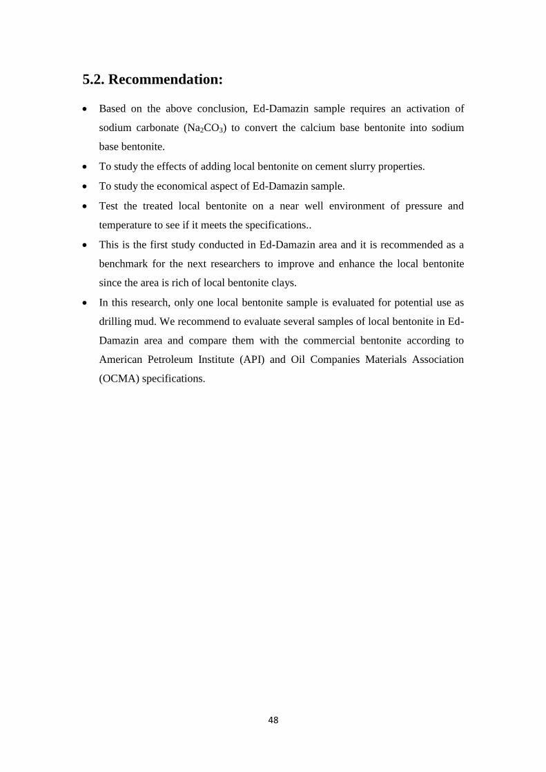
5.2. Recommendation:
Based on the above conclusion, Ed-Damazin sample requires an activation of
sodium carbonate (Na2CO3) to convert the calcium base bentonite into sodium
base bentonite.
To study the effects of adding local bentonite on cement slurry properties.
To study the economical aspect of Ed-Damazin sample.
Test the treated local bentonite on a near well environment of pressure and
temperature to see if it meets the specifications..
This is the first study conducted in Ed-Damazin area and it is recommended as a
benchmark for the next researchers to improve and enhance the local bentonite
since the area is rich of local bentonite clays.
In this research, only one local bentonite sample is evaluated for potential use as
drilling mud. We recommend to evaluate several samples of local bentonite in Ed-
Damazin area and compare them with the commercial bentonite according to
American Petroleum Institute (API) and Oil Companies Materials Association
(OCMA) specifications.

References:
1. Rabia, H. (2001). “Well Engineering & Construction : Drilling Fluids”.
2. Shakhatreh K. Saleh*, Mehaysen A. Mahasneh. (2015) “Activation of Jordanian
Ore Bentonite by Sodium Carbonates”. Irbid,Jordan, Al-Huson University College, Al-
Balq’a Applied University
3. Nweke, O.M. et al. (2015) “Comparative evaluation of clays from Abakaliki
Formation with commercial Bentonite clays for use as drilling mud” Ebonyi State,
Nigeria : Ebonyi State University.
4. Dardir M.M et al. (2014). ‘’Activation of Egyptian Bentonite properties to improve
their drilling fluid properties ’’. Cairo, Egypt : Egyptian Petroleum Research Institute
(EPRI).
5. Rashid.A.M.Hussein et al. (2013). “Rheological properties evaluation of Sudanese
Bentonite with different additives”. Khartoum, Sudan : SUST Journal of Engineering
and Computer Science (JECS) Vol. 15, No. 1.
6. Solomon Omale Obaje. (2013). “Suitability of Borno Bentonites as Drilling Mud”.
Kwara State, Nigeria : Nigerian Geological Survey Agency, Kwara State Office.
7. Arabi Suleiman Abdullahi.et al. (2011) “Comparative Evaluation of Rheological
Properties of Standard Commercial Bentonite and a Locally Beneficiated Bentonitic
Clay from a Marine Deposit in Upper Benue Basin, Nigeria ”.Nigeria, Centre for
Energy Research and Training, Ahmadu Bello University, Zaria.
8. SDJ Inglethorpe et al, (1993). ‘’Bentonite, Industrial Minerals Laboratory, Manual
British Geological Survey”.
9. Sattsh sharma (1994). “Drilling Operation Manual” Institute of Drilling
Technology, Oil and Natural Gas Corporation LTD, DEHADN.
10. American Petroleum Institute (API). (2006).Specification 13A, Specification for
Drilling Fluid Materials.
11. Abusabah. E. Elemam (2013), Optimizing Sudanese Bentonite Properties for
drilling applications,.sust.
12. Moore .D.M., Reynolds Jr. R.C., X-ray Diffraction and the Identification and
Analysis of Clay Minerals, Oxford University Press, Oxford, 1997.
13. Adam T.Bourgoyne Jr.et al,(1991).‘’Applied Drilling Engineering : Drilling
fluids”.
Copyright © 2022 FDOKUMEN