Ethernet Gateway Link150 - User Guide - 10/2015
56
DOCA0110EN-00 www.schneider-electric.com Ethernet Gateway Link150 DOCA0110EN-00 10/2015 Ethernet Gateway Link150 User Guide 10/2015
-
Upload
khangminh22 -
Category
Documents
-
view
0 -
download
0
Transcript of Ethernet Gateway Link150 - User Guide - 10/2015
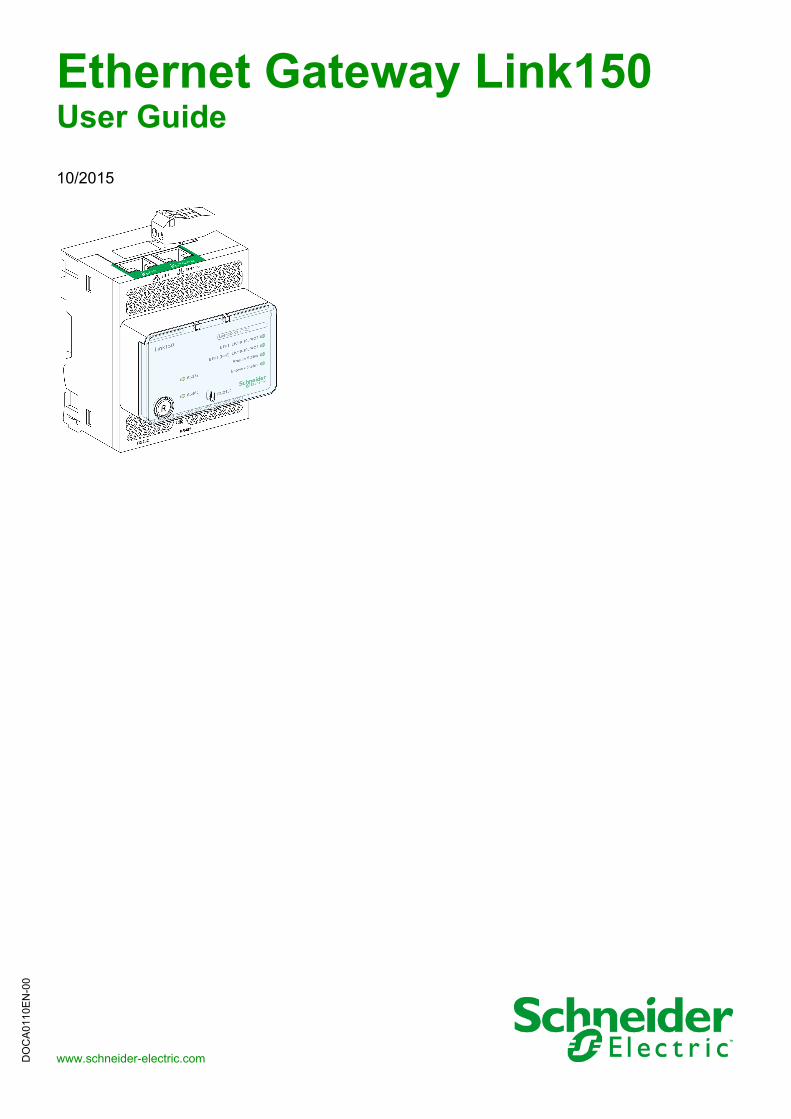
Ethernet Gateway Link150
DOCA0110EN-00 10/2015
DO
CA
011
0EN
-00
www.schneider-electric.com
Ethernet Gateway Link150User Guide
10/2015
The information provided in this documentation contains general descriptions and/or technical characteristics of the performance of the products contained herein. This documentation is not intended as a substitute for and is not to be used for determining suitability or reliability of these products for specific user applications. It is the duty of any such user or integrator to perform the appropriate and complete risk analysis, evaluation and testing of the products with respect to the relevant specific application or use thereof. Neither Schneider Electric nor any of its affiliates or subsidiaries shall be responsible or liable for misuse of the information contained herein. If you have any suggestions for improvements or amendments or have found errors in this publication, please notify us.
No part of this document may be reproduced in any form or by any means, electronic or mechanical, including photocopying, without express written permission of Schneider Electric.
All pertinent state, regional, and local safety regulations must be observed when installing and using this product. For reasons of safety and to help ensure compliance with documented system data, only the manufacturer should perform repairs to components.
When devices are used for applications with technical safety requirements, the relevant instructions must be followed.
Failure to use Schneider Electric software or approved software with our hardware products may result in injury, harm, or improper operating results.
Failure to observe this information can result in injury or equipment damage.
© 2015 Schneider Electric. All rights reserved.
2 DOCA0110EN-00 10/2015
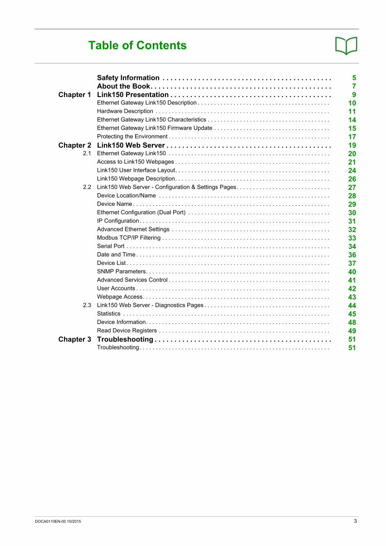
Table of Contents
Safety Information . . . . . . . . . . . . . . . . . . . . . . . . . . . . . . . . . . . . . . . . . . . 5About the Book. . . . . . . . . . . . . . . . . . . . . . . . . . . . . . . . . . . . . . . . . . . . . . 7
Chapter 1 Link150 Presentation . . . . . . . . . . . . . . . . . . . . . . . . . . . . . . . . . . . . . . . . . 9Ethernet Gateway Link150 Description . . . . . . . . . . . . . . . . . . . . . . . . . . . . . . . . . . . . . . . . . 10Hardware Description . . . . . . . . . . . . . . . . . . . . . . . . . . . . . . . . . . . . . . . . . . . . . . . . . . . . . . 11Ethernet Gateway Link150 Characteristics . . . . . . . . . . . . . . . . . . . . . . . . . . . . . . . . . . . . . . 14Ethernet Gateway Link150 Firmware Update . . . . . . . . . . . . . . . . . . . . . . . . . . . . . . . . . . . . 15Protecting the Environment . . . . . . . . . . . . . . . . . . . . . . . . . . . . . . . . . . . . . . . . . . . . . . . . . . 17
Chapter 2 Link150 Web Server . . . . . . . . . . . . . . . . . . . . . . . . . . . . . . . . . . . . . . . . . . 192.1 Ethernet Gateway Link150 . . . . . . . . . . . . . . . . . . . . . . . . . . . . . . . . . . . . . . . . . . . . . . . . . . 20
Access to Link150 Webpages . . . . . . . . . . . . . . . . . . . . . . . . . . . . . . . . . . . . . . . . . . . . . . . . 21Link150 User Interface Layout. . . . . . . . . . . . . . . . . . . . . . . . . . . . . . . . . . . . . . . . . . . . . . . . 24Link150 Webpage Description. . . . . . . . . . . . . . . . . . . . . . . . . . . . . . . . . . . . . . . . . . . . . . . . 26
2.2 Link150 Web Server - Configuration & Settings Pages. . . . . . . . . . . . . . . . . . . . . . . . . . . . . 27Device Location/Name . . . . . . . . . . . . . . . . . . . . . . . . . . . . . . . . . . . . . . . . . . . . . . . . . . . . . 28Device Name . . . . . . . . . . . . . . . . . . . . . . . . . . . . . . . . . . . . . . . . . . . . . . . . . . . . . . . . . . . . . 29Ethernet Configuration (Dual Port) . . . . . . . . . . . . . . . . . . . . . . . . . . . . . . . . . . . . . . . . . . . . 30IP Configuration. . . . . . . . . . . . . . . . . . . . . . . . . . . . . . . . . . . . . . . . . . . . . . . . . . . . . . . . . . . 31Advanced Ethernet Settings . . . . . . . . . . . . . . . . . . . . . . . . . . . . . . . . . . . . . . . . . . . . . . . . . 32Modbus TCP/IP Filtering . . . . . . . . . . . . . . . . . . . . . . . . . . . . . . . . . . . . . . . . . . . . . . . . . . . . 33Serial Port . . . . . . . . . . . . . . . . . . . . . . . . . . . . . . . . . . . . . . . . . . . . . . . . . . . . . . . . . . . . . . . 34Date and Time . . . . . . . . . . . . . . . . . . . . . . . . . . . . . . . . . . . . . . . . . . . . . . . . . . . . . . . . . . . . 36Device List . . . . . . . . . . . . . . . . . . . . . . . . . . . . . . . . . . . . . . . . . . . . . . . . . . . . . . . . . . . . . . . 37SNMP Parameters. . . . . . . . . . . . . . . . . . . . . . . . . . . . . . . . . . . . . . . . . . . . . . . . . . . . . . . . . 40Advanced Services Control . . . . . . . . . . . . . . . . . . . . . . . . . . . . . . . . . . . . . . . . . . . . . . . . . . 41User Accounts . . . . . . . . . . . . . . . . . . . . . . . . . . . . . . . . . . . . . . . . . . . . . . . . . . . . . . . . . . . . 42Webpage Access. . . . . . . . . . . . . . . . . . . . . . . . . . . . . . . . . . . . . . . . . . . . . . . . . . . . . . . . . . 43
2.3 Link150 Web Server - Diagnostics Pages . . . . . . . . . . . . . . . . . . . . . . . . . . . . . . . . . . . . . . . 44Statistics . . . . . . . . . . . . . . . . . . . . . . . . . . . . . . . . . . . . . . . . . . . . . . . . . . . . . . . . . . . . . . . . 45Device Information. . . . . . . . . . . . . . . . . . . . . . . . . . . . . . . . . . . . . . . . . . . . . . . . . . . . . . . . . 48Read Device Registers . . . . . . . . . . . . . . . . . . . . . . . . . . . . . . . . . . . . . . . . . . . . . . . . . . . . . 49
Chapter 3 Troubleshooting . . . . . . . . . . . . . . . . . . . . . . . . . . . . . . . . . . . . . . . . . . . . . 51Troubleshooting. . . . . . . . . . . . . . . . . . . . . . . . . . . . . . . . . . . . . . . . . . . . . . . . . . . . . . . . . . . 51
DOCA0110EN-00 10/2015 3

4 DOCA0110EN-00 10/2015
Safety Information
Important Information
NOTICE
Read these instructions carefully, and look at the equipment to become familiar with the device before trying to install, operate, or maintain it. The following special messages may appear throughout this documentation or on the equipment to warn of potential hazards or to call attention to information that clarifies or simplifies a procedure.
PLEASE NOTE
Electrical equipment should be installed, operated, serviced, and maintained only by qualified personnel. No responsibility is assumed by Schneider Electric for any consequences arising out of the use of this material.
A qualified person is one who has skills and knowledge related to the construction and operation of electrical equipment and its installation, and has received safety training to recognize and avoid the hazards involved.
FCC Notice
This equipment has been tested and found to comply with the limits for a Class A digital device, pursuant to part 15 of the FCC Rules. These limits are designated to provide reasonable protection against harmful interference when the equipment is operated in a commercial environment. This equipment generates, uses, and can radiate radio frequency energy and, if not installed and used in accordance with the instruction manual, may cause harmful interference to radio communications. Operation of this equipment in a residential area is likely to cause harmful interference in which case the user will be required to correct the interference at this own expense.
DOCA0110EN-00 10/2015 5

6 DOCA0110EN-00 10/2015
About the Book
At a Glance
Document Scope
The aim of this document is to provide the users, installers, and maintenance personnel with the technical information and procedures needed to access and maintain the Link150 web server.
Validity Note
The technical characteristics of the devices described in this document also appear online. To access this information online:
The characteristics that are presented in this manual should be the same as those characteristics that appear online. In line with our policy of constant improvement, we may revise content over time to improve clarity and accuracy. If you see a difference between the manual and online information, use the online information as your reference.
Related Documents
You can download these technical publications and other technical information from our website at http://download.schneider-electric.com
Step Action
1 Go to the Schneider Electric home page www.schneider-electric.com.
2 In the Search box type the reference of a product or the name of a product range. Do not include blank spaces in the reference or product range. To get information on grouping similar modules, use asterisks (*).
3 If you entered a reference, go to the Product Datasheets search results and click on the reference that interests you.If you entered the name of a product range, go to the Product Ranges search results and click on the product range that interests you.
4 If more than one reference appears in the Products search results, click on the reference that interests you.
5 Depending on the size of your screen, you may need to scroll down to see the data sheet.
6 To save or print a data sheet as a .pdf file, click Download XXX product datasheet.
Title of Documentation Reference Number
TSXETG100 ConneXium Ethernet Gateway User Guide 63230-319-225 (EN, ES, FR, DE)
EGX100 Ethernet Gateway User Guide 63230-319-204 (EN, ES, FR, DE, ZH)
Link150 Instruction Sheet NHA50221
DOCA0110EN-00 10/2015 7

8 DOCA0110EN-00 10/2015

Ethernet Gateway Link150
Link150 Presentation
DOCA0110EN-00 10/2015
Link150 Presentation
Chapter 1Link150 Presentation
What Is in This Chapter?
This chapter contains the following topics:
Topic Page
Ethernet Gateway Link150 Description 10
Hardware Description 11
Ethernet Gateway Link150 Characteristics 14
Ethernet Gateway Link150 Firmware Update 15
Protecting the Environment 17
DOCA0110EN-00 10/2015 9
Link150 Presentation
Ethernet Gateway Link150 Description
Introduction
This manual is to be used with Ethernet Gateway Link150. For installation information, see the Link150 Instruction Sheet.
Ethernet Gateway Link150 is a communication device that provides connectivity between Ethernet (Modbus TCP/IP) and Modbus serial line devices, allowing Modbus TCP/IP clients to access information from serial slave devices. It also allows serial master devices to access information from slave devices distributed across an Ethernet network.
Ethernet Gateway Link150 Features
The Ethernet Gateway Link150 supports the following Ethernet protocols: Modbus TCP/IP: Modbus TCP/IP is a protocol, which provides master/slave communication between
devices and TCP/IP that provides communications over an Ethernet connection. Modbus TCP/IP is used to exchange data between Ethernet Gateway Link150 and other compatible Modbus TCP/IP devices through TCP port 502.
Hypertext Transfer Protocol (HTTP): HTTP is a network protocol that handles delivery of files and data on the World Wide Web. It provides web server functionality through TCP port 80. Remote configuration of Ethernet Gateway Link150 and viewing of diagnostic data is possible using a web browser.
File Transfer Protocol (FTP): FTP is a network protocol that provides the ability to transfer files over the Internet from one computer to another. FTP is used to transfer firmware updates to Ethernet Gateway Link150 through TCP port 21.
Simple Network Management Protocol (SNMP): Based on MIB2 format, SNMP provides the ability to store and send identifying and diagnostic information used for network management purposes through UDP port 161.
Address Resolution Protocol (ARP): ARP is used to convert IP addresses to Ethernet addresses. ARP requests are sent by Ethernet Gateway Link150 to determine if its address is a duplicate IP address.
10 DOCA0110EN-00 10/2015
Link150 Presentation
Hardware Description
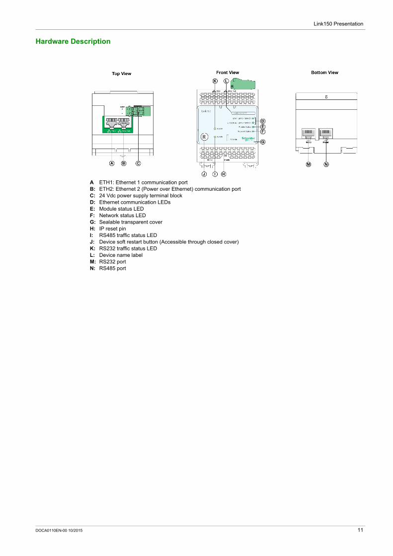
A ETH1: Ethernet 1 communication portB: ETH2: Ethernet 2 (Power over Ethernet) communication portC: 24 Vdc power supply terminal blockD: Ethernet communication LEDsE: Module status LEDF: Network status LEDG: Sealable transparent coverH: IP reset pinI: RS485 traffic status LEDJ: Device soft restart button (Accessible through closed cover)K: RS232 traffic status LEDL: Device name labelM: RS232 portN: RS485 port
DOCA0110EN-00 10/2015 11

Link150 Presentation
24 Vdc Power Supply Terminal Block
Ethernet Gateway Link150 is powered by 24 Vdc or Power-over-Ethernet (PoE). We recommend a UL listed and UL recognized limited voltage/limited current or a Class 2 power supply with a 24 Vdc, 500 mA minimum.
NOTE: When the module is connected with both PoE and 24 Vdc and if 24 Vdc is removed, there is a temporary communication loss until the device gets power from PoE.
A: Ethernet 1 communication portB: Ethernet 2 (PoE) communication portC: Midspan PoE injectorD: Ethernet switch with Endspan PoE portsE: Ethernet Switch
Ethernet Communication LEDs
Ethernet dual color LEDs indicates the communication status of Ethernet ports ETH1 and ETH2.
LED indication Status indication
Yellow 10 Mbps link
Yellow blink 10 Mbps activity
Green 100 Mbps link
Green blink 100 Mbps activity
12 DOCA0110EN-00 10/2015
Link150 Presentation
Module Status LED
Module status dual color LED indicates the module status of Ethernet Gateway Link150.
NOTE: If the IP reset pin is released after 5 seconds and before 10 seconds, the module status LED flashes
green till the IP reset pin is released. If the IP reset pin is released after 15 seconds, the module status LED turns to steady green.
Network Status LED
Network status dual color LED indicates the network status of Ethernet Gateway Link150.
RS232 Traffic LED
RS232 serial line traffic yellow LED indicates that the traffic is being transmitted or received over RS232 serial line network through the Ethernet Gateway Link150. The LED blinks during the transmission and reception of the messages. Otherwise, the LED is OFF.
RS485 Traffic LED
RS485 serial line traffic yellow LED indicates that the traffic is being transmitted or received over RS485 serial line network through the Ethernet gateway Link150. The LED blinks during the transmission and reception of the messages. Otherwise, the LED is OFF.
IP Reset Pin
When the IP reset pin is pressed for 1 to 5 seconds, the IP acquisition mode is reset to the factory default (DHCP).
Factory Reset
When the IP reset pin is pressed for 10 to 15 seconds, all user-configurable information is reset to factory defaults.
Device Soft Restart Button
Press the device soft restart button for 10 to 15 seconds to soft restart the Link150. For more details refer to troubleshooting (see page 51) section.
LED indication Status indication
Steady off No power
Steady green Device operational
Steady red Out of service
Flashing green (500 ms ON, 500 ms OFF) Firmware corrupted
Flashing red Degraded mode
Flashing green/red (250 ms green, 250 ms red) Self-test
LED indication Status indication
Off No power or no IP address
Steady green Valid IP address
Steady red Duplicated IP address
Blinking green/red (250 ms green, 250 ms red) Self test in progress
Steady amber Error in IP configuration or default IP address
DOCA0110EN-00 10/2015 13
Link150 Presentation
Ethernet Gateway Link150 Characteristics
Environmental Characteristics
Mechanical Characteristics
Electrical Characteristics
Physical Characteristics
Characteristics Value
Conforming to standards IEC/UL 60950 AS/ZNS 60950
CSA C22.2 IEC/UL 61010-2-201 EN55024 EN55022 IEC61000-6-2 Ed.2
Certification cULus, CE, RCM, and FCC marking
Ambient temperature Storage -40 to +85 °C (-40 to +185 °F)
Operation -25 to +70 °C (-13 to +158 °F)
Pollution Level 2
Characteristics Value
Shock resistance Conforming to IEC 60068-2-27 15 g/11 ms, 1/2 sinusoidal
Resistance to sinusoidal vibrations Conforming to IEC/EN 60068-2-6
Characteristics Value
24 Vdc mode POE mode
Power Supply 24 Vdc, -20%/+10% (19.2 Vdc -26.4 Vdc As per IEEE 802.3af compliant
Consumption Typical 24 Vdc, 130 mA at 20 °C 48 Vdc, 65 mA at 20 °C
Characteristics Value
Dimensions 72 x 105 x 71 mm (2.83 x 4.13 x 2.79 in)
Mounting DIN rail
Weight 175 g without packing
Degree of protection of the installed module On the front panel (wall-mounted enclosure): IP4x Connectors: IP2x Other parts: IP3x
Connections Screw type terminal block for 24 Vdc power RJ45 for communication
Installation type Open type equipment
14 DOCA0110EN-00 10/2015
Link150 Presentation
Ethernet Gateway Link150 Firmware Update
Description
Link150 firmware consists of two types of components: The executable binary component The webpage and supporting file (Data file)
The firmware on the Link150 can be updated using FTP.
Checking the Executable Binary Component Firmware Version
Upgrading the Firmware, Webpage, and Device Supporting Files in Windows PC Using Batch File
NOTE: YY.ZZ are the last 2 bytes of the Link150 MAC address. For example, A Link150 with MAC address 00-
B0-D0-86-BB-F7 (hexadecimal) or 0-176-208-134-187-247 (decimal), set the IP address as 169.254.187.247 in the batch file.
For the Link150 with the MAC address 00-B0-D0-86-02-12 (hexadecimal) or 0-176-208-134-02-18 (decimal), set the IP address as 169.254.2.18 in the batch file.
After successful firmware upgrade Link150 takes 40 seconds to restart.
Step Action Result
1 Open the web browser and log in to the Link150. Opens the Link150 home page.
2 From the Diagnostics menu, in the Device Information page, locate the firmware version.
NOTE: If you have updated the firmware recently, press F5 to refresh the webpage and update the displayed firmware number.
Determines the firmware version of the Link150.
Step Action Result
1 Download the latest Link150 firmware Link150FirmwareAndDataFilesVAAABBBCCC.zip file from www.schneider-electric.com (where AAABBBCCC is the datafile version number).
Downloads the Link150 firmware file.
2 Unzip Link150FirmwareAndDataFilesVAAABBBCCC.zip and store it in your local PC.
Stores the unzipped Link 150 firmware folder in the local PC.
3 Open the Link150FirmwareAndDataFilesVAAABBBCCC folder. Opens the Link 150 firmware folder.
4 Right-click the FirmwareUpgrade.bat, and then click Edit. Opens FirmwareUpgrade.bat in a notepad format.
5 Set the IP address, FTP user name, and password of the module being upgraded in the FirmwareUpgrade.bat file.
NOTE: Default IP address = 169.254.YY.ZZ Default FTP user name = Administrator Default FTP password = Gateway
The IP address, user name, and password are updated in the FirmwareUpgrade.bat file.
6 Save and exit the FirmwareUpgrade.bat file. The IP address, user name, and password are set in the FirmwareUpgrade.bat file.
7 Double-click the FirmwareUpgrade.bat file. The firmware and data file upgrade starts.
8 Wait until the FirmwareUpgrade.bat file closes itself. The firmware and data file upgrade is complete.
DOCA0110EN-00 10/2015 15
Link150 Presentation
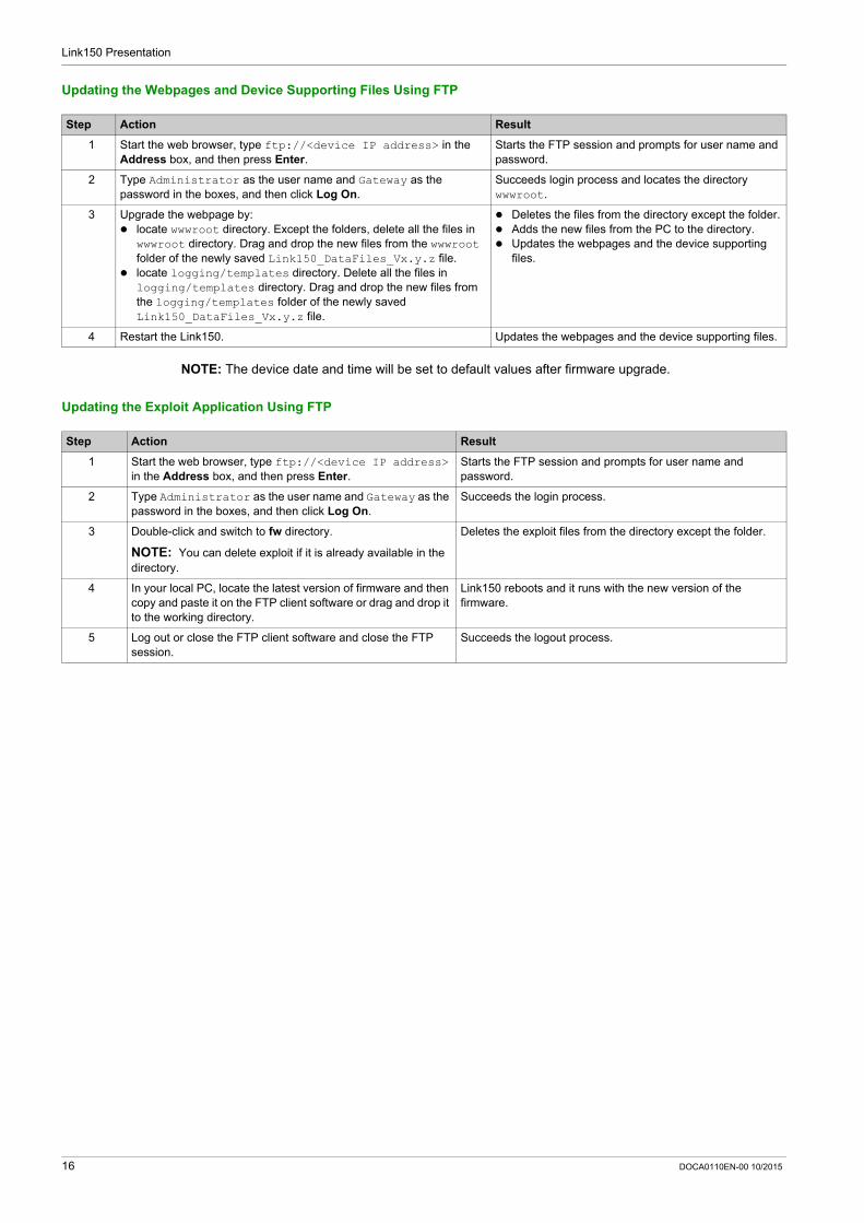
Updating the Webpages and Device Supporting Files Using FTP
NOTE: The device date and time will be set to default values after firmware upgrade.
Updating the Exploit Application Using FTP
Step Action Result
1 Start the web browser, type ftp://<device IP address> in the Address box, and then press Enter.
Starts the FTP session and prompts for user name and password.
2 Type Administrator as the user name and Gateway as the password in the boxes, and then click Log On.
Succeeds login process and locates the directory wwwroot.
3 Upgrade the webpage by: locate wwwroot directory. Except the folders, delete all the files in
wwwroot directory. Drag and drop the new files from the wwwroot folder of the newly saved Link150_DataFiles_Vx.y.z file.
locate logging/templates directory. Delete all the files in logging/templates directory. Drag and drop the new files from the logging/templates folder of the newly saved Link150_DataFiles_Vx.y.z file.
Deletes the files from the directory except the folder. Adds the new files from the PC to the directory. Updates the webpages and the device supporting
files.
4 Restart the Link150. Updates the webpages and the device supporting files.
Step Action Result
1 Start the web browser, type ftp://<device IP address> in the Address box, and then press Enter.
Starts the FTP session and prompts for user name and password.
2 Type Administrator as the user name and Gateway as the password in the boxes, and then click Log On.
Succeeds the login process.
3 Double-click and switch to fw directory.
NOTE: You can delete exploit if it is already available in the directory.
Deletes the exploit files from the directory except the folder.
4 In your local PC, locate the latest version of firmware and then copy and paste it on the FTP client software or drag and drop it to the working directory.
Link150 reboots and it runs with the new version of the firmware.
5 Log out or close the FTP client software and close the FTP session.
Succeeds the logout process.
16 DOCA0110EN-00 10/2015

Link150 Presentation
Protecting the Environment
Recycling Packaging
Packing materials from this equipment can be recycled. Help protect the environment by recycling them in appropriate containers.
Thank you for doing your part in protecting the environment.
End-of-Life Recycling
Modules of Link150 system have been optimized to decrease the amount of waste and valorize the product components and materials in the usual end of life treatment process.
The product design allows components to enter the usual end of life treatment processes as appropriate:
Depollute Reuse and/or dismantling
This increases the recycling performance and allows the rest of materials to be separated by shredding.
DOCA0110EN-00 10/2015 17

Link150 Presentation
18 DOCA0110EN-00 10/2015

Ethernet Gateway Link150
Link150 Web Server
DOCA0110EN-00 10/2015
Link150 Web Server
Chapter 2Link150 Web Server
What Is in This Chapter?
This chapter contains the following sections:
Section Topic Page
2.1 Ethernet Gateway Link150 20
2.2 Link150 Web Server - Configuration & Settings Pages 27
2.3 Link150 Web Server - Diagnostics Pages 44
DOCA0110EN-00 10/2015 19
Link150 Web Server
Ethernet Gateway Link150
Section 2.1Ethernet Gateway Link150
What Is in This Section?
This section contains the following topics:
Topic Page
Access to Link150 Webpages 21
Link150 User Interface Layout 24
Link150 Webpage Description 26
20 DOCA0110EN-00 10/2015
Link150 Web Server
Access to Link150 Webpages
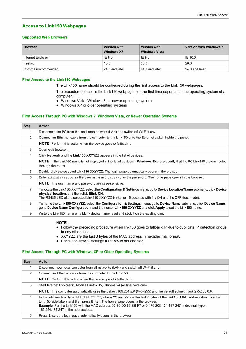
Supported Web Browsers
First Access to the Link150 Webpages
The Link150 name should be configured during the first access to the Link150 webpages.
The procedure to access the Link150 webpages for the first time depends on the operating system of a computer: Windows Vista, Windows 7, or newer operating systems Windows XP or older operating systems
First Access Through PC with Windows 7, Windows Vista, or Newer Operating Systems
NOTE: Follow the preceding procedure when link150 goes to fallback IP due to duplicate IP detection or due
to any other case. XXYYZZ are the last 3 bytes of the MAC address in hexadecimal format. Check the firewall settings if DPWS is not enabled.
First Access Through PC with Windows XP or Older Operating Systems
Browser Version with Windows XP
Version with Windows Vista
Version with Windows 7
Internet Explorer IE 8.0 IE 9.0 IE 10.0
Firefox 15.0 20.0 20.0
Chrome (recommended) 24.0 and later 24.0 and later 24.0 and later
Step Action
1 Disconnect the PC from the local area network (LAN) and switch off Wi-Fi if any.
2 Connect an Ethernet cable from the computer to the Link150 or to the Ethernet switch inside the panel.
NOTE: Perform this action when the device goes to fallback ip.
3 Open web browser.
4 Click Network and the Link150-XXYYZZ appears in the list of devices.
NOTE: If the Link150-name is not displayed in the list of devices in Windows Explorer, verify that the PC Link150 are connected through the router.
5 Double-click the selected Link150-XXYYZZ. The login page automatically opens in the browser.
6 Enter Administrator as the user name and Gateway as the password. The home page opens in the browser.
NOTE: The user name and password are case-sensitive.
7 To locate the Link150-XXYYZZ, select the Configuration & Settings menu, go to Device Location/Name submenu, click Device physical location, and then click Blink ON. The RS485 LED of the selected Link150-XXYYZZ blinks for 15 seconds with 1 s ON and 1 s OFF (test mode).
8 To name the Link150-XXYYZZ, select the Configuration & Settings menu, go to Device Name submenu, click Device Name, go to Device Name Configuration, and then enter Link150-XXYYZZ and click Apply to set the Link150 name.
9 Write the Link150 name on a blank device name label and stick it on the existing one.
Step Action
1 Disconnect your local computer from all networks (LAN) and switch off Wi-Fi if any.
2 Connect an Ethernet cable from the computer to the Link150.
NOTE: Perform this action when the device goes to fallback ip.
3 Start Internet Explorer 8, Mozilla Firefox 15, Chrome 24 (or later versions).
NOTE: The computer automatically uses the default 169.254.#.# (#=0–255) and the default subnet mask 255.255.0.0.
4 In the address box, type 169.254.YY.ZZ, where YY and ZZ are the last 2 bytes of the Link150 MAC address (found on the Link150 side label), and then press Enter. The home page opens in the browser.Example: For the Link150 with the MAC address 00-B0-D0-86-BB-F7 or 0-176-208-134-187-247 in decimal, type 169.254.187.247 in the address box.
5 Press Enter, the login page automatically opens in the browser.
DOCA0110EN-00 10/2015 21
Link150 Web Server
NOTE: Follow the preceding procedure when link150 goes to fallback IP due to duplicate IP detection or due
to any other case. XXYYZZ are the last 3 bytes of the MAC address in hexadecimal format.
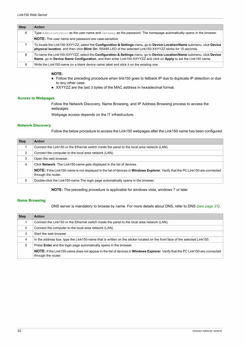
Access to Webpages
Follow the Network Discovery, Name Browsing, and IP Address Browsing process to access the webpages.
Webpage access depends on the IT infrastructure.
Network Discovery
Follow the below procedure to access the Link150 webpages after the Link150 name has been configured.
NOTE: The preceding procedure is applicable for windows vista, windows 7 or later
Name Browsing
DNS server is mandatory to browse by name. For more details about DNS, refer to DNS (see page 31).
6 Type Administrator as the user name and Gateway as the password. The homepage automatically opens in the browser.
NOTE: The user name and password are case-sensitive.
7 To locate the Link150-XXYYZZ, select the Configuration & Settings menu, go to Device Location/Name submenu, click Device physical location, and then click Blink On. RS485 LED of the selected Link150-XXYYZZ blinks for 15 seconds.
8 To name the Link150-XXYYZZ, select the Configuration & Settings menu, go to Device Location/Name submenu, click Device Name, go to Device Name Configuration, and then enter Link150-XXYYZZ and click on Apply to set the Link150 name.
9 Write the Link150-name on a blank device name label and stick it on the existing one.
Step Action
Step Action
1 Connect the Link150 or the Ethernet switch inside the panel to the local area network (LAN).
2 Connect the computer to the local area network (LAN).
3 Open the web browser.
4 Click Network. The Link150-name gets displayed in the list of devices.
NOTE: If the Link150-name is not displayed in the list of devices in Windows Explorer. Verify that the PC Link150 are connected through the router.
5 Double-click the Link150-name.The login page automatically opens in the browser.
Step Action
1 Connect the Link150 or the Ethernet switch inside the panel to the local area network (LAN).
2 Connect the computer to the local area network (LAN).
3 Start the web browser.
4 In the address box, type the Link150-name that is written on the sticker located on the front face of the selected Link150.
5 Press Enter and the login page automatically opens in the browser.
NOTE: If the Link150-name does not appear in the list of devices in Windows Explorer. Verify that the PC Link150 are connected through the router.
22 DOCA0110EN-00 10/2015
Link150 Web Server
IP Address Browsing
In IP Address Browsing, IP configuration can be done manually or it gets configured through DHCP or BootP.
First Time Log In
The web browser is a tool for reading and writing data. First time when you log in to Link150 webpage, you can use the default user name and password. To prevent unauthorized access, you can change your password from the User Accounts page under Configuration & Settings menu.
NOTE: The password should not be shared or distributed to unauthorized personnel. The password should not contain any personal or obvious information.
Step Action
1 Connect the Link150 or the Ethernet switch inside the panel to the local area network (LAN).
2 Connect the computer to the local area network (LAN).
3 Start the web browser.
4 In the address box, enter the IP address given by the IT administrator.
5 Press Enter and the login page automatically opens in the browser.
NOTE: If the login page in the web browser does not open or does not display correctly, verify the path. For example: In the Internet Explorer browser, verify that Internet Explorer\Tools\Compatibility View Settings\Display Intranet sites in Compatibility View are checked.
NOTICE
Immediately change the default password to a new and secure password. DO NOT distribute the password to unauthorized or otherwise unqualified personnel.
Failure to follow these instructions can result in equipment damage.
DOCA0110EN-00 10/2015 23
Link150 Web Server
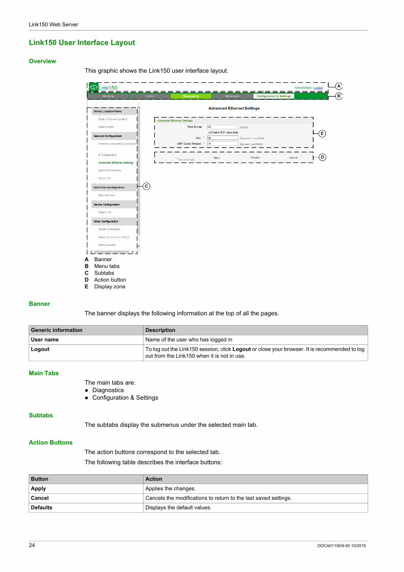
Link150 User Interface Layout
Overview
This graphic shows the Link150 user interface layout.
A BannerB Menu tabsC SubtabsD Action buttonE Display zone
Banner
The banner displays the following information at the top of all the pages.
Main Tabs
The main tabs are: Diagnostics Configuration & Settings
Subtabs
The subtabs display the submenus under the selected main tab.
Action Buttons
The action buttons correspond to the selected tab.
The following table describes the interface buttons:
Generic information Description
User name Name of the user who has logged in
Logout To log out the Link150 session, click Logout or close your browser. It is recommended to log out from the Link150 when it is not in use.
Button Action
Apply Applies the changes.
Cancel Cancels the modifications to return to the last saved settings.
Defaults Displays the default values.
24 DOCA0110EN-00 10/2015

Link150 Web Server
Display Zone
The display zone shows the selected subtab in detail with all related fields.
DOCA0110EN-00 10/2015 25
Link150 Web Server
Link150 Webpage Description
Diagnostics Webpage
Configuration & Settings Webpage
Diagnostics Submenu Webpage Description
General Statistics (see page 45)
Displays diagnostic data used to troubleshoot network-related problems.
Product Information Device Information (see page 48)
Contains information about the Link150 including: Device Name Product name Serial number Model number Firmware version Unique identifier MAC address IPv4 address IPv6 link local address Manufactured date
Device Health Check Read Device Registers (see page 49)
Displays register data for devices connected locally to the Link150.
Configuration & Settings Submenu
Webpage Description
Device Location/Name Device Physical Location (see page 28)
Click Blink ON to locate the Link150 device. The RS485 LED blinks for 15 s.
Device Name (see page 29)
Configures the Link150 device name
Network Configuration Ethernet Configuration (Dual port) (see page 30)
Configures the Ethernet ports.
IP Configuration (see page 31)
Configures the IP parameters including IPv4, and DNS settings.
Advanced Ethernet Settings (see page 32)
Configures the advanced Ethernet settings.
MBTCP/IP Filtering (see page 33)
Configures the maximum number of Modbus TCP/IP client connections. Configures the IP addresses that can access the Link150 through Modbus TCP/IP.
Serial Port (see page 34)
Configures serial communication parameters.
Date/Time Configuration Date and Time (see page 36)
Sets the date and time manually.
Device Configuration Device List (see page 37)
Configures the Modbus devices.
Other Configuration SNMP Parameters (see page 40)
Configures Simple Network Management Protocol (SNMP).
Advance Service Control (see page 41)
Enables or disables the advanced service control parameters.
User Accounts (see page 42)
Manages groups and users, including user email addresses.
Webpage Access (see page 43)
Configures webpage access rights for each user group.
26 DOCA0110EN-00 10/2015
Link150 Web Server
Link150 Web Server - Configuration & Settings Pages
Section 2.2Link150 Web Server - Configuration & Settings Pages
What Is in This Section?
This section contains the following topics:
Topic Page
Device Location/Name 28
Device Name 29
Ethernet Configuration (Dual Port) 30
IP Configuration 31
Advanced Ethernet Settings 32
Modbus TCP/IP Filtering 33
Serial Port 34
Date and Time 36
Device List 37
SNMP Parameters 40
Advanced Services Control 41
User Accounts 42
Webpage Access 43
DOCA0110EN-00 10/2015 27
Link150 Web Server
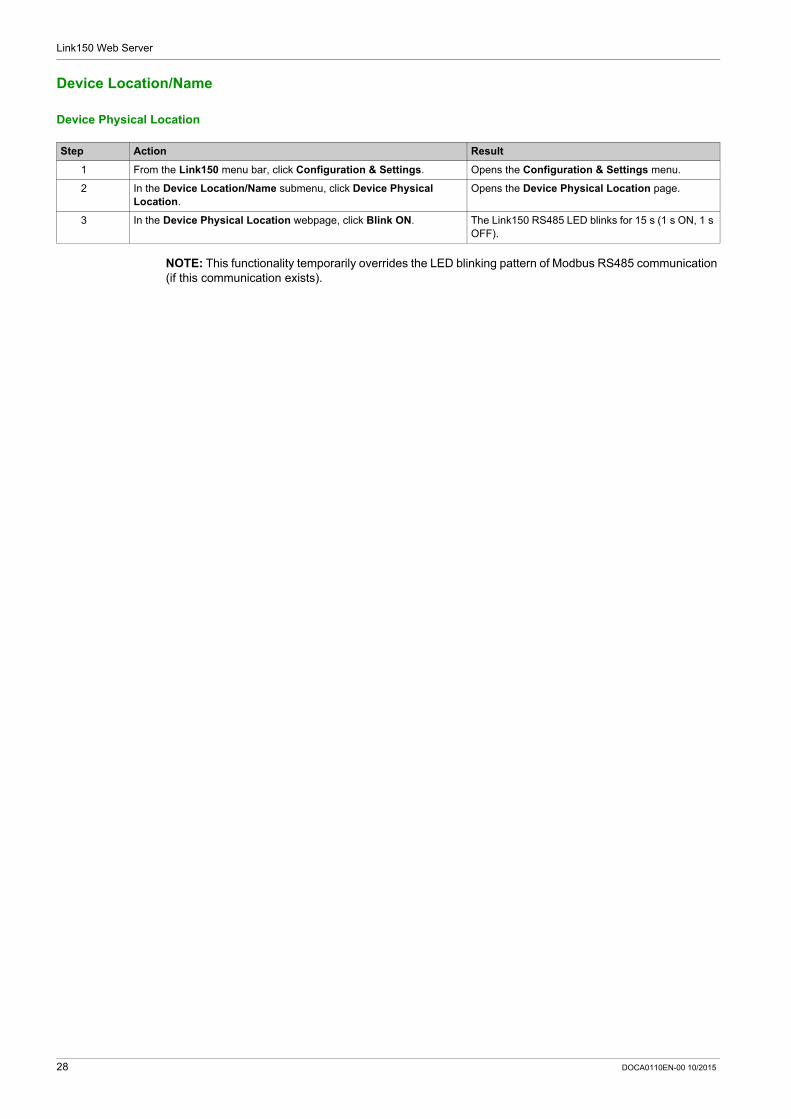
Device Location/Name
Device Physical Location
NOTE: This functionality temporarily overrides the LED blinking pattern of Modbus RS485 communication (if this communication exists).
Step Action Result
1 From the Link150 menu bar, click Configuration & Settings. Opens the Configuration & Settings menu.
2 In the Device Location/Name submenu, click Device Physical Location.
Opens the Device Physical Location page.
3 In the Device Physical Location webpage, click Blink ON. The Link150 RS485 LED blinks for 15 s (1 s ON, 1 s OFF).
28 DOCA0110EN-00 10/2015

Link150 Web Server
Device Name
Naming the Link150
Step Action Result
1 From the Link150 menu bar, click Configuration & Settings. Opens the page with all the submenu items.
2 In the Device Location/Name submenu, click Device Name. Opens the Device Name page.
3 In Device Name webpage, enter the device name and click Apply. The entered device name is updated.
DOCA0110EN-00 10/2015 29
Link150 Web Server
Ethernet Configuration (Dual Port)
Ethernet
Ethernet Port Control
Broadcast Storm Protection
Parameter Description Settings
MAC address A unique media access control address of the Link150. The MAC address is printed on the side label of the Link150.
-
Frame format Used to select the format for data sent over an Ethernet connection.
Ethernet II 802.3 Auto (Factory setting)
Parameter Description
Speed and mode for port #1 The Link150 automatically negotiates the physical Ethernet connection speed and transmission mode for Ethernet port 1.
Speed and mode for port #2 The Link150 automatically negotiates the physical Ethernet connection speed and transmission for Ethernet port 2.
Parameter Description Settings
Level Defines the storm protection level. The Link150 limits the amount of information it broadcasts or rebroadcasts (based on this setting) to reduce collisions or network traffic.
NOTE: If the level is changed, you are prompted to restart the device to implement changes.
0 1 2 3 4 (Factory setting) 5 6
Committed Information Rate Defines the read-only value of the storm protection level in kbit/s.
-
30 DOCA0110EN-00 10/2015
Link150 Web Server
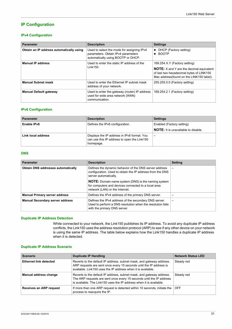
IP Configuration
IPv4 Configuration
IPv6 Configuration
DNS
Duplicate IP Address Detection
While connected to your network, the Link150 publishes its IP address. To avoid any duplicate IP address conflicts, the Link150 uses the address resolution protocol (ARP) to see if any other device on your network is using the same IP address. The table below explains how the Link150 handles a duplicate IP address when it is detected.
Duplicate IP Address Scenario
Parameter Description Settings
Obtain an IP address automatically using Used to select the mode for assigning IPv4 parameters. Obtain IPv4 parameters automatically using BOOTP or DHCP.
DHCP (Factory setting) BOOTP
Manual IP address Used to enter the static IP address of the Link150.
169.254.X.Y (Factory setting)
NOTE: X and Y are the decimal equivalent of last two hexadecimal bytes of LINK150 Mac address(found on the LINK150 label).
Manual Subnet mask Used to enter the Ethernet IP subnet mask address of your network.
255.255.0.0 (Factory setting)
Manual Default gateway Used to enter the gateway (router) IP address used for wide area network (WAN) communication.
169.254.2.1 (Factory setting)
Parameter Description Settings
Enable IPv6 Defines the IPv6 configuration. Enabled (Factory setting)
NOTE: It is unavailable to disable.
Link local address Displays the IP address in IPv6 format. You can use this IP address to open the Link150 homepage.
–
Parameter Description Setting
Obtain DNS addresses automatically Defines the dynamic behavior of the DNS server address configuration. Used to obtain the IP address from the DNS server automatically.
NOTE: Domain name system (DNS) is the naming system for computers and devices connected to a local area network (LAN) or the Internet.
–
Manual Primary server address Defines the IPv4 address of the primary DNS server. –
Manual Secondary server address Defines the IPv4 address of the secondary DNS server. Used to perform a DNS resolution when the resolution fails with the primary DNS server.
–
Scenario Duplicate IP Handling Network Status LED
Ethernet link detected Reverts to the default IP address, subnet mask, and gateway address. ARP requests are sent once every 15 seconds until the IP address is available. Link150 uses the IP address when it is available.
Steady red
Manual address change Reverts to the default IP address, subnet mask, and gateway address. The ARP requests are sent once every 15 seconds until the IP address is available. The Link150 uses the IP address when it is available.
Steady red
Receives an ARP request If more than one ARP request is detected within 10 seconds, initiate the process to reacquire the IP.
OFF
DOCA0110EN-00 10/2015 31
Link150 Web Server
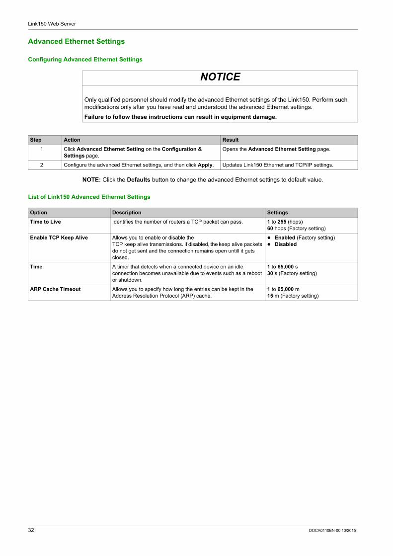
Advanced Ethernet Settings
Configuring Advanced Ethernet Settings
NOTE: Click the Defaults button to change the advanced Ethernet settings to default value.
List of Link150 Advanced Ethernet Settings
NOTICE
Only qualified personnel should modify the advanced Ethernet settings of the Link150. Perform such modifications only after you have read and understood the advanced Ethernet settings.
Failure to follow these instructions can result in equipment damage.
Step Action Result
1 Click Advanced Ethernet Setting on the Configuration & Settings page.
Opens the Advanced Ethernet Setting page.
2 Configure the advanced Ethernet settings, and then click Apply. Updates Link150 Ethernet and TCP/IP settings.
Option Description Settings
Time to Live Identifies the number of routers a TCP packet can pass. 1 to 255 (hops)60 hops (Factory setting)
Enable TCP Keep Alive Allows you to enable or disable the TCP keep alive transmissions. If disabled, the keep alive packets do not get sent and the connection remains open untill it gets closed.
Enabled (Factory setting) Disabled
Time A timer that detects when a connected device on an idle connection becomes unavailable due to events such as a reboot or shutdown.
1 to 65,000 s30 s (Factory setting)
ARP Cache Timeout Allows you to specify how long the entries can be kept in the Address Resolution Protocol (ARP) cache.
1 to 65,000 m15 m (Factory setting)
32 DOCA0110EN-00 10/2015
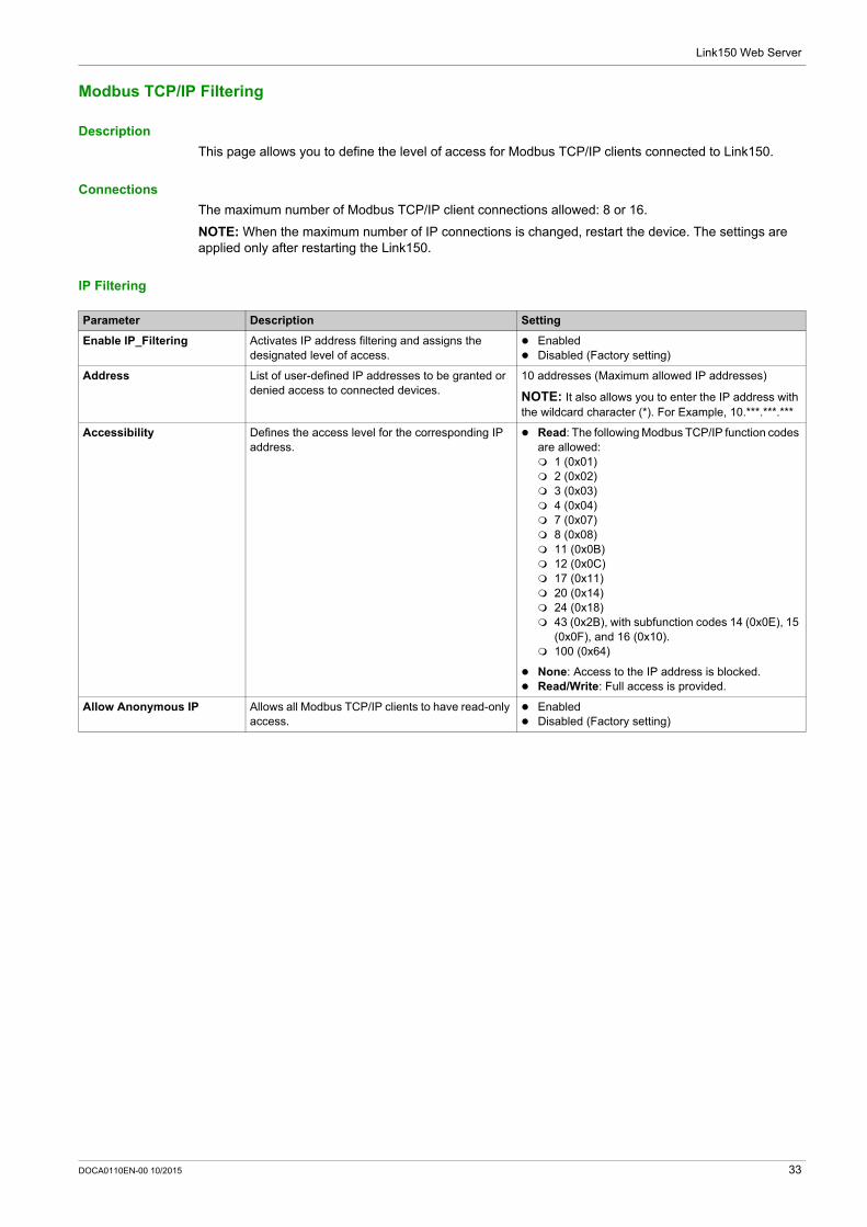
Link150 Web Server
Modbus TCP/IP Filtering
Description
This page allows you to define the level of access for Modbus TCP/IP clients connected to Link150.
Connections
The maximum number of Modbus TCP/IP client connections allowed: 8 or 16.
NOTE: When the maximum number of IP connections is changed, restart the device. The settings are applied only after restarting the Link150.
IP Filtering
Parameter Description Setting
Enable IP_Filtering Activates IP address filtering and assigns the designated level of access.
Enabled Disabled (Factory setting)
Address List of user-defined IP addresses to be granted or denied access to connected devices.
10 addresses (Maximum allowed IP addresses)
NOTE: It also allows you to enter the IP address with the wildcard character (*). For Example, 10.***.***.***
Accessibility Defines the access level for the corresponding IP address.
Read: The following Modbus TCP/IP function codes are allowed: 1 (0x01) 2 (0x02) 3 (0x03) 4 (0x04) 7 (0x07) 8 (0x08) 11 (0x0B) 12 (0x0C) 17 (0x11) 20 (0x14) 24 (0x18) 43 (0x2B), with subfunction codes 14 (0x0E), 15
(0x0F), and 16 (0x10). 100 (0x64)
None: Access to the IP address is blocked. Read/Write: Full access is provided.
Allow Anonymous IP Allows all Modbus TCP/IP clients to have read-only access.
Enabled Disabled (Factory setting)
DOCA0110EN-00 10/2015 33
Link150 Web Server
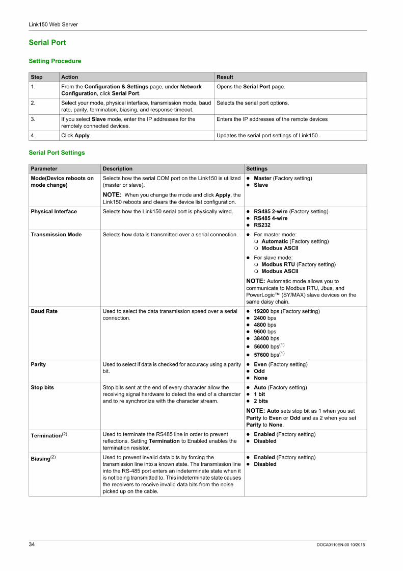
Serial Port
Setting Procedure
Serial Port Settings
Step Action Result
1. From the Configuration & Settings page, under Network Configuration, click Serial Port.
Opens the Serial Port page.
2. Select your mode, physical interface, transmission mode, baud rate, parity, termination, biasing, and response timeout.
Selects the serial port options.
3. If you select Slave mode, enter the IP addresses for the remotely connected devices.
Enters the IP addresses of the remote devices
4. Click Apply. Updates the serial port settings of Link150.
Parameter Description Settings
Mode(Device reboots on mode change)
Selects how the serial COM port on the Link150 is utilized (master or slave).
NOTE: When you change the mode and click Apply, the Link150 reboots and clears the device list configuration.
Master (Factory setting) Slave
Physical Interface Selects how the Link150 serial port is physically wired. RS485 2-wire (Factory setting) RS485 4-wire RS232
Transmission Mode Selects how data is transmitted over a serial connection. For master mode: Automatic (Factory setting) Modbus ASCII
For slave mode: Modbus RTU (Factory setting) Modbus ASCII
NOTE: Automatic mode allows you to communicate to Modbus RTU, Jbus, and PowerLogic™ (SY/MAX) slave devices on the same daisy chain.
Baud Rate Used to select the data transmission speed over a serial connection.
19200 bps (Factory setting) 2400 bps 4800 bps 9600 bps 38400 bps
56000 bps(1)
57600 bps(1)
Parity Used to select if data is checked for accuracy using a parity bit.
Even (Factory setting) Odd None
Stop bits Stop bits sent at the end of every character allow the receiving signal hardware to detect the end of a character and to re synchronize with the character stream.
Auto (Factory setting) 1 bit 2 bits
NOTE: Auto sets stop bit as 1 when you set Parity to Even or Odd and as 2 when you set Parity to None.
Termination(2) Used to terminate the RS485 line in order to prevent reflections. Setting Termination to Enabled enables the termination resistor.
Enabled (Factory setting) Disabled
Biasing(2) Used to prevent invalid data bits by forcing the transmission line into a known state. The transmission line into the RS-485 port enters an indeterminate state when it is not being transmitted to. This indeterminate state causes the receivers to receive invalid data bits from the noise picked up on the cable.
Enabled (Factory setting) Disabled
34 DOCA0110EN-00 10/2015

Link150 Web Server
Response Timeout Used to select how long the Link150 waits to receive a response from a serial device.
NOTE: The Response Timeout parameter is disabled if the Mode is set to Slave.
3 seconds (Factory setting) 0.1 to 10 seconds
Remote Device Connections (in slave mode only)
Used to define a list of Modbus TCP/IP addresses for the Link150 to use during slave mode communications.
-
(1) Only available when Physical Interface is set to RS232 and Transmission Mode is set to Modbus ASCII.(2) Only available when Physical Interface is set to RS485 4-wire or RS485 2-wire.
Parameter Description Settings
DOCA0110EN-00 10/2015 35

Link150 Web Server
Date and Time
Local Date and Time
This page allows you to enter the local date and time manually.
NOTE: As there is no SNTP or RTC, the date or time needs to be reset in the event of power loss.
Parameter Description Setting
Current Date(yyyy-mm-dd) Allows you to set the present date. Date format: yyyy-mm-dd
Current Time(h:min:sec) Allows you to set the present time. Time format: h:min:sec
36 DOCA0110EN-00 10/2015
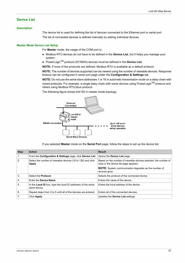
Link150 Web Server
Device List
Description
The device list is used for defining the list of devices connected to the Ethernet port or serial port.
The list of connected devices is defined manually by adding individual devices.
Master Mode Device List Setup
For Master mode, the usage of the COM port is:
Modbus RTU devices do not have to be defined in the Device List, but it helps you manage your system.
PowerLogicTM protocol (SY/MAX) devices must be defined in the Device List.
NOTE: If none of the protocols are defined, Modbus RTU is available as a default protocol.
NOTE: The number of devices supported can be viewed using the number of viewable devices. Response timeout can be configured in serial port page under the Configuration & Settings tab.
NOTE: Do not use the serial slave addresses 1 or 16 in automatic transmission mode on a daisy chain with
mixed protocols. For example, a single daisy chain with some devices using PowerLogicTM protocol and others using Modbus RTU/Jbus protocol.
The following figure shows link150 in master mode topology:
If you selected Master mode on the Serial Port page, follow the steps to set up the device list:
Step Action Result
1. From the Configuration & Settings page, click Device List. Opens the Device List page.
2. Select the number of viewable devices (16 to 128) and click Apply.
Based on the number of viewable devices selected, the number of rows in the device list page appears.
NOTE: System communication degrades as the number of devices grow.
3. Select the Protocol. Selects the protocol of the connected device.
4. Enter the Device Name. Enters the name of the device.
5. In the Local ID box, type the local ID (address) of the serial slave device.
Enters the local address of the device.
6. Repeat steps from 3 to 5 until all of the devices are entered. Enters all of the connected devices.
7. Click Apply. Updates the Device List settings
DOCA0110EN-00 10/2015 37
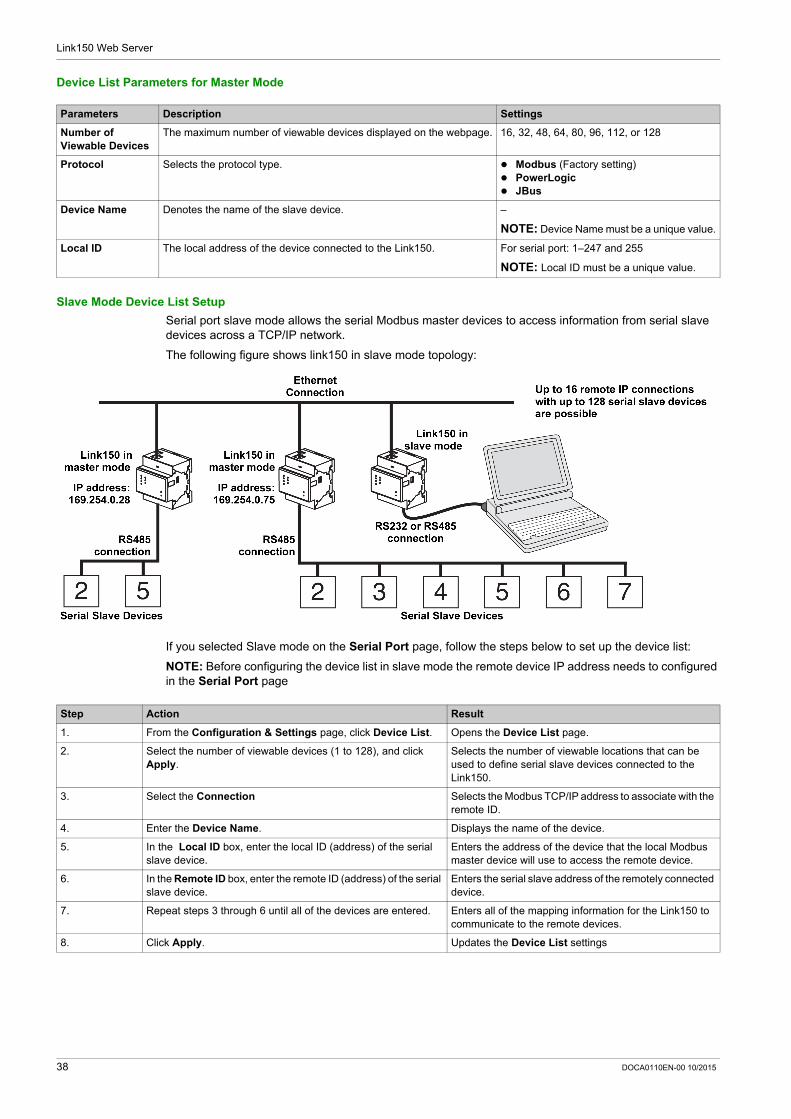
Link150 Web Server
Device List Parameters for Master Mode
Slave Mode Device List Setup
Serial port slave mode allows the serial Modbus master devices to access information from serial slave devices across a TCP/IP network.
The following figure shows link150 in slave mode topology:
If you selected Slave mode on the Serial Port page, follow the steps below to set up the device list:
NOTE: Before configuring the device list in slave mode the remote device IP address needs to configured in the Serial Port page
Parameters Description Settings
Number of Viewable Devices
The maximum number of viewable devices displayed on the webpage. 16, 32, 48, 64, 80, 96, 112, or 128
Protocol Selects the protocol type. Modbus (Factory setting) PowerLogic JBus
Device Name Denotes the name of the slave device. –
NOTE: Device Name must be a unique value.
Local ID The local address of the device connected to the Link150. For serial port: 1–247 and 255
NOTE: Local ID must be a unique value.
Step Action Result
1. From the Configuration & Settings page, click Device List. Opens the Device List page.
2. Select the number of viewable devices (1 to 128), and click Apply.
Selects the number of viewable locations that can be used to define serial slave devices connected to the Link150.
3. Select the Connection Selects the Modbus TCP/IP address to associate with the remote ID.
4. Enter the Device Name. Displays the name of the device.
5. In the Local ID box, enter the local ID (address) of the serial slave device.
Enters the address of the device that the local Modbus master device will use to access the remote device.
6. In the Remote ID box, enter the remote ID (address) of the serial slave device.
Enters the serial slave address of the remotely connected device.
7. Repeat steps 3 through 6 until all of the devices are entered. Enters all of the mapping information for the Link150 to communicate to the remote devices.
8. Click Apply. Updates the Device List settings
38 DOCA0110EN-00 10/2015
Link150 Web Server
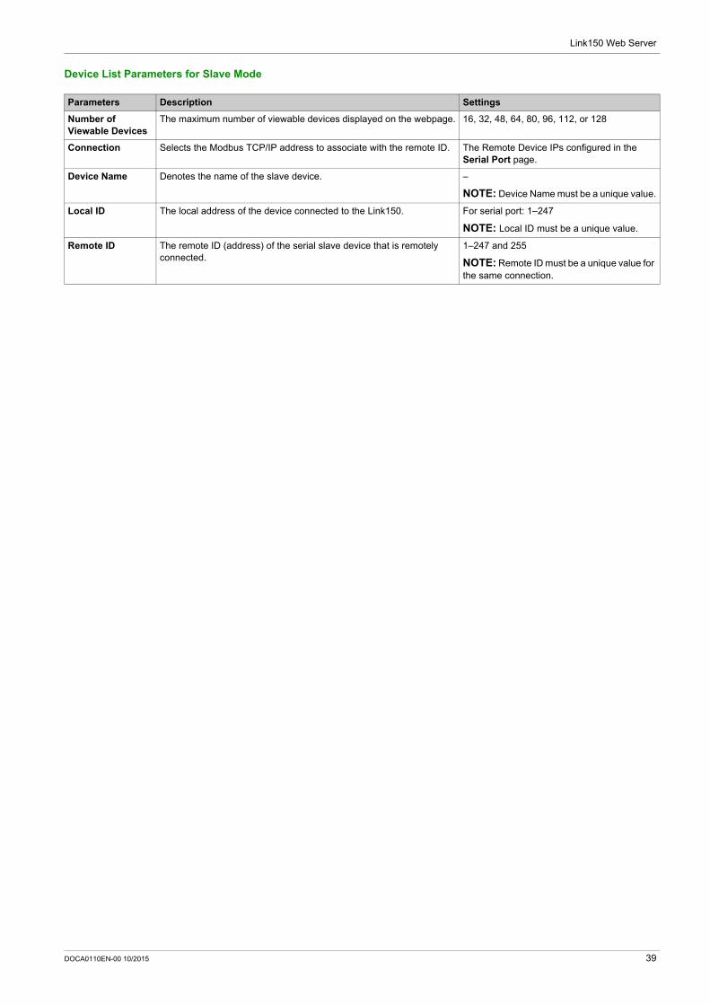
Device List Parameters for Slave Mode
Parameters Description Settings
Number of Viewable Devices
The maximum number of viewable devices displayed on the webpage. 16, 32, 48, 64, 80, 96, 112, or 128
Connection Selects the Modbus TCP/IP address to associate with the remote ID. The Remote Device IPs configured in the Serial Port page.
Device Name Denotes the name of the slave device. –
NOTE: Device Name must be a unique value.
Local ID The local address of the device connected to the Link150. For serial port: 1–247
NOTE: Local ID must be a unique value.
Remote ID The remote ID (address) of the serial slave device that is remotely connected.
1–247 and 255
NOTE: Remote ID must be a unique value for the same connection.
DOCA0110EN-00 10/2015 39
Link150 Web Server
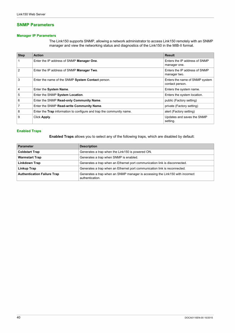
SNMP Parameters
Manager IP Parameters
The Link150 supports SNMP, allowing a network administrator to access Link150 remotely with an SNMP manager and view the networking status and diagnostics of the Link150 in the MIB-II format.
Enabled Traps
Enabled Traps allows you to select any of the following traps, which are disabled by default:
Step Action Result
1 Enter the IP address of SNMP Manager One. Enters the IP address of SNMP manager one.
2 Enter the IP address of SNMP Manager Two. Enters the IP address of SNMP manager two.
3 Enter the name of the SNMP System Contact person. Enters the name of SNMP system contact person.
4 Enter the System Name. Enters the system name.
5 Enter the SNMP System Location. Enters the system location.
6 Enter the SNMP Read-only Community Name. public (Factory setting)
7 Enter the SNMP Read-write Community Name. private (Factory setting)
8 Enter the Trap information to configure and trap the community name. alert (Factory setting)
9 Click Apply. Updates and saves the SNMP setting.
Parameter Description
Coldstart Trap Generates a trap when the Link150 is powered ON.
Warmstart Trap Generates a trap when SNMP is enabled.
Linkdown Trap Generates a trap when an Ethernet port communication link is disconnected.
Linkup Trap Generates a trap when an Ethernet port communication link is reconnected.
Authentication Failure Trap Generates a trap when an SNMP manager is accessing the Link150 with incorrect authentication.
40 DOCA0110EN-00 10/2015
Link150 Web Server
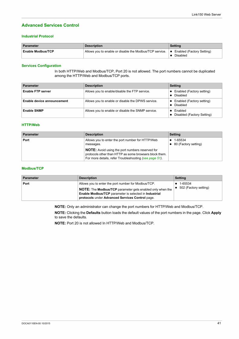
Advanced Services Control
Industrial Protocol
Services Configuration
In both HTTP/Web and Modbus/TCP, Port 20 is not allowed. The port numbers cannot be duplicated among the HTTP/Web and Modbus/TCP ports.
HTTP/Web
Modbus/TCP
NOTE: Only an administrator can change the port numbers for HTTP/Web and Modbus/TCP.
NOTE: Clicking the Defaults button loads the default values of the port numbers in the page. Click Apply to save the defaults.
NOTE: Port 20 is not allowed In HTTP/Web and Modbus/TCP.
Parameter Description Setting
Enable Modbus/TCP Allows you to enable or disable the Modbus/TCP service. Enabled (Factory Setting) Disabled
Parameter Description Setting
Enable FTP server Allows you to enable/disable the FTP service. Enabled (Factory setting) Disabled
Enable device announcement Allows you to enable or disable the DPWS service. Enabled (Factory setting) Disabled
Enable SNMP Allows you to enable or disable the SNMP service. Enabled Disabled (Factory Setting)
Parameter Description Setting
Port Allows you to enter the port number for HTTP/Web messages.
NOTE: Avoid using the port numbers reserved for protocols other than HTTP as some browsers block them. For more details, refer Troubleshooting (see page 51).
1-65534 80 (Factory setting)
Parameter Description Setting
Port Allows you to enter the port number for Modbus/TCP.
NOTE: The Modbus/TCP parameter gets enabled only when the Enable Modbus/TCP parameter is selected in Industrial protocols under Advanced Services Control page.
1-65534 502 (Factory setting)
DOCA0110EN-00 10/2015 41
Link150 Web Server
User Accounts
Description
The Link150 users are assigned user names and passwords. Each user belongs to a group, and each group has access rights to the Link150 web pages assigned by the Link150 administrator.
There are two pre-defined user accounts:
Administrator (default password is Gateway) Guest (default password is Guest)
Groups
To change the group name, type a new name in one of the groups text boxes.
NOTE: The Administrator group name cannot be changed.
Users
In addition to the two default user accounts, you can create up to 11 user accounts.
Link150 Accounts and Passwords
Parameter Description
Name Enter a name (1 to 15 characters) for a new user.
NOTE: User names is case-sensitive and can contain special characters.
Password Enter a password (0 to 11 characters) for a new user.
NOTE: Password is case-sensitive.
Email Id Enter a valid email address for the selected name.
NOTE: Enter the email domain name in lower case.
Group Select a group for the new user.
Language Select the default language for the new user.
Accounts Password
Administrator Gateway
NOTE: Gateway is the default password. It can also be used as a user-defined password.
Guest Guest
User-defined accounts (11 accounts possible) User-defined passwords
42 DOCA0110EN-00 10/2015
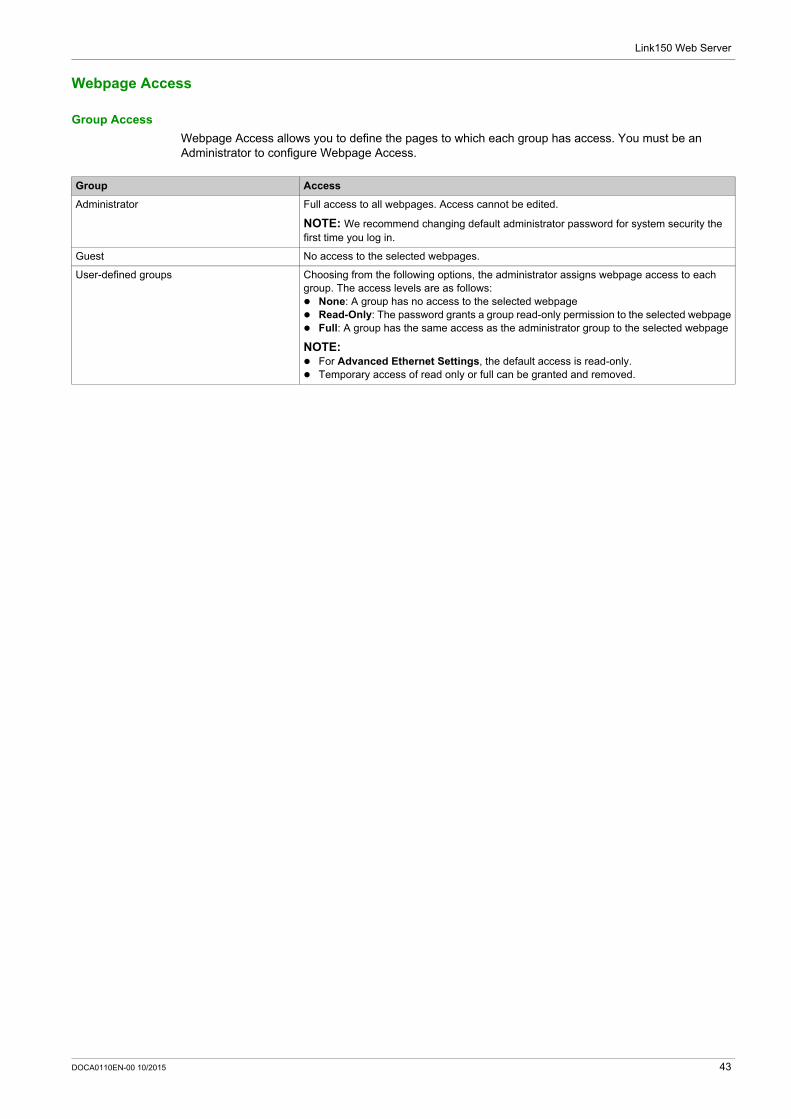
Link150 Web Server
Webpage Access
Group Access
Webpage Access allows you to define the pages to which each group has access. You must be an Administrator to configure Webpage Access.
Group Access
Administrator Full access to all webpages. Access cannot be edited.
NOTE: We recommend changing default administrator password for system security the first time you log in.
Guest No access to the selected webpages.
User-defined groups Choosing from the following options, the administrator assigns webpage access to each group. The access levels are as follows: None: A group has no access to the selected webpage Read-Only: The password grants a group read-only permission to the selected webpage Full: A group has the same access as the administrator group to the selected webpage
NOTE: For Advanced Ethernet Settings, the default access is read-only. Temporary access of read only or full can be granted and removed.
DOCA0110EN-00 10/2015 43
Link150 Web Server
Link150 Web Server - Diagnostics Pages
Section 2.3Link150 Web Server - Diagnostics Pages
What Is in This Section?
This section contains the following topics:
Topic Page
Statistics 45
Device Information 48
Read Device Registers 49
44 DOCA0110EN-00 10/2015
Link150 Web Server
Statistics
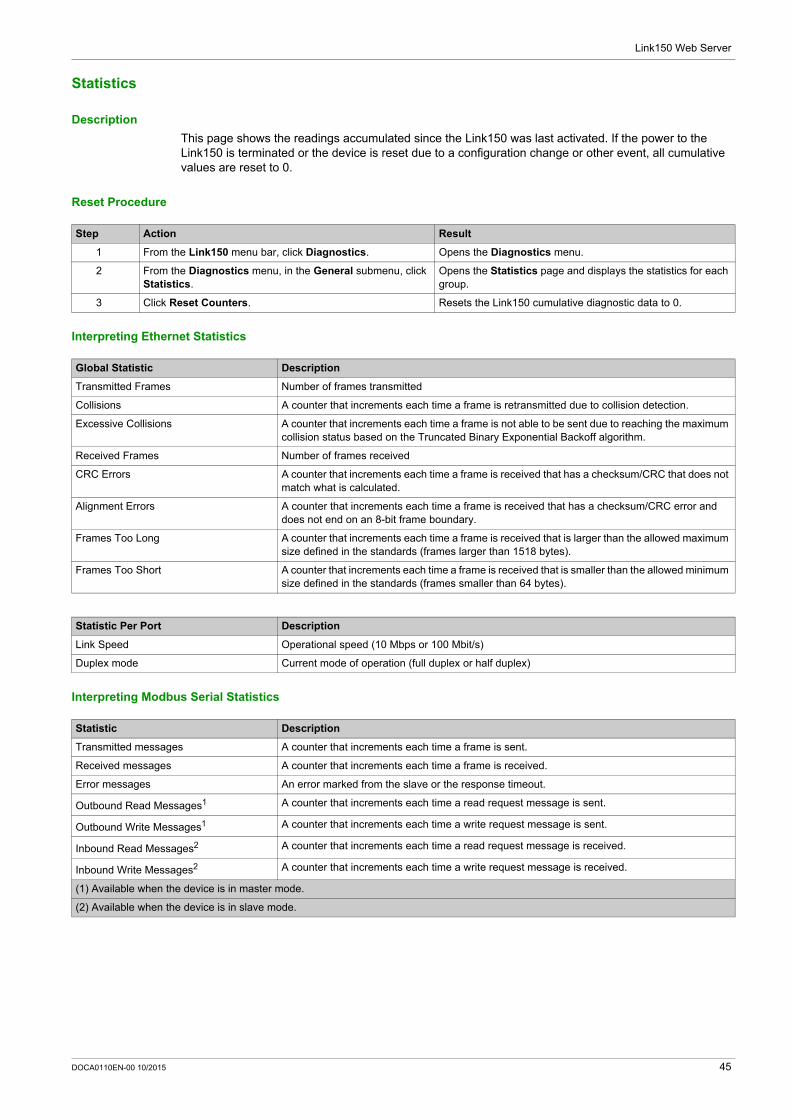
Description
This page shows the readings accumulated since the Link150 was last activated. If the power to the Link150 is terminated or the device is reset due to a configuration change or other event, all cumulative values are reset to 0.
Reset Procedure
Interpreting Ethernet Statistics
Interpreting Modbus Serial Statistics
Step Action Result
1 From the Link150 menu bar, click Diagnostics. Opens the Diagnostics menu.
2 From the Diagnostics menu, in the General submenu, click Statistics.
Opens the Statistics page and displays the statistics for each group.
3 Click Reset Counters. Resets the Link150 cumulative diagnostic data to 0.
Global Statistic Description
Transmitted Frames Number of frames transmitted
Collisions A counter that increments each time a frame is retransmitted due to collision detection.
Excessive Collisions A counter that increments each time a frame is not able to be sent due to reaching the maximum collision status based on the Truncated Binary Exponential Backoff algorithm.
Received Frames Number of frames received
CRC Errors A counter that increments each time a frame is received that has a checksum/CRC that does not match what is calculated.
Alignment Errors A counter that increments each time a frame is received that has a checksum/CRC error and does not end on an 8-bit frame boundary.
Frames Too Long A counter that increments each time a frame is received that is larger than the allowed maximum size defined in the standards (frames larger than 1518 bytes).
Frames Too Short A counter that increments each time a frame is received that is smaller than the allowed minimum size defined in the standards (frames smaller than 64 bytes).
Statistic Per Port Description
Link Speed Operational speed (10 Mbps or 100 Mbit/s)
Duplex mode Current mode of operation (full duplex or half duplex)
Statistic Description
Transmitted messages A counter that increments each time a frame is sent.
Received messages A counter that increments each time a frame is received.
Error messages An error marked from the slave or the response timeout.
Outbound Read Messages1 A counter that increments each time a read request message is sent.
Outbound Write Messages1 A counter that increments each time a write request message is sent.
Inbound Read Messages2 A counter that increments each time a read request message is received.
Inbound Write Messages2 A counter that increments each time a write request message is received.
(1) Available when the device is in master mode.
(2) Available when the device is in slave mode.
DOCA0110EN-00 10/2015 45
Link150 Web Server
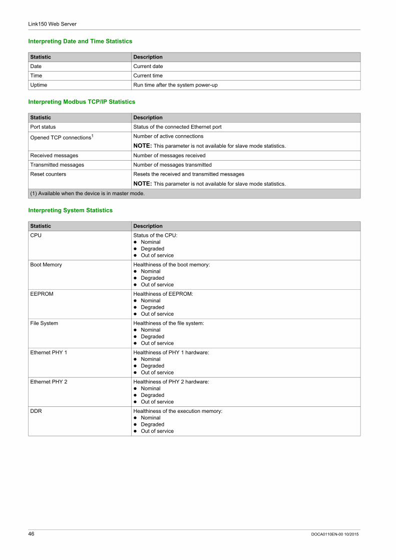
Interpreting Date and Time Statistics
Interpreting Modbus TCP/IP Statistics
Interpreting System Statistics
Statistic Description
Date Current date
Time Current time
Uptime Run time after the system power-up
Statistic Description
Port status Status of the connected Ethernet port
Opened TCP connections1 Number of active connections
NOTE: This parameter is not available for slave mode statistics.
Received messages Number of messages received
Transmitted messages Number of messages transmitted
Reset counters Resets the received and transmitted messages
NOTE: This parameter is not available for slave mode statistics.
(1) Available when the device is in master mode.
Statistic Description
CPU Status of the CPU: Nominal Degraded Out of service
Boot Memory Healthiness of the boot memory: Nominal Degraded Out of service
EEPROM Healthiness of EEPROM: Nominal Degraded Out of service
File System Healthiness of the file system: Nominal Degraded Out of service
Ethernet PHY 1 Healthiness of PHY 1 hardware: Nominal Degraded Out of service
Ethernet PHY 2 Healthiness of PHY 2 hardware: Nominal Degraded Out of service
DDR Healthiness of the execution memory: Nominal Degraded Out of service
46 DOCA0110EN-00 10/2015
Link150 Web Server
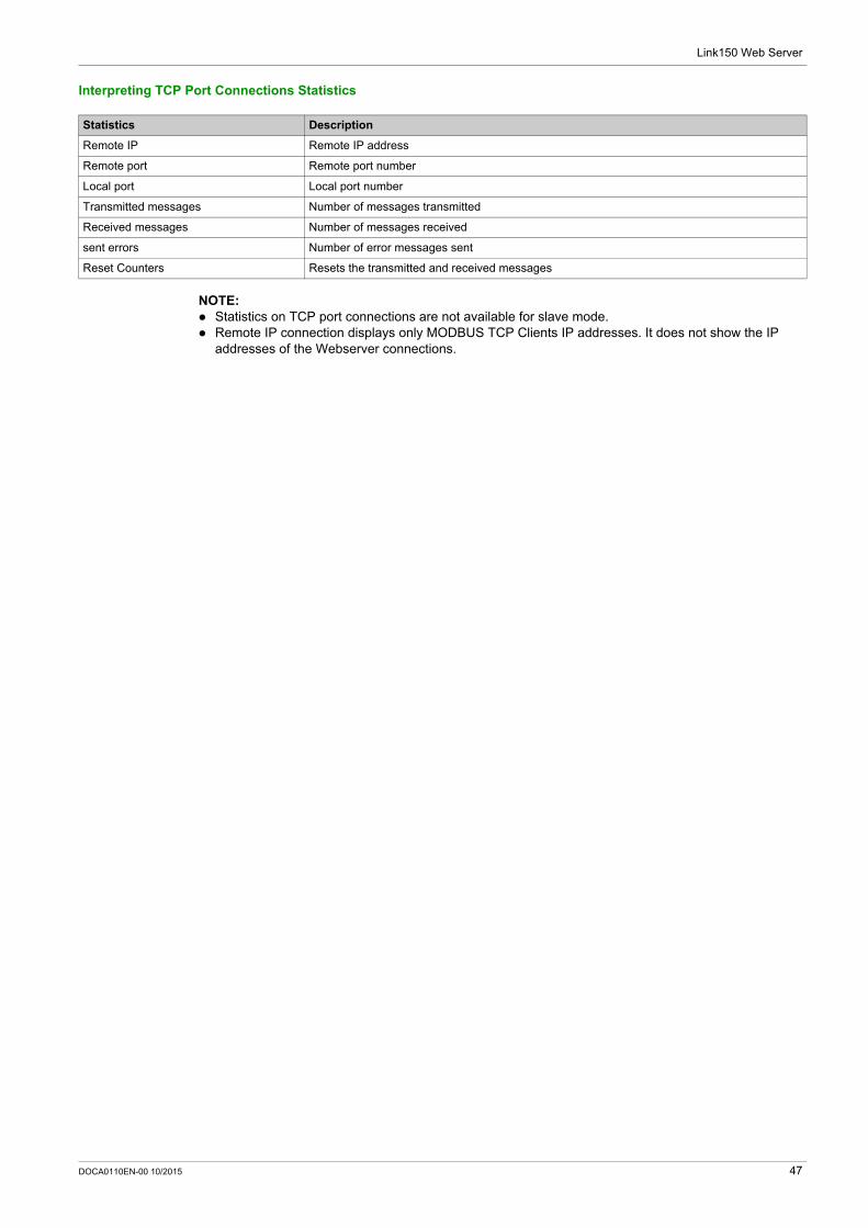
Interpreting TCP Port Connections Statistics
NOTE: Statistics on TCP port connections are not available for slave mode. Remote IP connection displays only MODBUS TCP Clients IP addresses. It does not show the IP
addresses of the Webserver connections.
Statistics Description
Remote IP Remote IP address
Remote port Remote port number
Local port Local port number
Transmitted messages Number of messages transmitted
Received messages Number of messages received
sent errors Number of error messages sent
Reset Counters Resets the transmitted and received messages
DOCA0110EN-00 10/2015 47
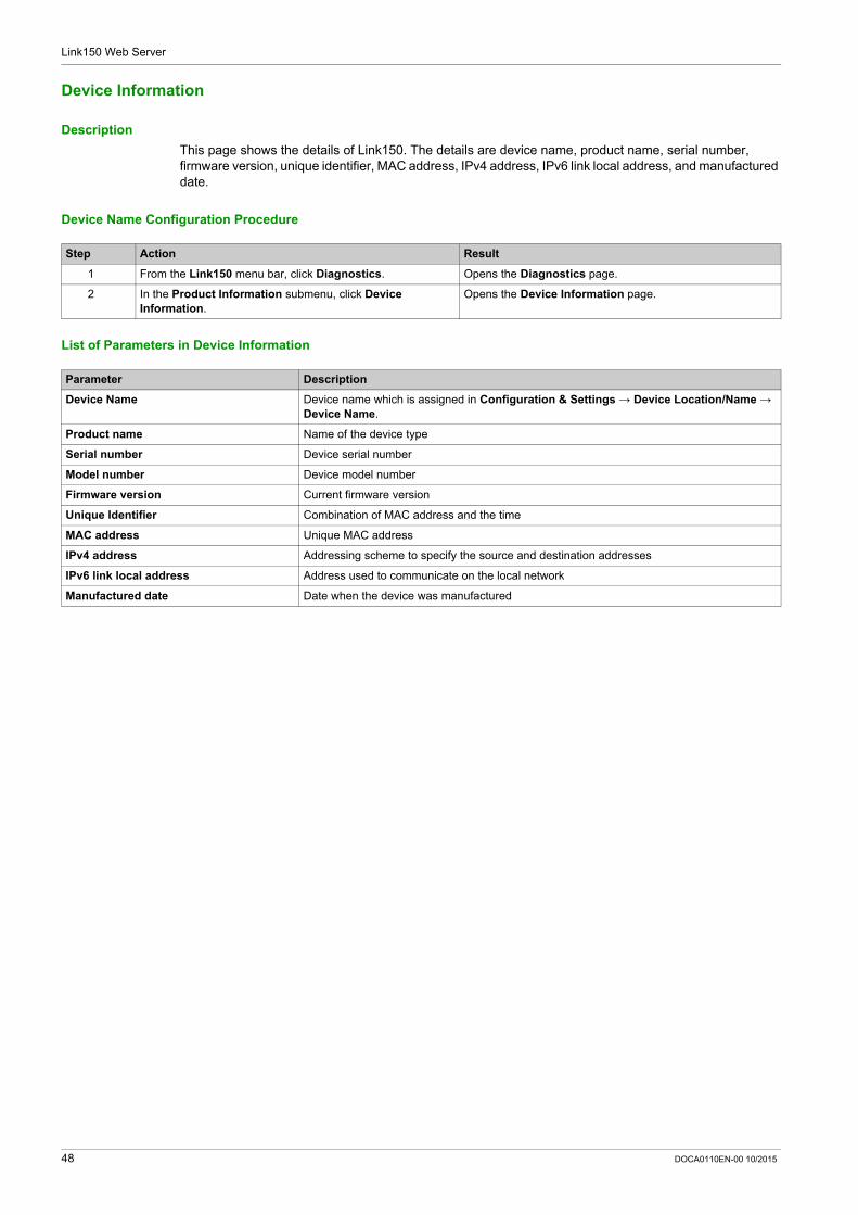
Link150 Web Server
Device Information
Description
This page shows the details of Link150. The details are device name, product name, serial number, firmware version, unique identifier, MAC address, IPv4 address, IPv6 link local address, and manufactured date.
Device Name Configuration Procedure
List of Parameters in Device Information
Step Action Result
1 From the Link150 menu bar, click Diagnostics. Opens the Diagnostics page.
2 In the Product Information submenu, click Device Information.
Opens the Device Information page.
Parameter Description
Device Name Device name which is assigned in Configuration & Settings → Device Location/Name → Device Name.
Product name Name of the device type
Serial number Device serial number
Model number Device model number
Firmware version Current firmware version
Unique Identifier Combination of MAC address and the time
MAC address Unique MAC address
IPv4 address Addressing scheme to specify the source and destination addresses
IPv6 link local address Address used to communicate on the local network
Manufactured date Date when the device was manufactured
48 DOCA0110EN-00 10/2015
Link150 Web Server
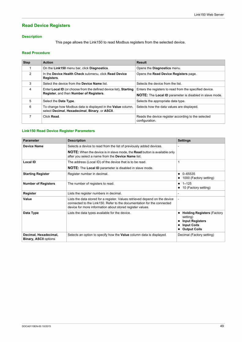
Read Device Registers
Description
This page allows the Link150 to read Modbus registers from the selected device.
Read Procedure
Link150 Read Device Register Parameters
Step Action Result
1 On the Link150 menu bar, click Diagnostics. Opens the Diagnostics menu.
2 In the Device Health Check submenu, click Read Device Registers.
Opens the Read Device Registers page.
3 Select the device from the Device Name list. Selects the device from the list.
4 Enter Local ID (or choose from the defined device list), Starting Register, and then Number of Registers.
Enters the registers to read from the specified device.
NOTE: The Local ID parameter is disabled in slave mode.
5 Select the Data Type. Selects the appropriate data type.
6 To change how Modbus data is displayed in the Value column, select Decimal, Hexadecimal, Binary, or ASCII.
Selects how the data values are displayed.
7 Click Read. Reads the device register according to the selected configuration.
Parameter Description Settings
Device Name Selects a device to read from the list of previously added devices.
NOTE: When the device is in slave mode, the Read button is available only after you select a name from the Device Name list.
-
Local ID The address (Local ID) of the device that is to be read.
NOTE: The Local ID parameter is disabled in slave mode.
1
Starting Register Register number in decimal. 0–65535 1000 (Factory setting)
Number of Registers The number of registers to read. 1–125 10 (Factory setting)
Register Lists the register numbers in decimal. -
Value Lists the data stored for a register. Values retrieved depend on the device connected to the Link150. Refer to the documentation for the connected device for more information about stored register values.
-
Data Type Lists the data types available for the device. Holding Registers (Factory setting)
Input Registers Input Coils Output Coils
Decimal, Hexadecimal, Binary, ASCII options
Selects an option to specify how the Value column data is displayed. Decimal (Factory setting)
DOCA0110EN-00 10/2015 49

Link150 Web Server
50 DOCA0110EN-00 10/2015
Ethernet Gateway Link150
Abbreviated title of Chapter
DOCA0110EN-00 10/2015
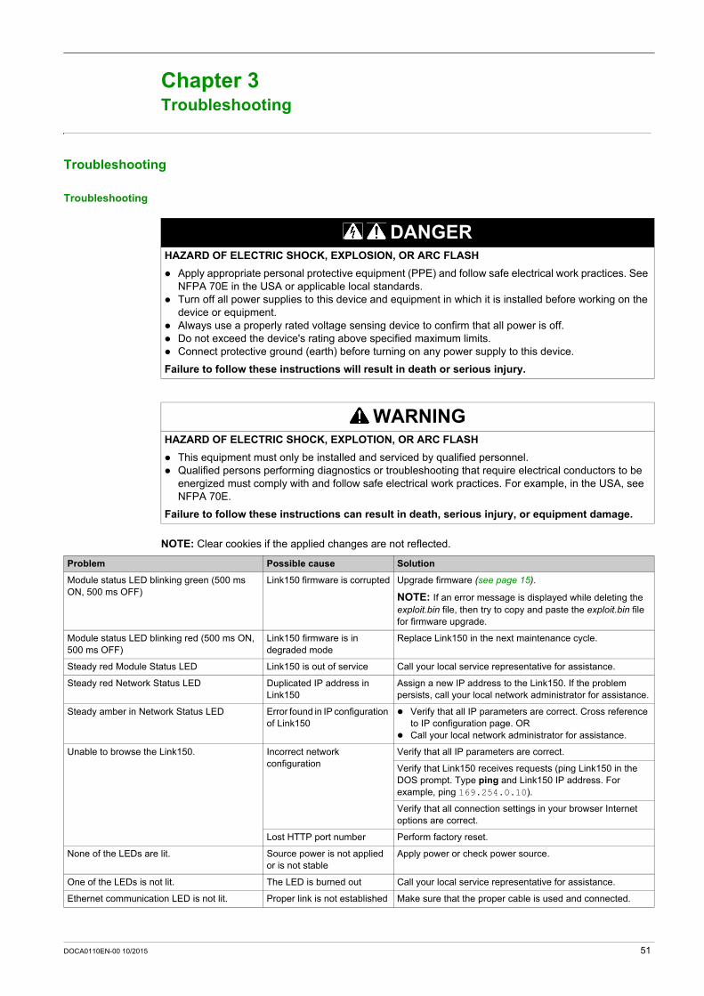
Troubleshooting
Chapter 3Troubleshooting
Troubleshooting
Troubleshooting
NOTE: Clear cookies if the applied changes are not reflected.
DANGERHAZARD OF ELECTRIC SHOCK, EXPLOSION, OR ARC FLASH
Apply appropriate personal protective equipment (PPE) and follow safe electrical work practices. See NFPA 70E in the USA or applicable local standards.
Turn off all power supplies to this device and equipment in which it is installed before working on the device or equipment.
Always use a properly rated voltage sensing device to confirm that all power is off. Do not exceed the device's rating above specified maximum limits. Connect protective ground (earth) before turning on any power supply to this device.
Failure to follow these instructions will result in death or serious injury.
WARNINGHAZARD OF ELECTRIC SHOCK, EXPLOTION, OR ARC FLASH
This equipment must only be installed and serviced by qualified personnel. Qualified persons performing diagnostics or troubleshooting that require electrical conductors to be
energized must comply with and follow safe electrical work practices. For example, in the USA, see NFPA 70E.
Failure to follow these instructions can result in death, serious injury, or equipment damage.
Problem Possible cause Solution
Module status LED blinking green (500 ms ON, 500 ms OFF)
Link150 firmware is corrupted Upgrade firmware (see page 15).
NOTE: If an error message is displayed while deleting the exploit.bin file, then try to copy and paste the exploit.bin file for firmware upgrade.
Module status LED blinking red (500 ms ON, 500 ms OFF)
Link150 firmware is in degraded mode
Replace Link150 in the next maintenance cycle.
Steady red Module Status LED Link150 is out of service Call your local service representative for assistance.
Steady red Network Status LED Duplicated IP address in Link150
Assign a new IP address to the Link150. If the problem persists, call your local network administrator for assistance.
Steady amber in Network Status LED Error found in IP configuration of Link150
Verify that all IP parameters are correct. Cross reference to IP configuration page. OR
Call your local network administrator for assistance.
Unable to browse the Link150. Incorrect network configuration
Verify that all IP parameters are correct.
Verify that Link150 receives requests (ping Link150 in the DOS prompt. Type ping and Link150 IP address. For example, ping 169.254.0.10).
Verify that all connection settings in your browser Internet options are correct.
Lost HTTP port number Perform factory reset.
None of the LEDs are lit. Source power is not applied or is not stable
Apply power or check power source.
One of the LEDs is not lit. The LED is burned out Call your local service representative for assistance.
Ethernet communication LED is not lit. Proper link is not established Make sure that the proper cable is used and connected.
DOCA0110EN-00 10/2015 51

Troubleshooting
52 DOCA0110EN-00 10/2015


As standards, specifications and designs change from time to time, please ask for confirmation of the information given in this publication.
DOCA0110EN-00
Schneider Electric Industries SAS35, rue Joseph MonierCS30323F - 92506 Rueil Malmaison Cedex
www.schneider-electric.com 10/2015