ES02 嵌入式軟體的硬體基礎.pdf
50
1 ES-02 Hardware Basics for Embedded Software 嵌入式軟體的硬體基礎 陳慶瀚 MIAT嵌入式計算實驗室/中央大學資工系 [email protected] 2009年9月25日
-
Upload
khangminh22 -
Category
Documents
-
view
5 -
download
0
Transcript of ES02 嵌入式軟體的硬體基礎.pdf

1
ES-02Hardware Basics for Embedded Software
嵌入式軟體的硬體基礎
陳慶瀚
MIAT嵌入式計算實驗室/中央大學資工系
[email protected]年9月25日

ES02-嵌入式軟體的硬體基礎 2
Embedded Processor
• Processor– Digital circuit that performs a computation tasks– Controller and datapath– General-purpose: variety of computation tasks– Single-purpose: one particular computation task
• Custom single-purpose processor– Fast, small, low power– But, high NRE, longer time-to-market, less flexible

ES02-嵌入式軟體的硬體基礎 3

ES02-嵌入式軟體的硬體基礎 4

ES02-嵌入式軟體的硬體基礎 5

ES02-嵌入式軟體的硬體基礎 6
Microcontroller
CCD preprocessor Pixel coprocessorA2D
D2A
JPEG codec
DMA controller
Memory controller ISA bus interface UART LCD ctrl
Display ctrl
Multiplier/Accum
Digital camera chip
lens
CCD
An Example : DSC Processor

ES02-嵌入式軟體的硬體基礎 7
Single-purpose processor model
controller datapath
…
…
External controlinputs
externalcontrol outputs
…
External datainputs
…External data
outputs
datapathcontrolinputs
datapathcontroloutputs

ES02-嵌入式軟體的硬體基礎 8
Single-purpose processor model… …
a view inside the controller and datapath
controller datapath
… …
stateregister
next-stateand
controllogic
registers
functionalunits

ES02-嵌入式軟體的硬體基礎 9
Design Example: greatest common divisor
GCDx_i y_i
d_o
go_i
• First create algorithm• Convert algorithm to
FSMD: finite-state machine with datapath
ES02-嵌入式軟體的硬體基礎 10
GSD: Algorithm & FSMD
0: int x, y;1: while (1) {2: while (!go_i);3: x = x_i; 4: y = y_i;5: while (x != y) {6: if (x < y) 7: y = y - x;
else 8: x = x - y;
}9: d_o = x;
}
y = y -x7: x = x - y8:
6-J:
x!=y5: !(x!=y)
x<y !(x<y)6:
5-J:
1:1
!1
x = x_i3:
y = y_i4:
2:
2-J:!go_i
!(!go_i)
d_o = x
1-J:
9:

ES02-嵌入式軟體的硬體基礎 11
State diagram templates
Assignment statement
a = bnext statement
a = b
next statement
Loop statement
while (cond) {loop-body-
statements}next statement
loop-body-statements
cond
next statement
!cond
J:
C:
Branch statement
if (c1)c1 stmts
else if c2c2 stmts
elseother stmts
next statement
c1
c2 stmts
!c1*c2 !c1*!c2
next statement
othersc1 stmts
J:
C:

ES02-嵌入式軟體的硬體基礎 12
Creating the datapath
• Create a register for any declared variable
• Create a functional unit for each arithmetic operation
• Connect the ports, registers and functional units– Based on reads and writes– Use multiplexors for
multiple sources
• Create unique identifier – for each datapath component
control input and output
y = y -x7: x = x - y8:
6-J:
x!=y
5: !(x!=y)
x<y !(x<y)
6:
5-J:
1:
1
!1
x = x_i3:
y = y_i4:
2:
2-J:
!go_i
!(!go_i)
d_o = x
1-J:
9:
subtractor subtractor7: y-x8: x-y5: x!=y 6: x<y
x_i y_i
d_o
0: x 0: y
9: d
n-bit 2x1 n-bit 2x1x_sel
y_selx_ld
y_ld
x_neq_y
x_lt_yd_ld
<5: x!=y
!=
Datapath

ES02-嵌入式軟體的硬體基礎 13
Creating the datapath
subtractor subtractor
7: y-x8: x-y5: x!=y 6: x<y
x_i y_i
d_o
0: x 0: y
9: d
n-bit 2x1 n-bit 2x1x_sel
y_sel
x_ld
y_ld
x_neq_y
x_lt_y
d_ld
<
5: x!=y
!=
Datapath
ES02-嵌入式軟體的硬體基礎 14
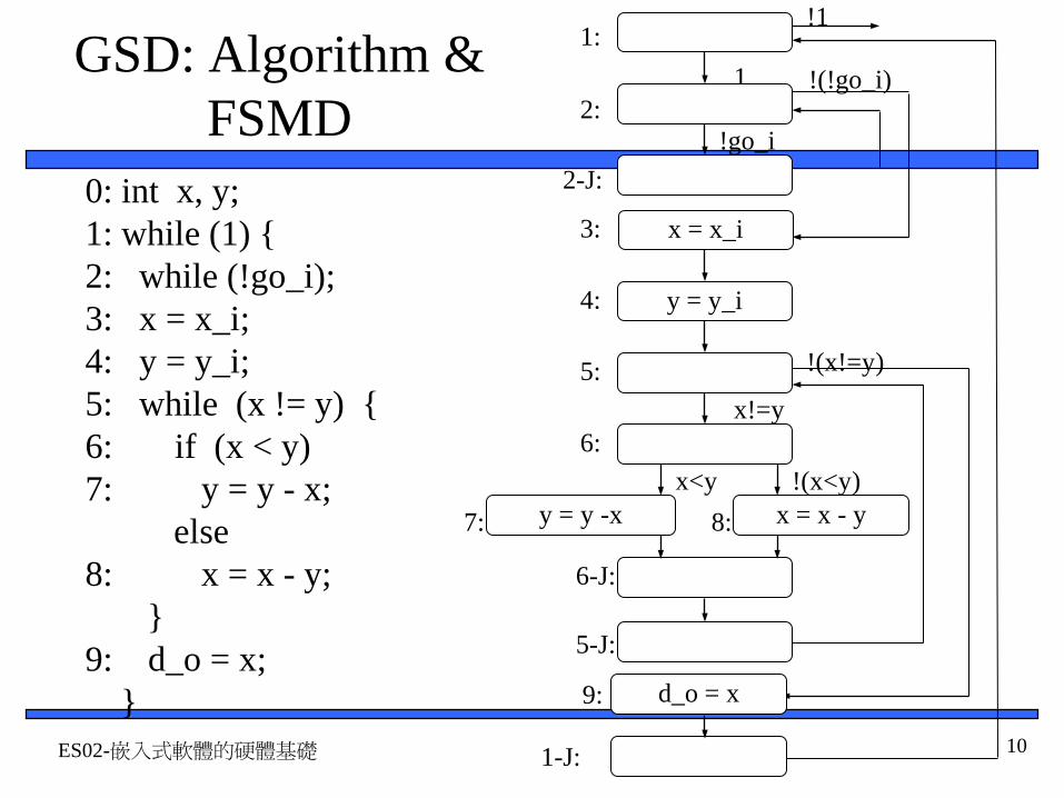
Creating the controller’s FSM
y_selx_sel
Combinational logic
Q3 Q0State register
go_i
x_neq_yx_lt_y
x_ldy_ld
d_ld
Q2 Q1
I3 I0I2 I1

ES02-嵌入式軟體的硬體基礎 15
Splitting into a controller and datapath
y_sel = 1y_ld = 1
7: x_sel = 1x_ld = 1
8:
6-J:
x_neq_y=1
5:x_neq_y=0
x_lt_y=1 x_lt_y=0
6:
5-J:
d_ld = 1
1-J:
9:
x_sel = 0x_ld = 13:
y_sel = 0y_ld = 14:
1:1
!1
2:
2-J:
!go_i
!(!go_i)
go_i
0000
0001
0010
0011
0100
0101
0110
0111 10001001
1010
1011
1100
ControllerController implementation model
y_selx_sel
Combinational logic
Q3 Q0
State register
go_i
x_neq_yx_lt_y
x_ldy_ld
d_ld
Q2 Q1
I3 I0I2 I1
subtractor subtractor7: y-x8: x-y5: x!=y 6: x<y
x_i y_i
d_o
0: x 0: y
9: d
n-bit 2x1 n-bit 2x1x_sel
y_selx_ld
y_ld
x_neq_y
x_lt_yd_ld
<5: x!=y
!=
(b) Datapath

ES02-嵌入式軟體的硬體基礎 16
Controller state table for the GCD exampleInputs Outputs
Q3 Q2 Q1 Q0 x_neq_y
x_lt_y
go_i I3 I2 I1 I0 x_sel
y_sel
x_ld y_ld d_ld
0 0 0 0 * * * 0 0 0 1 X X 0 0 00 0 0 1 * * 0 0 0 1 0 X X 0 0 00 0 0 1 * * 1 0 0 1 1 X X 0 0 00 0 1 0 * * * 0 0 0 1 X X 0 0 00 0 1 1 * * * 0 1 0 0 0 X 1 0 00 1 0 0 * * * 0 1 0 1 X 0 0 1 00 1 0 1 0 * * 1 0 1 1 X X 0 0 00 1 0 1 1 * * 0 1 1 0 X X 0 0 00 1 1 0 * 0 * 1 0 0 0 X X 0 0 00 1 1 0 * 1 * 0 1 1 1 X X 0 0 00 1 1 1 * * * 1 0 0 1 X 1 0 1 01 0 0 0 * * * 1 0 0 1 1 X 1 0 01 0 0 1 * * * 1 0 1 0 X X 0 0 01 0 1 0 * * * 0 1 0 1 X X 0 0 01 0 1 1 * * * 1 1 0 0 X X 0 0 11 1 0 0 * * * 0 0 0 0 X X 0 0 01 1 0 1 * * * 0 0 0 0 X X 0 0 01 1 1 0 * * * 0 0 0 0 X X 0 0 01 1 1 1 * * * 0 0 0 0 X X 0 0 0

ES02-嵌入式軟體的硬體基礎 17
Completing the GCD custom single-purpose processor design
• We finished the datapath• We have a state table for
the next state and control logic– All that’s left is
combinational logic design
… …
a view inside the controller and datapath
controller datapath
… …
stateregister
next-stateand
controllogic
registers
functionalunits

ES02-嵌入式軟體的硬體基礎 18
General Purpose Processor
– Processor designed for a variety of computation tasks– Low unit cost, in part because manufacturer spreads
NRE over large numbers of units– Can yield good performance, size and power – Low NRE cost, short time-to-market/prototype, high
flexibility– User just writes software; no processor design

ES02-嵌入式軟體的硬體基礎 19
Architecture of General Purpose Processor
• Control unit and datapath– Note similarity to
single-purpose processor
• Key differences– Datapath is general– Control unit doesn’t
store the algorithm –the algorithm is “programmed” into the memory
Processor
Control unit Datapath
ALU
Registers
IRPC
Controller
Memory
I/O
Control/Status
ES02-嵌入式軟體的硬體基礎 20
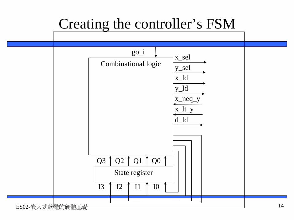
Datapath Operations
• Load– Read memory location
into register • ALU operation
– Input certain registers through ALU, store back in register
• Store
– Write register to memory location
Processor
Control unit Datapath
ALU
Registers
IRPC
Controller
Memory
I/O
Control/Status
10
...
...
10
+1
11
11

ES02-嵌入式軟體的硬體基礎 21
Control Unit
• Control unit: configures the datapath operations
– Sequence of desired operations (“instructions”) stored in memory –“program”
• Instruction cycle – broken into several sub-operations, each one clock cycle, e.g.:
– Fetch: Get next instruction into IR– Decode: Determine what the
instruction means– Fetch operands: Move data from
memory to datapath register– Execute: Move data through the
ALU– Store results: Write data from
register to memory
Processor
Control unit Datapath
ALU
Registers
IRPC
Controller
Memory
I/O
Control/Status
10
...
...
load R0, M[500] 500501
100inc R1, R0101
store M[501], R1102
R0 R1

ES02-嵌入式軟體的硬體基礎 22
Control Unit Sub-Operations
• Fetch– Get next instruction
into IR– PC: program
counter, always points to next instruction
– IR: holds the fetched instruction
Processor
Control unit Datapath
ALU
Registers
IRPC
Controller
Memory
I/O
Control/Status
10
...
...
load R0, M[500] 500501
100inc R1, R0101
store M[501], R1102
R0 R1100 load R0, M[500]

ES02-嵌入式軟體的硬體基礎 23
Control Unit Sub-Operations
• Decode– Determine what the
instruction means
Processor
Control unit Datapath
ALU
Registers
IRPC
Controller
Memory
I/O
Control/Status
10
...
...
load R0, M[500] 500501
100inc R1, R0101
store M[501], R1102
R0 R1100 load R0, M[500]

ES02-嵌入式軟體的硬體基礎 24
Control Unit Sub-Operations
• Fetch operands– Move data from
memory to datapath register
Processor
Control unit Datapath
ALU
Registers
IRPC
Controller
Memory
I/O
Control/Status
10
...
...
load R0, M[500] 500501
100inc R1, R0101
store M[501], R1102
R0 R1100 load R0, M[500]
10
ES02-嵌入式軟體的硬體基礎 25
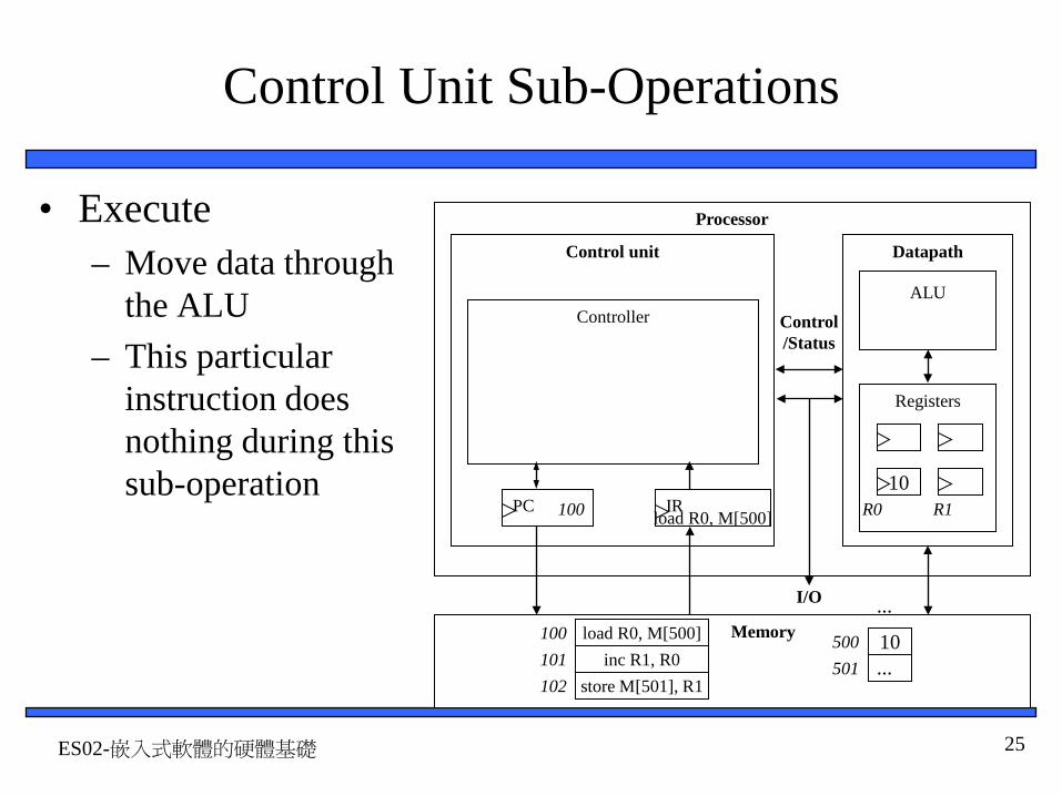
Control Unit Sub-Operations
• Execute– Move data through
the ALU– This particular
instruction does nothing during this sub-operation
Processor
Control unit Datapath
ALU
Registers
IRPC
Controller
Memory
I/O
Control/Status
10
...
...
load R0, M[500] 500501
100inc R1, R0101
store M[501], R1102
R0 R1100 load R0, M[500]
10

ES02-嵌入式軟體的硬體基礎 26
Control Unit Sub-Operations
• Store results– Write data from
register to memory– This particular
instruction does nothing during this sub-operation
Processor
Control unit Datapath
ALU
Registers
IRPC
Controller
Memory
I/O
Control/Status
10
...
...
load R0, M[500] 500501
100inc R1, R0101
store M[501], R1102
R0 R1100 load R0, M[500]
10

ES02-嵌入式軟體的硬體基礎 27
Instruction Cycles
Processor
Control unit Datapath
ALU
Registers
IRPC
Controller
Memory
I/O
Control/Status
10
...
...
load R0, M[500] 500501
100inc R1, R0101
store M[501], R1102
R0 R1
PC=100
10
Fetch ops
Exec. Store results
clk
Fetch
load R0, M[500]
Decode
100

ES02-嵌入式軟體的硬體基礎 28
Instruction Cycles
Processor
Control unit Datapath
ALU
Registers
IRPC
Controller
Memory
I/O
Control/Status
10
...
...
load R0, M[500] 500501
100inc R1, R0101
store M[501], R1102
R0 R110
PC=100Fetch Decode Fetch
opsExec. Store
resultsclk
PC=101
inc R1, R0
Fetch Fetch ops
+1
11
Exec. Store results
clk
101
Decode

ES02-嵌入式軟體的硬體基礎 29
Instruction Cycles
Processor
Control unit Datapath
ALU
Registers
IRPC
Controller
Memory
I/O
Control/Status
10
...
...
load R0, M[500] 500501
100inc R1, R0101
store M[501], R1102
R0 R11110
PC=100Fetch Decode Fetch
opsExec. Store
resultsclk
PC=101Fetch Decode Fetch
opsExec. Store
resultsclk
PC=102store M[501], R1
Fetch Fetch ops
Exec.
11
Store results
clk
Decode
102

ES02-嵌入式軟體的硬體基礎 30
Architectural Considerations
• N-bit processor– N-bit ALU, registers,
buses, memory data interface
– Embedded: 8-bit, 16-bit, 32-bit common
– Desktop/servers: 32-bit, even 64
• PC size determines address space
Processor
Control unit Datapath
ALU
Registers
IRPC
Controller
Memory
I/O
Control/Status

ES02-嵌入式軟體的硬體基礎 31
Architectural Considerations
• Clock frequency– Inverse of clock
period– Clock Period must be
longer than longest register to register delay in entire processor
– Memory access is often the longest
Processor
Control unit Datapath
ALU
Registers
IRPC
Controller
Memory
I/O
Control/Status

ES02-嵌入式軟體的硬體基礎 32
Pipelining: Increasing Instruction Throughput
1 2 3 4 5 6 7 8
1 2 3 4 5 6 7 8
1 2 3 4 5 6 7 8
1 2 3 4 5 6 7 8
Fetch-instr.
Decode
Fetch ops.
Execute
Store res.
1 2 3 4 5 6 7 8
1 2 3 4 5 6 7 8
1 2 3 4 5 6 7 8
1 2 3 4 5 6 7 8
1 2 3 4 5 6 7 8
Wash
Dry
Time
Non-pipelined Pipelined
Time
Time
Pipelined
pipelined instruction execution
non-pipelined dish cleaning pipelined dish cleaning
Instruction 1

ES02-嵌入式軟體的硬體基礎 33
Application-Specific Instruction-Set Processors (ASIPs)
• General-purpose processors– Sometimes too general to be effective in demanding
application• e.g., video processing – requires huge video buffers and operations
on large arrays of data, inefficient on a GPP– But single-purpose processor has high NRE, not
programmable• ASIPs – targeted to a particular domain
– Contain architectural features specific to that domain• e.g., embedded control, digital signal processing, video processing,
network processing, telecommunications, etc.– Still programmable

ES02-嵌入式軟體的硬體基礎 34
A Common ASIP: Microcontroller
• For embedded control applications– Reading sensors, setting actuators– Mostly dealing with events (bits): data is present, but not in huge
amounts– e.g., VCR, disk drive, digital camera (assuming SPP for image
compression), washing machine, microwave oven• Microcontroller features
– On-chip peripherals• Timers, analog-digital converters, serial communication, etc.• Tightly integrated for programmer, typically part of register space
– On-chip program and data memory– Direct programmer access to many of the chip’s pins– Specialized instructions for bit-manipulation and other low-level
operations

ES02-嵌入式軟體的硬體基礎 35
Another Common ASIP: Digital Signal Processors (DSP)
• For signal processing applications– Large amounts of digitized data, often streaming– Data transformations must be applied fast– e.g., cell-phone voice filter, digital TV, music synthesizer
• DSP features– Several instruction execution units– Multiple-accumulate single-cycle instruction, other instrs.– Efficient vector operations – e.g., add two arrays
• Vector ALUs, loop buffers, etc.

ES02-嵌入式軟體的硬體基礎 36
週邊硬體Peripherals Hardware
• Timers, counters, watchdog timers• UART…Serial Communication Protocol• PWM(Pulse width modulator)• LCD• KeyPad• Stepper motor• A/D, D/A

ES02-嵌入式軟體的硬體基礎 37
Timers, counters, watchdog timers
• Timer: measures time intervals– To generate timed output events
• e.g., hold traffic light green for 10 s– To measure input events
• e.g., measure a car’s speed• Based on counting clock pulses
• E.g., let Clk period be 10 ns • And we count 20,000 Clk pulses• Then 200 microseconds have passed• 16-bit counter would count up to 65,535*10 ns =
655.35 microsec., resolution = 10 ns• Top: indicates top count reached, wrap-around
16-bit up counter
Clk Cnt
Basic timer
Top
Reset
16

ES02-嵌入式軟體的硬體基礎 38
Counters
• Counter: like a timer, but counts pulses on a general input signal rather than clock
16-bit up counterClk
16
Cnt_in
2x1 mux
Mode
Timer/counter
Top
Reset
Cnt

ES02-嵌入式軟體的硬體基礎 39
Watchdog timer
scalereg
checkreg
timeregto system
resetor
interrupt
osc clk
prescaleroverflow overflow
ES02-嵌入式軟體的硬體基礎 40
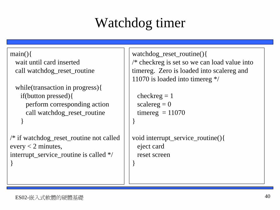
Watchdog timer
main(){wait until card insertedcall watchdog_reset_routine
while(transaction in progress){if(button pressed){
perform corresponding actioncall watchdog_reset_routine
}
/* if watchdog_reset_routine not called every < 2 minutes, interrupt_service_routine is called */}
watchdog_reset_routine(){/* checkreg is set so we can load value into timereg. Zero is loaded into scalereg and 11070 is loaded into timereg */
checkreg = 1scalereg = 0timereg = 11070
}
void interrupt_service_routine(){eject cardreset screen
}

ES02-嵌入式軟體的硬體基礎 41
Serial Transmission Using UARTs
embedded device1 0
0 11 0 1 1
Sending UART
1 0 0 1 1 0 1 1
Receiving UART
1 0 0 1 1 0 1 1
start bitdata
end bit
1 0 0 1 1 0 1 1
• UART: Universal Asynchronous Receiver Transmitter
– Takes parallel data and transmits serially
– Receives serial data and converts to parallel
• Parity: extra bit for simple error checking
• Start bit, stop bit• Baud rate
– signal changes per second– bit rate usually higher

ES02-嵌入式軟體的硬體基礎 42
Pulse width modulator
clk
pwm_o
25% duty cycle – average pwm_o is 1.25V
clk
pwm_o
50% duty cycle – average pwm_o is 2.5V.
clk
pwm_o
75% duty cycle – average pwm_o is 3.75V.
• Generates pulses with specific high/low times
• Duty cycle: % time high– Square wave: 50% duty cycle
• Common use: control average voltage to electric device
– Simpler than DC-DC converter or digital-analog converter
– DC motor speed, dimmer lights
• Another use: encode commands, receiver uses timer to decode

ES02-嵌入式軟體的硬體基礎 43
Controlling a DC motor with a PWM
void main(void){
/* controls period */PWMP = 0xff; /* controls duty cycle */PWM1 = 0x7f;
while(1){};}
The PWM alone cannot drive the DC motor, a possible way to implement a driver is shown below using an MJE3055T NPN transistor.
5V
B
A
Internal Structure of PWM
clk_div
cycle_high
counter( 0 – 254)
8-bit comparator
controls how fast the counter increments counter <
cycle_high,pwm_o = 1counter >= cycle_high, pwm_o = 0
pwm_o
clk Input Voltage % of MaximumVoltage Applied RPM of DC Motor
0 0 0
2.5 50 1840
3.75 75 6900
5.0 100 9200
Relationship between applied voltage and speed of the DC Motor
DC
MOTOR
5V
From processor

ES02-嵌入式軟體的硬體基礎 44
LCD controller
ER/WRS
DB7–DB0
LCD controller
communications bus
microcontroller8
void WriteChar(char c){
RS = 1; /* indicate data being sent */DATA_BUS = c; /* send data to LCD */EnableLCD(45); /* toggle the LCD with appropriate delay */
}
CODES
I/D = 1 cursor moves left DL = 1 8-bit
I/D = 0 cursor moves right DL = 0 4-bit
S = 1 with display shift N = 1 2 rows
S/C =1 display shift N = 0 1 row
S/C = 0 cursor movement F = 1 5x10 dots
R/L = 1 shift to right F = 0 5x7 dots
R/L = 0 shift to left
RS R/W DB7 DB6 DB5 DB4 DB3 DB2 DB1 DB0 Description
0 0 0 0 0 0 0 0 0 1 Clears all display, return cursor home
0 0 0 0 0 0 0 0 1 * Returns cursor home
0 0 0 0 0 0 0 1 I/D S Sets cursor move direction and/orspecifies not to shift display
0 0 0 0 0 0 1 D C B ON/OFF of all display(D), cursorON/OFF (C), and blink position (B)
0 0 0 0 0 1 S/C R/L * * Move cursor and shifts display
0 0 0 0 1 DL N F * * Sets interface data length, number ofdisplay lines, and character font
1 0 WRITE DATA Writes Data

ES02-嵌入式軟體的硬體基礎 45
Keypad controller
N1N2N3N4
M1M2M3M4
key_code
keypad controller
k_pressed
key_code
4
N=4, M=4

ES02-嵌入式軟體的硬體基礎 46
Stepper motor controller
Red AWhite A’Yellow BBlack B’
MC3479P1
5
4
3
2
7
8
6
16
15
14
13
12
11
10
9
Vd
A’
A
GND
Bias’/Set
Clk
O|C
Vm
B
B’
GND
Phase A’
CW’/CCW
Full’/Half Step
Sequence A B A’ B’1 + + - -2 - + + -3 - - + +4 + - - +5 + + - -
• Stepper motor: rotates fixed number of degrees when given a “step” signal– In contrast, DC motor just rotates when
power applied, coasts to stop
• Rotation achieved by applying specific voltage sequence to coils
• Controller greatly simplifies this

ES02-嵌入式軟體的硬體基礎 47
Stepper motor with controller (driver)
2 A’3 A
10 7
B 15B’ 14
MC3479PStepper Motor
Driver 8051
P1.0P1.1
StepperMotor
CLKCW’/CCW
The output pins on the stepper motor driver do notprovide enough current to drive the stepper motor.To amplify the current, a buffer is needed. Onepossible implementation of the buffers is picturedto the left. Q1 is an MJE3055T NPN transistorand Q2 is an MJE2955T PNP transistor. A isconnected to the 8051 microcontroller and B isconnected to the stepper motor.
Q2
1K
1KQ1
+V
A B
void main(void){
*/turn the motor forward */cw=0; /* set direction */clk=0; /* pulse clock */delay();clk=1;
/*turn the motor backwards */cw=1; /* set direction */clk=0; /* pulse clock */delay();clk=1;
}
/* main.c */
sbit clk=P1^1;sbit cw=P1^0;
void delay(void){int i, j;for (i=0; i<1000; i++)
for ( j=0; j<50; j++)i = i + 0;
}

ES02-嵌入式軟體的硬體基礎 48
Stepper motor without controller (driver)
StepperMotor
8051GND/ +VP2.4
P2.3P2.2P2.1P2.0
A possible way to implement the buffers is located below. The 8051 alone cannot drive the stepper motor, so several transistors were added to increase the current going to the stepper motor. Q1 are MJE3055T NPN transistors and Q3 is an MJE2955T PNP transistor. A is connected to the 8051 microcontroller and B is connected to the stepper motor.
Q2
+V
1KQ1
1K
+V
A
B
330
/*main.c*/sbit notA=P2^0;sbit isA=P2^1;sbit notB=P2^2;sbit isB=P2^3;sbit dir=P2^4;
void delay(){int a, b;for(a=0; a<5000; a++)
for(b=0; b<10000; b++)a=a+0;
}
void move(int dir, int steps) {int y, z;
/* clockwise movement */if(dir == 1){
for(y=0; y<=steps; y++){for(z=0; z<=19; z+4){
isA=lookup[z];isB=lookup[z+1];notA=lookup[z+2];notB=lookup[z+3];delay();
}}
}
/* counter clockwise movement */if(dir==0){
for(y=0; y<=step; y++){for(z=19; z>=0; z - 4){
isA=lookup[z];isB=lookup[z-1];notA=lookup[z -2];notB=lookup[z-3];
delay( );}
}}
}void main( ){
int z;int lookup[20] = {
1, 1, 0, 0,0, 1, 1, 0,0, 0, 1, 1,1, 0, 0, 1,1, 1, 0, 0 };
while(1){/*move forward, 15 degrees (2 steps) */
move(1, 2);/* move backwards, 7.5 degrees (1step)*/move(0, 1);
}}

ES02-嵌入式軟體的硬體基礎 49
Analog-to-digital converters
proportionality
Vmax = 7.5V
0V
11111110
0000
0010
0100
0110
1000
1010
1100
0001
0011
0101
0111
1001
1011
1101
0.5V1.0V1.5V2.0V2.5V3.0V
3.5V4.0V4.5V5.0V
5.5V6.0V6.5V7.0V
analog to digital
4
3
2
1
t1 t2 t3 t40100 1000 0110 0101
time
anal
og in
put (
V)
Digital output
digital to analog
4
3
2
1
0100 1000 0110 0101
t1 t2 t3 t4time
anal
og o
utpu
t (V
)
Digital input

ES02-嵌入式軟體的硬體基礎 50
Given an analog input signal whose voltage should range from 0 to 15 volts, and an 8-bit digital encoding, calculate the correct encoding for5 volts. Then trace the successive-approximation approach to find the correct encoding.
5/15 = d/(28-1)d= 85
Successive-approximation method
Digital-to-analog conversion using successive approximation
0 1 0 0 0 0 0 0
Encoding: 01010101
½(Vmax – Vmin) = 7.5 voltsVmax = 7.5 volts.
½(7.5 + 0) = 3.75 voltsVmin = 3.75 volts.
0 0 0 0 0 0 0 0
0 1 0 0 0 0 0 0½(7.5 + 3.75) = 5.63 voltsVmax = 5.63 volts
½(5.63 + 3.75) = 4.69 voltsVmin = 4.69 volts.
0 1 0 1 0 0 0 0
½(5.63 + 4.69) = 5.16 voltsVmax = 5.16 volts.
0 1 0 1 0 0 0 0
½(5.16 + 4.69) = 4.93 voltsVmin = 4.93 volts.
0 1 0 1 0 1 0 0
½(5.16 + 4.93) = 5.05 voltsVmax = 5.05 volts.
0 1 0 1 0 1 0 0
½(5.05 + 4.93) = 4.99 volts 0 1 0 1 0 1 0 1