Environmental Science & Technology 1974 Vol.8 No.7
99
-
Upload
khangminh22 -
Category
Documents
-
view
0 -
download
0
Transcript of Environmental Science & Technology 1974 Vol.8 No.7


Pretreatment:its many facetsfor wastewater
treatment613-618

Credentials,
0 00- f--
00Philips PW9700 502 MonitorGives the highest correlation coeffi- 00cient (0.933) with West Gaeke, the EPAreference method. Determined byfield evaluation of air pollution monitors 00conducted under EPA Contract No.CPA 70-101.*
Philips PW9700 502 Monitor 00The only S02 monitor for remote andlocal siting. Long term unattended
00operation provides for low operatingcosts and manpower requirements.Requires maintenance only 4 times ayear. Every other S02 monitor requires 00daily attention.
a..:: ~
~ ~
oPhilips PW9700 502 MonitorIts four year record of performance andreliability is unparalleled.
Philips PW9700 502 MonitorThe most widely used S02 monitor inthe U.S. and worldwide.
'Field Evaluation of New Air Pollution MonitoringSystems, Final Report, May 8, 1970 throughMay 8,1972.
Call Philips today. Ask for the Product Manager,Environmental Quality Monitoring, 914-664-4500,he'll be glad to describe the PW9700 and ourmonitoring systems.
000000000000
PHILIPSELECTRONICINSTRUMEl'ITS
A Norlh A,nPoriCdll PldilPS Comp~n'Y 0 0750 SClJt~ Fu(t'''T' A'/C'rl:~
Mt. V&:n.)\I, N'r 10:~50 •
CIRCLE 7 ON READER SERVICE CARD

EnvironmentalScience &Technology
...• EXTENDS A.CORDIAL INVITATION
TO EACH OF ITS90,000 READERS
TO VISIT ITS BOOTH(NUMBER 218)
WHILE AT THE3rd INTERNATIONAL
POLLUTION ENGINEERINGEXPOSITION &CONGRESS
I•
I•
I•II

NAME
STREET
TO EACH OF ITS
3rd INTERNATIONAL
90,000 READERSTO VISIT ITS BOOTH
(NUMBER 218)
WHILE AT THE
CORDIAL INVITATION
POLLUTION ENGINEERINGEXPOSITION &CONGRESS
ZIPSTATE
STREET
CITY
TITLE
COMPANY
EXPOSITION AND CONGRESS
COMPANY
TITLE
CITY STATE ZIP
DO NOT DETACH
FILL IN COMPLETELY .bove .nd below. Use TYPEWRITER CAPS only.
:i~S~~~~ a::faOnr~e ~~~~f~;~~~~e~n~~itM3~~e~Or~~rs~~~ :rg~~::~~~:De MOT ..II car. fer UPOSITION _." bring to registration desk.$1.00 registration fee with this clrd. Visitors without this card $2.00 registr.tion fee.CHECK 0 Full3·day Congress piUS available papers & Exposition $75.00
ONE 0 Any two half-d.ys, plus session papers, & Exposition $35.00(Pllasl IndiClt, Slision nlmben you pl.n to .ttend.)
o Exposition onIY-$1.00 registration fee
A. rlus. chICk 'OU, Company's ONE most Important industry It" ••.=lml f~{:si~;::~:, =g~g~ ¥~:~~r~~a~l~~h~~~'(pment_ (240) lumber/Furniture _ (380) Instruments/Controls= f~~g~ ~:fn~ing/PUbIiShing =f:;g~ ~~;t~\~~n~~,s:~r~~cturing_ (280) Chemicals Services=~~~ :~~~~~imastics =~r~~~ ~~:f}~~~fo~nglneerlng_ (320) Stone/Clay/Glass _ (400) Transportation Services_ (330) Primary Metals _ (500) Manufacturers'_ (340) Metal Products Representatives- (350). ~~~JreeC7r'ical - (900) Government_ (990) Other _
•. Pi.....~..k yo- title _ Jo~ rISPI••I~lIIty.
_ (02) President. Owner _ (18) R&D Technical=~g:~ ~a~r~n~;~~nt =H~~ ~~:f}~~fo~nl~~1;~ering=~~g~ ~r~~~t~~~~~~i~~~rlng =~~~ ~~~~~~~~t_ (12) Production/Manufacturing _ (42) OtherC. PI.IS. cltlcll yeur primat'J 'ater,st In pollution contrel.___ Air Water Solids NoiseFor advance congress registration, make chet:k payable toINDUSTRIAL EXPOSITIONS. INC.•nd mall to CI.pp & PolI.k, Inc.245 Park Avenue, New York, N.Y. 10017 LITHO IN u.s .....

The1974 InternationalPollution EngineeringExposition &Congress...what it means to you.Forthe 3rd consecutive year, the annual Pollution EngineeringExposition & Congress will convene once again, this time inChicago in September. Over 200 of the world's top pollutionequipment manufacturers and systems innovators will bethere to display the latest and greatest array of pollutioncontrol equipment, systems and ideas currently available.
Top level executives and engineers find the PollutionEngineering Show a complete Show that covers all areas ofpollution-air, water, solids and noise. And it saves time,travel, money and energy with its convenient one-stop supermarket shopping approach. This Show is a total pollutioncontrol show. Industry pros will be able to see and compareequipment and systems they used to see at 3 or 4 differentspecialized shows.
You'll want to evaluate the important equipment sY$temsand services currently available from the leading manufacturers. And there's only one place you can do it: At TheInternational Pollution Engineering Exposition.Don't Miss the ConferenceYou'll want to hear and discuss all the new ideas at the concurrent Congress, the best technical program in the country.In all 33 sessions emphasis will be placed on practical"how to·' management techniques, applications and methodology. Over 100 "user" speakers, each a recognizedexpert in his field, will answer questions and offer solutionsto many of today's pollution problems.
Join over 10,000 other visitors from industry and government who have the same problems you have. Plan nowto attend-you can't afford to miss it.
AIR·WATER, SO~IDS· NOI~E
Title _
Cily Slale Zip, _ II
_._------------------------------------------------------------------------------~
r--------------------------------------------------------------------------------,I 3rd INTERNATIONAL Clapp & Poliak, Inc. EST
OExposition ManagementPOLLUTI N 245 Park Avenue, Dept. EST, New York, New York 10017
ENGINE GGentlemen:
ERIN Yes, I plan to attend the 3rd International Pollution Engineering Exposi-tion and Congress in Chicago next September. Please send _EXPOSITION ~~::r's Guides and Rapid Registration Cards for me and my associates.
AND CONGRESS Company _
McCORMICK PLACE, CHICAGO Address, _
SEPTEMBER 9-12,1974
CIRCLE 2 ON READER SERVICE CARDVolume 8, Number 7, July 1974 591

For optimum accuracyin sampling airborneparticulates... specify
RAe continuous air samplers
RAC fractionating samplerDesigned to NASN requirements for more accurate determinations of suspended particle size distribution, this instrument uses a 5-stage cascadeimpactor to automatically segregate particulates and chemical components inambient air. Particles ranging from 3.0 to 0.5 microns dia are separated andcollected in the impactor. Smaller particles are collected in a 4" (100mm) diainline, membrane-type backup filter.
Unit operates continuously at 4-5 cfm flow rates for a 24-hr cycle. Samplesobtained wi'th this instrument can be precisely evaluated by gravimetric orchemical analyses.
RAe offers a variety of precision instruments designed to collect samples ofparticulate matter suspended in ambient air. These instruments meet performance parameters established by the American Society for Testing and Materials(ASTM), Environmental Protection Agency (EPA), and National Air SamplingNetwork (NASN).
RAC hi-volume air samplersThis design meets ASTM 2009 specs-and exceeds EPA requirements-foraccurate collection of suspended particulates in outdoor/indoor environments.Operating for 24-hr cycles (or longer), with constant flow rates ranging from 30to 50 scfm, RAG Hi-Vols collect particles down to 0.03 micro'ns dia on filtermedia with a 7 x 9" effective area. When equipped with optional accessories,these high-capacity units can operate as fully-automatic electronically-controlled systems that require only periodic filter replacement for continuousair sampling.
For details, write for BULLETIN 2338-B.CIRCLE 12 ON READER SERVICE CARD
RAC total particulatemembrane samplerDesigned and built to EPA specs, thisinstrument uses a membrane filter tocollect iine particles (to 3.0 micron dialnot easily sampled by paper or glassfilter media. Samples suitable for highlydefinitive analyses are obtained withno contamination from filter medium.
Unit operates continuously at 5.5 cfmflow rate when equipped with a 3.0micron membrane. Its 4" (100mm) diafilter has an 88mm effective area.
For details, write for BULLETIN 2349.
CIRCLE 13 ON READER SERVICE CARD
.'
RACHI-VOLSAMPLER
STACK SAMPLING SEMINARS (4th Year)RAC sponsors a series of 2-day technical howto seminars on stack sampling parameters andprocedures (EPA method). Write for descriptivefolder. CIRCLE 15 ON READER SERVICE CARD
RACFRACTIONATINGSAMPLER
For details, write for BULLETIN 2354.
CIRCLE 14 ON READER SERVICE CARD
RESEARCH APPLIANCE COMPANYRoute 8, Gibsonia, Pennsylvania 15044Environmental Instruments / Laboratory Products
592 Environmental Science & Technology

Volume 8, Number 7, July 1974
EnvironmentalScience & Technology
CONTENTS
CjO..:0IZf-(/)(/)(/)w_
612
Internaliqnal
602 European countries begin to curbindustrial discharges to waterways
PAT report
600 Gravel bed filters clean hot andabrasive industrial dusts
Features
614 Permutit's Lultinger and Hoche say ROsystems are right on with pretreatment
620 Consultant Minor tells how the organicchemicals industry treats waste waters
Contents
Papers
IBC
641
Outlook
606 Management of coastal zones is for today,future generations, and all seasons
608 Committee for Economic Developmentfinds growth and environment compatible
610 National meetings sort through therecovery aspects of all that trash
612 Internationai meeting assesses thepurity of the world's water supply
613 Industries must remove water pollutantsbefore discharging to municipal plants
Departments
594 Editorial
595 Letters
597 Currents
626 Industry trends
627 New products
629 New literature
631 Books
633 Meeting guide
635 Consulting services
637 Classified section
Current research
600
606
599
@Copyright 1974 by the American Chemical SocietyPublished monthly, with additional Pollution Conlrol Directory in November. by Ihe American Chemical Society.
from 20th and Northampton SiS., Easton, Pa. 18042. Executive ollices: Editorial Headquarters, 1155 16th St., N.W.,Washington, D.C. 20036. Advertising ollice: 50 West State St.. Westport, Corm. 06880. Second-class postage paid atWashington, D.C., and at additional mailing Oil ices.
ES&T ON MICROFILM: This publication is available on microfilm. For information, write to: Microfilm, SpecialIssues Sales, ACS. 1155 161h St" N.W. Washington. D.C. 20036.
SUBSCRIPTION SERVICE: Send all new and renewal subscriptions with paymelll to: Office of the Controller,1155 16th St.. NW.. Washington. D.C. 20036. Subscriptions should be renewed promptly to avoid a break in theseries. AU correspondence and telephone calis regarding changes 01 address. claims lor missing issues. subscription service, the status 01 records and accounts should be directed to: Manager. Membership and SubscriptionServices, American Chemical Society. P.O. Box 3337, Columbus. Ohio 43210. Telephone (614) 421-7230. Onchanges 01 address. include both old and new addresses with ZIP code numbers, accompanied by mailing labelfrom a recent issue. Allow four weeks lor change to become elfective
SUBSCRIPTION RATES 1974: Members. domestic and loreign. 1 year $6.00: nonmembers. domestic and foreign$9.00: 3 years. members $15: nonmembers $22. Postage: Canada and Pan American Union, $4.00 per year: aliother countries. $5.00 per year. Air freight rales, Europe $7.00 per year; Far East $14 per year. Single copies:current issues. $1.50: Pollution Control Directory. $3.00; rates for back issues or volumes are available Irom Special Issues Sales Department. 1155 16th St., N.W., Washington. D.C. 20036. Claims for missing numbers will notbe allowed (1) if loss was due to failure of notice of change in address to be received before the date speciliedabove. (2) if received more than sixty days from date of issue plus time normally required lor postal delivery 01journal and claim, or (3) ilthe reason for the claim is "issue missinglrom liIes."
Those interested in ioining the American Chemical Society should write to Admissions Department of WashingtonOffice.
The American Chemical Society assumes no responsibility for the stafements and opinions advanced by contributors to its publications
,r , ... ~'-il ·'-lJ;"':J1~11~"') r \ )6 \1.0. £,J
Volume 8, Number 7, July 1974 593

Editor: James J. MorganWASHINGTON EOITORIAL STAFFManaging Editor: Stanton S. MillerAssistant Editor: William S. ForesterAssistant Editor: Lena C. Gibney,Assistant Editor: Julian Josp.nhson
MANUSCRIPT REVIEWINGManager: Katherine I. BiggsEditorial Assislant: David Hanson
MANUSCRIPT EDITINGAssociate Production Manager:
Charlotte C. Sayre
GRAPHICS AND PRODUCTION
Head: Bacil GuileyManager: Lbroy L. CorcoranArt Director: Norman Favin
Artist: Gerald M. Quinn
Advisory Board: P. L. Brezonik, David Jenkins,
Charles R. O·Melia. John H. Seinfeld.
John W. Winchester
Published by theAMERICAN CHEMICAL SOCIETY115516th Street. N.W.Washington. D.C. 20036
Executive Director: Robert W. Cairns
PUBLIC AFFAIRS ANDCOMMUNICATION DIVISION
Director: Richard L. Kenyon
ADVERTISING MANAGEMENTCentcom, Ltd.
For offices and advertisers, see page 638
Please send research manuscripts to Manuscript Reviewing, feature manuscripts toManaging Editor.
For author's guide and editorial policy, seeJune 1974 issue, page 549, or write Katherine I.Biggs, Manuscript Reviewing Office, ES& T
594 Environmental Science & Technology
EDITORIAL
Industrial stepplngstonesTaking the first step in any endeavor is the hardest. It isalso the most important as well as the most memorable.It has a lot to do with initiative, as anyone who has everwatched a baby take its first step will agree.
Similarly, some industries are taking their baby steps.For these it is the most important step ever. For all it'sthe step after which others can be taken. And so it goeswith pretreatment, a first step that industries are taking onthe long road to zero discharge of pollutants.
ES& T's Lena Gibney distinguishes compatible pollutantsand finds that 31 industries are doing it. At the same timeother industries are pretreating their waters, not fordisposal but for in-plant use. Feature authors Luttingerand Hache point out that reverse osmosis systems areright on for a number of industries who need ultrapurewater. RO systems have already found use for processwater for the electronics industry, boiler feed water forutilities, to mention a few.
Many will wonder why these pretreatment steps werenot taken earlier. Some will simply point out that therewas no requirement to do so; others rely on the economicargument. Pretreatment is a cost factor; it isnonproductive use of revenu.e.
By now, however, an environmental consciousness hassurfaced. At times it may be difficult to perceive.Nevertheless, it is operative and will continue tostrengthen, like an infant's self-assurance and reliance onwalking.
What these industries are doing, or being required to doby the Federal Government under P.L. 92-500, is to limittheir discharge of certain specified pollutants, thoseincompatible with the municipal treatment plant connectedwith that industry. By limiting such discharges, themunicipal system is not thrown a curve ball.
As we move into fiscal year 1975, some industries willbegin and others will continue to pretreat waste waters.Competitive systems will become more of a commonpractice before the dawning of the age of zero dischargeof pollutants.

Less than $500
2212 East 12th St., Davenport, Iowa 52803
MAST~"~8. [iJ - EIDEVELOPMENT CO, -
MastModel 822·'1Calibrator
AlBMONITORINGDIVISION
posedly could produce 136 billionkWh of electrical power.
The more recent studies indicaterefuse generation is more like 115million tons per year. We are awareof no data that would justify a nearterm heating value projection greaterthan about 4500 Btu lib. This wouldgive a heat content projection ofroughly 1000 trillion Btu.
Furthermore the conversion ofheat to electrical power given'impliesthat a Btu of energy in refuse is fullyequivalent to a Btu in coal or oil. Thisis not true. If refuse is fired in a formrelatively near its original state all ormost of its energy will be delivered tothe furnace, but a smaller fraction ofits heating value will be availablethan for coal or oil. Compared to oilor coal, the penalty due to increasedmoisture in the flue gas will be 8-9%of the fuel's energy. The higher excess air required to burn refuse ongrates will cost another 4% under thebest of conditions. The excess airpenalty for firing shredded refuseprobably will be much smaller. However, shredding requires energy andthe net result will be no better.Therefore the upper bound of theequivalent heat control must be reduced to less than 900 trillion Btu.
If more sophisticated waste derived fuels are considered. the energy loss penalty involved in combustion becomes smaller. However, the
Completely portable permeation tubecalibration system for pollutiOli monitoring.• Uses stirred water as heat transfer medium.• Calibration standards of 0,05 ppm to 32 ppm.• Designed to be used with any instrument for
which a permeation tube standard Is available. as well as with Mast Chlorine. NitrogenDioxide and Sulfur Dioxide Monitors,
Write for details and free data brochure.
"The only effective control of the tussock moth is DDT ... " is apparentlyincorrect. Van Tassell reported thatthe two biological controls tested byNutrilite Products, tussock moth virusand Bacillus thuringiensis, seemed toprovide better results than DDT without affecting other life forms.
What concerns many environmentalists about DDT is its indiscriminateuse when safer, biological controlsexist. Granted, the use of DDT hashad many beneficial effects, but itsunlimited use when less damagingalternate methods exist, is like usinga shotgun to kill a fly (or a tussockmoth). A renaissance of DDT foruses where alternate, less harmfulcontrols exist, would be most unfortunate and environmentally detrimental.
John MusgroveHouston. Tex. 77034
Solid waste as fuel
Dear Sir: The article "Liabilitiesinto Assets" (ES&T, March 1974, p210) seems unrealistically optimistic.It gives urban refuse generation as136 million tons per year, with a heatcontent of 1433 trillion Btu. This sup-
LETTERS
DDT
Dear Sir: It is unfortunate that Robert Devlin ("DDT: A Renaissance?"ES& T. April 1974, p 322) did nothave the benefit of the letter to theeditor from Bert Van Tassell of Nutrilite Products. Inc., prior to writinghis article. Devlin's statement that,
Fabric filter correction
Dear Sir: ES& T published a list ofair pollution control manufacturerswith an indication of the varioustypes of collectors which they had tooffer (ES& T, April 1974, P 307).
American Air Filter Co. was inadvertently left out as a supplier of fabric collectors. We do, indeed, offer awide variety of fabric collectors andwould appreciate being listed as asupplier of this particular type of collection equipment the next time thislist is published. The other listings forAmerican Air Filter were correct.
Robert D. MooreAmerican Air Filter Co.. Inc.Louisville. Ky, 40201
Reclamation
Dear Sir: The article on phosphaticclays (ES&T, April 1974, p 312) wasa well-written and comprehensivesurvey of a very difficult environmental problem, although the title("Those Nasty Phosphatic ClayPonds"), in my opinion, did not reflect the tone of the article.
The article indicates that very littlereciamation of slimes storage pondsis taking place, citing Bureau ofMines statistics that less than 1 mi 2
has been returned to productive use.In actual fact, over 6000 acres of oldsettling areas have been reclaimed orare in the process of being reclaimed.By reclaimed, I mean put to productiveuse. Typical uses include: improvedpasture, truck farming, municipalparks, golf courses, campgrounds,and light industry.
The definition of reclamation as"generally meaning choked with wildplant growth and blending into localscenery," is not one that has beenused by the industry. There are over20,000 acres of old settling areasthat meet such a description, andmost of them appear to serve a useful function as thriving wildlife areas.Consideri ng the present trends in theindustry, combined with the pressures of a burgeoning population incentral Florida, we can anticipateeventual reclamation of essentiallyall of these areas, probably within thenext 10 to 20 years.
Leslie G. BromwellFlorida Phosphatic Clays Research Proj
ectLakeland, Fla, 33802
CIRCLE 4 ON READER SERVICE CARD
Volume 8, Number 7, July 1974 595

processing stage required to producethe new fuel from the original refuseconsumes more and more energy.As a result, the maximum net energydelivery approaches half of the original energy in the refuse.
We also would quarrel with someof the more specific conclusionslater in the article. There seems tobe no justification for the statementthat CEA's Eco-Fuel "will generateas much steam as pulverized coal onan equivalent weight basis." The heating value given is 6900 Btu/lb whichis considerably lower than coal·s.Furthermore the combustion loss associated with the latent heat of waterin the flue gas would be significantlyhigher. The operational excess airlevel is not given for the double vortex burner and therefore relative fluegas cannot be estimated.
Another point that should be takenmore seriously is density. At 7-10Ib/ft3 • shredded refuse is not particularly storable or transportable. Its potential utilization thus is severely restricted.
We do believe in energy recoveryfrom wastes. However. until projections and plans are put on a realisticbasis-which considers the negativeas well as the positive aspects-verylittle real progress is going to bemade.
Alfred C. W. EggenRonald KraatzK. T. Lear Associates. Inc.Manchester, Conn. 06040
Waste oil recovery
Dear Sir: In general the subjectmatter of the meeting, The First International Conference on Waste OilRecovery and Reuse (E5& T, April1974, p 310-311), was covered quitewell. However, the "specifications forre-refined oil" as set out in the blocktable are not technically correct,and, by implication, misrepresent thecapabilities of re-refined oils andmay be grossly misleading to readersnot familiar with the detail of lubricant formulation.
The SA, SO, SE grades listed inthe table refer to the API ServiceClassifications for automotive engineoils. Series 3 refers to a diesel engine oil specification developed byCaterpillar Tractor. Oils meetingthese specifications must pass carefUlly defined engine tests and otherlaboratory tests. Meeting the requirements of these tests demands acareful formulation of base oil andadditives. The properties listed in thetable do not represent the specifications for the API Service Classifications, nor should the conclusions bedrawn from them that used oils canbe re-refined to meet any of theseservice requirements.
No test data were available at theconference to demonstrate that rerefined oils produced by current processing methods can be formulated
596 Environmental Science & Technology
to meet defined quality. This is a lackwhich needs to be filled. Unfortunately, the testing is relatively expensive. And even for products formulated with virgin base oils, a givenspecification is limited to base oilfrom one specific source (i.e., onerefinery and one general type ofcrude oil). These limitations becomeprohibitive with respect to the variable input and relatively low volumeoutput of a single re-refining plant.
It is likely that re-refined oils canbe formulated with additives toachieve desired performance levels,but it should not be assumed thatthis can be accomplished by fiatmerely by direct substitution of rerefined base oils for virgin base oilsin a successful new oil formula. Theproper and advantageous use of socalled "waste" oil is a worthy problem, but it is not a simple one.
S. M. DarlingThe Standard Oil Co. (Ohio)Cleveland, Oh io 44128
Solid waste information
Dear Sir: I should like to tell yourreaders about a service that I haverecently utilized and found to behelpful in my environmental studies.This service is the Solid Waste Information Retrieval System (SWI RS)run by EPA's Office of Solid WasteManagement Programs. The addressfor this service is: SWIRS, P.O. Box2365, Rockville, Md. 20852. Recently,I sent a letter to SWI RS requesting information on participation of the public in solid waste management decisions and activities. I received apacket of materials in responsewhich is apparently the usual response to inquiries. The informationpackage included: a selection of abstracts of periodical and nonperiodical publications retrieved from theSWIRS data bank; xeroxed materialsconcerning relevant EPA grant andcontract activities; and general reference materials. Each abstract had acomplete bibliographic citation. Inaddition, I received. later, a numberof books and pamphlets from theOSWMP publications office.
I found the information that I received from SWIRS to be very useful.The abstracts sent to me had obviously been selected according totheir relevance to my own interests.In addition, the people at SWIRS arevery prompt; I received a response tomy inquiry within two weeks of thedate that I mailed it.
Since receiving my materials, Ihave mentioned SWI RS to a numberof my colleagues and have foundthat very few of them had heard of it.I am writing this letter in the hopethat you will be able to help me inform your readers of this valuableservice that they should often beable to find useful. The services ofSWIRS are available free of charge.I believe that SWIRS is set up to
handle inquiries which concern theeconomic and management aspectsof solid waste handling, scientificand technical questions, and areas ofpublic concern on environmentalmatters.
Jeannette McConnellGlassboro, N.J. 08028
Mining industry
Dear Sir: The article on coal minewaste and acid mine drainage(E5& T, Feb 1974, p 110), left outsome critical points. The most hazardous problem associated with coalwaste has been its impoundment ofwater. In 1972, a coal refuse dambuilt by Pittson Co. in West Virginiato settle and filter wastewater fromits coal-cleaning operation. burst,drowning 126 people .. These inherently unsafe impoundments are unneccessary, since alternate means oftreating coal preparation wastewaterare economically available. Anotherpoint concerning coal waste is that,due to the recent increased demandfor coal, some companies havefound it economical to recover coalfrom old refuse piles, while at thesame time reclaiming the area.
Acid drainage from abandonedmines remains the biggest pollutionproblem of the coal industry. Mineseals are usually ineffective andsometimes hazardous. A possible answer to both the coal waste and aciddrainage problems is to put coalwaste underground. Coal waste canbe returned to active mines either inempty shuttle cars, or piped in a slurry form or by compressed air. Coalwaste slurry can be injected throughboreholes into abandoned mines.Filling the underground void withwaste can be expected to greatly reduce acid formation by cutting downthe available air along with water infiltrating from roof fractures. The factthat research has never been doneon the extent to which acid is controlled by this method, is very unfortunate. Mine backfilling with coalwaste was practiced over 100 yearsago in Pennsylvania, and is done inone Utah coal mine today, as well aspractically all mines in West Germany and Holland.
Finally, our organization resentsthe implication of your article thatstrip mining is necessary. and thatopposition is based on purely aesthetic values and irrational fears. We invite the author to visit a strip minedWest Virginia hollow during a heavyrainstorm and observe for himselfthe landslides, increased flooding,and water pollution which are regularoccurences in these areas. All of thisdestruction is unneccessary becauseover 95% of our recoverable coalcan only be deep mined.
Ed LightCampaign Clean WaterCharleston. W. V. 25322

INTERNATIONAL
The United Nations Environment Program (UNEPj held a second sessionof its Governing Council in March inNairobi, Kenya. The 58-member nations Governing Council agreed tofund UNEP at a level of $18 millionin 1974 and $20 million in 1975 andassigned high priority to GEMS (the
NOAA's Robert White
Global Environment Monitoring System), including more attention to themonitoring of radionuclides resultingfrom nuclear tests. NOAA administrator Robert White is spearheadingthe U.S. role in monitoring. Next session of the Governing Council isplanned for April 1975 in Nairobi.
China has her pollution problems too,despite a law requiring that new industries be "clean" and existing industries clean up, according to ateam of scientists from Penn State.On a 20-day tour in spring, they noticed that the bicycle-riding countryis beset with dirty air from stacksand a shortage of energy. Trains arepulled by a steam locomotive burningcoal. and there is no heat for homesor other institutions during the winter.Their water, however, is qu ite clean,haVing been treated with a flotationprocess to remove oil residues. followed by chemical treatment; theidentity of the chemical was not revealed.
WASHINGTON
Commerce scientists link aerosols,global temperature, H. K. Weickmann and R. F. Pueschel of theNOAA (National Oceanographic andAtmospheric Administration) find thatwithin 23 years the amount of manmade aerosol introduced into the atmosphere will equal the amount of
CURRENTS
natural aerosols. Natural aerosolsstem from ash from volcanic eruptions, salt from the oceans, and dustbiown up from the soil, whereas theman-made aerosols come from industrial sources and vehicles. The effect a given aerosol will have on climate depends in large part on howlong it remains in the atmosphere.Some aerosols, such as lead fromcar exhaust, are rapidly removed byprecipitation; others may remain inthe stratosphere for months or years.
EPA is also concerned with aerosols.In a status report on sulfur oxides,EPA reports that recent reductions ofsulfur dioxide emission in majorcities have not controlled urban levels of acid sulfate aerosols.
EPA issued final regulations on unleaded gas availability, Beginning thismonth, some 111,000 gasoline stations are required to sell at least onegrade of unleaded gas. The gas is required for 1975 model vehiclesmost of which will be equipped withcatalytic converters. An estimatedadditional 10,000 gas stations in ruralareas will be required to sell the unleaded gas beginning next year.
EPA administrator Russell Train suspended all pesticide aerosols containing vinyl chloride used in homes,food handling establishments, hospitals, or in other enclosed areas.Some 28 products were involved.
EPA's John Quarles endorsed a nalional mandatory deposit for beverage containers, In testimony on S.2062, modeled after the beveragecontainer law which was enacted bythe State of Oregon in October 1972,the deputy administrator said, "Webelieve that a mandatory deposit program results in conservation of energy and materials and a reduction insolid waste and litter caused by beverage containers.
On the other hand, I. W. Abel,president of the United Steelworkersof America, testified that the proposed federal ban on nonreturnablebeverage containers would result in45,000-58,000 job losses in themetal and can industries, plus manythousands of jobs in related bottlingindustries.
The U.S. Supreme Court, in a recentdecision, found that air pollution inspectors do not need a search war-
rant to enter a plant's unrestrictedgrounds to monitor smoke emittedfrom the plant stacks.
STATES
Wisconsin's city of Janesville has theanswer to sewage sludge disposal.What began as a trial project by theUniversity of Wisconsin (Madison) inan effort to comply with state ordersto cut water pollution has proved effective. Sludge is applied to croplandas a low-grade fertilizer instead ofthe usual disposal methods of burning, burying, discharging into thenearest waters, or injection into theground. Sludge-irrigated plotscropped with rye gave higher yieldsthan plots irrigated with water. Cornand sorghum-sudan forage grassesplanted after a rye harvest alsoshowed better yields. Drawbacks,such as possible toxicity of heavymetals in the sludge to crops, areunder study.
Residents in northeastern Alabamacan look for better air as a result ofthe "scrUbbing" undertaken by TVA(Tennessee Valley Authority) engineers at the coal-burning WidowsCreek steam plant. The process willuse a mixture of water and powderedlimestone to solidify sulfur dioxideemissions which will then be washedaway to a waste disposal area. At acost of $42 million, the scrubber system will require 50 tons of powderedlimestone per hour. Pumps with combined capacity of 150 mgd will beneeded also to keep the water andlimestone moving. An additional75,000 tons of coal per year is necessary, however, to provide the heatand electricity for operation of thesystem.
Ohio's Erie Canal has received plutonium leakage from the AEC's (Atomic Energy Commission) weapons factory in Miamisburg. The radioactiveplutonium, an isotope of the manmade poisonous metal plutonium238, was found in the sedimentsunder water. Since the metal wasembedded deep in the mud and notfound in the air or soil, AEC officialsfeel that there should be no healthconsequences to the population ofsome 897,000 (including the city ofDayton). Plutonium can cause instant death only if inhalated. There
Volume 8, Number 7, July 1974 597

CURRENTS
has been as yet no cause for theleakage. although the absence of fhemetal in air indicates that it hadleaked out in a liquid effluent and notthrough a smokestack.
Some one·thousand Michigan cowswere quarantined last month. Federaland state officials investigating adrop in milk production found thatthe feed contained contaminatedmagnesium oxide, a milk productionbooster. Brominated biphenyl, a fireretardanf chemical used in roofingand textiles, was accidentally blend-
MiCh. quarantines cows
ed with the magnesium oxide duringpreparation at Michigan Farm BureauServices (Lansing) because of identical packaging. Some of the contaminated milk has already been distributed, but health officials feel fhatthere is little health hazard to consumers since that milk was processed with milk from untaintedcows during the packaging process.
Long Island Lighting Co.; recover40,000 tons per year (tpy) of ferrousmetals, 23,000 tpy of sorted glass.and 5000 tpy of aluminum. The installation will initially handle 2000tons per day of raw, unsorted garbage after start-up in 1977, with expansion capabilities to 3000. Hempstead Corp. will operate the centerfor 20 years, sharing revenues withthe town. Owens Illinois will buy therecovered glass. and U.S. Steel andReynolds Metals the recovered metals.
MONITORING
Optical detection of aerosols hasbeen made in the SI. Louis region.Nephelometric sensing of the deliquescence of ammonium sulfate produced by reaction of sulfuric acid orammonium bisulfate aerosol withammonia provides a means of detecting these substances in air. Fieldexperiments show them to be thedominant substances in the submicrometer, light-scattering aerosol inthe St. Louis region, reports RobertCarlson of Washington University (SI.Louis, Mo.).
TECHNOLOGY
A "third generation" S02 abatementprocess known as "POWERCLAUS"uses a low-cost inorganic salt (sodium phosphate). eliminates the effluent associated with earlier techniques, and produces marketable el-
emental sulfur. Stauffer ChemicalCo. (Westport, Conn.) has licensedChemical Construction Corp. (NewYork City) to market the process. Ona demonstration scale at Stauffer'scarbon disulfide facility (DelawareCity, Del.), and at Connecticut Lightand Power Co. (Norwalk, Conn.),sulfur removal efficiencies wereabout 95% during the test period,with an on-stream factor of 99.8%.The next step would be a 50.000-1OO,OOO-cfm treatment facility.
Peat moss bed filtration removesheavy metals from wastewaters, according to a patented adsorption process. All heavy metals are brought towithin EPA requirements. Coloringmatter is also removed, as is oil upto 2% by weight concentration, andBOD is reduced by 80-90% (morewith aeration). Cost is cut by 80%.One 16 X 8 X 9-ft module can handle80,000 gpd, amd modules can bestacked or arranged side-by-side.Metal recovery may be feasible forlarger electroplating or metal finishing shops. Couplan, Inc (Sherbrooke, Que.. Canada), has licensedHussong-Walker-Davis Co. (CornwallHeights, Pa.) to market the systemin the U.S.
Removal of sodium bicarbonate andsodium sulfate partiCUlate matter iseffected at the American Oil Co.(AMOCO) refinery at Whiting, Ind ..by two cyclones and a venturi scrubber system. The cyclones each handle 44,750 scfm at 1350°F. Inlet gasloading is 30 Ib/min of particulate
Dust to incinerator
CEA cyclone &scrubber system at AMOCO refinery
Water to secondarytreatment Recycle pump
Gas & steam
Air t
Air to incinerator
Gases fromincinerator
Cyclone separator
The Great Lakes gets another 53.5million for pollution control from theEPA. The money will be used forjoint U.S.-Canadian water qualifystudies under an agreement signedby the presidents of the twocountries in 1972. Investigations willbe twofold: water quality of theLakes Superior and Huron; contributions of agricultural. forestry, andother land activities to water pollutionand means of preventing future occurrences.
New York's first resource recoveryplant will be built in Hempstead bythe Hempstead Resource RecoveryCorp. at a cost of $44.6 million. Thefacility will reduce residential andcommercial wastes to less than 3%of original volume; generate 400,000Ib of steam per hour or enough electricity for the town residents and the
598 Environmental Science & Technology

matter. The venturi system cools thegas stream to 180°F and removesparticulate matter; a cyclonic moisture separator, which removes entrained exhaust droplets from venturiexhaust from a 316-tpd fluid-bed incinerator burning oily sludges andspent caustics. was supplied byCombustion Equipment Associates,Inc.
Over 90% S02 removal is achievedwith a double-alkali scrubber whichGeneral Motors Corp. (GM) recentlyput into operation at its ChevroletMotor Division plant (Parma. Ohio).The 502 from power plant flue gas isconverted to an inert solid materialsuitable for landfills. The new system's problem is that it adds $1 Oltonto the cost of coal, including facilitywrite-off. EPA has let a 1-yr contractto GM to study the design and construction "with an eye toward reducing both initial costs and operatingexpense."
Recovery of elemental sulfur fromstack gas cleaning may be possibleby treatment of Claus unit tail gas inthe liquid phase, a process beingchecked by the Institut Francais duPetroIe (IFP, Reuil-Malmaison,France). In the IFP 502 treatmentmethod the reaction liquor is a polyethylene glycol with a proprietarycatalyst in solution. The catalyst combines with hydrogen sulfide (H 2S) and502 to form a complex. The complexreacts with more H2S and 502 to regenerate the catalyst and from elemental sulfur of very good purity.
A process of separating thermoplastic film from otherwise recyclablewaste paper was recently patentedby James Laundrie of the U.S. ForestProducts Laboratory, Department ofAgriculture (Madison, Wis.). Theplastic films, suspended with paperin air at 250-350°F. contract upon'themselves and decrease their surface area in relation to their weight.Separation of paper and plastic bystandard air classification techniquesthen becomes possible. This thermalseparation process uses no water.
Old asphalt concrete can be recycledand made into a product virtually indistinguishable from asphalt concretemade from newly refined asphalt.This is accomplished by the RM I roadrunner which was developed by theLas Vegas Paving Co. (Las Vegas.Nev.). The roadrunner recycles old
asphalt into hot mix with an additive,or processes newly refined asphalt.but allows no gaseous hydrocarbonsto escape unburned. Savings on fueland raw materials are achievable.and removal of an eyesore. in theform of waste asphalt piles, is possible. The system was described byRobert Dunning. owner of PetroleumSciences/PAX International (Anaheim, Calif.).
INDUSTRYUniversal Oil Products Co. (UOP)dedicated its new automotive catalyst plant at Port of Catoosa. Okla.,in May. UOp's Automotive ProductsDiv. is processing monolithic catalysts at the new 134.600-sq ft facilityto meet Chrysler Corp.·s requirements for cars and light-duty trucks
UOp's John Logan
for the next five years. John Logan.UOP's president and chairman. saidthat UOP has been developing processes to make more and better gasoline from crude oil for 60 years. Healso said that UOP researchers havebeen investigating catalytic converters for the past 15 years as a method of cleaning up automotive exhaustemissions.
Research-Cottrell chief executiveJohn Schork announced that thecompany sustained a loss of $0.73/share ($3,071,000) in the secondquarter ending April 30. 1974. ascompared to a profit of $0.27 /share($1,103,000) in the correspondingperiod of 1973. The six months ending April 30,1974. showed a loss of$0.49/share ($2,057.000) against aprofit of $0.50/share ($2.077,000)for the previous year's correspondingperiod, despite an increase in salesfrom $60.650.000 to $66.406.000over those periods. These losseswere ascribed to problems with R-Celectrostatic precipitator business inthe U.S. and Canada. as well as material cost increases. shortages, and
higher interest expenses. However,Schork foresees far more favorableresults for the second half of 1974.
The Manufacturing Chemists Association (MCA. Washington, D.C.) hasrecently published a chronology concerning attention to occupationalhealth aspects of vinyl chloride monomer (VCM). According to MCA,VCM's principal risks were first believed to be only those of fire and explosion. and that maximum safe concentration. above which anestheticeffects were noted. was deemed tobe 500 ppm (1954; confirmed in1962; OSHA standard 1971). Thisstandard was later cut to 50 ppm(OSHA ruling, emergency basis,April), and after an MCA-administered study completed this May, a"no-detectable" standard was proposed by the Occupational Safetyand Health Administration (OSHA)(ES&T. April 1974, p301).
The Industrial Chemicals Division ofAllied Chemical Corp. says thatabout 200 municipal wastewatertreatment plants are using inorganicchemicals to precipitate phosphorus(P) and to reduce suspended solids(55) by coagulation. Of these plants,over 100 are using alum, accordingto Allied. To answer questions aboutP, 55, and BOD problems and theirchemical treatment. Allied has madeavailable a special report, "Choosingthe correct precipitant/coagulant."The report discusses precipitationand coagulation chemicals and othertechnical data to help select theproper materials for a given treatment plant (ES& T. May 1974, p 420).
The Boating Industry Associations(BIA. Chicago) completed a 2'/2year. $750,000 study, one-third funded by EPA. which concluded thatoutboard motors do not affect wateror its life systems harmfully. MattKaufman, project director. said thatthere were no acute or chronic effects. and that growth and reproduction of representative plants and animals in test lakes in Michigan andFlorida remained virtually constantwith or without outboard motors.Leaded and unleaded fuels wereused; engines in Michigan were ofthe newer drainless type, but oneFlorid.a lake was tested with theolder-type motor. from which unburned fuel may be drained. Fishtaste and chemical content of waterand bottom seemed unaffected.
Volume 8. Number 7. July 1974 599

PAT REPORTPRACTICAL, AVAILABLE TECHNOLOGY
Gravel bed filters cleanindustries' hot and abrasive dusts
Rexnord units clean air emissions on lime kilns in Arizona,clinker coolers in Florida, and a cement plant in Texas
and is applicable for any dusts that tend to agglomerate
Despite the fact that there are onlya few examples where the gravel be.dfilter has been applied and fully evaluated on an industrial scale, nevertheless there are 16 installations inthe cement industry that will be usingthis device to clean up their industrialemissions by 1975. By the end of1973, Rexnord had installed 116units at 12 sites and will be installinganother 127 units at another 11 sites.Hot and abrasive dusts from clinkercooler operations are one of themost difficult jobs for the gas cleaning equipment manufacturers, onereason being that the quickly changing gas temperatures and gas volumes make it difficult to control operations.
Rexnord Air Pollution Control Division (Louisville, Ky.) nevertheless,has eight units operating today. Thefirst REX gravel bed filter on theNorth American Continent went intooperation in July 1972. The unitcleans the gases from a lime kiln ofthe Kennedy Van Saun preheatertype, at the Paul Lime Co. (Douglas,Ariz.)
Stack emission tests were conducted by the Engineering TestingLaboratories, Inc. (Phoenix, Ariz.) inJuly, September, and October of1972. Actual stack particulate emissions were about one half of thoseallowed by the stri ngent processweight requirements in the state ofArizona. The performance was accomplished in spite of the actual gasvolume being approximately 50%greater than what was originally designed for. The company then ordered a second unit which has beenoperating since July 1973.
For hot and abrasive dust controlproblems, these gravel bed filtersachieve high efficiency, low operating costs, and no maintenance. Theyoperate at high temperatures (up to
600 Environmental Science &Technology
900°F) with minimum maintenance,no bags, no water, and no replacement filters. The filter medium itselfis relatively unaffected by temperatures up to 2000°F. In general, theunit can be applied to any dust whichagglomerates. And although theyhave been used or ordered for dustseparation in cement plants and limeindustries, they may soon be findingapplication in other industries.
Other installations
The control of abrasive dusts hasbeen confirmed in another geographic location. For example, GeneralPortland, Inc. installed three units onthree clinker coolers at their Tampa,Fla., plant between June and August1973. Their spokesman reaffirmed
General Portland's JohnsonMeeting Florida s/andards
earlier experience. Plant managerBob Johnson says, "Applicable Florida standards were achieved."
Then in August 1973, the unitswere installed by the Universal AtlasCement Division of U.S. Steel in theiroperation at Waco, Tex. Plant manager Tom Ryan reports that compliance testing was performed by Ecology Audits (Dallas, Tex.) and are incompliance with Texas air pollutionstandards.
Despite the fact that these unitsare being used extensively by the cement industry in the U.S., other studies are indicating the usefulness ofthese units to control emissions fromsinter plants in the steel industry,glass furnaces, fly ash, as well asother applications where hot andabrasive gases have to be cleaned.
At the installations tested, effluentquality has been well within the newsource performance standard forportland cement operations (ES&T,Oct. 1972, p 886).
The European connection
As you may be aware, the gravelbed filter on the North AmericanContinent is built in accordance withan exclusive licensee agreement between Gesellschaft fur Entstaubungsanlagen (GfE) (Munich, Ger.) andRexnord, Inc. (Milwaukee, Wis.).Prior to this agreement of March 8,1972, the German company, GfE hadbuilt more than 150 gravel bed filtersinside and outside Europe. The largest number of these were installed toclean gases from cement clinkercoolers, one of the hottest and mostabrasive dusts needing controls.Based on European experience, theunit is capable of achieving high efficiency and for all intents and purposes requires no maintenance, evenwhen the most difficult clinker coolerapplication is considered.

Hydrogen SulfideIronManganeseNitrate, NitrogenNitrite, NitrogenOxygen, DissolvedpHPhosphale, Ortho
& MetaSilicaSulfateTurbidity
Acidity, Free & TotalAlkalinityBromineCarbon DioxideChlorideChlorineChromateColorCopperFluorideHardness, CalciumHardness, Total
Models available:DR-EL, battery operated $350DR-EL, ac powered. . . .470·Direct Reading Engineer's Laboratory
To order, or for complete information, contact:
In A Handy CarryingCase-Just $350.
Simple and complete.Ask around. You'll find DR-EL' testoutfits used practically everywherewater quality is analyzed ... schools.industry, water treatment plants, laboratories, field surveys, power plants,agriculture.
With the DR-EL, you're set for 23different, imporiant water qualitytests:
(€AC?)HACH CHEMICAL CO.
P.O. Box 907Ames, Iowa 50010 U.S.A.
Phone: 515-232-2533TWX: 910-520-1158
And: Hach EuropeNamur, Belgium
Everything NecessaryFor
SimplifiedWater
Testing
ScreenClean air chamber
Cyclone separator
I--J---- Vortex tubePrimary collector
cessity to replace the filter medium• Temporary surges of gas volume,
dust loading. or gas temperatures,such as from normal SOO-900°F maximum, will not seriously affect equipment or performance
• Relatively wide variations in dustparticle size will not significantly affectfilter performance
• No dilution air required for veryhigh temperatures. Almost completeindependence trom the dust particlestructure
• Occasional red-hot sparks willnot damage the filter medium
1:1----- Rake drive
f.~~~~;t__ Rake mechanism0:11",,,_-- Gravel bed
nrn:;;yt~~I=== Vortex tubeFilter chamber
Backflus. duct
Why gravel beds?Chief attributes of these units in
clude:• High performance is achieved
without any necessity for maintenance• Unit accommodates quickly
changing gas temperatures arid volumes and handles abrasive dusts. Thiscombination is one of the most diffi·cult applications of gas-cleaningequipment
• Applicable standards are met atthe lowest possible operating costs
• A wear-resisting filter mediumwhich will withstand much higher temperatures than fabric filters
• Low maintenance costs becauseof minimal moving parts and no ne-
How it works
CIRCLE 3 ON READER SERVfCE CARD
Volume 8. Number 7, July 1974 601

INTERNATIONAL
European water cleanup is under wayCommon market countries and others
are taking measures to curb discharge ofindustrial effluents to waterways
Amsterdam conference
land, East and West Germany, Poland, Sweden, and The Soviet Union-agreed to restrictions to avoid polluting it.
HowellVorrink
Estuaries, also a concern
Pollution of estuaries and tidalreaches of rivers is one of the mostsevere problems, Denis Howell, U.K.Minister of State at the Departmentof the Environment, told attendees inhis keynote address. "It was thoughtthat the dilution available in such
large bodies of water would be enormous. Consequently, we were relatively slow to introduce controls overlarge volumes of untreated or partiaiIy treated sewage and industrial effluents discharged into estuaries."
In fact, Howell points out, "Inmany cases the water in estuaries isonly slowly replaced by fresh wateror water from the sea, so that polluting discharges may stay in the vicinity for weeks." Moreover, he adds,"Estuaries are often much deeperthan rivers so the ratio of surfacearea to volume and therefore the rateof oxygen supply is low."
For this reason, Europeancountries are becoming increasinglyconcerned about pollution of estuaries and indeed beyond, to the sea."We in the U.K. propose to controlall discharges to the sea and wehave supported work leading to theOslo and Paris conventions," Mr.Howell says.
sewer, for Holland is on the receivingend of pollutants that pour into theRhine as it passes from Switzerlandthrough West Germany and Francebefore traversing Holland on its wayto the sea.
At the December Ministerial Conference on Rhine pollution in Bonn,Mrs. Vorrink pointed out that agreement was reached on establishingthree categories of discharge relatingto their degree of offensiveness. Substances on the "Black List"-compounds of mercury and cadmium,pesticides based on organophosphorus, and the like-should be prohibited from entering the river.
There should be limited dischargeof "Gray List" materials-mineraloils, cyanides, fluorides and metalssuch as zinc, copper, and lead, andsubstances that give rise to bad tasteand odors. "Beige List" items, thosethat adversely influence the oxygencontent or damage the water, shouldbe subject to discharge regulationsstill to be decided. Mrs. Vorrink said,"It will be necessary to put increasing emphasis on pollution abatementat the source. In my opinion, it is thetask of the public authorities, as wellas of industry itself, to stimulate development of clean technology."
International consultations aboutthe Rhine aren't the only ones in thearea of water pollution in the Europewide context. In April, an agreementbecame effective curbing pollution ofthe North Sea and parts of the NorthAtlantic and Arctic Oceans. Knownas The Oslo Agreement, the 13countries party to the pact-Belgium,Denmark, Finland, France, WestGermany, Iceland, Ireland, The Netherlands, Norway, Portugal, Spain,Sweden, and the U.K.-put their signatures to the proposals in Oslo,Norway, in February 1972. It centerson both airborne and waterborne pollution.
A sequel to The Oslo Agreementwas signed in Paris last Septemberwhich relates to ocean dischargesfrom rivers, estuaries, and pipelines.Earlier this year, the seven countriesbordering the Baltic-Denmark, Fin-
This story was written forES&T by Dermot c)'Sullivan, London bureau headfor the ACS publication,Chemical & EngineeringNews, who attended theAmsterdam Water Conference in May.
The plethora of emerging laws,both at the national and internationallevels, that deal with control of waterpollution came into sharp focus inAmsterdam, Holland, in May. There,some 200 delegates from 17countries participated in a three-dayconference titled, "Industrial WasteWater and Disposal Within the European Economic Community," organized by the U.K.'s Society of Chemical Industry and its Industrial Waterand Effluents group.
Although, as the conference titlesuggests, discussions centered mainlyon the nine-member EEC countriesBelgium, Denmark, France, WestGermany, Ireland, Italy, Luxembourg,The Netherlands, and the U.K.-thefact that attendees came from theU.S., Canada, Australia, and elsewhere served to point up the commonconcern shared by all over pollution ofwater and the desire to share experiences, technical expertise, and tolearn from experiences of others.
The Rhine, a special case
In her opening address, Irene Vorrink, Holland's Minister of PublicHealth and Environmental Hygiene,made the impassioned plea, "Do notrequire mothers to keep their children from water, not because itmight drown them but because itmight poison them." It was natural,too, that Mrs. Vorrink should makespecial reference to the pollution ofthe Rhine, one of Western Europe'smajor rivers which has of late acquired the dubious distinction ofbeing classed as Europe's longest
602 Environmental Science &Technology
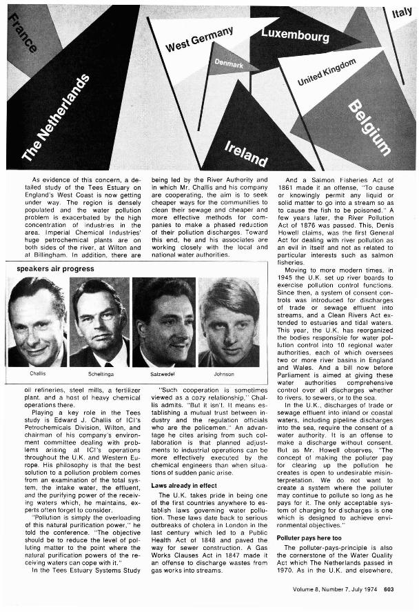
speakers air progress
As evidence of this concern, a detailed study of the Tees Estuary onEngland's West Coast is now gettingunder way. The region is denselypopulated and the water pollutionproblem is exacerbated by the highconcentration of industries in thearea. Imperial Chemical Industries'huge petrochemical plants are onboth sides of the river, at Wilton andat Billingham. In addition, there are
oil refineries, steel mills, a fertilizerplant, and a host of heavy chemicaloperations there.
Playing a key role in the Teesstudy is Edward J. Challis of ICl'sPetrochemicals Division, Wilton, andchairman of his company's environment committee dealing with problems arising at ICl's operationsthroughout the U.K. and Western Europe. His philosophy is that the bestsolution to a pollution problem comesfrom an examination of the total system, the intake water, the effluent,and the purifying power of the receiving waters which, he maintains, experts often forget to consider.
"Pollution is simply the overloadingof this natural purification power," hetold the conference, "The objectiveshould be to reduce the level of polluting matter to the point where thenatural purification powers of the receiving waters can cope with it."
In the Tees Estuary Systems Study
And a Salmon Fisheries Act of1861 made it an offense, "To causeor knowingly permit any liquid orsolid matter to go into a stream so asto cause the fish to be poisoned," Afew years later, the River PollutionAct of 1876 was passed, This, DenisHowell claims, was the first GeneralAct for dealing with river pollution asan evil in itself and not as related toparticular interests such as salmonfisheries.
Moving to more modern times, in1945 the U. K, set up river boards toexercise pollution control functions,Since then, a system of consent controls was introduced for dischargesof trade or sewage effluent intostreams, and a Clean Rivers Act extended to estuaries and tidal waters,This year, the U,K, has reorganizedthe bodies responsible for water pollution control into 10 regional waterauthorities, each of which overseestwo or more river basins in Englandand Wales, And a bill now beforeParliament is aimed at giving thesewater authorities comprehensivecontrol over all discharges whetherto rivers, to sewers, or to the sea,
In the U,K" discharges of trade orsewage effluent into inland or coastalwaters, including pipeline dischargesinto the sea, require the consent of awater authority, It is an offense tomake a discharge without consent.But as Mr, Howell observes, "Theconcept of making the polluter payfor clearing up the pollution hecreates is open to undesirable misinterpretation, We do not want tocreate a system where the pollutermay continue to pollute so long as hepays for it. The only acceptable system of charging for discharges is onewhich is designed to achieve environmental objectives,"
Polluter pays here too
The polluter-pays-principle is alsothe cornerstone of the Water QualityAct which The Netherlands passed in1970, As in the U,K, and elsewhere,
Johnson
"Such cooperation is sometimesviewed as a cozy relationship," Challis admits, "But it isn't. It means establishing a mutual trust between industry and the regulation officialswho are the policemen." An advantage he cites arising from such collaboration is that planned adjustments to industrial operations can bemore effectively executed by thechemical engineers than when situations of sudden panic arise,
being led by the River Authority andin which Mr. Challis and his companyare cooperating, the aim is to seekcheaper ways for the communities toclean their sewage and cheaper andmore effective methods for companies to make a phased reductionof their pollution discharges. Towardthis end, he and his associates areworking closely with the local andnational water authoril,ies.
Laws already in effect
The U, K, takes pride in being oneof the first countries anywhere to establish laws governing water pollution, These laws date back to seriousoutbreaks of cholera in London in thelast century which led to a PublicHealth Act of 1848 and paved theway for sewer construction, A GasWorks Clauses Act in 1847 made itan offense to discharge wastes fromgas works into streams,
SalzwedelScheltingaChallis
Volume 8, Number 7, July 1974 603

discharges of pollutants or harmfulsubstances into surface waters isprohibited without government consent. Quality control of Holland'slarge rivers, estuaries, and territorialwaters comes under the jurisdictionof the central government; that of thesmaller rivers and watercourses isthe responsibility of local county government.
The Act, notes Dr. H. M. J. Scheltinga who, in addition to being publichealth inspector at Holland's Ministryof Health and Environmental Hygienein Arnhem, is a member of the U.S.Water Pollution Control Federation,"provides the tools to tackle andcomplete the cleanup of water pollution in the country. It seems likelythat the official national aim, 'Controlover water pollution by 1985,' will bereached, at least in respect to oxygen balance."
The basis of charging for bothcommunity and industrial dischargesis the population equivalent (p.e.)oxygen demand. Th is is a measure ofthe average daily discharge of oxygen-demand substances per head ofpopulation. One p.e. unit represents180 grams of oxygen demand perliter of water, calculated by a combined COD and NOD analysis.
The tax or charge per p.e. of pollution discharge varies according to
Second Seriesby Norman MetzgerIntroductionby Isaac Asimov
menancJmoleculel
the area of the country, the total loadburden of the receiving water, andwhether the discharge enters largerivers or smaller local ones. In general, the charge varies from a low ofabout $2.00 per p.e. to about $7.00.Next year, the government intends tobroaden the scheme and introducetaxation of toxic wastes as well asoxygen-demand matter.
Dr. Scheltinga scotches the ideathat a company might elect to pay adischarge tax instead of investing insystems for cleaning up their wastesor otherwise avoiding the pollution."The authorities always have the option of refusing or withdrawing a discharge consent, even when a company is willing to pay, in cases wherethe water quality is very poor," henotes.
Water quality is a particularly critical one for Holland being, as Dr.Scheltinga puts it, "The basement ofEurope." The three major rivers flowing through the country-The Rhine,The Meuse, and The Schelde-areinternational waterways. Moreover,Holland has one of the highest population densities anywhere. Averaging1000 people per sq mi. In the heavilyindustrialized western part of thecountry, the figure is nearer to 5000per sq. mi. Too, Holland has undergone a very rapid industrial growth
A significant and absorbing new book aboutthe latest chemical achievements of theseventies based on interviews with NobelPrize-winning scientists. first aired on theradio series "Men & Molecules" sponsored bythe American Chemical Society.
This fascinating volume tells about some of theextraordinary breakthroughs taking place 'inlaboratories around the world today that willhave far-reaching effects on our future lives.
Read more about the exciting implications ofcurrent research into:
the riddle of agingthe quest for molecules which may be theorigin of stars and the "soup" in which lifebeganRussian waterthe creation of superheavy elementsthe search for neutrinos which may revealhow the sun burnsthe race to synthesize ribonucleasegenetics. nitrogen fixation. insect chemistry.and polluted oceans
Besides presenting recent discoveries. this compelling book offers valuable insight into thenature of scientific research with its constantlychanging "truth." Written in easy-to-follow,non-technical language. it will interest thegeneral reader. scientist, and student who canrelate class work to modern-day experiments.
246 pages with index & bibliography. ClothIT 9 72) $5.95. A Crown Publishers book. Postpaid In u.s. and Canada, plus 400 elsewhere.
Order from: Special Issues SalesAmerican Chemical Society1155 Sixteenth St.. N.W.Washington, D.C. 20036
since World War II. Two of theworld's largest oil refineries are located at Rotterdam which is alsoamong the world's busiest ports.
Laws in other countries
Speakers at Amsterdam also reviewed the water pollution measuresbeing taken in France and West Germany. In France, the administrationof the quality of inland waterways isshared by six regional basin authorities. Each oversees the behavior ofwater users both from the point ofview of water abstraction and effluents discharged. They also subsidize the cost of building water treatment facilities. For industries, grantsof up to 50% of the total costs aremade. But infringement of dischargeregulations can carry fines of up to$20,000 and possible jail sentencesof six months.
In West Germany, the FederalWater Act of 1960 is a frameworklaw within which each of the coun·try's 11 states have their own individual water acts. A new federal lawnow being debated might follow theFrench system of subsidizing thebuilding of water purification plantsfrom taxes levied on polluters, although Prof. J. Salzwedel of the Institute for Studies on Water Resources Law at the University ofBonn, holds that "This regulation is aviolation of the principle that the producer of the waste water has to pay.In the Federal Republic of Germany,there is more to be done regardinglegislation if water pollution is to bereduced."
Right now, the greatest hope forcoordinating the water quality plansfor most of Western Europe restswith the Commission of the EuropeanCommunities in Brussels which hasdrawn up an environment action planfor the nine member countries. Thereare numerous aims to the plan ranging from "preventing, reducing, and,as far as possible, doing away withthe harmful effects of pollution andnuisances in the environment" to"seeking common solutions to environmental problems with states outside the community."
At the community level there is adrive toward standardization of sampling and measuring methods, harmonizing pollutant specifications,and preparing lists of quality objectives. However, Stanley P. Johnsonof the Environment and ProtectionService of the Commission believesthat there tends to be too muchstress on the adverse health aspectsof pollution problems and not enoughon the esthetics of the environmentas a whole. "There may be other parameters that are more objectionalthan just the E. coli content of thewater," he remarks.
604 Environmental Science &Technology

10 Total Nitrogen and10 Total Phosphorus determinations
can be performed simultaneouslyin one hour on the AutoAnalyzer@II
with greater precision, accuracyand economy
than when performed manuall~
...and that's only the beginning!All of the nutrients in water can be measured with the Technicon® AutoAnalyzer IIsystem. As a matter of fact, the AutoAnalyzer II is capable of analyzing over 30 waterquality parameters with a speed, accuracy and economy that is incomparable. Manyanalyses can be run at rates of 60 samples per hour, and changeover of one test parameter to another may be accomplished rapidly.
This total versatility can completely justify the need for automated analysis inthe laboratory-any laboratory, regardless of size or daily test requirements. Minimaldaily test requirements can be handled with ease and as the workload increases, theAutoAnalyzer II can handle the additional test requirements without additional personnel. One system handles the water quality workload.
The Environmental Protection Agency has recommended many AutoAnalyzer IImethods for water quality analysis. If your laboratory is involved in measuring a varietyof water parameters, don't you owe it to yourself to find out all the facts?
'" "";''li ~~I I, . III I
.... I
I
For more informationwrite Department 180,
CJechnicoqIqdustrial SysteI1/.S
Tarrytown, New York 10591.CIRCLE 8
1IIIII1®

Faced with massive increases incoastal zone development-both onshore and- offshore-the U.S. is in aposition to lose as much as it couldgain, according to opinion voiced atthe National Oceanic and Atmospheric Administration-sponsored
.Conference on Coastal Zone Management held recently in Charleston,S.C.
Speakers held that money may begood, but so are some of the lesstangible qualities of coastal areas.And in order to assure a balance between the two a national coastalzone management program is needed, those attending the conferencewere told.
In keynoting the meeting, Sen. Ernest F. Hollings (D-S.C.), who longhas fought for federal coastal zonelegislation, pointed out that landfillsduring a 200-year period helped tocreate much of the port city ofCharleston, but that this developmentalso introduced some attendant uglyproblems. For example, the AshleyRiver at Charleston has become polluted. The Cooper River there hasbecome silted because of a hydroelectric project upstream, andocean-going vessels have difficultydocking. Urban sprawl has "marooned" the older section of Charleston, and now there is no room for acauseway, except through a marsh,to free the flow of traffic. The paradox is that more development isneeded to correct problems broughton by earlier development.
606 Environmental Science &Technology
Conference hears need for
balancing development
and environmental
considerations
Sen. Hollings, however, says theproblems are not insurmountable.Environmentally unique areas existboth in terms of natural beauty andwildlife preservation-where development should not take place. But inareas where development has ·takenplace, much can be done to reclaimwhat once was lost. He points outthat the city of Charleston has builtan excellent sewage treatment plant,and that oyster beds that wereclosed 47 years ago because of pollution were reopened last year. Thevalue of the beds is estimated at $60million, the Senator said.
Department of Commerce Secretary Frederick B. Dent took the occasion to announce the first-evergrants to help states set up coastalzone programs. The funds, which totaled almost $635,000 were awardedto Maine, Oregon, and Rhode Islandby NOAA under the Coastal ZoneManagement Act of 1972. Themoney is "to encourage effectivemanagement, beneficial use, protection, and development along the nation's sea coast and Great Lakesshores." It is a matching-fund program whereby the states put up onethird of the money.
Dent says the administration nowis committed to the program despitethe fact the federal office of Management and BUdget (OMB) refused tofund it for its first year of existence.Dent pointed out an appropriation of$12 million is available this fiscalyear (FY 1975) for the grants program, and that an additional $12 million for the program is being soughtby the President as part of his present bUdget requests.
Development to increase
The Commerce Secretary alsoconsidered the problem of energydevelopment, brought on by the recent crisis, the question of deepwater ports, and the problems of extracting minerals from submergedoffshore lands. What emerged wasthe administration's intent to go fullspeed ahead in all three areas. Dent,however, says the environment, too,must be considered. As he put it,"Only through effective managementof these valuable resources and theenvironment that supports them, canwe hope to realize their full potentialboth as a provider of food as well asjobs."
Although many feel more authorityis needed at the federal level if theproblems of the nation's coastalzones are to be adequately handled,the thrust of the 1972 Act is towardsetting up programs in each of theindividual states. A paper preparedfor the conference by Washington,D.C., consultant Harold F. Wise et

aI., stressed that the Coastal ZoneManagement Program "is primarily astate program." The paper pointedout that funds are provided to coastalstates so they can identify their owninterests and develop their own management mechanisms to protectthose interests at the same time.
But the state must meld together avariety of private and public interests, which include the interest of.the Federal Government. Thus, federal input in coastal zone programsis an assured thing. This input couldcome from such sources as the federal Energy Office; the Departmentof Defense, because of military establishments in coastal areas; theEnvironmental Protection Agency,which is responsible for air and waterquality standards enforcement; theCorps of Engineers, responsible forpermits for solid waste disposal incoastal waters and rivers; the Department of Commerce and its Officeof Coastal Environment; and others.Generally, most states wanted astrong hand in meeting their coastalzone problems.
Sen. Ted Stevens (R-Alaska) isadamant in his desire for strong statesupport. He said, "We are tryingthrough our state officials to identifyAlaska's problems and to convinceour federal agencies that, havingidentified these problems, we knowbest how to solve them." He notedparticularly that rules and regulationsthat apply to the other 49 states arenot relevant to nontemperate zones.
Sen. Stevens pointed to the necessity to consider Alaska as a uniquesituation rather than as part of a general U.S. program. In Alaska's coastal zone, there is every type of resource available anywhere in theother 49 states, and in greater abundance, he said. "Whether you arediscussing timber or watershed management, oil and gas development,fisheries protection and management, mineral exploration or extraction, tourism, the recreational potential, agricultural or industrial development, or the needs and desires of asprawling urban community, youcannot address problems of coastalzone management without involvingAlaska's unique situation."
The local view
The local view of the national interest in coastal zone planning andmanagement was discussed by LeeKoppleman, executive director of theNassau-Suffolk (New York) RegionalPlanning Board. He outlined theareas in which the various levels ofgovernment could best contribute.
Koppleman said the identificationof the most important coastal zoneproblems is well within local capability at the county, or even lower, level.
However, he said, "Identification, assembly, and interpretation of naturalscience are clearly beyond local capability and probably beyond statecapability, and should be a federalresponsibility. "
Application of local economic, social, and political realities, he said,requires local handling. But state andfederal overview is required in the interest of uniformity. "The translationof optimum environmental action requires local handling at county orlower level," he said. "However, federal and state overview may be required to assist in achieving minimum acceptable action that is beyond local resources and in the interest of uniformity."
Talks, Sen. Hollings and Commerce Secretary Dent were highlights of the meeting
Taking the point of view of the petroleum industry, Wayne Gibbens,president of Mid-Continent Oil andGas Association, said that the na-'tional interest referred to in the 1972Act is really the balance of many interests, including that of the petroleum industry. He said it was in thebest interest of the nation to goahead with offshore production of oiland gas, with increasing refinery capacity in coastal areas, and the development of deep water petroleumterminals.
Gibbens said that since oil production from land areas in the U.S. is "ina declining trend," and its future potential for further discovery is limited,"The frontier of American sufficiencylies immediately seaward of thecoastal zone." A first goal should beto stabilize public policy with regardto the siting of petroleum refineries.These refineries should be built on theAtlantic coast near the high-consumption markets of the seaboard'smetropolitan areas, he said.
Gibbens added that the U.S. willhave to continue importing vastquantities of crude oil despite effortsto become self-sufficient. This activity necessitates the construction ofdeepwater ports. He presented figures that estimated imports on theGulf Coast will have to increase to
about 3 million barrels per day (bpd)by 1978, and on the East Coast toabout 2 million bpd if future needsare to be met.
Environmentalists' viewpoint
On the environmentalists' side,Elvis Stahr, president of the NationalAudubon Society, said the real national interest demanded that illplanned development along coastalareas be controlled. He said eachstate should be required to put intoits coastal zone laws requirementsfor environmental impact statements,and that these statements shouldcontain an examination of alternatives as well as the effect of new development upon the environment. Headded that the financial positions oflocal planning officials involved - indecision making should be revealed.
In the long run, the recent Councilon Environmental Quality's report"The Effects of Oil and Gas Drillingon the Outer Continental Shelf"(OCS)-should partially buffer the efforts of those who advocate an allout development of these resources.The report concludes that leasingand development undertaken in theAtlantic OCS or in the Gulf of Alaskashould be guided by a set of essential principles, which are stipulated inthe report. The council claims thatenvironmental risks can be minimized if such guidelines are followed.
The CEQ study points out that therisk of environmental damage variesfrom area to area. For example, development of the Georges Bank (offMassachusetts and Rhode Island)and the Southern and Central Baltimore Canyon (off Southern New Jersey and Delaware) would involve relatively lower environmental risksthan development in the SoutheastGeorgia Embayment (off the Carolinas and Florida) and the Gulf of Alaska. The council' concluded thatwhen the environmental balance is unfavorable, development should notmove ahead. Members questionedwhether some areas should be developed at all.
Barbara Heller, from the Environmental Policy Center (Washington,D.C.), concluded her talk by callingattention to other development proposals for the coastal zones as wellas offshore drilling. She said offshore nuclear plants, refineries, superports, platform fabrication facilities, and nonenergy-related activitiessuch as sand and gravel dredgingoperations and hard mineral mining,all must be considered. The decisions for development should be jointones, she said, the decisions to useup our natural resources should bemade with care, wisdom, and concern for future generations. WSF
Volume 8, Number 7, July 1974 607

Environment and economic growthThe Committee for Economic Development believes thatenvironmental improvement and economic growth can go
hand in hand with proper cost/benefit planning
How can programs for a clean environment be made more effective?This question has caused much soulsearching in many quarters of industry, government, and academe. It isthe subject of intensive study on thepart of the Committee for EconomicDevelopment (CEO, New York City),a business-academic organization ofvery high prestige, composed ofleading, distinguished representativesof the industrial, economic, and university sectors.
CEO's study, conducted by theSubcommittee on Improving theOuality of the Environment (SlOE),chaired by Robert Semple, chairmanof the board of BASF WyandotteCorp. (Wyandotte. Mich.), stressedthat:
• There will be a steady increasein the economical recovery of solidwaste for fuels and materials, even ifthe energy shortage lessens.
• Despite uncertainties arisingfrom fuel shortages, the U.S. can afford and achieve a high-quality environment if it adopts programs thatweigh costs against benefits to produce maximum effectiveness.
• Although an economy that doesnot affect the environment is impossible, environmental progress will require more-not less-economicgrowth to carry the cost of pollutioncontrol (PC) programs.
Published this April, their study,"More Effective Programs for aCleaner Environment," is billed as AStatement on Nationai Policy by theResearch and Policy Committee ofthe Committee for Economic Development. It cautioned, however,against "crash abatement programs."
Clean water questions
The 1972 clean water law amendments introduced great uncertaintyinto most major business investmentdecisions. Business cannot predicthow the 1977 and 1983 guidelinesand the stated zero discharge (ZD)goal of 1985 will be interpreted, orwhether new or expanded plants will
608 Environmental Science & Technology
CEO's Semple"ZD achievable if industry stops"
meet legal requirements. Protractednegotiations with officials and appeals to courts could come about.
The subcommittee points out thatthe 1972 law requires uniform percentages of discharge abatement,which is very costly. Enforcement,with at least 50,000 permits needed,places a massive job of central planning in government hands and requires a large bureaucracy. This bureaucracy would be ineffective forlack of detailed price, market, andtechnology information available onlyto cognizant operating management.Thus the CEO/SlOE foresees eitherlack of vigorous enforcement orwidespread government regulation ofbusiness decisions.
The subcommittee therefore recommends a regional agency for eachriver basin or shoreline stretch toplan, execute. and control ali publicwater-quality programs. This agencywould enforce reguiations, supervisefederal grants, and conduct research. Each regional agency woulddiffer in terms of responsibility andorganization, depending on the region's needs. According to the CEO /SlOE, the Delaware River BasinCommission comes closest to beingsuch an organization.
As an alternative to regulation, thesubcommittee calls for the use of effluent fees in the form of a monetarycharge per unit of waste discharged.Careful regulation of toxic dischargeswould be retained. This system isused rather widely in Europe, especially in Germany's Ruhr Valleywhere it has been in force for decades. The effluent fee system wouldput PC decisions in private hands,with incentives to seek economic PCmethods, and make water quality improvement cheaper than would asystem for direct regulation. Moreover, it would reduce the likelihoodof discriminatory actions on the partof public officials, and remove muchdecision-making uncertainty.
The effluent fee concept, however.is not unopen to question. Du Pontpresident Edward Kane warns thatthe effluent fee is really a regulationunder another name, and that payment of the fee would be consideredby many as a license to pollute. Thispollution might occur if fee paymentis more economical than are controls. Charles Bowen, Jr., chairmanof Booz, Allen & Hamilton, Inc., andElvis Stahr, president of the NationalAudubon Society, emphasize that effluent fees must not be used (or misused) as a revenue source. Rather.reduction in fee proceeds should beviewed as a measure of PC success.
Into the air
To help allay uncertainties arisingfrom the 1970 Clean Air Act amendments, Semple's CEO/SlOE recommends air quality regions and regional agencies similar to those for waterquality, with sufficient geographicflexibility to match PC with needs.The subcommittee also says thatwhile an air emission fee systemmay be difficult to establish at present, ways should be sought to testthe feasibility of economic incentives, similar to effluent fees, for regulating air quality programs.
With respect to air standards, theCEO/SlOE strongly urges that envi-

~ Interagency committees
o River-basin commissions
• Federal-state compact commissions
Missouri Basin Upper Miss.
New England
Source: U.S. Water Resources Council (Washington, D.C. 1972)
ronmental agencies carefully consider whether extremely stringent em ission standards under very tight timeframes, including those for motor vehicles, can be justified on the basisof cost-benefit comparisons. In viewof the energy crunch, the Congressmay be having the same thoughts.The Senate approved a delay from1975 to 1977 for autos to conform toprescribed standards. Use of coal,where other types of fuel are notavailable, would be approved provided air quality standards are not beingviolated, or would be violated by conversion to coal. As this goes topress, differences between the Senate version, and a much more farreaching House-passed measure,must be resolved at conference.
Solid wastes
The subcommittee recommendsthat the states should establish regional agencies to collect and dispose of solid wastes, since this effort is basically a problem of organization, rather than cost or technology. These regional agencies may beable to handle solid wastes at lowercost, with better enforcement of d isposal, health hazard, and air andwater PC requirements. Lower costand improved services would be accentuated through increased relianceon private enterprise and its businesscompetition.
The open dump, at which 75% ofall municipal solid waste is deposited, must disappear, especially inlarge urban areas. The CEO/SlOEcalls for state and local governmentsto "take immediate steps" to substitute sanitary landfills and other disposal methods. In this regard, theState of Connecticut has a modelsystem planned (£5& T, Sept., 1973p. 802). If the cost is not justified,
well-operated public dumps shouldbe provided.
As things stand at present, however, enforcement of solid waste regulations is generally lax. In somestates and communities, enforcement of laws already "on the books"is needed. In others, existing lawsmay need to be tightened. The subcommittee feels that if a locality ishard pressed financially, perhaps thestate should share the cost of environmental upgrading required ofthese localities.
Frazar Wilde, chairman emeritusof Connecticut General Life Insurance Co., feels that the way thingsstand, the CEO/SlOE proposals onsolid waste will not be implemented,even in 25 years, if ever. He believesthat states must be directly involvedin the direction and financing of asolid waste program, mandated bystate legislation, and set up on a regional basis. If enforcement consistsof mere exhortation, many towns willpostpone, procrastinate, or fail toparticipate in such programs. Federalgrants should be made, Wilde believes, not only to develop and improve technology, but to help reducecosts through salvage coming fromrecycling.
Zero discharge
Zero discharge can be achievedalmost overnight. Semple said thatZO could be attained if his company,BASF Wyandotte Corp., ceased alloperations, and all other industrialmunicipal, governmental, and general human activity followed suit. Theultimate in ZO could be reachedthrough cessation of breathing, andall other human, animal, and plantfunctions. Effects on the U.S. andworld economy would probably notbe altogether beneficial.
ZO is really grist for newspapercopy, and for certain politicians gathering votes. As Semple puts it bluntly, ZO is probably impossible to attain with present and anticipatedtechnology and economics. Requirements for ZO stemmed more fromemqtionalism than from economicand technical good sense. One extreme example given by ClintonAllen, president of Wyandotte Terminal Railroad Co., and a very closeassociate of Semple's, is a requirement in some parts of Louisiana thatan. industrial plant return MississippiRiver water "cleaner" than it waswhen it entered the plant.
Indeed, much discharge does littleor no damage, as Semple points out,and the environment has a tremendous capacity to absorb dischargesand dilute them to the vanishingpoint. To be sure, a factory couldpollute a trout stream woefully, butthe same factory's properly controlled discharges might be virtuallyunnoticeable in the Mississippi River.In the air, for example, a small, controlled amount of S02 .(about twothirds of which is actually contributedby nature) is not dangerous. Indeed,to a certain extent, forests and grainsneed it for their normal growth.
Thus, the CEO/SlOE cautionsagainst tying environmental improvement into a reversal of economicprogress. On the contrary, environmental improvement and economicgrowth could go hand in hand. Indeed, they must, for economic stasisor regression could have highly adverse social effects. Semple pointsout, however, that the environment isa resource whose use, like the useof all other resources, must be paidfor, 'and it will be the consumer whoultimately pays the cost. JJ
Volume 8, Number 7, July 1974 609
l'\~,'2'l1Ifl fl~"~V\I,"""~"M!'-'

The old town dump is obsolescentPeople react negatively to trash and garbage. However,the value of recovered resources will help to alleviate
a good part of the momentary olfactory irritation
Typical steel scrap(% impurities)
Alu: Chro- Molyb-minum mlum Copper denum Nickel Tin
Auto 0.03 0.13 0.21 0.015 0.11 0.02Raw refuse 1.8 0.08 0.10 0.04 0.43Incinerated refuse 0.5 0.10 0.41 0.09 0.15Reject can mix 3.3 0.05 0.06 0.03 0.49Maximum desired 0.03 0.06 0.01 0.03 0.01
Source: Paper by C. Daellenbach. 4th MWUS (BuMines/Salt Lake City. Utah).
The town dump qUietly festering ona hot summer day-the city incinerator belching forth its rich. aromaticsmoke as potentially valuable resources are uselessly wafted into theair-these landmarks may soon beconsigned to the nostalgia file. To besure. recycling and reuse of certainmaterials. particularly metals. is notnew. Nevertheless. until recently.this type of resource recovery stayedlargely in the category of "things thatought to be done." For the most part.it was simply less economical to useand reuse than to use and lightly tossaway to the tune of 360 million tons/year.
The "three E·s"-environment. energy. and economics-are rapidlychanging this picture. Environmentalcleanup necessities. together with increasing scarcities and skyrocketingprices of many prime materials. andimproved techniques for solid wasteprocessing. are bringing home therealization that "There's gold in thatthar trash" (sometimes literally!).Recovering that "gold"-steel. aluminum, gas. oil and other values-wasthe topic of concern at the NationalMaterials Conservation Symposium(NMCS, Gaithersburg. Md., April)and the Fourth Mineral Waste Utilization Symposium (4th MWUS, Chicago, May).
The NMCS was sponsored by theNational Bureau of Standards (NBS).U.S. Bureau of Mines (BuMines).EPA, National Center for ResourceRecovery (NCRR). and American Society for Testing and Materials(ASTM). The 4th MWUS was sponsored by the Illinois Institute of Technology Research Institute (IITR I) andBuMines.
Garbage power
At the 4th MWUS, Fred Stellgen ofthe BuMines Pittsburgh (Pa.) EnergyResearch Center, described somemeans by which organic refuse mightbe converted to fuel oil or gas. Onesuch means is the BuMines COsteam process in which organicwaste slurry. together with recycleoil, is reacted with carbon monoxide
610 Environmental Science & Technology
(CO) and steam, with catalysts.under high temperature and pressure. A 3000-tpd plant could make632.8 tpd of oil (14,400 Btu/lb heating valve) and 75.8 tpd of ash whichcan be burned for heat. as can excess synthetic gas and oil-gas.which are also produced. Oil potential is estimated at 40-41 % by weightof moisture- and ash-free (maf)waste.
The BuMines Hydrane process.and the Institute of Gas Technology(IGT. Chicago) Biogas process areaimed at producing pipeline-qualitysubstitute natural gas (SNG). In theHydrane process. organic waste istreated at 1000 psi pressure, 550700° C. and gasified. Oxygasificationand steam treatment of char providethe hydrogen for the methanationstep. Gas yield could be 53-63% byweight. based on organic carbon. orover 19 million ft3 of gas per ton ofwaste. Pyrolysis at 900°C, by comparison. might give over 15 million ft3of 550 Btu/ft3gas per ton of waste.
IGT's Donald Klass estimated that204 million tons/year of municipalrefuse are currently produced in theU.S. This refuse could provide about1 trillion ft3/ yr of SNG which can beeconomically evolved through theBiogas process which uses anaerobic digestion of a refuse-sludge feed.and is being tried with Indianapolisrefuse. Organic residue can be disposed of without undue ecologicalabuse. Similar processes are beingtried in Israel and other locations(ES&T. February 1974, p 105). How-
ever, heavy metals and grit should beseparated. preferably before digestion.
Direct burning of organic garbageis another approach to energy recovery. Union Electric Co. (UEC. SI.Louis. Mo.) is replacing 10% or moreof the pulverized coal used in someboilers at UEC's Meramec plant withburnable garbage. Solid waste andash analysis. emission and corrosion
testing. and boiler performance observations are not as yet complete.but results to date appear very encouraging. A similar approach isbeing tried in Spain.
Playing it cool
The billions of waste rubber tiresare augmented annually in the U.S.by about 234 million additionaljunked tires. "Piled one on top of theother, these waste tires would reachthe moon." Norman Braton of theUniversity of Wisconsin/Madison.said. Moreover. these tires cannot beburned. buried, or biodegraded.
Braton's approach is to spraythese tires with liquid nitrogen afterthey are cut up. The rubber becomesvery brittle. and is pulverized; cleanfabric or metal values from the tireare then easily recovered. Tire volume is reduced by 80%, which issignificant. since tire shipping costsare about $15/ton. One ton of tirerubber can be retorted to give 1500ft3 of gas and 150 gal of oil; the remaining residue makes a good filter,asphalt mix. or soil conditioner, andhas even been found to filter mercury

Estimated "garbage power" costsAmount,per ton of Capital Operating costs,
Product waste costs dollars
CO-steam Oil, 14,400 4221b $51.2Btu/lb
Hydrane Gas, 1,000 19.6 million ft' 16,9Btu/ft'
Pyrolysis Gas, 550 15.7 million ft' 9.7Btu/ft'
Source: Paper by F. Steffgen, BuMines/Pittsburgh. Pa.
from stream water. Cost of cryoprocessing of tires is estimated at 1020¢/tire, as opposed to $1.00/tire by"conventional" means; moreover,marketable products are obtainable.
Old wires, aluminum and steel cables, plastic extrusions, scrap telephones, similar wastes can be cryoprocessed. Paint, insulation, plastic,and similar materials 'are easily removed, and clean metal is ready forthe recycled materials processor.Cryoprocessing costs are determinedby the temperature of the materialbefore liquid nitrogen treatment, andby the manner of conveyance of thematerial through the treatment system.
J. Bilbrey, of BuMines/Salt LakeCity, estimated that 600 Ib of liquidnitrogen will handle one ton of scrapmetal; with more efficiency, liquid nitrogen requirements could be lowered to 300 lb. For certain nonferrousrecovery applications, such as copper-zinc scrap, zinc recovery hasbeen found to be almost quantitative,since zinc shatters when very cold,but copper does not.
Process
Mine and mill wasteII the chemical composition is
right, certain furnace clags and mineor mill tailings may have good valuein a number of markets, particularlyas construction materials. By "right"chemical composition, it is meantthat lime may not exceed silicate bymore than 10%, or the material couldeasily break down. Steel slag is oftenrecycled back to a steel plant; however, blast furnace slag could have avariety of structural uses. Certainmine and mill tailings may also proveuseful as building materials, butsometimes slight radioactivity maymar the tailings' utility, as in the caseof uranium tailings, or some dewatered phosphate slimes.
In the Soviet Union, a building material called "temoseryy shlakositall"was developed from metallurgicalslag. This "shlakositall" has a !;lending strength of 1200 kg, and a 'compression strength of 7000 kg, and itcan withstand an impact of 7 kgcm/cm 2 . The Russians hope to market this material worldwide throughtheir patent licensing agency, "Licensintorg. "
One of the prime reasons for usingslag, tailings, or fly ash is to try tosubstitute for or replace portland cement. Some of these materials mayalso be good for paving as well asbuilding, and have acceptable wearing, antiskid, and antistripping properties. If these slags or tailings havesufficient fines and amorphous material, as well as a minimum of lime oralkali, they could become a constituent of bUilding materials, such aspelletized slag bricks, meeting ASTMspecifications, and sometimes beingequivalent to 25,000 psi concrete.
Recycling metals
Ferrous and nonferrous scrap isderived from numerous sources. Insome cases, the scrap is fairly pure,as in the case of aluminum cans orbattery lead. Aluminum cans, for example, need only be cleaned, melteddown, and reformed into acceptableingot with 5% of the energy expenditure needed to obtain primary aluminum.
When ferrous or nonferrous metalsare mixed or alloyed, however, metal
$9.48/ton waste7.86/bbl oil2.13/ton waste0.45/100 ft' gas3. 13/ton waste0.50/1000 ft' gas
separation will present varying degrees of difficulty. For instance, inthe previously mentioned cryoprocessing, zinc, a scarce resource,can often be quantitatively separated. In the case of metal from theubiquitous junked electrical appliance, tin can, or car, a far moredifficult situation is encountered.
The car, particularly, presentssome tough problems. Elliott Estes,executive vice-president of GeneralMotors Corp., told the NMCS that80-85% of all retired vehicles do getinto the scrap recovery network withno problem. However, there are 15million auto hulks rusting outside thisnetwork, and 400,000 more beingsimply abandoned each year. Tomake things worse, Estes says,many states make it legally cumbersome or impossible to "de-title" suchderelict autos; moreover, the presentrail freight rate structure discourageswider use of recycled or reclaimedmaterial.
Technical problems exist, too. C.Daellenbach of BuMines (TwinCities, Minn.) told the 4th MWUSthat typical auto scrap steel may
contain 0.03-0.11 % aluminum;0.13% chromium; 0.21 % copper;0.11 % nickel; and 0.02% tin. Moreover, there is 3.72% carbon, 1.94%silicon, and 0.077% sullur. Varyingamounts of these materials, somedeleterious to steel strength, will alsobe found in metal from raw refuse,incinerator residue, and reject cans.
One approach to separating objectionable metals, by vacuum meltingin an induction or electron beam furnace, was announced by the AtomicEnergy Commission (E5& T, January1974, p 11). Then, upon addition ofcorrect amounts of nickel and chromium, a No. 304 stainless steel results. Another approach, used byBuMines/Twin Cities, was to meltthe scrap at 2530°F with a scrapcoke ratio of 5.5:1.
Gerald Grott, president of WesternAmerica Ore Co. (WMOC, Coolidge,Ariz.) proposed a single-step melterfurnace to convert auto scrap to refined steel by using the furnace as asophisticated chemical reactor.Groll's idea, based on long experience, is to remove tin, and substitutecopper for a portion of the nickel inlow-alloy steels. The quality wouldnot be impaired. Nonferrous dust andfumes would be captured in a baghouse, refined, and marketed at aprofit at present prices. Enoughwaste heat would be generated tocontribute substantially to all electricpower needed for the process, Grottsaid.
For an operator able to handle150,000-300,000 auto bodies/year,Grott estimated that a furnace, preheater, baghouse, and laboratory/data center would cost $2.44 million.Operating costs (200,000 cars/year)would be about $15.30/ton, and annual personnel costs $1.2 million.These costs would be far less thanthose of "conventional" approaches,in which a 100-tpd shredding plantcosts over $2 million, conversioncosts vary widely around $10/ton,and electric melting costs run $2226/ton exclusive of metallics andcosts listed above.
Goodbye, town dump!
Demand for materials will continueto soar, environmental regulationswill become more stringent, and severe world competition for raw andprimary materials, with concomitantprice escalation, will result. Thus,recycling and reuse of materials willtake their proper place in the industrial economy. Part of the cost of thetechnology needed to achieve thisaim might be defrayed by the valueof hitherto unused research, whichWMOC's Groll told the 4th MWUS "isbigger than the national debt."
Goodbye, town dump! You will notbe missed. JJ
Volume 8, Number 7, July 1974 611

Conditions of the water utilities inthe U.S. are only good comparedwith underdeveloped countries, according to an EPA official at the 7thInternational Water Quality Symposium held last April in Washington,D.C. F. B. Taylor illustrated his pointwith the results of a 1969 study:
• 36% of the tap water sampledcontained too much bacteria
• 56% of the water systems haddeficient plants
• 77% of the water works operators were inadequately trained
• 79% of the utilities had gonethrough a year without a state orcounty inspection.
The director of the AmericanWater Works Association, E. F. Johnson, felt that public ignorance hadcontributed to the sloppiness on thepart of the utilities. He believed thatif the public knew how little it wouldcost for high quality water, and thusdemanded better water, the utilitieswould have to do more than just theminimum.
But in Europe, water conditions indensely populated and highly industrialized areas are even muchworse. Some 40 million people aredrinking water from the pollutedRhine River, according to one of Europe's leading water utility managers.It is hoped that the river will becleansed in the next 10-15 years.
U.S. use and supply
Water consumption has soared from40 billion gpd in 1900 to 390 billiongpd in 1968. By the year 2000, theprojected needs will be 1000 billiongpd, Home usage has been mainlyfor toilet flushing, bathing, and laundering, Elsewhere, water is used forheating, cooling, cleaning, and as asolvent.
Over 90% of our freshwater resources is underground. Yet only20% is extracted for our supply,pointed out Jay Lehr of the NationalWater Well Association. He felt thatgroundwater is a valuable sourcesufficient to last 7000 years or moreat the current depletion rate. Comparing costs-13¢ per 1000 gal forsurface water, 5¢ per 1000 gal forgroundwater, and 30e per 1000 galfor desalted water-he questionedthe preference for surface systems,such as lakes and dams.
The rebuttal came from D. W. Mil-
612 Environmental Science & Technology
Howpure is our
watersupply?
Some feel that waterpollution is not detrimentalto our health; others callfor money and technology
to better water quality
ler, a geologist, who said underground sources are being threatenedby contamination. He listed septictanks, land fills, fertilizers, pesticides, unlined industrial waste lagoons, and ruptured oil tanks as thepolluters.
Pollution
And yet water pollution, at presentlevels, has little direct effect on ourhealth, and "virtually none" on deathrates, asserted E. A. Lew, presidentof the Society of Actuaries.
In fact, trace elements, like chromium, are important in our nutrition.For example, the hexavalent state ofchromium occurring in water is muchbetter absorbed by the human organism than the trivalent form presentin foods, noted Walter Mertz, chair-
man of the Nutrition Institute of theU.S. Department of Agriculture.Some trace elements are also preventive against cardiovascular diseases, explained a specialist in theheart field.
On the other hand, water purification is still necessary for better quality, said K. E. Shull, an executive withthe Philadelphia Suburban Water Co.He did not think that chlorination, theonly treatment method used by abouthalf of the community suppliers ofwater, was effective in removing pesticides, herbicides, and other organicand inorganic chemicals. For bettertreatment, he thought that the publicshould pay hjgher rates.
Thinking along the same lines, Associate Justice W. O. Douglas of theU.S. Supreme Court calls money thekey to water purity, and a stimulantto better technology.
Closing the loop
To achieve the national goal ofzero discharge of pollutants to itsnavigable waters by 1985, as established by the P.L. 92-500, will requirethe recycling of industrial processwastewaters, said N. C. Kachman,manager of General Motors Corp.'sPlant & Engineering Group.
In closing the influent/effluentgap, there is the problem of dissolved solids removal on a "practicaland economical basis," he went onto say. At GM, three reverse osmosisconfigurations for dissolved solids removal are undergoing evaluation.
GM is also considering the aspectof the ultimate disposal of the dissolved solids, within the concentrated state. The assumption is madethat dissolved solids can be removedeffectively and economically from theeffluent stream to permit the reuse ofwater. In some cases, the concentrate may be satisfactory for use as aflushing medium for water closetsand urinals prior to discharge to thesanitary sewer. In other cases, suchas a concentrate containing highconcentration of metals, it may befeasible to evaporate the stream andrecover the metals.
An important consideration towater conservation efforts is that perhaps the resulting savings in energycosts cannot be offset by the higherenergy requirements imposed by thezero discharge goal. LCG

Thirty-one industries whose wastes are emptied intomunicipal systems, are now required to comply with ..
Pretreatment standards for dischargeDischarge of industrial wastewa
ters into combined municipal sewersystems has, in the past, been fairlyunregulated. Industries, often withneither the available space nor theaccessible waterways, have found itnecessary to use the publicly ownedwastewater treatment plants. Up tonow, the extent of their on-site treatment has only been affected by localordinances and user charges assessed by the municipals.
With the advent of tougher effluentstandard, urban areas have had tolimit the pollutants industries can introduce into their treatment systems.Thus industries will have to be morerigorous in pretreating their wastes tobe compatible with their respectivemunicipalities.
Earlier, pretreatment guidelines forpollutants entering waterways hadbeen developed by the federal government. Now, pretreatment standards are being promulgated for 31industries. This month is the cutoffdate for promulgation of all standardsfor these industries.
Pollutants
Allowable industrial wastes are bydefinition compatible pollutants, thatwhich will be removed by the particular treatment processes employed bythe particular municipality. Becausethey are removed, they will not harmor adversely affect the operation ofthe municipal treatment plant and itsability to meet effluent criteria.
Examples of compatible pollutantsinclude biochemical oxygen demand(BOD), suspended solids (55), pH,
and fecal coliform bacteria. Pretreatment of wastewaters containingthese and other compatible pollutants may sometimes be necessary,for example, in the form of spill protection or flow equalization.
On the other hand, specific prohibited wastes listed by the EPA encompass wastes which are inflammable,corrosive to the plant's structures,obstructive to the sewer's flow andhave excessive flow or dischargerate.
Pre- and joint treatment
The EPA requires that major con-.tributing industries pretreat their incompatible pollutants with the bestpracticable control technology. Bydefiniiion, a major contributing industry is one that has:
• a flow of 50,000 gpd• a flow greater than 5% of flow
carried by the municipal system receiving the wastes
• amounts of incompatible pollutants in violation of standards issuedunder Section 307 a of the P. L. 92500
• a significant impact, singly or incombination with other contributingindustries, on the public works.
Available pretreatment techniquesvary from biological to physicalchemical. The former covers the aerobic lagoon, roughing trickling filter,and anaerobic systems. The lalter includes such processes as screening(to remove coarse particles), sedimentation (to remove 55), equalization (to minimize fluctuations inwastewater characteristics), neutral-
ization, and dissolved and inducedair flotation (to clarify or thicken).
Joint treatment of industrial andmunicipal wastewaters is recommended by the EPA. A case in pointis the discharge of industrial wastescontaining organic material but devoid of nutrients required for biological treatment. If joint biological treatment is used, nutrients need not beadded since they are already presentin the municipal wastewaters.
Sampling
To be sure, sampling techniquesand equipment will differ with the individual requirement of a particularindustry. Nevertheless, grab samplesare generally recommended for analysis of dissolved gases, residualchlorine, temperature, pH, and soluble sulfides. Composite samples aretaken for monitoring flow variations,perturbations in waste constitutents,and the like.
Manual sampling is good for a preliminary survey of the conditions,whereas automatic sampling is moreconvenient in separate treatmentschemes for specific process wastewaters. The frequency of samplingshould be dependent on the flowrate, wastewater characteristics, andthe parameters to be monitored.
In any event, a comprehensivesampling program should save timeand facilitate industries whose dateof compliance is set at no later thanthree years from promulgation, andwho should begin building requiredpretreatment facilities within 18months from promulgation. LCG
Pretreatment requirements for discharge into municipal systems
lives >100 days. I Peak concentrations for 15 min or longerlimited to 5 times normal sewage BOD and SS concentrations.
Source: AWARE, Inc. (Nashville, Tenn.).
LIMITATIONSLIMITATIONS
Evans- Cin- Chat·
ConstituentsDallas, ville, cinnati, tanooga,
Tex. Ind. Ohio Tenn.
Temp, OF 150 150Oil and grease,'1 100 100' 10lJl>
mg/I.pH >5.5, >5.5, >5.5,
<10.5 <9.5 <9.5Chromium, mg/I. 3 5' 5c ,d 5"Copper, mg/1. 3 3" 3" 3"Zinc, mg/1. 3 2" 2" 2"Nickel, mg/1. 3Cadmiu!l1, mg/1. 3Iron, mg/I. 3 15" 15" 15"
" Free and emulsified substances. b Substances highly viscous32-150°F. c Hexavalent chromium only. d Concentration of totalwaste flow influent to treatment plant. e Substances with half-
Constituents
Lead, mg/I.Cyanide, mg/1.Radioactivity,
MC/1.Chlorine demand,
mg/1.BOD, mg/1.H,S, SO" N,O,
mg/1.Phenol, mg/1.
Dallas,Tex.
3100
Evans..ville,Ind.
2
30
Cincinnati,Ohio
2
30
10
0.5
Chattanooga,
Tenn.
2
10
0.5
Volume 8, Number 7, July 1974 613

FEATURE
Finding the rightpretreatment process-bythe continuous operationof a pilot plant beforefull-scale constructionprovides ...
Reverse osmosis treatment withLional B. Luttinger and Gabriel HocheThe Permutit Co., Paramus, N.J. 07652
The membrane process considered here is essentiallyreverse osmosis (RO). Other membrane processes, suchas ultrafiltration and the various types of electrodialysis,have been coming into commerical use. The latter processes share many of the same pretreatment problemswith RO, but may involve different pretreatment problemsarising from the electrochemical processes involved inelectrodialysis, for example.
Primarily, RO pretreatment problems arise from seawater and brackish water desalination ·as well as other typesof applications. With regard to pretreatment for RO systems, the type and extent of such pretreatment dependson a number of factors:
• the type of RO equipment used• the extent of conversion desired; for example, how
concentrated a reject stream is to be produced• the type of water treated• the desired quality of the end RO-treated water.
RO considerations
The major contemporary types of commercial ROequipment (tubular, spiral wound, and hollow fiber) eachhave individual idiosyncrasies with regard to the optimumpretreatment they require. For example, cellulose acetatemembranes are highly pH-sensitive and are best used inthe pH range 5-8. The polyamide membranes used in theDu Pont B-9 hollow fiber permeator are much less sensitive to pH, but more sensitive to certain other chemicaladditives such as chlorine.
In RO water treatment, the materials rejected by themembrane will concentrate in the reject stream. Since, inmany cases (CaS04, CaC03), an untreated RO influent isalready saturated or nearly saturated with respect to suchspecies, the inevitable further concentration in the ROmodule results in exceeding the solubility products ofsuch species, resulting in precipitation with the likelihoodof plugging or fouling the module. At relatively low extents of conversion (50%), the Langelier index, the kinetics of precipitation, or high linear throughput velocities inthe module may all tend to keep precipitation from occurring in the module. However, at higher conversionrates, say, 75%, when the dissolved solids in the reject
614 Environmental Science & Technology
stream are concentrated fourfold and other things remainunchanged, precipitation probably occurs in the module.
In many cases, such precipitation can be prevented byadjusting the pretreatment regiinen so that the Langelierindex of the reject stream will still be "safe" (zero orslightly negative). For the calcium salts consideredabove, softening, desulfating, pH adjustment, and addition of sequestrants are examples of pretreatment stepsthat will permit RO operations at higher conversions without the danger of precipitation/fouling in the module. Inthe case of lower extents of conversion, such pretreatment might not be necessary or might be required to asmaller degree. Similarly, fouling by other materials suchas colloids and organics constitute much more seriousproblems at high, and not low, extents of conversion.
Various types of water can be treated via RO and othermembrane processes. The particular water will, to a largeextent, determine the type of pretreatment desired. Atone end of the scale are certain well waters and somealready "refined" waters such as adequately treated municipal waters, which may require little or no further pretreatment. On the other end, some surface waters, evenafter clarification and other municipal treatment to reduce suspended solids to very low levels, have been notorious for the trouble they can cause when used directlyin RO without further pretreatment. Seawater, which ishigh in hardness, particulate and colloidal matter, corrosive chloride ion, and a wide variety of "trace" compounds, presents special pretreatment problems.
At the far end of the scale are those waters containinglarge quantities of solids or which require special sanitaryhandling. Such waters comprise certain chemical wastestreams, process chemical streams, foods, pharmaceuticals, and municipal sewage. They may require specialpretreatment regimens, as well as special modulegeometries and special flow velocities and/or turbulencepromoters, in order to prevent fouling, and may sometimes require the use of special materials of constructionas well. Surface or seawater may be made more suitablefor RO applications by means of a Ranney or radial watercollector system, consisting of a series of screened horizontal lateral porous pipes radiating from a central cais-

Rotated 180°
header Reject header
Permeate
Full-scale unit.Canada's Microsystemsprocesses 100, 000 galat water per day
predictable water quality
son set close to the water supply. This system functionsas a deep bed earth filter.
To some extent, pretreatment will determine the quality.of the effluent through a membrane system. For example,certain gases (oxygen, carbon dioxide, hydrogen sulfide)are not well rejected by most RO membranes. If lowvalues of such species are required in the effluent, thesegases may be removed in a pretreatment step, such asdegasification, pH adjustment, or in a post-treatmentstep of the same type. Similarly, if an RO system can remove, say, only 90% of the ions in the influent, and amuch greater level of removal (99%) is required, pre- orpost-treatment (ion exchange resins) will represent onemethod of achieving this result. Another method consistsot "staging" the RO modules.
Membranes are also subject to mechanical imperfections which permit the passage of small quantities of colloids, bacteria, and viruses. In many cases, even smallquantities of such materials are highly undesirable in theRO effluent and must be removed by pretreatment.
Treating water contaminants
Particulate (suspended) matter occurs to some extentin all waters. Some material of this type is unobjectionable in small quantities in many installations. More commonly suspended matter causes problems such as increased wear on the pumping system, fouling of themembranes, and transport of bacteria, viruses, and otherfinely divided matter through the system. For these andother reasons, almost all RO systems are protected bysome type of cartridge filter whose function is to removesuch material. Filters are often of the spool-wound fiberor paper type but may also comprise membrane filters.Usually, they are designed to remove particulates largerthan 5-25 I.t from the influent water. Finer membrane filters (removal of particulates above 0.2-0.45 IL) are alsoused in some installations. In treating thick pastey liquidssuch as tomato paste and concentrated wastes, a filter ofthis type may be replaced by a more open-textured gridto catch large particulates. The finer filters of this typewill also remove some slimy material from many waters.
The concentration of calcium and carbonate ions in the
RO reject stream leads, in many cases, to precipitationof calcium carbonate which can foul and damage themembranes. This concentration is particularly so whereinfluent water or reject stream has a positive Langelierindex. Deposition of this salt can, however, easily be prevented via several techniques of which, perhaps, the simplest is pH adjustment. At a pH of 5-6, the carbonate ionconcentration is so reduced via bicarbonate formationthat precipitation will usually not occur, save in the presence of very high levels of calcium ion. Other means ofpreventing calcium carbonate precipitation are hot orcold lime softening, ion exchange softening, and chelation or sequestration of the calcium ion. Since all thesemethods are relatively simple and foolproof, prevention ofcalcium carbonate formation constitutes one of the simpler pretreatment problems.
Calcium sulfate precipitation causes similar problemsin RO modules. Pretreatment for prevention of calciumsulfate precipitation is more difficult, since this reactionis relatively unaffected by pH changes which constitutethe simplest means of controlling calcium-carbonate precipitation. Nevertheless, the various forms of softeningmentioned under carbonate treatment may all be effective. In addition, ion exchange removal of sulfate ion viabasic ion exchange resins is also possible. A number ofchelants and sequestrants will also help prevent deposition of massive calcium sulfate in the RO module.
Iron and manganese behave rather similarly in waterand RO systems and are removed via similar types ofpretreatment. Their soluble (ous) forms are rejected bythe membrane. Their higher oxidation states (hydrous ferric and manganese oxides), in the forms of particulate,colloid or slime, can deposit on the RO membranes andcause serious fouling. The chief danger here is oxidationto insoluble forms at or near the membrane.
Several effective means of preventing fouling by theseions are available. One means is oxidation followed byfiltration. The ions are first fully oxidized to the insolubleforms and the latter are filtered out in a pretreatmentstep. Perhaps the most effective combined pretreatmentof this type is manganese zeolite oxidation and filtration.In this method, the influent is passed through a fine-
Volume 8, Number 7, July 1974 615

grained filter bed of manganese zeolite oxidized with permanganate. Manganese and iron in the "ous" states arequantitatively oxidized to insoluble forms in the bed andare trapped therein, resulting in excellent removal ofthese materials from the water. The exhausted manganese zeolite bed can be regenerated, when required, withpermanganate and can also be effectively backwashedas needed.
Iron and manganese fouling can also be prevented byreduction of the insoluble and colloidal materials to thesoluble "ous" forms. This can be achieved by treatmentwith a reducing agent such as sulfite. Deoxygenation(degasification) of the influent can be employed to prevent oxidation of these ions. Organically bound iron andmanganese are more difficult to treat than the inorganicforms. In such cases, the usual oxidation and filtrationtreatment of these metals may not be effective, and morepowerful methods (use of higher concentrations of oxidants, adsorption on macroreticular resins or activatedcarbon) may be necessary.
Colloids frequently present great difficulties to an ROsystem. They are not effectively removed by most conventional filters due to their small size. Columns of activated carbon, which are often so effective in removingsoluble organics from water, are often much less effective in removing colloids. Of the various types of colloidscausing serious fouling problems, among the most difficult to pretreat are silica and clays, biochemically produced organics, and high polymers.
Among the more simple means that can be used forcolloid removal are filtration assisted by coagulation/flocculation. In one variant of this method, a sand-mixedmedia or diatomite bed is pretreated with a very dilutesolution of polyelectrolyte f10cculant or freshly precipitated inorganic coagulant (hydrous oxides of ferric or aluminum ions), which deposits a coating on the filter that isrelatively effective in collecting colloids. In another variant, the hydrous metal oxide or polymer, at very low concentrations, is fed continuously into the influent water to
the filter (in-line coagulation). If proper concentrations,contact times, mixing, and the proper reagent are established, colloids as well as particulate matter may belargely removed from water by such processes. Whenlarger (1,000,000 gpd) RO plants become commonplace,the additional cost of such treatment will be relativelysmall.
The use of a sludge blanket precipitator/clarifier constitutes another means of colloid removal. Particulatematter is also easily removed this way, and the pretreatment system may be run so as to precipitate and removevarious other impurities (calcium sulfate, calcium carbonate, silicates, iron, manganese, microorganisms,polymers) at the same time. In the sludge blanket precipitator/ clarifier, addition of chemicals is followed bythorough mixing. After a detention time sufficient for thevarious precipitation, coagulation, and flocculation reactions to occur, the contents of the precipitator/clarifierrise. Since the reaction vessel is shaped like an invertedpyramid, the actual rate of rise decreases as the fluid ascends. A final point is reached, partway up the reactionvessel, at which the sludge phase is stabilized. Thesludge remains close to this position as a thick "sludgeblanket" of suspended solids and semisolids, containingmuch colloidal matter. The clear water, meanwhile, passes through the blanket and out of the precipitator / clarifier to the RO system.
A properly operating sludge blanket precipitator canact as a trap for much colloidal matter which is caught inthe blanket and will usually grow in particle size withtime. The efficiency of the device with regard to colloidand particulate removal can be increased by recyclingsome of the mature sludge and installing chevron-shapedtube settlers. The latter permit the attainment of muchfaster flow rates through the system.
Colloids can also largely be removed from RO influentby a pretreatment step consisting of an ultrafilter. Ultrafilters pass virtually all dissolved material and can be operated at higher flow rates and lower pressures than RO
CompanyTypical Permu RO installations
Market . Application GPD
Arabian American Oil (Saudi Arabia)
Bowmar Canada Ltd. (Ottawa, Canada)Cavanagh Communities (Rotunda West, Fla.)City of Leeds (Leeds, N. D.)Eagles Point (Punta Gorda, Fla.)Gulf State Utilities (Beaumont, Tex.)Kingston Shores (Ormond Beach, Fla.)Mlcrosystems (Ottawa, Canada)Mobil Oil (New Orleans, La,)Monongahela Power (Haywood, N. C.)Mostek. (Carrollton, Tex.)Nevada Power (Las Vegas. Nev.)RCA (Mountain Top, Pa.)Republic Steel (Cleveland, Ohio)Salt River Project (Kyrene, Ariz.)Southwestern Public Service (Earth, Tex.)Spark letts Drinking Water (Santa Ana, Calif.)Stelle Group (Chicago, III.)Unitrode (Watertown, Me.)Yates Industries (Beaumont, Calif.)
616 Environmental Science & Technology
Petroleum
ElectronicsMunicipalMunicipalMunicipalUtilityMunicipalElectronicsPetroleumUtilityElectronicsUtilityElectronicsMetalsUtilityUtilityMunicipalMunicipalElectronicsMetals
Potable and boilerfeed water
ProcessPotablePotablePotableBoiler feed waterPotableProcessPotableBoiler feed waterProcessBoiler feed waterProcessWasteBoiler feed waterBoiler feed waterPotablePotableProcessWaste
172,300
24,300500,000100,00018,00012,000
172,800100,000
6,000360,000216,00095,00018,00057,600
288,00050,60060,00024,30028,00060,000

systems. A relatively small ultrafilter can thus pretreat fora large RO installation. It is also possible to use ROmembranes themselves as a pretreatment method for thebulk of the RO system.
Handling other contaminants
Dissolved organics, unlike suspended colloidal organicmatter, are often not precipitable or coagulable, with theexception of long chain fatty acids and other weakly ionizable materials. A number of these soluble materials notonly foul membranes, but can, in high concentrations,act to dissolve them in part.
In seawater pretreatment for membrane processes,soluble organics are not expected to prove a major problem, the overall concentrations of these materials in seawater being relatively low and constant and relatively innocuous with respect to membrane solubility and corrosion enhancement. Nevertheless, it may prove necessaryin many instances to pretreat seawater as well as otherwaters for soluble organics removal. Oxidation with chlorine or hypochlorite will remove much of the soluble organic matter as well as some colloidal and particulate organic material. Stronger oxidants, such as ozone or permanganate, should prove even more effective to this end,but are more expensive.
Filtration through beds of activated carbon constitutesthe other major means of removing most soluble organics. The spent activated carbon may be regenerated relatively cheaply in large scale operations. However, not allorganics are adequately removed by active carbon treatment, and further treatment, for example, with an oxidantmay also be required, Activated carbon beds can also beused to keep the chlorine residual from chlorine pretreatment down to levels that would not damage the ROmembranes. Similar to the use of activated carbon is theuse of macroreticular resins-organic traps. These materials behave similarly to active carbon beds in trappingorganics. Macroreticular resins of various types are available. They offer the advantages of greater ease or regenerability and better mechanical stability than activatedcarbon, Although they are more expensive than the latter,they efficiently remove certain organic colloidal materialssuch as lignin derivatives, detergents, and humic acidswhich are less effectively removed by carbon.
Bacteria and their metabolic products can foul andalso damage RO membranes. These microorganisms, together with viruses, may pose health hazards or causeundesirable contamination in certain applications. Algaerepresent gross particulate matter and may, together withtheir metabolic products, clog various parts of the system. All these materials are generally undesirable andshould be removed, Algae themselves can be removedby filters such as sand filters and even microstrainers.Removal of such material at the far upstream end of thesystem prevents the development of complex problemsfarther down the line. All these organisms will be re-
moved rather successfully by in-line coagulation, ultrafiltration, or by a sludge blanket precipitator/clarifier. Inaddition, all are easily destroyed by chlorination andother oxidative treatment which destroys other forms oforganic particulate matter as well.
Silica and silicates may give rise to virtually irreversiblefouling in membrane systems; hence their removal is important. Silica exists in water in several forms. Crystallineand amorphous colloidal silica are usually both present.Colloidal silica presents such special problems that it isdiscussed here, apart from other colloids. Some of thesilica is in true solution form-H2Si03 and others. Thesoluble forms of silica may, for a variety of reasons, polymerize in the RO system to form deposits and films,However, it is the amorphous forms of silica, includingsilicates (clays), which frequently cause the most troublein RO systems. Such materials, particularly of submicronparticle size and even at very low concentration levels,often give rise to a particularly refractory type of foulingthat is difficult to prevent.
The crystalline, and to some extent the amorphous,forms of silica can be removed by coagulation in asludge blanket precipitator. Coagulation can be achievedwith ferric sulfate in conjunction with lime, at an optimumpH of about 9.0. The dosage required depends on the silica content of the raw water and the extent to which it isto be removed but, in general, it is rather high-about 8to over 20 ppm of ferric sulfate for each ppm of silica removed, Amorphous silica can be, to a large extent, hydrolyzed with caustic to low-molecular-weight dissolvedforms. Dissolved silica can be removed by ion exchange,by the cold lime-soda-magnesia or hot lime processes.
The removal of soluble silica by ion exchange can beaccomplished by the use of a strong base resin in theOH - form. Soluble silica can also be removed by magnesia in a cold lime softening process. It has been foundthat magnesium hydroxide is effective to this end, Therefore, the magnesium hardness of seawater, since it isprecipitated in situ as magnesium hydroxide when lime orcaustic is added, can be used to reduce the silica content. The sludge blanket precipitator is most commonlyused for silica removal because a prolonged, intimatecontact with an excess of magnesia-containing sludge isnecessary for efficient silica removal. In the sludge blanket type precipitator, slow upward filtration through thesuspended sludge blanket permits prolonged, intimatecontact of the water with an excess of the magnesia-containing sludge. pH also has an effect on the removal ofsilica. The percent silica removed increases with increasing pH until the pH reaches approximately 10.1. Furtherincrease in pH decreases the percent silica removed.The greater the percentage of silica removed at a lowerpH, the less important is the control of pH. Retentiontime also has an effect on silica removal. For example,water at 73°F had 40% of its silica removed after 1 hrand 57% of its silica removed after 3 hr.
Temperature also has an effect on silica removal.Higher temperature operation also reduced the requiredresidence time. Because of this significant effect of temperature, hot lime-soda softening is much more efficientthan cold lime-soda softening in removing silica by themagnesia process. However, heating of water for pretreatment is relatively expensive. The water must finallybe recooled to about 80-90°F before passage throughcontemporary RO membranes.
Macroreticula( resins (particularly Rohm and Haas IRA938 traps) pretreatment with ultrafilters and in-line coag-
Volume 8, Number 7, July 1974 617

Coordinated by LCG
Lienal B. Luttinger, senior researchchemist at Permutit. specializes inRO and pretreatment probtems. tiltration. floccutation. and other aspectsof cofloid science in water and wastetreatment.
Gabriel A. Heche, Permutit's regionalmanager for Middle East sales. isbased in Teheran. Iran. He specializes in water and waste treatmentsystems.
ulation also offer promise of dealing with colloidal silicain practical systems. In some cases, it may be importantto remove traces of heavy metals via pretreatment from aRO system. Precipitation as hydroxides or sulfides. followed by coagulation /f1occulation is probably the treatment of choice here. Certain metallic ions, for example,chromate and ferrous ion, if present, may require preoxidation or reduction to easily precipitable forms in thistreatment regimen.
Several other aspects of pretreatment remain to bementioned. These include: adjustment of pH even whereCaC03 precipitation is not a problem; the need to pretreat via a heat exchanger to ensure that the temperatureof the influent water is compatible with membrane properties and limitations. It must also be kept in mind thatsome waters, particularly waste streams and surface waters, are subject to enormous variations in impurity leveloften from day to day or seasonally. For this reason, themore flexible methods of pretreatment, such as sludgeblanket precipitation, have decided advantages.
Judging the effectiveness
A method of measuring the effectiveness of a chemical pretreatment step, particularly one designed to remove colloids and particulate or precipitable maller, is tocontinuously run the effluent from the pretreatmentthrough a membrane filter under a constant pressurehead, and measure the falloff in water permeation ratewith time. This information can be used to calculate plugging factors for the pretreatment effluent which are heldby some to have predictive value. For example, a plugging factor of, say 10%, indicates that RO membranescan operate on the feed from this pretreatment almost indefinitely without serious trouble, whereas a plugging factor of 90% indicates that the pretreatment is inadequatein that its effluent will plug the RO membrane very rapidly. In either case, cleaning can usually restore the membrane to its original effectiveness. This technique of measuring pretreatment effectiveness has been stated to bereiiable for some membranes (Du Pont's B-9 permeator)and not as reliable for others (spiral wound cellulose acetate).
The efficiency of coagulation/precipitation reactions ingeneral can, to some extent, be monitored by "jar" tests,but effective applications of the technique to RO pretreatment have not been established. An ultrasensitive photoelectric photometer, reading accurately to 0.01 JTU mayhave predictive value with regard to colloid removal bypretreatment, but no reports of applications of this technique to RO pretreatment have appeared. At the presenttime, predictive estimation of pretreatment methods forRO is most safely obtained by the continuous use, over along period of lime, of a small pilot plant replicate of theproposed full-scale RO system at the same installationsite or at least with an identical feed.
Ranges up to 2000 ppm,accuracy and linearity to ±2%, and weight of only 25Ibs. makes the Model 8A theideal instrument for takingshort-term samples at different locations, or from vehicles. Write today for moreinformation.
New, Portable NOChemiluminescent Gas Analyzer
New AmbientAir Chemiluminescent
NO-NOx AnalyzerTwo chambers, one tube, that's the best wayto measure ambient air concentrations ofNO-NOx with Thermo Electron's new Model14D.
The new unit is a sensitive, accurate, interference-free analyzer with unexcelledcapability to measure low NO-NOx concen-trations. Ranges vary from 0-50 ppb, to 0-10ppm, and are linear throughout. Write todayfor details.
CIRCLE lOON READER SERVICE CARD
Thermo Electron introducesits new Model 8A portableNO Chemiluminescent Analyzer. The Model 8A uses ahigh sensitivity photo detector to monitor the chemiluminescent reaction of NOand 0" and provides an internal sample pump andozone generator for singlepackage operation.
CIRCLE lION READER SERVICE CARD
618 Environmental Science &Technology

56 Wat~r Street. J~rsey City. NNt J~rsey 0730412011 434·6778
~to assure compliance with OSHA standards ...
M'to meet your needs for a total environmentalhealth program ...
IIiiil environmental health lab-_ ..-.._--_... "' .•, ...._-_........._-..._1_.'..........-_ .._-..".u._...................
The !SA Environmental Health laboratory is prepared to analyze vour samples, aid )'OUrcompliance with OSHA. and meet yOUr needs 01 a total environmental health program.Our siaN 01 professional analytical chemists is ready to serve you in every lacel Of envi-ronmental analysis:
o ELEMENTAL ANALYSIS o DUST lEVELS (Gravimetric)
o BIOASSAY BY ATOMIC o ASBESTOS FIBERABSORPTION CONCENTRATIONS
o FREE SILICA o PUMP CALIBRATION
o OUST lEVELS (By Microscopy) o GAS CHROMATOGRAPHY
I environmentol health consulting services IISA environment'! he.llh speel'hlS are available on a consult.love ba"s 10"'lsI yout company in .e<:ogmzlng. eva'''~lin!il and conUolllnll envuonment.,health '"POIUtllS to you, employ"'
IIimlend .lIl1mplelto the environment.1 he.llh I.b
INTERNATIONAL SAFETY ACADEMY1021 Georgia AvenueMacon, Georgia 31201(912) 74&-7677
Write 10r conference dates
CIRCLE 16 ON READER SERVICE CARD
CompleteTesting ServicesAA GC IR
UV XRDClassical Chemistry
Emission SpectroscopyFor
Water and Waste Water AnalysisPrecious Metals
Metals and Trace MetalsPesticides
Gas AnalysisEnvironmental Consulting
Physical TestingSpectrochemical and AA Standards
Solder AnalysisFROM THE
TOTAL-CAPABILITY LABORATORYFor full information, phone or write:
~.~ laboratories
aCIRCLE 1 ON READER SERVICE CARD
helping to solve energyand environmental
problems
NUS Corporation offerscomplete design, procurement,installation, maintenance, anddata evaluation services for meteorological, air quality, and hydrological monitoring systems.
To assure the accuracy ofthe data and the high degree ofsystem reliability required bycurrent federal and state regulatory authorities, many NUSdesigned systems are computercontrolled and have featuresthat periodically and automatically provide for instrument calibration and for monitoring important instrument as well assite parameters. NUS can demonstrate, therefore, that the datacollected and recorded by thesesystems are valid and suitablefor analysis or, by appropriatealarms, immediately establishthe need for equipment repair.
To solve environmentalmonitoring problems, call NUS.
.~PY§4 Rese.rch PIKe. Rockville, Md. 20850
301/948·7010
CIRCLE 5 ON READER SERVICE CARD
Volume 8, Number 7, July 1974 619

FEATUREOrganic chemical industry's waste waters
Treatment technology is showing good progressdespite a slow start in the environmental age
Paul S. MinorConsulting Chemical Engineer, Reston, Va. 22091
The organic chemical industry is complex. There arethousands of companies involved in the manufacturingchain which starts with basic raw materials such as petroleum, coal, natural gas, and brine and leads to the almost endless consumer and engineering products associated with twentieth century life. The technology to accomplish this conversion has evolved in the last 60 years.The U.S. organic chemical industry, which now leads theworld in production, was virtually nonexistent at the beginning of World War I, when Germany had a monopolyon organic chemical manufacturing technology.
Although pollution control technology has lagged manufacturing technology in all industries, a comparison ofthe complex manufacturing technology of the organicchemical industry with the status of the pollution controltechnology for the industry shows that this industry hadperhaps the greatest gap of all at the beginning of the eraof environmental concern in the late sixties. At that time,many of the major chemical corporations began to applytheir exceptional technical resources toward resolving thepollution problems associated with the manufacture of organic chemicals. The effort is now showing progress asnew pollution control facilities begin to go on-stream. Although a tremendous amount of work remains to be donebefore a complete solution to the wastestreams from thisindustry will be available, the last few years have shownvery good progress.
As would be expected from the number of productsand processes used in the organic chemical industry, thewastewater has widely varying characteristics. In dealingwith wastes from this industry, the pollution control engineer can generally expect to face most of the followingproperties:
• high concentrations of COD-consisting of an arrayof organic compounds with widely varying biological degradability and adsorption characteristics
• high total dissolved soiids• high COD/BOD ratio• possibility of small amounts of compounds inhibitory
to biological treatment• possibility of radical variations in waste characteris
tics as product mix changes• possibility of spills or emergency conditions which
can stress or destroy a treatment system through toxicityor corrosion
• possibility of heavy metals from the cataiysts used.All of these properties act to make the chemical indus
try's waste treatment more difficult than treating municipal wastes. Although some organic chemicals can bemanufactured without producing wastes with any of thesecharacteristics, the bulk of the organic chemical manufacturers must face these properties in designing a treatment system.
Organic chemical plants do have many sources ofwastes in common with other industries, such as wastesfrom barometric condensers, product washwater, equip-
620 Environmental Science &Technology
ment cleanup, and leaks. In addition, the chemical industry is unique in that water is produced by many of thechemical reactions. This water, since it is formed in contact with reactants and products, is usually heaviiy contaminated, and is inherent in producing the product.Water used as a medium for chemical reactions is similarly contaminated, yet can only be reused to a limiteddegree in many cases because of the adverse effects impurities will have on the chemical reactions.
In addition to the waterborne wastes, most organicchemical plants engaged in making purified products willhave one or several distillation column bottom streamswhich present a disposal problem. This stream representsthe concentrated impurities that have been separatedfrom the purified product. In certain manufacturing processes, some of these streams can be recycled to thereactors where they are converted into useful products,but it is almost certain that somewhere in an organicchemical plant, a concentrated stream of "heavy" orlarge-molecular-weight impurities will be produced. Thesestreams are usually viscous and contain a wide range ofcompounds. Since nonvolatile impurities from the entiremanufacturing plant are concentrated in this stream, itcan contain many toxic compounds, including heavy metals. This stream is a serious disposal problem. Land disposal can be hazardous.
Incineration (1) at high temperatures is the commonmethod for disposal of this stream. The liquid composition is usually set such that the stream is pumpable tothe incinerator. If the stream contains chlorinated compounds, the incinerator will produce hydrogen chloride aswell as carbon dioxide and water. The incinerator off-gasmust then be scrubbed. It is sometimes possible to recover a hydrochioric acid solution sufficiently pure forsome in-plant use. Otherwise the purge from the scrubber becomes a waste stream.
Reuse of water and waste chemicals
Because of the difficulties in treating wastes with thecharacteristics just described, treatment is, in effect, alast resort. It is used only after in-plant controls, waterreuse, and chemical recovery have been applied to theeconomic limit. A good in-plant control program will minimize treatment needs by decreasing the contact of freshwater with the process streams, preventing pump seal orpiping leaks from entering the waste stream, and allowing for the handling of spills with a minimum of flushingto the waste treatment system. Most organic chemicalcompanies that have entered into programs at improvingtheir in-plant practices have been pleasantly surprised atthe waste reductions possible.
Waste reuse (2) is one technique which organic chemical companies are beginning to apply. The major attraction for the reuse of wastewater is that the quality of thewater reused can be set by the manufacturer himself,based upon the requirements of his process, rather than

Petroleum
Coal
Natural gas
Mis. sources of carbon
Synthetic detergent bases
Non·ionic detergents
Ethanolamines
Fuel additives
Tetraethyllead
Ethyl bromide
_'.8._
Solvents
Trichloroethylene
Perchloroethylene
Methylchloroform
First generation petrochemicals
Alkenes~Olefins
Paraffins
Aromatics
Products
Plastics r. resins
Polyethylene
Polyethylene glycol
Polyester
Polyvinyl chloride
Polystyrene
Synthetics
Ethylene
Propylene
Butylene
Higher olefins
Synthetic fiber bases
Acetic acid
Acetic anhydride
Acrylonitrile
Ethylene glycol
Ethanolamines
by a regulatory agency. If the goal of zero discharge ofpollutants is to be even approached, it will be by the useof extensive water reuse. Complications occur withchemical plant wastes high in dissolved solids. These solids limit the number of reuse cycles obtainable beforeprocess problems associated with the buildup of impurities in the water begin to appear. Methods for removingthe critical impurities from the recirculating stream mustbe applied.
To enhance water reuse, precipitation, evaporation, ionexchange, electrodialysis, and reverse osmosis are techniques which have the theoretical capability of isolatingspecific troublesome contaminants from the waterstream. The implementation of these technologies, economically, in commercially operating plants has been aslow process requiring a case-by-case analysis. In addition, any method of separation that produces a mixedconcentrated stream of pollutants must be accompaniedby either an in-plant use or an end-disposal scheme, ifany environmental progress is to be realized for the relatively high cost of the concentration step. The economicremoval of accumulating impurities and the finding ofuses for these impurities are essential if water reuse is tobecome widespread in the organic chemical industry.There are, presently, a few specific examples wherewaste streams from organic chemical plants have beentreated to remove the specific contaminants and thestream has been reused in the chemical process.
In a project partially funded through an EPA demonstration grant, Dow Chemical is now ,using a 18% brinewaste stream from its phenol plant (Midland, Mich.) as afeed brine for its chlorine plant. Pilot electrolysis testsshowed that the brine could be used in the chlorine plantif the phenolic and carboxylic acid compounds were removed. The phenolic compounds (largely phenol) are adsorbed on activated carbon. The brine pH is then loweredand the carboxylic compounds (mainly acetic acid) are
reacted with chlorine in a photochemical reaction. Methylchloride is then stripped from the brine and either used orburned to recover the chloride value. The brine streamthus treated is then suitable (after saturation) for use asa feed to the chlorine/caustic plant. The phenols are removed from the activated carbon by a 4% caustic solution which is recycled to the phenol plant. Th is systemtherefore uses both the water and the impurities whichhad previously prevented the reuse of the water.
Certain wastewaters can be recycled to cooling towersto replace the fresh water used as cooling tower makeup.This practice can be attractive for using water contaminated with organics, but relatively low in dissolved salts,such as evaporator condensates or drying still overheads.Biological activity in the circulating cooling water will reduce the organics in the water. Sun Oil Co. has reportedextensive reduction in phenols by this method over several years operation. Care must be taken to distinguish between the biochemical degradation of organic wastes incooling tower systems and the less environmentallysound practice of using the cooling tower to strip volatileorganics from the water into the air.
Another common practice has been product integrationfor reduction of pollution loads. This practice is part ofthe technique of chemical recovery. Products are removed from the waste stream for reuse in the plantwhich formed them, by using the recovered chemicals ata different plant on the same site, or by shipping thewaste stream to another plant which has a use for themajor components. This practice is well developed in theorganic chemical industry, largely for economic reasons.It is common for one manufacturer to establish a plantnear another manufacturing facility to take advantage ofits by-products. Without this practice, pollution loads fromthe organic chemical industry would be many times theirpresent value. Also fortunate from an environmentalviewpoint is the fact that many processes, which produce
Volume 8, Number 7, July 1974 621

by-products for which no use could be found, have beenforced out of the market.
An example of recovering waste chemicals for reuse inthe same plant which generated them is the activatedcarbon application by Monsanto (Anniston, Ala.), inwhich the nitrophenol and the p-chlorobenzene are recovered and returned to the process. One outstandingexample of good product mix selection is the PPG Industries' chlorocarbon complex (Lake Charles, La.) whereseveral of the plants manufacturing highly chlorinatedcompounds can use, as their feedstock, "wastes" fromthe vinyl chloride or ethylene dichloride processes at thesame site.
Examples of shipping wastes from one plant to anothercan be found in the petroleum and paper industrieswhere the wastes have been used as the base for a profitable line of resins by many companies. Merichem(Houston, Tex.) has rebuilt a business on the utilizationof the waste caustic from gasoline sweetening, recoveringsodium sulfide for sale to the paper industry and cresylicacid for sale to other chemical companies. With the present environmental ethic, all of these practices should increase radically in the next few years, thereby increasingthe efficiency of the industry in most cases.
Pretreatment
Pretreatment is especially important in treating organicchemical plant wastes. Equalization, mixing, pH adjustment, flocculation/coagulation, primary settling, flotation,and oil separation are all commonly used to prepare thewastewater for either biological treatment or carbon adsorption. Troublesome to many organic chemical companies are those streams which have concentrations onthe borderline between levels normally associated withrecovery in the process plant and levels usually associated with waste treatment. Streams with soluble organicsconcentration between 0.5-5 wt % (5000-50,000 ppm)usually fall in this category.
In this gray area, although conventional chemical engineering techniques such as stripping, extraction, evaporation, or distillation can usually further reduce the concentration in the aqueous stream, the size and energy requirements of the expensive stripping or distillation columns begin to rise exponentially. Incineration at this levelof concentration is usually not feasible because of highfuel requi rements.
Evaporation is the most developed technique for concentrating waste streams containing mostly compoundsof negligible vapor pressure. Evaporation modifies concentrations out of the awkward range into a higher qualitywater suitable for biological treatment or reuse, and aconcentrated stream suitable for chemical recovery or incineration. Fouling tendencies characteristic of mostwastewaters often present problems. Comments madeearlier on removal of impurities from waste streams toall9w reuse of water apply here also. A case-by-casestepwise development is required, with special attentiongiven to achieving an acceptable fouling rate. Evaporation will be the most widely used technique in the nextfew years.
Distillation or stripping, used to separate the singlewaste streams of intermediate concentration into a relatively dilute stream and more concentrated stream, is applicable for compounds with appreciable vapor pressure.These techniques are more expensive than evaporation.In all cases, the resulting concentrated stream must beeither used in some manner in the plant or incinerated.
622 Environmental Science & Technology
Membrane separation processes theoretically could reduce the costs associated with modifying the concentration of streams of awJ<ward concentration since they theoretically require less energy and are compact. There hasbeen very little success in this area to date, however, because of the difficully of maintaining membrane efficiency in the harsh environment of the organic chemicalwaste streams. Perhaps recent improvements in membranes will eventually allow more use of this technique.
Extraction, in which the waste stream is contacted witha liquid with a more favorable solubility for the contaminant, is a well-developed chemical processing technique.It has not been widely applied to waste streams to datebecause of the need for distillation to separate the solvent from the extracted contaminant, and the lack of inexpensive solvents which have a water solubiiity sufficiently low to prevent excessive losses in the waterstream and additional environmental pollution.
Anaerobic biological treatment has been proved to bean effective means of pretreatment for many organicchemical wastes. Anaerobic systems can be acclimatedto accept wastes which cannot be handled in aerobicsystems and convert them to an acceptable feed for activated sludge or aerated lagoon systems. Such a systemalone cannot produce a satisfactory effluent. Industrialexperience includes Union Carbide's petrochemical complex in Texas City (Tex.).
Trickling filters are sometimes used. as pretreatmentfor organic chemical wastes. With sufficient recycle ofthe trickling filter effluent, a certain amount of protectionagainst strong chemical wastes is provided. Rollins Purle,for example, is a waste disposal contractor who uses thismethod. The successful application, with perhaps thewidest variation of wastes faced by any company, speakswell for the trickling filter performance in some organicchemical wastes.
Biological treatment
Through proper acclimation and care in operation ofboth the chemical plant and the waste treatment plant, alarge percentage of organic chemical wastes can be biologically treated. Great care must be taken, however, tolevel out waste characteristics. For those wastes whichcannot be treated by biological systems, activated carbonis a useful alternative.
In designing a waste treatment system for organicchemical wastes, many of the precepts and methods fordesign of sanitary waste systems are no longer valid. Amuch more fundamental understanding of the nature ofthe waste and its variation is required. Piloting is necessary almost without exception. The use of BODs as a primary parameter of study is usually not satisfactory. COD,TOC, and extensive analyses for specific chemical components are needed. This effort is leading to a morebasic understanding of biological systems.
Since it is expensive to design a biological or activatedcarbon system capable of handling the waste concentration extremes which occur in the average organic chemical plant, changes in plant operating philosophy to accomodate the waste treatment plant would save considerable investment. The implementation is difficuit and mostwaste treatment systems in organic chemical plants stillface these swings. A large portion of the waste treatmentsystems not operating well can be attributed to largerswings than expected, in both waste characteristics andflows from the production plant.

ctl~
Q)
..,
:JCl
l_
.Cl
lZ
mm
::.~
.~(fl
0Z
:JO(l)~mr<CD
:Js.c
..n05j~
3"
~:r~Oo
CllO
QlQ
l.Z
C;a=:(fl:J~S:~
~g.
;~
<3m~
3Q
lOC
ll<
Z(il
Ql;
;;-i
5g
.1i
-fO
:J:J
3:J
Cll
»:J
Qla.
_.0
(flr!
!!.
~S.~
0-3
(f)
(fl
3ca.~~
gQ
§-(1
)-
m(l
)::J~
l>3'~
zQ
~~~~~.~§'
<:J
_.
Ql
S·Cl
l0
'»0
~Q.a."'Z~
~5.sgoo
~Cll~:o'-f
o(flsg~
...
Cll
J::"
gI
Em
ploy
er's
Bus
ines
s:0
Man
ufa
ctu
rin
g0
Gov
ernm
ent
0A
cad
emic
0O
ther
_
Nam
eP
ositi
on_
City
Sta
teZ
ip_
IfM
anuf
actu
rer.
Typ
eo
fP
rodu
cts
Pro
duce
d_
:J>
mzZ
CI~
-4= mQ nZ
=3
:Z
mQ
Z~-4
Q:J
>~~
<en n - m Z n m
o..O
ther
Nat
ions
$11.
00
o.'O
ther
Nat
ions
$14.
00
o..O
ther
Nat
ions
$37.
00
oB
illm
e0
Bill
com
pan
y
o..C
.n.d
•.PU
AS$3
4.00
o..C
an.d
•.PU
AS$1
0.00
o..
C.n
.d•.
PUAS
$13.
00o
U.S
$6.0
0
oU.
S$9
.00
oU
S.$2
2.00
*NO
TE
:S
ubsc
ript
ions
atA
CS
mem
ber
rate
sar
efo
rpe
rson
alus
eon
ly*.
Pay
men
tm
ust
bem
ade
inU
.S.c
urr
ency
.b
yin
tern
atio
nal
mo
ne
yo
rder
.U
NE
SC
Oco
up
on
s.U
.Sb
an
kd
raft
:o
ro
rder
thro
ug
hyo
ur
book
dea
ler.
You
rE
mpl
oyer
_
Add
ress
0H
ome
oB
usin
ess
_
•ACS
mem
bers
Nonm
embe
rs
Thre
eYe
arRa
tes
Nonm
eml>e
r
oP
aym
ent
encl
ose
d(p
ayab
leto
Am
eric
anC
hem
ical
So
ciet
y)

BU
SIN
ES
SR
EP
LYM
AIL
No
po
stag
esta
mp
necessary
Ifm
ailedin
the
Un
itedS
tates
Po
stag
ew
illb
ep
aid
by
AM
ER
ICA
NC
HE
MIC
AL
SO
CIE
TY
11
55
Sixte
en
thS
tree
t,N
.W.
Wa
shin
gto
n.
DC
20
03
6
AT
TN
:J.M
ED
INA
>W
....::c!::!:!....
c.=t1.&.==
en
en.....
z:C
=!:
-~
tiwc.=t
::c::::::::ic.=t=
z:
=C
ICL.c.=t
wi5
2::c
w....~C
FIR
ST
CL
AS
S
Perm
itN
o.
14
11
·R
Wash
Ing
ton
.D
C

TABLE 1
Full-scale activated carbon systems treating organic chemical wastesGranular Wastewater Contaminants Reactivation
Company systems flow,gpd removed scheme Comments
Allied Chemical Hydrodarco 3,000 Phenols NoneBirmingham, Ala. 4000
Dow Chemical Witco 718 145,000 Phenols 4% NaOH Removes phenolsMidland, Mich. from 18% brine
solution for usein chlor/alkaliplant. Reactiva-tion solution re-cycled to phenolplant
East Coast Manufacturer Filtrasorb 400 58,000 Polyethers Thermal Discharges toN.J. municipal
system
General Electric Filtrasorb 300 Batch treatment Color Thermal Used for treating aPittsfield, Me. (varies with variety of waste
use) stream in-plant.On-streamDecember 1971
General Electric Filtrasorb 300 300,000 Phenolics ThermalSelkirk, N.Y. Toluene
Color
Hardwicke Chemicals Filtrasorb 20,000 Mixed organics Thermal Subscribes toElgin, S.C. Calgon Adsorp-
tion Service
Hercules Chemicals Filtrasorb 400 3,200,000 COD Thermal Just completingHattiesburg, Miss. Mixed organics start-up
Wood sugars
Monsanto Filtrasorb 300 65,000 p.nitrophenol Chemical ReactivationAnniston, Ala. p-chlorobenzene chemical with
recovered prod-uct returned toprocess
Rhodia, Inc. Filtrasorb 400 150,000 Chlorophenols ThermalPortland, Ore.
Schenectady Chemicals Filtrasorb 300 22,000 Phenols Thermal On stream MarchSchenectady, N.Y. Resorcinol 1973
Xylol
Stephan Chemical Co. Filtrasorb 300 15,000 Mixed organics Thermal On-stream JuneFieldsboro, N.J. associated with 1972
liquid detergentintermediates
Stauffer Chemicals Filtrasorb 300 8,000 COD from washout Expended carbon Treats segregatedSkaneateles Falls, N.Y. of batch equip- saved and shipped waste side-
ment used to to central processing stream. Effluentmake mixed facility where a tank then joins maindetergents and car load is waste streamwash compounds accumulated
Reichhold Chemicals Filtrasorb 300 500,000 Phenols, BOD, COD Thermal Treats concen-Tuscaloosa, Ala. trated waste reo.
suiting from ex-tensive in-plantwater use reduc-tion. On-streamlate 1972
Sherwin·Williams NucharWV-G, 65,000 p-cresol 10% NaOHChicago, III. 12 X 40
Vicksburg Chemical Hydrodarco 10,000 Phenols NaOHVicksburg, Miss. 4000
Ashland Chemicals Hydrodarcoa 140,000 Color, COD None Biological treat-Great Meadows, N.J. ment with 85
ppm of carbonadded toinfluent
Dow Chemical Nuchara 14,000,000 Mixed organics None Biological treat-Midland, Mich. ment with car-
bon added toinfluent
Koppers Chemical Nuchara 20,000 Phenolics None Used when bio-Follunsbee, W.Va. logical treatment
efficiency drops
~~~~~~r~.~.sl1~~~~'

Activated sludge systems, aerated lagoons, and oxidation ponds make up the vast majority of biological treatment systems in the organic chemical industry. To minimize the effects of changes in waste characteristics,completely mixed systems have been favored over plugflow systems. It has also been necessary to use high retention times, normally a minimum of 24 hr. This retention time is required because:
• Influent concentrations are high.• Increased protection against swings in waste char
acteristics is needed.• Biological activity is slow.• Kinetics of the completely mixed system are not as
favorable as the plug flow system.Start-up times for biological systems handling organic
chemical wastes are longer than for systems handlingsanitary wastes, because of the required acclimation period. A system is commonly started on innocuous wasteswhich are gradually displaced with the plant wastes. Because of the extremely unfavorable kinetics of taking areaction at fairly high concentrations to completion in asingle completely mixed step, staging is a common practice in organic chemical waste treatment systems. Thusan aerated lagoon preceding a completely mixed activated sludge system is commonly employed.
Reaching an optimum economic sequence requires thebalancing of many factors, based upon a thorough knowledge of the waste characteristics. The extension ofchemical reaction optimization techniques, used in designing chemical process reaction systems to the wastetreatment plant, is relatively new and is a contribution totreatment technology which the organic chemical industry is in a unique position to make.
As an example of the different sequences which canbe used because of varying waste characteristics, UnionCarbide is utilizing an anaerobic-aerated stabilizationbasin-faculative oxidation pond sequence at its TexasCity complex, an aerated stabilization basin-pure oxygenactivated sludge sequence at Taft (La.), and a straightoxygen-aerated activated sludge system at Sistersville(West Va.). The use of pure oxygen might be advantageous in certain organic chemical wastes. The claimedincreased stability and flexibility of pure oxygen systemsshould be beneficial. In addition, oxygen is commonlyused in many organic chemical processes. Pure oxygenis currently being used on a full-scale system at anAmerican Cyanamid pharmaceuticals plant where thewastewater has some of the properties of organic chemical plant wastes.
The rotating biological disk would appear to have somevalue in organic chemical waste treatment, at least as apretreatment technique because of the relative ease inwhich it can be arranged in a series of stages. To the author's knowledge, however, there is no full-scale biological disk system now operating on organic chemicalwastes in the U.S. Du Pont is expected to have the firstfull-scale operation in its Chattanooga (Tenn.) nylon plantwhere it will be used basically for nitrification on a lowCOD waste.
Physical-chemicallreatmenl
The properties of many organic chemicals complicatebiological treatment. Activated carbon can be an attractive alternative. It offers the following advantages overbiological systems for many wastes:
• less sensitivity to temperatures• less time required for start-up
624 Environmental Science &Technology
Carbon adsorption. BP Oil's refinery meets first-stage ultimate oxygen demand standards set by the Delaware RiverBasin Commission
• higher removal of COD for many (but not all)wastes
• insensitivity to toxics (and will in fact remove mosttoxic organics)
• effectiveness in streams with high dissolved solids.Since it can be regenerated and is easily prevented
from entrainment into the wastewater by screens, granular carbon has been chosen over powdered carbon in themajority of applications. The technology for evaluatingthe applicability of granular activated carbon and the ability to design commercial systems from pilot data are wellestablished.
A major inhibition to the widespread use of granularactivated carbon has been the high capital cost of installing thermal regeneration facilities in small installations.Calgon took a significant marketing step when it introduced the Adsorption Service concept in 1972 (ES& T.Jan. 1974, p 14). By using this service, customers canlease carbon adsorption systems at a guaranteed monthly charge. The company assumes the responsibility forregeneration at central facilities.
For the organic chemical industry, methods of regeneration other than thermal can often be attractive. The veryhigh COD levels, faced by activated carbon systems inorganic wastes, demand high regeneration rates. At theusual thermal regeneration loss of 5% per cycle, this canlead to high carbon makeup requirements. Chemical regeneration can save much of the investment and carbonloss associated with chemical regeneration. If a use forthe regenerating chemical solution can be found, this isusually an attractive route.
Powdered activated carbon has a lower first cost and ahigher adsorption rate than granular carbon. Since therehas been no commercially available regeneration technique for powdered carbon, its use in the organic chemical industry has been limited. Westvaco has been buyingback spent powdered carbon from corn syrup decolorization applications and regenerating it in a prototype thermal regeneration system in COVington (Va.). The commercialization of an economic reactivation system forpowdered carbon is a major requirement for the wide useof powdered carbon as a complete waste treatment step.

Powdered carbon is beginning to play an important rolein combined carbon-biological systems. Because of theability of activated carbon to give good performance inareas where biological systems are weak and the equivalent ability of biological systems to improve on activatedcarbon results, a combination of the two systems offersthe promise of enhanced performance. This cOlcept isnow undergoing extensive testing, using powdered carbon material in activated sludge systems.
The carbon is metered into the system with the influentat a concentration normally less than 100 g/ml. It is recirculated and purged along with the biological solids at arate which maintains an equilibrium concentration of1000-2000 mg/1. The powdered carbon increases sludgesettling, reduces the foaming tendency, and smooths outthe performance of the biological system by adsorbingsoluble components at their higher concentrations andlater desorbing them when the concentration decreases.Du Pont has extensively piloted this concept and is a pioneer in this area. It has announced a full-scale systemto be in operation by 1975.
Granular activated carbon finds application in removingaromatic, branched or halogen-containing, or other complex organic molecules of limited solubility in water.These are the areas where biological systems are weakest. For many highly soluble organic chemicals such asshort chain alcohols, biological systems are more effective. Since only carbon can remove certain componentsof organic wastes while only biological systems are effective in other areas, mixed wastes of these compoundscan be very difficult to adequately. treat by either systemalone. The use of biological systems combined with granular activated carbon systems is still relatively rare in theorganic chemical industry, however.
The selection of the best position to place the activated carbon column in relation to the biological system isnot always an easy decision. If the carbon columns areinstalled ahead of the biological system, they will protectit against toxics and smooth out concentration swingswhich have been such a serious operating problem inmany plants. The carbon columns will face a very highCOD concentration. (f the columns are placed after thebiological system, less carbon is required since the carbon sees a waste much lower in COD. The biologicalsystem is more susceptible to upsets, and a failure canoverload the carbon columns with a resulting poor effluent quality. The final decision obviously depends to alarge degree upon a detailed knowledge of the wastesthe entire treatment system will face in actual operation.
Regulatory status
The organic chemical industry has been extremely difficult to categorize sufficiently for the development of national effluent guidelines as is required under P.L. 92500. The EPA contractor for developing effluent gUidelines for the organic chemical industry suggested that itbe divided into four categories for this purpose:
• nonaqueous processes• processes in which water is used only as diluent
stream, for quenching, or as an absorbent• processes using only liquid phase reactions• processes using batch and semicontinuous pro
cesses.Suggested allowable pollutants per ton of product were
then suggested for each of the above categories basedupon the contractors judgment of best practical technology-staged biological treatment and/or carbon adsorption.
Although this novel approach simplifies a very complexsituation, the differences in waste properties betweenplants which fall within the same category are so greatas to severely limit the usefulness of any basic guidelinesalong these categories. Major waste characteristics areset by the chemical composition of feedstocks, intermediates and products, as well as the physical nature of theprocess. While the type of physical process used in manufacturing may affect the waste flows and concentrations, it is the chemical nature of the waste which dictates the type of treatment possible.
The Union Carbide Corp. (3), after an extensive discussion on the variations between wastes in the organicchemical industry, presented an alternate approach tothe Effluent Standards and Water Quality Information Advisory Committee (E5& T, Dec. 1973, p 1093) in whichthey suggested:
• Biological treatment met the definition of Best Practical Control Technology Currently Available.
• An empirical "treatability" equation should beused to adjust a base warm weather soluble BOD valueobtained by biological treatment at a feed concentrationof 100 mg/1. for differences in concentration, temperature, and suspended solids.
One missing part in this otherwise fine proposal is failure to include activated carbon treatment as a step insome cases. There are some organic chemical wasteswhich can be treated adequately only by including activated carbon in the treatment sequence. A major point tobe resolved is just how much compensation a manufacturer should be allowed in biological treatment of hiswastes before activated carbon treatment or a mixed system is required. This approach leads to consideration ofthe economic impact which will be imposed on thechemical industry.
It must be realized that whatever the form of the finalguidelines, a large portion of the manufacturers will haveplants which for various reasons will fall outside the"standard," and that much of the regulation of the organic chemical industry will be by a detailed case-by-casebasis. While this is undesirable from a regulatory viewpoint in that it will require many engineers familiar withthe industry to work out stringent yet fair effluent allowances, it appears that in this complex industry there is noother way.
Additional reading
(1) Santoler;, J. J., "Chlorinated Hydrocarbon Waste Disposaland Recovery Systems," Chern. Eng. Prog., 69, 1 (1973).(2) "Complete Water Reuse: Industries' Opportunity," Collectionof Papers, AIChE-EPA Technology Transfer Conference, Washington, D.C., April 23-27, 1973.(3) Conway, R. A.. et aI., "Treatability of Wastewater from Organic Chemical and Plastics Manufacturing- Experiences andConcepts." Report by the Research and Development Dept.,Plastics and Chemicals Div., Union Carbide Corp.
Paul S. Minor is a consulting chemical engineer, specializing in industrial pollution control. He was tormerIy head 01 EPA's industrial technology transler program. His industrialexperiences include organic chemical process development and startup activities at Union Carbide, PPGIndustries, and Parkson Corp.
Coordinated by LCG
Volume 8, Number 7, JUly 1974 625

INDUSTRY TRENDSThe Carter Oil Co. (Houston, Tex.)and the Columbia Coal GasificationCorp. (Wilmington, Del.) have signedagreements providing for the development of certain low-sulfur coal reserves in West Virginia, and a futuregasification opportunity for certaincoal reserves in Illinois.
International Paper Co. (New YorkCity) authorized plans for major expansion of the company's Androscoggin pulp and paper mill (Jay,Me.), contingent on acquiring necessary environmental permits, availability of needed transport, and resolution of current local tax issues.
Henningson, Durham & Richardson,Inc. of Texas (Dallas, Tex.) has designed the first plant in the U.S. touse pure oxygen for wastewatertreatment. The plant, at Lewisville,Tex., will surpass the tight TexasWater Quality Board and EPA standards.
Magnetic Engineering Associates,Inc. (Cambridge, Mass.) is now SalaMagnetics, Inc., after acquisition bySala International AB of Sweden.Sala Magnetics will continue commercial development of high-gradientmagnetic separators.
Fluor Corp. received a favorable taxruling on the acquisition of PioneerService & Engineering Co. (Chicago). Pioneer was one of the first engineering firms involved in nuclearpower plant development. The acquisition should proceed promptly.
Analytical Instrument Development,Inc. has recently moved to a newlocation at Avondale, Pa. The company manufactures environmental instrumentation used to analyze industrial environment contaminants andair pollutants.
The Midwest Research Institute announced that Fiscal 1973 producedthe institute's largest research volume in its 29-year history-$7.6 million-a 13% increase over 1972.
Americal Air Filter Co., Inc., hasbeen selected to supply $11.7 millionworth of air pollution control equipment for TVA's steam generatingplant at Kingston, Tenn.
Poly Can Corp. has signed a manufacturing and sales agreement withDuro Dakovic (Slavonski Brod, Yugoslavia). This entitles Duro Dakovicto make and sell Poly Con productsin Eastern Europe, Syria, Libya, andEgypt.
626 Environmental Science & Technology
Browning-Ferris Industries, Inc. announced revenues of $146,297,000for the six-month period endedMarch 31, 1974-the highest firsthalf revenues in the company's history.
Systems Control, Inc., a company inthe fields of electric power, environmental control, and defense andaerospace, and other services, hasrelocated to a new three-buildingcomplex at Stanford Industrial Park,Palo Alto, Cali!.
Alpha Analytical Laboratories ofAlpha Metals, Inc. has been appointed U.S. distributor for the line of colorimetric chemical analysis equipment made by Tintometer, Ltd.(Salisbury, England).
Dow Chemical U.S.A. is to supply 49million board feet of Styrofoam brandplastic foam to Alyeska Pipeline Co.to aid in building the Alaska pipeline.The $7 million order, to date, was thelargest of its kind Dow ever received.
The Heil Co. will supply a 15 tphcomplete waste-shredding system toChaffee County, Colo. The plant willbe located near Salida, the countyseat. Shredded waste will be disposed of at a nearby landfill site.
Du Pont has made a joint agreementwith the Diamond Shamrock Corp.(Cleveland, Ohio) to demonstrate theapplication of improved "Nafion" perf1uorosulfonic acid membranes inelectrolytic processes for chlorineand caustic manufacture.
Hercules Inc. is constructing an agricultural chemicals plant adjacent toits methanol facility at Plaquemine,La. The plant will produce Hercules'"Torak" miticide-insecticide.
Digital Acoustics, Inc. (Santa Ana,Cali!.) announced delivery of the firstof 17 portable community noise monitoring systems under a contract withthe U.S. Department of Housing andUrban Development.
CPL Corp. (East Providence, R.I.)has acquired the New EnglandChemical Supply Div. of Nyanza, Inc.(Lawrence, Mass.), a maker of aquaammonia, and processor of chlorineand sodium hypochlorite used inwater and effluent treatment.
Zurn Industries, Inc. ascribed its record earnings (fiscal year endedMarch 31, 1974) to record sales,sale of its heavy construction div.,and a way to dispose of its water-
front development project. Incomewas $1.37/common share, up 26¢over that of the previous year.
Ethyl Corp. (Richmond, Va.) announced the completion of a significant gas discovery in MatagordaCounty, Tex.
EI Paso Environmental Systems Inc.(EI Paso, Tex.) says that pilot studiesand EPA-funded plants demonstratedthat spiral wound reverse osmosis(RO) membranes apply to municipalwastewater treatment.
REECO (Regenerative EnvironmentalEquipment Co., Inc., Palisades Park,N.J.) will install REECO "Re-therm"fume and odor control system at theLancaster, Pa., facility of ArmstrongCork Co.
Procon, Inc., a Universal Oil Products Co. subsidiary, will help to builda $250 million grassroots oil refinery,Europe's largest, at Sines, Portugal,for Petrosul (Portugal).
The Singer Co. logged sales of metering, controls, and water resourcesequipment at $191.9 million in 1973,as compared to $198.9 million in1972.
Ecodyne Corp will build a 185,000gpm mechanical draft, closed-cyclecooling tower for the Georgia PowerCo.
The Torit Corp. will be merged withDonaldson Co., Inc. Terms involvedan exchange of stock.
American Air Filter Co. plans to acquire all outstanding shares of Industrifilter AB of Sweden, if the SwedishRiksbank (national bank) approves.
Northeast Utilities (Hartford, Conn.)has tendered documentation to theU.S. Atomic Energy Commission insupport of its plan to build a two-unit,2300-MW nuclear generating stationat Montague, Mass.
Kaiser Engineers, Inc. (Oakland,Cali!.) will assist in management ofconstruction activities of ClevelandElectric Illuminating Co.'s Perry Nuclear Power Plant to be built at NorthPerry, Oh io.
Alyeska Pipeline Service Co. (Bellevue, Wash.) authorized Fluor Alaska.Inc. to proceed, as general and management contractor, with construction of a marine tanker terminal atValdez, Alaska, and pumping stationfor the Alaska pipeline. The work willcost $1 billion.

Recovery systemResource recovery system flattensaluminum and steel cans, and crushes glass containers as well. The machine is a self-contained portableunit, and can be equipped with amagnetic pully for separation of steeland aluminum. It is compatible withcommonly used storage facilities anddoes not require any special supportequipment. Drew-it Corp. 101
Exhaust monitorPortable monitor is designed especially for measuring NO in stack andexhaust emissions. It is based on thechemiluminescent reaction of NOand ozone. It is strikingly sensitivefor a small size instrument. Specificto NO, the model is unaffected byS02, water, CO2, oxygen, and HCxpresent in normal stack gases. Thermo Electron Corp. 102
Brush chipperDevices are engineered for highspeed production and are available in12- and 16-in. models. These chippers feature forged steel rotors,which allow blades to be positionedat precise angles for smooth slicingaction. Also featured are two directional bed plates, turbine-type blowers, new machined steel flywheels,V-8 power, and hydraulic safetybrakes. FMC Corp. 103
Dust collectorSmall bag collector for mounting atthe top of lime plant load-out standsprevents pollution and collects material previously lost. The intake hosefrom the collector is placed in thevent hatch and both hatches are covered with tarpaulins to help seal offthe hoses. When the load-out is complete, device is shaken down anddust is returned by the intake hose tothe truck. Johnson-March Corp. 104
NEW PRODUCTS
Opacity monitorNew opacity monitor converts tomultiple stack gas instrument. It allows users to measure opacity initially and then convert to monitor up tofour gases-NO, S02, CO, CO2plus opacity with the same instrument. It will monitor continuouslyand provide readouts in percentopacity. Model operates on a splitbeam principle with a unique singledetector. Environmental Data Corp.
105
Machine mountsSeries of heavy-duty machinemounts reduce shock, vibrations,and noise levels, as well as simplifymove-ins, leveling, and later relocations of production machinery. Thesemounts meet OSHA anchoring requirements. Plant noises are loweredwith the use of a heavy rubber base,which reduces vibrations from impactand other machinery up to 90%. Sunnex, Inc. 106
Sewer flowmeterSewer conduit flowmeter is ideal fora variety of wastewater flow measurement uses. It is designed tocreate full pipe flow in the sewerconduit, thus making the area of flowconstant. It is ideal for user chargeprograms, infiltration/inflow field surveys, system analysis and design,enforcement actions, and plant monitoring. Portae 107
Ultracompact delumperUltracompact, low headroom delumper crusher can be used in very tightspots where other more cumbersomecrushers cannot fit. The unit can beplaced in existing systems of ducts,chutes, or pipes. It requires only 5 in.of headroom space in-line. It handlesagglomerates, lumpy solids, and homogeneous or heterogeneous materials without degrading the product.Franklin-Miller, Inc. 111
Advanced chlorinatorDirect cylinder-mounted pressurefeed gas chlorinator is designed forwater and wastewater treatment. Itutilizes the pressure of chlorine gasin the cylinder and requires no electrical power or water pressure to operate. It is ideal for use in remoteareas and for standby emergencyuse. Easy to install and operate.Capital Controls Co. 112
Chemical f10cculantDry chemical f10cculant increasesthe efficiency of liquid-solid separation processes in influent and effluenttreatment systems. This strongly anionic high-molecular-weight polyelectrolyte is synthesized to give improved water clarification while minimizing residual slUdge buildup. Useful over a wide pH range. Comes inpowder form. Petrolite Corp. 108
Sewage enzymesUnique formulation of natural enzymes is designed for use in sewagedisposal systems. The substance digests solid wastes and converts themto water and other nonpolluting endproducts. It contains specific enzymes for each type soil waste. It digests fats, grease, oils, proteins,starches, vegetable gums, apple andpotato peels, toilet tissue, and othercellulose articles. Applied Biochemists, Inc. 109
Air data systemAutomatic air quality data acquisitionsystem utilizes telephone lines orradio telemetry and a computerizedcentral station. Through this systemit provides real time data acquisition;the conversion, summarization, andreporting of this data; and control ofthe remote sensor calibration cycles.Standard features include float-battery powered remote stations andcentral station clock. Ball BrothersResearch Corp. 110
Volume 8. Number 7. July 1974 627

Reverse osmosis equipmentReverse osmosis systems are custom designed to suit the needs of industrial customers. The process removes up to 97% of dissolved inorganic salts and virtually 100% of suspended materials from water systems. Can reduce the cost of ultrapure water production by as much as70% in the electronics industry andfor high pressure boiler feed water.EI Paso Environmental Systems, Inc.
113
Conductivity meterPortable conductivity meter is acjdcinstrument supplied with a detachable line cord and batteries for measuring total dissolved solids. Selectorswitch allows the operator to selecteither manual or automatic temperature compensation. The unit is packaged in its own carrying case with astorage compartment in the lid.Aquatronics, Inc. 114
Ozone calibratorDevice is designed for use withozone analyzer or any other chemiluminescent ozone analyzer. It provides a repeatable ozone calibrationsource. Ozone concentrations from5-0.5 ppm can be generated for calibration. The calibrator is stable andrequires only a source of ac line voltage and external air. Analytical Instrument Development, Inc. 115
Solid waste compactorCompactor can compress 181 yd 3 ofloose refuse per hour with a hydraulic ram force of 49,500 lb. Powered bya 10-hp electric motor and activatedwith pushbutton controls, the unitcrushes 2.01 yd 3 of solid waste each4-sec cycle. Compaction ratio is 5 to1 for general refuse. Its charging boxwill accommodate objects up to 58%in. wide, 48 in. long, and 30 in. high.Tubar Waste Systems 117
Effluent monitorMonitor measures and records concentrations of suspended solids in industrial effluents, as well as in effluents from wastewater treatmentplants. It also is capable of helpingto locate the sources of pollution in aplant system. It is self-cleaning. Itcan be installed in open streams oron existing pipelines. It eliminatesthe need for a sampling pump. Biopherics Inc. 121
Trickling filtersTrickle filter media features easyhandling of shock loads, easy installation, and excellent biota-oxygencontact. According to the manufacturer, the devices greatly simplify thedesign of new wastewater treatmentsystems and are ideal for upgradingexisting systems. Capacity increasesup to 600% are claimed possible byinstalling the new media in place ofstone or slag. Norton Co. 122
628 Environmental Science & Technology
Anionic polymerLiquid polyelectrolyte containing ahigh-molecular-weight anionic polymer aids liquid-solids separations,thickening, and oil emulsion treating.It increases the efficiency of clarifiers, vacuum filters, thickeners, centrifuges, and separators in both largeand small systems. Supplied in 5-galpails, and 30- or 55-gal drums, it canbe used directly from containerswithout mixing or blending. ChemedCorp. 116
Wastewater flow recorderRecorder permits automatic and accurate recording of wastewater flowvolumes in manholes, wet wells, andother below-grade channels. Specialstainless steel mechanical linkagebetween recorder float and recordingmechanical linkage between recorder float and recording mechanismavoids malfunctions that often areencountered when above-groundreadings are required. BIF SaniTrol
118
Particulates monitorDevice monitors suspended particulates in both ambient air and industrial working areas. I t provides an accurate mass determination using thebeta-radiation attenuation measurement technique. Suspended particulate matter is collected on a fiberglass filter tape from a preset volumeof air. Its calibration is unaffected byvariations in particle size distributionor chemical composition. Lear Siegler, Inc. 119
Timer jprogrammersDevices are designed to use with lineof high-volume air samplers, and isapplicable for use with most anytimed device. One model will automatically initiate a device for a 24-hrtime period every six days. Whenused in conjunction with a high volume air sampler, particulate matteris collected in compliance with thesixth day format in the Federal Register. General Metals Works, Inc.
120
Waste paper balerBaler compresses corrugated cartonsand other paper waste into convenient bales. Forming a 29 X 60 X42-in. bale, weighing about 700 Ib,the device operates with a closed loophydraulic system. It is powered by a7 'h-hp electric motor and has springloaded hold-downs, front and back.Cycle time is 32 seconds. Easilymovable. Uhrden, Inc. 123
Chemical flocculantDry chemical flocculant reducessludge in both influent and effluentindustrial treating systems. It is acationic electrolyte especially synthesized to work over a wide rangeof pH as a prime flocculant andsludge dewatering aid. The resultingsludge is higher in density and lowerin total weight than that producedfrom inorganic salts. Petrolite Corp.
124
Tall treatment stacksTall stacks for corrosive service require little or no maintenance, evenwhen exhausting highly corrosiveacids and alkalies and fumes fromcomplex chemical operations. Stacksare made in 10-25-ft sections 2-13 ftin diameter. Fabricated from a special polyester reinforced fiberglassplastic, the stacks meet specifications for strength as well as corrosivestrength. Heil Process Equipment Co.
125
Shaker filter mechanismEccentric-shaft shaker mechanismgives doubly efficient bag cleaningwith high-performance fabric filtrationof abrasive, hygroscopic, and submicron particulate. It has high-temperature capabilities. It is designed forlow air velocities into the filter sothat abrasive particulates, such as flyash and some metal oxides, will notcause premature filter media wear.General Resource Corp. 126
NEW LITERATUREWater test meterLow-cost dissolved solids, water testmeter reads directly in parts per million of total dissolved solids. It is portable, weighing less than 10 oz, andfeatures solid state circuitry and special rugged construction. Automatictemperature compensation from 55125 F is built into the meter, with 2%meter accuracy. Devon Products,Inc. 127
Filler mediaMiscellaneous filter media is suitablefor use in industrial cartridge-type filtration systems. Guide is provided tothe proper selection of cleanable orreplaceable filter media according toflow rate, pressure drop, temperature, viscosity, and chemical compatibility. Filter cartridges of porousstainless steel, pleated wire mesh,pleated cellulose, and wound fiberand porous polypropylene are included. Service Filtration Corp. 128
Area CO monitorsSeries of monitors are designed toprovide full, continuous, and plantwide or field station monitoring.Most are fitted with dual visual-audioalarms that alert when CO concentrations reach a predetermined danger level. The monitors have outputsfor strip chart recorders to meetOSHA regulations for record-keeping.Remote central monitoring is possible. Energetics Science, Inc. 129
Wastewater spectrophotometerContinuous-wavelength optics andprecision-polished absorption cellwithin new spectrophotometer permits accurate and reproducible testsfor water, wastes, and industrial process fluids. Complete range from400-700 nm enable it to be readilyused with all WPCA and EPA approved standard methods. Specialpower cell permits remote monitoring. Delta Scientific 130
Need more information about anyitems? If so, just circle the appropriate numbers on one of the readerservice cards bound into the back ofthis issue and mail in the card. Nostamp is necessary.
Analyzer. Catalog offers the Model44, which is an NO-NOx chemiluminescent analyzer. Principles of operation are described, and full specifications and capabilities are given.Thermo Electron Corp. 151
Ceramics. Product bulletin 523, aspecial high-temperature selectorchart describing a list of ceramicmaterial, is available. It has been revised to list details on new materials.Aremco Products, Inc. 152
NOT, New brochure, "PetrochemicalIndustry Testing & Inspection," describes nondestructive testing and inspection services for refineries,chemical plants, production fields,offshore drilling rigs, and pipelines.Peabody Testing 153
Water level recorder. Bulletin 12 describes the Stevens Type A recorder,a float-operated device with unlimited range in water level stage. It canoperate unattended for many monthsat remote locations. Leupold & Stevens,lnc. 154
Reverse osmosis. A four-color brochure, describing reverse osmosisand ultrafiltration is available. It describes specific applications and provides a glossary of terms. UniversalOil Products Co. 155
Strainers. A 16-page illustrated technical catalog, Bulletin ST-4000, describes a whole line of duplex andsingle-basket pipeline strainers forremoving sediment, lumps, metallicparticles, and other foreign matterfrom the fluid stream. Hayward Manufacturing Co., Inc. 156
X-ray spectrometers. New 20-pagebulletin describes a complete line ofX-ray spectrometers from manuallyoperated units to multichannel systems for process control. SiemensCorp. 157
Submicron filtration. Bulletin PB 328,"Gelman small particle filtration systems for industry," covers new 'developments in the submicron filtrationfield. Gelman Instrument Co. 158
Bacterial colony counter. Bulletin No.299/7-909, "Fisher automatic bacterial colony counter," describes a newdigital counter that tallies plaques,surface, and subsurface bacterialcolonies in Petri dishes or membranefilters in seconds. Fisher Scientific~. 1~
Money from recycling. A sourcebook for those wanting to makemoney from recycling, "Miller's Recyclopedia" gives information oncollecting and processing aluminum,glass, paper, and steel products. Miller Manufacturing Co. 160
Gas chromatography. Book No.GCD-35, "Open tubular columns-anintroduction," discusses practical operation of wall-coated and supportcoated columns in gas chromatography. Perkin-Elmer Corp. 161
Newsletter. Rescue, Volume 2, No.2, a bimonthly newsletter of industrialpollution control, is available. RollinsEnvironmental Services, Inc. 162
Precipitators. Study report discusseschoices between a hot or cold fly ashprecipitator, and how to considersuch choices. Koppers Co., Inc.,/Environmental Elements Corp. 163
Course brochure. The course brochure explains the 1974 Environmental Law for Non-Lawyers Course, witha coupon for obtaining the text. Government Institutes, Inc. 164
Gamma counter. BrOChure describing the 1195 automatic gammacounter with "300" sample conveyorand anti jam system has recentlybeen published. Searle Analytic Inc.
165
Water treatment system. Broch uredescribes patented Hussong/Couplan water treatment systems to remove heavy metal pollutants in textile dyehouse and metal processingeffluents to or below EPA EffluentLimitations Schedule A, post-1977.Hussong-Walker-Davis Co. 166
Processing equipment. New broch uredescribes fermenters, Funda-filters,centrifuges, Ingold electrodes, vibromixers, and other research/processing equipment. Photographs are supplied. Chemapec, Inc. 167
Cooling water. Bulletin S600/1-0,"Cooling water cost analysis," offersengineers a handy gu ide for evaluating costs associated with equipmentcooling systems. Baltimore AircoilCo., Inc. 168
Spectroscopy. Infrared bulletin =42 isa new bibliography of textbooks andmonographs pertaining to infraredspectroscopy. Many topics are covered. Perkin-Elmer Corp. 169
Volume 8, Number 7, July 1974 629

DuPont source• •monltonng systems
letyou provecompltance reliablYmonth after montliafter month after...Whether you need to monitor S02 or NOx in your
stack gas, Du Pont Instruments provides a sourcemonitoring system that's comRlete from sample probeto readout and field proven in power plants, smelteroperations, refineries, pulp mills and other manufacturing plants.
All systems are designed with your needs andEPA guidelines and regulations in mind. All providedata acceptable to regulatory agencies. And all arebuilt to give you years of dependable operation withminimal maintenance.
Most systems have capability for multiple-pointsampling with a single analyzer, resulting in significantcost savings for many installations. All employ theDu Pont UV-Visible Photometric Analyzer-proven inthe field in over a thousand installations-as thebasic detector.
Systems are available for continuous monitoringof one pollutant, for sequential monitoring of pollutants, and for laboratory or survey use.
If compliance with emission standards is yourresponsibility, Du Pont Instruments can help you. Forfull information on Du Pont Pollution SourceMonitoring Systems, write Du Pont Instruments,Room 24004A, Wilmington, DE 19898.
<[(J POHP Instruments·UiVS ....TO"·
CIRCLE 17 ON READER SERVICE CARD
630 Environmental Science & Technology
Ultrafiltration. An updated selectionguide and catalog provides detailedinformation about ultrafiltration membranes and equipment for concentration, desalting, and fractionation ofmacromolecular solutions and suspensions. Amicon Corp. 190
Heat recovery. Heat recovery brochure details the company's fume incineration and heat recovery equipment as the contemporary approachto cleaner air and energy conservation. Bulletin SP-l77. titled, "There'llbe a new dawn in the morning."Eclipse Lookout Co. 191
Tanks. Bulletin LP-87 contains 20 illustrated case histories showing howlow-cost, low-maintenance tanks andstorage vessels, made with the company's polyester resin, are used in avariety of industries. ICI AmericaInc. 192
Sludge removal. Catalog 33 explainsunique automatic systems for removing sludge deposits from tanks, reservoirs, and process areas. Removalis enhanced by the M-7 cleaning system. Bristol Engineering Co. 193
Underground water. Report 181 reflects the results of an intensive U.S.Geological Survey underground waterstudy in Duval County. Tex. TexasWater Development Board, 1700 N.Congress Ave., Austin, Tex. 78701.(Write direcl.)
Standards catalog. The 1974 cataloglists over 3000 international standards and more than 5600 AmericanNational Standards in 176 pages.Metric conversion, consumer affairs.and occupational safety and healthare covered, along with other topicsof importance. American NationalStandards Institute, Inc. 1430 Broadway, New York, N.Y. 10018. (Writedirecl.)
Fuel perlormance. Fuel performancemap shows amount of fuel an engineconsumes at a specific horsepowerand speed. Maps are given for company's engines. Brochure EE-430.Allis-Chalmers 194
Aerator system. Bulletin AE-1 describes an aerator system which hasno risk of damaging a plastic liner ina waste disposal basin. There areneither moving parts nor air sprays.nor is there winter icing, or electricity. Kenics 195
Need more information about anyitems? If so. just circle the appropriate numbers on one of the readerservice cards bound into the back ofthis issue and mail in the card. Nostamp is necessary.

Mercury in the Western Environment.Donald R. Buhler, Ed. x + 360pages. Continuing Education Publications, Waldo Hall 100, Corvallis, Ore.97331.1973. $10, paper.
Proceedings based on workshopon Mercury in the Western Environment held in Portland, Ore., February1971. Explores the effects of mercury contamination in fish and wildlife,the analysis of mercury, and the nature and occurrence of mercury-related damage to man. Book also provides status report of contemporaryresearch on mercury pollution andtoxicity.
Environment and Man. 2nd ed. Richard H. Wagner. xiii + 528 pages. W.W. Horton §. Co.. Inc., 500 FifthAve., New York, N.Y. 10036. 1974.$7.95, hard cover.
Update of the 1971 edition, thissystematic study of environmentalproblems is for student and generalreader alike. It provides a balancedtreatment of such contemporaryproblems as air and water pollution,biocides, urban planning, populationcontrol, and the energy crises. Itseeks to answer how industrial manand a clean, healthy environmentcan coexist.
Proceedings of Second Joint Conference on Sensing of EnvironmentalPollutants. 377 pages. InstrumentSociety of America, 400 Stanwix St.,Pittsburgh, Pa. 15222. 1973. $40,hard cover.
Contains 45 papers on in-situ andremote sensing techniques of a biological, chemical, and physical nature. It focuses on sensing techniques rather than programs or platforms. These papers, first presentedat the conference conducted inWashington, D.C., December 1973,cover instrument quality and measurement standardization, remotepassive sensing of atmospheric pollutants, and 11 other topics.
Resource Recovery from MunicipalSolid Waste: A State-of-the-ArtStudy. National Center for ResourceRecovery. xiii + 182 pages. Lexington Books, 125 Spring Street, Lexington, Mass. 02173. 1974. $13, hardcover.
Presents an overview of the stateof the art in resource recovery as itpertains to municipal solid waste.The report aims to provide the readerwith bac kground information on thesubject, and serve as a referencepoint for further detail. It does not attempt to cover each subject or system in minute detail. It is one of aseries of reports on solid waste.
BOOKSAir Quality Abstracts. 773 pages.Pollution Abstracts, Inc., P.O. Box2369, La Jolla, Calif. 92037. 1974.$75, paper.
This one-volume reference fromAir Quality Abstracts summarizesand organizes significant air qualityliterature published since 1970. Itcontains nearly 6000 full abstractscovering the areas of emissionsources, atmospheric interactions,air quality measurements, controlmethods, legal and administrativeproblems, and basic sciences andtechnologies. Air pollution effects onhumans, animals, plants, and materials also are considered.
Pollution Engineering Techniques: AnOverview Introduction to the Problem. 227 pages ..Ann Arbor SciencePublishers, Inc., P.O. Box 1425, AnnArbor, Mich. 48106. 1974. $10,paper.
Includes papers submitted to the2nd Annual International PollutionEngineering Congress in Philadelphia, October 1973. The book considers virtually all principal problemsencountered in pollution control, withsome basic guidelines and proposalsfor solutions. The views are primarilythose of industry and governmentpersons. However, some academicpapers are included.
Regional Growth and Water Resource Investment. W. Cris Lewis etal. xi + 172 pages. Lexington Books,125 Spring St., Lexington, Mass.02173.1973. $14.50, hard cover.
Seeks to illustrate the way inwhich investment in water resourcesmight influence the pace and direction of regional economic growth.The state in question is Utah, butmany of the findings are generallyapplicable. The book attempts tobroaden the stock of knowledge onthis question, and thereby increasethe rationality under which such investment decisions are made.
Recycling and Disposal of SolidWastes: Industrial, Agricultural, Domestic. T. F. Yen, editor. viii + 372pages. Ann Arbor Science Publishers, Inc., P.O. Box 1425, Ann Arbor,Mich. 48106.1974. $20, hard cover.
Book covers a wide range of expertise concern ing the energy and biological aspects of solid wastes. Alsoconsidered are polymer-gas reactions, ionene polymers to flocculatecolloids, glass and metal containerrecycling, protein production fromcellulosic wastes, polymers for stabilizing mineral wastes, leachate formation in sanitary landfills, and animal, farm, and field waste problems.
Ecology: Selected Concepts. DavidB. Sutton and N. Paul Harmon. xv +287 pages. John Wiley & Sons, Inc.,605 Third Ave., New York, N.Y.10016. 1973. $3.95, paper.
Intended to provide the reader withan understanding of the basic concepts of ecology and the majorhuman implications of these concepts. Intended as a teaching device, the book both asks questions toprovoke thought, and answers thesequestions somewhere in the textualmaterial. It utilizes many graphs,charts, and illustrations in presentingthis information.
Pollution Control in the Dairy Industry. Harold R. Jones. ix + 277 pages.Noyes Data Corp., Park Ridge, N.J.07656.1974. $24, hard cover.
Based on authoritative governmentreports, book attempts to clarify theways and means open to the alertdairy processor who must keep hispolluting wastes down to a minimum.Important processes are interpretedand explained by actual case histories. It reflects on problems broughtabout by increasing costs, moststringent effluent discharge requirements, and land limitations becauseof urbanization.
Environmental Health and Safety.Herman Koren. xxii + 315 pages.Pergamon Press, Inc., MaxwellHouse, Fairview Park, Elmsford, N.Y.10523. 1974. $8.75, paper. $16, hardcover.
Makes available information forthe design and practice of environmental health and safety programs.It is designed both for the health professional and for the student. Thebook focuses mainly on the hospital,but its procedures are applicable forother institutions as well. Infectioncontrol, patient and employee safety,and special programs and techniques, all are considered.
Plants and Environment: A Textbookof Plant Autecology. 3rd ed. R. F.Daubenmire. ix + 422 pages. JohnWiley & Sons, inc., 605 Third Ave.,New York, N.Y. 10016. 1974.$13.50, hard cover.
Third edition of this textbook dealswith autecology, the study of plantecology that considers the interrelations between the individual plantand its environment. Elucidation ofbasic principles is the book's primaryobjective. Attention is given to thechoice of pertinent examples, andalso to the practical application ofecological principles.
Volume 8, Number 7, July 1974 631

GET THE CHEMTECH HABITand you won't be able to break it!
and you won't want to either .... because CHEMTECH is the lively, stimulating,innovative magazine that you'll read and use and refer to again and again ...
You'll keep abreast of your own chemical discipline while being informed aboutothers ...
You'll be exposed to challenging new viewpoints and plain exciting concepts ...
You'll hear from specialists and learn about their objectives and problems ...
You'll have months of enjoyable and valuable reading ...
and all for a very nominal sum.
You can start the rewarding CHEMTECH habit by just checking and returningthe order form below. Sign up for three years and you'll save $14.00 and protectyourself against future price raises during the next three years.
Act today!
,•
,,•
••
Other Nations0$14.00o $9.500$23.000$55.00
."
• •
o Bill Me
-.
...
-.
••
Name _
o HomeAddress OOffice _
City State Zip _
o Check enclosed 0 Bill Company•ACS member rates are for personal use only.
CHEMTECHAmerican Chemical Society1155 16th Street, NW., Wash .. D.C. 20036
U.S. Canada, PUASo $9.00 0 $13.00o $4.50 0 $8.500$18.00 0 $22.000$4000 0 $52.00
• ACS Member, 1 yearStudentNonmember. 1 yearNonmember. 3 years
-.
,. •• ' .,•, ,- ,- ,. .., •.-.
•• •.'-.
_.••
,.i
,.
••,•,
•,II,•,•••,
•,•,
632 Environmental Science & Technology

Salt Lake City, UtahNational AIChE MeetInstitute of Chemical
July 29-31 Columbia, Mo.Nuclear Methods in EnvironmentalResearch. American Nuclear Society
Write: David Pettengill, 244 E. OgdenAve.. Hinsdale, III. 60521
July 30-August 4 Seattle, Wash.Intersociety Conference on Environmental Systems. American Society ofMechanical Engineers
Write: ASME, 345 E. 47th St., NewYork, N.Y. 10017
August 4-9 Rindge, N.H.Engineering Coal Waste Disposal.Engineering Foundation
Conference on "Urban Runoff-Quantityand Quality" wiil be held at same locationAugust 11-16, Write: Engineering Foundation, 345 E. 47th St., New York, N.Y.10017
August11-14 Syracuse, N.Y.Annual Meeting. Soil ConservationSociety of America
Theme is "Land Use-Persuasion orRegulation?" Write: SCSA, 7515 Northeast Ankeny Rd .. Ankeny, Iowa 50021
August 18-21Seventy-eighthing. AmericanEngineers
Contact: Joel Henry, AIChE, 345 E.47thSt .. New York, N,Y.10017
August 21-23 Ft. Collins, Colo.Annual Meeting. International SolarEnergy Society, U.S. Section
Contact: S. Karaki, Dept. of Civil Engineering, Colorado State U., Ft. Collins,Colo. 80521
August 25-28 San Francisco, Calif.National Conference on Control ofHazardous Material Spills. AmericanInstitute of Chemical Engineers andEPA
Contact: J. Henry, AiChE, 345 E. 47thSt., New York, N.Y, 10017
August 26-30 Honolulu, HawaiiCircum-Pacific Energy and MineralResources. American Association ofPetroleum Geologists and others
Contact: Doily Shivers, ASME, 345 E,Halbouty Bldg., 5111 Westheimer Rd.,Houston, Tex, 77027
August 26-30 San Francisco, Calif.Intersociety Energy Conversion Engineering Conference. American Society of Mechanical Engineers
Contact: Dolly Shivers, ASME. 345 E.47th St .. New York, N.Y. 10017
MEETING GUIDE
August 29-September 2 New York,N.Y.Western Division Meeting. NationalAssociation of Recycling Industries
Other meetings held at various locations at different times. Write: NARI, 330Madison Ave.. New York, N.Y. 10017
September 8-12 Miami Beach, Fla.Joint Power Generation Conference,American Society of Mechanical Engineers
Write: ASME, 345 E, 47th St., NewYork, N.Y. 10017
September 9-11 Mystic, Conn.Transport Mechanisms in the Nearshore Environment. American Geophysical' Union
Write: AGU, 1707 L St.. N.W.. Washington, D.C. 20036
September 10-13 Washington, D.C.Annual Meeting, American Congresson Surveying and Mapping
Theme is "Responses to EnvironmentalProblems." Contact: ACSM, 201 HuttonSt.. Gaithersburg, Md. 20760
september 16-18 Warrenton, Va.Symposium on Chemical KineticsData for the Lower and Upper Atmosphere. EPA and others
Write: S. W. Benson, CODATA KineticsSymposium, Stanford Research Institute,333 Ravenswood Ave., Menlo Park, Calif.94025
September 17-18 Birmingham, Ala.Annual Meeting. Southern Section ofthe Air Pollution Control Association
Program includes sampling techniquesin the areas-pulp/paper, ferroalloys,land use, energy, woodworking. Contact:Don Meffert, Rust Engineering Co., P.O.Box 101, Birmingham, Ala. 35202
September 22-24 Tulsa, Okla.American Water Works Association-Southwest & Texas Sections Conference. Water and WastewaterEquipment Manufacturers Association
Write: WWEMA, 744 Broad St., Rm.3401. Newark, N,J. 07102
September 23-25 Washington, D.C.Annual Conference. Marine Technology Society
Theme is "National Needs and OceanSolutions." Write: MTS, 1730 M St., N.W..Washington, D.C. 20036
September 25-27 San Antonio,Tex.North American Conference on MotorVehicle Emission Control. Texas AirControl Board
Write: H. E. Sievers, TACB, 8520Shoalcreek Blvd., Austin, Tex. 78758
September 26-27 Chapel Hill, N.C.National Symposium on Ultimate Disposal of Wastewaters and Their Residual. Triangle Universities and others
Write: Water Resources Research In-stitute, U. of North Carolina, 124 RiddickBldg., Raleigh, N.C. 27607
September 30-0ctober 3 Boston,Mass.Secondary Fiber Pulping Conference.TAPPI
Contact: S. J. Hayes, TAPPI, 1 Dunwoody Park, Atlanta, Ga. 30341
September 30-0ctober 4 New Orleans, La.Navy Health and Safety Workshop.Dept. of the Navy
Emphasis on federal occupational safety and health and environmental quality.Write: W. A. Redman, Jr., Navy Environmental Health Center, 3333 Vine St.. Cincinnati, Ohio 45220
October 6-11 Denver, Colo.1974 WPCF Conference. Water Pollution Control Federation
Contact: Robert Canham, WPCF, 3900Wisconsin Ave., Washington, D.C. 20016
October 7-10 Chicago, III.Pack Expo 1974. Fibre Box Association
Write: FBA, 224 S. Michigan Ave.. Chicago, III. 60604
October 14-18 Champaign, III.Precipitation Scavenging. Atomic Energy Commission
Write: R. W. Beadle, Physical andChemical Transport Program, Div. of Biomedical and Environmental Research,AEC, Washington, D.C. 20545
October 14-19 Denver, Colo.Annual Meeting. Association of Engineering Geologists
Write: William Rogers, Tech, ProgramChairman, Box 15124, Denver, Colo.80215
October 15-17 Research TrianglePark, N.C.Seventeenth Biological Safety Conference, Becton, Dickinson, and Co.
Subjects to be covered includeNCI guideline for carcinogens, environmental pollution, and OSHA andEPA regulations for biological labs,
Write: L. A. Taylor, B-D Co.. P.O. Box12016, Research Triangle Park, N.C.27709
(Continued on page 634)
Volume 8, Number 7, July 1974 633

MEETING GUIDE (continued) professional consulting services directory
BECHTEL CORPORATION
ENVIRONMENTAL SERVICES DEPARTMENT
II .Industrial air, water, solids, and noise pollution control" • Laboratory and Pilot Plant Studies, • Environmental Impact Reports
We perform over 750 differentchemical and biological tests.
Write for complete list and prices.
Box 2599 Dept. JMadison, Wisconsin 53701Phone: 608/257-4851
••WARF INSTITUTE. INC.A Full Service Independent Laboratory
October 16-18 Honolulu, HawaiiAmerican Water Works Association-California Section Conference.Water and Wastewater EquipmentManufacturers Association
Write: WWEMA. 744 Broad St., Rm.3401, Newark, N.J. 07102
October 21-23 Madison, Wis.Lake Protection and Management.EPA and others
Write: Lake Protection & ManagementConference, U. of Wisconsin-Extension,1815 University Ave., Madison, Wis.53706
October 21-25 Kansas. Mo.Environmental Engineering Meeting.American Society of Civil Engineers
Write: ASCE, 345 E. 47 St., New York,N.Y.10017
October 22-24 Louisville. Ky.Coal and the Environment Exposition.The National Coal Association andothers
Contact: M. B. Wolf, P.O. Box 17413,Dulles International Airport, Washington,DC.20041
Courses
July 22-24 Boone, N.C.Environmental Assessment and Impact of Water Resource Development. University of North Carolina
Contact: F. E. McJunkin, Water Resources Research Institute, U. of NorthCarolina. 124 Riddick Bldg .. Raleigh. N.C.27606
July 22-26 Los Angeles, Calif.Air Pollution Microscopy. EPA
Various courses concerning airpollution are offered throughout theyear at major cities. Fee varies.
Write: Registrar, Air Pollution TrainingInstitute, Research Triangle Park, N.C.27711
50 California Street, San Francisco, Calif. 94111Phone: (415) 764-5893
Other offices: Houston, Texas-Gaithersburg (Md)
ENVIROENGINEERING, INC;27 WARREN STREET, SOMERVILLE, N.J. 08876
TEL. (201) 526-2700
air. water. solid waste. noise. osha
surveys. certification. testingsystems engineering & designturn key. impact statements
DIVISION OF H.V.WEEKS, INC. - INDUSTRIAL CONSULTANTS
SOMERVILLE, N.J.. GOLDEN. COLO.
July 22-26 Clemson, S.C.Industrial Pollution Control. ClemsonUniversity
Fee: $225. Write: Continuing Engineering Education, College of Engineering.116 Riggs Hall, Clemson U.. Clemson,S.C. 29631
July 22-26 Ann Arbor, Mich.Combustion Engine Emissions. University of Michigan
Other courses offered at various dates.Contact: U. of Michigan, Continuing Engineering Education, Chrysler Center-NoCampus, Ann Arbor, Mich. 48105
July 29-August9 Cambridge, Mass.Energy-A Unified View.' Massachusetts Institute of Technology
Write: Director of Summer Session,MIT, Rm. E19-356, Cambridge, Mass.02139
(Continued on page 638)
ENVIRONMENTAL IMPACT REPORTS
APPLIED RESEARCH ENGINEERING CONSULTING
DIFFUSION METEOROLOGY STACK TESTING
MARINE TECHNOLOGY ANALYTICAL LABORATORIES
The Research Corporation of New England125 Silas Deane Highway Wethersfield, Connecticut 06109
(203) 563·1431
.~"'" ~ COMPLETE ENVIRONMENTAL SERVICES:
Stea~!~~~~ip~ ~i~~r~o;i7'~~~~:t~m~a~~~~~t~~a~~~s ~'o'nit~l:iunt;~~ ~~:~:.. . perslon estimates ... Ecological consulting .. _
Meteorological fIeld studies & consulting services. Contact
ENVIRONMENTAL SCIENCES DIVISION P, O. Box 5888(303) 758-1122 Denve" Colorado 80217
634 Environmental Science & Technology

professional consulting services directory
COMPLETE LABORATORY SERVICES
WATER AND AIR POLLUTION CONSULTANTSEnvironmental Services - Water and Air Quality
Testing - Emission & Ambient Air Testing Microbiological and Chemical Analyses
ANALYSIS LABORATORIES, INC.2932 LIME STREET METAIRIE, LA. 70002
AIR, WATER AND NOISE POLLUTIONSAMPLING AND ANALYSIS
POLLUTION CONTROL PROCESS STUDIES AND SYSTEMS DESIGNBOX 28 BOX 1526 BOX 3305
SALINA, KS 67401 ARLINGTON, TX 67010 ALBUQUERQUE. NM 87110
(504) 889-0710
11LSONCOM PANYENGINEERS
ARC HITECTS t
RADIATION MANAGEMENT CORPORATIONUNIVERSITY CITY SCIENCE CENTER
3508 MARKET STREET, PHILADElPHIA, PA. 19104Phone (215) 386-1805
~CQNSULTATION AND LABORATORY SERVICES• Radionuclide Analysis • Bioassay• Environmental Studies • Health Physics Services• Low Level Tritium Counting • Whole Body Counting• Licensing Assistance (Mobile)
• Emergency Medical Planning
• WATER TREATMENT/DISTRIBUTIDN/LEAK AND FLDW STUDIES
• SEWERAGE/COLLECTION AND TREATMENT• SOLID WASTE PLANNING AND MANAGEMENT• AIR POLLUTION/INVESTIGATION/
EVALUATION/CONTROL• COMMUNITY PLANNING• INDUSTRIAL WASTEISTUDYITREATMENT• SUPERVISION OF CONSTRUCTION
AND OPERATION
(' i1bert .ASSOCIJtuS Illc
PARSONSBRINCKERHOFF
QUADEDOUGLAS
EngineersDesigners & Planners
..... ir QU.llu)' • W~rcr Quality• Water Rtsour~c) • Municip.. l& Industri:il Wlircr &. WaSteWater • Ri\'cr Basin StuJies• Dr.lin• .RC: &. Flood Conlrol• Solid W.Ute • Region:.!1 Plan·nm~ • ImJUCI AsscssmentSM.ma';CnlC'nl.
~~ ~O~~L~T~E~I~;~!~E~VIL~~RN:~:~~I~~c~~T~~~EERSAIR • WATER • WASTEWATER • INDUSTRIAL WASTES
SOLID WASTES • ENVIRONMENTAL PLANNING
1500 MEADOW LAKE PARKWAY, KANSAS CITY, MISSOURI 64114DALLAS. DENVER. ORLANDO' NEW YORK. SAN FRANCISCO. WASHINGTON D.C.
for .-ray analysisqualitative &. quantitative
• CHEMISTRY (z=9-92)• PARTICLE SIZE• SPECTROSCOPY
CONSULTATION DESIGN
• IDENTIFICATIONS• CRYSTALLIN ITY• DIFFRACTION
METHODS
One Penn Plaza, New York, NY 10001
~1flrl/l'(/. Hus/lm. IJerwl'r, lIollolulu,SOrt I'rllftcis/'o. Tn'uloll. 1I'11.~hill!lI()It. /J.C.
ES LABORATORIESB SOUTH MAPLE AVENUE - MARLTON, NEW JERSEY OB053 - (609) 9B3-3616,..
Laboratory and Process Development ~• Industrial Waste Water Control
liquid and Solid Incineration
Air Pollution Control
In-plant Control and Process Modifications
Desalination
CATALYTICINC.
ConsuItants_ Engineers_ConstructorsEnvironmental Systems DIvisiona.... 1528 Walnut S¥~~~lh~~p~hia, Pa. 19102~
ENVIRONMENTAL CONTROL
KAISER ENGINEERS300 LAKESIDE DRIVEOAKL.AND CA 94604
CHICAGO PITTSBURGH
*RjAR INC.Specialists in Industrial Pollution
Problems• Air, Water and Solid Waste
Engineering· Pollution Control Economics· Mobile Laboratories· Field Engineering Teams
Versar Inc.6621 EleclronlC DriveSpringfield, Va. 22151
(7031 354·3350
WATER ANALYSISMetals - Pesticides - T.O.C. - Etc.
Government approved procedures.Phone or write jor jurther ifljomwticm.
GALBRAITH LABORATORIES, Inc., Box 4187Knoxville. Tenn. 37921, (615) 546-1335
CROBAUGH LABORATORIESSINCE 1894
AIR AND WATER POLLUTIONSampling - Measurements
Analysis - Consulting
COMPLETE LABORATORY SERVICEChemistry-Metallurgy-Spectroscopy
Particle Size Analysis-Atomic AbsorptionInfrared-Chromatography-X·Ray Diffraction
21&-881-73203800 Perkins Ave.
Cleveland, Ohio 44114Member American Council of Independenl Laborcllories
ERNEST F. FULLAM. INC.P. O. BOX 444 • SCHENECTADY. N. Y. 12301TELEPHONE 518·78S·5533
Volume 8. Number 7, JUly 1974 635

professional consulting services directory
STUDIES' REPORTS' DESIGNCONSTRUCTION • OPERATION
Six TwelveUNIT Issues Issses
I" x 1 col. $28 $271" x Zcol. 56 52I" x 3 col. 81 732" x 1 col. 56 522" x 2 col. 104 944" x 1 col. 104 94
or call him at203-226-713l
ENVIRONMENTAL SYSTEMS" SERVICESTurnkey Construction lind Systems
• Dala ACQUISlllon - En"l'Ironmenlal AnalySIS
_ Hydrography Surveys - SIting StudIes
• Mathemallcal Modeling- Thermal Mappmg
GRUMMAN ~~@~~INi\J®
-----.,,-{~~~~~q~~@1n1 STEWA~T AVENUEBET~.NEWYt:Flt<"71a
TELEF't-lO'\lE: ~'6 ~~-2473
GEOLOGICAL SERVICETesting & Monitoring Laboratories
Complete Water and Waste Waler ServicesAtomic Adsorption Wet ChemicalOptical Emission X·Ray Spectroscopy
Bacteriological
JOHN H. BANKS LABORATORIES, INC.49 Cannonball Road, Pompton lakes, NJ201-839-3450 Telex: 130494 212-564-3934
Joseph P. Stenza
ENVIRONMENTAL SCIENCE& fECHNOLOGY50 West State St.
Westport, CT. 06880
USE THE COISULTAITS'DIRECTORY
Your card may appear in every issue foronc year, cvery issue for six months (COIlsecutive issues), or every other issue for oneyeM (alternate issucs). Send your copy to:
Chemical • Atomic Absorption • InfraredEmission Spect • Chromatographic • Microscopy
All Water Testing • Pollution • QualityCorrosion Control • Geothermal • Waste Disposal
1539 W. 16th Street (213) 436 4254Long Beach, CA 90813
j;;jrr!1-('f/&;.//ILASORATORIES INC.
545 Commerce St fr"nklm l"kes, N J 07417201.33/4774 201891.8787
• Atomic Absorption • Optlcel EmiSSion• Chemical • X.rav Spectrometry
Complete ArMlytlc,,1 Services forEnvlfonment,,1 Studies & PolllJtlon Control
Field work and studies in:Environmental, Safety, & Systems Engineering
I~U?!H'::1:Ta~ASSOCIATES, INC.
AnnapoltS. Marylano,J 301/261-8128 ~
fid'ed £'6itumA, fYk.!ff.CONSULTING CHEMIST
• Pollulton AnalYStS and MonitOring
• Trealability and Impact Studies P.O. 80x 203
• Product Liability lUlnglon, Mau. 02173• Salety and Hygiene (611)646·0220• Complete Labo.atory ServIces
ENVIRONMENTAL SERVICES DIVISION:
Specialists In ml'Q5urt'merlt. analYSIS. ana~OPllplltl'r modelmg of
WAVES· CURRENTS· WINDSfa,
Enuirom'U>'lta/ Studies. Sire Survl'!ls. DCt'IHl
""!P.l~6~COQ!p'SlalEngiurl'ril/8
••
Chemical AnalysesFor EnVironmental Studies
And PoIluhon Control
• WATER & AIR POLLUTION CONTROL• WATER SUPPLY &TREATMENT• LIQUID & SOLIO WASTES DISPOSAL• NOISE LEVEL CONTROL
DUNN LABORATORIES, INC.Chemists and Chemical Engineers
Chemical Analysis and Consultation717 Edgehill Ave. N. W.
Atlanta, Ga, 30318Tel. 404-873-6159
OLSON LABORATORIESANALYSIS - WATER - WASTE WATERBOD - COD - ATOMIC ABSORPTION
HEAVY METALS - FLAMELESS AAMERCURY - INDUSTRIAL
AGRICULTURAL - 68 E. MONTEREY ST.,FREEPORT, ILL. 61032 - TEL. 815·232-9110
1845 WALNUT ST., PHILAOELPHIA, PA. 19103Tel.: (215) 561·53DO
GREELEY AND HANSENENGINEERS
W oter Supply, Water PuriflcationSewerage, Sewage Treatment
Refuse Disposal
222 So. Riverside Plaza, Chicago, 111.60606233 Broadway, New York. N.Y. 10007
"-;r,, K I··(!jD,} U JlanENVIRONMENTAL ENGINEERS
525 Ashlond 51., North Adams, MA 012<47Tel. 413/663·6769
CHARLES R VELZYASSOCIATES, INC.
CONSULTING ENGINEERSWATER POLLUTION CONTROL. SOLIDWASTE DISPOSAL. AIR POLLUTIONCONTROL. INDUSTRIAL WASTES.
DRAINAGE. WATER SUPPLY350 Executive Boulevard
Elmsford, New York 10523Mineola, New York Babylon, New York
• Ambient Air Studies• Air & Water Pollution Control• Complete Analytical Laboratory• Source Testing & Stack Sampling• Industrial Hygiene & Safety• Combustion Studies
ONE RESEARCH DRIVESTAMFORD, CONNECTICUT 06906
(203) 325-1371
WESTERN DIY.-DENYER, CO(303) 758-4100
• TERRESTRIAL AND AQUATICBASE LINE STUDIES
• WATER QUALITY ANALYSISOCEAN ENGINEERINGHYDROTHERMAL SURVEYSMARINE FOULING STUDIESECOLOGICAL MONITORINGENVIRONMENTAL IMPACT REPORTS
YORK RESEARCH CORP.
Envi,.onmonul Engineer-ingIndustrial-Municipal- Water-Sewage
Solid Wastes ManagementAir Pollution Control· Power Engineering
ENGINEERS DESIGNERS CONSTRUCTORS.. 393 Sevenlh Avenue New York NY 10001
A SuoslOlary 01 DrallQ Coroorahon
Gibbs 6 Hill, Inc,
1Ji..~ accu-Iabs research, inc.1148$W.4aTH AVENUE, WHEAT RlooE, COLORADO 80033. (3GJI 413-276'
• Environmental Impact Studies• Air, Water and
Waste Analysis• Trace Elements in Coals and
Fly Ashes• Ultra Trace Mercury in Coals
and Tissues• Trace Elements in
Biological Samples• Identification of
Contaminants11485 W. 48TH AVE., WHEAT RIDGE, CO 80033
(303) 423·2766
COMPLETE ENVIRONMENTAL
II~il RESEARCH AND SERVICES
636 Environmental Science & Technology

CLASSIFIED SECTION • POSITIONS OPEN
ENVIRONMENTAL ENGINEERSWe h:lvC many positio:l openin.t:~ in U.S. for professionalsexpericnwJ in the desi~n, applic:Hio:l a:HI/or S.lJc of air.w.lfer or waste pollution cQrHrol eq\lipm~rH, chemicals:ud syslcms.- Client comp.lnics ply fees: Sc-nd rcaurne&. s.d:lrr hiswry in conl'i.knce !U Ro.t:er M. HolTm:lIl.
ESSEX PLACEMENT ASSOCIATES
Assistant Professor of Civil Engineer-ing. PhD required. Area of special-ization: environmental engineering.To teach and develop under~raduateand graduate COurses and inItiate reosearch. An equal opportunity em-~IOyer. Send resume to: D. C. Colony,
h.D., Chairman. Civil EngineeringDept., The University of Toledo,Toledo, Ohio 43606.
Postdoctoral Position: EPA-sponsoredproject on the chlorination of organicmaterials in wastewaters. Mass spec-troscopy, gaschromatography principaltools. $9,000 per year stipend. Send vitaand two references to W. H. Glaze, P.O.Box 5057, North Texas State University,Denton, Texas 75203. NTSU is an equalopportu nity{affirmative action em-ployer.
GROWTH POSITIONSENVIRONMENTAL SYSTEMS
S12,OOO-S25,OOOENGINEERING-RE5EARCH-MANAGEMENT
MARKETING-MANUFACTURING APPLICATIONFees company lUid. Include presenf salary, minimum sal-ary requirement and location nexibility with resume.Environmental Systems Oiv .. Lon~btrry EmpJoymtnt S~r\'·
icc, Inc., 6;0 Nib B;lnk DId.':., Nib, Ohio 44446.
til,····"..;.···.. ;-. ,',', ~_ l.
:.:.' I'·" e;.. -
SANITARY ENGINEERS
Immediate project assignment for sanitaryengineers with eight or more years of experience in the design of environmental projectsfor water pollution control.
Full range of employee benefits.
FDr immediate confidential response, sendyour resume to H. E. Tibbles.
Saturday interviews by appointment
MAJOR PROJECT RESPONSIBILITY
CAREER OPPORTUNITYWITH ONE OF THE
NATION'S LEADING CONSULTANTS
POSITIONS OFFER LONG-RANGE STABLEEMPLOYMENT WITH EXCELLENT
CHANCE FOR ADVANCEMENT
lp,\\"ich. ,\1.1«.019)82 Nonh .\l.1in
FREE RESUME KIT - ForChemists and Engineers. Scientific Placement, Inc., Employment Service, 5051 Westheimer,Houston, Texas 77027.
ENGINEERS ARCH!TECTS PLANNERS800 North 12th 8oulevard, St. Lauil, Minaurl 63101
Equal Opportunity Employer ·M/F
HYDROLOGISTEnvironmental Research & Technology, Inc. has an immediate opening for an individual to participate in hydrological aspects of environmental studies. Duties to includerefining and applying hydrologic computer models, stochastic and deterministic.
We are seeking an individual with a minimum of a Masters degree in Civil Engineering!Hydrology. 1-2 years experience desirable. Limited travel.
Send resume and salary requirements to Pic Lombardo-•• ENVIRONMENTAL RESEARCH &TECHNOLOGY, INC..1IIIiIrtrrr.... 429 Marrett Road Lexington, MA 02173 E.O.E. mit
CLASSIFIEDADVERTISING
RATESI{:l,te based all number of insertion;;w=ied within 12 monthH from da.t,c offirst insertion and not, on the number of inche~ llsed. Space in classified advcrt,ising CHIlIl01, be combined for frequency with HOP advertitiing. Clusoiried "dvertitiing "ceepted in inch multiples only.
Unit 1-T 3-T 6-T 12-T 24-T1 inch $50 $48 $46 $45 $44
(Check Cb"ifled Advertising Depart mell t for I'n.t,es if ad vertiscmen tio larger than 10".)
SHIPPING INSTRUCTIONS:
~end all materi,,1 10
Environmental Science& Technology
C10ssified AdvertisingDeportment
50 West Stote St.Westport, CT. 06880
I, "
CHAIRMAN, CIVIL ENGINEERING DEPARTMENT, University of Midmi, Floridd, Sept.1, 1974. To provide credtive leddership in ddePdrtment offering B.S. dnd M.S. degrees inStructures, Structurdl Mechdnics, Trdnsportdtion,Urbdn Design dnd Environmentdl Engineering.Ph.D. progrdm is dlso dvaildble in Structure~Mechdnics with the environmentdl dnd transportdtion engineering pending. The dePdrtmentCOnsists of 11 fdculty members dnd dDProximdtely120 undersrddudte students dnd 20 grddudtestudents. Desired qUdlificdtions include tedching, resedrcn, industridl dnd ddministrdtion experience. Pledse send resume to Professor ThomasT. C. Hsu, Chairman, Consultative Committee,Dept. of Civil Engineering, School of Engineering and Environmental Design, University ofMiami, Coral Gables, Florida, 331.,. ApriVdte, independent, interndtiondl university.
An equcll opportunity employer.
Assistant Professor-Analytical/Environmental Chemistry-North TexasState University in Denton, an equal
gf~~rt,ui~i~r(ea:f~~t~~~ion~cn~nap~~:tion at the Assistant Professor rank.Candidates should hold the Ph.D. andhave significant experience in environmental analytical chemistry. Successful applicant will be expected to sustain
re:~~or~~~d~eaSt~ar(~h~D~grfe~el)nda~~undergraduate courses. The position,
~~i~rt;meCI~nstf~t~ffO~~g~[;o~~eo~~~iStudies and the Department of Chern-
~~¥1: A":,i~li~:nr;~~~~II~~~n~eg~7n~~e~~~~~te~~~~ ~~f;~;~~;;liag~~,~ ?~b~.a~~H. Glaze, P.O. Box 5057, NTSU, Denton76203.
Volume 8, Number 7, July 1974 637

MEETING GUIDE (continued)
August 5-7 Dearborn, Mich.Fourth Institute on Noise Control Administration. Institute on Noise Control
Fee: $225. Contact: Institute on NoiseControl, Inc., P.O. Box 3164, Bethlehem,Pa.18107
August 11-16 Denver. Colo.Process and Environmental Analytical Instrumentation. Instrument Society of America
Fee: $300. Course entitled, "Samplingand Sample Systems for Process and Environmental Instrumentation" will be oftered concurrently. Write: ISA, 400 Stanwix St., Pittsburgh, Pa. 15222
August 19-23 Ann Arbor, Mich.Industrial and Municipal Water Pollution Control-Physical Chemical Processes. University of Michigan
Fee: $275. Write: Dr. Weber, Dept. ofCivil Engineering, U. of Mich., Ann Arbor,Mich. 48104
August 19-23 Amherst, Mass.Applications of Storm water Management Models. University of Massachusetts and EPA
Fee: $100. Write: U. of Massachusetts,Conference Office, 920 Campus Center,Amherst, Mass. 01002
August 19-23 Sacramento, Calif.Environmental Impact of Transportation Systems on Air Quality. California State University
Fee: $100. Write: Dr. Endres, Dean,Continuing Education, California State U·.,6000 J St., Sacramento, Calif. 95819
August 19-23 Cambridge, Mass.Resource Recovery from Refuse.Massachusetts Institute of Technology
Write: MIT, Rm. E19-356, Cambridge,Mass. 02139
August 26-30 Neosho, Mo.Activated Sludge Treatment Plant.Water & Wastewater TechnicalSchool
Other treatment courses held throughout the year. Write: WWTS, Box 370,Neosho, Mo. 64850
September 9-13 Berkeley, Calif.Environmental Monitoring for NuclearPower Generation. University of California Extension
Fee: $350. Contact: Continuing Education in Engineering, U. of Calif. Ext., 2223Fulton St., Berkeley, Calif. 94720
October 14-18 Cleveland, OhioIndustrial Noise Control Seminars.B&K Instruments, Inc.
Fee: $200. Write: Bill Rhodes, Directorof Communications, B&K Instruments,5111 W. 164th St., Cleveland, Ohio 44142
Call for Papers
August 5 deadlineTransport Mechanisms in the Nearshore Environment. American Geophysical Union
Conference will be held in Mystic,Conn., from September 9-11. Emphasison transport of sediment in coastal areas,and transport mechanisms of varioussubstances in air and water. Write: AGU,1707 l St., N.W., Washington, D.C.20036
September 1 deadlineIFAC/75. International Federation ofAutomatic Control
Conference will be held August 24-30in Cambridge, Mass. Write: IFAC/75,Secretariat, 400 Stanwi x St., Pittsburgh,Pa. 15222
September 1 deadlineInternational Symposium on Livestock Wastes. American Society ofAgricultural Engineers
Conference will be held in Champaign,III., from April 21-24, 1975. Topics include literature review of the state-of-art.and discussion of new applications ofmanure handling and management. Write:G. L. Pratt, Agricultural EngineeringDept., North Dakota State U., Fargo,N.D. 58102
INDEX TO ADVERTISERS IN THIS ISSUE
Alpha Analytical Laboratories 619Don Wise & Co., Inc.
Hach Chemical 601Wesley Day & Co., Inc.
Clapp & Poliak, Inc. .589-591Complan Inc.
du Pont Instruments 630N. W. Ayer & Son, Inc.
Donna C. Bilano
Greal Brilain and Western Europe Malcolm
Thiele, Technomedia ltd., Wood COllage, Beenhams Heath, Shurlock Row, Reading RG10 OOE.Berkshire, England
Japan .. , Haruo Moribayashi, Inlernational MediaRepresentalives, Lid., 1, Shibe-Kotohiracho,'Minato-Ku, Tokyo, Telephone 502-0656.
Chicago 60093 .. Eugene Eldridge, CENTCOM,LTD., 540 Frontage Rd., Northfield, III. (AreaCode 312) 441·6383
Cleveland Michael Hayes, CENTCOM, LTD.,20340 Center Ridge Rd., Rocky River, Ohio44116. (Area Code 216) 331-2324
Denver ... Clay S. Holden, CENTCOM. LTD., (AreaCode 213) 776-0552
Houston Michael Hayes, CENTCOM, LTD.,(Area Code 216) 331-2324
Los Angeles 90045 ... Clay S. Holden. CENTCOMLTD., Airport Arcade Bldg., 8820 S. SepulvedaBlvd., Suite 215, (Area Code 213) 776-0552
New York 10017 ... Anthony J. Giamanco. CENTCOM, LTD., 60 E. 42nd Streel, (Area Code 212)972-9660
Philadelphia 19034 Anthony J. Giamanco,CENTCOM. LTD., 535 Pennsylvania Avenue,Fori Washington, Pa., (Area Code 215) 6432586
San Francisco ... Clay S. Holden. CENTCOM, LTD.,(Area Code 213) 776-0552
Westport, Ct. 06880 ... Donald B. Davis, Anthony J.Giamanco, CENTCOM. LTD.. 50 West StateStreet, (Area Code 203) 226-1131
PRODUCTION DIRECTOR
Joseph P. Stenza
PRODUCTION ASSISTANT
605
632
IFC
... 637
592
SALES REPRESENTATIVESAtlanla Robert E. Moran, CENTCOM, LTD.,
Phone WX 2586
ADVERTISING SALES MANAGER
Thomas N. J. Koerwer
Advertising management for theAmerican Chemical Society Publications
CENTCOM, LTD.
Thomas N. J. Koerwer, President; Clay S.Holden, Vice President; Benjamin W. Jones.Vice President: Robert L. Voepe!. VicePresident; C. Douglas Wallach. Vice President; 50 West State Street, Westport, Connecticut 06880 (Area Code 203) 226·7131
Technicon CorporationMediad Inc.
Thermo Electron Corp.langler-Stevens, Inc.
PROFESSIONAL CONSULTINGSERVICES DIRECTORY .... 634-636
Research Appliance Co.W. F. Minnick &Associates, Inc.
CLASSIFIED SECTION
Philips Electronic InstrumentsJ-M Condon Inc.
619
619
595
OBCOrion Research Inc.Visual Research & Design
NUS CorporationKetchum, Macleod &Grove Inc.
International Safety Academy
Mast Development Co.Warren & Litzenberger
638 Environmental Science & Technology

ENVIRONMENTAL Science & Technology
ADVERTISED PRODUCTS:
1 2 3 4 5 6 7 8 9 10 11 12 13 14
15 16 17 18 19 20 21 22 23 24 25 26 27 28
29 30 31 32 33 34 35 36 37 38 39 40 41 42
43 44 45 46 47 48 49 50 51 52 53 54 55 56
57 58 59 60 61 62 63 64 65 66 67 68 69 70
71 72 73 74 75 76 77 78 79 80 81 82 83 84
NEW PRODUCTS, NEW LITERATURE:
101 102 103 104 105 106 107 108 109 110 111 112 113 114
115 116 117 118 119 120 121 122 123 124 125 126 127 128
129 130 131 132 133 134 135 136 137 138 139 140 141 142
143 144 145 146 147 148 149 150 151 152 153 154 155 156
157 158 159 160 161 162 163 164 165 166 167 168 169 170
171 172 173 174 175 176 177 178 179 180 181 182 183 184
185 186 187 188 189 190 191 192 193 194 195 196 197 198
QuichSearch:201 202 203 204 205 206 207 208 209 210 211 212 213 214
NAME
TITLE
FIRM
STREET
CITY
STATE ZIPPLEASE CHECK· o ACS MEMBER o NONMEMBER
EnvironmentalScience & Technology
QuickSearch!An added ES&T service enablingyou to get fast. free data on wholegroups of product types. Simplyscan this list. Then, circle the appropriate numbers in the QuickSearch section of the adjacentreply card.
No. Product
201 Air Pollution Instruments
202 Air Purification Equipment203 Auto Emission Instruments204 Books. Journals. Publications
205 Construction Services
206 Consulting Services
207 Chemicals & Gases
208 Noise Measuring Instruments
209 Residue Analysis Instruments
210 Solid Waste Equipment
211 Telemetering & Data Acquisition
212 Waste Disposal Services
213 Water Pollution Instruments
214 Water Purification Equipment
I.
I
I
I
I
I
I
I
I
I
I
I
I
I
I
I
I
I
I
I
I
I
I
I
I
I
II
I
II
'"Q)
men
...J "~- ·c« ::J
~Q)
:::> .'=
"...J .!!!Q. iiiW E
a: .->
CIJ<;;'"'"CIJ Q)u
W Q)c
2 0.
ECIJ ro
"':::) Q)
cc '"~00.0Z
JULY 1974
0-»Cle> en... 01:0 <ilaC CL
:>..
E~-Q en .~ (\')~C\l 1:1- <OIQ.
<ll OO/l OOCL-Q
xuj::::: .. a>s •• u 00<ll =-C co<t:i;» a> . ...JC\l 1:--'Vi ....~ 0-0 .IQ. CLCL
VALID THROUGHSEPTEM BER 1974

CITY
NAME _
STREET _
No. Product
An added ES&T service enablingyou to get fast free data on wholegroups of product types. Simplyscan this list. Then. circle the appropriate numbers in the QuickSearch section of the adjacentreply card.
QuickSearch!
201 Air Pollution Instruments
202 Air Purification Equipment203 Auto Emission Instruments
204 Books. Journals. Publications205 Construction Services
206 Consulting Services
207 Chemicals & Gases
208 Noise Measuring Instruments
209 Residue Analysis Instruments
210 Solid Waste Equipment
211 Telemetering & Data Acquisition
212 Waste Disposal Services
213 Water Pollution Instruments214 Water Purification Equipment
EnvironmentalScience & Technology
1
I
I
I
I
I
I
I
I
I
I
1
1
1
I
1
I
I
I
I
I
I
I1
1
I
1
-I
1
1
1
I
1
1
I
1
I
I
I
1
I
I
1
1
I
I
1
1
I
1
1
1
1
I
VALID THROUGHSEPTEM BER 1974
z0u~0; OJ<D<1l C'" (fl0;3
2u:J m<1ln (fl<1l
'" (fl'"'"-< :D=;;
3 m'" ""Cco ,...a. -<:;:;. S<1l
C »::? -;;; ,...a.(/);;~
-0-0 cnrn ~
I' e-0 Q. ::I '"r
~Ciii
»CO <cCl>
00() _.
:.:~X CD" ~QoO 0--u(x) -l::l
Cl>
Icr> ~
-0.)
~a '"!>c.o Q:0-:::rCl '"-0
~::1»0'"
c.o (Om"<-
0
JULY 1974
ADVERTISED PRODUCTS:
1 2 3 4 5 6 7 8 9 10 11 12 13 1415 16 17 18 19 20 21 22 23 24 25 26 27 2829 30 31 32 33 34 35 36 37 38 39 40 41 4243 44 45 46 47 48 49 50 51 52 53 54 55 5657 58 59 60 61 62 63 64 65 66 67 68 69 7071 72 73 74 75 76 77 78 79 80 81 82 83 84
NEW PRODUCTS. NEW LITERATURE:
101 102 103 104 105 106 107 108 109 110 111 112 113 114
115116 117 118 119 120 121 122 123 124 125 126 127 128
129 130 131 132 133 134 135 136 137 138 139 140 141 142
143 144 145 146 147 148 149 150 151 152 153 154 155 156
157 158 159 160 161 162 163 164 165 166 167 168 169 170
171 172 173 174 175 176 177 178 179 180 181 182 183 184
185 186 187 188 189 190 191 192 193 194 195 196 197 198
Qui""-'e",.,.,,:201 202 203 204 205 206 207 208 209 210 211 212 213 214
TITLE _
FIRM _
ENVIRONMENTAL Science & Technology
STATE ZIP _
PLEASE CHECK. 0 ACS MEMBER 0 NONMEMBER

CURRENT RESEARCH
Effects of Gasoline Aromatic and Lead Content on ExhaustHydrocarbon Reactivity
Jon M. Heuss, 1 George J. Nebel, and Basil A. D'Alleva
Environmental Science Department, General Motors Research Laboratories, Warren, Mich. 48090
• The effects of gasoline aromatic and lead content on exhaust hydrocarbon reactivity were 'separately investigatedin a large irradiation chamber. The study emphasized themeasurement of eye irritation and of photochemically produced eye irritants, particularly peroxybenzoyl nitrate(PBzN). Adding tetraethyllead (TEL) to an unleadedcommercial gasoline did not affect exhaust reactivity.However, adding aromatics to a special low-aromatic gasoline increased the reactivity criteria associated with eyeirritation, but had little or no effect on other reactivitycriteria such as ozone or N02 formation. Isopropyl benzene had the greatest effect, followed by o-xylene, n-propyl benzene, ethylbenzene, toluene, and benzene. Comparable tests with commercial gasolines failed to show a correlation between eye irritation and total aromatic contentof the gasoline. Some of the implications of the results forthe blending of future gasolines are discussed.
Regulating gasoline composition to reduce photochemi·cal smog, first suggested in the 1950's, has never beenwidely adopted. The only known regulation is Rule 63,which limits the olefin content of gasoline sold in Los Angeles County to about 15%. One reason why gasoline composition has not been more widely controlled is the realization that it would have only a limited effect on thecomposition of auto exhaust, and thus on its photochemical reactivity. It is well known that many of the photochemically reactive hydrocarbons in auto exhaust are notoriginally present in gasoline but are formed in the engine. Fuel composition, although important, is not theonly factor affecting exhaust composition.
Nevertheless, the relationships between fuel composition and exhaust composition have been emphasized inseveral recent studies (Morris and Dishart, 1971; Wigg etaI., 1972; Fleming, 1970; Dimitriades et aI., 1970; Ninomiya and Biggers, 1970). These studies have revived interest in fuel composition as an antismog measure. Also contributing to the increased interest has been the discoveryby Heuss and Glasson (1968) of peroxybenzoyl nitrate(PBzN), a potent eye irritant formed by irradiating certain aromatic hydrocarbons with nitric oxide. In the firstpart of the present study, Heuss's and Glasson's work withpure hydrocarbons was extended to auto exhaust. We particularly wanted to know whether PBzN can be formed by
1 To whom correspondence should be addressed.
irradiating auto exhaust and, if it can, what relationshipsexist between fuel composition, PBzN, and eye irritation.Accordingly, we blended different aromatic hydrocarbonsin a special low-aromatic gasoline and irradiated the hydrocarbons produced from these fuels (plus NO) in a largeirradiation chamber. Eye irritation, PBzN, and otherreaction products were measured.
The second part of the study concerns the effect oftetraethyllead (TEL) on exhaust reactivity. The TEL content of gasoline is gradually being reduced, and there isconsiderable speculation whether the transition to unleaded gasoline will affect photochemical smog. One study, byDimitriades et al. (1970), is often cited to show that it willincrease smog. They compared a group of prototype unleaded gasolines with some present-day leaded gasolinesand found an average increase of 25% in exhaust reactivityfor the unleaded gasolines, which they attributed to theirincreased aromatic content. We believe that this wellpublicized 25% increase is misleading, for two reasons.First, it is based on only one reactivity criterion, the rateof N02 formation, which does not always correlate withthe more meaningful measures of smog, such as eye irritation or ozone formation (Altshuller, 1970). Second, futureunleaded gasolines should not be greatly different in composition from present-day leaded gasolines, since all 1971and later model cars are designed to operate on lower octane fuel. We believe that a direct lead/no-lead comparison, with no other changes in fuel composition but withmore reactivity criteria measured, would be more relevant. Therefore, in the second part of our study, we testedthe exhaust from a commercial 91-octane gasoline withand without added TEL. Eye irritation, PBzN, PAN (peroxyacetyl nitrate), ozone, and formaldehyde, as well asthe rate of N02 formation were measured.
Experimental
The photochemical reactivities of auto exhaust hydrocarbons generated from the different fuels were measuredin the GMR smog chamber facility, shown schematicallyin Figure 1. Inasmuch as the apparatus and procedureshave been reported (Tuesday et aI., 1965; Heuss and Glasson, 1968; D'Alleva, 1969), they will be described onlybriefly.
Test Cars and Driving Cycles. Three productionmodel passenger cars were used in this investigation. CarA was a 1968 model with a 307 CID engine and the standard controlled combustion system to reduce exhaustemissions; car B was a 1966 model with a 389 CID engineand prototype air injection and exhaust recirculation control systems; car C was a 1971 model with a 350 CID en-
Volume 8, Number 7, July 1974 641

CH20 i;o~UBBER WAT~~o:RAP LOW-TE~~~~iURE TRAP
Figure 2. HC-collection/NOx-removal system
PHS·I0MPH Time MPH Time
Idle 30 52 90-19 8 52-37 12
19 15 37 1619-44 12 37-31 544-52 7 3l-D 13
127 sec
Los AngelesMPH Time MPH Time MPH Time
Idle 25.0 30 3.0 Idle 10.50-30 13.5 30-40 8.3 0-30 13.5
30-20 7.1 40 3.2 30-20 7.120 14.0 40-50 8.3 20-30 8.320-10 7.7 50 1.7 30 3.510-20 8.3 50-40 8.0 30-40 8.320 2.4 40 3.2 40-30 7.720-30 8.3 40-30 7.7 30 4.030-20 7.1 30 3.0 30-0 12.020-30 8.3 30-0 12.0
235 sec
Table I. Driving Cycles
al system is shown schematically in Figure 2. It consists ofa series of three cold traps and an absorber through whichthe dilute exhaust is pumped at a rate of about 0.4 cfm.Most of the hydrocarbons and other organics are retainedin the cold traps (kept at 32', 12', and -200'F), which aresubsequently removed, heated to 250'F, and their contents flushed into the chamber with nitrogen. Most of thenitrogen oxides are retained in the absorber (which contains vermiculite impregnated with a solution of 5%KMnO. and 10% Na2COa) and are discarded. The volatilehydrocarbons pass through the traps and the absorber andgo directly into the chamber. The system effectively removes 90-95% of the nitrogen oxides from the exhaust hydrocarbons. The hydrocarbon losses are only about 5%,which is considered tolerable.
In these experiments, enough exhaust was processed toproduce a hydrocarbon concentration of 2.0 ppm C6 in thechamber. The corresponding NOx concentration was between 0.2 and 0.4 ppm, but was increased to 1.0 ppm bythe addition of nitric oxide. Thus, the concentrations inthe chamber at the start of irradiation were 2.0 ppm HCas C6 and 1.0 ppm NOx (0.1 to 0.3 ppm N02 , and the remainder NO).
Irradiation Chamber. The exhaust hydrocarbon-NOxmixtures were irradiated in a 298-fta stainless steel chamber. Symmetrically spaced inside the chamber are 19Pyrex lamp tubes, each containing 10 blue fluorescentlamps, two black lamps, and one filtered sunlamp. Theradiation intensity within the chamber as measured bythe N02 photolysis method is 0.4 min- 1 . Lamp heat is removed by recirculating cooling air through the Pyrex lamptubes and a water-cooled heat exchanger. The chambertemperature is controlled to ±1'F within the range of 80l00'F by thermostatically regulating the water flowthrough the heat exchanger. During this investigation, thechamber temperature was maintained at 95'F. A mixingfan and five ports for measuring eye irritation are locatedalong the chamber walls.
Before each run, the chamber air was purified. It wasrecirculated through a furnace containing a rhodium-alumina catalyst at 950'F for 16 hr at a flow rate of 2 cfm.This treatment reduced the hydrocarbon concentration of
,-L--...L,c-..J."- V[NT
PURGE VENTAIR 510 tim
pC0~p b
sJ~~U~~l:~ER·lOFLOWMETER
VERMICULITE
8"ClASS BEADS NO ABSORBER IMPREGNATEDX WITH Nal03
AND KMn04
Figure I. GMR smog chamber facility
DILUTE EXHAUSTfROM CVS
lOA cfml
VENT
gine and the standard controlled combustion system.Each car had previously been driven several thousandmiles to stabilize emissions.
To generate exhaust for the reactivity measurements,the test car was installed on a chassis dynamometer andwas automatically driven through a repetitive drivingcycle. The PHS-lO cycle, once proposed as a standard exhaust emission test, was used for most of the study because it is a simple, closed cycle that is representative ofcity-suburban driving. Prior to the development of PHS10, the "Los Angeles" cycle was used for a few experiments (Tuesday et aI., 1965). The two driving cycles aredescribed in Table 1.
Exhaust Hydrocarbon Collection and NOx RemovalSystem. The entire exhaust from the test car was pipeddirectly into a large constant-volume sampler (CVS).After the test car had been thoroughly warmed up, asmall portion of the dilute exhaust from the CVS was diverted into the HC-collection/NOx-removal system. Thissystem separates most of the oxides of nitrogen from theexhaust hydrocarbons, thereby allowing the hydrocarbonsto be transferred to the chamber and to be irradiated at arealistic HC/NOx ratio. Such treatment is necessary because, as is well known, the low HC/NOx ratio of normalauto exhaust inhibits photochemical reactions which, inturn, makes it difficult to determine differences in hydrocarbon reactivity. (This is especially true for cars with exhaust emission controls.) The HC-collection/NOx-remov-
642 Environmental Science &Technology

the air from, typically, 0.6 ppm C6 to less than 0.1 ppmC6 . Most of the residual hydrocarbon was methane, whichis inert photochemically.
Analytical. The analytical methods used to monitor thereactant and product concentrations are described inTable II. The concentrations were measured both beforeand during the 5·hr irradiation period. The sample volume withdrawn for analysis was replaced by catalyticallypurified air that diluted the chamber contents by about15% at the end of a typical run.
Eye irritation was measured by a panel of eight members. At the end of each run, the panelists exposed theireyes at the eye ports for 4 min. They were instructed topress a timer button when they first experienced any irritation and to rate the intensity at the end of the exposureperiod. The threshold times were averaged and were converted to a 0 to 10 index by the following formula (Heussand Glasson, 1968):
>-
mI ~ UI_J~
z
~
~ ~ ~;:;
ILa-Ar Bz Tol EBz a-X nP8z iPBz Lo-Ar A B C 0
I 15 23 24 37 ~ Ar
AROMATIC BLENDS (25' in la-An GASOLINES
Figure 3. Eye irritation intensity trom irradiated auto exhaust
10..--------------------,
240 - tEI time index = x 10
240
where t is the average threshold time in seconds. Similarly, the intensity ratings were assigned numerical values of0, I, 2, or 3 for none, light, moderate, or severe. The average of these ratings is called the eye irritation intensityindex. Higher numbers on either index indicate more eyeirritation.
Photochemical reactivity was judged on the basis of thetwo eye irritation indexes and on the yields and formationrates of various smog reaction products. As defined in this
~
~ I_I ~ ~ ~ ~";=;:;
II ~Lo-M 52 Tol EBz o-X oPBz IPSz la-Ar A B C 0
15 23 24 31 ~ Ar
AROMATIC BLENDS 1m in lo-Arl GASOlINES
Figure 4. Eye irritation time index from irradiated auto exhaust
% Hydrocarbon (F1A)
Table III. Gasoline Composition Data
Table II. Smog Chamber Analytical Methods
Pb,Paraffin Olefin Aromatic 9/9al
Special gasoline" 66 33 1 4.0Commercial gasoline A 77 8 15 2.5Commercial gasoline B 69 8 23 2.7Commercial gasoline C 67 9 24 2.5Commercial gasoline D 55 8 37 2.1
" Same octane and distillation characteristics as commercial gasolines_
study, the yield of a product is the maximum concentration attained during the run; the formation rate is onehalf of the maximum concentration divided by the time(from the start of irradiation) to reach one half of themaximum concentration. Yields will be expressed in partsper million (ppm) and formation rates in parts per billionper minute (ppbjmin).
Effect of Aromatic Hydrocarbons in Gasoline on ExhaustHydrocarbon Reactivity
The objective of the first study was to determine theeffect of various aromatic hydrocarbons in gasoline on exhaust hydrocarbon reactivity, especially eye irritation. Sixaromatics, benzene, toluene, ethylbenzene, o-xylene, npropylbenzene, and isopropylbenzene were tested. Eacharomatic was blended with a special low-aromatic gasolinein the amount of 25% by volume, about the same aromatic content as the average commercial gasoline. In addition, four commercial gasolines of varying aromatic content were also tested. The hydrocarbon type (FIA) andlead analyses of the special gasoline and of the four commercial gasolines are presented in Table III.
Car A and the PHS-I0 driving cycle were used for thisportion of the study. Each fuel was tested once. The experimental results are summarized in Table IV and arediscussed below.
Eye Irritation. The eye irritation intensity and threshold time results are plotted in Figures 3 and 4, respectively. As shown in Figure 3, very little eye irritation was produced by irradiating the exhaust from the low-aromaticgasoline alone. The intensity index was only 0.4, justslightly above the typical blank value (0.2) for backgroundair. Adding aromatics to the low-aromatic gasoline increased the intensity index in all cases. Benzene had theleast effect, followed by toluene, a-xylene, n-propylben-
Remarks
Electron capture detector; 4-ft glass column packed with3.8%UC-W98on 80-100mesh Diatoport S
Electron capture detector; 20·in. glass column packed with 3%JXR on 60-80 meshGaschrom Q
McEwen (1966)
Two automated analyzers, one with dichromate oxidizer
Readings corrected forNO, interference
Automated analyzer
Gas chromatography
Mast
Chromotropicacid
Gas chromatography
Method
Flame ionization
Gas chromatography
Saltzman
Constituent
PBzN
Formaldehyde
PAN
Total hydrocarbonIndividual hydro
carbonNitrogen oxides
Ozone
Volume 8, Number 7, July 1974 643

Table IV. Effect of Various Aromatics in Gasoline on Exhaust Hydrocarbon Reactivity"Photochemical reactivityf,
Fuel EI into El time PBzN PAN CH,O 0, Ro, R:-;~
Gasoline-aromatic blends'
Gasoline only 0.4 2.7 <0.0002 0.21 0.81 0.56 6.3 18.9
Gasoline + benzene 0.7 3.3 <0.0002 0.20 0.63 0.48 3.1 14.5
Gasoline + toluene 1.2 2.8 0.0022 0.18 0.64 0.48 3.7 15.3
Gasoline + ethylbenzene 2.2 5.2 0.0072 0.20 0.79 0.46 4.1 19.3
Gasoline + a·xylene 1.8 6.7 <0.0002 0.25 0.77 0.51 4.8 18.4
Gasoline + n·propylbenzene 1.9 5.4 0.0088 0.20 0.68 0.46 3.1 15.8
Gasoline + isopropyl benzene 2.6 7.3 0.0070 0.17 0.74 0.53 4.0 14.6
Commercial gasolines
A(15% Ar) 2.0 5.3 0.0007 0.24 0.72 0.49 4.2 16.1
B (23% Ar) 1.'1 3.4 0.0008 0.20 0.66 0.51 3.8 14.0
C (24% Ar) 1.4 4.1 0.55 0.52 2.4 9.9
D (37% Ar) 1.4 3.7 0.0022 0.19 0.60 0.48 2.5 11.3(l. Initial concentration: 2.0 ppm He (CG); 1.0 ppm NO;..~ ~l%i(~i~?)t~n~~\~~~~~ ~~~~~~:~;i~Ysep~~ii~~tli~~_~~;"i~t~~~~;~~i~~~le; PBzN. PAN, CHzO, and O~ in ppm; Roaand R:-;o~ in ppb/min.
and threshold time results indicate that the importantfactor affecting eye irritation is the type of aromatics ingasoline, rather than the total quantity of aromatics.
PBzN. The PBzN yields are plotted in Figure 5. Neither the low-aromatic gasoline alone nor the benzene orthe o-xylene blends produced any detectable PBzN. Theethylbenzene and the two propylbenzene blends formedthe most PBzN, between 0.007 and 0.009 ppm; the toluene blend formed considerably less, only about 0.002 ppm.The yields from the commercial gasolines ranged up to0.002 ppm and generally increased with the aromatic content of the gasoline.
The correlation between the eye irritation intensityindex and the PBzN yield, plotted in Figure 6, is onlyfair, primarily because the 'o-xylene blend and gasoline Aproduced moderate eye irritation but little or no PBzN.
PAN. All the aromatic blends and all the commercialgasolines produced about the same amount of PAN, approximately 0.20 ppm. The slightly higher-than-averageyields from the a-xylene blend and gasoline A (0.25 and0.24 ppm) help to explain the discrepancy in the eye irritation results mentioned above, since PAN is a moderateeye irritant (Stephens et aI., 1961).
Formaldehyde. The low-aromatic gasoline producedthe most formaldehyde, 0.81 ppm. Adding aromatics tothe gasoline decreased the yield by as much as 20% for thebenzene and toluene blends. 'Phis result was not unexpected since pure hydrocarbon studies have shown thataromatics, as a class, produce less formaldehyde than doparaffins or olefins. The formaldehyde yields from thecommercial gasolines ranged from 0.55 to 0.72 ppm andgenerally decreased with the aromatic content of the gasoline.
Ozone. The ozone yields ranged from 0.46-0.56 ppm.There was little difference between fuels, although the lowaromatic gasoline formed slightly more ozone than any ofthe aromatic blends or any of the commercial gasolines.The ozone formation rates, plotted in Figure 7, rangedfrom 2.4-6.3 ppbjmin. The ozone rate was noticeablyhigher for the low-aromatic gasoline than for any of theother fuels.
Nitrogen Dioxide. The N02 formation rates are plottedin Figure 8. Except for ethylbenzene, adding aromatics tothe low-aromatic gasoline reduced the N02 formationrate. The N02 rates for the commercial gasolines were
0.008 0.0100.0060.0000.001
OL-_--L_-----'__--'-_---l._----'o
0.008
0.006
E!<
QOOOz
~
QOO1
I 0 0 NO--Lo-M Bz Tol EBz o-X nPBz iPSz Lo-M A 8 C 0
115232437"Ar
AROMATIC BLENDS 1m in Lo-Ar) CA50lINES
Figure 5. PBzN from irradiated auto exhaust
PBzN - ppm
Figure 6. Correlation between eye irritation intensity and PBzN
~_;'i /0'" ~/~
o 0 GASOLINE-AROMATIC BLENDS• COMMERCIAL GASOLINES
zene, ethylbenzene, and isopropylbenzene in ascendingorder. The highest intensity index was 2.6 for the isopropylbenzene blend. The ratings of the commercial gasolineswere all between 1.0 and 2.0 and did not correlate withtheir aromatic content.
The threshold time results, Figure 4, show the samegeneral trends. That is, adding certain aromatics to thelow-aromatic gasoline also increased the time index significantly, and the ratings of the commercial gasolines againdid not correlate with their aromatic content. Althoughthere were some differences between the two sets of eye irritation results, they are not considered important. (Thetime index was developed to discriminate between highlyirritating mixtures and is not as sensitive as the intensityindex for mildly irritative mixtures.) Both the intensity
644 Environmental Science & Technology

Table V. Eye Irritation from Irradiated AromaticHydrocarbons and from Irradiated AutoExhaust Derived from Aromatic-GasolineFuel Blends
Isopropylbenzene 0.6 2.6Ethylbenzene 1.6 2.2n·Propylbenzene 2.5 1.9o·Xylene 0.9 1.7Toluene 2.0 1.2Benzene 0.2 0.7
c u 0-3 scale. b He 2.0 ppm; NOx 1.0 pm (Heuss and Glasson, 1968).He 2.0 ppm CG; NO:.: 1.0 ppm (this study).
generally lower than for the aromatic blends and decreased with increasing aromatic content. The latter iscontrary to the finding of Dimitriades et al. (1970) thatincreasing the aromatic content of gasoline increases exhaust reactivity (N02 rate). One possible explanation forthis discrepancy is that the two investigations were conducted at different HCjNOx ratios-12:1 in ours and only3:1 in theirs. It is well known that the HCjNOx ratio affects photochemical reactivity and that mixtures withhigher ratios are more reactive. Thus, different hydrocarbons may rank in different order depending upon theHCjNOx ratio at which they are irradiated. Another possible explanation is that the gasolines in the two investigations were vastly different. Since the specific hydrocarbons in gasoline probably have more effect on exhaust reactivity than the total of anyone type, any correlation between exhaust reactivity and the total aromatic content ofgasoline may be coincidental.
Eye Irritant Precursors. Without additional information we cannot tell whether the differences in eye irritation previously discussed were primarily due to the fuelaromatics present in the exhaust or to other aromatic hydrocarbons or aldehydes formed in the engine. Someknowledge of the exhaust hydrocarbon composition and ofthe eye irritation produced by individual hydrocarbons isneeded. The detailed hydrocarbon analyses are not available, but individual hydrocarbon eye irritation data are(Heuss and Glasson, 1968). Comparing them with the exhaust hydrocarbon eye irritation values should enable usto tell whether the exhaust hydrocarbons are, on the average, more or less reactive than the parent compounds.
The two sets of eye irritation data are compared inTable V. The first column lists the aromatic hydrocarbontested; the second column, the eye irritation produced byirradiating the pure aromatic; and the third column, theeye irritation produced by irradiating the exhaust hydrocarbons from the gasoline blend containing 25% of the aromatic. Both studies were made at the same HC and NOx
concentrations, so they are directly comparable. Thegreatest difference in Table V is between pure isopropylbenzene and the exhaust hydrocarbons from the fuel containing isopropylbenzene. Pure isopropylbenzene producedvery little eye irritation when irradiated (with NO), butthe exhaust hydrocarbons from the isopropylbenzene-gasoline blend produced very strong eye irritation. The exhaust hydrocarbons from the ethylbenzene-, o-xylene-,and benzene-gasoline blends were also more irritatingthan the pure compounds, but the differences were not sogreat as with isopropylbenzene. These four aromaticsmust form some exhaust products that produce more eyeirritation than the parent compounds when irradiated. On
20
15c'·E
~10
p;~
Lo-Ar 6z Tal EBz a-X nPBz iPBz La-Ar A C 0115232437SAr
AROMATIC BLENDS (25" in La-Ar) GASOllNES
Figure 8. Rate of NO, formation in irradiated auto exhaust
the other hand, the exhaust hydrocarbons from the toluene- and the n-propylbenzene-gasoline blends were lessirritating than the pure compounds. These two aromaticsmust form exhaust products that, on the average, produceless eye irritation than the parent compounds.
A few experiments were made to identify the hydrocarbons formed in the engine that might have an importanteffect on eye irritation. Isopropylbenzene and toluene wereselected for study because they showed the greatest differences in the pure hydrocarbon exhaust comparison (TableV). Blends of 40% toluene in isooctane, 40% isopropylbenzene in isooctane, and pure isooctane were tested. Car Band the Los Angeles driving cycle were used for these experiments. This car produces relatively little NOx , so itwas not necessary to employ the trapping system. The exhaust was simply diluted with clean air and passed directly into the irradiation chamber. No extra NO was added.
The concentrations of individual hydrocarbons in thechamber before irradiation and the eye irritation after irradiation are shown in Table VI. The total HC and NOxconcentrations and the HCjNOx ratios are also shown.The HCjNOx ratio of the isooctane exhaust was muchhigher than for the two aromatic blends, but this is notconsidered important because there was almost no eye irritation from the isooctane-exhaust hydrocarbons. On theother hand, the exhaust hydrocarbons from the aromaticblends were very irritating. Most of the eye irritation fromthe toluene-isooctane blend can be attributed to the toluene in the exhaust. The concentrations of the reactivelight olefins were only slightly greater than for pure isooctane, and unreactive benzene was the only new aromatichydrocarbon found. The very strong eye irritation fromthe isopropylbenzene-isooctane blend must have beencaused by the small amounts of styrene and methyl styrene in the exhaust, both of which rate high on the eye irritation reactivity scale and form PBzN in good yield
la-Ar Bz Tal EBz a-X nPBz iPBz La-Ar ABO1152J2437SAr
AROMATIC BLENDS (25'. in La-ArJ GA501lNE5
Figure 7. Rate of ozone formation in irradiated auto exhaust
Eye irritation intensitya
Purehydrocarbon"Aromatic hydrocarbon
Volume 8, Number 7. July 1974 645

Table VI. Individual Hydrocarbons in Dilute Exhaustfrom Various Fuels
when irradiated (Heuss and Glasson, 1968). We suspectthat the styrenes and other aromatic olefins are importantcombustion-derived hydrocarbon precursors in exhaustfrom commercial gasolines. We also suspect that benzaldehyde is an important precursor since it has been foundin the exhausts from aromatic fuels (Ninomiya andBiggers, 1970) and since it is an intermediate in the production of PBzN from aromatic hydrocarbons (Heuss andGlasson, 1968). However, benzaldehyde was not determined in this investigation.
All these studies suggest that it may be possible to reduce the eye irritation aspects of photochemical smog byrestricting the amounts of certain aromatics in gasoline.At this time, however, not enough is known about the
After Irradiation
Beforeirradiation,
ppm
MethaneIsooctaneOther paraffinsAcetylenesEthylenePropyleneC,olefinsOther olefinsBenzeneTolueneStyrene",·Methyl styreneIsopropylbenzeneOther aromaticsTotal HC as C,Total NO,HC as C,fNO x
EI intensity,0-3 scale
EI time index,0-10 scale
Isooctane
0.750.730.130.230.170.210.290.02
1.68.28
36
0.3
1.9
Isooctane(60)toluene(40)
0.570.460.050.370.260.220.300.030.090.77
2.291.06
13
2.1
4.9
Isooctane(60)isopropyl
benzene(40)
0.590.420.090.370.230.200.270.020.060.020.090.030.400.032.161.13
11
2.7
6.7
complex relationships between gasoline composition andexhaust composition to establish the usefulness of this approach.
Effect of Tetraethyllead in Gasoline on ExhaustHydrocarbon Reactivity
The objective of this portion of the study was to determine the direct effect of tetraethyllead (TEL) on exhausthydrocarbon reactivity. A commercial, unleaded 91-octanegasoline was tested with and without added TEL (2.3grams Pb per gallon from Motor Mix). Car C and thePHS-10 driving cycle were used.
The results are presented in detail in Table VII. Eachfuel was tested five times. The target hydrocarbon and nitrogen oxide concentrations were 2.0 and 1.0 ppm, respectively. Although it is not shown in Table VII, it was nec·essary to process more exhaust when using unleaded fuelto attain the same hydrocarbon concentration in thechamber (about 24 ft3 vs. 22 ft 3 for leaded fuel). This indicates that the exhaust hydrocarbon concentration wasabout 8% higher with leaded fuel than with the same fuelwithout lead. Other investigators have also observed this"direct lead" effect (Leikkanen and Beckman, 1971).
The presence or absence of lead in gasoline had no significant effect on any of the seven reactivity criteria, as indicated by the low F values at the bottom of Table VII. The Fvalues, calculated by conventional analysis of variance techniques, are all well below the critical value of 5.32 for 95%confidence. The seven reactivity criteria are comparedgraphically in Figure 9 on a relative (unleaded = 1.00)basis. None of the differences indicated are significant.
In addition to PBzN, PAN, and formaldehyde, a fourtheye irritant, acrolein, was measured during some of theseruns. With either leaded or unleaded fuel, the acroleinconcentration in the chamber decreased from about 0.03ppm initially, to about 0.015 ppm after 5 hr of irradiation.This suggests that acrolein may not be an important eyeirritant in photochemical smog if, as in these experiments,it decomposes in the atmosphere faster than it forms.
Finding no significant differences between the testswith leaded and unleaded gasolines, we concluded thatTEL, per se, had no detectable effect on the photochemical reactivity of exhaust hydrocarbons in this series of ex-
Table VII. Effect of Tetraethyllead in Gasoline on Exhaust Hydrocarbon ReactivityInitial conen ppm Photochemical reactivity"
HC(C,) NOzh CH,O EI into EI time PBzN PAN CH,O O. RN~ Ro,
Unleaded Gasoline
2.29 1.01 0.11 0.85 2.67 0.0018 0.09 0.39 0.40 14.1 2.712.18 0.97 0.11 0.86 1.71 0.0022 0.11 0.49 0.34 17.7 3.332.13 0.99 0.11 1.05 3.25 0.0020 0.11 0.47 0.36 17.9 3.032.07 1.02 0.10 0.56 1.96 0.0017 0.09 0.45 0.38 18.2 2.902.23 1.00 0.10 0.72 2.79 0.0018 0.10 0.46 0.38 17.5 3.25
Av. 2.18 1.00 0.11 0.81 2.48 0.0019 0.10 0.45 0.37 17.1 3.04
Leaded Gasoline'
2.30 1.06 0.08 1.31 3.54 0.0017 0.11 0.44 0.35 16.6 3.072.12 1.01 0.08 0.75 2.00 0.0020 0.13 0.44 0.34 16.3 3.012.01 1.15 0.10 0.57 1.29 0.0022 0.10 0.46 0.35 16.5 2.522.24 1.05 0.07 0.94 3.25 0.0025 0.09 0.48 0.37 17.3 3.342.16 1.09 0.09 1.06 2.92 0.0027 0.10 0.47 0.38 16.7 3.25
Av. 2.17 1.07 0.08 0.93 2.60 0.0022 0.11 0.46 0.36 16.7 3.04Standard errord 0.24 0.80 0.0003 0.01 0.03 0.02 1.2 0.29F ratio 0.61 0.06 2.60 0.54 0.10 1.24 0.27 0.00
II Eye irritation intensity 0-3 scale; eye irritation time index 0-10 scale; P8zN. PAN. CH20, and 03 in ppm; Ro 3and R:-;02 in ppb/min. I> About 80%NO and 20% N02. (' Same unleaded gasoline plus 2.3 grams Pb per gallon from Motor Mix. <I Square root of the residual mean square.
646 Environmental Science & Technology

C UNlEAOEO GASOlI NE
o LEAOEO GASOlI NE
1.10>-;; 1.00;=
~ 0.80
> U60~
i:1 Q40
U10
ElIot. EI Tim. P8zN PAN CHzO OJ ROJ
RN02
Figure 9. Relative reactivity of irradiated auto exhaust fromleaded and unleaded gasoline
periments. This is essentially the same conclusion reachedby Morriss et al. (1958). It also helps to clarify the oftenquoted conclusion of Dimitriades et al. (1970) that thetransition from present-day leaded gasolines to future unleaded gasolines will increase exhaust reactivity (as measured by the rate of N02 formation) by as much as 25%.In the Dimitriades study, the leaded and unleaded gasolines were different in composition and, presumably, theincreases in reactivity were due to the higher aromaticcontent of the unleaded gasolines rather than to the absence of lead.
Sturm and Dimitriades (1973) extended these studies toinclude PAN and oxidant measurements. They concludedthat the emissions from prototype unleaded gasolines weremore reactive than those from present-day (pre-1971)leaded gasolines when measured by oxidant dosage orPAN dosage as well as by the rate of N02 formation. It isdifficult to compare their results with ours, however, because Sturm and Dimitriades irradiated mixtures of exhaust and evaporative emissions. Nevertheless, we believeit significant that Sturm and Dimitriades attributed thereactivity differences they measured to the higher contentof aromatics and of C.-Co olefins in their unleaded fuelsrather than to the absence of lead. This agrees with ourconclusion that the effect of TEL on the composition ofexhaust hydrocarbons, if any, is too small to affect theirphotochemical reactivity.
Summary and Conclusions
The presence or absence of TEL in gasoline did not affect the photochemical reactivity of the exhaust hydrocarbons produced from the gasoline. Therefore, the transitionfrom leaded to unleaded gasoline, now under way, shouldhave no effect on the photochemical reactivity of exhausthydrocarbons generally, as long as the unleaded gasolinesof the future are not greatly different in composition frompresent-day gasolines.
Peroxybenzoyl nitrate (PBzN) was formed in ppbamounts by irradiating auto exhaust in laboratory apparatus. Thus, it is likely that PBzN is also formed in the at-
mosphere and is an important eye irritant in photochemical smog.
Certain aromatics, when added to a low-aromatic gasoline, greatly increased the eye irritation and PBzN yieldof the exhaust hydrocarbons produced from the gasoline,although they did not increase other reactivity criteria,such as ozone, PAN, formaldehyde, or the N02 formationrate. The six aromatics tested can be ranked in the following order for their effect on eye irritation:
isopropylbenzene >
~ ~'_ir~e;Y~benzene} > toluene > benzene~ ethylbenzene
In the case of isopropylbenzene, aromatic olefins formedduring combustion appear to be important eye irritantprecursors .
The eye irritation produced by four commercial gasolines, similarly tested, did not correlate with their totalaromatic content. This is further evidence that the specif.ic aromatics in gasoline, not the total, is the importantfactor affecting eye irritation.
Literature Cited
Altshuller, A. P., J. Air Pollut. Contr. Ass., 20,424 (1970).D'Alleva, B. A., "A Laboratory Technique for Removing Nitrogen
Oxides from Air-Exhaust Gas Mixtures for Smog ChamberUse," Paper 69-14, presented at the 62nd Annual Meeting of theAir Pollution Control Assoc., New York, N.Y., June 22-26,1969.
Dimitriades, 8., Eccleston, B. H., Hum, R. W., J. Air Pollut.Contr. Ass., 20, 150 (1970).
Fleming, R. D., U.S. Bur. Mines, R.I. 7423,1970.Heuss, J. M., Glasson, W. A., Environ. Sci. Technol., 2, 1109
(1968).Leikkanen, H. E., Beckman, E. W., "The Effect of Leaded and
Unleaded Gasolines on Exhaust Emissions as Influenced byCombustion Chamber Deposits," Paper 710843, presented atNational SAE Meeting, St. Louis, Mo., October 26-29, 1971.
McEwen, D. J., Anal. Chern., 38, 1047 (1966).Morris, W. E., Dishart, K. T., "The Influence of Vehicle Emis
sion Control Systems on the Relationship Between Gasolineand Vehicle Exhaust Hydrocarbon Composition," Amer. Soc.Test. Mater., Spec. Tech. Pub!., 1971, STP 487, 63-101.
Morriss, F. V., Bolze, C., Goodwin, J. T., Ind. Eng. Chern., 50,673 (1958).
Ninomiya, J., Biggers, G., J. Air Pollut. Contr. Ass., 20, 609(1970).
Stephens, E. R., Darley, E. F., Taylor, O. C., Scott, W. E., Int. J.Air Water Pollut., 4,79 (1961).
Sturm, G. P., Dimitraides, B., U.S. Bur. Mines R.I. 7803,1973.Tuesday, C. S., D'Alleva, B. A., Heuss, J. M., Nebel, G. J., "The
General Motors Smog Chamber," Paper 65-19, presented at the58th Annual Meeting of the Air Pollution Control Assoc., Toronto, Can., June 20-24, 1965.
Wigg, E. E., Campion, R. J., Petersen, W. L., "The Effect of FuelHydrocarbon Composition on Exhaust Hydrocarbon and Oxygenate Emissions," Paper 720251, presented at SAE AnnualMeeting, Detroit, Mich., January 10-14, 1972.
Received for review October 30, 1972. Accepted February t 1, 1974.Presented at 163rd American Chemical Society National Meeting,Boston, Mass., April 9-14, 1972.
Volume 8. Number 7, July 1974 647

Characteristics of Laminar Jet Impactors
Virgil A. Marple and Benjamin Y. H. Liu 1
Particle Technology Laboratory, Mechanical Engineering Department. University of Minnesota,Minneapolis, Minn. 55455
1 To whom corre:-pondence should be addressed.
(0) (b)
Figure 1. Impactor contour and grid pattern used in numericalsolution(a) RectangUlar impactor used in the theoretical and experimental pointof-impact studies. (b) Round and rectangular impactors used in ·all theoretical calculations
(5)
(4)
(3)
(2)
(1)d'x' 37rI'Dp( , dX')
m dt" = --C-- V x - dt'
d'y' _ 3 7rI'DI' ( , dy')mdt" - C V,. - dt'
which can be written in dimensionless form as follows:
St d'x dx"2 dl' = V, dt
St d'y dy"2 dt' = V, dt
St = p"CV"D/91'W
where the Stokes number, St, is defined (Fuchs, 1964, p154) as the ratio of the particle stopping distance to thehalf-width of the impactor throat, Wj2. The square rootof the Stokes number, St' 2, is used here as a measure ofthe dimensionless particle size.
Equations 3 and 4 have been integrated using a RungeKutta fourth-order method of integration. The two equa-
mental studies and described a mathematical method fordetermining the flow field in impactors. The method isbased on the numerical solution of the Navier-Stokesequation and is applicable to both the two-dimensionalflow field of the rectangular impactor and the axi-symmetrical flow field of the round impactor. The method canbe applied to any impactor of a specified geometric contour, and the flow field can be determined to a high degree of accuracy, the ultimate accuracy being limited onlyby the availability of computer time.
The solution of the full Navier-Stokes equation with nosimplifying assumptions has made it possible to obtainactual flow fields in inertial impactors theoretically. Thusparameters affecting the operation of the inertial impactor, such as Reynolds number, jet-to-plate distance, andjet throat length, can now be studied theoretical1y andsystematically and their effect on the impactor operatingcharacteristics determined. Previously, these parameterscould only be studied empirically, and the results werenot always consistent, because of experimental difficulties.
This paper is concerned with impactor performancebased on particle trajectory calculations using the previously determined flow fields. The theoretical results arethen verified experimentally and compared with data reported in the literature.
Particle Trajectory Calculations
Figure la is a schematic diagram of the impactor contour and the system of grid lines used in the numericalsolution of the Navier-Stokes equation reported previously. The stream function and the velocity components ateach of the node points on this grid are known after therelaxation solution of the finite difference equations hasconverged in the computer solution. To calculate the particle trajectory through the rectangular impactor, we canuse the known flow field and the equations of motion ofthe particle in the x-y coordinate,
45
o1.0 0.515
DISTANCE FROM AXIS,
20
05
~I.O
I.,.
"'15
"'u uz ENTRANCE ~g 20 ~
t1 t1:>
25 ~
"' "'u uz 3.0 z
~ ~1S 1S
35
40
DISTANCE FROM AXIS, ll.
Inertial impactors have been used extensively for collecting airborne particles for gravimetric or chemical analysis. They have been used in air quality monitoring, instack sampling, and in other applications where theunique ability of the impactor to collect and separate airborne particles into finite size ranges is desired.
Many impactors have been described in the literature,but only a few theoretical impactor studies' have beenmade. In two previous papers Marple et al. (1973 and1974) summarized these previous theoretical and experi-
• The characteristics of rectangular and round impactorshave been determined by the numerical solution of theNavier-Stokes equations and of the equation of motion ofthe particles. The numerical method was verified by comparing the predicted point of particle impact with impactpoints determined experimentally. The effect of jet-toplate distance, jet Reynolds number, and jet throat lengthon the characteristic impactor efficiency curves has beenstudied. The jet throat length was found to have a negligible influence, but the Reynolds number has a substantialeffect below a value of about 500. The effect of the jet-toplate distance is small above a value of 1.5 jet widths and1.0 jet diameter for the rectangular and found impactors,respectively. Thus, actual impactors should be designedwith jet-to-plate distances above these critical values toensure that slight changes in this distance wil1 not significantly influence the cut-off particle diameter of the impactor.
648 Environmental Science & Technology

Figure 2. Apparatus for point-at-impact studies
1.0 1.2
..ISik
~.-~
"~
~0..
~.,
;(
·0"~ .,~
· .2
~
0..
.6
~x
·0~~ .,~
~.2
~
o.
.8 1.0 1.2 1.4 J 6
...ISik
1.0 1.2 1,6
..ISik
was prepared from a 1% solution of 100,000 cs Dow-Corning DC-200 silicone oil dissolved in hexane (McFarlandand Husar, 1967). Several drops of the solution wereplaced on the microscope slide and spread into a thinfilm. After the solvent had evaporated from the liquidfilm, a thin adhesive coating of the silicone oil was left onthe slide, and this film was very effective in preventingparticle bounce.
The particles used in these studies were polydisperse 6to 14-l'm diameter styrene-divinylbenzene spheres obtained from the Dow Chemical Co. (Midland, Mich.). Thedensity of these particles is 1.050 gjcc, according to themanufacturer. The particles were aerosolized by means ofa spinning-disk aerosol generator, and then passedthrough a Kr-S5 radioactive charge neutralizer to neutralize the particle electrostatic charge.
To determine the point of impact, the aerosol inlet tubewas placed at a distance Xc from the center line and theaerosol inlet valve was momentarily opened to allow someparticles to enter the impactor. The aerosol inlet was thenmoved to the same distance, Xc, on the other side of thecenter line, and another sample was similarly taken. Themicroscope slide impaction plate was then removed fromthe impactor and examined and photographed in an optical microscope. From the photomicrographs, the point ofimpact of the particles and the particle diameter weremeasured and compared with the theoretical calculations.
Figure 3 shows the results of three such point-of-impactstudies. The results were obtained for a Reynolds number
Figure 3. Comparison at theoretical and experimental impactionpoints in the variable point impactor for Re = 2000 and particlestarting points at (a) xc/w = 0.407. (b) xc/w = 0.813. and (c)xc/w = 1.220• Styrene-divinylbenzene latex particles: shaded area is impaction regionpredicted by theory
(6)1"" ~ 9 Stl-'W = 4p,,v,,cw
which is obtained from Equation 5. However, in manycases, it is only necessary to decide whether a particle willactually impact, given its position and velocity components at a point sufficiently close to the plate. In suchcases, considerable computer time will be saved if the analytical criteria given in the Appendix are used, since further integration of the equation of motion then becomesunnecessary.
tions must be integrated simultaneously, since the components of the fluid velocity, Vx and Vv , are dependent on theposition of the particle.
The integration process is started by first assigning aspecific Stokes number to a particle, and giving it an initial velocity equal to the local fluid velocity of the fluid atthe starting position at the entrance. By use of the RungeKutta integration method, the movement of the particle,t>x and t>y, during a small increment of time, tH, is determined. This gives the position of the particle at the end ofthe time increment. This process is then repeated, andthe movement of the particle through the impactor is followed until the particle either impacts on the plate orexits through the impactor exit. A detailed description ofthe numerical procedure and the computer program usedhas been given by Marple (1970).
As the particle comes near the impaction plate, one oftwo methods can be used to determine whether the particle will impact. If the point of impact on the plate or thevelocity of impact is needed, the motion of the particlemust be followed through until final impaction has occurred. A particle is considered to have impacted if itscenter has come to a distance of one particle radius fromthe plate. The particle radius is given by
Experimental Point-of-Impact Studies
To verify the results of the trajectory calculations, aspecial impactor was constructed. This impactor, shownschematically in Figure 2, differs from the conventionalimpactor in that the aerosol is introduced as a narrowstream into the impactor, and the point of entry along theinlet can be adjusted by means of a micrometer attachedto the small aerosol inlet tube (i.d. = 0.05 cm). By moving the aerosol inlet tube along the entrance and measuring the corresponding point of impact of the ·particles onthe impaction plate, we can determine the end points ofthe particle trajectories and compare them with the theoretical calculations.
To prevent particle bounce on the impaction plate. anadhesive coating was applied to the glass microscope-slideimpaction plate. Several coatings reported in the literature were tried, but the one found to be most satisfactory
Volume 8. Number 7. July 1974 649

of 2000 and three XclW values: 0.407, 0.813, and 1.220. Itshould be noted that larger particles with a higher Stokesnumber impacted closer to the center line, as the theorywould predict. The shaded areas bounded by the twocurves are the theoretically predicted areas of impaction.Finite areas of impaction are predicted by the theory because of the finite size of the aerosol inlet tube.
The agreement between theory and experimental datais seen to be very good for the two Xci W ratios of 0.407and 0.813. However, for Xci W = 1.220, there is some discrepancy between the theoretical and experimental results. The cause of this discrepancy is not entirely clear,but it was probably the slight deflection of the aerosolstream as it entered the impactor. This deflection was observed in separate studies in which a dense smoke was introduced through the aerosol inlet. The aerosol streamwould deflect toward the curved impactor entrance whenit was sufficiently close to the wall.
Impactor Efficiency Calculations
In the usual application of the inertial impactor one ofthe most important impactor characteristics is the efficiency of sampling, defined as the fraction of particles of acertain size that are removed from the aerosol stream bythe impaction process.
To construct an impactor efficiency curve, the value ofthe critical Stokes number must be known as a functionof the starting position of the particles at the impactor entrance. For particles starting at a specific point at the entrance, there is a minimum Stokes number below whichparticles will not impact. Thus, for impactor efficiencycalculations, the critical Stokes number must be calculated as a function of the particle starting position at the entrance.
To determine the critical Stokes number for a specificentrance position, a specific Stokes number is first assigned to a particle starting at that point. The motion ofthe particle through the impactor is then followed to de-
termine whether impaction would occur. If impaction occurs, the Stokes number is reduced and the particle motion similarly followed. Conversely, if impaction does notoccur, the Stokes number is increased and the particlemotion followed. By means of this procedure the criticalStokes number can be determined to any specified accuracy. In these calculations the critical Stokes number wasdetermined to an accuracy of ±0.002.
In Figure 4a, the calculation results for the criticalStokes number as a function of the particle starting position are shown for an impactor operated at SjW = 0.5and a Reynolds number of 1000. The starting position ofthe particle is specified by the quantity q, where q is theratio of the volumetric flow between the starting pointand the center line to the total flow through the impactor.The quantity, q, is a unique function of the value of thestream function at the starting point. The correspondingimpactor efficiency based on these critical Stokes numbervalues is shown in Figure 4b. The point of zero efficiencyon Figure 4b corresponds to the minimum Stokes numberpoint on Figure 4a. As the figures show, the minimumcritical Stokes number has a value at St' /2 = 0.568. To determine the efficiency of the impactor at St'J2 > 0.568, avertical line is drawn, as in Figure 4a, and the points ofintersection of this vertical line with the critical Stokesnumber curves are determined. The impactor efficiency isthen equal to the ratio of the flow between points A and Bto the total flow through the impactor. For example, atSt' /2 = 0.575, the calculated efficiency is equal to 0.43 bythe above method.
{aJ EFFECT OF JET-lO-PLATE DISTANCE (Re-3.000)
3,000
_25.000
3,OOO~-
l~-
{-
§ 2 1~ 0o;--~--:----:---'''"6-~-~..<i>:---+_-L-l-....l_..J
f!tlS/W·II2)
(0) CRITICAL STOKES NUMBERS
o oL5--l"'0"':~0~.7~~0~'~..Jo,
J5i'i(c
03
02
~ 06
~ 0.5
O.
~
(b) EFFECT OF JET REYNOLDS NUMBER lT/W'1l
!l.:!!(S/W·I)
,'fifop
i{,
~(S/W·1I2)
o
.,. 1.Or--,----,--r-__,--r--.,._,.".r-----.""''""""~,___,- ...
~ .8
§
03
02
0'
o o'"'.,c---l-e-:-'-""",~,,,,",~o'=.,~..,I.'="o.J
'Or------~~~~-,
0'
07
0'0.'
Ibl IMPACTOR EFFICIENCY
Figure 4. (a) Critical Stokes number as a function of particleentrance position. (b) Impactor efficiency curve for the retangular impactor used in the point-aI-impact studies for Re = 1000
(el EFFECT OF THROAT LENGTH IR.-3,OOOI
Figure 5. Critical Stokes number for the rectangular (brokenline) and the round (solid line) impactors showing the effect 01let-to-plate distance. Reynolds number and throat length
650 Environmental Science &Technology

(a) ROUND IMPACTOR
- PRESENT THEORY (Re.3000)
o MEACER a STAFFORD (1969)
o MITCHELL 8 PILCHER (1959)
I) ZELLER (1965)
8. RANZ 6 WONG (1952)
'\l STERN et al. (19621
....~ .,
.2
00 1 2 ,
S/W
cut" of a given impactor, is similar for both the rectangular and the round impactors; and the jet-to-plate distancehas a significant influence on the position of the impactorefficiency curve along the Stl/2 axis only at small jet-toplate distances.
The effect of jet-to-plate distance on the impactor characteristics is shown more clearly in Figure 7, where thevalue of Stl/2 at the 50% efficiency point is shown as afunction of the jet-to-plate distance. For the rectangularimpactor, StO.501/2 drops sharply with decreasing jet-toplate distance below S/W = 1.5 and for the round impactor, below S/W = 1.0. The experimental points shown inFigure 7 have been taken from the paper by Mercer andStafford (1969) for the round impactor and from the paperby Mercer and Chow (1968) for the rectangular impactor.The agreement between theory and experiment is seen tobe good, although there is a considerable scatter in theexperimental data points for the rectangular impactor.
Figure 8 shows a more detailed comparison of the impactor efficiencies for the round impactor again based onthe experimental data of Mercer and Stafford for severaljet-to-plate distances ranging from % to 5. The agreementis seen to be exceptionally good. This gives confidence in
If the critical Stokes number curve is a monotonic increasing function of the quantity, q, then this curve willbe identical to the impactor efficiency curve. This is thecase for the efficiency curve for S/W = 1, shown in Figure4b. However, in other cases (for example, S/W = 1hl. particles will impact only between the points A and B for aspecific Stokes number, and the critical Stokes numbercurve and the efficiency curves of the impactor are notidentical.
Results
The theoretical procedures described above can be usedto determine the impaction curves for rectangular impactors. The same procedures can be applied to a round impactor with axi-symmetrical flows if the coordinates, xand y, are replaced by the corresponding coodinates, randz, for the round impactor and the equations are suitablymodified.
By use of the geometrical contour and the grid patternshown in Figure 1b, the effect of jet-to-plate distance, jetthroat length, and jet Reynolds number has been studiedfor both the rectangular and the round impactors. Thecritical Stokes number is shown in Figure 5 as a functionof the starting position of the particles at the impactor entrance, and the corresponding impactor efficiency curvesare shown in Figure 6.
In Figure 6a the efficiency curves for both the rectangular and the round impactors are shown for a Reynoldsnumber of 3000, T/W ratios of 1 and 2, and several S/Wratios, where T is the jet throat length, S is the jet-toplate distance, and W is the jet width or diameter. Fromthis figure the following three conclusions can be drawn:Round impactors require smaller Stokes numbers for particles to impact than do rectangular impactors at corresponding jet-to-plate distances; the slope of the efficiencycurve, which provides a measure for the "sharpness of
o0);-~-!;-,--7---"~--;-----:.8~--;----",---7--!:I.0,-cCu---7"/ffi(
(0) EFFECT OF JET TO PLATE DISTANCE (R.·3.000)
o• 8'" i
.7
1.0
0
.8 aJ •
07 ~,7 of'fI 8t S/W.318 {; S/W'I/Z S/W:2 0o'
0 001.6 .8 .Z .' .6 .8 .Z .. .6 .8 .2
.IStk
w .8
~ .6~~ .4i:Ltt .2
o~Z~'!'-~---!
(b) RECTANGULAR IMPACTOR
Figure 7. Theoretical and experimental value of (Stk.o) 1,2 as afunction of jet-to-plate distance
s/w
- PRESENT THEORY (Re: 3000)
,t;" TlW:Q 18 1.6 MERCER a CHOW (19GB)o 10
• MAY (1945)• RANZ a WONG (1952)• STERN el 01 (1962)• LUNDGREN (1967).. LASKIN (1949)
Figure 8. Theoretical and experimental efficiencies of the roundimpactor- Theoretical results from the present work; 0 experimental data fromMercer and Stafford, 1969
oo'----~--~--~-~---.J
'.0 r---,--,r---,----,-'(---".",.--,-'-'-;..,_'""-~--,.,------,---.-----,
IC!:!S/W'II2) /?~ .6 I ~ II" =- /,1--~(SfW'I)~ .4 2 /~i -10
ti .2 .:' i
o0,:---,--~:-~~,--u-'-:-~.6:'-'--"-:-~,----:----:,:,---i----"
.ISfKleI EFFECT OF THROAT LENGTH (R.o3.000)
Figure 6. Impactor efficiency curves for the rectangular (brokenline) and the round (solid line) impactors showing the effect ofjet-to-plate distance, Reynolds number and throat length
.8
Volume 8. Number 7, July 1974 651

.6·,--o-oTlrTTTlT-......rrrrrrr--r-rTTTTTT1r--.-,.Il51.0.. /9'.. ;'
i.. J 8.. ' b/-64 ,"to
i J., ' // ', /.2 I '
<1 9..0..,.I'r
0.3 .. .9 1.0 I.l
-Iru
10' INFLUENCE Of JET-TO PLATE DISTANCE (T/W'1l
~ .50
...RECTANGULAR
ROUND
.80
.75
~~.70
..,
r.o y.. l.. i.7 i
~.. $.. 1"
l'j .. ei~ .3 i
TlW-/ y'.2
~'O
0 .. 1.0 I.l.,...ISik
(bl INFLUENCE Of THROAT LENGTH IS/W'1l
Figure 9. Theoretical (solid line) and experimental (0, Mercerand Chow, 1968) efficiencies of the rectangular impactor at Re= 3000 (broken line for round impactor shown for comparison)
the validity of both the experimental data of Mercer andStafford and the theoretical procedure developed in thepresent study.
A similar comparison of the theoretical results with theexperimental data of Mercer and Chow (1968) for the rectangular impactor is shown in Figure 9a. The discrepancyis seen to be substantial.
One possible explanation for this discrepancy is provided by the observation of Mercer and Chow, who found aconsiderable difference between the impactor efficiencycurve for a rectangular impactor with a short throatlength (T/W = 1) and that for a similar impactor with alonger throat length (T/W = 10). However, theoreticalcalculations using the procedure described in this papergive results that are not greatly different for these twocases (see the theoretical and experimental results shownin Figure 9b). This suggests that there were some flow irregularities in the short-throated impactor which Mercerand Chow used and that these irregularities were subsequently damped out by the longer throat length. It shouldbe noted that there is good agreement between the theoretical and the experimental efficiencies for the impactorwith the longer throat length, particularly at the upperend of the curve. The discrepancy at the lower end of thecurve probably can be attributed to the end effects resulting from the expansion of flow near the ends of the rectangular slit. These expansions would cause the rectangular impactor to behave more like a round impactor at lowStokes numbers since a round impactor requires a lowerStokes number than does a rectangular slit impactor tobegin particle impaction. This is seen to be the case inFigure 9b, where the experimental efficiency for the rectangular impactor with T/W = 10 begins to rise from zeroat a Stokes number close to that for the round impactor.
The theoretical effect of jet Reynolds number on theimpactor efficiency curve is shown in Figure 6b. The figure shows that the Reynolds num ber has a definite effect
652 Environmental Science & Technology
.40'-----l.--l.-l....Lll.llL;--l....-l....LL.Lll.ll..;_'---L..1.-LL.lll.'-;---l.-J .6010
REYNOLDS MMBER
Figure 10. Effect of Reynolds number on 50% cut point of impactorsRectangular impactor, S/W = , and T/w = ,; Round impactor, S/W =D.5 and T/W = 1
on the sharpness of cut of the efficiency curves at valuesbelow 500. However, as shown in Figure 10, the value of510.•0'/2 is relatively constant for Reynolds number valuesabove about 100. Therefore, if sharp cut-off characteristicsare not important, impactors can be operated below therecommended Reynolds number value of 500. In using theresults of Figure 10 it should be noted that these curvesare for S / W values of 'b. and 1 for round and rectangularimpactors, respectively. However, the curves should berelatively unchanged for S/ W values larger than thesevalues.
It is important to note in Figure 10 that varying theReynolds number in the range below 100 may cause a significant change in the value of StO.50'/2. Thus, the usualprocedure of calculating the cut·off particle diameter,D p2 , of an impactor stage at a new jet velocity, Vo2 , fromthe value, Dp " measured at a velocity, Vo', using theequation
(/)
may lead to substantial errors at low Reynolds numberssince the equation assumes that StO.50'/2 is independentof the jet velocity, or jet Reynolds number.
The "knee" near the lower end of the efficiency curvefor Re = 25,000 shown in Figure 6b is similar to the onefirst observed by Davies and Aylward (1951), who hadpredicted the existence of the knee on the basis of potential flow theories. The knee appears to be the result of thevery steep velocity gradient in the boundary layer aroundthe stagnation point at high Reynolds numbers. This effect can also be seen in Figure 5b.
The theoretically predicted effect of the throat lengthon the efficiency curve shown in Figure 6c is seen to besmall. However, as explained above, there is experimentalevidence that in real rectangular impactors the influenceof the throat length may be substantial when the flow isirregular.
Acknowledgment
We wish to thank the Numerical Analysis Center, University of Minnesota, for the use of the CDC 6600 digitalcomputing facilities.
APPENDIX
AlUllytical Criteria for Determining Impaction of Particles
Analytical criteria can be developed for determiningwhether a particle will impact without following through

the integration process until actual impaction has occurred.
Consider the equation of motion for the particle (Equation 4 in the text):
(A-8)
St d'y dy2" dt' = V, - dt (A-l)
I -, q~t = Ii tan p~ + V,
after it crosses the last grid line.For the overdamped case, the particle will reach the
impaction plate aty = Yl + ~ when
If it is assumed that the fluid velocity in the y direction,Vy , would decrease linearly with distance from the valueat the last grid line to zero at the plate, Equation A-I becomes
This condition would be satisfied if
In[m,~ + V,]t = mA + v,
m1 - m'2
(A-9)
(A-lO)
where
y = e'''(A cos qt + B sin qt) + (y, +~) (A-6)
(A-12)
(A-ll)
VI > ~/St
NomenclatureC = Cunnigham slip correctionD p = Diameter of particleE = impactor efficiencym = mass of particleq = fraction to total flow between the streamline of interest
and the stagnation streamline along the impactor axisRe = Reynolds number =pVo2WIIL for rectangular impac
tor = p Vo WIll for round impactorr', Z' = cylindrical coordinates measured from centerline
and entrance, respectivelyr. Z = dimensionless cylindrical coordinates, r' IW,z' I Wrp = radius of particleS = jet-to-plate distanceSt = Stokes number = ppCVoDpz19 IL WSt" = critical Stokes numberSto.501 / Z = value of St1 / Z at 50% efficiencyT = throat lengtht', t = time and dimensionless time t' IWIVoVo = mean fluid velocity at throatVI', VI = fluid velocity and dimensionless fluid velocity
(V'IVo) atYl'Vx ', Vv ' = x andy components of fluid velocityVX , V, = dimensionless components of fluid velocity
(Vx'IVo and Vy'IVo )
VI', VI = particle velocity and dimensionless particlevelocity (Vl' IVo) atYl'
W = jet width for rectangular impactor, = jet diameter forround impactor
x', y' = rectangular coordinates measured from centerlineand entrance, respectively
x, y = dimensionless rectangular coordinates, x' IW, y'IWXc = distance of the hypodermic needle from the center of
the variable point impactor
Thus, Equation A-ll is a necessary and sufficient condition for the impaction of particles.
For the critically damped case, Equation A-ll alsoapplies. However, in this case, ml = mz = liSt. Therefore, the criterion for the particle to impact is given by
m,~ + V,--'-~-----' > ImA +v,
must be satisfied. This can occur only when
Here the particle would impact only if t is positive and finite.
Since ~, VI, St, and VI are all positive, ml and mz arenegative. Further, Imzl > Imll, so ml - mz is positive.Therefore, for t to be positive the condition
(A-7)
(A-3)
(A-4)
(A-5)
2V,!St~[(~)'
1p=-
St
m,~ + V,c\ = m\ - m'l
-m,~ - V,c., =- m\ - m:!.
q=
A cos qt + B sin qt = 0
1 ~( l), :2 V,m, = - St + St - ~
1 ~( l)' 2V,m, = - St - St - St~
where
A = c, + c,
B = i(c, - c,)
The particle would always impact in this case, as one cansee from the fact that y = Yl + ~ when
The constants, Cl and Cz, are determined from the initialconditions: t = 0, Y = Yl, and dy Idt = VI, where VI is thecomponent of particle velocity in the y direction at thelast grid line y = Yl. Using these initial conditions, we obtain
Equation A-3 will have one of three forms, dependingon whether the quantity under the square root sign inEquation A-4 is negative, zero, or positive. These solutions are referred to as underdamped, critically damped,or overdamped, respectively, since the same equation andsolution apply to a second-order mechanical or electricalsystem undergoing oscillation with damping.
For the underdamped case, which is obtained for largeStokes numbers, Equation A-3 can be written in the form
From Equation A-7, it can be determined that the particle would impact at a time
where VI is the fluid velocity in the y direction at the lastgrid line at a distance of Yl from the impactor entrance,and ~ is the dimensionless distance (~'IWl from the lastgrid line to the plate. Equation A-2 is an ordinary differential equation of the second order with constant coefficients. The solution is:
Volume 8. Number 7. July 1974 653

Xi = particle's point of impact (distance from center of impaction plate)
Yl', y, = vertical coordinate and dimensionless verticalcoordinate of grid line adjacent to the impaction plate
Greek Letters
1.1 = fluid viscosityP = fluid densityPP = particle densityt>', t> = distance and dimensionless distance (t>' /Wl be
tween the grid line adjacent to the impaction plate andthe impaction plate
References
Davies. C. .. Aylward. M .. Proc. Phys. Soc. (London), B 64,889(1951).
Fuchs. N. A.. "The Mechanics of Aerosols." Per~amon Press.New York, .Y., 1964.
Laskin. S., in C. Voe~tlin and H. C. Hod~e, Eds., "Pharmacologyand Toxicology of Uranium Compounds," Vol. 1, 463-505,McGraw-Hill, New York, N.Y., 1949.
Lundgren, D. A., J. Air Pollul. Contr. Assoc.. 17,225 (1967).
Marple. V. A., "A Fundamental Study of Inertial Impactors,"PhD Thesis, Mechanical Engineering Department, Universityof Minnesota, Particle Technology Laboratory Pub!. No. 144,1970.
Marple, V. A., Liu, B. Y. H., Whitby. K. T., J. AerosoL Sci.. 5, PI'1-16 (19741.
Marple, V. A., Liu. B. Y. H., Whitby, K. T., presented at thejoint meeting of the Fluids Engineering Division and the Applied Mechanics Division, ASME. Atlanta, Ga., June 20-22,1973.
May, K. R., J. Sci. Instrurn .. 22, 187 (1945).McFarland, A. R.. Husar, R. B., University of Minnesota, Parti
cle Technology Laboratory Publ. No. 120, 1967.Mercer, T. T., Chow, H. Y., J. Col/oid Interface Sci.. 27, 75
(1968).Mercer. T. T .. Stafford, R. G., Ann. Gccup. Hyp .. 12,41(969),Mitchell, R. I.. Pilcher, J. M., Ind. Enp. Chern .. 51, 1039 (1959).Ranz. W. E., Wong. J. B.. ibid.. 44, 1371 (1952).Stern, S. C., Zeller, H. W., Schekman, A. I., Ind. Eng. Chern.
Fundam .. 1,273 (1962).Zeller, H., Applied Science Div., Litton Systems, Inc .. 2295 Wal
nut SI. SI. Paul. Minn. 55113; Rept. No. 2893. Proj. No. 89125.1965.
Received for reviel/' September 24. /973. Accepted February /4./974. Work supported in part underAEC Controct AT(t/-I)-/248and in part bv an NSF trainecship.
Solubility of Higher-Molecular-Weight n-Paraffins inDistilled Water and Seawater
Chris Sutton and John A. Calder 1
Department of Oceanography. Florida State University, Tallahassee, Fla. 32306
• The solubility of several n-paraffins has been determined in both distilled water and seawater. In all cases,the paraffins were less soluble in seawater than in distilled water. For example, the solubility of dodecane was3.7 ppb in distilled water and 2.9 ppb in seawater. Thecorresponding values for hexacosane were 1.7 and 0.1 ppb.The magnitude of the salting out effect increased with increasing molar volume of the paraffins in accordance withthe McDevit-Long theory. Calculations using the McDevit-Long theory gave values of salt coefficients in goodagreement with those obtained experimentally. The salting out effect observed for the n-paraffins indicates theimportance of estuaries in determining the geochemicaltransport and fate of n-paraffins as well as other organicmolecules.
The solubility of normal paraffins from methane to decane (C IO ) has been investigated by a number of workers(Claussen and Polglase, 1952; Morrison, 1952; McAuliffe,1963, 1969). The most extensive work is that of McAuliffe(1963). He found that the log of the solubility decreaseslinearly with increasing number of carbon atoms. Franks(1966) and Baker (1959) found that the solubilities of normal paraffins heavier than decane are much higher thanthat which would be predicted by extrapolation of the linearrelationship between log solubility and molar volume of thelower normal paraffins. Peake and Hodgson (1966, 1967)also extensively investigated the higher-molecular-weight
I To whom correspondance should be addressed.
654 Environmental Science & Technology
normal paraffins. However, they were more concerned withinvestigation of the micellar properties of hydrocarbons,rather than determining thermodynamic solubilities. Thereis no mention in the literature of solubilities of the highernormal paraffins in high ionic strength media such as seawater.
Solubility studies on the n-paraffins in aqueous mediaof differing ionic strengths will be important in the studyof the geochemical transport and fate of such molecules.Salting in or salting out processes may alter geochem icalpathways as n-paraffins are transported through a salinitygradient, such as those in estuaries. Such studies will alsohave relevance to the subsurface transport and accumulation of crude oils. Increasing amounts of oil are enteringthe oceans as pollutants. This addition is estimated at 10million tons/year (Blumer, 1971) and 100 million tons/year (SCEP, 1970). The major processes acting on oil afterits introduction include dissolution, evaporation, microbial degradation, and chemical oxidation. This study focuses on the dissolution of several higher-molecular-weightn-paraffins from dodecane (C I2 ) to hexadecane (C26 ) inboth distilled water and seawater.
Experimental
Equilibration of hydrocarbons with water occurred in aclosed flask environment. Erlenmeyer flasks (1000 ml)with ground glass stoppers were fitted with a horizontalside arm near the bottom. The side arm was equippedwith a Teflon stopcock. In each case, 175 mg of hydrocarbon were equilibrated with 700 ml of water. Liquid hydrocarbons were added volumetrically by syringe. Solid hydrocarbons were weighed and added as such. The flasks

Table I. Solubilities of Normal Paraffins in Seawater and Freshwater at 25°C
Solubility in seawater
Molecule
Solubility in distilled water
Mol frae X lOll) Ppb Mol frae X 1010 Ppb
Solubility indistilled water
from the literatu remol frae X lOlu
Dodecane (C I ,)
Tetradecane (CI')Hexadecane (CH;)
Octadecane (C I ,)
Eicosa ne (Coo)Hexacosane (C,,)
II Franks (1966). 1> Baker (1959).
4.02.00.71.51.10.8
3.72.20.92.11.91.7
3.11.50.30.50.50.06
2.91.70.40.80.80.1
8.9"6.3"5.0"4.3'
were equilibrated by shaking gently on a constant temperature bath at 25 ± O.l°C for 12 hr. After the flasks wereshaken, they were allowed to sit in the shaking bath for 24hr to allow dispersed droplets to rise to the surface.
Aliquots of 100 ml were removed through the side armof the flask. Each sample was filtered with very gentlesuction through a 0.45-llm Millipore filter to remove anysmall hydrocarbon droplets still in suspension. The following experiments were run to see if adsorption of dissolved hydrocarbons occurred upon the filters. A 100-mlaliquot of saturated hydrocarbon solution was filteredonce. Another 100-ml aliquot from the same solution wasfiltered through one filter, and the filtrate was filteredagain through a second filter. A third aliquot from thesame solution was filtered sequentially through three filters in a similar fashion. Tests showed that for saturatedsolutions of dodecane (C'2), hexadecane (C'6), and eicosane (C20 ), the final concentrations of filtered aliquotswere the same regardless of the number of times they hadbeen sequentially filtered. Thus adsorption of dissolvedhydrocarbons upon the filters did not occur to any significant degree.
Each filtered aliquot was extracted three times withlO-ml portions of hexane. The first portion of hexane contained a normal paraffin internal standard which differedby only one or two carbon atoms from the hydrocarbonunder investigation. Thus tridecane (C'3) was used as aninternal standard for the solubility of tetradecane (C14 ),
while tetracosane (C2.) was the internal standard for hexacosane (C261. The use of the internal standard ensuredthat any loss of the hydrocarbon under investigation, subsequent to filtering, could be compensated for. Each30-ml hexane extract was evaporated to 0.1 ml under astream of prepurified nitrogen gas.
The concentration of hydrocarbons was determined byinjection of the concentrated hexane extract into a dualcolumn gas chromatograph equipped with flame ionization detectors. The output was recorded by a strip chartrecorder equipped with a mechanical integrator. Peakareas of the concentrated hexane extract were comparedto peak areas of known concentration. The columns weretwo meters long by 2-mm inner diameter. The supportphase was Chromosorb G (AW, DMCS), and the organicphase Dexsil 300. The columns were made in the fashionof Horning et al. (963). The detectors were kept at 350°Cand the inlet ports at 250°C. The oven temperature wasvariable depending upon the hydrocarbon being injected.
All fresh water was doubly distilled. Periodic blankswere run by extracting 100 ml of doubly distilled water.The natural seawater used in equilibration was taken at adepth of 25 meters to avoid possible contamination fromsurface slicks. The water was collected with a 30-literNiskin bottle, and stored on board ship in 5-gal glass containers. The water was poisoned with a few ml of saturat-
ed mercuric chloride solution to avoid microbial activity.The seawater was filtered prior to use through a Gelmanglass fiber filter. The salinity of the water was found to be35 ± 0.5 parts per thousand as determined with a handheld refractometer. Aliquots 000 m!) of seawater were extracted with hexane; the hexane was concentrated and injected into the gas chromatograph to see if levels of naturally existing hydrocarbons were high enough to precludeusing natural seawater. Levels of naturally occurring nparaffins in this seawater were found to be too low tocause any interference problems.
The biggest single source of contamination was tracehydrocarbons in the hexane. To avoid serious contamination, reagent grade hexane was doubly distilled, the second distillation being performed with a 60-cm long Vigreux column. The hexane was subsequently stored inamber bottles in the dark. Fresh hexane was distilled biweekly. All hydrocarbons were 99+% pure from AnalabsInc.
All glassware was rinsed with doubly distilled hexane toremove any contaminant hydrocarbons. The glassware wasthen soaked for 24 hr in a concentrated chromic acid bath,rinsed with doubly distilled water, and dried for 12 hr ormore in an oven at 200°C. The glassware was not removedfrom the oven until just prior to use.
Results
The solubilities of the substances studies are shown inTable I, expressed as mole fractions and as ppb. Eightreplications were made for each substance. The average ofthe deviations of the mean for each substance gave an experimental error of ± 16%. The range of error is acceptableconsidering the amount of handling in preparation of asample for measurement.
The discrepancies between the data presented here andliterature values is thought to be due to the methods usedfor the removal of small hydrocarbon colloids. That suchcolloids exist is shown, for example, by values of 19.6 ppband 13.4 ppb obtained for the "accommodation" of dodecane and hexadecane, respectively, in distilled wateromitting the filtering step. Similarily Peake and Hodgson0966, 1967) have shown that higher-molecular-weight nparaffins may be accommodated as colloids up to 100 mgper liter. McAuliffe (1969) also demonstrated the existence of colloids for equilibrated solutions of undecane,tridecane, and tetradecane. It thus appears that removalof such colloids is a necessary step in determining solubilities. Franks (1966) did not filter or otherwise treat hissamples for colloid removal. The techniques used byBaker (959) were not specified.
Discussion
The solubilities of compounds in distilled water and
Volume 8. Number 7, July 1974 6S5

Table II. Salt Parameters for Normal Paraffins at 25°CParaffin K,"obsd K., calcd
higher ionic strength aqueous media may be related bythe Setschenow equation,
where So is the solubility in moles/liter in distilled water,S is the solubility in moles/liter in a salt solution of molarity Cs . As shown by Long and McDevit (1952), if thesolubilities So, and S are small the empirical Setschenowparameter K, may be equated with the theoretical saltparameter, Ks . If the sign of Ks is positive, the solubilityof a nonpolar compound will be less in salt solution thanin fresh water solutions and salting out will occur. If Ks isnegative the reverse is true and a nonpolar compound willbe salted in. Values of K s calculated for the various normal paraffins investigated in this work are shown in TableII. Cs is taken as 0.504 and is obtained in the manner described later in the text. Examination of Table II showsthat K s values for all paraffins are positive, and the magnitude of K s increases from dodecane to hexacosane.
The McDevit and Long (1952) theory of salt effects attributes salting in or salting out to the effect of electrolytes upon the structure of water. They show that thework done by placing a molecule of molar volume V,o in asalt solution is proportional to the degree of electrorestriction of the ions in the salt solution. K s is given by the expression,
(3)log S = log So - t X;K;.•C,,-I
where XI and Kia are the mole fraction and salting outparameter of the ith salt, and C, is the sum of the individual salt molarities. This equation is assumed to holdfor n-paraffins in seawater also. By comparing Equation 3
with Equation 1, it is apparent that the quantity, £ Xi-i:::}
K,s must be compared to experimental values of Ka. X,and Kia have to be calculated for each salt species in seawater. For computational purposes, seawater is assumedto have the composition of the artificial seawater proposedby Lyman and Fleming (1940). Only the six most prevalent saIts are used in the calculations. C, is obtained byadding the moles of each salt species needed to give a salinity of 35.0 parts per thousand and converting from molality to molarity by multiplying by the density of the saltsolution at 25°C (1.024 g/cm 3).
Values of the partial molal volume for the salts aretaken from the review by Millero (1972). The volume ofthe "liquid" salt, or true nonhydrated volume of an ion insolution cannot be measured directly. Experimental estimates of the nonhydrated or intrinsic ion volume havebeen made from compressibility measurements (Gibson,1934, 1935, 1938) and have been calculated (Hepler, 1957;Stokes and Robinson, 1957; Conway et aI., 1965). Thesemethods have indicated that the intrinsic volume of anion in solution is about 77% larger than the crystal volumeof an ion. However, Millero (1971) points out that this increase is caused by void space packing effects around thenonhydrated ion, and since the electrostatic pressure onthe ion in water is similar to that on the ion in the crystal,the intrinsic volume of an ion in solution may be set equalto the volume of the ion in a crystal. Crystal volumes aregiven in the review by Millero (1971). Calculated resultsof Ks are shown in Table II for the normal paraffins. Calculated results thus show the same sign as experimentalresults, and are of the same magnitude.
The discrepancies between calculated and observedvalues for K a are due primarily to uncertainties in thetrue values for Va. In our calculations, we used minimumvalues for Va. Also the value of the partial molal volumeof the solute in solution (V, 0) may be quite different thanthe molar volume of the pure liquid hydrocarbon.
It is interesting to consider some environmental implications of solubility measurements for the paraffins in freshwater and saltwater. Measurements of paraffin concentrations in various oceans have recently been made by Iliffe(1972), Parker et al. (1972), and Brown et al. (1973). Parkerfound that the concentrations of normal paraffins in variouswater samples from the Gulf of Mexico and Caribbean Searanged from 0.087 ltg/I. to 1.1 ltg/I. Iliffe found hydrocarbonconcentrations (including branched paraffins and cycloparaffins) ranging from 5.4-18.2 ltg/I. in the Gulf of Mexicoand Caribbean Sea. Brown found concentrations of totalsaturated hydrocarbons in the Atlantic Ocean between 1.0and 21.0 ppb. For the latter two workers, the weight fraction of reported hydrocarbon concentrations due to normalparaffins alone is not known. However, in comparing concentrations of hydrocarbons in ocean water with the solubility values of individual paraffins in seawater it seemsthat present hydrocarbon concentrations in ocean watersare not limited by their solubilities. Care must be taken,though, in extrapolating solubilities of individual hydrocarbons in seawater to seawater containing a large numberof hydrocarbons, since it is unlikely that the solubilities ofa number of hydrocarbons existing simultaneously in waterare equal to the sum of the solubilities of the individual.hydrocarbons.
(1)
(2)
0.2600.2980.3360.3730.4110.521
0.220.250.680.950.682.23
10glO S,'/S = KC.•
DodecaneTetradecaneHexadecaneOctadecaneEicosaneHexacosane
Vi'<Y.. - V.O)K .• = 2.3 RTfJu
where V,o is the molar volume of pure hydrocarbon, Vs isthe volume of "liquid" salt at temperature T, Vso is thepartial molal volume of the salt at temperature T in distilled water, and Po is the compressibility of pure water.Frank and Evans (1945) and Nemethy and Scheraga(1962) have shown that aliphatic hydrocarbons dissolvewith an increase in "ice-likeness" in the structure of watersurrounding the dissolved molecules. Ions for which Vs
Vso is positive disrupt this "ice-likeness" and salt out aliphatics, while ions for which Vs - Vso is negative enhancethe "ice-likeness" and salt in aliphatics.
It is apparent from examination of Equation 2 that theonly term which relates to the solute molecule is themolar volume term. Thus, under similar salt conditions,one would expect that salting in or salting out would increase as the molar volume of the solute increased. Forthe case of the normal paraffins, the salt effects on dodecane (V,O = 228.7 ml/mol) should be less than the salt effects on hexacosane (V,O = 456.5 ml/mol). Indeed this iswhat the experimentally observed values of K s indicate.
By use of Equation 2, calculations were made to determine the magnitude and sign of K a, and to compare themwith observed values. Since seawater is a mixture of salts,the assumption is that the salt effects of each salt speciesupon the paraffins are additive. Gordon and Thorne(1967a,b) have found salt effects on naphthalene for amixture of salts to be additive according to the equation
656 Environmental Science &Technology

Since our data indicate that normal paraffins are lesssoluble in seawater than in distilled water, it is possible tospeculate upon the geochemical fate of dissolved normalparaffins entering the ocean from rivers. If the fresh riverwater is saturated or near saturated with respect to normal paraffins (because of pollution, for example), saltingout will occur in the estuary. The salted out moleculesmight either adsorb on suspended minerals, on particulateorganic matter, or rise to the surface to exist as surfaceslicks. In either event they will have a different biogeochemical pathway from that which they would have if they weredissolved.
The salting out of dissolved organic molecules in estuaries applies not only to normal paraffins but to all natural or pollutant organic molecules whose solubilities aredecreased by addition of electrolytes. It is thus possiblethat regardless of the levels of dissolved organic pollutantsin river water, only given amounts will enter the ocean indissolved form owing to salting out effects of estuaries.Estuaries may act to limit the amount of dissolved organiccarbon entering the ocean, but may increase the amount ofparticulate organic carbon entering the marine environment.
Literature Cited
Baker, E. G., Science, 129,871-4 (1959).Blumer, M., Sanders, H. L., Graessie, J. F., Hampson, G. R, En
viron. Mag., 13(2),2-13 (1971).Brown, R. A., Searl, T. D., Elliot, J. J., Brandon, D. E., Monag
han, P. H., in "Proceedings of Joint Conference on Preventionand Control of Oil Spills," sponsored by EPA, API, USCG, pp505-20, Washington, D. C., 1973.
Claussen, W. F., Polglase, M. F., J. Arner. Chern. Soc., 74, 481719 (1952).
Conway, B. E., Verrall, R E., Desnoyers, J. E., Z. Physik.Chern., 230, 157-78 (1965).
Frank, H. S., Evans, M. W., J. Chern. Phys., 13,507-32 (1945).
Franks, F., Nature, 210, 87-8 (1966).Gibson, R E., J. Arner. Chern. Soc., 56, 4-14 (1934).Gibson, R E., ibid., 57, 284-93 (1935).Gibson, R. E., Arner. J. Sci., 35, 49-69 (1938).Gordon, J. E., Thorne, R L.,J. Phys. Chern., 71, 4390-9 (1967a).Gordon, J. E., Thorne, R. L., Geochirn. Cosrnochirn. Acta, 31,
2433-43 (1967b).Hepler, L. G., J. Phys. Chern., 61, 1426-8 (1957).Horning, E. C., Vanden Heuvel, W. J. A., Creech, B. G., in
"Methods of Biochemical Analysis," Vol. II, D. Glick, Ed., Interscience, pp 69-147,1963.
Iliffe, T. M., MS Thesis, Florida State University, Tallahassee,Fla., 1972.
Long, F. A., McDevit, W. F., Chern. Rev., 51, 119-59 (1952).Lyman, J., Fleming, R. H.,J. Mar. Res., 3, 134-46 (1940).McAuliffe, C., Nature, 200, 1092-3 (1963).McAuliffe, C., Science, 163,478-9 (1969).McDevit, W. F., Long, F. A., J. Arner. Chern. Soc., 74, 1773-7
(1952).Millero, F. J., in "A Treatise on Skin-Physical Properties of
Skin," Vol. 1, H. R. Elden, Ed., pp 329-72, Wiley-Interscience,1971.
Millero, F. J., in "Water and Aqueous Solutions: Structure,Thermodynamics and Transport Processes," R. A. Horne, Ed.,pp 519-96, Wiley-Interscience, 1972.
Morrison, T. J., J. Chern. Soc., 3814-18 (1952).Nomethy, F., Scheraga, H. A., J. Chern. Phys., 36, 3401-17
(1962).Parker, P. L., Winters, J. K., Morgan, J., in "Baseline Studies of
Pollutants in the Marine Environment," pp 555-82, NSF!DOE,1972.
Peake, E., Hodgson, G. W., J. Arner. Oil Chern. Soc., 43,215-22(1966).
Peake, E., Hodgson, G. W., ibid., 44,696-702 (1967).SCEP, "Study of Critical Environmental Problems," 319 pp,
MIT Press, 1970.Stokes, R H., Robinson, R. A., Trans. Faraday Soc., 53, 301-4
(1957).
Received for review June 15, 1973. Accepted February 20, 1974.This work was supported by National Science Foundation GrantGA·24235 and Grant GX-37351 frorn the NSF Office for the International Decade of Ocean exploration.
Oceanic Distribution of Low-Molecular-Weight HydrocarbonsBaseline Measurements
John W. Swinnerton* and Robert A. LamontagneU.S. Naval Research Laboratory, Washington, D.C. 20375
• During the past seven years, 452 water samples fromthe open ocean and near shore have been analyzed to ob·tain data on the concentration and distribution of low·molecular-weight hydrocarbons in the marine environment. Average baseline concentrations in nanoliters perliter for these hydrocarbons in the open ocean are: methane, 49.5; ethane, 0.50; ethylene, 4.8; propane, 0.34; andpropylene, 1.4. An empirical relationship, CI = 'fa (C,/C,*+ C2 /C2* + Ca/Ca*), referred to as the ContaminationIndex, is proposed to differentiate between open oceanclean water and water contaminated by hydrocarbons. C"C2, and Ca are concentrations of methane, ethane, andpropane, respectively, while C,*, C2*, and Ca* are the average baseline concentrations of these hydrocarbons inclean ocean water. Water is considered to be uncontaminated if CI is not greater than 3, possibly contaminated ifCI is greater than 3 but not greater than 5, and contaminated if CI is greater than 5.
There is a need to establish the baseline concentrationsof low-molecular-weight hydrocarbons in the world ocean.This information will be useful in assessing the extent ofoil pollution in the ocean environment. The purpose ofthis paper is to utilize all available data on low-molecular-weight hydrocarbons in surface ocean water to estimate the baseline concentrations for methane, ethane,ethylene, propane, propylene, and butanes in the worldocean. Since 1966, we have been obtaining data on theconcentration and distribution of light hydrocarbons inthe marine environment. The only reported measurementsof light hydrocarbons in seawater are the data of Brooksand Sackett (1), Brooks et a1. (2), and Lamontagne et a1.(3). All the measurements of Brooks et a1. are confined tothe Gulf of Mexico' and the western Caribbean. We haveobtained measurements of light hydrocarbons in thosesame areas, and in the tropical North Atlantic, North Atlantic, Arctic, Mediterranean Sea, Black Sea, Red Sea,Arabian Sea, North Tropical Pacific, and South Pacific
Volume 8. Number 7, July 1974 657

Table I. Light Hydrocarbons in Surface Waters, Gulf of MexicoConcentration units nanolitersjliterO
Descriptive location, Iso andno. of samples (x) and date CH, C2H, C:!H~ C3Ha C3H, wC 1HlO Clb no. Coordinates
1. Open Gulf (1) 6/73 37 0.11 6.4 0.05 1.6 Trace 0.4 22°58'N 86°13'W2. Open Gulf (1) 6/71' 53 1.0 5.2 1.31 0.4 1.1 2.3 23°45'N 92°39'W3. Open Gulf (1) 10/71' 79 1.1 1.7 0.70 0.1 0.60 2.0 27'30'N 87"08'W4. Yucatan Shelf (1) 10/71' 57 Trace 3.8 0.90 0.1 0.40 1.3 21'03'N 86°52'W5. Yucatan Shelf (1) 6/73 45 0.19 4.5 0.12 1.4 Trace 0.5 22°58'N 86'13'W6. Yucatan Shelf (1) 6/73 34 0.20 6.5 0.24 1.2 Trace 0.6 21'41'N 36°34'W7. Yucatan Shelf (1) 6/73 39 0.15 6.1 0.10 1.3 0.20 0.5 21°42'N 36'40'W8. Yucatan Shelf (1) 6/73 32 0.12 6.8 0.10 1.7 0.60 0.4 22°25'N 87°OB'W9. Louisiana Shelf (1) 10/71' 550 9.5 5.3 1.8 3.8 1.2 12d 28°26'N 900 49'W
10. Louisiana Shelf (1) 10/71' 430 6.7 2.3 5.3 0.1 8.0 13d 28°25'N 91°23'W11. Louisiana Shelf (1) 10/71' 6400 650- 2401 98 712 d 28°25'N 91'36'W12. Louisiana Shelf (1) 10/71' 1140 9.0 6.0 2.8 0.20 2.6 16d 28'29'N 92'13'W13. Florida Shelf (1) 10/71' 113 1.2 5.3 1.0 0.10 1.1 2.5 18'52'N 83°58'W14. Campeche Shelf (1) 10/71' 58 1.2 2.2 1.1 0.20 0.60 2.3 23'25'N 88'52'W15. Mississippi R. Shelf (1) 10/66 68 4.5- 0.24 0.90 0.60 3.7 28'59'N 88'11'W16. Mississippi R.-South Pass (1) 10/71' 2800 35- 65 16 30 106 d
17. Mississippi R. (1) 10/71' 2400 9.2' 8201 24 826 d
18. Mississippi R. Deita (1) 10/71' 8200 150 35.0 71 1.5 14 225d
19. 5 miles of Freeport (1) 6/71' 210 1.9 15.0 0.70 0.40 0.2 3.4 28°48'N 95'13'W20. 10 miles S. of Freeport (1) 6/71' 120 2.0 13.0 1.6 0.50 1.2 3.7 28'48'N 95'13'W21. 15 miles of Freeport (1) 6/71' 120 2.0 13.0 1.2 0.40 0.60 3.3 28'48'N 95°13'W22. 5 miles N. of Puerto Mexico (1) 6/71' 1130 240- 29 0.80 2.0 196d 18'25'N 94'25'W23. 10 miles N. of Puerto Mexico (1) 6/71' 100 6.1 10.2 1.0 1.7 Trace 5.7d 18'25'N 94'25'W24. 15 miles N. of Puerto Mexico (1) 6/71' 100 5.0 11.0 0.9 0.10 Trace 4.9 18'25'N 94'25'W25. Texas Shelf (1) 10/71' 890 12 12 3.2 0.10 2.0 17d 28'53'N 93°44'W26. Texas Shelf (1) 10/71' 380 1.4 4.6 2.0 0.10 2.7 5.5d 28°56'N 92'52'W27. Texas Shelf (1) 10/71' 167 2.4 1.9 1.5 0.10 1.0 4.2 29'03'N 94°14'W
II Nanoliters of the hydrocarbon gas at STP dissolved in Inter of water. One nanoliter = 10-' ml. /1 CI = 1!,(CJ/C1* + C?/C2* + C~/C3*) where CI isthe Contamination Index number; CI, C?, and CJare concentrations of methane. ethane. and propane. respectively, Cl*. C:*. and Ct* are the averagebaseline concentrations for clean ocean water; 427 samples used to establish baseline concentrations ... Samples collected in collaboration withBrook's et al. See references. It Contaminated samples based on Cl number. e Ethane concentration masks ethylene concentration. f Propane~~t7~~~rtc:,t~~~~~~~.r~~~~neconcentration. 9 Samples collected in collaboration with Dr. J. Bunt. Univ. of Miami. hSamples collected in collabo·
Table II. Light Hydrocarbons in Surface Waters, Caribbean SeaConcentration units nanolitersjliter"
Descriptive location, Iso andno. of samples (x) and date CH, C:!HI C2HI C3H, C3H, Il·CIH lo CI IJ no. Coordinates
28. Antilles Isis. (1) 5/71 40 0.25 4.1 0.11 1.3 Trace 0.5 16'38'N 62°32'W29. Antilles Isis. (1) 5/71 44 0.12 4.1 0.10 1.3 Trace 0.5 16'03'N 62'21'W30. Antilles Isis. (1) 5/71 49 0.20 5.1 0.10 1.2 Trace 0.6 15°03'N 61'51'W31. Antilles Isis. (1) 5/71 43 0.20 4.0 0.08 1.2 Trace 0.5 14°27'N 61'37'W32. Antilles Isis. (1) 5/71 40 0.15 2.9 0.06 0.9 Trace 0.4 13'54'N 61°12'W33. Northern Antilles Isis. (1) 5/71 42 0.16 4.6 0.10 1.3 Trace 0.5 17"46'N 63'10'W34. Northern Antilles Isis. (1) 5/71 42 0.25 4.1 0.10 1.3 Trace 0.5 17°11'N 62'55'W35. Cariaco Trench (10) 5/71 62 0.31 6.0 0.20 1.1 Trace 0.8 100 38'N 65'55'W36. North of Cariaco Trench (1) 5/71 42 0.22 3.8 0.11 1.0 Trace 0.5 lOo40'N 65'40'W37. Cariaco Trench (2) 4/69 51 Trace 2.4 0.06 0.6 Trace 0.4 16°38'N 64'44'W38. Grenada Banks (6) 5/71 58 Trace 2.2 Trace 0.5 Trace 0.4 11°33'N 61'53'W39. Windward Passage (1) 7/73 41 0.22 12.0 0.12 2.3 Trace 0.5 21°45'N 72'40'W40. Mid. Caribbean (1) 5/70 43 0.40 7.8 0.10 1.2 Trace 0.7 12°19'N 78'38W41. Mid. Caribbean (3) 5/70 43 Trace 7.4 Trace 1.1 Trace 0.3 13'48'N 77'50W42. South of Jamaica (1) 5/70 45 Trace 8.4 1.0 5.8 Trace 1.3 17"12'N 75°32'W43. Northern Caribbean (2) 7/73 39 0.20 7.3 0.20 1.9 0.14 0.6 19'09'N 70'55'W44. Northern Caribbean (1) 7/73 37 0.22 9.2 0.06 1.7 Trace 0.5 19°02'N 78°30'W45. Northern Caribbean (1) 7/73 39 0.22 12.0 0.07 2.5 Trace 0.5 19'30'N 75°30'W46. Mysterosa Bank (1) 10/71' 56 Trace 3.8 0.80 0.2 1.0 1.2 18'52'N 83°58'W47. Near Eastern Cuba (1) 7/73 42 0.22 12.0 0.14 2.5 Trace 0.6 20'06'N 73°42'W48. Bartlett Deep (1) 7/73 37 0.16 5.2 0.10 1.6 Trace 0.5 18'54'N 80'26'W49. N.W. Caribbean (1) 7/73 32 0.14 6.6 0.08 1.3 Trace 0.4 200 13'N 85'36'W
See Table I for footnotes.
6S8 Environmental Science & Technology

from the equator to the Antarctic. Other areas investigated are: the Potomac and York Rivers; Chesapeake Bay;near shore in Miami; several regions of anoxic water, suchas Lake Nitinat, Cariaco Trench, Black Sea; and a hotbrine of the Red Sea. Ocean areas yet to be surveyed arethe Indian Ocean, the South Atlantic, and the North Pacific above Hawaii. The accumulated results for light hydrocarbons will be used to discuss the distribution ofthese compounds in the surface waters of the world ocean.An empirically derived Contamination Index is utilized toidentify polluted'waters.
ATUlly tical Procedures
Most of the hydrocarbon measurements were made bygas chromatography aboard ship. In this technique, the
dissolved hydrocarbons are first stripped from solution bypurging with helium, and are then concentrated in coldtraps containing appropriate adsorbents; they are subsequently released by an increase in temperature and sweptinto the gas chromatograph by a second stream of heliumcarrier gas. With this method, sample size is not restricted, and very dilute solutions may be analyzed.
Two cold traps at -77'C were used in series. In thefirst, activated alumina was used to trap all hydrocarbonsexcept methane; in the second, a mixture of activatedcharcoal and molecular sieve was used to trap methane.When the stripping was complete, the traps were isolatedby closure of appropriate valves, and their temperaturewas raised to approximately 90'C. Helium carrier gas wasthen used to strip each adsorbent, in turn, of the adsorbed
Table III. Light Hydrocarbons in Surface Waters, Atlantic OceanConcentration units nanolitersjliterU
Descriptive location, Iso andno. of samples (x) and date CH, C2H 6 C2H1 C3Ha C3HG wC.,H 10 Clb no. Coordinates
50. Lower Sargasso Sea (5) 5/71 44 0.30 6.8 0.10 2.0 Trace 0.6 30'14'N 70'09'W51. Transit-Sargasso to Trinidad (6) 5/71 40 0.20 6.4 0.09 2.0 Trace 0.5 26'43' N 68'03'W52. Transit·Sargasso to Trinidad (7) 5/71 38 0.13 6.5 0_06 1.5 Trace 0.4 22'49'N 66'47'W53. Transit·Sargasso to Trinidad (5) 5/71 39 0.12 5.1 0.07 1.3 Trace 0.4 18'22'N 63'24'W54. East of Trinidad (4) 5/71 38 0.26 2.7 0.18 1.3 Trace 0.6 l1'28'N 60'29'W55. Transit·Bermuda to Norfolk (1) 12/69 65 Trace 11.0 Trace 0.6 Trace 0.4 32'14'N 64'37'W56. Transit-Bermuda to Norfolk (1) 12/69 46 Trace 3.5 Trace 0.3 Trace 0.3 35'12'N 67'53'W57. E. of Norfolk, Va.·Shelf (1) 12/69 280 1.0 3.3 0.10 0.3 Trace 2.7 36'36'N 74'41'W58. Trinidad Shelf (2) 5/71 108 0.40 2.7 0.10 0.9 Trace 1.1 l1'28'N 60'22'W59. N. of Lesser Antilles Isis. (1) 4/69 36 Trace 3.4 Trace 0.7 Trace 0.2 17'50' N 61'30'W60. N. of Lesser Antilles Isis. (2) 4/69 57 Trace 2.4 Trace 0.8 Trace 0.4 16'50'N 60'54'W61. E. of Lesser Antilles Isis. (1) 4/69 42 Trace 2.3 Trace 0.5 Trace 0.3 16'08'N 60'26'W62. E. of Lesser Antilles Isis. (1) 4/69 40 Trace 2.1 Trace 0.6 0.05 0.3 15'21' N 59'55'W63. Near Barbados (1) 4/69 31 Trace 2.4 Trace 0.6 Trace 0.2 13'13'N 59'07'W64. R. of Trinidad (1) 4/69 33 Trace 1.1 Trace 0.4 Trace 0.2 lO'38'N 60'05'W65. E. of Trinidad (1) 4/69 39 Trace 0.7 Trace Trace Trace 0.3 10'38'N 60'05'W66. E. of Trinidad (8) 4/69 36 Trace 1.8 Trace Trace Trace 0.2 10'38'N 60'05'W67. Mid Atlantic (1) 5/66 40 Trace 9.9 0.20 0.6 Trace 0.5 52'35'N 20'09'W68. E. of North Carolina Coast (1) 6/68 37 1.0 3.7 Trace 0.5 Trace 0.9 33'40' N 74'47'W69. E. of South Carolina Coast (1) 6/68 37 1.1 3.6 0.10 0.4 Trace 1.1 32'58'N 74'52'W70. E. of Northern Florida (1) 6/68 62 1.0 6.8 0.10 0.9 Trace 1.2 30'08'N 75'18'W71. E. of Southern Florida (1) 6/68 34 1.1 3.0 Trace 0.8 Trace 1.0 26'35'N 74'43'W72. Gulf Stream·Miami (10) 1972' 59 0.60 6.0 0.70 1.5 0.80 1.5 Jan thru June73. E. of Bahaman Islands (4) 7/73 36 0.21 6.9 0.08 2.2 0.05 0.5 25'20'N 75'l1'W74. Exuma Sound (1) 6/68 45 1.0 3.8 0.10 1.0 Trace 1.1 24'OO'N 75'30'W75. Grand Caicos lsI. (1) 6/68 48 1.0 3.0 Trace 0.8 Trace 1.0 22'04'N 71'43'W76. Exuma Sound (3) 7/73 39 0.40 7.7 0.09 2.3 Trace 0.6 24'33'N 76'14'W77. Miami·Nearshore (10) 1972' 190 1.5 16.0 0.94 4.7 2.20 3.2 Jan thru June78. Miami·Nearshore (9) 6/72' 280 1.4 26.0 1.20 4.8 4.40 4.0 24-hr sampling period79. Miami·Dockside (4) 1972' 1,300 2.6 30.0 2.8 11.0 4.70 13" Jan thru June80. N.E. of Windward Passage (1) 7/73 39 0.21 10.0 0.16 2.2 Trace 0.6 21'58'N 72'52'W81. S.E. of Chesapeake Bay Entrance (1)6/68 96 1.5 7.2 0.50 2.9 Trace 2.1 36'30'N 75'43'W
Norwegian-Greenland Sea Transit-Noon Positions-Av of Daily Samples82. Nearshore Scotland (7) 8/4/71' 62 1.0 5.0 1.0 0.9 Trace 2.1 58'28'N 5'41'W83. Transit (7) 8/5/71" 63 1.4 3.4 0.9 1.3 Trace 2.2 63'18'N 3'28'W84. Transit (7) 8/6/71" 58 1.3 2.8 1.3 1.1 Trace 2.5 66'30'N l'35'W85. Transit (7) 8/7/71" 62 1.4 2.4 1.3 0.8 Trace 2.6 70'l1'N l'l1'W86. Transit (7) 8/8/71" 69 1.2 2.1 1.4 1.0 Trace 2.6 72'59'N 2'58'E87. Transit (7) 8/9/71" 64 1.2 1.7 1.4 0.6 Trace 2.6 76'24'N 6'OO'E88. Transit (5) 8/10/71" 65 1.3 1.7 0.7 0.6 Trace 2.0 77'22'N 9'50'E89. Greenland Ice Pack (8) 8/13/71" 78 1.7 3.6 0.6 1.9 Trace 2.2 77'52'N l'38'W90. Greenland Ice Pack (8) 8/14/71" 77 1.6 3.3 0.71 1.6 Trace 2.3 77'54'N 2'OO'W91. Greenland Ice Pack (8) 8/15/71" 103 1.9 4.2 1.1 1.9 Trace 3.0 77'57'N 4'55'W92. Greenland Ice Pack (8) 8/16/71" 72 1.6 3.2 0.73 1.3 Trace 2.3 77'30'N l'55'W93. Transit (8) 8/17/71" 66 1.2 2.7 0.50 0.6 Trace 1.7 77'26'N O'59'W94. Transit (8) 8/18/71" 68 1.3 2.5 0.40 0.8 Trace 1.7 73'31'N 8'19'E
See Table I for footnotes.
Voiume 8, Number 7. July 1974 659

Table IV. Light Hydrocarbons in Surface Waters, Pacific OceanConcentration units nanolitersjliter"
Descriptive location, Iso andno. of samples (x) and date CH, C2Hs C2H" CaHs CaH, n-C1HIO Clb no. Coordinates
95. S.W. of Panama (4) 5(29(71 69 0.2 8.0 0.18 1.4 Trace 0.8 8°12'N 79°38'W96. Transit (2) 5(30(71 53 0.2 10 0.15 1.9 Trace 0.6 8°13'N 84°45'W97. Transit (6) 5(31(71 56 0.31 11 0.6 3.6 Trace 1.2 9°48'N 900 22'W98. Transit (6) 6(1(71 51 0.2 9.5 0.2 2.1 Trace 0.7 12°12'N 96°38'W99. Transit (6) 6(2(71 48 0.2 9.0 0.2 2.1 Trace 0.7 14°10'N 103°34'W
100. Transit (6) 6(3(71 47 0.1 6.7 0.1 1.4 Trace 0.5 16°03'N 1100 21'W101. Transit (7) 6(4(71 46 0.2 7.1 0.1 1.1 Trace 0.5 17°29'N 116°00'W102. Transit (3) 6(5(71 44 0.3 4.9 0.1 0.9 Trace 0.6 16'OO'N 1200 29'W103. Transit (6) 6(6(71 50 0.2 5.7 0.1 0.7 Trace 0.6 19°00'N 126°54'W104. Transit (6) 6(7(71 49 0.2 5.9 0.1 0.7 Trace 0.6 200 20'N 134°03'W105. Transit (6) 6(8(71 47 0.21 4.5 0.1 0.9 Trace 0.6 21°02'N 139°57'W106. Tra nsit (5) 6(9(71 44 0.1 4.2 0.1 0.6 Trace 0.5 21°22'N 146°14'W107. Hawaiian Isis. (3) 6(10(71 44 0.1 4.0 0.1 0.6 Trace 0.5 21°22'N 151°48'W
Long Beach, Calif.-Antarctica Transit-Noon Positions-Av of Daily Samples
108. Transit (1) 11(18(72 42 0.15 2.3 0.10 0.65 0.3 0.5 21°00'N 129°00'W109. Transit (5) 11(19(72 43 0.29 2.2 0.27 1.5 0.2 0.7 17'21'N 131°31'W110. Transit (4) 11(20(72 42 0.28 2.7 0.28 1.5 0.14 0.7 13°10'N 134°10'W111. Tra nsit (5) 11(21(72 41 0.25 3.9 0.33 2.6 0.3 0.8 8°42'N 137°09'W112. Transit (4) 11(22(72 42 0.28 5.2 0.37 3.3 1.3 0.8 4°23'N 139°20'W113. Transit (3) 11(23(72 42 0.31 5.7 0.32 2.2 0.2 0.8 O'OO'N 142°03'W114. Transit (7) 11(24(72 41 0.25 4.5 0.32 2.9 0.1 0.8 4°36'5 143°40'W115. Transit (7) 11(25(70 42 0.29 5.3 0.42 3.4 0.2 0.9 9°20'5 145°51'W116. Tahiti (5) 11(26(72 41 0.22 3.2 0.37 2.5 0.3 0.8 14'00'5 147'59'W117. Transit (6) 11(29(72 41 0.23 3.5 0.33 2.3 0.1 0.8 16°38'5 148°44'W118. Transit (5) 11(30(72 40 0.19 2.7 0.22 1.7 Trace 0.6 19'21'5 153°01'W119. Transit (7) 12(1(72 41 0.17 2.5 0.17 1.6 Trace 0.6 24°54'5 157'11'W120. Transit (7) 12(2(72 44 0.14 2.7 0.14 1.8 Trace 0.5 28°34'5 161°32'W121. Transit (5) 12(3(72 45 0.15 3.1 0.12 1.6 Trace 0.5 31°55'5 165°59'W122. Transit (4) 12(4(72 49 0.23 2.9 0.15 1.4 Trace 0.6 34°32'5 1700 14'W123. Transit (6) 12(5(72 51 0.32 4.6 0.25 2.4 Trace 0.8 37°56'5 175°55'W124. Transit (4) 12(6(72 51 0.23 2.6 0.22 1.3 Trace 0.7 40°32'5 178°28'W125. New Zealand (5) 12(15(72 74 0.47 3.8 0.36 1.2 Trace 1.2 41°31'5 174°49'E126. Transit (3) 12(16(72 57 0.33 4.3 0.29 1.6 Trace 0.9 46°44'5 174°49'E127. Transit (4) 12(17(72 57 0.21 3.1 0.16 0.9 Trace 0.7 52°28'5 175°49'E128. Transit (7) 12(18(72 59 0.27 3.6 0.32 1.1 Trace 0.9 56°44'5 178°18'E129. Transit (7) 12(19(72 68 0.43 3.2 0.55 1.4 Trace 1.3 62°05'5 177°30'E130. Transit·lce (3) 12(20(72 59 0.31 2.6 0.28 0.9 Trace 0.9 66°50'5 177°04'E131. Transit-Ice (3) 12(21(72 47 0.45 2.0 0.40 1.1 Trace 1.0 70°23'5 175°35'E132. Transit·lce (1) 12(22(72 64 0.68 5.8 0.57 1.4 0.5 1.4 73°55'5 173°20'E133. Ross Ice Shelf (1) 12(23(72 67 2.0 9.5 1.3 3.3 0.2 3.1 77°10'5 173°25'E
See Table I for footnotes.
Table V. Light Hydrocarbons in Surface Waters, Miscellaneous SamplesConcentration units nanolitersjliterh
Descriptive location, Iso andno. of samples (x) and date CH, CtH 6 CtH_1 CaHs CJH6 n-CIH1O CI II no. Coordinates
134. Lake Nitinat (1) 11(67 850 0.3 4.8 0.3 3.2 0.3 6.2" Lake Nitinat135. Arabian Sea (1) 6(67 52 0.3 4.3 0.2 1.6 0.7 18°42'N 65°12'E136. Mediterranean Sea (1) 5(67 53 0.5 3.0 0.4 1.2 1.1 36°30'N 13'45'E137. E. Mediterranean Sea (1) 5(67 50 0.4 4.6 0.2 1.9 0.8 32°52'N 300 48'E138. Red Sea (1) 6(67 47 0.5 4.3 0.2 1.9 0.8 21°24'N 38°07'E139. Sargasso Sea (1) 9(67 55 0.6 6.0 0.13 0.8 0.9 31°55'N 64°08'W140. Black Sea (1) 5(67 80 1.1 7.0 0.2 3.1 1.5 42°46'N 300 16'E141. York River, Va. (6) 11(71 850 610 13.0 1100 8.0 220 1491 d Tidal Influence142. Potomac River-Wilson Bridge (1) 6(68 3.800 4.9 11.0 2.1 6.8 1.5 31 Tidal Influence143. Lower Chesapeake Bay (3) 6(68 750 7.3 9.0 1.3 2.9 0.8 11 37°28'N 76°08'W
See Table I for footnotes.
660 Environmental Science &Technology

gases, and to carry these gases into the chromatograph forfurther separation and analysis. A four-foot column containing activated alumina with 10% Nujol was used toseparate low-molecular-weight hydrocarbons other thanmethane. Methane was separated on a molecular sievecolumn. A schematic diagram of the apparatus is presented elsewhere by Swinnerton and Linnenbom, (4).
For the light hydrocarbons, the absolute sensitivity ofthe method is approximately 2 x 10- 12 mol. On the basisof 1-liter water samples, this sensitivity coresponds to 5 X
10- 8 ml of dissolved gas at standard temperature andpressure (STP) per liter of seawater. At this lower limit,the precision of the method, on the basis of replicate measurements under laboratory conditions, is ± 10%. Forquantities of gas greater by a factor of 10 or more, the precision improves to ±1.0%. Additional error incurred during field operations may increase this spread in uncertainty. The chromatograph was calibrated with an artificialgas mixture containing known amounts of the hydrocarbons in question.
Results
All of the results for low-molecular-weight hydrocarbonsin the surface seawater are listed in Tables I-V. Figure 1is a map of the world showing the locations where thesamples were taken. Sample numbers in Figure 1 corre-
spond to those in Tables I-V. A total of 452 samples werecollected over a seven-year period. In each table, column 1gives the descriptive location, number of samples (x), anddate of collection. Columns 2-7 present the various lowmolecular-weight hydrocarbon concentrations in nl liter- 1
(nanoliters of the hydrocarbon gas at STP per liter ofwater). Column 8 is the Contamination Index (explainedbelow), and column 9 lists the coordinates of each sample.
Discussion
All of the data presented in the Tables I-V concern concentrations of light hydrocarbons in surface waters. Several general observations can be made. Surface concentrations appear to be consistent from area to area. Methanein seawater has about the value one would expect on thebasis of its partial pressure in the atmosphere. For theC2-C. hydrocarbons, atmospheric partial pressure dataare just now becoming available (5, 6).
In the upper layers of the oceans from 0-150 meters, wehave found pronounced concentration peaks, with the olefins generally being higher in concentration than their saturated homologs (Figures 2 and 3). This nonhomogeneousdistribution suggests the existence of processes occurringat rates faster than physical mixing rates. Plankton distributions in the upper layer also show pronounced peaks,which suggests a possible correlation between the hydro-
200 40" .60° 80'90° 90"
60°
80' "
~-_."
.'
80' 100" 1200 1400 IGOO 180' 1600 1400 1200 100" 800 GOO 400. 200
400
Figure 1. Transits and individual slalions(1-27) Gulf of Mexico, (28-49) Caribbean Sea. (50-81) Tropical N. Allanfic. (82-94) Norwegian Sea and Arctic Ocean, (95-107) Tropical N. Pacific.(108-133) Long Beach, Calif.. to Antarctic via New Zealand. (134) Lake Nitinat (135) Arabian Sea). (136-137) Mediterranean Sea. (138) Red Sea,(140) Black Sea, (141-143) Chesapeake Bay and Potomac River
Volume 8, Number 7, July 1974 661

ETkANE
ETH'fLOIE 0
NANOLlTERS/LITfR
"r~\
~}
ANTARCTIC ICE -OE:C 12
17°lO'S
'12° 25'[
/
NANOLITERS/LITER,, r-r----r--n>--,--,------,
I
l
,, \'OX\
116·00'N
12O"3O'W
,I
~I· 32°12'$
166°20'\11
""'.
Figure 2. Vertical distribution of ethane (x) and ethylene (0) inthe North and South Pacific Ocean and the Antarctic Ocean
Concentration units are nanoliters/liter. depth in meters
]()Ol.'N
carbon distribution and biological processes. Laboratoryexperiments involving marine organisms have shown substantial production of unsaturated hydrocarbons, such asethylene and propylene, and only minimal, if any, increase in the concentrations of ethane and propane (7).
In oxygenated waters, concentrations of saturated lighthydrocarbons generally tend to decrease with increasingdepth, but in anoxic areas the situation is reversed, withmethane increasing three to four orders of magnitude, andethane approximately one to two orders of magnitude.Unsaturated compounds, however, appear only as tracesin truly anoxic environments. This suggests that themechanism for hydrocarbon production in anoxic waters isdifferent from that in oxygenated upper layers. It isknown that methane is produced by anaerobic decomposition of organic matter, and this may also be true forhigher-molecular-weight hydrocarbons.
Contaminated Water. For the purpose of this paper,the criterion for distinguishing contaminated water will bebased on the concentrations of methane, ethane, and propane. As a first approximation, it will be assumed that amethane concentration of 90 nl liter- 1 constitutes anupper limit for uncontaminated water. This concentrationwas obtained by multiplying the solubility coefficient formethane in fresh water at O'C by the average atmosphericpartial pressure of methane, which is 1.5 ppm. It is thenobvious that methane concentrations in samples 9-12 and16-18, for example, are well above 90 nl liter- 1 and thatthese samples are contaminated. It is not surprising thatwaters of the Louisiana Shelf and Mississippi Delta arefound to be high in methane. Several factors could be responsible: organic decay, the result of anaerobic conditions, gas and oil seeps from oil well rigs, and man-madesources, such as shipping activity.
Contamination Index. A second, more definitive approximation can be made by using an empirical formula,CI = If:J (C1 /CI* + C2 /C2* + C3 /C3*), which we call theContamination Index (column 8, Tables I-V). This formu-
Figure 3. Vertical distribution of ethane (X), ethylene (0), andpropylene (l\.) in the North Atlantic, Gulf of Mexico. and Caribbean Sea
Concentration units are nanoliters/liter, depth in melers
la can be used to differentiate between clean and contaminated seawater. CI refers to the methane concentration,while C2 and C3 refer to ethane and propane concentrations. CI*, C2*, and C3* are average baseline concentra·tions based on the analysis of 427 clean ocean water samples, where CI* = 49.5 nl liter-I; C2* = 0.50 nl liter-I;and C3* = 0.34 nlliter- I Ethane and propane concentrations are utilized because these gases are always presentin anoxic water environments, and are also commonlyfound in gas and oil seeps, which occur both on land andin the ocean. They are good indicators of contaminatedwater systems (1). The concentration ranges of the gasesin nlliter- I in clean open ocean water are 31-80 for methane, 0.1-1.7 for ethane, and 0.05-1.4 for propane. Undoubtedly these ranges are due in part to the effect oftemperature on gas solubility (the highest concentrationsare found at high latitudes). When reliable values of thesolubility coefficients of these gases in seawater as functions of temperature become available, it will be possibleto take into account temperature effects in the determination of baseline values.
The high levels of ethane and propane in the orwegianSea (samples 82-94) may be due in part to an outflow ofthe North Sea into the Norwegian Sea. There are considerable oil and gas reserves under the North Sea, many ofwhich are being exploited. There are no available data onthe concentrations of methane and propane in the NorthSea's outflow.
To establish a numerical basis for distinguishing between clean and contaminated water, the highest knownconcentrations of methane, ethane, and propane in cleanopen ocean water, as indicated above, were utilized to calculate a criterion Contamination Index. The criterionContamination Index calculated from these values is 3.0.
662 Environmental Science & Technology

Therefore, all Contamination Index values not greaterthan three are considered to indicate clean water environments. A transition range in which CI is greater thanthree but not greater than five is arbitrarily chosen to provide for questionable samples. A sample with CI abovefive would be considered contaminated. In Tables I-V, therange of ethane concentration in contaminated samples is1.4 to 650 nl liter- 1 , and the average concentration is 71nlliter- 1 . The corresponding concentration range for propane is 1.0 to 1100 nl liter-1, with an average of 95 nlliter- 1 . All contaminated samples reported in Tables I-Vare designated by a superscript d.
It is noteworthy that most of the open ocean sampleshave CI values less than unity. The reason is that most ofthese samples were collected in tropical and subtropicalareas, whereas the baseline averages (denominators in theCI formula) are biased upward by the contributions fromhigh latitudes.
Unsaturated C2 and Ca Hydrocarbons. Ethylene andpropylene concentrations are not used to calculate theContamination Index, because they are found in relativelyhigh concentrations in both the open ocean and near shorecontaminated water. They can, however, be used as aguideline to productivity (2, 7, 8). Baseline concentrationsof ethylene in the open ocean range from 0.7-12.1 nlliter- 1 , with an average of 4.8. In water that has a Contamination Index greater than five, the range of ethyleneconcentration is 1.9-35 nlliter -1, with an average of 11.0.
Propylene concentrations in open ocean water range between 0.1 and 5.8 nl liter- 1 , with an average of 1.4. Therange of propylene concentration in contaminated water is0.1-16 nll- 1 , with an average of 2.8. In general, the concentrations of ethylene and propylene decrease with increasing depth in the water column, reaching trace levelsat 150-200 meters (Figures 2 and 3). Production of the unsaturated compounds seems to be related to biologicalprocesses and/or photochemical reactions on organic matter in the seawater. It is then not unexpected that theproduction of unsaturated hydrocarbons in near shoreareas is equal to or higher than in the open ocean, as therecan be considerably higher concentration of organic matter in the near shore areas. In a truly anoxic environmentsuch as the Cariaco Trench, the unsaturated hydrocarbonconcentrations decrease rapidly to trace levels.
C. Hydrocarbons. In general, the iso- and normal butanes are in relatively low concentration, usually in traceamounts (about 0.05 nl 1- 1 ) in the open ocean samples.Measurable concentrations of butanes are observed in thenear shore contaminated areas, as indicated by samples11-18. Butane concentrations also increase very rapidly intruly anoxic environments. Butenes appear to behave similarly to ethylene and propylene in both distribution andconcentration range. They are not reported in the tables,because only a few samples have been measured.
Summary of Baseline Data. The surface waters of theopen ocean have relatively low concentrations of saturated
light hydrocarbons. Methane in the surface waters of theopen ocean is nearly in equilibrium with the atmosphere,while at nearshore areas, the methane concentration maybe over loo-fold higher. The average concentration ofmethane in open ocean surface water is determined to be49.5 nl liter- 1 . This average is closer to typical values fortropical water masses, primarily because more sampleshave been obtained from these areas. Methane concentrations in samples, for which the Contamination Index isgreater than five, range from 103-3800 nl liter- 1, with anaverage value of 1250. Baseline concentrations for ethaneand propane in the open ocean average 0.50 nlliter- 1 and0.34 nl liter 1, respectively. Contaminated nearshoresamples usually contain 100-200 times the baseline concentrations of ethane and propane. Baseline concentrations of ethylene and propylene average 4.8 and 1.4 nlliter- 1 , respectively, and the concentrations of these twoolefins appear to be influenced by biological activity andproductivity, rather than by contamination.
To demonstrate the usefulness of methane, ethane, andpropane for determining the degree of contamination, oneneeds only to compare the ratios of open ocean concentrations with the contaminated concentrations. Using average calculated concentrations from each of the above, thefollowing ratios (contaminated/open ocean) can be determined: methane, 1250/49.5 = 25; ethane, 71/0.50 = 142;propane, 95/0.34 = 280; ethylene, 11.0/4.8 = 2.3; propylene, 2.8/1.4 = 2. It is obvious from these calculations thatthe saturated low-molecular-weight hydrocarbons canserve as sensitive indicators for detecting the presence ofman-made or natural hydrocarbon pollutants. Unsaturated low-molecular-weight hydrocarbons as indicators ofcontamination or pollution do not appear to be as sensitive, as there is only a factor of two difference betweencontaminated and open ocean samples.
Acknowledgment
We thank Peter E. Wilkniss and C. H. Cheek for theircritical evaluation of this manuscript.
Literature Cited
(1) Brooks, J. M., Sackett, W. M., J. Geophys. Res., 78, 52481973.
(2) Brooks, J. M., Fredericks, A. D., Sackett, W. M., Swinnerton,J. W., Environ. Sci. Technol.. 7,639 (1973).
(3) Lamontagne, R. A., Swinnerton, J. W., Linnenbom. V. J., inpress, TELLUS, January 1974.
(4) Swinnerton, J. W., Linnenbom, V. J., J. Gas Chromatog.. 5,570 (1967).
(5) Robinson, E., Rasmussen, R. A., WestberK, H. A., Holden,M. W.,J. r.eophys. Res., 78,5345 (1973).
(6) Behar, J. V., Zafonte, 1.., Cameron, R. E., Morelli, F. A.,AntarcticJ.. 7,94 (1972).
(7) Wilson, D. F., Swinnerton, .J. W., LamontaKne, R. A..Science. 168,1577-9 (1970).
(8) Linnenbom, V. J., Swinnerton, J. W., "Organic Matter inNatural Waters," D. W. Hood, Ed., University of Alaska Press,Fairbanks, Alaska, 1970.
Received for review November 23. /973. Accepted March /3. 1974.
Volume 8. Number 7. July 1974 663

Bacterial Degradation and Emulsification of No.6 Fuel Oil
James E. Zajic,1 Bernard Supplisson, and Bohumil Volesky
Chemical and Biochemical Engineering, Faculty of Engineering Science, The University of Western Ontario,london, ant., Canada
• The bacterial cultures were isolated from sewage whichremoved almost completely the paraffinic componentsfrom Grade 6 fuel oil (Bunker C oi\). Of the major components in fuel oil, only the saturate fraction decreases during biodegradation. These microbes, particularly cultureB2, produce a very active emulsifying agent for Grade 6fuel oil. This emulsifier is synthesized from the paraffiniccomponents in the fuel oil. Oil globules are 3-161L size.This emulsifier appears to be a high-molecular-weight polysaccharide. Low temperatures and high salt levels tend toinhibit the emulsification process, although emulsificationdoes occur. Thus it would appear that the major emulsification process involved in a massive oil spill is attributedto microbial emulsification.
Surface water oil spillage treatment was recently enhanced by taking into consideration the potential oil degradability by microorganisms. The authors (Zajic andSupplisson, 1972) showed that biodegradation and dispersion of No.6 fuel oil, also referred to as "Bunker C," wasreadily achieved with a mixed microbial population containing bacteria and fungi.
Iguchi et al. (1969), Suzuki et al. (1969), and Hisatsukaet al. (1971) reported that the dispersion of paraffinic hydrocarbon was promoted by biochemical intermediatesduring fermentation. The Anthrone positive substancesproduced had a strong emulsifying activity. Zajic andKnettig (1972) also reported isolation of an interfaciallyactive product from kerosine fermentation capable ofemulsifying paraffinic hydrocarbons and No. 6 fuel oil(Table I).
The work herein is concerned with the degradation andemulsification of No.6 fuel oil by three different bacteriaof the pseudomonas type labeled J1, J3, and B2. Intermediates excreted during the biochemical oxidation of No.6fuel oil are capable of disrupting the large lump of waterand oil (w/o) emulsion which is formed initially into smalloil droplets. The resulting oil phase consists of oil pelletsvarying in sizes according to the bacterial activity.
Materials and Methods
Culture Conditions. The bacteria were isolated frommunicipal sewage by enrichment procedures. Cultureswere purified however taxonomic. Identification of theseisolates has not been completed at this time. The rodshaped bacteria J1 and J3 synthesized yellow pigmentswhen grown on liquid n-paraffin substrates. The curvedrod-like B2 bacterium forms a white pigment and sometimes occurs in irregular clusters of cells. The aqueousmineral salts supporting medium has been described byZajic and Supplisson (1972). One percent No.6 fuel oilwas added as a source of carbon. N-paraffins were sometimes tested at the levels specified. Pure culture experiments were conducted in 100 ml of sterilized culture broth(5OO-ml shake flasks) on a rotary shaker (200 rpm) at23°C.
1 To whom correspondence should be addressed.
664 Environmental Science &Technology
No.6 Fuel Oil Recovery and Analysis. To help breakthe emulsion, the aqueous phase was acidified withH3PO. to pH 2.0. The biomass was removed prior to oilextraction by centrifugation. The fuel oil remaining in theculture medium after degradation was extracted withchloroform and recovered by solvent evaporation in vacuum.
The cbanges of oil composition after bacterial degradation were determined by clay-gel adsorption chromatography. This technique was used to classify the fuel oil intothe following hydrocarbon types: resins, aromatics, andsaturates. Before clay-gel adsorption chromatography, theasphaltenes were removed by extraction with n-pentaneusing the method described in the American Society forTesting and Materials (1969).
The n-paraffins were extracted from the saturates fraction by adsorption in the vapor phase on 5A-type Molecular Sieve (Mortimer and Luka, 1967).
The paraffinic fraction was analyzed by gas-liquid chromatography. The apparatus used was a Hewlett-Packardmodel 5750 fitted with dual columns and a dual flameionization detector. Columns were 3 ft x 'Is in. o.d. ofstainless steel and packed with 2.5% UC W98 on chromosorb G AW-DMCS (60-80 mesh). The sample size was 1ILl. of n-octane solution. The column temperature was programmed from 80°C (2-min hold) to 250°C at lOoC/min.The injection port temperature was 320°C and the detector temperature 285°C. Helium was used as the carrier gasat the flow rate of 80 ml/min. The F.I.D. was operatedwith the hydrogen flow rate of 55 ml/min and the air flowrate at 450 ml/min.
Extracellular Emulsifiers. Subsequent filtration(Whatman No. 2 oil removal), centrifugation (13,000rpm), and repeated filtration (millipore 0.45 IL) steps wereapplied to obtain an oil- and cell-free supernatant.
Table I. Composition of No.6 Fuel Oil, Wt %Saturates 34.2Aromatics 38.0Resins 18.8Asphaltenes 9.0Sulfur 1.66GraVity 0.968 SG 15°C
The extracellular emulsifier was precipitated from thesupernatant by addition of three volumes of 95% ethanolat pH 2. The anthrone reaction was employed to establishthe total carbohydrate content of the supernatant (Ashwell, 1957).
The degree of emulsifying activity has been estimatedby determining under a microscope the size frequency distribution of oil globules in the emulsion stabilized in agar(Katinger et aI., 1970).
Results
Fuel oil from culture broth was separated into asphaltenes, resins, aromatics, and saturates by clay-gel chromatography. The results are presented in Table II. Fol-

Table II. Fractionation of No.6 Fuel Oil by Clay-Gel Adsorption ChromatographyNo.6 fuel oil Composition (% wJw) after
composition, % w/w bacterial biodegradation by
Fraction Sample Control HZ Jl J3
Saturates 34.8 34.9 27.0 29.0
Aromatics 38.8 36.7 (56.4) 39.3 (53.8) 38.9 (54.7)
Resins 18.1 18.1 (27.8) 21.6 (29.6) 20.1 (28.4)
Asphaltenes 8.3 10.3 (15.8) 12.1 (16.6) 12.0 (16.9)The figures in parentheses indicate the percentage of that fraction to the total amount of aromatics, resins. and asphaltenes.The control sample was No.6 fuel oil agitated in fresh water and recovered the same way as biologically treated samples.
27.0
36.9 (50.4)
22.6 (31.0)
13.5 (18.5)
lowing chloroform extraction, an increase in asphaltenecontent can be seen in the control sample and in the samples degraded by bacteria. The proportions of aromaticsand resins remained almost constant. The experimentshowed a disappearance of waxes during biodegradation.In general, the reduction of saturate content was about 7%of the total oil weight.
The normal paraffin content was analyzed by gas liquidchromatography. Figures 1 and 2 show comparisons ofchromatograms of the control saturate fraction and thesaturate fraction recovered after 15 days of biodegradation
carried out by bacteria B2, J 1, and J3, respectively. Asmall amount of n-docosane was added to help locate then-C22 peak (Figure 1B). Small peaks for iso-, or olefiniccompounds can be observed within the range C19-C2•.
They became more noticeable in the biodegraded oil samples.
Figure 3 shows comparison of paraffinic hydrocarbons ofNo.6 fuel oil extracted on molecular sieve and composition of this fraction after 15 days of biodegradation of bacterium B2. This No.6 fuel oil possessed paraffinic hydrocarbons ranging from normal heptadecane (n-C17 ) to nor-
A' OIL BIODEGRADED BYBACTE;iIUM B2
C21
C20CI9
CI8
C25
C24
C23C22
A- O~L Gl()OlSRf.[1(O OYBflClt:JlIUM JI
C21
C20CI9
CI8CI7
C32C33
CI7
B'OIL BIODEGRADED BY BACTERIUM B2WITH ADDITION OF ~ - DOCOSc.NE
C25C24
C22 C23
C21
C20Cl9
CI8CI7
0203
B-OIL BIODEGRADED BYBACTERIUM J3
C21
C20CI9
CI8
C27
C33
Cl7
'-------_._-----------
Figure 2. Biodegradation at NO.6 fuel oil by bacterial culturesJ1andJ2A. Removal of paraffinic hydrocarbons by culture J 1. B. Removal ofparaffinic hydrocarbons by culture J2. C. Nonbiodegraded NO.6 fuel oil(control)
C33
C27C26
C25
C24
C23
C22
CI7
C- NON BIODEGRADE Dn06 FuEL OIL
c- NON BIODEGRADEDro6 FUEL OIL
Figure 1. Removal of paraffinic hydrocarbons from NO.6 fuel oilby bacterium B2A. No.6 fuel oil after being biodegraded for 15 days by bacterium 82. B.Same as A. except n-docosane was added as a marker. C. Nonbjode~
graded control
Volume 8, Number 7, July 1974 665

B-n-PARAFFIN FRACTION OF no.6 FUEL OILBIODEGRADED BY BACTERIUM B2
Figure 3. Biodegradation of NO.6 fuel oil: removal of paraffinichydrocarbons from C17 to C33 by culture B2. Fuel oil was extracted on a molecular sieve to improve resolution of the peaks
A. Control. B. Biodegraded sample
----~
supernatants recovered was determined on 1% (w Iw) ofNo.6 fuel oil. Results are summarized in Table III. Theextracellular material in the supernatant from the B2 culture grown on n-dodecane exhibited the most effectiveemulsification activity. The test oil phase was broken upinto pellets ranging from 0.1-1 mm in diameter while theaqueous phase had a mean oil globule size of 2 1". A general appearance of the aqueous phase was brown. A similareffect resulted when n-pentadecane and glucose were usedas a substrate. The culture supernatant from the glucose,however, produced only partial disruption of the oil phaseinto threads and globules (1-5 mm in diameter). A clearaqueous phase and only partial disruption of the oil phase(threads) was produced by a culture supernatant whenhexadecane was used as a substrate.
All the supernatants tested contained polysaccharideswhich gave a positive reaction to the anthrone test. Ingeneral, the anthrone assay results could only be correlated with the degree of surface activity except in systemswhere glucose was the sole source of carbon.
Because of the preferential growth of bacteria on normalparaffins, tests were conducted to determine whether improved emulsification could be obtained by addition ofparaffins to No.6 fuel oil prior to inoculation with bacteria. n-Dodecane was chosen as the substrate supplement.Culture B2 was cultivated on either No. 6 fuel oil or amixture of n-dodecane and No.6 fuel (1:1). The additionof n-dodecane to the basic No.6 fuel oil substrate increased the oil emulsification rate and also gave a greaterdispersion of oil in the aqueous phase. Results are summarized in Table IV. After 112 hr, the oil fraction in theaqueous phase consisted of 11 % of the total oil when thecombination paraffin-fuel oil substrate was used. This iscompared to 5% of total oil dispersed in the aqueousphase when No.6 fuel oil was used.
Oil spills which challenge the environment take placeover a large temperature range. To evaluate the effect oftemperature on the emulsification process, a series of experiments on various emulsion systems were conducted attemperatures of 6°, 12°, or 23°C. Table V shows the temperature effect upon the rate of oil dispersion. In all theculture systems the growth was reduced and dispersionwas minimal at low temperatures. The necessary period oftime to initiate oil dispersion was longer when the carbonsubstrate consisted of No. 6 fuel oil. The emulsificationeffect of the extracellular product tested by itself remainsalmost un,,:fected by a decrease of temperature.
Tests were carried out to evaluate the effect of in-
C21 C22 C23
C24C25
C26C27
C20
Cl9
A-NORMAL PARAFFINFRACTION OFn06 FUEL OIL
mal tritriacontane (n-C33 ) without any discontinuity. Allthree bacteria (Jl, J3, B2) reduced the normal paraffincontent.
Emulsifying properties of microbial extracellular product(s) were studied. The research described was restrictedto the cultivation of bacterium B2. The recovered cell-freesupernatant produced partial disruption and breakup of a1% freshly added oil phase into 1-10 mm long threadsafter 24 hr of rotary shaking. The aqueous phase stayedclear. The control sample produced only a big lump ofwlo emulsion. The presence of a material within the cellfree supernatant capable of surface activity, which causedstabilization of oil globules in the water phase, could thusbe postulated. This material can be precipitated from theaqueous solution by addition of ethanol.
Cultivation of bacterium B2 on the standard supportingmedium was carried out with the No.6 fuel oil substratereplaced by either n-dodecane, n-tridecane, n-pentadecane, n-heptadecane, or glucose as the sole source of carbon. The emulsifying activity of all the different types of
Table III. Fuel Oil Dispersion by Cell-Free Supernatant Produced by 82 Culture from Various Carbon Sources"Cell-free supernatantl' No.6 fuel oil dispersion
Carbon sourcefor 82 growth
Extracellularmaterial
concentration,ppm
Oil pelletmean diameter
(oil phase)
Oil globules(aqueous phase)
Size Distribution Comments
Larger oil aggregates alsooccur in the oil phase
77%15%
S%79%21%
Clear aqueous phase
3" less3 r S"
Sr15 "3" less3 "-6,,
None
0.1-1 mm
0.1-1 mm
1-5 mm272
21S
253
210
Glucose
Oil aggregates; pellet propor·tion less important thanpreviously
Partial disruption of oilphase in threads
3" less 25% Same as above; oil spread·3 ,,-6 " 75% ing on the water surface
II The evaluation was conducted after four days of rotary shaking at 23e e ± 2. h From seven-day-old 82 bacterial culture. r Recovered by precipitation with 95% ethanol.
666 Environmental Science & Technology

Table IV. Effect of n-ell Addition to No.6 Fuel Oil During Bacterial Growth of B2Temperature, 23 ± 2°C
Degree of dispersion by bacterial culture 82
21%1%
1% No.6 fuel oil (control)
Brown21' 90%
10 I'
20 I' 3%501' 5%
15% of total oil
0.5% n-Oodecane + 0.5% No.6 fuel oil
Aqueous phaseTime of oil globules
incubation Oil phasehr appearance Size DistribU1ion
0 Black patch Colorless
42 Pellets, Colorless0.1-1 mm
65 Pellets, 0.5-21' 77%1-5 mm 2-51' 18%
5-10 I' 4%10-15 I' 1%
90 Pellets, Brown1-5 mm
112 Pellets Brown1-5 mm 0.5-21' 76%
2-5 I'
10-15 I'
11% of total oilAny oil globule of size less than 50 1J. is considered to be part of the aqueous phase.
Oil phaseappearance
Black patch
Patch
Pellets,0.1-1 mm
Pellets,0.05-5 mm
Pellets,0.05-5 mm
Size
Aqueous phaseoil globules
Distribution
Colorless
Colorless
Colorless
Colorless
Table V. Temperature Effects on Emulsification ProcessOit emulsification,
oil globule diameter
Aqueous phase
Oil Oil concn.size ppm Color
21' 1100 Brown21' 165 Brown21' 505 Brown
None21' 43 Brown21' Brown21' 38 Brown
51' Brownish
Oil phase,size mm
Time fordispersionto begin,
daysTemp,
°cInoculumSupporting
medium
0.50.5
Hydrocarbon,%w!w
1.0
0.50.51.01.01.01.01.0
No.6fuel oil n-e l :!
B2 23 2 0.1-1B2 12 4 0.1-1B2 23 3 0.1-5B2 12 9 0.1-5
23 0.8 0.1-26 1.2 0.1-2
2 + 1% NaCI 23 0.8 1-2 +patch
2 + 1.5% NaCI 1.2 1-2 +aggregates
£I Mineral salts medium. b Cell-free supernatant from seven·day old 82 culture grown on n-Cl~.
Table VI. Salt Tolerance of Emulsification Systems"The evaluation was conducted at 23°C ± 2, 24 hr after addition of 1% w/w of fuel oil
No.6 Fuel Oil Dispersion
Aqueous phase
Oil pellet Oil globuleNoel, mean diameter, Oil content,
%w/w mm Size Distribution, 10 Color %w/w
0.1-2 2 I' less 94 Brown 0.421'-61' 561'-91' 1
1.0 1-2 21' less 95 Brown 0.321'-61' 461'-9 I' 1
2.0 1-2 2 I' less ~99 Brown·green 0.33.0 1-2 11' less ~99 Greenish3.5 1-2 Clear
<I The system consisted of cell·free supernatant of seven-day-old bacterial broth of 82 grown on normal C1!.
Comments
Most of oil stays as apatch on water surface
SameSameSame
Volume 8. Number 7, July 1974 667

creased salinity upon the emulsification process. Additionof sodium chloride at different concentration levels waschosen to simulate seawater conditions. The test solutionconsisted of the cell-free supernatant from a seven-day-oldculture of B2 grown on n-dodecane, NaCl, and 1% No.6fuel oil.
Table VI shows that oil dispersion became more difficult as the sodium chloride concentration increased. Thedispersion test was conducted for 24 hr. At a 3% NaCIconcentration, the agitated system produced a patch ofsurface oil and oil pellets from 1-2 mm in diameter. Theaqueous phase had a greenish appearance and contained anonmeasurable amount of oil.
Discussion
When No.6 fuel oil is spilled in water undergoing agitation, wlo emulsions containing 50% water or more in theoil phase are formed within 24 hr. Greenlee (1960)showed that the water droplets induced the flucculation of
.asphaltene micelles present in the oil phase. They subsequently became encased in a film of precipitated asphaltenes.
When the system is inoculated with bacteria, the microorganisms which behave like hydrophilic colloids areeasily trapped and bound in the water capsules within theemulsion. The stability of the large single lump of w10emulsion was shown in our experiments to be affectedafter two or three days of bacterial action. The lumpbroke ultimately into pellets of 1-5 mm average diameteras shown in Figures 4 and 5.
During biodegradation, the bacteria metabolized theless refractile compounds-i.e., small molecular weighthydrocarbons in No.6 fuel oil. The clay-gel chromatography analysis showed a reduction of the saturate fraction.The slight decrease in the percentage of aromatics and therelative increase of resins might be related to each other;however, this could not be readily ascertained. Part of thearomatics appeared to stay bound to the clay packing andthus could be recovered from the bed later with the benzene-acetone mixture as a part of the resin fraction. It isalso possible that a portion of aromatics was attached tothe asphaltene fraction. Yet the possible biodegradation ofaromatics was not excluded to account for the slightweight reduction of this fraction.
The results show it is unlikely that asphaltenes and resins fractions undergo any microbial degradation whichwould lead to their partial removal. Studies conductedseparately on purified asphaltenes show they are almostvery resistent to biodegradation. The increase of the asphaltene content seemed to be associated with the solventrecovery procedure rather than with biodegradative action. This effect was attributed to polymerization promoted by chloroform.
Gas-liquid chromatography of the saturates fractionshowed more specifically an expected selective removal ofparaffinic hydrocarbons. The complete normal paraffinprofile ranging from normal heptadecane to normal tritriacontane disappeared during bacterial degradation of the
668 Environmental Science & Technology
oil. After 15 days of microbial activity, no definite conclusion could be made showing a preferential degradation ofany particular paraffinic hydrocarbon.
Other hydrocarbons such as nonlinear saturates andnaphthenes may undergo oxidation or, in some cases, cooxidation. Consequently, the intermediate products mayhave very different structures.
The extracellular material recovered from microbialbroth possessed emulsifying properties. Preliminary testsfor carbonhydrates indicate the emulsifier has a polysaccharide structure.
Greater amounts of the extracellular product were recovered after growth of bacterium B2 on an aqueous substrate containing pure dodecane. Better emulsification ofthe oil phase was also observed using the product derivedfrom this substrate.
The temperature and salinity affected only slightly theactivity of extracellular emulsifier.
It can be concluded that microbes may play an activerole in the biodegradation and dispersion of No.6 fuel oilwhen it is spilled in fresh or marine water. The bacteriareported herein metabolize the paraffinic hydrocarbonspresent in the oil and convert the paraffinic hydrocarbonsinto emulsifying materials. The extracellular emulsifyingagent could be produced separately and added in pureform to obtain emulsification of No.6 fuel oil under adverse environmental conditions.
Literature Cited
American Society for Testing and Materials, "Characteristicgroups in rubber extender and processing oils by the clay-geladsorption chromatographic method," ASTM Standards, 18,498-505 (1969).
American Society for Testing and Materials, "Standard specifications for fuel oils," ASTM Standards, 17, 162-6 (1969).
Ashwell, G., "Colorimetric analysis of sugars" in "Methods inEnzymology," edited by S. P. Colowick, and N. O. Kaplan,Vol. 3, pp 73-105, Academic Press, New York, N.Y., 1957.
Greenlee, R. W., "Factors in the stability of petroleum emulsions," Amer. Chern. Soc. Div. Petrol. Chern. Preprints, 5 (3),133-40 (1960).
Hisatsuka, K., Nakahara, T., Sano, N., Yamada, K., "Formationof rhamnolipid by Pseudomonas aeruginosa and its function inhydrocarbon fermentation," Agr. Bioi. Chern., 35, 686-92(1971).
Iguchi, T., Takeda,!., Ohsawa, H., "Emulsifying factors of hydrocarbon-assimilating yeast, 33,1657-8 (1969).
Katinger, H., Nobis, A., Meyrath, Y., "Estimation of emulsification of hydrocarbons in culture fluids," Experientia, 26 (5),565-6 (1970).
Mortimer, J. V., Luka, L. A., "The determination of normal paraffins in petroleum products," Anal. Chirn. Acta., 38. 119-26(1967).
Suzuki, T., Tanaka, K., Matsubara,!., Kinoshita, S., "Trehaloselipid and a-branched-Il-hydroxy fatty acid formed by bacteriagrown on n-alkanes," Agr. Bioi. Chern., 33, 1619 (1969).
Zajic, J. E., Knettig, E., "Polymer production from kerosene,"Biotech. Boeng., 14.379-90 (1972).
Zajic, J. E., Supplisson, B., "Emulsification and degradation of'Bunker C' fuel oil by microorganisms," ibid" pp 331-43.
Received forreviewJune 25, /973. Accepted February 25, /974.

Monitoring Narragansett Bay Oil Spills by Infrared Spectroscopy
Chris W. Brown, * Patricia F. Lynch, and Mark Ahmadjian
Department of Chemistry, University of Rhode Island, Kingston, R.1. 02881
• A 1973 oil spill on Narragansett Bay was monitored for30 days using infrared spectroscopy. All samples of thespill collected during this period were traced to the sourceof the spill by computer matching of their infrared spectra. Two subsequent oil slicks found in the same generalarea were shown to be from a different source by the samemethod of analysis.
During the evening of April 9, 1973, an oil tanker struckan underwater object in Narragansett Bay approximately10 miles from its destination in East Providence, R.I. Thetanker was extensively damaged and ~100,000 gal. of No.6 grade fuel oil were released into the Bay. On April 11,less than 48 hr after the spill, we started sampling the oilfrom the beaches and shallow waters near the shore. Inthis report we show that the source of the oil can be identified by infrared spectroscopy after more than 30 days ofweathering on the open sea.
The infrared bands used to identify the oil and thecomputer analysis of the spectra have been discussed previously (I). Complete infrared spectra from 4000-400cm -1 are recorded; however, 21 selected bands between1200 and 650 cm -1 are used for the identification. Foreach of the known samples the peak heights of the 21bands are converted into absorptivities, and these arestored in a computer file (if a band is not observed it isgiven a zero absorptivity and is eliminated from the analysis). To match an unknown with the correct known, thefollowing procedure is carried out: The absorptivities ofthe bands in the spectrum of the unknown are calculated,the ratios of the absorptivities for an unknown to those of
each known are calculated, these ratios are averaged foreach known stored in the computer file, the percent difference between this average and each ratio is determined, and finally the number of bands with a percentdifference less than a certain value (e.g., 5, 10, 25%) arelisted. The unknown is matched to a known when most ofits bands are within 5 or 10%.
Other methods to identify the source of oil spills by infrared spectroscopy have been suggested (2-9). The present analysis differs from the others in the type and number of bands used, and in the method of computer analysis. By use of our method, an unknown can be matched tothe correct known (assuming that the required data forthe known are stored in the computer file) in approximately 30 min; this includes the time required to measurethe spectrum and perform computer analysis of the data.
Experimental
Infrared spectra of the samples taken from the tanker,the beaches, and the water were measured on a PerkinElmer Model 521 infrared spectrometer. The spectral slitwidth of the instrument was <2 cm -1 from 600-2000 and<4 cm -1 from 2000-4000 cm -1 Samples taken from thebeaches and water were collected in bottles and on aluminum foil. The techniques of using Al foil to collect samples and using the same foil as a sample "cell" for obtaining infrared spectra are discussed elsewhere (10). Oilsadhere to the Al foil whereas water is repelled; thus, it isa very useful technique for obtaining spectra of oil-wateremulsions. Most of the spectra were measured using AgCIwindows in a O.l-mm demountable cell; however, spectraof samples saturated with water were measured using theAI foil technique.
Table I. Samples Taken from Narragansett Bay Oil SpillNumber of bands with % difference <10% with dates Number of bands with % difference <10% with dates
Known Knownno. 4/11 4/12 4/15 4/16 4/17 4/19 4/21 4/22 5/1 5/10 no. 4/11 4/12 4/15 4/16 4/17 4/19 4/21 4/22 5/1 5/10
101 6 5 6 6 6 7 3 3 3 5 122 3 0 3 3 2 3 2 0 1 2102 2 1 1 2 2 2 1 2 0 1 123 2 3 2 2 3 1 2 3 1 0103 1 2 1 2 2 3 1 3 2 l 124 5 6 3 4 3 4 5 5 4 2104 1 2 1 1 1 2 2 2 0 1 125 3 4 3 0 1 1 2 2 1 2105 3 2 1 2 3 3 2 3 1 3 126 2 1 2 3 2 3 2 l 0 0106 3 3 3 3 2 3 3 1 1 2 127 2 2 2 2 2 2 2 1 2 1107 6 6 6 6 6 6 4 3 3 5 128 4 3 4 2 2 3 4 3 2 2108 3 2 2 3 3 3 5 3 1 1 129 6 4 5 4 5 6 4 4 3 5109 4 3 4 4 3 3 0 3 1 4 130 3 4 3 3 3 3 2 3 3 2110 0 1 0 1 0 1 1 2 0 0 131 2 2 2 1 2 1 1 3 1 1111 2 1 1 2 2 2 1 1 2 1 132 3 2 2 2 2 3 2 3 2 1112 3 2 2 2 2 2 1 3 0 2 133 3 4 3 4 4 3 3 2 2 3113 5 5 5 5 5 3 2 4 3 4 134 1 1 0 1 a 1 0 1 2 0114 3 3 3 3 3 3 2 2 1 1 135 2 3 2 2 2 3 3 2 0 1115 1 1 0 2 1 2 1 2 0 0 136 2 1 1 2 2 2 2 0 1 2116 4 6 7 5 4 5 3 5 2 5 137 1 1 1 1 1 1 2 l 0 1117 5 5 5 5 5 4 3 2 2 4 138 10 9 10 10" 10" 8 9 7 7 9118 3 3 3 3 3 3 3 2 1 2 No. of119 2 2 2 2 2 3 1 2 1 1 bands120 2 2 2 1 0 1 2 1 2 1 com-121 0 0 0 1 0 2 1 0 1 1 pared 10 10 10 10 10 10 9
"All bands within 5%.
Volume 8, Number 7, July 1974 669

Figure 1. Infrared spectra (650-1200 cm-') of samples fromthe tanker, from Narragansett Bay and from another suspectsource(A) Comparison of spectra of samples from the tanker and from the vicinity of the spill (slick I): a. from the tanker; b, Bay sample laken onApril 16. 1973: c, Bay sample taken on April 21: d, Bay sample takenMay 10. (8) Comparison of spectra of two subsequent oil slicks with thatof the tanker and a suspect source: a, from the tanker; b. slick II: c,slick III; d. oit from the suspect source weathered for 14 days on theroof of our laboratory. Spectra in A were measured using the conventional transmission method, whereas spectra in B were measured using theAI foil technique
Results and Discussion
To monitor the spill on Narragansett Bay we obtained alarge sample of oil from the tanker involved in the accident. The infrared spectrum of this sample was recordedand the required data were stored along with 37 otherknowns in the computer file. Spectra in the 650-1200em -1 region of a sample from the tanker and three samples taken from Narragansett Bay during the month following the accident are shown in Fif(ure 1A. As can beseen, the only major spectral changes after 31 days ofweathering are the shapes of the bands at 1020 and 1070em -1 Even the weak bands and shoulders below 900cm- 1 remain constant with weathering.
The computer analysis of 10 samples taken from theBay between April 11 and May 10 are listed in Table I.Each of the field samples is compared with 38 knownsamples of crude oils and their distillate products. Thenumber of bands with a percent difference <10% are listed. The known sample taken from the tanker is ::138.Comparison of the field samples with this known is almostperfect in all cases. Even after 31 days of weathering, 9out of 9 bands compare within 10%. It should be noted
.~
that the field samples also compared favorably with nos.101, 107, and 129; however, the comparison with no. 138 isalways better.
Since the time of the original spill there have been twoother minor oil slicks reported on Narraf(ansett Bay. Thefirst of these slicks (II) was found in early May about 12miles south of the original shore deposits. It was reportedin the local press that this slick also came from the original spill-i.e., the tanker. We obtained several samples ofthis new slick. Its spectrum (b) is compared with a sample from the tanker (a) in Fif(ure lB. Careful comparisonof the spectra indicates that sample b is from a differentorigin. The major visual difference is the ratio of the twostrong bands between 700 and 800 em -1. Computer analysis further confirmed our visual observations-i.e., absorptivities of the bands in the spectrum of this new slick wereconsiderably different from those of known no. 138.
A third oil slick (III) was discovered on the Bay on June4; a spectrum of this spill (c, Figure 1B) indicated a closesimilarity to the second slick (II). We felt that the twocame from the same location, and we obtained a samplefrom the suspect source. After weathering the samplefrom the suspect source on the roof of our laboratory for14 days its spectrum (d, Figure 1B) was very similar tothose from slicks II and III. Our conclusion is that bothslicks originated from the same suspect source.
In summary, we have shown that infrared spectroscopyprovides a simple, rapid means of tracing the source of oilspills; coupled with computer analysis the identificationcan be performed in <30 min. At present, we have measured the infrared spectra of ~ 125 known samples ofcrude oils and their distillate products, and all have characteristic spectra which can provide positive identification. Furthermore, we have sampled five oil slicks on theopen sea, and all of the results strongly support thismethod of analysis.
Received for review Novem ber 16. 1973. Accepted March /8. /974.
Literature Cited(1) Lynch, P. F., Brown. C. W., Environ. Sci. Techno! .. 7, 1128
(1973).(2) Cole, R. D.,J. Inst. Petroleum. 54,288 (1968).(3) Kawahara, F. K., Environ. Sci. Technol., 3, 150 (1969).(4) Kawahara, F. K., J. Chromatol!'. Sci .. 10,629 (19721.(5) Kawahara, F. K., Santner. J. F., .Julian, E. C., Anal. Chem ..
46,266 (1974).(6) Mattson,.J. S., ibid.. 4:1, 1872 (1971).(7) Mattson, J. S.. Mark. H. B., Kolpack, R. L., Schutt. C. E..
ibid. 42,234 (1970)(8) Adlard, E. R.,J. Inst. Petroleum. 58,63 (1972).(9) Baier, R. E.,J. Geophys. Res., 77,5062 (19721.(10) Brown. C. W., Lynch, P. F., Ahmarljian. M.. Anal. Chem ..
4(;,189 (1974).
100
B
1100 900 700 1100 900
fRE~UENCY,eM· 1
A
1300
670 Environmental Science &Technology

NOTES
Cryogenic Separation of Methane from Other Hydrocarbons in Air
John C. Cooper,l Harvey E. Birdseye, and Russell J. Donnelly
Department of Physics, University of Oregon, Eugene, Ore, 97403
Device Description
Examination of vapor pressure data for hydrocarbons (some extrapolated from higher temperatures)indicated that at temperatures near nOK it should bepossible to trap most hydrocarbon compounds to such anextent that their concentrations would be reduced to negligibly small levels in an air sample. At the same time,methane, at typical ambient air concentrations of a fewparts per million, should pass through the trap. Thus aseparation appeared possible using a cryogenic trap at liquid nitrogen temperature.
The basic methane separation device is a cooled tube(trap) through which air flows before entering a total hydrocarbon analyzer (THC). At the optimum temperature,methane concentration in the air is unchang-ed, while concentrations of the heavier hydrocarbons and many otherair contaminants are reduced, most to neg-lig-ibly smallamounts. The THC then measures the methane level withvery little interference from other compounds. A temperature around 800 K will cause g-ood separation betweenmethane and other hydrocarbons. Liquid nitrogen boils atnOK, is readily available and not expensive, so it wasused as the coolant in our work to date.
To operate this device with ambient air for reasonablelengths of time, several additions to the basic trap weremade. The flow diag-ram of the current version of a methane separator is shown in Fig-ure 1. Timer-controlledvalves have been added alternately to supply ambient airor processed air to the THC. Thus the THe alternatelymeasures total hydrocarbons or methane. Levels of hydrocarbons, methane corrected, are obtained by subtraction.
Oxyg-en will condense from ambient air at nOK and willeventually fill the trap with liquid. This can be avoidedby operating the trap at a partial vacuum (less than about24 in. of mercury absolute). The pump on the outlet and
• Methane has a higher vapor pressure than any otherhydrocarbon. Because of this, methane can be separatedfrom the other hydrocarbons in ambient air by condensingthe heavier ones on a suitably cold surface. A methaneseparator based on this idea has been constructed andtested with bottled gas mixtures. At the present stage ofdevelopment, the device traps more than 95% of all thenonmethane hydrocarbons used and has no measurable effect on methane. When used with a total hydrocarbon analyzer, the separator establishes a baseline for nonmethane hydrocarbons, obviating the problem of setting an accurate hydrocarbon zero level.
Many of the hydrocarbon contaminants in air take partin the photochemical reactions that form smog, but methane. which occurs naturally at relatively high levels, doesnot. Studies (Environmental Protection Agency, 1970)have shown that methane typically is present at levelsabove 940 IJg/m 3 (1.4 ppm) and constitutes perhaps halfof the total hydrocarbon level in an urban atmosphere.The ratio of methane to nonmethane hydrocarbons variesso widely, however, that total hydrocarbon measurementsdo not accurately reflect smog generation potential. Forthis reason the Environmental Protection Agency (EPA)has set a national primary and secondary ambient airstandard for hydrocarbons (Federal Re~ister. 1971) specifying that the 6-9 a.m. 3-hr average of nonmethane hydrocarbons shall not exceed 160 IJg/m3 (0.24 ppm) more thanonce per year.
Methane in ambient air can be measured by gas chromatography using flame ionization detectors (Stevens etaI., 1970). Systems that will automatically sample ambientair once each 5-15 m in. measuring separately methaneand total hydrocarbons, are commercially available andthis method has been approved by the EPA (Federal Re~
i"ter, 1971). There are, however, reasons for consideringother possible methods of measurement. Gas chromatography is inherently a batch process, requiring a few minutes per analysis, thus it cannot follow the more rapid hydrocarbon fluctuations that occur in urban atmospheres.Also, since this system and the requirement to correct formethane is fairly new, many air pollution agencies havetotal hydrocarbon analyzers but no method of discriminating between methane and other hydrocarbons. Forthem a relatively inexpensive modification to their sampling system would be preferable to purchase of a complete new instrument.
This paper describes a device based on a cryogenic trapthat provides a useful separation of methane from otherhydrocarbons. Results of tests performed in our laboratoryare included. Evaluation of performance of this instrument for a wide range of ambient air conditions will bepart of a comprehensive field test program planned for thenext year.
PRESSURE
FLOWMETER
TIMER
_SAFETYVALVE
DEWARFLASK
LIQUID NITROGEN
ICE COLLECTOR
SAMPLE IN
1 To whom correspondence should be addressed.
TO THCANALYZER
Figure 1. Schematic diagram of the methane separator
Volume 8, Number 7, July 1974 671

Table I. Percent of Various Hydrocarbons That PassThrough Trap
Dew Point of Input Gas Stream, °C
oL------------,-----;----;-----;-loI I I
}--IOMIN.-l TIME
Figure 2. Typical data from a total hydrocarbon monitor whenused with the methane separator. This recording was obtainedat about 2:00 p.m. in downtown Eugene, Ore.
CH I 100 100 100C,H I 33 <2" 2.5C,H, 17 <2 <2C,H, 28 <2 <2j·C,H IO 33 <2 <2n·C,H IO 33 <2 <2
" < indicates the concentration was t?elow the leyel indicated. Thevalue shown is the minimum level for relIable detectIon.
Discussian
In these laboratory tests this system does appear to provide a useful separation of methane from other lil(ht hydrocarbons. In the tests performed using moist air or ni-
in nitrol(en. The air mixture contained about 5-10 ppmwater vapor (dew point -65· to -60·C). Dew point of thenitrogen mixture was not available, but it was also apparently very dry compared to ambient air.
Separator performance was measured using a HewlettPackard 7620 series gas chromatograph and flame ionization detector. The column was 6 ft Porapak Q in 'k in.stainless steel. Carrier was N 2 at 40 ccjmin, and the Ovenwas programmed from 70-150·C. System sensitivity wassuch that hydrocarbon concentrations between 1% and 2%of the levels in the test gases could be reliably detected.Hydrocarbon peak heil(hts were measured for samples ofgas leaving the separator and these values were comparedwith peak heights from samples of the inlet I(as to determine change in concentrations of the various hydrocarbons.
In one series of tests, only bottled I(as was admitted tothe separator after the trap was cooled. Initial separationwas good. Methane was unchanged and no other hydrocarbons were detected in the trap effluent. In a shorttime, however, the other hydrocarbons bel(an to breakthrough, and the various output hydrocarbon levels stabilized in 15-60 min at the amounts shown in the left-handcolumn of Table 1.
Better separation efficiency was observed after normalroom air had been admitted to the trap. This promptedaddition of water vapor to the test I(as stream, done bybubbling finely dispersed test I(as through water, resultingin a dew point near the water temperature. Tests wereperformed usinl( water temperatures of 1· and 25·C. Results are shown in the center and ril(ht-hand columns ofTable 1.
With water vapor in the inlet I(as, behavior was morestable and separation efficiency much improved. Concentrations of many of the heavier hydrocarbons were belowthe minimum level for reliable detection (1-2% of input).From this data it appears that more than 95% of the nomethane hydrocarbons were collected while methane wasnot significantly effected.
When moist test I(as mixtures were used, only ethyleneshowed any measureable variation in output concentration. Early in a test at a dew point of 1·C, ethylene output concentration was as hil(h as 12% of the input. Thisdecreased steadily to below detectable limits (1.6%) in 2hr. In another test with the gas stream at a dew point of25·C, the ethylene peak was initially 2.5% of input, and itremained at or below this level throughout the test.
This device was also operated at the Lane Rel(ional AirPollution Authority's continuous air monitorinl( station inEugene, Ore. The separator was connected into the sample line just before the sample reached their BeckmanModel 400 THC. The separator operated on a 10-mincycle, alternatinl( between a 3-min period with the trap inline and a 7-min one with the trap bypassed. A typicalstrip chart recordinl( of the THC output is shown in Fil(ure 2. The relatively stable lower level sections of thetrace were obtained when the sample passed through thetrap before reachinl( the THe, and should represent primarily CH•. The hil(her, more variable parts of the recordresulted when the sample bypassed the trap and indicatetotal hydrocarbon content of the ambient air. Operated inthis manner, the device establishes a new baseline correspondinl( to the relatively stable CH. levels, above whichnonmethane hydrocarbon levels are measured.
E-I ~
- 5 ..c::
"-4£..E
zs-60Component
Q; 3-c::
".<:QjE..~
~a>a:..u....~'"E
needle valve on the inlet combine to keep the pressure inthe trap low enoul(h to avoid oxygen condensation andalso provide the sample at the pressure required by theBeckman Model 400 THC used.
Water also condenses and the larger diameter inlet section avoids clogging the trap with the relatively largeamounts of ice formed. The present trap in the methaneseparator consists of a 6 in. lonl( 'b-in. diameter stainlesssteel entrance section followed by a 160-in. length of 'I.-in.o.d. copper refrigeration tubing.
Development and Testing
During development, several lengths and diameters ofstainless steel, copper, and Teflon were tried. The material seems to have little effect on separator performance.Tubing diameter must be large enoul(h to avoid cloggingwith ice or CO 2 but for a given sample flow rate it haslittle effect on performance otherwise. Flow rate and traplength are the primary variables that have significant effect on the efficiency with which the trap collects heavierhydrocarbons. In I(eneral, the lower the flow rate or thelonger the trap, the better will be the trap efficiency. Thespecific relationship remains to be worked out.
Laboratory Tests
The ability of this device to separate methane fromother hydrocarbons was checked in our laboratory usinl(bottled gas mixtures. One mixture contained about 10parts per million (ppm) each of methane, ethane, propane, isobutane, and normal butane in air, the other mixture about 2 ppm each of methane, ethylene, and propane
672 Environmental Science & Technology
trogen as the diluent, well over 95% of the nonmethanehydrocarbons were trapped, while methane level was notmeasureably changed. The presence of relatively largeamounts of water vapor compared to the amount of hydrocarbons is necessary for this performance. In very dryconditions it may be useful to add water vapor to the gasstream as was done in our tests with bottled gas.
Use of this separator with a total hydrocarbon monitormakes it possible to monitor ambient total hydrocarbonlevels most of the time with the speed of response of thetotal hydrocarbon monitor, and to sample the relativelystable methane levels periodically. This method essentially generates a new baseline, corresponding to the CH.level above which nonmethane levels are measured.Sinn~e the standards do not require measurement of theactual level of methane, it is only necessary to set thespan of the THC accurately. The exact zero setting nolonger effects the data, so the troublesome problems ofsetting an accurate zero are eliminated.
Algal Blooms-Possible Effects of Iron
Stephen D. Morton! and Terrence H. Lee
WARF Institute, P.O. Box 2599, Madison, Wis. 53701
• Iron, in concentrations of 0.1-1.0 mg/I., causes a shift inthe dominant type of algae grown in batch cultures fromrelatively unobjectionable greens to the scum-formingblue-greens, without causing a significant change in thetotal algal biomass. Results were not dependent on themanganese concentration (0-0.40 mg/I.) or the phosphorus concentration (0.07-7.0 mg/I.).
Perhaps the most widely publicized method of controlling excessive algal growth in a lake is by limiting an essential nutrient, such as the removal of phosphorus fromsewage effluents and detergents. However, not all types ofalgae are equally troublesome in eutrophication problems.Blue-green algae, which form surface scums and causeodors, are very undesirable at typical algal bloom concentrations of 6-12 mg/1. (dry weight) while the sameamounts of green algae are not so objectionable. It istherefore important to understand the chemical and physical conditions that control the dominant algal type.
It is well known that certain factors, both natural andman caused, can increase the green to blue-green algalratio (G/BG), without necessarily changing the total algalbiomass. The diversion of domestic sewage effluent awayfrom a lake can cause the G/BG to increase as does aeration, mixing, and upwelling. Symons (1969) and coworkers, Bernhardt (1967), Wirth et al. (1970), and others havedocumented the increase in the G/BG and the changes inwater chemistry when small lakes and reservoirs aremixed mechanically or with compressed air. Shapiro(1973) and King (1970) feel that low CO2 concentrationsand high pH favor blue-greens and that the increase inthe G/BG with aeration is due to increased CO2. Our previous work (Morton et al. 1972) on CO2 and eutrophica-
I To whom correspondence should be addressed.
Acknowledgment
To aid in this work the Lane Regional Air Pollution Authority provided a grant of equipment and the use of theirContinuous Monitoring Station in downtown Eugene. Discussions with Ron Nance of LRAPA and R. K. Stevens ofEPA have been most helpful.
Literature Cited
Environmental Protection Agency, Air Pollution Control Office,Washington, D.C., "Air Quality Criteria for Hydrocarbons,"AP-64, pp 3-lto 3-15, 1970.
Fed. Regist., Vol. 36, p 22385, Supt. of Documents, U.S. GPO,Washington, D.C., 1971.
Ibid., pp 22394-6.Stevens, R. K., O'Keeffe, A. E., Ortman, G. C., ISA Trans., 9,
1-9 (1970).
Received for review September 10, 1973. Accepted January 18,1974. This work was supported by the National Science Foundation, RANN grant 33017x, and by the Lane Regional Air PollutionAuthority.
tion showed that both greens and blue-greens can efficiently utilize CO2 at very low concentrations and highpH, but we worked with individual algae species and notmixtures. Bella (1970) feels that aeration and mixing favorthe denser species. Guseva (1952) and Patrick et al. (1969)have studied the effects of manganese and concluded thathigh manganese concentrations inhibit the blue-greensmore than the greens and diatoms. Gerloff and Skoog(1957), using the blue-green alga Microcystis, found thatiron antagonizes or reduces the manganese toxicity.
Procedure
We have studied in the laboratory the effects of ironand manganese on the G/BG in mixtures of algae grownin batch cultures. Algae used were the green algae Chlorella pyrenoidosa (Wis 2005), Dictyosphaerium pullchellum, and Selenastrum capricornutum; and the problemcausing blue-green algae Anabaena circinalis (Wis 1038),Cloeotrichia echinulata (Wis 1052), and Microcystis aeruginosa (Wis 1036). The growth medium was Hughes'(1958), modified to contain 15 mg/1. N as NaN03, 0.077.0 mg/1. P as K2HPO., 10 mg/1. Ca as CaCh, 7 mg/1.Mg as MgSO., 20 mg/1. Na2C03, 6 mg/1. citric acid, and25 mg/1. Na2Si03. EDTA was not present except wherenoted. The medium was prepared using double glass distilled water. The light intensity was 150 ft-candles andthe temperature was 23-25"C. The growth of each type ofalgae was followed by cell counts, while the total algalgrowth was also monitored by spectrophotometric measurements at 600 mil. Manganese was added asMnCh·4H2 0 in the concentration range of 0-1 mg/1. Ironwas added as FeCla·6H20 in the concentration range of0.01-2 mg/1. Data were· taken at various growth timeswith total algal growth from 8-150 mg/1. The initial pHrange of the various solutions was between 7.2 and 7.8,which is satisfactory for both greens and blue-greens. Thecontrols showed iron was not toxic to any of the individualalgal species but that manganese did exhibit increasing
Volume 8, Number 7, July 1974 673

Table I, Growth of Chlorella-Anabaena Mixturesas Function of Iron, Manganese, andPhosphorus
Iron, Total algae, Total algae,mg/I. mg/I. G/BG" mg/I. G/BG"
P = 7.0 mg/1.Mn = 0.00 mg/1. Mn = 0.10 mg/1.
0.10 10 >100 13 >1000.30 9 >100 13 >1001.0 12 3.1 19 0.512.0 15 0.32 36 0.13
P = 1.4 mg/1.Mn = 0.30 mg/1. Mn = 0.60 mg/1.
0.10 27 >100 21 >1000.30 24 1.9 22 3.20.60 24 3.9 25 0.782.0 24 1.9 27 0.78
P = 0.21 mg/1.Mn = 0.10 mg/1. Mn = 0.40 mg/1.
0.05 9 35 18 160.20 12 0.26 12 0.861.0 12 0.32 15 0.44
P = 0.07 mg/1.Mn = 0.00 mg/1. Mn = 0.40 mg/1.
0.05 11 >100 17 140.20 11 5.0 25 0.911.0 12 0.33 23 0.24
II Green to blue-green algal ratio as determined by cell counts.
toxicity with concentration to the blue-greens but not tothe greens.
Results and Discussion
A few typical results are shown in Tables I and II forAnabaena-Chlorella and Gloeotrichia-Chlorella mixtures.In general, as the iron concentration increased the growthof the blue-greens was stimulated more than the greens.At about 0.1-1.0 mg/1. of total iron the blue-greens started to dominate over the greens. At manganese concentrations of over 0.4 mg/I., we usually did not see a completeblue-green dominance at high iron as we did at lowermanganese levels, but nevertheless there was usually ageneral decrease in the G/BG with increasing iron. Weattribute this to the blue-green toxicity of manganese atthese high levels. We found no universal relationship between the G/BG and the iron to manganese ratio, sincethe stimulation of blue-greens by iron occurred even withno manganese present. The G/BG's showed similar trendsover a total algal biomass range of 8-150 mg/1. in anygiven experiment, though they did vary somewhat in absolute magnitude.
The green algae Selenastrum, the selected species forstandardized tests evaluating the nutrient potential ofnatural waters (EPA, 1971), and Dictyosphaerium, a filterclogging alga which causes problems in the Great Lakes,were substituted for Chlorella in experiments using Anabaena and Microcystis, and results similar to those in Tables I and II were obtained.
We do not know what is the mechanism of the stimulation of the blue-greens by iron; however, we can rule out afew possibilities. We obtained similar results over a phosphorus concentration range of 0.07-7.0 mg/1. Therefore, itseems unlikely that the iron is tying up the phosphorus,thereby permitting the blue-greens to dominate due tomore favorable phosphorus uptake kinetics. We also obtained similar results with no EDTA as we did for EDTA
674 Environmental Science & Technology
Table II. Growth of Chlorella-Gloeotrichia Mixtures asFunction of Iron, Manganese, and Phosphorus
Iron. Total algae, Total algae,mg/I. mg/I, G/BG" mg/I. G/BG"
P = 1.4 mg/1.Mn = 0.00 mg/1. Mn = 0.10 mg/1.
0.01 60 >1000.05 60 210.10 66 4.8 72 130.30 60 0.07 57 2.21.0 72 0.01 96 0.05
Mn = 0.30 mg/1. Mn = 0.60 mg/1.0.10 90 24 42 5.00.30 72 6.5 66 4.40.60 54 0.38 42 3.2
P = 0.07 mg/1.Mn = 0.00 mg/1. Mn = 0.10 mg/1.
0.05 9 >100 11 >1000.20 12 17 11 4.91.0 13 2.3 18 0.61
" Green to blue-green algal ratio as determined by cell counts.
concentrations of 0.01, 0.10, and 1.0 mg/1. This minimizesthe possibility that iron may be coagulating some impurity that is toxic to the blue-greens but not to the greens,since EDTA is often used to complex metals that are toxicto blue-green algae.
Microcystis was used as a representative of objectionable blue-green algae that are not capable of fixing nitrogen; the results were the same as with the blue-greenalgae Anabaena and Gloeotrichia that are nitrogen fixers.Therefore, the effects of iron are probably not related tonitrogen metabolism.
In conclusion, increases in the total iron, even when already present in excess, favor some common species ofblue-greens over some greens. Therefore, considerationshould be given to the total dissolved and colloidal iron ineffluents. One example of this is in some wastewaterphosphorus removal processes that use excess FeCh toprecipitate the phosphorus. We also feel there are undoubtedly many factors that can affect the G/BG in alake and that this report should be taken only to emphasize iron as one of them rather than to deemphasize theothers.
Literature Cited
Bella, D. A., J. Water Pollut. Contr. Fed., 42, R140 (1970).Bernhardt, H., ,I. Am. Water Works Ass.. 59, 943 (1967).Environmental Protection Agency, National Eutrophication Re-
search Program, Corvallis, Ore., "Algal Assay Procedure,"1971.
Gerloff, G. C., Skoog, F., Ecology, 38, 551 (1957).Guseva, K. A., Tr. Vse.,. Gidrobiol. Obshchest. Akad. Nauk
SSSR, 4, 3-92 (1952); trans. by V. Topchy, NRCC, Ottawa,Canada, 1963.
Hughes, E. P., Gorham P. R., Zehnder, A., Can. J. Microbiol.. 4,225 (1958).
King, D. L., J. Water Pollut. Contr. Fed., 42, 2035 (1970).Morton, S. D., Sernau, R., Derse, P. H., "Nutrients and Eutro-
phication," pp 197-202, Allen Press, Lawrence, Kan., 1972.Patrick, R., Crum, B., Coles, J., Nat. Acad. Sci., 64, 472 (1969).Shapiro, J., Science, 179.382 (1973).Symons, J. M.. "Water Quality Behavior in Reservoirs," U.S.
Pub. Health Servo Pub!. No. 1930, 1969.Wirth, T., Dunst, R., Uttormark, P., Hilsenhoff, W., State of
Wis. D.N.R. Res. Rept. No. 62,1970.
Received for review November 12. 1973. Accepted March 7. 1974.Work .'upported by EPA Grant R801 168.

Valence Formulas for C2H3NOs-PAN or APN?
Richard D. Harcourt' and David P. Kelly
Department of Chemistry, University of Melbourne, Parkville, Victoria, Australia 3052
:0-:-0:
:O~O: + R)
:o=():
il'1(l'
Chart II
may be generated from the molecular orbital configuration (Green and Linnett, 1960; Linnett, 1972). It has beendeduced (Harcourt, 1972a) that triplet oxygen may beformed as follows, by the free radical decomposition R02 •
-R· + O2 :
..--- .?'--~: ~ t~?:
R R
Isomers (4), (5), and (6) with the NO rr-bond for thenitro group of (6) resonating between two positions,should be more stable. Structure (5) was not consideredby Hanst. Lachowicz and Kreuz (1967) examined a similar structure R1R2CHOONO ("superoxynitrite") for theproduct of the low-temperature reaction between dinitrogen tetroxide, oxygen, and olefins. However, these workersshowed with both chemical and spectroscopic data, thatthe product had the structure R1 R2CHOON02-i.e., similar to PAN (6). It might be argued that the formal chargesof (6) can also generate decomposition according to themechanism in Chart II, but this does not reduce the magnitudes of the formal charges. Further, (6) and (7) shouldparticipate appreciably in resonance, but of course theON bond will be weakened.
Chart I
b O'/ ""1";:/R tN
.1:0 "'"~Ol"
• Simple valence considerations suggest that the compound with the formula C2HaNO, is better formulated asperoxyacetylnitrate (PAN) rather than as acetylpernitrate(APN).
It is now well accepted that one of the more objectionable compounds formed in the atmosphere by reactionsbetween automobile exhaust gases and oxygen or ozone,has a molecular formula C2HaNO, (Stephens, 1969). Untilrecently, the structure of this compound has been given asCHa(CO)00N02 peroxyacetylnitrate or PAN (Stephens,1969) formed according to Reaction 1. However, Hanst(1971) has presented evidence that NOa and acetyl, ratherthan N02 and peracetyl, are the species which give rise toC2HaNO,. Although he favors the Reaction 2 givingacetylpernitrate (APN), Hanst concedes that the reactioncould also produce PAN.
CH,(CO)()() + NO, ~ CHiCO)OONO, PAN (1)
CH3(CO)O + NQ, ~ CH,tCO)ON03 APN (2)
The acetylpernitrate (APN) has been formulated "withoutan oxygen-oxygen bond" (presumably between a carbonand a nitrogen atom), and the observation of oxygen evolution and nitrite ion formation on hydrolysis has been rationalized in terms of the pernitrate ion, NO. - (Hanst,1971). However, there is little information available onthe structure of this ion (Moeller, 1952) and pernitric acidmay be formulated either as N02 .O.O.N02 plus n-H20(Mellor, 1928) or HOON02 (Schwarz, 1948).
In this communication, we shall demonstrate how simple bonding theory for RONOa (R=CHaCO) suggests thatthe molecule is better formulated as PAN rather than asAPN. To do this, we shall make the following assumption.Because the Pauling electronegativities (Pauling, 1960) ofnitrogen and oxygen atoms (3.0 and 3.5) are not very different, stable valence formulas should have small formalcharges on these atoms when they are adjacent in neutralmolecules. For illustrative purposes, we shall endeavor tomake these charges zero, sometimes using new techniques(Harcourt, 1971, 1972 a,b).
For RONOa, it is possible to construct Lewis-Paulingvalence-bond formulas thereby obtaining four structuralisomers for this molecule, (1)-(4) of Chart 1. By means ofthe mechanisms shown in Chart I, decomposition of isomers (1 )-(3) into singlet O2 and acetyl nitrite (RONO) reduces the nitrogen and oxygen formal charges to zero,thereby rendering these isomers unstable.
(The valence formula:
:0==0:
with all electrons spin paired, represents a singlet-spin excited state for oxygen. It can be generated from Lewisacid-base reactions, a few examples Qf which are the decompositions above. The triplet-spin ground state of oxygen has two unpaired electrons with parallel spins, and(omitting spin designations here) the valence formula forit,
1 To whom correspondence should be addressed.
o NR-....... / '-.... / ~o .0.0.
I"
'"RO'" /.,()
'0'I"~
N
II0:
Volume 8, Number 7, July 1974 675

Chart V
N-AC/\
R H
On the basis of these simple valence considerations, andin the absence of definitive structural data for the pernitrate ion, we conclude that the compound with the molecular formula C2H3NO. is better formulated as PAN ratherthan APN. Similar considerations also suggest that thePAN formulation should be preferred to those for threecyclic isomers, each having a 5-atom NO. ring.
Literature Cited
Bruna, P. J., Sicre, J. E.. Schumacher, H. J., Z. Anorg. Allg.Chern., 385, 131 (1971).
Green, M., Linnett, J. W.,J. Chern. Soc., 1960, p 4959.Hanst, P. L.,J. Air Pollut. Contr. Ass.. 21,269 (1971).Harcourt, R D.. J. Malec. Struc., 9.221 (1971).Harcourt, R D., ibid., 11,1 (l972a) [errata, 18,515 (1973)].Harcourt, R. D., ibid., 12,351 (l972b).Lachowicz, D. R, Kreuz, K. L., J. Orf{. Chem., 32,3885 (1967).Linnett, J. W., Sci. Progr., 61, 1 (1972).Mellor, J. W., "A Comprehensive Treatise on Inorganic and The
oretical Chemistry," Vol. 8, p 384, Wiley, New York, N.Y.,1928.
Moeller, T , "Inorganic Chemistry," p 507, Wiley, New York,N.Y., 1952.
Mudd, J. 8., J. Biol. Chern., 241,4077 (1966).Pauling, L., "The Nature of the Chemical Bond," 3rd ed .. p 89,
Cornell Univ. Press, Ithaca, N.Y., 1960.Schwarz, R., Z. Anorg. Chern., 256,3 (1948).Steer, R P., Darnall, K. R, Pitts, ,J. N., Tetrahedron Lett., 43,
3765 (1969).Stephens, E. R, in "Advances in Environmental Sciences," Vol.
I, Eds. J. N. Pitts and R. L. Metcalf, p 119, Interscience. NewYork, N.Y., 1969.
Stephens, E. R., Almas. Environ.. 1,19, (1967).Varetti, E. L., Pimentel, G. C.,J. Chern Ph."s .. 55,3813 (1971),Wendschuh, P. H.. Fuhr, H., Gaffney, ,J. S., Pitts. J. N., J.
Chem. Soc., Chern. Cornmun., 1973, p 74.
Received for review March 26, 1973. Accepted January 25, 1974.
Recently, Wendschuh et al. (l973) have studied thereactions of C2H3NO. with some primary amines. Theproducts for each of these reactions were an acetamide,nitrous acid, and molecular oxygen. If one uses the "increased-valence" structure (11) for PAN, and the R02· R· + O2 mechanism of this paper, one can account for thefonnation of these products by means of the mechanismshown in Chart V. This mechanism generates the tripletspin O2 ground state, and it is therefore consistent withthe failure to observe any singlet O2 chemiluminescencein these reactions.
nO)
R"" ;o~ '0a. ~'.' .,.
·a·
b
'0'Y--")~
~"·9.. 1->
'Ol.)
,.
Chart IV
1' 0 0~/ ""''i!J~
(I;:0:(-)
Chart III
On reaction with OH-, C2H3NO. liberates CH3COOH+ N02- + singlet O2 (Mudd, 1966; Stephens, 1967; Steeret aI., 1969). The action of OH- on isomers (4), (5), and(6) generates three NO. - isomers each of which can decompose into N02- + singlet O2.
It is possible to reduce the magnitudes of the formalcharges in the valence-bond formulas (6), (7), (9), and(10). Recently, one of us has shown that this may be donefor nitro groups by delocalizing oxygen nonbonding electrons into vacant bonding NO orbitals (Harcourt, 1971,1972a). The quantum mechanical details for this type ofdelocalization have been described on numerous occasionselsewhere (Harcourt, 1971, 1972a,b), and we need onlynote the result here. Thus, (6) ~ (11) (Chart IV) therebystabilizing (11) relative to (6) by increasing the number ofelectrons which participate in bonding and reducing simultaneously the magnitude of the formal charges to zero.Valence formula (11) with two extra bonding electrons isan example of an "increased-valence" formula and it canbe shown to be more stable than (6) (Harcourt, 1971,1972a,b). From (7) and (10), "increased-valence" formulasmay also be generated with extra stability and smallerformal charges. However, these "increased-valence" formulas would have nonzero formal charges and thereforewill be less important than those obtained from (6) and (8).Some specific examples are discussed elsewhere (Harcourt, 1971).
The resonance of (6) .... (7) is expected to help stabilizethe PAN isomer relative to isomers (4) and (5). For N20 3,two isomers are known (Varetti and Pimentel, 1971),namely sym ONONO and asym ONN02; their valencebond formulas, namely (8) and (9) - (l0) with Y = =0in Chart III, are similar to (5) and (6) A (7). The asymisomer· has been estimated (Varetti and Pimentel, 1971) tobe more stable by about 5 kcal/mol. When Y = F in (8)(10), the nitrosyl and nitryl isomers ONOF and FN02 areobtained. ONOF has been synthesized recently, and canbe isomerized (Bruna et aI., 1971) to FN02. However,when Y = CH3 in (8)-(10) (methyl nitrite and nitromethane), the contribution from (10) to the resonance stabilization of (9) will be small because of low electronegativityof the methyl group.
676 Environmental Science & Technology

Clean Environment for Ultratrace Analysis
Morris Zief* and Alexander G. Nesher'
Research Laboratories, J. T. Baker Chemical Co., Phillipsburg, N.J. 08865
Table I. Trace Impurities in Sodium Carbonate"Cr Cu Fe Ni
G By DC·arc spectrography after collection via coprecipitation withindium using 8·quinolinol·tannic acid-thionalide and ignitIon to oxidesagainst commercial standards in indium oxide (see R. L. Mitchell andR. O. Scott, Spectrochim. Acta, 31, 367 (1948); E. F. Joy, N. A. Kershnerand A. J. Barnard, Jr., Spex SpeaKer, 16(3),1 (1971).
b 25% Aqueous solution of sodium carbonate after mercury cathodeelectrolysis and filtration through a O.2·,um cellulose acetate membranefilter in an all,.Teflon housing; analysis based on sodium carbonatecontent. '
c Anhydrous sodium carbonate obtained from sample A in a class 100laminar-flow hOMI. The solution was frozen in a polyethylene table-topfilter containing a 60-,um polyethylene frit. As the solid was allowed toreach room temperature slowly, a vacuum was applied to the filter.The moist solid was then dried in Teflon® TfE dishes at 185°C under afiltered argon blanket in a quartz-tube furnace.
d Same as 3 but sample A was worked up in the open laboratory with·out regard to a clean air environment,
such a sample showed that it contained 3% Fe and 1.5%Ni. Inasmuch as vanadium and nickel concentrations exceed 100 ng/m3 in the atmosphere of urban centers, contamination from ambient air influences blanks in preciseultratrace analysis of these elements (6, 7). The fallout ofcadmium from the air in a conventional laboratory hasbeen shown to make a significant contribution to theblank (8). Thus, blood and other samples must be handled in an environment meeting the class 100 cleanlinesslevel under Federal Standard 209a for ultratrace results tobe valid (2). Some hospitals send samples to a commercialor special regional laboratory for ultratrace analysis (9),but contamination during packaging of these samples in aconventional laboratory and subsequent shipment maywell vitiate the results (10).
In the 1960's, the high cost of- class 100 laminar flowclean rooms discouraged many applications. Today, existing laboratories can be upgraded with minimum alterations and with no loss in existing bench and floor space(11). To achieve an effective and economical conversion ofa laboratory to class 100 conditions we have adopted atwo-phase procedure in our laboratory to reduce highblanks in ultratrace analysis of diverse chemicals.
In Phase I the general laboratory space is given attention. All incoming air from air conditioning, heating, andventilating sources must be provided with high-efficiency(85-95%) filters. All walls and ceilings should be coatedwith a nonshedding enamel paint. Floors should be covered with a vinyl floor covering. All unnecessary shelving,partitions, and furniture should be removed. All windowsand wall openings must be made airtight by caulking toprevent dust penetration. In addition, the room must bekept under constant positive air pressure of at least 1.5mm of mercury above ambient. To eliminate chemical vapors in the atmosphere, a ventilating unit containing anactivated charcoal filter can be placed strategically in thelaboratory .
Phase II is intended to supply clean air to critical workareas. Clean air modules (Microvoid IV M, 1.5 m wide x0.76 m deep, Air Control Inc., Norristown, Pa.) are placedabout 1 meter above laboratory bench tops (11). Figures 1and 2 show the air flow pattern immediately after passingthrough a 70.3% dust-arrest prefilter. The air is then
• The inability to control ambient air blanks at levels insignificant in comparison with the constituent being determined severely restricts accuracy and precision of ultratrace metal determinations. Techniques are presentedfor upgrading a laboratory to control contamination fromparticulates in air. The importance of humidity control ineliminating electrostatic charges is discussed.
Determinations of trace (1-100 /lg/g) and ultratrace «1/lg/g) concentrations of metals in the human body are nowassuming increasing importance in assessing exposure totoxic substances and in relating enhanced concentrationsof these elements to arteriosclerosis, diabetes, and neoplastic disease. In the determination of chromium andnickel normally present in blood serum at 30 and 25 ng/g,respectively (1), the blank contribution of these elementsfrom the laboratory atmosphere, as well as the chemicalreagents and apparatus required for the analysis, may exceed that in the sample. This paper is concerned with thereduction in that portion of the blank contributed by laboratory air.
The effectiveness of our techniques in upgrading the airenvironment of a laboratory was demonstrated by theanalysis of sodium carbonate samples prepared under avariety of conditions (Table I). Here an ultrapure solutionof sodium carbonate was the starting point for all experiments. When this solution was converted to anhydrous sodium carbonate in a conventional laboratory, the ironcontent usually increased by a factor of 3-10. Iron continued to be the dominant trace transition element impurityeven after all operations were carried out under class 100clean conditions (2). This is not surprising since iron isthe second most common metal (aluminum is first) on theearth's surface. The chromium and nickel content of thematerial prepared in the open laboratory was most surprising. The data suggest that the chromium and nickelcontent of our general laboratory environment can, indeed, playa significant role in determinations of these elements at the low ng/g level.
In current manual and automated methods of clinicalanalysis, the goals for relative standard deviation varyfrom 0.5-3%. Blood serum, for example, contains approximately 100 /lg/g of calcium. The goal for the determination of calcium, however, is a precision of ± 0.5 /lg/g (3).An error of 500 ng/g represents 20 times the normal nickellevels in blood serum. The relative standard deviation of 17consecutive daily determinations of nickel in a pooled specimen of human serum has been reported to be ± 9.9% (4).Although it is not surprising that the standard deviation isan order of magnitude higher than that encountered in thecalcium determination, complications during precise measurement of this element in blood due to atmospheric concentrations of nickel are not often recognized.
As much as 200 /lg of dust/m3 is present in the unfiltered air of a noncontrolled laboratory (5). Analysis of
'Engineering consultant, clean air and sterile facilities design,216 Fitzwilliam Lane, Rosemont, Pa. 19010
SampleA'B'Cd
<74
37
101224
Ng/g
102080
<101029
Volume 8, Number 7, July 1974 677

CLEAN AIR SUPPLY
~ ~ tf··~~_~~~~~s~~
DIVERGING LAMINAR FLOW
\
\
\
~-WORK SURfACE
"",--
CLEAN AIR SUPPLY
------,---,r-t-t-t~---_______~ l F MEMBRANE
1111[";['1'11· :~. ~ 1~..;;0,\ \
IFigure 1. Vertical laminar flow unit with front diverging air flowfor wall 'bench
Figure 2. Diverging vertical laminar flow for center bench withaccess from both sides
forced by a blower system through a HEPA (high-efficiency particulate air) filter 99.97% efficient in removing particles of 0.5-l'm diameter or greater. The clean air is thenpassed through a divergent anodized aluminum membrane containing holes (1.2 mm in diameter) spaced alongthe entire membrane at 4.8-mm intervals. The divergenceof the membrane at the front of the laminar flow hoodsgives the air flow patterns in Figures 1 and 2 made visibleby holding a container of liquid nitrogen close to the anodized membrane. The sides and back of the hood beneaththe membrane are constructed from 6A-mm polypropylene panels.
The laminar flow membranes in these wall and centerbench assemblies substantially eliminate the inductioneffects observed when front shielding panels are removedfrom conventional clean benches. Directional air thus provides an air curtain with unrestricted access for processingbiological fluids and tissues.
The lower back portion of the clean hood should containa louvered exhaust opening for venting noxious fumes.During all wet ashing the louvers should be positioned sothat the air pattern of Figure 1 is maintained. Apparatusfor fuming should be placed at the rear of the hood asclose to the exhaust opening as possible to trap all vapors.In addition, the air flow speed should approximate 30 ± 3mjmin. At speeds below 18 mjmin, fuming with acid overa six-month period can corrode the aluminum separatorsused to pleat the porous sheets of glass fiber filters in theHEPA filter and, thereby, ruin the integrity of the cleanhood. On this account HEPA filters containing plasticseparators are recommended for fuming. The anodizedaluminum membranes are impervious to corrosion byfumes.
When Phases I and II are completed, the clean spaceunder the HEPA filters fits the definition of a class 100area; the rest of the laboratory becomes better than class
10,000. The relative humidity of the latter area must bekept between 45-50%. At lower relative humidity, airborne particles develop electrostatic charges that permitthe particles to attach themselves to the technologist.These particles are rapidly transferred to the clean areawhen plastic apparatus is employed. For example, polyfluorohydrocarbons acquire negative charges readily during handling. Such transfer is also minimized when thetechnologist wears polyvinyl chloride gloves, lint-free hatsand uniforms (nylon or Dacron) to prevent air travel ofparticles from clothing, skin, or hair. In addition to theseprecautions, laboratory walls and work areas should bevacuumed regularly; floors particularly need frequentcleaning to avoid airborne contamination. It is not enoughto control one source of airborne contamination; all recognized sources must be monitored and certain clean roomdisciplines must be observed at all times.
Literature Cited
(1) Christian, G. D., Anal. Chern. 41 (1), 24A (1969).(2) "Clean Room and Work Station Requirements, Controlled
Environment," Federal-Standard 209a, General Services Administration Business Service Centers, August 10, 1966.
(3) Pybus, J., Feldman, F. J., Bowers, G. N., Jr., Clin. Chern. 16,998 (1970).
(4) NomotoS., Sunderman, F. W., Jr., ibid., p477.(5) Ruzicka, J., Stary, J., "Substoichiometry in Radiochemical
Analysis," pp 54-8, Pergamon Press, New York, N.Y .. 1968.(6) Tolg, G., Talanta 19, 1489 (1972).(7) Alimarin, I. P., Ed., "Analysis of High-Purity Materials," pp
1-31, Israel Program for Scientific Translations, Jerusalem,1968.
(8) Taylor, J. K., Ed., NBS Technical Note 545, p 54, December1970.
(9) Laga, E., Peter Bent Brigham Hospital, personal communication.
(10) Zief, M., Michelotti, F. W., Clin. Chern, 17,833 (1971).(11) Zief, M., Nesher, A. G., ibid., 18,446 (1972).
Received for review October 23, /973, Accepted April/O. /974.
678 Environmental Science & Technology

CORRESPONDENCE
Air Quality Control Using Minimum Pollution Dispatching Algorithm
Sir: The paper summarizing the ongoing research bythe authors [R. L. Sullivan and D. F. Hackett, Environ.Sci. Technol., 17 (Il), 1019-22 (1973») is an interestingand timely contribution to an important problem, and wemerely wish to add some additional l:oncepts and ideaswhich extend the usefulness of their models. Particularly,we would like to elaborate on the authors' closing statements, that minimization techniques other than those presented should be considered.
To begin with, we wish to use a somewhat simpler notation as follows: Let there be J sources of power, j = 1, 2,3, ... , J, and I receptor or control points, i = 1, 2, 3, ... , I.Let ail = ground level concentration of a pollutant at apoint i from a unit of production at source j. Furthermore,let the production at point j be limited by lower andupper bounds-i.e., for all j, I} ~ p} ~ Uj, and let the S02emission be related to power production by the function,Q} = Ci} + fl}p} + "oP/, and let the total power requirementbeP.
1. Consider now the case where we wish to minimize theground level concentration for a particular point, saypoint 1. [The authors' terminology of "environmentalcost" is somewhat awkward and inappropriate; their objective function (1) is the ground level concentration at aspecific control point.) The mathematical programmingproblem then is,
solve this type of problem (1, 2). These algorithms havegreat advantages over the Lagrangian multiplier approach. While a Lagrangian multiplier approach and theKuhn-Tucker condition identify a global optimum, theyare not a readily implementable procedure to find the optimal solution. For a discussion of the problems with thisapproach, see Charnes and Cooper (3). To find a globaloptimum, the only requirement is that the function mustbe convex, which is the case here, since the function is apositive semidefinite quadratic form.
2. Consider now the case where one wishes to minimizethe cost of producing power subject to the constraint thatthe ground level concentration at a particular point, sayk, must be below some limiting value. Assume that thecost of producing power is a convex function of the form(AP}), then we have the problem,
Minimize: ""I.flP)
Subject to: I) ~ p) ~ U J
.)
L p) ~ P)-1
.J
L ak)(u) + (3)PJ + 'YJP)) ~ e.)-1
Wind in X-direction
.J
Minimize: L ai/ OI ) + (3jP j + 'Y)P/))-1
[I/(x - 1)] e-11lX - 1,fl+,,.-Il')
[I/lx - I)] e-I,<x-IJI'!+ '" - ""I
[1/lx - 2)] e-'/<x-"'["+ I.' -,,'I
C,(x,y)
C,(x,Y)
C,(x,y)
Again, this is a convex programming problem with oneadditional quadratic constraint. But, it is a convex constraint, and can be handled by the penalty function approach by adding the constraint to the objective function.
3. Consider now the case where the maximum allowableground level concentration is specified not for a singlecontrol point, but for an entire area. The basic problemthen is to determine where to locate the, for example,control points, such that these points will be representingthe areas of maximum concentration. One approach is toput a fine grid over the area of interest, and specify amaximum ground level concentration for every point,This, of course, leads to a large number of constraints anda significant computational burden. A more efficient approach is to exploit the properties of the dispersion modelequation. This function is a unimodal function reachingits maximum value at a certain distance downwind fromthe source. The ground level concentration of any point isthe summation of the contributions from each source, andthis function is a multipeak surface obtained by summingthe individual unimodal functions. It is not known, a priori, which of the peaks is the greatest, nor where the peaksactually occur. However, since all the individual functionsare of the unimodal type, the maxima (peaks) must occuron a line connecting the maxima of the individual functions. It is therefore sufficient to write the constraints fora number of points along these lines. If the constraints aremet at these points, they will be met at every other pointin the region (4).
Consider, for example, three sources of pollution, arranged in an area as shown in Figure 1. Assume a winddirection that is out of the west (in X direction), and further assume for simplicity the dispersion model to be ofthe form
M2
j = I, 2, 3, ... , J
•52
•51 M1
1 2 3
X ..Figure 1. Three point sources of pollution
4
1
This type of problem is known as the quadratic programming problem-that is, to find the minimum of a quadratic function subject to linear constraints. There areseveral algorithms and computer programs available to
yr2
Volume 8. Number 7, July 1974 679

The individual maximum ground level concentrations ofthe three sources will occur at the points M I , M2, and M a.It is therefore sufficient to write the constraints for theground level concentrations at points along the lines connecting these three points.
Finally, we wish to point out that the authors might'want to consider the operation of the generators at thepower stations as an on-off proposition-that is, a generator is either operating or not. Under this assumption, theproblems may -be reformulated as integer programmingproblems.
Literature Citl!d
(1) Wolfe, P., "The Simplex Method for Quadratic Programming," Economet., 27 (3) (July 1959).
(2) Beale, E. M. L., "On Quadratic Programming," Naval Res.Logist. Quart., 6 (1) (March 1959).
(3) Charnes, A., Cooper, W. W., "Management Models and Industrial Applications of Cinea Programming," Wiley & Sons,1961.
(4) "Air Pollution Control," Chap. III in "Models for Environmental Pollution Control," R. A. Deninger, Ed., Ann ArborScience Publishers, Ann Arbor, Mich., 1973.
Rolf A. DeiningerJoel M. Cohen
School of Public HealthThe University of MichiganAnn Arbor, Mich. 48104
tiL,\ = - tiP.,. or specifically
tiLtiL = -,\ tiP.,. or tiP.,. = - >:
With this information and incremental cost informationfor the two s:ystems involved, and operator could determine the cost of decreasing the ground level concentration
L =ground level S02 concentration in ppmM i =meteorological coefficient containing all meteoro
logical parametershi = conversion factor converting quadratic cost curves
into quadratic emission rate curves
From Equation 1, we have
Sir: The authors (R. L. Sullivan and D, F. Hackett)would like to thfink Deininger and Cohen (see above) fortheir interesting response to the authors' paper on ambient air quality control [Environ. Sci. Technol., 17 (ll),1019-221 (1973)). Since they made several points con·cerning various aspects of the paper, each point will beaddressed separately.
As Deininger and Cohen correctly pointed out, the basicproblem could be formulated as a quadratic programmingproblem subject to either linear or quadratic constraints,where solution techniques for solving such problems arereadily available. The Lagrange multiplier and KuhnTucker approach was used in the paper in spite of thecomputational difficulties, which can be circumvented(I), because of the inherent valuable control informationassociated with the various multipliers.
For the power system dispatcher to make a control decision, it is often convenient and necessary to have sensitivity information for each of the independent parameters.The Lagrange multiplier, A, for example, provides the dispatcher with sensitivity' information relating the change inground level concentrations to the change in the amountof imported or exported power (2)-i.e.,
(2)
by amount tiL. Obviously, it is also possible to utilize theKuhn-Tucker dual variables in the same manner.
.Another advantage of the approach taken by the authors is that if no inequality constraints are violated,then an optimal linear control law defined by the following equation can be developed:
Dept. of Electrical EngineeringUniversity of FloridaGainesville. Fla. 32601
Robert L. Sullivan
IP"I! ItiP,., Iti: = K :
p,,(; tJ"P,.s
tiPG, = change in output of generator itJ"P f.J = change in load at bus j
The optimal control strategy defined by Equation 2 facilitates changing the generator outputs automatically assmall changes in load occurs, thus ensuring continuousminimum pollution dispatching (I).
Deininger and. Cohen also suggest a problem formulation that is amenable to integer programming techniques.Unfortunately the authors feel that the use of integer programming is inappropriate in this case since the requirement that the generators must be on or off is implied. Inreality, generators operate, once they are on-line, overtheir complete capability range in a continuous fashion,although certainly the range of operation could be discretized to allow only integer operating levels. Integer programming could be used, however, to determine whichgenerators to commit to service, since in this case the generators are either committed or not committed-a pointworth further investigation.
To conclude this discussion, the authors would like topoint out that this basic approach to ambient air qualitycontrol should be classified as an on-line approach only. Itdoes not, for example, suggest how a given utility with acertain amount of low-sulfur fuel could best utilize thatfuel, taking into consideration generator forced outagesand maintenance schedules. The authors are presently investigating a technique that is basically a probabilisticplanning tool for determining minimum pollution fuelusage strategies and maintenance schedules.
Literature Cited
(1) Peschon, J., Piercy, D., et aI., "Sensitivity In Power Systerns," IEEE Transactions On Power Apparatus and Systems,Vol. PAS-87 No.8, August 1968.
(2) Sullivan, R. L., "Minimum Pollution Dispatching," IEEEpaper C72468-7, 1972.
(I)
~~+ P.,. + L..."1-1 1';
2:-1 -; MiKi"Yi
~ Mill i (cr, + (j,P", + ~' p(;-,)P.,. = I,P,;; - Pl.o;'rl
(;
2: MiQ,i-I
(;
2: ~,i-I
L
680 Environmental Science & Technology

CURRENT RESEARCH
648
NOTES
Cryogenic separation of methane from otherhydrocarbons in air 671
J. C. Cooper, * H. E. Birdseye, and R. J. Donnelly
Since methane has a higher vapor pressure than otherhydrocarbons. it can be separated by condensing the heavierones on a suitably cold surface. A methane separator has beenbuilt and tested to trap 95% of all nonmethane hydrocarbons.
Effects of gasoline aromatic and lead content on exhausthydrocarbon reactivity 641
J. M. Heuss,* G. J. Nebel, and B. A. D'Alieva
Effects of lead and aromatic hydrocarbons in gasoline werestudied for activity relating to eye irritation and ozone or NO,formation. Lead did not affect exhaust reactivity, but aromaticsincreased reactivity criteria associated with eye irritation.
Characteristics of laminar jet impactors
V. A. Marple and B. Y. H. Liu*
Theoretical characterization of jet impactors was done by thenumerical solution of the Navier-Stokes equation. This theoreticalstudy was verified by comparison with experimentally determinedimpact points. Effects of jet-to-plate distance, jet Reynoldsnumber, and jet throat length are discussed.
Algal blooms-possible effects of iron
S. D. Morton* and T. H. Lee
Increases in total iron cause a shift in the dominant type ofalgae grown in cultures from greens to blue-greens. Resultswere not dependent on manganese or phosphorusconcentrations.
673
654
677
675Valence formula for C2H3NOs-PAN or APN?
R. D. Harcourt* and D. P. Kelly
The compound with the formula C,H3N05, formed in thereactions of auto exhaust with oxygen or ozone, because ofvalence considerations, is better formulated asperoxyacetylnitrate (PAN) than as acetylpernitrate (APN).
Clean environment for ullratrace analysis
Morris Zief* and A. G. Nesher
Metals in particulates in ambient laboratory air restrictprecision and accuracy in ultratrace metal determinations.Methods for increasing laboratory control of these contaminantsare presented. The importance of humidity control is alsodiscussed.
Solubility of higher-molecular-weight n-paraffinsin distilled water and seawater
Chris Sullon and J. A. Calder*
Solubilities of several n-paraffins were found to be less inseawater than in distilled water. The magnitude of the saltingout is in accordance with the MCDevitt-Long theory.Calculations using this theory gave salt coefficients in agreementwith those obtained experimentally.
Oceanic distribution of low-molecular-weighthydrocarbons. Baseline measurements 657
J. W. Swinnerton and R. A. Lamontagne
Surface water samples were collected from many ocean areasand analyzed for light hydrocarbons by gas chromatography.An empirical relationship, the Contamination Index, is proposedto differentiate between clean and contaminated ocean water.
664Bacterial degradation and emulsification of NO.6
fuel oil
J. E. Zajic, * Bernard Supplisson, and BohumilVolesky
Bacterial cultures isolated from sewage synthesize an activeemulsifying agent from the paraffinic components of NO.6 fueloil. The emulsifier appears to be a large polysaccharide. andthe emulsification process is inhibited by low temperaturesand high salt levels.
CORRESPONDENCE
Air Quality Control Using Minimum PollutionDispatching Algorithm
R. A. Deininger* and J. M. CohenR. L. Sullivan
679
Monitoring Narragansell Bay oil spills by infraredspectroscopy 669C. W. Brown,* P. F. Lynch, and Mark Ahmadjian
An oil spill was monitored by infrared spectroscopy for 30 days.All the samples collected during this period could be traced tothe source of the spill by their ir spectra. Two subsequent slicksin the area were shown to be from a different source by thesame method.
*To whom correspondence should be addressed.
This issue contains no papers lor which there is supplementary material in microform.
Credits: 600. FotoArl, Tampa, Fla.; 602 (r), simon livingslone studios; 603 (I), leiAgricultural Division; 603 (mr). Dorothea Bleibtreu. Bonn; 607 (r), U.S. Dept. ofCommerce; 608, Fabian Bachrach; 615, Microsystems Inc., Canada; 624, CalgonAdsorption Service
Cover: Joe Phillips

For a free copy of the Analytical Methods Guidewrite to: Orion Research, 380 Putnam Avenue,Cambridge, Massachusetts 02139, US.A.
Analysis by electrode- .Orion knows how.
methodsA listing by chemical species and typeof sample. Outlines sample preparation, sensing and reference electrodesused, analytical procedure, andIiterature references.
applicationsTells where and how ORION electrodesare being successfully used. Listed byfield - from agricultural soil testingto water softening monitoring.
ORION RESEARCH
CIRCLE 9 ON READER SERVICE CARD