Entanglement between static and flying qubits in quantum wires
17
arXiv:cond-mat/0511126v2 [cond-mat.mes-hall] 2 Feb 2006 Entanglement between static and flying qubits in a semiconducting carbon nanotube D Gunlycke 1 , J H Jefferson 2 , T Rejec 3 , A Ramˇ sak 4 , D G Pettifor 1 and G A D Briggs 1 1 Department of Materials, University of Oxford, Parks Road, Oxford, OX1 3PH, UK 2 QinetiQ, St. Andrews Road, Malvern, WR14 3PS, UK 3 Department of Physics, Ben-Gurion University of the Negev, Beer Sheva 84105, Israel 4 Faculty of Mathematics and Physics, University of Ljubljana, J. Stefan Institute, 1000 Ljubljana, Slovenia Abstract. Entanglement can be generated by two electrons in a spin-zero state on a semiconducting single-walled carbon nanotube. The two electrons, one weakly bound in a shallow well in the conduction band, and the other injected into the conduction band, are coupled by the Coulomb interaction. Both transmission and entanglement are dependent on the well characteristics, which can be controlled by a local gate, and on the kinetic energy of the injected electron. Regimes with different degrees of electron correlation exhibit full or partial entanglement. In the latter case, the maximum entanglement can be estimated as a function of width and separation of a pair of singlet-triplet resonances. PACS numbers: 03.67.Mn, 72.10.-d, 73.63.Fg Submitted to: J. Phys.: Condens. Matter 1. Introduction Entanglement is a unique resource of quantum information processing (QIP), making possible the exploitation of the full range of quantum states and their associate manipulation. Endohedral fullerenes in single-walled carbon nanotubes are candidates for the physical embodiment of QIP [1, 2]. Carbon nanotubes have long decoherence lengths and exhibit ballistic transport near the quantum limit [3, 4, 5]. Their cylindrical geometry permits filling of various species, and their special energy dispersions include electron-hole symmetry [6]. Local gating of carbon nanotubes can be used to create quantum dots [7] and spin filters [8]. It has also been shown that two ballistic electrons scattering against a magnetic impurity can generate entanglement [9]. Entanglement can be generated between two qubits, one static and one flying. Flying qubits in QC serve the purpose of an information bus. DiVincenzo extended his original five requirements [10] of QC by including two further desirable conditions about flying qubits [11]. The qubits in our model are embodied by electron spin with respect to a certain axis. The problem is analogous to treating the collision of an
-
Upload
independent -
Category
Documents
-
view
4 -
download
0
Transcript of Entanglement between static and flying qubits in quantum wires

arX
iv:c
ond-
mat
/051
1126
v2 [
cond
-mat
.mes
-hal
l] 2
Feb
200
6
Entanglement between static and flying qubits in a
semiconducting carbon nanotube
D Gunlycke1, J H Jefferson2, T Rejec3, A Ramsak4,
D G Pettifor1 and G A D Briggs1
1 Department of Materials, University of Oxford, Parks Road, Oxford,OX1 3PH, UK2 QinetiQ, St. Andrews Road, Malvern, WR14 3PS, UK3 Department of Physics, Ben-Gurion University of the Negev, Beer Sheva84105, Israel4 Faculty of Mathematics and Physics, University of Ljubljana, J. StefanInstitute, 1000 Ljubljana, Slovenia
Abstract. Entanglement can be generated by two electrons in a spin-zerostate on a semiconducting single-walled carbon nanotube. The two electrons,one weakly bound in a shallow well in the conduction band, and the otherinjected into the conduction band, are coupled by the Coulomb interaction. Bothtransmission and entanglement are dependent on the well characteristics, whichcan be controlled by a local gate, and on the kinetic energy of the injected electron.Regimes with different degrees of electron correlation exhibit full or partialentanglement. In the latter case, the maximum entanglement can be estimatedas a function of width and separation of a pair of singlet-triplet resonances.
PACS numbers: 03.67.Mn, 72.10.-d, 73.63.Fg
Submitted to: J. Phys.: Condens. Matter
1. Introduction
Entanglement is a unique resource of quantum information processing (QIP), makingpossible the exploitation of the full range of quantum states and their associatemanipulation. Endohedral fullerenes in single-walled carbon nanotubes are candidatesfor the physical embodiment of QIP [1, 2]. Carbon nanotubes have long decoherencelengths and exhibit ballistic transport near the quantum limit [3, 4, 5]. Theircylindrical geometry permits filling of various species, and their special energydispersions include electron-hole symmetry [6]. Local gating of carbon nanotubes canbe used to create quantum dots [7] and spin filters [8]. It has also been shown that twoballistic electrons scattering against a magnetic impurity can generate entanglement[9].
Entanglement can be generated between two qubits, one static and one flying.Flying qubits in QC serve the purpose of an information bus. DiVincenzo extendedhis original five requirements [10] of QC by including two further desirable conditionsabout flying qubits [11]. The qubits in our model are embodied by electron spin withrespect to a certain axis. The problem is analogous to treating the collision of an
Entanglement between static and flying qubits in a nanotube 2
electron with a hydrogen atom, with due regard to Fermi statistics [12, 13]. In ourmodel one of the electrons is injected into the conduction band of a semiconductingnanotube from an electrode, and the other electron is confined in a quantum well in thesame band. The well is located at a section of the nanotube somewhere in-betweenthe electrodes and may be created by local gates or by some other effect causingelectrostatic modulation. Due to the high confinement in the transverse directions,the well has discrete energy levels and in this sense is a quantum dot. The modelis inspired by a similar study where a two-dimensional electron gas (2DEG) wasused [14]. Incidentally, research on 2DEGs also suggests that unintentional shallowwells of the kind described could be responsible for the 0.7 anomaly in conductanceexperiments [15, 16]. The dynamics in our model are governed by a long-rangerepulsive Coulomb interaction and a relatively short-range attractive well potential.The Coulomb interaction was also exploited to generate entanglement between twoelectrons in another 2DEG study [17]. Adding the potential contributions from theCoulomb interaction and the well forms a resonant structure with either two or threebarriers depending on the choice of parameters. We solve the scattering problemusing π-orbital envelope function theory. The reflection and transmission coefficientsin the complete two-electron problem depend on the spin configuration of the twoelectrons. This is due to the spin exchange that occurs while the two electrons have awavefunction overlap. The spin exchange generates entanglement shared between thetwo electrons. We study the dependence of this entanglement on kinetic energy of theinjected electron for different wells and show that there are three distinctly differentpictures depending on electron correlation.
There are six sections in this paper. The next section introduces some furtherdetail of our model. It formulates the basic requirements and presents a study ofthe well parameters. Section 3 covers single-electron approaches based on differentHartree approximations and in the subsequent section, we solve the complete two-electron problem. Section 5 discusses the entanglement generated in the scatteringprocess, and finally, the results are then concluded in section 6.
2. The model
2.1. Preparations and requirements
Before the entanglement process begins, the system is prepared with one of theelectrons bound in a shallow well in the conduction band of the semiconductingnanotube. The first step in obtaining this state is to apply a local external potentialusing either a narrow gate segment of the type used to fabricate carbon-nanotube field-effect transistors [18] or a narrow split gate [19]. A single electron is then introducedinto the nanotube using a turnstile injector and the system is allowed to relax to itsground state with the electron occupying the quantum well. For the purpose of thesecalculations, the potential induced on the nanotube by the external gate is chosen tobe the one-dimensional potential energy
V (x) =
{
V0 cos2(
πxa
)
|x| ≤ a/2,0 |x| > a/2,
(1)
where x is the spatial coordinate along the direction of the nanotube axis, V0 isthe potential energy at the potential minimum, and a is the total width of the well(figure 1). To avoid confusion with other potential energies to be discussed later, werefer to this well as the applied potential. For a certain width a, the parameter V0 is

Entanglement between static and flying qubits in a nanotube 3
0ε
kε
0
−V
a
Figure 1. One electron with energy ε0 is located in the ground state of a shallowwell. The well has depth V0 and total width a. A second electron is injected intothe conduction band with energy εk.
chosen to give a well shallow enough to accommodate one and only one electron anddeep enough so that a second incident electron will not cause ionisation. The boundelectron occupies the ground state level which has energy ε0. Although the bound statecan, in principle, accommodate two electrons of opposite spin, the Coulomb energyU , associated with adding a second electron in the dot, pushes the two-electron stateinto the continuum, provided that the well is sufficiently shallow. This gives rise to aresonant state for the second electron with
ε0 + U ≥ 0. (2)
The second electron is injected into the nanotube through a turnstile in conjuctionwith a spin filter. The kinetic energy of the injected electron, εk, may be changed viagates but must be restricted to εk < |ε0| to avoid ionisation of the bound electron. Ifthe energy of the incident electron is tuned to the lowest resonance energy, we obtainthe approximate relation εk ∼ ε0 +U . Combining the two relations gives the followingionisation condition
2ε0 + U ≤ 0. (3)
We restrict the kinetic energy and well parameters to fulfil equations (2) and (3) toensure single occupation of the well for asymptotic states.
2.2. Parameter study
The scattering of the propagating electron from the bound electron in a single-wallednanotube may be described accurately by an effective single-band model for the lowestconduction band, derived from envelope function theory combined with either π-orbital~k · ~p or orthogonal tight-binding theory. Within the framework of the effective massapproximation, both these theories yield the same result which, at the one-electronlevel, is an equation identical to the time-independent Schrodinger equation
Hφ = Eφ. (4)
H is the single-electron Hamiltonian
H = − h2
2m∗d2
dx2+ V (x), (5)
where m∗ = Eg/2v2F is the effective mass, with vF the fermi velocity of a single
graphene sheet, and V (x) is the effective one-electron potential energy in equation(1). The bound states of the quantum dot, with boundary conditions
limx→±∞
φ(x) = 0, (6)
Entanglement between static and flying qubits in a nanotube 4
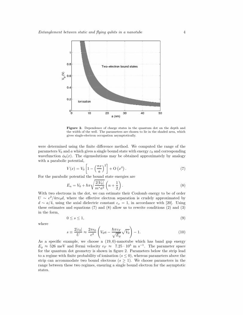
Figure 2. Dependence of charge states in the quantum dot on the depth andthe width of the well. The parameters are chosen to lie in the shaded area, whichgives single-electron occupation asymptotically.
were determined using the finite difference method. We computed the range of theparameters V0 and a which gives a single bound state with energy ε0 and correspondingwavefunction φ0(x). The eigensolutions may be obtained approximately by analogywith a parabolic potential,
V (x) = V0
[
1 −(πx
a
)2]
+ O(
x4)
. (7)
For the parabolic potential the bound state energies are
En = V0 + hπ
√
2|V0|m∗a2
(
n +1
2
)
. (8)
With two electrons in the dot, we can estimate their Coulomb energy to be of orderU ∼ e2/4πǫ0d, where the effective electron separation is crudely approximated byd ∼ a/4, using the axial dielectric constant ǫx = 1, in accordance with [20]. Usingthese estimates and equations (7) and (8) allow us to rewrite conditions (2) and (3)in the form,
0 ≤ s ≤ 1, (9)
where
s ≡ 2|ε0|U
≈ 2πǫ0e2
(
V0a − hπvF√
Eg
√
V0
)
− 1. (10)
As a specific example, we choose a (19, 0)-nanotube which has band gap energyEg ≈ 526 meV and Fermi velocity vF ≈ 7.25 · 105 m s−1. The parameter spacefor the quantum dot geometry is shown in figure 2. Parameters below the strip leadto a regime with finite probability of ionisation (s ≤ 0), whereas parameters above thestrip can accommodate two bound electrons (s ≥ 1). We choose parameters in therange between these two regimes, ensuring a single bound electron for the asymptoticstates.
Entanglement between static and flying qubits in a nanotube 5
3. Single-electron approximations
3.1. The frozen Hartree approximation
We impose the constraint that one electron remains bound in the dot in the one-electron state φ0 and consider the scattering of the second injected electron, takinginto account the Coulomb repulsion between the two. Although this frozen Hartreeapproximation is rather severe, it illustrates the origin of quasi-bound state resonancesand also gives insight into where and why such an approximation breaks down. Thefixed charge distribution of the bound electron appears as a point charge at largedistances with 1/r-dependence whereas inside the well approaching the centre, thereis competition between increasing Coulomb energy and decreasing potential energydue to the well. To derive a quantitative expression for the effective potential we startwith the Coulomb potential between the two electrons in the approximate form,
VC(x1, x2) =e2
4πǫ0√
(x1 − x2)2 + λ2, (11)
where the parameter λ is the effective distance between the two electrons whenx1 = x2. To estimate λ, we start from the unscreened three-dimensional Coulombexpression
VC(~r1, ~r2) =e2
4πǫ0√
(x1 − x2)2 + R21 + R2
2 − 2R1R2 cosα. (12)
and integrate over the transverse modes around the circumference and radially. Forx1 = x2 this gives directly,
1
λ≡ 1
2π
∫ 2π
0
dα
2√
(R − ∆R)2 sin2(α/2) + (∆R)2. (13)
where R ≈ 0.75 nm is the nanotube radius and ∆R ≡ 5a0/Zeff ≈ 0.0814 nm isthe radial extent of a π-electrons. For x1 6= x2, equation (11) remains an excellentapproximation and is clearly correct asymptotically.
The effective frozen Hartree Coulomb potential energy is the expectation valueof equation (11) where the position of the bound electron is given by its envelopefunction φ0(x);
VC(x) =
∫ ∞
−∞
e2
4πǫ0√
(x − x′)2 + λ2|φ0(x
′)|2 dx′. (14)
Summation of the two potential contributions gives the total effective potentialexperienced by the propagating electron,
Veff(x) = V (x) + VC(x), (15)
which is shown in figure 3 together with the potentials in equations (1) and (14). Thepotential well in this example is narrow with a = 4.8 nm, which gives a width forthe ground-state wavefunction in the well of order the nanotube diameter. Indeedthis may be realized in practise by using a metallic nanotube itself to form the gate.In this regime, the effective potential has the shape of a double barrier structure.If the well parameters are chosen such that 0 < s < 1, then the structure containsat least one resonance. Figure 4 shows this resonance for various depths of the wellranging from V0 = 1.5 eV to V0 = 1.2 eV. The curve with the rightmost resonanceis calculated for the same parameters as in figure 3, and in this case the resonant

Entanglement between static and flying qubits in a nanotube 6
−4 −3 −2 −1 0 1 2 3 4
−1
−0.5
0
0.5
1
1.5
x (nm)
Ene
rgy
(eV
)
Figure 3. Effective potential acting on the free electron in the frozen Hartreepicture. The dashed curve illustrates the applied potential, where V0 = 1.2 eV anda = 4.8 nm. The dash-dotted curve represents the potential from the Coulombrepulsion to the fixed bound electron in the quantum dot and the solid line showsthe total potential.
0.3 0.4 0.5 0.6 0.7 0.8 0.9 1
0
0.2
0.4
0.6
0.8
1
E (eV)
Tra
nsm
issi
on P
roba
bilit
y
Figure 4. Transmission probability of the free electron as a function of itskinetic energy, calculated within the frozen Hartree picture. The curves withresonances from left to right are calculated using the depth of the well V0 =(1.5, 1.4, 1.3, 1.2) eV, in that order. The width of the well is a = 4.8 nm.
Entanglement between static and flying qubits in a nanotube 7
−8 −6 −4 −2 0 2 4 6 80
0.1
0.2
0.3
0.4
0.5
0.6
0.7
0.8
x (nm)
Ene
rgy
(eV
)
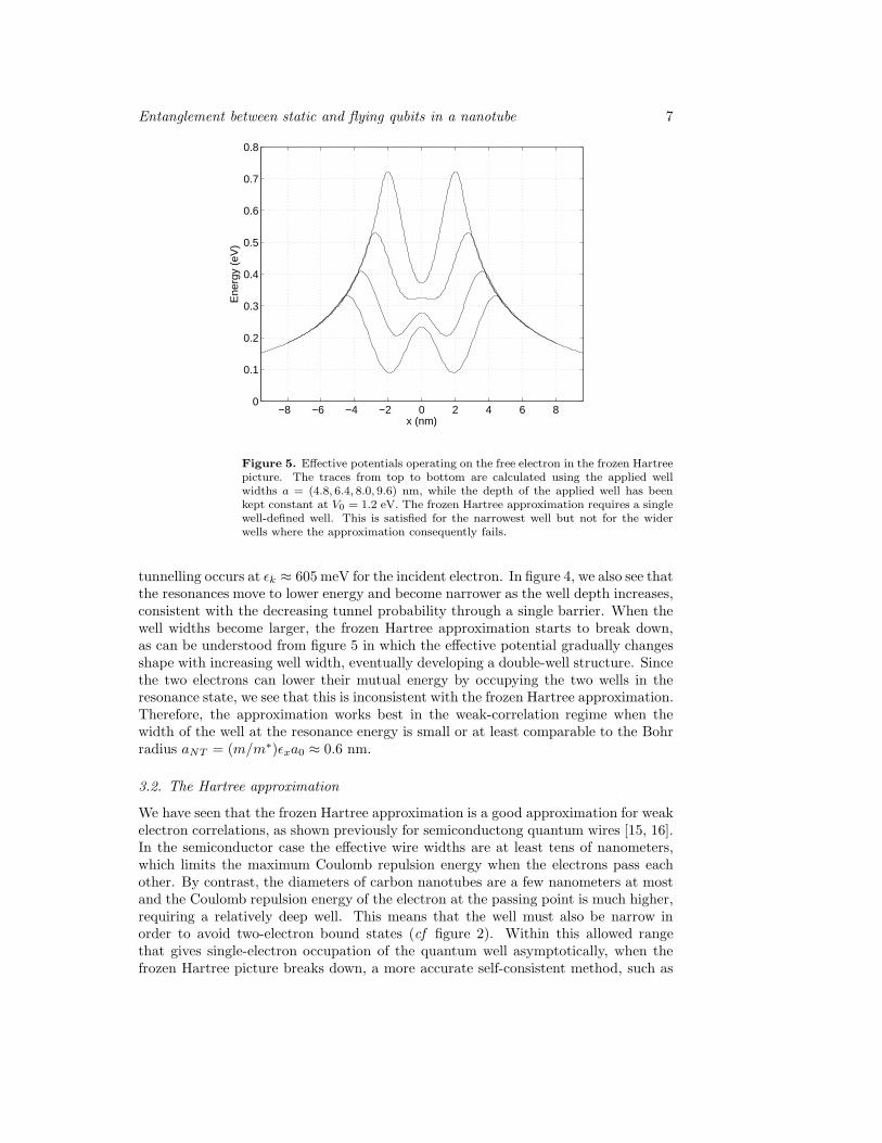
Figure 5. Effective potentials operating on the free electron in the frozen Hartreepicture. The traces from top to bottom are calculated using the applied wellwidths a = (4.8, 6.4, 8.0, 9.6) nm, while the depth of the applied well has beenkept constant at V0 = 1.2 eV. The frozen Hartree approximation requires a singlewell-defined well. This is satisfied for the narrowest well but not for the widerwells where the approximation consequently fails.
tunnelling occurs at ǫk ≈ 605 meV for the incident electron. In figure 4, we also see thatthe resonances move to lower energy and become narrower as the well depth increases,consistent with the decreasing tunnel probability through a single barrier. When thewell widths become larger, the frozen Hartree approximation starts to break down,as can be understood from figure 5 in which the effective potential gradually changesshape with increasing well width, eventually developing a double-well structure. Sincethe two electrons can lower their mutual energy by occupying the two wells in theresonance state, we see that this is inconsistent with the frozen Hartree approximation.Therefore, the approximation works best in the weak-correlation regime when thewidth of the well at the resonance energy is small or at least comparable to the Bohrradius aNT = (m/m∗)ǫxa0 ≈ 0.6 nm.
3.2. The Hartree approximation
We have seen that the frozen Hartree approximation is a good approximation for weakelectron correlations, as shown previously for semiconductong quantum wires [15, 16].In the semiconductor case the effective wire widths are at least tens of nanometers,which limits the maximum Coulomb repulsion energy when the electrons pass eachother. By contrast, the diameters of carbon nanotubes are a few nanometers at mostand the Coulomb repulsion energy of the electron at the passing point is much higher,requiring a relatively deep well. This means that the well must also be narrow inorder to avoid two-electron bound states (cf figure 2). Within this allowed rangethat gives single-electron occupation of the quantum well asymptotically, when thefrozen Hartree picture breaks down, a more accurate self-consistent method, such as

Entanglement between static and flying qubits in a nanotube 8
Hartree or Hartree-Fock, may improve the range of validity. Although, this is strictlynot valid for such an unbound system of two electrons where the probability densityis dominated by one electron being far from the well, we can nevertheless gain someinsight into the effects of strong Coulomb repulsion between the two electrons whenthey are both in the well by extending the parabolic well such that there are true boundstates for both electrons and then solving Hartree equations, allowing the possibilityof a different Hartree potential for each electron. This procedure has previously beenapplied to two electrons in square quantum dots, giving similar results to unrestrictedHartree-Fock and showing that in the strong-correlation regime, the electrons avoideach other thereby lowering their Coulomb repulsion energy [21]. These true bound-state Hartree solutions can be solved using the Hartree equations
Eφn(x) = − h2
2m∗d2φn
dx2+
(
∫ ∞
−∞
e2
4πǫ0√
(x − x′)2 + λ2|φm(x′)|2 dx′
+V (x)) Φn(x), (16)
where n, m = 1, 2 with n 6= m, and the confining potential is the potential in equation(7). The solutions are expected to give similar energies and charge densities to thoseof the resonant bound states when both electrons are in the well and this is indeedverified by the exact solutions. The effective potential acting on one of the electronsin the dot is shown in figure 6(a) with the potential of the other being the mirrorimage. The parameters are the same as in figure 5, and when a = 4.8 nm, the twoelectrons, described by the two one-electron envelope functions φ1(x) and φ2(x), arebound tightly together in the centre by the applied potential with φ1(x) = φ2(x). Inorder to lower their mutual Coulomb repulsion energy, the electrons start to avoid eachother as the gate width increases, which results in a breakdown of the symmetry. Thelocations of the electrons can be observed in the charge density plotted in figure 6(b).This figure shows that the use of wider wells results in greater separation of theelectrons, eventually leading to a double quantum dot with one electron occupyingeach well. The energy of the bound state is positive for well parameters satisfying ourrequirements. Provided that the tunnel probability through the barriers at the dotinterfaces is small, the bound state energy is approximately that of the resonance statein the scattering problem. The results give the correct picture for charge polarisationwithin the well but do not make any reference to the spin of the electrons. In thestrong correlation regime, the effects of spin on charge density are small but they canhave a marked effect on spin-dependent resonances. To understand this we need tosolve the full two-electron problem numberically.
4. Two-electron scattering
4.1. The two-electron model
The full two-electron Hamiltonian is, from the one-electron Hamiltonian (5) and theapproximate mutual Coulomb interaction potential in equation (11),
H = − h2
2m∗
(
∂2
∂x21
+∂2
∂x22
)
+ V (x1) + V (x2) +e2
4πǫ0√
(x1 − x2)2 + λ2, (17)
where the indices label the two electrons and V (x) is the effective one-electron potentialenergy in equation (1). Spin-orbit coupling is negligible in carbon and has been

Entanglement between static and flying qubits in a nanotube 9
−4 −3 −2 −1 0 1 2 3 4−0.5
0
0.5
1
x (nm)
Ene
rgy
(eV
)
a
−4 −3 −2 −1 0 1 2 3 40
0.2
0.4
0.6
0.8
1
x (nm)
ρ(x)
/e
b
Figure 6. Effective potentials and charge densities in the Hartree approximation.The traces with center values from top and downwards are calculated using thegate widths a = (4.8, 6.4, 8.0, 9.6) nm. The depth of the well is V0 = 1.2 eV.(a) The effective potential is symmetric for the narrowest well but becomesasymmetric for wider wells. (b) The total electron charge density which peaksin the centre for narrow wells but shows a double peak for wider wells, reflectingcharge polarisation towards away from the centre.
neglected. Hence, total spin is conserved and the eigenfunctions can, for this caseof two electrons, be separated into spin and orbital factors;
Ψ(x1, σ1, x2, σ2) = Φ(x1, x2)χ(σ1, σ2), (18)
where,
χ(σ1, σ2) ∈
χ↑↑1√2(χ↑↓ + χ↓↑)
χ↓↓1√2(χ↑↓ − χ↓↑)
, (19)

Entanglement between static and flying qubits in a nanotube 10
with the first three basis states belonging to the symmetric triplet and the last statebelonging to antisymmetric singlet. To ensure overall antisymmetry with respect tointerchange of spin and orbital coordinates, the orbital states must satisfy,
Φ(x1, x2) = ±Φ(x2, x1), (20)
with the plus sign corresponding to the singlet state and the minus sign a triplet.The wavefunctions for these symmetric and antisymmetric orbital states are thencalculated by applying the finite difference method to the envelope function equationHΦ = EΦ, after cancellation of the spin parts. The coordinates of the two particlesare mapped onto a two-dimensional square Cartesian surface which splits into twotriangles about x1 = x2. We need to solve for the envelope function on only one of thesetriangles as the other half is always given by equation (20) with the sign determinedby the chosen symmetry. The triangular surface has three boundary conditions. Thehypotenuse must have either Dirichlet or Neumann boundary conditions to satisfyequation (20). The other two boundaries correspond to one electron outside thequantum dot on the source or drain side, respectively. If the electrons are far apart, the(anti)symmetric envelope function can be replaced by factorised one-electron solutionsto a good approximation and the envelope functions matched to asymptotic scatteringfunctions,
Φ(−x0, x2) =1√L
(ξ→1 (−x0) − rξ←1 (−x0)) φ0(x2), (21)
Φ(x1, x0) =t√L
ξ→1 (x0)φ0(x1), (22)
where r and t are the reflection and transmission amplitudes. ξ←1 (x) and ξ→1 (x) arethe left- and right-going asymptotic one-electron solutions, with Coulomb functionsthat may be approximated by plane waves. These boundary conditions are sufficientto determine the full envelope function surface.
4.2. Transmission and Correlation
The system of linear equations is solved using the bi-conjugate gradient method. Acalculation of the transmission probability is shown in figure 7, where we have used thesame parameters as in figure 4. The resonances in the frozen Hartree approximationagree qualitatively with the singlet resonances (solid lines) for this very narrow well,but the resonances occur at higher energies with significantly more broadening for thehighest energy resonance. These differences are attributable to the bound electronmoving away from the barriers through which the other electron is tunnelling. As aresult, the effective tunnelling barriers in the two-electron case (cf the one-electronbarriers in figure 3) are slightly lower, and narrower at the top. In experiments,the wide range of resonance widths may be exploited in such a way that a desiredresonance width can be obtained by tuning the applied gate potential and the energyof the injected electron. The triplet transmissions (dashed lines) in figure 7 do notexhibit resonances since the two electrons are forbidden to occupy the same quasi-bound state due to the Pauli Exclusion Principle and higher-energy single-electronstates occur above the quantum dot tunnel barriers for this choice of parameters.The electron densities of two singlet resonances are plotted in figure 8. The first iscalculated with a well width a = 4.8 nm. At this width, the system is in the medium-correlated regime where the two electrons are slightly separated but maintain a sizeableoverlap. The second graph illustrates a somewhat different scenario in which the well

Entanglement between static and flying qubits in a nanotube 11
0.2 0.3 0.4 0.5 0.6 0.7 0.8
0
0.2
0.4
0.6
0.8
1
E (eV)
Tra
nsm
issi
on P
roba
bilit
y
Figure 7. Transmission probability as a function of the kinetic energy of theincident electron using a full two-electron calculation. The solid and dashedcurves are solutions, in which symmetric and anti-symmetric envelope functionshave been enforced, respectively. The well parameters are the same as in figure 4.
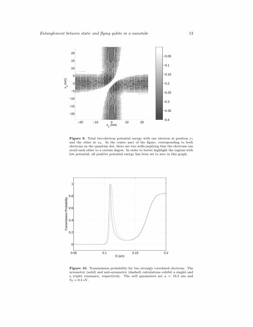
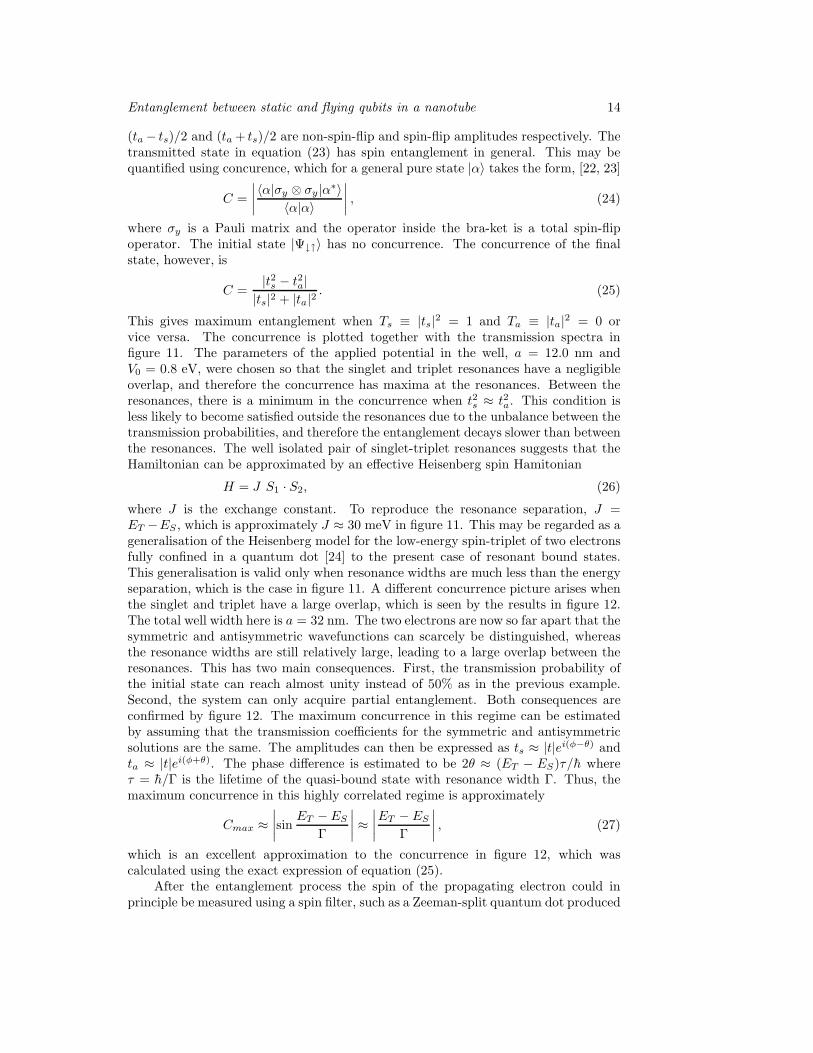
width is a = 19.2 nm. The electrons are highly correlated and repel each other inthe well, leading to a minimum density overlap. In the highly-correlated electronregime, the total potential has two distinct minima as shown in figure 9. There are sixregions with a potential energy below −0.3 eV. In the outer four minima, one of theelectrons is outside the dot. In the two central minima both electrons are in the dotand are spatially separated, so that the total potential resembles a double quantumdot where each is singly occupied. This is similar to ordinary double-dot systems (orindeed a single-dot system with two electrons in the strong correaltion regime) whichhave a low-lying singlet-triplet pair of energy levels. However, in our system, theselevels become resonances, or quasi-bound states as shown in figure 10. The separationbetween the resonances is small in this high-correlation example. The overlap becomeseven more pronounced for larger wells, since the resonance separation appraches zeroexponentially with increasing well width. As a consequence, antisymmetrisation ofthe total wavefunction becomes unnecessary. The two high-correlation regimes withsmall and large resonance overlaps offer controlled entanglement.
5. Entanglement
The transmission probabilities for symmetric and antisymmetric orbital states, shownin figures 7 and 10, correspond to singlet and triplet states respectively [cf equations(18), (19), and (20)]. Since the Hamiltonian does not depend on spin, the total Sand Sz must be conserved for these eigenstates. However, if the system is preparedwith the injected electron with spin-up and the bound electron with spin-down, whichis not an eigenstate of the Hamiltonian, then the subsequent Coulomb interactionbetween the two electrons will give rise to a superposition state of the singlet andSz = 0 triplet. As described in [14], the asymptotic transmitted state after scattering

Entanglement between static and flying qubits in a nanotube 12
−50
5
−5
0
5
2
4
6
8
x 10−4
x1 (nm)x
2 (nm)
a
−20−10
010
20
−20
0
20
2468
1012
x 10−5
x1 (nm)x
2 (nm)
b
Figure 8. Electron densities at the singlet-resonance. Graph (a) is calculated fora narrow well width of a = 4.8 nm with V0 = 1.5 eV and shows a typical situationwhere the electrons are medium correlated. The density has started to developa double-peak-structure, but retains a strong overlap. The electron density ingraph (b) exhibits only a very small overlap. This calculation has a comparablywide gate width of a = 19.2 nm with V0 = 0.4 eV and illustrates a situation withstrongly correlated electrons.
may be determined as follows. The injected electron should be regarded as being ina broad wave-packet far away from the bound electron. The initial state is a singledeterminant of spin-orbitals which is the sum of the singlet state state and Sz = 0triplet state, and cannot be factorised into a product of spin and orbital parts. Sincethe scattered state is the sum of the separately evolved singlet and triplet states, thenthe normalised asymptotic transmitted state is
1√2
(ts|Ψ0;0〉 + ta|Ψ1;0〉) =ta − ts
2|Ψ↓↑〉 +
ta + ts2
|Ψ↑↓〉, (23)
where |Ψ↓↑〉 is a single determinant corresponding with the bound-electron againhaving spin-down and |Ψ↑↓〉 the determinant in which the spins are exchanged. Thus
Entanglement between static and flying qubits in a nanotube 13
−20 −10 0 10 20
−20
−15
−10
−5
0
5
10
15
20
x1 (nm)
x 2 (nm
)
−0.4
−0.35
−0.3
−0.25
−0.2
−0.15
−0.1
−0.05
Figure 9. Total two-electron potential energy with one electron at position x1
and the other at x2. In the centre part of the figure, corresponding to bothelectrons on the quantum dot, there are two wells,implying that the electrons canavoid each other to a certain degree. In order to better highlight the regions withlow potential, all positive potential energy has been set to zero in this graph.
0.05 0.1 0.15 0.2
0
0.2
0.4
0.6
0.8
1
E (eV)
Tra
nsm
issi
on P
roba
bilit
y
Figure 10. Transmission probability for two strongly correlated electrons. Thesymmetric (solid) and anti-symmetric (dashed) calculations exhibit a singlet anda triplet resonance, respectively. The well parameters are a = 19.2 nm andV0 = 0.4 eV.
Entanglement between static and flying qubits in a nanotube 14
(ta − ts)/2 and (ta + ts)/2 are non-spin-flip and spin-flip amplitudes respectively. Thetransmitted state in equation (23) has spin entanglement in general. This may bequantified using concurence, which for a general pure state |α〉 takes the form, [22, 23]
C =
∣
∣
∣
∣
〈α|σy ⊗ σy |α∗〉〈α|α〉
∣
∣
∣
∣
, (24)
where σy is a Pauli matrix and the operator inside the bra-ket is a total spin-flipoperator. The initial state |Ψ↓↑〉 has no concurrence. The concurrence of the finalstate, however, is
C =|t2s − t2a|
|ts|2 + |ta|2. (25)
This gives maximum entanglement when Ts ≡ |ts|2 = 1 and Ta ≡ |ta|2 = 0 orvice versa. The concurrence is plotted together with the transmission spectra infigure 11. The parameters of the applied potential in the well, a = 12.0 nm andV0 = 0.8 eV, were chosen so that the singlet and triplet resonances have a negligibleoverlap, and therefore the concurrence has maxima at the resonances. Between theresonances, there is a minimum in the concurrence when t2s ≈ t2a. This condition isless likely to become satisfied outside the resonances due to the unbalance between thetransmission probabilities, and therefore the entanglement decays slower than betweenthe resonances. The well isolated pair of singlet-triplet resonances suggests that theHamiltonian can be approximated by an effective Heisenberg spin Hamitonian
H = J S1 · S2, (26)
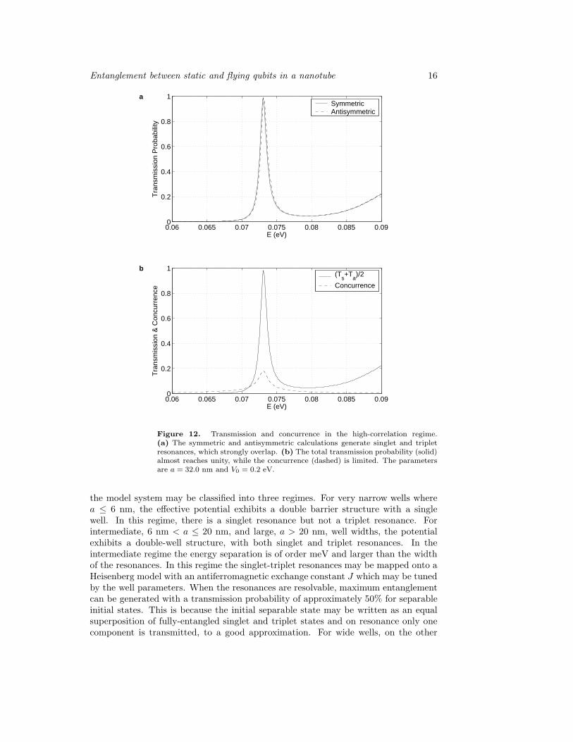
where J is the exchange constant. To reproduce the resonance separation, J =ET −ES , which is approximately J ≈ 30 meV in figure 11. This may be regarded as ageneralisation of the Heisenberg model for the low-energy spin-triplet of two electronsfully confined in a quantum dot [24] to the present case of resonant bound states.This generalisation is valid only when resonance widths are much less than the energyseparation, which is the case in figure 11. A different concurrence picture arises whenthe singlet and triplet have a large overlap, which is seen by the results in figure 12.The total well width here is a = 32 nm. The two electrons are now so far apart that thesymmetric and antisymmetric wavefunctions can scarcely be distinguished, whereasthe resonance widths are still relatively large, leading to a large overlap between theresonances. This has two main consequences. First, the transmission probability ofthe initial state can reach almost unity instead of 50% as in the previous example.Second, the system can only acquire partial entanglement. Both consequences areconfirmed by figure 12. The maximum concurrence in this regime can be estimatedby assuming that the transmission coefficients for the symmetric and antisymmetricsolutions are the same. The amplitudes can then be expressed as ts ≈ |t|ei(φ−θ) andta ≈ |t|ei(φ+θ). The phase difference is estimated to be 2θ ≈ (ET − ES)τ/h whereτ = h/Γ is the lifetime of the quasi-bound state with resonance width Γ. Thus, themaximum concurrence in this highly correlated regime is approximately
Cmax ≈∣
∣
∣
∣
sinET − ES
Γ
∣
∣
∣
∣
≈∣
∣
∣
∣
ET − ES
Γ
∣
∣
∣
∣
, (27)
which is an excellent approximation to the concurrence in figure 12, which wascalculated using the exact expression of equation (25).
After the entanglement process the spin of the propagating electron could inprinciple be measured using a spin filter, such as a Zeeman-split quantum dot produced

Entanglement between static and flying qubits in a nanotube 15
0.05 0.1 0.15 0.2 0.25 0.3 0.350
0.2
0.4
0.6
0.8
1
E (eV)
Tra
nsm
issi
on P
roba
bilit
y
aSymmetricAntisymmetric
0.05 0.1 0.15 0.2 0.25 0.3 0.350
0.2
0.4
0.6
0.8
1
E (eV)
Tra
nsm
issi
on &
Con
curr
ence
b(T
s+T
a)/2
Concurrence
Figure 11. Transmission and concurrence in the medium-correlation regime.(a) The symmetric and anti-symmetric calculations generate singlet and tripletresonances, which have negligible overlap. (b) The total transmission probability(solid) and concurrence (dashed) each have two maxima, corresponding to thesinglet and triplet resonances. The parameters are a = 12.0 nm and V0 = 0.8 eV.
by gates along the nanotube, with subsequent charge detection using a single-electrontransistor. Measuring the static spin directly would be more difficult. However, thismay be verified indirectly as follows [25]. After detection of the spin of the flying qubitthe static qubit should have opposite spin. This may then be verified by injecting afurther spin of the same polarity as the (now known) static spin and subsequentlymeasuring it using a spin filter.
6. Conclusion
Spin-entanglement can be created between a propagating electron and a boundelectron in a single-walled nanotube, provided that neither the bound electron isionised nor the propagating electron is captured by the well. These requirements leadto conditions on the well. We have shown that when these conditions are satisfied,
Entanglement between static and flying qubits in a nanotube 16
0.06 0.065 0.07 0.075 0.08 0.085 0.090
0.2
0.4
0.6
0.8
1
E (eV)
Tra
nsm
issi
on P
roba
bilit
y
aSymmetricAntisymmetric
0.06 0.065 0.07 0.075 0.08 0.085 0.090
0.2
0.4
0.6
0.8
1
E (eV)
Tra
nsm
issi
on &
Con
curr
ence
b(T
s+T
a)/2
Concurrence
Figure 12. Transmission and concurrence in the high-correlation regime.(a) The symmetric and antisymmetric calculations generate singlet and tripletresonances, which strongly overlap. (b) The total transmission probability (solid)almost reaches unity, while the concurrence (dashed) is limited. The parametersare a = 32.0 nm and V0 = 0.2 eV.
the model system may be classified into three regimes. For very narrow wells wherea ≤ 6 nm, the effective potential exhibits a double barrier structure with a singlewell. In this regime, there is a singlet resonance but not a triplet resonance. Forintermediate, 6 nm < a ≤ 20 nm, and large, a > 20 nm, well widths, the potentialexhibits a double-well structure, with both singlet and triplet resonances. In theintermediate regime the energy separation is of order meV and larger than the widthof the resonances. In this regime the singlet-triplet resonances may be mapped onto aHeisenberg model with an antiferromagnetic exchange constant J which may be tunedby the well parameters. When the resonances are resolvable, maximum entanglementcan be generated with a transmission probability of approximately 50% for separableinitial states. This is because the initial separable state may be written as an equalsuperposition of fully-entangled singlet and triplet states and on resonance only onecomponent is transmitted, to a good approximation. For wide wells, on the other

Entanglement between static and flying qubits in a nanotube 17
hand, full transmission can be achieved but the overlapping resonances give only smallentanglement, approximately equal to the singlet-triplet energy separation in units oflinewidth.
Acknowledgments
This research is part of the QIP IRC (GR/S82176/01, is supported throughthe Foresight LINK Award Nanoelectronics at the Quantum Edge by EPSRC(GR/R660029/01, Hitachi Europe Ltd. GADB thanks EPSRC for a ProfessorialResearch Fellowship (GR/S15808/01). JHJ acknowledges support from the UK MOD.
References
[1] Ardavan A, Austwick M, Benjamin S C, Briggs G A D, Dennis T J S, Ferguson A, Hasko D G,Kanai M, Khlobystov A N, Lovett B W, Morley G W, Oliver R A, Pettifor D G, Porfyrakis K,Reina J H, Rice J H, Smith J D, Taylor R A, Williams D A, Adelmann C, Mariette H andHamers R J 2003 Phil. Trans. R. Soc. A 361 1473
[2] Ardavan A, Benjamin S C, Briggs G A D, Gunlycke D, Jefferson J H, Jones M, Leigh D,Lovett B W, Morton J J L, Owen J, Porfyrakis K, Sambrook M R and Tyryshkin A MTowards a fullerene-based quantum computer J. Phys.: Condens. Matter (accepted)
[3] White C T and Todorov T N 1998 Nature 393 240[4] Liang W, Bockrath M, Bozovic D, Hafner J H, Tinkham M and Park H 2001 Nature 411 665[5] Kong J, Yenilmez E, Tombler T W, Kim W, Dai H, Laughlin R B, Liu L, Jayanthi C S and
Wu S Y 2001 Phys. Rev. Lett. 87 106801[6] Jarillo-Herrero P, Sapmaz S, Dekker C, Kouwenhoven L P and van der Zant H S J 2004 Nature
429 389[7] Mason N, Biercuk M J and Marcus C M 2004 Science 303 655[8] Gunlycke D, Jefferson J H, Bailey S W D, Lambert C J, Pettifor D G and Briggs G A D 2004 J.
Phys.: Condens. Matter (accepted), Preprint cond-mat/0412406[9] Costa A T Jr. and Bose S 2001 Phys. Rev. Lett. 87 277901[10] DiVincenzo D P 1996 Preprint cond-mat/9612126[11] DiVincenzo D P 2000 Fortschr. Phys. 48 771[12] Oppenheimer J R 1928 Phys. Rev. 32 361[13] Mott N F 1930 Phil. Trans. R. Soc. A 126 259[14] Jefferson J H, Ramsak A and Rejec T 2005 Preprint cond-mat/0509010[15] Rejec T, Ramsak A and Jefferson J H 2000 Phys. Rev. B 62 12985[16] Rejec T, Ramsak A and Jefferson J H 2003 Phys. Rev. B 67 075311[17] Saraga D S, Altshuler B L, Loss D and Westervelt R M 2004 Phys. Rev. Lett. 92 246803[18] Wind S J, Appenzeller J and Avouris Ph 2003 Phys. Rev. Lett. 91 058301[19] Robinson L A W, Lee S -B, Teo K B K, Chhowalla M, Amaratunga G A J, Milne W I,
Williams D A, Hasko D G and Ahmed H 2003 Nanotechnology 14 290; Microelec. Eng. 67 615[20] Leonard F and Tersoff J 2002 Appl. Phys. Lett. 81 4835[21] Creffield C E, Jefferson J H, Sarkar S and Tipton D L 2000 Phys. Rev. B 62 7249[22] Bennett C H, DiVincenzo D P, Smolin J A and Wootters W K 1996 Phys. Rev. A 54 3824[23] Wootters W K 1998 Phys. Rev. Lett. 80 2245[24] Jefferson J H and Hausler W 1996 Phys. Rev. B 54 4936[25] We are grateful to Prof S. Popescu for suggesting this.