
Efficient Generation of Photonic Entanglement and Multiparty ...
159
Efficient Generation of Photonic Entanglement and Multiparty Quantum Communication Pavel Trojek M¨ unchen 2007
-
Upload
khangminh22 -
Category
Documents
-
view
3 -
download
0
Transcript of Efficient Generation of Photonic Entanglement and Multiparty ...
Efficient Generation of Photonic
Entanglement and Multiparty
Quantum Communication
Pavel Trojek
Munchen 2007

Efficient Generation of Photonic
Entanglement and Multiparty
Quantum Communication
Pavel Trojek
Dissertation submittedfor the degree of
Doctor of Philosophy
Faculty of PhysicsLudwig-Maximilians-Universitat Munchen
September 2007

Erstgutachter/ First referee: Prof. Dr. Harald WeinfurterZweitgutachter/ Second referee: Prof. Dr. Eberhard RiedleTag der mundlichen Prufung/ Day of oral exam: 19.12.2007

Contents
Zusammenfassung vii
Summary ix
1 Introduction 11.1 Quantum mechanics . . . . . . . . . . . . . . . . . . . . . . . . . . . . 1
1.1.1 The underlying principles . . . . . . . . . . . . . . . . . . . . . . 11.1.2 EPR paradox and Bell’s theorem . . . . . . . . . . . . . . . . . . 21.1.3 Clauser-Horne-Shominy-Holt inequality . . . . . . . . . . . . . . . 5
1.2 Quantum information processing and communication . . . . . . . . . . . . 8
1.3 Overview . . . . . . . . . . . . . . . . . . . . . . . . . . . . . . . . . . 8
2 Spontaneous parametric down-conversion 112.1 Nonlinearity and anisotropy of a dielectric . . . . . . . . . . . . . . . . . . 12
2.2 Simple theoretical model . . . . . . . . . . . . . . . . . . . . . . . . . . 17
2.3 Multimode description . . . . . . . . . . . . . . . . . . . . . . . . . . . . 222.3.1 Spectra of down-conversion fields . . . . . . . . . . . . . . . . . . 252.3.2 Time distribution of down-conversion fields . . . . . . . . . . . . . 30
2.4 Spatial emission distribution of down-conversionphotons . . . . . . . . . . . . . . . . . . . . . . . . . . . . . . . . . . . 32
2.5 Bell state preparation . . . . . . . . . . . . . . . . . . . . . . . . . . . . 432.5.1 Momentum and energy-time entanglement . . . . . . . . . . . . . 432.5.2 Polarization entanglement . . . . . . . . . . . . . . . . . . . . . . 45
3 Sources of polarization-entangled photon pairs 513.1 Photons as information carriers . . . . . . . . . . . . . . . . . . . . . . . 51
3.1.1 Challenges in quantum communication . . . . . . . . . . . . . . . 523.1.2 Quest for high-flux entangled-photon sources . . . . . . . . . . . . 53
iii

iv CONTENTS
3.2 Methods to generate entangled photon pairs . . . . . . . . . . . . . . . . 543.2.1 SPDC sources . . . . . . . . . . . . . . . . . . . . . . . . . . . 543.2.2 Fiber sources . . . . . . . . . . . . . . . . . . . . . . . . . . . . 553.2.3 Semiconductor sources . . . . . . . . . . . . . . . . . . . . . . . 56
3.3 Compact non-collinear type-II SPDC source . . . . . . . . . . . . . . . . . 563.3.1 Method . . . . . . . . . . . . . . . . . . . . . . . . . . . . . . . 573.3.2 Implementation . . . . . . . . . . . . . . . . . . . . . . . . . . . 623.3.3 Results . . . . . . . . . . . . . . . . . . . . . . . . . . . . . . . 663.3.4 Discussion . . . . . . . . . . . . . . . . . . . . . . . . . . . . . 69
3.4 Compact collinear type-I SPDC source . . . . . . . . . . . . . . . . . . . 703.4.1 Method . . . . . . . . . . . . . . . . . . . . . . . . . . . . . . . 703.4.2 Spatial effect . . . . . . . . . . . . . . . . . . . . . . . . . . . . 723.4.3 Time effect . . . . . . . . . . . . . . . . . . . . . . . . . . . . . 733.4.4 Implementation . . . . . . . . . . . . . . . . . . . . . . . . . . . 823.4.5 Results . . . . . . . . . . . . . . . . . . . . . . . . . . . . . . . 853.4.6 Discussion and outlook . . . . . . . . . . . . . . . . . . . . . . . 88
4 Single-qubit multiparty quantum communication 914.1 Communication complexity . . . . . . . . . . . . . . . . . . . . . . . . . 92
4.1.1 Introduction . . . . . . . . . . . . . . . . . . . . . . . . . . . . . 924.1.2 Quantum-assisted communication complexity . . . . . . . . . . . . 924.1.3 Communication complexity problems . . . . . . . . . . . . . . . . 934.1.4 Optimal classical protocol . . . . . . . . . . . . . . . . . . . . . . 954.1.5 Optimal quantum protocol . . . . . . . . . . . . . . . . . . . . . . 974.1.6 Implementation . . . . . . . . . . . . . . . . . . . . . . . . . . . 984.1.7 Results . . . . . . . . . . . . . . . . . . . . . . . . . . . . . . . 100
4.2 Secret sharing . . . . . . . . . . . . . . . . . . . . . . . . . . . . . . . 1014.2.1 Introduction . . . . . . . . . . . . . . . . . . . . . . . . . . . . . 1014.2.2 Quantum-assisted secret sharing . . . . . . . . . . . . . . . . . . 1024.2.3 Entanglement-based protocol . . . . . . . . . . . . . . . . . . . . 1034.2.4 Single-qubit protocol . . . . . . . . . . . . . . . . . . . . . . . . 1044.2.5 Implementation . . . . . . . . . . . . . . . . . . . . . . . . . . . 1074.2.6 Results . . . . . . . . . . . . . . . . . . . . . . . . . . . . . . . 108
4.3 Discussion and outlook . . . . . . . . . . . . . . . . . . . . . . . . . . . 109
5 Conclusions and Outlook 111
Appendices 115
A Sources of polarization-entangled photon pairs 115A.1 Crystals . . . . . . . . . . . . . . . . . . . . . . . . . . . . . . . . . . . 115
A.1.1 Beta-barium borate . . . . . . . . . . . . . . . . . . . . . . . . . 115

CONTENTS v
A.1.2 Yttrium vanadate . . . . . . . . . . . . . . . . . . . . . . . . . . 116
A.2 Historical progress of sources . . . . . . . . . . . . . . . . . . . . . . . . 116
A.3 Photos . . . . . . . . . . . . . . . . . . . . . . . . . . . . . . . . . . . 118
B Single-qubit multiparty quantum communication 119B.1 Classical bounds of success probability in communication complexity problems 119
B.2 Photo . . . . . . . . . . . . . . . . . . . . . . . . . . . . . . . . . . . . 121
C Author’s publications related to the presented work 123
Bibliography 125
List of figures 137
List of tables 141
Acknowledgments 143


Zusammenfassung
Verschrankte Photonen sind von zentralem Interesse im Bereich experimenteller Quan-tenphysik. Sie wurden fur die ersten fundamentalen Tests der Quantentheorie ver-wendet und bilden die Grundlage bei der Realisierung vieler neuer Kommunikation-sprotokolle die auf quantenmechanischen Effekten basieren, wie zum Beispiel Quan-tenkryptographie, “dense coding” oder Teleportation. Die effiziente Erzeugung ver-schrankter Photonen sowie deren genaue Analyse ist folglich von großer Bedeutung,insbesondere im Hinblick auf die Umsetzbarkeit der vielen Quantenkommunikation-sanwendungen. Die vorliegende Arbeit behandelt im Wesentlichen das Problem dereffizienten Erzeugung von Photon Verschrankung. Das Hauptaugenmerk liegt dabeiauf der Entwicklung einer Quelle verschrankter Photonen, die den Anforderungen fureinen zuverlassigen und wirtschaftlichen Betrieb in Beispielanwendungen der Quan-tenkommunikation genugt. Unser Ansatz verwendet die Emission korrelierter Photo-nen Paare im Prozess der spontanen parametrischen Fluoreszenz. Der Prozess wirdmit Licht einer handlichen und billigen blauen Laserdiode gepumpt. Es werden zweialternative Aufbauten fur die Quelle betrachtet. Der erste verwendet das altbewahrteKonzept der entarteten nicht-kollinearen Emission in einem einzelnen nichtlinearenKristall vom Typ II. Der zweite Ansatz basiert auf einer neuen Methode in der dieEmission zweier aneinaderliegender, phasenangepasster Kristalle vom Typ I koharentuberlagert wird. Die Phasenanpassung erfolgt dabei im kollinearen nicht-entartetenZustand. Mit einer Rate von 106 Paaren in der Sekunde bei einem Interferenzkontrastder Polarisationskorrelationen von > 98 % erwies sich die neue Methode als wesentlicheffizienter. Diese Leistungsfahigkeit, in Verbindung mit einem nahezu justagefreienBetrieb, lasst dieses System vielversprechend fur zukunftige praktische Anwendun-gen, wie Quantenkryptographie, Detektorkalibrierung oder Praktikumsversuche furStudenten erscheinen.
Ein weiteres Thema das im Rahmen dieser Arbeit behandelt wird ist die Verein-fachung und Implementierung kommunikationstheoretischer Problemlosungen unterZuhilfenahme quantenmechanischer Effekte. Wahrend der rasante Fortschritt derletzten Jahre bei der Entwicklung von Quellen zur Erzeugung verschrankter Photo-nenpaare zu einer großen Anzahl von Veroffentlichungen auf dem Gebiet der Zwei-Parteien-Quantenkommunikation gefuhrt hat, hielt sich die Zahl der Implementierun-
vii
viii Zusammenfassung
gen von Protokollen mit mehr als zwei Parteien in Grenzen. Dies liegt hauptsachlichdaran, dass die benotigten Mehr-Teilchen verschrankten Zustande mit dem heutigenStand der Technik schwer zu produzieren sind und daruber hinaus hohes Rauschenaufweisen. Wir zeigen, dass Verschrankung nicht die einzige Ressource ist, die Mehr-parteien-Quanten-Informationsverarbeitung ihre Starke verleiht. Im Gegenteil, diesequentielle Kommunikation und Transformation eines einzelnen Qubits kann bere-its ausreichend fur die Losung bestimmter Probleme sein. Dies zeigen wir anhandzweier verschiedener informationstheoretischer Problemstellungen, dem “secret shar-ing” und der Kommunikationskomplexitat. Die erste befasst sich mit der Aufteilungeines kryptographischen Schlussels auf mehrere Parteien in einer Weise, die fur dessenRekonstruktion die Zusammenarbeit aller Parteien erfordert. Die zweite zielt auf dieReduzierung der Kommunikation beim Losen distributiver Berechnungen ab. Be-merkenswerterweise ist das hier verwendete qubit-basierte Losungsverfahren mit demheutigen Stand der Technik umsetzbar, was wir durch dessen Realisierung im Laborfur 6 bzw. 5 Personen zeigen. Nach unserem Wissen ist dies die hochste Anzahlan aktiv agierenden Teilnehmern in einem Quantenkommunikationsprotokoll die jeimplementiert wurde. Die erfolgreiche Losung und Implementierung von Problem-stellungen aus den Bereichen der Kryptographie und der Informatik bringt somitMehrparteien Quantenkommunikation einen Schritt naher an kommerzielle Anwen-dungen heran.

Summary
Entangled photons are at the heart of experimental quantum physics. They wereused for the first fundamental tests of quantum theory, and became a basic buildingblock for many novel quantum protocols, such as quantum cryptography, dense cod-ing or teleportation. Therefore, the efficient generation of entangled photons, as wellas their distribution and accurate analysis are of paramount importance, particularlywith regard to the practicability of many applications of quantum communication.This thesis deals largely with the problem of efficient generation of photonic entangle-ment with the principal aim of developing a bright source of polarization-entangledphoton pairs, which meets the requirements for reliable and economic operation ofquantum communication prototypes and demonstrators. Our approach uses a cor-related photon-pair emission in nonlinear process of spontaneous parametric down-conversion pumped by light coming from a compact and cheap blue laser diode. Twoalternative source configurations are examined within the thesis. The first makesuse of a well established concept of degenerate non-collinear emission from a singletype-II nonlinear crystal and the second relies on a novel method where the emis-sions from two adjacent type-I phase-matched nonlinear crystals operated in collinearnon-degenerate regime are coherently overlapped. The latter approach showed to bemore effective, yielding a total detected rate of almost 106 pairs/s at > 98 % quan-tum interference visibility of polarization correlations. This performance, togetherwith the almost free of alignment operation of the system, suggest that it is an espe-cially promising candidate for many future practical applications, including quantumcryptography, detector calibration or use in undergraduate lab courses.
The second issue addressed within the thesis is the simplification and practicalimplementation of quantum-assisted solutions to multiparty communication tasks.While the recent rapid progress in the development of bright entangled photon-pairsources has been followed with ample experimental reports on two-party quantumcommunication tasks, the practical implementations of tasks for more than two par-ties have been held back, so far. This is mainly due to the requirement of multi-party entangled states, which are very difficult to be produced with current methodsand moreover suffer from a high noise. We show that entanglement is not the onlynon-classical resource endowing the quantum multiparty information processing its
ix

x Summary
power. Instead, only the sequential communication and transformation of a singlequbit can be sufficient to accomplish certain tasks. This we prove for two distinctcommunication tasks, secret sharing and communication complexity. Whereas thegoal of the first is to split a cryptographic key among several parties in a way that itsreconstruction requires their collaboration, the latter aims at reducing the amountof communication during distributed computational tasks. Importantly, our qubit-assisted solutions to the problems are feasible with state-of-the-art technology. Thiswe clearly demonstrate in the laboratory implementation for 6 and 5 parties, respec-tively, which is to the best of our knowledge the highest number of actively performingparties in a quantum protocol ever implemented. Thus, by successfully solving andimplementing a cryptographic task as well as a task originating in computer science,we clearly illustrate the potential to introduce multiparty communication problemsinto real life.
Acronyms
APD avalanche photodiode
BBO beta-barium borate (β-BaB2O4)
CCP communication complexity problem
CW continuous-wave
CHSH Clauser-Horne-Shimony-Holt
ECLD external cavity laser diode
EPR Einstein-Podolsky-Rosen
FWHM full width at half maximum
FWM four-wave mixing
GHZ Greenberger-Horne-Zeilinger
KLM Knill-Laflamme-Milburn
KTP potassium titanyl phosphate (KTiOPO4)
LD laser diode
MFD mode field diameter
NIR near-infrared
PPKTP periodically poled KTP
QBER quantum bit error rate
QPM quasi-phase matching
QSS quantum secret sharing
SPDC spontaneous parametric down-conversion
VLPC visible-light photon counters
WDM wavelength division multiplexer
xi


Chapter 1Introduction
1.1 Quantum mechanics
Some discoveries bring answers to questions. Others are so deep, that they cause aradical revolution in our fundamental comprehension of nature. Without any doubt,quantum mechanics has done so.
1.1.1 The underlying principles
From the origin of quantum mechanics at the beginning of twentieth century, scien-tists struggled to bring its peculiar theoretical frame in accordance with an intuitiveview dictated by everyday’s experience and common sense. The central tenet of thistheory - probabilistic description of physical objects - seriously undermined the dogmaof determinism, which was deeply embedded in physical theories over many centuries.In its base the determinism, as distinctly exemplified by Newtonian physics, statesthat the knowledge of position and momentum of any physical object at one timedetermines these quantities at all other times, provided, of course, that some otherobject does not interfere with it. However, in quantum mechanics, the physical ob-jects, such as particles, do not have necessarily well defined positions and momenta.Instead, they are represented by what is called a wave function. It contains all theinformation we can know about a particle, both its position, and its momentum. Thesquare of the wave function gives the probability that the particle will be found atcertain position. The rate, at which the wave function varies from point to point,gives the momentum of the particle.
In 1927 Werner Heisenberg realized one of the major implications of the wave-function description - the uncertainty principle. This principle imposes fundamentallimits on a measurement accuracy of two complementary variables, such as positionand momentum of a particle. The more precisely the position is determined, the lessprecisely the momentum is known in this instant, and vice versa. For example, the
1

2 Introduction 1.1
wave function with a form of a plane wave, represents a particle with precisely de-fined momentum, but gives uniform probability of finding particle anywhere in space.On the other hand, a particle whose spatial spread is described by a δ-function isperfectly localized, but there is maximum uncertainty in determination of its mo-mentum. In this way, quantum mechanics introduces its inherent duality: Indeed,we can precisely determine some physical quantities of a physical object, however atthe cost of precluding the possibility of ascertaining the other, complementary phys-ical quantities. This concept is in stark contrast with deterministic classical physics,which assumes the precise knowledge of all physical quantities at a given time.
Still, quantum mechanics contains a kind of determinism, but definitely not theone envisaged by Newton. Namely, if a wave function at one time is known, then itsevolution to any other time is determined by the so called Schrodinger equation. Itallows us to predict future, but somewhat in a “fuzzy” way, when compared to theclassical 19th century view.
1.1.2 EPR paradox and Bell’s theorem
The success of quantum mechanics in elucidation of known phenomena at atomic-length scales was indisputable. However, the apparent randomness inherent in quan-tum mechanical description was an eyesore for many physicist, first and foremost forAlbert Einstein, who summed up his views in his famous phrase, ’God does not playdice’. He believed there exists an underlying reality, in which all the physical objectshave well defined positions and momenta and would evolve according to deterministiclaws, in spirit of Newton’s classical mechanics. Over the years, he proposed a num-ber of objections to uncover loopholes in the structure of quantum mechanics and toshow that its theoretical framework does not say the last word about the function ofthe universe. His effort culminated by a famous attack on the uncertainty principle,known as EPR paradox, which he devised together with his colleagues Boris Podol-sky and Nathan Rosen in 1935 [1]. Their strategy was straightforward: Give a proofthat every particle has its certain position and momentum at a given instant, andthereby conclude that the uncertainty principle discloses a fundamental restriction onthe quantum-mechanical approach. Simply, if quantum mechanics fails to describeall the elements of the reality, such as positions and momenta of particles, it cannotbe considered as a complete theory. It cannot be a final link in the chain of physicaltheories.
Einstein, Podolsky and Rosen were partly inspired in their argumentation byHeisenberg’s initial vague explanation of the uncertainty relation: The simultaneousexact determination of position and momentum of a particle cannot be accomplished,because the measurement of one quantity necessarily disturbs the result of the mea-surement of the other quantity. They cleverly suggested a method how to measurethe position and momentum of a particle without disturbing it in any way. Thecornerstone of this method is a pair of spatially distant particles (I and II) withperfectly correlated momenta and positions. The wave function of the composed

1.1 Quantum mechanics 3
system (I + II) cannot be written as a product of the wave functions of individualparticles. Thus, all the information one can infer about the particles is contained intheir mutual correlations and the position or momentum of either particle cannot bepredicted, unless a measurement is performed. Such particles later came to be called“entangled”, the term introduced by Schrodinger. Now, let’s assume the position of“particle I” is measured. By this act, the position of “particle II” is determined, too,due to the existence of tight correlations. Analogously, by measuring the momentumof particle I, the momentum of particle II can be ascertained. Thus, even though wedid not disturb particle II in any way1, its complementary properties can be predictedwith certainty. In fact, the EPR paradox does not contradict the uncertainty rela-tion in the first place, because the described measurement procedure does not allowsimultaneous determination of the position and momentum of particle II. However,EPR paradox shows that these complementary properties pertaining to particle II dohave simultaneous “reality”, which was according to Einstein, Podolsky and Rosensufficient to assert the incompleteness of quantum-mechanical description. The op-ponents of this interpretation, represented particularly by Niels Bohr, eliminated theraised problem by shifting it to a rather philosophical level. They claimed there islittle point to ask whether a particle has defined position and momentum, if theycannot be determined simultaneously. Their conclusion was that any physical theoryshould deal only with measurable properties of the universe. Since no means seemedto exist to decide which view was right, because the whole issue was essentially anantithetic statement, the question remained open for almost thirty years, until JohnBell discovered his famous theorem.
The incompleteness of quantum mechanics concluded from the EPR paradox im-plies that additional parameters must be supplemented into the description of physicalobjects, in order to fully account for their properties. These parameters are calledhidden and can be considered, in a sense, to provide a program, which predeterminesthe measurable properties of each particle. Furthermore, they are claimed to be lo-cal, since any non-local features were not required to complete quantum-mechanicaldescription according to hidden variables models. In 1964 John Bell proposed a mech-anism to test for the existence of these local hidden variables, and proved that entirefamily of hidden variables models cannot reproduce exactly the quantum-mechanicalpredictions, forcing us to abandon at least one of the EPR’s premises, the reality or lo-cality [2]. He drew this conclusion by investigating the statistical predictions obtainedin a simplified version of the EPR experiment, which was proposed by David Bohm[3]. Bohm’s version assumes a source emitting pairs of entangled spin-1/2 particles,such as positron-electron pairs, which are freely moving in opposite directions. Twoindependent observers, each receiving one of the particles, perform measurements ofthe spin components along a predefined direction using Stern-Gerlach apparatuses.According to the rules of quantum mechanics, the measured spin component can take
1Here the locality principle is assumed, i.e., the act of measurement on particle I cannot disturbthe other particle (II) due to their sufficient spatial separation.
4 Introduction 1.1
only two values, for simplicity called spin-up and spin-down2. The exact simultane-ous determination of spin along more than one direction is forbidden. Thus, in spiritof the original EPR paradox, one may ask a question, whether the spin componentsalong any direction are real, existing quantities, similarly, as it was done before withthe position and momentum.
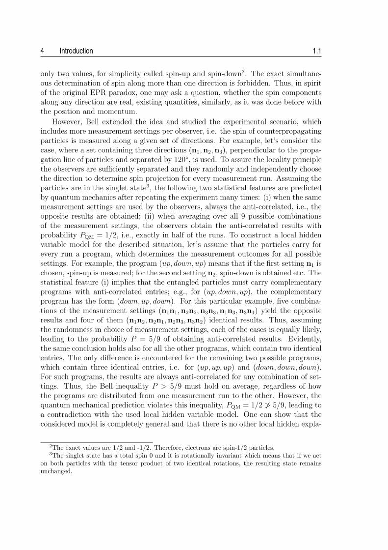
However, Bell extended the idea and studied the experimental scenario, whichincludes more measurement settings per observer, i.e. the spin of counterpropagatingparticles is measured along a given set of directions. For example, let’s consider thecase, where a set containing three directions (n1,n2,n3), perpendicular to the propa-gation line of particles and separated by 120◦, is used. To assure the locality principlethe observers are sufficiently separated and they randomly and independently choosethe direction to determine spin projection for every measurement run. Assuming theparticles are in the singlet state3, the following two statistical features are predictedby quantum mechanics after repeating the experiment many times: (i) when the samemeasurement settings are used by the observers, always the anti-correlated, i.e., theopposite results are obtained; (ii) when averaging over all 9 possible combinationsof the measurement settings, the observers obtain the anti-correlated results withprobability PQM = 1/2, i.e., exactly in half of the runs. To construct a local hiddenvariable model for the described situation, let’s assume that the particles carry forevery run a program, which determines the measurement outcomes for all possiblesettings. For example, the program (up, down, up) means that if the first setting n1 ischosen, spin-up is measured; for the second setting n2, spin-down is obtained etc. Thestatistical feature (i) implies that the entangled particles must carry complementaryprograms with anti-correlated entries; e.g., for (up, down, up), the complementaryprogram has the form (down, up, down). For this particular example, five combina-tions of the measurement settings (n1n1,n2n2,n3n3,n1n3,n3n1) yield the oppositeresults and four of them (n1n2,n2n1,n2n3,n3n2) identical results. Thus, assumingthe randomness in choice of measurement settings, each of the cases is equally likely,leading to the probability P = 5/9 of obtaining anti-correlated results. Evidently,the same conclusion holds also for all the other programs, which contain two identicalentries. The only difference is encountered for the remaining two possible programs,which contain three identical entries, i.e. for (up, up, up) and (down, down, down).For such programs, the results are always anti-correlated for any combination of set-tings. Thus, the Bell inequality P > 5/9 must hold on average, regardless of howthe programs are distributed from one measurement run to the other. However, thequantum mechanical prediction violates this inequality, PQM = 1/2 ≯ 5/9, leading toa contradiction with the used local hidden variable model. One can show that theconsidered model is completely general and that there is no other local hidden expla-
2The exact values are 1/2 and -1/2. Therefore, electrons are spin-1/2 particles.3The singlet state has a total spin 0 and it is rotationally invariant which means that if we act
on both particles with the tensor product of two identical rotations, the resulting state remainsunchanged.
1.1 Quantum mechanics 5
nation, which could account for both aforementioned statistical features predicted byquantum mechanics. The presented argument, devised by David Mermin, shows inan intuitive way the nature of Bell’s discovery by exemplifying the appropriate localhidden variable model [4].
Interestingly, the conflict between local realism and quantum mechanics exposedby Bell’s theorem can be even sharpened using a system of three or more entangledspin-1/2 particles in a so-called Greenberger-Horne-Zeilinger (GHZ) state [5]. Forsuch a system the local realistic model predicts always a class of measurement out-comes, which quantum mechanics never allows and vice versa. This always-neverargument against local realism first shown by the GHZ theorem totally eliminatesthe statistical nature of Bell’s theorem and resorts to the requirement of Bell-typeinequalities only due to imperfections in practical realizations and finite number ofmeasurement runs.
1.1.3 Clauser-Horne-Shominy-Holt inequality
The most widespread version of Bell’s inequality used in experimental tests is the onefrom Clauser, Horne, Shimony and Holt (hereafter referred to as CHSH) requiringonly two measurement settings per observer [6]. Notably, this version was the first,which did not rely upon the assumption of perfect correlations and was thereforeperfectly suited for the actual experiments.
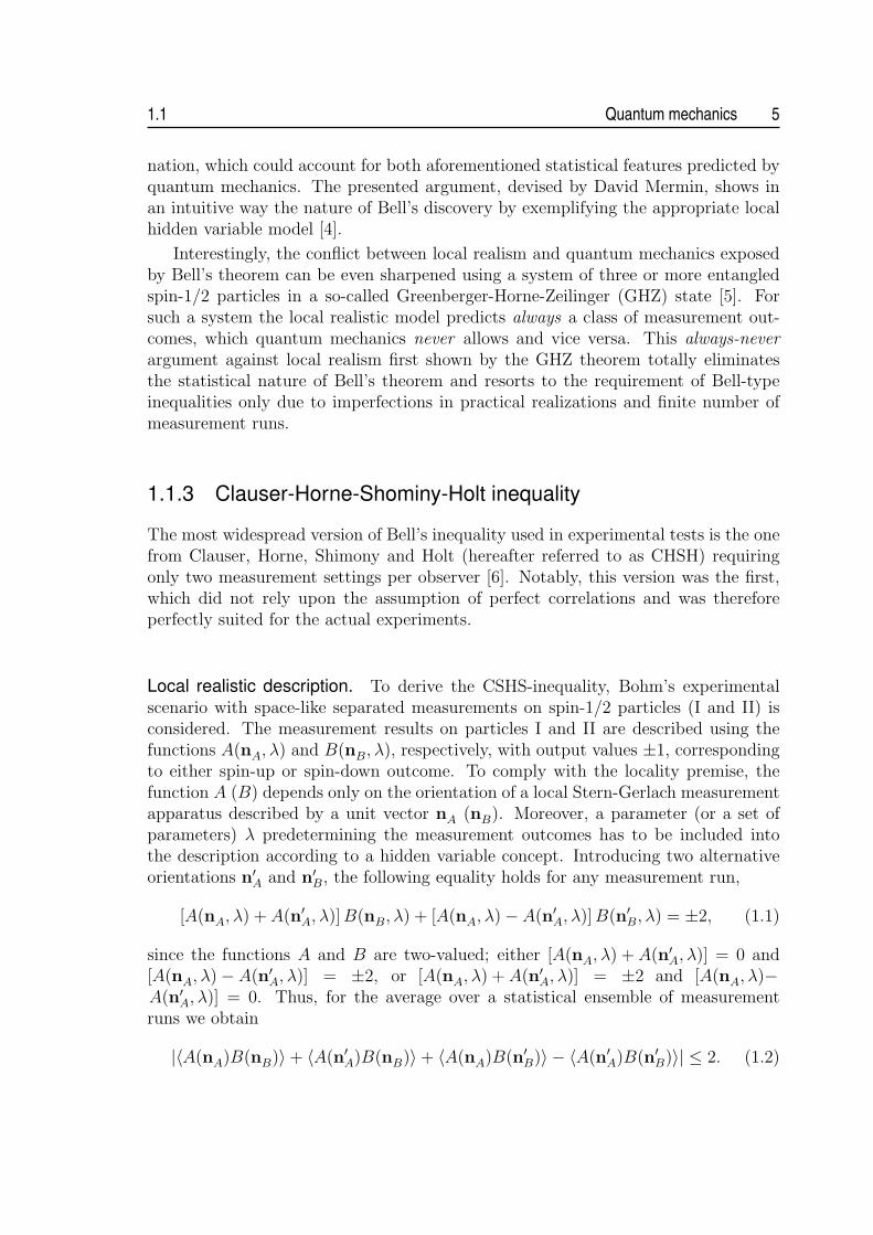
Local realistic description. To derive the CSHS-inequality, Bohm’s experimentalscenario with space-like separated measurements on spin-1/2 particles (I and II) isconsidered. The measurement results on particles I and II are described using thefunctions A(nA, λ) and B(nB, λ), respectively, with output values ±1, correspondingto either spin-up or spin-down outcome. To comply with the locality premise, thefunction A (B) depends only on the orientation of a local Stern-Gerlach measurementapparatus described by a unit vector nA (nB). Moreover, a parameter (or a set ofparameters) λ predetermining the measurement outcomes has to be included intothe description according to a hidden variable concept. Introducing two alternativeorientations n′A and n′B, the following equality holds for any measurement run,
[A(nA, λ) + A(n′A, λ)] B(nB, λ) + [A(nA, λ)− A(n′A, λ)] B(n′B, λ) = ±2, (1.1)
since the functions A and B are two-valued; either [A(nA, λ) + A(n′A, λ)] = 0 and[A(nA, λ)− A(n′A, λ)] = ±2, or [A(nA, λ) + A(n′A, λ)] = ±2 and [A(nA, λ)−A(n′A, λ)] = 0. Thus, for the average over a statistical ensemble of measurementruns we obtain
|〈A(nA)B(nB)〉+ 〈A(n′A)B(nB)〉+ 〈A(nA)B(n′B)〉 − 〈A(n′A)B(n′B)〉| ≤ 2. (1.2)

6 Introduction 1.1
Figure 1.1: Bloch sphere. Anypoint on the sphere defined bythe spherical angles θ and φrepresents a corresponding spin-1/2 state |ψ〉.
This is known as the CHSH inequality, giving an upper bound on the correlationsbetween measurement results under the assumption of local realism.
Quantum violation. Quantum mechanics allows to directly calculate the correlationfunctions in the inequality (1.2). For that, we start with a singlet state:
|Ψ−〉 =1√2
(|0〉I|1〉II − |1〉1|0〉II) , (1.3)
where |0〉 and |1〉 represent two orthogonal states of particles I and II, correspondingto two possible spin projections onto an arbitrary direction n; e.g. “0” correspondsto spin-up and “1” to spin-down. The measurement on either particle is representedby the projector operator P (θ, φ) = |ψ(θ, φ)〉〈ψ(θ, φ)|, where
|ψ(θ, φ)〉 = cos(θ/2)|0〉+ eiφ sin(θ/2)|1〉. (1.4)
This qubit parametrization assigns each point on a Bloch sphere to a unique purequantum state, see figure 1.1.
The maximum violation of the CHSH inequality (1.2) occurs for such set of ori-entations {nA,n′A,nB,n′B}, which obeys the following conditions: angles ](nAnB) =](nBn′A) = ](n′An′B) equal π/4 and the angle ](nAn′B) equals 3π/4. These ori-entations correspond to the projector operators {PA, P ′
A, PB, P ′B}, defined as, e.g.,
PA = P (0, 0), P ′A = P (π/2, 0), PB = P (π/4, 0) and P ′
B = P (3π/4, 0). Given theseforms of observables, the following expectation values can be easily calculated:
〈Ψ−|PAPB|Ψ−〉 = 〈Ψ−|P ′APB|Ψ−〉 = 〈Ψ−|P ′
AP ′B|Ψ−〉 = −〈Ψ−|PAP ′
B|Ψ−〉 = cos(π/4).(1.5)
Assuming that the above operators reveal in turn the values of the dichotomic func-

1.1 Quantum mechanics 7
tions A and B in (1.2), their substitution can be done,
∣∣∣〈Ψ−|PAPB|Ψ−〉+ 〈Ψ−|P ′APB|Ψ−〉+ 〈Ψ−|P ′
AP ′B|Ψ−〉 − 〈Ψ−|PAP ′
B|Ψ−〉∣∣∣
= 4 cos(π/4) = 2√
2 > 2, (1.6)
obtaining the Cirel’son’s upper limit on the violation of CHSH inequality [7]. Thereare three other states leading to the maximal violation:
|Φ−〉 = (1⊗ σx)|Ψ−〉, |Φ+〉 = (1⊗ iσy)|Ψ−〉, |Ψ+〉 = (1⊗ σz)|Ψ−〉, (1.7)
where 1 is the identity matrix and
σx =
(0 11 0
), σy =
(0 −ii 0
), σz =
(1 00 −1
)(1.8)
are well-known Pauli matrices. The three states defined in Eq. (1.7) together with|Ψ−〉 form an orthonormal basis to four-dimensional Hilbert space of two qubits andare usually referred to as Bell states.
Experimental tests. Prompted by the derivation of the CHSH inequality, a firstseries of tests using polarization-entangled photon pairs emitted in an atomic cascadetransition were performed in the early 1970s [8, 9], clearly corroborating the quantumpredictions. Yet, the local realistic explanation of the obtained results remained atleast logically possible, because of the existence of two loopholes arising from theimperfections of the experimental tests.
The first loophole occurs, whenever the communication of the measurement set-ting from one observer to the other cannot be excluded before completing the actualmeasurement process. This opens the possibility of establishing the correlations be-tween remote measurement processes, thereby allowing local hidden variable interpre-tation of the obtained results. The first experiment addressing the locality loopholeby Aspect et al. [10] employed fast quasi-periodic modulators to select the settingsof polarization analyzers only after the entangled photons left the source. This re-markable experiment was further refined in the test of Weihs et al. [11], where strictlocality conditions were enforced by using fast, random switching of the analyzersthat were separated by about 400 meters.
This left only the second loophole, so called detection-efficiency or fair-samplingloophole, open. It arises whenever the detection of particles is inefficient enough sothat the detected events may be unrepresentative of the whole ensemble. Even thougha significant progress in the area of semiconductor detectors has been made duringthe last decade, and single-photon detection with close to perfect quantum efficiencyhas been reported [12], no photonic Bell test eliminating the fair-sampling hypothesishas been presented until now, due to other experimental difficulties. The only Belltest successful in this respect was performed with a pair of entangled beryllium ions

8 Introduction 1.3
[13]. Regrettably, the actual separation of the ions by a distance of about 3 µm givesno foreseeable chance to close the locality loophole with that system.
Hence, after almost 50 years since Bell’s discovery, one must still face the situationthat no conclusive experimental test ruling out the local realistic description of naturehas been accomplished. The present challenge is to design and perform such anexperiment, closing both loopholes at the same time.
1.2 Quantum information processing and communica-tion
Apart from the fundamental motivations, quantum superposition and quantum en-tanglement are the bedrock on which new paradigms for information transmission,storage, and processing can be built. Current developments eloquently demonstratethat these characteristic quantum phenomena may enable one to perform some tasksof practical interest beyond the capabilities of any other known (classical) method.The preeminent examples of such tasks are quantum cryptography, offering new meth-ods for secure communication with its inviolability ensured by the laws of quantumphysics [14, 15]; quantum dense coding, allowing to enhance the capacity of a commu-nication channel [16]; or quantum teleportation, the remote transmission and recon-struction of the state of a quantum system [17]. In the field of quantum computation,novel procedures, as often exemplified by Shor’s algorithm to factorize large numbers[18] and Grover’s algorithm for searching data bases [19], were shown to lead to adramatic speed-up over any (known) classical computation.
All these discoveries initiated a worldwide search for new technologies to reali-ze quantum communication and computation systems. The early experiments havehighlighted how difficult it will be to build working prototypes, by identifying deco-herence in quantum systems as a key issue in practical implementations. In quantumcommunication the major challenge lies in the error-free transmission of quantuminformation over noisy and lossy communication channels, followed by efficient re-covering of the encoded information. In quantum computation main difficulties stemfrom the requirement of strong coupling between quantum bits by gates, while at thesame time their complete decoupling from external influences, except during write,control and readout the phases when information must flow in and out of the com-puter.
1.3 Overview
This thesis predominantly focuses on the field of quantum communication. Therein,an impressive progress has been achieved since the entry into the experimental eramarked by the first demonstration of single-photon quantum cryptography over thedistance of 32 cm in 1989 [20]. Many novel concepts, protocols and methods have been

1.3 Overview 9
demonstrated practically, some even outside the ideal lab environment. Nevertheless,there is still a long way to go - the practicality of the systems must be improved,higher bit rates and longer distances must be achieved before any meaningful successescan be claimed. The work presented here contributes to these lines of research byaddressing two particular issues.
First, the topic of efficient and practical generation of entangled photon pairs viaspontaneous parametric down-conversion (SPDC) is addressed within the thesis. Thechapter 2 is intended to cover the theoretical aspects associated with the problem. Itbrings the detailed theoretical description of the SPDC process and reviews the mostcommon methods of preparation of the emitted photon pairs in maximally-entangledBell states encoded in different accessible degrees of freedom. Particular attention isdevoted to polarization encoding. The subsequent chapter 3 gives the details aboutthe actual design and practical realization of two different compact sources using ablue laser diode as the pump of SPDC. The major parameters of the sources andtheir output performance are compared to other state-of-the-art implementations.
Second, the chapter 4 deals with two apparently different communication tasks,the secret sharing and the communication complexity. Whereas the goal of the first isto distribute a cryptographic key among several parties in a way that its reconstruc-tion requires the collaboration of the parties, the latter aims at reducing the amount ofcommunication during distributed computation. In common, both tasks were shownto be efficiently solvable via the resource of multi-partite entanglement. This is, how-ever, very difficult to be produced in practice, making the implementation of thetasks technologically very challenging. We show that the quantum-assisted solutionto both tasks can be significantly simplified via novel protocols based on sequentialcommunication and transformation of single qubits. This makes the tasks feasiblewith current experimental methods and above all, scalable in practical applications.These benefits are clearly demonstrated in the proof-of-principle implementations ofthe tasks described at the end of the chapter.


Chapter 2Spontaneous parametricdown-conversion
In this chapter the theoretical model of spontaneous parametric down-conver-sion is reviewed, putting a particular emphasis on the analysis of spectral andspatiotemporal characteristics of down-conversion light. In addition, the basicmethods for preparation of the emitted photon-pairs in maximally entangledBell states encoded in the polarization degree of freedom are discussed here.
Parametric processes are widely used in nonlinear optics. In the field of quan-tum optics they are applied for the generation of quantum fields having no classicalanalogue. Spontaneous parametric down-conversion is probably the best known ex-ample of a simply realizable parametric process manifesting an inherent quantum-mechanical nature of electromagnetic fields. It was first investigated theoretically byKlyshko in late 1960s [21] and experimentally by Burnham and Weinberg few yearslater [22]. Their pioneering work was followed by a wealth of studies paying a partic-ular attention to nonclassical photon-number statistics [23] and correlation effects ofdown-conversion fields [24]. Moreover, due to a strong time correlation of the gener-ated fields [25] and output powers in sub-picowatt range, the first applications in thefield of metrology were recognized soon [26].
In the SPDC process photons from an intense laser beam interact with a dielec-tric medium, and split into two lower-frequency photons. This process is forbidden invacuum by the rules of quantum electrodynamics, but can occur with a small proba-bility in nonlinear crystals having non-zero second-order susceptibility χ(2), providedthat energy and momentum conservation is respected. In the following, the physicsof nonlinear χ(2) media is briefly reviewed.
11

12 Spontaneous parametric down-conversion 2.1
2.1 Nonlinearity and anisotropy of a dielectric
The presence of electromagnetic fields in a dielectric causes a polarization of themedium. The polarization [dipole moment per unit volume; P (t)] induced in themedium can be expanded in power series of instantaneous electric field E(t) [27]:
P = ε0
(χ(1)E + χ(2)E2 + χ(3)E3 + . . .
), (2.1)
where χ(n) are nonlinear dielectric susceptibility coefficients and ε0 is permittivityof vacuum. Under most conditions, the quadratic and higher-order terms can beneglected in the expansion (2.1), which means that the response of the mediumto the applied field is linear (linear optics). Nevertheless, for some materials andsufficiently high intensities of the electric field, the quadratic or cubic polarizationbecome significant and the response is nonlinear. Due to the fact that SPDC is asecond-order nonlinear process, the series (2.1) can be truncated after the secondterm for our purposes and the cubic nonlinearity will not be considered any longer.
Suppose, the electric field E(t) = A cos(ωt) pumps a medium with nonzeroquadratic nonlinearity. Then its response can be written as
P (t) = ε0χ(1)A cos(ωt) +
1
2ε0χ
(2)A2[1 + cos(2ωt)
]. (2.2)
The polarization of the medium contains, additionally to the frequency ω of the in-cident light, a component oscillating at the second harmonic frequency. Dividingthe polarization P into its linear P L = ε0χ
(1)A cos(ωt) and nonlinear part PNL =12ε0χ
(2)A2[1 + cos(2ωt)], the propagation of electromagnetic fields in a nonlinearmedium is described by the wave equation:
∇2E − 1
c2
∂2E
∂t2= −S (2.3)
S = −µ0∂2PNL
∂t2, (2.4)
where c and µ0 are the speed of light in vacuum and permeability of vacuum, re-spectively. The function S represents a source emitting the electromagnetic field:whenever ∂2PNL
∂t2is nonzero, charges in the medium are being accelerated, which,
according to Larmor’s theorem from electromagnetism, leads to generation of elec-tromagnetic radiation. Due to the fact that S contains a component with frequency2ω, an electromagnetic field at this frequency is emitted from the medium. Thus,a portion of the incident field is converted to the output at the second harmonicfrequency. Thereof, this process is called second harmonic generation.
The SPDC process can, in a sense, be considered as the inverse of second harmonicgeneration. Whereas in the latter case two incident photons generate one photon atthe double frequency, in down-conversion one photon incident on the medium with

2.1 Nonlinearity and anisotropy of a dielectric 13
nonzero χ(2) decays into two lower-frequency photons [28], which are for historicalreasons often called the signal photon and the idler photon. Denoting the angularfrequencies of the interacting fields as ωp, ωs and ωi (pump, signal and idler field,respectively), the energy conservation must hold:
ωp = ωs + ωi. (2.5)
This condition is not the only, which has to be fulfilled for SPDC to occur. Thisis due to the fact that the optical materials are dispersive causing the relative driftbetween the interacting fields. As a result the fields will not be generally in phaseover a substantial space region: the signal and idler fields created at one place in anonlinear medium will interfere destructively with fields created at another place sothat no conversion occurs whatsoever. Therefore, the fields have to be phase-matched,which can be expressed by the condition:
kp = ks + ki, (2.6)
where km are the wave vectors of the waves with frequencies ωm (m = p, s, i) and
km = |km| = ωmnm
c. (2.7)
Here, the quantities nm = n(ωm) are the refractive indices of the three interactingwaves.
In reality, it is often very difficult to fulfill the conditions (2.5) and (2.6). Mostmaterials are normally dispersive, which means that their refractive index is a mono-tonic increasing function of frequency. Assuming that ωi ≤ ωs ≤ ωp, the effect ofnormal dispersion implies that ni ≤ ns ≤ np. As a result, for the collinear geometryof SPDC, where the wave vectors of the interacting fields have the same direction,the condition for perfect phase matching (2.6), rewritten now into the form
npωp = nsωs + niωi, (2.8)
cannot be achieved in normally dispersive materials. To show this the followingexpressions can be derived with the use of Eqs. (2.5) and (2.8):
np − ns =nsωs + niωi
ωp
− ns =ns(ωs − ωp) + niωi
ωp
= (ni − ns)ωi
ωp
. (2.9)
In the case of normal dispersion, the inequalities (np − ns) > 0 and (ni − ns) < 0must hold, and therefore Eq. (2.9) cannot have any solution. The same conclusioncan be inferred also for the general case of non-collinear SPDC.
In principle, the phase-matching condition (2.8) can be fulfilled in anomalouslydispersive dielectrics, for which the refractive index decreases with increasing fre-quency near the absorption bands. Nevertheless, this method is only rarely used

14 Spontaneous parametric down-conversion 2.1
in practice because of a high energy absorption. The most common procedure forachieving perfect phase matching is to make use of the birefringence in anisotropiccrystals.
In anisotropic crystals, each of the components of the polarization vector P =(P1, P2, P3) is a linear combination of three components of the electric field E =(E1, E2, E3). Assuming that cubic and higher-order nonlinearities vanish, the materialequation for isotropic materials (2.1) is rewritten into the form [27]:
Pi = ε0
∑j
χ(1)ij Ej + ε0
∑
jk
χ(2)ijkEjEk, (i, j, k) = 1, 2, 3. (2.10)
Here, χ(1)ij and χ
(2)ijk are the elements of the susceptibility tensors χ(1) and χ(2), which
correspond to the scalar coefficients χ(1) and χ(2) from Eq. (2.1). It can be shown
that χ(1)ij = χ
(1)ji and χ
(2)ijk = χ
(2)ikj, i.e., the susceptibility tensors, are symmetric. Conse-
quently, by choosing the appropriate set of coordinate axes, known as principal axes ofthe medium and denoted here as X, Y and Z, the tensor χ(1) can be diagonalised, ze-roing all the tensor components except χ
(1)11 , χ
(1)22 and χ
(1)33 . Furthermore, an alternative
notation, dab, can be used for the elements of quadratic susceptibility χ(2)ijk, where a = i
and b varies from 1 to 6 to represent jk values of 11, 22, 33, 23(32), 13(31), 12(21)1.Due to the fact that the linear susceptibility χ(1) is a tensor, the refractive index
n of an anisotropic crystal must be a tensor as well. In the principal coordinatesystem, the three non-vanishing elements of n can be determined according to therelation:
ni =(1 + χ
(1)ii
)1/2
, (2.11)
where i = 1, 2, 3 represent the axes X, Y and Z of the coordinate system, respectively.In general, n1 6= n2 6= n3, and the crystals are known as biaxial. Nevertheless, in crys-tals of certain structures (trigonal, tetragonal and hexagonal), two of the refractiveindices are equal, no = n1 = n2, whereas the third is different ne = n3 6= no. Thesecrystals are uniaxial and the refractive indices no and ne are called ordinary andextraordinary, respectively. If ne > no, the crystal is said to be positive; if ne < no, itis said to be negative. The difference between the refractive indices, ∆n = |ne − no|,is known as birefringence. For the sake of simplicity, the following description isrestricted to uniaxial crystals, but it can be easily extended to the case of biaxialcrystals.
In uniaxial crystals an unique direction exists, called the optic axis2. Light po-larized perpendicular to the plane containing the wave vector k and the optic axisexperiences the ordinary refractive index no, and therefore it is referred to as ordinarypolarized. Light polarized in the plane containing k and the optic axis experiences theextraordinary refractive index ne; therefore, it is said to be extraordinary polarized.
1Usually, dab is introduced with an extra factor 2 so that d is half of χ(2): 2dab = χ(2)ijk.
2The optic axis coincides with Z axis of the principal coordinate system.

2.1 Nonlinearity and anisotropy of a dielectric 15
Figure 2.1: Index ellipsoid, the geometrical representation of the orientation and relativemagnitude of refractive indices in an anisotropic crystal [29]. (a) In uniaxial crystals theellipsoid is rotationally symmetric around the optic axis Z. For light propagating underany angle θ with regard to optic axis, we can plot the index ellipse (shaded ellipse), whosesemi-minor and semi-major axes define the values no and ne(θ). (b) Due to rotationalsymmetry of ellipsoid, one of the semi-axes of the index ellipse always lies in the circularsection perpendicular to optic axis, defining the value no of ordinary polarized light. (c)The semi-axis of the index ellipse defining the value ne(θ) lies in the plane, which containsthe optic axis and the wave vector k. This plane cuts from the ellipsoid an ellipse. Therelation for ne(θ) (2.13) is thus given by an equation of ellipse.
The refractive index of the ordinary polarized light does not depend on the propa-gation direction, whereas for the extraordinary polarized light it does; ne = ne(θ),where θ is the angle between optic axis and vector k3. This can be illustrated usingthe geometrical construction called index ellipsoid (or optical indicatrix), which is foruniaxial crystals defined as
x2 + y2
n2o
+z2
n2e
= 1. (2.12)
The index ellipsoid has a rotational symmetry around the optical axis, see Fig. 2.1.To determine the refractive indices, the plane intersecting the ellipsoid center andperpendicular to wave vector k is considered, cutting the ellipsoid in so-called indexellipse. Due to rotational symmetry of ellipsoid, one of the semi-axes of index ellipsealways defines the value no, which is independent of the direction k. The othersemi-axis then defines the value ne(θ), which can be determined according to the
3To avoid confusion with the principal value of the extraordinary refractive index ne, index e isin this case written as a superscript.
16 Spontaneous parametric down-conversion 2.2
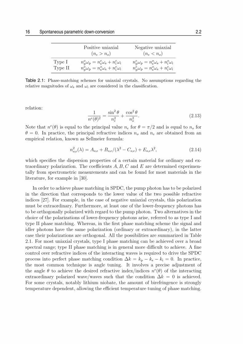
Positive uniaxial Negative uniaxial(ne > no) (ne < no)
Type I nopωp = ne
sωs + nei ωi ne
pωp = nosωs + no
i ωi
Type II nopωp = no
sωs + nei ωi ne
pωp = nosωs + ne
i ωi
Table 2.1: Phase-matching schemes for uniaxial crystals. No assumptions regarding therelative magnitudes of ωs and ωi are considered in the classification.
relation:1
ne(θ)2=
sin2 θ
n2e
+cos2 θ
n2o
. (2.13)
Note that ne(θ) is equal to the principal value ne for θ = π/2 and is equal to no forθ = 0. In practice, the principal refractive indices no and ne are obtained from anempirical relation, known as Sellmeier formula:
n2o,e(λ) = Ao,e + Bo,e/(λ
2 − Co,e) + Eo,eλ2, (2.14)
which specifies the dispersion properties of a certain material for ordinary and ex-traordinary polarization. The coefficients A,B, C and E are determined experimen-tally from spectrometric measurements and can be found for most materials in theliterature, for example in [30].
In order to achieve phase matching in SPDC, the pump photon has to be polarizedin the direction that corresponds to the lower value of the two possible refractiveindices [27]. For example, in the case of negative uniaxial crystals, this polarizationmust be extraordinary. Furthermore, at least one of the lower-frequency photons hasto be orthogonally polarized with regard to the pump photon. Two alternatives in thechoice of the polarizations of lower-frequency photons arise, referred to as type I andtype II phase matching. Whereas, in the first phase matching scheme the signal andidler photons have the same polarization (ordinary or extraordinary), in the lattercase their polarizations are orthogonal. All the possibilities are summarized in Table2.1. For most uniaxial crystals, type I phase matching can be achieved over a broadspectral range; type II phase matching is in general more difficult to achieve. A finecontrol over refractive indices of the interacting waves is required to drive the SPDCprocess into perfect phase matching condition ∆k = kp − ks − ki = 0. In practice,the most common technique is angle tuning. It involves a precise adjustment ofthe angle θ to achieve the desired refractive index/indices ne(θ) of the interactingextraordinary polarized wave/waves such that the condition ∆k = 0 is achieved.For some crystals, notably lithium niobate, the amount of birefringence is stronglytemperature dependent, allowing the efficient temperature tuning of phase matching.
2.2 Simple theoretical model 17
2.2 Simple theoretical model
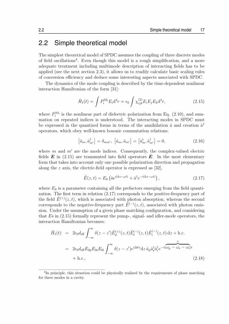
The simplest theoretical model of SPDC assumes the coupling of three discrete modesof field oscillations4. Even though this model is a rough simplification, and a moreadequate treatment including multimode description of interacting fields has to beapplied (see the next section 2.3), it allows us to readily calculate basic scaling rulesof conversion efficiency and deduce some interesting aspects associated with SPDC.
The dynamics of the mode coupling is described by the time-dependent nonlinearinteraction Hamiltonian of the form [31]:
HI(t) =
∫PNL
i Eid3r = ε0
∫χ
(2)ijkEiEjEkd
3r, (2.15)
where PNLi is the nonlinear part of dielectric polarization from Eq. (2.10), and sum-
mation on repeated indices is understood. The interacting modes in SPDC mustbe expressed in the quantized forms in terms of the annihilation a and creation a†
operators, which obey well-known bosonic commutation relations:
[am, a†m′
]= δmm′ ,
[am, am′
]=
[a†m, a†m′
]= 0, (2.16)
where m and m′ are the mode indices. Consequently, the complex-valued electricfields E in (2.15) are transmuted into field operators E. In the most elementaryform that takes into account only one possible polarization direction and propagationalong the z axis, the electric-field operator is expressed as [32],
E(z, t) = E0
(aei(kz−ωt) + a†e−i(kz−ωt)
), (2.17)
where E0 is a parameter containing all the prefactors emerging from the field quanti-zation. The first term in relation (2.17) corresponds to the positive-frequency part ofthe field E(+)(z, t), which is associated with photon absorption, whereas the secondcorresponds to the negative-frequency part E(−)(z, t), associated with photon emis-sion. Under the assumption of a given phase matching configuration, and consideringthat Es in (2.15) formally represent the pump-, signal- and idler-mode operators, theinteraction Hamiltonian becomes:
HI(t) = 2ε0deff
∫ ∞
−∞δ(z − z′)E(+)
p (z, t)E(−)s (z, t)E
(−)i (z, t) dz + h.c.
= 2ε0deffE0pE0sE0i
∫ ∞
−∞δ(z − z′)ei∆kzdz apa
†sa†i e−i(
0︷ ︸︸ ︷ωp − ωs − ωi)t
+ h.c., (2.18)
4In principle, this situation could be physically realized by the requirements of phase matchingfor three modes in a cavity.

18 Spontaneous parametric down-conversion 2.2
where deff is an effective nonlinearity, which can be determined from the tensor d[see definition in the paragraph below Eq. (2.10)] assuming a certain crystallographicstructure of the nonlinear medium [30].
The description of the mode coupling using interaction Hamiltonian (2.18) ac-counts for an effect of pump depletion, due to the quantized form of this field. How-ever, under standard experimental conditions this effect is negligible, because theincident pump field is intense and conversion efficiency in SPDC is very low. Thelatter can be inferred from closer inspection of the relative magnitudes between thelinear and the nonlinear term in the expansion of the dielectric polarization:
∣∣P NL∣∣
|P L| =2deff |Es(i)|
n2 − 1, (2.19)
where |Es(i)| represents the strength of the signal (or idler) mode, which emergesas amplification of vacuum fluctuations; |Es(i)| ¿ 1 V/m. Assuming the realisticmagnitudes of the other quantities, deff ≈ 10−12 m/V, n2 ≈ 1–10, this ratio is closeto zero, corresponding to the spontaneous nature of SPDC. Therefore, to a goodapproximation, we can treat the pump mode ap classically as a complex-valued fieldof a constant amplitude ap.
The total Hamiltonian consists of the term H0 describing the energy of a freetwo-mode field and the interaction term HI from Eq. (2.18) [31]:
H = H0 + HI =∑m=s,i
~ωm
(ama†m +
1
2
)+ ~g
(a†i a
†sap + h.c.
), (2.20)
where g is the mode coupling parameter describing the strength of nonlinear interac-tion. It is proportional to the effective nonlinearity deff and to a factor ei∆ktc, wherewe put t = z′/c. In Heisenberg representation the time evolution of the field operatorsis described by the coupled equations of motions [31]:
das
dt=
1
i~
[as, H
]= −iωsas − iga†i ap, (2.21a)
dai
dt=
1
i~
[ai , H
]= −iωi ai − iga†sap, (2.21b)
and their Hermitian conjugates. Note that these equations are identical to equationsderived for a classical parametric amplifier, see e.g. [29], provided that the annihila-tion and creation operators are identified with classical mode amplitudes and theircomplex conjugates, respectively. Making use of commutation rules (2.16), it followsdirectly from Eqs. (2.21):
d
dta†sas =
d
dta†i ai, (2.22)

2.2 Simple theoretical model 19
which is equivalent to the commutation relations:
[a†sas, H
]=
[a†i ai, H
], (2.23)
so that a†sas − a†i ai is a constant of motion. Recalling the definition of the numberoperator n [32]:
a†a|n〉 = n|n〉 = n|n〉, (2.24)
where n is the number of quanta in a mode and |n〉 is the corresponding eigenstate,we can finally write:
ns(t)− ns(0) = ni(t)− ni(0), (2.25)
which is a well known Manley-Rowe relation5 [33], reflecting the fact that signal andidler photons are always created in pairs.
The equations of motions (2.21) posses the following solution [34]:
as(t) = e−iωst[as(0) cosh
(κ|ap|
)− ia†i (0) sinh(κ|ap|
)], (2.26a)
ai (t) = e−iωi t[ai (0) cosh
(κ|ap|
)− ia†s(0) sinh(κ|ap|
)], (2.26b)
where we introduced κ(tI) =∫ tI−∞ g(t)dt. In practice, the interaction time tI may
be taken as propagation time through the nonlinear medium of length L, tI ≈ L/c,which allows to reduce the integration limits in κ:
∫ t
−∞ −→ ∫ tI0
. The Eqs. (2.26) canbe readily used to calculate certain expectations on photon number statistics. To thisend we first express the number operators in terms of the field operators at t = 0:
ns(t) = a†s(t)as(t) = a†s(0)as(0) cosh2(κ|ap|
)+
[1 + a†i (0)ai(0)
]
× sinh2(κ|ap|
)− 1
2i[a†s(0)a†i (0)− as(0)ai(0)
]sinh
(2κ|ap|
), (2.27a)
ni(t) = a†i (t)ai(t) = a†i (0)ai(0) cosh2(κ|ap|
)+
[1 + a†s(0)as(0)
]
× sinh2(κ|ap|
)− 1
2i[a†i (0)a†s(0)− ai(0)as(0)
]sinh
(2κ|ap|
). (2.27b)
Next, assuming that the initial state at t = 0 is |ns(0), ni(0)〉, the time evolution ofthe average photon-number 〈ns〉 (〈ns〉) at frequency ωs (ωi) can be easily evaluated:
〈ns(t)〉 = ns(0) cosh2(κ|ap|
)+ [1 + ni (0)] sinh2
(κ|ap|
), (2.28a)
〈ni (t)〉 = ni (0) cosh2(κ|ap|
)+ [1 + ns(0)] sinh2
(κ|ap|
). (2.28b)
5Since the number of photons n is related to the optical power P by P = n~ω, we can rewriteexpression (2.25) in the form Ps/ωs = Pi/ωi, in accordance with the original formulation fromManley and Rowe.

20 Spontaneous parametric down-conversion 2.2
Due to the commutation rules (2.16), the second terms in Eqs. (2.28a) and (2.28b)contain an extra 1, which gives under any initial conditions a nonzero contributionsinh2
(κ|ap|
)to the average photon number. Thus, even if the signal and idler modes
are initially in vacuum states, i.e. ns(0) = ni(0) = 0, after a time period tI longenough there will be photons in these modes. This purely quantum-mechanical effectelucidates the possibility of spontaneous emission in parametric down-conversion,which emerges as an amplification of the vacuum fluctuations associated with thenoncommutation of the field operators. Let us note that the presence of the inputsignal field stimulates the emission of photons in the idler field and vice versa. Thatis, the initial conditions ns(0) 6= 0 or ni(0) 6= 0 correspond to the effect of stimu-lated emission, which is fully accounted for by the classical theory of the parametricamplifier.
The interaction time tI is extremely short for realistic crystal lengths (∼ mm), sothat generally we can consider the short-time limit condition, κ|ap| ¿ 1, to be valid.Then, the photon flux emitted from SPDC is given by
〈ns(t)〉 = 〈ni(t)〉 = sinh2(κ|ap|
) ≈ (κ|ap|
)2. (2.29)
The average photon numbers in the signal and idler mode are proportional to theintensity of the pump field Ip ∼ |ap|2. As Ip gives the rate at which pump photons fallon the nonlinear medium, the parameter |κ|2 is a dimensionless number determiningthe fraction of incident pump photons to be converted into lower-frequency photons.The following scaling behavior can be inferred by closer inspection of the parameterκ, see the definition below Eqs. (2.26):
κ ∝ deffLsinc
(∆kL
2
), (2.30)
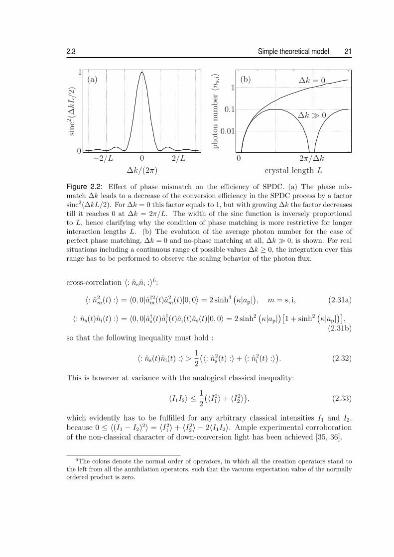
where sinc function, sinc(x) = sin(x)/x, accounts for the impact of phase mismatch∆k on the efficiency of SPDC. As illustrated in Fig. 2.2(a), for a given L the phasemismatch ∆k corresponds to a decrease in efficiency by a factor, which is inverselyproportional to L. The quadratic scaling of the photon flux with L for the case ofperfect phase matching is therefore generally reduced to a linear dependence ∝ L if∆k 6= 0, see Fig. 2.2(b). Furthermore, it follows from (2.30) that the yield of down-conversion photons grows quadratically with the effective nonlinearity deff . Due tothe fact that signal and idler photons are always created in pairs, the afore-mentionedscaling rules do not apply only for photon emissions into an individual mode, but alsofor simultaneous double-photon emissions into both modes.
Notably, the above simple theoretical model is sufficient to prove the nonclassicalstatistics of down-conversion light [31]. To that end, the mathematical steps leadingto Eqs. (2.28) are again applied here to evaluate the second moment 〈: n2
s,i :〉 and the
2.3 Simple theoretical model 21
Figure 2.2: Effect of phase mismatch on the efficiency of SPDC. (a) The phase mis-match ∆k leads to a decrease of the conversion efficiency in the SPDC process by a factorsinc2(∆kL/2). For ∆k = 0 this factor equals to 1, but with growing ∆k the factor decreasestill it reaches 0 at ∆k = 2π/L. The width of the sinc function is inversely proportionalto L, hence clarifying why the condition of phase matching is more restrictive for longerinteraction lengths L. (b) The evolution of the average photon number for the case ofperfect phase matching, ∆k = 0 and no-phase matching at all, ∆k À 0, is shown. For realsituations including a continuous range of possible values ∆k ≥ 0, the integration over thisrange has to be performed to observe the scaling behavior of the photon flux.
cross-correlation 〈: nsni :〉6:
〈: n2m(t) :〉 = 〈0, 0|a†2m(t)a2
m(t)|0, 0〉 = 2 sinh4(κ|ap|
), m = s, i, (2.31a)
〈: ns(t)ni(t) :〉 = 〈0, 0|a†s(t)a†i (t)ai(t)as(t)|0, 0〉 = 2 sinh2(κ|ap|
)[1 + sinh2
(κ|ap|
)],
(2.31b)so that the following inequality must hold :
〈: ns(t)ni(t) :〉 >1
2
(〈: n2s (t) :〉+ 〈: n2
i (t) :〉). (2.32)
This is however at variance with the analogical classical inequality:
〈I1I2〉 ≤ 1
2
(〈I21 〉+ 〈I2
2 〉), (2.33)
which evidently has to be fulfilled for any arbitrary classical intensities I1 and I2,because 0 ≤ 〈(I1 − I2)
2〉 = 〈I21 〉 + 〈I2
2 〉 − 2〈I1I2〉. Ample experimental corroborationof the non-classical character of down-conversion light has been achieved [35, 36].
6The colons denote the normal order of operators, in which all the creation operators stand tothe left from all the annihilation operators, such that the vacuum expectation value of the normallyordered product is zero.

22 Spontaneous parametric down-conversion 2.3
2.3 Multimode description
In the previous, the theoretical description of SPDC process has been introduced,assuming that just two monochromatic modes of the lower-frequency fields becomeexcited. This treatment could account for some phenomena associated with SPDC,but fails in most cases, where the correlation effects start to be prominent. There-fore, more realistic models are needed, decomposing the down-conversion fields intoan infinite set of modes, which is eventually treated as continuum [24, 37]. Thistreatment conceptualizes the signal and idler photons as short wave packets ratherthan monochromatic waves, even though the sum of their frequencies has a sharpvalue.
The down-conversion fields are described as a superposition of modes representedby plane waves, so that each mode is characterized by a wave vector k and a po-larization index. The rules of birefringent phase matching dictate that all modesbelonging to the signal or the idler field, respectively, have to have the same polar-ization - either ordinary or extraordinary. This greatly simplifies the situation andallows to omit the polarization indexing in the course of the following derivation. Itwill be just sufficient to assign certain polarization directions to interacting fields inthe final formulas, provided that a certain phase matching scheme will be considered,see Table 2.1. The electric-field operator of the down-conversion field can be thuswritten as
Em(r, t) =∑
km
em(ωkm)am [km(ωkm)] eikm(ωkm )r−iωkm t + h.c., m = s, i, (2.34)
where em(ωkm) =√~ωkm/2ε0V is the amplitude per photon of the mode with a wave
vector km and a frequency ωkm . Similarly as in the previous section, the parametricapproximation is applied here, treating the pump as a classical, undepleted field.Further, the pump field is assumed to be linearly polarized and propagating in zdirection, so that we can write:
Ep(z, t) = E (+)p (z, t)e−iω0
pt + h.c., (2.35)
where ω0p is the central frequency and E (+)
p (z, t) is the positive-frequency part of thecomplex pump-field envelope, expressed in the form [38]:
E (+)p (z, t) =
∫ ∞
−∞dνp E (+)
p (0, νp)eikp(ωkp )z−iνpt, (2.36)
where νp = ωkp −ω0p and E (+)
p (0, νp) is the spectrum of the field envelope E (+)p (0, t) at
z = 0, defined through the Fourier transformation:
E (+)p (0, νp) =
1
2π
∫ ∞
−∞dt E (+)
p (0, t)eiνpt. (2.37)

2.3 Multimode description 23
In the majority of real experimental scenarios, the down-conversion fields areemitted close to the forward direction. Therefore, in the following derivation, we canadopt a reasonable assumption that the transverse k-vector components of the down-conversion modes are negligible and put Em(r, t) ≡ Em(z, t), (m = s, i). This approx-imation will substantially simplify the following consideration, but, needles to say,prohibits to gain any information on the spatial characteristics of down-conversionemission. The total Hamiltonian of the system can be expressed as a sum of twoterms - the energy in the free uncoupled fields:
H0 =∑
ks
~ωks
(a†s(ks)as(ks) +
1
2
)+
∑
ki
~ωki
(a†i (ki)ai(ki) +
1
2
)(2.38)
and the energy arising from the interaction of the fields, see Eq. (2.15):
HI(t) = CI
∫ 0
−L
dz
∫ ∞
−∞dνp
∑
ks
∑
ki
E (+)p (0, νp)
× a†s(ks)a†i (ki)e
i(kp−ks−ki)z−i(ωkp−ωks−ωki)t + h.c., (2.39)
where CI includes the effective nonlinearity deff and the slowly varying functionses(ωks) and ei(ωki
). The first integration in (2.39) extends over the length L of thenonlinear crystal in z direction; the origin of the coordinates is assumed to be at theoutput plane of the crystal. The expressions (2.38) and (2.39) should be compared tothe Hamiltonian from Eq. (2.20) describing the discrete three-mode SPDC process.
The splitting of the Hamiltonian into a free unperturbed part H0 and an inter-action part HI , which can be treated as a perturbation, suggests that we can takean advantage of a quantum-mechanical description in the interaction representation,where the time evolution of an arbitrary state vector |ψ(t)〉 is defined as [32]
|ψ(t)〉 = exp
(1
i~
∫ t0+tI
t0
HI(t)
)|ψ(0)〉 = |ψ(0)〉+
∞∑n=1
(1
i~
)n
×∫ t0+tI
t0
dt1
∫ t0+tI
t0
dt2 · · ·∫ t0+tI
t0
dtn HI(t1)HI(t2) · · · HI(tn)|ψ(0)〉. (2.40)
Here, tI is the time of interaction and |ψ(t = t0)〉 = |ψ(0)〉 represents the state att0, when the interaction has not been started yet. In the SPDC process there is noinput radiation in any signal and idler mode, so that the initial state |ψ(0)〉 is themultimode vacuum state |vac〉. Furthermore, the spontaneous nature of the processimplies that the perturbation HI is very small compared to H0, which means thatthe series from Eq. (2.40) must converge fast. Under most experimental conditionsonly the first term in the series is relevant, corresponding to the emission of a photonpair from SPDC. Thus, the two-photon state of down-conversion photons |ψ(2)(0, t)〉

24 Spontaneous parametric down-conversion 2.3
at the output of the nonlinear medium (z = 0) can be written as
|ψ(2)(0, t)〉 =1
i~
∫ ∞
−∞dt HI(t)|vac〉. (2.41)
By extending the limits of integration in (2.41) to infinity we explicitly assume thatthe interaction Hamiltonian approaches zero for times before t0 and after t0 + tI .Substituting for the interaction Hamiltonian and evaluating the time integral, thetwo-photon state becomes:
|ψ(2)(0, t)〉 =CI
i~
∫ 0
−L
dz
∫ ∞
−∞dνp
∑
ks
∑
ki
E (+)p (0, νp)a
†s(ks)a
†i (ki)
× ei(kp−ks−ki)z+i(ωks+ωki)t δ(ωkp − ωks − ωki
)|vac〉, (2.42)
For the further consideration we expand the wave numbers of interacting fieldsabout their carrier frequencies ω0 [38]:
km(ωkm) = k0m
(ω0
m
)+
1
vm
(ωkm − ω0
m
)+
1
2Dm
(ωkm − ω0
m
)2= k0
m + εkm, (2.43)
where m = p, s, i and the higher-order terms are dropped. The central wave numbersof the fields k0
m (ω0m) are given by Eq. (2.7). The symbol vm is the group velocity of
the field m, expressed in terms of the refractive index n(λm) as
1
vm
=dkm
dωkm
∣∣∣∣ωkm=ω0
m
=1
c
[n(λm)− λm
dn(λm)
dλm
], (2.44)
and D is the group velocity dispersion parameter:
Dm =d2km
d2ωkm
∣∣∣∣ωkm=ω0
m
=d
dωkm
1
vm
∣∣∣∣ωkm=ω0
m
=λ3
2πc2
d2n(λm)
dλ2m
. (2.45)
Applying the above expressions in Eq. (2.42) and assuming that the carrier frequen-cies ω0
m and the central wave numbers k0m of the interacting fields fulfill energy- and
momentum-conservation conditions from Eqs. (2.5) and (2.6), respectively, we arriveat the following form of the two-photon state [39]:
|ψ(2)(0, t)〉 =CIe
i(ω0s +ω0
i )t
i~
∫ 0
−L
dz
∫ ∞
−∞dνp
∫ ∞
−∞dνs
∫ ∞
−∞dνi E (+)
p (0, νp)
× exp
[i
(νp
vp
− νs
vs
− νi
vi
)z
]exp
[i
2
(Dpν2p −Dsν
2s −Diν
2i
)z
]
× δ(νp − νs − νi)ei(νs+νi)t|νs〉|νi〉, (2.46)

2.3 Multimode description 25
where νm = ωkm − ω0m is the detuning frequency from the central frequency and
|νm〉 is a one-photon Fock state; m = s, i. The output two-photon state fromSPDC is represented by a continuous superposition of states in which the signaland idler photons have frequencies νs and νi, respectively. The energy-conservationlaw, leading to strong correlations of the frequencies νs and νi, is explicitly displayedin |ψ(2)(0, t)〉 by the delta function. By evaluating the spatial integral in (2.46) weobtain sinc [(εkp − εks − εki)L/2], which accounts for the momentum correlation ofthe down-conversion photons. In the limit of very long crystals, L → ∞, the sincfunction approaches delta function δ(εkp − εks − εki). That is, in such a limitingcase, a down-conversion event is allowed only, if the momenta of the lower-frequencyphotons sum to the momentum of the pump. Note that the delta functions precludethe possibility of factorization |ψ(2)(0, t)〉 into a product state of the signal and theidler photon, i.e., |ψ(2)(0, t)〉 from Eq. (2.46) is an EPR-type entangled state.
2.3.1 Spectra of down-conversion fields
The knowledge of the two-photon state |ψ(2)(0, t)〉 allows us to readily evaluate thespectral properties of the individual down-conversion fields. The spectrum of thesignal (idler) field behind the nonlinear crystal is defined as follows [39, 40]:
Ss(i)(νs(i)) = 〈ψ(2)(0, t)|a†s(i)(νs(i))as(i)(νs(i))|ψ(2)(0, t)〉. (2.47)
Using the state |ψ(2)(0, t)〉 from (2.46), the expression for the signal field becomes
Ss(νs) =|CI |2~2
∫ ∞
−∞dνp
∣∣E (+)p (0, νp)
∣∣2 L2
× sinc2
[L
2
(upiνp − usiνs +
Dpi
2ν2
p −Dsi
2ν2
s +Diνpνs
)], (2.48)
in which we introduced the following parameters:
upm =1
vp
− 1
vm
, Dpm = Dp −Dm, m = s, i, (2.49)
usi =1
vs
− 1
vi
, Dsi = Ds +Di, (2.50)
The spectrum of the idler field is obtained from (2.48) by substituting the dispersionparameters upi, Dpi and Di for ups, Dps and Ds, respectively. In the limiting case ofthe continuous-wave (CW) pumping at the frequency ω0
p, the complex spectrum of
the pump-field envelope E (+)p (0, νp) is put as the delta function δ(νp) multiplied by

26 Spontaneous parametric down-conversion 2.3
the amplitude ξp, and the expression (2.48) reduces to the following analytical form:
S(cw)s (νs) =
|CIξp|2~2
L2sinc2
[L
2
(usiνs +
Dsi
2ν2
s
)]. (2.51)
The spectral profiles of the emitted photon wave packets are determined by a sinc2
function, which appears in the expression (2.48) due to the double integration overthe finite length L of the crystal. Note that the idler spectrum will be given by theformula identical to (2.51), because none of the dispersion parameters from (2.49)are contained therein. That is, the spectra of the two generated fields are always thesame in CW-pumped SPDC. This is explained by perfect anti-correlation of the signaland idler frequencies: The two frequencies always sum up to the pump frequency ω0
p,
which ensures that the output two-photon state |ψ(2)(0, t)〉 will be symmetric in thefrequencies of signal and idler photon wave packets.
A further simplification of the expression (2.51) for down-conversion spectra inthe CW-pumping limit might be attained, when assuming a certain phase matchingscheme. This also allows to investigate the scaling behavior of the spectral width onthe relevant parameters, showing remarkably different results for type I and type IIphase matching. Unless specified otherwise, the spectral width is defined here as thefull width at half maximum (FWHM) of the sinc2 profile.
We start with type II phase matching scheme. There, signal and idler wave packetsare orthogonally polarized, and therefore they are necessarily subjected to distinctmaterial dispersion in the nonlinear crystal due to its anisotropy, see section 2.1.Consequently, the difference in the group velocities of photons reaches considerablevalues; for standard materials usi is roughly ≈ 10−10 s/m. The parameter Dsi reachesusually ≈ 10−25 s2/m in case of type-II phase matching, so that the second term insinc2 function of Eq. (2.51) can be neglected for the realistic values of the detuningfrequencies νs, νi ≈ 1013 –1014 s−1. The phase-matched spectral width of the down-conversion fields is thus solely determined by the difference in group velocities usi andthe thickness of the crystal L, and it scales as ∝ 1/(usiL). That is, the longer thecrystal L and the higher the difference in group velocities |vs − vi|, the narrower theresultant spectrum will be.
For type I phase matching a markedly different situation is encountered. Theemitted photons have the same polarization and therefore they propagate throughthe nonlinear crystal with identical group velocities. Consequently, the dispersionparameter usi vanishes and it is now the second term in the sinc2 function of Eq.(2.51), which will determine the spectral characteristics of down-conversion light.Due to the fact that this term is smaller by 1–2 orders of magnitude than the term,which was previously dominant for type II phase matching, significantly broaderspectra might be expected in case of type I phase matching. Moreover, the spectralwidth now scales as ∝ 1/
√(DsiL). This means that the width shrinks only with the
square root of crystal length.Note that the above discussion implicitly assumed degenerate central output fre-

2.3 Multimode description 27
Figure 2.3: Scaling of down-conversion spectral width with the crystal length for differentphase-matching configurations. The widths are for degenerate type I and type II SPDCrepresented by blue and red solid curves, respectively. The first scales as ∝ 1/
√L and
the latter as ∝ 1/L. The dashed curves in corresponding colors show the widths for non-degenerate type I and type II phase matching, assuming a 100 nm separation betweencentral down-conversion wavelengths. In the plot SPDC in a BBO crystal and pumped ata wavelength λ0
p = 403 nm is assumed.
quencies, i.e. the condition ω0p = 2ω0
s = 2ω0i . If non-degenerate central frequencies
(ω0s 6= ω0
i ) are phase-matched in type I SPDC, the parameter usi does not vanishany longer due to the dispersive nature of the nonlinear crystal, and both terms inthe sinc2 function have to be taken into account. As a result, the spectral widthshrinks compared to the degenerate case, and approaches the type-II phase-matchedwidth as the non-degeneracy increases. In contrast to type I phase matching, thereis only a little effect on the width of phase-matched spectra in type II SPDC whengoing away from the non-degeneracy point. The resultant width might slightly in-crease or decrease depending on whether the higher central non-degenerate frequencycorresponds to extraordinary or ordinary polarization.
The general conclusions drawn above for the CW-pumped SPDC are quantita-tively demonstrated in the Fig. 2.3, showing the dependencies of spectral width on thecrystal lengths for different phase matching configurations. An example of SPDC ina beta-barium borate nonlinear crystal (β-BaB2O4 or BBO, the basic characteristicsare given in appendix A.1.1) is considered therein.
While the idler and signal wave packets produced in narrow-band pumped SPDCare perfectly anti-correlated in their frequencies, the broadband pumping of SPDCentails more complex spectral correlation of the wave packets. For the latter case, theenergy-conservation condition is relaxed, because a down-conversion event is permit-ted, whenever the frequencies of the daughter photons sum to some frequency foundin the pump. As a finite range of pump frequencies is available for the nonlinear pro-cess, the phase matching condition is fulfilled for more signal and idler frequencies andconsequently, their natural spectra are broadened in comparison with CW-pumpingcase. Moreover, for type II SPDC the broadband pumping causes a symmetry break-

28 Spontaneous parametric down-conversion 2.3
ing between the spectra of ordinary- and extraordinary-polarized wave packets [41].They are no longer identical, which is attributed to the distinct influence of materialdispersion on the two polarizations.
To quantitatively estimate the effect of broadband pumping on the down-conver-sion spectra, we conveniently represent the pump field as a gaussian pulse with aduration τp. Then, the following form of the pump-field envelope from Eq. (2.35)applies [38]:
E (+)p (0, t) = ξp exp
(−1 + iap
τ 2G
t2)
, (2.52)
where ξp is the amplitude and ap represents the linear chirp of the pulse. The param-eter τG determines the pulse duration τp (measured as the full width at half maximumof the intensity profile) via the following relation:
τp =√
2 ln 2τG. (2.53)
The Fourier transformation of (2.52) according to the definition in Eq. (2.37) intothe frequency domain gives:
E (+)p (0, νp) = ξp
τG
2√
π√
1 + iap
exp
[− τ 2
G
4(1 + iap)ν2
p
], (2.54)
which might be directly substituted into the expression (2.48) to find the down-conversion spectra. The results of a numerical evaluation are presented in Fig. 2.4,assuming a specific example of SPDC in a 2 mm long BBO nonlinear crystal. For shortpump-pulse durations, a significant broadening of spectra is observed for both typeI and type II SPDC. Moreover, as expected, the spectrum of the ordinary polarizedwave packet is broader than that of the extraordinary-polarized photon in case oftype II SPDC.
It is important to bear in mind that the above theoretical model is built upon twoapproximations, which limit the general validity of the inferred results. First, it treatsthe pump field as a superposition of plane waves, which all propagate in z direction,see Eq. (2.36). Thus, the effect of pump-beam focusing is not included in the modelwhatsoever. We might expect, that this effect will be completely analogous to thatof spectral broadening of the pump. Because a wider range of pump-wave vectorsis available for the nonlinear process in case of tight focusing, the phase matchingcondition is fulfilled for more signal and idler frequencies/momenta and consequently,their natural spectra will be broadened. Indeed, it was shown that the tight focusingof the pump to waist sizes of ¿ 100 µm leads to a significant increase of down-conversion spectral width [42] (provided that crystals with lengths in ∼ mm rangeare used). A second limitation arises from the assumption of the collinear geometry ofthe nonlinear process, which was adopted in the model. This implies that the faithfulresults are obtained only for the emission of down-conversion photons close enoughto the direction of the pump beam. A more sophisticated treatment is required, if

2.3 Multimode description 29
Figure 2.4: Effect of the broad-band pumping on the phase-matched spectral width. The up-per plot shows the results obtainedfor type I SPDC and the lower fortype II SPDC. In the latter plotthe solid and dashed curves cor-respond to ordinary and extraor-dinary polarization, respectively.The evaluation assumes SPDC ina 2 mm long BBO crystal pumpedat a wavelength of λ0
p = 403 nm.
the directions of down-conversion photons deviate significantly from the pump-beamdirection [42].
Finally, we emphasize again that the formula (2.47) provides the spectral characte-ristics of the natural phase matching in SPDC. I.e., in fact, it determines the spectralwidths of the photon wave packets right behind the nonlinear crystal. Nevertheless,it is straightforward to elaborate the theoretical frame and incorporate the effect offrequency filtering, which is commonly used in the experimental arrangements. Inpractice, frequency filtering is realized by interference filters or by restricting theangular distribution of the emitted down-conversion fields. In either case it can bemodelled to a good approximation by a spectral transmission function with a gaussianprofile centered around the carrier frequency ω0
m:
Fm(νm) = exp
(−2ν2
m
σ2m
), m = s, i. (2.55)
The FWHM of the profile is defined as√
2 ln 2σm. Frequency filtering is then in-cluded in the theoretical frame by inserting the term
√FiFs in the two-photon state|ψ(2)(0, t)〉 defined in Eq. (2.46). Consequently, the signal (idler) spectra evaluatedaccording to Eq. (2.47) account not only for a trivial effect of spectral filteringperformed directly on signal (idler) photons, but also for a non-local effect, whichmight be loosely referred to as cross-filtering. It means, e.g., if a frequency filter-ing is performed on the signal photon, then the corresponding idler-photon spectra,which effectively contribute to the two-photon state, will be altered as well due toentanglement of photon pairs in the frequency domain.

30 Spontaneous parametric down-conversion 2.3
2.3.2 Time distribution of down-conversion fields
The joint time distribution of down-conversion fields is conveniently described interms of the two-photon amplitude, which is sometimes referred to as biphoton am-plitude. It is defined as a matrix element for the transition of the down-conversionfields from a two-photon state |ψ(2)(0, t)〉 into a vacuum state |vac〉 [39, 40],
A(τs, τi) = 〈vac|E(+)s (0, t0 + τs)E
(+)i (0, t0 + τi)|ψ(2)(0, t0)〉. (2.56)
That is, A defines the amplitude that two separated ideal detectors of negligiblesizes record the signal and idler photons at the times τs and τi, respectively. Thisinterpretation comes directly from standard quantum field theory, see e.g. [43]. Itbecomes then obvious that the square of the two-photon amplitude determines thesecond-order correlation function G(2)(τs, τi) = |A(τs, τi)|2, which is proportional tothe probability of coincidence detection of the down-conversion photons at the timesτs and τi. Integrating the correlation function G(2)(τs, τi) over a time interval T givesthe average coincidence count rate Rc of the two detectors during T , which might bewritten as [44]:
Rc ∝ 1
T
∫ T
0
dτs
∫ T
0
dτi 〈ψ(2)(0, t0)|E(−)i (0, t0 + τi)E
(−)s (0, t0 + τs)
× E(+)s (0, t0 + τs)E
(+)i (0, t0 + τi)|ψ(2)(0, t0)〉. (2.57)
The above formula directly relates the measurable quantity - the coincidence countrate - to the two-photon amplitude.
In general, the two-photon amplitude determines all the measurable joint charac-teristics of the down-conversion fields [40]. I.e., A(τs, τi) plays a role of a wavefunction,which describes the effective field of the two-photon wave packet (biphoton). Since weare primarily interested in the time characterization of the two-photon wave packet,the spatial dependency of the amplitude A(τs, τi) is completely omitted in the abovedescription. Substituting for the electric-field operators and the two-photon state,Eq. (2.56) becomes [39]
A(τs, τi) =CI
i~es(ω
0s )ei(ω
0i )e
i(ω0s τs+ω0
i τi)
∫ 0
−L
dz
∫ ∞
−∞dνp
∫ ∞
−∞dνs
∫ ∞
−∞dνi E (+)
p (0, νp)
× exp
[i
(νp
vp
− νs
vs
− νi
vi
)z
]exp
[i
2
(Dpν2p −Dsν
2s −Diν
2i
)z
]
× δ(νp − νs − νi)ei(νsτs+νiτi)Ts(νs)Ti(νi)|νs〉|νi〉. (2.58)
The newly introduced symbols Ts and Ti represent the optical transfer functions[29], which describe the effect of any linear optical system (or series of linear opticalsystems) on signal and idler photons. This allows us to evaluate the effective two-photon amplitude at any place of a real experimental set-up. E.g., putting Tm(νm) ≡

2.3 Multimode description 31
√Fm(νm) [see Eq. (2.55)], the expression (2.58) defines the amplitude A of the
two-photon down-conversion wave packet after passing through frequency filters.For CW-pumped SPDC [E (+)
p (0, νp) = ξpδ(νp)], the expression for the two-photonamplitude simplifies to
A(τs, τi) =CI
i~es(ω
0s )ei(ω
0i )ξpe
i(ω0s τs+ω0
i τi)
∫ ∞
−∞dνs e−iνs(τs−τi)
× Ts(νs)Ti(−νs) exp
[−i
Lνs
2
(usi +
Dsi
2νs
)]sinc
[Lνs
2
(usi +
Dsi
2νs
)], (2.59)
where the dispersion parameters usi and Dsi are defined in (2.50). In order to grasp thebasic physics of (2.59), we put, for simplicity, Ts(νs) = Ti(−νs) = 1, and analyze thetwo-photon amplitude right after the nonlinear crystal. The two photon-amplitude isconveniently studied in the rotated coordinate system with the axes τ+ = (τs + τi)/2and τ− = τs − τi. We may interpret τ− as the difference in the arrival times of thesignal and idler photon at the output face of the crystal. If it is positive, the signalphoton arrives after the idler photon and vice versa. The value of τ+ may be regardedas the time at which the center of the two-photon wave packet arrives at the outputface of the crystal. The origin for the τ+ axis is defined by the arrival time of thepump.
We immediately recognize that the expression (2.59) is independent of the timeτ+ except for an irrelevant phase factor. This must be clearly right for the case of CWpumping, because an SPDC event can occur in principle at any time, so that all thevalues τ+ are equally probable. In general, the two-photon amplitude is determinedalong the τ+ direction by the temporal characteristics of the pump field and thegroup velocity mismatch between the pump and the two-photon down-conversionwavepacket. Apparently, for very short crystals, the time profile of the pump willbe directly transferred to the τ+-profile of |A(τ+, τ−)|. For long enough crystals thebroadening of the τ+-profile due to the effect of the group velocity mismatch willbecome significant.
By closer inspection of (2.59), the distinct profiles of the two-photon amplitudesmight be recognized along the τ− axis for type I and type II SPDC, see Fig. 2.5. Thisis evidently a consequence of different effects, which lead to time mismatch in arri-vals of signal and idler photons at the output face of the nonlinear crystal. For typeII SPDC, it is the difference in group velocities, which causes a rectangular-shapedasymmetric profile. This profile stretches from 0 to the value of usiL, which corre-sponds to the difference in time required for ordinary- and extraordinary-polarizedphoton to cross the full length of the crystal. For degenerate type I SPDC the groupvelocities are identical and it is the next order in the expansion of the wave numbers[see Eq. (2.43)], i.e. the effect of group velocity dispersion, which determines thewidth of biphoton in τ− direction. Consequently, a narrow symmetric triangular-shaped profile is observed.
The above description together with the results from Fig. 2.5 suggest that the

32 Spontaneous parametric down-conversion 2.4
Figure 2.5: Absolute value of the normalized two-photon amplitude, |A(τ+, τ−)|, for CW-pumped (a) type I and (b) type II SPDC. Whereas a narrow triangular-shaped profile isobserved for type I phase matching in the τ− direction, type II is characterized by a widerectangular profile, which is asymmetric to τ− = 0. In the graphs, SPDC in a 2 mm longBBO pumped at λ0
p = 403 nm is considered; the signal (idler) is identified with ordinary(extraordinary) polarization.
width of |A(τ+, τ−)| in the τ− direction is inversely proportional to the phase-matchedspectral width of down-conversion photons in case of CW pumped SPDC7. Thisclarifies, why the spectral bandwidth of down-conversion photons is incomparablybroader for type I phase matching. For non-degenerate type I phase matching orfor increasing crystal lengths, the amplitude |A(τ+, τ−)| spreads in the τ− direction.This behavior is in accordance with the observation from the subsection 2.3.1 thatthe phase-matched spectral width shrinks in such cases.
2.4 Spatial emission distribution of down-conversionphotons
In the foregoing sections the spectral and temporal characteristics of the down-conversion fields have been investigated. To keep the theoretical frame on a manage-able level, the spatial properties of the fields interacting in SPDC have been ignored.This section addresses the issue of the spatial properties of these fields and derivesthe emission characteristics of down-conversion photons. The emission characteristicsare derived from the analysis of the energy and momentum conservation conditions.For a fixed pump wave vector and a fixed wavelength of one down-conversion photon
7Indeed, for the FWHM values of 28.2 fs (type I phase matching) and 388.9 fs (type II phasematching) inferred for the parameters used in Fig. 2.5, we find the related “Fourier” spectral widthsof 76.8 nm and 5.5 nm, respectively, which fit well to results plotted in Fig. 2.3.

2.4 Spatial emission distribution of down-conversion photons 33
Figure 2.6: General geometrical set-ting to analyze the angular distribu-tion of down-conversion light. Thedistribution is defined in terms ofthe external emission angles θ andφ, which are measured with respectto the central pump wave vector k0
p.This vector forms an angle Θ0
p withoptic axis of the nonlinear crystal.
from the pair, all emission directions allowed by conservation laws can be calculated.
In practical experiments, a gaussian beam of a certain divergence is usually usedfor pumping of the nonlinear crystal. To account for this feature, the pump is de-composed into a representative set of plane waves, each characterized by a wavevector8. The allowed emission directions are then searched for each vector separately.To include the effect of finite spectral bandwidth, which is always phase-matchedin SPDC, the wavelengths of down-conversion photons are varied within the rele-vant ranges during the evaluation. The angular distribution of down-conversion lightinside the crystal is then evaluated as a weighted superposition of all the found solu-tions. Finally, Snell’s law is applied to determine the distribution outside the crystal.This external angular distribution is obtained in terms of the angles θ and φ, whichare defined with regard to the central pump wave vector k0
p, see Fig. 2.6.
This relatively simple approach to the problem, based on the analysis of phase-matching conditions, determines the emission pattern related to the single-photoncount rate [45], rather than the coincidence count rate, which has to be considered inthe context of two-photon imaging or other spatial correlation effects (see e.g. [46]).In practice, the single-photon pattern can be experimentally captured by imagingthe down-conversion emission onto an intensified charge coupled device array. Theknowledge of this pattern is sufficient to understand the spectral and spatial char-acteristics of the parametric down conversion process for the purpose of maximizingthe yield of available photon pairs in common experiments.
In the following, we shall discuss the elements of the method at length. We startthe analysis by decomposing the phase matching condition (2.6) into a linear set ofequations associated with momentum conservation along the principal axes of the
8The justification of this approach is addressed later in this section.

34 Spontaneous parametric down-conversion 2.4
Figure 2.7: Principal coordinate system of the crystal with the definitions of unit wavevectors of the three interacting fields in SPDC. Each of the vectors is specified by aninternal azimuth angle Θm and an internal polar angle Φm, (m = p, s, i). These angles aremeasured with respect to central pump wave vector k0
p. For clarity, only the wave vectorskp and ki of pump and idler photons, respectively, are displayed in the figure; the signalvector is defined analogously.
crystal. Using the relation (2.7), we write these equations in the form:
ωsnsxs + ωinixi = ωpnpxp,
ωsnsys + ωiniyi = ωpnpyp,
ωsnszs + ωinizi = ωpnpzp,
(2.60)
where xm, ym, zm, (m = p, s, i) are the projections of the unit wave vectors onto theaxes of the principle coordinate system, which is identified with the crystallographicstructure of the crystal, see Fig. 2.7. The choice of this coordinate system shows tobe preferable for the analysis of phase matching because it allows fairly direct defini-tion of the wave vectors in question and avoids any confusions in the calculation ofrefractive indices. Applying the energy conservation law (2.5) and the normalizationcondition, x2
m + y2m + z2
m = 1, the Eqs. (2.60) can be combined into a single equationof the form [45]:
(ωpnp
√1− y2
p − z2p − ωini
√1− y2
i − z2i
)2
+(ωpnpyp − ωiniyi
)2+
(ωpnpzp − ωinizi
)2= n2
s
(ωp − ωi
)2, (2.61)
where all the variables related to the wave vector of the signal photon were eliminated.Orientations of the pump and idler wave vectors, expressed using the projectionsyp, zp and yi, zi, respectively, can be conveniently redefined with the help of Fig. 2.7

2.4 Spatial emission distribution of down-conversion photons 35
in terms of the azimuthal angles Θp, Θi and polar angles Φp, Φi as follows
yi = sin (Φi) , zi = cos(Θ0
p −Θi
) √1− sin2 (Φi), (2.62)
yp = sin (Φp) , zp = cos(Θ0
p + Θp
) √1− sin2 (Φp). (2.63)
Assuming type I phase matching in a negative uniaxial crystal, such as beta-bariumborate, the classification of Table 2.1 asserts the pump photon to be extraordinary po-larized, whereas both signal and idler photons to be ordinary polarized. Accordingly,the following refractive indices have to substituted into Eq. (2.61):
np ≡ ne(λp; Θ0p,Θp, Φp) =
ne(λp)no(λp)√n2
o(λp) +[n2
e(λp)− n2o(λp)
]z2p
,
ns ≡ no(λs), ni ≡ no(λi).
(2.64)
The first expression (for extraordinary refractive index) is deduced from Eq. (2.13).In type II phase matching, the idler photon is co-polarized with the extraordinarypump photon, whereas the signal photon remains ordinary polarized as in type Iphase-matching. Consequently, the following triad of refractive has to be used in Eq.(2.61):
np ≡ ne(λp; Θ0p, Θp, Φp) =
ne(λp)no(λp)√n2
o(λp) +[n2
e(λp)− n2o(λp)
]z2p
,
ns ≡ no(λs), ni ≡ ne(λi; Θ0p, Θi, Φi) =
ne(λi)no(λi)√n2
o(λi) +[n2
e(λi)− n2o(λi)
]z2i
.
(2.65)
For a fixed pair of pump and idler wavelengths, λp and λi, the corresponding signal-photon wavelength is known, λs = λiλp/(λi− λp), and the refractive indices given byEqs. (2.64) and (2.65) can be easily determined using the Sellmeier formula (2.14).Consequently, Eq. (2.61) assigns to every pump orientation a continuous set of idleremission directions defined in terms of internal angles Θi and Φi. The correspondingsignal emission angles Θs and Φs, meeting the momentum conservation condition(2.60), can be readily determined, bearing in mind the following equivalence formulas:
ys = sin (Φs) , zs = cos(Θ0
p −Θs
) √1− sin2 (Φs). (2.66)
The last step in the evaluation procedure entails the calculation of the emissiondirections outside the crystal. We shall consider a general arrangement of pumpingthe nonlinear crystal under a non-normal direction, which is often required to achieveperfect phase matching in angle-tuned crystals. In case of uniaxial crystals the tech-nique of angle-tuning involves a precise adjustment of the angle Θ0
p, as explained at

36 Spontaneous parametric down-conversion 2.4
Figure 2.8: Refraction of the relevant wave vectors on the faces of the crystal; the attentionis restricted only to the XZ-plane containing the central pump wave vector and the opticaxis of the crystal. The internal and external angles of the pump incidence, Ξp and ξp,have to be taken into account when calculating the emission angles θs and θi of down-conversion light outside the crystal. For clarity, only the central pump wave vector k0
p andthe projection of idler wave vector ki on the afore-mentioned plane are displayed in thefigure; the definitions for the signal vector are analogous.
the very end of section 2.1. Therefore, we can confine the non-normal incidence ofthe pump on the crystal only to the plane containing the optic axis and the pumpdirection, i.e. to the XZ-plane of the principle coordinate system depicted in Fig.2.7.
The refraction of the central pump wave vector k0p at the dielectric-air interface
is described by Snell’s law, relating the internal angle of incidence Ξp to the externalangle of incidence ξp:
ne(λp; Θ0p, Θp, Φp) sin Ξp = sin ξp. (2.67)
Here, we have directly set the pump polarization to the extraordinary one, in accor-dance with the assumptions put into force above. Due to the fact that the down-conversion emission directions are defined with respect to the central pump wavevector k0
p, the angles ξp and Ξp will play the roles of offsets in the calculation of theemission angles outside the crystal; see also Fig. 2.8. That is, the external emissionangles θs and θi of the down-conversion light along the XZ-plane are given by
nm sin(Θm + Ξp) = sin(θm + ξp), m = s, i. (2.68)
Obviously, the external emission angles φs and φi along the YZ-plane of the prin-

2.4 Spatial emission distribution of down-conversion photons 37
Figure 2.9: Angular distribution of down-conversion light in type I phase matching. Thecharacteristic emission rings centered around the pump direction (determined by an angleφ = θ = 0◦) at the wavelengths 780 nm (blue, “b”), 806 nm (green, “g”) and 834 nm(red,“r”) are shown. The three patterns from the left to the right correspond in turn topump angles of Θ0
p = 28.95◦, Θ0p = 29.0◦ and Θ0
p = 29.1◦. The missing green ring in the leftpattern signifies that no phase-matched output at 806 nm is obtained in this configuration.The plot shows the expected emission patterns from a BBO crystal pumped at a wavelengthof λp = 403 nm.
ciple coordinate system are given by the standard Snell’s formula:
nm sin Φm = sin φm, m = s, i, (2.69)
due to the normal incidence of the central pump wave vector on the crystal.
It is well known that the emission pattern of down-conversion light is formedby cones, which result in the characteristic rings in the plane perpendicular to thepump direction. In type I phase matching the cones are concentric around the pumpdirection, as illustrated in Fig. 2.9. This is, needles to say, a consequence of the equalpolarization of the down-conversion photons. For the degenerate case, the signal andidler are absolutely indistinguishable and their emission patterns overlap, formingeffectively a single cone. The transverse momentum conservation requires that thephotons have to emerge from the crystal along the directions lying always on exactlyopposite sides of this cone. For the non-degenerate emission, the cones of signal andidler photons do not overlap in general. The opening angles of the emission conesthus depend on the wavelengths of signal and idler photons, but also on the angle Θ0
p
between the pump direction and the optic axis. The smaller the angle Θ0p, the smaller
the opening angle of a cone. At a certain limiting angle, the momentum and energyconservation conditions are satisfied only in the collinear direction. In this case wemight imagine the cones to “collapse” into a single line coinciding with the pumpdirection. Interestingly enough, with decreasing values of Θ0
p this collapse appearsfirst for the cone representing the emission at degenerate wavelengths (compare thefirst two patterns in Fig. 2.9). This allows to tune the emission into a configuration,

38 Spontaneous parametric down-conversion 2.4
Figure 2.10: Angular distribution of down-conversion light in type II phase matching. Theemission rings of extraordinary-polarized idler photons are shifted along the axis φ = 0◦
towards positive values of angle θ, whereas the ordinary-polarized rings of signal photons areshifted in the opposite direction. The three patterns from the left to the right correspondin turn to pump angles of Θ0
p = 41.2◦, Θ0p = 42.0◦ and Θ0
p = 42.9◦. The blue (“b”), green(“g”) and red (“r”) colors show the emission at the wavelengths of 780 nm, 806 nm and834 nm, respectively. The plot shows the expected emission patterns from a BBO crystalpumped at a wavelength of λp = 403 nm.
where signal and idler photons at any desired non-degenerate wavelengths emergefrom the crystal collinearly with the pump light.
In type II phase matching the emission cones (or corresponding rings in far field)of extraordinary photons split from those of ordinary polarized photons and are dis-placed in the direction defined by φ = 0◦, see Fig. 2.10. This guarantees the mirrorsymmetry of the emission rings around this line. The emission pattern is, however,asymmetric to the axis θ = 0◦. In type II phase matching, the tuning of phase-matched wavelengths λs and λi or tuning of angle Θ0
p produce not only a change inring radii but also a shift of ring centers along the axis φ = 0◦. At a specific angleΘ0
p, the collinear situation is obtained and the signal and idler cones at given wave-lengths λs and λi touch each other along the pump direction corresponding to theangle φ = θ = 0◦. If the angle Θ0
p is decreased, the two emission cones get separatedentirely. However, if the angle Θ0
p increases, the cones will overlap to some extent,intersecting each other along two directions.
The above discussion of the emission patterns for both type I and type II phasematching dealt with an oversimplified case of pumping the crystal with a plane wave

2.4 Spatial emission distribution of down-conversion photons 39
and the down-conversion emission at fixed wavelengths λs and λi.As can be readily deduced from rainbow-type emission rings depicted in Figs. 2.9
and 2.10, the finite spectral bandwidths of down-conversion photons around λs andλi will manifest themselves by an angular spread of the cones to certain widths ∆αs
and ∆αi, respectively. Due to the concentricity and perfect circular shape of emissionrings in type I phase matching, the angular widths ∆αs and ∆αi will possess radialsymmetry. This cannot be, however, the case in type II phase matching, where thewavelength tuning of down-conversion photons causes a change in both, ring radiusand ring center. Thus, the angular widths ∆αs and ∆αi will be a function of a radialorientation in general. Nevertheless, the effect of asymmetric broadening of emissionrings is expected to be hardly visible in view of the fact that a spectral bandwidth ofonly several nanometers is usually phase-matched in type II SPDC (see Fig. 2.3).
We note at this point that the adopted approach to calculate the down-conversionangular distribution confines one to the case of perfect phase-matching, which assignsa unique sharp emission ring to every output frequency. The breakdown of perfectphase matching will cause the down-conversion photons at a fixed frequency to beemitted in a wider set of directions, resulting in a natural width of emission rings9.This natural width is, however, small in comparison to the width ∆αm, (m = s, i)of angular spread of the phase-matched frequencies. Therefore, for standard exper-imental scenarios, where a finite spectral bandwidth (often natural phase-matchedbandwidth) is detected, the assumption of perfect phase-matching does not pose anyconsiderable limitation in the study of down-conversion emission characteristics.
A large wave-vector spread, which is associated with focused pumping, causesthe broadening of emission rings to certain widths ∆α′s and ∆α′i. Whereas for typeI phase matching the radial symmetry of the angular width can be expected dueto the concentricity of the cones, for type II the emission distribution acquires aspatial asymmetry. In this sense, the transition from plane-wave to focused pumpingis analogous to the transition from a single down-conversion wavelength to a finitebandwidth of wavelengths. Nevertheless, the effects of focused pumping on SPDC-emission pattern, particularly the effect of asymmetric broadening, are expected tobe much stronger.
For a better insight into the origin of the asymmetric broadening of type II emis-sion rings, it is useful to investigate the effects of pump focusing in YZ-plane andXZ-plane separately, see Fig. 2.11. Focusing the pump in YZ-plane, a range of in-put pump angles Φp has to be considered, corresponding to a continuous shift of theemission ring in the φ direction. Consequently, a roughly uniform broadening of therings in this direction is observed, as illustrated in Fig. 2.11(a). In the latter case,the change of the input pump angle Θp associated with focusing in XZ-plane, causesthe twofold effect on the SPDC-emission pattern: the center of the ring is shifted inthe θ direction, while the radius of the ring increases (for the shift of the ring towards
9The natural angular spread of a given output frequency is given by a sinc function, sinc(∆L/2),where the function ∆ determines the magnitude of phase-mismatch (see e.g. [47]).
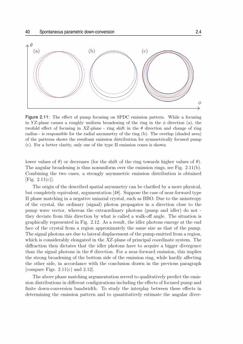
40 Spontaneous parametric down-conversion 2.4
Figure 2.11: The effect of pump focusing on SPDC emission pattern. While a focusingin YZ-plane causes a roughly uniform broadening of the ring in the φ direction (a), thetwofold effect of focusing in XZ-plane - ring shift in the θ direction and change of ringradius - is responsible for the radial asymmetry of the ring (b). The overlap (shaded area)of the patterns shows the resultant emission distribution for symmetrically focused pump(c). For a better clarity, only one of the type II emission cones is shown.
lower values of θ) or decreases (for the shift of the ring towards higher values of θ).The angular broadening is thus nonuniform over the emission rings, see Fig. 2.11(b).Combining the two cases, a strongly asymmetric emission distribution is obtained[Fig. 2.11(c)].
The origin of the described spatial asymmetry can be clarified by a more physical,but completely equivalent, argumentation [48]. Suppose the case of near-forward typeII phase matching in a negative uniaxial crystal, such as BBO. Due to the anisotropyof the crystal, the ordinary (signal) photon propagates in a direction close to thepump wave vector, whereas the extraordinary photons (pump and idler) do not -they deviate from this direction by what is called a walk-off angle. The situation isgraphically represented in Fig. 2.12. As a result, the idler photons emerge at the endface of the crystal from a region approximately the same size as that of the pump.The signal photons are due to lateral displacement of the pump emitted from a region,which is considerably elongated in the XZ-plane of principal coordinate system. Thediffraction then dictates that the idler photons have to acquire a bigger divergencethan the signal photons in the θ direction. For a near-forward emission, this impliesthe strong broadening of the bottom side of the emission ring, while hardly affectingthe other side, in accordance with the conclusion drawn in the previous paragraph[compare Figs. 2.11(c) and 2.12].
The above phase matching argumentation served to qualitatively predict the emis-sion distributions in different configurations including the effects of focused pump andfinite down-conversion bandwidth. To study the interplay between these effects indetermining the emission pattern and to quantitatively estimate the angular diver-

2.4 Spatial emission distribution of down-conversion photons 41
Figure 2.12: Spatial walk-off as a cause of asymmetric broadening of type II emissionpattern. Assuming near-forward emission, ordinary (red) photons propagate through thecrystal in the direction close to k0
p, whereas extraordinary (green) photons deviate in con-junction with the pump (represented by blue arrow). In this way extraordinary photonsacquire a spatial distribution similar to that of the pump, becoming strongly divergent,when the pump is tightly focused. The angular distribution of ordinary photons is barelyaffected by focusing of the pump beam.
gence of down-conversion photons along a certain emission direction, the evaluationelements discussed step by step in this section are simply combined into a single proce-dure. In short, this procedure repeats the calculation of internal emission angles [Eq.(2.61)] and subsequent application of Snell’s law [Eqs. (2.68) and (2.69)] for an arrayof input pump wave vectors and a range of phase-matched down-conversion wave-lengths. The down-conversion emission distribution is then obtained as a weightedsum of the results from all executed evaluation runs.
The representation of the pump as an array of characteristic wave vectors isperfectly justified by the measurement of the transverse coherence area of signal(idler) field, demonstrating the spatial incoherence of the down-conversion source[49]. This was later corroborated by the theoretical analysis of second-order (ampli-tude) and fourth-order (intensity) coherence functions at pairs of spatially-resolvedpoints within the signal (idler) field [50], showing that there is no spatial coherence inthe source other than the limits for the angular distribution defined by the conditionsof energy and momentum conservation. This suggests that the down-conversion emis-sion from every point within the pump can be treated independently. Accordingly,the transverse cross-section of pump beam inside the crystal can be decomposed intoa representative set of virtual fields, each characterized by its position {x, y} and a
wave vector k(x,y)p , as illustrated in Fig. 2.13. Moreover, a weight associated with
the pump intensity I(x,y) at the point {x, y} is assigned to each of the fields. Theallowed emission directions from each field are calculated and finally superposed withcorresponding weights to simulate the effect of a gaussian pump beam.

42 Spontaneous parametric down-conversion 2.4
Figure 2.13: Representation of the pump beam in the study of down-conversion emissiondistribution. The cross-section of the pump beam in the crystal is decomposed into anarray of virtual fields (represented by squares in the 2D density plot), each characterized bya position {x, y}, a wave vector k
(x,y)p and an integrated intensity I(x,y). The vectors k
(x,y)p
are determined in the far region from the beam waist position using simple geometricalarguments. Each of the virtual fields can be treated separately in the evaluation, assumingthe spatial incoherence of the down-conversion source.
Apparently, in the far field, i.e. for substantial distances from the emission plane,the source might be treated as dimensionless10, thereby allowing the definition ofthe emission distribution in the phase space using the angles θ and φ, as alreadyshown in Figs. 2.9 and 2.10. However, in the near field the transverse dimensionof the down-conversion source cannot be neglected when determining the emissionpattern. Consequently, the results have to be given for a fixed distance z from thesource in the real space. In this case, we might imagine the angular distribution tobe projected on an observation plane positioned at a distance z from the nonlinearcrystal. Nevertheless, in either case it is straightforward to extract from the patternthe angular divergence of the down-conversion photons along any emission direction.Examples of simulated emission distributions from type II SPDC in BBO nonlinearcrystal are presented in the next chapter.
10A condition ρ2/(zλs,i) ¿ 1, where ρ2 = x2max + y2
max is the maximum distance of an emissionpoint from the center of the pump beam and z is the distance from the source, can be applied inaccordance with the diffraction theory to guarantee the validity of this approximation.

2.5 Bell state preparation 43
Finally, we add that the presented method to evaluate the emission characteris-tics, does not include effects arising from the depth of the nonlinear process. Forsubstantial interaction lengths the spatial walk-off or the transverse deviation ofdown-conversion light in the crystal might influence to some extent the emissionpattern, when determining it in the near field.
2.5 Bell state preparation
The preparation of a photon pair in one of the four possible Bell states requires thatthere has to be only two discrete ways of creating and/or observing such a pair.Regardless of a concrete physical embodiment, e.g., both photons must be in state|0〉 or in state |1〉. Moreover, the two alternative ways have to coherently add up toform the entangled state of the form displayed in Eq. (1.4). To achieve that, thewave functions associated with the superposed terms in the entangled state have tobe made indistinguishable. Only then, the perfect correlations between the outcomesof the independent measurements on the two photons in any common basis (forexample, {(|0〉+ |1〉)/√2, (|0〉 − |1〉)/√2}) can be always observed, thereby allowingthe violation of Bell’s inequalities.
It is the simultaneous emission of the two photons together with energy andmomentum conservation that make the creation of entanglement in SPDC processpossible [51]. Nevertheless, to observe the entanglement in various accessible degreesof freedom, such as momentum, time, polarization etc., the proper spatial and tem-poral selection of down-conversion photon pairs has to be always accomplished. Inthe following, the most common examples of entanglement encoding are conciselydiscussed, pointing out the advantages or drawbacks of the individual approaches.
2.5.1 Momentum and energy-time entanglement
Due to energy and momentum conservation the signal and idler photons emittedfrom SPDC are strongly correlated in these two continuous degrees of freedom.This is directly manifested in the presence of the functions δ(νp − νs − νi) andsinc [(εkp − εks − εki)L/2] in the two-photon state |ψ(2)〉 [see Eq. (2.46)], therebyprecluding its factorization into a product of the states corresponding to signal andidler photons. To prepare the down-conversion photons in the momentum or theenergy-time Bell state, the continuous spectrum of existing creation/observation pos-sibilities has to be reduced to just two alternatives, as it was mentioned above.
Considering first the case of momentum encoding, this can be practically achievedby selecting the two spatial mode pairs (emission directions) using pinholes [52], seeFig. 2.14. If carried out properly, the pairs of selected spatial modes, denoted hereas a1, b2 and a2, b1, carry the two photons at slightly non-degenerate wavelengths

44 Spontaneous parametric down-conversion 2.5
Figure 2.14: Schematic set-up of the experiment to demonstrate momentum entanglementfrom a down-conversion source.
λa and λb. Thus, the state of the photon pair behind the pinholes can be written as
|Ψ〉 =1√2
[eiφa|λa〉a1|λb〉b2 + eiφb|λa〉a2|λb〉b1
]. (2.70)
This state is not entangled at this stage, yet, because the spatial modes are evidentlydistinguishable. If this spatial information is erased, e.g. by recombining the a-modes and b-modes at beam-splitters, the momentum entanglement manifests itselfin a sinusoidal dependence of the coincidence count rate on the difference of thephases φa and φb, which can be easily controlled with a pair of phase plates insertedin the modes before the beam-splitter.
In case of the energy-time encoding, the two alternatives contributing to the Bellstate can be realized by the two possible creation/detection times of down-conversionphotons. This can be physically implemented by detecting the down-conversion pho-tons behind the identical unbalanced interferometers, having their short (S) and long(L) paths [53], see Fig. 2.15. Since the path-length difference of the interferome-ters is designed to be much greater than the coherence length of the photons, nointerference is seen in a single-detector count rate. Nevertheless, due to energy-timeentanglement, the interference is observable in the rate of coincidence detections aswe vary the phase difference, φ1 − φ2, in either interferometer. This can be under-stood, when closely inspecting the state of the photons within the interferometers.Due to energy conservation in SPDC the emission of any pair is uncertain within thecoherence time of the pump (which is supposed to be very long) and therefore, thestate can be expressed as a coherent sum of the four combinations of the passage ofthe down-conversion photons through the interferometers:
|Ψ〉 =1
2
[|S〉1|S〉2 + ei(φ1+φ2)|L〉1|L〉2 + eiφ2|S〉1|L〉2 + eiφ1|L〉1|S〉2
]. (2.71)
The simultaneous emissions of the photons from CW-pumped SPDC in a nonlinearcrystal ensures that only the first two terms in Eq. (2.71), i.e. short-short (S1S2) andlong-long (L1L2) detections, are truly coincident. In practice, they can be filteredfrom the remaining contributions with a proper coincidence gating. We thus end up

2.5 Bell state preparation 45
Figure 2.15: Schematic set-up of the unbalanced interferometer to analyze energy-timeentanglement. In a pulsed version of energy-time entanglement, which is usually referredto as time-bin entanglement, the unbalanced interferometer serves as a pump preparationdevice, too. Then, the emission time of the photon pair from SPDC is given by a coherentsuperposition of only two discrete terms (time-bins), instead of a continuous range boundedonly by the coherence length of the pump laser as in the case of energy-time entanglement.
with the maximally entangled Bell state encoded in the time basis {|S〉, |L〉}.A notable variation of energy-time entanglement, often referred to as time-bin
entanglement, has been proposed [54], avoiding the need for a CW pump laser havinglong coherence time. Instead, a pulsed laser is employed followed by the unbalancedinterferometer, identical to those used for the analysis of energy-time entanglement,see Fig. 2.15. Here, it serves as preparation device, transforming the state of thepump photon into the superposition α|S〉p +β|L〉p, provided that the pump durationis short compared to the path length difference. With such pump preparation, theemission time of the photon pair from SPDC is given by a coherent superpositionof only two discrete terms (time-bins), instead of a continuous range bounded onlyby the coherence length of the pump laser as in the previous case. Thus, the down-conversion photons are directly created in the Bell state:
|Ψ〉 = α|S〉1|S〉2 + β|L〉1|L〉2, (2.72)
where |S〉 and |L〉 form again the basis of our qubit space. The values of α and β canbe controlled by varying the coupling ratio and phase of the unbalanced pump inter-ferometer. Hence any two-qubit entangled state can be prepared with the method.
Although its analysis using interferometers is rather demanding, the coding ofentanglement in the time basis found undeniably its practical use in fiber-based re-alizations of certain communication protocols, such as entanglement-based quantumkey distribution or secret sharing. This is due to the inherent robustness of such acoding against birefringence of fibres, which, e.g., poses a serious problem in case ofpolarization encoding, that is discussed in the next part.
2.5.2 Polarization entanglement
Arguably the most illustrative and also the most popular encoding of entanglementis in polarization degree of freedom. Contrary to energy-time entanglement provideddirectly by SPDC process, the achievement of polarization entanglement between the

46 Spontaneous parametric down-conversion 2.5
down-conversion photons necessitates an additional effort. In particular, it is theemission of the identically polarized photons from the type I phase matching and thespatiotemporal characteristics of the type II emission that do not allow for a directextraction of polarization entanglement from either phase matching configuration.Consequently, an additional optics has to be always supplied to bring the initiallyseparable polarization state of down-conversion photons into an entangled state.
The first experimentally examined method for producing polarization entangle-ment used type-I emission from SPDC [55]. The degenerate pairs of momentumcorrelated photons have been selected and the polarization of one of them rotated byπ/2, before being superposed with the other photon on a beam-splitter. Conditionedupon the detection of one photon in either output mode of the beam-splitter (denotedas “1” and “2”) the maximally entangled polarization state is obtained:
|Ψ〉 =1√2
[|H〉1|V 〉2 + eiφ|V 〉1|H〉2], (2.73)
where |H〉 and |V 〉 stand for horizontal and vertical polarization, respectively. Thismethod, however suffers from a necessary postselection by coincidence measurement.In fact, the total state of photons behind the beam-splitter is not entangled and itis the act of postselection of only the half of the total states, which approximates anentangled state.
To avoid this problem, two basic methods have been suggested and experimentallydemonstrated. The first uses non-collinear type-II phase matching in a single crystal[56], whereas the other relies on the coherent spatial overlap of the emissions from twoadjacent type-I phase-matched nonlinear crystals [57]. Nowadays, these two methodsare widely used in sources of polarization-entangled photon pairs and as such deservea good deal of attention.
Type-II source. The use of type-II phase matching for the generation of the photonpairs in polarization Bell states appears to be a natural solution. Recall just thecorresponding angular emission distribution [see Fig. (2.10)]. Considering the de-generate case, the down-conversion photons are emitted along the two (orthogonallypolarized) cones, which intersect each other for certain orientations of the nonlin-ear crystal. This intersections define two directions (“1” and “2”), along which thepolarization of each emitted photon is undefined, but perfectly anti-correlated withthe polarization of the other one. Therefore, it might seem that the photon pairsin the polarization-entangled state (2.73) are directly produced in this configuration.However, this is not yet true, because in the birefringent crystal the ordinary and theextraordinary photons will propagate at different group velocities and under differentdirections11.
11Historically, it was exactly the lack of understanding of spatiotemporal properties of the type-IIemission, which delayed the demonstration of the polarization entanglement in this configuration

2.5 Bell state preparation 47
For example, if one uses a negative uniaxial crystal, such as BBO, the extraordinary-polarized photons propagate faster than the ordinary-polarized photons inside thecrystal. Identifying the horizontal (vertical) direction with ordinary (extraordinary)polarization, this causes that the detector 1 positioned in the mode “1” would fire firstin a |V 〉1|H〉2 term, whereas the detector 2 in the second mode would fire first in theother |H〉1|V 〉2 term. Thus, the two terms are, at least in principle, distinguishable.The propagation of ordinary and extraordinary polarization under different directionsin the crystal has a two-fold effect on the spatial characteristics of down-conversionemission, see Fig. 2.12. First, the extraordinary-polarized photons are emitted froma spot approximately the same size as that of the pump, whereas the emission regionof ordinary photons is considerably elongated in the direction of the transverse walk-off. Second, the emission spot of the extraordinary photons is laterally displacedwith respect to that of the ordinary photons. As a result, this two-fold spatial effectprovides the partial label of the terms in (2.73), too.
The optimum compensation of the described spatiotemporal effect in the down-conversion crystal is achieved by inserting identical crystals of half the length in eachof the two down-conversion modes [56]. If the polarization of the down-conversionlight is rotated by π/2 before passing the crystals, the spatial overlap of ordinary andextraordinary emission modes is restored, thereby effectively erasing the spatial labelof the |V 〉1|H〉2 and |H〉1|V 〉2 terms in (2.73). Analogously, the temporal retardationof the ordinary and extraordinary are exchanged in this way, introducing the temporalindistinguishability of the terms in question.
To prove the latter, we can apply the evaluation tools of section 2.3.2 to deter-mine the joint time distributions A(τ+, τ−) of the biphoton associated with the terms|V 〉1|H〉2 and |H〉1|V 〉2. Assuming CW pumping of SPDC for convenience, the am-plitude A(τ+, τ−) is independent of τ+ = (τ1 + τ2)/2, where τ1 and τ2 are individualdetection times of the photon at the first and the second detector, respectively. There-fore, the analysis can be restricted only to the dependence on the time τ− = τ1 − τ2,which is interpreted as the difference in the time of the two detections. Due to therectangular shape of A(τ−) in type II phase matching, and its asymmetry to τ− = 0[see Fig. 2.5(b)], the two distributions do not overlap whatsoever, unless a propercompensation is applied. The temporal distribution of |H〉1|V 〉2 stretches from 0 tousiL, where the dispersion parameter usi is defined in Eq. (2.50) and L is the length ofthe crystal. I.e, the horizontally-polarized photon arrives at the detector 1 always af-ter registering of the vertically-polarized photon at the detector 2, τ1 > τ2. Applyingthe analogous arguments to the term |V 〉1|H〉2, it is straightforward to deduce thatthe corresponding distribution stretches from −usiL to 0, as illustrated in Fig. 2.16.This proves the complete temporal distinguishability of the two terms in question. Inorder to achieve the perfect overlap, both distributions has to be shifted by |usiL/2| inthe proper direction. Obviously, this is exactly realized by the suggested half-lengthcrystals, which are rotated by π/2 with respect to down-conversion crystal.
by approximately a decade, to the mid-90s.

48 Spontaneous parametric down-conversion 2.5
Figure 2.16: Explanation of the temporal distinguishability of the |H〉1|V 〉2 and |V 〉1|H〉2terms in Eq. (2.73). Whereas, the temporal distribution of the first term stretches inτ−(= τ1 − τ2) direction from 0 till usiL, the distribution of the latter is the mirror imageof the first one about τ− = 0. Consequently, no polarization entanglement can be observedunless a proper compensation is applied.
The described compensation method completely erases any possible spatial andtiming information of the two terms and therefore the true polarization-entangledphotons in the state (2.73) are produced. Furthermore the compensation crystalscan be exploited to set the relative phase φ in the state. If an additional half-waveplate in one of the two modes is inserted, we can prepare any of the four maximally-entangled Bell states [see Eqs. (1.3) and (1.7)] in the polarization basis.
Double crystal type I source. The second widely used method to prepare polarization-entangled photon pairs relies on the coherent spatial overlap of the two non-collineartype I emissions. Consider two adjacent nonlinear crystals, both operated in type-Iphase-matching configuration and pumped with linearly polarized light. The other-wise identical crystals are oriented such that their optic axes lie in mutually perpendic-ular planes. For example, let the optic axis of the first (second) crystal define togetherwith the pump direction the vertical (horizontal) plane. Due to the type-I coupling,the down-conversion process occurs only in the crystal, where the pump photon is ex-traordinary polarized, emitting the ordinary polarized down-conversion photons into acharacteristic cone. That is, with the vertically-polarized pump the down-conversionprocess occurs only in the first crystal, whereas with the horizontally-polarized pumpit occurs only in the second crystal. By pumping the crystals with light, linearlypolarized at 45◦ with regard to horizontal and vertical direction, there is an equalprobability that a pump photon will be down-converted in either crystal. Providedthat the two emission processes are coherent with one another, which is fulfilled aslong as there is no way of ascertaining whether a photon pair was produced in thefirst or the second crystal, the following entangled state is automatically produced:
|Ψ〉 =1√2
[|H〉1|H〉2 + eiφ|V 〉1|V 〉2]. (2.74)
The labels “1” and “2” again correspond to the two spatial modes, which are experi-mentally selected with e.g. pinholes or fibres. The relative phase φ is determined bythe details of the phase matching and thickness of the crystals, but can be controlled

2.5 Bell state preparation 49
by adjusting the relative phase between the horizontal and vertical components ofthe pump light.
The distinguishing information, which might possibly label the emission processesand thereby reduce their mutual coherence, can be either of temporal or spatial char-acter. The first type is usually precluded by using CW pumping. Nevertheless, ifpumping with (pulsed) light of short coherence length is required, e.g. for timingpurposes, the two processes could be at least in principle distinguished by the detec-tion times. Therefore, in such a case a proper compensation is required to restore thetemporal coherence of the emission processes [58, 59]. The analysis of the joint timedistributions associated with the two emissions might be applied, similarly as in theprevious case of the type-II source, in order to determine the suitable compensation.A particular example of such analysis is presented in the next chapter and thereforeit is not discussed here further. The second possibility, which can lead to the loss ofcoherence between the two terms, occurs whenever the emission modes from the twocrystals are spatially distinguishable. To avoid this situation, the nonlinear crystalshave to be thin enough. Only then, the emission cones at certain wavelength overlapto a great extent and very pure polarization-entangled photon pairs can be obtained[57].
A remarkable feature of this source is that by a plain rotation of the linearpump polarization, any non-maximally entangled state, i.e of the form |H〉1|H〉2 +ε|V 〉1|V 〉2, |ε| 6= 1, can be prepared without degrading a production rate of the photonpairs. In other sources this is often possible only by manipulating the down-conversionlight, thereby affecting significantly the accessible yield of the photon pairs.


Chapter 3Sources of polarization-entangledphoton pairs
This chapter describes the design and implementation of two different compactsources of polarization-entangled photon pairs using a blue laser diode as apump source for spontaneous-parametric down conversion. Whereas the firstsource uses a well established concept of degenerate non-collinear emission froma single type-II nonlinear crystal, the other features a fully collinear geometrywhere the photon pairs at non-degenerate wavelengths emitted from two adjacenttype-I down-converters are collected to one single-mode fibre and subsequentlysplit using a wavelength division multiplexer.
3.1 Photons as information carriers
Photons are natural carriers of quantum information due to their easy distributionand the fairly weak interaction with the environment. The other non-photonic sys-tems, such as atoms and ions, do not offer such potential, which significantly lowerstheir applicability for information transfer, leaving photons as the only practical al-ternative for the foreseeable future.
The first quantum communication schemes were based on the exchange of sin-gle photons [14]. Nevertheless, the vast majority of novel quantum communicationprotocols, including quantum dense coding [16], quantum state teleportation [17] orentanglement-enhanced classical communication [60] uses as a resource the photonicentanglement. Also quantum key distribution, the most advanced application ofquantum communication, significantly profits when applying the entanglement-basedschemes [15]. With regard to further extension of bridgeable distances in quantumcommunication, it even appears mandatory to apply entanglement in the quantum re-peater [61] (or quantum relay [62]) architectures, where the communication channel isdivided into shorter segments connected via entanglement swapping. The technology
51

52 Sources of polarization-entangled photon pairs 3.1
of the generation of photonic entanglement, its distribution and detection, togetherwith the methods of controlling and recovery of the encoded data, are therefore vitalfor the further progress in the field of quantum communication.
3.1.1 Challenges in quantum communication
To ensure the high-level performance of any application with entangled photons, theselection of the proper operating wavelength must be done carefully. In this contexttwo communication systems are being currently under intensive development (for areview, see e.g. [63, 64, 65]).
The first type, which is undeniably the most promising for future terrestrial quan-tum communication, utilizes the transport of photons in single-mode optical fibres.To take full advantage of today’s telecommunication technology, the most advanta-geous wavelengths turn out to be at λ = 1.31 µm and λ = 1.55 µm, i.e., at thelow-dispersion and low-absorption spectral windows of fibres. The distortion of po-larization due to birefringence and polarization mode dispersion in the fibres posethe crucial obstacle for the use of any kind of polarization-encoding scheme. Hence,in fiber-based communication systems energy-time or time-bin encodings of entan-gled photons are usually employed. They offer a good stability for long-distanceapplications since they are not sensitive to polarization fluctuations in optical fibers;and chromatic dispersion can be passively compensated using linear optics. Efficientand practical down-conversion sources of time-bin entangled photons at the telecomwavelengths have been developed [54], [66], however, the only applicable single-photonphotodiodes made from germanium or InGaAs/InP semiconductor material show lowefficiencies (typically ranging from 10% to 25 %), and high dark count noise (over 10kHz). The combination of the poor detection and the attenuation in optical fibres1
limit the communication distances to the order of 100 km. Without a major break-through in the fiber and/or detector technology or the demonstration of the workingquantum repeater architecture, whose development is still in its infancy, no furtherextension of communication reach by an order of magnitude is to be expected.
The second type of the communication system utilizes the transmission of thephotons over free space. The increase of atmosphere transmission towards infraredwavelengths, together with the peak detection efficiencies of silicon avalanche pho-todiodes (APD; typically up to 70%) in the visible red and the near-infrared (NIR)spectral region, suggest that the optimal operating wavelengths lie within the 700–900nm range. Furthermore, the atmosphere is only weakly dispersive and essentially non-birefringent, allowing the use of polarization encoding, for which simple and efficientcontrol elements and analyzers are standardly available. The terrestrial communica-tion using free-space links suffers from many problems, which are not encountered in
1The minimum attenuations in standard telecom fibers at λ = 1.31 µm and at λ = 1.55 µm areof the order of 0.35 dB/km and 0.20 dB/km, respectively, corresponding in turn to the 99% lossafter about 57 and 100 km.

3.1 Photons as information carriers 53
fiber-based systems, e.g. requirement of line-of-sight path between the communicat-ing parties, dependence of the system’s performance on the weather, pollution andother atmospheric conditions etc. This generally limits the communication reach ofthe terrestrial free-space links to the same order as the fiber links. To fully exploitthe advantages of free-space communication, it is necessary to use space and satellitetechnology. Quantum communication via satellites appears to be feasible even withtoday’s technology, thereby allowing to bridge distances on a global scale. Ultimately,this solution holds a promise for establishing the global quantum communication net-work.
3.1.2 Quest for high-flux entangled-photon sources
One of the major challenges to successfully implement free-space communicationsystems is the development of practical, polarization-entangled photon sources withsufficient performance2. The performance of sources can be conveniently quantifiedin terms of their brightness, measured as a number of detected pairs per secondand miliwatt of pump power and the quantum-interference visibility of polarization-entanglement. Besides reaching a high performance, the practical source has to fulfilladditional criteria regarding compactness and robustness of the design, as well as lowoperation costs or turn-key operation requiring minimum alignment.
The development of the compact high-flux sources of (polarization-entangled)photon pairs is not important only for quantum communication, but has undeniablya great impact on the progress in the other research areas of quantum optics. Op-tical quantum computing, particularly with KLM (Knill, Laflamme and Milburn)architecture [68], involves as one of the key ingredients an efficient single-photon andentangled-photon generation. The tight correlations of entangled photon pairs arealso of great benefit in the field of quantum metrology, e.g., for distant clock synchro-nization [69] or for absolute calibration of detectors without the need for a referencesystem [26, 70]. Other possible applications include quantum imaging with a fas-cinating perspective of remote sensing; or quantum lithography (and microscopy),where entangled photons are applied to write (and observe) structures at a resolu-tion exceeding that imposed by classical diffraction theory [71]. Finally, the majorityof today’s multi-photon entangled sources, which are essential for advanced multi-party communication or cluster state quantum computing, rely on the interference ofindependently created entangled photon pairs.
Sources of polarization-entangled photon pairs made a rapid progress in the recentyears. The detected photon-pair flux increased tremendously - an empirical obser-vation suggests that the brightness doubles approximately every 12 months, see Fig.3.1. Keeping the present pace of the brightness growth, we might expect that the
2For example, the preliminary feasibility studies of the space quantum experiments estimate theminimum required production rate of 106 pairs per second and quantum-interference visibility of atleast 98% [67].

54 Sources of polarization-entangled photon pairs 3.2
Figure 3.1: Growth of thesource brightness over therecent years. The expo-nential fit suggests that thebrightness doubles approxi-mately every 12 months. Pa-rameters of the sources usedin the plot are listed in ap-pendix A.2.
production rate reaches the gigahertz level before 2015. Also the practicality of thesources increases steadily. Only five years ago, large-frame ion lasers were used com-monly for pumping the SPDC process. Nowadays, the new generation of blue andviolet laser diodes (LDs) starts to be widely utilized, making sources more compactand economical.
3.2 Methods to generate entangled photon pairs
Since the first demonstration of a source producing polarization-entangled photonpairs based on an atomic decay, a wealth of theoretical proposals and experimentalprototypes have been reported. Nowadays, the generation of entangled photon pairsis a routine lab work and the development of sources focuses largely on their simplifi-cation and/or optimization of their performance. The most widely spread way how togenerate entangled photon pairs relies on the emission from the SPDC. Nevertheless,novel techniques of photon-pair generation based on the four-wave mixing process innonlinear optical fibres or on the decay processes in semiconductor structures havebeen suggested, offering a great potential to outperform the traditional approacheseventually, and thus to be once widely integrated in practical applications. In the fol-lowing the most common methods are briefly described, pointing out their strengthsand/or weaknesses and possible future prospects.
3.2.1 SPDC sources
Presently, the two most established methods to generate polarization-entangled pho-ton pairs utilize spontaneous parametric down conversion. The first makes use oftype-II phase-matching in a single crystal [56], whereas the second relies on thecoherent spatial overlap of the emissions from two adjacent type-I phase-matchednonlinear crystals [57]; (for further details see section 2.5.2). Usually, due to the

3.2 Methods to generate entangled photon pairs 55
non-collinear geometry of the methods, the nonlinear crystal must be relatively short(typically in the range from 0.5 mm to 3 mm), thereby limiting strongly the potentialbrightness of the methods to the order of only hundreds of coincidence counts persecond. Many variations of the two original proposals including confinement of thenonlinear crystal in a cavity [72] or phase-compensated collection of a wider solidangle of the emitted light [73] were reported over the past few years enhancing theyield of down-conversion photons by roughly an order of magnitude.
Birefringent phase matching in materials with a relatively high nonlinearity, suchas beta-barium borate or lithium iodate (LiIO3), is regularly applied for the SPDCprocess. However, this method fails, when the material does not exhibit sufficientbirefringence at the interacting wavelengths. As an alternative, quasi-phase matchingin periodically poled structures can be used, opening the possibility to noncriticallyphase match almost any combination of wavelengths within the transparency rangeof the nonlinear materials. This enables to access the highest nonlinear coefficientsof many materials, such as lithium niobate (LiNBO3), lithium tantalate (LiTaO3) orpotassium titanyl phosphate (KTiOPO4), thereby enhancing the overall conversionefficiency of the SPDC process.
Different configurations of sources using bulk periodically poled crystals were in-vestigated over the recent few years. The best results were reported in collineargeometry using bi-directional pumping of a single periodically poled crystal [74, 75]or coherent overlap of the emissions from two crystals [76, 77, 78]. This way, thebrightness increased by at least one order of magnitude in comparison to sourcesusing BBO crystals, reaching values above 104 detected pairs/s/mW, while at thesame time keeping the high purity of polarization entanglement. A further boost ofphoton-pair yield might be expected, when exchanging bulk crystals for nonlinearperiodically poled waveguides. Due to the field confinement, waveguides provide animproved mode overlap of the interacting waves, leading to an enhancement of theconversion efficiency. Conversion efficiencies of up to 10−6, roughly 4 orders of magni-tude more than that obtained with BBO crystal, were already demonstrated, thoughwithout the possibility for direct generation of polarization entanglement [79, 80].
3.2.2 Fiber sources
Four-wave mixing (FWM) via the third-order (χ(3)) nonlinearity of optical fibers canbe utilized to generate correlated photon pairs at unequal wavelengths [81]. The gen-erated pairs are predominantly co-polarized with the pump, which can be exploitedfor obtaining polarization entanglement by bi-directional pumping of a fiber Sagnacloop [82]. This geometry has the advantage that the counter-propagating pairs re-main in a coherent superposition without the need for any phase or path adjustments.Substantial interaction lengths together with the strong mode confinement lead tounprecedented brightness [83]. However, the occurrence of significant spontaneousRaman background makes the actual production of high-purity polarization entan-glement complicated. Usually, pumping at very low powers, a careful filtering of

56 Sources of polarization-entangled photon pairs 3.3
true correlated photon pairs and an operation at liquid nitrogen temperatures is re-quired, to reach near-to-unity quantum-interference visibility [84]. This problem canbe somewhat avoided by pumping the fiber in normal dispersion regime generatingphotons at widely spaced wavelengths (typically by hundreds of nanometers) outsidethe Raman scattering region. In either case, the need of mode-locked picosecondlasers for pumping the FWM process together with the difficulties in extracting high-purity polarization entanglement make today’s fiber sources less suitable for practicalapplications. Nevertheless, the achieved high production rates suggest their possiblefuture applicability in multi-photon quantum information experiments [85].
3.2.3 Semiconductor sources
Semiconductor quantum dots became widely utilized as optically and electricallydriven sources of single photons on demand. Few years ago, the biexciton decay in asingle quantum dot via an intermediate exciton level was proposed to provide a sourceof triggered, entangled photon pairs [86]. In contrast to afore-mentioned methodsbased on SPDC and FWM processes, which generate probabilistic numbers of photonspairs, the biexciton decay produces no more than two photons per excitation cycle.This makes such a compact and integrated device a favorable alternative to othersources, with the additional benefit of being easily implemented using simple, LED-like technologies.
Practically, structure asymmetries lead to polarization dependent splitting of theintermediate exciton level, resulting in only polarization correlated photons. How-ever, two schemes to eliminate the polarization splitting by control of growth orapplication of magnetic field, have enabled the recent observation of polarization-entangled photons, although at very poor quality [87]. Many tremendous engineeringchallenges still remain in order to realize a practical quantum dot source of entangledphotons. Improvements must be made to the efficiency of the device, to the frequencyof operation, and, most importantly, to the degree of entanglement.
3.3 Compact non-collinear type-II SPDC source
To generate photon pairs in the NIR spectral region compatible with high-efficientsilicon APDs and the low-absorption window of the atmosphere, the pump-beamwavelength for SPDC has to be shorter than 450 nm. This requirement generallyled to the use of large-frame ion lasers, which, due to their complexity and highoperating costs are not suitable for practical applications. Hence, a great deal ofattention has been recently devoted to replace these cumbersome and expensive lasers.The first step towards this goal have been undertaken by Volz et al. [88], whosuccessfully demonstrated the generation of polarization-entangled photon pairs inNIR using a frequency doubled, red LD. The advent of a new generation of galliumnitride based blue LDs promised a further simplification of the system. The first

3.3 Compact non-collinear type-II SPDC source 57
reported implementation, however, did not reach the expected brightness and high-purity polarization entanglement [89]. It was therefore our goal to demonstrate thatthe performance of sources using low-cost LDs can be comparable to those using CWion lasers [90].
3.3.1 Method
For the generation of polarization-entangled photons we use a well-established tech-nique based on SPDC emission from a single type II phase-matched nonlinear crystal.For closer details of this method, addressing particularly the issue of entanglementproduction, we refer to section 2.5.2. Since in many applications a well-defined spatialmode is highly desirable, in our source single-mode fibres are used for coupling of thedown-conversion light. To increase the yield of photon pairs we aim at optimizing thephoton-pair collection efficiency into single-mode fibres. Due to a limited laser-diodepump power available for SPDC, this issue is of particular importance in our source.
The problem of maximizing the coupling efficiency is investigated at length fortype-I phase matching in both CW and pulsed pumping regime [91, 92]. The fibrecoupling of type-II emission is less explored mainly due to difficulties in determiningthe angular distribution of SPDC light along the intersection of the output rings.The first work along this line was reported by Kurtsiefer et al. [93], who suggesteda simple hands-on method for determining the optimum parameters of the pumpand the collection optics. The method involves adjusting the crystal orientation tillthe perpendicular intersection of the SPDC rings is provided. Then, emission modesalong the intersection lines might be approximated by gaussian profiles with a diver-gence, which can be easily determined from the fixed relation between the emissiondirection and the output wavelength. To maximize the yield of fibre-coupled pho-ton pairs, collection modes with the same divergence are chosen. Furthermore, thepump beam waist size is suggested to match the size of the target collection modein the crystal. Later Bovino et al. [94] presented a more rigorous approach to theproblem based on maximizing the overlap between the two photon amplitude A ofthe entangled photon state and the field distribution of single-mode fibres. This al-lowed to study the interplay of the major experimental parameters, including crystallength, magnification of the coupling system or fibre mode field diameter, in deter-mining the coupling efficiency. Both approaches have been verified experimentally,demonstrating a high net coupling efficiency.
Here we propose yet another approach to the problem. Even though it resemblesthe method proposed in [93] to some extent, it avoids using therein applied simpli-fications, including rotational symmetry of the down-conversion rings or plane-wavepumping. Using the evaluation tools introduced in section 2, our approach takes fullyinto account the focusing geometry of all three interacting fields. Contrary to [93],our results suggest that the maximum yield of fibre-coupled pairs is not achievedif the pump beam waist size matches the size of the target collection mode in thenonlinear crystal; see also [94].

58 Sources of polarization-entangled photon pairs 3.3
Our fibre-coupling strategy might be divided into a few successive steps: (i) de-termination of the optimum pump beam divergence; (ii) evaluation of the emissioncharacteristics; and (iii) determination of the collection mode. In the following theindividual steps are discussed in more detail.
Pump-beam dependencies. The first important observation relevant to the deter-mination of the optimum pump beam divergence αp for SPDC is the spatial incoher-ence of the down-conversion source. If the transverse width of the source is too large,the collective emission will be spatially multimode. This explains the impossibilityof efficient fibre-coupling of the photons in this regime.
The need of a focused pump for successful collection of down-conversion photonshas been demonstrated in several theoretical and experimental works [48, 93, 94, 95].The only theoretical model predicting the opposite, i.e., achieving high coupling effi-ciencies if the pump-beam waist size wp and the collection-mode divergence αC arechosen large enough, has been suggested recently [96]. To disprove this hypothesisand show that indeed the size of the emission region has to be sufficiently small, weapply the evaluation steps described in section 2.4 and calculate the distribution ofdown-conversion light with a certain spectral bandwidth. Similarly as in Kurtsiefer’soptimization method [93], we analyze the configuration for a perpendicular intersec-tion of the SPDC rings. This appears to be a convenient choice for achieving efficientfibre-coupling due to an approximate rotational symmetry of the emission modes.Next, from the calculated distributions of the two intersection regions we single outonly emission directions restricted within a small interval of polar angles φ (or, al-ternatively within a small interval of azimuth angles θ). From a physical perspectivethis step corresponds to a selection of down-conversion light from the intersectionregions using a very narrow vertical (or horizontal) slit apertures. Using this pro-cedure, we obtain a representative set of light rays, which are to be coupled into asingle-mode fibre. To this end, the collection optics has to be designed first, matchingthe angular width of the emission modes to a gaussian distribution of the receivingmodes. This distribution can be easily determined from a mode field diameter (MFD)of single-mode fibres. To investigate the actual process of fibre-coupling, a standardray-tracing method allowing us to track the path of down-conversion photons throughthe collection lens is applied3. This way, we arrive at clearly different regimes of fibrecoupling for a focused and collimated pump [compare Figs. 3.2(a) and 3.2(b)]. Inthe first case, the coupling lens concentrates the down-conversion rays to a spot ofseveral microns in diameter, which is compatible to the core sizes of standard fibreswith single-mode operation in NIR spectral region [for the parameters in Fig. 3.2(a)the focused spot has the diameter of ≈ 5.5 µm]. However, for the second case, aroughly one order of magnitude larger diameter of the focus is observed, suggest-
3We note that even though the methods of geometric optics approach cannot be used for arigorous investigation of fibre-coupling efficiencies [97], the ray-tracing approach clearly demonstratesthe feasibility of coupling the down-conversion light into single-mode fibres.

3.3 Compact non-collinear type-II SPDC source 59
Figure 3.2: Ray tracing of representative set of down-conversion emissions (λ = 806 nm,∆λ = 5 nm) through the aspheric coupling lens in different regimes of pumping: (a) forfocused pump with the divergence of αp = 1.9 mrad and (b) for almost collimated pumpwith αp ≈ 0.1 mrad. An aspheric lens with effective focal length of f = 7.5 mm at a distanceof z = 210 mm and z = 370 mm from the crystal is used in (a) and (b), respectively.The distances were determined to optimally match the calculated down-conversion angulardivergence to the numerical apertures of the receiving mode defined by the MFD = 5.2 µmof a single-mode fibre. SPDC emission from BBO crystal cut at Θ0
p = 42.9◦ and pumpedat a wavelength of λp = 403 nm is assumed in the plots.
ing a transverse multi-mode character of the emission modes [for the parameters inFig. 3.2(b) the spot diameter is ≈ 39 µm]. One has to face the same situation, if anonlinear-crystal is moved well beyond the Rayleigh range of the focused pump - it isthe size of the pump cross-section inside the nonlinear crystal, which predeterminesthe feasibility of efficient fibre-coupling of down-conversion light.
Notably, the results of ray-tracing also suggest that if down-conversion photonsare collected into spatially multi-mode channels4, such as a pair of circular apertures
4In multi-mode collection channels the emission angles of down-conversion photons are resolvable.This is in contrast to single-mode channels, where all the information on emission angles is erased.

60 Sources of polarization-entangled photon pairs 3.3
in the far zone of the source, a collimated pump might be even preferred [56]. Due tothe reduced divergence of the emission modes in this regime, an increased collectionrate of down-conversion photons is achieved for a given opening of the apertures.Thus, a collimated pump should yield a higher degree of polarization entanglementfor a given detected photon-pair flux than a focused pump [48, 98].
The rule of increasing fibre-coupling efficiency with decreasing size of pump-beamwaist inside the nonlinear crystal, however, fails below certain critical waist sizes.Recall that a large wave-vector spread, which is associated with tight focusing causesthe asymmetric broadening of the emission rings [for further explanation see section2.4]. As a result, the intensity distribution within the intersection of the rings losesits approximate rotational symmetry and becomes elongated in one direction, seeFig. 2.12. Thus, it can be mapped to the receiving modes of optical fibres onlywith a limited efficiency. We note, that the integration of tailored cylindrical opticalelements into coupling optics can restore a high fibre-coupling efficiency. This is,however, experimentally demanding and not practical.
To determine the critical pump beam waist size, which still leads to a tolerableemission-mode asymmetry, a series of down-conversion emission distributions havebeen evaluated for different values of pump-beam divergence αp, see Fig. 3.3. Asexpected, the gradual transition of the ring intersection distribution from an initiallycircular shape towards an elongated elliptical profile is observed. For the input diver-gence of 2 mrad, the aspect ratio of the elliptical profile reaches the value of about0.585. This corresponds to the maximum overlap between the emission modes andthe receiving modes of above 0.9, which we still consider as a tolerable value. Forthe input divergence of 3 mrad, the aspect ratio is reduced to ≈ 0.42, resulting in amaximum overlap of 0.85, which is below the set limit.
The asymmetry of the emission mode does not lead only to a reduction of fibre-coupling efficiencies, but also limits the maximum accessible degree of polarization,eventually. The effect arises, if the collection modes are dissimilar, resulting in fi-bre coupling of one predominant polarization state and consequently, the detectionof nonmaximal entanglement [48]. Furthermore, the increase of pump-beam diver-gence far beyond 1–2 mrad (provided that crystals with lengths in ∼ mm range areused) was shown to be accompanied with a significant broadening of down-conversionspectra [42], which is unwanted with regard to practical applications as well. In sum-mary, all the above argumentation suggests that the best regime of source operationis obtained for pump-beam divergence αp, ranging between 1 and 2 mrad.
SPDC emission dependencies. The fixed relation between the emission directionand the output down-conversion wavelength allows a pure geometrical definition ofthe fibre-coupled spectral bandwidth ∆λ by properly designing the collection modes.In principle, any bandwidth ∆λ (of course, below the naturally phase-matched width
5The obtained values of aspect ratios are independent of the considered down-conversion spectralwidth. Thus, any reasonable value can be entered in the evaluation of the emission distributions.

3.3 Compact non-collinear type-II SPDC source 61
Figure 3.3: Simulated down-conversion emission distributions restricted to the immediatevicinity of the intersection of the rings as a function of the pump-beam divergence: (a)αp = 0.1 mrad, (b) αp = 1.0 mrad, (c) αp = 2.0, (d) αp = 3.0 mrad, and (e) αp = 4.0mrad. The patterns show the distributions determined at a distance of z = 250 mm fromthe BBO crystal (Θ0
p = 42.9◦); the size of one pixel corresponds to 140 µm in real spaceand the zero of the coordinate system is given by the position of the pump beam (λp = 403nm).
for a given crystal length, see Fig. 2.3) can be freely chosen in this way and thus, nointerference filters reducing the resultant efficiency of the source are required.
Fixing the parameters of the pump beam, the corresponding emission distribu-tion can be calculated at any distance from the nonlinear crystal for a given spectralbandwidth ∆λ, which is aimed to be collected into the single-mode fibre. The eval-

62 Sources of polarization-entangled photon pairs 3.3
Figure 3.4: Basic emission properties of violet LDs. (a) The spectrum exhibits multiple-peak structure (blue line; taken from [99]) with an aggregate FWHM bandwidth of roughly0.5 nm (red line; measured). The broadening of measured spectral profile due to a spectrom-eter resolution of 0.15 nm is subtracted from FWHM. (b) The angular emission distributionsin the two main planes show nearly ideal Gaussian profiles; taken from [99]. FWHM diver-gences reach typically the values of ∼ 8◦ (blue; plane parallel to the diode junction) and∼ 22◦ (red; plane perpendicular to the diode junction).
uation is repeated several times at different distances and the geometrical width ofthe emission mode is determined by fitting the ring-intersection distribution with agaussian profile at each of them. This way, we can readily infer the divergence of theemission mode αE.
Collection mode. We now define Gaussian collection modes, which are aligned withthe intersection directions of the emission rings. In order to maximize the fibre-collection efficiency of down-conversion light with a desired bandwidth ∆λ, the diver-gence of collection modes must match that of the emission modes [93], i.e. we set αC =αE. This determines the waist size of a Gaussian collection mode of w0 = λs(i)/(παC),which is optically mapped using a coupling lens to the MFD of the collection fibre.
3.3.2 Implementation
Pump-beam preparation. The pump beam for SPDC is provided by a violet trans-verse single-mode LD (Nichia, No. NDHV310ACA) with a maximum optical outputpower of 30 mW at about 60 mA driving current. Alternatively, a 60 mW LD (Nichia,No. NDHV310APC) is applied as the pump. The diode is mounted in an aluminiumhousing, which is temperature stabilized with a Peltier element to about 20 ◦C. Bothtypes of diodes operate at λp = 403 nm and exhibit multiple-peak spectra with anaggregate FWHM ranging from ∆λp = 0.4 nm to ∆λp = 0.6 nm, depending on theparticular LD [see Fig. 3.4(a)]. This spectral bandwidth corresponds to a coherence

3.3 Compact non-collinear type-II SPDC source 63
Figure 3.5: A typical example of the beam-shaped violet-LD output captured with a CCDcamera. The snapshots of the beam profile at (a) beam waist position, and at (b) 240 mmdistance from the waist position are shown. Using cylindrical lenses a nearly circular beamis achieved, exhibiting the ellipticity factor of > 0.95 in a wide region around the beamwaist position.
time of roughly 1 psec. Besides, a weak broadband in-line emission centered in thevisible red spectral range is observed.
The angular emission distributions of the laser-diode light show nearly ideal Gaus-sian profiles [see Fig. 3.4(b)], suggesting that no mode filters are required to improvethe quality of the beam. The FWHM beam divergences typically reach θ‖ = 7–10◦ and θ⊥ = 20 – 26◦ in the directions parallel (usually termed as slow axis) andperpendicular (fast axis) to the diode junction. A quality factor, M2, defining thedeviation of the laser beam from a theoretical Gaussian (M2 = 1) was measuredalong the slow and fast axes using the four-cuts method [100], yielding the values ofM2‖ ∼ 1.3 and M2
⊥ ∼ 2.3, respectively. The radial asymmetry of the angular diver-
gence, together with the mismatch of the M2 factors along the slow and fast axesmake the laser-diode beam highly astigmatic. To correct the astigmatism, usuallyan adjustable anamorphic prism pair or cylindrical lenses are utilized. The lattertechnique delivered better results in our case and permitted complete removal of theastigmatism inherent to the laser-diode light. This is simply accomplished by properfocussing of the lenses in each direction. First, a pair of lenses, a positive asphericlens (focal length f = 4.6 mm) and a negative singlet lens (typically f = −15 to −30mm), forming a Galilean-type telescope is used to focus the slow axis to the desiredsize. Then, a cylindrical lens or lens pair (typically f = 150 to 350 mm) is usedto match the size and the position of the beam waist in the plane of the fast axis.This way we are able to focus the laser beam to waist radii between 50 µm and 300µm at a distance of 180–240 mm from the laser diode. The smaller focal length ofthe negative lens results in a shortening of this distance, however at the expense ofstiffening the positioning tolerances. A typical example of the achieved beam profilesof the focused laser-diode beam is shown in Fig. 3.5. For the operation of the non-

64 Sources of polarization-entangled photon pairs 3.3
collinear type II source we choose the waist radius of wp = 75 µm, correspondingto a pump-beam divergence of αp = 1.7 mrad. In accordance with the conclusionsdrawn above, such a divergence should allow an efficient coupling of down-conversionphotons into single-mode fibres.
Nonlinear crystal and SPDC emission. We use beta-barium borate (β-BaB2O4 orBBO; basic characteristics are given in appendix A.1.1) as a nonlinear material forSPDC. The crystal with dimensions 7× 7× 2 mm3 is cut for type II collinear phasematching at an angle of Θc = 42.0◦ (Φc = 29.0◦). The perpendicular intersection ofthe emission cones at the degenerate wavelengths of λs = λi = 806 nm is obtained fora pump orientation of Θ0
p = 42.9◦ with respect to the optical axis (see green rings inthe altogether right pattern of Fig. 2.10). The corresponding intersection lines forman external angle of φ = 3.26◦, measured with regard to the pump direction.
For the crystal length of L = 2 mm the output phase-matched spectral widthis expected to reach ∆λ ≈ 5 nm, according to Fig. 2.3. The finite pump-beamcoherence time of ≈ 1 psec contributes to a broadening of this width only negligibly,see Fig. 2.4. Aiming for all the phase-matched bandwidth of 5 nm to be collectedinto the fibres, the emission-mode divergence of αE ≈ 0.30◦ is determined from thedown-conversion distributions calculated at different distances from the BBO crystal[see Fig. 3.6]. The pumping of the crystal by a Gaussian beam with a waist radius ofwp = 75 µm is assumed in the evaluation. The fibre-coupling optimization methodrequires αC = αE, which fixes the waist size of the Gaussian collection mode tow0 = 59 µm.
The non-collinear geometry of the nonlinear process puts the constraints on themaximum depth Lmax of the down-conversion emission, which is still possible tocollect into single-mode fibres. The increase of the crystal length beyond Lmax bringsno further gain in the number of collected photon pairs. Using simple geometricalarguments one can show that the maximum depth equals to Lmax = 2w0/ sin φ, seeFig. 3.7. For the parameters of w0 = 59 µm and φ = 3.26◦ this implies the maximumusable crystal length of about Lmax = 2.1 mm. This agrees well with the actuallychosen crystal length of L = 2 mm.
Compensation and fiber coupling. Due to birefringent nature of BBO material thehorizontally- and vertically- polarized down-conversion photons propagate at differentgroup velocities and under different directions. This provides a spatiotemporal dis-tinguishability of the two created polarization states6 and thus leads to non-maximalentanglement [for further explanation see section 2.5.2]. To compensate the effect andto obtain polarization-entanglement for all wavelengths in the acceptance spectrum
6The maximum time delay and the maximum lateral displacement of down-conversion photonsat the output face of a 2-mm-long crystal amount to 382 fs and 145 µm, respectively. This hasto be compared to the photon coherence time and coherence width to estimate the extent of thedistinguishability.

3.3 Compact non-collinear type-II SPDC source 65
Figure 3.6: Emission characteristics of SPDC light calculated for the actual parametersof the source. Figure (a) shows the intensity distribution of SPDC light with the centralwavelength of 806 nm and the bandwidth of 5 nm, which is determined at the distanceof 250 mm from the BBO crystal. The size of one pixel corresponds to 140 µm in realspace and the zero of the coordinate system is given by the position of the pump beam;the parameters of the pump are: wp = 75 µm, λp = 403 nm. Figure (b) shows the linearincrease of the emission-mode radius with the distance from the crystal in the horizontal(red full points) and in the vertical (blue open points) directions. The data are obtainedby fitting the ring-intersection distributions with gaussian functions.
Figure 3.7: The sketch of the non-collinear geometry of SPDC process. The waist size w0
and the relative orientation (determined by the angle φ) of the collection modes define themaximum depth Lmax of the down-conversion emission, which is possible to collect withfibres. Thus, the depth Lmax limits the practically usable crystal length.

66 Sources of polarization-entangled photon pairs 3.3
Figure 3.8: Schematic set-up of the compact non-colli-near type-II SPDC source:half-wave plate (HWP), mir-ror (M), compensation BBOcrystal (cBBO), longpass fil-ter (LF), aspheric lens (AL),single-mode fibre (SMF).
of down conversion photons, additional BBO crystals of length 1 mm preceded by ahalf-wave plate are inserted into the emission modes of the photons.
The photons are coupled into single-mode fibres at a distance of about 270 mmfrom the emission point. This spacing is determined by the aspheric coupling lenseswith focal length of f = 11.0 mm, the calculated waist size of the collection modesof w0 = 59 µm, and the MFD of the used optical fibres of 5.2 µm.
Set-up overview. The sketch of the source set-up is shown in Fig. 3.8 (the photo ofthe tested source is included in appendix A.3). The laser beam of a free-running LDat 403 nm is focused into the type II phase-matched BBO crystal and produces pairsof polarization-entangled photons at the degenerate wavelength of 806 nm, which arecollected into single-mode fibres. Two long-pass filters with a cut-off wavelength at715 nm are used to block the residual violet light. For compensation of the walk-off,two additional BBO crystals preceded by a half-wave retarder are used. To keepthe source compact, two mirrors are used to fold the paths of the down-conversionphotons.
3.3.3 Results
The two essential parameters characterizing the performance of sources are the qual-ity of the produced polarization entanglement and the brightness. The first is usuallydetermined as a visibility of correlation curves in complementary bases and the lat-ter as a number of detected pairs per second and milliwat of pump power. Withregard to some applications requiring a supply of narrow-band photons, such as foraddressing atoms, a better figure of merit is spectral brightness, which includes inits definition the spectral bandwidth of the photons. A further benchmark quanti-fying the performance of sources is the degree of violation of the CHSH inequalityin a fixed measurement period. Large speed of violation is possible only if both the

3.3 Compact non-collinear type-II SPDC source 67
Figure 3.9: Detected single(black) and coincidence (red)count rates depending on thepump power, measured at thecrystal position.
brightness and the entanglement-purity reaches a high level. Additional parameters,which show to be important in many applications, are the spectral bandwidth of thedown-conversion photons and the coupling efficiency.
Brightness. In order to determine the brightness and the coupling efficiency, theoutput single-mode optical fibers are directly connected to two actively quenchedsilicon APDs (Perkin Elmer, No. SPCM-AQ4C). Their detection efficiency is esti-mated to be ≈ 51 % at 800 nm using a calibration method relying on the photon-pairemission from SPDC [70] and a conventional measurement technique with a strongreference beam. We detect a flux of roughly B = 800 pairs per second and milliwatt ofpump power, see Fig. 3.9. For the maximum LD output power of 25 mW measuredat the crystal position, this implies a coincidence count rate of about 20000 s−1. Theestimated accidental coincidences are negligible for the observed single-count ratesof ≈ 60000 and the gate time of τc = 5.8 ns. The coincidence to single count ratio,characterizing the quality of coupling, reaches values of up to µ ≈ 0.34. Taking intoaccount the limited detection efficiency and other losses in the set-up, such as thereflection at the tips of the fibers (together > 10 %) and the optics in the path ofdown-conversion photons (> 2 %), the estimate of the net coupling efficiency reachesvalues as high as 75%.
Entanglement quality. To verify the entanglement of fibre-coupled photon pairs,their polarization correlations in two complementary bases are measured. This isdone by directing the down-converted light into adjustable polarization analyzers,each consisting of a polarizing beamsplitter cube preceded by a rotatable half-waveplate. After passing through the analyzers, the light is re-coupled into multi-modefibres and detected with APDs. Fig. 3.10 shows the expected sin2 dependence ofthe measured coincidence rates on the rotation angle ϕ1 of one half-wave plate, whilekeeping the other one at fixed orientation of ϕ2 = 0◦ or ϕ2 = 22.5◦, respectively.For the setting of ϕ2 = 0◦, corresponding to a detection of photons in H/V linear

68 Sources of polarization-entangled photon pairs 3.3
Figure 3.10: Polarizationcorrelations between pho-tons measured in the H/V(red points) and +45/-45(blue points) polarizationbases. The visibilities ob-tained from sin2 fits (solidlines) to the measured dataare 99.6 ± 0.3% and 94.2 ±0.3 %, respectively.
polarization basis, a visibility of VH/V = 99.55 ± 0.31 % is observed. For the secondinvestigated setting of ϕ2 = 22.5◦, i.e., a detection of photons in +45/-45 linearpolarization basis, we obtain a visibility of V45 = 94.20± 0.30 %.
CHSH-inequality violation. The high-visibility sinusoidal coincidence fringes ob-tained by measuring the polarization correlations of photon pairs suggest a violationof a suitable Bell’s inequality. Particularly, according to the most frequently used in-equality in the CHSH formulation, any local-hidden variable theory is bound by thecorrelation coefficient |S| ≤ 2, whereas, according to quantum mechanics, |S| reachesthe value of 2
√2 for maximally-entangled state with unit visibility. If the two-photon
polarization state decoheres equally in all polarization bases, a minimum violationimplies a visibility larger than 71 %. In the actual measurement, we recorded the coin-cidence count rates for 16 combinations of analyzer settings ϕ1 = {0, π/2, π/4, 3π/4}and ϕ2 = {π/8, 5π/8, 3π/8, 7π/8}. In section 1.1.3 this particular set of settingsis proved to be optimal. The chosen integration time per one measurement run isTI = 5 s. Following the procedure of, e.g., [10], the obtained data are combined,yielding the value S = 2.743± 0.006. This corresponds to a violation of the classicalbound by 124 standard deviations. To unify results obtained from the measurementsof CHSH-inequality violation over different integration times and to allow for a di-rect comparison of sources, the parameter “normalized speed of CHSH violation” hasbeen suggested recently in [77]. It is defined as the number of standard deviationsσS by which the correlation coefficient S is violated per
√s. For the measured values
we infer the speed of violation of (S − 2)/(σS
√TI) ≈ 55 σS s−1/2.
Spectrum. In order to spectrally analyze the parametric down-conversion light cou-pled into single-mode fibres, the fibres are individually connected to a grating spec-trometer with single-photon sensitivity. We determine its wavelength resolution tobe about 1.2 nm at a wavelength of 785 nm. As shown in Fig. 3.11, the measuredspectral distributions are centered around the degenerate wavelength of 806 nm, with

3.4 Compact non-collinear type-II SPDC source 69
Figure 3.11: Spectral distri-butions of down-conversionlight collected into single-mode fibres. The solid linesshow Gaussian fits to mea-sured data. The offset of≈ 5400 counts is due to darkcounts of the APDs.
the separation of ≈ 0.7 nm due to residual misalignment of the fiber coupler positions.The full widths at half maxima are found from the gaussian fits to be 6.24 ± 0.17nm and 6.47 ± 0.19 nm. Correcting the inferred widths for the finite wavelengthresolution of the spectrometer, a reasonable agreement with the design parametersof the coupling-optimization method is obtained.
3.3.4 Discussion
The brightness and the degree of polarization entanglement reached in the describedLD-pumped source are comparable to conventional systems utilizing ion lasers [93].Also, the achieved coupling efficiency appears to be at the level of the best reportedvalues, indicating a successful implementation of the proposed fibre-coupling strategy.These traits make the LD-based systems a compact and cheap alternative for a varietyof quantum-optics experiments. Moreover, the source shows to be a very suitabletool to practically demonstrate the phenomenon of entanglement in undergraduatelaboratories [89, 101].
Nevertheless, no dramatic improvement of the present system, particularly re-garding its brightness, is to be expected in future. This is due to the geometry ofnon-collinear type-II emission, which has some disadvantages. First, only a smallfraction of the total SPDC output flux is polarization-entangled. Second, the overlapof the intensity distribution of the emission modes with the guiding mode of single-mode fibres is limited, lowering thus the accessible coupling efficiency to some extent.Finally, the practically applicable length of nonlinear crystals is restricted within onlya few mm range. These drawbacks and the associated limitations certainly lower theusability of this type of source in future demanding applications of quantum infor-mation processing and communication and highlight the need for novel methods ofentangled photon-pair generation.

70 Sources of polarization-entangled photon pairs 3.4
Figure 3.12: Conceptual layout of the method to generate entangled photon pairs usingcollinear geometry of SPDC operated in type I non-degenerate configuration.
3.4 Compact collinear type-I SPDC source
The concept of non-collinear SPDC entails several inevitable shortcomings. Besidesthose linked to the output performance of the source, purely practical problems ariseas well. This is due to the use of two separate spatial collection modes defined by thecoupling optics and single-mode fibres. High-purity polarization entanglement canbe obtained only, if the divergences of these modes, as well as their mutual spatialorientations, are perfectly matched. Consequently, a careful alignment is alwaysrequired, making such type of sources rather impractical for applications.
The following section introduces a novel method to generate entangled photonpairs using a collinear geometry of SPDC operated in type I non-degenerate con-figuration [102]. As will be demonstrated in the following, the proposed methodovercomes many deficiencies of the prior art, including those outlined above.
3.4.1 Method
The conceptual layout of the method is shown in Fig. 3.12. The photon pairs at non-degenerate wavelengths are generated collinearly with respect to the pump light viaSPDC and collected into one single-mode fiber. The spectral information is exploitedto split the photons into two distinct spatial modes using a wavelength division mul-tiplexer (WDM). To achieve a successful operation of the method, the wavelengthsof the down-conversion photons have to be such that, first, their propagation in thesame single-mode optical fiber, and second, their splitting with a high isolation ratiois possible.
For the actual generation of the photon pairs, SPDC in a simple two-crystalgeometry is applied. Consider two adjacent nonlinear crystals, both operated intype-I phase-matching configuration and pumped with linearly polarized light. Theorientation of otherwise identical crystals is adjusted such, that the optic axes ofthe first and second crystal lie in vertical and horizontal plane, respectively. Witha 45◦-polarized pump light, SPDC occurs equally likely in either crystal, producing

3.4 Compact collinear type-I SPDC source 71
Figure 3.13: Collinearlyphase-matched output wave-lengths of down-conversionphotons as a function of theangle Θ0
p between the pumpand the optic axis. Thecalculation assumes SPDCin a BBO crystal pumped atλp = 403 nm.
pairs of horizontally polarized (|H〉|H〉) or vertically polarized (|V 〉|V 〉) photons dueto type-I coupling. For further details on the method, which was originally suggestedfor non-collinear configuration of SPDC in [57], we refer to the section 2.5.2.
By angle tuning the crystals, down-conversion is driven to a collinear phase-matching configuration, emitting pairs of photons at non-degenerate wavelengths[58]. This mode of operation has been proved to be feasible in section 2.4. Fig. 3.13shows the calculated tuning curve of collinearly phase-matched SPDC assuming theparticular case of emission from BBO crystal. There are two clearly different regionsabove and below a limiting angle Θmax, which corresponds to the degenerate emissionof photons at the double wavelength of the pump light. In the region above Θmax
no collinearly phase-matched output is obtained whatsoever. Yet, tuning the anglein the regime of Θ0
p < Θmax, the photons at any desired conjugate non-degeneratewavelengths λ1 and λ2 are phase matched in the nonlinear crystal .
Provided that the two emission processes are coherent with one another, which isfulfilled as long as there is no way of ascertaining whether a photon pair was producedin the first or the second crystal, the entangled state
|Ψ〉 =1√2
[|H〉λ1|H〉λ2 + eiφ|V 〉λ1|V 〉λ2
](3.1)
is automatically produced. The relative phase φ is determined by the details of phasematching. The non-degenerate wavelengths are mapped onto two distinct spatialmodes (labelled as usual by “1” and “2”) using a WDM, thereby finally arriving atthe state in the form:
|Ψ〉 =1√2
[|H〉1|H〉2 + eiφ|V 〉1|V 〉2]. (3.2)
This way, the method produces polarization entangled photon pairs directly, with-

72 Sources of polarization-entangled photon pairs 3.4
out a need for any post-selection [103] or beam overlap [75], which is often requiredin sources utilizing collinear geometry of SPDC. The fully collinear configuration ofthe method utilizing only one spatial mode for collecting down-conversion photonsbrings numerous advantages. First, it minimizes the complexity of the source andthereby enhances its inherent robustness. Second, it precludes the occurrence of anyintrinsic spatial effect limiting the quantum-interference visibility, while at the sametime allows the use of long down-conversion crystals yielding a higher photon-pairflux. From a practical point of view, the technical requirements and the demand foralignment are enormously reduced. The only evident drawback of the method lies inthe restriction to non-degenerate wavelengths of the photons. Although this poses nolimitation for a practical realization of a majority of quantum-communication proto-cols, some applications, e.g. those involving the overlap of down-conversion photons,cannot be accomplished with the proposed source.
The generation of non-degenerate photons using SPDC in a two-crystal geometryis accompanied with a detrimental spatiotemporal effect, which results in a poor fibre-coupling efficiency and also low-quality polarization entanglement. In the followingwe discuss this issue in detail and show, how to design an optimum compensation.
3.4.2 Spatial effect
It is well known that due to crystal birefringence the extraordinary wave gets spatiallydeflected from the ordinary wave by a walk-off angle γ. This leads to a lateraldisplacement of the two waves at the output surface of the crystal by δ = L tan γ.One has to face the same situation in case of the SPDC process in the two crossedtype-I non-linear crystals. The down-conversion photons from the first crystal havethe extraordinary polarization in the second crystal and therefore they are laterallydisplaced with regard to ordinary polarized photons created there. The situation issomewhat more complex, because the ordinary and extraordinary components of thepump wave undergo a birefringent spatial separation as well. This is schematicallysummarized in Fig. 3.14(a). There, one can see that the spatial walk-off has a two-fold effect on the emission characteristics. First, elliptical shapes are obtained for thehorizontally- and vertically-polarized down-conversion emission spots at the outputface of the second crystal. Second, the spots are laterally displaced with regard to eachother, thereby reducing their mutual overlap. The resulting down-conversion emissionregion has an L-shaped profile. The spatial separation of the photons precludes thepossibility of efficient fibre-coupling. Either the photons originating in the first crystalcan be collected into the single-mode fibre or those originating in the second crystal,but never both together. Using simple geometrical arguments one can show thatoptimum compensation includes the same pair of crystals, but only half as long. Thisis graphically illustrated in Fig. 3.14(b).
We note that the described lateral displacement between the horizontally- andvertically-polarized photons does not impair the resultant purity of polarization en-tanglement. This is due to the fact that the single-mode nature of the collection fibre
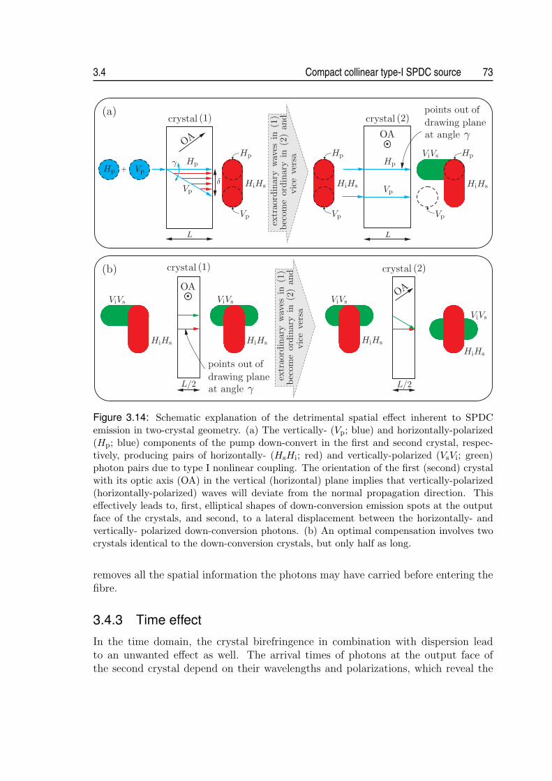
3.4 Compact collinear type-I SPDC source 73
Figure 3.14: Schematic explanation of the detrimental spatial effect inherent to SPDCemission in two-crystal geometry. (a) The vertically- (Vp; blue) and horizontally-polarized(Hp; blue) components of the pump down-convert in the first and second crystal, respec-tively, producing pairs of horizontally- (HsHi; red) and vertically-polarized (VsVi; green)photon pairs due to type I nonlinear coupling. The orientation of the first (second) crystalwith its optic axis (OA) in the vertical (horizontal) plane implies that vertically-polarized(horizontally-polarized) waves will deviate from the normal propagation direction. Thiseffectively leads to, first, elliptical shapes of down-conversion emission spots at the outputface of the crystals, and second, to a lateral displacement between the horizontally- andvertically- polarized down-conversion photons. (b) An optimal compensation involves twocrystals identical to the down-conversion crystals, but only half as long.
removes all the spatial information the photons may have carried before entering thefibre.
3.4.3 Time effect
In the time domain, the crystal birefringence in combination with dispersion leadto an unwanted effect as well. The arrival times of photons at the output face ofthe second crystal depend on their wavelengths and polarizations, which reveal the

74 Sources of polarization-entangled photon pairs 3.4
Figure 3.15: Explanation of the detrimental time effect inherent to SPDC emission in a two-crystal geometry. Due to crystal birefringence and dispersion, the arrival times of photonsat the output face of the second crystal differ in general for the two emission possibilities.Consequently, a compensation erasing their temporal distinguishability has to applied.
actual position of the photon-pair’s origin. This leads to a partial loss of the coher-ence between the two emission processes, and thus to a reduced entanglement. Thedetrimental temporal effect is two-fold, which is illustrated in a simplified fashion inFig. 3.15. First, it is primarily the group-velocity mismatch between the pump andthe down-conversion light, which causes that the photon pairs born in the first crys-tal are advanced with regard to those originating in the second crystal. Second, thedispersive delay of the down-conversion photons at the non-degenerate wavelengthsis different for the two emission possibilities, because the photons generated in thefirst crystal acquire an extra spread by propagating through the second crystal.
To investigate the time effect and to find the optimum compensation, the evalu-ation tools introduced in section 2.3.2 are applied to determine the joint time distri-butions of the two-photon wave-packets A1(τ+, τ−) and A2(τ+, τ−), associated withthe down-conversion emission in the first and second crystal, respectively. Since thenon-degenerate wavelengths effectively label the photons of the emitted pair, we maydefine τ+ = (τλ1 + τλ2)/2 and τ− = τλ1 − τλ2 , where τλ1 and τλ2 are individual arrivaltimes of the photons at λ1 and λ2 to the output face of the second crystal. Puttingλ1 < λ2 for convenience, the two-photon amplitudes will be constrained only to theregion of positive values of τ− due to τλ1 > τλ2 in normally dispersive materials.
The two-photon amplitudes are evaluated using Eq. (2.58). To find A1(τ+, τ−)originating in the first crystal, we put Tλ1 ≡ exp[ike
1(λ1)L] and Tλ2 ≡ exp[ike2(λ2)L].
This way, the propagation of the photons through the second crystal is automaticallyaccounted for. In the calculation the wave numbers ke
1(λ1) and ke2(λ2) of the extra-
ordinary polarized photons at non-degenerate wavelengths have to be expanded intoa power series according to Eq. (2.43). The correct form of A2(τ+, τ−) is obtainedwhen putting Tλ1 ≡ Tλ2 ≡ 0. In this case we must insert a function exp[iko
p(λp)L] into

3.4 Compact collinear type-I SPDC source 75
Figure 3.16: Absolute value of the normalized two-photon amplitudes (a) A1(τ+, τ−) and(b) A2(τ+, τ−) revealing the time distribution of photon wave-packets originating from thefirst and second crystal, respectively. The evaluation assumes SPDC in the pair of BBOcrystals, each L = 15.76 mm long and cut at Θ0
p = 28.95◦, corresponding to collinear phasematching of the wavelengths λ1 ≈ 765 nm and λ2 ≈ 850 nm (see Fig. 3.13). The parametersof the pump are: λp = 403 nm, τp = 1 ps.
Eq. (2.58) to include the effect of the pump propagation through the first crystal7.
Fig. 3.16 shows the time distributions of the numerically calculated amplitudesassuming type I SPDC in the pair of BBO crystals, each with the length of L = 15.76mm. The limited extent of the amplitudes in the τ+ direction signifies that a pumpwith a finite coherence time has been used for the evaluation (compare to two-photonsamplitudes obtained in CW-pumped regime, see Fig. 2.5). In particular, we assumedthe pump with a duration of 1 psec, which roughly corresponds to the coherence timeof the used blue LDs. The distribution of A2(τ+, τ−) is shifted towards larger valuesof τ+ in comparison to A1(τ+, τ−). From a physical point of view this correspondsto a time delay of the photons created in the second crystal with regard to thosecreated in the first. The time distributions of amplitudes in the τ− direction isdetermined by the extent of the chromatic dispersion: a huge difference of groupvelocities vλ1 and vλ2 at non-degenerate wavelengths will manifest itself by a largespread of the amplitudes in this direction and vice versa. Whereas the distribution ofA2 is constrained to roughly 0 < τ− < L(1/vo
λ1− 1/vo
λ2), the amplitude A1 stretches
7Note that the polarization of the pump photon, which eventually down-converts in the secondcrystal, has to be ordinary in the first crystal. Analogously, when evaluating A1 we have to takeinto account that the down-conversion photons generated in the first crystal become extraordinarypolarized in the second crystal.

76 Sources of polarization-entangled photon pairs 3.4
in a range of L(1/veλ1− 1/ve
λ2) < τ− < L(1/ve
λ1− 1/ve
λ2) + L(1/vo
λ1− 1/vo
λ2). The
offset L(1/veλ1− 1/ve
λ2) is due to the passage of the photons originating in the first
crystal through the second crystal. For the present parameters we calculate L(1/voλ1−
1/voλ2
) = 285 fs and L(1/veλ1−1/ve
λ2) = 258 fs. A slight broadening of the amplitudes
in Fig. 3.16 compared to these calculated values is due to the finite phase-matchedbandwidth of the photons. The tilt of both amplitudes in the τ+/τ− plane expressesthe fact that the photons created at the very end of either crystal are always delayedwith regard to those created at the beginning. This is again caused by the group-velocity mismatch between the pump and the generated down-conversion photons.
The overlap of the amplitudes A1 and A2 provides a measure of the maximumaccessible quantum-interference visibility V in polarization correlation measurements.To understand that, the overlap might be interpreted from the perspective of mutualdistinguishability of two paths (or Feynman alternatives) leading to a coincidencedetection [39, 104]. No overlap signifies the paths being totally distinguishable. Con-sequently, no quantum interference can be observed whatsoever. When the overlapis complete, the interference pattern has a maximum visibility. Mathematically, theoverlap O12 of the amplitudes A1 and A2 is expressed in the form
O12 =
∫ ∞
−∞dτ+
∫ ∞
−∞dτ− Re
[A1(τ+, τ−)A∗2(τ+, τ−)
], (3.3)
where the symbol Re denotes the real part of its argument. Normalizing the overlapO12 to the modulus squared of the amplitudes, D, which is defined as
D =
∫ ∞
−∞dτ+
∫ ∞
−∞dτ−
∣∣A1(τ+, τ−)∣∣2 =
∫ ∞
−∞dτ+
∫ ∞
−∞dτ−
∣∣A2(τ+, τ−)∣∣2, (3.4)
we directly obtain the quantum-interference visibility V (i.e., V = O12/D).Without a further evaluation it is directly apparent from Fig. 3.16 that the
amplitudes A1 and A2 do not overlap whatsoever. The detrimental distinguishing in-formation has to be eliminated by temporal engineering of the two-photon amplitudes[58, 104]. This is physically achieved by including additional special birefringent ele-ments in front and/or behind the nonlinear crystals. They effectively redistribute theamplitudes and, if designed properly, they allow restoring of their complete overlap.
First, we investigate the effect of a birefringent crystal placed in the path of thedown-conversion photons. As a material we conveniently choose yttrium orthovana-date (YVO4; basic characteristics are given in appendix A.1.2) due to its very highbirefringence of ∆n = |ne − no| > 0.2 at NIR wavelengths. For this crystal the slopeof chromatic dispersion, which was shown to determine the projected distribution ofthe amplitudes onto the τ− axis, is higher for the extraordinary polarization. Thus,if we adjust the crystal orientation such that the photons born in the second BBOcrystal have extraordinary polarization within the compensation YVO4, the overlapof A1 and A2 becomes larger in the τ− direction. For a certain length of the crystal,which is calculated to be l = 8.20 mm in the considered example, the overlap reaches

3.4 Compact collinear type-I SPDC source 77
Figure 3.17: Absolute value of the normalized two-photon amplitudes (a) A1(τ+, τ−) and(b) A2(τ+, τ−), revealing the time distribution of photon wave-packets originating from thefirst and second crystal, respectively. The plots show the amplitudes after passage throughthe compensation element YVO4 with a length of l = 8.20 mm positioned behind thedown-conversion crystals. All the other parameters are the same as in Fig. 3.16.
its maximum. In this case the temporal spread of photons at non-degenerate wave-lengths inside the YVO4 reaches l(1/go
λ1− 1/go
λ2) = 585 fs for ordinary polarization
and l(1/geλ1− 1/ge
λ2) = 843 fs for extraordinary polarization. Here gλ1 and gλ2 denote
the corresponding group velocities in YVO4. That is, passing through the YVO4
crystal, the amplitude A1 is confined within the range
0.843 ps = l
(1
goλ1
− 1
goλ2
)+ L
(1
veλ1
− 1
veλ2
)< τ−
< l
(1
goλ1
− 1
goλ2
)+ L
(1
veλ1
− 1
veλ2
)+ L
(1
voλ1
− 1
voλ2
)= 1.128 ps, (3.5)
which perfectly matches the limits found for the amplitude A2:
0.843 ps = l
(1
geλ1
− 1
geλ2
)< τ− < l
(1
geλ1
− 1
geλ2
)+L
(1
voλ1
− 1
voλ2
)= 1.128 ps. (3.6)
The calculated amplitudes are shown in Fig. 3.17.
Although the suggested compensation provides an optimum overlap of the ampli-tudes in the τ− direction, it makes them more distinguishable along the τ+ axis atthe same time. This is due to the fact that YVO4 is a positive birefringent crystal, in
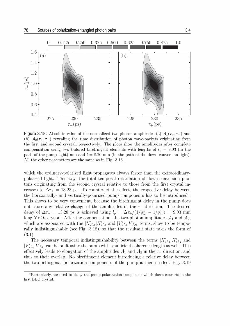
78 Sources of polarization-entangled photon pairs 3.4
Figure 3.18: Absolute value of the normalized two-photon amplitudes (a) A1(τ+, τ−) and(b) A2(τ+, τ−) revealing the time distribution of photon wave-packets originating fromthe first and second crystal, respectively. The plots show the amplitudes after completecompensation using two tailored birefringent elements with lengths of lp = 9.03 (in thepath of the pump light) mm and l = 8.20 mm (in the path of the down-conversion light).All the other parameters are the same as in Fig. 3.16.
which the ordinary-polarized light propagates always faster than the extraordinary-polarized light. This way, the total temporal retardation of down-conversion pho-tons originating from the second crystal relative to those from the first crystal in-creases to ∆τ+ = 13.28 ps. To counteract the effect, the respective delay betweenthe horizontally- and vertically-polarized pump components has to be introduced8.This shows to be very convenient, because the birefringent delay in the pump doesnot cause any relative change of the amplitudes in the τ− direction. The desireddelay of ∆τ+ = 13.28 ps is achieved using lp = ∆τ+/(1/go
λp− 1/go
λp) = 9.03 mm
long YVO4 crystal. After the compensation, the two-photon amplitudes A1 and A2,which are associated with the |H〉λ1|H〉λ2 and |V 〉λ1|V 〉λ2 terms, show to be tempo-rally indistinguishable (see Fig. 3.18), so that the resultant state takes the form of(3.1).
The necessary temporal indistinguishability between the terms |H〉λ1|H〉λ2 and|V 〉λ1|V 〉λ2 can be built using the pump with a sufficient coherence length as well. Thiseffectively leads to elongation of the amplitudes A1 and A2 in the τ+ direction, andthus to their overlap. No birefringent element introducing a relative delay betweenthe two orthogonal polarization components of the pump is then needed. Fig. 3.19
8Particularly, we need to delay the pump-polarization component which down-converts in thefirst BBO crystal.

3.4 Compact collinear type-I SPDC source 79
Figure 3.19: The map of maximum accessible quantum-interference visibility V as a func-tion of the length l of the compensation YVO4 crystal and the pump duration τp. If a laserlight with a sufficiently long coherence length is applied for pumping SPDC, no birefringentcompensation element preceding the down-conversion crystals is required for achieving ahigh visibility. Values of the parameters are the same as in Fig. 3.16.
Figure 3.20: The mapof maximum accessiblequantum-interference vi-sibility V as a functionof the lengths l and lp ofthe compensation YVO4
crystals. Values of the pa-rameters are the same asin Fig. 3.16.
illustrates the issue in a quantitative way. It shows the map of visibility V as afunction of the length l of the compensation YVO4 crystal and the pump durationτp. To achieve the quantum-interference visibility of at least V = 90 % the pumpduration has to be longer than τp ≈ 31 ps in the considered example of the temporalretardation of ∆τ+ = 13.28 ps.
Finally, Fig. 3.20 shows the density plot of visibility V evaluated in dependenceon the lengths l and lp of either YVO4 compensation crystal. It demonstrates that

80 Sources of polarization-entangled photon pairs 3.4
a deviation of several hundreds of microns from the determined optimum values of land lp might be accompanied by a notable drop in the achieved quantum-interferencevisibility. The suggested compensation method using a pair of birefringent elementsworks equally efficient for even shorter pump-coherence lengths than the one investi-gated. Yet, we must be aware of the substantial stiffening of the tolerances imposedon the lengths l and lp when very short pump pulses, such as with fs duration, areused.
The described time effect can be understood from another, but completely equiv-alent perspective, which is based on the investigation of the relative phase φ in thestate (3.2). This phase generally depends on the particular wavelengths of pump anddown-conversion photons being considered. The following argument might be usedto determine this dependence: both |H〉1|H〉2 and |V 〉1|V 〉2 terms in (3.2) receive anequal ordinary phase in the crystals, where they are created. Therefore, these phasescan be neglected as a global phase. Besides, the |H〉1|H〉2 term originating in thefirst crystal9 acquires an additional extraordinary phase in the second crystal equalto
2πL
λne(λ, Θ0
p) +2πL(λ− λp)
λλp
ne
(λλp
λ− λp
, Θ0p
), (3.7)
and the |V 〉1|V 〉2 term originating in the second crystal acquires an additional ordi-nary phase,
2πL
λp
no(λp), (3.8)
which is given by the propagation of the pump photon in the first crystal. In the ex-pression (3.7) λ denotes the wavelength of one of the down-conversion photons. Thedifference of the phases (3.7) and (3.8) determines the relative phase φ = φ(λ, λp), upto irrelevant constant phase factors. As demonstrated in Fig. 3.21(a), a strong varia-tion of φ(λ, λp) over a relevant spectral region is observed for the parameters consid-ered above, which corresponds to an effective dephasing of photon-pair polarizationstate. Consequently, no interference pattern can be observed in the polarization-correlation measurements.
The distinct dispersive delay between the down-conversion photons at the non-degenerate wavelengths for the two emission possibilities, results in a dependenceof the phase map φ(λ, λp) on the wavelength λ. Previously, it was shown to be acause of different distributions of two-photon amplitudes A1(τ+, τ−) and A2(τ+, τ−)in the τ− direction, which could be compensated using a tailored YVO4 crystal withthe length of l = 8.20 mm inserted in the path of down-conversion photons. Sucha crystal has an effectively reverse phase characteristics to φ(λ) and therefore, afterthe compensation the relative phase φ becomes independent of the down-conversionwavelength λ, see Fig. 3.21(b).
9Here, without any loss of generality we assume a particular setting, where the optic axis of thefirst crystal defines, together with the pump direction, the vertical plane, and the optic axis of thesecond crystal the horizontal plane.

3.4 Compact collinear type-I SPDC source 81
Figure 3.21: Calculated de-pendence of the relative phaseφ on the wavelengths ofpump λp and one of thedown-conversion photons λfor different configurations:(a) Uncompensated configu-ration. (b) With the birefrin-gent YVO4 element of lengthl = 8.20 mm included inthe path of down-conversionphotons. (c) Ideally com-pensated configuration usinga pair of YVO4 with lengthsof lp = 9.03 mm (in thepath of pump light) mm andl = 8.20 mm (in the path ofdown-conversion light). Af-ter compensation, the initiallystrongly varying phase mapφ(λ, λp) becomes flat over therelevant spectral region (notethe change in the verticalscale), which signifies that allthe detected photon pairs aredescribed by essentially thesame polarization state.
The group-velocity mismatch between the pump and the down-conversion light,which causes the delay of the photons born in the second crystal with regard to thoseoriginating in the first crystal, manifests itself as a finite slope of the phase mapφ(λ, λp) in the λp direction. This effect can be simply precluded using the narrow-band pump, which effectively corresponds to a selection of a particular phase value
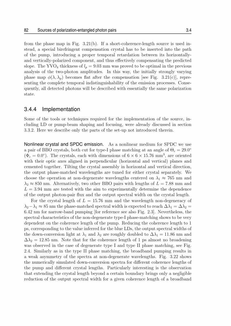
82 Sources of polarization-entangled photon pairs 3.4
from the phase map in Fig. 3.21(b). If a short-coherence-length source is used in-stead, a special birefringent compensation crystal has to be inserted into the pathof the pump, introducing a proper temporal retardation between its horizontally-and vertically-polarized component, and thus effectively compensating the predictedslope. The YVO4 thickness of lp = 9.03 mm was proved to be optimal in the previousanalysis of the two-photon amplitudes. In this way, the initially strongly varyingphase map φ(λ, λp) becomes flat after the compensation [see Fig. 3.21(c)], repre-senting the complete temporal indistinguishability of the emission processes. Conse-quently, all detected photons will be described with essentially the same polarizationstate.
3.4.4 Implementation
Some of the tools or techniques required for the implementation of the source, in-cluding LD or pump-beam shaping and focusing, were already discussed in section3.3.2. Here we describe only the parts of the set-up not introduced therein.
Nonlinear crystal and SPDC emission. As a nonlinear medium for SPDC we usea pair of BBO crystals, both cut for type-I phase matching at an angle of Θc = 29.0◦
(Φc = 0.0◦). The crystals, each with dimensions of 6 × 6 × 15.76 mm3, are orientedwith their optic axes aligned in perpendicular (horizontal and vertical) planes andcemented together. Tilting the crystal assembly in horizontal and vertical direction,the output phase-matched wavelengths are tuned for either crystal separately. Wechoose the operation at non-degenerate wavelengths centered on λ1 ≈ 765 nm andλ2 ≈ 850 nm. Alternatively, two other BBO pairs with lengths of L = 7.88 mm andL = 3.94 mm are tested with the aim to experimentally determine the dependenceof the output photon-pair flux and the output spectral width on the crystal length.
For the crystal length of L = 15.76 mm and the wavelength non-degeneracy ofλ2−λ1 ≈ 85 nm the phase-matched spectral width is expected to reach ∆λ1 = ∆λ2 =6.42 nm for narrow-band pumping [for reference see also Fig. 2.3]. Nevertheless, thespectral characteristics of the non-degenerate type-I phase-matching shows to be verydependent on the coherence length of the pump. Reducing the coherence length to 1ps, corresponding to the value inferred for the blue LDs, the output spectral widths ofthe down-conversion light at λ1 and λ2 are roughly doubled to ∆λ1 = 11.86 nm and∆λ2 = 12.85 nm. Note that for the coherence length of 1 ps almost no broadeningwas observed in the case of degenerate type I and type II phase matching, see Fig.2.4. Similarly as in the type II phase matching, the broadband pumping results ina weak asymmetry of the spectra at non-degenerate wavelengths. Fig. 3.22 showsthe numerically simulated down-conversion spectra for different coherence lengths ofthe pump and different crystal lengths. Particularly interesting is the observationthat extending the crystal length beyond a certain boundary brings only a negligiblereduction of the output spectral width for a given coherence length of a broadband

3.4 Compact collinear type-I SPDC source 83
Figure 3.22: Calculated non-degenerate spectra centered on λ1 ≈ 765 nm and λ2 ≈ 850nm obtained from type I phase-matched BBO crystal for (a) different coherence lengths ofpump light: CW pumping, i.e. τp = ∞ (red,“r”), τp = 1.0 ps (green, “g”), τp = 0.5 ps(blue, “b”); and (b) for different crystal lengths: L = 3.94 mm (red,“r”), L = 7.88 mm(blue, “b”), L = 15.76 mm (green, “g”), L = 31.52 mm (cyan, “c”). In plot (a) the crystallength of L = 15.76 mm is assumed and in plot (b) a coherence length of the pump light ofτp = 1.0 ps is assumed.
pump. In such a case the only possibility to achieve narrower spectral distributionsis to enlarge the pump-beam coherence length.
Wavelength division multiplexer. The collinearly emitted photons at the wavelengthsof λ1 = 765 nm and λ2 = 850 nm are coupled into a single-mode fibre using anaspheric lens. The fibre is pigtailed to the custom made visible WDM (Fiber Op-tic Network Technology Co.), which demultiplexes the two wavelengths into outputsingle-mode fibres each carrying one wavelength. The WDM was characterized usinga broadband light source, yielding the spectral dependence of the insertion loss andisolation into both outputs, see Fig. 3.23. The isolation of > 17 dB is obtained in thebandpass of 15 nm around the operating wavelengths of 765 nm and 850 nm. Thepeak isolation reaches nearly 22 dB. The insertion loss was found to be about 0.35 dBin 765 nm output port and 0.3 dB in 850 nm port. A separate measurement of theinternal polarization effects at the operating wavelengths determined the maximumpolarization-dependent loss to be below 0.1 dB.
Set-up overview. The schematic set-up of the source is shown in Fig. 3.24 (thephoto of the experimental source is included in appendix A.3). The linearly polarizedpump light is provided by a 60 mW free-running laser diode. The light is reflectedseveral times at dichroic mirrors to remove the background broadband laser emissionand passes through a half-wave plate rotating the angle of polarization to 45◦ withregard to the horizontal direction. A triad of lenses is used to focus the pump beam
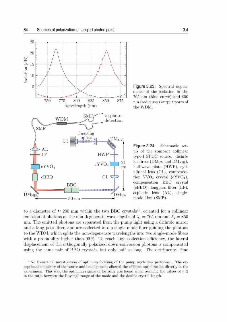
84 Sources of polarization-entangled photon pairs 3.4
Figure 3.23: Spectral depen-dence of the isolation in the765 nm (blue curve) and 850nm (red curve) output ports ofthe WDM.
Figure 3.24: Schematic set-up of the compact collineartype-I SPDC source: dichro-ic mirror (DMUV and DMNIR),half-wave plate (HWP), cyli-ndrical lens (CL), compensa-tion YVO4 crystal (cYVO4),compensation BBO crystal(cBBO), longpass filter (LF),aspheric lens (AL), single-mode fibre (SMF).
to a diameter of ≈ 200 mm within the two BBO crystals10, oriented for a collinearemission of photons at the non-degenerate wavelengths of λ1 = 765 nm and λ2 = 850nm. The emitted photons are separated from the pump light using a dichroic mirrorand a long-pass filter, and are collected into a single-mode fiber guiding the photonsto the WDM, which splits the non-degenerate wavelengths into two single-mode fiberswith a probability higher than 99%. To reach high collection efficiency, the lateraldisplacement of the orthogonally polarized down-conversion photons is compensatedusing the same pair of BBO crystals, but only half as long. The detrimental time
10No theoretical investigation of optimum focusing of the pump mode was performed. The ex-ceptional simplicity of the source and its alignment allowed the efficient optimization directly in theexperiment. This way, the optimum regime of focusing was found when reaching the values of ≈ 2in the ratio between the Rayleigh range of the mode and the double-crystal length.
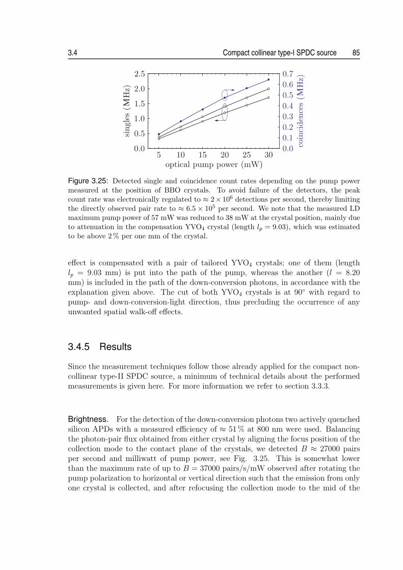
3.4 Compact collinear type-I SPDC source 85
Figure 3.25: Detected single and coincidence count rates depending on the pump powermeasured at the position of BBO crystals. To avoid failure of the detectors, the peakcount rate was electronically regulated to ≈ 2× 10⁶ detections per second, thereby limitingthe directly observed pair rate to ≈ 6.5× 10⁵ per second. We note that the measured LDmaximum pump power of 57 mW was reduced to 38 mW at the crystal position, mainly dueto attenuation in the compensation YVO4 crystal (length lp = 9.03), which was estimatedto be above 2 % per one mm of the crystal.
effect is compensated with a pair of tailored YVO4 crystals; one of them (lengthlp = 9.03 mm) is put into the path of the pump, whereas the another (l = 8.20mm) is included in the path of the down-conversion photons, in accordance with theexplanation given above. The cut of both YVO4 crystals is at 90◦ with regard topump- and down-conversion-light direction, thus precluding the occurrence of anyunwanted spatial walk-off effects.
3.4.5 Results
Since the measurement techniques follow those already applied for the compact non-collinear type-II SPDC source, a minimum of technical details about the performedmeasurements is given here. For more information we refer to section 3.3.3.
Brightness. For the detection of the down-conversion photons two actively quenchedsilicon APDs with a measured efficiency of ≈ 51% at 800 nm were used. Balancingthe photon-pair flux obtained from either crystal by aligning the focus position of thecollection mode to the contact plane of the crystals, we detected B ≈ 27000 pairsper second and milliwatt of pump power, see Fig. 3.25. This is somewhat lowerthan the maximum rate of up to B = 37000 pairs/s/mW observed after rotating thepump polarization to horizontal or vertical direction such that the emission from onlyone crystal is collected, and after refocusing the collection mode to the mid of the

86 Sources of polarization-entangled photon pairs 3.4
respective crystal11.The output photon-pair flux was measured also for shorter BBO crystals with
L = 7.88 mm and L = 3.94 mm. In the first case we detected about B = 25000pairs/s/mW in the balanced configuration and up to B ≈ 28000 pairs/s/mW whenthe collection from one crystal was optimized. In the latter case no apparent dif-ference in the output rates was observed in both configurations; the brightness wasB ≈ 23000 pairs/s/mW. This clearly suggests that we cannot take full advantage ofhigher photon-pair fluxes converted in longer crystals, because of the impossibility tooptimally collect photons from both crystals at the same time. Furthermore, from thedetected rates we can infer that the fibre-coupled photon pair flux scales maximallywith the square root of the crystal length (∝ √
L). This is in agreement with theconclusions drawn in [95].
The impossibility of optimum simultaneous collection of photons from long crys-tals, however, does not preclude achieving of a high coincidence/single ratio µ. Thiscan be explained by the perfect rotational symmetry of the collinear emission mode:if one of the photons from the pair is emitted within the acceptance angular region ofthe single-mode fibre, the other photon must occupy this region as well, even in thecase of non-optimum focusing of the collection mode. This hypothesis is evidentlyverified in the experiment, where we measured µ ≈ 0.38 for crystals with the lengthof L = 15.76 mm. Taking into account the limited detection efficiency and otherlosses in the set-up, such as the reflection at the tips of the fibers (together > 10 %)and the optics in the path of down-conversion photons (> 3 %) or the insertion lossof the WDM (> 5 %), the moderate estimate of the net coupling efficiency reachesvalues as high as 90%.
Entanglement quality. To verify the entanglement of photon pairs, the degree ofpolarization correlations in two complementary bases was measured using a pairof polarizers. After correction for accidental coincidences, we obtain a visibility ofVH/V = 98.85 ± 0.11 % in the horizontal/vertical basis and V45 = 98.48 ± 0.13 % inthe basis rotated by 45◦, see Fig. 3.26. The corrected visibilities are, within errors,consistent with those obtained at low pump power of about 1 mW, where accidentalcoincidences are negligible. The gap between the measured value and the maximumquantum-interference visibility is attributed to polarization-dependent loss inside theWDM rather than to the state preparation.
We note that the removal of one of the compensation YVO4 elements from the set-up was accompanied with a dramatic drop of quantum-interference visibility. In orderto confirm that high-purity polarization entanglement can be achieved in the narrow-
11The applied divergence of the collection mode was optimized with regard to maximum photon-pair flux obtained in the balanced configuration. Although the reduction of collection-mode diver-gence results in a relaxation of the tolerances imposed on the positioning of its focus, the reducedangular range implies a coupling of a smaller proportion from the total SPDC emission and thussmaller detected rate.

3.4 Compact collinear type-I SPDC source 87
Figure 3.26: Polarizationcorrelations between pho-tons measured in the H/V(red points) and +45/-45(blue points) polarizationbases. The solid lines incorresponding colors are sin2
fits to the measured coinci-dence count rates, yieldingvisibilities of about 98.5% inboth bases.
band pumping regime even without YVO4 crystal preceding the down-conversionBBO crystals (for explanation see section 3.4.2), the external cavity laser diode withthe spectral line-width of < 50 MHz was applied as the pump. The measurementof polarization correlations yielded the visibility of above 98% also without a com-pensation in the pump beam, thereby supporting the conclusions of the theoreticalmodel.
CHSH-inequality violation. The measurement of CHSH-type Bell inequality wasaccomplished at the maximum pump power of LD using a pair of polarizers. Byperforming the whole measurement within 16 s (i.e., TI = 1 s per angle setting),we obtained the value of the correlation coefficient of S = 2.80399 ± 0.00125. Thiscorresponds to a violation of the inequality by 694 standard deviations. The specifiedvalues assume the correction of raw data for accidental coincidences. Note that aneven higher violation should be possible with the present source if one employs theoptimized polarization analysis with high-transmission elements. The correspondingspeed of CHSH violation [= (S − 2)/(σS
√TI)] is 694 σS s−1/2.
Spectrum. The fibre-coupled down-conversion light was spectrally analyzed usingthe grating spectrometer with single-photon sensitivity and a measured resolution ofabout 1.2 nm. The bandwidths of photons determined from the gaussian fits to themeasured data were found to be ∆λ1 = 14.56±0.72 nm and ∆λ2 = 15.38±1.23 nm atthe non-degenerate wavelengths of λ1 = 762.8± 0.4 nm and λ1 = 849.4± 0.6 nm, seeFig. 3.27. Taking into account the given wavelength resolution of the spectrometer,the measured values are consistent with the theoretical widths of ∆λ1 = 11.86 nmand ∆λ2 = 12.85 nm.
The spectra of down-conversion photons were measured for shorter BBO crystalswith L = 7.88 mm and L = 3.94 mm as well. In the first case we obtained the widthsof ∆λ1 = 18.65±1.74 nm and ∆λ2 = 22.37±2.23 nm, which are again in a reasonableagreement with the theoretically inferred values of ∆λ1 = 16.21 nm and ∆λ2 = 16.94

88 Sources of polarization-entangled photon pairs 3.4
Figure 3.27: Spectral distribution of down-conversion light collected into a single-modefibre. The solid line shows a Gaussian fit to the measured data. The photons of the pairare centered on the wavelengths of λ1 =≈ 763 nm and λ2 =≈ 849 nm, which agree well withthe operation wavelengths of WDM. The lower peak number of counts at λ2 is attributed toa reduced efficiency of the spectrometer towards NIR wavelengths and the offset of ≈ 1100counts is due to dark counts of the APDs.
nm. For L = 3.94 mm we measured ∆λ1 = 31.21± 1.68 nm and ∆λ2 = 40.33± 1.91nm. This has to be compared to theoretically determined widths of ∆λ1 = 30.75 nmand ∆λ2 = 31.03 nm.
Spectral brightness. From the afore-mentioned results we infer that the spectralbrightness of the source increased from the initial rate of B(s) ≈ 650 s−1nm−1mW−1
for L = 3.94 mm to B(s) ≈ 1220 s−1nm−1mW−1 for L = 7.88 mm and finallyto B(s) ≈ 1800 s−1nm−1mW−1 for the crystal length of L = 15.76 mm. Fitting theexperimentally recorded growth of brightness in dependence on the crystal length, weobtain the scaling of B(s) ∝ L0.72. This is considerably slower than the theoreticallyassumed dependence of B(s) ∝ L for degenerate phase-matching. Due to the factthat at a high non-degeneracy the phase-matched down-conversion width approachesthat obtained in type II phase matching (see also Fig. 2.3), it seems that even fasterscaling of up to B(s) ∝ L
√L should be obtained in such a case. The slower increase of
the experimentally inferred scaling of B(s)(L), compared to that inferred theoretically,is due to the two-crystal geometry of the SPDC emission, which does not allow theoptimum simultaneous coupling of photons from both crystals.
3.4.6 Discussion and outlook
The recorded performance of the source shows to be extraordinarily high. To thebest of our knowledge, the achieved brightness is the highest using a conventionalcrystal [73] and at the level of the best results obtained with quasi-phase matched

3.4 Compact collinear type-I SPDC source 89
periodically poled crystals [75, 105]. Together with the purity of the polarizationentanglement, which appears to be only limited by a weak depolarization effect inWDM, we could measure the violation of CHSH inequality as high as 694 σS s−1/2.This exceeds even the speed of 468 σS s−1/2, inferred from the results reported usingan ultra-bright source, where almost 10 times higher pump power was applied to thedown-conversion crystals [73]. The only shortcoming in the source characteristics liesin the down-conversion spectra, which might appear to be rather broad with regardto certain applications. Nevertheless, we have theoretically shown that a substantialreduction of the spectral widths should be feasible when applying a pump light withsufficiently long coherence length. This was also verified experimentally to someextent, by observing a reduction of spectral widths by about 6 nm in narrow-bandpumping regime for BBO crystals with the length of L = 3.94 mm.
The use of other materials with higher nonlinearity, such as bismuth triborate(BiB3O6), or the use of quasi-phase matched periodically poled crystals, such as peri-odically poled potassium titanyl phosphate (KTiOPO4), will lead to further immenseimprovement of the source parameters regarding the bandwidth of down-conversionphotons and its brightness. For example, the relative magnitude between the effectivenonlinearities of BiB3O6 (deff = 3.41 pm/V) and BBO (deff = 1.93 pm/V) impliesan increase in photon-pair yield by a factor ≈ 3. At the same time the calculationpredicts the reduction of the phase-matched spectra to below 3 nm for narrow-bandpumping (for L = 15.76 mm) and to about 10 nm, when the pump source is a free-running blue laser diode. In case of quasi-phase matched KTiOPO4 (deff ≈ 9.5 pm/V,[106]), an even higher relative ratio of the effective nonlinearities of ≈ 5 is reached,which suggests that an increase of the brightness by a factor of 15–25 should becertainly feasible. Remarkably, this potential brightness is at the level of the bestresults reported using four-wave mixing process in the optical fibres [83]. The alreadydemonstrated performance and the future prospects for its improvement, along withthe simple configuration requiring minimum alignment, make this type of source anespecially promising candidate for integration into future practical applications.
Apart from the practical motivations, the described source might find its relevancealso in fundamental tests of quantum mechanics. Particularly, to eliminate the fair-sampling hypothesis in photonic Bell tests, high detection and collection efficiencies ofentangled photon pairs are indispensable; for a brief introduction into the problem seealso section 1.1.3. The lower bound on the overall coincidence/single ratio necessaryto close detection loophole has been proven to be 2(
√2−1) ≈ 0.83 (assuming all other
aspects of the experiment to be ideal) [107], which, in the limit of no background noise,reduces to 2/3 ≈ 0.67 [108]. Whereas high detection efficiencies in the visible spectralregion of up to η = 90 % have been reported with visible-light photon counters(VLPC) [12], the experimental demonstration of the required collection efficiency ofentangled photon pairs is missing. With our source we achieved the coincidence/singleratio of µ ≈ 0.38 (detection efficiency η ≈ 0.51), to our knowledge the highest valueever reported (for comparison see appendix A.2). Scaling our result to a VLPCdetection efficiency of η = 90 %, we arrive at the overall coincidence/single ratio of

90 Sources of polarization-entangled photon pairs 3.4
0.67, i.e. exactly at the theoretical limit for successful detection loophole-free Bell testfor no background. The further increase of this ratio to ≈ 0.8 should be possible aftereliminating the current inefficiencies inherent in the source, including the reflectionat the tips of the single-mode fibers or absorption in other optical elements placedin the path of the down-conversion photons. Our results are very encouraging andindeed, move the feasibility of a loophole-free photonic Bell test into the realm ofstate-of-the-art technologies.

Chapter 4Single-qubit multiparty quantumcommunication
This chapter deals with two distinct multiparty communication tasks, the secretsharing and communication complexity. Whereas the goal of the first is to splita secret among several parties in a way that its reconstruction requires theircollaboration, the latter aims at reducing the amount of communication duringdistributed computational tasks. We describe the simple and practical quantum-assisted solutions of both tasks and show their proof-of-principle experimentalimplementations.
The use of quantum resources leads to a speed-up in solving many communicationtasks or even achieving goals which are classically not possible at all. Probably thebest-known example is quantum key distribution, the first commercialized applicationof quantum information science. While there is already quite a number of othertwo-party tasks demonstrated in the lab, there is hardly anything for more than twoparties. This is due to the fact that most of such tasks require as a resource multipartyentangled states, which are very difficult to be produced with current methods andmoreover suffer from a high noise.
In the following it is shown that entanglement is not the only non-classical resourcegiving quantum information processing its power. Instead, only sequential commu-nication and transformation of a single qubit can be sufficient to accomplish cer-tain tasks. Such simplification makes multiparty communication tasks feasible and,most importantly, technologically comparable to quantum key distribution. This wedemonstrate for two distinct multiparty communication tasks, communication com-plexity [109] and secret sharing [110].
The chapter is subdivided into two parts. The first part is concerned with com-munication complexity. After it, the section analyzing secret sharing follows.
91

92 Single-qubit multiparty quantum communication 4.1
4.1 Communication complexity
4.1.1 Introduction
Complexity theory addresses the problem of reduction of inherent costs required forsolving information processing tasks. In its most widespread branch, computationalcomplexity, the inherent costs are traditionally measured by the number of operationsrequired and/or the amount of memory spent during a large-scale computation. Here,we deal with yet another type of problems - communication complexity problems(CCPs) - where the resource under investigation and aimed to be minimized is theamount of communication during distributed computation.
The notion of communication complexity was introduced by Andrew Yao [111],who investigated the following two-party scenario: The parties P1 and P2 receiveeach an n-bit string X1 and X2 with the common goal to compute the value of agiven function T (X1, X2). Before distribution of the strings, the parties are allowedto communicate freely and prepare themselves jointly in any way, e.g., by sharingclassically correlated random variables, agreeing on a common strategy etc. However,once received, they must communicate as little as possible. The question is how manybits of information exchange then is enough to compute T (X1, X2), or alternativelyhow high is the probability to reach the correct value of T (X1, X2) under a specificcommunication restriction.
In general terms CCPs are aimed at finding the communication protocols mini-mizing the amount of information that parties, performing some local computation,have to exchange in order to accomplish some globally defined goal. This abstractproblem finds its relevancy in many contexts: First and foremost in distributed com-puting, where enhancing the communication efficiency among the local computers,processing in parallel a large-scale computational task, leads to a speed-up. Besides,the problem finds its practical use in optimizing the design of Very Large Scale Inte-grated (VLSI) circuits or computer networks as well as in studies of data structures(for survey of the field, see [112]).
4.1.2 Quantum-assisted communication complexity
The pioneer of communication complexity, Andrew Yao, was also the first who in-troduced a qubit-communication model, where the parties are allowed to exchangequbits rather than bits [113]. It is not immediately clear whether this variation mightbring some savings in communication, given a fundamental theorem in quantum in-formation theory by Holevo [114]. The theorem implies that the mutual informationbetween two unentangled parties cannot increase by more than one bit per qubitof communication between them. This still holds even if the communication is notrestricted to be one-way [115]. More generally, if the parties share a prior entangle-ment the information capacity of communication increases to maximally two bits perexchanged qubit [16].

4.1 Communication complexity 93
The first example that quantum-assisted protocols enhance the communicationefficiency compared to any known classical ones, was given by R. Cleve et al. [116].They considered a different model than that of Yao, the entanglement model, where inaddition to the classical communication we allow the parties to perform measurementson previously shared set of qubits in an entangled state. As with the qubit model,there are no trivial communication advantages in this model, because entanglementalone cannot be used to signal information. Even though, R. Cleve et al. showedthat entanglement can act as a substitute for communication, when the goal is tocompute inner product function with the data distributed among three parties.
Since then, it was theoretically proven that entanglement or qubit communicationcan help to solve a range of tasks more efficiently compared to the best classicalscenarios [115, 117, 118, 119, 120]. For some tasks even an exponential separationin efficiency between quantum and classical protocols was demonstrated [121, 122].Moreover, the generic link between the classical/quantum conflict exposed by Bell’stheorem and the advantage of quantum communication complexity protocols over theclassical ones, was shown in [123, 124]. It was established there that the violation ofBell’s inequality is the criterion of the advantage of the quantum protocols over theclassical ones.
Despite many theoretical results, to date no experiment showing a genuine quan-tum advantage in solving CCPs has been reported; see also feasibility studies [125,126]. The only laboratory demonstrations corrected the measured results for theexperimental inefficiencies [127, 128], and thus did not provide the conclusive andunambiguous practical manifestation of the superiority of quantum-assisted proto-cols in distributed computations.
4.1.3 Communication complexity problems
In general, one can distinguish two types of CCPs, related to the following twoquestions: (i) What is the minimal amount of communication for the parties todetermine the value of a searched function T with the success probability of P = 1,that is with certainty [115, 118, 119]? (ii) What is the highest possible probability ofsuccess P if only a restricted amount of communication is allowed [119, 123, 124, 125]?The particular tasks might further differ according to whether all the parties or onlyone of them are required to determine the value of T , whether they are restricted to acertain communication architecture (such as sequential or tree-like communication),etc.
In the following we consider only the second class of problems. This choice ismotivated primarily by the goal of performing a fair comparison between the optimumclassical protocol and the quantum-assisted protocol in a realistic experiment, whichis inherent of many inefficiencies. Whereas the inefficiencies are directly reflected inthe reduction of the measured success probability Pexp, which is readily compared tothe classically allowed value, it is not directly obvious how to deal with the issue ofexperimental imperfections in the first class of problems. Let us now introduce the

94 Single-qubit multiparty quantum communication 4.1
two CCPs analyzed and implemented here [109].
Problem A. The problem A is the so-called modulo-4 sum problem. It was firstdefined for three parties by Buhrman et al. [119] and later generalized to N partiesin [118]. The problem in the setting with restricted communication is stated asfollows: Imagine N separated partners P1, . . . ,PN . Each of them receives a two-bit input string Xk, (Xk = 0, 1, 2, 3; k = 1, . . . , N). The Xks are distributed suchthat their sum is even, i.e., (
∑Nk=1 Xk)mod2 = 0. No partner has any information
whatsoever on the values received by the others. Next, the partners communicatewith the goal that one of them, say PN , can tell whether the sum modulo-4 of allinputs is equal 0 or 2. That is, PN should announce the value of a dichotomicfunction1 T (X1, . . . , XN) given by TA = 1 − (
∑Nk=1 Xkmod4). The total amount of
communication is restricted to only N − 1 bits (classical scenario). The partners canfreely choose a communication protocol as long as it does not depend on input data2.Such a dependence would imply a violation of the communication restriction.
An alternative description of the task A, simplifying the calculation of the maxi-mum classical success probability and making the connection with the task B morevisible, can be introduced. It puts the probability distribution for local data as
pA(X1, . . . , XN) =1
22N−1
∣∣∣∣∣cos
(π
2
N∑
k=1
Xk
)∣∣∣∣∣ , (4.1)
and the global task function as
TA(X1, . . . , XN) = cos
(π
2
N∑
k=1
Xk
). (4.2)
Problem B. Problem B has a similar structure as A, but now N real numbersX1, . . . , XN ∈ [0, 2π) with probability density
pB(X1, . . . , XN) =1
4(2π)N−1
∣∣ cos(X1 + . . . + XN)∣∣ (4.3)
are distributed to the partners. Their task is to compute whether cos(X1 + . . .+XN)is positive or negative, i.e. to give the value of the dichotomic function
TB = S
[cos
(N∑
k=1
Xk
)], (4.4)
1A dichotomic function is a function with a range restricted to two values of ±1.2E.g. they can choose between sequential communication from one to the other, or any arbitrary
tree-like structure ending at the last party PN .
4.1 Communication complexity 95
where S(x) = x/|x|. The communication restriction is the same as for problem A,i.e., only N − 1 bits are allowed to be exchanged.
4.1.4 Optimal classical protocol
To find the best performing protocols for these two CCPs, it is convenient to firstrewrite the random inputs Xks. For the task A we put Xk = (1 − yk) + xk, whereyk ∈ {−1, 1}, xk ∈ {0, 1}. For the task B we write Xk = π(1− yk)/2 + xk, with yk ∈{−1, 1}, xk ∈ [0, π). Accordingly, the task function T can now be reformulated in acommon form: T = f(x1, . . . , xN)
∏Nk=1 yk and p(X1, . . . , XN) = 2−Np′(x1, . . . , xN)3.
Specifically, for the task A we have f = fA = cos(π2
∑Nk=1 xk) with p′ = p′A =
2−N+1| cos(π2
∑Nk=1 xk)|, and for the task B, f = fB = S[cos(
∑Nk=1 xk)] with p′ =
p′B = 2−1π−N+1| cos(∑N
k=1 xk)|.We note that the dichotomic variables yk are not restricted by the probability
distributions, p, for the Xks. Thus, they are completely random. Furthermore, sinceT is proportional to the product of all yks, the answer eN = ±1 of PN is completelyrandom with respect to T , if it does not depend on every yk. Thus, an unbrokencommunication structure is necessary: the information from all N − 1 partners mustdirectly or indirectly reach PN . Due to the restriction to N−1 bits of communicationeach of the partners, Pk, where k = 1, . . . , N−1, sends only an one-bit message, whichfor convenience will be denoted as ek = ±1.
The task function T as well as the answer eN of PN takes only two values, ±1.If the answer is correct, then T = eN and thus TeN = 1; otherwise, TeN = −1.Therefore, following [124] we can quantify the average success of the protocol withthe fidelity F =
∑X1,...,XN
pTeN , or equivalently
F =1
2N
∑x1,...,xN=0,1
p′(x1, . . . , xN)f(x1, . . . , xN)
×∑
y1,...,yN=±1
N∏
k=1
ykeN(x1, . . . , xN ; y1, . . . , yN) (4.5)
For the problem B integrations replace summations (∑
xk→ ∫ π
0dxk); the probability
of success reads P = (1 + F )/2.In any classical protocol the answer eN given by PN can depend on yN , xN , and on
the messages, ei1 , . . . , ei` , received directly from partners Pi1 , . . . ,Pi` . That is, eN =e(xN , yN , ei1 , . . . , ei`). Let us fix xN , and treat e as a function exN
of the remaining` + 1 dichotomic variables, yN , ei1 , . . . , ei` . In the 2`+1 dimensional space of such
functions one has an orthogonal basis given by Vjj1...j`(yN , ei1 , . . . , ei`) = yj
N
∏`k=1 ejk
ik,
3This reformulation enables one to adopt the mathematical formalism developed forentanglement-assisted communication complexity models in [123, 124].

96 Single-qubit multiparty quantum communication 4.1
where j, j1, . . . , j` = 0, 1. Thus, one can expand exN:
exN=
∑j,j1,...,j`=0,1
cjj1...j`(xN)yj
N
∏
k=1
ejkik
, (4.6)
where
cjj1...j`(xN) =
1
2`+1
∑yN ,ei1
,...,ei`=±1
exNVjj1...j`
.
Since |exN| = |Vjj1...j`
| = 1, one has |cjj1...j`(xN)| ≤ 1. We put the expansion to
Eq. (4.5). As,∑
yN=±1 yNy0N = 0, and
∑yk=±1 yke
0k = 0, only the term with
j, j1, . . . , j` = 1 in expansion (4.6) can give a non-zero contribution to Fc. Thus,without changing the result of Eq. (4.5), eN in (4.5) can be replaced by a functione′N = yNcN(xN)
∏`k=1 eik , where cN(xN) stands for c11...1(xN). Next, notice that, e.g.,
ei1 , which is in the formula for e′N , can depend only on xi1 , yi1 and the messagesobtained by Pi1 from a subset of partners: ep1 , . . . , epm (this set does not contain anyeik). In analogy with (4.6), ei1 , for a fixed xi1 , can be expanded in terms of orthogonalbasis functions:
ei1 =∑
j,j1,...,jm=0,1
c′jj1...jm(xi1)y
ji1
m∏
k=1
ejkpk
. (4.7)
Again, |c′jj1...jm(xi1)| ≤ 1. If one puts this into e′N one obtains for the fidelity
Fc =1
2N−2
∑x1,...,xN
g(x1, . . . , xN)cN(xN)ci1(xi1)∑
y′
∏
k 6=N,i1
yk
m∏r=1
epr
∏
k=2
eik , (4.8)
where g = p′f , ci1(xi1) = c′11...1(xi1), and∑
y′ represents summation over y1, . . . , yi1−1,yi1+1, . . . , yN−1 = ±1. Note that each message appears in the product only once. Wecontinue this procedure of expanding the messages, till it halts (i.e., till we reach thelevel of those partners who do not receive any messages). The end result is
Fc =∑
x1,...,xN
g(x1, . . . , xN)N∏
n=1
cn(xn), (4.9)
with |cn(xn)| ≤ 1. Since Fc in Eq. (4.9) depends on the product of local functionscn(xn), it has to be bounded from above, i.e., |Fc| ≤ B(N), where B(N) is the max-imum classical fidelity. The reasoning is similar to that leading to Bell inequalities4
[123, 124]. The extrema of Fc are at the limiting values cn(xn) = ±1, because Fc
is linear in every cn(xn). It becomes apparent now that the class of protocols, inwhich the partners P1 to PN−1 calculate ek = ykck(xk), with ck(xk) = ±1, and send
4As a matter of fact the inequality |Fc| ≤ B(N), where Fc is defined in (4.9), is an algebraicversion of a general Bell inequality for N observers.
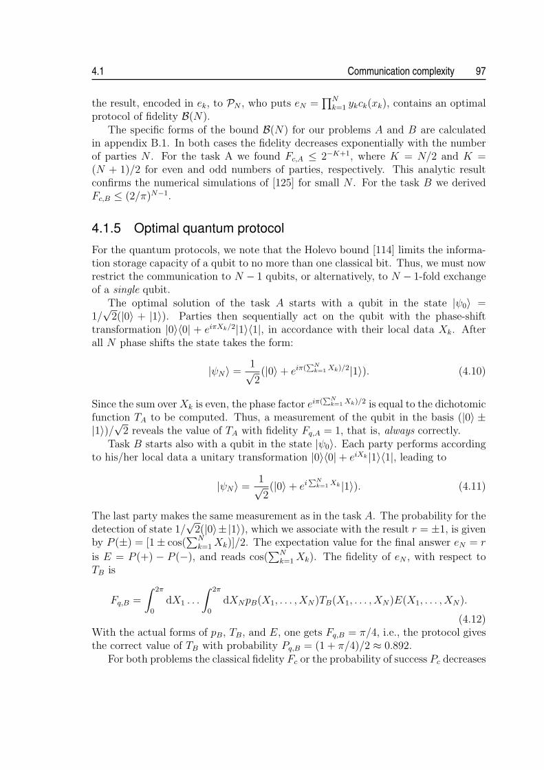
4.1 Communication complexity 97
the result, encoded in ek, to PN , who puts eN =∏N
k=1 ykck(xk), contains an optimalprotocol of fidelity B(N).
The specific forms of the bound B(N) for our problems A and B are calculatedin appendix B.1. In both cases the fidelity decreases exponentially with the numberof parties N . For the task A we found Fc,A ≤ 2−K+1, where K = N/2 and K =(N + 1)/2 for even and odd numbers of parties, respectively. This analytic resultconfirms the numerical simulations of [125] for small N . For the task B we derivedFc,B ≤ (2/π)N−1.
4.1.5 Optimal quantum protocol
For the quantum protocols, we note that the Holevo bound [114] limits the informa-tion storage capacity of a qubit to no more than one classical bit. Thus, we must nowrestrict the communication to N − 1 qubits, or alternatively, to N − 1-fold exchangeof a single qubit.
The optimal solution of the task A starts with a qubit in the state |ψ0〉 =1/√
2(|0〉 + |1〉). Parties then sequentially act on the qubit with the phase-shifttransformation |0〉〈0| + eiπXk/2|1〉〈1|, in accordance with their local data Xk. Afterall N phase shifts the state takes the form:
|ψN〉 =1√2(|0〉+ eiπ(
∑Nk=1 Xk)/2|1〉). (4.10)
Since the sum over Xk is even, the phase factor eiπ(∑N
k=1 Xk)/2 is equal to the dichotomicfunction TA to be computed. Thus, a measurement of the qubit in the basis (|0〉 ±|1〉)/√2 reveals the value of TA with fidelity Fq,A = 1, that is, always correctly.
Task B starts also with a qubit in the state |ψ0〉. Each party performs accordingto his/her local data a unitary transformation |0〉〈0|+ eiXk |1〉〈1|, leading to
|ψN〉 =1√2(|0〉+ ei
∑Nk=1 Xk |1〉). (4.11)
The last party makes the same measurement as in the task A. The probability for thedetection of state 1/
√2(|0〉±|1〉), which we associate with the result r = ±1, is given
by P (±) = [1± cos(∑N
k=1 Xk)]/2. The expectation value for the final answer eN = r
is E = P (+) − P (−), and reads cos(∑N
k=1 Xk). The fidelity of eN , with respect toTB is
Fq,B =
∫ 2π
0
dX1 . . .
∫ 2π
0
dXNpB(X1, . . . , XN)TB(X1, . . . , XN)E(X1, . . . , XN).
(4.12)With the actual forms of pB, TB, and E, one gets Fq,B = π/4, i.e., the protocol givesthe correct value of TB with probability Pq,B = (1 + π/4)/2 ≈ 0.892.
For both problems the classical fidelity Fc or the probability of success Pc decreases

98 Single-qubit multiparty quantum communication 4.1
Figure 4.1: Experimental set-up for qubit-assisted CCPs. Pairs of orthogonally polarizedphotons are emitted from a BBO crystal via the type-II SPDC process. The detection ofone photon by the trigger detector DT indicates the existence of the protocol photon. Thepolarization state is prepared with a half-wave plate (HWP1) and a polarizer, placed in thetrigger arm. Each of the parties introduces a phase-shift by the rotation of a birefringentYVO4 crystal (C1 to C5). The last party performs the analysis of a photon-polarizationstate using a half-wave plate (HWP2) followed by a polarizing beam-splitter (PBS).
exponentially with growing N to the value corresponding to a random guess by PN .I.e., communication becomes useless. In contrast, Pq does not change with N . For thetask A it equals 1, and for B we have≈ 0.892. The simple, one qubit assisted quantumprotocol, without any shared multi-particle entanglement, clearly outperforms thebest classical protocols.
4.1.6 Implementation
We implemented the quantum protocols for N = 5 parties [109], using a heraldedsingle photon as the carrier of the qubit communicated sequentially by the partners.The qubit was encoded in the polarization, so that the computational basis, “0” and“1”, corresponds to horizontal H and vertical V linear polarization, respectively. Thedata Xk of each party was encoded on the qubit via a phase shift, using birefringentmaterials. The last party performed a measurement in the basis 1/
√2(|H〉 ± |V 〉) to
obtain the answer eN .The experimental set-up is shown in Fig. 4.1. Time-correlated photon pairs are
produced via non-collinear SPDC process in a 2-mm-long BBO crystal pumped bya blue LD (λp = 402.5 nm) with the output optical power of about 10 mW. Thedetection of one photon by the trigger detector DT heralds the existence of the otherone used in the protocol. The narrow gate window of 4 ns for coincidence detectionbetween these two photons, along with the single-count rates of ≈ 140000 s−1 at thedetectors D+ and D−, warrant that the recorded data are due to single photons only5.
5The probability of having more than one photon per heralding signal and during time corre-sponding to the gate window is estimated to 2 × 10⁻³, assuming the given parameters and thePoissonian photon-number statistics of SPDC photons.

4.1 Communication complexity 99
Figure 4.2: Deviation of the phaseshift by an YVO4 crystal from the ex-pected value, measured over the fullrange [0, 2π] in steps of π/60.
Since a type II degenerate phase-matching scheme is used, the emitted photon pairsat λ = 805 nm (∆λ ≈ 6 nm) are orthogonally polarized. Filtering of the verticalpolarization for the trigger photons, ensures that the protocol photon has horizontalpolarization initially. A half-wave plate (HWP1) transforms the qubit to the initialstate 1/
√2(|H〉+ |V 〉) as required by the optimal quantum protocol.
The individual phase shifts of parties are implemented using a 200 µm thickYttrium-Vanadate (YVO4) birefringent uniaxial crystals (Ci). The crystals, cut withtheir optic axes parallel to the surface, are aligned in such a way that H and V polar-ization states correspond to their normal modes. In this configuration the differencebetween optical paths of horizontal and vertical polarization can be continuouslytuned using motor-driven rotations of the crystals along their optic axes, therebyallowing to set any desired phase-shift from 0 to 2π independently from the incomingpolarization state. The precision in applying an arbitrary phase shift was measuredto be better than 0.02π over the full phase range, see Fig. 4.2. An additional YVO4
crystal (Ccomp,1000 µm long), aligned with its optic axis in the plane perpendicular tothe direction defined by the optic axes of the previous crystals, is used to compensatedispersion effects (for details, see [129]). To analyze the polarization state of photonsin the basis (|0〉 ± |1〉)/√2, a half wave-plate (HWP2) at an angle of 22.5◦ followedby polarizing beam-splitter (PBS) is used.
For a fair comparison of the quantum protocols with the classical ones, no heraldedevents are discarded, even if the detection of the protocol photon fails. In such a caseone can still guess the value of T , but with success rate of only 1/2. Therefore, a highdetection efficiency η of the heralded photons, i.e. high coincidence/single ratio for ourset-up, is essential for an unambiguous demonstration of the superiority of the qubit-assisted protocol6. To minimize the cases with no detection of the photon, the yieldof heralded photons was maximized by adopting an unbalanced SPDC scheme. Weselect a restricted spatial mode with well defined polarization of the trigger photons by
6E.g., in a realistic implementation of the five-party problem A, the efficiency of η & 0.33 wasestimated to be sufficient to beat the optimum classical protocol, see [125].

100 Single-qubit multiparty quantum communication 4.1
coupling them into a single-mode fiber behind a polarizer, whereas no spatial filteringis performed on the protocol photons. As a result, we observed ≈ 5000 trigger eventsper second at the detector DT with ≈ 2400 coincident events per second of protocoldetections, i.e. an overall detection efficiency of η ≈ 0.48, close to the limit given bythe detector efficiency of our silicon APDs (measured to be about ≈ 55 %).
The protocols were run many times, to obtain sufficient statistics. Each run tookabout one second. It consisted of generating a set of pseudorandom numbers obeyingthe specific distribution, subsequent setting of the corresponding phase shifts, andopening detectors for a collection time window τ . The limitation of communicatingone qubit per run requires that only these runs, in which exactly one trigger photonis detected during τ , are selected for the evaluation of the probability of success Pexp.To maximize the number of such runs, n, the length of τ was optimized to 200 µs,assuming a Poissonian photon-number distribution of SPDC photons.
We merely remark that essentially the same set-up could be used to solve theCCPs using bright polarized pulses. However, in such a case, a suitable polarizationmeasurement of the pulses reveals all the encoded input data of any party: twobits for the task A, and arbitrarily many for the task B. Thus, the communicationrestriction to N − 1 bits is violated. Attenuation of the pulses to the single-photonlevel does not help either. The efficiency of the protocol is significantly lowered insuch a case, due to many non-detection events, forcing one to guess the answer mostof the time.
4.1.7 Results
In order to determine the probability of success from the data acquired during the runswe have to distinguish the following two cases. First, the heralded photon is detected,which happens with probability η, given by the coincidence/single ratio. Then, theanswer eN can be based on the measurement result. However, the answer is correctonly with a probability γ, due to experimental imperfections in the preparation ofthe initial state, the setting of the desired phase shifts, and the polarization analysis.This must be compared with the theoretical limits given by Pq,A and Pq,B for thetask A and B, respectively. Second, with the probability 1 − η the detection of theheralded photon fails. Forced to make a random guess, the answer is correct in halfof the cases. This leads to an overall success probability Pexp = ηγ + (1− η)0.5, or afidelity of Fexp = η(2γ − 1).
Due to a finite measurement sample, our experimental results for the successprobability are distributed around the value Pexp as shown in Fig. 4.3 for bothtasks. The width of the distribution is interpreted as the error in the experimentalsuccess probability. For the task A we obtain a quantum success probability ofPexp,A = 0.711 ± 0.005. The bound Pc,A = 5/8 of the optimal classical protocol forN = 5 parties is violated by 17 standard deviations. For the task B we reachedPexp,B = 0.669± 0.003, whereas the classical bound is Pc,B ≈ 0.582. The violation isby 29 standard deviations. Expressing the final results in terms of fidelities, we obtain

4.2 Secret sharing 101
Figure 4.3: Histograms of measured quantum success probabilities (a) for the task A and(b) for task B. The bounds for optimum classical protocols are displayed, too.
n η γ
task A 6692 0.452± 0.010 0.966± 0.003task B 18169 0.471± 0.006 0.858± 0.004
Table 4.1: Relevant experimental parameters in the implementation of communicationcomplexity problems A and B: n - number of correct runs, η - overall detection efficiencyof heralded photons, and γ - success rate of the protocol for the fraction of the runs withdetected heralded photon.
Fexp,A = 0.421 ± 0.010 for the task A, and Fexp,B = 0.337 ± 0.006 for the task B.This must be compared to the performance of the best classical protocol for N = 5parties reaching Fc,A = 0.25 for A and Fc,B ≈ 0.164 for B. Table 4.1 summarizes therelevant experimental parameters for both tasks.
4.2 Secret sharing
4.2.1 Introduction
Splitting a secret in a way that a single player or an unauthorized subset of players isnot able to reconstruct it, is a common task in information processing and especially,in high security applications. Suppose, for example that a launch sequence of anuclear missile is protected by a secret code. Yet, it has to be ensured that a singlelunatic is not allowed to activate it, as well as two are not. At least three out of fiveofficers are required to be lethal lunatics before the missile launch can be initiated.This problem, together with its many possible variations and generalizations, is calledsecret sharing.
The secret sharing problems are extensively studied in the framework of classicalcryptography [130]. The classical solution usually involves a randomized encoding of

102 Single-qubit multiparty quantum communication 4.2
a secret into an n-tuple, the coordinates of which are each distributed to n differentplayers. The encoding, i.e the partitioning of the secret into so-called shares given toplayers, has to be such that the reconstruction of the secret requires a specified level ofconcurrence by the players. This can be expressed in the majority of cases by a singlenumber - the so-called concurrence threshold k - which means that (i) knowledge ofany k or more shares makes the secret easily computable and (ii) knowledge of anyk − 1 or fewer shares leaves the secret completely undetermined in the sense that allits possible values are equally likely7.
The two classic examples of the algorithms for the general (k, n) threshold secretsharing scheme are due to A. Shamir [131] and G. R. Blakley [132]. Shamir’s techniquerelies on the fact that k points in an R2 space uniquely determine a (k − 1)th degreepolynomial, but there are infinitely many polynomials of degree k−1 defined by k−1points. Clearly, k or more players, each knowing the coordinates of one point, are thenable to recover the polynomial by interpolation of their values. The Blakley’s schemeis geometric in nature. The secret is defined as a point in a k dimensional spaceand the shares distributed among n players are the equations of (k − 1)-dimensionalhyperplanes comprising that point. Moreover, the intersection of the hyperplanesdefines the coordinates of the point. Analogously to Shamir’s version, any collusionof k − 1 or fewer players will not be able to obtain a unique point by intersectingtheir hyperplanes. Thus, they have no better chance of recovering the secret thanan outsider who does not hold any of the shares. On the other hand, as soon as anyk players concur, they can easily compute the coordinates of the point and retrievethus the secret.
That is, both schemes are unconditionally secure in the sense that the securitythey provide is independent of the computing time or power that the cheater maybring to bear on subverting the system; or put in another way, even with infinitecomputing power the cheater can do no better than guess the secret.
4.2.2 Quantum-assisted secret sharing
So far we did not address the issue of distribution of the shares among the players.Obviously, if the shares are accessed during this phase by an eavesdropper or evenby some dishonest player (i.e. by a cheater), the security of the system is ruined8.
Unfortunately, classical and conventional cryptographic solutions offer no toolsto guarantee the security of the shares during their communication to the players.They are vulnerable to eavesdropping attacks. The only provable way how to defeateavesdropping is provided by quantum cryptography [14, 15]. Unlike the conven-
7In view of this definition the example with the missile launch is a (k = 3, n = 5) thresholdscheme.
8By eavesdropping we refer to an attack from an outsider, that is from a person who is notinvolved with the group of players whatsoever, whereas by cheating we refer to an attack from oneof the players.

4.2 Secret sharing 103
tional cryptography with its security relying only on computational assumptions, thesecurity of quantum cryptography is based upon the laws of quantum mechanics,which ultimately guarantee that distributed keys cannot be captured without beingirretrievably altered and therefore rendered useless - a process that is provably de-tectable. Therefore, quantum cryptography has to be integrated into secret sharingprotocols with the principal motivation of discovering whether an eavesdropper orcheater has been active during the protocol. The most obvious way how to achievethis goal is to establish a mutual secret key with each of the players separately via astandard two-party quantum key distribution protocol and then implement a classicalsecret sharing procedure, such as in the Shamir’s or Blakley’s version. This solutionis however not efficient and scalable with regard to the number n of the participatingplayers.
An elegant way how to achieve the task of secret sharing via the resource of mul-tiparty entanglement was outlined by Zukowski et al. [133]9 and later discussed inmore depth by Hillery et al. [134]. They showed that a shared maximally-entangledGHZ-state allows the information splitting and the protection against eavesdrop-ping simultaneously. But, due to lack of efficient and stable entangled multi-photonsources, an experimental demonstration of a working quantum secret sharing (QSS)shows to be very challenging. Till now, solely the in-principle feasibility of was shownin an experimental realization using pseudo-GHZ states [135] and very recently thescenario for three players was implemented [136].
In the following we propose a general protocol for n players, in which a sequentialsingle qubit communication between them is used with no need for GHZ-states [110].As our protocol requires only single qubits it is realizable with the current state-of-the-art technologies, and above all, scalable with respect to the number of participatingplayers. These merits made the experimental demonstration of our protocol for sixplayers possible. To grasp the essential elements in the construction of QSS let usfirst briefly describe the entanglement-based protocol using a multiparty GHZ state[134, 137].
4.2.3 Entanglement-based protocol
Consider a group of n players, each having a particle from the maximally-entangledn particle GHZ-state
|GHZ〉 =1√2
(| 00 . . . 0︸ ︷︷ ︸
n
〉+ | 11 . . . 1︸ ︷︷ ︸n
〉)
, (4.13)
9To be perfectly accurate the task being discussed in [133] is a bit different from secret sharing.It is often termed as “Third-Man” cryptography, and its goal is the generation of the cryptographickey between the players in such a way that its activation can be controlled by the Third Man.Nevertheless, as a matter of fact both tasks in question are very similar and their quantum-assistedsolutions are closely inter-linked.
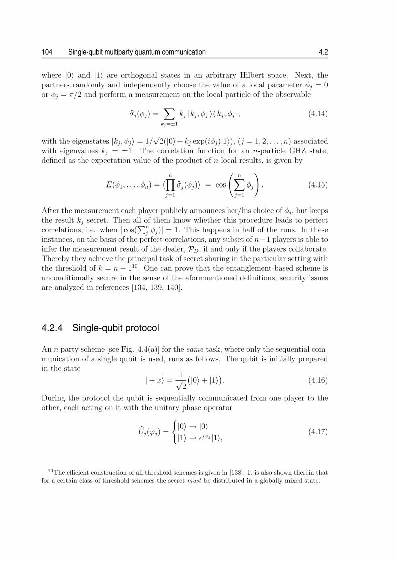
104 Single-qubit multiparty quantum communication 4.2
where |0〉 and |1〉 are orthogonal states in an arbitrary Hilbert space. Next, thepartners randomly and independently choose the value of a local parameter φj = 0or φj = π/2 and perform a measurement on the local particle of the observable
σj(φj) =∑
kj=±1
kj |kj, φj 〉〈 kj, φj |, (4.14)
with the eigenstates |kj, φj〉 = 1/√
2(|0〉+ kj exp(iφj)|1〉), (j = 1, 2, . . . , n) associatedwith eigenvalues kj = ±1. The correlation function for an n-particle GHZ state,defined as the expectation value of the product of n local results, is given by
E(φ1, . . . , φn) = 〈n∏
j=1
σj(φj)〉 = cos
(n∑
j=1
φj
). (4.15)
After the measurement each player publicly announces her/his choice of φj, but keepsthe result kj secret. Then all of them know whether this procedure leads to perfectcorrelations, i.e. when | cos(
∑nj φj)| = 1. This happens in half of the runs. In these
instances, on the basis of the perfect correlations, any subset of n−1 players is able toinfer the measurement result of the dealer, PD, if and only if the players collaborate.Thereby they achieve the principal task of secret sharing in the particular setting withthe threshold of k = n− 110. One can prove that the entanglement-based scheme isunconditionally secure in the sense of the aforementioned definitions; security issuesare analyzed in references [134, 139, 140].
4.2.4 Single-qubit protocol
An n party scheme [see Fig. 4.4(a)] for the same task, where only the sequential com-munication of a single qubit is used, runs as follows. The qubit is initially preparedin the state
|+ x〉 =1√2
(|0〉+ |1〉). (4.16)
During the protocol the qubit is sequentially communicated from one player to theother, each acting on it with the unitary phase operator
Uj(ϕj) =
{|0〉 → |0〉|1〉 → eiϕj |1〉, (4.17)
10The efficient construction of all threshold schemes is given in [138]. It is also shown therein thatfor a certain class of threshold schemes the secret must be distributed in a globally mixed state.

4.2 Secret sharing 105
with the randomly chosen value of ϕj ∈ {0, π, π/2, 3π/2}. Therefore, having passedall parties, the qubit will end up in the state
|χN〉 =1√2
(|0〉+ ei(
∑nj ϕj)|1〉
). (4.18)
The last party performs a measurement on the qubit in the basis |±x〉 = 1√2(|0〉±|1〉)
leading to the result ±1. As it will be clarified later, for her/him it suffices to chooseonly between ϕn = 0 or ϕn = π/2. The probability that she/he detects the state|+ x〉 reads
p+(ϕ1, . . . , ϕn) =1
2
[1± cos
(n∑j
ϕj
)], (4.19)
whereas the probability to detect the state | − x〉 is
p−(ϕ1, . . . , ϕn) =1
2
[1± cos
(n∑j
ϕj
)]. (4.20)
That is, the expectation value of the measurement is
E ′(ϕ1, . . . , ϕn) = p+(ϕ1, . . . , ϕn)− p−(ϕ1, . . . , ϕn) = cos
(n∑j
ϕj
). (4.21)
Note that this expectation value (Eq. 4.21) has the same structure like the correlationfunction (Eq. 4.15) and can therefore also be used to obtain a shared secret. Forthis purpose each participant divides his action for every run into two classes: aclass X corresponding to the choice of ϕj ∈ {0, π} and a class Y corresponding toϕj ∈ {π/2, 3π/2}. Following this classification they broadcast the class of their actionfor each run, but keep the particular value of ϕj secret. This corresponds in the GHZscheme to the announcement of φj while keeping kj secret. The order in which theyannounce the classification is each time randomly chosen. From that procedure theycan determine which runs lead to a deterministic measurement result, i.e. whencos(
∑nj ϕj) equals to either 1 or -1, or equivalently, to either p+ = 1 or p− = 1,
respectively. Such sets of ϕs occur on average in half of the runs. These are validruns of the protocol. In such cases any subset of n−1 players is able to infer the choiceof phase ϕD of the dealer, if and only if, they concur and reveal among themselvestheir values of ϕj. In case that this subset contains the last partner, he/she mustreveal the measurement result11. The task of secret sharing in the particular setting
11Note that although doing different things in practice (measurement/phaseshift) all parties areequal as far as the amount of information is concerned. In fact the state preparation and detectioncould be formally separated from the parties and be performed by some higher instance etc. Yet wedo not think this is in any way of practical importance.

106 Single-qubit multiparty quantum communication 4.2
RNG RNGRNG
RNG RNG RNG
Figure 4.4: (a) Scheme for n party single qubit secret sharing. A qubit is prepared in aninitial state and sequentially communicated from one player to the next, each applying arandomly chosen phase ϕj from a preselected set. The last player performs a measurementon the qubit leading to the result ±1. In half of the cases the phases add up such that themeasurement result is deterministically depending on the sum of phases. These instancescan be used to achieve the aim of secret sharing. (b) Experimental set-up. Pairs of orthog-onally polarized photons are generated via type II SPDC. The detection of one photon byDT heralds the existence of the other one used in the protocol. The initial polarization stateis prepared using a polarizer in the trigger arm. Each of the players (P1, . . . ,P6) introducesone out of four phase shifts, according to the output of a pseudo random number generator(RNG), using a half- and quarter-wave plate (HWP1, QWP) or YVO4 crystals (C1,. . . ,C5),respectively. The last party analyzes additionally the final polarization state of the photonby detecting it behind a half-wave plate (HWP2) and a polarizing beam splitter (PBS).
with the threshold of k = n− 1, is now achieved via local manipulation of phases ona communicated single qubit, and no multi-particle entangled GHZ state is requiredanymore.
Security of the protocol. In order to ensure the security of the protocol againsteavesdropping or cheating, the dealer PD of the secret arbitrarily selects a certainsubset (the size depends on the degree of security requirements) of valid runs. Forthese runs the value of ϕD is compared with the one inferred by the players. To thisend each of the players sends, in a random order, the value of his/her phase ϕj. Thecomparison reveals any eavesdropping or cheating strategy. That can be easily seenby discussing the following intercept/resend eavesdropping attacks.
Imagine for instance the first player Pj who follows directly after the dealer PD
tries to infer the secret on her/his own, i.e. without the required level of concurrence
k = n − 1, by measuring the qubit, before acting on it with Uj(ϕj) and afterwardssending it to the next player Pj+1. For convenience, let us assume Pj chooses for thismeasurement one of the two protocol bases |±x〉 or |±y〉 = 1√
2(|0〉±i|1〉). The choice
of these bases appears to be natural because at any stage of the protocol the qubit isin one of these four states. As PD applies randomly one of four different phase shifts,the probability that the qubit is an eigenstate of the measurement chosen by Pj is 1/2

4.2 Secret sharing 107
and thus in half of the cases the measurement result of Pj will be completely bitwiserandom, because |〈±y | ±x 〉|2 = 1/2. Thus, the cheater Pj gets no informationabout the secret. Furthermore, such cheating causes an overall error of 25% in thefinal measurement results. Simply, if Pj chooses the wrong basis, the final state ofthe qubit after all the introduced phase shifts will not always be of the form (4.18).
An eavesdropper following such a strategy faces a similar situation. The usage ofthe bases x and y for an intercept/resend attack is the optimal with regard to theinformation gain on the valid runs. One might also consider using the intermediate(or so-called Breidbart) basis |±b〉 = 1√
2+√
2(|±x〉+ |±y〉) = 1√
2(|0〉±eiπ/4|1〉) which
gives the eavesdropper maximum information on all exchanged bits [141]. But evenhere the error rate goes necessarily up to 25%. The security of the presented protocolagainst a general eavesdropping attack follows from the proven security of the wellknown BB84 protocol [14, 63]. Each communication step between two successiveparties can be regarded as a BB84 protocol using the bases x and y. Any set ofdishonest players in our scheme can be viewed as an eavesdropper in BB84 protocol.
4.2.5 Implementation
The single-qubit protocol for secret sharing was experimentally implemented for n =6 players with a threshold of k = n − 1 = 5, thereby clearly demonstrating thepracticality of the scheme [110]. The implementation exploits numerous tools alreadyapplied in the experimental set-up to solve CCPs. Therefore, the following descriptionis rather cursory; for more details we refer to section 4.1.6.
The experimental set-up for single-qubit secret sharing is shown in Fig. 4.4(b);(photo of the set-up is included in appendix B.2). The protocol qubit is encodedin a polarization state (the computational basis states |0〉 and |1〉 correspond to thehorizontal |H〉 and vertical |V 〉 polarization states) of a single photon provided by theheralded single photon source based on a correlated photon pair emission from typeII SPDC. Filtering of the vertical polarization of the trigger photon by a polarizer,ensures that the protocol photon has horizontal polarization initially.
The first player P1 is equipped with a motorized half-wave plate (HWP1) followedby a quarter-wave plate (QWP) at an angle of 45◦. By rotating of HWP1 to the angles0◦, 45◦ and 22.5◦, −22.5◦ he transforms the horizontally polarized photons comingfrom the source to | ± y〉 and | ± x〉. This corresponds to applying the phase-shiftsϕ ∈ {π/2, 3π/2} and ϕ ∈ {0, π}, respectively. As the phase-shifts of the other players(P2, . . . ,P6) have to be applied independently of the incoming polarization state, theusage of standard wave plates is not possible. Therefore the unitary phase operatoris implemented by rotating 200 µm long YVO4 birefringent crystals (Ci) along theiroptic axis, oriented perpendicularly to the beam. An additional YVO4 crystal (Ccomp)compensates dispersion effects. The last party performs the measurement behind ahalf-wave plate (HWP2) at an angle of 22.5◦ followed by polarizing beam-splitter(PBS).

108 Single-qubit multiparty quantum communication 4.2
ztotal zraw zval QBER (%)
| ± x〉 27501 883 452 25.22± 2.04| ± y〉 24993 784 409 30.32± 2.27| ± b〉 38174 1137 588 30.27± 1.89
Table 4.2: Results of the simulation of an intercept/resend eavesdropping strategy in theprotocol bases as well as in the intermediate bases. The attack was done by inserting apolarizer between the first two players. In each case the quantum bit error rate (QBER)rises up to more than 25 % and by this blows the eavesdropper’s cover.
The photons are detected at D+/D− and DT by passively quenched silicon APDswith a measured efficiency of about 35% at our operating wavelength. At the typicalsingle-count rates of ≈ 35000 s−1 both in D+ and D− and about 5000 s−1 in DT weobtained a coincidence rate of 1200 s−1. Together with a chosen coincidence gatewindow of 4 ns this implies the communication of single photons only. Accidentalcoincidences or multi-coincidences were negligible.
4.2.6 Results
The protocol was repeated ztotal = 25000 times. One run consisted of generatingpseudo-random variables, rotating the crystals accordingly and opening the detectorsfor a collection time window τ = 200 µs, what took all together about 1 s. Therequirement of communicating a single photon imposes that only those runs wereincluded into the protocol in which just one coincidence between DT and either D+
or D− was detected during τ . In these runs a single coincidence detection happenedzraw = 2107 times which provided us with the raw key. From this we extractedzval = 982 valid runs where | cos(
∑nj ϕj)| = 1 [506 times cos(
∑nj ϕj) = 1 and 476
times cos(∑n
j ϕj) = −1] with a quantum bit error rate (QBER) of 2.34± 0.48%. Tocalculate the error on the QBER the experiment is considered to be a sequence ofBernoulli trials implying a binomial distribution of error events. The error correctionprotocols (like, e.g., parity check) could be used exactly like in conventional quantumcryptography to further reduce the errors.
In order to show that the QBER increases significantly by an eavesdropping attackwe simulated an intercept/resend strategy by inserting a polarizer between the firsttwo players. The attack was done in the protocol bases | ± x〉, | ± y〉 as well as in theintermediate bases |±b〉. For the latter two the polarizer was additionally sandwichedby two quarter-wave plates. The angular settings {1st QWP, polarizer, 2nd QWP}were {45◦, 0◦,−45◦} and {−45◦, 22.5◦, 45◦}. For every choice of the basis the QBERwent up to at least 25% (or even higher due to other experimental imperfections).The results are summarized in Table 4.2.
A different eavesdropping/cheating strategy could be of a Trojan Horse type.One of the players could pass polarized light through the devices of the other play-

4.3 Discussion and outlook 109
ers and therefore attempt to gain information on local phase shifts. However, suchaction might be easily discovered by the players by checking the nature of lightpassing through their devices from time to time. Note further that any excess pho-tons, i.e. those not in coincidence with the trigger, cannot be utilized for eaves-dropping/cheating as they do not have a defined polarization12. Only higher-orderemissions, i.e. two pairs emitted within the coherence time (≈ 360 fs), are useful forbeam-splitting attacks; this is just the same as in entanglement-based quantum cryp-tography, see e.g. [142, 143, 144]. The probability for such a opportunity, however,for our parameters is as low as 7.1× 10⁻⁸ per run.
We merely remark that the use of weak coherent pulses of light containing muchless than one photon on average, instead of a heralded single photon source, is possibleand further reduces the required experimental resources. However, this would be atthe expense of the concept of communicating strictly one qubit and can be alsodisadvantageous for the practical performance of the protocol [145, 146]. While wehave realized our secret sharing protocol using photons and polarization encoding,alternative schemes, like proposed or realized in BB84-type protocols can be adoptedas well.
4.3 Discussion and outlookWe introduced new schemes for solving the multiparty communication tasks of com-munication complexity and secret sharing. Unlike other quantum-assisted methodsemploying multi-particle entangled states, our protocols involve only the sequentialcommunication and transformation of a single qubit. As single-qubit operations usinglinear optical elements and the analysis of photon polarization states are efficientlyrealizable with today’s technology, we were therefore able to present the first success-ful experimental demonstrations of the protocols for as many as five and six parties,respectively. This is to our knowledge the highest number of actively performingparties in a quantum protocol ever implemented. In principle, we see no experimen-tal barrier to extend the performed protocols to even significantly higher number ofparticipants.
From theoretical point of view, our work unambiguously demonstrates the powerof qubit communication in multiparty tasks. Even though a qubit can be used tocommunicate only one bit of information between two unentangled parties [114], thefull continuous nature of the quantum state still helps when performing some quan-tum information tasks. The trick is not to require that the information encoded ina qubit is actually read out, but rather substituted for a large amount of classical
12The initial polarization of the heralded photons is fixed in the experiment by putting the polar-ization filter in the path to the trigger detector, see Fig. 4.4(b). Since the photons form polarizationentangled EPR pairs, detection of a trigger photon behind a polarization filter collapses the initiallyundefined polarization state of the heralded one to the required |+ x〉. All other photons, since notrigger event accompanies them, remain unpolarized.

110 Single-qubit multiparty quantum communication 4.3
information, which is sequentially processed by every party.
(i) In CCPs with restricted amount of communication this allows to achieve theexponential separation between the quantum/classical performance with increasingnumber of parties. The performance of the quantum protocol and of its implemen-tation is so high that even without any correction for detector efficiency, loss in theset-up etc., our experimental results significantly outperform the best classical pro-tocols for both studied tasks.
(ii) In QSS this allows to induce among the players the GHZ-like correlations, whichare essential for achieving secret sharing task. Still, due to the different architecturesof the GHZ-assisted and single-qubit schemes one has to be aware of possibly newsecurity dangers. Since eavesdropper might have an access to input and output portsof the partners, particulary the attacks of Trojan Horse type have to be carefullyanalyzed in our scheme. Yet, they can be precluded by the players with a reasonabletechnological effort like, e.g., discussed in [147]. Also, very recently it was shown thatby using a quantum memory and a teleportation protocol the cheater/eavesdroppercan learn a minor random part of the key (the size depends on her/his position in thecommunication chain) in our protocol [148]. To close this subtle security loopholevarious classical methods, like e.g. hash functions, have to be applied or the quantumprotocol has to be further refined [149].
Interestingly, our single-qubit communication protocols for CCPs and QSS can beconsidered as a direct adaptation of the corresponding entanglement-based protocolsusing GHZ states. While the entanglement-based protocols use a non-local quantumphase, which can be operated on locally by each party, the single-qubit protocolsuse a quantum phase of a qubit to sequentially encode local information as it fliesby the parties towards the last party, who performs a suitable measurement. Theexpectation value of such a measurement has the same structure as a correlationfunction of GHZ state (defined as the expectation value of the product of the localmeasurement results by parties). This explains why the tasks of secret sharing andcommunication complexity are efficiently solvable with protocols involving only thecommunication of a single qubit. It appears rather plausible that our single-qubitapproach may be a practical solution for many other problems, which were believedto be possible only with the use of multiparty entangled states until now.
In summary, by successfully solving and implementing a cryptographic task aswell as a task originating in computer science, we clearly illustrate the potential tointroduce multiparty communication problems into real life.

Chapter 5Conclusions and Outlook
The work presented in this thesis addresses two topics related primarily to the de-velopment of technologies and systems for practical quantum communication. Thefirst topic is the efficient generation of photonic entanglement and the second is thesimplification and implementation of quantum-assisted solutions to multiparty com-munication tasks.
Generation of photonic entanglement. In the last decade we witnessed a dramaticprogress of photon pair sources in terms of the output flux and the practicality ofsystems. It appears safe to say that some of the concepts have come to reach anupper bound, forcing one to develop novel methods and techniques for the generationof photonic entanglement. This gradual progress is also clearly perceptible in thisthesis, which describes the work on two distinct sources of polarization-entangledphoton pairs, spanning the period of over four years.
The first type of source was designed and implemented using the well establishedconcept of degenerate non-collinear emission from a single type-II nonlinear crys-tal. With a blue laser diode as a pump source of SPDC, this configuration yieldsmaximally hundreds of detected pairs per second and mW of pump power. Moreimportantly, no substantial increase of the brightness is to be expected in the future.This is due to the limitation of the crystal length to a few mm range and due tothe fact that only a small fraction of the total SPDC output flux is polarization-entangled. However, the main goal of this design, to demonstrate the feasibility ofsources using blue laser diodes as replacement of costly large frame ion lasers, wasachieved. Moreover, based on this design, a setup for a lab course on entanglementand the EPR-Bell-problem could be built.
Deficiencies of the first setup are overcome in the second type of source, whichfeatures a novel configuration with only a single spatial mode for collecting non-degenerate photon pairs generated via SPDC in a double-crystal geometry. This fullycollinear configuration greatly enhances the practicality of the source. Particularly, itallows one to use very long nonlinear crystals, resulting in a highly increased photon-
111

112 Conclusions and Outlook 5.0
pair flux. With a pair of 16-mm-long crystals we observed almost two order ofmagnitudes higher photon-pair flux compared to the non-collinear type II source.The usage of the only spatial mode for coupling of the photons also precludes theoccurrence of any intrinsic spatial effect limiting the quantum-interference visibility.Applying a tailored dispersion compensation, we were thereby able to reach nearly99% quantum-interference visibility, even though a free-running laser diode as apump of SPDC was used and no filtering of generated photons was applied. Thesemerits, together with almost free-of-alignment operation, suggest that this type ofsource is an especially promising candidate for many future practical applications,including quantum cryptography, detector calibration or use in undergraduate labcourses. Apart from the practical applicability, the source might find its relevance alsoin fundamental tests of quantum mechanics. Particularly, a measured net couplingefficiency of photons pairs of about 90% offers a unique chance to accomplish aphotonic Bell test excluding a fair sampling hypothesis for the first time.
There is a multitude of future research directions following on from the work onphoton pair sources presented in this thesis. As the technology for manufacturingquasi-phase-matched materials have progressed, periodically poled crystals like PP-KTP have become commonly available, offering a greater freedom in the choice ofwavelengths and an access to the highest nonlinear coefficients. Their integrationinto the collinear type I source should bring a higher output brightness, reduction ofphoton bandwidth, and possibly, complete suppression of the spatial walk-off effect,which has to be compensated in the current realization using additional birefrin-gent crystals. Another issue deserving more attention is the usage of ultrashort (fsto ps range) pulse pumped SPDC. The precise timing information inherent to suchtype of pumping showed to be very useful for the realization of certain experimentsin quantum optics including generation of multi-photon entangled states, quantumteleportation or other advanced communication protocols. Although the theoreticalmodel developed in the thesis suggests that the concept of collinear type I sourceworks equally efficient for ultrashort pulse pumping, the experimental verificationhas to be accomplished.
Turning to applications, it is the next goal for the source of non-degenerate en-tangled photon pairs to be used for a real world experiment such as a demonstrationof long-distance quantum cryptography; see also [150]. The preliminary steps inthis direction have been already taken by testing the source outside an ideal labenvironment, showing no impairment of the output performance and an overall long-term stability of the system. Concerning the applicability of the source for futureapplications a great deal of effort has to be also made to miniaturize the system,to further minimize the necessary adjustment, and to use a design with superior(thermo-)mechanical stability such as, for example, using fixed components.
Multiparty communication tasks. The use of quantum resources leads to a speed-upin solving many communication tasks or even achieving goals which are classically

5.0 Conclusions and Outlook 113
not possible at all. While the recent rapid progress in the development of brightentangled photon-pair sources has been followed with ample experimental reports ontwo-party quantum communication tasks, the practical implementations of tasks formore than two parties have been quite rare, so far. This is primarily due to the re-quirement of multiparty entangled states, which are very difficult to be produced withcurrent methods and, moreover, suffer from high noise and (depending on the num-ber of partners) exponentially decreasing output yield. We show that entanglementis not the only non-classical resource endowing the quantum multiparty informationprocessing its power. Instead, only the sequential communication and transformationof a single qubit can be sufficient to accomplish certain tasks in a highly efficient way.This we prove for two distinct communication tasks, communication complexity andsecret sharing.
Quantum communication complexity addresses the problem of communication re-duction for distributed computation tasks by the utilization of quantum effects. Inthe thesis we study two CCPs, in which N separated partners with local random datamust determine in common the correct value of a globally defined Boolean functionwith the highest possible probability of success. In these tasks the parties can com-municate only N−1 bits (classical scenario) or N−1 qubits (quantum scenario). Wetheoretically show that for such tasks with restricted communication the advantageof single-qubit assisted protocols over the corresponding classical ones may increaseeven exponentially with the number of partners. Furthermore, we successfully imple-ment the quantum protocols for N = 5 partners using a heralded single photon fromparametric down-conversion as the carrier of the qubit communicated from one part-ner to the other. For a fair comparison with the classical scenario, no correction forimperfections of the state-of-the-art set-up was done whatsoever. The performanceof the protocol and of its implementation is so high that even without any correctionfor detector efficiency, loss in the set-up etc., we significantly outperform the bestclassical protocols for both studied tasks.
Secret sharing is a cryptographic task with the aim of distributing a secret in sucha way that its reconstruction requires the collaboration of the participating partners.Classically the problem is solved by splitting the information using some mathemati-cal algorithms and distributing the resulting pieces to the legitimate parties. However,classical communication is not secure and thus integration of quantum cryptographyto secret sharing was proposed. In this protocol a shared GHZ-state allows the in-formation splitting and the eavesdropper protection simultaneously. We propose aprotocol for N partners, in which only single-qubit communication is used with noneed for GHZ-states. As our protocol requires only single qubits it is realizable withthe current state-of-the-art technologies and, above all, scalable with respect to thenumber of participating partners. These merits enabled us to accomplish the firstexperimental proof-of-principle demonstration of secret sharing for as many as sixpartners. This is to our knowledge the highest number of actively performing partiesin a quantum protocol ever implemented.
By successfully solving and implementing a cryptographic task as well as a task

114 Conclusions and Outlook 5.0
originating in computer science, we clearly illustrate the potential to introduce mul-tiparty communication problems into real life. Yet, a great deal of effort need to bespent for this to succeed. It was our aim to provide proof-of-principle realizations ofsingle-qubit protocols. Further work should be focused on the demonstration of moreelaborate implementations and on the design of optimum system architectures. Also,many theoretical issues remain open. As concerns quantum communication com-plexity, the following questions of considerable significance should be answered: Doall entanglement-based protocols with higher-than-classical performance have single-qubit counterparts? Can one use the single-qubit approach to solve a broader classof CCPs? Does the higher-dimensional encoding (qudits) bring an increased per-formance of quantum protocols? Turning to secret sharing, first and foremost, thesecurity of the single-qubit protocol has to be inspected in more detail. The nextissue to be investigated is the usage of other types of qubit encoding (in particulartime-bin encoding, which is suitable for fiber-based systems). Finally, on a moregeneral note, it appears rather plausible that our single-qubit approach may be apractical solution for many other problems, which were believed to be possible onlywith the use of multiparty entangled states until now. The quest for such problemsshould certainly not be left out from the future research.

Appendix ASources of polarization-entangledphoton pairs
A.1 Crystals
A.1.1 Beta-barium borate
Beta-barium borate (β-BaB2O4 or BBO) is a common non-linear optical material.Its useful characteristics include transparency over a large bandwidth from ultravi-olet through infrared wavelengths, wide phase-matching capabilities, high nonlinearcoefficient and damage threshold, and low hygroscopic susceptibility. Table A.1 listsbasic optical properties of BBO crystal.
Crystal type Negative uniaxial (no > ne)
Crystal structure Trigonal, point group 3m
Transparency range 0.198–2.6 µm
Nonlinear coefficients d22 = ±(2.22± 0.09) pm/Vd31 = ±(0.16± 0.08) pm/V
Effective nonlinearity deff = d31 sin θ − d22 cos θ sin 3φ (type I)deff = d22 cos2 θ cos 3φ (type II)
Sellmeier coefficients Ao = 2.7359 Ae = 2.7353Bo = 0.01878 µm2 Be = 0.01224 µm2
Co = −0.01822 µm−2 Ce = −0.01667 µm−2
Eo = −0.01354 µm−2 Ee = −0.01516 µm−2
Table A.1: Basic nonlinear optical properties of BBO crystal according to [30] and referencestherein.
115

116 APPENDIX A
A.1.2 Yttrium vanadateUndoped yttrium orthovanadate (YVO4) is widely used in optical polarization com-ponents due to its very high birefringence of ∆n > 0.2 within its entire transparencyrange and due to its superior physical and mechanical characteristics. Basic opticalproperties of YVO4 crystal are given in Table A.2.
Crystal type Positive uniaxial (no < ne)
Crystal structure Tetragonal, point group I41/amd
Transparency range 0.4–5.0 µm
Sellmeier coefficients Ao = 3.77834 Ae = 4.59905Bo = 0.06974 µm2 Be = 0.11053 µm2
Co = −0.04724 µm−2 Ce = −0.04813 µm−2
Eo = −0.01081 µm−2 Ee = −0.01227 µm−2
Table A.2: Basic structural and optical properties of YVO4 crystal according to [151].
A.2 Historical progress of sourcesThe parameters of the sources reported over the recent 15 years have been collectedinto the Table A.3 and used to quantify the historical growth of the achieved photonpair fluxes. To make a fair comparison, only sources emitting photon pairs in thevisible and the near-infrared spectral region compatible with today’s high-efficiencysilicon APDs, and exhibiting at least 90 % quantum-interference visibility, have beenselected.
The following data are listed in the columns: (i) reference and year of publication;(ii) method used for the generation of entangled photon pairs and wavelengths of thepump, signal and idler; (iii) type of nonlinear crystal and pump laser; (iv) type ofdetectors and their efficiencies; (v) quantum-interference visibility V of polarizationcorrelations; (vi) brightness B (detected pairs/sec/mW) and spectral brightness B(s)
(detected pairs/sec/mW/nm); (vii) detected coincidence/single ratio µ.
Ref. method/ laser/ detectors V B/ µ(year) wavelengths medium (efficiency) B(s)
[103] SPDC (type II)/ Ar+/ Si APD ∼ 99% 0.2 ?/ ?(1993) 351 → 702 + 702 BBO (30-60%?) 0.2 ?[56] SPDC (type II)/ Ar+/ Si APD 97.8% 10/ ?
(1995) 351 → 702 + 702 BBO (30-60%?) 2[57] SPDC (type I)/ Ar+/ Si APD ∼ 95% 140/ 0.05
(1999) 351 → 702 + 702 BBO (65%) 28continues on the next page. . .

APPENDIX A 117
. . . continued from the previous page
Ref. method/ laser/ detectors visibility B/ µ(year) wavelengths medium (efficiency) B(s)
[72] SPDC (type II)/ Ar+/ Si APD 92.2% 105/ ?(2000) 351 → 702 + 702 BBO (30-60%?) ?[93] SPDC (type II)/ Ar+/ Si APD 96.3% 900/ 0.28
(2001) 351 → 702 + 702 BBO (30-60%?) 210[94] SPDC (type II)/ Ti:Sapp/ Si APD 97.2% ∼ 200/ 0.3
(2003) 415 → 830 + 830 BBO (50%) ∼ 20[90] SPDC (type II)/ LD/ Si APD 94.3% 220/ 0.19
(2004) 402 → 805 + 805 BBO (36%) 37[152] SPDC (type II)/ Kr+/ Si APD 96.0% 775/ 0.26
(2004) 407 → 815 + 815 BBO (45-60%?) 16[76] QPM (type II)/ Ti:Sapp Si APD 90.0% 12000/ 0.18
(2004) 398 → 797 + 797 PPKTP (45-60%?) 4000[73] SPDC (type I)/ Ar+/ Si APD ∼ 95%? 3640/ > 0.3
(2005) 351 → 702 + 702 BBO (65%) 146[153] QPM (type II)/ Ti:Sapp Si APD 96.0% 820/ ?
(2005) 398 → 797 + 797 PPKTP (45-60%?) 820[75] QPM (type II)/ ECLD/ Si APD 96.6% 18600/ ?
(2006) 405 → 810 + 810 PPKTP (45-60%?) 18600[ a ] SPDC (type I)/ LD/ Si APD 98.5% 27000/ 0.38
(2007) 402 → 805 + 805 BBO (51%) 1800[105] QPM (type II)/ LD/ Si APD 97.3% 28000/ 0.15
(2007) 405 → 810 + 810 PPKTP (45-60%?) ?[105] QPM (type II)/ ECLD/ Si APD 99.5% 50000/ 0.28
(2007) 405 → 810 + 810 PPKTP (45-60%?) 80500[ a ] This work (section 3.4).
Table A.3: Comparison of sources of polarization entangled photons pairs. Exponentialgrowth of the brightness with time can be deduced from the parameters. Moreover, ina few last years the gradual exchange of ion lasers (Ar+ and Kr+) for blue laser diodes,and the exchange of conventional crystals (typically BBO) for quasi-phase matched (QPM)periodically poled crystals (typically KTP), can be observed.

118 APPENDIX A
A.3 Photos
Figure A.1: Photo of the compact non-collinear type-II SPDC source of polarization-entangled photon pairs pumped with a blue laser diode.
Figure A.2: Photo of the compact collinear type-I SPDC source of polarization-entangledphoton pairs pumped with a blue laser diode.

Appendix BSingle-qubit multiparty quantumcommunication
B.1 Classical bounds of success probability in commu-nication complexity problems
In the following we calculate the classical fidelity bounds B(N) for the problems Aand B defined in section 4.1.3.
The bound B(N) is found as the maximum of the fidelity Fc expressed in (4.9).With the use of formulas (4.1) and (4.2) we obtain for the specific problem A thefollowing form of Fc,A:
Fc,A =1
2N−1
∑x1,...,xN
cos
(π
2
N∑
k=1
xk
)N∏
k=1
ck(xk)
=1
2N−1Re
[N∏
k=1
∑xk
exp(ixk
π
2
)ck(xk)
]. (B.1.1)
Each of the numbers x1, . . . , xN takes only the values 0 and 1, so the sum in (B.1.1)reduces to ∑
xk
exp(ixk
π
2
)ck(xk) = ck(0) + ick(1). (B.1.2)
Since ck are dichotomic functions of spectrum ±1, the possible values of (B.1.2) are
±1± i =√
2 exp(iπ
4+ in
π
2
), (B.1.3)
where n is an integer. Considering an even number N of parties, i.e. N = 2K,K being an integer ≥ 1, the expression in (B.1.1) is maximized by using pairs of
119

120 APPENDIX B
conjugate values (B.1.3). Thus the maximum is given by
B(N = 2K) = max(Fc,A) =1
22K−1Re
[K∏
i=1
√2 exp
(iπ
4+ in
π
2
)√2 exp
(−i
π
4− in
π
2
)]
(B.1.4)and one can easily show that the bound for even number of parties is
B(N = 2K) = 2−K+1. (B.1.5)
Analogously, for odd number of parties, i.e. N = 2K − 1, we can find the bound
B(N = 2K − 1) = 2−K+1. (B.1.6)
For the problem B, the fidelity Fc,B is given by
Fc,B =1
2πN−1
∫ π
0
dx1 . . .
∫ π
0
dxN cos
(N∑
k=1
xk
)S
[cos
(N∑
k=1
xk
)]N∏
k=1
ck(xk).
(B.1.7)Since |y| · S[y] = y and |ck(xk)| = 1, one can derive the following inequality [154]:
∫ π
0
dx1 . . .
∫ π
0
dxN cos
(N∑
k=1
xk
)N∏
k=1
ck(xk) ≤ 2N (B.1.8)
Therefore, the classical bound B(N) for the task B involving any number of partiesN is given by
B(N) = max(Fc,B) =1
2πN−12N =
(2
π
)N−1
. (B.1.9)

APPENDIX B 121
B.2 Photo
Figure B.1: Photo of the demonstration of single-qubit quantum secret sharing for 6 players.Each of them uses a rotatable birefringent crystal to introduce a relative phase shift to thequbit encoded in polarization state of a single photon, which is provided by a heraldedsingle photon source.


Appendix CAuthor’s publications related to thepresented work
Articles¥ P. Trojek, C. Schmid, M. Bourennane, C. Kurtsiefer, and H. Weinfurter. Com-
pact source of polarization-entangled photon pairs. Opt. Express 12, 276–281(2004).
¥ P. Trojek, C. Schmid, M. Bourennane, Caslav Brukner, M. Zukowski, andH.Weinfurter. Experimental quantum communication complexity. Phys. Rev.A 72, 050305(R) (2005).
¥ C. Schmid, P. Trojek, M. Bourennane, C. Kurtsiefer, M. Zukowski, and H.Weinfurter. Experimental single qubit quantum secret sharing. Phys. Rev.Lett. 95, 230505 (2005).
¥ C. Schmid, P. Trojek, S. Gaertner, M. Bourennane, C. Kurtsiefer, M. Zukowski,and H. Weinfurter. Experimental quantum secret sharing. Fortschr. Phys.54, 831–839 (2006).
¥ C. Schmid, P. Trojek, M. Bourennane, C. Kurtsiefer, Marek Zukowski, and H.Weinfurter. Schmid et al. reply. Phys. Rev. Lett. 98, 028902 (2007).
¥ R. Ursin, F. Tiefenbacher, T. Schmitt-Manderbach, H. Weier, T. Scheidl, M.Lindenthal, B. Blauensteiner, T. Jennewein, J. Perdigues, P. Trojek, B. Omer,M. Furst, M. Meyenburg, J. Rarity, Z. Sodnik, C. Barbieri, H. Weinfurter,and A. Zeilinger: Entanglement-based quantum communication over 144 km.Nature Physics 3, 481–486 (2007).
¥ P. Trojek and H. Weinfurter. Collinear source of polarization-entangled photonpairs at nondegenerate wavelengths. Appl. Phys. Lett. 92, 211103 (2008).
123

124 APPENDIX C
Proceedings and book contributions
¥ C. Schmid, P. Trojek, S. Gaertner, M. Bourennane, C. Kurtsiefer, M. Zukowski,and H. Weinfurter. Experimental quantum secret sharing. In: Elements ofQuantum Information, 303–314 (Wiley-VCH, Weinheim, 2007).
¥ M. Bourennane, C. Schmid, P. Trojek, C. Kurtsiefer, C. Brukner, M. Zukowski,and H. Weinfurter. Experimental single qubit quantum multiparty communi-cation. In: Quantum Communication and Security, 22–30 (IOS Press, Amster-dam, 2007).
Patents¥ Inventors: M. Bourennane, C. Kurtsifer, C. Schmid, P. Trojek, H. Weinfurter,
and M. Zukowski. Single-particle quantum-enhanced secret sharing. Publica-tion No. WO/2006/074153 (2006).
¥ Inventors: P. Trojek and H. Weinfurter. Gerat oder Methode zur Erzeugungvon quantenkorrelierten und/oder polarisationsverschrankten Photonenpaaren.Application No. PCT/IB2008/050815 (2008).

Bibliography
[1] A. Einstein, B. Podolsky, and N. Rosen. Can quantum-mechanical descriptionof physical reality be considered complete? Phys. Rev. 47, 777–780 (1935).
[2] J. S. Bell. On the Einstein-Podolsky-Rosen paradox. Physics 1, 195–200 (1964).
[3] D. Bohm. Quantum Theory. Prentice-Hall, Englewood Cliffs, New York, 1951.
[4] N. D. Mermin. Is the moon there when nobody looks? Reality and the quantumtheory. Phys. Today 38, 38–47 (1985).
[5] D. M. Greenberger, M. A. Horne, A. Shimony, and A. Zeilinger. Bell’s theoremwithout inequalities. Am. J. Phys. 58, 1131–1143 (1990).
[6] J. F. Clauser, M. A. Horne, A. Shimony, and R. A. Holt. Proposed experimentto test local hidden-variable theories. Phys. Rev. Lett. 23, 880–884 (1969).
[7] B. S. Cirel’son. Quantum generalizations of Bell’s inequality. Lett. Math. Phys.4, 93–100 (1980).
[8] S. J. Freedman and J. F. Clauser. Experimental test of local hidden-variabletheories. Phys. Rev. Lett. 28, 938–941 (1972).
[9] J. F. Clauser and A. Shimony. Bell’s theorem: experimental tests and implica-tions. Rep. Prog. Phys. 41, 1881–1927 (1978).
[10] A. Aspect, J. Dalibard, and G. Roger. Experimental test of Bell’s inequalitiesusing time-varying analyzers. Phys. Rev. Lett. 49, 1804–1807 (1982).
[11] G. Weihs, T. Jennewein, C. Simon, H. Weinfurter, and A. Zeilinger. Violationof Bell’s inequality under strict Einstein locality conditions. Phys. Rev. Lett.81, 5039–5043 (1998).
[12] S. Takeuchi, J. Kim, Y. Yamamoto, and H. H. Hogue. Development of a high-quantum-efficiency single-photon counting system. Appl. Phys. Lett. 74, 1063–1065 (1999).
125

126 BIBLIOGRAPHY
[13] M. A. Rowe, D. Kielpinsky, V. Meyer, C. A. Sacket, W. M. Itano, C. Monroe,and D. J. Wineland. Experimental violation of a Bell’s inequality with efficientdetection. Nature 409, 791–794, (2001).
[14] C. H. Bennett and G. Brassard. Quantum cryptography: Public key distribu-tion and coin tossing. In: Proceedings of IEEE International Conference onComputers Systems and Signal Processing, 175–179 (Bangalore, India, 1984).
[15] A. K. Ekert. Quantum cryptography based on Bell’s theorem. Phys. Rev. Lett.67, 661–663 (1991).
[16] C. H. Bennett and S. J. Wiesner. Communication via one- and two-particleoperators on Einstein-Podolsky-Rosen states. Phys. Rev. Lett. 69, 2881–2884(1992).
[17] C. H. Bennett, G. Brassard, C. Crepeau, R. Jozsa, A. Peres, and W. K. Woot-ters. Teleporting an unknown quantum state via dual classical and Einstein-Podolsky-Rosen channels. Phys. Rev. Lett. 70, 1895–1899 (1993).
[18] P. W. Shor. Polynomial-time algorithms for prime factorization and discretelogarithms on a quantum computer. SIAM J. Sci. Statist. Comput. 26, 1484–1509 (1997). [Preliminary version appeared in: Proceedings of 35th AnnualSymposium on Foundations of Computer Science, 124–134 (IEEE Press, LosAlamitos, 1994).]
[19] L. K. Grover. Quantum mechanics helos in searching for a needle in a haysteck.Phys. Rev. Lett. 79, 325–328 (1997).
[20] C. H. Bennett and G. Brassard. The dawn of a new era for quantum cryp-tography: The experimental prototype is working! Sigact News 20, 78–82(1989).
[21] D. N. Klyshko. Coherent decay of photons in a nonlinear medium. Pis’maZh. Eksp. Teor. Fiz. 6, 490–492 (1967) [Translation: Sov. Phys. JETP Lett. 6,23–25 (1967)].
[22] D. C. Burnham and D. L. Weinberg. Observation of simultaneity in parametricproduction of optical photon pairs. Phys. Rev. Lett. 25, 84–87 (1970).
[23] D. N. Klyshko and B. Y. Zel’dovich. Statistics of field in parametric lumines-cence. Pis’ma Zh. Eksp. Teor. Fiz. 9, 69–74 (1969) [Translation: Sov. Phys.JETP Lett. 9, 40–44 (1969)].
[24] B. R. Mollow. Photon correlation in the parametric frequency splitting of light.Phys. Rev. A 8, 2684–2694 (1973).

BIBLIOGRAPHY 127
[25] C. K. Hong, Z. Y. Ou, and L. Mandel. Measurement of subpicosecond timeintervals between two photons by interference. Phys. Rev. Lett. 59, 2044–2046(1987).
[26] D. N. Klyshko. On the use of two-photon light for absolute calibration ofphotodetectors. Kvantovaya Electron. 7, 1932–1940 (1980) [Translation: Sov.J. Quantum Electronics 10, 1112–1116 (1980)].
[27] R. W. Boyd. Nonlinear optics. Academic Press, San Diego (2002).
[28] D. N. Klyshko. Photons and Nonlinear Optics. Nauka, Moscow (1980) [Trans-lation: Gordon & Breach, New York (1988)].
[29] B. E. A. Saleh and M. C. Teich. Fundamentals of photonics. John Wiley &Sons, Inc., New York (1991).
[30] V. G. Dmitriev, G. G. Gurzadyan, and D. N. Nicogosyan. Handbook of nonlinearoptical crystals. Springer Verlag, Berlin (1999).
[31] L. Mandel and E. Wolf. Optical Coherence and Quantum Optics. CambridgeUniv. Press, Cambridge (1995).
[32] M. O. Scully and M. S. Zubairy. Quantum optics. Cambridge Univ. Press,Cambridge, (1997).
[33] W. H. Louisell, A. Yariv, and A. E. Siegman. Coupled mode and parametricelectronics. John Wiley & Sons, Inc., New York (1960).
[34] W. H. Louisell, A. Yariv, and A. E. Siegman. Quantum fluctuations and noisein parametric processes. I. Phys. Rev. 124, 1646–1654 (1961).
[35] S. Friberg, C. K. Hong, and L. Mandel. Intensity dependence of the normalizedintensity correlation function in parametric down-conversion. Opt. Commun.54, 311–316 (1985).
[36] X. Y. Zou, L. J. Wang, and L. Mandel. Violation of classical probability inparametric down-conversion. Opt. Commun. 84, 351–354 (1991).
[37] C. K. Hong and L. Mandel. Theory of parametric frequancy down conversionof light. Phys. Rev. A 31, 2409–2418 (1985).
[38] J.-C. Diels and W. Rudolph. Ultrashort laser pulse phenomena. AcademicPress, Inc., San Diego (1996).
[39] J. Perina Jr. Properties of pulsed entangled two-photon fields. Eur. Phys. J.D 7, 235–242 (1999).

128 BIBLIOGRAPHY
[40] A. V. Belinsky and D. N. Klyshko. Two-photon wave packets. Laser Phys. 4,663–689 (1994).
[41] W. P. Grice and I. A. Walmsley. Spectral distinguishability in type-II down-conversion with a broadband pump. Phys. Rev. A 56, 1627–1634 (1997).
[42] S. Carrasco, A. V. Sergienko, B. E. A. Saleh, M. C. Teich, J. P. Torres, and L.Torner. Spectral engineering of entangled two-photon states. Phys. Rev. A 73,063802 (2006).
[43] R. J. Glauber. The quantum theory of optical coherence. Phys. Rev. 130,2529–2539 (1963).
[44] Y. Shih. Entangled biphoton source – property and preparation. Rep. Prog.Phys. 66, 1009–1044 (2003).
[45] C. Kurtsiefer, M. Oberparleiter, and H. Weinfurter. Generation of correlatedphoton pairs in type-II parametric down conversion – revisited. J. Mod. Opt.48, 1997–2007 (2001).
[46] T. B. Pittman, D. V. Strekalov, D. N. Klyshko, M. H. Rubin, A. V. Sergienko,and Y. H. Shih. Two-photon geometric optics. Phys. Rev. A 53, 2804–2815(1996).
[47] M. H. Rubin. Transverse correlation in optical spontaneous parametric down-conversion. Phys. Rev. A 54, 5349–5560 (1996).
[48] R. S. Bennink, Y. Liu, D. D. Earl, and W. P. Grice. Spatial distinguishability ofphotons produced by spontaneous parametric down-conversion with a focusedpump. Phys. Rev. A 74, 023802 (2006).
[49] P. H. S. Ribeiro, C. H. Monken, and G. A. Barbosa. Measurement of coher-ence area in parametric downconversion luminescence. Appl. Opt. 33, 352–355(1993).
[50] A. Joobeur, B. E. A. Saleh, T. S. Larchuk, and M. C. Teich. Coherence proper-ties of entangled beams generated by parametric down-conversion: Theory andexperiment. Phys. Rev. A 53, 4360–4371 (1996).
[51] Editors: D. Bouwmeester, A. Ekert, and A. Zeilinger. The physics of quantuminformation. Quantum cryptography, quantum teleportation, quantum compu-tation. Springer Verlag, Berlin (2000).
[52] J. G. Rarity and P. R. Tapster. Experimental violation of Bell’s inequalitybased on phase and momentum. Phys. Rev. Lett. 64, 2495–2498 (1990).

BIBLIOGRAPHY 129
[53] J. D. Franson. Bell inequality for position and time. Phys. Rev. Lett. 62,2205–2208 (1989).
[54] J. Brendel, N. Gisin, W. Tittel, and H. Zbinden. Pulsed energy-time entangledtwin-photon source for quantum communication. Phys. Rev. Lett. 82, 2594–2597 (1999).
[55] Y. H. Shih and C. O. Alley. New type of Einstein-Podolsky-Rosen-Bohm ex-periment using pairs of light quanta produced by optical parametric down con-version. Phys. Rev. Lett. 61, 2921–2924 (1988).
[56] P. G. Kwiat, K. Mattle, H. Weinfurter, A. Zeilinger, A. V. Sergienko, and Y.Shih. New high-intensity source of polarization-entangled photon pairs. Phys.Rev. Lett. 75, 4337–4341 (1995).
[57] P. G. Kwiat, E. Waks, A. G. White, I. Appelbaum, and P. H. Eberhard. Ultra-bright source of polarization-entangled photons. Phys. Rev. A 60, R773–R776(1999).
[58] Y. H. Kim, S. P. Kulik, and Y. Shih. High-intensity pulsed source of space-timeand polarization double-entangled photon pairs. Phys. Rev. A 62, 011802(R)(2000).
[59] Y. Nambu, K. Usami, Y. Tsuda, K. Matsumoto, and K. Nakamura. Genera-tion of polarization-entangled photon pairs in a cascade of two type-I crystalspumped by femtosecond pulses. Phys. Rev. A 66, 033816 (2002).
[60] C. H. Bennett, C. A. Fuchs, and J. A. Smolin. Entanglement-enhanced classicalcommunication on a noisy quantum channel. In: Quantum Communication,Computing and Measurement, 79–88 (Plenum, New York, 1997).
[61] H.-J. Briegel, W. Dur, J. I. Cirac, and P. Zoller. Quantum repeaters: The roleof imperfect local Operations in quantum communication. Phys. Rev. Lett. 81,5932–5935 (1998).
[62] B. C. Jacobs, T. B. Pittman, and J. D. Franson. Quantum relays and noisesuppression using linear optics. Phys. Rev. A 66, 052307 (2002).
[63] N. Gisin, G. Ribordy, W. Tittel, and H. Zbinden. Quantum cryptography. Rev.Mod. Phys. 74, 145–195 (2002).
[64] M. Dusek, N. Lutkenhaus, and M. Hendrych. Quantum Cryptography. In:Progress in Optics 49, 381–454 (Elsevier, 2006).
[65] A. V. Serginko. (Ed.) Quantum communications and cryptography. CRC Press,Taylor & Francis Group, New York (2005).

130 BIBLIOGRAPHY
[66] S. Tanzilli, W. Tittel, H. De Riedmatten, H. Zbinden, P. Baldi, D. B. Ostrowsky,and N. Gisin. PPLN waveguide for quantum communication. Eur. Phys. J. D18, 155–160 (2002).
[67] M. Pfennigbauer, M. Aspelmeyer, W. R. Leeb, G. Baister, T. Dreischer, T.Jennewein, G. Neckamm, J. M. Perdigues, H. Weinfurter, and A. Zeilinger.Satellite-based quantum communication terminal employing state-of-the-arttechnology. J. Opt. Netw. 4, 549560 (2005).
[68] E. Knill, R. Laflamme and G. J. Milburn. A scheme for efficient quantumcomputation with linear optics. Nature 409, 46–52 (2001).
[69] A. Valencia, G. Scarcelli, and Y. Shih. Distant clock synchronization usingentangled photon pairs. Appl. Phys. Lett. 85, 2655–2657 (2004).
[70] A. Migdall. Correlated-photon metrology without absolute standards. PhysicsToday January, 41–46 (1999).
[71] M. D’Angelo, M. V. Chekhova, and Y. Shih. Two-photon diffraction and quan-tum lithography. Phys. Rev. Lett. 87, 013602 (2001).
[72] M. Oberparleiter and H. Weinfurter. Cavity-enhanced generation ofpolarization-entangled photon pairs. Opt. Comm. 183, 133–137 (2000).
[73] J. B. Altepeter, E. R. Jeffrey, and P. G. Kwiat. Phase-compensated ultra-brightsource of entangled photons. Opt. Express 13, 8951–8959 (2005).
[74] F. Konig, E. J. Mason, F. N. C. Wong, and M. A. Albota. Efficient andspectrally bright source of polarization-entangled photons. Phys. Rev. A 71,033805 (2005).
[75] F. N. C. Wong, J. H. Shapiro, and T. Kim. Efficient generation of polarization-entangled photons in a nonlinear crystal. Laser Phys. 16, 1517–1524 (2006).
[76] M. Fiorentino, G. Messin, C. E. Kuklewicz, F. N. C. Wong, and J. H. Shapiro.Generation of ultrabright tunable polarization entanglement without spatial,spectral, or temporal constraints. Phys. Rev. A 69, 041801(R) (2004).
[77] D. Ljunggren, M. Tengner, P. Marsden, and M. Pelton. Theory and experimentof entanglement in a quasi-phase-matched two-crystal source. Phys. Rev. A 73,032326 (2006).
[78] S. Sauge, M. Swillo, S. Albert-Seifried, G. B. Xavier, J. Waldeback, M. Tengner,D. Ljunggren, and A. Karlsson. Narrowband polarization-entangled photonpairs distributed over a WDM link for qubit networks. Optics Express 15,6926–6933 (2007).

BIBLIOGRAPHY 131
[79] S. Tanzilli, H. De Riedmatten, W. Tittel, H. Zbinden, P. Baldi, M. De Micheli,D. B. Ostrowsky, and N. Gisin. Highly efficient photon-pair source using aperiodically poled lithium niobate waveguide. Electron. Lett. 37, 26–28 (2001).
[80] A. B. U’Ren, C. Silberhorn, K. Banaszek, and I. A. Walmsley. Efficient condi-tional preparation of high-fidelity single photon states for fiber-optic quantumnetworks. Phys. Rev. Lett. 93, 093601 (2004).
[81] L. J. Wang, C. K. Hong, and S. R. Friberg. Generation of correlated photonsvia four-wave mixing in optical fibers. J. Opt. B: Quantum Semiclass. Opt. 3,346–352 (2001).
[82] X. Li, P. L. Voss, J. E. Sharping, and P. Kumar. Optical-fiber source ofpolarization-entangled photons in the 1550 nm telecom band. Phys. Rev. Lett.94, 053601 (2005).
[83] J. Fulconis, O. Alibart, W. Wadsworth, P. Russell, and J. Rarity. High bright-ness single mode source of correlated photon pairs using a photonic crystalfiber. Opt. Express 13, 7572–7582 (2005).
[84] C. Liang, K. F. Lee, M. Medic, P. Kumar, R. H. Hadfield, and S. W. Nam.Characterization of fiber-generated entangled photon pairs with superconduct-ing single-photon detectors. Opt. Express 15, 1322–1327 (2007).
[85] J. Fulconis, O. Alibart, W. J. Wadsworth, J. G. Rarity. Quantum interferencewith photon pairs using two micro-structured fibres. ArXiv: quant-ph/0701129(2007).
[86] O. Benson, C. Santori, M. Pelton, and Y. Yamamoto. Regulated and entangledphotons from a single quantum dot. Phys. Rev. Lett. 84, 2513–2516 (2000).
[87] R. M. Stevenson, R. J. Young, P. Atkinson, K. Cooper, D. A. Ritchie, and A. J.Shields. A semiconductor source of triggered entangled photon pairs. Nature439, 179–182 (2006).
[88] J. Volz, C. Kurtsiefer, and H. Weinfurter. Compact all-solid-state source ofpolarization-entangled photon pairs. Appl. Phys. Lett. 79, 869–871 (2001).
[89] D. Dehlinger and M. W. Mitchell. Entangled photon apparatus for the under-graduate laboratory. Am. J. Phys. 70, 898–902 (2002).
[90] P. Trojek, C. Schmid, M. Bourennane, C. Kurtsiefer, and H. Weinfurter. Com-pact source of polarization-entangled photon pairs. Opt. Express 12, 276–281(2004).
[91] A. Dragan. Efficient fiber coupling of down-conversion photon pairs. Phys. Rev.A 70, 053814 (2004).

132 BIBLIOGRAPHY
[92] R. Andrews, E. Pike, and S. Sarkar. Optimal coupling of entangled photonsinto single-mode optical fibers. Opt. Express 12, 3264–3269 (2004).
[93] C. Kurtsiefer, M. Oberparleiter and H. Weinfurter. High-efficiency entanglephoton pair collection in type-II parametric fluorescence. Phys. Rev. A 64,023802 (2001).
[94] F. A. Bovino, P. Varisco, A. M. Colla, G. Castagnoli, G. Di Giuseppe, andA. V. Sergienko. Effective fiber-coupling of entangled photons for quantumcommunication. Opt. Comm. 227, 343–348 (2003).
[95] D. Ljunggren and M. Tengner. Optimal focusing for maximal collection ofentangled narrow-band photon pairs into single-mode fibers. Phys. Rev. A 72,023802 (2005).
[96] S. Castelletto, I. P. Degiovanni, A. Migdall, and M. Ware. On the measurementof two-photon single-mode coupling efficiency in parametric down-conversionphoton sources. New J. Phys. 6, 87, (2004).
[97] E.-G. Neumann. Single-mode fibers: Fundementals. Springer-Verlag, Berlin,1988.
[98] C. H. Monken, P. H. Souto Ribeiro, and S. Padua. Optimizing the photon paircollection efficiency: A step toward a loophole-free Bell’s inequalities experi-ment. Phys. Rev. A 57, R2267–R2269 (1998).
[99] Nichia corporation. Spec. Sheet NDHV310APC, http://www.nichia.co.jp/product/laser-main.html.
[100] T. F. Johnston. Beam propagation (M2) measurement made as easy as it gets:The four-cuts method. Appl. Opt. 37, 4840–4850 (1998).
[101] D. Dehlinger and M. W. Mitchell. Entangled photons, nonlocality, and Bellinequalities in the undergraduate laboratory. Am. J. Phys. 70, 903–910 (2002).
[102] P. Trojek and H. Weinfurter. Collinear source of polarization-entangled photonpairs at nondegenerate wavelengths. Appl. Phys. Lett. 92, 211103 (2008).
[103] T. E. Kiess, Y. H. Shih, A. V. Sergienko, and C. O. Alley. Einstein-Podolsky-Rosen-Bohm experiment using pairs of light quanta produced by type-II para-metric down-conversion. Phys. Rev. Lett. 71, 3893–3897 (1993).
[104] Y.-H. Kim, W. P. Grice. Generation of pulsed polarization entangled two-photon state via temporal and spectral engineering. J. Mod. Opt. 49, 2309–2323(2002).
[105] A. Fedrizzi. Private communication.

BIBLIOGRAPHY 133
[106] A. Arie, G. Rosenman, V. Mahal, A. Skliar, M. Oron, M. Katz, and D. EgerGreen and ultraviolet quasi-phase-matched second harmonic generation in bulkperiodically-poled KTiOPO4. Opt. Commun. 142, 265–268 (1997).
[107] N. D. Mermin. The EPR experiment – thoughts about the ‘loophole’. In: Newtechniques and Ideas in Quantum Measurement Theory 480, 422–427, (NewYork Academy of Sciences, New York, 1986).
[108] P. H. Eberhard. Background level and counter efficiencies required for aloophole-free Einstein-Podolsky-Rosen experiment. Phys. Rev. A 47, R747–R750 (1993).
[109] P. Trojek, C. Schmid, M. Bourennane, Caslav Brukner, M. Zukowski, andH.Weinfurter. Experimental quantum communication complexity. Phys. Rev.A 72, 050305(R) (2005).
[110] C. Schmid, P. Trojek, M. Bourennane, C. Kurtsiefer, M. Zukowski, and H.Weinfurter. Experimental single qubit quantum secret sharing. Phys. Rev.Lett. 95, 230505 (2005).
[111] A. C.–C. Yao. Some complexity questions related to distributed computing.In: Proceedings of the 11th Annual ACM Symposium on Theory of Computing,209–213 (ACM Press, NewYork, 1979).
[112] E. Kushilevitz and N. Nisan. Communication complexity. (Cambridge Univer-sity Press, England, 1997).
[113] A. C.–C. Yao. Quantum circuit complexity. In: Proceedings of the 34th AnnualIEEE Symposium on Foundations of Computer Science, 352–361 (IEEE Press,Los Alamitos, 1993).
[114] A. S. Holevo. Bounds for the quantity of information transmitted by a quan-tum communication channel. Probl. Peredachi Inf. 9, 3–11 (1973) [Translation:Probl. Inf. Transm. 9, 177–183 (1973)].
[115] R. Cleve, W. van Dam, M. Nielsen, and A. Tapp. Quantum entanglement andthe communication complexity of the inner product function. Lecture Notes inComputer Science 1509, 61–74 (Springer–Verlag, London, 1999).
[116] R. Cleve and H. Buhrman. Substituting quantum entanglement for communi-cation. Phys. Rev. A 56, 1201–1204 (1997).
[117] L. Hardy and W. van Dam. Quantum communication using a nonlocal Zenoeffect. Phys. Rev. A 59, 2635–2640 (1999).
[118] H. Buhrman, W. van Dam, P. Høyer, and A. Tapp. Multiparty quantum com-munication complexity. Phys. Rev. A 60, 2737–2741 (1999).
134 BIBLIOGRAPHY
[119] H. Buhrman, R. Cleve, and W. van Dam. Quantum entanglement and commu-nication complexity. Siam J. Comput. 30, 1829–1841 (2001).
[120] T. Rudolph, and L. Grover. Quantum communication complexity of establish-ing a shared reference frame. Phys. Rev. Lett. 91, 217905 (2003).
[121] H. Buhrman, R. Cleve, and A. Wigderson. Quantum vs. classical communica-tion and computation. In: Proceedings of the 30th Annual ACM Symposium onTheory of Computing, 63–68 (ACM Press, New York, 1998).
[122] R. Raz. Exponential separation of quantum and classical communication com-plexity. In: Proceedings of the 31th Annual ACM Symposium on Theory ofComputing, 358–367 (ACM Press, New York, 1999).
[123] C. Brukner, M. Zukowski, and A. Zeilinger. Quantum communication complex-ity protocol with two entangled qutrits. Phys. Rev. Lett. 89, 197901 (2002).
[124] C. Brukner, M. Zukowski, J.-W. Pan, and A. Zeilinger. Bell’s inequalities andquantum communication complexity. Phys. Rev. Lett. 92, 127901 (2004).
[125] E. F. Galvao. Feasible quantum communication complexity protocol. Phys.Rev. A 65, 012318 (2002).
[126] A. Cabello and J. Lopez-Tarrida. Proposed experiment for the quantum “GuessMy Number” protocol. Phys. Rev. A 71, 020301(R) (2005).
[127] P. Xue, Y.-F. Huang, Y.-S. Zhang, C.-F. Li, and G.-C. Guo. Reducing thecommunication complexity with quantum entanglement. Phys. Rev. A 64,032304 (2001).
[128] R. T. Horn, S. A. Babichev, K.-P. Marzlin, A. I. Lvovsky, and B. C. Sanders.Single-qubit optical quantum fingerprinting. Phys. Rev. Lett. 95, 150502 (2005).
[129] C. Schmid. Kompakte Quelle verschrankter Photonen und Anwendungen inder Quantenkommunikation. Master’s thesis, Ludwig-Maximilians-UniversitatMunchen, 2004.
[130] B. Schneier. Applied Cryptography. John Wiley & Sons, Inc., New York (1996).
[131] A. Shamir. How to share a secret. Communications of the ACM 22, 612–613(1979).
[132] G. R. Blakley. Safeguarding cryptographic keys. In: Proceedings of the Ameri-can Federation of Information Processing 1979 National Computer Conference48, 313–317 (American Federation of Information Processing, Arlington, 1979).
[133] M. Zukowski, A. Zeilinger, M. A. Horne, and H. Weinfurter. Quest for GHZstates. Acta Phys. Pol. 93, 187–195 (1998).

BIBLIOGRAPHY 135
[134] M. Hillery, V. Buzek, and A. Berthiaume. Quantum secret sharing. Phys. Rev.A 59, 1829–1834 (1999).
[135] W. Tittel, H. Zbinden, and N. Gisin. Experimental demonstration of quantumsecret sharing. Phys. Rev. A 63, 042301 (2001).
[136] Y.-A. Chen, A.-N. Zhang, Z. Zhao, X.-Q. Zhou, C.-Y. Lu, C.-Z. Peng, T. Yang,and J.-W. Pan. Experimental quantum secret sharing and third-man quantumcryptography. Phys. Rev. Lett. 95, 200502 (2005).
[137] A. Karlsson, M. Koashi, and N. Imoto. Quantum entanglement for secretsharing and secret splitting. Phys. Rev. A 59, 162–168 (1999).
[138] R. Cleve, D. Gottesman, and H.-K. Lo. How to share a quantum secret. Phys.Rev. Lett. 83, 648–651 (1999).
[139] V. Scarani and N. Gisin. Quantum key distribution between N partners: Op-timal eavesdropping and Bell’s inequalities Phys. Rev. A 65, 012311 (2001).
[140] A. Sen(De), U. Sen, and M. Zukowski. Unified criterion for security of secretsharing in terms of violation of Bell inequalities. Phys. Rev. A 68, 032309(2003).
[141] B. Huttner and A. Ekert. Information gain in quantum eavesdropping. J. Mod.Opt. 41, 2455–2466 (1994).
[142] T. Jennewein, C. Simon, G. Weihs, H. Weinfurter, and A. Zeilinger. Quantumcryptography with entangled photons. Phys. Rev. Lett. 84, 4729–4732 (2000).
[143] D. S. Naik, C. G. Peterson, A. G. White, A. J. Berglund, and P. G. Kwiat.Entangled state quantum cryptography: Eavesdropping on the Ekert protocol.Phys. Rev. Lett. 84, 4733–4736 (2000).
[144] W. Tittel, J. Brendel, H. Zbinden, and N. Gisin. Quantum cryptography usingentangled photons in energy-time Bell states. Phys. Rev. Lett. 84, 4737–4740(2000).
[145] G. Brassard, N. Lutkenhaus, T. Mor, and B. C. Sanders. Limitations on prac-tical quantum cryptography. Phys. Rev. Lett. 85, 1330–1333 (2000).
[146] N. Lutkenhaus. Security against individual attacks for realistic quantum keydistribution. Phys. Rev. A 61, 052304 (2000).
[147] N. Gisin, S. Fasel, B. Kraus, H. Zbinden, and G. Ribordy. Trojan-horse attackson quantum-key-distribution systems. Phys. Rev. A 73, 022320 (2006).
[148] G. P. He. Comment on “Experimental single qubit quantum secret sharing”.Phys. Rev. Lett. 98, 028901 (2007).

136 BIBLIOGRAPHY
[149] C. Schmid, P. Trojek, M. Bourennane, C. Kurtsiefer, Marek Zukowski, and H.Weinfurter. Schmid et al. reply. Phys. Rev. Lett. 98, 028902 (2007).
[150] R. Ursin, F. Tiefenbacher, T. Schmitt-Manderbach, H. Weier, T. Scheidl, M.Lindenthal, B. Blauensteiner, T. Jennewein, J. Perdigues, P. Trojek, B. Omer,M. Furst, M. Meyenburg, J. Rarity, Z. Sodnik, C. Barbieri, H. Weinfurter,and A. Zeilinger. Entanglement-based quantum communication over 144 km.Nature Physics 3, 481–486 (2007).
[151] Casix, Inc. Properties of Yttrium Vanadate (YVO4) Crystal http://www.
casix.com.
[152] P. S. K. Lee, M. P. van Exter, and J. P. Woerdman. Increased polarization-entangled photon flux via thinner crystals. Phys. Rev. A 70, 043818 (2004).
[153] M. Fiorentino, C. E. Kuklewicz, and F. N. C. Wong. Source of polarizationentanglement in a single periodically poled KTiOPO4 crystal with overlappingemission cones. Opt. Express 13, 127–135 (2004).
[154] M. Zukowski. Bell theorem involving all settings of measuring apparatus. Phys.Lett. A 177, 290–296 (1993).

List of Figures
1.1 Bloch sphere . . . . . . . . . . . . . . . . . . . . . . . . . . . . . . . . 6
2.1 Index ellipsoid . . . . . . . . . . . . . . . . . . . . . . . . . . . . . . . 152.2 Effect of phase mismatch on the efficiency of SPDC . . . . . . . . . . 212.3 Scaling of down-conversion spectral width with the crystal length for
different phase-matching configurations . . . . . . . . . . . . . . . . . 272.4 Effect of the broadband pumping on the phase-matched spectral width 292.5 Absolute value of the normalized two-photon amplitude, |A(τ+, τ−)|,
for CW-pumped type I and type II SPDC . . . . . . . . . . . . . . . 322.6 General geometrical setting to analyze the angular distribution of down-
conversion light . . . . . . . . . . . . . . . . . . . . . . . . . . . . . . 332.7 Principal coordinate system of the crystal with the definitions of unit
wave vectors of the three interacting fields in SPDC . . . . . . . . . . 342.8 Refraction of the relevant wave vectors on the faces of the crystal . . 362.9 Angular distribution of down-conversion light in type I phase matching 372.10 Angular distribution of down-conversion light in type II phase matching 382.11 The effect of pump focusing on SPDC emission pattern . . . . . . . . 402.12 Spatial walk-off as a cause of asymmetric broadening of type II emis-
sion pattern . . . . . . . . . . . . . . . . . . . . . . . . . . . . . . . . 412.13 Representation of the pump beam in the study of down-conversion
emission distribution . . . . . . . . . . . . . . . . . . . . . . . . . . . 422.14 Schematic set-up of the experiment to demonstrate momentum entan-
glement from a down-conversion source . . . . . . . . . . . . . . . . . 442.15 Schematic set-up of the unbalanced interferometer to analyze energy-
time entanglement . . . . . . . . . . . . . . . . . . . . . . . . . . . . 452.16 Explanation of the temporal distinguishability of down-conversion pho-
tons arising in type II phase-matching of SPDC . . . . . . . . . . . . 48
3.1 Growth of the source brightness over the recent years . . . . . . . . . 543.2 Analysis of fibre coupling of down-conversion emission from a type-II
phase-matched crystal in different regimes of pump focusing. . . . . . 59
137

138 LIST OF FIGURES
3.3 Simulated down-conversion emission distributions as a function of thedivergence of the pump beam. . . . . . . . . . . . . . . . . . . . . . . 61
3.4 Basic emission properties of violet laser diodes . . . . . . . . . . . . . 62
3.5 A typical example of the beam-shaped violet-LD output captured witha CCD camera . . . . . . . . . . . . . . . . . . . . . . . . . . . . . . 63
3.6 Emission characteristics of SPDC light calculated for the actual pa-rameters of the source . . . . . . . . . . . . . . . . . . . . . . . . . . 65
3.7 The sketch of the non-collinear geometry of SPDC process . . . . . . 65
3.8 Schematic set-up of the compact non-collinear type-II SPDC source . 66
3.9 Photon-pair flux obtained from the compact non-collinear type-II SPDCsource . . . . . . . . . . . . . . . . . . . . . . . . . . . . . . . . . . . 67
3.10 Polarization correlation measurement of the photons emitted from non-collinear type-II source . . . . . . . . . . . . . . . . . . . . . . . . . . 68
3.11 Spectra of down-conversion light obtained in non-collinear type II source 69
3.12 Conceptual layout of the method to generate entangled photon pairsusing collinear geometry of SPDC operated in type I non-degenerateconfiguration . . . . . . . . . . . . . . . . . . . . . . . . . . . . . . . 70
3.13 Nonlinear phase-matching diagram for collinear type-I SPDC process 71
3.14 Schematic explanation of the detrimental spatial effect inherent toSPDC emission in the two-crystal geometry . . . . . . . . . . . . . . 73
3.15 Explanation of the detrimental time effect inherent to SPDC emissionin a two-crystal geometry . . . . . . . . . . . . . . . . . . . . . . . . . 74
3.16 Theoretical time distributions of photon wave packets originating fromSPDC process in a two-crystal geometry . . . . . . . . . . . . . . . . 75
3.17 Theoretical time distributions of photon wave packets originating fromSPDC process in a two-crystal geometry after passing through com-pensation crystal . . . . . . . . . . . . . . . . . . . . . . . . . . . . . 77
3.18 Theoretical time distributions of photon wave packets originating fromSPDC process in a two-crystal geometry after complete compensationusing two tailored birefringent elements . . . . . . . . . . . . . . . . . 78
3.19 The map of visibility V as a function of the length l of the compensationYVO4 crystal and the pump duration τp . . . . . . . . . . . . . . . . 79
3.20 The map of visibility V as a function of the lengths l and lp of thecompensation YVO4 crystals . . . . . . . . . . . . . . . . . . . . . . . 79
3.21 Calculated dependence of the relative phase on the wavelengths ofpump and one of the down-conversion photons for uncompensated andcompensated configuration . . . . . . . . . . . . . . . . . . . . . . . . 81
3.22 Numerically simulated down-conversion spectra in type I non-degeneratephase matching for different coherence lengths of pump light and dif-ferent crystal lengths . . . . . . . . . . . . . . . . . . . . . . . . . . . 83
3.23 Spectral dependence of the isolation in two output ports of the WDM 84
3.24 Schematic set-up of the compact collinear type-I SPDC source . . . . 84

LIST OF FIGURES 139
3.25 Photon-pair flux obtained from the compact collinear type-I SPDCsource . . . . . . . . . . . . . . . . . . . . . . . . . . . . . . . . . . . 85
3.26 Polarization correlation measurement of the photons emitted fromcollinear type-I source . . . . . . . . . . . . . . . . . . . . . . . . . . 87
3.27 Spectra of down-conversion light obtained in collinear type I source . 88
4.1 Experimental set-up for solving qubit-assisted communication com-plexity problems . . . . . . . . . . . . . . . . . . . . . . . . . . . . . 98
4.2 Deviation of the phase shift by an YVO4 crystal from the expected value 994.3 Histograms of measured quantum success probabilities for the two im-
plemented communication complexity problems . . . . . . . . . . . . 1014.4 General scheme for n party single-qubit secret sharing and the exper-
imental set-up for n = 6 . . . . . . . . . . . . . . . . . . . . . . . . . 106
A.1 Photo of the compact non-collinear type-II SPDC source . . . . . . . 118A.2 Photo of the compact collinear type-I SPDC source . . . . . . . . . . 118
B.1 Photo of the demonstration of single-qubit quantum secret sharing . . 121


List of Tables
2.1 Phase-matching schemes for uniaxial crystals . . . . . . . . . . . . . . 16
4.1 Relevant experimental parameters in the implementation of communi-cation complexity problems . . . . . . . . . . . . . . . . . . . . . . . 101
4.2 Results of the simulation of intercept/resend eavesdropping strategyin single-qubit secret sharing protocol . . . . . . . . . . . . . . . . . . 108
A.1 Basic nonlinear optical properties of BBO crystal . . . . . . . . . . . 115A.2 Basic optical properties of YVO4 crystal . . . . . . . . . . . . . . . . 116A.3 Comparison of sources of polarization entangled photons pairs . . . . 117
141


Acknowledgments
My Ph.D. study was exciting as well as challenging period of my life. What makes itan exceptional experience are fascinating people from whom I have learned not onlyprofessionally, but who also shaped (for the better) my personality. This thesis is adirect result of their helpful influence, for which I am very thankful.
First and foremost, I would like to express my deep and sincere gratitude to mysupervisor Harald Weinfurter for giving me the opportunity to come to his group andfor guiding me from the stage of being a novice to the stage where I can hopefullysay interesting and new things about physics. His constant support, enthusiasm andinsightful advice always provided a perfect basis for succeeding in many experiments.
I also thank Mohamed Bourennane and Christian Kurtsiefer for co-supervising meat the initial stages of the study. They have been always generous in their thoughts,time and advices. Marek Zukowski for the clear and to-the-point explanations oftheoretical problems, and stimulating discussions resulting in several publications.
In particular, a great deal of gratitude goes to Chris, Manfred, Nikolai and Witleffor the encouragement and countless discussions, which always helped to overcomephysical (and sometimes non-physical) problems. It has truly been a pleasure work-ing with them for the last almost five years here in Garching. One of the pleasuresof doing my Ph.D. was enjoying time with other friends and colleagues from MPQand University: Daniel, Reinhold, Roland, Sascha, Uli, Yousef, and Carsten, Chun-lang, Daniel, Florian, Gerhard, Henning, Jurgen, Magdalena, Markus, Martin, Oliver,Patrick, Sebastian, Tobias, Wenjamin. I thank them for their help whenever I neededand for their friendship.
The first year of my study would not be possible without the financial supportof Marie Curie Fellowships, which I greatly appreciate as well. I also would like tothank Miloslav Dusek and Jan Perina, Jr., who helped me very much with the smoothtransition to Munich.
I am grateful to my parents and brother for their unwavering support and un-derstanding throughout all the years. Finally, in a very special way, I thank to dearMonika: for her endless patience, encouragement, and healthy amount of distractionfrom the work. Without her I would never overcome plenty of difficult and unexpectedsituations and truly enjoy all the joys around us. I am her debtor.
143