Enhancing the efficiency of absorption refrigeration cycle by ‘seeding’ nanoparticles directly...
24
1 This is the Pre-Print version of our paper which has been accepted for publication at by the International Journal of Environmental Studies [2013] ENHANCING THE EFFICIENCY OF ABSORPTION REFRIGERATION CYCLE BY ‘SEEDING’ NANOPARTICLES DIRECTLY IN THE WORKING FLUID Rahul Gulati, Ashwanth Reddy, Vikrant Khullar, Vishal Bhalla, Himanshu Tyagi* School of Mechanical, Materials and Energy Engineering Indian Institute of Technology Ropar Rupnagar - 140001, Punjab, INDIA Yuebin Zhao, Edward Law, Robert A. Taylor School of Mechanical and Manufacturing Engineering University of New South Wales Sydney, NSW, 2052, Australia *Corresponding Author Tel: +91-1881-242119 Fax: +91-1881-223395 Email: [email protected]
-
Upload
independent -
Category
Documents
-
view
3 -
download
0
Transcript of Enhancing the efficiency of absorption refrigeration cycle by ‘seeding’ nanoparticles directly...
1
This is the Pre-Print version of our paper which has been accepted for publication
at by the International Journal of Environmental Studies [2013]
ENHANCING THE EFFICIENCY OF ABSORPTION REFRIGERATION
CYCLE BY ‘SEEDING’ NANOPARTICLES DIRECTLY IN THE WORKING
FLUID
Rahul Gulati, Ashwanth Reddy, Vikrant Khullar, Vishal Bhalla, Himanshu Tyagi*
School of Mechanical, Materials and Energy Engineering
Indian Institute of Technology Ropar
Rupnagar - 140001, Punjab, INDIA
Yuebin Zhao, Edward Law, Robert A. Taylor
School of Mechanical and Manufacturing Engineering
University of New South Wales
Sydney, NSW, 2052, Australia
*Corresponding Author
Tel: +91-1881-242119
Fax: +91-1881-223395
Email: [email protected]

2
ABSTRACT
The fossil fuel-driven electricity grid supplies space cooling, especially in tropical/temperate
climate regions. The timing of the peak load closely coincides with the peak of available solar
irradiance. Therefore, solar-driven space cooling can reduce the peak loads in a smart grid.
Solar-powered, direct absorption refrigeration cycles fit well. The efficiency of this cycle can be
enhanced through the use of new, engineered materials. This study analyses a model of
ammonia-water based absorption refrigeration cycle in which nanoparticles are directly ‘seeded’
in the working fluid itself. The model has been tested at various locations in India.
KEYWORDS
absorption refrigeration, nanofluids, smart grid
INTRODUCTION
In tropical areas, more than half of the total household energy is used in heating, ventilation and
air-conditioning. This is often accomplished with fossil fuels. There is a need for an alternative
energy resource for cooling and heating applications. Cooling is mostly required during warm
periods when there is a large availability of solar energy. An absorption refrigeration cycle using
solar energy can be designed to use this freely available energy. Solar energy is a lucrative
option, but it requires the use of smart grids [1]. As in the case of other renewable energy
resources such as wind, the continuous solar energy resource monitoring and forecasting will
prove to be a useful input for optimized functioning of such smart grids [2]. All this will make
the benefits of such renewable energy-based systems more tangible and overcome the problem
of intermittency.
Absorption refrigerators are usually expensive and less efficient in comparison to
conventional vapour compression refrigerators. The energy input in conventional refrigeration is
work which is high grade energy and therefore expensive [3]. In vapour compression
refrigeration system, a relatively large amount of work is required, because in compression the
vapour undergoes a large change in specific volume. Therefore, absorption refrigeration can be
both economic and ecological in meeting the cooling requirements [4, 5].
The daily average solar energy incident in India varies from 4 to 7 kWh/m2 with about
2500 sunshine hours per year [6]. The temperatures reach up to 45℃ during summers, levels
which demand high cooling requirements.
Various types of solar collectors are available in the market such as flat plate, parabolic
trough, linear Fresnel and evacuated tube. This paper examines a direct absorption flat plate

3
collector for the mathematical modelling. Usually a direct absorption flat plate collector consists
of various auxiliaries such as glazing, insulated layers etc. Glazing is used to reduce heat loss
due to convection from the collector [7].
Recent studies by Khullar et al. [8], Lenert et al. [9] and Vishwakarma et al., [10] show
that adding nanoparticles to fluid flowing in a solar collector increases the efficiency of the
collector by 5-10%. This is due to the scattering and absorption effects of nanoparticles
according to the Mie scattering theory. Kameya et al. [11] also demonstrated the increase in
absorption of solar radiation by the addition of nanoparticles in the fluid. The path followed by
light increases due to scattering by nanoparticles in the fluid, and therefore more radiation is
absorbed.
Figure 1 shows a schematic of a conventional solar based vapour absorption refrigerator.
It consists of absorber, condenser, evaporator and generator. Typically, in solar based
absorption refrigerators the generator consists of two units. In one unit, solar energy is used to
increase the temperature of a fluid flowing through the solar collector. This heat energy is
transferred to the working fluid in the second unit using a heat exchanger.
Figure 2 shows the model proposed in this paper. The working fluid of the absorption
refrigeration cycle is ‘seeded’ with nanoparticles. Solar energy is directly incident on the
generator which consists of nanofluid flowing through a direct absorption flat plate collector.
This avoids the use of a heat exchanger to transfer heat between the two units of generator.
Commonly used absorption refrigeration cycles are ammonia-water and lithium bromide-
water. As compared to an ammonia water absorption refrigerator, the lithium bromide
absorption refrigerator is limited to relatively high evaporating temperatures since the refrigerant
is water [3]. For this case study ammonia-water is chosen as the working fluid.
This paper focuses on the analysis of the generator of a solar based AWAR (Ammonia
Water Absorption Refrigerator) with nanofluid flowing through it. Detailed mathematical
modelling has been carried out to optimize various parameters of the nanofluid flowing through
the generator. Radiative, conductive and convective heat transfers have been considered. A finite
difference method has been employed to calculate the intensity absorption and temperature
distribution by varying various parameters of nanoparticles. These results are used in the
analysis of the AWAR cycle to find optimum values of these parameters.

4
THEORETICAL MODEL
Ammonia-Water Absorption Refrigeration
The ammonia-water absorption refrigerator uses ammonia as the refrigerant and water as the
absorber. Figure 2 shows the working cycle of a nanofluid based AWAR. It consists of four
basic components: absorber, generator, condenser and evaporator. Ammonia mixes with water
in an absorber which is then passed through a pump. This high pressure mixture then passes
through a solution heat exchanger (SHX) where it is preheated before entering the generator.
The mixture is then heated in the generator, where most of the refrigerant i.e. ammonia separates
from the absorber fluid, i.e. water. This refrigerant then passes through a condenser where the
vapours are condensed to liquid and then passed through an expansion valve to reduce the
pressure. This lower pressure refrigerant is then passed through an evaporator where the
refrigerant evaporates at low pressure and absorbs heat, providing a cooling effect. The
refrigerant then mixes with water and the cycle continues.
In the proposed design, nanoparticles are directly added to the working fluid. This
ammonia-water mixture along with the nanoparticles is passed through a direct absorption flat
plate collector in the generator where solar energy is directly incident on the working fluid. This
enhances the absorption of the incident radiation, thereby increasing the performance.
Mathematical Modelling
This section presents the mathematical equations involved in modelling the absorption
refrigeration cycle. Figure 2 shows the working fluid flowing through various states. The
assumptions made to model this system are listed below [12]. The properties of ammonia-water
binary mixture have been taken from Kuehn et al [3].
Assumptions
State 1: Saturated weak solution (liquid).
State 4: Saturated strong solution (liquid).
State 7: Saturated refrigerant (vapour).
State 8: Saturated refrigerant (liquid).
State 10: Saturated refrigerant (vapour).
At state 10, with the assumption that NH3 is in saturated vapour state, pressure can be calculated
since its temperature is known. Enthalpy of pure ammonia at state 10 can then be calculated.
Similarly, using the assumption that NH3 is in saturated liquid state at state 8, its pressure can be

5
calculated. Since the upper and lower pressure values are known, pressure at every state is
known.
Next, enthalpy of the saturated NH3 vapour at state 7 can be calculated since its
temperature and pressure are known. Due to throttling, enthalpy at state 9 is equal to enthalpy at
state 8. The pressure of NH3 at state 9 is next calculated as its temperature and enthalpy are
known. Using the assumption that the mixture is saturated strong solution at state 4 and further
that the temperature and pressure are known, we can calculate the mass fraction at this state. It is
also known that the mass fraction at state 4, 5 and 6 is the same. Enthalpy at state 5 can then be
calculated since pump work is assumed to be negligible [12].
Temperature rise in the generator can be calculated by the given particle diameter, D and
volume fraction, fv of the nanoparticles. Using this temperature rise, outlet temperature at the
generator is known. Mass fraction at state 1 can then be calculated by its temperature and
pressure since it is assumed to be saturated solution. The mass fraction at state 1, 2, 3 is the same
also. Next, enthalpy of state 6 is calculated from thermodynamic tables [3].
Mass flow rates are then calculated as,
7
10 9
Cooling Capacitym
h h (1)
Across the generator,
1 76m m m (2)
6 1 76 1m X m X m (3)
Assuming the effectiveness of SHX to be 1, the energy balance equation can be used as,
2 1 56 6 2 1 5m h m h m h m h (4)
Heat used by the generator (Qg) can be then calculated as,
1 71 7 6 6gQ m h m h m h (5)
And then, COP can be calculated as,
e
g p
QCOP
Q W (6)
Where Qe is the heat absorbed at evaporator, Wp is the pump work and Qg is heat input to
generator.

6
Extinction Coefficient
The extinction coefficient is related to the refractive index that is a measure of the amount of
light intensity absorbed by the medium. As presented in Tyagi et al. (2009) [13] and Taylor et
al. (2011) [14], the extinction coefficient has been calculated in this section. The intensity of
solar energy incident on the surface of earth has been calculated using Planck’s law (see Eq. 10);
1exp
2),(
5
2
solarB
o
o
solar
Tk
hc
hcTI
(7)
where oc is the speed of light, h is Planck’s constant and kB is the Boltzmann constant.
Using the value of spectral intensity from Eq. 7, the radiative transport equation can be
applied to determine the distribution of intensity in the ammonia-water mixture as:
IKIKKy
Iesa )(
(8)
For the fluid, the extinction coefficient can be calculated by the equation:
4a
kK (9)
Ka signifies the extent to which the fluid absorbs the incident energy. For the nanoparticle, the
size parameter can be calculated as:
D (10)
Calculation of the extinction coefficient (Keλ) requires two terms: absorption coefficient
(Kaλ) and scattering coefficient (Ksλ) as shown in equations:
2 2 2 2 4 2
2 2 2 2
12 1 1 27 38Im 1
2 15 2 2 3
va
f m D m m mK
m m m (11)
24 3 2
4 2
8 1
2
vs
D f mK
m (12)
sae KKK (13)
Once the extinction coefficient for nanofluid is obtained, spectral intensity distribution
along the thickness can then be obtained as follows:
IKIKKy
Inanofluidelesnanoparticefluida ,,, )(
(14)

7
The values of n, real part of refractive index and k, complex part of refractive index for
aluminium oxide, aluminium and graphite have been taken from Brewster [15] and Palik [16].
The equations used for finite difference energy balance are next discussed. The heat
conduction through the top layer is modelled as:
1
1( ) ( )( )
i i i ii N N N N
c N p
input
K T T T Th T T I C yV
y x (15)
Similarly, heat conduction through the bottom layer is modelled as:
1
1( ) ( )i i i i
N N N Np
input
K T T T TI C yV
y x (16)
And that of in-between layers as:
1
1 1( ) ( ) ( )i i i i i i
N N N N N Np
input output
K T T K T T T TI C yV
y y x (17)
where ‘i’ is the step time interval, ‘N’ is the layer number.
For the boundary layers, heat loss by convection is considered and there is no heat input
due to conduction. For other layers, there is no convection loss since the flow through the direct
absorption flat plate is assumed to be plug flow, where the velocity is constant across the cross
section of the direct absorption flat plate.
Optical efficiency can be calculated using,
0
0
.
.
ab
opt
inc
I d
I d
(18)
Numerical Modelling
The intensity incident on direct absorption flat plate collector is assumed to be 1000 W/m2 [7].
To get the profile of the intensity distribution within the fluid using radiative transport equation,
the first step is to calculate the extinction coefficient. For calculating the extinction coefficient, a
wavelength range of 0 to 3 µm is incorporated since this is the range where more than 99% of
solar intensity is concentrated [7]. The optical properties of liquid ammonia are found to be very
close to those of water. Therefore, the optical properties of the ammonia-water mixture have
been approximated as those of pure water. It is the magnitude of the imaginary part (k) of the
complex refractive index which dictates the absorption capability of a material. As the k values
of nanoparticles are considerably higher than those of the base fluid (ammonia-water mixture),
the effective absorption capability of the nanofluid mainly depends on the nanoparticle optical

8
properties. The thermo-physical properties (k, ρ, Cp) are not affected by the presence of
nanoparticles at low volume fractions [9]. The boiling point of liquid may rise upon the addition
of nanoparticles, but these effects have not been taken into account in the current study.
As figure 3 shows, a finite difference technique has been employed to solve heat transfer
equations numerically and determine the intensity and temperature distribution in the direct
absorption flat plate collector. The temperature gradient is significantly greater in y direction
than in x and z directions. Therefore, a one dimensional model has been considered. The flat
plate collector is divided into 20 layers in the y-direction of length dy each. Each layer is
assumed to have a constant temperature. Mass flow rate and hence the density is assumed to be
uniform throughout the direct absorption flat plate. The depth of the flat plate, H, is 2 mm and
length, l of collector is 2 m. The mass flow rate of the nanofluid is 0.00913 kg/second, which is
obtained by fixing the input parameters such as absorber temperature of the AWAR. The length
of each layer, i.e. dy, is then calculated to be 0.1 mm. The value of the convective heat transfer
coefficient between the plate and atmosphere (ambient temperature 30ºC) is approximated to be
6.43 W/m2-K and the thermal conductivity is approximated as 0.6 W/m
2 [13]. The bottom
surface of the direct absorption flat plate is assumed to be adiabatic. For calculation of various
parameters such as temperature rise and intensity distribution, the volume fraction has been
varied from 0% to 1.2% for aluminium and 0% to 0.4% for graphite nanoparticles respectively.
These values are selected since there is not much variation in the parameters such as intensity
absorbed after this value; and the particle diameter has been varied from 10 nm to 20 nm.
Results and Discussion
This section starts by presenting the properties of nanofluids and their effect on absorption of
solar energy and their temperature rise. A program has been written in MATLAB for the
theoretical formulation of these. Later on, various parameters such as particle volume fraction,
particle diameter and type of nanoparticles have been varied to study their influence on
temperature rise and intensity variation in the direct absorption flat plate collector. Further, the
effect of varying various parameters of the nanofluid on the absorption cycle has been studied.
Figures 4, 5 and 6 show the plot of extinction coefficient of ammonia-water nanofluid
inside the generator as a function of wavelength for different nanoparticles such as aluminium
oxide, graphite and aluminium at volume fractions, fv= 0%, 0.04%, 0.6% and 1.2% and at
particle diameter, D=20nm. These values of volume fraction have been chosen as there is not
much variation in parameters such as intensity absorbed after volume fraction, fv= 1.2%. These
9
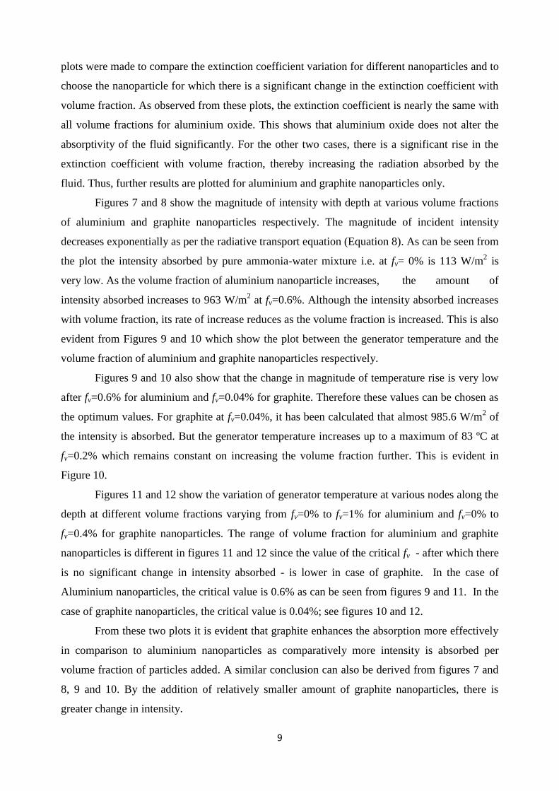
plots were made to compare the extinction coefficient variation for different nanoparticles and to
choose the nanoparticle for which there is a significant change in the extinction coefficient with
volume fraction. As observed from these plots, the extinction coefficient is nearly the same with
all volume fractions for aluminium oxide. This shows that aluminium oxide does not alter the
absorptivity of the fluid significantly. For the other two cases, there is a significant rise in the
extinction coefficient with volume fraction, thereby increasing the radiation absorbed by the
fluid. Thus, further results are plotted for aluminium and graphite nanoparticles only.
Figures 7 and 8 show the magnitude of intensity with depth at various volume fractions
of aluminium and graphite nanoparticles respectively. The magnitude of incident intensity
decreases exponentially as per the radiative transport equation (Equation 8). As can be seen from
the plot the intensity absorbed by pure ammonia-water mixture i.e. at fv= 0% is 113 W/m2 is
very low. As the volume fraction of aluminium nanoparticle increases, the amount of
intensity absorbed increases to 963 W/m2 at fv=0.6%. Although the intensity absorbed increases
with volume fraction, its rate of increase reduces as the volume fraction is increased. This is also
evident from Figures 9 and 10 which show the plot between the generator temperature and the
volume fraction of aluminium and graphite nanoparticles respectively.
Figures 9 and 10 also show that the change in magnitude of temperature rise is very low
after fv=0.6% for aluminium and fv=0.04% for graphite. Therefore these values can be chosen as
the optimum values. For graphite at fv=0.04%, it has been calculated that almost 985.6 W/m2 of
the intensity is absorbed. But the generator temperature increases up to a maximum of 83 ºC at
fv=0.2% which remains constant on increasing the volume fraction further. This is evident in
Figure 10.
Figures 11 and 12 show the variation of generator temperature at various nodes along the
depth at different volume fractions varying from fv=0% to fv=1% for aluminium and fv=0% to
fv=0.4% for graphite nanoparticles. The range of volume fraction for aluminium and graphite
nanoparticles is different in figures 11 and 12 since the value of the critical fv - after which there
is no significant change in intensity absorbed - is lower in case of graphite. In the case of
Aluminium nanoparticles, the critical value is 0.6% as can be seen from figures 9 and 11. In the
case of graphite nanoparticles, the critical value is 0.04%; see figures 10 and 12.
From these two plots it is evident that graphite enhances the absorption more effectively
in comparison to aluminium nanoparticles as comparatively more intensity is absorbed per
volume fraction of particles added. A similar conclusion can also be derived from figures 7 and
8, 9 and 10. By the addition of relatively smaller amount of graphite nanoparticles, there is
greater change in intensity.

10
Figure 13 depicts the plot of incident intensity with depth at particle diameters = 10 nm,
15 nm, 20 nm at constant volume fraction, fv= 0.2% of graphite nanoparticles. This value of
volume fraction has been chosen as it is higher than the optimum value of fv=0.04%. Although
the intensity absorbed increases by increasing particle diameter, its effect is not as significant as
that of volume fraction. A similar trend can also be seen in figure 14 where generator
temperature is plotted along various depths for these particle diameters. Similarly, there is no
significant effect of particle diameter in the case of aluminium (not shown).
So far, the nanofluids were studied for their intensity absorption and temperature rise in
the collector. From here onwards, this collector is embedded in an absorption chiller and the
results of a theoretical model are plotted. To calculate the COP of the cycle, various parameters
that were considered are shown in Table 1. Table 2 gives the thermodynamic properties at
various states, at volume fraction, fv=0.2% for graphite nanoparticles in ammonia-water mixture.
Table 1 Parameters known for the calculation of the COP of the AWAR cycle.
Parameter Value
Tevap 0℃
Tcond 30℃
Tabs 25℃
Tg,in 45℃
4m
0.00913 kg/s
Table 2 Thermodynamic properties at various states in the AWAR cycle for graphite
nanoparticles of 20 nm and at fv=0.2%.
State Temperature(℃) Pressure(MPa) Enthalpy(KJ/kg) Mass
fraction
Mass flow
rate(kg/s)
1 83 1.167 210 0.41 0.00649
2 - 1.167 - 0.41 0.00649
3 - 0.429 - 0.41 0.00649
4 25 0.429 -30 0.58 0.00913
5 25 1.167 -30 0.58 0.00913
6 45 1.167 70 0.58 0.00913
7 83 1.167 1616 1 0.00263
8 30 1.167 322.4 1 0.00263

11
9 0 0.4296 322.4 1 0.00263
10 0 0.4296 1442 1 0.00263
In general, the value of COP increases initially, reaches a peak and then reduces due to
increase in irreversibility at higher temperatures, as found by Sathyabhama and Ashok Babu
[12]. Irreversibility may be attributed to the mixing process of the absorbent and the refrigerant.
As the generator temperature increases, this irreversibility of mixing also increases, resulting in
decrease in COP [17].
Figure 15 shows the plot of COP as a function of volume fraction of graphite
nanoparticles. As the volume fraction increases, the temperature rise in the generator also
increases; thus, the COP increases. In this plot, initially COP increases rapidly and reaches a
peak of 0.592 for graphite nanoparticles at volume fraction of fv= 0.02%. COP then remains
almost constant. These plots can be used to calculate the amount of nanoparticles to be added in
the working fluid for maximum COP.
Figure 16 shows the temperature rise of nanofluid flowing through the flat plate of the
model presented for graphite nanoparticles volume fraction, fv=0.2% at different locations all
over India. Each of these locations belong to different climatic zones; namely, tropical wet (Goa,
South India), semi-arid (New Delhi, North Central India), arid (Jaipur, West India), mountain
(Srinagar, North India), humid subtropical (Lucknow, South India), tropical wet and dry
(Hyderabad, South-East India). These plots were made using the data of annual global horizontal
incidence [18] at different locations to check the feasibility of the model presented.
CONCLUSION
These results clearly suggest that by ‘seeding’ nanoparticles directly in the generator, the
performance of the cycle improves because of the absorption and scattering effects of
nanoparticles. An optimum value of volume fraction fv=0.6% for aluminium and fv=0.04% for
graphite can be observed. Particle diameter does not play an important role for graphite
nanoparticles. Comparing the nanoparticles, it is observed that graphite is the best choice,
followed by aluminium and then aluminium oxide. This study can be carried out for many more
types of nanoparticles. In a tropical country like India, these absorption refrigerators can reduce
the peak loads. A detailed grid management policy needs to be devised to integrate these solar
systems with the dominant fossil fuel energy systems. .

12
ACKNOWLEDGEMENTS
The authors based in India (R.G., A.K.R., V.K., V.B. and H.T.) wish to acknowledge the
support provided by the School of Mechanical, Materials & Energy Engineering at IIT Ropar.
The Australia based authors (Y.Z., E.L. and R.A.T.) gladly acknowledge support provided by
UNSW. Many thanks also to the anonymous reviewers for their work, and to the Editor for his
unfailing patience..
REFERENCES
[1] Cheung, B., Cao. N., Carriveau, R., and Ting, D. S. K., 2012, Distensible Air Accumulators
as a Means of Adiabatic Underwater Compressed Air Energy Storage, International Journal of
Environmental Studies, Vol. 69(4), pp. 566-577.
[2] Diesendorf, M. 2006, Wind Power in Australia, International Journal of Environmental
Studies, Vol. 63(6), pp. 765-776.
[3] Kuehn, T.H., Ramsey, J.W., and Threlkeld, J.L., 1998, Thermal Environmental Engineering,
Prentice Hall, New Jersey.
[4] Khullar, V., and Tyagi, H., 2012, A Study on Environmental Impact of Nanofluid-Based
Concentrating Solar Water Heating System, International Journal of Environmental Studies,
Vol. 69(2), pp. 220-232.
[5] Otanicar, T.P., Taylor, R.A., and Phelan, P.E., 2012, Prospects for Solar Cooling – An
Economic and Environmental Assessment, Solar Energy, Vol. 86(5), pp. 1287-1299.
[6] National Renewable Energy Laboratory (NREL),
http://www.nrel.gov/international/ra_india.html, (accessed in January 2013).
[7] Duffie, J. A., and Beckman, W. A., 1980, Solar Engineering of Thermal Processes, Wiley,
New York.
[8] Khullar, V., Tyagi, H., Phelan, P. E., Otanicar, T. P., Singh, H., and Taylor, R. A., 2012,
Solar Energy Harvesting Using Nanofluids-Based Concentrating Solar Collector, Journal of
Nanotechnology in Engineering and Medicine, Vol. 3 (3).
[9] Lenert, A., and Wang, E.N., 2012, Optimization of Nanofluid Volumetric Receivers for
Solar Thermal Energy Conversions, Solar Energy, Vol. 86(1), pp. 253-265.
[10] Vishwakarma, V., Singhal, N., Khullar, V., Tyagi, H., Taylor, R.A., Otanicar, T.P., and
Jain. A., 2012, Space Cooling Using the Concept of Nanofluids-Based Direct Absorption Solar
Collectors, Paper No. IMECE2012-87726, Proceedings of ASME 2012 International
Mechanical Engineering Congress & Exposition, November, Houston, Texas, USA.

13
[11] Kameya, Y., and Hanamura, K., 2011, Enhancement of Solar Radiation Absorption Using
Nanoparticle Suspension, Solar Energy, Vol. 85(2), pp. 299-307.
[12] Sathyabhama, A., and Ashok Babu, T.P., 2008, Thermodynamic Simulation of Ammonia-
Water Absorption Refrigeration System, Thermal Science, Vol. 12(3), pp. 45-53.
[13] Tyagi, H., Phelan, P., and Prasher, R., 2009, Predicted Efficiency of a Low Temperature
Nanofluid-based Direct Absorption Solar Collector, Journal of Solar Energy Engineering, Vol.
131(4), pp. 0410041-0410047
[14] Taylor, R.A., Phelan, P.E., Otanicar, T.P., Adrian, R., and Prasher, R., 2011, Nanofluid
Optical Property Characterization Towards Efficient Direct Absorption Solar Collectors,
Nanoscale Research Letter, Vol. 6(1), pp.X1-11.
[15] Brewster, M. Q., 1992, Thermal Radiative Transfer and Properties, Wiley, New York.
[16] Palik, E, Handbook of Optical Constants of Solids, London, Elsevier, 1998.
[17] Arora, C. P., 2009, Refrigeration and Air Conditioning, Tata McGraw-Hill, New Delhi.
[18] Ministry of New and Renewable Energy (MNRE), Government of India,
http://mnre.gov.in/sec/GHI_Data.xls, (accessed in February 2013).
NOMENCLATURE
English Symbols
A Area of direct absorption flat plate collector, [m]
co Speed of light, [m/s]
D Mean particle diameter, [nm]
dy Thickness of spatial node along y-direction, [m]
fv Particle volume fraction
H Depth of Collector, [m]
h Planck’s constant
hc Convection coefficient, [W/m2K]
h Enthalpy, [kJ/Kg]
I Intensity, [W m-2
str-1
µm-1
]
K Radiative coefficients, [m-1
]
k Complex part of refractive index
kB Boltzmann constant
l Length of Collector, [m]
m Normalized refractive index
m Mass flow rate, [Kg/s]

14
N Node number
n Real part of refractive index
P Pressure, [kPa]
Qe Refrigeration effect, [kW]
Qgen Heat input to generator, [kW]
T Temperature, [˚C]
Tsolar Black body temperature of sun, Tsolar= 5800 K
V Velocity of the nanofluid through the direct absorption flat plate collector.
w Width of Collector, [m]
X Mass fraction of ammonia in water
Greek symbols
η Collector efficiency
λ Wavelength, µm
Subscripts
a Absorption
ab Absorbed
abs Absorber
cond Condenser
e Evaporator
evap Evaporator
g Generator
in Inlet
inc Incident
opt Optical
s Scattered
λ Spectral
Abbreviations
AWAR Ammonia Water Absorption Refrigeration
SHX Solution heat exchanger
TOR Tons of Refrigeration
15
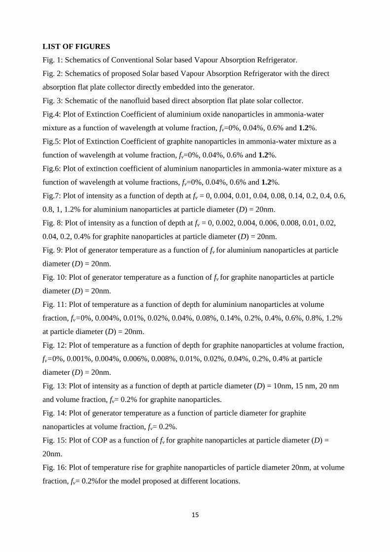
LIST OF FIGURES
Fig. 1: Schematics of Conventional Solar based Vapour Absorption Refrigerator.
Fig. 2: Schematics of proposed Solar based Vapour Absorption Refrigerator with the direct
absorption flat plate collector directly embedded into the generator.
Fig. 3: Schematic of the nanofluid based direct absorption flat plate solar collector.
Fig.4: Plot of Extinction Coefficient of aluminium oxide nanoparticles in ammonia-water
mixture as a function of wavelength at volume fraction, fv=0%, 0.04%, 0.6% and 1.2%.
Fig.5: Plot of Extinction Coefficient of graphite nanoparticles in ammonia-water mixture as a
function of wavelength at volume fraction, fv=0%, 0.04%, 0.6% and 1.2%.
Fig.6: Plot of extinction coefficient of aluminium nanoparticles in ammonia-water mixture as a
function of wavelength at volume fractions, fv=0%, 0.04%, 0.6% and 1.2%.
Fig.7: Plot of intensity as a function of depth at fv = 0, 0.004, 0.01, 0.04, 0.08, 0.14, 0.2, 0.4, 0.6,
0.8, 1, 1.2% for aluminium nanoparticles at particle diameter (D) = 20nm.
Fig. 8: Plot of intensity as a function of depth at fv = 0, 0.002, 0.004, 0.006, 0.008, 0.01, 0.02,
0.04, 0.2, 0.4% for graphite nanoparticles at particle diameter (D) = 20nm.
Fig. 9: Plot of generator temperature as a function of fv for aluminium nanoparticles at particle
diameter (D) = 20nm.
Fig. 10: Plot of generator temperature as a function of fv for graphite nanoparticles at particle
diameter (D) = 20nm.
Fig. 11: Plot of temperature as a function of depth for aluminium nanoparticles at volume
fraction, fv=0%, 0.004%, 0.01%, 0.02%, 0.04%, 0.08%, 0.14%, 0.2%, 0.4%, 0.6%, 0.8%, 1.2%
at particle diameter (D) = 20nm.
Fig. 12: Plot of temperature as a function of depth for graphite nanoparticles at volume fraction,
fv=0%, 0.001%, 0.004%, 0.006%, 0.008%, 0.01%, 0.02%, 0.04%, 0.2%, 0.4% at particle
diameter (D) = 20nm.
Fig. 13: Plot of intensity as a function of depth at particle diameter (D) = 10nm, 15 nm, 20 nm
and volume fraction, fv= 0.2% for graphite nanoparticles.
Fig. 14: Plot of generator temperature as a function of particle diameter for graphite
nanoparticles at volume fraction, fv= 0.2%.
Fig. 15: Plot of COP as a function of fv for graphite nanoparticles at particle diameter (D) =
20nm.
Fig. 16: Plot of temperature rise for graphite nanoparticles of particle diameter 20nm, at volume
fraction, fv= 0.2%for the model proposed at different locations.

16
Fig. 1: Schematics of Conventional Solar based Vapour Absorption Refrigerator.

17
Fig. 2: Schematics of proposed Solar based Vapour Absorption Refrigerator with the direct
absorption flat plate collector directly embedded into the generator.
Fig. 3: Schematic of the nanofluid based direct absorption flat plate solar collector.

18
Fig.4: Plot of Extinction Coefficient of aluminium oxide nanoparticles in ammonia-water
mixture as a function of wavelength at volume fraction, fv=0%, 0.04%, 0.6% and 1.2%.
Fig.5: Plot of Extinction Coefficient of graphite nanoparticles in ammonia-water mixture as a
function of wavelength at volume fraction, fv=0%, 0.04%, 0.6% and 1.2%.

19
Fig.6: Plot of extinction coefficient of aluminium nanoparticles in ammonia-water mixture as a
function of wavelength at volume fractions, fv=0%, 0.04%, 0.6% and 1.2%.
Fig.7: Plot of intensity as a function of depth at fv =0, 0.004, 0.01, 0.04, 0.08, 0.14, 0.2, 0.4, 0.6,
0.8, 1, 1.2% for aluminium nanoparticles at particle diameter (D) = 20nm.

20
Fig. 8: Plot of intensity as a function of depth at fv =0, 0.002, 0.004, 0.006, 0.008, 0.01, 0.02,
0.04, 0.2, 0.4% for graphite nanoparticles at particle diameter (D) = 20nm.
Fig. 9: Plot of generator temperature as a function of fv for aluminium nanoparticles at particle
diameter (D) = 20nm.

21
Fig. 10: Plot of generator temperature as a function of fv for graphite nanoparticles at particle
diameter (D) = 20nm.
Fig. 11: Plot of temperature as a function of depth for aluminium nanoparticles at volume
fraction, fv=0%, 0.004%, 0.01%, 0.02%, 0.04%, 0.08%, 0.14%, 0.2%, 0.4%, 0.6%, 0.8%, 1.2%
at particle diameter (D) = 20nm.

22
Fig. 12: Plot of temperature as a function of depth for graphite nanoparticles at volume fraction,
fv=0%, 0.001%, 0.004%, 0.006%, 0.008%, 0.01%, 0.02%, 0.04%, 0.2%, 0.4% at particle
diameter (D) = 20nm.
Fig. 13: Plot of intensity as a function of depth at particle diameter (D) = 10nm, 15 nm, 20 nm
and volume fraction, fv= 0.2% for graphite nanoparticles.

23
Fig. 14: Plot of generator temperature as a function of particle diameter for graphite
nanoparticles at volume fraction, fv= 0.2%.
Fig. 15: Plot of COP as a function of fv for graphite nanoparticles at particle diameter (D) =
20nm.

24
Fig. 16: Plot of temperature rise for graphite nanoparticles of particle diameter 20nm, at volume
fraction, fv= 0.2%for the model proposed at different locations.