Engineering_137274.pdf - Prasar Bharati
32
-
Upload
khangminh22 -
Category
Documents
-
view
3 -
download
0
Transcript of Engineering_137274.pdf - Prasar Bharati

Specification No. 100 W FM Tx./44lApril/2019-D (TDiFM)
PRASAR BHARATI(lndia's Publ it: service Broodcaster)
DIRECTORATE GENERAL: ALL INDIA RADIO(PLANNING & DEVELOPMENT UNIT)
SPECI FICATIONS.fo,
supply o.f 100 ll Digitn! comp tible vHF FM Sotid-Slote MOSFET Technology Bosed Broadcnst
Tit^nsmiiter in (I+t) configuration alongwith pre-wirer! Rtck inclutling Prograntme Input & Mottitoring
equipmenls and other associuled eq uipmenls/ilens
INTRODUCTION
This Specification is for Supply of 100 W Digital Compatible (Transmitter should be able to s$'itch into
"lass iB tinear mode for OFDM use) VHF FM Solid-State MOSFET technology based Broadcast
transmitter in (l+l) configuration alongwith pre-wired Rack including Programnre Input & Monitoring
equiprrerrts and otller associated equipurents/iterns to be installed af variorts sites in AIR netrvork.
SUMMARY OF CONTENTS:
S. No. Description
ffiPageNo.l-3
1 Essential Eligibility Criteria for teuderers
3. Section L0, GeneralSection 2.0. Techn ical Specifi cations of Transntitlgl
5-10
4. I l-15
5. Section 3.0, Technical Parameters of Transmitter l6-1 8
6. S*to'r +1. f..lr.""l Wcifications of Automatic Changeover Unit, RF Coaxial
Changeover Su,itch, Pre-wired rack including programme input & monitoritlg
equipments, Automatic Audio Chu"g"ou., S*it"h
t9-24
1. Annexure-1, Inspection Details
8. S..t- S.O (A), Schedtrle of Reqttirentetlts Materials (Un-Priced) 26-21
9. Se"i-, t0 @), Schedule of R.qul@ 21-28
t0. enn"*r.,r"-tt- rufonna for infornration about Local Oq99 fot "ftefiel9$fp!94-29
ll AlnexLrre- lll- List of Places 30
l.
ESSENTIAL REOUIREMENTS FOR TENDER:
(i) The tenderer should subnrit SchedLrle of ReqLlirenrents/Materials of Suppll' (un-priced) itr lhe same
1ormot (rs given in Sat,tion-5.0 (A&B) of All India Radio Specifications in the techrrical bid, failing
wlrich the tender slrall be colsidered incol'llplete and rs liable to be re.iected
(ii) lt is also mandatory ro mentiolt Mnke & Modet of the offerett equipment in the Schedule of
Req u irernents/Materials of Supply, failing which the tender shall be considered incornplete and is
liable to be rejected.
& suppoded by printed technicalmanuals fi'ont the manufacturer ofwithout which the tender will be
A.
2. Eaclr statement oIliterature, techtr ica I
tb
this specification has to be complied withclata sheets. scheruatic dra\\ings and technical
tlre tenderer. to assess the nlerit of the offer
a\ ./Y./XZ ,,Sry-,,;,:;", *il*.,ou, ^r,,d,*' n,
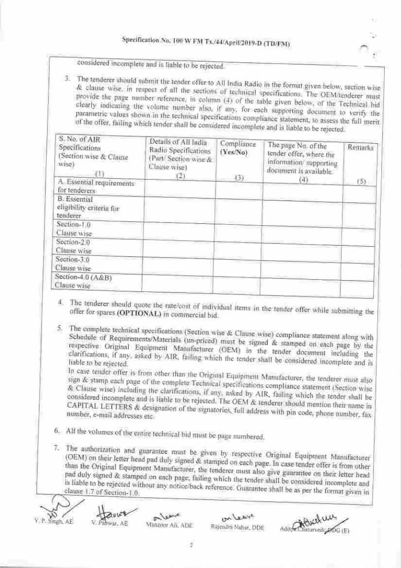
I S. No. of AIRSpecifications(Section wise & C lausewise)
(r)
Details of AII IndiaRadio Specificarions(Part/ Section wise &C Iause wise)
(2\
Compliance(Yes/No)
(l)
The page No. ofthetender offer, where theinfonnation/ supporlingdocument is available.
(4)
Remarks
(s)A. Essential requirerne.ntsfor tenderersB. Essentialeligibility criteria fortendererSection- I .0Clause u,iseSection-2.0Clause wiseSection-3.0Clause wiseSection-4.0 (A&B)Clause wise
3 The tenderer should submit the tender offer to All India Radio in the format given berorv, section wise& ctause wise, in respecr of a, the *"fi";r;f ;;;;;iJi sp"c,t,"ations. The oEM/tenderer mustprovide the page number relerence,. in column 1+1 oithe taur. given belolv, of the Technical bidciearly indicating the voru'ne number.arso, ;r'"iy. r"r-"."r,' supporting document to verifi theparametric values shown in the technical .p".in"utlonr .o,niriance statement, to assess the furt nreritof the offer, fairing which render sha, b" .;"r;;.;;;;;;oi5r" *o is liabre to be rejected.
t ffi.til't:;:l",.,"di"?s"i1ff,r:",];T:,".1ji3il:"" items in the tender offer wrrire submitting the
5' The comprete technical specifications (Section wise & crause wise)-compriance statement arong withSchedule of Requiremenis/Muteriur, iun-pricear' r,i "u""rig*d & stamped on
"a"h pug" oy th"respective originar Equipment
.Manufacture.' toevi-'; "rrr.. ,""a"r"io"#."i''i"!ir"J,ng 0,'";:iil:'f[:n..';:kn1.
asted by AtR. faiting which the LnJer sna' be considered incomptere and isln case tender offer is from r
srgn & stamp each page of ,ft"tt than the original Equiprnent Manufacturer, the tenderer must also
&'cru,," ;'[;;l;.ffi;,;,;"".::#::l""Hiffirj::i$Til;,irui, ruT :rf *l]i:m ;:considered incomprete and is riabre to u. r"je"t"J. ihe oiil'a ,"na".",. shourd mention their name rn
ntJli"l*:nrL1$,0.::l*"",- "r*.lig,"t".i",,iii'"aa,"* with pin code, phone number, rax
. All the volumes oftlre entire technical bid must be page nurnbereo.
7' The authorization and guarar)tee. mLrst be given by respective originar Equipment Manufacturer(oEM) on their retter head oad duly^signed alt"rp"ir on J*n pug". rn case tender offer is from otherthan the originar Equipment Man;fac;urer, ;;;;;ffi ffi; arso give guarantee on their lefter headt,Jfl$l:t;,f;:i:,:J?Tnifffi*"-"",":fli":$,n.?"0", sharr be considered incomprete and
Specification No. I00 W FM Tx./44/Aprit/2019_D (TD/FM)
considered in.ornpl"t" ani ii liibG toE ,jild
:llJ::T ?"t'r':::,";;1,::,*,,anv notii-elback.;;";;.;,;;;;;JH1,ff"":$::#;:Altj:l;i:
cr^\o'uv'Rajendra Nahar, DDE Adir
.Mr*t o^.\.r-*-,.v. pahwirr. AF Varrzour Ali. ADl,
Specificalion No. 100 W FM Tx./44lApril/2019-D (TD/FM)
B.
9.
8.
10.
ll.
I1 case tender offel is frorr other thar the Original Equipnrent Martufacturer, the tellderer should also
furnish a certificate frorn rhe OEM that tlte tenderer can quote iten.rs of the OEM directly, failing1vhich the tender slrall be considered incomplete and is liable to be rejected without any notice/back
reference.
Any change in the AIR technical specifications fonnat or language or in parameters or of any other
nature including the deletion of technical specifications clause, words, lines in the tecllnical
specifications compliance statement by the OEM/ tenderer will not be acceptable to AIR and the
tender is liable to be re.jected.
Public Procurement (Preference to Make in lndia) Order No. P-45021/217017 -B.E ll dated 15.06.2017
of Government of India, Ministry of Commerce and Industry, Departn'lent of Industrial Policy and
Pronrotion shall be applicable.
Optional itents will ttol he considered./br runkittg purpose.
ESSENTIAL ELIGIBILITY CRITERIA FOR Tf,NDERER:
(a) The tenderer should either be the OEM of VHF FM transmitter or their authorized
representative/dealer.
(b) (i) The OEM of the trans:nitter must have an experience of manufacturing and supplying VHF FM
translritters of power output not less than 100 W for at least last 5 years. Docttt'nentary evidence to
support this must be provided.
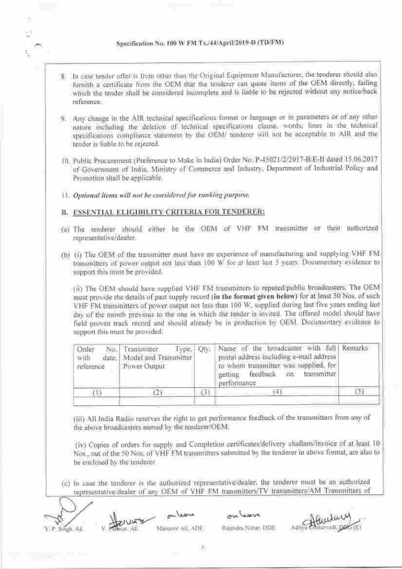
(ii) The OEM should have supplied VHF FM transmitters to reputed/public broadcasters. The OEMmust provide the details ofpast supply record (in the format given belo'rv) for at least 50 Nos. ofsuchVHF FM transmitters of power output not less than 100 W, supplied during last five years ending last
day of the montlr previous to the one in which the tender is invited. The offered model should have
field proven track record and should already be in production by OEM. Documentary evidence tosupport this rrust be provided.
Order No.with date,reterence
Transnritter T) pe,
Model and Transnr itterPower Output
Qt). Name of tlle broadcaster with fullpostal address including e-mail address
to whom transmitter u,as supplied, forgetting feedback on transmitterperformance
Remarks
1 (z) (j) (1) (5)
(iii) All India Radio reserves the right to get perfornrance feedback ofthe transnritters from any ofthe above broadcasters named by the tenderer/OEM.
(iv) Copies of orders for supply and Completion ceftificates/delivery challans/invo ice ofat least l0Nos.. out of the 50 Nos. of VHF FM transnritters subrnitted by the tenderer in above fornat, are also to
be enclosed by the tenderer.
(c) In case the tenderel is the authorized representative/dealer, tlre tenderer must be an authorized
reoresentative/dealer of anv OEM of VHF FM transnitters/Tv transmitters/AM Transmitters of
No* \^-o^t
Raiendm Nahar. DDE" M,xy-,";:;,,
power not less than 100 W for last three y Jsupply of VHF FM transmitters/TV transmitters/AM Transmitters of power not less than roo w io,last three years or more. Documentary evidence to support this must be provided.
Specification No. t00 W FM Tx./44/ApriU2}t 9-D (TD/FM)
(d) The oEM of the offered vHF FM transmi*er must have his rocar office/authorizedrepresentative/dearer in India for after sares suppoft. A certificate as per Annexure-riarry .ign"o rythe oEM as well as local office/authorized iepresentative/dealer must u. suumitt"J *itii ile ott-er.Copy of Agreement/MoU executed between dEMs and their authorized ,"pr...ntutiu"7l.ur", ortysigned by both must also be subrnitted with the offer.
( \./-{1/Y. P. Singh, AE *q""ilHlo. ^,*,N*Fo,,,"h*rf-;ffi".
SDecification No. 100 W FM Tx./44lApril/2019-D (TD/FM)
SECTION - 1.0
GENERAL
1.1 Please refer tender documents for general terms and conditions of contract for supply including alltbe comm€rcial aspects like; Packing and packing list, Insurance and Marine Risk etc. Payment terms,
Penalty/Compensation for delay, Darnages and liabilities, Time Period and Exterrsion for Delay,
Foreclosure of contract due to Abandoulnent or Reduction in scope ofsupply, Cancellatiotl of contract
in full or pat1, Recovery of security deposit, Perforrnance Guarantee. Unsatisfactory workmanship,
Damages incurred durirg transit. tenderer lrable for darnages, Defects, Recovery of compensat;orl.
Ensuring payment aud amenities, tenderer to indemnify Government against Patent Rights, Release ofsecurity deposit, Safety Code, insurance frorn manufacturer's works/factory to respective site etc. i.e. intotality.
1.2 INSPECTION:
1.2,1 Detailed inspection of transnritters u,ill be carried out at OEM's Works by representatives of DG: AIRas per details giveu in Anuexure-1.
1.2.2 Call for Pre-dispatch lnspecrion (PDI) at OEM'S Works is to be given by the tenderer to All India
Radio at least 4 weeks in advauce. Inspection period will be 5 working days. Testing/measurements
reports as per approved ATP must be subrnitted to All India Radio alongwith the call for inspection oftransmitters for analyzing etc.
1.7.3 Expenses for inspection clrarges. if arrv, are to be quoted by the tenderer. The expenditure towards Toarrd Frojournel', lodging. boarding & DA in respect of irtspector(s) will be borne by AIR
1.2,4 The complete Acceprance Test Procedure/Protocol (ATP) will be prepared by the respective OEM and
submitted to DDC (E-FM). P&D Unit, DG: AIR for approval within 15 days of issue of Acceptance ofTender. ATP will also indicate full details of setup for measuring/test ing equipments to be deployed
during the performance nt easu reurents/inspect ion at the OEM u'orks. The approved ATP shall fornr
the basis for performance r'ueasLrrements/inspection to be carried out. AIR has the right to include other
technical parameters in ATP sulrnritted by OEN'I \yithin the ambit of specification of tlre producto ffered.
1.3 INFORMATION TO BE SUPPLIED WITH THE TENDER:1.3.1 The complete technical specifications (Section wise & Ciause u'ise) compliance statement alongwith
Schedule of Req uirenrents/Materials (un-priced) duly signed & staniped on each page by the respective
Original Equipment Marufacturer (OEM) and countersigned by the tertderer as Per the fbrmat giverr
above in clause A (3).
1.3.2 Conrplete printed technical literature/technical data sheet/schematic drawings/detailed information
ilcluding Technical Manuals (for Installation, Testing, Comrnissioning, Operation, Maintenance &Service, iucluding theory of operation, circuit description and fault diagnosis) of 100 W DigitalCornpatible VHF FM Solid-State MOSFET technology based Broadcast transmitter in (l+l)configuration, pre-wired Rack including Programme Input & Monitoring equipments and associated
eq u ipnents/iterns as per Section-5.0 (A&B) from the respective Original Equipment Manufacturer(OEM) in suppoft of conrpliance statement should be firrnished on non-returnable basis, to assess the
firll rrerit of the offer. rvithout u'hich the tender offer rvill be considered incomplete and is liable fbrreJ ect lon.
1.3.3 Detailed Schedule of Requ irerlents/MaterialsVHF FM Solid-State MOSFET technolosy
(un-priced) for the supply of 100 W Digital Compatiblebased Broadcast transmitter in (1+l) configuration, pre-
ired Rack and associated should be in conformil\ ra irh Section-5.0 (A&B) \\ ithoulltems
1r\Y. P. Singh. AE
ttl r
&a,*<)t oh v-o'\-A
Vf{irrar- AL \4.1r,ioor Alr. Al}L ,.f.h; "r, ^rt,,#f#At*.-.
Specification No. 100 W FM ^tx./14/Aprit/2}t 9-D (TD/FM)
v p sJ/+e "KLffi- u,"fiXiloou nui"nHff'oe
any change in tlre forrnat, *,',nt runrejection. The tenderer nrust quote all iterns.
li-., ie for
l'3'4 Descriptive information and co'prere details^ofeach equipnlent offered sha' be given b1, the tenderer.l'3'5 country of origin, Make, Type & Model of all the offered items should be m".ntion"d inclLrding thename & address oftheir vendors.1'3'6 A copy of the lnstallation Manual, operation, Maintenance & Service Manual must be enclosed withtechnical bid for assessinq tlre transmitter system. The Installation Manual una tl. op"rution aMaintenance Manual mus't include at t"o.t it
" a"tu;t. giu",l O"f o*,
(A) The lnstallation Manual must describe the following information:
(i) A-suggestive floor equipment layout plan drawing with dimensions in metres for installation ofthe vHFFM transmitter system in a transmitter hall with u'il ulli"d "qu,p,n"ntr.(ii) Diagrams shou'ing the isometric view of VHF FM transmitter and allied equipnents with dimerrsions inmetres are to be provided.
Jill] llj installarion drawings with dirnensions,ir r€spect ofsLrpprred equipmenrs are to be provided.(iv) All mechanical assembly drawings of the VHF FM transnritter sl,srem wtth dimensions are to beprovided.(v) Allthe views, i.e. front, rear, top and side (open) ofthe vHF FM transmitter witil dimensions are to beprovided.
!"i) The details ofunpacking are to be provided.(vii) A detailed write up in English regarding installation of vHF FM transminer system along with its. ... associated equipments/items should be provided.(viii) All Do's and Don'ts which ale essential for safe installation ofthe transmitter syslem should bedescribed.(ix) An inter-wiring diagram for all transmitter units/modules installed in the transmitter rack, inpuvoutputto transmitter and interlocks
','ith external units and accessories like dummy load, changelver s*itcles,patch panel etc. which are wired in the transmitter interlocks.
(B) operation' Maintenance & Service Manuar must describe the fblowing:
(i) ceneral description ofthe otferecJ vHF FM transnritter, transrnitter block d iagrarn/sc hematic drawingsindicating the details ofdifferent blocks, modules and redundancy in"o.porrtEJ in i*nl,nlii". una itssubsystems.(ii) General description and structural overview ofthe transmitter racks indicating the position ofdifferentmodules, units, power distribution etc., front, rear, top & sicte (open) views with dimensions(iii) Colour?hotographs of transmitrer showing ihe tollo*i,rg,(a) Front view ofthe transmrrrer(b) Rear vieu of tlre transrnitter(c) Top view ol the transnliner(iu) screen shots ofvarious display screens shou'ing nronitorabre and nreasurable parameters oftransmitter.(v) A detailed description with all relevant circuit d-iagrams ofthe transmitter stroura U. prou;a.a *;tl,details oftest Doints.(vi) The details ofall electrical circuits in various stages ofthe transm.itter used along with their w.re-ups.(vii) General description ofRF signal flow diagram for comfi"r. Rp
"hu;n fro,r,
"x.ii". to fiit., outprt *itt. .... information about power level at input & JLrtput ofeach stage.(viii) Descriptiorl ofprotections underabnornrar corrditions and schematic drawing indicating
intercon n ection s to different external units and accessories like dumrny load, changeover switches, patchpanel etc. which are wired in the transmitter rack.(ix) Details and schematic drawings of remote control & telemetry sysrem arong witlr screen shots oi.thei!terface displays. The renroteiy monitorable and controllabre parameters oF,r,," irun*ii .r"rr,o*ra rr"Az;# ,s*.*=1,ff-^,.fiyil0o,
Specification No. 100 W FM Tx./44/April/2019-D (TD/FM)
clearly ind icated.(x) Geneial description of transmitter Control System and schematic drawings for control signaL
d istribution.(xi)DescriptiorrofprotectionmechanismagainsthighVSWR,overload.hightemperatureofthetransmitter.(xii) Description of VSWR/temperature fotdiack along with range of foldback. The expla'ation of foldback
with the help of circuit diagrarn must also be provided'
(xiii) Description of various inte-rfaces. connectors, connecting cables arld accessories used in the VHF FM
transm itter.(xiv) A corlplete list ol'all pafts/transistors/lCs/comporents used in the transmitter must be provided'
ixv) The make and number of LDMOS/MOS devices used in tlre VHF FM transmitter.
ixvi) Technical data sheet of LDMOS/MOS devices used in the VHF FM transmrtter'
ixvii) Procedure for changing the frequency ofoperation ofthe transmitter'
ixviiiy A,tt Do,s and Don'ti which ur..rr"niiol foi safe Operation & Maintenance ofthe transmitter should be
described.(xix) The detailed procedure for trouble shooting of the VHF FM transmitlel pref'erably up to compollent
level shou ld be described(xx) The systenlatic trouble shooting/tault tree and florv diagranr should be provided for diagnosis ofthe
l'aults w;th their remedial nteasures.
(xxi) The maitttenatlce schedule for the transnritter shor-rld also be described'
ixxii) General descriptior of electrical power distributiorr and schematic drarvings of power supply system
used for the transmltter systenl
I..IINFORMATIONToBESUPPLIEDBYTHTTENDTRERWITHIN15DAYSAFTERISSUEOF ACCEPTANCE OF TENDER:one set of Teclrnical Manuals (for lnstallation, Testing, commissioning, operation' Maintenance &
Service, inclLrding theory of operatioll, circuit description and fault diagnosis) colouR printed and
duly bound for t00 w Digital compatible vHF FM Solid-State MOSFET technology based Broadcast
transmitter in (l+l) configuration, Automatic Clrangeover Switch, RF Coaxial Changeover Switch,
Automatic Audio changeover Switch, pre-wired rack including Programme lnput & Monitoring
equiprnents, dummy load and associated equipments/itetrs alongwith soft copy on CD must be supplied
to "DDG (E-FM), P & D Unit, DC: AIR, New Delhi- I I 000I "The tenderer will also provide MIB file of the SNMP compliant devices i.e. transmitter, automatic
changeover Unit, Automatic changeover switch etc
r.5 INFORMATION TO PRECEDE DESPATCII OF EQUIPMENT:Following informarion should be supplied to the DDG (E-FM), P & D Unit, DG:AIR and each of the
consignee prior to dispatch of Equiptrent:a) Detailed list ofequipnrent under dispatch.
bj photograpS shorving location of various units/sub units with item nunrbers rnarked thereon.
1.6 INFORMATION TO BE SUPPLIED ALONGWITH EQUIPIVIENT:Techrrical manuals (for lnstallatiotr, Testitlg, Cotn rn issioning, Operation & Maintenance, ircluding theory
of operatio', circuit clescription and fault diagnosis) COLOUR printed and duly bound for 100 W Digital
conrpatible vHF FM Solid-State MOSFET technology based Broadcast. transmitter in (I+I)con6guratiorr, Automatic Changeover Switch. RF Coaiial Changeover Switch, Automatic Audio
Cha'"geover Switch, pre-wired ralck including Prograrnme lnpLrt & Mo'itoring equipments, dummy load
and aisociateil equipntents/items and OEM test ceftificate with soft copy on CD shall be supplied as per
Section-5.0 (A&B).The tenderer will also provide MIB file of the SNMP compliant devices i.e. transmitter, automatlc
cltrngeover Unit, Automatic chattgeover s\\itcll etc
Cr* \-a-r^t'-
Rdienclfa Nahirr. DDEY. P. Singh. AE "k1fi,[]r^,,,
I.7 GUARANTEI:
Specification No. 100 W FM Tx,/14/ Aprit/2019-D (TD/FM)
o^\-ola.roR iendfa Nahar. DDE
(ii) A guarantee to make good r.vithin 7 days (frorn the date of fiexpense anv.orpon.-nt wrrich becornes defective ,ro.r;"r,iti,':tj;;ffi::fi?xf?::Tl;::T:.ir.J;the date of supply lf the tenderer.failea to r".tit" ii.'fair'lt
'vithin the stipulated period of 7 days, theguarantee period would be extended correspondingio the outage period.(iii)A^guarantee to supply.all. components for I p*l"i
"ri"" y"ars tiorn the date of suppry. ar rares at whichthese -are
being suppried by the firm to other custom;rs and arso shourd match prices of originalmanutactures ofthese components prevailing at that time.
(iv)lf at any stage during next l0 years, tlre manufacturer stops production of this rnodel of vHF FM;i*::'-"t
the firm shall intinrate All Inclia Radio in advance to enabre the ratter to srock the criticar
The tenderer shall subnrit rvith his tender.an .ndenaking to accept the fbllo,,ving guarantees:
'#;:,,"";:;',J';-,:',#:':, ;:,,::::;:;l),*;',, "i ,i:,i'iiLiil,",,,ri,,*, niitione,t in schedute ortD
l,:fi?::::"i1,ffi::lt#:T#:l';:i"-,Xiff.;;cordance with these specincarions, varied onrv to the
I.8 LANGUAGEfuNITS:All information supplied by the renderer & all markinss, notrwrite-ups rhrll b" i;..E;gli.f, f^"grrg";,o"iy.
r.qr^"rbJ' 'Ietes, designation on the drawings & associated
All dimensions, units on drawingsitt ?.i"r.ni". to weigrrts, measures & qLrantities shalr be in SI Units.1.9 DELIVERY PERIOD OF EQUIPMENT:
i. For Indian Bidders:Suppry wi' have to be compreted r.vithin Three months from the date of Acceptance of render orThree months from the date of the Decision t-"tt". i.or"wpc(wherever is required) in respect of *,equlpment, provided by AIR, whichever is later.
ii. For Foreign Bidders:
f;'nntr *itl have to be cornpleted within Three months fronr the date of opening of Letter of credit
1.I() PACKING AND PACKING LISTS:All the equipment should besha,, be nr ;";;";,."c;;,,T."i!!Fi" "d[,?Tfffi i;:il1Til:lx?fi;,?,xl,lil"T,lltiligiving derairs of the it#s contained i,,.
"r"rr p;;i;;J;;orr"o. pru."a inside the package in a water proofgnvelop. to enable easy identification
""a ,f,r"rij=-*"t";"instattation ,i'u*i;g.t;;;rp;;enrs rists.,cop,es of;;.k;;r;j'rr'"",,T fi:r.:,ffi.:"rJ,T:,,rf""ijl::ro"H.iJro fespectrve consignee and arso to the Dy. Director ceneiar 1'e-nv;, p & D Unit, DG: AIR. New Derhi.
1,I1 INSURANCE AND MARINE RISKS ETC:Please refer to commercial terms.
eh. AE
ll.fu,w*a*- cr".\o-"'v. P.rn\r.r. Af \..1jr l/,,u. .\li. {Dt
Specification No. 100 W FM Tx./44lApriV20l9-D (TD/FM)
I.I3 ESSENTIAL REQUIRf,MENT FOR LOCAL OFFICE/AUTHORIZED REPRESENTATIVf,/DEALER:
(a) The OEM should have complete setup for maintenance/repair of the transmitter in India, either ofits own or through local office/authorized representative/dealer.
(b) The local office/authorized representative/dealer will be the nodal point for resolving issues relatedto after sales support. It is the responsibility of local offrce/authorized representative/dealer toarrange the repair/replacement of faulty items. Any module of transmitter or other equipmentrequiring repairs will be repaired at site. If it is not feasible to repair the module at site, the samewill be collected from the site by local office/authorized representative/dealer that will arrangerepairs locally. The cost of transportation, repairs etc. shall be borne by the tenderer during theguarantee period.
(c) After sales support for the repairslmaintenance of transmitter system after the completion ofguarantee period, shall also be provided by the respective OEM of the transmitter and otherassociated equipments through their local oflices/authorized representatives/dealers in Indra.
(d) The details of technical facilities available with local office/authorized representative/dealer forafter sales support such as test bench, necessary test & measuring equipment andphotographs thereof, must be provided in the technical bid.
(e) At the discretion of AIR, AIR representative(s) may visit the works of local office/authorizedrepresentative/dealer of OEM in India to ensure/verifu that adequate technical infrashucture isavailable for after sales service for timely resolving the issues related to attending/replacing theequipments. Tenders from the tenderers who failed to meet these criteria shall be consideredincomplete and is liable to be rejected.
1.14 DEMONSTRATION OF THE OFFERED EQUIPMENT:The tenderer will have to arrange demonstration ofthe complete offered VIIF FM transmitter as a part oftechnical evaluation at New Delhi, India within 30 days from the date of issue of AIR request letter.Accordingly, the tenderer should be in readiness for demonstration within 30 days from the date of issueof AIR request letter, failing which the tender offer is liable to be rejected without any furthercorrespondence.The tenderer/OEM is also required to give an undertaking at the time of demonstration during evaluationthat the offered VHF FM transmitter is compatible for broadcasting in HD Radio OR DRM* mode.Functional checking as per AIR specification clause 2.6 & 2-7.8 rnder Section-2.O and performancemeasurements as per AIR specification clause 3.7 under Section-3.0 will be carried out for compatibilitytest of the offered VHF FM transmitter in HD or DRM+ mode during PDI.HDIDRM+ Equipments are not the part of Supply with this tender. However, all necessaryequipments required for checking the compatibility of the offered VHF FM transmitter in HD or DRM+mode during PDI stage will be ananged by the tenderer.The tenderer will also have to make all necessary arrangement for testing ofthe complete offered VFIFFM transmitter with full rated power. Exhaustive checking and measurements will be carried out so asto completely check the compliance of the transmitter and its sub systems with the requirements asprojected in the specifications.All expenses & liabilities for demonstration of above offered VHF FM transmitter will be borne by thetenderer. This is purely for Technical Evaluation ofthe offered VHF FM transmitter and is without anycommitment for acceptance of offer, whatsoever at this stage.
.-$7 $.***.o^-\a-'." o.^\oo^. rrlnr..r.,t11',,
Y. P. Siigh, AE V. Panwar, AE Manzoor Ali, ADE Rajendra Nahar, DDE "Ots)iJl!Jl${r:)/f6\
(D Operating voltage AC Sinele Phase : 230 Volts +10 %
(iD Frequency 50 Hz+ 4oh
Specilication No. 100 W FM Tx,/44lApriv20f9-D (TD/FM)
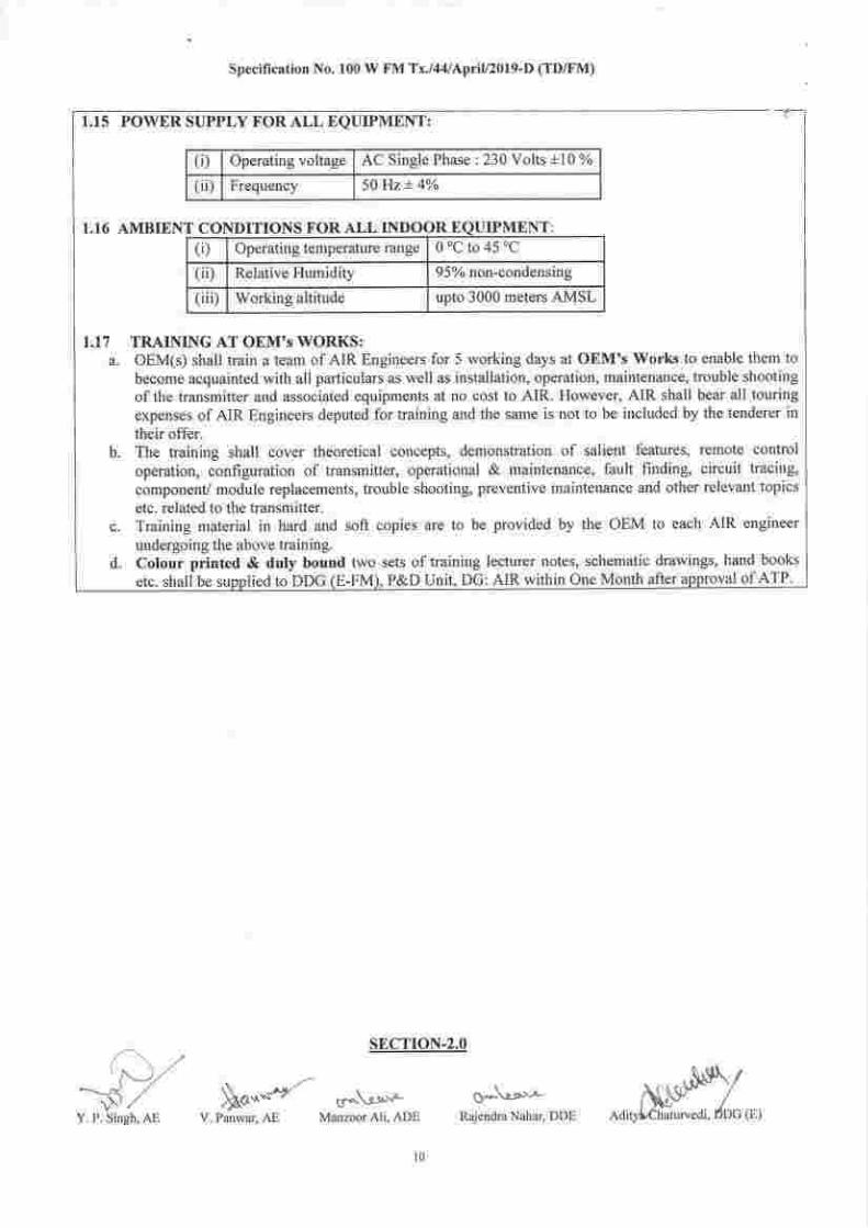
1.15 POWER SUPPLY FOR ALL EQUIPMENT:
AMBIENT CONIDITIONS FOR ALL INDO( )R EQUIPIVIEN l':(D Operating temperature range 0'C to 45 "C
(iD Relative Humiditv 950lo non-condensing
(iii) Working altitude uoto 3000 meters AMSL
1.17 TRAINING AT OEM's WORI(S:a. OEM(s) shall train a team of AIR Engineers for 5 working days at OEM's Works to enable them to
become acquainted with all particulars as well as installation, operation, maintenance, trouble shooting
ofthe transmitter and associated equipments at no cost to AlR. However, AIR shall bear all touring
expenses of AIR Engineers deputed for training and the same is not to be included by the tenderer intheir offer.
b. The training shall cover theoretical concepts, demonstration of salient features, remote control
operation, configuration of transmitter, operational & maintenance, fault finding, circuit tracing,
component/ module replacements, trouble shooting, preventive maintenance and other relevant topics
etc. related to the transmitter.c. Training material in hard and soft copies are to be provided by the OEM to each AIR engineer
undergoing the above training.d. Colour printed & duly bound two sets of training lecturer notes, schematic drawings, hand books
etc. shall be suonlied to DDG (E-FM), P&D Unit, DG: AIR within one Month after approval of ATP
Sf,CTION-2.0/'^'\. ,''{'-'-)/
\>'/Y. P. Singh, AE
M""'/'- u'^\-o-'"-Manzoor Ali, ADE Rajend.a Nahar, DDEV. Panwar, A!
10
Specification No. 100 W FM Tx./44lApriy2ol9-D (TD/FM)
TECHNICAL SPEQIFICATIONS OF TRANSMITTER:
2.1 All India Radio is interested to procure on 100 w Digital compatible vHF FM Solid-StateMOSFET technology based Broadcast transmitter in (l+l) configuration alongwith pre-wiredRack and other associated equipmentslitems at various places. These 100 W Digital CompatibleVuF FM Solid-State MOSFET technologlr based Broadcast transmitter units will be as per thespecifications of AIR. The transmitters should be rugged, reliable and stable in operation underIndian tropical condition.
2.2 The FM Transmitter unirs are to be supplied as ',complete system" including cooling system (aircooled with built-in fan unit), Automatic Changeover unit (ACU), RF -oaxial changeoverswitch, Automatic Audio changeover switch, interconnecting cables, Dummy load, prelwiredRack, Analog Disribution Amplifier, Digital Distribution Amplifier etc. as per the sciedule ofRequirements/Materials for Supply (un-priced).
2.3 It will be the responsibilif ofthe tenderer to ensure that the system is complete in all respects.
2.4 A detailed block schematic diagram for the entire FM Transmitter system in (l+1) configurationwith all its constituent items should be provided with the offer.
2.5 The layout of the various equipments in the Transmitter cum pre-wired Rack as oer ArRSpecification should be provided with the offer.
2.6 -Two.nos. of 100 W Digital Compatible VHF FM Solid-State MOSFET technologr basedBroadcast transmitter in (l+l) configuration with auto changeover unit shall be supptied witheach set of Transmitter. The operation in (l+1y 6u16 changeover mode is done by an Automaticchangeover Unit (ACU), the detailed specifications for which are given in Section-4.0.The Digital compatibre r00 w vHF FM sorid-state vrosrnr technorogy basedBroadcast transmitter should be compatible for DRM+/ HD Radio mode. HiIDRM+Equipments are not the part of Supply with this tender. However, all necessary equipmentsrequired for checking the compatibility of the offered vI{F FM transmitter in rin o. brut+mode during PDI stage will be arranged by the tenderer.The Digital compatibre 100 w vHF FM sorid-state MosFET technorogy basedBroadcast Transmitter should be abte to switch into class AB linear mode for oiDM usewithout any requirement of modifications in the supplied transmitter equipment,
2.7 100 W Disital Compatible Transmitter Unit:
2.7.1 The FM Transmitter unit shall be consistent with the latest state ofthe art technolos/using most rugged, reliable components, circuit design and shall be suitable forunattended operation. It should be user friendly and simple to operate.2.7.2 All equipment assembries, sub assemblies, pcB's, deviies and comDonents should beof latest field proven design. All materials used in the FM Transmitter System shouldbe of Professional Broadcast euality.
2.7.3
2.7.4
( ,, ,-Yr,,/Y. P. Singh, AI
The Transmitter system quoted must conform to the latest Intemational Standards ofsafety and EMC. The conformance to such standards (indicating Standard's Name andNumber) must be stated in compliance statement.The Transmitter unit shall be suitable for FM monophonic and stereophonic/ multiplextransmission in the frequency range from 88 MHz to l0g MI-Iz.
rl I
*aq*e." -
ct^ v.r^,.-
V. Panwar, AE Manzoor Ali, ADE *;H;,", ffiWW,,,
Specification No, 100 W F.M Tx./44lApriU2019_D (TDffM)
2'7 '5 The Transmitter and other ancillary units shall be characterized by high reliability, highMTBF. It should be field Droven.
2.7.6 The Transmitter shall satisS, the requirement of ITU Radio Regulations. It shouldcomply with IEC-215 Safety Standards so as to eliminate electri-cal hazards to thepersonnel.
2.7 7 Transmitter equipment shall have. compact design. A metal works shall be adequatelyprotected against rust and corrosion and shall be non-inflammable and fire retardanr.
2'7 '8 The 100 w Digitar compatibre vIrF FM Sorid-State MosFET technorogy basedBroadcast transmitter shourd have the fac ity on the front panei of thetransmitter for serection of either FM Mode or Digitar Mode so ihat externarDRM+/HD Radio Modulator is selected in place of FM Exciter.
2.8 Facilitiesr
100 w Digital compatible vHF FM Solid-State MosFET technology based Broadcasttransmitter in (1+l) configuration shall have in-built Limiter and low pai- filter (30 Hz to 15kHz) at audio input to ensure distortion free transmission inespective of source level. Thetransmitter shall have in-built Exciter, Stereo coder with each l0d w Digital compatible vHFFM Solid-State MOSFET technology based Broadcast transminer al,ong witti AutomaticChangeover Unit (ACU) in (l+l) automatic changeover mode with manual ovenide.
2.9 Circuit Design:
The Transmitter will consist of solid state devices. All stages i.e. Exciter, Amplifier, harmonicfilters, etc. should be ofBroad Band design for operating in the entire Vi.tF lrequency band of88 MFIz to 108 MHz without need of any tuning/change of components.
2.10 Exciter :
2.10.1 The Exciter should have Direct Digital Synthesis. The Exciter should be an integralpart of 100 w Digital compatible vItr FM solid-state MosFET technoloev basedBroadcast Transmitter. It should accept Analog Mono. Anarog Stereo (left ani- righq lEncoded Stereo signals (MPx), RDS/DARC, scA and AES/EBU inputs. It should becompatible for Mono and Stereo Broadcasting using pilot tone system.
2.10.2 lt should display various parameters like forward and reflected power, frequencydeviation, input-audio level, DC voltages & currents on LCD displarz.
2.10.3 lt should be synthesized wirh easy channel selection of minimum i0 kHz spacing i.e.can be operated on any of the FM channels from gg MHz to l0g MHz in Vfn Sind_II. The Exciter should be "Frequency agile" i.e. not requiring any tu'ing over itsentire specified operating frequency range.
2.11 Power Amplifier (PA):
2.11.1 rhe Power Amplifier (PA) should be an integral part of 100 w Digital compatiblevHF FM Solid-State MOSFET technology based Broadcast Transmitter. The powerAmplifier (PA) shall be of wide band design for operation in the entire vHFfrequency band of 88 MHz to 108 MHz without tuning i change of components. ThePA shall be rugged in design and wilr consist of MOSFET device incomorated in aseparate amplifier board. The PA shall be provided with RF monitor locaied on FrontPanel to monitor output RF power.
)i\//P//a-\-!
'/ \\
.. ^Jrt.,, - )ka., "ar/' o^\ro*Y. P. Singh. AE V. Pirlr.rar. A-E Maizoor Ali, nDE *.isilYi,ou oo,,Sh#Soo,,,
SDecification No. 100 W FNI Tx'/4'1lApril/2019-D (TD/FM)
2.'l1.2 The PA shall have built in protection against high Reflected Power (Shorr and Open
loads). PA sl.rall also be protected against, over current' over temperature' overdrive
and airflorv failure
2.12 Power SuPPIY:
2.12.1 The Power Supply unit should be an integral palt of 100 W Digital Compatible VHF
FM Solid_state niospEr technology based Broadcast Transmitter. The Transmitter
shall be complete in all respects AlR shall provide power supply as per clause 1 15 at
a single point. All the power supply reqLrired for the Transmitter and its associated
equipntettt' slrorrld be dc[ir ed fronl tlre srll]e Poirlt
2.12.2 The transmitler shalt have in-bLrilt voltage stabitizer tbr taking care of specified
variatiot-tsinther-nairrsupply.Therectifierandfi|tercircuitsshou|dbeab|etotakecare of voltage surges on power lines Power supply unit shall be protected against
over temperature, over current and over voltage etc'
2.13 Protection SYstem:
Adequate protectloll systenr shotrld be providetj to safe gltard the system frorn datnage
under laLitt conditions. The protection slstent stror.rld be fast acting to safe guard the system
and componellts. Foltowing ale the typical requirenrentsin this regard:
2. I 3. I irotection agaillst Jver loads, transients, severe fluctuation/variatiot.t in power supply,
arr) oll)er tttalfuttctiorring etc. fol trattstnitter'
2.13.2 Proteition against over temperature on heat sinks'
2. l3.3 Protection agaitrst blorver failure and less volunre of cooling air'
2.13-4PlotectiotlagainsthighVSWRincILrdingopenandshortcorrditionsatoUtptlt'2.1i.5 Ilnnledrate por.ver fold back under serere/darrraging f ault corrditiotrs of VSWR and
tenlperature. The power of transnitter should autonlatically corne down to a suitable
safe design Iimit, so that the trallsmilter and its subsystem do not get damaged due to
load rnismatch/ high temperature Details of fold back are to be provided'
2.13.6 Transmitter should be protected against lightning by providing DC/RF discharge path
and details ofthe same are to be given'
2.14 Control:rnd Interlocking:
2'l4.lThecontrolandinterlockcircuitsshallensureprotectionandoperationalSafetyoftheequipmentandpersonnel.Theyslra|lallowthetransmitteftobeswitchedinoroutofservice i,.l u piop., sequence only Switching-in of the Durnmy Load slrall be
su itably interlocked.2.l4.2DetailSot.corrtrol/n-rorlitorirlg/protectionurritshouldbegiverr.Stagesolseque|ltial
operatio's of sr.vitching 'ONt and 'OFF' of the Trallsrllitter shall be indicated. In
addition,trippingandporvertbldbackshallrerllairrindicateduntilreset'
2.15 INSTRUMENTATION AND INDICATIONS:
2.15.]TheTransmittershallbeprovidedwithLCDdisplay|orfullymonitoringtheTfansmltteroperation'AllirrrponantparalnetersreqLriredfor|aultfindingslrouldbedisplayed. These are indicatiorls for fotrvard atrd reflected power' VSWR' AF input
level for eaclr ,rhannel. deviation. DC voltage etc. The details of these should be
g-,.L-o'-Rajendra Nahar. DDE
It**r-- 6^\o-c.'..1 .ffiir. .rt Van/o,,r Ali. \DL Aditya Chal
Specitication No. t00 !V FM Tx./14/Aprit/20 t 9-D (TD/FM)
::ij:::1J'hfnder. rransmitter starus and fautt conditions shall be indicated by
2 r5 2 Transmitter units sha, be provicred with Non Voratrre Random Access Memory (NVRAM) with Battery Backup to save a, pararreters when transmitter is switched-oFF.
''" i.llffili"Tli;i";;":l:'-et/ con'ols/ input level monitoring sha' be provided,
a) BNC socket for RF Monitor output.b) Input level of Mono/ MpX signal.c) Input level of left and right ch-annels.d) Output power tevet.e) LCD back lighted display.0
")fo:f;:l"ir::f", ,; browse/setection/operation of menus with parameter
" . - _ C] LED's for high RF. high VSWR indicarions.l. t).4 Follo\^ ing conneclors isocket sllall be provided. preterably on Back panel;{i) One earrhling clip tGROUNDt.(ii) Mains input socket with a Starl/Stop swrtch.{iii} Femrle N_r1pe socker for nf o,,irri.-(iv) Fernale B\C socker for Muhipler / Mulro irrprrt.(u) Fenrale BNC socker for RDS/bARC. SCA(vi) XLR socket for Balanced Analog L/'R-aLrOio tnput.(vii) XLR socket for AES/EB(.1(viii) BNC socket for I9 kHz and multiplex ourput.(ix) Suitabre & compatibre interface connectois for Remore contror & monitorrng2.16 COOLING SYSTEM:
FLrll details of air coolrpower output,r," b" i"j1lj",ty;tem
shall be given Temperatttre rise of cooling air for rated
2.17 SPARES:(Optionat)
The tenderer sha, quote ror one unir of 100 w Digitar cornpatibre vHF FM sorid_stateMOSFET technologv based Broadcast frr.,"lu.r. ,iii'ipri.";";;; ;;;;!i.,uiin. qro,.o separarery. <erlrote control & Telemetrv svstem.
2.18 REMOTE CONTROL AND TBLEMETRY SYSTEM
2'r8'1 The transmitter sha, be conrrolrabre from distant rocation with web browser-basedGUI and SNMp over TCp/lp via u t"t."or or';"t*ork connection ".
*"ri rr'r*"rrywith password or.-.j"::1.:L,"11 works with any eC/laptop "r.ln;;hon;.;li.#."n,shoLrrd be crear and intuitive to the operator. The screen rayout shourd contain mrmicdiagram of AC nrains flow and ALrdio/RF flow separately..preferably, each unit rrayhave its own screen, ina block.diagram style for quick to"urlon of iurits. i,fr" oin, ,".remote pc and rocar pc shourd b"ieparut" so thai borrr *" "p"*" ,i*rr"""J*r".
2.18.2 The Remote control and Telel
ml*lii"1;; :l#il*#, ".l{11.J:'''".T, ;:::'i, *,:li;?i"",,?;,::i:lllL-#"
a r
", " " " " i- i I
"
j;i;;"i' ;: ;,:: : !.,|, Hi :1,"*il t"J,:$ :t ; lril;fl *::*i; j| -'-/&n*P-
V. Panwar, AE Manzoor AIj. ADEtt^.Vl-" 0-
Rajendra Nahar, DDE A
n Specification No. 100 W FM Tx./44lApril/2019-D (TD/FM)
country by connecting the PC to the web as well as SNMP through broadband
connectlon.2.13.3 All technical pammeters motioned for remote control and telemetry system should also
be made available in any port through serial commands and physical points.
2.18.4 Details of monitoring, control parameters, indications & metering etc. shall also be
given by the tenderer.
2.18.5 Software and allied equipments for remote control and telemetry shall be part of the
supply ofthe transmitter. The broadband connection shall be provided by AIR.
2.18.6 MIB files wili be provided by tenderer.
n=-{/ \\ -1^t/ b^\b.-
". plKoe ".Cfu'lF ManzoorAri.ADE
q^\,.cr-'Rajendra Nahar, DDE
l5
Specification No. 100 W FM Tx./44lApril/2019-D (TD/FM)
SECTION-3.0
OF THE TRANSMITTERTECHNICAL PARAMETERS
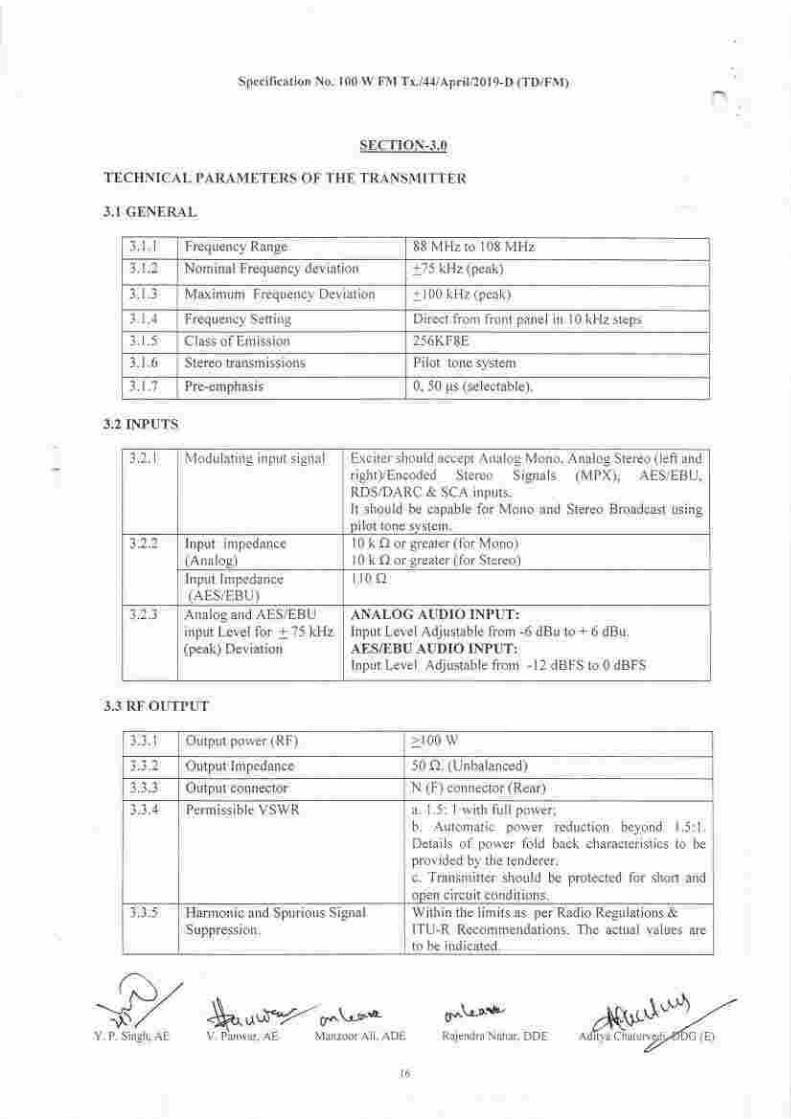
3.I GENERAL
3.2 INPUTS
3.3 RF OUTPUT
i zf,-$/,, SF^,.^'ifY--sr^.\,-!'r.Y. P. Singh, AE V. Penwar, AE Manzoor Ali, ADE
g*\r.Jrrl-Raiendra Nahar, DDE
3.1.1 Frequency Range 88 MHz to I 08 MHz
3.1.2 Nominal Frequency deviation +75 kHz (peak)
3.1.3 Maximum Frequerrcy Deviation + 100 kHz (peakl
3.1 .4 Frequency Setting Direct frorl front panel in l0 kHz steps
3.1.5 Class of Emission 256KF8E
3.1.6 Stereo transmissions Pilot tone system
3.1 .'7 Pre-emphasis 0, 50 prs (selectable.l.
3.2. r ModLrlating input signal Exciter shoLrld accept Analog Mono, Analog Stereo (left and
right)/Encoded Stereo Signals (MPX), AES/EBU,RDS/DARC & SCA inputs.It should be capable for Mono and Stereo Broadcast usingpilot tone system.
Input impedance(Analog)
l0 k Q or greater (for Mono)l0 k f) or greater (for Stereo)
Input Impedance(AES/EBU)
ll0 f)
3.2.3 Analog and AES/EBUinput Level for + 75 kHz(peak) Deviation
ANALOG AUDIO INPUT:lnput Level Adjustable from -6 dBu to + 6 dBu.AES/EBU AUDIO INPUT:Inout Level Adiustable frorn -12 dBFS to 0 dBFS
t.3. r Output power (RF) >t00 w
Output Impedance 50 Q. 1U nba lanced.l
J-J.J Output connector N (F) connector (Rear)
Penr issible VSWR a. I .5: I with full power;b. Auton'ratic power reduction beyond J.5:1.Details of power fold back characteristics to be
provided by the tenderer.c. Transmitter should be protected for short andopen circuit conditions.
3.3.5 Harmonic and Spurious SignalSuppression.
Within the limits as per Radio Regulations &ITU-R Recommendations. The actual values areto be indicated.
Xti"S' ./. ' ^\|AOrtya Lnalurvg
Specillcation No. 100 W FM Tx./.1'1lApril/2019-D (TD/FVI)
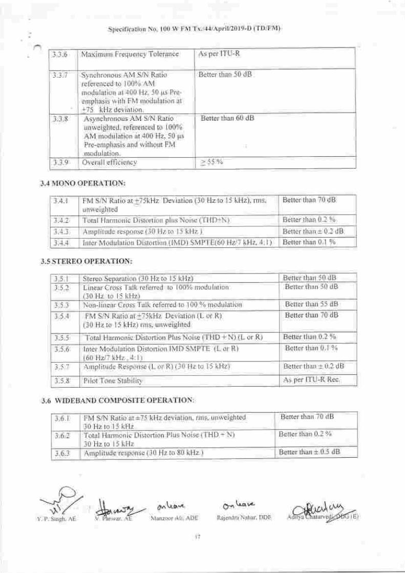
3.3.6 Maximum Frequency Tolerance As per ITU-R
3.3.7 Synchronous AM S,Al Ratioreferenced to I 00% AMrnodtrlatiorr ar 400 H2.50 1ts Prc-
ernphasis with FM modulation at+75 kHz deviation.
Better than 50 dB
1.1.8 Asynchronous AM S/N Ratiounweighted, referenced to 10004
AM rnodulatiorr at 400 H2.50 ps
Pre-emphasis and without FMmodulation.
Better than 60 dB
i,1.9 Overallefficiency > 55 o/o
3.,1 MONO OPERATION:
3.5 STEREO OPERATION:
3.6 WIDEBAND COMPOSITE OPERATION:
3.4.1 FM SfN Ratio at +75kHz Deviation (30 Hz to l5 kHz), rrns,
unweighted
Better than 70 dB
Total Harrrouic Distorlion plLrs Noise (THD+N) Better than 0.2 %
Amplitude response (30 Hz to l5 kHz ) Better than t 0.2 dB
3.1.4 lrrter Modulation Distortion (lMD) SMPTE(60 HzJl kqz,4:1) Better than 0.1 %
3.5.1 Stereo Separation (30 Hz to 15 kHz) Befter than 50 dB
3 .5.2 Linear Cross Talk referred to 10070 modulation(10 Hz ro l5 kHz)
Better than 50 dB
3.5.3 Non-linear Cross Talk referred to 100 % nrodulation Better than 55 dB
3.5.4 FM Sni Ratio at+75kHz Deviation (L or R)(30 Hz to l5 kHz) rms, unweighted
Better tlian 70 dB
i .5.5 Total Harrronic Distortion Plus Noise (THD + N) (L or R) Better than 0.2 oZ
i .5.6 Inter Modulation Distorlion IMD SMPTE (L or R)(60 Hzll kHz . ;l:l)
Better than 0.1 %
3.5.1 Arnplitude Response (L or R) (30 Hz to l5 kHz) Better than t 0.2 dB
3.5.8 Pilot Tone Stabilitv As per ITU-R Rec.
3.6.I FM S/N Ratio at +75 kHz deviation, rms, unweighted30 Hz to l5 kHz
Better than 70 dB
3.6.2 Total Harrnonic Distortion PlLrs Noise (THD + N)30 Hzto l5 kHz
Better than 0.2 o%
3.6.3 AmplitLrde response (30 Hz to 80 kHz ) Better than t 0.5 dB
tPu----lJ ,/ l, o,.\r-r,..jJ1 &,,sy..-
Y. P. Singh, AE V. Fbnwar. AE Manzoor Ali. ADE
Ot Ulr''-
Raiendra Nahar, DDE
l7
Specification No. 100 W FM Tx./,|,|/April/2019-D (TD/FM)
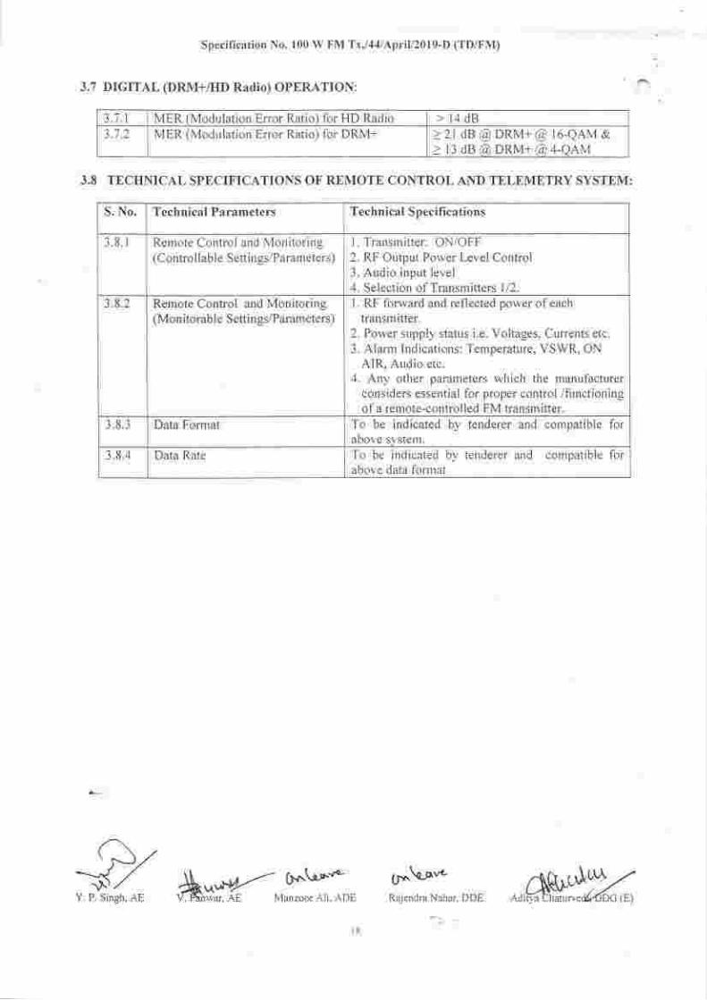
3.7 DIGITAL (DRM+/I-ID Radio) OPf,RATION:
3.'1 .1 MER (Modulation Error Ratio) for HD Radio 14 dB3.7.2 MER (Modulation Error Ratio) for DRM+ z2rdB@DRM+@ r6-QAM&
> l3 dB @ DRM+ @ 4-OAM
3.8 TECIINICAL SPECIFICATIONS OF REMOTE CONTROL AND Tf,LEMf,TRY SYSTEM:
S. No. Technical Parameters Technical Specifi cations
3.8.1 Remote Control and Monitoring(Control lable Settings/Parameters)
l. Transmitter: ON/OFF2. RF Output Power Level Control3. Audio input level4. Selection of Transmitters 1/2.
3.8.2 Remote Control and Monitoring(Monitorable Settings/Parameters)
I . RF forward and reflected power of each
transmltter.2. Power supply status i.e. Voltages, Currents etc.3. Alarm Indications: Temperature, VSWR, ON
AIR, Audio etc.4. Any other parameters which the manufacturer
considers essential for proper control /functioningof a remote-controlled FM transmitter.
3.8.3 Data Format To be indicated by tenderer and compatible foraDove system.
3.8.4 Data Rate To be indicated by tenderer and compatible forabove data fbrrnat
C,J,,---'l ,/ \\ Cr.n\-ar"'-
" r*]"'!i.o, dk*fK ManzoorAri.ADE
()'.\-q*Rajend.a Nahar, DDE
l8
Specification No. 100 W FM Tx./.1,1/APril/2019-D (TD/FM)
SECTION.4.O
TECHNICAL SPECIFICATIONS OF AUTOMATIC CHANGEOVER UNIT, RF COAXIALCHANGEOVER SWITCH, PRE-WIRED R{CK INCLUDING PROGRAMME INPUT &MONITORING EQUIPMENTS, AUTOMATIC AUDIO CHANGEOVER SWITCH, DUMMYLOAD etc.
4.1 AUTOMATIC CHANGEOVER UNIT (ACU):4.1.1 One Automatic Changeover Unit (ACU l for operating the Transmitter in (l + 1) mode to
facilitate automatic switch "ON" of tlre 2"o Transmitter Unit in case of failure of RFoutput of I't Transmitter Unit slrall be supplied with each set.
4.1.2 Any one of the l 00W Transm itter unit shall be selectable as master or slave autornaticallyin active standby nrode. Wlren the RF porver ofthe lst transmitter goes down by nrore
than 3 dB, it should be sensed as a failure to switch to second transmitter autornatically.In case of failure of the complete systen, tllree trials at interval adjustable up to l0minutes shall be done betbre final switch ofl
4.1.3 The complete switching sequence ofchangeover of transmitters and associated equipmentsrnay be provided with the technical offer.
4. I .4 Arrangernent shall be rnade for bypassing the ACU in case of its lailure so as to enableoperating personnel to operate tlre transnritter in tlre nranual ntode.
4.1.5 In case of aLrdio failLrre. an indication shall be displayed in the front panel ofACU.
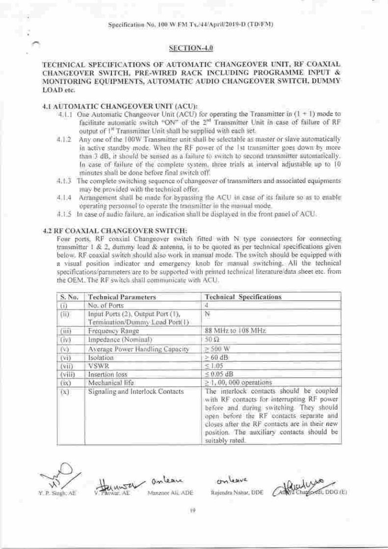
,1.2 RF COAXIAL CHANGEOVER SWITCH:Four ports, RF coaxial Clrangeover switch fined with N type connectors for connectingtransmitter I & 2, dummy load & antenna, is to be quoted as per technical specifications givenbelow. RF coaxial switch should also work in manual mode. The switch should be equipped witha visual position indicator and emergency knob for manual switching. All the technicalspecifications/parameters are to be sLrpported rvith printed technical literature/data sheet etc. fromthe OEM. The RF switch shall comnrunicate with ACU.
S. No. Technical Par:rnreters Technical Soecifications(i) No. of Ports 4( ii) lnput Ports (2), Output Port ( l),
Term irration/Durlmv Load Port( I )
N
Ill Frequency Range 88 MHz to 108 MHz(iv) Impedance (Nominal) i0i')(v) Average Power Hand ling Capacity >500w(v i) lso lat ior.r >60dB(vii) VSWR < 1 .05(v iii) Insertion loss < 0.05 dB(ix) Mechanical life Z I, 00, 000 operations(x) S ignaling and Interlock Contacts The interlock contacts should be coupled
with RF contacts for interrupting RF power
before arrd during switching. They shouldopen betbre the RF contacts separate and
closes after the RF contacts are in tlleir newposition. The auxiliary contacts should be
suitably rated.
-xYZY. P. Singh. AE ,.*,*x-,:;3;", 'Crrl\-Lvo
Rajendra Nahar, DDE
l9
Specification No' 100 W FM Tx'/4;l/April/2019-D (TD/FM)
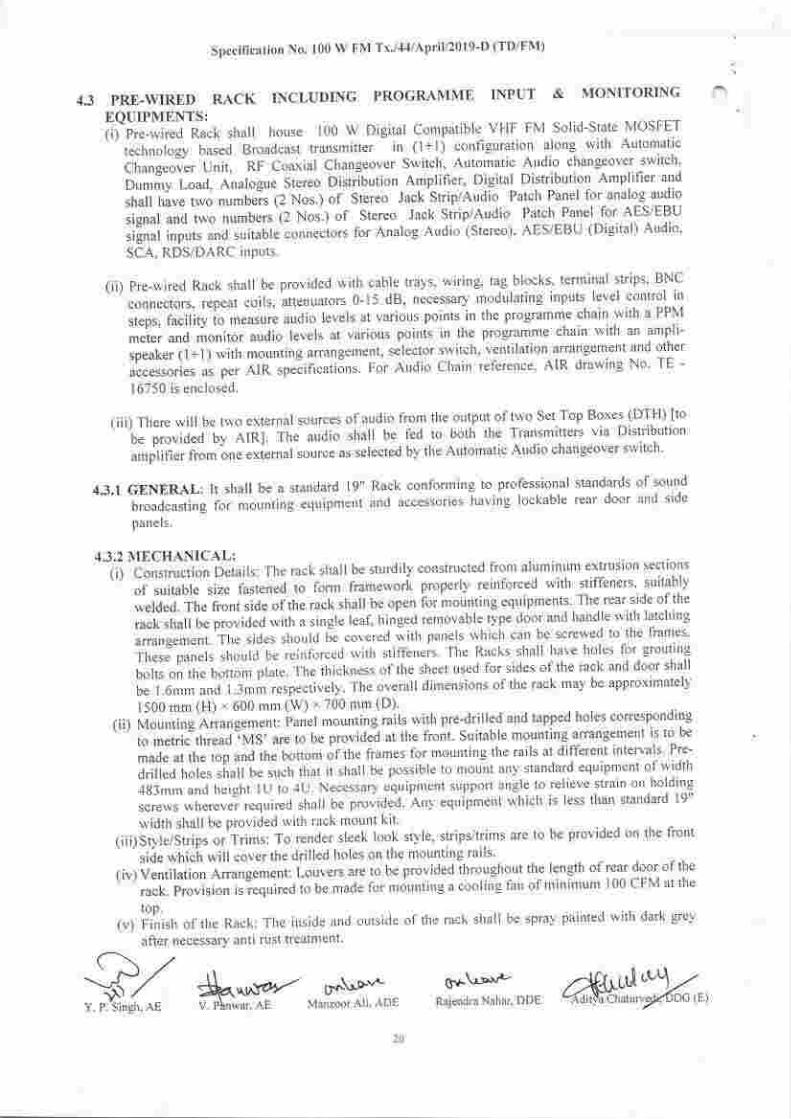
4.3 PRtr.WIRED RACK INCLUDING PROGRAMME INPUT & MONITORING
EQUIPMENTS:(i)Pre-lviredRackshal|housel00WDigitalCornpatibleVHFFMSo|id-StateMOSFET
technology based Broadcast transmitter in (l+l) configuration along with Automatic
Changeoier Unit, RF Coaxial Changeover Switch, Automatic Audio changeover switch'
DumrnyLoad,Ana|ogueStereoDistri-butionAmplifier,DigitalDistributionAmplifierandshallhavetwonumbers(2Nos')ofStereoJackStrip/AudioPatclrPanelforanalogaudiosignalandtwonumbers(2Nos.lorStereo-JackStrip/AudioPatchPanel_forAES/EBUsilnal inputs and suitable connecrofs fof Analog Atrdio (Stereo), AES/EBU (Digital) Audio,
SCA, RDS/DARC inPuts.
(ii) Pre-wired Rack shall be provided with cable trays, wiring' tag blocks' terminal strips' BNC
connectors,repeatcoils,attenuators0-l5dB,necessarymodulatinginputslevelcontrolinsteps, facility to measure audio levels at various points in the programme chain with a PPM
meter and monitor audio levels at various points in the programme chain with an ampli-
Speaker(l+1)withmountingarrangemel]t,selectorswitclr,Ventilationarrangementandotheraccessories as per AIR speiificatilns. For Audio chain ref'erence, AIR drawing No. TE -
l6/)U ls etlclosec.
(iii) There will be two external sources ofaudio from the output of two Set.Top Boxes (DTH) fto.beprovidedbyAlR].TheaudioshallbefedtoboththeTransmittersviaDistribution
amplifierfromoneextenalsourceasselectedbytheAutomaticAudiochangeoversr'vitch'
4.3'IGENERAL:Itshallbeastandardlg''RackconformingtoprofessionalstandardsofsoundbroadcastingibrmoLtntingeqtripmentandaccessorieshavinglockabIereardoorandsidepanels.
4.3.2 MECHANICAL:(i)ConstructionDetai|s:Therackshallbesturdilyconstructedfroma|uminumextruslonsect|ons
ofsuitablesizet.astenedtofonnframeworkproperlyreinforcedwithstiffeners'.stritab|ywelded. The front side ofthe rack shall be open for mounting equ ipments
. The.rear. side ofthe
racksliallbeprovidedwithasingleleaf'hingedremovabletypedoorandhandlewith|atchingarrangement.Thesidesshouldb.-e"o.,.,."d*ithpanelswhichcanbescrer,vedtothefrallles'Tlrese'pane|sslroulclbereinforcedwitlrstiffeners.TheRackssha||haveholesforgroutingboltsonthebottomplate'Thethicknessofthesheetusedforsidesoftherackanddoorsha||bel'6mmandl.3mmrespective|y.Theoveralldimensionsoftlrerackmaybeapproximately1500 mm (H) * 600 mm (W) x 700 mm (D)'
(ii) Mountlng Arrangement: i'anel mounting rails with pre-drilled and tapped holes corresponding
to metric thread ,MS, are to be providi at the front. Suitable mounting arrangement is to be
madeatthetopandthebottomoftheframesformountingtherailsatdifferentintervals.Pre-drilled holes shalt be such that it shall be possible to moLlnt any standard equiprrent of width
4S3mmandheightlUto4U'Necessar}.eqrripmentsttpportangletorelievestrainon.ho|dingScrewswhereverrequiredshalIbeprovidec|.AnyequipmentwhichisIesst|ranstandardl9''rr idth shall be pror ided u illr rack mount kit'
(iii)Style/StripsorTrims:TorendersIeeklookstyle,strips/trimsaretobeprovidedonthefrontside which will cover the drilled lioles on the mounting rails'
(iv)VentilationArrangement:LouversaretobeprovidedthroLrghoutthelengthofrea^rdooroftherack.Provision,rr"qni,..atobemadeformountingacoolirrgfarrofminimuml00CFMattherop.
(v) Finish ofthe Rack: The inside and outside of tlre rack shall be spray painted with dark grey
after necessary antl rust treatn]ellt
qv-\5v'-Rajendra Nahar, DDE
(\ ./'. -^#/ $,^*"t*.- D'\'o*Y. P.'Singh. AE V. P\n*cr. AL Man/oor AIi ADF
,1.3.3 JACK STRIP FIELD/ AUDIO PATCH PANEL:(i) Standard Jacks Strip of robust constructiotl and positive action shall be used. lnput and output
of all the equipments and the programrne lines shall be brought to the Jack-Field..Few jack
points shall be r'rsed as check points without disrupting the signal flow & few to. be.leftas
spares for the tie lines, parallel points and for future use. The jack strip panels shall be
ooenable on front sides without strain on connector and wiring.
(ii) Jack Srip cor'rstruction: The jacks shall have preferably a nickel plated brass frame, with
nickel-silver springs and gold-silver/ Palladium contacts. The jacks shall be mounted on
20mm centers. The Jacks shall be as per DIN specitications.(iii)Contact arrallgemeut: Each.lack shall be a 24 poirrt.jack. providing a break circLlit (on both
wires) and ar isolated eafthing lug.(iv) Indicating strip: A strip covered with transparerlt plastic shall be provided above the row of
jacks fbr labeling purposes.
(v) Separate jack strip field/ auclio patch panel for analog and digital inputs will be provided by
the tenderer.
4.3.4 PEAK PROGRAMME METER:Tlre Programme level metering shall be with Peak Programme Meter (Bar graph Display or
LEDs Type). This unit shall work independently irr any configuratiorr for signal monitoring
without loading the source.
4.3.5 AMPLI-SPEAKERPANEL:The Anrpli-speaker with mounting arrangements shall have two ampli-speakers, one for eac}t
cliannel. The monitoring output will be fed to the arnpli-speakers. The Ampli-speaker shall
ureet the lbllowing spec ificat ions:
Specilication No. 100 W FM Tx./44lAprili20l9-D (TD/FM)
S. No. Technical Parameters Technical Snecifi cation(i) Freq uency range 63 Hz-]5 kHz
Audio Power 8 Watt Continuous for each channel
i) Volume Control adiustable for each channel
( v) Audio input Balanced Stereo
(v) lnput Irnpedance >t0 kc,
1ri) Power Supply As per AIR specification clause I I5
4.3.6 REPEAT COIL:(i) A Line to line audio transformer shall be provided for isolating balanced and
unbalanced circuits.(ii) Hum reduction: The shielding and design of the windings shall be such that the hum
level picked up by the unit, when placed in normal magnetic field inside equipment rack
is better then -75dBm, as measured across either winding, both secondary and primary
being terminated by 600 A.(iii) Insertion Loss: Less than ldB(iv) Frequency response; betler than + I dB (i0 Hz-l5kHz) referred to I kHz'
4,3.7 R{CK WIRING:(i) All the wiring irr rhe rack shall be carried out with MIL standard approved PTFE
insulated, shielded, twin core, audio cables of standard size in PVC cable duct'
0-t L-ot-Rajendra Nahar, DDE
(ii) Tlre wiring for all the equipment shall be routed through terrninal blocks which shall
suitably located for easy accessibility. All the r.viriug on the terminal block shall
-t-Pr' --\\-.' ^. -,..- o\Ls^
, ,t]rr(, ffi$*f MdnloorAri. ADL
be
be
2l
-*4.w{"^1 -Ad i rya Chatu rveJLi..DOG (E)
Specil.icarion No. t00 W FM Tx,/tt/Aprit/2019_D (TD/FNI.)
suitabry marked rhe wiring bunches shat be neatry rard and cramped to the bod_v ofthe(iii) Power suppty *'r'"q::l:,11^O,ir:
llr"ich separare conduits and shail be sesresate<isuitably from the audio wiring in order to avoid noise and hum pick uo.
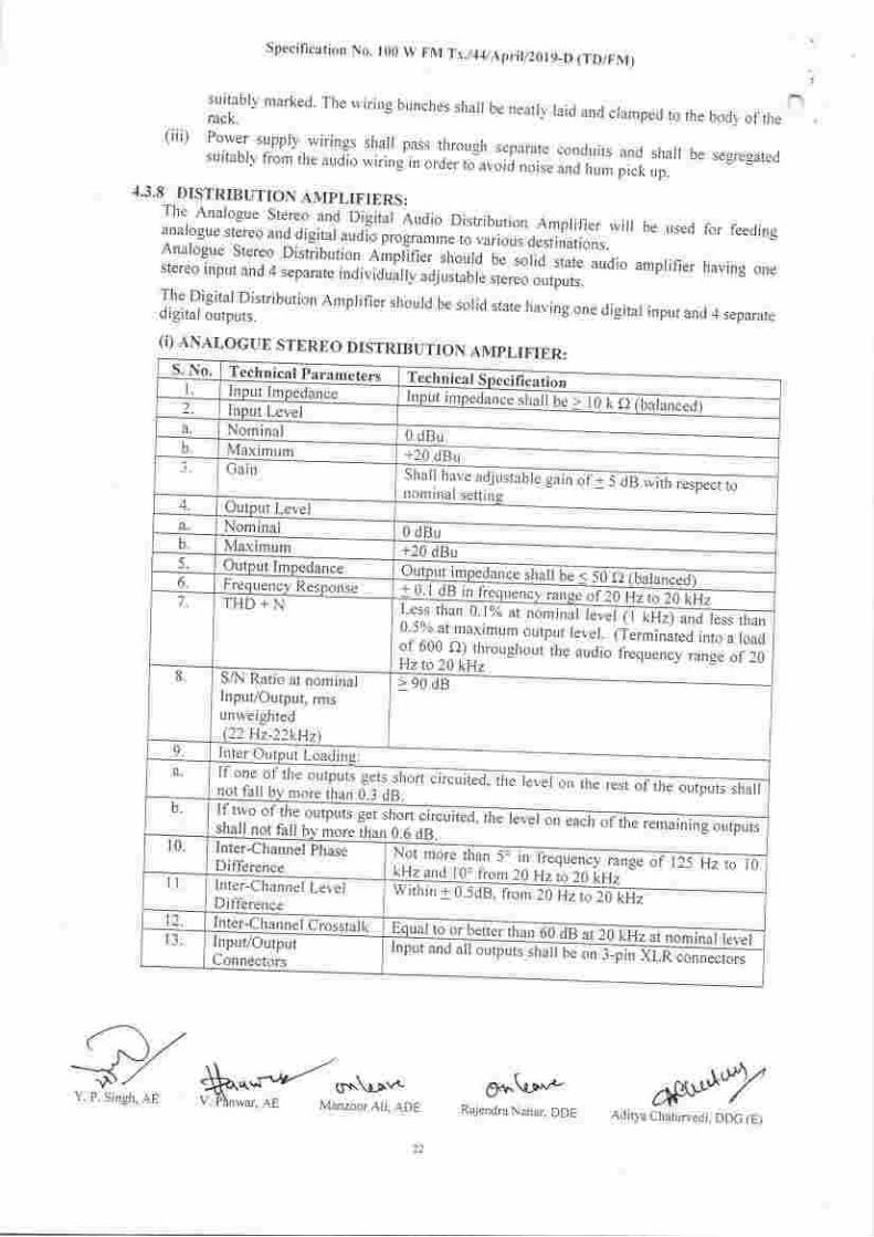
4.3,8- DISTRIBUTION AMPLIFIERS :The Analogue Stereo ancl Digital Audio Distribution Arnplifier will be useil for feedinsanalogue stereo and digital audio p.ogru,rr. a uuriou"r'o"r,inu,,onr. bAnalogue Stereo Distiibutiol. .fmnlifier should ;;;iid.state audio amplifier havins onestereo input and 4 separate individually adjusr"l[ *.""'"i,,0*r.The Digital Disribution Amplifier should be solid state havirdigital outputs. surru slare navtng one digital input and 4 separate
(i) ANALOGUE STEREO DISTRIBUTION AMPLIFIER:S, NO, Technical Para meters Tech n ica I Specificatin
..--.---.---.----..---..---._--
lnprt rnrpedance shall be < I0 k ellalanced)-I Input lmpgdance2. Input Level
NominalMaximumGr;n_-
a. 0 dBu
-
_j^^__._-
'rU dBU^,--.- --
-
ii1].11*.r9i, ","ble eain of _idB *rrhlespecr ro-l)orn Ina I Setttng
------g-
b.
3.
4. Output LeveiNominala. 0 dBu
-
ffib. Maximum5. Output Impedan-6. Frequency Response7. THD+N ; : ---j-::-:Ll:lE: l'r zv nz t\) tU RHZ
^Less
lhan 0.100 tt lrorninal leiet lf Tl_fzl una t.s, ttralrv.r- 0 ar maxrmum o tprrt level. (Terminated into a loadof 600 f)t, rhroughout the audio frequencl ,r";.;i;;Hz to 20 kHz
-
8. I S,4.i Ratio at nominit -I Input/Output, rms
lunweighted| (22 Hz-22kHztf_- -_ '= -- --I jrSlo{pltt Lq3lLns:
rr one ol the outputs qet:
+g ral1!r,'prc!&" qJ ,
rr rwo ot the outputs get I
shall loLFa llbllrpl.e tharInter-L hannel PhaseDifference;-_----.-lnter-Channel Le\ elDifference l----=:-_---.tnter-Chant)elCrosstalk
l
9.
a.
lB.
10.6 dB.
*#+r3:+:1?q+1e4it,' - ' "
b.
10.
lt
-
I-attrzl f^ Ar hah-. iL^- z^ ih - -:;----12.
13. InpuVOutputConnectors
gtQ)-'- N*JYAditya Chaturvedi, DDc (E)
<).2X"f, h;*.ny,:",
Rejendrc Nohrr. DDE
Specification No. 100 W FM Tx./,14lApril/2019-D (TD/FM)
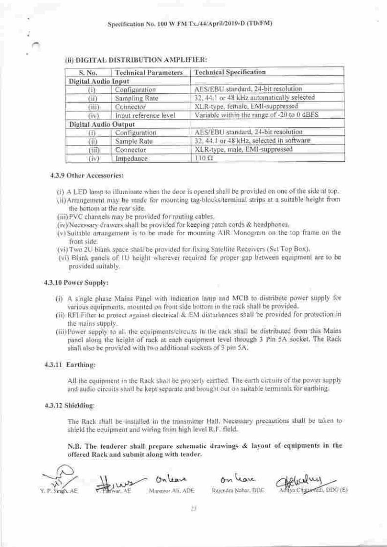
(ii) DIGITAL DISTRIBUTION AMPLIFItrR:
S. No. Technical Parameters Technical Specifi cationDisital Audio Input
(i) Configuration AES/EBU standard. 24-bit resoluuon( i) Sarnpling Rate 32,44.1 or 48 kHz automatically selected
r) Connector XLR-type, female, EMI-su ppressed
( v) lnput reference level Variable within the ranse of -20 to 0 dBFS
Disital Audio Outout(i) Con figuration AES/EBU standard, 24-bit resolution( ii) Sample Rate 32. 44. I or 48 kHz, selected in software(iii) Connector XLR-type, male, EMI-suppressed(iv) Impedance 110 c)
,1.3.9 Other Accessories:
(;) A LED lanrp to illunrinate wlren the door is opened shall be provided on one of the side at top.
(ii) Arrangernent may be rrade for nrounting tag-blocks/term inal strips at a suitable height fromthe bottom at tlre rear side.
(iii) PVC channels may be provided for routing cables.(iv)Necessary drawers shall be provided for keeping patch cords & headphones.(v) Suitable arrangement is to be rnade for nrounting AIR Monograrn ou the top frarre on the
front side.(vi) Two 2U blank space shall be provided for fixing Satellite Receivers (Set Top Box).(vi) Blank panels of lU height lvlrerever required for proper gap betweelt equipment are to be
provided suitably.
4.3.10 Porver Supply:
(i) A single phase Mains Panel with indication lanrp and MCB to distribute porver supply forvarious equipments, r'nounted ou front side bottom in the rack shall be provided.
(ii) RFI Filter to protect against electrical & EM disturbances shall be provided for protection in
the mains supply.(iii)Power supply to all the equ ipments/circuits irr the rack shall be distributed from this Mains
panel along the heiglrt of rack at each equipment level through 3 Pin 5A socket. The Rack
shall also be provided with two additional sockets of 3 pin 5A.
4.3.11 Earthing:
All the equiprrent in the Rack shall be properly ea(hed. The earth circuits of the power supplyand audio circuits shall be kept separate and brought out on suitable terrninals for earthing.
,1.3.12 Shielding:
The Rack shall be installed in the transmitter Hall. Necessary precautions shall be taken toshield the equipment and wiring frorn high level R.F. field.
N.B. The tenderer shall prepare schematic drawings & Iayout of equipments in theoffered Rack and sutrmit along rvith tender.
-.--i-A--^t'\./Y. P. Singh- AE
(}"La.^ C- Lo*#or+*- Minzoor Ali. ADE Raiendra Nahar. DDE #"[$*G-*,,,
4.4 AUTOMATIC AUDIO CHANGEOVER SWITCH:There will be two extemar sources of audio from the output of two set Top Boxes (DTH)trobe provided by AlRl. The aLrdio shall be fed to both the Transnriters via Diitributiori amplifierfrom one extental source as selected by the Autornatic Audio changeover s,,vitch.
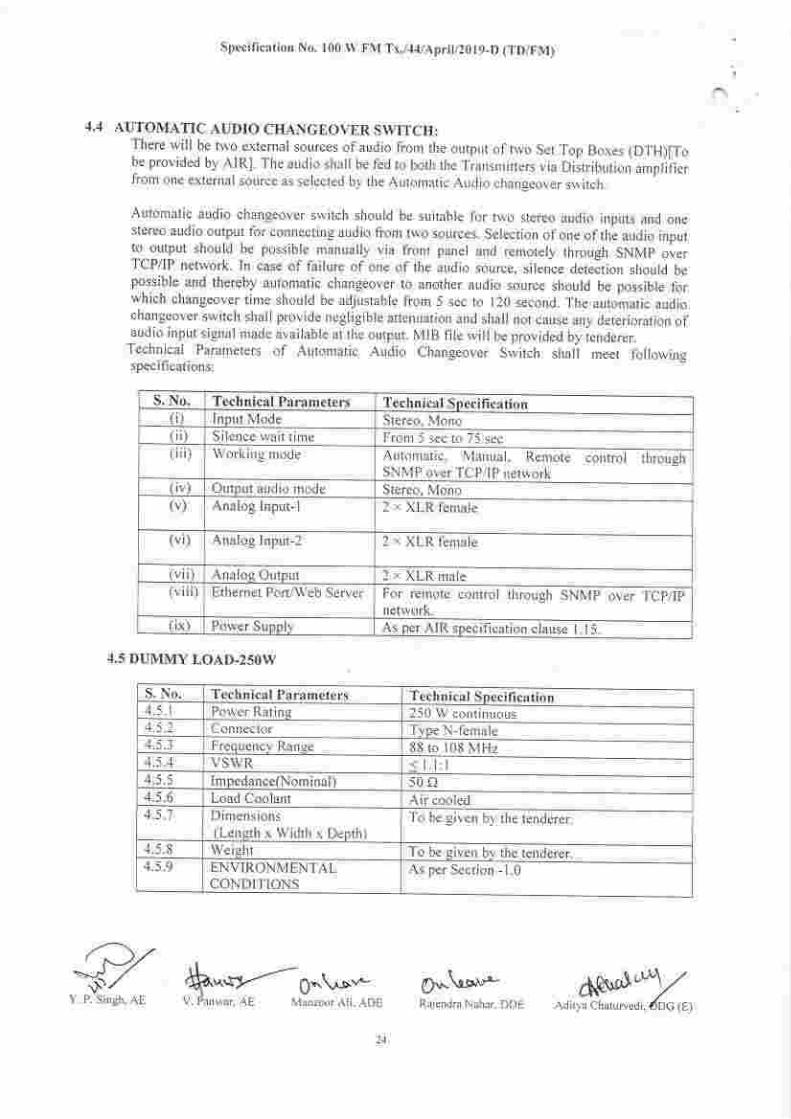
Automatic audio changeover sr'vitch should be suitable for two stereo audio inputs and onestereo audio otltput for connecting audio from two sources. Selection ofone ofthe aLrdio inputto output should be possible manually via frorrt panel and remotely through SNMp overTCP/IP network. In case of failure of one of the audio source, silence detection should bepossible and thereby automatic changeover to another audio source should be possible forwhich changeover time should be adjustable from 5 sec to 120 second. The automatic audiochangeover switch shall provide negligible attenuation and shall not callse any deterioration ofaudio input signal made available at the output. MrB fire wiI be provided bv ienderer.Teclrnical Parameters of Automatic Arrdio Clrangeorer Switclr shalj meet follouingspecifications:
Specification No. | 00 lV FNt Tx./.1.1/Aprit/2019-D (TD/FM)
S. No. Technical Parameters Technical Specifi cation(i) lnput Mode Stereo, Mono(ii) S ilence rvait time Fronr 5 sec to 75 sec( iii) Working rnode Automatic. Marrual, Remote control through
SNMP over TCP/lP network(iv) Output audio mode Stereo, Mono(v, Analog Input- I 2 x XLR female
(vi) Analog Input-2 2 x XLR female
(v ii) Analog Output 2 x XLR male( vi ii) Ethernet Porl/Web Server For remote control throllgh SNMP over TCp/lp
network.( ix) Power Supply As per AIR specification clause 1.15.
4.5 DUMMY LOAD-250W
O.-\lstl"'-
S. No. Technical Parameters Technical Snecifi cation4.5. l Porver Rating 250 W corrtinuous4.5 .2 Connector Type N-female4.5.3 Frequency Range 88 to 108 MHz4.5.4 VSWR < l.l:l4.5.5 ImpedancelNom inal 1 s0o4.5.6 Load Coolant Air cooled
Dimensions(LengthxWidthxDepth)
To be given by the tenderer.
4.5.8 Weight To be given by the tenderer.4.5.9 ENVIRONMENTAL
CONDITIONSAs per Section - 1.0
rJz ,
N/^,. R:x-,g;h;, Rrlcndra Nrhrr DDEA0-"I*Z
.Adir\ a Chrrur\,cdr. dDC (E)
Specification No. 100 W FM Tx./44lApriU20l9-D (TD/FM)
AIINEXURE-IINSPECTION DETAILS
The inspection for acceptance of the Transmitter with Automatic Changeover Unit on dummy
load and prewiied Rack including Programme Input & Monitoring equipments will be canied out at
OEM's Works by Engineers of All India Radio in accordance with Acceptance Test Procedure/Protocol
(ATP). All facilities like complete set of measuring instruments, power supply, manpower etc. will be
provided by the Manufacturer. Complete details and specifications of the transmitter will be checked and
all parameter values will be measured.The tenderer shall put up all the 100 Nos. of Transmitters with Automatic Changeover Unit and
pre-wired Rack including Programme Input & Monitoring equipments for inspection, out of which 10 %
(10 Nos.) randomly selected shall be inspected in details and measurements shall be taken. All the l0 %randomly selected transmitters shall be tested for 24 Hours continuously on dummy load. Rest of the
90%(90 Nos.) will be accepted on the basis of OEM's Test Certificate'The tenderer is also required to demonstrate during PDI the compatibility of the FM transmitter
for Digital Broadcasting (DRM+ OR HD Radio) on one of the Digital Compatible VIIF FM Solid-State
MOSF-ET technology based Broadcast transmitters. The tenderer is also required to provide additional
equipments (if any) during PDI, to check the compatibility ofthe FM transmitter for Digital Broadcasting(DRM+ OR HD Radio).
Testing/measurements including Operational & functional checking of th€ transmitter will be
carried out at OEM's Works on single phase, 230 Volt(rms) + 10o/o, 50 Hz + 4yo power supply available
at the transmitter's input circuit breaker without any outside transformer unit etc. No other voltage will be
acceptable to AIR at the transmitter's input circuit breaker and failing which the transmitter equipment is
liable to be rejected.The technical facilities/equipment for varying within + 10% of 230 Volts(rms), single phase
should be available at OEM's Works for testing/measurements including Operational & functional
checking of the transmitter during the inspection. The performance of transmitter as per parameters inSection-3.0 shall be guaranteed without degradation with the given power supply tolerances.
Exhaustive checking and measurements will be carried out so as to completely check the
compliance of the transmitter and including Programme Input & Monitoring equipments as projected inthe specifications.
It is mandatory that testing/measurements including operational & functional checking of all the
transmitters and measurements as per parameters in Section-3.0 at three different frequencies including
operating frequency of the transmitter in the VHF Band i.e. 88 MHz to 108 MHz without change ofcomponentVsettings/tuning are carried out well in advance. These must be submitted to All India Radio
along with the call for inspection of transmitters well in advance for analyzing etc. These measurement
details, graphical printouts, notes and figures must be available at the OEM's Works at the time ofinspection.
Al[ the spares ordered as per AT will be tested in actual circuit at OEM's Works by Engineers ofAIR.
Tenderer shall arrange for the pholographs of inside of transmitter's cubicle which will be
attached with the ATP/InsDection reDort.Following information should also form part of above data which will also be checked
inspection by AIR'S representative at the OEM'S Works.l. Origin of Country, Make, Model and type of Transmitter with Automatic Changeover Unit, Pre-wired
Rack including Programme Input & Monitoring equipments, accessories and spares.
2. Dimension ofTransmitter, sub-units and accessories.3. Working/operation ofall sub-units and accessories.4. System configuration check and completeness ofTransmitter.5. Checkins meter readinss and calibration.
d''.L-o"c--]P/nn,/
Y. P. Singh, AE ,M[E ';^nY;, Rajendra Nahar, DDE ".*6&,${rrl'9t
6. Measurements of parameters as per specification.7. Checking of controVprotection system of Transmitter.8. Checking ofall power levels, meters, LCDs etc.9. Measurement of levels in the whole AF and RF chain.10. Checking ofRF voltages on test points.1 1. Interchangeability of sub-modules and PCBs.12. Checking of spares, PCB's, modules for the respective transmitter.
Specilication No. 100 W FM Tx./44lApril/2019-D (TDIFM)
SECTION-s.0 (A)
SCHEDULE OF REQUIREMENTS/MATERIALS (UN-PRICED) IFOR ONE SET OFSUPPLY OF IOO W DIGITAL COMPATIBLE VHF FM SOLID-STATE MOSFETTf,CHNOLOGY BASED BROADCAST TRANSMITTER IN (1+1) CONFIGURATION &ASSOCIATED EQUIPMENTSiITEMS]
S^\rt'-'''.-Rajendra Nahar, DDE
S. No. Description Make Model Qty.
I Supply of 100 W Digital Compatible VHF FM Solid-State
MOSFET technology based Broadcast transmitter in (l+l)configuration including in-built Exciter, Stereo Coder withAutomatic Changeover Unit (ACU) alongwith remote control& telemetry equipment as per AIR specification.Each Set shall comprise of 2 Nos. of independent 100 WDigital Compatible VHF FM Solid-State MOSFET technologybased Broadcast transmitter Units and Automatic Changeover
Unit.
I SetComplete
z- Supply of Automatic Audio Changeover Switch as per AIRsnecifications.
I Set
-). Supply of Four ports, RF coaxial Changeover switch fittedwith N type connectors for connecting transmitter 1 & 2,
dummy load & antenna as per AIR specifications. All thenecessary low loss RF Coaxial Cables with N type Connectors
for connecting Two Nos. of FM transmitters and dummy load
shall be supplied alongwith the switch.
i Set
4. Supply of 250 Watt Dummy Load mounted in pre-wired Rackas per AIR specifications.
1 SetComplete
5. Suppty of Pre-wired Rack including Analogue Stereo
Distribution Amplifier, Digital Distribution Amplifier, twonumbers (2 Nos.) of Stereo Jack Strip/Audio Patch Panel foranalog audio signal and two numbers (2 Nos.) of Stereo Jack
Strip/Audio Patch Panel for AES/EBU signal inputs and
suitable connectors for Analog Audio (Stereo), AES/EBU(Digital) Audio, SCA, RDS/DARC inputs as per AIRspecifications.Pre-wired Rack shall also be provided with cable trays, wiring,tag blocks, terminal strips, BNC connectors, repeat coils,attenuators, necessary modulating inputs level control in steps,
facility to measure audio levels at various points in the
programme chain with Peak Programme Meter and monitoraudio levels at various points in the programme chain with an
1 Set
Complete
";# ",ks*-;",:;H NA*,$K",,,
a-pti-spea"er tt+1) with mounting arrangement, selector
switch, ventilation arrangement and other accessorres as per
AIR specifications.o. A@iompleteneis of the
system.
1 Lot
7. @s works of transmitter as
per AIR specifications.
1 Lot
e @ion, Testing, commissioning,
ODeration. Maintenance & Service, including theory ofoperation, circuit description and fault diagnosis) COLOUIpiitrt"d -d duly bound for 100 W Digital Compatible VHF
FM Solid-Stut" MOSFET technology based Broadcast
transmitter in (1+1) configuration, Automatic Changeover
Switch, RF Coaxial Changeover Switch, Automatic Audio
Changeover Switch, pre-wired rack including Programme
Input & Monitoring equipments, dummy load and associated
equipments/items alongwith soft copy on CD & Inspection
Repofl of the inspection carried out at OEM's works as per
distribution given beiow.8.1 fo. plC @-f10, P & D Unit, DG: AIR, New Delhi-1 10001
{Within i5 days of issue of Acceptance of Tender)(inesoective ofnumber oftransmitters to be ordered)
l Set
8.2 For Consignee {To be supplied alongwith the equipT."tl- 2 Sets
8.3 F;th" f.lt"*hg Oft""Vofficers, Technical manuals are to
be supplied alongwith the equipment as per distribution given
below)(irrespective of nurnber of transmitters to be ordered)
13 Sets
(D DDG (E-FI\,[), P&D Unit, DG:AIR - i Set
(ii) Zonal Office (Project Wing)(For SZ,WZ,NZ &EZ) - 4 Sets
(iii) Zonal Office (Maintenance Wing)Gotsz-wZ-NZ&EZ\ 4 Sets
(iv) DDG (E-TM), DG: AIR -1 Set
(v) Technical Library, P&D Unit, DG:AIR -1 Set
(vi) NABM, New Delhi -l Set
(vi) R&D, AIR & DD, New Delhi -l Set
Total -13 Sets
Specification No. 100 W FM Tx./44lApril/2019-D (TDrTNt)
SECTION.5.O (B)
SCHEDULE OF REQUIREMENTS/MATERIALS (UN-PRICED)[TOR ONE SET OF'
SUPPLYoFI00wDIGITALCOMPATIBLE\iHFFMSOLID-STATEMoSFETTECHNOLOGYBASEDBROADCASTTRANSMITTERIN(1+1)CONT.IGI]RATION&ASSOCIATED EQUIPMENTS/ITEMSI (OPTIONAL) (Not to be considered for Ranking)
{The tenderer must quote all items}
a/ s,ntz-V. Panwax, AE Manzoor Ali, ADE Rajendra Nahar, DDE
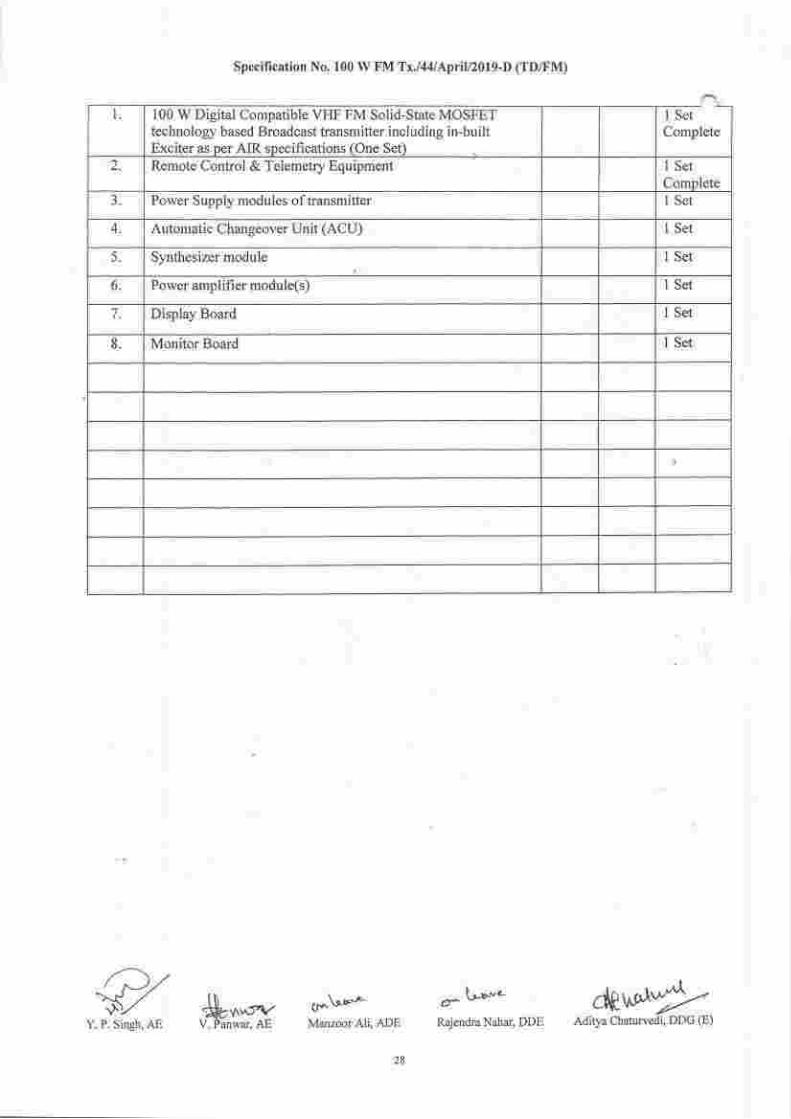
S. No. Description Make Model Qty
R"co-.e.d"d .p".ei for one set of transmitter & associated
equipments: State NA, if not applicable
Y. P. Singh, AE Mr#i
Specification No. 100 W FM Tx./44lApriV2019-D (TD/FM)
Cts \-9-o.-
Manzoor Ali, ADE
100 W Digital Compatible VIIF FM Solid-State MOSFETtechnologr based Broadcast transmitter including in-built
Remote Control & Telemetry Equipment
Power Supply modules of transmitter
Automatic Changeover Unit (ACU)
Synthesizer module
Power amplifi er module(s)
Display Board
1 SetComplete
r)z\S," .$**Y. P. Sinel, AE V. Panwar, AE
crLr-. ewi"*Rajendra Nahar. DDE Aditya Chaturvedi. DDG (E)
Specification No. 100 W FM Tx'/44lApril/2019-D (TD/FM)
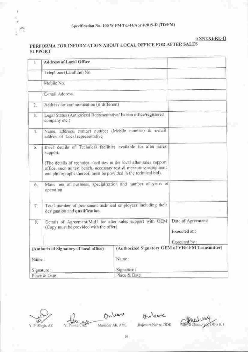
ANNEXURE-II
PERT'ORMA FOR INFORMATION ABOUT LOCAL OFFICE FOR AFTER SALES
SUPPORT
Add ress of Local Office
Telephone (Landline) No.
Mobile No.
E-nrail Address
2. Address for comrlunication (if different)
3. Legal Status (Authorized Representative/ Iiaison offi celregistered
company etc.)
4. Nanre, addtess, contact number (Mobile nunrber) & e-rnail
address of Local represerltative
5. Brief details of Technical facilities available for after sales
support:
(The details of technical facilities irt the local after sales suppon
office, such as test bench, rtecessary tesi & measuring equtplnent
and photographs thereof, must be provided in the technical bid)
6. Main lineoperatron
of business, specialization and nunrber of years of
7. Total number of permanent technical employees including their
designation and qualilication
8. Details of Agreernent/MoU for after sales suppofi with OEM(Copy must be provided with the offer)
Date of Agreement:
Executed at :
Executed by :
(Authorized Signatory of local oflice)
Name :
Signature:
(Authorized Signatory OtrM of VHF FM Transmitter)
Nanre :
Signature:Place & Date Place & Date
-9Y. P. Singh, AE
$."V""'c-l0 O*.'suffi"Hffi"7oor Ari. ADI Raiendra Nahar, DDE c&bhl,#d,,,,
Spccification No. 100 W FM Tx./,1.1/Aprit/2019-D (TD/FM)
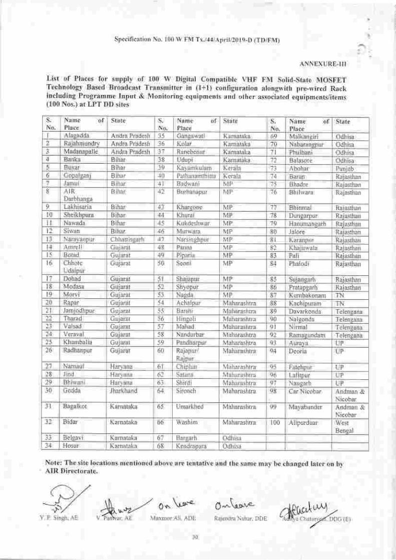
ANNEXURE.III
List of Places for supply of 100 W Digital Compatible \TIF FM Solid-State MOSFETTechnology Based Broadcast Transmitter in (l+l) configuration alongwith pre-n'ired Raclrincluding Programme Input & Monitoring equipments and other associated eq uipme nts/items(100 Nos.) at LPT DD sites
s.No.
Name ofPlace
State s.No.
Name ofPlace
State S.
No,Name ofPlace
State
I Alaeadda Andra Pradesh 35 Canga\ ati Karnataka 69 Malkansiri Odhisa2 Rajahmundry Andra Pradesh 36 Kolar Karnataka 70 Nabarangpur Odhisa3 MadanapalJe Andra Pradesh 31 Renebenur Karnataka 7l Phulbani Odhisa4 Banka Bihar 38 Udupi Karnataka 72 Balasore Odhisa5 Buxar B nar 39 Kayan'rkulam Kerala 13 Abohar Pun lab6 C opalganj B har 40 Pathanamth itta Kerala 14 Baran Raiasthan,7
Jamul B har ,.lt Baduani MP '/5 Bhadre Raiasthan8 AIR
DarbhangaB ihar 42 Burhanapur MP 16 Bh ilwara Rajasthan
9 Lakhisaria B ihar 43 Kharsone MP 77 Bhinmal Raiasthanl0 Sheikhpura B ihar 44 Khurai MP 78 Dungarour Raiasthan11 Nawada Bihar Kukdeshwar MP 79 Hanumansafh Raiasthant2 Siwan B ihar 40 Murwara MP 80 Jalore Raiasthanl3 Narayanpur Ch hanisgarh 41 Narsinqhpur MP 8t Karanpur Raiasthan
Amreli Gu iarat 48 Pann a MP 82 Khaiuwala Rajasthanl5 Botad C uiarat 49 P ipar ia MP 83 Pali Ra iasthanl6 Chhote
UdaipurGujarat 50 Seoni MP 84 Phalodi Rajasthan
17 Dohad G u iarat 51 Shajapur MP 85 Su jan.earh Raiasthan18 Modasa Guiarat 52 Shyopur MP 86 Pratapgarh Raiasthani9 Morvi Guiarat Nasda MP 87 Kumbakonam TN20 Rapar C uiarat Ac ha lDu r Maharashtra E8 Kachipuram TN21 Jamiodhpur C uiarat 55 Barshi Maharashtra 89 Davarkonda Telengana22 Tharad C u iarat 56 Hineoli N4aharashtra 90 Naleonda Telengana23 Valsad C uiarat 5',7 Mahad Maharashtra 9l Nirmal Telengana1/1 Veraval Cuiarat 58 Nandurbar Maharashtra 92 Ramaqundam Telengana25 Khambalia Cu iarat 59 Pandharpur Maharashtra 93 Auraya UP26 Radhanpur G uj arat 60 Rajapur/
RaipurMaharashtra 91 Deoria UP
27 Narnaul Harl ana 6l Chiplun Maharashtra 95 Fatehpur UP28 Jind Haryana 62 Satana Maharashtra 96 La litpur UP29 Bhiwani Haryana 63 Shirdi Maharashtra 97 Nauqarh UP30 Codda Jharkhand 64 Sironch Maharashtra 98 Car Nicobar Andman &
Nicobar3l Bagalkot Kamataka o) Umarkhed Maharashtra 99 Mayabunder Andman &
Nicobar32 B idar Karnataka 66 Washim Maharashtra r00 AJipurduar West
Benqal33 Belgavi Karnataka 61 Barparh Odhisai4 Hosur Kamataka 68 Kendrapara Odhisa
Note: The site locations mentioned above are tentative andAIR Directorate.
the same may be changed later on by
(-\ ./.t47 &^-*" o*\-o'*
Y P. srneh. AF V.-Pan\v.r. AL Vanznr'- Ali. ADI
0^^Lonr-Rajendra Nahar. DDE #@",,,