ENGINEERING PROPOSAL DATA - Banner Associates, Inc.
148
ENGINEERING PROPOSAL DATA Prepared For: Project: Engineer: Lake Poinsett Sanitary District Sanitary District East and Northeast Lake Drive Wastewater System Expansion Part 2 Lift Station NO 5,6,7,8 and11 Lake Poinsett SD Banner Associates, Inc Date: May 14, 2018 MO No: MO001682
-
Upload
khangminh22 -
Category
Documents
-
view
0 -
download
0
Transcript of ENGINEERING PROPOSAL DATA - Banner Associates, Inc.

ENGINEERING PROPOSAL DATA
Prepared For: Project:
Engineer:
Lake Poinsett Sanitary District Sanitary District East and Northeast Lake Drive Wastewater System Expansion Part 2 Lift Station NO 5,6,7,8 and11 Lake Poinsett SD Banner Associates, Inc
Date: May 14, 2018
MO No: MO001682

Operating Instructions MO001682‐1 Lift Station No. 5
Revision Date: 5/11/2018 Page 1 of 5
Lake Poinsett Sanitary District
Lake Poinsett, SD
Operating Instructions Operating Instructions MO001682‐1 Lift Station No. 5
Sweeney Controls Company 234 28th St S Fargo, ND 58103 Phone (701) 232‐3644 – 24 Hour Service Fax (701) 232‐3635 www.sweeneycontrols.com

Operating Instructions MO001682‐1 Lift Station No. 5
Revision Date: 5/11/2018 Page 2 of 5
Contents
1. Auto Operation .......................................................................................................................... 3
2. Hand Operation ......................................................................................................................... 3
3. Off Operation ............................................................................................................................. 3
4. Running Light ............................................................................................................................. 3
5. Fail Light ..................................................................................................................................... 3
6. Hour meter ................................................................................................................................ 3
7. Dual Run Hour Meter ................................................................................................................ 3
8. High Level .................................................................................................................................. 3
9. Low Level ................................................................................................................................... 3
10. Thermal Failure (Automatic Pump Restart) ............................................................................... 4
11. Seal Failure................................................................................................................................. 4
12. Outside Alarm Light ................................................................................................................... 4
13. Alarm Dialer ............................................................................................................................... 4
14. 1‐2 AUTO 2‐1 Selector Switch .................................................................................................... 4
15. Float Test Switches. ................................................................................................................... 4
16. Power Monitor .......................................................................................................................... 4
17. Lightning Arrester ...................................................................................................................... 5
18. Surge Capacitor .......................................................................................................................... 5
19. Condensation Heater ................................................................................................................. 5
20. Air Conditioner .......................................................................................................................... 5

Operating Instructions MO001682‐1 Lift Station No. 5
Revision Date: 5/11/2018 Page 3 of 5
1. Auto Operation
For automatic operation keep all switches in the “AUTO” position. The water will come in and fill the wetwell,
closing the Stop Float. When the level reaches the Lead Float the lead pump will run until opening the Stop Float. If
the lead pump cannot keep up with the incoming flow, the level will rise to the Lag Float, and will turn the lag pump
on. Both pumps will run until the Stop Float opens. Upon reaching the Stop Float the pumps will alternate so that
the next pump will take the lead position. If both pumps cannot keep up with the incoming flow the level will rise to
the High Float and turn the outside alarm light on, calling for immediate attention.
2. Hand Operation
When the selector switch for a pump is put in the “HAND” position the pump will run independent of the level
in the wetwell. The pump will remain on until the selector switch is put in the “OFF” position or “AUTO” position.
3. Off Operation
When the selector switch for a pump is put in the “OFF” position the pump will be shutdown and not allowed
to start. The pump will remain off until the selector switch is put in the “HAND” position or “AUTO” position.
4. Running Light
The running light will come on when the pump is running in the “HAND” position and the “AUTO” position.
5. Fail Light
The fail light will come on when the pump is called to run and does not run. This is sensed by the auxiliary
contact on the motor starter.
6. Hour meter
The hour meter will accumulate when the pump is running in the “HAND” position or the “AUTO” position.
7. Dual Run Hour Meter
This hour meter will accumulate when both pumps are running in the “HAND” position or the “AUTO”
position.
8. High Level
There is a high level float switch that will close when the wetwell level is high. When the high float switch closes
the outside alarm light will turn on.
9. Low Level
There is a low‐level float switch that will open when the wetwell has a low level. When there is a low level
neither pump will work in the “AUTO” position. If the “STOP” float hangs up the level will drop down to the low
float and the pump(s) will shut‐off. The pumps will not start again until the level reaches the lead float.

Operating Instructions MO001682‐1 Lift Station No. 5
Revision Date: 5/11/2018 Page 4 of 5
10. Thermal Failure (Automatic Pump Restart)
The pumps have thermal switches in them that open when the pump becomes hot. When the switch opens the
pump will not be allowed to run. The pump will automatically restart when the pump cools down. There is a red
light on the inner door that will turn on for thermal failure. The light will turn on if the pump is hot. The light will
not turn off until it is reset. To reset the light press the “THERMAL RESET” pushbutton. If the light will not reset the
pump is still hot.
11. Seal Failure
The pumps have seal failure sensors in them to indicate that the seal has failed. The amber seal failure light will
come on when a seal has failed. The light will remain on until the seal has been repaired.
12. Outside Alarm Light
When there is a high or low level alarm the outside alarm light will turn on and flash.
13. Alarm Dialer
The alarm dialer will dial out for the following conditions:
SHUT OFF SHUT OFF
INDICATION PUMP ALL PUMPS CH1 CH2 CH3 CH4 CH5 CH6 CH7 CH8
HIGH LEVEL •
LOW LEVEL • •
INCOMING SOURCE POWER FAIL • • •
PUMP #1 FAIL •
PUMP #2 FAIL •
PUMP #1 OR #2 THERMAL FAIL • •
PUMP #1 OR #2 SEAL FAIL •
14. 1‐2 AUTO 2‐1 Selector Switch
The station is also equipped with a pump alternator selector switch for pump lead selection, “1‐2, AUTO & 2‐1”.
This switch will remain in the auto position unless one of the pumps is not functioning. If a pump fails change the
selector switch from the auto position to either the “1‐2” or “2‐1” position. To force pump 1 to be lead put the
switch in the “1‐2” position. To force pump 2 to be lead put the switch in the “2‐1” position.
15. Float Test Switches.
This station has float simulation switches; to simulate the floats push the test button located on the inner door.
16. Power Monitor
There is a utility power‐monitoring relay that will shut the pumps down if the utility power fails. There are
diagnostic LEDs that will show trip status. The light will be green when the power is acceptable. The pumps will
automatically restart when the power is acceptable.

Operating Instructions MO001682‐1 Lift Station No. 5
Revision Date: 5/11/2018 Page 5 of 5
17. Lightning Arrester
There is a lightning arrester installed in the control panel to protect the electrical equipment from lightning
induced surges. Heavy direct lightning strikes may exceed the unit’s capacity. There are two windows on the surge
arrester if any portion of either window turns black the unit must be replaced.
18. Surge Capacitor
There is a surge capacitor installed in the control panel to protect the electrical equipment from surges that are
too fast or to light for the lightning arrestor. Heavy direct lightning strikes may exceed the unit’s capacity.
19. Condensation Heater
The panel has a heater that will keep condensation out of the panel. The temperature can be adjusted on the
heater. The fan will run continuously. The heating element will operate off the thermostat.
20. Air Conditioner
The panel has an air conditioner that will keep the panels internal temperature regulated. To adjust the
temperature use the interface display located on the inner door.

Operating Instructions MO001682‐2 Lift Station No. 6
Revision Date: 5/11/2018 Page 1 of 5
Lake Poinsett Sanitary District
Lake Poinsett, SD
Operating Instructions Operating Instructions MO001682‐2 Lift Station No. 6
Sweeney Controls Company 234 28th St S Fargo, ND 58103 Phone (701) 232‐3644 – 24 Hour Service Fax (701) 232‐3635 www.sweeneycontrols.com

Operating Instructions MO001682‐2 Lift Station No. 6
Revision Date: 5/11/2018 Page 2 of 5
Contents
1. Auto Operation .......................................................................................................................... 3
2. Hand Operation ......................................................................................................................... 3
3. Off Operation ............................................................................................................................. 3
4. Running Light ............................................................................................................................. 3
5. Fail Light ..................................................................................................................................... 3
6. Hour meter ................................................................................................................................ 3
7. Dual Run Hour Meter ................................................................................................................ 3
8. High Level .................................................................................................................................. 3
9. Low Level ................................................................................................................................... 3
10. Thermal Failure (Automatic Pump Restart) ............................................................................... 4
11. Seal Failure................................................................................................................................. 4
12. Outside Alarm Light ................................................................................................................... 4
13. Alarm Dialer ............................................................................................................................... 4
14. 1‐2 AUTO 2‐1 Selector Switch .................................................................................................... 4
15. Float Test Switches. ................................................................................................................... 4
16. Power Monitor .......................................................................................................................... 4
17. Lightning Arrester ...................................................................................................................... 5
18. Surge Capacitor .......................................................................................................................... 5
19. Condensation Heater ................................................................................................................. 5
20. Air Conditioner .......................................................................................................................... 5

Operating Instructions MO001682‐2 Lift Station No. 6
Revision Date: 5/11/2018 Page 3 of 5
1. Auto Operation
For automatic operation keep all switches in the “AUTO” position. The water will come in and fill the wetwell,
closing the Stop Float. When the level reaches the Lead Float the lead pump will run until opening the Stop Float. If
the lead pump cannot keep up with the incoming flow, the level will rise to the Lag Float, and will turn the lag pump
on. Both pumps will run until the Stop Float opens. Upon reaching the Stop Float the pumps will alternate so that
the next pump will take the lead position. If both pumps cannot keep up with the incoming flow the level will rise to
the High Float and turn the outside alarm light on, calling for immediate attention.
2. Hand Operation
When the selector switch for a pump is put in the “HAND” position the pump will run independent of the level
in the wetwell. The pump will remain on until the selector switch is put in the “OFF” position or “AUTO” position.
3. Off Operation
When the selector switch for a pump is put in the “OFF” position the pump will be shutdown and not allowed
to start. The pump will remain off until the selector switch is put in the “HAND” position or “AUTO” position.
4. Running Light
The running light will come on when the pump is running in the “HAND” position and the “AUTO” position.
5. Fail Light
The fail light will come on when the pump is called to run and does not run. This is sensed by the auxiliary
contact on the motor starter.
6. Hour meter
The hour meter will accumulate when the pump is running in the “HAND” position or the “AUTO” position.
7. Dual Run Hour Meter
This hour meter will accumulate when both pumps are running in the “HAND” position or the “AUTO”
position.
8. High Level
There is a high level float switch that will close when the wetwell level is high. When the high float switch closes
the outside alarm light will turn on.
9. Low Level
There is a low‐level float switch that will open when the wetwell has a low level. When there is a low level
neither pump will work in the “AUTO” position. If the “STOP” float hangs up the level will drop down to the low
float and the pump(s) will shut‐off. The pumps will not start again until the level reaches the lead float.

Operating Instructions MO001682‐2 Lift Station No. 6
Revision Date: 5/11/2018 Page 4 of 5
10. Thermal Failure (Automatic Pump Restart)
The pumps have thermal switches in them that open when the pump becomes hot. When the switch opens the
pump will not be allowed to run. The pump will automatically restart when the pump cools down. There is a red
light on the inner door that will turn on for thermal failure. The light will turn on if the pump is hot. The light will
not turn off until it is reset. To reset the light press the “THERMAL RESET” pushbutton. If the light will not reset the
pump is still hot.
11. Seal Failure
The pumps have seal failure sensors in them to indicate that the seal has failed. The amber seal failure light will
come on when a seal has failed. The light will remain on until the seal has been repaired.
12. Outside Alarm Light
When there is a high or low level alarm the outside alarm light will turn on and flash.
13. Alarm Dialer
The alarm dialer will dial out for the following conditions:
SHUT OFF SHUT OFF
INDICATION PUMP ALL PUMPS CH1 CH2 CH3 CH4 CH5 CH6 CH7 CH8
HIGH LEVEL •
LOW LEVEL • •
INCOMING SOURCE POWER FAIL • • •
PUMP #1 FAIL •
PUMP #2 FAIL •
PUMP #1 OR #2 THERMAL FAIL • •
PUMP #1 OR #2 SEAL FAIL •
14. 1‐2 AUTO 2‐1 Selector Switch
The station is also equipped with a pump alternator selector switch for pump lead selection, “1‐2, AUTO & 2‐1”.
This switch will remain in the auto position unless one of the pumps is not functioning. If a pump fails change the
selector switch from the auto position to either the “1‐2” or “2‐1” position. To force pump 1 to be lead put the
switch in the “1‐2” position. To force pump 2 to be lead put the switch in the “2‐1” position.
15. Float Test Switches.
This station has float simulation switches; to simulate the floats push the test button located on the inner door.
16. Power Monitor
There is a utility power‐monitoring relay that will shut the pumps down if the utility power fails. There are
diagnostic LEDs that will show trip status. The light will be green when the power is acceptable. The pumps will
automatically restart when the power is acceptable.

Operating Instructions MO001682‐2 Lift Station No. 6
Revision Date: 5/11/2018 Page 5 of 5
17. Lightning Arrester
There is a lightning arrester installed in the control panel to protect the electrical equipment from lightning
induced surges. Heavy direct lightning strikes may exceed the unit’s capacity. There are two windows on the surge
arrester if any portion of either window turns black the unit must be replaced.
18. Surge Capacitor
There is a surge capacitor installed in the control panel to protect the electrical equipment from surges that are
too fast or to light for the lightning arrestor. Heavy direct lightning strikes may exceed the unit’s capacity.
19. Condensation Heater
The panel has a heater that will keep condensation out of the panel. The temperature can be adjusted on the
heater. The fan will run continuously. The heating element will operate off the thermostat.
20. Air Conditioner
The panel has an air conditioner that will keep the panels internal temperature regulated. To adjust the
temperature use the interface display located on the inner door.

Operating Instructions MO001682‐3 Lift Station No. 7
Revision Date: 5/11/2018 Page 1 of 5
Lake Poinsett Sanitary District
Lake Poinsett, SD
Operating Instructions Operating Instructions MO001682‐3 Lift Station No. 7
Sweeney Controls Company 234 28th St S Fargo, ND 58103 Phone (701) 232‐3644 – 24 Hour Service Fax (701) 232‐3635 www.sweeneycontrols.com

Operating Instructions MO001682‐3 Lift Station No. 7
Revision Date: 5/11/2018 Page 2 of 5
Contents
1. Auto Operation .......................................................................................................................... 3
2. Hand Operation ......................................................................................................................... 3
3. Off Operation ............................................................................................................................. 3
4. Running Light ............................................................................................................................. 3
5. Fail Light ..................................................................................................................................... 3
6. Hour meter ................................................................................................................................ 3
7. Dual Run Hour Meter ................................................................................................................ 3
8. High Level .................................................................................................................................. 3
9. Low Level ................................................................................................................................... 3
10. Thermal Failure (Automatic Pump Restart) ............................................................................... 4
11. Seal Failure................................................................................................................................. 4
12. Outside Alarm Light ................................................................................................................... 4
13. Alarm Dialer ............................................................................................................................... 4
14. 1‐2 AUTO 2‐1 Selector Switch .................................................................................................... 4
15. Float Test Switches. ................................................................................................................... 4
16. Power Monitor .......................................................................................................................... 4
17. Lightning Arrester ...................................................................................................................... 5
18. Surge Capacitor .......................................................................................................................... 5
19. Condensation Heater ................................................................................................................. 5
20. Air Conditioner .......................................................................................................................... 5

Operating Instructions MO001682‐3 Lift Station No. 7
Revision Date: 5/11/2018 Page 3 of 5
1. Auto Operation
For automatic operation keep all switches in the “AUTO” position. The water will come in and fill the wetwell,
closing the Stop Float. When the level reaches the Lead Float the lead pump will run until opening the Stop Float. If
the lead pump cannot keep up with the incoming flow, the level will rise to the Lag Float, and will turn the lag pump
on. Both pumps will run until the Stop Float opens. Upon reaching the Stop Float the pumps will alternate so that
the next pump will take the lead position. If both pumps cannot keep up with the incoming flow the level will rise to
the High Float and turn the outside alarm light on, calling for immediate attention.
2. Hand Operation
When the selector switch for a pump is put in the “HAND” position the pump will run independent of the level
in the wetwell. The pump will remain on until the selector switch is put in the “OFF” position or “AUTO” position.
3. Off Operation
When the selector switch for a pump is put in the “OFF” position the pump will be shutdown and not allowed
to start. The pump will remain off until the selector switch is put in the “HAND” position or “AUTO” position.
4. Running Light
The running light will come on when the pump is running in the “HAND” position and the “AUTO” position.
5. Fail Light
The fail light will come on when the pump is called to run and does not run. This is sensed by the auxiliary
contact on the motor starter.
6. Hour meter
The hour meter will accumulate when the pump is running in the “HAND” position or the “AUTO” position.
7. Dual Run Hour Meter
This hour meter will accumulate when both pumps are running in the “HAND” position or the “AUTO”
position.
8. High Level
There is a high level float switch that will close when the wetwell level is high. When the high float switch closes
the outside alarm light will turn on.
9. Low Level
There is a low‐level float switch that will open when the wetwell has a low level. When there is a low level
neither pump will work in the “AUTO” position. If the “STOP” float hangs up the level will drop down to the low
float and the pump(s) will shut‐off. The pumps will not start again until the level reaches the lead float.

Operating Instructions MO001682‐3 Lift Station No. 7
Revision Date: 5/11/2018 Page 4 of 5
10. Thermal Failure (Automatic Pump Restart)
The pumps have thermal switches in them that open when the pump becomes hot. When the switch opens the
pump will not be allowed to run. The pump will automatically restart when the pump cools down. There is a red
light on the inner door that will turn on for thermal failure. The light will turn on if the pump is hot. The light will
not turn off until it is reset. To reset the light press the “THERMAL RESET” pushbutton. If the light will not reset the
pump is still hot.
11. Seal Failure
The pumps have seal failure sensors in them to indicate that the seal has failed. The amber seal failure light will
come on when a seal has failed. The light will remain on until the seal has been repaired.
12. Outside Alarm Light
When there is a high or low level alarm the outside alarm light will turn on and flash.
13. Alarm Dialer
The alarm dialer will dial out for the following conditions:
SHUT OFF SHUT OFF
INDICATION PUMP ALL PUMPS CH1 CH2 CH3 CH4 CH5 CH6 CH7 CH8
HIGH LEVEL •
LOW LEVEL • •
INCOMING SOURCE POWER FAIL • • •
PUMP #1 FAIL •
PUMP #2 FAIL •
PUMP #1 OR #2 THERMAL FAIL • •
PUMP #1 OR #2 SEAL FAIL •
14. 1‐2 AUTO 2‐1 Selector Switch
The station is also equipped with a pump alternator selector switch for pump lead selection, “1‐2, AUTO & 2‐1”.
This switch will remain in the auto position unless one of the pumps is not functioning. If a pump fails change the
selector switch from the auto position to either the “1‐2” or “2‐1” position. To force pump 1 to be lead put the
switch in the “1‐2” position. To force pump 2 to be lead put the switch in the “2‐1” position.
15. Float Test Switches.
This station has float simulation switches; to simulate the floats push the test button located on the inner door.
16. Power Monitor
There is a utility power‐monitoring relay that will shut the pumps down if the utility power fails. There are
diagnostic LEDs that will show trip status. The light will be green when the power is acceptable. The pumps will
automatically restart when the power is acceptable.

Operating Instructions MO001682‐3 Lift Station No. 7
Revision Date: 5/11/2018 Page 5 of 5
17. Lightning Arrester
There is a lightning arrester installed in the control panel to protect the electrical equipment from lightning
induced surges. Heavy direct lightning strikes may exceed the unit’s capacity. There are two windows on the surge
arrester if any portion of either window turns black the unit must be replaced.
18. Surge Capacitor
There is a surge capacitor installed in the control panel to protect the electrical equipment from surges that are
too fast or to light for the lightning arrestor. Heavy direct lightning strikes may exceed the unit’s capacity.
19. Condensation Heater
The panel has a heater that will keep condensation out of the panel. The temperature can be adjusted on the
heater. The fan will run continuously. The heating element will operate off the thermostat.
20. Air Conditioner
The panel has an air conditioner that will keep the panels internal temperature regulated. To adjust the
temperature use the interface display located on the inner door.

Operating Instructions MO001682‐4 Lift Station No. 8
Revision Date: 5/11/2018 Page 1 of 5
Lake Poinsett Sanitary District
Lake Poinsett, SD
Operating Instructions Operating Instructions MO001682‐4 Lift Station No. 8
Sweeney Controls Company 234 28th St S Fargo, ND 58103 Phone (701) 232‐3644 – 24 Hour Service Fax (701) 232‐3635 www.sweeneycontrols.com

Operating Instructions MO001682‐4 Lift Station No. 8
Revision Date: 5/11/2018 Page 2 of 5
Contents
1. Auto Operation .......................................................................................................................... 3
2. Hand Operation ......................................................................................................................... 3
3. Off Operation ............................................................................................................................. 3
4. Running Light ............................................................................................................................. 3
5. Fail Light ..................................................................................................................................... 3
6. Hour meter ................................................................................................................................ 3
7. Dual Run Hour Meter ................................................................................................................ 3
8. High Level .................................................................................................................................. 3
9. Low Level ................................................................................................................................... 3
10. Thermal Failure (Automatic Pump Restart) ............................................................................... 4
11. Seal Failure................................................................................................................................. 4
12. Outside Alarm Light ................................................................................................................... 4
13. Alarm Dialer ............................................................................................................................... 4
14. 1‐2 AUTO 2‐1 Selector Switch .................................................................................................... 4
15. Float Test Switches. ................................................................................................................... 4
16. Power Monitor .......................................................................................................................... 4
17. Lightning Arrester ...................................................................................................................... 5
18. Surge Capacitor .......................................................................................................................... 5
19. Condensation Heater ................................................................................................................. 5
20. Air Conditioner .......................................................................................................................... 5

Operating Instructions MO001682‐4 Lift Station No. 8
Revision Date: 5/11/2018 Page 3 of 5
1. Auto Operation
For automatic operation keep all switches in the “AUTO” position. The water will come in and fill the wetwell,
closing the Stop Float. When the level reaches the Lead Float the lead pump will run until opening the Stop Float. If
the lead pump cannot keep up with the incoming flow, the level will rise to the Lag Float, and will turn the lag pump
on. Both pumps will run until the Stop Float opens. Upon reaching the Stop Float the pumps will alternate so that
the next pump will take the lead position. If both pumps cannot keep up with the incoming flow the level will rise to
the High Float and turn the outside alarm light on, calling for immediate attention.
2. Hand Operation
When the selector switch for a pump is put in the “HAND” position the pump will run independent of the level
in the wetwell. The pump will remain on until the selector switch is put in the “OFF” position or “AUTO” position.
3. Off Operation
When the selector switch for a pump is put in the “OFF” position the pump will be shutdown and not allowed
to start. The pump will remain off until the selector switch is put in the “HAND” position or “AUTO” position.
4. Running Light
The running light will come on when the pump is running in the “HAND” position and the “AUTO” position.
5. Fail Light
The fail light will come on when the pump is called to run and does not run. This is sensed by the auxiliary
contact on the motor starter.
6. Hour meter
The hour meter will accumulate when the pump is running in the “HAND” position or the “AUTO” position.
7. Dual Run Hour Meter
This hour meter will accumulate when both pumps are running in the “HAND” position or the “AUTO”
position.
8. High Level
There is a high level float switch that will close when the wetwell level is high. When the high float switch closes
the outside alarm light will turn on.
9. Low Level
There is a low‐level float switch that will open when the wetwell has a low level. When there is a low level
neither pump will work in the “AUTO” position. If the “STOP” float hangs up the level will drop down to the low
float and the pump(s) will shut‐off. The pumps will not start again until the level reaches the lead float.

Operating Instructions MO001682‐4 Lift Station No. 8
Revision Date: 5/11/2018 Page 4 of 5
10. Thermal Failure (Automatic Pump Restart)
The pumps have thermal switches in them that open when the pump becomes hot. When the switch opens the
pump will not be allowed to run. The pump will automatically restart when the pump cools down. There is a red
light on the inner door that will turn on for thermal failure. The light will turn on if the pump is hot. The light will
not turn off until it is reset. To reset the light press the “THERMAL RESET” pushbutton. If the light will not reset the
pump is still hot.
11. Seal Failure
The pumps have seal failure sensors in them to indicate that the seal has failed. The amber seal failure light will
come on when a seal has failed. The light will remain on until the seal has been repaired.
12. Outside Alarm Light
When there is a high or low level alarm the outside alarm light will turn on and flash.
13. Alarm Dialer
The alarm dialer will dial out for the following conditions:
SHUT OFF SHUT OFF
INDICATION PUMP ALL PUMPS CH1 CH2 CH3 CH4 CH5 CH6 CH7 CH8
HIGH LEVEL •
LOW LEVEL • •
INCOMING SOURCE POWER FAIL • • •
PUMP #1 FAIL •
PUMP #2 FAIL •
PUMP #1 OR #2 THERMAL FAIL • •
PUMP #1 OR #2 SEAL FAIL •
14. 1‐2 AUTO 2‐1 Selector Switch
The station is also equipped with a pump alternator selector switch for pump lead selection, “1‐2, AUTO & 2‐1”.
This switch will remain in the auto position unless one of the pumps is not functioning. If a pump fails change the
selector switch from the auto position to either the “1‐2” or “2‐1” position. To force pump 1 to be lead put the
switch in the “1‐2” position. To force pump 2 to be lead put the switch in the “2‐1” position.
15. Float Test Switches.
This station has float simulation switches; to simulate the floats push the test button located on the inner door.
16. Power Monitor
There is a utility power‐monitoring relay that will shut the pumps down if the utility power fails. There are
diagnostic LEDs that will show trip status. The light will be green when the power is acceptable. The pumps will
automatically restart when the power is acceptable.

Operating Instructions MO001682‐4 Lift Station No. 8
Revision Date: 5/11/2018 Page 5 of 5
17. Lightning Arrester
There is a lightning arrester installed in the control panel to protect the electrical equipment from lightning
induced surges. Heavy direct lightning strikes may exceed the unit’s capacity. There are two windows on the surge
arrester if any portion of either window turns black the unit must be replaced.
18. Surge Capacitor
There is a surge capacitor installed in the control panel to protect the electrical equipment from surges that are
too fast or to light for the lightning arrestor. Heavy direct lightning strikes may exceed the unit’s capacity.
19. Condensation Heater
The panel has a heater that will keep condensation out of the panel. The temperature can be adjusted on the
heater. The fan will run continuously. The heating element will operate off the thermostat.
20. Air Conditioner
The panel has an air conditioner that will keep the panels internal temperature regulated. To adjust the
temperature use the interface display located on the inner door.

Operating Instructions MO001682‐5 Lift Station No. 11
Revision Date: 5/11/2018 Page 1 of 5
Lake Poinsett Sanitary District
Lake Poinsett, SD
Operating Instructions Operating Instructions MO001682‐5 Lift Station No. 11
Sweeney Controls Company 234 28th St S Fargo, ND 58103 Phone (701) 232‐3644 – 24 Hour Service Fax (701) 232‐3635 www.sweeneycontrols.com
Operating Instructions MO001682‐5 Lift Station No. 11
Revision Date: 5/11/2018 Page 2 of 5
Contents
1. Auto Operation .......................................................................................................................... 3
2. Hand Operation ......................................................................................................................... 3
3. Off Operation ............................................................................................................................. 3
4. Running Light ............................................................................................................................. 3
5. Fail Light ..................................................................................................................................... 3
6. Hour meter ................................................................................................................................ 3
7. Dual Run Hour Meter ................................................................................................................ 3
8. High Level .................................................................................................................................. 3
9. Low Level ................................................................................................................................... 3
10. Thermal Failure (Automatic Pump Restart) ............................................................................... 4
11. Seal Failure................................................................................................................................. 4
12. Outside Alarm Light ................................................................................................................... 4
13. Alarm Dialer ............................................................................................................................... 4
14. 1‐2 AUTO 2‐1 Selector Switch .................................................................................................... 4
15. Float Test Switches. ................................................................................................................... 4
16. Power Monitor .......................................................................................................................... 4
17. Lightning Arrester ...................................................................................................................... 5
18. Surge Capacitor .......................................................................................................................... 5
19. Condensation Heater ................................................................................................................. 5
20. Air Conditioner .......................................................................................................................... 5

Operating Instructions MO001682‐5 Lift Station No. 11
Revision Date: 5/11/2018 Page 3 of 5
1. Auto Operation
For automatic operation keep all switches in the “AUTO” position. The water will come in and fill the wetwell,
closing the Stop Float. When the level reaches the Lead Float the lead pump will run until opening the Stop Float. If
the lead pump cannot keep up with the incoming flow, the level will rise to the Lag Float, and will turn the lag pump
on. Both pumps will run until the Stop Float opens. Upon reaching the Stop Float the pumps will alternate so that
the next pump will take the lead position. If both pumps cannot keep up with the incoming flow the level will rise to
the High Float and turn the outside alarm light on, calling for immediate attention.
2. Hand Operation
When the selector switch for a pump is put in the “HAND” position the pump will run independent of the level
in the wetwell. The pump will remain on until the selector switch is put in the “OFF” position or “AUTO” position.
3. Off Operation
When the selector switch for a pump is put in the “OFF” position the pump will be shutdown and not allowed
to start. The pump will remain off until the selector switch is put in the “HAND” position or “AUTO” position.
4. Running Light
The running light will come on when the pump is running in the “HAND” position and the “AUTO” position.
5. Fail Light
The fail light will come on when the pump is called to run and does not run. This is sensed by the auxiliary
contact on the motor starter.
6. Hour meter
The hour meter will accumulate when the pump is running in the “HAND” position or the “AUTO” position.
7. Dual Run Hour Meter
This hour meter will accumulate when both pumps are running in the “HAND” position or the “AUTO”
position.
8. High Level
There is a high level float switch that will close when the wetwell level is high. When the high float switch closes
the outside alarm light will turn on.
9. Low Level
There is a low‐level float switch that will open when the wetwell has a low level. When there is a low level
neither pump will work in the “AUTO” position. If the “STOP” float hangs up the level will drop down to the low
float and the pump(s) will shut‐off. The pumps will not start again until the level reaches the lead float.

Operating Instructions MO001682‐5 Lift Station No. 11
Revision Date: 5/11/2018 Page 4 of 5
10. Thermal Failure (Automatic Pump Restart)
The pumps have thermal switches in them that open when the pump becomes hot. When the switch opens the
pump will not be allowed to run. The pump will automatically restart when the pump cools down. There is a red
light on the inner door that will turn on for thermal failure. The light will turn on if the pump is hot. The light will
not turn off until it is reset. To reset the light press the “THERMAL RESET” pushbutton. If the light will not reset the
pump is still hot.
11. Seal Failure
The pumps have seal failure sensors in them to indicate that the seal has failed. The amber seal failure light will
come on when a seal has failed. The light will remain on until the seal has been repaired.
12. Outside Alarm Light
When there is a high or low level alarm the outside alarm light will turn on and flash.
13. Alarm Dialer
The alarm dialer will dial out for the following conditions:
SHUT OFF SHUT OFF
INDICATION PUMP ALL PUMPS CH1 CH2 CH3 CH4 CH5 CH6 CH7 CH8
HIGH LEVEL •
LOW LEVEL • •
INCOMING SOURCE POWER FAIL • • •
PUMP #1 FAIL •
PUMP #2 FAIL •
PUMP #1 OR #2 THERMAL FAIL • •
PUMP #1 OR #2 SEAL FAIL •
14. 1‐2 AUTO 2‐1 Selector Switch
The station is also equipped with a pump alternator selector switch for pump lead selection, “1‐2, AUTO & 2‐1”.
This switch will remain in the auto position unless one of the pumps is not functioning. If a pump fails change the
selector switch from the auto position to either the “1‐2” or “2‐1” position. To force pump 1 to be lead put the
switch in the “1‐2” position. To force pump 2 to be lead put the switch in the “2‐1” position.
15. Float Test Switches.
This station has float simulation switches; to simulate the floats push the test button located on the inner door.
16. Power Monitor
There is a utility power‐monitoring relay that will shut the pumps down if the utility power fails. There are
diagnostic LEDs that will show trip status. The light will be green when the power is acceptable. The pumps will
automatically restart when the power is acceptable.

Operating Instructions MO001682‐5 Lift Station No. 11
Revision Date: 5/11/2018 Page 5 of 5
17. Lightning Arrester
There is a lightning arrester installed in the control panel to protect the electrical equipment from lightning
induced surges. Heavy direct lightning strikes may exceed the unit’s capacity. There are two windows on the surge
arrester if any portion of either window turns black the unit must be replaced.
18. Surge Capacitor
There is a surge capacitor installed in the control panel to protect the electrical equipment from surges that are
too fast or to light for the lightning arrestor. Heavy direct lightning strikes may exceed the unit’s capacity.
19. Condensation Heater
The panel has a heater that will keep condensation out of the panel. The temperature can be adjusted on the
heater. The fan will run continuously. The heating element will operate off the thermostat.
20. Air Conditioner
The panel has an air conditioner that will keep the panels internal temperature regulated. To adjust the
temperature use the interface display located on the inner door.

Lake Poinsett SD
Lake Poinsett Sanitary DistrictCustomer:
MO001682-1Job Number:
Lift Station NO 5Description:
Sanitary District East and Northeast Lake^Drive Wastewater System Expansion Part 2Project:
Bill of Materials (With Device Tags)
234 28th Street SFargo, ND 58103
(701) 232-3644www.sweeneycontrols.com
Quantity Part Number Manufacturer Device TagDetailed DescriptionCategoryNo.
Lift Station NO 5Installation:
TB1Terminal block, 600V, 18A, #10-24 screw & #14-22 insulation displacement, gray, DIN rail mountDIN Mtd. TerminalsABB0199 034.15191
F-LFused terminal block, 120VAC blown fuse light, 600V, 25A, #10-22, screw terminal, for 1/4in x 1 1/4, DIN rail mount, BlackDIN Fuse TerminalsABB0199 168.0012
TB1Terminal block end section for screw to insulation displacement terminalDIN Mtd. TerminalsABB0199 336.2013
F-LFused terminal block Side Marker, Black, for screw type fused TBs, DIN rail mountDIN Fuse TerminalsABB0199 635.2414
TB1Terminal block End Stop, Gray, DIN rail mountDIN Mtd. TerminalsABB0399 903.02125
REC567Receptacle, 20A, GFCI duplex, white, 3 wire, side or internal screw wire, Nema 5-20R, spec gradeReceptaclePass & Seymour2097W16
VFD203PowerFlex 400 VFD, 33A, 240V, 3 pole, 10hp, 24VDC control, LED display, digital keypad w/speed pot, frame size CVFD - AB PowerFlex 400Allen-Bradley22C-B033N10317
VFD303PowerFlex 400 VFD, 33A, 240V, 3 pole, 10hp, 24VDC control, LED display, digital keypad w/speed pot, frame size CVFD - AB PowerFlex 400Allen-Bradley22C-B033N10318
PDB503Power distribution block, 195A, 1 pole, (1) 2/0-#14 primary, (4) #4-14 secondaryPower Dist. BlockFerraz Shawmut6313119
PDB512Power distribution block, 195A, 2 pole, (1) 2/0-#14 primary, (4) #4-14 secondaryPower Dist. BlockFerraz Shawmut63132110
RTM223Hour Meter, electromechanical, 120V Type 1, 6 digit including tenths display, Spade ConnectionsRun Time MeterRedington722-0003111
RTM323Hour Meter, electromechanical, 120V Type 1, 6 digit including tenths display, Spade ConnectionsRun Time MeterRedington722-0003112
RTM376Hour Meter, electromechanical, 120V Type 1, 6 digit including tenths display, Spade ConnectionsRun Time MeterRedington722-0003113
SS16130mm contact block, 1 normally closed, 1 normally openContact BlockSquareD9001 KA1114
SS24130mm contact block, 1 normally closed, 1 normally openContact BlockSquareD9001 KA1115
SS34130mm contact block, 1 normally closed, 1 normally openContact BlockSquareD9001 KA1116
PB14730mm, contact block, 1 Normally OpenContact BlockSquareD9001 KA2117
PB14930mm, contact block, 1 Normally OpenContact BlockSquareD9001 KA2118
PB15130mm, contact block, 1 Normally OpenContact BlockSquareD9001 KA2119
PB15330mm, contact block, 1 Normally ClosedContact BlockSquareD9001 KA3120
PB15530mm, contact block, 1 Normally ClosedContact BlockSquareD9001 KA3121
LT22530mm, Green pilot light, 120V, LED bulb, Type 4X & 13, plastic domed lens cap, plastic body w/plastic nutPilot LightSquareD9001 SKP38LGG9122
LT32530mm, Green pilot light, 120V, LED bulb, Type 4X & 13, plastic domed lens cap, plastic body w/plastic nutPilot LightSquareD9001 SKP38LGG9123
LT25330mm, Red pilot light, 120V, LED bulb, Type 4X & 13, plastic domed lens cap, plastic body w/plastic nutPilot LightSquareD9001 SKP38LRR9124
LT26530mm, Red pilot light, 120V, LED bulb, Type 4X & 13, plastic domed lens cap, plastic body w/plastic nutPilot LightSquareD9001 SKP38LRR9125
LT35330mm, Red pilot light, 120V, LED bulb, Type 4X & 13, plastic domed lens cap, plastic body w/plastic nutPilot LightSquareD9001 SKP38LRR9126
LT36530mm, Red pilot light, 120V, LED bulb, Type 4X & 13, plastic domed lens cap, plastic body w/plastic nutPilot LightSquareD9001 SKP38LRR9127
LT26030mm, Amber pilot light, 120V, LED bulb, Type 4X & 13, plastic domed lens cap, plastic body w/plastic nutPilot LightSquareD9001 SKP38LYA9128
LT36030mm, Amber pilot light, 120V, LED bulb, Type 4X & 13, plastic domed lens cap, plastic body w/plastic nutPilot LightSquareD9001 SKP38LYA9129
PB14730mm, PB, momentary, flush head, Type 4X & 13, plastic body w/plastic nutPushbuttonSquareD9001 SKR1U130
PB14930mm, PB, momentary, flush head, Type 4X & 13, plastic body w/plastic nutPushbuttonSquareD9001 SKR1U131
PB15130mm, PB, momentary, flush head, Type 4X & 13, plastic body w/plastic nutPushbuttonSquareD9001 SKR1U132
PB15330mm, PB, momentary, flush head, Type 4X & 13, plastic body w/plastic nutPushbuttonSquareD9001 SKR1U133
PB15530mm, PB, momentary, flush head, Type 4X & 13, plastic body w/plastic nutPushbuttonSquareD9001 SKR1U134
PB25330mm, PB, momentary, flush head, Type 4X & 13, plastic body w/plastic nutPushbuttonSquareD9001 SKR1U135
Page 1/4Sweeney Controls Company05/11/2018 MO001682-1Project:

Quantity Part Number Manufacturer Device TagDetailed DescriptionCategoryNo.
PB35330mm, PB, momentary, flush head, Type 4X & 13, plastic body w/plastic nutPushbuttonSquareD9001 SKR1U136
SS16130mm, 3 pos. switch, maintained, Type 4X & 13, plastic body w/plastic nutSelector Switch HeadSquareD9001 SKS43B137
SS24130mm, 3 pos. switch, maintained, Type 4X & 13, plastic body w/plastic nutSelector Switch HeadSquareD9001 SKS43B138
SS34130mm, 3 pos. switch, maintained, Type 4X & 13, plastic body w/plastic nutSelector Switch HeadSquareD9001 SKS43B139
H700Wall-Mount Type 4X Enclosure, Stainless Steel, 14 gauge, 3 Point Latch paddlelock handle, 48inx36inx12inEnclosureHoffmanA48H3612SSLP3PT140
H600Steel Panel 48 x 36Internal ComponentHoffmanA48P36141
WW1Wireway Cover 1", 0.1 = 1'WirewayPanduitC1WH6142
SC518Surge capacitors, 250V max, single phase, 3 wire, 18in wire leadsSurge CapacitorDeltaCA 302R143
HTR565Electric Heater, 200 watt Aluminum (115v 50-60Hz)Enclosure HeaterHoffmanDAH2001A144
DINDIN Rail 35mm, 1.38" wide, 7.5mm, 0.3" tall, 0.1 = 1'Din RailGenericDIN-35MM.545
SCC600Latch, tall wing (handle), black powder coated, w/.16in pawl offsetEnclosureSouthcoE5-1-125-030146
WW1Wireway 1"x2", 0.1 = 1'WirewayPanduitF1X2WH61.0247
F-LFuse, 250V, 5 AMP, Time Delay, Glass , 3AG, .25in x 1.25inFuse 3AGGenericF-3AG-TD-5A148
FS445Fixed flash rate 75 flashes/min, 120V AC, 1A Max,Solid State FlasherSSACFS126149
CB523Thermal Magnetic, 600V, 50A, 2 pole, 25kA@240, 18kAICCircuit BreakerSquareDHDL26050150
CB531Thermal Magnetic, 600V, 50A, 2 pole, 25kA@240, 18kAICCircuit BreakerSquareDHDL26050151
CB506Thermal Magnetic, 600V, 100A, 2 pole, 25kA@240, 18kA@480Circuit BreakerSquareDHDL26100152
AC571Electric Air Conditioner, 120VAC, 4000 BTU/Hr, 8.28FLA, Stainless Steel Enclosure, Rear Mounted DisplayAir ConditionerICEqubeIQ4000EV-126-SS-N4X-STDR153
PDB503Lug, surface mount, 1 pole, 2/0-#14, for grounding lugPower Dist. BlockPenn-UnionLA-2/0154
PM542Power monitor, 190-240V, 1 phase, SPDT, 8 pin round basePower MonitorSymcomMODEL 201-200-SP-T-9155
FC144Pump controller, 120V, intrinsically safe, 4 or 5 float, 4 channel, form C contacts, with built in alternatorPump ControllerSymcomMODEL ISS-105156
AD412Omnisite cell service, 2 yearALARM DIALEROmni-SiteOMNISITE CELL SERVICE157
PDB506Ground bar kit, 9 pole, 225APower Dist. BlockSquareDPK9GTA158
PS40312VDC power supply, Slimline 120/240V primary, 2.5A, 30W, UL508 ListedPower SupplyIDECPS5R-SC12159
CB563Thermal Magnetic, 240V, 10A, 1 pole, 10 kAIC - 240V, flush, surface or DIN rail mountingCircuit BreakerSquareDQOU110160
CB565Thermal Magnetic, 240V, 10A, 1 pole, 10 kAIC - 240V, flush, surface or DIN rail mountingCircuit BreakerSquareDQOU110161
CB567Thermal Magnetic, 240V, 15A, 1 pole, 10 kAIC - 240V, flush, surface or DIN rail mountingCircuit BreakerSquareDQOU115162
CB571Thermal Magnetic, 240V, 20A, 1 pole, 10 kAIC - 240V, flush, surface or DIN rail mountingCircuit BreakerSquareDQOU120163
CR221Relay, 120V coil, 10A contacts, 1PDT, 5 blade square terminalControl RelayIDECRH1B-UAC120164
CR151Relay, 120V coil, 10A contacts, 2PDT, 8 blade square terminalControl RelayIDECRH2B-UAC120165
CR153Relay, 120V coil, 10A contacts, 2PDT, 8 blade square terminalControl RelayIDECRH2B-UAC120166
CR241Relay, 120V coil, 10A contacts, 2PDT, 8 blade square terminalControl RelayIDECRH2B-UAC120167
CR258Relay, 120V coil, 10A contacts, 2PDT, 8 blade square terminalControl RelayIDECRH2B-UAC120168
CR321Relay, 120V coil, 10A contacts, 2PDT, 8 blade square terminalControl RelayIDECRH2B-UAC120169
CR341Relay, 120V coil, 10A contacts, 2PDT, 8 blade square terminalControl RelayIDECRH2B-UAC120170
CR358Relay, 120V coil, 10A contacts, 2PDT, 8 blade square terminalControl RelayIDECRH2B-UAC120171
CR250Relay, 120V coil, 10A contacts, 3PDT, 11 blade square terminalControl RelayIDECRH3B-UAC120172
CR350Relay, 120V coil, 10A contacts, 3PDT, 11 blade square terminalControl RelayIDECRH3B-UAC120173
CR441Relay, 120V coil, 10A contacts, 3PDT, 11 blade square terminalControl RelayIDECRH3B-UAC120174
LT445Alarm light, red, 120V, Type 4, Lexan globe w/20W bulb, bulb changable from inside panelOutdoor Ind. LightOhio ElectricRL-3K175
TR255Time delay relay, 120V coil, 10A contacts, DPDT, ON delay, interval, cycle ON/OFF, 8 pin round terminalTime Delay RelayIDECRTE-P1AF20176
TR263Time delay relay, 120V coil, 10A contacts, DPDT, ON delay, interval, cycle ON/OFF, 8 pin round terminalTime Delay RelayIDECRTE-P1AF20177
TR355Time delay relay, 120V coil, 10A contacts, DPDT, ON delay, interval, cycle ON/OFF, 8 pin round terminalTime Delay RelayIDECRTE-P1AF20178
Page 2/4Sweeney Controls Company05/11/2018 MO001682-1Project:

Quantity Part Number Manufacturer Device TagDetailed DescriptionCategoryNo.
TR363Time delay relay, 120V coil, 10A contacts, DPDT, ON delay, interval, cycle ON/OFF, 8 pin round terminalTime Delay RelayIDECRTE-P1AF20179
LA514Lightning arrestor, 120/240V, 2 pole, 36in wire leads, UL ListedSurge Suppressor
Advanced ProtectionTechnologi
S50A120V2P180
AD412RTU Replacement Battery,12V, Sealed Lead Acid, 8 Amp hourBatteryOmni-SiteS-BT-CX-RBATT181
CB506Circuit Breaker Stand Leg, aluminum, 1/8in, for H And J Frame Circuit BreakersCircuit Breaker AccySCCSCC-BKR-LEG-H/J-1282
CB523Circuit Breaker Stand Leg, aluminum, 1/8in, for H And J Frame Circuit BreakersCircuit Breaker AccySCCSCC-BKR-LEG-H/J-1283
CB531Circuit Breaker Stand Leg, aluminum, 1/8in, for H And J Frame Circuit BreakersCircuit Breaker AccySCCSCC-BKR-LEG-H/J-1284
CB506Circuit Breaker Stand Mounting C-Channel, Aluminum, 1/8in, for H And J Frame Circuit BreakerCircuit Breaker AccySCCSCC-BKR-STND-H/J-1185
CB523Circuit Breaker Stand Mounting C-Channel, Aluminum, 1/8in, for H And J Frame Circuit BreakerCircuit Breaker AccySCCSCC-BKR-STND-H/J-1186
CB531Circuit Breaker Stand Mounting C-Channel, Aluminum, 1/8in, for H And J Frame Circuit BreakerCircuit Breaker AccySCCSCC-BKR-STND-H/J-1187
H700Door stop kit for outer door, Stainless Steel, with hold open latchEnclosureSCCSCC-DSTOP188
SCC700Floor stand, stainless steel, 24inHx12inD, 12 gaugeEnclosureSCCSCC-FS-24X12-SS189
SCC700.2Floor stand, stainless steel, 24inHx12inD, 12 gaugeEnclosureSCCSCC-FS-24X12-SS190
SCC600Inner door bracket, aluminum, 16ga, 44inHx1.5inW, for 48inHx36inW enclosureEnclosureSCCSCC-IDB-48X36-2191
SCC600Inner door door, aluminum, 16ga, 42.8"Hx32.8"W, for 48"Hx36"W Hoffman Series A enclosureEnclosureSCCSCC-IDD-48X36-2192
SCC700.1Skirt, stainless steel, 16ga, 23.75inHx35.25inW, for 36inW enclosure with 24in legsEnclosureSCCSCC-S-24X36-SS-1293
CR221Relay base, 300V, 10A, 5 blade square, DIN rail/surface mountControl RelayIDECSH1B-05194
CR151Relay base, 300V, 10A, 8 blade square, DIN rail/surface mountControl RelayIDECSH2B-05195
CR153Relay base, 300V, 10A, 8 blade square, DIN rail/surface mountControl RelayIDECSH2B-05196
CR241Relay base, 300V, 10A, 8 blade square, DIN rail/surface mountControl RelayIDECSH2B-05197
CR258Relay base, 300V, 10A, 8 blade square, DIN rail/surface mountControl RelayIDECSH2B-05198
CR321Relay base, 300V, 10A, 8 blade square, DIN rail/surface mountControl RelayIDECSH2B-05199
CR341Relay base, 300V, 10A, 8 blade square, DIN rail/surface mountControl RelayIDECSH2B-051100
CR358Relay base, 300V, 10A, 8 blade square, DIN rail/surface mountControl RelayIDECSH2B-051101
CR250Relay base, 300V, 10A, 11 blade square, DIN rail/surface mountControl RelayIDECSH3B-051102
CR350Relay base, 300V, 10A, 11 blade square, DIN rail/surface mountControl RelayIDECSH3B-051103
CR441Relay base, 300V, 10A, 11 blade square, DIN rail/surface mountControl RelayIDECSH3B-051104
PM542Relay base, 300V, 10A, 8 pin round, DIN rail/surface mountControl RelayIDECSR2P-061105
TR255Relay base, 300V, 10A, 8 pin round, DIN rail/surface mountControl RelayIDECSR2P-061106
TR263Relay base, 300V, 10A, 8 pin round, DIN rail/surface mountControl RelayIDECSR2P-061107
TR355Relay base, 300V, 10A, 8 pin round, DIN rail/surface mountControl RelayIDECSR2P-061108
TR363Relay base, 300V, 10A, 8 pin round, DIN rail/surface mountControl RelayIDECSR2P-061109
CB506Legend tag, .5in x 2.5in, black with engraved white lettering w/adhesive backTagSCCTAG .5X2.51110
CB523Legend tag, .5in x 2.5in, black with engraved white lettering w/adhesive backTagSCCTAG .5X2.51111
CB531Legend tag, .5in x 2.5in, black with engraved white lettering w/adhesive backTagSCCTAG .5X2.51112
CB563Legend tag, .5in x 2.5in, black with engraved white lettering w/adhesive backTagSCCTAG .5X2.51113
CB565Legend tag, .5in x 2.5in, black with engraved white lettering w/adhesive backTagSCCTAG .5X2.51114
CB567Legend tag, .5in x 2.5in, black with engraved white lettering w/adhesive backTagSCCTAG .5X2.51115
CB571Legend tag, .5in x 2.5in, black with engraved white lettering w/adhesive backTagSCCTAG .5X2.51116
LT225Legend tag, .5in x 2.5in, black with engraved white lettering w/adhesive backTagSCCTAG .5X2.51117
LT253Legend tag, .5in x 2.5in, black with engraved white lettering w/adhesive backTagSCCTAG .5X2.51118
LT260Legend tag, .5in x 2.5in, black with engraved white lettering w/adhesive backTagSCCTAG .5X2.51119
LT265Legend tag, .5in x 2.5in, black with engraved white lettering w/adhesive backTagSCCTAG .5X2.51120
Page 3/4Sweeney Controls Company05/11/2018 MO001682-1Project:

Quantity Part Number Manufacturer Device TagDetailed DescriptionCategoryNo.
PB253Legend tag, .5in x 2.5in, black with engraved white lettering w/adhesive backTagSCCTAG .5X2.51121
RTM376Legend tag, .5in x 2.5in, black with engraved white lettering w/adhesive backTagSCCTAG .5X2.51122
SS161Legend tag, .5in x 2.5in, black with engraved white lettering w/adhesive backTagSCCTAG .5X2.51123
PB147Legend tag, .75in x 2.5in, black with engraved white lettering w/adhesive backTagSCCTAG .75X2.51124
PB149Legend tag, .75in x 2.5in, black with engraved white lettering w/adhesive backTagSCCTAG .75X2.51125
PB151Legend tag, .75in x 2.5in, black with engraved white lettering w/adhesive backTagSCCTAG .75X2.51126
PB153Legend tag, .75in x 2.5in, black with engraved white lettering w/adhesive backTagSCCTAG .75X2.51127
PB155Legend tag, .75in x 2.5in, black with engraved white lettering w/adhesive backTagSCCTAG .75X2.51128
SS241Legend tag, .75in x 2.5in, black with engraved white lettering w/adhesive backTagSCCTAG .75X2.51129
SS341Legend tag, .75in x 2.5in, black with engraved white lettering w/adhesive backTagSCCTAG .75X2.51130
AD412 Alarm Dialer, 10 Channel inputs, XR-50, 12VDC, backpanel mountAlarm DialerOmni-SiteXR50-PM-121131
WetwellInstallation:
FS147Float, suspended, Cable Mounted, direct acting, snap action switch, NO, 60ft of cordFloat SwitchAnchor ScientificGW60NO1132
FS149Float, suspended, Cable Mounted, direct acting, snap action switch, NO, 60ft of cordFloat SwitchAnchor ScientificGW60NO1133
FS151Float, suspended, Cable Mounted, direct acting, snap action switch, NO, 60ft of cordFloat SwitchAnchor ScientificGW60NO1134
FS153Float, suspended, Cable Mounted, direct acting, snap action switch, NO, 60ft of cordFloat SwitchAnchor ScientificGW60NO1135
FS155Float, suspended, Cable Mounted, direct acting, snap action switch, NO, 60ft of cordFloat SwitchAnchor ScientificGW60NO1136
FS147Coated 15lb mushroom head anchor, with vinyl coated stainless steel cable, 40ftAccessoryAnchor ScientificWRW-401137
Page 4/4Sweeney Controls Company05/11/2018 MO001682-1Project:

Lake Poinsett SD
Lake Poinsett Sanitary DistrictCustomer:
MO001682-2Job Number:
Lift Station NO 6Description:
Sanitary District East and Northeast Lake^Drive Wastewater System Expansion Part 2Project:
Bill of Materials (With Device Tags)
234 28th Street SFargo, ND 58103
(701) 232-3644www.sweeneycontrols.com
Quantity Part Number Manufacturer Device TagDetailed DescriptionCategoryNo.
Lift Station NO 6Installation:
TB2Terminal block, 600V, 18A, #10-24 screw & #14-22 insulation displacement, gray, DIN rail mountDIN Mtd. TerminalsABB0199 034.15191
F1Fused terminal block, 120VAC blown fuse light, 600V, 25A, #10-22, screw terminal, for 1/4in x 1 1/4, DIN rail mount, BlackDIN Fuse TerminalsABB0199 168.0012
TB2Terminal block end section for screw to insulation displacement terminalDIN Mtd. TerminalsABB0199 336.2013
F1Fused terminal block Side Marker, Black, for screw type fused TBs, DIN rail mountDIN Fuse TerminalsABB0199 635.2414
TB2Terminal block End Stop, Gray, DIN rail mountDIN Mtd. TerminalsABB0399 903.02125
REC567Receptacle, 20A, GFCI duplex, white, 3 wire, side or internal screw wire, Nema 5-20R, spec gradeReceptaclePass & Seymour2097W16
VFD203PowerFlex 400 VFD, 33A, 240V, 3 pole, 10hp, 24VDC control, LED display, digital keypad w/speed pot, frame size CVFD - AB PowerFlex 400Allen-Bradley22C-B033N10317
VFD303PowerFlex 400 VFD, 33A, 240V, 3 pole, 10hp, 24VDC control, LED display, digital keypad w/speed pot, frame size CVFD - AB PowerFlex 400Allen-Bradley22C-B033N10318
PDB503Power distribution block, 195A, 1 pole, (1) 2/0-#14 primary, (4) #4-14 secondaryPower Dist. BlockFerraz Shawmut6313119
PDB512Power distribution block, 195A, 2 pole, (1) 2/0-#14 primary, (4) #4-14 secondaryPower Dist. BlockFerraz Shawmut63132110
RTM223Hour Meter, electromechanical, 120V Type 1, 6 digit including tenths display, Spade ConnectionsRun Time MeterRedington722-0003111
RTM323Hour Meter, electromechanical, 120V Type 1, 6 digit including tenths display, Spade ConnectionsRun Time MeterRedington722-0003112
RTM376Hour Meter, electromechanical, 120V Type 1, 6 digit including tenths display, Spade ConnectionsRun Time MeterRedington722-0003113
SS16130mm contact block, 1 normally closed, 1 normally openContact BlockSquareD9001 KA1114
SS24130mm contact block, 1 normally closed, 1 normally openContact BlockSquareD9001 KA1115
SS34130mm contact block, 1 normally closed, 1 normally openContact BlockSquareD9001 KA1116
PB14730mm, contact block, 1 Normally OpenContact BlockSquareD9001 KA2117
PB14930mm, contact block, 1 Normally OpenContact BlockSquareD9001 KA2118
PB15130mm, contact block, 1 Normally OpenContact BlockSquareD9001 KA2119
PB15330mm, contact block, 1 Normally ClosedContact BlockSquareD9001 KA3120
PB15530mm, contact block, 1 Normally ClosedContact BlockSquareD9001 KA3121
LT22530mm, Green pilot light, 120V, LED bulb, Type 4X & 13, plastic domed lens cap, plastic body w/plastic nutPilot LightSquareD9001 SKP38LGG9122
LT32530mm, Green pilot light, 120V, LED bulb, Type 4X & 13, plastic domed lens cap, plastic body w/plastic nutPilot LightSquareD9001 SKP38LGG9123
LT25330mm, Red pilot light, 120V, LED bulb, Type 4X & 13, plastic domed lens cap, plastic body w/plastic nutPilot LightSquareD9001 SKP38LRR9124
LT26530mm, Red pilot light, 120V, LED bulb, Type 4X & 13, plastic domed lens cap, plastic body w/plastic nutPilot LightSquareD9001 SKP38LRR9125
LT35330mm, Red pilot light, 120V, LED bulb, Type 4X & 13, plastic domed lens cap, plastic body w/plastic nutPilot LightSquareD9001 SKP38LRR9126
LT36530mm, Red pilot light, 120V, LED bulb, Type 4X & 13, plastic domed lens cap, plastic body w/plastic nutPilot LightSquareD9001 SKP38LRR9127
LT26030mm, Amber pilot light, 120V, LED bulb, Type 4X & 13, plastic domed lens cap, plastic body w/plastic nutPilot LightSquareD9001 SKP38LYA9128
LT36030mm, Amber pilot light, 120V, LED bulb, Type 4X & 13, plastic domed lens cap, plastic body w/plastic nutPilot LightSquareD9001 SKP38LYA9129
PB14730mm, PB, momentary, flush head, Type 4X & 13, plastic body w/plastic nutPushbuttonSquareD9001 SKR1U130
PB14930mm, PB, momentary, flush head, Type 4X & 13, plastic body w/plastic nutPushbuttonSquareD9001 SKR1U131
PB15130mm, PB, momentary, flush head, Type 4X & 13, plastic body w/plastic nutPushbuttonSquareD9001 SKR1U132
PB15330mm, PB, momentary, flush head, Type 4X & 13, plastic body w/plastic nutPushbuttonSquareD9001 SKR1U133
PB15530mm, PB, momentary, flush head, Type 4X & 13, plastic body w/plastic nutPushbuttonSquareD9001 SKR1U134
PB25330mm, PB, momentary, flush head, Type 4X & 13, plastic body w/plastic nutPushbuttonSquareD9001 SKR1U135
Page 1/4Sweeney Controls Company05/11/2018 MO001682-2Project:

Quantity Part Number Manufacturer Device TagDetailed DescriptionCategoryNo.
PB35330mm, PB, momentary, flush head, Type 4X & 13, plastic body w/plastic nutPushbuttonSquareD9001 SKR1U136
SS16130mm, 3 pos. switch, maintained, Type 4X & 13, plastic body w/plastic nutSelector Switch HeadSquareD9001 SKS43B137
SS24130mm, 3 pos. switch, maintained, Type 4X & 13, plastic body w/plastic nutSelector Switch HeadSquareD9001 SKS43B138
SS34130mm, 3 pos. switch, maintained, Type 4X & 13, plastic body w/plastic nutSelector Switch HeadSquareD9001 SKS43B139
H700Wall-Mount Type 4X Enclosure, Stainless Steel, 14 gauge, 3 Point Latch paddlelock handle, 48inx36inx12inEnclosureHoffmanA48H3612SSLP3PT140
H600Steel Panel 48 x 36Internal ComponentHoffmanA48P36141
WW1Wireway Cover 1", 0.1 = 1'WirewayPanduitC1WH61.1242
SC518Surge capacitors, 250V max, single phase, 3 wire, 18in wire leadsSurge CapacitorDeltaCA 302R143
HTR565Electric Heater, 200 watt Aluminum (115v 50-60Hz)Enclosure HeaterHoffmanDAH2001A144
DIN1DIN Rail 35mm, 1.38" wide, 7.5mm, 0.3" tall, 0.1 = 1'Din RailGenericDIN-35MM.545
SCC600Latch, tall wing (handle), black powder coated, w/.16in pawl offsetEnclosureSouthcoE5-1-125-030146
WW1Wireway 1"x2", 0.1 = 1'WirewayPanduitF1X2WH61.1247
F1Fuse, 250V, 5 AMP, Time Delay, Glass , 3AG, .25in x 1.25inFuse 3AGGenericF-3AG-TD-5A148
FS445Fixed flash rate 75 flashes/min, 120V AC, 1A Max,Solid State FlasherSSACFS126149
CB523Thermal Magnetic, 600V, 50A, 2 pole, 25kA@240, 18kAICCircuit BreakerSquareDHDL26050150
CB531Thermal Magnetic, 600V, 50A, 2 pole, 25kA@240, 18kAICCircuit BreakerSquareDHDL26050151
CB506Thermal Magnetic, 600V, 100A, 2 pole, 25kA@240, 18kA@480Circuit BreakerSquareDHDL26100152
AC571Electric Air Conditioner, 120VAC, 4000 BTU/Hr, 8.28FLA, Stainless Steel Enclosure, Rear Mounted DisplayAir ConditionerICEqubeIQ4000EV-126-SS-N4X-STDR153
PDB503Lug, surface mount, 1 pole, 2/0-#14, for grounding lugPower Dist. BlockPenn-UnionLA-2/0154
PM542Power monitor, 190-240V, 1 phase, SPDT, 8 pin round basePower MonitorSymcomMODEL 201-200-SP-T-9155
FC144Pump controller, 120V, intrinsically safe, 4 or 5 float, 4 channel, form C contacts, with built in alternatorPump ControllerSymcomMODEL ISS-105156
AD412Omnisite cell service, 2 yearALARM DIALEROmni-SiteOMNISITE CELL SERVICE157
PDB506Ground bar kit, 9 pole, 225APower Dist. BlockSquareDPK9GTA158
PS40312VDC power supply, Slimline 120/240V primary, 2.5A, 30W, UL508 ListedPower SupplyIDECPS5R-SC12159
CB563Thermal Magnetic, 240V, 10A, 1 pole, 10 kAIC - 240V, flush, surface or DIN rail mountingCircuit BreakerSquareDQOU110160
CB565Thermal Magnetic, 240V, 10A, 1 pole, 10 kAIC - 240V, flush, surface or DIN rail mountingCircuit BreakerSquareDQOU110161
CB567Thermal Magnetic, 240V, 15A, 1 pole, 10 kAIC - 240V, flush, surface or DIN rail mountingCircuit BreakerSquareDQOU115162
CB571Thermal Magnetic, 240V, 20A, 1 pole, 10 kAIC - 240V, flush, surface or DIN rail mountingCircuit BreakerSquareDQOU120163
CR221Relay, 120V coil, 10A contacts, 1PDT, 5 blade square terminalControl RelayIDECRH1B-UAC120164
CR151Relay, 120V coil, 10A contacts, 2PDT, 8 blade square terminalControl RelayIDECRH2B-UAC120165
CR153Relay, 120V coil, 10A contacts, 2PDT, 8 blade square terminalControl RelayIDECRH2B-UAC120166
CR241Relay, 120V coil, 10A contacts, 2PDT, 8 blade square terminalControl RelayIDECRH2B-UAC120167
CR258Relay, 120V coil, 10A contacts, 2PDT, 8 blade square terminalControl RelayIDECRH2B-UAC120168
CR321Relay, 120V coil, 10A contacts, 2PDT, 8 blade square terminalControl RelayIDECRH2B-UAC120169
CR341Relay, 120V coil, 10A contacts, 2PDT, 8 blade square terminalControl RelayIDECRH2B-UAC120170
CR358Relay, 120V coil, 10A contacts, 2PDT, 8 blade square terminalControl RelayIDECRH2B-UAC120171
CR250Relay, 120V coil, 10A contacts, 3PDT, 11 blade square terminalControl RelayIDECRH3B-UAC120172
CR350Relay, 120V coil, 10A contacts, 3PDT, 11 blade square terminalControl RelayIDECRH3B-UAC120173
CR441Relay, 120V coil, 10A contacts, 3PDT, 11 blade square terminalControl RelayIDECRH3B-UAC120174
LT445Alarm light, red, 120V, Type 4, Lexan globe w/20W bulb, bulb changable from inside panelOutdoor Ind. LightOhio ElectricRL-3K175
TR255Time delay relay, 120V coil, 10A contacts, DPDT, ON delay, interval, cycle ON/OFF, 8 pin round terminalTime Delay RelayIDECRTE-P1AF20176
TR263Time delay relay, 120V coil, 10A contacts, DPDT, ON delay, interval, cycle ON/OFF, 8 pin round terminalTime Delay RelayIDECRTE-P1AF20177
TR355Time delay relay, 120V coil, 10A contacts, DPDT, ON delay, interval, cycle ON/OFF, 8 pin round terminalTime Delay RelayIDECRTE-P1AF20178
Page 2/4Sweeney Controls Company05/11/2018 MO001682-2Project:

Quantity Part Number Manufacturer Device TagDetailed DescriptionCategoryNo.
TR363Time delay relay, 120V coil, 10A contacts, DPDT, ON delay, interval, cycle ON/OFF, 8 pin round terminalTime Delay RelayIDECRTE-P1AF20179
LA514Lightning arrestor, 120/240V, 2 pole, 36in wire leads, UL ListedSurge Suppressor
Advanced ProtectionTechnologi
S50A120V2P180
AD412RTU Replacement Battery,12V, Sealed Lead Acid, 8 Amp hourBatteryOmni-SiteS-BT-CX-RBATT181
CB506Circuit Breaker Stand Leg, aluminum, 1/8in, for H And J Frame Circuit BreakersCircuit Breaker AccySCCSCC-BKR-LEG-H/J-1282
CB523Circuit Breaker Stand Leg, aluminum, 1/8in, for H And J Frame Circuit BreakersCircuit Breaker AccySCCSCC-BKR-LEG-H/J-1283
CB531Circuit Breaker Stand Leg, aluminum, 1/8in, for H And J Frame Circuit BreakersCircuit Breaker AccySCCSCC-BKR-LEG-H/J-1284
CB506Circuit Breaker Stand Mounting C-Channel, Aluminum, 1/8in, for H And J Frame Circuit BreakerCircuit Breaker AccySCCSCC-BKR-STND-H/J-1185
CB523Circuit Breaker Stand Mounting C-Channel, Aluminum, 1/8in, for H And J Frame Circuit BreakerCircuit Breaker AccySCCSCC-BKR-STND-H/J-1186
CB531Circuit Breaker Stand Mounting C-Channel, Aluminum, 1/8in, for H And J Frame Circuit BreakerCircuit Breaker AccySCCSCC-BKR-STND-H/J-1187
H700Door stop kit for outer door, Stainless Steel, with hold open latchEnclosureSCCSCC-DSTOP188
SCC700.1Floor stand, stainless steel, 24inHx12inD, 12 gaugeEnclosureSCCSCC-FS-24X12-SS189
SCC700.2Floor stand, stainless steel, 24inHx12inD, 12 gaugeEnclosureSCCSCC-FS-24X12-SS190
SCC600Inner door bracket, aluminum, 16ga, 44inHx1.5inW, for 48inHx36inW enclosureEnclosureSCCSCC-IDB-48X36-2191
SCC600Inner door door, aluminum, 16ga, 42.8"Hx32.8"W, for 48"Hx36"W Hoffman Series A enclosureEnclosureSCCSCC-IDD-48X36-2192
SCC700Skirt, stainless steel, 16ga, 23.75inHx35.25inW, for 36inW enclosure with 24in legsEnclosureSCCSCC-S-24X36-SS-1293
CR221Relay base, 300V, 10A, 5 blade square, DIN rail/surface mountControl RelayIDECSH1B-05194
CR151Relay base, 300V, 10A, 8 blade square, DIN rail/surface mountControl RelayIDECSH2B-05195
CR153Relay base, 300V, 10A, 8 blade square, DIN rail/surface mountControl RelayIDECSH2B-05196
CR241Relay base, 300V, 10A, 8 blade square, DIN rail/surface mountControl RelayIDECSH2B-05197
CR258Relay base, 300V, 10A, 8 blade square, DIN rail/surface mountControl RelayIDECSH2B-05198
CR321Relay base, 300V, 10A, 8 blade square, DIN rail/surface mountControl RelayIDECSH2B-05199
CR341Relay base, 300V, 10A, 8 blade square, DIN rail/surface mountControl RelayIDECSH2B-051100
CR358Relay base, 300V, 10A, 8 blade square, DIN rail/surface mountControl RelayIDECSH2B-051101
CR250Relay base, 300V, 10A, 11 blade square, DIN rail/surface mountControl RelayIDECSH3B-051102
CR350Relay base, 300V, 10A, 11 blade square, DIN rail/surface mountControl RelayIDECSH3B-051103
CR441Relay base, 300V, 10A, 11 blade square, DIN rail/surface mountControl RelayIDECSH3B-051104
PM542Relay base, 300V, 10A, 8 pin round, DIN rail/surface mountControl RelayIDECSR2P-061105
TR255Relay base, 300V, 10A, 8 pin round, DIN rail/surface mountControl RelayIDECSR2P-061106
TR263Relay base, 300V, 10A, 8 pin round, DIN rail/surface mountControl RelayIDECSR2P-061107
TR355Relay base, 300V, 10A, 8 pin round, DIN rail/surface mountControl RelayIDECSR2P-061108
TR363Relay base, 300V, 10A, 8 pin round, DIN rail/surface mountControl RelayIDECSR2P-061109
CB506Legend tag, .5in x 2.5in, black with engraved white lettering w/adhesive backTagSCCTAG .5X2.51110
CB523Legend tag, .5in x 2.5in, black with engraved white lettering w/adhesive backTagSCCTAG .5X2.51111
CB531Legend tag, .5in x 2.5in, black with engraved white lettering w/adhesive backTagSCCTAG .5X2.51112
CB563Legend tag, .5in x 2.5in, black with engraved white lettering w/adhesive backTagSCCTAG .5X2.51113
CB565Legend tag, .5in x 2.5in, black with engraved white lettering w/adhesive backTagSCCTAG .5X2.51114
CB567Legend tag, .5in x 2.5in, black with engraved white lettering w/adhesive backTagSCCTAG .5X2.51115
CB571Legend tag, .5in x 2.5in, black with engraved white lettering w/adhesive backTagSCCTAG .5X2.51116
LT225Legend tag, .5in x 2.5in, black with engraved white lettering w/adhesive backTagSCCTAG .5X2.51117
LT253Legend tag, .5in x 2.5in, black with engraved white lettering w/adhesive backTagSCCTAG .5X2.51118
LT260Legend tag, .5in x 2.5in, black with engraved white lettering w/adhesive backTagSCCTAG .5X2.51119
LT265Legend tag, .5in x 2.5in, black with engraved white lettering w/adhesive backTagSCCTAG .5X2.51120
Page 3/4Sweeney Controls Company05/11/2018 MO001682-2Project:

Quantity Part Number Manufacturer Device TagDetailed DescriptionCategoryNo.
PB253Legend tag, .5in x 2.5in, black with engraved white lettering w/adhesive backTagSCCTAG .5X2.51121
RTM376Legend tag, .5in x 2.5in, black with engraved white lettering w/adhesive backTagSCCTAG .5X2.51122
SS161Legend tag, .5in x 2.5in, black with engraved white lettering w/adhesive backTagSCCTAG .5X2.51123
PB147Legend tag, .75in x 2.5in, black with engraved white lettering w/adhesive backTagSCCTAG .75X2.51124
PB149Legend tag, .75in x 2.5in, black with engraved white lettering w/adhesive backTagSCCTAG .75X2.51125
PB151Legend tag, .75in x 2.5in, black with engraved white lettering w/adhesive backTagSCCTAG .75X2.51126
PB153Legend tag, .75in x 2.5in, black with engraved white lettering w/adhesive backTagSCCTAG .75X2.51127
PB155Legend tag, .75in x 2.5in, black with engraved white lettering w/adhesive backTagSCCTAG .75X2.51128
SS241Legend tag, .75in x 2.5in, black with engraved white lettering w/adhesive backTagSCCTAG .75X2.51129
SS341Legend tag, .75in x 2.5in, black with engraved white lettering w/adhesive backTagSCCTAG .75X2.51130
AD412 Alarm Dialer, 10 Channel inputs, XR-50, 12VDC, backpanel mountAlarm DialerOmni-SiteXR50-PM-121131
WetwellInstallation:
FS147Float, suspended, Cable Mounted, direct acting, snap action switch, NO, 60ft of cordFloat SwitchAnchor ScientificGW60NO1132
FS149Float, suspended, Cable Mounted, direct acting, snap action switch, NO, 60ft of cordFloat SwitchAnchor ScientificGW60NO1133
FS151Float, suspended, Cable Mounted, direct acting, snap action switch, NO, 60ft of cordFloat SwitchAnchor ScientificGW60NO1134
FS153Float, suspended, Cable Mounted, direct acting, snap action switch, NO, 60ft of cordFloat SwitchAnchor ScientificGW60NO1135
FS155Float, suspended, Cable Mounted, direct acting, snap action switch, NO, 60ft of cordFloat SwitchAnchor ScientificGW60NO1136
FS147Coated 15lb mushroom head anchor, with vinyl coated stainless steel cable, 40ftAccessoryAnchor ScientificWRW-401137
Page 4/4Sweeney Controls Company05/11/2018 MO001682-2Project:

Lake Poinsett SD
Lake Poinsett Sanitary DistrictCustomer:
MO001682-3Job Number:
Lift Station NO 7Description:
Sanitary District East and Northeast Lake^Drive Wastewater System Expansion Part 2Project:
Bill of Materials (With Device Tags)
234 28th Street SFargo, ND 58103
(701) 232-3644www.sweeneycontrols.com
Quantity Part Number Manufacturer Device TagDetailed DescriptionCategoryNo.
Lift Station NO 7Installation:
TB3Terminal block, 600V, 18A, #10-24 screw & #14-22 insulation displacement, gray, DIN rail mountDIN Mtd. TerminalsABB0199 034.15191
F-LFused terminal block, 120VAC blown fuse light, 600V, 25A, #10-22, screw terminal, for 1/4in x 1 1/4, DIN rail mount, BlackDIN Fuse TerminalsABB0199 168.0012
TB3Terminal block end section for screw to insulation displacement terminalDIN Mtd. TerminalsABB0199 336.2013
F-LFused terminal block Side Marker, Black, for screw type fused TBs, DIN rail mountDIN Fuse TerminalsABB0199 635.2414
TB3Terminal block End Stop, Gray, DIN rail mountDIN Mtd. TerminalsABB0399 903.02125
REC567Receptacle, 20A, GFCI duplex, white, 3 wire, side or internal screw wire, Nema 5-20R, spec gradeReceptaclePass & Seymour2097W16
VFD203PowerFlex 400 VFD, 33A, 240V, 3 pole, 10hp, 24VDC control, LED display, digital keypad w/speed pot, frame size CVFD - AB PowerFlex 400Allen-Bradley22C-B033N10317
VFD303PowerFlex 400 VFD, 33A, 240V, 3 pole, 10hp, 24VDC control, LED display, digital keypad w/speed pot, frame size CVFD - AB PowerFlex 400Allen-Bradley22C-B033N10318
PDB503Power distribution block, 195A, 1 pole, (1) 2/0-#14 primary, (4) #4-14 secondaryPower Dist. BlockFerraz Shawmut6313119
PDB512Power distribution block, 195A, 2 pole, (1) 2/0-#14 primary, (4) #4-14 secondaryPower Dist. BlockFerraz Shawmut63132110
RTM223Hour Meter, electromechanical, 120V Type 1, 6 digit including tenths display, Spade ConnectionsRun Time MeterRedington722-0003111
RTM323Hour Meter, electromechanical, 120V Type 1, 6 digit including tenths display, Spade ConnectionsRun Time MeterRedington722-0003112
RTM376Hour Meter, electromechanical, 120V Type 1, 6 digit including tenths display, Spade ConnectionsRun Time MeterRedington722-0003113
SS16130mm contact block, 1 normally closed, 1 normally openContact BlockSquareD9001 KA1114
SS24130mm contact block, 1 normally closed, 1 normally openContact BlockSquareD9001 KA1115
SS34130mm contact block, 1 normally closed, 1 normally openContact BlockSquareD9001 KA1116
PB14730mm, contact block, 1 Normally OpenContact BlockSquareD9001 KA2117
PB14930mm, contact block, 1 Normally OpenContact BlockSquareD9001 KA2118
PB15130mm, contact block, 1 Normally OpenContact BlockSquareD9001 KA2119
PB15330mm, contact block, 1 Normally ClosedContact BlockSquareD9001 KA3120
PB15530mm, contact block, 1 Normally ClosedContact BlockSquareD9001 KA3121
LT22530mm, Green pilot light, 120V, LED bulb, Type 4X & 13, plastic domed lens cap, plastic body w/plastic nutPilot LightSquareD9001 SKP38LGG9122
LT32530mm, Green pilot light, 120V, LED bulb, Type 4X & 13, plastic domed lens cap, plastic body w/plastic nutPilot LightSquareD9001 SKP38LGG9123
LT25330mm, Red pilot light, 120V, LED bulb, Type 4X & 13, plastic domed lens cap, plastic body w/plastic nutPilot LightSquareD9001 SKP38LRR9124
LT26530mm, Red pilot light, 120V, LED bulb, Type 4X & 13, plastic domed lens cap, plastic body w/plastic nutPilot LightSquareD9001 SKP38LRR9125
LT35330mm, Red pilot light, 120V, LED bulb, Type 4X & 13, plastic domed lens cap, plastic body w/plastic nutPilot LightSquareD9001 SKP38LRR9126
LT36530mm, Red pilot light, 120V, LED bulb, Type 4X & 13, plastic domed lens cap, plastic body w/plastic nutPilot LightSquareD9001 SKP38LRR9127
LT26030mm, Amber pilot light, 120V, LED bulb, Type 4X & 13, plastic domed lens cap, plastic body w/plastic nutPilot LightSquareD9001 SKP38LYA9128
LT36030mm, Amber pilot light, 120V, LED bulb, Type 4X & 13, plastic domed lens cap, plastic body w/plastic nutPilot LightSquareD9001 SKP38LYA9129
PB14730mm, PB, momentary, flush head, Type 4X & 13, plastic body w/plastic nutPushbuttonSquareD9001 SKR1U130
PB14930mm, PB, momentary, flush head, Type 4X & 13, plastic body w/plastic nutPushbuttonSquareD9001 SKR1U131
PB15130mm, PB, momentary, flush head, Type 4X & 13, plastic body w/plastic nutPushbuttonSquareD9001 SKR1U132
PB15330mm, PB, momentary, flush head, Type 4X & 13, plastic body w/plastic nutPushbuttonSquareD9001 SKR1U133
PB15530mm, PB, momentary, flush head, Type 4X & 13, plastic body w/plastic nutPushbuttonSquareD9001 SKR1U134
PB25330mm, PB, momentary, flush head, Type 4X & 13, plastic body w/plastic nutPushbuttonSquareD9001 SKR1U135
Page 1/4Sweeney Controls Company05/11/2018 MO001682-3Project:

Quantity Part Number Manufacturer Device TagDetailed DescriptionCategoryNo.
PB35330mm, PB, momentary, flush head, Type 4X & 13, plastic body w/plastic nutPushbuttonSquareD9001 SKR1U136
SS16130mm, 3 pos. switch, maintained, Type 4X & 13, plastic body w/plastic nutSelector Switch HeadSquareD9001 SKS43B137
SS24130mm, 3 pos. switch, maintained, Type 4X & 13, plastic body w/plastic nutSelector Switch HeadSquareD9001 SKS43B138
SS34130mm, 3 pos. switch, maintained, Type 4X & 13, plastic body w/plastic nutSelector Switch HeadSquareD9001 SKS43B139
H700Wall-Mount Type 4X Enclosure, Stainless Steel, 14 gauge, 3 Point Latch paddlelock handle, 48inx36inx12inEnclosureHoffmanA48H3612SSLP3PT140
H600Steel Panel 48 x 36Internal ComponentHoffmanA48P36141
WW1Wireway Cover 1", 0.1 = 1'WirewayPanduitC1WH6142
SC518Surge capacitors, 250V max, single phase, 3 wire, 18in wire leadsSurge CapacitorDeltaCA 302R143
HTR565Electric Heater, 200 watt Aluminum (115v 50-60Hz)Enclosure HeaterHoffmanDAH2001A144
DINDIN Rail 35mm, 1.38" wide, 7.5mm, 0.3" tall, 0.1 = 1'Din RailGenericDIN-35MM.545
SCC600Latch, tall wing (handle), black powder coated, w/.16in pawl offsetEnclosureSouthcoE5-1-125-030146
WW1Wireway 1"x2", 0.1 = 1'WirewayPanduitF1X2WH61.0247
F-LFuse, 250V, 5 AMP, Time Delay, Glass , 3AG, .25in x 1.25inFuse 3AGGenericF-3AG-TD-5A148
FS445Fixed flash rate 75 flashes/min, 120V AC, 1A Max,Solid State FlasherSSACFS126149
CB523Thermal Magnetic, 600V, 50A, 2 pole, 25kA@240, 18kAICCircuit BreakerSquareDHDL26050150
CB531Thermal Magnetic, 600V, 50A, 2 pole, 25kA@240, 18kAICCircuit BreakerSquareDHDL26050151
CB506Thermal Magnetic, 600V, 100A, 2 pole, 25kA@240, 18kA@480Circuit BreakerSquareDHDL26100152
AC571Electric Air Conditioner, 120VAC, 4000 BTU/Hr, 8.28FLA, Stainless Steel Enclosure, Rear Mounted DisplayAir ConditionerICEqubeIQ4000EV-126-SS-N4X-STDR153
PDB503Lug, surface mount, 1 pole, 2/0-#14, for grounding lugPower Dist. BlockPenn-UnionLA-2/0154
PM542Power monitor, 190-240V, 1 phase, SPDT, 8 pin round basePower MonitorSymcomMODEL 201-200-SP-T-9155
FC144Pump controller, 120V, intrinsically safe, 4 or 5 float, 4 channel, form C contacts, with built in alternatorPump ControllerSymcomMODEL ISS-105156
AD412Omnisite cell service, 2 yearALARM DIALEROmni-SiteOMNISITE CELL SERVICE157
PDB506Ground bar kit, 9 pole, 225APower Dist. BlockSquareDPK9GTA158
PS40312VDC power supply, Slimline 120/240V primary, 2.5A, 30W, UL508 ListedPower SupplyIDECPS5R-SC12159
CB563Thermal Magnetic, 240V, 10A, 1 pole, 10 kAIC - 240V, flush, surface or DIN rail mountingCircuit BreakerSquareDQOU110160
CB565Thermal Magnetic, 240V, 10A, 1 pole, 10 kAIC - 240V, flush, surface or DIN rail mountingCircuit BreakerSquareDQOU110161
CB567Thermal Magnetic, 240V, 15A, 1 pole, 10 kAIC - 240V, flush, surface or DIN rail mountingCircuit BreakerSquareDQOU115162
CB571Thermal Magnetic, 240V, 20A, 1 pole, 10 kAIC - 240V, flush, surface or DIN rail mountingCircuit BreakerSquareDQOU120163
CR221Relay, 120V coil, 10A contacts, 1PDT, 5 blade square terminalControl RelayIDECRH1B-UAC120164
CR151Relay, 120V coil, 10A contacts, 2PDT, 8 blade square terminalControl RelayIDECRH2B-UAC120165
CR153Relay, 120V coil, 10A contacts, 2PDT, 8 blade square terminalControl RelayIDECRH2B-UAC120166
CR241Relay, 120V coil, 10A contacts, 2PDT, 8 blade square terminalControl RelayIDECRH2B-UAC120167
CR258Relay, 120V coil, 10A contacts, 2PDT, 8 blade square terminalControl RelayIDECRH2B-UAC120168
CR321Relay, 120V coil, 10A contacts, 2PDT, 8 blade square terminalControl RelayIDECRH2B-UAC120169
CR341Relay, 120V coil, 10A contacts, 2PDT, 8 blade square terminalControl RelayIDECRH2B-UAC120170
CR358Relay, 120V coil, 10A contacts, 2PDT, 8 blade square terminalControl RelayIDECRH2B-UAC120171
CR250Relay, 120V coil, 10A contacts, 3PDT, 11 blade square terminalControl RelayIDECRH3B-UAC120172
CR350Relay, 120V coil, 10A contacts, 3PDT, 11 blade square terminalControl RelayIDECRH3B-UAC120173
CR441Relay, 120V coil, 10A contacts, 3PDT, 11 blade square terminalControl RelayIDECRH3B-UAC120174
LT445Alarm light, red, 120V, Type 4, Lexan globe w/20W bulb, bulb changable from inside panelOutdoor Ind. LightOhio ElectricRL-3K175
TR255Time delay relay, 120V coil, 10A contacts, DPDT, ON delay, interval, cycle ON/OFF, 8 pin round terminalTime Delay RelayIDECRTE-P1AF20176
TR263Time delay relay, 120V coil, 10A contacts, DPDT, ON delay, interval, cycle ON/OFF, 8 pin round terminalTime Delay RelayIDECRTE-P1AF20177
TR355Time delay relay, 120V coil, 10A contacts, DPDT, ON delay, interval, cycle ON/OFF, 8 pin round terminalTime Delay RelayIDECRTE-P1AF20178
Page 2/4Sweeney Controls Company05/11/2018 MO001682-3Project:

Quantity Part Number Manufacturer Device TagDetailed DescriptionCategoryNo.
TR363Time delay relay, 120V coil, 10A contacts, DPDT, ON delay, interval, cycle ON/OFF, 8 pin round terminalTime Delay RelayIDECRTE-P1AF20179
LA514Lightning arrestor, 120/240V, 2 pole, 36in wire leads, UL ListedSurge Suppressor
Advanced ProtectionTechnologi
S50A120V2P180
AD412RTU Replacement Battery,12V, Sealed Lead Acid, 8 Amp hourBatteryOmni-SiteS-BT-CX-RBATT181
CB506Circuit Breaker Stand Leg, aluminum, 1/8in, for H And J Frame Circuit BreakersCircuit Breaker AccySCCSCC-BKR-LEG-H/J-1282
CB523Circuit Breaker Stand Leg, aluminum, 1/8in, for H And J Frame Circuit BreakersCircuit Breaker AccySCCSCC-BKR-LEG-H/J-1283
CB531Circuit Breaker Stand Leg, aluminum, 1/8in, for H And J Frame Circuit BreakersCircuit Breaker AccySCCSCC-BKR-LEG-H/J-1284
CB506Circuit Breaker Stand Mounting C-Channel, Aluminum, 1/8in, for H And J Frame Circuit BreakerCircuit Breaker AccySCCSCC-BKR-STND-H/J-1185
CB523Circuit Breaker Stand Mounting C-Channel, Aluminum, 1/8in, for H And J Frame Circuit BreakerCircuit Breaker AccySCCSCC-BKR-STND-H/J-1186
CB531Circuit Breaker Stand Mounting C-Channel, Aluminum, 1/8in, for H And J Frame Circuit BreakerCircuit Breaker AccySCCSCC-BKR-STND-H/J-1187
H700Door stop kit for outer door, Stainless Steel, with hold open latchEnclosureSCCSCC-DSTOP188
SCC700Floor stand, stainless steel, 24inHx12inD, 12 gaugeEnclosureSCCSCC-FS-24X12-SS189
SCC700.2Floor stand, stainless steel, 24inHx12inD, 12 gaugeEnclosureSCCSCC-FS-24X12-SS190
SCC600Inner door bracket, aluminum, 16ga, 44inHx1.5inW, for 48inHx36inW enclosureEnclosureSCCSCC-IDB-48X36-2191
SCC600Inner door door, aluminum, 16ga, 42.8"Hx32.8"W, for 48"Hx36"W Hoffman Series A enclosureEnclosureSCCSCC-IDD-48X36-2192
SCC700.1Skirt, stainless steel, 16ga, 23.75inHx35.25inW, for 36inW enclosure with 24in legsEnclosureSCCSCC-S-24X36-SS-1293
CR221Relay base, 300V, 10A, 5 blade square, DIN rail/surface mountControl RelayIDECSH1B-05194
CR151Relay base, 300V, 10A, 8 blade square, DIN rail/surface mountControl RelayIDECSH2B-05195
CR153Relay base, 300V, 10A, 8 blade square, DIN rail/surface mountControl RelayIDECSH2B-05196
CR241Relay base, 300V, 10A, 8 blade square, DIN rail/surface mountControl RelayIDECSH2B-05197
CR258Relay base, 300V, 10A, 8 blade square, DIN rail/surface mountControl RelayIDECSH2B-05198
CR321Relay base, 300V, 10A, 8 blade square, DIN rail/surface mountControl RelayIDECSH2B-05199
CR341Relay base, 300V, 10A, 8 blade square, DIN rail/surface mountControl RelayIDECSH2B-051100
CR358Relay base, 300V, 10A, 8 blade square, DIN rail/surface mountControl RelayIDECSH2B-051101
CR250Relay base, 300V, 10A, 11 blade square, DIN rail/surface mountControl RelayIDECSH3B-051102
CR350Relay base, 300V, 10A, 11 blade square, DIN rail/surface mountControl RelayIDECSH3B-051103
CR441Relay base, 300V, 10A, 11 blade square, DIN rail/surface mountControl RelayIDECSH3B-051104
PM542Relay base, 300V, 10A, 8 pin round, DIN rail/surface mountControl RelayIDECSR2P-061105
TR255Relay base, 300V, 10A, 8 pin round, DIN rail/surface mountControl RelayIDECSR2P-061106
TR263Relay base, 300V, 10A, 8 pin round, DIN rail/surface mountControl RelayIDECSR2P-061107
TR355Relay base, 300V, 10A, 8 pin round, DIN rail/surface mountControl RelayIDECSR2P-061108
TR363Relay base, 300V, 10A, 8 pin round, DIN rail/surface mountControl RelayIDECSR2P-061109
CB506Legend tag, .5in x 2.5in, black with engraved white lettering w/adhesive backTagSCCTAG .5X2.51110
CB523Legend tag, .5in x 2.5in, black with engraved white lettering w/adhesive backTagSCCTAG .5X2.51111
CB531Legend tag, .5in x 2.5in, black with engraved white lettering w/adhesive backTagSCCTAG .5X2.51112
CB563Legend tag, .5in x 2.5in, black with engraved white lettering w/adhesive backTagSCCTAG .5X2.51113
CB565Legend tag, .5in x 2.5in, black with engraved white lettering w/adhesive backTagSCCTAG .5X2.51114
CB567Legend tag, .5in x 2.5in, black with engraved white lettering w/adhesive backTagSCCTAG .5X2.51115
CB571Legend tag, .5in x 2.5in, black with engraved white lettering w/adhesive backTagSCCTAG .5X2.51116
LT225Legend tag, .5in x 2.5in, black with engraved white lettering w/adhesive backTagSCCTAG .5X2.51117
LT253Legend tag, .5in x 2.5in, black with engraved white lettering w/adhesive backTagSCCTAG .5X2.51118
LT260Legend tag, .5in x 2.5in, black with engraved white lettering w/adhesive backTagSCCTAG .5X2.51119
LT265Legend tag, .5in x 2.5in, black with engraved white lettering w/adhesive backTagSCCTAG .5X2.51120
Page 3/4Sweeney Controls Company05/11/2018 MO001682-3Project:

Quantity Part Number Manufacturer Device TagDetailed DescriptionCategoryNo.
PB253Legend tag, .5in x 2.5in, black with engraved white lettering w/adhesive backTagSCCTAG .5X2.51121
RTM376Legend tag, .5in x 2.5in, black with engraved white lettering w/adhesive backTagSCCTAG .5X2.51122
SS161Legend tag, .5in x 2.5in, black with engraved white lettering w/adhesive backTagSCCTAG .5X2.51123
PB147Legend tag, .75in x 2.5in, black with engraved white lettering w/adhesive backTagSCCTAG .75X2.51124
PB149Legend tag, .75in x 2.5in, black with engraved white lettering w/adhesive backTagSCCTAG .75X2.51125
PB151Legend tag, .75in x 2.5in, black with engraved white lettering w/adhesive backTagSCCTAG .75X2.51126
PB153Legend tag, .75in x 2.5in, black with engraved white lettering w/adhesive backTagSCCTAG .75X2.51127
PB155Legend tag, .75in x 2.5in, black with engraved white lettering w/adhesive backTagSCCTAG .75X2.51128
SS241Legend tag, .75in x 2.5in, black with engraved white lettering w/adhesive backTagSCCTAG .75X2.51129
SS341Legend tag, .75in x 2.5in, black with engraved white lettering w/adhesive backTagSCCTAG .75X2.51130
AD412 Alarm Dialer, 10 Channel inputs, XR-50, 12VDC, backpanel mountAlarm DialerOmni-SiteXR50-PM-121131
WetwellInstallation:
FS147Float, suspended, Cable Mounted, direct acting, snap action switch, NO, 60ft of cordFloat SwitchAnchor ScientificGW60NO1132
FS149Float, suspended, Cable Mounted, direct acting, snap action switch, NO, 60ft of cordFloat SwitchAnchor ScientificGW60NO1133
FS151Float, suspended, Cable Mounted, direct acting, snap action switch, NO, 60ft of cordFloat SwitchAnchor ScientificGW60NO1134
FS153Float, suspended, Cable Mounted, direct acting, snap action switch, NO, 60ft of cordFloat SwitchAnchor ScientificGW60NO1135
FS155Float, suspended, Cable Mounted, direct acting, snap action switch, NO, 60ft of cordFloat SwitchAnchor ScientificGW60NO1136
FS147Coated 15lb mushroom head anchor, with vinyl coated stainless steel cable, 40ftAccessoryAnchor ScientificWRW-401137
Page 4/4Sweeney Controls Company05/11/2018 MO001682-3Project:

Lake Poinsett SD
Lake Poinsett Sanitary DistrictCustomer:
MO001682-4Job Number:
Lift Station NO 8Description:
Sanitary District East and Northeast Lake^Drive Wastewater System Expansion Part 2Project:
Bill of Materials (With Device Tags)
234 28th Street SFargo, ND 58103
(701) 232-3644www.sweeneycontrols.com
Quantity Part Number Manufacturer Device TagDetailed DescriptionCategoryNo.
Lift Station NO 8Installation:
TB4Terminal block, 600V, 18A, #10-24 screw & #14-22 insulation displacement, gray, DIN rail mountDIN Mtd. TerminalsABB0199 034.15191
F-LFused terminal block, 120VAC blown fuse light, 600V, 25A, #10-22, screw terminal, for 1/4in x 1 1/4, DIN rail mount, BlackDIN Fuse TerminalsABB0199 168.0012
TB4Terminal block end section for screw to insulation displacement terminalDIN Mtd. TerminalsABB0199 336.2013
F-LFused terminal block Side Marker, Black, for screw type fused TBs, DIN rail mountDIN Fuse TerminalsABB0199 635.2414
TB4Terminal block End Stop, Gray, DIN rail mountDIN Mtd. TerminalsABB0399 903.02125
REC567Receptacle, 20A, GFCI duplex, white, 3 wire, side or internal screw wire, Nema 5-20R, spec gradeReceptaclePass & Seymour2097W16
VFD203PowerFlex 400 VFD, 33A, 240V, 3 pole, 10hp, 24VDC control, LED display, digital keypad w/speed pot, frame size CVFD - AB PowerFlex 400Allen-Bradley22C-B033N10317
VFD303PowerFlex 400 VFD, 33A, 240V, 3 pole, 10hp, 24VDC control, LED display, digital keypad w/speed pot, frame size CVFD - AB PowerFlex 400Allen-Bradley22C-B033N10318
PDB503Power distribution block, 195A, 1 pole, (1) 2/0-#14 primary, (4) #4-14 secondaryPower Dist. BlockFerraz Shawmut6313119
PDB512Power distribution block, 195A, 2 pole, (1) 2/0-#14 primary, (4) #4-14 secondaryPower Dist. BlockFerraz Shawmut63132110
RTM223Hour Meter, electromechanical, 120V Type 1, 6 digit including tenths display, Spade ConnectionsRun Time MeterRedington722-0003111
RTM323Hour Meter, electromechanical, 120V Type 1, 6 digit including tenths display, Spade ConnectionsRun Time MeterRedington722-0003112
RTM376Hour Meter, electromechanical, 120V Type 1, 6 digit including tenths display, Spade ConnectionsRun Time MeterRedington722-0003113
SS16130mm contact block, 1 normally closed, 1 normally openContact BlockSquareD9001 KA1114
SS24130mm contact block, 1 normally closed, 1 normally openContact BlockSquareD9001 KA1115
SS34130mm contact block, 1 normally closed, 1 normally openContact BlockSquareD9001 KA1116
PB14730mm, contact block, 1 Normally OpenContact BlockSquareD9001 KA2117
PB14930mm, contact block, 1 Normally OpenContact BlockSquareD9001 KA2118
PB15130mm, contact block, 1 Normally OpenContact BlockSquareD9001 KA2119
PB15330mm, contact block, 1 Normally ClosedContact BlockSquareD9001 KA3120
PB15530mm, contact block, 1 Normally ClosedContact BlockSquareD9001 KA3121
LT22530mm, Green pilot light, 120V, LED bulb, Type 4X & 13, plastic domed lens cap, plastic body w/plastic nutPilot LightSquareD9001 SKP38LGG9122
LT32530mm, Green pilot light, 120V, LED bulb, Type 4X & 13, plastic domed lens cap, plastic body w/plastic nutPilot LightSquareD9001 SKP38LGG9123
LT25330mm, Red pilot light, 120V, LED bulb, Type 4X & 13, plastic domed lens cap, plastic body w/plastic nutPilot LightSquareD9001 SKP38LRR9124
LT26530mm, Red pilot light, 120V, LED bulb, Type 4X & 13, plastic domed lens cap, plastic body w/plastic nutPilot LightSquareD9001 SKP38LRR9125
LT35330mm, Red pilot light, 120V, LED bulb, Type 4X & 13, plastic domed lens cap, plastic body w/plastic nutPilot LightSquareD9001 SKP38LRR9126
LT36530mm, Red pilot light, 120V, LED bulb, Type 4X & 13, plastic domed lens cap, plastic body w/plastic nutPilot LightSquareD9001 SKP38LRR9127
LT26030mm, Amber pilot light, 120V, LED bulb, Type 4X & 13, plastic domed lens cap, plastic body w/plastic nutPilot LightSquareD9001 SKP38LYA9128
LT36030mm, Amber pilot light, 120V, LED bulb, Type 4X & 13, plastic domed lens cap, plastic body w/plastic nutPilot LightSquareD9001 SKP38LYA9129
PB14730mm, PB, momentary, flush head, Type 4X & 13, plastic body w/plastic nutPushbuttonSquareD9001 SKR1U130
PB14930mm, PB, momentary, flush head, Type 4X & 13, plastic body w/plastic nutPushbuttonSquareD9001 SKR1U131
PB15130mm, PB, momentary, flush head, Type 4X & 13, plastic body w/plastic nutPushbuttonSquareD9001 SKR1U132
PB15330mm, PB, momentary, flush head, Type 4X & 13, plastic body w/plastic nutPushbuttonSquareD9001 SKR1U133
PB15530mm, PB, momentary, flush head, Type 4X & 13, plastic body w/plastic nutPushbuttonSquareD9001 SKR1U134
PB25330mm, PB, momentary, flush head, Type 4X & 13, plastic body w/plastic nutPushbuttonSquareD9001 SKR1U135
Page 1/4Sweeney Controls Company05/11/2018 MO001682-4Project:

Quantity Part Number Manufacturer Device TagDetailed DescriptionCategoryNo.
PB35330mm, PB, momentary, flush head, Type 4X & 13, plastic body w/plastic nutPushbuttonSquareD9001 SKR1U136
SS16130mm, 3 pos. switch, maintained, Type 4X & 13, plastic body w/plastic nutSelector Switch HeadSquareD9001 SKS43B137
SS24130mm, 3 pos. switch, maintained, Type 4X & 13, plastic body w/plastic nutSelector Switch HeadSquareD9001 SKS43B138
SS34130mm, 3 pos. switch, maintained, Type 4X & 13, plastic body w/plastic nutSelector Switch HeadSquareD9001 SKS43B139
H700Wall-Mount Type 4X Enclosure, Stainless Steel, 14 gauge, 3 Point Latch paddlelock handle, 48inx36inx12inEnclosureHoffmanA48H3612SSLP3PT140
H600Steel Panel 48 x 36Internal ComponentHoffmanA48P36141
WW1Wireway Cover 1", 0.1 = 1'WirewayPanduitC1WH6142
SC518Surge capacitors, 250V max, single phase, 3 wire, 18in wire leadsSurge CapacitorDeltaCA 302R143
HTR565Electric Heater, 200 watt Aluminum (115v 50-60Hz)Enclosure HeaterHoffmanDAH2001A144
DINDIN Rail 35mm, 1.38" wide, 7.5mm, 0.3" tall, 0.1 = 1'Din RailGenericDIN-35MM.545
SCC600Latch, tall wing (handle), black powder coated, w/.16in pawl offsetEnclosureSouthcoE5-1-125-030146
WW1Wireway 1"x2", 0.1 = 1'WirewayPanduitF1X2WH6147
F-LFuse, 250V, 5 AMP, Time Delay, Glass , 3AG, .25in x 1.25inFuse 3AGGenericF-3AG-TD-5A148
FS445Fixed flash rate 75 flashes/min, 120V AC, 1A Max,Solid State FlasherSSACFS126149
CB523Thermal Magnetic, 600V, 50A, 2 pole, 25kA@240, 18kAICCircuit BreakerSquareDHDL26050150
CB531Thermal Magnetic, 600V, 50A, 2 pole, 25kA@240, 18kAICCircuit BreakerSquareDHDL26050151
CB506Thermal Magnetic, 600V, 100A, 2 pole, 25kA@240, 18kA@480Circuit BreakerSquareDHDL26100152
AC571Electric Air Conditioner, 120VAC, 4000 BTU/Hr, 8.28FLA, Stainless Steel Enclosure, Rear Mounted DisplayAir ConditionerICEqubeIQ4000EV-126-SS-N4X-STDR153
PDB503Lug, surface mount, 1 pole, 2/0-#14, for grounding lugPower Dist. BlockPenn-UnionLA-2/0154
PM542Power monitor, 190-240V, 1 phase, SPDT, 8 pin round basePower MonitorSymcomMODEL 201-200-SP-T-9155
FC144Pump controller, 120V, intrinsically safe, 4 or 5 float, 4 channel, form C contacts, with built in alternatorPump ControllerSymcomMODEL ISS-105156
AD412Omnisite cell service, 2 yearALARM DIALEROmni-SiteOMNISITE CELL SERVICE157
PDB506Ground bar kit, 9 pole, 225APower Dist. BlockSquareDPK9GTA158
PS40312VDC power supply, Slimline 120/240V primary, 2.5A, 30W, UL508 ListedPower SupplyIDECPS5R-SC12159
CB563Thermal Magnetic, 240V, 10A, 1 pole, 10 kAIC - 240V, flush, surface or DIN rail mountingCircuit BreakerSquareDQOU110160
CB565Thermal Magnetic, 240V, 10A, 1 pole, 10 kAIC - 240V, flush, surface or DIN rail mountingCircuit BreakerSquareDQOU110161
CB567Thermal Magnetic, 240V, 15A, 1 pole, 10 kAIC - 240V, flush, surface or DIN rail mountingCircuit BreakerSquareDQOU115162
CB571Thermal Magnetic, 240V, 20A, 1 pole, 10 kAIC - 240V, flush, surface or DIN rail mountingCircuit BreakerSquareDQOU120163
CR221Relay, 120V coil, 10A contacts, 1PDT, 5 blade square terminalControl RelayIDECRH1B-UAC120164
CR151Relay, 120V coil, 10A contacts, 2PDT, 8 blade square terminalControl RelayIDECRH2B-UAC120165
CR153Relay, 120V coil, 10A contacts, 2PDT, 8 blade square terminalControl RelayIDECRH2B-UAC120166
CR241Relay, 120V coil, 10A contacts, 2PDT, 8 blade square terminalControl RelayIDECRH2B-UAC120167
CR258Relay, 120V coil, 10A contacts, 2PDT, 8 blade square terminalControl RelayIDECRH2B-UAC120168
CR321Relay, 120V coil, 10A contacts, 2PDT, 8 blade square terminalControl RelayIDECRH2B-UAC120169
CR341Relay, 120V coil, 10A contacts, 2PDT, 8 blade square terminalControl RelayIDECRH2B-UAC120170
CR358Relay, 120V coil, 10A contacts, 2PDT, 8 blade square terminalControl RelayIDECRH2B-UAC120171
CR250Relay, 120V coil, 10A contacts, 3PDT, 11 blade square terminalControl RelayIDECRH3B-UAC120172
CR350Relay, 120V coil, 10A contacts, 3PDT, 11 blade square terminalControl RelayIDECRH3B-UAC120173
CR441Relay, 120V coil, 10A contacts, 3PDT, 11 blade square terminalControl RelayIDECRH3B-UAC120174
LT445Alarm light, red, 120V, Type 4, Lexan globe w/20W bulb, bulb changable from inside panelOutdoor Ind. LightOhio ElectricRL-3K175
TR255Time delay relay, 120V coil, 10A contacts, DPDT, ON delay, interval, cycle ON/OFF, 8 pin round terminalTime Delay RelayIDECRTE-P1AF20176
TR263Time delay relay, 120V coil, 10A contacts, DPDT, ON delay, interval, cycle ON/OFF, 8 pin round terminalTime Delay RelayIDECRTE-P1AF20177
TR355Time delay relay, 120V coil, 10A contacts, DPDT, ON delay, interval, cycle ON/OFF, 8 pin round terminalTime Delay RelayIDECRTE-P1AF20178
Page 2/4Sweeney Controls Company05/11/2018 MO001682-4Project:

Quantity Part Number Manufacturer Device TagDetailed DescriptionCategoryNo.
TR363Time delay relay, 120V coil, 10A contacts, DPDT, ON delay, interval, cycle ON/OFF, 8 pin round terminalTime Delay RelayIDECRTE-P1AF20179
LA514Lightning arrestor, 120/240V, 2 pole, 36in wire leads, UL ListedSurge Suppressor
Advanced ProtectionTechnologi
S50A120V2P180
AD412RTU Replacement Battery,12V, Sealed Lead Acid, 8 Amp hourBatteryOmni-SiteS-BT-CX-RBATT181
CB506Circuit Breaker Stand Leg, aluminum, 1/8in, for H And J Frame Circuit BreakersCircuit Breaker AccySCCSCC-BKR-LEG-H/J-1282
CB523Circuit Breaker Stand Leg, aluminum, 1/8in, for H And J Frame Circuit BreakersCircuit Breaker AccySCCSCC-BKR-LEG-H/J-1283
CB531Circuit Breaker Stand Leg, aluminum, 1/8in, for H And J Frame Circuit BreakersCircuit Breaker AccySCCSCC-BKR-LEG-H/J-1284
CB506Circuit Breaker Stand Mounting C-Channel, Aluminum, 1/8in, for H And J Frame Circuit BreakerCircuit Breaker AccySCCSCC-BKR-STND-H/J-1185
CB523Circuit Breaker Stand Mounting C-Channel, Aluminum, 1/8in, for H And J Frame Circuit BreakerCircuit Breaker AccySCCSCC-BKR-STND-H/J-1186
CB531Circuit Breaker Stand Mounting C-Channel, Aluminum, 1/8in, for H And J Frame Circuit BreakerCircuit Breaker AccySCCSCC-BKR-STND-H/J-1187
H700Door stop kit for outer door, Stainless Steel, with hold open latchEnclosureSCCSCC-DSTOP188
SCC700Floor stand, stainless steel, 24inHx12inD, 12 gaugeEnclosureSCCSCC-FS-24X12-SS189
SCC700.1Floor stand, stainless steel, 24inHx12inD, 12 gaugeEnclosureSCCSCC-FS-24X12-SS190
SCC600Inner door bracket, aluminum, 16ga, 44inHx1.5inW, for 48inHx36inW enclosureEnclosureSCCSCC-IDB-48X36-2191
SCC600Inner door door, aluminum, 16ga, 42.8"Hx32.8"W, for 48"Hx36"W Hoffman Series A enclosureEnclosureSCCSCC-IDD-48X36-2192
SCC700.2Skirt, stainless steel, 16ga, 23.75inHx35.25inW, for 36inW enclosure with 24in legsEnclosureSCCSCC-S-24X36-SS-1293
CR221Relay base, 300V, 10A, 5 blade square, DIN rail/surface mountControl RelayIDECSH1B-05194
CR151Relay base, 300V, 10A, 8 blade square, DIN rail/surface mountControl RelayIDECSH2B-05195
CR153Relay base, 300V, 10A, 8 blade square, DIN rail/surface mountControl RelayIDECSH2B-05196
CR241Relay base, 300V, 10A, 8 blade square, DIN rail/surface mountControl RelayIDECSH2B-05197
CR258Relay base, 300V, 10A, 8 blade square, DIN rail/surface mountControl RelayIDECSH2B-05198
CR321Relay base, 300V, 10A, 8 blade square, DIN rail/surface mountControl RelayIDECSH2B-05199
CR341Relay base, 300V, 10A, 8 blade square, DIN rail/surface mountControl RelayIDECSH2B-051100
CR358Relay base, 300V, 10A, 8 blade square, DIN rail/surface mountControl RelayIDECSH2B-051101
CR250Relay base, 300V, 10A, 11 blade square, DIN rail/surface mountControl RelayIDECSH3B-051102
CR350Relay base, 300V, 10A, 11 blade square, DIN rail/surface mountControl RelayIDECSH3B-051103
CR441Relay base, 300V, 10A, 11 blade square, DIN rail/surface mountControl RelayIDECSH3B-051104
PM542Relay base, 300V, 10A, 8 pin round, DIN rail/surface mountControl RelayIDECSR2P-061105
TR255Relay base, 300V, 10A, 8 pin round, DIN rail/surface mountControl RelayIDECSR2P-061106
TR263Relay base, 300V, 10A, 8 pin round, DIN rail/surface mountControl RelayIDECSR2P-061107
TR355Relay base, 300V, 10A, 8 pin round, DIN rail/surface mountControl RelayIDECSR2P-061108
TR363Relay base, 300V, 10A, 8 pin round, DIN rail/surface mountControl RelayIDECSR2P-061109
CB506Legend tag, .5in x 2.5in, black with engraved white lettering w/adhesive backTagSCCTAG .5X2.51110
CB523Legend tag, .5in x 2.5in, black with engraved white lettering w/adhesive backTagSCCTAG .5X2.51111
CB531Legend tag, .5in x 2.5in, black with engraved white lettering w/adhesive backTagSCCTAG .5X2.51112
CB563Legend tag, .5in x 2.5in, black with engraved white lettering w/adhesive backTagSCCTAG .5X2.51113
CB565Legend tag, .5in x 2.5in, black with engraved white lettering w/adhesive backTagSCCTAG .5X2.51114
CB567Legend tag, .5in x 2.5in, black with engraved white lettering w/adhesive backTagSCCTAG .5X2.51115
CB571Legend tag, .5in x 2.5in, black with engraved white lettering w/adhesive backTagSCCTAG .5X2.51116
LT225Legend tag, .5in x 2.5in, black with engraved white lettering w/adhesive backTagSCCTAG .5X2.51117
LT253Legend tag, .5in x 2.5in, black with engraved white lettering w/adhesive backTagSCCTAG .5X2.51118
LT260Legend tag, .5in x 2.5in, black with engraved white lettering w/adhesive backTagSCCTAG .5X2.51119
LT265Legend tag, .5in x 2.5in, black with engraved white lettering w/adhesive backTagSCCTAG .5X2.51120
Page 3/4Sweeney Controls Company05/11/2018 MO001682-4Project:

Quantity Part Number Manufacturer Device TagDetailed DescriptionCategoryNo.
PB253Legend tag, .5in x 2.5in, black with engraved white lettering w/adhesive backTagSCCTAG .5X2.51121
RTM376Legend tag, .5in x 2.5in, black with engraved white lettering w/adhesive backTagSCCTAG .5X2.51122
SS161Legend tag, .5in x 2.5in, black with engraved white lettering w/adhesive backTagSCCTAG .5X2.51123
PB147Legend tag, .75in x 2.5in, black with engraved white lettering w/adhesive backTagSCCTAG .75X2.51124
PB149Legend tag, .75in x 2.5in, black with engraved white lettering w/adhesive backTagSCCTAG .75X2.51125
PB151Legend tag, .75in x 2.5in, black with engraved white lettering w/adhesive backTagSCCTAG .75X2.51126
PB153Legend tag, .75in x 2.5in, black with engraved white lettering w/adhesive backTagSCCTAG .75X2.51127
PB155Legend tag, .75in x 2.5in, black with engraved white lettering w/adhesive backTagSCCTAG .75X2.51128
SS241Legend tag, .75in x 2.5in, black with engraved white lettering w/adhesive backTagSCCTAG .75X2.51129
SS341Legend tag, .75in x 2.5in, black with engraved white lettering w/adhesive backTagSCCTAG .75X2.51130
AD412 Alarm Dialer, 10 Channel inputs, XR-50, 12VDC, backpanel mountAlarm DialerOmni-SiteXR50-PM-121131
WetwellInstallation:
FS147Float, suspended, Cable Mounted, direct acting, snap action switch, NO, 60ft of cordFloat SwitchAnchor ScientificGW60NO1132
FS149Float, suspended, Cable Mounted, direct acting, snap action switch, NO, 60ft of cordFloat SwitchAnchor ScientificGW60NO1133
FS151Float, suspended, Cable Mounted, direct acting, snap action switch, NO, 60ft of cordFloat SwitchAnchor ScientificGW60NO1134
FS153Float, suspended, Cable Mounted, direct acting, snap action switch, NO, 60ft of cordFloat SwitchAnchor ScientificGW60NO1135
FS155Float, suspended, Cable Mounted, direct acting, snap action switch, NO, 60ft of cordFloat SwitchAnchor ScientificGW60NO1136
FS147Coated 15lb mushroom head anchor, with vinyl coated stainless steel cable, 40ftAccessoryAnchor ScientificWRW-401137
Page 4/4Sweeney Controls Company05/11/2018 MO001682-4Project:

Lake Poinsett SD
Lake Poinsett Sanitary DistrictCustomer:
MO001682-5Job Number:
Lift Station NO 11Description:
Sanitary District East and Northeast Lake^Drive Wastewater System Expansion Part 2Project:
Bill of Materials (With Device Tags)
234 28th Street SFargo, ND 58103
(701) 232-3644www.sweeneycontrols.com
Quantity Part Number Manufacturer Device TagDetailed DescriptionCategoryNo.
Lift Station NO 11Installation:
TB5Terminal block, 600V, 18A, #10-24 screw & #14-22 insulation displacement, gray, DIN rail mountDIN Mtd. TerminalsABB0199 034.15191
F-LFused terminal block, 120VAC blown fuse light, 600V, 25A, #10-22, screw terminal, for 1/4in x 1 1/4, DIN rail mount, BlackDIN Fuse TerminalsABB0199 168.0012
TB5Terminal block end section for screw to insulation displacement terminalDIN Mtd. TerminalsABB0199 336.2013
F-LFused terminal block Side Marker, Black, for screw type fused TBs, DIN rail mountDIN Fuse TerminalsABB0199 635.2414
TB5Terminal block End Stop, Gray, DIN rail mountDIN Mtd. TerminalsABB0399 903.02125
REC567Receptacle, 20A, GFCI duplex, white, 3 wire, side or internal screw wire, Nema 5-20R, spec gradeReceptaclePass & Seymour2097W16
VFD203PowerFlex 400 VFD, 33A, 240V, 3 pole, 10hp, 24VDC control, LED display, digital keypad w/speed pot, frame size CVFD - AB PowerFlex 400Allen-Bradley22C-B033N10317
VFD303PowerFlex 400 VFD, 33A, 240V, 3 pole, 10hp, 24VDC control, LED display, digital keypad w/speed pot, frame size CVFD - AB PowerFlex 400Allen-Bradley22C-B033N10318
PDB503Power distribution block, 195A, 1 pole, (1) 2/0-#14 primary, (4) #4-14 secondaryPower Dist. BlockFerraz Shawmut6313119
PDB512Power distribution block, 195A, 2 pole, (1) 2/0-#14 primary, (4) #4-14 secondaryPower Dist. BlockFerraz Shawmut63132110
RTM223Hour Meter, electromechanical, 120V Type 1, 6 digit including tenths display, Spade ConnectionsRun Time MeterRedington722-0003111
RTM323Hour Meter, electromechanical, 120V Type 1, 6 digit including tenths display, Spade ConnectionsRun Time MeterRedington722-0003112
RTM376Hour Meter, electromechanical, 120V Type 1, 6 digit including tenths display, Spade ConnectionsRun Time MeterRedington722-0003113
SS16130mm contact block, 1 normally closed, 1 normally openContact BlockSquareD9001 KA1114
SS24130mm contact block, 1 normally closed, 1 normally openContact BlockSquareD9001 KA1115
SS34130mm contact block, 1 normally closed, 1 normally openContact BlockSquareD9001 KA1116
PB14730mm, contact block, 1 Normally OpenContact BlockSquareD9001 KA2117
PB14930mm, contact block, 1 Normally OpenContact BlockSquareD9001 KA2118
PB15130mm, contact block, 1 Normally OpenContact BlockSquareD9001 KA2119
PB15330mm, contact block, 1 Normally ClosedContact BlockSquareD9001 KA3120
PB15530mm, contact block, 1 Normally ClosedContact BlockSquareD9001 KA3121
LT22530mm, Green pilot light, 120V, LED bulb, Type 4X & 13, plastic domed lens cap, plastic body w/plastic nutPilot LightSquareD9001 SKP38LGG9122
LT32530mm, Green pilot light, 120V, LED bulb, Type 4X & 13, plastic domed lens cap, plastic body w/plastic nutPilot LightSquareD9001 SKP38LGG9123
LT25330mm, Red pilot light, 120V, LED bulb, Type 4X & 13, plastic domed lens cap, plastic body w/plastic nutPilot LightSquareD9001 SKP38LRR9124
LT26530mm, Red pilot light, 120V, LED bulb, Type 4X & 13, plastic domed lens cap, plastic body w/plastic nutPilot LightSquareD9001 SKP38LRR9125
LT35330mm, Red pilot light, 120V, LED bulb, Type 4X & 13, plastic domed lens cap, plastic body w/plastic nutPilot LightSquareD9001 SKP38LRR9126
LT36530mm, Red pilot light, 120V, LED bulb, Type 4X & 13, plastic domed lens cap, plastic body w/plastic nutPilot LightSquareD9001 SKP38LRR9127
LT26030mm, Amber pilot light, 120V, LED bulb, Type 4X & 13, plastic domed lens cap, plastic body w/plastic nutPilot LightSquareD9001 SKP38LYA9128
LT36030mm, Amber pilot light, 120V, LED bulb, Type 4X & 13, plastic domed lens cap, plastic body w/plastic nutPilot LightSquareD9001 SKP38LYA9129
PB14730mm, PB, momentary, flush head, Type 4X & 13, plastic body w/plastic nutPushbuttonSquareD9001 SKR1U130
PB14930mm, PB, momentary, flush head, Type 4X & 13, plastic body w/plastic nutPushbuttonSquareD9001 SKR1U131
PB15130mm, PB, momentary, flush head, Type 4X & 13, plastic body w/plastic nutPushbuttonSquareD9001 SKR1U132
PB15330mm, PB, momentary, flush head, Type 4X & 13, plastic body w/plastic nutPushbuttonSquareD9001 SKR1U133
PB15530mm, PB, momentary, flush head, Type 4X & 13, plastic body w/plastic nutPushbuttonSquareD9001 SKR1U134
PB25330mm, PB, momentary, flush head, Type 4X & 13, plastic body w/plastic nutPushbuttonSquareD9001 SKR1U135
Page 1/4Sweeney Controls Company05/11/2018 MO001682-5Project:

Quantity Part Number Manufacturer Device TagDetailed DescriptionCategoryNo.
PB35330mm, PB, momentary, flush head, Type 4X & 13, plastic body w/plastic nutPushbuttonSquareD9001 SKR1U136
SS16130mm, 3 pos. switch, maintained, Type 4X & 13, plastic body w/plastic nutSelector Switch HeadSquareD9001 SKS43B137
SS24130mm, 3 pos. switch, maintained, Type 4X & 13, plastic body w/plastic nutSelector Switch HeadSquareD9001 SKS43B138
SS34130mm, 3 pos. switch, maintained, Type 4X & 13, plastic body w/plastic nutSelector Switch HeadSquareD9001 SKS43B139
H700Wall-Mount Type 4X Enclosure, Stainless Steel, 14 gauge, 3 Point Latch paddlelock handle, 48inx36inx12inEnclosureHoffmanA48H3612SSLP3PT140
H600Steel Panel 48 x 36Internal ComponentHoffmanA48P36141
WW1Wireway Cover 1", 0.1 = 1'WirewayPanduitC1WH6142
SC518Surge capacitors, 250V max, single phase, 3 wire, 18in wire leadsSurge CapacitorDeltaCA 302R143
HTR565Electric Heater, 200 watt Aluminum (115v 50-60Hz)Enclosure HeaterHoffmanDAH2001A144
DINDIN Rail 35mm, 1.38" wide, 7.5mm, 0.3" tall, 0.1 = 1'Din RailGenericDIN-35MM.545
SCC600Latch, tall wing (handle), black powder coated, w/.16in pawl offsetEnclosureSouthcoE5-1-125-030146
WW1Wireway 1"x2", 0.1 = 1'WirewayPanduitF1X2WH61.0247
F-LFuse, 250V, 5 AMP, Time Delay, Glass , 3AG, .25in x 1.25inFuse 3AGGenericF-3AG-TD-5A148
FS445Fixed flash rate 75 flashes/min, 120V AC, 1A Max,Solid State FlasherSSACFS126149
CB523Thermal Magnetic, 600V, 50A, 2 pole, 25kA@240, 18kAICCircuit BreakerSquareDHDL26050150
CB531Thermal Magnetic, 600V, 50A, 2 pole, 25kA@240, 18kAICCircuit BreakerSquareDHDL26050151
CB506Thermal Magnetic, 600V, 100A, 2 pole, 25kA@240, 18kA@480Circuit BreakerSquareDHDL26100152
AC571Electric Air Conditioner, 120VAC, 4000 BTU/Hr, 8.28FLA, Stainless Steel Enclosure, Rear Mounted DisplayAir ConditionerICEqubeIQ4000EV-126-SS-N4X-STDR153
PDB503Lug, surface mount, 1 pole, 2/0-#14, for grounding lugPower Dist. BlockPenn-UnionLA-2/0154
PM542Power monitor, 190-240V, 1 phase, SPDT, 8 pin round basePower MonitorSymcomMODEL 201-200-SP-T-9155
FC144Pump controller, 120V, intrinsically safe, 4 or 5 float, 4 channel, form C contacts, with built in alternatorPump ControllerSymcomMODEL ISS-105156
AD412Omnisite cell service, 2 yearALARM DIALEROmni-SiteOMNISITE CELL SERVICE157
PDB506Ground bar kit, 9 pole, 225APower Dist. BlockSquareDPK9GTA158
PS40312VDC power supply, Slimline 120/240V primary, 2.5A, 30W, UL508 ListedPower SupplyIDECPS5R-SC12159
CB563Thermal Magnetic, 240V, 10A, 1 pole, 10 kAIC - 240V, flush, surface or DIN rail mountingCircuit BreakerSquareDQOU110160
CB565Thermal Magnetic, 240V, 10A, 1 pole, 10 kAIC - 240V, flush, surface or DIN rail mountingCircuit BreakerSquareDQOU110161
CB567Thermal Magnetic, 240V, 15A, 1 pole, 10 kAIC - 240V, flush, surface or DIN rail mountingCircuit BreakerSquareDQOU115162
CB571Thermal Magnetic, 240V, 20A, 1 pole, 10 kAIC - 240V, flush, surface or DIN rail mountingCircuit BreakerSquareDQOU120163
CR221Relay, 120V coil, 10A contacts, 1PDT, 5 blade square terminalControl RelayIDECRH1B-UAC120164
CR151Relay, 120V coil, 10A contacts, 2PDT, 8 blade square terminalControl RelayIDECRH2B-UAC120165
CR153Relay, 120V coil, 10A contacts, 2PDT, 8 blade square terminalControl RelayIDECRH2B-UAC120166
CR241Relay, 120V coil, 10A contacts, 2PDT, 8 blade square terminalControl RelayIDECRH2B-UAC120167
CR258Relay, 120V coil, 10A contacts, 2PDT, 8 blade square terminalControl RelayIDECRH2B-UAC120168
CR321Relay, 120V coil, 10A contacts, 2PDT, 8 blade square terminalControl RelayIDECRH2B-UAC120169
CR341Relay, 120V coil, 10A contacts, 2PDT, 8 blade square terminalControl RelayIDECRH2B-UAC120170
CR358Relay, 120V coil, 10A contacts, 2PDT, 8 blade square terminalControl RelayIDECRH2B-UAC120171
CR250Relay, 120V coil, 10A contacts, 3PDT, 11 blade square terminalControl RelayIDECRH3B-UAC120172
CR350Relay, 120V coil, 10A contacts, 3PDT, 11 blade square terminalControl RelayIDECRH3B-UAC120173
CR441Relay, 120V coil, 10A contacts, 3PDT, 11 blade square terminalControl RelayIDECRH3B-UAC120174
LT445Alarm light, red, 120V, Type 4, Lexan globe w/20W bulb, bulb changable from inside panelOutdoor Ind. LightOhio ElectricRL-3K175
TR255Time delay relay, 120V coil, 10A contacts, DPDT, ON delay, interval, cycle ON/OFF, 8 pin round terminalTime Delay RelayIDECRTE-P1AF20176
TR263Time delay relay, 120V coil, 10A contacts, DPDT, ON delay, interval, cycle ON/OFF, 8 pin round terminalTime Delay RelayIDECRTE-P1AF20177
TR355Time delay relay, 120V coil, 10A contacts, DPDT, ON delay, interval, cycle ON/OFF, 8 pin round terminalTime Delay RelayIDECRTE-P1AF20178
Page 2/4Sweeney Controls Company05/11/2018 MO001682-5Project:

Quantity Part Number Manufacturer Device TagDetailed DescriptionCategoryNo.
TR363Time delay relay, 120V coil, 10A contacts, DPDT, ON delay, interval, cycle ON/OFF, 8 pin round terminalTime Delay RelayIDECRTE-P1AF20179
LA514Lightning arrestor, 120/240V, 2 pole, 36in wire leads, UL ListedSurge Suppressor
Advanced ProtectionTechnologi
S50A120V2P180
AD412RTU Replacement Battery,12V, Sealed Lead Acid, 8 Amp hourBatteryOmni-SiteS-BT-CX-RBATT181
CB506Circuit Breaker Stand Leg, aluminum, 1/8in, for H And J Frame Circuit BreakersCircuit Breaker AccySCCSCC-BKR-LEG-H/J-1282
CB523Circuit Breaker Stand Leg, aluminum, 1/8in, for H And J Frame Circuit BreakersCircuit Breaker AccySCCSCC-BKR-LEG-H/J-1283
CB531Circuit Breaker Stand Leg, aluminum, 1/8in, for H And J Frame Circuit BreakersCircuit Breaker AccySCCSCC-BKR-LEG-H/J-1284
CB506Circuit Breaker Stand Mounting C-Channel, Aluminum, 1/8in, for H And J Frame Circuit BreakerCircuit Breaker AccySCCSCC-BKR-STND-H/J-1185
CB523Circuit Breaker Stand Mounting C-Channel, Aluminum, 1/8in, for H And J Frame Circuit BreakerCircuit Breaker AccySCCSCC-BKR-STND-H/J-1186
CB531Circuit Breaker Stand Mounting C-Channel, Aluminum, 1/8in, for H And J Frame Circuit BreakerCircuit Breaker AccySCCSCC-BKR-STND-H/J-1187
H700Door stop kit for outer door, Stainless Steel, with hold open latchEnclosureSCCSCC-DSTOP188
SCC700Floor stand, stainless steel, 24inHx12inD, 12 gaugeEnclosureSCCSCC-FS-24X12-SS189
SCC700.2Floor stand, stainless steel, 24inHx12inD, 12 gaugeEnclosureSCCSCC-FS-24X12-SS190
SCC600Inner door bracket, aluminum, 16ga, 44inHx1.5inW, for 48inHx36inW enclosureEnclosureSCCSCC-IDB-48X36-2191
SCC600Inner door door, aluminum, 16ga, 42.8"Hx32.8"W, for 48"Hx36"W Hoffman Series A enclosureEnclosureSCCSCC-IDD-48X36-2192
SCC700.1Skirt, stainless steel, 16ga, 23.75inHx35.25inW, for 36inW enclosure with 24in legsEnclosureSCCSCC-S-24X36-SS-1293
CR221Relay base, 300V, 10A, 5 blade square, DIN rail/surface mountControl RelayIDECSH1B-05194
CR151Relay base, 300V, 10A, 8 blade square, DIN rail/surface mountControl RelayIDECSH2B-05195
CR153Relay base, 300V, 10A, 8 blade square, DIN rail/surface mountControl RelayIDECSH2B-05196
CR241Relay base, 300V, 10A, 8 blade square, DIN rail/surface mountControl RelayIDECSH2B-05197
CR258Relay base, 300V, 10A, 8 blade square, DIN rail/surface mountControl RelayIDECSH2B-05198
CR321Relay base, 300V, 10A, 8 blade square, DIN rail/surface mountControl RelayIDECSH2B-05199
CR341Relay base, 300V, 10A, 8 blade square, DIN rail/surface mountControl RelayIDECSH2B-051100
CR358Relay base, 300V, 10A, 8 blade square, DIN rail/surface mountControl RelayIDECSH2B-051101
CR250Relay base, 300V, 10A, 11 blade square, DIN rail/surface mountControl RelayIDECSH3B-051102
CR350Relay base, 300V, 10A, 11 blade square, DIN rail/surface mountControl RelayIDECSH3B-051103
CR441Relay base, 300V, 10A, 11 blade square, DIN rail/surface mountControl RelayIDECSH3B-051104
PM542Relay base, 300V, 10A, 8 pin round, DIN rail/surface mountControl RelayIDECSR2P-061105
TR255Relay base, 300V, 10A, 8 pin round, DIN rail/surface mountControl RelayIDECSR2P-061106
TR263Relay base, 300V, 10A, 8 pin round, DIN rail/surface mountControl RelayIDECSR2P-061107
TR355Relay base, 300V, 10A, 8 pin round, DIN rail/surface mountControl RelayIDECSR2P-061108
TR363Relay base, 300V, 10A, 8 pin round, DIN rail/surface mountControl RelayIDECSR2P-061109
CB506Legend tag, .5in x 2.5in, black with engraved white lettering w/adhesive backTagSCCTAG .5X2.51110
CB523Legend tag, .5in x 2.5in, black with engraved white lettering w/adhesive backTagSCCTAG .5X2.51111
CB531Legend tag, .5in x 2.5in, black with engraved white lettering w/adhesive backTagSCCTAG .5X2.51112
CB563Legend tag, .5in x 2.5in, black with engraved white lettering w/adhesive backTagSCCTAG .5X2.51113
CB565Legend tag, .5in x 2.5in, black with engraved white lettering w/adhesive backTagSCCTAG .5X2.51114
CB567Legend tag, .5in x 2.5in, black with engraved white lettering w/adhesive backTagSCCTAG .5X2.51115
CB571Legend tag, .5in x 2.5in, black with engraved white lettering w/adhesive backTagSCCTAG .5X2.51116
LT225Legend tag, .5in x 2.5in, black with engraved white lettering w/adhesive backTagSCCTAG .5X2.51117
LT253Legend tag, .5in x 2.5in, black with engraved white lettering w/adhesive backTagSCCTAG .5X2.51118
LT260Legend tag, .5in x 2.5in, black with engraved white lettering w/adhesive backTagSCCTAG .5X2.51119
LT265Legend tag, .5in x 2.5in, black with engraved white lettering w/adhesive backTagSCCTAG .5X2.51120
Page 3/4Sweeney Controls Company05/11/2018 MO001682-5Project:

Quantity Part Number Manufacturer Device TagDetailed DescriptionCategoryNo.
PB253Legend tag, .5in x 2.5in, black with engraved white lettering w/adhesive backTagSCCTAG .5X2.51121
RTM376Legend tag, .5in x 2.5in, black with engraved white lettering w/adhesive backTagSCCTAG .5X2.51122
SS161Legend tag, .5in x 2.5in, black with engraved white lettering w/adhesive backTagSCCTAG .5X2.51123
PB147Legend tag, .75in x 2.5in, black with engraved white lettering w/adhesive backTagSCCTAG .75X2.51124
PB149Legend tag, .75in x 2.5in, black with engraved white lettering w/adhesive backTagSCCTAG .75X2.51125
PB151Legend tag, .75in x 2.5in, black with engraved white lettering w/adhesive backTagSCCTAG .75X2.51126
PB153Legend tag, .75in x 2.5in, black with engraved white lettering w/adhesive backTagSCCTAG .75X2.51127
PB155Legend tag, .75in x 2.5in, black with engraved white lettering w/adhesive backTagSCCTAG .75X2.51128
SS241Legend tag, .75in x 2.5in, black with engraved white lettering w/adhesive backTagSCCTAG .75X2.51129
SS341Legend tag, .75in x 2.5in, black with engraved white lettering w/adhesive backTagSCCTAG .75X2.51130
AD412 Alarm Dialer, 10 Channel inputs, XR-50, 12VDC, backpanel mountAlarm DialerOmni-SiteXR50-PM-121131
WetwellInstallation:
FS147Float, suspended, Cable Mounted, direct acting, snap action switch, NO, 60ft of cordFloat SwitchAnchor ScientificGW60NO1132
FS149Float, suspended, Cable Mounted, direct acting, snap action switch, NO, 60ft of cordFloat SwitchAnchor ScientificGW60NO1133
FS151Float, suspended, Cable Mounted, direct acting, snap action switch, NO, 60ft of cordFloat SwitchAnchor ScientificGW60NO1134
FS153Float, suspended, Cable Mounted, direct acting, snap action switch, NO, 60ft of cordFloat SwitchAnchor ScientificGW60NO1135
FS155Float, suspended, Cable Mounted, direct acting, snap action switch, NO, 60ft of cordFloat SwitchAnchor ScientificGW60NO1136
FS147Coated 15lb mushroom head anchor, with vinyl coated stainless steel cable, 40ftAccessoryAnchor ScientificWRW-401137
Page 4/4Sweeney Controls Company05/11/2018 MO001682-5Project:

246
IECNFC DIN
UL CSA
D 4/6... .ADO
R
14
16
D 4/6.ADO 0199 035.16D 4/6.N.ADO 0199 036.17D 4/6.ADO 0199 071.22D 4/6.ADO 0199 069.00D 4/6.ADO 0199 070.05D 4/6.ADO 0199 039.22D 4/6.ADO 0199 040.07
7
12
14
1
2
3
4
5
6
6
6
7 à 12
13
15
16
R
0199 034.15
T03015
1 2
3
5
9,5 mm 4 mm 0,5-0,8 Nm IP 20.37" .16" 4.4-7 lb.in NEMA 1
0,2-4 mm² 24-10 AWG 24-10 AWG0,22-4 mm² 24-10 AWG 24-10 AWG
0,34-2,5 mm² 22-14 AWG 22-14 AWG0,34-2,5 mm² 22-14 AWG 22-14 AWG
1000 V 600 V 600 V8 kV
3
17,5 A 18 A 18 A
4/2,5 mm² 10/14 AWG 10/14 AWG
4
18
20
FEDAD1 3 mm 0199 336.20FEDAD1 3 mm 0199 338.02FEDAD1 3 mm 0199 339.03SCAD 0196 896.00AL2 (1) 2 mm 0163 043.21AL3 (1) 3 mm 0163 261.00DCJ 0173 059.03FC2 2 mm 0007 865.26FC4 4 mm 0167 860.01BJM6 32 A 2 0168 516.25BJM6 32 A 3 0168 517.26BJM6 32 A 4 0168 518.07BJM6 32 A 5 0168 519.00BJM6 32 A 10 0168 973.07BJMI6 32 A 2 0176 663.00BJMI6 32 A 3 0176 664.01BJMI6 32 A 4 0176 665.02BJMI6 32 A 5 0176 666.03BJMI6 32 A 10 0176 667.04BJS6 32 A 20 0174 784.20EV6 0168 604.16BJE6.2 32 A 2 0299 694.04BJE6.3 32 A 3 0299 695.05BJE6.4 32 A 4 0299 696.06BJE6.5 32 A 5 0299 697.07BJE6.6 32 A 6 0299 698.10BJE6.7 32 A 7 0299 699.11BJE6.8 32 A 8 0299 700.26BJE6.9 32 A 9 0299 701.13BJE6.10 32 A 10 0299 702.14BJB 0199 466.23BJADO6.2 17,5 A 2 0205 974.06BJADO6.3 17,5 A 3 0205 975.07BJADO6.4 17,5 A 4 0205 976.00BJADO6.5 17,5 A 5 0205 977.01BJADO6.10 17,5 A 10 0205 982.27BJADO6.20 17,5 A 20 0205 992.21BJP6 35 A 0174 413.14BJA6 32 A 10 0116 541.12BJDP1 (2) 50 A 6 <-> 16 0179 623.03BJDP3 (2) 70 A 6 <-> 12 0179 625.05BJDP4 (2) 50 A 6 <-> 0174 781.25EL6 35 A 0173 627.21PC6 35 A 2 0113 546.14PC6 35 A 3 0116 536.05PC6 35 A 4 0116 537.06PC6 35 A 10 0113 548.26EIP 0113 550.24CBM5 0,5 mm 0178 745.14CBM8 0,8 mm 0178 746.15EP6 4 0163 427.17VSP6 0163 433.15AD2,5 24 A 0114 205.20OUMAD 0179 466.06OUPAD 0178 944.04OUTAD 0205 710.11OUTA 0205 284.03EXAD2 0205 721.00
5 RC65 11 RC610 12 RTM7
ADO
11
13
15
17
8
19
21
9,0 mm BADL V0 0199 408.02
35 x 7,5 x 1 PR3Z2 0174 300.1735 x 15 x 2,3 PR4 0168 500.1235 x 15 x 1,5 PR5 0168 700.22
6
22
23
24
10
9
011024
Solid wireStranded wireSolid wireStranded wire
Characteristics
RatedPulsePollution degree
Rated
Rated
Wire size
Current
Voltage
Wire size
Wire stripping Recommended Recommendedlength (screw) screwdriver torque (screw) Protection
Accessories Type Part numbers
Color Type Part numbers
Standard block 8 mm. To connect two wires to an ADOterminal, the two wires must be of the same gage and nature(solid or stranded). Terminal block body material is UL 94 V0.
End stop th.Other end stop: See Accessories sectionRailRailRailOther rails: See Accessories sectionOther accessories: See Accessories section
Screw
1 End section greyblue
yellow2 Separator grey3 Test socket
4 Test device5 Test plug
6 Assembled jumper bar(without IP20 protection)
7 Assembled jumper bar(with IP20 protection)
8 Jumper bar not assembledPost + screw + washer
9 Screwless jumper barorange IP20
10 Jumper bar11 Screwless jumper bar
to be inserted into ADO jaworange IP20
12 Pivoting jumper bar13 Jumper bar for alternated jumping14 Universal jumper bar
15 Connector plate16 Comb type jumper bar
Insulating tip17 Shield connector
18 Protection labelScrew for protection label
19 IDC jumper20 Hand tool kit21 Semi-automatic tool22 Pneumatic tool kit23 Replacement head kit24 Extraction tool kit
R See section on markersmarking method
Terminal blocksInsulationdisplacementA.D.O. - Compression clamp
DIN3
A.D.O. side Screw side0,34 - 2,5 mm² 0,2 - 4 mm²22 - 14 AWG 22 - 10 AWG
Spacing 6 mm +0,05 .238"
(1) A circuit separator SCAD and 500 V (IEC) rated voltage are required with theseaccessories.
(2) See column on opposite page : "Various applications".
th.th.th.
DIA.DIA.
yellowDIA.DIA.
polespolespolespolespolespolespolespolespolespolespoles
polespolespolespolespolespolespolespolespoles
polespolespolespolespolespoles
polesspa. spa.
spa. spa.spa. spa. 8 or 10
polespolespolespoles
th.th.
blocks
Standard blocks
OrangeBlueBlackRedIvoryYellowGreen
Grey
jsalber
Highlight
jsalber
Highlight
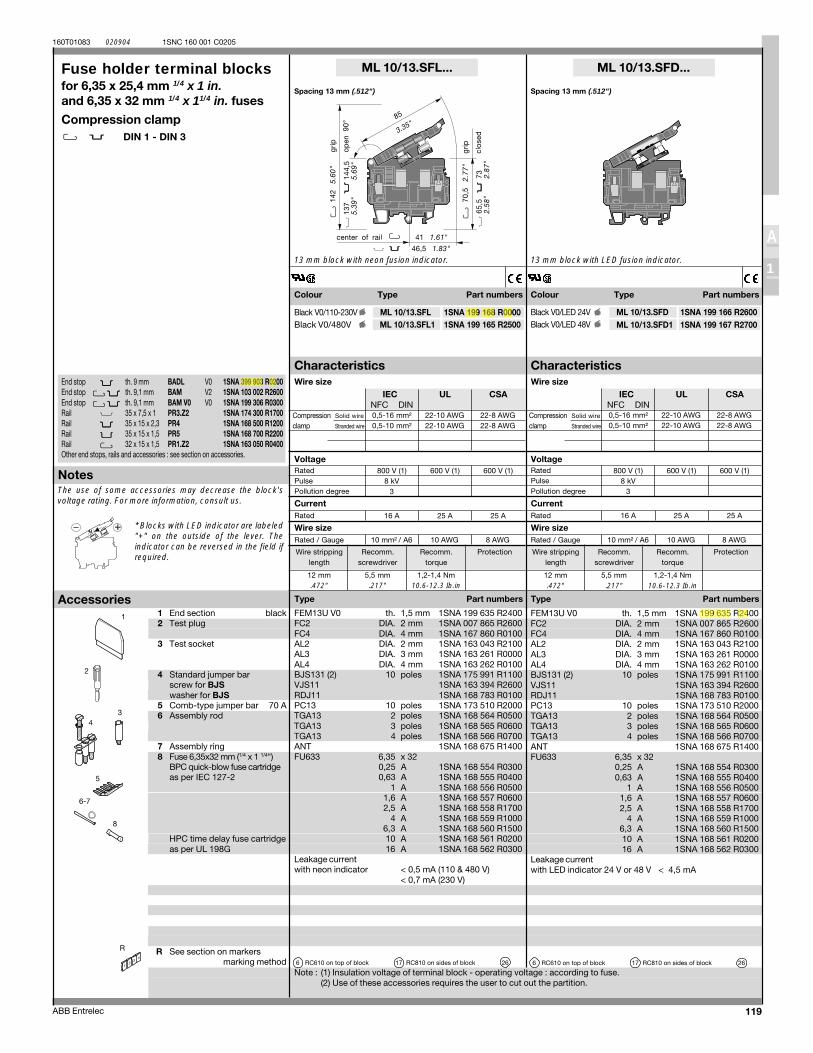
119
160T01083 020904
ABB Entrelec
A
1
1SNC 160 001 C0205
0,5-16 mm² 22-10 AWG 22-8 AWG0,5-10 mm² 22-10 AWG 22-8 AWG
800 V (1) 600 V (1) 600 V (1)8 kV
3
16 A 25 A 25 A
10 mm² / A6 10 AWG 8 AWG
0,5-16 mm² 22-10 AWG 22-8 AWG0,5-10 mm² 22-10 AWG 22-8 AWG
800 V (1) 600 V (1) 600 V (1)8 kV
3
16 A 25 A 25 A
10 mm² / A6 10 AWG 8 AWG
IEC UL CSANFC DIN
IEC UL CSANFC DIN
ML 10/13.SFL...
12 mm 5,5 mm 1,2-1,4 Nm.472" .217" 10.6-12.3 Ib.in
FEM13U V0 1,5 mm 1SNA 199 635 R2400FC2 2 mm 1SNA 007 865 R2600FC4 4 mm 1SNA 167 860 R0100AL2 2 mm 1SNA 163 043 R2100AL3 3 mm 1SNA 163 261 R0000AL4 4 mm 1SNA 163 262 R0100BJS131 (2) 10 1SNA 175 991 R1100VJS11 1SNA 163 394 R2600RDJ11 1SNA 168 783 R0100PC13 10 1SNA 173 510 R2000TGA13 2 1SNA 168 564 R0500TGA13 3 1SNA 168 565 R0600TGA13 4 1SNA 168 566 R0700ANT 1SNA 168 675 R1400FU633 6,35 x 32
0,25 A 1SNA 168 554 R03000,63 A 1SNA 168 555 R0400
1 A 1SNA 168 556 R05001,6 A 1SNA 168 557 R06002,5 A 1SNA 168 558 R1700
4 A 1SNA 168 559 R1000 6,3 A 1SNA 168 560 R1500 10 A 1SNA 168 561 R020016 A 1SNA 168 562 R0300
< 0,5 mA (110 & 480 V)< 0,7 mA (230 V)
6 17 26
ML 10/13.SFD...
ML 10/13.SFD 1SNA 199 166 R2600ML 10/13.SFD1 1SNA 199 167 R2700
12 mm 5,5 mm 1,2-1,4 Nm.472" .217" 10.6-12.3 Ib.in
ML 10/13.SFL 1SNA 199 168 R0000ML 10/13.SFL1 1SNA 199 165 R2500
1 FEM13U V0 1,5 mm 1SNA 199 635 R2400FC2 2 mm 1SNA 007 865 R2600FC4 4 mm 1SNA 167 860 R0100AL2 2 mm 1SNA 163 043 R2100AL3 3 mm 1SNA 163 261 R0000AL4 4 mm 1SNA 163 262 R0100BJS131 (2) 10 1SNA 175 991 R1100VJS11 1SNA 163 394 R2600RDJ11 1SNA 168 783 R0100PC13 10 1SNA 173 510 R2000TGA13 2 1SNA 168 564 R0500TGA13 3 1SNA 168 565 R0600TGA13 4 1SNA 168 566 R0700ANT 1SNA 168 675 R1400FU633 6,35 x 32
0,25 A 1SNA 168 554 R03000,63 A 1SNA 168 555 R0400
1 A 1SNA 168 556 R05001,6 A 1SNA 168 557 R06002,5 A 1SNA 168 558 R1700
4 A 1SNA 168 559 R1000 6,3 A 1SNA 168 560 R1500 10 A 1SNA 168 561 R020016 A 1SNA 168 562 R0300
< 4,5 mA
6 17 26
R
8
6-7
5
43
2
End stop th. 9 mm BADL V0 1SNA 399 903 R0200End stop th. 9,1 mm BAM V2 1SNA 103 002 R2600End stop th. 9,1 mm BAM V0 V0 1SNA 199 306 R0300Rail 35 x 7,5 x 1 PR3.Z2 1SNA 174 300 R1700Rail 35 x 15 x 2,3 PR4 1SNA 168 500 R1200Rail 35 x 15 x 1,5 PR5 1SNA 168 700 R2200Rail 32 x 15 x 1,5 PR1.Z2 1SNA 163 050 R0400Other end stops, rails and accessories : see section on accessories.
Colour Type Part numbers Colour Type Part numbers
Fuse holder terminal blocksfor 6,35 x 25,4 mm 1/4 x 1 in.and 6,35 x 32 mm 1/4 x 11/4 in. fuses
Compression clampDIN 1 - DIN 3
1 End section black2 Test plug
3 Test socket
4 Standard jumper barscrew for BJSwasher for BJS
5 Comb-type jumper bar 70 A6 Assembly rod
7 Assembly ring8 Fuse 6,35x32 mm (1/4 x 1 1/4")
BPC quick-blow fuse cartridgeas per IEC 127-2
HPC time delay fuse cartridgeas per UL 198G
R See section on markersmarking method
13 mm block with neon fusion indicator.
Spacing 13 mm (.512") Spacing 13 mm (.512")
13 mm block with LED fusion indicator.
* Blocks with LED indicator are labeled"+" on the outside of the lever. Theindicator can be reversed in the field ifrequired.
th.DIA.DIA.DIA.DIA.DIA.
poles
polespolespolespoles
Leakage currentwith neon indicator
RC610 on top of block RC810 on sides of block
Black V0/LED 24VBlack V0/LED 48V
Black V0/110-230VBlack V0/480V
th.DIA.DIA.DIA.DIA.DIA.
poles
polespolespolespoles
Leakage currentwith LED indicator 24 V or 48 V
RC610 on top of block RC810 on sides of block
Note : (1) Insulation voltage of terminal block - operating voltage : according to fuse.(2) Use of these accessories requires the user to cut out the partition.
Characteristics Characteristics
Type Part numbers
Rated
Rated / Gauge
Wire size
Current
Wire size
Notes
Type Part numbers
Rated
Rated / Gauge
Wire size
Current
Wire size
Accessories
Wire stripping Recomm. Recomm. Protectionlength screwdriver torque
Wire stripping Recomm. Recomm. Protectionlength screwdriver torque
Compression Solid wire
clamp Stranded wire
RatedPulsePollution degree
VoltageRatedPulsePollution degree
Compression Solid wire
clamp Stranded wire
Voltage
The use of some accessories may decrease the block'svoltage rating. For more information, consult us.
jsalber
Highlight
jsalber
Highlight
jsalber
Highlight
jsalber
Highlight
jsalber
Highlight
jsalber
Highlight
jsalber
Highlight
jsalber
Highlight

10
Residential Self-Test GFCI Receptacles
Commercial Self-Test GFCI Receptacles
CATALOG NO. DESCRIPTIONRATINGS
COLORS NEMA Config.A. V.
1597TR* TradeMaster®/Spec Grade Tamper-Resistant 15 Amp Duplex GFCI 15 125 I, W, —, BK, LA, NI,
AB, DB 5-15R
1597* TradeMaster®/Spec Grade 15 Amp Duplex GFCI 15 125 I, W, —, GRY, BK, RED, LA 5-15R
1597TRA* TradeMaster® Audible Alarm Tamper-Resistant Duplex GFCI 15 125 I, W, —, BK, LA 5-15R
1597SWTTR*CC4 Combination Tamper-Resistant Single-Pole Switch/GFCI (No Federal Specification) 15 125 I, W, BK, LA 5-15R
1597NTLTR*CC4 Combination Tamper-Resistant 15 Amp Night Light/GFCI 15 125 I, W, BK, LA, NI,
AB, DB 5-15R
1597TRWR* TradeMaster®/Spec Grade Weather-Resistant 15 Amp Duplex GFCI 15 125 I, W, —, GRY, BK, LA 5-15R
1597TRR* RoHS-Compliant TradeMaster®/Spec Grade Tamper-Resistant 15 Amp Duplex GFCI 15 125 I, W, LA 5-15R
CATALOG NO. DESCRIPTIONRATINGS
COLORS NEMA Config.A. V.
2097TR* Spec Grade Tamper-Resistant 20 Amp Duplex GFCI 20 125 I, W, —, GRY, BK, RED, LA 5-20R
2097* Spec Grade 20 Amp Duplex GFCI 20 125 I, W, —, GRY, BK, RED, LA 5-20R
1597HGTR*Hospital Grade Tamper-Resistant Duplex GFCI
15 125 I, W, —, GRY, BK, RED, LA
5-15R
2097HGTR* 20 125 5-20R
1597HG*
Hospital Grade Duplex GFCI
15 125I, W, GRY, BK, RED,
LA5-15R
2097HG* 20 125I, W, —, GRY, BK,
RED, LA5-20R
1597IGTR*Spec Grade Isolated Ground Tamper-Resistant Duplex GFCI
15 125 I, W, LA, O 5-15R
2097IGTR* 20 125 I, W, GRY, BK, LA, O 5-20R
1597IGHGTR*Hospital Grade Isolated Ground Tamper-Resistant Duplex GFCI
15 125 O 5-15R
2097IGHGTR* 20 125I, W, GRY, RED,
LA, O5-20R
2097NTLTR* Combination Tamper-Resistant 20 Amp Night Light/GFCI 20 125 I, W, GRY, LA 5-20R
1597HGNTLTR*Hospital Grade Combination Tamper-Resistant Night Light/GFCI
15 125 I, W, —, RED 5-15R
2097HGNTLTR* 20 125 I, W, GRY, RED, LA 5-20R
2097TRWR* Spec Grade Weather-Resistant 20 Amp Duplex GFCI 20 125 I, W, —, GRY, BK, LA 5-20R
*COLOR DESIGNATION
I IvoryW White
GRY GrayBK Black
RED RedLA Light AlmondNI Nickel— Brown
AB Antique BrassDB Dark Bronze
O Orange
Third-Party Compliance: cULus Listed, File Number E42190, Standard UL498, Federal Specification WC596
Third-Party Compliance: cULus Listed, File Number E42190, Standard UL498, Federal Specification WC596
bberndt
Highlight
bberndt
Highlight

Providing users with easy installation in mechanical fan and pump systems, the Allen-Bradley PowerFlex® 400 AC drive offers a wide range of built-in features allowing for seamless buildingsystem integration. Available in power ratings of 7.5-100 HP @ 380 – 480V AC and 7.5-50 HP @ 200 – 240V AC, the PowerFlex 400 is designed to meet global OEM, contractor andend-user demands for flexibility, space savings and ease-of-use.The PowerFlex 400 is a cost-effective solution for speed control in variable torque fan and pump applications.
Features• Integral PID Controller allows a process variable to be
maintained by automatically adjusting the output frequency• Three programmable Skip Frequencies and Bands prevent
the drive from running continuously at resonant speeds which could cause mechanical breakdowns
• Selectable Fan/Pump Curves provide reduced voltage patterns for centrifugal fan and pump loads
• Sleep Function allows the drive to be cycled off when the system demand drops below a preset level and to be restarted automatically when the demand increases
• For applications that require unattended operation, the Start At PowerUp Function provides the ability to resume running once power is restored after a power outage
• Connection to fire and life safety systems via Freeze/Fire and Purge inputs
Operator Keypad:• Integral keypad features 2 line,
16 character LCD display• 5 LED indicators provide system
configuration and fault status• Configurable Hand/Off/Auto
function buttons
Communications:• RS485 communications integral to base drive• Embedded Modbus RTU and Johnson Metasys N2 protocols
are parameter selectable and require no additional hardware or software
• Supports Drive Serial Interface (DSI) communication modules and accessories
• DriveExplorer™ and DriveTools™ SP software can be used to easily program, monitor and control the drives
Packaging:• Installation flexibility is enhanced by the UL plenum
rating allowing for direct mounting in an airhandling system
• Disconnect and contactor bypass packages simplify installation and startup by combining operator interface, control, communications and poweroptions in preconfigured assemblies
• Contactor bypass packages supplied with 3 - contactors allowing drive test functionality and drive isolation when in bypass mode
AC Drive Optimized for Commercial Fan and Pump Applications
PowerFlex 400

Standards • UL and cUL (CSA) Listed • CE Marked• UL Plenum Rating • EMC EN61800-3 (with external filter)• C-Tick • Low Voltage EN60204-1/EN50178
Input Specification 3-Phase Voltage: 200-240 / 380-480V +/-10%Frequency: 48-63 HzLogic Control Ride Through: >= 0.5 seconds, 2 seconds typical
Output Specification Voltage: Adjustable from 0V to rated motor voltageFrequency Range: 0 to 320 HzOverload Current: 110% for 60 seconds
Enclosure and Ambient • Frame COperating Temperature IP20 / NEMA Type Open: -10 to 50°C (14 to 122°F)
IP30 / NEMA1 / UL Type 1 (with conversion kit): -10 to 45°C (14 to 113°F)• Frame D and E
IP30 / NEMA1 / UL Type 1: -10 to 45°C (14 to 113°F)Control • 7 Digital Inputs (24V sink/source) • 2 Analog Inputs – 1 Isolated (-10 to 10V or 4 to 20mA)
– 3 Semi-Programmable – 1 Non-Isolated (0 to 10V or 4 to 20mA)– 4 Programmable • 2 Analog Outputs (0 to 10V or 4 to 20mA)
• 2 Programmable Form C Relay Outputs • 1 Optocoupler OutputOptions (Accessories) • Communication: DeviceNet™, EtherNet/IP™ and PROFIBUS™ Communication Cards •DSI Cables
• EMC Line Filters •IP30 Conversion/ • Line and Load Reactors Conduit Kit (Frame C)
Ratings Voltage Class kW (HP) Cont. Output Current (Amps) Frame200-240V 5.5 (7.5) 24 C200-240V 7.5 (10) 33 C200-240V 11 (15) 49 D200-240V 15 (20) 65 D200-240V 18.5 (25) 75 D200-240V 22 (30) 90 D200-240V 30 (40) 120 E200-240V 37 (50) 145 E380-480V 5.5 (7.5) 12 C380-480V 7.5 (10) 17 C380-480V 11 (15) 22 C380-480V 15 (20) 30 C380-480V 18.5 (25) 38 D380-480V 22 (30) 45.5 D380-480V 30 (40) 60 D380-480V 37 (50) 72 E380-480V 45 (60) 88 E380-480V 55 (75) 105 E380-480V 75 (100) 142 E
Dimensions mm (in) C Frame: 260 (10.2) H x 130 (5.1) W x 180 (7.1) DD Frame: 384 (15.12) H x 250 (9.84) W x 205.4 (8.08) DE Frame: 589 (23.19) H x 370 (14.57) W x 260 (10.24) D
www.rockwellautomation.com
Corporate HeadquartersRockwell Automation, 777 East Wisconsin Avenue, Suite 1400, Milwaukee, WI, 53202-5302 USA, Tel: (1) 414.212.5200, Fax: (1) 414.212.5201
Headquarters for Allen-Bradley Products, Rockwell Software Products and Global Manufacturing SolutionsAmericas: Rockwell Automation, 1201 South Second Street, Milwaukee, WI 53204-2496 USA, Tel: (1) 414.382.2000, Fax: (1) 414.382.4444Europe: Rockwell Automation SA/NV, Vorstlaan/Boulevard du Souverain 36-BP 3A/B, 1170 Brussels, Belgium, Tel: (32) 2 663 0600, Fax: (32) 2 663 0640Asia Pacific: Rockwell Automation, 27/F Citicorp Centre, 18 Whitfield Road, Causeway Bay, Hong Kong, Tel: (852) 2887 4788, Fax: (852) 2508 1846
Headquarters for Dodge and Reliance Electric ProductsAmericas: Rockwell Automation, 6040 Ponders Court, Greenville, SC 29615-4617 USA, Tel: (1) 864.297.4800, Fax: (1) 864.281.2433Europe: Rockwell Automation, Brühlstraße 22, D-74834 Elztal-Dallau, Germany, Tel: (49) 6261 9410, Fax: (49) 6261 1774Asia Pacific: Rockwell Automation, 55 Newton Road, #11-01/02 Revenue House, Singapore 307987, Tel: (65) 351 6723, Fax: (65) 355 1733
Publication 22C-PP001B-EN-P — April, 2004 Copyright ©2004 Rockwell Automation. All Rights Reserved. Printed in U.S.A.
PowerFlex, DriveExplorer and DriveTools SP are registered trademarks of Rockwell Automation. DeviceNet and EtherNet/IP are registered trademarks of ODVA.PROFIBUS is a registered trademark of the PROFIBUS Trade Organization.
Specifications

P-4 Overview
Catalog Number Explanation
Code Voltage Ph.B 240V AC 3D 480V AC 3
Code Version3 RS485
Code Interface Module1 Fixed Keypad
Code EnclosureN IP20/UL Open-Type(1)
A IP30/NEMA 1/UL Type 1(2)
1-3 4 5 6-8 9 10 11 12
22C - D 038 A 1 0 3Drive Dash Voltage Rating Rating Enclosure HIM Emission Class Comm Slot
Output Current @ 200-240V 60Hz InputCode Amps kW (HP) Frame024 24 5.5 (7.5) C033 33 7.5 (10) C049 49 11 (15) D065 65 15 (20) D075 75 18.5 (25) D090 90 22 (30) D120 120 30 (40) E145 145 37 (50) E
Code Rating0 Not Filtered
Output Current @ 380-480V InputCode Amps kW (HP) Frame012 12 5.5 (7.5) C017 17 7.5 (10) C022 22 11 (15) C030 30 15 (20) C038 38 18.5 (25) D045 45.5 22 (30) D060 60 30 (40) D072 72 37 (50) E088 88 45 (60) E105 105 55 (75) E142 142 75 (100) E
Code22C PowerFlex 400
(1) Frame C drives only available with IP20/UL Open-Type enclosure. Field installed conversion kit available to achieve IP30/NEMA 1/UL Type 1 rating.
(2) Frame D and E drives only available with IP30/NEMA 1/UL Type 1 enclosure.
Additional accessories, options and adapters are available. See Appendix B for details.
alawler
Highlight
alawler
Highlight
alawler
Highlight
alawler
Highlight
alawler
Highlight
jsalber
Highlight
mphillips
Highlight
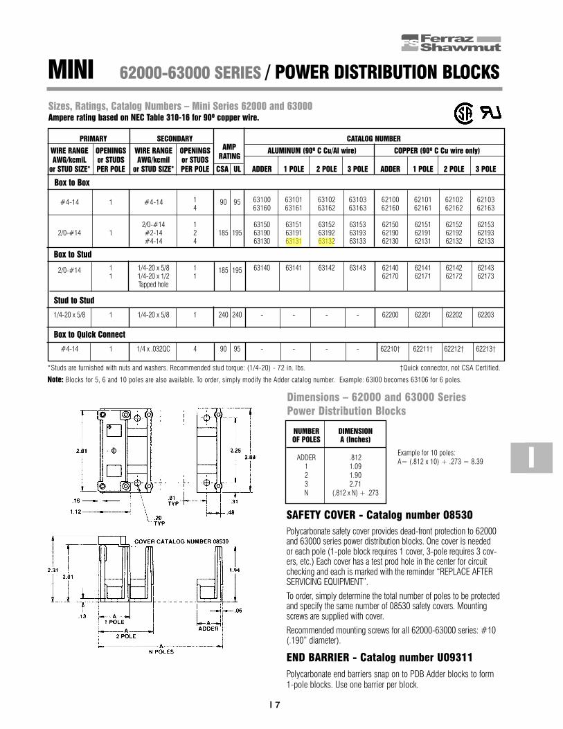
MINI 62000-63000 SERIES / POWER DISTRIBUTION BLOCKS
I 7
PRIMARY SECONDARY CATALOG NUMBER
WIRE RANGE OPENINGS WIRE RANGE OPENINGS AMP ALUMINUM (90º C Cu/Al wire) COPPER (90º C Cu wire only)AWG/kcmiL or STUDS AWG/kcmil or STUDS RATING
or STUD SIZE* PER POLE or STUD SIZE* PER POLE CSA UL ADDER 1 POLE 2 POLE 3 POLE ADDER 1 POLE 2 POLE 3 POLE
Box to Box
#4-14 1 #4-14 1 90 95 63100 63101 63102 63103 62100 62101 62102 621034 63160 63161 63162 63163 62160 62161 62162 62163
2/0-#14 1 63150 63151 63152 63153 62150 62151 62152 621532/0-#14 1 #2-14 2 185 195 63190 63191 63192 63193 62190 62191 62192 62193
#4-14 4 63130 63131 63132 63133 62130 62131 62132 62133
Box to Stud
2/0-#14 1 1/4-20 x 5/8 1 185 195 63140 63141 63142 63143 62140 62141 62142 621431 1/4-20 x 1/2 1 62170 62171 62172 62173
Tapped hole
Stud to Stud
1/4-20 x 5/8 1 1/4-20 x 5/8 1 240 240 - - - - 62200 62201 62202 62203
Box to Quick Connect
#4-14 1 1/4 x .032QC 4 90 95 - - - - 62210† 62211† 62212† 62213†
Sizes, Ratings, Catalog Numbers – Mini Series 62000 and 63000Ampere rating based on NEC Table 310-16 for 90º copper wire.
*Studs are furnished with nuts and washers. Recommended stud torque: (1/4-20) - 72 in. lbs. †Quick connector, not CSA Certified.
Note: Blocks for 5, 6 and 10 poles are also available. To order, simply modify the Adder catalog number. Example: 63l00 becomes 63106 for 6 poles.
SAFETY COVER - Catalog number 08530Polycarbonate safety cover provides dead-front protection to 62000and 63000 series power distribution blocks. One cover is needed or each pole (1-pole block requires 1 cover, 3-pole requires 3 cov-ers, etc.) Each cover has a test prod hole in the center for circuitchecking and each is marked with the reminder “REPLACE AFTERSERVICING EQUIPMENT”.
To order, simply determine the total number of poles to be protectedand specify the same number of 08530 safety covers. Mountingscrews are supplied with cover.
Recommended mounting screws for all 62000-63000 series: #10(.190” diameter).
END BARRIER - Catalog number U09311Polycarbonate end barriers snap on to PDB Adder blocks to form1-pole blocks. Use one barrier per block.
NUMBER DIMENSION OF POLES A (Inches)
ADDER .8121 1.092 1.903 2.71N (.812 x N) + .273
Example for 10 poles:A= (.812 x 10) + .273 = 8.39
Dimensions – 62000 and 63000 SeriesPower Distribution Blocks
I
alawler
Highlight
dripplinger
Highlight

Model 722
90
Electromechanical Totally Sealed Hour Meter
722-0001 2-Hole Rectangular, 90-264VAC 50/60Hz, ¼” [6.3mm] spade terminals, hours & 1/10’s722-0002 Flush-Rectangular, 90-264VAC 50/60Hz, ¼” [6.3mm] spade terminals, hours & 1/10’s722-0003 Flush-Round, 90-264VAC 50/60Hz, ¼” [6.3mm] spade terminals, hours & 1/10’s722-0004 3-Hole Round, 90-264VAC 50/60Hz, ¼” [6.3mm] spade terminals, hours & 1/10’s
5003-009 NEMA 4X, 12 Gasket for Model 722-00025003-010 NEMA 4X, 12 Gasket for Model 722-00015003-011 NEMA 4X, 12 Gasket for Model 722-00045003-008 NEMA 4X, 12 Gasket for Model 722-0003
* All items are normally in factory stock
Models Description
Specifications
Features Options
DescriptionThe Redington Model 722 provides an AC Hour Meter with an operating range of 90-264VAC 50/60 Hz. You no longer require two separate meters, one for 115VAC and one for 230VAC. Models are available in the standard industry housings, 2-Hole Rectangular, Flush-Rectangular, Flush-Round and 3-Hole Round. Its quartz time base insures accurate long-term time keeping. The Totally Sealed case protects against the environment and provides years of reliable service. All models are NEMA 4X,12 rated when mounted with optional gasket.
• Operating voltage 90-264VAC 50/60Hz• Totally Sealed• UL/cUL Recognized, CE & RoHS Compliant• 6 Figure, 99999.9• Quartz accuracy
• Wire leads• Gasket kit (for NEMA 4X, 12 rating)• Custom lens• Terminals up, down, straight
Figures: 6 - digits, 0.14” [3.6mm] 99999.9 Hours and idicator - white on black Decimal - black on whiteReset: Non-resetVoltage: 90-264VACFrequency: 50/60HzPower: 1 watt max.Mounting: Clip or mounting holesTermination: ¼” [6.3mm] spade terminalsWeight: ~2 oz [57 g]Accuracy: ± 0.02% over entire range
Case Material: Black polymerLens Material: PolymerAgency Approvals: UL/cUL Recognized, CE & RoHS Compliant, SAE & NEMA 4X, 12 CompliantEnvironmental: Totally Sealed Front Panel: NEMA 4X, 12 rated with optional gasket Temperature: -40°F to +185°F [-40°C to + 85°C] Humidity: 95% (SAE J1378) Vibration: 10-80 Hz. 20g max. (SAE J1378) Shock: 55g @ 9 - 13msec (SAE J1378)
bberndt
Highlight

91
Model 722 Electromechanical Totally Sealed Hour Meter
Applications
.7 [18]
1.89 [48.0]MAX
.10 [2.5]
.93 [23.5]
1.43 [36.3]
2.19 [55.6]MAX
1.60 [40.6]
1.08 [27.4]
.88 [22.4]
25°REF
1/10
Dimensions
.7 [18]
1.89 [48.0]MAX
.10 [2.5]
.93 [23.5]
1.43 [36.3]
2.19 [55.6]MAX
1.47 [37.4]
1.03 [26.2]
.88 [22.4]
.15 [3.8]1.75 [44.5]
2.05 [52.1]
2X Ø.15 [Ø3.8]
25°REF
1/10
Medical Equipment Test Equipment Office Equipment
.7 [18]
1.87 [47.5]MAX
.10 [2.5].21 [5.3]
.93 [23.5]
1.43 [36.3]
2.17 [55.1]MAX
Ø2.24 [Ø56.9]
Ø1.95 [Ø49.4]
Ø1.82 [Ø46.2]
FOAMGASKET
Ø1.98 [Ø50.3]
25°REF
1/10
Panel Opening: 2.0” [50.6]Panel Thickness: 0.40 [10.2] Max.
Panel Opening: 2.0” [50.6]
Panel Opening: 1.45” X 0.95” [36.8 X 24.1] Panel Opening: 1.45” X 0.95” [36.8 X 24.1]Panel Thickness: 0.03 to 0.63 [0.76 to 16.00]
.70 [17.8]
1.87 [47.5]MAX
.09 [2.3].21 [5.3]
Ø1.98 [Ø50.3]
.93 [23.5]
1.43 [36.3]
2.17 [55.1]MAX
Ø.16 [Ø4.0]
Ø.13 [Ø3.2]
Ø2.53 [Ø64.3]
Ø2.42 [Ø61.5]
Ø2.80 [Ø71.1]
25°REF
1/10
2-Hole
3-Hole RoundFlush-Round
Flush-Rectangular
Control Panels Generators

24 © 2003-2006 Schneider Electric All Rights Reserved
References (continued) Control and signalling units Ø 30 0
Harmony® Style 9Contact blocks, light modules, and lamps
9001 Contacts and Light ModulesContact Blocks
Standard N/O N/C C/O ReferencePositive opening — — 1 9001KA1— 1 — — 9001KA2Positive opening — 1 — 9001KA3Late break — — 1 9001KA4Late break — 1 — 9001KA5Early make 1 — — 9001KA6
Logic Reed Hermetically sealed— — 1 9001KA411 — — 9001KA42— 1 — 9001KA432 — — 9001KA45
Power Reed Hermetically sealed— — 1 9001KA511 — — 9001KA52— 1 — 9001KA53
Alternate Action Module - Contact blocks mounted behind 9001K85 exhibit push on - push off actionReference
NOTE: N/O circuits require KA4 or KA6 blocks
— — — — 9001K85
Light ModulesResistor Type Lamp Supply Voltage Color Reference
Incandescent BA9s 12-14 Vac-dc — 9001KM3224 Vac-dc — 9001KM35120 Vac-dc — 9001KM38230 Vac-dc — 9001KM25
Super Bright LED BA9s 24 Vac-dc — —120 Vac-dc Green 9001KM38LG120 Vac-dc Red 9001KM38LR230 Vac-dc — —
TransformerIncandescent BA9s 120 Vac — 9001KM1
230 Vac — 9001KM7380-480 Vac-dc — 9001KM5
Shallow Depth - resistorIncandescent BA9s 24-28 Vac-dc — 9001KM55
110-120 Vac-dc — 9001KM58LED BA9s 24 Vac-dc Red 9001KM55LR
24 Vac-dc Green 9001KM55LG24 Vac-dc Yellow 9001KM55LY120 Vac-dc Red 9001KM58LR120 Vac-dc Green 9001KM58LG120 Vac-dc Yellow 9001KM58LY
Other AccessoriesDescription Application Diameter Color • Sold in lots of ReferenceSuper Bright LED Bulbs
24 V 9001•••35L•or
48 V 9001•••36L•or
120 V 9001•••38L•
Red 1 6508805210Green 1 6508805212Amber 1 6508805211Blue 1 6508805213White 1 6508805214
LED Bulbs120 V 9001•••1L•
or380 V 9001•••S•
or230 V 9001•••7•
Red 1 6508805201Yellow 1 6508805202Green 1 6508805203
Incandescent BulbsResistor Light Modules 12 V - code 32 1 2550101037
24 V - code 35 1 2550101002 48 V - code 36 1 2550101025120 V - code 38 1 2550101027
Transformer Light Modules 120 V - code 1 1 2550101020230 V - code 7 1 2550101020380 V - code 6 1 2550101020600 V - code 6 1 2550101020
821
136
821
135
jsalber
Highlight
dripplinger
Highlight
dripplinger
Highlight

www.schneider-electric.us
19P
US
H B
UT
TO
NS
AN
D
OP
ER
AT
OR
INT
ER
FA
CE
© 2009 Schneider ElectricAll Rights Reserved
19-79
30 mm Push Buttons Type SK Corrosion Resistant Pilot LightsClass 9001 / Refer to Catalog 9001CT0001
a Add the voltage assembly code as chosen from Table 19.228 or Table 19.229 on page 19-82.EXAMPLE: SKTqR31 with 208 Vac red LED voltage = SKT37LRR31.
b Add the color code as chosen from the color cap table below.EXAMPLE: SKP1c with a blue fresnel cap = SKP1L31.
c The cap must be the same color as the LED light module chosen, e.g., for a green LED, use a green color cap.d On neon light modules, use clear color caps only.e Use only full voltage or resistor voltage assembly codes on remote test pilot lights. Do not choose LED, neon or transformer codes. For AC use only.
NOTE: When ordering, add prefix 9001 to the catalog number. To select and order contact blocks, light modules, and accessories, see pages 19-81through 19-88.
Table 19.220: Pilot Lights—UL Types 4, 4X, 13/NEMA 4, 4X, 13For use in hazardous locations—See page 19-83. Legend plate not included.
Description Voltage StyleWith Red
Fresnel Color Cap
With Green Fresnel Color
Cap
With Other Color Cap $ Price Without
Color Cap $ Price
9001SKP1
StandardPilot Light
(Fresnel color cap shown)
110–120 V, 50–60 Hz Transformer SKP1R31 SKP1G31 SKP1b 153. SKP1 143.
220–240 V, 50–60 Hz Transformer SKP7R31 SKP7G31 SKP7b 153. SKP7 143.
24–28 Vac/Vdc Full Voltage SKP35R31 SKP35G31 SKP35b 125. SKP35 116.
For other voltagessee Table a
Transformer, Flashing or LEDc SKPaR31 SKPaG31 SKPab 125. SKPa 116.
Full Voltage, Neon or Resistord SKPaR31 SKPaG31 SKPab 125. SKPa 116.
9001SKT1
Push-To-TestPilot Light
(Fresnel color cap shown)
110–120 V, 50–60 Hz Transformer SKT1R31 SKT1G31 SKT1b 197. SKT1 185.
220–240 V, 50–60 Hz Transformer SKT7R31 SKT7G31 SKT7b 197. SKT7 185.
24–28 Vac/Vdc Full Voltage SKT35R31 SKT35G31 SKT35b 167. SKT35 158.
For other voltagessee Table a
Transformer, Flashing or LEDc SKTaR31 SKTaG31 SKTab 197. SKTa 158.
Full Voltage, Neon or Resistord SKTaR31 SKTaG31 SKTab 197. SKTa 158.
9001SKTR38
Remote TestPilot Light
(Fresnel color cap shown)
120 Vac Only Resistor SKTR38R31 SKTR38G31 SKTR38b 197. SKTR38 185.
24–28 Vac Only Full Voltage SKTR35R31 SKTR35G31 SKTR35b 197. SKTR35 185.
For other voltagessee Tables abe
Full Voltage or Resistor e
SKTRaR31 SKTRaG31 SKTRab 197. SKTRa 185.
Table 19.221: Color Caps
Color
b Plastic Fresnel b Plastic Domed
AmberBlueClearGreenRed
WhiteYellow
A31L31C31G31R31W31Y31
A9L9C9G9R9W9Y9
R
M
M O.L.
L2
321
L1
STOPSTART
L2
C
Test
L1
M
Push-To-Test Pilot Light
Typical Wiring Diagram
STOP
LSI
M3
(TEST) C
(TEST) C L2
L2
L1(SIG)
CR
M2
M1
L2(TEST) C
START
TEST BUTTONL1 L2
L1(SIG)
L1(SIG)
Remote Test Pilot Light
CP1 Discount Schedule
bberndt
Highlight
bberndt
Highlight
bberndt
Highlight
dripplinger
Highlight
dripplinger
Highlight

www.schneider-electric.us
19-82 © 2009 Schneider ElectricAll Rights Reserved
19P
US
H B
UT
TO
NS
AN
D
OP
ER
AT
OR
INT
ER
FA
CE
30 mm Push Buttons Type K, SK and KX Electrical ComponentsClass 9001 / Refer to Catalog 9001CT0001
For use in hazardous locations—See page 19-83.• With neon type light modules, use a clear color cap only.• With LED light modules, use either a clear color cap or a cap the same color as the LED.
a Not for use on KX operators.b For use with all operators except KX and remote test pilot.
NOTE: Light modules are available in other voltages. For additional information, refer to Catalog 9001CT0001.
For use in hazardous locations—See page 19-83. • Reduces the depth of illuminated push buttons with contact blocks by over 33%.• With LED light modules, use a cap that is the same color as the LED.
c For use with all operators except KX and remote test pilot.
NOTE: When ordering, add prefix 9001 to the catalog number.
Table 19.228: Standard Light Modules for Types K, SK, and KX Control Units b
Voltage DescriptionLight Module Voltage
Assembly Code
RatingReplacement Lamp
Type $ Price Part Number b $ Price
All Full Voltage (without Bayonet Base Lamp) KM40 78.00 40 — None —
6 Vac/Vdc Full Voltage KM31 86.00 31 .9 VA 2550101020 12.456 Vac/Vdc LED Red KM31LR 116.00 31LR 6508805201 42.756 Vac/Vdc LED Green KM31LG 116.00 31LG 6508805203 42.756 Vac/Vdc LED Yellow KM31LY 116.00 31LY 6508805202 28.5012–14 Vac/Vdc Full Voltage KM32 86.00 32 1.2 VA 2550101037 12.4512–14 Vac/Vdc LED Red KM32LR 116.00 32LR 6508805201 42.7512–14 Vac/Vdc LED Green KM32LG 116.00 32LG 6508805203 42.7512–14 Vac/Vdc LED Yellow KM32LY 116.00 32LY 6508805202 28.5018 Vac/Vdc Resistor KM33 86.00 33 1.4 VA 2550101037 12.4524–28 Vac/Vdc Full Voltage KM35 86.00 35 1.2 VA 2550101002 12.4524–28 Vac/Vdc LED Red KM35LR 116.00 35LR .28 VA 6508805210 42.7524–28 Vac/Vdc LED Green KM35LG 116.00 35LG .28 VA 6508805212 42.7524–28 Vac/Vdc LED Yellow KM35LY 116.00 35LY .28 VA 6508805211 42.7524–28 Vac/Vdc LED White KM35LW 116.00 35LW .28 VA 6508805214 42.7524–28 Vac/Vdc LED Blue KM35LL 116.00 35LL .28 VA 6508805213 42.7548 Vac/Vdc Full Voltage KM36 86.00 36 2.6 VA 2550101025 12.45110–120 V, 50–60 Hz LED Red KM1LR 143.00 1LR 6508805201 42.75110–120 V, 50–60 Hz LED Green KM1LG 143.00 1LG 6508805203 42.75110–120 V, 50–60 Hz LED Yellow KM1LY 143.00 1LY 6508805202 42.75110–120 V, 50–60 Hz Transformer KM1 116.00 1 2.4 VA 2550101020 12.45110–120 V, 50–60 Hz Flashing KMF1 116.00 F1 .85 VA 2550101036 16.50120 Vac/Vdc Resistor KM38 86.00 38 3.0 VA 2550101027 12.45120 Vac/Vdc Full Voltage KM38 86.00 38 3.0 VA 2550101027 12.45120 Vac/Vdc Neon a KM11 86.00 11 0.2 VA 2550101013 32.85120 Vac/Vdc LED Red KM38LR 116.00 38LR 1.4 VA 6508805210 42.75120 Vac/Vdc LED Green KM38LG 116.00 38LG 1.4 VA 6508805212 42.75120 Vac/Vdc LED Yellow KM38LY 116.00 38LY 1.4 VA 6508805211 42.75120 Vac/Vdc LED White KM38LW 116.00 38LW 1.4 VA 6508805214 42.75120 Vac/Vdc LED Blue KM38LL 116.00 38LL 1.4 VA 6508805213 42.75208–220 V, 50–60 Hz Transformer KM3 116.00 3 2.5 VA 2550101020 12.45208–220 V, 50–60 Hz LED Red KM3LR 143.00 3LR 6508805201 42.75208–220 V, 50–60 Hz LED Green KM3LG 143.00 3LG 6508805203 42.75208–220 V, 50–60 Hz LED Yellow KM3LY 143.00 3LY 6508805202 42.75220–240 V, 50–60 Hz Transformer KM7 116.00 7 2.0 VA 2550101020 12.45220–240 V, 50–60 Hz LED Red KM7LR 143.00 7LR 6508805201 42.75220–240 V, 50–60 Hz LED Green KM7LG 143.00 7LG 6508805203 42.75220–240 V, 50–60 Hz LED Yellow KM7LY 143.00 7LY 6508805202 42.75240 Vac/Vdc Resistor KM25 86.00 25 6.0 VA 2550101027 12.45240 Vac/Vdc Neon a KM12 86.00 12 0.3 VA 2550101013 32.85277 V, 50–60 Hz Transformer KM8 116.00 8 2.4 VA 2550101020 12.45380–480 V, 50–60 Hz Transformer KM5 116.00 5 2.8 VA 2550101020 12.45480 Vac/Vdc Neon a KM14 86.00 14 0.5 VA 2550101013 32.85550–600 V, 50–60 Hz Transformer KM6 116.00 6 2.5 VA 2550101020 12.45
Table 19.229: Shallow Depth Light Modules For Types K and SK Control Units c
Voltage DescriptionLight Module Voltage Assembly
Code RatingReplacement Lamp
Type $ Price Part Number $ Price
24–28 Vac/Vdc
Full Voltage KM55 86.00 55 1.2 VA 2550101002 12.45LED Red KM55LR
116.0055LR
0.5 VA6508805204
42.75LED Green KM55LG 55LG 6508805206LED Yellow KM55LY 55LY 6508805205
110–120 Vac/Vdc
Full Voltage KM58 86.00 58 3.0 VA 2550101027 12.45LED Red KM58LR
116.0058LR
0.5 VA6508805204
42.75LED Green KM58LG 58LG 6508805206LED Yellow KM58LY 58LY 6508805205
FileCCN
E42259NKCR
FileClass
LR254903211 03 marked
CP10 CP1 Discount Schedule
bberndt
Highlight
dripplinger
Highlight
dripplinger
Highlight

www.schneider-electric.us
19P
US
H B
UT
TO
NS
AN
D
OP
ER
AT
OR
INT
ER
FA
CE
© 2009 Schneider ElectricAll Rights Reserved
19-73
30 mm Push Buttons Type SK Corrosion Resistant Non-Illuminated OperatorsClass 9001 / Refer to Catalog 9001CT0001
a The universal push button operators include one each of the following color inserts: black, red, green, yellow, orange, blue and white.b See Table 19.206.c Knob has the words “Emergency Stop” in raised letters highlighted in white for readability.d See Table 19.206.e These operators can be ordered complete with contact blocks. For maximum block usage, see page 19-84. Add the “H” number chosen from
page 19-84 to the end of the operator type number and add the cost of the “H” number to the operator cost.
NOTE: When ordering, add prefix 9001 to the catalog number. To select and order contact blocks, light modules, and accessories, see pages 19-81 through 19-88.
Table 19.205: Non-Illuminated Momentary Push Button Operators—UL Types 4, 4X, 13/NEMA 4, 4X, 13For use in hazardous locations—See page 19-83.Contact blocks and legend plate not included unless otherwise noted.
Description Color
Operator with 1 N.O. and
1 N.C. Contact (KA1)
$ PriceOperator with 1 N.O. Contact
(KA2)
Operator with 1 N.C. Contact
(KA3)$ Price Operator Only
No Contacts e $ Price
9001SKR1BFull Guard
Black SKR1BH13 89.00 SKR1BH5 SKR1BH6 66.00 SKR1B 38.60
Red SKR1RH13 89.00 SKR1RH5 SKR1RH6 66.00 SKR1R 38.60
Green SKR1GH13 89.00 SKR1GH5 SKR1GH6 66.00 SKR1G 38.60
Universal a SKR1UH13 89.00 SKR1UH5 SKR1UH6 66.00 SKR1U 38.60
Other b SKR1bH13 89.00 SKR1bH5 SKR1bH6 66.00 SKR1b 38.60
9001SKR3BNo Guard
Black SKR3BH13 89.00 SKR3BH5 SKR3BH6 66.00 SKR3B 38.60
Red SKR3RH13 89.00 SKR3RH5 SKR3RH6 66.00 SKR3R 38.60
Green SKR3GH13 89.00 SKR3GH5 SKR3GH6 66.00 SKR3G 38.60
Universal a SKR3UH13 89.00 SKR3UH5 SKR3UH6 66.00 SKR3U 38.60
Other b SKR3bH13 89.00 SKR3bH5 SKR3bH6 66.00 SKR3b 38.60
9001SKR2BExtended Guard
Black SKR2BH13 89.00 SKR2BH5 SKR2BH6 66.00 SKR2B 38.60
Red SKR2RH13 89.00 SKR2RH5 SKR2RH6 66.00 SKR2R 38.60
Green SKR2GH13 89.00 SKR2GH5 SKR2GH6 66.00 SKR2G 38.60
Universal a SKR2UH13 89.00 SKR2UH5 SKR2UH6 66.00 SKR2U 38.60
Other b SKR2b 89.00 SKR2bH5 SKR2bH6 66.00 SKR2b 38.60
9001SKR4B1-3/8 in. (35 mm) Mushroom Button
Snap-In Mushroom Button
Black SKR4BH13 138.00 SKR4BH5 SKR4BH6 112.00 SKR4B 81.00Red SKR4RH13 138.00 SKR4RH5 SKR4RH6 112.00 SKR4R 81.00
Red c SKR4R05H13 142.00 SKR4R05H5 SKR4R05H6 119.00 SKR4R05 86.00Green SKR4GH13 138.00 SKR4GH5 SKR4GH6 112.00 SKR4G 81.00
Other d SKR4dH13 138.00 SKR4dH5 SKR4dH6 112.00 SKR4d 81.00
Screw-On Mushroom Button with Set Screw Security
Black SKR24BH13 138.00 SKR24BH5 SKR24BH6 112.00 SKR24B 81.00Red SKR24RH13 138.00 SKR24RH5 SKR24RH6 112.00 SKR24R 81.00
Green SKR24GH13 138.00 SKR24GH5 SKR24GH6 112.00 SKR24G 81.00Other d SKR24dH13 138.00 SKR24dH5 SKR24dH6 112.00 SKR24d 81.00
9001SKR52-1/4 in. (57 mm) Mushroom Button
Snap-In Mushroom Button
Black SKR5BH13 138.00 SKR5BH5 SKR5BH6 112.00 SKR5B 81.00Red SKR5RH13 138.00 SKR5RH5 SKR5RH6 112.00 SKR5R 81.00
Red c SKR5R05H13 142.00 SKR5R05H5 SKR5R05H6 119.00 SKR5R05 86.00Green SKR5GH13 138.00 SKR5GH5 SKR5GH6 112.00 SKR5G 81.00
Other d SKR5dH13 138.00 SKR5dH5 SKR5dH6 112.00 SKR5d 81.00
Screw-On Mushroom Button with Set Screw Security
Black SKR25BH13 138.00 SKR25BH5 SKR25BH6 112.00 SKR25B 81.00Red SKR25RH13 138.00 SKR25RH5 SKR25RH6 112.00 SKR25R 81.00
Green SKR25GH13 138.00 SKR25GH5 SKR25GH6 112.00 SKR25G 81.00Other d SKR25dH13 138.00 SKR25dH5 SKR25dH6 112.00 SKR25d 81.00
Table 19.206: Color CodesColor b SKR1, 2, 3 Place Color Code in Type Number d SKR4, 5, 24, 25 Place Color Code in Type Number
Blue L LYellow Y YWhite W —
Orange S SGray E —
CP1 Discount Schedule
bberndt
Highlight
bberndt
Highlight

www.schneider-electric.us
19P
US
H B
UT
TO
NS
AN
D
OP
ER
AT
OR
INT
ER
FA
CE
© 2009 Schneider ElectricAll Rights Reserved
19-77
30 mm Push Buttons 9001SK Selector SwitchesClass 9001 / Refer to Catalog 9001CT0001
NOTE: To order, add prefix 9001 to the beginning of the catalog number.
NOTE: To select and order Contact Blocks, Light Modules, Knobs, and Accessories. See pages 19-81 through 19-88.
Table 19.215: 3-Position Selector SwitchesCONTACT BLOCK REQUIRED 1 — Contact Closed 0 — Contact Open
ContactBlock
Position
QuantityandType
Mounton
Side
Center Center Center Center Center Center Center Center Center
KA1or
KA3
KA1#2 or
KA3#2 1 0 0 1 0 0 0 0 1 1 0 0 1 0 0 1 0 0 1 0 0 0 1 0 1 1 0
KA2KA2#2 0 1 1 0 0 1 0 1 0 0 1 0 0 0 1 0 1 1 0 1 1 1 0 0 0 0 1
KA1or
KA3
KA1#1 or
KA3#1 0 0 1 1 0 0 0 0 1 1 0 0 0 1 0 0 0 1 1 0 1 0 0 1 0 1 1
KA2KA2#1 1 1 0 0 0 1 0 1 0 0 1 0 0 0 1 1 0 0 0 1 0 0 1 0 1 0 0
Top View
Side 2Side 1
Operator LocatingNotch
Cam (see page 19-69) B C D E F G J L M
Non-Illuminated Operators Type Type Type Type Type Type Type Type Type $ Price
Manual Return, Operator Only (without contact blocks) a
Without Knob SKS42 SKS43 SKS44 SKS45 SKS46 SKS47 SKS49 SKS401 SKS402 42.80With Knob (select style and color from table 19.168 below) SKS42c SKS43c SKS44c SKS45c SKS46c SKS47c SKS49c SKS401c SKS402c 53.00
Operator with Contact Blocks and Standard black knob d
With 1 KA1 on Side #2 (H13) SKS42BH13 SKS43BH13 SKS44BH13 SKS45BH13 SKS46BH13 SKS47BH13 SKS49BH13 SKS401BH13 SKS402BH13 106.00With 1 KA1 on Side #1 (H1) SKS42BH1 SKS43BH1 SKS44BH1 SKS45BH1 SKS46BH1 SKS47BH1 SKS49BH1 SKS401BH1 SKS402BH1 106.00With 1 KA1 on Side #1 and 1 KA1 on side #2 (H2) SKS42BH2 SKS43BH2 SKS44BH2 SKS45BH2 SSKS46BH2 SKS47BH2 SKS49BH2 SKS401BH2 SKS402BH2 152.00
Spring Return from Left to Center, Operator Only (without contact blocks) a
Without Knob SKS62 SKS63 SKS64 SKS65 SKS66 SKS67 SKS69 SKS601 SKS602 71.00With Knob (select style and color from table 19.168 below) SKS62c SKS63c SKS64c SKS65c SKS66c SKS67c SKS69c SKS601c SKS602c 81.00
Spring Return from Right to Center, Operator Only (without contact blocks) a
Without Knob SKS72 SKS73 SKS74 SKS75 SKS76 SKS77 SKS79 SKS701 SKS702 71.00With Knob (select style and color from table 19.168 below) SKS72c SKS73c SKS74c SKS75c SKS76c SKS77c SKS79c SKS701c SKS702c 81.00
Spring Return from Both Sides to Center, Operator Only (without contact blocks) a
Without Knob SKS52 SKS53 SKS54 SKS55 SKS56 SKS57 SKS59 SKS501 SKS502 71.00With Knob (select style and color from table 19.168 below) SKS52c SKS53c SKS54c SKS55c SKS56c SKS57c SKS59c SKS501c SKS502c 81.00
Illuminated Operators Type Type Type Type Type Type Type Type Type $ Price
Manual Return, Operator Only (without contact blocks) a
Without Knob, 110-120V 50-60 Hz Transformer SK42J1 SK43J1 SK44J1 SK45J1 SK46J1 SK47J1 SK49J1 SK401J1 SK402J1 158.00With Standard Red Knob, 110-120V 50-60 Hz Transformer SK42J1R SK43J1R SK44J1R SK45J1R SK46J1R SK47J1R SK49J1R SK401J1R SK402J1R 167.00With Other Color Knob and other voltage Light Module b c SK42Jbc SK43Jbc SK44Jbc SK45Jbc SK46Jbc SK47Jbc SK49Jbc SK401Jbc SK402Jbc 167.00
Spring Return from Left to Center, Operator Only (without contact blocks) a
Without Knob, 110-120V 50-60 Hz Transformer SK62J1 SK63J1 SK64J1 SK65J1 SK66J1 SK67J1 SK69J1 SK601J1 SK602J1 185.00With Standard Red Knob, 110-120V 50-60 Hz Transformer SK62J1R SK63J1R SK64J1R SK65J1R SK66J1R SK67J1R SK69J1R SK601J1R SK602J1R 197.00With Other Color Knob and other voltage Light Module b c SK62Jbc SK63Jbc SK64Jbc SK65Jbc SK66Jbc SK67Jbc SK69Jbc SK601Jbc SK602Jbc 197.00
Spring Return from Right to Center, Operator Only (without contact blocks) a
Without Knob, 110-120V 50-60 Hz Transformer SK72J1 SK73J1 SK74J1 SK75J1 SK76J1 SK77J1 SK79J1 SK701J1 SK702J1 185.00With Standard Red Knob, 110-120V 50-60 Hz Transformer SK72J1R SK73J1R SK74J1R SK75J1R SK76J1R SK77J1R SK79J1R SK701J1R SK702J1R 197.00With Other Color Knob and other voltage Light Module b c SK72Jbc SK73Jbc SK74Jbc SK75Jbc SK76Jbc SK77Jbc SK79Jbc SK701Jbc SK702Jbc 197.00
Spring Return from Both Sides to Center, Operator Only (without contact blocks) a
Without Knob, 110-120V 50-60 Hz Transformer SK52J1 SK53J1 SK54J1 SK55J1 SK56J1 SK57J1 SK59J1 SK501J1 SK502J1 185.00With Standard Red Knob, 110-120V 50-60 Hz Transformer SK52J1R SK53J1R SK54J1R SK55J1R SK56J1R SK57J1R SK59J1R SK501J1R SK502J1R 197.00With Other Color Knob and other voltage Light Module b c SK52Jbc SK53Jbc SK54Jbc SK55Jbc SK56Jbc SK57Jbc SK59Jbc SK501Jbc SK502Jbc 197.00a These operators can be ordered complete with contact blocks. Add the "H code" from page 19-84 as needed for your application.b Add the voltage assembly code as chosen from page 19-82. Example: K25Jb with 208Vac = K25J3.c Add the knob color code from Table 19.216. For LED, knob color must match LED.d For other color knobs replace the B with knob color code from Table 19.216.
Table 19.216: Selector Switch Assembly Code and Knob Cat. No.
ColorStandard Knob Gloved Hand Knob
$ Pricec Knob Code Cat. No. c Knob Code Cat. No.
Black B B11 FB B25
9.90
Red R R8 FR R24Green G G8 FG G24Yellow Y Y8 FY Y24Blue L L8 FL L24White W W8 FW W24Amber A A8 FA A24Clear C C8 FC C24
70 70
3 Position
I Discount Schedule
bberndt
Highlight
bberndt
Highlight
bberndt
Highlight

Bulletin
STAINLESS STEEL
A4SW3
Stainless Steel Type 4X Wall-Mounted Enclosures
with 3-Point Latch
1
Corrosion-Resistant Enclosures
Application
Construction
Finish
Industry Standards
Meets Type 3RX requirements
Patents
Accessories
Modification Services Program
NOTE: For information about modifications outside the scope of the Modification Services program, contact your Hoffman sales representative.
Standard Sizes Stainless Steel Type 4X Wall-Mount Enclosures with 3-Point Latch
Catalog NumberA x B x C (in.)
A x B x C (mm)
Stainless Steel Type
F (in.)
F (mm)
Steel Panel CatalogNumber
Conductive Panel Catalog Number
Stainless Steel Panel CatalogNumber
Panel Size D x E (in.)
Panel Size D x E (mm)
Data Pocket
A24H2006SSLP3PT 24.00 x 20.00 x 6.00 610 x 508 x 152 304 3.00 76 A24P20 A24P20G A24P20SS6 21.00 x 17.00 533 x 432 SmallA24H2006SS6LP3PT 24.00 x 20.00 x 6.00 610 x 508 x 152 316L 3.00 76 A24P20 A24P20G A24P20SS6 21.00 x 17.00 533 x 432 SmallA24H2008SSLP3PT 24.00 x 20.00 x 8.00 610 x 508 x 203 304 3.00 76 A24P20 A24P20G A24P20SS6 21.00 x 17.00 533 x 432 SmallA24H2008SS6LP3PT 24.00 x 20.00 x 8.00 610 x 508 x 203 316L 3.00 76 A24P20 A24P20G A24P20SS6 21.00 x 17.00 533 x 432 Small
A24H2408SSLP3PT 24.00 x 24.00 x 8.00 610 x 610 x 203 304 3.00 76 A24P24 A24P24G A24P24SS6 21.00 x 21.00 533 x 533 SmallA24H2408SS6LP3PT 24.00 x 24.00 x 8.00 610 x 610 x 203 316L 3.00 76 A24P24 A24P24G A24P24SS6 21.00 x 21.00 533 x 533 SmallA30H2408SSLP3PT 30.00 x 24.00 x 8.00 762 x 610 x 203 304 3.00 76 A30P24 A30P24G A30P24SS6 27.00 x 21.00 686 x 533 LargeA30H2408SS6LP3PT 30.00 x 24.00 x 8.00 762 x 610 x 203 316L 3.00 76 A30P24 A30P24G A30P24SS6 27.00 x 21.00 686 x 533 LargeA30H3008SSLP3PT 30.00 x 30.00 x 8.00 762 x 762 x 203 304 3.00 76 A30P30 A30P30G A30P30SS6 27.00 x 27.00 686 x 686 LargeA30H3008SS6LP3PT 30.00 x 30.00 x 8.00 762 x 762 x 203 316L 3.00 76 A30P30 A30P30G A30P30SS6 27.00 x 27.00 686 x 686 LargeA36H2408SSLP3PT 36.00 x 24.00 x 8.00 914 x 610 x 203 304 3.00 76 A36P24 A36P24G A36P24SS6 33.00 x 21.00 838 x 533 LargeA36H2408SS6LP3PT 36.00 x 24.00 x 8.00 914 x 610 x 203 316L 3.00 76 A36P24 A36P24G A36P24SS6 33.00 x 21.00 838 x 533 Large

Bulletin
STAINLESS STEELStainless Steel Type 4X Wall-Mounted Enclosures
with 3-Point Latch A4SW3
2
Catalog NumberA x B x C (in.)
A x B x C (mm)
Stainless Steel Type
F (in.)
F (mm)
Steel Panel CatalogNumber
Conductive Panel Catalog Number
Stainless Steel Panel CatalogNumber
Panel Size D x E (in.)
Panel Size D x E (mm)
Data Pocket
A36H3008SSLP3PT 36.00 x 30.00 x 8.00 914 x 762 x 203 304 3.00 76 A36P30 A36P30G A36P30SS6 33.00 x 27.00 838 x 686 LargeA36H3008SS6LP3PT 36.00 x 30.00 x 8.00 914 x 762 x 203 316L 3.00 76 A36P30 A36P30G A36P30SS6 33.00 x 27.00 838 x 686 LargeA48H3608SSLP3PT 48.00 x 36.00 x 8.00 1219 x 914 x 203 304 3.00 76 A48P36 A48P36G A48P36SS6 45.00 x 33.00 1143 x 838 LargeA48H3608SS6LP3PT 48.00 x 36.00 x 8.00 1219 x 914 x 203 316L 3.00 76 A48P36 A48P36G A48P36SS6 45.00 x 33.00 1143 x 838 LargeA24H2010SSLP3PT 24.00 x 20.00 x 10.00 610 x 508 x 254 304 3.00 76 A24P20 A24P20G A24P20SS6 21.00 x 17.00 533 x 432 SmallA24H2010SS6LP3PT 24.00 x 20.00 x 10.00 610 x 508 x 254 316L 3.00 76 A24P20 A24P20G A24P20SS6 21.00 x 17.00 533 x 432 SmallA36H3010SSLP3PT 36.00 x 30.00 x 10.00 914 x 762 x 254 304 3.00 76 A36P30 A36P30G A36P30SS6 33.00 x 27.00 838 x 686 LargeA36H3010SS6LP3PT 36.00 x 30.00 x 10.00 914 x 762 x 254 316L 3.00 76 A36P30 A36P30G A36P30SS6 33.00 x 27.00 838 x 686 LargeA42H3010SSLP3PT 42.00 x 30.00 x 10.00 1067 x 762 x 254 304 3.00 76 A42P30 A42P30G A42P30SS6 39.00 x 27.00 991 x 686 LargeA48H3610SSLP3PT 48.00 x 36.00 x 10.00 1219 x 914 x 254 304 3.00 76 A48P36 A48P36G A48P36SS6 45.00 x 33.00 1143 x 838 LargeA48H3610SS6LP3PT 48.00 x 36.00 x 10.00 1219 x 914 x 254 316L 3.00 76 A48P36 A48P36G A48P36SS6 45.00 x 33.00 1143 x 838 LargeA24H2412SSLP3PT 24.00 x 24.00 x 12.00 610 x 610 x 305 304 3.00 76 A24P24 A24P24G A24P24SS6 21.00 x 21.00 533 x 533 SmallA24H2412SS6LP3PT 24.00 x 24.00 x 12.00 610 x 610 x 305 316L 3.00 76 A24P24 A24P24G A24P24SS6 21.00 x 21.00 533 x 533 SmallA30H2412SSLP3PT 30.00 x 24.00 x 12.00 760 x 610 x 305 304 3.00 76 A30P24 A30P24G A30P24SS6 27.00 x 21.00 686 x 533 LargeA30H2412SS6LP3PT 30.00 x 24.00 x 12.00 760 x 610 x 305 316L 3.00 76 A30P24 A30P24G A30P24SS6 27.00 x 21.00 686 x 533 LargeA36H3012SSLP3PT 36.00 x 30.00 x 12.00 914 x 762 x 305 304 3.00 76 A36P30 A36P30G A36P30SS6 33.00 x 27.00 838 x 686 LargeA36H3012SS6LP3PT 36.00 x 30.00 x 12.00 914 x 762 x 305 316L 3.00 76 A36P30 A36P30G A36P30SS6 33.00 x 27.00 838 x 686 LargeA36H3612SSLP3PT 36.00 x 36.00 x 12.00 914 x 914 x 305 304 3.00 76 A36P36 A36P36G A36P36SS6 33.00 x 33.00 838 x 838 LargeA36H3612SS6LP3PT 36.00 x 36.00 x 12.00 914 x 914 x 305 316L 3.00 76 A36P36 A36P36G A36P36SS6 33.00 x 33.00 838 x 838 LargeA42H3612SSLP3PT 42.00 x 36.00 x 12.00 1067 x 914 x 305 304 3.00 76 A42P36 A42P36G A42P36SS6 39.00 x 33.00 991 x 838 LargeA48H3612SSLP3PT 48.00 x 36.00 x 12.00 1219 x 914 x 305 304 3.00 76 A48P36 A48P36G A48P36SS6 45.00 x 33.00 1143 x 838 LargeA48H3612SS6LP3PT 48.00 x 36.00 x 12.00 1219 x 914 x 305 316L 3.00 76 A48P36 A48P36G A48P36SS6 45.00 x 33.00 1143 x 838 LargeA60H3612SSLP3PT 60.00 x 36.00 x 12.00 1524 x 914 x 305 304 3.00 76 A60P36 A60P36G A60P36SS6 57.00 x 33.00 1448 x 838 LargeA60H3612SS6LP3PT 60.00 x 36.00 x 12.00 1524 x 914 x 305 316L 3.00 76 A60P36 A60P36G A60P36SS6 57.00 x 33.00 1448 x 838 LargeA48H3616SSLP3PT 48.00 x 36.00 x 16.00 1219 x 914 x 406 304 3.00 76 A48P36 A48P36G A48P36SS6 45.00 x 33.00 1143 x 838 LargeA48H3616SS6LP3PT 48.00 x 36.00 x 16.00 1219 x 914 x 406 316L 3.00 76 A48P36 A48P36G A48P36SS6 45.00 x 33.00 1143 x 838 LargeA60H3616SSLP3PT 60.00 x 36.00 x 16.00 1524 x 914 x 406 304 3.00 76 A60P36 A60P36G A60P36SS6 57.00 x 33.00 1448 x 838 LargeA60H3616SS6LP3PT 60.00 x 36.00 x 16.00 1524 x 914 x 406 316L 3.00 76 A60P36 A60P36G A60P36SS6 57.00 x 33.00 1448 x 838 Large
Standard Sizes Stainless Steel Type 4X Wall-Mounted Enclosures with 3-Point Latch (Cont.)
Purchase panels separately. Optional composite and aluminum panels are available for most sizes.
jsalber
Highlight
jsalber
Highlight

DELTA SURGE CAPACITORS
Delta Surge Capacitors Prevent Surge Damage to Electricaland Electronic Equipment. Surge Capacitors control surges'which are too light or fast for a Lightning or Surge Arrestor.
CA 302R CA 603R CA 603Leads:36" *123 black1 white
-.......-.,..
MODEl CAUl._..... 000 ... _..-_..--.....
CASE DIMENSIONS:5~" High 311> " Dlamotor
Rated Voltage· 650V, threephase, four wire. An Internalautomatic discharge circuitIs provided.This unit Is designed torheavy duty service such asmotor installations.Installation: Connect theblack wires below the fusesor breaker. Connect thewhite wire to the groundand/or neutral.
Leads:18" #123 black1 white
CASE DIMENSIONS:41J!l "Hlgh 2V.. ... Diameter
Rated Voltage - 6OOV, threephase, four wire. An internalautomatic discharge circuitIs provided.This unit Is designed forregular duty service such ascommercial three phase service entrance panels.Installation: Connect theblack wires below the mainor below a branch circuitbreaker set. Connect thewhite wire to the neutralbus.
Leads:18" #122 black1 while
CASE DIMENSIONS:4"h" High 2V.... DlemeterRated Voltage· 250V singlephase, three wire. Voltage toneutral· 125V. An Internalautomatic discharge circuitis provided.This unit Is designed forlight duty service such assingle phase commercialand residential service en·trance panels.Instructions: Connect theblack wires below the mainor below a branch circuitbreaker set. Connect thewhite wire to the neutralbus.
Surge capacitors function differently from surge arrestors. Surge Arrestors begin to conduct ata level somewhat above normal line voltage after a specific time delay. Capacitors conduct cur·rent at normal line voltage continually. Therefore there is no time delay or voltage change beforecapacitors begin to conduct. A surge arrestor might act In as little as five nanoseconds. A surgecapacitor reacts continually, Therefore the response time Is zero. An arrestor might react to aslittle as a ten percent increase in voltage. A capacitor will react to any Increase in voltage. Surgecapacitors should always be installed with surge arrestors which will handle the high currentsurges.
DELTA LIGHTNING ARRESTORS, INC. P. O. BOX 1084BIG SPRING, TEXAS 79721
alawler
Highlight
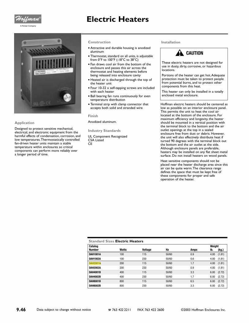
Construction
• Attractive and durable housing is anodizedaluminum
• Thermostat, standard on all units, is adjustablefrom 0°F to 100°F (-18°C to 38°C)
• Fan draws cool air from the bottom of theenclosure and passes this air across thethermostat and heating elements beforebeing released into enclosure cavity
• Heated air is discharged through the top ofthe heater unit
• Four 10-32 x self-tapping screws are includedwith each heater
• Ball bearing fan runs continuously for eventemperature distribution
• Terminal strip with clamp connector thataccepts both solid and stranded wire
Finish
Anodized aluminum.
Industry Standards
UL Component RecognizedCSA ListedCE
Hoffman electric heaters should be centered aslow as possible on an interior enclosure panel.This permits the unit to heat the cool airlocated at the bottom of the enclosure. Formaximum efficiency and longevity, the heatershould be mounted in a vertical position withthe terminal block to the bottom and the airoutlet openings at the top in a sealedenclosure free from dust or debris. However,the unit will also effectively distribute heat ifturned 90 degrees with the terminal block outthe bottom and the air outlet at the side.Although enclosure panels are preferable,heaters may be installed on any flat sheet metalsurface. Do not install heaters on wood panels.
Heat sensitive components should not beplaced near the heater discharge area since thisair can be quite warm.The clearance rangedefines the space that must be kept free ofthese components for proper and safeoperation of the heater.
Application
Designed to protect sensitive mechanical,electrical, and electronic equipment from theharmful effects of condensation, corrosion, andlow temperatures.Thermostatically controlledfan-driven heater units maintain a stabletemperature within enclosures so criticalcomponents can perform more reliably over a longer period of time.
Catalog WeightNumber Watts Voltage Hz Amps lb. (kg.)DAH1001A 100 115 50/60 0.9 4.00 (1.81)
DAH1002A 100 230 50/60 0.6 4.00 (1.81)
DAH2001A 200 115 50/60 1.7 4.00 (1.81)
DAH2002A 200 230 50/60 0.9 4.00 (1.81)
DAH4001B 400 115 50/60 3.3 6.00 (2.72)
DAH4002B 400 230 50/60 1.7 6.00 (2.72)
DAH8001B 800 115 50/60 6.5 6.00 (2.72)
DAH8002B 800 230 50/60 3.3 6.00 (2.72)
Standard Sizes Electric Heaters
9.46 Data subject to change without notice ☎ 763 422 2211 FAX 763 422 2600 ©2003 Hoffman Enclosures Inc.
Electric Heaters
Installation
CAUTION
These electric heaters are not designed for use in dusty, dirty, corrosive, or hazardouslocations.
Portions of the heater can get hot.Adequateprotection must be taken to protect peoplefrom potential burns, and to protect othercomponents from this heat.
This heater can only be installed in a totallyenclosed metal enclosure.
mmyers
Highlight

9.47Data subject to change without notice ☎ 763 422 2211 FAX 763 422 2600 ©2003 Hoffman Enclosures Inc.
Heaters
Electric H
eaters
9
Bulletin
D85
■ Dimensions and Clearance Range for DAH1001A, -2A and DAH2001A, -2A
■ Dimensions and Clearance Range for DAH4001B, -2B and DAH8001B, -2B
Bulletin
D85

jsalber
Highlight
jsalber
Highlight
jsalber
Highlight

jsalber
Highlight

C 11
1. 250VAC @ 35A I.R./125VAC @ 10kA I.R.2. 250VAC @ 100A I.R./125VAC @ 10kA I.R.3. 250VAC @ 200A I.R./125VAC @ 10kA I.R.4. 125VAC @ 10kA I.R.5. 32VAC @ 300A I.R.
GDL / GDL-VGSA / GSA-V
ELECTRONIC / GLASS FUSES
1. 250VAC @ 35A I.R./125VAC @ 10kA I.R.2. 250VAC @ 100A I.R./125VAC @ 10kA I.R.3. 250VAC @ 400A I.R./125VAC @ 10kA I.R.4. 250VAC @ 200A I.R./125VAC @ 10kA I.R.5. 125VAC @ 400A I.R.
StandardFuse Ampere Ratings
Ceramic BodyTime Delay1/4” x 1-1/4”1-1/2” Axial Leads Optional
1/4A through 10A, 250VAC - UL Listed, 12A through 20A UL Recognized 1/4A through 20A, 250VAC - CSA Certified25A and 30A, 125VAC - CSA Certified, UL Recognized
StandardFuse Ampere Ratings
Glass BodyTime Delay1/4” x 1-1/4”
1/100A through 8A, 250VAC - UL Listed and CSA Certified10A through 15A, 125VAC - UL Listed and CSA Certified20A through 30A, 32VAC - UL Recognized
GDL1/100GDL1/32GDL4/100GDL1/16GDL1/10GDL1/8GDL15/100GDL175/1000GDL3/16GDL2/10GDL1/4GDL3/10GDL3/8GDL4/10GDL1/2GDL6/10GDL7/10GDL3/4GDL8/10GDL1GDL1-2/10GDL1-1/4GDL1-1/2GDL1-6/10GDL1-8/10GDL2GDL2-1/4GDL2-1/2GDL2-8/10GDL3GDL3-2/10GDL4GDL5GDL6GDL6-1/4GLD7GLD8GLD10GDL12GDL15GDL20GDL25GDL30
250V250V250V250V250V250V250V250V250V250V250V250V250V250V250V250V250V250V250V250V250V250V250V250V250V250V250V250V250V250V250V250V250V250V250V250V250V125V125V125V32V32V32V
1111111111111111111122222222222333333444555
CATALOG AXIAL LEAD AMPERE VOLTS I.R.NUMBER CAT. NO RATING
GDL-V1/100GDL-V1/32GDL-V4/100GDL-V1/16GDL-V1/10GDL-V1/8
GDL-V15/100GDL-V175/1000
GDL-V3/16GDL-V2/10GDL-V1/4GDL-V3/10GDL-V3/8GDL-V4/10GDL-V1/2GDL-V6/10GDL-V7/10GDL-V3/4GDL-V8/10
GDL-V1GDL-V1-2/10GDL-V1-1/4GDL-V1-1/2GDL-V1-6/10GDL-V1-8/10
GDL-V2GDL-V2-1/4GDL-V2-1/2GDL-V2-8/10
GDL-V3GDL-V3-2/10
GDL-V4GDL-V5GDL-V6
GDL-V6-1/4GDL-V7GDL-V8GDL-V10GDL-V12GDL-V15GDL-V20GDL-V25GDL-V30
1/100A1/32A4/100A1/16A1/10A1/8A
15/100A175/1000A
3/16A2/10A1/4A3/10A3/8A4/10A1/2A6/10A7/10A3/4A8/10A
1A1-2/10A1-1/4A1-1/2A1-6/10A1-8/10A
2A2-1/4A2-1/2A2-8/10A
3A3-2/10A
4A5A6A
6-1/4A7A8A10A12A15A20A25A30A
GSA1/100GSA1/32GSA1/16GSA1/10GSA1/8GSA15/100GSA175/1000GSA3/16GSA2/10GSA1/4GSA3/10GSA3/8GSA4/10GSA1/2GSA6/10GSA7/10GSA3/4GSA8/10GSA1GSA1-2/10GSA1-1/4GSA1-1/2GSA1-6/10GSA2GSA2-1/4GSA2-1/2GSA2-8/10GSA3GSA3-2/10GSA3-1/2GSA4GSA5GSA6GSA6-1/4GSA7GSA8GSA10GSA12GSA15GSA20GSA25GSA30
1/100A1/32A1/16A1/10A1/8A
15/100A175/100A
3/16A2/10A1/4A3/10A3/8A4/10A1/2A6/10A7/10A3/4A8/10A
1A1-2/10A1-1/4A1-1/2A1-6/10A
2A2-1/4A2-1/2A2-8/10A
3A3-2/10A3-1/2A
4A5A6A
6-1/4A7A8A10A12A15A20A25A30A
250V250V250V250V250V250V250V250V250V250V250V250V250V250V250V250V250V250V250V250V250V250V250V250V250V250V250V250V250V250V250V250V250V250V250V250V250V250V250V250V125V125V
CATALOG AXIAL LEAD AMPERE VOLTS I.R.NUMBER CAT. NO RATING
111111111222222222222222222222334333333355
GSA-V1/100GSA-V1/32GSA-V1/16GSA-V1/10GSA-V1/8
GSA-V15/100GSA-V175/1000
GSA-V3/16GSA-V2/10GSA-V1/4GSA-V3/10GSA-V3/8GSA-V4/10GSA-V1/2GSA-V6/10GSA-V7/10GSA-V3/4GSA-V8/10
GSA-V1GSA-V1-2/10GSA-V1-1/4GSA-V1-1/2GSA-V1-6/10
GSA-V2GSA-V2-1/4GSA-V2-1/2GSA-V2-8/10
GSA-V3GSA-V3-2/10GSA-V3-1/2
GSA-V4GSA-V5GSA-V6
GSA-V6-1/4GSA-V7GSA-V8GSA-V10GSA-V12GSA-V15GSA-V20GSA-V25GSA-V30
C
jsalber
Highlight

196
FS101A01 05.30.02
FlasherFS100 SeriesSolid State Flasher
Fixed Flash Rate at 75 Flashes Per MinuteCustom Flash Rate 45 ... 150 F.P.M.1 or 2 A Output24 or 120 V AC Are AvailableSmall Size: 1.5 x 0.94 in. (38 x 23.9 mm)
DescriptionThe FS100 Series may be used to controlinductive, incandescent or resistive loads. Thisseries offers a 1 A (fullwave) or a 2 A (halfwave)steady state, 10 A inrush solid state output; andmay be ordered with an input voltage of 24 or120 V AC. The FS100 Series offers a factoryfixed flash rate of 75 flashes per minute or maybe ordered with a fixed custom flash rate rangingfrom 45 to 150 flashes per minute. Ideal for OEMapplications where cost is a factor.
OperationUpon application of input voltage, the T2 OFF timebegins. At the end of the OFF time, the T1 ONtime begins and the load energizes. At the end ofT1, T2 begins and the load de-energizes. Thiscycle repeats until input voltage is removed.Reset: Removing input voltage resets the outputand the sequence to T2.
Approvals:
SpecificationsMode of Operation OFF/ON solid state flasher for continuous dutyInput Voltage 24, 120 V AC, +/-15%, 50 ... 60 HzFlash Rate Factory fixed at 75 flashes per minute +/-20%ON/OFF Ratio ≅ 50%Load Type Incandescent, resistive, or inductive
(Choose RC Suffix for inductive loads)Output Fullwave AC or Halfwave rectified ACMaximum Load Rating Fullwave: 1A steady state
Halfwave: 2 A steady stateInrush 10 ACustom Flash Rates Available From 45 ... 150 FPM +/-20%Mounting Surface mount with one #8 (M4 x 0.7) screwPackage 1.5 x 0.94 in. (38.1 x 23.9 mm)Circuitry EncapsulatedOperating Temperature -20°C ... +60°CStorage Temperature -40°C ... +85°CHumidity 95% relative, non-condensingWeight ≅ 1.1 oz (31 g)
Part NumberLoad Type *Output Rating Output TypeInput
* Load Type: A - Incandescent & Resistive B - Incandescent, Resistive & Inductive
V = Voltage L = LoadR = Red Wire B = Black Wire
Inches (Millimeters)
W = 18 AWG (0.82 mm2) wires 6 in. (15.2 cm)
Mounting bracket is removable
Flasher (OFF First)
V = Voltage R = Reset L = LoadT1 = ON Time T2 = OFF Time
120 V AC120 V AC120 V AC 24 V AC 24 V AC 24 V AC
1 A1 A2 A1 A1 A2 A
ABAABA
AC, FullwaveAC, FullwaveAC, HalfwaveAC, FullwaveAC, FullwaveAC, Halfwave
FS126 FS126RC FS127 FS146 FS146RC FS147
Technical Data
Sales Information 1-800-431-2308 Technical Assistance 1-800-377-SSAC (7722) www.ssac.com
alawler
Highlight

eCao·"oat
Eco-Float Model GDescription
The Eco-float IS a mercury·~ree float sWItch forconlrolhng liqUid levels in a w,r'ety of applICations. Asnap-aellon sWItch 1$ acllVated by a sleel ball roilingback and forth withIn a sWlIchlng lube In a plastIC fl031hou!ing There is a mnimum diHerenlial between ~on
and ~off· of approxImately 35 Inches. Greate, drtferenualscan be achieved when the pipe mounted C'r externaJ~
.....eighted mounting styles are used. Various lengths ofcable and circuit configurations afe aVailable and inslock.
Features• Mercury Free
• Variety 01 Mounllng Styles
• Vanely of CirCUli ConfiguratIons
• InSlallatlOn Easy
• Differerlialln One Float
• Replaces Diaphragm and Mercury SWitches
Applici'ttionsTh'J Eco-Float can be used in a variety of liqUid
level monitoring applications including sumps. sewageejectors, sepllC lanks. vaulls. llft stations. a"d lanks.Eco·Floats are ruggedly constructed 01 co' ~sion
reslSlanl malerlals. enabling lhem to be used In avariety of different liquids. Some applications aresubJecl 10 additional requirements described i.ltheNational ElectriC Code. G
SE (external weight)
Sl (internal weight)
P (pipe mounted)
10. 15. 20. 30. 40. 50
Custom lengths available
NO (normally open)
NC (normally closed)
NONC (normally open!
normally closed)
Model GSE
CirCUI!
Configuration
ExampleGSI 20NO . Eco·Float. suspertded infernal WI_ 20'.normally open contacts. 2 Wire FIoat-
c;==
("able Length
3 Win! FIOiII.NONC
Ordering InformationSpecIfy:Model
Mounllng Style
18-2 or 18-3 SJO W/A, 60 C..41 x 34 stranding dia.•29{18-2); .31(18-3)
Polypropylene Dim: 3.00x 4.25
7A. @ 115 VAC: 3.5A@ 230VAC
PolyproPl'lsne. (Merlel GP)
Leac. 300 serIes st;t.nlesssteel (Model GSEI
140 F
Electncal Ratings
Float Housing
Clamp
External WeIght
SpecificationsCabie
nlivingston
Highlight
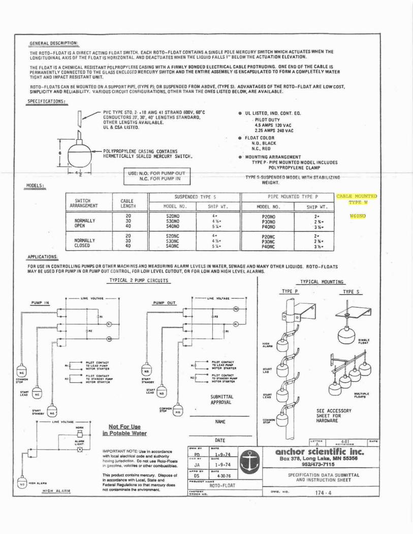
GENER"L DESCRIPTION:
THE ROTO-flO.-.r IS" DIRECT ACTING fLOAT SWITCH. EACH ROTO-flO"T CONT"tNS" SINGLE !'OLE MERCURY SWITCH WHICH "CTUUES MIEN THELONGITUOIN"L "JUS Of THE flOAT 1$ MORIZONTAL NlQ OE"cru"ns WHEN THE LIOUID FALLS IN BElOW THE ACTUATION ELEV"TlON.
THE fLO"T IS A CMEMICAL RES.STUr !'OLPROPVlUE CASING WITH A flRtU YBONDED ELECTIIIUL UBLE 'II0rllUOING. ONE END OF THE CABLE ISl'ERMANENTlY CONNECTED TO THE GLASS ENCLOSED .EIICUIIY SWITCH AND TME ENTIRE ASSEMILY IS ENCAPSULATED TO fORM A COMPLETELY WATERTIGHT AND IMPACT IIESISTANT UNIT.
ROTO_fLOATS C...N BE MOUNTED ON "SUPl'{IRT PIP£. (TYP£ PI: OR SUsPENDED fROM ABOVE, (TYPE SI. "'DVAHTAGES Of THE ROTa_fLOAT AilE LOW COST.SI ..PlICITY "NO REliABILITY. VARIOUS CIIICUIl COHfIGURAT10NS. OTMER TIlAN THE ONES lISTEO BElOW. AilE AV"'UABLE.
SPEC[fICATIOIIS:
W60NO
CABLE HOUNTEDTYPE W
,.".".
SHIP ItT.
PIPE MOtJHTED TYPE I'
P20NC 2'PJONC 2"·P40NC 3~'
P2OHO,P4"'"
MODEL 1Kl.
• ilL LISTED. IHD. CONT. EO.PILOT DUTY4.5AlIIPS IlDVAC2.25 AMPS 240 VAt
• flO"" COLORH.O.. BLACKN.C., RED
• MOUNTING ARIIANGElIIENTTYPE p. PIPE MOUNTED MODELIHCLUOES
I'OLY'ROPVlENE ClAMP
TYPE S·SIISl'EHOEO flIilDH WITH STABILIZINGWEIGHT.
USl!. N.D. POR PUMP OUTN.C. FOR PUMP INI
~~ PVC TYPE STO.l· .IB AWG 41 STRAHD 6OOV. 6O'C
,..- CONDUCTORS n. 30'. 40' LENGTHS STANOAIID.OTNER LEMGns AVAILABLE.ilL & GSA LISTED.
Gfr• POUPIlOP\'l(1I! CASING CONTAINSil HERMETICAllY SEALED IlEIICURY SWITCH.
I-·t~MODELS:
SWITOISUSPENDED TYPE S
CAll"AIIAANGElCEIfT LENGTH r<lOEL HO. SHIP ItT.
20 S",", ,.""""" 30 S_ ".,"'" " 50"'" ".
20 S20HC ••""""'-" 30 S","C ".CLOSED " S4QNC ".
APf'lICATIONS.
fOR USE III COIlTROlliNG PUMPS OR OTHER "ACHINES AND M[ASUIIING ALARM LEV[LS IN WATER. SEWAliE AND MANY OTHER lI0UIDS. ROTO-flo ...n.....Y BE usn fOR PUMP IN OR PUIiP OUT CONTROL, FOR lOW LEVel CUTOUT, OR FOR lOW AND HIGH l(VEl"'LAfIM$.
TYPICAl. 2 PlI'lP CIRCUITS TYPICAL I10UIlTlNG
-D1L!.. TYPE S-- .... _.... -- --".. _.... --
..21
SEE ACCESSDflYSliEET FOR1Wl000RE
114·4
"f."
SPECIfiCATION O...T... SUBMlnALAHO INSTRUCTION SHEET
Qnchor scientific Inc•Box 378, Long L.a_. MN M3S8
9521413-7115
•j.
..........OC'.....__....-
............00 _
.'0' .
SUBMITTALAPPROVAL
IlOTD·fLOAT
DATE
-::. •..:.."0... .. _..
" 1_9_74_.... _..DS 4-)0·16
......... __ I
........••••• n.
~- ..
PUMP OUT
..,~ ..........-
Not For USfIn potable Water
1'No lI'Odu<I-"'a 'Ntal'Y.~ 01In _ ,.." Loc:aI. SlMto a/'OIff_ RtoguIot...... 00 lItat ...."""Y _
IMPORTANT NOT£,U.In__----_.lIII\otIIyheWtD~ 00_ .... AoIo-_
"'~''''''-''-~
..... --... ........ ~.."....
.,
.....T .09" .-".. '...,'-., -,..,09 ..._._.............
I j.
·c·C
[_ .... _'-~
i I :::::•
"I<lIIP ,N
.'.....'._...
I§_.~...
18Is:.-
nlivingston
Highlight
jschoenberg
Highlight

www.us.schneider-electric.comFOR CURRENT INFORMATION
7M
INIA
TU
RE
AN
D M
OL
DE
D C
AS
E
CIR
CU
IT B
RE
AK
ER
S
7-22 © 2007 Schneider ElectricAll Rights Reserved
PowerPact® Circuit Breakers
H- and J-frame Circuit BreakersClass 611 / Refer to Catalog 0611CT0401
Accessories . . . . . . . . . . . . . . . . . . . . . . . . . . . . . . . . . . . . . . . . . . . Page 7-35Optional Lugs . . . . . . . . . . . . . . . . . . . . . . . . . . . . . . . . . . . . . . . . . Page 7-38Dimensions . . . . . . . . . . . . . . . . . . . . . . . . . . . . . . . . . . . . . . . . . . . Page 7-54Enclosures . . . . . . . . . . . . . . . . . . . . . . . . . . . . . . . . . . . . . . . . . . . . Page 7-55
HD and HG 2P
New!
H-frame
J-frame
Table 7.37: H-frame 150 A and J-frame 250 A Thermal-magnetic Circuit Breakers (600 Vac, 250 Vdc) With Factory Sealed Trip Unit Suitable for Reverse Connectiona
Current Rating @
40o C
Fixed AC Magnetic
Trip Cat. No.bc
Interrupting Rating (2nd Letter of Catalog Number)D G J L
TerminalWire Range$ Price
Hold Trip 80% Rated 100% Rated 80% Rated 100% Rated 80% Rated 100% Rated 80% Rated 100% Rated H-frame, 150A 2P, 600 Vac 50/60 Hz, 250 Vdc
15 A 350 A 750 A H( )L26015(C) 580.00 696.00 846.00 1015.00 1039.00 1247.00 1576.00 1891.00
AL150HD14–3/0 AWG
Al or Cu
20 A 350 A 750 A H( )L26020(C) 580.00 696.00 846.00 1015.00 1039.00 1247.00 1576.00 1891.0025 A 350 A 750 A H( )L26025(C) 580.00 696.00 846.00 1015.00 1039.00 1247.00 1576.00 1891.0030 A 350 A 750 A H( )L26030(C) 580.00 696.00 846.00 1015.00 1039.00 1247.00 1576.00 1891.0035 A 400 A 850 A H( )L26035(C) 580.00 696.00 846.00 1015.00 1039.00 1247.00 1576.00 1891.0040 A 400 A 850 A H( )L26040(C) 580.00 696.00 846.00 1015.00 1039.00 1247.00 1576.00 1891.0045 A 400 A 850 A H( )L26045(C) 580.00 696.00 846.00 1015.00 1039.00 1247.00 1576.00 1891.0050 A 400 A 850 A H( )L26050(C) 580.00 696.00 846.00 1015.00 1039.00 1247.00 1576.00 1891.0060 A 800 A 1450 A H( )L26060(C) 580.00 696.00 846.00 1015.00 1039.00 1247.00 1576.00 1891.0070 A 800 A 1450 A H( )L26070(C) 708.00 849.00 998.00 1198.00 1147.00 1377.00 1742.00 2091.0080 A 800 A 1450 A H( )L26080(C) 708.00 849.00 998.00 1198.00 1147.00 1377.00 1742.00 2091.0090 A 800 A 1450 A H( )L26090(C) 708.00 849.00 998.00 1198.00 1147.00 1377.00 1742.00 2091.00100 A 900 A 1700 A H( )L26100(C) 708.00 849.00 998.00 1198.00 1147.00 1377.00 1742.00 2091.00110 A 900 A 1700 A H( )L26110(C) 1381.00 1657.00 2039.00 2447.00 2966.00 3559.00 3689.00 4427.00125 A 900 A 1700 A H( )L26125(C) 1381.00 1657.00 2039.00 2447.00 2966.00 3559.00 3689.00 4427.00150 A 900 A 1700 A H( )L26150(C) 1381.00 1657.00 2039.00 2447.00 2966.00 3559.00 3689.00 4427.00
H-frame 150A 3P, 600 Vac 50/60 Hz, 250 Vdc15 A 350 A 750 A H( )L36015(C) 725.00 870.00 995.00 1194.00 1299.00 1559.00 1899.00 2279.00
AL150HD14–3/0 AWG
Al or Cu
20 A 350 A 750 A H( )L36020(C) 725.00 870.00 995.00 1194.00 1299.00 1559.00 1899.00 2279.0025 A 350 A 750 A H( )L36025(C) 725.00 870.00 995.00 1194.00 1299.00 1559.00 1899.00 2279.0030 A 350 A 750 A H( )L36030(C) 725.00 870.00 995.00 1194.00 1299.00 1559.00 1899.00 2279.0035 A 400 A 850 A H( )L36035(C) 725.00 870.00 995.00 1194.00 1299.00 1559.00 1899.00 2279.0040 A 400 A 850 A H( )L36040(C) 725.00 870.00 995.00 1194.00 1299.00 1559.00 1899.00 2279.0045 A 400 A 850 A H( )L36045(C) 725.00 870.00 995.00 1194.00 1299.00 1559.00 1899.00 2279.0050 A 400 A 850 A H( )L36050(C) 725.00 870.00 995.00 1194.00 1299.00 1559.00 1899.00 2279.0060 A 800 A 1450 A H( )L36060(C) 725.00 870.00 995.00 1194.00 1299.00 1559.00 1899.00 2279.0070 A 800 A 1450 A H( )L36070(C) 885.00 1061.00 1134.00 1361.00 1399.00 1679.00 2099.00 2519.0080 A 800 A 1450 A H( )L36080(C) 885.00 1061.00 1134.00 1361.00 1399.00 1679.00 2099.00 2519.0090 A 800 A 1450 A H( )L36090(C) 885.00 1061.00 1134.00 1361.00 1399.00 1679.00 2099.00 2519.00100 A 900 A 1700 A H( )L36100(C) 885.00 1061.00 1134.00 1361.00 1399.00 1679.00 2099.00 2519.00110 A 900 A 1700 A H( )L36110(C) 1733.00 2080.00 2399.00 2879.00 3449.00 4139.00 4499.00 5399.00125 A 900 A 1700 A H( )L36125(C) 1733.00 2080.00 2399.00 2879.00 3449.00 4139.00 4499.00 5399.00150 A 900 A 1700 A H( )L36150(C) 1733.00 2080.00 2399.00 2879.00 3449.00 4139.00 4499.00 5399.00
Current Rating @
40oC
Adjustable AC Magnetic
Trip Cat. No.bc
Interrupting Rating (2nd Letter of Catalog Number)D G J L
TerminalWire Range$ Price
Low High 80% Rated 100% Rated 80% Rated 100% Rated 80% Rated 100% Rated 80% Rated 100% Rated J-frame 250A 2P, 600 Vac 50/60 Hz, 250 Vdc
150 A 750 A 1500 A J( )L26150(C) 1450.00 1740.00 2141.00 2569.00 3114.00 3737.00 3874.00 4648.00 AL175JD4–4/0 AWG Al or Cu175 A 875 A 1750 A J( )L26175(C) 1450.00 1740.00 2141.00 2569.00 3114.00 3737.00 3874.00 4648.00
200 A 1000 A 2000 A J( )L26200(C) 1450.00 1740.00 2141.00 2569.00 3114.00 3737.00 3874.00 4648.00 AL250JD3/0 AWG–350 kcmil
Al or Cu225 A 1125 A 2250 A J( )L26225(C) 1450.00 1740.00 2141.00 2569.00 3114.00 3737.00 3874.00 4648.00250 A 1250 A 2500 A J( )L26250(C) 1992.00 2390.00 2834.00 3401.00 4150.00 4979.00 4796.00 5755.00
J-frame 250A 3P, 600 Vac 50/60 Hz, 250 Vdc150 A 750 A 1500 A J( )L36150(C) 1820.00 2184.00 2519.00 3023.00 3621.00 4346.00 4724.00 5669.00 AL175JD
4–4/0 AWG Al or Cu175 A 875 A 1750 A J( )L36175(C) 1820.00 2184.00 2519.00 3023.00 3621.00 4346.00 4724.00 5669.00200 A 1000 A 2000 A J( )L36200(C) 1820.00 2184.00 2519.00 3023.00 3621.00 4346.00 4724.00 5669.00 AL250JD
3/0 AWG–350 kcmil Al or Cu
225 A 1125 A 2250 A J( )L36225(C) 1820.00 2184.00 2519.00 3023.00 3621.00 4346.00 4724.00 5669.00250 A 1250 A 2500 A J( )L36250(C) 2499.00 2999.00 3334.00 4001.00 4825.00 5790.00 5995.00 7194.00a See page 7-23 for circuit breakers with field interchangeable trip units.b To complete catalog number, replace the blank with the appropriate rating (D, G, J, L).c For 100% rated circuit breakers add a “C” in the 9th character place (for example, HDL26015C or JDL26150C).
Table 7.38: H- and J-frame Termination OptionsTermination Letter
A - I-Line (See Section 9)F = No Lugs (includes terminal nut kit on both ends)dL = Lugs both endsM = Lugs ON end Terminal Nut Kit OFF endP = Lugs OFF end Terminal Nut Kit ON endN = Plug-in eD = Drawout eS = Rear Connected e
d Add TS suffix for circuit breaker without terminal nut kit.e For N and D pricing, add termination pricing on page 7-41 to price. For S pricing, add termination pricing on page 7-37 to price.
H G L 3 6 1 0 0
For factory-installed termination, place termination letter in the third block of the circuit breaker catalog number.
Termination LetterPlug-in Drawout Rear Connected
Table 7.39: H- and J-frame Interrupting Ratings
VoltageInterrupting Rating
D G J L240 Vac 25 kA 65 kA 100 kA 125 kA480 Vac 18 kA 35 kA 65 kA 100 kA600 Vac 14 kA 18 kA 25 kA 50 kA
DE2 Discount Schedule
bberndt
Highlight
bberndt
Highlight
sreinhold
Highlight
sreinhold
Highlight
sreinhold
Highlight
dripplinger
Highlight
dripplinger
Highlight

Standard Features• Compact 11” (287mm) width to fit on smaller cabinets.• Three position condenser air flow with the option to direct hot discharge air
in different directions.• Standard Digital Controller with programmable temperatures and alarm.• Controller can be installed on either front or rear of the unit (inside or outside of enclosure).• Can be used with or without purge system.• UL Listed, (third party certified).• Outdoor model operating temperature range from -40O F/-40O C to 140O F/60O C.• Environment friendly refrigerant.• Efficient, quiet, and long lasting rotary compressor.• Powder Coat finish on durable 16 gauge welded steel.• Easy pull out cleanable, reusable electrostatic 10 micron filter.• Every unit 100% factory tested before shipping.• Minimal visible fasteners.• NEMA type 12, 3R, 4, 4X available.
Options & Accessories• Custom finishes.• 304 or 316 Stainless steel.• Ethernet controller (ETHR).
• Low ambient (LA).• Alarm output (XO3).• 4 Micron condenser filter.• Total corrosive e-coating (CP3).
• 120V 60Hz.• 220/230V 50/60Hz.• 400V 50/60Hz.• 480V 50/60Hz.
The next evolution of cutting edge design is here now. The EV Evolution Series fromIce Qube is a certified for general purpose and hazardous locations Class I Division2 Groups A, B, C, & D air conditioner taking our Ice Qube product line to new levels.
Technical Data
Vertical Mount Evolution SeriesCertified for General Purpose & Hazardous LocationsClass I Division 2 Groups A, B, C, & D4,000 BTUH - 1202 Watt Cooling Capacity Air Conditioner
Standard FeaturesOptionsTechnical Data
Ice Qube, Inc., 141 Wilson Ave., Greensburg, PA 15601 Call: 724.837.7600 Fax: 724.837.3386www.iceqube.com Email: [email protected]
Cooling Solutions
2-15-17 Rev 6
Conditioned EnclosedAir Flow
Internal CabinetAir Flow
Model BTU/Watts Volts/Hz Max Amps Max Temp ºF/ºC Weight (lbs/Kg) Dimensions (In/mm)
IQ4000EV 4100/1202 120/60 8.28 140/60 97.5 / 44.2 H 28.58” (726 mm) x W 11.31” (287mm) x D 14.15” (359mm)
IQ4000EV 4100/1202 220/50 3.73 140/60 97.5 / 44.2 H 28.58” (726 mm) x W 11.31” (287mm) x D 14.15” (359mm)
IQ4000EV 4100/1202 230/60 4.30 140/60 97.5 / 44.2 H 28.58” (726 mm) x W 11.31” (287mm) x D 14.15” (359mm)
IQ4000EV 4100/1202 400/50 2.22 140/60 117.5 / 53.3 H 28.58” (726 mm) x W 11.31” (287mm) x D 14.15” (359mm)
IQ4000EV 4100/1202 400/60 2.47 140/60 117.5 / 53.3 H 28.58” (726 mm) x W 11.31” (287mm) x D 14.15” (359mm)
IQ4000EV 4100/1202 480/50 2.00 140/60 117.5 / 53.3 H 28.58” (726 mm) x W 11.31” (287mm) x D 14.15” (359mm)
IQ4000EV 4100/1202 480/60 2.08 140/60 117.5 / 53.3 H 28.58” (726 mm) x W 11.31” (287mm) x D 14.15” (359mm)
4000
BTU
EV
Ser
ies
Class I Division 2Groups A, B, C, & D
0
2000
4000
6000
8000
10000
20 25 30 35 40 45 50 55 60
Cap
acity
(BTU
/hr)
Return Air Temperature - ° C
IQ4000EV 60Hz Capacity Chart
25º C Ambient
35º C Ambient
45º C Ambient
55º C Ambient
Enclosure Air Flow
jschoenberg
Highlight

Ice Qube, Inc., 141 Wilson Ave., Greensburg, PA 15601 Call: 724.837.7600 Fax: 724.837.3386www.iceqube.com Email: [email protected]
Drawings depict all voltages. Data is subject tochange.
Specification Drawings
Vertical Mount Evolution SeriesCertified for General Purpose & Hazardous LocationsClass I Division 2 Groups A, B, C, & D4,000 BTUH - 120V 60Hz, 220/230V 50/60Hz, 400V 50/60Hz, &480V 50 & 60 Hz Air Conditioners
Cooling Solutions
2-15-17 Rev 6
AMBIENT EXHAUST
28.584726.04
11.309287.26
14.150359.40
DATE
U
IQ4000EV
AMBIENT EXHAUSTIQ4000EVNOMINAL COOLING CAPACITY:4100 BTUH @ 140-140 F4400 BTUH @ 95-95 FINTERNAL HEAT OPTION: 400W MAXIMUMMAXIMUM AMPS: 8.28 @ 120V/60Hz w/ INTERNAL HEAT 4.00AMAXIMUM AMPS: 3.73 @ 220V/50Hz w/ INTERNAL HEAT 2.20AMAXIMUM AMPS: 4.30 @ 230V/60Hz w/ INTERNAL HEAT 2.10AMAXIMUM AMPS: 2.00 @ 480V/50Hz w/ INTERNAL HEAT 2.20AMAXIMUM AMPS: 2.08 @ 480V/60Hz w/ INTERNAL HEAT 2.10AMAXIMUM AMPS: 2.22 @ 400V/50Hz w/ INTERNAL HEAT 2.21AM X S @ 400V/60Hz w/ INTERNAL HEAT 2.10AM
(6) PEM, NUT, #1/4-20 ENCLOSUREEXHAUST
ENCLOSURE
LOCATION
INTAKE
OPTIONAL CONTROLLER (2) PEM, STUD, 1/4"-20, 1"LG
203.208.000
179.47
7.066
5.500139.70
WITH GUARD
AMBIENT INTAKE FILTER
8.000203.20
14.000355.60
STANDARD
CONTROLLERLOCATION
52.122.052
9.046229.77
DRAIN TUBE .375" [9.53] O.D.

ALUMINUM SOLDERLESS LUGS • TYPE LAOne hole, front entrance copper or aluminum conductors 600 Volt Rated
Torque Approximate Dimensions
Catalog Value Wire Fig. L W H T B C D Dia.
Number In-Lbs. Range‡ No. in in in in in in in
LA-6 45 14-6 1 11/16 1/2 1/2 3/32 11/16 1/4 17/64
LA-2 50 14-2 1 15/32 1/2 35/64 7/64 11/16 5/16 17/64
LA-0 50 14-1/0 1 115/32 5/8 25/32 3/16 27/32 27/64 17/64
LA-2/0 120 14-2/0 2 115/32 5/8 51/64 3/16 27/32 7/16 17/64
LA-250 275 6-250 2 2 1 11/8 1/4 1 29/64 21/64
LA-350 275 6-350 2 21/4 11/8 11/4 1/4 11/8 1/2 13/32
LA-500 375 4-500 2 213/16 11/4 19/16 5/16 19/16 7/8 13/32
LA-600 375 2-600 2 33/16 11/2 19/16 7/16 113/16 25/32 13/32
LA-800 375 300-800 2 31/2 13/4 115/16 1/2 17/8 13/16 21/32
LA-1000 375 500-1000 2 31/2 13/4 115/16 1/2 17/8 13/16 21/32
‡For conversion to metric range, see page 175.
486BLISTEDAL9CU
Body, fabricated from high strength aluminum alloy extrusion.
Lug is 100% reusable using either screw driver or hex wrench.No special tools required.
Maximum conductivity, compact design light weight with ultimatestrength.
Finish, electro-tin plated to assure minimum contact resistanceand protection against corrosion when used with copper wire.(For added protection apply Penn-Union Cual-Aid® to cable be-fore installation.)
Standard stud hole sizes and locations are shown on chart.
77
ALUMINUM LAY-IN LUGS • TYPE LIOne hole, side entrance copper or aluminum continuous conductors
486BLISTEDAL9CU
Body, fabricated from high strength aluminum alloy extrusion.
Finish, electro-tin plated to assure minimum contact resistanceand protection against corrosion when used with copper wire.(For added protection apply Penn-Union Corp. Cual-Aid® to cablebefore installation.)
The side entrance design permits the quick installation of onecontinuous conductor as a jumper to multiple locations without abreak in the conductor. Excellent choice for use on groundingconductors.
T
L
C
D DIA.
B
H W
FIG. 2 FIG. 1
Catalog Wire Diameter Approximate Dimensions ScrewNumber Range L W H Type
LI-50S2 14-4 11/16" 3/8" 25/32" Slot
LI-112S 14-1/0 11/2" 19/32" 111/64" Slot
LI-200S 6-3/0 2" 51/64" 19/16" Socket
LI-252S 6-250 213/64" 51/64" 151/64" Socket
L
H
W
csundberg
Highlight

2880 North Plaza Drive • Rapid City, SD 57702(800) 843-8848 • (605) 348-5580 • FAX (605) 348-5685www.symcominc.com • email: [email protected]
Features
Bicolor LED indicatorlight is green in normalconditions and red dur-ing trip conditions.
Compact design savesprecious panel space.
Microcontroller-basedprovides better accuracyand higher reliabilitythan analog designs.
Transient protected tomeet IEEE 587 and IEC 1000-4-5 standardsand stand up undertougher conditions.
10A @ 240 VACGeneral Purpose Relaycan switch most loads.
Model 201-SPModel 201-SP-T
Model 201-SP-T01Single Phase
Voltage Monitor•
EngineeredProtection
•Microcontroller
Based
Protects single phase systems from:
•Low Voltage
•High Voltage (Option 9)
Additional Features:•UL and cUL listed
•5 year Warranty
•Made in USA
•Din Rail or
Surface Mount
Model 201-SP is a plug-in voltage monitor designed to protect single phasemotors regardless of size. It can be used on 95-120 VAC (201-100-SP),190-240 VAC (201-200-SP), or 380-480 VAC (201-400-SP) motors to pre-vent damage caused by low voltage or high voltage (optional).
The unique microcontroller-based voltage and phase sensing circuit constantly monitors the voltage to detect harmful power line conditions.When a harmful condition is detected, the MotorSaver's output relay isdeactivated after a specified trip delay. The output relay reactivates afterpower line conditions return to an acceptable level for a specified amount of time (RESTART DELAY). The trip delay prevents nuisance tripping dueto rapidly fluctuating power line conditions.
9/02

2880 North Plaza Drive • Rapid City, SD 57702(800) 843-8848 • (605) 348-5580 • FAX (605) 348-5685www.symcominc.com • email: [email protected]
Specifications
Line Voltage Ranges ................................95 to 120 (100V Model)....................................................................190 to 240 (200V Model)....................................................................380 to 480 (400V Model)Frequency ................................................50 or 60 Hz
Low Voltage (% of set point)•Trip ............................................................90%•Reset ........................................................93%Trip Delay Time•Low Voltage or Optional High Voltage ......4 secondsRestart Delay Time•After a Fault ..............................................2 seconds•After a Complete Power Loss ..................2 secondsOutput Contact Rating (Pilot Duty)•SPDT ........................................................480 VA @ 240 VAC
or 10A @240 VAC Gen. PurposeTransient Protection (Internal) ................IEC 1000-4-5; 1995 to ±4kVPower Consumption ................................5 Watts (Max.)Weight ......................................................9 oz.
Socket Available ......................................The same 600V socket can be Model Number OT08 surface mounted or installed on (UL Rating 600V) Din Rail
Specifications•
Operating Points•
Special Options
9/02
SymCom warrants its microcontroller-based products against defects in material or workmanship for a period offive (5) years from the date of manufacture. All other products manufactured by SymCom shall be warrantedagainst defects in material and workmanship for a period of two (2) years from the date of manufacture. For complete information on warranty, liability, terms, returns, and cancellations, please refer to the SymComTerms and Conditions of Sale document.
Model 201-SPModel 201-SP-T
Model 201-SP-T01Single Phase
Voltage Monitor
jsalber
Highlight

2880 North Plaza Drive • Rapid City, SD 57702(800) 843-8848 • (605) 348-5580 • FAX (605) 348-5685www.symcominc.com • email: [email protected]
Features
Model ISS-105
IntrinsicallySafe Switch
•EngineeredProtection
•Made in USA
UL 913 listed.*
Compact Design
Finger safe terminals.
DIN rail or surfacemountable.
LED state indicator.
Isolated output relay forPLC or control voltage.
The Model ISS-105 IS Super Cell is a “smart” five-channel intrinsically safe relay andpump controller. It can operate in a wide variety of pumping configurations including alternating or non-alternating duplex, duplex separate pump stop (SPS), triplex and quadplex for either pump up or pump down applications. It can also be set up as asimple five channel intrinsically safe relay.
The IS Super Cell has a long list of “smart” features that are needed for multiple pumpapplications. The IS Super Cell can indicate low, high and out-of-sequence alarms.If an out-of-sequence alarm occurs, the skipped pump(s) will be started as intended.The Model ISS-105 can be set up to do non-alternating control, alternating control andalternating control with one non-alternating pump.The non-alternating pump is intended foruse as an emergency pump or jockey pump. The IS Super Cell can start the non-alternatingpump once every 50 cycles to keep it working freely. Using the built-in DIP switches,individual pumps can be disabled when taken out of service for repair or maintenance.ISS-105 must be installed in a non-hazardous area. Follow SymCom’s Control Drawing 105for proper installation (See ISS-105 installation guide).
12/04
*Meets all newrequirements for UL 913 sixth edition,August 8, 2002!
Additional Features•Five intrinsically safe input channels meeting UL 913 Sixth Edition, August 8, 2002•Four normally open output relays & one SPDT output relay•Field selectable pump control options•Duplex pump control•Duplex SPS (Separate Pump Stop) pump control•Triplex pump control•Quadplex pump control•Out-of-sequence alarm•High and/or low alarm options depending on number of pumps and settings•Audible alarm output•Meets IEC EMC standards for Electrical Fast Transients (EFT), Electrostatic Discharge (ESD) and Radio Frequency Immunity (RFI)•DIN rail or surface mount in one package•User selectable alternator/non-alternator option•Non-alternating pump option for emergency or jockey applications•Pump disable switches•Delay on make timer for all lag pumps in all pump control modes•Delay on make/break timer in five channel ISS mode•Pump up or pump down control
jsalber
Highlight

2880 North Plaza Drive • Rapid City, SD 57702(800) 843-8848 • (605) 348-5580 • FAX (605) 348-5685www.symcominc.com • email: [email protected]
SymCom warrants its products against defects in material or workmanship for a period of two (2) yearsfrom the date of manufacture. For complete information on warranty, liability, terms, returns, and cancellations, please refer to the SymCom Terms and Conditions of Sale document.
Specifications•
Operating Points•
Special Options
SPECIFICATIONS
Supply Voltage ••••••••••••••••••••••120 VAC ±10%Relay Output RatingGeneral Purpose •••••••••••••••••••••••7 Amps @ 240 VACPilot Duty•••••••••••••••••••••••••••••••480 VA @ 240 VAC, B300Relay Contact Life (Electrical) ••••••••100,000 cycles min. @ rated loadRelay Contact Life (Mechanical) ••••••10,000,000 cycles Operating Temperature•••••••••••-20 to 55° CWeight•••••••••••••••••••••••••••••••••1.2 lbPower Consumption •••••••••••••••5 Watts max.Wire range •••••••••••••••••••••••••••12 to 20 AWGRecommended Terminal Torque•••3.5 to 4.5 in. lbs. (max. 6 in. lbs.)Provides intrinsically safe circuits in the following locations:
••••••••••••••••••••••••••••••••••••••••Class I, Groups A,B,C,D;••••••••••••••••••••••••••••••••••••••••Class II, Groups E,F,G;••••••••••••••••••••••••••••••••••••••••and Class III
Entity Parameters ••••••••••••••••••Voc = 16.8 V••••••••••••••••••••••••••••••••••••••••Isc = 1.7 mA••••••••••••••••••••••••••••••••••••••••La = 0••••••••••••••••••••••••••••••••••••••••Ca = 0
Standards PassedElectrostatic Discharge (ESD) ••••••••IEC 61000-4-2,Level 3,6kv contact,8kv air.Radio Frequency Immunity (RFI) •••••••IEC 61000-4-2,Level 3,10V/mFast Transients••••••••••••••••••••••••••IEC 61000-4-4,Level 3,4kv input power
••••••••••••••••••••••••••••••••••••••••••••2kv Inputs/Outputs
12/04
Model ISS-105INTRINSICALLYSAFE SWITCH
.192
3.511
3.750.621
5.025
2.350
FRONT VIEW
TOP VIEW
SIDE VIEW
#1 #2 #3 #4 #5 C
MODEL ISS-105
INTRINSICALLYSAFE INPUTS
#1
PUMP#1
PUMP#2
LOWALARM
HIGHALARM
LOWALARM
HIGHALARMOFF LEAD LAG1 COMMON
AUDIBLEALARM
MODE 1DUPLEXER
PUMP DOWN
#2 #3 #4 #5 INPUT
120 VAC
IS Super Cell
Low Alarm Float
Stop Float
Lead Float
Lag 1 Float
High Alarm Float
120 VAC
Pump1
Pump2
Audible Alarm
HighAlarm
LowAlarm
PUMP
Typical Application:Duplex Pump Down with High and Low Alarms.
Many other configurations are possible.See users manual for more details.

PE1A DE2A DE3A DiscountSchedule
7P
AN
EL
BO
AR
DS
8-8
8P
AN
EL
BO
AR
DS
3/00© 2000 Square DAll Rights Reserved
NQODMain Lug Interiors — Accepts Plug-On and Bolt-On Breakers
k “Cu’’ suffix indicates copper bussing.r Embossed mounting holes add a .25 inch standoff to back of MH box.a Add “F’’ for flush, “S’’ for surface.p Refer to 42 circuit rule — NEC Article 384-14 and 384-15.c Copper bus standard on 600 A interiors.h Feed-thru lug interior.t Enclosure includes trim kit.
NQOD Accessories
k 42 circuit panelboard requires MH38 box, 54 circuit panelboard requires MH44 box.
Max. No. of
One Pole QO
QOB Breakers
Mains Rating
Total PriceInterior
Front and Enclosure
Interior Only (Order Branch Circuit Breakers Separately)
NEMA Type 1 Enclosure NEMA Type 3R, 5, 12 Enclosure t
Box 20"W x 5 3/4"Dr MONO-FLAT® Front a Enclosure 20"W x 6 1/2"DHeight
(In.)NEMAType 1
NEMA Type 3R, 5,12 Catalog No. k Price Catalog No. Price Catalog No. Price Catalog No. Price
20" Wide Cabinet — Single Phase 3 Wire
12 $ 799. $1849. NQOD12L100CU $ 466. MH20 $71. MHC20 ( ) $262. MH20WP $1383. 2020 100 848. 1886. NQOD20L100 498. MH23 71. MHC23 ( ) 279. MH23WP 1388. 2320 899. 1937. NQOD20L100CU 549. MH23 71. MHC23 ( ) 279. MH23WP 1388. 23
30 1087. 2100. NQOD30L225 701. MH32 71. MHC32 ( ) 315. MH32WP 1399. 3230 1135. 2148. NQOD30L225CU 749. MH32 71. MHC32 ( ) 315. MH32WP 1399. 3242 1242. 2250. NQOD42L225 850. MH35 71. MHC35 ( ) 321. MH35WP 1400. 3542 225 1515. 2724. NQOD42L225TFLh 1070. MH47 71. MHC47 ( ) 374. MH47WP 1654. 4742 1292. 2300. NQOD42L225CU 900. MH35 71. MHC35 ( ) 321. MH35WP 1400. 3542 1587. 2796. NQOD42L225CUTFh 1142. MH47 71. MHC47 ( ) 374. MH47WP 1654. 4754p 1394. 2383. NQOD54L225 973. MH41 71. MHC41 ( ) 350. MH41WP 1410. 4154p 1445. 2434. NQOD54L225CU 1024. MH41 71. MHC41 ( ) 350. MH41WP 1410. 41
30 1502. . . . NQOD30L400 1029. MH50 71. MHC50V ( ) 402. Use Cu . . . 5030 1576. 2759. NQOD30L400CU 1103. MH50 71. MHC50V ( ) 402. MH50WP 1656. 5042 400 1620. . . . NQOD42L400 1129. MH53 71. MHC53V ( ) 420. Use Cu . . . 5342 1695. 2865. NQOD42L400CU 1204. MH53 71. MHC53V ( ) 420. MH53WP 1661. 5354p 1709. . . . NQOD54L400 1196. MH59 71. MHC59V ( ) 442. Use Cu . . . 5954p 1837. 2995. NQOD54L400CU 1324. MH59 71. MHC59V ( ) 442. MH59WP 1684. 59
30 1674. 2924. NQOD30L600 1183. MH53 71. MHC53V ( ) 420. MH656WP 1741. 53/6542 600c 1782. 3027. NQOD42L600 1282. MH56 71. MHC56V ( ) 429. MH686WP 1741. 56/6842 2391. 3618. NQOD42L600TFLh 1868. MH62 71. MHC62V ( ) 452. MH746WP 1750. 62/7454p 1897. 3124. NQOD54L600 1374. MH62 71. MHC62V ( ) 452. MH746WP 1750. 62/74
20" Wide Cabinet —Three Phase 4 Wire
12 884. 1934. NQOD412L100CU $ 551. MH20 $71. MHC20 ( ) $262. MH20WP $1383. 2024 973. 2011. NQOD424L100 623. .MH23 71 MHC23 ( ) 279. MH23WP 1388. 2324 100 1024. 2062. NQOD424L100CU 674. MH23 71. MHC23 ( ) 279. MH23WP 1388. 2330 1072. 2097. NQOD430L100 706. MH26 71. MHC26 ( ) 295. MH26WP 1391. 2630 1122. 2147. NQOD430L100CU 756. MH26 71. MHC26 ( ) 295. MH26WP 1391. 26
30 1157. 2170. NQOD430L225 771. MH32 71. MHC32 ( ) 315. MH32WP 1399. 3230 1206. 2219. NQOD430L225CU 820. MH32 71. MHC32 ( ) 315. MH32WP 1399. 3242 1329. 2337. NQOD442L225 937. MH35 71. MHC35 ( ) 321. MH35WP 1400. 3542 225 1565. 2774. NQOD442L225TFLh 1120. MH47 71. MHC47 ( ) 374. MH47WP 1654.42 1377. 2385. NQOD442L225CU 985. MH35 71. MHC35 ( ) 321. MH35WP 1400. 3542 1653. 2862. NQOD442L225CUTFh 1208. MH47 71. MHC47 ( ) 374. MH47WP 1654.54p 1457. 2446. NQOD454L225 1036. MH41 71. MHC41 ( ) 350. MH41WP 1410. 4154p 1509. 2498. NQOD454L225CU 1088. MH41 71. MHC41 ( ) 350. MH41WP 1410. 41
30 1655. . . . NQOD430L400 1182. MH50 71. MHC50V ( ) 402. Use Cu . . . 5030 1730. 2913. NQOD430L400CU 1257. MH50 71. MHC50V ( ) 402. MH50WP 1656. 5042 400 1768. . . . NQOD442L400 1277. MH53 71. MHC53V ( ) 420. Use Cu . . . 5342 1845. 3015. NQOD442L400CU 1354. MH53 71. MHC53V ( ) 420. MH53WP 1661. 5354p 1884. . . . NQOD454L400 1371. MH59 71. MHC59V ( ) 442. Use Cu . . . 5954p 1962. 3120. NQOD454L400CU 1449. MH59 71. MHC59V ( ) 442. MH59WP 1684. 59
30 1850. 3100. NQOD430L600 1359. MH53 71. MHC53V ( ) 420. MH656WP 1741. 53/6542 600c 1944. 3189. NQOD442L600 1444. MH56 71. MHC56V ( ) 429. MH686WP 1745. 56/6842 2570. 3797. NQOD442L600TFLh 2047. MH62 71. MHC62V ( ) 452. MH746WP 1750. 62/7454p 2080. 3307. NQOD454L600 1557. MH62 71. MHC62V ( ) 452. MH746WP 1750. 62/74
Description Catalog No. Price Schedule
Sub-feed lug kits—main lugs only—1Ø or 3Ø k100 A................................................................. NQOD100SFL $ 98.00 PE1A225 A................................................................. NQOD225SFL 129.00 PE1A
Sub-feed: Plug-on: 2-Pole ...................................... QO2125SL 87.00 DE2A3-pole QO3125SL 87.00 DE2A
Sub-feed: Bolt-on: 2-Pole ....................................... QOB2125SL 111.00 DE2A3-pole QOB3125SL 111.00 DE2A
Equipment ground bars: 12 circuit 225A max. ...... PK9GTA 8.50 DE3A20 circuit 225 A max. PK12GTA 10.00 DE3A24 circuit 225 A max. PK15GTA 10.90 DE3A30 circuit 225 A max. PK18GTA 11.90 DE3A54 circuit 225 A max. PK23GTA 13.50 DE3A54 circuit 600 A max. PK27GTA 21.40 DE3APK15GTA with #1 to 4/0 Al/Cu lug................... PK15GTA-L 22.20 DE3APK18GTA with #1 to 4/0 Al/Cu lug................... PK18GTA-L 24.00 DE3APK23GTA with #1 to 4/0 Al/Cu lug................... PK23GTA-L 25.80 DE3A
Ground bar insulator kit.......................................... PKGTAB 27.80 DE3AFiller plate ............................................................... QOFP 2.30 DE2ADirectory cards ....................................................... 80031-158-01 3.40 PE1APlastic stick-on directory pouch ............................. 80031-159-01 8.70 PE1A
Description Catalog No. Price Schedule
Circuit I.D. number strips 1-96................................ 80043-295-03 5.00 PE1A
Lock - for MONO-FLAT fronts ................................ PK4FL 57.00 PE1AKey — NSR-251 (for all locks)................................ LP9618 18.30 PE1ATouch-up paint USAS #49 Gray (Aerosol can)...... PK49SP 24.80 DE1Handle attachments — branch breakers:
Handle lock-off .................................................. HLO-1 6.30 DE2AHandle tie - (QO and QOB only) ...................... QO1HT 2.40 DE2AHandle padlock attachment - 1-Pole ................ QO1PA 6.80 DE2A2 and 3-Pole QO1PL 6.80 DE2ACombination handle tie and lock-off
Three 1-Pole (QO, QOB).............................. QO3HT 8.50 DE2ANeutral Lugs: #10 to #2 Al or #14 to #4 Cu ........... QO70AN 6.30 DE3A
#4 to #1/0 Al/Cu Q1-100AN 7.00 DE3A#1 to #4/0 Al/Cu Q1-150AN 20.60 DE3A
Endwalls for MH BoxesBlank ................................................................. 80110-105-01 26.10 PE1AWith Knockouts ................................................. 80110-104-01 26.10 PE1A
Elevating Nuts (4 required)100/225 Ampere ............................................... 80110-810-01 2.30 PE1A400/600 Ampere ............................................... 23427-02200 .82 PE1A
NQOD Merchandised Panelboards20" Wide Enclosures — 240 Vac, 48 VdcClass 1630
MONO-FLAT is a Registered Trademark of Square D Company or related companies.
jsalber
Highlight

PS5R Slim Line Series
107USA: 800-262-IDEC Canada: 888-317-IDEC
PLCsO
perator InterfacesA
utomation Softw
arePow
er SuppliesSensors
Comm
unication & N
etworking
Power Supplies
PS5R Slim Line Series Switching Power Supplies
Power Supplies
File #E234997 (SEMI F47 120W &
240W only)
Designed with Accessibility & Convenience in Mind!
DC Low Indicator (15W, 120W & 240W Slim Line Only)The indicator turns on when the output
voltage drops below 80% of the rated value.
This assists in troubleshooting power supply
problems.
DC ON IndicatorThe indicator turns on when the unit is powered
up. This is a convenient way to know when the
power supply is receiving power.
Output Voltage AdjustmentThe output voltage can be easily adjusted within + 10% of the rated voltage.
Fingersafe, Spring-up Screw TerminalsDon’t worry about losing screws or getting an
inadvertent shock from a terminal. The terminals are
captive spring-up screws, which makes using them
as easy as pushing a screw down and tightening it.
They are shock and vibration resistant, and work
with ring lugs, fork connectors or stripped wire
connections. The terminals are rated IP20 (when
tightened) meaning they are recessed to keep fi n-
gers and objects from touching the input contacts.
Top View
Universal Input PowerThe applied input power has a range of 85-264V
AC (100-350V DC) without the use of jumpers or
slide switches. This makes IDEC power supplies
suitable for use anywhere in the world.
Output ChannelWith very low output ripples of less than 1% peak
to peak, the 120W and 240W power supplies are
some of the best in the industry. The output comes
with overload protection that avoids damaging the
power supply and the spring-up, fi ngersafe, screw
terminals add a level of safety and ease for the
user. The 240W power supply also has the conve-
nience of two output terminals.
Ventilation GrillProvides cooling for
the power supply and
prevents small objects
from falling into the
power supply circuitry.
Long Life ExpectancyIDEC power supplies are very reliable, with a life
expectancy of 70,000 hrs. (minimum) or longer,
depending on usage. Power factor correction has
also been included to minimize harmonic distortion,
resulting in a longer operating life and increased
reliability.
Key features of the PS5R Slim Line series include:Lightweight and compact in size
Wide power range: 10W-240W
Universal input:
10W to 90W: 85-264V AC/100-370V DC
120W and 240W: 85-264V AC/100-350V DC
Power Factor Correction for 60W to 240W
(EN61000-3-2)
Meets SEMI F47 Sag Immunity (120W & 240W only)
Approved for Class 1, Div. 2 Hazardous Locations
Overcurrent protection, auto-reset
Overvoltage protection, shut down
Spring-up screw terminal type, IP20
DIN rail or panel surface mount
Approvals:
CE Marked
TÜV
c-UL, UL508
UL1310 (PS5R-SB, -SC, -SD)
•
•
•
•
•
•
•
•
•
•
•
UL1604 (Hazardous locations)
EN50178:1997
LVD: EN60950:2000
EMC: Directive EN61204-3:2000 (EMI: Class B, EMS: Industrial)

PS5R Slim Line Series
108 www.idec.com
PLCs
Ope
rato
r Int
erfa
ces
Aut
omat
ion
Softw
are
Pow
er S
uppl
ies
Sens
ors
Com
mun
icat
ion
& N
etw
orki
ngPower Supplies
Item Watts Rated Voltage
Rated Current
Part Number
10 5V DC 2.0A PS5R-SB05
15
12V DC 1.2A PS5R-SB12
24V DC 0.65A PS5R-SB24
30
12V DC 2.5A PS5R-SC12
24V DC 1.3A PS5R-SC24
60 24V DC 2.5A PS5R-SD24
Item Watts Rated Voltage
Rated Current
Part Number
90 24V DC 3.75A PS5R-SE24
120 24V DC 5A PS5R-SF24
240 24V DC 10A PS5R-SG24
Part Numbers
Accessories
Appearance Description Part Number
Panel Mounting Bracket for PS5R-SB PS9Z-5R1B
Panel Mounting Bracket for PS5R-SB (fl at side mounting) PS9Z-5R2B
Panel Mounting Bracket for PS5R-SC and PS5R-SD PS9Z-5R1C
Panel Mounting Bracket for PS5R-SE PS9Z-5R1E
Panel Mounting Bracket for PS5R-SF & PS5R-SG PS9Z-5R1G
DIN rail (1000mm) BNDN1000
DIN rail end clip BNL5
alawler
Highlight

PS5R Slim Line Series
109USA: 800-262-IDEC Canada: 888-317-IDEC
PLCsO
perator InterfacesA
utomation Softw
arePow
er SuppliesSensors
Comm
unication & N
etworking
Power Supplies
Specifi cations
PartNumbers
5V DC output PS5R-SB05 – – – – –
12V DC output PS5R-SB12 PS5R-SC12 – – – –
24V DC output PS5R-SB24 PS5R-SC24 PS5R-SD24 PS5R-SE24 PS5R-SF24 PS5R-SG24
Output Capacity 15W (5V Model is 10W) 30W 60W 90W 120W 240W
Inpu
t
Input Voltage (single-phase, 2-wire)
85 to 264V AC,
100 to 370V DC
85 to 264V AC,
100 to 350V DC
Input Current (maximum)
100VAC 0.45A 0.9A 1.7A 2.3A 1.8A 3.5A
200VAC 0.3A 0.6A 1.0A 1.4A 1.0A 1.7A
Internal Fuse Rating 2A 3.15A 4A 6.3A
Inrush Current (cold start) 50A maximum (at 200V AC)
Leakage Current (at no load) 132V AC: 0.38 mA maximum
264V AC: 0.75 mA maximum0.75mA maximum 1mA maximum
TypicalEffi ciency
5V DC 69% – – – – –
12V DC 75% 78% – – – –
24V DC 79% 80% 83% 82% 84%
Out
put
Output Current Ratings
5V DC 2.0A – – – – –
12V DC 1.2A 2.5A – – – –
24V DC 0.65A 1.3A 2.5A 3.75A 5A 10A
Voltage Adjustment ±10% (V. ADJ control on front)
Output Holding Time 20ms minimum (at rated input and output)
Starting Time 200ms maximum – – – 650ms maximum 500ms maximum
Rise Time 100ms maximum (at rated input and output) 200ms maximum
Line Regulation 0.4% maximum
Load Regulation 1.5% maximum 0.8% max
Temperature Regulation 0.05% degree C maximum
Ripple Voltage 2% peak to peak maximum (including noise) 1% peak to peak maximum (including noise)
Overcurrent Protection 105% or more, auto reset 105 to 130%, auto reset 103 to 110%, auto reset
Overvoltage Protection 120% min. SHUTDOWN
Operation Indicator LED (green)
Voltage Low Indication LED (amber) – – – LED (amber)
Dielectric StrengthBetween Input and Ground: 2000 V AC, 1 minute
Between input and output: 3000V AC, 1 minute;
Between output and ground: 500V AC, 1 minute.
Insulation Resistance Between Input & Output Terminals: 100 MΩ Min
Operating Temperature –10 to +65°C (14 to 149°F) -10 to 60°C (14 to 140°F)
Storage Temperature -25 to 75°C (-13 to +167°F)
Operating Humidity 20 to 90% relative humidity (no condensation)
Vibration Resistance Frequency 10 to 55Hz, Amplitude 0.375mm
Shock Resistance 300m/s2 (30G) 3 times each in 6 axes
ApprovalsEMC: EN61204-3 (EMI: Class B, EMS: Industrial), c-UL (CSA 22.2 No. 14), UL1604, UL508, LVD: EN60950, EN50178
UL1310 Class 2, c-UL (CSA 22.2 No. 213 and 223) – SEMI F47
Harmonic Directive N/A EN61000-3-2 A14 class A
Weight (approx.) 160g 250g 285g 440g 630g 1000g
Terminal Screw M3.5 slotted-Phillips head screw (screw terminal type)
IP protection IP20 fi ngersafe
Dimensions H x W x D (mm) 90 x 22.5 x 95 95 x 36 x 108 115 x 46 x 121 115 x 50 x 129 125 x 80 x 149.5
Dimensions H x W x D (inches) 3.54 x 0.89 x 3.74 3.74 x 1.42 x 4.25 4.53 x 1.81 x 4.76 4.53 x 1.97 x 5.08 4.92 x 3.15 x 5.89
1. For dimensions, see page 111.

www.SquareD.comFor the most up-to-date information
QOU and QYU Unit MountMiniature Circuit BreakersClass 720
CIR
CU
IT B
RE
AK
ER
S
6Low Ampere QOU Miniature Circuit Breakers
General Specifications Common to All Low Ampere QOU Circuit Breakers
• For convenient flush mount, surface mount or DIN mount (symmetrical rail 35 x 7.5 DIN/EN 50 022)
• Single handle with internal common trip
• Terminal lug wire size (1) #14–#2 AWG Cu or Al
• Reversible line and load lugs
• Field-installable quick connectors
• UL Listed 48 Vdc (5,000 AIR)
• UL Listed as HACR Type—10–70 A
High Ampere QOU Circuit Breakers
General Specifications Common to All High Ampere QOU Circuit Breakers
• Flush mount, surface mount, and DIN rail mount
• Internal common trip
• Lugs supplied in standard position only
• Terminal lug wire size (1) #12–#2/0 AWG Cu or Al
• UL Listed 60 Vdc per pole (5000 AIR)—Note: except switches
• UL Listed as HACR type—80–125 A
6-1
© 2005 Schneider Electrica High-ampere QOUs use appropriately sized terminal lugs and accessories.
QOU Miniature Circuit BreakersQOU unit mount miniature circuit breakers (cable-in/cable-out) are ideal for OEM applications. They have Square D’s unique Visi-Trip feature and can be DIN rail-mounted or surface- or flush-mounted using mounting feet.
Ampere Rating
1-pole 120 Vac Price
2-pole 120/240 Vac Price
2-pole 240 Vac Price
3-pole 240 Vac Price
Catalog No. Catalog No. Catalog No. Catalog No.
10,000 AIR
10 QOU110
$26.80
QOU210
$ 58.00
QOU210H
$112.00
QOU310
$190.00
15 QOU115 QOU215 QOU215H QOU31520 QOU120 QOU220 QOU220H QOU32025 QOU125 QOU225 QOU225H QOU32530 QOU130 QOU230 QOU230H QOU330
35 QOU135 QOU235 . . . . . . . QOU33540 QOU140 QOU240 . . . . . . . QOU34045 QOU145 QOU245 . . . . . . . QOU34550 QOU150 QOU250 . . . . . . . QOU35060 QOU160 QOU260 . . . . . . . QOU360
70 QOU170 52.00 QOU270 114.00 . . . . . . . QOU370a 242.00
80 QOU180a117.00
QOU280a164.00
. . . . . . . QOU380a277.0090 QOU190a QOU290a . . . . . . . QOU390a
100 QOU1100a QOU2100a . . . . . . . QOU3100a
125 . . . . . . . QOU2125a 301.00 . . . . . . . . . . . . . .
22,000 AIR
15 QOU115VH
67.00
QOU215VH
126.00
. . . . . . . QOU315VH
284.0020 QOU120VH QOU220VH . . . . . . . QOU320VH25 QOU125VH QOU225VH . . . . . . . QOU325VH30 QOU130VH QOU230VH . . . . . . . QOU330VH
35 QOU135VH QOU235VH . . . . . . . . . . . . . .40 QOU140VH QOU240VH . . . . . . . . . . . . . .45 QOU145VH QOU245VH . . . . . . . . . . . . . .50 QOU150VH QOU250VH . . . . . . . . . . . . . .60 QOU160VH QOU260VH . . . . . . . . . . . . . .
QOU-HMHigh magnetic trip circuit breakers are recommended for applications where high initial inrush may occur and for individual dimmer applications.
15 QOU115HM 26.80 . . . . . . . . . . . . . . . . . . . . .20 QOU120HM . . . . . . . . . . . . . . . . . . . . .
QYU UL1077 Recognized Supplementary Protectors (5,000 AIR)
1-pole 277 Vac
15 QYU115
81.00
. . . . . . . . . . . . . . . . . . . . .20 QYU120 . . . . . . . . . . . . . . . . . . . . .25 QYU125 . . . . . . . . . . . . . . . . . . . . .30 QYU130 . . . . . . . . . . . . . . . . . . . . .
QOU Non-Automatic SwitchesNon-automatic switches have the same physical packaging as miniature circuit breakers, but provide no overcurrent or short circuit protection. They are UL Listed per UL1087 and are CSA certified.
60 . . . . . . . . . . . . . . QOU200 58.00 QOU300 190.00
100 . . . . . . . . . . . . . . QOU2000 164.00 QOU3000 277.00
125 . . . . . . . . . . . . . . QOU20001 301.00 QOU30001 477.00
Discount
Interrupting Ratings. . . . . . . . . . . . . . . . . . . . . . . . . . . . . . . . . . . . . . .page 6-3Accessories . . . . . . . . . . . . . . . . . . . . . . . . . . . . . . . . . . . . . . pages 6-12, 6-15Dimensions . . . . . . . . . . . . . . . . . . . . . . . . . . . . . . . . . . . . . . . . . . . .page 6-49
ved/05
4All Rights Reser9/27
9/27/05
DE2Schedule
jsalber
Highlight
dripplinger
Highlight
dripplinger
Highlight
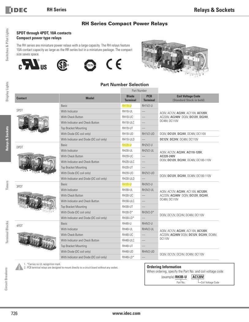
RH Series
726 www.idec.com
Switc
hes
& P
ilot L
ight
sD
ispl
ay L
ight
sRe
lays
& S
ocke
tsTi
mer
sTe
rmin
al B
lock
sCi
rcui
t Bre
aker
sRelays & Sockets
RH Series Compact Power Relays
SPDT through 4PDT, 10A contacts Compact power type relays
The RH series are miniature power relays with a large capacity. The RH relays feature
10A contact capacity as large as the RR series but in a miniature package. The compact
size saves space.
����
Part Number SelectionPart Number
Contact Model Blade Terminal
PCB Terminal
Coil Voltage Code(Standard Stock in bold)
SPDT
Basic RH1B-U RH1V2-U
AC6V, AC12V, AC24V, AC110V, AC120V,
AC220V, AC240V DC6V, DC12V, DC24V,
DC48V, DC110V
With Indicator RH1B-UL —
With Check Button RH1B-UC —
With Indicator and Check Button RH1B-ULC —
Top Bracket Mounting RH1B-UT —
With Diode (DC coil only) RH1B-UD RH1V2-UD DC6V, DC12V, DC24V, DC48V, DC110V
With Indicator and Diode (DC coil only) RH1B-ULD — DC12V, DC24V, DC48V, DC110V
DPDTBasic RH2B-U RH2V2-U
AC6V, AC12V, AC24V, AC110-120V,
AC220-240V
DC6V, DC12V, DC24V, DC48V, DC100-110V
With Indicator RH2B-UL RH2V2-UL
With Check Button RH2B-UC —
With Indicator and Check Button RH2B-ULC —
Top Bracket Mounting RH2B-UT —
With Diode (DC coil only) RH2B-UD RH2V2-UDDC6V, DC12V, DC24V, DC48V, DC100-110V
With Indicator and Diode (DC coil only) RH2B-ULD —
3PDTBasic RH3B-U RH3V2-U
AC6V, AC12V, AC24V, AC110V, AC120V,
AC220V, AC240V DC6V, DC12V, DC24V,
DC48V, DC110V
With Indicator RH3B-UL RH3V2-UL
With Check Button RH3B-UC —
With Indicator and Check Button RH3B-ULC —
Top Bracket Mounting RH3B-UT —
With Diode (DC coil only) RH3B-D* RH3V2-D*DC6V, DC12V, DC24V, DC48V, DC110V
With Indicator and Diode (DC coil only) RH3B-LD* —
4PDTBasic RH4B-U RH4V2-U
AC6V, AC12V, AC24V, AC110V, AC120V,
AC220V, AC240V DC6V, DC12V, DC24V, DC48V,
DC110V
With Indicator RH4B-UL RH4V2-UL
With Check Button RH4B-UC —
With Indicator and Check Button RH4B-ULC —
Top Bracket Mounting RH4B-UT —
With Diode (DC coil only) RH4B-UD RH4V2-UDDC6V, DC12V, DC24V, DC48V, DC110V
With Indicator and Diode (DC coil only) RH4B-LD* —
1. *Carries no UL recognition mark.
2. PCB terminal relays are designed to mount directly to a circuit board without any socket. Ordering InformationWhen ordering, specify the Part No. and coil voltage code:
(example) RH3B-U AC120V Part No. Coil Voltage Code
bberndt
Highlight
dripplinger
Highlight
dripplinger
Highlight

RH Series
727USA: 800-262-IDEC Canada: 888-317-IDEC
Switches &
Pilot LightsD
isplay LightsRelays &
SocketsTim
ersTerm
inal Blocks
Circuit Breakers
Relays & Sockets
Sockets (for Blade Terminal Models)
Relays Standard DIN Rail Mount 1 Finger-safe DIN Rail Mount 1 Through Panel Mount PCB Mount
RH1B SH1B-05 SH1B-O5C SH1B-51 SH1B-62
1. DIN Rail mount
socket comes with
two horseshoe
clips. Do not use
unless you plan to
insert pullover wire
spring. Replacement
horseshoe clip part
number is Y778-011.
RH2B SH2B-05 SH2B-05C SH2B-51 SH2B-62
RH3B SH3B-05 SH3B-05C SH3B-51 SH3B-62
RH4B SH4B-05 SH4B-05C SH4B-51 SH4B-62
Hold Down Springs & Clips
Appearance Description Relay For DIN Mount Socket
For Through Panel & PCB Mount Socket Min Order Qty
Pullover Wire
Spring
RH1B SY2S-02F1 2
SY4S-51F1 10
2. Must use horseshoe clip
when mounting in DIN
mount socket. Replacement
horseshoe clip part number is
Y778-011.
3. Two required per relay.
RH2B SY4S-02F1 2
RH3B SH3B-05F1 2
RH4B SH4B-02F1 2
Leaf Spring
(side latch)RH1B, RH2B, RH3B, RH4B SFA-202 3 SFA-302 3
20
Leaf Spring
(top latch)RH1B, RH2B, RH3B, RH4B SFA-101 3 SFA-301 3
AC Coil Ratings
Voltage (V)
Rated Current (mA) ±15% at 20°C Coil Resistance (Ω)±10% at 20°C
Operation Characteristics(against rated values at 20ºC)AC 50Hz AC 60Hz
SPDT DPDT 3PDT 4PDT SPDT DPDT 3PDT 4PDT SPDT DPDT 3PDT 4PDT Max. Continuous Applied Voltage
Pickup Voltage
Dropout Voltage
6 170 240 330 387 150 200 280 330 330 9.4 6.4 5.4
110%80%
maximum
30%
minimum
12 86 121 165 196 75 100 140 165 165 39.3 25.3 21.2
24 42 60.5 81 98 37 50 70 83 83 153 103 84.5
110 9.6 — 18.1 21.6 8.4 — 15.5 18.2 18.2 — 2,200 1,800
110-120 —9.4-
10.8— — — 8.0-9.2 — — — — — —
120 8.6 — 16.4 19.5 7.5 — 14.2 16.5 16.5 — 10,800 7,360
220 4.7 — 8.8 10.7 4.1 — 7.7 9.1 9.1 — 10,800 7,360
220-240 — 4.7-5.4 — — — 4.0-4.6 — — 18,820 — —
240 4.9 — 8.2 9.8 4.3 — 7.1 8.3 8.3 — 12,100 9,120
DC Coil Ratings
Voltage (V)
Rated Current (mA) ±15% at 20°C Coil Resistance (Ω)±10% at 20°C
Operation Characteristics(against rated values at 20ºC)
SPDT DPDT 3PDT 4PDT SPDT DPDT 3PDT 4PDT Max. Continuous Applied Voltage
Pickup Voltage
Dropout Voltage
6 128 150 240 250 47 40 25 24
110%80%
maximum
10%
minimum
Standard coil voltages
are in BOLD.12 64 75 120 125 188 160 100 96
24 32 36.9 60 62 750 650 400 388
48 18 18.5 30 31 2,660 2,600 1,600 1,550
100-110 — 8.2-9.0 — — — 12,250 — —
110 8 — 12.8 15 13,800 — 8,600 7,340
bberndt
Highlight
bberndt
Highlight
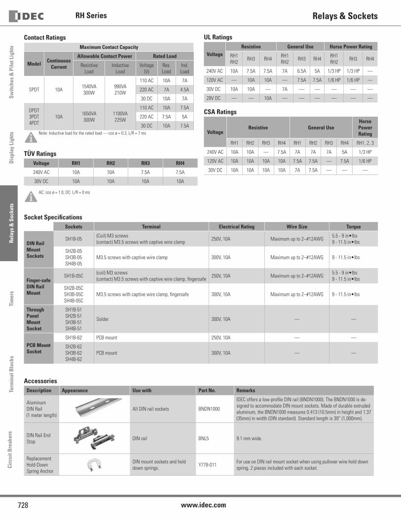
RH Series
728 www.idec.com
Switc
hes
& P
ilot L
ight
sD
ispl
ay L
ight
sRe
lays
& S
ocke
tsTi
mer
sTe
rmin
al B
lock
sCi
rcui
t Bre
aker
sRelays & Sockets
Contact RatingsMaximum Contact Capacity
Model Continuous Current
Allowable Contact Power Rated Load
Resistive
Load
Inductive
Load
Voltage
(V)
Res.
Load
Ind.
Load
SPDT 10A1540VA
300W
990VA
210W
110 AC 10A 7A
220 AC 7A 4.5A
30 DC 10A 7A
DPDT
3PDT
4PDT
10A1650VA
300W
1100VA
225W
110 AC 10A 7.5A
220 AC 7.5A 5A
30 DC 10A 7.5A
Note: Inductive load for the rated load — cos ø = 0.3, L/R = 7 ms
TÜV RatingsVoltage RH1 RH2 RH3 RH4
240V AC 10A 10A 7.5A 7.5A
30V DC 10A 10A 10A 10A
AC: cos ø = 1.0, DC: L/R = 0 ms
Socket Specifi cationsSockets Terminal Electrical Rating Wire Size Torque
DIN Rail Mount Sockets
SH1B-05(Coil) M3 screws
(contact) M3.5 screws with captive wire clamp250V, 10A Maximum up to 2–#12AWG
5.5 - 9 in•lbs
9 - 11.5 in•lbs
SH2B-05
SH3B-05
SH4B-05
M3.5 screws with captive wire clamp 300V, 10A Maximum up to 2–#12AWG 9 - 11.5 in•lbs
Finger-safe DIN Rail Mount
SH1B-05C(coil) M3 screws
(contact) M3.5 screws with captive wire clamp, fi ngersafe250V, 10A Maximum up to 2–#12AWG
5.5 - 9 in•lbs
9 - 11.5 in•lbs
SH2B-05C
SH3B-05C
SH4B-05C
M3.5 screws with captive wire clamp, fi ngersafe 300V, 10A Maximum up to 2–#12AWG 9 - 11.5 in•lbs
ThroughPanel Mount Socket
SH1B-51
SH2B-51
SH3B-51
SH4B-51
Solder 300V, 10A — —
PCB Mount Socket
SH1B-62 PCB mount 250V, 10A — —
SH2B-62
SH3B-62
SH4B-62
PCB mount 300V, 10A — —
AccessoriesDescription Appearance Use with Part No. Remarks
Aluminum
DIN Rail
(1 meter length)
All DIN rail sockets BNDN1000
IDEC offers a low-profi le DIN rail (BNDN1000). The BNDN1000 is de-
signed to accommodate DIN mount sockets. Made of durable extruded
aluminum, the BNDN1000 measures 0.413 (10.5mm) in height and 1.37
(35mm) in width (DIN standard). Standard length is 39” (1,000mm).
DIN Rail End
StopDIN rail BNL5 9.1 mm wide.
Replacement
Hold-Down
Spring Anchor
DIN mount sockets and hold
down springs. Y778-011
For use on DIN rail mount socket when using pullover wire hold down
spring. 2 pieces included with each socket.
UL Ratings
VoltageResistive General Use Horse Power Rating
RH1
RH2RH3 RH4
RH1
RH2RH3 RH4
RH1
RH2RH3 RH4
240V AC 10A 7.5A 7.5A 7A 6.5A 5A 1/3 HP 1/3 HP —
120V AC — 10A 10A — 7.5A 7.5A 1/6 HP 1/6 HP —
30V DC 10A 10A — 7A — — — — —
28V DC — — 10A — — — — — —
CSA Ratings
VoltageResistive General Use
Horse Power Rating
RH1 RH2 RH3 RH4 RH1 RH2 RH3 RH4 RH1, 2, 3
240V AC 10A 10A — 7.5A 7A 7A 7A 5A 1/3 HP
120V AC 10A 10A 10A 10A 7.5A 7.5A — 7.5A 1/6 HP
30V DC 10A 10A 10A 10A 7A 7.5A — — —

RH Series
729USA: 800-262-IDEC Canada: 888-317-IDEC
Switches &
Pilot LightsD
isplay LightsRelays &
SocketsTim
ersTerm
inal Blocks
Circuit Breakers
Relays & Sockets
Specifi cationsContact Material Silver cadmium oxide
Contact Resistance 1 50mΩ maximum
Minimum Applicable Load 24V DC, 30 mA; 5V DC, 100 mA (reference value)
Operate Time 2
SPDT
DPDT20ms maximum
3PDT
4PDT25ms maximum
Release Time 2
SPDT
DPDT20ms maximum
3PDT
4PDT25ms maximum
Power Consumption (approx.)
SPDT AC: 1.1VA (50Hz), 1VA (60Hz) DC: 0.8W
DPDT AC: 1.4VA (50Hz), 1.2VA (60Hz) DC: 0.9W
3PDT AC: 2VA (50Hz), 1.7VA (60Hz) DC: 1.5W
4PDT AC: 2.5VA (50Hz), 2VA (60Hz) DC: 1.5W
Insulation Resistance 100MΩ minimum (500V DC megger)
Dielectric Strength 3
SPDTBetween live and dead parts: 2,000V AC, 1 minute
Between contact and coil: 2,000V AC, 1 minute
Between contacts of the same pole: 1,000V AC, 1 minute
DPDT
3PDT
4PDT
Between live and dead parts: 2,000V AC, 1 minute
Between contact and coil: 2,000V AC, 1 minute
Between contacts of different poles: 2,000V AC, 1 minute
Between contacts of the same pole: 1,000V AC, 1 minute
Operating Frequency Electrical: 1,800 operations/hour maximum
Mechanical: 18,000 operations/hour maximum
Vibration Resistance Damage limits: 10 to 55Hz, amplitude 0.5 mm
Operating extremes: 10 to 55Hz, amplitude 0.5 mm
Shock ResistanceDamage limits: 1,000m/s2 (100G)
Operating extremes: 200m/s2 (20G - SPDT, DPDT)
100m/s2 (10G - 3PDT, 4PDT)
Mechanical Life 50,000,000 operations minimum
Electrical Life
DPDT 500,000 operations minimum (120V AC, 10A)
SPDT
3PDT
4PDT
200,000 operations minimum (120V AC, 10A)
Operating Temperature 4
SPDT –25 to +50°C (no freezing)
DPDT
3PDT
4PDT
–25 to +40°C (no freezing)
Operating Humidity 45 to 85% RH (no condensation)
Weight (approx.) SPDT: 24g, DPDT: 37g, 3PDT: 50g, 4PDT: 74g
Note: Above values are initial values.
1. Measured using 5V DC, 1A voltage drop method
2. Measured at the rated voltage (at 20°C), excluding contact bouncing
Release time of relays with diode: 40 ms maximum
3. Relays with indicator or diode: 1000V AC, 1 minute
4. For use under different temperature conditions, refer to Continuous Load Current vs. Operating Temperature Curve. The operating
temperature range of relays with indicator or diode is –25 to +40°C.


Switc
hes
& P
ilot L
ight
sSi
gnal
ing
Ligh
tsRe
lays
& S
ocke
tsTi
mer
sCo
ntac
tors
Term
inal
Blo
cks
Circ
uit B
reak
ers
RTE Timers
836 www.IDEC.com
Timers
RTERTE Series — Analog Timers
Key features:• 20 time ranges and 10 timing functions• Time delays up to 600 hours• Space-saving package• High repeat accuracy of ± 0.2%• ON and timing OUT LED indicators• Standard 8- or 11-pin and 11-blade termination• 2 form C delayed output contacts• 10A Contact Rating
Cert. No. E9950913332316 (EMC, RTE)Cert. No. BL960813332355 (LVD, RTE)
UL ListedFile No. E66043
General Specifications Contact RatingsOperation System Solid state CMOS Circuit
Contact Configuration 2 Form C, DPDT (Delay output)
Allowable Voltage / Allowable Current 240V AC, 30V DC / 10A
Maximum Permissible Operating Frequency 1800 cycles per hour
Rated Load
Resistive 10A 240V AC, 30V DC
Inductive 7A 240V AC, 30V DC
Horse Power Rating 1/6 HP 120V AC, 1/3 HP 240V AC
LifeElectrical 500,000 op. minimum (Resistive)
Mechanical 50,000,000 op. minimum
Operation Type Multi-Mode
Time Range 0.1sec to 600 hours
Pollution Degree 2 (IE60664-1)
Over voltage category III (IE60664-1)
Rated Operational Voltage
AF20 100-240V AC(50/60Hz)
AD24 24V AC(50/60Hz)/24V DC
D12 12V DC
Voltage Tolerance
AF20 85-264V AC(50/60Hz)
AD24 20.4-26.4V AC(50/60Hz)/21.6-26.4V DC
D12 10.8-13.2V DC
Input off Voltage Rated Voltage x10% minimum
Ambient Operating Temperature -20 to +65ºC (without freezing)
Ambient Storage and Transport Temperature -30 to +75ºC (without freezing)
Relative Humidity 35 to 85%RH (without condensation)
Atmospheric Pressure 80kPa to 110kPa (Operating), 70kPa to 110kPa (Transport)
Reset Time 100msec maximum
Repeat Error ±0.2%, ±20msec*
Voltage Error ±0.2%, ±20msec*
Temperature Error ±0.5%, ±20msec*
Setting Error ±10% maximum
Insulation Resistance 100MΩ minimum (500V DC)
Dielectric Strength
Between power and output terminals: 2000V AC, 1 minute
Between contacts of different poles: 2000V AC, 1 minute
Between contacts of the same pole:1000V AC, 1 minute
Vibration Resistance 10 to 55Hz amplitude 0.5mm2 hours in each of 3 axes
Shock Resistance
Operating extremes: 98m/sec2 (10G)
Damage limits: 490m/sec2 (50G)
3 times in each of 3 axes
Degree of Protection IP40 (enclosure) (IEC60529)
Power Consumption (Approx.)
TYPE RTE-P1, -B1 RTE-P2, -B2
*For the value of the error against a preset time, whichever the largest, applies.
AF20120V AC/60Hz 6.5VA 6.6VA
240V AC/60Hz 11.6VA 11.6VA
24V AC 60Hz/DC 3.4VA/1.7W 3.5VA/1.7W
D12 1.6W 1.6W
Mounting Position Free
DimensionsRTE-P1, P2 40Hx 36W x 77.9D mm
RTE-B1, B2 40Hx 36W x 74.9D mm
Weight (Approx.)RTE-P1 RTE-P2 RTE-B1, -B2
87g 89g 85g

Switches &
Pilot LightsSignaling Lights
Relays & Sockets
Timers
ContactorsTerm
inal BlocksCircuit Breakers
837800-262-IDEC (4332) • USA & Canada
RTETimers
Part Numbering Guide
RTE series part numbers are composed of 4 part number codes. When ordering a RTE series part, select one code from each category. Example: RTE-P1AF20
RTE — P 1 AF20
j Series k Terminal Style
l Function Group
m Input Voltage
Part Numbers: RTE SeriesDescription Part Number Code Remarks
j Series RTE series RTE For internal circuits, see next page.
k Terminal StylePin P
Select one only.Blade B
l Function GroupON-delay, interval, cycle OFF, cycle ON 1 Each function group has different timing functions.
ON-delay, cycle OFF, cycle ON, signal ON/OFF delay, OFF-delay, one-shot 2 See page 832.
m Input Voltage
100 to 240V AC(50/60Hz) AF20
24V AC(50/60Hz)/24V DC AD24
12V DC D12
Part Numbers
VoltagePower Triggered Start Input Triggered
8-Pin Blade 11-Pin Blade
12V DC RTE-P1D12 RTE-B1D12 RTE-P2D12 RTE-B2D12
24V AC/DC RTE-P1AD24 RTE-B1AD24 RTE-P2AD24 RTE-B2AD24
100-240V AC RTE-P1AF20 RTE-B1AF20 RTE-P2AF20 RTE-B2AF20
Time Range Determined by Time Range Selector and Dial SelectorDial 0 - 1 0 - 3 0 - 10 0 - 30 0 - 60
Rang
e
Second 0.1 sec - 1 sec 0.1 sec - 3 sec 0.2 sec - 10 sec 0.6 sec - 30 sec 1.2 sec - 60 sec
Minute 1.2 sec - 1 min 3.6 sec - 3 min 12 sec - 10 min 36 sec - 30 min 1.2 min - 60 min
Hour 1.2 min - 1 hr 3.6 min - 3 hr 12 min - 10 hr 36 min - 30 hr 1.2 hr - 60 hr
10 Hours 12 min - 10 hr 36 min - 30 hr 2 hr - 100 hr 6 hr - 300 hr 12 hr - 600 hr
jschoenberg
Highlight
jschoenberg
Highlight
jschoenberg
Highlight
jschoenberg
Highlight
jschoenberg
Highlight
jschoenberg
Highlight
jschoenberg
Highlight

Switc
hes
& P
ilot L
ight
sSi
gnal
ing
Ligh
tsRe
lays
& S
ocke
tsTi
mer
sCo
ntac
tors
Term
inal
Blo
cks
Circ
uit B
reak
ers
RTE Timers
838 www.IDEC.com
Timing Diagrams
RTE-P1, -B1
RTE-P2
1110
9
12
3
45 6 7
8
(~/-)(~/+)
start
RTE-B2
2 3
A B
9
1
(~/-)(~/+)
4 5 6
7 8
2 3
A B
9
1
(~/-)(~/+)
4 5 6
7 8
RTE-B1
1
2
3
4 5
6
7
8
(~/-)(~/+)
RTE-P1
startexternalcontrolsignal
externalcontrolsignal
RTE-P2
1110
9
12
3
45 6 7
8
(~/-)(~/+)
start
RTE-B2
2 3
A B
9
1
(~/-)(~/+)
4 5 6
7 8
2 3
A B
9
1
(~/-)(~/+)
4 5 6
7 8
RTE-B1
1
2
3
4 5
6
7
8
(~/-)(~/+)
RTE-P1
startexternalcontrolsignal
externalcontrolsignal
1. RTE-B1: Do not apply voltage to terminals #2, #5 & #8.2. IDEC sockets are as follows: RTE-P1: SR2P-06* pin type socket,
RTE-B1: SR3B-05* blade type socket, (*-may be followed by suffix letter A,B,C or U).
A: ON-Delay 1 (power start)Set timer for desired delay, apply power to coil. Contacts transfer after preset time has elapsed, and remain in transferred position until timer is reset. Reset occurs with removal of power.
Item Terminal Number Operation
Power (1) 2 - 7(2) A - B
Delayed Contact
(1) 1 - 4, 5 - 8(2) 1 - 7, 3 - 9 (NC)
(1) 1 - 3, 6 - 8(2) 4 - 7, 6 - 9 (NO)
IndicatorPWR
OUT
Set TimeT
C: Cycle 1 (power start, OFF first)Set timer for desired delay, apply power to coil. First transfer of contacts occurs after preset delay has elapsed, after the next elapse of preset delay contacts return to original position. The timer now cycles between on and off as long as power is applied (duty ratio 1:1).
Item Terminal Number Operation
Power (1) 2 - 7(2) A - B
Delayed Contact
(1) 1 - 4, 5 - 8(2) 1 - 7, 3 - 9 (NC)
(1) 1 - 3, 6 - 8(2) 4 - 7, 6 - 9 (NO)
IndicatorPWR
OUT
Set TimeT T
B: Interval (power start)Set timer for desired delay, apply power to coil. Contacts transfer immediately, and return to original position after preset time has elapsed. Reset occurs with removal of power.
Item Terminal Number Operation
Power (1) 2 - 7(2) A - B
Delayed Contact
(1) 1 - 4, 5 - 8(2) 1 - 7, 3 - 9 (NC)
(1) 1 - 3, 6 - 8(2) 4 - 7, 6 - 9 (NO)
IndicatorPWR
OUT
Set TimeT
C: Cycle 3 (power start, ON first)Functions in same manner as Mode C, with the exception that first transfer of contacts occurs as soon as power is applies. The ratio is 1:1. Time On = Time Off
Item Terminal Number Operation
Power (1) 2 - 7(2) A - B
Delayed Contact
(1) 1 - 4, 5 - 8(2) 1 - 7, 3 - 9 (NC)
(1) 1 - 3, 6 - 8(2) 4 - 7, 6 - 9 (NO)
IndicatorPWR
OUT
Set TimeT T

Switches &
Pilot LightsSignaling Lights
Relays & Sockets
Timers
ContactorsTerm
inal BlocksCircuit Breakers
839800-262-IDEC (4332) • USA & Canada
RTETimers
Timing Diagrams con’t
RTE-P2, -B2
RTE-P2
1110
9
12
3
45 6 7
8
(~/-)(~/+)
start
RTE-B2
2 3
A B
9
1
(~/-)(~/+)
4 5 6
7 8
2 3
A B
9
1
(~/-)(~/+)
4 5 6
7 8
RTE-B1
1
2
3
4 5
6
7
8
(~/-)(~/+)
RTE-P1
startexternalcontrolsignal
externalcontrolsignal
RTE-P2
1110
9
12
3
45 6 7
8
(~/-)(~/+)
start
RTE-B2
2 3
A B
9
1
(~/-)(~/+)
4 5 6
7 8
2 3
A B
9
1
(~/-)(~/+)
4 5 6
7 8
RTE-B1
1
2
3
4 5
6
7
8
(~/-)(~/+)
RTE-P1
startexternalcontrolsignal
externalcontrolsignal 1. RTE-P2: Do not apply voltage to terminals #5, #6 & #7.
2. RTE-B2: Do not apply voltage to terminals #2, #5 & #8.3. IDEC sockets are as follows: RTE-P2: SR3P-05* pin type socket,
RTE-B2: SR3B-05* blade type socket, (*-may be followed by suffix letter A,B,C or U).
A: ON-Delay 2 (signal start)When a preset time has elapsed after the start input turned on while power is on, the NO output contact goes on.
Item Terminal Number Operation
Power (A) 2 - 10(B) A - B
Start (A) 5 - 6(B) 2 - 5
Delayed Contact
(A) 1 - 4, 8 - 11(B) 1 - 7, 3 - 9 (NC)
(A) 1 - 3, 9 - 11(B) 4 - 7, 6 - 9 (NO)
IndicatorPWR
OUT
Set TimeT
C: Cycle 4 (signal start, ON first)When the start input turns on while power is on, the NO contact goes on. The output oscillates at a preset cycle (duty ratio 1:1).
Item Terminal Number Operation
Power (A) 2 - 10(B) A - B
Start (A) 5 - 6(B) 2 - 5
Delayed Contact
(A) 1 - 4, 8 - 11(B) 1 - 7, 3 - 9 (NC)
(A) 1 - 3, 9 - 11(B) 4 - 7, 6 - 9 (NO)
IndicatorPWR
OUT
Set TimeT T T T T T T T Ta
E: Signal OFF-DelayWhen power is turned on while the start input is on, the NO output contact goes on. When a preset time has elapsed after the start input turned off, the NO output contact goes off.
Item Terminal Number Operation
Power (A) 2 - 10(B) A - B
Start (A) 5 - 6(B) 2 - 5
Delayed Contact
(A) 1 - 4, 8 - 11(B) 1 - 7, 3 - 9 (NC)
(A) 1 - 3, 9 - 11(B) 4 - 7, 6 - 9 (NO)
IndicatorPWR
OUT
Set TimeT Ta T Ta
B: Cycle 2 (signal start, OFF first)When the start input turns on while power is on, the output oscillates at a preset cycle (duty ratio 1:1), starting while the NO contact off.
Item Terminal Number Operation
Power (A) 2 - 10(B) A - B
Start (A) 5 - 6(B) 2 - 5
Delayed Contact
(A) 1 - 4, 8 - 11(B) 1 - 7, 3 - 9 (NC)
(A) 1 - 3, 9 - 11(B) 4 - 7, 6 - 9 (NO)
IndicatorPWR
OUT
Set TimeT T T T T T T T T Ta
D: Signal ON/OFF-DelayWhen the start input turns on while power is on, the NO output contact goes on. When a preset time has elapsed while the start input remains on, the output contact goes off. When the start input turns off, the NO contact goes on again. When a preset time has elapsed after the start input turned off, the NO contact goes off.
Item Terminal Number Operation
Power (A) 2 - 10(B) A - B
Start (A) 5 - 6(B) 2 - 5
Delayed Contact
(A) 1 - 4, 8 - 11(B) 1 - 7, 3 - 9 (NC)
(A) 1 - 3, 9 - 11(B) 4 - 7, 6 - 9 (NO)
IndicatorPWR
OUT
Set TimeT T Ta T T Ta
F: One-Shot (signal start)When the start input turns on while power is on, the NO output contact goes on. When a preset time has elapsed, the NO output contact goes off.
Item Terminal Number Operation
Power (A) 2 - 10(B) A - B
Start (A) 5 - 6(B) 2 - 5
Delayed Contact
(A) 1 - 4, 8 - 11(B) 1 - 7, 3 - 9 (NC)
(A) 1 - 3, 9 - 11(B) 4 - 7, 6 - 9 (NO)
IndicatorPWR
OUT
Set Time

������������ ��� ����������������� ����������� ������������������� ������������������������ ���!���"���� �#���������$��"�� %��&���������������� ���������� ����'��$�������������(
������������� �� ���� ��������"�)�������� �
�������� * ��������������� �&�+�������!��� ������������ �&����������������������� ���,����-���"-��������%���./0��1��� ��-������2"����������%��������������� �+���
�� ������� �� ������ �� ����� 3�&����$������&�4���"�����������5�� 6��/778�9-�� � ������2��:���;+�<=3/=>/����$$$<6�<������6����� �*�?@?�+A3<7/</ 3BB3��+A3<7/<3 3BB3���� �+A3<7> 3BB3�� *����� /�� 3BB0�*+���������30>�� ?+�A/A7=��+�� #��� ?������� �C���������-�������� ?���8BB/:3BBB�+����2� �D�����&�����"�������&������ ?���/EB3>:3BB>�+����2� �9�������
#���)�������������F�����������
�� <�=@7G /7�*�����
?* ����������4�������������<5
����������� ���� ����� ����� �� ���������� �� ����������������������� �� ������������� ������!"�#������$����%�������4�6��9&���3���������5
� 3B)�����H�������6��8A����"-����"�C����������������������� +�������������� ������������� �$���������������� ���������
�� �������&&'��(����(� �$���� �$$���#��)*��� �+&!�%��,-�� �&��� ��,�����.�/$* � �.��� ��� 0�$�,1�����/�2/�"���1�3��!��-��(��4�������,��5���#��6��2���,$$7�� ��#8�*���.���,$$,�����-���(����(�*����1�9���4�$�� 3
� �,(��*����(�*�������!����:���$�;�<�,/�������"��#',�$!� ����������0��*,$�"�,1�����/�3���,� �������=��,� ������ ����,�
"��#��$ ��������%� ������ >B)��0,3BI��C����� ��� 6��/778������ �?�������:�3B)��4-�"-�����%�������5�J�/B)��� 6��/778������ ��++K:�3BB)��4������� ���5��� ���"� #���)�=7����L����������� ?� �%� ����&�M��� �!�9-������&�C������� ������� 6��/778������"��C����������K����"��4�CK�5:
� �ABB������/3B���/3B@37B��3B0N@/3B� �/BBB������3EE���70BN@3EE�
�� K�������%��?������:�>BBB� �=)� 0,3BI�O�/BBB� �/B)� 0,3BI��� ���������������� �������)��"�
"&��� ������%� ������ K�����%��P��� ��&�K��"�:�B 8>Q���� ��� �����"�� ��������"�M��L����&:�7E A=PR�� ��������"�9����������:� 3>�+�4 />�M5����JAB�+�4/7B�M5�� K��������9���:�S�/��������� ��� ���� �������#� ���������������������� *���7T�C��&������������������H6�E7A+4�/5��6��87 >���� C�� $��� �$��-�=(�4/�5����./B��1����� ������� 9&������9&���3�+���������:�./B��1�����=B������)��
�$������
�������������������*���@��9�C����� ���"�������������!�%��� �����
3.26” 3.26”
1.15”
4.13”
3/4”-14
Sized for std 35mm DIN-rail
3.31” 3.57”
Weight: 1.60 lbs(0.73 kg)
��:����H����,������!"� ���1�� �-������������� �� �����
40BB5�3=E 7>AEh4E3E5�>=> A==8�h�M�,�4E3E5�>=8 08>>�
� I,�/� �!����/������/��$�1���
$$$<����%��<����h�����j����%��<����h�$$$<����� <����h�����j����� <���
/7>>B�>0�-��������*���-�h�+����$������M���� ��==EAB

"��#��$ ����� �
8+"��� ���(�
0�$�,1��%�&��21
6��/778�9P?K� ������4�����3BB85
�����"��C����������K����"���CK�=BBB�
.� �&&' 8&+0
�#: �#� :#HJ �#HJ
�>B�/3B�/C� /3B�� ABB ABBk /BBBk 3B)� 3BB)� />B�>B�/3B�3C /3B�@37B� ABB /BBB ABBk /BBBk 3B)� 3BB)� />B�>B�/3B�=N 3B0N@/3B� ABB /BBB ABBk /BBBk 3B)� 3BB)� />B�>B�/3E�/C /3E�� EBB ABBk /3BBk 3B)� /BB)� /0B�>B�/3E�3C /3E@3>7� EBB /3BB ABBk /3BBk 3B)� /BB)� /0B�>B�/3E�=N 33BN@/3E� EBB /3BB ABBk /3BBk 3B)� /BB)� /0B�>B�33B�/C 33B� /����� /3BB /BBBk /0BBk 3B)� 3BB)� =3B�>B�33B�=N =0BN@33B� /3BB 3BBB /BBBk /0BBk 3B)� 3BB)� =3B
�>B�37B�=P /3B@37B�� �P� ��"�����
ABB@/3BB
/BBB@/>BB ABBk /BBBk
@/>BBk 3B)� 3BB)� />B@=3B
�>B�37B�/C 37B� /����� /3BB /BBB /0BB 3B)� 3BB)� =3B
�>B�37B�= 37B������� =����� />BB /3BB 3B)� 3BB)� =3B
�>B�3EE�/C 3EE� /3BB /BBBk /0BBk 3B)� 3BB)� =3B�>B�3EE�3C 37B@70B� /3BB 3BBB /BBBk /0BBk 3B)� 3BB)� =3B�>B�3EE�=N 70BN@3EE� /3BB 3BBB /BBBk /0BBk 3B)� 3BB)� =3B�>B�=7E�=N ABBN@=7EN />BB 3>BB /3BBk 3>BBk 3B)� 3BB)� 73B�>B�70B�/C 70B� /����� /0BB /B)� 3BB)� >>B
�>B�70B�= 70B������� =����� =BBB /0BB /B)� 3BB)� >>B
�>B�70B�=P 37B@70B�� P� ��"�����
/3BB@/0BB 3>BB /B)� 3BB)� =3B@
>>B
�>B�ABB�= ABB������� =����� 3>BB 3>BB 3B)� 3BB)� A8B
�/BB�/3B�3C /3B@37B� ABB /BBB ABB 3B)� /BB)� />B�/BB�3EE�3C 37B@70B� /BBB /0BB /BBB 3B)� /BB)� =3B
k�$��-����������* ������������
�����
����� ����� '���� ��������
��!�
$��#�
���1
$���
!�$�
�#���
$���!
,��
K �
L�#�
�1"
�$�,
�N�9��+�*M?�6K�9?�*
?*�9����n/B(4=�5�MK����K�?+��*9K�*+��K��9K�*�M�K�K
?*�9�����9��K�*�K��K�?+��*9K�*+��K��9K�*�M�K�K
:#H�<�� � �#�����������L�����* ������������
"�M�����,(��-�:#H�<�� �#�* �������������
��""����
� %���� �C����������9��-����"���/7>>B�>0�-��������*���-���+����$������M���� ��==EAB
E3E<>=><A==8�����,:�E3E<>=8<088>���0BB<3=E<7>AE$$$$<����%��<����������j����%��<���
������(�$)���� >B � ���9�� �N�9� +!.+:�
)�@C-��� ������ /3B� /C *>B)� /3E� 3C
33B� =N 337B�� =3EE� =P=7E�70B�ABB�
�����
/C�����C��������"���C-���
3C�9$��C�����������C-���
=N�9-����C����1&�
=�9-����C��������
=P�9-����C����P� ��"�����
*���* ��C�������������&�+�������!��� ����������3���9&���3��C#�����"��6�����)
,������:���>B�/3B�=N���>B)���/3B���=������43B0N@/3B�5�>B�3EE�=N*���>B)���3EE���=������470BN@3EE�5��$��-�* �
����� �����$�*�����*��� ��� ���'��)���'� �$
N��(�&�"� �&���,/�39-����4=5�./0�$������,����-����������������&����+�������#�������*������&�������K� ����*������&�+���� �� *������&�����:��
6������&�!�#����� *������&�+���� :��
6������&�!�K�
Phase A (BLK)
Phase B (BLK)Phase C (BLK)Ground (GRN)
Voltage Model Number
BLK
BLKBLK
GRN
Hot (BLK)
Neutral (WHT)
Ground (GRN)
Voltage Model Number Model Number
BLK
WHT
BLK
WHT
GRN
Hot (BLK)
Hot (BLK)
Neutral (WHT)
Ground (GRN)
Voltage Model Number Model Number
}}
}
BLK
BLKWHT
BLK
BLKWHT
GRN
Phase B (ORNG)Phase A (BLK)
Hot (BLK)Neutral (WHT) Ground (GRN)
Voltage Model Number Model Number
BLK
BLK
ORNG
WHT
BLK
BLK
ORNG
WHT
GRN
Hot (BLK)Ground (GRN)
Neutral (WHT)
Phase B (BLK)Phase A (BLK)
Voltage Model Number Model Number
A
N
C
B
BLK
BLK
BLK
WHT
BLK
BLK
BLK
GRN
WHT
S50A240V3HS50A480V3HN
S50A240V3D
Advanced Protection Technologies14550 58th St. N.Clearwater, FL 33760800.237.4567 X www.aptspd.com
Advanced Protection Technologies14550 58th St. N.Clearwater, FL 33760800.237.4567 X www.aptspd.com
Advanced Protection Technologies14550 58th St. N.Clearwater, FL 33760800.237.4567 X www.aptspd.com
Advanced Protection Technologies14550 58th St. N.Clearwater, FL 33760800.237.4567 X www.aptspd.com
Advanced Protection Technologies14550 58th St. N.Clearwater, FL 33760800.237.4567 X www.aptspd.com
Advanced Protection Technologies14550 58th St. N.Clearwater, FL 33760800.237.4567 X www.aptspd.com
Advanced Protection Technologies14550 58th St. N.Clearwater, FL 33760800.237.4567 X www.aptspd.com
Advanced Protection Technologies14550 58th St. N.Clearwater, FL 33760800.237.4567 X www.aptspd.com
Advanced Protection Technologies14550 58th St. N.Clearwater, FL 33760800.237.4567 X www.aptspd.com
v
v
v
vv
v
&�������H��*� � �
"�$�,]�6���������� ����!��������������C�����)�!�"��������"���� �4 ��"��������$���������������������&5�
K�%+��3<//</B���.�0/E8
�* �4$���$,�(3���������� ��$-�����&��������������������4?�� ��"����������,���"���-���4�<�<��������5��������$�������� 5
C�$������ �
�&�+��������� �
#��� ���&
K�
jschoenberg
Highlight

Sockets SH Series: DIN Rail Snap-Mount
www.idec.com USA: (800) 262-IDEC or (408) 747-0550, Canada (888) 317-IDEC F-9
F
SH Series: DIN Rail Snap-Mount Sockets
SH1B Sockets
SH1B-05
Style 5-blade, snap-mount/surface mount
Terminal (Coil) M3 screws/(contact) M3.5 screwswith captive wire clamp
Wire Size Maximum up to 2–#12AWG
Electrical Rating 250V, 10A
Compatible Relay RH1B
Hold-Down Spring SY2S-02F1
Hold-Down Clip SFA-101 (top notch), SFA-202 (side notch)
(14.5mm)0.566"
(8mm)0.315"
(17mm)0.663"
(2.5mm)0.098" (16mm)
0.63"
(20mm)0.780"
Ø 0.164"(4.2mm)
5
1
149
13
(25mm)0.975"
(47mm)1.833"
(28.5mm)1.122"
(67mm)2.613"
DINRail
0.63"(16mm)
Ø 0.164"(4.2mm)2 Holes
0.172"(4.4mm) 0.216"(5.5mm)
Ø 0.140"(3.6mm)
(7.9mm)0.311"
Ø 0.137"(M3.5)
Panel Cutout for Surface Mounting
SH1B-05C Fingersafe
Style 5-blade, snap-mount/surface mount
Terminal(Coil) M3 screws/(contact) M3.5 screws with captive wire clamp, fingersafe
Wire Size Maximum up to 2–#12AWG
Electrical Rating 250V, 10A
Compatible Relay RH1B
Hold-Down Spring SY2S-02F1
Hold-Down Clip SFA-101 (top notch), SFA-202 (side notch)
5
1
149
13
(7mm)0.275"
(17mm)0.663"
(1.5mm)0.059" (16mm)
0.63"
(20mm)0.780"
Ø 0.164"(4.2mm)
(69mm)2.691"
(18.7mm)0.729"
(29.5mm)1.150"
(48mm)1.872"
(33mm)1.287"
DINRail
0.63"(16mm)
Ø 0.164"(4.2mm)2 Holes
Ø 0.137"(M3.5)
Panel Cutout for Surface Mounting
1. For socket mounting accessories, see page F-24.2. For hold-down clip/spring selections, see page F-4.
alawler
Highlight

Sockets SH Series: DIN Rail Snap-Mount
F-10 www.idec.com USA: (800) 262-IDEC or (408) 747-0550, Canada (888) 317-IDEC
F
SH2B Sockets
SH2B-05
Style 8-blade, snap-mount/surface mount
Terminal M3.5 screws with captive wire clamp
Wire Size Maximum up to 2–#12AWG
Electrical Rating 300V, 10A
Compatible Relay RH2B
Hold-Down Spring SY4S-02F1
Hold-Down Clip SFA-101 (top notch), SFA-202 (side notch)
(25mm)0.975"
(14.5mm)0.566"
(18mm)0.702"(28.5mm)
1.122"
1.170"(30mm)
1.023"(26mm)
Ø 0.164"(4.2mm)
(8mm)0.315"
(22mm)0.858"
(2.5mm)0.098"
14 13
12 9
8 5
4 1
(47mm)1.833"
DINRail(67mm)
2.613"
1.023"(26mm)
Ø 0.164"(4.2mm)2 Holes
0.172"(4.4mm) 0.216"(5.5mm)
Ø 0.140"(3.6mm)
(7.9mm)0.311"Ø 0.137"(M3.5)
TerminalArrangements
(top view)
Panel Cutout for Surface Mounting
SH2B-05C Fingersafe
Style 8-blade, snap-mount/surface mount
Terminal M3.5 screws with captive wire clamp, finger-safe
Wire Size Maximum up to 2–#12AWG
Electrical Rating 300V, 10A
Compatible Relay RH2B
Hold-Down Spring SY4S-02F1
Hold-Down Clip SFA-101 (top notch), SFA-202 (side notch)
14 13
12 9
8 5
4 1
(29.5mm)1.150"
(18.7mm)0.729"
(33mm)1.299"
(49mm)1.911"
DINRail
1.170"(30mm)
1.023"(26mm)
Ø 0.164"(4.2mm)
(7mm)0.275"
(22mm)0.858"
(1.5mm)0.059"
(69mm)2.699"
1.023"(26mm)
Ø 0.164"(4.2mm)2 Holes
Ø 0.137"(M3.5)
Panel Cutout for Surface Mounting
1. For socket mounting accessories, see page F-24.2. For hold-down clip/spring selections, see page F-4.
alawler
Highlight

Sockets SH Series: DIN Rail Snap-Mount
www.idec.com USA: (800) 262-IDEC or (408) 747-0550, Canada (888) 317-IDEC F-11
F
SH3B Sockets
SH3B-05
Style 11-blade, snap-mount/surface mount
Terminal M3.5 screws with captive wire clamp
Wire Size Maximum up to 2–#12AWG
Electrical Rating 300V, 10A
Compatible Relay RH3B, RH2LB
Hold-Down Spring SH3B-05F1
Hold-Down Clip SFA-101 (top notch), SFA-202 (side notch)
(14.5mm)0.566"
(18mm)0.709"
(8mm)
(2.5mm)0.098"
Ø 0.164"(4.2mm)
8 6 5
4 2 1
14 13
12 10 9
DINRail
(25mm)0.975"
(28.5mm)1.122"
(47mm)1.833"
Ø 0.137"(M3.5)
0.315" (32mm)1.248"
(36mm)1.417"
(40mm)1.560"
(67mm)2.613"
1.417"(36mm)
Ø 0.164"(4.2mm)2 Holes
0.172"(4.4mm) 0.216"
(5.5mm)
Ø 0.140"(3.6mm)
(7.9mm)0.308"
Panel Cutout for Surface Mounting
SH3B-05C Fingersafe
Style 11-blade, snap-mount/surface mount
Terminal M3.5 screws with captive wire clamp, fingersafe
Wire Size Maximum up to 2–#12AWG
Electrical Rating 300V, 10A
Compatible Relay RH3B, RH2LB
Hold-Down Spring SH3B-05F1
Hold-Down Clip SFA-101 (top notch), SFA-202 (side notch)
8 6 5
4 2 1
14 13
12 10 9
(8mm)
(2.5mm)0.098"
Ø 0.164"(4.2mm)
Ø 0.137"(M3.5)
0.315" (32mm)1.248"
(36mm)1.417"
(40mm)1.560"
(69mm)2.716"
DINRail
(33mm)1.299"
(18.7mm)0.737"
(49mm)1.92"
(29.5mm)1.16"
1.417"(36mm)
Ø 0.164"(4.2mm)2 Holes
TerminalArrangements
(top view)
Panel Cutout for Surface Mounting
1. For socket mounting accessories, see page F-24.2. For hold-down clip/spring selections, see page F-4.
alawler
Highlight

Sockets SR Series: DIN Rail Snap-Mount
F-6 www.idec.com USA: (800) 262-IDEC or (408) 747-0550, Canada (888) 317-IDEC
F
SR Series: DIN Rail Snap-Mount Sockets
SR2P Sockets
SR2P-05
Style 8-pin octal, snap-mount/surface mount
Terminal M3.5 screws with captive wire clamp
Wire Size Maximum up to 2–#12AWG
Electrical Rating 300V, 10A
Compatible Relay RR2P
Compatible Timer RTE-P1, GT3 (8-pin), GT5P, GE1A
Hold-Down Spring SR2B-02F1 (for RR2P)
Hold-Down Clip SFA-203 (for timers only, except GE1A)
1.142"(29mm)
(8mm)0.315"
0.117"(3mm)
Ø 0.137"
(4.2mm)Ø 0.165"
(16.5mm)0.644"
1.111"(28.5mm)
0.780"(20mm)
(25mm)0.975"(33mm)1.287"
(32mm)1.250"
DINRail
(36mm)1.417"
(M3.5)
2 Holes
2.028"(52mm)
5
6
4
3
7
8
2
1
1.142"(29mm)
Ø 0.164"(4.2mm)2 Holes
0.172"(4.4mm) 0.195"(5mm)
Ø 0.140"(3.6mm)
(7.8mm)0.307"
TerminalArrangements
(top view)
Panel Cutout for Surface Mounting
SR2P-05C Fingersafe
Style 8-pin octal, snap-mount/surface mount
Terminal M3.5 screws with captive wire clamp, fingersafe
Wire Size Maximum up to 2–#12AWG
Electrical Rating 300V, 10A
Compatible Relay RR2P
Compatible Timer RTE-P1, GT3 (8-pin), GT5P, GE1A
Hold-Down Spring SR2B-02F1 (for RR2P)
Hold-Down Clip SFA-203 (for timers only, except GE1A)
(21.5mm)0.839"
(7mm)0.273"
0.086"(2.2mm)
DINRail
(30mm)1.170"
(10mm)0.390"
(16mm)0.624"
(33.5mm)1.307"
(58mm)2.262"
1.142"(29mm)
(36mm)1.404"
Ø 0.137"
(4.2mm)Ø 0.165"
(M3.5)
2 Holes
5
6
4
3
7
8
2
1
1.142"(29mm)
Ø 0.164"(4.2mm)2 Holes
Panel Cutout for Surface Mounting
SR2P-06
Style 8-pin octal, snap-mount/surface mount
Terminal M3.5 screws with captive wire clamp
Wire Size Maximum up to 2–#12AWG
Electrical Rating 300V, 10A
Compatible Relay RR2P
Compatible Timer RTE-P1, GT3 (8-pin), GT5P, GE1A
Hold-Down Spring SR2B-02F1 (for RR2P)
Hold-Down Clip SFA-202 (for timers only, except GE1A)
(18mm)0.702"
(8mm)0.315"
DINRail(25mm)
0.975"
(25.5mm)0.995"
0.858"(22mm)
0.039"(1mm)
(40mm)1.560"
(60mm)2.340"
1.299"(33mm)
Ø 0.137"
(4.2mm)Ø 0.165"
(M3.5)
2 Holes
6 5 4 3
7 8 1 2
1.299"(33mm)
Ø 0.164"(4.2mm)2 Holes
0.172"(4.4mm) 0.195"(5mm)
Ø 0.140"(3.6mm)
(7.8mm)0.307"
Panel Cutout for Surface Mounting
1. For socket mounting accessories, see page F-24.2. For hold-down clip/spring selections, see page F-4.
jsalber
Highlight

Type V'tIRW Bracketwith S.S. Eyebolt
TypeW
Ordering Irtormation:IM1en Clf'dering, specify "WRN- (length eX SS wire rope)'Exar1lJle: 'MM'-15'MM' calls out bracket, eyebolt and anchor, 15 calls outfifteen ft eX vinyl coated 316 SS wire rope.
ns.s. uaalll
n
Drwn by: jp Chkd by: JP TYPICAL INSTAU.ATION:1109197 1/10197 Typo W. Roto-Float, Rotc-Roat SST1-------'--------.1 Mni-Aoat, Eco-Float, Solo-Root
• •• •
SUBMITIED _
APPROVED
Roat Cable BracketDetail
anc scleBox 378 Fx: 612-473-6002Long Lake,~ 55356 Ph: 612-473-7115
1/8" 316 Stainless Steel, Vinyl CoatedVVire Rope
s.s. Aircraft. Nuts • •
5.5. Wre RopeClip.ss 'Mre Rope Detail
AAchor 1SLJ)s., VinylCoated Cast Iron
Rev.
DVIKi 2975-1
bberndt
Highlight
bberndt
Highlight

A ~~-~ ~111n1 1 e CELLl LAR MONT ORING SOLL'TIONS
Application
The OmniSite XR50 provides for a flexible, easy to install and configure, powerful equipment and machinery alarm monitor.
The OmniSite XR50 data may be fully integrated into existing SCADA databases using OmniSite's SCADA-Bridge™ software package.
Single Integrated device eliminates the need for multiple PLCs, radios, software, computers, modems, relays and other accessories. Complete packaged unit can be installed in under two hours, without the need for highly specialized technicians.
The XR50 includes OmniSite's "plug and play" Guard Dog web interface which eliminates the need for custom programming.
omniSite products are protected by us Patent #7,228,129 and other patents pending
Item Description The omniSite XR50 alarm monitor provides the capability to monitor remotely located equipment and machinery without dedicated telephone lines or proprietary radio systems. Your connected equipment is completely monitored over the Internet using just a web browser, so there is no software to buy If an abnormal condition occurs, notifications are sent by e-mail, pager, or voice call to any location.
Features • Microprocessor based alarm monitor
• Pulse totalization feature
• Daily reports of accumulated equipment run time
• True SCADA replacement at fraction of cost/complexity
• Cellular GSM coverage works where private radio systems cannot reach
Specification Highlights
Power
communications
Inputs
Access Key
Terminal Blocks
operating Temp.
operating Humidity
certification
Dimensions
Memory Stick
LCD Display
Keypad
12VDC or 120VAC
Cellular GSM 850/900/1800/1900 MHZ
(10) Universal Inputs accept 12VACIVDC -120VACIVDC
smart security key to identify personnel on site
Removable style accepts #14-18 AWG solid or stranded wire
-20/150 Deg F
0-90% RH Non-condensing
UL Pending
8.9"H X 9.4''W X 3.5"D
32Mb- 1 Gb user selectable
Backlit 2 X 16
(4) universal navigation buttons
494 S. Emerson Ave. Suite E I Greenwood, IN 461431 (317) 885-6330 I www.omnisite.com

XR50 Data Sheet
:ELLULAR MONITO RING S O LUT IONS
Ordering Information How OmniSite Works
I Model DescrhJtion
I XR50 XR50 Alarm Monitor
Enclosure 0 11tions
PM No Enclosure - NEMA 1 Rated
EN NEMA 4X Enclosure with Sol id Ouamte Cover
ENCV NEMA 4X Enclosure with Clear See-ThrotHih Cover
Power Sllll l>lv
12 I 12 VD C
120 I 120 VAC
I I XR50 I ENCV 1 120 1
omnrsrte relies on a combrnation of cellular telephone and web based technology. The XR50 rs rnstalled at your remote equrpment and
sends a wireless signal to the local cellu lar tower
That srgnal is bounced to om nrsrte's web interface. where you can log on -any day, any time. from any can puter -and see how your remote
equipment is operatrng. A "call out" list is set up onli ne. so that when an alarm rs triggered. identifred operators are contacted immediately.
Because omnrsrte engineers recognize today·s fast-paced busy world. that notificatron canes by way of text message, emarl or call to your cellular
or hard-wrred phone.
fl ,\1//
~ Equipment Alarm
OmniSite Monitor
~, Cell Tower
Example: XR50-ENCV-120 XR50 Alarm Monitor in NEMA 4X Enclosure w/ clear cover and 120VAC power. ~
Wiring
0
NOTE: The XR50 Universal Voltage Inputs cannot directly monitor a dry contact. Example shows them being powered by Onboard 12VDC supply, but could be any source up to 120VAC
• I
'
+ -
I I : EXAMPi.E:
' 1-ir-+,. .~ • R•c.nttdl
I '--u-i ,..,t ,R•~
I : ·---•114,.••1 : fmt.num
XRSO
lGN
l~<f~l 'I I I
.I I' Q yyy 12UAC lnpul~ u..- .. u
I . : Filii fUltr (E Hl ) ---- .... ~~hlstOU1Pil Mn
___ --+ u, .... ! Ra.lll a.,._ ( EJd f'llla. · · ) - "-'lsi OuJP-1 • D 11~
Th• Intern•! t1
~
494 S. Emerson Ave. Suite E I Greenwood, IN 461431 (317) 885-6330 I www.omnisite.com Copyright© 2009, OmniSite
bberndt
Highlight
bberndt
Highlight
bberndt
Highlight

Lake Poinsett SD
Lake Poinsett Sanitary DistrictLocation:
MO001682-1Job Number
Lift Station NO 5Description:
Sanitary District East and Northeast Lake Drive Wastewater System ExpansionPart 2
Project:
Drawing Index
Learn How To Read Our Drawings!
How To Read Control Panel Schematic Drawings
View Our Short Video
Scan The QR Code Here
Or Click The Link Below Or Search YouTube For The Title:
DescriptionDrawing Number
Control SchematicMO001682-1-1Pump #1 Control SchematicMO001682-1-2Pump #2 Control SchematicMO001682-1-3Control SchematicMO001682-1-4Power SchematicMO001682-1-5Backpanel And Inner LayoutMO001682-1-6Panel LayoutMO001682-1-7
Symbols Wiring Symbols Description Page
UL Labeling
UL698A
Sweeney Controls CompanyPage 1/1 05/11/2018
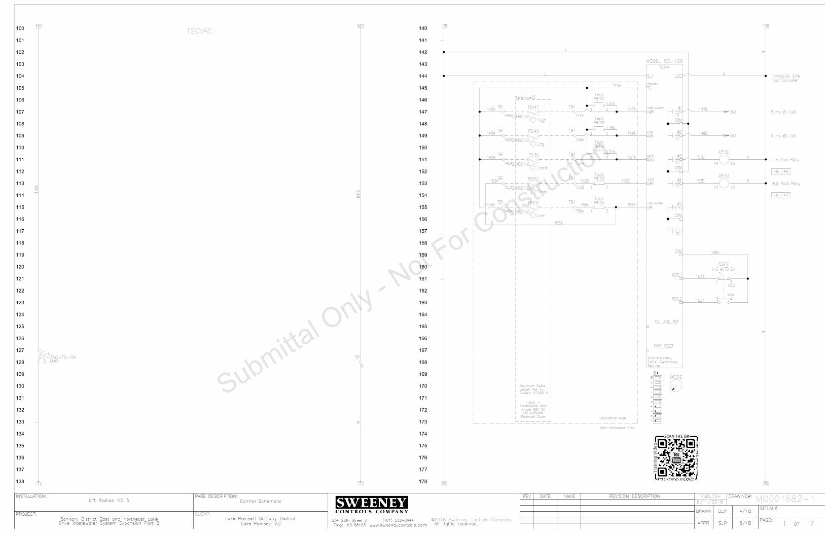
100
101
102
103
104
105
106
107
108
109
110
111
112
113
114
115
116
117
118
119
120
121
122
123
124
125
126
127
128
129
130
131
132
133
134
135
136
137
138
140
141
142
143
144
145
146
147
148
149
150
151
152
153
154
155
156
157
158
159
160
161
162
163
164
165
166
167
168
169
170
171
172
173
174
175
176
177
178
SERIAL#:
PAGE:
INSTALLATION:
PROJECT:
OF
REV
DRAWING#:
PAGE DESCRIPTION:
APPR
REVISION DESCRIPTION
DATE
NAME
DRAWN
All rights reserved.
C
Fargo, ND 58103
SERIAL#:
PAGE:
INSTALLATION:
PROJECT:
OF
REV
DRAWING#:
PAGE DESCRIPTION:
APPR
REVISION DESCRIPTION
DATE
NAME
DRAWN
2018 Sweeney Controls Company.
All rights reserved.
C
Fargo, ND 58103
PUBLISH
CLIENT:
71www.sweeneycontrols.com
234 28th Street S (701) 232-3644
Lift Station NO 5
DLR 4/18
SLR 5/18
Sanitary District East and Northeast Lake Lake Poinsett Sanitary District
Lake Poinsett SD
Control Schematic
71www.sweeneycontrols.com
234 28th Street S (701) 232-3644
Lift Station NO 5
DLR 4/18
SLR 5/18
Sanitary District East and Northeast Lake Lake Poinsett Sanitary District
Lake Poinsett SD
Control Schematic
MO001682-1
5 AMP
F-LF-3AG-TD-5A
TB1
120VAC
138
140
138
140 200 200
Pump #2 Call
Pump #1 Call
Device
Safe Switching
Intrinsically
Electrical Code
The National
Article 504 Of
Accordance With
Install In
Exceed 10,000 ft
Length Not To
Maximum Cable
Hazardous Area
Non-Hazardous Area
Float Controller
MODEL ISS-105
Intrinsically Safe
FC144
L2
SIL._AND_RST
RCTL2
RCTL1
COM
#1
#2
#3
COM
#4
#5
COM
C
#2
PWR_RESET
#3
COM
#4
#1
#5
L1
MODE
43
87
65
12
10
9
ON
1
COMMON
LOW ALARM
STOP
LEAD
LAG
HIGH ALARM
High
FS147
Lag
FS149
Lead
FS151
Stop
FS153
Low
FS155
1-2 AUTO 2-1
SS161
43
21
OOX
XOO
TB1
TB1
TB1
145A
TB1
TB1
TB1
TB1
TB1
TB1
TB1
3 4
PB147
Test
GW60NO
3 4
PB149
Test
GW60NO
3 4
PB151
Test
GW60NO
GW60NO
GW60NO
1 2
PB153Test
1 2
PB155Test
CR153
High Float Relay14 13
CR151
Low Float Relay14 13
343
414 447
416 445
563 563
145A
145A
145A
153A
147A
149A
151A
153B
155A
100
A
145A
145A
145A
145A
145A
147A
149A
151A
153A
153A
147A
149A
151A
153B 153C
155A
153A
147B
149B
151B
153D
159A
161A
163A
243
N
N
L
N
N
100
B
L
L
L
L
N
N
=Wetwell
L
N
5/11/2018
Drive Wastewater System Expansion Part 2Drive Wastewater System Expansion Part 2

200
201
202
203
204
205
206
207
208
209
210
211
212
213
214
215
216
217
218
219
220
221
222
223
224
225
226
227
228
229
230
231
232
233
234
235
236
237
238
240
241
242
243
244
245
246
247
248
249
250
251
252
253
254
255
256
257
258
259
260
261
262
263
264
265
266
267
268
269
270
271
272
273
274
275
276
277
278
SERIAL#:
PAGE:
INSTALLATION:
PROJECT:
OF
REV
DRAWING#:
PAGE DESCRIPTION:
APPR
REVISION DESCRIPTION
DATE
NAME
DRAWN
All rights reserved.
C
Fargo, ND 58103
SERIAL#:
PAGE:
INSTALLATION:
PROJECT:
OF
REV
DRAWING#:
PAGE DESCRIPTION:
APPR
REVISION DESCRIPTION
DATE
NAME
DRAWN
2018 Sweeney Controls Company.
All rights reserved.
C
Fargo, ND 58103
PUBLISH
CLIENT:
72www.sweeneycontrols.com
234 28th Street S (701) 232-3644
Lift Station NO 5
DLR 4/18
SLR 5/18
Sanitary District East and Northeast Lake Lake Poinsett Sanitary District
Lake Poinsett SD
Pump #1 Control Schematic
72www.sweeneycontrols.com
234 28th Street S (701) 232-3644
Lift Station NO 5
DLR 4/18
SLR 5/18
Sanitary District East and Northeast Lake Lake Poinsett Sanitary District
Lake Poinsett SD
Pump #1 Control Schematic
MO001682-1
178 178 238
240
238
240 300 300
Output 2
Analo
g
Output
1
Analo
g
Input 2
Analo
g
Input
1
Analo
g
Source
Sin
k/
for
har
dware e
na
ble)
whe
n
usin
g ter
min
al
01
(re
mo
ve
EN
BL ju
mper
10V
20mA
10V
20mA
10V
20mA
10V
20mA
SNK
SRC
Powerflex 400
Allen Bradley
AO2
AO1
Shld
AI2 Com
AI2
AI1 Com
AI1
+10VDC
Opto Out 1
Opto Com
Relay Out
Relay Out
Enable
Common
Input 4
Input 3
Input 2
Input 1
Common
Rev
Fwd
+24VDCPump #1 VFD
VFD203
R6
R5
R4
R3
R2
R1
20
19
18
17
16
15
14
13
12
11
10
9
8
7
6
5
4
3
2
1
22C-B033N103
G
X2X1
LT225
Pump #1 Running Light
CR221
14 13
Pump #1 Running Relay
Pump #1 Call
TB1
TB1=Pump #1
250A
XOO
OOX
1 2
3 4
HAND OFF AUTO
SS241
CR241
14 13
Pump #1 Call Relay
9 5
CR241
206
CR250
14 13
Pump #1 Thermal
Fail Relay
9 5
CR250
206
4
CR250
12
253
R
X2X1
LT253
Pump #1 Thermal
Fail Light
2 7
On-Delay
TR255
Pump #1 Thermal Fail
Time Delay Relay
2 Sec.
1 2
PB253
1 3
TR255
255
TB1
CR258
14 13
Pump #1 Seal Fail Relay258A
TB1=Pump #1
Seal
A
X2X1
LT260
Pump #1 Seal
Fail Light4
CR258
12
260
2 7
On-Delay
TR263
Pump #1 Fail Time
Delay Relay
1 Sec.
9 1
CR221
263
8
CR241
12
263
R
X2X1
LT265
Pump #1 Fail Light1 3
TR263
265
376
424
426
420
428
9 5
CR441
523
221A
221A
206A 206B 206C
201A
201A
201A
201A
221A
221A
221A
241A
147147C
N
L
L
250A
253A
258A
260A
263A
265A
N
N
N
N
N
N
N
N
N
N
N
N
N
RTM223
Pump #1 Hourmeter
Pump #1 Running
Pump #1 Running
263B
253B
Thermal Reset
L
L
L
L
L
L
L
L
L
L
5/11/2018
Drive Wastewater System Expansion Part 2Drive Wastewater System Expansion Part 2

300
301
302
303
304
305
306
307
308
309
310
311
312
313
314
315
316
317
318
319
320
321
322
323
324
325
326
327
328
329
330
331
332
333
334
335
336
337
338
340
341
342
343
344
345
346
347
348
349
350
351
352
353
354
355
356
357
358
359
360
361
362
363
364
365
366
367
368
369
370
371
372
373
374
375
376
377
378
SERIAL#:
PAGE:
INSTALLATION:
PROJECT:
OF
REV
DRAWING#:
PAGE DESCRIPTION:
APPR
REVISION DESCRIPTION
DATE
NAME
DRAWN
All rights reserved.
C
Fargo, ND 58103
SERIAL#:
PAGE:
INSTALLATION:
PROJECT:
OF
REV
DRAWING#:
PAGE DESCRIPTION:
APPR
REVISION DESCRIPTION
DATE
NAME
DRAWN
2018 Sweeney Controls Company.
All rights reserved.
C
Fargo, ND 58103
PUBLISH
CLIENT:
73www.sweeneycontrols.com
234 28th Street S (701) 232-3644
Lift Station NO 5
DLR 4/18
SLR 5/18
Sanitary District East and Northeast Lake Lake Poinsett Sanitary District
Lake Poinsett SD
Pump #2 Control Schematic
73www.sweeneycontrols.com
234 28th Street S (701) 232-3644
Lift Station NO 5
DLR 4/18
SLR 5/18
Sanitary District East and Northeast Lake Lake Poinsett Sanitary District
Lake Poinsett SD
Pump #2 Control Schematic
MO001682-1
278 278 338
340
338
340 400 400
Pump #2 Call
Output 2
Analo
g
Output
1
Analo
g
Input 2
Analo
g
Input
1
Analo
g
Source
Sin
k/
for
har
dware e
na
ble)
whe
n
usin
g ter
min
al
01
(re
mo
ve
EN
BL ju
mper
10V
20mA
10V
20mA
10V
20mA
10V
20mA
SNK
SRC
Powerflex 400
Allen Bradley
AO2
AO1
Shld
AI2 Com
AI2
AI1 Com
AI1
+10VDC
Opto Out 1
Opto Com
Relay Out
Relay Out
Enable
Common
Input 4
Input 3
Input 2
Input 1
Common
Rev
Fwd
+24VDCPump #2 VFD
VFD303
R6
R5
R4
R3
R2
R1
20
19
18
17
16
15
14
13
12
11
10
9
8
7
6
5
4
3
2
1
CR321
14 13
Pump #2 Running Relay
RTM323
Pump #2 Hourmeter
G
X2X1
LT325
Pump #2 Running Light
22C-B033N103XOO
OOX
1 2
3 4
HAND OFF AUTO
SS341
CR341
14 13Pump #2 Call Relay
9 5
CR341
R
X2X1
LT353
Pump #2 Thermal
Fail Light
2 7
On-Delay
TR355
Pump #2 Thermal Fail
Time Delay Relay
2 Sec.
1 2
PB353
1 3
TR355
CR358
14 13Pump #2 Seal Fail Relay
Seal
A
X2X1
LT360
Pump #2 Seal
Fail Light4
CR358
12
2 7
On-Delay
TR363
Pump #2 Fail Time
Delay Relay
1 Sec.
CR350
14 13Pump #2 Thermal
Fail Relay
9 5
CR350
4
CR350
12
8
CR341
12
R
X2X1
LT365
Pump #2 Fail Light1 3
TR363
306
306 353
355
360
363
365
TB1
TB1
=Pump #2
=Pump #2TB1
TB1
9 1
CR321
363
Pump #2 Running
149
RTM376
Dual Run Hourmeter 2278
CR321
12
376
425
427
422
430
432
8
CR441
12
531
N
N
221A
149C
350A
358A
301A
301A
301A
301A 306A 306B 306C
321A 321A
321A
321A
321A
N
N
N
341A 341A N
N
N
N
N
N
N
N
N
365A
363A
360A
363B
350A
358A
353A 353B
353B
376A N
L
L
Thermal Reset
L
L
L
L
L
L
L
L
L
L
376A
5/11/2018
Drive Wastewater System Expansion Part 2Drive Wastewater System Expansion Part 2

400
401
402
403
404
405
406
407
408
409
410
411
412
413
414
415
416
417
418
419
420
421
422
423
424
425
426
427
428
429
430
431
432
433
434
435
436
437
438
440
441
442
443
444
445
446
447
448
449
450
451
452
453
454
455
456
457
458
459
460
461
462
463
464
465
466
467
468
469
470
471
472
473
474
475
476
477
478
SERIAL#:
PAGE:
INSTALLATION:
PROJECT:
OF
REV
DRAWING#:
PAGE DESCRIPTION:
APPR
REVISION DESCRIPTION
DATE
NAME
DRAWN
All rights reserved.
C
Fargo, ND 58103
SERIAL#:
PAGE:
INSTALLATION:
PROJECT:
OF
REV
DRAWING#:
PAGE DESCRIPTION:
APPR
REVISION DESCRIPTION
DATE
NAME
DRAWN
2018 Sweeney Controls Company.
All rights reserved.
C
Fargo, ND 58103
PUBLISH
CLIENT:
74www.sweeneycontrols.com
234 28th Street S (701) 232-3644
Lift Station NO 5
DLR 4/18
SLR 5/18
Sanitary District East and Northeast Lake Lake Poinsett Sanitary District
Lake Poinsett SD
Control Schematic
74www.sweeneycontrols.com
234 28th Street S (701) 232-3644
Lift Station NO 5
DLR 4/18
SLR 5/18
Sanitary District East and Northeast Lake Lake Poinsett Sanitary District
Lake Poinsett SD
Control Schematic
MO001682-1
378 378 438
440
438
440
/End
/End
G
NL1
-V
V+
V+
-V
PS403
PS5R-SC12
12VDC
12VDC Power Supply
30W
High Level Alarm
Low Level Alarm
Pump #1 Fail Alarm
Pump #2 Fail Alarm
Fail Alarm
Pump #1 Or #2 Thermal
Accumulation
Pump #1 Runtime
Fail Alarm
Pump #1 Or #2 Seal
Accumulation
Pump #2 Runtime
Accumulation
Dual Runtime
9 5
CR153
9 5
CR151
8 6
TR263
8 6
TR363
2
CR250
10
9 1
CR258
9 1
CR358
2
CR350
10
229
327
377
CR441
14 13
Incoming Source Power
Fail Alarm
Incoming Source Power2
CR441
10
418206
R
X2X1
LT445
Outside Alarm Light
Normally Off8
CR151
12
8
CR153
12
81
PM542
306
N
221A
321A
376A
N
N
N
N
N
N
N
N
N
426A
414A
416A
418A
420A
422A
N
N
N
441A
445A
FS445
FS126445B
Ok Relay
424A
L
L
L
L
L
L
L
L
L
L
L
L
L
L 445A
INPUTS OR RAIN GAUGE
USER SELECTED ALARM
ALARM INPUTS
COUNTER
INPUTS OR PULSE
USER SELECTED ALARM
ACCUMULATION
PUMP 1, 2, & 3 RUNTIME
BATTERY BACKED 12VDC
G
NH
-
+
-
+
10
9
8
7
6
5
4
3
2
1
10
9
8
7
6
5
4
3
2
1
Antenna
AD412
XR50-PM-12
Omni XR50
Alarm Dialer
ANT410
=Exterior Mounted Equipment
N
N
+12VDC
+12VDC
-12VDC
-12VDC
Battery
12VDC Back-Up
+ -
BAT407
12V
L
N
5/11/2018
Drive Wastewater System Expansion Part 2Drive Wastewater System Expansion Part 2

500
501
502
503
504
505
506
507
508
509
510
511
512
513
514
515
516
517
518
519
520
521
522
523
524
525
526
527
528
529
530
531
532
533
534
535
536
537
538
540
541
542
543
544
545
546
547
548
549
550
551
552
553
554
555
556
557
558
559
560
561
562
563
564
565
566
567
568
569
570
571
572
573
574
575
576
577
578
SERIAL#:
PAGE:
INSTALLATION:
PROJECT:
OF
REV
DRAWING#:
PAGE DESCRIPTION:
APPR
REVISION DESCRIPTION
DATE
NAME
DRAWN
All rights reserved.
C
Fargo, ND 58103
SERIAL#:
PAGE:
INSTALLATION:
PROJECT:
OF
REV
DRAWING#:
PAGE DESCRIPTION:
APPR
REVISION DESCRIPTION
DATE
NAME
DRAWN
2018 Sweeney Controls Company.
All rights reserved.
C
Fargo, ND 58103
PUBLISH
CLIENT:
75www.sweeneycontrols.com
234 28th Street S (701) 232-3644
Lift Station NO 5
DLR 4/18
SLR 5/18
Sanitary District East and Northeast Lake Lake Poinsett Sanitary District
Lake Poinsett SD
Power Schematic
75www.sweeneycontrols.com
234 28th Street S (701) 232-3644
Lift Station NO 5
DLR 4/18
SLR 5/18
Sanitary District East and Northeast Lake Lake Poinsett Sanitary District
Lake Poinsett SD
Power Schematic
MO001682-1
T3
T1
GND
Pump #2
T2FLA
T3
T1
GND
Pump #1
T2FLA
PDB506
PK9GTA
1 Phase 3 Wire
120/240VAC
Incoming Power
Controls
L1
Convenience Receptacle
REC567
L2
200W
Enclosure Heater
HTR565
QOU115
Receptacle
15 AMP
QOU110
Heater
10 AMP
QOU110
Controls
10 AMP
=Pump #2
CB563
CB565
CB567
538
540
538
540
538
540
538
540
L2L1
T2T1
HD
L26100
100
AM
P
Main
Arrestor
Lightning
A
B G
LA514
S50A120V2P
A
B N
SurgeCapacitor
SC518
CA 302R
PDB503
63131
PDB512
63132
24.3
L1
L2
T1
T2
CB523
HDL2605050 AMP
Pump #1
24.3
L1
L2
T1
T2
CB531
HDL2605050 AMP
Pump #2
6
7
PM542
Power
Monitor
CB571
QOU12020 AMP
100 100
441
Pump #1 VFD
22C-B033N103
VFD203
G
T3
T2
T1
G
L3
L2
L1
Pump #2 VFD
22C-B033N103
VFD303
G
T3
T2
T1
G
L3
L2
L1
3
AW
G
3
AW
G
8AWG
8AWG
8AWG
8AWG
8AWG
14AWG
14AWG
14AWG
14AWG
100A
8AWG
8AWG
8AWG
14AWG
12AWG
100B
8AWG
8AWG
CB506
4000 BTU
AC571
100
B
100B
100B
100B
565A
567A
MODEL 201-200-SP-T-9
100
B
Air Conditioner
Air Conditioner
571A 100B
=Pump #1
Connected Directly To VFD's
Pump Grounds Must Be
5/11/2018
Drive Wastewater System Expansion Part 2Drive Wastewater System Expansion Part 2

SERIAL#:
PAGE:
INSTALLATION:
PROJECT:
OF
REV
DRAWING#:
PAGE DESCRIPTION:
APPR
REVISION DESCRIPTION
DATE
NAME
DRAWN
All rights reserved.
C
Fargo, ND 58103
SERIAL#:
PAGE:
INSTALLATION:
PROJECT:
OF
REV
DRAWING#:
PAGE DESCRIPTION:
APPR
REVISION DESCRIPTION
DATE
NAME
DRAWN
2018 Sweeney Controls Company.
All rights reserved.
C
Fargo, ND 58103
PUBLISH
CLIENT:
76www.sweeneycontrols.com
234 28th Street S (701) 232-3644
Lift Station NO 5
DLR 4/18
SLR 5/18
Sanitary District East and Northeast Lake Lake Poinsett Sanitary District
Lake Poinsett SD
76www.sweeneycontrols.com
234 28th Street S (701) 232-3644
Lift Station NO 5
DLR 4/18
SLR 5/18
Sanitary District East and Northeast Lake Lake Poinsett Sanitary District
Lake Poinsett SD
MO001682-1
XR50
Omni-Site
AD412
CB506
HDL26100
100 AMP
CB523
HDL26050
50 AMP
CB531
HDL26050
50 AMP
FC144
HTR565
200W
PDB506
1" X 2" X 18" Wiring
1" X 2" X 18" Wiring
1" X 2" X 18" Wiring
1"
X
2"
X
10"
Wirin
g
ON
OFF
CB563 10 AMP
CONTROLS
ON
OFF
CB565 10 AMP
HEATER
ON
OFF
CB571 20 AMP
AIR CONDITIONER
RECEPTACLEON
OFF
CB567 15 AMP
CR151
CR153
CR221
CR241
CR250
CR258
CR321
CR341
CR350
CR358
CR441
LA514
S50A120V2P
PM542
?
PS403
12VDC
REC567
SC518
L
145
A
145
A
145
A
145
A
147
A
149
A
151
A
153
A
153
B
155
A
250A
258A
350A
358A
L
L
L
L
N
TR255
TR263
TR355
TR363
BLOCK
DISTRBUTION
POWER
BLOCK
DISTRBUTION
PDB512
BL
OC
K
NU
ET
RA
L
PDB503
63131
PDB503
MAIN
PUMP #2
PUMP #1
HOURS
RTM223
HOURS
RTM323
HOURS
RTM376
DUAL RUN
RUNNING
G
LT225
G
LT325
R
LT265
FAILED
R
LT365
SS241
PUMP #1
HAND OFF AUTO
SS341
PUMP #2
HAND OFF AUTO
R
LT253
R
LT353
A
LT260
SEAL FAIL
A
LT360
PB253
Bk
RESET
PB353
Bk
SS161
1-2 AUTO 2-1
PB147
Bk
PB149
Bk
PB151
Bk
PB153
Bk
PB155
Bk
HIGH FLOAT
TEST
LAG FLOAT
TEST
LEAD FLOAT
TEST
STOP FLOAT
TEST
LOW FLOAT
TEST
PumpSaver
MODEL ISS-105
IS Super Cell
SymComwww.symcominc.com
SAFE INPUTS
INTRINSICALLY
#1 #2 #3 #4 #5
120VAC
INPUT
#1 #2 #3 #4 #5
DC ON
V.ADJ
L N
-V +VOUTPUT
INPUT
1"
X
2"
X
14"
Wirin
g
Mounted Beneath Main CB
Lightning Arrestor
VFD203
22C-B033N103
VFD303
22C-B033N103
Backpanel And Inner LayoutBackpanel And Inner Layout
1"
X
2"
X
42.5
"
Wirin
g
THERMAL FAIL
5/11/2018
Drive Wastewater System Expansion Part 2Drive Wastewater System Expansion Part 2

UL698A
UL Listing
36"
Legs And Skirts Area
Door Stop Kit:
Attached Bug Screen Behind Louvers:
Punched Louvers:
Laminated Wiring Diagrams:
Stainless Steel Enclosure 12" Deep:
Note
AC571
IQ4000EV-126-SS-N4X-STDR
R
LT445
SERIAL#:
PAGE:
INSTALLATION:
PROJECT:
OF
REV
DRAWING#:
PAGE DESCRIPTION:
APPR
REVISION DESCRIPTION
DATE
NAME
DRAWN
All rights reserved.
C
Fargo, ND 58103
SERIAL#:
PAGE:
INSTALLATION:
PROJECT:
OF
REV
DRAWING#:
PAGE DESCRIPTION:
APPR
REVISION DESCRIPTION
DATE
NAME
DRAWN
2018 Sweeney Controls Company.
All rights reserved.
C
Fargo, ND 58103
PUBLISH
CLIENT:
77www.sweeneycontrols.com
234 28th Street S (701) 232-3644
Lift Station NO 5
DLR 4/18
SLR 5/18
Sanitary District East and Northeast Lake Lake Poinsett Sanitary District
Lake Poinsett SD
77www.sweeneycontrols.com
234 28th Street S (701) 232-3644
Lift Station NO 5
DLR 4/18
SLR 5/18
Sanitary District East and Northeast Lake Lake Poinsett Sanitary District
Lake Poinsett SD
MO001682-1
48"
24"
72"
Panel LayoutPanel Layout 5/11/2018
Drive Wastewater System Expansion Part 2Drive Wastewater System Expansion Part 2

Description
Wirin
g Sym
bols
SERIAL#:
PAGE:
INSTALLATION:
PROJECT:
OF
REV DRAWING#:
CUSTOMER:
PAGE
DESCRIPTION:
APPR
REVISION DESCRIPTIONDATE NAME
DRAWN
Sweeney Controls Company.
All rights reserved.
C
##www.sweeneycontrols.com
234 28th Street S
Fargo, ND 58103
(701) 232-3644
XXX
MO######-#
Installed)
(To Be Field
UPS###
5 AMP
F101A
101A
ANTENNA
DIAG.
-
+
RS-232
RM###
ALA###
X1 X2
LT###
G
1 2
3
X1 X2
4
LT###
R
TS###
TS###
10A
CB###
Controls
FS###
High
L1 L2
REC###
A1OL
M###
100
101
102
103
104
105
106
107
108
109
110
111
112
113
114
115
116
117
118
119
120
121
122
123
124
125
126
127
128
129
130
131
132
133
134
135
136
137
138
140
141
142
143
144
145
146
147
148
149
150
151
152
153
154
155
156
7 4
CR###
8 2
CR###
B A
CR###
Control Relay Coil
B A
CR103
Thermal Fail Relay
109 106
XXX###
1 To 3 Letter Device Abbreviation
Page Number
Line Number
Inside The Panel
Next To The Physically Mounted Part
This Id Number Is Also Found On Or
03 Line 1elay Page Rontrol CEx
Device ID
Terminal Number
Used
The Drawings Contacts of This Device Are
Cross Reference Box. This Shows Where In
09 Line 1Page
Ex: Contact Is Used On
Used Contact Identifier
Unused Contact Space
156
154
157
155
158
Wire Links
56 Line 1Page
Ex: Wire Goes To
Wire Link
Goes To Line 156
54 Line 1Page
Ex: Wire Comes From
Wire Link
Comes From Line 154
Wire Link
Comes From Line 157
Wire Link
Goes To Line 155
158 Wire Link
Connects To Line
=Pump #1
TB1
103A
TB1
L
Device Description
TS103
Terminal Block Row 1
Line Number
Is The First Terminal Block On That A
And 03 Line 1Ex: Corresponds To Page
Terminal Block IDField Installation Box
Field Installation Location
Control Panel Wiring
Solid Line Indicates Internal
Field Wiring
Dashed Line Indicates
Normally Open Control Relay Contact
Normally Closed Control Relay Contact
Normally Closed Temperature Switch
Normally Open Temperature Switch
(Used As High Float)
Normally Open Float Switch
(Indicating Green Lens)
Pilot Light
(Indicating Red Lens)
Push To Test Pilot Light
Not To Exceed 10,000ft
Maximum Cable Length
Electrical Code
Of The National
With Article 504
Accordance
Install In
Hazardous
Area
Non-
Hazardous
Area
Device
Safe Switching
Intrinsically
POWER
SUPPLY
CH1
CH2
CH1
CH2
CH2
LF
K
PR
LF
CH1
PR
K
SS
14
1
2
11
8
13
12
10
9
7
4
5
ISB###
Intrinsically Safe Barrier
Intrinsically Safe Circuit Area
RTM###
Run Time Meter
I:0/4/00
RACK
MODULE
00
PLC109
4
T
0
1746-IA16Device ID
Module Number
PLC Address
PLC Address Description
Part Number
Rack Number
Terminal Number
I/O Card
HAND OFF AUTO
AH###
Alarm Horn
13
2
POT###
Potentiometer
H2H3
480V
120V
H1 H4
X1 X2
T###
5KVA
Overload Contact
Motor Starter Coil With
(Controls CB Rated At 10 Amps)
1 Pole Circuit Breaker
(480V Primary/120V Secondary)
Transformer
#/## ####
Wiring Symbols Description
XXX #/##
Uninterruptible Power Supply
Digital Output Connections
Flowmeter With Power, Analog Output, And
Antenna Lightening Arrestor
L1
L2
L3
T1
T2
T3
M460
Pump #1 Motor Starter
CC160
8536SF01V02S
L1
L2
L3
T1
T2
T3200 AMP
CB142
Pump #1
KAL36200
M FLA
HPT1
T2
T3
GND
103
Pump #1
84
=Pump #1
7 4
CR103
8 2
CR103
03Line
1elay Coil is Found On Page Rontrol CEx:
N/O Relay Contact
Eg: No Wire Connection
Wire Looped Over Another Wire
Wire Connected To Another Wire
Wire Connection Point
Fuse Identifier
Fuse Amp Rating
L1
L2
L3
G
T1
T2
T3
G
VFD142 Pump #1 VFD
22C-D088A103
A1
B1
C1
A2
B2
C2
LR142
Pump #1
KDRULF2H
L1
L2
L3
T1
T2
T3
M450
Pump #1 VFD Isolation
8502SF02V02S
Contactor
Device ID
Rating
Circuit Breaker Amp
Number
Circuit Breaker Part
Description Device IDDescription
50 Line 4Found On Page
Indicates Contactor Coil Is
Device ID
Description
Number
Line Reactor Part
Device IDDescription
VFD Part Number
Number
Motor Starter Part
Number
Overloads Part
Motor Starter
Description
60 Line 4On Page
Indicates Starter Coil Is Found
Device ID
Number
Contactor Part
Field Installation Location
103A
Wire Number
106A
Number
The Second Wire On That Line
Means Its B And 06 Line 1Page
Ex: This Wire Originates On
Wire Number
Pump Information
LS###
LS###
HTR###
200W
3 4
PB###
Lamp Test
1 2
PB###
Reset
Normally Open Limit Switch
Normally Closed Limit Switch
(Used As A Lamp Test Button)
Normally Open Pushbutton
(Used As A Reset Pushbutton)
Normally Closed Pushbutton
X1 X2
M###
Contactor Coil
(Shown As 200 Watts)
Heater
Thermal Fail Input
Receptacle
109A
Wire Number
7 4
CR422
106B
Wire Number 22 Line 4On Page
elay Coil is Found Rontrol CEx:
N/O Relay Contact
Position Only
Closed In Hand
Position Only
Closed In Auto
Device Id Format
5 AMP
F-L
GDL5
L
(GDL5 Is Fuse Part Number)
Fuse Block
2 7
TR###
5 Seconds
3 4
TR###
(Set To 5 Seconds)
Time Delay Relay Coil
Relay Contact
Normally Open Delayed On Time Delay
TB1
####
Terminal Block
Example Of Control WiringExample Of 3 Phase Power Wiring
I:0/4/00
PLC Address Format:
Input Rack:0 Module:4 Address:00
Shown On This Page
Used In Drawings Are
Note: Not All Symbols
03 Line 1On Page
elay Coil is Found Rontrol CEx:
N/C Relay Contact
PROTECTED
UNPROTECTEDL N
L N
G
G
SUP###
G
NL1
-V
V+
V+
-V
PS###
24VDC
30W
ANT###
AC
Not Used
4-20mA
L N
+ -
FM###
Flow Meter
Digital Output
157
158
159
160
161
162
163
164
165
166
167
168
169
170
171
172
173
174
175
176
177
178
159
159 Wire Link
Connects To Line
TRANSDUCER
LEVEL
4-20mA
+ -LXD###
XOO
OOX
1 2
3 4
SS###
Legend Above
Are Closed With Respect To Switch
"X" Specifies What Position The Contacts
Surge Suppressor
(24VDC Output Rated To 30 Watts)
DC Power Supply
Antenna
2-Wire Analog Level Transducer
Radio Modem

Lake Poinsett SD
Lake Poinsett Sanitary DistrictLocation:
MO001682-2Job Number
Lift Station NO 6Description:
Sanitary District East and Northeast Lake Drive Wastewater System ExpansionPart 2
Project:
Drawing Index
Learn How To Read Our Drawings!
How To Read Control Panel Schematic Drawings
View Our Short Video
Scan The QR Code Here
Or Click The Link Below Or Search YouTube For The Title:
DescriptionDrawing Number
Control SchematicMO001682-2-1Pump #1 Control SchematicMO001682-2-2Pump #2 Control SchematicMO001682-2-3Control SchematicMO001682-2-4Power SchematicMO001682-2-5Backpanel And Inner Door LayoutMO001682-2-6Panel LayoutMO001682-2-7
Symbols Wiring Symbols Description Page
UL Labeling
UL698A
Sweeney Controls CompanyPage 1/1 05/11/2018

100
101
102
103
104
105
106
107
108
109
110
111
112
113
114
115
116
117
118
119
120
121
122
123
124
125
126
127
128
129
130
131
132
133
134
135
136
137
138
140
141
142
143
144
145
146
147
148
149
150
151
152
153
154
155
156
157
158
159
160
161
162
163
164
165
166
167
168
169
170
171
172
173
174
175
176
177
178
SERIAL#:
PAGE:
INSTALLATION:
PROJECT:
OF
REV
DRAWING#:
PAGE DESCRIPTION:
APPR
REVISION DESCRIPTION
DATE
NAME
DRAWN
All rights reserved.
C
Fargo, ND 58103
SERIAL#:
PAGE:
INSTALLATION:
PROJECT:
OF
REV
DRAWING#:
PAGE DESCRIPTION:
APPR
REVISION DESCRIPTION
DATE
NAME
DRAWN
2018 Sweeney Controls Company.
All rights reserved.
C
Fargo, ND 58103
PUBLISH
CLIENT:
71www.sweeneycontrols.com
234 28th Street S (701) 232-3644
Lift Station NO 6
DLR 4/18
SLR 5/18
Sanitary District East and Northeast Lake Lake Poinsett Sanitary District
Lake Poinsett SD
Control Schematic
71www.sweeneycontrols.com
234 28th Street S (701) 232-3644
Lift Station NO 6
DLR 4/18
SLR 5/18
Sanitary District East and Northeast Lake Lake Poinsett Sanitary District
Lake Poinsett SD
Control Schematic
MO001682-2
5 AMP
F1F-3AG-TD-5A
TB2
120VAC
138
140 200
Pump #2 Call
Pump #1 Call
Device
Safe Switching
Intrinsically
Electrical Code
The National
Article 504 Of
Accordance With
Install In
Exceed 10,000 ft
Length Not To
Maximum Cable
Hazardous Area
Non-Hazardous Area
Float Controller
MODEL ISS-105
Intrinsically Safe
FC144
L2
SIL._AND_RST
RCTL2
RCTL1
COM
#1
#2
#3
COM
#4
#5
COM
C
#2
PWR_RESET
#3
COM
#4
#1
#5
L1
MODE
43
87
65
12
10
9
ON
1
COMMON
LOW ALARM
STOP
LEAD
LAG
HIGH ALARM
High
FS147
Lag
FS149
Lead
FS151
Stop
FS153
Low
FS155
TB2
TB2
TB2
TB2
TB2
TB2
TB2
TB2
TB2
TB2
GW60NO
GW60NO
GW60NO
GW60NO
GW60NO
3 4
PB147
Test
3 4
PB149
Test
3 4
PB151
Test
1 2
PB153Test
1 2
PB155Test
CR151
14 13
Low Float Relay
CR153
14 13
High Float Relay
243
343
138
140 200
416 445
414 447
563 563
100
A
100
B
L
L
L
145A
145A
145A
145A
153A
153D 153A
153B
155A
147A
149A
151B
151A
149B
149A
147B
147A
L
L
145A
153B 153C
145A
145A
145A
145A 153A 155A
153A
151A
147A
149A
151A
159A
161A
163A
N
N
N
L
N
N
N
N
=Wetwell
XOO
OOX
1 2
3 4
HAND OFF AUTO
SS161
5/11/2018
Drive Wastewater System Expansion Part 2Drive Wastewater System Expansion Part 2
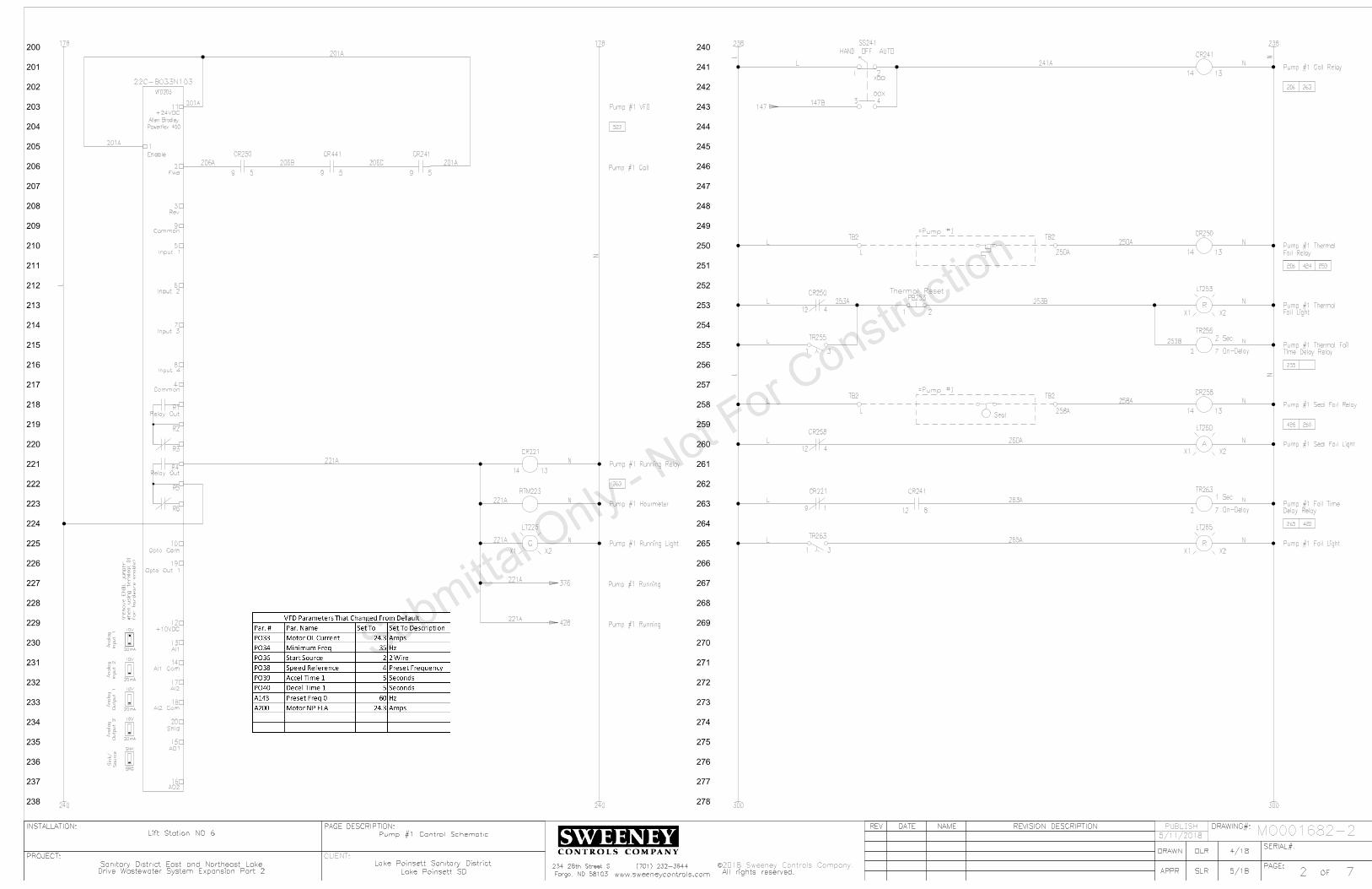
200
201
202
203
204
205
206
207
208
209
210
211
212
213
214
215
216
217
218
219
220
221
222
223
224
225
226
227
228
229
230
231
232
233
234
235
236
237
238
240
241
242
243
244
245
246
247
248
249
250
251
252
253
254
255
256
257
258
259
260
261
262
263
264
265
266
267
268
269
270
271
272
273
274
275
276
277
278
SERIAL#:
PAGE:
INSTALLATION:
PROJECT:
OF
REV
DRAWING#:
PAGE DESCRIPTION:
APPR
REVISION DESCRIPTION
DATE
NAME
DRAWN
All rights reserved.
C
Fargo, ND 58103
SERIAL#:
PAGE:
INSTALLATION:
PROJECT:
OF
REV
DRAWING#:
PAGE DESCRIPTION:
APPR
REVISION DESCRIPTION
DATE
NAME
DRAWN
2018 Sweeney Controls Company.
All rights reserved.
C
Fargo, ND 58103
PUBLISH
CLIENT:
72www.sweeneycontrols.com
234 28th Street S (701) 232-3644
Lift Station NO 6
DLR 4/18
SLR 5/18
Sanitary District East and Northeast Lake Lake Poinsett Sanitary District
Lake Poinsett SD
Pump #1 Control Schematic
72www.sweeneycontrols.com
234 28th Street S (701) 232-3644
Lift Station NO 6
DLR 4/18
SLR 5/18
Sanitary District East and Northeast Lake Lake Poinsett Sanitary District
Lake Poinsett SD
Pump #1 Control Schematic
MO001682-2
178 238
240 300
Pump #1 Running
Output 2
Analo
g
Output
1
Analo
g
Input
2
Analo
g
Input
1
Analo
g
Source
Sin
k/
for
har
dware e
na
ble)
whe
n
usin
g ter
min
al
01
(re
mo
ve
EN
BL ju
mper
10V
20mA
10V
20mA
10V
20mA
10V
20mA
SNK
SRC
Powerflex 400
Allen Bradley
AO2
AO1
Shld
AI2 Com
AI2
AI1 Com
AI1
+10VDC
Opto Out 1
Opto Com
Relay Out
Relay Out
Enable
Common
Input 4
Input 3
Input 2
Input 1
Common
Rev
Fwd
+24VDCPump #1 VFD
VFD203
R6
R5
R4
R3
R2
R1
20
19
18
17
16
15
14
13
12
11
10
9
8
7
6
5
4
3
2
1
22C-B033N103
Pump #1 Call
Pump #1 Running
CR221
14 13
Pump #1 Running Relay
RTM223
Pump #1 Hourmeter
G
X2X1
LT225
Pump #1 Running Light
CR241
14 13
Pump #1 Call Relay
XOO
OOX
1 2
3 4
HAND OFF AUTO
SS241
147
TB2
TB2=Pump #1
1 2
PB253Thermal Reset
CR250
14 13
Pump #1 Thermal
Fail Relay
9 5
CR250
206
4
CR250
12
253
R
X2X1
LT253
Pump #1 Thermal
Fail Light
2 7
On-Delay
TR255
Pump #1 Thermal Fail
Time Delay Relay1 3
TR255
255
TB2
TB2=Pump #1
Seal
CR258
14 13
Pump #1 Seal Fail Relay
A
X2X1
LT260
Pump #1 Seal Fail Light4
CR258
12
260
9 5
CR241
206
2 7
On-Delay
TR263
Pump #1 Fail Time
Delay Relay
1 Sec
2 Sec
R
X2X1
LT265
Pump #1 Fail Light
9 1
CR221
263
1 3
TR263
265
376
178 238
240 300
424
426
420
428
8
CR241
12
263
9 5
CR441
523
L
L
147B
206C
N
N
221A
221A
201A
206A 206B
201A
201A
201A
221A
221A
221A
N
N
N
250A
258A
L
L
L
L
L
L
L
L
L N
250A
253A 253B
258A
260A
263A
265A
241A
N
N
N
N
N
N
N
253B
N
L
L
5/11/2018
Drive Wastewater System Expansion Part 2Drive Wastewater System Expansion Part 2

300
301
302
303
304
305
306
307
308
309
310
311
312
313
314
315
316
317
318
319
320
321
322
323
324
325
326
327
328
329
330
331
332
333
334
335
336
337
338
340
341
342
343
344
345
346
347
348
349
350
351
352
353
354
355
356
357
358
359
360
361
362
363
364
365
366
367
368
369
370
371
372
373
374
375
376
377
378
SERIAL#:
PAGE:
INSTALLATION:
PROJECT:
OF
REV
DRAWING#:
PAGE DESCRIPTION:
APPR
REVISION DESCRIPTION
DATE
NAME
DRAWN
All rights reserved.
C
Fargo, ND 58103
SERIAL#:
PAGE:
INSTALLATION:
PROJECT:
OF
REV
DRAWING#:
PAGE DESCRIPTION:
APPR
REVISION DESCRIPTION
DATE
NAME
DRAWN
2018 Sweeney Controls Company.
All rights reserved.
C
Fargo, ND 58103
PUBLISH
CLIENT:
73www.sweeneycontrols.com
234 28th Street S (701) 232-3644
Lift Station NO 6
DLR 4/18
SLR 5/18
Sanitary District East and Northeast Lake Lake Poinsett Sanitary District
Lake Poinsett SD
Pump #2 Control Schematic
73www.sweeneycontrols.com
234 28th Street S (701) 232-3644
Lift Station NO 6
DLR 4/18
SLR 5/18
Sanitary District East and Northeast Lake Lake Poinsett Sanitary District
Lake Poinsett SD
Pump #2 Control Schematic
MO001682-2
278 338
340 400
Output 2
Analo
g
Output
1
Analo
g
Input 2
Analo
g
Input
1
Analo
g
Source
Sin
k/
for
har
dware e
na
ble)
whe
n
usin
g ter
min
al
01
(re
mo
ve
EN
BL ju
mper
10V
20mA
10V
20mA
10V
20mA
10V
20mA
SNK
SRC
22C-B033N103
RTM323
Pump #2 Hourmeter
G
X2X1
LT325
Pump #2 Running Light
Powerflex 400
Allen Bradley
AO2
AO1
Shld
AI2 Com
AI2
AI1 Com
AI1
+10VDC
Opto Out 1
Opto Com
Relay Out
Relay Out
Enable
Common
Input 4
Input 3
Input 2
Input 1
Common
Rev
Fwd
+24VDCPump #2 VFD
VFD303
R6
R5
R4
R3
R2
R1
20
19
18
17
16
15
14
13
12
11
10
9
8
7
6
5
4
3
2
1
Pump #2 Call
Pump #2 Running
CR341
14 13Pump #2 Call Relay
XOO
OOX
1 2
3 4
HAND OFF AUTO
SS341
1 2
PB353Thermal Reset
CR350
14 13Pump #2 Thermal
Fail Relay
4
CR350
12
R
X2X1
LT353
Pump #2 Thermal
Fail Light
2 7
On-Delay
TR355
Pump #2 Thermal Fail
Time Delay Relay1 3
TR355
1 3
TR363
Seal
CR358
14 13Pump #2 Seal Fail Relay
A
X2X1
LT360
Pump #2 Seal Fail Light4
CR358
12
2 7
On-Delay
TR363
Pump #2 Fail Time
Delay Relay
1 Sec
2 Sec
R
X2X1
LT365
Pump #2 Fail Light
353
355
360
365
=Pump #2
=Pump #2
149
CR321
14 13
Pump #2 Running Relay
9 1
CR321
363
RTM376
Dual Run Hourmeter8
CR321
12
376
227
9 5
CR350
306
9 5
CR341
306
8
CR341
12
363
278 338
340 400
425
427
422
432
430
8
CR441
12
531
L
N
L
N
149B
221A
L
TB2
L
TB2
350A
TB2
358A
TB2
376A
L
N
301A
301A
301A
301A 306A 306B 306C
N
N
N
321A
321A
321A
321A
321A
L
L
L
L
L
L
L
L
N
N
N
N
N
N
N
N
341A
350A
353A 353B
358A
360A
363A 363B
365A
353B 353A
N
376A
5/11/2018
Drive Wastewater System Expansion Part 2Drive Wastewater System Expansion Part 2

400
401
402
403
404
405
406
407
408
409
410
411
412
413
414
415
416
417
418
419
420
421
422
423
424
425
426
427
428
429
430
431
432
433
434
435
436
437
438
440
441
442
443
444
445
446
447
448
449
450
451
452
453
454
455
456
457
458
459
460
461
462
463
464
465
466
467
468
469
470
471
472
473
474
475
476
477
478
SERIAL#:
PAGE:
INSTALLATION:
PROJECT:
OF
REV
DRAWING#:
PAGE DESCRIPTION:
APPR
REVISION DESCRIPTION
DATE
NAME
DRAWN
All rights reserved.
C
Fargo, ND 58103
SERIAL#:
PAGE:
INSTALLATION:
PROJECT:
OF
REV
DRAWING#:
PAGE DESCRIPTION:
APPR
REVISION DESCRIPTION
DATE
NAME
DRAWN
2018 Sweeney Controls Company.
All rights reserved.
C
Fargo, ND 58103
PUBLISH
CLIENT:
74www.sweeneycontrols.com
234 28th Street S (701) 232-3644
Lift Station NO 6
DLR 4/18
SLR 5/18
Sanitary District East and Northeast Lake Lake Poinsett Sanitary District
Lake Poinsett SD
Control Schematic
74www.sweeneycontrols.com
234 28th Street S (701) 232-3644
Lift Station NO 6
DLR 4/18
SLR 5/18
Sanitary District East and Northeast Lake Lake Poinsett Sanitary District
Lake Poinsett SD
Control Schematic
MO001682-2
378 438
440
G
NL1
-V
V+
V+
-V
PS403
PS5R-SC12
12VDC
12VDC Power Supply
30W
378 438
440
FS445
FS126
Ok Relay
CR441
14 13Incoming Source Power
R
X2X1
LT445
Outside Alarm Light
Normally Off
8
CR151
12
8
CR153
12
High Level Alarm
Low Level Alarm
Fail Alarm
Incoming Source Power
Pump #1 Fail Alarm
Pump #2 Fail Alarm
Fail Alarm
Pump #1 Or #2 Thermal
Fail Alarm
Pump #1 Or #2 Seal
Accumulation
Pump #1 Runtime
Accumulation
Pump #2 Runtime
Accumulation
Dual Runtime
9 5
CR153
9 5
CR151
2
CR441
10
418
8 6
TR263
8 6
TR363
2
CR250
10
2
CR350
10
9 1
CR258
9 1
CR358
377
327
206
229
306
/End
/End
81
PM542L
N
376A
321A
221A
L
N
L
N
L N
L
L
L
L
L
L
L
L
L
424A
414A
416A
418A
420A
422A
426A
N
N
N
N
N
N
N
N
L
L
L
N
N
441A
445A 445B
445A
INPUTS OR RAIN GAUGE
USER SELECTED ALARM
ALARM INPUTS
COUNTER
INPUTS OR PULSE
USER SELECTED ALARM
ACCUMULATION
PUMP 1, 2, & 3 RUNTIME
BATTERY BACKED 12VDC
G
NH
-
+
-
+
10
9
8
7
6
5
4
3
2
1
10
9
8
7
6
5
4
3
2
1
Antenna
AD412
XR50-PM-12
Omni XR50
Alarm Dialer
ANT410
=Exterior Mounted Equipment
N
N
+12VDC
+12VDC
-12VDC
-12VDC
5/11/2018
Battery
12VDC Back-Up
+ -
BAT407
12V
L
N
Drive Wastewater System Expansion Part 2Drive Wastewater System Expansion Part 2

500
501
502
503
504
505
506
507
508
509
510
511
512
513
514
515
516
517
518
519
520
521
522
523
524
525
526
527
528
529
530
531
532
533
534
535
536
537
538
540
541
542
543
544
545
546
547
548
549
550
551
552
553
554
555
556
557
558
559
560
561
562
563
564
565
566
567
568
569
570
571
572
573
574
575
576
577
578
SERIAL#:
PAGE:
INSTALLATION:
PROJECT:
OF
REV
DRAWING#:
PAGE DESCRIPTION:
APPR
REVISION DESCRIPTION
DATE
NAME
DRAWN
All rights reserved.
C
Fargo, ND 58103
SERIAL#:
PAGE:
INSTALLATION:
PROJECT:
OF
REV
DRAWING#:
PAGE DESCRIPTION:
APPR
REVISION DESCRIPTION
DATE
NAME
DRAWN
2018 Sweeney Controls Company.
All rights reserved.
C
Fargo, ND 58103
PUBLISH
CLIENT:
75www.sweeneycontrols.com
234 28th Street S (701) 232-3644
Lift Station NO 6
DLR 4/18
SLR 5/18
Sanitary District East and Northeast Lake Lake Poinsett Sanitary District
Lake Poinsett SD
Power Schematic
75www.sweeneycontrols.com
234 28th Street S (701) 232-3644
Lift Station NO 6
DLR 4/18
SLR 5/18
Sanitary District East and Northeast Lake Lake Poinsett Sanitary District
Lake Poinsett SD
Power Schematic
MO001682-2
T3
T1
GND
Pump #2
T2FLA
T3
T1
GND
Pump #1
T2FLA
PDB506
PK9GTA
PDB503
63131
1 Phase 3 Wire
120/240VAC
Incoming Power
Controls
L1
Convenience Receptacle
REC567
L2
200W
Enclosure Heater
HTR565
QOU115
Receptacle
15 AMP
QOU110
Heater
10 AMP
QOU110
Controls
10 AMP
=Pump #2
=Pump #1CB563
100
CB565
CB567
538
540
538
540
538
540
538
540
L2L1
T2
T1
HDL26100
100
AMP
Main
CB506
63132
PDB512
Arrestor
Lightning
A
B G
S50A120V2P
A
B N
SurgeCapacitor
CA 302R
LA514
SC518
24.3
24.3
L1
L2
T1
T2
CB523
HDL2605050 AMP
Pump #1
L1
L2
T1
T2
CB531
HDL2605050 AMP
Pump #2
L1
L2
L3
G
T1
T2
T3
G
VFD203
22C-B033N103
Pump #1 VFD
L1
L2
L3
G
T1
T2
T3
G
VFD303
22C-B033N103
Pump #2 VFD
6
7
PM542
MODEL 201-200-SP-T-9
Power
Monitor
441
/1
CB571
QOU12020 AMP
Air Conditioner
4000 BTU
AC571
Air Conditioner
100A
100
100
B
8AWG
8AWG
8AWG
8AWG
3
AW
G
100B
100
B
100B
100B
100B
100B
565A
567A
571A
14AWG
14AWG
12AWG
14AWG
14AWG
14AWG
8AWG
8AWG
8AWG
8AWG
8AWG
3
AW
G
Connected Directly To VFD's
Pump Grounds Must Be
5/11/2018
Drive Wastewater System Expansion Part 2Drive Wastewater System Expansion Part 2

SERIAL#:
PAGE:
INSTALLATION:
PROJECT:
OF
REV
DRAWING#:
PAGE DESCRIPTION:
APPR
REVISION DESCRIPTION
DATE
NAME
DRAWN
All rights reserved.
C
Fargo, ND 58103
SERIAL#:
PAGE:
INSTALLATION:
PROJECT:
OF
REV
DRAWING#:
PAGE DESCRIPTION:
APPR
REVISION DESCRIPTION
DATE
NAME
DRAWN
2018 Sweeney Controls Company.
All rights reserved.
C
Fargo, ND 58103
PUBLISH
CLIENT:
76www.sweeneycontrols.com
234 28th Street S (701) 232-3644
Lift Station NO 6
DLR 4/18
SLR 5/18
Sanitary District East and Northeast Lake Lake Poinsett Sanitary District
Lake Poinsett SD
Backpanel And Inner Door Layout
76www.sweeneycontrols.com
234 28th Street S (701) 232-3644
Lift Station NO 6
DLR 4/18
SLR 5/18
Sanitary District East and Northeast Lake Lake Poinsett Sanitary District
Lake Poinsett SD
Backpanel And Inner Door Layout
MO001682-2
CB506
HDL26100
100 AMP
MAIN
VFD203
22C-B033N103
VFD303
22C-B033N103
CB523
HDL26050
50 AMP
PUMP #1
CB531
HDL26050
50 AMP
PUMP #2
HTR565
200W
BLOCK
DISTRBUTION
POWER
BLOCK
DISTRBUTION
PDB512
LA514
S50A120V2P
SC518
XR50
Omni-Site
AD412
1"
X
2"
X
42.5
"
Wirin
g
1"
X
2"
X
10"
Wirin
g
1" X 2" X 18" Wiring
1" X 2" X 18" Wiring
1" X 2" X 18" Wiring
ON
OFF
CB563 10 AMP
CONTROLS
ON
OFF
CB565 10 AMP
HEATER
RECEPTACLEON
OFF
CB567 15 AMP
ON
OFF
CB571 20 AMP
AIR CONDITIONER
REC567
PDB506
CR151
CR153
CR221
CR241
CR250
CR258
CR321
CR341
CR350
CR358
CR441
FC144
?
PS403
12VDC
PM542
TR255
TR263
TR355
TR363
BL
OC
K
NU
ET
RA
L
PDB503
63131
PDB503
HOURS
RTM223
HOURS
RTM323
HOURS
RTM376
DUAL RUN
RUNNING
G
LT225
G
LT325
R
LT265
FAILED
R
LT365
SS241
PUMP #1
HAND OFF AUTO
SS341
PUMP #2
HAND OFF AUTO
R
LT253
THERMAL FAIL
R
LT353
A
LT260
SEAL FAIL
A
LT360
PB253
Bk
RESET
PB353
Bk
PB147
Bk
HIGH FLOAT
TEST
PB149
Bk
LAG FLOAT
TEST
PB151
Bk
LEAD FLOAT
TEST
PB153
Bk
STOP FLOAT
TEST
PB155
Bk
LOW FLOAT
TEST
1"
X
2"
X
14"
Wirin
g
L
L
L
L
L
145
A
145
A
145
A
145
A
147
A
149
A
151
A
153
A
153
B
155
A
250A
258A
350A
358A
N
PumpSaver
MODEL ISS-105
IS Super Cell
SymComwww.symcominc.com
SAFE INPUTS
INTRINSICALLY
#1 #2 #3 #4 #5
120VAC
INPUT
#1 #2 #3 #4 #5
DC ON
V.ADJ
L N
-V +VOUTPUT
INPUT
Mounted Beneath Main CB
Lightning Arrestor
SS161
1-2 AUTO 2-1
5/11/2018
Drive Wastewater System Expansion Part 2Drive Wastewater System Expansion Part 2

SERIAL#:
PAGE:
INSTALLATION:
PROJECT:
OF
REV
DRAWING#:
PAGE DESCRIPTION:
APPR
REVISION DESCRIPTION
DATE
NAME
DRAWN
All rights reserved.
C
Fargo, ND 58103
SERIAL#:
PAGE:
INSTALLATION:
PROJECT:
OF
REV
DRAWING#:
PAGE DESCRIPTION:
APPR
REVISION DESCRIPTION
DATE
NAME
DRAWN
2018 Sweeney Controls Company.
All rights reserved.
C
Fargo, ND 58103
PUBLISH
CLIENT:
77www.sweeneycontrols.com
234 28th Street S (701) 232-3644
Lift Station NO 6
DLR 4/18
SLR 5/18
Sanitary District East and Northeast Lake Lake Poinsett Sanitary District
Lake Poinsett SD
Panel Layout
77www.sweeneycontrols.com
234 28th Street S (701) 232-3644
Lift Station NO 6
DLR 4/18
SLR 5/18
Sanitary District East and Northeast Lake Lake Poinsett Sanitary District
Lake Poinsett SD
Panel Layout
MO001682-2
AC571
IQ4000EV-126-SS-N4X-STDR
R
LT445
UL698A
UL Listing
Door Stop Kit:
Attached Bug Screen Behind Louvers:
Punched Louvers:
Laminated Wiring Diagrams:
Stainless Steel Enclosure 12" Deep:
Note
Legs And Skirts Area
36"
48"
24"
72"
5/11/2018
Drive Wastewater System Expansion Part 2Drive Wastewater System Expansion Part 2

Description
Wirin
g Sym
bols
SERIAL#:
PAGE:
INSTALLATION:
PROJECT:
OF
REV DRAWING#:
CUSTOMER:
PAGE
DESCRIPTION:
APPR
REVISION DESCRIPTIONDATE NAME
DRAWN
Sweeney Controls Company.
All rights reserved.
C
##www.sweeneycontrols.com
234 28th Street S
Fargo, ND 58103
(701) 232-3644
XXX
MO######-#
Installed)
(To Be Field
UPS###
5 AMP
F101A
101A
ANTENNA
DIAG.
-
+
RS-232
RM###
ALA###
X1 X2
LT###
G
1 2
3
X1 X2
4
LT###
R
TS###
TS###
10A
CB###
Controls
FS###
High
L1 L2
REC###
A1OL
M###
100
101
102
103
104
105
106
107
108
109
110
111
112
113
114
115
116
117
118
119
120
121
122
123
124
125
126
127
128
129
130
131
132
133
134
135
136
137
138
140
141
142
143
144
145
146
147
148
149
150
151
152
153
154
155
156
7 4
CR###
8 2
CR###
B A
CR###
Control Relay Coil
B A
CR103
Thermal Fail Relay
109 106
XXX###
1 To 3 Letter Device Abbreviation
Page Number
Line Number
Inside The Panel
Next To The Physically Mounted Part
This Id Number Is Also Found On Or
03 Line 1elay Page Rontrol CEx
Device ID
Terminal Number
Used
The Drawings Contacts of This Device Are
Cross Reference Box. This Shows Where In
09 Line 1Page
Ex: Contact Is Used On
Used Contact Identifier
Unused Contact Space
156
154
157
155
158
Wire Links
56 Line 1Page
Ex: Wire Goes To
Wire Link
Goes To Line 156
54 Line 1Page
Ex: Wire Comes From
Wire Link
Comes From Line 154
Wire Link
Comes From Line 157
Wire Link
Goes To Line 155
158 Wire Link
Connects To Line
=Pump #1
TB1
103A
TB1
L
Device Description
TS103
Terminal Block Row 1
Line Number
Is The First Terminal Block On That A
And 03 Line 1Ex: Corresponds To Page
Terminal Block IDField Installation Box
Field Installation Location
Control Panel Wiring
Solid Line Indicates Internal
Field Wiring
Dashed Line Indicates
Normally Open Control Relay Contact
Normally Closed Control Relay Contact
Normally Closed Temperature Switch
Normally Open Temperature Switch
(Used As High Float)
Normally Open Float Switch
(Indicating Green Lens)
Pilot Light
(Indicating Red Lens)
Push To Test Pilot Light
Not To Exceed 10,000ft
Maximum Cable Length
Electrical Code
Of The National
With Article 504
Accordance
Install In
Hazardous
Area
Non-
Hazardous
Area
Device
Safe Switching
Intrinsically
POWER
SUPPLY
CH1
CH2
CH1
CH2
CH2
LF
K
PR
LF
CH1
PR
K
SS
14
1
2
11
8
13
12
10
9
7
4
5
ISB###
Intrinsically Safe Barrier
Intrinsically Safe Circuit Area
RTM###
Run Time Meter
I:0/4/00
RACK
MODULE
00
PLC109
4
T
0
1746-IA16Device ID
Module Number
PLC Address
PLC Address Description
Part Number
Rack Number
Terminal Number
I/O Card
HAND OFF AUTO
AH###
Alarm Horn
13
2
POT###
Potentiometer
H2H3
480V
120V
H1 H4
X1 X2
T###
5KVA
Overload Contact
Motor Starter Coil With
(Controls CB Rated At 10 Amps)
1 Pole Circuit Breaker
(480V Primary/120V Secondary)
Transformer
#/## ####
Wiring Symbols Description
XXX #/##
Uninterruptible Power Supply
Digital Output Connections
Flowmeter With Power, Analog Output, And
Antenna Lightening Arrestor
L1
L2
L3
T1
T2
T3
M460
Pump #1 Motor Starter
CC160
8536SF01V02S
L1
L2
L3
T1
T2
T3200 AMP
CB142
Pump #1
KAL36200
M FLA
HPT1
T2
T3
GND
103
Pump #1
84
=Pump #1
7 4
CR103
8 2
CR103
03Line
1elay Coil is Found On Page Rontrol CEx:
N/O Relay Contact
Eg: No Wire Connection
Wire Looped Over Another Wire
Wire Connected To Another Wire
Wire Connection Point
Fuse Identifier
Fuse Amp Rating
L1
L2
L3
G
T1
T2
T3
G
VFD142 Pump #1 VFD
22C-D088A103
A1
B1
C1
A2
B2
C2
LR142
Pump #1
KDRULF2H
L1
L2
L3
T1
T2
T3
M450
Pump #1 VFD Isolation
8502SF02V02S
Contactor
Device ID
Rating
Circuit Breaker Amp
Number
Circuit Breaker Part
Description Device IDDescription
50 Line 4Found On Page
Indicates Contactor Coil Is
Device ID
Description
Number
Line Reactor Part
Device IDDescription
VFD Part Number
Number
Motor Starter Part
Number
Overloads Part
Motor Starter
Description
60 Line 4On Page
Indicates Starter Coil Is Found
Device ID
Number
Contactor Part
Field Installation Location
103A
Wire Number
106A
Number
The Second Wire On That Line
Means Its B And 06 Line 1Page
Ex: This Wire Originates On
Wire Number
Pump Information
LS###
LS###
HTR###
200W
3 4
PB###
Lamp Test
1 2
PB###
Reset
Normally Open Limit Switch
Normally Closed Limit Switch
(Used As A Lamp Test Button)
Normally Open Pushbutton
(Used As A Reset Pushbutton)
Normally Closed Pushbutton
X1 X2
M###
Contactor Coil
(Shown As 200 Watts)
Heater
Thermal Fail Input
Receptacle
109A
Wire Number
7 4
CR422
106B
Wire Number 22 Line 4On Page
elay Coil is Found Rontrol CEx:
N/O Relay Contact
Position Only
Closed In Hand
Position Only
Closed In Auto
Device Id Format
5 AMP
F-L
GDL5
L
(GDL5 Is Fuse Part Number)
Fuse Block
2 7
TR###
5 Seconds
3 4
TR###
(Set To 5 Seconds)
Time Delay Relay Coil
Relay Contact
Normally Open Delayed On Time Delay
TB1
####
Terminal Block
Example Of Control WiringExample Of 3 Phase Power Wiring
I:0/4/00
PLC Address Format:
Input Rack:0 Module:4 Address:00
Shown On This Page
Used In Drawings Are
Note: Not All Symbols
03 Line 1On Page
elay Coil is Found Rontrol CEx:
N/C Relay Contact
PROTECTED
UNPROTECTEDL N
L N
G
G
SUP###
G
NL1
-V
V+
V+
-V
PS###
24VDC
30W
ANT###
AC
Not Used
4-20mA
L N
+ -
FM###
Flow Meter
Digital Output
157
158
159
160
161
162
163
164
165
166
167
168
169
170
171
172
173
174
175
176
177
178
159
159 Wire Link
Connects To Line
TRANSDUCER
LEVEL
4-20mA
+ -LXD###
XOO
OOX
1 2
3 4
SS###
Legend Above
Are Closed With Respect To Switch
"X" Specifies What Position The Contacts
Surge Suppressor
(24VDC Output Rated To 30 Watts)
DC Power Supply
Antenna
2-Wire Analog Level Transducer
Radio Modem

Lake Poinsett SD
Lake Poinsett Sanitary DistrictLocation:
MO001682-3Job Number
Lift Station NO 7Description:
Sanitary District East and Northeast Lake Drive Wastewater System ExpansionPart 2
Project:
Drawing Index
Learn How To Read Our Drawings!
How To Read Control Panel Schematic Drawings
View Our Short Video
Scan The QR Code Here
Or Click The Link Below Or Search YouTube For The Title:
DescriptionDrawing Number
Control SchematicMO001682-3-1Pump #1 Control SchematicMO001682-3-2Pump #2 Control SchematicMO001682-3-3Control SchematicMO001682-3-4Power SchematicMO001682-3-5Backpanel And Inner LayoutMO001682-3-6Panel LayoutMO001682-3-7
Symbols Wiring Symbols Description Page
UL Labeling
UL698A
Sweeney Controls CompanyPage 1/1 05/11/2018

100
101
102
103
104
105
106
107
108
109
110
111
112
113
114
115
116
117
118
119
120
121
122
123
124
125
126
127
128
129
130
131
132
133
134
135
136
137
138
140
141
142
143
144
145
146
147
148
149
150
151
152
153
154
155
156
157
158
159
160
161
162
163
164
165
166
167
168
169
170
171
172
173
174
175
176
177
178
SERIAL#:
PAGE:
INSTALLATION:
PROJECT:
OF
REV
DRAWING#:
PAGE DESCRIPTION:
APPR
REVISION DESCRIPTION
DATE
NAME
DRAWN
All rights reserved.
C
Fargo, ND 58103
SERIAL#:
PAGE:
INSTALLATION:
PROJECT:
OF
REV
DRAWING#:
PAGE DESCRIPTION:
APPR
REVISION DESCRIPTION
DATE
NAME
DRAWN
2018 Sweeney Controls Company.
All rights reserved.
C
Fargo, ND 58103
PUBLISH
CLIENT:
71www.sweeneycontrols.com
234 28th Street S (701) 232-3644
Lift Station NO 7
DLR 4/18
SLR 5/18
Sanitary District East and Northeast Lake Lake Poinsett Sanitary District
Lake Poinsett SD
Control Schematic
71www.sweeneycontrols.com
234 28th Street S (701) 232-3644
Lift Station NO 7
DLR 4/18
SLR 5/18
Sanitary District East and Northeast Lake Lake Poinsett Sanitary District
Lake Poinsett SD
Control Schematic
MO001682-3
5 AMP
F-LF-3AG-TD-5A
TB3
120VAC
138
140
138
140 200 200
Pump #2 Call
Pump #1 Call
Device
Safe Switching
Intrinsically
Electrical Code
The National
Article 504 Of
Accordance With
Install In
Exceed 10,000 ft
Length Not To
Maximum Cable
Hazardous Area
Non-Hazardous Area
Float Controller
MODEL ISS-105
Intrinsically Safe
FC144
L2
SIL._AND_RST
RCTL2
RCTL1
COM
#1
#2
#3
COM
#4
#5
COM
C
#2
PWR_RESET
#3
COM
#4
#1
#5
L1
MODE
43
87
65
12
10
9
ON
1
COMMON
LOW ALARM
STOP
LEAD
LAG
HIGH ALARM
High
FS147
Lag
FS149
Lead
FS151
Stop
FS153
Low
FS155
1-2 AUTO 2-1
SS161
43
21
OOX
XOO
TB3
TB3
TB3
145A
TB3
TB3
TB3
TB3
TB3
TB3
TB3
3 4
PB147
Test
GW60NO
3 4
PB149
Test
GW60NO
3 4
PB151
Test
GW60NO
GW60NO
GW60NO
1 2
PB153Test
1 2
PB155Test
CR153
High Float Relay14 13
CR151
Low Float Relay14 13
343
414 447
416 445
563 563
145A
145A
145A
153A
147A
149A
151A
153B
155A
100
A
145A
145A
145A
145A
145A
147A
149A
151A
153A
153A
147A
149A
151A
153B 153C
155A
153A
147B
149B
151B
153D
159A
161A
163A
243
N
N
N
L
N
N
100
B
L
L
L
L
L
N
N
=Wetwell
5/11/2018
Drive Wastewater System Expansion Part 2Drive Wastewater System Expansion Part 2

200
201
202
203
204
205
206
207
208
209
210
211
212
213
214
215
216
217
218
219
220
221
222
223
224
225
226
227
228
229
230
231
232
233
234
235
236
237
238
240
241
242
243
244
245
246
247
248
249
250
251
252
253
254
255
256
257
258
259
260
261
262
263
264
265
266
267
268
269
270
271
272
273
274
275
276
277
278
SERIAL#:
PAGE:
INSTALLATION:
PROJECT:
OF
REV
DRAWING#:
PAGE DESCRIPTION:
APPR
REVISION DESCRIPTION
DATE
NAME
DRAWN
All rights reserved.
C
Fargo, ND 58103
SERIAL#:
PAGE:
INSTALLATION:
PROJECT:
OF
REV
DRAWING#:
PAGE DESCRIPTION:
APPR
REVISION DESCRIPTION
DATE
NAME
DRAWN
2018 Sweeney Controls Company.
All rights reserved.
C
Fargo, ND 58103
PUBLISH
CLIENT:
72www.sweeneycontrols.com
234 28th Street S (701) 232-3644
Lift Station NO 7
DLR 4/18
SLR 5/18
Sanitary District East and Northeast Lake Lake Poinsett Sanitary District
Lake Poinsett SD
Pump #1 Control Schematic
72www.sweeneycontrols.com
234 28th Street S (701) 232-3644
Lift Station NO 7
DLR 4/18
SLR 5/18
Sanitary District East and Northeast Lake Lake Poinsett Sanitary District
Lake Poinsett SD
Pump #1 Control Schematic
MO001682-3
178 178 238
240
238
240 300 300
Output 2
Analo
g
Output
1
Analo
g
Input 2
Analo
g
Input
1
Analo
g
Source
Sin
k/
for
har
dware e
na
ble)
whe
n
usin
g ter
min
al
01
(re
mo
ve
EN
BL ju
mper
10V
20mA
10V
20mA
10V
20mA
10V
20mA
SNK
SRC
Powerflex 400
Allen Bradley
AO2
AO1
Shld
AI2 Com
AI2
AI1 Com
AI1
+10VDC
Opto Out 1
Opto Com
Relay Out
Relay Out
Enable
Common
Input 4
Input 3
Input 2
Input 1
Common
Rev
Fwd
+24VDCPump #1 VFD
VFD203
R6
R5
R4
R3
R2
R1
20
19
18
17
16
15
14
13
12
11
10
9
8
7
6
5
4
3
2
1
22C-B033N103
G
X2X1
LT225
Pump #1 Running Light
CR221
14 13
Pump #1 Running Relay
Pump #1 Call
TB3
TB3=Pump #1
250A
XOO
OOX
1 2
3 4
HAND OFF AUTO
SS241
CR241
14 13
Pump #1 Call Relay
9 5
CR241
206
CR250
14 13
Pump #1 Thermal
Fail Relay
9 5
CR250
206
4
CR250
12
253
R
X2X1
LT253
Pump #1 Thermal
Fail Light
2 7
On-Delay
TR255
Pump #1 Thermal Fail
Time Delay Relay
2 Sec.
1 2
PB253
1 3
TR255
255
TB3
CR258
14 13
Pump #1 Seal Fail Relay258A
TB3=Pump #1
Seal
A
X2X1
LT260
Pump #1 Seal
Fail Light4
CR258
12
260
2 7
On-Delay
TR263
Pump #1 Fail Time
Delay Relay
1 Sec.
9 1
CR221
263
8
CR241
12
263
R
X2X1
LT265
Pump #1 Fail Light1 3
TR263
265
376
424
426
420
428
9 5
CR441
523
221A
221A
206A 206B 206C
201A
201A
201A
201A
221A
221A
221A
241A
147147C
N
L
L
250A
253A
258A
260A
263A
265A
N
N
N
N
N
N
N
N
N
N
N
N
N
RTM223
Pump #1 Hourmeter
Pump #1 Running
Pump #1 Running
263B
253B
Thermal Reset
L
L
L
L
L
L
L
L
L
L
5/11/2018
Drive Wastewater System Expansion Part 2Drive Wastewater System Expansion Part 2

300
301
302
303
304
305
306
307
308
309
310
311
312
313
314
315
316
317
318
319
320
321
322
323
324
325
326
327
328
329
330
331
332
333
334
335
336
337
338
340
341
342
343
344
345
346
347
348
349
350
351
352
353
354
355
356
357
358
359
360
361
362
363
364
365
366
367
368
369
370
371
372
373
374
375
376
377
378
SERIAL#:
PAGE:
INSTALLATION:
PROJECT:
OF
REV
DRAWING#:
PAGE DESCRIPTION:
APPR
REVISION DESCRIPTION
DATE
NAME
DRAWN
All rights reserved.
C
Fargo, ND 58103
SERIAL#:
PAGE:
INSTALLATION:
PROJECT:
OF
REV
DRAWING#:
PAGE DESCRIPTION:
APPR
REVISION DESCRIPTION
DATE
NAME
DRAWN
2018 Sweeney Controls Company.
All rights reserved.
C
Fargo, ND 58103
PUBLISH
CLIENT:
73www.sweeneycontrols.com
234 28th Street S (701) 232-3644
Lift Station NO 7
DLR 4/18
SLR 5/18
Sanitary District East and Northeast Lake Lake Poinsett Sanitary District
Lake Poinsett SD
Pump #2 Control Schematic
73www.sweeneycontrols.com
234 28th Street S (701) 232-3644
Lift Station NO 7
DLR 4/18
SLR 5/18
Sanitary District East and Northeast Lake Lake Poinsett Sanitary District
Lake Poinsett SD
Pump #2 Control Schematic
MO001682-3
278 278 338
340
338
340 400 400
Pump #2 Call
Output 2
Analo
g
Output
1
Analo
g
Input 2
Analo
g
Input
1
Analo
g
Source
Sin
k/
for
har
dware e
na
ble)
whe
n
usin
g ter
min
al
01
(re
mo
ve
EN
BL ju
mper
10V
20mA
10V
20mA
10V
20mA
10V
20mA
SNK
SRC
Powerflex 400
Allen Bradley
AO2
AO1
Shld
AI2 Com
AI2
AI1 Com
AI1
+10VDC
Opto Out 1
Opto Com
Relay Out
Relay Out
Enable
Common
Input 4
Input 3
Input 2
Input 1
Common
Rev
Fwd
+24VDCPump #2 VFD
VFD303
R6
R5
R4
R3
R2
R1
20
19
18
17
16
15
14
13
12
11
10
9
8
7
6
5
4
3
2
1
CR321
14 13
Pump #2 Running Relay
RTM323
Pump #2 Hourmeter
G
X2X1
LT325
Pump #2 Running Light
22C-B033N103XOO
OOX
1 2
3 4
HAND OFF AUTO
SS341
CR341
14 13Pump #2 Call Relay
9 5
CR341
R
X2X1
LT353
Pump #2 Thermal
Fail Light
2 7
On-Delay
TR355
Pump #2 Thermal Fail
Time Delay Relay
2 Sec.
1 2
PB353
1 3
TR355
CR358
14 13Pump #2 Seal Fail Relay
Seal
A
X2X1
LT360
Pump #2 Seal
Fail Light4
CR358
12
2 7
On-Delay
TR363
Pump #2 Fail Time
Delay Relay
1 Sec.
CR350
14 13Pump #2 Thermal
Fail Relay
9 5
CR350
4
CR350
12
8
CR341
12
R
X2X1
LT365
Pump #2 Fail Light1 3
TR363
306
306 353
355
360
363
365
TB3
TB3
=Pump #2
=Pump #2TB3
TB3
9 1
CR321
363
Pump #2 Running
149
RTM376
Dual Run Hourmeter 2278
CR321
12
376
425
427
422
430
432
8
CR441
12
531
N
N
221A
149C
350A
358A
301A
301A
301A
301A 306A 306B 306C
321A 321A
321A
321A
321A
N
N
N
341A 341A N
N
N
N
N
N
N
N
N
365A
363A
360A
363B
350A
358A
353A 353B
353B
376A N
L
L
Thermal Reset
L
L
L
L
L
L
L
L
L
L
376A
5/11/2018
Drive Wastewater System Expansion Part 2Drive Wastewater System Expansion Part 2

400
401
402
403
404
405
406
407
408
409
410
411
412
413
414
415
416
417
418
419
420
421
422
423
424
425
426
427
428
429
430
431
432
433
434
435
436
437
438
440
441
442
443
444
445
446
447
448
449
450
451
452
453
454
455
456
457
458
459
460
461
462
463
464
465
466
467
468
469
470
471
472
473
474
475
476
477
478
SERIAL#:
PAGE:
INSTALLATION:
PROJECT:
OF
REV
DRAWING#:
PAGE DESCRIPTION:
APPR
REVISION DESCRIPTION
DATE
NAME
DRAWN
All rights reserved.
C
Fargo, ND 58103
SERIAL#:
PAGE:
INSTALLATION:
PROJECT:
OF
REV
DRAWING#:
PAGE DESCRIPTION:
APPR
REVISION DESCRIPTION
DATE
NAME
DRAWN
2018 Sweeney Controls Company.
All rights reserved.
C
Fargo, ND 58103
PUBLISH
CLIENT:
74www.sweeneycontrols.com
234 28th Street S (701) 232-3644
Lift Station NO 7
DLR 4/18
SLR 5/18
Sanitary District East and Northeast Lake Lake Poinsett Sanitary District
Lake Poinsett SD
Control Schematic
74www.sweeneycontrols.com
234 28th Street S (701) 232-3644
Lift Station NO 7
DLR 4/18
SLR 5/18
Sanitary District East and Northeast Lake Lake Poinsett Sanitary District
Lake Poinsett SD
Control Schematic
MO001682-3
378 378 438
440
438
440
/End
/End
G
NL1
-V
V+
V+
-V
PS403
PS5R-SC12
12VDC
12VDC Power Supply
30W
High Level Alarm
Low Level Alarm
Pump #1 Fail Alarm
Pump #2 Fail Alarm
Fail Alarm
Pump #1 Or #2 Thermal
Accumulation
Pump #1 Runtime
Fail Alarm
Pump #1 Or #2 Seal
Accumulation
Pump #2 Runtime
Accumulation
Dual Runtime
9 5
CR153
9 5
CR151
8 6
TR263
8 6
TR363
2
CR250
10
9 1
CR258
9 1
CR358
2
CR350
10
229
327
377
CR441
14 13
Incoming Source Power
Fail Alarm
Incoming Source Power2
CR441
10
418206
R
X2X1
LT445
Outside Alarm Light
Normally Off8
CR151
12
8
CR153
12
81
PM542
306
N
221A
321A
376A
N
N
N
N
N
N
N
N
N
426A
414A
416A
418A
420A
422A
N
N
N
441A
445A
FS445
FS126445B
Ok Relay
424A
L
L
L
L
L
L
L
L
L
L
L
L
L
L 445A
INPUTS OR RAIN GAUGE
USER SELECTED ALARM
ALARM INPUTS
COUNTER
INPUTS OR PULSE
USER SELECTED ALARM
ACCUMULATION
PUMP 1, 2, & 3 RUNTIME
BATTERY BACKED 12VDC
G
NH
-
+
-
+
10
9
8
7
6
5
4
3
2
1
10
9
8
7
6
5
4
3
2
1
Antenna
AD412
XR50-PM-12
Omni XR50
Alarm Dialer
ANT410
=Exterior Mounted Equipment
N
N
+12VDC
+12VDC
-12VDC
-12VDC
L
N
Battery
12VDC Back-Up
+ -
BAT407
12V
5/11/2018
Drive Wastewater System Expansion Part 2Drive Wastewater System Expansion Part 2

500
501
502
503
504
505
506
507
508
509
510
511
512
513
514
515
516
517
518
519
520
521
522
523
524
525
526
527
528
529
530
531
532
533
534
535
536
537
538
540
541
542
543
544
545
546
547
548
549
550
551
552
553
554
555
556
557
558
559
560
561
562
563
564
565
566
567
568
569
570
571
572
573
574
575
576
577
578
SERIAL#:
PAGE:
INSTALLATION:
PROJECT:
OF
REV
DRAWING#:
PAGE DESCRIPTION:
APPR
REVISION DESCRIPTION
DATE
NAME
DRAWN
All rights reserved.
C
Fargo, ND 58103
SERIAL#:
PAGE:
INSTALLATION:
PROJECT:
OF
REV
DRAWING#:
PAGE DESCRIPTION:
APPR
REVISION DESCRIPTION
DATE
NAME
DRAWN
2018 Sweeney Controls Company.
All rights reserved.
C
Fargo, ND 58103
PUBLISH
CLIENT:
75www.sweeneycontrols.com
234 28th Street S (701) 232-3644
Lift Station NO 7
DLR 4/18
SLR 5/18
Sanitary District East and Northeast Lake Lake Poinsett Sanitary District
Lake Poinsett SD
Power Schematic
75www.sweeneycontrols.com
234 28th Street S (701) 232-3644
Lift Station NO 7
DLR 4/18
SLR 5/18
Sanitary District East and Northeast Lake Lake Poinsett Sanitary District
Lake Poinsett SD
Power Schematic
MO001682-3
T3
T1
GND
Pump #2
T2FLA
T3
T1
GND
Pump #1
T2FLA
PDB506
PK9GTA
1 Phase 3 Wire
120/240VAC
Incoming Power
Controls
L1
Convenience Receptacle
REC567
L2
200W
Enclosure Heater
HTR565
QOU115
Receptacle
15 AMP
QOU110
Heater
10 AMP
QOU110
Controls
10 AMP
=Pump #2
=Pump #1CB563
CB565
CB567
538
540
538
540
538
540
538
540
L2L1
T2T1
HD
L26100
100
AM
P
Main
Arrestor
Lightning
A
B G
LA514
S50A120V2P
A
B N
SurgeCapacitor
SC518
CA 302R
PDB503
63131
PDB512
63132
24.3
L1
L2
T1
T2
CB523
HDL2605050 AMP
Pump #1
24.3
L1
L2
T1
T2
CB531
HDL2605050 AMP
Pump #2
6
7
PM542
Power
Monitor
CB571
QOU12020 AMP
100 100
441
Pump #1 VFD
22C-B033N103
VFD203
G
T3
T2
T1
G
L3
L2
L1
Pump #2 VFD
22C-B033N103
VFD303
G
T3
T2
T1
G
L3
L2
L1
3
AW
G
3
AW
G
8AWG
8AWG
8AWG
8AWG
8AWG
14AWG
14AWG
14AWG
14AWG
100A
8AWG
8AWG
8AWG
14AWG
12AWG
100B
8AWG
8AWG
CB506
4000 BTU
AC571
100
B
100B
100B
100B
565A
567A
MODEL 201-200-SP-T-9
100
B
Air Conditioner
Air Conditioner
571A 100B
Connected Directly To VFD's
Pump Grounds Must Be
5/11/2018
Drive Wastewater System Expansion Part 2Drive Wastewater System Expansion Part 2

SERIAL#:
PAGE:
INSTALLATION:
PROJECT:
OF
REV
DRAWING#:
PAGE DESCRIPTION:
APPR
REVISION DESCRIPTION
DATE
NAME
DRAWN
All rights reserved.
C
Fargo, ND 58103
SERIAL#:
PAGE:
INSTALLATION:
PROJECT:
OF
REV
DRAWING#:
PAGE DESCRIPTION:
APPR
REVISION DESCRIPTION
DATE
NAME
DRAWN
2018 Sweeney Controls Company.
All rights reserved.
C
Fargo, ND 58103
PUBLISH
CLIENT:
76www.sweeneycontrols.com
234 28th Street S (701) 232-3644
Lift Station NO 7
DLR 4/18
SLR 5/18
Sanitary District East and Northeast Lake Lake Poinsett Sanitary District
Lake Poinsett SD
76www.sweeneycontrols.com
234 28th Street S (701) 232-3644
Lift Station NO 7
DLR 4/18
SLR 5/18
Sanitary District East and Northeast Lake Lake Poinsett Sanitary District
Lake Poinsett SD
MO001682-3
XR50
Omni-Site
AD412
CB506
HDL26100
100 AMP
CB523
HDL26050
50 AMP
CB531
HDL26050
50 AMP
FC144
HTR565
200W
PDB506
1" X 2" X 18" Wiring
1" X 2" X 18" Wiring
1" X 2" X 18" Wiring
1"
X
2"
X
10"
Wirin
g
ON
OFF
CB563 10 AMP
CONTROLS
ON
OFF
CB565 10 AMP
HEATER
ON
OFF
CB571 20 AMP
AIR CONDITIONER
RECEPTACLEON
OFF
CB567 15 AMP
CR151
CR153
CR221
CR241
CR250
CR258
CR321
CR341
CR350
CR358
CR441
LA514
S50A120V2P
PM542
?
PS403
12VDC
REC567
SC518
L
145
A
145
A
145
A
145
A
147
A
149
A
151
A
153
A
153
B
155
A
250A
258A
350A
358A
L
L
L
L
N
TR255
TR263
TR355
TR363
BLOCK
DISTRBUTION
POWER
BLOCK
DISTRBUTION
PDB512
BL
OC
K
NU
ET
RA
L
PDB503
63131
PDB503
MAIN
PUMP #2
PUMP #1
HOURS
RTM223
HOURS
RTM323
HOURS
RTM376
DUAL RUN
RUNNING
G
LT225
G
LT325
R
LT265
FAILED
R
LT365
SS241
PUMP #1
HAND OFF AUTO
SS341
PUMP #2
HAND OFF AUTO
R
LT253
R
LT353
A
LT260
SEAL FAIL
A
LT360
PB253
Bk
RESET
PB353
Bk
SS161
1-2 AUTO 2-1
PB147
Bk
PB149
Bk
PB151
Bk
PB153
Bk
PB155
Bk
HIGH FLOAT
TEST
LAG FLOAT
TEST
LEAD FLOAT
TEST
STOP FLOAT
TEST
LOW FLOAT
TEST
PumpSaver
MODEL ISS-105
IS Super Cell
SymComwww.symcominc.com
SAFE INPUTS
INTRINSICALLY
#1 #2 #3 #4 #5
120VAC
INPUT
#1 #2 #3 #4 #5
DC ON
V.ADJ
L N
-V +VOUTPUT
INPUT
1"
X
2"
X
14"
Wirin
g
Mounted Beneath Main CB
Lightning Arrestor
VFD203
22C-B033N103
VFD303
22C-B033N103
Backpanel And Inner LayoutBackpanel And Inner Layout
1"
X
2"
X
42.5
"
Wirin
g
THERMAL FAIL
5/11/2018
Drive Wastewater System Expansion Part 2Drive Wastewater System Expansion Part 2

UL698A
UL Listing
36"
Legs And Skirts Area
Door Stop Kit:
Attached Bug Screen Behind Louvers:
Punched Louvers:
Laminated Wiring Diagrams:
Stainless Steel Enclosure 12" Deep:
Note
AC571
IQ4000EV-126-SS-N4X-STDR
R
LT445
SERIAL#:
PAGE:
INSTALLATION:
PROJECT:
OF
REV
DRAWING#:
PAGE DESCRIPTION:
APPR
REVISION DESCRIPTION
DATE
NAME
DRAWN
All rights reserved.
C
Fargo, ND 58103
SERIAL#:
PAGE:
INSTALLATION:
PROJECT:
OF
REV
DRAWING#:
PAGE DESCRIPTION:
APPR
REVISION DESCRIPTION
DATE
NAME
DRAWN
2018 Sweeney Controls Company.
All rights reserved.
C
Fargo, ND 58103
PUBLISH
CLIENT:
77www.sweeneycontrols.com
234 28th Street S (701) 232-3644
Lift Station NO 7
DLR 4/18
SLR 5/18
Sanitary District East and Northeast Lake Lake Poinsett Sanitary District
Lake Poinsett SD
77www.sweeneycontrols.com
234 28th Street S (701) 232-3644
Lift Station NO 7
DLR 4/18
SLR 5/18
Sanitary District East and Northeast Lake Lake Poinsett Sanitary District
Lake Poinsett SD
MO001682-3
48"
24"
72"
Panel LayoutPanel Layout 5/11/2018
Drive Wastewater System Expansion Part 2Drive Wastewater System Expansion Part 2

Description
Wirin
g Sym
bols
SERIAL#:
PAGE:
INSTALLATION:
PROJECT:
OF
REV DRAWING#:
CUSTOMER:
PAGE
DESCRIPTION:
APPR
REVISION DESCRIPTIONDATE NAME
DRAWN
Sweeney Controls Company.
All rights reserved.
C
##www.sweeneycontrols.com
234 28th Street S
Fargo, ND 58103
(701) 232-3644
XXX
MO######-#
Installed)
(To Be Field
UPS###
5 AMP
F101A
101A
ANTENNA
DIAG.
-
+
RS-232
RM###
ALA###
X1 X2
LT###
G
1 2
3
X1 X2
4
LT###
R
TS###
TS###
10A
CB###
Controls
FS###
High
L1 L2
REC###
A1OL
M###
100
101
102
103
104
105
106
107
108
109
110
111
112
113
114
115
116
117
118
119
120
121
122
123
124
125
126
127
128
129
130
131
132
133
134
135
136
137
138
140
141
142
143
144
145
146
147
148
149
150
151
152
153
154
155
156
7 4
CR###
8 2
CR###
B A
CR###
Control Relay Coil
B A
CR103
Thermal Fail Relay
109 106
XXX###
1 To 3 Letter Device Abbreviation
Page Number
Line Number
Inside The Panel
Next To The Physically Mounted Part
This Id Number Is Also Found On Or
03 Line 1elay Page Rontrol CEx
Device ID
Terminal Number
Used
The Drawings Contacts of This Device Are
Cross Reference Box. This Shows Where In
09 Line 1Page
Ex: Contact Is Used On
Used Contact Identifier
Unused Contact Space
156
154
157
155
158
Wire Links
56 Line 1Page
Ex: Wire Goes To
Wire Link
Goes To Line 156
54 Line 1Page
Ex: Wire Comes From
Wire Link
Comes From Line 154
Wire Link
Comes From Line 157
Wire Link
Goes To Line 155
158 Wire Link
Connects To Line
=Pump #1
TB1
103A
TB1
L
Device Description
TS103
Terminal Block Row 1
Line Number
Is The First Terminal Block On That A
And 03 Line 1Ex: Corresponds To Page
Terminal Block IDField Installation Box
Field Installation Location
Control Panel Wiring
Solid Line Indicates Internal
Field Wiring
Dashed Line Indicates
Normally Open Control Relay Contact
Normally Closed Control Relay Contact
Normally Closed Temperature Switch
Normally Open Temperature Switch
(Used As High Float)
Normally Open Float Switch
(Indicating Green Lens)
Pilot Light
(Indicating Red Lens)
Push To Test Pilot Light
Not To Exceed 10,000ft
Maximum Cable Length
Electrical Code
Of The National
With Article 504
Accordance
Install In
Hazardous
Area
Non-
Hazardous
Area
Device
Safe Switching
Intrinsically
POWER
SUPPLY
CH1
CH2
CH1
CH2
CH2
LF
K
PR
LF
CH1
PR
K
SS
14
1
2
11
8
13
12
10
9
7
4
5
ISB###
Intrinsically Safe Barrier
Intrinsically Safe Circuit Area
RTM###
Run Time Meter
I:0/4/00
RACK
MODULE
00
PLC109
4
T
0
1746-IA16Device ID
Module Number
PLC Address
PLC Address Description
Part Number
Rack Number
Terminal Number
I/O Card
HAND OFF AUTO
AH###
Alarm Horn
13
2
POT###
Potentiometer
H2H3
480V
120V
H1 H4
X1 X2
T###
5KVA
Overload Contact
Motor Starter Coil With
(Controls CB Rated At 10 Amps)
1 Pole Circuit Breaker
(480V Primary/120V Secondary)
Transformer
#/## ####
Wiring Symbols Description
XXX #/##
Uninterruptible Power Supply
Digital Output Connections
Flowmeter With Power, Analog Output, And
Antenna Lightening Arrestor
L1
L2
L3
T1
T2
T3
M460
Pump #1 Motor Starter
CC160
8536SF01V02S
L1
L2
L3
T1
T2
T3200 AMP
CB142
Pump #1
KAL36200
M FLA
HPT1
T2
T3
GND
103
Pump #1
84
=Pump #1
7 4
CR103
8 2
CR103
03Line
1elay Coil is Found On Page Rontrol CEx:
N/O Relay Contact
Eg: No Wire Connection
Wire Looped Over Another Wire
Wire Connected To Another Wire
Wire Connection Point
Fuse Identifier
Fuse Amp Rating
L1
L2
L3
G
T1
T2
T3
G
VFD142 Pump #1 VFD
22C-D088A103
A1
B1
C1
A2
B2
C2
LR142
Pump #1
KDRULF2H
L1
L2
L3
T1
T2
T3
M450
Pump #1 VFD Isolation
8502SF02V02S
Contactor
Device ID
Rating
Circuit Breaker Amp
Number
Circuit Breaker Part
Description Device IDDescription
50 Line 4Found On Page
Indicates Contactor Coil Is
Device ID
Description
Number
Line Reactor Part
Device IDDescription
VFD Part Number
Number
Motor Starter Part
Number
Overloads Part
Motor Starter
Description
60 Line 4On Page
Indicates Starter Coil Is Found
Device ID
Number
Contactor Part
Field Installation Location
103A
Wire Number
106A
Number
The Second Wire On That Line
Means Its B And 06 Line 1Page
Ex: This Wire Originates On
Wire Number
Pump Information
LS###
LS###
HTR###
200W
3 4
PB###
Lamp Test
1 2
PB###
Reset
Normally Open Limit Switch
Normally Closed Limit Switch
(Used As A Lamp Test Button)
Normally Open Pushbutton
(Used As A Reset Pushbutton)
Normally Closed Pushbutton
X1 X2
M###
Contactor Coil
(Shown As 200 Watts)
Heater
Thermal Fail Input
Receptacle
109A
Wire Number
7 4
CR422
106B
Wire Number 22 Line 4On Page
elay Coil is Found Rontrol CEx:
N/O Relay Contact
Position Only
Closed In Hand
Position Only
Closed In Auto
Device Id Format
5 AMP
F-L
GDL5
L
(GDL5 Is Fuse Part Number)
Fuse Block
2 7
TR###
5 Seconds
3 4
TR###
(Set To 5 Seconds)
Time Delay Relay Coil
Relay Contact
Normally Open Delayed On Time Delay
TB1
####
Terminal Block
Example Of Control WiringExample Of 3 Phase Power Wiring
I:0/4/00
PLC Address Format:
Input Rack:0 Module:4 Address:00
Shown On This Page
Used In Drawings Are
Note: Not All Symbols
03 Line 1On Page
elay Coil is Found Rontrol CEx:
N/C Relay Contact
PROTECTED
UNPROTECTEDL N
L N
G
G
SUP###
G
NL1
-V
V+
V+
-V
PS###
24VDC
30W
ANT###
AC
Not Used
4-20mA
L N
+ -
FM###
Flow Meter
Digital Output
157
158
159
160
161
162
163
164
165
166
167
168
169
170
171
172
173
174
175
176
177
178
159
159 Wire Link
Connects To Line
TRANSDUCER
LEVEL
4-20mA
+ -LXD###
XOO
OOX
1 2
3 4
SS###
Legend Above
Are Closed With Respect To Switch
"X" Specifies What Position The Contacts
Surge Suppressor
(24VDC Output Rated To 30 Watts)
DC Power Supply
Antenna
2-Wire Analog Level Transducer
Radio Modem

Lake Poinsett SD
Lake Poinsett Sanitary DistrictLocation:
MO001682-4Job Number
Lift Station NO 8Description:
Sanitary District East and Northeast Lake Drive Wastewater System ExpansionPart 2
Project:
Drawing Index
Learn How To Read Our Drawings!
How To Read Control Panel Schematic Drawings
View Our Short Video
Scan The QR Code Here
Or Click The Link Below Or Search YouTube For The Title:
DescriptionDrawing Number
Control SchematicMO001682-4-1Pump #1 Control SchematicMO001682-4-2Pump #2 Control SchematicMO001682-4-3Control SchematicMO001682-4-4Power SchematicMO001682-4-5Backpanel And Inner Door LayoutMO001682-4-6Panel LayoutMO001682-4-7
Symbols Wiring Symbols Description Page
UL Labeling
UL698A
Sweeney Controls CompanyPage 1/1 05/11/2018

100
101
102
103
104
105
106
107
108
109
110
111
112
113
114
115
116
117
118
119
120
121
122
123
124
125
126
127
128
129
130
131
132
133
134
135
136
137
138
140
141
142
143
144
145
146
147
148
149
150
151
152
153
154
155
156
157
158
159
160
161
162
163
164
165
166
167
168
169
170
171
172
173
174
175
176
177
178
SERIAL#:
PAGE:
INSTALLATION:
PROJECT:
OF
REV
DRAWING#:
PAGE DESCRIPTION:
APPR
REVISION DESCRIPTION
DATE
NAME
DRAWN
All rights reserved.
C
Fargo, ND 58103
SERIAL#:
PAGE:
INSTALLATION:
PROJECT:
OF
REV
DRAWING#:
PAGE DESCRIPTION:
APPR
REVISION DESCRIPTION
DATE
NAME
DRAWN
2018 Sweeney Controls Company.
All rights reserved.
C
Fargo, ND 58103
PUBLISH
CLIENT:
71www.sweeneycontrols.com
234 28th Street S (701) 232-3644
Lift Station NO 8
DLR 4/30
SLR 5/18
Sanitary District East and Northeast Lake Lake Poinsett Sanitary District
Lake Poinsett SD
Control Schematic
71www.sweeneycontrols.com
234 28th Street S (701) 232-3644
Lift Station NO 8
DLR 4/30
SLR 5/18
Sanitary District East and Northeast Lake Lake Poinsett Sanitary District
Lake Poinsett SD
Control Schematic
MO001682-4
5 AMP
F-LF-3AG-TD-5A
TB4
120VAC
138
140
138
140 200 200
Pump #2 Call
Pump #1 Call
Device
Safe Switching
Intrinsically
Electrical Code
The National
Article 504 Of
Accordance With
Install In
Exceed 10,000 ft
Length Not To
Maximum Cable
Hazardous Area
Non-Hazardous Area
Float Controller
MODEL ISS-105
Intrinsically Safe
FC144
L2
SIL._AND_RST
RCTL2
RCTL1
COM
#1
#2
#3
COM
#4
#5
COM
C
#2
PWR_RESET
#3
COM
#4
#1
#5
L1
MODE
43
87
65
12
10
9
ON
1
COMMON
LOW ALARM
STOP
LEAD
LAG
HIGH ALARM
High
FS147
Lag
FS149
Lead
FS151
Stop
FS153
Low
FS155
TB4
TB4
TB4
TB4
TB4
TB4
TB4
TB4
TB4
TB4
=Wetwell
GW60NO
GW60NO
GW60NO
GW60NO
GW60NO
3 4
PB147
Test
3 4
PB149
Test
3 4
PB151
Test
1 2
PB153Test
1 2
PB155Test
CR151
14 13
Low Float Relay
CR153
14 13
High Float Relay
XOO
OOX
1 2
3 4
SS161
1-2 AUTO 2-1
243
343
416 445
414 447
563 563
100
A
100
B
L
N
L
N
145A
145A
145A
145A
153A
155A
147A
149A
151A
153B
L
N
L
N L
L N
N
N
145A
145A
145A
145A
145A
153A
153A
155A 153A
147A
149A
151A
153B 153C
151A
149A
147A 147B
149B
151B
153D
159A
161A
163A
5/11/2018
Drive Wastewater System Expansion Part 2Drive Wastewater System Expansion Part 2

200
201
202
203
204
205
206
207
208
209
210
211
212
213
214
215
216
217
218
219
220
221
222
223
224
225
226
227
228
229
230
231
232
233
234
235
236
237
238
240
241
242
243
244
245
246
247
248
249
250
251
252
253
254
255
256
257
258
259
260
261
262
263
264
265
266
267
268
269
270
271
272
273
274
275
276
277
278
SERIAL#:
PAGE:
INSTALLATION:
PROJECT:
OF
REV
DRAWING#:
PAGE DESCRIPTION:
APPR
REVISION DESCRIPTION
DATE
NAME
DRAWN
All rights reserved.
C
Fargo, ND 58103
SERIAL#:
PAGE:
INSTALLATION:
PROJECT:
OF
REV
DRAWING#:
PAGE DESCRIPTION:
APPR
REVISION DESCRIPTION
DATE
NAME
DRAWN
2018 Sweeney Controls Company.
All rights reserved.
C
Fargo, ND 58103
PUBLISH
CLIENT:
72www.sweeneycontrols.com
234 28th Street S (701) 232-3644
Lift Station NO 8
DLR 4/30
SLR 5/18
Sanitary District East and Northeast Lake Lake Poinsett Sanitary District
Lake Poinsett SD
Pump #1 Control Schematic
72www.sweeneycontrols.com
234 28th Street S (701) 232-3644
Lift Station NO 8
DLR 4/30
SLR 5/18
Sanitary District East and Northeast Lake Lake Poinsett Sanitary District
Lake Poinsett SD
Pump #1 Control Schematic
MO001682-4
178 178 238
240
238
240 300 300
Output 2
Analo
g
Output
1
Analo
g
Input 2
Analo
g
Input
1
Analo
g
Source
Sin
k/
for
har
dware e
na
ble)
whe
n
usin
g ter
min
al
01
(re
mo
ve
EN
BL ju
mper
10V
20mA
10V
20mA
10V
20mA
10V
20mA
SNK
SRC
Powerflex 400
Allen Bradley
AO2
AO1
Shld
AI2 Com
AI2
AI1 Com
AI1
+10VDC
Opto Out 1
Opto Com
Relay Out
Relay Out
Enable
Common
Input 4
Input 3
Input 2
Input 1
Common
Rev
Fwd
+24VDCPump #1 VFD
VFD203
R6
R5
R4
R3
R2
R1
20
19
18
17
16
15
14
13
12
11
10
9
8
7
6
5
4
3
2
1
Pump #1 Call
CR221
14 13
Pump #1 Running Relay
22C-B033N103
RTM223
Pump #1 Hourmeter
G
X2X1
LT225
Pump #1 Running Light
Pump #1 Running
Pump #1 Running
CR241
14 13
Pump #1 Call Relay
9 5
CR241
206
XOO
OOX
1 2
3 4
HAND OFF AUTO
SS241
TB4
L
TB4=Pump #1
14 13
Pump #1 Thermal
Fail Relay
CR250
9 5
CR250
206
4
CR250
12
253
R
X2X1
LT253
Pump #1 Thermal
Fail Light1 2
PB253Reset
2 7
On-Delay
TR255
Pump #1 Thermal Fail
Time Delay Relay1 3
TR255
255
TB4
L
TB4=Pump #1
Seal
CR258
14 13
Pump #1 Seal Fail Relay
A
X2X1
LT260
Pump #1 Seal Fail Light4
CR258
12
260
2 7
On-Delay
TR263
Pump #1 Fail Time
Delay Relay
1 Sec.
2 Sec.
9 1
CR221
263
8
CR241
12
263
1 3
TR263
265
R
X2X1
LT265
Pump #1 Fail Light
147
376
424
426
420
428
9 5
CR441
523
L
N
L
N
147B
221A
221A
221A
221A
221A
258A
250A
L
N
201A
201A
201A
201A
201A 206A 206B 206C
N
N
N
L 241A N
N
N
N
N
N
N
N
L
L
L
L
L
L
L
253A
260A
263A
265A
253B
253B
258A
263B
250A
5/11/2018
Drive Wastewater System Expansion Part 2Drive Wastewater System Expansion Part 2

300
301
302
303
304
305
306
307
308
309
310
311
312
313
314
315
316
317
318
319
320
321
322
323
324
325
326
327
328
329
330
331
332
333
334
335
336
337
338
340
341
342
343
344
345
346
347
348
349
350
351
352
353
354
355
356
357
358
359
360
361
362
363
364
365
366
367
368
369
370
371
372
373
374
375
376
377
378
SERIAL#:
PAGE:
INSTALLATION:
PROJECT:
OF
REV
DRAWING#:
PAGE DESCRIPTION:
APPR
REVISION DESCRIPTION
DATE
NAME
DRAWN
All rights reserved.
C
Fargo, ND 58103
SERIAL#:
PAGE:
INSTALLATION:
PROJECT:
OF
REV
DRAWING#:
PAGE DESCRIPTION:
APPR
REVISION DESCRIPTION
DATE
NAME
DRAWN
2018 Sweeney Controls Company.
All rights reserved.
C
Fargo, ND 58103
PUBLISH
CLIENT:
73www.sweeneycontrols.com
234 28th Street S (701) 232-3644
Lift Station NO 8
DLR 4/30
SLR 5/18
Sanitary District East and Northeast Lake Lake Poinsett Sanitary District
Lake Poinsett SD
Pump #2 Control Schematic
73www.sweeneycontrols.com
234 28th Street S (701) 232-3644
Lift Station NO 8
DLR 4/30
SLR 5/18
Sanitary District East and Northeast Lake Lake Poinsett Sanitary District
Lake Poinsett SD
Pump #2 Control Schematic
MO001682-4
278 278 338
340
338
340 400 400
Output 2
Analo
g
Output
1
Analo
g
Input 2
Analo
g
Input
1
Analo
g
Source
Sin
k/
for
har
dware e
na
ble)
whe
n
usin
g ter
min
al
01
(re
mo
ve
EN
BL ju
mper
10V
20mA
10V
20mA
10V
20mA
10V
20mA
SNK
SRC
Pump #2 Call
Pump #2 Running
22C-B033N103
RTM323
Pump #2 Hourmeter
G
X2X1
LT325
Pump #2 Running Light
Powerflex 400
Allen Bradley
AO2
AO1
Shld
AI2 Com
AI2
AI1 Com
AI1
+10VDC
Opto Out 1
Opto Com
Relay Out
Relay Out
Enable
Common
Input 4
Input 3
Input 2
Input 1
Common
Rev
Fwd
+24VDCPump #2 VFD
VFD303
R6
R5
R4
R3
R2
R1
20
19
18
17
16
15
14
13
12
11
10
9
8
7
6
5
4
3
2
1
CR341
14 13Pump #2 Call Relay
XOO
OOX
1 2
3 4
HAND OFF AUTO
SS341
14 13Pump #2 Thermal
Fail Relay
CR350
4
CR350
12
R
X2X1
LT353
Pump #2 Thermal
Fail Light1 2
PB353Reset
2 7
On-Delay
TR355
Pump #2 Thermal Fail
Time Delay Relay1 3
TR355
Seal
CR358
14 13Pump #2 Seal Fail Relay
A
X2X1
LT360
Pump #2 Seal Fail Light4
CR358
12
2 7
On-Delay
TR363
Pump #2 Fail Time
Delay Relay
1 Sec.
2 Sec.
8
CR341
12
1 3
TR363
R
X2X1
LT365
Pump #2 Fail Light
353
355
360
363
365
9 5
CR341
306
9 5
CR350
306
=Pump #2
=Pump #2
CR321
14 13
Pump #2 Running Relay
9 1
CR321
363
149
227
RTM376
Dual Running Hourmeter8
CR321
12
376
TB4
L
TB4
TB4
L
TB4
425
427
422
430
432
8
CR441
12
531
L
N
L
N
149B
221A
350A
358A
301A
301A
301A
301A
301A
306A 306B 306C
321A
321A
321A
321A
N
N
N
N
N
N
N
N
N
N
N
L
L
L
L
L
L
L
L
353A
360A
363A
365A
350A
353B
358A
363B
353B
341A
376A
376A
N
5/11/2018
Drive Wastewater System Expansion Part 2Drive Wastewater System Expansion Part 2
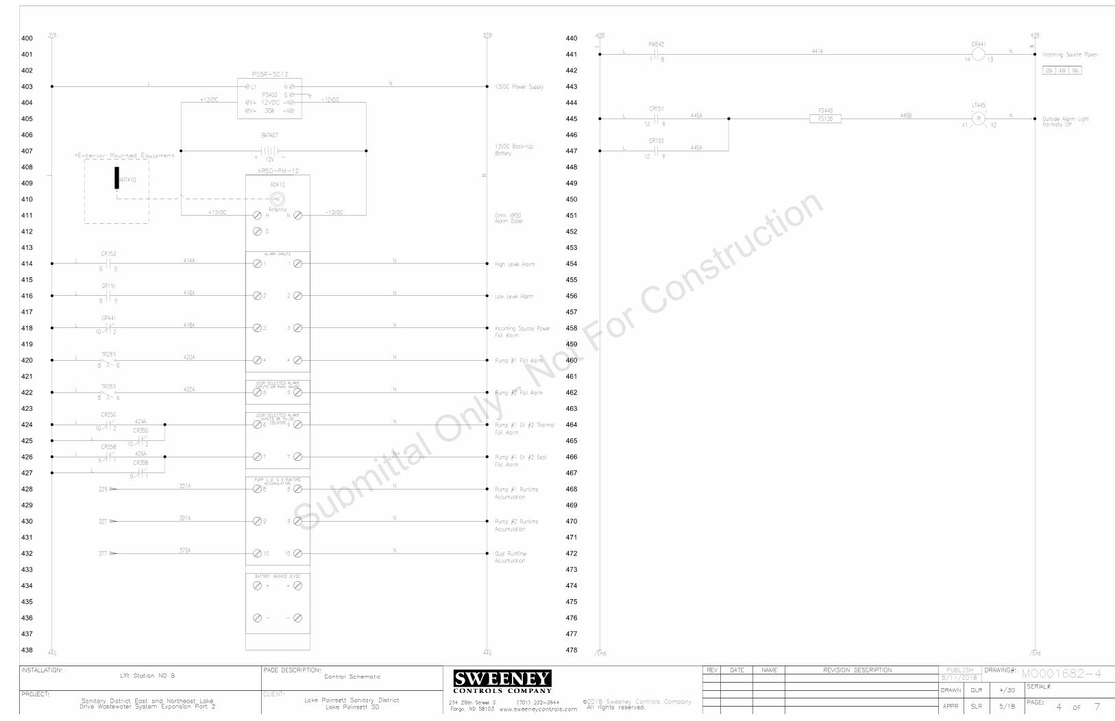
400
401
402
403
404
405
406
407
408
409
410
411
412
413
414
415
416
417
418
419
420
421
422
423
424
425
426
427
428
429
430
431
432
433
434
435
436
437
438
440
441
442
443
444
445
446
447
448
449
450
451
452
453
454
455
456
457
458
459
460
461
462
463
464
465
466
467
468
469
470
471
472
473
474
475
476
477
478
SERIAL#:
PAGE:
INSTALLATION:
PROJECT:
OF
REV
DRAWING#:
PAGE DESCRIPTION:
APPR
REVISION DESCRIPTION
DATE
NAME
DRAWN
All rights reserved.
C
Fargo, ND 58103
SERIAL#:
PAGE:
INSTALLATION:
PROJECT:
OF
REV
DRAWING#:
PAGE DESCRIPTION:
APPR
REVISION DESCRIPTION
DATE
NAME
DRAWN
2018 Sweeney Controls Company.
All rights reserved.
C
Fargo, ND 58103
PUBLISH
CLIENT:
74www.sweeneycontrols.com
234 28th Street S (701) 232-3644
Lift Station NO 8
DLR 4/30
SLR 5/18
Sanitary District East and Northeast Lake Lake Poinsett Sanitary District
Lake Poinsett SD
Control Schematic
74www.sweeneycontrols.com
234 28th Street S (701) 232-3644
Lift Station NO 8
DLR 4/30
SLR 5/18
Sanitary District East and Northeast Lake Lake Poinsett Sanitary District
Lake Poinsett SD
Control Schematic
MO001682-4
378 378 438
440
438
440
/End
/End
INPUTS OR RAIN GAUGE
USER SELECTED ALARM
ALARM INPUTS
COUNTER
INPUTS OR PULSE
USER SELECTED ALARM
ACCUMULATION
PUMP 1, 2, & 3 RUNTIME
BATTERY BACKED 12VDC
G
NH
-
+
-
+
10
9
8
7
6
5
4
3
2
1
10
9
8
7
6
5
4
3
2
1
Antenna
AD412
XR50-PM-12
Omni XR50
Alarm Dialer
G
NL1
-V
V+
V+
-V
PS403
PS5R-SC12
12VDC
12VDC Power Supply
30W
High Level Alarm9 5
CR153
9 5
CR151
Low Level Alarm
Fail Alarm
Incoming Source Power
Pump #1 Fail Alarm
Pump #2 Fail Alarm
Fail Alarm
Pump #1 Or #2 Thermal
Fail Alarm
Pump #1 Or #2 Seal
Accumulation
Pump #1 Runtime
Accumulation
Pump #2 Runtime
Accumulation
Dual Runtime
8 6
TR263
8 6
TR363
2
CR250
10
2
CR350
10
9 1
CR258
9 1
CR358
229
327
377
CR441
14 13
Incoming Source Power
206
R
X2X1
LT445
Outside Alarm Light
Normally Off
FS445
FS1268
CR151
12
8
CR153
12
2
CR441
10
418
81
PM542
306
L
N
221A
376A
L N
N
N
N
N
N
N
N
N
N
N 321A
+12VDC
+12VDC
ANT410
=Exterior Mounted Equipment
L
L
L
L
L
L
L
L
L
414A
416A
418A
420A
422A
424A
426A
L N
L N
L
441A
445A 445B
445A
5/11/2018
Drive Wastewater System Expansion Part 2Drive Wastewater System Expansion Part 2
L
N
Battery
12VDC Back-Up
+ -
BAT407
12V
-12VDC
-12VDC

500
501
502
503
504
505
506
507
508
509
510
511
512
513
514
515
516
517
518
519
520
521
522
523
524
525
526
527
528
529
530
531
532
533
534
535
536
537
538
540
541
542
543
544
545
546
547
548
549
550
551
552
553
554
555
556
557
558
559
560
561
562
563
564
565
566
567
568
569
570
571
572
573
574
575
576
577
578
SERIAL#:
PAGE:
INSTALLATION:
PROJECT:
OF
REV
DRAWING#:
PAGE DESCRIPTION:
APPR
REVISION DESCRIPTION
DATE
NAME
DRAWN
All rights reserved.
C
Fargo, ND 58103
SERIAL#:
PAGE:
INSTALLATION:
PROJECT:
OF
REV
DRAWING#:
PAGE DESCRIPTION:
APPR
REVISION DESCRIPTION
DATE
NAME
DRAWN
2018 Sweeney Controls Company.
All rights reserved.
C
Fargo, ND 58103
PUBLISH
CLIENT:
75www.sweeneycontrols.com
234 28th Street S (701) 232-3644
Lift Station NO 8
DLR 4/30
SLR 5/18
Sanitary District East and Northeast Lake Lake Poinsett Sanitary District
Lake Poinsett SD
Power Schematic
75www.sweeneycontrols.com
234 28th Street S (701) 232-3644
Lift Station NO 8
DLR 4/30
SLR 5/18
Sanitary District East and Northeast Lake Lake Poinsett Sanitary District
Lake Poinsett SD
Power Schematic
MO001682-4
T3
T1
GND
Pump #2
T2FLA
T3
T1
GND
Pump #1
T2FLA
PDB506
PK9GTA
1 Phase 3 Wire
120/240VAC
Incoming Power
Controls
L1
Convenience Receptacle
REC567
L2
200W
Enclosure Heater
HTR565
QOU115
Receptacle
15 AMP
QOU110
Heater
10 AMP
QOU110
Controls
10 AMP
=Pump #2
=Pump #1CB563
100 100
CB565
CB567
538
540
538
540
538
540
538
540
24.3
24.3
L1
L2
T1
T2
CB523
HDL2605050 AMP
Pump #1
L1
L2
T1
T2
CB531
HDL2605050 AMP
Pump #2
Connected Directly To VFD's
Pump Grounds Must Be
A
B N
SurgeCapacitor
SC518
CA 302R
Arrestor
Lightning
A
B G
LA514
S50A120V2P
63132
PDB512
63131
PDB503
L2L1
T2
T1
HDL26100
100
AMP
Main
CB506
6
7
PM542
MODEL 201-200-SP-T-9
Power
Monitor
441
Pump #2 VFD
22C-B033N103
VFD303
G
T3
T2
T1
G
L3
L2
L1
Pump #1 VFD
22C-B033N103
VFD203
G
T3
T2
T1
G
L3
L2
L1
CB571
QOU12020 AMP
Air Conditioner
4000 BTU
AC571
Air Conditioner
100
B
100A
12AWG
3
AW
G
3
AW
G
14AWG
14AWG
565A
567A
571A
14AWG
100B
100B
100B
100B
100B
14AWG
14AWG
8AWG
8AWG
8AWG
8AWG
8AWG
8AWG
8AWG
8AWG
8AWG
8AWG
5/11/2018
Drive Wastewater System Expansion Part 2Drive Wastewater System Expansion Part 2

SERIAL#:
PAGE:
INSTALLATION:
PROJECT:
OF
REV
DRAWING#:
PAGE DESCRIPTION:
APPR
REVISION DESCRIPTION
DATE
NAME
DRAWN
All rights reserved.
C
Fargo, ND 58103
SERIAL#:
PAGE:
INSTALLATION:
PROJECT:
OF
REV
DRAWING#:
PAGE DESCRIPTION:
APPR
REVISION DESCRIPTION
DATE
NAME
DRAWN
2018 Sweeney Controls Company.
All rights reserved.
C
Fargo, ND 58103
PUBLISH
CLIENT:
76www.sweeneycontrols.com
234 28th Street S (701) 232-3644
Lift Station NO 8
DLR 4/30
SLR 5/18
Sanitary District East and Northeast Lake Lake Poinsett Sanitary District
Lake Poinsett SD
Backpanel And Inner Door Layout
76www.sweeneycontrols.com
234 28th Street S (701) 232-3644
Lift Station NO 8
DLR 4/30
SLR 5/18
Sanitary District East and Northeast Lake Lake Poinsett Sanitary District
Lake Poinsett SD
Backpanel And Inner Door Layout
MO001682-4
1" X 2" X 18" Wiring
1"
X
2"
X
42.5
"
Wirin
g
1"
X
2"
X
14"
Wirin
g
1" X 2" X 18" Wiring
1" X 2" X 18" Wiring
1"
X
2"
X
10"
Wirin
g
XR50
Omni-Site
AD412
CB506
HDL26100
100 AMP
MAIN
PUMP #1
CB523
HDL26050
50 AMP
PUMP #2
CB531
HDL26050
50 AMP
ON
OFF
CB563 10 AMP
CONTROLS
ON
OFF
CB565 10 AMP
HEATER
RECEPTACLEON
OFF
CB567 15 AMP
ON
OFF
CB571 20 AMP
AIR CONDITIONER
REC567
HTR565
200W
LA514
S50A120V2P
SC518
PDB506
BLOCK
DISTRBUTION
POWER
BLOCK
DISTRBUTION
PDB512
BL
OC
K
NU
ET
RA
L
PDB503
63131
PDB503
VFD203
22C-B033N103
VFD303
22C-B033N103
PM542
FC144
CR151
CR153
CR221
CR241
CR250
CR258
CR321
CR341
CR350
CR358
CR441
?
PS404
12VDC
TR255
TR263
TR355
TR363
145
A
145
A
145
A
145
A
147
A
149
A
151
A
153
A
153
B
155
A
L
L
L
L
L
N
250A
258A
350A
358A
RUNNING
G
LT225
G
LT325
R
LT265
FAILED
R
LT365
R
LT253
R
LT353
A
LT260
SEAL FAIL
A
LT360
PB253
Bk
RESET
PB353
Bk
SS161
1-2 AUTO 2-1
HOURS
RTM223
HOURS
RTM323
HOURS
RTM376
DUAL RUN
SS241
PUMP #1
HAND OFF AUTO
SS341
PUMP #2
HAND OFF AUTO
PB147
Bk
HIGH FLOAT
TEST
PB149
Bk
LAG FLOAT
TEST
PB151
Bk
LEAD FLOAT
TEST
PB153
Bk
STOP FLOAT
TEST
PB155
Bk
LOW FLOAT
TEST
Mounted Beneath Main CB
Lightning Arrestor
PumpSaver
MODEL ISS-105
IS Super Cell
SymComwww.symcominc.com
SAFE INPUTS
INTRINSICALLY
#1 #2 #3 #4 #5
120VAC
INPUT
#1 #2 #3 #4 #5
DC ON
V.ADJ
L N
-V +VOUTPUT
INPUT
THERMAL FAIL
5/11/2018
Drive Wastewater System Expansion Part 2Drive Wastewater System Expansion Part 2

SERIAL#:
PAGE:
INSTALLATION:
PROJECT:
OF
REV
DRAWING#:
PAGE DESCRIPTION:
APPR
REVISION DESCRIPTION
DATE
NAME
DRAWN
All rights reserved.
C
Fargo, ND 58103
SERIAL#:
PAGE:
INSTALLATION:
PROJECT:
OF
REV
DRAWING#:
PAGE DESCRIPTION:
APPR
REVISION DESCRIPTION
DATE
NAME
DRAWN
2018 Sweeney Controls Company.
All rights reserved.
C
Fargo, ND 58103
PUBLISH
CLIENT:
77www.sweeneycontrols.com
234 28th Street S (701) 232-3644
Lift Station NO 8
DLR 4/30
SLR 5/18
Sanitary District East and Northeast Lake Lake Poinsett Sanitary District
Lake Poinsett SD
Panel Layout
77www.sweeneycontrols.com
234 28th Street S (701) 232-3644
Lift Station NO 8
DLR 4/30
SLR 5/18
Sanitary District East and Northeast Lake Lake Poinsett Sanitary District
Lake Poinsett SD
Panel Layout
MO001682-4
R
LT445
AC571
IQ4000EV-126-SS-N4X-STDR
24"
48"
72"
36"
UL698A
UL Listing
Legs And Skirts Area
Door Stop Kit:
Attached Bug Screen Behind Louvers:
Punched Louvers:
Laminated Wiring Diagrams:
Stainless Steel Enclosure 12" Deep:
Note
5/11/2018
Drive Wastewater System Expansion Part 2Drive Wastewater System Expansion Part 2

Description
Wirin
g Sym
bols
SERIAL#:
PAGE:
INSTALLATION:
PROJECT:
OF
REV DRAWING#:
CUSTOMER:
PAGE
DESCRIPTION:
APPR
REVISION DESCRIPTIONDATE NAME
DRAWN
Sweeney Controls Company.
All rights reserved.
C
##www.sweeneycontrols.com
234 28th Street S
Fargo, ND 58103
(701) 232-3644
XXX
MO######-#
Installed)
(To Be Field
UPS###
5 AMP
F101A
101A
ANTENNA
DIAG.
-
+
RS-232
RM###
ALA###
X1 X2
LT###
G
1 2
3
X1 X2
4
LT###
R
TS###
TS###
10A
CB###
Controls
FS###
High
L1 L2
REC###
A1OL
M###
100
101
102
103
104
105
106
107
108
109
110
111
112
113
114
115
116
117
118
119
120
121
122
123
124
125
126
127
128
129
130
131
132
133
134
135
136
137
138
140
141
142
143
144
145
146
147
148
149
150
151
152
153
154
155
156
7 4
CR###
8 2
CR###
B A
CR###
Control Relay Coil
B A
CR103
Thermal Fail Relay
109 106
XXX###
1 To 3 Letter Device Abbreviation
Page Number
Line Number
Inside The Panel
Next To The Physically Mounted Part
This Id Number Is Also Found On Or
03 Line 1elay Page Rontrol CEx
Device ID
Terminal Number
Used
The Drawings Contacts of This Device Are
Cross Reference Box. This Shows Where In
09 Line 1Page
Ex: Contact Is Used On
Used Contact Identifier
Unused Contact Space
156
154
157
155
158
Wire Links
56 Line 1Page
Ex: Wire Goes To
Wire Link
Goes To Line 156
54 Line 1Page
Ex: Wire Comes From
Wire Link
Comes From Line 154
Wire Link
Comes From Line 157
Wire Link
Goes To Line 155
158 Wire Link
Connects To Line
=Pump #1
TB1
103A
TB1
L
Device Description
TS103
Terminal Block Row 1
Line Number
Is The First Terminal Block On That A
And 03 Line 1Ex: Corresponds To Page
Terminal Block IDField Installation Box
Field Installation Location
Control Panel Wiring
Solid Line Indicates Internal
Field Wiring
Dashed Line Indicates
Normally Open Control Relay Contact
Normally Closed Control Relay Contact
Normally Closed Temperature Switch
Normally Open Temperature Switch
(Used As High Float)
Normally Open Float Switch
(Indicating Green Lens)
Pilot Light
(Indicating Red Lens)
Push To Test Pilot Light
Not To Exceed 10,000ft
Maximum Cable Length
Electrical Code
Of The National
With Article 504
Accordance
Install In
Hazardous
Area
Non-
Hazardous
Area
Device
Safe Switching
Intrinsically
POWER
SUPPLY
CH1
CH2
CH1
CH2
CH2
LF
K
PR
LF
CH1
PR
K
SS
14
1
2
11
8
13
12
10
9
7
4
5
ISB###
Intrinsically Safe Barrier
Intrinsically Safe Circuit Area
RTM###
Run Time Meter
I:0/4/00
RACK
MODULE
00
PLC109
4
T
0
1746-IA16Device ID
Module Number
PLC Address
PLC Address Description
Part Number
Rack Number
Terminal Number
I/O Card
HAND OFF AUTO
AH###
Alarm Horn
13
2
POT###
Potentiometer
H2H3
480V
120V
H1 H4
X1 X2
T###
5KVA
Overload Contact
Motor Starter Coil With
(Controls CB Rated At 10 Amps)
1 Pole Circuit Breaker
(480V Primary/120V Secondary)
Transformer
#/## ####
Wiring Symbols Description
XXX #/##
Uninterruptible Power Supply
Digital Output Connections
Flowmeter With Power, Analog Output, And
Antenna Lightening Arrestor
L1
L2
L3
T1
T2
T3
M460
Pump #1 Motor Starter
CC160
8536SF01V02S
L1
L2
L3
T1
T2
T3200 AMP
CB142
Pump #1
KAL36200
M FLA
HPT1
T2
T3
GND
103
Pump #1
84
=Pump #1
7 4
CR103
8 2
CR103
03Line
1elay Coil is Found On Page Rontrol CEx:
N/O Relay Contact
Eg: No Wire Connection
Wire Looped Over Another Wire
Wire Connected To Another Wire
Wire Connection Point
Fuse Identifier
Fuse Amp Rating
L1
L2
L3
G
T1
T2
T3
G
VFD142 Pump #1 VFD
22C-D088A103
A1
B1
C1
A2
B2
C2
LR142
Pump #1
KDRULF2H
L1
L2
L3
T1
T2
T3
M450
Pump #1 VFD Isolation
8502SF02V02S
Contactor
Device ID
Rating
Circuit Breaker Amp
Number
Circuit Breaker Part
Description Device IDDescription
50 Line 4Found On Page
Indicates Contactor Coil Is
Device ID
Description
Number
Line Reactor Part
Device IDDescription
VFD Part Number
Number
Motor Starter Part
Number
Overloads Part
Motor Starter
Description
60 Line 4On Page
Indicates Starter Coil Is Found
Device ID
Number
Contactor Part
Field Installation Location
103A
Wire Number
106A
Number
The Second Wire On That Line
Means Its B And 06 Line 1Page
Ex: This Wire Originates On
Wire Number
Pump Information
LS###
LS###
HTR###
200W
3 4
PB###
Lamp Test
1 2
PB###
Reset
Normally Open Limit Switch
Normally Closed Limit Switch
(Used As A Lamp Test Button)
Normally Open Pushbutton
(Used As A Reset Pushbutton)
Normally Closed Pushbutton
X1 X2
M###
Contactor Coil
(Shown As 200 Watts)
Heater
Thermal Fail Input
Receptacle
109A
Wire Number
7 4
CR422
106B
Wire Number 22 Line 4On Page
elay Coil is Found Rontrol CEx:
N/O Relay Contact
Position Only
Closed In Hand
Position Only
Closed In Auto
Device Id Format
5 AMP
F-L
GDL5
L
(GDL5 Is Fuse Part Number)
Fuse Block
2 7
TR###
5 Seconds
3 4
TR###
(Set To 5 Seconds)
Time Delay Relay Coil
Relay Contact
Normally Open Delayed On Time Delay
TB1
####
Terminal Block
Example Of Control WiringExample Of 3 Phase Power Wiring
I:0/4/00
PLC Address Format:
Input Rack:0 Module:4 Address:00
Shown On This Page
Used In Drawings Are
Note: Not All Symbols
03 Line 1On Page
elay Coil is Found Rontrol CEx:
N/C Relay Contact
PROTECTED
UNPROTECTEDL N
L N
G
G
SUP###
G
NL1
-V
V+
V+
-V
PS###
24VDC
30W
ANT###
AC
Not Used
4-20mA
L N
+ -
FM###
Flow Meter
Digital Output
157
158
159
160
161
162
163
164
165
166
167
168
169
170
171
172
173
174
175
176
177
178
159
159 Wire Link
Connects To Line
TRANSDUCER
LEVEL
4-20mA
+ -LXD###
XOO
OOX
1 2
3 4
SS###
Legend Above
Are Closed With Respect To Switch
"X" Specifies What Position The Contacts
Surge Suppressor
(24VDC Output Rated To 30 Watts)
DC Power Supply
Antenna
2-Wire Analog Level Transducer
Radio Modem
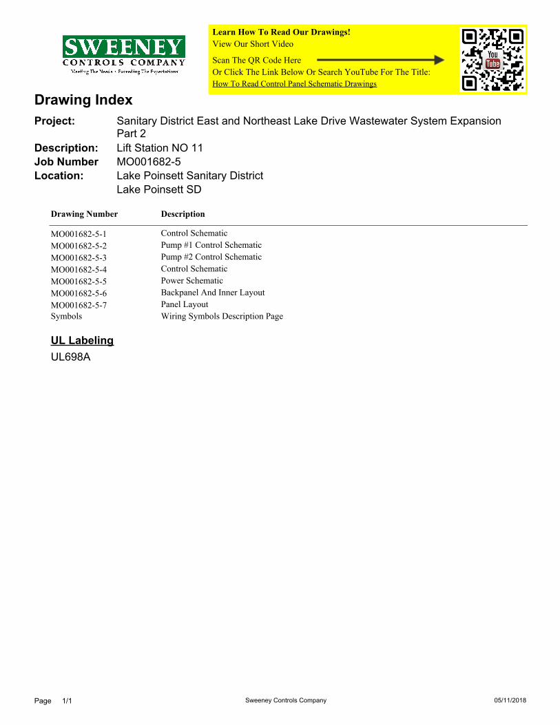
Lake Poinsett SD
Lake Poinsett Sanitary DistrictLocation:
MO001682-5Job Number
Lift Station NO 11Description:
Sanitary District East and Northeast Lake Drive Wastewater System ExpansionPart 2
Project:
Drawing Index
Learn How To Read Our Drawings!
How To Read Control Panel Schematic Drawings
View Our Short Video
Scan The QR Code Here
Or Click The Link Below Or Search YouTube For The Title:
DescriptionDrawing Number
Control SchematicMO001682-5-1Pump #1 Control SchematicMO001682-5-2Pump #2 Control SchematicMO001682-5-3Control SchematicMO001682-5-4Power SchematicMO001682-5-5Backpanel And Inner LayoutMO001682-5-6Panel LayoutMO001682-5-7
Symbols Wiring Symbols Description Page
UL Labeling
UL698A
Sweeney Controls CompanyPage 1/1 05/11/2018

100
101
102
103
104
105
106
107
108
109
110
111
112
113
114
115
116
117
118
119
120
121
122
123
124
125
126
127
128
129
130
131
132
133
134
135
136
137
138
140
141
142
143
144
145
146
147
148
149
150
151
152
153
154
155
156
157
158
159
160
161
162
163
164
165
166
167
168
169
170
171
172
173
174
175
176
177
178
SERIAL#:
PAGE:
INSTALLATION:
PROJECT:
OF
REV
DRAWING#:
PAGE DESCRIPTION:
APPR
REVISION DESCRIPTION
DATE
NAME
DRAWN
All rights reserved.
C
Fargo, ND 58103
SERIAL#:
PAGE:
INSTALLATION:
PROJECT:
OF
REV
DRAWING#:
PAGE DESCRIPTION:
APPR
REVISION DESCRIPTION
DATE
NAME
DRAWN
2018 Sweeney Controls Company.
All rights reserved.
C
Fargo, ND 58103
PUBLISH
CLIENT:
71www.sweeneycontrols.com
234 28th Street S (701) 232-3644
Lift Station NO 11
DLR 4/18
SLR 5/18
Sanitary District East and Northeast Lake Lake Poinsett Sanitary District
Lake Poinsett SD
Control Schematic
71www.sweeneycontrols.com
234 28th Street S (701) 232-3644
Lift Station NO 11
DLR 4/18
SLR 5/18
Sanitary District East and Northeast Lake Lake Poinsett Sanitary District
Lake Poinsett SD
Control Schematic
MO001682-5
5 AMP
F-LF-3AG-TD-5A
TB5
120VAC
138
140
138
140 200 200
Pump #2 Call
Pump #1 Call
Device
Safe Switching
Intrinsically
Electrical Code
The National
Article 504 Of
Accordance With
Install In
Exceed 10,000 ft
Length Not To
Maximum Cable
Hazardous Area
Non-Hazardous Area
Float Controller
MODEL ISS-105
Intrinsically Safe
FC144
L2
SIL._AND_RST
RCTL2
RCTL1
COM
#1
#2
#3
COM
#4
#5
COM
C
#2
PWR_RESET
#3
COM
#4
#1
#5
L1
MODE
43
87
65
12
10
9
ON
1
COMMON
LOW ALARM
STOP
LEAD
LAG
HIGH ALARM
High
FS147
Lag
FS149
Lead
FS151
Stop
FS153
Low
FS155
1-2 AUTO 2-1
SS161
43
21
OOX
XOO
TB5
TB5
TB5
145A
TB5
TB5
TB5
TB5
TB5
TB5
TB5
3 4
PB147
Test
GW60NO
3 4
PB149
Test
GW60NO
3 4
PB151
Test
GW60NO
GW60NO
GW60NO
1 2
PB153Test
1 2
PB155Test
CR153
High Float Relay14 13
CR151
Low Float Relay14 13
343
414 447
416 445
563 563
145A
145A
145A
153A
147A
149A
151A
153B
155A
100
A
145A
145A
145A
145A
145A
147A
149A
151A
153A
153A
147A
149A
151A
153B 153C
155A
153A
147B
149B
151B
153D
159A
161A
163A
243
N
N
N
L
N
N
100
B
L
L
L
L
L
N
N
=Wetwell
5/11/2018
Drive Wastewater System Expansion Part 2Drive Wastewater System Expansion Part 2

200
201
202
203
204
205
206
207
208
209
210
211
212
213
214
215
216
217
218
219
220
221
222
223
224
225
226
227
228
229
230
231
232
233
234
235
236
237
238
240
241
242
243
244
245
246
247
248
249
250
251
252
253
254
255
256
257
258
259
260
261
262
263
264
265
266
267
268
269
270
271
272
273
274
275
276
277
278
SERIAL#:
PAGE:
INSTALLATION:
PROJECT:
OF
REV
DRAWING#:
PAGE DESCRIPTION:
APPR
REVISION DESCRIPTION
DATE
NAME
DRAWN
All rights reserved.
C
Fargo, ND 58103
SERIAL#:
PAGE:
INSTALLATION:
PROJECT:
OF
REV
DRAWING#:
PAGE DESCRIPTION:
APPR
REVISION DESCRIPTION
DATE
NAME
DRAWN
2018 Sweeney Controls Company.
All rights reserved.
C
Fargo, ND 58103
PUBLISH
CLIENT:
72www.sweeneycontrols.com
234 28th Street S (701) 232-3644
Lift Station NO 11
DLR 4/18
SLR 5/18
Sanitary District East and Northeast Lake Lake Poinsett Sanitary District
Lake Poinsett SD
Pump #1 Control Schematic
72www.sweeneycontrols.com
234 28th Street S (701) 232-3644
Lift Station NO 11
DLR 4/18
SLR 5/18
Sanitary District East and Northeast Lake Lake Poinsett Sanitary District
Lake Poinsett SD
Pump #1 Control Schematic
MO001682-5
178 178 238
240
238
240 300 300
Output 2
Analo
g
Output
1
Analo
g
Input 2
Analo
g
Input
1
Analo
g
Source
Sin
k/
for
har
dware e
na
ble)
whe
n
usin
g ter
min
al
01
(re
mo
ve
EN
BL ju
mper
10V
20mA
10V
20mA
10V
20mA
10V
20mA
SNK
SRC
Powerflex 400
Allen Bradley
AO2
AO1
Shld
AI2 Com
AI2
AI1 Com
AI1
+10VDC
Opto Out 1
Opto Com
Relay Out
Relay Out
Enable
Common
Input 4
Input 3
Input 2
Input 1
Common
Rev
Fwd
+24VDCPump #1 VFD
VFD203
R6
R5
R4
R3
R2
R1
20
19
18
17
16
15
14
13
12
11
10
9
8
7
6
5
4
3
2
1
22C-B033N103
G
X2X1
LT225
Pump #1 Running Light
CR221
14 13
Pump #1 Running Relay
Pump #1 Call
TB5
TB5=Pump #1
250A
XOO
OOX
1 2
3 4
HAND OFF AUTO
SS241
CR241
14 13
Pump #1 Call Relay
9 5
CR241
206
CR250
14 13
Pump #1 Thermal
Fail Relay
9 5
CR250
206
4
CR250
12
253
R
X2X1
LT253
Pump #1 Thermal
Fail Light
2 7
On-Delay
TR255
Pump #1 Thermal Fail
Time Delay Relay
2 Sec.
1 2
PB253
1 3
TR255
255
TB5
CR258
14 13
Pump #1 Seal Fail Relay258A
TB5=Pump #1
Seal
A
X2X1
LT260
Pump #1 Seal
Fail Light4
CR258
12
260
2 7
On-Delay
TR263
Pump #1 Fail Time
Delay Relay
1 Sec.
9 1
CR221
263
8
CR241
12
263
R
X2X1
LT265
Pump #1 Fail Light1 3
TR263
265
376
424
426
420
428
9 5
CR441
523
221A
221A
206A 206B 206C
201A
201A
201A
201A
221A
221A
221A
241A
147147C
N
L
L
250A
253A
258A
260A
263A
265A
N
N
N
N
N
N
N
N
N
N
N
N
N
RTM223
Pump #1 Hourmeter
Pump #1 Running
Pump #1 Running
263B
253B
Thermal Reset
L
L
L
L
L
L
L
L
L
L
5/11/2018
Drive Wastewater System Expansion Part 2Drive Wastewater System Expansion Part 2

300
301
302
303
304
305
306
307
308
309
310
311
312
313
314
315
316
317
318
319
320
321
322
323
324
325
326
327
328
329
330
331
332
333
334
335
336
337
338
340
341
342
343
344
345
346
347
348
349
350
351
352
353
354
355
356
357
358
359
360
361
362
363
364
365
366
367
368
369
370
371
372
373
374
375
376
377
378
SERIAL#:
PAGE:
INSTALLATION:
PROJECT:
OF
REV
DRAWING#:
PAGE DESCRIPTION:
APPR
REVISION DESCRIPTION
DATE
NAME
DRAWN
All rights reserved.
C
Fargo, ND 58103
SERIAL#:
PAGE:
INSTALLATION:
PROJECT:
OF
REV
DRAWING#:
PAGE DESCRIPTION:
APPR
REVISION DESCRIPTION
DATE
NAME
DRAWN
2018 Sweeney Controls Company.
All rights reserved.
C
Fargo, ND 58103
PUBLISH
CLIENT:
73www.sweeneycontrols.com
234 28th Street S (701) 232-3644
Lift Station NO 11
DLR 4/18
SLR 5/18
Sanitary District East and Northeast Lake Lake Poinsett Sanitary District
Lake Poinsett SD
Pump #2 Control Schematic
73www.sweeneycontrols.com
234 28th Street S (701) 232-3644
Lift Station NO 11
DLR 4/18
SLR 5/18
Sanitary District East and Northeast Lake Lake Poinsett Sanitary District
Lake Poinsett SD
Pump #2 Control Schematic
MO001682-5
278 278 338
340
338
340 400 400
Pump #2 Call
Output 2
Analo
g
Output
1
Analo
g
Input 2
Analo
g
Input
1
Analo
g
Source
Sin
k/
for
har
dware e
na
ble)
whe
n
usin
g ter
min
al
01
(re
mo
ve
EN
BL ju
mper
10V
20mA
10V
20mA
10V
20mA
10V
20mA
SNK
SRC
Powerflex 400
Allen Bradley
AO2
AO1
Shld
AI2 Com
AI2
AI1 Com
AI1
+10VDC
Opto Out 1
Opto Com
Relay Out
Relay Out
Enable
Common
Input 4
Input 3
Input 2
Input 1
Common
Rev
Fwd
+24VDCPump #2 VFD
VFD303
R6
R5
R4
R3
R2
R1
20
19
18
17
16
15
14
13
12
11
10
9
8
7
6
5
4
3
2
1
CR321
14 13
Pump #2 Running Relay
RTM323
Pump #2 Hourmeter
G
X2X1
LT325
Pump #2 Running Light
22C-B033N103XOO
OOX
1 2
3 4
HAND OFF AUTO
SS341
CR341
14 13Pump #2 Call Relay
9 5
CR341
R
X2X1
LT353
Pump #2 Thermal
Fail Light
2 7
On-Delay
TR355
Pump #2 Thermal Fail
Time Delay Relay
2 Sec.
1 2
PB353
1 3
TR355
CR358
14 13Pump #2 Seal Fail Relay
Seal
A
X2X1
LT360
Pump #2 Seal
Fail Light4
CR358
12
2 7
On-Delay
TR363
Pump #2 Fail Time
Delay Relay
1 Sec.
CR350
14 13Pump #2 Thermal
Fail Relay
9 5
CR350
4
CR350
12
8
CR341
12
R
X2X1
LT365
Pump #2 Fail Light1 3
TR363
306
306 353
355
360
363
365
TB5
TB5
=Pump #2
=Pump #2TB5
TB5
9 1
CR321
363
Pump #2 Running
149
RTM376
Dual Run Hourmeter 2278
CR321
12
376
425
427
422
430
432
8
CR441
12
531
N
N
221A
149C
350A
358A
301A
301A
301A
301A 306A 306B 306C
321A 321A
321A
321A
321A
N
N
N
341A 341A N
N
N
N
N
N
N
N
N
365A
363A
360A
363B
350A
358A
353A 353B
353B
376A N
L
L
Thermal Reset
L
L
L
L
L
L
L
L
L
L
376A
5/11/2018
Drive Wastewater System Expansion Part 2Drive Wastewater System Expansion Part 2

400
401
402
403
404
405
406
407
408
409
410
411
412
413
414
415
416
417
418
419
420
421
422
423
424
425
426
427
428
429
430
431
432
433
434
435
436
437
438
440
441
442
443
444
445
446
447
448
449
450
451
452
453
454
455
456
457
458
459
460
461
462
463
464
465
466
467
468
469
470
471
472
473
474
475
476
477
478
SERIAL#:
PAGE:
INSTALLATION:
PROJECT:
OF
REV
DRAWING#:
PAGE DESCRIPTION:
APPR
REVISION DESCRIPTION
DATE
NAME
DRAWN
All rights reserved.
C
Fargo, ND 58103
SERIAL#:
PAGE:
INSTALLATION:
PROJECT:
OF
REV
DRAWING#:
PAGE DESCRIPTION:
APPR
REVISION DESCRIPTION
DATE
NAME
DRAWN
2018 Sweeney Controls Company.
All rights reserved.
C
Fargo, ND 58103
PUBLISH
CLIENT:
74www.sweeneycontrols.com
234 28th Street S (701) 232-3644
Lift Station NO 11
DLR 4/18
SLR 5/18
Sanitary District East and Northeast Lake Lake Poinsett Sanitary District
Lake Poinsett SD
Control Schematic
74www.sweeneycontrols.com
234 28th Street S (701) 232-3644
Lift Station NO 11
DLR 4/18
SLR 5/18
Sanitary District East and Northeast Lake Lake Poinsett Sanitary District
Lake Poinsett SD
Control Schematic
MO001682-5
378 378 438
440
438
440
/End
/End
G
NL1
-V
V+
V+
-V
PS403
PS5R-SC12
12VDC
12VDC Power Supply
30W
High Level Alarm
Low Level Alarm
Pump #1 Fail Alarm
Pump #2 Fail Alarm
Fail Alarm
Pump #1 Or #2 Thermal
Accumulation
Pump #1 Runtime
Fail Alarm
Pump #1 Or #2 Seal
Accumulation
Pump #2 Runtime
Accumulation
Dual Runtime
9 5
CR153
9 5
CR151
8 6
TR263
8 6
TR363
2
CR250
10
9 1
CR258
9 1
CR358
2
CR350
10
229
327
377
CR441
14 13
Incoming Source Power
Fail Alarm
Incoming Source Power2
CR441
10
418206
R
X2X1
LT445
Outside Alarm Light
Normally Off8
CR151
12
8
CR153
12
81
PM542
306
N
221A
321A
376A
N
N
N
N
N
N
N
N
N
426A
414A
416A
418A
420A
422A
N
N
N
441A
445A
FS445
FS126445B
Ok Relay
424A
L
L
L
L
L
L
L
L
L
L
L
L
L
L 445A
INPUTS OR RAIN GAUGE
USER SELECTED ALARM
ALARM INPUTS
COUNTER
INPUTS OR PULSE
USER SELECTED ALARM
ACCUMULATION
PUMP 1, 2, & 3 RUNTIME
BATTERY BACKED 12VDC
G
NH
-
+
-
+
10
9
8
7
6
5
4
3
2
1
10
9
8
7
6
5
4
3
2
1
Antenna
AD412
XR50-PM-12
Omni XR50
Alarm Dialer
ANT410
=Exterior Mounted Equipment
N
N
+12VDC
+12VDC
-12VDC
-12VDC
5/11/2018
Battery
12VDC Back-Up
+ -
BAT407
12V
L
N
Drive Wastewater System Expansion Part 2Drive Wastewater System Expansion Part 2

500
501
502
503
504
505
506
507
508
509
510
511
512
513
514
515
516
517
518
519
520
521
522
523
524
525
526
527
528
529
530
531
532
533
534
535
536
537
538
540
541
542
543
544
545
546
547
548
549
550
551
552
553
554
555
556
557
558
559
560
561
562
563
564
565
566
567
568
569
570
571
572
573
574
575
576
577
578
SERIAL#:
PAGE:
INSTALLATION:
PROJECT:
OF
REV
DRAWING#:
PAGE DESCRIPTION:
APPR
REVISION DESCRIPTION
DATE
NAME
DRAWN
All rights reserved.
C
Fargo, ND 58103
SERIAL#:
PAGE:
INSTALLATION:
PROJECT:
OF
REV
DRAWING#:
PAGE DESCRIPTION:
APPR
REVISION DESCRIPTION
DATE
NAME
DRAWN
2018 Sweeney Controls Company.
All rights reserved.
C
Fargo, ND 58103
PUBLISH
CLIENT:
75www.sweeneycontrols.com
234 28th Street S (701) 232-3644
Lift Station NO 11
DLR 4/18
SLR 5/18
Sanitary District East and Northeast Lake Lake Poinsett Sanitary District
Lake Poinsett SD
Power Schematic
75www.sweeneycontrols.com
234 28th Street S (701) 232-3644
Lift Station NO 11
DLR 4/18
SLR 5/18
Sanitary District East and Northeast Lake Lake Poinsett Sanitary District
Lake Poinsett SD
Power Schematic
MO001682-5
T3
T1
GND
Pump #2
T2FLA
T3
T1
GND
Pump #1
T2FLA
PDB506
PK9GTA
1 Phase 3 Wire
120/240VAC
Incoming Power
Controls
L1
Convenience Receptacle
REC567
L2
200W
Enclosure Heater
HTR565
QOU115
Receptacle
15 AMP
QOU110
Heater
10 AMP
QOU110
Controls
10 AMP
=Pump #2
=Pump #1CB563
CB565
CB567
538
540
538
540
538
540
538
540
L2L1
T2T1
HD
L26100
100
AM
P
Main
Arrestor
Lightning
A
B G
LA514
S50A120V2P
A
B N
SurgeCapacitor
SC518
CA 302R
PDB503
63131
PDB512
63132
24.3
L1
L2
T1
T2
CB523
HDL2605050 AMP
Pump #1
24.3
L1
L2
T1
T2
CB531
HDL2605050 AMP
Pump #2
6
7
PM542
Power
Monitor
CB571
QOU12020 AMP
100 100
441
Pump #1 VFD
22C-B033N103
VFD203
G
T3
T2
T1
G
L3
L2
L1
Pump #2 VFD
22C-B033N103
VFD303
G
T3
T2
T1
G
L3
L2
L1
3
AW
G
3
AW
G
8AWG
8AWG
8AWG
8AWG
8AWG
14AWG
14AWG
14AWG
14AWG
100A
8AWG
8AWG
8AWG
14AWG
12AWG
100B
8AWG
8AWG
CB506
4000 BTU
AC571
100
B
100B
100B
100B
565A
567A
MODEL 201-200-SP-T-9
100
B
Air Conditioner
Air Conditioner
571A 100B
Connected Directly To VFD's
Pump Grounds Must Be
5/11/2018
Drive Wastewater System Expansion Part 2Drive Wastewater System Expansion Part 2

SERIAL#:
PAGE:
INSTALLATION:
PROJECT:
OF
REV
DRAWING#:
PAGE DESCRIPTION:
APPR
REVISION DESCRIPTION
DATE
NAME
DRAWN
All rights reserved.
C
Fargo, ND 58103
SERIAL#:
PAGE:
INSTALLATION:
PROJECT:
OF
REV
DRAWING#:
PAGE DESCRIPTION:
APPR
REVISION DESCRIPTION
DATE
NAME
DRAWN
2018 Sweeney Controls Company.
All rights reserved.
C
Fargo, ND 58103
PUBLISH
CLIENT:
76www.sweeneycontrols.com
234 28th Street S (701) 232-3644
Lift Station NO 11
DLR 4/18
SLR 5/18
Sanitary District East and Northeast Lake Lake Poinsett Sanitary District
Lake Poinsett SD
76www.sweeneycontrols.com
234 28th Street S (701) 232-3644
Lift Station NO 11
DLR 4/18
SLR 5/18
Sanitary District East and Northeast Lake Lake Poinsett Sanitary District
Lake Poinsett SD
MO001682-5
XR50
Omni-Site
AD412
CB506
HDL26100
100 AMP
CB523
HDL26050
50 AMP
CB531
HDL26050
50 AMP
FC144
HTR565
200W
PDB506
1" X 2" X 18" Wiring
1" X 2" X 18" Wiring
1" X 2" X 18" Wiring
1"
X
2"
X
10"
Wirin
g
ON
OFF
CB563 10 AMP
CONTROLS
ON
OFF
CB565 10 AMP
HEATER
ON
OFF
CB571 20 AMP
AIR CONDITIONER
RECEPTACLEON
OFF
CB567 15 AMP
CR151
CR153
CR221
CR241
CR250
CR258
CR321
CR341
CR350
CR358
CR441
LA514
S50A120V2P
PM542
?
PS403
12VDC
REC567
SC518
L
145
A
145
A
145
A
145
A
147
A
149
A
151
A
153
A
153
B
155
A
250A
258A
350A
358A
L
L
L
L
N
TR255
TR263
TR355
TR363
BLOCK
DISTRBUTION
POWER
BLOCK
DISTRBUTION
PDB512
BL
OC
K
NU
ET
RA
L
PDB503
63131
PDB503
MAIN
PUMP #2
PUMP #1
HOURS
RTM223
HOURS
RTM323
HOURS
RTM376
DUAL RUN
RUNNING
G
LT225
G
LT325
R
LT265
FAILED
R
LT365
SS241
PUMP #1
HAND OFF AUTO
SS341
PUMP #2
HAND OFF AUTO
R
LT253
R
LT353
A
LT260
SEAL FAIL
A
LT360
PB253
Bk
RESET
PB353
Bk
SS161
1-2 AUTO 2-1
PB147
Bk
PB149
Bk
PB151
Bk
PB153
Bk
PB155
Bk
HIGH FLOAT
TEST
LAG FLOAT
TEST
LEAD FLOAT
TEST
STOP FLOAT
TEST
LOW FLOAT
TEST
PumpSaver
MODEL ISS-105
IS Super Cell
SymComwww.symcominc.com
SAFE INPUTS
INTRINSICALLY
#1 #2 #3 #4 #5
120VAC
INPUT
#1 #2 #3 #4 #5
DC ON
V.ADJ
L N
-V +VOUTPUT
INPUT
1"
X
2"
X
14"
Wirin
g
Mounted Beneath Main CB
Lightning Arrestor
VFD203
22C-B033N103
VFD303
22C-B033N103
Backpanel And Inner LayoutBackpanel And Inner Layout
1"
X
2"
X
42.5
"
Wirin
g
THERMAL FAIL
5/11/2018
Drive Wastewater System Expansion Part 2Drive Wastewater System Expansion Part 2
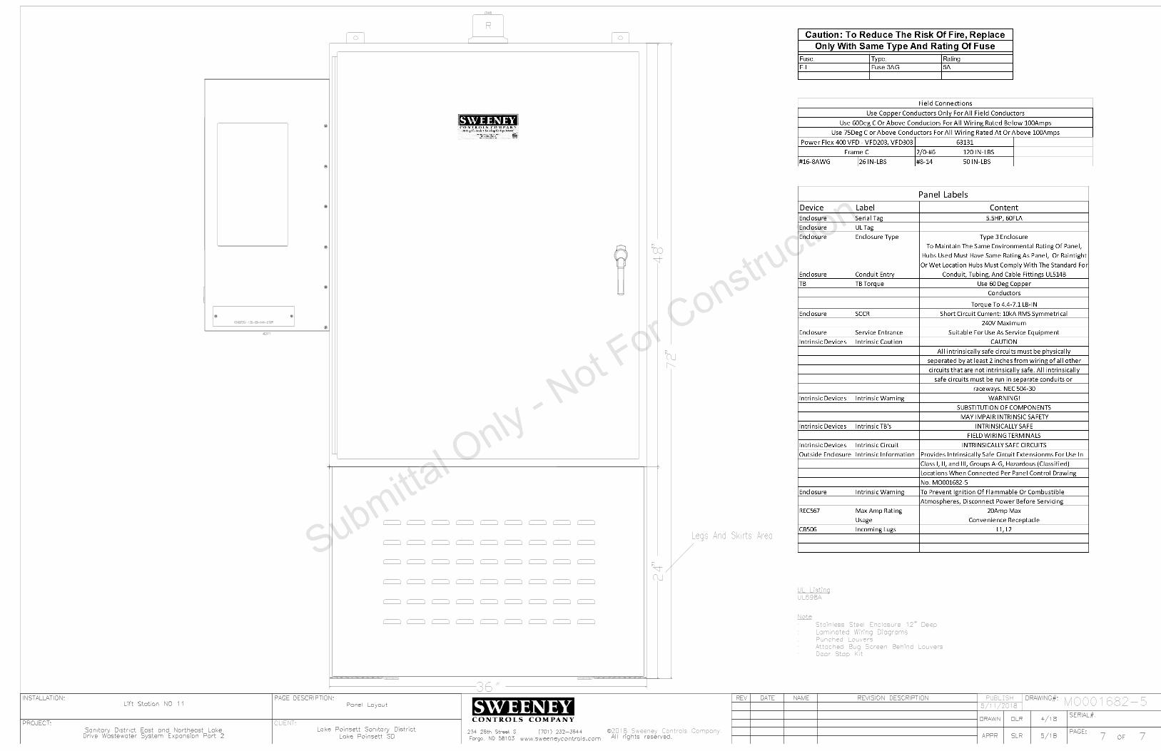
UL698A
UL Listing
36"
Legs And Skirts Area
Door Stop Kit:
Attached Bug Screen Behind Louvers:
Punched Louvers:
Laminated Wiring Diagrams:
Stainless Steel Enclosure 12" Deep:
Note
AC571
IQ4000EV-126-SS-N4X-STDR
R
LT445
SERIAL#:
PAGE:
INSTALLATION:
PROJECT:
OF
REV
DRAWING#:
PAGE DESCRIPTION:
APPR
REVISION DESCRIPTION
DATE
NAME
DRAWN
All rights reserved.
C
Fargo, ND 58103
SERIAL#:
PAGE:
INSTALLATION:
PROJECT:
OF
REV
DRAWING#:
PAGE DESCRIPTION:
APPR
REVISION DESCRIPTION
DATE
NAME
DRAWN
2018 Sweeney Controls Company.
All rights reserved.
C
Fargo, ND 58103
PUBLISH
CLIENT:
77www.sweeneycontrols.com
234 28th Street S (701) 232-3644
Lift Station NO 11
DLR 4/18
SLR 5/18
Sanitary District East and Northeast Lake Lake Poinsett Sanitary District
Lake Poinsett SD
77www.sweeneycontrols.com
234 28th Street S (701) 232-3644
Lift Station NO 11
DLR 4/18
SLR 5/18
Sanitary District East and Northeast Lake Lake Poinsett Sanitary District
Lake Poinsett SD
MO001682-5
48"
24"
72"
Panel LayoutPanel Layout 5/11/2018
Drive Wastewater System Expansion Part 2Drive Wastewater System Expansion Part 2

Description
Wirin
g Sym
bols
SERIAL#:
PAGE:
INSTALLATION:
PROJECT:
OF
REV DRAWING#:
CUSTOMER:
PAGE
DESCRIPTION:
APPR
REVISION DESCRIPTIONDATE NAME
DRAWN
Sweeney Controls Company.
All rights reserved.
C
##www.sweeneycontrols.com
234 28th Street S
Fargo, ND 58103
(701) 232-3644
XXX
MO######-#
Installed)
(To Be Field
UPS###
5 AMP
F101A
101A
ANTENNA
DIAG.
-
+
RS-232
RM###
ALA###
X1 X2
LT###
G
1 2
3
X1 X2
4
LT###
R
TS###
TS###
10A
CB###
Controls
FS###
High
L1 L2
REC###
A1OL
M###
100
101
102
103
104
105
106
107
108
109
110
111
112
113
114
115
116
117
118
119
120
121
122
123
124
125
126
127
128
129
130
131
132
133
134
135
136
137
138
140
141
142
143
144
145
146
147
148
149
150
151
152
153
154
155
156
7 4
CR###
8 2
CR###
B A
CR###
Control Relay Coil
B A
CR103
Thermal Fail Relay
109 106
XXX###
1 To 3 Letter Device Abbreviation
Page Number
Line Number
Inside The Panel
Next To The Physically Mounted Part
This Id Number Is Also Found On Or
03 Line 1elay Page Rontrol CEx
Device ID
Terminal Number
Used
The Drawings Contacts of This Device Are
Cross Reference Box. This Shows Where In
09 Line 1Page
Ex: Contact Is Used On
Used Contact Identifier
Unused Contact Space
156
154
157
155
158
Wire Links
56 Line 1Page
Ex: Wire Goes To
Wire Link
Goes To Line 156
54 Line 1Page
Ex: Wire Comes From
Wire Link
Comes From Line 154
Wire Link
Comes From Line 157
Wire Link
Goes To Line 155
158 Wire Link
Connects To Line
=Pump #1
TB1
103A
TB1
L
Device Description
TS103
Terminal Block Row 1
Line Number
Is The First Terminal Block On That A
And 03 Line 1Ex: Corresponds To Page
Terminal Block IDField Installation Box
Field Installation Location
Control Panel Wiring
Solid Line Indicates Internal
Field Wiring
Dashed Line Indicates
Normally Open Control Relay Contact
Normally Closed Control Relay Contact
Normally Closed Temperature Switch
Normally Open Temperature Switch
(Used As High Float)
Normally Open Float Switch
(Indicating Green Lens)
Pilot Light
(Indicating Red Lens)
Push To Test Pilot Light
Not To Exceed 10,000ft
Maximum Cable Length
Electrical Code
Of The National
With Article 504
Accordance
Install In
Hazardous
Area
Non-
Hazardous
Area
Device
Safe Switching
Intrinsically
POWER
SUPPLY
CH1
CH2
CH1
CH2
CH2
LF
K
PR
LF
CH1
PR
K
SS
14
1
2
11
8
13
12
10
9
7
4
5
ISB###
Intrinsically Safe Barrier
Intrinsically Safe Circuit Area
RTM###
Run Time Meter
I:0/4/00
RACK
MODULE
00
PLC109
4
T
0
1746-IA16Device ID
Module Number
PLC Address
PLC Address Description
Part Number
Rack Number
Terminal Number
I/O Card
HAND OFF AUTO
AH###
Alarm Horn
13
2
POT###
Potentiometer
H2H3
480V
120V
H1 H4
X1 X2
T###
5KVA
Overload Contact
Motor Starter Coil With
(Controls CB Rated At 10 Amps)
1 Pole Circuit Breaker
(480V Primary/120V Secondary)
Transformer
#/## ####
Wiring Symbols Description
XXX #/##
Uninterruptible Power Supply
Digital Output Connections
Flowmeter With Power, Analog Output, And
Antenna Lightening Arrestor
L1
L2
L3
T1
T2
T3
M460
Pump #1 Motor Starter
CC160
8536SF01V02S
L1
L2
L3
T1
T2
T3200 AMP
CB142
Pump #1
KAL36200
M FLA
HPT1
T2
T3
GND
103
Pump #1
84
=Pump #1
7 4
CR103
8 2
CR103
03Line
1elay Coil is Found On Page Rontrol CEx:
N/O Relay Contact
Eg: No Wire Connection
Wire Looped Over Another Wire
Wire Connected To Another Wire
Wire Connection Point
Fuse Identifier
Fuse Amp Rating
L1
L2
L3
G
T1
T2
T3
G
VFD142 Pump #1 VFD
22C-D088A103
A1
B1
C1
A2
B2
C2
LR142
Pump #1
KDRULF2H
L1
L2
L3
T1
T2
T3
M450
Pump #1 VFD Isolation
8502SF02V02S
Contactor
Device ID
Rating
Circuit Breaker Amp
Number
Circuit Breaker Part
Description Device IDDescription
50 Line 4Found On Page
Indicates Contactor Coil Is
Device ID
Description
Number
Line Reactor Part
Device IDDescription
VFD Part Number
Number
Motor Starter Part
Number
Overloads Part
Motor Starter
Description
60 Line 4On Page
Indicates Starter Coil Is Found
Device ID
Number
Contactor Part
Field Installation Location
103A
Wire Number
106A
Number
The Second Wire On That Line
Means Its B And 06 Line 1Page
Ex: This Wire Originates On
Wire Number
Pump Information
LS###
LS###
HTR###
200W
3 4
PB###
Lamp Test
1 2
PB###
Reset
Normally Open Limit Switch
Normally Closed Limit Switch
(Used As A Lamp Test Button)
Normally Open Pushbutton
(Used As A Reset Pushbutton)
Normally Closed Pushbutton
X1 X2
M###
Contactor Coil
(Shown As 200 Watts)
Heater
Thermal Fail Input
Receptacle
109A
Wire Number
7 4
CR422
106B
Wire Number 22 Line 4On Page
elay Coil is Found Rontrol CEx:
N/O Relay Contact
Position Only
Closed In Hand
Position Only
Closed In Auto
Device Id Format
5 AMP
F-L
GDL5
L
(GDL5 Is Fuse Part Number)
Fuse Block
2 7
TR###
5 Seconds
3 4
TR###
(Set To 5 Seconds)
Time Delay Relay Coil
Relay Contact
Normally Open Delayed On Time Delay
TB1
####
Terminal Block
Example Of Control WiringExample Of 3 Phase Power Wiring
I:0/4/00
PLC Address Format:
Input Rack:0 Module:4 Address:00
Shown On This Page
Used In Drawings Are
Note: Not All Symbols
03 Line 1On Page
elay Coil is Found Rontrol CEx:
N/C Relay Contact
PROTECTED
UNPROTECTEDL N
L N
G
G
SUP###
G
NL1
-V
V+
V+
-V
PS###
24VDC
30W
ANT###
AC
Not Used
4-20mA
L N
+ -
FM###
Flow Meter
Digital Output
157
158
159
160
161
162
163
164
165
166
167
168
169
170
171
172
173
174
175
176
177
178
159
159 Wire Link
Connects To Line
TRANSDUCER
LEVEL
4-20mA
+ -LXD###
XOO
OOX
1 2
3 4
SS###
Legend Above
Are Closed With Respect To Switch
"X" Specifies What Position The Contacts
Surge Suppressor
(24VDC Output Rated To 30 Watts)
DC Power Supply
Antenna
2-Wire Analog Level Transducer
Radio Modem

234 28th Street S Fargo, ND 58103 Phone 701-232-3644 Fax 701-232-3635
www.sweeneycontrols.com