
Enforced generative patterns for the specification of the syntax and semantics of visual languages
44
Enforced Generative Patterns for the Specification of the Syntax and Semantics of Visual Languages Paolo Bottoni a , Esther Guerra b , Juan de Lara c,* a University of Rome “Sapienza”, Comp. Science Dep., Rome (Italy) b Universidad Carlos III, Comp. Science Dep., Madrid (Spain) c Universidad Aut´onoma, Polytechnic School, Madrid (Spain) Abstract We present the new notion of enforced generative pattern, a structure that declares positive or negative conditions that must be satisfied by a model. Patterns are ap- plied to transformation rules resulting in new rules that modify models according to the pattern specification. In the case of a negative pattern, an application condition is added to the rule. In the case of a positive one, the rule is modified to consider additional context in its left-hand side and to increase its effects. We have defined these patterns in an abstract setting, which enables their instantiation for different structures, like graphs, triple graphs and graph transformation rules. We apply the previous concepts to the specification of the syntax and semantics of visual languages. In particular, we show instantiations for: (i) graphs, with ap- plications at the syntactical level; (ii) triple-graphs, for the coordination of syntax and static semantics; and (iii) rules, for the incremental construction of execution rules. We present some examples that illustrate the usefulness of the combination of these three instantiations. In particular, we show the specification of environ- ments for visual languages with token-holder semantics, discrete-event semantics and communication semantics. Key words: Visual Languages, Graph Transformation, Triple Graph Grammars, Graph Constraints, Patterns, Meta-Modelling, Specification of Semantics * Corresponding author. Email addresses: [email protected] (Paolo Bottoni), [email protected] (Esther Guerra), [email protected] (Juan de Lara). Preprint submitted to Elsevier 6 April 2008
Transcript of Enforced generative patterns for the specification of the syntax and semantics of visual languages
Enforced Generative Patterns for the
Specification of the Syntax and Semantics of
Visual Languages
Paolo Bottoni a, Esther Guerra b, Juan de Lara c,∗
aUniversity of Rome “Sapienza”, Comp. Science Dep., Rome (Italy)bUniversidad Carlos III, Comp. Science Dep., Madrid (Spain)cUniversidad Autonoma, Polytechnic School, Madrid (Spain)
Abstract
We present the new notion of enforced generative pattern, a structure that declarespositive or negative conditions that must be satisfied by a model. Patterns are ap-plied to transformation rules resulting in new rules that modify models according tothe pattern specification. In the case of a negative pattern, an application conditionis added to the rule. In the case of a positive one, the rule is modified to consideradditional context in its left-hand side and to increase its effects. We have definedthese patterns in an abstract setting, which enables their instantiation for differentstructures, like graphs, triple graphs and graph transformation rules.
We apply the previous concepts to the specification of the syntax and semanticsof visual languages. In particular, we show instantiations for: (i) graphs, with ap-plications at the syntactical level; (ii) triple-graphs, for the coordination of syntaxand static semantics; and (iii) rules, for the incremental construction of executionrules. We present some examples that illustrate the usefulness of the combinationof these three instantiations. In particular, we show the specification of environ-ments for visual languages with token-holder semantics, discrete-event semanticsand communication semantics.
Key words: Visual Languages, Graph Transformation, Triple Graph Grammars,Graph Constraints, Patterns, Meta-Modelling, Specification of Semantics
∗ Corresponding author.Email addresses: [email protected] (Paolo Bottoni),
[email protected] (Esther Guerra), [email protected] (Juan de Lara).
Preprint submitted to Elsevier 6 April 2008

1 Introduction
The design of Domain Specific Visual Languages (DSVLs) implies the defini-tion of their syntax, usually derived from the notations in use in the domaincommunity, as well as of their static and dynamic semantics [11]. The formerincludes the interpretation of the syntactic concepts in terms of the relevant se-mantic elements (e.g. the fact that a circle at the syntactic level is interpretedas a holder for tokens). Dynamic semantics can be given in an operationalway, by specifying how the different semantic elements evolve with respect totime. Different approaches can be used, with varying levels of integration andincrementality between construction of syntactic sentences and interpretationin terms of abstract syntax or static semantics.
Meta-models are gaining popularity as a way to define the characteristics ofboth syntax and semantics, so that designing a new language involves the spe-cialization of meta-classes and their relations [6]. Using meta-models, elementsof concrete and abstract syntaxes are defined as instances of abstract conceptsand constraints on their possible relations are given. The same mechanismsare used to define the semantic roles that elements can play [10]. Designersof new languages can thus map different concrete syntaxes to a common ab-stract one, given as a meta-model, and reuse significant parts of a languagedefinition, in particular through inheritance [6,9,17]. However, the specifica-tion of the language semantic aspects – referring to the processes defined andsimulated via the visual language – and of their connection to the syntacticones is in many cases carried out by hand and from scratch, if no predefinedrelation is established between syntactic objects and semantic roles.
In previous works, we introduced the notion of semantic variety, expressedthrough a meta-model identifying the dynamic roles played by syntactic el-ements [5], and proposed triple patterns as a mechanism to generate triplegraph operational rules (see [8,22,32]) coupling syntactic and semantic rolessimply starting from the definition of syntactic rules [10]. Moreover, we pro-posed action patterns as a mechanism to generate rewriting rules expressingthe execution semantics [4]. The application of these patterns allows the in-cremental generation of both the static and the execution semantics, in termsof transformations occurring with respect to designated elements of the visualsentence under construction. In particular, basic patterns have been definedfor the token-holder transition semantic variety, in which discrete transforma-tions occur by removing and adding tokens from and to holders representingsome condition. Typical examples of languages presenting (discrete) semanticsof this form are Finite State Automata, the different types of Petri nets, orworkflow languages, but also languages based on positioning of elements in agrid, such as Agentsheets [28], or those describing chessboard games.
2

In this paper, we generalize these previous results by introducing a generalnotion of enforced generative pattern (EG-pattern) as a way to specify con-straints in a declarative way. In particular, we set our study in the context ofadhesive High-Level Replacement categories [12], and define a pattern as anobject in such a category. When a pattern is applied to a rule based on mor-phisms in the same category, the rule is modified to ensure the production ofan object conformant to the pattern. We present a general algorithm for pat-tern application entirely expressed in categorical terms. The algorithm can acton the different components of a rule, extending its effects and/or enriching itscontext, to make its effect conform to the pattern. Then, we show that bothtriple patterns and action patterns are special cases of EG-patterns. In partic-ular, triple patterns are an instantiation for the category of triple graphs [17],while action patterns are an instantiation for the category of Double Pushoutrules [12]. Thus, the application of these two different kinds of patterns torules is based on a specialization of the algorithms given for EG-patterns.
We illustrate the potential of this approach by presenting its application to anumber of DSVLs for specifying discrete systems and communication struc-tures. Moreover, we introduce some extensions to EG-patterns, providing arich catalog of tools to simplify the task of designing new visual languages orsyntax-directed integrated environments.
Paper Organization. Section 2 introduces related research. Section 3 presentsbasic background on graph transformation and meta-modelling for definingsyntax and semantic roles. In Section 4, we motivate the approach by pre-senting some situations which could benefit from the pattern concept. Sec-tion 5 introduces additional background, concerning triple graph grammarsand meta-rules. Section 6 presents the algorithms for the application of posi-tive enforced generative patterns. Section 7 shows an instantiation of patternsfor triple graphs and its application to the coordination of the syntax andthe static semantics of DSVLs. Section 8 instantiates patterns for rules (i.e.action patterns) and uses them for the specification of execution semanticsof DSVLs. Section 9 gives some examples for languages with token-holder,discrete-event, and communication semantics. Section 10 introduces advancedpattern concepts, while Section 11 ends with conclusions and prospects forfuture work.
2 Related Work
The proposal of EG-pattern relates to different approaches to the expressionof constraints on the effect of rules, as well as to specific mechanisms for theirinstantiation for triple graph grammars or execution rules. As a consequence,we touch on work concerning all these aspects.
3

Patterns expressing graph constraints were proposed in [19], and an algo-rithm was given to translate them into rule post-conditions, and then to pre-conditions. The algorithm does not affect the rule actions (i.e., the elementsthat the rule adds or deletes), but complements a rule with pre-conditionsensuring that, if the rule is applied, the resulting graph is consistent with theoriginal graph constraint. Differently from [19], we are interested in modify-ing the rule actions, so that the produced graph conforms to the pattern. Ina sense, the work in [19] can be seen as a particular case of the algorithmswe provide. This is so as we give a whole spectrum of possibilities for ap-plying the patterns, balancing how much the rule pre-conditions are modifiedwith respect to the changes in the rule actions (the less the pre-conditions arechanged, the more changes have to be done to the actions and vice-versa). Thesituation where the rule context is maximally extended and the rule actionsare not changed corresponds to the ideas in [19]. Moreover, our patterns areexpressed in categorical terms, so that they can be instantiated by differentcategories, like graphs, triple graphs or graph transformation rules.
The approach presented here also relates to the notion of manipulation of rulesby means of rules, as proposed for graph transformation [25] and subsequentlyextended to High-Level Replacement Systems [26,29]. This is based on thedefinition of rule refinement through rule [29] and subrule [25] morphisms.Applications are found in termination analysis [7], as well as in managementof security policies [21]. In [29], an algebra of rules is defined based on rulemorphisms, including operators for rule composition. Multiple matches for arule into another one give rise to different versions of the transformed rule.In this paper, we explore situations in which either several rules or a singleone can be derived from a specific rule through pattern application, but alsodiscuss the possibility of iterating the process to arrive at progressively refinedrules. Our approach deals with local, as opposed to global, transformations [26];in particular, it can also be used to generate rules by specialization, analogyor inheritance, but in a different way from [26].
The specialization of enforced generative patterns to the synchronization ofsyntactic and semantic rules relies on the notion of Triple Graph Grammars(TGGs, see [32]) and provides an efficient way to obtain TGG operationalrules, whenever a grammar for one of the graphs already exists. In this sce-nario, patterns need not specify which elements should be created and whichshould already exist in one of the graphs – as is needed for the traditionalspecification of declarative TGG rules [32] – as this is expressed in the normalrule to which the pattern is applied. Thus, patterns may be used in severalways, providing a more flexible and declarative usage.
Abstract patterns [4,10] (in their different instantiations) exploit meta-modelsto express in a compact form a number of concrete patterns where an instanceof a class is replaced by an instance of some given concrete subclass. In general,
4

the notion of abstract pattern can be employed in any situation where a meta-model is available to characterize objects in the considered category. Notethat this is unrelated to the use of the term “abstract pattern” by Pagel andWinter [24], who propose a meta-pattern to describe object-oriented designpatterns, dealing with pattern instantiation but not pattern enforcement.
In the field of TGGs, approaches based on meta-models already consider in-heritance (see [8,22]). We add the possibility of applying abstract patternsto rules that can themselves be abstract, and to generate operational TGGrules which discriminate types by using negative application conditions. A for-malization of TGGs with inheritance can be found in [17]. The instantiationof EG-patterns to triple graphs can generate operational TGG rules for thescenarios in [22]. We use triple graphs exploiting morphisms from the corre-spondence graph to the other two graphs, whereas in Fujaba a correspondencenode can be related to several nodes in either graph, to express many-to-manyrelationships [20]. Baar uses TGGs to connect concrete and abstract syntaxesof DSVLs, allowing the static verification of their conformity [1]. However, hisproposal is related to the structure of the visual sentence, and not to its oper-ational interpretation. Moreover, it does not exploit inheritance, and requiresthe presence of display managers relating abstract and concrete syntaxes.
In [16], Gottler proposes meta-rules to modify syntactic or semantic standardrules, describing a programming language as a triple formed by a syntax, asemantics, and a function φ to build the semantic model from the syntactic one.In our case, meta-rules are associated with and triggered by syntactic editingrules. Moreover, they are automatically generated from action patterns.
In Ermel and Bardohl’s approach to animation, execution semantics is givenin terms of transformations of configurations of the graph defining the processstate, and analogous rules transform an associated visualization [13]. Rulemorphisms then synchronize rule application in the process and visualizationdomains. Our approach could be applied to visualization by considering therelation between static semantics and syntactic sentences (see [10]).
In [3], static semantics is incrementally built via meta-rules defining the cor-respondence between the elements of the diagram notation and those of thesemantic domain, represented by High-Level Timed Petri Nets. Notation fam-ilies are also introduced, to model commonalities in notations with slight dif-ferences in their interpretation. Our action patterns are able to support thedefinition of different interpretations on the same notation and the same staticsemantics. Moreover, our notion of semantic variety also encompasses differentnotations, sharing a similar structure for their interpretation.
In [33], amalgamation is exploited to generate execution rules for graphs de-scribing static semantics. A specialized global execution rule is generated by
5

considering all possible simultaneous matches for a set of rules, once the com-plete host graph has been produced. Thus, the generation of parallel rulesis not incremental, but needs to consider the whole graph and requires theidentification of the effects on the interfaces between rules. For action pat-terns, instead, different matches independently contribute to the generationof a meta-rule. Hence, by generating specific execution rules for each transi-tion, we overcome some limitations of [33], in which, for example, checkingin a Petri net whether all pre-conditions for firing a transition are satisfiedis solved by specific Double Pushout idioms, such as rewriting the transitionitself. This exploits the dangling edge condition (not present in other rewritingapproaches) if some place does not have enough tokens (hence, not produc-ing a match for the sub-rule). Our framework is not tied in principle to anyspecific rewriting approach and provides more concise specifications.
Patterns of execution have been studied in the modelling of workflow processesand a semantics for them has been given by Coloured Petri Nets [34]. Asthese may be expressed in terms of action patterns, the definition of a patternlanguage for workflows could benefit from the approach presented here.
3 Formal Background I
3.1 Introduction to Graph Transformation
Graph transformation [12,30] is a visual, formal, and declarative means toexpress graph manipulations, by defining a set of rules and an initial graph.Rules have left and right hand sides (LHS and RHS), each containing graphs.When applying a rule to a host graph G, a match morphism must be foundbetween LHS and G. Then, the elements not preserved by the rule (roughlyLHS − (LHS ∩ RHS)) are deleted in G, and the new elements (roughlyRHS − (LHS ∩ RHS)) are added. This step is called direct derivation. Thedefined language is the set of all possible graphs obtained by iterating directderivations starting from the initial graph.
The left of Fig. 1 shows the “move” rule and a direct derivation, using anabstract syntax representation similar to UML object diagrams. The rule isconcerned with the simulation of an automaton-like visual language. It movesa current pointer between two states as effect of the execution of a transition.It is applied to a graph G, using a match m and yielding graph H. The pictureshows the mapping for nodes, through equality of identifiers; a similar mappingfor edges is also part of the match. The right of Fig. 1 shows the same rule in acompact notation that will be used throughout the paper. The elements addedby the rule are enclosed in coloured regions, marked as “{new}”. Similarly,
6

the deleted elements are enclosed in regions marked as “{del}”.
Fig. 1. Direct Derivation Example (left). Compact Notation for Rules (right).
One of the most popular formalizations of graph transformation is based oncategory theory and is called Double Pushout (DPO) [12]. In this approach,a direct derivation is modelled in two steps. First, elements are removed fromthe host graph according to the rule specification, and then the new elementsare added. For this purpose, a rule is made of three component graphs: the leftand right hand sides (L and R), and the interface graph K, which contains theelements preserved by the rule application. Two injective morphisms l : K → Land r : K → R model the embedding of K in L and R. The left of Fig. 2 showsa DPO direct derivation diagram. Square (1) is a pushout (i.e. G is the unionof L and D through their common elements in K) that performs the deletion,while pushout (2) adds the new elements.
L
m
²²(1)
K
(2)
loo r //
k
²²
R
m∗
²²
Yij
oij//
=
Xi
ni--
=
yijoo L
m
²²(1)
xioo K
(2)
loo r //
k
²²
R
m∗
²²G Dfoo g // H G Dfoo g // H
Fig. 2. DPO Direct Derivation Diagram (left). Derivation for Rule with NAC (right).
Fig. 3 shows a DPO direct derivation example using the same rule and hostgraph as Fig. 1. The left square deletes the curr edge from the current nodeto state s1, while the right square adds an edge from the current node tos2. The figure also shows the fact that rules may have parameters, modelledby graph M and injective morphism ml : M → L. Parameters are used toinitialize the match to which the rule is applied. In the example, the parameterinitialization enforces the application of the rule to transition t1, should therebe more than one option. Thus, the rule can only be applied at a match mif m ◦ml = mM . Throughout the paper, we prefer the compact notation forshowing example rules. However, we will use the DPO notation of Fig. 3 forthe theoretical presentation of the algorithms and corresponding examples.
Sometimes, rules are equipped with application conditions, expressing addi-tional conditions that the match should satisfy to make the rule applicable [12].
7

Fig. 3. DPO Direct Derivation Example.
Particularly useful are negative application conditions (NAC), given by addi-tional graphs Ni related to L by morphisms ni : L → Ni. The rule is ap-plicable if, for each i, there is no morphism qi : Ni → G commuting withm (i.e. such that qi ◦ ni = m). We also use more general conditions of theform {xi : L → Xi, {yij : Xi → Yij}j∈Ji
}i∈I , which are satisfied by a matchm : L → G if, for each ni : Xi → G such that ni ◦ xi = m, there exists someoij : Yij → G such that oij ◦ yij = ni (see the right of Fig. 2). Note that a NACis an application condition where Ji = ∅.
The previous examples use typed graphs as the underlying data structure. For-mally, a type graph is a construct TG = (NT , ET , sT , tT ) with NT and ET setsof node and edge types, respectively. sT : ET → NT and tT : ET → NT definethe source and target node types for each edge type. A typed graph on TGis a graph G = (N, E, s, t) equipped with a graph morphism type : G → TG,composed of two functions typeN : N → NT and typeE : E → ET preservingthe sT and tT functions. In this paper, we use type graphs with node typeinheritance, defined by a pair TGI = (TG, I), where I = (NI , EI , s
I , tI) andNI = NT . Hence, I has the same nodes as TG, but its edges are the inheri-tance relations. The inheritance clan of a node n is the set of all its childrennodes (including n itself): clan(n) = {n′ ∈ NI |∃ path n′ →∗ n in I} ⊆ NI .
For different applications, other structures may be more appropriate, like at-tributed (typed) graphs, triple graphs or P/T nets. These considerations haveled to generalizing the graph transformation theory to higher-level structures:(weak) adhesive High-Level Replacement categories, short (w)aHLR [12], sothat DPO rewriting can be used with objects in any (w)aHLR category.
3.2 Meta-Models in the Definition of Syntax and Static Semantics
We adopt a meta-modelling approach for the definition of syntax and staticsemantics for diagrammatic languages, based on the classes of Fig. 4, whichshows two meta-models related through a correspondence meta-model. This
8

structure is called meta-model triple [17] and we use it to describe two relatedlanguages in a modular way (in this case, one for expressing concrete syn-tax, the other for static semantics). The correspondence meta-model is usedto relate concepts in both languages, therefore its nodes have morphisms tonodes or edges in the other two meta-models. In the meta-model for concretesyntax shown in the lower part of Fig. 4, semantic relations are expressedvia spatial relations between identifiable elements. Different specialisations ofIdentifiableElement and SpatialRelation define different families of vi-sual languages [6], such as the connection- and containment-based ones. Iden-tified elements are put in correspondence with semantic roles, as defined bythe semantic variety to which the visual language belongs.
source
IdentifiableElement
AttachZone
Hybrid<<final>>
SemanticRole
*
*
*Token Holder TransitionElement
*
*
Touches
GraphicElementComplex
Role
SpatialRelation*
Contains
Container Connection
GraphicElement ReferableElement
Entity DotTouches
1
1..*
1..*
1
1
*
*
pre−conditions
1post−conditions
Correspondence
decorates
Syntax
Semantics
target1..*
1
2
1
1
Fig. 4. Meta-model Triple for Syntax and Semantics of Visual Languages.
The upper part of Fig. 4 presents the fundamental classes for the transitionsemantic variety. In general, this relies on some notion of configuration of asystem, which is significantly changed by the firing of the transition. Hence, thetransition variety collects uses of visual languages to describe transformationprocesses in which a diagram depicts an instantaneous configuration, evolvingunder some well-defined law. The possible evolutions at each step can bestatically derived from the form of the diagram (e.g. transitions in Petri nets),or described externally (e.g. by grammar rules). Internal descriptions of theadmissible transformations rely on the presence of identifiable elements whichdirectly represent Transitions, with which Holder elements are associatedas either pre- or post-conditions. Examples of such direct representationsare arrows and nodes in finite state machines, or boxes and circles in Petrinets. Associations between holders and transitions allow the specification ofthe static semantics associated with a diagram, while its execution semanticsis defined by some external interpreter, and results into deleting or creatingassociations between Token and Holder elements. In particular, this can begiven through rules of type before-after, based on the differences in the wayTokens decorate Holders. For example, in grid-based languages, holders aregrid cells and tokens are symbolic representations of the domain elements. Anexecution semantics in terms of before-after rules can also be imparted ontransition-based languages by specifying, for each transition, the movement of
9

tokens from pre-condition to post-condition holders.
The concrete and semantic roles in a visual language are defined by refiningthe previous meta-model triple. For example, the left of Fig. 5 shows elementsin the concrete syntax and semantic roles for Petri nets. The significant spatialrelations are refined (via a creation graph grammar, which specifies how thedifferent elements are connected) to be the Touches relation between instancesof ArcPT (ArcTP) and a source Place (Transition) or a target Transition
(Place), and the Contains relation between Places and Tokens. A Place canplay both the role of an Entity, with respect to the arcs referring to it, andof a Container, with respect to the Tokens it holds. The right of Fig. 5 showsa triple graph example conformant to the meta-model triple to its left.
source
Pl2Sem
Role
Place Transition
Container EntityConnectionIdentifiableElement
ArcTP ArcPT
Tr2Sem
ContainsTouches
SpatialRelation
Tok2Sem
Token
*post−conditions*
TransSemPlaceSem
DotTouches
ReferableElement
1
2
*
*
target
1..*
pre−conditions* * TransitionElementHolderdecorates
*Token 1
TokSem
*
1
1
Fig. 5. Meta-Model Triple for the Definition of Petri Nets (left). Triple Graph withConcrete and Semantic Roles for a Petri Net Model (right).
According to the adopted syntax, the representation of the system dynamicscan be directly supported by some canonical animation, in which instances ofthe Token abstract class (in the semantics model) may appear or disappear, ormove from one instance of a Holder to another. It is to be noted that the meta-model definition of the static and execution semantics allows the adoption ofdifferent syntactic representations for the same semantics, provided that someequivalence can be established between the two. For example, a Petri net canbe represented by replacing transition boxes with hyperedges.
4 From Syntax to Execution through Static Semantics
This section presents a motivating example, introduces the mechanisms ex-ploited in the paper and explains their benefits. Suppose you are planning thedevelopment of an integrated environment for designing and executing Petri
10

nets, providing a syntax-directed editor in which a designer can directly ma-nipulate places and transitions. The environment maps concrete elements ontoan abstract syntax, acting as a repository for the constructed net, in corre-spondence with a static semantics, seeing the net as a collection of transitionswith pre- and post-conditions. Advanced editing commands allow one to createtransitions with associated pre- and post-condition places, introduce conflictsbetween two existing transitions, or add cascading transitions to existing ones.
The abstract syntax exploits elements of type Place, Transition, ArcPT, andArcTP, while the static semantics assigns to PlaceSem elements, representa-tive of places, the roles of pre- or post-conditions with respect to TransSem
elements, denoting transitions (see the meta-model triple in Fig. 5).
Fig. 6 shows the concrete and abstract syntax rules for creating a transition,with associated source and target places, and updating the static semantics.
Fig. 6. Rules to Update the Concrete Syntax, the Abstract Syntax and the StaticSemantics when Creating a Transition.
The execution mechanism we propose associates each transition with a spe-cialized rewriting rule that checks that all pre-condition PlaceSem elements forthe corresponding TransSem element are decorated with Token elements, re-moves them, and decorates all its post-conditions with new tokens. Thus, eachrewriting rule can only be executed at a particular transition. We rely on amechanism that initializes the match of the execution rule with the particulartransition node, restricting its application. Whenever such match initializationis important, we express it through parameters, as shown in Fig. 3.
A different approach could define a set of graph transformation rules, detectingwhen a Petri net transition is enabled and firing it. This has several disadvan-tages: (i) several rule executions are needed to simulate the actual firing of aPetri net transition, so that execution is less efficient and analysis harder, (ii)auxiliary elements would be needed to detect that the transition pre-placeshave enough tokens, or to add tokens in post-places. As a result, fewer rulescould be needed, but at the price of modifying the Petri net meta-model. More-over, generating customized rules allows their static analysis, independentlyof the host graph. This in fact is a standard procedure when representing Petrinets with graph transformation rules [23]. Finally, the mechanism we proposein this paper saves the designer from building such execution rules, while thefact that a rule is generated for each transition is transparent to the end user,and can lead to faster pattern matching.
11

Fig. 7 presents a meta-rule (i.e. a rule transforming a rule) that initializes theexecution rule associated with the transition created by the rules in Fig. 6.Note how the meta-rule updates rules that refer to specific elements created bythe static semantics rule, against which they should only be instantiated. Thismeans that the execution rule can be applied only to the TransSem elementcreated by the static semantics rule of Fig. 6. This is ensured by parameterpassing: the meta-rule initializes the execution rule with one parameter, whichis used to pass the TransSem node created by the static semantics rule.
Fig. 7. Rule to Initialize the Execution Semantics upon Generation of a Transition.
Fig. 8 shows the concrete and abstract syntax rules for inserting a conflict, aswell as the update of the static semantics with the insertion of a PlaceSem
related by the pre-conditions association with each of the two TransSem.
Fig. 8. Rules to Update the Concrete Syntax, Abstract Syntax and Static Semanticsfor Insertion of a Conflict.
Fig. 9 describes the updating of the execution rules associated with the twotransitions. The TransSem nodes “t1” and “t2” have to be the same as thosein Fig. 8 (in the upper and lower part of the rule for static semantics) so theywill be passed as parameters. As the same PlaceSem element appears as aprecondition in both rules, the rules are in conflict, which will be managed bythe execution mechanism, for example along the lines of [18].
Fig. 9. Rules to Update the Execution Semantics for the First (left) and Second(right) Transitions in Conflict.
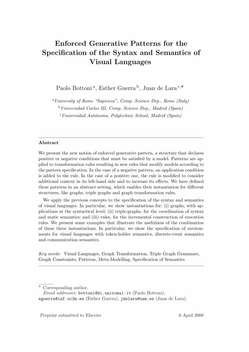
Fig. 10 describes the concrete, abstract syntax and the static semantics forthe construction of a chain of cascading transitions, while Fig. 11 refers to
12
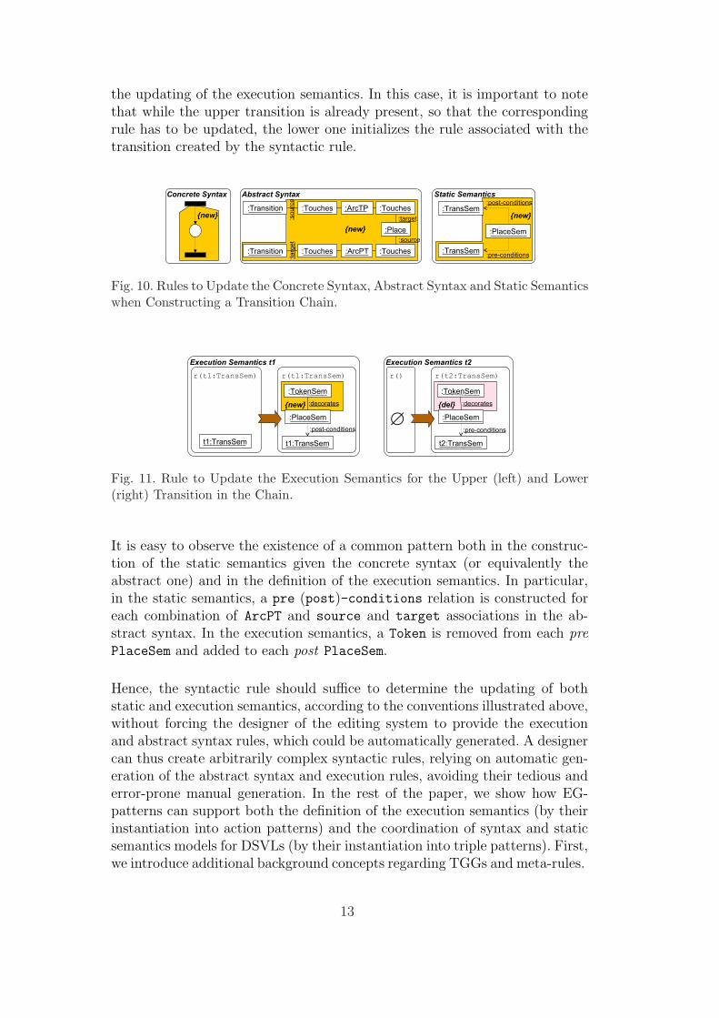
the updating of the execution semantics. In this case, it is important to notethat while the upper transition is already present, so that the correspondingrule has to be updated, the lower one initializes the rule associated with thetransition created by the syntactic rule.
Fig. 10. Rules to Update the Concrete Syntax, Abstract Syntax and Static Semanticswhen Constructing a Transition Chain.
Fig. 11. Rule to Update the Execution Semantics for the Upper (left) and Lower(right) Transition in the Chain.
It is easy to observe the existence of a common pattern both in the construc-tion of the static semantics given the concrete syntax (or equivalently theabstract one) and in the definition of the execution semantics. In particular,in the static semantics, a pre (post)-conditions relation is constructed foreach combination of ArcPT and source and target associations in the ab-stract syntax. In the execution semantics, a Token is removed from each prePlaceSem and added to each post PlaceSem.
Hence, the syntactic rule should suffice to determine the updating of bothstatic and execution semantics, according to the conventions illustrated above,without forcing the designer of the editing system to provide the executionand abstract syntax rules, which could be automatically generated. A designercan thus create arbitrarily complex syntactic rules, relying on automatic gen-eration of the abstract syntax and execution rules, avoiding their tedious anderror-prone manual generation. In the rest of the paper, we show how EG-patterns can support both the definition of the execution semantics (by theirinstantiation into action patterns) and the coordination of syntax and staticsemantics models for DSVLs (by their instantiation into triple patterns). First,we introduce additional background concepts regarding TGGs and meta-rules.
13
5 Formal Background II
5.1 Triple Graph Grammars
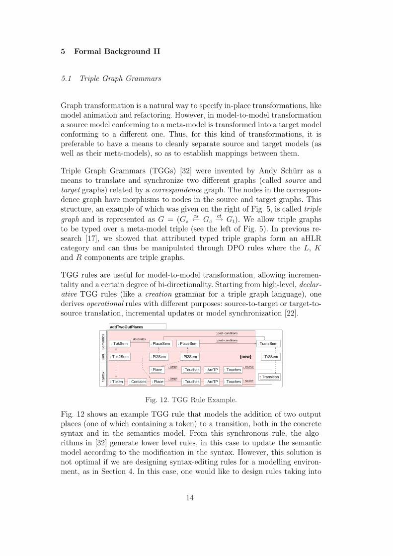
Graph transformation is a natural way to specify in-place transformations, likemodel animation and refactoring. However, in model-to-model transformationa source model conforming to a meta-model is transformed into a target modelconforming to a different one. Thus, for this kind of transformations, it ispreferable to have a means to cleanly separate source and target models (aswell as their meta-models), so as to establish mappings between them.
Triple Graph Grammars (TGGs) [32] were invented by Andy Schurr as ameans to translate and synchronize two different graphs (called source andtarget graphs) related by a correspondence graph. The nodes in the correspon-dence graph have morphisms to nodes in the source and target graphs. Thisstructure, an example of which was given on the right of Fig. 5, is called triple
graph and is represented as G = (Gscs← Gc
ct→ Gt). We allow triple graphsto be typed over a meta-model triple (see the left of Fig. 5). In previous re-search [17], we showed that attributed typed triple graphs form an aHLRcategory and can thus be manipulated through DPO rules where the L, Kand R components are triple graphs.
TGG rules are useful for model-to-model transformation, allowing incremen-tality and a certain degree of bi-directionality. Starting from high-level, declar-ative TGG rules (like a creation grammar for a triple graph language), onederives operational rules with different purposes: source-to-target or target-to-source translation, incremental updates or model synchronization [22].
: Touches
: Touches
: Touches
: Touches : ArcTP
: ArcTP
: Place
: Place: target
: target
: Contains: Token
: post−conditions
: post−conditions
: Pl2Sem : Pl2Sem
: source
: source
: PlaceSem
Sem
antic
sC
orr.
Syn
tax
{new}
addTwoOutPlaces
: decorates
: PlaceSem: TokSem
: Tok2Sem : Tr2Sem
: Transition
: TransSem
Fig. 12. TGG Rule Example.
Fig. 12 shows an example TGG rule that models the addition of two outputplaces (one of which containing a token) to a transition, both in the concretesyntax and in the semantics model. From this synchronous rule, the algo-rithms in [32] generate lower level rules, in this case to update the semanticmodel according to the modification in the syntax. However, this solution isnot optimal if we are designing syntax-editing rules for a modelling environ-ment, as in Section 4. In this case, one would like to design rules taking into
14

consideration the concrete syntax only; and then have some mechanisms topropagate such changes. Sometimes, a synchronous modification of the seman-tic model is preferred. Moreover, a synchronous mechanism becomes essentialwhen performing an execution at the semantic level, and we want to observethe animation at the concrete syntax level. Again, instead of building TGGrules by hand, a designer can automatically obtain them starting from theexecution rules and mechanisms relating syntax and semantics. In Section 7,we give an instantiation of enforced generative patterns to triple graphs per-forming exactly this task [10] and minimizing the effort needed for specifyingconsistency mechanisms between syntax and semantics.
5.2 Meta-Rules
In order to specify the execution semantics of a visual language, we rely onthe identification of active elements, such as transitions in Petri nets or stateautomata, for which execution rules are created. Each execution rule is asso-ciated with one particular active element and models its dynamic semantics.Editing rules create and connect elements of the language and are used to buildthe model. Fig. 13 shows the syntactic rule addPlaces, and the correspondingsemantic one, to add an incoming and an outgoing place to a transition.
Fig. 13. An Editing Rule Example in Concrete Syntax (left). Derived Rule for theStatic Semantics Model (center). A Direct Derivation (right).
In our approach, editing rules are paired with one or more meta-rules to updatethe associated execution rule for each transition element considered by theediting rule. A meta-rule is invoked each time the corresponding syntacticrule is applied. The meta-rule modifies the execution rule for the involvedtransition elements, in order to obtain a customized rule reflecting the exactcontext (exact number and identities of pre- and post-conditions) in whichthe transition can perform a transformation step. Hence, meta-rules are DPOrules modifying rules (i.e. each of the L, K and R components of a meta-ruleis in turn a DPO rule). This is possible, as DPO rules can be shown to forman aHLR category. Briefly, if C is an aHLR category, then so is the functorcategory DPO(C) = [· ← · → ·,C]. This category has as objects all possiblefunctors from the scheme category · ← · → · to C (where one such functorrepresents a DPO rule) and as arrows all natural transformations. Similarly,DPO rules with parameters also form an aHLR category, due to the fact that
15
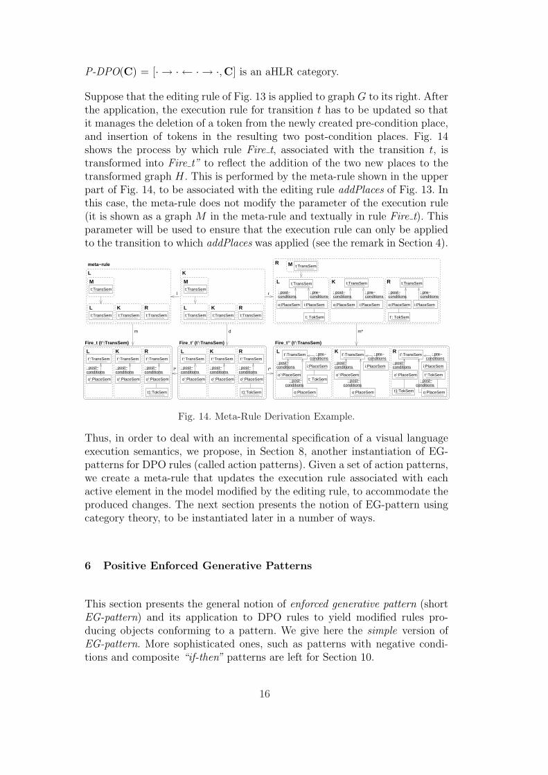
P-DPO(C) = [· → · ← · → ·,C] is an aHLR category.
Suppose that the editing rule of Fig. 13 is applied to graph G to its right. Afterthe application, the execution rule for transition t has to be updated so thatit manages the deletion of a token from the newly created pre-condition place,and insertion of tokens in the resulting two post-condition places. Fig. 14shows the process by which rule Fire t, associated with the transition t, istransformed into Fire t” to reflect the addition of the two new places to thetransformed graph H. This is performed by the meta-rule shown in the upperpart of Fig. 14, to be associated with the editing rule addPlaces of Fig. 13. Inthis case, the meta-rule does not modify the parameter of the execution rule(it is shown as a graph M in the meta-rule and textually in rule Fire t). Thisparameter will be used to ensure that the execution rule can only be appliedto the transition to which addPlaces was applied (see the remark in Section 4).
t: TokSem
t’:TransSem
o:PlaceSem
i:PlaceSem
o’:PlaceSem o’:PlaceSem o’:PlaceSem
Fire_t’’ (t’:TransSem)
Rconditions
: pre−
t’:TokSem
t1:TokSem
L Kconditions
: pre−
: post− : post−conditions conditionsconditions
: post−conditions
: pre−
conditions conditions conditions: post− : post− : post−
t1:TokSem
o’:PlaceSemo’:PlaceSem
t’:TransSem
o’:PlaceSem
t’:TransSem
: post−conditions
L
Fire_t (t’:TransSem)
t’:TransSem
conditions: post−
R
: post−conditions
K
t:TransSem t:TransSemt:TransSemt:TransSem t:TransSemt:TransSem
t:TransSem t:TransSem
o:PlaceSem i:PlaceSem o:PlaceSem i:PlaceSem
t’: TokSem
o:PlaceSem i:PlaceSem
t: TokSem
t:TransSem t:TransSem t:TransSem
t:TransSemM
l* r*
Fire_t’ (t’:TransSem)
: post−conditions
L
: post−conditions
Kt’:TransSem
conditions: post−
R
m d m*
rl
K
K RL
L
K RL
M M
conditions: pre−conditions conditions
: pre−conditionsconditions
: pre−conditions
: post− : post− : post−
L K R
Rmeta−rule
o’:PlaceSem
t’:TransSem
o’:PlaceSem
t’:TransSem
t1:TokSem
o’:PlaceSem
t’:TransSem
i:PlaceSem
o:PlaceSem
t’:TransSem
o:PlaceSem
i:PlaceSem
Fig. 14. Meta-Rule Derivation Example.
Thus, in order to deal with an incremental specification of a visual languageexecution semantics, we propose, in Section 8, another instantiation of EG-patterns for DPO rules (called action patterns). Given a set of action patterns,we create a meta-rule that updates the execution rule associated with eachactive element in the model modified by the editing rule, to accommodate theproduced changes. The next section presents the notion of EG-pattern usingcategory theory, to be instantiated later in a number of ways.
6 Positive Enforced Generative Patterns
This section presents the general notion of enforced generative pattern (shortEG-pattern) and its application to DPO rules to yield modified rules pro-ducing objects conforming to a pattern. We give here the simple version ofEG-pattern. More sophisticated ones, such as patterns with negative condi-tions and composite “if-then” patterns are left for Section 10.
16
A simple positive EG-pattern (short SP-pattern) is an object P in a (w)aHLRcategory. An object H satisfies P , written H |= P , if ∃m : P → H injectivemorphism. Intuitively, this means that at least one occurrence of P is foundin H. For the moment, we take an existential view of pattern satisfaction. Wesometimes use the term “H is conformant to (or consistent with) P”.
The application of an SP-pattern P to a DPO rule p : Ll←− K
r−→ R yieldsa modified version of p that, when applied to an object G, produces an objectH consistent with P . We consider non-deleting DPO rules, i.e. with L = K,hence p : L
r−→ R. Constructions are similar for deleting (and non-creating)rules in which K = R and roles of L and R are reversed. In order to produce arule conforming to the pattern, we have two extreme solutions: extending onlythe RHS (i.e., the rule effects), or both the LHS and the RHS, but withoutcreating any new element that the original rule did not create. There are alsointermediate situations, where additional context is considered in the LHS andthe rule effects are expanded. The three cases can be described with a singlealgorithm. However, for better understanding, we start with the two extremesituations and finish with the general algorithm.
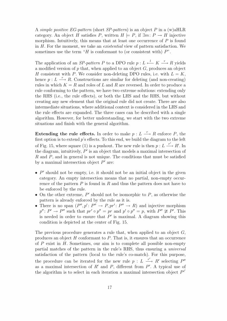
Extending the rule effects. In order to make p : Lr−→ R enforce P , the
first option is to extend p’s effects. To this end, we build the diagram to the left
of Fig. 15, where square (1) is a pushout. The new rule is then p : Lr′−→ R′. In
the diagram, intuitively, P ′ is an object that models a maximal intersection ofR and P , and in general is not unique. The conditions that must be satisfiedby a maximal intersection object P ′ are:
• P ′ should not be empty, i.e. it should not be an initial object in the givencategory. An empty intersection means that no partial, non-empty occur-rence of the pattern P is found in R and thus the pattern does not have tobe enforced by the rule.
• On the other extreme, P ′ should not be isomorphic to P , as otherwise thepattern is already enforced by the rule as it is.
• There is no span (P ′′, p′ : P ′′ → P, pr′ : P ′′ → R) and injective morphismp′′ : P ′ → P ′′ such that pr′ ◦ p′′ = pr and p′ ◦ p′′ = p, with P ′′ � P ′. Thisis needed in order to ensure that P ′ is maximal. A diagram showing thiscondition is depicted at the center of Fig. 15.
The previous procedure generates a rule that, when applied to an object G,produces an object H conformant to P . That is, it ensures that an occurrenceof P exist in H. Sometimes, our aim is to complete all possible non-emptypartial matches of the pattern in the rule’s RHS, thus ensuring a universalsatisfaction of the pattern (local to the rule’s co-match). For this purpose,
the procedure can be iterated for the new rule p : Lr′−→ R′ selecting P ′′
as a maximal intersection of R′ and P , different from P ′. A typical use ofthe algorithm is to select in each iteration a maximal intersection object P i′
17
Lr //
r′=a◦r ÂÂ@@@
@@@@
@ R
a
²²(1)
P ′proo
p
²²R′ P
boo
P ′pr
¢¢
p
zz
p′′}}
R
a
²²(1)
P ′′pr′oo
p′
²²R′ P
boo
Lr //
r′′=a′◦a◦r
¸***
****
****
****
****
**r′
ÃÃAAA
AAAA
A R
a
²²P.O.
P ′proo
p
²²R′
a′
²²
P.O.
Pboo
P ′′
pr′aaCCCCCCCC
p′
²²R′′ P
b′oo
Fig. 15. Extending the Effects of a Rule According to SP-pattern P (left). Conditionfor Maximal Intersection Object P ′ (center). Iteration (right).
having a non-empty intersection with the R component of the original rule(and differing from the previous intersections). This ensures that the originalrule is completed in all possible ways, and also guarantees termination of theiteration: as P i′ has to be maximal and cannot grow more than P , there isonly a finite number of possible matches onto the original R. The scheme ofthe iteration is shown on the right-hand side of Fig. 15.
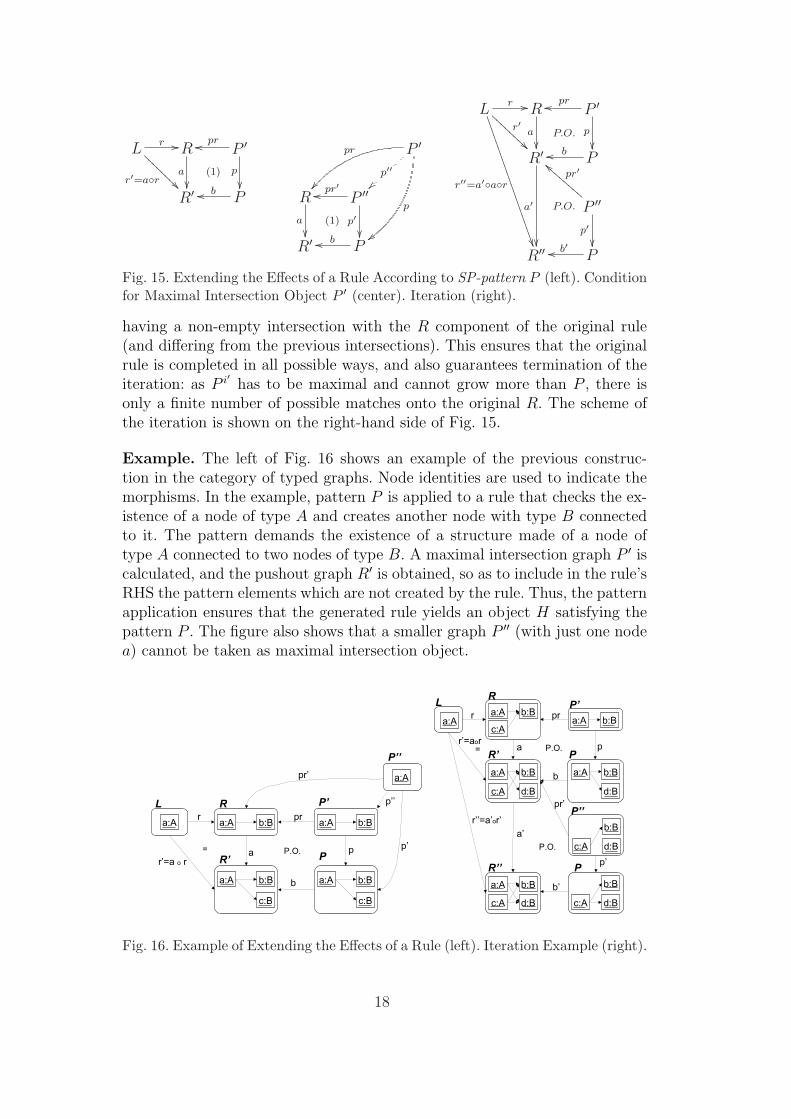
Example. The left of Fig. 16 shows an example of the previous construc-tion in the category of typed graphs. Node identities are used to indicate themorphisms. In the example, pattern P is applied to a rule that checks the ex-istence of a node of type A and creates another node with type B connectedto it. The pattern demands the existence of a structure made of a node oftype A connected to two nodes of type B. A maximal intersection graph P ′ iscalculated, and the pushout graph R′ is obtained, so as to include in the rule’sRHS the pattern elements which are not created by the rule. Thus, the patternapplication ensures that the generated rule yields an object H satisfying thepattern P . The figure also shows that a smaller graph P ′′ (with just one nodea) cannot be taken as maximal intersection object.
Fig. 16. Example of Extending the Effects of a Rule (left). Iteration Example (right).
18

The right of Fig. 16 shows an iteration until no valid maximal intersectionobject is found. Given one node of type A, the rule creates another one of thesame type, both connected to a new node of type B. However, the patternspecifies that two Bs are necessary for each A. Thus, in a first step, the RHSis modified to connect the already existing A to a new node B. In a secondstep, this newly created B is reused and connected to the other A.
Note that the use of the procedure proposed in [21], calculating all the max-imal intersection objects a-priori, would result in a bigger RHS, which is notdesirable. In the example, the rule would create three Bs in total, instead ofjust two. With the iteration, we are reusing parts of the different RHSs, whichresults in the creation of the smallest object satisfying the pattern.
Extending the rule context. The second option is to maximally extend therule’s LHS to incorporate all the necessary context, so that the resulting ruledoes not have to create anything new to satisfy the pattern. That is, the ruleeffects are not modified. However, as we will see, this is not always possible.
To extend the rule, a maximal intersection object P ′ is chosen and the pushoutobject R′ is obtained. Then, L is maximally completed to yield L′. The mainidea is to partition P into PL and PR, where PL is what will be added to Lto yield L′. As we want to maximally extend L without modifying the ruleeffects, we take PR as small as possible, thus we take it to be P ′. As PL hasto be glued with L, we calculate the gluing object Q as the pullback 1 objectof r : L → R and pr : P ′ → R. In this way, Q is the intersection of patternPL with L. If PL exists, it has to be the pushout complement of qP : Q → PR
and q : PR → P (as P ′ = PR, we have q = p). If such PL exists, then wecalculate L′ as the pushout of qL : Q → L and qPL
: Q → PL to obtain L′.Note that r′ : L′ → R′ uniquely exists due to the pushout universal property,as a ◦ r ◦ qL = b ◦ c ◦ qPL
. If no such PL exists, then we cannot extend L, butwe obtain a rule where only R is extended to R′, and set r′ = a ◦ r.
QqL
ÄÄ~~~~
~~ qP
ÃÃAAA
AAA
P.B.
QqL //
qPL ²²P.O.
Lr //
l′²²
Ra
²²P.O.
P ′proo
p²²
PLd //
c
66L′ r′ // R′ Pboo PR = P ′p=qoo
PL
c
OOP.O.
Q
qP
OO
qPL
oo
Fig. 17. Maximally Extending the Rule Context (left). Example (right).
As previously, the procedure can be iterated for each valid maximal intersec-
1 Roughly, a pullback object is an intersection of two objects sharing a commoncontext.
19

Fig. 18. Example: Maximally Extending the Context of a Rule, First Iteration (left).Second Iteration. Non-Existence of PL (right).
tion object having a non-empty intersection with the original rule’s RHS.
Example. The right of Fig. 17 shows a maximal extension of the LHS ofa rule, according to pattern P (previously shown in Fig. 16). A maximalintersection P ′ is found, and then R′ is calculated, extending R with oneadditional B connected to the A node. The pullback graph of pr and r iscalculated, which contains only one node A. This graph is used to calculate thepushout complement (PL) of p and qP . As PL exists in this case, we can extendL by considering the extra B connected to the existing A. Overall, the rulehas been extended with additional context, but its effect is not enlarged. Notethat the condition for the pushout complement for graphs to exist basicallystates that for any node n ∈ P ′ − qP (Q), all incident edges to its image p(n)should have a preimage in PR. This is similar to the dangling-edge conditionfor direct derivations. In the example, PL would not exist if P had in additionan edge between the two B’s. The existence of pushout complements for thecase of (w)aHLR categories is discussed in Theorem 6.4 of [12].
The example shown in Fig. 18 presents an iteration, but in the second iterativestep the pushout complement PL does not exist, which means that we cannotextend the LHS twice 2 . Thus, the resulting rule is p′ : L′ → R′′
Intermediate situations. Now we consider situations where some part ofthe pattern is added to the context, and the rule effects are also expanded.We split pattern P into PL and PR, where, intuitively, PL is added to the LHS,and when glued together (through some common subgraph SP ), PL +SP
PR
yields P . Thus, the effects of the rule are enlarged according to P , and theLHS according to PL. The situation is similar to the previous construction;however, PL is now not required to be a maximal extension of L. The left ofFig. 19 shows the diagram for this construction. Again, morphism r′ uniquely
2 This can be regarded as a conflict between the pattern and the rule.
20
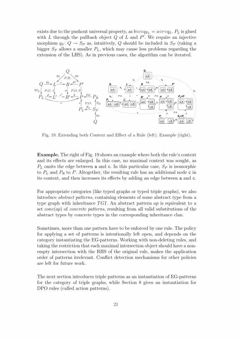
exists due to the pushout universal property, as b◦c◦qPL= a◦r◦qL. PL is glued
with L through the pullback object Q of L and P ′. We require an injectivemorphism qS : Q → SP as, intuitively, Q should be included in SP (taking abigger SP allows a smaller PL, which may cause less problems regarding theextension of the LHS). As in previous cases, the algorithm can be iterated.
QqL
ÄÄ~~~~
~~ qP
ÃÃAAA
AAA
P.B.
QqL //
qPL ²²P.O.
Lr //
l²²
Ra
²²P.O.
P ′proo
p²²
PLd //
c
66L′ r′ // R′ Pboo
P.O.
PRpRoo
PL
c
OO
SPSLoo
SR
OO
Q
qS
OO
Fig. 19. Extending both Context and Effect of a Rule (left). Example (right).
Example. The right of Fig. 19 shows an example where both the rule’s contextand its effects are enlarged. In this case, no maximal context was sought, asPL omits the edge between a and c. In this particular case, SP is isomorphicto PL and PR to P . Altogether, the resulting rule has an additional node c inits context, and then increases its effects by adding an edge between a and c.
For appropriate categories (like typed graphs or typed triple graphs), we alsointroduce abstract patterns, containing elements of some abstract type from atype graph with inheritance TGI. An abstract pattern ap is equivalent to aset conc(ap) of concrete patterns, resulting from all valid substitutions of theabstract types by concrete types in the corresponding inheritance clan.
Sometimes, more than one pattern have to be enforced by one rule. The policyfor applying a set of patterns is intentionally left open, and depends on thecategory instantiating the EG-patterns. Working with non-deleting rules, andtaking the restriction that each maximal intersection object should have a non-empty intersection with the RHS of the original rule, makes the applicationorder of patterns irrelevant. Conflict detection mechanisms for other policiesare left for future work.
The next section introduces triple patterns as an instantiation of EG-patternsfor the category of triple graphs, while Section 8 gives an instantiation forDPO rules (called action patterns).
21

7 Patterns for the Specification of Static Semantics
This section presents triple patterns, an instantiation of EG-patterns for triplegraphs, together with a specialization of the previous constructions. We are in-terested in triple patterns declaring the admissible relations between elementsin concrete syntax and semantics models. We present an algorithm that, givenan editing rule acting on the concrete syntax only and a set of triple patterns,generates an operational TGG rule that synchronously creates the necessaryelements in the target and correspondence graphs. The algorithm is based onthe constructions given in the previous section (instantiated for attributedtyped triple graphs [17]), thus generalizing the one given in [10]. Symmetri-cally, the input rule could act on the target graph, and the generated TGGrule would complete the source graph. This could be useful to extend the ex-ecution rules acting on the semantic model only (like the ones we generate innext section) to synchronous TGG rules modifying in addition the concretesyntax. As in [32], we can also generate other TGG operational rules: batchrules (i.e. assume that the source elements exist, and then create the targetgraph elements), rules for creating the correspondence graph given a sourceand a target graphs, and for checking the validity of the correspondence graph.
Example. We first start by giving an intuition of the algorithm through anexample. We use triple patterns in order to specify in a visual, high-level,acausal notation the kind of configurations we want to find in our semantic(syntax) models when certain syntactic (semantic) configurations are met.In this example, triple patterns are triple graphs conforming to the meta-model of Fig. 5. The triple pattern in Fig. 20 depicts the needed structure inthe syntactic model for a holder to have a token in the semantic model. Inthis case, a Place in the syntactic model has an associated PlaceSem role (asubclass of Holder) in the semantic model. Similarly, a Token in the syntacticmodel has a TokSem role in the semantic model (a subclass of class Token
in the semantic meta-model). In the semantic model, a token decorates aholder, while at the syntactic level the place contains the token.
: Pl2Sem
: PlaceSem : TokSem: decorates
: Place : Contains : Token
: Tok2Sem
Syn
tax
Sem
antic
sC
orr.
Pattern for Tokens
: Pl2Sem
: PlaceSem: decorates
: PlaceaddToken (syntactic Rule)
: Place
Apply
Syn
tax
{new}
addToken’ (Generated Operational Rule)
Syn
tax
Sem
antic
sC
orr.
{new}: TokSem
: Contains
: Tok2Sem
: Token
: Token: Contains
Fig. 20. Applying a Pattern to a Rule.
22
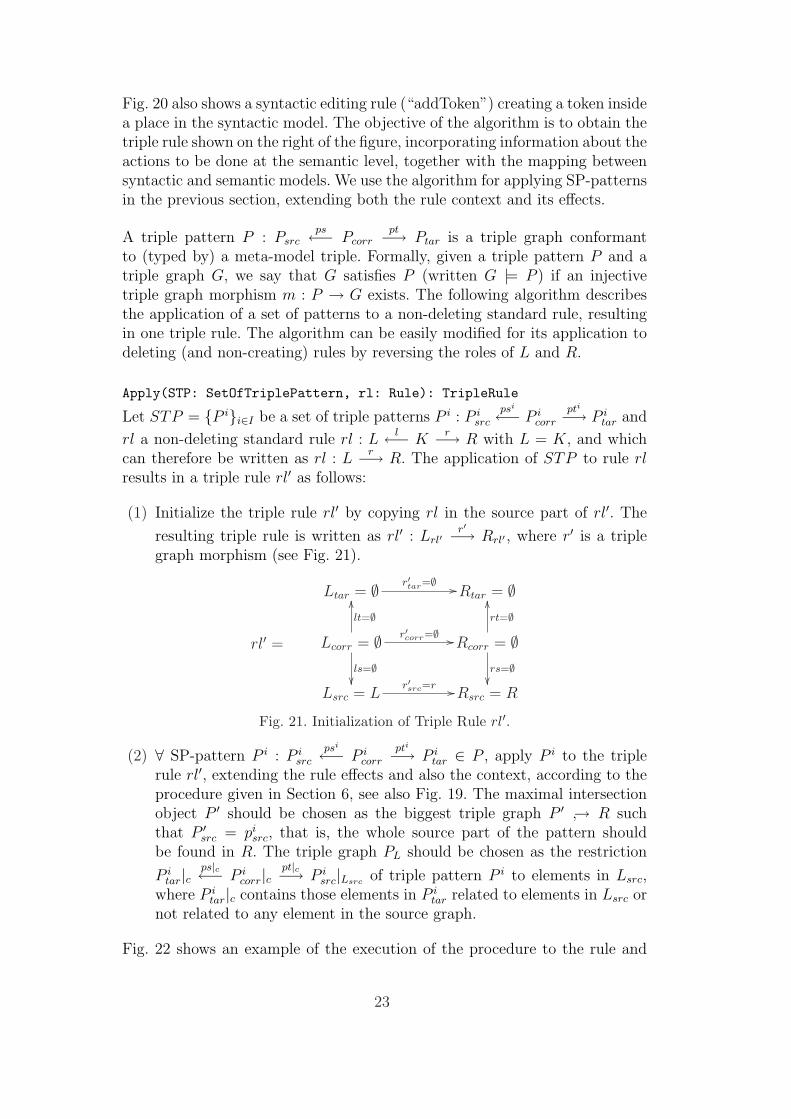
Fig. 20 also shows a syntactic editing rule (“addToken”) creating a token insidea place in the syntactic model. The objective of the algorithm is to obtain thetriple rule shown on the right of the figure, incorporating information about theactions to be done at the semantic level, together with the mapping betweensyntactic and semantic models. We use the algorithm for applying SP-patternsin the previous section, extending both the rule context and its effects.
A triple pattern P : Psrcps←− Pcorr
pt−→ Ptar is a triple graph conformantto (typed by) a meta-model triple. Formally, given a triple pattern P and atriple graph G, we say that G satisfies P (written G |= P ) if an injectivetriple graph morphism m : P → G exists. The following algorithm describesthe application of a set of patterns to a non-deleting standard rule, resultingin one triple rule. The algorithm can be easily modified for its application todeleting (and non-creating) rules by reversing the roles of L and R.
Apply(STP: SetOfTriplePattern, rl: Rule): TripleRule
Let STP = {P i}i∈I be a set of triple patterns P i : P isrc
psi←− P icorr
pti−→ P itar and
rl a non-deleting standard rule rl : Ll←− K
r−→ R with L = K, and whichcan therefore be written as rl : L
r−→ R. The application of STP to rule rlresults in a triple rule rl′ as follows:
(1) Initialize the triple rule rl′ by copying rl in the source part of rl′. The
resulting triple rule is written as rl′ : Lrl′r′−→ Rrl′ , where r′ is a triple
graph morphism (see Fig. 21).
Ltar = ∅ r′tar=∅ // Rtar = ∅
rl′ = Lcorr = ∅ r′corr=∅ //
lt=∅OO
ls=∅²²
Rcorr = ∅rt=∅OO
rs=∅²²
Lsrc = Lr′src=r // Rsrc = R
Fig. 21. Initialization of Triple Rule rl′.
(2) ∀ SP-pattern P i : P isrc
psi←− P icorr
pti−→ P itar ∈ P , apply P i to the triple
rule rl′, extending the rule effects and also the context, according to theprocedure given in Section 6, see also Fig. 19. The maximal intersectionobject P ′ should be chosen as the biggest triple graph P ′ ↪→ R suchthat P ′
src = pisrc, that is, the whole source part of the pattern should
be found in R. The triple graph PL should be chosen as the restriction
P itar|c
ps|c←− P icorr|c
pt|c−→ P isrc|Lsrc of triple pattern P i to elements in Lsrc,
where P itar|c contains those elements in P i
tar related to elements in Lsrc ornot related to any element in the source graph.
Fig. 22 shows an example of the execution of the procedure to the rule and
23

pattern shown to the left of Fig. 20. Thus, R′ is a triple graph that connectsthe source elements with the target ones according to P . Moreover, L′ is builtby connecting the elements in the source part of L according to PL.
R’
p:Place t:Token
R
c:Contains
p:Place
Q
p:Place
L
p:Place
Q
p2s:Pl2Sem
ps:PlaceSem
p:Place
PL
p2s:Pl2Sem
ps:PlaceSem
p:Place
qL
qLqP
p2s:Pl2Sem
c:Contains t:Token
ps:PlaceSem ts:TokSem
t2s:Tok2Sem
p2s:Pl2Sem
ps:PlaceSem
p:Place
p2s:Pl2Sem
c:Contains t:Token
ps:PlaceSem
p:Place t:Token
t2s:Tok2Sem
ts:TokSem
p:Place
ps:PlaceSem
ps:PlaceSem
SP
qS
pR
PR
s L
PL
s R
c:Contains t:Token
t2s:Tok2Sem
ts:TokSem
TGG rule P.B.
r
d
qPL
l’
r’
aP.O.
p:Place
pr
p
c
p:Place
P’
c:Contains
P.O. P
P.O.
b
p:Place
L’
Fig. 22. Applying the Pattern for Tokens.
Fig. 23 shows additional patterns for the Petri nets example. According tothe left pattern, output places of a transition in the syntactic graph are post-condition PlaceSem objects for the TransSem object associated with the tran-sition. The pattern to the right models the correspondence for input places. Byapplying these patterns to the editing rule to the left of Fig. 24 (twice the pat-tern for post-conditions, and once that for tokens), we obtain the operationalTGG rule shown to its right.
Pattern for Pre−Condition Holders
: post−conditions
: Touches
: TransSem
: Tr2Sem
: Transition: source
: Pl2Sem
: PlaceSem
: Place: target
: Touches
: ArcTP
Cor
r.S
em.
Syn
tax
Pattern for Post−Condition Holders
: pre−conditions
: Touches
: TransSem
: Tr2Sem
: Transition
: Pl2Sem
: PlaceSem
: Place : Touches
: ArcPT
: source : target
Cor
r.S
em.
Syn
tax
Fig. 23. Additional Patterns for the Example.
: Contains
: Token
: target
: target
: Transition
: ArcTP
: ArcTP
: source
: source
{new}
: Touches : Touches
addTwoOutPlaces
: Touches : Touches
: Place
: Place
: Touches
: Touches
: Touches
: Touches : ArcTP
: ArcTP
: Place
: Place: target
: target
: Contains: Token
: post−conditions
: post−conditions
: Pl2Sem : Pl2Sem
: source
: source
: PlaceSem
Sem
antic
sC
orr.
Syn
tax
{new}
addTwoOutPlaces
: decorates
: PlaceSem: TokSem
: Tok2Sem : Tr2Sem
: Transition
: TransSem
Fig. 24. Syntactic Rule (left). Derived TGG Rule (right).
24
The advantage of these patterns is that they are specified once, and can thenbe applied to complex syntactic rules. The DSVL designer does not have tomodify each syntactic rule by hand in order to add the semantic information,but only to specify the patterns once. Moreover, the patterns do not have totake into account which elements are created and which are already existing,as this is specified in the standard rules to which they are applied. Thus,the pattern may be used in several ways (i.e. in parts of the rule which arenewly created or in existing ones). In our example, the same patterns areused to build the semantic model from the concrete syntax (by applying themto editing rules), and to extend the execution rules acting on the semanticmodel only (see next section) to TGG rules synchronously modifying boththe semantic model and the concrete syntax.
7.1 Abstract Triple Patterns
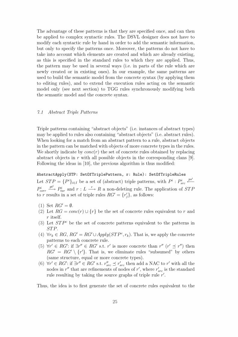
Triple patterns containing “abstract objects” (i.e. instances of abstract types)may be applied to rules also containing “abstract objects” (i.e. abstract rules).When looking for a match from an abstract pattern to a rule, abstract objectsin the pattern can be matched with objects of more concrete types in the rules.We shortly indicate by conc(r) the set of concrete rules obtained by replacingabstract objects in r with all possible objects in the corresponding clans [9].Following the ideas in [10], the previous algorithm is thus modified:
AbstractApply(STP: SetOfTriplePattern, r: Rule): SetOfTripleRules
Let STP = {P i}i∈I be a set of (abstract) triple patterns, with P i : P isrc
psi←−P i
corr
pti−→ P itar and r : L
r−→ R a non-deleting rule. The application of STPto r results in a set of triple rules RG′ = {r′j}, as follows:
(1) Set RG′ = ∅.(2) Let RG = conc(r) ∪ {r} be the set of concrete rules equivalent to r and
r itself.(3) Let STP c be the set of concrete patterns equivalent to the patterns in
STP .(4) ∀rk ∈ RG, RG′ = RG′∪Apply(STP c, rk). That is, we apply the concrete
patterns to each concrete rule.(5) ∀r′ ∈ RG′: if ∃r′′ ∈ RG′ s.t. r′ is more concrete than r′′ (r′ ¹ r′′) then
RG′ = RG′ \ {r′}. That is, we eliminate rules “subsumed” by others(same structure, equal or more concrete types).
(6) ∀r′ ∈ RG′: if ∃r′′ ∈ RG′ s.t. r′′src ¹ r′src then add a NAC to r′ with all thenodes in r′′ that are refinements of nodes of r′, where r′src is the standardrule resulting by taking the source graphs of triple rule r′.
Thus, the idea is to first generate the set of concrete rules equivalent to the
25
abstract rules (step 2), as well as the set of concrete patterns equivalent to theabstract ones (step 3). After applying the patterns, we eliminate redundantrules (step 5) and finally, NACs are added to the generated rules (for thesource graph), so that they cannot be applied to more concrete types if arefined rule was also generated. For efficiency reasons, an implementation ofthis algorithm would not generate all concretizations of rules and patternsat steps (2) and (3), but work at an abstract level, for example using clanmorphisms [9], which take into account the inheritance relations in the meta-models. For further details on the algorithm, the reader is referred to [10].
8 Patterns for the Specification of Execution Semantics
This section describes an instantiation of EG-patterns for the category of DPOrules (called action patterns) and how the constructions in Section 6 have tobe specialized. We use action patterns for the construction of execution rulesby means of meta-rules. Each meta-rule, associated with an editing rule, isused to incrementally construct an execution rule describing the semantics ofa particular active element of the model (e.g. a transition). However, to avoidwriting each meta-rule by hand, we propose to exploit a set of action patternsto describe semantics. We present a procedure to generate a meta-rule, startingfrom a set of patterns and an editing rule.
A type system for patterns over a type graph with inheritance TGI = (TG, I)is a construct TSP = (TGI, tr, σ), where tr ∈ NT is a designated nodetype whose semantics is described by the action patterns (e.g. a transition inthe case of a Petri net). In addition, σ ⊂ TGI is a subgraph of types (withinheritance) relative to the execution mechanism, with tr ∈ σNT
(the set ofnodes in σ). Elements in σ are needed in order to express the operationalsemantics of the language (e.g. places and arcs). An action pattern over TSP
is a DPO rule ap : La la←− Ka ra−→ Ra such that⋃
n∈XaN
type(n) ∩ σNT6= ∅,
for X = {L, K, R}, where XN is the set of nodes of graph X. Thus, an actionpattern is a DPO rule where some elements have types in σ. As in Section 7,we admit abstract action patterns containing elements with abstract typing.
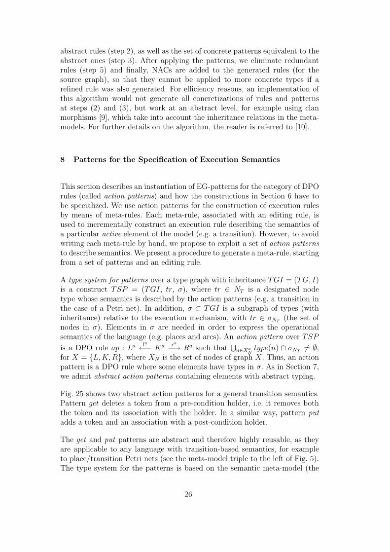
Fig. 25 shows two abstract action patterns for a general transition semantics.Pattern get deletes a token from a pre-condition holder, i.e. it removes boththe token and its association with the holder. In a similar way, pattern putadds a token and an association with a post-condition holder.
The get and put patterns are abstract and therefore highly reusable, as theyare applicable to any language with transition-based semantics, for exampleto place/transition Petri nets (see the meta-model triple to the left of Fig. 5).The type system for the patterns is based on the semantic meta-model (the
26

Element: Holder
: decorates
: Token {del}
get
:Transition:pre−conditionsElement
:post−conditions: Holder
: decorates
: Token {new}
put
:Transition
Fig. 25. Action Patterns for Transition Based Semantics.
upper one) in Fig. 4, and the subclasses added by each particular language.In all cases, the designated type tr is TransitionElement. For the exampleof Petri nets, σ contains the classes in the semantic model of Fig. 5, exceptclass Token and the decorates association. For some classes of Petri nets,where tokens with identities are used, one can introduce a move pattern thatdoes not remove or insert tokens, but only transfers the decorates associationconnecting the token from one holder to another.
8.1 Generating the Meta-Rules
We present an algorithm that, given a set of action patterns and an edit-ing rule, generates a meta-rule that updates the execution rule associatedwith a transition element. The algorithm is based on the constructions forEG-patterns in Section 6. To provide intuition, we illustrate how the actionpatterns in Fig. 25 are applied to the editing rule on the left of Fig. 26 toobtain the meta-rule on its right.
Fig. 26. Editing Rule (left). Associated Meta-Rule (right).
As the editing rule adds a pre- and post-holder to an existing transition, theassociated meta-rule must update the execution rule by adding the semanticsof an additional pre-holder and post-holder. Hence, the meta-rule should iden-tify the transition in the execution rule and modify it by enlarging the LHSwith the pre- and post-holders, together with a token in the pre-holder. Then,the RHS is enlarged with the pre- and post-holders, the deletion of the tokenin the pre-holder and the addition of the token in the post-holder.
In a situation as depicted on the left of Fig. 27, the editing rule (and thereforethe associated meta-rule) has been fired twice for the transition. This pro-duces the execution rule shown to its right. As previously mentioned, the ruleapplication mechanism initializes the match of the execution rule (using itsparameter) with the transition of the editing rule. Thus, such execution rulecan only be applied at the transition in the semantic model to its left.
27

: PlaceSem : PlaceSem
:TokSem
: PlaceSem : PlaceSem
:TokSem :TokSem
:post−conditions:post−conditions :pre−conditions :pre−conditions
: decorates : decorates
execution Rule r(t:TransSem):pre−conditions:post−conditions
t: TransSem:pre−conditions:post−conditions
semantic Model
: decorates
{del}
: decorates
{new}
:TokSem
: TransSem
: PlaceSem : PlaceSem : PlaceSem : PlaceSem
Fig. 27. Semantic Model and Resulting Rule.
Let TGI = ((NT , ET , sT , tT ), I) be a type graph with inheritance, TSP =
(TGI, tr, σ) a type system for patterns over TGI, AP = {api : Lai
lai←− Kai
rai−→
Rai }i∈I a set of action patterns over TSP and e : L
l←− Kr−→ R an editing
rule typed over TGI. The application of AP to e produces a meta-rule foreach transition element in e, according to the following algorithm.
Apply(AP:SetofActionPattern, e:Editing Rule, tsp:TypeSystemPattern):
SetofMeta-rule
(1) Initialize the set of meta-rules, MRS = ∅.(2) Set AP c =
⋃ap∈AP conc(ap), i.e. all concretizations of the action patterns.
(3) ∀t ∈ R|clan(tr)|σNT(R|clan(tr)|σNT
is the RHS of e restricted to subtypes in
σNTof the designated node type tr):
• Initialize the meta-rule mrt as follows: Ls = Ks = Rs = K|t, whereK|t is the kernel of the editing rule restricted to node t. L′s = K ′s =R′s = sub(R, t)|σ, where sub(R, t)|σ is the smallest connected subgraphof R containing node t and no other element t′ with type in clan(tr),
restricted to types in σ. The meta-rule thus becomes: mrt = (Ls id←−Ks id−→ Rs) → (L′s id←− K ′s id−→ R′s).
• ∀apj : La la←− Ka ra−→ Ra ∈ AP c, apply apj to meta-rule mrt extendingthe meta-rule effects, according to the first procedure given in Section 6.
• The parameter of the meta-rule’s LHS and RHS are Ks|t and K ′s|t.• Add mrt to the set MRS.
(4) return MRS.
As in the algorithm of Section 7.1, an efficient implementation would not gen-erate the concretizations of the patterns, but work at the abstract level. Fig. 28shows the execution of the algorithm for patterns get and put and the editingrule in Fig. 26. This rule contains a single transition, hence one meta-rule isgenerated. The LHS of the meta-rule is initialized with the unique transitionelement, the RHS with the smallest connected subgraph of the editing rule’sRHS that contains the transition element and no other one. In addition, theinitialization is restricted to elements with types in σ, which usually does notcontain dynamic elements (i.e. tokens). This is necessary as the fact that anediting rule adds or deletes tokens is irrelevant for updating the executionrule. The concretized get pattern is applied once. This pattern is like the one
28

in Fig. 25, but with elements of type PlaceSem, TransSem and TokSem insteadof Holder, TransitionElement and Token. After applying get, pattern putis applied, thus yielding the final RHS. The left and right hand side rules ofthe resulting meta-rule have the TransSem node as parameter (not shown inthe figure for simplicity). Hence, the generated meta-rule takes an executionrule with a TransSem in its LHS, RHS and parameter, and adds a pre- and apost-condition, together with the appropriate handling of tokens.
i:PlaceSem
: pre−conditions
o:PlaceSem
: post−
t:TransSemK
conditions
i:PlaceSem
: pre−conditions
o:PlaceSem
: post−
t:TransSemR
conditions
i:PlaceSem
: pre−conditions
o:PlaceSem
: post−
t:TransSem
conditions
i:PlaceSemo:PlaceSem
t:TokSem
: pre−conditions
: post−
L
:decorates
t:TransSem
conditions
i:PlaceSemo:PlaceSem
: pre−conditions
: post−
Kt:TransSem
conditions
i:PlaceSemo:PlaceSem
: pre−conditions
: post−
R
t:TransSem
o:PlaceSem i:PlaceSem
t:TokSem
:decorates
L
: pre−conditions
: post−conditions
t:TransSem
o:PlaceSem i:PlaceSem
K
: post− : pre−conditionsconditions
t:TransSem
o:PlaceSem i:PlaceSem
t:TokSem
:decorates
R
: post− : pre−conditionsconditions
t:TransSem
i:PlaceSem
L
: pre−conditions
t:TransSem
i:PlaceSem
K
: pre−conditions
t:TransSem
i:PlaceSem
R
: pre−conditions
t:TransSem
i:PlaceSem
t:TokSem
L
: pre−conditions
:decorates
t:TransSem
i:PlaceSem
K
: pre−conditions
t:TransSem
i:PlaceSem
R
: pre−conditions
t:TransSem
o:PlaceSem
L
: post−conditions
o:PlaceSem
t:TransSem
K
conditions: post−
t:TransSem
o:PlaceSem
conditions: post−
R
t:TokSem
t:TransSem
o:PlaceSem
conditions: post−
:decorates
Rt:TransSem
o:PlaceSem
K
conditions: post−
t:TransSem
o:PlaceSem
L
: post−conditions
meta−rule
R’
a’
r’
r’’
R
pr
P’
get
b
pr’
a p
P’’
put
b’
R’’
t:TransSem t:TransSem t:TransSem
LL
K Rr
p’
t:TransSemL
conditions
Fig. 28. Applying Patterns get and put.
Once the execution rules are generated, we can apply the triple patterns pre-sented in previous section to extend them to synchronous TGG rules modifyingboth the static semantics and the concrete syntax.
9 Examples
We provide examples highlighting the use of patterns in the incremental con-struction of the abstract syntax and execution semantics of visual languages.
29
9.1 Token-Holder like Visual Languages
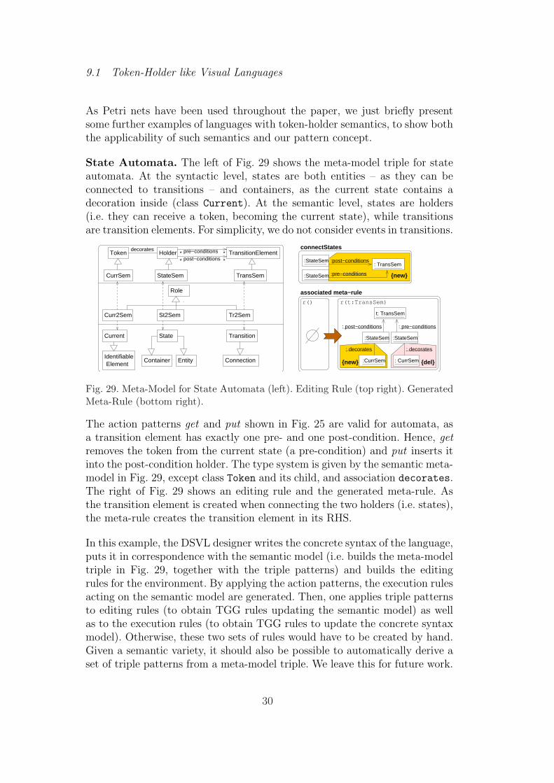
As Petri nets have been used throughout the paper, we just briefly presentsome further examples of languages with token-holder semantics, to show boththe applicability of such semantics and our pattern concept.
State Automata. The left of Fig. 29 shows the meta-model triple for stateautomata. At the syntactic level, states are both entities – as they can beconnected to transitions – and containers, as the current state contains adecoration inside (class Current). At the semantic level, states are holders(i.e. they can receive a token, becoming the current state), while transitionsare transition elements. For simplicity, we do not consider events in transitions.
CurrSem
Curr2Sem St2Sem
Role
IdentifiableElement
Container Entity
Tr2Sem
Connection
Transition
TransSem
Token
Current
pre−conditionspost−conditions *
* TransitionElement**Holder
decorates
:StateSem :StateSem
t: TransSem
associated meta−rule
r() r(t:TransSem)
: decorates
{new} :CurrSem {del}: CurrSem
: post−conditions : pre−conditions
: decorates
: TransSem:StateSem
{new}StateSem
State
:pre−conditions:StateSem
connectStates
:post−conditions
Fig. 29. Meta-Model for State Automata (left). Editing Rule (top right). GeneratedMeta-Rule (bottom right).
The action patterns get and put shown in Fig. 25 are valid for automata, asa transition element has exactly one pre- and one post-condition. Hence, getremoves the token from the current state (a pre-condition) and put inserts itinto the post-condition holder. The type system is given by the semantic meta-model in Fig. 29, except class Token and its child, and association decorates.The right of Fig. 29 shows an editing rule and the generated meta-rule. Asthe transition element is created when connecting the two holders (i.e. states),the meta-rule creates the transition element in its RHS.
In this example, the DSVL designer writes the concrete syntax of the language,puts it in correspondence with the semantic model (i.e. builds the meta-modeltriple in Fig. 29, together with the triple patterns) and builds the editingrules for the environment. By applying the action patterns, the execution rulesacting on the semantic model are generated. Then, one applies triple patternsto editing rules (to obtain TGG rules updating the semantic model) as wellas to the execution rules (to obtain TGG rules to update the concrete syntaxmodel). Otherwise, these two sets of rules would have to be created by hand.Given a semantic variety, it should also be possible to automatically derive aset of triple patterns from a meta-model triple. We leave this for future work.
30

WorkFlow. Fig. 30 shows an excerpt of the meta-model for a simple workflowlanguage, in the style of [34]. Two kinds of blocks – parallel and sequential– exist, playing the roles of both transition elements and holders. Parallelblocks are amenable to incremental semantics, as they require a token in eachincoming block for firing, and add a token in each outgoing block.
Choice
TransitionElement
Parallel
Control
Token Holder
IdentifiableElement
Conc2Sem
BlockSequent
SemCtrl Seq2Sem
WFBlock
post−conditionspre−conditions *
***
t: Parallel t: Parallel
:Control
r(t:Parallel) r(t:Parallel)
:decorates
:post−conditions
:Choice
{new}meta−rule foraddChoice
:Choice
addChoice
Role
Container Entity
ConcurrCurrent
:post
:pre
:post
:pre
{del} {new}
execution rulefor "Choice"
:WFBlock
:WFBlock
:Choice:Parallel {new}
:Control
:Control
Fig. 30. Meta-Model for Workflow Language (left). Editing Rule (top right). Gen-erated Meta-rule (middle right). Execution Rule for Choice (bottom right).
An example editing rule is shown in the upper-right corner of Fig. 30. Thisrule adds a choice as a post-condition for the parallel block, while the latterbecomes a pre-condition for the choice. Below the editing rule the generatedmeta-rule for addChoice is shown. Choice blocks have a sequential semantics:they take one token from one of the incoming blocks (randomly chosen), andput the token in one of the outgoing ones (also randomly chosen). No incre-mental construction is needed for choice blocks, and the global execution rulein the lower-right corner of Fig. 30 is enough. This rule is abstract (equivalentto four normal rules), as we do not care about the explicit type of the incom-ing or outgoing blocks. Thus, in this case, we need the type system TSP toinclude Choice in the determination of the context of the execution rules forParallel, but we avoid the generation of a meta-rule for the class Choice
which does not need incremental semantics. Therefore, TSP includes in TGall types in the upper part of the meta-model triple of Fig. 30, but excludesChoice, Token and Control from σNT
.
In this example the DSVL designer can reuse the action patterns for the token-holder semantics. However, the DSVL semantics for this case is not entirelycovered by the patterns, but has to be refined by adding a non-incrementalrule (to avoid the parallel semantics of the choice blocks).
31

9.2 Visual Languages for Discrete-Event Simulation
In Discrete-Event Simulation Systems (DESS) [14,31], a number of entitiesgenerate events to be processed at a future time. These events are stored(ordered by their execution time) in a so called future event queue. The simu-lator proceeds by taking the first event in the queue and executing it. In theevent-scheduling approach, the execution of an event follows a specificationand gives rise to the scheduling of further events.
Fig. 31. An EventGraph.
Event Graphs [31] are a classical example of event-scheduling DESS. A simple model is shown in Fig. 31,with four types of events and some causality relations.An event graph model does not have to worry aboutthe event queue, as this is a mechanism for execution,which does not belong to the modelling phase. Otherdiscrete simulation languages, such as Time Transi-tion Petri nets or Process-Interaction notations [14],have similar execution semantics.
The meta-model triple on the left of Fig. 32 extracts the DESS semanticsand relates it to the concrete syntax of the particular DESS formalism. Anexecutable DESS model needs some event specification and an event queue forits execution. The specification defines event types, and is made of a numberof event types related through Schedules objects, annotated with the timeafter which an event of the given type will occur. Events in the event queuecontain the time at which they have to be executed, and are instances ofsome event type, as depicted by the association instanceOf. Each event inthe queue points to the next one. A Scheduler entity takes care of orderingnew events in the queue. The type system for the action patterns containsclasses Schedules and EventSpec (which is the distinguished active element)together with associations source and target. The concrete syntax part of themeta-model triple assumes that event specifications can be produced using anyreferable element, but the scheduling of new events is specified via directedconnections (i.e. we assume a graph-like language). The right of Fig. 32 showsthe specialization for Event Graphs.
The syntactic rule on the left of Fig. 33 creates new event specifications (i.e.event types). The triple pattern in the middle shows the relation betweenevent specifications in the concrete syntax and the semantic model. The actionpattern on the right describes part of the execution semantics of the newlycreated event type. Thus, if an event of this type is the first one in the queue,the execution rule deletes it and moves the queue pointer to the following one.
Once the event specification has been created, a possible syntactic action is
32

Fig. 32. Meta-Model Triple for DESS (left). Specialization for Event Graphs (right).
Fig. 33. Editing Rule for Creating Event Types (left). Triple Pattern for EventSpecifications (middle). Action Pattern (right).
the scheduling of other event specifications when an event of the given type isexecuted. This is modelled by the syntactic rule shown on the left of Fig. 34.The (attributed) triple pattern in the middle describes the relation betweenconnected events in the concrete syntax and in the semantics. The action pat-tern on the right describes the execution semantics for event scheduling. Thus,the modification to the meta-rule produced by this pattern allows changingthe execution rule associated with the source event specification, so that itcreates a new event of the type specified by the schedule object’s target. Thenew event is created and linked to the scheduler object, the behaviour of whichis handled by the non-incremental rules shown in Fig. 35.
Fig. 34. Editing Rule for Scheduling new Events (left). Triple Pattern (middle) andAction Pattern (right).
The set of non-incremental rules shown in Fig. 35 initialize the simulation(init) and model the behaviour of the scheduler (rules insert and insert first).Rule init creates the scheduler and the event queue, initialized with the initial
33
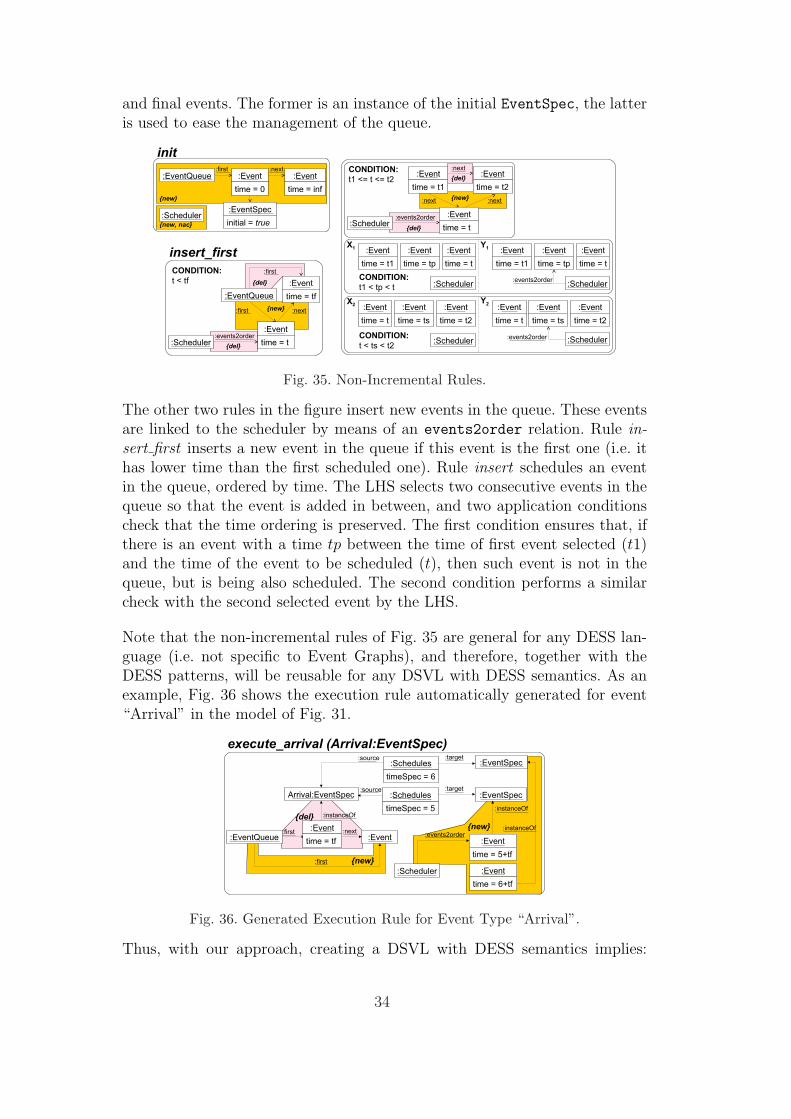
and final events. The former is an instance of the initial EventSpec, the latteris used to ease the management of the queue.
Fig. 35. Non-Incremental Rules.
The other two rules in the figure insert new events in the queue. These eventsare linked to the scheduler by means of an events2order relation. Rule in-sert first inserts a new event in the queue if this event is the first one (i.e. ithas lower time than the first scheduled one). Rule insert schedules an eventin the queue, ordered by time. The LHS selects two consecutive events in thequeue so that the event is added in between, and two application conditionscheck that the time ordering is preserved. The first condition ensures that, ifthere is an event with a time tp between the time of first event selected (t1)and the time of the event to be scheduled (t), then such event is not in thequeue, but is being also scheduled. The second condition performs a similarcheck with the second selected event by the LHS.
Note that the non-incremental rules of Fig. 35 are general for any DESS lan-guage (i.e. not specific to Event Graphs), and therefore, together with theDESS patterns, will be reusable for any DSVL with DESS semantics. As anexample, Fig. 36 shows the execution rule automatically generated for event“Arrival” in the model of Fig. 31.
Fig. 36. Generated Execution Rule for Event Type “Arrival”.
Thus, with our approach, creating a DSVL with DESS semantics implies:
34
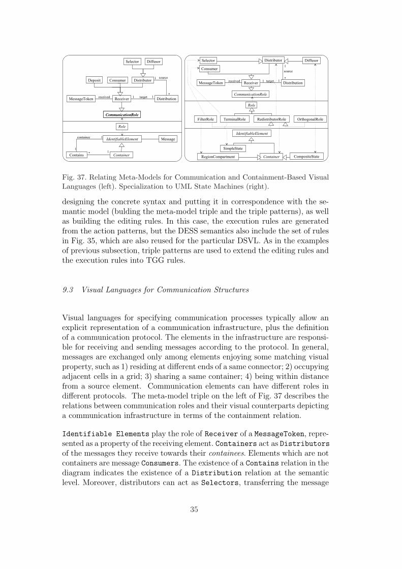
Fig. 37. Relating Meta-Models for Communication and Containment-Based VisualLanguages (left). Specialization to UML State Machines (right).
designing the concrete syntax and putting it in correspondence with the se-mantic model (bulding the meta-model triple and the triple patterns), as wellas building the editing rules. In this case, the execution rules are generatedfrom the action patterns, but the DESS semantics also include the set of rulesin Fig. 35, which are also reused for the particular DSVL. As in the examplesof previous subsection, triple patterns are used to extend the editing rules andthe execution rules into TGG rules.
9.3 Visual Languages for Communication Structures
Visual languages for specifying communication processes typically allow anexplicit representation of a communication infrastructure, plus the definitionof a communication protocol. The elements in the infrastructure are responsi-ble for receiving and sending messages according to the protocol. In general,messages are exchanged only among elements enjoying some matching visualproperty, such as 1) residing at different ends of a same connector; 2) occupyingadjacent cells in a grid; 3) sharing a same container; 4) being within distancefrom a source element. Communication elements can have different roles indifferent protocols. The meta-model triple on the left of Fig. 37 describes therelations between communication roles and their visual counterparts depictinga communication infrastructure in terms of the containment relation.
Identifiable Elements play the role of Receiver of a MessageToken, repre-sented as a property of the receiving element. Containers act as Distributorsof the messages they receive towards their containees. Elements which are notcontainers are message Consumers. The existence of a Contains relation in thediagram indicates the existence of a Distribution relation at the semanticlevel. Moreover, distributors can act as Selectors, transferring the message
35

exactly to one containee, or Diffusors, transferring a copy of it to all of them.Finally, a Deposit role is played by a container which maintains messages, forreceivers to retrieve them according to some other visual relation.
As an example, the right of Fig. 37 shows a simplified version of the modelfor the graphical representation of UML State Machines. We only considerthe containment-based aspect of a machine and its semantics in terms of dis-tribution of event-messages to internal states, seen as processes started bythe reception of a message (or event) at the containing State interface. ASimpleState is a State for which the isSimple attribute has value true.These can only be Consumers of a message, as indicated by the morphismsfrom the TerminalRole class. They have a distinct representation from thatof Composite States, which in turn are distinguished in Orthogonal or not.Composite states contain RegionCompartments, which may in turn containother composite or simple states. An orthogonal composite state contains atleast two regions, separated by a dashed line, while a non-orthogonal statecontains only one region. A region always acts as a Selector, delivering themessage only to the currently active one inside it. A composite state alwaysacts as a Diffusor of the message to all its internal region compartments. Thisis represented by the different specializations of the CommunicationRole. Weomit initial and terminal states, as these do not play a role in the communica-tion semantics, and do not consider any special representation for a message.
Based on the meta-model triple, one can incrementally construct a commu-nication semantics, while designing a state machine through syntactic graphtransformation rules. With each Composite State creation, a correspondingreceiver structure is added to the semantics. Elements can be inserted onlyinside containers (the presence of an outermost container being an axiom);this generates a new instance of the Distribution relation and creates thecorrespondence with the inserted element. We use here only the most specificrole that can be assigned to an element. Hence, when inserting a compositestate, one must specify whether it is orthogonal or not. An orthogonal stateis created with two empty regions, and new regions can then be added.
Fig. 38 describes a set of triple rules and a concrete syntax presentation: re-gions are added to the bottom of a composite state and the size of the containeris expanded to accommodate the new region, as prescribed by rule r1. Ruler2 shows how to add simple states to a region compartment. Triple rules areobtained from syntactic ones by specializing the abstract triple pattern on theleft of Fig. 39, as well as the abstract action pattern on the right, to the mostconcrete patterns for Selectors, Diffusors and Consumers roles.
Finally, a communication semantics can be defined exploiting a pattern anal-ogous to that for token-based execution, where messages are used as tokensto be associated with their possible receivers. To this end, the abstract ac-
36

Fig. 38. Rules for Syntax Directed Editing and Incremental Semantics Definitionfor Communication in State Machines.
: Receiver
: ActivityToken
:received:received
:source :target{del} {new}
: MessageToken
: Distribution
: Diffusor
Fig. 39. Triple Pattern for Connecting Containment and Communication Semantics(left). Basic Action Pattern for the Communication Process (right).
tion pattern on the right of Fig. 39 prescribes that a message received by aDiffusor must be delivered to any active Receiver with which it maintains aDistribution relation. The ActivityToken element in the abstract patternrepresents the condition of being active of a state according to the executionsemantics of UML state machines and is a specialization of Token from themeta-model for the transition variety, complementing the communication one.In particular, the presence of active tokens in the receivers is constrained bythe concurrent semantics of UML state machines.
10 Extensions of Enforced Generative Patterns
In this section we provide additional extensions of EG-patterns: simple nega-tive patterns, composite patterns and patterns with application conditions.
10.1 Simple Negative Patterns
A simple negative EG-pattern (short SN-pattern) is an object N in a (w)aHLRcategory. An object H satisfies N , written H |= N , if @m : N → H injective
37
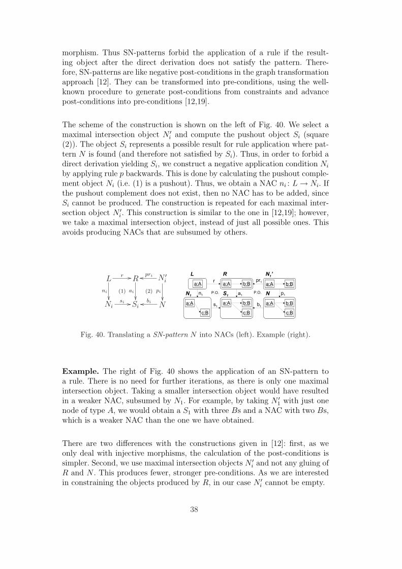
morphism. Thus SN-patterns forbid the application of a rule if the result-ing object after the direct derivation does not satisfy the pattern. There-fore, SN-patterns are like negative post-conditions in the graph transformationapproach [12]. They can be transformed into pre-conditions, using the well-known procedure to generate post-conditions from constraints and advancepost-conditions into pre-conditions [12,19].
The scheme of the construction is shown on the left of Fig. 40. We select amaximal intersection object N ′
i and compute the pushout object Si (square(2)). The object Si represents a possible result for rule application where pat-tern N is found (and therefore not satisfied by Si). Thus, in order to forbid adirect derivation yielding Si, we construct a negative application condition Ni
by applying rule p backwards. This is done by calculating the pushout comple-ment object Ni (i.e. (1) is a pushout). Thus, we obtain a NAC ni : L → Ni. Ifthe pushout complement does not exist, then no NAC has to be added, sinceSi cannot be produced. The construction is repeated for each maximal inter-section object N ′
i . This construction is similar to the one in [12,19]; however,we take a maximal intersection object, instead of just all possible ones. Thisavoids producing NACs that are subsumed by others.
Lr //
ni
²²(1)
R
ai
²²(2)
N ′i
prioo
pi
²²Ni
si // Si Nbioo
Fig. 40. Translating a SN-pattern N into NACs (left). Example (right).
Example. The right of Fig. 40 shows the application of an SN-pattern toa rule. There is no need for further iterations, as there is only one maximalintersection object. Taking a smaller intersection object would have resultedin a weaker NAC, subsumed by N1. For example, by taking N ′
1 with just onenode of type A, we would obtain a S1 with three Bs and a NAC with two Bs,which is a weaker NAC than the one we have obtained.
There are two differences with the constructions given in [12]: first, as weonly deal with injective morphisms, the calculation of the post-conditions issimpler. Second, we use maximal intersection objects N ′
i and not any gluing ofR and N . This produces fewer, stronger pre-conditions. As we are interestedin constraining the objects produced by R, in our case N ′
i cannot be empty.
38

10.2 Composite Patterns
Composite positive patterns (CP-patterns) have the form Xx−→ Y (with x
injective), meaning: “if X is found, then Y should be found as well”. In asimilar way, composite negative patterns (CN-patterns) of the form X
n−→ Nmean “if X is found, then N must not be found”.
An object G satisfies a CP-pattern pp : (Xx−→ Y ), written G |= pp iff the
diagram to the left of Fig. 41 commutes, or @X m−→ G. In this latter casewe also say that G trivially satisfies pp. Similarly, an object G satisfies a CN-pattern np : (X
n−→ N), written G |= np iff in the diagram on the right of
Fig. 41 there is no Nt−→ G such that t ◦ n = m, or @X m−→ G. In this latter
case we also say that G trivially satisfies np.
Xx //
m ÃÃAAA
AA=
Y
y~~~~~~
~
G
Xn //
m ÃÃAAA
AA=
N|}}
}t~~}}}
G
Fig. 41. Satisfaction of CP-pattern (left). Satisfaction of CN-pattern (right).
The application of composite patterns to rules is similar to that shown inSection 6, but involves one more step, making an extra pushout.
CP-patterns. The left of Fig. 42 shows the application of a CP-pattern forthe case in which pattern X, hence its consequence Y , must be enforced. Theprocedure is similar to that for SP-patterns (see Section 6), but after enforcingX through the pushout object R′, we have to enforce Y by calculating thepushout object R′′. Note that XL and XR play the same role as objects PL
and PR in Fig. 19. XR is the part of X that is enforced by simply creatingthe missing elements, whereas XL is enforced by extending the rule’s left-handside. As the CP-pattern pp : (X
x−→ Y ) can also be trivially satisfied if noX is found in the host graph, another rule resulting from the procedure forSN-patterns (taking only X as SN-pattern) has to be generated.
CN-patterns. In order to apply a CN-pattern np : (Xn−→ N) to a rule,
we enforce the positive part X and then we forbid N . Enforcing the positivepart is done in the same way as for SP-patterns (using the constructions ofSection 6). After each iteration, we generate a NAC using the procedure forSN-patterns. The right of Fig. 42 shows a diagram where X is enforced bymaximally extending the rule’s effects (pushout (1)). Then, the constructionof Fig. 40 is applied to generate a NAC ni : L → Ni (pushouts (2) and (3)).Note that we could have used any of the constructions in Section 6 to enforceX. Moreover, enforcing X may require further iterations, after each of whichthe procedure for SN-patterns has to be applied (possibly resulting in one or
39

QqL
~~}}}}
}} qP
ÃÃAAA
AAA
P.B.
qS
µµ
QqL //
qPL ²²P.O.
Lr //
l²²
Ra
²²P.O.
P ′proo
p²²
XR
pR}}{{{{
{{
XLpl // L′ r′ //
r′′
ÃÃ
R′
a′²²
P.O.
Xboo P.O.
x²²
SP
aaDDDDDD
}}zzzz
zz
R′′ Yb′oo XL
pLaaCCCCCC
Lr //
ni
²²
r′ !!BBB
BBB R
a²²
(1)
P ′proo
p²²
R′ai
²²(2)(3)
Xboo
pi²²
Nisi // Si N
bioo
Fig. 42. Extending the Rule Context and Effect According to CP-pattern x : X → Y(left). Applying CN-pattern n : X → N (right).
zero NACs). Even if no iteration is needed to enforce X (i.e. X is included inR), the SN-pattern procedure must be applied to generate the needed NAC.
10.3 Patterns with Application Conditions
Lr //
r′=a◦r ÃÃ@@@
@@@ R
a²²
(1)
P ′proo
p²²
R′ Pboo n // N
/x
ff
Fig. 43. Application ofSP-Pattern with NAC.
Patterns (of any kind) can also be supplementedwith application conditions. These constrain theapplicability of the pattern to the rule. We ex-plain the case for SP-patterns and NACs, as therest is similar. An SP-pattern with NAC is a tu-ple (P, n : P → N), where n : P → N is a NAC.When the pushout with R′ is built, the applica-tion is valid only if there is no morphism x : N → R′ such that x ◦ n = b, asFig. 43 shows.
11 Conclusions
Patterns are a common way to describe some abstract characteristics of amodel, as well as to state some required “shape” for it. The typical way toexploit patterns is therefore through the definition of some morphism from thepattern to an existing model to check whether the latter conforms to the first,i.e. if an instance of the pattern can be found in it. Little support is howeverprovided by this notion for the case in which such a match is not found, forexample to identify how conformance can be established.
We have proposed enforced generative patterns as a means to ensure thatrules used to produce a model act in such a way that the resulting modelconforms to the required shape. In particular, we have shown the relevance ofthis notion to the development of DSVLs, by showing how the application ofsuitable sets of patterns to rules of the concrete syntax is sufficient to generate
40
triple rules, incrementally reconciling the syntax and the static semantics ofa visual sentence, and meta-rules, used to incrementally update its executionsemantics. Triple patterns can be applied to the execution rules to obtain triplerules updating the concrete syntax. The approach has been demonstrated ona number of known visual languages, showing its potential in the constructionof syntax-directed integrated environments for their management.
An important issue for the practical application of EG patterns is managementof attributes. We used attributes in triple patterns in Section 9.2 (see e.g.Fig. 34). However, up to now, triple patterns are limited to copy attributevalues. The action pattern in Fig. 34 performs a simple attribute computation,and we do not foresee any problem with attribute handling in action patterns.For triple patterns however, we need to restrict to invertible dependenciesbetween attribute values, as the pattern might be applied to the source or thetarget graphs. Investigating attribute conditions is also left for future work.
We now plan to systematically explore the application of enforced generativepatterns to several fields with established notion of patterns. In particular, wesee possibilities for the generation of UML-based development environmentsenriched with support for design patterns in the sense of [15], where basicediting rules could be transformed to generate instances of the patterns. Inthis way, EG patterns could be used to produce pattern-oriented modellingenvironments for DSVLs. In this context, activities like pattern discovery andpattern-oriented model redesigns are interesting challenges.
Another interesting development is the introduction of universal quantifica-tion into patterns. For example, the basic pattern for creating nodes only ifconnected to an existing one could be quantified on the latter to ensure thateach new node gets connected to all the nodes already in the graph. Thiscould open the way to the definition of a pattern language. This line of re-search would probably intersect the Local Shape Logic introduced in [27] andthe use of patterns as synthetic expression of rules presented in [2].
Acknowledgements. Work supported by the Spanish Ministry of Educationand Science, projects MOSAIC (TSI2005-08225-C07-06) and MODUWEB(TIN2006-09678). We thank the referees for their detailed and useful com-ments, which helped us in improving the paper.
References
[1] T. Baar. Correctly defined concrete syntax for visual models. In MoDELS/UML2006, volume 4199 of LNCS, pages 111–125. Springer, 2006.
[2] D. Balasubramanian, A. Narayanan, S. Neema, F. Shi, R. Thibodeau, and
41

G. Karsai. A subgraph operator for graph transformation languages. In GT-VMT 2007, Electronic Communications. EASST, 2007.
[3] L. Baresi and M. Pezze. Formal interpreters for diagram notations. ACMTOSEM, 14(1):42–84, 2005.
[4] P. Bottoni, J. de Lara, and E. Guerra. Action patterns for the incrementalspecification of the execution semantics of visual languages. In VL/HCC 2007,pages 163–170. IEEE CS Press, 2007.
[5] P. Bottoni, D. Frediani, P. Quattrocchi, L.Rende, G.Sarajlic, and D. Ventriglia.A transformation-based metamodel approach to the definition of syntax andsemantics of diagrammatic languages. In Visual Languages for InteractiveComputing: Definitions and Formalization, pages 51–73. IGP Press, 2007.
[6] P. Bottoni and A. Grau. A suite of metamodels as a basis for a classification ofvisual languages. In P. Bottoni, C. Hundhausen, S. Levialdi, and G. Tortora,editors, VL/HCC 2004, pages 83–90. IEEE CS Press, 2004.
[7] P. Bottoni, K. Hoffmann, F. Parisi Presicce, and G. Taentzer. High-levelreplacement units and their termination properties. J. Vis. Lang. Comput.,16:485–507, 2005.
[8] S. Burmester, H. Giese, J. Niere, M. Tichy, J. Wadsack, R. Wagner,L. Wendehals, and A. Zundorf. Tool integration at the meta-model level: theFujaba approach. J. Softw. Tools Technol. Transfer, 6(3):203–218, 2004.
[9] J. de Lara, R. Bardohl, H. Ehrig, K. Ehrig, U. Prange, and G. Taentzer.Attributed graph transformation with node type inheritance. Theor. Comput.Sci., 376(3):139–163, 2007.
[10] J. de Lara, E. Guerra, and P. Bottoni. Triple patterns: Compact specificationsfor the generation of operational triple graph grammar rules. In GT-VMT’07,volume 6 of Electronic Communications of the EASST, 2007.
[11] J. de Lara and H. Vangheluwe. Defining visual notations and their manipulationthrough meta-modelling and graph transformation. J. Vis. Lang. Comput.,15(3-4):309–330, 2004.
[12] H. Ehrig, K. Ehrig, U. Prange, and G. Taentzer. Fundamentals of AlgebraicGraph Transformation. Springer, Berlin, Heidelberg, New York, 2006.
[13] C. Ermel and R. Bardohl. Scenario animation for visual behavior models: Ageneric approach. Software and System Modeling, 3(2):164–177, 2004.
[14] G. S. Fishman. Discrete Event Simulation. Modeling, Programming andAnalysis. Springer Series in Operations Research, 2001.
[15] E. Gamma, R. Helm, R. Johnson, and J. Vlissides. Design Patterns. Elementsof Reusable Object-Oriented Software. Addison Wesley, 1994.
[16] H. Gottler. Semantical description by two-level graph-grammars forquasihierarchical graphs. In WG’79, Applied Computer Science 13. Carl HansenVerlag, 1979.
42
[17] E. Guerra and J. de Lara. Event-driven grammars: Relating abstract andconcrete levels of visual languages. SoSyM, 6(3):317–347, 2007.
[18] R. Heckel, J. M. Kuster, and G. Taentzer. Confluence of typed attributed graphtransformation systems. In ICGT 2002, volume 2505 of LNCS, pages 161–176.Springer, 2002.
[19] R. Heckel and A. Wagner. Ensuring consistency of conditional graph rewriting- a constructive approach. ENTCS, 2, 1995.
[20] E. Kindler and R. Wagner. Triple graph grammars: Concepts, extensions,implementations, and application scenarios. Technical Report tr-ri-07-284,Software Engineering Group, Dep. Comp. Sci., Univ. Paderborn, 2007.
[21] M. Koch, L. V. Mancini, and F. Parisi-Presicce. Graph-based specification ofaccess control policies. J. Comput. Syst. Sci., 71(1):1–33, 2005.
[22] A. Konigs and A. Schurr. Tool integration with triple graph grammars - asurvey. ENTCS, 148:113–150, 2006.
[23] H.-J. Kreowski. A comparison between Petri-nets and graph grammars. InGraph-theoretic Concepts in Computer Science, volume 100 of LNCS, pages306–317. Springer, 1980.
[24] B. Pagel and M. Winter. Towards pattern-based tools. In EuroPLoP’96, 1996.
[25] F. Parisi Presicce. Transformation of graph grammars. In TAGT, LNCS 1073,pages 428–442. Springer, 1996.
[26] F. Parisi Presicce. On modifying high level replacement systems. In UNIGRA2001, ENTCS, 44(4), pages 16–27, 2001.
[27] A. Rensink. Canonical graph shapes. In D. A. Schmidt, editor, ESOP 2004,volume 2986 of LNCS, pages 401–415. Springer, 2004.
[28] A. Repenning and T. Sumner. Agentsheets: A medium for creating domain-oriented visual languages. IEEE Computer, 28(3):17–25, 1995.
[29] M. G. Rhode, F. Parisi Presicce, and M. Simeoni. Formal software specificationwith refinements and modules of typed graph transformation systems. Journalof Computer and System Sciences, 64:171–218, 2002.
[30] G. Rozenberg, editor. Handbook of Graph Grammars and Computing by GraphTransformations, Volume 1: Foundations. World Scientific, 1997.
[31] L. Schruben. Simulation modeling with event graphs. CACM, 26(11):957–963,1983.
[32] A. Schurr. Specification of graph translators with triple graph grammars. InWG’94, LNCS, pages 151–163. Springer, 1994.
[33] G. Taentzer. Parallel and Distributed Graph Transformation. FormalDescription and Application to Communication-Based Systems (PhD. Thesis).Shaker Verlag, 1996.
43
[34] W. van der Aalst, A. ter Hoefstede, B. Kiepuszewski, and A. Barros. Workflowpatterns. Distributed and Parallel Data Bases, 14(3):5–51, 2003.
44