An Analytical Comparison of Generative Programming Technologies

AMIT 2 (11) 2010
1
MONITORING URBAN DESIGN THROUGH GENERATIVE DESIGN SUPPORT TOOLS: A GENERATIVE GRAMMAR FOR PRAIA José N. Beirão Technical University of Delft, The Netherlands; Technical University of Lisbon, Portugal
José P. Duarte, Nuno Montenegro Technical University of Lisbon, Portugal
Jorge Gil Technical University of Delft, The Netherlands 1. Introduction Design new urban spaces is a complex process that extends for a long period, goes through several stages, and addresses several issues, including defining the urban programme and devising the plan layout in all its details, such as the street network, the neighbourhood identity, the city block typologies, and so on. Developing solutions for problems on each stage and evaluating the qualities of such solutions are two fundamental activities that participants in the urban design processes need to deal with. The complexity is such that it becomes difficult to control the outcome, including how it will be received by futures inhabitants. Part of the complexity stems from the fact that the design process itself interferes with the city development process, thereby changing the context on which it was based (Portugali, 2000). Changes in the context require reformulation of the problem and, consequently, of the solution, thereby making the design of urban spaces like trying to hit a moving target. To deal with such indeterminacy, urban design and city planning should be supported by more interactive and intelligent design support tools than the ones currently available. We need tools that permit flexible design and evolutionary solutions. This can be accomplished if such tools permit the evaluation of proposed solutions, the reformulation of the design problem, followed by the redesign of the initial solutions. Only then contextual changes can be taken into account. This paper describes research project that aims to develop a tool with formulation capabilities based on pattern languages (Alexander et al., 1977) generative capabilities based on shape grammars (Stiny and Gips, 1972), and evaluation ones based on space syntax (Hillier, 1983), among other theoretical frameworks. This tool is includes a GIS platform and 3 modules. The formulation module is used to define appropriate urban programmes for given contexts using a description grammar (Stiny, 1981). The generation module generates design solutions that match the defined urban programmes using compound shape grammars. The evaluation module is used to guarantee that evolving programmes and design solutions match the context given a priori. The research project is called City Induction. The theoretical background is based on the discursive grammar formalism (Duarte, 2005) extended for urban design. A discursive grammar is composed of a programming grammar defined through a description grammar, a designing grammar defined through a shape grammar and a set of heuristics that guide generation by selecting on each step rules that best fit the specified goals. The paper describes the overall research but is focused on the generation module. To define this module four case studies have been used to extract basic design rules. The first case study is an extension plan for the city of Praia in Cabo Verde. The other case studies are urban plans of similar size, one in Portugal and two in the Netherlands, from which we expect to extend the body of rules in the generation module. This paper addresses two different but related issues: how can one develop a general urban design tool based on a set of rules extracted from a small number of specific case studies, and how can one take advantage of the proposed tool for city planning and urban design. The paper is divided into seven sections. Section 2 outlines the general goals of the research project and the specific goals of the research described in the paper. Section 3 provides some

AMIT 2 (11) 2010
2insight into the theoretical background of the research concerning the generation module. Section 4 describes the generation module and how it works by using urban design patterns encoded into discursive grammars. Section 5 discusses the utility of the tool for urban planning and monitoring and describes the role of formulation and evaluation in the monitoring process. Section 6 discusses the use of the City Induction tool in the particular case of developing countries and the case of sustainability-driven planning and design. Section 7 outlines the conclusions of the current research and points out goals for future work. 2. Research goals The City Induction research project aims at defining an urban design support tool consisting of three related parts: a programme formulation module, a generation module and an evaluation module. This tool reads data from the site context on a GIS platform, then generates programme descriptions according to the contextual conditions and finally generates alternative design solutions guided by evaluation processes to guarantee that they match the programme. The programme formulation module is perceived as a system for developing context dependent planning programmes, or in other words, a development vision (Friedman, 1997) that fits the site. The generation module is thought of as an intelligent design support tool that generates solutions following typical design operations encoded into a customizable general design grammar. The evaluation module is foreseen as a system that guides the design decisions involved in the other two modules. The goals of the paper are twofold. The first is to present an urban design support tool focusing on its generative module, which relies on the encoding of Urban Induction Pattern (UIP) using shape grammars. A grammar for the extension plan of the city of Praia is presented as one of the case studies that are being used to support the UIP definition and to illustrate its application. The second goal is to show how the generative module complemented by programme formulation and evaluation modules, can be a powerful tool for developing and monitoring urban plans. 3. Theoretical support – design patterns, grammars and interactive design support systems The concept of patterns has become quite successful since ‘A Pattern Language’ (Alexander et al) was published in 1977. The concept of identifying recurrent problems and providing them with typified flexible solutions was captured and reused in several research fields, and acquired a particular meaning in object oriented programming. The ‘design patterns’ concept as developed by GoF (Gang of Four – Gamma et al, 1995) contributed for defining a rigorous pattern structure suitable for computer programming thereby adding accuracy to Alexander’s patterns. Both concepts of patterns are at the origin of our concept of Urban Induction Patterns (UIP). Urban Induction Patterns are the main concept supporting the generation module. It uses the discursive grammar formalism (Duarte, 2005), adapted to fit urban design. Urban designs are obtained by applying an urban grammar which is a specific arrangement of UIPs. UIPs encode typical urban design operations or design moves (Schon, 1983) and they generate designs using a short discursive grammar operating with objects within a predefined city ontology. As a discursive grammar, it has a shape grammar part (Stiny and Gips, 1972) and a description grammar part (Stiny, 1980). UIPs involve rules codifying typical urban design operations into a shape grammar in such a way as to match requirements specified in urban programs formulated using a description grammar. The complete design generation involves the application of a sequence of UIPs. An urban grammar is, therefore, a compound grammar composed of several discursive grammars, each corresponding to a different UIP. The generation module encompasses three main parts: an Ontology, an Interpreter, and an Interface.

AMIT 2 (11) 2010
3 The Ontology organizes urban objects in a structure of object classes which is common to the three City Induction modules. According to Gruber (1993) an ontology is a "formal, explicit specification of a shared conceptualisation". It is a formal representation of concepts about some real or imagined domain and the relationships between them. This structure encodes all the singular elements that have an expression in urban environments (Beirão et al, 2008, 2009b). It is this structure that permits the modules of City Induction to communicate with each other. The Interpreter is a grammar interpreter, that is, a computer implementation of a shape grammar that combines and interprets a finite selection of UIPs. The Interface allows for the user, in most cases the designer, to customize the shape grammar. This customized shape grammar is defined by selecting a sequence of UIPs and constraining the rule application parameters of the initial, general shape grammar. The interface is also the communication channel with the formulation and the evaluation modules, that is, the interface prompts questions or data requests outwards and receives data inputs inwards. The inputs come from:
• Validation through the evaluation module (or prompted by the designer); • Description provided by the formulation module (or prompted by the designer); • Validation by input of standard values just taken from predefined data bases or further
constrained by the evaluation module; • Direct input from the designer.
There are six memory banks: MB1_PlReq – Memory Bank for Plan Requirements; MB2_NeiReq – Memory Bank for Neighbourhood Requirements; MB3_Reg – Memory Bank for Regulations; MB4_QuaSta – Memory Bank for Quality Standards; MB5_PlData – Memory Bank for Plan Data; and MB6_PatSeq – Memory Bank for Pattern Sequences. MB1_PlReq and MB2_NeiReq are defined by the formulation model or by direct input from the designer. These memory banks contain the urban programme. MB3_Reg and MB4_QuaSta are available data bases used as design guidelines. They store data regarding norms and urban quality standards that can be used to guide the design generation into correct solutions (Pedro, 2002; Steiner and Butler, 2007; Neufert, 2004). Nevertheless, stored data is not rigid but can be updated to fit particular contexts. MB5_PlData and MB6_PatSeq are created during the design process and they store data extracted from the generated design, like construction areas and volumes, and the sequence of UIPs used to generate the design. The Interpreter contains a general algorithm and UIPs include specific algorithms. The Interpreter’s algorithm is used to guide the urban design process through four design phases (Beirão, 2005). This design sequence is completed by UIPs’ flexible algorithms that can be used to instantiate diverse versions of UIPs. UIPs use objects found in the Ontology. The shape parts of the rules in the Urban Induction Patterns also are found in the Ontology. These objects have variable parameters that request values for generating particular instances of such object. Diagram in Figure 1 summarizes this description. Designing with UIPs is foreseen as a system for using semi-automated design procedures for exploring alternative design solutions supported by evaluation processes which guide the generation to comply with norms, quality standards, and other requirements, such as environmental or cultural requirements. The use of shape grammars and patterns in urban design as a means of supporting rule based design systems is already known, as well as its creative and design exploration potential (Beirão, 2005; Beirão and Duarte, 2009). Figure 2 shows a few examples of results obtained in design studios. However, the implementation of a tool that takes advantage of grammars and

AMIT 2 (11) 2010
4patterns for urban design is still a wide field for research and it is the subject of our current research.
Ontology Interpreter
Object Class 1
UIP 1
UIP 2
Fig. 1. Schematic structure of the generation system.
4. A generative model for City Induction – designing with Urban Induction Patterns
Following the concepts defined in the previous section, we initiated the process of developing grammars for urban design by codifying Urban Induction Patterns as shape grammars. The difficulties of this process were basically of two types: (1) to be usable for recurrent design purposes, the UIPs should be defined in a very abstract way such that the underlying design procedure was not particular of one specific case but could be used to fit different design contexts, needs, or expressions; (2) the number of necessary UIPs is difficult to define a priori as the number of design procedures is unpredictable. However, two strategies were taken to deal with these problems. First, we tried to develop patterns in the most abstract possible way, by leaving certain parameters to be defined during rule application, either by the designer or by the formulation or evaluation modules. Second, we used a case study out of a set of four to extract common UIPs. The idea was to define UIPs by encoding the design procedures used in one case study in such a way that variations found in the other case studies could be explained just by changing the selection of UIPs or by constraining the rule application parameters. We also tried to define them in a way that could be used to explain other design cases outside our small set of case studies, thereby increasing its ability to be reused in new design situations. The case studies were used basically to bind the universe of possibilities into a manageable set of patterns.
Object Class 2
Object Class n
UIP 3
UIP n
Interface
Inputs are requested through the interface –
connects with formulation and evaluation models
Memory Bank
MB1_PlReq
MB2_NeiReq
MB3_Reg
MB4_QuaSta
MB5_PlData
MB6_PatSeq
Values for variables ??
Output Designs
The memory bank is used through the
interface to add some inputs

AMIT 2 (11) 2010
5The first case study used to extract and encode UIPs was the extension plan for the city of Praia in Cabo Verde, designed by Chuva Gomes (Fig.5). The other case studies can be found in Beirão et al (2008). So, designers combine UIPs in their design processes. These patterns correspond to recurrent design operations to which designers can refer to by using a commonly accepted name. Briefly, in the generation module, designers select patterns from a pool of available UIPs to produce their designs. They create their own design language during the design process while selecting patterns and imposing constraints on the variable parameters associated with the grammar rules of the patterns. The design language is dependent on two factors: the specific selection of patterns and their parameter specifications.
Fig. 2. 2 designs developed by students: a) Team 1: a bottom-up rule based system. The rules
combine 2 blocks grouping them in sets of 4 blocks; b) Team 2: The rules were inferred from the property patchwork pattern and applied to replicate the existent morphology in the new
planned areas. The initial patterns in the design derivation recognize features in the territory to support initial rule application. These features are common to any intervention site and they are basically of two types. First, a boundary which we will call the Intervention Site Limit (labelled Is) and second, elements that the designer selects as references to support the design. These selected elements are labelled Ref to denote that they constitute ReferenceFeatures. Viewpoints, roads, monuments, buildings, and trees can constitute ReferenceFeatures as long as they are selected as such by the designer. They can be linear or focal elements selected from the representation of the design context and so they can be represented by polylines, lines or points. Note that Is is always a closed polyline and the designs can only be developed inside this polyline, but the label Ref may be applied to elements inside or outside Is (Beirão et al, 2009b). Considering the principles just described, all patterns available for initiating the generation process have rules that apply to elements containing the label Ref. Each step in the design generation process corresponds to a pattern application. After each step, the system shows what other UIPs may be applied next. In order to allow for such behaviour, all patterns must have clearly defined end states and initial states that are compatible with the end states of other patterns. Attributes are properties of the ontological objects and labels assign attributes to shapes. A shape may have several attributes but each attribute is represented by only one label. Labels are key to trigger shape rules whenever the initial shape geometry is not known but its semantic value is recognizable by a label.
b.
t1
t
t1
t
t1t
t1t
TA
TA
t1t
t1t
TA
TA
TB
TB
t1t
t1t
TA
TA
TB
TB
TA
TA
t1t
t1t
TA
TA
TB
TB
TA
TA
TA
TA
10
X
Y
12X Ya.
TA
TATB
TA TA
TATB
TA
t
TA
TA
TA
t
TA
TA
SQ

AMIT 2 (11) 2010
6
Fig. 3. Cidade da Praia Plan (Chuva Gomes). The next sub-section shows a few grammar rules encoding a few urban induction patterns used in the generation of the Praia plan. However, these patterns can be used in the generation of novel plans. 4.1. Urban Induction Patterns for Cidade da Praia extension plan The Praia design starts by creating two orthogonal axes oriented towards the cardinal points. We argue that this follows a very old pattern in urbanism known in the Roman times as Cardus and Decumanus, where Cardus is an axis following the north south direction. Chuva, the Praia plan author, says he was looking for a long line to structure the whole composition. He drew such a line by extending a rectilinear section of an existing road that started from an existing building, thereby creating the Cardus axis. Then he drew a line perpendicular to Cardus passing through a visually relevant landmark, the top of a hill that stood just outside the Intervention Site (Is), thereby tracing the Decumanus axis. We split the pattern in two, Cardus + Decumanus. Patterns descriptions are not complete due to space restrictions, but the omitted parts are not essential to understand their concepts and shapes. The sequence of Urban Induction Patterns needed to generate the Praia plan until the grid is complete and squares are created is as follows: Cardus+(AxisHierarchya1) → Decumanus+Promenade → OrthogonalAxis+Promenade → OrthogonalAxis+Promenade → OrthogonalAxis+AxisHierarchya3 → OrthogonalAxis +AxisHierarchya3 → AddPlaza → AddingBlockCells (x number of cells) +AdjustingAxistoCells (x number of cells crossing main axes) → AddBlocktoCell (x number of cells) → AdjustingBlockCells (x number of cells crossing the boundary) → GeneratePlaza → SquarefromBlockSubtraction (x 3) → SquarefromBlockTrim (x 4) → SquarefromCornerTrim (x 6) → TrimPublicSpaceinBlock (x 3) → BuildingHeadingAxis (x 5) → AddArches (x 6). Fig. 4 shows the derivation sequence until the grid is finished. The AddPlaza pattern is omitted due to space constraints. In this figure and in rules a1, a2, a3 and a4 there are axes with different hierarchies. They are object types taken from a class of objects in the ontology called Axial Network (AN) (Beirão et al, 2009b). These notations may be found in the rules. Figures 5, 6 and 8 through 11 show patterns Cardus, Decumanus, AddingBlockCells, AddBlocktoCell, AdjustingBlockCells and AdjustingAxistoCells.

AMIT 2 (11) 2010
7
=> =>a2
a1 a1
Ref
Ref
=>
I
Cardus + a1 Decumanus + Promenade (a2)
OrthogonalAxis + Promenade (a2) OrthogonalAxis + Promenade (a2)
=>a2
a2
=>
OrthogonalAxis + a3 OrthogonalAxis + a3
=>
Ref
=> =>
a3
a3
=>
=>=> =>=>
Start AddingBlockCells
=>=>
=>=> =>=>
x
=>=>
=>=>
AdjustingAxistoCells
x
=>=> =>=>x x

AMIT 2 (11) 2010
8
=>=>=>=> =>=>
=>=> =>=> =>=>
=>=> =>=> =>=>
=>=> =>=> =>=>
=>=> =>=> =>=>
=>=> =>=> =>=>
=>=> =>=>=>=>
AddBlocktoCell
AdjustingAxistoCells
x x
AdjustingAxistoCells
xx
x x
x x x
AdjustingAxistoCells
x x
x x x
x x x
AMIT 2 (11) 2010
9
AdjustingBlockCells AdjustingBlockCells
=>=>=>=>x x
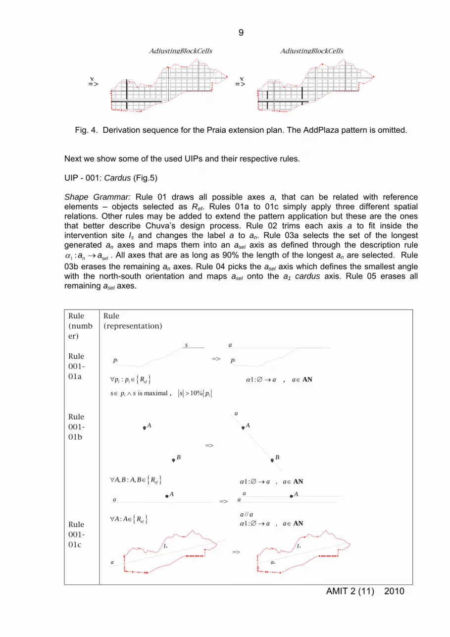
Fig. 4. Derivation sequence for the Praia extension plan. The AddPlaza pattern is omitted. Next we show some of the used UIPs and their respective rules. UIP - 001: Cardus (Fig.5) Shape Grammar: Rule 01 draws all possible axes a, that can be related with reference elements – objects selected as Ref. Rules 01a to 01c simply apply three different spatial relations. Other rules may be added to extend the pattern application but these are the ones that better describe Chuva’s design process. Rule 02 trims each axis a to fit inside the intervention site Is and changes the label a to an. Rule 03a selects the set of the longest generated an axes and maps them into an asel axis as defined through the description rule
1 :α →n sela a . All axes that are as long as 90% the length of the longest an are selected. Rule 03b erases the remaining an axes. Rule 04 picks the asel axis which defines the smallest angle with the north-south orientation and maps asel onto the a1 cardus axis. Rule 05 erases all remaining asel axes. Rule (number)
Rule (representation)
Rule 001-01a
=>pl
s a
pl
Rule 001-01b
Rule 001-01c
{ }:l l efp p R∀ ∈
is maximal
AN 1: a→ aα ∅ ∈ ,
=>
a
B
A
B
A
=>A A
aa
a
=>a an
Is Is
1: aα ∅→ a , ∈AN { }, : , efA B A B R∀ ∈
//a a1: a
α ∅→ a , ∈AN { }: efA A R∀ ∈
ls p s∈ ∧ , s 10% lp>

AMIT 2 (11) 2010
10
=>aselan
Rule 001-02 Rule 001-03a
Rule 001-03b Rule 001-04 Rule 001-05
=> Øan
=> a1asel
NN
=>asel Ø
, na a ∈AN1: na a
α →
Is is a closed polyline
na∀ ∈AN AN: 90%
Fig. 5. Rules for the pattern Cardus.
Before Decumanus is applied a street width is assigned to the Cardus (Fig.7). The rule 001-06 shown in Fig.7 is presented as an extra rule for the pattern Cardus. However, this is really a simplification of a widely applicable UIP called AssignStrTypetoAxis which assigns the role of this street in the street system depending on the defined requirements. These requirements are provided by the formulation module or by direct input from the designer. The input is requested by the memory bank MB1_PlReq in the beginning of the generation process. To avoid detailing this process we show only the rules in Fig. 7 in order to provide enough information to understand the derivation sequence. Rule 002-06 is a similar situation for a2 axes. Similar rules for a3 axes were also used although omitted
ere.
IP – 002: Decumanus (Fig.6)
le 04 assigns an a2 label and decumanus to the axis. Rule 05 erases all maining Ref.
h U Shape Grammar: Rule 01 draws perpendicular axes (p) to the cardus passing through all points labelled Ref. Rule 02 trims all p axes outside Is. Rule 03 selects from 2 available p axes the one closer to the middle point M of the cardus. The rule applies recursively until it selects only the closest to M. It can be argued that there might be other criteria for this rule but other rules may be added to the pattern in order to extend its application. This was simplified in this version of the pattern. Rure
1: selaα →∅
na∀ ∈AN
1: selaα →∅ sela∀ ∈AN
11: ;sela a cardusα →
1, ,sela a cardus∈AN
sela∀ ∈AN
if αR is minimum
sel n sel na a a a∃ ∈ < <
1: n sela a
α →

AMIT 2 (11) 2010
11
=>
Rule 002-01 Rule 002-02
Rule 002-03
Rule 002-04 Rule 002-05
a1 a1
A A
p
=>I s I s
p
pn
=>a1 a1
pa
M M
pn pn
x1 x2
m
=>
pa a2
Fig. 6. Rules for the UIP Decumanus.
The next Urban Induction Patterns relate to the generation of orthogonal grids. Non-orthogonal grids and distortions on orthogonal grids are the subject of ongoing research. During the case study analysis it became clear that there would be two different ways of producing the street grid: one by adding axes in one direction and then orthogonal axes (AddingAxes), and a second by adding block cells incrementally (AddingBlockCells) (Fig.8). We wanted to define the smallest possible set of UIPs, therefore, we considered five patterns: one to generate the main compositional axis called MainAxisistheLongerLine, which becomes Cardus in case its direction is north south ; one pattern to generate orthogonal axes, OrthogonalAxis, which is Decumanus if it is the second axis in the composition and perpendicular to Cardus; two grid induction patterns used to fill the empty spaces, AddingAxes and AddingBlockCells; and an additional pattern to define the axes hierarchy – AssignStrTypetoAxis and the associated street type (AxisHierarchya2, Promenade, etc).
6 : efRτ →∅
11: aα1: n ap p
α →
1 2:n np p x x∀ ∈ ∃ <AN, n∈ Ґ,
{ }1 1a a cardus∈ ∧ ∈AN , 1 2m a=
, np p ∈AN n∈ Ґ1: np p,
α →
Is is a closed polyline
{ }A : efA R∀ ∈
{ 11: aα
1:}1 1a a cardus∈ ∧ ∈AN pα ∅→ , 1p a⊥
21: ;ap a decumanusα →

AMIT 2 (11) 2010
12
=>
Rule 001-06
Rule 002-06
a1a1
a1 width is dependent on the options provided by MB1_PlReq (memory bank for plan requirements).
=>
a2a2
a2 width is dependent on the options provided by MB1_PlReq (memory bank for plan requirements).
Fig. 7. Additional rules for attributing a street width to the axes. Rule 001-06 is presented as an
additional rule to Cardus and rule 002-06 as an additional rule to Decumanus. However, this was simplified from a widely applicable pattern called AssignStrTypetoAxis which assigns to an
axis its role as a street in the street system. Many design variations can be obtained just with these patterns. These variations are the result of different sequences of UIPs, as well as of different applications of each UIP grammar rules, namely, different rule application sequences and parameter values. The extension plan for Praia provides an opportunity for developing design rules for over constrained design goals. Chuva had very specific ideas regarding several aspects of the plan: (1) he wanted to structure the whole plan from six main axes by aligning them with elements found in the territory; (2) he wanted to apply a very rigid grid with fixed dimensions concerning both block size and street width, which meant that the distances between axes would vary depending on street hierarchy since it determined street width. As compositional axes are aligned with site elements (e.g. a local landmark) or features (e.g. a ridge line) with divergent attributes, the complete set of design intensions became over constrained. However, Chuva overcame this problem by making iterative adjustments to drawn elements and considering those referential elements as flexible. In the case of grid design, two design strategies can be derived from this principle: in one the grid (or the block sizes) is adapted to the axes positions, and in the other the axes positions are adapted to fit the grid. Chuva follows the second strategy to keep the grid rigid, that is, equal blocks and well defined axes and alignments. He also uses fixed parameters for the block size – 80m x 50m. But, note that some of the alignments are not completely strict. For instance, a hill top landmark is not an precise reference point but a region where that point may be found. In this paper, we replicate Chuva’s design decisions. Future work will show how the same patterns can generate different style grids by manipulating the Urban Induction Patterns sequence and each pattern’s grammar. Finally, AddingAxes and AddingBlockCells produce the same result only in specific sequences and with the same block size used in the Praia plan case. If the AddingBlockCells UIP were applied with different block sizes the result would obviously be different. Although we can
21: aα 2 :a∀ { }2 2ANa a decumanus∈ ∧ ∈
1 :a∀ { } 11: aα 1 1a a cardus∈ ∧ ∈AN

AMIT 2 (11) 2010
13produce the same results with both patterns, Chuva’s plan is closer to AddingAxes and to a top down planning type, while AddingBlockCells is closer to a bottom up process. Nevertheless, we chose to show the derivation using AddingBlockCells to illustrate the potential for generating different design variations by manipulating pattern grammar rules.
UIP 003 - Rules for adding cells one by one – AddingBlockCells A A grid cell is defined by the street axes involving an urban block. The size of the grid cell (u • v) is defined by the size of the block (h • w) plus half the width of the streets surrounding it. Note that it is the block parcel being defined. The block itself might have a different geometry as long as it is part of the block parcel. Specific rules for that purpose correspond to specific UIPs.
u
v
h
w
d2d1
d4
bl
d3
During the generation of grid cells, cells are always added with a4 axes. The typical cell size in the grid will therefore be u a and
. 4 _ width h= +
4 _ widthv a w= +
The following rules adjust the position of an axis so that it fits the grid defined by the cells generated during the cell generation sequence. They allow re-adjusting the compositional axes in a regular grid. In these rules the dashed lines represent elements that are really not part of the rule, but that allow for a better understanding of it by giving the dashed element as a graphic reference. Likewise, the doted lines in the right hand side of the rules shows the relative position of the elements erased by the rule.
B Rule 1 - places 4 � labels in the crossing of an and an+1 axes to start the generation process; it chooses the least n value, i.e. it takes an a1 if present in the bounded area where it applies otherwise searches for the smallest n value.
=>an
an+1
an
an+1
Rule 2 - erases � label next to a crossroads defined by two axes of the type an and an+1, inserts a block with two a4 axis segments and places two more � labels to continue the generation
1 2/ 2 / 2u d h d= + +
3 4/ 2 / 2v d w d= + +
{1 }n ,2,3∈

AMIT 2 (11) 2010
14
=>an
an+1
d3
d4d1
d2
a4
a4
u
v
an
an+1
Rule 3 - erases � label next to a crossroads defined by two axes of the type (horizontal) an and (vertical) a4, inserts a block with two a4 axis segments and places two more � labels to continue the generation
=>d3
d4
a4
an an d2
a4 a4
d4
u
v
a4
Rule 4 - erases � label next to a crossroads defined by two axes of the type (vertical) an and (horizontal) a4, inserts a block with two a4 axis segments and places one more � label to continue the generation
=>
an
a4
an
a4
d3
d4d1
a4
a4
d3
u
v
Rule 5 - erases � label next to a (vertical) a4 axis, inserts a block with two a4 axis segments and places one more � label to continue the generation
1 _ / 2n widthd a 2 1_ / 2n widthd a += = {1,2,3}n∈
3 4 / 2widthd a 4 4 / 2widthd a= =
1 4u d h d+ + 2 3v d w d= = + + l and h are respectively the block length and width
2 _ / 2n widthd a {1,2,3}n= ∈
3 4 / 2widthd a 4 4 / 2widthd a= =
42u h d= + 2 3v d w d= + + l and h are respectively the block length and width
1 _ / 2n widthd a {1,2,3}n= ∈
3 4 / 2widthd a= 4 4 / 2widthd a=
1 4u d h d
+ + 32v w d= = + l and h are respectively the block length and width

AMIT 2 (11) 2010
15
=>
d3
d4
a4 a4
a4
a4
d4
u
v
Rule 6 - erases � label next to a (horizontal) a4 axis, inserts a block with two a4 axis segments and places one more � label to continue the generation
=>
d3
d4
a4 a4
a4
a4
d4
d3
u
v
Rule 7 - erases � labels falling outside the bounded area or intervention site limit.
=> Ø ∀ � sI⊄
where Is is the Intervention Site Limit Rule 8 - Trims axes outside the intervention site. The label Is indicates the inside side of Is polygon.
=>a4
Is
a4
Is
4 s a I∀ ∩
where Is is the Intervention Site Limit Rule 9 - Erases axes outside the intervention site.
=>a4
Ø
4 s a I∀ ⊄
where Is is the Intervention Site Limit All symmetrical rule arrangements may be applied.
3 4 / 2widthd a 4 4 / 2widthd a= =
42u h d= + 32v w d= + l and h are respectively the block length and width
3 4 / 2widthd a 4 4 / 2widthd a= =
42u h d= + 32v w d= + l and h are respectively the block length and width
Fig. 8. A – grid cell definitions; B – AddingBlockCells rules.

AMIT 2 (11) 2010
16
UIP 004 - Rules for adding blocks to cells – AddBlocktoCells Rule 1 - Inserts a block between any 4 axes.
=> bl
d3
d4d1
d2
an'
an
an''
an'''
an'
an
an''
an'''
Rule 2 - Inserts a block between any 3 axes in an incomplete cell.
=> bl
d1 an'
an
an''
an'
an
d3d2
an''
I s I s
Rule 3 - Inserts a block between any 2 axes in an incomplete cell.
=>bl
d1
an
an''
an
d3
an''
I s I s
1 _ / 2n widthd a= '2 _ / 2n widthd a=
''3 / 2n width= '''
4 / 2n widthd a=
, na∀ {1,2,3,4}n∈:
d a ,
1 _ / 2n widthd a= '2 _ / 2n widthd a=
''3 _ / 2n widthd a=
, na∀ {1,2,3,4}n∈:
Fig. 9. AddBlocktoCells rules.
UIP 005 - Rules for adjusting blocks that fall outside the boundary – AdjustingBlockCells Rule 1 - Reduces the size of a block so that it fits inside the bounded area giving an additional buffer area corresponding to the width of the street an which is coincident with the border.
=> s
an an
1 _ / 2n widthd a= ''3 _ / 2n widthd a=na∀ {1,2,3,4}n∈ , :
_ / 2n widths a {1,2,3,4}n= ∈

AMIT 2 (11) 2010
17
Rule 2a - Reduces the size of a block so that it fits inside the bounded area - when no street is coincident with the border line
=>
Is I s
Rule 2b - Reduces the size of a block so that it fits inside the bounded area and creates an a4 street
=>
Is I s
s
a4
Rule 3 - Reduces the size of a block so that it fits inside the bounded area giving an additional buffer area corresponding to the width of the street an which is coincident with the border
=>an an s
Rule 4 - Reduces the size of a block so that it fits inside the bounded - when no street is coincident with the border line
=>
wsI s I s
Next rules are optional. Some sets of rules are mandatory although only one of the rules in the set may be applied - in this sense those are options for a mandatory set of rules. Rules 5-7 are a mandatory set for eliminating very small blocks - below standard values. Rule 5 - Erases small blocks
=>ws Ø
4 _ widths a=
_ / 2n widths a {1,2,3,4}n= ∈
ws>12m
This value is an open variable defined by the memory bank. 12m is the value used by Chuva.
If block area is smaller than 10% of the regular block size or smaller than a prefixed minimum block area or ws<12m

AMIT 2 (11) 2010
18
Instead of erasing them, small blocks can be joined with others through rules: Rule 6 - Joining small blocks - joining below minimum block with another incomplete block
=>ws
Rule 7 - Joining small blocks - joining below minimum block with complete block
=>
ws
Incomplete blocks can be joined together even when none of them is below the minimum block size. Rule 8 - Joining small blocks - joining below minimum block with complete block
=>
If block area is smaller than 10% of the regular block size or smaller than a prefixed minimum block area or ws<12m
Fig. 10. Rules for adapting the blocks falling outside the bounded area making them fit inside it. UIP 006 - Rules for adjusting main axes to grid cells – AdjustingAxistoCells Rule 1 – Adjusts axis to the right side of cell – Whenever there is an axis an such that and d >0 then an is moved from its ori/ 2d u≤ ginal
position and re-positioned at a t positive distance from its previous position. The a4 axis parallel to an is erased and the a4 perpendicular is scaled from size u to size ut.
If block area is smaller than 10% of the regular block size or smaller than a prefixed minimum block area or ws<12m

AMIT 2 (11) 2010
19
=>
a4
an
d
a4
a4
u
v
an
t
ut
v
Rule 2 – Adjusts axis to the left side of cell – Whenever there is an axis an such that and/ 2d u> d u< then an is moved from its original position and re-positioned at a t negative distance from its previous position. The labeled a4 axis parallel to an is moved a wa positive distance as well as the block, the vertical a4 axis on the left side of an is erased and the a4perpendiculars are scaled from size u to size ut.
=>d
a4
a4
u
v
an
a4
a4
d
a4
a4
ut
v
an
a4
a4
u ut
twa wa
wa
All symmetrical rule arrangements may be applied.
, {1,2,3}: / 2 0na n d u d∀ ∈ ≤ ∧ >
4 _ widthu a h= +
4 _ widthv a w= +
4 _ _/ 2 / 2t width n widthu a h a= + +
4 _ _/ 2 / 2width n widtht d a a
= − + :
Fig. 11. Rules for adjusting main axes to grid cells – AdjustingAxistoCells.
The above example is incomplete due to space constraints. The underlying idea is to show that we can encode design operations into formalisms that can be used for a generative exploration of design solutions. In our research we have found that it is possible to produce different designs with the same UIPs by manipulating their sequence and their rules and to get to similar results using different UIPs (Beirao et al, 2009, forthcoming).The important outcome of these findings is that the use of UIPs can support the creation of different urban design languages. The integration of such a generative design module with formulation and evaluation modules will constitute the foundation for a City Information Model (CIM) system. 4.2. The role of City Induction in monitoring urban planning and design The implementation of urban plans, especially the large scale ones, can be very slow and time consuming processes that may take many years from the initial programme formulation to the final physical implementation. It is not uncommon to find that some of the first assumptions have changed with time, sometimes as consequence of the beginning of the plan implementation. Monitoring plans should, therefore, have a more active role than usually has; but above all,
, {1,2,3}: / 2na n d u d u∀ ∈ > ∧ <
4 _ widthu a h= +
4 _ widthv a w= +
4 _ / 2t width au a h w= + + _ / 2a n widthw a=
4 _ / 2widtht u d a
,
= − +
4 : t→a u u (for the 2 horizontal a4 axes)
4 ta u u→

AMIT 2 (11) 2010
20allowing the plan to accommodate new requirements that emerge during the process should be a regular procedure. Usually, this is not done because it implies reviewing the plan, and redoing a lot of work. By using generative tools, one can augment one’s own designing capabilities. Designs can be easily changed and regenerated, by manipulating generative rules. Regeneration can be total or partial. City Induction’s generative module allows redesigning or partially redesigning plans while maintaining design principles and planning goals and, therefore, making it possible to rapidly readjust designs to new inputs or requirements. The proposed connection of the generative module with the formulation and evaluation modules opens the possibility of simultaneously revaluating the programme and the redesigned solutions. The formulation of urban programmes is conceived to increase qualitative inputs, by reducing ambiguities, through a flexible automated process applied to urban planning. It takes into account strategies, regulations, guidelines, site features, and furthermore, the social, cultural and economic characteristics of the population. Due to the complexity of the urban environment, an overall perception of its phenomena requires an ontological representation. This will enable one to construct clear diagrammatic representations of urban environments (Montenegro and Duarte, 2008). It also will allow one to describe and classify the various aspects related to the formulation process, in order to identify design requirements and develop the design-brief, thereby specifying the core ingredients of the future plan. The urban formulation model consists of three basic components:
1. The first component (Data) corresponds to the set of relevant information that can be gathered towards building a description of the plan’s targets and development vision. It corresponds to the set of contextual information collected on both the site and the population, as well as on client features, requirements, or ideas about the future development. The Data set defines the Input component of the model.
2. The second component (Interpreter) corresponds to the core of the formulation model,
and it constitutes the mechanism that links contextual data to programmatic descriptions, which will define the plan’s ingredients in the form of design patterns. The mechanism is activated by feeding it with the mentioned data and then processing and interpreting it until defining the programmatic descriptions.
3. The third component (Programme) is the set of design specifications, requirements
patterns that constitute the design brief. This aims at summarizing the previous data components, filtered by the interpreter, and controlled by the classes of information defined in the ontology. Herein the data is organized in a hierarchic structure ready to use by the generation module. The specifications thus are the output component of the formulation module and the input of the generation one.
The evaluation module effectively simulates the future outcomes of design decisions at various levels, from infrastructural and environmental to socio-economic, thus guiding the design towards a more adequate solution according to the original urban development vision. Such an evaluation system can support the large scale urban planning process in two stages: in the production of the initial plan and in the monitoring of its physical implementation. The role of evaluation at the start is essential to provide a plan that is more responsive to its context and one that meets the requirements set out by the urban programme. In particular, it plays an important role in defining the most elemental aspect of urban plans, urban layout and configuration, which determines much about its sustainability (TCPA, 2007). Urban layout is the scaffolding around which the design process develops, when very little is still known about the details of the plan, and over time becomes the most costly aspect to change, economically,

AMIT 2 (11) 2010
21politically and socially. Performing spatial analysis on this elemental component in the early stages is essential (Marshall, 2005; Hillier et al, 1983). As the plan develops and gets implemented, the evaluation module supports a continuous process of monitoring its detail in terms of the finer components such as urban blocks and buildings, with data about population, land use, construction indices, construction materials and cost. This evaluation verifies whether what is planned still meets the requirements of the development vision, in light of what has been achieved so far. And where it fails to meet such requirements, because the context of the plan changes naturally over time, namely as a consequence of the new elements that have been introduced, the evaluation module can guide the re-design of the plan towards valid updated solutions. The changes might only affect detail aspects such as building densities and land-use, but at this more advanced stage are essential to ensure the socio-economic viability of the plan, and thus its future sustainability. In this line of thought, the City Induction project aims at integrating these three main components of the urban design process: programme formulation, design generation, and programme and design evaluation. The three modules should be able to provide what one could call a City Information Model (CIM) system by analogy with BIM (Building Information Model) systems. Furthermore, the more complex the urban systems are, the greater the need we have for a good CIM system and for a tool providing a controlled re-adaptation of design solutions. The next section will develop further these ideas. 5. City Induction, the complexity of global cities and sustainability driven planning Charles Correa in his urban manifesto (1999) indicates three motifs to praise cities. The first is ‘cities generate the skills we need for development’. This is supported by the fact that cities are responsible for producing knowledge by forming specialized professionals for our society. The second motif is ‘cities are centres of hope’ where people expect to find the best opportunities for their future. And third one is ‘cities are engines of economic growth’ because they can create funds for their own development and surrounding areas. Based on these arguments, he supports the idea that cities will continue growing, particularly in developing countries. Focusing on the case of India, he also stresses that housing in the third world should comply with eight main concepts: incrementality, pluralism, malleability, participation, income generation, equity, open-to-sky space and disaggregation. The idea is that housing should be developed by many different systems, be participated by the users, provide flexible and incremental solutions, and also create the means to generate commercial activities thereby providing, in his words, income generation. Flexibility and change is the whole point of the argument. Correa’s own work is full of examples of housing plans and city extensions showing solutions satisfying the concepts he supports. However, the planned systems often get a bit out of control, although including rules to avoid undesired developments. The City Induction approach seems to be a desirable way to tackle incrementality and flexibility, not only concerning formal incremental development, but also functional adaptability and infrastructural management. Evolutionary implementation based on culturally supported construction units is indeed pointed as a design strategy. The distinguishable ‘fractality’ of some of Correa’s designs clearly reveals a strongly ruled design system capable of having different evolutionary responses while keeping culturally inspired formal relations. These design systems can be easily encoded into shape grammars and applied in urban planning with a generative support tool. The capacity of shape grammars to encode design styles largely supports this argument (Stiny and Mitchell, 1978; Koning and Eizenberg, 1981). Evaluation tools can provide information about the saturation of a design system in a planned area giving an insight on how to plan many centres (Correa, 1999; Alexander et al, 1977) and their relationships among the larger city structure.

AMIT 2 (11) 2010
22What City Induction aims at, is to provide the means for incremental planning, by continuously considering information on the programme requirements and design options, while yielding feedback on the qualities of the solutions provided by the evaluation module. As referred to in Section 3, City Induction follows a four phase design sequence. This sequence conducts the design process through four different scales of the urban design problem from large territorial scale to detail scale (Beirão, 2005). In this work it is also shown that this approach allows for developing many different local approaches while maintaining the larger scale design principles. Furthermore, depending on the sequence in which rules are applied, we may have bottom-up developments. Figure 2a shows a good example of such a situation, a plan generated by the incremental arrangement of 4 block units. Some of Correa’s designs obey to similar conceptual rules and could be planned through similar processes. Duarte’s Malagueira grammar (2001) stands also as a good example for implementing customizable housing units in a planned area. Furthermore, the formulation module can be used to implement diverse criteria on sustainability matters by defining programmatic requirements that take them into consideration and thus, guiding design generation into more sustainable solutions. City Induction’s formulation module, by being responsible for developing context dependent urban programmes, is able to insert and read as context, the incrementally built parts that are added to that context during the physical implementation of the plan. Finally, the use of UIPs permits to identify design procedures that respond to specific contextual requirements. They are intended as a tool to support designers in the development of contextualized urban programmes, in the design of urban spaces and in the evaluation of design solutions using the design generation capabilities of shape grammars to generate candidate solutions. The use of different UIPs in different contexts is likely to generate different solutions while guaranteeing order and maintaining the principles embedded in the development vision such as the ones defined by Correa. 6. Conclusions and future work The ultimate goal of the City Induction project is a computer platform encompassing modules for formulating, generating and evaluating urban designs. The project is still in the beginning stages of its development and a many research questions are still to be answered. Work has mainly focused on the development of a common structure for the three modules, including the underlying ontology, which will create the basis for a City Information Model. The resulting platform is expected to function both as a design tool and a monitoring tool, able to support urban planning from scratch to physical implementation. City Induction aims to integrate a large body of knowledge into a single urban planning design, and participation support tool, by gathering programme formulation methodologies, generative design systems, and urban evaluation processes. This tool is expected to support decision-making on various levels and by different participants involved in urban planning processes. Planning is enabled because the formulation module allows for the specification of an adequate development vision. Design is supported because the generative module facilitates the generation of alternative solutions to be assessed by the evaluation module, thereby making it possible for the designer to find solutions that best fit the planning goals. Participation is fostered by showing alternative solutions to other participants in the process, such as planners, municipalities, developers, and users, and so takes their feedback into account. In summary, City Induction can be used as a planning, design, and participatory tool, by combining both top-down and bottom up planning approaches. The generation module of City Induction uses shape grammars in a novel way, by using them to encode the concept of Urban Induction Patterns, that is, recurrent urban design operations that originate urban features and spaces found frequently in urban environments. This allows for the use of shape grammars during exploratory design phases. The underlying idea is to start the design with a very general shape grammar that can be used to define a potentially very large

AMIT 2 (11) 2010
23set of specific grammars. These specific grammars can be defined first by selecting certain patterns over others and then by controlling the rule application parameters in the grammars that encode the selected patterns. Therefore, the synthesis of new grammars is a sequence of the decisions made by the designer along the design process. The general grammar does not cover all the possible design solutions but we believe that it covers to the big majority of current design solutions and it may be extended by enlarging the set of available urban induction patterns. The next stage of the project will address the computer implementation of Urban Induction Patterns, which will permit to test and debug the model proposed for the generation system. Subsequent stages will be concerned with testing its applicability with a specific case study. This work will permit to determine to which extent a designer can freely explore design solutions by manipulating a small set of Urban Induction Patterns, and when and how s/he will need to create new ones. It also will permit to find out how City Induction can be used by the various stakeholders in city planning to generate plans and monitor its implementation. Acknowledgements The City Induction project is funded by Fundação para a Ciência e Tecnologia (FCT), Portugal (PTDC/AUR/64384/2006), hosted by ICIST at TU Lisbon, and coordinated by José P. Duarte. J.N. Beirão, J. Gil and N. Montenegro also are funded by grants SFRH/BD/39034/2007, SFRH/BD/46709/2008 and SFRH/BD/45520/2008 from FCT. Beirão, Gil, and Montenegro are responsible for the generation, the evaluation, and the formulation modules, respectively. We would like to thank Rudi Stouffs, Henco Bekkering, Sevil Sariyildiz, Frank van der Hoeven, Vincent Nadin and Stephen Read for their readings, comments and support. References
1. Alexander, C Ishikawa, S Silverstein M: 1977, A Pattern Language: Towns, Buildings, Construction, Oxford University Press, New York.
2. Beirão, JN: 2005, Gramáticas Urbanas (Urban Grammars), Master Thesis, ISCTE,
Lisbon, available at http://www.bquadrado.com/paginas_web/targets/grammars.html
3. Beirão, J, Duarte, J and Stouffs, R, 2008, Structuring a Generative Model for Urban Design: Linking GIS to Shape Grammars, Architecture in Computro - 26th eCAADe Conference Proceedings, Antwerpen, pp. 929-938.
4. Beirão, JN and Duarte, JP: 2009, Urban Design with Patterns and Shape Rules, in EH
Stolk and M Brömmelstroet, (eds), Model Town – Using Urban Simulation in New Town Planning, Almere.
5. Beirão, J, Duarte, J and Stouffs, R, 2009a, An Urban Grammar for Praia: Towards
Generic Shape Grammars for Urban Design, Computation: The New Realm of Architectural Design [27th eCAADe Conference Proceedings / ISBN 978-0-9541183-8-9] Istanbul (Turkey) 16-19 September 2009, pp. 575-584
6. Beirão, J, Duarte, J and Stouffs, R, 2009b, Grammars of designs and grammars for
designing - grammar-based patterns for urban design, T. Tidafi and T. Dorta (eds) Joining Languages, Cultures and Visions: CAADFutures 2009, PUM, http://cumincad.scix.net/cgi-bin/works/Show?cf2009_890
7. Correa, Charles: 1999, Housing and urbanisation. London: Thames & Hudson.
8. Duarte, J.P.: 2001, Customizing mass housing: a discursive grammar for Siza’s
Malagueira houses. PhD Dissertation, Massachussets Institute of Technology.

AMIT 2 (11) 2010
24
9. Duarte, JP: 2005, A Discursive Grammar for Customizing Mass Housing: the case of Siza's houses at Malagueira, Automation in Construction, 14 (2): 265-275.
10. Friedman, A: 1997, Design for Change: Flexible Planning Strategies for the 1990s and
Beyond, Journal of Urban Design, 2, 3, 277-295.
11. Gamma, E, Helm R, Johnson R and Vlissides J: 1995, Design Patterns: Elements of Reusable Object-Oriented Software, Addison-Wesley, Reading, MA.
12. Gil, J and Duarte, JP, 2008, Towards an Urban Design Evaluation Framework,
Architecture in Computro - 26th eCAADe Conference Proceedings, Antwerpen, pp. 257-264.
13. Gruber, T. B.: 1993, A translation approach to portable ontology specifications,
Knowledge Acquisition, 5(2), pp. 257-267
14. Hillier B, Hanson J, Peponis J, Hudson J and Burdett R: 1983, Space syntax, Architects Journal 178(48): 67-75.
15. Koning H, Eizenberg J, 1981, "The language of the prairie: Frank Lloyd Wright's prairie
houses" Environment and Planning B 8(3) 295-323.
16. Marshall, S: 2005, Streets and Patterns: The Structure of Urban Geometry, Ed. Taylor & Francis.
17. Montenegro, NC and Duarte, JP: 2008, Towards a Computational Description of Urban
Patterns, Architecture in Computro - 26th eCAADe Conference Proceedings, Antwerpen, pp. 239-248.
18. Neufert, P: 2004, Arte de projectar em arquitectura. Barcelona, Editorial Gustavo Gili,
ISBN: 84-252-1900-0.
19. Pedro, JB: 2002, Programa Habitacional, vol.4 – Vizinhança Próxima, (Housing program, vol.4 – Close neighbourhood), LNEC, Lisbon.
20. Portugali J: 2000, Self-Organization and the City, Springer, 1565 Heidelberg.
21. Schon, DA: 1983, The Reflective Practitioner: How Professionals Think in Action. New
York, Basic Books.
22. Steiner, F and Butler K: 2007, Planning and Urban Design Standards, John Wiley & Sons, Inc.
23. Stiny, G and Gips J: 1972, Shape Grammars and the Generative Specification of
Painting and Sculpture, Information Processing, 71: 1460-1465.
24. Stiny, G: 1980, Introduction to shape and shape grammars, Environment and Planning B: Planning and Design, 7: 343-351.
25. Stiny, G: 1981, A note on the description of designs, Environment and Planning B:
Planning and Design, 8: 257-267.
26. Stiny, G and Mitchell, WJ: 1978, The Palladian grammar, Environment and Planning B: Planning and Design, 5(1): 5-18.

AMIT 2 (11) 2010
2527. Town and Country Planning Association (TCPA) and Lock, D.: 2007, Eco-towns: scoping
report, helping to deliver a step change in the quality and availability of homes for the people of England, TCPA, UK.
Copyright © 2022 FDOKUMEN