ENERGY ASSISTANTS MATERIAL ENGLISH P (1).pdf
145
1
-
Upload
khangminh22 -
Category
Documents
-
view
4 -
download
0
Transcript of ENERGY ASSISTANTS MATERIAL ENGLISH P (1).pdf
1
1
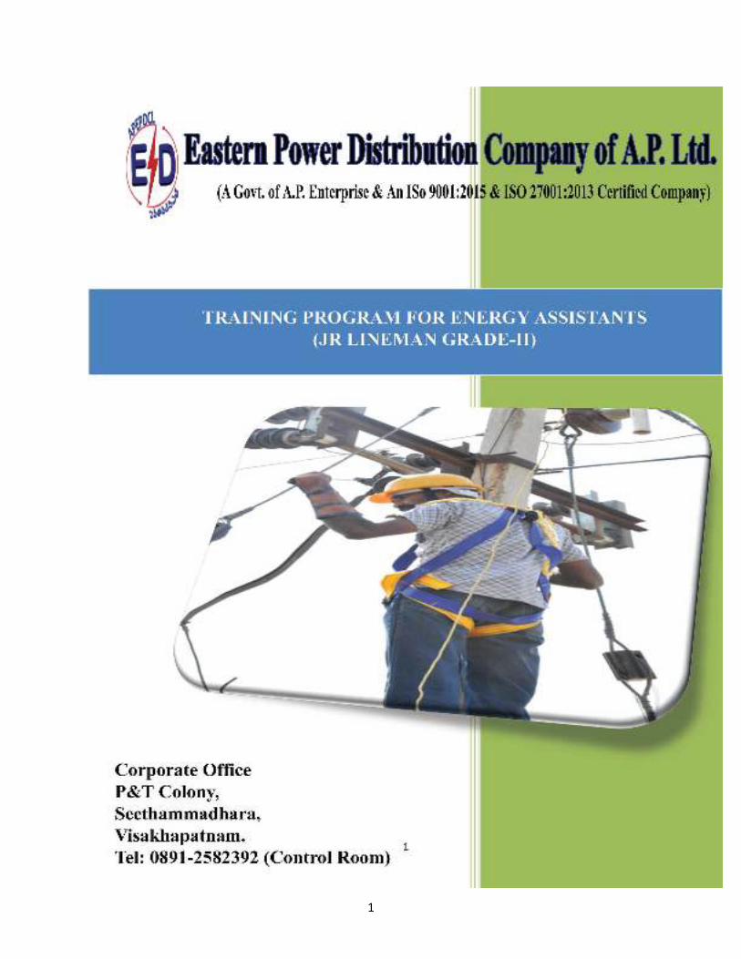
INDEX
SI. No. Particulars Page Nos.
1 Duties and Responsibilities of Energy Assistants (Jr Lineman Gr-II) 2
2 Basic of Electricity and AT & C Losses 4
3 Electricity Act,2003 17
4 Line Construction, Commissioning of new line 22
5 Line Inspection & Maintenance 42
6 Safety Requirements for overhead lines, Underground Cables 47
7 Earthing, Earth Tester & Earth Resistance 54
8 Transformers erection, maintenances & Fuse Grading 60
9 Basics of Metering, Types of Meters 78
10 Types of Cables including AB Cables and Control Cables 86
11 Safety and First Aid 95
12 Fire Fighting Equipments 120
13 Personal protective equipments and Behavioral based safety 126
14 Customer Relations Management & Communication Skills 128
15 Tariffs and Schemes 135

2
CHAPTER – 1
Duties and Responsibilities of Energy Assistants (Jr Lineman Gr-II)
a) Ensuring New power connections to the poor households as per the data collected by the Village Volunteers.
b) Identification of power supply problems, short circuits points and transformers failures to run the Water Supply Schemes effectively.
c) Identification of street lights without meters and without switching points and erections.
d) Controlling unauthorized power use by the households.
e) Reconciliation of monthly power bill and actual consumption and suggest ways to reduce power bill.
f) He shall be the store in-charge for O&M related to street lights and water supply schemes maintenance.
g) Identification of loose and hanging wires to avoid the power breakdowns and unforeseen accidents.
h) Regular tree cutting for proper power supply and identification of damaged poles and inform the same to Electricity Department for rectification.
i) Awareness creation on Energy efficient practices
j) All grievances related to street lights shall be redressed by utilizing the services of electrical worker available in the village with the supporting of Panchayat Secretary.
k) The energy assistant shall monitor the O&M complaints regarding LED lights along with the concerned agency.
l) Maintenance of transformers in coordination with the Electricity Department
m) Meter reading of L.T. services, recording and submission when entrusted to him.
n) Disconnection and reconnection of services as and when ordered by the Assistant Engineer/Operation of the section concerned.
o) Helping DISCOM staff in releasing of new services.
p) Helping the DISCOM staff in patrolling the L.T. Lines, rectification of defects and maintenance.
3
q) Noticing and reporting of direct tapings, cases of pilferage of energy and other malpractices notice in his jurisdiction, to the Lineman of the area concerned.
r) Switch ON/OFF street lights.
s) Assistance in transformer and other equipment maintenance.
t) All other works entrusted by the superior officers from time to time apart from fuse off calls, breakdowns and consumer complaints should be obeyed by the Energy Assistant Grade-II.
u) Should maintain a diary of work done every day to be reviewed by the Village Panchayath Authorities.
v) In emergencies, jurisdictions should not be observed and all staff have to rise as one man to tackle the emergency and work to restore total normalcy.
w) Energy Assistants Grade-II should uphold dignity and image of the DISCOM in the public and strive hard for the benefit of the DISCOM and consumer satisfaction.
x) Any other work(s) entrusted to him by the superiors of DISCOM or by the Village Panchayath authorities.
y) Each Energy Assistant should maintain a diary of work done each day for review by the Village Panchayath Authorities/ Section Officers.
z) JLM Grade 2 candidates have to attend to the works related to Gram Panchayath and Meter readings etc.
4
CHAPTER – 2
BASICS OF ELECTRICITY AND AT & C LOSSES
ELEMENTS OF AN ATOM:
All matter is made up atoms. Atoms have a nucleus with electrons in motion around it. The
nucleus is composed of protons and neutrons. Electrons have a negative charge (-). Protons have a
positive charge (+). Neutrons are neutral. In the normal state of an atom, the number of electrons is equal
to the number of protons and the negative charge of the electrons is balanced by the positive charge of the
protons.
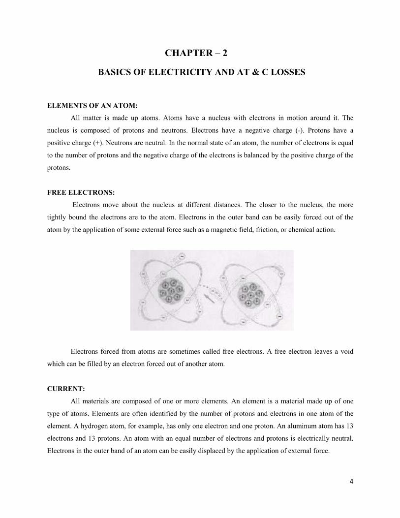
FREE ELECTRONS:
Electrons move about the nucleus at different distances. The closer to the nucleus, the more
tightly bound the electrons are to the atom. Electrons in the outer band can be easily forced out of the
atom by the application of some external force such as a magnetic field, friction, or chemical action.
Electrons forced from atoms are sometimes called free electrons. A free electron leaves a void
which can be filled by an electron forced out of another atom.
CURRENT:
All materials are composed of one or more elements. An element is a material made up of one
type of atoms. Elements are often identified by the number of protons and electrons in one atom of the
element. A hydrogen atom, for example, has only one electron and one proton. An aluminum atom has 13
electrons and 13 protons. An atom with an equal number of electrons and protons is electrically neutral.
Electrons in the outer band of an atom can be easily displaced by the application of external force.

5
The flow of free electrons in a material from one atom to the next atom in the same direction is
referred to as current and is designated by the symbol I.
The amount of current flowing is determined by the number of electrons that pass through a
cross-section of a conductor in one second. It takes about 1024 atoms to fill one cubic centimeter of a
copper conductor. Current is measured in amperes, often shortened to amps. The letter A is the symbol for
amps. A current of one amp means that in one second about 6.24 x 10¹⁸ electrons move through a cross-
section of conductor.
VOLTAGE:
The force required to make electricity flow through a conductor is called a difference in potential,
electromotive force (emf), or voltage. Voltage is designated by the letter E or the letter V. The unit of
measurement for voltage is the volt which is also designated by the letter V. A voltage can be generated in
various ways. A battery uses an electrochemical process. A car’s alternator and a power plant generator
utilize a magnetic induction process. All voltage sources share the characteristic of an excess of electrons
at one terminal and a shortage at the other terminal. This results in a difference of potential between the
two terminals. For a direct current (DC) voltage source, the polarity of the terminals does not change, so
the resulting current constantly flows in the same direction.
6
RESISTANCE:
A third factor that plays a role in an electrical circuit is resistance. All material impedes the flow
of electrical current to some extent. The amount of resistance depends upon the composition, length,
cross-section and temperature of the resistive material. As a rule of thumb, the resistance of a conductor
increases with an increase of length or a decrease of cross-section. Resistance is designated by the symbol
R. The unit of measurement for resistance is the ohm.
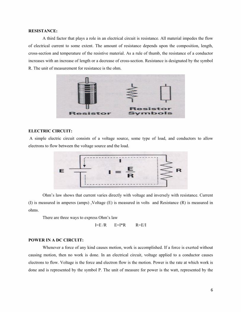
ELECTRIC CIRCUIT:
A simple electric circuit consists of a voltage source, some type of load, and conductors to allow
electrons to flow between the voltage source and the load.
Ohm’s law shows that current varies directly with voltage and inversely with resistance. Current
(I) is measured in amperes (amps) ,Voltage (E) is measured in volts and Resistance (R) is measured in
ohms.
There are three ways to express Ohm’s law
I=E /R E=I*R R=E/I
POWER IN A DC CIRCUIT:
Whenever a force of any kind causes motion, work is accomplished. If a force is exerted without
causing motion, then no work is done. In an electrical circuit, voltage applied to a conductor causes
electrons to flow. Voltage is the force and electron flow is the motion. Power is the rate at which work is
done and is represented by the symbol P. The unit of measure for power is the watt, represented by the
7
symbol W. In a direct current circuit, one watt is the rate at which work is done when 1 volt causes a
current of 1 amp.
From the basic formula, power = current *voltage.
ALTERNATING CURRENT:
The supply of current for electrical devices may come from a direct current (DC) source or an
alternating current (AC) source. In a direct current circuit, electrons flow continuously in one direction
from the source of power through a conductor to a load and back to the source of power. Voltage polarity
for a direct current source remains constant. DC power sources include batteries and DC generators. By
contrast, an AC generator makes electrons flow first in one direction then in another. In fact, an AC
generator reverses its terminal polarities many times a second, causing current to change direction with
each reversal.
AC SINE WAVE:
Alternating voltage and current vary continuously. The graphic representation for AC is a sine
wave. A sine wave can represent current or voltage. There are two axes. The vertical axis represents the
direction and magnitude of current or voltage. The horizontal axis represents time. When the waveform is
above the time axis, current is flowing in one direction. This is referred to as the positive direction. When
the waveform is below the time axis, current is flowing in the opposite direction. This is referred to as the
negative direction. A sine wave moves through a complete rotation of 360 degrees, which is referred to as
one cycle. Alternating current goes through many of these cycles each second.
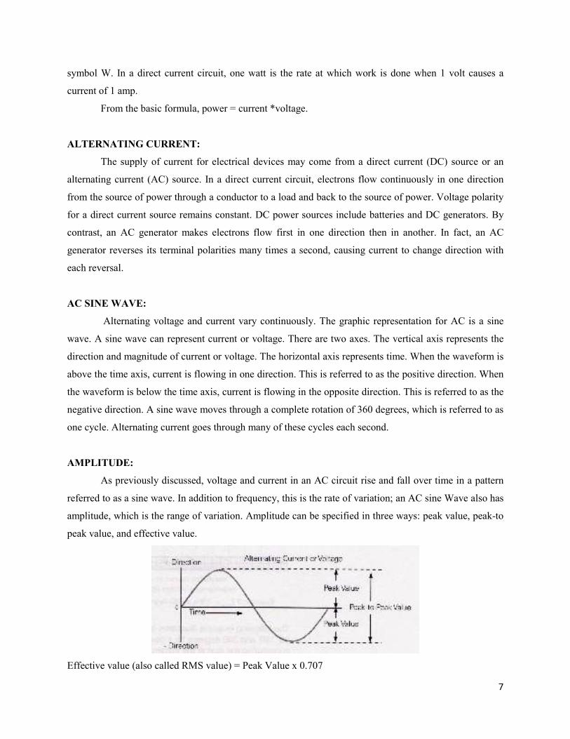
AMPLITUDE:
As previously discussed, voltage and current in an AC circuit rise and fall over time in a pattern
referred to as a sine wave. In addition to frequency, this is the rate of variation; an AC sine Wave also has
amplitude, which is the range of variation. Amplitude can be specified in three ways: peak value, peak-to
peak value, and effective value.
Effective value (also called RMS value) = Peak Value x 0.707
8
The peak value of a sine wave is the maximum value for each half of the sine wave. The peak-to-
peak value is the range from the positive peak to the negative peak. This is twice the peak value. The
effective value of AC is defined in terms of an equivalent heating effect when compared to DC.
Instruments designed to measure AC voltage and current usually display the effective value. The effective
value of an AC voltage or current is approximately equal to 0.707 times the peak value. The effective
value is also referred to as the RMS value. This name is derived from the root-mean-square mathematical
process used to calculate the effective value of a waveform.
INSTANTANEOUS VALUE:
The instantaneous value is the value at any one point on the sine wave. The voltage waveform
produced as the armature of a basic two-pole AC generator rotates through 360 degrees is called a sine
wave because the instantaneous voltage or current is related to the sine trigonometric function.
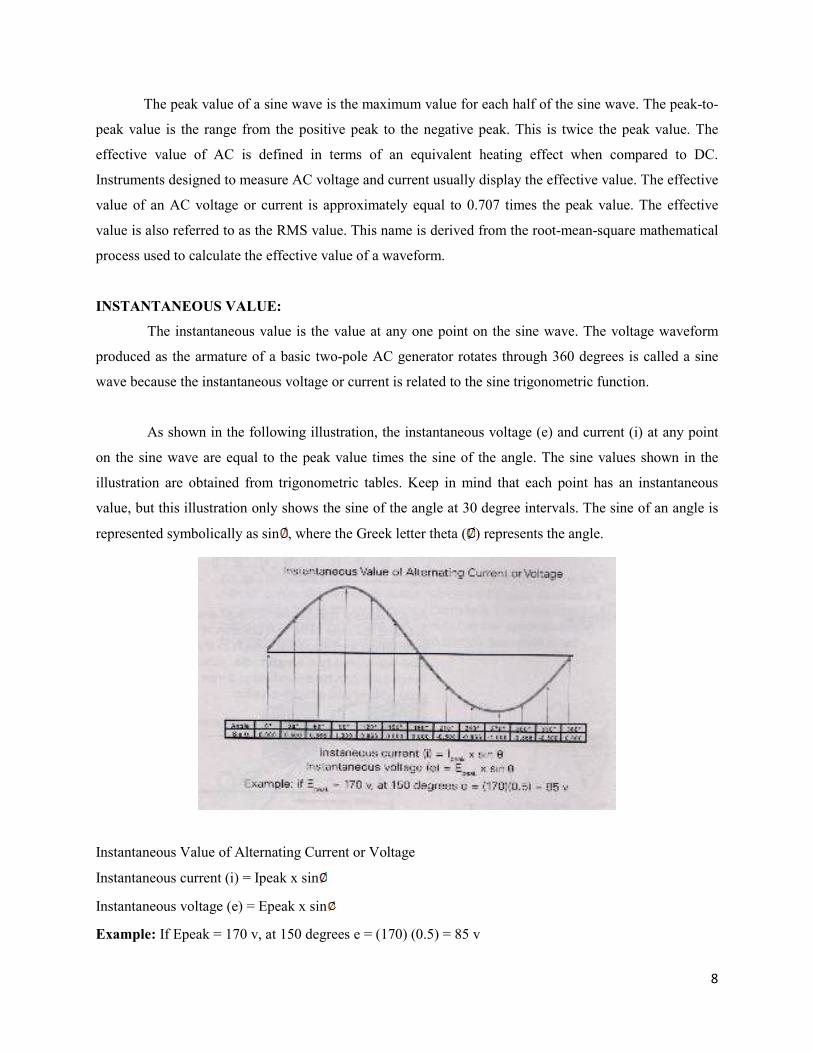
As shown in the following illustration, the instantaneous voltage (e) and current (i) at any point
on the sine wave are equal to the peak value times the sine of the angle. The sine values shown in the
illustration are obtained from trigonometric tables. Keep in mind that each point has an instantaneous
value, but this illustration only shows the sine of the angle at 30 degree intervals. The sine of an angle is
represented symbolically as sin , where the Greek letter theta ( ) represents the angle.
Instantaneous Value of Alternating Current or Voltage
Instantaneous current (i) = Ipeak x sin
Instantaneous voltage (e) = Epeak x sin
Example: If Epeak = 170 v, at 150 degrees e = (170) (0.5) = 85 v
9
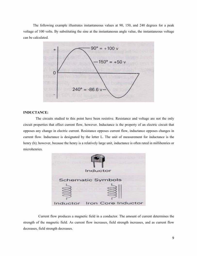
The following example illustrates instantaneous values at 90, 150, and 240 degrees for a peak
voltage of 100 volts. By substituting the sine at the instantaneous angle value, the instantaneous voltage
can be calculated.
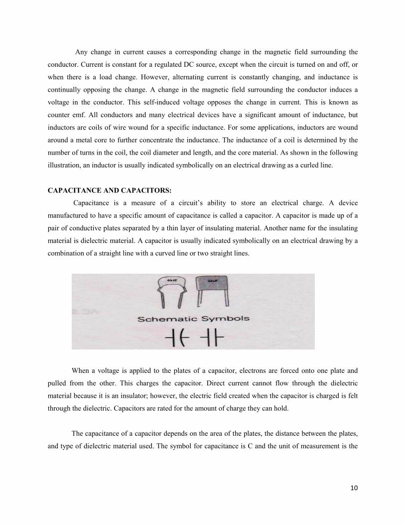
INDUCTANCE:
The circuits studied to this point have been resistive. Resistance and voltage are not the only
circuit properties that effect current flow, however. Inductance is the property of an electric circuit that
opposes any change in electric current. Resistance opposes current flow, inductance opposes changes in
current flow. Inductance is designated by the letter L. The unit of measurement for inductance is the
henry (h); however, because the henry is a relatively large unit, inductance is often rated in millihenries or
microhenries.
Current flow produces a magnetic field in a conductor. The amount of current determines the
strength of the magnetic field. As current flow increases, field strength increases, and as current flow
decreases, field strength decreases.
10
Any change in current causes a corresponding change in the magnetic field surrounding the
conductor. Current is constant for a regulated DC source, except when the circuit is turned on and off, or
when there is a load change. However, alternating current is constantly changing, and inductance is
continually opposing the change. A change in the magnetic field surrounding the conductor induces a
voltage in the conductor. This self-induced voltage opposes the change in current. This is known as
counter emf. All conductors and many electrical devices have a significant amount of inductance, but
inductors are coils of wire wound for a specific inductance. For some applications, inductors are wound
around a metal core to further concentrate the inductance. The inductance of a coil is determined by the
number of turns in the coil, the coil diameter and length, and the core material. As shown in the following
illustration, an inductor is usually indicated symbolically on an electrical drawing as a curled line.
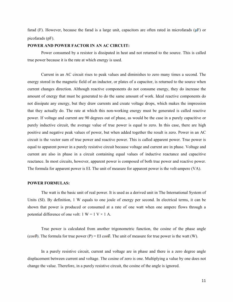
CAPACITANCE AND CAPACITORS:
Capacitance is a measure of a circuit’s ability to store an electrical charge. A device
manufactured to have a specific amount of capacitance is called a capacitor. A capacitor is made up of a
pair of conductive plates separated by a thin layer of insulating material. Another name for the insulating
material is dielectric material. A capacitor is usually indicated symbolically on an electrical drawing by a
combination of a straight line with a curved line or two straight lines.
When a voltage is applied to the plates of a capacitor, electrons are forced onto one plate and
pulled from the other. This charges the capacitor. Direct current cannot flow through the dielectric
material because it is an insulator; however, the electric field created when the capacitor is charged is felt
through the dielectric. Capacitors are rated for the amount of charge they can hold.
The capacitance of a capacitor depends on the area of the plates, the distance between the plates,
and type of dielectric material used. The symbol for capacitance is C and the unit of measurement is the
11
farad (F). However, because the farad is a large unit, capacitors are often rated in microfarads ( F) or
picofarads (pF).
POWER AND POWER FACTOR IN AN AC CIRCUIT:
Power consumed by a resistor is dissipated in heat and not returned to the source. This is called
true power because it is the rate at which energy is used.
Current in an AC circuit rises to peak values and diminishes to zero many times a second. The
energy stored in the magnetic field of an inductor, or plates of a capacitor, is returned to the source when
current changes direction. Although reactive components do not consume energy, they do increase the
amount of energy that must be generated to do the same amount of work. Ideal reactive components do
not dissipate any energy, but they draw currents and create voltage drops, which makes the impression
that they actually do. The rate at which this non-working energy must be generated is called reactive
power. If voltage and current are 90 degrees out of phase, as would be the case in a purely capacitive or
purely inductive circuit, the average value of true power is equal to zero. In this case, there are high
positive and negative peak values of power, but when added together the result is zero. Power in an AC
circuit is the vector sum of true power and reactive power. This is called apparent power. True power is
equal to apparent power in a purely resistive circuit because voltage and current are in phase. Voltage and
current are also in phase in a circuit containing equal values of inductive reactance and capacitive
reactance. In most circuits, however, apparent power is composed of both true power and reactive power.
The formula for apparent power is EI. The unit of measure for apparent power is the volt-ampere (VA).
POWER FORMULAS:
The watt is the basic unit of real power. It is used as a derived unit in The International System of
Units (SI). By definition, 1 W equals to one joule of energy per second. In electrical terms, it can be
shown that power is produced or consumed at a rate of one watt when one ampere flows through a
potential difference of one volt: 1 W = 1 V × 1 A.
True power is calculated from another trigonometric function, the cosine of the phase angle
(cos ). The formula for true power (P) = EI cos . The unit of measure for true power is the watt (W).
In a purely resistive circuit, current and voltage are in phase and there is a zero degree angle
displacement between current and voltage. The cosine of zero is one. Multiplying a value by one does not
change the value. Therefore, in a purely resistive circuit, the cosine of the angle is ignored.
12
In a purely reactive circuit, either inductive or capacitive, current or voltage is 90 degrees out of
phase. The cosine of 90 degrees is zero. Multiplying a value times zero results in a zero product.
Therefore, no energy is consumed in a purely reactive circuit. Although reactive components do not
consume energy, they do increase the amount of energy that must be generated to do the same amount of
work. The rate at which this non-working energy must be generated is called reactive power. The unit for
reactive power the var (or VAr), which stands for volt-ampere reactive.
ENERGY:
The SI unit for energy is joule (J). Joule is used primarily in science. It is the amount of energy
exerted by a force of one newton (1 N) to move an object through a distance of 1 m in the direction of the
force. Joule is a relatively small unit. The energy unit commonly used for electricity consumption,
particularly for utility bills, is the kilowatt-hour (kWh), which is a measurement of a net electricty flow
over given period of time, such as a month. One kilowatt-hour is the amount of energy equivalent to a
steady flow of 1 kW for 1 hour. For example, a 100-W bulb in 10 hours will use 1 kWh energy.
Note that 1kWh=3,600,000J.
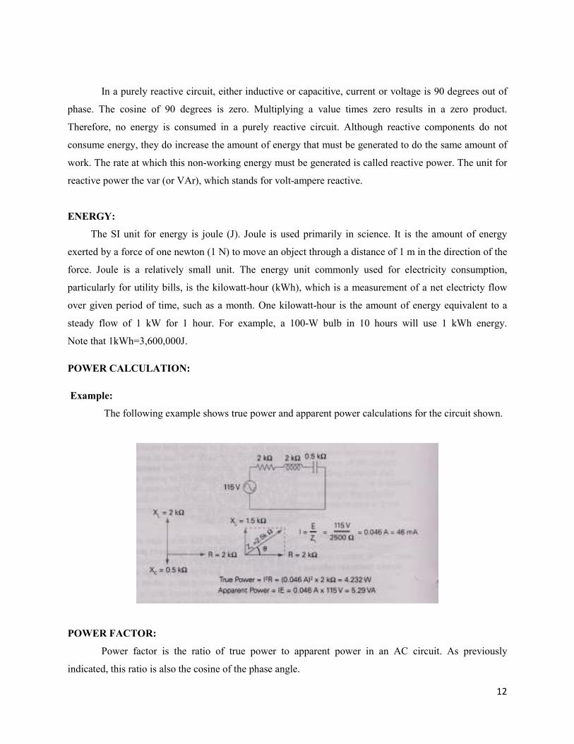
POWER CALCULATION:
Example:
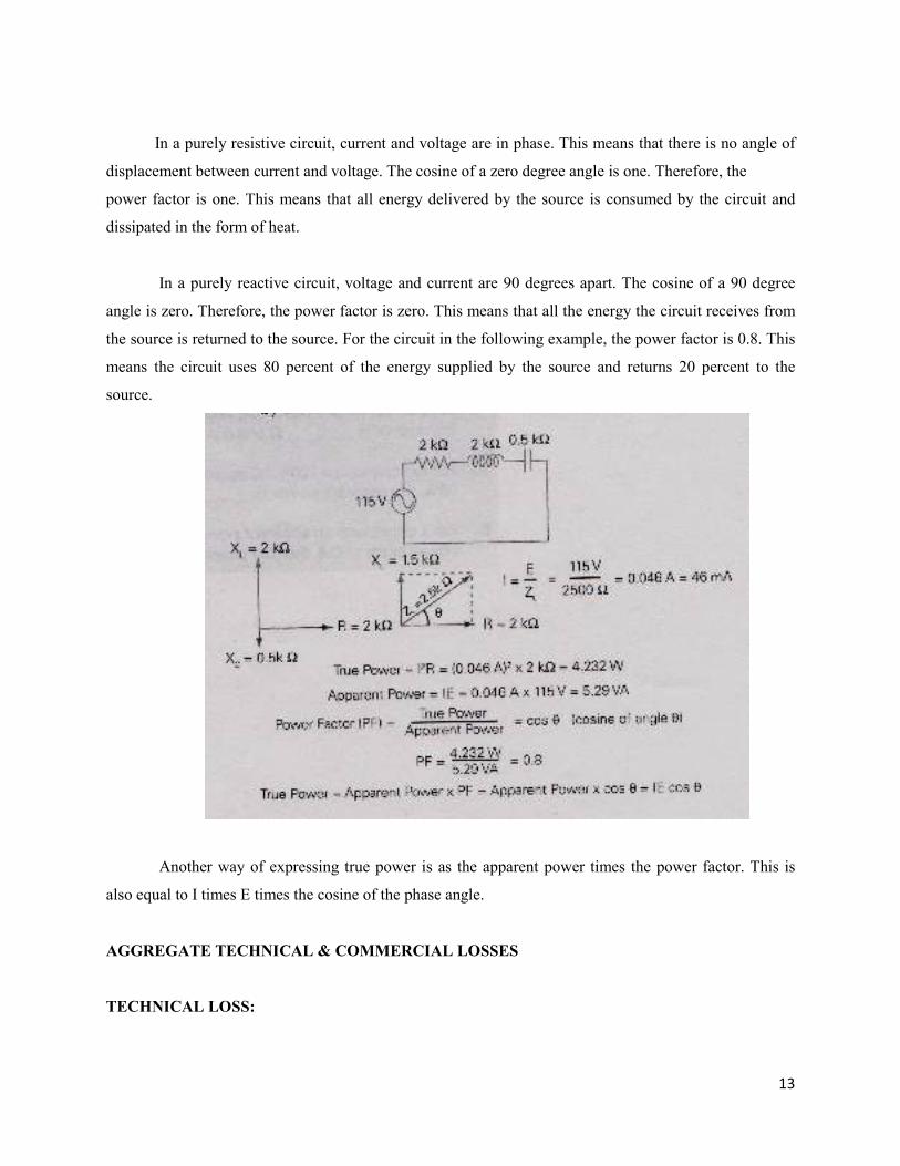
The following example shows true power and apparent power calculations for the circuit shown.
POWER FACTOR:
Power factor is the ratio of true power to apparent power in an AC circuit. As previously
indicated, this ratio is also the cosine of the phase angle.
13
In a purely resistive circuit, current and voltage are in phase. This means that there is no angle of
displacement between current and voltage. The cosine of a zero degree angle is one. Therefore, the
power factor is one. This means that all energy delivered by the source is consumed by the circuit and
dissipated in the form of heat.
In a purely reactive circuit, voltage and current are 90 degrees apart. The cosine of a 90 degree
angle is zero. Therefore, the power factor is zero. This means that all the energy the circuit receives from
the source is returned to the source. For the circuit in the following example, the power factor is 0.8. This
means the circuit uses 80 percent of the energy supplied by the source and returns 20 percent to the
source.
Another way of expressing true power is as the apparent power times the power factor. This is
also equal to I times E times the cosine of the phase angle.
AGGREGATE TECHNICAL & COMMERCIAL LOSSES
TECHNICAL LOSS:
14
Every element in a power System (a line or a transformer etc) offers resistance to power flow and
thus consumes some energy while performing the duty expected of it. The cumulative energy consumed
by all these elements is classified as “Technical Loss”.
COMMERCIAL LOSS:
Losses occur on account of non-performing and under performing meters, wrong applications of
multiplying factors, defects in CT & PT circuitry, meters not read, pilferage by manipulating or by
passing of meters, theft by direct tapping etc. These are all due to non-metering of actual consumption
and are called commercial losses. The total of “Technical” and “Commercial” losses are termed are
T&D loss. It is unfortunate that in addition to the above, there is also a loss in revenue due to non-
realization of billed demand. This is in addition to commercial losses and the aggregate of T&D loss and
revenue loss due to non-realization is termed as “AT&C loss” (Aggregate technical and Commercial
loss).
Therefore AT&C loss to the utility is the sum total of technical loss, commercial losses and
shortage due to non-realization of total billed demand.
Example:
Units Input 100 MU
Unit billed 70 MU
Revenue collection with reference to billed demand: 90%
This means out of 70 MU, sales realization is for 90% of 70 MU i.e. 63%
T & D Losses 30 MU
ATC losses 37%
Power distribution systems in developing countries had to face phenomenal and rapid growth of
load in the last two decades. Distribution systems were expanded on adhoc and haphazard basis keeping
minimum investments in view.
Power systems are highly cost intensive and the investments needed to reduce technical losses by
every 1% are too high. Computer aided load flow studies are to be made to arrive at peak power loss and
also to arrive at technical losses based on load-duration curves. The Transmission system planning is
done on a separate footing that is keeping in view system adequacy, system security, reliability etc for n-1
15
and n-2. Conditions as per guide lines given by CEA. Losses in transmission systems are too small and
loss reduction is not an issue of focus in Transmission system planning.
FACTORS CONTRIBUTING FOR HIGH TECHNICAL LOSSES
The main factors that contribute for high technical losses are usage of lower size conductors, low
voltage pockets, lack of reactive power control, etc. The methods to reduce technical losses in the order
of priority based on cost impact are:
1. Re configuration (change over of loads or feeding source).
2. Re conductoring (Replacing existing conductor by higher size or conversion of single to double
circuit).
3. Shunt or series capacitor installation (switched and fixed).
4. Auto voltage booster.
5. Additional link lines
6. Combination of two or more of the above.
7. As a last resort to go in for another sub-station followed up by reconfiguration.
8. Software tools are available for the studies to be made is termed as IOSP (Integrated Optimum
System Planning) in order to determine and prioratise such works, which result in maximum LRVI
(loss reduction and voltage improvement) with least investment. Based on cost benefit ratio, the best
option for investment can be chosen.
9. Combination of GIS and network analysis tools like Power Net.
However these studies shall be done keeping in view future load growth aiming for a five-year horizon.
HVDS:
Of late, the Discoms have realized that the distribution systems shall be at high voltage and the L.T.
system shall be the least or eliminated as far as possible. HVDS or high voltage distribution systems by
converting existing LVDS is in progress in many Discoms reducing the technical losses appreciably.This
can be explained by one single illustration that for a 100 KVA load the amperage at 11KV is 5 Amps
where as it is 140 Amperes at L.T. voltage of 415 Volts.
AMORPHOUS CORE TRANSFORMERS:
Recently DTRs with amorphous core have entered Indian market and few utilities have installed
these. The core (magnetizing or no load losses) get substantially reduced. However the high cost is
16
coming in the way for large scale introduction. Efforts are being made to make amorphous core material
indigenously and the cost is expected to go down considerably.
COMMERCIAL LOSSES:
A good distribution network shall be in place for providing reliable power supply at assured voltage
levels to consumers and the same shall be with least technical losses. The commercial losses can be
reduced by accurate metering, efficient billing and prompt collections implementing.
Accurate Metering (A metering plan for installing meters with sustained accuracy).
Appropriate range of meter with reference to connected load.
Electronic meters with (TOD, tamper proof data and remote reading facility) for HT & HV services.
Intensive inspections by pooling up staff.
Reduce meter exceptional.
Use energy Audit as a tool to pinpoint areas of high losses.
Eradication of theft.
AMR systems.
REASONS FOR LOSSES AND REMEDIES:
The major amount of losses in a power system is in primary and secondary distribution
lines; while transmission and sub-transmission lines account for only about 30% of the total losses.
Therefore the primary and secondary distribution systems must be properly planned to ensure that losses
are within acceptable limits.
17
CHAPTER - 3
ELECTRICITY ACT 2003
Its content super cedes and consolidates the provisions of
The Electricity Act 1910
The Indian Electricity Act 1948
The Electricity Regulatory Commission Act 1998
Brief discussion of the above acts:
ELECTRICITY ACT 1910:
This act regulates License, Works, Supply, and Transmission & Usage of Energy by non licensee,
Administration and Rules, Criminal offenses and Procedures
ELECTRICITY ACT 1948:
This act rationalizes the production and supply of Electricity. It enacts
a. The central electricity authority
b. State Electricity Boards, Transmission companies, Generating companies
c. Powers & duties of State electricity boards, transmission companies and generation companies
d. The works and trading procedures of Board and companies
e. Boards, Finance, Accounts and Audits
ELECTRICITY REGULATORY COMMISSION ACT 1998:
This Act provides
1. Establishment of Central Electricity Regulatory commission and State electricity commission
2. Central and State Transmission Utilities
3. Rationalization of Electricity tariff
4. Transparent policies regarding subsidies
18
PURPOSE OF THE ACT:
Electricity Act 2003 was enacted by the Parliament with the objective of
Consolidating the laws relating to Generation, transmission, distribution, trading and use of
electricity.
Taking measures conductive to the development of electricity industry.
Promoting competition in electricity industry
Protecting the interests of consumers
Supply of electricity to all areas
Rationalization of electricity tariff
Constituting a central electricity authority, Regulatory commissions and Appellate tribunals.
Section 3: The Central Government shall from time to time prepare National electricity policy and
tariff policy in consultation with State Government and authority for development of power system.
Section 4: National Policy on standalone system for rural areas and non conventional energy systems.
Section 5: National policy on electrification and local distribution in rural areas.
The Central Government in consultation with State Government and State Commission
formulate a National policy for rural electrification of Local distribution in rural areas through franchises.
Section 6: The Government shall endeavor to supply electricity to all areas including villages and
hamlets.
GENERATION OF ELECTRICITY:
Section 7: Any Generating Company may establish operate maintain a generating station without
obtaining License if it complies with technical standards.
Section 8: Hydro Electric Generation: Notwithstanding anything contained in section 7 any
Generating Company intending to set up hydro station shall obtain license
19
Section 9: Captive Generation:
o A person may construct, maintain or operate a captive plant and dedicated transmission lines.
o He has the right to open access for the purpose of carrying electricity from generating plant to
destination of his use.
Section 10: Duties of Generating Company: The company shall be able to establish, operate and
maintain Generating station, tie lines, substation and dedicated transmission lines. Generating
company may supply electricity to any license for distribution of power.
Section 12: Licensing
o No Person shall
o Transmit electricity
o Distribute electricity or
o Undertake trading in electricity unless he is authorized to do so by a license issued by appropriate
commission.
Section 13: Power to Exempt: The appropriate commission direct by notification that the provision
of section 12 shall not apply to all local authority or franchises.
Section 24: Suspension of distribution license:
The appropriate commission may suspend the license if:-
o The distribution licensee failed to maintain uninterrupted supply of electricity to consumer.
o The distribution licensee unable to discharge the functions.
o Persistently default.
o The distribution licensee breaks the terms conditions of license
Transmission of Electricity
Section 25: The central Government may make region wise demarcation for the purpose of interstate,
regional and interregional transmissions.
20
Section 26: The central Government may establish National load dispatch centre at National level,
and at regions- Regional level dispatch centers.
Section 30: The State Commission shall facilitate and promote transmission, wheeling and inter
connection arrangements.
Section 31: The State Government shall establish a centre known State level of Dispatch Centre.
Section 34: Every transmission license shall comply with such technical standards of operation and
maintenance of transmission lines.
Section 39: State Transmission Utility:
o The state Government may notify the Board or a Government Company as state transmission
utility.
o The state transmission utility shall not engage the business of trading in electricity.
Distribution of Electricity
Section 42: Duties of Distribution Licensee:
o The Licensee shall develop and maintain efficient, coordinated and economical distribution
system.
o The state commission shall introduce open access.
o State Commission permits a consumer to receive supply of electricity from a person other than
the distribution license of his area of supply; such consumer shall be liable to pay an additional
surcharge on wheeling charges.
o The licensee may establish a forum for redressal of grievances of consumers.
o State commission appoints Ombudsman for redressal of grievances of consumers who aggrieved
by non-redressal at Forum
Section 43: Every Distribution Licensee shall, on an application by the owner - give supply to the
premises within a month after receipt of application.
21
Section 50: A distribution licensee may, with prior intimation to appropriate commission, engage in
any other businesses.
Section 53: The Authority may, in consultation with State Government specify suitable measures for
o Protecting public from danger (including persons in Generation, Transmission and Distribution)
arising from Generation, Transmission, Distribution.
o Eliminating or reducing the risk of personal inquiry to any person.
Section 55: No Licensee shall supply electricity except through installation of correct meter.
Section 56: Where any person neglects to pay any charge for electricity, the license may cut off
supply after giving 15 days notice.
Section 57: The appropriate commission specifies standards of performance.
Tariff
Section 61: Tariff Regulations
The appropriate commissions shall specify the terms and conditions determination of tariff 20
o Offences and Penalties
Section 135: Theft of electricity: - Whoever dishonestly
o Taps overhead lines, underground cables or service wires of a license
o Tampers a meter, loop connection or any other device or a method which interferes with proper
recording of units.
o Damage electric meter.
Shall be punishable with imprisonment for a term which may extend to 3 years or with fine or with
both.
Section 153: The State Government may further purposes of providing speedy trial of offenses
referred constitute as many special courts as may be necessary. A special court consists of a single
judge appointed by Government with concurrence of High court.
22
CHAPTER-4
LINE CONSTRUCTION, COMMISIONING OF NEW LINE
The Director of Research and R.E.C. have circulated the method of construction of lines and
equipments. It should be followed. For construction of new lines, initial survey should be carried out.
The transformer should be proposed at load center. Avoid the location where transportation of
Transformer is inconvenient. Avoid installation of transformer at roadside, if it is possible to install at
load center because it will be uneconomical, illegal and non-technical.
Voltage Regulation :
As per the I.E. Rule 1956, the L.T. voltage at consumer’s premises should be maintained ± 6 % of
the declared voltage. There is agreement between consumer and utility about providing 440 volt supply. If
L.T. line extension carried out exorbitantly and increasing load without any technical consideration; then
the consumers will get the voltage lower than the permissible limit. Benefit of keeping the length of L.T.
lines short is that patrolling length while breakdown is reduced, resulting consumer complaints attended
in least time. This will reduce the interruption period thereby revenue loss of company. Also this will
reduce the occurrences of conductor snapping, fatal accidents, etc.
Short length H.T. line reduces interruption period and also line loss reduction.Emanating more
than one feeder from Substation does this. During line survey various type of crossings i.e. Highway
crossing, Railway, River, Telephone lines, E.H.V. lines etc to be taken in account. It should be seen that
Telephone line should not be parallel to power line for excessive length. The Induction effect on
telephone line will cause disturbance to Telephone communication and even damage equipments. It is
necessary to obtain the approval of P & T Department (B.S.N.L.) for route of lines 33 KV and above
voltages.
Any crossing should be at right angle i.e. 90 degree, which enables to keep short span and safe
clearance. If possible, Highway and Railway crossings should be avoided. Railway authority gives
23
permission for overhead crossing only for E.H.V. Lines. Low and medium voltage lines to be crossed
with underground cables.
Double pole structure should be used for river crossings and large span. In case of large span, to
maintain safe clearance, long supports are used and additional stays required.
While carrying out survey of overhead lines, provision of proper number of supports with
sufficient height and stays should be done, as estimates are prepared as per the survey. Line should not be
constructed without the approval and permission of competent authority. Also alteration in line, shifting
of line, removing one circuit from double circuit line, shifting of load from one transformer to another,
removing neutral conductor etc. should not be done without approval. This may cause low voltage to
consumer, reduce the company's revenue and reduce the life of equipment due to overloading, safety of
lines and also illegal. Before transferring the load from one H.T. feeder to another, capacity of another
feeder breaker, C.T. capacity, etc. should be considered. Otherwise interruptions may increase and cause
fast decay of equipments. Construction should be carried out as per the sanctioned estimate and approved
line layout. The length of lines should not be more than sanctioned one. Unless all the sanctioned H.T.
Lines, transformers and L.T. load diversions are totally commissioned under system improvement, no
additional load should be connected, or if the double circuit is sanctioned no load shall be connected
unless the additional circuit is erected.
Generally short length lines up to 33 KV on single pole are surveyed with ranger rod. The
distance between poles being less, sag is also less. Following points are to be considered while survey.
1) Line voltage.
2) Maximum current
3) Type of cross arm to be used.
4) Whether single circuit or double circuit.
5) Line Formation.
6) Maximum wind pressure of the area.
7) Sag of the line.
8) Span
9) Ground clearance .
10) Snow fall.
11) Position of support (pole) in the line (i.e. Straight, angle or end pole.)
24
Pole Errection :- Poles are transported before erection. While transporting P.S.C. poles, care should be
taken to avoid breakage. They should be unloaded carefully from the truck. Two or three channels to be
placed slanting the truck edge. Each pole is to be tied by ropes and slowly slide on the channels. Care
should be taken that the pole will not strike the ground. When the pole is lying on the ground it should be
transported to the proposed site by lifting or by pushing by crowbars.
Mark pole pit before digging. The pit shall be normally 2'*2 ½’ size. While digging the pit the
excavated soil should not be kept along the pit edge to avoid the soil falling in the pit. The depth of the
pole pit shall be 1/6th of the pole height. While digging the pit it should be dug straight. After pit digging,
base of the pole shall be brought near the pit. Once the pole is brought near the pit it should be uplifted by
bipod/ gadam .The pole should be tied up from all four sides by rope and when the pole is lifted to
sufficient height, it's base should be put into the pit and erected. Once the pole is erected, it should be
supported from all sides, and it should be aligned properly. Cant hook tool is used for alignment of pole.
Concreting should be done after pole erection.
General proportion of Concrete Mixer are as below:-
Material Proportion Proportion Proportion
1:3:6 1:2:4 1:4:8
1) 1*1/4 Stone Metal 100 Cft. 100 Cft. 100 Cft.
2) Sand 50 Cft. 50 Cft. 50 Cft.
3) Cement 13 bag. 20 bag. 10 bag.
4) Water 484 Ltr. 484 Ltr. 484 Ltr.
Due to the weight of fittings, pole, and conductor, pole may sink in soft soil. Hence base padding is
necessary. The base padding distributes the total weight and reduces the weight per Sq. feet.
Poles and its use.
The pole or supports are classified as per the material used for it.
1) Steel (2) Cement (3) Wooden.
1) Types of steel poles used are-
A) I type beam (B) Rail Pole (C) Tubular pole (D) Fabricated.
2) Cement Pole: -
P.S.C. i.e. Pre Stressed Cement concrete pole. These poles are solid or ladder type
i.e. English "A" type.
25
Care to be taken while transportation of P.S.C. poles.
1. While loading/unloading, avoid concentrated pressure.
2. Do not thrust pole from truck.
3. Unload on soft soil.
4. During transportation, avoid cantilever loading.
Selection of poles.
1) The strength of pole.
2) Conductor type.
3) Maximum wind pressure.
4) Maximum line tension.
5) Size of conductor.
6) Snow fall.
7) Different crossings like river, road, railway, telephone lines etc.
8) Guarding.
9) Fruit farm.
All the above points decide span of the line. All the crossings should be at right angle.
If it is not possible the angle should not be less than 60 degrees.
Precautions while pole erection.
1) After tightening of nut bolts, threads should be punched at least at three places.
2) The length of bolts should be such that only two threads will be left out after tightening of the nut. If
the length of bolt is more, unnecessary washers are required. This will increase the expenditure.
3) Always use one spring washer and one plain washer.
4) The rail pole should be erected in such a way that it’s flat portion will be towards roadside.
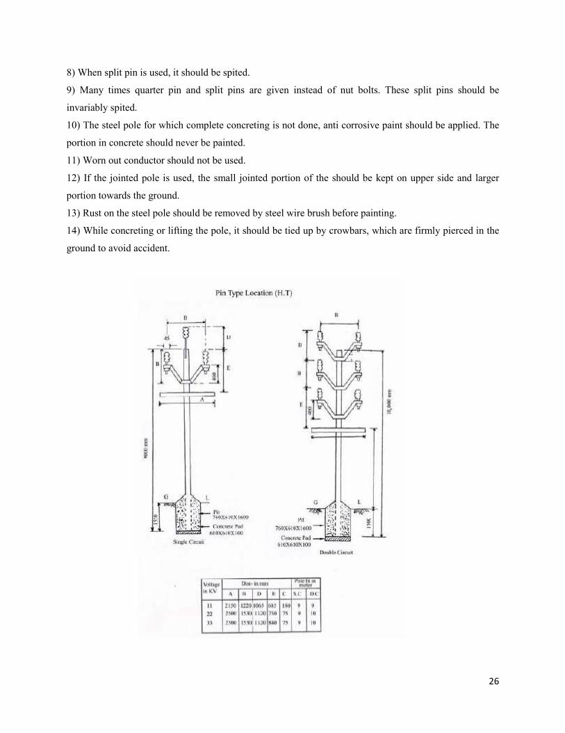
5) Girder, P.S.C. pole or rail pole should be erected as shown below. (The weaker section towards line
and stronger section towards a wind direction.). For angle location the stronger axis will be in line with
axis of angle and end pole shall be erected as the line poles. For tubular or square poles this question does
not arise, as it is stronger from all sides.
6) Cracked P.S.C. pole should not be used.
7) It is the habit of the line staff to strike the pole on the edge of the pit to align pole in line. This should
not be done as P.S.C. poles may crack. The pole should be lifted and pushed or by fixing a clamp at lower
portion of the clamp for alignment. Tapping of the line should always be from pole and not from mid
span.
26
8) When split pin is used, it should be spited.
9) Many times quarter pin and split pins are given instead of nut bolts. These split pins should be
invariably spited.
10) The steel pole for which complete concreting is not done, anti corrosive paint should be applied. The
portion in concrete should never be painted.
11) Worn out conductor should not be used.
12) If the jointed pole is used, the small jointed portion of the should be kept on upper side and larger
portion towards the ground.
13) Rust on the steel pole should be removed by steel wire brush before painting.
14) While concreting or lifting the pole, it should be tied up by crowbars, which are firmly pierced in the
ground to avoid accident.
27
S T A Y S
(1)Ordinary Stay, (2) ‘A’ Type, (3) Self Stay,(“B” type) (4) ‘Y’ stay (5) Flying stay, (6) Strut, (7) Storm
guys .
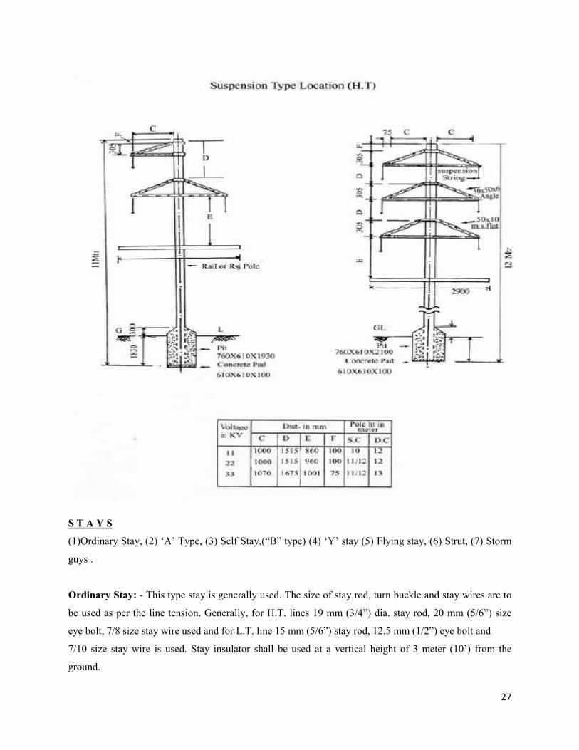
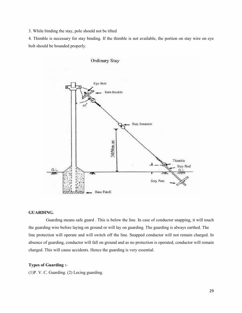
Ordinary Stay: - This type stay is generally used. The size of stay rod, turn buckle and stay wires are to
be used as per the line tension. Generally, for H.T. lines 19 mm (3/4”) dia. stay rod, 20 mm (5/6”) size
eye bolt, 7/8 size stay wire used and for L.T. line 15 mm (5/6”) stay rod, 12.5 mm (1/2”) eye bolt and
7/10 size stay wire is used. Stay insulator shall be used at a vertical height of 3 meter (10’) from the
ground.
28
‘A’ Type Stay: - When the line tension is less and there is no sufficient space for stay, this type stay is
used. In city area, many times, there is no sufficient space for stay. At such places, the stay pit is dug at
short distance from the pole and hence cannot take adequate tension. A support angle is fixed to the pole.
Arrangement is available to affix the stay wire to the angle. This is called “Stay out trigger”. This type
looks like English ‘A’.
Self stay or ‘B’ type stay: -When there is no space for stay, the lower portion of the stay wire is clamped
by stay clamp to the lower portion of the pole. Such type is called Self or ‘B’ type stay.
Flying stay: - When the line is on roadside and there is no space for stay, pole piece of sufficient height is
erected at the other side of the road and a stay wire is tied up between pole and pole piece. For giving
tension to the pole piece, stay wire and stay rod is used.
Strut (Stud): -When the pole is on the roadside and there is no space for stay, one pole is used as a
support to the line pole from opposite side of stay. The support pole is called “Strut”. Strut is fixed to line
pole by a suitable clamp.
‘Y’ type Stay: -It is used for supporting guarding cross arm. It is also used for side brackets.
Storm Guys: -
When the line is straight and cut-points to cut-points distance is more, this type of stay is used.
At mid pole of the line, two stays at an angle of 600on both sides are tied up. Such type of stay is called
“Storm Guys”. For angle location, stays are to be given so as to avoid the tilting of pole due to conductor
tension. Stay insulators are used to obstruct the leakage current.
Stay Binding: -
The stay should be linked with pole earthing and /or neutral wire using G.I.wire so that leakage
current will pass through earthing or neutral to the ground. Such binding is called “Stay Binding”.
Remember :-
1. If stay insulator is not provided, 8 s.w.g. G.I. wire shall be used near the stay clamp and link it to
neutral conductor. The length of G.I. wire should be sufficient to join the stay wire to neutral of L.T. line
or in case of H.T. line, to the H.T. earthing. This G.I. wire should be well bound to the earthing or neutral.
2. Stay insulator should not be less than 10 ft from ground.
29
3. While binding the stay, pole should not be tilted
4. Thimble is necessary for stay binding. If the thimble is not available, the portion on stay wire on eye
bolt should be bounded properly.
GUARDING.
Guarding means safe guard . This is below the line. In case of conductor snapping, it will touch
the guarding wire before laying on ground or will lay on guarding. The guarding is always earthed. The
line protection will operate and will switch off the line. Snapped conductor will not remain charged. In
absence of guarding, conductor will fall on ground and as no protection is operated, conductor will remain
charged. This will cause accidents. Hence the guarding is very essential.
Types of Guarding :-
(1)P. V. C. Guarding. (2) Lecing guarding.
30
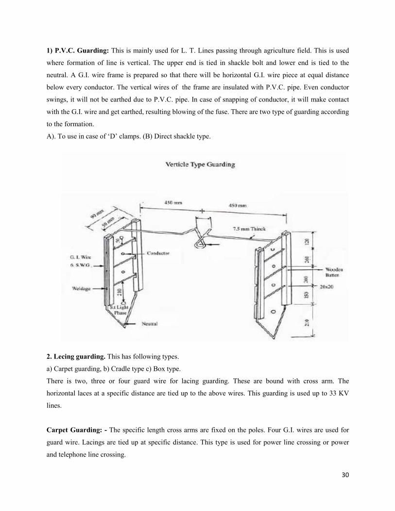
1) P.V.C. Guarding: This is mainly used for L. T. Lines passing through agriculture field. This is used
where formation of line is vertical. The upper end is tied in shackle bolt and lower end is tied to the
neutral. A G.I. wire frame is prepared so that there will be horizontal G.I. wire piece at equal distance
below every conductor. The vertical wires of the frame are insulated with P.V.C. pipe. Even conductor
swings, it will not be earthed due to P.V.C. pipe. In case of snapping of conductor, it will make contact
with the G.I. wire and get earthed, resulting blowing of the fuse. There are two type of guarding according
to the formation.
A). To use in case of ‘D’ clamps. (B) Direct shackle type.
2. Lecing guarding. This has following types.
a) Carpet guarding, b) Cradle type c) Box type.
There is two, three or four guard wire for lacing guarding. These are bound with cross arm. The
horizontal laces at a specific distance are tied up to the above wires. This guarding is used up to 33 KV
lines.
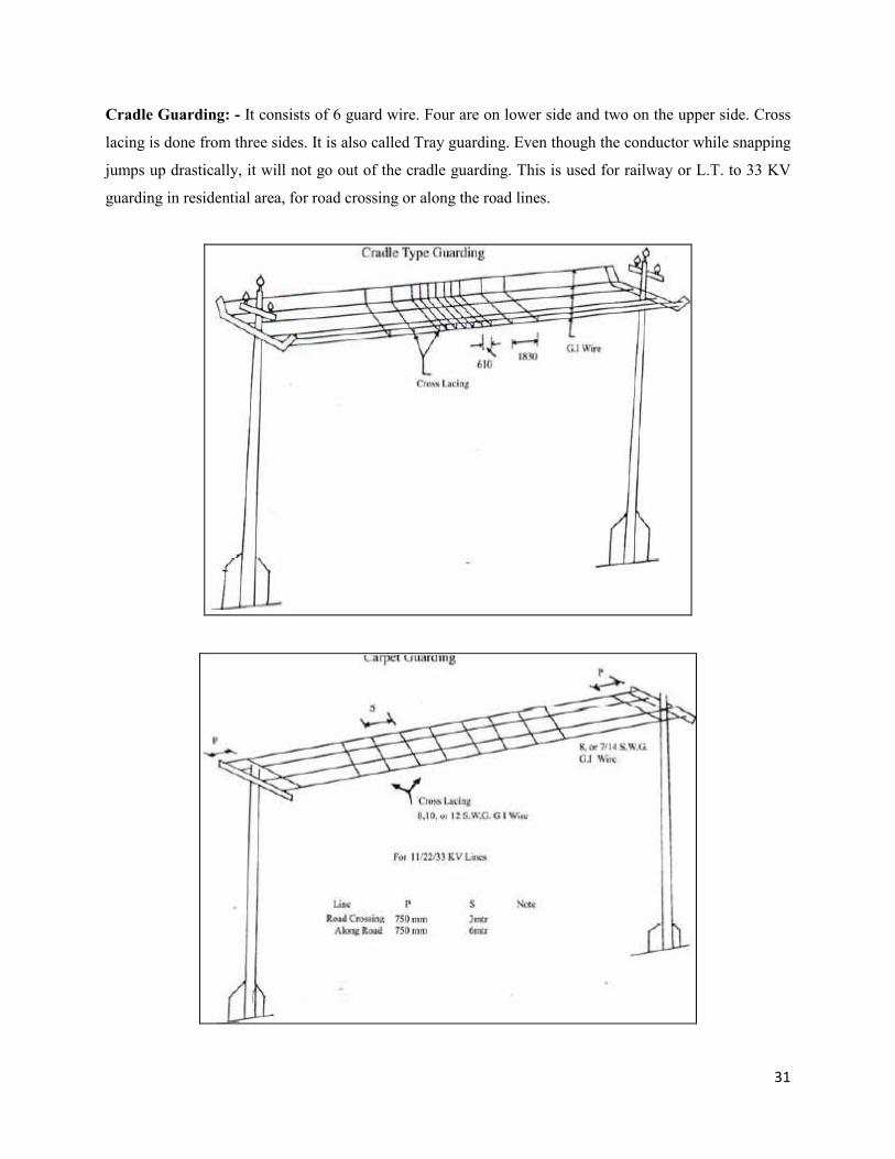
Carpet Guarding: - The specific length cross arms are fixed on the poles. Four G.I. wires are used for
guard wire. Lacings are tied up at specific distance. This type is used for power line crossing or power
and telephone line crossing.
31
Cradle Guarding: - It consists of 6 guard wire. Four are on lower side and two on the upper side. Cross
lacing is done from three sides. It is also called Tray guarding. Even though the conductor while snapping
jumps up drastically, it will not go out of the cradle guarding. This is used for railway or L.T. to 33 KV
guarding in residential area, for road crossing or along the road lines.
32
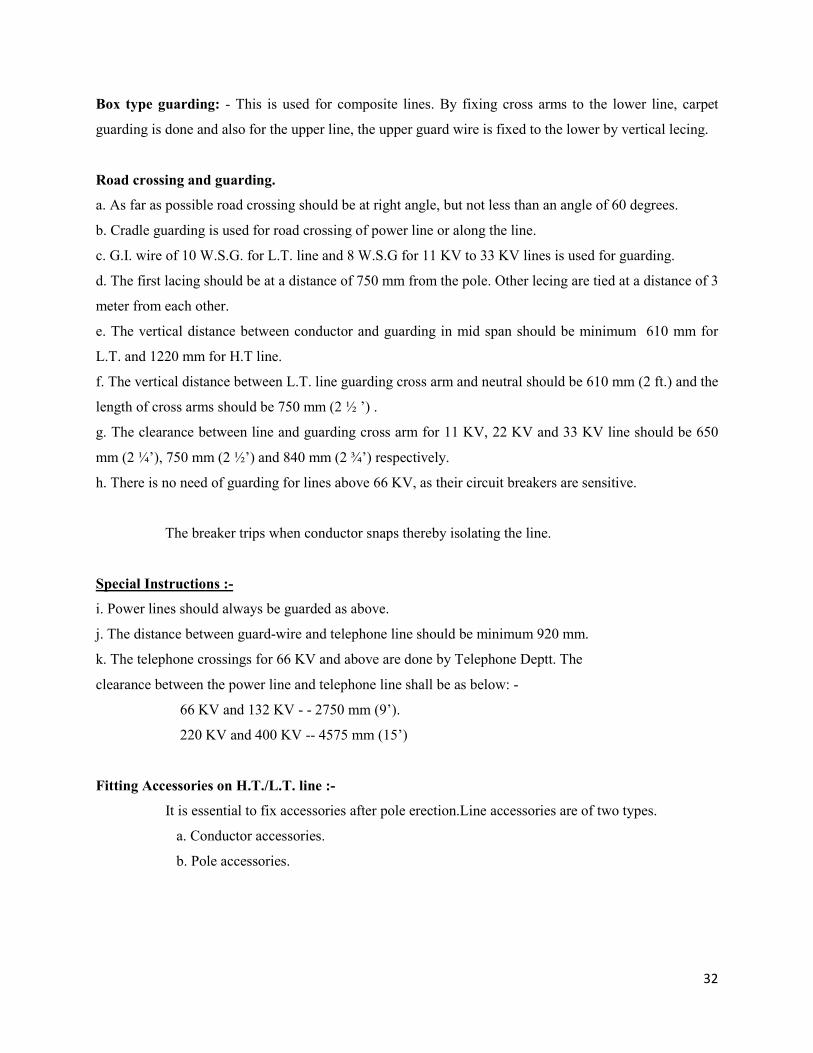
Box type guarding: - This is used for composite lines. By fixing cross arms to the lower line, carpet
guarding is done and also for the upper line, the upper guard wire is fixed to the lower by vertical lecing.
Road crossing and guarding.
a. As far as possible road crossing should be at right angle, but not less than an angle of 60 degrees.
b. Cradle guarding is used for road crossing of power line or along the line.
c. G.I. wire of 10 W.S.G. for L.T. line and 8 W.S.G for 11 KV to 33 KV lines is used for guarding.
d. The first lacing should be at a distance of 750 mm from the pole. Other lecing are tied at a distance of 3
meter from each other.
e. The vertical distance between conductor and guarding in mid span should be minimum 610 mm for
L.T. and 1220 mm for H.T line.
f. The vertical distance between L.T. line guarding cross arm and neutral should be 610 mm (2 ft.) and the
length of cross arms should be 750 mm (2 ½ ’) .
g. The clearance between line and guarding cross arm for 11 KV, 22 KV and 33 KV line should be 650
mm (2 ¼’), 750 mm (2 ½’) and 840 mm (2 ¾’) respectively.
h. There is no need of guarding for lines above 66 KV, as their circuit breakers are sensitive.
The breaker trips when conductor snaps thereby isolating the line.
Special Instructions :-
i. Power lines should always be guarded as above.
j. The distance between guard-wire and telephone line should be minimum 920 mm.
k. The telephone crossings for 66 KV and above are done by Telephone Deptt. The
clearance between the power line and telephone line shall be as below: -
66 KV and 132 KV - - 2750 mm (9’).
220 KV and 400 KV -- 4575 mm (15’)
Fitting Accessories on H.T./L.T. line :-
It is essential to fix accessories after pole erection.Line accessories are of two types.
a. Conductor accessories.
b. Pole accessories.
33
a.) Conductor Accessories: -
l. Binding Tape: - Binding tape is used for binding pin insulator, shackle or Line insulator to the
conductor. The tape is wound on the conductor. The metal of binding tape should be same as that of
conductor. The first layer is wound along the wire in direction of twist of wire and second layer is in
opposite the twist. The portion on which the binding wire is to be wound should be taped 25 mm more
from either side. This tape is used for avoiding conductor snapping due to friction.
2. Binding wire: - It is used for binding insulator to the conductor.
3. P.G. Clamp: - Means parallel groove clamp. This is used for joining jump wire. Line tension cannot be
given on P.G. Clamps. Bi-metallic P.G. Clamp is made out of two different metals and the conductor of
the same metal is used in the same type of metal groove of P.G.Clamp.
4. T clamp: T clamps are used in substation to connect the jumps and cannot sustain tension.
B) Pole Accessories: -
1. Cross Arm, (2) Channel, (3) Guarding, (4) Anti-climbing device (Barbed wire), (5) Number plate, (6)
Phase plate, (7) Circuit plate, (8) Danger Board, (9) Insulator etc.
1) Cross Arms:- Cross arm designed as per the formation of line i.e. vertical, horizontal, or delta.
The length, width and design is based on following conditions.
1. The min. distance required between line and pole. This depends on line voltage.
2. Weight of conductor.
3. Tension on the conductor.
4. Max. sag.
5. Minimum clearance between two phases (it depends on line voltage.)
2. Channels: - Channels are used for mounting of Transformer, D.O. set, A.B. switch,L.A., guarding etc.
on pole.
3. Stays: To avoid pole bending.
4. Guarding: - To avoid snapping of conductor on ground/ another line.
34
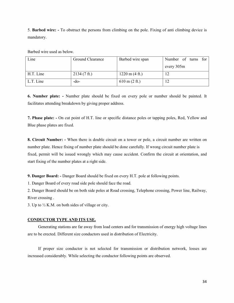
5. Barbed wire: - To obstruct the persons from climbing on the pole. Fixing of anti climbing device is
mandatory.
Barbed wire used as below.
Line Ground Clearance Barbed wire span Number of turns for
every 305m
H.T. Line 2134 (7 ft.) 1220 m (4 ft.) 12
L.T. Line -do- 610 m (2 ft.) 12
6. Number plate: - Number plate should be fixed on every pole or number should be painted. It
facilitates attending breakdown by giving proper address.
7. Phase plate: - On cut point of H.T. line or specific distance poles or tapping poles, Red, Yellow and
Blue phase plates are fixed.
8. Circuit Number: - When there is double circuit on a tower or pole, a circuit number are written on
number plate. Hence fixing of number plate should be done carefully. If wrong circuit number plate is
fixed, permit will be issued wrongly which may cause accident. Confirm the circuit at orientation, and
start fixing of the number plates at a right side.
9. Danger Board: - Danger Board should be fixed on every H.T. pole at following points.
1. Danger Board of every road side pole should face the road.
2. Danger Board should be on both side poles at Road crossing, Telephone crossing, Power line, Railway,
River crossing .
3. Up to ½ K.M. on both sides of village or city.
CONDUCTOR TYPE AND ITS USE.
Generating stations are far away from load centers and for transmission of energy high voltage lines
are to be erected. Different size conductors used in distribution of Electricity.
If proper size conductor is not selected for transmission or distribution network, losses are
increased considerably. While selecting the conductor following points are observed.
35
1) Conductor capacity: - The current carrying capacity of conductor depends on the type of metal used
and its size.
2) Mechanical strength of Conductor: - When the conductor is strung, it has to bear tension. If the
conductor cannot bear tension, it will break and snap. Hence proper capacity conductor should be used.
Types of conductor are as below.
a. Copper.
b. All Aluminum Conductors.
c. All Aluminum Alloy conductors.
d. Aluminum Conductor steel reinforced one.
e. Steel conductor (Galvanized Iron or G.I.)
f. Cables (1) Control Cable, (2) Service Wire (3) Power Cable.
The Copper conductor is best one; but due to its high cost it is not used widely. The Copper
Conductor has low resistance and high mechanical strength.
All Aluminum conductors are generally made of strands and is used when the line tension is
low. It is generally used for L. T. lines. General sizes are No.8,No. 6, Rose, Ant, etc.
A.C.S.R. Conductor is used for E.H.V. and H.T. lines. Aluminum strands carry the current and
steel strands bear the mechanical tension. The sizes used are: 0.02 Squirrel, 0.03 weasel, 0.06 Mint, 0.1
Dog, 0.15 Wolf, 0.2 Panther, 0.3 Goat, 0.35 Sheep, 0.4 Deer, and 0.5 Moose etc.
Based on conductor covering there are two types.1.Bare Conductor: - It is not covered with
insulation. 2. Insulated Conductor is covered by insulation and called as cable. They are again classified
as (1) Solid, (2) Stranded i.e. made of bunch of strands twisted. The conductor size is measured in
Standard Wire gauge.
Measurement of Standard Conductor: - Two numbers are used for this. The first number shows the
number of strands and second one the gauge of each strand or dia. For ex. A) 7/8 S.W.G. stay wire means
it has 7 strands with 8 S.W.G. size strands. (B) 3/0.36 inch weather proof wire means 3 strands each
having 0.36 inch dia. Or 1/1.4 weather proof wire means one strand with 1.4 mm dia.
36
CONDUCTOR JOINTING.
It means joining two conductors each other.
Necessity. 1) While construction of new line, one conductor coil is insufficient; the other has to be laid in
continuation.
2. The conductor breaks by some reason.
Types of Joints: -
(1) Britannia, (2) Telephone, (3) Merid Joint, (4) ‘T” joint, (5) Steel joints, (6) Compression joint.
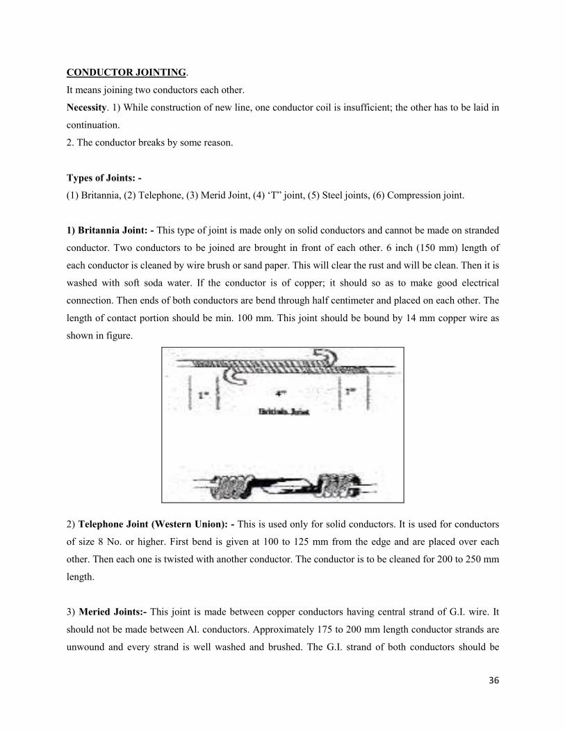
1) Britannia Joint: - This type of joint is made only on solid conductors and cannot be made on stranded
conductor. Two conductors to be joined are brought in front of each other. 6 inch (150 mm) length of
each conductor is cleaned by wire brush or sand paper. This will clear the rust and will be clean. Then it is
washed with soft soda water. If the conductor is of copper; it should so as to make good electrical
connection. Then ends of both conductors are bend through half centimeter and placed on each other. The
length of contact portion should be min. 100 mm. This joint should be bound by 14 mm copper wire as
shown in figure.
2) Telephone Joint (Western Union): - This is used only for solid conductors. It is used for conductors
of size 8 No. or higher. First bend is given at 100 to 125 mm from the edge and are placed over each
other. Then each one is twisted with another conductor. The conductor is to be cleaned for 200 to 250 mm
length.
3) Meried Joints:- This joint is made between copper conductors having central strand of G.I. wire. It
should not be made between Al. conductors. Approximately 175 to 200 mm length conductor strands are
unwound and every strand is well washed and brushed. The G.I. strand of both conductors should be
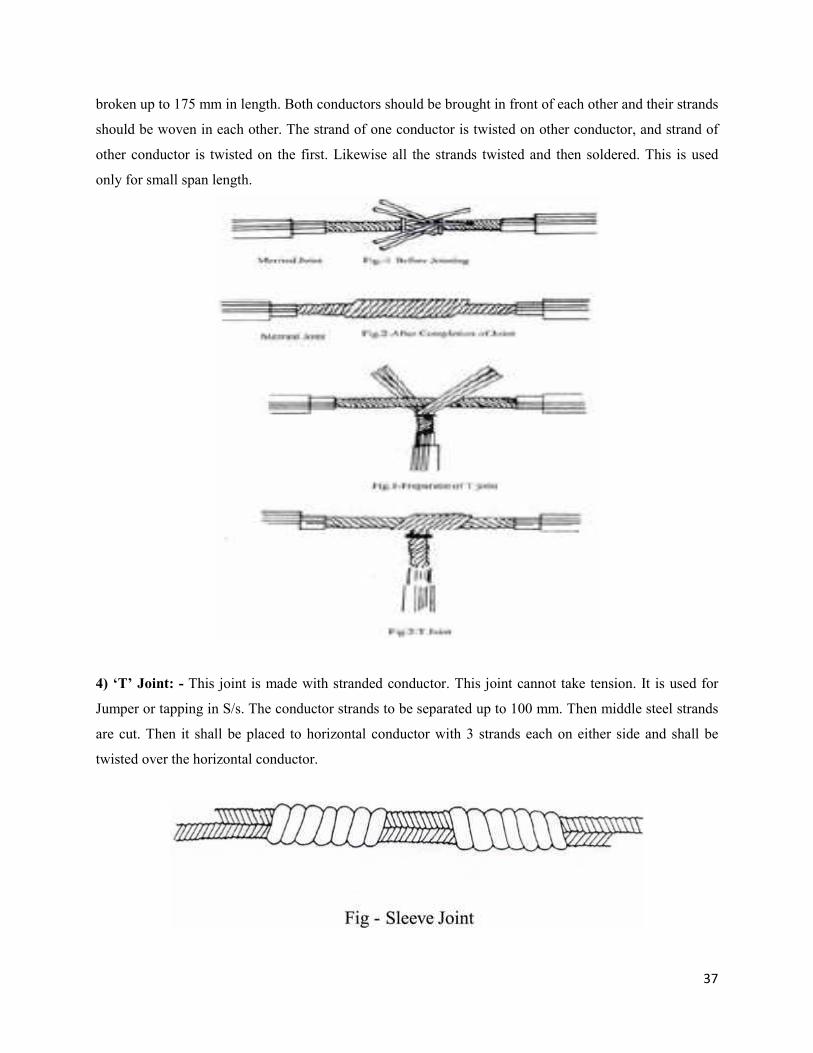
37
broken up to 175 mm in length. Both conductors should be brought in front of each other and their strands
should be woven in each other. The strand of one conductor is twisted on other conductor, and strand of
other conductor is twisted on the first. Likewise all the strands twisted and then soldered. This is used
only for small span length.
4) ‘T’ Joint: - This joint is made with stranded conductor. This joint cannot take tension. It is used for
Jumper or tapping in S/s. The conductor strands to be separated up to 100 mm. Then middle steel strands
are cut. Then it shall be placed to horizontal conductor with 3 strands each on either side and shall be
twisted over the horizontal conductor.
38
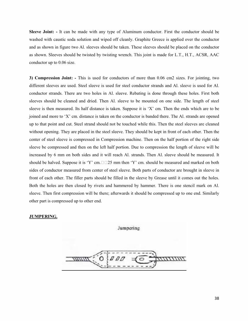
Sleeve Joint: - It can be made with any type of Aluminum conductor. First the conductor should be
washed with caustic soda solution and wiped off cleanly. Graphite Greece is applied over the conductor
and as shown in figure two Al. sleeves should be taken. These sleeves should be placed on the conductor
as shown. Sleeves should be twisted by twisting wrench. This joint is made for L.T., H.T., ACSR, AAC
conductor up to 0.06 size.
3) Compression Joint: - This is used for conductors of more than 0.06 cm2 sizes. For jointing, two
different sleeves are used. Steel sleeve is used for steel conductor strands and Al. sleeve is used for Al.
conductor strands. There are two holes in Al. sleeve. Rebating is done through these holes. First both
sleeves should be cleaned and dried. Then Al. sleeve to be mounted on one side. The length of steel
sleeve is then measured. Its half distance is taken. Suppose it is ‘X’ cm. Then the ends which are to be
joined and more to ‘X’ cm. distance is taken on the conductor is banded there. The Al. strands are opened
up to that point and cut. Steel strand should not be touched while this. Then the steel sleeves are cleaned
without opening. They are placed in the steel sleeve. They should be kept in front of each other. Then the
center of steel sleeve is compressed in Compression machine. Then on the half portion of the right side
sleeve be compressed and then on the left half portion. Due to compression the length of sleeve will be
increased by 6 mm on both sides and it will reach Al. strands. Then Al. sleeve should be measured. It
should be halved. Suppose it is ‘Y’ cm.25 mm then ‘Y’ cm. should be measured and marked on both
sides of conductor measured from center of steel sleeve. Both parts of conductor are brought in sleeve in
front of each other. The filler parts should be filled in the sleeve by Grease until it comes out the holes.
Both the holes are then closed by rivets and hammered by hammer. There is one stencil mark on Al.
sleeve. Then first compression will be there; afterwards it should be compressed up to one end. Similarly
other part is compressed up to other end.
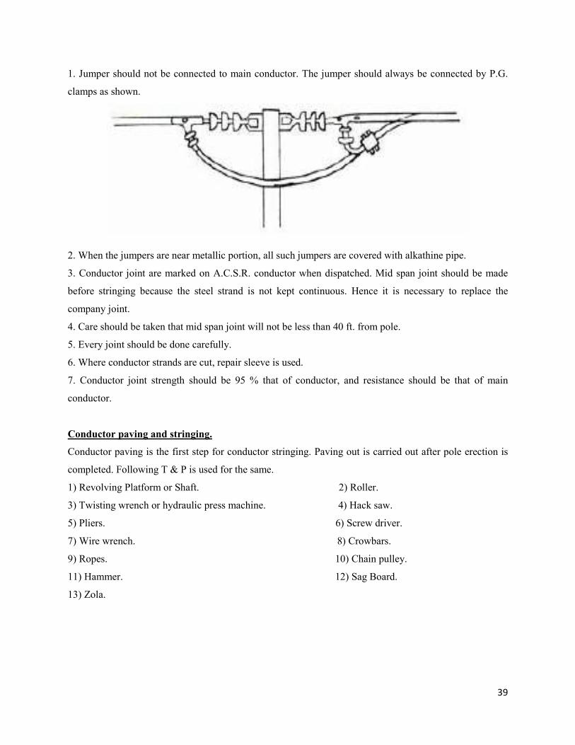
JUMPERING.
39
1. Jumper should not be connected to main conductor. The jumper should always be connected by P.G.
clamps as shown.
2. When the jumpers are near metallic portion, all such jumpers are covered with alkathine pipe.
3. Conductor joint are marked on A.C.S.R. conductor when dispatched. Mid span joint should be made
before stringing because the steel strand is not kept continuous. Hence it is necessary to replace the
company joint.
4. Care should be taken that mid span joint will not be less than 40 ft. from pole.
5. Every joint should be done carefully.
6. Where conductor strands are cut, repair sleeve is used.
7. Conductor joint strength should be 95 % that of conductor, and resistance should be that of main
conductor.
Conductor paving and stringing.
Conductor paving is the first step for conductor stringing. Paving out is carried out after pole erection is
completed. Following T & P is used for the same.
1) Revolving Platform or Shaft. 2) Roller.
3) Twisting wrench or hydraulic press machine. 4) Hack saw.
5) Pliers. 6) Screw driver.
7) Wire wrench. 8) Crowbars.
9) Ropes. 10) Chain pulley.
11) Hammer. 12) Sag Board.
13) Zola.
40
While conductor paying out, care should be taken that the conductor should not rub the ground. A
revolving platform and rollers are used to avoid damage. If the conductor is rubbing the ground, it should
be lifted and stretched. Conductor paying out can be done easily by use of revolving platform. Care
should be taken to avoid sharp bend while unwinding. Sharp bend may lead to breaking of conductor.
Sag Board should be used while stringing. Wind pressure, snow fall, etc should be considered and
proper sag should be given.
Binding tape should be used for conductor binding. While binding the conductor, conductor should
be inspected to ascertain the damages. Kerolite compound is also used. There should not be gap between
tape and conductor as there is a possibility of sparking.
1) For L.T. neutral conductor binding on pole, if the conductor is of copper C.I. bobbin to be used and in
case of Aluminum conductor Al. bobbin should be used.
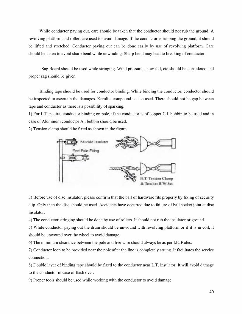
2) Tension clamp should be fixed as shown in the figure.
3) Before use of disc insulator, please confirm that the ball of hardware fits properly by fixing of security
clip. Only then the disc should be used. Accidents have occurred due to failure of ball socket joint at disc
insulator.
4) The conductor stringing should be done by use of rollers. It should not rub the insulator or ground.
5) While conductor paying out the drum should be unwound with revolving platform or if it is in coil, it
should be unwound over the wheel to avoid damage.
6) The minimum clearance between the pole and live wire should always be as per I.E. Rules.
7) Conductor loop to be provided near the pole after the line is completely strung. It facilitates the service
connection.
8) Double layer of binding tape should be fixed to the conductor near L.T. insulator. It will avoid damage
to the conductor in case of flash over.
9) Proper tools should be used while working with the conductor to avoid damage.
41
10) Before joining, the conductor ends should be properly cleaned. In case of copper, clean by sand paper
and for aluminum conductor, first apply jointing compound and then brush so as to remove the al. oxide.
In absence of jointing compound caustic soda can be used. After cleaning, use graphite grease and then
complete the joint.
11) P.G. clamps and the conductor should have the same current capacity.
12) To avoid bi-metallic action in bi-metallic P.G. clamps, lead foil is used.
In order to avoid by material action a strip is used as a media in bi-metallic P.G. clamps. As there is
bimetal action between copper and aluminum; but no action occurs between copper, zinc and aluminum.
COMMISSIONING OF NEW LINE.
The line under first commissioning should be thoroughly inspected. Rigorous inspection should be
carried out to see whether the line is erected as per I.E.Rules. Clearance at all places, guarding etc. should
be thoroughly checked. The concreting of every pole should also be checked. Stays should be checked for
proper tension. Fixing of danger board, phase plates should be checked. Earthing on poles, L.As., Horn
gap or D.O. fuses should also be checked.
After inspection, some line test should be carried out before commissioning. Insulation
resistance between phase to phase and phase to neutral should be checked by megger and values to be
recorded in register. After removing all the faults/descripancies observed in patrolling and if the megger
results are proper, a written report for commissioning should be given to Senior Officer. Permission from
Electrical Inspector is necessary for charging the line.
If the line is charged satisfactorily, it means that line commissioning is complete.
42
CHAPTER-5
LINE INSPECTION & MAINTENANCE
1. It is the statutory obligation, to inspect the lines & equipment by the competent authority, before
the charging of line, after construction.
2. The following are to be observed effectively, while carrying out inspection of lines and
equipment.
a. The equipment or lines should be as per the approval.
b. In respect of Substation, the work should be done, as per the layout approval.
c. Statutory clearances have to be ensured, while works are inspected for the following
crossings.
i. Railway crossings
ii. P & T crossings
iii. Junctions
iv. Road Crossings
v. Proper clearance should be maintained for the lines with different voltages are in
operation, on the same supports.
vi. Adequate safety and clearances should be ensured while running the lines at
domestic colonies.
d. Proper earthing should be ensured, wherever necessary.
e. Proper supports and conductors should be ensured.
f. DP’s and Cut points should be inspected, based on need and approvals.
g. Twin cross arms to be ensured at cut points.
h. Proper stay sets should be ensured, at junction points, Tangential points and perpendicular
points.
i. Any crossing should be at right angles, to the extent possible.
j. Proper cross arms, extension cross arms should be ensured as per the requirement.
k. Proper clearance should be ensured between the phases.
l. Proper jumpering should be ensured.
m. Concreting with proper mixture should be ensured, wherever necessary.
43
3. Premonsoon Inspection:
It is the statutory obligation, to keep intact the lines and equipment, in fit condition, before the
onset of monsoon by conducting premonsoon inspections.
1. Premonsoon inspection should be carried out by advance planning , with proper, tools,
and equipment, duly taking shut down, on information to the customers through daily
News paper.
2. Tree cutting should be properly executed.
3. Sagging of lines should be minimized.
4. Leaned poles should be rectified.
5. Lines should be properly aligned by tightening with proper bolts and nuts.
6. Earthing should be checked.
7. Torn insulators / flash over insulators should be replaced.
8. Jumpers at cut points should be checked up.
9. Stay wires should be properly aligned.
10. Ensure guy insulators of suitable capacity to the stay sets.
11. Proper clearance should be ensured between the lowest conductors to ground.
12. Guarding should be provided wherever necessary.
LINE MAINTENANCE
33 KV and 11 KV Lines maintenance: 33 KV and 11 KV Lines maintenance is required to minimize
interruptions and improve the efficiency of power supply. The overhead lines should be inspected
periodically for maintenance purpose to detect any fault which may lead to break down or interruption of
electric supply and necessary repairs should be programs soon there after. For third all overhead lines
should be patrolled periodically at intervals not exceeding one month at ground level while the line is live
and is called as ground patrol or pole to pole inspection. Usually many break-downs occur soon after the
monsoon. Therefore, it is worth while programming a special inspection of the lines just before the
monsoon period. This inspection is normally carried out with the over head lines without supply to
enable close inspection of the line and is called as Pre-monsoon Inspection.
When an overhead line trips on a sustained fault, it should be inspected to find out the
nature of fault such as loose sag, snapping of conductors, tree branches touching the line conductor filling
on cross arms and insulator failure or puncture to avoid these types of faults Pre-monsoon inspection
should be arranged and repairs carried out.
44
L.T. Lines
1. Annually pole fittings, street light brackets shall be checked. Alignment of poles shall be checked.
Damaged service wire due to ageing shall be replaced. Aerial fuses shall be provided for each
service. If there are more services section fuses shall be provided. Road crossings are to be checked.
A clearance of at-least 1.2 m shall be maintained with telephone line.
2. Damage to L.T. Conductor shall be checked such as damage to strands, black spots on conductor.
3. Bird nests etc. shall be removed on cross arms.
4. Tree clearance should be done once in a month.
5. Loose spans stringing and providing PVC separaters should be done.
Pole to Pole or Ground Patrol
a) Poles
1. Leaning of pole
2. Sinking of earth around the pole
3. Corrosion of metal at ground level (RSJ Poles)
4. Cracks (In PSCC) and (RSJ) poles
b) Cross Arms
1. Tilting of cross arms
2. Rusting of cross arms
3. Observing of any bird nest or creeper on cross arm.
c) Bindings:
1. Looseness and cutting of bindings
d) Conductors:
1. Observing of cut strands, burnt marks and corrosion etc
2. Looseness of conductors.
3. Observing of kites, green creepers on the conductors.
4. Sufficient clearance over roads, rivers, railways’ telecommunications etc.
5. Guarding and earth for conductors are intact.
45
e) Guys:
1. Corrosion of guy rod and stay wire
2. Guy wire tightness, and insulator intact
3. Any creeper on the stay wire
4. Sleeve concreting is in order any guy pits sleeving
f) A.B. Switches
1. Defect in closing of the A.B. Switch.
2. Missing of the lock
3. Damage of earth wire
4. Dust accumulation on the insulators
5. Blades / contact burnings
g) 11 KV Cable and Cable Boxes:
1. Proper supporting of cable and cable boxes
2. Damage to insulator and compound leakage from the box.
3. Intactness of terminal connections with over head lines and earthing lead from the cable box.
h) Insulator discs
1. Insulator
2. Flash over marks
For special inspections (pre-monsoon) and emergency inspections (Break down) the following
points to be checked in addition to Pole to Pole (Ground patrolling) inspection.
a) Lighting Arresters:
1. Damage of Porcelain.
2. Intactness of line and earth connections
3. Any external indication to show the lighting arresters that have been punctured.
46
b) Earthing system:
1. Earthing connections of the metal supports are intact.
The patrolling party should write inspection reports and pass them on to the concerned Section
Officer for arranging necessary repairs. Side by side with this inspection, the repairs obviously necessary
are also carried out simultaneously to the extent possible.
47
CHAPTER – 6
SAFETY REQUIREMENTS FOR OVERHEAD LINES, UNDERGROUND
CABLES
I. Material and strength:
(1) All conductors of overhead lines shall have a breaking strength of not less than 350 Kg.
(2) Where the voltage does not exceed 250 V and the span is of less than fifteen metres and is drawn
through the owner’s or consumer’s premises, a conductor having an actual breaking strength of not less
than 150 kg may be used.
II. Joints:
(1) No conductor of an overhead lines shall have more than one joint in a span and joints between
conductors of overhead lines shall be mechanically and electrically secure under the conditions of
operation.
(2) The ultimate strength and the electrical conductivity of the joint shall be as per relevant Indian
Standards.
III. Maximum stresses and factors of safety:
(1) The load and permissible stresses on the structural members, conductors and ground wire of self
supporting steel lattice towers for overhead transmission lines shall be in accordance with the
specifications laid down, from time to time, by the Bureau of Indian Standards.
(2) Overhead lines shall have the following minimum factors of safety, namely:-
(i) for metal supports - 1.5
(ii) for mechanically processed concrete supports - 2.0
(iii) for hand-moulded concrete supports - 2.5
(iv) for wood supports - 3.0
The minimum factor of safety for stay-wires, guard-wires or bearer-wires shall be 2.5 based on
the ultimate tensile strength of the wire.
48
IV. Clearance above ground of the lowest conductor of overhead lines:
(1) No conductor of an overhead line, including service lines, erected across a street shall at any part
thereof be at a height of less than
(i) for lines of voltage not exceeding 650 Volts - 5.8 metres
(ii) for lines of voltage exceeding 650 Volts but not exceeding - 33 kV 6.1 metres
(2) No conductor of an overhead line, including service lines, erected along any street shall at any
part thereof be at a height less than
(3) N
o
conductor of an overhead line including service lines, erected elsewhere than along or across any street
shall be at a height less than –
(i) for lines of voltage upto and including 11,000 Volts, if bare - 4.6 metres
(ii) for lines of voltage upto and including 11,000 Volts, - if
insulated
4.0 metres
(iii) for lines of voltage exceeding 11,000 Volts but - not
exceeding 33 Kv
5.2 metres
V. Clearance from buildings of lines of voltage and service lines not exceeding 650 Volts:
(1) An overhead line shall not cross over an existing building as far as possible and no building shall
be constructed under an existing overhead line.
(2) Where an overhead line of voltage not exceeding 650 V passes above or adjacent to or terminates
on any building, the following minimum clearances from any accessible point, on the basis of maximum
sag, shall be observed, namely:
(i) for any flat roof, open balcony, varandah roof and lean-to-roof-
(a) when the line passes above the building a vertical clearance of 2.5 metres from the highest point, and
(b) when the line passes adjacent to the building a horizontal clearance of 1.2 metres from the nearest
point, and
(i) for lines of voltage not exceeding 650 Volts - 5.5 metres
(ii) for lines of voltage exceeding 650 Volts but not exceeding - 33 kV 5.8 metres
49
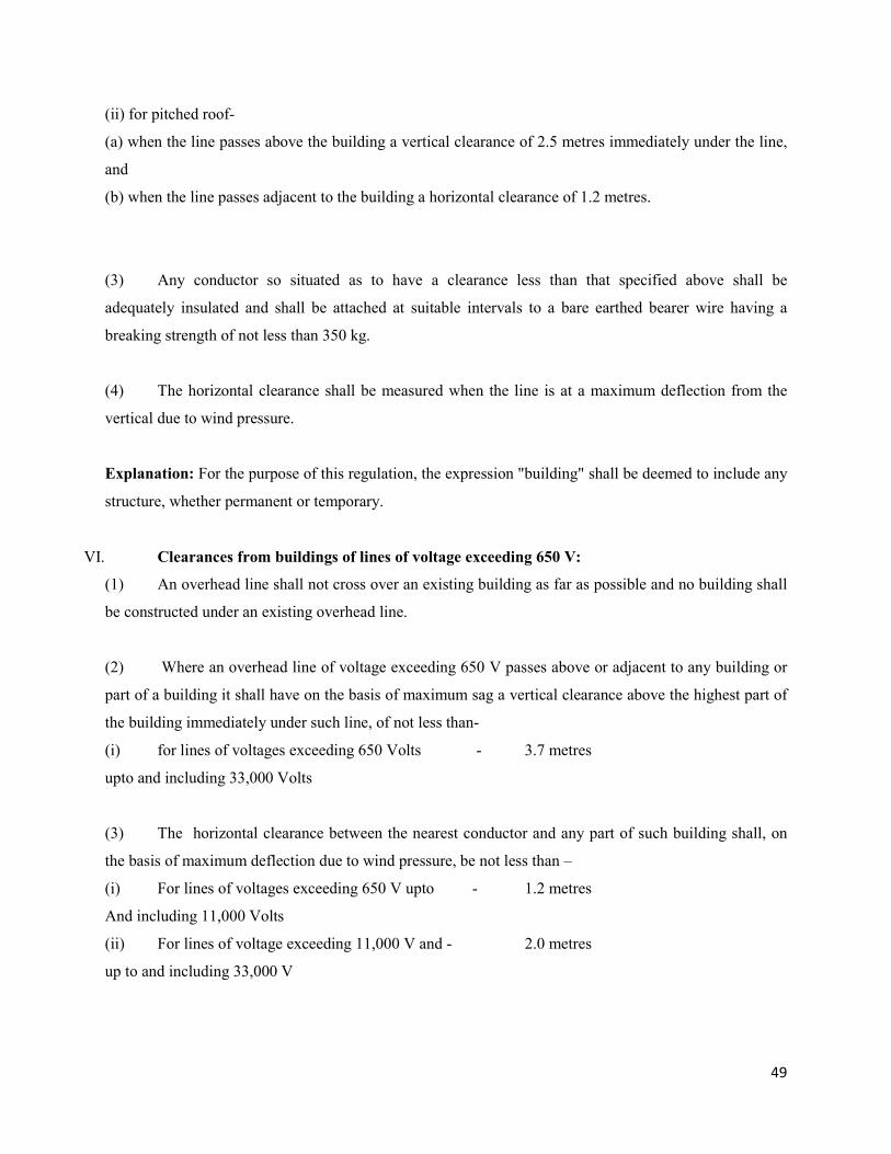
(ii) for pitched roof-
(a) when the line passes above the building a vertical clearance of 2.5 metres immediately under the line,
and
(b) when the line passes adjacent to the building a horizontal clearance of 1.2 metres.
(3) Any conductor so situated as to have a clearance less than that specified above shall be
adequately insulated and shall be attached at suitable intervals to a bare earthed bearer wire having a
breaking strength of not less than 350 kg.
(4) The horizontal clearance shall be measured when the line is at a maximum deflection from the
vertical due to wind pressure.
Explanation: For the purpose of this regulation, the expression "building" shall be deemed to include any
structure, whether permanent or temporary.
VI. Clearances from buildings of lines of voltage exceeding 650 V:
(1) An overhead line shall not cross over an existing building as far as possible and no building shall
be constructed under an existing overhead line.
(2) Where an overhead line of voltage exceeding 650 V passes above or adjacent to any building or
part of a building it shall have on the basis of maximum sag a vertical clearance above the highest part of
the building immediately under such line, of not less than-
(i) for lines of voltages exceeding 650 Volts - 3.7 metres
upto and including 33,000 Volts
(3) The horizontal clearance between the nearest conductor and any part of such building shall, on
the basis of maximum deflection due to wind pressure, be not less than –
(i) For lines of voltages exceeding 650 V upto - 1.2 metres
And including 11,000 Volts
(ii) For lines of voltage exceeding 11,000 V and - 2.0 metres
up to and including 33,000 V
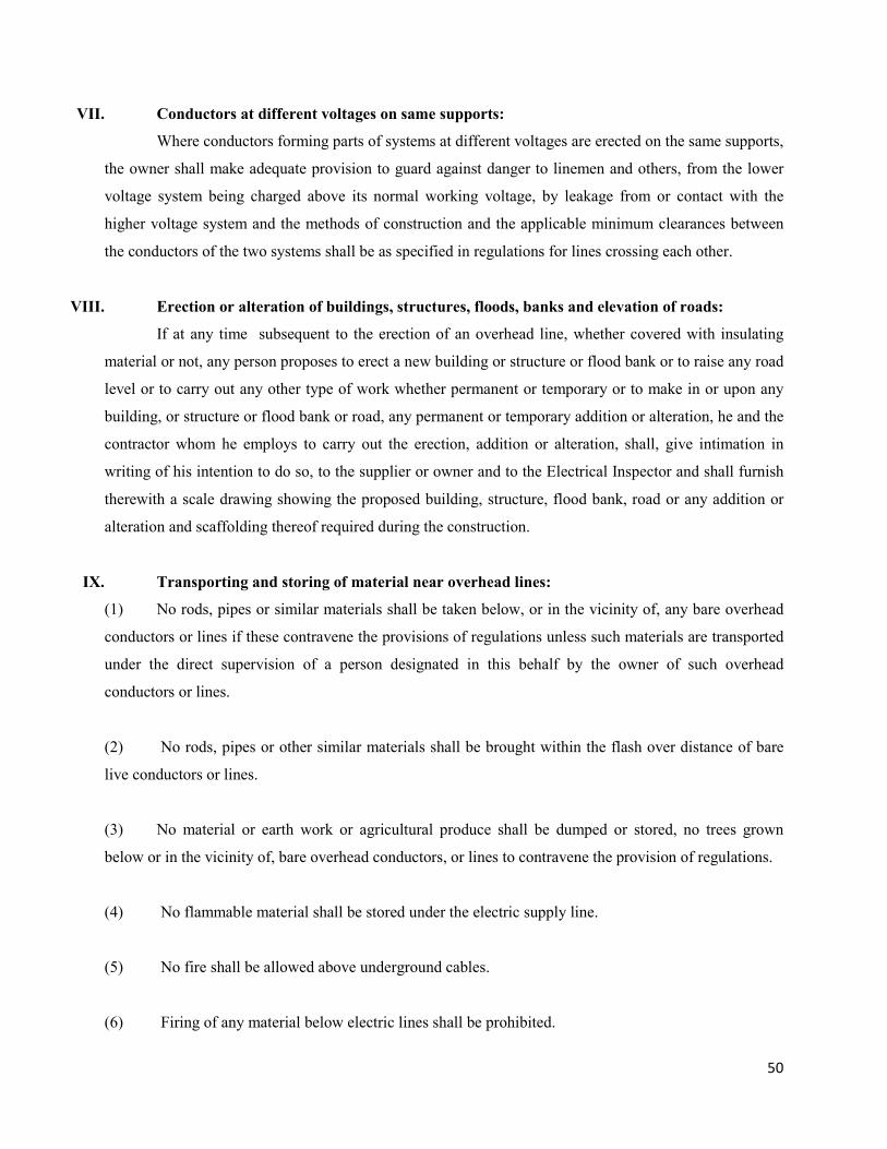
50
VII. Conductors at different voltages on same supports:
Where conductors forming parts of systems at different voltages are erected on the same supports,
the owner shall make adequate provision to guard against danger to linemen and others, from the lower
voltage system being charged above its normal working voltage, by leakage from or contact with the
higher voltage system and the methods of construction and the applicable minimum clearances between
the conductors of the two systems shall be as specified in regulations for lines crossing each other.
VIII. Erection or alteration of buildings, structures, floods, banks and elevation of roads:
If at any time subsequent to the erection of an overhead line, whether covered with insulating
material or not, any person proposes to erect a new building or structure or flood bank or to raise any road
level or to carry out any other type of work whether permanent or temporary or to make in or upon any
building, or structure or flood bank or road, any permanent or temporary addition or alteration, he and the
contractor whom he employs to carry out the erection, addition or alteration, shall, give intimation in
writing of his intention to do so, to the supplier or owner and to the Electrical Inspector and shall furnish
therewith a scale drawing showing the proposed building, structure, flood bank, road or any addition or
alteration and scaffolding thereof required during the construction.
IX. Transporting and storing of material near overhead lines:
(1) No rods, pipes or similar materials shall be taken below, or in the vicinity of, any bare overhead
conductors or lines if these contravene the provisions of regulations unless such materials are transported
under the direct supervision of a person designated in this behalf by the owner of such overhead
conductors or lines.
(2) No rods, pipes or other similar materials shall be brought within the flash over distance of bare
live conductors or lines.
(3) No material or earth work or agricultural produce shall be dumped or stored, no trees grown
below or in the vicinity of, bare overhead conductors, or lines to contravene the provision of regulations.
(4) No flammable material shall be stored under the electric supply line.
(5) No fire shall be allowed above underground cables.
(6) Firing of any material below electric lines shall be prohibited.
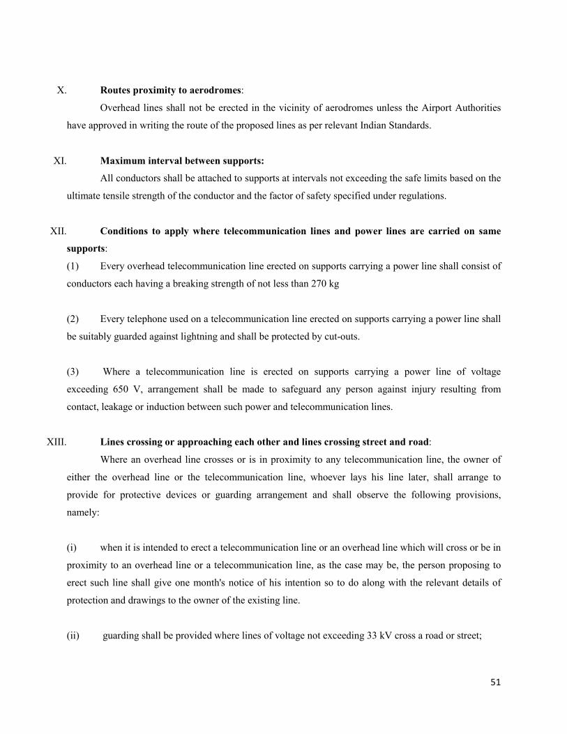
51
X. Routes proximity to aerodromes:
Overhead lines shall not be erected in the vicinity of aerodromes unless the Airport Authorities
have approved in writing the route of the proposed lines as per relevant Indian Standards.
XI. Maximum interval between supports:
All conductors shall be attached to supports at intervals not exceeding the safe limits based on the
ultimate tensile strength of the conductor and the factor of safety specified under regulations.
XII. Conditions to apply where telecommunication lines and power lines are carried on same
supports:
(1) Every overhead telecommunication line erected on supports carrying a power line shall consist of
conductors each having a breaking strength of not less than 270 kg
(2) Every telephone used on a telecommunication line erected on supports carrying a power line shall
be suitably guarded against lightning and shall be protected by cut-outs.
(3) Where a telecommunication line is erected on supports carrying a power line of voltage
exceeding 650 V, arrangement shall be made to safeguard any person against injury resulting from
contact, leakage or induction between such power and telecommunication lines.
XIII. Lines crossing or approaching each other and lines crossing street and road:
Where an overhead line crosses or is in proximity to any telecommunication line, the owner of
either the overhead line or the telecommunication line, whoever lays his line later, shall arrange to
provide for protective devices or guarding arrangement and shall observe the following provisions,
namely:
(i) when it is intended to erect a telecommunication line or an overhead line which will cross or be in
proximity to an overhead line or a telecommunication line, as the case may be, the person proposing to
erect such line shall give one month's notice of his intention so to do along with the relevant details of
protection and drawings to the owner of the existing line.
(ii) guarding shall be provided where lines of voltage not exceeding 33 kV cross a road or street;
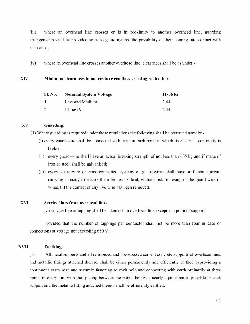
52
(iii) where an overhead line crosses or is in proximity to another overhead line, guarding
arrangements shall be provided so as to guard against the possibility of their coming into contact with
each other;
(iv) where an overhead line crosses another overhead line, clearances shall be as under:-
XIV. Minimum clearances in metres between lines crossing each other:
Sl. No. Nominal System Voltage 11-66 kv
1. Low and Medium 2.44
2 11- 66kV 2.44
XV. Guarding:
(1) Where guarding is required under these regulations the following shall be observed namely:-
(i) every guard-wire shall be connected with earth at each point at which its electrical continuity is
broken;
(ii) every guard-wire shall have an actual breaking strength of not less than 635 kg and if made of
iron or steel, shall be galvanised;
(iii) every guard-wire or cross-connected systems of guard-wires shall have sufficient current-
carrying capacity to ensure them rendering dead, without risk of fusing of the guard-wire or
wires, till the contact of any live wire has been removed.
XVI. Service lines from overhead lines:
No service-line or tapping shall be taken off an overhead line except at a point of support:
Provided that the number of tappings per conductor shall not be more than four in case of
connections at voltage not exceeding 650 V.
XVII. Earthing:
(1) All metal supports and all reinforced and pre-stressed cement concrete supports of overhead lines
and metallic fittings attached thereto, shall be either permanently and efficiently earthed byproviding a
continuous earth wire and securely fastening to each pole and connecting with earth ordinarily at three
points in every km. with the spacing between the points being as nearly equidistant as possible or each
support and the metallic fitting attached thereto shall be efficiently earthed.
53
(2) Metallic bearer wire used for supporting insulated wire of overhead service lines of voltage not
exceeding 650 V shall be efficiently earthed or insulated.
(3) Each stay-wire shall be similarly earthed unless insulator has been placed in it at a height not less
than 3.0 metres from the ground.
The owner of every overhead line of voltage exceeding 650 V shall make adequate arrangements
as per relevant Indian Standards to prevent undesignated persons from ascending any of the supports of
such overhead lines which can be easily climbed upon without the help of a ladder or special appliances
Explanation: For the purpose of this regulation, rails, reinforced cement concrete poles and pre-stressed
cement concrete poles without steps, tubular poles, wooden supports without steps, I-sections and
channels shall be deemed as supports which cannot be easily climbed upon.
XVIII. Protection against lightning-
The owner of every overhead line, sub-station or generating station which is exposed to lightning
shall adopt efficient means for diverting to earth any electrical surges due to lightning which may result
into injures.
The earthing lead for any lightning arrestor shall not pass through any iron or steel pipe, but shall
be taken as directly as possible from the lightning arrestor 'without touching any metal part to a separate
vertical ground electrode or junction of the earth mat already provided for the sub-station of voltage
exceeding 650 V subject to the avoidance of bends wherever practicable.
XIX. Unused overhead lines:
Where an overhead line ceases to be used as an electric supply line:
(i) The owner shall maintain it in a safe mechanical condition in accordance with regulations or
remove it.
(ii) The Electrical inspector shall, by a notice in writing served on the owner, require him to maintain
it in a safe mechanical condition or to remove it within thirty days of the receipt of the notice.
XX. Protection against electromagnetic interference:
The owner of every overhead power line of voltage level 11 kV or higher shall submit proposal
for obtaining Power Telecommunication Co-ordination Committee clearance to ensure safety of the
personnel and telecom equipment.
54
CHAPTER-7
EARTHING, EARTH TESTER & EARTH RESISTANCE
Earthing and it’s types.
It is very important to earth the line and electrical equipment. It will be electrically unsafe without
earthing. The pole/ body of equipment connected solidly to earth is called earthing.
1) For Electrical supports and equipments.
It case of short circuit or leakage, current will pass with minimum resistance to earth so that
maximum current will flow through effected circuit so that fuse will blow or circuit breaker to trip. This
will isolate the faulty line or equipment from live circuit.
2) Transformer neutral earthing.
a. The leakage or unbalanced current will have path with minimum resistance.
b. Sensitive protecting equipment works properly. (Earth Fault Relay.)
c. It prevents the lines being charged to excessive high voltage due to lightening or switching surges.
d. By connecting resistance in the neutral earthing, fault current is controlled.
e. It helps for keeping neutral voltage always zero.
3) For Lightening Arrestor: -
The lightening arrestor earthing discharges the lightening charge with very low resistance, which
prevents possible damages. For this, very low earth resistance is necessary. This quality can be achieved
by piercing earth electrode deep in the ground up to wet soil. Earth resistance depends on-
1) Types of soil, (2) Temperature of soil, (3) Wetness of soil, (4) Minerals in soil, (5) Size of Electrode,
(6) Cross section of electrode, (7) Deepness of electrode in ground, (8) Distance between two electrodes.
Earth tester measures Earth resistance and its unit is ohm.
LINE AND POLE EARTHING.
1) Every fifth metallic pole of L.T. line should be earthed.
2) Cross arms, top clip, insulator pins of P.S.C. pole should be earthed along with the pole.
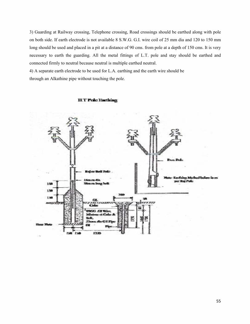
55
3) Guarding at Railway crossing, Telephone crossing, Road crossings should be earthed along with pole
on both side. If earth electrode is not available 8 S.W.G. G.I. wire coil of 25 mm dia and 120 to 150 mm
long should be used and placed in a pit at a distance of 90 cms. from pole at a depth of 150 cms. It is very
necessary to earth the guarding. All the metal fittings of L.T. pole and stay should be earthed and
connected firmly to neutral because neutral is multiple earthed neutral.
4) A separate earth electrode to be used for L.A. earthing and the earth wire should be
through an Alkathine pipe without touching the pole.
56
Methods of Earthing.
1) Plate Earthing :
A) In major power stations and major sub-stations 12 mm thick, 1200 m long, 1200 mm wide Cast Iron
plates are used.
B) For minor sub-stations 18 mm broad, 50 x 50 cm. G.I. plates are used. These plates are dug vertically
in the pit. Coal, sand and salt are filled in the pit each of 150 mm layer. The plate should be dug deep so
that soil will be wet from all sides. The plate should be placed at a distance of 1200 cm. from each other.
2) Pipe Earthing
A) For Power Stations, and major sub-stations 12 mm thick, 150 mm dia, 300 cms. Long G.I. pipes are
used. A minimum distance of 1200 cm. should be kept between earth electrodes in major sub-stations and
180 cms in case of minor sub-stations. At least one electrodes to be used at every corner in sub-stations.
Each electrical equipment structure and the entire metal fitting should be earthed. Three earth electrodes
are used for polemounted transformer. The transformer neutral and body should be double earthed. A
minimum 8 S.W.G. G.I. wire should be used for earthing. Separate earthing should be done for
distribution box. 7/10 SWG G.I. wire should be used for tower earthing, and for S/s. gantries 3mm thick,
50 mm x 50 mm M.S. plate is used. G.I. pipe of 25 mm thick, 1910 mm long is used for H.T. line, and 20
mm thick, 1720 mm long for L.T. lines.
The purpose of coal and salt is to keep wet the soil permanently. The salt percolates and coal
absorbs water keeping the soil wet. Care should always be taken by watering the earth pits in summer so
that the pit soil will be wet. Coal is made of carbon which is good conductor minimizing the earth
resistant. For sub-station earthing the provisions in I.S.I. 3043 (1966) Section 1,2 & 3 should be utilized.
Joints: - Rivets are used for joining the earth system, nut bolts or welding also used depending on the
temperature rise of the system.
The joint to earth conductor in switchgear unit or cable sheaths required to be separated frequently,
hence nut bolts are used at joint. In case of steel system they should inconsistently be by welding. Only
the places where earth testing is carried, should be nut bolted.
All joints should be properly painted. Channel, supporting control boards and panels are used as
earth electrodes (This is possible only when they are connected to earth system at both ends.)
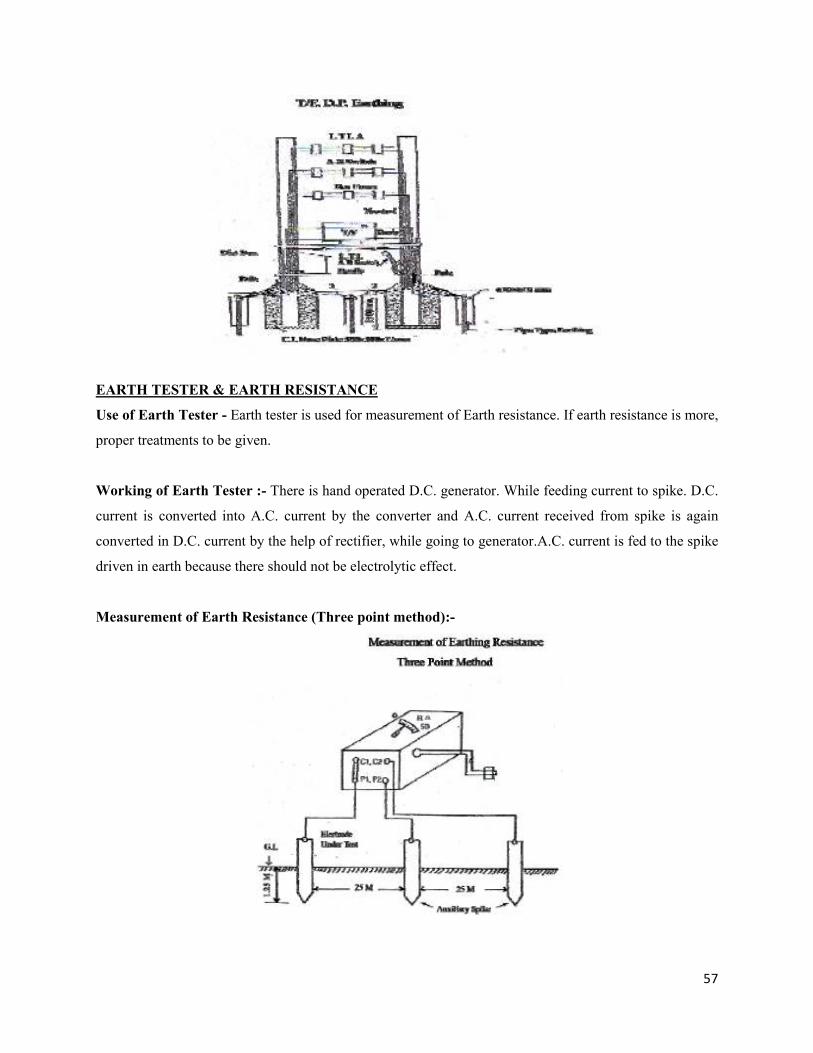
57
EARTH TESTER & EARTH RESISTANCE
Use of Earth Tester - Earth tester is used for measurement of Earth resistance. If earth resistance is more,
proper treatments to be given.
Working of Earth Tester :- There is hand operated D.C. generator. While feeding current to spike. D.C.
current is converted into A.C. current by the converter and A.C. current received from spike is again
converted in D.C. current by the help of rectifier, while going to generator.A.C. current is fed to the spike
driven in earth because there should not be electrolytic effect.
Measurement of Earth Resistance (Three point method):-
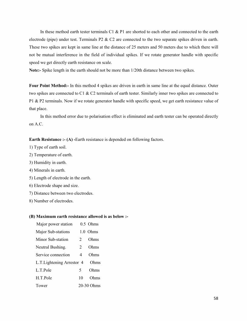
58
In these method earth tester terminals C1 & P1 are shorted to each other and connected to the earth
electrode (pipe) under test. Terminals P2 & C2 are connected to the two separate spikes driven in earth.
These two spikes are kept in same line at the distance of 25 meters and 50 meters due to which there will
not be mutual interference in the field of individual spikes. If we rotate generator handle with specific
speed we get directly earth resistance on scale.
Note:- Spike length in the earth should not be more than 1/20th distance between two spikes.
Four Point Method:- In this method 4 spikes are driven in earth in same line at the equal distance. Outer
two spikes are connected to C1 & C2 terminals of earth tester. Similarly inner two spikes are connected to
P1 & P2 terminals. Now if we rotate generator handle with specific speed, we get earth resistance value of
that place.
In this method error due to polarisation effect is eliminated and earth tester can be operated directly
on A.C.
Earth Resistance :- (A) -Earth resistance is depended on following factors.
1) Type of earth soil.
2) Temperature of earth.
3) Humidity in earth.
4) Minerals in earth.
5) Length of electrode in the earth.
6) Electrode shape and size.
7) Distance between two electrodes.
8) Number of electrodes.
(B) Maximum earth resistance allowed is as below :-
Major power station 0.5 Ohms
Major Sub-stations 1.0 Ohms
Minor Sub-station 2 Ohms
Neutral Bushing. 2 Ohms
Service connection 4 Ohms
L.T.Lightening Arrestor 4 Ohms
L.T.Pole 5 Ohms
H.T.Pole 10 Ohms
Tower 20-30 Ohms
59
If earth resistance is more than above values, following Treatments can be made for minimizing
resistance.
1) Oxidation on joints should be removed and joints be tightened.
2) Sufficient water should be poured in earth electrode.
3) Earth Electrode of bigger size as far as possible be used.
4) Electrodes should be connected in parallel.
5) Earth pit of more depth & width- breadth be made.
60
CHAPTER-8
TRANSFORMERS ERECTION, MAINTENANCE & FUSE GRADING
Transformers: Need, Types & Applications.
Need: - In our Power Generating Stations, electricity is generated at 15 kV or less voltage. It would be
un-economical to transmit the electricity at such a low voltage because of its high current. As well as
there will be voltage drop & conductor size will also be required to be increased very much.
Hence, the power generated in generating stations is stepped up in voltage by means of Power
Transformer. The Power transmitted at high voltage is again stepped down for Distribution purpose
at low voltage because three phase equipments and single phase equipments/ appliances are designed to
work at 440 v. & 230 v. respectively as per I.E. rules. Hence for proper distribution, also transformers are
used.
Advantages: -
1. Transformer being a stationary machine, there is no wear and tear.
2. High voltage insulation can be provided due to stationery windings.
3. Low cost of maintenance because less maintenance is required.
Capacity: - The capacity of Power Transformer is denoted in MVA & that of Distribution transformer is
denoted in KVA.
Types: - Transformers are classified in two basic types.
1) Power Transformers.
2) Instrument Transformer.
Power Transformers can further be classified as :
a) As per cores - 1) Core type (2) Shell type.
b) As per phases - 1) Single phase (2) Three phase.
c) As per windings - 1) Single winding. (2) Two windings.
61
d) As per voltage - 1) Step up (2) Step Down.
e) As per application 1) Power Transformer (2) Dist. Transformer.
Note: - In a Power Transformer (1 MVA & above) voltage is changed and then it is sub transmitted by
transmission lines.
Power (0.5 MVA or less)
But in a Dist. Transformer, line voltage is reduced and is used to cater load on secondary side.
There are two main types of Instrument Transformers.
1) Current Transformer ( C.T.)
2) Potential Transformer (P.T.)
Applications of Instrument Transformer are:
1) To isolate metering instruments, relays & wiring from main supply.
2) To convert high voltage & current as per instrument capacity ratings.
3) To maintain & standardize voltage & current ratings of instruments and relays.
Note:- Current Transformers are always connected in series & Potential transformers in Paralleled with
the line.
Auto Transformers: - Autotransformer is a Power transformer with a single winding having a
central tap. Auto transformers are economical only when transformation ratio is 1: 3 or near to it.
Transformer Parts and Accessories.
Definition: - The stationary equipment, which converts high voltage to low or vice versa by virtue of
magnetizing effects and keeping magnitude and frequency of the electrical energy the same, is called
transformer.
Principle of working :- It works on the principle of Mutual Induction.
Mutual Induction :- When the transformer winding is connected to induce voltage in it. It is also known
as back emf. and the process to form the induced voltage is known as Selfinduction.
The same magnetic field also cuts the secondary winding to form induced voltage in it.This is
known as Mutual Induction.
62
Transformers are mainly classified in (1) Power Transformer and (2) Instrument transformer and
Step Up or Step down as per the application.
Parts of Transformer
(1) Main Tank: - It is made of steel sheets by welding them. In the main tank, core, winding and
transformer oil is placed.
(2) Core: - It is a set of 0.35 mm thick high-grade electrical steel sheets. Both sides of these lamination
sheets are coated laminations with insulating varnish to insulate them electrically from each other. The
shape of the core can be square shape or stepped shape windings are assembled on the limbs of the core.
Magnetic flux is transformed from one side to other through the yoke.
(3) Winding: - Windings of the transformers are assembled on limbs of the core while
Assembling the windings on core, first L.V. winding is assembled and H.V. or Secondary winding is
assembled over it. Conductors of both the windings are coated with insulation varnish. In addition to that,
they are covered with paper and cotton tapes, which are properly impregnated with insulation, vanish.
Both windings are insulated from core and main tank by providing sufficient electrical insulation. Primary
is generally connected in delta whereas secondary is connected in star. As the resistance of the winding
conductor is very low, it cannot be supplied with D.C.
Back emf is not created in D.C. and hence the current will flow excessively thereby
damaging the coil. Whereas in the case of A.C., due to impedance and back e.m.f., current does not
exceed the limit.
Accessories of Transformer :-
1) Bushings: - Winding leads are to be taken out of the transformer tank for connections. To maintain
sufficient safe clearance of these leads from body, Porcelain bushings are provided on Primary and
Secondary sides of the transformer. Rain sheds are provided to the bushings to protect them from
rainwater.
Oil filled or condenser bushings are used in case of EHV Transformers.
2) Explosion Vent :- On the top plate of the transformer tank, a narrow pipe of sufficient diameter with
diaphragms on its both ends is fitted. One diaphragm is in between the oil in the tank and the pipe
whereas the upper diaphragm is at the top end of the pipe. Whenever there is severe fault inside the
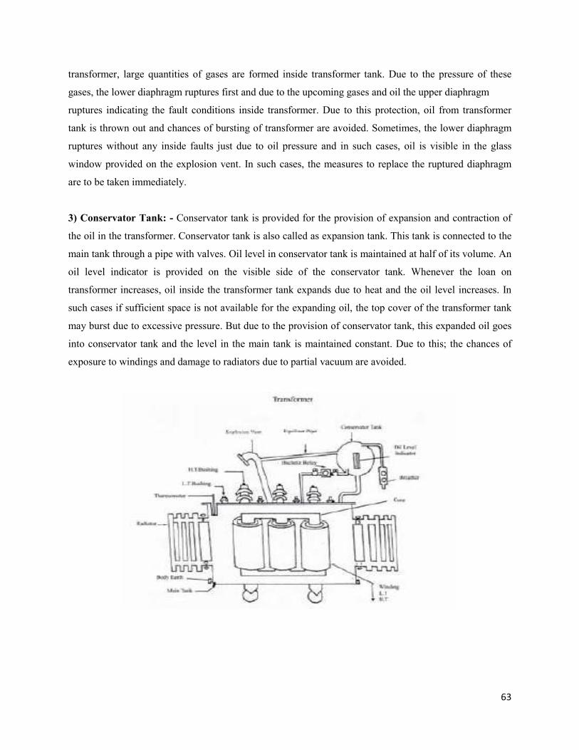
63
transformer, large quantities of gases are formed inside transformer tank. Due to the pressure of these
gases, the lower diaphragm ruptures first and due to the upcoming gases and oil the upper diaphragm
ruptures indicating the fault conditions inside transformer. Due to this protection, oil from transformer
tank is thrown out and chances of bursting of transformer are avoided. Sometimes, the lower diaphragm
ruptures without any inside faults just due to oil pressure and in such cases, oil is visible in the glass
window provided on the explosion vent. In such cases, the measures to replace the ruptured diaphragm
are to be taken immediately.
3) Conservator Tank: - Conservator tank is provided for the provision of expansion and contraction of
the oil in the transformer. Conservator tank is also called as expansion tank. This tank is connected to the
main tank through a pipe with valves. Oil level in conservator tank is maintained at half of its volume. An
oil level indicator is provided on the visible side of the conservator tank. Whenever the loan on
transformer increases, oil inside the transformer tank expands due to heat and the oil level increases. In
such cases if sufficient space is not available for the expanding oil, the top cover of the transformer tank
may burst due to excessive pressure. But due to the provision of conservator tank, this expanded oil goes
into conservator tank and the level in the main tank is maintained constant. Due to this; the chances of
exposure to windings and damage to radiators due to partial vacuum are avoided.
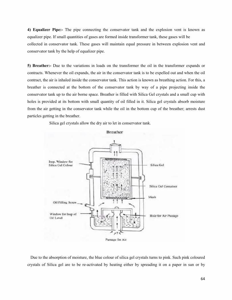
64
4) Equalizer Pipe:- The pipe connecting the conservator tank and the explosion vent is known as
equalizer pipe. If small quantities of gases are formed inside transformer tank, these gases will be
collected in conservator tank. These gases will maintain equal pressure in between explosion vent and
conservator tank by the help of equalizer pipe.
5) Breather:- Due to the variations in loads on the transformer the oil in the transformer expands or
contracts. Whenever the oil expands, the air in the conservator tank is to be expelled out and when the oil
contract, the air is inhaled inside the conservator tank. This action is known as breathing action. For this, a
breather is connected at the bottom of the conservator tank by way of a pipe projecting inside the
conservator tank up to the air borne space. Breather is filled with Silica Gel crystals and a small cup with
holes is provided at its bottom with small quantity of oil filled in it. Silica gel crystals absorb moisture
from the air getting in the conservator tank while the oil in the bottom cup of the breather; arrests dust
particles getting in the breather.
Silica gel crystals allow the dry air to let in conservator tank.
Due to the absorption of moisture, the blue colour of silica gel crystals turns to pink. Such pink coloured
crystals of Silica gel are to be re-activated by heating either by spreading it on a paper in sun or by
65
heating it slowly in a metallic vessel. Whenever the crystals turn white, it renders useless and are to be
replaced by new. Oil in the bottom cup of the breather also needs replacement if it becomes dirty.
6) Tap Changer :- It is essential to control the voltage in the system for two reasons.
i) To control the flow of KW & KVAr in the lines connecting generating stations.
ii) To maintain voltage at consumer end as per I.E. rules (+ 6%)
Voltage regulation is done by means of change of number of turns in H.V. winding with the help of
tapings and the tap changer switch provided outside the tank. In a three-phase transformer, the
arrangement of the switch is made in such a manner that the contacts of all the three windings are
changed simultaneously. This tap changing assembly is known as Tap changer. There are two types of tap
changers.
(a) Off Load Tap Changer:- Off Load Tap Changer is provided to transformer on H.V. windings by
making taps on them. Connection of off load tap changer is brought on the top plate of the tank. It is oil
immersed and is located in main tank. It is designed to carry full load current of the transformer and is
dissimilar to Circuit Breaker design i.e. it is not designed to work under loading conditions. Hence if Off
load tap changer is operated while the transformer is "ON"; there can be severe damage to the transformer
and so the taps in such type of tap changer are changed by switching the transformer "OFF".
(b) On Load Tap Changer (O.L.T.C.) :- In this type of the tap changers, transformer tap can be changed
while the transformer is "ON" and is under loaded conditions. It is not essential to switch off the supply in
this type of changer.
The operations can be local manually; local electrically and remote electrically as per requirements.
There are various types of OLTC as per constructional difference.
1) Winding is done in circuit and in this arrangement; taps can be operated serially without making the
transformer “OFF”. In such arrangement, twice the number of tappings is required as compared to normal
tapings of the winding.
2) Preventive Reactor Type Changer: - In this type, reactor from the central tap is used whenever the
contacts are connected to any tapping, the current is divided and it flows in opposite direction in the
reactor and gets neutralized. During the transaction, two tapings are connected to reactor thereby causing
more losses and resulting into more noise.
Maintenance:- Damaged fixed contacts to be replaced by removing them from the insulated phase board
after disconnecting the leads. Moving contacts and springs if required can be refitted. Retaining pins clips
should be replaced by new. Oil in the tap changer is to be filtered generally after 30,000 operations
66
through the drain valve and top cover valve of O.L.T.C. During filtration, switching unit should be
cleaned thoroughly with fresh oil and carbon deposits in the switch unit to be removed.
During the normal maintenance, driving mechanism should be inspected. Gear teeth, rollers etc.
should be lubricated using grease and polydrum disulphide. Filters pads may be cleaned by using petrol or
by vacuum cleaner.
7) Buchholtz Relay :- Buchhoultz Relays are used for transformer above 500 KVA. It is a gas operated
relay and is used in Power transformers. Whenever there is fault inside the transformer; due to
decomposition of oil, gases are formed in bubbles. These bubbles pass through the pipe connecting
transformer tank and conservator. In this route, the Buchholtz Relay is situated. Gas bubbles are trapped
in the Buchholtz Relay thereby creating pressure. It is made of cast iron. It consists of two floats. In the
upper hollow float, mercury switch is located which is connected to Buchholtz Alarm circuit and the
mercury switch that is located in the lower baffle is connected to the trip circuit. On the top of the relay
chamber, a pet cock is provided for gas sampling. The gases trapped in Buchholtz can be released from
this pet cock. Relay chamber is also provided with a glass window through which the quantity and colour
of gas can be seen. There is a provision for operating the trip and alarm mechanism manually. To pump
air through the pet cock and operate the relay is also one of the simple methods for testing the working of
the relay.
8) Radiators :- Radiators are used to limit the temperature of the transformers to a safe limit.Fins are
provided to the radiators to radiate the heat of the oil to atmosphere more effectively.Hot oil circulates
through the radiator tubes/fins and the heat is radiated to atmosphere by the principle of conduction and
radiation. In the radiator oil circulates downwards because the hot oil in the main tank goes to the top
portion of main tank and to the radiator. After its heat is lost in atmosphere through the radiator, it
becomes cool and goes downwards again entering the main tank through bottom valves of radiators.
Note :- While carrying out oil filtration, all the radiator valves are kept close and after some time, all the
radiator valves are opened to filter the oil entirely.
Some of the accessories are finding their use in Power Transformers recently.
1) Dry Cool Breather :- This instrument works on electronic circuits. In this, the air above the
conservator oil level is dehydrated/ dried in the breather. It is generally used for transformers above 50
MVA.
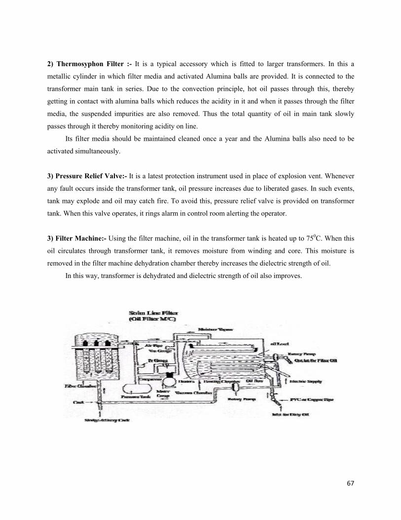
67
2) Thermosyphon Filter :- It is a typical accessory which is fitted to larger transformers. In this a
metallic cylinder in which filter media and activated Alumina balls are provided. It is connected to the
transformer main tank in series. Due to the convection principle, hot oil passes through this, thereby
getting in contact with alumina balls which reduces the acidity in it and when it passes through the filter
media, the suspended impurities are also removed. Thus the total quantity of oil in main tank slowly
passes through it thereby monitoring acidity on line.
Its filter media should be maintained cleaned once a year and the Alumina balls also need to be
activated simultaneously.
3) Pressure Relief Valve:- It is a latest protection instrument used in place of explosion vent. Whenever
any fault occurs inside the transformer tank, oil pressure increases due to liberated gases. In such events,
tank may explode and oil may catch fire. To avoid this, pressure relief valve is provided on transformer
tank. When this valve operates, it rings alarm in control room alerting the operator.
3) Filter Machine:- Using the filter machine, oil in the transformer tank is heated up to 750C. When this
oil circulates through transformer tank, it removes moisture from winding and core. This moisture is
removed in the filter machine dehydration chamber thereby increases the dielectric strength of oil.
In this way, transformer is dehydrated and dielectric strength of oil also improves.
68
Transformer Maintenance:
Transformers give prolonged efficient service if regular inspections and maintenance is carried out.
Maintenance will also require less expenditure if carried out regularly. Following factors need be
considered while carrying out transformer maintenance.
1) Oil :- (a) Transformer oil is a hydrocarbon base mineral oil. It is free from impurities and moisture.
Physical/ Chemical & Electrical properties and their values are laid down as per IS 335:1989. Especially
Dielectric strength of new transformer oil should be minimum 50 Kv for 1 minute.
2) Visual Inspection observations of Transformer oil may be compared with following.
Colour Oil Quality
Yellowish/Transparent/Sparkling 1) Very Good
Yellow/Dull 2) Good
Brownish 3) Bad
Black/Brownish 4) Contaminated
Black 5) Discard able
(b) Oil Temperature:- Transformer temperature rises due to various reasons. Overloading is one of the
reasons for rise in transformer oil and winding temperature. If there is an abnormal rise in winding and oil
temperature of the transformer; it should immediately be isolated and inspected for reasons. Cooling
systems of adequate efficiency should be provided to Transformer. If fans are provided for forced air-
cooling, they should be kept running till the temperature of transformer returns to normal.
(c) Oil Level: - Transformer oil level should be checked regularly. If oil level found reduced due to
leakages or evaporation, transformer should be topped up with good quality fresh oil.
(d) Oil Leakages:-Oil leaks at oil level gauge, gasket sheet, packing gaskets, Bolts, Welded joints,
radiators, valve flanges etc. Any type of oil leakage should be attended on priority. Nuts & Bolts should
be tightened to attend gasket oil leakages. If the oil leakage does not stop after tightening of Nut & Bolts,
the gasket should be replaced by new. If the leakage is from joints then it should be attended by welding.
Reasons of contamination of Transformer Oil.
1) Overloading of transformer. When transformer is overloaded, more heat is generated in transformer
winding causing overheating and oxidation of transformer oil, thereby reducing its dielectric strength.
69
2) Absorption of Moisture - Due to load variation, transformer oil expands and contracts, each time the
breathing action takes place. If oil is inhaling moist air while breathing, Moisture will be absorbed in oil
thereby increasing its water content and reducing BDV/resistivity.
3) Gases:- When there is inside fault, of incipient nature, such as intermittent sparking, partial discharge,
arcing etc., various gases are generated inside transformer due to decomposition of oil. These gases
dissolve in oil thereby reducing its flash point.
4) Sludge:- Due to continuous heating of transformer insulation material such as varnishes, cellulose,
paper insulation etc. get decomposed and dissolves in oil and form a sticky compound called sludge.
Sludge formation results into reduction in heat dissipation capacity of oil thereby increasing O.T. & W.T.
5) Acids:- Due to the combined effect of heat, dissolution of varnishes and cellulose, inorganic & organic
acids are formed in transformer oil thereby increasing its acidity. Acidity when increased, it ultimately
results into reduction of resistivity, dielectric strength and tan delta of oil and also it corrodes the winding
material. Acidic oil is very harmful to transformer health.
Oil Testing :- Transformer oil samples should be tested for various tests regularly. If the dielectric
strength of oil goes down below 40 KV; it should be filtered till B.D.V. reaches to 50 K.V.
Oil filtration by regular type of filter machine cannot reduce acidity of the oil unless the filter is
provided with special attachment of acidity removal Alumina Column.
If the acidity of the oil increases above 0.1 Mg.KOH/gm. Core and windings of transformer should
be checked through inspection manhole. Oil from OCB and Transformer needs to be tested periodically.
Following precautions should be taken while sampling the oil.
1) Sampling bottle, preferably of glass or polythene should be thoroughly cleaned and dried. It should be
rinsed twice with the oil sample itself.
2) Clean the valve externally from which the sample is to be drawn. This would reduce the chances of
contamination of the sample due to dust.
3) Draw the sample by PVC tube as rubber may chemically react with oil.
4) Sample should not come in contact with fibrous cloth or body touch.
5) Cock/Stopper of the bottle should be cleaned with the same oil and be replaced immediately after
filling the sample bottle. This will avoid insertion of any moisture in the oil sample.
6) Always draw the oil sample from the bottom valves of transformer or O.C.B. because the impure oil
with heavy impurities such as sludge, moisture always settles at bottom.
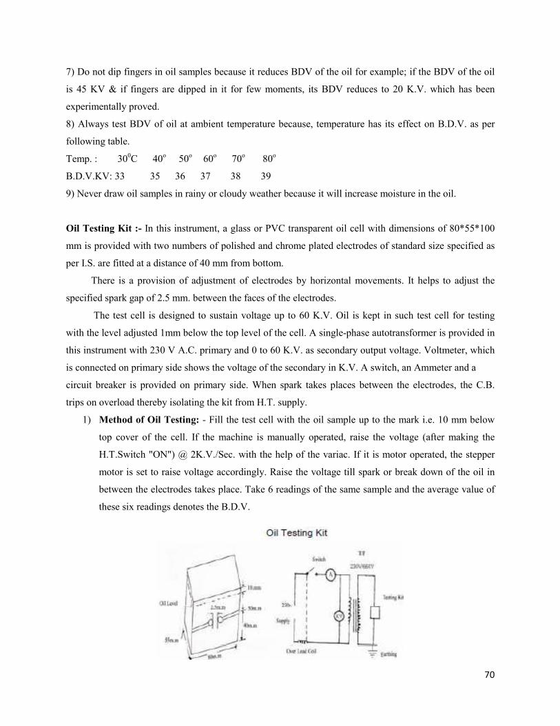
70
7) Do not dip fingers in oil samples because it reduces BDV of the oil for example; if the BDV of the oil
is 45 KV & if fingers are dipped in it for few moments, its BDV reduces to 20 K.V. which has been
experimentally proved.
8) Always test BDV of oil at ambient temperature because, temperature has its effect on B.D.V. as per
following table.
Temp. : 300C 40o 50o 60o 70o 80o
B.D.V.KV: 33 35 36 37 38 39
9) Never draw oil samples in rainy or cloudy weather because it will increase moisture in the oil.
Oil Testing Kit :- In this instrument, a glass or PVC transparent oil cell with dimensions of 80*55*100
mm is provided with two numbers of polished and chrome plated electrodes of standard size specified as
per I.S. are fitted at a distance of 40 mm from bottom.
There is a provision of adjustment of electrodes by horizontal movements. It helps to adjust the
specified spark gap of 2.5 mm. between the faces of the electrodes.
The test cell is designed to sustain voltage up to 60 K.V. Oil is kept in such test cell for testing
with the level adjusted 1mm below the top level of the cell. A single-phase autotransformer is provided in
this instrument with 230 V A.C. primary and 0 to 60 K.V. as secondary output voltage. Voltmeter, which
is connected on primary side shows the voltage of the secondary in K.V. A switch, an Ammeter and a
circuit breaker is provided on primary side. When spark takes places between the electrodes, the C.B.
trips on overload thereby isolating the kit from H.T. supply.
1) Method of Oil Testing: - Fill the test cell with the oil sample up to the mark i.e. 10 mm below
top cover of the cell. If the machine is manually operated, raise the voltage (after making the
H.T.Switch "ON") @ 2K.V./Sec. with the help of the variac. If it is motor operated, the stepper
motor is set to raise voltage accordingly. Raise the voltage till spark or break down of the oil in
between the electrodes takes place. Take 6 readings of the same sample and the average value of
these six readings denotes the B.D.V.
71
2) Transformer Body: - Check transformer body and other parts for rusting. If any part found rusted,
painting should be carried out. Transformer should be painted periodically.
3) Core & Winding: - Core and winding should be inspected once in 5 years and be ensured that no nuts
bolts inside are tight and no sludge deposit is found.
4) Insulator Bushings: - Clean insulator bushings free of dust, using clean and dry cloth. Check bushings
for cracks or chippings. If found, make up with M-Seal adhesive compound.
5) Cable sealing ends: - Check cable boxes periodically for sealing. There should not be leakage of
compound. Gasket joints should be tightened.
6) External connections: - All external connections should be checked. Burnt or rusted connectors
should be replaced.
7) Conservator Tank: - Check oil level in conservator tank regularly.
8) Breather :- Silica gel and oil in the bottom cup of the breather should be checked regularly. Silica gel
if turns pink, should either activated or replaced. Hole at the bottom of breather should be maintained
free.
9) Bucholz Relay :- Inspection of the relay should be regularly carried out and test trials of relay should
be conducted every six month.
10) Explosion Vent: - Inspect explosion vent. If the diaphragm is found damaged, it should be replaced
and cause should be investigated.
11) Gaskets: - Nuts and Bolts of gasket joints should be tightened periodically and leaking gaskets
should be replaced.
12) Coolers and Cooling Fans: - Radiators should be maintained free of dirt and painted if necessary.
Cooling fan bearings lubricated and maintained in good working condition.
13) Earthing: - Neutral earthing should be checked regularly and soil resistivity should be checked
periodically.
14) Tap Changers: - (a) Diverter switch contacts should be serviced. Oil level in the diverter switch tank
should be maintained (b) Driving Mechanism: - Notch controller and contact rings should be maintained
free of dust and do not lubricate them. Heaters should be maintained in working condition. Copper
contacts should be finely surfaced. If copper contacts are silver amalgamated and if amalgamation is
worn, contacts should be replaced. (c) Selector switch contacts should be checked annually.
Note: - 1) Oil testing kits, Megger and gas testing kits should be available in every substation.
2) (a) Silica gel needs to be heated between 150C to 200C for proper activation.
(b) While replacing Silica gel; oil in the bottom cup of the breather should also be replaced.
72
3) While working on transformer, it should be isolated from both the ends and should be solidly
grounded at bushings.
4) (a) While maintaining tap changers, recommendations from manufacturers should be followed.
(b) While carrying out servicing of transformer; if any abnormalities are observed; manufacturers
should be referred along with order reference.
Care to be taken while charging a transformer :-
After complete fitting of accessories of transformer and after proper drying out of transformer and
filtration, following precautions, care is required to be taken.
1) Radiator valves should be open.
2) Conservator tank oil level should be as per marking.
3) Breather should have blue Silica Gel and oil at the bottom cup.
4) Jumper connections on both H.T. & L.T. sides should be properly connected.
5) L.T. cable if provided should be tested.
6) Neutral connection should be proper and as per rules.
7) For Distribution Transformer: -
(a) There should be separate earthing for Dist. box body and Main switch body and it
should be firm.
(b) Neutral of incoming and outgoing cables should be connected to each other.
(A) After confirming the above things.
1) Provide proper capacity D. O. fuses, Keep L.T. Main switch off and charge the transformer.
Check humming of the transformer to be normal.
2) In the Main Switch; voltage between phase to phase and phase to neutral should be tested by Voltmeter
or Avometer and it should be proper as per rating.
(B) Following tests should be conducted prior to charging of new transformer.
(1) I.R.values (2) Continuity Test (3) Insulation Test (4) Ratio Test (5) Short circuit Test (6) Polarity Test
(7) Phase sequence & (8) Phasing out.
1) Megger Test: - While carrying out megger tests, leads of Megger should be properly insulated. For
this purpose, 7/20 swg copper PVC coated wire is adequate. Do not use aluminium wire for lead
connections. Do not touch leads to transformer body.
Note: - In cloudy or rainy weather, Megger results may not be correct.
73
2) Continuity Test: - Megger results for a healthy transformer should be as follows.
H.T. Phase to Phase i.e. R-Y; Y-B; B-R = 0
L.T. -do- i.e. r-y; y-b; b-r = 0
L.T. Phase to neutral i.e. r-n; y-n; b-n = 0
Neutral to body (if earthed) = 0
3) Insulation Tests :- I.R. values should be as follows :
H.T. Phase to Earth.
L.T. Phase to Earth. - Normally above 500 mega Ohms.
H.T. Phase to L.T. Phase.
Neutral to Body (if not earthed)
Note: - With every 10oC to 15oC rise in temperature; I.R. values halve.
Causes of failure of transformer :-
(a) Transformer requires minimum maintenance. But the minimum required maintenance and inspection
is also not carried out and transformer fails due to negligence in maintenance.
(1) Damage of Insulation :- Loosening of core laminations or improper insulation in core, improper or
unhealthy insulation in winding or short circuit.
(2) Bushings: - Cracking of bushings or tracking of insulation due to dust.
(3) Switching Surge or Lightening Surge: - Due to improper earthing to L.A.; failure of L.A. or non
availability of L.A.
(4) Unbalancing or Overloading: - Unbalancing due to uneven load/ phase. Overloading due to
improper size of L.T./ H.T. fuses.
(5) Overheating: - Due to lack of proper Protection, fuses, loss of oil level or loose
connections.
74
Following points/factors should be carefully observed while carrying out
maintenance.
1) Oil Temperature: - Transformer temperature rises abnormally due to overloading. In such case,
transformer should be switched off and cooling fans should be made on for cooling.
2) Oil leakage: - There can be number of oil leakage sources. After tightening of Nuts & Bolts of the
flanges or plates, if the leakage does not stop, gaskets should be replaced. If there is leakage through
welding joints; it should be attended by welding.
3) Bushings should be maintained clean and polished. Cracks/ Chipping if any found should be made up
with M-seal putty. Joints, connections should be maintained tight.
4) Breather: - Silica gel in the breather should be maintained blue as well as hole at the bottom of the
breather should be maintained through.
To identify neutral bushing of an unmarked old Distribution Transformer.
Make primary connections and charge the transformer without secondary connections. With the
help of series test land (i.e. having two bulbs of same wattage in series connection ); test two of the four
bushings on L.T. side with test lamp. If the bulbs glow with full brightness, both the bushings are phases
and if it glows dim, then one of the bushing is neutral. In this way; neutral can be identified by testing all
the bushings.
1) Unbalanced current in neutral is dangerous to transformer and this can be avoided by properly
grounding the neutral.
2) Transformer body earthing as well as neutral earthing should be provided with double conductor each
with separate earth pits and earth electrodes.
3) Some distribution transformers are also provided with explosion vent. In a very loaded areas like
Bhivandi; many times, hot oil is expelled out of transformer bushings or explosion vent causing accidents
and burning injuries to public. For this, L.V. side MCB is a must and it should never be by-passed.
4) Many times, due to some reasons, a phase in an A.B. switch, a fuse in Dist. Box/ or Main switch is
made direct. Such practices should never be adopted and if adopted due to utter emergency, clear cut
danger board stating the changed status should be displayed. This board or safety warnings will be helpful
to avoid accidents.
75
5) Many times, just due to haste, proper discharging of equipment is not done before starting the works.
This practice invites accidents. Discharge rods should have sufficient length such as D.O.rods. Not using
discharge rods just due to idleness habits will invite accidents.
Note:- Discharge rods and handgloves are the protective shields which will save the life of an employee
from all types of accidents occurring due to wrong operations done by others or from unknown faults.
Tap Changers: - Many times low voltage complaints are received from the consumers which are away
from transformer centers. This happens due to drop of voltage and lengthy of distribution lines. In such
cases, tap changers of the transformer should be operated.
To operate the tap changer is not the job of an unskilled helper. Only linemen or Senior staff are
authorized for it. Before operating the tap changer, D.O.fuses should be dropped; transformer should be
made dead and then only tap changer be operated.
Oil leakages should be attended on priority. New transformer when charged, humming
should be checked and if found unsatisfactory; then only load should be taken on it.
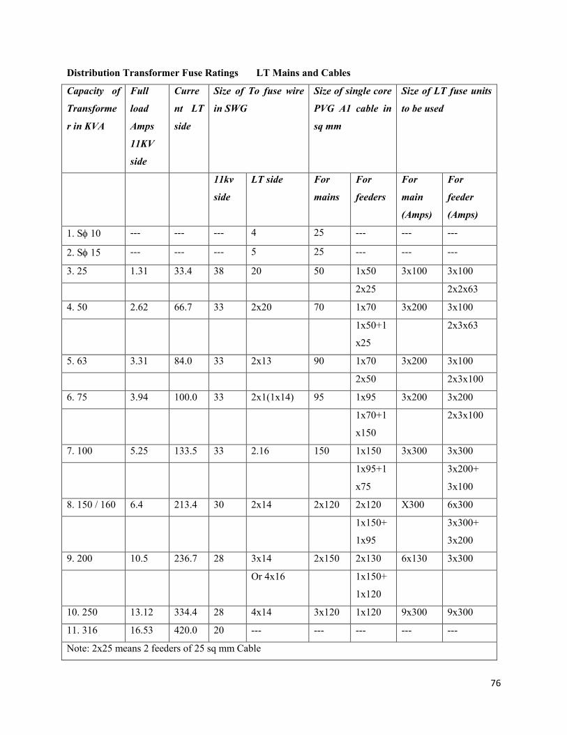
76
Distribution Transformer Fuse Ratings LT Mains and Cables
Capacity of
Transforme
r in KVA
Full
load
Amps
11KV
side
Curre
nt LT
side
Size of To fuse wire
in SWG
Size of single core
PVG A1 cable in
sq mm
Size of LT fuse units
to be used
11kv
side
LT side For
mains
For
feeders
For
main
(Amps)
For
feeder
(Amps)
1. S 10 --- --- --- 4 25 --- --- ---
2. S 15 --- --- --- 5 25 --- --- ---
3. 25 1.31 33.4 38 20 50 1x50 3x100 3x100
2x25 2x2x63
4. 50 2.62 66.7 33 2x20 70 1x70 3x200 3x100
1x50+1
x25
2x3x63
5. 63 3.31 84.0 33 2x13 90 1x70 3x200 3x100
2x50 2x3x100
6. 75 3.94 100.0 33 2x1(1x14) 95 1x95 3x200 3x200
1x70+1
x150
2x3x100
7. 100 5.25 133.5 33 2.16 150 1x150 3x300 3x300
1x95+1
x75
3x200+
3x100
8. 150 / 160 6.4 213.4 30 2x14 2x120 2x120 X300 6x300
1x150+
1x95
3x300+
3x200
9. 200 10.5 236.7 28 3x14 2x150 2x130 6x130 3x300
Or 4x16 1x150+
1x120
10. 250 13.12 334.4 28 4x14 3x120 1x120 9x300 9x300
11. 316 16.53 420.0 20 --- --- --- --- ---
Note: 2x25 means 2 feeders of 25 sq mm Cable
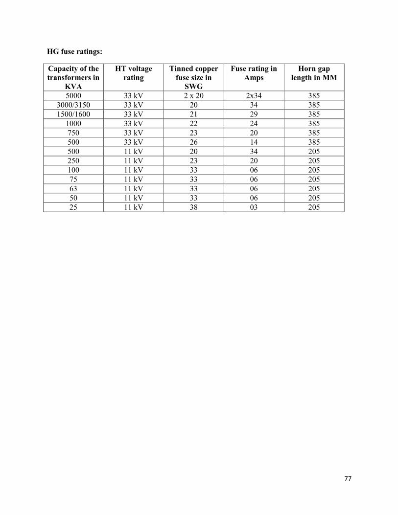
77
HG fuse ratings:
Capacity of the
transformers in
KVA
HT voltage
rating
Tinned copper
fuse size in
SWG
Fuse rating in
Amps
Horn gap
length in MM
5000 33 kV 2 x 20 2x34 385 3000/3150 33 kV 20 34 385 1500/1600 33 kV 21 29 385
1000 33 kV 22 24 385 750 33 kV 23 20 385 500 33 kV 26 14 385 500 11 kV 20 34 205 250 11 kV 23 20 205 100 11 kV 33 06 205 75 11 kV 33 06 205 63 11 kV 33 06 205 50 11 kV 33 06 205 25 11 kV 38 03 205
78
CHAPTER 9
BASICS OF METERING, TYPES OF METERS
Introduction
1) Energy meter is vital equipment in the Electrical Industry. Especially in the present day context of
conservation of energy and conservation of resources, the meter accuracy assumes importance.
2) When the energy measurement is looked at it becomes clear that meter as such is a part of
metering and the energy measurement, therefore depends on not only accurate meter but the
metering system as a whole, which may comprise the associated current and potential
transformers and other wiring practices etc,.
3) When you think of an energy meter, we visualize an induction disc rotating from left to right and
registering the energy by pointers or set of drum type registers.
4) However, the advent of electro static devices and especially the microprocessor based devices
entering the field of metering, has slowly revolutionized the metering.
5) The microprocessor based metering has entered the field in a big way making the meter in fact, a
store house of data. The data is extractable with the help of electronic gadgets by either direct
contact or indirect modem.
Ferari Meters
1) The classical meter is an induction disc meter where rotation is proportional to the energy being
consumed
2) Since the disc is rotating, friction is inevitable and reduction of friction by employing highly
polished single jewel bearings, double jewel bearings or Magnetic suspension type are specified
in standards.
79
The Static Meters
1) The static meter and meters based on microprocessor are generally designed for recording not
only the energy by kWAh but also other parameters such as kVAh, KVARh, etc.
2) The CBIP Technical report No.88 covers the requirements of Static Electrical Energy meters for
Active, Reactive and apparent Energy measurement of accuracy classes 0.2, 0.5, 1.0 and 1.5.
3) The manufacturers are now being asked to make available meters such that a universal Meter
Reading Instrument (M.R.I), can read different makes of meters. For this purpose, they have to
make available the necessary software, through which the M.R.I can extract the meter reading.
Future Metering
1) The future for static meters appears to be very bright and microprocessors based meters are
probably going to dominate the field.
2) Some of the features which are advocated in this area are:
a) Meter with historical data with a few M.B. Memory to store various parameters.
b) Meters to be read by hand held MRIs.
c) Meter to be read by remote reading instruments.
3) The conservation of energy and load management systems demand intelligent meters which
switch off lights in an unused room or switch off the yard lighting automatically.
Some Important Aspects
1) At present, the static meters of class 0.2, 0.5 and 1 are dealt in the CBIP specifications No.88.
This is based on IEC specification No.687, which is for KWh meters only. The CBIP specification
arrived at the requirements of KVARh by suitably adopting the specification for KWh. The accuracy
of kVAh is still dependent on the accuracy of KWh and KVARh.
80
2) The concepts of KWh and rkVAh reference standards have come up in the older days of
Electromagnetic meters where a direct measurement of kVAh for the full range of power factors was
not available. The mechanical summator of L&G design is the technology available for kVAh
measurement, in those days.
3) The measurement of kVAh directly is possible now with the advent of Electronic Technology and
especially microprocessor based and it is time that an independent KVAH is to be thought of. With
this objective, an attempt is made to specify a kVAh meter in the CBIP report No.88
Conclusions
1. A universal type of meter reading is to be developed by the manufacturers of static meters, by
coming to an understanding.
2. Utilities shall go in for latest state-of-art metering technology in a phased manner to achieve
better load management and financial status. However, initially these schemes have to be
implemented as pilot schemes, in small areas, so as to assess the difficulties that arise during
operation.
Methods of Three Phase Power Measurement
There are basically two types of three phase power measurements namely
1) Three watt meter method (Three Phase three element meter or Three phase four wire meter)
2) Two watt meter method (Three Phase two element meter or Three phase three wire meter)
Three Watt Meter Method
In a three watt meter method, three potential coils and three current coils are provided in the meter.
Infact, a three phase four wire meter can be said to be three numbers of single phase parameters
accommodated in one frame, each element (i.e. potential and current coil) maintaining its own identity. A
single common disk is there to record the consumption. It is necessary that operation of each element is
checked separately when it is carrying load current to ensure that all elements are recording in positive
direction and that no negative torque is exerted in any element.
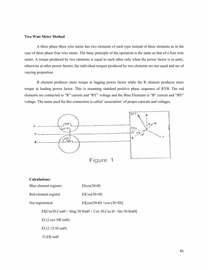
81
Two Watt Meter Method
A three phase three wire meter has two elements of each type instead of three elements as in the
case of three phase four wire meter. The basic principle of the operation is the same as that of a four wire
meter. A torque produced by two elements is equal to each other only when the power factor is in unity,
otherwise at other power factors, the individual torques produced by two elements are not equal and are of
varying proportion.
B element produces more torque at lagging power factor while the R element produces more
torque at leading power factor. This is assuming standard positive phase sequence of RYB. The red
elements are connected to “R” current and “RY” voltage and the Blue Elements is "B" current and “BY”
voltage. The name used for this connection is called ‘association’ of proper currents and voltages.
Calculations:
Blue element register: EIcos(30-Ø)
Red element register EICos(30+Ø)
Net registration EI[cos(30-Ø) +cos (30+Ø)]
EI[Cos30.CosØ + Sing 30 SinØ + Cos 30.Cos Ø - Sin 30.SinØ]
EI (2.cos 30CosØ)
EI (2.√3/2CosØ)
√3.EICosØ
82
It is necessary to maintain appropriate association of currents and voltages. i.e. R current with
RY voltage and B current with BY voltage apart from maintaining correct polarities. The vector
grouping in the poly phase PT should also Yyo with no phase shift between primary and secondary
voltage vector.
Types of Energy Meters
General:
1) Accuracy and proper functioning of energy meters and metering equipment’s are of vital
importance. They should be accurate and maintain the accuracy over long duration to register
the consumption properly.
2) Meters are to be selected according to the load characteristics. Before installing them, they
should be tested. Connections should be proper and at the time of commissioning, registration
of meters should be checked on load. Periodical checking has to be conducted so that the
complete equipment remains well maintained. This will assure proper functioning of the
equipment over a long period.
3) Good quality of meters maintain high accuracy over a long period of 15/20 years with
varying load without recalibration or maintenance, provided they are installed and
commissioned properly and protected from dust, vermins and mis-handling. However, test
checks are to be applied from time to time.
Types of Meters:
1) Single phase meters
2) 3-phase 4 wire meters -L.T
3) 3-phase 3 wire meters -L.T
4) 3-phase 4 wire CT operated meters with MD indication
5) 3-phase 3 wire CT operated meters with MD indication
6) Special meters: 3- phase 3 wire or 3- phase 4 wire Tri-vector or bivector meters(H.T meters)
7) Summation meters for parallel feeders at consumer end.
83
Electronic Meters
Electronic tri-vector meters are now available for providing at the Substations or at the H.T.
consumer’s premises. The special features are described below.
Special Technical Features of Electronic Tri-Vector Meters
The display system of the meters, now consists of
i. Active Energy utilization KWh
ii. Reactive Energy utilization KVARh
iii. Apparent Energy utilization kVAh
iv. Peak Maximum demand Kva
kW (with lagging PF)
v. a) Cumulative demand kVA
b) Billed MD for previous months
vi. Reset Counter
vii. Power Factor
viii. Frequency
ix. Occurrence of missing PT. for supply of voltage
x. Time of the day metering
xi. Time-interval for time of the day metering
xii. Energy- import/export
xiii. Tamper information
xiv. Raising demand with elapsed time
The meters could therefore be used at S/s ends or at the consumer’s end to have accurate data-base and
utilization of energy.
The meters meet with IEC 687 standard and are suitably designed to record accurately with
variation in voltage from +10 to -3% and frequency ±5%. The meters are of 0.5 accuracy. The battery to
meet voltage demand of the circuit is of 3 volt lithium.
84
The multiplying factor can be kept at unity, in order to avoid error due to use of various ratings of
CTs and PTs. Three seals are provided, one on the front cover, one for terminal cover and one for M.D.
reset button. All other features are built-in, to display the details described above. The meters are
designed for CT. ratios of 5 amps or 1 amp on secondary side and PT. ratio of 110 volts on secondary
side.
Installation of Meters with CTs & PTs
In order to increase the range of an ammeter, shunts are generally used. A low resistance shunt is
placed in parallel with an ammeter to measure current which is more than that which the instrument itself
can carry. Similarly in order to increase the` range of a voltmeter, a resistance (with negligible
inductance) is used in series with the instrument. This type of arrangement is used in multi-range testing
instruments.
A very general method of increasing range of A.C. instruments is to use instrument
transformers with ammeters, voltmeters or watt meters etc. The transformers are either current
transformers or potential transformers, which are respectively used to increase current or voltage range of
instruments. The advantages of use of instrument transformers are as follows:
(i) Single range instruments can be used to cover large current or voltage range. The usual ranges
of ammeters and voltmeters are 5 amperes or 1 ampere and 110 volts. .
(ii) The indicating instruments can be located away from the H.T. circuit and do not require
insulation for higher voltage.
(iii) A split core CT. with primary winding on which secondary winding is also wound can be used to
measure the current in heavy current bus-bar without breaking the current circuit.
Installation of Meters
Before installation of meters with CTs and PTs, metering equipment has to be tested for
1. Correct polarity of CTs and PTs.
2. Continuity test of primary and secondary windings.
3. Ratio test by primary injection kit for CTs.
4. Voltage ratio test for PTs by applying L.T. voltage on the primary side.
5. Insulation resistance.
6. Terminal markings as per name plate details.
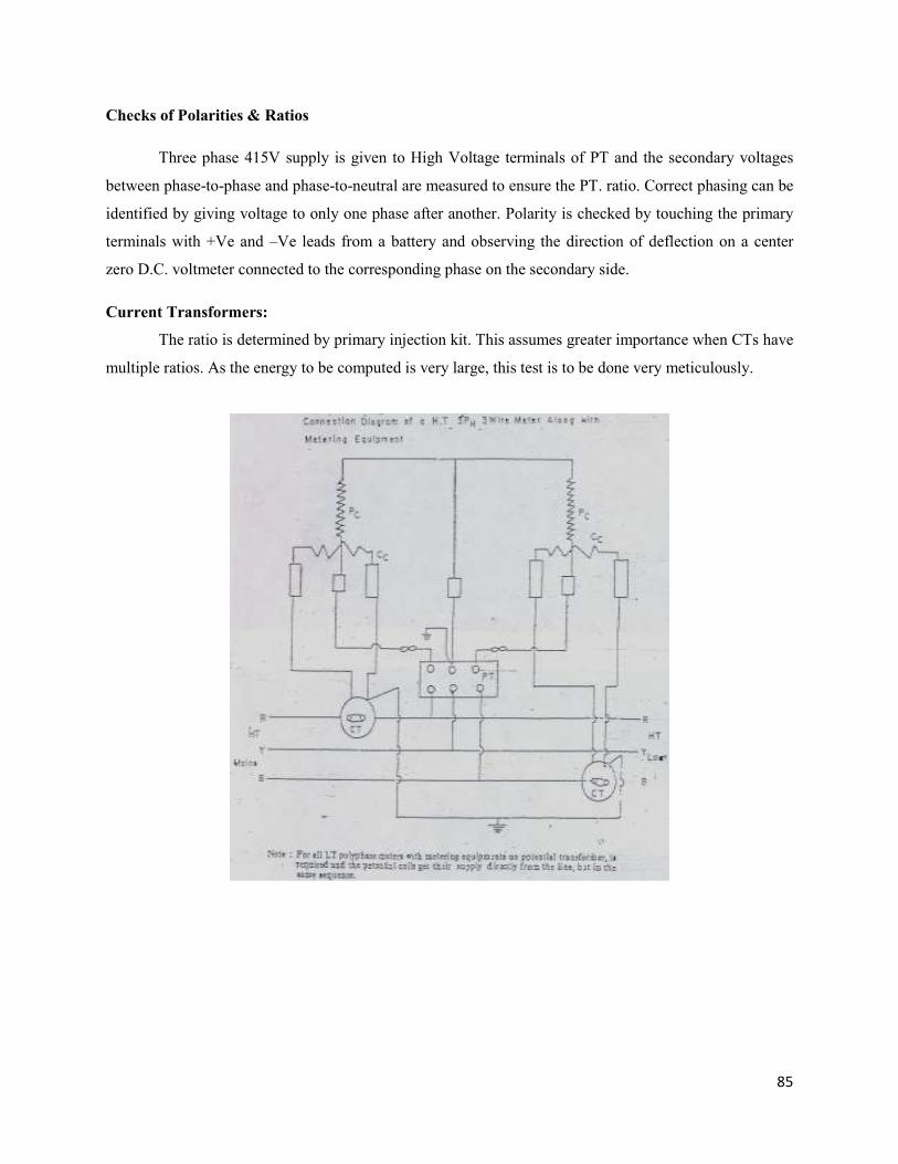
85
Checks of Polarities & Ratios
Three phase 415V supply is given to High Voltage terminals of PT and the secondary voltages
between phase-to-phase and phase-to-neutral are measured to ensure the PT. ratio. Correct phasing can be
identified by giving voltage to only one phase after another. Polarity is checked by touching the primary
terminals with +Ve and –Ve leads from a battery and observing the direction of deflection on a center
zero D.C. voltmeter connected to the corresponding phase on the secondary side.
Current Transformers:
The ratio is determined by primary injection kit. This assumes greater importance when CTs have
multiple ratios. As the energy to be computed is very large, this test is to be done very meticulously.
86
CHAPTER-10
TYPES OF CABLES INCLUDING AB CABLES AND CONTROL CABLES
Cables are named according to the formation, voltage, material used. The cables are also named
according to the use i.e. low tension, high tension cables etc. as per voltage and single core, two core,
three core, 3 1/2 core, etc.
As per the form of the internal conductor, circular sector armoured, unarmoured as per composition
and in addition gas filled, oil filled, PLCC, XLPE, PILC etc.
Generally, PLCC and XLPE cables are used in H.T. network, and oil filled, gas filled for EHV
Network. Proper cable end boxes shall be used for these cables. When the cable is not used, its both ends
should be properly sealed. PVC armoured cables are used for L.T. distribution. Gland should be used at
cable end to have earth continuity with armouring. Gland provides rigidity so that cable will not swing
and damage of insulation, loose connection is avoided.Apply m-seal to avoid water entry in the cable.
Lugs shall be properly crimped at cable ends. Connect the lugs by using nut bolts and washer to
avoid loose connection. Heat is generated due to loose connection and insulation is damaged reducing the
life of the cable. While selecting cable capacity, factor of safety is taken as 1.5.
Generally, there are two types of faults is any electric circuit [1] Open circuit, [2] Short circuit.
The open circuit fault occurs due to break in conductor. The supply is discontinued due to open
circuit. Short circuit means phase to neutral or phase to earth fault due to which fuse blows, C.B. Trips. It
is very difficult to detect the fault point precisely. Meggering can detect the fault. The fault location is
searched with fault detector.
Straight Joint is used for connecting one cable to another cable or after removing small damaged
portion of the cable.
87
UNDERGROUND POWER CABLES
(Construction, design, storing, laying, jointing, testing and fault location etc)
INTRODUCTION
Due to the fast growth in load densities (MW per Sq km) in major towns and cities, 33 KV, 11
KV & LT underground cables are used to meet the ever growing demand of electric power. The
underground cable system has attained much importance in transmission, distribution, and
communication networks mainly due to:
Non-availability of right of way to erect overhead system.
To extend supply from source to load centers on any route profile
To maintain fairly uninterrupted and reliable power supply.
To maintain the aesthetic beauty of the town / city as a whole.
In the towns and cities almost all the roads are already occupied by LT, HT overhead lines,
telephone lines, street light, advertising boards, etc., on either side of the roads. Further, due to upcoming
of the major high-rise buildings, it has become difficult to go for overhead system for sub transmission,
distribution and underground cable system has become a necessity.
Further, multistoried complexes both domestic and commercial are coming up where some
portion in the cellar is made available for housing the transformer. It is becoming increasingly difficult to
take the overhead lines up to the cellar and to extend supply from the cellar to individual flats.
The overhead system with bare conductors is prone for frequent breakdowns causing interruption
in power supply and by employing underground cable ring system uninterrupted power supply can be
maintained.
Selection of Cable: The factors that influence the selection of Cable are (i) Load, (ii)
System Voltage (iii) Type of insulation (iv) Short Circuit rating (v) Mode of installation (vi) Economics
and Safety.
88
For the same conductor size, the maximum continuous current carrying capacity depends on
depth of laying, ground temperature, soil resistivity, ambient temperature, proximity of other cables, type
of ducts used and load cycle. The maximum permissible conductor temperature is as follow:
33 KV 11 KV LT
Paper insulated Lead
covered
650C 700C 800C
PVC 700C 700C 700C
XLPE 900C 900C 900C
Depending upon the voltage at which the power is transmitted or distributed, the cables are
designated as
EHV Cables 66 KV and above
Medium and HV Cables 3.3 KV to 33 KV
LT Cables Insulated to 1100 volts
The initial cost of laying the underground cable system is very high but the maintenance charges
are minimum and also have long life. It is estimated that the cost of underground cable system at any
voltage and for the same current carrying capacity is ten times the cost of an overhead system.
Design Criteria of the Cables
The following are the important factors in designing the cable to meet the requirements.
Conductor :
The Conductor ( core) is to be designed such that it can continuously carry the rated current and
the short circuit current for shorter duration without overheating and voltage drop to be within the limits
prescribed.
89
Insulation:
The materials used for insulation shall have good dielectric strength and proper thickness and
shall be suitable for operating at optimum voltage continuously with high degree of stability, reliability
and safety.
Materials:
All the materials used in manufacturing the cables shall have good mechanical and physical
properties to ensure longer life.
Finishing:
All the materials used for finishing shall have good mechanical and chemical properties to
prevent damage and also to suit environmental conditions.
Sizing of Cables:
The sizing of cable depends on the following:
1. Current carrying capacity
2. Short circuit current
3. Voltage drop
4. Losses
Short Circuit Current:
The short circuit rating of the cables (ISC) is expressed as:
ISC=K*A
√t
Where A is the Cross Sectional area of conductor in Sq mm,’t’ is the duration of short circuit in
seconds and K is a constant depending on dielectric used for insulation.
Voltage Drop:
This is an important consideration in selection of the cable. The voltage drop shall be within the
limits prescribed.
90
Losses in the Cables:
There are two types of losses in the cable i.e.,
i. Dielectric loss
ii. Sheath and Screen loss
Dielectric losses: Cables of same conductor diameter, insulation material and similar construction will
have similar small dielectric losses (watts/m). The dielectric losses will be lower in XLPE cables
compared to paper insulated cables.
Sheath and Screen Losses: Sheath and Screen losses will be proportional to the current carried by the
cable and will be same for stranded cables of same type and size.
Types of cables:
The cables are manufactured for single phase or three phase, Earthed and Unearthed systems as
follow:
Single Core Unscreened, Unarmoured
Single Core Screened, Unarmoured
Single Core armoured, screened or unscreened
Three Core armoured, screened or unscreened
In certain EHV class cables, optic fibre cable is also embedded along with conductor to act as
communication media.
Earthed system:
The Electrical system is said to be 'Earthed System' which fulfils the following conditions:
The neutral point or the midpoint connection is earthed in such a manner that even under fault
condition, the maximum voltage between the conductor and earth does not exceed 80% of the
nominal system voltage.
The neutral point or the midpoint connection is not earthed but a protective device is installed
which automatically cuts out any part of the system, which accidentally becomes earthed.
91
In case of AC systems only, the neutral point is earthed through an arc suppression coil
with arrangement for isolation with in 1 hr of occurrence of fault for non radial field and within 8 hr for
radial field cables provided that the total of such period does not exceed 125 h in a year.
Unearthed system:
The electrical system, which does not fulfill the requirement of the earthed system.
In an electric system where an earth fault is not cleared promptly, the extra stresses on the
insulation of the cables reduce the life of the cable. Therefore if the system is expected to be operate with
prolonged unbalance, it is advisable to select the cable suitable for unearthed system.
Voltage grading (Uo/U)
Earthed system: 1.9 KV/3.3 KV, 3.8/6.6 KV
6.35 KV /11 KV 12.7/22 or 19/33 KV
Unearthed system: 3.3/3.3 KV 11 KV/11 KV
Up to 33 KV voltage level, 3 core cables are manufactured and above this voltage level single
core cables are manufactured because of the increase in the dimensions of the materials and over all
diameter of the cable.
Constructional features of the Cables: (up to medium voltage)
1. Conductor 7. Belting Paper
2. Conductor Screen 8. Metallic Sheath / PVC Sheath
3. Insulation 9. Inner bidding
4. Insulation Screen 10. Armouring
5. Metallic Screen 11. Outer Servicing / Sheath
6. Fillers
EHV Cables:
The following are the constructional features:
1. Conductor
2. Conductor Screen .
3. Insulation
4. Insulation Screen
5. Water Penetration layer
92
6. Metallic Sheath ( Aluminum corrugated)
7. PVC Outer Sheath (graphite coated)
Conductor: The conductor (core) shall be of:
a. Copper or Aluminum
b. Solid or Stranded
c. Circular (Concentric stranded or compact stranded) or sector / segmental shaped
Conductor Screen:
Cables rated above 3.3 KV shall be provided with conductor screening of semi conducting tape
or semi conducting compound for uniform distribution of the stress in the conductor and also to make
core surface smoother over which the insulation is extruded.
Insulation:
The following are the important characteristics of good insulating material:
a) Should have high Sp. Resistance.
b) Should have high dielectric strength.
c) Should be tough and flexible.
d) Should be non -Hygroscopic.
e) Should have thermal resistance i.e, it should withstand high temperature without much
deterioration.
f) Should be non -flammable.
g) Should not be attacked by acids and alkalies.
h) Should be capable of withstanding high rupturing voltages.
Based on the above characteristics different types of insulations used are as follows:
a) Rubber
b) Paper
c) PVC
d) XLPE
Rubber:
Rubber is mostly used for insulating material in the cable. It has a dielectric strength between 2
and 3 dielectric stress of 350 KV / cm, But it absorbs moisture slightly and the maximum safe
93
temperature is approximately 380c. So pure rubber cannot be used as insulation since it cannot withstand
high temperatures and cannot be put up rough usage being too soft. Pure rubber is mixed with minerals
such as Zinc oxide, Red lead etc., and a little quantity of sulphur to make it stronger, durable and capable
of withstanding high temperatures and remain more elastic.
Paper:
Paper made or specific wood impregnated in mineral oils makes it suitable for insulation. It is
cheap, has a low capacitance and high dielectric strength. But it is not hygroscopic. Hence, metallic
sheath of lead or Lead alloy is extruded over the insulation to make it non hygroscopic.
PVC: (Poly Vinyl Chloride):
It is a good thermoplastic synthetic resin and is widely used as an insulating material. It has a
high electrical resistivity and good dielectric strength and mechanical toughness over a wide range of
temperature. It is non hygroscopic and is not affected by acids and alkalies.
XLPE (Cross Linked Poly Ethylene):
Polyethylene is a synthetic thermoplastic resin and is a very good dielectric and withstands long
ageing. Ordinary polyethylene has Linear molecular structure and it is converted in chemical process in to
bonded structure and the process is called cross-linking. This cross-linked polyethylene has good
electrical, mechanical properties and at the same time lighter in weight. It offers flexibility for any route
profile. It can carry more current compared to other type of insulating materials and has better thermal
stability. The XLPE insulation is widely used even for EHV cables.
Insulation and metallic screens:
During power flow through the conductor (core), two types of stresses are developed (i) Radial
and (ii) Tangential stress. The radial stress will be along the conductor and the tangential stress will be
moving in tangential direction. The stresses will pass through the semi-conducting screen (insulation
screen) and in close contact with it is metallic screen of copper tape which is maintained at earth potential
and connected to the earth at the termination which helps in discharging the stresses.
Further, the stress (electric flux) lines are predominant at the point where the screen or shield is
terminated. Discharge could occur at these points, which reduces the life of the terminations and the
cable. The flux lines (stress lines) are to be controlled especially in cables beyond 3.3 KV voltage level.
Necessary stress control is ensured by application of high resistance tapes or by using stress cone.
94
Fillers:
The interstices between the 3 cores are to be filled with non-hygroscopic materials to make the
cable circular shaped.
Metallic sheath / PVC inner sheath:
The paper insulation which is impregnated mineral oils to give insulation properties is not non-
hygroscopic i.e., it absorbs moisture or water reducing the insulation value leading to failure and
breakdown. To make paper insulation non-hygroscopic lead or lead alloy is extruded over belted cores in
paper-insulated cables. In other cables, PVC tape is used as inner sheath.
Inner bedding:
This is an mechanical protective layer. The insulating materials used in cable manufacturing are
mechanically weak and need protection from mechanical damage. This mechanical protection is provided
by A) Steel tape applied helically in two layers (for paper insulated cables ) B) Steel strips / round wires
for PVC and XLPE cables.
Outer serving / sheath:
This is the finishing part of the cable. The paper insulated cable after armouring with steel
tapes, is finished with fibrous material impregnated in bitumen compound and is called outer serving. The
PVC are XLPE insulated cables after armouring with steel strips/ round wires are finished with extrusion
of PVC compound and is called outer sheath. For EHV cables, the outer PVC sheath is coated with
graphite.
95
CHAPTER - 11
SAFETY & FIRST AID
General Safety Precaution & Safety Rules:
Self care as well as co-worker’s has utmost important while carrying out electrical works to avoid
mishap/accident and thereby injuries. The accident will not occur if self safety is observed.
Everybody should follow the following points :-
[A] Safety of the self [B] Safety of the Co-workers.
[C] Safety of the Public [D] Safety of the Company's Property.
Before starting any work, if the working condition seems to be unsafe or if there is confusion, get
matter clarified and then take the work in hand.
Please take following safety precaution before starting the work.
1] Do not consume liquor while working or before coming to work.
2] While working on line avoid cracking of jokes or any foul play.
3] Checkout the working conditions of safety tools and plants like ladder, hand gloves, Zola, safety rope /
waist-belt, etc.
4] Make sure about safety precaution.
Example - Whether line is dead or not, Earthing is done or not.
Basic Elements / Safety Fundamentals:
1] Co-operation of all co-workers is essential to avoid accident.
2] Unsafe worker is burden on the Company, as he may become the cause of accident to self as well as to
others.
3] Use of incomplete or little knowledge is dangerous and may invite accident.
4] Accident is the result of unsafe working condition and unsafe work.
96
General Causes of Accidents :
a] Working without authority.
b] Doing work in an unsafe way, such as throwing T & P/ line material or doing hasty work.
c] Using higher capacity fuse or by passing the fuse.
d] Use of improper T & P Example - using pliers instead of Screw-Driver, using pliers in place of
spanner, not using insulated pliers or screw - driver etc.
e] To work on unsafe or dangerous equipment such as - cleaning / greasing or adjusting any of running
m/c.
f] Diverting the attention of worker from his work or cracking jocks etc. at work place.
g] Non-use of safety equipments and T & P like - ladder, Zola, waist belt / rope, hand gloves, D.O.
operating rod, Earthing rod, etc.
h] Working in insufficient light
Precautions to be taken while working on live line / equipment :
1] All the elect. Circuits or equipments are hazardous. Hence do not start work unless following steps are
taken -
a] Circuit is in off condition
b] Line clear permit is taken on equipment.
c] Equipment / Line is properly earthed.
2] Every Elect. line / equipment should be first made off and take line clear permit before taking the work
in hand.
3] It is essential to get authorized permit on 11 KV and above voltage line. If the line is under own
authority, then take self-permit.
4] Make sure that feeder / equipment is made off and properly earthed as noted in line clear permit.
5] A.B. Switch should be kept off and locked. If possible, keep somebody there for watch / ward.
6] Line should be got discharged and earthed by earth - rod at one pole before and after the work place
before starting the work.
97
7] Make sure that all men and material has safely reached / climbed down to ground after completion of
work. Further, make sure that no T&P left on the line and earth rods are removed properly.
8] While operating A.B.Switch or other line equipments Hand gloves should invariably be used.
9] Use the safety belt or Zola and waist belt / rope while working on line.
Most of the accidents / eventualities can be avoided, if above instructions followed while working
or before working on Elect. Lines/Equipments. If proper attention is given, accident to the worker himself
and also the co-worker can be avoided.
Safety Equipments & Safety of Equipments:
We have taken the information of general safety precautions. Now we will see which are the safety
equipments and how to use and where to use the same. What care should be taken for the safe use and
safety of these safety equipments. Following equipments / T&Ps are known as safety equipment and
the technical staff must use them properly.
SAFETY EQUIPMENTS / T&P
1] Rubber Handloves:Rubber handgloves are mainly of two types and used for HT & LT Line
respectively. The handgloves meant for L.T. lines should not be used for H.T. Line work. Handgloves
should invariably be used for following works -
1] For closing and opening of A.B.Switch and isolators.
2] For discharging the HT & LT lines and equipments, using discharge rod and for Earthing work.
3] For inserting and taking out of Distribution box fuse and pole fuse.
4] For operating transformer D.O. and Horn -gap fuse
5] For on or off O.C.B. operations.
Safety Precaution for Keeping & Handling Handgloves :
1] Use handgloves, where it is essential.
2] Do not fold handgloves and don't store them with other material.
3] Don't keep any T & P etc inside handgloves.
4] Always keep gloves clean and dry. Boric Acid Powder be used inside and outside.
5] Use gamaxin powder for vermin proofing of gloves.
6] Inspect the gloves carefully for any cut or leakage, etc. before use.

98
II] Bamboo-ladder:
1] Always use bamboo - ladder for climbing on pole.
2] Ladder shall be of 6 meters length.
3] The ladder shall be varnished or oiled so as to keep safe from rain / water. Never use metallic colours
to ladder.
4] Metal - ladder should not be used unless permitted.
5] Only one person shall climb and work at a time on ladder.
6] Discard the damaged ladder.
III] Discharge - Rod:
The discharge rod shall be used to discharge the static and induction charge of the power line after
opening it. The discharge rod is a prime importance safety tool, which can safeguard from unforeseen
dangers and even fatal accident.
1] Discharge rod shall safeguard in the event of opening line other than earmarked. The question will not
arise to say " I was not aware of it ' or ' I don't know how it happened. ", because the discharge rod will
safeguard from above eventuality.
2] The use of discharge rod safeguards us from all types of back feeding cases / eventualities such as -
a] Consumer may start his generator set.
b] The line is charged by some mischievous or unknown person not having adequate knowledge.
c] The area of T/F under shutdown due to fault, the line is charged from other source.
d] Power swing may cause charging line if the guarding is not provided at line crossing.
e] Line clear permit is given, but forget to open the line.
f] Operator may forget that the line is under permit and he may charge the line for testing etc.
g] The change in status of line feeding is not known to the operator after returning from long leave, etc.
h] The use of discharge rod safe guards from above type of eventualities.
The line should be treated charged until the neutral or earth wire is discharged. There is
possibility of charging of line due to static charge, induction or fault current. Hence first discharge the
line by using discharge rod.
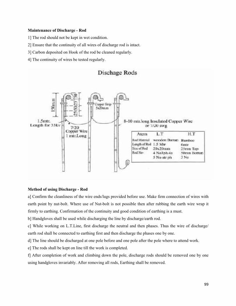
99
Maintenance of Discharge - Rod
1] The rod should not be kept in wet condition.
2] Ensure that the continuity of all wires of discharge rod is intact.
3] Carbon deposited on Hook of the rod be cleaned regularly.
4] The continuity of wires be tested regularly.
Method of using Discharge - Rod
a] Confirm the cleanliness of the wire ends/lugs provided before use. Make firm connection of wires with
earth point by nut-bolt. Where use of Nut-bolt is not possible then after rubbing the earth wire wrap it
firmly to earthing. Confirmation of the continuity and good condition of earthing is a must.
b] Handgloves shall be used while discharging the line by discharge/earth rod.
c] While working on L.T.Line, first discharge the neutral and then phases. Thus the wire of discharge/
earth rod shall be connected to earthing first and then discharge the phases one by one.
d] The line should be discharged at one pole before and one pole after the pole where to attend work.
e] The rods shall be kept on line till the work is completed.
f] After completion of work and climbing down the pole, discharge rods should be removed one by one
using handgloves invariably. After removing all rods, Earthing shall be removed.
100
g] After this, if we notice that some work is still balance or some T&P, etc. is still left on the line, then Do
not climb on line unless the line is discharged again. The eventuality often occurs within seconds, Hence
don't take risk or don't be hasty and work calmly and with concentration, without any disturbances. There
is no any alternative to discharge rod.
IV] Insulated T&P:
All insulated T&P should be used as per correct procedure. Ensure that the insulation of T&P is
intact before use. Insulated T&P means screwdriver, pliers, tester, etc.
V] Zoola:
Always use zola while working on pole or D.P. etc. Ensure that the rope of zola, thimble, hook, etc.
are in good condition and then only start the work.
VI] Safety - Rope:
Sometime the zoola may broke and worker fell on the ground. Hence while working on zoola, the
worker must use a safety rope on waist. Confirm the knot is tight and other end of this rope should be
wrapped tightly with the pole to avoid any mishap. The rope must be in good condition, quality and size.
VII] Crash - Helmet:
While working on pole or on D.P., the nut bolt, clamp, spanner, pliers and other T&P may fall
accidentally on ground and on head /body of the worker working on ground. Hence the worker should use
the crash helmet as a safety precaution.
VIII] Welding - Goggle:
During welding work, one must wear the welding goggles to avoid injuries to eyes due to spark and
intense light of welding.
IX] Fire - Fighting Equipments:
The bucket full with sand, carbon di-oxide cylinders, etc., should be kept in the substation, offices,
generating station, etc. so as to use the same in case of fire.
X] Gumboots:
The gumboots must be used while patrolling, particularly in the night or rainy season to safeguard
from snakebite /reptile etc. Also, it shall be used while operating D.O. Switch / A.B.Switch, etc. along
with handgloves.

101
Safety of Equipments
The safe and timely maintenance of the equipments used in the substation as well as on line such as
transformers, circuit breakers, battery, earthing, etc. is a prime important duty of technical staff.
Transformers
In case of Power and Distribution T/Fs, always take care that the T/F should not be over loaded
because it can not sustain the higher load / current than rated capacity written on Name-plates. The oil
level of the T/Fs should be watched for adequate level and leakages etc. should be avoided and attended if
any. Lugs of Bushings and jumpers etc. should be properly checked and tightened at the time of
shutdown.
Circuit - Breakers:
For the safety of the lines and T/Fs, various types of circuit - breakers are used. The circuit breaker
oil shall be tested and replaced as per manufacturer’s instructions. The air/gas pressure of breaker should
be checked from time to time and be filled if necessary. The proper working of male/female contacts
should also be got checked at the time of pre-arranged shutdown.
Sub-Station Panels
The regular maintenance of relay and control panels should be carried out. Care should be taken to
avoid loose connection, unnecessary openings to panel. The vermin proofing should be done. The
Earthing nut-bolts should be tightened. The Earth resistance should be measured quarterly. It should be
within limits as per IE rules.
Safety of T&Ps
T&P used for erection and maintenance of lines and s/stn equipment, etc. should be kept in good
working condition so as avoid accidents and for longer life. For example -
1] The rope must be wrapped and kept in proper condition. The rope should not be in wet condition. It
should be knot properly. Damaged rope should not be used.
2] Avoid overloading on steel rope, turfer m/c.
3] Don't use spanner as a hammer.
4] Check zola rope before use.
5] Ladder should be varnished regularly.
6] Handgloves shall be cleaned. Use boric powder before keeping it in store. Do not wrap or keep any
T&P inside it. Proper care of T&P should be taken
102
Rules regarding permit and important notices / information :
1] General :These instructions are given for safe working on electrical installations. These instructions
are given for the safeguard of the worker himself and hence should be followed strictly.
2] Permit :Unless line clear permit is issued by the authorized person, worker should not climb on pole or
apparatus. No one should go in the vicinity of bare conductor and work.
3] Competent and Authorized Person :
[a] Only Shift Engineer or Operation In charge is Authorised to issue permit.
[b] The line clear permit should only be issued to person duly authorised for said work.
[c] The Competent Authority to authorise the person as (a) & (b) is Executive Engineer of that division or
Superintending Engineer only. It is essential to issue written authorisation order.
[d] The permit can only be issued or obtained by such authorised person as (a) & (b) above for the work
and jurisdiction as prescribed in the written authorisation order of Competent Authority mentioned at (c).
[e] The Written Order of Competent Authority mentioned at (c) should invariably be displayed on notice
Board at concerned Sub-station, Power House and Distribution Centers in specific format.
[f] The consolidated Authorisation should be kept at office of the concerned Superintending Engineer.
[g] The Superintending Engineer or Chief Engineer of Circle / Zone can authorise person other than stated
above such as E.E. (Testing) or Testing Staff (Or any other person who is competent to work in the views
of concerned SE/CE) The Area Authority should include the names of such authorised persons in their
list.
[h] The Area Officer should obtain the list of authorised persons of bulk consumers and area in the
vicinity and also handover his list to them.
103
[i] Generally, Line Inspector or Equivalent post persons are authorised for the working on H.T. Line /
Installations. However Division Engineer may authorise the person/persons of below rank if confident
about his skills.
[4] Method of Issuing / Obtaining and returning the Permit :
[A] For obtaining line clear permit, the authorised person should apply to the person authorised to issue
line clear permit and such authority will issue the permit accordingly.
[B] Where it is not possible to obtain permit in writing then permit can be obtained on Telephone. In such
case, the permit obtaining authority should confirm by repeating the matter with permit issuing authority
on phone. The same should be noted in the permit book by both the persons. The duplicate copy of line
clear permit after cancellation be sent to each other by post / in person as early as possible for record. This
register should be inspected by Area / Divisional Officer from time to time.
[C] The permit book is an important record and should be preserved properly.The pages of permit book
should be numbered serially. Pages from this book should not be taken out or torn out or used for any
other work. In case if any page is torn-out or taken-out by some person due to any reason, then the
concerned person should sign on the same and make dated entry in the logbook of S/stn./ Power House
with signature.
[D] The person, who has taken the permit, should return it. In case where the permit issuing and obtaining
authority is same, the self-permit should be taken in his name and cancel after completion of work. This
procedure should be followed strictly.
[E] In case the permit is taken in personally, same can be returned on phone. However, the procedure as
stated in (a) above shall be followed as far as possible (Only in event of Breakdown)
[F] While issuing or returning permit on phone, the code words should be used.
[5] Precautions to be taken while issuing permit :
It is the duty of the Shift Engineer or person issuing the line clear permit to ensure that the
S/Stn./Feeder/Equipment for which the permit is being issued, should be made dead equipment / feeder
should be discharged and properly earthed. First, he should switch off the equipment / feeder as per the
104
instructions laid down. Thereafter, he should follow the following instructions regarding grounding and
locking of equipment.
[a] The H.T. and L.T. side Controlling Isolators of the step down or step-up power T/F should be opened
(off position) and locked, at S/stn. respectively and the warning Board with following instructions should
be tagged on handles of isolators / breakers.
"Do not charge. Workers are working."
"The line / equipment under permit - Don't charge."
"Attention - work in progress - Do not change the line / equipment."
Further, the same type of warning Board's should be tagged on handles of control switchgear. Panel
of ckt. breaker/ T/f etc. The control ckt. fuse of control panel should also be taken out and kept in the
custody of permit issuing authority. Also, the L.V. side breaker of the T/f should be pulled out from the
breaker - panel. The HT and LT Terminals of the T/F should be permanently discharged using discharge
rods and earth rods should be kept as it is until cancellation of permit.
[b] The High voltage potential T/Fs and LA's, if erected on ground level, the same be discharged from
outside the fencing and then earthed perfectly.
[c] Out-door type ckt. breakers should be first discharged from all six terminals and then perfectly
earthed. The both sides isolators of ckt. breakers should be locked in off condition and warning board be
tagged to its handle.
[d] In case of indoor type H.T. Panels, P.Ts should be made off, discharged and perfectly earthed before
permit is given.
[e] Outdoor Bus Bar, isolators etc. and switchgear or complete section of Bus Bar where line clear permit
is to be issued, should be first isolated from all equipments and perfectly earthed. The isolated portions or
parts should be brought to the notice of person to whom permit is being issued and accordingly noted in
the permit. It is possible that some part of isolated switch may remain live; the same shall be brought to
the notice of person whom permit is being issued and noted in the permit.
While doing maintenance work above the ground level, the live parts or conductors may come in
the vicinity of the worker, such possibilities should be brought to the notice of person whom permit is
being issued and in such cases, temp. screening arrangements should be made.
105
[f] At some places, the transformers, isolators are associated with the structure. In such cases, the
climbing on the fuse structure is not advisable. The ladder should be used for replacement of fuses.
[g] Outdoor H.T. (Kiosk) :- The O.C.B. must be switched off in case of outdoor H.T. (Kiosk). The
incoming and outgoing links of OCB, PT and CT should be removed using operating rod and discharged.
The bus isolators of are in live condition and this point should be kept in mind.
[h] Indoor Cubical Gears :- The OCB should be switched off. Use operating rod to open links and earth.
The isolating chamber or incoming cable may be live and such cases should be brought to the notice of
person whom permit is being issued.
H.T. LINE
1] H.T. OVERHEAD LINE:-
The Circuit/ conductor on which work to be carried out, should be isolated by opening the CB and line
links. In case of double feeding circuit, switches of both the ends should be opened and the earth switches
of either end closed if provided or line should be earthed locally before issue of line clear permit. If the
feeders are controlled through trunk type metal clad gears, then gear must be separated from each other.
Where earthing switch is not provided, conductors should be discharged and earthed perfectly.
2] H.T. UNDERGROUND FEEDERS: -
The procedure like overhead lines is also applicable here. Further before taking work in hand it should be
discharged and earthed at specific points.
3] The low/medium pressure circuits, apparatus, equipments, control switches should be opened and made
electrically dead. If circuit fuses are provided, they should be separated or breaker units should be racked
down. The switches should be locked in off position and warning Boards should be tagged on it. Before
starting work, the overhead line conductors should be perfectly earthed till the work is completed in all
respect.
4] Where Apparatus/or switches are remotely controlled, the control circuit fuses should be removed and
kept in the custody of permit issuing authority and handed over to the person of next shift.
106
5] PERMIT LOG IN, ISSUE AND RETURN PERMIT :
All the operations carried out should be logged in the substation log book as per the sequence of
operations. All operations carried out at Down Substation/ up substation/other end person should be
logged in. The last operation regarding issue of/ return of permits should be entered in the log-book with
red-ink. During shift change, the outgoing operator/ Engineer should give the oral information about
pending line permits and logged in the logbook by red ink along with other important information about
pending permit.
The incoming operator/ Engineer should also note about the balance work and note in the log-book
about permit All the sub-station operators concerned should follow the above practice. Equipment / line
should not be charged unless permit is returned and cancelled. The person who has taken the permit
should himself return the permit to the person from whom the permit is taken or to the next duty operator
if shift changes.
6] PRECAUTIONS TO BE TAKEN DURING THE WORK BY PERMIT HOLDER :
[a] The permit holder should ensure before taking the work in hand that equipments / lines, switchgear,
etc. on which permit is taken, are duly earthed. If it is not earthed properly, then the permit holder should
not permit his staff to touch the equipment/switchgear. The information such as the specific places where
one should not climb, the dead equipments, limit switches and structures etc. are brought to the notice
of the co-workers/staff. The no entry warning Board's should be tagged on line portion or on places where
climbing is not permitted. The rope or red-flag can also be used at such places. When one has to climb on
any structure or equipment, which are in the vicinity of live portion, then permit holder himself should be
present there and proper guidance be given to the workers.
7] PRECEAUTION TO BE TAKEN WHEN WORK IS TO BE CARRIED OUT ON LIVE
EQUIPMENT OR LINE:
[1] All the circuits or equipments are to be treated as dangerous one. The work should not be started
unless the following things are done:
(a) Equipment / Line is made off.
(b) Permit is taken.
(c) Earthing is done
107
[2] No work should be carried out on live line or equipment unless permit is taken. If one or more phase
at Distribution Box is made direct, then working on it is dangerous. Hence in such case, by opening the
D.O. Link should make the same off.
[3] It is necessary to obtain authorised permit if work is to be carried out on 11 KV or above voltage line /
equipment. In case of L.T. Line under your own authority, self-permit should be taken so that the chances
of making mistake are eliminated.
[4] Please ensure that the feeders / equipment mentioned in the permit are made off and duly earthed. The
AB Switch should not be opened on load and taking permit on it is a must.
[5] After opening the AB Switch, it should be locked and one person should be kept there. Please ensure
that the three phases of AB switch are opened.
[6] Before starting the work please discharge and earth one pole before and one pole after the work place.
Further, please ensure that no T&P remains on line and then only earthing rod should be removed.
[7] Hand Gloves should be used while operating the AB Switch or any other equipment.
[8] After completion of work, please ensure that all the workers on line have climbed down and no T&P
is remained on line. Then only the earthing rod should be removed.
[9] Always use the waist belt / rope and zoola when working on overhead line.
[10] If the different groups are working at different places on line at same time, then clear communication
and understanding should be established between them and they should be fully aware of work and
informed clearly then only operations can be started. Work should not be carried out and line should
not be charged by fixing some approximate time or by fixing fictitious codes. All the relevant information
regarding the network of line, its changeover arrangements, back feeding points, unguarded line crossing
points or places where clearance is very less, possibilities of charging of line from another
transformer/line should be known to workers. In case of parallel lengthy H.T. Lines, the high pressure
may be developed due to induction effect. The spots of multiple feeding points or common street light
phase from 2 or 3 T/fs, should be fully known to workers. The possibility of testing of street light by
workers and from Panchayat / Muncipality organisation from other source may be taken into
108
consideration while attending fuse call complaints. The person who knows all above possibilities / points
is the correct authorised person to attend the work on such lines. Also the person who has clear
knowledge of points from where or up to which point supply could be made off and what are the
dangerous spots, and one who has sufficient knowledge of above points and can inform the same to
person taking permit, is the correct authorised person to issue permit.
[11] H.T. Handgloves should be used while operating H.T. Switchgear. L.T. handgloves should be used
for operating L.T. Switchgear. The L.T. handgloves should not be used in any case for operations on H.T.
line because it may endanger one's life.
[12] Before removing the Earth connection, the discharge rod should be removed first. Also earth
connection should be done before putting discharge rod on the line.
[13] All the three phases of line should be made off even if one has to work on single phase only and self
permit be taken accordingly.
[14] There is danger at place where two different lines are in vicinity of each other, because there is
possibility of touching the hand or conductor to live line. Hence in such cases permit be taken on both the
lines.
[15] Do not climb on line even for putting D.O. links or don't try to put D.O. by climbing on Distribution
Box or using only half operating rod.
[16] While working, one should not wear wristwatch or chain (Metallic) on the neck.
The Methods of Taking Self - Permit
When work is to be carried out by the authorised and competent authority within his own
jurisdiction for issuing the permit, no higher rank authority / person is available, then in such cases, the
concerned competent /authorised person should take permit in his own name and cancel by himself after
completion of work. Such type of permit system called 'Self-Permit system. However, all the rules and
precaution of issuance and cancellation of permit should be strictly observed by person getting self
permit.
109
Accident and Prevention Thereof
Accidents are never occurred accidentally but occurred due lack of safe condition or due to unsafe
working practices. In case of working of Electrical Company/Board, the meaning of occurrence of
accident means either due to Electric current or on the line. There are classified in two categories.
(1) Non-fatal and (2) Fatal accident.
[A] We Can Classify the Accidents as given below so far as work on lines is concerned.
For Ex. : (1) The accident occurred due to falling of poles while stringing of conductor during erection of
poles, erected in non-aligned condition.
(2) Due to non use of proper stay or due to lack of proper earthing, the line may be charged and accident
may occur to persons or animals.
(3) Due to lack of provision of guarding at Road-crossing points and crossing of H.T./ L.T. lines may
result in accident.
(4) The line coming to AB Switch or D.O. fuse is not connected at proper place and proper way.
(5) Accident may occurs when service connection is not provided properly as per standard practice.
[B] Accidents occurred due to work carried out by unauthorised person:-
(1) Using the services of N.M.Rs for overhead work or for placing a fuse link.
(2) Instructions issued to work on live line to the line helper.
(3) When fuse links or meter cutout fuses are replaced by consumer.
[C] Accidents occurred due to ignorance of proper working methods :-
(1) Proper precaution is not taken, while working on such pole which is fed through both sides i.e. at
multi feeding points.
(2) The circuit on which work is to be carried out is not fully and properly made dead, or street light line
is not made off.
(3) Proper precaution / attention is not given when some phase is made direct.
(4) Proper attention is not given to probable danger while doing crossing work of H.T., L.T. lines or
carrying out work at crossing points.
(5) When permit is taken but line is not made off and person sent for patrolling or climbing on pole.
110
[D] Accidents occurred due to non-use of safety equipment :
(1) Not using the safety rope and zoola.
(2) Not using of handgloves or insulated plier, screw driver, etc.
(3) Non - use of ladder while doing work of street - light maintenance.
(4) Non-use of discharge rod, earthing rods at proper place.
[E] Non-obeying of Standing Orders or not obtaining authorized permit :-
(1) To work on H.T. Line without obtaining proper permit.
(2) Carry out work on T/f without opening of D.O. Links.
(3) Where there is H.T. and L.T. lines on same pole and starting of work on L.T. Line without taking
permit on H.T. Line or not making L.T. Line off.
(4) Due to non-use of and lock at AB Switch points.
[F]Accident due to carelessness: -
(1) No proper attention in given while erecting the pole or during stringing line.
(2) Non-use of safety equipment.
(3) While doing work, the wrist watch or metals/ metallic chain of neck are not removed.
(4) Work on live line in over-confidence.
(5) Doing work in unsafe condition or proper safety precaution not taken.
[G] Accidents due to lack of regular or necessary maintenance:-
(1) Not giving proper attention to tree-clearances.
(2) Non-maintenance of broken guarding or earthing.
(3) Non-replacement of broken / kitkats.
(4) Non-replacement of worn out / cracked service wire.
(5) Proper and regular maintenance of T/Fs is not done.
Way of Avoiding Accidents
[A] Responsibility of Super Visors:- Precautions to be taken by supervisor / inspector.
(1) Making safe-conditions and methods and use thereof.
(2) Confirming availability of safety equipments and use thereof.
(3) Proper maintenance of T&P should be got done.
(4) Confirming that workers are doing work in proper way and as per general instructions.
(5) Allotment of work to workers as per their capacity of doing work.
111
(6) If it is learnt or observed that safety precautions and rules are not followed up by workers, then
immediate remedial measures be taken and implemented accordingly.
(7) Confirming that worker knows the following points :
(a) About the work which is to be carried out.
(b) probability of dangers be informed.
(c) Safe-procedure of work adopted by worker.
(8) Repeating the oral instructions and get it confirmed from worker.
Personal Responsibility: Observance of the following precaution is the responsibility of supervisor /
concerned staff.
(1) (a) Self-safety, (b) Safety of Co-workers, (c) Safety of outside persons, (d) Safety of Board's /
Company's assets.
(2) Confirming that worker / supervisor knows about safety precautions.
(3) The doubts about rules / procedures if any should be got cleared from higher authorities.
(4) Informing the doubts or dangers in the work involved if any by the worker to in charge of work and
taking his suggestions.
(5) The improper condition of Board's equipments or some dangerous position if observed, should be
informed to in charge or supervisor.
[B] Personal Behavior:-
(1) Smoking and liquor consumption while on duty is prohibited.
(2) Unnecessary talking other than work or cracking jokes etc. at work place is also prohibited.
[C] Personal Precautionary Measures to be taken before starting the work :-
(1) Always make practice to keep yourself alert mentally and physically. Also take notice of danger -
boards / Markings if any at work place.
(2) Work Safety: Overlook if somebody from worker alleges about you that you are of fearful nature.
(3) The work allotted to you should be got clearly understood.
(4) If some work is done in improper way and nothing has happened that time, hence again doing the
work in same way is not correct way of working and should be avoided.
(5) All the T&Ps and safety equipments be got checked before starting work.
(6) Due to illness or physical weakness if you are unable to work, then the same should be brought to the
notice of supervisor.
112
[D] Reporting of Accidents:-
(1) The report of accidents if any should be immediately reported to all authorities concerned and within
stipulated time.
(2) All the accidents should be analyzed for reason of accident.
(3) Keep the record of accidents along with reasons, so that the accident in future can be avoided.
ELECTRIC SHOCK AND SAFETY MEASURES FOR ACCIDENTS
If any Electric Current passes through the body of the worker, then he feels shock and causes severe
pain. Because, in event of passing of current through our body the body tissues / muscles get vibrations.
The same is called 'Electric-shock'. The resistance of a general person's body between two hands is about
1000 ohms, but if both the hands are in wet condition, than the resistance becomes 150 ohm only. In case
if your hands are wet with salt or salty water, then the resistance becomes 50 ohms only. Therefore, in
Bathroom or at wet places or during rainy season, the electric shock will be severe and can cause fatality.
The reasons of Electric Shock :
(1) Flowing of Electric Charge through our body.
(2) Electric Voltage.
(3) The portion of body comes into contact of live wire. (Area thereof)
(4) Resistance of human / animal body.
(5) Period of Contact.
(6) Higher the portion or area comes into contact of Electric Wire, the Electric shock will also be of that
magnitude.
When a current of 1 mili amp. to 10 mili. amp. with 50 cycles frequency flows through the body
then the tissues of muscles start vibrating and person feels electric shock. But the human body may
sustain flow of current up to this limit only. If electric current of 29 mili.amp. (29/1000 Amp.) started
flowing in the body then the person body looses the muscle control and he became injured. In case 40 to
50 mili.amp. Current flows through the body, then the respiratory system of person fails. In such cases,
the person can be kept survived by using method of artificial respiration.
113
In event of such incidences, the following measure should be taken:-
(1) First dis-connect the power supply and if possible send somebody else for disconnecting the supply.
(2) The person if under contact of live wires / equipments, than do not isolate him by hands or don't try to
isolate him away by standing on wooden planks. Because even if we are on wooden - plank, the ckt. is
completed through body of person getting electric shock and there is possibility that you may get
electrocuted.
(3) If a person came into contact with now or medium voltage line / equipment than using rubber gum-
boots and handgloves, the electrocuted person can be isolated from line contacts. However, confirm that
the things used for such operations are dry and insulated one. If the shock is through H.T. Line then the
safety equipments/items used for separation should be of that much voltage capacity i.e. H.T. Voltage
capacity, otherwise don't try to isolate the person under shock.
(4) After removing / isolating the electrocuted person from live line / equipment, first loose his clothes.
Then take out the pan, Tobacco, Betel nuts or artificial teeth from his mouth. If the respiration system has
failed, than try to give him artificial respiration immediately.
(5) Following important points be noted.
(i) Take remedial measures immediately without delay.
(ii) Passing of time may cause into death of the shocked person.
(iii) Though all electric shocks are of fatal tendency, but timely aid and remedial measures may save the
life of the shocked person. Otherwise delay may cause into certain death.
(iv) The Heart muscles remains live up to 1/2 hour time after shock. Hence, the artificial respiration may
save the life of the shocked person.
(v) Call the doctor/medical help immediately.
(vi) The artificial respiration should continue till doctor or medical help arrives.
(vii) The electric shock with passing of 50 miliampere current for more than 3 seconds, the Heart function
gets failed and resulted into death.
(viii) For flowing of 10 milliampere current at 50 Hz frequency and sufficient enough to cause the flow of
50 volts through the body. Do not get panic in the event of electric shock and continuous try may save the
life of electrocuted person.
114
First Aid to Electrocuted Person
(1) Apply the burnol or furasin type creams to burnt part of body of electrocuted person and do the
bandage. The wound should not come into contact of air. Hence the same should be bandaged properly.
(2) Keep the person warm by wrapping blanket or coat. Do such things that his body should remain worm
enough.
(3) If possible, both the feet of him should be kept in worm water.
(4) If the electrocuted person become unconscious then do not give him any drink / water etc.
(5) Do not give him any toxic drink unless doctor permits.
(6) Arrange immediately for giving articificial respiratory system.
(7) After the person become conscious please do the following things :
(a) Enough quantity of water mixed with Soda-bi-carbonate be given to the electrocuted person.
(b) Given him table-salt inhaling.
(c) If his throat is injured or he has pains in throat, no any drink / water be given unless otherwise advised
by doctor.
(d) If the person passes the urine, than keep the urine - sample for pathological tests.
(e) Arrange immediately to call doctor and artificial respiratory system should be kept continued.
(f) Don't try to do anything which can cause mental / physical stress till the doctor is available.
(g) If the person becomes normal then allow him to take rest, the tea should be given.
Treatment on Electrocution (Artificial Respiratory System)
(1) First shut-off the electric supply if somebody is electrocuted. This should be done immediately. If not
possible, don't waste time in searching of switches etc.
(2) Isolate the person from electric supply. While doing so, you should keep yourself safe. Rest on
insulated item/ place like rubber matting, dry wooden plank or linolium. Always use Rubber Handgloves,
dry wooden baton or dry rope or dry cotton. If the person's respiration is stopped then arrange to give him
artificial respiration. The same should be given till the person's respiration starts. There are following
types of methods used for Artificial respiration :
115
1] Mouth to Mouth Procedure: In this system first standup near the head of electrocuted person or sit on
his knee. His head should be kept in down position by one hand and by other hand lift his lower jaw and
you inhale the deep breath and keep your opened mouth on the mouth of electrocuted person.Close his
both nostrails of his nose by one hand and exhale your breath into the lungs of subject person slowly. By
doing so, see whether his chest get expanded or not. Then keep your mouth away and again inhale deep
breath in your lungs and repeat the procedure as mentioned above. Try to repeat such artificial
respiration about 10 to 12 times in a minute. If there is some difficulty in doing so, try to push more the
persons head and again pull the lower jaw. If again you find it difficult to give him this treatment, than see
whether the lips of the person are open and try to see if the teeth are jammed, if so, then use the nose to
mouth method.
2] Nose to Mouth System: If the above procedure is not possible than try to use nose to mouth system. In
this system stand up near head of person or sit on his knees. Push his head fully to down side and pull up
the lower jaw of person. Then inhale deep breath and after opening the lips cover the nose of person fully.
By other hand close the mouth of the person tightly and exhale the breath from your mouth in to the nose
of person slowly so that air enter his lungs. See if his chest gets expanded. The same procedure be
repeated 10 to 12 times in a minute. When the person starts breathing his own, then give him such
breathing in a synchronous way and see if his chest gets expanded. When person comes to comfortable
position, allow him full rest. Put him on a stretcher and see that no any difficulty comes in his respiratory
system. His body should be wrapped in a cumble or blanket and keep him worm. The unconsciousness
position due to electric shock may cause damage to his heart. Thus every worker / engineer should know
this method and try to get training of such procedures.
Note:
(1) If the practice of nose to mouth is required to be done, then the air will go slowly, to the electrocuted
person. Hence this system is more safe and in case when the nose of the person electrocuted is very
narrow then the system of mouth to mouth should be adopted.
(2) If it is observed that the throat of person is very narrow or closed due to some object, then the same
should be cleaned by fingers.
(3) In case, the teeth of the person are tightly closed, then use the nose to mouth system.
(4) If possible keep a thin handkerchief on the mouth of the person for using mouth to mouth procedure.
116
(5) For infant or young children if affected, then use the blow of air from our mouth. Send at least 20
times per minute respiration of which respiration should be done.
(6) In case, when we have to use this artificial respiration on pole, then first safeguard yourself from the
live parts and also safeguard yourself from coming into the contact of electrocuted person if he is still
under shock. Stand carefully in such a way on pole by using safety belt so that we place our mouth on the
mouth / nose of electrocuted person.
Always remember that:-
(1) Stop the blowing of air into the mouth of person, if his chest is expanded.
(2) There is a possibility that due to blowing of air into the stomach of person, the blood supply to heart
may reduce or vomiting sensation may occur.
(3) Take out the air from stomach slowly. So we have now learnt the procedure of artificial respiration
mouth to mouth or mouth to nose. Now we will see that how the artificial respiration can be done by way
of muscular movement or with help of some equipment.
Three Systems of artificial respiration :-
(1) Holger Nelson System: In this procedure, first lay down the person in downward position and keep
his hands on back in crossed position, and on that hand, keep his neck in one sided position and give
pressure lightly. Both the shoulder of person. Keep our right side knee near the head of the person and
the feet near the elbow of affected person. Put our palms on the back of affected person in such a way that
our thumbs of both hands rest on back-bone of person and the other portion of palms rests on balance
portion of back side of person. Then start giving light pressure by both the palms on back of affected
person and keeping this position for 2.5 seconds duration and then start releasing pressure slowly from
back. Now hold the arms of crossed - hands of person and put his hands in upward position and pull them
forward. In this way, the procedure should be repeated 10 to 12 times per minute till the person starts
breathing on his own.
(2) Sheffer system (exhale air outside): In this system also lay down the person in downward position
and keep some pillow / or clothes below his head and put his neck on one side. Now lay the knees and on
the back side of waist, bring the thumb of hands in such a way that both the thumbs are near to each other.
Place your fingers of hands on back side of persons fore-arm from both sides. Bowdown on person
slowly. While doing so, give the constant pressure on back of person.
117
Inhaling the Breath: Give a tilt to back side of person in such a way that your hands remain on
his back. For exhaling the breath keep your hands on back of person in the same position. Keep continue
both the works simultaneously. This simultaneous procedure is to be done with rate of 15 times per
minute. The reason behind this is to keep the respiration continuous of electrocuted person through the
expansion and contraction of lung muscles. The person doing this function should breath slowly for
exhaling and inhaling action by pushing / pulling the electrocuted person and he can see the effects of this
action and amount of pressure will maintain and will result into synchronizations of breathing of affected
person. This procedure should keep continued till the person electrocuted starts breathing of his own.
This exercise may take 1/2 hour or more to get proper effect of respiration. The subject system described
above is considered as best system. The pressure should be 20 to 25 pound magnitude.
(3) Silverester's System: Lay down the electrocuted person in upward position. Loosen the clothes
on his chest and stomach. A pillow should be placed below his shoulders in such a way that the neck and
head of the affected person will be in some what downward position. Then pull his tongue outside. The
person giving treatment should sit on his knees near the affected person. Keep the hands of the person
below the elbow and pull his hands till it becomes parallel to earth. This treatment should be given for 3
seconds. After that, bring both the hands of person below his chest and press the chest to inside position.
This action should be given for 2 seconds. Thus the procedure be repeated 10 to 12 times per minute. In
this system since the head of the affected person remain in upward position, the effect or action of
artificial respiration can be seen immediately. If the persons treating the affected person, are more one,
that during every action, the tongue of the person be pulled upward when lungs get expanded and push it
inside, when the lungs get contraction.
Note:- For man, give 20 to 25 pound pressure for 10 to 12 times. In case of women and child, the pressure
should be 10 to 15 pounds for 10 to 12 times per minute. For very young child or infant, the pressure
should be 15 times per minute. This procedure be kept continued till the affected person starts taking
breath of his own.
FIRST AID
The first-aid is a prime - importance in event of any accident. Hence, everybody should know the
methods of first aid.
(1) Bring the affected person at peaceful and airy place and care should be taken that he should not get
suffocated.
118
(2) All the parts of body of affected person be kept in straight position and should be laid down on even
spot.
(3) If he got head injury than lay down the affected person in such a way that his head rest in upward
position.
(4) If he is having trouble in proper respiration, then he should be kept in sitting position.
(5) If he is in the epilaptic condition, then lay down him ensuring that his head is below the level of his
body.
(6) If he is having wounds, then take water in one small bucket and add 4 drops of Iodine in it to make it
anti-bacterial and wash the wounds neatly and carefully and dry it. Then apply the iodine on wounds and
wrap it by medicated /antibacterial cotton.
There are four types of bleeding through injuries:
(1) Minor bleeding.
(2) Bleeding through artery or main blood circulatory system.
(3) Bluenen or bleeding from vain.
(4) Internal bleeding.
(A) If the bleeding is of (1) or (3) type, then first tightly wrap the part of body before and after of wound
so as to stop the bleeding. In case the bleeding is of internal type such as in stomach, from brain or trough
lungs etc. then we can not see such type of bleeding. However, it can be seen in the vomiting or spiting of
injured person. The internal bleeding is very dangerous rather than external bleeding. In such situation
give him the cold water or ice and arrange for immediate medical help. The excessive bleeding after
injury may cause death rather than bleeding from wounded spot. Hence arranging immediately for
medical help is MUST.
(B) Injuries to Bones : In event of some accidents, the bones of the body may brea, and the tip of the
broken part may come out along with wound. In such cases, first try to stop bleeding without touching the
wounded part. Then try to join the broken bones by pushing from both the side of wound or broken
point. Whether it is effective or not always wrap the broken body part resting on wooden plank and take
the injured to hospital as early as possible and if the bones of legs are broken then the injured person
should be taken on structure.
119
(C) Injuries due to Burning : In some types of accidents, there may be injuries due to burning. Then never
use the iodine on such wounds, instead we should use soft cloth which should be dipped in the solutions
backing soda with water. Strips of such type of cloth be used for such burning injuries. If the burn
injuries are more, then apply the olive oil on the same. If the burn injuries are due to acid action then we
should first wash and clean the wound using backing soda water. The burn injury is due to carbolinacid
the such injuries be cleaned and washed by spirit.
The following medicines / items should be kept in first-aid-box :
(1) Small size dressing cotton / patty.
(2) Medium size dressing patti.
(3) Large size dressing patti.
(4) Yellow patti or dressing pad for burn injuries.
(5) Clean and sterlised cotton pads.
(6) Tincture - iodine.
(7) Pottessium permagnate.
(8) Sol-violate spirit (for smelling of unconcious person)
(9) Adhesive plaster.
(10) Eye drops.
(11) Boric powder.
(12) Tourniquet.
(13) Three angle bandage (in case of Broken bone)
(14) Safety pins
(15) Soda-Bi-Carbon.
(16) 2 or 3 wooden plaques.
(17) Tablets of Aspirin
(18) Bottle of Dettol
(19) Bottle of spirit
(20) Scissor / knife etc.

120
CHAPTER-12
FIRE FIGHTING EQUIPMENTS
The Chapter IV in Indian Electricity rules specifies the General Safety precautions required to be
taken by supplier of Electrical Energy. The rules regarding Fire-fighting equipment, First-aid box and
Treatment for electric shock are produced below.
Rule No. 43: Provisions Applicable To Protective Equipment.
1) Fire buckets filled with clean dry sand and ready for Immediate use for extinguishing fires, In addition
to fire extinguishers suitable for dealing with electric fires, shall be conspicuously marked and kept in all
generating stations, (enclosed sub- stations and switch stations) In convenient situations.
2) First-aid boxes or cupboards, conspicuously marked and equipped with such contents, as the State
Government may specify, shall be provided and maintained in every generating station, enclosed sub-
station and enclosed switch station so as to be readily accessible during a11 working hours. All such
boxes and cupboards shall, except in the case of unattended sub- station and switch station, be kept in
charge of responsible persons who are trained In first-aid treatment and one of such persons
shall be available during working hours.
Rule No. 44: Instructions For Restoration or Persons suffering from Electric Shock.
1) Instructions, In English, Hindi and the local language of the district, for the restoration of persons
suffering from electric shock, shall be affixed by the owner in B conspicuous place in every (Generating
station, enclosed sub- station, enclosed switch- station and in every factory as defined in clause (tn) of
Section 2 of the Factories Act, 1948 (LXIII of 1948) In which electricity is used and in such other
premises where electricity is used as the Inspector ( or any officer appointed to assist the Inspector, may
by notice In writing served on the owner direct.
2) Copies of the Instructions shall be supplied on demand by an officer or officers appointed by the
Central Government or state Government in this behalf at a price to be fixed by the Central or state
Government.
121
3) The owner of every generating station, enclosed switch station and every factory or other premises to
which this rule applies shall ensure that all authorized persons employeed by him are acquainted with and
are competent to apply the instructions referred to in sub-rule (1)
The Information about different types of fire-extinguishers, their Installation, maintenance and
testing is given below for guidelines. 'At all our E.H. V., H. V. substations, we do have some firefighting
equipment Installed.
In order to have uniform practices everywhere, the fire fighting equipments to be provided for (I)
Major substations viz 66 KV and above (II) Minor substations 33 KV and below. (III) Central Stores etc.
have been standardized vide DOR Circular No. DR/FF/554136 dt.21.11.66.
Carbon dioxide (CO2) Extinguisher 15 Litters or C. T. C. of quivalent capacity 2 Litters (1) 66 KV and
above Substations
(I) Transformers - One for the first -2 transformers.
One for every additional 2 transformers or less.
(2) OCBs – One for the first 2 E.H.V. bulk oil circuit breakers.
One for every additional 2 E.II.V O.C.Bs or less
b) One for the first 3 E.H.V,. Air blast circuit breaker (ABCBs) or Min. oil circuit breakers - one for every
additional 3 E.H.V. ABCBs or less,
Note.:- Where O.C.B.s and ABCBs are both in service in a substation ,they may be either treated as
OCBs or ABCBs depending upon which ever are more.
(3) 33 KV line bus-one if OCBs or ABCBs are in service.
(4) 11 Kv line bus -one If OCBs or ABCBs are in service.
(5) Control panel -one for the panel.
In addition to above, one/two 50 lbs, trolley mounted CO2 fire extinguisher may be provided for all
the above category of substations having 3 EHV transformers or more in service.
Sand and water buckets:
At every E.H.V. substation 6 Nos. each round bottomed sand buckets / water buckets hung on stand may
be prescribed just outside the control houses door leading to the yard. The buckets may he painted from
outside red paint and fire work written on them.
122
First Aid Boxes:
This shall be conspicuously marked and equipped with all contents. This should be
readily accessible during all working hours. This shall be kept in-charge of responsible persons who are
trained In first aid treatment and one of such persons shall be available during working hours.
The Instructions contained regarding (I) Different type of extinguishers (II) Use of extinguisher
(III) Inspection & testing equipment & (Iv) Maintenance of firefighting equipment shall be got noted by
all the staff attached to sub-station.
DIFFERENT TYPE OF EXTINGUISHERS AND ITS USES:
I. Transformers
I. Foam extinguisher : Should be used on fires involving Inflammable liquids.
e.g. petrol, varnish etc.
II. Soda Acid extinguisher : Should not be used on fires involving electricity or Inflammable liquids.
III. CTC and carbon dioxide : CTC and carbon dioxide extinguisher should be only used for electrical
fires, These shall be kept In cable bays, switch yard and control rooms and also in other places where
there Is Likelihood of fire. When the current is switched off, tile fire should be treated as an ordinary fire.
IV. Fire Hydrants : The fire hydrants should be operated only after the power supply is cut off to the
transformer and other equipments. It is also necessary to keep some foam powder and foam branch pipe
for use in case of oil fire in the substation.
All the extinguisher should have the following information
a) Serial Number b) Date of charge c) Date of test
A history sheet for each extinguisher in service should be maintained giving
a) Source of Receipt
b) Date of Receipt
c) Date initial charge
d) Date of subsequent charges.
e) Date of hydraulic test carried out.
123
f) Date of subsequent painting
g) Date when repairs, overhauling work carried out so as to ensure that the extinguishers installed all over
the premises are kept in serviceable condition. .
INSTRUCTIONS REGARDING USE OF EXTINGUISHERS:
Water and sand buckets:
(i) About 2/3rd of the bucket should be filled with water.
(ii) Only loose sand will be filled for about 2/3 capacity of the bucket. No water will be poured on the
bucket Sand if becomes heap will be made loose or replaced.
(iiI) Buckets will not be removed from the fire points except for fire fighting and water/sand filling
therein and shall not be used for any other purposes. This shall be replaced immediately after the
practices.
II. Foam extinguishers:
(i) To operate: (Operated by one man) Release locking device on top of extinguisher. Grasp
extinguisher by handle and base, invert, keep Inverted and direct jets of foam so that a blanket is formed
on the surface or burning liquid
(ii) Recharging: Refill consists of two separate powders. Thoroughly clean the Extinguisher (inside &
outside) with water. See that the nozzle and vent holes are free from obstructions. Mix the powders with ,
water according to Instructions Issued with refill. Pour Into the respective containers. Insert inner
container. Replace filler cap, close locking device.
III. Soda Acid Extinguisher:
(i) To operate : (operated by one man) Remove protecting cap If In use. Grasp extinguisher by handle.
Invert, Strike, on ground so that plunger is driven Into the extinguisher. Keep Inverted and direct
jet on fire.
(ii) . Recharging: Refill consists of a quantity of powder and a bottle containing an acid. Thoroughly clean
extinguisher (inside and outside) with water. See that nozzle and vent holes are free from
obstructions. Mix powder Into ten Liters of water and pour into extinguisher. Place acid bottle in position.
Replace filler cap and screw tight.
IV. Portable Foam Extinguisher (Wheeled) :
This is exactly similar in working principle to the 10 litter type described above but is filled with a
wheeled carriage so that it can be easily moved.
124
Operation:
Take extinguisher to the scene of fire, run out holes. Open sealing valve at head of extinguisher.
Pull down handles so that extinguisher is in horizontal Position. Agitate at intervals to ensure proper
mixing of contents.
(ii) Refilling: The refill consist of –
NO.1 Foam salt or outer container refill.
NO.2 Acid salt or inner container refill.
Instructions for refilling are provided on Label affixed.
INSPECTION AND TESTING OF EXTINGUISHERS
Regular Inspection and testing by makers is recommended, since periodical reconditioning and
pressure testing of the outer container can then be carried out if necessary. For satisfactory performance,
inspection and testing should be carried out by acredited representative of the maker’s. The date of
Inspection should be recorded and attached to each extinguisher. If signs of corrosion are found, the
containers should be replaced.
In all extinguisher's Inspection, the liquid levels should be checked and the hose if any and its
attachments examined to ensure, that they are in good condition.
MAINTENANCE OF FIRE FIGHTING EQUIPMENT:
It is important that portable fire appliances should always be kept in their proper position but if
temporarily removed, they should be replaced.
Portable extinguishers:
All extinguishers should be recharged immediately after discharge and spare refills always kept in
stock. Care should be taken to see that all movable parts are working properly and that the nozzle is not
obstructed in any way.
Recommended maintenance
1) Water type - (Soda Acid): They should be kept properly filled up to but not above the liquid line. After
use they should be taken to see that all movable parts are free from corrosion and see that they are not too
tight to restrict operation or so loose that they allow gas to escape. Keep nozzle and vent holes clear.
Grease plunger spindle. Every month remove filter cap and acid bottle, stir content, replace acid bottle
125
and stir cap.
2) Water type - (Gas pressure): These require the same maintenance as the soda acid type and particular
care should be taken to avoid over filling.
3) Foam type: The contents of both the Inner and outer containers should be maintained at the correct
level. After use they should be thoroughly washed out, including the cap and loose before recharging. The
nozzle and vent holes shall be clear. Grease locking device. Periodically the contents of Inner and outer
containers should be stirred using different sticks for each. Take out a little from each container and mix
outside to ensure formation of foam. The nozzle holes and vent holes should be clear and free from
obstruction.
126
CHAPTER – 13
PERSONAL PROTECTIVE EQUIPMENT & BEHAVIOURAL BASED
SAFETY
“Basic Safety Precaution” is the inherent characteristic that any person should keep in view, while
working on Power equipment. Never should we forget that “Electricity is an obedient servant and
dangerous master”.
There should be some fundamental knowledge that any power worker should imbibe.
1. Operating instructions
2. Line clear approach
3. NBFC ( No Back feed certificate)
4. EARTHING arrangement
5. Deployement of proper tools.
6. Authorisation to work on power equipment and lines.
7. Proper Approach while withdrawing line clear.
8. Withdrawal of any tools or equipment lying on the line, while returning line clear should
be ensured.
9. Earth rods are to be withdrawn before returning line clear.
10. To ensure that effective opening or closing of all AB switch blades as the case may be.
The following protective equipment and safety appliances should be carried by any worker, while
working on lines.
1. Tester
2. Earth Rods
3. Cutting plier
4. HELMET
5. GUM BOOTS
6. Safety Ladder
7. HAND GLOVES ( Suitable to various voltages in operation)
8. Battery Light
9. Test Lamp
127
Besides the above, the “Behavioral based safety” is of prime importance
1. Power worker should never work with over confidence.
2. Worker should never be hasty in taking decision
3. Worker should never attempt unauthorized work.
4. Never a worker should commence work without proper line clear.
5. Worker should always exercise utmost care, while driven by his superiors to rush into the
work.
6. Workers should be steady, and properly proceed to handle the work with proper safety
equipment.
7. Workers should be directed properly by display of “Danger Boards”.
8. The place of working should be neat, clean and tidy.
9. The work site should be adequately illuminated.
10. Electrical circuits should be properly identified by LABLES.
11. In the event of near approach of a lightning storm, all outside work on electrical system
should cease.
12. Loose clothing should not be worn.
13. Shoes with nailed soles should not be worn.
14. Metal key chains or metal keepers for key rings or watch rings should not be worn.
15. Workmen should transfer the tools by tool bag.
16. Workmen should keep in mind that the safety of other workers also lies in his hands.
17. Extra Precautions should be taken while working on damp area.
128
CHAPTER – 14
CUSTOMER RELATIONS MANAGEMENT & COMMUNICATION
SKILLS
ELEMENTS OF BETTER CUSTOMER RELATION MANAGEMENT (CRM)
1. REGULAR COMMUNICATION WITH CUSTOMERS- A NEW UTILITY CULTURE
Communication, a method of sending a message from one person or group of persons to
another , is of vital importance to a business because it involves all the persons and
organizations connected with the business - employees, customers, shareholders, suppliers,
creditors, debtors, media representatives, tax authorities, local government and national government
officials.
Good communication will ensure that all these persons and organizations understand the
message sent, which also makes them likely to respond favorably to the message. Good
communication is not only what is said, but how it is said.
Bad communication makes people confused by the message and less likely to do what the
business wants. Failure of communication may the fault of various factors, such as the message
sender, the receiver , or the choice of channel (written, spoken, electronic, one-way, or two-way
channel).
With regular communication, we are likely to minimize the risk of communication failure,
miscommunication, confusion, misunderstanding the purpose of the message. For a utility it is
vital to stay in regular touch with its customers using a combination of various methods that
may include the following:
Keep customers informed of any short or long term possible changes- for a customer,
any 'news' is bad news.
Offer the customers a free news letter subscription.
Ask customers if they want to be by e-mail when you make changes to your website.
After every new sign up, follow up with the customer to see if they are satisfied with
the sign up/ account activation/ service procedures.
129
Create a customer focus group of ten to twenty of your most loyal customers to meet
regularly and brain storm on ideas and input on how to improve your customer
service.
Make it easy for your customers to navigate on your web site. Have a "Frequently Asked
Questions" page to preempt often repeating questions and save your customer the
effort to make a telephone inquiry.
Have an electronic survey to find out how to make your web site more customer
friendly, as well as how to improve customer service.
Make it easy for your customers to contact you by offering as many contact methods
as possible (phone, fax, email, face-to-face).
Conduct face-to-face meeting to disseminate information that would benefit from
instant feedback and an opportunity of discussion. Use visual aids, such as a
presentation to illustrate main points. This allows for enforcement of the presented
information and encourages discussion, while keeping large gatherings to the point.
Use written messages (direct mailing/ public notices/ newsletter memorandums) to
disseminate information that requires documenting a permanent record, and does not
require quick or any feedback. Use visual aids, such as charts, graphs and photographs
to illustrate key points influence the comprehension of complex messages.
Use internet and company website to disseminate additional/ large amounts of
information or data that needs regular updating. Make sure to keep all information
accurate and up to date to promote consumer trust in the reliability of the company,
and to encourage customers to look for information on their own initiative.
2. CUSTOMER EXPECTATIONS:
The best way to understand and anticipate what the customer is expecting from the utility
is to put oneself in the shoes of the customer and think what you would expect from any
service provider. As the competition in the electricity distribution sector grows bigger and fiercer,
it is often the quality of customer service that makes or breaks a service provider. If a customer
is able to buy the same amount and quality of service/ product for a similar amount of money
from more than one service provider, he is likely to go the one he has had the most pleasant
communication experience. It is, therefore, imperative to consider the numerous different aspects
that are related to customer service, and the various forms of customer service a customer may
comes into contact with the utility. Most typical top priorities and expectations of the customer
130
seem very simple and self evident. Yet, they are not to be taken lightly and are often difficult to
follow:
Be accessible Do it right the first time Meet your commitments, keep your promises Tell the customer what to expect Be socially responsible and ethical Follow up as often as necessary Don't make the customer deal with poorly trained and ill-informed
employees Do what the customer ask for promptly Be responsive to what the customer needs and wants Treat the customer courteously
3. EFFECTIVE SYSTEMS FOR HANDLING CUSTOMER’S REQUIREMENTS – BILLING
AND COLLECTION PROCEDURES:
Improvement in collections is often listed amongst the corporate objectives of a utilities are
focusing on new best practice concepts that strike three key dimensions:
i. effectiveness to reduce bad debt;
ii. efficiency to optimize the cost-to-collect; and
iii. Yield to improve receivables cash flow.
Best practices in collections include:
Credit scoring based on credit risk, not just historical payment timeliness
Offering prepayment products
Offering multiple payment options
Monitoring business accounts for early signs of credit risk
Tailoring collections treatment paths for each customer segment
Optimizing collections treatments while maintaining multi-jurisdiction regulatory compliance
Utilizing outbound calling
Pursuing call centre efficiency
Enforcing consistency in deferred payment agreements
Optimizing use of field disconnections
Taking dynamic collection action, not bound by billing cycles
Employing multiple collection agencies
Knowing when to factor debt
Optimizing cost to collect against debt recoveries
Measuring and monitoring collections performance
Instituting a continuous improvement regime
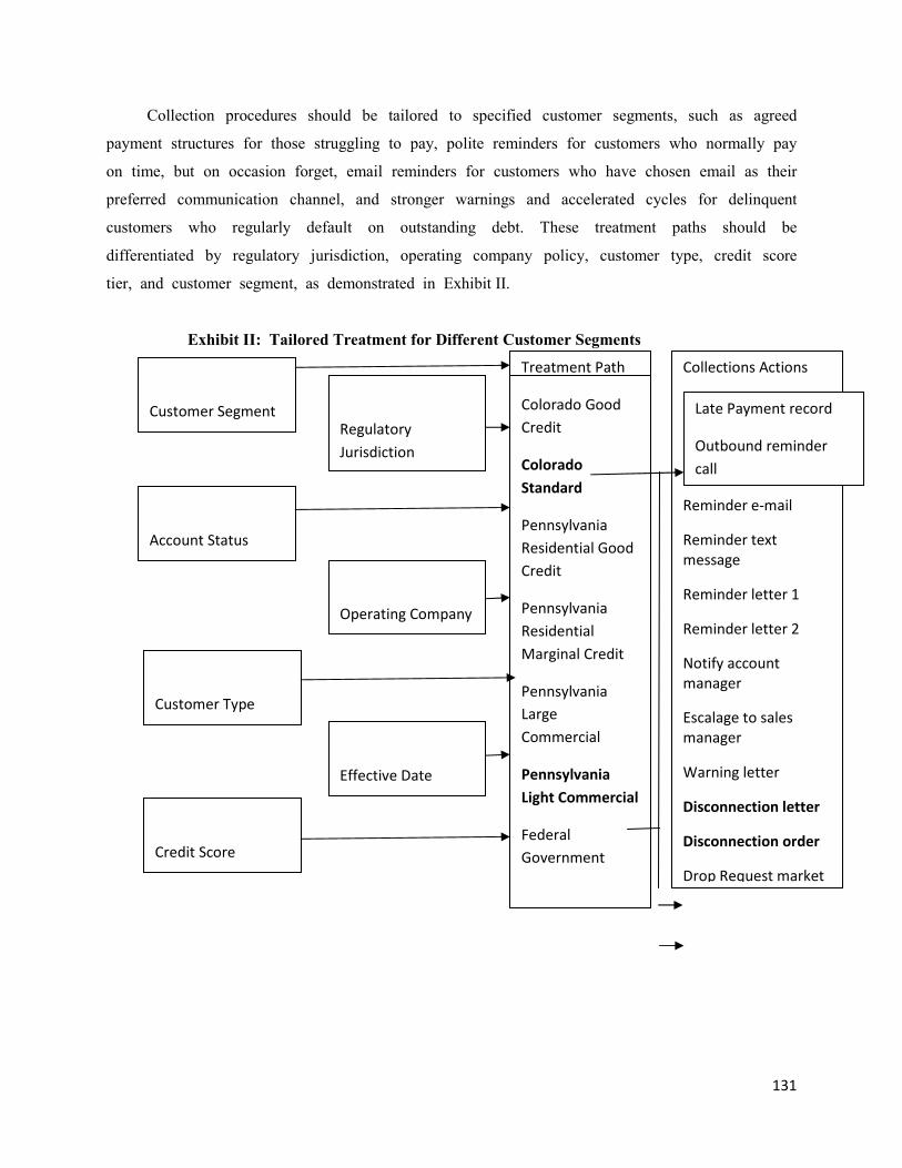
131
Collection procedures should be tailored to specified customer segments, such as agreed
payment structures for those struggling to pay, polite reminders for customers who normally pay
on time, but on occasion forget, email reminders for customers who have chosen email as their
preferred communication channel, and stronger warnings and accelerated cycles for delinquent
customers who regularly default on outstanding debt. These treatment paths should be
differentiated by regulatory jurisdiction, operating company policy, customer type, credit score
tier, and customer segment, as demonstrated in Exhibit II.
Exhibit II: Tailored Treatment for Different Customer Segments
Customer Segment
Account Status
Customer Type
Credit Score
Regulatory
Jurisdiction
Operating Company
Treatment Path
Colorado Good
Credit
Colorado
Standard
Pennsylvania
Residential Good
Credit
Pennsylvania
Residential
Marginal Credit
Pennsylvania
Large
Commercial
Pennsylvania
Light Commercial
Federal
Government
Collections Actions
Reminder e-mail
Reminder text
message
Reminder letter 1
Reminder letter 2
Notify account
manager
Escalage to sales
manager
Warning letter
Disconnection letter
Disconnection order
Drop Request market
Effective Date
Late Payment record
Outbound reminder
call
132
Providing a start date and a data for expiration for the collections policy can allow a utility to
manage seasonal variations, and to
i. try new collections approaches,
ii. measure the impact on such metrics as bad debt and outstanding sales, and
iii. compare the effect of altering variables such as action types and customer segmentation
to fine tune the treatment paths.
Another important collection procedure is to achieve consistency in deferred payment
agreements. In addition to calculating and scheduling multiple installment deferred payment
schedules automatically, best practice should include defined payment agreement policies for each
customer segment. These need to be established to meet both customer needs and regulatory
requirements, and enforced automatically in the call center. Customer payments must be tracked
against agreements in order, which enables the customer service representative to deal with each
customer in a fair and consistent manner. The importance to the utility is highlighted by the that
some customers today use 'rep-shopping', where customers continually phone the call center until
they find a more lenient representative who offers the most favorable terms.
4. OTHER INNOVATIVE SYSTEMS FOR DEALING WITH THE CUSTOMER’S
REQUIREMENTS:
As the market continues to evolve, the key to maintaining a competitive advantage is the
development and implementation of more nimble data tools - especially as they relate to customer
service innovation. Today, advanced technologies related to metering, energy management, and
billing enable the energy industry to leverage future opportunities and minimize risks. At the
same time, these technologies provide a unique opportunity to gain market efficiencies and to
develop competitive customer service offerings.
Meter standards and communications protocols aside, advanced automation, metering and
billing systems have opened up several new avenues foe development of innovative customer
services:
Advanced Building Automation Programs - many new energy savings benefits are
available to building owners through use of the newest developments from the controls
industry. Enhanced building automation can increase the capability of existing energy or
building management systems. These technologies also enable the integrated management
and control of multi-site businesses with multiple meters.
133
Energy Information and Analysis - many utilities are already taking advantage of the
opportunity to provide their customers with information and tools to manage their
energy use more efficiently. The use of interval metered data combined with front-end
tools to enable the input of energy use characteristics for each device provides a wealth
of data to enable more informed energy decisions.
Other potential Uses of Standardized Metered Data - for large users, who often purchase
power from alternative suppliers, the following tools could provide great value in
contracting for energy:
o On-line quotation engines for complex contracts.
o Simulation of multi-supplier options using usage data and transparent methods for
price calculations.
o Making the algorithms of price calculation publicly available in order to enable
electronic contracts.
o Bill audits using usage data to check if bills are correct.
5. PREVENTIVE/PREDICTIVE MAINTENANCE AND CORRECTIVE MAINTENANCE:
Utility personnel perform both preventive maintenance (PM) as well as corrective
maintenance (CM). PM is the scheduled inspection or servicing of equipment at specific points
in time to retain the functional capabilities of the unit. CM is the unscheduled repair of failed
equipment to restore its functional capabilities. Because, generally, corrective maintenance due to
partial or complete system breakdown is much more costly and time consuming, the goal is to
statistically develop a maintenance plan that meets reliability and budget goals.
General objectives of such utility maintenance plan include the following:
Reduce utility and energy costs
control inventory and assets
Extend the life of your equipment
Increase productivity
Improve maintenance responsiveness
Improve facility appearance
Reduce facility and personnel liability risks
Anticipate scheduled maintenance
134
Elements of a utility maintenance plan should at the minimum target the following goals:
Assess and minimize risks
Ensure operational reliability
Identify equipment included in the program
Insure testing, inspection and maintenance of critical components
Provide utility system plans and layouts to personnel operating the system
Investigate utility failures and identify necessary corrective action
Provide training, and education, to all personnel responsible for operation and maintenance
of the systems
Develop performance standards for personnel, equipment operation, maintenance, and
repair
Develop emergency procedures detailing the initial response to utility failures
135
CHAPTER – 15
TARRIFFS AND SCHEMES
1)SC/ST Consumers:
For SC/ST consumers subsidy is given for 200 units/ month as per the following G.Os.
1. G.O.MS.No.91 Dated: 24.07.2019
2. G.O.MS.No.94 Dated: 25.07.2019
The SC/ST consumers avail subsidy for the first 200 units and have to pay
only for the consumption exceeded above 200 units per month.
2)Aquaculture Services:
The actual rate of billing for these services is Rs.3.85ps per month but as per G.O.Rt.No.70
Dated:02.07.2019, theses services are billed at only Rs.1.50ps per unit per month.
3)Solar rooftop services:
The domestic consumers taking solar connections avail subsidy as shown below
1KWp to 3KWp ------ 40% subsidy from CFA(Central Finance Assistance)
4KWp to 10KWp ------ 20% subsidy from CFA(Central Finance Assistance)
4)Agricultural Services:
The agricultural consumers are categorised as Corporate farmers and Non-Corporate farmers. The
consumers who fall under the category of incometax payee are Corporate farmers and those who are
not are Non-Corporate farmers.
Corporate farmers pay --- Rs.2.50ps per unit per month
Non-Corporate farmers --- Nil
If the Non-Corporate farmers have no DSM, they could not avail subsidy and have to pay Rs.2.50ps
same as Corporate famers.
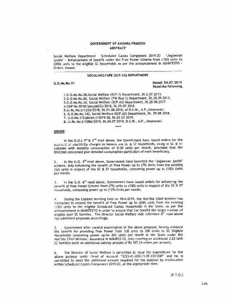
136
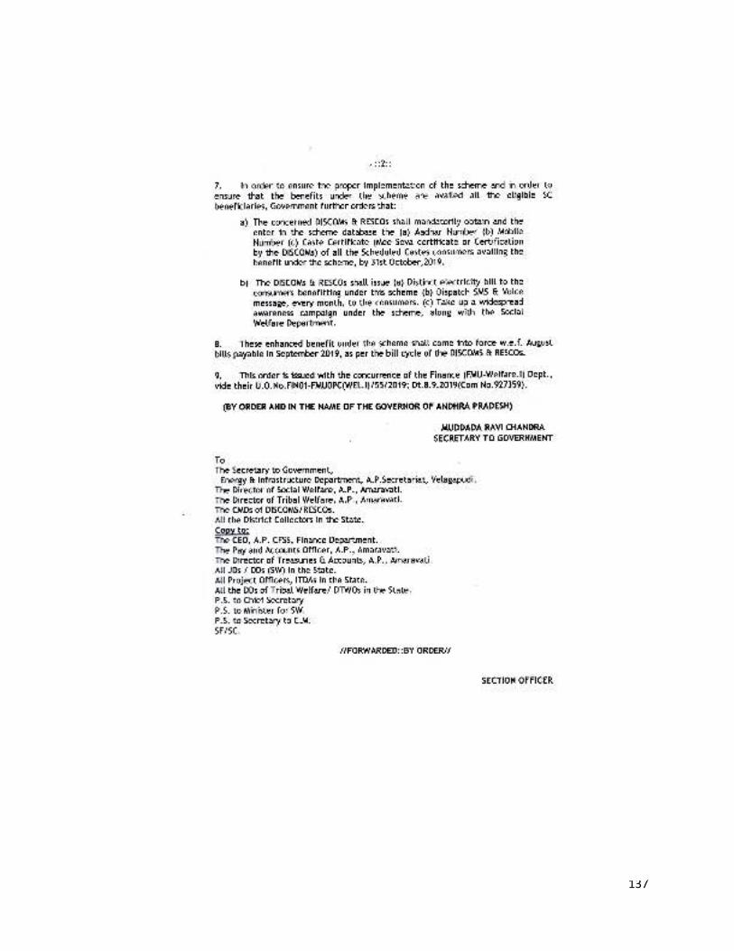
137
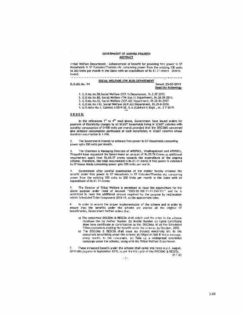
138
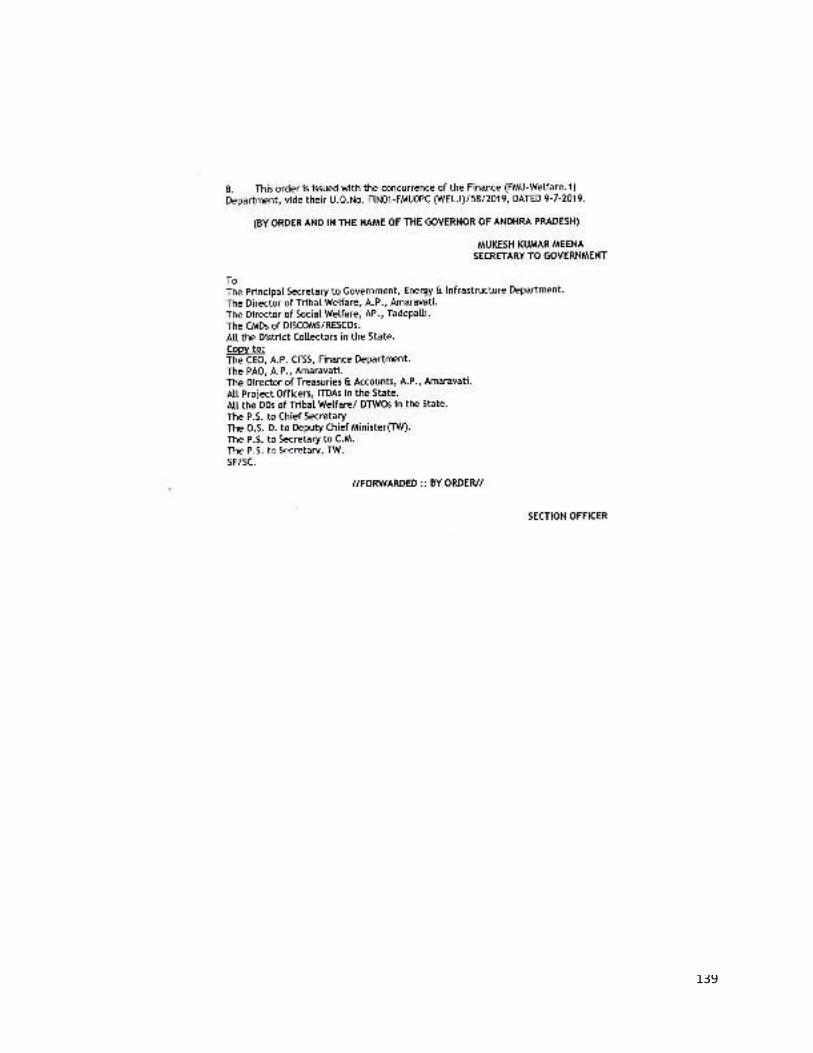
139
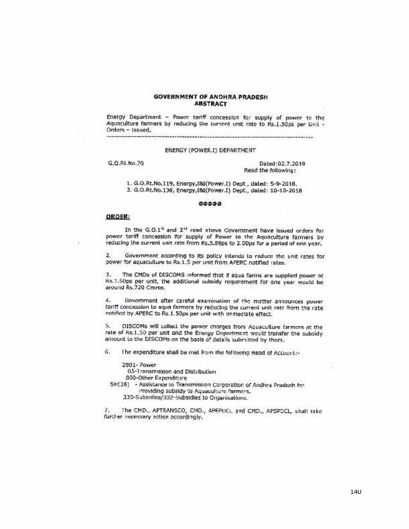
140
141
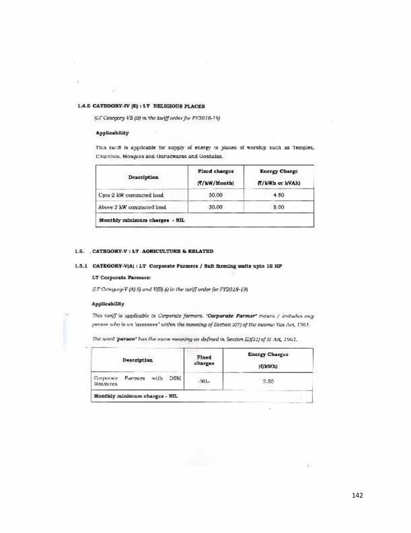
142
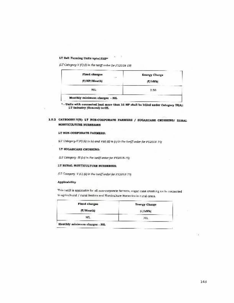
143
144