Energy absorption and ballistic limit of targets struck by heavy ...
20
www.lajss.org Latin American Journal of Solids and Structures 3 (2006) 21–39 Energy absorption and ballistic limit of targets struck by heavy projectile M. Ganesh Babu a , R. Velmurugan a,* and N. K. Gupta b a COMPTEC, IIT Madras b Dept of Applied Mechanics, IIT Delhi, India Abstract Impact on composite structures was a critical topic with great importance in the recent past. In this paper, impact on Glass/epoxy laminates by a 558.6 gms mild steel cylindro- conical projectile, in the range of 30 – 100m/s, was studied. Composite panels consisting of 3 and 5 layers of 3 types of glass reinforcement with different combinations were pre- pared viz.3 layers of WRM/epoxy, CSM/epoxy, Glass Fabric/epoxy, WRM/CSM/epoxy, WRM/Fabric/epoxy and CSM/Fabric/epoxy laminates. Tests were conducted to determine the ballistic limit as well as energy absorption for different initial velocity of the projectile using a piston type, gas gun launcher. A mathematical model based on the energy balance principle was proposed to predict the ballistic limit. The WRM/ epoxy laminates showed higher energy absorption capability and better ballistic limit whereas CSM/Epoxy showed the least of all. Increase in energy absorption was noted up to a certain limit and then de- creases slightly for all the 6 types of panels. The delamination area increased with increase in initial velocity up to ballistic limit and a small decrement was observed from thereon. The ballistic limit determined experimentally was compared with the proposed model and showed good agreement with the experimental value. Keywords: ballistic limit, glass reinforcement, and energy absorption and mathematical modeling. List of symbols Adel Area of the delaminated zone CSM Chopped Strand Mat d f diameter of the fiber E Young’s Modulus El Energy lost by the projectile during impact Etot Total energy absorbed during an impact Edef Energy associated with global plate deflection * Corresp. author Email: [email protected] Received 15 October 2005; In revised form 12 December 2005
-
Upload
khangminh22 -
Category
Documents
-
view
1 -
download
0
Transcript of Energy absorption and ballistic limit of targets struck by heavy ...

www.lajss.orgLatin American Journal of Solids and Structures 3 (2006) 21–39
Energy absorption and ballistic limit of targets struck by heavyprojectile
M. Ganesh Babua, R. Velmurugana,∗ and N. K. Guptab
aCOMPTEC, IIT MadrasbDept of Applied Mechanics, IIT Delhi, India
Abstract
Impact on composite structures was a critical topic with great importance in the recentpast. In this paper, impact on Glass/epoxy laminates by a 558.6 gms mild steel cylindro-conical projectile, in the range of 30 – 100m/s, was studied. Composite panels consistingof 3 and 5 layers of 3 types of glass reinforcement with different combinations were pre-pared viz.3 layers of WRM/epoxy, CSM/epoxy, Glass Fabric/epoxy, WRM/CSM/epoxy,WRM/Fabric/epoxy and CSM/Fabric/epoxy laminates. Tests were conducted to determinethe ballistic limit as well as energy absorption for different initial velocity of the projectileusing a piston type, gas gun launcher. A mathematical model based on the energy balanceprinciple was proposed to predict the ballistic limit. The WRM/ epoxy laminates showedhigher energy absorption capability and better ballistic limit whereas CSM/Epoxy showedthe least of all. Increase in energy absorption was noted up to a certain limit and then de-creases slightly for all the 6 types of panels. The delamination area increased with increasein initial velocity up to ballistic limit and a small decrement was observed from thereon.The ballistic limit determined experimentally was compared with the proposed model andshowed good agreement with the experimental value.
Keywords: ballistic limit, glass reinforcement, and energy absorption and mathematicalmodeling.
List of symbols
Adel Area of the delaminated zoneCSM Chopped Strand Matdf diameter of the fiberE Young’s ModulusEl Energy lost by the projectile during impactEtot Total energy absorbed during an impactEdef Energy associated with global plate deflection
∗Corresp. author Email: [email protected] Received 15 October 2005; In revised form 12 December 2005

22 M. Ganesh Babu, R. Velmurugan and N. K. Gupta
Edel Delamination energyEfrac Fracture energyEfric Frictional energyEd Energy density of the composite laminateFf Frictional forceGIIc Mode II interlaminar fracture toughnessh Thickness of the laminateILSS Interlaminar shear stressLp Length of the projectileM Mass of the projectileRdel Radius of the delaminated zoneR Radius of the plateRp Radius of the projectileV Initial velocity of the projectileVr Residual velocity of the projectileVo Ballistic limitWRM Woven Roving Matwc Central plate deflectionτ Maximum shear strengthσr Radial stressν Poisson’s ratioσy Yield strength of the compositeεr Radial strain
1 Introduction
Fiber reinforced polymer matrix composites have been widely used in aerospace, marine andautomotive structures due to their high specific strength, light weight and stiffness. But the maindrawback with these materials is that they have poor impact resistance. They are susceptible tofailure in the form of delamination when impacted by foreign objects. Impact damage in metal iseasily detected as damage starts at the impacted surface; however, damage in composites oftenbegins on the non-impacted surface or in the form of an internal delamination. The behavior offiber reinforced composites when impacted by a solid object is the subject of much numerical,analytical and experimental research. The penetration and perforation of targets by projectileinvolve highly complex processes, which have been investigated experimentally for more thantwo centuries and analytically during the last two decades [1, 2].
Fiber reinforced laminates have been considered for armor application, glass fiber being morepopular than other types of fiber such as kevlar because of their cost advantage [12]. Cantwelland Morton [4] studied the influence of projectile mass on CFRP laminates under low and high
Latin American Journal of Solids and Structures 3 (2006)
Energy absorption and ballistic limit of targets struck by heavy projectile 23
velocity impact and found that low velocity impact results in global deformation whereas highvelocity impact results in a localized deformation Information yielded by C-scans and opticalmicrographs indicated that, for a given impact energy, decreasing the impactor mass resulted ingreater levels of incurred damage and, therefore, poorer post-impact properties. Fatt and Lin [9]studied the perforation of clamped woven E-glass polyester panels and proposed an analyticalsolution for a fully clamped panel under static indentation by a blunt cylinder. The analyticalpredictions of ballistic limit were within 13% of the test data, while the analytical predictionsof total energy dissipated at the ballistic limit were within 25% of the test results. Duringimpact, matrix cracking, delamination and fiber failure occurred and energy was absorbed in allthese process. But most of the energy was absorbed in plate deflection and delamination, whichreduced the panel bending stiffness and allowed higher transverse deformations to emanate awayfrom the projectile. The more likely mode of failure for a laminated panel was large global platedeformation and tensile fracture [9].
Wen [11] investigated the penetration and perforation of FRP laminates using different shapeof projectiles. Analytical equations were developed for predicting the penetration and perfora-tion by projectiles with different nose shapes. It was based on the assumption that the de-formation is localized and that the mean pressure offered by the laminate targets to resist theprojectiles can be decomposed into two parts. One part is a cohesive quasi-static resistive pres-sure due to the elastic plastic deformation of the laminate materials. The other is a dynamicresistive pressure arising from velocity effects. It is shown that the model predictions are ingood correlation with available experimental data.
Lee and Sun [8] carried out a combined experimental and numerical study of the dynamicpenetration of clamped circular CFRP laminates by a 30g, 14.5 mm diameter flat ended projectilein the velocity range of 24 – 91 m/s. The material used was Hercules AS4 3501-6 graphite –fiber epoxy and the stacking sequence of all the laminates was based on a basic pattern, namely[0/95/45/-45]s. Three types of impact tests were conducted which had two thicknesses and theballistic limits were determined. A finite element model was established to simulate the staticpunch process. It was shown that the computational results were in good agreement with thelimited experimental data. Zhu et al [6] studied the response of kevlar/polyester laminate toquasi-static and dynamic penetration by cylindro-conical projectiles. Ballistic limit and terminalvelocity were determined.
Most of the researchers have studied low and high velocity impact of projectiles on compositetarget. But the impact on composites in the velocity range of 30 – 100m/sec was given very lessimportance. This was critical in the case of automobiles, where the impact was likely to occurwith in this range. In the present case, impacts on different composite targets were carried outto estimate the ballistic limit and energy absorption, based on which a mathematical model wasproposed.
Latin American Journal of Solids and Structures 3 (2006)
24 M. Ganesh Babu, R. Velmurugan and N. K. Gupta
2 Experimental
2.1 Specimen preparation
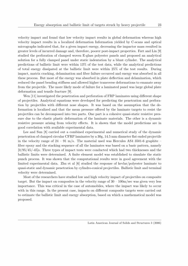
Six sets (combination of WRM, CSM and Glass Fabric) of composite panels consisting of 3and 5 layers were prepared by hand lay-up technique. Commercially available epoxy (AralditeLY556, Hardener HY951) was used as the matrix material. Chopped strand with 600 gsm andWRM with 610 gsm was used in the present study. Uniform thickness was maintained duringmanufacturing for each set of laminates. In case of combination of different reinforcement eitherCSM or fabric was placed in-between two WRM. A weight fraction of 50% (approximately32% volume fraction) was maintained for all the laminates. The laminates were cured in roomtemperature and sufficient time was given for complete curing. The material properties weregiven in Table 1. The panels were cut to a size of 290 x 290 mm by a band saw cutter and theedges were trimmed. Sample specimens for static tests were cut from the same laminate so asto avoid any variation in mechanical properties.
Table 1: Material Properties of different lay-ups.Material Property WRM Fabric CSM WRM/
FabricWRM/CSM
CSM/Fabric
Young’s Modulus (E)‘GPa’
40.2 39.1 36.1 38.6 38.3 37.241.3 39 36.4 38.1 39.2 37.5
Average Panelthickness (h) ‘mm’
2.3 1.9 2.31 2.2 2.25 2.293.9 3.1 3.95 3.76 3.86 3.81
Poisson’s ratio (ν)0.3 0.3 0.29 0.3 0.29 0.290.3 0.29 0.29 0.3 0.29 0.29
Interlaminar shearstrength ‘ N/mm2’
17.44 15.26 15.2 16.2 15.23 15.220.36 16.23 18.3 20.1 17.23 16.23
Tensile strength of thetarget (σy) ‘MPa’
201 189 172 196 186 176211 193 165 203 181 180
Energy Density (Ed)‘MPa’
11.1 10.2 8.63 10.9 10.9 9.615.6 11.6 9.23 12.1 11.3 10.8
2.2 Impact Test
Impact tests were performed on the composite panels using a piston type gas gun setup. Thegun consists of a charging chamber, which has an inlet for charging, an outlet for releasing atone end and a provision to fit a 3.5m long barrel at its other end. The charging chamber wasrested on two steel rails and pivoted at the center. A 2.5-m nozzle made of FRP was designed
Latin American Journal of Solids and Structures 3 (2006)

Energy absorption and ballistic limit of targets struck by heavy projectile 25
and attached to the other end of the barrel in to which the projectile was placed. A stopperwas attached to the FRP nozzle to prevent the projectile from getting into the steel barrel. AProjectile of mass 558.6gm made of mild steel was used in the experiment. The details of theprojectile are given in the Table 2. Figure 1 show the experimental set up used to impact thecomposite specimens.
Table 2: Projectile Characteristics.Characteristics ProjectileLength of the Projectile (Lp) 100Shank Length (Ls) 56Nose Length (Ln) 44Projectile Radius (Rp) 19.6Mass (M) 556.8Cone Angle (θ) 60o
Figure 1: Experimental setup for conducting impact test
The specimen, which was prepared earlier, was mounted in the fixture and clamped on twoopposite sides. The fixture was placed perpendicular to the direction of travel of projectile,at a distance equal to 1m from the end of the nozzle. This gap between the target fixtureand the end of the nozzle was utilized to accommodate the setup for measuring the projectile’sinitial velocity. The projectile was placed inside the nozzle and was accelerated by openingthe release valve electrically, after charging the charging chamber of the gas gun setup with
Latin American Journal of Solids and Structures 3 (2006)
26 M. Ganesh Babu, R. Velmurugan and N. K. Gupta
compressed air up to the required pressure. Initial velocity of the projectile was determinedusing a laser- photo diode setup consisting of a pair of laser emitting source and photodiodes.The two laser emitting sources were mounted on a fixture and separated by a small distance.When the projectile crossed the first laser beam, it triggered the digital counter and the counterwas stopped when the projectile blocked the second beam. From the counter reading and fromthe distance between the two laser beams, the initial velocity of the projectile was calculated.
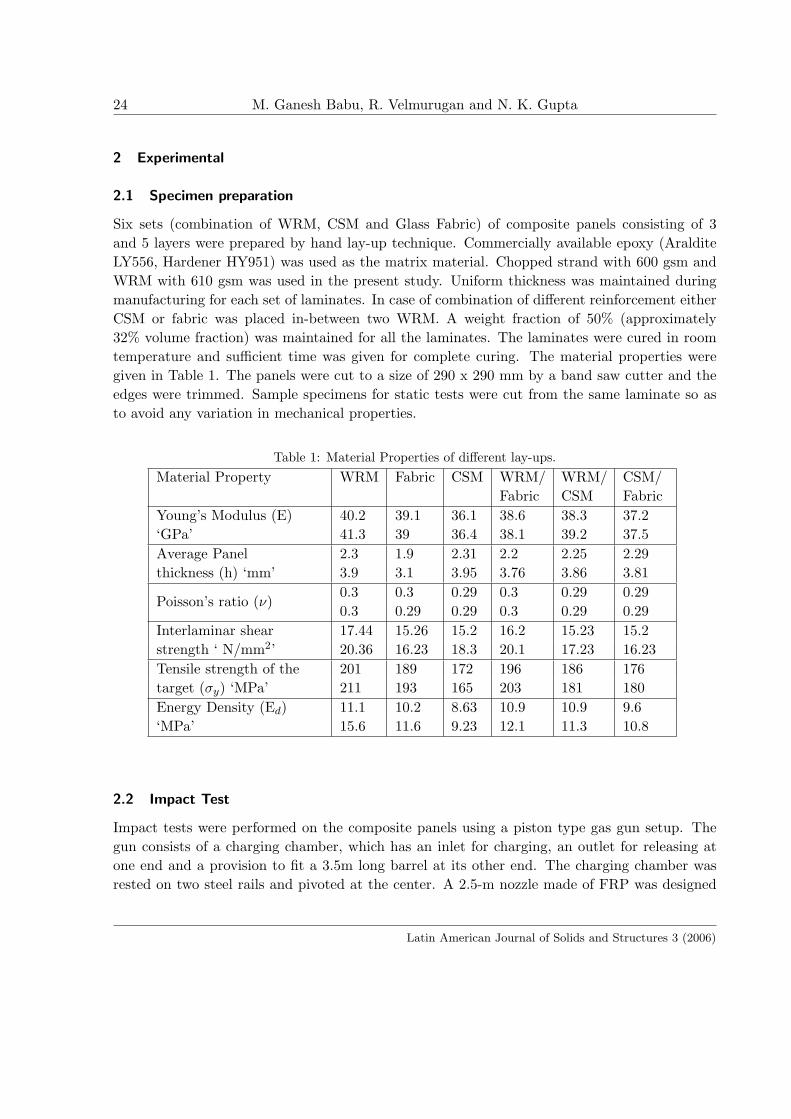
A simple technique was developed in the present investigation for the measurement of residualvelocity. Since the path of the projectile was unpredictable after penetration, the measuringdevice must be able to cover a certain area and the debris should not falsely trigger it. As aresult, two papers of 500mm x 500mm were used. A continuous strip of conducting aluminiumfoil was pasted on the paper in a zigzag fashion as shown in figure 2. The gap between thestrips could be varied depending on the size of the projectile. The two ends of the foil wereconnected to a battery source, which in turn was connected to an electronic counter to form aclosed circuit. These papers were placed behind the target and separated by a known distance.Once the projectile penetrated the target, it pierced the paper and opened the circuit there bytriggering the counter. During medium velocity impact the possibility of the formation of debriscloud was less and hence this set up could produce a reliable result. From the counter, the timetaken by the projectile to pierce the papers was noted. Sandbags were placed behind the fixtureto capture the projectile. It should be noted that the velocity obtained from the counter couldbe the exact residual velocity, provided, the trajectory of the projectile was normal to the paperafter penetrating the target. However, the projectile tends to deviate from its normal path andcan make a maximum angle of θmax with the normal. Hence an error term has to be includedto account for the deviation in the path of the projectile after penetration.
Figure 2: Setup to determine the residual velocity
The initial, final velocities and the corresponding kinetic energies of the projectile were calcu-lated from the counter value and thus the energy absorption. After performing the impact test,
Latin American Journal of Solids and Structures 3 (2006)
Energy absorption and ballistic limit of targets struck by heavy projectile 27
the surface and internal damages in the target were thoroughly analyzed. The delamination areawas also visualized. This was repeated for all the specimens. The ballistic limit was determinedexperimentally by conducting the impact test at different initial velocity. The velocity at whichthe projectile got struck into the target was taken to be the ballistic limit.
2.3 Quasi-static test
Quasi-static tests were performed on the samples that were cut from the panels. Tensile strength,shear strength and flexural strength were determined using a Universal Testing Machine (UTM).Izod impact test was performed on the sample using Izod impact testing machine. Short beamtest was performed to find out the shear strength using INSTRON UTM for the three differentsets of laminates. The entire tests were carried out according to ASTM standards, samples of 5were tested for each test and the average values were taken for analysis.
2.4 Analytical Modeling
An Analytical model is proposed to find out the ballistic limit of the target material. The modelis based on the energy absorption principle. In developing the model, the following assumptionsare made.
1. The projectile is rigid and remains undeformed during the impact. This is confirmed byexperiment which showed that the projectiles retained their shape and mass after impact.
2. Projectile strikes the target normally.
3. There exist friction between the target and the projectile.
4. The failure mechanism of composites is uniform through out its thickness.
5. There is no change in volume during the impact.
The kinetic energy of a moving projectile of mass M, with a velocity V, is given by
K.E =12MV 2 (1)
After striking the target, the velocity of the projectile becomes ‘Vr’.
FinalK.E =12MV 2
r (2)
The energy lost during impact El is given by
El =12M
(V 2 − V 2
r
)(3)
Latin American Journal of Solids and Structures 3 (2006)
28 M. Ganesh Babu, R. Velmurugan and N. K. Gupta
At ballistic limit the residual velocity is almost zero and hence the energy lost will be equalto the initial kinetic energy of the projectile.
El =12MV 2
0 (4)
Where Vo is the Limiting velocity or ballistic limit, which is the velocity at which theprojectile gets struck into the target and experimentally it can be taken as the average of threevelocities just above ballistic limit and three below the ballistic limit.
During the medium or low velocity impact, the major portion of the energy is absorbed inglobal plate deflection or deformation as suggested by N.K.Gupta et al [7]. This can be seenfrom the experiment, where there is enough deflection of the target before perforation. Onlyafter the deflection, delamination, fiber fracture and perforation have occurred, but the energyabsorbed in global plate deflection is the major energy absorption process.
There is also evidence of delamination on the tested specimens, which absorbs a portion ofthe incident energy. In addition to this energy absorbing mechanism, there is some contributionfrom fiber failure, friction and fiber pull out.
Thus the total energy absorbed is given by
Etot = Edef + Edel + Efrac + Efri + Epull (5)
At ballistic limit this total energy absorbed is equal to the Energy lost by the projectile andhence
El = Etot (6)
Etot =12MV 2
o (7)
Ballistic limit Vo =√
2Etot/M (8)
In order to calculate the total energy absorbed during impact, the contribution of individualenergies has to be evaluated.
3 Energy absorbed in global plate deflection
During medium velocity impact the deformation of the plate was assumed to be globalized.N.K.Gupta et al [7] have shown that the radial stretching of the plate absorbs major portionof the projectile energy during medium velocity impact for aluminium targets. This has beentaken into consideration for our case also.
The energy of the radial stretching of the plate due to the radial stress σr is evaluated byneglecting the circumferential stress since radial stress is responsible for the radial cracks [3]
Latin American Journal of Solids and Structures 3 (2006)
Energy absorption and ballistic limit of targets struck by heavy projectile 29
Strain energy can be written as
W = ∫v
(∫ σrdεr + σθdεθ) dv. (9)
σ r and σθ are the radial and circumferencial stresses and the corresponding strains are εr
and εθ. Here the circumferencial strain is zero and neglecting the circumferencial Stress we get
W = ∫v
(∫ σrdεr) dv. (10)
Applying Mises Condition
σ2r + σrσθ + σ2
θ = (σr + αεr)2 (11)
Neglecting the work hardening ‘α’, we have
W =2πh√
1− ν + ν2
r∫
0
σy.εr.r.dr (12)
Where σy is the initial yield stress, h is the plate thickness and ν is the Poisson’s ratio.For large deflections, the radial strain can be approximately written as[11]
εr =12
(dw
dr
)2
(13)
W =2πh
(√
1− ν + ν2)
∫σy
12
(dw
dr
)2
r.dr (14)
It has been empirically found that permanent deformation profile of the plate subject toprojectile impact is [10]
w(r) = woe−r (15)
W =πh√
1− ν + ν2
∫σy.w
20.e
−2r.r.dr (16)
The lower limit was taken to be zero and the upper limit as the radius of the plate R. Afterintegration, the Energy absorbed during plate deflection is found to be
Edef =πhσy.w
20.(e
−2R.(1 + 2R))4.√
1− ν + ν2(17)
From the above expression it is possible to find out the energy absorbed during global platedeflection.
Latin American Journal of Solids and Structures 3 (2006)
30 M. Ganesh Babu, R. Velmurugan and N. K. Gupta
4 Energy absorbed in delamination
In the previous section, the energy absorbed during global plate deflection is calculated which isconsidered to be the major energy absorbing mechanism. There is also some contribution fromdelamination. The energy absorbed during delamination is given by [9]
Edel = Adel.GIIc (18)
Here Adel is the area of the delaminated zone which can be calculated by
Adel = πR2del (19)
Where Rdel is the radius of the delaminated zone, which can be given interms of the delam-ination load and interlaminar shear stress of the Glass/ epoxy.
Rdel =Pd
2πh(ILSS)(20)
Davis et all [5] used a simple mode II fracture analysis to describe the critical load for theonset of a single circular delamination in an isotropic material.
P 2d =
8π2E.h3.GIIc
9(1− ν2)(21)
Here E is the average panel stiffness that can be evaluated from the flexural test, ν is thePoisson’s ratio
So the energy absorbed during delamination is given by
Edel =2EhGIIc
9(1− ν2)(ILSS)2(22)
Where GIIc is the mode II interlaminar fracture toughness and ILSS is the interlaminarshear strength.
5 Energy absorbed in tensile fracture of the fibers
During the impact process, after plate deflection and delamination, the fibers under the point ofimpact undergoes tensile failure. There is also failure of the yarns along the crack length. Thefailure of yarn occurs when the deflection of plate reaches a maximum level. Beyond maximumdeflection, the fibers under the point of impact undergo tensile failure due to radial stretchingof the target. This tensile failure of the fibers has absorbed a portion of the incident energy.
If the energy density at the point of tensile fracture of the composite laminate per unitvolume is Ed, (which can be approximately taken to be the area under the stress strain curveduring tensile test) then the total energy absorbed in tensile fracture ‘Efrac’ is given by [5]
Latin American Journal of Solids and Structures 3 (2006)

Energy absorption and ballistic limit of targets struck by heavy projectile 31
Efrac = Ed.V (23)
V being the volume of the composite strained to its tensile failure. It has been experimentallyfound that, during impact, only the fibers under the point of impact have undergone tensilefailure. Area of the composite, which has strained to tensile failure during impact by theprojectile, is slightly greater than the area of the projectile. This can been seen from figure 3and so the volume is treated to be equal to the volume of the composite with area equal to thecross sectional area of the projectile and the thickness equal to the thickness of the composite.The aim of the mathematical model is to predict the ballistic limit based on energy balanceprinciple without carrying out dynamic test and so approximation such as this shows negligibleeffect.
Efrac = Ed.πR2.h (24)
Figure 3: 5 layer WRM laminate showing no petals
6 Frictional Energy
In the previous investigations the energy associated with the friction between the projectileand the target has been neglected since the projectile was small. This is the case with highvelocity impact. But with low and medium velocity impact some amount of energy is absorbedin overcoming the friction between the target and the projectile. More over when the mass andsize of the projectile becomes large, the friction between the projectile and the target is moreand hence this cannot be neglected. Energy associated with friction is given by
Efric = Ff .Lp (25)
Latin American Journal of Solids and Structures 3 (2006)

32 M. Ganesh Babu, R. Velmurugan and N. K. Gupta
Where Ff is the frictional force that can be evaluated from the static test and Lp is thelength of the striker or the projectile.
The total energy is thus given by
Etot = Edef + Edel + Efrac + Efric
and the expression for ballistic limit is
Vo =√
2Etot/M (26)
7 Results and Discussion
7.1 Crack and Petal formation
All the composite panels are tested with a cylindro -conical projectile. From the experiment itis found that the tested specimens show crack formation, which indicates that during impact,the plates have undergone radial stretching. Petals are not formed during impact on sampleswhich contain WRM suggesting that WRM hinder the formation of petals during impact (figure3). Since there are rovings in both the directions, it is difficult for the crack to break therovings along a straight line leaving behind an irregular failure of the fibers. This phenomenonis observed in both 3 and 5 layered composite panels. But when CSM or Fabric is struck byprojectile, petals are clearly seen. This can be confirmed from figures 4 and 5. In case of CSM,for velocity above ballistic limit, the number of petals was limited to 4 or 5 and the root of thepetal was broken. Hence the friction is reduced between the target and the projectile. But infabric/epoxy laminates, there are more than 5 petals and are of mostly triangular in shape andalso the root does not fail.
Figure 4: 3 layer CSM Laminate showing petals and crack
Latin American Journal of Solids and Structures 3 (2006)

Energy absorption and ballistic limit of targets struck by heavy projectile 33
Figure 5: 5 layer Glass Fabric laminate showing petals and crack struck by projectile above
ballistic limit
7.2 Perforation and Delamination
In all the tests performed, the geometry of the perforation matches exactly the shape of theprojectile. But the area of delamination depends on both the projectile characteristics andnature of the target. Backlighting and visual inspection measure the area of delamination. It isalmost equal for WRM, CSM and Fabric panels. Mostly the peripheral area around perforationand the area under impact are delaminated. The delamination area for a WRM/CSM andWRM/Fabric laminates are more when compared with other sets of 3 and 5 layer panels (Fig6). This shows that when different types of reinforcement are used, the resulting compositepanels are more susceptible to undergo large delamination during impact when compared tocomposites with similar type of reinforcement.
Figure 6: 5 layer WRM/CSM Laminate showing more delamination than other laminates struckby projectile below ballistic limit
Fig 7 shows the SEM picture of a WRM specimen struck by the projectile. The image istaken normal to the travel of projectile. It is seen that the bottom most ply has undergone more
Latin American Journal of Solids and Structures 3 (2006)

34 M. Ganesh Babu, R. Velmurugan and N. K. Gupta
delamination than the top most ply. It is also observed that there is good interfacial bondingbetween the fiber and the matrix. The crack runs in between the roving as well as between thelayers. The lower most laminate has undergone stretching and subsequently underwent failureby the motion of the projectile. The damage pattern resembles the pine tree pattern as suggestedby Abrate [1]. Extent of delamination is more on the rear side for all the tested panels and alsothe shape of the delaminated zone differs for the rear face. In some panels the delaminated zoneis more or less circular in shape but with others it is of irregular shape. It is clear that the platehas undergone sufficient deformation, which absorbs major portion of the incident energy, beforeperforation and that tensile failure, has occurred on the back face of the laminate. When WRMor CSM or fabric alone is used, there is not much delamination in between the plies but whenthese are combined, an increase in delamination area is observed. The same failure pattern isalso observed with 5-ply laminate.
Figure 7: SEM Photographs of targets struck by cylindro conical projectile
7.3 Ballistic Limit
The ballistic limit for each target is determined from the experiment. For 3ply WRM laminates,the ballistic limit is approximately 35m/s whereas this limit is around 30m/s for CSM/WRMlaminate, 27m/s for CSM laminates, 32m/s for Fabric, 33m/s for WRM/Fabric and 29m/s forCSM/Fabric laminates. For 5 layer laminates it is 39, 34, 31, 34, 35 and 32 m/sec, respectively.It is clear that WRM laminates possess higher ballistic limit amongst all. At lower velocities theperforation of the target does not take place but causes delamination and formation of circularrings (Figure 8) around the impact zone. These circular rings confirm the radial stretching ofthe target material during impact. It is also observed that at low velocities, more delamination
Latin American Journal of Solids and Structures 3 (2006)

Energy absorption and ballistic limit of targets struck by heavy projectile 35
was seen on the lower most ply for all the laminates.
Figure 8: 3 layer Glass Fabric/Epoxy laminate showing the formation of concentric ring aroundthe impact region
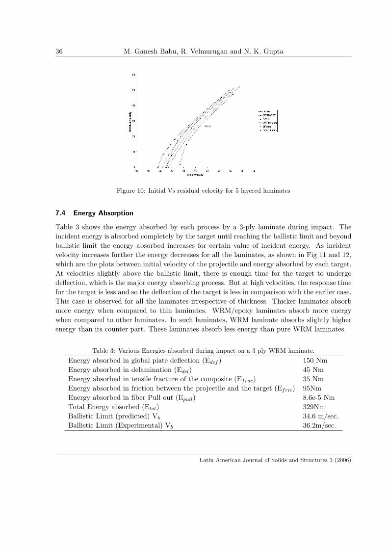
Figs 9 and 10 show the plot between the Initial velocity and the residual velocity for threeand five layered laminates, respectively. From the figure it is clear that an increase in initialvelocity results in the increase in residual velocity for all thickness. It is observed that theresidual velocity remains zero up to a certain value of the initial velocity and then increaseswith the initial velocity. The velocity at which the residual velocity just shoots up may betreated as the ballistic limit. For WRM laminates more work is done to cause failure of the fiberand also more energy is spent in overcoming the friction between the panel and the projectileand hence more energy is absorbed showing higher ballistic limit. It is observed that increasein target thickness increases the ballistic limit irrespective of the nature of material.
Figure 9: Initial Vs residual velocity for 3 layered laminates
Latin American Journal of Solids and Structures 3 (2006)
36 M. Ganesh Babu, R. Velmurugan and N. K. Gupta
Figure 10: Initial Vs residual velocity for 5 layered laminates
7.4 Energy Absorption
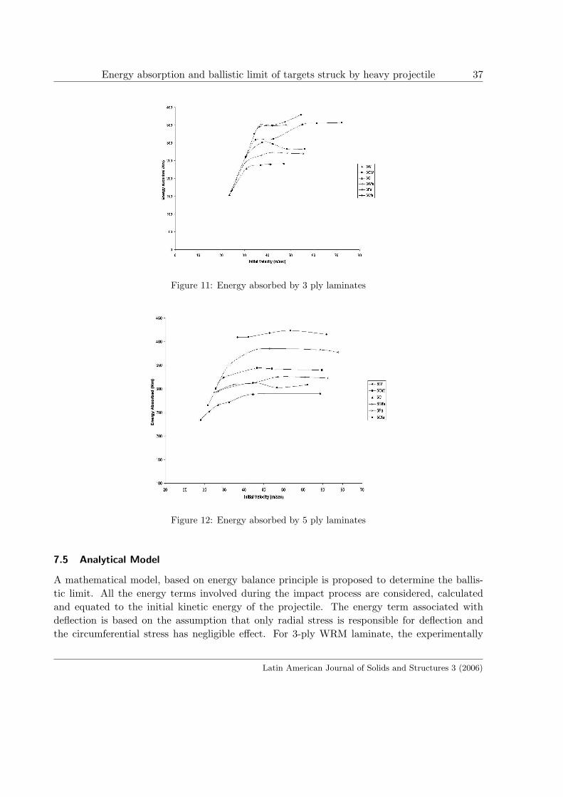
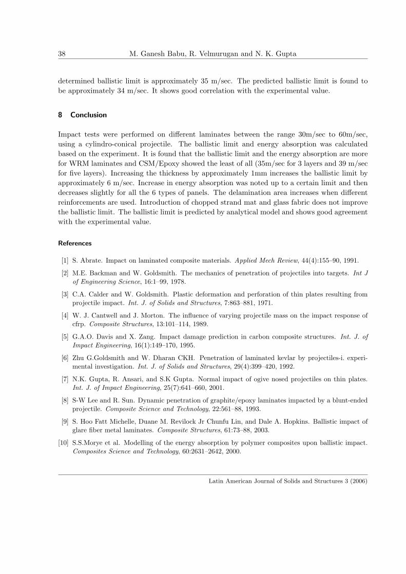
Table 3 shows the energy absorbed by each process by a 3-ply laminate during impact. Theincident energy is absorbed completely by the target until reaching the ballistic limit and beyondballistic limit the energy absorbed increases for certain value of incident energy. As incidentvelocity increases further the energy decreases for all the laminates, as shown in Fig 11 and 12,which are the plots between initial velocity of the projectile and energy absorbed by each target.At velocities slightly above the ballistic limit, there is enough time for the target to undergodeflection, which is the major energy absorbing process. But at high velocities, the response timefor the target is less and so the deflection of the target is less in comparison with the earlier case.This case is observed for all the laminates irrespective of thickness. Thicker laminates absorbmore energy when compared to thin laminates. WRM/epoxy laminates absorb more energywhen compared to other laminates. In such laminates, WRM laminate absorbs slightly higherenergy than its counter part. These laminates absorb less energy than pure WRM laminates.
Table 3: Various Energies absorbed during impact on a 3 ply WRM laminate.Energy absorbed in global plate deflection (Edef ) 150 NmEnergy absorbed in delamination (Edel) 45 NmEnergy absorbed in tensile fracture of the composite (Efrac) 35 NmEnergy absorbed in friction between the projectile and the target (Efric) 95NmEnergy absorbed in fiber Pull out (Epull) 8.6e-5 NmTotal Energy absorbed (Etot) 329NmBallistic Limit (predicted) Vb 34.6 m/sec.Ballistic Limit (Experimental) Vb 36.2m/sec.
Latin American Journal of Solids and Structures 3 (2006)
Energy absorption and ballistic limit of targets struck by heavy projectile 37
Figure 11: Energy absorbed by 3 ply laminates
Figure 12: Energy absorbed by 5 ply laminates
7.5 Analytical Model
A mathematical model, based on energy balance principle is proposed to determine the ballis-tic limit. All the energy terms involved during the impact process are considered, calculatedand equated to the initial kinetic energy of the projectile. The energy term associated withdeflection is based on the assumption that only radial stress is responsible for deflection andthe circumferential stress has negligible effect. For 3-ply WRM laminate, the experimentally
Latin American Journal of Solids and Structures 3 (2006)
38 M. Ganesh Babu, R. Velmurugan and N. K. Gupta
determined ballistic limit is approximately 35 m/sec. The predicted ballistic limit is found tobe approximately 34 m/sec. It shows good correlation with the experimental value.
8 Conclusion
Impact tests were performed on different laminates between the range 30m/sec to 60m/sec,using a cylindro-conical projectile. The ballistic limit and energy absorption was calculatedbased on the experiment. It is found that the ballistic limit and the energy absorption are morefor WRM laminates and CSM/Epoxy showed the least of all (35m/sec for 3 layers and 39 m/secfor five layers). Increasing the thickness by approximately 1mm increases the ballistic limit byapproximately 6 m/sec. Increase in energy absorption was noted up to a certain limit and thendecreases slightly for all the 6 types of panels. The delamination area increases when differentreinforcements are used. Introduction of chopped strand mat and glass fabric does not improvethe ballistic limit. The ballistic limit is predicted by analytical model and shows good agreementwith the experimental value.
References
[1] S. Abrate. Impact on laminated composite materials. Applied Mech Review, 44(4):155–90, 1991.
[2] M.E. Backman and W. Goldsmith. The mechanics of penetration of projectiles into targets. Int Jof Engineering Science, 16:1–99, 1978.
[3] C.A. Calder and W. Goldsmith. Plastic deformation and perforation of thin plates resulting fromprojectile impact. Int. J. of Solids and Structures, 7:863–881, 1971.
[4] W. J. Cantwell and J. Morton. The influence of varying projectile mass on the impact response ofcfrp. Composite Structures, 13:101–114, 1989.
[5] G.A.O. Davis and X. Zang. Impact damage prediction in carbon composite structures. Int. J. ofImpact Engineering, 16(1):149–170, 1995.
[6] Zhu G.Goldsmith and W. Dharan CKH. Penetration of laminated kevlar by projectiles-i. experi-mental investigation. Int. J. of Solids and Structures, 29(4):399–420, 1992.
[7] N.K. Gupta, R. Ansari, and S.K Gupta. Normal impact of ogive nosed projectiles on thin plates.Int. J. of Impact Engineering, 25(7):641–660, 2001.
[8] S-W Lee and R. Sun. Dynamic penetration of graphite/epoxy laminates impacted by a blunt-endedprojectile. Composite Science and Technology, 22:561–88, 1993.
[9] S. Hoo Fatt Michelle, Duane M. Revilock Jr Chunfu Lin, and Dale A. Hopkins. Ballistic impact ofglare fiber metal laminates. Composite Structures, 61:73–88, 2003.
[10] S.S.Morye et al. Modelling of the energy absorption by polymer composites upon ballistic impact.Composites Science and Technology, 60:2631–2642, 2000.
Latin American Journal of Solids and Structures 3 (2006)

Energy absorption and ballistic limit of targets struck by heavy projectile 39
[11] H.M. Wen. Predicting the penetration and perforation of frp laminates struck normally by projectileswith different nose shapes. Composite Structures, 49:321–329, 2000.
[12] J.A. Zukus. Penetration and perforation of solids. In Zukus JA et al., editors, Impact dynamics,pages 155–214. Newyork: Wiley, 1982, 1982.
Latin American Journal of Solids and Structures 3 (2006)