
End-to-end analysis and design of the satellite communication ...
495
Thesis paper End-to-end analysis and design of the satellite communication links System design of the communication subsystem of the Delfi-n3Xt nanosatellite Author Arthur Tindemans [email protected] Chair of Space Systems Engineering Faculty of Aerospace Engineering Delft University of Technology June 2010 Examination committee Prof. Dr. E.K.A. Gill Chair of Space Systems Engineering Dr. C.J.M. Verhoeven Chair of Space Systems Engineering J. Bouwmeester MSc Chair of Space Systems Engineering A.R. Bonnema MSc Innovative Solutions In Space B.V.
-
Upload
khangminh22 -
Category
Documents
-
view
0 -
download
0
Transcript of End-to-end analysis and design of the satellite communication ...

Thesis paper
End-to-end analysis and design of thesatellite communication links
System design of the communication subsystem of the Delfi-n3Xt nanosatellite
Author
Arthur [email protected]
Chair of Space Systems EngineeringFaculty of Aerospace EngineeringDelft University of Technology
June 2010
Examination committee
Prof. Dr. E.K.A. GillChair of Space Systems Engineering
Dr. C.J.M. VerhoevenChair of Space Systems Engineering
J. Bouwmeester MScChair of Space Systems Engineering
A.R. Bonnema MScInnovative Solutions In Space B.V.

Thesis paperAuthor: Arthur Tindemans
Date: 21-06-2010
ii End-to-end analysis and design of the satellite communication links
System design of the communication subsystem of the Delfi-n3Xt nanosatellite

Thesis paperAuthor: Arthur Tindemans
Date: 21-06-2010
iiiEnd-to-end analysis and design of the satellite communication links
System design of the communication subsystem of the Delfi-n3Xt nanosatellite
Preface
This thesis document represents all work performed during the second and final year of the Master degree ofAerospace Engineering. I have started this work in December of 2008, currently one-and-a-half year ago. Inthe middle of my thesis duration I have been away for exactly six months, to do an internship (unrelated tothe thesis work). That means, all-in-all, I have taken some 13 months. Also, I have made common practice ofhaving average days of over 10 hours, in order to fulfill my own desires to deliver high-quality work.
Thesis work performed within the Delfi-n3Xt programme adds to a general thesis assignment a couple ofextra dimensions. First of all, there is a certain product on which work is performed. This product is an actualsatellite that is to be launched in the very near future. Second of all, there are many students working on thisone final product at any given time; team-work. Finally, there is a definite link to the Dutch space industry.Payloads within the satellite are provided by external parties.
In fact, there is one more aspect. A thesis assignment within the Delfi-n3Xt project is one of freedom anddiversity. One is not assigned a main research question and a means of research; one is assigned a function.In my case, this function was to be the systems engineer of the communication subsystem. The purpose: toensure that the final satellite will be able to communicate with us and us with it.
This input to my work has been twofold. A top-level design of the radios and other systems required on theDelfi-n3Xt satellite had been made by my predecessor. This specified the global identity of the new satellite,but no detailed design had taken place. At the same, there was and still is a working satellite in the sky rightnow, Delfi-C3, communicating with us around noon on a daily basis. And whereas the Delfi-C3 mission was asuccess, it is one realized by in some cases using design shortcuts and in most cases not having soliddocumentation to argue for the choices made. And, of course not everything worked as it should have.
The thesis work has proven to be a dynamic and insightful adventure. Using the documentation andequipment already in place, I have had to dig into many subjects related to communication theory to discoverwhy choices have been made and what alternatives there are. And of course, what options there are forDelfi-n3Xt and its systems and operations. I have made sure to document these options and these choices,and to establish design options for Delfi-n3Xt. It is my hope that using this knowledge, not only the end-to-end communication system of Delfi-n3Xt can be finalized, fabricated and operated without problems, but thatalso future students will be able to acquaint themselves with the matter without requiring extensive research.
The body of this document is somewhat unconventional, due to the notion of ‘technical notes’. Projectdocumentation is kept and these documents consequently contain all knowledge. For the thesis however, aseparate document is used to introduce the thesis and summarize the work done. This is the documentcurrently in your hands; the thesis paper. All project documentation is added to the thesis paper in the formof appendices.
I would like to thank both Jasper Bouwmeester and Chris Verhoeven, as well as all other staff members onthe Delfi project for being open to questions and discussions on Delfi-related or non-Delfi-related topics. AlsoI would like to thank all Delfi-C3 experts and non-Delfi staff members who have allowed me to meet withthem to discuss certain expertise. Finally I would of course like to thank my project members and friends fortheir continuing presence, enthusiasm, support and distraction.
Arthur Tindemans
Delft, 21st of June 2010

Thesis paperAuthor: Arthur Tindemans
Date: 21-06-2010
iv End-to-end analysis and design of the satellite communication links
System design of the communication subsystem of the Delfi-n3Xt nanosatellite

Thesis paperAuthor: Arthur Tindemans
Date: 21-06-2010
vEnd-to-end analysis and design of the satellite communication links
System design of the communication subsystem of the Delfi-n3Xt nanosatellite
Table of Contents
1 Introduction ..............................................................................................................................................1
1.1 Delfi-n3Xt .....................................................................................................................1
1.2 COMMS .........................................................................................................................1
1.3 Document structure......................................................................................................2
2 Primary communication link ..................................................................................................................3
2.1 Link characteristics.......................................................................................................32.1.1 Transmission bands and frequencies ...................................................................................... 32.1.2 Link budget .......................................................................................................................... 42.1.3 Modulation and data rate ...................................................................................................... 52.1.4 Data protocol........................................................................................................................ 6
2.2 Primary radio system on Delfi-n3Xt .............................................................................82.2.1 PTRX.................................................................................................................................... 82.2.2 Antenna System ................................................................................................................... 9
2.3 Ground station............................................................................................................11
2.4 Operations ..................................................................................................................12
3 High speed communication link ..........................................................................................................13
3.1 Link characteristics.....................................................................................................133.1.1 Transmission band and frequency........................................................................................ 133.1.2 Modulation scheme ............................................................................................................. 143.1.3 Forward Error Correction..................................................................................................... 143.1.4 Data protocol...................................................................................................................... 14
3.2 High speed radio system on Delfi-n3Xt ......................................................................153.2.1 STX.................................................................................................................................... 153.2.2 Antenna system.................................................................................................................. 17
3.3 Ground station............................................................................................................19
3.4 Operations ..................................................................................................................19
4 Systems engineering tasks ..................................................................................................................23
5 Description of work performed during thesis ..................................................................................25
5.1 Status of COMMS before arrival .................................................................................25
5.2 Work performed .........................................................................................................26

Thesis paperAuthor: Arthur Tindemans
Date: 21-06-2010
vi End-to-end analysis and design of the satellite communication links
System design of the communication subsystem of the Delfi-n3Xt nanosatellite
6 Conclusions and recommendations....................................................................................................29
6.1 Achievements of thesis work......................................................................................29
6.2 Follow-up work...........................................................................................................29
6.3 Lessons learned ..........................................................................................................30
Symbol list........................................................................................................................................................33
Acronyms and abbreviations ........................................................................................................................37
References .......................................................................................................................................................39
Appendix A COMMS – Top-level Design of Communication System ................................... 45
Appendix B COMMS – STX System Design ........................................................................ 335
Appendix C COMMS – Antenna System Design................................................................. 419
Appendix D Delfi-n3Xt Link Budget................................................................................... 457
Thesis paperAuthor: Arthur Tindemans
Date: 21-06-2010
1End-to-end analysis and design of the satellite communication links
System design of the communication subsystem of the Delfi-n3Xt nanosatellite
1 Introduction
The title of this thesis paper is the: End-to-end analysis and design of the satellite communication links. Thesubtitle is: System design of the communication subsystem of Delfi-n3Xt. Both Delfi-n3Xt and itscommunication subsystem (COMMS) are introduced in sections 1.1 and 1.2 respectively, to properly introducethe context of the thesis subject. The notion of communication links and the communication links of theDelfi-n3Xt mission are consequently introduced at the end of section 1.2. Section 1.3 finally explains thecontent and direction of the thesis work performed and presents the document structure.
1.1 Delfi-n3Xt
In order to facilitate low-cost in-space technology demonstrations and applications, the CubeSat standard hasbeen developed. Small satellites of 10x10x10 cm can be launched jointly or together with a large satellite withunoccupied space in the launcher. Furthermore, three single-unit CubeSats can combined to form one triple-unit CubeSat. These CubeSats generally have a mass of only several kilos, and therefore fall in the class ofnanosatellites. The Delft University of Technology has, or more specifically the faculties of AerospaceEngineering (AE) and Electrical Engineering, Electronics and Computer Science (EEMCS) have adopted thisstandard within the Delfi programme. The first satellite, Delfi-C3, has been successfully launched in 2008 in isstill operational.
Delfi-n3Xt is the successor of Delfi-C3. Its mission statement:
The clauses in bold can be further specified:
Reliability of Delfi-n3Xt shall be improved with respect to that of Delfi-C3 by offering improvementswithin the satellite bus
Substantial advances shall be aimed to take place in the Attitude Determination and ControlSubsystem (ADCS); Delfi-C3 applied no active attitude control which is aimed for with Delfi-n3Xt
Two payloads are:
o T3μPS: a cold-gas micro propulsion experiment provided by TNO
o ITRX: a power-efficient, reconfigurable transceiver provided by ISIS
2012 is the anticipated launch date
Next to the goals stipulated above, a number of other experiments and technology demonstrations areanticipated, depending on their status. One of these technology demonstrations is the inclusion of a highspeed communication downlink, as further explained below.
1.2 COMMS
In order to facilitate the payloads, a satellite requires what is generally referred to as the satellite bus. Withinthis bus a division is usually made between subsystems. In case of Delfi-n3Xt, these subsystems are definedto be the STS, MechS, TCS, EPS, CDHS, ADCS and COMMS. The latter of course is of prime importance to thisthesis, and stands for the Communication Subsystem.

Thesis paperAuthor: Arthur Tindemans
Date: 21-06-2010
2 End-to-end analysis and design of the satellite communication links
System design of the communication subsystem of the Delfi-n3Xt nanosatellite
The main functionalities of the COMMS are to get:
Payload data from the satellite to the customer
Housekeeping data from the satellite to the satellite operator
Telecommands from the satellite operator to the satellite.
As can be seen, payload data and housekeeping data are to be transmitted to ground by the satellite. Nodistinction shall be made between the two for the communication system and the two are grouped togetheras telemetry data (TM). The satellite should in turn be able to receive telecommands (TCs) from the groundsegment. In result, this means there should be both a downlink and an uplink. Together, these can be said toform the primary communication link. As a technology demonstration, the secondary high speedcommunication downlink has been designed. These two links together form the communication links ofDelfi-n3Xt.
1.3 Document structure
This document aims to provide an executive summary of the work that has been performed by the authorduring the thesis duration and the conclusions that have followed. The detailed work is documented withinproject documentation. The resulting documents are added to this thesis paper as appendices. This thesispaper will use the communication links of Delfi-n3Xt as a red line, by discussing their design and status.
As illustrated by the above, a satellite communication system is not limited to the architecture required on thesatellite, but also that required on-ground. Furthermore, the link itself should be specified, along with therules that both transmitter and receiver should adhere to.
In contrary to more conventional theses, there has been no main research question. The goal of the workperformed has been to contribute to the design and realization of the Delfi-n3Xt. More specifically: the designand realization of the communication subsystem of Delfi-n3Xt and its communication links.
The two communication links introduced above are discussed in two respective chapters: The primary communication link Chapter 2 The high speed communication downlink Chapter 3
Consequently, two chapters aim to illustrate the work performed that has lead to the conclusions presented inchapters 2 and 3. Chapter 4 discusses the application of systems engineering tools. Chapter 5 provides asketch of the definition of the Delfi-n3Xt COMMS before the author arrived, and presents a (short) descriptionof all work that has been performed during the thesis duration. Finally, chapter 6 concludes with a statementof the general value of the work performed to Delfi-n3Xt, and what the consequent steps within the projectare. Also, a short list of lessons learned and recommendations is given.
The appendices contain four different documents. These documents are labeled technical notes. These are:1. COMMS – Top-level Design of Communication System [SLR 0014]2. COMMS – STX System Design [SLR 0387]3. COMMS – Antenna System Design [SLR 0036]4. Delfi-n3Xt Link Budget [SLR 0106]
Most content of these documents is unique, that is to say written by the author. In case content results fromearlier versions of the project document, the respective sections are indicated on the title page of theappendix.
Whenever relevant, this thesis paper refers to chapters and sections of these documents, as indicated by theSLR code mentioned above, to facilitate looking up more detailed information. Within the documents itself,general SLR codes are used to refer to all references. Whenever an SLR code refers to one of the documentswritten by the author, the respective SLR code is underlined.

Thesis paperAuthor: Arthur Tindemans
Date: 21-06-2010
3End-to-end analysis and design of the satellite communication links
System design of the communication subsystem of the Delfi-n3Xt nanosatellite
2 Primary communication link
The primary communication link is the essential one. Its functions are exactly those as introduced in theprevious chapter; it should allow for TM to be transmitted by the satellite, and TCs to be received by thesatellite. In fact, the link can be interpreted to consist of two different links; uplink and downlink.Nevertheless, equipment for the two links is shared both on the satellite and on-ground, so that the two arelogically grouped and discussed simultaneously.
The important components of the primary communication link are illustrated Figure 2.1 below.
Figure 2.1: Primary communication link
The consequent four sections explain the aspects of this link. The characteristics of the link, common to bothends are introduced first. The primary radio system of Delfi-n3Xt and the ground segment are discussedconsequently. Finally, operational aspects are discussed.
2.1 Link characteristics
2.1.1 Transmission bands and frequencies
Frequency transmission of the primary communication link will take place in the: VHF radio amateur band (144-148 MHz) for the downlink UHF radio amateur band (420-450 MHz) for the uplink
The use of these frequencies requires a return service to the radio amateur community. A primary andsecondary return service will be available in case of Delfi-n3Xt, being:
A linear transponder service A software data reception client, DUDe
These return services are in fact equal to those of Delfi-C3. The linear transponder operates in both the VHFand UHF bands. The VHF transponder bandwidth can be used for the transmission of OLFAR signals as well(OLFAR is introduced in section 2.2 below). Graham Shirville is part of the committee of AMSAT (AmateurSatellite community) that coordinates the frequency coordination within the radio amateur bands. He hasbeen heavily involved in the arrangement of the frequencies for Delfi-C3. It has in discussion with him beendecided that Delfi-n3Xt can reuse the transmission frequencies of Delfi-C3.
The following Figure 2.2 demonstrates the resulting transmission frequencies anticipated for Delfi-n3Xt. Theuplink transmission frequencies are masked for reasons of secrecy.
Figure 2.2: Transmission frequencies in the UHF and VHF band [SLR 0014, Figure 8.1]

Thesis paperAuthor: Arthur Tindemans
Date: 21-06-2010
4 End-to-end analysis and design of the satellite communication links
System design of the communication subsystem of the Delfi-n3Xt nanosatellite
In comparison to the Delfi-C3 frequency allocation, the transmission bandwidths have been increased: TM downlink: increased from 2.4 kHz to 20 kHz. The increased bandwidth will allow for data rates
of up to 9.6 kBaud. TC uplink: increased from 2.4 to 4.8 kHz. The increased bandwidth will allow for data rates of up to
2.4 kBaud.
The data rates are indicated in Baud. Baud stands for symbols/s. Usually, Baud equals b/s. Nevertheless, insome cases, as in the uplink of Delfi-C3 (and Delfi-n3Xt), two symbols are required for the transmission of onebit due to application of a line code. This effectively reduces the bit rate. The above changes to the originalDelfi-C3 frequency allocation have been discussed with AMSAT and should pose no problem. The next step isfor official frequency filing to commence, to confirm the (re)use of the above frequencies. It is fullyacceptable if technical constraints in the end will not result in the maximum data rates to be met.
There is one remark to be made on the topic of the allotted bandwidth. Officially, a certain power reduction isto be achieved at the sides of these bandwidths. As is shown by detailed spectrum measurements performed[SLR 0014, section 7.4 and 8.4], Delfi-C3 did not achieve the required power reduction, for both the up- anddownlink. It has however been agreed upon that within the radio amateur bands these reductions are to betaken more as an indication, as long as proper effort is made to reduce the spectrum. This is important forthe selection of the modulation scheme.
2.1.2 Link budget
The link budget for Delfi-n3Xt has been worked out in much detail in [SLR 0106]. It takes into account allgains, losses and noise additions along the communication link, as well as final required bit energy to noisespectral density ratio Eb/N0. The link budget thereby takes into account the anticipated modulation approachas introduced in the next section. Conversely, the selection of a modulation scheme takes into account themargin in the link budget. This allows concluding on both the achievable data rate, as well as the availablelink margin. The margins predicted by the link budget for minimal data rates are shown in Table 2.1 below,for the minimum and maximum orbit altitudes of Delfi-n3Xt.
Table 2.1: Link margins of the primary link for the Delfi-n3Xt range of orbit altitudes [SLR 0014, Table 8.2]
Link directionOrbit
altitudeData rate
ReceivedEb/N0
Required Eb/N0
incl. min. marginLink
margin
600 km 1200 Baud 26.45 dB 13.30 dB 13.15 dBDown (VHF)
850 km 1200 Baud 24.23 dB 13.30 dB 11.02 dB
600 km 1200 Baud 42.27 dB 16.30 dB 25.97 dBUp (UHF)
850 km 1200 Baud 40.14 dB 16.30 dB 23.84 dB
If the data rate is doubled, the link margin is halved. A maximum data rate of 9.6 kBaud then comes at thecost of 9 dB link margin. In conclusion, the link budget closes with sufficient margin for both the up- anddownlink for all achievable data rates.
Delfi-n3Xt is no longer assumed to perform sun-pointing. As a result, available power has droppedsignificantly. At the same time, Delfi-n3Xt operations will likely consume more power than Delfi-C3 and theinclusion of a battery yields to prefer continuous operations, even during eclipses. As a result, it can bedecided to lower the power output of the primary transmitter of Delfi-n3Xt, the PTRX. Even in case themaximum data rate is used, a minimum of 2 dB additional margin would be available.
In order to verify the accuracy of the link budget of the downlink, the signal strength of Delfi-C3 wasmeasured during a pass [SLR 0106, chapter 3]. The received signal strength (-91.40 dBm) is perfectly in linewith the prediction of the link budget (-87.41 to -94.33 dBm). The latter range is specified by an unknownsatellite attitude and on-ground pointing error, both related to the antenna gain.

Thesis paperAuthor: Arthur Tindemans
Date: 21-06-2010
5End-to-end analysis and design of the satellite communication links
System design of the communication subsystem of the Delfi-n3Xt nanosatellite
2.1.3 Modulation and data rate
Digital modulation is a process that impresses a digital symbol onto a signal suitable for transmission. In caseof a satellite link, this signal is an electromagnetic wave. The frequency of the final wave to be transmitted isto be equal to the transmission frequency allocated to it. Different digital modulation schemes are introducedin [SLR 0014, section 7.2]. There are three parameters important for the selection of a modulation scheme.These are:
Bandwidth efficiency Power efficiency Complexity
It has been shown above that the link budget closes for all data rates that are allowed within the radioamateur bands; the links are thus not power limited. The RAP of Delfi-C3 however only performed at 1200Baud, up- and downlink. The primary transceiver of Delfi-n3Xt is based on the RAP. As such, the primarycommunication link is complexity limited. But, as explained above, the frequency spectrum should be usedrespectfully and an effort should be made to reduce the required bandwidth, especially on the downlink. Theuplink spectrum only affects a local region of the Earth and within very limited timeslots. Also, higher datarates than 9.6 kBaud are not allowed due to the limited available bandwidth.
A detailed analysis of existing modulation schemes has been performed. For Delfi-C3, modulation schemes ofminimum complexity were chosen. Also, as these modulation schemes have been successfully implemented,relative complexity is even less. As such, it makes sense for Delfi-n3Xt to reuse the modulation schemesapplied in Delfi-C3 [SLR 0014, sections 8.3-8.4]:
Downlink: BPSK or binary phase shift keying Uplink: FSK or (binary) frequency shift keying
Related to the choice of modulation scheme are line coding and pulse shaping. Line codes specify themanner in which consequent bits are represented; normally consequent ‘high’s’ and ‘low’s’ represent 1’s and0’s respectively. An adapted line code can allow lowering demodulation complexity at the cost of power orbandwidth efficiency, amongst others. Line codes are introduced in [SLR 0014, section 7.3]. In order toreduce the demodulation complexity, the following line codes are applied, with their indicated ‘price’:
Downlink: NRZ-S (-0.8 dB of link margin) Uplink: NRZ-S and Manchester (-3.8 dB of link margin and a doubled symbol rate in Baud)
Pulse shaping serves to lower the produced bandwidth spectrum, but requires a certain additional modulationcomplexity [SLR 0014, section 7.4]. It involves shaping a (normally rectangular) bit shape to a smoother one.The consequently modulated signal will then have a lower frequency spectrum. For the VHF downlink, it isdecided to apply pulse shaping:
Downlink: (time-domain) raised cosine
For both the uplink and downlink the possibility of increasing data rates has consequently been assessed, byanalyzing the hardware implications [SLR 0014, sections 8.3-8.4]. In result, the following targets are stated:
Downlink: 2400-9600 b/s Uplink: 600-1200 b/s
High downlink data rates (9.6 kb/s) are likely achievable but should be proven by means of final integrationtests. The weakest link is the microcontroller. At the same time, the data budget should be updated todetermine the operational need or use for high data rates. For the uplink, a higher data rate requires areplacement of the demodulator chip. For data rates higher than 1.2 kb/s (2.4 kBaud) the processor wouldlikely become a bottleneck, so that 1.2 kb/s is set as a maximum. TCs can in any case be transmitted usingboth 0.6 and 1.2 kb/s, so that an increase of data rate would serve mainly as proof of performance.
In both cases, there are no reasons to have a data rate varying during the mission as the link budget closesfor all elevation angles. This is further explained in [SLR 0014, subsection 8.3.5].

Thesis paperAuthor: Arthur Tindemans
Date: 21-06-2010
6 End-to-end analysis and design of the satellite communication links
System design of the communication subsystem of the Delfi-n3Xt nanosatellite
2.1.4 Data protocol
A data protocol adds digital data to the content that is to be transmitted, in order to [SLR 0014, section 7.6]: Facilitate demodulation Ensure the proper reception of the digital content
In order to achieve this, a data protocol introduces a certain overhead. This overhead is expressed as anumber of bits and is dependent of frame size. In case of Delfi-C3, the AX.25 protocol was used. This protocolrequires an overhead of:
Data fields: 160 bits per frame Bitstuffing: An additional 1 bit per 6 bits (the flag is not allowed to occur within the frame)
In case of Delfi-C3, an additional counter was added to each frame. [SLR 0014, section 7.6] introduces theconcept of throughput efficiency of a data protocol, taking into account the frame length (relativeoverhead) as well as the anticipated amount of transmission errors (rejected frames). In result thethroughput efficiency for the Delfi-C3 downlink was only 66%. If packet sizes would have been increased to4800 bits with the same protocol, this efficiency could have been 76%.
For Delfi-n3Xt, a customized replacement is proposed; the DelfiX protocol. It is customized for bi-directional(satellite) communication between two transceivers. It requires only an overhead of:
Data fields: 80 bits per frame Bitstuffing: An additional 1 bit per 14 bits
The DelfiX protocol attains, for data frame size sizes of 1200 bits, throughput efficiency of 82%. If framesizes are increased to 4800 bits, the throughput efficiency becomes 86%. A frame size of 2400 bits yields thesame efficiency.
The data fields of the DelfiX protocol are shown in Figure 2.3 below.
Figure 2.3: DelfiX frame, optimized version [SLR 0014, Figure 8.9]In summary:
Flags: The length of the flags has been doubled with respect to the AX.25 protocol. This requiresless bitstuffing over the entire frame content; a maximum of 1 per 14 bits as opposed to 1 per 6 bits.
Sender Address field: The address field has been reduced from 14 bytes to 3. Satellitecommunication requires only a sender to be known (either satellite or GS) and requires fewercharacters to do so. For Delfi-n3Xt and the Delft GS respectively DNX and DGS are suggested.
Frame Type: This type field has been added for clarity; Delfi-C3 communication required a separateindicator as part of the frame to indicate the content type of the frame (e.g. TC, TM1, TM2, etc.).
FCS: The frame-check sequence is equal to that of AX.25. Three unique errors can be detected inmessage sizes up to over 32,000 bits, and 99% of all larger amounts of errors.
Reducing the amount of bitstuffing has effects on demodulation facility as less bit transitions are guaranteed.Tests using the digital demodulation core of Rascal/DUDe however have shown that flag sizes of at least 25bits should be no problem [SLR 0014, section 8.5].
The above data protocol should be applied to two scenarios; the TM downlink and TC uplink. Of course otherapplications are possible, a TM request frame and software upload frame are discussed in [SLR 0014, section8.6]. The two main scenarios require different additional fields and (data) operations and are discussed inmore detail below.

Thesis paperAuthor: Arthur Tindemans
Date: 21-06-2010
7End-to-end analysis and design of the satellite communication links
System design of the communication subsystem of the Delfi-n3Xt nanosatellite
For the TC uplink, the TC can be specified [SLR 0014, section 8.6], see Figure 2.4:
Figure 2.4: DelfiX TC frame construction [SLR 0014, Figure 8.14]
From left to right a number of aspects can be seen: TC code: See below. Telecommand: The actual telecommand is assumed to be 64 bits long. For Delfi-C3 the same value
was used. Not all bytes were used for Delfi-C3 but more TCs might be defined for Delfi-n3Xt. Also,size is not much of an issue on the uplink.
Encryption: An ARC4 cipher with a certain offset is applied over the actual TC. FCS 2: Delfi-C3 applied multiple different CRCs for TCs, also depending on the type of TC. For
Delfi-n3Xt, a clearer approach is suggested. This is to have only one additional CRC to ensure propertransmission. The selected CRC is optimized for message lengths up until 151 bits, and allowsdetecting 5 unique errors. Both FCS’s in a TC frame each allow for 99% of larger numbers of errors tobe detected as well, guaranteeing near-faultless error detection.
Additional data aspects: Preamble: It is suggested to add 20 flags before the transmission of multiple TCs Repeat: It is suggested to repeat every TC at least 2 or 4 times, if not (much) more, to ensure
proper reception
For Delfi-C3, the (default) telecommand procedure requires 1) the transmission of a TC, 2) a confirmation onthe downlink of the exact received TC and 3) the transmission of a TC confirmation. This ensures that peopledo not try to command the satellite by copying the transmission signal (without knowledge of the protocol)and gives extra reception verification.
For Delfi-n3Xt, it is suggested that functionalities are separated because verification of the message issufficiently performed by the CRCs. The approach is therefore suggested to be changed. Whenever a TC issent up, the TC code that is sent up should match the TC code which was previously sent or is being senddown to the ground via the TM downlink. After a successfully received TC, the satellite then changes this TCcode. This similarly ensures people cannot command the satellite without knowledge of the protocol. At thesame time, commanding the satellite only requires one properly received TC.
For Delfi-C3, blind commanding was also possible, requiring only a single transmission. For Delfi-n3Xt, in casecommanding without a required TM downlink is desirable, a predefined and semi-constant golden TC codecan be used, which can be changed during operations. This gives additional security over Delfi-C3 operationsas the blind command signal can change over time (preventing copying of the transmission signal).
The TC code can also be used as the offset for the encryption applied, as mentioned above when introducingthe applied encryption.

Thesis paperAuthor: Arthur Tindemans
Date: 21-06-2010
8 End-to-end analysis and design of the satellite communication links
System design of the communication subsystem of the Delfi-n3Xt nanosatellite
For the TM downlink, the content of the packages should still be fully specified by the CDHS systemsengineer. Some fields are however suggested in [SLR 0014, subsection 8.6.2], such as a:
Unique frame ID (5 bytes) TC code (1 byte) Last processed TC type and address (2 bytes)
The frame size of the downlink can be determined taking into account data rate, throughput efficiency andspeed of internal data generation. From a transmission point-of-view, throughput efficiency is most importantassuming the satellite is rotating only slowly. Taking into account the optimum frame size and the knowledgethat Delfi-C3 successfully applied 1-second frames, it is suggested that:
Frame sizes of 2400 bits are used for a data rate of 2.4 kb/s Frame sizes of 4800 bits are used for data rates of 4.8 kb/s or higher
Of course, the CDHS does not have to supply a frame every 0.5 second, even if the frame rate is 0.5 frame/s;it can simply supply (the content of) two frames once every second. For Delfi-C3, a flag frame was also addedevery 4 other frames due to the limited throughput of the command and data handling system. This reducedoverall data efficiency by another 20%. For Delfi-n3Xt, this frame is not deemed necessary. Additional flagsare only transmitted in between frames when non-maximum bitstuffing allows for them to be added.
2.2 Primary radio system on Delfi-n3Xt
On the satellite, two components are essential: PTRX: The Primary Transceiver (PTRX) is exactly what the name implies. It adheres to all
functionalities established above. It interfaces digitally with the on-board computer (OBC), and in ananalogue fashion with the antenna system.
Antenna System: The antenna system consists of those components required on the satellite otherthan the PTRX, in order to establish a communication link.
As a back-up radio the ITRX payload is used. If necessary, this payload could also be replaced by a secondPTRX. As the design of the ITRX is not the responsibility of the TU Delft, it will not be further discussedbelow. The ITRX shall be prepared to use the above data protocol, as has been discussed with ISIS.
OLFAR might be flown as a technology demonstration. It is an integrated circuit designed to realize thereception of low-frequency signals over the antennas, in order to transmit these over the VHF band. ThePTRX should take care of final preparation for transmission, but as [SLR 0014, chapter 11] argues: if OLFAR isto be flown, the bulk of the required circuitry should be integrated within the antenna system.
2.2.1 PTRX
The PTRX is based on the design of the RAP. Nevertheless, a number of things have been changed: Only digital interfaces to the OBC: The RAP had an analogue line between the transceiver and
the OBC. In other words, the OBC was required to extract the actual (digital) TC. The PTRX takescare of all actions itself and thereby form a more modular radio.
Separated TX and RX sections: By using two different processors, the TX and RX sections arecompletely separated functionally and electrically. Only the transponder forms a direct linkbetween the two. Using two separate standard system bus interfaces, this allows switching offone without the other.
Increased transmission data rate of possibly 9.6 kb/s: Analysis of the design has shown thatthe only component affected by a change of data rate is the processor. As a more powerfulMSP430 processor is used for the PTRX compared to the PIC of the RAP, higher data rates arecertainly possible. It is assumed that a data rate of 9.6 kb/s can even be achieved.
Improved electrical design: A number of filters, crystals and other components have beenchanged. This has improved (temperature) stability, performance and areal requirements.
Possibly, the reception data rate can also be increased as explained, depending on the final receiver design.

Thesis paperAuthor: Arthur Tindemans
Date: 21-06-2010
9End-to-end analysis and design of the satellite communication links
System design of the communication subsystem of the Delfi-n3Xt nanosatellite
The following Figure 2.5 clearly shows the separated sections and their interfaces.
Figure 2.5: Integration of the PTRX processors [adapted from SLR 0014, Figure 9.11]
In the middle of the figure the transponder can be seen, with its analogue link between the RX and TXsections. The OLFAR interface is not shown, but would provide an analogue signal to the transmitter section.
The Frame Generator is able to switch between modes, to activate either one of: TM mode Transponder mode OLFAR mode TX OFF mode
Neither one of these modes switches off the receiver; the latter should always be on.
A much more detailed diagram has also been made and can be found in [SLR 0014, Figure 9.8]. It shows: All main functional components (amplifiers, mixers, oscillators, processors, etc.) including the
components required for the generation of housekeeping data. All required interfaces. This includes those required for the transmission and reception of data, for
the generation of housekeeping data and for switching between transmission modes.
2.2.2 Antenna System
All analogue RF interfaces of the PTRX (and ITRX) connect to the Antenna System. The antenna systemlogically receives and transmits these signals from and to the wireless medium. The antenna systemsupplements the PTRX with:
Antennas Phasing circuit Coax cables and connectors
The antenna configuration (per frequency band) is assumed to be identical as for Delfi-C3; applying fourantennas in a canted turnstile configuration. The resulting configuration is illustrated by Figure 2.6 below.This configuration approaches an omnidirectional gain pattern. The antennas are deployed using ModularAntenna Boxes, or MABs. The MABs are part of the heritage of Delfi-C3. These MABs in turn are integrated onthe DAB, the Deployment and Antenna Board, which is a PCB. The MABs and the DAB can also clearly beseen in Figure 2.6. This DAB is placed at the bottom of the satellite, logically with the openings of the MABsfacing outwards.

Thesis paperAuthor: Arthur Tindemans
Date: 21-06-2010
10 End-to-end analysis and design of the satellite communication links
System design of the communication subsystem of the Delfi-n3Xt nanosatellite
Figure 2.6: DAB including MABs and antennas; top-view (left), side-view (right) [SLR 0036, Figure 3.5]
The UHF/VHF antenna system of Delfi-n3Xt will be similar in concept to that of Delfi-C3, with one importantchange; no separate UHF and VHF antennas will be used but combined antennas. There are two goodreasons for this [SLR 0036, chapter 3]:
Only four antennas and deployment mechanisms are required; this allows a volume saving of about10% of the satellite given the height of the MABs of about 3 cm, next to a reduction of mass andcomplexity.
All components can be located on one side of the satellite; this additionally reduces the amount ofcomponents required and complexity involved.
The combination of the antenna is possible because the wavelength of the UHF transmission frequencies(~69 cm) is more or less one third of the VHF wavelength (~206 cm). Maximum power performance can beobtained for antennas of either a quarter-wavelength or three-quarter-wavelength. The length of the VHFantennas would satisfy both constraints for VHF and UHF frequencies respectively. Two effects of combiningthe antennas should be prepared for:
1. The VHF transmission signal should not interfere with the UHF signals to be received2. The length of the UHF antennas becomes slightly non-optimal
The gravity of the first effect has been measured using the Delfi-C3 spare model. The power amplifier of theRAP/PTRX in fact causes harmonics of the transmission frequency to have significant signal strength.According to the link budget, a worst case reduction of -116 dB is required due to the differences in signalstrength between up- and downlink. The third harmonic, which might interfere with the UHF frequencies, hasmeasured signal strength of -58.20 dB with respect to the main carrier. However, the third harmonic of theVHF transmission frequency and the UHF transmission frequency are in fact spaced apart by ~2 MHz. A signalstrength reduction of another -40 dB of the third harmonic has been measured within 17.5 kHz; lower valuescould not be measured due to the noise floor of the test set-up. In conclusion however, it seems highly likelythe worst case required reduction is met within 2 MHz.
The second effect results in impedance mismatch loss if not corrected for. Given the fact that the VHFantenna length is only slightly non-optimal for the UHF frequencies (2 MHz / 436 MHz ≈ 2%) circuitry can beintroduced to compensate for this. In fact, this is one of the roles of the new Delfi-n3Xt phasing circuit.
The phasing circuit is required to: Introduce proper phase shift between the antennas for the resulting gain pattern to be
omnidirectional and circularly polarized Isolate the UHF frequencies from the VHF frequencies Correct for the non-optimal length of the UHF antennas when combined with the VHF antennas

Thesis paperAuthor: Arthur Tindemans
Date: 21-06-2010
11End-to-end analysis and design of the satellite communication links
System design of the communication subsystem of the Delfi-n3Xt nanosatellite
The first two aspects were in fact also required of the Delfi-C3 phasing circuit. However, as the antennasystems were separated the interference of the VHF transmission was less severe. The updated Delfi-n3Xtphasing circuit has been tested and built by Wolter van der Kant. Some losses are incurred in the phasingcircuit, but these are comparable to those on Delfi-C3. The phasing circuit is also integrated on the DAB.
Coax cables and connectors logically connect the PTRX (and ITRX) and the antenna system. Rather largevertical SMA connectors were used for Delfi-C3, as well as smaller MMCX connectors to connect the MABs tothe antenna board. Several suggestions for Delfi-n3Xt have been made in [SLR 0036, chapter 5]. The cableused can be the same as that used in Delfi-C3 (RG178BU, Ø ≈ 2 mm), but a slightly thicker cable (RG-316, Ø= 2.5 mm) can instead be used to halve the signal attenuation losses; most important for the S-band.
Finally, OLFAR can be placed on the DAB. This would require only a small space and the DAB already has astandard system bus interface required for OLFAR operations. This would however require the DAB processorto be used other than during deployment and to be programmed to operate the OLFAR chip. If OLFAR isplaced on the DAB, an additional coax cable would be required to connect OLFAR and PTRX.
2.3 Ground station
On-ground, transmission and reception is primarily taken care of by one system: the Delft ground station(GS). The Delft GS will be the only station that is configured to command the satellite. Radio amateursworldwide however are motivated to receive and forward TM data transmitted by the satellite, as satellitetransmission is continuous. In order to facilitate this, a software telemetry client named DUDe will be spread,similar in function to Rascal in the Delfi-C3 mission.
The Delft GS has been analyzed in detail, in order to: Properly identify the effects of changes to the transmission techniques Specify all values in the link budget
The main components of the Delft GS can be seen in Figure 2.7 below. In fact, more components arenecessary to operate the antennas and to relay the signals between the roof and the actual transceiver hard-and software. All components are introduced and discussed in more detail in [SLR 0014, chapter 15].
Figure 2.7: The Delft GS main equipment [SLR 0014, Figure 15.2]
The following updates to the GS are required for the Delfi-n3Xt mission:
Software: DIGIT 2.0: The software that has been written for Delfi-C3 telecommanding should be updated. DUDe: Some parameters should be changed in the software to allow for higher data rates.

Thesis paperAuthor: Arthur Tindemans
Date: 21-06-2010
12 End-to-end analysis and design of the satellite communication links
System design of the communication subsystem of the Delfi-n3Xt nanosatellite
TNC 31S: The software should be updated to allow for the use of the DelfiX protocol.Hardware:
ICOM 910: The transceiver should be replaced to allow for higher downlink data rates. A suitablereplacement can be delivered by ISIS.
TNC 31S: This component should be replaced if higher data rates are applied on the uplink. A suitablereplacement can be delivered by ISIS.
Antenna tracking system: Currently, the antenna sometimes has to rotate by 360° during mid-pass asthe rotor begins halfway through its rotation range. This should be changed by updating thedriving software or by changing the orientation of the (mechanical) rotator connection.
A further suggestion is to: Add error correcting capabilities to DUDe: The CRC that is applied on the TM downlink can
actually be used to correct for single errors, using a look-up table approach. It is rather computationintensive, but other than during a pass the GS computer performs no serious functions.
2.4 Operations
In order to fulfil all main tasks on the primary communication link, a number of COMMS modes are necessary.These COMMS modes are in fact combinations of all operational modes of the PTRX and ITRX. These modesare shown in Table 2.2.
Table 2.2: COMMS modes and respective PTRX and ITRX modes [adapted from SLR 0014, Figure 14.1]
COMMS mode Effects
PTRX mode (default) TCs received by PTRX and ITRX and TM transmitted by PTRX
ITRX mode (secondary) TCs received by PTRX and ITRX and TM transmitted by ITRX
Transponder mode TCs received by PTRX and ITRX and Transponder activated
ITRX test mode TCs received by PTRX and ITRX and ITRX tests activated
OLFAR mode (experimental) TCs received by PTRX and ITRX and OLFAR activated
All TXs OFF TCs received by PTRX and ITRX
In order to asses the anticipated performance of the VHF downlink, the TM frames received from Delfi-C3 andstored in the telemetry database have been analyzed. The entire analysis is described in [SLR 0014, section14.2]. The main conclusions are:
Almost 2% of the maximum theoretically generated amount of data has been received over twoyears time of Delfi-C3 operations.
Radio amateurs have increased the received amount of unique data by 124%, or when includingnon-unique (duplicate) data, even by 293%.
In the first month alone, radio amateurs have received more data than has been collected by theDelft GS in over two years time.
The Delft GS is able to monitor passes at very low elevation angles, in some cases up to 1°. The Delft GS itself has been able to receive between 15% and 35% of all data maximally
transmitted within its range.
For Delfi-n3Xt, a higher performance is anticipated due to: A more stable CDHS that does not ‘hang’ until an eclipse has passed or a TC has been received A battery that possibly allows transmission to continue during eclipse
At the same time, radio amateurs should definitely be motivated to participate again.

Thesis paperAuthor: Arthur Tindemans
Date: 21-06-2010
13End-to-end analysis and design of the satellite communication links
System design of the communication subsystem of the Delfi-n3Xt nanosatellite
3 High speed communication link
The high speed communication link is one that is aimed at technology demonstration. The link is not basedon any heritage. The inclusion of a high-speed transmitter on Delfi-n3Xt should be pursued in order to:
Have a proven S-band transmitter for future missions Increase the novelty and appearance of Delfi-n3Xt with respect to Delfi-C3
The link is designed to achieve a data rate, or more specifically bit rate, as high as possible. At the sametime, a working link can allow for the total Delfi-n3Xt mission data yield to be increased largely; this ishowever a secondary function. The high speed communication downlink is a uni-directional one. The link isshown in Figure 3.1 below.
Figure 3.1: High speed communication link
This chapter follows the same structure as the previous one, discussing the link, the high speed radio systemon Delfi-n3Xt, the GS and link operations (including resulting data rate) in four respective sections.
3.1 Link characteristics
3.1.1 Transmission band and frequency
The high-speed communication downlink will take place within the: S-band radio amateur band (2400-2450 MHz)
The radio amateur portion of the S-band overlaps with the larger ISM band (2.4-2.5 GHz). Within this bandthe bandwidth is shared; no restrictions in overall bandwidth exist as long as power values are sufficientlylow. Radio amateur equipment is not allowed to disturb other equipment, which is of no concern for low-power satellite transmitters. Along these lines, available bandwidth is not limited, if properly used.
A discussion with AMSAT has lead to the conclusion that: Frequency allocation should be as close to the bottom of the band, while taking into account a
maximum Doppler shift. This minimizes disturbances from other equipment to the satellite signal. The maximum data rate determines the required bandwidth and exact transmission frequency.
The following Figure 3.2 shows the preliminary transmission frequency and bandwidth as determined in[SLR 0014, section 12.1]. The bandwidth is based on a spectrum measurement of the transmission bandwidthof the modulator introduced below.
Figure 3.2: STX downlink frequency (bandwidth) [SLR 0014, Figure 12.2]

Thesis paperAuthor: Arthur Tindemans
Date: 21-06-2010
14 End-to-end analysis and design of the satellite communication links
System design of the communication subsystem of the Delfi-n3Xt nanosatellite
Furthermore, it has been agreed upon that even if the frequencies are filed for, it is no problem if it turns outa working transmitter will not be flown due to limited resources or technical constraints.
3.1.2 Modulation scheme
As illustrated by the above, the S-band communication link is not bandwidth limited. As bit rates as high aspossible are strived for, the system is both:
Power limited and complexity limited
In terms of power efficiency, a number of simple modulation schemes perform equally: MSK, BPSK and QPSK.The latter two however perform much worse in terms of bandwidth efficiency, if no pulse shaping is applied.Pulse shaping in turn requires a linear amplifier, as a non-constant envelope is introduced. The possible(future) use of high-efficiency non-linear amplifiers therefore leads to prefer MSK. Modulation schemes withbetter power efficiency are for MFSK schemes with M ≥ 8; these are however very bandwidth inefficient andrequire increased complexity. Simple COTS MSK modulators are available, so that:
The preferred modulation scheme for the S-band communication link is MSK.
No additional pulse shaping or line coding is required.
3.1.3 Forward Error Correction
Forward error correction (FEC) allows decreasing power efficiency at the cost of bandwidth efficiency; itinvolves adding extra symbols to the bit stream in order for the combined total to be demodulated with alower required signal-to-noise ratio. When applying FEC, data rate goes up (stated in Baud) as opposed to bitrate (stated in b/s).
When it comes to introducing error correction, there are two other advantages on the S-band link: There is no need for real-time or little-delay communication The satellite involves only an encoder
These arguments are relevant as FEC coded signals logically take time to prepare and decode, and as mostcomplexity is incurred in the decoder. In result, it makes sense to try and apply FEC to the S-band link. Threeoptions are suggested in [SLR 0014, section 12.3], with the achievable coding gains indicated:
1. Preset CC2500 FEC coding scheme 2-3 dB2. BCH block code 3-4dB3. The AO-40 FEC coding scheme 7 dB
The top option is the most simple to implement, with the bottom one being the most complex. In all caseshowever software is available in some form or another, and the coding schemes have been well-defined. Assuch, the preferred option logically is the AO-40 FEC coding scheme. The CC2500 FEC coding scheme formsan absolute minimum and can be directly applied using selected COTS hardware.
3.1.4 Data protocol
When FEC is applied, application of a data protocol becomes more complicated. This is due to the fact thatthe two functions of a data protocol, as introduced before, should be separated. These were to:
Facilitate demodulation Ensure the proper reception of the digital content
The reason for the required separation is that facilitation of demodulation is required before decoding andcontent verification will take place after decoding. Also, an additional required functionality of the dataprotocol is to:
Facilitate decoding: The data protocol should ensure that the decoder is in fact synchronized with thereceived encoded signal.

Thesis paperAuthor: Arthur Tindemans
Date: 21-06-2010
15End-to-end analysis and design of the satellite communication links
System design of the communication subsystem of the Delfi-n3Xt nanosatellite
The raw data that is to be send over the S-band is assumed to be the exact same as that to be send over theprimary communication link. As such, raw data consists of the information field and frame type fields from theDelfiX protocol. Figure 3.3 below shows the general data protocol functionalities that should be performed onthis received data, irrespective of the applied FEC coding scheme. On-ground, these functionalities areperformed in reverse.
Figure 3.3: Primary data protocol operations [SLR 0014, Figure 12.3]
These fields are in fact identical in name and content to those of the DelfiX protocol. In case the AO-40 FECcoding scheme is applied, the following Figure 3.4 demonstrates the functionalities additionally required.
Figure 3.4: Secondary data protocol operations [SLR 0014, Figure 12.4]
The preamble as added in the scheme above is in the form of a stream of alternating 0’s and 1’s. The exactoperations of the AO-40 FEC coding scheme are introduced in detail in [SLR 0014, section 7.8]. Similarly, dataprotocol operations for the other FEC coding schemes are presented in [SLR 0014, section 12.4].
3.2 High speed radio system on Delfi-n3Xt
On Delfi-n3Xt again two configuration items can be distinguished: STX: STX is short for S-band transmitter. It receives digital data from the OBC and delivers analogue
data to the antenna system. Antenna System: For the S-band, a completely separated antenna system is required.
3.2.1 STX
The transmitter that is to provide communication over the S-band is the STX. Significant effort of the authorhas been put into designing the STX. The ambition of the STX is to provide a bit rate of at least 9.6 kb/s.
Four design goals have been established for the STX:
No satellite pointing shall be required The STX shall have power consumption no higher than the PTRX (~1.75 W currently) Commercial-off-the-shelf (COTS) components shall be used whenever possible All components in the design should be as modular as possible
[SLR 0387] uses the minimum data rate and these design goals to establish required functionalities, derivefrom these the required component types, and finally establish for every component type a suitablecomponent.
The following Figure 3.5 shows the resulting suggested component diagram.

Thesis paperAuthor: Arthur Tindemans
Date: 21-06-2010
16 End-to-end analysis and design of the satellite communication links
System design of the communication subsystem of the Delfi-n3Xt nanosatellite
Figure 3.5: STX hardware components and their interfaces [SLR 0387, Figure 13.1]
The following components can be identified: Processor: The processor anticipated is the default Delfi-n3Xt processor. It will therefore require
minimum integration complexity and enjoys the radiation proven performance of the latter. Data storage: External data storage is required as integrated processor memory is not sufficient.
FLASH memory allows for large storage sizes and COTS components exist in the form of SD cardsfor example. At the same time, FLASH memory is a form of non-volatile storage, so that data isnot lost in an eclipse without continued operations.
Modulator: The selected COTS modulator chip delivers MSK up until data rates of 500 kBaud. It isdesigned for optimal cooperation with the MSP430 processor.
Oscillator: One 26-27 MHz crystal is integrated to provide the required clock signals to both themodulator and processor, at the same time providing the frequency required to up-convert thetransmission signal to RF.
Power amplifiers (2): Two high-efficiency amplifiers (58%) can each provide up to 25 dBm or 315mW of power. This allows making optimal use of low-power COTS amplifiers as well as two patchantennas, as explained in the next section.
Housekeeping sensors (2): Three components are used to provide three values per signal path: atemperature value of the PA and values of power reflected by and forwarded to the antennasystem. The components in the top half of the diagram are logically equal to those at the bottomhalf.
In the above figure it can be seen that the processor is able to: Switch the transmission of the CC2500 on and off Switch one or two PAs on and off using integrated on/off switches
This allows the processor to switch between operational modes and submodes as introduced below. At thesame time, the processor receives sensor data from the housekeeping sensors.
The final STX is expected to consume ~100 mW during storage operations, ~700 mW with one PA activatedand ~1450 mW with two PAs activated [SLR 0387, section 14.3]. All components, most notably processor,data storage, modulator and power amplifier perform one main functionality and have simple interfaces.When the design constraints change in the current or a future mission, these components can easily bechanged. All components are COTS components. The independence of satellite pointing is further illustratedbelow. In conclusion, the above configuration satisfies all four design goals as stated.

Thesis paperAuthor: Arthur Tindemans
Date: 21-06-2010
17End-to-end analysis and design of the satellite communication links
System design of the communication subsystem of the Delfi-n3Xt nanosatellite
The STX is most logically integrated on a PCB similar to the PTRX. However, given the low number ofrequired components, it might be possible to opt for a more exotic approach. One can think of integration onthe backside of the ground plane of the S-band patch antennas. Of course, these possibilities will depend onthe final electrical design and its physical extent. For Delfi-n3Xt, they are currently not assumed as volume isno problem and regular PCB integration simplifies mechanical integration.
3.2.2 Antenna system
Several types of antenna exist and can be used to transmit S-band signals. Parabolic and helical antennaswould however require sizeable volume on-board of the satellite. Wire antennas can be smaller, but wouldrequire to be deployed. As a result, patch antennas are the logical choice. Also, all (three) successfullyoperated CubeSats with S-band transmission capability have applied patch antennas. A number of largermicrosatellites similarly did so.
Two available patch antennas are found and presented in [SLR 0036, chapter 4]. Both patch antennasfunction in the proper frequency range and deliver right-handed circularly polarized radiation. The measured
gain patterns of the patch antennas for or angles off-boresight of 90 90 are plotted in Figure 3.6
below. The patterns are approximately rotationally symmetric. For a definition of the axes and angles, see[SLR 0036, chapter 4].
Figure 3.6: Gain values in dBic for different angles off-boresight of the SSTL and SPECEMC patch antennas[SLR 0036, Figure 4.2]
It can be seen that the two patch antennas found, labeled the SSTL patch antenna and SPECEMC antennahave similar gain patterns, although that of the SSTL patch antenna is more directed at no cost of gain atlower angles off-boresight. The antenna is however a lot larger and heavier than the other. The gainperformances of the two patch antennas have been used to draw conclusions on possible antennaconfigurations. As mentioned by one the design goals of the STX, no satellite pointing shall be required forthe operation of the latter. As such, the most logical antenna gain configuration is an omnidirectional one.

Thesis paperAuthor: Arthur Tindemans
Date: 21-06-2010
18 End-to-end analysis and design of the satellite communication links
System design of the communication subsystem of the Delfi-n3Xt nanosatellite
Patch antennas only radiate significantly to one side, perpendicular to the antenna. As such, anomnidirectional pattern gain be achieved using either two or six patch antennas, applied to respectively twoopposite sides or all six sides of the satellite. Logically, the application of six patch antennas would becomevery difficult on a satellite as Delfi-n3Xt due to reasons of area, volume, mass and complexity. Therefore twopatch antennas should be applied on two opposite sides. In fact, this is the configuration applied by one ofthe three successful CubeSats mentioned above, CanX-2. The other two, GeneSat and Pharmasat used justone patch antenna for sporadic communication possibilities.
The application of two patch antennas can ideally be combined with the use of two PAs on the STX. In thismanner:
The power output of the STX is effectively doubled, while satisfying power constraints of Delfi-n3Xt The two different amplified signals do not have to be exactly in-phase as the signals will feed two
antennas on opposite sides of the satellite; no negative interference will occur.
Using this implementation, three options become possible, switchable by telecommand: Omnidirectional pattern, two PAs activated
The minimum gain value is -8 dB, but the use of two PAs effectively adds 3 dB. Near-omnidirectional pattern, two PAs activated
With the available patch antennas, a minimum gain value of -5 dB can be assumed for ~80% ofthe time assuming a (slowly) rotating satellite (other minimum gain values can of course also bechosen). Again, the use of two PAs effectively adds 3 dB.
Hemispherical pattern, one PA activatedOne PA and thus one respective patch antenna can be used at a time. This lowers overall powerconsumption, with a minimum gain of -5 dB within just one hemisphere.
In result, a very flexible solution is proposed, allowing maximum amplification using high-efficiency COTSamplifiers and switching between antennas for pointed or semi-pointed operations (switching off the patchantenna that does not happen to look at the ground station). At the same time, the implementation of twopatch antennas and PAs adds failure-resistance.
On which sides the patch antennas should be attached remains to be determined. In fact, the largestinsecurity is the final solar panel configuration. Currently work is performed on determining the Delfi-n3Xtsolar panel configuration by Johannes Bürkle. Solar panels will incur negative reflections if placed in front ofthe antennas. Nevertheless, two general options for the patch antenna integration:
One patch antenna at the TOP, one patch antenna at the BOP (top panel and bottom panelrespectively; these are the short sides of Delfi-n3Xt)
Two patch antennas on opposite long sides
On all suggested sides some area is available, as well as some volume ‘behind’ the side. The SSTL patchantenna as introduced above is likely too large as it requires 80x80x20mm. The SPECEMC patch antenna issignificantly smaller as it requires some 45x45x7.5 mm, where the size and thickness of the ground plane canstill be adjusted.
A test model of the SPECEMC patch antenna has been requested and has been sent from the Germany officeto the Netherlands. Whenever it arrives, performance testing can be performed. Also, it should be determinedwhether the design is space-worthy.
Finally, the S-band antenna system requires cables and connectors as does the UHF/VHF antenna system.The same cable and connector suggestions apply that have been made in the previous chapter for the latterantenna system.

Thesis paperAuthor: Arthur Tindemans
Date: 21-06-2010
19End-to-end analysis and design of the satellite communication links
System design of the communication subsystem of the Delfi-n3Xt nanosatellite
3.3 Ground station
In order to receive the S-band signal, a dedicated ground station set-up is necessary. Currently, no S-bandequipment has been installed at the Delft GS. A minimum equipment set-up can be seen in Figure 3.7 below.Suggestions have been taken from the components used in the UHF/VHF set-up.
Figure 3.7: The proposed minimum S-band ground station set-up [SLR 0014, Figure 15.4]
An introduction to all components indicated above can be found in [SLR 0014, chapter 15].
3.4 Operations
As already suggested above, the STX will have two main modes. These are:
TX OFF mode
TM mode (1 or 2 PAs active and an adjustable data rate)
A complete OFF mode is automatically provided by the standard system bus connection as the ‘PCB’ can beswitched off. The default mode is the TX OFF mode if the final power budget allows for it. In this mode, notransmission shall take place but data sent to the PTRX or ITRX (as well) is continuously stored in the datastorage of the STX. When however Delfi-n3Xt is above Delft, the TM mode can be activated. It is mostdesirable to do this by means of a large number of submodes. The option to activate either one or two PAshas already been commented on above. The preference to adjust the data rate is further explained below.
Activation of the STX should be done by means of telecommand. If possible, the STX should be scheduled bytelecommand. This would allow for the STX to be activated automatically and in advance, making optimal useof a possible pass. The STX will, due to its experimental status, not likely be integrated in nominal operations.Optimal use of the data storage could be made if specific data could furthermore be requested by means oftelecommand.
The most significant loss incurred in the link budget is the path loss. This path loss however changesdrastically during a pass; between an elevation angle of 10 and 90° the path loss changes reduces over 10dB. This 10 dB equals an achievable data rate of a factor 10(!).
The following Figure 3.8 shows the normalized data volume that can be downloaded for a pass, given itsoff-zenith angle (for its definition, see [SLR 0014, section 7.9]), in case:
The data rate is constant and based on a closed link budget for a minimum elevation The data rate is optimally changed between passes to maximize downloadable data volume during
that pass, but kept constant during the pass The data rate is continuously changed during a pass (theoretically maximum downloadable data
volume)

Thesis paperAuthor: Arthur Tindemans
Date: 21-06-2010
20 End-to-end analysis and design of the satellite communication links
System design of the communication subsystem of the Delfi-n3Xt nanosatellite
Figure 3.8: Maximum downloadable data volume versus off-zenith angle, plotted with two other scenarios[SLR 0014, Figure 7.54]
It can be seen that very large differences in achievable performance exist. It should however be said that theconventional approach of basing the data rate on a low minimum elevation angle is still the best approach tomaximize downloadable data content if, and only if:
The data rate is kept constant throughout the mission and all passes are utilized and monitored
The difficulty in changing the data rate lies with: Having an amount of data available that allows for a varying data rate transmission Having a transmitter and receiver that are able to change the transmission data rate Having intelligence to determine the data rate
For the STX however: Data storage basically forms an infinite pool of data The CC2500 allows for a very large number of data rate presets to be defined, and variable on-
ground data rate reception is likely neither a problem Telecommands should be used to switch on the STX anyhow
This last aspect is where the notion of submodes comes in. Whenever the STX is activated, it makes sense tocommand it to do so with a certain data rate. The intelligence will then be located on-ground. In this manner,data rates can easily be changed in between passes. In other words, the blue (middle) line in Figure 3.8 canbe approached.
[SLR 0014, section 7.9] presents the theory required to establish the optimum data rate (by means of theminimum elevation angle), given the off-zenith angle θ of a pass.

Thesis paperAuthor: Arthur Tindemans
Date: 21-06-2010
21End-to-end analysis and design of the satellite communication links
System design of the communication subsystem of the Delfi-n3Xt nanosatellite
If possible, the transmission data rate of the STX can even be changed during a pass. This can allowincreasing the downloadable data volume by adjusting the data rate:
A single time, to correct for the momentarily attitude of the satellite (related to antenna directivity) Continuously, to compensate for the decrease in path loss
Of course, changing the data rate continuously or following discrete steps during a pass requires morecomplicated automated or manual procedures. Nevertheless, feasibility can be tested with the STX.
It remains to determine what data rates can actually be achieved on the S-band communication downlink.The link budget [SLR 0106] again presents in much detail the anticipated losses, gains and noise values, andpresents achievable data rates for a pessimistic and optimistic case. The main differences between the twocases are the:
Ground antenna directivity: either 22 or 32 dB depending on final antenna size Coding gain: either 3 or 7 dB based on the above FEC coding schemes
The optimistic case does however take into account a minimum antenna gain value based on a closed linkbudget for all satellite attitudes. As explained above, 3 dB gain can be achieved by accepting the link budgetto close for only ~80% of the time. The following Table 3.1 presents the achievable data rates for theoptimistic case, depending on the final orbit altitude of Delfi-n3Xt and the elevation angle at whichcommunication is commenced.
Table 3.1: Optimistic STX implementation [adapted from SLR 0014, Figure 12.4]
Orbit altitude h = 600 km h = 850 km
Minimum elevation 10° 40° 10° 40°
Bit rate 93 kb/s 576 kb/s 57 kb/s 298 kb/s
Symbol rate 233 kBaud 1441 kBaud 143 kBaud 744 kBaud
In the above table it can be seen that very sizable data rates can be achieved, of course assuming theoptimal FEC coding scheme as well as a 3 m parabolic reflector as ground antenna. It is important to notethat higher data rates than 500 kBaud are not supported by the modulator (CC2500). Similarly, the processor(MSP430) will have a finite maximum output data rate.
Given the fact that sizeable bit rates might be reached, it is tempting to try and see if the STX can in factprovide all data generated in the Delfi-n3Xt mission to be downloaded, given correct operations and using asingle ground station. The following Table 3-2 presents the data rates required to download all data forpasses with different characteristics; these characteristics in turn specify the indicated pass time. MultiplePTRX data rates are indicated, where for each data rate it is assumed that the entire data rate is used for thetransmission of unique data. A 1.2 kb/s PTRX data rate will yield about 1050 b/s of raw data, when removingthe application of the DelfiX protocol. In fact, the transmission by the STX also requires a certain dataprotocol overhead but this is ignored for the moment. The maximum achievable data rates as presented inTable 3.1 are repeated in Table 3-2 in italics. The required data rates that are less than the maximumachievable data rates are indicated in bold.
Table 3-2 illustrates that in fact it might be possible to download all mission data, but only if the unique datageneration within Delfi-n3Xt will end up being between 1.2 and 2.4 kb/s.

Thesis paperAuthor: Arthur Tindemans
Date: 21-06-2010
22 End-to-end analysis and design of the satellite communication links
System design of the communication subsystem of the Delfi-n3Xt nanosatellite
Table 3-2: STX required bit rates for a complete data dump, using a constant data rate[SLR 0014, Figure 14.5]
Required constant data rateMaximumachievabledata rate
PTRX data rate 1.2 kb/s 2.4 kb/s 9.6 kb/s -
Daily data volume 90,029 kb 186,278 kb 763,776 kb -
All passes, εmin=10°,h=850 km 48 min 31 kb/s 62 kb/s 249 kb/s 57 kb/s
All passes, εmin=10°,h=600 km 31 min 49 kb/s 98 kb/s 391 kb/s 93 kb/s
All passes, εmin=40°,h=850 km 7 min 223 kb/s 445 kb/s 1.8 Mb/s 298 kb/s
All passes, εmin=40°,h=600 km 4 min 401 kb/s 802 kb/s 3.2 Mb/s 576 kb/s
The above table however does not take into account a data rate that changes during a pass, or even betweenpasses. Therefore, if indeed the STX is continuously operated, and the intelligence is implemented to actuallyoptimize the data rate per pass, Figure 3.8 above shows that the total downloaded data volume can beincreased to anywhere between two times and five times. In that case, it might be possible to downlink alldata generated within the Delfi-n3Xt mission.
Finally, if the final ADCS will allow for some sort of satellite pointing, the effective gain of the communicationlink can be increased by anywhere between 8 and 10.5 dB, as concluded by looking at Figure 3.6 above andassuming a 30° pointing accuracy.
In conclusion, the S-band communication link is: Primarily, one to perform end-to-end technology demonstration. The ability to communicate on the S-
band with a minimum data rate can be proven. Secondly, an experimental link that can be used to generate varying data rates and analyze the
performance and difficulties involved. Thirdly, a link that can provide a significant increase in downloaded Delfi-n3Xt mission data.

Thesis paperAuthor: Arthur Tindemans
Date: 21-06-2010
23End-to-end analysis and design of the satellite communication links
System design of the communication subsystem of the Delfi-n3Xt nanosatellite
4 Systems engineering tasks
A discussion on the work performed as a systems engineer of the Delfi-n3Xt team would not be properwithout an assessment of typical systems engineering tasks performed. Systems engineering deals withdesigning and managing complex engineering projects. A general systems engineering approach in theauthors perception, and that as applied on different levels within the COMMS is that shown in Figure 4.1below.
Figure 4.1: Systems engineering design flow
The first four steps illustrated above can be applied to any product, be it the ultimate satellite or simply a(sub)system of it. A configuration item (CI) tree with respective requirements will result. If a single CI is splitinto several other ones, the collective of these CIs should perform the function(s) of the higher level CI. If asufficiently low level is reached, concrete design options can be determined, and concepts in the form ofhardware can be selected. The final step then in all cases will be electrical and mechanical assembly,integration, testing and verification; this is the current stage of most COMMS components.
In the Delfi-n3Xt project a large number of configuration items (CIs) has been defined following a detailedfunctional analysis. In fact, this has lead to the notion of having subsystems. Each subsystem is part of thesatellite bus and performs a dedicated function. On the level of the COMMS the same analysis has beenperformed to determine all components of the COMMS. These are specified in [SLR 0014, chapter 5]. Thecomponents are as introduced above the PTRX, STX, antenna system and OLFAR. The ITRX can be seen as aCOMMS component although it is in fact a payload; no detailed design is performed on it.
The exact same sequence as shown Figure 4.1 has been performed by the author for every single one of theCOMMS components, except for the ITRX. This has allowed the low-level design to take place. In otherwords, this has allowed the step to be made from top-level design to detailed design.
In case of some components, detailed design solutions already existed; the PTRX is a good example. As itturned out that the PTRX would not be the simple update of the RAP that it theoretically could have been, ithas been important to analyze its design using a top-down approach as well. In the end, this has allowed todetermine the interfaces to OLFAR and to decide to separate the TX and RX sections.
For the STX, no functional or hardware design existed yet. As such, the entire flow of systems engineeringtasks has been performed. The STX only had one established main function:
Provide a data rate of over 9.6 kb/s over the S-band.
In the previous chapter, a component diagram of the STX (Figure 3.5) has been presented. [SLR 0387]presents the entire analysis as performed, following a systems engineering approach. It concludes with thiscomponent diagram. As an illustration, the systems engineering diagrams leading up to this componentdiagram are shown in respectively Figure 4.2, Figure 4.3 and Figure 4.4 below.

Thesis paperAuthor: Arthur Tindemans
Date: 21-06-2010
24 End-to-end analysis and design of the satellite communication links
System design of the communication subsystem of the Delfi-n3Xt nanosatellite
Per figure: Figure 4.2 shows the subfunctions required to perform the final main function Figure 4.3 shows the hardware components required to fulfil these functions with proper respect for
interfaces Figure 4.4 shows the resulting CIs, excluding antenna system but including housekeeping sensors
Figure 4.2: STX functional flow diagram [SLR 0387, Figure 5.1]
Figure 4.3: STX hardware diagram [SLR 0387, Figure 5.2]
STX
lemon
STX TX
lemon
STXSupport
lemon
STX Processor(incl. Software)
lemon
STXHousekeeping
Sensorslemon
STX DataStorage
lemon
STXModulator
lemon
STX PowerAmplifier
lemon
STXFrequency
Up-converterlemon
[SAT.2.3.2]
[SAT.2.3.2.1] [SAT.2.3.2.2]
[SAT.2.3.2.1.1] [SAT.2.3.2.1.2] [SAT.2.3.2.1.3] [SAT.2.3.2.2.1] [SAT.2.3.2.2.2] [SAT.2.3.2.2.3]
Figure 4.4: STX Configuration Item tree [adapted from SLR 0387, Figure 5.3]
Consequently, requirements have been established for every CI, and design options are explained in [SLR0387]. The different components have been selected taking into account the interfaces. The componentdiagram of the STX (Figure 3.5) is the result.

Thesis paperAuthor: Arthur Tindemans
Date: 21-06-2010
25End-to-end analysis and design of the satellite communication links
System design of the communication subsystem of the Delfi-n3Xt nanosatellite
5 Description of work performed during thesis
The work performed by the author has in some sense been a continuation of the work performed by theprevious COMMS systems engineer, or even of the COMMS work performed for Delfi-C3. To properly illustratethe added value of the author, the two sections of this chapter establish the status of the Delfi-n3Xt COMMSbefore the author’s arrival, and the exact work performed during the thesis.
5.1 Status of COMMS before arrival
The previous COMMS systems engineer, Martijn de Milliano, has established the global architecture andobjectives of the Delfi-n3Xt COMMS. The main conclusions and decisions made are summarized below.Possible limitations which are logically improved upon during the author’s work are indicated.
Top-level Main COMMS components: The higher level components of the COMMS had been established;
PTRX, ITRX, STX, Antenna System. OLFAR was still envisioned to be completely integrated on thePTRX, and was thus part of the latter.
Frequency bands: The frequency bands that were to be used had been established, and the reuseof the linear transponder had been confirmed. Discussion with the radio amateur community aboutfrequency allocation had however not taken place yet.
Requirements: A (too) large list of requirements had been made. CI tree: A CI breakdown had been made (without proper functional analysis performed)
PTRX RAP-based: The PTRX had been decided to be based on the RAP. This meant that its functions were
taken for granted without further analysis, applying to modulation schemes including line codes andpulse shaping approaches as well as the data protocol (AX.25).
Demodulation on PTRX: It had been decided to move the demodulation capability to the PTRX,moving it away from the OBC as on Delfi-C3. At the same however it was decided to let it performback-up TC interpretation functionality without proper trade-off.
Increase of data rates suggested: The suggestion had been made to investigate the increase ofdata rates
STX Purpose: The main function of the STX had been established (deliver a data rate above 9.6 kb/s).
No functional design had taken place. Design suggestions: Some design suggestions had been made:
o Include data storageo Include a high-efficiency switching amplifiero Include a high-speed and low-speed mode
Pointing: Pointed operations were assumed and some pointing scenarios were roughly sketched.
OLFAR Experiment definition: The OLFAR experiment had been established, i.e. the scientific value. No
functional design had taken place.
Antenna system UHF/VHF antenna configuration: Possible configurations had been assessed in much detail.
Unfortunately these configurations were based on the old solar panel configuration using four panelspointed towards the sun at all times. Also, the option of integrating the antennas had not beenassessed.
STX antenna configuration: A theoretical design of a patch antenna has been made and thesepatches were used to establish a (high-directivity) antenna configuration. Unfortunately, this wasagain based on the old solar panel configuration and assuming three-dimensional pointing.

Thesis paperAuthor: Arthur Tindemans
Date: 21-06-2010
26 End-to-end analysis and design of the satellite communication links
System design of the communication subsystem of the Delfi-n3Xt nanosatellite
Link budget Preliminary link budget: An eye-catching template had been established and a preliminary link
budget was made. However:o Variables in the link budget were not explainedo Values were not argued for in many caseso Many values were to be specified in more detail, but most significantly: the downlink PA
output was taken too high (-2 dB), the phasing circuit losses were forgotten (-2 dB on boththe up- and downlink) and no noise calculations were performed
o The template had stability issues (‘corrupted file’ errors)o The S-band link budget was highly tentative due to its design statuso The presentation was rather messy and the calculation of its values non-transparent
Also, in the author’s opinion, the general COMMS document structures were rather unclear. Furthermore, theground station and its functionalities or performance had not been analyzed; In other words, the work hadbeen focused on the top-level design of (only) the COMMS of Delfi-n3Xt.
5.2 Work performed
The author has expanded this work in two directions: Downwards: The functional components of the COMMS have been analyzed, and in turn the
components of these components. In other words, detailed design was started. Sideways: The scope was expanded to include the complete communication links and the ground
segment.
The added scope further explains the title of this thesis paper. Detailed analysis of the COMMS of Delfi-n3Xtgoes hand-in-hand with detailed analysis of the on-ground systems and operations; thus involving the entirecommunication link(s).
The following consists of a near-exhaustive list of all work that has been performed. Given the lack of a mainthesis research question, many different subjects have been addressed during the thesis period. These are alltasks on which days if not several weeks have been spent. All topics are documented in different concretesections of the project documentation, as indicated. Topics that already have been assessed in more detail inthe previous chapters are not explained. This list can be used as a look-up table for certain topics.
Top-level work Requirements definition: After the redefinition of the mission, all requirements have been
redefined. In fact many requirements were unstructured as they were derived by different people indifferent phases. The top-level requirements as well as all COMMS requirements were restructuredand redefined.
CI definition: All COMMS CIs have been defined for all low-level components following a properfunctional analysis.
Researching communication techniques [SLR 0014] Modulation schemes [section 7.2 and appendix A]: Detailed research has taken place into the
workings of different schemes and their power, bandwidth and (de)modulation complexities. Line codes [section 7.3 and appendix B]: Characteristics of different line codes such as NRZ-I and
Manchester have been researched. Pulse shaping [section 7.4]: Commonly applied pulse shaping filters as well as that applied in
Delfi-C3 have been analyzed in detail. Data protocol [section 7.6]: The requirements of a data protocol are established, and the AX.25 and
FX.25 protocols are introduced. Also, the concept of throughput efficiency is introduced. CRCs [section 7.7]: Research has been performed to establish applicable CRCs, involving exhaustive
analyses performed in several papers discussing detection performances of CRCs up to 16 bit. FEC codes [section 7.8]: The purpose of FEC coding is explained, and different FEC codes, FEC
coding techniques and FEC coding scheme performances are given.

Thesis paperAuthor: Arthur Tindemans
Date: 21-06-2010
27End-to-end analysis and design of the satellite communication links
System design of the communication subsystem of the Delfi-n3Xt nanosatellite
Optimizing downloadable data volume [section 7.9]: Continuing on a suggestion made byMartijn de Milliano, approaches to maximize downloadable data volume are discussed. Optimumelevation angles are given for different orbit altitudes as well as off-zenith angles.
Analyzing Delfi-C3 heritage Spectrum measurements [SLR 0014, section 7.4 and 8.4]: The spectral performance of the
downlink signal, when transmitted by the satellite and when received on-ground, as well as thetransmitted uplink frequency spectrum have been measured and analyzed.
Power measurement [SLR 0106, chapter 3]: Using the received downlink signal strength of Delfi-C3, the feasibility of the (Delfi-n3Xt) link budget has been assessed.
Ground station set-up [SLR 0014, section 15.1]: All components present on the ground station andrelevant to the UHF/VHF communication link have been analyzed and mapped.
Telemetry data base analysis [SLR 0014, section 14.2]: The actual data yield performance ofDelfi-C3 has been analyzed.
RAP functionalities [SLR 0014, chapter 8 and 9]: The components taking care of differentfunctionalities have been analyzed in detail to assess possible improvements, most notably related tothe choice of modulation scheme.
Telecommand procedures [SLR 0014, section 8.6]: The procedures and the specific data exchangeinvolved when sending TCs has been determined and documented as this was not previously done.
Design of the UHF/VHF communication link [SLR 0014] Transmission frequencies and bands [section 8.1] Modulation scheme [section 8.3 and 8.4] Customized (DelfiX) data protocol [section 8.5] Additional data fields and operations [section 8.6]: The telecommand procedures and the
general data content of a TC have been established, including aspects as preambles and TCrepetition. For the downlink, suggestions have been made as to what fields are required.
Design of the PTRX [SLR 0014] Functional analysis [section 9.1-9.4]: Following a functional analysis, the interfaces and hardware
components of the PTRX have been mapped in detail. Housekeeping values [section 9.5]: Given the actual systems on the PTRX, the different
housekeeping variables and the required components have been mapped, along with severalsuggestions to increase the amount of produced housekeeping data.
Processor functionalities [section 9.6]: The different functionalities of the processors have beenestablished to facilitate software writing.
Linear transponder [section 9.8]: The linear transponder as well as its transponder beacon havebeen functionally specified and documented, based on the final (undocumented) operations of theRAP.
Analysis of new features [section 9.7 and 9.9]: Options such as TC interpretation, a variablevoltage bus connection and software upload capability are discussed.
Design of the S-band communication link [SLR 0014] Transmission frequencies and bands [section 12.1] Modulation scheme [section 12.2] FEC coding scheme options [section 12.3] Data protocol [section 12.4] Data rate (approach) [section 12.6] Operations [section 14.3]: The link activation by means of TC and the operational modes are
explained. Data yield assessment [section 14.4]: Taking into account achievable data rates, the possibility to
download all generated Delfi-n3Xt TM data is assessed.

Thesis paperAuthor: Arthur Tindemans
Date: 21-06-2010
28 End-to-end analysis and design of the satellite communication links
System design of the communication subsystem of the Delfi-n3Xt nanosatellite
Design of the STX [SLR 0387] Functional analysis [chapter 5]: The CIs of the STX have been established using a functional and
interface analysis, after which requirements have been stipulated for each CI. Component selection [chapters 6-11]: For each CI concrete component selection has been
performed for as far as possible to yield a final component diagram. Housekeeping values [chapter 8]: All required housekeeping data has been established as well as
the consequently required components. Integration options [chapter 13] Power consumption estimation [section 14.3] Experimental features [chapters 11-12 and appendix A]: Different features such as the inclusion of
a high-efficiency (switching) amplifier, a low data rate (beacon) mode, the connection to a variablevoltage bus and the application of an FPGA have been assessed.
Design of the Antenna system [SLR 0036] Combination of UHF and VHF antennas [section 3.2] UHF and VHF antenna configuration [chapter 3] S-band antenna system [chapter 4]
o Constrained pointing scenarios [deleted]: Assuming the old solar panel configuration aswell as sun-pointed operations, a (preliminary) analysis has been done of the optimal patchantenna gain pattern and S-band antenna configuration, assuming not all axes are availablefor S-band pointing.
Wiring and connectors [chapter 5]: Suggestions have been made to improve upon the wires andconnectors applied in Delfi-C3.
Link budget [SLR 0106] Introduction of variables and explanation of values [chapter 2]: All different variables/values
used in the link budget are carefully explained and documented. Detailed noise calculations [section 2.4]: Instead of giving overall noise assumptions the total
noise has been calculated for all communication links using the characteristics of different receivercomponents.
Template and presentation: The stability issues of the template and the overall transparency ofthe link budget has been improved upon.
Other OLFAR [SLR 0014, chapter 11]: Using the component design of the OLFAR chip its integration on the
satellite has been reassessed and determined to be on the DAB, if at all. ITRX [SLR 0014, chapter 12]: Changes to the UHF/VHF communication link of relevance to the ITRX
have been discussed (with ISIS) and can be incorporated. Ground station upgrades [SLR 0014, section 15.1]: Different (required or optional) upgrades are
presented, including a possible set-up required to receive S-band signals. Doppler shift (rate) calculation [SLR 0014, section 3.4.3]: A more detailed analytical calculation
of the size of Doppler shift and Doppler shift rates has been performed. Frequency allocation: Discussions with Graham Shirville have allowed the allocation of the
preliminary frequencies and bandwidths. Also, bandwidth regulations were researched in more detail.
Delfi-n3Xt Promotion: Finally, this amounts to a ‘softer’ type of work performed. On differentaccounts stands were manned, presentations were given, articles were written and other project-related promotion tasks were performed.

Thesis paperAuthor: Arthur Tindemans
Date: 21-06-2010
29End-to-end analysis and design of the satellite communication links
System design of the communication subsystem of the Delfi-n3Xt nanosatellite
6 Conclusions and recommendations
As a result of the performed work, the final status of the COMMS as well as the required next steps can beestablished. Some concrete achievements of the thesis work shall first be stated in section 6.1. Afterwardsthe recommended next steps to be taken are assessed in section 6.2. Finally, some concrete lessons learnedor words of caution are expressed by the author in section 6.3.
6.1 Achievements of thesis work
Three different achievements can be stated of relevance to Delfi-n3Xt:
All higher level Delfi-C3 design choices relevant to COMMS have now been documented, at leastindirectly. All original choices made relevant to current Delfi-n3Xt components have been taken into accountfor the design of these components, in which case the decision processes have been properly documented.Also, systems such as the GS have been properly mapped in terms of all their components.
A reference work for communication techniques has been established. All design choices forcommunication techniques applied on Delfi-n3Xt have been introduced with required theory, not being limitedto only explaining the design choices at hand. A large chapter of some 100 pages [SLR 0014, chapter 7 incl.appendix A and B] has been devoted to introducing all theoretical and practical knowledge of communicationtechniques required to make the relevant design choices afterwards. This same material can be used for thedefinition and design of any new satellite communication link.
The ‘paper phase’ has been finalized as far as the Delfi-n3Xt COMMS is concerned. For all componentssuch as PTRX, STX, OLFAR and the antenna system it holds that the functional design choices have beenmade and documented, and that the next step is (electrical) integration and testing. The antenna systemdoes however still require knowledge of the new solar panel configuration as assessed below. A lot ofinterfaces do exist with the CDHS, which should still be defined from a top-level by the responsible CDHSengineer. Examples of topics are the gathering of housekeeping data, the definition of telecommands and thecontent of telemetry frames. For the COMMS, a dedicated top-level systems engineer should no longer berequired.
6.2 Follow-up work
On a top-level, only little work remains to be performed. Three tasks:
Frequency licensing: The frequencies should be and can be filed for a soon as possible, using theestablished information. The author can still be involved in this process given required knowledge andcorrespondence.
Antenna System: As soon as the new solar panel configuration has been defined, the antennaconfigurations for both the UHF/VHF and S-band antenna systems should be determined and/orconfirmed given the suggestions made in the respective documentation.
OLFAR: The future of OLFAR on Delfi-n3Xt should be established given the anticipated differentopinions on the manner within the management. OLFAR:
o Can provide valuable technology demonstration for a future OLFAR mission.o Requires an allocation of resources to test and possibly adapt the design; an on-chip solution
design has been delivered by Edwin Wiek but it yet to be produced.o Has definite effects on data architecture, power consumption and structural implementation
given its required implementation on the DAB. This necessitates a separate (cable)connection to the PTRX as well as a processor to operate it; the DAB processors areotherwise inactive after deployment.

Thesis paperAuthor: Arthur Tindemans
Date: 21-06-2010
30 End-to-end analysis and design of the satellite communication links
System design of the communication subsystem of the Delfi-n3Xt nanosatellite
The general focus of the COMMS can and should now be shifted to lower-level integration and testing. Thisholds for all (in-house) components of the COMMS:
Primary communication link
PTRX: The components design is finished and different hardware has been tested. A completetransmitter, receiver or PTRX has however not yet been delivered.
UHF/VHF antenna system: The system can be built and tested using a mock-up of Delfi-n3Xt,awaiting the determination of the final solar panel configuration.
Ground station: The software of the GS should be updated for Delfi-n3Xt operations, pending thefurther specification of the CDHS architecture. UHF/VHF hardware should be replaced if a higher datarate on the downlink is supported; ISIS can likely support these activities.
Link budget: the UHF/VHF links are specified with sufficient precision.
High speed communication link
STX: The component design has been specified for as far as possible. Integration and testing shouldbe performed to confirm and improve its design.
S-band antenna system: The preferred antenna configuration has been established. The finalsolar panel configuration can confirm the antenna configuration after which integration tests andperformance measurements can be performed, using available patch antennas.
Ground station: The ground station should be expanded to support the S-band communicationlink. Again ISIS can likely support the actual integration.
Link budget: The S-band link mainly depends on the configuration of the ground station, thefeasibility of the FEC coding scheme in the STX and the final S-band satellite antenna systemperformance. Also, when more is known on the ground station set-up this information should beused to perfect the link budget.
6.3 Lessons learned
As a systems engineer of a subsystem of Delfi-n3Xt, a firm understanding is gained of the subsystem at hand,the COMMS in the author’s case. But at the same time, all other subsystems of the satellite are heavilyinvolved in the daily work. As such, a Delfi-n3Xt systems engineer expands his or her knowledge of the entiresatellite bus design. Even more interestingly, COMMS knowledge as required to design a satellite relatesdirectly to general (tele)communication processes on-ground such as internet and telephone. And finally,general systems engineering as applied on a complex project such as designing a satellite, is useful for anycomplex (professional) project, with many people, (sub)systems and interfaces.
A couple of concrete lessons learned of various natures:
Bandwidth restrictions within the radio amateur bands are relatively unimportant: Considerabletime has been spent by the author on first of all determining the regulations, second of all determining theallocated bandwidth for Delfi-C3, third of all discovering that these regulations are not met for both the down-and uplink and finally that they are in fact not so important. The ITU specifies a minimum reduction of powerat the edge of the spectrum, but radio amateurs quite simply seem to accept that these measures are notreached within their bands. Although it is good to have the matter sorted out now including actual measuresof performance for Delfi-C3 and anticipated measures for Delfi-n3Xt, it seems unlikely that the relative un-importance of these rules was not known by people and thus not documented.

Thesis paperAuthor: Arthur Tindemans
Date: 21-06-2010
31End-to-end analysis and design of the satellite communication links
System design of the communication subsystem of the Delfi-n3Xt nanosatellite
Delfi-n3Xt is delayed by the lag in Delfi-C3 documentation: The effect of documentation that has notbeen made for Delfi-C3 should not be underestimated. In case of the COMMS, decisions and features turnedup during the detailed design process that were previously unknown due to a lack of documentation (the finaldesign of the RAP, the implementation in hard- and software of the transponder beacon, TC uplinkprocedures incl. encryption and CRCs, etc.). The time-profit that was made at the end of Delfi-C3 by notdocumenting, has added to the time-schedule of Delfi-n3Xt.
The initial over-ambitiousness of Delfi-n3Xt has caused a large time-delay: The over-ambitiousnesshas consisted of the choice to rely on 3-axis attitude control, as well as having a large number of additionalnovelties. The removal of the guarantee of sun-pointing has caused a large delay on top of the delay causedby its initial inclusion. In many cases the design change (which was indeed necessary) has forced design tobe redone; currently the redesign of the solar panel configuration takes place, and will have structural andoperational impacts. Within the COMMS, this has caused detailed analyses performed on both the UHF/VHFand S-band antenna systems to be outdated. At the same time the many possible novelties have caused‘possible constraints’ everywhere. The variable voltage bus is a good example.
The Delfi programme lacks a good approach for electrical integration and general AIVT: Thesetypes of ‘time-consuming’ and possibly ‘simple’ activities (from an academic point-of-view, yet requiringdefinite expertise) are not properly supported within the Delfi programme. (Aerospace and ElectricalEngineering) students can not readily be used for this due to the lack of academic depth and the requiredexpertise. This has held for the electrical integration and testing of the PTRX and this will again hold for finalsoldering and PCB design that will have to be performed, as well as AIVT activities near the end. Theattempted solution of using HBO students has only marginally worked, given the fact that already five HBOstudents have performed work on the PTRX without delivering a working radio; they have only a very limitedduration of stay of which considerable time goes into familiarizing oneself with the matter.
The value of the Delfi-experience increases when more systems engineers are active, andconversely decreases when less systems engineers are available. Needless to say, the Delfi programmesuffers from the lack of (Aerospace Engineering) students. But more importantly so, the dynamicity of theprogramme decreases if there are less interfaces and if many estimations have to be made for othersubsystems. Unfortunately, it turns out to be difficult to have a constant influx of students.
The faculty of EEMCS is generally disconnected from the AE faculty, where the actual developmentof a satellite takes place. Although arguably many top-level decisions can be relatively unimportant for low-level electrical designs, the boundaries of information exchange are too high. This causes electrical decisionsto not be properly considered from a higher-level point-of-view (moving OLFAR to the DAB or not), and at thesame time does not allow the Aerospace Students to casually tap into the knowledge of electrical systemsessential for final design choices to be made. It might be hard to solve this problem, but an optimal solutionwould of course be a (perhaps only periodically) shared location.
The SLR quickly grows very large due to the continuous addition of documents and files of variousnatures. Although this is not a problem from a reference point-of-view, this decreases the possiblefunctionality of the SLR as a source of knowledge for beginners. The current SLR contains 164 documentsrelated to COMMS; logically these documents (including books that are not instantly available) can never allbe scanned by a beginner. In other words, more emphasis will be placed on the available (top-level) technicalnotes and their introduction the beginner, as well as consistent use of references whenever knowledge resultsfrom a reference. In much old and new documentation facts or concepts are stated without proper reference.In case of the COMMS top-level document, the author had made an effort to refer to all COMMS relatedproject documentation, and at the same time introduce all new concepts and facts with proper referencesthroughout the documentation.

Thesis paperAuthor: Arthur Tindemans
Date: 21-06-2010
32 End-to-end analysis and design of the satellite communication links
System design of the communication subsystem of the Delfi-n3Xt nanosatellite

Thesis paperAuthor: Arthur Tindemans
Date: 21-06-2010
33End-to-end analysis and design of the satellite communication links
System design of the communication subsystem of the Delfi-n3Xt nanosatellite
Symbol list
1. Units
Many units are used with the prefixes μ, m, k, M to indicate an extra factor of receptively 10-6, 10-3, 103, 106.
Unit: Abbreviation: Description:
Ampere A unit of electric charge
Baud Baud symbol per second
Bit b 1 or 0
Byte B 8 bits
Decibel dB 10 log X, where X is any number
Degree ° unit of angle
Hertz Hz times per second
Joule J unit of energy
Kelvin K unit of temperature
Meter m unit of distance
Ohm Ω unit of electrical impedance
Second s unit of time
Steradian sr unit of solid angle
Volts V unit of electromotive force
Watt W unit of power
Unit: Description:
dBc power ratio in decibels of the signal power relative to the carrier signal
dBd forward gain of an antenna relative to a half-wave dipole antenna
dBi forward gain of an antenna relative to the hypothetical isotropic antenna
dBic forward gain of an antenna relative to a circularly polarized isotropic antenna
dBm power ratio in decibels of the measured power relative to 1 mW
dBw power ratio in decibels of the measured power relative to 1 Wppm parts per million
2. Constants
Constant: Value : Unit: Description:
143.986004418 10 m3s-2 gravitational parameter of Earth
c 82.99792458 10 m s-1 speed of light
k 231.3806504 10 J K-1 Boltzmann constant

Thesis paperAuthor: Arthur Tindemans
Date: 21-06-2010
34 End-to-end analysis and design of the satellite communication links
System design of the communication subsystem of the Delfi-n3Xt nanosatellite
3. Variables
Variable: Unit: Description:
° angle
- value between 0 and 1
signal transmission efficiency between antenna and LNA (1-total loss)
° angle
- value between 0 and 1
- signal transmission efficiency between LNA and second amplifier
(1-total loss)
° elevation angle
min ° minimum elevation angle
opt ° optimum elevation angle
min ° minimum Earth central angle
max ° maximum Earth central angle
m signal wavelength
throughput - throughput efficiency
° off-zenith angle
° phase angle
° angle off-boresight
° azimuth angle
s - spectral density
solid angle
Hz frequency
A - amplitude
B - bandwidth
99%B Hz bandwidth in which 99% of the signal energy is contained
TB Hz transmission bandwidth
BER - bit error ratio
BR - bitstuffing ratio
BT Hz s bandwidth time product
passD b downloadable data volume during a pass
DL b average data loss
0/bE N dB bit energy to noise spectral density ratio
XE - x-component of the electric field vector
YE - y-component of the electric field vector

Thesis paperAuthor: Arthur Tindemans
Date: 21-06-2010
35End-to-end analysis and design of the satellite communication links
System design of the communication subsystem of the Delfi-n3Xt nanosatellite
0f Hz centre frequency
carrierf Hz carrier frequency
IFf Hz frequency at IF
oscillatorf Hz frequency of the oscillator
FS b frame size
LNAG - Gain of the LNA
h m orbit altitude
h - frequency separation (in FSK schemes)
I - amplitude of a waveform
k b message length
pL - path loss
M - positive integer
m b CRC length
N Hz Nyquist bandwidth
n b total message length
n b block length
n b positive integer
M - positive integer
OV b overhead
P s orbital period
bP - bit error ratio
R m radius of the Earth
R - code rate
R Baud data rate
bR b/s bit rate
dataR Baud data rate
maxR Baud maximum data rate
S m slant range
0T K system temperature and reference temperature
(physical temperature)
2ndStageT K noise temperature of the second amplifier (not a physical
temperature)
aT K antenna or sky temperature (not a physical temperature)
coverageT s coverage time
LNAT K LNA noise temperature (not a physical temperature)

Thesis paperAuthor: Arthur Tindemans
Date: 21-06-2010
36 End-to-end analysis and design of the satellite communication links
System design of the communication subsystem of the Delfi-n3Xt nanosatellite
maxT s maximum duration of pass
passT s duration of pass
Ts K The system noise temperature
T s duration
t b integer number of correctable bits
t s time
V - amplitude
cv m/s circular velocity
rv m/s radial velocity with respect to the ground station
x - any value
y - any value

Thesis paperAuthor: Arthur Tindemans
Date: 21-06-2010
37End-to-end analysis and design of the satellite communication links
System design of the communication subsystem of the Delfi-n3Xt nanosatellite
Acronyms and abbreviations
3D 3-Dimensional
A/D Analog to digital
ac alternating current
ADCS Attitude Determination and ControlSubsystem
AE Aerospace Engineering
AES Advanced Encryption Standard
AGC Automatic Gain Control
AHP Analytical Hierarchy Process
AM Amplitude Modulation
AMI Alternate Mark Inversion
AMSAT Amateur Satellite
ARQ Automatic Repeat Request
ARS Antenna Rotor System
ASK Amplitude Shift Keying
AWGN additive white Gaussian noise
BCH Bose-Chaudhuri-Hocquenghem
BER Bit Error Rate
BFSK Binary FSK
BM Beacon Mode
BOP Bottom Panel
BPSK Binary PSK
CD Compact-Disc
CDHS Command and Data Handling Subsystem
CDMA Code Division Multiplexing
CF Carrier Frequency
CI Configuration Item
CL Connectionless
CO Connection-Oriented
COMMS Communication Subsystem
COTS Commercial-Off-The-Shelf
CPM Constant Phase Modulation
CRC Cyclic Redundancy Check
CRC-16 16 bit Cyclic Redundancy Check
CW Continuous Wave
D/A Digital to Analog
DAB Deployment and Antenna Board
DAC Digital-to-Analog
dc direct current
DES Data Encryption Standard
DRAM Dynamic Random Access Memory
DSB-SC Double Sideband, Suppressed Carrier
DUDe Delfi Universal Data extractor
EEMCS Electrical Engineering, Mathematics andComputer Science
EEPROM Electrically Erasable ProgrammableRead-Only Memory
EER Envelop Elimination and Restoration
EIRP Effective Isotropic Radiated Power
EM Electromagnetic
EPROM Erasable Programmable Read-OnlyMemory
EPS Electrical Power Subsystem
FCS Frame-Check Sequence
FDMA Frequency Division Multiplexing
FEC Forward Error Correction
FIR Finite impulse response
FM Frequency Modulation
FPGA Field Programmable Gate Array
FSK Frequency Shift Keying
GENSO Global Educational Network for SatelliteOperations
GFSK Gaussian FSK
GMSK Gaussian MSK
GS Ground Station
GSE Ground Support Equipment
GSM Global System for MobileCommunications
GSN Ground Station Network
HD Hamming Distance
HDM High Data rate Mode
HK Housekeeping
I(-frame) Information(-frame)
I2C Inter-Integrated Circuit
IARU International Amateur Radio Union
IC Integrated Circuit
IF Intermediate Frequency
IIR Infinite Impulse Response
IMD Intermodulation Distortion
ISI Intersymbol Interference
ISIS Innovative Solutions In Space
ISM industrial, scientific and medical
ITRX ISIS Transceiver
ITU International Telecommunication Union
KISS Keep It Simple and Stupid

Thesis paperAuthor: Arthur Tindemans
Date: 21-06-2010
38 End-to-end analysis and design of the satellite communication links
System design of the communication subsystem of the Delfi-n3Xt nanosatellite
L-EPS Local EPS
LHCP Left-Handed Circularly Polarized
LNA Low-Noise Amplifier
LO Local Oscillator
LOS Launch and Orbit Segment
LTDN Local Time of the Descending Node
MAB Modular Antenna Box
MASK M-ary ASK
MechS Mechanisms Subsystem
MFSK M-ary FSK
MMCX Micro-Miniature Coaxial
MOST Microvariability and Oscillation of Stars
MPSK M-ary PSK
M-QAM M-ary QAM
MSK Minimum Shift Keying
NASA National Aeronautics and SpaceAdministration
NRZ Non-Return-to-Zero
NRZ-I Non-Return-to-Zero-Inverted
OBC On-Board Computer
ODFM Orthogonal Frequency DivisionMultiplexing
OLFAR Orbiting Low Frequency Antennas forRadio astronomy
OOK On-Off Keying
OQPSK Offset QPSK
OSI Open Systems Interconnection
OVTA Optimized VTA
PA Power Amplifier
PAE Power Added Efficiency
PCB Printed Circuit Board
PID Protocol Identifier
PM Phase Modulation
PROM Programmable Read-Only Memory
PSD Power Spectral Density
PSK Phase Shift Keying
PT Pseudoternary
PTC positive thermal conductor
PTRX Primary Transceiver
QAM Quadrature AM
QPSK Quadrature PSK
RAP Radio Amateur Platform
RAP Radio Amateur Platform
RC-BPSK Raised Cosine BPSK
RF Radio Frequency
RHCP Right-Handed Circular Polarization
RS Reed-Solomon
RSSI Received Signal Strength Indicator
RTC Real Time Clock
RX Receiver
RZ Return-to-Zero
S(-frame) Supervisory(-frame)
SCL Serial Data Line
SDL Serial Clock Line
SEU Single Event Upset
SFL Space Flight Laboratory
SLR Standard List of References
SMAD Satellite Mission Analysis and Design
SMSK Serial MSK
SPLASH Space FLASH
SQL Structured Query Language
SRAM Static Random Access Memory
SSB Standard System Bus
SSB-SC Single Sideband, Suppressed Carrier
SSID secondary station identifiers
SSTL Surrey Satellite Technology Ltd.
STK Satellite Tool Kit
STS Structural Subsystem
STX S-band Transmitter
TC Telecommand
TCM Trellis Coded Modulation
TCS Thermal Control Subsystem
TLA Table Lookup Algorithm
TLE Two-Line Element
TM Telemetry
TNC Terminal Node Controller
TOP Top Panel
TRASH The Radio Amateur Satellite Handbook
TRX Transceiver
TRXVU VHF/UHF Transceiver
TX Transmitter
TXS S-band Transmitter of ISIS
U(-frame) Unnumbered(-frame)
UHF Ultra High Frequency
UI(-frame) Unnumbered Information(-frame)
USB Universal Serial Bus
UTIAS University of Toronto Institute forAerospace Studies
VHF Very High Frequency
VTA Virtual Table Algorithm
WLAN Wireless Local Area Network
WP Work Package

Thesis paperAuthor: Arthur Tindemans
Date: 21-06-2010
39End-to-end analysis and design of the satellite communication links
System design of the communication subsystem of the Delfi-n3Xt nanosatellite
References
Living Project Documentation written by the author
[SLR 0014] COMMS – Top Level Design of Communications Subsystem, by Tindemans A.M.V 3.1, 13-6-2010
[SLR 0036] COMMS Antenna System Design, by Tindemans A.M.V 3.0, 18-6-2010
[SLR 0106] Delfi-n3Xt Link Budget, by Tindemans A.M.V 2.1, 13-6-2010
[SLR 0387] COMMS - STX System Design, by Tindemans A.M.V 3.0, 13-6-2010
Living Project Documentation
[SLR 0017] Delfi-n3Xt Power budget, by Teuling, R.V 2.4, 17-9-2009
[SLR 0018] Delfi-n3Xt Mass budget, by Perez-Lebbink, L.V 3.1, 3-7-2009
[SLR 0019] EPS – Top Level Design of Electrical Power Subsystem, by Teuling, R.V 1.5, 16-3-2009
[SLR 0029] CDHS – Top Level Data Bus Architecture, by Jong, S. deV 1.6, 1-6-2009
[SLR 0104] CDHS – High level Software Design, by Jong, S. deV 1.0, 30-12-2008
[SLR 0105] CDHS – OnBoard Computer System Design, by Jong, S. deV 2.0, 29-12-2008
[SLR 0167] Delfi-n3Xt Requirements Management Tool, by Genbrugge, M.V 2.7, 15-12-2009
[SLR 0169] STS – Top Level Design of Structural Subsystem, by Go, S.Y.V 2.2, 1-7-2009
[SLR 0170] OLFAR Experiment Definition, by Wiek, E.V 1.3, 15-6-2009
[SLR 0182] Interface Control Document ITRX, by Perez-Lebbink, L.V 1.1, 28-11-2008
[SLR 0263] Delfi-n3Xt – Mission Definition, Systems Overview and General Design Approach by Bouwmeester J.V 0.6, 6-11-2008
[SLR 0281] COMMS - PTRX Design, by Li, S.V 1.1, 17-6-2009
[SLR 0282] Delfi-n3Xt Data Budget, by Jong, S. deV 1.3, 15-12-2008
[SLR 0285] Delfi-n3Xt Operational Modes, by Teuling, R.V 1.1, 14-6-2009
[SLR 0300] CDHS – OnBoard Computer Microcontroller Selection, by Noroozi, A.V 0.4, 28-10-2008
[SLR 0303] Delfi-n3Xt Volume Budget, by Go, S.Y.V 1.4, 10-5-2009
[SLR 0317] Systems Engineering Team Members Manual, by Genbrugge, M.V 1.1, 10-7-2009
[SLR 0325] Delfi-n3Xt Configuration Tree, by Tindemans, A.M.V 2.2, 25-3-2010
[SLR 0591] COMMS - PTRX - Transmitter Overview, by Bock, R. deV 1.0, 20-4-2009

Thesis paperAuthor: Arthur Tindemans
Date: 21-06-2010
40 End-to-end analysis and design of the satellite communication links
System design of the communication subsystem of the Delfi-n3Xt nanosatellite
[SLR 0592] COMMS - PTRX - BPSK Modulator, by Bock, R. deV 1.0, 21-4-2009
[SLR 0659] PTRX - Electrical Circuit Diagrams, by Li, S.V 0.5, 6-8-2008
[SLR 0715] COMMS - Advanced Phasing Network Design, by Kant, W. van derV 0.1, 8-4-2010
[SLR 0722] PTRX - Frame Generator & Frame Interpreter Design, by Hartman, C.V 1.0, 19-3-2010
Standing Project Documentation
[SLR 0244] Thesis on RAP Transmitter, by StoopmanV 1.0, 1-3-2007
[SLR 0245] RAP Integration and Testing, Bart, R.J.V 1.0, 1-1-2007
[SLR 0248] Thesis on RAP, by Ubbels, W.J.V 1.0, 1-10-2005
[SLR 0492] Roel Reijerse, The Delfi-C3 Distributed Ground Station Network, by Reijers, R.H.V 1.0, 1-9-2005
[SLR 0643] Het communicatiesysteem van Delfi-n3Xt in de S−band, by Eijk, R. vanV 1.0, 5-6-2009
Project Software
[SLR 0654] PTRX - Telecommand Processor Software, by Hartman, C.V 0.9, 7-1-2010
[SLR 0655] GSN - RASCAL Telemetry Client Software, by Aalbers, G.T.V 1.1, 1-6-2009
Tools
[SLR 0219] AMSAT-IARU Link Budget Tool, by King J.A.V 2.4.1, 14-10-2008
External literature
[SLR 0166] Digital Communications, by Proakis, J. G.5th Edition, McGraw-Hill, 2008
[SLR 0261] Antenna Theory, by Balanis, C.A.3rd Edition, 2005
[SLR 0293] AX.25 Specification, by McGuire, J.V 2.2, 1-7-1998
[SLR 0294] FX.25 Specification, by McGuire, J.V draft, 1-9-2006
[SLR 0310] Information for Amateur Radio SatellitesV 15.5, 6-10-2006
[SLR 0311] Swisscube CMDS Phase B Design, by Pierre-André, T.V 1.0, 24-2-2007
[SLR 0316] Space Mission Analysis and Design, by Wertz, J.R.3rd Edition, Space Technology Library
[SLR 0384] FPGAs: Instant Access, by Maxfield, C.1st Edition, Elsevier Ltd., 2008
[SLR 0389] Space Systems Engineering (AE4-S12) Lecture Notes, by Hamann, R.J.V 4.0, TU Delft, 1-12-2006
[SLR 0396] Relative Measurement and its Generalization in Decision Making: (…), by Saaty, T.L.Real Academia de Ciencas, 2008

Thesis paperAuthor: Arthur Tindemans
Date: 21-06-2010
41End-to-end analysis and design of the satellite communication links
System design of the communication subsystem of the Delfi-n3Xt nanosatellite
[SLR 0443] Digital and Analog Communications, by Couch, L.W.7th Edition, Pearson – Prentice Hall, 2007
[SLR 0447] Digital Modulation in Communication Systems, an Introduction,14-3-2001
[SLR 0552] Digital Modulation Techniques, by Xiong, F.2nd Edition, Artec House Inc., 2006
[SLR 0573] Turbo Coding, Turbo Equalisation and Space-Time Coding, by Hanzo, L.1st Edition, Wiley, 2002
[SLR 0575] Error Correcting Codes Lecture Notes, by Weber, J.H.V 1.0, TU Delft, 1-2-2006
[SLR 0683] Error Detection, Correction and Related Topics, by Pfeiffer, J.J.29-4-2009
[SLR 0684] Optimum Cyclic Redundancy-Check Codes with 16-Bit Redundancy, by Castagnoli, G.1-1-2009, IEEE Transactions on Communications Vol 38. No. 01
[SLR 0685] Undetected error probability performance of cyclic redundancy-check codes of 16-bit redundancy by Baicheva, T.5-10-2000, IEE Proceedings-Communications
[SLR 0686] 32-Bit Cyclic Redundancy Codes for Internet Applications, by Koopman, P.1-1-2002, Proceedings of The International Conference on Dependable Systems and Networks,
[SLR 0687] Cyclic Redundancy Code (CRC) Polynomial Selection For Embedded Networks, by Koopman,P.1-1-2004, Proceedings of The International Conference on Dependable Systems and Networks
[SLR 0688] Efficient High Hamming Distance CRCs for Embedded Networks, by Ray, J.25-6-2006, Proceedings of The International Conference on Dependable Systems and Networks
[SLR 0689] Optimization of Cyclic Redundancy -Check Codes with 24 and 32 Parity Bits, by Castagnoli, G.1-6-1993, IEEE Transactions on Communications Vol. 41 No. 06
[SLR 0694] Signals & Systems, by Oppenheim, A.V.2nd Edition, Pearson – Prentice Hall, 2007
[SLR 0695] Practical GMSK Data Transmission, by Kostedt, F.1-1-1998
[SLR 0718] Error Correction Coding, by Moon, T.K.1st Edition, Wiley, 2005
[SLR 0730] Transmission Systems Engineering (ET4036), by Arnbak, J.C.TU Delft, 1-10-2006
[SLR 0731] Proposed Coded AO-40 Telemetry Format, by Karn, P.V 1.2, 7-1-2002
[SLR 0732] Proposal for a FEC-Coded AO-40 Telemetry Link, by Karn, P.
[SLR 0733] Oscar-40 FEC Telemetry, by Miller, J.1-8-2003
[SLR 0738] Performance and Reliability Evaluation of the S-Band Vienna Satellite Ground Station, by Keim, W.28-8-2008, Proceedings of the 5th IASTED International Conference
[SLR 0739] A New Approach for Enhanced Communication to LEO Satellites, by Gill, E.K.A.Proceedings of the SpaceOPS Conference, Issue 9, 1-9-2009
[SLR 0745] GeneSat-1 Post Flight Report
[SLR 0746] Canadian Advance Nanospace Experiment 2: Scientific and Technological Innovation on Thee-kilogram Satellite, bySarda, K.19-4-2006
Websites
http://www.ka9q.net/ao40/Last accessed on 21-06-2010

Thesis paperAuthor: Arthur Tindemans
Date: 21-06-2010
42 End-to-end analysis and design of the satellite communication links
System design of the communication subsystem of the Delfi-n3Xt nanosatellite
Data Sheets and manuals
[SLR 0110] AD8361 Datasheet, 1-1-2004
[SLR 0138] MAX2640-MAX2641 Datasheet, 1-4-2007
[SLR 0139] MAX2630-MAX2633 Datasheet, 1-2-2007
[SLR 0199] MC3362-D Datasheet, 2-1-1996
[SLR 0213] Saw Filter Specification, 10-12-2004
[SLR 0437] S-band Class E Power Amplifier Preliminary Specification, by Harbers, J.W.L. V 1.0, 1-4-2008
[SLR 0454] MSP430 Microcontroller Datasheet,2-1-2008
[SLR 0556] CC2500 2.4 GHz RF Transceiver Note, V 1.3, 9-5-2007
[SLR 0559] eZ430-RF2500 S-band Development Tool User’s Guide, 1-2-2009
[SLR 0576] AM42-0055 2 Watt S-band Power Amplifier, 2.2-2.4 GHz, V 1.0
[SLR 0578] CGB 240 2-Stage Bluetooth InGaP HBT Power Amplifier, V 1.5, 16-12-2003
[SLR 0579] SST12LP00 2.5-2.5 GHz Power Amplifier, V 3.0, 1-2-2009
[SLR 0581] MSP430x15x, MSP430x16x Microcontroller Notes, 1-8-2006
[SLR 0692] SMT16030 Digital Temperature Sensor, 1-7-2005
[SLR 0719] Directional Couplers 2 - 2600 MHz
[SLR 0720] Aircell 7 & Ecoflex 15 Coaxial Cable
[SLR 0721] RF1-LIM RF power transmission protector
[SLR 0723] RG178BU coaxial cable, 1-7-2005
[SLR 0724] RMS-1 0.5 to 500 MHz Frequency Mixer
[SLR 0725] SP-2000 & SP-7000 Pre-amplifiers, 21-10-1994
[SLR 0726] RF-components for Mobile Radio Base Stations, 1-1-2006
[SLR 0734] 2MCP14 Circular Polarized Yagi, 30-8-1999
[SLR 0736] 436CP30 Circular Polarized Yagi, 21-8-2001
[SLR 0737] IC-910H VHF/UHF Transceiver, V 4.0, 1-1-2004
[SLR 0741] RF2713, 29-1-2001
[SLR 0742] S-band Patch Antenna, V 5.3, 1-7-2009
[SLR 0743] PA-28-2450 Patch Antenna Gain Test Data, 18-3-2004
[SLR 0744] Patch Antenna Elements & Assemblies, 1-1-2006
[SLR 0747] RG316/U 50 Ohm Coaxial Cable, 24-2-2005

Thesis paperAuthor: Arthur Tindemans
Date: 21-06-2010
43End-to-end analysis and design of the satellite communication links
System design of the communication subsystem of the Delfi-n3Xt nanosatellite
Appendix A
COMMS – Top-level Design of Communication System
SLR 0014
Within this document, the following sections are based on texts from the earlier versions of the projectdocumentation. These earlier versions have not been written by the author. Per section a short line explainsthe extent of the adoption. In all cases have the texts been updated and edited for correctness andrelevance.
Chapter 3 Available frequencies (~5 pages)The content is largely old, with the exception of the section on Doppler shift. This section has beenexpanded with calculations and better values.
Chapter 5: COMMS space segment design (~5 pages)The content of this chapter is based on the old content, however with newly written texts andupdated figures.
Chapter 9: PTRX (~1/2 page)The section on ranging (9.8.3) is adopted.
Chapter 10: ITRX (~2 pages)The introduction of the ITRX is based on the old ITRX chapter.
Chapter 15: Ground Segment (~2 pages)The sections on the worldwide radio amateur network, Eindhoven ground station and GENSO areresults of the old documentation (15.2-4).

Thesis paperAuthor: Arthur Tindemans
Date: 21-06-2010
44 End-to-end analysis and design of the satellite communication links
System design of the communication subsystem of the Delfi-n3Xt nanosatellite

Technical NoteDocument
AuthorDateIssue
DNX-TUD-TN-0014Arthur Tindemans13/06/20103.1
45End-to-end analysis and design of the satellite communication links
System design of the communication subsystem of the Delfi-n3Xt nanosatellite
COMMS – Top-Level Design of Communication System
Description: Top-Level Design of the Delfi-n3Xt Communication System
Subsystem(s)involved: A
DC
S
CD
HS
CO
MM
S
EP
S
Mech
S
ST
S
TC
S
ITR
X
MP
S
T3μ
PS
SD
M
Sp
lash
GS
E
GS
N
La
un
ch
x x
Revision Record and Authorization
Issu
e
Date Author / Editor
Re
vie
we
r
ch
eck
ed
PM
ap
pro
ve
dAffectedChapter
(s)Description of change
0.1 31/03/2008 Martijn de Milliano SB JB All First issue
1.0 10/09/2008 Martijn de Milliano MG JB Outdated changes
2.0 27/11/2008 Martijn de Milliano RT Outdated changes
2.1 29/01/2009 Martijn de Milliano AT JB Outdated changes
3.0 31/02/2010 Arthur Tindemans All:123
45
678910111213141516
17
Complete update:Completely rewrittenNew chapterOld chapter 2:-Expanded Doppler section-Improved references-Added available band explanationNew chapterCompletely rewritten (old chapter 4),except for “frequency selection”New chapterNew chapterNew chapterCompletely rewritten (old chapter 6)Completely rewritten (old chapter 7)New chapterNew chapterCompletely rewritten (old chapter 8)New chapterNew chapterCompletely rewritten (old chapter 6),except for “GENSO”Completely rewritten (old chapter 11)

Technical NoteDocument
AuthorDateIssue
DNX-TUD-TN-0014Arthur Tindemans13/06/20103.1
46 End-to-end analysis and design of the satellite communication links
System design of the communication subsystem of the Delfi-n3Xt nanosatellite
3.1 13/06/2010 Arthur Tindemans All13-1717 & A, B
7.77.8
8.18.3 & 8.48.5
9.79.9
121314.3/.415
16
Random technical and visual updatesOld chapter 13 deletedRemoved notion of ‘experiments’Moved introduction of modulationschemes to appendix A, introductionof line codes to appendix BAdded theory on FEC codesRearranged and expanded sectionafter comments from E. GillEstablished transmission bandwidthsRestructured and clarifiedNotion of ‘default’ and ‘optimized’DelfiX removedSection on TC interpretation addedSection on PTRX power reductionaddedContent writtenContent writtenContent writtenUpgrades extended and added S-band supportNext steps written

Technical NoteDocument
AuthorDateIssue
DNX-TUD-TN-0014Arthur Tindemans13/06/20103.1
47End-to-end analysis and design of the satellite communication links
System design of the communication subsystem of the Delfi-n3Xt nanosatellite
Table of Contents
1 INTRODUCTION __________________________________________________________________ 53
1.1 Overview of the communication system _______________________________ 54
1.2 Document structure ______________________________________________ 55
2 THE TOP-LEVEL AND ITS REQUIREMENTS ___________________________________________ 57
2.1 First level: mission _______________________________________________ 58
2.2 Second level: satellite _____________________________________________ 58
2.3 Third level: satellite bus ___________________________________________ 59
3 AVAILABLE FREQUENCIES _________________________________________________________ 61
3.1 Types of frequency licenses ________________________________________ 61
3.2 Selection of a frequency license type _________________________________ 62
3.3 Available frequency bands _________________________________________ 64
3.4 Decision factors _________________________________________________ 653.4.1 Path loss __________________________________________________________________ 653.4.2 Antenna gain and pointing accuracy ____________________________________________ 653.4.3 Doppler shift _______________________________________________________________ 653.4.4 Available bandwidth _________________________________________________________ 683.4.5 Equipment of radio amateurs__________________________________________________ 68
4 COMMS REQUIREMENTS __________________________________________________________ 69
4.1 Technical requirements____________________________________________ 69
4.2 Organizational requirements _______________________________________ 71
5 COMMS: SPACE SEGMENT DESIGN _________________________________________________ 73
5.1 Description of the communication platform ____________________________ 73
5.2 Frequency band selection __________________________________________ 755.2.1 PTRX and ITRX _____________________________________________________________ 755.2.2 STX ______________________________________________________________________ 755.2.3 OLFAR ____________________________________________________________________ 75
5.3 Return service to radio amateurs ____________________________________ 76
5.4 Overview of the communication platform elements ______________________ 77
5.5 Specification of the communication platform elements ___________________ 79

Technical NoteDocument
AuthorDateIssue
DNX-TUD-TN-0014Arthur Tindemans13/06/20103.1
48 End-to-end analysis and design of the satellite communication links
System design of the communication subsystem of the Delfi-n3Xt nanosatellite
5.5.1 PTRX _____________________________________________________________________ 795.5.2 ITRX (payload) _____________________________________________________________ 795.5.3 STX (experiment) ___________________________________________________________ 805.5.4 OLFAR (experiment) _________________________________________________________ 805.5.5 Antenna system ____________________________________________________________ 80
5.6 Failure cases ____________________________________________________ 81
5.7 Delfi-C3 heritage_________________________________________________ 81
6 LOWER LEVEL REQUIREMENTS_____________________________________________________ 83
6.1 PTRX __________________________________________________________ 84
6.2 ITRX __________________________________________________________ 86
6.3 STX ___________________________________________________________ 87
6.4 Antenna System _________________________________________________ 88
6.5 OLFAR _________________________________________________________ 89
7 TRANSMISSION TECHNIQUES _____________________________________________________ 91
7.1 The transmission medium __________________________________________ 94
7.2 Digital modulation _______________________________________________ 95
7.3 Line codes _____________________________________________________ 101
7.4 Pulse shaping __________________________________________________ 1057.4.1 Raised cosine filter _________________________________________________________ 1067.4.2 Raised cosine in Delfi-C3_____________________________________________________ 1107.4.3 Gaussian filter _____________________________________________________________ 118
7.5 The superheterodyne principle _____________________________________ 121
7.6 Data protocol __________________________________________________ 1237.6.1 An introduction to data frames________________________________________________ 1237.6.2 The AX.25 protocol _________________________________________________________ 1257.6.3 The FX.25 protocol _________________________________________________________ 1277.6.4 (Delfi-C3) data throughput efficiency and optimal frame length______________________ 128
7.7 Data security___________________________________________________ 1317.7.1 Cyclic Redundancy Check (CRC) ______________________________________________ 1317.7.2 Encryption ________________________________________________________________ 1377.7.3 (Encrypted) hash function ___________________________________________________ 137
7.8 Forward error correction__________________________________________ 1387.8.1 Code classes ______________________________________________________________ 1407.8.2 Viterbi algorithm ___________________________________________________________ 1407.8.3 Soft- and hard-decision decoding______________________________________________ 1417.8.4 Interleaving_______________________________________________________________ 141

Technical NoteDocument
AuthorDateIssue
DNX-TUD-TN-0014Arthur Tindemans13/06/20103.1
49End-to-end analysis and design of the satellite communication links
System design of the communication subsystem of the Delfi-n3Xt nanosatellite
7.8.5 Concatenation _____________________________________________________________ 1427.8.6 Turbo Codes ______________________________________________________________ 1427.8.7 AO-40 FEC coding__________________________________________________________ 1447.8.8 Coding performances _______________________________________________________ 146
7.9 Selecting the data rate for optimum data volume_______________________ 1487.9.1 Constant data rate, zenith pass _______________________________________________ 1517.9.2 Constant data rate, all in-range passes _________________________________________ 1547.9.3 Changing data rates between passes __________________________________________ 1577.9.4 Changing data rates during a pass ____________________________________________ 166
8 THE UHF/VHF COMMUNICATION LINK _____________________________________________ 169
8.1 Transmission frequencies and bandwidth_____________________________ 1708.1.1 Transmission frequencies ____________________________________________________ 1718.1.2 Transmission bandwidth_____________________________________________________ 1718.1.3 Transponder bandwidth _____________________________________________________ 173
8.2 Link budget ____________________________________________________ 174
8.3 Physical layer: downlink modulation scheme and data rate _______________ 1758.3.1 Selection of modulation scheme of Delfi-C3______________________________________ 1768.3.2 Possible improvements of the modulation scheme ________________________________ 1778.3.3 Scheduled implementation of the modulator_____________________________________ 1798.3.4 Scheduled implementation of the demodulator___________________________________ 1818.3.5 Determination of the data rate approach _______________________________________ 1838.3.6 Selection of modulation scheme of Delfi-n3Xt: ___________________________________ 184
8.4 Physical layer: uplink modulation scheme and data rate _________________ 1868.4.1 Selection of modulation scheme of Delfi-C3______________________________________ 1868.4.2 Possible improvements of the modulation scheme ________________________________ 1868.4.3 Scheduled implementation of the modulator_____________________________________ 1908.4.4 Scheduled implementation of the demodulator___________________________________ 1928.4.5 Determination of the data rate approach _______________________________________ 1948.4.6 Selection of modulation scheme of Delfi-n3Xt____________________________________ 194
8.5 Data link layer: data protocol ______________________________________ 1968.5.1 Flags ____________________________________________________________________ 1978.5.2 Address field ______________________________________________________________ 1998.5.3 No PID and Control fields ____________________________________________________ 1998.5.4 Frame Type indicator _______________________________________________________ 1998.5.5 Frame Check Field / Sequence (FCS)___________________________________________ 2008.5.6 Bitstuffing bit errors ________________________________________________________ 2028.5.7 Throughput efficiency and optimum frame length ________________________________ 2038.5.8 Implementation of a new data protocol_________________________________________ 205
8.6 Data link layer: different scenarios __________________________________ 2078.6.1 Telecommand frame (uplink) _________________________________________________ 2078.6.2 Telemetry frame (downlink)__________________________________________________ 2118.6.3 Telemetry request frame (downlink) ___________________________________________ 2158.6.4 Software update frame (uplink) _______________________________________________ 215

Technical NoteDocument
AuthorDateIssue
DNX-TUD-TN-0014Arthur Tindemans13/06/20103.1
50 End-to-end analysis and design of the satellite communication links
System design of the communication subsystem of the Delfi-n3Xt nanosatellite
9 PTRX ___________________________________________________________________________ 217
9.1 Functional description and modes___________________________________ 2189.1.1 Receive telecommands ______________________________________________________ 2199.1.2 Transmit telemetry _________________________________________________________ 2199.1.3 Provide linear transponder functionality ________________________________________ 2209.1.4 Generate housekeeping data _________________________________________________ 2209.1.5 Facilitating the OLFAR experiment _____________________________________________ 221
9.2 Configuration items _____________________________________________ 222
9.3 Hardware implementation ________________________________________ 224
9.4 PTRX interfaces_________________________________________________ 226
9.5 Housekeeping data ______________________________________________ 228
9.6 PTRX Processors ________________________________________________ 2309.6.1 RAP processors and their functionalities ________________________________________ 2309.6.2 PTRX processors and their functionalities _______________________________________ 231
9.7 Telecommand interpretation on the PTRX ____________________________ 236
9.8 Linear transponder ______________________________________________ 2379.8.1 Transponder functionality____________________________________________________ 2379.8.2 Transponder beacon________________________________________________________ 2389.8.3 Ranging __________________________________________________________________ 240
9.9 Decreasing the gain of the PTRX Power Amplifier_______________________ 240
9.10 Possible experimental features of Delfi-n3Xt __________________________ 2419.10.1 Software upload capability ___________________________________________________ 2419.10.2 Variable voltage bus ________________________________________________________ 241
9.11 Status ________________________________________________________ 242
9.12 Changes compared to RAP ________________________________________ 242
9.13 Future improvements ____________________________________________ 243
10 ITRX ___________________________________________________________________________ 245
10.1 Functional description and operating modes __________________________ 246
10.2 ITRX interfaces _________________________________________________ 247
10.3 Housekeeping data ______________________________________________ 247
10.4 Delfi-n3Xt experiments on the ITRX _________________________________ 248
10.5 Status ________________________________________________________ 248

Technical NoteDocument
AuthorDateIssue
DNX-TUD-TN-0014Arthur Tindemans13/06/20103.1
51End-to-end analysis and design of the satellite communication links
System design of the communication subsystem of the Delfi-n3Xt nanosatellite
11 OLFAR__________________________________________________________________________ 249
11.1 Functional description____________________________________________ 249
11.2 Configuration Items _____________________________________________ 250
11.3 Hardware components ___________________________________________ 250
11.4 Possible OLFAR integrations _______________________________________ 25211.4.1 Completely integrated on PTRX _______________________________________________ 25211.4.2 Mainly integrated on PTRX ___________________________________________________ 25211.4.3 Mainly integrated on Phasing Board____________________________________________ 25311.4.4 Conclusion________________________________________________________________ 253
11.5 Status ________________________________________________________ 253
12 S-BAND COMMUNICATION LINK __________________________________________________ 255
12.1 Transmission frequencies and bandwidth_____________________________ 255
12.2 Physical Layer: modulation scheme _________________________________ 258
12.3 Data link layer: Forward Error Correction _____________________________ 261
12.4 Data link layer: data protocol ______________________________________ 26412.4.1 AO-40 FEC coding scheme ___________________________________________________ 26712.4.2 Block coding scheme _______________________________________________________ 26812.4.3 CC2500 convolutional coding scheme __________________________________________ 270
12.5 Data link layer: compress data (optionally) ___________________________ 271
12.6 Data rate approach and determination _______________________________ 27212.6.1 Data rate approach_________________________________________________________ 27212.6.2 Link budget _______________________________________________________________ 273
13 INTEGRATING THE COMMS ON DELFI-N3XT ________________________________________ 277
14 OPERATIONS AND PERFORMANCE_________________________________________________ 279
14.1 COMMS operations and modes _____________________________________ 279
14.2 VHF downlink performance________________________________________ 28114.2.1 Delfi-C3 data yield performance _______________________________________________ 28114.2.2 Delfi-n3Xt data yield performance _____________________________________________ 286
14.3 STX operations _________________________________________________ 28714.3.1 STX operational modes______________________________________________________ 28714.3.2 STX activation _____________________________________________________________ 28814.3.3 STX data preference ________________________________________________________ 289
14.4 S-band downlink performance _____________________________________ 290

Technical NoteDocument
AuthorDateIssue
DNX-TUD-TN-0014Arthur Tindemans13/06/20103.1
52 End-to-end analysis and design of the satellite communication links
System design of the communication subsystem of the Delfi-n3Xt nanosatellite
15 GROUND SEGMENT ______________________________________________________________ 293
15.1 Delft Ground Station _____________________________________________ 29415.1.1 Requirements _____________________________________________________________ 29515.1.2 Delft ground station main equipment __________________________________________ 29615.1.3 Delft ground station supporting equipment______________________________________ 29815.1.4 Upgrades _________________________________________________________________ 300
15.2 Worldwide radio amateur network __________________________________ 303
15.3 Eindhoven Command Ground Station ________________________________ 303
15.4 GENSO________________________________________________________ 304
16 NEXT STEPS_____________________________________________________________________ 305
APPENDIX A MODULATION SCHEMES ________________________________________ 307
A.1 M-ary Frequency Shift Keying (MFSK) _____________________________ 307
A.2 M-ary Phase Shift Keying (MPSK)_________________________________ 314
A.3 Minimum Shift Keying (MSK) ____________________________________ 320
A.4 Continuous Phase Modulation (CPM) ______________________________ 322
A.5 M-ary Amplitude Shift Keying (MASK) _____________________________ 322
A.6 Quadrature Amplitude Modulation (QAM) __________________________ 323
A.7 Trellis Coded Modulation (TCM) __________________________________ 323
A.8 Orthogonal Frequency Division Multiplexing (ODFM)__________________ 324
A.9 Spread spectrum techniques ____________________________________ 324
APPENDIX B BLOCK CODES ________________________________________________ 325
B.1 NRZ codes___________________________________________________ 325
B.2 RZ codes ____________________________________________________ 327
B.3 Pseudoternary codes __________________________________________ 327
B.4 Biphase codes (including Manchester) _____________________________ 329
B.5 Delay Modulation _____________________________________________ 330
B.6 Substitution line codes _________________________________________ 330
B.7 Block codes__________________________________________________ 331

Technical NoteDocument
AuthorDateIssue
DNX-TUD-TN-0014Arthur Tindemans13/06/20103.1
53End-to-end analysis and design of the satellite communication links
System design of the communication subsystem of the Delfi-n3Xt nanosatellite
1 Introduction
The Delfi-n3Xt satellite consists of a number of payloads and a number of subsystems, in order to make thesatellite work and facilitate the payloads. Per usual satellite convention, Delfi-n3Xt has been subdivided in anumber of subsystems, being STS, Mechanisms, ADCS, TCS, CDHS, EPS and COMMS. This documentdescribes the top level design of the latter, being the Delfi-n3Xt communication system (COMMS). Thecommunication system forms the interface between the ground station(s) on the surface of the Earth and thesatellite.
The context of the COMMS on Delfi-n3Xt can be seen in Figure 1.1 below. It shows the Space Segment, beingDelfi-n3Xt, and the Ground Station Network, being part of the larger Ground Segment:
Delfi-n3Xt: Within Delfi-n3Xt the COMMS is shown, with active interfaces to the electrical powersubsystem (EPS), and the command and data handling subsystem (CDHS), providing power and datacommunication respectively. These interfaces connect to a number of radios within the COMMS.These radios in turn connect to the Antenna System for data transmission and reception.
Ground Station Network: The Ground Station Network primarily consists of a Ground Station,located in Delft, which is in charge of commanding the satellite and receiving data from the satellite.Also, a number of Radio Amateurs worldwide are anticipated to receive data from Delfi-n3Xt as well.
Radios
Antenna System
COMMS
Delfi-n3Xt
EPS
CDHS Data
Power
Radio Amateurs
GroundStation
Network
DelftGroundStation
OtherSystems
Data
Figure 1.1: COMMS context

Technical NoteDocument
AuthorDateIssue
DNX-TUD-TN-0014Arthur Tindemans13/06/20103.1
54 End-to-end analysis and design of the satellite communication links
System design of the communication subsystem of the Delfi-n3Xt nanosatellite
The primary tasks of a satellite communication system are to get:
Payload data from the satellite to the customer
Housekeeping data from the satellite to the satellite operator
Telecommands from the satellite operator to the satellite.
These functional streams can be divided in a downlink and uplink transmission, in which the first two types ofdata can be jointly called telemetry and the latter involves only telecommands. In order to transmit andreceive data a transmitter and receiver are required, generally combined in a single transceiver unit. At thesame time, in order to physically receive and transmit the signal, an antenna system is required.
The overview of the Delfi-n3Xt COMMS is presented in section 1.1 below, after which the document structureis presented in section 1.2.
1.1 Overview of the communication system
The entire COMMS from an organizational point of view can effectively be subdivided in a number ofcomponents. This document or subdocuments introduced in this document serve to specify the design ofthese components. The components are:
1) Transceiver(s): The transceivers take care of the ground communication. The transceivers have tobe specified in terms of transmission frequency, modulation scheme, transmission/receptionpower, data rate and data protocol. The number of transceivers required has to be determined asredundancy is required to ensure reliability of the Delfi-n3Xt mission.
2) Antenna system: The antenna system transmits or receives transceiver data. The antenna systemhas to be specified in terms of physical configuration, number of antennas and antenna gainpattern, amongst others.
3) Ground Station(s): At least one ground station is required to receive transmitted telemetry, and totransmit telecommands. The ground station is not a part of the COMMS, but logically thecommunicational aspects of the satellite should be properly tuned to those on-ground.
4) Delfi-n3Xt technology demonstration: In the Delfi-n3Xt COMMS two non-essential systems areincluded, both with the primary purpose of technology demonstration for futureapplications.These are:
The STX: A high speed transmitter that would allow, now or in the future combined withsatellite pointing, to transmit a large amount of data during a pass.
OLFAR: A science proof-of-technology that would allow low frequencies that exist in theuniverse to be intercepted and measured for studying.
5) Link budget: The link budget takes into account transceiver characteristics on the satellite and on-ground, as well as properties of the channel used for transmission, in order to conclude on therequired transmission power levels and thus data rate. This budget should be taken into accountin all other components. The link budget is however not discussed or introduced in thisdocument, but in [SLR 0106]. Its results are however presented and used.

Technical NoteDocument
AuthorDateIssue
DNX-TUD-TN-0014Arthur Tindemans13/06/20103.1
55End-to-end analysis and design of the satellite communication links
System design of the communication subsystem of the Delfi-n3Xt nanosatellite
1.2 Document structure
In order to properly constrain the COMMS its higher-levels will be defined in chapter 2, along with all high-level requirements. Consequently, the choice of frequency licence type is made and commented on in chapter3, as this affects the architecture and constraints of the COMMS. Chapter 4 then presents the resultingrequirements on a COMMS level.
Chapter 5 moves into the design and determination of the COMMS Space Segment. In fact, COMMS is definedto be a space segment subsystem, but the link with the ground segment is also discussed in a later chapters.After all COMMS space segment parts have been introduced, its requirements are presented in chapter 6.
Chapter 7 gives a significant introduction to radio transmission techniques. This chapter is rather large,spanning almost 100 pages (including the appendices). It presents all theory required to determine thecharacteristics of the transmission links between Delfi-n3Xt and the ground station(s). The information is theresult of literature research, performance calculations and performance measurements from Delfi-C3. A readerwith sizeable knowledge of transmission techniques can skip through it and focus on the general conclusions.
As the primary communication link, the only link being non-experimental is the UHF/VHF link; chapter 8determines the communication link’s characteristics. With this done, the PTRX and ITRX can be introduced inchapter 9 and 10 respectively. Chapter 11 describes the OLFAR experiment, due to its link with the PTRX.Chapter 12 then moves on to the secondary (S-band) link and its specification.
As all COMMS communication links and required components have been established, chapter 13 discusses theintegration of the COMMS components on Delfi-n3Xt. Chapter 14 discusses COMMS operations andperformance.
Chapter 15 moves into the topic of the ground segment, and discusses the part of ground segment requiredfor proper communication.
Finally, chapter 16 presents the next steps that are important with respect to the COMMS.
Appendix A and Appendix B are in fact extensions of the matter discussed in chapter 7, in these appendicesseveral modulation techniques and line codes are introduced in more detail.

Technical NoteDocument
AuthorDateIssue
DNX-TUD-TN-0014Arthur Tindemans13/06/20103.1
56 End-to-end analysis and design of the satellite communication links
System design of the communication subsystem of the Delfi-n3Xt nanosatellite

Technical NoteDocument
AuthorDateIssue
DNX-TUD-TN-0014Arthur Tindemans13/06/20103.1
57End-to-end analysis and design of the satellite communication links
System design of the communication subsystem of the Delfi-n3Xt nanosatellite
2 The top-level and its requirements
The Delfi-n3Xt mission is specified by a large number of Configuration Items, CIs. There is one top-level CI,the Delfi-n3Xt mission, and a large number of CIs on lower levels. In fact, as CIs contain other CIs, aConfiguration item Tree is formed [SLR 0325]. The CIs are based on hardware; a CI generally represents aphysical system. Consequently, persons are, whenever possible, allocated to a CI on any level, the lower theCI, the more specified and tangible the work-package that can be derived from the CI. The same holds fordocumentation, documents are whenever possible also linked to the CIs; this document logically describes allthings relevant to the COMMS CI. Finally, per CI requirements are determined. This chapter introduces thehigher levels down to the COMMS, as well as the requirements of these; requirements are listed in [SLR0167].
Figure 2.1 demonstrates the higher level CIs of the Delfi-n3Xt, which are relevant to the context of COMMS.The figure is relatively self-explanatory. The requirements belonging to the first three levels are introduced insections 2.1 through 2.3 below. These requirements are input requirements, as they have been defined on ahigher level. COMMS requirements are derived from these, as will be done in chapter 4.
Figure 2.1: Top-level CI tree relevant to COMMS

Technical NoteDocument
AuthorDateIssue
DNX-TUD-TN-0014Arthur Tindemans13/06/20103.1
58 End-to-end analysis and design of the satellite communication links
System design of the communication subsystem of the Delfi-n3Xt nanosatellite
2.1 First level: mission
The Delfi-n3Xt mission has a low number of top-level requirements, which are therefore for clarity reasonsincluded in this document. Table 2-1 shows these requirements; they are derived in [SLR 0263]. Categories ofrequirements are indicated, as well as a requirement number. For more information on categories andnumbering, see [SLR 0317].
Table 2-1: Delfi-n3Xt mission requirements
Category Req. # Requirement
FUNCTIONAL MIS-F.01 The mission shall facilitate payloads from external partners
FUNCTIONAL MIS-F.02 The mission shall facilitate bus advancements w.r.t. Delfi-C3
FUNCTIONAL MIS-F.03 The mission shall facilitate additional experiments under strict conditions, as specified in [SLR 0263]
GENERAL MIS-G.02 The mission shall facilitate educational objectives
2.2 Second level: satellite
The requirements of the second level can be seen in Table 2-2 below. These are important mainly becausethey influence all satellite bus systems, thus also the COMMS. Some comments are made below the table.
Table 2-2: Delfi-n3Xt satellite requirements
Category Req. # Requirement
FUNCTIONAL SAT-F.01 The satellite shall be able to communicate with the Ground Segment (GS)
FUNCTIONAL SAT-F.02 The satellite shall be able to be put in orbit by the Launch and Orbit Segment (LOS)
FUNCTIONAL SAT-F.03 The satellite shall be able to switch off any transmitter on the satellite
CONSTRAINT SAT-C.01 All satellite systems shall comply with the mass budget, as given in [SLR 0018]
CONSTRAINT SAT-C.02 All satellite systems shall comply with the volume budget, as given in [SLR 0303]
CONSTRAINT SAT-C.03 All satellite systems shall comply with the power budget, as given in [SLR 0017]
CONSTRAINT SAT-C.04 All satellite systems shall comply with the data budget, as given in [SLR 0282]
CONSTRAINT SAT-C.05 All satellite systems shall comply with power and data bus interfaces, as specified in [SLR 0263]
CONSTRAINT SAT-C.06 All satellite systems shall be able to withstand the launch environment
CONSTRAINT SAT-C.07 All satellite systems shall be able to withstand the space environment
Some remarks: Requirement SAT-F.01: This functionality is completely covered by the COMMS. Requirement SAT-F.03: This requirement follows from ITU regulations; any transmitter using a
transmission frequency should be able to be switched off in case of an emergency or harmfulinterference caused by a defect for example [SLR 0310]. It is however not a COMMS requirement; itcan be taken care of using power supply switching.
All constraint requirements: These requirements are applicable to all satellite systems, no matteron what level.

Technical NoteDocument
AuthorDateIssue
DNX-TUD-TN-0014Arthur Tindemans13/06/20103.1
59End-to-end analysis and design of the satellite communication links
System design of the communication subsystem of the Delfi-n3Xt nanosatellite
2.3 Third level: satellite bus
Finally, the third level or satellite bus requirements can be seen in Table 2-3 below. Again two requirementsare important as they influence all satellite bus systems.
Table 2-3: Delfi-n3Xt satellite bus requirements
Category Req. # Requirement
FUNCTIONAL SAT.2-F.01 The satellite bus shall facilitate the payloads
FUNCTIONAL SAT.2-F.02 All satellite bus systems shall generate housekeeping data when of interest to satellite operation
CONSTRAINT SAT.2-C.01 All satellite bus systems shall adhere to reliability standards, as specified in [SLR 0263]
Some remarks: Requirement SAT.2-F.02: Any satellite bus system with an interface to the CDHS shall provide the
latter with any housekeeping data that is of interest to satellite operation. Requirement SAT.2-C.03: A number of reliability standards are stated in [SLR 0263], which should
be adhered to by all satellite bus systems. Most important is the demand of single-point-of-failurefree systems.

Technical NoteDocument
AuthorDateIssue
DNX-TUD-TN-0014Arthur Tindemans13/06/20103.1
60 End-to-end analysis and design of the satellite communication links
System design of the communication subsystem of the Delfi-n3Xt nanosatellite

Technical NoteDocument
AuthorDateIssue
DNX-TUD-TN-0014Arthur Tindemans13/06/20103.1
61End-to-end analysis and design of the satellite communication links
System design of the communication subsystem of the Delfi-n3Xt nanosatellite
3 Available frequencies
Before discussing the communication system and its requirements, it is important to present the topic oftransmission frequency licences. The frequency bands and the consequent costs, be it money or returnservices, as well as the bandwidth restrictions pose requirements for the communication system architecture.
Section 3.1 introduces the licenses available, after which section 3.2 decides on the license type to be usedfor Delfi-n3Xt. Section 3.3 introduces the different frequency bands available to radio amateurs and finallysection 3.4 presents advantages and disadvantages of these bands in order to decide on the bands used laterin chapter 5 in determining the space segment of Delfi-n3Xt.
3.1 Types of frequency licenses
There are basically two types of licences available for a programme such as the Delfi programme withunspecified payloads. These two options are commercial licenses and radio amateur licences.
A commercial license is one option for a frequency license, but this is relatively expensive compared to theentire costs for a nanosatellite and the total budget available for building a university nanosatellite. No exactdata could be obtained, but the range is reported to be € 10,000 – € 100,000 (2008) for one frequency(bandwidth) for a reasonable data rate for just one year. The license for a commercial frequency is lessflexible in terms of time: if the launch of the satellite is delayed, the frequency license still needs to be paidfor. Also, a delayed launch could cause the licensed time window to be missed.
A radio amateur licence forms the second option. With such an agreement, it is allowed to use certainfrequencies within the radio amateur bands. As a return favour, however, the satellite needs to provide aservice to the radio amateur community. This service is generally a store-and-forward system for messages,or a linear transponder, as in the case of Delfi-C3. However, other options are also possible. This returnservice adds some complexity to the satellite.
Two restrictions apply to the use of amateur bands. The data transmitted over the amateur frequencies maynot be used for any commercial purpose, and when using an amateur license data encryption is not allowedexcept for uplink telecommands. All data on what bit rates, encodings, modulation techniques and dataprotocols must be made available to the public, so that anyone is able to decode the information in the signal.These two restrictions pose some issues when payloads for industry are flown, as is the case for Delfi-n3Xt,but it is assumed that this can be solved. For Delfi-C3 it was no problem.

Technical NoteDocument
AuthorDateIssue
DNX-TUD-TN-0014Arthur Tindemans13/06/20103.1
62 End-to-end analysis and design of the satellite communication links
System design of the communication subsystem of the Delfi-n3Xt nanosatellite
3.2 Selection of a frequency license type
In order to make a decision on which bands to use, initially the following criteria were selected:
Cost: the total cost for being able to use one frequency, including the additional costs for providing areturn service in the case of using amateur bands.
Coordination time: the time required from the start of the frequency coordination process to thepoint where the frequencies are actually available for use and the satellite is allowed to belaunched.
Use for commercial purposes: the ability to use the frequencies to transmit data that are used forcommercial purposes.
Return favour requirement: the requirement for having to provide a service to radio amateurs inreturn for using a frequency in one of their frequency bands.
Ground segment: consequences the choice of frequency license has for the ground segment, i.e.coverage, heritage, and support.
Encryption: whether or not it is allowed to use encryption to protect data.
Flexibility: whether there is a penalty in some form when the launch is delayed.
Using the Analytical Hierarchy Process (AHP) [SLR 0389, SLR 0396] weights were assigned to these criteria.The results are shown in Table 3.1. The overall consistency ratio according to the definition of the AHP is 9%,which is less than 10% so it is acceptable [SLR 0389, SLR 0396]. It is concluded that the criteria Coordinationtime, Commercial usage and Encryption are not relevant, and are ignored. After removing these criteria, theconsistency ratio is improved to 7%.
Table 3.1: Trade-off criteria
Criterion Normalized weight (%)
Cost 37
Coordination time 6
Commercial usage 4
Return favour requirement 14
Ground segment support 28
Encryption 2
Flexibility in schedule 10
Total 100
The criteria Cost, Return favour requirement, Ground segment support, and Flexibility are used in the trade-off. The results are presented in Table 3.2.

Technical NoteDocument
AuthorDateIssue
DNX-TUD-TN-0014Arthur Tindemans13/06/20103.1
63End-to-end analysis and design of the satellite communication links
System design of the communication subsystem of the Delfi-n3Xt nanosatellite
Table 3.2: Trade-off table of frequency license types
CostReturn favourrequirement
Ground segmentFlexibility in
scheduleTotalscore
Weight (%) 42 16 31 11 100
1 red 4 green 1 red 2 ora.
CommercialExpensive No
Expensive, no globalcoverage, no heritage
Stricter license1.59
3 lime 2 orange 3 lime 3 lime
AmateurReturn favour only Yes
Support from GENSO andradio amateurs
Amat. flexible2.84
red Strongly disadvantageousorange Slightly disadvantageouslime Somewhat advantageousgreen Strongly advantageous
The above table clearly shows that for Delfi-n3Xt the most favourable option is to use frequencies in the radioamateur band.
The main reasons are the fact that a commercial license is expensive, and that when using the amateurbands the ground segment has global coverage and there is heritage from previous missions. The maindisadvantage of using an amateur license is that the satellite needs to provide a service for radio amateurs inreturn, but a linear transponder has already been developed and flown on Delfi-C3.
In case payload providers would not agree with the openness of the data, a backup option would be to useone commercial frequency over which payload data is transmitted. However, in that case it would morereadily be a reason not to fly the respective payload; unless they would be willing to pay for the commerciallicense (partly). For Delfi-n3Xt, there are no objections to using a radio amateur licence.
As such, it is decided to pursue a license for frequencies in the amateur band for Delfi-n3Xt.

Technical NoteDocument
AuthorDateIssue
DNX-TUD-TN-0014Arthur Tindemans13/06/20103.1
64 End-to-end analysis and design of the satellite communication links
System design of the communication subsystem of the Delfi-n3Xt nanosatellite
3.3 Available frequency bands
The radio amateur frequency bands that are available for use are listed in Table 3.3. Only those bands areshown that are of interest to Delfi-n3Xt. After the frequency range is selected, detailed frequencycoordination can take place. This is done at first via the Amateur Satellite community (AMSAT), which dividesand manages frequencies within the radio amateur bands. Official frequency conventions are then to be madevia the International Amateur Radio Union (IARU), which serves as an intermediary between the satellitedeveloper and the International Telecommunication Union (ITU). The ITU is a part of the United Nations, inwhich all countries are represented. The exact frequencies are determined by investigating possibleinterference within the satellite as well as with other users of the spectrum, which can either be other satelliteoperations or operations on the surface of the Earth.
Table 3.3: Selection of the frequency bands in the amateur satellite service [SLR 0310]
Band Frequency range [MHz] Remarks on the band
VHF band for satellites 145.80—146.00 Primary
UHF band for satellites 435.00—438.00 Non-interference basis
L-band 1260.0—1270.0 Earth-to-space only, non-interference basis
S-band 2400.0—2450.0 Secondary as it is part of ISM band
The VHF band is the generally used band for satellite communications; standard equipment is readilyavailable, but it is also crowded. In the UHF band an extra rule is in place that stipulates that no interferenceshould be caused to a number of (terrestrial) services operating. This has proven not to be a problem withDelfi-C3. The L-band is uni-directional, and has the same non-interference rules. The S-band finally is part ofthe ISM band, being one designated for industrial, scientific and medical applications. This requires thatharmful interference from these applications must be accepted, and is therefore a secondary band.Nevertheless, the ISM band is from 2400 to 2500 MHz, with a centre frequency set at 2450 MHz. Therefore,interference is limited at frequencies near 2400 MHz.

Technical NoteDocument
AuthorDateIssue
DNX-TUD-TN-0014Arthur Tindemans13/06/20103.1
65End-to-end analysis and design of the satellite communication links
System design of the communication subsystem of the Delfi-n3Xt nanosatellite
3.4 Decision factorsThere are a number of factors that play a role in frequency selection. These include, but are not limited to:path loss, pointing accuracy, Doppler shift, available bandwidth and distribution of equipment among radioamateurs. These aspects are shortly commented on in subsections 3.4.1 through 3.4.5 below.
3.4.1 Path loss
Path loss of a radio signal occurs when RF energy is emitted into free space. As the distance betweentransmitting and receiving antenna increases, the power flux density decreases. This effect is stronger forincreasing wavelengths. The path loss factor Lp is given by [SLR 0316]:
22
44
fS
c
SLp
, (2-1)
Where is the wavelength, S the distance between transmitting and receiving antenna, f the frequency and cthe speed of light. The path loss increases with increasing frequency and increasing distance. This wouldfavour lower frequencies.
3.4.2 Antenna gain and pointing accuracy
At higher frequencies, it is easier to create antennas with high gain. An increase in gain, however, alsoincreases the required accuracy of antenna pointing (the antenna pattern lobes of transmitting and receivingantennas must overlap, which becomes more difficult with narrower lobes) [SLR 0261].
3.4.3 Doppler shift
Due to the fact that the satellite is moving with respect to the ground station, a Doppler shift will occur. Dueto the Doppler shift, the frequency at which the downlink signal is received and the frequency at which theuplink signal must be transmitted must be corrected for Doppler shift during a transmission. The Doppler shiftis given by the following equation:
0rv ff
c
(2-2)
Where f0 is the centre frequency of the signal, rv is the speed of the satellite relative to the ground station in
line-of-sight direction and c the speed of light.
Assuming a perfectly spherical, non-rotating Earth, as well as a perfect circular orbit, the radial velocity withrespect to the ground station can calculated relatively easily. This scenario is illustrated by Figure 3.1 below.
A big blue arrow that is indicated by cv signifies the circular velocity of a satellite body. It is decomposed in
two components, one signifying the tangential velocity component with respect to the ground station, tv and
the blue component signifying the required radial component with respect to the ground station, rv .
Furthermore the radius of the Earth R and the satellite orbit altitude h are indicated, as well as angles α andβ, with α signifying the satellite elevation.

Technical NoteDocument
AuthorDateIssue
DNX-TUD-TN-0014Arthur Tindemans13/06/20103.1
66 End-to-end analysis and design of the satellite communication links
System design of the communication subsystem of the Delfi-n3Xt nanosatellite
Figure 3.1: The radial velocity component of a satellite with respect to the ground station
The circular velocity can be calculated using the following relation [SLR 316]:
cvR h
(2-3)
Where is the gravitational parameter of the Earth. The tangential component can then be calculated
using:
sinr cv v (2-4)
In order to calculate angle then the sine rule can be used, expressing in terms of the satellite
elevation .
sin(90 )
R h R
(2-5)
Substituting relations 2-3, 2-4 and 2-5 in 2-2, yields the following equation for the Doppler shift:
0 sin(90 )sincv f R
Doppler shiftc R h
(2-6)
Also derived can be the expression for rotational speed, being / t , given the circumference of the orbit and
its circular velocity:
3602 ( )
cV
t R h
(2-7)
Then, differentiating equation 2-6 and multiplying with relation 2-7 gives the Doppler shift rate:
0 sin(90 ) cos(90 )coscv f R R
Doppler shift ratec R h R h
(2-8)

Technical NoteDocument
AuthorDateIssue
DNX-TUD-TN-0014Arthur Tindemans13/06/20103.1
67End-to-end analysis and design of the satellite communication links
System design of the communication subsystem of the Delfi-n3Xt nanosatellite
The two relations 2-6 and 2-8 can be plotted to yield the following results, see Figure 3.2 (top and bottom).An elevation angle of 90° per definition means that the satellite is right above the ground station. It can beseen that total Doppler shift is maximum at 0 and 180° angles, with no Doppler shift occurring during anoverhead pass. Doppler shift rate however is the highest when the satellite is passing overhead. Knowledgeof the Doppler shift is important as receiver and/or transmitter should have a certain tuning range forfrequency adjustment. Knowledge of Doppler shift rate on the other hand is important as it gives informationon how frequent the frequency should be re-tuned.
Figure 3.2: Doppler shift and Doppler shift rate vs. elevation angle during a pass; h = 600 and 0f =146 MHz
Figure 3.2 shows the Doppler shift and Doppler shift rate for a transmission frequency of 146 MHz, and anorbit altitude of 600 km. Two maximum values have been indicated, being 2.9 kHz and 36.3 Hz/s. The orbitaltitude of 600 km gives a worst case, as an orbit altitude of 850 km only yields 2.8 kHz and 32.3 Hz/srespectively. Also, the frequency used in the above plot is 145 MHz; Doppler shift and Doppler shift rate scalelinearly with the frequency.
However, a number of assumptions have been made and it turns out actual Doppler shift and Doppler shiftrate values are higher. Neglected aspects that have a significant influence:
The Earth is actually rotating The Earth is actually slightly elliptical The orbit will be slightly elliptical, gradually increasing with time during the mission
As a result, Satellite Tool Kit or STK was used to give Doppler shift data or actually radial velocity values withrespect to the ground station. These radial velocity values can be recalculated to Doppler shift values usingrelation 2-2 above. This was done for the Delfi-n3Xt range of orbits, having an orbit altitude between 600 and850 km and being sun synchronous. Also, the radial velocities for Delfi-C3 have been determined, having anorbit that is sun synchronous at 630 km altitude. The resulting values are presented in Table 3.4 below;Doppler shift in reality turns out to be some 15% higher than according to the theory, due to the assumptionsmade to obtain theoretical values.
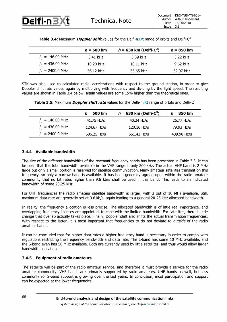
Technical NoteDocument
AuthorDateIssue
DNX-TUD-TN-0014Arthur Tindemans13/06/20103.1
68 End-to-end analysis and design of the satellite communication links
System design of the communication subsystem of the Delfi-n3Xt nanosatellite
Table 3.4: Maximum Doppler shift values for the Delfi-n3Xt range of orbits and Delfi-C3
h = 600 km h = 630 km (Delfi-C3) h = 850 km
0f = 146.00 MHz 3.41 kHz 3.39 kHz 3.22 kHz
0f = 436.00 MHz 10.20 kHz 10.11 kHz 9.62 kHz
0f = 2400.0 MHz 56.12 kHz 55.65 kHz 52.97 kHz
STK was also used to calculated radial accelerations with respect to the ground station, in order to giveDoppler shift rate values again by multiplying with frequency and dividing by the light speed. The resultingvalues are shown in Table 3.4 below; again values are some 15% higher than the theoretical ones.
Table 3.5: Maximum Doppler shift rate values for the Delfi-n3Xt range of orbits and Delfi-C3
h = 600 km h = 630 km (Delfi-C3) h = 850 km
0f = 146.00 MHz 41.75 Hz/s 40.24 Hz/s 26.77 Hz/s
0f = 436.00 MHz 124.67 Hz/s 120.16 Hz/s 79.93 Hz/s
0f = 2400.0 MHz 686.25 Hz/s 661.42 Hz/s 439.98 Hz/s
3.4.4 Available bandwidth
The size of the different bandwidths of the revenant frequency bands has been presented in Table 3.3. It canbe seen that the total bandwidth available in the VHF range is only 200 kHz. The actual VHF band is 2 MHzlarge but only a small portion is reserved for satellite communication. Many amateur satellites transmit on thisfrequency, so only a narrow band is available. It has been generally agreed upon within the radio amateurcommunity that no bit rates higher than 9.6 kb/s shall be used in this band. This leads to an indicatedbandwidth of some 20-25 kHz.
For UHF frequencies the radio amateur satellite bandwidth is larger, with 3 out of 10 MHz available. Still,maximum data rate are generally set at 9.6 kb/s, again leading to a general 20-25 kHz allocated bandwidth.
In reality, the frequency allocation is less precise. The allocated bandwidth is of little real importance, andoverlapping frequency licenses are appointed, to cope with the limited bandwidth. For satellites, there is littlechange that overlap actually takes place. Finally, Doppler shift also shifts the actual transmission frequencies.With respect to the latter, it is most important that frequencies to do not deviate to outside of the radioamateur bands.
It can be concluded that for higher data rates a higher frequency band is necessary in order to comply withregulations restricting the frequency bandwidth and data rate. The L-band has some 10 MHz available, andthe S-band even has 50 MHz available. Both are currently used by little satellites, and thus would allow largerbandwidth allocations.
3.4.5 Equipment of radio amateurs
The satellite will be part of the radio amateur service, and therefore it must provide a service for the radioamateur community. VHF bands are primarily supported by radio amateurs. UHF bands as well, but lesscommonly so. S-band support is growing over the last years. In conclusion, most participation and supportcan be expected at the lower frequencies.

Technical NoteDocument
AuthorDateIssue
DNX-TUD-TN-0014Arthur Tindemans13/06/20103.1
69End-to-end analysis and design of the satellite communication links
System design of the communication subsystem of the Delfi-n3Xt nanosatellite
4 COMMS requirements
In chapter 2 the top-level requirements were presented, belonging to the first three levels introduced in thesame chapter. In this chapter the requirements for the fourth level, the COMMS itself, shall be derived andpresented. In some cases these requirements follow from the top-level requirements, and another number ofrequirements follow from the choice to use radio amateur frequencies. Also, a number of requirementsnecessary on the COMMS level related to performance and security can and should be stated. Finally, anumber of organizational requirements are stipulated.
The first type of requirement is labelled technical requirement and is presented in section 4.1. The secondtype, logically called organizational requirement is presented in section 4.2.
A number of top-level requirement stated in chapter 2 in fact also apply to all COMMS components, but thesewill not be restated. An example is the requirements concerning budgets and reliability.
4.1 Technical requirements
The technical requirements are presented in Table 4-1 and Table 4-3 below. As before, categories are givenfollowed by a requirement number and the actual requirement. If applicable, the parent(s) is/are given.Underneath each requirement a rationale is given.
Table 4-1: COMMS technical requirements (part one)
Category Req. # Requirement
FUNCTIONAL SAT.2.3-F.01The COMMS shall be able to receive telecommands transmitted by the Ground StationNetwork
Parent: SAT-F.0.1
Rationale: As COMMS is in charge of communicating with the GS, this requirement follows fromthe parent.
FUNCTIONAL SAT.2.3-F.02The COMMS shall transmit telemetry (payload and housekeeping data) from the satellite tothe Ground Station Network
Parent: SAT-F.0.1
Rationale: As COMMS is in charge of communicating with the GS, this requirement follows fromthe parent.
FUNCTIONAL SAT.2.3-F.03 The COMMS shall provide a return service to the radio amateur community
Rationale: In the previous chapter the choice for radio amateur frequencies was explained. Thelogical consequence of this is that a return service should be provided.
FUNCTIONAL SAT.2.3-F.04The COMMS may be able to receive other data such as software updates transmitted by theGround Station Network
Parents: SAT-F.0.1 & MIS-F.0.3
Rationale: This requirement is a further specification of the parent requirement of being able tocommunicate with the GS. However, it also follows from the requirement to facilitate additionalexperiments, such as the ability to receive software upload data.
FUNCTIONAL SAT.2.3-F.05 The COMMS shall facilitate the STX
Parent: MIS-F.0.3
Rationale: The STX should be flown as a technology demonstration

Technical NoteDocument
AuthorDateIssue
DNX-TUD-TN-0014Arthur Tindemans13/06/20103.1
70 End-to-end analysis and design of the satellite communication links
System design of the communication subsystem of the Delfi-n3Xt nanosatellite
Table 4-2: COMMS technical requirements (part two)
Category Req. # Requirement
FUNCTIONAL SAT.2.3-F.06 The COMMS may facilitate the OLFAR experiment
Parent: MIS-F.0.3
Rationale: OLFAR is an experiment that may be flown.
PERFORMANCE SAT.2.3-P.01All transmitters shall provide a maximum permitted power level for spurious emissions indBc according to -43 - 10 log (P), where P is the transmitted power
Rationale: ITU regulations give boundaries for the transmission bandwidth out-of-band for anyofficially allocated transmission frequency. However, given the use of radio amateur bands andlimited transmission power, the actual requirement is less strict, and more ‘best-effort’.
PERFORMANCE SAT.2.3-P.02The bit error rate of all digital data transmission links shall be designed to be at most10^-5
Rationale: Bit errors follow from probabilities related to channel noise. A BER value of 10-5 is acommon value in spaceflight and for non-critical information [SLR 0316].
PERFORMANCE SAT.2.3-P.03 In the link budget a minimum link margin of 3 dB is required for all transmission links
Parent: MIS-F.0.3
Rationale: This value is again a common value in spaceflight, accounting for inaccuracies inthe system model [SLR 0316].
CONSTRAINT SAT.2.3-C.01The frequencies for communicating with the satellite shall lie within the frequency bandsallocated to the amateur satellite service
Parent: SAT-F.0.1
Rationale: As was decided in the last chapter, the radio amateur frequency bands shall beused for data communication.
CONSTRAINT SAT.2.3-C.02Any data transmitted to and from the satellite other than telecommands shall not beencrypted in any way
Parent: SAT-F.0.1
Rationale: This requirement follows from radio amateur regulations and is a consequence ofthe choice for the radio amateur frequencies.
CONSTRAINT SAT.2.3-C.03 All receivers that can receive telecommands shall be turned on by default
Rationale: This requirement is one that underlines the essential role of the receivers; in case ofany malfunctions the ability to command the satellite can save the mission. Therefore specialattention should be paid to the availability of the receivers.
CONSTRAINT SAT.2.3-C.04 The COMMS shall facilitate a redundant set of transceivers
Parent: SAT.2-C.01
Rationale: Following from the parent requirement of reliability, a single-point-of-failure freecommunication system results in a desire for two transceivers; which makes more sense thendoubling every component on one radio.
CONSTRAINT SAT.2.3-C.05All UHF and VHF antenna connections and transmission lines on the satellite will have animpedance of 50 ohm
Rationale: This value is the commonly used value with COTS components. It has also beenused in the Delfi-C3 architecture.
GENERAL SAT.2.3-G.01It shall be prevented that parties other than designated satellite operators shall be able tocommand the satellite
Rationale: This requirement follows from mission security. It can be implemented by usingunpredictable or unknown (encryption) protocols, which consequently should be kept secret.This requirement of secrecy is further addressed in the next section on organizationalrequirements.

Technical NoteDocument
AuthorDateIssue
DNX-TUD-TN-0014Arthur Tindemans13/06/20103.1
71End-to-end analysis and design of the satellite communication links
System design of the communication subsystem of the Delfi-n3Xt nanosatellite
4.2 Organizational requirements
A small amount of organizational requirements follow from the COMMS; these are listed and argued for inTable 4-3 below. No strict numbering system is determined (yet) so they are logically numbered ORG.1-3.
Table 4-3: STX TX requirements
Category Req. # Requirement
ORGANIZATIONAL ORG.1A downlink specification for each transmission link shall be made publicly available,including transmission frequency, data rate, modulation scheme, data protocol and content
Rationale: This requirement follows again from the choice of using the radio amateurtransmission frequencies, as the latter allows no transmission of nonpublic information.
ORGANIZATIONAL ORG.2Uplink transmission frequencies, intermediate frequencies and oscillator frequencies in thereceiver, telecommand codes and encryption keys and offset shall be kept secret and beavailable only in restricted documentation
Rationale: This requirement follows from the desire of having no unauthorized people operatingthe satellite.
ORGANIZATIONAL ORG3Documentation on daily operations of the ground station as well as the ground station itselfshall have restricted access
Rationale: This requirement follows from the desire of having no unauthorized people operatingthe satellite.

Technical NoteDocument
AuthorDateIssue
DNX-TUD-TN-0014Arthur Tindemans13/06/20103.1
72 End-to-end analysis and design of the satellite communication links
System design of the communication subsystem of the Delfi-n3Xt nanosatellite

Technical NoteDocument
AuthorDateIssue
DNX-TUD-TN-0014Arthur Tindemans13/06/20103.1
73End-to-end analysis and design of the satellite communication links
System design of the communication subsystem of the Delfi-n3Xt nanosatellite
5 COMMS: space segment design
As stated in the introduction of this document, COMMS hardware includes a number of transceivers,experiments, the antenna system and the ground segment. As the latter is called the ground segment, thefirst three components logically form the space segment.
Section 5.1 introduces all CIs that make up the COMMS. Sections 5.2 and 5.3 consequently argue for theexact frequency bands that are to be used as well as the radio amateur return service that is to be provided.Using this knowledge, a resulting overview of the COMMS can be given in section 5.4, and a furtherspecification of the CIs and their documentation is presented in section 5.5. Finally, sections 5.6 and 5.7describe failure cases and Delfi-C3 heritage amongst the COMMS components.
5.1 Description of the communication platform
It has been presented in the previous chapter that there are a number of payloads. One of these payloads isthe ITRX; being a transceiver built by ISIS. It is built to function as a primary transceiver for CubeSats.
A primary radio, if possible being non-experimental and thus proven is required for Delfi-n3Xt. The ITRXhowever is a new design and is little proven. Also, it is a payload and as such little control on the actualstatus is exerted. This is unacceptable for a mission critical system and as such the primary transceiver orPTRX is decided to serve as the primary radio. In order to make the radio non-experimental in as far aspossible, it has been decided that the PTRX is based on the RAP of Delfi-C3 (requirement SYS.REQ.G.008). Inreality, more changes have been necessary but nevertheless large parts are based on proven concepts withDelfi-C3 flight heritage. The PTRX is used to transmit payload data and housekeeping data, together being:telemetry (TM), and to receive telecommands (TCs).
The implementation of the ITRX payload however allows the latter to be used as a redundant radio. Whereasthe ITRX is not yet a finished design, the PTRX also requires more changes then anticipated. As such, the useof two different radios spreads risks but also possibly allows the possibly more power-efficient ITRX to beused during nominal operations. If in the end the ITRX turns out to be not ready, of course a second PTRXcan be flown as a redundant radio.
As a result, there will be two main radios on board of Delfi-n3Xt:
PTRX: The primary transceiver for transmitting telemetry and receiving telecommands;
ITRX: The secondary transceiver for redundancy, also a payload.
Each of the radios is integrated on PCBs. As the signals produced or to be processed by the transceivers areto be translated to and from wireless signals by antennas, also required is the:
Antenna system: Depending on the transmission frequencies, a set of antennas is required for theradios on Delfi-n3Xt, as well as all connections from the PCBs to the antennas. This antenna systemwould also include any required STX antenna parts, explained below.

Technical NoteDocument
AuthorDateIssue
DNX-TUD-TN-0014Arthur Tindemans13/06/20103.1
74 End-to-end analysis and design of the satellite communication links
System design of the communication subsystem of the Delfi-n3Xt nanosatellite
Within the COMMS, two technology demonstrations are further more specified. These systems have nomission-critical purpose, and no resources should be devoted to them if these resources can otherwise beused for mission-critical systems. The demonstrations related to the COMMS:
STX: An optional high-speed transmitter of telemetry. STX stands for S-band transmitter. Theselection of frequency band will be explained below in section 5.2. A transmitter in a differentfrequency band requires extra antenna(s) and connections, thus enlarging the content of the antennasystem.
OLFAR: Using the same antennas as the PTRX, signal of frequencies between 1 and 30 MHz are tobe received in order to investigate space-borne radiofrequency waves.
The following figure shows all configuration items or CIs that represent parts of the total communicationsystem. This figure introduces one extra level to the CI tree presented in Figure 2.1 above.
Figure 5.1: The COMMS CIs

Technical NoteDocument
AuthorDateIssue
DNX-TUD-TN-0014Arthur Tindemans13/06/20103.1
75End-to-end analysis and design of the satellite communication links
System design of the communication subsystem of the Delfi-n3Xt nanosatellite
5.2 Frequency band selection
In chapter 3 the choice was made to use radio amateur bands. However, it remains to confirm the exactbands, as multiple radio amateur frequency bands exist. Subsections 5.2.1, 5.2.2 and 5.2.3 present the choiceof band for respectively PTRX and ITRX, STX, and OLFAR. The exact transmission frequencies are presentedin chapters 8 and 12 on the UHF/VHF and S-band transmission links.
5.2.1 PTRX and ITRX
The PTRX and the ITRX are based on the RAP of Delfi-C3. It is a requirement that for the PTRX the RAP is notchanged to a large extent, similarly the ITRX will be designed to use the popular UHF/VHF bands. A changeof frequency would incur design changes, thereby increasing complexity. Also, as will be commented on inchapter 8, reusing the same frequency bands simplifies the frequency filing procedure as Delfi-C3 frequenciescan be reused. Thus, both the PTRX and the ITRX will use the UHF band for uplink and the VHF band fordownlink. More precisely, they will use the satellite transmission portions of the radio amateur band, in turnbeing part of the UHF and VHF bands. In terms of frequencies:
PTRX/ITRX downlink: 145.80-146.00 MHz PTRX/ITRX uplink: 435-438 MHz
5.2.2 STX
The high-speed downlink transmitter is not allowed to operate in the UHF band, since this can causeinterference with both the receiver of the PTRX as well as the receiver in the ITRX. This leaves the VHF bandand the S-band (2—4 GHz) as possible frequency bands. The L-band (1—2 GHz) can only be used in theEarth-to-space direction in the amateur satellite service [SLR 0310].
Since for VHF only a very limited bandwidth is available, this is also not a suitable frequency band for a high-speed link. Frequencies higher than S-band are not considered because the higher the frequency, the moredifficult the design will be. Due to the increased path loss more power or a higher antenna gain (with theresulting pointing requirements) is needed. Operation in S-band is considered to be ambitious already, andtherefore this will be the maximum frequency that can be used for the STX on Delfi-n3Xt. At the same time,different CubeSats, such as GeneSat and CanX-2, and the S-band transmitter HISPICO have demonstratedlarge data rates to be achievable within the s-band, using small transmitters. Considering all thesearguments, it is concluded that the frequency band of the experimental high-speed transmitter (STX) is the S-band. In terms of frequencies:
STX downlink: 2400-2450 MHz
5.2.3 OLFAR
The OLFAR experiment (see [SLR 0170]) receives frequencies in the band 10—30 MHz, inherent to theexperiment. Transmission of the signals will be done in the VHF band (144—146 MHz), using the sametransmission architecture as the PTRX. Since the satellite only receives at 0.3—30 MHz, no frequencycoordination needs to be done (this only applies for transmitting).

Technical NoteDocument
AuthorDateIssue
DNX-TUD-TN-0014Arthur Tindemans13/06/20103.1
76 End-to-end analysis and design of the satellite communication links
System design of the communication subsystem of the Delfi-n3Xt nanosatellite
5.3 Return service to radio amateurs
Delfi-n3Xt will operate in the amateur satellite service. A requirement is that the satellite provides a servicefor the radio amateur community in return for use of radio amateur frequency bands, as explained in chapter3. Examples of return favours are:
Carrying a linear transponder: A transponder receives signals in some frequency band, amplifiesthese signals and retransmits the signal in another frequency band. A linear transponder works insuch a way that the shape of the signal is not altered. A linear transponder can therefore be usedfor all kinds of signals: amplitude modulated signals, frequency modulated signals as well asphase modulated signals. The use of an Automatic Gain Control amplifier however might removethe support for amplitude modulated signals.
Providing a store-and-forward service: This type of service allows users to up- and downloadmessage to and from the satellite.
Testing of new radio equipment to advance radio science: New equipment that can, ifsuccessful, be of use to the radio amateur community, can be tested.
Providing a beacon: This is the simplest return service. Basically any signal that is transmitted inthe radio amateur bands forms a beacon. The content of the transmission can be altered tosatisfy radio amateurs.
[SLR 0248] describes the trade-off performed for Delfi-C3. It mentions that discussions with the radio amateurcommunity have brought forward a number one preference of a linear transponder as the return favour. It:
Accommodates a large number of signal types due to its linearity Allows multiple radio contacts at the same time Can easily be integrated in the transceiver architecture Has proven itself on a number of amateur satellites, the latter of course being Delfi-C3.
As the linear transponder functionality consequently has been implemented successfully on Delfi-C3, itsreimplementation on Delfi-n3Xt is rather simple. Of course a linear transponder has already been flown (onDelfi-C3), so its application is less novel and its inclusion could be perceived to be less valuable. Nevertheless,the Delfi-C3 transponder is no longer active, and there seem to be no reasons to think the feature might beless interesting to radio amateurs. Early discussions with the radio amateur community have not presentedany doubts with respect to the re-inclusion of a linear transponder. As such:
Delfi-n3Xt will provide a linear transponder service as a return service to radio amateurs
It will be included on the PTRX, which is an update to the original RAP, which featured the linear transponderas well. In fact, a beacon will also be provided to announce the activation of the linear transponder. Thetransponder has no direct functionality for the mission; its implementation is only as return-of-service for theuse of the radio amateur frequencies and the forwarding of our telemetry by radio amateurs during normaloperations. The linear transponder is further discussed in chapter 9 on the PTRX.
Furthermore, in the Delfi-C3 mission the RASCAL client was conceived. This program allows demodulatingsampled telemetry data, interpreting and visualizing the data and forwarding it to the TM (telemetry)Database. This program was welcomed with open arms by the radio amateurs and at the same time providedus with invaluable data. As such:
A second return service will be the Delfi-n3Xt data reception client, named DUDe

Technical NoteDocument
AuthorDateIssue
DNX-TUD-TN-0014Arthur Tindemans13/06/20103.1
77End-to-end analysis and design of the satellite communication links
System design of the communication subsystem of the Delfi-n3Xt nanosatellite
In addition, a number of radio amateurs have expressed their interest in having an S-band beacon on asatellite. Whenever the STX will be on, telemetry will likely be transmitted, thereby posing as a beacon and areturn service. This can be seen as a third return service, but will not be explicitly stated to be one as it is infact simply our TM transmission. Also, no link between the transponder and the STX for a more complicatedS-band transponder system shall for now be assumed, given the additional complexity required. This might bean option for the future.
For now, the aforementioned return services are deemed sufficient. Indeed, a conversation with GrahamShirville, who is in charge of the frequency conversation within the AMSAT community, confirms that thereturn services stated would be sufficient.
5.4 Overview of the communication platform elements
All main functionalities and frequency bands of the radios have been specified. One other functionality existsand has not been mentioned above, which is the payload functionality of the ITRX; a number of tests can beperformed by the latter involving transmission and reception. Combining all radio functionalities anddistinguishing between transmission and reception yields the following Figure 5.2. It also shows thetransmission frequencies. Finally, OLFAR and the STX are indicated as being a technology demonstration.
Figure 5.2: Delfi-n3Xt radios and their inputs and outputs
Figure 5.3 below consequently shows not only the radio segments, but also the antenna system, as well asthe OBC, or on-board computer of Delfi-n3Xt. The latter is the communication point for all digital data. In thisfigure it can be clearly seen that if the STX is to be flown, it requires a separate antenna system.
Only transmission related interfaces are shown; other interfaces such as those related to housekeeping dataare commented on in later chapters. It can be seen that both PTRX and ITRX can interface with the OBC toexchange TM and TCs. Both the PTRX and ITRX also exchange signals with the Antenna System, which canbe seen to consist of Phasing Circuit, S-band Antenna Connection and Antennas. It should be noted thatOLFAR is most likely largely integrated on the UHF/VHF Phasing Circuit; it is however not part of the AntennaSystem, it is defined as a separate CI. This is of course assuming the OLFAR will be flown.

Technical NoteDocument
AuthorDateIssue
DNX-TUD-TN-0014Arthur Tindemans13/06/20103.1
78 End-to-end analysis and design of the satellite communication links
System design of the communication subsystem of the Delfi-n3Xt nanosatellite
Figure 5.3: Delfi-n3Xt radios and their inputs and outputs

Technical NoteDocument
AuthorDateIssue
DNX-TUD-TN-0014Arthur Tindemans13/06/20103.1
79End-to-end analysis and design of the satellite communication links
System design of the communication subsystem of the Delfi-n3Xt nanosatellite
5.5 Specification of the communication platform elements
This document aims to provide a first specification of all systems, at least in terms of subfunctionalities,interfaces and integration on Delfi-n3Xt. This section will specify what exactly is discussed in later chapters,and what is discussed in other (project) documentation.
In the sections 5.5.1 through 5.5.4 below the 5 lower level CIs are further commented on, starting with thetransceivers, followed by the experimental transmitter, in turn followed by OLFAR experiment and finishing offwith the required antenna system.
5.5.1 PTRX
This document describes the top-level design of the PTRX, including the specification of its(sub)functionalities and its CIs. In order to do so, the entire UHF/VHF link is first specified with regard topower, bandwidth and complexity effects, taking into account the ground station effects as well. In otherwords, important to the PTRX are:
Chapter 8: The UHF/VHF communication link Chapter 9: PTRX
A large number of other documents describe the PTRX or parts of it, on a lower level and generally related toelectrical aspects. An extensive list of current PTRX-centred documentation:
[SLR 0281]: PTRX Design [SLR 0591}: PTRX Transmitter [SLR 0592]: PTRX Modulator [SLR 0722]: PTRX Frame Interpreter and Frame Generator Design [SLR 0659]: PTRX Electrical Circuit Diagrams
Also, PTRX Processors software is integrated in the SLR: [SLR 0654]: Frame Interpreter software [SLR 0655]: Frame Generator software
5.5.2 ITRX (payload)
This document introduces the ITRX and its functionalities, modes and interfaces. However, as it is a payload,it is treated more or less as a black box. Therefore the main design is not part of Delfi programme. In thisdocument the following chapters are of interest:
Chapter 8: The UHF/VHF communication link Chapter 10: ITRX
There is one and only on other document that describes ITRX aspects, and that is a general interfacedocument which is used for all payloads:
[SLR 0182]: ITRX Interface Control Document

Technical NoteDocument
AuthorDateIssue
DNX-TUD-TN-0014Arthur Tindemans13/06/20103.1
80 End-to-end analysis and design of the satellite communication links
System design of the communication subsystem of the Delfi-n3Xt nanosatellite
5.5.3 STX (experiment)
The STX is only a transmitter as opposed to a transceiver. It has no Delfi heritage and has to be designedfrom scratch. Hopefully, the design will have advanced to a point where it can be flown at launch. Afunctional and operational specification, as well as a possible design of its lower-level components has beenmade.
This document determines aspects with respect to the S-band communication link, involving not just the STXbut also the ground segment, and similarly the operations of the STX will be discussed. This is done in:
Chapter 12: S-band communication link Chapter 14: Operations and performance
The functional specification of the STX, its configuration items, its interfaces and its operational modes arediscussed in a separate top-level document. The same document presents the design philosophy of the STXgiven the project status, as well as a possible hardware design and its status:
[SLR 0387]: Top-level design of the STX
5.5.4 OLFAR (experiment)
This document introduces the functionalities and architecture of the OLFAR experiment, as well as its impactson the other systems. In order to so it is mainly discussed in two chapters:
Chapter 9: PTRX Chapter 11: OLFAR
Furthermore, there is one main document discussing the entire OLFAR experiment: [SLR 0170]: The OLFAR experiment
Finally, the relation of the OLFAR system to the Antenna System is discussed in: [SLR 0036]: Antenna System Design
5.5.5 Antenna system
The antenna system is not discussed in this document, but in a separate one. This document is: [SLR 0036]: Antenna System Design
The failure cases of the antenna system are however quickly assessed below.

Technical NoteDocument
AuthorDateIssue
DNX-TUD-TN-0014Arthur Tindemans13/06/20103.1
81End-to-end analysis and design of the satellite communication links
System design of the communication subsystem of the Delfi-n3Xt nanosatellite
5.6 Failure cases
Without a functioning communication system it is not possible to retrieve the data produced by the payloadsor to control the satellite. Therefore, it is important to consider the impact of failures of components of thecommunication system, given the vision of complete redundancy of all mission critical satellite elements.
Failure of PTRX receiver – If the PTRX receiver fails, the ITRX receiver should still function, thereforetelecommands can still be received. At the same time, the PTRX is designed to have its receiver andtransmitter sections separately connected to the power and data bus, therefore a failure of thereceiver would not automatically cause failure of the transmitter section. The transponderfunctionality however requires both, and is lost in case of failure of any of the two. The latterhowever is not mission-critical and is thus acceptable.
Failure of PTRX transmitter – A failure of the PTRX transmitter leaves the ITRX with the transmissionresponsibility. Possible the STX can be used as well. The PTRX receiver is not automatically lost, butthe linear transponder is.
Failure of ITRX – Telemetry is, as per default, transmitted by the PTRX or possibly the STX. Receivingtelecommands is done, also per default, by the PTRX. The ITRX experiments are lost. The ITRX is notdesigned to have separately connected receiver and transmitter sections.
Failure of STX – If the STX will be flown, and it fails, PTRX or ITRX only transmit telemetry data. The STX inany case is not mission-critical.
Alos, with respect to the antenna system the following can be stated. The details of the antenna system areexplained in [SLR 0036].
Failure of one UHF/VHF antenna – A failure of one UHF/VHF antenna will not cause loss of the link, asfour different antennas are in place. Two opposite antennas are actually only required. A failure ofone antenna (for example because the deployment fails) will likely only cause an assymetrical gainpattern and consequently slightly deteriorated performance (depending on the nature of the failure).
Failure of one S-band antenna – A failure of one out of two S-band antennas or its connection will stillallow for communication in more or less 50% of the time. For the purpose of technologydemonstration, this would still be sufficient.
It is concluded that the presented communication subsystem concept fulfils the mission goals, and for thecritical bus systems there is at least one backup. Failure cases are detected by either faulty or not receivedhousekeeping data, or by the Local EPS systems on-board of all bus-connected systems.
5.7 Delfi-C3 heritage
The following components of Delfi-n3Xt have Delfi-C3 heritage:
The PTRX (the general transmission and reception architecture are based on the RAP, and the lineartransponder is equal in design)
The VHF antennas and the deployment MABs (but will now also be used for UHF signal reception)
New components of the Delfi-n3Xt communication system are:
The STX
The STX Antenna System
The phasing circuit required for the integration of VHF and UHF antennas
The OLFAR experiment and its integration

Technical NoteDocument
AuthorDateIssue
DNX-TUD-TN-0014Arthur Tindemans13/06/20103.1
82 End-to-end analysis and design of the satellite communication links
System design of the communication subsystem of the Delfi-n3Xt nanosatellite

Technical NoteDocument
AuthorDateIssue
DNX-TUD-TN-0014Arthur Tindemans13/06/20103.1
83End-to-end analysis and design of the satellite communication links
System design of the communication subsystem of the Delfi-n3Xt nanosatellite
6 Lower level requirements
Given the CIs presented in the last chapter, requirements can be stated for each of them. In chapters 2 and 4the top-level requirements have been presented. A number of requirements on higher levels are equallyrequirements on lower levels. Examples on the highest level are all those related to budgets, as well spaceand launch environment requirements. On the COMMS however as well, performance requirements related tobandwidth occupancy and bit error rates for example are equally applicable to COMMS radios. As such Table6-1 below gives all requirements that are generally relevant for the lower level systems, without repeating theexact requirements.
Table 6-1: Generally applicable higher level requirements
Level Requirement(s)
Satellite SAT-C.01, SAT-C.02, SAT-C.03, SAT-C.04, SAT-C.05, SAT-C.06, SAT-C.07
Satellite Bus SAT.2-F.02, SAT.2-C.01
COMMS SAT.2.3-P.01, SAT.2.3-P.02, SAT.2.3-C.02, SAT.2.3-C.03, SAT.2.3-C.05
Sections 6.1 through 6.5 discuss respectively the PTRX, ITRX, STX, Antenna System and OLFARrequirements.

Technical NoteDocument
AuthorDateIssue
DNX-TUD-TN-0014Arthur Tindemans13/06/20103.1
84 End-to-end analysis and design of the satellite communication links
System design of the communication subsystem of the Delfi-n3Xt nanosatellite
6.1 PTRX
The PTRX requirements are presented and argued for in Table 6-2 and Table 6-3 below.
Table 6-2: PTRX requirements (part one)
Category Req. # Requirement
FUNCTIONAL SAT.2.3.1-F.01 The PTRX shall be able to receive telecommands
Parent: SAT.2.3-F.01
Rationale: With the PTRX being the primary transceiver, this requirement follows logicallyfrom the parent.
FUNCTIONAL SAT.2.3.1-F.02 The PTRX shall be able to transmit telemetry (payload and housekeeping data)
Parent: SAT.2.3-F.02
Rationale: With the PTRX being the primary transceiver, this requirement follows logicallyfrom the parent.
FUNCTIONAL SAT.2.3.1-F.03 The PTRX shall have linear transponder functionality
Parent: SAT.2.3-C.02
Rationale: In the previous chapter the choice for a linear transponder was explained,along with the logic of integration it on the PTRX.
FUNCTIONAL SAT.2.3.1-F.04 The PTRX may facilitate the OLFAR experiment
Parent: SAT.2.3-F.06
Rationale: If the OLFAR experiment is indeed flown, the PTRX should (partly) facilitate itsintegration
FUNCTIONAL SAT.2.3.1-F.05The PTRX may be able to receive other data such as software updates transmitted bythe Ground Station Network
Parent: SAT.2.3-F.04
Rationale: If software data frames are uploaded with characteristics differing from TCpackets, these should be properly received and forwarded to the OBC.
INTERFACE SAT.2.3.1-I.01The PTRX shall have an interface with the Antenna System to forward and receive ananalogue data signal
Rationale: This interface is logically required.
PERFORMANCE SAT.2.3.1-P.01 The PTRX shall allow for transmission of data with a data rate of at least 1200 bits/s
Rationale: The RAP on which the PTRX is based attained a downlink data rate of 1200b/s; as such this is the minimum that is to be achieved for the PTRX.
PERFORMANCE SAT.2.3.1-P.02 The PTRX shall allow for reception of data with a data rate of at least 600 bits/s
Rationale: The RAP on which the PTRX is based attained an uplink data rate of 1200 b/s;as such this is the minimum that is to be achieved for the PTRX.

Technical NoteDocument
AuthorDateIssue
DNX-TUD-TN-0014Arthur Tindemans13/06/20103.1
85End-to-end analysis and design of the satellite communication links
System design of the communication subsystem of the Delfi-n3Xt nanosatellite
Table 6-3: PTRX requirements (part two)
Category Req. # Requirement
CONSTRAINT SAT.2.3.1-C.01The centre frequency of the VHF signal transmitted by the PTRX transmitter shall liewithin the frequency band 145.80-146.00 MHz
Parent: SAT.2.3-C.01
Rationale: As the parent requirement specifies, the radio amateur bandwidths shall beused. This requirement is expanded here by including exact frequencies.
CONSTRAINT SAT.2.3.1-C.02The centre frequency of the UHF signal received by the PTRX receiver shall lie withinthe frequency band 435-438 MHz
Parent: SAT.2.3-C.01
Rationale: As the parent requirement specifies, the radio amateur bandwidths shall beused. This requirement is expanded here by including exact frequencies.
CONSTRAINT SAT.2.3-C.02 Received telecommands shall be encrypted
Parent: SAT.2.3-G.01
Rationale: Given the requirement of restricting the commandability of the satellite,encryption shall be applied as was done with Delfi-C3. In fact, this choice is formally madein chapter 8.
CONSTRAINT SAT.2.3-C.03 Changes of the PTRX with respect to the RAP design shall be minimized
Rationale: The RAP in practice has been successful although with a number of issues.As the PTRX is a mission-critical system, it makes sense to try and limit the changes tothe proven design to essential or valuable ones.

Technical NoteDocument
AuthorDateIssue
DNX-TUD-TN-0014Arthur Tindemans13/06/20103.1
86 End-to-end analysis and design of the satellite communication links
System design of the communication subsystem of the Delfi-n3Xt nanosatellite
6.2 ITRX
The ITRX requirements are largely the same as those of the PTRX, but with the experimental features andtransponder functionality removed. Also, as the Delfi-team is not involved with the actual design, no lower-level design requirements are specified. The resulting reduced list of requirements is presented in Table 6-4below.
Table 6-4: ITRX requirements
Category Req. # Requirement
FUNCTIONAL SAT.1.1-F.01 The ITRX shall be able to receive telecommands
Parent: SAT.2.3-F.01
Rationale: See PTRX requirements description
FUNCTIONAL SAT.1.1-F.02 The ITRX shall be able to transmit telemetry (payload and housekeeping data)
Parent: SAT.2.3-F.02
Rationale: See PTRX requirements description
INTERFACE SAT.1.1-I.01The ITRX shall have an interface with the Antenna System to forward and receive ananalogue data signal
Rationale: See PTRX requirements description
PERFORMANCE SAT.1.1-P.01 The ITRX shall allow for transmission of data with a data rate of at least 1200 bits/s
Rationale: See PTRX requirements description
PERFORMANCE SAT.1.1-P.02 The ITRX shall allow for reception of data with a data rate of at least 600 bits/s
Parent: SAT.2.3-C.01
Rationale: See PTRX requirements description
CONSTRAINT SAT.2.3.1-C.01The centre frequency of the VHF signal transmitted by the PTRX transmitter shall liewithin the frequency band 145.80-146.00 MHz
Parent: SAT.2.3-C.01
Rationale: See PTRX requirements description
CONSTRAINT SAT.2.3.1-C.02The centre frequency of the UHF signal received by the PTRX receiver shall lie withinthe frequency band 435-438 MHz
Parent: SAT.2.3-C.01
Rationale: See PTRX requirements description
CONSTRAINT SAT.2.3-C.02 Received telecommands shall be encrypted
Parent: SAT.2.3-G.01
Rationale: See PTRX requirements description

Technical NoteDocument
AuthorDateIssue
DNX-TUD-TN-0014Arthur Tindemans13/06/20103.1
87End-to-end analysis and design of the satellite communication links
System design of the communication subsystem of the Delfi-n3Xt nanosatellite
6.3 STX
The STX requirements are presented and argued for in Table 6-5 below.
Table 6-5: STX requirements
Category Req. # Requirement
FUNCTIONAL SAT.2.3.1-F.01 The STX shall be able to transmit telemetry (payload and housekeeping data)
Parent: SAT.2.3-F.02
Rationale: With the PTRX being a transmitter, this requirement follows logically from theparent.
FUNCTIONAL SAT.2.3.1-F.02 The STX shall have a buffer to store data that must be transmitted
Parent: SAT.2.3-F.02
Rationale: As STX transmission data rate is supposed to be higher than data is receivedfrom the OBC, data storage is required.
FUNCTIONAL SAT.2.3.1-F.03The STX shall have an interface with the Antenna System to forward an analogue datasignal
Rationale: This interface is logically required.
FUNCTIONAL SAT.2.3.1-F.04 The STX shall allow for transmission of data with a data rate of at least 9600 bits/s
Parent: SAT.2.3-F.06
Rationale: This performance goal is based on the fact that CubeSat radios on UHF/VHFfrequencies generally have data rates not higher than 9.6 kb/s. Similarly, the requiredassumed bandwidth (up to 20 kHz) is generally the maximum allocated within radioamateur transmission bands. Therefore, a significant improvement by a (high-speed)transmitter in a different frequency bandwidth is made and only made by improving onthis limit.
FUNCTIONAL SAT.2.3.1-F.05The STX Data Storage must have a size that represents at least 24 hours of all uniquepayload data and housekeeping data
Parent: SAT.2.3-F.04
Rationale: This requirement is based on the fact that (at least) one good day-light passover Delft is assumable per day. Multiple passes per day can of course be utilized, andlarger data storage could be used if available at little cost.
INTERFACE SAT.2.3.1-I.01The STX is assumed to transmit the exact same raw data as the PTRX, with raw dataindicating data excluding transmission protocol specific data
Rationale: This requirement reduces the impact of the STX on the satellite, as the datacan simple be sent to both PTRX/ITRX and STX.
CONSTRAINT SAT.2.3.1-C.01The STX signal shall be within the S-band frequency band between 2400 and 2450MHz
Parent: SAT.2.3-C.01
Rationale: As the parent requirement specifies, the radio amateur bandwidths shall beused. This requirement is expanded here by including exact frequencies.

Technical NoteDocument
AuthorDateIssue
DNX-TUD-TN-0014Arthur Tindemans13/06/20103.1
88 End-to-end analysis and design of the satellite communication links
System design of the communication subsystem of the Delfi-n3Xt nanosatellite
6.4 Antenna System
The Antenna System requirements are presented and argued for in Table 6-6 below.
Table 6-6: Antenna System requirements
Category Req. # Requirement
FUNCTIONAL SAT.2.3.3-F.01 The Antenna System shall be able to receive the uplink signal over the UHF frequencies
Parent: SAT.2.3-F.01 & SAT.2.3-C.01
Rationale: This requirement follows logically from the parents.
FUNCTIONAL SAT.2.3.3-F.02The Antenna System shall be able to radiate the downlink signal over the VHFfrequencies
Parent: SAT.2.3-F.02 & SAT.2.3-C.01
Rationale: This requirement follows logically from the parents.
FUNCTIONAL SAT.2.3.3-F.03The Antenna System may be able to radiate the downlink signal over the S-bandfrequencies
Parent: SAT.2.3-C.01
Rationale: This requirement follows logically from the parents.
FUNCTIONAL SAT.2.3.3-I.01The Antenna System shall have an interface with the PTRX to forward and receive ananalogue data signal
Rationale: This interface is logically required.
FUNCTIONAL SAT.2.3.3-I.02The Antenna System shall have an interface with the ITRX to forward and receive ananalogue data signal
Rationale: This interface is logically required.
INTERFACE SAT.2.3.3-I.03The Antenna System may have an interface with the STX to forward an analogue datasignal
Rationale: This interface is logically required.
CONSTRAINT SAT.2.3.3-C.01 The polarization of the Antenna System shall be circular
Rationale: For a satellite it is desired to have circular polarization, because with linearpolarization the orientation of the polarization at the ground station is unknown due toFaraday rotation in the atmosphere.
CONSTRAINT SAT.2.3.3-C.02 A single antenna deployment failure should not cause loss of the link
Parent: SAT.2-C.01
Rationale: This follows from the parent requirement, stating a single-point-of-failure freedesign.

Technical NoteDocument
AuthorDateIssue
DNX-TUD-TN-0014Arthur Tindemans13/06/20103.1
89End-to-end analysis and design of the satellite communication links
System design of the communication subsystem of the Delfi-n3Xt nanosatellite
6.5 OLFAR
The OLFAR requirements are presented and argued for in Table 6-7 below.
Table 6-7: OLFAR requirements
Category Req. # Requirement
FUNCTIONAL SAT.2.3.4-F.01OLFAR shall receive signals in the frequency range 0.3 – 30 MHz and prepare these forretransmission
Rationale: This is the functionality as defined for the OLFAR experiment.
FUNCTIONAL SAT.2.3.4-I.01OLFAR shall have an interface with the Antenna System to receive an analogue datasignal
Parent: SAT.2.3-F.02 & SAT.2.3-C.01
Rationale: This interface is logically required.
FUNCTIONAL SAT.2.3.4-I.02 OLFAR shall have an interface with the PTRX to forward an analogue data signal
Parent: SAT.2.3-C.01
Rationale: This interface is logically required.
FUNCTIONAL SAT.2.3.4-C.01 OLFAR is classified as an experiment, as specified in [SLR 0263]
Parent: MIS-F.03
Rationale: OLFAR is classified as one of the experiments indicated by the parent requirement.

Technical NoteDocument
AuthorDateIssue
DNX-TUD-TN-0014Arthur Tindemans13/06/20103.1
90 End-to-end analysis and design of the satellite communication links
System design of the communication subsystem of the Delfi-n3Xt nanosatellite

Technical NoteDocument
AuthorDateIssue
DNX-TUD-TN-0014Arthur Tindemans13/06/20103.1
91End-to-end analysis and design of the satellite communication links
System design of the communication subsystem of the Delfi-n3Xt nanosatellite
7 Transmission techniques
In layman’s terms, a radio often refers to a receiver, a transmitter, or both: a transceiver. In all these casesits functionality can be described quite simply, for example a transmitter takes a data input (bits, a voicesignal, sounds, but in any case at some point in the process portrayed by an electronic signal), and convertsthis to a transmittable signal, and finally transmits it. A receiver does the reverse, and logically a transceivercan do both. Due to the increased use of computers in all radios, at some point or another, the data usuallyconsists of bits. As such, the functionality of the same transmitter can be reduced to “preparing a digitalsignal for transmission, and transmitting it”.
In terms of hardware, a logical distinction can usually be made between antenna, and the rest. The radio ismade up of electronics, integrated circuitry, whereas the antenna is usually connected to these electronics viaa cable, and has a distinct shape and location on the ‘radio’. The same holds for Delfi-n3Xt. As such, threeradios can be said to be integrated on it, together with the antenna systems to take care of actual physicaltransmission. Therefore, the functionality of our transmitter has reduced to “preparing a digital signal fortransmission”. This functionality is exemplified by Figure 7.1 below.
Figure 7.1: Input and output of a simple transmitter
This exact functionality in fact takes place in not just radios, but also in (wired/wireless) internet connections,or even USB connections. As such, a standardized model has been described to subdivide transmissiontechniques and functionalities, called the OSI-model (Open Systems Interconnection). This model applieslayers to conceptually similar functions, interfacing solely with the layer above and under it. As such,communication functionalities are often described in layers (for a more detailed explanation, see [SLR 0574]).
Whereas the OSI-model has 7 layers in total, only 2 are required to accurately describe Delfi-n3Xtcommunication with the ground station. Other layers, such as those required for data routing are addressedwithin the software on-ground. The two required layers are the physical layer and the data link layer.
The physical layer deals with how to portray bits. It works on a bit-per-bit level. It describes the interactionof a single device with a medium.
The data link layer deals with how to portray data. It works on the level of chunks of bits. It describes theinteraction of two or more devices with a shared medium; it adds functionality required for the reception ofthe data by a second device. It is dealt with in software.
In fact, all layers other than the physical layer deal with data in software. A third layer, the network layer,would encompass functionalities required to communicate between multiple devices. As for Delfi-n3Xt there isonly ‘itself’ and ‘the ground station’ no routing protocols are required. As mentioned above, possibleforwarding of received data by radio amateurs is handled by DUDe, the program used to receive and forwarddata.

Technical NoteDocument
AuthorDateIssue
DNX-TUD-TN-0014Arthur Tindemans13/06/20103.1
92 End-to-end analysis and design of the satellite communication links
System design of the communication subsystem of the Delfi-n3Xt nanosatellite
Different layer one functionalities relevant to Delfi-n3Xt radios are shown in Figure 7.2 below.
Figure 7.2: Physical layer (layer one) functionalities
The following processes are demonstrated: Line coding: Line codes are a way of portraying bits, by two or three power levels for example. In
fact, a bit sequence in a computer is already portrayed by a specific line code, which might bechanged for beneficial modulation or demodulation properties, such as reduced bandwidth,improved carrier or symbol synchronization, polarity independence and even simple errordetection. Examples of line codes are Manchester and NRZ-I.
Pulse shaping: Line codes include abrupt changes at edges, which gives rise to large occupiedbandwidths. As such pulse shaping, also more vaguely called filtering, can be applied beforemodulation to smoothen the signal changes. Effects depend on the modulation scheme selected.Examples of pulse-shaping filters are the raised cosine and Gaussian filters.
Modulation: After line coding and filtering the signal is modulated, the information signal is mappedonto a waveform; a carrier signal of a certain frequency. This frequency does not have to be theultimate transmission frequency, generally it is not. The modulator then modulates the bit streamonto an intermediate frequency (IF) carrier, which has at least the frequency of the bit stream.This IF frequency is chosen in relation to the modulation scheme and electronics. Examples of(digital) modulation are BPSK, FSK, and MSK.
Frequency conversion, amplification and filtering: Through a process often realized withmultiple steps, the IF frequency is up-converted to transmission frequency or radio frequency(RF). This is called the superheterodyne principle. After frequency transformation resultingfrequency by-products should be filtered out and the signal should be amplified to sufficientstrength for transmission. Afterwards again unwanted amplification by-products should be filteredout. Multiple amplification or filtering steps can take place. In this stage, if proper filters are used,the information content of the signal is not changed; only the signal frequency is changed andstrength is increased.
As layer two functionalities take place in software, they effectively change the bit sequence. As such in thetransmission process these take place on the bits, before line coding. As such Figure 7.2 above can beextended to Figure 7.3.
Figure 7.3: Data Link layer (layer two) functionalities in relation to those of the physical layer
Applicable layer two functionalities in case of Delfi-n3Xt are data framing, the addition of forward errorcorrection (FEC) and possibly the application of data security measures such as encryption and errordetection. Data framing is usually specified by means of the data protocol.

Technical NoteDocument
AuthorDateIssue
DNX-TUD-TN-0014Arthur Tindemans13/06/20103.1
93End-to-end analysis and design of the satellite communication links
System design of the communication subsystem of the Delfi-n3Xt nanosatellite
This chapter aims to describe techniques involved with preparing data for transmission, which leads to beable to select techniques for the transmission links on the VHF, UHF and S-bands in the following chapters. Infact, these sections are structured to serve as theoretical foundation for a selection for any similar satelliteradio. The information presented focuses on the important conclusions to serve as an overview of thesetechniques, without loss of the general perspective.
Frequency conversion, bandpass filtering and amplifying move into the domain of electronic design. Theintermediate frequencies, filter specifics and amplifiers need to be designed and chosen with proper bottom-level knowledge. These aspects are consequently not discussed in detail in this top-level document, but otherdocuments serve this purpose, such [SLR 0281] in case of the PTRX. The superheterodyne principle will beexplained however, to properly explain the architecture of the transmitter and receiver, and to give acomplete review of the transmitter or receiver physical layer. The selection of other physical layerfunctionalities can be done without thorough electrical knowledge.
Looking at Figure 7.3 this chapter deals with the layers described, but more or less in reverse. This is forreasons of clarity, as certain functionalities depend on and support others. Firstly, in section 7.1, thetransmission medium and its effects are introduced.
The heart of the physical layer is modulation, which therefore is explained next in section 7.2. Line codingand pulse shaping supplement modulation schemes and are therefore discussed in sections 7.3 and 7.4respectively. The superheterodyne principle, explaining the use of frequency converters and filters isintroduced in section 7.5.
Afterwards data link layer functionalities are discussed, commenced by an introduction to data frames (dataprotocol) in section 7.6 and followed by a discussion on data security measures, dealing with ensuring dataintegrity, in section 7.7. Error correction, not just involved with ensuring data integrity but also allowingreducing (modulation) power requirements is discussed in section 7.8.
Finally, theory on maximizing downloadable data volume by changing or setting the data rate accordingly ispresented in section 7.9.

Technical NoteDocument
AuthorDateIssue
DNX-TUD-TN-0014Arthur Tindemans13/06/20103.1
94 End-to-end analysis and design of the satellite communication links
System design of the communication subsystem of the Delfi-n3Xt nanosatellite
7.1 The transmission medium
Before different transmission techniques are introduced, a general medium and its information-changingeffects are first introduced. Transmission techniques should take into account these effects, and how toovercome them. Amplifying is applied to overcome the effects of signal attenuation, which is not shown as itdoes not change the information content of the signal. Figure 7.4 below shows a model of data transfer,starting with modulation and ending with demodulation. When the (wireless) channel is passed certain effectsare imposed on the signal as is explained below.
Figure 7.4: Digital communication system model for modulation and demodulation [SLR 0552]
The first block after modulation shows the Channel Filter, which represents the transmitter filter, the actualchannel filter and the receiver filter. Due to hardware filters implemented in both the transmitter and receiverthe actual bandwidth that is produced by the modulator is limited, in order to meet bandwidth restrictions andto cut off parasitic frequencies. The actual channel can also have certain bandwidth limiting effects, forexample the atmosphere filtering out certain EM waves. Proper carrier frequency selection and sufficientlynarrow signal bandwidth takes care of this effect. Finally the receiver includes a filter to limit the receivedbandwidth, in order to cut off noise and interference outside of the used bandwidth.
The second block after modulation indicates fading effects, which refer to multiple versions of the transmittedsignal being received at slightly different times (multipath effects). This happens due to reflections in ruralareas for example. This effect is minimized and often not important in space communication.
Finally the third block after modulation indicates the addition of noise and interference within the usedbandwidth. Interference can follow from interfering signals within the frequency bandwidth. Noise is theusually the most important channel characteristic. The channel adds noise to the signal, on all frequencies.The noise channel is usually modeled by an additive white Gaussian noise (AWGN) channel, implying signalsexperience no amplitude loss or phase distortion, but white Gaussian noise is added to the signal. Theamplitude frequency response is flat in this model, which means that equal noise is added at all frequencies.This assumption is also used in results shown in this as well as the nest section. Space can almost exactly bemodeled by an AWGN channel.
The demodulator must receive a signal of sufficient quality, taking into account all mentioned effects, as wellas decreasing signal strength as distance (including circuitry) is traversed. The quantity used to describe thisquality is the ratio Eb/N0, which is the bit energy to noise spectral density ratio. When talking about digitalsignal transmissions, the quantity is inversely related to the bit error rate (BER); per modulation scheme aminimum Eb/N0 is required to achieve a certain maximum BER. The BER indicates the chance that atransmitted bit is received incorrectly. A usual BER accepted for data transmission is 10-5, which means that 1bit per 100,000 bits is corrupted. This BER value is also used for Delfi-n3Xt system design.

Technical NoteDocument
AuthorDateIssue
DNX-TUD-TN-0014Arthur Tindemans13/06/20103.1
95End-to-end analysis and design of the satellite communication links
System design of the communication subsystem of the Delfi-n3Xt nanosatellite
7.2 Digital modulation
In order to transmit data over a wireless channel, modulation is applied. In case of Delfi-n3Xt all data isdigitized, therefore requiring digital modulation techniques. Usual techniques are BPSK, BFSK, MSK, OOK orQAM for example. This section gives an introduction to digital modulation, in order to yield enoughbackground information to argue for modulation techniques to be applied on Delfi-n3Xt. An important sourceof provided information is [SLR 0552].
Digital modulation is a process that impresses a digital symbol onto a signal suitable for transmission. Inwireless transmission, the applied modulation technique is called bandpass modulation, or carrier modulation.A sequence of digital symbols is used to alter the parameters of a high-frequency sinusoidal signal, also calledcarrier. A sinusoidal signal has three parameters, being amplitude, frequency and phase. Therefore the threebasic carrier modulation methods are:
Amplitude Modulation (AM) Frequency Modulation (FM) Phase Modulation (PM)
When talking about binary carrier modulation these modulation methods are more specifically called:
Amplitude shift keying (ASK) Frequency shift keying (FSK) Phase shift keying (PSK)
Using these three types of modulation methods a variety of schemes can be derived. The inverse ofmodulation, the process of extracting information from the received signal, is logically called demodulation.
The three basic types of modulation are illustrated in Figure 7.5 below. (a) and (b) are line codes, or simplymethods of portraying bits in digital systems. OOK is a version of ASK, where one of the two used amplitudesis equal to zero. BPSK shifts the phase of the carrier signal at phase boundaries, and FSK shifts the frequencyto portray a different bit. Finally double side band, suppressed carrier, or DSB-SC (with pulse shaping of thebaseband digital system) is shown, which is a type of AM. Since BPSK suffers from energy percentageefficiency as will be explained below, shaping the bits beforehand can drastically improve this efficiency. Thismodification of BPSK is called DSB-SC (with shaping), or Raised Cosine BPSK. Pulse shaping is introduced insection 7.4.
One can also notice in Figure 7.5, a 1 b/s signal (1 Hz bit stream) does not require a 1 Hz carrier. In fact, thecarrier should at least be the bit frequency, but can also be much more. In practice, the modulator modulatesonto a certain ‘temporary’ carrier defined by modulation advantages and electronics; the intermediatefrequency or IF, as introduced above.

Technical NoteDocument
AuthorDateIssue
DNX-TUD-TN-0014Arthur Tindemans13/06/20103.1
96 End-to-end analysis and design of the satellite communication links
System design of the communication subsystem of the Delfi-n3Xt nanosatellite
Figure 7.5: Bandpass digitally modulated signals [SLR 0443]
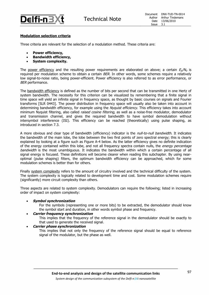
Technical NoteDocument
AuthorDateIssue
DNX-TUD-TN-0014Arthur Tindemans13/06/20103.1
97End-to-end analysis and design of the satellite communication links
System design of the communication subsystem of the Delfi-n3Xt nanosatellite
Modulation selection criteria
Three criteria are relevant for the selection of a modulation method. These criteria are:
Power efficiency, Bandwidth efficiency, System complexity.
The power efficiency and the resulting power requirements are elaborated on above; a certain Eb/N0 isrequired per modulation scheme to obtain a certain BER. In other words, some schemes require a relativelylow signal-to-noise ratio, being power-efficient. Power efficiency is also referred to as error performance, orBER performance.
The bandwidth efficiency is defined as the number of bits per second that can be transmitted in one Hertz ofsystem bandwidth. The necessity for this criterion can be visualized by remembering that a finite signal intime space will yield an infinite signal in frequency space, as thought by basic courses on signals and Fouriertransforms [SLR 0443]. The power distribution in frequency space will usually also be taken into account indetermining bandwidth efficiency, for example using the Nyquist efficiency. This efficiency takes into accountminimum Nyquist filtering, also called raised cosine filtering, as well as a noise-free modulator, demodulatorand transmission channel, and gives the required bandwidth to have symbol demodulation withoutintersymbol interference (ISI). This efficiency can be reached (theoretically) using pulse shaping, asintroduced in section 7.3.
A more obvious and clear type of bandwidth (efficiency) indicator is the null-to-null bandwidth. It indicatesthe bandwidth of the main lobe, the lobe between the two first points of zero spectral energy; this is clearlyexplained by looking at a figure such as Figure A-4 below. As the latter efficiency gives no definite indicationof the energy contained within this lobe, and not all frequency spectra contain nulls, the energy percentagebandwidth is the most unambiguous. It indicates the bandwidth within which a certain percentage of allsignal energy is focused. These definitions will become clearer when reading this subchapter. By using near-optimal (pulse shaping) filters, the optimum bandwidth efficiency can be approached, which for somemodulation schemes is better than for others.
Finally system complexity refers to the amount of circuitry involved and the technical difficulty of the system.The system complexity is logically related to development time and cost. Some modulation schemes require(significantly) more circuit complexity than others.
Three aspects are related to system complexity. Demodulators can require the following; listed in increasingorder of impact on system complexity:
Symbol synchronizationFor the symbols (representing one or more bits) to be extracted, the demodulator should knowthe symbol start and duration, in other words symbol phase and frequency.
Carrier frequency synchronizationThis implies that the frequency of the reference signal in the demodulator should be exactly tothat used to generate the received signal.
Carrier phase synchronizationThis implies that not only the frequency of the reference signal should be equal to referencesignal of the modulator, but the phase as well.

Technical NoteDocument
AuthorDateIssue
DNX-TUD-TN-0014Arthur Tindemans13/06/20103.1
98 End-to-end analysis and design of the satellite communication links
System design of the communication subsystem of the Delfi-n3Xt nanosatellite
Symbol synchronization is required to extract data; in other words in all demodulators. Modulation schemesdo not automatically yield enough information for symbol synchronization to be guaranteed, but it can beachieved by guaranteeing sufficient transitions in the received signal, for the demodulator to ‘lock’ onto thesignal. This can be taken care off by applying a specific line code (such as Manchester coding) or by involvinghigher level functionality; a specific sequence of symbols can allow the demodulator to get a lock on thesignal through the use of a synchronizer circuit. The AX.25 protocol provides exactly this through the use offlags (see section 7.6.2). Also, the protocol assures sufficient symbol transitions during communicationsthrough the use of bit stuffing.
Carrier frequency synchronization requires knowing the exact carrier frequency. Reference signals can beextracted from the received carrier, or a separate oscillator can be used. Nevertheless, if Doppler shift takesplace in the carrier frequency, carrier frequency tracking is required and complexity is increased; its extentdepending on the modulation scheme. To be clear, for proper communication of course the transmissionfrequency should be known; electronics will be designed for this frequency and proper filters are in place.However, certain demodulators can get away with having just a sufficiently-wide-band filter tuned to thetransmission frequency with margins for the Doppler shift (requiring no reference frequency). In these cases,carrier frequency synchronization is said not to be necessary.
Carrier phase synchronization simply requires not only knowing the exact carrier frequency, but also itsphase. The reference signal should be exactly in phase with the oscillator used in the modulator. If indeedboth carrier frequency and phase synchronization are realized, one speaks of coherent demodulation. Itsopposite, noncoherent demodulation involves only carrier frequency synchronization or no form of carriersynchronization. If a modulation scheme is to be demodulated noncoherently, one speaks of a noncoherentmodulation scheme.
A final criterion, related to both complexity and power efficiency is having a constant envelope modulationscheme. This means that the envelope of the transmitted signal, in other words the spectral power at thetargeted frequency, does not change. If it does not, more efficient non-linear power amplifiers can be usedsuch as class C and D amplifiers, without dedicated feedback systems. This is because no information iscarried by the amplitude for those modulation schemes. ASK schemes per definition have non-constantenvelopes. PSK schemes do not, but as they usually require (amplitude varying) pulse shaping to improvebandwidth efficiency, they are not suitable either. As such, only FSK schemes generally provide this feature.

Technical NoteDocument
AuthorDateIssue
DNX-TUD-TN-0014Arthur Tindemans13/06/20103.1
99End-to-end analysis and design of the satellite communication links
System design of the communication subsystem of the Delfi-n3Xt nanosatellite
The following Figure 7.6 gives a good overview of the power and bandwidth efficiency of some of the mostimportant digital modulation techniques.
The horizontal axis indicates the required signal Eb/N0 for successful demodulation for a BER, or PB of 10-5.The vertical axis indicates the perfect theoretical bandwidth efficiency, or Nyquist efficiency, given by a ratioof bit rate (R) over bandwidth (W). It should thus be realized, that even without changing modulationscheme, a doubled data rate will lead to a doubled required bandwidth.
Figure 7.6: Bandwidth and power efficiencies of modulation techniques, Pb = 10-5 [SLR 0552]

Technical NoteDocument
AuthorDateIssue
DNX-TUD-TN-0014Arthur Tindemans13/06/20103.1
100 End-to-end analysis and design of the satellite communication links
System design of the communication subsystem of the Delfi-n3Xt nanosatellite
A lot of information is presented in Figure 7.6 but attention will be placed on only a certain fewcharacteristics. A complete description can be found in [SLR 0552].
It can be seen that MFSK techniques tend to become more power efficient as the amount of appliedfrequencies M increases, whereas MPSK techniques tend to become more bandwidth efficient with increasingamounts of phase values M. At a certain point (M-)QAM techniques outperform MPSK techniques, from M=16onwards. MSK is not shown in the figure, but actually it has the same theoretical efficiency as BPSK. In termsof energy percentage bandwidth efficiency however it outperforms BPSK. Noncoherent MFSK as opposed toits coherent version is indicated, even though it theoretical performance is the same as its counterpart.
All modulation schemes shown in the figure above plus some more advanced onces are reviewed in moredetail in Appendix A. Given the size of the resulting text the content has been moved to an appendix. Also,exact knowledge of these schemes is not required to follow the reasoning of selecting modulation schemesfor Delfi-n3Xt in later chapters.
The appendix presents the exact characteristics of the different modulation schemes and presents in moredetail the power performance, bandwidth performance and required complexity. Also, different options ofcomplexity which in turn improve on either power or bandwidth efficiency are introduced. Modulator anddemodulator schematics are presented. The level of detail for each of the modulation schemes is dependenton the assumed relevance to Delfi-n3Xt.
For the following, it is useful to introduce the term Baud. In a modulated signal one symbol can signifymultiple bits; in this case the rate in Baud is only half the bit rate. Indeed, Baud is another word for symbolsper second. When Manchester coding or FEC coding is applied, as introduced in respectively the next sectionand section 7.8, more symbols are required per bit. In those cases, the rate in Baud is increased with respectto the bit rate.

Technical NoteDocument
AuthorDateIssue
DNX-TUD-TN-0014Arthur Tindemans13/06/20103.1
101End-to-end analysis and design of the satellite communication links
System design of the communication subsystem of the Delfi-n3Xt nanosatellite
7.3 Line codes
As introduced in the last section, digital modulation is a matter of mapping digital data onto a signal suitablefor transmission. Before that, it can be decided how the data is represented in the first place. Whereas usually‘1’ or ‘0’ bits within digital logic (computers) are represented by respectively positive signals or signals withzero magnitude (unipolar NRZ-L code as introduced below), there are different conventions possible. In fact,different codes have different properties which can be desirable, also when combined with a variety ofmodulation methods. As these codes deal with direct transmission without frequency transform, it is labeledbaseband modulation. Other names are baseband formats, baseband waveforms, or line codes.
This section introduces different line codes and their characteristics. This in turn allows proper considerationof line codes for Delfi-n3Xt transmission systems. Unless indicated otherwise all data has been extracted from[SLR 0552].
Figure 7.7 below demonstrates a quite complete list of interesting and basic binary line codes. Four basicclasses are represented; the nonreturn-to-zero class (NRZ), the return-to-zero class (RZ), pseudoternary (PT)codes and the biphase codes. More advanced codes are substitution codes and block codes. Aliases can beseen as well in the figure below, such as the NRZ-I and Manchester codes applied on Delfi-C3.
Figure 7.7: Basic line codes [adapted from SLR 0552]
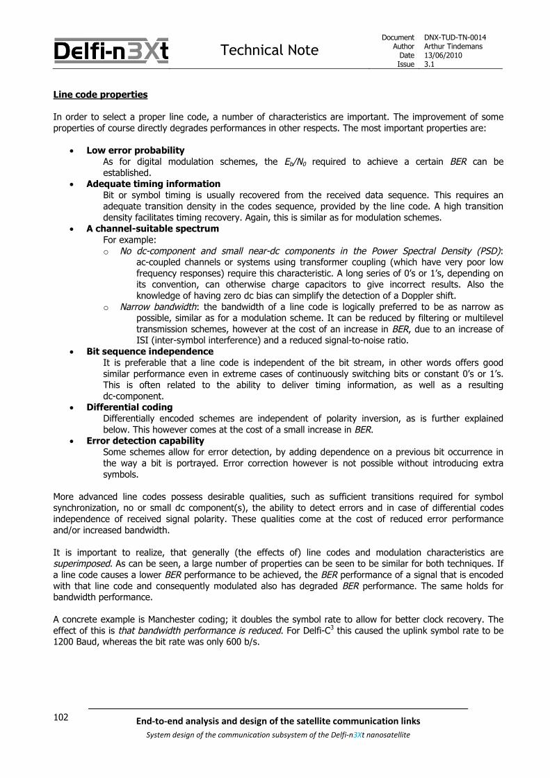
Technical NoteDocument
AuthorDateIssue
DNX-TUD-TN-0014Arthur Tindemans13/06/20103.1
102 End-to-end analysis and design of the satellite communication links
System design of the communication subsystem of the Delfi-n3Xt nanosatellite
Line code properties
In order to select a proper line code, a number of characteristics are important. The improvement of someproperties of course directly degrades performances in other respects. The most important properties are:
Low error probabilityAs for digital modulation schemes, the Eb/N0 required to achieve a certain BER can beestablished.
Adequate timing informationBit or symbol timing is usually recovered from the received data sequence. This requires anadequate transition density in the codes sequence, provided by the line code. A high transitiondensity facilitates timing recovery. Again, this is similar as for modulation schemes.
A channel-suitable spectrumFor example:o No dc-component and small near-dc components in the Power Spectral Density (PSD):
ac-coupled channels or systems using transformer coupling (which have very poor lowfrequency responses) require this characteristic. A long series of 0’s or 1’s, depending onits convention, can otherwise charge capacitors to give incorrect results. Also theknowledge of having zero dc bias can simplify the detection of a Doppler shift.
o Narrow bandwidth: the bandwidth of a line code is logically preferred to be as narrow aspossible, similar as for a modulation scheme. It can be reduced by filtering or multileveltransmission schemes, however at the cost of an increase in BER, due to an increase ofISI (inter-symbol interference) and a reduced signal-to-noise ratio.
Bit sequence independenceIt is preferable that a line code is independent of the bit stream, in other words offers goodsimilar performance even in extreme cases of continuously switching bits or constant 0’s or 1’s.This is often related to the ability to deliver timing information, as well as a resultingdc-component.
Differential codingDifferentially encoded schemes are independent of polarity inversion, as is further explainedbelow. This however comes at the cost of a small increase in BER.
Error detection capabilitySome schemes allow for error detection, by adding dependence on a previous bit occurrence inthe way a bit is portrayed. Error correction however is not possible without introducing extrasymbols.
More advanced line codes possess desirable qualities, such as sufficient transitions required for symbolsynchronization, no or small dc component(s), the ability to detect errors and in case of differential codesindependence of received signal polarity. These qualities come at the cost of reduced error performanceand/or increased bandwidth.
It is important to realize, that generally (the effects of) line codes and modulation characteristics aresuperimposed. As can be seen, a large number of properties can be seen to be similar for both techniques. Ifa line code causes a lower BER performance to be achieved, the BER performance of a signal that is encodedwith that line code and consequently modulated also has degraded BER performance. The same holds forbandwidth performance.
A concrete example is Manchester coding; it doubles the symbol rate to allow for better clock recovery. Theeffect of this is that bandwidth performance is reduced. For Delfi-C3 this caused the uplink symbol rate to be1200 Baud, whereas the bit rate was only 600 b/s.

Technical NoteDocument
AuthorDateIssue
DNX-TUD-TN-0014Arthur Tindemans13/06/20103.1
103End-to-end analysis and design of the satellite communication links
System design of the communication subsystem of the Delfi-n3Xt nanosatellite
Similar to modulation techniques, each line code itself yields a certain required Eb/N0 for a required BER or Pb.For all classes of important codes the following Figure 7.8 demonstrates the error performances.
Figure 7.8: BER performances of line codes [SLR 0552]
Again, in the case of Delfi-n3Xt the values belonging to a Pb of 10-5 are relevant. Even though the figure is notcentered on this region, a number of things can be concluded.
First of all, even without digital modulation on a signal ready for transmission a code already requires a 9.6dB Eb/N0! This value is the exact same as that for a number of standard and simple modulation schemes suchas BPSK, QPSK, MSK and 4FSK. In fact, these modulation schemes implicitly take a power efficient code suchas (unipolar or bipolar) NRZ-L and replace the level changes by phase or frequency shifts. However, thisimplies that these standard modulation schemes actually come at no cost in terms of BER with respect to theline codes itself. Some modulation schemes such as FSK (for values of M higher than 4), actually improve theBER performance. They spread the bit sequence to a number of different frequencies, thereby effectivelydecreasing the data rate on that frequency and with that the required signal-to-noise ratio for properdemodulation.

Technical NoteDocument
AuthorDateIssue
DNX-TUD-TN-0014Arthur Tindemans13/06/20103.1
104 End-to-end analysis and design of the satellite communication links
System design of the communication subsystem of the Delfi-n3Xt nanosatellite
Second of all, it can be seen that there are 6 line codes in Figure 7.7 that have the best BER performance;indeed it is for that reason that they are generally the most useful for satellite missions. Moreover, while notproperly shown in the graph, all other schemes yield an Eb/N0 of at least 3 dB more than a simple NRZ-Lcoded bit stream, being 12.6 dB for Unipolar NRZ or RZ for example.
The four classes of basic line codes and some more advanced line codes are introduced in Appendix B. As thetext is sizeable and its function in some cases is limited to giving proper background information to aninterested reader the text has been moved to an appendix.
Attention is paid to the advantageous and disadvantageous properties of the different line codes. The level ofdetail is limited to an introduction. Line codes of most importance to Delfi-n3Xt are the (differential) NRZcodes and the Manchester code.

Technical NoteDocument
AuthorDateIssue
DNX-TUD-TN-0014Arthur Tindemans13/06/20103.1
105End-to-end analysis and design of the satellite communication links
System design of the communication subsystem of the Delfi-n3Xt nanosatellite
7.4 Pulse shaping
Any fast transition in a signal, whether in amplitude, phase or frequency, will require a large occupiedbandwidth for correction transmission and reception. Techniques that help smoothen these transitions reducethe amount of required bandwidth. The idea of pulse shaping is to shape the bit shape, per definition onewith abrupt transitions, in order to smoothen its edges.
All line codes as introduced in the previous section are based on a rectangular pulse shape. When arectangular shape is mixed with a sinusoid, effectively, a convolution takes place. Remember that thisbasically takes place in any type of modulation; amplitude, phase or frequency shift keying. The onlydifference is that in amplitude modulation two consequent rectangular pulses take on different amplitudes, inphase modulation consequent signals have equal but opposite amplitudes, and in frequency modulation themodulated frequencies for consequent signals are different. The resulting frequency pattern is called theFourier transform. [SLR 0694] describes basic signal theory, and shows the spectral characteristics of arectangular shape; see Figure 7.9 below.
Figure 7.9: Fourier transform pairs involving a rectangular pulse [SLR 0694]
As Figure 7.9 (top) shows, a rectangular shape in the time domain, yields an infinite shape in the frequencydomain; a sin(π/x)/ πx or sinc shape. In fact, this frequency response is exactly the PSD of a BPSK signal, asshown in Figure A-16; a rectangular pulse of 1 second gives T1 =0.5, whereas π equals 0.5f, and finally incase of BPSK the rectangular input has an apparent amplitude of ‘2’, as a shift from -1 to +1 or vice versa hastaken place. Replacing and entering these values as well as replacing ω on the axis by fT, and realizing that‘negative’ frequencies are in fact frequencies with a flipped phase, gives exactly Figure A-16. Indeed, it is thefrequency characteristics that are inherent to the rectangular pulse that determine the (bad) frequencycharacteristics of a BPSK signal. Therefore improving these characteristics allows improving the bandwidthefficiency.

Technical NoteDocument
AuthorDateIssue
DNX-TUD-TN-0014Arthur Tindemans13/06/20103.1
106 End-to-end analysis and design of the satellite communication links
System design of the communication subsystem of the Delfi-n3Xt nanosatellite
The filter implicitly applied in case of a rectangular pulse shape is called a Boxcar filter. Figure 7.9 (bottom)shows its inverse, the Sinc filter. It can be seen that the sinc pulse very closely resembles the Fouriertransform of the rectangular pulse, and vice versa. A difference in amplitude of 2π exists, which in the present
discussion is unimportant. If an infinitively broad sinc pulse would be used to indicate a bit, an optimumlimited bandwidth would result; one that equals exactly the minimum Nyquist bandwidth.
Of course, it is impractical or even impossible to apply an infinite pulse. As such, an optimum should befound. The characteristics offered by the sinc filter are approached by the raised cosine filter. In fact, it canbe said that the sinc filter is a special type of the raised cosine filter. This filter is introduced below insubsection 7.4.1. A large number of other filters exist, such as Butterworth filters, Chebyshev filters or Besselfilters. These filters are however not generally used as pulse shaping filters in modulation schemes, as theyare outperformed by the Gaussian filter. The latter is introduced in subsection 7.4.3 below.
7.4.1 Raised cosine filter
The raised cosine filter is designed to approach the optimum sinc filter, as this sinc filter is in fact impossibleto implement. The sinc filter in fact has another important property, which is that of no intersymbolinterference, or ISI. What this means is illustrated by Figure 7.10 below.
Figure 7.10: Time domain response of a raised cosine filtered pulse for different values of β
Figure 7.10 shows the time domain pulse strength of a raised cosine filtered bit. It can be seen that at everyinteger multiple of T except at 0*T, the total power is zero. This means, that at the point where a next bit hasits maximum power, on the bit decision point, the residual power of another bit is zero. A demodulator,basing its bit value on this point, will therefore not be influenced. This is called zero ISI.
In the same figure it can also be seen that multiple graphs are plotted, with different values of β (dependingon the source, both α and β are used). A β of zero gives the optimum spectrum. Larger β’s can more easilybe implemented in reality, as their power for larger values of T quickly drops off and at some point can beignored. Also, less total amplification power is then necessary (explained below) and the effects of ademodulator basing its bit decision on not the exact middle of a bit are less severe. But of course, theresulting bandwidth reduction is less. The resulting frequency spectrum can be seen in Figure 7.11 below.

Technical NoteDocument
AuthorDateIssue
DNX-TUD-TN-0014Arthur Tindemans13/06/20103.1
107End-to-end analysis and design of the satellite communication links
System design of the communication subsystem of the Delfi-n3Xt nanosatellite
The time domain shape, shown above, can be given by the following equation [SLR 0697]:
2
sinc cos
( )2
1
t t
T Tp t
t
T
, (6-1)
As a side note, if the above relation is used for calculations, care should be taken to avoid βt/T=±1/2, as thiswill make the denominator go to zero. The limit of p(t) at βt/T=±1/2 can be shown to be given by (π/4) sinc(t/T); not infinity.
Figure 7.11: Frequency domain response of a raised cosine filtered pulse for different values of β
As Figure 7.11 illustrates, the bandwidth required to transmit a raised cosine filtered symbol stream of X Hz isbetween 1 and 2 times X. In fact, the relation between occupied bandwidth, symbol rate and β is:
Occupied bandwidth = symbol rate * (1 + β) (6-2)
It can also be seen that the raised cosine frequency spectrum belonging to β = 1, actually is a raised cosine;indeed it is from the frequency spectrum response that the filter gets its name. The equations of frequencydomain graph will not be presented but can be found in [SLR 0697] and [SLR 0696]. The spectrum for arectangular pulse in fact is almost the same to the case where β is 1, being slightly larger in power contentaround 1/2T. After 1/T however spectral regrowth occurs.
In Figure 7.10 it can be seen that, to avoid large bandwidth occupation, significant power outside of theactual bit duration must be transmitted; this is due to the overshoot necessary (the power cannot go to zeroand stay zero). In fact, this overshoot causes more power to be necessary than the symbol itself requires. Ifthis power would be filtered or limited, ISI will still be introduced. If the total power would be limited, theresulting signal-to-noise ratio would be reduced, whereas a minimum is required for correct demodulation.The effect of this can be sizeable; for example QPSK with a β of 0.2 requires some 5 dB more power [SLR0447].

Technical NoteDocument
AuthorDateIssue
DNX-TUD-TN-0014Arthur Tindemans13/06/20103.1
108 End-to-end analysis and design of the satellite communication links
System design of the communication subsystem of the Delfi-n3Xt nanosatellite
In case of constant envelope modulation schemes (M-FSK and MSK), the situation is different; no extra poweris required to implement the changes as the signal total strength is not dependant on the input, but the maintransmission frequency is. As such, in that case, the signal-to-noise ratio at the bit decision points wouldremain identical independent of the pulse shaping scheme as long as no ISI is introduced. It should be saidhowever, that constant envelope schemes are per definition less bandwidth efficient and therefore, even witha raised cosine filter, would require more bandwidth (as two or more transmission frequencies are used).Therefore, raised cosine filtering is not often applied for FSK schemes.
Filters can be implemented in an analogue and digital fashion. Digital filters offer serious advantages overanalogue designs, as they can be integrated directly on silicon, thus in on-chip designs. Also, component driftdue to temperature and aging is eliminated [SLR 0697]. Two types of digital filters exist; finite impulseresponse (FIR) and infinite impulse response (IIR). The fundamental difference between the two is theinclusion of feedback in the latter. Hence, the future of the output is dependent on the input history. Evenlong after the input signal is terminated, the IIR will continue producing a signal. As this is generally notdesired, FIRs are used. These can then be used to approach the actual raised cosine spectrum, depending onthe sampling rate of the FIR (as a multiple of the symbol rate) and the amount of symbol periods over whichan input symbol is spread (see [SLR 0696]). The latter amount depends on the application, and a small delayis introduced at the start of signal transmission because of it.
To give a final example of the effects of raised cosine filtering, see Figure 7.5. The final demonstratedmodulation scheme, DSB-SC or just BPSK, with applied raised cosine filtering is demonstrated. The effect isthat at the transitions the signal amplitude is much reduced. As such, in can be understood that thebandwidth effects of the sudden change are reduced, as the power content of the sudden change is alsoreduced.
The downside of the raised cosine filter is that its implementation through the use of a FIR filter quicklybecomes very demanding, as higher data rates are applied. The sampling rate required should be multipliedby the amount of bit periods over which the symbol is spread, and each additional bit period over which thesignal is spread increases the required possible states exponentially. Therefore, less demanding Gaussianfilters are usually applied for higher bit rates. Also, whereas realistic raised cosine filters will rarely decreasethe bandwidth below 1.5 times the signal frequency, Gaussian filters can reduce this bandwidth to even lessthan 1 times the signal frequency.
Finally, Delfi-C3 actually applied a simpler implementation of the raised cosine filters, which achieved lowerbandwidth reductions than regular raised cosine filters, however coming at the cost of very little complexity.This scheme is introduced in subsection 7.4.2 below.

Technical NoteDocument
AuthorDateIssue
DNX-TUD-TN-0014Arthur Tindemans13/06/20103.1
109End-to-end analysis and design of the satellite communication links
System design of the communication subsystem of the Delfi-n3Xt nanosatellite
Root raised cosine
As a receiver requires the use of filters to limit the received spectrum, in some cases a root raised cosine filteris used. The idea is to integrate a root raised cosine filter shape at both the transmitter and receiver, so thatthe resulting total filter is the zero-ISI raised cosine filter. Its integration in the transmission link is shown inFigure 7.12 below.
Figure 7.12: The implementation of a root raised cosine scheme [SLR 0447]
It can be seen that the data is first digitally filtered, after which a DAC (digital-to-analogue converter) is usedto produce a useable signal to the modulator. After transmission the receiver filters the signal in an analoguefashion, after which demodulation yields the transmitted bits. The difficulty in this set-up is the inclusion ofthis analogue filter with the exact desired properties, and the matching of both the transmitter and receiverfilter to actually create one full raised cosine. If multiple manufacturers are involved, with transmitters andreceivers of different types and sizes, this is quickly complicated. In any case a trade-off should be made, asmore bandwidth is required for transmission when only a root raised cosine is applied, but at the gain of morefiltering of broadband noise and other transmissions in nearby channels. In case of space flight and pointedantennas however the latter aspect is luckily limited.

Technical NoteDocument
AuthorDateIssue
DNX-TUD-TN-0014Arthur Tindemans13/06/20103.1
110 End-to-end analysis and design of the satellite communication links
System design of the communication subsystem of the Delfi-n3Xt nanosatellite
7.4.2 Raised cosine in Delfi-C3
Although not represented by found literature, in case of Delfi-C3 a variant of raised cosine filtering wasactually applied. It likely has to do with more generally applied radio amateur approaches. In any case theapproach has been to use the raised cosine shape, and not a sinc shape, in the time domain to represent abit. This is illustrated by Figure 7.13 below. This means that no infinite pattern in the time domain isapproached, thereby creating a clear infinite pattern in the frequency domain. In other words, less bandwidthefficiency is obtained.
Figure 7.13: Time domain raised cosine filtering [SLR 0248]
The benefit of the approach however is that required power is optimal, as no more power is required for thetransmission of one bit; no overshoot occurs. The integral area underneath both shapes is equal (in fact, aseries of pulses even has a constant envelope when summed together, just as a series of rectangular pulseswould have). The power spreading is maximized, as the pulse is spread up until the points of zero ISI. Also,complexity is limited as one bit is only spread out over two bit periods. Therefore, this method provides a low-complexity solution with significant reduction of the required bandwidth, at no power cost.
The actual bandwidth (reduction) effects can be calculated, using the relation 6-1 presented above, as in factthe frequency response of a time domain signal is equal to a time response of a frequency domain signal,adjusted for a value of 2*π as shown in Figure 7.9 above. Plotting the relation for βs of 0 and 1 gives thegraphs in Figure 7.14 below, being in fact equal to those shown in Figure 7.10, but plotted on a logarithmicscale and for larger bandwidth. The frequency / bit rate value indicates the bandwidth required for thetransmission of one bit per second and the spectral power in dBc indicates the spectral power with respect tothe main carrier frequency.
As was already explained before, the frequency pattern created by a BPSK modulated signal is exactly equalto the Fourier transform of the modulated pulse.

Technical NoteDocument
AuthorDateIssue
DNX-TUD-TN-0014Arthur Tindemans13/06/20103.1
111End-to-end analysis and design of the satellite communication links
System design of the communication subsystem of the Delfi-n3Xt nanosatellite
Figure 7.14: Spectral power vs. normalized bandwidth
It can be seen that, as already shown in the previous section, a rectangular pulse has very poor bandwidthcharacteristics. The time domain raised cosine pulse decreases the required bandwidth significantly as itintroduces a clear decreasing trend (Figure 7.14).
In reality, not a single pulse will be transmitted, but a pulse train. This pulse train can in turn be assumed tobe infinite, for a continuous data stream. As a pulse can be said to indicate a ‘1’ bit, and ‘no pulse’ can be saidto indicate a ‘0’ bit, a pulse train of a certain frequency can be said to simulate a bit sequence of alternating0’s and 1’s of double that frequency. In order to be able to analyze Delfi-C3 bandwidth performance below,bitrates applied on Delfi-C3 will be used: the case of a 1200 b/s signal. The pulse train will then have a 600 Hzfrequency.
The resulting frequency spectrum of this rectangular pulse train is shown in Figure 7.15 below, generatedusing a signal generator and measured with a spectrum analyzer, both available at the faculty of EEMCS.
The frequency spectrum of an infinite raised cosine pulse train will not be shown, the latter would logicallyyield a sine function of constant frequency; this is further commented on below. The spectrum generated bya constant sine logically is a single impulse at the frequency of the sine.

Technical NoteDocument
AuthorDateIssue
DNX-TUD-TN-0014Arthur Tindemans13/06/20103.1
112 End-to-end analysis and design of the satellite communication links
System design of the communication subsystem of the Delfi-n3Xt nanosatellite
Figure 7.15: Measured frequency spectrum of a 600 Hz rectangular pulse train over a 10 kHz span
In the above figure a span of 20 kHz is portrayed, starting at 0 Hz. The pulse train main frequency is at 600Hz, or 0.6 kHz. A large peak can be seen at 0 Hz, this one should be ignored as it represents the zero-dccomponent present in the spectrum analyzer; a by-product of the experimental set-up thus. The pure signalgenerated by the pulse train then has a peak at 0.6 kHz, and its signal strength actually steadily decreasestowards 0 Hz. Signal strength is indicated on a logarithmic scale, with a 10 dB decrease per vertical square.
In the figure it can be seen that a pulse train similarly has bad spectrum characteristics. Compared to thespectrum of a single rectangular pulse, the pulse train frequency spectrum at first decreases less withfrequency; only a small ~2 dB decrease from the first to the second peak compared to some -7 dB for thesingle pulse. However, the spectrum of the single pulse afterwards remains larger; within the 10 kHz span itseems to converge to a -15 dB value. The pulse train frequency spectrum reaches this same value at 10 kHzapproximately despite its larger spectrum at low frequencies, but continues to decrease more significantlyafterwards.
The behaviour that can be seen here can be explained by Fourier transforms: a finite pulse in the timedomain will yield an infinite frequency spectrum, whereas an infinite signal in the time domain yields afrequency spectrum that is finite.

Technical NoteDocument
AuthorDateIssue
DNX-TUD-TN-0014Arthur Tindemans13/06/20103.1
113End-to-end analysis and design of the satellite communication links
System design of the communication subsystem of the Delfi-n3Xt nanosatellite
As explained, Delfi-C3 applied a time-domain raised cosine filter. The time-varying characteristics of the pulsetrain then depend on the bit sequence. In order to explain the resulting pattern slightly better theimplementation of the time-domain raised cosine filter is better explained below.
In Figure 7.10 above the pulse shape for a 0 or 1 bit value is shown, depending on convention a 0 bit can beportrayed by the exact same shape but mirrored in the x-axis. The total amplitude values along the time axisare then summed together. The time domain raised cosine pulse shape, showed in Figure 7.13, follows thesame convention. The resulting pattern, for a random bit sequence, can be seen in Figure 7.16 below. It canbe realized that using positive and negative raised cosine shapes, or a positive raised cosine shape for 1 bit,and no shape for a 0 bit, yield the exact same pattern when summed together, due to the symmetricalproperties of the cosine shape. The only difference is the introduced dc-level in the pattern, which can beremoved by simply subtracting a certain voltage. The actual pulse shaper also takes into account twoconsecutive bits, as two consequent ones should yield a line of constant amplitude, and actually shapes eitherhalf a cosine or a constant line. The resulting signal sent to the modulator is then a constant level signal for astream of only 0’s or only 1’s, or a perfect sine for a stream of alternating 0’s and 1’s. For any other pattern,it will be a combination of the two extremes.
Figure 7.16: Delfi-C3 implementation of a raised cosine filter applied on a bit sequence [SLR 0248]
In conclusion, the two possible extreme signals are a constant sine, or a constant line. In the frequencydomain this would be indicated by an impulse at either the sine frequency, or at zero Hz. The actual signalwill be no single impulse, but also will never have a frequency spectrum as bad as that of the rectangularpulse train.
In order to obtain the actual transmitted frequency spectrum, one should consider the modulation process. Asexplained earlier this chapter, BPSK modulation in fact is the mixing of a bipolar bit stream. The same holds ifpulse shaping is applied. What is important to realize, is that (ideal) mixing creates two frequencies; onebeing the sum of the two mixed frequencies, and one being the difference. This is explained in the nextsection on the superheterodyne principle.
When a zero Hz or 600 Hz information signal are then modulated onto a carrier, the resulting signal is a purecarrier signal or a double-peaked sum of the two. In reality, the information signal is similar in behavior tothat shown in Figure 7.15 above. The resulting frequency spectrum for Delfi-C3 is presented below.

Technical NoteDocument
AuthorDateIssue
DNX-TUD-TN-0014Arthur Tindemans13/06/20103.1
114 End-to-end analysis and design of the satellite communication links
System design of the communication subsystem of the Delfi-n3Xt nanosatellite
As Delfi-C3 has been built and is operational, there are two sources to determine the actual transmittedspectrum. These are Delfi-C3 itself (during a pass over the ground station), and its flight spare which is still inthe clean room of the AE building. A spectrum analyzer has been used to determine the bandwidthcharacteristics of both in Science Mode, therefore generating a representative stream of ‘random’ missiondata. The resulting measurements are presented below.
For illustration, three pictures are shown which demonstrate the frequency spectrum on different scales ofthe transmission signal as measured on the spare model. The y-axis is kept constant and shows a signalreduction of –10 dB per vertical square. The x-axis spans respectively 800, 60 and 20 kHz in Figure 7.17,Figure 7.18 and Figure 7.19 respectively.
Figure 7.17: Measured frequency spectrum of the Delfi-C3 spare model transmission over a 800 kHz span
In Figure 7.17 above, it can be seen that the spectrum as ‘zoomed out’ basically is one simple peak, whichhas a span of some 160 kHz, and power levels at the outer edges of some 60 dB less than in the center. Ifone zooms in more, as in Figure 7.18 below, three peaks are shown. The two-side peaks are likely the resultof non-linear effects in the modulation and/or up-conversion process. They have a value of some 40 dB lessthan the main peak. The final figure, Figure 7.19, then shows a pattern similar to that caused by therectangular pulse train, but more steep. This then, is the effect of the added time-domain raised cosine filter.
As compared to the spectrum of the rectangular pulse train, the signal is mirrored in the carrier signal; twomain peaks result at the carrier frequency (CF) plus 600 Hz, and CF minus 600 Hz. The carrier itself issuppressed. In fact, here it can be seen that BPSK modulation is in fact a form of Double Sideband,Suppressed Carrier (DSB-SC) modulation.

Technical NoteDocument
AuthorDateIssue
DNX-TUD-TN-0014Arthur Tindemans13/06/20103.1
115End-to-end analysis and design of the satellite communication links
System design of the communication subsystem of the Delfi-n3Xt nanosatellite
Figure 7.18: Measured frequency spectrum of the Delfi-C3 spare model transmission over a 60 kHz span
Figure 7.19: Measured frequency spectrum of the Delfi-C3 spare model transmission over a 20 kHz span
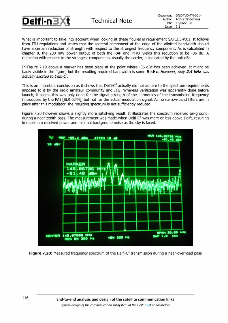
Technical NoteDocument
AuthorDateIssue
DNX-TUD-TN-0014Arthur Tindemans13/06/20103.1
116 End-to-end analysis and design of the satellite communication links
System design of the communication subsystem of the Delfi-n3Xt nanosatellite
What is important to take into account when looking at these figures is requirement SAT.2.3-P.01. It followsfrom ITU regulations and states that the spectral component at the edge of the allotted bandwidth shouldhave a certain reduction of strength with respect to the strongest frequency component. As is calculated inchapter 8, the 200 mW power output of both the RAP and PTRX yields this reduction to be -36 dB. Areduction with respect to the strongest components, usually the carrier, is indicated by the unit dBc.
In Figure 7.19 above a marker has been place at the point where -36 dBc has been achieved. It might bebadly visible in the figure, but the resulting required bandwidth is some 9 kHz. However, only 2.4 kHz wasactually allotted to Delfi-C3.
This is an important conclusion as it shows that Delfi-C3 actually did not adhere to the spectrum requirementsimposed to it by the radio amateur community and ITU. Whereas verification was apparently done beforelaunch, it seems this was only done for the signal strength of the harmonics of the transmission frequency(introduced by the PA) [SLR 0244], but not for the actual modulation signal. As no narrow-band filters are inplace after this modulator, the resulting spectrum is not sufficiently reduced.
Figure 7.20 however shows a slightly more satisfying result. It illustrates the spectrum received on-ground,during a near-zenith pass. The measurement was made when Delfi-C3 was more or less above Delft, resultingin maximum received power and minimal background noise as the sky is faced.
Figure 7.20: Measured frequency spectrum of the Delfi-C3 transmission during a near-overhead pass

Technical NoteDocument
AuthorDateIssue
DNX-TUD-TN-0014Arthur Tindemans13/06/20103.1
117End-to-end analysis and design of the satellite communication links
System design of the communication subsystem of the Delfi-n3Xt nanosatellite
The received signal is in fact surrounded by background noise. The effect of this background noise is that thespectrum at lower power levels, thus that at the edges of the transmitted signal, is immersed in the noise.Then, Earth receivers with sensitivity similar to that of the Delft GS will never have disturbances moresignificant than the noise already present. Radio amateur ground stations will in general perform worse orsimilar to the Delft GS, given its equipment and excellent altitude. The only exception would be for remoteareas with little radio activity, such as in deserts. The signal power levels of only 4 peaks can be said to beabove the noise floor, resulting in a bandwidth of some 5.0 kHz. While still not compliant to the regulations,or below the value of 2.4 kHz, it is significantly less than 9 kHz.
The latter measure, using the bandwidth above noise levels, is not stated by regulations but is a moresatisfying one for reasons of common sense. In fact, what seems to be a downside of the regulations thatstate the required power reductions at the sides of the spectrum, is that they do this with respect to thetransmitted center frequency power. Whereas many (space) transmitters have transmission powers of manywatts, that of the Delfi-C3 RAP and similarly the Delfi-n3Xt PTRX is only 0.2 W.
The use of a reference bandwidth in order to determine the signal strength at the edge of allotted bandwidth,as further explained in chapter 8, reduces the ‘official’ value as an average power value is taken within a 4kHz span. Still, this is not enough to be compliant.
However, there is a big comment that can be made. In fact, as confirmed by a conversation with multipleradio amateurs, such as also Graham Shirville who heads frequency coordination, bandwidth is indeed a fairlyambiguous term and should not be weighed too heavily. Especially on the radio amateur bandwidths,frequency spectra of different projects per definition can overlap, which is a necessary evil of the limitedresources. Also, as commented on above, the power levels of many radio amateur satellites are moderate. Ageneral rule of thumb for the supposed occupied bandwidth then becomes some 2-2.5 times the data rate,irrespective of whether this requirement is actually formally met. And indeed, no complaints have ever beenreceived on the topic of Delfi-C3.
For Delfi-n3Xt, it becomes important to know what the spectrum will do when the data rate goes up. As datarate and occupied spectrum are directly correlated, a doubled data rate would logically yield a doubledrequired spectrum. Of course, the absolute violation of the regulations becomes larger then, assuming adoubled allotted bandwidth for doubled data rates. A discussion on the effects and possibilities for Delfi-n3Xtis included in chapter 8.
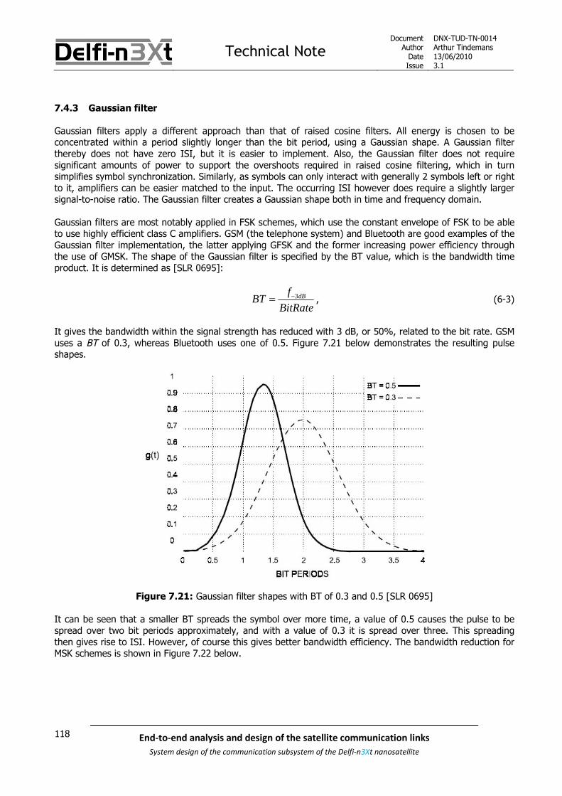
Technical NoteDocument
AuthorDateIssue
DNX-TUD-TN-0014Arthur Tindemans13/06/20103.1
118 End-to-end analysis and design of the satellite communication links
System design of the communication subsystem of the Delfi-n3Xt nanosatellite
7.4.3 Gaussian filter
Gaussian filters apply a different approach than that of raised cosine filters. All energy is chosen to beconcentrated within a period slightly longer than the bit period, using a Gaussian shape. A Gaussian filterthereby does not have zero ISI, but it is easier to implement. Also, the Gaussian filter does not requiresignificant amounts of power to support the overshoots required in raised cosine filtering, which in turnsimplifies symbol synchronization. Similarly, as symbols can only interact with generally 2 symbols left or rightto it, amplifiers can be easier matched to the input. The occurring ISI however does require a slightly largersignal-to-noise ratio. The Gaussian filter creates a Gaussian shape both in time and frequency domain.
Gaussian filters are most notably applied in FSK schemes, which use the constant envelope of FSK to be ableto use highly efficient class C amplifiers. GSM (the telephone system) and Bluetooth are good examples of theGaussian filter implementation, the latter applying GFSK and the former increasing power efficiency throughthe use of GMSK. The shape of the Gaussian filter is specified by the BT value, which is the bandwidth timeproduct. It is determined as [SLR 0695]:
3dBfBT
BitRate , (6-3)
It gives the bandwidth within the signal strength has reduced with 3 dB, or 50%, related to the bit rate. GSMuses a BT of 0.3, whereas Bluetooth uses one of 0.5. Figure 7.21 below demonstrates the resulting pulseshapes.
Figure 7.21: Gaussian filter shapes with BT of 0.3 and 0.5 [SLR 0695]
It can be seen that a smaller BT spreads the symbol over more time, a value of 0.5 causes the pulse to bespread over two bit periods approximately, and with a value of 0.3 it is spread over three. This spreadingthen gives rise to ISI. However, of course this gives better bandwidth efficiency. The bandwidth reduction forMSK schemes is shown in Figure 7.22 below.

Technical NoteDocument
AuthorDateIssue
DNX-TUD-TN-0014Arthur Tindemans13/06/20103.1
119End-to-end analysis and design of the satellite communication links
System design of the communication subsystem of the Delfi-n3Xt nanosatellite
Figure 7.22: Gaussian filter frequency responses for different values of BT [SLR 0695 & SLR 0552]
Figure 7.22 (left) shows clearly the reduced spectrum for the two most well-known BT values of Gaussianfilters, applied to MSK. A second lobe is allowed to appear, just as with regular MSK, but further lobes aresuppressed. In Figure 7.22 (right) it can be seen that for smaller BT values this second lobe even disappearsaltogether. The result of the introduced ISI finally is a reduced error performance. [SLR 0552] gives someresults of this phenomenon, as can be seen in Figure 7.23 below.

Technical NoteDocument
AuthorDateIssue
DNX-TUD-TN-0014Arthur Tindemans13/06/20103.1
120 End-to-end analysis and design of the satellite communication links
System design of the communication subsystem of the Delfi-n3Xt nanosatellite
Figure 7.23: GMSK BER performances for different values of BT [SLR 0552]
First of all, it can be seen that regular MSK (with a BT value of infinity) yields some required 10.1 dB Eb/N0 fora BER of 10-5, even though theoretically it should only be 9.6 dB. This can be specific to the scenarios of thetest, including modulator and demodulator. Therefore, the resulting difference between different BT values ismost relevant. It shows that the BT value of 0.25 has only an error performance reduction of about 1 dB,compared to regular MSK. A BT value of 0.2 gives more significant differences, of some 2.5 – 3 dB more thanMSK. However, as these BT values start to affect not 2 but 4 symbols next to that being transmitted, the 0.3value is the lowest practically used. Depending on the allowed bandwidth, GMSK signals ‘fit’ within abandwidth of some 1 times the bit rate, given the sizeable power reductions at the edges of between 30 and40 dBc.

Technical NoteDocument
AuthorDateIssue
DNX-TUD-TN-0014Arthur Tindemans13/06/20103.1
121End-to-end analysis and design of the satellite communication links
System design of the communication subsystem of the Delfi-n3Xt nanosatellite
7.5 The superheterodyne principle
Present-day radios commonly apply what is referred to as the heterodyne principle. The idea ofsuperheterodyne designs is to perform essential functionalities as modulating, but also consequent(pre-)amplifying and filtering at a far lower frequency than that that will be used for transmission; theintermediate frequency or IF. The effect is that the signal path thereby has to be sensitive to only a smallrange of frequencies. This principle is best explained by referring to the transmitter pictured in Figure 7.24below, indicating several hardware blocks.
Figure 7.24: A superheterodyne transmitter
The complete modulation scheme, also including line coding and pulse shaping, is performed at baseband.Baseband indicates that frequencies close to zero are used, such as the bit transmission rates. Duringmodulation, these digital signals are modulated onto a carrier, being an intermediate carrier, or IF. IFamplifiers can be inserted to amplify this low-frequency signal, using low-complexity linearized IF amplifiers.
An IF signal is consequently converted to a higher frequency, either being a secondary IF frequency ifmultiple conversion steps are used, or the ultimate radio frequency, RF. The generation of new frequenciesby mixing or multiplying two oscillating waveforms is called heterodyning. The created frequencies aresimilarly called heterodynes. This process is further illustrated by Figure 7.25 below.
Figure 7.25: The process of heterodyning [SLR 0244]
An IF, having frequency ω1 is mixed with a frequency ω2 originating from a LO, or local oscillator. Theresulting frequencies are created according to the relation:
1 21 1 2 2 1 2 1 2cos cos cos cos
2
VVV t V t t t , (6-4)
Where V1 and V2 are amplitude values and t is time logically.

Technical NoteDocument
AuthorDateIssue
DNX-TUD-TN-0014Arthur Tindemans13/06/20103.1
122 End-to-end analysis and design of the satellite communication links
System design of the communication subsystem of the Delfi-n3Xt nanosatellite
Therefore, ideally, two frequencies result, being ω1+ω2 and ω1-ω2. In reality however mixing is performed bya non-linear process as mixers are not ideal. As such, the original frequencies remain present in the output,as well as harmonics of them and the sum of the frequencies; being integer multiples of ω1, ω2, and ω1 andω2. The unwanted frequency resulting in the process described by relation 6-5, usually the lower one in thetransmitter and the higher one in a receiver, as well as all other unwanted mixing products should be filteredout. This is done by what is usually called an image-rejecting filter, again see Figure 7.24.
As in this manner a one sideband can be said to be cut off, and as the carrier, being the LO frequency issuppressed, the resulting transmitted signal is of the form Single Sideband, Suppressed Carrier (SSB-SC).
After one or more frequency conversion steps using available electronics and after filtering the signal, thesignal can be amplified to contain sufficient power for transmission. Therefore a dedicated RF amplifier orpower amplifier (PA) is used. It is only this amplifier which adds significant amounts of power to the signal,and therefore efficiency becomes very important only for this amplifier. The signal should then be passed onvia radio frequency circuitry and cables to the antenna, where a wireless signal is created.
It can be seen that by applying the heterodyne principle, modulation frequency and ultimate RF arefunctionally separated. This has advantages for the application of COTS components, and modularity ingeneral. The same holds for intermediate components, as several IF frequencies as 455 kHz, 10.7 MHz and70 MHz are highly standardized. The PTRX in fact applies exactly these IF frequencies, and thereby as well alarger number of mixers, filters and amplifiers than are suggested by Figure 7.24. The electronic design of thePTRX as said before is not discussed in this document, but in documents as [SLR 0281]. The consequenthardware block diagram including all IFs is presented in chapter 9 on the PTRX.
The collective of (de)modulation and superheterodyne design of mixers, filters and amplifiers establishes theentire physical layer involved in a transmitter or receiver. The specification of the digital input/output isdiscussed next in the following sections on data link layer functionalities.
Technical NoteDocument
AuthorDateIssue
DNX-TUD-TN-0014Arthur Tindemans13/06/20103.1
123End-to-end analysis and design of the satellite communication links
System design of the communication subsystem of the Delfi-n3Xt nanosatellite
7.6 Data protocol
Whereas modulation and line coding deal with bit-per-bit transmission, or physical layer functionalities,wireless communication requires more control. If a communication channel is only used for one-directionalcommunication, thus in the absence of varying noise, and if transmitter and receiver are perfectlysynchronized, there would be no direct need for further control. Since this is rarely the case, data frames arebeing made us of in all practical digital communication types, adding layer two functionalities. The functionsperformed on the data to form the data frames are specified by the data protocol.
Data frames are introduced in section 7.6.1. Afterwards the popular radio transmission data protocol AX.25 isintroduced in subsection 7.6.2. A suggested improvement, allowing for error correction, FX.25, is introducedin subsection 7.6.3. Finally in subsection 7.6.4 some theory is presented with respect to data throughputefficiency of data protocols, yielding conclusions on optimum frame length.
7.6.1 An introduction to data frames
There are two general types of communication; connection-oriented (CO) and connectionless (CL). In the firsttype, small packets of information sent between transmitter and receiver negotiate a channel with certaincharacteristics, after which all raw data can be sent in one stream. In connectionless communication howeverraw data is just sent; usually in multiple packets with enough extra data to address the packets properly andto confirm whether the correct data was sent. CO communication thereby allows negotiating a certain qualityof service conforming to the type of information sent. CO communication requires specific data packages inthe negotiation of the channel, whereas CL communication uses data frames to package all information. Theuse of these data frames is further elaborated on below.
In space to earth communication or vice versa, only CL communication is seriously feasible. The direct reasonis the delay introduced in their communication by the long distance in between. At the very least this type ofcommunication will require a certain preamble to allow the raw data to be sent. As the receiver will not likelyknow precisely when or at what precise frequency the data will be sent (due to a Doppler shift, but potentiallyalso variations in the transmitter caused by temperature for example); preamble can provide these details.The reception of a signal could trigger a receiver to ‘pay attention’, but also the preamble can provide detailsfor carrier and symbol synchronization, depending on the requirements of a modulation scheme. These topicsalong with modulation have been further discussed in section 7.2, but in summary carrier synchronizationimplies tuning to the exact centre frequency (or the main centre frequency in case of frequency shift keying,or FSK), whereas symbol frequency allows the receiver to lock on the ‘clock’ of the signal, each tick signifyingone symbol.
Whereas raw data with a certain preamble could consequently provide a working communication link,packaging is usually applied. Next to synch
Next to synchronization, more control is required as the transmission channel is not disturbance free for theduration of the entire transmission. Control of the data can be provided by wrapping pieces of data inconcrete frames. Each of these frames will only require a short limited time to be sent, and as such not allinformation has to be received in one stream, and by the same receiver. Furthermore the accuracy of thereceived data can be confirmed or increased by adding redundant error detection or error correction data toselected blocks of information; usually with a block equalling the data content of one data frame (excludingpossible flags; these are explained below).
Now the question is: “what comprises a data package?”

Technical NoteDocument
AuthorDateIssue
DNX-TUD-TN-0014Arthur Tindemans13/06/20103.1
124 End-to-end analysis and design of the satellite communication links
System design of the communication subsystem of the Delfi-n3Xt nanosatellite
In fact, for a satellite mission, a data package can be quite simple. The essential parts:
Start/end-indicatorsA start-of-frame indicator, and, if the frame length is variable and not specified within the frame,an end-of-frame indicator are necessary to properly read out the frame configuration. An end-frame indicator can thus be replaced by a length field or a length previously agreed upon.
An address fieldAssuming the frame construction is not unique (for the mission at hand) and/or there are multiplesources/destinations that apply the same protocol, a sender/destination address is necessary toverify that the source/destination of the data is correct and that thus the frame is accepted ordiscarded. One or two addresses specifying the sender and/or receiver can then be integrated ina designated address field.
Information contentThe actual message, consisting of any predefined or variable number of bits.
Bits to allow for demodulationDepending on the type of modulation, carrier synchronization (see section 7.2) might be required.At the same time, depending on the bit stream and/or line code, additional symbolsynchronization (bit synchronization) might be required. Both can be achieved by implementingbit patterns yielding preferred characteristics; an 111111 pattern with BPSK modulation yields apure carrier signal useful for carrier synchronization, and a 010101 with FSK modulation yields alarge number of transitions usable for symbol synchronization.
Error detectionAs there is no way to know a package is corrupted given the above fields, some form of errordetection is simply required as space communication is prone to errors due to small transmissionpowers and long distances traversed. Depending on the frame length, a simple code of severalbytes calculated over the frame can usually guarantee no small amounts of errors in the frame.As an error detection code might expect a certain number of bits, bits can be added to yield acertain multiple of 2, 4 or 8 bits for example.
The above fields basically comprise a minimum. Other things that can be included are listed below. As theseare not automatically required for successful communication, they can also be seen as part of the informationframe.
Error correctionInstead of just error detection, (many) more bits can be added to not only allow for errordetection, but also correction. This is the topic of the next section, 7.8.
Extra addressing informationMore addresses, required for routing for example might be required.
Higher level control informationIn the same vein as the previous point, additional addressing might be required to specify thehigher level protocols; meaning for example software / application protocols.
Frame type identifierThe frame protocol might include different frame types (corresponding to different functionalities,such as downlinking information, uplinking telecommands, confirming telecommands); in thiscase the type can be specified by a field.
Information type identifierPayload data, housekeeping data, and possible different configurations / combinations of thesecan be identified by a field.
Frame numberTo keep track of which frames are successfully received, a unique number can be added to eachone.

Technical NoteDocument
AuthorDateIssue
DNX-TUD-TN-0014Arthur Tindemans13/06/20103.1
125End-to-end analysis and design of the satellite communication links
System design of the communication subsystem of the Delfi-n3Xt nanosatellite
Real Time Clock (RTC) tagTo give more details about the information content, a real time clock tag can be added; whichcan be a relative or absolute time tag (a number of seconds since a certain date and time, or adate and time directly for example).
Encryption / security measuresThe content of a data frame, any number of fields, can be encrypted. Similarly, a (frame-content-dependent) key or encrypted hash (bit sequence calculated over the frame content) can beadded to verify the sender and data integrity.
7.6.2 The AX.25 protocol
The AX.25 protocol [SLR 0293] is a set of rules that defines data framing for simple communication channelsthat do not require extensive routing, signalling and error correction. It does however allow for both CO andCL types of communication. It is widely used by radio amateurs as well as CubeSat teams not too differentfrom the Delfi team. Similarly it is applied in the Delfi-C3 mission and is thus well-proven in its use. The AX.25protocol offers the essential functionalities as introduced above and little else, and is as a result reasonablydata efficient. Adding the given advantage of its widespread application within the radio amateur community,whom Delfi-n3Xt is supposed to provide a favour for, for using the radio amateur frequencies, the AX.25protocol provides a good option. It is further introduced below.
The AX.25 protocol offers 3 types of frames: information, supervisory and unnumbered (S, I and U) frames.I frames carry the actual information in normal flow conditions. S frames in turn, as [SLR 0293] states,“…provide supervisory link control such as acknowledging or requesting retransmission of I frames, and link-layer window control“. The latter (window) indicates an approach in which multiple I frames are sent afterwhich the first should still be acknowledged. As such, basically I frames automatically trigger anacknowledgement or a repeat request, in normal operations. U frames, can then be used to establish andterminating connections, in other words, in a CO approach. These functionalities are not required or desirablein a CL or connectionless approach. As such, UI frames can be used.
UI frames are classified as U frames, but mimic the functionality of an I frame, but without including a framenumber and thereby requesting a confirmation. A UI frame in the AX.25 protocol has the construction asshown in Figure 7.26:
Figure 7.26: AX.25 UI frame [SLR 0293]
As can be seen the AX.25 incorporates exactly what is required for a simple one directional traffic stream, andnot much more:
The flags indicate the start and end of a frame, whereas the first flag also allows for carriersynchronization depending on the modulation scheme. For this purpose the first flag of the firstframe is usually repeated a number of times. It should be noted that AX.25 is designed to beused with NRZ-I encoding or more precisely NRZ-S encoding (see section 7.3); in other words 6consecutive ‘1’ bits cause no signal transitions, thus a pure carrier signal.
The address field of 112 bits gives two addresses, exactly that of the sender and receiver. Morefunctionality can be added by extending it to 224 bits. The address field merits some furtherexplanation as is given below.
The control field stipulates the type of AX.25 frame used, and at the same time offers some morefunctionality as including the frame counter. In case of a UI frame it has an 8 bit length, and isset to 00000011 or 03 in hexadecimal (base 16 as opposed to base 2 with bits); 03hex.

Technical NoteDocument
AuthorDateIssue
DNX-TUD-TN-0014Arthur Tindemans13/06/20103.1
126 End-to-end analysis and design of the satellite communication links
System design of the communication subsystem of the Delfi-n3Xt nanosatellite
The PID (protocol identifier) field allows for higher layer protocols to be specified, to supplementspecific applications and allow for routing for example. As this functionality is similarly notrequired, 11110000 specifies “no layer 3 protocol”, thus F0hex.
The info field is the field where actual raw data is encapsulated, as indicated in Figure 7.26 the onlyconstraint is that it should be an integer number of bytes.
The frame-check sequence or FCS field finally provides the ability to check the contents of thetransmitted frame. It is calculated over the entire frame with the exception of the flags (and theFCS of course). The applied ‘generator polynomial’ is called CCITT-16, and equals x16+x12+x5+1,yielding 1+ 25+ 212+ 216. This equals a bit sequence 1 00010000 00100001. Section 7.7 explainshow this generator polynomial is applied. This FCS has the ability to detect all single, double andtriple errors in messages shorter than 32752 bits, or 4094 bytes, as well a burst errors up to 15bits of length.
The 112 bits address field is composed of a destination address block, followed by a source address block.The lay-out of the address field is illustrated in Figure 7.27 below. Per address 6 bytes are available. Thisallows to specify a callsign of maximally 6 128-bit ASCII characters (supplemented with spaces), being eitheruppercase alpha or numeric characters. The 8th bit in each address byte is set to 0, to indicate more addressbytes to follow. However, as AX.25 reverses the order of all bits, this is shown as the 1st bit. Only in the lastbyte, A14, if no address extension (224 bit address field) is applied, this 1st bit is set to 0.
Figure 7.27: AX.25 Address Field
The bytes A7 and A14 as indicated allow for SSIDs, or secondary station identifiers to be added. Secondarystations are basically radios with the same callsign, but then an SSID of more than 0000. The primary radioindeed has a SSID of 0000. The second and third bit as indicated, officially being the 6th and 7th bit, arereserved for future use and are to be set to 1. The final bits of both fields A7 and A14 are per definition set to0.
As can be seen from the description above, the start and end flag have efficiently been combined with a flagnecessary for symbol synchronization. As the end flag bit sequence should not be allowed to occur within theframe, bit stuffing is applied. This makes sure all sequences of 5 1’s are followed by a 0 bit within the framebody. This, at the same time, yields a guarantee for sufficient bit transitions during the frame to maintainsymbol synchronization.
The frame length of an AX.25 frame is arbitrary, as N in the info field can take any (integer) number. Apractical maximum is given by the FCS generator however. If N is sufficiently large, the overhead introduced(extra bits added) by using the AX.25 protocol is little. The fields added that would not be strictly necessaryfor simple communication are most notably the control field, the PID field, and the address field. The first oneindicates the type of frame (UI), whereas the second basically says “no information”. The address field, asargued before, can be said to be required to identify that the data actually comes from the proper source. Ifthe source is trivial, it might not even be necessary. The same holds for the destination. In any case theaddress could be shorter, to indicate just the simple situation of frames coming from Delfi-n3Xt, and going tothe ground station; which in the end indicates the same server.
In conclusion, this means that 16 bits are effectively useless but required due to the protocol, and 112 bitswould be inefficiently used in case of a simple mission such as that of Delfi-n3Xt. Given a long enough framethis effect is minimized and AX.25 brings along the advantage of being a standard data protocol, at that onethat is not very complicated. For shorter frames, or those of known length, it might not be desirable.

Technical NoteDocument
AuthorDateIssue
DNX-TUD-TN-0014Arthur Tindemans13/06/20103.1
127End-to-end analysis and design of the satellite communication links
System design of the communication subsystem of the Delfi-n3Xt nanosatellite
7.6.3 The FX.25 protocol
The AX.25 protocol does not provide error correction, only error detection. For this exact reason the FX.25protocol was introduced [SLR 0294]. FX.25 is an extension to AX.25; FX.25 is designed not to replace thelatter but to supplement it. A receiver capable of interpreting only AX.25 will interpret FX.25 data frames byAX.25 data frames surrounded by noise. For this exact reason the FX.25 protocol is also introduced here; itadds error correction to a well-known and well-integrated protocol.
The FX.25 data frame construction is shown in Figure 7.28 below. The entire AX.25 frame as shown in Figure7.26, including flags, is integrated as indicated.
Figure 7.28: FX.25 frame [SLR 0294]
The four blocks in the middle represent the AX.25 data frame as illustrated in Figure 7.26. The idea of FX.25is to pad the bits in the AX.25 frame with a number of bits, so that an FEC algorithm can calculate a numberof FEC check symbols; these are consequently added to the padded AX.25 frame. The expected FECalgorithm is thus a block code; it takes a block of bits, and calculates a number of coding bits. This type ofcoding as well as its alternatives are introduced in section 7.8.
The resulting data block, of AX.25 frame plus FEC-related bits, is illustrated in Figure 7.28 under the name ofthe FEC codeblock. In order to specify the FEC algorithm used, a correlation tag is used. As the correlationtag itself should be interpretable even in a noisy environment, use of Gold Codes [SLR 0294] is advised, in ablock of 8 bytes or 64 bits. As this use of FX.25 causes the original AX.25 flags to be hidden, there is a needfor new preamble and postamble for frame start and end indication, and additional signal synchronization. Assuch it can be concluded that FX.25 introduces some practically unnecessary overhead, at the gain ofinteroperability with AX.25 interpreters. To be precise, the AX.25 flags, as well as the FCS are not strictlyrequired anymore except for the recognition of the AX.25 frame. Nevertheless if the frame body is largeenough these extra fields cause little unnecessary overhead.

Technical NoteDocument
AuthorDateIssue
DNX-TUD-TN-0014Arthur Tindemans13/06/20103.1
128 End-to-end analysis and design of the satellite communication links
System design of the communication subsystem of the Delfi-n3Xt nanosatellite
7.6.4 (Delfi-C3) data throughput efficiency and optimal frame length
The use of a data frame introduces a certain overhead. At such, it makes sense to reduce the relativeoverhead, by reducing the data protocol overhead itself, or by increasing the frame length. Duringtransmission however, information is subject to a certain bit error rate or BER. Whenever a bit error occurs, awell-designed data frame will notice this, but due to overhead or complexity limitations will often not be ableto correct this. Therefore, the entire frame is discarded. From a BER point of view then, the frame size shouldbe minimized. The relation between these two parameters can be simply written out mathematically, yieldingdata throughput efficiency:
totalthroughput
FS OV DL
PS
(6-5)
The effective frame size (FS) is reduced by two parameters, being the total overhead introduced by the dataprotocol (OVtotal) and the average data loss (DL) due to transmission errors.
The total overhead can be divided in two separate losses, that incurred by data protocol fields (OVfields) andthat incurred by bitstuffing (OVbitstuffing), if any. The first is just an invariant number, depending on the dataprotocol. The second can be written as a product of frame size and bitstuffing ratio BR, resulting in:
total fields bitstuffing fieldsOV OV OV OV BR FS (6-6)
The data loss on the other hand is determined by the amount of data (not any form of overhead) lost onaverage. This can be written as equation 6-7, with BER being the bit error rate already introduced above:
( )totalDL FS BER FS OV (6-7)
The product of PS and BER represents the amount of frames that will not arrive due to transmission errors,where the difference of PS and OVtotal indicates the amount of data lost per transmission error.
Equation 6-6 can be substituted in equation 6-7, and equations 6-6 and 6-7 can then be substituted inequation 6-5 to yield equation 6-8:
( ) ( ( ))fields fields
throughput
FS OV BR FS FS BER FS OV BR FS
FS
(6-8)
To give some concrete results, equation 6-8 can be applied to the AX.25 protocol, with Delfi-C3 telemetry(TM) frames as reference. TM frames profit the most from an optimized throughput, as data yield on-groundshould be maximized. Telecommand (TC) frames on the other hand have no push to increase data volumethroughput. Delfi-C3 TM frames contained a maximum of 1200 bits, due to a 1200 b/s data rate and 1 frameper second. Bitstuffing is defined by the AX.25 protocol as 1 in 6 bits maximum, but frames were nevercreated with more information that the worst-case would allow. Therefore, 200 bits out of 1200 werereserved for bitstuffing. Also, the AX.25 (UI) frame requires 160 bits of fields, next to the information field.Finally, the BER to be designed for is 10-5. In summary:
511200, , 160, 10
6fieldsFS BR OV BER (6-9)

Technical NoteDocument
AuthorDateIssue
DNX-TUD-TN-0014Arthur Tindemans13/06/20103.1
129End-to-end analysis and design of the satellite communication links
System design of the communication subsystem of the Delfi-n3Xt nanosatellite
As was already explained above, the occurrence of overhead would favour an infinite frame length, whereastransmission errors would favour a bit-per-bit transmission. The optimum then is somewhere in between.
With the assumed BER, and the use of the AX.25 protocol, a throughput efficiency of 76% can be obtained.In case of Delfi-C3 however, this efficiency was only 69%, due to the frame size of only 1200 bits. Theoptimum occurs at a frame size of 4400 bits, nearly four times as much. A frame size of 2400 bits howeverwould have already raised the efficiency to more than 73%; some 40 bits per 1000 more.
In fact, Delfi-C3 also applied a frame identifier (2 bits), and a larger frame counter (32 bits). As these fieldsare only useful once per frame, independent of its size, they effectively are overhead as well. Adding thesebits to the overhead, thereby adjusting OVfields to 194 bits, gives an efficiency of only 66%, with a maximumachievable value of again nearly 76% with frame sizes of 4800 bits. Again, 2400 bits per frame would haveimproved the efficiency to almost 74%, or 80 bits per 1000 more. In other words, frame rate had likely betterbeen set to 2 frames per second (thereby integrating housekeeping and payload data). Given the currentrotation rate of only a little over 0.2° per second, this would not have caused any problems related topolarization.
Both amounts of overhead discussed above are plotted for both BERs in Figure 7.29 below, the first casebeing “General AX.25, BER=10^-5” and the second being “Delfi AX.25, BER=10^-5”. The two lines aretherefore nearly superimposed middle lines.
Now what should also be mentioned, is that generally a link margin exists, which in case of Delfi-C3 wassizeable. This additionally available transmission power effectively decreases the BER. As illustrated by thegraphs in section 7.2, for BPSK modulation an extra signal-to-noise ratio of 3 dB already lowers the bit errorrate to only 10-8. The effect of such a BER is that overhead becomes the limiting factor; only an effective low-efficiency lower limit to frame size is set and larger frames are favoured.
It can clearly be seen in Figure 7.29 below that at small frame lengths, where overhead is relatively verysizeable, throughput efficiency is very low. From 1200 bits onwards it becomes acceptable, but 2400 is abetter value. Afterwards, BER begins to play a role; a larger BER will push the graphs down again so thatoverall efficiency again goes down. A smaller BER, for example when the link margin is (momentarily) high,causes the throughput efficiency to keep rising slightly, in fact until a maximum optimum frame size isreached at 153,000 bits, with a total efficiency of 83% for the case of largest overhead. Effectively, thelatter takes BER out of the equation.
What is also plotted is that at a BER of only 10-4, only 60% efficiency can be obtained, and frame efficiencydrops off quickly so frame sizes should be strictly limited. Not plotted, is that at a BER of 10-3 no positiveaverage throughput can be obtained anymore; one in every 1000 bits will be in error.

Technical NoteDocument
AuthorDateIssue
DNX-TUD-TN-0014Arthur Tindemans13/06/20103.1
130 End-to-end analysis and design of the satellite communication links
System design of the communication subsystem of the Delfi-n3Xt nanosatellite
Figure 7.29: Throughput efficiencies vs. frame sizes for the AX.25 protocol
In general it can be said that: Overhead should in any case be decreased as much as possible, 160 bits and 1/6 of the total
amount of message bits in AX.25 is a lot. The overhead is most notably caused by bit stuffing as itincreases relatively to the frame size.
Data throughput can be optimized by increasing frame size. In other words, by movingtowards or over the maximum of this curve. The maximum can be approached relatively quickly, andsurpassing the maximum will only decrease throughput slightly or increase it slightly, depending onthe actual BER including margins.
In the next chapter the relation presented above is further used for the optimization of total data throughputfor Delfi-n3Xt.

Technical NoteDocument
AuthorDateIssue
DNX-TUD-TN-0014Arthur Tindemans13/06/20103.1
131End-to-end analysis and design of the satellite communication links
System design of the communication subsystem of the Delfi-n3Xt nanosatellite
7.7 Data security
The AX.25 protocol introduced above applies a FCS, or frame-check sequence. This sequence is inserted toensure the data integrity of the frame. In other words, this FCS is a form of data security. Data security isgenerally added as any real medium is prone to errors, be it in small amounts or large. These ‘errors’ can alsobe wilfully incurred by a third party, which tries to change the message conveyed.
This section introduces various applicable measures of data security, starting with the CRC, which is a generalname for the type of security offered by the FCS, in subsection 7.7.1. Encryption is introduced in subsection7.7.2. Afterwards, as the CRC is actually a form of a more general hashing algorithm, the (encrypted) hashfunction is the topic of subsection 7.7.3.
7.7.1 Cyclic Redundancy Check (CRC)
A CRC is a form or error detection. It is designed to warn for the occurrence of random channel errors, which,even in a very well-designed system can occur. In fact this system is designed to have a certain low bit errorrate; in case of Delfi-n3Xt one of 10-5 bits. Another word for a CRC is a polynomial code checksum; by using a(generator) polynomial code it devises a checksum of fixed length. Depending on the length of the packageto be transmitted, or word length, a specific number of bit errors can be detected. The number of uniqueerrors is always limited, for example a well-chosen 16-bit CRC calculated over a 2048-bit word can neverdetect more than 3 random errors with 100% certainty, but depending on the location of them it can detect a(much) larger number. While this is prone to random success, the use of a specific polynomial in thecalculation of the checksum, allows not only singular errors can be corrected, but also burst errors of lengthless than the polynomial itself [SLR 0683], and even more than 99% of larger burst errors [SLR 0688]. Ascommunication is usually the target of these errors exactly, this feature proves very useful. Furthermore CRCcodes thank their popularity to their computational facility; both encoding and decoding can be doneextremely fast in processors.

Technical NoteDocument
AuthorDateIssue
DNX-TUD-TN-0014Arthur Tindemans13/06/20103.1
132 End-to-end analysis and design of the satellite communication links
System design of the communication subsystem of the Delfi-n3Xt nanosatellite
Calculation of the CRC
The word ‘cyclic’ in the name CRC comes from the fact that the message is cycled through while applying thesame polynomial The latter has a length much smaller than the actual message. Computational facility comesfrom the fact that a simple shift register can be used, applying modulo-2 arithmetic. This latter means thatwhen bits are added, regular addition rules apply, except for the case of two 1’s being added; this results in a0. The shift register is shown below in Figure 7.30 below.
Figure 7.30: CRC shift register operation [SLR 0683]
The application of a 5-bit polynomial, 11001, is shown. In fact, the name polynomial comes from the possiblebinary polynomial representation of the sequence; in this case it would be x4+x3+1. A bit sequence, themessage, is shifted through the register. Circles indicate operations, whereas squares indicate value storelocations. Step after step, the incoming bits are at the same time passed on from square to square. At first,all squares contain zeros. The first square value is combined with the floating ‘1’ value and is passed on tothe circles with a value of 1 above them, or those with feedback loops connected to them; in other wordswhenever the first bit equals a zero, no changes are incurred to the bit stream. If however the first bit equalsa 1, all circles with ‘1’ values above them invert their input; a 0 is mixed with a 1 to become a 1, and a 1 ismixed with another 1 to become a 0. The result of this operation is a remainder of the length of thepolynomial minus 1, which is the CRC.
The above process is rather time consuming, as it shifts and recalculates a value on a bit-per-bit basis. It hashowever been proven that simple PICs were able to live up to the task as well as processing the AX.25 frameson Delfi-C3, applying the standard 16-bit AX.25 CRC. [SLR 0688] does however suggest another calculationapproach (the Table Lookup Algorithm, or TLA) in which n bits can be processed at the same time, at the costof a look-up table of size k*2n, with k equalling the CRC size in bits; this yields a required 256 kB memory sizefor optimal 8-bit processing of the 16-bit CRC. An intermediate approach, the Virtual Table Algorithm (VTA),and a variant called Optimized VTA (OVTA) are also introduced in [SLR 0688] with speeds and memory sizesof intermediate values. The article finishes with typical execution times versus memory sizes.
On reception, the CRC can be recalculated over the message, to see if the received CRC is the same. Or, asecond option is to perform the same CRC calculation over the message and the transmitted CRC; if themessage and CRC are error-less, the result will be 0. If the result is not 0 however, this latter approach allowsnot only to detect errors, but to correct one error as well, if the error detection capability of the applied CRCis at least 2. The required processing application is sizeable however; the functionality is introduced furtherbelow.

Technical NoteDocument
AuthorDateIssue
DNX-TUD-TN-0014Arthur Tindemans13/06/20103.1
133End-to-end analysis and design of the satellite communication links
System design of the communication subsystem of the Delfi-n3Xt nanosatellite
Performance of CRCs
As introduced above, CRC capabilities depend on CRC length and word length. Any CRC will be able to detectsingle errors, as the minimal functionality is given by the parity check; if all bits are added together modulo-2,the resulting 1-bit 0 or 1 value will be able to detect all odd numbers of errors. Nevertheless larger CRClengths are in general more useful, as they will allow for more errors to be detected and they add the bursterror detection functionality. 4-bit CRCs are used in the USB protocol, but usual CRCs are integer multiples of8, as (micro)processers generally calculate with 8 bit applications. Indeed also in Delfi-n3Xt this is the case.
Figure 7.31 below gives an impression of the maximum achievable amount of detected errors for a CRC ofgiven size, for certain word lengths. It is the result of an exhaustive research into all possible CRCs for givenlengths. HD stands for Hamming Distance; HD-1 yields the amount of detectable errors. The word maximumword length for the applicable scenario is given in the cells, with a hexadecimal representation of the CRCpolynomial underneath it. Details of this representation can be found in [SLR 0687]. The pluses for HD=2indicate that indeed every CRC can detect single errors in a word of indefinite length.
Figure 7.31: Optimal CRCs for a given CRC length, HD and word length [adapted from SLR 0687]
16-bit CRCs are those that have seen the most use over the years. As such they have logically seen a lot ofresearch. [SLR 0684] aims to provide an exhaustive research into 16-bit CRCs. It concluded that there is noone ‘optimal’ 16-bit CRC, as with other lengths. A CRC focussed on a specific word length will underperformwhen compared to a similar-length CRC focussed on a different word length. The following Table 7-1 showsthe maximum achievable performances for 16-bit CRCs, with given total lengths (including CRC).

Technical NoteDocument
AuthorDateIssue
DNX-TUD-TN-0014Arthur Tindemans13/06/20103.1
134 End-to-end analysis and design of the satellite communication links
System design of the communication subsystem of the Delfi-n3Xt nanosatellite
Table 7-1: Maximum achievable performances for 16-bit CRCs [adapted from SLR 0684]
Total length n Hamming Distance
17 17
18 12
19-21 10
22 9
23-31 8
32-35 7
36-151 6
152-257 5
258-32767 4
32768-65535 3
≥65536 2
It can be seen that HD=6, or 5 detectable errors, can be achieved until total length of 151 bits. The codethat achieves this result however, with a generator of 236545 (in this polynomials codes are expressed asproducts of three octals; i.e. 23 stands for 8 bits), achieves only HD=2 above n = 151. Another code withgenerator 371237 achieves HD=6 until n = 130, HD=4 until n = 258, after which it drops to HD=2. HD=5can be reached until n = 257, but also decreases to HD=2 for larger values of n.
The more power is used to transmit (higher link margin), the less errors are expected to occur. The uplinksignal of Delfi-n3Xt has by far the most link margin as is further assessed in the next chapter. However, itsreliable communication is more important as no telecommand should be wrongly interpreted. The abovecodes can therefore be very useful for (generally short) telecommands.
The downlink signal, with larger frame lengths, is more susceptible to errors. As such, 16-bit CRCs withperformance optimized for larger word lengths are shown in Table 7-2.
Table 7-2: Maximum achievable performances for 16-bit CRCs with large n [adapted from SLR 0684]
HD Total length n per CRC polynomial
200433 321353 320227 (IBM-SDLC) 210041 (CCITT)
10 17-18
8 19-27 17-24
6 17-115 28-109 25-83
4 116-28658 110-32767 84-32766 17-32767
2 ≥28659 ≥32768 ≥32767 ≥32768

Technical NoteDocument
AuthorDateIssue
DNX-TUD-TN-0014Arthur Tindemans13/06/20103.1
135End-to-end analysis and design of the satellite communication links
System design of the communication subsystem of the Delfi-n3Xt nanosatellite
The fourth polynomial is the familiar x16+x12+x5+1 polynomial applied in the AX.25 protocol, and thus also inDelfi-C3. It can be seen that in fact other polynomials are strictly better. [SLR 0687] presents anotherpolynomial by its generator value of 0xBAAD, which achieves HD=5 until n = 122, which turns out to be themaximum achievable for a code also providing HD=4 for message lengths of 1024; the article research is saidto be exhaustive for all CRC codes up until this length.
Whereas [SLR 0687] mentions polynomial were once restricted by hardware complexity as polynomial 1’swere more difficult to implement due to feedback loop, as illustrated by Figure 7.30, this is no longer the caseas software is indifferent to the number of 1’s. Nevertheless, the improvement of other polynomials can besaid to be of pure theoretical value if the smaller message lengths are not used.
One thing to be added to the discussion above is the fact that CRCs are said to have HD=N up until the firstword length where they lose this ability; afterwards a finite number of words exists where the HD value is nolonger guaranteed. The CRCs can however still detect errors for larger messages. This number of words mayvary per polynomial, and thereby also the chance that a larger number of bit errors is still detected. This iscalled error performance of CRCs.
[SLR 0685] gives a detailed analysis of these effects but only up until word lengths of 1024 bits. In this regionthe CCITT CRC is shown to outperform the IBM code. CRCs are generally applied to cope with randomchannel errors, which occur in the order of bits as opposed to bytes for example. A general rule of thumb[SLR 0686] says that if a BER of 10-2 is maintained on a link, the chance of two errors occurring isapproximately 102 less. Therefore, as a BER of 10-5 is designed for in case of Delfi-n3Xt, which yields only onein 100,000 bits to be in error on average. The occurrence of two errors then is expected to take place a factorof 105 less. Therefore, the importance of this error performance to Delfi-n3Xt is limited.
24- and 32-bits are discussed in detail by [SLR 0689] which follows up the discussions on 16-bit CRC in[SLR 0684]. Three interesting 24-bit CRCs are introduced, which for convenience shall only be named by their‘birth names’:
CRC-24/6.1: HD=6 for n = 84-2050, HD=4 for n = 2051-4098 and HD=2 for n ≥ 4099 CRC-24/5.1: HD=6 for n = 38-252, HD=5 for n = 253-4097 and HD=2 for n ≥ 4098 CRC-24/6.1: HD=6 for n = 62-846, HD=4 for n = 847-8,388,607 and HD=2 for larger n
For 32-bit CRCs total lengths of 306 bits can be reached with HD=8, at the same time yielding HD=6 until32,768 bits and HD=4 until 65,534 bits. [SLR 0686] introduces yet another code class with HD=6 until only16,360 bits, but extending the range of HD=4 to 114,663 bits. Little 32-bit CRC codes are presented thatseem to be optimized for smaller word lengths, or these are simply of little practical interest as relativelylarger overhead would also be incurred for these messages. The largest HD at intermediate total lengths wasfound to be HD=8 until n = 1024, but after n = 2046 quickly dropping of to HD=2, with an intermediatevalue of HD=4. It can be seen that a doubling of CRC length, with respect to 16-bit versions, does not directlydouble the amount of errors that can be corrected at intermediate lengths, but it can more than double theallowed word length.

Technical NoteDocument
AuthorDateIssue
DNX-TUD-TN-0014Arthur Tindemans13/06/20103.1
136 End-to-end analysis and design of the satellite communication links
System design of the communication subsystem of the Delfi-n3Xt nanosatellite
Error correction
As introduced above, by calculating the FCS over a received message and its FCS a remainder results, beingeither 0 or not. In case of a 0, no errors can be assumed to have occurred. If the value is nonzero however,the remainder itself holds the information as to where the error has occurred. As the message consists of bits,knowledge of where exactly the error has occurred allows to simple ‘flip’ the bit value for a resulting correctmessage.
For large messages, the calculation of the error can be difficult. In fact, general targeted error correctionapproaches usually add relatively large overheads (as opposed to CRCs) so that errors can be extractedrelatively easily. Nevertheless, for single error correction using CRCs some shortcuts can be used. Therestrictions:
The message length cannot be more that 2d-1-1, where d is the degree of the generator [SLR 0691].This is the largest factor in the generator; CCITT has an x16 term, so degree = 16. The maximummessage length is then 32,768.
Three bit errors can generate the same residual as a single bit error; therefore to make use of errorcorrection the chance of a three bit error should be very low.
The frame length should be known.
There are different manners of calculating the erroneous bit location, but only one class leads to anacceptably reduced calculation overhead for sizeable frames. This is by means of a table look-up algorithm.The idea is quite simple. For a given received message, due the properties of a CRC, there is only oneoptional received FCS per error location. In result however, a straight-forward table would have to store 232
values of 32 bits for a 32 total length of message and CRC. For larger messages this is of course undoable. Assuch, smarter table look-up algorithms have been created; an optimized one is given in [SLR 0690].
The resulting table has a much smaller length, with a total amount of n rows, where n is the total length ofmessage and FCS as above. The total amount of bits that need to be stored is then equal to:
22 ( 1 (log ))p m p k (6-10)
Where m is the amount of CRC bits, k is the message length and p depends on the polynomial and message
length; it has a value of at minimum 2log n , in other words the amount of bits needed to express the
message length with. The trick with the algorithm is that an appropriate set of distinct rows should beobtained; if it is not found, p is increased by 1 and the search process is restarted. No results are given ontypical iterations for sizeable message lengths.
A simple calculation gives for a downlink frame length of Delfi-C3 (1000 bits total, excluding bit stuffing) amatrix with 1000 rows of course, and a total matrix size of at least 17,000 bits or 2.1 kB. Potentially thisnumber should however be multiplied by 2 a number of times. In case of a 2400 and 4800 bit framerespectively with a 16 bit CRC the equation yields a minimum matrix size of 70,000 and 130,000 bits, or some9 and 16 kB.

Technical NoteDocument
AuthorDateIssue
DNX-TUD-TN-0014Arthur Tindemans13/06/20103.1
137End-to-end analysis and design of the satellite communication links
System design of the communication subsystem of the Delfi-n3Xt nanosatellite
7.7.2 Encryption
The goal of encryption is to mask the information being transmitted. This subsection will present someterminology and gives a non-exhaustive introduction to some examples of cryptography.
In the process of masking original data, plain text is transformed into cipher text. A cipher controls theencryption and decryption, usually be means of a key. Whereas the cipher then is the algorithm, the keychanges the variables of the encryption. The key therefore add security to the algorithm. There is a distinctdifference between symmetric and public key schemes; a symmetric key system implies having a similar keyat transmission and reception, whereas a public key system does not. Consequently, there is also a differencebetween block ciphers and stream ciphers; block ciphers operate on a block of predefined size such as 64 or128 bits, whereas stream ciphers do not. Any content to be encrypted with block ciphers should therefore bea multiple of these block lengths; if it is not it can be stuffed with ‘dummy’ bits. The best-known symmetrickey block ciphers are DES (Data Encryption Standard) and AES (Advanced Encryption Standard). RC4, alsoknown as ARC4, is the most-widely used symmetric key stream cipher. Public key systems, such as Diffie-Hellman, RSA and DSA have the downside of involving a much larger computational load [SLR 0492].
Stream ciphers yield the largest flexibility, as the message size is not restricted. Using a 25-character key, apseudorandom key stream is generated, which is used to transform the message. The key stream iscombined with the message (the TC info field in the Delfi-C3 case) using a bitwise exclusive-or operation. Theresulting cipher text can only be decrypted by applying the same process, with the same key stream. RC4,next to being the most-widely used, is remarkable for its simplicity and speed in software. It has thereforesuccessfully been applied in Delfi-C3 for the TC uplink.
7.7.3 (Encrypted) hash function
Hash functions are a general class of functions that reduce a large amount of data to a small related amountof data. CRCs are in fact non-secure hash functions; multiple messages can transform to the same hash. Twoidentical hashes following from a different message create a hash collision. CRCs do not have the samepurpose as a hash, as they are intended to protect against a small number of transmission errors. Hashfunctions have multiple uses, such as speeding up search processes by means of hash searching. Also, incase of data transmission, hash functions can provide much better protection against intentional altering ofthe message during transmission; if the hash algorithm is unknown that is. Compared to CRCs however theythereby incur a much larger overhead, depending on the amount of hash collisions allowed.
Hash sizes can be effectively reduced by applying encryption. A smaller, less effective hash function mightproduce many possible hash collisions, which can be misused by a potential attacker by changing themessage while yielding the same hash. Encryption however can make use of the fact that the encryptionalgorithm is now known, thereby allowing a number of existing hash collision, without the attacker havingsufficient knowledge to exploit them. Well-known encrypted has functions are those of the SHA family, orMD5 [SLR 0492]. Of course, the complete process of extracting a hash and encrypting it is rathercomputation intensive.

Technical NoteDocument
AuthorDateIssue
DNX-TUD-TN-0014Arthur Tindemans13/06/20103.1
138 End-to-end analysis and design of the satellite communication links
System design of the communication subsystem of the Delfi-n3Xt nanosatellite
7.8 Forward error correction
The previous section has introduced means of error detection, through using the CRC or a more general hashfunction. Depending on the application, erroneous frames or content can then be simply discarded, or adiscard can be followed by a new request for the corrupted date, requiring repeating transmitted data. This isthe first of two methods that can be used to deal with frequently occurring errors in a digital communicationsystem. These two methods are to make use of:
An automatic repeat request (ARQ) Forward error correction (FEC)
The first type of error handling works by labelling blocks of data and adding redundant bits (parity bits) suchas in the CRC approach. The calculation of these bits is based on the content of the data block, and if thesame calculation on the received bits yields a different result, a request for a repetition of the erroneous datablock is sent to the original transmitter. This is an example of error detection, followed by the actual ARQ.
In case of forward error correction or FEC, redundant bits can also be used to correct for errors. However,FEC is generally used for a different purpose than correcting sporadic errors. It is used to actually increasethe achievable bit rate, by lowering the required power needed to transmit a data bit. This is explained withthe use of two figures directly below.
It was introduced before that a certain Eb/N0 is required to transmit a bit with a certain (low) probability oferror, or BER. This Eb/N0 depends on the modulation scheme, also including line coding and filtering. If thedata rate is increased, but available power is unchanged, the Eb/N0, or bit-energy-to-noise ratio goes down.Indeed, when error correction bits are added to a certain amount of data bits with fixed total power, the BERgoes up. This is shown in Figure 7.32 below.
Figure 7.32: Eb/N0 versus BER for different data rates [SLR 0718]

Technical NoteDocument
AuthorDateIssue
DNX-TUD-TN-0014Arthur Tindemans13/06/20103.1
139End-to-end analysis and design of the satellite communication links
System design of the communication subsystem of the Delfi-n3Xt nanosatellite
Figure 7.32 above shows the performance of a BPSK modulated signal. A rate (short for code rate) of R=1signifies an uncoded signal, whereas an indicated rate of R=1/2 and R=1/3 signify 2 and 3 times as muchtransmitted bits respectively. Code rate is defined by k/n, where k is the amount of information bits and n isthe total amount of bits transmitted. It can be said that the amount of bits is increased, but the amount ofdata remains the same; the same can be said of the bit rate and data rate. Logically, 3 dB of increased Eb/N0
is required for a doubling and almost 5 dB for the tripling, for an unchanged BER. Clearly, for the added bitsto be of any value, the coding bits should compensate for the lower transmission power per bit, and yielderror correction capability. Fortunately, many types of codes exist that meet this criterion. An example of theresulting performance is shown in Figure 7.33 below.
Figure 7.33: Eb/N0 versus BER for different data rates, including coding effects [SLR 0718]
Figure 7.33 illustrates the performance of a (7,4) Hamming code, the specifics of which are not importanthere. The uncoded BER versus Eb/N0 can again be seen, as well as the graph for a coded signal without beingdecoded. Also added then is the resulting decoded BER versus Eb/N0, which indeed can be seen to introduce acertain coding gain with respect to the original signal. A maximum theoretical performance for soft-inputdecoding is given; soft-input or soft-decision decoding uses a demodulator that is not limited to binary data,instead a value that is closer to a ‘1’ or a ‘0’ is taken along in the decoding process. The indicatedperformance is theoretical as it indicates the result for an infinite amount of bits taken along in the decision-making process.
In conclusion, it can be seen that the addition of FEC bits lowers the total Eb/N0 required for a certain BER tobe achieved. As such, more bits can be transmitted with the same BER, thereby effectively not introducingerror correction to the end-to-end product. Of course, the error correction capability can also just be used todecrease the overall BER. Generally, FEC is simply used to increase data rates at the cost of increasedcomplexity. Depending on the type of error correcting code (if no estimation algorithms are used, such aswith simple block codes) these codes also allow for error detection if more errors are induced. Otherwise,low-complexity error detection fields can still be added to detect errors. An acceptable BER is determined atmission definition, in case of Delfi-n3Xt 10-5.

Technical NoteDocument
AuthorDateIssue
DNX-TUD-TN-0014Arthur Tindemans13/06/20103.1
140 End-to-end analysis and design of the satellite communication links
System design of the communication subsystem of the Delfi-n3Xt nanosatellite
Error correction is a very broad and especially complicated field, which is further complicated by active on-going research and the existence of intellectual property and patents. As such this chapter gives anintroduction to the field, including definitions and techniques used, and presenting typical performances.Decoding approaches and algorithms are generally not discussed, books as [SLR 0573] and [SLR 0718] canbe consulted for this. Highest performances are currently achieved with turbo codes and concatenated codingschemes, so more time is taken to explain these coding schemes.
General code classes are first explained in subsection 7.8.1. Subsections 7.8.2 through 7.8.5 discuss typicaltechniques applied in coding schemes. Using this knowledge, both turbo codes and a more specific type ofconcatenated coding scheme designed within the radio amateur community are introduced in subsections7.8.6 and 7.8.7. Finally, coding performances are listed and compared in subsection 7.8.8.
7.8.1 Code classes
Channel codes can be classified into two broad categories: Block codes Convolutional codes
Block codes are the simplest to visualize. A number of k bits is processed by a coding algorithm to produce anumber of coding bits. These coding bits are added to the k bits to produce a number of n bits. Knowledge ofthe used algorithm when decoding will provide the ability to detect and usually correct a certain number oferrors. Convolutional codes provide continuous coding data on a data stream, in other words they havememory. Based on the current bit and a number of previous bits certain coding bits are produced and addedto the data stream. One can also distinguish between systematic codes and non-systematic codes. Blockcodes are per definition systematic codes; the original data bits are embedded in the resulting bit stream.Convolutional codes do not necessarily have to be systematic; the coded bits can replace original bits. Thesystematic coding property is important for turbo codes as is assessed below.
Convolutional codes with little or moderate memory are the easiest to implement on the encoder side; thesehowever increase the code rate, as more bits are added overall. Block codes are neither very complex toimplement, but require a certain buffer size; usually limited to one or two hundred bits. The code rate forblock codes is usually moderate, typically between 0.70 and 0.90, whereas for convolutional codes they tendto be lower. The best-known block codes are those of the BCH (Bose and Ray-Chaudhuri) class, of which asubtype is that of the Reed-Solomon (RS) codes. RS codes add to the general BCH code the ability to correctalso a number of burst errors instead of just single errors.
Most complexity is incurred in the decoding process. A complete discussion of the techniques required fordecoding falls out of the scope of this document, and is the topic of many (large) books. Nevertheless, forstandard codes the decoding algorithms are readily available in programmed packages. The performances ofcodes are introduced in subsection 7.8.8 below.
7.8.2 Viterbi algorithm
A very important decoding algorithm for convolutional codes is the Viterbi algorithm. The Viterbi algorithm isa maximum likelihood sequence estimation algorithm. Having knowledge of the encoding process, thealgorithm calculates the most likely original data stream by considering all possible state transitions at theencoder. For a detailed explanation, see [SLR 0573].
An important conclusion with regard to the Viterbi algorithm is that it increases system complexity only at thedecoding side; a regular convolutional encoder is used in encoding the data.

Technical NoteDocument
AuthorDateIssue
DNX-TUD-TN-0014Arthur Tindemans13/06/20103.1
141End-to-end analysis and design of the satellite communication links
System design of the communication subsystem of the Delfi-n3Xt nanosatellite
Viterbi decoding can in theory also be applied on block codes, but as the block size increases the number ofdecoding states increases exponentially. Other maximum likelihood algorithms such as the Chase algorithmcan deal with block codes in a smarter way, nevertheless block sizes should be minimized, while larger blocksizes already yield higher coding gains reducing the need for complex decoding. Having knowledge of theallowed complexity a trade-off can be performed.
Finally the Viterbi algorithm can also be applied directly to the demodulation process, without added FECcoding. This causes the demodulator to decide on the value of the received bit, taking into account also anumber of other received values representing bits. If soft-decision demodulation is applied however the sameinformation that would be used in direct Viterbi demodulation is passed on to the decoder.
7.8.3 Soft- and hard-decision decoding
An important distinction can be made between hard-decision and soft-decision decoding; this is especiallyimportant when applying Viterbi decoding, but soft-decision decoded block coded and convolutional codes(without Viterbi decoding) have also been applied. A usual demodulator will yield bit values, in other words1’s and 0’s, indicated by high and low bit values. The nature of demodulation however, be it phase, amplitudeor frequency shifted (see chapter 7), will never present clear values at bit boundaries. For example in thecase of PSK the phase will, due to channel noise and the bit precision point, never be exactly +1 or -1. If thedemodulator outputs not 1’s and 0’s or +1 and -1 values, but a number of intermediate values, the decodingprocess can achieve much better performance. In terms of Eb/N0 (assessed in more detail in chapter 7), thedifference between hard-decision and soft-decision decoding is an approximate 2 dB.
7.8.4 Interleaving
A technique frequently used in coding to circumvent burst errors is interleaving. An interleaver takes asequence of data bits and changes its order in a predetermined way. The result of this is that burst errors, orerrors that occur on a number of consecutive bits, are in the deinterleaving process spaced apart and as suchbetter correctable. Burst errors usually occur due to fading effects, as discussed in chapter 7, as well as dueto spin effects. The latter refers to a satellite that spins and consequently produces a fading and growingsignal as its antenna changes orientation. The application of interleaving is demonstrated in Figure 7.34below.
After the FEC coding, the order of the bit stream is changed by inversing the rows and columns of a matrix ofpredefined size. In the reception process the same inversion takes place after demodulation and before FECdecoding, to again inverse columns and rows. It can be envisioned that in this manner, burst errors occurredduring transmission are spaced apart and therefore more easily detected.
Figure 7.34: Interleaving applied during the transmission process [adapted from SLR 0556]
An important application of interleaving is the use of turbo coding.

Technical NoteDocument
AuthorDateIssue
DNX-TUD-TN-0014Arthur Tindemans13/06/20103.1
142 End-to-end analysis and design of the satellite communication links
System design of the communication subsystem of the Delfi-n3Xt nanosatellite
7.8.5 Concatenation
Concatenated codes are a means of effectively obtaining a longer code, while retaining modest decodingcomplexity. A basic concatenated coding scheme is shown in Figure 7.35 below. Two codes, an inner and anouter code, are combined and executed in series.
Figure 7.35: A concatenated coding scheme [SLR 0718]
Generally, the outer code is a relatively simple RS code, involving low complexity but being applied for itsability to correct burst errors. The inner code then usually is a convolutional code, which is optimally decodedby a Viterbi decoder. If a Viterbi decoder makes a mistake, it typically involves a few consequent bits. Theburst-error correction capability of the RS decoding, taking place after the Viterbi decoding, can then handlethis.
7.8.6 Turbo Codes
A number of techniques introduced above, such as interleaving, soft-decision decoding and Viterbi decodingare combined in the application of turbo codes. Turbo codes are the first line of codes which perform close tothe maximum channel capacity. The general turbo encoder is graphically illustrated in Figure 7.36.
Figure 7.36: Turbo encoder schematic [SLR 0573]
As can be seen in Figure 7.36 the information sequence is splitted in two similar streams, of which one of thetwo is interleaved to make the two approximately statistically independent. Consequently, they are encodedtwice by two component codes, but with the two being in parallel. Turbo codes do not apply a concatenatedcoding scheme with two codes in series. In turbo coding schemes, these two codes are then logically equal;this has to do with the puncturing taking place afterwards.
The combining of the two streams is simply called multiplexing. When identical and systematic codes are usedas component codes, both codes produce the original bits and half can be discarded. The usual approach is toconsequently puncture the parity bits from both encoders; only half the parity bits are kept.
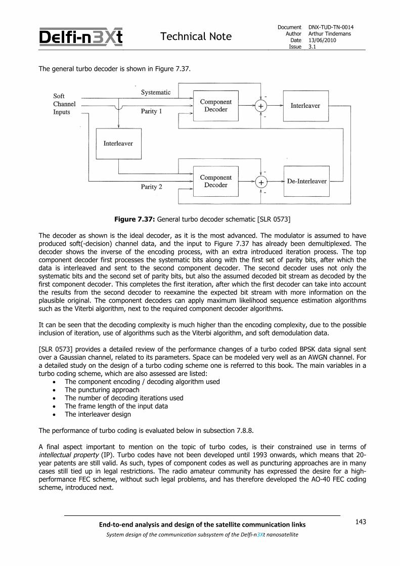
Technical NoteDocument
AuthorDateIssue
DNX-TUD-TN-0014Arthur Tindemans13/06/20103.1
143End-to-end analysis and design of the satellite communication links
System design of the communication subsystem of the Delfi-n3Xt nanosatellite
The general turbo decoder is shown in Figure 7.37.
Figure 7.37: General turbo decoder schematic [SLR 0573]
The decoder as shown is the ideal decoder, as it is the most advanced. The modulator is assumed to haveproduced soft(-decision) channel data, and the input to Figure 7.37 has already been demultiplexed. Thedecoder shows the inverse of the encoding process, with an extra introduced iteration process. The topcomponent decoder first processes the systematic bits along with the first set of parity bits, after which thedata is interleaved and sent to the second component decoder. The second decoder uses not only thesystematic bits and the second set of parity bits, but also the assumed decoded bit stream as decoded by thefirst component decoder. This completes the first iteration, after which the first decoder can take into accountthe results from the second decoder to reexamine the expected bit stream with more information on theplausible original. The component decoders can apply maximum likelihood sequence estimation algorithmssuch as the Viterbi algorithm, next to the required component decoder algorithms.
It can be seen that the decoding complexity is much higher than the encoding complexity, due to the possibleinclusion of iteration, use of algorithms such as the Viterbi algorithm, and soft demodulation data.
[SLR 0573] provides a detailed review of the performance changes of a turbo coded BPSK data signal sentover a Gaussian channel, related to its parameters. Space can be modeled very well as an AWGN channel. Fora detailed study on the design of a turbo coding scheme one is referred to this book. The main variables in aturbo coding scheme, which are also assessed are listed:
The component encoding / decoding algorithm used The puncturing approach The number of decoding iterations used The frame length of the input data The interleaver design
The performance of turbo coding is evaluated below in subsection 7.8.8.
A final aspect important to mention on the topic of turbo codes, is their constrained use in terms ofintellectual property (IP). Turbo codes have not been developed until 1993 onwards, which means that 20-year patents are still valid. As such, types of component codes as well as puncturing approaches are in manycases still tied up in legal restrictions. The radio amateur community has expressed the desire for a high-performance FEC scheme, without such legal problems, and has therefore developed the AO-40 FEC codingscheme, introduced next.
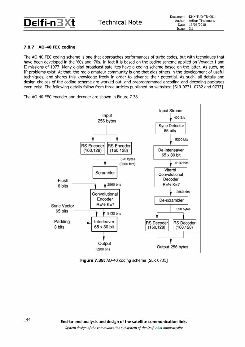
Technical NoteDocument
AuthorDateIssue
DNX-TUD-TN-0014Arthur Tindemans13/06/20103.1
144 End-to-end analysis and design of the satellite communication links
System design of the communication subsystem of the Delfi-n3Xt nanosatellite
7.8.7 AO-40 FEC coding
The AO-40 FEC coding scheme is one that approaches performances of turbo codes, but with techniques thathave been developed in the ‘60s and ‘70s. In fact it is based on the coding scheme applied on Voyager I andII missions of 1977. Many digital broadcast satellites have a coding scheme based on the latter. As such, noIP problems exist. At that, the radio amateur community is one that aids others in the development of usefultechniques, and shares this knowledge freely in order to advance their potential. As such, all details anddesign choices of the coding scheme are worked out, and preprogrammed encoding and decoding packageseven exist. The following details follow from three articles published on websites: [SLR 0731, 0732 and 0733].
The AO-40 FEC encoder and decoder are shown in Figure 7.38.
Figure 7.38: AO-40 coding scheme [SLR 0731]

Technical NoteDocument
AuthorDateIssue
DNX-TUD-TN-0014Arthur Tindemans13/06/20103.1
145End-to-end analysis and design of the satellite communication links
System design of the communication subsystem of the Delfi-n3Xt nanosatellite
All different fields of the encoder are quickly discussed here, with the number of bits at that point in the chainindicated:
Input (2048 bits)A predetermined message size has been set, which works out with all other coding lengths andinserted bit values.
RS Encoders (2560 bits)Two RS encoders are used, with even-numbered bits encoded by the first encoder, and odd-numbered bits encoded by the second. The details of the code can be found in [SLR 0731]. Thetwo streams of data are then joined simply in an odd/even fashion again.
Scrambler (2560 bits)Scrambling is actually applied to insert sufficient transition density in the data stream; requiredfor DBSPK demodulation. In case of MSK demodulation (see S-band communication linkdefinition, chapter 12), this might actually not be required. In any case, the procedure here is toXOR the data with a generator, not unlike CRC calculation. The generator suggested in this caseis x8+x7+x5+x3+1.
Flush (2566 bits)Six 0’s are added in front of the data stream in order to make the convolutional encoder start inan ‘all 0’s state’. This is likely beneficial to know when decoding.
Convolutional Encoder (5132 bits)This encoder applies a convolutional code with a code rate of ½ and a memory size K of 7 bits.Again, code specifics are presented in [SLR 0731]. Nevertheless, the purpose of combining an RScode with a convolutional code is to remove errors that might occur in the Viterbi decodingprocess of the convolutional code.
Sync Vector (5197 bits)A sync(hronization) vector is added to the data for correct data reception. The sync vector ismatched to the row size of the consequent Interleaver, and adds one sync bit to each column. Itis generated by using the x7+x3+1 generator, repeated to form a 65-bit bit stream. This vectorshould allow a receiver to recognize the data while scanning, and to position the start of thepackage. In fact, this is a spread spectrum technique as introduced in Appendix A. As [SLR 0731]explains, a correlator that looks for a 65-bit vector has 10*log(65) = 16 dB more signal strengththan the message in which the vector is contained, which is argued to be some -1 dB in case ofbad reception. 16-1=15 dB which is sufficient to guarantee near-always reception.
Padding (5200 bits)Padding (of 0’s or 1’s) is quite simply applied to round-off the total number of bits to 5200, tosimplify the interleaver.
Interleaver (5200 bits)This interleaver is, as explained before, applied as an anti-fading measure.
The resulting message can be decoded by logically inversing the main operations. An input stream issuggested (400 symbols/s) but is not restricted to low data rates. Viterbi decoding is logically applied in thedecoding of the convolutional decoder. Soft-decision demodulation is advised with 3-4 bit values [SLR 0732].256 bytes should result again at the end of the cycle.
The performance of this code is described below, and compared to other code performances.
Software (‘C’ language) for the implementation of this FEC coding scheme has been written, and can befound here (last accessed 13-06-2010): http://www.ka9q.net/ao40/

Technical NoteDocument
AuthorDateIssue
DNX-TUD-TN-0014Arthur Tindemans13/06/20103.1
146 End-to-end analysis and design of the satellite communication links
System design of the communication subsystem of the Delfi-n3Xt nanosatellite
7.8.8 Coding performances
As introduced above, the most prominent class of block codes is that of Bose-Chaudhuri-Hocquenghem (BCH)codes, and a subclass of it Reed-Solomon codes. These codes are usually expressed by for exampleBCH(n,k,t), where n is the number of bits per total block, k is the number of information bits and t is themaximum number of correctable bit errors. Due to its complexity the block size of BCH codes rarely is above127. Consequently the BCH(127,71,19) code yields best performance, with a gain of almost 4 dB for a BER of10-5 over uncoded BPSK. Conversely, a smaller block codes can be used with a Viterbi decoder; a soft-Viterbidecoded BCH(31,16,7) code can yield a similar gain of a little over 4 dB. [SLR 0730] yields more BCH codesand their performance, with gain values between 1.7 and 3.0 dB.
RS codes perform slightly worse for random errors, but they are slightly better in dealing with burst errors. Assuch these codes are used in compact-discs (CDs).
At the cost of more complexity, convolutional coding schemes can be pushed to have better performances. Anumber of space missions [SLR 0575] have applied sizeable convolutional coding schemes. The planetarystandard code, with a rate of ½, a memory size of 7 bits and soft-decision Viterbi decoding achieves a gain of5.1 dB. Pioneer missions 10 and 11 to Jupiter and Saturn applied as well a rate ½ coding but with a memorysize of 32 bits, using a sub-optimal decoding scheme called sequential decoding as Viterbi decoding could notbe applied due to the large memory size, achieving a gain of 6.9 dB. The aforementioned Voyager I and IImissions, as well as the 1998 DirecTV satellite system use again a variation of the planetary standard code.Using the latter as the inner code, and a combination of a convolutional code with RS(255,223,33) blockcoding with Viterbi soft-decision decoding, produces a gain of 7.1 dB.
The AO-40 FEC coding scheme is heavily based on this Voyager scheme, and [SLR 0732] mentions a verysimilar performance; 2.6 dB Eb/N0 is noted to be required for BPSK modulation, normally requiring some 9.6dB. As such, 7 dB coding gain is noted, of course assuming soft-decision demodulation.
Finally, turbo codes yield the best theoretical performance. Using turbo codes as assessed above, a codinggain of more than 8 dB is relatively easily achieved over the required Eb/N0 of uncoded BPSK with a requiredEb/N0 of 9.6 dB. Whereas this requires at least 4 to 8 iterations at the decoder, the encoder complexity is stillrelatively low. A frame length of at least 4000 bits is preferable. The maximum gain to be achieved using thecurrent architecture is almost 9 dB, however using an interleaver of size 216 and 18 iterations at the decoder.
In summary, typical coding performances are listed in Table 7.3 below; values are generally taken from [SLR0443]. A data rate capability has also been indicated, as a measure of complexity. All values mentioned abovecan also be found in the table. AO-40 FEC coding is in fact of the type ‘concatenated RS and convolution(Viterbi decoding)’.
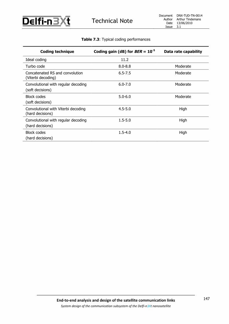
Technical NoteDocument
AuthorDateIssue
DNX-TUD-TN-0014Arthur Tindemans13/06/20103.1
147End-to-end analysis and design of the satellite communication links
System design of the communication subsystem of the Delfi-n3Xt nanosatellite
Table 7.3: Typical coding performances
Coding technique Coding gain (dB) for BER = 10-5 Data rate capability
Ideal coding 11.2
Turbo code 8.0-8.8 Moderate
Concatenated RS and convolution(Viterbi decoding)
6.5-7.5 Moderate
Convolutional with regular decoding
(soft decisions)
6.0-7.0 Moderate
Block codes
(soft decisions)
5.0-6.0 Moderate
Convolutional with Viterbi decoding(hard decisions)
4.5-5.0 High
Convolutional with regular decoding
(hard decisions)
1.5-5.0 High
Block codes
(hard decisions)
1.5-4.0 High

Technical NoteDocument
AuthorDateIssue
DNX-TUD-TN-0014Arthur Tindemans13/06/20103.1
148 End-to-end analysis and design of the satellite communication links
System design of the communication subsystem of the Delfi-n3Xt nanosatellite
7.9 Selecting the data rate for optimum data volume
[SLR 0106] introduces the link budget. The link budget takes into account all losses and gains along atransmission link, and basically results in final signal strength. Having knowledge of the minimum requiredsignal strength then allows to determine a maximum achievable data rate, given a certain bit error raterequirement to be met.
As is introduced in the link budget, a number of parameters vary with the elevation angle. These are: Atmosphere loss Receiver noise temperature Path loss
The atmosphere loss in fact varies somewhere between 0 and 1 dB between elevation angles of 90° and 10°respectively. The contribution is therefore generally minor. A notable exception however occurs at lowerelevation angles, at 5° elevation the atmosphere loss becomes some 2.1 dB, whereas moving towards 0°increased the atmosphere loss to over 10 dB [SLR 0219].
Noise temperature is presented in [SLR 0106], and is composed of a receiver noise temperature and anantenna noise temperature. The former is dependent on the equipment used, whereas the latter depends onthe received noise through the antenna. The antenna temperature is not actually a physical temperature. It isa parameter that is hard to determine, and is usually estimated based on the frequency band and the groundstation location and isolation. Or, it is measured. At low elevation angles, the antenna receives more noisefrom terrestrial (transmitting) sources. At very low elevation angles the antenna noise can therefore be muchhigher than at slightly higher ones. Again, its effects are most significant at low elevation angles.
Then there is path loss. Path loss pL is given by the following relation [SLR 0316]:
2
4pL
S
(7-11)
Where is the (constant) signal wavelength and S stands for slant range, in turn given by the following
equation, assuming a circular orbit:
2
2
2cos sin
R hS R
R
(7-12)
Where R is Earth radius, h equals orbit altitude and the satellite elevation (angle).

Technical NoteDocument
AuthorDateIssue
DNX-TUD-TN-0014Arthur Tindemans13/06/20103.1
149End-to-end analysis and design of the satellite communication links
System design of the communication subsystem of the Delfi-n3Xt nanosatellite
Maximum achievable data rates maxR can be directly correlated to path loss, as a higher path loss
(counterintuitively defined to be a smaller actual loss) directly increases the achievable data rate. In otherwords:
max pR L (7-13)
Then, maxR is indirectly given by relation 7-11 via the following relation, assuming all other losses are
constant with elevation angle :
max[ ] [ ]pR C L (7-14)
Concluding from equation 7-12, given an orbital altitude of 600 km; the total distance between the GS andthe satellite changes from 1932 km to 600 km with an elevation angle between 10 and 90°. According toequation 7-11, path loss then shows a whopping reduction from -141.40 dB to -131.24 dB. This difference of10 dB equals a factor 10; in other words a data rate of a factor 10 more can be reached when transmitting atmaximum data rate when the satellite is directly overhead!
According to relation 7-14, the instantaneously achievable data rate maxR is given as a function of elevation
angle . The resulting graph for different orbit altitudes (corresponding to the Delfi-n3Xt range of orbit
altitudes) can be seen as Figure 7.39 below. The achievable data rates are normalized with respect to thehighest value.
Figure 7.39: Normalized achievable data rate versus elevation angle for the Delfi-n3Xt range of orbits

Technical NoteDocument
AuthorDateIssue
DNX-TUD-TN-0014Arthur Tindemans13/06/20103.1
150 End-to-end analysis and design of the satellite communication links
System design of the communication subsystem of the Delfi-n3Xt nanosatellite
As the horizon is usually obstructed by buildings, and as explained atmosphere loss and antenna noise canincrease abruptly moving to an elevation angle of 0°, the elevation angle for start of communication is usuallytaken to be slightly higher. A usual value is 10°, or possibly 5°, but rarely less. This then influences the totaluseful contact time, as a larger minimum elevation angle decreases the total ground station visibility zone.The data rate and the contact time together determine the total data volume that can be transferred duringone pass, following the integral:
pass
0
( )passT
dataD R t dt (7-15)
Where Dpass is the total data volume that can be transmitted during a pass, Tpass is the contact time during a
pass and ( )dataR t is the data rate over time.
Generally, the data rate in satellite missions is constant throughout the mission. This is due to the complexityinvolved with generating a variable stream of data, changing the data rate on-board the satellite and properlycommunicating a changing data rate between the satellite and the GS. Also, the data rate is generally set tohave a proper communication link during the entire pass; from a small elevation angle onwards.
This section discusses the effects of path loss on the achievable data rate. This will show that an approachwhere the data rate that is based on the minimum elevation angle when communication is possible, will infact not always maximize total downloadable data volume, depending on the mission constraints. Using thedesign target of maximizing this downloadable data volume, different scenarios are discusses in this section.
The scenario first described is that of a single direct overhead pass but applying a constant data rate; this isdone in subsection 7.9.1. Afterwards, in subsection 7.9.2 the case shall be enlarged to include all passes, butstill keeping the constraint of having a constant data rate throughout all passes. Subsections 7.9.3 and 7.9.4respectively relax and remove the constraints of having a constant data rate. The former subsection describesthe case where data rates can be changed between passes and the latter describes a scenario where datarates can be changed even during passes. The latter allows approaching the maximum (theoretical) possibledata volume download.

Technical NoteDocument
AuthorDateIssue
DNX-TUD-TN-0014Arthur Tindemans13/06/20103.1
151End-to-end analysis and design of the satellite communication links
System design of the communication subsystem of the Delfi-n3Xt nanosatellite
7.9.1 Constant data rate, zenith pass
The most simple analysis case for a satellite pass is that of zenith pass. In this case, the pass is basicallyone-dimensional. This section shows what the optimal data rate approach would be in case of a perfectzenith, or overhead pass.
A zenith pass with a certain orbit altitude yields one contact time value. As any pass that is not directlyoverhead will have a lower contact time, the zenith contact time is always the maximum contact timeachievable given a certain orbit altitude. Thus considering only zenith passes:
pass maxT T (7-16)
Given also the fact that data rate ( )dataR t is constant in the case assumed in this section, relation 7-15 can
be reduced to:
pass max dataD T R (7-17)
For simplicity, the effects of a non-spherical and rotating Earth will be ignored, as these effects are minor; theflattening of the Earth is less than 0.5% and the Earth rotation is less than 5° for a <20 minute pass.
The following relations follow from [SLR 0316]. The maximum contact time for a satellite in a circular orbit isgiven by:
maxmaxT P
(7-18)
Where P is the orbital period and max is the maximum Earth central angle. The first parameter, the orbital
period P , is for a circular orbit given by:
3
2R h
P
(7-19)
Where R is Earth radius, h equals orbit altitude and is the Earth gravitational parameter. The second
parameter, the Earth central angle max is for a circular orbit given by:
1max min minsin cos
2
R
R h
(7-20)
Where εmin is the minimum elevation angle. Substituting relations 7-18 and 7-19 into 7-17 gives:
3
1max min min2 2sin cos
R h RT
R h
(7-21)
A plot of the resulting maximum communication time is shown in Figure 7.40 below.
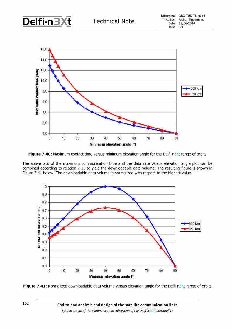
Technical NoteDocument
AuthorDateIssue
DNX-TUD-TN-0014Arthur Tindemans13/06/20103.1
152 End-to-end analysis and design of the satellite communication links
System design of the communication subsystem of the Delfi-n3Xt nanosatellite
Figure 7.40: Maximum contact time versus minimum elevation angle for the Delfi-n3Xt range of orbits
The above plot of the maximum communication time and the data rate versus elevation angle plot can becombined according to relation 7-15 to yield the downloadable data volume. The resulting figure is shown inFigure 7.41 below. The downloadable data volume is normalized with respect to the highest value.
Figure 7.41: Normalized downloadable data volume versus elevation angle for the Delfi-n3Xt range of orbits

Technical NoteDocument
AuthorDateIssue
DNX-TUD-TN-0014Arthur Tindemans13/06/20103.1
153End-to-end analysis and design of the satellite communication links
System design of the communication subsystem of the Delfi-n3Xt nanosatellite
The latter figure yields an interesting conclusion. The figure shows that there is a minimum elevation angleand respective constant data rate for which the total data volume per pass is maximal. The minimumelevation angle for which the communication link is then designed to yield a maximum data volume download
will be called the optimum elevation angle, or opt .
The optimum minimum elevation angle shown by Figure 7.41 is clearly larger than the 5° or 10° of minimumelevation that is usually assumed for satellite communication.
[SLR 0739] continues on this conclusion, and better specifies the effects of altitude on the optimum elevation
angle. It presents the following relation between the optimal elevation angle opt and orbit altitude h :
45[ ] 0.00446[ ] [ ]opt h km (7-22)
For Delfi-n3Xt, the orbit altitude range defined to be of interest is 600-850 km. Using relation 7-22 this givesoptimal elevation angles of 42.5° and 41.2° for the lower and higher boundary value respectively.
Of course, the scenario described is for a one-dimensional perfect overhead pass, which, in fact almost neveroccurs. Therefore, the following three sections will look at two-dimensional cases, including next to the along-track direction also an off-track direction.

Technical NoteDocument
AuthorDateIssue
DNX-TUD-TN-0014Arthur Tindemans13/06/20103.1
154 End-to-end analysis and design of the satellite communication links
System design of the communication subsystem of the Delfi-n3Xt nanosatellite
7.9.2 Constant data rate, all in-range passes
A satellite in a sun-synchronous orbit will in fact pass over completely different Earth locations in a timeperiod of days or even weeks. Whereas one of these passes might be or might be close to a zenith pass,most will be more ‘to the side’. The next section will introduce an off-zenith angle to describe this angulardistance.
When the communication link is designed for a certain minimum elevation angle, the visibility zone of theground station (GS) is determined. While a higher minimum elevation angle will decrease overall along-trackpass time, it will also decrease off-track field-of-view. This then restricts the amount of satellite passes thatcan be seen by the GS.
The difference between the number of daily passes that can consequently be ‘seen’ for high and lowminimum elevation angles is drastic. This is illustrated by Figure 7.42 below, generated using Satellite Tool Kitor STK. Whereas 5-6 passes daily are within range in case of a 10° minimum elevation angle, only 1-2 passesare seen in case of a 42.5° minimum elevation angle. The latter would be the optimum elevation angle formaximized downloadable data volume, in case of a 600 km zenith pass, as shown in the last section.
Figure 7.42: 3 consequent passes projected on the Earth surface with GS visibility shown
The figure above clearly shows the much greater visibility zone in case a 10° elevation angle is designed for,compared to the 42.5° case; both are indicated by the colored oval shapes, purple and red respectively.Directly obvious is the very sizeable difference in area enclosed by the two shapes.
The figure also shows three consequent passes for a typical sun-synchronous orbit. Whereas one pass isdirectly overhead of the Delft GS in this case, the other two miss the small visibility circle completely, but arestill in range in case of the larger visibility zone. Concluding from the spacing between the passes, all passescan actually miss the small visibility circle.

Technical NoteDocument
AuthorDateIssue
DNX-TUD-TN-0014Arthur Tindemans13/06/20103.1
155End-to-end analysis and design of the satellite communication links
System design of the communication subsystem of the Delfi-n3Xt nanosatellite
But, as the satellite has a consequent number of passes on each ‘side’ of the globe (once top-to-bottom, andonce bottom-to-top), the satellite will always have at least one pass inside of the 42.5° circle per day. Thiscan be during nighttime depending on the orbit chosen. The 10° circle will contain at least 5 passes daily,consistent with the value given above.
Whereas the previous section has concluded that path loss quickly decreases with increasing elevation anglesεmin, it can thus be seen that total visibility decreases quickly with increasing εmin as well. This factor will morethan counteract for the decreasing path loss, as is shown below.
If one takes into account all passes within a visibility zone, the contact time per pass passT can be replaced by
an overall coverage value, coverageT . The latter is defined as the time period that the satellite is within proper
communication range of the GS. Again assuming a constant ( )dataR t , allows to simply equation 7-15 to:
pass coverage dataD T R (7-23)
It is very difficult to obtain analytical values for the total coverage of a day, or the average coverage during aday. STK however can be used to friendly yield numerical approximations of the coverage time, or moreprecisely the coverage percentage; even taking into account Earth shape and rotation. This coverage canthen be multiplied by the length of a day to give a daily data yield. Generating coverage percentages for allelevation angles, for both a 600 and 850 km orbit yields the following plot, see Figure 7.43. These values areoverall averages for a sun-synchronous orbit with the given orbit altitude, taken over a two year period.Th e The
Figure 7.43: Overall ground station coverage versus elevation angle for which the link budget closes

Technical NoteDocument
AuthorDateIssue
DNX-TUD-TN-0014Arthur Tindemans13/06/20103.1
156 End-to-end analysis and design of the satellite communication links
System design of the communication subsystem of the Delfi-n3Xt nanosatellite
The above figure should be compared to Figure 7.40; the latter showing only some factor 4 difference inmaximum contact time between a 0° and 40° elevation angle case. If however the total coverage is takeninto account, as done in Figure 7.43, a factor 15-20 difference exists between the two cases depending onthe orbit altitude. Figure 7.43 and Figure 7.39 can again be combined according to relation 7-22 to yield theachievable downloaded data volume given a minimum elevation angle, as is shown in Figure 7.44 below.
Figure 7.44: Normalized achievable data volume versus elevation angle for the Delfi-n3Xt range of orbits
This figure clearly shows that if a constant data rate is to be used throughout the mission, and a satellite canbe tracked during every pass, it merits doing so with a link budget that closes for elevation angles as low aspossible. There is no minimum elevation angle that performs better than another, except for those beinglower. In other words, a lower minimum elevation angle is always better, if all passes can be used forcommunication. However, as was already presented before, at very low elevation angles atmosphere lossincreases drastically, antenna noise rises, and obstructions can be in place. As such, a value of 5° to 10°should then be used in the link budget.
Finally, it is interesting to note that taking into account coverage minimizes the differences in downloadabledata volume between 600 and 850 km orbit altitudes, only a few percent difference remains whereas for asingle zenith pass the difference is a factor 1.4.
The number of passes related to ground station visibility was in fact not previously taken into account whenthe theory was investigated by Martijn de Milliano. It was argued that an average value for the pass timecould be used, one that is presented in [SLR 0316]. Whereas the latter source does not give any commentson the relation to orbital altitude and visibility, it mentions that the average pass within the field-of-view of aGS is approximately 80% of the maximum pass time. Using this value to correct for the fact that off-zenithangles are in fact incurred in actual passes, neglects to take into account the fact that the visibility of theground station becomes much less, and thus much less passes are seen.

Technical NoteDocument
AuthorDateIssue
DNX-TUD-TN-0014Arthur Tindemans13/06/20103.1
157End-to-end analysis and design of the satellite communication links
System design of the communication subsystem of the Delfi-n3Xt nanosatellite
7.9.3 Changing data rates between passes
The previous section has shown that given the constraint of a constant data rate throughout a mission, thecommunication link can best me designed based on a near-zero minimum elevation angle. However, if theconstraint of having a constant data rate is relaxed or even removed, higher data rates can be useful. Thisand the next section investigate these options. In order to provide limited complexity, this section describesthe case where data rates can be changed only between passes.
A zenith pass of a satellite for an orbit altitude between 600 and 850 km leads to an optimum minimum
elevation angle opt of 41.2° to 42.5°. Logically, this minimum elevation angle goes down for passes with an
introduced off-zenith angle; the latter causes the pass time to be reduced and the maximum achievable datarate to be lowered. The exact impact is calculated and shown in this subsection. As such, the optimal
minimum elevation angle shall be presented as a function of the off-zenith angle , to be defined below.
Again, Earth rotation and flattening shall be ignored.
In order to calculate the effects of an introduced off-zenith angle, only the reduced contact time has to betaken into account. To further clarify, one can look at Figure 7.42. During a pass a certain data rate isallowed, specified by the minimum elevation angle that is designed for. This minimum elevation angle in turnspecifies a visibility circle. When a pass occurs that is not a zenith pass, this circle radius does not change, butthe satellite passes more to the right or left of the GS. In result, only its time within in visibility circle reduces.
As ( )dataR t is again constant in this scenario, equation 7-15 can again be used and simplified to:
pass pass dataD T R (7-24)
passT then remains to be specified, and can be written according to a more general form of equation 7.180 as
presented in [SLR 0316]:
max1
min
coscos
cospass
PT
(7-25)
Where min is the minimum Earth central angle, and could be set to zero in case of a zenith pass. This angle
specifies in fact the off-zenith angle, but with respect to the center of the Earth. Therefore, in order to makethe above relation useful, the minimum Earth central angle should be expressed in terms of the off-zenithangle, being the angle between the line perpendicular to the Earth surface at the location of the GS, and theline between satellite and GS at minimum pass distance. The relation between the two can be determined
using Figure 7.45 below. Also, the off-zenith angle can more conventionally be described as:
max90 (7-26)
Figure 7.45 shows the scenario of a satellite pass at the point of minimum pass distance. In this case, the
Earth central angle becomes the minimum Earth central angle min , and the angle can be seen to
indicate the off-zenith angle. These two angles are in the same plane. The maximum elevation angle max
has also been indicated in the figure.

Technical NoteDocument
AuthorDateIssue
DNX-TUD-TN-0014Arthur Tindemans13/06/20103.1
158 End-to-end analysis and design of the satellite communication links
System design of the communication subsystem of the Delfi-n3Xt nanosatellite
Figure 7.45: Pass geometry showing the relation between off-track angle and Earth central angle
A number of relations can be stated using geometry:
Applying the sine rule: 1 sin
sinsin sin
R h R R
R h
(7-27)
Property of a triangle: min min (7-28)
Property of a line: (7-29)
Substituting equation 7-29 into 7-27, and 7-27 and 7-29 into 7-28, as well as realizing that
sin sin yields for the minimum Earth central angle:
1min
sinsin
R
R h
(7-30)
max has already been expressed in terms of the minimum elevation angle min in relation 7-19, and P has
been given by relation 7-20, so that passT can consequently be expressed directly in terms of variables off-
zenith angle , minimum elevation angle min and orbit altitude h :
13 min min
1
1
cos sin cos2
2 cossin
cos sin
pass
R
R h R hT
R
R h
(7-31)

Technical NoteDocument
AuthorDateIssue
DNX-TUD-TN-0014Arthur Tindemans13/06/20103.1
159End-to-end analysis and design of the satellite communication links
System design of the communication subsystem of the Delfi-n3Xt nanosatellite
The results of equation 7-31 are visualized in different manners below. The overall 3D plot including both the
variables off-zenith angle and minimum elevation angle min , but with h constrained to be 600 km is
shown as Figure 7.46 below.
In Figure 7.46 the case of a zenith pass, thus when = 0, can clearly be recognized against the ‘back wall’,
being identical to Figure 7.41 above; the same bell shape is present. Moving along the axis of off-zenithangles, the bell shape is being flattened, and its peak lowered.
Figure 7.46: Normalized data volume vs. off-track angle and minimum elevation angle, h = 600 km
The behaviour of the 3D plot in Figure 7.46 is better demonstrated by Figure 7.47 and Figure 7.48 below.
Figure 7.47 shows a contour plot of Figure 7.46. It can be clearly seen that off-zenith angle plus minimum
elevation angle min can never be more than 90°; a 90° off-zenith pass can only be seen at the edge of a 0°
elevation GS visibility circle.
Figure 7.48 better demonstrates the effect of an introduced off-zenith angle on downloadable data volume; inother words the decrease of size of the bell shape. This curve can again be compared to Figure 7.41, of whichthe 600 km case is actually included in the figure below as the red (top) line. Again, orbit altitude is set at 600km; this plot demonstrates behavior and not absolute values.

Technical NoteDocument
AuthorDateIssue
DNX-TUD-TN-0014Arthur Tindemans13/06/20103.1
160 End-to-end analysis and design of the satellite communication links
System design of the communication subsystem of the Delfi-n3Xt nanosatellite
Figure 7.47: Normalized data volume vs. off-track angle and minimum elevation angle, h = 600 km
Figure 7.48: Normalized data volume vs. minimum elevation angle for different off-track angles, h = 600 km

Technical NoteDocument
AuthorDateIssue
DNX-TUD-TN-0014Arthur Tindemans13/06/20103.1
161End-to-end analysis and design of the satellite communication links
System design of the communication subsystem of the Delfi-n3Xt nanosatellite
In Figure 7.48 above, as well as in the contour and 3D plots it can be seen clearly that opt decreases for
higher values of . The exact relation between optimum elevation angle opt and off-zenith angle is
shown in Figure 7.49 below, for the possible range of Delfi-n3Xt orbit altitudes.
In fact, the curve produced is rather simple, with an optimum elevation angle decreasing with time in a
slightly accelerating fashion. Also, in off-zenith angles up to 20°, opt changes only by some 5°. It is
interesting also to note that at some point, before 90° off-zenith angles are reached, the optimum elevationangle already becomes 0°; the higher the orbit the sooner it does.
Figure 7.49: Optimum elevation angle vs. off-track angle for the Delfi-n3Xt range of orbits
In section 7.9.1 an approximization relation (equation 7-22) was presented for the optimum elevation angle
opt , given the orbit altitude h . This relation was appealing because it turns out to be a linear one. In the
case off-zenith angles are considered, a similar approximation can be made but unfortunately not a linear
one. However, it turns out that given orbit altitudes above a certain value (~ 200[ ]h km ), the only
approximate effect of a different altitude is a downwards translation of all values of opt versus ; again
linearly. Therefore, it then remains to find an approximization relation for the above plot of opt versus . In
fact, it can be approximated relatively well by a third-degree polynomial.
The resulting approximization relation can be given by:
5 3 3 2 23.3 10 [ ] 8.9 10 [ ] 1.25 10 [ ] 0.00446 [ ]opt h km (7-32)

Technical NoteDocument
AuthorDateIssue
DNX-TUD-TN-0014Arthur Tindemans13/06/20103.1
162 End-to-end analysis and design of the satellite communication links
System design of the communication subsystem of the Delfi-n3Xt nanosatellite
Equation 7-32 is only valid for values of opt above 0°, for negative results the optimum is logically 0°. It
gives an accuracy of ~1° for useful orbit altitudes h above ~200 km. Orbit altitudes above ~10,000 km nolonger have a nonzero optimum elevation angle.
The accuracy of the above equation is further illustrated by the following Figure 7.50.
Figure 7.50: Illustration of the accuracy of the approximization relation for opt
The following two figures better demonstrate the data volumes that can be obtained given certain off-zenith
angles .
Figure 7.51 shows total data volumes that can be obtained given a certain off-zenith angle, if the minimum
elevation angle min is allowed to be changed between passes to match the optimum elevation angle opt for
that off-zenith angle. The plot is normalized to the maximum downloadable data volume in case of a zenithpass of 600 km altitude, being the minimum Delfi-n3Xt altitude.
Figure 7.52 on the contrary, shows the (normalized) maximum downloadable data volume versus off-track
angle for a 600 km orbit when min is not allowed to be changed and is thus kept constant, independent of
off-zenith angle. For reasons of clarity, the subscript of min has been dropped in this figure.
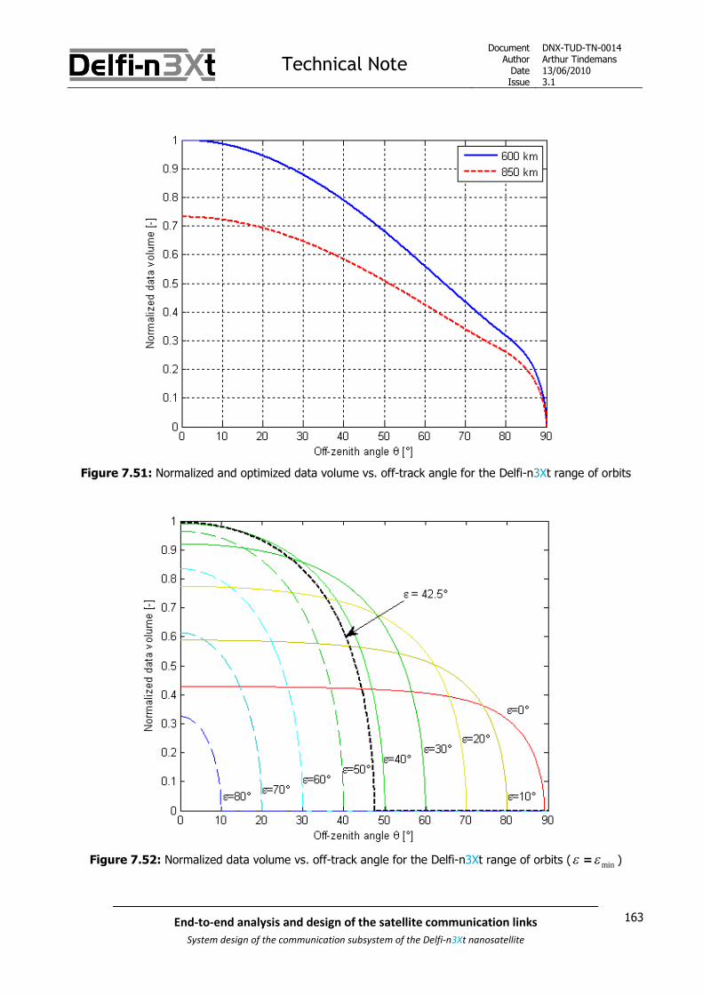
Technical NoteDocument
AuthorDateIssue
DNX-TUD-TN-0014Arthur Tindemans13/06/20103.1
163End-to-end analysis and design of the satellite communication links
System design of the communication subsystem of the Delfi-n3Xt nanosatellite
Figure 7.51: Normalized and optimized data volume vs. off-track angle for the Delfi-n3Xt range of orbits
Figure 7.52: Normalized data volume vs. off-track angle for the Delfi-n3Xt range of orbits ( = min )

Technical NoteDocument
AuthorDateIssue
DNX-TUD-TN-0014Arthur Tindemans13/06/20103.1
164 End-to-end analysis and design of the satellite communication links
System design of the communication subsystem of the Delfi-n3Xt nanosatellite
The plots in Figure 7.51 and Figure 7.52 show the difference in performance between choosing a fixed datarate throughout the mission and what can be achieved using an optimized minimum elevation angle in the
link budget design. The line indicated by min = 0° in the bottom figure gives achievable download volumes for
a conventional constant data rate approach based on a (very) low elevation. At low zenith angles, it can be
seen to be outperformed by a link budget design based on opt , by a factor of more than 2.
However, the red line also shows a constant, positive data volume value over a large range of values.Whereas the optimum elevation angle of 42.5° yields the highest possible data yield, its productivity drops offquickly for increasing off-zenith angles. This clearly shows why a lower data rate is favored if, and only if, aconstant data rate is used during the entire mission.
Finally, Figure 7.52 also shows again that minimum elevation angles higher than the value of 42.5° shouldnever be designed for; the curves belonging to these higher elevation angles are completely dominated bythe 42.5° curve. All points of maximum performances for the curves shown in Figure 7.52 in turn make upthe blue plot shown in Figure 7.51, belonging to an orbit altitude of 600 km.
Possible applications
The presented theory in this subsection and the last has shown a preference for a certain momentarily fixeddata rate, depending on the mission constraints. It had already been shown that if in fact all passes can bemonitored, and a constant transmission data rate is used during the mission, the best approach would be todesign this data rate for the link budget to close at very low elevation angles. However, the application of adata rate higher than this minimum value becomes interesting in case of a:
Constant mission data rate, but a smaller number of monitored passes Changing data rate, but using only a limited number of data rate values Changing and truly variable data rate, but constant during a pass
Constant mission data rate
The first option basically becomes useful in case of: Power or pointing constraints on-board of the satellite Limited operational resources on-ground (man-power or costly equipment)
The first argument indicates that if only a small number of transmissions is supported by the power systemon-board of the satellite or the pointing system, it is more beneficial to use a few close passes only, with ahigher data rate than would be possible otherwise. The second argument states that if ground stationoperations are or tracking is expensive, or simply not possible due to shared schedules, it might be beneficialagain to focus on a small number of passes, with a higher data rate.
If this approach would be chosen, a number of passes should be determined that is to be monitored, andbased on this a maximum overall data rate can be chosen. As an incurred off-zenith angle will specify a
optimal elevation angle opt that is less than that would hold for a zenith pass, the data rate that should be
chosen should also be lower than that advised for a zenith pass. The specific value will depend on the
number of passes and maximum pass off-zenith angle .
An added benefit to choosing a (constant) data rate higher than the minimum data rate possible is that thelink budget is generally based on worst-case values. As a result, the actual contact time might turn out to behigher, resulting in a higher actual downloadable data volume during the pass. In case of a lower minimumelevation angle, a lower ‘unexpected’ gain in data volume can be obtained due to this over-budgeting and theimpact is lower or even non-existent if the horizon is obstructed.

Technical NoteDocument
AuthorDateIssue
DNX-TUD-TN-0014Arthur Tindemans13/06/20103.1
165End-to-end analysis and design of the satellite communication links
System design of the communication subsystem of the Delfi-n3Xt nanosatellite
Disadvantages or challenges that have to be taken into account when increasing the data rate at the cost ofless communication time are:
The available time becomes more valuable due to the higher data rates:o Signal acquisition should be accounted foro Transmission disturbances during the pass have a larger effect
A higher data rate increases transmitter and receiver complexity, as well as required transmissionbandwidth
In case of Delfi-n3Xt, radio amateurs with lower antenna gain might not be able to receive a signalsas the mid-pass link margin is reduced
Changing data rates
The second and third option of changing data rates are more desirable, and in all cases win over theconventional approach of having a constant data rate over the entire mission based on a low minimumelevation angle. They do however require a certain increase of complexity, necessitating:
Accurate on-board orbit determination or accurate time-scheduling using telecommands A transmitter with a variable transmission data rate, including proper hardware (i.e. filters, amplifiers)
and software (data protocol, internal communication) Varying data generation from the satellite bus, or data storage in the transmitter and intelligent
software A receiver capable of receiving different data rates, possibly through auto-detection of the data rate
An interesting means of switching on the transmitter autonomously can be done by means of transmittedTwo-Line Elements or TLEs; the satellite OBC can base its transmission times on TLEs that are updated dailyor even weekly be means of telecommands. The satellite then does not need to have active orbitdetermination itself; this requires only simplified algorithms.
The difference between the second and third aforementioned options is that in the second case thecomplexity is limited by using a restricted number of discrete data rates. This can simplify for exampleinternal operational modes and data generation, data packaging and filtering.
In case the second option is applied, concrete steps should be formulated in terms of maximum off-zenithangles. Afterwards Figure 7.49 or relation 7-34 can be used to determine the optimum elevation angle thatshould be used to calculate the data rate per step (keeping in mind a certain inaccurate link margin in the linkbudget). Due to the presented reasons of coverage and the resulting increased number of passes, the datarate should then always be designed to match the maximum off-zenith angle of the pass zone. This could
result in for example a data rate presets based on an = 20, 50 and 80°, resulting in min values of
approximately 40, 25, 10°.
The third option on the contrary could in the best case result in the maximum performance as shown inFigure 7.51. In this case, the data rate should basically be completely variable. An added benefit ofcontinuously being able to adjust the data rate of transmission is that any errors (margins) in the link budgetcan be corrected for, and overall performance can be maximized.

Technical NoteDocument
AuthorDateIssue
DNX-TUD-TN-0014Arthur Tindemans13/06/20103.1
166 End-to-end analysis and design of the satellite communication links
System design of the communication subsystem of the Delfi-n3Xt nanosatellite
7.9.4 Changing data rates during a pass
The previous sections have shown that given the constraint of having a constant data rate during the missionor even between passes, leads to a preferred data rate if a maximum downloadable data volume is to bedesigned for. Of course, the maximum downloadable data volumes can be achieved if data rates are not onlychanged between passes, but in fact also during passes.
In this case, the data rates can be chosen to follow the evolution of path loss during a pass, as shown byFigure 7.39, and the limiting factor becomes the complexity involved with changing data rates during a pass.The following figure nicely illustrates the downloadable data volumes achievable when constant data rates areused, but also illustrates the effects if several discrete steps are used.
Figure 7.53: Normalized data rate vs. time into pass with data volumes (I, II & III) [SLR 0739]
Figure 7.53 demonstrates the data volumes that can be downloaded when transmission is started at different(pass) times, using again an optimized data rate (given the path loss) at the time of start of transmission.Cases I and III yield equal data volumes, whereas II yields a maximized data volume for a direct overheadpass. If however the data rates can be changed following discrete steps, a data volume equal to the areacovered by I, II and III together can be reached. In this manner, the maximum theoretical downloadabledata volume can be approached, which in turn would require an infinite amount of possible steps.
Expression 7-15 can be rewritten to signify this maximum downloadable data volume maxD for a given off-
zenith angle :
max
max max
0
( , )T
D R t dt (7-33)
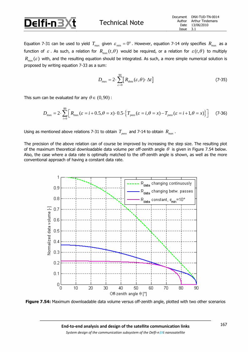
Technical NoteDocument
AuthorDateIssue
DNX-TUD-TN-0014Arthur Tindemans13/06/20103.1
167End-to-end analysis and design of the satellite communication links
System design of the communication subsystem of the Delfi-n3Xt nanosatellite
Equation 7-31 can be used to yield maxT given min 0 . However, equation 7-14 only specifies maxR as a
function of . As such, a relation for max ( , )R t would be required, or a relation for ( , )t to multiply
max ( )R with, and the resulting equation should be integrated. As such, a more simple numerical solution is
proposed by writing equation 7-33 as a sum:
90
max0
2 ( , )dataD R t
(7-35)
This sum can be evaluated for any (0,90) :
89
max max0
2 ( 0.5, ) 0.5 ( , ) ( 1, )pass passi
D R i x T i x T i x
(7-36)
Using as mentioned above relations 7-31 to obtain passT and 7-14 to obtain maxR .
The precision of the above relation can of course be improved by increasing the step size. The resulting plot
of the maximum theoretical downloadable data volume per off-zenith angle is given in Figure 7.54 below.
Also, the case where a data rate is optimally matched to the off-zenith angle is shown, as well as the moreconventional approach of having a constant data rate.
Figure 7.54: Maximum downloadable data volume versus off-zenith angle, plotted with two other scenarios

Technical NoteDocument
AuthorDateIssue
DNX-TUD-TN-0014Arthur Tindemans13/06/20103.1
168 End-to-end analysis and design of the satellite communication links
System design of the communication subsystem of the Delfi-n3Xt nanosatellite
In the above figure it can clearly be seen that where large gains in data volume can be achieved by changingthe data rate between passes, more significant gains can be achieved still; but requiring a more advancedscenario where data rates are changed, if possible almost continuously, during a pass.
Implementation complexity:
Of course, having a data rate that changes even between passes is constrained by complexity. All complexityissues introduced in the previous subsection still hold, but become even stricter:
On-board orbit determination or time-scheduling should be accurate enough for pass information inthe order of seconds, possible tenths of seconds
Data preparation and resulting data rates should be adjusted almost instantaneously Auto-detection of the data rates becomes a near-requirement, or a complicated (failure-sensitive)
feedback process using the uplink should be incorporated. Auto-detection of the data rate is alreadychallenging, but can be incorporated most notably in software; its complexity however increasingvastly with each possible data rate.
But in fact, the differences in complexity between a truly variable data rate between passes and a data ratethat can switch several times during a pass can be said to be limited. As a matter of fact, a truly variable datarate between passes might be more complex than one that changes along several discrete steps. Thesediscrete steps than may be predefined data rates, such as those presented in the last subsection, or the steps
might be based on the actual pass and its off-zenith angle .
In terms of performance, a change of data rate will likely need some ‘digital hand-shake’ procedure in orderto establish the new data rate, which will involve telecommanding. However, the lost time is quickly made upfor by the increased data rate afterwards. The resulting gain in performance can, as shown by Figure 7.54, beenormous.

Technical NoteDocument
AuthorDateIssue
DNX-TUD-TN-0014Arthur Tindemans13/06/20103.1
169End-to-end analysis and design of the satellite communication links
System design of the communication subsystem of the Delfi-n3Xt nanosatellite
8 The UHF/VHF communication link
Using the theoretical background presented in the previous chapter, this chapter specifies the Delfi-n3Xtcommunication down/uplink over the UHF and VHF bands. Afterwards the radios making use of this link, thePTRX and ITRX are further introduced. A later chapter will similarly establish the S-band communication link.
The primary use of both the PTRX and ITRX is nominal up- and downlink communication; sendingtelecommands and receiving telemetry. Secondary uses of the UHF and VHF bands are the transponder up-and downlink, the OLFAR downlink, and strictly speaking the ITRX experiments. The transponder and OLFARare analogue functionalities, and no signal content processing is performed. The ITRX experiments are not ofour concern, given the payload status. These functionalities are therefore not further discussed in thischapter. The transponder/OLFAR bandwidth however is shortly presented.
This chapter introduces the functionalities required to specify the primary telecommand/telemetry link dividedover the different layers.
The primary communication requires both first and second layer functionalities, as introduced in the previouschapter. Multiple scenarios can also be recognized, such as transmitting TCs or TM, these can be said to formanother layer. All required high-level functionalities are determined in this chapter.
The boundary conditions of the link are established first in sections 8.1 and 8.2, presenting: The transmission frequencies and bandwidth available The power constraints following from the link budget
Afterwards, the physical layer functionalities are determined in sections 8.3 and 8.4: The modulation scheme of the VHF downlink The modulation scheme of the UHF uplink
Finally, all data link layer functionalities are presented in sections 8.5 and 8.6: The data protocol applied to both the UHF and VHF communication links The operations and data involved with the different scenarios as introduced above
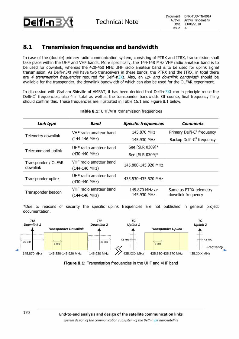
Technical NoteDocument
AuthorDateIssue
DNX-TUD-TN-0014Arthur Tindemans13/06/20103.1
170 End-to-end analysis and design of the satellite communication links
System design of the communication subsystem of the Delfi-n3Xt nanosatellite
8.1 Transmission frequencies and bandwidth
In case of the (double) primary radio communication system, consisting of PTRX and ITRX, transmission shalltake place within the UHF and VHF bands. More specifically, the 144-148 MHz VHF radio amateur band is tobe used for downlink, whereas the 420-450 MHz UHF radio amateur band is to be used for uplink signaltransmission. As Delfi-n3Xt will have two transceivers in these bands, the PTRX and the ITRX, in total thereare 4 transmission frequencies required for Delfi-n3Xt. Also, an up- and downlink bandwidth should beavailable for the transponder, the downlink bandwidth of which can also be used for the OLFAR experiment.
In discussion with Graham Shirville of AMSAT, it has been decided that Delfi-n3Xt can in principle reuse theDelfi-C3 frequencies; also 4 in total as well as the transponder bandwidth. Of course, final frequency filingshould confirm this. These frequencies are illustrated in Table 15.1 and Figure 8.1 below.
Table 8.1: UHF/VHF transmission frequencies
Link type Band Specific frequencies Comments
145.870 MHz Primary Delfi-C3 frequencyTelemetry downlink
VHF radio amateur band
(144-146 MHz) 145.930 MHz Backup Delfi-C3 frequency
See [SLR 0309]*Telecommand uplink
UHF radio amateur band
(430-440 MHz) See [SLR 0309]*
Transponder / OLFARdownlink
VHF radio amateur band
(144-146 MHz)145.880-145.920 MHz
Transponder uplinkUHF radio amateur band
(430-440 MHz)435.530-435.570 MHz
Transponder beaconVHF radio amateur band
(144-146 MHz)
145.870 MHz or145.930 MHz
Same as PTRX telemetrydownlink frequency
*Due to reasons of security the specific uplink frequencies are not published in general projectdocumentation.
Frequency
TMDownlink 1
145.870 MHz 145.930 MHz
TMDownlink 2
Transponder Downlink
145.880-145.920 MHz
TCUplink 1
435.XXX MHz
TCUplink 2
Transponder Uplink
435.530-435.570 MHz 435.XXX MHz
4.8 kHz
8 kHz8 kHz20 kHz
4.8 kHz20 kHz
Figure 8.1: Transmission frequencies in the UHF and VHF band

Technical NoteDocument
AuthorDateIssue
DNX-TUD-TN-0014Arthur Tindemans13/06/20103.1
171End-to-end analysis and design of the satellite communication links
System design of the communication subsystem of the Delfi-n3Xt nanosatellite
In Figure 8.1 three aspects are important: Transmission frequencies op the up and downlink Allocated bandwidth per transmission frequency Transponder bandwidth
These three aspects are addressed in sections 8.1.1 through 8.1.3 below.
8.1.1 Transmission frequencies
Table 15.1 states the specific transmission frequencies clearly. The question that remains is which of thefrequencies will be allocated to the PTRX and which to the ITRX. Currently the primary Delfi-C3 RAP is used,in other words, downlink operations are nominal. The possibility for a disturbance following both satelliteshaving the same frequencies in use is small, having posed an argument for frequency reuse in the first placetogether with the minimal required design changes. Nevertheless, it makes sense to allocate the back-upDelfi-C3 frequency to the effective primary Delfi-n3Xt radio. While the PTRX is designed to be the most secureradio, the ITRX might turn out to be more power-efficient. As such, the ITRX might turn out to be the primaryradio in operations. This question therefore remains to be answered. For the uplink, it is less of an issue, asDelfi-C3 and Delfi-n3Xt will never be commanded at the same time and they cannot respond to each otherscommands.
There is in fact also an Indian satellite, VUsat, or named by its radio amateur distinction OSCAR-52, which hascomplete overlap with the Delfi-C3 frequencies. Its transponder frequency range overlaps with the whole ofDelfi-C3; 145.870-145.930 MHz. This theoretically would allow for clashes of communication momentarily.But, sharing of the (free) resources is a necessary evil.
To be determined: Which downlink/uplink frequencies will be allocated to respectively the PTRX and ITRX?
8.1.2 Transmission bandwidth
The transmission frequencies establish the center of the transmission bandwidth. As explained in the previouschapter, all data transmission requires a certain transmission bandwidth.
Bandwidth and its allocation can be better explained by looking at Figure 8.2 below.
Figure 8.2 shows a certain necessary band, required for actual data transmission and more importantly itscorrect reception. The rest is actually not required for correct interpretation, but the signal bandwidth cannotbe reduced without affecting also the signal content within the necessary bandwidth. Therefore, unwantedemissions are a necessary evil.
The ‘end’ of the bandwidth will be defined in terms of a required power reduction with respect to the maintransmission signal power, or center frequency power. But, as a certain band is required for power levels todrop, a certain out-of-band domain is automatically required. Anything outside of this band will then be calledthe spurious domain.
The total allotted bandwidth within a certain frequency band is then a combination of the necessarybandwidth and out-of-band bandwidth.

Technical NoteDocument
AuthorDateIssue
DNX-TUD-TN-0014Arthur Tindemans13/06/20103.1
172 End-to-end analysis and design of the satellite communication links
System design of the communication subsystem of the Delfi-n3Xt nanosatellite
Figure 8.2: Definition of the bandwidth domains [ITU regulations]
In case of the VHF and UHF radio amateur bands, available transmission bandwidth is severely limited. This isillustrated by the fact that frequencies can even be allocated to multiple satellites at the same time.Therefore, the general consensus is that no data rates higher than 9.6 kb/s are supported. This holds for boththe VHF and UHF bands.
Based on the specified data rate, a bandwidth shall be allocated. Usually, this bandwidth is more or less twicethe symbol rate. In case of Manchester coding for example, the symbol rate is twice the bit rate. For Delfi-C3
therefore, the specified bandwidth was 2.4 kHz, for both the up- and downlink.
Higher data rates then would require a larger bandwidth. In fact, there seem to be no objections from theradio amateur community (according to Graham Shirville) to increase the allocated bandwidth of Delfi-n3Xt tosupport higher data rates. As will be explained in sections 8.3 and 8.4 below, there is good reason for thedownlink to aim for a 9.6 kb/s data rate. For the uplink, 1.2 kb/s or 2.4 kBaud is set as a maximum. Similarlythe ITRX aims to transmit data at a data rate of 9.6 kb/s, and will be able to receive data at 1.2 kb/s. Assuch, logical bandwidth values coupled to data rates of 9.6 kb/s and 2.4 kBaud are 20 kHz and 4.8 kHz.These values have been indicated in Figure 8.1 above.
In any case, there are no repercussions if a larger bandwidth is requested and the higher data rates are notachieved due to technical difficulties. As such, the bandwidths specified above should be filed for.

Technical NoteDocument
AuthorDateIssue
DNX-TUD-TN-0014Arthur Tindemans13/06/20103.1
173End-to-end analysis and design of the satellite communication links
System design of the communication subsystem of the Delfi-n3Xt nanosatellite
For satellite transmissions, the minimal signal reduction out-of-bandwidth, thus at the start of the spuriousdomain as introduced above, is stipulated by given ITU regulations, see requirement SAT.2.3-P.01. Theconstraint states that spurious emissions for the satellite and ground transmitter should have a maximumstrength of -43 - 10 log (P) in dBc (which indicates the amount of dB with respect to the main transmissionfrequency or center frequency), where P is the transmitted power, or -60 dBc, whichever value is larger.
Given the anticipated transmitter power on the RAP and designed to be similar on the PTRX, being 0.2 W: Spurious emissions on the downlink should be limited to -36.0 dBc
For the uplink transmission, the HLV-550, which is the final amplifier, can theoretically deliver some 550Wtransmission power. In fact, it is limited in operational use to 250 W. This means the calculated value easilysurpasses -60 dBc. As such:
Spurious emissions on the uplink should be limited to -60 dBc
Finally, it can be said that according the ITU regulations, this reduction is measured over a 4 kHz bandwidth,independent of frequency band, the reference bandwidth. In fact this means that from the start of thespurious domain, an average power value over the next 4 kHz is taken. One can realize that this means that aslightly higher power at the actual boundary of the spurious and out-of-band domains can thus be tolerated.When low total bandwidths are used, such as the 2.4 kHz bandwidth used for Delfi-C3 or the Delfi-n3Xtuplink, the effect of this can actually be sizeable.
There is an important note to be made. It has been explained that following the bandwidth requirements,transmission data rates are limited. The exact transmission bandwidth however, is less so. It is recognizedthat the power reductions stated above are hard to achieve in practice within the stated bandwidths, givenlimited complexity. Therefore, it is not essential for typical radio amateur satellite transmissions with lowpower emissions. At the same time, ground station transmissions do have high signal strength, but onlytransmit sporadically and with a very high directivity towards space. In other words, the actual bandwidthrequirements within the radio amateur community are more indicative than anything else.
8.1.3 Transponder bandwidth
The transponder bandwidth has been indicated in Figure 8.1, and is 40 kHz broad. There is no specifictransmission frequency belonging to it. Multiple users can make use of the transponder bandwidth at thesame time, using different transmission frequencies.
The total bandwidth was determined originally in discussion with the radio amateur community, preferring atransponder service basically as broad as possible. Due to circuitry design complexity and most notable linearamplifier bandwidth and power the total bandwidth was limited to 40 kHz. Albeit not officially constrained,this allows for 5 individual slots of usual sizes of 3 kHz, with 5 kHz in between slots for signal damping [SLR0244]. These slot sizes are per usual radio amateur convention. From a design point-of-view, these slots arenot important.
The transponder bandwidth can also be used for the OLFAR experiment.

Technical NoteDocument
AuthorDateIssue
DNX-TUD-TN-0014Arthur Tindemans13/06/20103.1
174 End-to-end analysis and design of the satellite communication links
System design of the communication subsystem of the Delfi-n3Xt nanosatellite
8.2 Link budget
The link budget [SLR 0106] of all transmission links gives the available power for transmission of data. Thelink budget takes as an input the transmission power at the transmitter output and takes into account alllosses and gains on the link to finally in combination with the modulation scheme be able to conclude onachievable data rate. At the same time it gives the transmission margin left over when a certain data rate isselected.
The orbit altitude of Delfi-n3Xt is to be determined, but is slated to be between 600 and 850 km. Theminimum elevation applied determines the received Eb/N0, as path loss changes significantly with elevationangle. In turn this allows drawing conclusions on data rate. A worst case situation, power wise, of designingfor a 10° elevation angle is used below to give received Eb/N0 values; this choice is explained in the nextsection.
Table 8.2 summarizes the results of the current link budget [SLR 0106]. The modulation scheme is identicalto that of Delfi-C3. Minimum data rates, identical to those of Delfi-C3 are shown.
Table 8.2: Link margins of the UHF/VHF communication links for the Delfi-n3Xt range of orbit altitudes
Link directionOrbit
altitudeData rate
ReceivedEb/N0
Required Eb/N0
incl. min. marginLink
margin
600 km 1200 Baud 26.45 dB 13.30 dB 13.15 dBDown (VHF)
850 km 1200 Baud 24.23 dB 13.30 dB 11.02 dB
600 km 1200 Baud 42.27 dB 16.30 dB 25.97 dBUp (UHF)
850 km 1200 Baud 40.14 dB 16.30 dB 23.84 dB
In the last section it has been explained that a maximum symbol rate of 9600 b/s is allowed over the radioamateur bandwidths. For the uplink, the current bit rate is 600 b/s, but the symbol rate is 1200 b/s or 1200Baud as will be explained in this chapter. In both cases then, an increase to 9600 Baud would come at thecost of 9 dB. The maximum data rate can then be achieved for both the up- and downlink according to thelink budget.
Another option that will be discussed in chapter 9 on the PTRX is to lower the gain of the power amplifier onthe downlink. In this manner, the total output power of the PTRX can be reduced, logically at the gain ofhaving less power consumption. The above link budget shows that a -2 dB link budget would still close fordata rates of up to 9.6 kBaud, for all satellite altitudes. For lower data rates, even larger reductions arepossible.
A small note regarding the transponder as well as OLFAR; no complete link budget can be given as thereceiving stations are not determined as well as the signal content. Using automatic gain control and thetransmitter power amplifier, the output power of the resulting signal (or the power of the peak component inthe bandwidth) shall be a constant 0.2 W, or -7 dBW. As said before, the following sections will no longertake into account transponder and OLFAR communication.

Technical NoteDocument
AuthorDateIssue
DNX-TUD-TN-0014Arthur Tindemans13/06/20103.1
175End-to-end analysis and design of the satellite communication links
System design of the communication subsystem of the Delfi-n3Xt nanosatellite
8.3 Physical layer: downlink modulation scheme and data rate
As addressed in chapter 7 physical layer activities range from modulating (in turn necessitating line codingand/or pulse shaping) to frequency conversion and amplification. Frequency conversion and amplification donot change the information content of the signal. Establishing the physical layer then results in a question ofselecting modulation scheme. At the same time, line coding and pulse shaping approaches should beselected.
There are two cases relevant for the choice of modulation methods; downlink and uplink. These cases will beaddressed separately, in two separate sections, in order to keep a clear header structure. This section,section 8.3, discusses the downlink modulation scheme, whereas section 8.4 handles the uplink modulationscheme. The introduction given directly below applies to both sections.
As presented in section 7.2, there are three general criteria for selecting modulation methods: Bandwidth efficiency Power efficiency System complexity
The bandwidth and power constraints resulting from the choice of frequency and the link budget have beenaddressed above. System complexity of modulation schemes has been addressed in the previous chapter, butmore important is heritage; a system already available or partly available has (much) less added complexityand poses the default choice. Also, when proposing changes the availability of COTS components againreduces implementation complexity.
Related to the three criteria is achievable data rate; whereas a data rate as high as possible is in principlepreferable; it is limited by power, bandwidth and complexity arguments. Data rate is concluded upon belowas well, and using theory presented before the approach of fixing or changing the data rate, and to whatamount(s) is discussed.
In the two following sections six aspects are discussed in order:
1. Selection of modulation scheme of Delfi-C3
2. Possible improvements of the modulation scheme
3. Scheduled implementation of the modulator
4. Scheduled implementation of the demodulator
5. Determination of the data rate approach
6. Selection of modulation scheme of Delfi-n3Xt
The (de)modulator implementation sections show the currently envisioned hardware implementation. Thedesigns are based on the RAP implementation, but in some cases updates have already been made in termsof components, such as the microprocessors and software. This allows drawing conclusions on whatimprovements are possible and at what cost.
The six aspects are discussed in subsections 8.3.1 through 8.3.6 below.

Technical NoteDocument
AuthorDateIssue
DNX-TUD-TN-0014Arthur Tindemans13/06/20103.1
176 End-to-end analysis and design of the satellite communication links
System design of the communication subsystem of the Delfi-n3Xt nanosatellite
8.3.1 Selection of modulation scheme of Delfi-C3
The trade-off for the Delfi-C3 downlink modulation scheme was performed in [SLR 0248]. It was performed bylooking at modulation schemes (generally) applied within the radio amateur community, in order to ensurecompatibility with radio amateur equipment. The schemes introduced were BPSK and BFSK, with variants forthe first two applying filters (raised cosine and a filter type called G3RUH; the latter is a rather complicatedscheme which limits the bandwidth). Also, an analogue modulation scheme with very bad error performance(20 dB for a BER of 10-5), but historically often used (AFSK or Audio FSK) is taken into account. Finally, andrather incidentally, a non-radio-amateur-standard, MSK, was compared.
The resulting option used for the downlink of Delfi-C3 was:
Delfi-C3 Modulation scheme: BPSK (1200 b/s)Delfi-C3 Pulse shaping: (Time domain) raised cosine (roll-off factor of 1)Delfi-C3 Line coding: NRZ-I, or more specifically NRZ-S (0 causes a transition)
BPSK has, of the proposed options, the best error performance, together with MSK. MSK however has betterbandwidth efficiency (see Figure A-17). Modulation complexity for both is very low, while demodulationcomplexity neither is very high, albeit slightly in favorite of MSK; the latter can be easily demodulated at thecost of not even 1 dB of gain. However, under the argument of being an amateur standard, BPSK waschosen. The used frequency spectrum was to be limited using a (time domain) raised cosine filter beforemodulation, and the problem of phase ambiguity was to be solved by adding NRZ-I encoding.
The total approach of the trade-off performed in [SLR 0248] does not feel very complete, as it pays no mindto system complexity, it only describes bandwidth efficiency by “good” or “poor” (not quantitatively, such asby using out-of-band power), and finally, with the exception of MSK, it presents the argument of being aradio standard as a definitive criterion.
Nevertheless, the result of the trade-off was the fact that raised cosine BPSK was selected and successfullyapplied on Delfi-C3. The consequent effect is that the relative complexity of the chosen modulation scheme isvery low as successful heritage is available. In other words, it becomes the default choice for Delfi-n3Xt.Using general and relative complexity, as well as bandwidth efficiency and power efficiency arguments,conclusions on the preferred Delfi-n3Xt modulation scheme are drawn below.

Technical NoteDocument
AuthorDateIssue
DNX-TUD-TN-0014Arthur Tindemans13/06/20103.1
177End-to-end analysis and design of the satellite communication links
System design of the communication subsystem of the Delfi-n3Xt nanosatellite
8.3.2 Possible improvements of the modulation scheme
The previous section shows that bit rates of 9.6 kb/s are achievable given the current link budget. Higherdata rates than 9.6 kb/s are not allowed within the radio amateur VHF band, but 9.6 kb/s itself is. The RAPhowever only performed at 1.2 kb/s. In conclusion, the system was:
Complexity limited
For data rates above 9.6 kb/s, the system would become both power limited and bandwidth limited.
However, it has been stated that official bandwidth regulations are actually not met, although this is(unofficially) accepted by radio amateur standards. Nevertheless, it would be desirable to reduce transmittedfrequency spectra. As such, the system can also be said to be generally bandwidth limited.
Concluding from the above, the modulation scheme does not limit performance. It is in fact the complexitythat has limited higher data rates. Also, the current modulation scheme has been selected largely for reasonsof minimum complexity. As such, the logical direction of advancement is:
1. Increasing the data rate with the same modulation schemeAn increased data rate is preferable for Delfi-n3Xt, because of the increased number ofpayloads/experiments as well as satellite bus complexity (resulting in more housekeeping data)with respect to Delfi-C3. Also, a proven transmitter which delivers a higher data rate increases the(future) potential of the satellite bus.
It has however been stated also that a reduced bandwidth spectrum would be desirable. Chapter 7 haspresented alternatives of BPSK which have higher bandwidth efficiency. With minimum added complexity andequal power efficiency, the alternatives are the higher MPSK schemes and MSK. For M ≥ 8, the system wouldbecome more power inefficient. This would not be acceptable given the link budget. Therefore, QPSK andMSK are the two options.
While the bandwidth spectrum of MSK is narrower than that of QPSK, QPSK can easily be shaped by a (timedomain) raised cosine filter. In both case more advanced pulse shaping schemes would also be possible. Also,the bandwidth efficiency of QPSK can be increased by implementing an extra control loop to avoid 180°phase shifts; in other words by applying π/4-QPSK. Also, MSK and QPSK are closely related as they can bederived from each other by applying pulse shaping.
The real benefit of QPSK lies in the fact that the current BPSK modulator, the RF 2713 [SLR 0741], thatreplaces the BPSK modulator and mixer of the old RAP on the PTRX, is in fact a QPSK modulator. Currently, itis connected as a BPSK modulator. However, at a later stage it can be tested when operated as a real QPSKmodulator. Therefore the second option of advancement is:
2. Applying QPSK to increase bandwidth efficiency at no power costQPSK would theoretically half the bandwidth produced by modulation
The resulting incurred complexity in the satellite and on-ground for both advancements is commented onbelow in a discussion on modulator and demodulator.
Technical NoteDocument
AuthorDateIssue
DNX-TUD-TN-0014Arthur Tindemans13/06/20103.1
178 End-to-end analysis and design of the satellite communication links
System design of the communication subsystem of the Delfi-n3Xt nanosatellite
Pulse shaping
In case of Delfi-C3, no ‘real’ raised cosine filtering was applied, but a more easily implementable time-domainraised cosine filtering. This type of filtering has extensively been addressed in chapter 7. Without itsapplication, required bandwidth for a BPSK signal would enlarge to an unreasonable extent; chapter 7indicates BPSK requires 4 times the data rate to reduce signal power with only -20 dBc. Also, no additionalfilters are in place after modulation in the PTRX system design to limit the resulting bandwidth. Filters forthese narrow bandwidths are practically not available.
In chapter 7, the raised cosine filter has been introduced, including both its time domain and frequencydomain implementations. For Delfi-C3, it has been shown that the downlink transmission actually occupies 9kHz given the power reductions required, of which 5 kHz is above noise levels on-ground. For higher datarates, this bandwidth is expected to scale approximately linearly with the data rate, so that 40 kHz might bereceived on-ground above noise levels. Although not very satistactionary, it gives acceptable performance.
This filter should therefore certainly be reapplied in Delfi-n3Xt, also given its limited complexity. A desirableimporvement however would become:
3. Implementing a (real) raised cosine filterA simple implementation of this type of filter could limit the frequency spectrum to 2 times thedata rate, with required spreading period of only 5-7 symbols most likely. A small power cost isincurred, but this amount should be available according to the link budget. The frequencyspectrum would then likely adhere to all requirements. The filter should be completelyimplemented digitally.
Line code
The default line code is unipolar NRZ, which is the output of any microprocessor. For the modulation processthis line code should be converted to bipolar NRZ in case of BPSK. NRZ has the minimum bandwidth asexplained in chapter 7, as well as the maximum error performance. At the same time it does not guarantee azero dc-component or a large number of transitions necessary for symbol synchronization. The former hasnot proven to be a problem in Delfi-C3 signal reception, as the signal is demodulated in software. Sufficienttransitions are introduced due to the bitstuffing feature of the data protocol.
It is interesting to note that an RZ code would effectively create an OOK scheme, as the carrier is switched onand off. RZ codes require a 3 dB higher Eb/N0 for correct demodulation. And, indeed, OOK has 3 dB worseerror performance than BPSK. Also, more complicated codes such as AMI codes require a higher Eb/N0 fordemodulation, which is not desirable. AMI-NRZ, requires 3 dB more, at the gain of error detection. It ishowever more oversightful and less complex to keep error detection functionality at the data link layer, alsocosting less bandwidth.
As with BPSK the phase is not determined to signify either 0 or 1, but the phase is shifted in case of atransition from a 0 to 1 or vice versa, a signal at any given time can signify both a 0 and a 1. As such,differential coding should be applied, as is further explained in the previous chapter. A differential version ofNRZ, NRZ-S shall therefore be used for the downlink. The fact that 0’s are mapped as transitions as opposedto 1’s, is a matter of definition and is used in the data protocol.
The use of a differential code does introduce a slightly reduced error performance of 0.8 dB, so that 10.3 dBEb/N0 is required to demodulate the signal. This is due to the demodulation dependence on a previous bit,which might be erroneous.
No changes of line code are suggested.

Technical NoteDocument
AuthorDateIssue
DNX-TUD-TN-0014Arthur Tindemans13/06/20103.1
179End-to-end analysis and design of the satellite communication links
System design of the communication subsystem of the Delfi-n3Xt nanosatellite
8.3.3 Scheduled implementation of the modulator
In case of the downlink modulation scheme, it is important to have little complexity on-board, as opposed toon-ground. Indeed BPSK delivers a very simple modulation scheme; in effect only an oscillator should bemixed with a bipolar NRZ bit stream, as illustrated by Figure A-11. In functional components, the entiremodulation can then by illustrated by the following set-up (Figure 8.3). Details are limited to the componentsthat play a role in the modulation scheme, but the general interfaces and system boundaries are shown.
Figure 8.3: Default integration of the Delfi-n3Xt downlink modulator
Data received over the I2C bus is coded according to the data protocol, and the Unipolar NRZ-I line code.Along with pulse shaping all these functionalities are taken care of by one microprocessor, being an MSP430processor (this will be further explained in the next chapter). It does however involve a DAC (digital-to-analogue converter) to convert a digitally sampled raised cosine shape to an actual analogue cosine signal. InDelfi-n3Xt the combination of microprocessor and DAC is to be called the Frame Generator in case of thetransmitter.
Bipolar NRZ coding is consequently created, quite simply by subtracting half the voltage used to indicate aunipolar 1, using an offset of 1.65V. This functionality together with the mixing functionality is taken care ofby a BPSK modulator. The oscillator and mixer bring the signal to a (first) intermediate frequency (IF1) of10.67 MHz.
A system of filters, cascaded amplifiers and several frequency conversion steps follow before the signal istransmitted by the antennas.

Technical NoteDocument
AuthorDateIssue
DNX-TUD-TN-0014Arthur Tindemans13/06/20103.1
180 End-to-end analysis and design of the satellite communication links
System design of the communication subsystem of the Delfi-n3Xt nanosatellite
The possibility of implementation of the improvements suggested before, with the current hardware, and theimpact of its change is indicated below. A short description is given as well as a color code for illustrationalpurposes. A final judgment of the feasibility for Delfi-n3Xt is given in subsection 8.3.6.
Green indicates little to no changes with a good idea of the impactsBlue indicates moderate changes with some unknown impactsRed indicates a serious change with unknown specific impacts
1 Increasing the data rate with the same modulation schemeA higher bit rate would have the following effects on the components above.
Microprocessor (MSP430): 9.6 kb/s is likely acceptableThe microprocessor, next to applying NRZ-I encoding and outputting the digital raised cosineshape with 16 samples per bit, is also tasked with the application of the data protocol and I2ccommunication. A preliminary test for a bit rate of 2400 b/s has been tested in terms ofmicroprocessor capacity and was positive [SLR 0722]. Higher bit rates should still be tested, butare likely acceptable. As an illustration; the actions currently most load-consuming are pulseshaping and as a reasonable second, the calculation of the data protocol CRC (see section 8.5).o Every sample requires 5 operations for it to be pulse shaped. 16 samples gives 80 operations
per bit. A data rate of 9600 b/s requires 77 kHz, which is far below the maximum processorfrequency of 8 MHz.
o The entire CRC for a 1200 bit package is calculated in (only) the time it takes to prepare 4pulse shaped bits.
DAC: Acceptable without changesThe digital-to-analogue converter is in charge of converting an input bit value to a certain outputvoltage. The current clock speed is some 7.4 MHz, and it takes 13 clock cycles to process one bitvalue. As such, up to 500 kb/s is theoretically possibly.
Oscillator frequency: Acceptable without changesThe IF carrier frequency is largely sufficient for and independent of large bit rates, as long as theIF frequency (10.67 MHz) is much larger than the bit rate.
Analogue components: Acceptable without changesThe bandwidth over the entire process, most notably from the frequency converter (mixer)onwards, is increased. As the next chapter will show, no narrow-band filters are in place, thus itshould pose no problem.
2 Applying QPSK to increase bandwidth efficiency at no power costAs explained before, the BPSK modulator is in fact a QPSK modulator. The only affected component then isthe:
Microprocessor (MSP430): Acceptable with changes to software and electrical integrationThe interfaces between the processor (incl. DAC) and the QPSK modulator should be adapted.The processor should output signals to an amplitude (I) and quadrature (Q) output. Softwareshould therefore be adapted and processor load is slightly increased. Electrical interfaces shouldbe changed and tests are required.
3 Implementing a (real) raised cosine filterAs the raised cosine filter is a digital filter, the only affected component is:
Microprocessor (MSP430): Likely requires a new processorThe difficulty with a frequency domain raised cosine filter lies with the memory required; ananalogue wave should be formed based on a number of bits, likely 3, 5 or more. At the sametime, the amount of samples per bit is important; in fact the number of samples per bit times thenumber of bit periods gives the required complexity. Complexity thereby increases exponentially.As such, integration of this functionality within the microprocessor should be seriously tested. Inany case the filtering requires a software implementation.
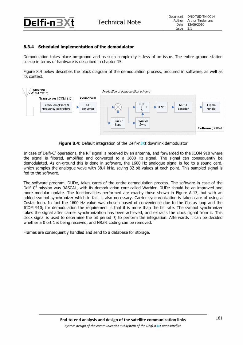
Technical NoteDocument
AuthorDateIssue
DNX-TUD-TN-0014Arthur Tindemans13/06/20103.1
181End-to-end analysis and design of the satellite communication links
System design of the communication subsystem of the Delfi-n3Xt nanosatellite
8.3.4 Scheduled implementation of the demodulator
Demodulation takes place on-ground and as such complexity is less of an issue. The entire ground stationset-up in terms of hardware is described in chapter 15.
Figure 8.4 below describes the block diagram of the demodulation process, procured in software, as well asits context.
( 1)k T
kT
dt
Figure 8.4: Default integration of the Delfi-n3Xt downlink demodulator
In case of Delfi-C3 operations, the RF signal is received by an antenna, and forwarded to the ICOM 910 wherethe signal is filtered, amplified and converted to a 1600 Hz signal. The signal can consequently bedemodulated. As on-ground this is done in software, the 1600 Hz analogue signal is fed to a sound card,which samples the analogue wave with 38.4 kHz, saving 32-bit values at each point. This sampled signal isfed to the software.
The software program, DUDe, takes cares of the entire demodulation process. The software in case of theDelfi-C3 mission was RASCAL, with its demodulation core called Warbler. DUDe should be an improved andmore modular update. The functionalities performed are exactly those shown in Figure A-13, but with anadded symbol synchronizer which in fact is also necessary. Carrier synchronization is taken care of using aCostas loop. In fact the 1600 Hz value was chosen based of convenience due to the Costas loop and theICOM 910; for demodulation the requirement is that it is more than the bit rate. The symbol synchronizertakes the signal after carrier synchronization has been achieved, and extracts the clock signal from it. Thisclock signal is used to determine the bit period T, to perform the integration. Afterwards it can be decidedwhether a 0 ort 1 is being received, and NRZ-I coding can be removed.
Frames are consequently handled and send to a database for storage.

Technical NoteDocument
AuthorDateIssue
DNX-TUD-TN-0014Arthur Tindemans13/06/20103.1
182 End-to-end analysis and design of the satellite communication links
System design of the communication subsystem of the Delfi-n3Xt nanosatellite
1 Increasing the data rate with the same modulation schemeIn case downlink data rate is increased, three components are affected:
The ICOM 910: Requires an available replacementBoth filtering and frequency conversion are dependant on the bit rate. The ICOM 910 has a 2.7kHz channel bandwidth for BPSK reception, which is sufficient for the reception of a 1.2 kb/s datasignal. For higher data rates however, the ICOM 910 filter bandwidth will limit performance. Assuch, a replacement is required. However, as further discussed in chapter 15, ISIS provides atransceiver that will be able to support much higher data rates on the downlink. Consequently, aspecific center frequency for the resulting signal should be selected and can be set in coherencewith the demodulation software.
The sound card: Requires no changes or an available replacementThe current sampling rate of the video card integrated in the ground station computer is 38.4kHz. Nyquist theorem states that a wave being sampled should be sampled with at least twotimes the maximum frequency that is to be recuperated from the signal. Practical values arehowever much higher, also as demodulation involves integration the resulting signal. Thereceived signal frequency in current settings is 1600 Hz, yielding 24 samples per frequencyperiod, or 32 per bit period at a data rate of 1200 b/s. Then, the sampling rate is likely sufficientfor data rates of 2.4 kb/s. Higher data rates however require a higher sampling rate; (cheap)commercially available video cards with sampling rates up until 192 kHz exist and as these areplug-and-play components in modern PC hardware an easy update can be performed. Also, thetransceiver that ISIS can provide should have integrated sampling rates up to several MHz.
The software, DUDe: Requires minor changesThe demodulation core should be easily reconfigured to allow for a higher bit rate. Primarily, theexpected bit period should be changed, in the actual demodulation process and in thesynchronization loops. At the same time the expected input signal frequency should be changed.This is all a matter of proper settings. Finally, computer processing power and process memoryshould be sufficient for the increased calculation load; assuming moderate data rate incrementsthis should not be a problem for a relatively powerful desktop computer.
2 Applying QPSK to increase bandwidth efficiency at no power costOn-ground, the actual demodulation takes place in software. As such, the only affected component is:
The software, DUDe: Requires changes to the demodulation algorithmsThe demodulation core should be configured to allow for a higher bit rate. Primarily, the expectedbit period should be changed, in the actual demodulation process and in the synchronizationloops. At the same time the expected input signal frequency should be changed. This is all amatter of proper settings. Finally, computer processing power and process memory should besufficient for the increased calculation load; assuming moderate data rate increments this shouldnot be a problem for a relatively powerful desktop computer.
3 Implementing ‘real’ raised cosine filteringNo changes are required on-ground.

Technical NoteDocument
AuthorDateIssue
DNX-TUD-TN-0014Arthur Tindemans13/06/20103.1
183End-to-end analysis and design of the satellite communication links
System design of the communication subsystem of the Delfi-n3Xt nanosatellite
8.3.5 Determination of the data rate approach
In section 7.9 theory was presented on maximizing the downloadable data volume. In case of the UHF/VHFcommunication link, a dedicated ground station is in place, which is able to track Delfi-n3Xt. Also, it isautomated. As such, it at least makes no sense to, if a constant mission data rate is used, select one basedon a minimum elevation angle no higher than 10°. The 10° in this case is based on:
Increasing atmosphere loss and antenna noise at low elevationsSee [SLR 0106] or section 7.9.
Obstructions on the horizonThese are present up to several degrees in every direction, but there are more profoundobstructions up to 10° elevation between 140 and 160° azimuth direction (Delft GS, [SLR 0243]).
A (slight) over budgeting in the link budgetThis is due to the calculation with worst-case values as well as a link margin; therefore the linkbudget can reasonably be assumed to remain closed for smaller elevation angles.
Then the only relevant decision becomes to determine whether the data rate will be changed during themission, either between passes or during passes. More downloadable data volume can always be useful, evenif it might not strictly be required. However, there are a couple of arguments against either option:
The PTRX, and similarly the ITRX, is not power limitedEven at 10° minimum elevation the power is available to go up to 9.6 kb/s. Higher bit rates arenot allowed due to bandwidth constraints.
Generation of data with a varying data rate is difficultFor a constant data rate, the CDHS needs just to deliver and acquire a constant amount of datafollowing a fixed schedule. For multiple data rates, different data acquisition schemes should beincorporated introducing also more complexity for the CDHS, as well as data generating systems.Due to CDHS being the main project-constraint at this moment, again this complexity is notdesired. If on the other hand data acquisition is kept constant, some kind of data buffer shouldbe introduced to be able to send stored data, again at the cost of extra complexity.
Either orbit determination or scheduling via telecommands should take placeOrbit determination should not be assumed. Scheduling again would increase complexity at theCDHS, and put extra emphasis on the availability of an accurate on-board clock.
On-ground systems should be prepared to receive different data ratesCurrently, the ground system is not prepared for this. Whereas the transceiver able to deal withhigher data rates should be able to receive multiple data rates, it will not be able to auto-detectthese data rates, and similarly the demodulation software (DUDe) is not prepared for this. Again,this would require a significant time-investment.
In conclusion, changing data rates for the PTRX is not deemed useful as the system is not power limited. Inany case, the addition of this feature would come at the cost of added complexity in at least PTRX, CDHS andGS. At the same time, the UHF/VHF communication link is of course mission-critical and experimental featuresat the cost of extra complexity are not desirable. A possible STX would be more open to these kinds offeatures. In result, the link budget for the VHF downlink shall indeed be based on a 10° minimum elevationangle, with a constant data rate throughout the mission.

Technical NoteDocument
AuthorDateIssue
DNX-TUD-TN-0014Arthur Tindemans13/06/20103.1
184 End-to-end analysis and design of the satellite communication links
System design of the communication subsystem of the Delfi-n3Xt nanosatellite
8.3.6 Selection of modulation scheme of Delfi-n3Xt:
Three options of improvement have been suggested. The conclusions regarding implementational difficultiesare summarized below, and the resulting modulation scheme and data rate for Delfi-n3Xt are presented.
1 Increasing the data rate with the same modulation scheme
Increasing the data rate to 9.6 kb/s is likely possible. Even if not, data rates (much) higher than 1200 b/s are.Functional tests should be performed, and hopefully this can be done soon given the transmitter sectionfinalized by Maurits Schaap and the Frame Generator software prepared by Christiaan Hartman. No additionalchanges to the satellite hardware are required.
On-ground, the transceiver should be replaced and the DUDe software core should be updated, but only inthe form of simple operational parameters. The transceiver can be delivered by ISIS.
If proven, it should still be decided whether 9.6 kb/s will be functionally used by the CDHS. In other words:whether 9.6 kb of data will be generated every second. If not:
Frames can simply be repeated a number of times, possibly with repeats spaced apart by a givenamount of time. This would require a certain buffer size implemented in the Frame Generator, butwould allow full in-orbit testing of the maximum data rate.
The transmitter can work at a lower speed in nominal operations, but 9.6 kb/s operation can beintegrated as test functionality, as it only involves a software setting
The latter suggestion can also be used if the high data rate will not be used in nominal operations and thepower consumption of the PTRX will be reduced by lowering the gain. This option is discussed in chapter 9,but will likely imply a lower nominal data rate to be used on the PTRX than the maximum allowable 9.6 kb/s.
2 Applying QPSK to increase bandwidth efficiency at no power cost
QPSK can be integrated with minimal on-satellite complexity, given the current inclusion of a QPSKmodulator. The processor should however be configured and connected differently. The exact impacts are toa certain extent unknown, so tests might be performed if time allows for it.
On-ground however, the change to QPSK requires a sizeable update of the DUDe demodulation softwarecore. Most notably, this would require a significant effort to understand the current demodulation softwareand adjust it accordingly. Also, this would require making significant adjustments to a very critical andcurrently proven software core.
Nevertheless, optimally this functionality would be integrated in the PTRX as test functionality. The softwarecore can be updated at a later stage as this requires on-ground complexity. For now however, QPSKimplementation is considered an optional nice-to-have.
3 Implementing ‘real’ raised cosine filtering
This option infers sizeable extra processor load and complexity, likely requiring a new processor. This wouldrequire moving away from the standard Delfi-n3Xt processor, and rewriting part of the software alreadywritten for the MSP430. On-ground however no changes are incurred.
Due to its on-satellite implications, it is not assumed this functionality is necessary on Delfi-n3Xt given thelevel of its impact and the mildness of radio amateur bandwidth restrictions.

Technical NoteDocument
AuthorDateIssue
DNX-TUD-TN-0014Arthur Tindemans13/06/20103.1
185End-to-end analysis and design of the satellite communication links
System design of the communication subsystem of the Delfi-n3Xt nanosatellite
As a result:
Delfi-n3Xt:Modulation scheme: BPSKPulse shaping: (Time domain) raised cosine (roll-off factor of 1)Line coding: NRZ-I, or more specifically NRZ-S (0 causes a transition)Bit rate: up to 9600 b/sRequested bandwidth: 20 kHz
Alternative names for the combination of modulation scheme and pulse shaping: RC-BPSK (raised cosine BPSK) SSB-SC (single side band, suppressed carrier)
Alternative names for the combination of modulation scheme, line coding and demodulation method: Coherent DEBPSK

Technical NoteDocument
AuthorDateIssue
DNX-TUD-TN-0014Arthur Tindemans13/06/20103.1
186 End-to-end analysis and design of the satellite communication links
System design of the communication subsystem of the Delfi-n3Xt nanosatellite
8.4 Physical layer: uplink modulation scheme and data rate
As was done in the previous section for the VHF downlink, this section discusses the UHF uplink modulationscheme. It follows the same structure, moving from Delfi-C3 modulation scheme selection to Delfi-n3Xtmodulation scheme in six subsections, being subsections 8.4.1 through 8.4.6 below.
8.4.1 Selection of modulation scheme of Delfi-C3
The selection for the uplink modulation scheme is again described in [SLR 0248]. FSK, or in fact Manchesterencoded FSK was chosen for the simple reason that it requires the simplest architecture on-board of thesatellite. Its reduced power efficiency is of little concern because large (on-ground) amplifiers can be used forthe uplink. Being an amateur standard neither was of concern, as the uplink transmission would not bepublic. Manchester coding was added for easy clock synchronization, although it comes at cost of a halvedeffective data rate. The resulting option used for the uplink of Delfi-C3 was:
Delfi-C3 Modulation scheme: FSK (600 b/s)Delfi-C3 Line coding: NRZ-I (NRZ-S) followed by Manchester codingDelfi-C3 Pulse shaping: None
This scheme again poses the default scheme for Delfi-n3Xt.
8.4.2 Possible improvements of the modulation scheme
Following the rationale of the radio amateur bandwidths, 9.6 kb/s or actually 9.6 kBaud would be acceptablefrom a bandwidth point-of-view. The Delfi-C3 uplink bit rate was 0.6 kb/s, and 1.2 kBaud. At the same, thelink budget shows a very large link margin. In other words, the Delfi-C3 uplink was:
Complexity limited
As for the downlink, it is however desirable to reduce the transmitted spectrum to approach regulatoryvalues. Nevertheless, in case of the uplink the impact is very minor as the uplink is not continuous and highlydirected.
Compared to other modulation techniques, FSK, or more specifically BFSK is neither very bandwidth efficientnor power efficient. Both aspects however, as argued above, do not pose a serious argument for change. FSKwas chosen as it yields the simplest possible demodulation architecture, inherent to FSK schemes. Even so,the system is still complexity limited. Therefore changing away from a FSK type scheme does not seemdesirable, or necessary. Only a 600 b/s bit rate was achieved, but the transmission of TCs does not require ahigher data rate, thus a higher complexity.
However, a potential future software upload feature, or other more complex uplink signals, might. In thatcase, the primary direction of advancement would be:
1. Increasing the data rate with the same modulation schemeFor Delfi-n3Xt higher data rates might be useful, but in any case it would create a more powerful(future) satellite bus.
Although it might not be directly required, a number of changes can be made which would adjust for thewasteful aspects of the current modulation scheme. First of all, FSK is not very power efficient. Second of all,Manchester coding is very bandwidth efficient.

Technical NoteDocument
AuthorDateIssue
DNX-TUD-TN-0014Arthur Tindemans13/06/20103.1
187End-to-end analysis and design of the satellite communication links
System design of the communication subsystem of the Delfi-n3Xt nanosatellite
The first option can be addressed by:
2. Changing the modulation scheme from (B)FSK to MSKIt has been explained in chapter 7 that MSK can actually be derived from BFSK by applying NRZ-Icoding and choosing two frequencies with a distance of h = 0.5. As NRZ-I, as explained below, isalso performed, only the frequency distance should be changed. In case of a changing data rate,this is automatically done in fact as h depends on data rate.
MSK yields an increased error performance of 3 dB; theoretically not directly required but a worthwhileimprovement if at minimal cost. An added benefit of MSK is that the produced bandwidth is strongly reduced.The bandwidth inefficiency of Manchester coding is addressed below.
Line Coding
As explained for the downlink, the default line code is unipolar NRZ. FSK modulation does not require this tobe converted to bipolar NRZ. For design facility however, NRZ-I can be applied; in that case (COTS)modulation and demodulation hardware both do not need to agree upon which frequency represents whichbit (0 or 1). The same holds for the couple of processor and (de)modulator in the receiver and transmitter.Furthermore, NRZ-I encoding on both the downlink and uplink allows the flags of the data protocol used to bethe same. As such, the downside of 0.8 dB reduced error performance and slightly increased complexity areacceptable; the former because of the huge link margin compared to only 0.8 dB loss, and the latter becauseof its proven unimportance, as is was applied in the Delfi-C3 uplink.
In order to be as simple and resilient as possible, Manchester coding can be applied. Manchester code, or Bi-Ф-L as introduced in section 7.3, is a very simple code to program, guaranteeing a transition per bit and anoverall zero dc-component per bit. It does come at the cost of a halved effective bit rate, as it is a 1B2B code.
Guaranteed transitions: not only does a high transition density allow maintaining symbolsynchronization, a guaranteed transition per bit allows achieving this synchronization even moresimply. No bit duration estimation based on for example a Costas loop is required, as every bitallows for a unique and new identification of the bit length, independent of Doppler shift or otherimpacts. A transition can be expected within a preset bit length, adjusted for the maximumoffset. As Doppler shift in the transmission frequency in the current ground station set-up isupdated once per second, the bit length change can be rather abrupt.
Zero dc-component: if a dc-component exists, for example, a string of 1’s can become interpreted as0’s because no centre dc level has been defined to signify a 0. The importance of this to thedemodulator is dependent on the electronic design.
While particularly simple, Manchester coding is also quite wasteful. Therefore an optional improvement wouldbe:
3. Removing Manchester coding for an automatic doubling of the bit rateManchester code has a bandwidth of twice that of regular NRZ. As such, a 600 b/s bit raterequires a 1200 Baud symbol rate. When removing the Manchester code, changes are onlyoccurred within a select number of components as most components are prepared for a symbolrate of 1200 b/s. At the same time however, a doubled bit rate is obtained.
Some comments can be made with respects to the impact of removing the Manchester code

Technical NoteDocument
AuthorDateIssue
DNX-TUD-TN-0014Arthur Tindemans13/06/20103.1
188 End-to-end analysis and design of the satellite communication links
System design of the communication subsystem of the Delfi-n3Xt nanosatellite
Transitions: currently (in AX.25 and the DelfiX protocol, see next section) a flag includes a small period ofno bit transitions, so that knowledge of the Manchester code allows locking onto the only other transitions;those in the middle of bits. If on the contrary the flag would include forced bit transitions, similar lockingcould take place, but focussed not on the middle but the edges of bits. After the flag, transitions are nolonger guaranteed so the processor should estimate the length of a bit, and control this estimation byregularly recurring transitions. This latter process is in indeed generally applied for symbol synchronization.The main downside of this approach is the added complexity of these control loops. If therefore theManchester code would be removed, more processor complexity is required, along with the time investmentof developing software. However, as on Delfi-n3Xt MSP430s will be applied as opposed to much less powerfulPIC controllers, it might indeed be feasible.
DC-component: as assessed above, the existence of a dc-component might be of concern. This then mightincrease implementation complexity, with implications on all electronics. A possible solution could then beoffered by more complex coding schemes, such as other mB(m+1)B line codes. For example a 3B4B Griffithscode has 75% data efficiency, as opposed to 1B2B Manchester with 50% efficiency. Even better would be a5B6B Griffiths code with 82.3% efficiency, while still limiting the number of 0’s or 1’s to 6-in-a-row. However,these codes introduce more substantial processor load.
The resulting incurred complexity of the possible changes in the satellite and on-ground again is commentedon below in a discussion on modulator and demodulator.
Pulse shaping
Figure A-4 shows that for coherently modulated FSK, the signal dampens relatively quickly. Nevertheless, therequired reduction of -60 dBc is not reached within a bandwidth shown. In fact, even for MSK this limit is notreached within a bandwidth of five times the data rate. However, pulse shaping applied on FSK schemesrequires more complicated modulators, due to the required generated frequencies between the two maintransmission frequencies.
The bandwidth performance of a transmitted Delfi-C3 telecommand has been measured and is shown inFigure 8.5 below. The frequency span illustrated is 50 kHz. The decimals of the transmission frequency havebeen censored for security reasons.

Technical NoteDocument
AuthorDateIssue
DNX-TUD-TN-0014Arthur Tindemans13/06/20103.1
189End-to-end analysis and design of the satellite communication links
System design of the communication subsystem of the Delfi-n3Xt nanosatellite
Figure 8.5: Produced frequency spectrum of a Delfi-C3 telecommand transmission over a 50 kHz span
First of all, the two peaks belonging to both modulated frequencies in a BFSK scheme can clearly be seen.What is however interesting to note, is that the peaks are 4.8 kHz apart. The frequency of the 1200 b/ssymbol stream is however only 600 Hz; this would require only a separation of 0.6 kHz. In other words, theFSK modulation applied is not ideally matched to the transmission data rate. In terms of a parameterintroduced in chapter 7; h = 8 instead of 1. The reason for this is quite simple; the applied COTS equipmenthas been prepared for a maximum data rate allowable within the radio amateur bands. The effect of thishowever is that produced spectrum is larger than required.
Second of all, the overall produced spectrum can be seen. Although the spacing between the peakscontributes to a larger spectrum, the main effect results just from the broadness of the modulation schemeapplied. To reach the regulatory -60 dBc, about 40 kHz is required. This is again far more than the 2.4 kHzallotted. Although filtering is applied within the transmitter, this filtering is again prepared for a data rate of9.6 kb/s. Even if it were not, the regulatory values would not be reached.
Nevertheless, it has been said before and will be said again, the actual regulations on the radio amateurbands are not that strict. Even less so for an uplink, which has only very (geographically) local impacts. Tothis it can be added that pulse shaping applied to an FSK scheme is difficult.
In conclusion, no pulse shaping on the uplink is required.

Technical NoteDocument
AuthorDateIssue
DNX-TUD-TN-0014Arthur Tindemans13/06/20103.1
190 End-to-end analysis and design of the satellite communication links
System design of the communication subsystem of the Delfi-n3Xt nanosatellite
8.4.3 Scheduled implementation of the modulator
As opposed to the downlink, modulator complexity if of less importance to the uplink as it takes place onground. But in fact, modulator complexity is also very low, as BFSK modulation can be performed by thesimple architecture sketched in Figure A-2. The implementation of the modulation scheme on ground will thenbe as follows:
Figure 8.6: Default integration of the Delfi-n3Xt uplink modulator
Figure 8.6 demonstrates that a new program, suggestively called DIGIT 2.0, should basically prepare astream of data (according to the data protocol), encoded with NRZ-I. The original DIGIT (1.0) prepared Delfi-C3 telecommands so it should at least be updated.
However, in case of Delfi-C3 the TNC31S took on part of data protocol application; it received data framesaccording to the KISS protocol, and replaced this protocol by AX.25; including the NRZ-I encoding. As theseare software functionalities, the execution of them can relatively easily be shifted. Changes to the dataprotocol (see next section) leads to prefer integration in DIGIT, also circumventing the use of the extra KISSdata protocol. Software on the TNC31S can also be updated.
The TNC31S should in any case take care of timing the bits, as a data stream coming from a desktop PC isunreliable in timing due to delays and queuing. Manchester encoding is also performed by the TNC hardware.
Consequent frequency modulation of the signal, as well as filtering, amplifying and up-converting of the signalis performed by the ICOM 910. An additional amplifier, the BEKO HLV-550, is generally used to furtheramplify the signal, as explained in chapter 15.
The proposed improvements are discussed below. In the cases where the effective data rate is increased, thesoftware should also allow a larger data rate output, but this has little impact given the assumed large on-ground processor power. The TNC is as said concerned with consequent timing of the bits, resulting in aconstant bit period.

Technical NoteDocument
AuthorDateIssue
DNX-TUD-TN-0014Arthur Tindemans13/06/20103.1
191End-to-end analysis and design of the satellite communication links
System design of the communication subsystem of the Delfi-n3Xt nanosatellite
The color codes used to illustrate the impact of implementation of the suggested advancements are the sameas in the previous section. For clarity:
Green indicates little to no changes with a good idea of the impactsBlue indicates moderate changes with some unknown impactsRed indicates a serious change with unknown specific impacts
1 Increasing the data rate with the same modulation schemeAn increase of data rate affects the following components:
TNC31S. Requires an available replacementThe current TNC31S supports only a 1200 Baud signal, in other words a 600 b/s Manchesterencoded signal, and should thus be changed. The TNC currently incorporates a specific modemthat applies the Manchester coding to a specific bit rate; this modem can be replaced by amodem available at ISIS allowing up to 115 kBaud.
ICOM 910. Acceptable without changesThe ICOM 910 can actually support up to 9.6 kBaud FSK signals, with a maximum filterbandwidth of 15 kHz. Therefore, up to 4.8 kb/s Manchester encoded data signals would beacceptable.
2 Changing the modulation scheme from (B)FSK to MSKThis change would require changes in one component:
ICOM 910. Requires a unidentified component updateThe value of h, the distance between the FSK frequencies, depends on the bit rate, and itdetermines whether one deals with ‘regular’ FSK or FSK with h = 0.5, MSK. Therefore acomponent should be found that creates an MSK signal for a given bit rate, instead of the currentICOM 910. This application does not seem unique and a COTS component replacement should beavailable. Nevertheless, no such component has been identified yet.
3 Removing Manchester coding and doubling the data rateThe option of removing Manchester and doubling the data rate would have one effect:
TNC31S: Requires a unidentified component updateThe modem which is integrated in the TNC should be replaced, as the current hardware appliesManchester encoding.

Technical NoteDocument
AuthorDateIssue
DNX-TUD-TN-0014Arthur Tindemans13/06/20103.1
192 End-to-end analysis and design of the satellite communication links
System design of the communication subsystem of the Delfi-n3Xt nanosatellite
8.4.4 Scheduled implementation of the demodulator
The demodulator should be as simple as possible. Part of the solution is to use COTS components. However,just as with the modulator circuit of the downlink, the frequency conversion system is custom designed. Theintegration of the total demodulator and its (internal) functionalities can be seen in Figure 8.7 below.
( 1)k A
kA
dt
( 1)k A
kA
dt
( 1)k A
kA
dt
( 1)k A
kA
dt
Figure 8.7: Default integration of the Delfi-n3Xt uplink demodulator
After filtering, amplifying and frequency conversion the signal is passed on to the Motorola MC3362. This chipis in charge of extracting the carrier frequencies from the signal (only in terms of frequency, not phase). Ityields an output at each moment consisting of a low or high signal; not to be confused with digital data asthe period or clock is not defined. This system is explained in detail in Appendix A.
The consequent high/low signal should represent a Manchester encoded bit stream, which is decoded by theFrame Interpreter in the form of an MSP430 microprocessor. This same processor then removes the NRZ-Icode, handles the frames and communicates with the I2c bus.
Whereas the demodulation seems really complex, even much more so than that of BPSK reviewed above, it isin fact not so. Whereas Doppler shift requires carrier synchronization, the FSK demodulator allows having onlycarrier frequency synchronization. Consequently, the use of Manchester coding renders complex symbolsynchronization unnecessary. Finally, as can be seen in Figure 8.7, most complexity is integrated in one COTSchip.

Technical NoteDocument
AuthorDateIssue
DNX-TUD-TN-0014Arthur Tindemans13/06/20103.1
193End-to-end analysis and design of the satellite communication links
System design of the communication subsystem of the Delfi-n3Xt nanosatellite
1 Increasing the data rate with the same modulation schemeAn increase of the data rate would involve the following components:
Motorola MC3362. Requires replacement but one that is most likely already necessaryDue to a change of data rate, the required carrier frequencies of the FSK signal change (hrelation). As such, it is not automatically true that this chip would support these frequencies. Infact, its datasheet [SLR 0199] mentions that a data rate of 1200 Baud, due to the Manchestercoding, 600 b/s, is the typical limit to ensure data integrity. This can also be related to the factthat the chip bases its integration period not on the bit length, but on a period presumably muchsmaller than that. A halved bit period might complicate this approach. As such, this componentrequires replacing. However, this component is already out of production, so it is likely that itshould be replaced in any case.
Analogue components: Requires replacement but one that is most likely already necessaryThe relevant bandwidth contained within the signal received by the receiver is doubled by adoubled data rate, more so for higher data rates. The last filter is only 5.5 kHz broad, so mightunnecessarily decrease received signal quality for data rates at least above 1.2 kb/s. However,this filter is part of the Motorola MC3362 so should be replaced in any case. Also, this filter mightin fact not be required in the first place.
Frame Interpreter: Data rate of 1.2 kb/s likely acceptable, possibly higherThe microprocessor, interpreting the Manchester code and removing it to yield bits, andconsequently removing the NRZ-I code, should do this functionality twice as fast for a doubled bitrate. At the same time, it should still perform its frame extraction functionality, most notablyincluding decryption and the calculation of two CRCs. It capabilities should be tested.Nevertheless, on Delfi-C3 the OBC, which was the same MSP430 processor as the FrameInterpreter is, was in charge of these taks as well as other tasks. It interpreted the bit signal fromtwo (RAP1 and RAP2) radios at the same time. As such, it seems likely that at least a doubled bitrate is achievable.
2 Changing the modulation scheme from (B)FSK to MSKWhen implementing MSK the following components have to be thought of:
Analogue components. Acceptable without changesThis optional change is actually one of luxury; it can be decided to limit the filter bandwidths asMSK requires less transmission bandwidth as shown by Table A-1.
Motorola MC3362. Requires replacement but one that is most likely already necessaryThe data sheet of the chip gives no answer as to what values of h it supports, only that it isfabricated for FSK modulation. As such, possibly it might be useable. But, given the fact that themodel is already out of production, it is preferred to check for this specification in a successor.
3 Removing Manchester coding and doubling the data rateRemoving Manchester would require a new method of symbol synchronization. Furthermore, as an unknownand slightly varying dc-component arises this should be designed for.
Motorola MC3362. Requires feasibility testThe specifications for a resulting dc-component in the demodulated signal are unclear, as thechip is a ‘black-box’. It should therefore be tested, possibly in its successor.
Frame Interpreter. Requires feasibility testWithout Manchester coding, a cleverer symbol synchronization method should be integrated insoftware (most logically), this comes at the cost of complexity and thus required processorpower. Again this would come on top of decryption and CRC calculation, and the doubled datarate.

Technical NoteDocument
AuthorDateIssue
DNX-TUD-TN-0014Arthur Tindemans13/06/20103.1
194 End-to-end analysis and design of the satellite communication links
System design of the communication subsystem of the Delfi-n3Xt nanosatellite
Also required for the last option: Changing the flags of the data protocol of the uplink signal. Requires minor changes
Albeit not a physical layer functionality; important not to forget. In order to have a well-functioning symbol synchronizing circuit, this improvement would require an adapted flag, with asufficient number of transitions. More about this in the next section on data link layerfunctionalities.
8.4.5 Determination of the data rate approach
In case of the UHF uplink, power efficiency if of no concern. As such, changing data rates with elevationangle would not be useful. The system is, as concluded above, complexity limited.
As a result, following the same arguments as for the VHF downlink, a minimum elevation angle of 10° isdesigned for in the link budget.
8.4.6 Selection of modulation scheme of Delfi-n3Xt
Again three options of improvement have been suggested.
1 Increasing the data rate with the same modulation scheme
Increasing the uplink data rate to above 600 b/s requires, on-ground, a change of the TNC integratedmodem, which is no problem. On-board however the receiver requires a new a new demodulator chip as wellas possibly a changed filter approach and minor software changes. Also, it should be tested whether theprocessor is able to handle increased speeds, however speeds of 1.2 kb/s are likely possible.
As such, it can be said that a possible data rate increase depends mainly on the electrical integrationcomplexity in the receiver. Currently no one performs work on the receiver section of the PTRX. As such, thepossible replacement of the demodulator remains to be commented on.
It can however be said that an increase of the uplink data rate is not required for the transmission oftelecommands. It might be useful for a future software upload capability and would thus create a morepowerful radio. For Delfi-C3, a bit rate of 1.2 kb/s was in fact envisioned, but in the end was not realized dueto reasons of complexity. For Delfi-n3Xt it therefore does seem desirable to increase the data rate as animprovement, but no significant resources should be devoted to it. As such, a data rate of 1.2 kb/s is set as atarget. At the same time, the ‘improved RAP’ that ISIS has made works at 1.2 kb/s (not more). As such, thisseems a reasonable goal. The final data rate currently shall be assumed to be either 0.6 or 1.2 kb/s.
2 Changing the modulation scheme from (B)FSK to MSK
The implementation of MSK requires a change of the ICOM 910 and the demodulator chip, having anunknown impact. The ICOM 910 does have to be replaced already in case of higher downlink data rates.
However, in the best case this upgrade gives an additional link margin of 3 dB, next to the link margin ofmore than 20 dB already available. Therefore this update is considered a luxury option, but is not to beactively pursued.
3 Removing Manchester coding and doubling the data rate
The implementation of no Manchester coding along with a doubled bit rate would require a change of thedemodulator, as well as increased complexity of and time investment in the Frame Interpreter. As this is amission-critical element, added (un-proven) complexity is not much preferred. Certainly as the increase ofdata rate to 2.4 kb/s is of unknown relevance to Delfi-n3Xt.

Technical NoteDocument
AuthorDateIssue
DNX-TUD-TN-0014Arthur Tindemans13/06/20103.1
195End-to-end analysis and design of the satellite communication links
System design of the communication subsystem of the Delfi-n3Xt nanosatellite
Given the limited project occupancy within the Delfi-n3Xt programme, and the fact that the primaryfunctionality (transmitting TCs) can easily be performed using the same modulation scheme as Delfi-C3, mostproposed changes above are, for now, of more academic importance.
However, an increased bit rate should be further investigated in cooperation with a future student in chargeof the PTRX (transmitter) as its potential value to the Delfi programme is recognized.
In conclusion:
Delfi-n3Xt:Modulation scheme: FSK (h = 1)Line coding: NRZ-I (NRZ-S) followed by Manchester codingPulse shaping: NoneBit rate: 600 b/s or 1200 b/sIndicated bandwidth: 2.4 kHz or 4.8 kHz
Alternative names for the modulation scheme: Orthogonal FSK (h equals an integer number) Sunde’s FSK (h equals 1)
Alternative names for the combination of modulation scheme and pulse shaping: Manchester FSK

Technical NoteDocument
AuthorDateIssue
DNX-TUD-TN-0014Arthur Tindemans13/06/20103.1
196 End-to-end analysis and design of the satellite communication links
System design of the communication subsystem of the Delfi-n3Xt nanosatellite
8.5 Data link layer: data protocol
Data link layer functionalities deal with bits and are necessary to establish a link between two stations. Therequired feature is the data protocol; it supplements the modulation scheme by offering synchronizationcapabilities and it adds addressing and possibly error detection or correction.
In case of the physical layer there is a functional distinction between downlink and uplink. In case of the dataframes and operation, there logically is a difference between not only up and down, but the type ofcommunications as well; telemetry downlink, telecommand (TC) uplink, telemetry requests and possiblysoftware updates. These cases will be referred to as scenarios. These functionalities are also strictly no longerdata link layer functionalities, but those belonging to higher layers as they are not strictly required forestablishing a link between two stations.
What will be defined as the data protocol shall be equal for all these scenarios. This section introduces thisdata protocol. The next section then addresses scenario-dependent data functionalities.
The AX.25 protocol is extensively used for communication, and has successfully been applied in Delfi-C3. Ithas been introduced in detail in chapter 7. It is usable for a wide range of applications. Due to this multi-functionality however the overhead created is rather large. For example, it incorporates very large addressfields allowing for both a sender and a receiver, and a PID and a Control field which, as demonstrated byDelfi-C3 have no use. Even more so, in case of Delfi-C3 RASCAL was used and required for the forwarding oftelemetry; as such no standardized equipment allowing for AX.25 decoding was preferred as this did not allowfor telemetry forwarding. Without RASCAL frames could be received, but not interpreted. Therefore it seemsthe protocol can be adjusted without much loss of functionality. The idea suggested here is therefore to basea new design on AX.25, which is a proven protocol, but to improve its efficiency for the mission at hand. Infact, the resulting protocol is one that is useful for all similar satellite missions.
The newly derived protocol, the DelfiX protocol, will be derived in two steps. First, the AX.25 protocol isreduced without changing the transmission characteristics, to form the conservative DelfiX protocol.Afterwards the final DelfiX protocol is presented, taking into account another improvement. Figure 8.8 belowdemonstrates the conservative DelfiX frame.
Figure 8.8: DelfiX frame, conservative version
In general, the characteristic of having byte-length fields is retained due to 8-bit processor calculations andtherefore modularity. Nevertheless, the information field, which is not further discussed below, can have anycontent and any number of bits as the protocol itself is not dependent on an integer number of bytes. Also,all fields are filled most-significant bits first as opposed to with the AX.25 protocol; in other words all bits andfields are read logically, left-to-right.
The result is a saving of 96 bits with respect to the AX.25 protocol, keeping its essential functionalities andadding a Frame Type field in a total of 64 bits. Also, using the same CRC as AX.25, single bit error correctioncan possibly be achieved. However, a large amount of bitstuffing is required due to the small flag size. Thisaspect is improved upon in the final DelfiX frame; by extending the flag to two bytes instead of one,maximum required bit stuffing is reduced from 1 in 6 to 1 in 14 bits. This is illustrated by Figure 8.9 below.

Technical NoteDocument
AuthorDateIssue
DNX-TUD-TN-0014Arthur Tindemans13/06/20103.1
197End-to-end analysis and design of the satellite communication links
System design of the communication subsystem of the Delfi-n3Xt nanosatellite
Figure 8.9: DelfiX frame, final version
The characteristics of the DelfiX protocol and the changes with respect to AX.25 are elaborated on in thesubsections 8.5.1 through 8.5.5 below.
Figure 7.2 below illustrates how the both frame types should be constructed, from the point of view of thetransmitter; in case of Delfi-n3Xt the microprocessor on the PTRX, or the ITRX. The OBC then providesInformation Field plus a Frame Type label, which depends on the information content (it is still part of theDelfiX protocol as it is present for all scenarios introduced below). In an order similar to that of the AX.25protocol, fields are added and bitstuffing is applied. A note on the effects of the moment of bitstuffing can befound in subsection 8.5.6. A receiver should apply the process shown in Figure 8.10 in reverse.
Figure 8.10: DelfiX frame construction
In subsection 8.5.7 throughput efficiency of the DelfiX protocol is commented upon, yielding conclusions onthe optimum frame size, depending on bit error rate.
8.5.1 Flags
The flags have two functions: Indicate the start and end of a frame Allow for carrier and/or symbol synchronization, depending on the modulation scheme
The flags are thus used not only for interpreting data, but also for synchronization required as part ofdemodulation. The start flag 1’s yield a perfect sinus when combined with BPSK modulation as no transitionsoccur, which allows for carrier synchronization (this sequence is unaltered by NRZ-I encoding, as this changesthe stream of 1’s to 0’s). In case of Manchester encoded FSK modulation it yields continuous transitions, butonly in the middle of bit periods (due to the Manchester code and not due to bit transitions) which allow forsymbol synchronization.
An end flag is not necessarily required if packed length is known. Nevertheless, bit stuffing introduces somevariability in length, or its definition should be changed to insert a default number of bits as no flag has to beprevented in the frame content if no end flag is used. In any case, bit stuffing itself is required for keepingsymbol synchronization, as addressed below. The end flag can also be replaced by a frame length field.However, the demodulation software is simplified and data protocol modularity is increased by keeping it.
Furthermore, in the AX.25 protocol it was allowed to combine the end flag of one frame with the start flag ofanother frame. This will, at least in case of Delfi-n3Xt, not be applied. There is no good reason to do so giventhe transmission scenarios; due to a varying amount of bitstuffing per frame length frames will not seamlesslycross over.

Technical NoteDocument
AuthorDateIssue
DNX-TUD-TN-0014Arthur Tindemans13/06/20103.1
198 End-to-end analysis and design of the satellite communication links
System design of the communication subsystem of the Delfi-n3Xt nanosatellite
Due to the function of the synchronization sequence as start and end flag, bit stuffing is applied to make sureit does not reappear in the frame; after 5 1’s a 0 is inserted in the AX.25 protocol. At the same time however,the insertion of ‘0’ bits creates a transition, following the NRZ-I encoding. Therefore, transitions are realizedevery 6 bits maximum, allowing for keeping symbol synchronization in the downlink signal. (The uplink signaldoes in fact not require this feature due to the Manchester coding. Nevertheless, as the primary uplink signalof TCs consists of small packages, it has no significant effect.)
This exact functionality has been copied in the conservative version of the DelfiX protocol, as bit stuffingaffects also signal demodulation. However, (digital) symbol synchronization does not seem to require such alarge transition density, as confirmed by multiple internet sources. Therefore, it is suggested that the flaglength be doubled to a frame of 14 1’s, flanked by 0’s, creating the final DelfiX protocol.
Using a custom-written Matlab modulation program, applying NRZ-I coding and BPSK modulation to a 1600Hz carrier as that being used to demodulate the signal in RASCAL/DUDe, the effects of streams of 1’s havebeen tested. Matlab was used to generate a digital audio file that could consequently be played. Using anaudio cable the signal was monitored by RASCAL/Dude, in a way identical to how the ground station listens tothe satellite. A continuously increasing stream of 1’s, alternated by a number of flags for re-synchronizationwas played.
The results: The program showed remarkably little problems with streams of up to 30 1’s in-a-row. The same held true when a Doppler shift of 50 Hz was added, which is about twice the maximum
Doppler shift rate per second; Doppler shift is corrected for every second by the receiver on-ground. Finally, as signal power was decreased (by adjusting the volume of the transmission, simulating a
reduced signal-to-noise) the seamless recovery ability was slightly reduced but not by more than 5bits in-a-row. At lower power the entire stream became unreadable. The realistic signal-to-noise ratioshould than have laid somewhere in between.
As such, preliminary tests show that a doubled flag length, to form a continuous stream of 13 1’s in the worstcase, should likely be no big problem. Of course, the same test should again be done as the actual analoguesection of the transmitter is finished, to confirm the implementation of the final DelfiX protocol.
Due to the constant data generation of Delfi-n3Xt, downlink frame length is constant. Bit stuffing then yieldsa number of bits to be reserved for bitstuffing, assuming the worst case scenario.
Increasing the header length to two bytes comes at the cost of two bytes in the complete frame, at the gainof more than half the reserved bit stuffing bits. In a frame length of 1200 bits, this decreases the bit stuffingbits from 200 to 86. An enlargement of another 8 bits for the flags would only save another 30 bits, whilecosting 16 bits. Of course this effect would be bigger for larger data frames, but the above test results showthat larger streams of 1’s could result in demodulation problems. Also, moderate room assumed for bitstuffing, if not required in a certain frame with plenty transitions, can be used for appending flags useful forsignal synchronization.

Technical NoteDocument
AuthorDateIssue
DNX-TUD-TN-0014Arthur Tindemans13/06/20103.1
199End-to-end analysis and design of the satellite communication links
System design of the communication subsystem of the Delfi-n3Xt nanosatellite
8.5.2 Address field
Two changes with respect to the AX.25 address field are made: There is no longer a sender and receiver field The total length is reduced to three bytes.
In case of simple satellite mission, there is only one ground station and one satellite. As such, a satellite islogically linked to the ground station and stipulating only one of the two gives enough information. In case ofDelfi-n3Xt, as with Delfi-C3, there is only one true ground station, but many receivers. Nevertheless, theaddressing is always the same and on-ground software (DUDe and RASCAL respectively) takes care of thedistribution. As such, no receiver field is proposed.
The AX.25 protocol allows many users and as such many address bytes are required. 6 ASCII characters areallowed per sender/receiver, followed by a SSID or Secondary Station ID. In fact, this means 7 bytes, or 42bits are used for an address. This field can be minimized by using a numbered approach; 8 bits can allow for256 ‘address numbers’. It is here that a trade-off should be made between minimizing bits used, andmodularity.
A small number of bits is not preferred, as a bit sequence or a (hexadecimal) number should be rememberedfor a satellite (or satellite-ground station combination). This gives little oversight when multiple satellites usethe same protocol, be it future Delfi satellites or even other satellites. Therefore, the use of ASCII charactersis deemed useful. To make meaningful acronyms, yet give a large number of options, a 3 byte address field isselected; allowing for not only letters but also numbers and symbols. It is then suggested to use:
DNX for Delfi-n3Xt; indicating a downlink signal DGS for Delfi ground station; indicating an uplink signal
As flags are similar to AX.25 frames, as well as the CRC, and the address field starts off similar to that of theAX.25 frame, it makes sense to guarantee that the difference between the two is clear; an AX.25 framereceiver should reject these frames, and a DelfiX frame receiver should reject AX.25 frames. A dual receivercould switch modes when it recognizes the data protocol. A clear marker of difference is integrated with the1st bit of the each address byte; in case of the AX.25 frame these bits are set to ‘0’ to indicate that theaddress field continues, with a mandatory number of 14 bytes minimum. As such, it is proposed to set all 1st
bits to ‘1’. In fact, in AX.25 frames the field contents are inverted (‘least significant’ or last bit first, per byte).The inversion is deemed not useful, and is not applied in the DelfiX protocol.
8.5.3 No PID and Control fields
Both the PID and Control fields in the AX.25 protocol were of no use to Delfi-C3, as only the UI-frames wereused and no higher layer protocols were specified. Nevertheless they took up 16 bits and as such they areremoved in the DelfiX protocol.
8.5.4 Frame Type indicator
As was mentioned above, a number of different scenarios exist, yielding different frame compositions whenthe info field is taken into account. These scenarios are (currently) telecommand, telemetry, telemetryrequest and software update. More can be added when required. Different telemetry types such ashousekeeping data and payload data can also be indicated and even combinations of payload data if not allpayload data will fit in singular frames. Therefore 4 bits are deemed necessary. In order to stick to an integernumber of bytes, it is extended to 8 bits; 4 bits can be used to indicate the generic frame type (scenario) andanother 4 bits can indicate the payload frame type in case of telemetry data, for example. In the current databudget these two counters exist and are separated in location. This is to be further specified by the CDHSsubsystem engineer who is in charge of determining frame content.

Technical NoteDocument
AuthorDateIssue
DNX-TUD-TN-0014Arthur Tindemans13/06/20103.1
200 End-to-end analysis and design of the satellite communication links
System design of the communication subsystem of the Delfi-n3Xt nanosatellite
8.5.5 Frame Check Field / Sequence (FCS)
In case of an AX.25 frame, a CRC check is applied, which is a form of error detection. Single, double andtriple error can be detected within a frame of a maximum of 32,768 bits, as well as burst errors up to 15 bitslong, using a 16-bit CRC. Section 7.7 has given an introduction to data security measures. As any frame to betransmitted using the DelfiX protocol will be subjected to a certain bit error rate, it makes sense to addcertain measures to make sure corrupted data is not accepted in the database. Hash and encryptionmeasures are not designed for this purpose, and neither are advanced error correction schemes. The latteryields large overheads which are not preferable in a general data protocol standard. Therefore, cyclicredundancy checks or CRCs are suitable.
The total BER for which Delfi-n3Xt transmission links are designed is 10-5. This means that, depending on theframe size, a certain number of frames is slated to have errors in them. A single error will occur on averageevery 100,000 bits, or roughly every 40 frames with 2400-bit length, or every 20 frames for 4800-bit frames.This is a sizeable number. Double errors are however slated to occur some 100,000 less often, as presentedin section 7.7. Nevertheless, with one frame per second, one such frame will exist every 50 days or 25 dayson average. This suggests single error detection is at least necessary, but a reasonable argument is posed forhaving larger error detection of at least 2 bits, next to resulting in a more general sense of safety and systemwith some margin for failure.
In reality, the BER will not be equal to 10-5, but higher in nominal operations. There is at least a small linkmargin on the VHF downlink (in addition to the minimum link margin of 3 dB), and a huge link margin on theUHF uplink. Nevertheless, if margins turn out to be lower (most noticeably on the downlink), the systemshould not fail on error detection capability. At the same time, many amateurs might receive and forwardtelemetry frames, using less powerful or dedicated equipment. To not underestimate this feature, it makessense to slightly over-design the error verification feature.
In section 7.7 it has been shown that only single errors can be detected using up to 12 bits for the desiredmessage lengths. This is the same result then as a 1 bit parity check, although burst errors can then also bedetected. A small increase to a 16-bit CRC then gives triple error detection capability as well as 15-bit bursterror detection capability. Therefore, the increase to triple error as opposed to single error detection seemsworthwhile, and a CRC of at least 16 bits is advised.
If the frame message length will be less than 4097 bits, a 24-bit CRC can yield HD=5 (allowing 4 independenterrors to be detected), but at larger lengths only HD=4 is feasible, and using a different CRC. Slightly higherresults can be obtained by 32-bit CRC schemes, but these are optimal for (large) frame lengths not likely forDelfi-n3Xt or similar satellites for that matter. Given the above, there seems to be no good argument toincrease the CRC length to be able to detect 4 errors, or slightly more.
In conclusion:
Choice of CRC: CCITT-16 (16 bits) with a generator of x16+x12+x5+1 or 1 00010000 00100001.
Additional argumentation is given below.

Technical NoteDocument
AuthorDateIssue
DNX-TUD-TN-0014Arthur Tindemans13/06/20103.1
201End-to-end analysis and design of the satellite communication links
System design of the communication subsystem of the Delfi-n3Xt nanosatellite
The given generator is a general standard as it is applied in AX.25, and because of this it has successful Delfiheritage. Section 7.7 gives two better generators, being those labelled as 200433 and 321353. The first yieldsHD=6 up until 115 bits total length, while having a maximum HD=4 until 28,658 bits. The second dominatesCCITT-16 in terms of singular errors as it yields HD=6 up until 109 bits total length with the same maximumlength of 32,767 maximum total length for HD=4. [SLR 0685] does suggest however that the error detectionperformance for more than 3 errors is better for CCITT.
Also, a maximum achievable 122 bits with a HD above 4, 5 in this case, and at the same time giving HD=4for message lengths above 1024 bits, is given by the 0xBAAD polynomial. Its maximum message length is notclear however for HD=4.
While a CRC generator change should have no other implications than changing the simple bit sequence inthe packaging and depackaging software, it does involve reverting from a proven standard to a moretheoretically presented one. Furthermore, as is shown in the next section, the smallest frame, a TC, will notfit the 115 bits total length, adding no extra functionality. The added benefit of any general 16-bit CRC is thatit allows for larger (future) data frames involved with higher data rates and it creates a modular and future-proof standard, even though 32 kb will not be reached as it would be better to break up frames at theselengths.
Error correction
An added advantage of a scheme of at least triple error detection capability is that it can in theory alsocorrect for single error detections. Three requirements have been presented in section 7.7, which are met;triple errors are very unlikely given the BER, the message lengths are not variable during transmission andthe generator degree is sufficient.
The incurred complexity of the error correction process is of course completely on-ground. Even if thecalculation intensity is too high for real-time correction to be applied, it makes sense that between passesthere is easily sufficient processor power for it to be performed. In that case, it should be a feature of DUDe,as erroneous frames are normally discarded in the data interpretation process. These frames can, instead ofbeing discarded, simply be set aside to correct, directly or when processor power is available. As such, therelevant incurred extra complexity is involved with preparing DUDe to apply error correction. As such, errorcorrection is certainly suggested if project development constraints allow for it.
Message length
It has been concluded that CRC features heavily depend on the message length. As such, it can bequestioned whether a smaller package would not merit a different CRC. In other words, why should the CRCbe a data protocol specific feature and not a scenario specific feature? The answer is that it simply is clearerin this manner, and that there is no large incentive to have different CRCs. In case of Delfi-n3Xt the onlyframe of significantly different length is that of the TC. The TC will in fact, as argued below, have anadditional CRC targeted at a small message length. The size inefficiency of having two CRCs is not importantas total size is not an issue for TCs at those scales.

Technical NoteDocument
AuthorDateIssue
DNX-TUD-TN-0014Arthur Tindemans13/06/20103.1
202 End-to-end analysis and design of the satellite communication links
System design of the communication subsystem of the Delfi-n3Xt nanosatellite
8.5.6 Bitstuffing bit errors
As introduced above, bitstuffing under the DelfiX protocol, such as with the AX.25 protocol, takes place afterthe calculation of the CRC. The effect of this is that bit errors, thus bit flips of bitstuffing bits, or thosesurrounding them, can have unpredictable effects. Three situations can occur, involving 1 bit error:
An inserted 0 can flip to a 1, being followed by a 0The resulting pattern is recognized as a flag, and the current frame (before and after the ‘flag’)will (very likely) fail as not all protocols elements are present in the frame.
An inserted 0 can flip to a 1, being followed by a 1The first 0 to follow this sequence of 1’s will be removed. The result is that a sequence of bits willbe shifted one position to the right, with an erroneous 1 inserted, and a 0 removed at the end.The CRC capability to detect a burst error of maximum length 15 will detect this error. Anadditional error in the frame however might possibly yield the errors undetectable, but this is veryunlikely.
A 1 before (in any of the 5 or 13 spots) an inserted 0 flips to a 0The 0 is not removed and the frame length is increased by 1. The entire bit sequence is shifted tothe right, and two 0’s have replaced a 1. As explained by the operation of a CRC in subsection7.7.1, this causes 1 more bit modulo-2 addition to take place then otherwise; the result is thatthis type of error is always detected. An additional error in the frame however might possiblyyield the errors undetectable, but this is again very unlikely.
It has been shown that the CRC takes care of bit errors related to bitstuffing in a sufficient manner. A verysmall chance exists that two bit flips occur, possibly with one of the cases above, causing a bit error to passthrough. Double bit flips have a very small chance of occurrence, whereas in turn the problem combinationshave an even smaller chance of occurring, and even against those the CRCs detection capabilities are far frompowerless. And, no such error that could take place would and should have a catastrophic effect.
If, in case of a lower BER for example, it would be required to protect against these scenarios, bitstuffing canbe performed before calculating the CRC. This would mean that a larger and unknown number of bits iscontrolled by the CRC, which is not a problem and comes at a small cost of increased processor power. TheCRC should however also be bitstuffed afterwards, and for example a 0 has to be inserted to make sure thatthe end of the message in combination with the start of the CRC will not incur a flag (as opposed to checkingfor this scenario). Therefore also a small additional loop should be integrated in software to take care of theextra CRC check. Although this implication is not very difficult, it might lead to confusion as processes have tobe reversed. Also, users familiar to the AX.25 order might be confused which can lead to errors. In general itis concluded that bitstuffing can just be performed after CRC calculation at minimum extra incurred risk.

Technical NoteDocument
AuthorDateIssue
DNX-TUD-TN-0014Arthur Tindemans13/06/20103.1
203End-to-end analysis and design of the satellite communication links
System design of the communication subsystem of the Delfi-n3Xt nanosatellite
8.5.7 Throughput efficiency and optimum frame length
Section 7.6 has presented a discussion on data protocol throughput efficiency, given frame sizes and BERvalues. This section compares the throughput efficiency of the DelfiX protocol to that of the AX.25 protocoland comments on its optimum frame length.
Throughput efficiency
As explained in section 7.6, Delfi AX.25 indicates the use of AX.25 frames with the addition of a framecounter. The final DelfiX frame has been presented above, as well as the conservative DelfiX frame. Thethroughput efficiencies of the three frame types for different frame sizes are given in Figure 8.11 below.
Figure 8.11: Throughput efficiencies of DelfiX versus Delfi AX.25
In conclusion it can be seen that the conservative DelfiX frames outperform Delfi AX.25 frames especially atlow frame sizes, with a difference of 8% (74% to 66%) at 1200 bits, 4% (77.5% to 73.5%) at 2400 bits andonly 1% (77% to 76%) at 4800 bits. The final DelfiX frames however show very different absolute values,with respectively 82%, 86% and 86% efficiency at 1200, 2400 and 4800 bits per frame.
As such, the final DelfiX protocol can realize some 10-15% better throughput efficiency than the AX.25version applied on Delfi-C3. This can be translated to some 100 received bits per 1000 transmitted bits extra,or simply 10-15% more received payload and housekeeping data during the entire mission.

Technical NoteDocument
AuthorDateIssue
DNX-TUD-TN-0014Arthur Tindemans13/06/20103.1
204 End-to-end analysis and design of the satellite communication links
System design of the communication subsystem of the Delfi-n3Xt nanosatellite
Optimum frame length
As can be seen from the slopes in Figure 8.11, at low frame lengths throughput efficiencies are very low, andat a certain point maximum throughput efficiency is reached. The following Figure 8.12 zooms in on the areaaround this maximum. This allows determining an optimum frame length. However, as indicated before, adecreased BER increases this optimum frame length. And, as a link budget margin usually remains, a higheroptimum frame length is more usual during transmission. As such, no one point is easily classifiable.Nevertheless, it can clearly be concluded that certain low frame sizes yield relatively low efficiencies.
Figure 8.12: Throughput efficiencies of DelfiX with BER values of 10-5 and 10-8
In case of a BER of 10-5, the optimum frame length for both DelfiX versions is 3600 bits, with both 2400 and4800 bits being within 0.5% distance. Frame lengths up until 9600 bits cause some 3% efficiency to be lost.Data frames of 1200 bits cause some 4-5% efficiency to be lost. As such, frame sizes of 2400-4800 arepreferred.
In case of a BER of 10-8, the optimum frame length for both DelfiX versions surpasses some 200,000 bits.Nevertheless, the increase beyond 9600 bits is actually only some 1%. Decreasing to 4800 bits again causessome 1% loss, and some 2% is lost when moving from 4800 to 2400 bits. As such, frames sizes of 4800-9600+ are preferred.
As in reality the BER will usually be lower than 10-5, given that this is a worst case value, a wide range offrame sizes can be argued for. As the BER varies between 10-5 and 10-8, frame sizes of 2400-9600 have goodperformance. 1200 bits is not preferred.

Technical NoteDocument
AuthorDateIssue
DNX-TUD-TN-0014Arthur Tindemans13/06/20103.1
205End-to-end analysis and design of the satellite communication links
System design of the communication subsystem of the Delfi-n3Xt nanosatellite
8.5.8 Implementation of a new data protocol
While DelfiX clearly outperforms AX.25 for the Delfi mission, its actual implementation (effort) should also beconsidered. In case of the UHF/VHF transmission link on Delfi-n3Xt there are two radios that transmit andreceive data, and there is the ground station network that is to receive and transmit data. The componentsthat should be considered when changing the data protocol are shown in Figure 8.13 below. The indicatedcomponents are commented on afterwards.
Figure 8.13: Components which are impacted by a change of data protocol
The indicated components:
1. PTRX receiver: updated.As will be introduced in the next chapter, PTRX receiver and transmitter sections are separatedfunctionally. As such, both components should be updated with the new data protocol DelfiX, ifindeed both the down- and uplink apply it. The software of the TX and RX sections has alreadybeen prepared for the protocol.
2. PTRX transmitter: updatedSee receiver.
3. ITRX: will be updatedThe ITRX is formally a payload and to be treated as a black box. It has been discussed with ISISand this protocol can be integrated without problems.
4. All ground receivers: updatedThe ground station(s) as well as radio amateur receivers (all further introduced in chapter 15),are slated to use the same software for demodulation and data interpretation: DUDe. Thepossibility to receive the DelfiX protocol has been integrated in this new program.

Technical NoteDocument
AuthorDateIssue
DNX-TUD-TN-0014Arthur Tindemans13/06/20103.1
206 End-to-end analysis and design of the satellite communication links
System design of the communication subsystem of the Delfi-n3Xt nanosatellite
5. Ground station transmitters: to be doneThe ground station(s) hold(s) the capability to transmit telecommands to the satellite. Soft- andhardware is in place to generate telecommands. In case of Delfi-C3, two components wereimportant: DIGIT, and the TNC31S.
DIGIT: This software program runs on a PC, and generates telecommands. It should in anycase be updated to generate Delfi-n3Xt telecommands. At the same time, the dataprotocol can be updated. However, currently it generates KISS frames, a data protocolused to communicate with the TNC31S.
TNC31S: This piece of hardware with integrated software expects KISS frames, andgenerates AX.25 frames. Thereby it takes away part of the functionality which can bedone by DIGIT, however requiring a second data protocol to be used.
For Delfi-n3Xt it has been suggested already above that software intelligence be shifted to thePC, or to DIGIT 2.0. Then the KISS protocol can be replaced by the DelfiX protocol. Software onthe TNC can easily be updated, more easily as functionalities only have to be removed. A sizeablework package still exists in updating the ground station transmitter software, but only a minoraddition is required by the implementation of a new data protocol.
It can be concluded that for the downlink, for which the update is most important given the improvedeffective data rates, the implementation of the DelfiX protocol has no implementation drawbacks (anymore).In case of the uplink, some work is to be done, but it should pose no barrier. However, if for some reason itdoes, the AX.25 protocol can still be used; only for the uplink.

Technical NoteDocument
AuthorDateIssue
DNX-TUD-TN-0014Arthur Tindemans13/06/20103.1
207End-to-end analysis and design of the satellite communication links
System design of the communication subsystem of the Delfi-n3Xt nanosatellite
8.6 Data link layer: different scenarios
As announced above, different scenarios are said to exist. Per scenario, different aspects are important:
Length per frame and frame rate Amount of preamble Additional processes such as encryption Additional procedures such as digital handshakes Additional subfields within the info field
All of these aspects are related to proper communication. The actual (complete) content of the informationfield is to be determined by the CDHS systems engineer.
The telecommand frame is discussed first in subsection 8.6.1, as it determines part of the content of thetelemetry downlink (the TC confirmation). Afterwards telemetry frames are discussed as well as itscounterpart, the telemetry request frame, in subsection 8.6.2 and 8.6.3. Finally a possible future softwareupdate frame is discussed in subsection 8.6.4.
8.6.1 Telecommand frame (uplink)
Telecommands frames or TC frames are the shortest frames and the simplest to visualise. Their maininformation content is a telecommand, portrayed by a number of bits. Delfi-C3 applied the following approach[SLR 0043].
In total 8 bytes were used per TC: A first byte specified a total of 7 types of TC, based on functionality. Another byte signified the destination within the satellite, which in fact also gave the parameter to be
changed. The final 6 bytes allowed for the definition of values, but only 4 bytes were effectively used.
The first two bytes for type and destination have a certain ‘minimum distance’ between them, so that in caseof a bit flip no other command results. This holds for data bus errors only, as the encryption (introducedbelow) will scramble the effects of bit flips during transmission. Transmission error detection is also takencare of by the FCS field.
For Delfi-n3Xt, the exact content is to be determined and again by the CDHS systems engineer. Neverthelessan anticipated configuration shall be given here, to conclude on aspects such as frame length. 8 bytes waslargely sufficient for Delfi-C3, and can likely be reduced. Nevertheless, as the TC frames are by no meanslarge frames there seems to be no necessity to reduce frame length further. Therefore an 8 byte actualtelecommand is assumed.
Telecommands are essential to the success of the mission, or at least to the practical success of it. Thirdparties should not be allowed to send TCs in name of the ground station, thereby influencing your mission.Also, a transmitted TC should not be interpreted as another TC. Thus, security is required. A first step ofprotection is keeping the transmission frequency secret. Nevertheless, this frequency is decided upon by athird party and is therefore possibly not very secure. In the past, this frequency was even found online. Also,the transmitted signal could theoretically be measured.
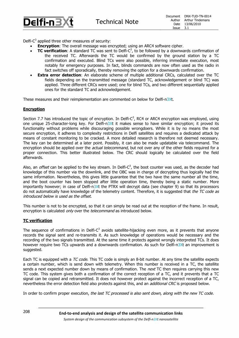
Technical NoteDocument
AuthorDateIssue
DNX-TUD-TN-0014Arthur Tindemans13/06/20103.1
208 End-to-end analysis and design of the satellite communication links
System design of the communication subsystem of the Delfi-n3Xt nanosatellite
Delfi-C3 applied three other measures of security: Encryption: The overall message was encrypted; using an ARC4 software cipher. TC verification: A standard TC was sent to Delfi-C3, to be followed by a downwards confirmation of
the received TC. Afterwards the TC would be confirmed by the ground station by a TCconfirmation and executed. Blind TCs were also possible, inferring immediate execution, mostnotably for emergency purposes. In fact, blinds commands are now often used as the radio infact switches off sporadically, thereby removing the option for a downwards confirmation.
Extra error detection: An elaborate scheme of multiple additional CRCs, calculated over the TCfields depending on the transmitted message (standard TC, acknowledgement or blind TC) wasapplied. Three different CRCs were used; one for blind TCs, and two different sequentially appliedones for the standard TC and acknowledgement.
These measures and their reimplementation are commented on below for Delfi-n3Xt.
Encryption
Section 7.7 has introduced the topic of encryption. In Delfi-C3, RC4 or ARC4 encryption was employed, usingone unique 25-character-long key. For Delfi-n3Xt it makes sense to have similar encryption; it proved itsfunctionality without problems while discouraging possible wrongdoers. While it is by no means the mostsecure encryption, it adheres to complexity restrictions in Delfi satellites and requires a dedicated attack bymeans of constant monitoring to be cracked. A more detailed research is therefore not deemed necessary.The key can be determined at a later point. Possibly, it can also be made updatable via telecommand. Theencryption should be applied over the actual telecommand, but not over any of the other fields required for aproper connection. This better illustrated below. The CRC should logically be calculated over the fieldafterwards.
Also, an offset can be applied to the key stream. In Delfi-C3, the boot counter was used, as the decoder hadknowledge of this number via the downlink, and the OBC was in charge of decrypting thus logically had thesame information. Nevertheless, this gives little guarantee that the two have the same number all the time,and the boot counter has been stopped after little operation time, thereby being a static number. Moreimportantly however; in case of Delfi-n3Xt the PTRX will decrypt data (see chapter 9) so that its processorsdo not automatically have knowledge of the telemetry content. Therefore, it is suggested that the TC code asintroduced below is used as the offset.
This number is not to be encrypted, so that it can simply be read out at the reception of the frame. In result,encryption is calculated only over the telecommand as introduced below.
TC verification
The sequence of confirmations in Delfi-C3 avoids satellite-hijacking even more, as it prevents that anyonerecords the signal sent and re-transmits it. As such knowledge of operations would be necessary and therecording of the two signals transmitted. At the same time it protects against wrongly interpreted TCs. It doeshowever require two TCs upwards and a downwards confirmation. As such for Delfi-n3Xt an improvement issuggested.
Each TC is equipped with a TC code. This TC code is simply an 8-bit number. At any time the satellite expectsa certain number, which is send down with telemetry. When this number is received in a TC, the satellitesends a next expected number down by means of confirmation. The next TC then requires carrying this newTC code. This system gives both a confirmation of the correct reception of a TC, and it prevents that a TCsignal can be copied and retransmitted. It does not however protect against the incorrect reception of a TC,nevertheless the error detection field also protects against this, and an additional CRC is proposed below.
In order to confirm proper execution, the last TC processed is also sent down, along with the new TC code.

Technical NoteDocument
AuthorDateIssue
DNX-TUD-TN-0014Arthur Tindemans13/06/20103.1
209End-to-end analysis and design of the satellite communication links
System design of the communication subsystem of the Delfi-n3Xt nanosatellite
A means of blind telecommanding could be the following: a golden TC code can be defined. This one TC codefrom the same set of numbers is not allowed as a regular TC code, and will trigger action withoutconsequently demanding a new golden TC code. This allows for consecutive commands without immediateconfirmation, in case of emergencies. A later TC can then alter the golden TC code to a new number.
A special case arises when the transponder or OLFAR is switched on; in this case no TM frames aretransmitted. The suggested approach in that case is rather simple and in line with the above scheme. Eitherthe last transmitted TC code, if received, is used, or the golden TC code is used. If the last transmitted TCcode is used to switch the transponder off or OLFAR, a new TC code will be transmitted over the downlink asusual afterwards.
Additional CRC
As explained, Delfi-C3 applied multiple additional CRCs. In fact, other than to create confusion outside of andwithin the team, there is no good reason to have multiple extra CRCs. To keep functionalities well-separated,it is therefore proposed to have one additional CRC just to ensure proper reception of the TC. The CRCs ofDelfi-C3 have as hexadecimal polynomial generators: 0x1021, 0x8005 and 0x1957. All these CRCs are of 16-bit length. Their source is unknown, but as mentioned by the writer of the DIGIT software, Gerard Aalbers,they are based on well-known CRC polynomials.
Chapter 7 has provided an in-depth discussion of available CRC codes and their performances, and gives anoptimum alternative. The maximum amount of detectable errors for a field size of 36 to 151 bits is 5, given aHamming distance of 6. This field size optimally matches the TC content, of 72 bits, including the 64-bitactual TC and an 8-bit TC code. Chapter 7 presents the optimal code for this range. It has the generatorpolynomial 236535. The article presenting this code uses a polynomial code expression of three octalproducts.
It generator polynomial can then also be given by the product: (x4+x2+x1+1) (x6+1) (x5+x3+x2+1) or 1 00000110 00101011
It is proposed that this code be used as an extra CRC. In this manner 5 errors can be detected by the firstCRC, and another 3 by the second CRC, which is the general DelfiX CRC. Also, the latter should not be usedtwice as its mathematical similarity would remove its added effect. In both CRC cases it holds that more than99% of larger combinations of errors are also detected, as with general 16-bit CRCs. Then, it becomesreasonably safe to say that no corrupt TCs will be processed by the OBC in the limited lifetime of Delfi-n3Xt.
The smaller CRC introduced above should be calculated before the regular CRC.
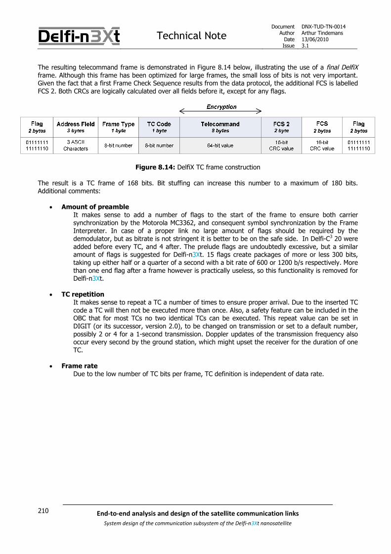
Technical NoteDocument
AuthorDateIssue
DNX-TUD-TN-0014Arthur Tindemans13/06/20103.1
210 End-to-end analysis and design of the satellite communication links
System design of the communication subsystem of the Delfi-n3Xt nanosatellite
The resulting telecommand frame is demonstrated in Figure 8.14 below, illustrating the use of a final DelfiXframe. Although this frame has been optimized for large frames, the small loss of bits is not very important.Given the fact that a first Frame Check Sequence results from the data protocol, the additional FCS is labelledFCS 2. Both CRCs are logically calculated over all fields before it, except for any flags.
Figure 8.14: DelfiX TC frame construction
The result is a TC frame of 168 bits. Bit stuffing can increase this number to a maximum of 180 bits.Additional comments:
Amount of preambleIt makes sense to add a number of flags to the start of the frame to ensure both carriersynchronization by the Motorola MC3362, and consequent symbol synchronization by the FrameInterpreter. In case of a proper link no large amount of flags should be required by thedemodulator, but as bitrate is not stringent it is better to be on the safe side. In Delfi-C3 20 wereadded before every TC, and 4 after. The prelude flags are undoubtedly excessive, but a similaramount of flags is suggested for Delfi-n3Xt. 15 flags create packages of more or less 300 bits,taking up either half or a quarter of a second with a bit rate of 600 or 1200 b/s respectively. Morethan one end flag after a frame however is practically useless, so this functionality is removed forDelfi-n3Xt.
TC repetitionIt makes sense to repeat a TC a number of times to ensure proper arrival. Due to the inserted TCcode a TC will then not be executed more than once. Also, a safety feature can be included in theOBC that for most TCs no two identical TCs can be executed. This repeat value can be set inDIGIT (or its successor, version 2.0), to be changed on transmission or set to a default number,possibly 2 or 4 for a 1-second transmission. Doppler updates of the transmission frequency alsooccur every second by the ground station, which might upset the receiver for the duration of oneTC.
Frame rateDue to the low number of TC bits per frame, TC definition is independent of data rate.

Technical NoteDocument
AuthorDateIssue
DNX-TUD-TN-0014Arthur Tindemans13/06/20103.1
211End-to-end analysis and design of the satellite communication links
System design of the communication subsystem of the Delfi-n3Xt nanosatellite
8.6.2 Telemetry frame (downlink)
Telemetry by means of TM frames is meant to provide a continuous downlink signal over the PTRX (or ITRX).Also, its reception is best-effort, it is not guaranteed. Data rate is a limiting factor; content is determinedbased on what amount of space there is. In case however the data rate turns out to be high enough so thatthe content cannot be filled usefully, consecutive frames can be repeated, possible spaced apart by a certainamount of time if allowed for by the processor buffer.
For the TM frames the frame rate as well as amount of preamble should be determined. At the same time,some subfields of the information field can be specified, related to communication aspects. The finalimplementation of these subfields is again to be determined by the CDHS systems engineer. The aboveaspects are discussed below.
Frame rate
As mentioned above it makes sense to maximize the amount of data sent by increasing effective data rate.This can be done by:
Increasing the actual data rate Increasing the average throughput efficiency
As shown in subsection 8.5.6, the DelfiX protocol increases the throughput efficiency by some 10-15%. Incase of Delfi-C3 with a bitrate of 1200 b/s, 1 frame per second was transmitted on the downlink. Section 7.6has shown that this was on the high side, a 2-second frame would have increased data throughput by 8%.This would then decrease the amount of frame per second to 0.5.
Nevertheless, frame duration is also limited by time-varying communication aspects such as changing Dopplershift rate and satellite rotation. Satellite rotation rates however turn out to be not very significant on this timescale (an estimated 0.2° per second for Delfi-C3), and neither are Doppler shift rates on the VHF downlinkcompared to the frame duration. The choice of having one frame per second for Delfi-C3 was rather arbitrary.However, it has proven to work nicely.
Satellite rotation will assumably be of the same order for Delfi-n3Xt, although dependent on the final ADCSimplementation. So the frame rate should not have to be reduced. Subsection 8.5.6 has shown that framesizes of 2400-4800 are preferred for BER values of 10-5, and frame sizes of 4800-9600+ are preferred for BERvalues of some 10-8.
In conclusion, frame sizes of 2400-9600 are all acceptable. 4800 bits would be on the safe side for variousBER values. For a data rate of 2400 however this would involve spreading a frame over two seconds, whereastotal overhead per frame is relatively small with the DelfiX protocol. As such, the following frame sizes andframe rates are suggested for different final bit rates:
2400 b/s: frame size of 2400 bits frame rate of 1 frame/s 4800 b/s: frame size of 4800 bits frame rate of 1 frame/s 9600 b/s: frame size of 4800 bits frame rate of 2 frame/s

Technical NoteDocument
AuthorDateIssue
DNX-TUD-TN-0014Arthur Tindemans13/06/20103.1
212 End-to-end analysis and design of the satellite communication links
System design of the communication subsystem of the Delfi-n3Xt nanosatellite
Amount of preamble
In case of Delfi-C3 the effective amount of frames per second was only 4/5, as one second (thus one frame)was filled with flags (preamble) after the transmission of every 4 TM frames (in Science mode). This secondwas simply required by satellite processing speeds. An added benefit was that it gave a second for radioamateurs to clearly spot the transmission frequency, but in fact the frequency spectrum can also easily belocated without this constant frequency. Similarly, simple tests performed by playing back a recorded Delfi-C3
telemetry sample, without flag frame, show a seamless demodulation in RASCAL/DUDe. Therefore, no suchperiod is planned for with Delfi-n3Xt.
The TM signal can be assumed to be continuous; there is no defined beginning and end of transmission otherthan those of the frames. As bit stuffing will almost never be maximal, frames of less than the defined framesize will be supplemented by flags, and some 1’s to reach an integer number of bytes. This will add somepreamble in between every TM frame to allow for synchronization.
Unique frame ID
Two types of labels are useful for telemetry data; one is a time stamp, and one is a frame counter. Thecounter can yield information on reception completeness, whereas the time stamp can give information onthe moment of frame generation. In delfi-C3, no time stamp was used as no real time clock was integrated. Acounter was used, but had to solve the problem of uniqueness; when a reset occurred the counter shouldremain unique. Storing each counter however in nonvolatile memory would quickly use up the allowedmemory-write cycles. Therefore, a boot counter and a cycle (temporary) counter were incorporated.Nevertheless, after countless resets the boot counter was switched off in fear of using up the memory.Whereas a counter can be seen as part of the protocol, is it also interesting for communications as it allowsfor requesting data if storage is incorporated in Delfi-n3Xt, such as on the STX.
In Delfi-n3Xt continuous operation is assumed, due to the incorporation of a battery. The previously proposedsolution of adding IDs to frames [SLR 0282] is to add a 39-bit RTC (Real Time Clock), which are then uniquemarkers. Furthermore, in case of a payload frame another RTC is added at the exact moment of payload datageneration. Whether this last one is indeed necessary and useful, is part of the CDHS data assessment. Inany case, no counter is present, just the clock data. The problem with this set-up is twofold:
It does not give data on completenessA frame is not per definition generated every second in case of failures or non-nominaloperations.
It does not automatically allow for unique data requestsThe RTC counts in tenths of seconds and data frame generation by the OBC is not constricted toa specific moment in a second. Simply ignoring the tenth seconds is no option either as possibly afirst frame is generated, say, in the early 29th second, and a second one in the late 29th second.
Furthermore, as will be shown below, 39 bits is excessive if the time is expressed in tenths of seconds from acertain moment in time onwards. Therefore, two options of improvement are suggested. The general solutionis to add a (small) counter to the RTC added. This counter will be stored in volatile memory and will justrestart after its maximum length is reached or after a power loss.

Technical NoteDocument
AuthorDateIssue
DNX-TUD-TN-0014Arthur Tindemans13/06/20103.1
213End-to-end analysis and design of the satellite communication links
System design of the communication subsystem of the Delfi-n3Xt nanosatellite
Two propositions:
Maximized completeness, good requestabilityIn this case, the counter cycle is completed: it runs its full cycle and restarts afterwards. It is notlinked to the RTC, but the combined RTC allows concluding on when the cycle took place.Requestability is acceptable through requesting numbered frames belonging to a certain period.An RTC of 32 bits allows for 13.6 years to be counted in tenths of seconds, which with an 8-bitcounter yields cycles of 256 numbers, totalling 40 ID bits, or 5 bytes.
Maximized requestability, good completenessIn the case, the counter is linked to the RTC and does not run a full or predefined cycle. It issuggested that the RTC counts in minutes, where 24 bits allow for 31.9 years. Seconds andtenths of seconds are then counted by a 10-bit counter. Every minute then a new 4-bit counterstarts, which can run to 59, 60 or 61 depending on the frame generation speed within a certainminute. In this manner, each frame is allocated a unique number which can be anticipated inadvance or retrospect, and requested with maximum ease. It might however not be immediatelyclear whether a 60th or 61st frame exists within a minute, assuming a frame generation speed of 1per second. Also, this approach requires an active link between clock and counter generation.This system is shown schematically in Figure 8.15 below; from left to right a complete countercan be obtained, either a total time counter or a unique frame counter.
Figure 8.15: Suggestion for a practical unique frame ID
The result of the suggestions above is a 40 bit unique ID.
In the end, CDHS complexity and reliability should be taken along to make the final decision. Of course, alarge (unique) counter can also be added but this would require more bits; the same holds for anotherdedicated boot counter. Then again, large framer counters might not end up to be a problem if the downlinkdata rate of 9.6 kb/s is reached. And still, this would require the problem of required storage to be solved incase the satellite is not constantly powered.
For the clock it holds that it can be assumed to work constantly, depending on its implementation (including asmall battery for example). If it does not, a small overlap can be accepted (revert in time). In case ofcommunications this can be monitored by adding another time stamp to the received telemetry, on-ground.

Technical NoteDocument
AuthorDateIssue
DNX-TUD-TN-0014Arthur Tindemans13/06/20103.1
214 End-to-end analysis and design of the satellite communication links
System design of the communication subsystem of the Delfi-n3Xt nanosatellite
Data security
The first line of defense against corrupted data is the CRC. As presented above it allows discovering up to 3independent bit errors, or more in specific patterns. With dedicated processing even single bit errors can becorrected. This then protects sufficiently against transmission errors, given the BER of 10-5.
A tweaked recording of TM data (send by a possible wrongdoer) can however circumvent the CRC.Consequently, data transmitted by RASCAL, or data received by RASCAL, does not necessarily have to be theoriginal data. Section 7.7 has introduced techniques to circumvent this.
Encryption is not allowed on the downlink over a radio amateur frequency. Nevertheless, a unique hash canbe inserted. As this will come at the cost of many bits, it is not preferred. An encrypted hash can be used, asit reduces the bit load. Nevertheless, it increases complexity.
As it is not assumed that Delfi-n3Xt will be the target or database spamming attacks, and every framesubmission will be accompanied by a user name, no additional security is deemed required on the downlink.
TM info field
As introduced in the last section, the telemetry downlink frames should also include the TC code, as well asthe last executed TC. The latter can simply be done with sufficient accuracy by transmitting just the 8-bit TCtype and destination. The TC code field can in case of a received golden TC code be set to 00000000 or11111111. This section has suggested a 40-bit counter. Both the TC code and last TC fields can be said to bepart of the CDHS housekeeping data, as a matter of convention.
The total (minimum) CDHS HK field length is then 24 bits.
The resulting suggestion for (part of) the content of the TM frame is demonstrated in Figure 8.16 below. Ifhigh data rates are reached and more space is available, of course a more complete repetition of the lastexecuted TC can be sent down. In that case, even a short history of executed TCs can be added.
Figure 8.16: TM Information Field content suggestion

Technical NoteDocument
AuthorDateIssue
DNX-TUD-TN-0014Arthur Tindemans13/06/20103.1
215End-to-end analysis and design of the satellite communication links
System design of the communication subsystem of the Delfi-n3Xt nanosatellite
8.6.3 Telemetry request frame (downlink)
Assuming some form of storage will be available on Delfi-n3Xt, be it on the STX or even directly connected tothe OBC, stored-telemetry requests will be useful. Even if not, telemetry packages can be requested withspecific data via telecommand. A telecommand will therefore have to be defined for these cases, and atelemetry request frame will have to be defined, the TM-request frame. The proposed frame type field whichis part of the DelfiX protocol can simply be used to indicate a special type of telemetry frame, even if it meansthe body of the frame is identical to the originally transmitted telemetry frame.
8.6.4 Software update frame (uplink)
Software updating is a possible addition to Delfi-n3Xt, if feasible. Especially when Delfi-n3Xt might become atest bed for ACDS purposes, software updating can be very useful. Whether software updating is feasiblefrom a CDHS side should be investigated, but it should be no problem for communication reasons. Atelecommand should announce the start of a software update transmission, which will then last for as long asthere is data to be transmitted. As this is surely more than one usual TC frame length, a special frame typeshould be defined; the software update frame.
Different aspects are quickly discussed below.
Frame rate: The software update frame would most likely resemble the TM frame, in the sense that datacontent exceeds data frame length. Therefore the maximum data rate should be used, and a default framelength of 600 bits can be used, given a 600 b/s bit rate. If however the bitrate indeed is only 600 b/s, a 6%increase in data throughput can be achieved by lowering the frame rate to 0.5 frames/s. A further halvingwould yield only 2% increase. Nevertheless, if the upload program is not excessive, transmission time is notcritical and safety can be chosen over speed. The frame rate can be changed by means of experiment, ifindeed the buffer of the PTRX or ITRX receiver is sufficiently large, but it does not make much sense to dothis for a dangerous procedure such as software uploading.
Data fields: The frame type field can again identify the software update frame. The info field can be filledwith any defined information, most likely preceded by a software package frame number and a total number.
Security: As any upload procedure, software updates can influence mission success. As such, some form ofsecurity is recommended, and allowed as we are dealing with an uplink signal. Most simply, the TC code canagain be used as a simple ’password’. Nevertheless, as it does not make sense to change the TC code persoftware update frame, a single password for the complete session or the program to be uploaded can beused. This code can simply be the one delivered as a response to the TC announcing the software upload.Furthermore, encryption can again be applied; possibly with a different key than regular TCs. Nevertheless, inthis case it should be tested whether the OBC can keep up with real-time decryption.
Amount of preamble: As software upload sizes can be significant, it does make sense to limit the numberof flags transmitted before a frame. On the other hand, it is important that every frame should be receivedproperly in contrary to the downlink. At the same time, a large link margin is available. As such, an amount of3-5 flags between frames should be sufficient. The first software upload frame however can again bepreceded by the same number of flags as a telecommand to ensure proper arrival, such as 20 flags.

Technical NoteDocument
AuthorDateIssue
DNX-TUD-TN-0014Arthur Tindemans13/06/20103.1
216 End-to-end analysis and design of the satellite communication links
System design of the communication subsystem of the Delfi-n3Xt nanosatellite

Technical NoteDocument
AuthorDateIssue
DNX-TUD-TN-0014Arthur Tindemans13/06/20103.1
217End-to-end analysis and design of the satellite communication links
System design of the communication subsystem of the Delfi-n3Xt nanosatellite
9 PTRX
The primary transceiver (TRX) on Delfi-n3Xt is logically called PTRX. It is a complicated system as seen froma top-level point of view, due to the reason that it is based on the RAP, on which many people have workedand last-minute tweaking have extensively been performed without extensive documentation. At the sametime a radio requires many people with different competences to work together, with work varying from top-level conceptual to low-level electrical integration.
This chapter describes the top-level conceptual design, but also discusses lower-level component integration.The previous chapter has described the techniques and components involved with the UHF/VHF link; on thesatellite this link is operated primarily by the PTRX.
A functional description of the PTRX is used to define operational modes in section 9.1. This leads to anumber of CIs, as presented in section 9.2. The resulting hardware integration of the PTRX CIs in presentedin section 9.3, and its interfaces with the local EPS and CDHS components and external components areshown in section 9.4.
Using knowledge of the hardware components allows determining the housekeeping data that is to begathered and transmitted to the OBC in section 9.5. The latter is to be done by the PTRX processors, which atthe same time have a rather large number of functionalities to take care of; this is explained in section 9.6.Related to the processors is the choice of having telecommand interpretation functionality integrated in thePTRX RX, discussed in section 9.7.
The linear transponder, which functions as the return service to the radio amateur community, and itsimplementation are presented in section 9.8. The option of reducing the power consumption of the PTRX bylowering the gain of its PA is discussed in section 9.9. Consequently, two experimental features on a mission-level, software uploading and the variable voltage bus, are discussed in section 9.10. Finally, the status of thePTRX, the overall changes with respect to its predecessor and potential future improvements are discussed insections 9.11, 9.12 and 9.13 respectively.

Technical NoteDocument
AuthorDateIssue
DNX-TUD-TN-0014Arthur Tindemans13/06/20103.1
218 End-to-end analysis and design of the satellite communication links
System design of the communication subsystem of the Delfi-n3Xt nanosatellite
9.1 Functional description and modes
Based on the set of requirements on the PTRX specified in chapter 6, the main tasks of the PTRX are to:
Receive telecommands (TCs)
Transmit telemetry (TM)
Provide linear transponder functionality
Generate housekeeping data
Also, being a secondary mission objective, it should if possible:
Facilitate the OLFAR experiment
These different functionalities of the PTRX gives rise to multiple operational modes. Telecommands can bereceived in all modes. Housekeeping data is also generated in all modes. The other functionalities cannot beexecuted at the same time, due to power reasons and reasons of shared bandwidth. The resulting mutuallyexclusive modes are:
TM mode
This is the default mode. Telemetry is transmitted, which is internally received from the OBC overthe I2C bus. If however no telemetry is received, a continuous stream of flags is transmitted.
Transponder mode
The transponder is activated. Any signal received within the transponder bandwidth is convertedto transmission frequency, amplified and transmitted.
OLFAR mode
The OLFAR experiment is activated. Low frequency signals (<30 MHZ) are transformed to thetransmission frequency, amplified and transmitted.
TX OFF mode
As regulations prescribe that it should be possible that no signal is transmitted (requirement SAT-F.03), all transmissions should have an OFF switch. The processor however does not requireknowledge of this mode; TX and RX sections are separated. Power is supplied, or not. Whenpower is received in the TX section, TM mode will be activated.
The functionalities are further discussed below, as well as the required subfunctionalities, in subsections 9.1.1through 9.1.4. The following section can then derive a number of configuration items (CIs) required on thePTRX, after which section 9.3 can comment on the final hardware implementation.

Technical NoteDocument
AuthorDateIssue
DNX-TUD-TN-0014Arthur Tindemans13/06/20103.1
219End-to-end analysis and design of the satellite communication links
System design of the communication subsystem of the Delfi-n3Xt nanosatellite
9.1.1 Receive telecommands
The functionality of receiving telecommands can be functionally described by Figure 9.1 below.
This figure as well as those that will be introduced below, are conceptually very similar to those introduced inchapter 7 on transmission techniques. Nevertheless, these are more expanded and allow demonstratingoverlap in components. Physical or Data Link Layer functionalities are separately indicated by a small headerand different colours.
Figure 9.1: PTRX functionalities required for receiving telecommands.
An RF signal is received via a COAX cable, after which the physical layer functionalities as amplification,filtering and frequency conversion are performed, as introduced clearly in the previous chapter. Amplificationis taken as a separate block, as a primary RF amplifier is required, which is a more important component thatsimpler IF amplifiers. Frequency down-conversion is a conceptually important step, required to deliver theproper signal to the demodulator. In the process of frequency down-conversion a number of filters and IFamplifiers is necessary. Actually multiple down-conversion steps are applied. These are collectively indicatedas ‘frequency down-conversion’. Afterwards demodulation can take place, and a digital signal results.
Data link functionalities are different in that they require a processor, and software. The most important steptaken care of by the PTRX processors is the application and removal of data frames. In case of uplinkpackages however, data encryption is applied and it is suggested that the PTRX also removes dataencryption. This is not done similarly on Delfi-C3, however it is logically integrated with other data streamfunctionalities on the PTRX, and it takes away complexity from the OBC.
9.1.2 Transmit telemetry
The functionality of transmitting telemetry is again best shown by a figure, being Figure 9.2 below.
Figure 9.2: PTRX functionalities required for transmitting telemetry.
The functionalities shown above are very similar to those of Figure 9.1, but in reverse. No encryption isapplied on the downlink. The (final) amplification step is again shown separately as the power amplifierrequired is an important separate component, which could also be changed.

Technical NoteDocument
AuthorDateIssue
DNX-TUD-TN-0014Arthur Tindemans13/06/20103.1
220 End-to-end analysis and design of the satellite communication links
System design of the communication subsystem of the Delfi-n3Xt nanosatellite
9.1.3 Provide linear transponder functionality
The linear transponder subfunctionalities are shown in Figure 9.3 below.
Figure 9.3: PTRX functionalities required for providing linear transponder functionality.
The linear transponder functionality is conceptually very simple, as no data interpretation has to take place.An RF signal is first received, amplified and frequency down-converted. It is brought back to an IF of 10.67MHz, at which it is amplified using automatic gain control in order to give the signal a defined peak power.Afterwards the signal is again frequency converted, but this time to a higher frequency, and afterwardsamplified for transmission.
The benefit of converting to a low IF is that simple COTS electronics can be used for automatic gain control,but more importantly part of the transmitter and receiver architecture required on the PTRX can be reused.
9.1.4 Generate housekeeping data
The final main PTRX functionality required is to generate housekeeping data. This functionality has no directexternal communication aspect, as data is gathered within the PTRX, and transmitted to the OBC. The OBCthen joins housekeeping data and payload data in telemetry frames, to be returned to the PTRX fortransmission.
The functionalities involved are shown in Figure 9.4.
Figure 9.4: PTRX functionalities required to provide housekeeping data.
Different housekeeping values will be produced at different locations on the PTRX. In case these are analoguevalues, an analogue-to-digital converter integrated in the PTRX processor can be used to interpret the values.In case sensors are digital, the data is directly read out by the processor. The processor can then forward thedata to the OBC.
In case of the RAP, values such as amplifier temperature, Doppler shift current, forwarded and reflectedpower were gathered. The approach for the PTRX is further assessed in section 9.6 on the PTRX processors.

Technical NoteDocument
AuthorDateIssue
DNX-TUD-TN-0014Arthur Tindemans13/06/20103.1
221End-to-end analysis and design of the satellite communication links
System design of the communication subsystem of the Delfi-n3Xt nanosatellite
9.1.5 Facilitating the OLFAR experiment
The OLFAR experiment is not considered to be an actual part of the PTRX, and in fact should add little to thePTRX architecture. On the PTRX it would require the following functionalities (Figure 9.5):
Figure 9.5: Functionalities required on the PTRX to integrate the OLFAR experiment.
The majority of OLFAR components should be located on the DAB, or Deployment and Antenna Board, beingpart of the Antenna System. This is further explained in chapter 11 on OLFAR. The entire OLFAR experimentis explained in [SLR 0170]. A signal received via the antennas is converted to an IF of 10.67 MHz, after whichit is guided to the PTRX by means of a COAX cable. Consequently, the signal is transformed to RF, amplifiedfor transmission and forwarded to the antennas.
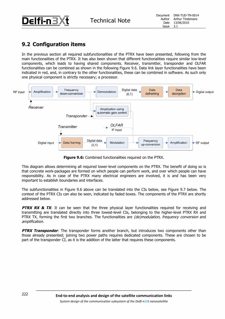
Technical NoteDocument
AuthorDateIssue
DNX-TUD-TN-0014Arthur Tindemans13/06/20103.1
222 End-to-end analysis and design of the satellite communication links
System design of the communication subsystem of the Delfi-n3Xt nanosatellite
9.2 Configuration items
In the previous section all required subfunctionalities of the PTRX have been presented, following from themain functionalities of the PTRX. It has also been shown that different functionalities require similar low-levelcomponents, which leads to having shared components. Receiver, transmitter, transponder and OLFARfunctionalities can be combined as shown in the following Figure 9.6. Data link layer functionalities have beenindicated in red, and, in contrary to the other functionalities, these can be combined in software. As such onlyone physical component is strictly necessary; a processor.
Figure 9.6: Combined functionalities required on the PTRX.
This diagram allows determining all required lower-level components on the PTRX. The benefit of doing so isthat concrete work-packages are formed on which people can perform work, and over which people can haveresponsibility. As in case of the PTRX many electrical engineers are involved, it is and has been veryimportant to establish boundaries and interfaces.
The subfunctionalities in Figure 9.6 above can be translated into the CIs below, see Figure 9.7 below. Thecontext of the PTRX CIs can also be seen, indicated by faded boxes. The components of the PTRX are shortlyaddressed below.
PTRX RX & TX: It can be seen that the three physical layer functionalities required for receiving andtransmitting are translated directly into three lowest-level CIs, belonging to the higher-level PTRX RX andPTRX TX, forming the first two branches. The functionalities are (de)modulation, frequency conversion andamplification.
PTRX Transponder: The transponder forms another branch, but introduces two components other thanthose already presented; joining two power paths requires dedicated components. These are chosen to bepart of the transponder CI, as it is the addition of the latter that requires these components.

Technical NoteDocument
AuthorDateIssue
DNX-TUD-TN-0014Arthur Tindemans13/06/20103.1
223End-to-end analysis and design of the satellite communication links
System design of the communication subsystem of the Delfi-n3Xt nanosatellite
Figure 9.7: Configuration Items to be implemented on the PTRX.
PTRX Support: Both a Frame Generator and a Frame Interpreter can be seen, these are the processors(aided by oscillators and ADC/DACs) of respectively the TX and RX sections. The two processors are branchedunder PTRX Support and not under PTRX TX and RX. The reason for this is that in this manner the PTRX RXand PTRX TX CIs are completely analogue. The processors on the other hand involve software, and thereforedifferent integration expertise. Also, the processors are charged with preparing housekeeping data. The finalCI of the support branch shows these Housekeeping Sensors, which should be placed on the PTRX andshould be read out by the processors.
Finally, OLFAR is included as a separate branch. This is mainly because the OLFAR system is spread over thePTRX and the antenna board. The latter is part of the Antenna System. In fact, it should almost completely beintegrated within the latter. But, as OLFAR requires the use of part of the transmitter section, the OLFARsignal from the antenna board is led to the PTRX, in order to be combined with the transmitter section. This isdone through the use of a switch, in order to have full control over the possible reception of an OLFAR signalon the PTRX.

Technical NoteDocument
AuthorDateIssue
DNX-TUD-TN-0014Arthur Tindemans13/06/20103.1
224 End-to-end analysis and design of the satellite communication links
System design of the communication subsystem of the Delfi-n3Xt nanosatellite
9.3 Hardware implementation
As was already suggested before, the actual low-level implementation of the PTRX is slightly more complexthan suggested by figures such as Figure 9.6 on the combined functionalities. The reason is that multiplefrequency conversion steps are used as well as multiple amplifiers and a number of filters. The actualimplementation of the PTRX on the component level is based on the design of the RAP, but has evolved sincethat time, and is shown in Figure 9.8 below.
Figure 9.8: Hardware components of the PTRX and its interfaces.
The design behind Figure 9.8 is a result of many design steps, originating with the RAP, but with the lastdesign stages of the PTRX described in [SLR 0281] and others, see chapter 5 for the complete list. Theprocess of preparing an analogue signal for transmission or reception is clearly seen in hardware blocks, withtransmission signal flow indicated by solid lines and generally moving from left to right. Some operationalsupport connections are indicated by dashed lines.

Technical NoteDocument
AuthorDateIssue
DNX-TUD-TN-0014Arthur Tindemans13/06/20103.1
225End-to-end analysis and design of the satellite communication links
System design of the communication subsystem of the Delfi-n3Xt nanosatellite
The main characteristics shown in Figure 9.8:
PTRX functional blocksThree clear functional blocks can be seen: receiver, transmitter and transponder. OLFAR is afourth functionality that has no clear functional blocks integrated on the PTRX except for themandatory switch, being implemented in the transmitter path.
External interfacesTwo bit stream interfaces with the I2C bus can be seen, as well as three radio frequencyinterfaces with COAX cable connections to the Antenna Board. The latter include the two logicalRF signal connections to receiver and transmitter, as well as an OLFAR IF signal generated on theantenna board. A final interface, that supplying power, is not indicated. For clarity reasons, theI2C interfaces are indicated as being unidirectional.
Superheterodyne principleThis principle applied on receiver, transmitter and transponder section can clearly be recognized,applying frequency converters, image-rejection filters, bandwidth filters and IF amplifiers. Somedeviating names are used for different amplifiers in the design, such as LNA for low-noiseamplifier, PA driver for Power Amplifier driver or pre-amplifier, and AGC for automatic gaincontrol.
IFs and RFs and oscillator frequenciesAll oscillator frequencies required for the frequency conversion steps are indicated in the figure,as well as the resulting or incoming IFs or RFs. Components operating on certain IF logically havethis IF as centre frequency.
Filter bandwidthsFilter bandwidths as opposed to centre frequencies have been indicated. These bandwidths areimportant for top-level conclusions on transmission bandwidths. The downlink shows no practicalbandwidth filters, only image-rejection filters. The final filter has 3.3 MHz bandwidth. In case ofthe receiver the signal is reduced to have only 5.5 kHz bandwidth, which does limit the actualideal transmitted signal as an FSK signal of 1200 symbols/s is broader than 5.5 kHz.
Processors and (de)modulatorsMost components are relatively standard components as is, but processors involve a lot morefunctionalities in software, and the (de)modulator integrates more hardware functionalities asalready has been introduced in the previous chapter. In the figure they have been logicallyindicated as single components. The processors are introduced in section 9.6 below.
Processor interfacesDashed connections are indicated to show processor interfaces. These connections allow formode switching and the generation of housekeeping data. The connections between the FrameGenerator and respectively Transponder AGC and Transmitter Switch allow switching betweenPTRX modes. The four other dashed connections deliver housekeeping data to the two PTRXprocessors.

Technical NoteDocument
AuthorDateIssue
DNX-TUD-TN-0014Arthur Tindemans13/06/20103.1
226 End-to-end analysis and design of the satellite communication links
System design of the communication subsystem of the Delfi-n3Xt nanosatellite
9.4 PTRX interfaces
The components introduced in the previous sections are all combined onto one PCB. These PCBs are stackedinside the structural frame of Delfi-n3Xt, and have interfaces to the power bus and data bus. In order toproperly provide these interfaces, components belonging to the electrical power subsystems (EPS) andcommand and data handling subsystem (CDHS) are integrated on each PCB. These components are jointlycalled the local EPS and local CDHS respectively. Also, in case of the PTRX, coax cables are connected to thePTRX PCB and communicate analogue signals between the PTRX and the Antenna Board. As such the PTRXPCB and its interfaces can be shown by Figure 9.9 below. A more detailed explanation on the local EPS andCDHS components can be found in the respective top-level documents, [SLR 0019] and [SLR 0029].
In fact, the illustrated interface diagram shown below is outdated. The final design of the Standard SystemBus (including power and data interfaces) is still to be determined.
Figure 9.9: PTRX interfaces and the implementation of the local EPS/CDHS.

Technical NoteDocument
AuthorDateIssue
DNX-TUD-TN-0014Arthur Tindemans13/06/20103.1
227End-to-end analysis and design of the satellite communication links
System design of the communication subsystem of the Delfi-n3Xt nanosatellite
Some comments on Figure 9.9:
3 types of external interfaces between the PTRX PCB and other systemsAs explained above, a power and data bus interface connect to the PTRX, as well as the analoguecommunication lines. 3 coax cables, as suggested by Figure 9.8 above, are required for analoguesignals. A 12V bus supplies power for the PTRX and the local CDHS system. Digital data incommunicated via the SDA line, or serial data line, and is supported by the SCL line, or serialclock line.
Double power and data bus architecture for both PTRX processorsIn the previous section it has been stated that two processors will be implemented on the PTRX,one in charge of receiver functionalities and one in charge of transmitter functionalities. Thisdecision is further explained in section 9.6 below. As the transmitter should be switched off ifnecessary due to reasons of interference, but the receiver should in principle never be switchedoff, the local circuits should be doubled for both the Frame Generator and Frame Interpreter. Thisalso allows failures in either transmitter or receiver not to force a transceiver shut off. In fact, itcan be decided to remove the possibility of switching the receiver off altogether. In this case, theI/O port can be removed, and possibly a simple PTC (positive thermal conductor) could be usedas a short-circuit protection. The same approach has been used in Delfi-C3; this choice dependson the final system bus integration.
Local EPSA local EPS consists of DC-DC convertors to convert from 12V to 3.3V, and protection circuits.The local EPS powers both the PTRX core and the local CDHS. The transponder is powered by thetransmitter power supply as it is also controlled by the transmitter processor.
Local CDHSA local CDHS consists of an I2C I/O Port and an I2C bus protector. The former basically switcheson the power supply of the PTRX via an I2C command originating from the OBC, whereas thelatter shuts off the PTRX from the I2C bus when not powered.

Technical NoteDocument
AuthorDateIssue
DNX-TUD-TN-0014Arthur Tindemans13/06/20103.1
228 End-to-end analysis and design of the satellite communication links
System design of the communication subsystem of the Delfi-n3Xt nanosatellite
9.5 Housekeeping data
To monitor the performance of the PTRX, or any subsystem or PCB, the regular gathering of housekeepingdata by the OBC and consequent transmission of it is required. The types of housekeeping data that areinteresting from an electrical point of view are generally:
Current consumption values Signal strength indicators Temperature values
Other values that can be thought of are digital values related to processor operations. The differentmeasurables per category are commented on below. Most values have been measured similarly on the RAP.Other, new suggestions have been indicated as being optional.
On the RAP all values were measured with 10-bit precision; the reason for this was quite simply that the ADCconverters of the PICs had this precision. Those of the MSP430s to be used on the PTRX have a 12-bitaccuracy. Nevertheless, in all cases an 8-bit accuracy seems to be enough; as in all cases the values areactually measured to spot irregular values, which can be spotted without large precision. A possible exceptionis information on Doppler shift; nevertheless the Doppler indicator introduced below value quite simply doesnot give a very absolute accurate Doppler shift value. The amount of bits per value is indicated below forclarity and explained if the value is (possibly) different from 8.
All values except for the current consumption values are to be measured by the PTRX processors.
Current consumption values:
Receiver current (8 bits): In order to get an idea of whether the receiver is operating withoutserious electrical problems, the current consumption can be monitored to check for nominalvalues.
Transmitter current (8 bits): The same holds for the transmitter current.
In general also the total PTRX current can be monitored. However, as explained below, two processors willallow or even require a separate power supply. Consumption is logically measured at the power supply, bywhat will be introduced below as the local EPS. Current consumption monitoring of individual componentsdoes not seem necessary.
Signal strength indicators:
Forwarded power (8 bits): The forwarded power, together with the reflected power, indicates thetotal power forwarded to the antenna system by the transmitter. In case of an antenna failure,these two values allow to notice and draw conclusions on the failure that has occurred. This valueis measured in an analogue fashion using a power detector and an ADC port of the MSP430.
Reflected power (8 bits): See forwarded power. Received Signal Strength Indicator (RSSI) (8 bits): To have an indication of the signal
strength received in the PTRX, this value can be used. This value is delivered by the FSKDemodulator and to be digitized by an MSP430.
Technical NoteDocument
AuthorDateIssue
DNX-TUD-TN-0014Arthur Tindemans13/06/20103.1
229End-to-end analysis and design of the satellite communication links
System design of the communication subsystem of the Delfi-n3Xt nanosatellite
Temperature values:
Power amplifier (PA) (8 bits): The power amplifier is the only component that significantly heatsup during nominal operations. With an efficiency of only 16%, more than 1 W is effectively usedto heat the amplifier and its environment. Therefore it is essential to monitor this heating. Adigital temperature sensor is used that yields a digital value. The 8-bit precision of the value canbe increased to produce a better thermal model.
One of the downsides observed of Delfi-C3 is that there were not enough temperature measurements done tovalidate the thermal model. As such, it might make sense to increase the amount of temperaturemeasurements. Optional:
Processors (Frame Generator and Frame Interpreter) (8-12 bits): MSP430 processors havean integrated temperature sensor. As such, these temperature values can easily becommunicated to the OBC and transmitted to the ground if the data budget allows for it. AsMSP430 processors are to be implemented everywhere on the satellite, a general approachshould be chosen. 12 bits is the precision of the value provided by the MSP430 processors, but 8bits might be enough.
PCB (8-12 bits): One or multiple PCB temperature values can be measured to get a good idea ofthe temperature distribution on the PCB and its components. This would however requirededicated temperature sensors at strategic locations. This is a choice that should be made on thesatellite level, as the same argumentation holds for all PCBs, albeit with more or less activity.Again 8-12 bits can be used.
Other analogue data:
Doppler indicator (8 bits): The chip used for signal demodulation constantly outputs a value toindicate the amount of frequency correction required to demodulate the signal. This amount ofcorrection is an indication of the amount of Doppler shift that has occurred. It does not give anabsolute Doppler shift value, as aging and temperature effects change the oscillator specifics.
Processor (digital) values:
A number of values can be thought of that can be provided by the processor as it performs its functionalities.Processing times can be measured on-ground and are assumed not to change during operation. Transmissiondata can generally be analyzed by the OBC itself, as the data originates there. Therefore options are mostlikely limited to reception data. Two optional suggestions:
Received erroneous frame counter (8 bits): It is interesting from a transmission point of view toget a good idea of how many transmission errors actually occur. The most logical way of countingwould be to keep track of how many times an erroneous CRC is calculated. It is assumed that nolarge numbers of erroneous frames are received, therefore an 8 bits counter should be sufficient,but more is possible. If the counter is ‘full’ it can simply be reset to 0. In order to have an idea ofthe percentage of erroneous frames of all received frames, a received frame counter can also bekept:
Received frame counter (16 bits): This counter will more quickly grow to large numbers. It doesnot however have to be a unique number, it can reset after a certain value; most likely togetherwith the received erroneous frame counter. It should then however be a lot larger than the latter,as many more correct frames than incorrect frames are anticipated. The ratio of 8 to 16 bits israther arbitrary; another ratio can be chosen pending the data budget.
All values shall in principle be gathered once per second. The OBC will pick-up the data every second, or lessoften.

Technical NoteDocument
AuthorDateIssue
DNX-TUD-TN-0014Arthur Tindemans13/06/20103.1
230 End-to-end analysis and design of the satellite communication links
System design of the communication subsystem of the Delfi-n3Xt nanosatellite
9.6 PTRX Processors
The processors on the PTRX have been chosen to differ in type and in terms of functionalities from those ofthe RAP. This section argues for the changes and introduces the activities to be performed by the PTRXprocessors, being the Frame Generator and Frame Interpreter. The technical note dealing with theimplementation of the functionalities on these processors is [SLR 0722]. Subsection 9.6.1 below introducesthe processors and their interfaces and functionalities of the RAP of Delfi-C3. Subsection 9.6.2 consequentlydecides on the approach for the Delfi-n3Xt PTRX, and specifies all functionalities.
9.6.1 RAP processors and their functionalities
On the RAP, there were three processors; being Peripheral Interface Controllers, or PICs with rather lowprocessing power. These were the Control PIC, the Bitshaping PIC and the EPS PIC. The latter in fact had afunction similar to the Local EPS included on the PTRX board, as introduced in section 9.4. As such, twomicroprocessors were basically used for the operation of the RAP. The Bitshaping PIC was involved withtransmission only, whereas the Control PIC was in charge of support. The OBC supplied frame content to theBitshaping PIC, but it received TC data directly from the receiver section of a separate bus line. Theimplementation of the two RAP operation microprocessors and their functionalities are illustrated in Figure9.10 below.
Figure 9.10: Integration of the RAP processors
From the figure the performed functionalities can be derived. These functionalities are presented in Table 9.1below. In case of the OBC only the functionalities that are related to communication are shown. Four types offunctionalities can be seen:
I2C communication Housekeeping data generation Mode switching Data preparation (transmission and reception)
The latter functionality can be subdivided in multiple subfunctionalities, which together form all digital actionsbetween having interpretable frame content and a modulated / demodulated signal.

Technical NoteDocument
AuthorDateIssue
DNX-TUD-TN-0014Arthur Tindemans13/06/20103.1
231End-to-end analysis and design of the satellite communication links
System design of the communication subsystem of the Delfi-n3Xt nanosatellite
Table 9.1: RAP transmission functionalities per processor
Bitshaping PIC Control PIC OBC
I2C communication
Data preparation(transmission)
o AX.25 frame application
o NRZ-I encoding
o Raised cosine PWM*
I2C communication
Housekeeping datageneration
Mode switching
Data preparation (reception)
o Bit interpreting(removing Manchester)
o NRZ-I decoding
o AX.25 frame removal
o TC decryption
*PWM: Pulse Width Modulation, which indicates approximating an analogue wave by using many digitalvalues at a specific sample rate to indicate the amplitude of the analogue signal. In this case the DACafterwards converts the PWM signal to an analogue signal.
It can be seen that the OBC has significant functionality. In fact, the bit interpreting capability required asampling rate of 25 kHz, requiring a halt of operations every 1/50,000 seconds as two receivers were on-board. The NRZ-I encoding as well as later CRC checking and decryption required a calculation intensive bit-per-bit operation, and at the same time the AX.25 frame removal requires searching for flags and recognizingproper frames. Finally the system required a separate connection as the signal forwarded to the OBC is notyet digital. The system is therefore not very modular.
9.6.2 PTRX processors and their functionalities
There are several good arguments to move all transmission functionalities to the PTRX:
Reducing the processing load on the OBC.
In case of the RAP significant actions had to be executed by the OBC. This posed significant loadon the OBC. As Delfi-n3Xt is a satellite significantly more ambitious than Delfi-C3, it makes senseto assume that the OBC will have more tasks to perform as well, but a similar MSP430 processoris slated to be used.
Simplifying the software of the OBC.
In Delfi-C3 the OBC is interrupted every 1/50,000 second for sampling the signal on one of thereceiver lines (the sample rate is 25 kHz for each receiver). These interrupts increased thecomplexity of the software.
Increasing reliability.
The interrupts occurring every 1/50,000 second may well have been the reason forsynchronization problems that occurred during testing.
Removing one line on the bus.
All communications can take place over the I2C bus as bits are interpreted by the PTRX itself.
Increasing the modularity of the system.
The radio can receive and transmit digital from and to the bus without extra processing required.The OBC needs no knowledge of transmission aspects. Also, the number of transceiversconnected to the OBC is no longer important. Finally, the PTRX transceiver can be testedseparately from the OBC. The radio thereby becomes a modular system.
More powerful MSP430 processors have been selected for subsystems.
Per default these processors are to be used on all subsystems. As these are more powerful, thetransition of functionalities seems feasible.

Technical NoteDocument
AuthorDateIssue
DNX-TUD-TN-0014Arthur Tindemans13/06/20103.1
232 End-to-end analysis and design of the satellite communication links
System design of the communication subsystem of the Delfi-n3Xt nanosatellite
The main disadvantages of including the all communication functionalities on the PTRX are:
It requires a significant change in the design of the RAP.
Requirement SAT.2.3-C.03 states that changes with respect to the RAP design shall beminimized.
The Delfi-C3 system has proven to work reliably in space.
Moving part of the functionality to the radio board requires a change of a mission critical part.
The disadvantages given above relate to the proven nature of Delfi-C3 and its RAP. At the same timehowever, stability issues of the OBC are known to be related to the previous implementation. Furthermore,significant benefits in terms of implementation and testing due to increased modularity are foreseen. As such,it is decided to include all transmission functionalities on the PTRX.
When deciding to move all transmission functionalities to the PTRX, it remains to decide which processor willtake care of this load. As on Delfi-n3Xt MSP430s will be used, processor load is less of a problem.Nevertheless, it does seem rather heavy to integrate all functionalities on one processor. Also, the followingrequirements state:
SAT.REQ.O.000 – The first priority of the satellite shall always be to enable commanding of the satellite.SAT.REQ.F.001 – The satellite shall have a means of switching off any transmitter on the satellite.SAT.REQ.F.003 – There shall be no provision for switching off a telecommand receiver other than an over-current protection.
Whereas the transmitter should be able to be switched off, most logically by removing the power of the entiresection, the receiver should not be able to be switched off other than by an over-current protection. As such,a more elegant solution is the following:
Two processors are used, which each take care of all functionalities involved with reception andtransmission respectively. This means the generation of housekeeping data generation isshared.
In summary, the main benefits of this approach follow from reasons of security, regulations and load sharing: A failure of the receiver or transmitter would not automatically cause failure of the other The transmitter must be shut off in case of disturbances and can so be shut off by removing power
without shutting off the receiver Processing load is shared between the two processors
The resulting architecture can then be seen in Figure 9.11 below.

Technical NoteDocument
AuthorDateIssue
DNX-TUD-TN-0014Arthur Tindemans13/06/20103.1
233End-to-end analysis and design of the satellite communication links
System design of the communication subsystem of the Delfi-n3Xt nanosatellite
Figure 9.11: Integration of the PTRX processors.
The Frame Generator and Frame Interpreter are the names given to the processors aided by oscillators andADCs and DACs. These processors are MSP430 processors, most likely of the type MSP430F1612. Theresulting functionalities are summed up in Table 9.2 below.
Table 9.2: PTRX processor functionalities
Frame Generator Frame Interpreter
I2C communication
Housekeeping data generation
Mode switching
Data preparation (transmission)
o AX.25 frame application
o NRZ-I encoding
o Raised cosine PWM
I2C communication
Housekeeping data generation
Data preparation (reception)
o Bit interpreting (removing Manchester)
o NRZ-I decoding
o AX.25 frame removal
o TC decryption
o Putting the TC in the buffer and awaitpick-up by the OBC
The same four different functionalities that have been introduced before are divided over the two processors.These four functionalities are shortly commented on below in three subsections.
I2C communication
Both processors should be appointed an I2C address, and should be able to properly communicate over theI2C bus. The protocols to be followed are equal to those of other subsystems on-board of Delfi-n3Xt. Theseand a number of general requirements thereby apply which apply to all subsystems that are connected to thedata bus; see [SLR 0029].

Technical NoteDocument
AuthorDateIssue
DNX-TUD-TN-0014Arthur Tindemans13/06/20103.1
234 End-to-end analysis and design of the satellite communication links
System design of the communication subsystem of the Delfi-n3Xt nanosatellite
Housekeeping data generation
A number of housekeeping data variables have been introduced in section 9.5 above. The currentconsumption values are to be read out and provided to the OBC by the local CDHS. The other values are tobe read out by the PTRX processors.
The housekeeping data generation is divided over the Frame Generator and Frame Interpreter, respectivelybeing part of the transmitter and receiver sections. All values should be read out once per second afterreception of a command from the OBC. This is important as it means that sensors are read out atapproximately the same point in time. A consequent command will request the values from the processors.
The following Table 9.3 shows the values to be read out and provided to the OBC by both PTRX processors.
Table 9.3: PTRX housekeeping values per processor
Frame Generator Frame Interpreter
Certain:
Forwarded power (8 bits)
Reflected power (8 bits)
Power amplifier (PA) temperature (8 bits)
Optional:
Frame Generator temperature
PCB temperature (read-out by both processorsor just by the Frame Generator)
Certain:
Received Signal Strength Indicator (RSSI)(8 bits)
Doppler indicator (8 bits)
Optional:
Frame Interpreter temperature
PCB temperature (read out by both processorsor just by the Frame Interpreter)
Received erroneous frame counter (8 bits)
Received frame counter (16 bits)
Mode switching and data preparation (transmission and reception)
This subsection presents the last two functionalities, as switching between modes yields certain datapreparation actions.
Mode switching only applies to the Frame Generator. The Frame Receiver only has one mode, the default‘receiver’ mode. The four modes of the Frame Generator are equal to the four PTRX modes. The FrameGenerator is in charge of activating and deactivating the Transponder AGC and switching the OLFAR switch;this has been illustrated by Figure 9.8 above.
The following Table 9.4 shows the possible PTRX modes including the peripherals, two of which are to bechanged by the Frame Generator itself. The consequent required data preparation actions are demonstrated.Similarly, the more evident Frame Interpreter mode and its required actions are shown in Table 9.5. A moredetailed description of all data preparation activities has been given in chapter 8 on the UHF/VHFtransmission link.

Technical NoteDocument
AuthorDateIssue
DNX-TUD-TN-0014Arthur Tindemans13/06/20103.1
235End-to-end analysis and design of the satellite communication links
System design of the communication subsystem of the Delfi-n3Xt nanosatellite
Table 9.4: Frame Generator modes and consequent data preparation actions
PTRX mode PeripheralsFrame Generator
Data preparation actions
TM mode PTRX TX power supply on
Transponder AGC off
OLFAR switch set to TX
If data is received from the OBC:
o AX.25 frame application
If no data is received from the OBC:
o Generation of continuous flags
In both cases:
o NRZ-I encoding
o Raised cosine PWM
Transponder mode PTRX TX power supply on
Transponder AGC on
OLFAR switch set to TX
Generate Morse signal (see section 9.8)
o Generate Morse text message bymeans of PWM
OLFAR mode PTRX TX power supply on
Transponder AGC off
OLFAR switch set to OLFAR
None
TX OFF mode PTRX TX power supply off None
Table 9.5: Frame Interpreter modes and consequent data preparation actions
PTRX mode PeripheralsFrame Generator
Data preparation actions
Any PTRX RX power supply on When a signal is received:
o Bit interpreting (removingManchester)
o NRZ-I decoding
o AX.25 frame removal
o TC decryption
o Putting the TC in the buffer andawait pick-up by the OBC
In the last table it can be seen that the consequence of moving the frame interpretation functionality to thePTRX is that a buffer has to be used. The OBC will consequently poll for TCs periodically as the PTRXprocessors will functions as slaves.

Technical NoteDocument
AuthorDateIssue
DNX-TUD-TN-0014Arthur Tindemans13/06/20103.1
236 End-to-end analysis and design of the satellite communication links
System design of the communication subsystem of the Delfi-n3Xt nanosatellite
9.7 Telecommand interpretation on the PTRX
A functionality that has been suggested to incorporate in the PTRX has been the ability to interprettelecommands. In case of a failure of the OBC, this would mean the PTRX could put received telecommandson the bus directly. More specifically, this would concern the receiver section of the PTRX and its FrameInterpreter.
At the very least this would involve:
Required master switching functionality. All subsystems should be able to receive commandsfrom both the PTRX and the OBC. Currently, the PTRX RX is only integrated as a slave.
Required OBC failure verification. A system should likely protect the bus from PTRX interventionin case no failure has occurred for security reasons. This could be done by letting the PTRXmonitor the I2C bus constantly to see if the OBC fails. In any case, the PTRX should provide theclock signal if the OBC no longer does it.
Increased software complexity and processor load: Monitoring of the system bus as well asthe functionalities required to properly address and send commands to systems increase softwarecomplexity as well as processor loading.
Increased overall risk. Increased complexity logically gives rise to increases risk. This holds for allsystems that should be able to receive data from two masters, but also for the mission-criticalPTRX.
Decreased modularity: As functionalities will overlap between different systems, overall modularityof Delfi-n3Xt would be decreased
The above scenario would only involve incorporating on the PTRX the ability to put telecommands directly onthe bus. As such, the CDHS would not be single-point-of-failure free as a failure of the OBC will still drasticallyreduce mission capabilities. Therefore, more OBC capabilities can be placed with the PTRX. Of course, thiswould come at the cost of yet more increased complexity, more failure cases and thus increased risk.
In order to circumvent a single-point-of-failure free system without moving all OBC functionalities to thePTRX, it has been decided to design a system with two redundant OBCs on the same PCB [SLR 0105]. In thiscase, the question becomes whether additional TC functionality on the PTRX would be worthwhile.
This would however still incur the above disadvantages. The only extra failures cases that can in this case beresisted are:
Software bugs and errors
Common mode failures in the OBC hardware design and circuitry
Specific second-degree failures
The latter failure case is however not part of the design-philosophy of Delfi-n3Xt; second-degree failures mayjeopardize the mission. Given future results of the testing and integration of the (redundant) OBC, these andpossibly additional failure cases should be assessed. If then in turns out that some additional TCinterpretation functionality on the PTRX would be useful, it should be reassessed. Nevertheless, the abovedisadvantages should be taken into account seriously.
For now the conclusion is that, given the redundant incorporation of the OBC, added TC interpretationfunctionality on the PTRX is not required, and it would involve only limited extra functionalities at the cost ofincreased complexity and thus risk.

Technical NoteDocument
AuthorDateIssue
DNX-TUD-TN-0014Arthur Tindemans13/06/20103.1
237End-to-end analysis and design of the satellite communication links
System design of the communication subsystem of the Delfi-n3Xt nanosatellite
9.8 Linear transponder
As introduced in chapter 5, the main return service to the radio amateur community is the inclusion of a lineartransponder. As it shares hardware architecture with the PTRX receiver and transmitter, it is logically includedcompletely on the PTRX board. This section introduces the functioning of the linear transponder.
When the PTRX is set to transponder mode, it will stop transmitting telemetry, but at no time it will stopbeing able to receive telecommands. The transponder functionality is explained below in section 9.8.1. At thetime the transponder is activated, a signal will be continuously transmitted, or broadcasted to announce theactive transponder. This signal, the transponder beacon, and its contents are explained in section 9.8.2. Afinal application worth mentioning is that of ranging, commented on in section 9.8.3.
9.8.1 Transponder functionality
The hardware architecture of receiver and transmitter is shared with the PTRX. This automatically means thatthe UHF band will be used for the transponder uplink, and the VHF band for the transponder downlink; thetransponder can be said to be of mode-UV.
A signal received in the uplink band will be transformed to the downlink and inverted. The inversion meansthat a high frequency in the uplink (i.e. 435.570 MHZ of .530-.570) will be transformed to a low frequency inthe downlink (in that case 145.880 MHz of .880-.920). The benefit of the inversion is that downlink Dopplershift can be subtracted from uplink Doppler shift. Also, as explained before, linear amplification is requiredover the whole bandwidth to not distort received signals and therefore allow a wide range of signals to beforwarded.
The transponder functionality only involves a physical layer; data is not interpreted. Independent of thesignificance of the signal that is transmitted, it will be returned. As such, the depth of discussion in this top-level link establishment is low. The transmission frequency will be transformed and the signal will beamplified. These functionalities have been shown in Figure 9.3 above.
The linear transponder was first implemented in the RAP of Delfi-C3. It has flown and operated successfully,for a reasonable amount of time. It is a secondary functionality, and as such possible improvements to thedesign are not of high priority. Therefore it is suggested to keep the design identical to that of Delfi-C3. Thisconclusion goes hand-in-hand with the suggestion from AMSAT to keep the transmission frequencies thesame.
For a more detailed design description of the transponder, also reviewing electrical figures, one is referred to[SLR 0281] where the PTRX is further discussed.

Technical NoteDocument
AuthorDateIssue
DNX-TUD-TN-0014Arthur Tindemans13/06/20103.1
238 End-to-end analysis and design of the satellite communication links
System design of the communication subsystem of the Delfi-n3Xt nanosatellite
9.8.2 Transponder beacon
As introduced above, the function of the transponder beacon is to signal the activation of the transpondermode (to radio amateurs). Its function is therefore not complicated, and no strict requirements exist as tohow it should be done. For Delfi-C3 it was therefore chosen to send a simple Morse code, using a techniqueknown as continuous wave or CW transmission. The name of the latter does not properly explain itsapplication, but it includes switching on and off a continuous wave signal. The language used to wrapinformation into the transmission is that of Morse code. The idea is that the signal can be received even bythe simplest receiver set-ups.
CW transmission is in fact a variation to a type of digital modulation explained in chapter 7, being amplitudeshift keying or ASK, or more specifically on-off keying (the case in which one of the two amplitude values iszero). While Morse code does involve a primarily binary alphabet, of ‘short’ and ‘long’ characters, it alsoincludes spaces and the length of each character is different. As such, CW is actually a type of the moregeneral amplitude modulation or AM.
What is interesting about using a CW transmission is that it can in fact be generated by the BPSK modulator.In effect, the most simple approach would be transmitting a string of 1’s or 0’s to create a constant signal,which combined with the 10.67 MHz IF carrier would yield a perfect sinusoid; consequently turning thistransmission on and off allows for a Morse beacon with two signal frequencies at IF; 10.67 MHZ and 0 MHz.Nevertheless, a slightly more advanced integration is chosen.
The ‘off’ Morse code before modulation will indeed simply be portrayed by a string of 0’s, resulting in notransmitted signal. The ‘on’ Morse code however will be portrayed by a sinus of 1200 Hz, generated by theFrame Generator (digitally and followed by a D-A conversion). The benefits of this are:
Reduced transmission bandwidth: no abrupt signal changes take place Increased testability: the 1200 Hz tone is an audible tone and the Morse generator can then be
tested before frequency up-conversion even takes place.
The PTRX Frame Generator can generate this stream of data itself independent of the OBC when put intotransponder mode, and it can bypass operations as NRZ-I encoding the data and pulse shaping. Astransmitter power is to be shared between transponder and beacon, the beacon signal should have lowersignal strength than a normal BPSK signal. As such, the stream of 1’s that will be transmitted (as a matter ofconvention) is transmitted with a signal power value of 10 dB less than normal. The pulse delivered to theBPSK modulator is then 5 times less in amplitude -> a halved amplitude gives a quarter of the power. Also,10 dB equals a factor of 10.
The transponder beacon transmission frequency options are given in chapter 8, and depend on whatfrequency will be allocated to the PTRX.

Technical NoteDocument
AuthorDateIssue
DNX-TUD-TN-0014Arthur Tindemans13/06/20103.1
239End-to-end analysis and design of the satellite communication links
System design of the communication subsystem of the Delfi-n3Xt nanosatellite
The Morse alphabet
The Morse code is defined by a number of simple rules. As said above and generally known, the alphabetconsists of a ‘short’ character, a ‘long’ character and a space or silence. The combination of the threecharacters can be used to form letters, which are the general letters of the international alphabet. Definitionshave also been established for general symbols such as the hyphen (-) in Delfi-n3Xt. This leaves open forinterpretation the relative length of the characters.
The rules are: A dash is equal to tree dots The space between parts of the same letter is equal to one dot The space between two letters is equal to three dots The space between two words is equal to seven dots
The absolute length of the characters however thereby is not yet determined, as everything has beendescribed in terms of the length of a dot. To give a rather extensive description; transmission speed isgenerally denoted by average amount of words per minute. As word lengths again differ in size, a generalreference is the word PARIS as it has average length in terms of characters, being 50 dots. For a commonspeed of 20 words per minute this yields 60 milliseconds per dot. In terms of the Delfi-n3Xt application ofgenerating a 1200 Hz tone, this means one dot equals 72 complete sinuses.
The transmitted message
In case of Delfi-C3 the transmitted message was:
“HI HI DE DELFI-C3 DELFI-C3”, followed by ten dots
The message is based on an international standard of broadcasting one’s presence; ‘de’ signifying the French‘of’. As such, the Delfi-n3Xt transponder message is proposed to logically be:
“HI HI DE DELFI-N3XT DELFI-N3XT” followed by ten dots

Technical NoteDocument
AuthorDateIssue
DNX-TUD-TN-0014Arthur Tindemans13/06/20103.1
240 End-to-end analysis and design of the satellite communication links
System design of the communication subsystem of the Delfi-n3Xt nanosatellite
9.8.3 Ranging
The communication system, or more specifically the transponder system, can be used for performing satelliteranging. Ranging is a method of determining the distance between objects. Ranging is not a required feature,as two-line elements or TLEs of Delfi-n3Xt can easily be acquired as the satellite is automatically tracked byNORAD, a US defence initiative.
Both one-way ranging and two-way ranging can be performed. One-way ranging requires high-precisioncomponents on the spacecraft [SLR 0371], whereas two-way ranging does not. For two-way ranging, thesatellite needs to have some form of a transponder that relays the signal transmitted to the satellite by thetracking station back to the Earth. On Delfi-n3Xt, a suitable transponder is of course present.
As such, optionally ranging experiments can be done with Delfi-n3Xt using the PTRX transponder in order todetermine the orbit. For these experiments to be accurate, tests are required on-ground to characterize thelinear transponder in terms of time delay, phase noise and bandwidth. The ITRX also has rangingfunctionality; this is one of the experiments that will be conducted with the ITRX.
The ranging method can be code tracking (for coarse measurements) or carrier phase tracking (for finemeasurements), or both. The accuracy that can be achieved depends on the properties of the lineartransponder.
In conclusion, if time allows for it, ranging experiments can be performed. A spare model of the transpondercan be used to characterize it; as such, the experiments can be prepared even after launch of Delfi-n3Xt.
9.9 Decreasing the gain of the PTRX Power Amplifier
Due to the ‘redefinition of Delfi-n3Xt’, the anticipated available power will be much lower than first assumed.Delfi-n3Xt currently is slated to use more power than Delfi-C3 in nominal operations and it is desired to havecontinuous operation throughout the eclipses using the battery. Therefore this does not simply allow forreapplying the Delfi-C3 solar panel configuration without additional power saving measures. Even if the solarpanel configuration is changed, these measures might be required.
One of the measures that have been suggested is to reduce the power consumption of the PTRX. The PTRX isnecessary in all nominal operations, as it is the primary transceiver. Even if an ITRX or even STX might beable to deliver the same downlink data transmission at lower power consumption, the power budget shouldbe designed to support the PTRX.
The PA used on the PTRX allows for decreasing its gain and thus supply power relatively easily by tweakingits resistor network. As has been shown in chapter 8, even for data rates of 9.6 kb/s and 850 km orbitaltitude, a reduction of 2 dB is acceptable according to the link budget. For lower final data rates, even morelink margin remains. It might not seem very desirable to give up the entire margin to save on power,nevertheless, a suitable reduction can be considered if required from a power point-of-view.

Technical NoteDocument
AuthorDateIssue
DNX-TUD-TN-0014Arthur Tindemans13/06/20103.1
241End-to-end analysis and design of the satellite communication links
System design of the communication subsystem of the Delfi-n3Xt nanosatellite
9.10 Possible experimental features of Delfi-n3Xt
Two experimental features that might be implemented on Delfi-n3Xt are software upload capability and avariable voltage bus. This section quickly discusses their impact on or relation to the PTRX in subsections9.10.1 and 9.10.2 below.
9.10.1 Software upload capability
This feature was actually already introduced in the last chapter on the UHF/VHF transmission link with respectto the data protocol. It can be very useful to be able to correct for malfunctioning software or to adjustsoftware capabilities to actual in-orbit Delfi-n3Xt performance. In case of the ADCS it could allow for differentexperiments to be defined later on in the mission.
In fact, the PTRX would be little impacted other than in software. As such, the only requirement is that thecommunication protocol between the CDHS and PTRX is well-defined in case a larger number of continuouspackages is received. In order to do so, the buffer of the PTRX microcontrollers or more specifically that ofthe Frame Interpreter should be (temporarily) enlarged. Nevertheless, this should not be a problem. In otherwords, this experiment is completely feasible as far as the PTRX is concerned.
9.10.2 Variable voltage bus
The variable voltage bus is a bus that might be implemented to basically present all left-over power to anysystem. In theory, COMMS could use this power for an increase of transmission power or data rate. It ishowever not preferred to connect this bus to the PTRX, for the following reasons:
The PTRX amplifier is designed to work on a predetermined supply voltageA high-efficiency class C amplifier is however being designed, primarily for the ITRX. This type ofamplifier can accept a variable supply voltage. Even if however this amplifier would beimplemented on the PTRX, the electrical design of a system that would guarantee to provide theminimum amount of power required by the PTRX, but possibly more by means of a variablevoltage bus, is difficult to design and implement.
The PTRX is a mission-critical designAny additional changes might only serve to decrease the reliability of the system, at the cost ofmore required project resources. Sporadically increased transmission power is also not requiredfor primary functionalities.
The variability of the variable voltage bus is, at least at this point, unknownIf it would be very high with fast transitions, unwanted effects might be incurred as thetransmitted signal might become too difficult to properly receive.

Technical NoteDocument
AuthorDateIssue
DNX-TUD-TN-0014Arthur Tindemans13/06/20103.1
242 End-to-end analysis and design of the satellite communication links
System design of the communication subsystem of the Delfi-n3Xt nanosatellite
9.11 Status
Currently the PTRX is still under development. Three main sections have been the target of development:
PTRX processorsThe general software for the PTRX processors has been written. The DelfiX protocol has beenintegrated, and the software has been prepared for 2400 b/s downlink and 600 b/s uplink. I2cprotocols and telecommand definitions should still be integrated. A higher bit rate can beintegrated relatively simply in software. The software has also been prepared for the proper read-out of housekeeping sensors and mode switching.
PTRX transmitterCurrently, all analogue components of the transmitter section are selected, and problems with theBPSK modulator have been solved. All analogue components have not yet been interfaced toform a working analogue transmitter section and also the Frame Generator has not beenconnected to the analogue transmitter section.
PTRX receiverAn updated design of the receiver has been made, but no working hardware is available yet. Theoption to increase the data rate is also still to be assessed in terms of components.
The required consequent steps:1) As soon as working analogue transmitter and receiver sections are available, they should be
interfaced to respectively the Frame Generator and Frame Interpreter and functional tests should beperformed.
2) Consequently, the transponder section can be incorporated based on the RAP design, and completefunctional tests can be performed.
3) Afterwards the PCB design can be made, including also all housekeeping sensors. The PCB can befabricated and complete functional testing can be performed. Possibly this might already include thestandard system bus as to be implemented on Delfi-n3Xt.
4) Finally, processor software can be upgraded to include all required functionalities.
9.12 Changes compared to RAP
There have been a number of (serious) changes, or improvements to the RAP design. These are:
The system has only digital data interfaces; it is therefore more modularThe RAP had a separate signal line from the demodulator on the RAP to the OBC, which wascharged with data interpretation
The RX and TX sections are fully separatedBy including two complete system bus interfaces, the TX sections can be switched off in hardwarewhile the RX sections remains active. This is useful due to the large power constraints of the TXsections, and the essential functionality of the RX section. At that, it provides independent failureprotection.
The PTRX transmitter can support higher data rates, possibly up to 9.6 kb/sThe Frame Generator is programmed to support higher data rates, 9.6 kb/s might even beallowed and used in operations. All other sections of the PTRX transmitter are unaffected byhigher data rates.
The PTRX receiver can possibly support a higher data rate of up to 1.2 kb/sDepending on its final design, 1.2 kb/s might be supported.

Technical NoteDocument
AuthorDateIssue
DNX-TUD-TN-0014Arthur Tindemans13/06/20103.1
243End-to-end analysis and design of the satellite communication links
System design of the communication subsystem of the Delfi-n3Xt nanosatellite
The data protocol has been customized for better performanceThe DelfiX protocol allows up to 10-15% more data to be sent compared to the AX.25 protocol, inthe same transmission time using the same data rate.
The overall electrical design has been reviewed and improvedThe entire design has been reviewed and still is under development, but a number ofcomponents has already been changed. This includes the BPSK modulator, filters and crystals. Inturn this improves on stability, performance and areal requirements, amongst others. In fact, partof the changes were required to replicate a working TRX on-ground, as last-minute changes tothe RAP were not documented.
The OLFAR experiment is most likely connected with the PTRX boardThis results in an extra switch on the PCB.
9.13 Future improvements
From a top-level point-of-view, a number of possible improvements can still be made:
A more efficient PA can be integrated in the PTRX TXA switching amplifier is under development by Robin Kearey, and is slated to be integrated on theITRX. This PA is currently specified to provide some 60% efficiency, which for similar transmitterpower would decrease the PTRX power requirements by almost 1 W.
The downlink modulation scheme can be changed to QPSKThe current BPSK modulator in fact is a QPSK modulator, electrically connected to pose as a BPSKmodulator. If it can be connected as a QPSK modulator, and on-ground demodulation software isadjusted, the required transmission bandwidth can be halved.
Frequency domain raised cosine filtering can be applied in the PTRX TXCurrently, raised cosine filtering in the time-domain is used. As chapter 7 has shown, theresulting frequency spectrum is in fact not compliant with regulations. Therefore, a morecomplicated Finite Impulse Response filter should be implemented, which is a digital filter orpulse shaper.
A look-up table can be used for quick CRC calculation in the PTRX TXWhile requiring a sizeable memory size, this can free up essential processor power requires forhigher data rates or FIR filtering.
Uplink data rates can be increasedThis can be done by increasing the actual data rate or by removing the (need for) Manchestercoding. Even if the data rate is increased to 1.2 kb/s, maximum data rates of 9.6 kBaud areallowed on the UHF radio amateur bands.
The uplink modulation scheme can be changed to MSKThis allows for a quick improvement of 3 dB in the link budget.

Technical NoteDocument
AuthorDateIssue
DNX-TUD-TN-0014Arthur Tindemans13/06/20103.1
244 End-to-end analysis and design of the satellite communication links
System design of the communication subsystem of the Delfi-n3Xt nanosatellite

Technical NoteDocument
AuthorDateIssue
DNX-TUD-TN-0014Arthur Tindemans13/06/20103.1
245End-to-end analysis and design of the satellite communication links
System design of the communication subsystem of the Delfi-n3Xt nanosatellite
10 ITRX
The secondary transceiver on-board of Delfi-n3Xt is the ITRX, or ISIS transceiver. It is also a payload,manufactured and provided by ISIS BV. The primary functionality for Delfi-n3Xt is to serve as a back-up radiofor the PTRX. However, as a payload it is supposed to demonstrate and test its correct performance in orbit.Also, it will be used to perform ranging experiments.
The ITRX will have characteristics similar to the PTRX. The main differences between ITRX and PTRX are:
The ITRX has a high-efficiency power amplifier.
The ITRX has a variable downlink data rate between 1200 and 9600 bit/s.
The ITRX does not have a linear transponder.
The ITRX has ranging functionality as well as a large number of other transmission modes.
As the ITRX is in fact a payload, it is not designed by the TU Delft or any part of the Delfi-n3Xt team.Therefore, there is only one CI as far as the team is concerned, see Figure 10.1 below.
Figure 10.1: The ITRX CI.
The ITRX shall be treated as a black box. No detailed subfunctionalities are to be derived by the Delfi-n3Xtteam and no components will be designed or selected. The operation and interfaces however are important.This chapter will focus on the definition of these.
The chapter follows the same structure as the chapter on the PTRX, but then more limited in content. Thefunctional description is presented first in section 10.1, along with the operating modes. The externalinterfaces are explained in section 10.2. Afterwards, the housekeeping data produced is presented in section10.3. The feasibility of some Delfi-n3Xt experiments in relation to the ITRX is then shortly discussed in section10.4. Finally, the status of the ITRX is commented on in section 10.5.
This chapter actually gives a small summary of the communication aspects covered in the more generalinterface control document, or ICD, see [SLR 0182]. However, some aspects as the support of the DelfiXprotocol and its interfaces are not yet included in the last version of the latter document.

Technical NoteDocument
AuthorDateIssue
DNX-TUD-TN-0014Arthur Tindemans13/06/20103.1
246 End-to-end analysis and design of the satellite communication links
System design of the communication subsystem of the Delfi-n3Xt nanosatellite
10.1 Functional description and operating modes
As the ITRX is slated to serve as a back-up for the PTRX, it should at least provide the main functionalities ofthe PTRX:
Receive telecommands (TCs)
Transmit telemetry (TM)
Generate housekeeping data
It is not required to have a second linear transponder. The ITRX is however a payload, and as such it has anumber of other functionalities. These will be commonly named as the ability to:
Perform ITRX tests
These main functionalities as well as the ability to perform ITRX tests leads to a large number of operationalmodes. As with the PTRX, telecommands can be received in all modes. Housekeeping data is also generatedin all modes. The resulting mutually exclusive modes are presented in [SLR 0182] and are:
Essential modes for Delfi-n3Xt:
Receive only mode: This is the default mode. It is basically the TX OFF mode of the PTRX.
DelfiX telemetry mode: This mode is the normal mode for transmitting telemetry, which is alsoused by the PTRX. The ITRX will include the DelfiX data protocol in its operations.
ITRX test modes:
Morse beacon mode: A beacon is transmitted continuously with a fixed Morse signal (CW).
Morse telemetry mode: Similar to the Morse beacon mode, but instead of a fixed signal, telemetryis transmitted in Morse.
AX.25 telemetry mode: This mode is the normal mode for transmitting telemetry, which is alsoused by the PTRX and the RAP of Delfi-C3.
AX.25 beacon mode: In this mode a signal is transmitted that consists of AX.25 flags.
ISIX beacon mode: This mode is comparable to AX.25 beacon mode, but instead of AX.25 the ISISprotocol ISIX is used.
ISIX telemetry: This mode is comparable to AX.25 telemetry mode, but instead of AX.25 the ISIXprotocol is used.
Loopback mode: In this mode any signal received by the receiver is transmitted directly. This isdone for the purpose of performing ranging experiments.
All modes other than those essential for Delfi-n3Xt are only activated by means of TC and above Delft so thattheir functionality can be verified. As such, the only incurred complexity of these modes other than the usualones is the required definition of an internal telecommand as well as a method for switching these modes off.The latter can be done by means of switching to another mode via telecommand, or using an automatedtimer in OBC or ITRX, after which regular TM transmission is resumed.

Technical NoteDocument
AuthorDateIssue
DNX-TUD-TN-0014Arthur Tindemans13/06/20103.1
247End-to-end analysis and design of the satellite communication links
System design of the communication subsystem of the Delfi-n3Xt nanosatellite
10.2 ITRX interfaces
The interfaces of the ITRX adhere to the standard system bus interface as defined for Delfi-n3Xt. However,depending on the actual definition of this interface, it is to be determined whether the ITRX will have aninterface lay-out similar to the PTRX, having separated RX and TX sections on the bus, or not.
The ITRX will in fact be based on the TRXVU (VHF/UHF Transceiver – which in turn is based on the originalRAP). The TRXVU has an I/O pin that can be used to switch on or off the power supply of the transmittersection. Therefore the transmitter section can in fact be switched on relatively simply, but in a manner notstandard given Delfi-n3Xt interface definitions. An adjustment to the Local EPS can be made to be able toswitch off the TX section directly, but as this involves extra complexity in a non-modular manner, it is notpreferred. Possibly, the option of separated sections can also be ignored, given the fact that the ITRX itself isalready a back-up radio and does not require an independent receiver section. In the end, the finalimplementation choice will lie with ISIS, given the input of the Delfi team. After the standard system bus hasbeen completely defined, ISIS has promised to review the matter and discuss the approach.
10.3 Housekeeping data
The housekeeping data produced by the ITRX again strongly resembles that produced by the PTRX. Thefollowing Table 10.1 shows the resulting values. It should be noted that more data is produced during theITRX test modes; this data is however referred to as payload data. Also, it is transmitted by the ITRX itself, sonot important for Delfi-n3Xt data budgets.
Table 10.1: Housekeeping data generated during receive only mode
Telemetry valueSize
[bits]
Minimum sampling rate
[Hz]
Average bit rate
[b/s]
PA temperature 8 0.2 1.6
PCB temperature 8 0.2 1.6
Forwarded power 8 0.2 1.6
Reflected power 8 0.2 1.6
Doppler voltage 8 1 8
Received signal strength 8 1 8
Receiver supply current 8 0.2 1.6
Transmitter supply current 8 0.2 1.6
Bus voltage 8 0.2 1.6
Total 72 N/A 27.2
It can be seen that a sampling rate is given, as in fact housekeeping data will not be produced every second.Two extra values are introduced with respect to those of the PTRX, being the PCB temperature and the busvoltage. The use of the former was commented on in the previous chapter, whereas the bus voltage is in factimplemented because of the modular implementation design of the ITRX (for customers). It makes sense forthe ITRX to provide housekeeping data on both power reception and power consumption, but, in fact, in caseof Delfi-n3Xt the local EPS already takes care of measuring the incoming power. If necessary, it can thereforebe required to drop this variable.
Technical NoteDocument
AuthorDateIssue
DNX-TUD-TN-0014Arthur Tindemans13/06/20103.1
248 End-to-end analysis and design of the satellite communication links
System design of the communication subsystem of the Delfi-n3Xt nanosatellite
10.4 Delfi-n3Xt experiments on the ITRX
Two experiments have been discussed in case of the PTRX, software upload capability and the variablevoltage bus. It was concluded that the latter is not required or feasible in relation to the PTRX. The sameholds for the ITRX, even more so as the ITRX is a payload and such experiments are not preferred by thepayload partner and have not been incorporated in any agreements. The capability to upload softwarehowever, as explained before, comes down to a (small) software update and a proper definition of theinterface. As such, would it be decided that software uploading is feasible, it can easily be discussed with thepayload partner whether the ITRX will or will not support this feature.
10.5 Status
The ITRX is currently under development. Within ISIS sufficient radio experts are available, although WouterJan is unavailable for a prolonged period. The resources (money) required for the actual implementation of allpresented features (improvements) have not been secured however. Nevertheless, the ITRX is as said beforebased on the TRXVU, which for Delfi-n3Xt purposes would be sufficient. As such, there is no direct reason toassume a working payload, at the same time being a redundant radio, will not be delivered on time.
For Delfi-n3Xt, the ITRX can theoretically also be replaced by a second PTRX with little implications.

Technical NoteDocument
AuthorDateIssue
DNX-TUD-TN-0014Arthur Tindemans13/06/20103.1
249End-to-end analysis and design of the satellite communication links
System design of the communication subsystem of the Delfi-n3Xt nanosatellite
11 OLFAR
OLFAR has been introduced in chapter 5, being a technology demonstration experiment which is part of thecommunication subsystem. It can be defined to be a radio, but it is not designed to receive human-madesignals. Using the antenna system of Delfi-n3Xt, a naturally present signal in the bandwidth of 0.3 – 30 MHzwill be received and amplified, and converted to an intermediate frequency. Sharing PTRX architecture, itshould consequently transmit the signal over the transponder transmission bandwidth, to be received on-ground.
OLFAR has no high priority and is not allowed to have mission-slowing impacts. Therefore, human resourcesshould be found to finalize the OLFAR experiment that would otherwise not logically provide mission-criticalfunctionalities. OLFAR and its technical design and design considerations are introduced in detail in [SLR0170]. This chapter gives only a functional and hardware introduction, in order to specify the systemsengineering impacts of the OLFAR experiment on Delfi-n3Xt.
Following the same structure as the PTRX chapter for as far as possible, the OLFAR functional description isfirst given in section 11.1, followed by the definition of the CIs as well as the hardware components insections 11.2 and 11.3 respectively. Section 11.4 then describes possible OLFAR integrations and section 11.5finishes off by giving the current status of OLFAR.
11.1 Functional description
OLFAR has only one simple function, which is to: Receive signals in the frequency range 0.3 – 30 MHz and prepare these for retransmission
The PTRX will consequently retransmit these signals. Also, it is envisioned that no housekeeping data isgenerated by the OLFAR experiment as only relatively simple and low-power electronics are applied.
A number of subfunctionalities can be distinguished in order to perform the main task, given the interfaceswith the antennas and the PTRX transmitter section. These subfunctionalities are shown in Figure 11.1 below.
Figure 11.1: Extra functionalities required to facilitate the OLFAR experiment.
Signals (that are automatically received on the UHF/VHF antennas) should first be extracted, and othercomponents should be filtered out. The resulting signal should be amplified, and converted to the rightfrequency in order to join the PTRX transmitter path with the proper IF of 10.67 MHz. Finally, the signal isbrought to a predetermined power value, similarly as is done in the transponder.

Technical NoteDocument
AuthorDateIssue
DNX-TUD-TN-0014Arthur Tindemans13/06/20103.1
250 End-to-end analysis and design of the satellite communication links
System design of the communication subsystem of the Delfi-n3Xt nanosatellite
11.2 Configuration Items
The subfunctionalities can be used to deduce a number of CIs. These CIs can be seen in Figure 11.2 below.Most CIs and their meaning are assumed to be straight-forward. The OLFAR Phasing Circuit should serve toextract useful signals and filter unwanted signals. The OLFAR Switch at the end was already introduced in thechapter on the PTRX and is required to join the OLFAR and PTRX paths, and to switch between modes.
Figure 11.2: OLFAR Configuration Items.
11.3 Hardware components
Given the required subfunctionalities, a component design can be set-up. This diagram is shown as Figure11.3 below. The design rationale will be given in [SLR 0170]. A short description of the functioning of thiscircuit is given below the figure.
Figure 11.3: OLFAR hardware components.

Technical NoteDocument
AuthorDateIssue
DNX-TUD-TN-0014Arthur Tindemans13/06/20103.1
251End-to-end analysis and design of the satellite communication links
System design of the communication subsystem of the Delfi-n3Xt nanosatellite
The basic idea of the OLFAR design is that the desired signals are extracted from the signal receivedautomatically by the UHF/VHF antennas. However, as these antennas are the same ones that transmit VHFsignals, including the OLFAR signal, the transmitted signal should be suppressed. This signal is not centred inthe 0-30 MHz range, but as its power even at low frequencies is much larger than naturally present low-frequency signals, harmonics and intermodulation products pose a serious disturbance.
In order to suppress the transmission signal, OLFAR extracts signals from the first and third antennas, whichindividually transmit a signal with a 180 degree phase shift with respect to each other. When summing thesesignals, the transmitted signal is completely suppressed. Two low-pass filters filter out high-frequencycomponents so that only the low-frequency components remain, of frequencies 0 to 30 MHz.
Consequently a low-noise amplifier combines the signals and increases the power content. Afterwardsfrequency conversion will take place. This consists of two steps; a frequency up-conversion and frequencydown-conversion. This is because the final IF lies within the range of 0-30 MHz; frequencies of interest caneither have a frequency lower or higher than the IF. If the entire signal would not first be up-converted, thefrequency conversion step would at times have to down-convert, and at times have to up-convert. Thereforethe entire 0-30 MHz band is lifted over the 10.67 MHz. A phase locked loop (PLL) integrates a VCO (voltage-controlled oscillator) to change the conversion frequency.
As the final transponder bandwidth is only 40 kHz broad, the 40 kHz of interest was effectively selected in thislast phase. The consequence is that there is a need for a processor that supplies a VCO input value,originating in the OBC. In other words; a processor is required to control OLFAR operations. This is animportant conclusion that is further evaluated below.
After up-conversion the frequency is brought (back) down to 10.67 MHz, the IF of the transmitter section ofthe PTRX, and the signal bandwidth is brought back to 40 kHz. An AGC sets the signal’s peak power to apredetermined value, and the signal is forwarded to the PTRX transmitter section, joined together by meansof a switch.
It is important to note that all components within the OLFAR box, with the exception of the three componentsmarked red, are to be integrated in one chip. As such, a small chip (some 1 cm2) with 24 interface pinsresults, supported by two stable crystal oscillators and a sharp bandwidth limiting filter. To give a simplevalue for the total integration space required, the four components can be estimated to require 4 cm2.
Technical NoteDocument
AuthorDateIssue
DNX-TUD-TN-0014Arthur Tindemans13/06/20103.1
252 End-to-end analysis and design of the satellite communication links
System design of the communication subsystem of the Delfi-n3Xt nanosatellite
11.4 Possible OLFAR integrations
In order to establish the impacts of the OLFAR experiment, this section evaluates the OLFAR integrationoptions. Three options have been suggested throughout time, which will be introduced below in subsections11.4.1 through 11.4.3, and traded off in section 11.4.4. All options take into account complete integration oneither or both the PTRX PCB and Phasing Board. In theory another PCB could house the componentsrequired, but as the input comes from the Phasing Board and the output should be presented at the PTRXPCB it makes no sense to place them somewhere else. This in turn would introduce even more cables andcomplexity. As almost all components are integrated in one chip, the integration is either mainly on one PCB,or the other.
11.4.1 Completely integrated on PTRX
The first idea at the conception of OLFAR was to basically have an implementation similar to that of thetransponder, on the PTRX. OLFAR mode could be switched on, at which point the OLFAR signals would beextracted from the RF signal received on the PTRX PCB via a preexisting connection. The required impactwould be limited to:
Area on the PTRX PCB Power from the Local EPS of the PTRX A VCO interface with the PTRX Processor, and slightly increased complexity for the latter
This option however is no longer possible due to the integration of the UHF and VHF antennas to a combinedset of UVF/VHF antennas (see [SLR 0036]). This is due to the interference on OLFAR signal receptionresulting from data transmission. It might already have been difficult in case of separated antennas.Therefore, this solution is basically not an option.
11.4.2 Mainly integrated on PTRX
A second option, solving the problem of the previous solution, is to retain having the most components on thePTRX, but moving the functionality of ‘extraction of useful signals’ to the Antenna System, or more specificallythe Deployment and Antenna Board (DAB). The latter houses the Modular Antenna Boxes (MABs), theirdeployment systems connected to a standard system bus and the UHF/VHF Phasing Circuit (as furtherexplained in [SLR 0036]). All other components would however be kept on the PTRX. Moving this functionalitywould basically mean having two signal ‘taps’ connected to two of the four antennas. Total required impacts:
Area on the PTRX PCB, and some on the DAB Power from the Local EPS of the PTRX A VCO interface with the PTRX Processor, and slightly increased complexity for the latter 2 COAX cables between the Phasing Board and the PTRX
However, one problem is created by this type of set-up. The OLFAR entrance filters have a very high-impedance. Indeed this high impedance is required as no signal of the PTRX, reception or transmission,should be lost to OLFAR. However, this requires that the filters be connected to the regular signal lines withminimum extra incurred distance. If however a sideline is created, which by means of a cable shouldtransport a signal to the PTRX before being filtered, the high impedance is lost.
In effect, the addition of a transmission line creates what is called an open stub. Using different cable lengthsthe impedance can be tweaked, but [SLR 0715] shows that it is not a matter of a few centimeters. It canhowever be resolved by introducing extra circuitry. Therefore, this second option would also require:
Additional phasing circuitry on DAB or PTRX that is yet to be designed

Technical NoteDocument
AuthorDateIssue
DNX-TUD-TN-0014Arthur Tindemans13/06/20103.1
253End-to-end analysis and design of the satellite communication links
System design of the communication subsystem of the Delfi-n3Xt nanosatellite
11.4.3 Mainly integrated on Phasing Board
A third option then is to move the overwhelming amount of components to the DAB, and have only a switchon the PTRX to join the paths. This removes the problem of having a need for additional circuit complexitysuch as in the second option, but at least requires space on the DAB. The consequent required impacts:
Area on the Phasing Board, and some on the PTRX PCB Power from the Local EPS of the DAB A VCO interface with the DAB processor, and slightly increased complexity for the latter 1 IF cable between the Phasing Board and the PTRX; this cable can be less thick and protected than
those required for RF signal transportation
It can be seen that this third option shifts occupancy and complexity to the DAB, but requires a simpler cableto transport the IF signal.
11.4.4 Conclusion
The first option, as explained, is no longer feasible. As such, the second and third options remain.
In both cases power and a processor interface is required, on either the PTRX PCB or the DAB. This is not asignificant impact. Processors are in both cases in place and logically connected to the standard system bus.
Both solutions require cabling from the DAB to the PTRX, but in case of the latter only one, being a thin one.Similarly, the third option does not require additional circuit complexity as the second option would require.This favors the third option.
Finally there is the question of space. Both PCBs are not lightly packed. In case of the PTRX, space has always assumed to be available but no significant blank spots can
be spotted on the RAP. However, COAX connections are assumed to be decreased in size. At thesame time, the bus interface has been changed with unknown precise impacts as the design hasnot been finalized.
In case of the DAB, space will be created by the removal of the old connector which in case ofDelfi-C3 was placed in the middle of the board. Also, in case the solar panel deployment systemswill all be or all be operated from one side, the deployment mechanisms can be removed fromthe DAB. However, a slightly more complicated Phasing Circuit is necessary due to the integrationof the antennas.
In both cases it holds however that only a small amount of space is required.
In conclusion, the space argument is still inconclusive, giving no security for space on either PCB, but likelyspace on both. Implementation on a different PCB would have far larger consequences and is certainly notpreferred. The cable impact as well as the requirement of additional complexity and time investment of thesecond option would prefer the third option. As such, this option shall be assumed as the implementation forOLFAR. It should be considered at a later stage if OLFAR indeed has advanced far enough to merit theadditional impact on the mission.
11.5 Status
The OLFAR hardware and its chip integration are under development by Edwin Wiek. The end-result of hiswork is a finalized chip design. Production and testing will remain to be done. As such, the experiment can inany case only be implemented if more resources are found for OLFAR testing and post-development.

Technical NoteDocument
AuthorDateIssue
DNX-TUD-TN-0014Arthur Tindemans13/06/20103.1
254 End-to-end analysis and design of the satellite communication links
System design of the communication subsystem of the Delfi-n3Xt nanosatellite

Technical NoteDocument
AuthorDateIssue
DNX-TUD-TN-0014Arthur Tindemans13/06/20103.1
255End-to-end analysis and design of the satellite communication links
System design of the communication subsystem of the Delfi-n3Xt nanosatellite
12 S-band communication link
Similar to how chapter 8 did for the UHF/VHF communication link; this chapter specifies the S-bandcommunication link. This link in fact is one that is only between the STX and the S-band ground segment; it istherefore not linked to the other communication link or its radios. Also, there is just one transmitter and justone receiver; it is a unidirectional link from satellite to ground.
As the STX is a new radio, this link is in fact not based on Delfi heritage. As such, more is unknown and theorder of this chapter will be slightly different from that of chapter 8. The first topic to be discussed is againthat of transmission frequencies, in section 12.1. Section 12.2 will consequently select the most preferablemodulation scheme. No data rate is determined yet, as this requires the link to be further defined. Sections12.3 through 12.5 deal with data link layer functionalities, being respectively forward error correction, dataprotocol and data compression. Finally section 12.6 uses all information presented before to determine a datarate approach and give estimated values, using knowledge from the technical note describing the STX design[SLR 0387] and the link budget [SLR 0106].
12.1 Transmission frequencies and bandwidth
As was already stated, the STX will use the S-band, and more specifically the radio amateur portion of the S-band. This band overlaps with the larger ISM band, used for industrial, scientific and medical applications,which ranges from 2400 to 2500 MHz. The latter has a centre frequency set at the logical centre of 2450MHz, which means that lowest interference should in principal occur near the 2400 MHz frequency of theradio amateur band. This is due to the fact that many applications in this band, such as wireless internet,have varying data rates and thus varying overall spectrum occupancy; still, they are centred towards themiddle to remain in the band even for high data rates.
A preliminary discussion has taken place with Graham Shirville, which has lead to the conclusion that: Frequency allocation should indeed be as close to the bottom of the band, but not within 2400 to
2400.1, to allow for a maximum Doppler shift. This Doppler shift, as calculated in chapter 3, isactually not more than 60 kHz.
The resulting maximum data rate determines the required bandwidth and exact transmissionfrequency.
There seem to be no objections to the operation of the STX in the radio amateur band, and similarly nostrong constraints exist as to what data rates are acceptable. This is due to the sharing of resources inherentto the S-band radio amateur and ISM band. The allocated bandwidth should be reasonable given the datarates however.
The transmitted power should be limited at the boundary of the allocated bandwidth. The same regulationsapply for the S-band as for UHF/VHF frequencies. In other words, the minimal signal reduction out-of-bandwidth is as stated by requirement SAT.2.3-P.01 at maximum -43 - 10 log (P) dBc, where P is thetransmitted power, or 60 dBc, whichever value is smaller.
In case of the STX, an amplifier is suggested in [SLR 0387], the SST12LP00, which would have an outputvalue of 0.315 W. In this case:
Spurious emissions on the downlink should be limited to -38 dBc

Technical NoteDocument
AuthorDateIssue
DNX-TUD-TN-0014Arthur Tindemans13/06/20103.1
256 End-to-end analysis and design of the satellite communication links
System design of the communication subsystem of the Delfi-n3Xt nanosatellite
As is explained in [SLR 0387], currently the CC2500 is assumed to be used as modulator, and is a COTS chipproduced by Texas Instruments. This chip has a maximum datarate of 500 kBaud. As explained later in thischapter, given the pass characteristics, this data rate could be reached momentarily. The CC2500 data sheet[SLR 0556] indicates that a default digital channel filter of 812 kHz is applied at 500 kBaud. It also indicatesthat using this filter, at the ‘next channel’, outside of a 1 MHz bandwidth, -21 dBc is reached. However, nobandwidth value is given for the required -38 dBc requirement.
As the CC2500 is available for testing, its bandwidth can be measured. The problem however, is thatknowledge of the specific software is required to set the CC2500 to both ‘MSK’ and ‘500 kBaud’, and finally tolet it output a constant stream of data. Nevertheless, it can deliver 250 KBaud, MSK and its temperaturesensor data once per second. This will not generate a constant stream of data, but its envelope can bemonitored. The resulting figure can be seen in Figure 12.1 below.
Figure 12.1: Measured frequency spectrum of CC2500 transmission (2500 kBaud, MSK) over a 5 MHz span
In the CC2500 datasheet [SLR 0556], -21 dBc is stated to be reached within 750 kHz for a 250 kBaud datarate. Also, this setting applies a digital filter bandwidth of 540 kHz. The figure above shows that, given the 5MHz span, indeed 750 kHz is the approximate bandwidth for signals with a power value above -21 dBc. Therequired -38 dBc reduction then requires a bandwidth of some 1.75 MHz.
As for a data rate 500 kBaud a -21 reduction is stated to occur within 1 MHz, as opposed to 0.75 MHz for 250kBaud, it is concluded that bandwidth does not scale linearly with data rate. This can have to do with thedifferent digital channel filter bandwidth values of 540 and 812 kHz respectively for 250 kBaud and 500 kBaudsettings. Therefore, it is concluded that some 2.5 MHz would be necessary to reduce the power to thenecessary values, assuming MSK, 500 kBaud and an 812 kHz filter bandwidth.
In fact, the 812 kHz bandwidth can still be reduced. This could introduce ISI, likely at the cost of ameasurable reduction in power performance. This can later be tested, if further bandwidth reduction isimportant.

Technical NoteDocument
AuthorDateIssue
DNX-TUD-TN-0014Arthur Tindemans13/06/20103.1
257End-to-end analysis and design of the satellite communication links
System design of the communication subsystem of the Delfi-n3Xt nanosatellite
Although the bandwidth of maximally 2.5 MHz is officially required, it becomes the question whether it isuseful to file for such a large frequency bandwidth. This is due to the low power transmission. It is howeverimportant that the reduction of -38 dBc is reached at the boundary of the radio amateur and ISM bands.
As such, the centre frequency can be determined to be at 2.5/2+2400.1 MHz, in other words 2401.3 MHz. Totake a little safety margin, 2401.5 MHz is taken. This centre frequency can be lowered followingmeasurements of the actual performance later on. Nevertheless, if frequency filing is commenced before thattime, the above centre frequency can just be used; the difference in disturbances will be rather minor aroundwithin several tenths of a MHz.
The results of the performance measurements have again been discussed with Graham Shirville, after whichhe has suggested to use the expected 2.5 MHz in the frequency allocation, but indicating that this is thebandwidth required to reduce the signal strength at the boundaries to -38 dBc.
The results are summarized in Table 12.1 and Figure 12.2 below.
Table 12.1: S-band transmission frequency
Link type Band Specific frequency Comments
STX downlinkRadio amateur S-band
(2400-2450 MHz)~2401.500 MHz To be formalized
Figure 12.2: STX downlink frequency (bandwidth)
The exact bandwidth performance of the CC2500 at maximum operations should of course be tested.However as explained, as this requires some specific software to be written, the test has not been performedyet. When this test will be performed, attention will have to be paid to set the device to ‘500 kBaud’ and‘MSK’. Consequently, the effects on bandwidth and demodulation performance can be tested when the digitalfilter bandwidth is reduced.

Technical NoteDocument
AuthorDateIssue
DNX-TUD-TN-0014Arthur Tindemans13/06/20103.1
258 End-to-end analysis and design of the satellite communication links
System design of the communication subsystem of the Delfi-n3Xt nanosatellite
12.2 Physical Layer: modulation scheme
As explained above, the STX is not a bandwidth limited system. On the other hand, the goal of the STX is tohave data rates as high as possible. The system is therefore both:
Power limited and complexity limited
Power requirements and complexity can be traded off against each other, for example by using forward errorcorrection coding and directional antenna systems. As the STX is a system that should be designed fromscratch, and at the same time project constraints limit the available resources, a suitable middle-groundshould be found.
Chapter 7 has presented the different available modulation schemes. From a power point-of-view, it followsthat the preferred modulation techniques are the higher order FSK methods, as they become gradually morepower efficient at the expense of bandwidth efficiency. The simpler schemes such as MSK, BPSK and QPSKhave good power efficiency as well, while at the same time requiring relatively low complexity.
Finally, there is one important aspect related to the power amplifier; as explained in [SLR 0387] a constantenvelope scheme is preferred as this allows for amplifiers to be used that have a high efficiency but are non-linear, lowering their complexity.
In the following table the most relevant modulation methods are summarized with their power and bandwidthefficiencies indicated, as well as whether they have a constant envelope or not. The indicated bandwidthefficiency is the Nyquist bandwidth efficiency as is explained in chapter 7.
Table 12-2: Power and bandwidth efficiencies of relevant modulation schemes, BER=10-5
Modulation schemePower efficiency(required Eb/N0)
Bandwidth efficiency(bit/s/Hz)
Constantenvelope
Coherent QPSK with pulse shaping 9.6 2 no
Coherent MSK 9.6 1 yes
Coherent BPSK with pulse shaping 9.6 1 no
Coherent OOK 12.6 1 no
Noncoherent BFSK 13.3 0.5 yes
Coherent BFSK 12.7 0.5 yes
GFSK 12.0 0.5 yes
Noncoherent 4FSK 10.7 0.5 yes
Coherent 4FSK 9.8 0.5 yes
Noncoherent 8FSK 9.2 0.375 yes
Coherent 8FSK 8.5 0.375 yes
Noncoherent 16FSK 8.2 0.25 yes
Coherent 16FSK 7.5 0.25 yes

Technical NoteDocument
AuthorDateIssue
DNX-TUD-TN-0014Arthur Tindemans13/06/20103.1
259End-to-end analysis and design of the satellite communication links
System design of the communication subsystem of the Delfi-n3Xt nanosatellite
The ‘default’ Eb/N0 required for the simplest schemes is 9.6 dB. Power efficiency is almost halved (~3 dBdifference) for the low order FSK schemes as well as for OOK. Therefore these latter schemes are notdesirable. QPSK has no constant envelope. BPSK in fact does, however it is has unacceptably poor bandwidthefficiency for high data rates due to the occurrence of large sidebands. Therefore, it would require pulseshaping, which in turn renders the envelope non-constant.
The best-performing modulation schemes in terms of power efficiency are the higher order FSK schemes, asindicated in bold italics. They do however become quite wasteful in terms of bandwidth and at the sametime require increasing complexity. Also, power efficiency does not increase rapidly for increasing values of M.4FSK however does not outperform MSK in terms of power efficiency and complexity, so is no good option.
MSK, also indicated, finally forms a solid option with acceptable power efficiency and low relative complexity.It has the added benefit that MSK is frequently used, also at S-band frequencies. As such, standardequipment can be assumed to exist; at least with higher certainty than for the higher order FSK schemes. Incase of the STX system, the project constraints lead to a preference for COTS equipment. [SLR 0387] furtherexpands on the argument of available COTS equipment, and indeed presents an available MSK modulator(the CC2500).
As detailed electrical integration has not started, the choice for this modulator and thus modulation schemeshould not be final. Nevertheless, as power efficiency is good, a useable COTS component exists and hasbeen purchased, and bandwidth occupancy seems acceptable:
The preferred modulation scheme on the S-band communication link is MSK.

Technical NoteDocument
AuthorDateIssue
DNX-TUD-TN-0014Arthur Tindemans13/06/20103.1
260 End-to-end analysis and design of the satellite communication links
System design of the communication subsystem of the Delfi-n3Xt nanosatellite
Pulse shaping
As introduced in chapter 7, pulse shaping reduces transmitted bandwidth. Two filter types have beenintroduced in more detail due to their frequent application, Gaussian filtering and raised cosine filtering.
Raised cosine filtering leads to having no ISI. A frequency domain raised cosine implementation through theuse of a FIR would quickly become very complex and undoable for high bit rates in the order of hundreds ofkb/s. A simple time domain implementation would not give a very satisfying required bandwidth, and isquickly outperformed by a Gaussian filter. Gaussian filters come at the cost of only slight power performance,for low values of BT.
GMSK, thus Gaussian filtered MSK, has been introduced in and is used in the GSM system; mobile telephonecommunication. The frequencies in GSM are however lower, so no equipment is per definition automaticallyavailable. Nevertheless from its application in the GSM system some achievable performance characteristicscan be taken. Similarly Bluetooth applies Gaussian filtering, but to a FSK scheme. From Figure 7.21 thebandwidth performance of Gaussian filters in MSK schemes can be seen for applied BT values:
A BT value of 0.5 reduces the bandwidth to the required -43 dBc within ~1.1*R [Hz] A BT value of 0.3 reduces the bandwidth to the required -43 dBc within ~0.75*R [Hz]
The bandwidth of Gaussian filtered MSK signals is far superior to the spectrum generated by the CC2500.Nevertheless, bandwidth performance is said to be of limited importance within the radio amateur bands,given the large (shared) bandwidth available. Also, the CC2500 does not support Gaussian filtering (for highdata rates and a scheme other than FSK).
Therefore, pulse shaping will currently not be assumed to be required.
Line coding
Line codes can serve to remove a dc-component, introduce extra timing information, add error correction orremove signal polarity. In general, this comes at the cost of power efficiency. As such, it is not desirable forthe STX if not required.
Differential coding is actually already implied as MSK can be seen as differentially coded FSK. Error correctionis more logically implemented on the data layer, and at the same time introducing more levels to the datasignal would create a signal with a non-constant envelope. Finally, the removal of a dc-component andintroducing extra timing information is not anticipated to be needed, if proper hardware is used. The CC2500mentioned above, can transmit and in fact also receive MSK-modulated signals without requiring these extraline codes.
As such, no additional line codes are suggested for the STX modulation scheme.

Technical NoteDocument
AuthorDateIssue
DNX-TUD-TN-0014Arthur Tindemans13/06/20103.1
261End-to-end analysis and design of the satellite communication links
System design of the communication subsystem of the Delfi-n3Xt nanosatellite
12.3 Data link layer: Forward Error Correction
In case of the UHF/VHF communication link, it was not necessary to add FEC as the system was not powerlimited. Also, FEC comes at the cost of bandwidth efficiency and the UHF/VHF links are in fact bandwidthlimited. For a link such as the S-band communication link, the addition of FEC then becomes a logical choice,if allowed for by the complexity limitations.
When it comes to introducing error correction, the STX has two other big advantages: There is no need for real-time or little-delay communication The STX only requires an encoder
Firstly, a lot of codes in use today have a direct need for little delay in either encoding or decoding, think oftheir use in telephone or data traffic, as well as in playing music. The STX will only transmit at given intervals,giving it has a long period to gather and prepare data. Also, at the ground station no requirements arestipulated for the speed at which information should be made available; decoding does not have to be real-time.
Secondly, it has been pointed out that advanced coding schemes require sizeable complexity at the receiver,however at the encoder it is a matter of applying one or two codes as well as possibly interleaving,multiplexing and scrambling. At the receiver this prescribes the use of iteration, maximum-likelihoodprocessing and if possible soft-decision demodulation outputs. All except for the last aspect simply requiremore processing power, which is of little problem in modern day computers.
The field of error correcting codes is one that is very large and very complex. Given the limited resources ittherefore makes sense to make use of proven concepts, and likely those being simple and straight-forward intheir implementation. The radio amateur community is a good example for these kinds of concepts, as theyhave similar (satellite) applications, and in general they provide open information. As such, two goodsuggestions result from chapter 7:
A block codeMany block codes are well-documented, and are easily integrated in both encoder and decoderusing pre-written software. As opposed to many convolutional codes, they simplify operations anddata preparation as specified block sizes are used. The radio amateur FX.25 data protocol [SLR0294] prescribes the application of block codes in satellite communication. A choice can be madebetween BCH and RS codes, the latter of which provide some burst error capability but lessoverall coding gain. Some concrete examples are given below. Gain values of up to 4 dB can beobtained. Possibly, soft-decision block decoding can be applied, optimally increasing the gain to5-6 dB.
The AO-40 FEC coding schemeThis coding scheme approaches the maximum achievable performance, given the constraints ofavailability and intellectual property. It can yield some 7 dB coding gain, and software has beenwritten and is in principle available.

Technical NoteDocument
AuthorDateIssue
DNX-TUD-TN-0014Arthur Tindemans13/06/20103.1
262 End-to-end analysis and design of the satellite communication links
System design of the communication subsystem of the Delfi-n3Xt nanosatellite
A further option of minimum complexity is provided by the CC2500 modulation chip:
A convolutional code:The aforementioned CC2500 chip provides certain FEC features in its packet handler functionality.It can be set to apply a rate ½ convolutional code with a memory size of 4 bits, also applying a 4by 4 interleaver matrix if preferred. Hard-decision decoding (such as provided by the CC2500integrated receiver itself) gives rise to an estimated 2-3 dB coding gain at best. This codingscheme is logically applied ‘on-the-fly’ or real-time by the CC2500. A possible (soft-decision)Viterbi decoder could give an estimated 1 dB increase of performance given the small codememory.
Table 12-3 below summarizes the selected options, giving an indication of the performance as well theintegration complexity.
On-ground complexity is expressed given the required on-ground equipment. The CC2500 yields its owndemodulator and decoder, however possibly giving worse performance (such as sensitivity) than largerequipment. Hard-decision decoders only require simple demodulation, also possibly done by the CC2500.Soft-decision demodulation requires dedicated equipment.
Table 12-3: Possible STX FEC coding schemes with their performance and integrated complexity
Code type CodeCoding
gainApplied by
Softwarestatus
On-groundrequirements
ConvolutionalCC2500 preset
R=0.5, hard-decision2-3 CC2500
Written andintegrated
little
CC2500 presetR=0.5, soft-decision
3-4 CC2500Written andintegrated
large
BlockReed-Solomonhard-decision
~3 STX ProcessorPresumably
availablemoderate
BCH(127,106,3)R=0.84, hard-decision
3 STX ProcessorPresumably
availablemoderate
BCH(127,71,19)R=0.56, hard-decision
4 STX ProcessorPresumably
availablemoderate
Any, soft-decision 5-6 STX Processor unknown large
Concatenatedconvolutionaland block
AO-40 FEC schemeR=0.4, soft-decision
7 STX ProcessorAvailable,but not
integratedlarge

Technical NoteDocument
AuthorDateIssue
DNX-TUD-TN-0014Arthur Tindemans13/06/20103.1
263End-to-end analysis and design of the satellite communication links
System design of the communication subsystem of the Delfi-n3Xt nanosatellite
A definite trade-off cannot be performed, quite simply because not all data is available; on actualperformance, software status and demodulation and decoding equipment. More important however:Delfi-n3Xt project resources. Three concrete options:
1. Preset CC2500 FEC coding schemeThis is the simplest option by far as it is integrated in the CC2500 pre-written software. It can besimply switched on for a minimum coding gain. Then, if hard-decision demodulation is used, thesame CC2500 chip can be used-ground to handle signal demodulation and decoding.
2. BCH block codeThe two BCH options are concrete and have defined performances. Whereas one gives bettercoding performance, the bandwidth performance is less which might limit achievable data rateswith the CC2500 given its maximum data rate of 500 kBaud. Soft-decision decoding is lessdocumented and therefore not anticipated.
3. The AO-40 FEC coding schemeThis scheme is the most desired, as it gives best overall performance. It should be achievablegiven the fact that software and required ground station equipment is available.
Next to the technical aspects given above, the AO-40 FEC coding scheme has been tested, applied and itssoftware is readily available. Also, this scheme is at least in some form supported by the radio amateurcommunity, which can increase download potential and can increase radio amateur support of Delfi-n3Xt.Therefore it is concluded that:
The implementation of the AO-40 FEC coding scheme is preferred and poses the design goal for theSTX. However, the preset CC2500 FEC coding scheme, as the name implies, can be preset in CC2500software to form an absolute minimum at no cost. If the A0-40 FEC coding scheme turns out not tobe feasible, the BCH block code scheme can be considered, taking into account available resourcesand software. The BCH block code is preferred over the CC2500 coding scheme due to similar codinggains, but the wasteful code rate of the latter.
During STX operations, it would be easy to switch between FEC schemes if any scheme other that theCC2500 scheme is also implemented. This would logically be done by means of telecommand.
One constraint regarding the A0-40 FEC coding scheme:
The code has been designed for a 400 b/s BPSK transmission signal [SLR 0732]. The stated data rateleads to having a fixed and relatively small number of input bits of 2048, while the stated modulationscheme leads to synchronization capabilities having been optimized for BPSK signals and BPSKequipment.
The synchronization capabilities of the AO-40 FEC coding will in any case not be a disadvantage. The amountof input bits is similarly not a problem and is taken along in the discussion on the data protocol in the nextsection.

Technical NoteDocument
AuthorDateIssue
DNX-TUD-TN-0014Arthur Tindemans13/06/20103.1
264 End-to-end analysis and design of the satellite communication links
System design of the communication subsystem of the Delfi-n3Xt nanosatellite
12.4 Data link layer: data protocol
Three suggested options of various impacts have been suggested in the last section. A preference wasexpressed for the AO-40 FEC coding scheme. For all three options, specific data protocol requirements areincurred, which are discussed below.
The STX should receive from the OBC the exact data that is send to the PTRX or ITRX, for operationalsimplicity (requirement SAT.2.3.2-P.01). From the fields established within the DelfiX protocol that means itwill receive frame content in the form of Information field + Frame Type ID. Also, within the informationfield a frame counter will be included to be able to identify the frame. The frame content is of currentundefined length, pending the confirmation of the final downlink data rate and an update of the data budget.
In the following, a frame will always refer to a Delfi-n3Xt frame. If coding content of predefined length isdiscussed, this will be referred to as a block.
As specified by the last section, FEC coding is applied on the frame content. However, additional fields shouldbe added:
Before encoding: required for frame interpretation After encoding: required for demodulation and decoding
These fields together again form the data protocol. The following individual fields can be distinguished:
Preamble (required for demodulation)A certain preamble is required for the modulator to achieve signal synchronization (chapter 7).Demodulation takes place before decoding, thus preamble should be added outside of codingfields. The type of preamble required is independent of the type of FEC applied as it depends onthe modulation scheme. Its specifics for the STX are introduced below.
Block boundary indication (required for decoding)A FEC decoder based on some kind of block code should know where to begin; as such someindicator should be included at the start. If frame or block length is constrained, no end field isrequired. The difficulty in applying this indication is that it should be placed outside of encodedfields. The indicator should therefore be able to be detected in a noisy environment.
Frame boundary indication (required for frame interpretation)The frame interpreter should know what amount of bits signifies a frame. In the DelfiX protocol,the flags are used for this purpose; they indicate start and end. To circumvent the signaling offalse boundaries, bit stuffing is then also required. For the S-band communication link anotherapproach is chosen, as 1) performing bit stuffing before encoding has no use for purposes ofestablishing a link and 2) additional bit stuffing itself is not required for MSK demodulation.Therefore it is suggested to make use of the:o DelfiX flag
The flag is a simple 2-byte indication of the start or end of a frame. It can easily bescanned for, as it is a simple sequence. It cannot be assumed to be a unique marker,as the data stream can quite simply include the 16-bit sequence. Therefore the uniquemarker will be the combination of the flag and the address field.
o DelfiX address fieldWhenever a flag is located, the next field should be the address field. This 3-byteindicator is known for STX data. The 5 combined bytes of flag and address field give apseudo-unique stream that is not likely to reappear in the data stream.

Technical NoteDocument
AuthorDateIssue
DNX-TUD-TN-0014Arthur Tindemans13/06/20103.1
265End-to-end analysis and design of the satellite communication links
System design of the communication subsystem of the Delfi-n3Xt nanosatellite
The same combination of flag and address field can be used to indicate the end of a frame. Asthe frame length will be known, an end marker is not strictly necessary. However, havingknowledge of the frame length and having an additional end marker allows concluding on theproper reception of the frame. If a decoded block that is part of a frame has been discarded, thelength between two indicators will be too small. In case multiple frames are transmitted directlyafter each other, the start indicator of the next frame can function as the end indicator for theprevious frame.
Frame content control (required for data interpretation)In the DelfiX protocol, a CRC is added to check for the proper reception of all frame bits. In caseof FEC coding, any resulting errors in the data field are not likely restricted to single, double orpossibly triple errors, as they result from single, double or triple errors in the encoded datastream. Nevertheless, the addition of a CRC provides a good additional check. Also, 99% of largerother amounts of errors are still spotted. As such, the following field can be added:o DelfiX Frame-check sequence
The FCS field will contain the CRC. The same CRC as applied in the DelfiX protocol issuggested, as it is proven in its use and gives good result for long frames.
In conclusion, the preliminary work that has to be performed by the STX processor on the data received fromthe OBC will be, irrespective of the FEC coding scheme, as indicated in Figure 12.3 below.
Figure 12.3: Primary data protocol operations
On-ground, the received data frames can be interpreted. The frame interpreter should perform the followingsteps:
1) Scan for a flag that indicates the start of a frame2) Check whether a correct address field is placed next to the flag3) Determine the next combination of flag and address field4) Check whether the length of the frame is correct5) Calculate the CRC as an extra check
If all checks are positive, the received data frame can be forwarded to the TM Database as if it was receivedon the VHF/downlink. It makes sense however to add a small marker to indicate the source.
For each of the FEC coding schemes, it remains to specify the:
Frame division: The relation between the frame size and possible block size Block boundary indication: the indicator that signals the start of a coded block Preamble amount and frequency: The number of preamble bytes and how often they are added
These aspects are introduced for each of the three FEC coding schemes introduced in the previous section, insubsections 12.4.1 through 12.4.3 below. The data protocol steps that have to be taken to prepare the datafor transmission, in addition to those shown in Figure 12.3 above, are then also stated.

Technical NoteDocument
AuthorDateIssue
DNX-TUD-TN-0014Arthur Tindemans13/06/20103.1
266 End-to-end analysis and design of the satellite communication links
System design of the communication subsystem of the Delfi-n3Xt nanosatellite
Required preamble for MSK
In case of MSK modulation, carrier and symbol synchronization can be achieved rather simply by transmittinga series of 0’s and 1’s, interchangingly. This bit sequence creates a clear and consistent signal at the apparentcentre frequency, and at the same time allows locking onto the symbol period. [SLR 0552] shows a dedicatedcircuit that when receiving this sequence can achieve both carrier and symbol synchronization. As such, it issuggested that a preamble of alternating 0’s and 1’s is simply added to the start of the FEC-coded stream.
The suggested modulator chip, the CC2500, in fact allows adding preamble in this exact form to a block ofdata. It also a suggestion to the amount required for normal operations, as described in [SLR 0556]. Itmentions that for a Baud rate of 250 ksymbols, 4 bytes are required, but for a Baud rate of 500 ksymbols, 8bytes are suggested, or 64 bits. This is further commented on below per coding scheme in subsections 12.4.1through 12.4.3.

Technical NoteDocument
AuthorDateIssue
DNX-TUD-TN-0014Arthur Tindemans13/06/20103.1
267End-to-end analysis and design of the satellite communication links
System design of the communication subsystem of the Delfi-n3Xt nanosatellite
12.4.1 AO-40 FEC coding scheme
Frame division
The AO-40 FEC coding scheme requires 2048-bit sized blocks. The frame size has not yet been defined forDelfi-n3Xt. However, it seems unlikely that frames will fit seamlessly in AO-40 blocks. To illustrate this; theuse of the final DelfiX protocol would yield a maximum frame content size of 1036 or 2148 bits for frame sizesof respectively 1200 and 2400 bits. A flag, address field and FCS should be added to the content. The 1036bits would fit in a AO-40 block, but this would waste lots of space. All other frame sizes of 2400 bits andhigher, would simply not fit in AO-40 blocks.
As explained before, frame sizes of 4800 bits are preferred. As such, frame cutting will have to take place.
In fact, this can be done rather transparently. Frames are received from the OBC, and the required flag,address and FCS fields are added. Assuming multiple frames to be queued, this continuous stream of datacan simply be cut (per byte for example) to fit the 2048-bit blocks.
In this manner, the data decoding layer and the data frame interpretation layer are completely separatedfunctionally.
It should be kept in mind that even when a block is decoded incorrectly, the RS codes of the AO-40 FECcoding scheme provide additional error correction. As such, incorrect AO-40 block are rejected, and do notend up in the decoded data stream. The ‘frame length’ check or the ‘CRC’ check as performed by the frameinterpreter software will then reject the frame(s) to which this incorrectly decoded block belonged.
Frame boundary indication
A synchronization vector is added by the coding scheme for this exact purpose. This allows identifying thedata sequence and synchronizing the blocks with respect to the decoder.
Preamble
Preamble can be added by the CC2500 chip or otherwise simply by the STX Processor. Operations will benoisier that the CC2500 default settings assume. Also, frames are not divided separately amongst blocks. Assuch, it is suggested to add not only 8 bytes, but 16 bytes to every block of 5200 encoded bits.
The resulting data protocol operations that have to be performed on the data received the OBC, in addition tothose operations shown in Figure 12.3, are illustrated in Figure 12.4 below.
Figure 12.4: Secondary data protocol operations

Technical NoteDocument
AuthorDateIssue
DNX-TUD-TN-0014Arthur Tindemans13/06/20103.1
268 End-to-end analysis and design of the satellite communication links
System design of the communication subsystem of the Delfi-n3Xt nanosatellite
12.4.2 Block coding scheme
Frame division
Similar to the AO-40 FEC coding scheme, a code block requires a certain bit size. This block size is limited tosome 128 bits, of which only between 71 and 106 bits are information bits. Again, frames do logically not fitin coding blocks. However, since the block size is very small, it is not suggested to fully separate the framesizes from the block size. It is suggested to:
1) Select a number of frames to be grouped2) Add a combination of flag and address field to the end of the last data frame3) Pad the bit sequence with 0’s or 1’s to make it divisible by the block information field size4) Encode the bit sequence block-per-block
As this approach decouples the last frame from a subsequent frame, a frame end marker in the decoded datastream is required. It makes most sense to then repeat the combination of flag and address field at the endof the bit sequence as stated above.
The suggested approach gives a larger encoded frame package; multiple encoded frames packagedtogether. The benefit of the suggested approach is that a frame boundary indicator and preamble are addedonly to complete frame sets. This makes sense as the reception of half a frame is useless.
As with the AO-40 FEC coding scheme, the block code itself provides additional error detection capabilitieson-top of the error correction capabilities. This will provide a content check per coding block.
Frame boundary indication:As explained before, the start indication should be error resistant. In case of the AO-40 scheme, anidentification code is embedded in the interleaved code. In this case, another approach is suggested, takenfrom the design of the FX.25 data protocol [SLR 0294] as also introduced in chapter 7. This approach is toadd a correlation tag to the encoded data stream.
The suggested correlation tag is a Gold Code, developed by Robert Gold. They are simple to generate andhave favourable detection characteristics. A 64-bit size is suggested, providing good correlation at minimumbandwidth. A randomly taken Gold Code from [SLR 0294] which can be used is, in 64-bit hexadecimalnotation:
0x41C246CB5DE62A7E
Preamble
As again more coding gain is achieved with this coding scheme than with the standard CC2500 scheme, itsindicated default preamble length is best increased. As such, it is suggested to again add not only 8 bytes,but 16 bytes to every encoded frame package.

Technical NoteDocument
AuthorDateIssue
DNX-TUD-TN-0014Arthur Tindemans13/06/20103.1
269End-to-end analysis and design of the satellite communication links
System design of the communication subsystem of the Delfi-n3Xt nanosatellite
The resulting data protocol operations that have to be performed on the data received from the OBC inaddition to those operations shown in Figure 12.3 are illustrated in Figure 12.5 below.
Input:Add address field & flag
(back – 5 bytes)Encode the bit sequence
block-per-block
Output:
Encoded frame packagewith preamble and tag
Pad bit sequence(back)
n data frames
Add correlation tag(front – 8 bytes)
Add preamble(front – 16 bytes)
Figure 12.5: Secondary data protocol operations
The total number of frames per encoded frame package remains to be specified. As an illustration, themaximum incurred overhead by the above encoding process consists of:
Addition of address field and flag: 5 bytes Pad bit sequence: 16 bytes maximum Correlation tag: 8 bytes Preamble: 16 bytes
This results in an additional overhead of at worst 45 bytes, or 360 bits. If final frame sizes are indeed 4800bits, yielding a frame content of some 4400 bits, some 8% extra overhead would be incurred. If two framesare joined together this overhead drops to 4%, and 2% for sets of n = 4. Then, n = 4 is assumed to be agood value.
Of course, in case of high data rates 2% overhead per frame can still be considered a lot if final data volumeis considered. Therefore much higher values of n can also be chosen. The requirement of an uninterrupteddata link during the transmission of an encoded frame package should then be taken into account properly.

Technical NoteDocument
AuthorDateIssue
DNX-TUD-TN-0014Arthur Tindemans13/06/20103.1
270 End-to-end analysis and design of the satellite communication links
System design of the communication subsystem of the Delfi-n3Xt nanosatellite
12.4.3 CC2500 convolutional coding scheme
Frame division
A convolutional code works on a bit-per-bit basis. As such, an approach similar to that introduced in theprevious section is suggested:
1) Select a number of frames to be grouped2) Add a combination of flag and address field to the end of the last data frame3) Encode the bit sequence bit-per-bit
Again, a frame end marker in the decoded data stream is required.
Preamble can be added to each encoded frame package.
Frame boundary indication
As a convolutional code works on a bit-per-bit basis, there is no block size defined. As such, it can simply startdecoding (the small 4-bit coding memory is set to all 0’s for a first bit). Therefore, no other frame boundaryindication is required to signal the start of the coding block.
Preamble
The CC2500 itself suggests to add 8 bytes to every encoded frame package. Also, although not officiallypreamble, the CC2500 can apply data whitening, removing long strings of equal bits. This improves its ownreception capability (see [SLR 0556]).
The resulting required additional data protocol operations in the STX can be summarized as shown in Figure12.6. Possible data whitening is not included.
Figure 12.6: Secondary data protocol operations
Again, the total number of frames per encoded frame package should still be determined. In this case, theoverhead incurred consists of:
Addition of address field and flag: 5 bytes Preamble: 8 bytes
The incurred overhead is only 13 bytes, or 104 bits per encoded frame package. Therefore single frames of4400 bits can be grouped in an encoded frame package at the cost of only 2% overhead. Higher values of ncan however again be chosen.

Technical NoteDocument
AuthorDateIssue
DNX-TUD-TN-0014Arthur Tindemans13/06/20103.1
271End-to-end analysis and design of the satellite communication links
System design of the communication subsystem of the Delfi-n3Xt nanosatellite
12.5 Data link layer: compress data (optionally)
An optional feature to implement on the S-band communication link is data compression. Data received fromthe CDHS can be compressed, before it is encoded or framed.
There are a number of good arguments for implementing data compression:
Compression enlarges the effective data rate Data ‘sits still’ in storage at the STX processing core for a long time
The downsides of data compression however are that:
Processing load of most importantly the compressor is increased Implementation complexity is increased, both at transmitter and receiver side Power consumption is increased Possibly more write cycles to the data storage are required
Implementation complexity indeed is increased, but relatively simple and well-known compression algorithms(such as ZIP) can be applied for which software exists and is easily available. The increase in powerconsumption is likely very minor; the MSP430 processor uses only 2 mW at maximum operation [SLR 0581].The use of compression does also not automatically mean more write cycles to the data storage, requiringmore power and using up the write cycles of the device.
The most important downside becomes the increased processor load, which will have an unknown impact. Itis possibly that large periods of time exist during which the processor has excessive processing poweravailable.
The effective data compression (compression ratio) achievable will be dependent on the compressionalgorithm and the TM data that is to be compressed. If a lot of similarities exist in the data (which consists ofpayload and housekeeping data) a high compression ratio can be reached. The similarities of course increaseif larger time periods are grouped within one compressed file. Data compression therefore also requiresdividing the received TM data in separate ‘chunks’ of multiple frames, not all too different from the applicationof FEC blocks as introduced in the previous section.
In conclusion, data compression can be a worthwhile addition to the STX. However, it will not increase thephysical transmission capabilities of the STX. It is therefore not a primary requirement for the technologydemonstration of the STX and the S-band communication link. Data compression shall thus not be currentlyassumed for this link.
Whenever software is developed however, and when the data budget has taken a more definite form, datacompression can be reconsidered if its implementation complexity is minimal.

Technical NoteDocument
AuthorDateIssue
DNX-TUD-TN-0014Arthur Tindemans13/06/20103.1
272 End-to-end analysis and design of the satellite communication links
System design of the communication subsystem of the Delfi-n3Xt nanosatellite
12.6 Data rate approach and determination
The main specifics of the S-band communication link have been specified in this chapter, except for the datarate. [SLR 0387] discusses the top-level design of the STX itself, and [SLR 0106] presents the link budget forthe S-band communication link. Using the information on the link and the STX system design, the approachfor the data rate can be established. This is done in subsection 12.6.1 below. Achievable data rates are thenassessed in subsection 12.6.2.
12.6.1 Data rate approach
In section 7.9 theory has been presented that shows that the data rate should be changed between passes oreven during a pass to realize maximum achievable download volumes. This is mainly due to the variation ofpath loss during a pass.
In case of the VHF downlink (PTRX) it was argued that (subsection 8.3.5): The system is not power limited Generation of a varying amount of data is difficult Scheduled link activation would be required On-ground systems should be prepared to receive a varying data rate
For the STX however it can be said that: The system is power limited The data storage creates a basically infinite pool of data and the CC250 chip allows setting data rate
presets Scheduled link activation is already required (see chapter 14) On-ground systems should already be able to receive a varying bit rate.
As indicated by the above, the CC2500 can have a large number of internal data presets. Therefore it makessense to integrate a large umber of presets, basically varying from minimum to maximum data rates. As theSTX should be switched on by means of telecommand, the telecommand can at the time of activation specifythe data rate, based on the link budget and satellite position. This allows to:
Specify the data rate based on a calculation of optimum elevation angle, given the off-zenith angle Adjust the data rate for actual measured link (budget) performance, correcting for over-conservative
or over-confident assumptions
Therefore it makes sense to, with the STX, aim for the following:1) Establish a working link2) Adjust link budget to actual performance3) Perform experiments with changing data rates, between and during orbits
In this manner the STX will optimally yield an invaluable piece of technology for future missions, which canthen be designed to operate exactly to provide maximized data volume downloads.

Technical NoteDocument
AuthorDateIssue
DNX-TUD-TN-0014Arthur Tindemans13/06/20103.1
273End-to-end analysis and design of the satellite communication links
System design of the communication subsystem of the Delfi-n3Xt nanosatellite
12.6.2 Link budget
The link budget is presented as [SLR 0106]. For the S-band communication link, in other words the STXdownlink, it gives gains, losses and noise levels for a large number of elements in the chain. Using this linkbudget, achievable data rates can be determined, which is what will be done in this subsection.
A number of insecurities still exist for the STX and the S-band communication link, quite simple because: The STX has not been produced yet The S-band antenna system has not been produced and tested yet The S-band ground station is not in place yet
Although a large number of losses are based on assumptions in the link budget, the largest variablescurrently still are:
Ground antenna directivityOptimally, a 3 m parabolic reflector will be installed on the Delft GS, with its structural andmechanical implications. The alternative would be a smaller one, with a minimum of some 0.7 m.The difference in directivity, corrected for pointing losses is huge, being some 10 dB.
Satellite antenna directivity pattern and assumed minimum directivityThe S-band antenna pattern will not be designed to rely on the pointing capability of Delfi-n3Xt.As such, an omnidirectional pattern will be designed for. The arguments and conclusions arepresented in [SLR 0387] and [SLR 0036]. Two options are suggested:
o A closed budget for all satellite attitudes, with a minimum gain value of -5 dBo A closed budget for ~80% of the time, with a minimum gain value of -2 dB
Of course larger gain values can be chosen, resulting in less chance of having a proper satelliteattitude; the maximum possible gain value is some 4 to 7 dB, depending on the final antennapatch design. Antenna pointing could also allow approaching these values.
Coding gainSeveral options for coding schemes have been introduced above. Simple coding should surely beachievable (the CC2500 scheme or a single block code), but a concatenated coding scheme ispreferred. Therefore, a value of 3 dB is assumed to be minimally achievable, but 7 dB is optimallyachieved.
Orbit altitudeFor Delfi-n3Xt the orbit altitude will be between 600 and 850 km, resulting in a combined pathand atmosphere loss that varies some 3 dB.
Finally, as the data rate can and will be changed:
Pass characteristicsDepending on the off-zenith angle and possibly even the current elevation angle of the pass, thedata rate can be adjusted.
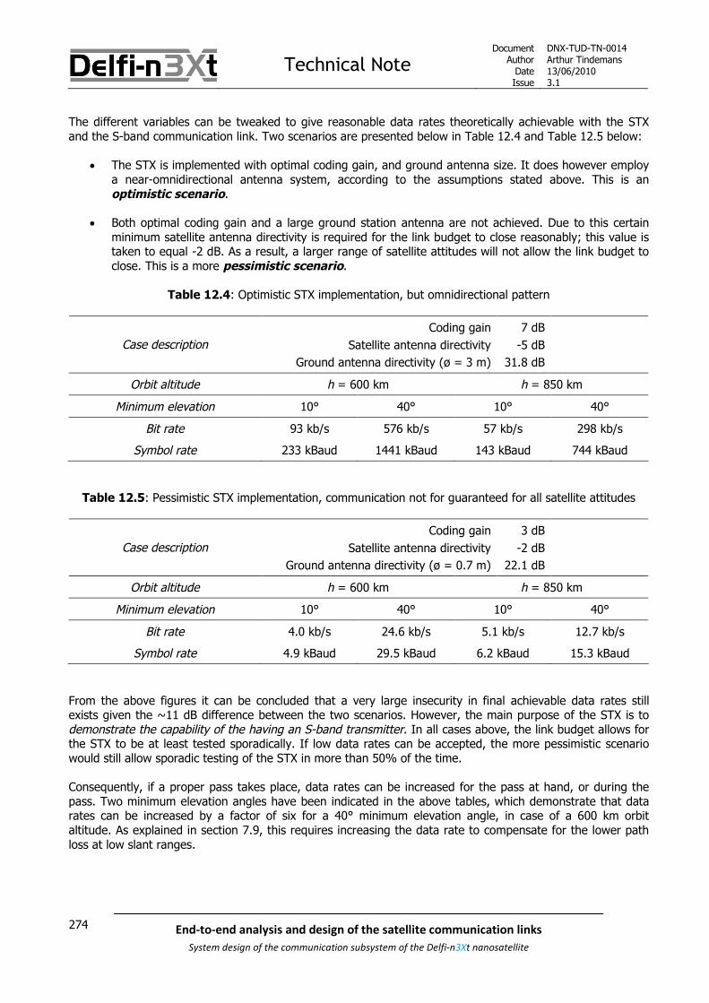
Technical NoteDocument
AuthorDateIssue
DNX-TUD-TN-0014Arthur Tindemans13/06/20103.1
274 End-to-end analysis and design of the satellite communication links
System design of the communication subsystem of the Delfi-n3Xt nanosatellite
The different variables can be tweaked to give reasonable data rates theoretically achievable with the STXand the S-band communication link. Two scenarios are presented below in Table 12.4 and Table 12.5 below:
The STX is implemented with optimal coding gain, and ground antenna size. It does however employa near-omnidirectional antenna system, according to the assumptions stated above. This is anoptimistic scenario.
Both optimal coding gain and a large ground station antenna are not achieved. Due to this certainminimum satellite antenna directivity is required for the link budget to close reasonably; this value istaken to equal -2 dB. As a result, a larger range of satellite attitudes will not allow the link budget toclose. This is a more pessimistic scenario.
Table 12.4: Optimistic STX implementation, but omnidirectional pattern
Coding gain 7 dB
Satellite antenna directivity -5 dBCase description
Ground antenna directivity (ø = 3 m) 31.8 dB
Orbit altitude h = 600 km h = 850 km
Minimum elevation 10° 40° 10° 40°
Bit rate 93 kb/s 576 kb/s 57 kb/s 298 kb/s
Symbol rate 233 kBaud 1441 kBaud 143 kBaud 744 kBaud
Table 12.5: Pessimistic STX implementation, communication not for guaranteed for all satellite attitudes
Coding gain 3 dB
Satellite antenna directivity -2 dBCase description
Ground antenna directivity (ø = 0.7 m) 22.1 dB
Orbit altitude h = 600 km h = 850 km
Minimum elevation 10° 40° 10° 40°
Bit rate 4.0 kb/s 24.6 kb/s 5.1 kb/s 12.7 kb/s
Symbol rate 4.9 kBaud 29.5 kBaud 6.2 kBaud 15.3 kBaud
From the above figures it can be concluded that a very large insecurity in final achievable data rates stillexists given the ~11 dB difference between the two scenarios. However, the main purpose of the STX is todemonstrate the capability of the having an S-band transmitter. In all cases above, the link budget allows forthe STX to be at least tested sporadically. If low data rates can be accepted, the more pessimistic scenariowould still allow sporadic testing of the STX in more than 50% of the time.
Consequently, if a proper pass takes place, data rates can be increased for the pass at hand, or during thepass. Two minimum elevation angles have been indicated in the above tables, which demonstrate that datarates can be increased by a factor of six for a 40° minimum elevation angle, in case of a 600 km orbitaltitude. As explained in section 7.9, this requires increasing the data rate to compensate for the lower pathloss at low slant ranges.

Technical NoteDocument
AuthorDateIssue
DNX-TUD-TN-0014Arthur Tindemans13/06/20103.1
275End-to-end analysis and design of the satellite communication links
System design of the communication subsystem of the Delfi-n3Xt nanosatellite
In the above tables the coding rate that is introduced by a certain coding gain can also be seen. Theachievable bit rate is increased with a value of 1/0.40 and 1/0.83 for respectively Table 12.4 and Table 12.5.Now what is important to note is that the transmission speed of the CC2500 is actually limited to 500 kBaud.While in certain cases this would be a limiting factor, it would already be a sizeable accomplishment if thesedata rates can be reached momentarily.
Also, 26 kBaud is a minimum symbol rate if MSK is to be used on the MSK. If lower speeds are used, FSKshould be applied, increasing the required signal-to-noise ratio on-ground by 3 dB. This therefore effectivelymeans no data rates between 13 and 26 kBaud are supported, as 24 kBaud according to the above linkbudget would be equal to 12 kBaud on FSK. Therefore, 26 kBaud should be aimed for as a minimum datarate. In the pessimistic case, this would mean communication would only be possible for even a smallerpercentage of the time, when satellite attitude is beneficial or at elevation angles even higher than 40°.

Technical NoteDocument
AuthorDateIssue
DNX-TUD-TN-0014Arthur Tindemans13/06/20103.1
276 End-to-end analysis and design of the satellite communication links
System design of the communication subsystem of the Delfi-n3Xt nanosatellite

Technical NoteDocument
AuthorDateIssue
DNX-TUD-TN-0014Arthur Tindemans13/06/20103.1
277End-to-end analysis and design of the satellite communication links
System design of the communication subsystem of the Delfi-n3Xt nanosatellite
13 Integrating the COMMS on Delfi-n3Xt
All COMMS components, or CIs, are envisioned to be integrated on Printed Circuit Boards, or PCBs. ThesePCBs are stacked in Delfi-n3Xt, separated by certain distances. The exact structural rules are determined inthe top-level STS document [SLR 0169]. The latter document also specifies the lay-out and exact areal spaceavailable on a PCB.
In case of the COMMS, four PCBs are reserved: The PTRX PCB The ITRX PCB The DAB The STX PCB
The DAB integrates the antennas for the UHF/VHF system. However, a number of cables for signalcommunication are also required. Finally, if the STX will be flown, it requires a separate antenna system, mostlikely in the form of two patch antennas, not integrated on a PCB but on the outer Delfi-n3Xt structure. Thus,in summary, also required are the [SLR 0387]:
Communication cables (coax) S-band antenna system
All mentioned PCBs, as well as the main components of the Antenna System are shown in Figure 13.1 below.More specifically, four UHF/VHF antennas can be seen and a single Modular Antenna Box (MAB) is outlined.Two possible S-band antenna patch locations are indicated as well. The figure shows the bottom side of Delfi-n3Xt, per definition of [SLR 0169].
Figure 13.1: Structural integration of COMMS components [adapted from SLR 0169

Technical NoteDocument
AuthorDateIssue
DNX-TUD-TN-0014Arthur Tindemans13/06/20103.1
278 End-to-end analysis and design of the satellite communication links
System design of the communication subsystem of the Delfi-n3Xt nanosatellite
In fact, the volume arrangement of Delfi-n3Xt still awaits to be changed after the removal of severalpayloads. The above figure is just an illustration of the relevant COMMS components with their possiblelocations.
The two integration options of the S-band patches are explained in [SLR 0387]. The options are to have twopatches either at two opposite sides or at the top and bottom of Delfi-n3Xt. The BOP can be seen to haveslits for the openings of the MABs. The MABs are placed on the DAB. Directly above this the primary radio islocated, the PTRX. This arrangement allows for minimum cable losses for the latter. After the PTRX the ITRXcan be placed, with similarly low cable losses. The STX is currently placed in the middle, which can be optimalif two antenna patches are placed on both the TOP and BOP; in that case cable lengths are equal to bothpatches. If the patch antennas are located at the sides, it is most beneficial if the STX is located at the sameheight as the patch antennas.
A number of general Delfi-n3Xt budgets are maintained. The three budgets of importance are the volumebudget, the mass budget and the power budget. The data budget also exists on a satellite level, but will notbe discussed here; the housekeeping data collected by the CDHS as well as the ultimate telemetry providedby the CDHS to the COMMS has already been commented on in this document. The three aforementionedbudgets, volume, mass and power, are documented as [SLR 0303], [SLR 0018] and [SLR 0017] respectively.
The resulting values are summarized in Table 13.1 below.
Table 13.1: Mass, volume and power values for all COMMS components
Component Mass Volume Power
PTRX 125.5 g 20 mm240 mW (TX OFF mode)1750 mW (All TX modes)
ITRX 132 g 20 mm240 mW (TX OFF mode)1750 mW (All TX modes)
STX 159 g 14 mm
110 mW (TX OFF mode)799 mW (TM mode, 1 PA active)
1447 mW (TM mode, 2 PAs active)
DAB (incl. MABs, excl. OLFAR) 110.4 g 41.1 mm N.A.
S-band patches 80 g N.A. N.A.
Connectors & cables 22 g N.A N.A.
OLFAR (incl. additional cable) 13 g N.A. 49 mW
A couple of notes: Mass of the PTRX, ITRX and STX is in fact based on the RAP mass. The differences are due to
included contingencies related to the development status. Volume envelopes were strictly limited before the MPS was removed. Currently volume restrictions
can be loosened, if there would be reason for that. Only height in the PCB stack is taken into accountfor the volume budget.
Power values for the PTRX and ITRX are also based on the RAP, with respective contingencies. TheSTX power values are as argued for in [SLR 0387]. Cables, connectors and antennas do not activelyconsume power. The required power consumption for deployment is not stated.
OLFAR is indicated as a separate system. It should however be integrated on a PCB, logically the DABif it will be flown. In that case, the weight and power required by only the additional components areshown above. This includes an extra cable, in the worst case being an RF cable.

Technical NoteDocument
AuthorDateIssue
DNX-TUD-TN-0014Arthur Tindemans13/06/20103.1
279End-to-end analysis and design of the satellite communication links
System design of the communication subsystem of the Delfi-n3Xt nanosatellite
14 Operations and performance
Given all the specific (sub)systems introduced in the previous chapters, this chapter aims to specify theirimplementation in the actual Delfi-n3Xt mission. That is to say, COMMS operations are defined and COMMSperformance is analyzed. This chapter will make a division between the primary COMMS elements and theUHF/VHF communication link, and the S-band communication link and its STX.
The operations are in general specified by the different modes. In case of the UHF/VHF systems, theseform the general communication system modes. These modes, their respective functions and their activationfor the UHF/VHF systems are introduced in section 14.1 below. The operations of the STX are basicallydisconnected from other modes, as the STX itself is not strictly dependent on the operation of other COMMSsystems. Therefore the operation of the STX is discussed in a later section, section 14.3.
The performance of the UHF/VHF transmission link will be discussed in terms of the data yield resulting onthe downlink. For the uplink, TCs are transmitted with the only requirement that they are properly received.Whereas in case of Delfi-C3 not all TCs are received, no clear data is kept on this percentage. Also, if TCs areonly transmitted during passes, the theoretical reception should be 100%. For the downlink, per definition notall transmitted data will be received. VHF downlink performance is discussed in section 14.2. S-band downlinkperformance is discussed in section 14.4.
14.1 COMMS operations and modes
Primary COMMS operations are straight-forward and relatively simple. The UHF/VHF system is per defaultswitched on, and set to transmit telemetry and receive telecommands. The system is not designed to requireany orbital or attitude awareness, even if Delfi-n3Xt might have this, and thereby applies an omnidirectionalantenna system. Transmitting TM and receiving TCs forms the default mode.
As two transceivers as well as systems such as the transponder and OLFAR (if possible) are to be flown onDelfi-n3Xt, a larger number of communication system modes is required. These are formed because of:
The individual modes of the radios (the PTRX can transmit TM, function as a transponder or transmitthe OLFAR signal)
The power limitations, allowing not all systems to be on at the same time
As such, these global COMMS modes are combinations of PTRX and ITRX modes. The individual modes andthe required actions have already been explained in the respective chapters on the PTRX and ITRX, chapters9 and 10.
All modes are activated and deactivated by means of telecommand, except for the default mode. Uponreception of the TC, the OBS will then activate the respective PTRX and ITRS modes via the I2C bus.
The resulting COMMS modes are listed in Table 14.1 below, listing also the respective PTRX and ITRX modesand the operational effects.
The possibly STX is not included in the table below; the operations of the STX are not linked to the otherradios. It is to be decided via TC whether the STX will be activated, which in principle can be during anyCOMMS mode.

Technical NoteDocument
AuthorDateIssue
DNX-TUD-TN-0014Arthur Tindemans13/06/20103.1
280 End-to-end analysis and design of the satellite communication links
System design of the communication subsystem of the Delfi-n3Xt nanosatellite
Table 14.1: COMMS modes and respective PTRX and ITRX modes
COMMS mode Radio modes Effects
PTRX mode
(default)
PTRX to “TM mode”
ITRX to “Receive only mode”
TCs received by PTRX and ITRX
TM transmitted by PTRX
No transponder or OLFAR signal
ITRX mode
(secondary)
PTRX to “TX OFF mode”
ITRX to “DelfiX mode”
TCs received by PTRX and ITRX
TM transmitted by ITRX
No transponder or OLFAR signal
Transponder mode PTRX to “Transponder mode”
ITRX to “Receive only mode”
TCs received by PTRX and ITRX
No TM transmitted
No OLFAR signal
Transponder activated
ITRX test mode PTRX to “TX OFF mode”
ITRX to any mode other than“Receive only” and “DelfiX mode”
TCs received by PTRX and ITRX
No TM transmitted
No transponder or OLFAR signal
Various ITRX transmission
OLFAR mode(experimental)
PTRX to “OLFAR mode”
ITRX to “Receive only mode”
TCs received by PTRX and ITRX
No TM transmitted
No transponder signal
OLFAR activated
All TX OFF PTRX to “TX OFF mode”
ITRX to “Receive only mode”
TCs received by PTRX and ITRX
No TM transmitted
No transponder or OLFAR signal

Technical NoteDocument
AuthorDateIssue
DNX-TUD-TN-0014Arthur Tindemans13/06/20103.1
281End-to-end analysis and design of the satellite communication links
System design of the communication subsystem of the Delfi-n3Xt nanosatellite
14.2 VHF downlink performance
Any data received via the VHF transmission allows drawing conclusions on the success of the mission. If nodata is received, nothing can be concluded on operations, and the mission is a failure. Whereas more datawill not proportionally increase the value of the mission, more can in that case be concluded on theoperations and payloads nonetheless. This section aims to give an idea of the expected data yield for theDelfi-n3Xt mission.
As the Delfi-n3Xt primary communication system is based on that of Delfi-C3, in terms of its main radio,antenna system, ground station, and radio amateur involvement, a concrete example of performance exist:Delfi-C3. A short description of the downlink data performance of the latter is given in subsection 14.2.1below. Afterwards, the anticipated performance of Delfi-n3Xt is elaborated on in subsection 14.2.2, indicatingthe operational differences between Delfi-C3 and Delfi-n3Xt, in other words the expected improvements.
14.2.1 Delfi-C3 data yield performance
In case of Delf-C3, the main communication system is very simple in operation. Once the satellite was firstswitched on, the satellite switched to Science Mode and data was generated, and transmitted to the ground.This data in Science Mode consists of a set of 5 repeating types of frames:
3 payload frames 1 housekeeping frame 1 flag frame
The flag frame is not actually forwarded to the database as it serves to establish a good transmission link.Also, it was required internally (in Delfi-C3) to process the other frames, and is thus in effect an empty frame.In total, the transmission of these 5 frames, of which 4 are actually interpreted on-ground, takes 5 seconds.
The satellite applies an omnidirectional antenna system, and has no orbit or attitude awareness. It simplytransmits at every opportunity it has. As such, the only moments it does not transmit data is when:
A mode without data transmission is active, such as Transponder mode. In Transponder modeno frames are transmitted, whereas in Basic Mode only housekeeping (HK) frames aretransmitted. Only Science Mode and Basic Mode yield (digital) data transmission.
No power is available as the satellite is in eclipse; in umbra or penumbra. Umbra means thatthe sun is completely blocked by the Earth with respect to the satellite, whereas in penumbra thesun is partially blocked and lower power is available. In fact, the period of penumbra is verysmall. A calculation of the time in umbra and penumbra is given below.
In case of Delfi-C3, as will be the case for Delfi-n3Xt, radio amateur frequencies are used for datatransmission, and at the same time radio amateurs were and are encouraged to receive data from thesatellite and forward it to the TM Database using preconfigured software; RASCAL in case of Delfi-C3. In fact,a total number of 339 radio amateurs worldwide have used RASCAL to subscribe, after which 184 havetransmitted actual received data to the database, up until now.
The database is an SQL (Structured Query Language) database, and this section will use the data stored inthe database to draw conclusions on the actual transmitted data performance of Delfi-C3. Also, the theoreticalcontact times will be concluded upon using STK (Satellite Tool Kit), containing information on the orbitalpropagation of Delfi-C3 over its first two years, from the 28th of April 2008 to the 27th of April 2010.

Technical NoteDocument
AuthorDateIssue
DNX-TUD-TN-0014Arthur Tindemans13/06/20103.1
282 End-to-end analysis and design of the satellite communication links
System design of the communication subsystem of the Delfi-n3Xt nanosatellite
Within the above period, STK can be used to give a more or less exact percentage of time the satellite was indirect sun, or in penumbra. The resulting values are:
Percentage of time in direct sun: 66.27 % Percentage of time in penumbra: 0.38 %
As can be seen, the time in penumbra is small. The exact satellite operations are unclear in this period, aspower generation might be insufficient. Therefore, penumbra shall be treated as umbra; no operations.Delfi-C3 has no battery and switches off when no power is available. Upon exiting eclipse, the satellite bootsand restarts transmitting data.
As in Science Mode a data frame is transmitted every second, except for the seconds a flag frame istransmitted, the amount of seconds the satellite has been in direct sun then gives a direct upper limit for theamount of data frames transmitted. Aspects that actually decrease this amount:
The boot time required The time other modes have been activated The time the satellite software had crashed, or the RAP was switched off. In fact, in turns out Delfi-C3
crashes at frequent intervals, and is not rebooted until an eclipse has passed. Similarly, the RAP canbe automatically switched off even when a crash has not taken place. This causes a major andunpredictable loss of transmission time.
Still, the maximum amount of powered time will be used to calculate a total theoretical amount of dataframes transmitted. Table 14.2 below compares this amount to different data resulting from the SQLdatabase.
Table 14.2: Delfi-C3 data yield from the 28th of April 2008 to the 27th of April 2010
Total data transmitted (theoretically) 33,348,580 frames
Payload data 25,011,435 (75%)By type
Housekeeping data 8,337,145 (25%)
Total unique data received 618,091 frames (1.9% of theoretical total)
Payload data 409,148 (1.6% of total theoretical payload data)By type
Housekeeping data 208,813 (2.5% of total theoretical HK data)
Delft GS 190,757 (0.6% of theoretical total)By receiver
Radio amateurs1 427,334 (1.3% of theoretical total)
Total non-unique data received 940,966 frames (-)2
Payload data 641.137 (-)3By type
Housekeeping data 305,316 (-)3
Delft GS4 190,757 (0.6% of theoretical total)By receiver
Radio amateurs 750,209 (-)

Technical NoteDocument
AuthorDateIssue
DNX-TUD-TN-0014Arthur Tindemans13/06/20103.1
283End-to-end analysis and design of the satellite communication links
System design of the communication subsystem of the Delfi-n3Xt nanosatellite
In the table above the percentages of the total theoretical values have been indicated. A number of noteshave been indicated:
1. The amount given is actually the total amount of unique data received minus the unique datareceived by the Delft GS. If the Delft GS is not considered, more ‘unique’ data amongst radioamateurs can be said to be received. Nevertheless, in this manner the added value of radio amateursis illustrated.
2. Non-unique data indicates a sheer number of frames, which might include double frames. Therefore,no percentage of a total can be given as the total would be infinite.
3. For reasons not understood, the sum of both payload and housekeeping data does not amount to thetotal, but differs slightly according to the database. The difference is however small.
4. This value is equal to the unique data received as the Delft GS cannot receive duplicate frames.
Conclusions: Almost 2% of total theoretically generated data has been received over two years time. Radio amateurs have increased the received amount of unique data by 124%, or when including
non-unique data, even by 293%. In both the unique and non-unique data cases, more housekeeping data has been received then
ratio-wise expected compared to payload data, this should be due to the activation of Basic Mode. The reception of non-unique data has increased the total amount of received data by 52%.
It is clear from the above data that the participation of radio amateurs has been a success, yielding a largeincrease of received data. What however is not instantly clear is how well the Delft GS performed, given thefact that it only has limited visibility. The resulting performance is shown in Table 14.3 below.
Table 14.3: Delfi-C3 to Delft GS data yield from the 28th of April 2008 to the 27th of April 2010
GS range ε = 0° ε = 10°
Visibility 3.91 % 1.65 %
Total data transmitted (theoretically) 1,303,098 frames 549,969 frames
Received data percentage 15% 35%
Two different GS ranges have been indicated in the table above, specified by an elevation angle. This is dueto the fact that a 10° has in fact been designed for in the link budget, but a large final link margin combinedwith little obstructions on the horizon should have effectively increased the field of view of the Delft GS.Therefore it results that between 15 and 35% of the total amount of packets that could theoretically havebeen transmitted by Delfi-C3 and received by the Delft GS, has actually been received by the GS.
Of course, due to reasons stated above the actual transmitted amount of data is lower. Also, the receivedamount is lower due to:
Tracking, pointing and operation errors. For example, the current rotator connection occasionallycauses the antenna system to rotate by 360° mid-pass (see next chapter).
It is interesting to see how the reception of data by the Delft GS varies over time, and the result is surprising.For both cases of 1) data reception per day for a month, and 2) data generation per month for two years, notrend can be found in the results. To illustrate this point only the plot of the daily data reception during thefirst month of Delfi-C3 operation is shown below in Figure 14.1. Also added are values representing themaximum theoretical amount of transmitted and received frames during these days resulting from dailycoverage; an intermediate elevation angle of 5° is selected for the latter.

Technical NoteDocument
AuthorDateIssue
DNX-TUD-TN-0014Arthur Tindemans13/06/20103.1
284 End-to-end analysis and design of the satellite communication links
System design of the communication subsystem of the Delfi-n3Xt nanosatellite
Figure 14.1: Delfi-C3 theoretically transmitted and actually received data during May 2008
Daily coverage can be seen to be more or less constant. For a 5° elevation angle, STK shows that there areon average 5.9 passes per day, with all amounts being either 5 or 6 as expected. The resulting changes intheoretically transmitted data do in no way explain the variations in data reception shown in Figure 14.1.Delfi-C3 operational stability is most likely the culprit. A more detailed analysis falls outside of the scope of thisdocument. Also, its relevance to the Delfi-n3Xt COMMS is likely low as it more logically concerns Delfi-C3 busstability.
Nevertheless, one interesting aspect shall be shortly reviewed from the graph above. Three points, on the 3rd,28th and 30th of May can be seen to have very high data reception. What is interesting here is that thedatabase shows they have had 6 or 7 successful passes each. However, according to STK, only 6 passes canbe seen within even a 5° elevation angle, or a 5° artificial horizon. This therefore is proof that the groundstation system not only can make use of all daily passes, but also passes that in some cases are below 5°elevation angle. Indeed, STK confirms, 7 passes take place but only within a 1° artificial horizon. This is animportant conclusion for assumed Delfi-n3Xt operations.
A further interesting side note is that the amount of passes changes per season, whereas it is more or lessconstant on a one-year basis. In May the daily average amount of passes is 1 higher for 0°, 5° and 10°elevation angle cases with respect to the yearly average. In December in some cases only 3 passes take placewithin a 0° artificial horizon! This however has everything to do with the eclipse differences during summerand winter, an aspect that should play no role in case of Delfi-n3Xt if batteries are properly integrated inoperations.

Technical NoteDocument
AuthorDateIssue
DNX-TUD-TN-0014Arthur Tindemans13/06/20103.1
285End-to-end analysis and design of the satellite communication links
System design of the communication subsystem of the Delfi-n3Xt nanosatellite
A final aspect to be reviewed in slightly more detail is the participation of radio amateurs. The data yieldfollowing from the active participation of radio amateurs over two years time is plotted in Figure 14.2 below.
Figure 14.2: Delfi-C3 data yield due to radio amateur participation over two years time
It can be seen that the radio amateur return appears to be more consistent than the Delft GS return,although admittedly the above plot is on a monthly scale and the values have been compressed towards thebottom more due to the inclusion of high values at the start. Nevertheless, the radio amateur yield does notseem correlated with the monthly values of the Delft GS yield (not shown), and indeed is more constant overtime. The more interesting aspect however is the overall evolution over time.
At the start of the plot, three very high values can be seen, of respectively 187,738, 97,746 and 60,659frames. In fact, this first month alone, resulted in more data forwarded by radio amateurs than data collectedby the Delft GS in over two years time!
Directly after the first three months, two months of silence can be seen; in fact during these months Delfi-C3
has been in Transponder mode almost constantly, generating nearly no data. This was a deserved returnservice to these radio amateurs. Finally in the graph, the data yield seems to average out with slight peaksand lows. The most interesting conclusion from this last period is that up until now, a solid handful still tracksDelfi-C3 on a daily basis, most likely automated. Total daily radio amateur yield is still higher than Delft GSyield alone.

Technical NoteDocument
AuthorDateIssue
DNX-TUD-TN-0014Arthur Tindemans13/06/20103.1
286 End-to-end analysis and design of the satellite communication links
System design of the communication subsystem of the Delfi-n3Xt nanosatellite
14.2.2 Delfi-n3Xt data yield performance
Delfi-n3Xt primary communication should be similar to that of Delfi-C3. Data is produced in either of two radiomodes, being the default PTRX mode or the secondary ITRX mode. In the other modes no data frames aretransmitted, and thereby no telemetry can be received.
The last subsection on Delfi-C3 performance yields a few valuable conclusions of interest to Delfi-n3Xt: The Delft GS indeed has shown to be able to make use of all passes within range and a visibility up
to a 1° artificial horizon has been shown under certain conditions. A battery should be able to increase the total data yield by 50% over that achieved by Delfi-C3,
given the time the latter was in eclipse. The Delfi-n3Xt orbit will be one similar to that of Delfi-C3,however likely with a different local time of the ascending node and orbit altitude; eclipse timeswill also be different. The inclusion of a battery can also remove the variability in data yield perseason due to the varying eclipse times as well as a required boot time after every (pen)umbra.Of course, this assumes that the battery of Delfi-n3Xt will indeed be able to ensure continuedoperations even in eclipse. This has not yet been confirmed after the redefinition of the mission.
Radio amateurs are very valuable, especially in the early mission when data can even be of mostinterest. Also, the primary mission is designed for three months, during which in case of Delfi-C3
heavy support was present. A similar encouragement of radio amateurs should therefore certainlybe pursued.
Finally, the stability problems of Delfi-C3 related to the CDHS of the latter, most likely in the form of ‘freezes’and consequent required resets, were mentioned; a more stable CDHS in Delfi-n3Xt should remove theseproblems.
In theory, this would mean that all geometrical passes within range of the Delft ground station should be ableto be used for data reception, with the possible exception of the (minimal) time lost due to the trackingmechanism on-ground and the time when other modes have been activated.
Averaged out over a period of two years, this would give the coverage percentages as shown in Table 14.4below as given for the Delfi-n3Xt range of orbits and for different assumed artificial horizons. The variablesare expressed by orbit altitude h and minimum elevation ε respectively.
Table 14.4: Coverage percentages of the Delft GS anticipated for the Delfi-n3Xt mission
h = 600 km h = 850 km
ε = 0° 3.93 % 5.72 %
ε = 5° 2.53 % 3.80 %
ε = 10° 1.66 % 2.60 %
Finally, these percentages will be increased by an unknown amount due to the participation of radioamateurs. Using Delfi-C3 as a measure, some 1-2 times the effective coverage is expected to be additionallysupplied by the radio amateur network over the lifetime of Delfi-n3Xt, with a higher peak at the start of themission.

Technical NoteDocument
AuthorDateIssue
DNX-TUD-TN-0014Arthur Tindemans13/06/20103.1
287End-to-end analysis and design of the satellite communication links
System design of the communication subsystem of the Delfi-n3Xt nanosatellite
14.3 STX operations
The operations of the STX will not depend on any satellite attitude pointing capability, just as the UHF andVHF systems do not. If possible, pointing of the ADCS could be used to exploit directivity peaks in the finalS-band antenna gain pattern, but for general operations it will not be assumed.
The STX will also not be on continuously. In fact, it is unknown in what periods of time the STX will beactivated, and in fact this also depends on its actual performance. As power is limited on Delfi-n3Xt, the STXshall be assumed to be switched on only if the PTRX transmitter is switched off. The PTRX TX:
Is the largest consumer of power Provides functionality similar to that of the STX; transmitting
Depending on the performance of the STX, the STX can then be switched on more often. Another possibilityis that the ITRX will have the high-efficiency amplifier it aims to have; currently some 60% efficiency isanticipated. This would reduce the power consumption of the ITRX by some 1 W with respect to the PTRX ascurrently anticipated, which could possibly allow operating the ITRX and STX at the same time.
As argued for in chapter 12, it makes sense to, with the STX, aim for the following goals in order:1) Establish a working link2) Adjust link budget to actual performance3) Perform experiments with changing data rates, between and during orbits
Depending on the actual signal power of the received signal, the data rate of the STX can be adjustedbetween passes or even during pass. The latter would also allow adjusting for the attitude of the satelliteduring a pass.
In case of operations, the question becomes what operating modes are then required and how these modesare activated. This is discussed in subsections 14.3.1 and 14.3.2 below. Subsection 14.3.3 then introduces theoption of selecting the data to be transmitted.
14.3.1 STX operational modes
STX operational modes are independent of other COMMS modes. [SLR 0387] introduces the operationalmodes in more detail, but the following operational modes can be distinguished:
TX OFF mode
This is the default mode. The STX is switched on, but its transmission is switched off. In this wayit gathers and stores all TM data that is transmitted to PTRX and/or ITRX.
TM mode
When power is available and likely during a Delft pass with proper satellite attitude, this modecan be activated. Telemetry is transmitted after being read out from the data buffer.
In order to have different achievable data rates, submodes with different data rate presets can be used. Alltransmission submodes are part of the TM mode. Also, the design of the STX as presented in [SLR 0387]includes two switchable power amplifiers. In result, it can be decided to switch on just one PA, or both PAs.
In conclusion, within the TM mode the following can be configured: The active PAs (3 options; either one or both) The data rate of the transmission

Technical NoteDocument
AuthorDateIssue
DNX-TUD-TN-0014Arthur Tindemans13/06/20103.1
288 End-to-end analysis and design of the satellite communication links
System design of the communication subsystem of the Delfi-n3Xt nanosatellite
The number of data rate presets should be based on the following:
A minimum and maximum data rateThe minimum is logically a few kBaud (applying a modulation scheme other than MSK, forminimum performance) and the maximum would be the CC2500 maximum; 500 kBaud.
A number of data rate steps in betweenBasically, any number supported by the CC2500 and the telecommand structure can be used.This value can be as high as 256, specified by an 8-digit number and allowing for 2 kBaud datarate steps. Although this might be excessive, this suggestion illustrates the capabilities. In anycase, due to the large insecurities in the link budget and the allowed number of presets, it doesnot seem useful to base the actual data rates on complex calculations based on pass probabilitiesand coverage values.
14.3.2 STX activation
The insecurity of the final STX design makes it unlikely that it will in fact allow all gathered mission data to bedownloaded. More importantly, this is not the main goal of the technology demonstration. As such, it is morelikely that the STX will function in a way similar to PTRX/ITRX; it will send down data using a best-effortapproach. Therefore, no ‘hand-shakes’ or similar procedures are required to establish a proper connectionbefore data transmission; transmission should just commence.
All non-default COMMS modes are activated by means of telecommand. Given the fact that the STX is moreexperimental, it is logical that also the STX is only switched on by means of telecommand. This leads to twooptions:
Switch on by telecommandA(n) (automated) telecommand is send to the satellite as it is barely in sight to switch on theSTX. As long as the STX is then switched on when the elevation angle designed for isapproached, operations are nominal. An OBC timer would then most likely switch off the STXafter its maximum possible pass time has passed, to ensure a proper switch-off. Of course thisapproach causes some transmission time to be lost in awaiting the TC reception and STXactivation.
Schedule by telecommandA more advanced approach would be to schedule the HDM mode to be activated a certain timeafter a telecommand has been sent. This would maximize the useful transmission time. Multipleactivations can also be scheduled following a number of consequent telecommands.
The second option is the most preferable in order to maximize downloadable data volume, and should beallowed for by the OBC given the integrated RTC. Also, a simpler timer can be set. The second option issimply a more advanced version of the first.
As such, the option of activating the STX by means of scheduling by telecommand is preferred.
A final option, possible only if Delfi-n3Xt capabilities turn out to be (very) potent:
Automated switch-on by (simplified) orbit determinationUsing TLEs and schedule data the STX can be activated during passes over Delft that satisfyspecific criteria such as minimum off-track angle. In this case the system can be completelyautonomous. This would require orbit determination capabilities on-board of Delfi-n3Xt, possiblyas part of the ADCS operations. Also, this requires that the STX performs exactly as designed.

Technical NoteDocument
AuthorDateIssue
DNX-TUD-TN-0014Arthur Tindemans13/06/20103.1
289End-to-end analysis and design of the satellite communication links
System design of the communication subsystem of the Delfi-n3Xt nanosatellite
14.3.3 STX data preference
Again, as the STX will not likely be able to downlink all generated data of the mission, it could make sense toselect data to have priority over other data. This could imply:
Data that is generated over the oceans for example, as this information will not likely be successfullydownlinked by the PTRX or ITRX.
Early mission data, as this data can be more valuable.
The data storage size can be increased to more seriously support this functionality.
Preferred data could be selected by means of the frame counters that are included in the TM frames. Ofcourse this would require some form of read-out intelligence for the STX in order to locate data in its storagethat meets specific criteria. At the same time its FEC coding approach should be prepared for this.Furthermore extra intelligence in telecommanding and CDHS commanding would be required.
In conclusion, this functionality shall be of low priority and not be assumed for the STX as long as the STXitself has uncertain performance. The primary purpose of the STX is to demonstrate successful transmissioncapabilities, independent of the actual content transmitted.

Technical NoteDocument
AuthorDateIssue
DNX-TUD-TN-0014Arthur Tindemans13/06/20103.1
290 End-to-end analysis and design of the satellite communication links
System design of the communication subsystem of the Delfi-n3Xt nanosatellite
14.4 S-band downlink performance
The performance of the STX is a hard aspect to discuss given the fact that it has no nominal operationalmodes. It is to be defined when the STX shall be activated, given the power capacity of Delfi-n3Xt as well asthe final capabilities of the STX. What can however be done, is to illustrate the potential added value of theSTX given the performance of the PTRX.
The STX is slated to receive the exact same TM data as the PTRX or ITRX. As it is not transmitting, the datais stored. During a pass, the STX can then be switched on. Given information of the pass, a matched datarate is selected.
Consequently, any data rate between a few kBaud and 500 kBaud can possibly be achieved. This canmomentarily be 25 times the maximum possible data rate of the PTRX. Any second the system might be onand functional, the STX can yield up to a quarter of a minute of PTRX transmitted data, when corrected forcode rates required. For lower final PTRX data rates than 9.6 kb/s, the STX capability will double or quadruplewith respect to the PTRX.
At that, the STX will logically yield data gathered outside of the pass window, due to its data storagecapability. The overall data yield of the mission can therefore be greatly increased.
Table 14-5 below assesses the data rates required if all generated data would be transmitted by the STX, anda constant data rate is applied throughout the mission. A single ground station is assumed, that of Delft, andall passes are assumed to be monitored. The data volume has been calculated based on the use of the finalDelfiX protocol, assuming maximum information field sizes. Also, it is assumed the PTRX data rate is fullyutilized, with higher data rates allowing more data to be generated in the satellite. Frame sizes are assumedto be equal to the bit rate. On the other hand, data protocol overhead required on the S-band transmissionlink is ignored for the moment.
In Table 14-5, maximum achievable data rates are indicated, based on the optimistic link budget case asdiscussed in chapter 12. Orbit altitudes h and minimum elevation angles εmin are indicated, which togetherresult in a daily coverage in minutes. The coverage is calculated again using STK, for sun-synchronous orbitsover a two-year span.
Table 14-5: STX required bit rates for a complete data dump, using a constant data rate
Required constant data rateMaximumachievabledata rate
PTRX data rate 1.2 kb/s 2.4 kb/s 9.6 kb/s -
Daily data volume 90,029 kb 186,278 kb 763,776 kb -
All passes, εmin=10°,h=850 km 48 min 31 kb/s 62 kb/s 249 kb/s 57 kb/s
All passes, εmin=10°,h=600 km 31 min 49 kb/s 98 kb/s 391 kb/s 93 kb/s
All passes, εmin=40°,h=850 km 7 min 223 kb/s 445 kb/s 1.8 Mb/s 298 kb/s
All passes, εmin=40°,h=600 km 4 min 401 kb/s 802 kb/s 3.2 Mb/s 576 kb/s
In the above table, the bold values are lower than the maximum achievable data rate, and would yieldsymbol rates below 500 kBaud given the 0.4 code rate required. These scenarios would allow all generateddata to be transmitted.

Technical NoteDocument
AuthorDateIssue
DNX-TUD-TN-0014Arthur Tindemans13/06/20103.1
291End-to-end analysis and design of the satellite communication links
System design of the communication subsystem of the Delfi-n3Xt nanosatellite
If constant mission data rates are applied, it can be concluded from the table above that the chances that theSTX will be able to transmit all mission data are not very large even if the entire pass is monitored, assumingthe PTRX data rate and the Delfi-n3Xt data budget will indeed allow for a 2400 kb/s unique data rate, orhigher.
As section 7.9 has presented however, a data rate that is changed between passes allows almost two timesas much data volume to be downloaded for close passes, when compared to the constant data rate case withεmin = 10°. This would likely allow all data to be downloaded for the case where the PTRX has a data rate of2.4 kb/s.
Finally, being able to change the data rate continuously even during a pass, would allow to greatly improvethe link budget as the satellite attitude can be taken into account; currently some -5 dB gain is assumed butmaximum gain values up to 4 dB are possible. Even more so, optimally changing the data rate continuouslycould allow downloaded data volume to be increased by almost five times with respect to the constantmission data rate case. In this case, the maximum transmit data rate of 500 kBaud would certainly become alimiting factor, but this would likely allow all generated data of Delfi-n3Xt to be downloaded by the STX.
This is of course, assuming the optimistic implementation of the STX and its link budget. At the same timethis also assumes only one receiving ground station, that of Delft.

Technical NoteDocument
AuthorDateIssue
DNX-TUD-TN-0014Arthur Tindemans13/06/20103.1
292 End-to-end analysis and design of the satellite communication links
System design of the communication subsystem of the Delfi-n3Xt nanosatellite

Technical NoteDocument
AuthorDateIssue
DNX-TUD-TN-0014Arthur Tindemans13/06/20103.1
293End-to-end analysis and design of the satellite communication links
System design of the communication subsystem of the Delfi-n3Xt nanosatellite
15 Ground segment
The ground segment is in fact not part of the COMMS. Better said, the Delfi-n3Xt mission in terms of (CI)components is divided in the Launch & Orbit Segment, the Delfi-n3Xt Satellite or Space Segment, and theGround Segment. Part of the Ground Segment deals with satellite communication; it is that part that will becommented on below. The entire Ground Segment is topic of the top-level Ground Segment document, [SLR0657]. Figure 15.1 below indicates the CIs of importance to COMMS and COMMS functionalities, with properregard for its context.
Figure 15.1: Ground segment CIs related to COMMS.
It can be seen that the ground segment consist of two branches, GSE (Ground Support Equipment) and GSN(Ground Station Network). Within the GSN, there is a segment Operations, Users, and TM Database. It is onlythe first branch that has a (communication) link to the satellite.
The Delft GS is the main ground station. It is to be used for Delfi-n3Xt data reception and for datatransmission towards Delfi-n3Xt. More specifically it should receive TM and should be able to transmit TCs.Furthermore, as Delfi-n3Xt follows in the footsteps of Delfi-C3, radio amateur transmission frequencies areused, and radio amateurs are to be stimulated to receive TM as well. Using a custom designed client, DUDe,this data can be received, interpreted and forwarded to a central TM Database. This database can be seen inthe CI tree above as well. The two options above form the main ground segment communication CIs.
Furthermore two other lower level CIs are shown, being the Eindhoven GS and GENSO. The Eindhoven GShas been used in the Delfi-C3 mission to function as a back-up GS, although never required and GENSO is anESA initiative that envisions goals similar to using the radio amateur network for increased coverage.
The four operational GSN CIs are discussed in sections 15.1 through 15.4 below.

Technical NoteDocument
AuthorDateIssue
DNX-TUD-TN-0014Arthur Tindemans13/06/20103.1
294 End-to-end analysis and design of the satellite communication links
System design of the communication subsystem of the Delfi-n3Xt nanosatellite
15.1 Delft Ground Station
The Delft GS is the primary communication point on-ground. Therefore it is the most important part of theground segment, and its equipment can be used as the baseline for other ground station receivers or possiblytransmitters. The data reception software, DUDe, is designed to also function as essential software for radioamateurs.
The Delft GS is fully redundant, which means that all components are present twice. This holds for theantennas plus antenna steering hard- and software, as well as all transceiver hard- and software. Two PCterminals are in place. Also, any failure can be fixed relatively quickly as the GS is on-ground and uses mostlyCOTS components. Therefore, a back-up GS such as the Eindhoven GS is not strictly required.
The Delft GS is located at the top floor of the faculty of EEMCS (Electrical Engineering, Mathematics andComputer Science) on the campus of Delft University of Technology. Therefore the following specifics can begiven (see Table 15.1).
Table 15.1: Delft Command Ground Station specifications.
Position: 51°59’55’’ N, 4°22’25’’
Elevation: 90 m
All requirements of the Ground Segment are logically specified in the top-level document of the latter, but anumber of requirements are incurred by the COMMS. Therefore, subsection 15.1.1 presents theserequirements. Subsection 15.1.2 specifies the ground station and its main components required fortransmission and reception. What is labelled as supporting equipment, being similarly required but lessobviously, is presented in subsection 15.1.3. Finally possible upgrades to the current equipment are discussedin subsection 15.1.4.

Technical NoteDocument
AuthorDateIssue
DNX-TUD-TN-0014Arthur Tindemans13/06/20103.1
295End-to-end analysis and design of the satellite communication links
System design of the communication subsystem of the Delfi-n3Xt nanosatellite
15.1.1 Requirements
The following Table 15-2 presents all requirements imposed on the Delft GS by the COMMS of Delfi-n3Xt.
Table 15-2: Delft GS requirements imposed by the COMMS
Category Requirement # Requirement
FUNCTIONAL GS.2.2.1-F.01 The Delft GS shall be able to transmit telecommands over the VHF band
Parent: SAT-F.01
Rationale: This requirement follows logically from the parent requirement of being able tocommunicate with the satellite.
FUNCTIONAL GS.2.2.1-F.02 The Delft GS shall be able to receive telemetry over the UHF band
Parent: SAT-F.01
Rationale: This requirement follows logically from the parent requirement of being able tocommunicate with the satellite.
FUNCTIONAL GS.2.2.1-F.03 The Delft GS shall be able to receive a Morse Beacon over the VHF band
Rationale: This requirement follows from the beacon signal that is transmitted by the PTRX whenin Transponder Mode; correct reception of the latter allows verification of the activated mode.
FUNCTIONAL GS.2.2.1-F.04 The Delft GS shall be able to receive data over the S-band
Rationale: This requirement is necessary for the STX technology demonstration.
INTERFACE GS.2.2.1-F.05 The Delft GS shall be able to forward received telemetry to the TM Database
Rationale: This requirement is actually not imposed by the COMMS, but included forcompleteness. The Delft GS should forward TM to the TM Database.
INTERFACE GS.2.2.1-F.06 The Delft GS may be able to receive the OLFAR signal over the VHF band
Rationale: To test the correct functioning of OLFAR, the signal should be received on-ground. Ifthe data (entire bandwidth) is also to be analyzed, more complex hardware is necessary.
CONSTRAINT GS.2.2.1-C.01 The Delft GS shall be able to receive signals in the VHF range of 144-147 MHz
Rationale: These values follow from the transmission frequencies, but are adjusted for Dopplershift and possible oscillator drift.
CONSTRAINT GS.2.2.1-C.02 The Delft GS shall be able to transmit signals in the UHF range of 435-438 MHz
Rationale: These values follow from the transmission frequencies, but are adjusted for Dopplershift and possible oscillator drift.
CONSTRAINT GS.2.2.1-C.03 The Delft GS may be able to receive signals in the S-band range of 2400-2450 GHz
Rationale: These values are still vague as the exact transmission frequencies within the S-bandare not yet specified. As such, the entire ISM S-band is indicated.
The GS currently does not meet all requirements as it misses: UHF/VHF equipment in the case the data rates used for reception or transmission are increased The UHF/VHF reception software, as DUDe is being created as an update to RASCAL All S-band equipment
The transponder is not actively supported at the Delft GS. The transceiver can currently tune in to thetransponder frequencies, and can then receive a transponder signal, but only with a limited bandwidth; notthe entire 40 kHz bandwidth but only 2.4 kHz. Depending on the use of the transponder channel, being forexample voice transmission or the transmission of different data, different equipment can be required. Noneof this is required for the Delfi-n3Xt mission so this will not be further commented on. Also, if higher downlinkdata rates are supported, larger bandwidth reception will be supported.
The transponder beacon can be received as is commented on in the next section.

Technical NoteDocument
AuthorDateIssue
DNX-TUD-TN-0014Arthur Tindemans13/06/20103.1
296 End-to-end analysis and design of the satellite communication links
System design of the communication subsystem of the Delfi-n3Xt nanosatellite
15.1.2 Delft ground station main equipment
A large amount of equipment is required within the Delft GS in order to facilitate correct communication withDelfi-n3Xt. The main functionalities and equipment required have been introduced in chapters 7, 8 and 12 ontransmission techniques and the Delfi-n3Xt communication links. The resulting equipment is introduced in thissubsection. As in fact even more equipment is required, the next subsection introduces equipment labelled as‘supporting equipment’. Currently, no S-band communication is supported so this is covered in section 15.1.4on ground station upgrades.
Thus, this subsection introduces all components directly involved with transmission and reception of data,each having clear and distinct data processing functionalities. The resulting set-up is presented visually inFigure 15.2 below.
Figure 15.2: The Delft GS main equipment.
The hardware components present in the Delft GS are all indicated, including the functionalities relevant fordata transmission and reception. The functionalities required for (de)modulation on the Delft ground stationhave been commented on in chapter 8 on the UHF/VHF transmission link. All indicated components areshortly commented on below, first introducing the transceiver and then going through the downlink anduplink chain respectively:
Transceiver (ICOM 910)This transceiver is used for the uplink and downlink. It:
o Applies filtering to limit the bandwidth, in downlink and uplinko Converts the frequency to IF in case of the downlink (to 1600 Hz)o Applies the FSK modulation in case of the uplink using the received 1200 Baud signalo Applies a certain amount of amplification, in downlink and uplink (up to 75W)
The ICOM 910 is designed for use in the UHF and VHF bands, and the exact frequencies can beset on the machine. Also, the transceiver receives a Doppler correction every second, whichoriginates from the orbit prediction software installed (combination of NOVA and an applicationcalled Doppler Determination Program). It uses this value to correct the transmission frequenciesfor the anticipated Doppler shift. This also has an impact on the on-board demodulator, as thefrequency shifts abruptly every second. Doppler shift rates are limited to some 100 Hz persecond, which translates to a minor effect to say the least; 100 Hz per 145 MHz, with 1200symbols per second, results in a changed duration per symbol of not even 1/1000th of its originalduration.

Technical NoteDocument
AuthorDateIssue
DNX-TUD-TN-0014Arthur Tindemans13/06/20103.1
297End-to-end analysis and design of the satellite communication links
System design of the communication subsystem of the Delfi-n3Xt nanosatellite
The transceiver automatically allows for reception of the transponder beacon; it is transmitted over the TMdownlink frequency. As the transceiver incorporates a speaker, the Morse signal can simply be heard. A smalldevice (which is present) can also be used to decode the consequent Morse signal.
Downlink
VHF antenna (M2 2M CP14)This antenna is used for signal reception, and is designed for use with the frequencies in therange 143-148 MHz. It is circularly polarized. It can be configured to be either right-handed orleft-handed circularly polarized, through a switch incorporated in the antenna. A simple cable canbe connected to this switch to change the polarity by means of a short 12V signal.
SoundcardThe 1600 Hz signal originating from the ICOM 910 is sampled with 38.4 kHz with 32-bit precision.These values are send to software, DUDe in case of Delfi-n3Xt, being a successor to RASCAL.
DUDeThis program basically fulfils four functions, indicated per functionality layer:
o Physical layer: demodulation of the digitalized waveformo Data link layer: the data frames are checked and interpretedo Presentation layer: the content of the data frame is interpreted and visualized for the
usero Network layer: the frames are forwarded to the TM Database
Uplink
DIGIT 2.0This program should generate telecommands. DIGIT (1.0) was used for Delfi-C3, but astelecommands will logically be different for Delfi-n3Xt, this program should be updated.
TNC (TNC 31S)The TNC is mainly in charge of applying Manchester coding, and ensuring proper timing of theresulting data stream. As a desktop computer cannot guarantee a constant data stream, due toprocessing delays and queues, an external device is used. Combining this with the appliedManchester coding, the TNC delivers a perfect 1200 Baud signal. In the current situation, the TNCreceives telecommands from DIGIT in the KISS protocol; it then also applies the AX.25 protocolto the TCs. As the DelfiX protocol is preferred, an update is similarly preferred. This is discussedbelow.
Amplifier (SP7000PA)This extra amplifier is optional, and is in principle not required for correct transmission towardsthe satellite. Nevertheless, in order to be safe it is generally used. It can reach output powervalues of 500 W, but is limited to 250 W.
UHF antenna (M2 436CP30)This UHF antenna is used for signal transmission, and is designed for use with the frequencies inthe range 432-440 MHz. It is circularly polarized, and can be switched between right-handed andleft-handed polarization similar to the VHF antenna.

Technical NoteDocument
AuthorDateIssue
DNX-TUD-TN-0014Arthur Tindemans13/06/20103.1
298 End-to-end analysis and design of the satellite communication links
System design of the communication subsystem of the Delfi-n3Xt nanosatellite
15.1.3 Delft ground station supporting equipment
The supporting equipment can roughly be divided in two functional categories: Signal transmission Support
The components dealing with signal transmission are not very important from a functional point-of-view interms of transmission techniques, but they are very important for the link budget for example. Supportequipment is introduced in order to increase understanding of the communication system, and to illustratewhat other components are actually in place on the Delft ground station.
The two categories of supporting equipment are demonstrated in a functional chain shown as Figure 15.3below. Afterwards again the components are discussed one-by-one, except for the antennas which have beenintroduced above and are actually not to be seen as supporting equipment but are included for clarity.
VHF antenna(M2 2M CP14)
UHF antenna(M2 436CP30)
Rotator(Yeasu G-5500)
Surge protectors(Telegärtner
J01028A0037)
Pre-amplifier(SP 2000)
RF cables(AIRCELL 7, 5m)
RF cables(ECOFLEX 15, 20m)
Power limiter(KEPS RF1-LIM)
Downlink signal(to transceiver)
Uplink signal(from PA)
Customizedcontroller
Polarization switch signal 12V cables(RG58CU, 25m)
Data cable(FLEX-J2, 25m)
Wind sensor data
Orbit data
Data transmission (top)
Support (bottom)
Manual controller(Yeasu G-5500)
Figure 15.3: The Delft GS supporting equipment
Data transmission equipment
RF cables (AIRCELL 7, 5 m)These cables form the connection between the UHF and VHF antennas and the surge protectors.They are relatively short, and are more light-weight and flexible than extremely low-loss cables.These cables should rotate along with the antenna.
Surge protectors (Telegärtner J01028A0037)These components are in place for lightning protection. These surge protectors in fact function aspassband filters. Any alternating voltage of an out-of-band frequency (such as those resultingfrom a lightning strike) is simply short-circuited, meaning discharged to the ground. In order todo so, these surge protectors are integrated in a box with a ground connection.
Pre-amplifier (SP 2000)In case of the downlink only, a pre-amplifier is inserted at this point. The goal of this is toeffectively increase the signal strength, before more losses are incurred in the longer distancebetween the antenna system and the actual GS and receiver. This is taken along in the linkbudget and decreases overall added noise.
RF cables (ECOFLEX 15, 20 m)These cables transport the signals over the significant distance between the roof of EEMCS andthe actual GS on the 22nd floor. As losses should be minimized and can otherwise be significant,expensive and heavy, well-protected cables are used with minimum losses.

Technical NoteDocument
AuthorDateIssue
DNX-TUD-TN-0014Arthur Tindemans13/06/20103.1
299End-to-end analysis and design of the satellite communication links
System design of the communication subsystem of the Delfi-n3Xt nanosatellite
Power limiter (KEPS RF1-LIM)This power limiter serves to protect the downlink receiver equipment from the immense power ofthe uplink transmitter. While it is not transmitted in the same frequency band, the signal strengthscale is vastly different and can ‘leak’ into the receiver equipment via the antennas.
Support equipment
Rotator (Yaesu G-5500)This actuator takes care of the pointing of both antennas towards the satellite. It can rotatethrough an entire half sphere, with an extra margin in azimuth direction for a total range of 450°.
Manual controller (Yaesu G-5500)The Yaesu G-5500 actually comprises of a rotator, and manual controller. The manual controllerquite simply allows changing either elevation or azimuth direction. It however has an externalcontrol input.
Customized controllerA customized box includes an automated controller to control the manual controller, based on anARS-rotor interface card, where ARS stands for antenna rotor system. This card then forms theinterface between the computer and its software (ARSWIN) and the manual controller. Thissoftware in turn receives orbit data from orbit calculation software and wind sensor data alsogathered on the roof. This data (software) is shortly commented on below. The customizedcontroller also has a manual switch to change the antenna polarization from right-handed to left-handed circular polarization and vice versa. This functionality has been commented on above.
Data cable (FLEX-J2, 25 m)This cable quite simply relays the controller data to the rotator. Therefore any cable specifics arenot relevant.
12V cable (RG58CU, 25 m)Again this cable suite simply relays signals, this time from the controller to the antennas, with thepurpose of changing the antenna polarization. Cable specifics are again not relevant.
One section of the GS that has not been covered in detail is the equipment and software dealing with orbitdata generation, wind sensor data generation, and Doppler shift data calculation. In fact, TLEs collected fromthe NORAD database are processed in software by means of NOVA/Orbitron, and ARSWIN consequentlycreates commands that are directly fed to the controller. The first set of programs also yields the Dopplerdata send to the transceiver by means of a simple data interface. A separate wind sensor on the roof is readout by software called DARCA, and this generates wind sensor data, again forwarded to ARSWIN. Allprograms are installed on the same PC that houses DUDe, DIGIT, and a sampling soundcard.
These programs and equipment are of less relevance to the COMMS, and therefore not further introduced.The design has been described in [SLR 0393] and it is also shortly addressed in [SLR 0657] along with thetop-level design of the ground segment for Delfi-n3Xt.

Technical NoteDocument
AuthorDateIssue
DNX-TUD-TN-0014Arthur Tindemans13/06/20103.1
300 End-to-end analysis and design of the satellite communication links
System design of the communication subsystem of the Delfi-n3Xt nanosatellite
15.1.4 Upgrades
A number of upgrades are required or possibly required on the Delft GS. These are listed below. First thechanges to the current UHF/VHF link are stated, after which the proposed S-band set-up is presented.
For the UHF/VHF link, the first three suggestions are in fact envisioned to be executed to support the designchoices made in this document. The possibility of increasing the data rate for the uplink should be assessed,and finally two suggestions are made with respect to the inclusion of error correction on the downlink and therotator performance.
Required in any case
DIGIT 2.0DIGIT should be upgraded for Delfi-n3Xt, resulting in a tentatively called DIGIT 2.0.
Implementing the DelfiX protocol
Currently, DIGIT applies KISS frames and the TNC changes the data protocol to AX.25. It makes sense tomove the entire data protocol functionality to DIGIT in PC software. In that case:
DIGIT 2.0DIGIT should be configured to support the DelfiX protocol.
TNC 31SThe TNC software should be updated to only apply Manchester coding.
Implementing higher bit rates on the downlink
TransceiverThe ICOM 910 transceiver only allows downlink BPSK data rates of up to 1200 b/s. As such, thetransceiver should be upgraded, most likely to the solution offered by ISIS. A software basedradio is being developed, for which a customer is already found. As such, it is a safe assumptionthat this transceiver will be available at the launch of Delfi-n3Xt with sufficient margin. Thespecifics are currently unknown. It will however provide a sampled output signal, therebyremoving the need for a soundcard. It will support sampling rates of 4 MHz, widely sufficient forany VHF downlink data rate anticipated or even allowed by radio amateur bands.
DUDeThe demodulation software should undergo a rather simple update as input frequencies changewith changed data rate. As the DUDe user interface is currently already prepared to supporthigher data rates, the actual changes at a later point are minor.
Implementing higher bit rates on the uplink
The transceiver currently used, the ICOM 910 supports data rates of up 9600 b/s. As such there is only onecomponent that requires an upgrade in case of increased uplink data rates:
TNC 31SThe TNC integrated modem should be replaced, as it simply only supports 600 b/s. Again ISISoffers an update of the integrated modem, while reusing the same TNC. This update can yield upto 115 kb/s output data rate, again more than allowed by radio amateur bands. This upgrade canbe performed relatively easily.

Technical NoteDocument
AuthorDateIssue
DNX-TUD-TN-0014Arthur Tindemans13/06/20103.1
301End-to-end analysis and design of the satellite communication links
System design of the communication subsystem of the Delfi-n3Xt nanosatellite
Performing single-bit error correction on the downlink
It has been explained in section 8.5 that (single-bit) error correction can be performed using the CRC used inthe DelfiX protocol. The application of error correction would affect only:
DUDeAn extra software feature should be written that does not discard erroneous frames, but attemptsto correct them. Even though this (table-look-up) algorithm can be quite computationallyintensive, the time between passes would easily allow for the process to be performed. Thiswould mean erroneous frames would simply be queued for later correction during the pass. Thecorrected frames can then be labelled (in order to monitor the usefulness and correctness) andsend to the TM database. The table-look-up algorithm required has been established and isdiscussed in several papers (see section 7.7).
Improve pointing performance by correcting rotator orientation
Currently, the combination of software applied for tracking and rotator default orientation causes problems tooccur approximately mid-pass for some passes. The reason for this is the (limited) rotation range of therotator of 450° around its vertical axis. As the software used does not take into account this range beforestarting pointing, some passes will yield the rotator to reach its maximum value, requiring a 360° ‘back-spin’.The software used is closed-source and cannot be easily updated. Therefore the easiest update would be tothe:
Rotator connection orientationThe rotator has basically been oriented randomly when connecting it to the roof. If instead, itspoint of minimum rotation is placed close to the orientation required for the satellite pass to befollowed, a ‘back-spin’ would never be required.

Technical NoteDocument
AuthorDateIssue
DNX-TUD-TN-0014Arthur Tindemans13/06/20103.1
302 End-to-end analysis and design of the satellite communication links
System design of the communication subsystem of the Delfi-n3Xt nanosatellite
Receiving an S-band signal
Currently, the ground station has no equipment to receive an S-band signal, with the exception of a small0.7 m parabolic reflector. ISIS offers a full S-band ground station, which can be adapted to specific needs.Due to the special relation of ISIS they would gladly install the entire system, of course assuming the TU Delftpays for the equipment. Figure 15.4 below shows the global components that should at least be incorporated.
Figure 15.4: The proposed minimum S-band ground station set-up
The minimum required components are:
Parabolic reflectorThis type of antenna is generally used for the S-band due to the high achievable directivityvalues. ISIS seems to be confident to be able to provide a 3 m dish, which consequently shouldbe able to provide 0.5° pointing accuracy; not taking into account further wind-induced errorsand orbit inaccuracies. Of course, the structural impact of such a dish is very large so it should beverified whether this is even achievable. Also, it should be taken into account that heavy windsmight cause the antenna to be temporarily out of operation.
Surge protectorBetween the essential pre-amplifier and the parabolic reflector some form of lightning protectionis necessary. As the component used for the UHF/VHF bands can also be used for the S-band, itis suggested here.
Pre-amplifierAs with the VHF downlink, a pre-amplifier is required. On the S-band it is however even moreessential, and should have even higher gain to account for the cable losses incurred afterwards.Also, the pre-amplifier should be located more or less directly on the dish.
RF cablesThese cables carry the signal to the actual receiver, and a similar distance and cable type isassumed as for the UHF/VHF connections. It could also be considered to move the receiver to theroof, to get rid of cable losses all together.
ReceiverThe receiver should filter, amplify, frequency convert, demodulate, and decode the signal. In factthis can be done my multiple devices. Soft demodulation is certainly preferred and according toISIS no problem.
Desktop computer or databaseThe digital signal should ultimately be forwarded to the TM Database, but logically is interpretedby a normal desktop computer first.
Driving systemFinally, as with the UHF/VHF systems, some form of tracking software and hardware is required.This equipment is all grouped under this common header. Due to the proposed size of the dish, aseparate system, similar to that as already in place is likely required.

Technical NoteDocument
AuthorDateIssue
DNX-TUD-TN-0014Arthur Tindemans13/06/20103.1
303End-to-end analysis and design of the satellite communication links
System design of the communication subsystem of the Delfi-n3Xt nanosatellite
15.2 Worldwide radio amateur network
For the Delfi-C3 mission the choice has been made to include and motivate radio amateurs all over the worldto assist in collecting telemetry. Overall data reception has thereby been largely increased. Therefore, forDelfi-n3Xt again this participation is pursued.
In order to realize this participation, radio amateurs should be able to receive and forward telemetry fromDelfi-n3Xt. Data reception requires specific equipment, in case of the Delfi-C3 mission limited to an antenna, atransceiver, a soundcard, and software. Also, antenna tracking hard- and software is required. Dataforwarding is taken care of by software.
The current Delft GS set-up uses much generally used radio amateur equipment. The large participation ofradio amateurs has proven that they possess the required hardware. In case of Delfi-n3Xt, increased datarates might change this situation. However, as shown in the previous section, higher data rates on thedownlink only affect the transceiver and possibly soundcard. Both the soundcard and transceiver can easily bereplaced. At the same time, many (radio amateur) satellites already transmit at 9.6 kb/s so suitable hardwareis likely already in place in many cases.
The software, DUDe, can be easily upgraded for higher data rates and will after it has been properlycustomized to receive Delfi-n3Xt telemetry, be distributed. DUDe will then serve data reception and forwardclient.
Delfi-n3Xt must, when its launch approaches, be represented at radio amateur meetings in order to get radioamateurs enthusiastic for this mission as well.
S-band reception hard- and software might already be widespread amongst radio amateurs as well, as itssupport is growing. It will be interesting to see if also radio amateurs can receive S-band signals transmittedfrom Delfi-n3Xt. Of course, this will depend on the periods of activation of the STX.
If downloaded data yield is to be increased using radio amateur support, a method of forwarding thetelemetry will be required. This is not envisioned yet. In any case, the focus of the STX for now lies onproving the technology, so extensive radio amateur support is no requirement given the limited resources.
15.3 Eindhoven Command Ground Station
In case of the Delfi-C3 mission the Eindhoven GS was used as a backup GS. It was to be used only in case ofa failure of the Delft GS. Nevertheless, as mentioned above, a back-up option is not seriously required due tothe redundancy amongst Delfi GS components and the accessibility of the latter in case of failures.
Nevertheless, the potential role of the Eindhoven GS can again be discussed in the near-future with theoperators. It never hurts to have extra back-up or expanded communication capabilities, especially for theinformation-critical start of the mission.

Technical NoteDocument
AuthorDateIssue
DNX-TUD-TN-0014Arthur Tindemans13/06/20103.1
304 End-to-end analysis and design of the satellite communication links
System design of the communication subsystem of the Delfi-n3Xt nanosatellite
15.4 GENSO
A final ground component worth mentioning is that of GENSO. The Global Educational Network for SatelliteOperations (GENSO) can theoretically serve as a supplement to the Delft GS.
As a number of universities have already built their own small satellites, each university has its own groundstation to operate the satellite. GENSO is an ESA initiative to interconnect all these ground stations to form alarge ground station network, so that almost global coverage can be achieved for small university satellites.
GENSO ground stations have the capability to receive data from small satellites. This has the effect that thestatus of the satellite is also known when it is not in view of the university’s own ground station. GENSO canprovide support to universities willing to set up a new ground station to expand the community even further.In a later stage, GENSO stations will also have the capability to send telecommands to other satellites, so thatsatellites can be commanded at any time from anywhere in the world.
All GENSO ground stations operate in the amateur radio bands, most of them in VHF and UHF only. TheGENSO specification specifies that the stations should have both uplink and downlink capability in UHF andVHF bands. The Delft GS is in fact fully equipped for this purpose. Since some recent small satellite proposalsinclude a communication system operating in the S-band, it is expected that new stations will have S-bandcapability as well.
GENSO and its required software have however already been in development for many years, with little actualprogress. No importance to the Delfi-n3Xt mission should therefore be assumed. Of course, the GENSOoperations fit perfectly with the envisioned radio amateur support so additional ground stations willing toreceive and forward Delfi-n3Xt telemetry should be motivated to do so.
For security reasons it is and will be undesired that others have the information required for commandingDelfi-n3Xt. Therefore, for Delfi-n3Xt the only ground station that will in principle be used for commandingDelfi-n3Xt will be the Delft Ground Station.
Technical NoteDocument
AuthorDateIssue
DNX-TUD-TN-0014Arthur Tindemans13/06/20103.1
305End-to-end analysis and design of the satellite communication links
System design of the communication subsystem of the Delfi-n3Xt nanosatellite
16 Next steps
From a COMMS point-of-view, next steps can be established for all the components. In general however itholds that the ‘paper phase’ has been finalized; all higher-level (desirable) functionalities have beenestablished and integration and testing should now commence or continue. There are two actions that formexceptions to this statement:
Commence frequency filing using the parameters as established in this document. Itshould also be decided which transmission and reception frequencies are allocated to the PTRX,and which to the ITRX.
The future and support of OLFAR should be determined. It should be decided whetherresources will actively be allocated to OLFAR. This is necessary in order to properly account for itsmechanical, electrical and operational integration.
To make a distinction between the primary (essential) communication link, and the experimental S-band link,the two are presented separately below.
UHF/VHF communications link
PTRX:
As the design of the PTRX is finished on paper, all hardware should be integrated and tested. This inturn allows to test the:
o Final data rate achievable (downlink). Consequently, the frame size can be confirmed. Also,frequency spectrum meaurements can then be performed to establish the new performance.
o End-to-end downlink using an antenna and the GS equipment to receive and demodulate thesignal; this can confirm the use of the DelfiX protocol as well as the higher data rates(requiring an upgraded receiver).
ITRX:
As the ITRX is a payload, no design is taken care of in-house. Nevertheless:
o The standard system bus interface should be confirmed pending on the final SSB definition.
o The DelfiX protocol should be incorporated.
Antenna system:
Following the definition of the new Delfi-n3Xt solar panel configuration, the UHF/VHF antennaconfiguration should be confirmed as assessed in [SLR 0036]. Consequently, the system should beintegrated and tested, using the phasing circuit and four MABs. Possibly, the performance of theantennas can be measured in a manner similar as done for Delfi-C3, in cooperation with NLR.
Ground Station:
DIGIT should be updated following the definition of Delfi-n3Xt TCs.
DUDe should be finalized.
The TNC31S software and the ICOM 910 hardware should be replaced to allow for higher downlinkbit rates and the DelfiX protocol.

Technical NoteDocument
AuthorDateIssue
DNX-TUD-TN-0014Arthur Tindemans13/06/20103.1
306 End-to-end analysis and design of the satellite communication links
System design of the communication subsystem of the Delfi-n3Xt nanosatellite
S-band communications link
From a top-level, as well as the link budget it is most important to establish the:
FEC coding scheme that will be applied
The size of the ground station antenna that can be implemented
Concrete next steps for the STX are stated in [SLR 0387].
Concrete next steps for the S-band antenna system are stated in [SLR 0036].
Concrete next steps for the STX downlink link budget are stated in [SLR 0106].
Ground Station:
The Delft GS should be upgraded to properly receive an MSK modulated S-band signal, preferably ofvaring data rate.

Technical NoteDocument
AuthorDateIssue
DNX-TUD-TN-0014Arthur Tindemans13/06/20103.1
307End-to-end analysis and design of the satellite communication links
System design of the communication subsystem of the Delfi-n3Xt nanosatellite
Appendix A Modulation schemes
As introduced in section 7.2, this appendix contains an introduction a large number of modulation schemes.Emphasis is placed on those schemes with most assumed relevance to Delfi-n3Xt. The power performance,bandwidth performance and required complexity are discussed in more detail. Also, different options ofcomplexity which in turn improve on either power or bandwidth efficiency are introduced. Modulator anddemodulator schematics are presented.
Subsections A.1 and A.2 discuss the two basic modulation techniques FSK and PSK. A scheme related to both,minimum shift keying (MSK), is assessed in subsection A.3. Subsection A.4 introduces the more general classto which MSK belongs; Continuous Phase Modulation or CPM. Subsection A.5 reviews the third basicmodulation technique ASK, with its derivative quadrature amplitude modulation (QAM) discussed insubsection A.6.
The latter three subsections assess techniques that can be used in coherence with (some of) the othermodulation schemes; trellis codes modulation (TCM), orthogonal division frequency multiplexing (ODFM) andspread spectrum techniques. TCM is part of the approach in which coding is integrated with modulation as isfurther explained in subsection A.7. ODFM uses multiple frequencies to directly increase achievable data ratesas introduced in subsection A.8. Finally spread spectrum techniques are quickly introduced in section A.9,providing a means to lower the required signal-to-noise ratio during transmission.
A.1 M-ary Frequency Shift Keying (MFSK)
As explained at the start of this chapter, FSK applies different carrier frequencies to represent different bitvalues. Consequently MFSK indicates the use of M frequencies, as such 2FSK or BFSK indicates M=2. Whenan M higher than 2 is used, the bit rate increases with respect to the symbol rate. If 4 frequencies are usedfor example, a demodulated ‘symbol’ indicates one out of 4 choices. Therefore every choice can represent 2bits (10, 00, 11, 01).
The difference between the M frequencies used for a MFSK signal is usually given by h. This value is definedas:
22
b
fh fT
R
, (6-9)
f is defined as the difference between the (apparent) carrier frequency, in other words 2 f equals the
difference between the two (or more) FSK frequencies. The larger h one has, the larger bandwidth isrequired. Therefore it makes sense to minimize this value.
The following Figure A-1 demonstrates the signals generated for BFSK in case of h = 1 and h = 3/4. It can beseen that phases are continuous in the case of h = 1, also called Sunde’s FSK, whereas in the other case theyare not. The latter broadens signal bandwidth and is therefore generally not preferred. Sunde’s FSK in factalways yields a continuous phase, as long as bit transitions take place at the zero-phase points. It also resultsin orthogonality of the two frequencies, which is important for demodulation.

Technical NoteDocument
AuthorDateIssue
DNX-TUD-TN-0014Arthur Tindemans13/06/20103.1
308 End-to-end analysis and design of the satellite communication links
System design of the communication subsystem of the Delfi-n3Xt nanosatellite
Figure A-1: BFSK modulation with and without continuous phases [SLR 0552]
The minimum h for continuous phases and frequency orthogonality is actually h = 0.5; this yields MinimumShift Keying or MSK. In this case however, bits are no longer independent of each other, as phases are notnecessarily 0 degrees at bit transitions, but can also equal 90 or 270 degrees. In order to guaranteecontinuous phase, the following bit frequency should then also start with a 90 or 270 degree phase shift. MSKis further reviewed in section A.3.
An h of 1 yields continuous phases and is independent of bit sequence. Other values of h in fact also can yieldcontinuous phases (but no bit sequence independence), but this requires more complex modulators anddemodulators. This type of modulation is called CPM or continuous phase modulation. It is further reviewed insubsection A.4. In fact, pulse shaping, as will be introduced in section 7.4, if applied on FSK schemes andgenerally used in CPM schemes, also requires more complex (CPM) modulators as they involve slowlychanging from one to the other frequency to reduce required bandwidth; this cannot be done by themodulator introduced below.
FSK can be both coherently and noncoherently modulated. Noncoherently modulated FSK modulation usestwo signal frequencies with no regard for their initial phases. Coherently modulated FSK modulation applies aslightly smarter approach, with a frequency synthesizer taking care of having equal initial phases, such as inthe case of Sunde’s FSK. In order to have coherent FSK, both coherent modulation and coherentdemodulation are needed. FSK can easily be coherently modulated; it just requires an oscillator, and afrequency synthesizer to extract from this oscillating signal to in-phase frequencies. A multiplexer thendecides on which frequency to pass depending on incoming 0’s or 1’s. This set-up in terms of functionalblocks is shown in Figure A-2 below.

Technical NoteDocument
AuthorDateIssue
DNX-TUD-TN-0014Arthur Tindemans13/06/20103.1
309End-to-end analysis and design of the satellite communication links
System design of the communication subsystem of the Delfi-n3Xt nanosatellite
Figure A-2: Coherent BFSK modulator [SLR 0552]
Coherent demodulation is difficult however, due to the need for coherent reference signals (carriersynchronization in terms of phase and frequency). Consequently it is not often done, since the resultingperformance degradation is little. The difference in performance for BFSK is illustrated by Figure A-4 below. Itcan be seen that at a BER or Pb of 10-5 the difference in required Eb/N0 is less than 1 dB gain; 12.6 dB isrequired for coherently demodulated BFSK, with 13.3 dB required for noncoherent demodulation. This issimilar for higher M’s. The more power efficient BPSK is introduced in the next subsection.
Figure A-3: Pb of BFSK and BPSK versus Eb/N0 [SLR 0552]
Although noncoherent demodulation is in most cases acceptable, it is important to modulate the signalcoherently; coherently modulated FSK manages to have 90% of its power within a bandwidth of 1.23 Rb, andB99% ≈ 2.12 Rb yielding a practical transmission bandwidth BT = 2 Rb. In case of noncoherently modulated FSKit is doubled; with BT practically equaling 4 Rb. These values for coherently modulated FSK are illustrated byFigure A-4 below, which demonstrates properties of Sunde’s FSK thus with h = 1. In order to explain energypercentage bandwidth efficiency, some additional matter is required as will be introduced first.
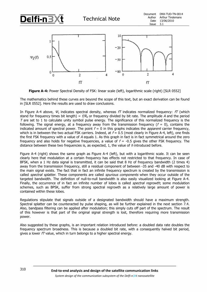
Technical NoteDocument
AuthorDateIssue
DNX-TUD-TN-0014Arthur Tindemans13/06/20103.1
310 End-to-end analysis and design of the satellite communication links
System design of the communication subsystem of the Delfi-n3Xt nanosatellite
Figure A-4: Power Spectral Density of FSK: linear scale (left), logarithmic scale (right) [SLR 0552]
The mathematics behind these curves are beyond the scope of this text, but an exact derivation can be foundin [SLR 0552]. Here the results are used to draw conclusions.
In Figure A-4 above, Ψs indicates spectral density, whereas fT indicates normalized frequency: fT (whichstand for frequency times bit length) = f/Rb or frequency divided by bit rate. The amplitude A and the periodT are set to 1 to calculate unity symbol pulse energy. The significance of this normalized frequency is thefollowing. The signal energy, at a frequency away from the transmission frequency (f = 0), contains theindicated amount of spectral power. The point f = 0 in this graphs indicates the apparent carrier frequency,which is in between the two actual FSK carriers. Indeed, at f = 0.5 (most clearly in Figure A-4, left), one findsthe first FSK frequency with a value of A equals 1. As this graph in fact is in fact symmetrical around the zerofrequency and also holds for negative frequencies, a value of f = -0.5 gives the other FSK frequency. Thedistance between these two frequencies is, as expected, 1, the value of h introduced before.
Figure A-4 (right) shows the same graph as Figure A-4 (left), but with a logarithmic scale. It can be seenclearly here that modulation at a certain frequency has effects not restricted to that frequency. In case ofBFSK, when a 1 Hz data signal is transmitted, it can be said that 8 Hz of frequency bandwidth (2 times 4)away from the transmission frequency, still a residual component of between -35 and -40 dB with respect tothe main signal exists. The fact that in fact an infinite frequency spectrum is created by the transmission iscalled spectral splatter. These components are called spurious components when they occur outside of thetargeted bandwidth. The definition of null-to-null bandwidth is also easily visualized looking at Figure A-4.Finally, the occurrence of in fact an infinite number of lobes is called spectral regrowth; some modulationschemes, such as BPSK, suffer from strong spectral regrowth as a relatively large amount of power iscontained within these lobes.
Regulations stipulate that signals outside of a designated bandwidth should have a maximum strength.Spectral splatter can be counteracted by pulse shaping, as will be further explained in the next section 7.4.Also, bandpass filtering can be applied after modulation; this simply cuts off part of the spectrum. The resultof this however is that part of the original signal strength is lost, therefore requiring more transmissionpower.
Also suggested by these graphs, is an important relation introduced before: a doubled data rate doubles thefrequency spectrum broadness. This is because a doubled bit rate, with a consequently halved bit period,gives a lower fT value, which in turn belongs to a higher spectral energy.

Technical NoteDocument
AuthorDateIssue
DNX-TUD-TN-0014Arthur Tindemans13/06/20103.1
311End-to-end analysis and design of the satellite communication links
System design of the communication subsystem of the Delfi-n3Xt nanosatellite
Figure A-5: Power Spectral Density of FSK: linear scale (left), logarithmic scale (right) [SLR 0552]
Using the graphs established above, Figure A-5 above can be established. It is basically the result ofcalculating the surface underneath the graphs in Figure A-4, between – fT and +fT, and establishing howmuch power is present outside of this bandwidth; the out-of-band power. By taking a range of f values, abandwidth B is then obtained. And, as also negative frequencies are taken into account, the BT value isdoubled. The graph then shows the amount of power located within a certain bandwidth, centered on the(apparent) transmission frequency (in dB). It should at this point be said that the calculation of these PSDsassumes equiprobable bit sequences; in other words an equal total number of 0’s and 1’s.
The noncoherent FSK demodulator is not only simple compared to coherent FSK demodulators, but alsocompared to PSK and QAM demodulators; also for higher M. It can be implemented with so-called correlatorsand squarers, or even simpler through the use of matched filters and envelope detectors. These types ofdemodulator for BFSK are shown schematically in Figure A-7 and Figure A-6 respectively. Another type ofdemodulator, using a conventional frequency discriminator can also be used, but as its resulting powerperformance is some 1 dB less it will not be reviewed here.
The use of filters and envelope detectors is conceptually the easiest, as illustrated by Figure A-6. Twobandpass filters allow for one frequency but filter out the other. Consequently envelope detectors throw awayfrequency and phase information, but keep the overall amplitude value. Once per bit period, if possible at themiddle, both signals are sampled; k is an integer equal to the total amount of bits, and T is the bit period.The comparator then gives a 0 or 1 depending on which of the two channels contains higher power content.This approach is the simplest as it does not require any carrier synchronization in terms of phase orfrequency. Performance however degrades quickly if Doppler shift is seriously present, as the filters can thenno longer be very narrow-band. As such, the bandpass filters can be replaced by what are called matchedfilters, which require carrier frequency synchronization to specify the filter specifics.
Figure A-6: Noncoherent BFSK demodulator using bandpass filters and envelope detectors [SLR 0552]

Technical NoteDocument
AuthorDateIssue
DNX-TUD-TN-0014Arthur Tindemans13/06/20103.1
312 End-to-end analysis and design of the satellite communication links
System design of the communication subsystem of the Delfi-n3Xt nanosatellite
A second approach, also requiring carrier frequency but not phase synchronization, is the use of correlatorsand squarers as illustrated in Figure A-7. A received signal (without noise) can be written as:
( , ) cos(2 ) cos cos 2 sin sin 2S t A ft A ft A ft , (A-1)
Where A is an amplitude value, t is time, f is frequency and is the unknown phase angle. The received
signal can be seen to be partly correlated with cos 2 ft , and partly with sin 2 ft . Using the so-called
correlators, the frequency products together with the integrators in Figure A-7 below, the signal energy inthese two parts are collected. By squaring the results and adding them, the resulting signal becomes
independent of the signal phase, as2 2cos sin 1 . Consequently, a comparator indicates which signal
frequency was received; the required orthogonality between the FSK frequencies makes sure that when onesignal is being detected, the other set of correlators and squarers will only yield a noise component.
Figure A-7: Noncoherent BFSK demodulator using correlators and squarers [SLR 0552]
The same demodulation simplicity commented on above yields FSK to be used for the telecommand uplink inDelfi-C3’s RAP. However, as Doppler shift is seriously present, the final noncoherent modulator usingcorrelators and squarers was chosen. Also, the modulators and demodulators above can easily be expandedto modulation schemes with higher values of M.

Technical NoteDocument
AuthorDateIssue
DNX-TUD-TN-0014Arthur Tindemans13/06/20103.1
313End-to-end analysis and design of the satellite communication links
System design of the communication subsystem of the Delfi-n3Xt nanosatellite
The bit error rates of MFSK versus Eb/N0 can be found in Figure A-8 below. It can be seen that Pb
performance goes up with higher M; this comes at the cost of more complexity and less bandwidth efficiencyas was illustrated by Figure 7.6.
Figure A-8: Pb of noncoherently modulated MFSK versus Eb/N0 [SLR 0552]

Technical NoteDocument
AuthorDateIssue
DNX-TUD-TN-0014Arthur Tindemans13/06/20103.1
314 End-to-end analysis and design of the satellite communication links
System design of the communication subsystem of the Delfi-n3Xt nanosatellite
A.2 M-ary Phase Shift Keying (MPSK)
PSK works by shifting the phase of a carrier signal when a bit shift takes place, as illustrated by Figure 7.5.The simplest case with M = 2, shifts only the phase Q of the carrier, the absolute magnitude I remains thesame. This is further illustrated in Figure A-9 below.
Figure A-9: BPSK modulation for two choices of carrier frequency
As is demonstrated in the top of the figure, case (a), if fc is an integer multiple of Rb, the phase at bittransitions is either 0 or . In case (b) however this is not so. In principle, the former condition is required to
ensure minimum bit error probability. If however fc >> Rb, this condition is negligible. In case of Delfi-C3’sRAP, the 1200 b/s signal is immediately modulated onto a 10.7 MHz signal; therefore the latter criterion issatisfied.
If M is more than 2, also the phase Q is shifted, hence quadrature modulation is applied. An illustration ofQPSK is included as Figure A-10, with the horizontal and vertical axes representing amplitude or intensity Iand phase or quadrature Q respectively.
Figure A-10: QPSK state diagram [SLR 0447]
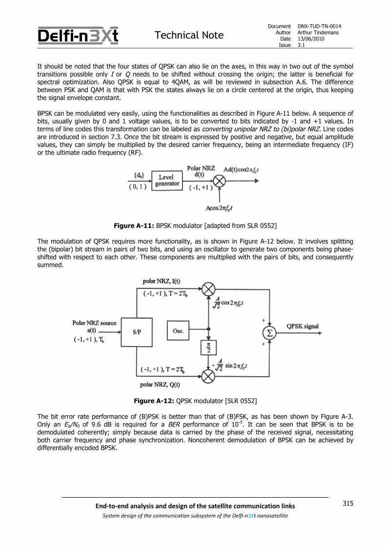
Technical NoteDocument
AuthorDateIssue
DNX-TUD-TN-0014Arthur Tindemans13/06/20103.1
315End-to-end analysis and design of the satellite communication links
System design of the communication subsystem of the Delfi-n3Xt nanosatellite
It should be noted that the four states of QPSK can also lie on the axes, in this way in two out of the symboltransitions possible only I or Q needs to be shifted without crossing the origin; the latter is beneficial forspectral optimization. Also QPSK is equal to 4QAM, as will be reviewed in subsection A.6. The differencebetween PSK and QAM is that with PSK the states always lie on a circle centered at the origin, thus keepingthe signal envelope constant.
BPSK can be modulated very easily, using the functionalities as described in Figure A-11 below. A sequence ofbits, usually given by 0 and 1 voltage values, is to be converted to bits indicated by -1 and +1 values. Interms of line codes this transformation can be labeled as converting unipolar NRZ to (bi)polar NRZ. Line codesare introduced in section 7.3. Once the bit stream is expressed by positive and negative, but equal amplitudevalues, they can simply be multiplied by the desired carrier frequency, being an intermediate frequency (IF)or the ultimate radio frequency (RF).
Figure A-11: BPSK modulator [adapted from SLR 0552]
The modulation of QPSK requires more functionality, as is shown in Figure A-12 below. It involves splittingthe (bipolar) bit stream in pairs of two bits, and using an oscillator to generate two components being phase-shifted with respect to each other. These components are multiplied with the pairs of bits, and consequentlysummed.
Figure A-12: QPSK modulator [SLR 0552]
The bit error rate performance of (B)PSK is better than that of (B)FSK, as has been shown by Figure A-3.Only an Eb/N0 of 9.6 dB is required for a BER performance of 10-5. It can be seen that BPSK is to bedemodulated coherently; simply because data is carried by the phase of the received signal, necessitatingboth carrier frequency and phase synchronization. Noncoherent demodulation of BPSK can be achieved bydifferentially encoded BPSK.

Technical NoteDocument
AuthorDateIssue
DNX-TUD-TN-0014Arthur Tindemans13/06/20103.1
316 End-to-end analysis and design of the satellite communication links
System design of the communication subsystem of the Delfi-n3Xt nanosatellite
Differentially encoded BPSK is called BEPSK. It can be coherently and differentially demodulated. If adifferential demodulator is used, the scheme is called DBPSK, or in short DPSK. A differential modulationscheme is actually one that applies a differential line code, and consequently applies the targeted modulationscheme. In case of BPSK, NRZ-I is applied; this encodes bits relatively, thus with respect to the previous bit,instead of absolutely. This means an exclusive OR (XOR) operation is performed between the present bit andprevious (from this operation) resulting bit; two equal bits give a 0, two different bits a 1 (in effect this meansthe first resulting bit should be assumed to equal either 0 or 1; this can be shown not to matter indemodulation). The result of this coding however is that the demodulator does not need to know the polarityof the signal; whether what it defines as +A represents a 0 or a 1. The exact characteristics of this code areintroduced in the next section, 7.3.
BEPSK adds the feature of polarity indifference at the cost of slight error performance degradation withrespect to coherent BPSK, as can be seen in Figure A-15; this is induced because the demodulator is for eachbit dependent on the previous bit, exposed to a certain error rate. However, because of the polarityindependence in case differential coding is applied, carrier phase synchronization is actually no longerrequired in the demodulator.
The optimum DBPSK demodulator still applies carrier frequency synchronization to increase BER performance.Nevertheless, due to an increase of complexity when Doppler shift plays an important role, matchingoscillators in both modulator and demodulator cannot take care of this. Therefore, more complicated carrierrecovery is required; mainly achieved by an M-th power loop or a Costas loop. The resulting demodulatorrequired is than demonstrated in Figure A-13 below.
Figure A-13: Coherent BPSK demodulator [SLR 0552]
It can be seen that a CR, or carrier recovery circuit is to be used to return the perfectly synchronized carrierused to modulate the signal in the modulator. The result of the multiplication of the original signal with anidentical frequency with unit amplitude is a value of T/2 times the bit amplitude, and a remainder which isdependent on the relation between the carrier frequency and data rate. If the carrier frequency is equal to aninteger multiple of the data rate, or as mentioned above, the carrier frequency is much more than the datarate, the second term equals or approaches zero. A consequent integration of the bit period duration giveseither a positive or negative signal, belonging to a transmitted -1 or +1 value. A final block checks the value land gives a conclusion as to a 0 or 1 is received.

Technical NoteDocument
AuthorDateIssue
DNX-TUD-TN-0014Arthur Tindemans13/06/20103.1
317End-to-end analysis and design of the satellite communication links
System design of the communication subsystem of the Delfi-n3Xt nanosatellite
Carrier recovery however is not required in a third variant, called suboptimum DBPK. Suboptimum DPSKlowers the demodulation complexity and requires only symbol synchronization; in fact a local oscillator is noteven required, and its bandwidth filters should only be tuned to allow the entire (possibly Doppler shifted)information signal to pass. The resulting demodulator is shown in Figure A-14.
Figure A-14: Noncoherent DBPSK demodulator [SLR 0552]
First, a filter, such as a conceptually easy to visualize bandpass filter, limits the input signal to the targetedfrequency bandwidth. Consequently two consecutive bits are mixed together by multiplication, and passed onto an integrator. The signals added together are either equal, or opposite. As such, there are continuouslyopposite or continuously equal amplitude values added together. Equal values always result in a positive total
energy ( A A or A A ), whereas opposite values result in a negative total energy ( A A ). Theintegrator adds all values during a bit period and yields either a positive or negative output belonging to a 1or 0. The differential coding is clearly used here, as consecutive bits are added to give a result based on thembeing equal, or different.
The demodulator schemes for QPSK will not be presented for brevity. Nevertheless, as with the differencebetween modulator and demodulator for BPSK and QPSK, it involves the same architecture as either FigureA-13 or Figure A-14, but again with two streams between which a phase difference is introduced, after whichthey are summed together.
The error performances of the DBPSK schemes are shown in Figure A-15 below. In case of optimum DBPSK, aPb or BER of 10-5 requires an Eb/N0 of 10.3 dB and in the case of suboptimum DBPSK some 11.5 dB isrequired, as opposed to 9.6 dB for coherent BPSK. The suboptimal DBPSK demodulator is the usual-sensedemodulator due to its complexity advantages, but only if Doppler shift is limited. In case of Delfi-n3Xthowever, as with Delfi-C3, it is not. As such, also taking advantage of the fact the on-ground demodulationcan be more complicated, the coherent DEBSPK scheme was implemented in the Delfi-C3 mission, with thedemodulator as indicated in Figure 7.7 implemented in RASCAL, the demodulator software.

Technical NoteDocument
AuthorDateIssue
DNX-TUD-TN-0014Arthur Tindemans13/06/20103.1
318 End-to-end analysis and design of the satellite communication links
System design of the communication subsystem of the Delfi-n3Xt nanosatellite
Figure A-15: Pb of BPSK and BFSK versus Eb/N0 [SLR 0552]
As was shown in Figure 7.6, with an increasing M, MPSK schemes increase bandwidth efficiency at theexpense of power efficiency. The performance of QPSK compared to BPSK however is a special case, in thesense that QPSK doubles the bit rate achievable, without a decrease in BER performance; even moresurprisingly without too much added complexity for the modulator and demodulator. Nevertheless, this is thecase only for coherently demodulated QPSK.
Optimally differentially encoded MPSK schemes have an increased required Eb/N0 of 3 dB with respect to theirnondifferential counterparts, at M=∞. Of more practical use of course are lower values of M; at M=4 (QPSK)the increase is 2.3 dB, with a 2.7 dB increase at M=8. This means that optimum DQPSK requires an Eb/N0 of2.3 more than optimum DBPSK, at the gain of 3 dB in data rate.
A suboptimal differentially decoded MPSK demodulator only exists for DQPSK, next to of course that ofDBPSK; higher MPSK schemes can not be demodulated without carrier frequency synchronization. Theperformance difference between suboptimum DBPSK and DQPSK decreases slightly with respect to optimumversions, to 1.75 dB. As a result, suboptimally and differentially demodulated QPSK still outperforms its BPSKcounterpart, as the bitrate can be doubled (+3 dB) requiring only slightly more power (-1.75 dB).

Technical NoteDocument
AuthorDateIssue
DNX-TUD-TN-0014Arthur Tindemans13/06/20103.1
319End-to-end analysis and design of the satellite communication links
System design of the communication subsystem of the Delfi-n3Xt nanosatellite
The maximum theoretical efficiency for PSK schemes is high. However, in reality there are some drawbacks;due to the large sudden phase changes belonging to PSK modulation, large spectral regrowth occurs. Thiscan be seen in Figure A-16. Figure A-16 (left) shows that QPSK contains much more energy within 1 Hzbandwidth (fT = -0.5 to +0.5). It also reaches first null two times as fast. Figure A-16 (right) clearly showsthe spectral lobes. Looking at the trend of the top of the lobes shows that spectral power does not decreasefast anymore, after only small values of fT.
Figure A-16: Power Spectral Density of PSK: linear scale (left), logarithmic scale (right) [SLR 0552]
This spectral inefficiency is even better shown by Figure A-17 below, which indicates the out-of band power.The differences between BPSK and QPSK consistently are 3 dB. But from the graphs in Figure A-17 (left) itcan be seen that out-of-band power hardly decreases with increasing bandwidth. As such, in all practicalsystems, BPSK and QPSK require filtering and/or pulse shaping. MSK is also introduced in Figure A-17 and willbe discussed in the nest subsection.
Figure A-17: Fractional out-of-band power of several modulation schemes [SLR 0552]

Technical NoteDocument
AuthorDateIssue
DNX-TUD-TN-0014Arthur Tindemans13/06/20103.1
320 End-to-end analysis and design of the satellite communication links
System design of the communication subsystem of the Delfi-n3Xt nanosatellite
The following table summarizes the 90% and 99% energy bandwidths of BFSK, BPSK, QPSK and MSK.
Table A-1: Energy percentage bandwidth of popular modulation techniques
Modulation technique 90% energy bandwidth 99% energy bandwidth
BPSK 1.7 Rb 20 Rb
QPSK 0.8 Rb 10 Rb
BFSK 1.23 Rb 2.12 Rb
MSK 0.76 Rb 1.2 Rb
By applying filters before the modulation process, in other words by shaping the bits the energy bandwidthfor the PSK schemes can be improved. This is reviewed in [SLR 0447]. Applying a Nyquist filter, usually in theform of a raised cosine, before modulation can largely reduce sideband production, but practically not untilthe level of energy efficiency of BFSK and MSK. The resulting carrier signal for a shaped BPSK modulationscheme is illustrated in Figure 7.5, under its alias double side band, suppressed carrier or DSB-SC (withshaping). Another name is raised cosine BPSK, or RC-BPSK. The downside of this shaping is next to someadded complexity that the modulation scheme is no longer constant envelope, which can be required by non-linear amplifiers if they do not offer some type of envelope elimination and restoration (EER) via anincorporated feedback system.
Finally worth mentioning are the well known related offset QPSK or OQPSK and π/4-QPSK. Both apply a delaybetween the I and Q shifts in the signal modulation, in order to avoid 180° phase shifts. This makes thesignal less susceptible to spectral side lobe restoration (large power contents out of the targeted frequencybandwidth, when amplified by a non-linear amplifier after bandpass filtering) compared to QPSK. This isbeneficial in satellite communication in case of severe bandwidth restrictions, and non-linear amplification.OQPSK however cannot be differentially demodulated, therefore complicating demodulation. π/4-QPSKhowever, can. It has little added complexity with respect to suboptimum DQPSK at no extra penalty in errorperformance.
A.3 Minimum Shift Keying (MSK)
The previous section introduced OQPSK, with its main advantage over QPSK that it exhibits less phasechanges at symbol transitions, limiting out-of-band interference. MSK provides even further improvement bymaking phase transitions completely continuous. MSK can be derived from OQPSK by shaping the pulses tothe modulator with half sinusoidal waveforms. Also, and simpler, MSK can be produced as differentiallyencoded FSK with a value of h of 0.5, which is the minimum frequency separation that still allows fororthogonality between the FSK signals, hence ‘minimum’ shift keying; orthogonality requires a separation ofan integer multiple of 1/2T. This orthogonality is required for coherent demodulation, if used. Differentiallyencoded FSK implies applying NRZ-I coding. Since producing MSK signals from OQPSK leaves a 180° phaseambiguity this method requires NRZ-I coding and decoding as well.
It can be seen in Figure 7.6 that the resulting performance of MSK compared to BPSK, BFSK, 4FSK is simplybetter. The power spectral density of MSK is illustrated in Figure A-18 and shows the lobes that have widthsbetween those of BPSK and QPSK, but the overall power content of the lobes drops off much faster. Thuswhereas QPSK has a better null-to-null bandwidth efficiency, its energy percentage bandwidth for largepercentages is worse.

Technical NoteDocument
AuthorDateIssue
DNX-TUD-TN-0014Arthur Tindemans13/06/20103.1
321End-to-end analysis and design of the satellite communication links
System design of the communication subsystem of the Delfi-n3Xt nanosatellite
Figure A-18: Power Spectral Density of MSK (logarithmic scale) [SLR 0552]
Together with the bandwidth advantages MSK is easily demodulated noncoherently at the cost of a small lossin Eb/N0 just as all FSK schemes. However coherent demodulation comes at the cost of little added complexityas phase locked loops (PLLs) can be used to extract the strong spectral components flanking the MSK signalneeded for carrier frequency and phase synchronization.
What is interesting about MSK is that in fact it is continuous in phase; but unlike simple FSK schemes with h= 1, there are certain bit sequences that cannot exist due to properties of the differential code. An example isthe sequence ‘0101’. As such, knowledge of this yields certain information on the bit sequence to be decoded.The phase continuity and bit sequence information mean a maximum likelihood algorithm such as the Viterbialgorithm can be used to demodulate a MSK-modulated signal. This algorithm is further introduced in section7.8. Whereas in case of MSK the so-called observation interval usually is 2T (to account for the differentialcoding), it can be increased to 3T or 5T for an error performance increment of 1 and 1.2 dB respectively.Longer intervals yield minor improvements at complexity increments that do not seem to favor them oversimple but efficient MSK.
Gaussian MSK or GMSK applies a Gaussian filter to the data stream before it is modulated. It significantlysuppresses spectral splatter further to generally acceptable values at a cost of only up to 1 dB errorperformance. These performances and the characteristics of Gaussian filtering are further discussed in section7.4. The application of a Gaussian filter does require a more advanced modulator than generally required, asthe frequencies used to indicate 0’s and 1’s should slowly be varied. GMSK is used in the European GlobalSystem for Mobile Communications, or the GSM system, as well as Bluetooth.
Another version of MSK used in high data rate communication is Serial MSK, or SMSK, but this scheme is saidonly to provide benefits at high data rates (1 Mb/s and up), not (yet) applicable to the Delfi programme.Together with MSK these modulation schemes can be grouped under the collective header CPM techniques,or constant phase modulation techniques.

Technical NoteDocument
AuthorDateIssue
DNX-TUD-TN-0014Arthur Tindemans13/06/20103.1
322 End-to-end analysis and design of the satellite communication links
System design of the communication subsystem of the Delfi-n3Xt nanosatellite
A.4 Continuous Phase Modulation (CPM)
CPM techniques have as the name implies, constant phases. Thereby they improve upon the generalbandwidth efficiency of FSK schemes, while keeping good error performance. In fact, due to the notion ofmemory even error performance can be improved upon. With respect to MSK, which is a simple CPM scheme,either general power efficiency or bandwidth efficiency can be increased. Of course, all comes at the cost ofcomplexity. With respect to QAM schemes, as are introduced below and which have the best bandwidthefficiency, CPM schemes have a constant envelope, thereby allowing for nonlinear amplification.
In comparison to FSK schemes, CPM schemes also have a predetermined M (number of frequencies) and h(distance between frequencies). Furthermore important are specific pulse (bit) shapes (rectangular in thesimplest case) and the symbol time L. Pulse shaping is introduced in section 7.4 below, and smoothes theabrupt changes between symbols. MSK then becomes a simple CPM version with M = 2, h = 0.5, L = 1 and arectangular pulse shape. Due to the introduced of extra variables, guaranteeing a continuous phase, memoryis effectively introduced in the phase of the received signal. CPM schemes modulate a signal based on theinput bit, but also on the present phase state of the modulated signal.
As well as (generally) introducing a filter, CPM requires added complexity in the demodulator in the form ofmore complex synchronization, and a maximum likelihood algorithm; the observation interval should beincreased for better error performance. In case of the Delfi programme, CPM schemes (other than MSK) willlikely not be of much use until the boundaries of either power and bandwidth efficiency are seriously pushed;currently modulation and demodulation complexity is more of a bottleneck.
A final CPM subtype worth mentioned is that of multi-h CPM, or MHPM. As the name suggests, the h can bechosen to vary. The result is that overall error performance can increase, whereas more bandwidth isrequired, but with less intensity. At the gain of yet more complexity, this can yield even more power efficiencyand overall bandwidth efficiency, most useful in channels where the specific channel to be used is not strictlylimited, but power efficiency is. In fact its addition can be seen as a form of error correction introduced to themodulation scheme.
A.5 M-ary Amplitude Shift Keying (MASK)
Most of the modulation schemes discussed above have constant envelopes, which can be an essentialproperty if highly efficient yet non-linear amplifiers are used to amplify the RF signal. If a constant envelope isnot required, techniques as ASK or QAM can be used, reviewed in this and the next subsection.
The main advantage of MASK is its implementation simplicity. The simplest type of ASK in turn is OOK, asillustrated in Figure 7.5, where the signals shift between M = 2 amplitude levels, of which one equals zero.OOK has the same bandwidth efficiency as BPSK but with a spectral line which can be locked on to by a PLL.The BER performance of coherent OOK however is 3 dB below that of coherent BPSK, therefore only if circuitsimplicity is of prime concern should OOK be selected for digital modulation. It holds that MASK is simplyinferior to MPSK, with as mentioned 3 dB of lesser error performance at M = 2, asymptotically increasing to 6dB at M = ∞.
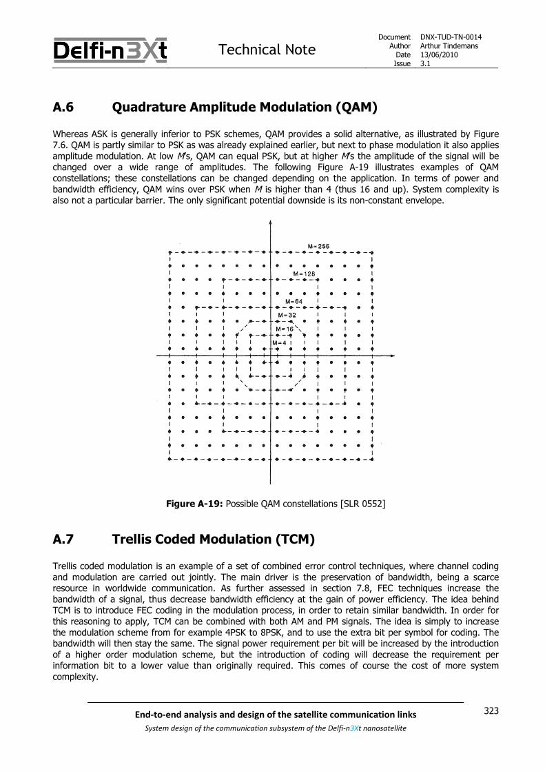
Technical NoteDocument
AuthorDateIssue
DNX-TUD-TN-0014Arthur Tindemans13/06/20103.1
323End-to-end analysis and design of the satellite communication links
System design of the communication subsystem of the Delfi-n3Xt nanosatellite
A.6 Quadrature Amplitude Modulation (QAM)
Whereas ASK is generally inferior to PSK schemes, QAM provides a solid alternative, as illustrated by Figure7.6. QAM is partly similar to PSK as was already explained earlier, but next to phase modulation it also appliesamplitude modulation. At low M’s, QAM can equal PSK, but at higher M’s the amplitude of the signal will bechanged over a wide range of amplitudes. The following Figure A-19 illustrates examples of QAMconstellations; these constellations can be changed depending on the application. In terms of power andbandwidth efficiency, QAM wins over PSK when M is higher than 4 (thus 16 and up). System complexity isalso not a particular barrier. The only significant potential downside is its non-constant envelope.
Figure A-19: Possible QAM constellations [SLR 0552]
A.7 Trellis Coded Modulation (TCM)
Trellis coded modulation is an example of a set of combined error control techniques, where channel codingand modulation are carried out jointly. The main driver is the preservation of bandwidth, being a scarceresource in worldwide communication. As further assessed in section 7.8, FEC techniques increase thebandwidth of a signal, thus decrease bandwidth efficiency at the gain of power efficiency. The idea behindTCM is to introduce FEC coding in the modulation process, in order to retain similar bandwidth. In order forthis reasoning to apply, TCM can be combined with both AM and PM signals. The idea is simply to increasethe modulation scheme from for example 4PSK to 8PSK, and to use the extra bit per symbol for coding. Thebandwidth will then stay the same. The signal power requirement per bit will be increased by the introductionof a higher order modulation scheme, but the introduction of coding will decrease the requirement perinformation bit to a lower value than originally required. This comes of course the cost of more systemcomplexity.

Technical NoteDocument
AuthorDateIssue
DNX-TUD-TN-0014Arthur Tindemans13/06/20103.1
324 End-to-end analysis and design of the satellite communication links
System design of the communication subsystem of the Delfi-n3Xt nanosatellite
A.8 Orthogonal Frequency Division Multiplexing (ODFM)
A modulation technique worth mentioning due to its widespread application nowadays is that of orthogonalfrequency division multiplexing. This technique implies dividing a data stream and modulating multiplecarriers, each using a bandwidth efficient modulation technique as QAM or PSK. The total frequencybandwidth used is increased by this logically, but so are the data rates achieved. Nevertheless this techniqueprimarily requires more power too, next to extra complexity and as such is no serious option for a missionsuch as Delfi-n3Xt, or satellite communication in general. ODFM is a subtype of frequency division multipleaccess (FDMA) which allows for multiple data streams to concur simultaneously, by using different carrierfrequencies.
A.9 Spread spectrum techniques
By using a code to postmodulate data, multiple data streams can be sent over the same bandwidth. Thesespread spectrum techniques are actually not a type of modulation, but are generally presented as part ofmodulation. In general the techniques can be applied if the required transmission power for one datatransmission in a certain bandwidth is too high, due to regulations for example. Spread signal techniquesdecrease the power spectral density of a signal, thereby resulting in an increased resistance to interference, alower probability of detection and the possibility of spectrum sharing. If spread spectrum techniques are usedto achieve the latter it is a form of code division multiple access (CDMA). Spread spectrum techniques canalso be used to yield accurate range (distance) or range rate (velocity) measurements. A detailed discussioncan be found in [SLR 0166].
The basic working is as follows. A signal spreader is introduced after the modulator. When the signal isspread, the energy of the signal remains the same, but the bandwidth of the signal is enlarged. The powerspectral density therefore decreases. At reception, the consequent signal-to-noise ratio can be well below 1.As noise is uncorrelated, and the receiver does have information of the received signal, this information canbe used to correlate the received signal. When the signal is correlated, despreading occurs, and the originalsignal is retrieved. The level of this signal should consequently again be above the noise level.
Spread spectrum techniques do not increase the achievable data rate. With the possible exception of theimproved capability of bandwidth sharing, the advantages of spread spectrum techniques are consequentlynot directly applicable to small university satellite missions, but are more of interest for military applications.

Technical NoteDocument
AuthorDateIssue
DNX-TUD-TN-0014Arthur Tindemans13/06/20103.1
325End-to-end analysis and design of the satellite communication links
System design of the communication subsystem of the Delfi-n3Xt nanosatellite
Appendix B Block codes
As explained in section 7.3, this appendix introduces the different code classes as demonstrated in Figure 7.7.Attention is paid to the different advantageous and disadvantageous properties, such as bandwidthperformance and complexity. Power performance of the basic code classes has already been introduced insection 7.3. The four classes, NRZ codes, RZ codes, Pseudoternary codes and Biphase codes are introduced insections B.1 through B.4.
Consequently, a line code going by the name of Delay modulation or Miller code, strictly part of the biphasegroup but with distinct characteristics, is discussed in subsection B.5. Finally more advanced line codesclasses are introduced in subsections B.6 and B.7, being the substitution codes and block codes.
B.1 NRZ codes
The (bipolar) NRZ codes, or nonreturn-to-zero codes use two levels, being +A and –A. As presented above,the (unipolar) NRZ-L code is the usual code in digital logic as we all know. NRZ-M and NRZ-S are differentialforms of NRZ-L; one bit (0 or 1) is defined as a state transition, whereas the other bit causes no transition. Incase of NRZ-S, if the bit to be transmitted is a 0, the signal is transitioned from whatever state it is in to theother, whereas in sending a 1 no transition in signal takes place. Another name for differentiated NRZ is NRZ-I, the name which was used to represent this line code in its use for Delfi-C3. Consequently it depends onconvention whether a 1 or 0 creates a transition. Nevertheless, the term NRZ-I is often used.
NRZ codes have no dc component, assuming an equiprobable binary data sequence. If however a largeramount of just 1’s or just 0’s is transmitted, a dc component will be introduced. This intuitively makes senseas the total averaged signal becomes slightly positive or negative. More importantly, a small stream ofconsequent 1’s or 0’s can directly saturate capacitors in this way.
Differential codes as suggested above have one main advantage; the same original bit stream can berecovered, regardless of the polarity of the transmitted encoded signal. See [SLR 0552] for a detailedexplanation of this phenomenon, but by symbolizing bits relatively instead of absolutely no knowledge isrequired on the polarity of the signal. However, as Figure 7.8 suggests, this comes at the cost of reduced BERperformance. This is caused by the dependence of one bit on previous bits. As also quantatively stated in[SLR 0316], the required Eb/N0 for a similar BER of 10-5 is 10.3, or 0.8 dB more. A further disadvantage ofdifferential NRZ coding is a slight increase of complexity, but this is minimal as the differential coding can beintegrated in software; basically the bit sequence is just changed.
Finally, NRZ codes do not automatically yield sufficient bit timing or symbol synchronization, as a string of all0’s, all 1’s or alternating 1’s and 0’s yields no transitions, depending on the type of NRZ coding. This cancause synchronization to be lost, which can be prevented by precoding the data to remove these strings. Asthe AX.25 protocol (see section 7.6) is prepared to use NRZ-S (there simply labeled NRZ-I) coding, it indeedremoves long strings of 1’s to allow for maintaining bit synchronization through bit stuffing.
The (bipolar) NRZ codes can be made unipolar by changing the lower –A level to 0. This creates a dccomponent at a level of A/2, assuming an equal number of 0’s and 1’s.
The power spectral densities or PSDs of both (bi)polar and unipolar NRZ are illustrated in Figure B-1 below(left), as well the bandwidth efficiencies (right). The significance of PSDs has been introduced in section 7.2.Per figure a number of aspects can be noted, which are preceded by a small explanation of what the figuresexactly demonstrate.

Technical NoteDocument
AuthorDateIssue
DNX-TUD-TN-0014Arthur Tindemans13/06/20103.1
326 End-to-end analysis and design of the satellite communication links
System design of the communication subsystem of the Delfi-n3Xt nanosatellite
Power spectral densities: normalized to have a maximum at Ψs = 1, these graphs indicate how muchpower is present in a 1-second average pulse at any frequency.
The zero frequency indicates a constant total power level in one bit or pulse. In the case of bipolarNRZ it is easy to visualize that total signal strength per bit is constant and nonzero, independent of a0 or 1 is being transmitted. Only the sign changes. This nonzero signal strength, at zero frequencyindicates a dc component. Polar NRZ then yields no net dc component if 0 and 1 bits alternate eachother, as mentioned above. Unipolar NRZ on the contrary, although slightly hard to see from thefigure, has a power impulse of value 0.5 at zero frequency, even if symbols alternate nicely. In otherwords, the signal always has a net positive power content.
For both polar and unipolar NRZ it can be seen that the first null is reached at fT = 1; In other wordsBnull = 1 Rb. It can therefore be said that the signal has no spectral energy at the clock frequency.
Fractional out-of-band bandwidths: these graphs demonstrate at any value of BT, how much percent ofthe power in the signal is out-of-band. As mentioned in the previous section, reading the value at -10 dB onthe vertical axis gives the 90% energy bandwidth (log relation). BT = B/Rb; an approximate 0.85 at -10 dBindicates B90% at 0.85 Rb. Furthermore, as can be verified by calculation, B99% ≈ 10 Rb.
What is possibly more interesting about the graphs shown in Figure B-1 (a), is that they are identical to thePSD of BPSK. In fact, as explained before, bipolar NRZ coding is required to modulate BPSK. As the abruptchanges are indeed part of the NRZ code, and not the IF or RF signal mixed with the bit sequence, the codeindeed gives the BPSK modulation its frequency characteristics.
Figure B-1: PSD (left) and out-of-band power (right) of (a) Polar NRZ and (b) Unipolar NRZ [SLR 0552]

Technical NoteDocument
AuthorDateIssue
DNX-TUD-TN-0014Arthur Tindemans13/06/20103.1
327End-to-end analysis and design of the satellite communication links
System design of the communication subsystem of the Delfi-n3Xt nanosatellite
B.2 RZ codes
The RZ codes, or return-to-zero codes, introduce extra timing information in the signal, by adding moretransitions. The amplitude indicating a bit is simply returned to 0 after half the bit period. Unipolar RZ codingis also possible, where the 0 bits yield no transition with a continuous zero amplitude. The latter has again nobit transitions for long strings of 0’s and introduces a certain dc component at the cost of extra complexity,thus is not reviewed further.
The bipolar RZ code guarantees a transition per bit, which comes at no cost in BER performance, but only atthe cost of increased bandwidth and complexity. A third amplitude level is introduced and the bandwidth isdoubled, as can be seen in Figure B-2. In conclusion:
Power spectral density: the shape is the same as that of Polar NRZ, but with half the power and a nullbandwidth that is twice as large: Bnull = 2 Rb. This is due to the fact that the amount of abrupt changes in thebit sequence has doubled. A dc component can arise in a non-perfectly alternating bit sequence.
Fractional out-of-band bandwidth: also more or less twice that of NRZ codes; B90% ≈ 1.7 Rb and B99% ≈22 Rb.
Figure B-2: PSD (left) and out-of-band power (right) of Polar RZ [SLR 0552]
B.3 Pseudoternary codes
Similar to RZ codes, these codes apply three levels, ±A and 0. They are also called bipolar codes in thetelecommunication industry. AMI codes are part of this group. AMI stands for alternative mark inversion,indicating that consecutive bits, per convention 1’s, have opposite signal amplitude. As one can imagine, thiscan yield RZ and NRZ versions. What this code introduces is a form of error detection, by adding adependence on previous bits.
These codes also have no dc component. The 0 bits yield no signal strength, thus neither a dc component,and 1 bits are per definition alternated so that an overall dc component is excluded. Nevertheless, little bittransitions might introduce synchronization difficulties. Also, three signal levels introduce additional systemcomplexity and BER performance is worse than for simpler line codes.
Next to AMI codes there are the dicodes, which are basically differential AMI codes. This, as expected, comesat the cost of more BER performance as illustrated by Figure 7.8. The power spectral densities of thepseudoternary RZ and NRZ codes as well as their out-of-band power are illustrated by Figure B-3 below.
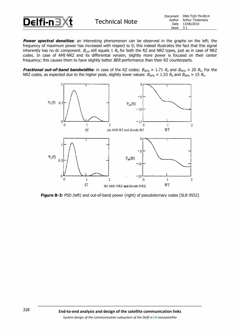
Technical NoteDocument
AuthorDateIssue
DNX-TUD-TN-0014Arthur Tindemans13/06/20103.1
328 End-to-end analysis and design of the satellite communication links
System design of the communication subsystem of the Delfi-n3Xt nanosatellite
Power spectral densities: an interesting phenomenon can be observed in the graphs on the left; thefrequency of maximum power has increased with respect to 0; this indeed illustrates the fact that this signalinherently has no dc component. Bnull still equals 1 Rb for both the RZ and NRZ types, just as in case of NRZcodes. In case of AMI-NRZ and its differential version, slightly more power is focused on their centerfrequency; this causes them to have slightly better BER performance than their RZ counterparts.
Fractional out-of-band bandwidths: in case of the RZ codes: B90% ≈ 1.71 Rb and B99% ≈ 20 Rb. For theNRZ codes, as expected due to the higher peak, slightly lower values: B90% ≈ 1.53 Rb and B99% ≈ 15 Rb.
Figure B-3: PSD (left) and out-of-band power (right) of pseudoternary codes [SLR 0552]

Technical NoteDocument
AuthorDateIssue
DNX-TUD-TN-0014Arthur Tindemans13/06/20103.1
329End-to-end analysis and design of the satellite communication links
System design of the communication subsystem of the Delfi-n3Xt nanosatellite
B.4 Biphase codes (including Manchester)
Biphase codes apply half-period pulses with possible different phases. The Bi-Ф-L (which stands for bi-phaselevel) format is better known as Manchester code. A 1 is indicated by a higher level first half bit, followed by alower level second half bit. The 0 is coded vice versa. The pulse shapes can also be exchanged. Othervariants such as Bi-Ф-M and Bi-Ф-S ensure a bit transition at the start and ends of a bit, but thereby do notguarantee a bit transition during the bit. This increases coding complexity somewhat but most notably comesat the cost of 3 dB decreased BER performance. Finally conditioned Bi-Ф-L is basically differential Manchestercoding.
As with RZ codes, used bandwidth is doubled as the two levels per bit are required. This is illustrated byFigure B-4. However, biphase codes only require two different signal levels, to achieve similar BERperformance. Therefore the impact on system complexity is less. The consequence is that depending on theexact biphase code a transition at the start/end and middle of a bit is not guaranteed; offering slightly lesssymbol synchronization possibilities. Nevertheless, as illustrated by its widespread application this extrasynchronization is usually not required. Manchester coding is used in Ethernet, as well as of course the uplinkof Delfi-C3, with success. In the latter case also NRZ-I coding (of type NRZ-S) is applied, effectively applyingdifferentially encoded Manchester; however in the opposite sense as that illustrated in Figure 7.7 asConditioned Bi-Ф-L. Finally, Manchester coding as well as its differential version has no dc component, whichis guaranteed as every bits contains equals parts positive as negative amplitude. As is explained below,Manchester is actually part of a larger block code class, called mBnB codes.
DMI codes or Differential Mode Inversion codes, similarly classified as block codes being further reviewedbelow, actually have the same spectral performance as biphase codes. The codes add error correctioncapabilities to the biphase code characteristics; 1’s are consequently mapped to a 00 and 11 of each half a bitperiod, whereas 0’s are mapped to 01 and 10. The transition capabilities are consequently lowered withrespect to for example Manchester, at the gain of some error detection capability.
Power spectral density: as with the AMI codes, the frequency of maximum power is shifted. The spectrumis however rather broad, so Bnull = 2 Rb; as with RZ codes the number of transitions per bit have beendoubled, forcing the bandwidth occupation to do the same.
Fractional out-of-band bandwidth: these values are quite broad as well, with B90% ≈ 3.05 Rb and B99% ≈29 Rb.
Figure B-4: PSD (left) and out-of-band power (right) of biphase and DMI codes [SLR 0552]

Technical NoteDocument
AuthorDateIssue
DNX-TUD-TN-0014Arthur Tindemans13/06/20103.1
330 End-to-end analysis and design of the satellite communication links
System design of the communication subsystem of the Delfi-n3Xt nanosatellite
B.5 Delay Modulation
Whereas delay modulation or Miller code can strictly be seen as part of the biphase code group, as it has twophases per bit, if offers some unique behaviour. The representation for a 1 is alternated, being one-half +Aand one-half –A. A 0 yields no transition, unless it is followed by another 0. Miller codes give little beneficialproperties in terms of bit synchronization, but result in a very small bandwidth and a very small dccomponent. This of course comes at the cost of complexity and non-optimal BER performance.
Power spectral density: again a shifted (and high) power peak, as with other biphase codes, but this timeyielding a very narrow one. The main lobe bandwidth is only about 0.5 Rb. There is a small dc componentintroduced, its value depending on the specific momentary bit sequence. This however still renders it suitablefor many applications without dc response.
Fractional out-of-band bandwidth: the power spectrum, however having a very narrow peak, convergesto zero very slowly. This results in having only 76.4% of the power within 2 Rb and only 83.7% within 250 Rb.
Figure B-5: PSD (left) and out-of-band power (right) of Delay Modulation [SLR 0552]
B.6 Substitution line codes
An improvement of AMI codes in terms of transitions, resulting in better symbol synchronization performance,is given by substitution line codes.
As has been shown above, in a number of line codes a long series of 0’s or 1’s causes no transitions to takeplace, complicating symbol synchronization. The idea behind substitution line codes is to replace a certainmaximum string of 0’s or 1’s by a predefined code. The problem of with a predefined code of course is thatthis code should not occur elsewhere in the bit sequence. Substitution codes solve this problem by using anAMI code, and inserting intentional bipolar violations.
AMI codes make use of alternating symbols, indicating 1’s. This feature allows for some error detection. Ifhowever two consecutive 1’s are not represented by an alternating symbol, one speaks of a bipolar variation.This feature can next to error detection be used for more conveyance of information, as done through theuse of substitution coding. Of course this lowers the error detection capability slightly, depending on thecomplexity of the substitution.

Technical NoteDocument
AuthorDateIssue
DNX-TUD-TN-0014Arthur Tindemans13/06/20103.1
331End-to-end analysis and design of the satellite communication links
System design of the communication subsystem of the Delfi-n3Xt nanosatellite
B.7 Block codes
Block codes are a general name for more advanced line codes that do not map bits to symbols (1 by 1), butmap a number of bits onto a number of symbols. In fact, some of the line codes above can be seen as blockcodes; all RZ codes map on bit to two symbols, as well as the biphase codes.
Two general approaches can be distinguished:
Additional symbols can be added; usually to yield better transition characteristics and a virtually zerodc component. This of course comes at the cost of increased bandwidth. The most advancedschemes are used for example optical transmissions, where only on-off signaling is possible (twolevels) and bandwidth is relatively unimportant.
More bits can be mapped to less symbols, usually 4 bits to three ternary symbols; this savesbandwidth. An increase in complexity of the coding alphabet can come at the gain of total digitalsum, see below. It can however only by used in cases where more than two levels can be used toindicate symbols. These codes are less logically applied in combination with wireless modulation, as ineffect they themselves introduce a sort of amplitude modulation.
A code classified as a block code and which adds symbols for increased functionality, as already introducedabove is the DMI code. A version called CMI, Coded Mark Inversion, does not alternate the 1 code, and justmaps it to 01 or 10. The codes, as well as biphase codes can be classified under the common header mBnBcodes, where m bits are mapped to a higher number n.
An interesting code that removes the dc component and adds symbol transitions is the Carter code. It is anmB(m+1)B code; more precisely a 8B9B code. It looks at a block of 8 bits, and then either inverts thesequence, or not; in order to average out the total number of 0’s and 1’s sent (reducing disparity or digitalsum). At the same time, this introduces transmissions as a sequence of 1’s can not be followed by a sequencewith a large number of 0’s. The ninth bit per sequence is inserted to indicate a conversion.
The Griffiths code also removes a dc component and adds symbol transitions. It improves the characteristic ofCarter code that 18 1’s or 0’s can follow each other. It works by mapping a certain bit pattern onto anotherpattern and it is usually of the form 3B4B or 5B6B. In fact, its 1B2B form is equal to Manchester. Higher-ordercodes introduce excessive complexity. The 3B4B Griffiths code uses only zero- and single-disparity words,limiting the maximum number of 1’s or 0’s to 4 in-a-row. The 5B6B Griffiths code applies only zero- anddouble-disparity words, limiting the maximum number of 1’s or 0’s to 6 in-a-row. Manchester, or 1B2B has amaximum of 2 equal symbols in-a-row.
A 2B3B dc-constrained code, as the name implies, does not reduce the dc-component completely butconstrains it. The latter approach yields bit redundancy to be used for error correction. It yields a constant dccomponent of -1/3. It has an average number of changes per level of between 1 and 2, and a maximumnumber of symbols without change of 7.
Finally mB1C and DmB1M codes add a bit per m bits to incur a transition, by making sure the added bit isdifferent from the last bits of the block. mB1C looks only at the last block bit, whereas DmB1M looks at theentire block and thereby adds a certain error detection capability.

Technical NoteDocument
AuthorDateIssue
DNX-TUD-TN-0014Arthur Tindemans13/06/20103.1
332 End-to-end analysis and design of the satellite communication links
System design of the communication subsystem of the Delfi-n3Xt nanosatellite

Thesis paperAuthor: Arthur Tindemans
Date: 21-06-2010
333End-to-end analysis and design of the satellite communication links
System design of the communication subsystem of the Delfi-n3Xt nanosatellite
Appendix B
COMMS – STX System Design
SLR 0387
The entire document has been written by the author.

Thesis paperAuthor: Arthur Tindemans
Date: 21-06-2010
334 End-to-end analysis and design of the satellite communication links
System design of the communication subsystem of the Delfi-n3Xt nanosatellite

Technical NoteDocument
AuthorDateIssue
DNX-TUD-TN-0387Arthur Tindemans13/06/20103.0
335End-to-end analysis and design of the satellite communication links
System design of the communication subsystem of the Delfi-n3Xt nanosatellite
COMMS – STX System Design
Description: Document establishing modules and design options for the STX system
Subsystem(s)involved: A
DC
S
CD
HS
CO
MM
S
EP
S
Mech
S
ST
S
TC
S
ITR
X
MP
S
T3μ
PS
SD
M
Sp
lash
GS
E
GS
N
La
un
ch
X X X X
Revision Record and Authorization
Issu
e
Date Author / Editor
Re
vie
we
r
ch
eck
ed
PM
ap
pro
ve
d
AffectedSection(s)
Description of change
0.1 XX-12-2008 A. Tindemans All First issue, functional definition
1.0 10-4-2009 A. Tindemans All Entire document (re)written
2.0 16-11-2009 A. Tindemans All Total update; mainly operations
3.0 13-06-2010 A. Tindemans 123 & 45-111213
141516
STX goals (re)definedRequirements updatedChapters switched and updatedCI chapters updatedNew chapterOld chapter 12Component diagram updatedand added integration optionsOld chapter 13Power consumptions updatedOld chapter 14Next steps added

Technical NoteDocument
AuthorDateIssue
DNX-TUD-TN-0387Arthur Tindemans13/06/20103.0
336 End-to-end analysis and design of the satellite communication links
System design of the communication subsystem of the Delfi-n3Xt nanosatellite

Technical NoteDocument
AuthorDateIssue
DNX-TUD-TN-0387Arthur Tindemans13/06/20103.0
337End-to-end analysis and design of the satellite communication links
System design of the communication subsystem of the Delfi-n3Xt nanosatellite
Table of Contents
1 INTRODUCTION _________________________________________________________________ 341
2 REQUIREMENTS _________________________________________________________________ 345
3 FUNCTIONAL DESCRIPTION AND MODES __________________________________________ 347
4 INTERFACES ____________________________________________________________________ 349
5 DEFINING THE CIS ______________________________________________________________ 351
5.1 Subfunctionalities of the STX system ________________________________ 351
5.2 Establishing hardware packages____________________________________ 352
5.3 Determination of configuration items (CIs) ___________________________ 353
6 STX PROCESSOR (INCL. SOFTWARE) ______________________________________________ 357
6.1 Requirements definition __________________________________________ 357
6.2 Interfaces _____________________________________________________ 3606.2.1 Sensor interface (analogue to digital) __________________________________________ 3606.2.2 I2C interface (digital) _______________________________________________________ 3606.2.3 Data storage interface (digital) _______________________________________________ 3606.2.4 Modulator interface (digital)__________________________________________________ 360
6.3 Data flows_____________________________________________________ 3616.3.1 Housekeeping data flow _____________________________________________________ 3616.3.2 Command data flow ________________________________________________________ 3616.3.3 Transmission data storage flow _______________________________________________ 3616.3.4 Transmission data process flow _______________________________________________ 3616.3.5 Transmission data output flow ________________________________________________ 361
6.4 STX Processor __________________________________________________ 3626.4.1 A/D and D/A converting _____________________________________________________ 3636.4.2 Clock signals ______________________________________________________________ 3636.4.3 Integrated memory_________________________________________________________ 364
6.5 Work to be done for the STX Processor (incl. Software) __________________ 364

Technical NoteDocument
AuthorDateIssue
DNX-TUD-TN-0387Arthur Tindemans13/06/20103.0
338 End-to-end analysis and design of the satellite communication links
System design of the communication subsystem of the Delfi-n3Xt nanosatellite
7 STX DATA STORAGE______________________________________________________________ 365
7.1 Requirements definition __________________________________________ 365
7.2 Required memory size____________________________________________ 365
7.3 Memory type ___________________________________________________ 367
7.4 Operation _____________________________________________________ 368
7.5 Work to be done for the STX Data Storage ____________________________ 368
8 STX HOUSEKEEPING SENSORS ____________________________________________________ 369
8.1 Requirements definition __________________________________________ 369
8.2 Housekeeping data specification ___________________________________ 369
8.3 Sensor specification _____________________________________________ 371
8.4 Work to be done for the Housekeeping Sensors ________________________ 371
9 STX MODULATOR ________________________________________________________________ 373
9.1 Requirements definition __________________________________________ 373
9.2 STX Modulator hardware__________________________________________ 3749.2.1 The CC2500 2.4 GHz transceiver ______________________________________________ 3749.2.2 CC2500 modulation schemes _________________________________________________ 3769.2.3 Packet handler functionality __________________________________________________ 3769.2.4 Electrical integration ________________________________________________________ 378
9.3 Work to be done for the STX Modulator ______________________________ 379
10 STX FREQUENCY UP-CONVERTER__________________________________________________ 381
10.1 Requirements definition __________________________________________ 382
10.2 Oscillator circuit ________________________________________________ 382
10.3 Bandpass filter _________________________________________________ 383
10.4 Work to be done for the STX Frequency Up-converter ___________________ 384

Technical NoteDocument
AuthorDateIssue
DNX-TUD-TN-0387Arthur Tindemans13/06/20103.0
339End-to-end analysis and design of the satellite communication links
System design of the communication subsystem of the Delfi-n3Xt nanosatellite
11 STX POWER AMPLIFIER __________________________________________________________ 385
11.1 Requirements definition __________________________________________ 385
11.2 Power amplifier_________________________________________________ 38611.2.1 Switching amplifiers ________________________________________________________ 38611.2.2 Applicable COTS amplifiers___________________________________________________ 38711.2.3 STX options _______________________________________________________________ 39011.2.4 Switching amplification in the STX_____________________________________________ 392
11.3 Bandwidth filter ________________________________________________ 392
11.4 Work to be done for the STX Power Amplifier__________________________ 393
12 THE VARIABLE VOLTAGE BUS AND BEACON MODE __________________________________ 395
12.1 The variable voltage bus __________________________________________ 39512.1.1 The need for an excess power handling system on Delfi-n3Xt other than the STX_______ 39512.1.2 The limited power generation of the redefined Delfi-n3Xt __________________________ 39612.1.3 The limited functionality of available COTS amplifiers _____________________________ 39612.1.4 Conclusions _______________________________________________________________ 398
12.2 Beacon mode___________________________________________________ 398
13 INTEGRATING THE COMPONENTS _________________________________________________ 399
13.1 The STX component lay-out _______________________________________ 399
13.2 The STX electrical interfaces_______________________________________ 401
13.3 The STX PCB ___________________________________________________ 401
13.4 STX integration without a PCB _____________________________________ 402
14 THE STX IN THE DELFI-N3XT BUDGETS ____________________________________________ 403
14.1 Volume budget _________________________________________________ 403
14.2 Mass budget ___________________________________________________ 404
14.3 Power budget __________________________________________________ 404
15 NEXT STEPS_____________________________________________________________________ 407

Technical NoteDocument
AuthorDateIssue
DNX-TUD-TN-0387Arthur Tindemans13/06/20103.0
340 End-to-end analysis and design of the satellite communication links
System design of the communication subsystem of the Delfi-n3Xt nanosatellite
APPENDIX A IMPLEMENTING AN FPGA.........................................................................411
A.1 Field programmable gate arrays (FPGAs) _______________________________ 411
A.2 Types of FPGA ____________________________________________________ 412
A.3 Comparison between FPGAs and ASIC designs w.r.t. STX ___________________ 413
A.4 Conclusion with regard to the STX ____________________________________ 414

Technical NoteDocument
AuthorDateIssue
DNX-TUD-TN-0387Arthur Tindemans13/06/20103.0
341End-to-end analysis and design of the satellite communication links
System design of the communication subsystem of the Delfi-n3Xt nanosatellite
1 Introduction
The STX is part of the Delfi-n3Xt communication system, or COMMS. The COMMS is introduced in [SLR 0014]along with its top-level design. The latter document therefore introduces the components that make up theCOMMS. They can be said to consist of a primary communication system, consisting of PTRX, ITRX and arespective antenna system, and a secondary communication system, consisting of two technologydemonstrations and their respective antenna system parts. One of the demonstrations is OLFAR, the other isthe S-band transmitter, or shortened: STX.
The STX is an experimental transmitter that is designed to facilitate high data rate one-way communicationfrom the satellite to the Earth, in order to increase the capacity of the Delfi satellite bus. As UHF and VHFfrequencies do not generally allow higher data rates than 9.6 kb/s to be achieved on the radio amateurfrequency bands, as a minimum performance standard the STX data rate is set to ≥9.6 kb/s.
Since the conception of the STX during the mission definition of Delfi-n3Xt almost two years ago, two relevantthings have changed:
Full attitude control is no longer guaranteedWhereas the ADCS is the subsystem where significant advances are to be made, its developmentis no longer allowed to delay the program and significantly increase the operational risks. Aconsequence of this choice is also that instantaneously generated power is decreased from 10-18W to about 3.5 W, although a battery is available.
Student resources have turned out to be scarceA long period of little students has been combined with a heavy under-anticipated work-load onthe primary radio system, the PTRX. No significant lower-level work on the STX has beenperformed yet.
The result of these changes has been that the inclusion of the STX on Delfi-n3Xt has been questioned.Nevertheless, during a meeting with staff, students and relevant partners it has been decided that an effortshould be made to fly the STX, in order to:
Have a proven S-band transmitter for future missions Increase the novelty and appearance of Delfi-n3Xt with respect to Delfi-C3
The matter of requesting a transmission frequency for a system that might in the end not be flown due tolimited resources was also discussed, but it was decided the frequency coordination process should becommenced based on the current specifications. The arguments:
No regulatory or moral obligationsThe radio amateur community poses no repercussions for not being able to deliver; projectchanges due to for example limited resources are acceptable. This has later been confirmed byGraham Shirville, who heads the frequency allocation of the AMSAT community.
A substitute can possibly be flownIf the STX itself cannot be finished, a substitute S-band transmitter can potentially be bought andaccustomed to Delfi-n3Xt, such as the TXS of ISIS B.V.
The above facts lead to the design philosophy of the STX, as presented on the next page.

Technical NoteDocument
AuthorDateIssue
DNX-TUD-TN-0387Arthur Tindemans13/06/20103.0
342 End-to-end analysis and design of the satellite communication links
System design of the communication subsystem of the Delfi-n3Xt nanosatellite
The design philosophy of the STX can be stated by means of four design goals:
No pointing shall be required for the technology demonstrationPointing would allow much higher data rates to be achieved. However, if the ADCS is dependedon by the STX, the chances of halving a fully operational STX would be halved (simplistically). Assuch, a more or less omnidirectional antenna pattern shall be implemented, for as far as possible.
The STX shall have power consumption no higher than the PTRX (~1.75 W maximum)Power is (very) limited on Delfi-n3Xt; there is little power available on top of nominalfunctionalities. Although a battery is available on Delfi-n3Xt, the STX would be little flexible if itdepends on the latter. At that, it would increase risks for a proper technology demonstration. Ifthe STX consumes less power than the PTRX, the PTRX transmitter can be switched off, to switchon the STX. Ideally, this would replace identical transmission functionalities. Currently, some1.75 W is allocated to the PTRX. This value might be lowered somewhat by adjusting the gain ofthe amplifier if the final power budget demands for it.
COTS components shall be used wherever possibleThe use of COTS components logically decreases required (project) resources.
All components in the design should be as modular as possibleAn STX with a separated processor, data storage, modulator and power amplifier amongst otherscan easily be updated if software, power or complexity constraints change (for example in afuture mission or later in the Delfi-n3Xt mission).
The actual testability of the STX will depend on the antenna directivity pattern and consequently the attitudeof Delfi-n3Xt during a pass. Assuming a (slowly) rotating satellite, STX testing will always be possible.
As partly introduced above, design of systems related to the STX, such as the STX top-level design, has beenestablished in other documents. These documents are:
[SLR 0014]: COMMS – Top Level Design of the Communication Subsystem [SLR 0036}: COMMS – Antenna System Design
The first document introduces not only the STX and the reasons for its inclusion, but also establishes thecharacteristics of the S-band communication link, taking into account ground segment as well as STX design,in turn introduced in this document. More specifically, the transmission frequencies, modulation scheme, FECapproach, data rate approach and data protocol have been specified in the top level document. Finally, alsothe anticipated operations of the STX and its activation have been discussed.
The second document establishes the antenna system required for the STX to function. In order to approachan omnidirectional gain pattern, the use of two S-band patch antennas on opposite sides of Delfi-n3Xt issuggested.

Technical NoteDocument
AuthorDateIssue
DNX-TUD-TN-0387Arthur Tindemans13/06/20103.0
343End-to-end analysis and design of the satellite communication links
System design of the communication subsystem of the Delfi-n3Xt nanosatellite
Document structure
The objective of the current document is to specify the design of the STX in terms of its low-levelcomponents. The required subfunctionalities shall be derived taking as an input the requirements on the STX,its functional description and physical interfaces with Delfi-n3Xt systems. These three aspects are presentedin chapters 2, 3 and 4 respectively. Chapter 5 then specifies the subfunctionalities of the STX and from thisderives a number of concrete CIs or configuration items.
The lowest level configuration items of the STX consequently form the guiding line for the main body of thereport; each of the CI chapters includes a discussion on its requirements, design options, planning and anintroduction to required theory. Design options are judged on ease of implementation and thus project impactand risk as well as availability, achievable functionality and added value in terms of innovation and modularityfor example. As the Delfi-n3Xt project has already advanced to a stage where attention should be paid todetailed design and as the STX is of low actual mission priority, an important focus lies on the inclusion ofavailable COTS components.
Chapters 6 through 11 then describe these 6 lower level CIs that make up the STX. At the end of eachchapter on a CI a concrete list of work yet to be performed is given with some priorities indicated.
Chapter 12 consequently discusses two design options that have been coined in the relation to the STX, beingthe variable voltage bus and a beacon mode. In fact, it is explained that these two design options have in factresulted from the (unfulfilled) desire to have a high efficiency switching amplifier on the STX. This chaptertherefore discusses the current position of these two design options.
After all CIs have been discussed, the suggested component lay-out or low-level design of the STX ispresented in chapter 13, and it is shown that all design goals as stated above are achieved. This samechapter discusses electrical integration, as well as physical integration, using a PCB or a more exotic choice.Chapter 14 discusses Delfi-n3Xt volume, mass and power budgets.
Finally, all work left to be done in order to have a working Delfi-n3Xt STX and the suggested next steps arepresented in chapter 15.
Additionally, Appendix A discusses the possible application of an FPGA within the STX, and argues why thisoption is not pursued.

Technical NoteDocument
AuthorDateIssue
DNX-TUD-TN-0387Arthur Tindemans13/06/20103.0
344 End-to-end analysis and design of the satellite communication links
System design of the communication subsystem of the Delfi-n3Xt nanosatellite

Technical NoteDocument
AuthorDateIssue
DNX-TUD-TN-0387Arthur Tindemans13/06/20103.0
345End-to-end analysis and design of the satellite communication links
System design of the communication subsystem of the Delfi-n3Xt nanosatellite
2 Requirements
This chapter lists the requirements as specified for the STX experiment. The requirements have beenpresented in [SLR 0014], introducing also their origins and rationale.
The STX requirements are composed of a set top-level requirements, applicable to all lower level systems,and a number of specific STX requirements. These two sets of requirements are shown in Table 2-1 andTable 2-2 respectively.
Table 2-1: Generally applicable STX requirements
Category Req. # Requirement
FUNCTIONAL SAT-F.03 The satellite shall be able to switch off any transmitter on the satellite
CONSTRAINT SAT-C.01 All satellite systems shall comply with the mass budget, as given in [SLR 0018]
CONSTRAINT SAT-C.02 All satellite systems shall comply with the volume budget, as given in [SLR 0303]
CONSTRAINT SAT-C.03 All satellite systems shall comply with the power budget, as given in [SLR 0017]
CONSTRAINT SAT-C.04 All satellite systems shall comply with the data budget, as given in [SLR 0282]
CONSTRAINT SAT-C.05All satellite systems shall comply with power and data bus interfaces, as specified in [SLR0263]
CONSTRAINT SAT-C.06 All satellite systems shall be able to withstand the launch environment
CONSTRAINT SAT-C.07 All satellite systems shall be able to withstand the space environment
FUNCTIONAL SAT.2-F.02All satellite bus systems shall generate housekeeping data when of interest to satelliteoperation
CONSTRAINT SAT.2-C.01 All satellite bus systems shall adhere to reliability standards, as specified in [SLR 0263]
PERFORMANCE SAT.2.3-P.01All transmitters shall provide a maximum permitted power level for spurious emissions indBc according to -43 - 10 log (P), where P is the transmitted power
PERFORMANCE SAT.2.3-P.02The bit error rate of all digital data transmission links shall be designed to be at most
10^-5
CONSTRAINTSAT.2.3-C.02 Any data transmitted to and from the satellite other than telecommands shall not be
encrypted in any way
CONSTRAINT SAT.2.3-C.05All UHF and VHF antenna connections and transmission lines on the satellite will have animpedance of 50 ohm

Technical NoteDocument
AuthorDateIssue
DNX-TUD-TN-0387Arthur Tindemans13/06/20103.0
346 End-to-end analysis and design of the satellite communication links
System design of the communication subsystem of the Delfi-n3Xt nanosatellite
Table 2-2: STX-specific requirements
Category Req. # Requirement
FUNCTIONAL SAT.2.3.1-F.01 The STX shall be able to transmit telemetry (payload and housekeeping data)
FUNCTIONAL SAT.2.3.1-F.02 The STX shall have a buffer to store data that must be transmitted
FUNCTIONAL SAT.2.3.1-F.03 The STX shall have an interface with the Antenna System to forward an analogue datasignal
FUNCTIONAL SAT.2.3.1-F.04 The STX shall allow for transmission of data with a data rate of at least 9600 bits/s
FUNCTIONAL SAT.2.3.1-F.05 The STX Data Storage must have a size that represents at least 24 hours of all uniquepayload data and housekeeping data
INTERFACE SAT.2.3.1-I.01 The STX is assumed to transmit the exact same raw data as the PTRX, with raw dataindicating data excluding transmission protocol specific data
CONSTRAINT SAT.2.3.1-C.01 The STX transmission signal shall be within the S-band frequency band between 2400 and2450 MHz
In chapter 5 the Configuration Items (CIs) are established; these visualize the different hardware componentswithin the STX system. Per CI a set of (low-level) requirements will be specified. A number of requirementsmentioned above are generally applicable to all lower level CIs; these are indicated in Table 2-3 below.
Table 2-3: Higher level requirements applicable to all STX CIs
Level Requirement(s)
Satellite SAT-C.01, SAT-C.02, SAT-C.03, SAT-C.04, SAT-C.05, SAT-C.06, SAT-C.07
Satellite Bus SAT.2-C.01
COMMS SAT.2.3-P.02
STX SAT.2.3.2-P.01
Requirement SAT.2.3-P.02, stating the maximum allowable BER, strictly does not apply to all components, butmost. It should be taken along in all decisions related to transmission, being modulation, filtering andamplifying.
Technical NoteDocument
AuthorDateIssue
DNX-TUD-TN-0387Arthur Tindemans13/06/20103.0
347End-to-end analysis and design of the satellite communication links
System design of the communication subsystem of the Delfi-n3Xt nanosatellite
3 Functional description and modes
According to the general and STX-specific requirements, the STX should be able to fulfil the followingfunctionalities:
Transmit telemetry (TM)
Generate housekeeping data
Store data that is to be transmitted
Whenever the STX board is active, housekeeping data should be generated. Data should be stored constantly,as Delfi-n3Xt has no other form of data storage and thus generated TM frames should be forwarded to theSTX continuously. The high power requirements of telemetry transmitting however prohibit there to be asingle operational mode; transmission cannot take place continuously.
As such, two operational modes should exist:
TX OFF mode
This is the default mode. The STX is switched on, but its transmission is switched off. In this wayit gathers all TM data that is transmitted to PTRX and/or ITRX. Also, this mode provides therequired functionality according to regulations (requirement SAT-F.03), stating that signalstransmissions should be able to be switched off.
TM mode
When power is available, and likely during a Delft pass with proper satellite attitude, this modecan be activated. Telemetry is transmitted, read out from the data buffer. As is further explainedin [SLR 0014], submodes should be defined with different data rates and possibly different datacontent. The suggested data rates that would belong to these submodes are also introduced in[SLR 0014].
As is discussed in chapter 12, a beacon mode had previously been defined for the STX as well. However, asthe variable voltage bus is no longer assumed to be a useful feature as far as the STX is concerned (as isdiscussed in the same chapter), there is no functional use for a separate beacon mode anymore.

Technical NoteDocument
AuthorDateIssue
DNX-TUD-TN-0387Arthur Tindemans13/06/20103.0
348 End-to-end analysis and design of the satellite communication links
System design of the communication subsystem of the Delfi-n3Xt nanosatellite

Technical NoteDocument
AuthorDateIssue
DNX-TUD-TN-0387Arthur Tindemans13/06/20103.0
349End-to-end analysis and design of the satellite communication links
System design of the communication subsystem of the Delfi-n3Xt nanosatellite
4 Interfaces
This chapter quickly assesses all the interfaces the STX system has with other subsystems. Next to thepayloads there can be said to be seven subsystems in the space segment of the Delfi mission. These are theSTS, MechS, TCS, EPS, CDHS, ADCS and COMMS. For more information on these subsystems one is referredto corresponding technical notes. The STX is of course part of the COMMS.
While the COMMS consists of multiple radios, there are no active connections betweens them. The STS ofcourse provides structure, while the TCS provides thermal control. The CDHS and EPS have definite andactive interfaces with the STX as demonstrated in Figure 4.1.
In fact, the illustrated interface diagram shown below is outdated. The final design of the Standard SystemBus (including power and data interfaces) is still to be determined.
SDA SCLSTX
Local EPS: Switch, Faultprotection, DC-DC
I2C I/O Port
PCF8574
On/OffFault data
I2C busprotector
P82B96
STX core
Fail-Safe DC-DC
Variablevoltage bus(obsolete)
12V bus I2C bus
Figure 4.1: STX interface with the CDHS and EPS [adapted from SLR 0029]
The figure above shows the connections of the Standard System Bus, being the bus that takes care of powerand data interfaces. It characteristics are defined in [SLR 0263], as stipulated by requirement SAT-C.05. SDAand SCL stand for serial data line and serial clock line respectively. All components shown are to be integratedon the STX PCB. Next to the STX core there is what is defined as the local EPS and local CDHS; indicated bylight blue and orange boxes respectively.
The basic working of the structure shown in the figure is as follows. The I/O Port is commanded by the OBCto switch the STX system on or off and therefore communicates with the OCB. The I/O Port consequentlycontrols the power switch (including fault protection and DC/DC conversion) and can receive fault data fromthe local EPS system. When power is switched on the I2C bus protector opens up communication between theSTX core and the OBC. The power interface connects to the regular 12V bus, which supplies power to all STXsupport components and the STX core.
In the original design a connection to the variable voltage bus was envisioned, but this will no longer bepursued as is further explained in chapter 12.

Technical NoteDocument
AuthorDateIssue
DNX-TUD-TN-0387Arthur Tindemans13/06/20103.0
350 End-to-end analysis and design of the satellite communication links
System design of the communication subsystem of the Delfi-n3Xt nanosatellite
The STX core currently has four physical links as can be seen in Figure 4.1, two of which are the differentvoltage buses and the other two are to the OBC. The clock line just provides the clock signal, whereas theSTX is required to communicate to the OBC over the data line. This means the STX core must follow the I2Cprotocols in terms of commanding and addressing in its communication with the OBC. Also the STX core issupposed to put housekeeping data such as amplifier temperature and used current on the bus (see alsochapter 8 on the housekeeping sensors).
A top-level requirement has been stipulated to shut down any transmitter in case necessary (SAT-F.03). Aswith other radios and subsystems, the proposed implementation of local CDHS/EPS means that the STXtransmitter can be shut off by shutting down the entire STX board. This can be done by the I2C I/O port,commanded by the OBC. However, this would also shut down the data storage capability. Therefore the TXOFF mode has been introduced in the previous chapter.

Technical NoteDocument
AuthorDateIssue
DNX-TUD-TN-0387Arthur Tindemans13/06/20103.0
351End-to-end analysis and design of the satellite communication links
System design of the communication subsystem of the Delfi-n3Xt nanosatellite
5 Defining the CIs
In order to develop a hardware and consequently work package architecture this chapter first establishes thesubfunctionalities of the STX required to perform its main functionalities presented in chapter 3. This iscovered in section 5.1. Consequently these subfunctionalities are related to discrete hardware packages andattention is paid to the interfaces between multiple packages in section 5.2. Finally, the CI tree for the STX isgiven in section 5.3.
5.1 Subfunctionalities of the STX system
In order to transmit TM in case of the STX, a number of subfunctionalities are required. General transmissiontechniques and functionalities have been introduced in [SLR 0014], including also the superheterodyneprinciple again applied here. In case of the STX, data storage is also required for correct operation. Theresulting functional flow diagram required for STX data transmission is shown in Figure 5.1. This chain ismore or less applicable to any transmitter.
The functionality of gathering housekeeping data is not reflected by the subfunctionalities shown below, as itis not part of the transmission flow. This functionality is again taken into account when defining the CIs insection 5.3.
Figure 5.1: STX functional flow diagram
The functions as described in Figure 5.1 are further explained below:
1) Receive data: Data is sent by the OBC over the I2C bus, and as such the STX should be able tocommunicate over this bus correctly. This has implications on both communication protocols anddata rate.
2) Process data: The data received should be digitally prepared to be transmitted at this stage. Thisincludes putting the data in correct data frames, adding error correction and possibly applying datacompression.
3) Store data: Data storage as argued is required due to the possible high transmission speeds and thelimited TM data generation speeds within Delfi-n3Xt. The application of data framing, errorcorrection and data compression needs some form of memory too; large data storage allows datato be pre-processed and stored before actual transmission.
4) Modulate data: Modulation is required to impress data on a signal used for wireless transmission. Themodulation schemes optional for the STX have been commented on in [SLR 0014].
5) Transform to RF: Due to physical constraints regarding signal processing in terms of signal power,technological complexity and thus also cost it is better to perform work on a baseband signal, thento perform signal processing at transmission frequency. Therefore the frequency of the signal is

Technical NoteDocument
AuthorDateIssue
DNX-TUD-TN-0387Arthur Tindemans13/06/20103.0
352 End-to-end analysis and design of the satellite communication links
System design of the communication subsystem of the Delfi-n3Xt nanosatellite
usually up-converted to the radio frequency (RF) after digital data processing and modulation,according to the superheterodyne principle.
6) Amplify signal: The higher the signal power level, the more losses are incurred during signalprocessing. Therefore it is better to work with voltages or currents at low power for as long aspossible, and to have serious power dissipation in the antenna and power amplifier only. The signalof low power level is then amplified for transmission at this stage.
7) Transmit signal: After amplification the signal is ready for transmission, as exemplified by the lastrequired functionality. The element used for transmission is per definition an antenna. In casemultiple antennas or even multiple feeds per antenna are to be used proper phase differenceshould be introduced. Phasing is important to achieve a certain antenna gain pattern and signalpolarization.
5.2 Establishing hardware packages
Since the functionalities introduced in the previous section are different in nature, different pieces ofhardware will take care of these functions. Therefore this section will sketch the STX in terms of hardwarepackages and will link the functionalities to hardware.
Figure 5.2 demonstrates the hardware components required to fulfil the functionalities as shown in Figure5.1. The functionalities in Figure 5.1 are numbered, and as such the components or combinations ofcomponents in Figure 5.2 are indicated by numbers to represent the respective functionalities they can fulfil.
Figure 5.2: STX hardware diagram
A step-wise description:
Processing core: Once the STX processing core (as indicated in the figure) is powered and thusswitched on as discussed in chapter 4 on interfaces, data can be exchanged between the STXcore and the OBC via the I2C bus. Some form of data processor will be necessary for thisfunction. In other words the processor will take care of receiving the data, but will also be incharge of processing the data. In order to perform the data processing subfunctionalities (1, 2and 3) as described above and in more detail in chapter 6 some form of memory is necessary,and an oscillator to generate a clock signal required to perform calculations.
Modulator: The modulator will logically take care of the modulation functionality. Frequency up-converter: A combination of an oscillator, a mixer and a filter can take care of
transforming the signal frequency. A filter is necessary after mixing in any case to removefrequency images introduced in the mixing process (commonly called an image-rejection filter).The mixer can be replaced by a more complicated phase locked loop (PLL) scheme. Nevertheless,the general approach is shown here.

Technical NoteDocument
AuthorDateIssue
DNX-TUD-TN-0387Arthur Tindemans13/06/20103.0
353End-to-end analysis and design of the satellite communication links
System design of the communication subsystem of the Delfi-n3Xt nanosatellite
Power amplifier: The amplifier logically amplifies the signal. It is accompanied by a filter to limit thefinal transmission bandwidth, which might or might not be required. As multiple amplifiers canexist along the chain, but only one will actually provide the required transmission power, this oneis called the power amplifier.
Antenna system: After the signal is amplified it is to be passed on to the antenna system. In thefigure the components to be used for transmission are labelled ‘Wiring and circuitry’ and‘Antenna(s)’. The signal will leave the STX configuration item (CI) and will be forwarded to the S-band Antenna System. As will be shown in this document, the additional ‘circuitry’ is in fact notrequired.
The components in Figure 5.2 are described as usual discrete components. The oscillator can in fact also bean integrated part of the processor, as can the data storage. The former is generally not done due to theneed for highly stable (crystal) oscillators in space. The latter can be done, although a relatively large amountof memory is required in the STX. A larger amount of components could even be integrated into a fieldprogrammable gate array (FPGA). At the moment this does not seem feasible for Delfi-n3Xt; this topic iscovered in Appendix A.
5.3 Determination of configuration items (CIs)
In the Delfi-n3Xt project use is made of a configuration item tree, or CI tree based on hardware [SLR 0325].The highest-level CI is the Delfi-n3Xt Mission, with the Delfi-n3Xt Satellite at one level lower, with thesubsystems (satellite bus) and payloads at the next. The STX itself is a CI of the COMMS branch.
The CI tree for the STX can be derived using the hardware diagram as pictured in Figure 5.2.
The CI tree is inserted as Figure 5.3; the entire CI tree can be found in [SLR 0325].
For clarity in function a division has been made between the transmission and support parts of the STX,
STX TX: This branch takes a digital data stream and outputs an amplified analogue signal.Subfunctionalities 4, 5 and 6 from Figure 5.1 are covered by the Modulator, Frequency Up-converter and Power Amplifier respectively. Filtering is included in the CIs of both the FrequencyConverter and Amplifier, since the nature of the process (possibly) requires filtering afterwards.The Frequency Up-Converter also requires the oscillator as shown in Figure 5.2.
STX Support: This branch is involved with the satellite and its operations through communicatingand providing housekeeping data. It delivers the digital transmission signal to the STX TX. Therequired STX processing core delivers the STX Processor and the STX Data Storage. Theprocessor also incorporates an oscillator. The additional STX Housekeeping Sensors were asexplained before not part of the hardware breakdown presented, but are logically added to theSTX Support.
The cables and circuitry required for signal transmission are part of another branch of the complete CI tree,being part of the Antenna System (SAT 2.3.3).
No requirements will be specified on the level of the STX TX and STX Support, as these are included forreasons of functional distinction; if a person performs work at this level he/she can work with all lowest-levelrequirements.

Technical NoteDocument
AuthorDateIssue
DNX-TUD-TN-0387Arthur Tindemans13/06/20103.0
354 End-to-end analysis and design of the satellite communication links
System design of the communication subsystem of the Delfi-n3Xt nanosatellite
Figure 5.3: STX Configuration Item tree [SLR 0325]
The only aspect not covered directly by the CI tree is that involved with the electrical interfaces between thecomponents, and consequently the PCB design. This can only take place at a later stage when all componentshave been specified. Integrating PCB designs in the CI tree is further complicated by the fact thatcomponents represented by CIs from different branches can be combined on PCBs.
Using the configuration items as a guideline, the following six chapters discuss the six lowest-level CIs inmore detail; by describing functionalities more specifically, providing operational background information,mentioning design considerations and where possible delivering hardware choices. This is done in light ofproject constraints, as well as availability and technological feasibility. The requirements are established perCI, and as such the requirements plus the description given in the respective chapters should providesufficient context on the CI to be able to continue work at a lower level; including the electrical design of thecomponent.
Chapter 6 through 8 deal with the three STX Support CIs, and chapters 9 through 11 consequently deal withthe three CIs of the STX TX branch respectively. Afterwards the integration and interfacing of the differentCIs is discussed in chapter 13.

Technical NoteDocument
AuthorDateIssue
DNX-TUD-TN-0387Arthur Tindemans13/06/20103.0
355End-to-end analysis and design of the satellite communication links
System design of the communication subsystem of the Delfi-n3Xt nanosatellite

Technical NoteDocument
AuthorDateIssue
DNX-TUD-TN-0387Arthur Tindemans13/06/20103.0
356 End-to-end analysis and design of the satellite communication links
System design of the communication subsystem of the Delfi-n3Xt nanosatellite

Technical NoteDocument
AuthorDateIssue
DNX-TUD-TN-0387Arthur Tindemans13/06/20103.0
357End-to-end analysis and design of the satellite communication links
System design of the communication subsystem of the Delfi-n3Xt nanosatellite
6 STX Processor (incl. Software)
The STX Processor lies at the core of the STX Support, since this component takes care of the communicationwith the OBC over the I2C bus, and will deliver data to the STX TX. Since the STX should house data storageand provide housekeeping data, both the STX Data Storage and the STX Housekeeping Sensors are required;these components in turn need the STX processor to read data from and/or write data to them.
The interfaces as described above, as well as the main functionalities and data flows of the STX Processor arethe topic of the first part of this chapter. Section 6.1 establishes the functions, interfaces and data flows ofthe processor. Sections 6.2 and 6.3 then investigate the interfaces and data flows in more detail respectively.Section 6.4 will use this knowledge to discuss the hardware implications and options. Finally section 6.5 stateswhere the priorities lie within the STX Processor CI.
The STX Processor hardware and software are not split amongst two CIs for the reason that they arenaturally intertwined in their operation and requirements often hold for both. This chapter will presentinformation relevant to selecting the processor as well as writing the software. The STX Data Storage on theother hand is a separate CI, while enough memory can possibly be integrated in the processor. This is furtherassessed in section 6.4 of this chapter and in chapter 7.
6.1 Requirements definition
In order to present a set of requirements it should be clear what the exact functions and interfaces of theSTX Processor are. The following Figure 6.1 demonstrates these.
Data processing
I2C bus
STX Processor
Data processing
STX Data Storage
I2C businterface
Data storageinterface
Modulatorinterface
Sensorinterface
F1: Generate housekeeping data
F0: Prepare data for transmission
STX HousekeepingSensors
STX Modulator
1
2
3 4 5
Figure 6.1: STX Processor data flow

Technical NoteDocument
AuthorDateIssue
DNX-TUD-TN-0387Arthur Tindemans13/06/20103.0
358 End-to-end analysis and design of the satellite communication links
System design of the communication subsystem of the Delfi-n3Xt nanosatellite
In Figure 6.1 a number of things can be seen regarding:
Functions: There are two main functions to be executed by the STX Processor, labelled F0 and F1 inthe figure. The STX Processor should prepare digital telemetry data for transmission, and the STXcore should produce housekeeping data which shall be read out, processed and delivered to theOBC by the STX Processor. All interfaces and data flows are in place to provide these twofunctionalities.
Interfaces: Four different interfaces have been indicated in italic. In order to fulfil the two mainfunctions these four interfaces are necessary. These interfaces are the topic of section 6.2.
Data flows: Five different data flows take place in the STX Processor. These data flows arenumbered 1 through 5. Each of these data flows requires specific interfaces and providesdifferent subfunctionalities in order to be able to as a whole fulfil the two main functionalities.These data flows are listed below, and are the topic of section 6.3:
1) Housekeeping data flow2) Command data flow3) Transmission data storage flow4) Transmission data process flow5) Transmission data output flow
While in Figure 6.1 the STX Data Storage is illustrated as a separate piece of hardware, it can physically beintegrated with the processor. The reason is that the functionalities do not change in this case, only thephysical architecture. The processing core of the processor should still interface with the, in that case, internalmemory.
The functions and interfaces introduced above yield functional and interface requirements. A number of high-level requirements that are generally applicable to all CIs and thus also the STX Processor was alreadypresented in chapter 2. One other high-level requirement applies only to the STX Processor and not the otherlower level CIs, and is presented in Table 6-1 below. All specific STX Processor requirements are given inTable 6-2 shown afterwards. In the second table an eventual parent is stated in case the requirement followsfrom a higher level requirement, and a rationale for the requirement is given if necessary.
Table 6-1: Higher level requirements applicable to the STX Processor
Category Req. # Requirement
CONSTRAINT SAT.2.3-C.02Any data transmitted to and from the satellite other than telecommands shall not be encryptedin any way
SAT.2.3-C0.2 is to be taken into account in the software, and simply means no encryption shall be included.

Technical NoteDocument
AuthorDateIssue
DNX-TUD-TN-0387Arthur Tindemans13/06/20103.0
359End-to-end analysis and design of the satellite communication links
System design of the communication subsystem of the Delfi-n3Xt nanosatellite
Table 6-2: STX Processor requirements
Category Req. # Requirement
FUNCTIONAL SAT.2.3.2.2.1-F.01 The STX Processor shall prepare the digital data to be transmitted by the STX
Rationale: As explained above.
FUNCTIONAL SAT.2.3.2.2.1-F.02The STX Processor shall generate housekeeping data of interest to satelliteoperation
Parent: SAT.2-F.0.2
Rationale: As explained above.
INTERFACE SAT.2.3.2.2.1-I.01 The STX Processor shall have an interface with the OBC to exchange digital data
Rationale: As explained above.
INTERFACE SAT.2.3.2.2.1-I.02The STX Processor shall have an interface with the STX Data Storage to exchangedigital data
Rationale: As explained above.
INTERFACE SAT.2.3.2.2.1-I.03The STX Processor shall have an interface with the STX Housekeeping Sensors togather digital data
Rationale: As explained above.
INTERFACE SAT.2.3.2.2.1-I.04The STX Processor shall have an interface with the STX Modulator to providedigital data
Rationale: As explained above.
OPERATIONAL SAT.2.3.2.2.1-O.01 The STX Processor shall be able to switch off the STX transmitter
Parent: SAT-F.0.3
Rationale: As a shut-off of the entire STX also shuts off data storage, it makes senseto have an ‘off’ mode directed by the STX Processor.

Technical NoteDocument
AuthorDateIssue
DNX-TUD-TN-0387Arthur Tindemans13/06/20103.0
360 End-to-end analysis and design of the satellite communication links
System design of the communication subsystem of the Delfi-n3Xt nanosatellite
6.2 Interfaces
As was indicated in Figure 6.1 there are four interfaces between the STX Processor and other components, aswell as five data flows. Whereas the data flows pass through the processor and consequently requireprocessing; interfaces can be seen as languages. In order to receive data to be processed and deliverprocessed data the processor should be able to communicate with different external components. Each ofthese interfaces has different characteristics such as its data type (digital or analogue), data rate and theprotocols required for communication. These four interfaces are shortly reviewed below in subsections 6.2.1through 6.2.4.
6.2.1 Sensor interface (analogue to digital)
The sensor interface is different from the other interfaces, as sensing is anticipated to imply reading analoguedata, whereas the processor works with digital data. The data provided by the sensors is further discussed inchapter 8, but measurements are anticipated to deliver (analogue) voltage or current signals. For examplethe reflected power amplifier current can be directly measured as a current, but a temperature sensor, ifanalogue, will also provide either a measurable current or voltage. As such there is a likely need for an A/Dconverter; either separate or integrated in the actual processor. This is further discussed in section 6.5.
6.2.2 I2C interface (digital)
A further definition of this interface is given in [SLR 0263], as it is linked to requirement SAT-C.05 whichstipulates that all (sub)systems should adhere to standard system bus specification. This bus consists of thepower bus and the data bus; the latter operates via the I2C protocol.
In order to communicate with the I2C bus a number of subrequirements follow. These are: There should be a physical connection to the serial data line (SDL) There should be a physical connection to the serial clock line (SCL) The STX Processer should be able to communicate at 100 kb/s An I2C address should be appointed to the STX processor core The STX Processer should function as a slave and should listen to the SDL for data addressed to the
STX processing unit, possibly via broadcast The STX Processer should be able to reply using the proper protocols (i.e. adding addresses)
As was mentioned by the requirement SAT.2.3.1-I.01, all data that is to be delivered to the STX is assumed tobe the exact same as that provided to the PTRX and ITRX, to minimize impact. This then suggests that abroadcast can be used by the OBC to provide PTRX, ITRX and STX with raw data at the same time.
6.2.3 Data storage interface (digital)
The exact physical interface between the STX Processor and the STX Data Storage will depend on the exactprocessor chosen and the type of memory. The memory, being either the integrated processor memory or acombination of this and external memory should be digitally accessed by different processes.
6.2.4 Modulator interface (digital)
The modulator interface is a very simple interface; the STX processor shall output a prepared data stream tothe STX Modulator. The STX Modulator is in charge of performing digital to analogue conversion so a digitalbit stream is expected. The only thing that is important to be specified is the data rate of the digital bitstream. As explained before, the minimum would be 9.6 kb/s, but a (much) higher data rate should beallowed by the STX Processor. Also, the output data rate can be varied depending on pass and link budgetspecifics.

Technical NoteDocument
AuthorDateIssue
DNX-TUD-TN-0387Arthur Tindemans13/06/20103.0
361End-to-end analysis and design of the satellite communication links
System design of the communication subsystem of the Delfi-n3Xt nanosatellite
6.3 Data flows
As explained before the data flows require explicit processing in the STX Processor. A data flow architecturehas been incorporated in Figure 6.1 with five distinct data flows. This division is based on functionality andcould be slightly different in integration as is also explained below. Nevertheless in the current division thefunctionalities of each flow are clearly distinct, and as such every data flow can be handled by differentroutines. Every data flow also has its own data rate, mostly determined by its interfaces.
6.3.1 Housekeeping data flow
As was explained for the sensor interface, every sensor shall in principle provide a continuous measurable(likely analogue) signal. As such the processor itself can determine when the signal is read out andconsequently when digital (housekeeping) data is produced. Normal operations will have the OBC send a‘gather housekeeping data’ command, followed by a ‘send housekeeping data’ to each subsystem, spaced bya certain amount of time for each subsystem processor to gather and temporarily store the data in internalprocessor. The processor will consequently send the housekeeping data over the I2C bus, complying with therules of the I2C bus.
6.3.2 Command data flow
The command data flow is envisioned to deliver the executable commands to the STX Processer, but alsodeliver responses to the OBC. At the moment possible commands envisioned are related to:
Mode selection – see chapter 3 Data rate determination – see [SLR 0014] Housekeeping data requests – as discussed in subsection 6.3.1
6.3.3 Transmission data storage flow
Since the only anticipated data connection between the OBC and the STX Data Storage is via the data line ofthe I2C bus, the STX Processor will have to pass on the data to the STX Data Storage. The transmission datastorage flow is exactly this, and nothing more. The data rate of this flow is directed by the OBC and the I2Cbus. In reality the boundaries between this and the next data flow can be artificial.
6.3.4 Transmission data process flow
The telemetry and housekeeping data provided by the OBC should be processed before it is send on to theSTX TX. The following actions (can) take place:
Addition of FEC Addition of data protocol Application of data compression (possibly but unlikely)
These processes have been introduced in detail in [SLR 0014] for the S-band communication link.
Looking at Figure 6.1 there are three different moments where this data processing can take place; duringthe transmission data storage, process or output flow. It does not make sense to prepare data fortransmission just before sending it out, due to high and possibly unknown processing delay. Thereforeprocessing directly on reception or more precisely after a specific amount of data is received (taking intoaccount operations as data framing or FEC coding, which need minimum chunks of data) is most logical.Therefore, a separate data flow results which exchanges data between processor and data storage. After datais processed and prepared for transmission, it is stored again awaiting actual transmission.
6.3.5 Transmission data output flow
When the STX is transmitting this data flow will simply read out data from the memory storage at a certaindata rate, and deliver this to the STX Modulator.
Technical NoteDocument
AuthorDateIssue
DNX-TUD-TN-0387Arthur Tindemans13/06/20103.0
362 End-to-end analysis and design of the satellite communication links
System design of the communication subsystem of the Delfi-n3Xt nanosatellite
6.4 STX Processor
At the core of all the functionalities, interfaces and data flows lies of course the actual STX Processor. The CIthat is the topic of this chapter is labelled “STX Processor (incl. Software)”, thereby emphasizing the fact thatin order for the CI to perform its functions there is the need for an actual processor and operating software.
As is covered in [SLR 0300], the default processor chosen to be used in every subsystem in the Delfi-n3Xtmission is the MSP430, more specifically the MSP430F16X family, since this family can fulfil all defaultrequirements. The MSP430 processor is also the only microcontroller for which (positive) data on radiationtesting is available.
All members within the family have equal connections and peripherals, so they can be interchanged ratherseamlessly; in terms of interfaces and software. Within the family however the preferred processor is theMSP430F1612, having the largest integrated program memory. Since interfacing and Delfi-n3Xt softwaredesign will be most simple if similar or even identical processors are used, this processor family is also thedefault choice for the STX system. This increases modularity and decreases integration complexity.
In order to accept this default choice it should be verified whether:A. The default processor can meet all requirements as imposed on the processorB. The are no other processors meet that A. and provide extra benefits
To answer to point B. there are processors that incorporate modulation functionalities. While this can be anadded benefit, it also removes the option to replace the modulator without changing the processor. For a testbed such as the STX this might be useful. Also, the modulator that is introduced in chapter 9 is in factdesigned to work seamlessly with the MSP430. Furthermore, no other processors have the proven spaceperformance that the MSP430 has.
Most importantly, modularity as stated is one of the design goals of the STX. Using the standard Delfi-n3Xtprocessor will lead to minimal integration difficulties of the finalized STX design. This is important given thelimited available resources.
As such, the MSP430 processor is indeed selected as the default processor on the STX.
It remains to verify that the processor can indeed meet the requirements as posed on the STX Processor. Thefunctions and interfaces are related to processing power, memory, physical connections and software. Somerequirements do not differ substantially from those of the other processors on Delfi-n3Xt, such as thoserelated to housekeeping sensors and the I2C interface and commanding. Then the processing tasks areexactly those listed in subsection 6.3.4 to be those related to transmission data processing, together with theoverhead created by the communication with the data storage.
The reading from and writing to a form of data storage is not assumed to pose a severe load, as is theaddition of a data protocol. Data compression, as argued in [SLR 0014], is not likely to be applied. FEC codingwill have the most significant impact. But, as with any FEC coding scheme the most significant impact will beon-ground. Nevertheless, in case high bit rates will be used, the application of the FEC coding will become thelimiting factor. Functional testing will provide the final answer. Final transmission speeds are in any caselimited to by the current modulator to 500 kBaud as introduced in chapter 9.
Subsections 6.4.1 and 6.4.2 investigate the possibilities of A/D and D/A converting within the MSP430F16Xfamily, and the need for external clocks respectively. The available integrated memory within theMSP430F16X family is commented on in subsection 6.4.3.
Technical NoteDocument
AuthorDateIssue
DNX-TUD-TN-0387Arthur Tindemans13/06/20103.0
363End-to-end analysis and design of the satellite communication links
System design of the communication subsystem of the Delfi-n3Xt nanosatellite
6.4.1 A/D and D/A converting
In subsection 6.2.1 the constraint was anticipated that the STX Processor CI should incorporate an A/Dconverter. The MSP430F16X subfamily [SLR 0454] incorporates this converter. In Delfi-C3 also use was madeof internal A/D converters of the PICs to read out housekeeping sensors [0245], which offered 10-bitprecision. As such it would seem the internal A/D converter functionality in this case could fulfill the samegoal. The MSP430F16X family provides 12-bit A/D conversions, but as argued in [SLR 0014], 8-bit is mostlikely enough.
The MSP430F16X also has an incorporated D/A converter, so optionally this could also be used in relationwith the STX Modulator. However, assuming the use of the CC2500 modulator as assessed in chapter 9, noD/A conversion is expected to be required.
6.4.2 Clock signals
In order to process data and to communicate over its interfaces a processor needs a clock signal. TheMSP430F16X has an integrated clock signal tunable to be at maximum about 8 MHz, but the responsibleoscillator is not stable under varying temperature conditions. The I2C bus will provide a clock signal, but thiswill be at 100 kHz. For the processor’s operations this frequency is certainly uselessly low and potentially alsofor the modulator interface, and even more so standard system bus requirements specify an internal clock ofat least 1 MHz. Therefore a higher frequency oscillator should be externally connected to the processor. Thisoscillator could produce a clock signal close to the original maximum 8 MHz, to allow for the maximumprocessing speed for the MSP430F16X. Consequently this signal can be changed by an internal frequencymanager to produce clock signals suitable for all processor operations. A suitable clock will most likely beselected for general use with the MSP430F16X’s within the Delfi-n3Xt mission. Consequently the speeds of thedifferent processes should be determined in close coherence to software design.
In case of the STX the clock signal could also originate from the oscillator required to up-convert thefrequency to radio frequency. The STX Frequency Up-converter is further reviewed in chapter 10. TheMSP430F16X as mentioned has an internal frequency manager, which can produce multiple clock signals bydivision from up to two external oscillators. Therefore it needs an external clock signal other than that of theI2C bus, which is at minimum equal to the required processor speed. Also, the integrated frequency managercannot handle a clock signal above 8 MHz, and as such an external high frequency oscillator should beconnected to a separate controller to decrease the clock signal to a usable one.
The CC2500, the 2.4 GHz transceiver chip suggested as the STX Modulator (see chapter 9) provides exactlythis option. This is further reviewed in chapter 10.

Technical NoteDocument
AuthorDateIssue
DNX-TUD-TN-0387Arthur Tindemans13/06/20103.0
364 End-to-end analysis and design of the satellite communication links
System design of the communication subsystem of the Delfi-n3Xt nanosatellite
6.4.3 Integrated memory
It has been mentioned that the MSP430F1612 is the preferred processor within the MSP430F16X family, dueto its largest program memory. Nevertheless the MSP430F1611 actually offers the most process memory, inthe form of volatile SRAM; Table 6-3 illustrates the differences. In all other aspects the two processors areidentical.
Table 6-3: Memory difference of the MSP430F1611/12
Processor Programmemory (kb)
Programmemory (kB)
Process memory(Mb)
Process memory(MB)
MSP430F1611 384 48 81.920 10.240
MSP430F1612 440 55 40.960 5.120
Since the MSP430F1612 has been primarily selected to be able to fulfill all OBC functionalities [SLR 0300], thesmall difference in program memory in case of the STX Processor is not likely to make much difference. Theincrease in process memory on the other hand can have larger implications. If the process memory proves tobe enough for the processor to perform its operations and at the same time to temporarily store all requiredtelemetry data to be transmitted in a downlink event, there would be no need for an external piece of datastorage. In other words the STX Data Storage could be physically integrated in the STX Processor.
As the next chapter reviews however, the maximum integrated process memory would be on the light side forthe envisioned operation. But in any case, since the STX Processor will be much more involved with actualdata processing than processors on other subsystems, there could be a good reason to maximize processmemory. Working with internal memory should allow for quicker processing than making use of externalmemory. This would favor the MSP430F1611 processor.
The next chapter addresses the requirements on the data storage and as such also addresses the processmemory of the MSP430F16X further.
6.5 Work to be done for the STX Processor (incl. Software)
Work to be done: The processor (MSP430F16X) should be selected, depending on the choice of data storage The software should be written, offering correct interfaces and data flow functionality
Highest priority: None
Clarification: The main priority within the STX CI lies with creating a working transmitter. This can be done using
any MSP430F16X processor. Test software can then be written at the same time. The final softwareincluding all operational aspects and coding etc. can be written at a later stage.
The priority of the STX Processor with respect to the other CIs is discussed in chapter 15
Technical NoteDocument
AuthorDateIssue
DNX-TUD-TN-0387Arthur Tindemans13/06/20103.0
365End-to-end analysis and design of the satellite communication links
System design of the communication subsystem of the Delfi-n3Xt nanosatellite
7 STX Data Storage
The second CI in the branch of the STX labelled STX Support, as can be seen in Figure 5.3 is the STX DataStorage. The previous chapter has already elaborated extensively on the link between the STX Data Storageand the STX Processor, including their possible integration in terms of components.
This chapter presents the requirements on the STX Data Storage, and consequently derives what this meansfor the hardware. The requirements are first defined in section 7.1. Afterwards sections 7.2 and 7.3 discussmemory size and memory type respectively. Section 7.4 assesses some operational aspects of the STX DataStorage, and Section 7.5 concludes with an assessment of where the priorities of the STX Data Storage CI lie.
7.1 Requirements definition
The STX Data Storage is a relatively simple component, since it is an entirely passive component. The STXProcessor is in charge of reading and writing to it. Therefore the data storage has only one interface. It alsohas no higher level requirements applying only to itself. The result short list of requirements on the STX DataStorage is presented in Table 7-1, as before with a rationale and parent included if applicable.
Table 7-1: STX Data Storage requirements
Category Req. # Requirement
FUNCTIONAL SAT.2.3.2.2.2-F.01 The STX Data Storage shall provide storage for all data to be transmitted by the STX
Parent: SAT.2.3.2-F.02
Rationale: direct derivative of parent.
INTERFACE SAT.2.3.2.2.2-I.01 The STX Data Storage shall have an interface with the OBC to exchange digital data
Rationale: As explained above.
CONSTRAINT SAT.2.3.2.2.2-C.02The STX Data Storage must have a size that represents at least 24 hours of all uniquepayload data and housekeeping data
Parent: SAT.2.3.2-P.02
Rationale: direct derivative of parent.
It can be concluded that the main driver for the STX Data Storage is its memory size. The constraintrequirement was based on the desire to use the STX for a high speed down link once per 24 hours. While thisdesire is no strict requirement, it forms a good guide line; in any case no smaller size would be wise.
7.2 Required memory size
As stated by requirement SAT.2.3.2-P.03, the STX shall receive the exact same data as the PTRX or ITRX.This means that the STX will receive a data density directly dependent on this in turn. As argued in [SLR0014], a data rate of 9600 b/s is likely achievable, but it might not be functionally used in terms of datageneration. A minimum data rate is 1200 b/s. The amount of payload and housekeeping data is less due tooverhead required in data transmission. The maximum amount of telemetry data will be produced if the finalDelfiX protocol [SLR 0014] will be used. Excluding the bits of the Frame Type ID field, 72 bits are used persecond for the protocol overhead, and 86 bit stuffing bits per 1200 bits. In case of a bit rate of 1200 b/s thiswould then yield 1042 bits per second to be delivered to the STX.
The following Table 7-2 presents the resulting daily data production amounts for the cases that a data rate of1200 b/s, 2400 b/s or 9600 b/s will be designed for.

Technical NoteDocument
AuthorDateIssue
DNX-TUD-TN-0387Arthur Tindemans13/06/20103.0
366 End-to-end analysis and design of the satellite communication links
System design of the communication subsystem of the Delfi-n3Xt nanosatellite
Table 7-2: Raw data storage requirement
PTRXbit rate
DelfiX overhead Raw data rateDaily dataproduction
(b)
Daily dataproduction
(Mb)
Daily dataproduction
(MB)
1200 b/sDelfiX fields: 72 bits
Bit stuffing: 86 bits1042 b/s 90,028,800 90.029 11.254
2400 b/sDelfiX fields: 72 bits
Bit stuffing: 172 bits2156 b/s 186,278,400 186.278 23.285
9600 b/sDelfiX fields: 72 bits
Bit stuffing: 688 bits8840 b/s 763,776,000 763.776 95.472
It can be seen that the daily data rate production at minimum is a little over 10 MB. In fact, this is alreadymore than the MSP430F16X family can offer.
Some effects that would increase the required storage size even further:
FEC coding will have big effects on required data storage, as this is not likely applied only on-the-flydue to a heavy processing load. An advanced FEC scheme, such as the AO-40 FEC coding schemeincreases the data rate or symbol rate to 2.5 times its original value, due to a code rate of 0.4 (1out of 2.5 bits is an information bit).
The data protocol adds bits in the form of fields to the message; this might be stored beforetransmission. These fields however cause little physical (number of bits) overhead.
Bit error prevention: data storage is in theory sensitive to bit errors due to the space environment,most notably radiation. Depending on the actual type of storage and its reliability, an approachcould therefore be preferred in which data is stored redundantly, possible in triple. A comparisonbetween all instances of the same data could then yield the most likely original data. An approachwith less overhead would be to calculate check sums over stored data, so that errors can at leastbe detected. This all comes at the cost of increased processor load and complexity, and of coursestorage capacity, and is hopefully not required for sufficient operations.
And in case internal memory would be used:
Processing memory is also required, next to the amount required for direct storage. A certainamount should be identified and reserved for data processing.
However, two arguments for a smaller required storage size are the following:
Lower actual download performance: there is a good chance that not all produced data can bedownloaded by the STX, not even in the best possible case, as reviewed in [SLR 0014]. In thiscase the choice could be made to store not all daily data, but just a certain amount.
Data compression would if feasible decrease the storage size for the same time period, as data canbe compressed before being stored.
In conclusion, it is not likely that the MSP430F1611 internal data storage capacity is sufficient, as even with aminimum data rate and without FEC coding it is too small. Reducing the required storage size due to the datacompression is not likely as the latter functionality is not anticipated, and limiting download capability byminimizing the storage size by choosing a smaller storage window would be unappealing as it lowers overallpotential.

Technical NoteDocument
AuthorDateIssue
DNX-TUD-TN-0387Arthur Tindemans13/06/20103.0
367End-to-end analysis and design of the satellite communication links
System design of the communication subsystem of the Delfi-n3Xt nanosatellite
Then, holding on to the requirement of having data storage size equal to the data production of one day, anestimated 2.5 times these values should be assumed, taking into account only additional FEC coding. Thisyields a minimum storage size of almost 30 MB, and a maximum of 240 MB. Larger amounts would in turnallow for much more data storage to take place, which can be of interest to request missing data.
For example, early mission data can be stored for the first days or even months, after which this can bedownlinked bit by bit at request. Sticking to the assumption that not more data can be received by the STXthan the PTRX or ITRX will receive, an anticipated 3 month mission lifetime would yield between 1 and 8 GBbased on the above numbers. Two years would then yield 8 to 64 GB of data. Having several GBs of storageis by no means off limits thinking of current (small) COTS storage memory card applications, and according to[SLR 0300] 4 or 8 GB should be interfaceable to an MSP430F16X without problems.
Only if integrated processor data storage turns out to be absolutely preferred, possibly due to a lower designcomplexity or due to more predictable radiation behaviour of the MSP430 processor, the storage capacitymight be reduced.
7.3 Memory type
When talking about memory an important consideration next to size is its type. The main subdivision inmemory types is between volatile and non-volatile memory. [SLR 0105] gives a good introduction to the twotypes and its subtypes. Also Appendix A reviews some memory types in FPGAs.
The difference between volatile and non-volatile memory is the ability to retain information after power isremoved; the latter types are able to do so while the former do not. Also, volatile memory types are muchfaster in their operation. In case of the STX Data Storage it is actually not really important to retaininformation when no power is available, since in nominal operations the STX Data Storage should always bepowered. However, the capability of the battery to ensure continuous operations during all eclipses has notbeen confirmed yet.
If emphasis on serious data storage in the STX in increased, for periods longer than 24 hours, non-volatilememory is preferred. At the same time, the added speed offered by volatile memory is not directly required(in both cases still in the order of 10 nanoseconds).
Due to higher power requirements and a higher probability of single event upsets (SEUs – due to spaceradiation) SRAM seems to win over DRAM, also since physical size is not too important at these scales. PROMis not an option since it cannot be rewritten, and EPROM is mentioned to be outdated compared to EEPROMand FLASH, which are similar. Therefore the choice seems to be between SRAM, and EEPROM/FLASH, beingvolatile and non-volatile respectively. [SLR 0300] makes a case for FLASH however, due to its lower generalpower consumption and its application on a nano-satellite as Swisscube. FLASH adds the advantage of non-volatility and availability, as it is the type of memory storage used in USB drives and memory cards (e.g. SDcards). These chips can easily be taken out of their package and interfaced with an MSP430F16X.
As is discussed in [SLR 0104] read/write cycles play a role for non-volatile memory storage, but theendurance is said to be between 10,000 and 100,000 write cycles per sector. This is confirmed by [0311].These numbers would largely suffice for the 730 daily cycles over a 2 year mission, including sufficient marginfor multiple read/write sessions per day related to FEC coding, data framing and compression as well as moregeneral processor operations. Also, a larger memory size would allow for less effective read/write cycles.
[SLR 0300] reviews a number of memory units on the basis of power consumption, reliability, radiationresistance and storage size, amongst others. Approaching the actual graduation of Armin Noroozi the finalversion of the latter document will hopefully allow to straight-forwardly select a specific data storage chip tobe applied on the STX.

Technical NoteDocument
AuthorDateIssue
DNX-TUD-TN-0387Arthur Tindemans13/06/20103.0
368 End-to-end analysis and design of the satellite communication links
System design of the communication subsystem of the Delfi-n3Xt nanosatellite
To be further investigated What specific data storage device should be used as the STX Data Storage? Is a type of redundant data storage necessary?
7.4 Operation
The operation of the STX Data Storage was assessed in detail in chapter 6, since all activity of the storagedevice is directly dependent on the STX Processor. Different processes might have to be able to access thestorage device more or less simultaneously; not at all uncommon to general data storage device operations.
An aspect that has not been covered in the previous chapter is that of its buffer functionality; new data isconstantly added to the data storage, and since the requirement is that all data from the last 24 hours shouldbe stored, data could also be erased or overwritten outside of the interval of the last 24 hours. Data can alsobe erased after a read out during data transmission, but this would assume all data can be send only exactlyonce.
It is most simple to use the data storage as a buffer regardless of whether data is actually being read from it;this means that the oldest data should simply be overwritten when new data is added, depending on storagesize. A maximum amount of available data storage should be defined for storage purposes (in case theprocessor will use the data storage also for value storage) and the memory should function as a push-outbuffer. The processor can use a number of sectors in an identical sequence and start from the beginningwhen the last sector has been written to.
7.5 Work to be done for the STX Data Storage
Work to be done: The data storage device to be used should be selected
o Is consequently a type of redundant data storage necessary?
Highest priority: The selection of the data storage device
Clarification:Continuing from work to be presented by [SLR 0300], a specific data storage device should be selectablerelatively straight-forwardly. Some research should be done with respect to radiation resistance at the sametime, and the interfaces with the MSP430F16X can be tested afterwards.
The priority of the STX Data Storage with respect to the other CIs is discussed in chapter 15.

Technical NoteDocument
AuthorDateIssue
DNX-TUD-TN-0387Arthur Tindemans13/06/20103.0
369End-to-end analysis and design of the satellite communication links
System design of the communication subsystem of the Delfi-n3Xt nanosatellite
8 STX Housekeeping Sensors
The final CI as part of the STX Support branch is that of the STX Housekeeping Sensors. The goal of thehousekeeping sensors is to provide data to be able to spot irregularities that indicate system errors orfailures, or vice versa to be able to pinpoint where problems originate after an error or failure occurs. Section8.1 first presents the current requirements on the sensors. Section 8.2 establishes the variables that are to bemeasured, after which section 8.3 introduces the components required and some concrete options. Again, thefinal section 8.4 concludes on where the priorities lie within the STX Housekeeping Sensors CI.
8.1 Requirements definition
The functionality of the STX Housekeeping Sensors has been described in short above. All housekeepingsensors have one interface to the STX Processor. Momentarily this leads to only two requirements on the STXHousekeeping Sensors, as can be seen in Table 8-1 below.
Table 8-1: STX Housekeeping Sensors requirements
Category Req. # Requirement
FUNCTIONAL SAT.2.3.2.2.3-F.01The STX Housekeeping Sensors shall provide housekeeping data of interest tosatellite operation
Parent: SAT.2-F.0.2
Rationale: The main and only functionality of the housekeeping sensors; therefore theyare solely required due to the parent requirement.
INTERFACE SAT.2.3.2.2.3-I.01The STX Housekeeping Sensors shall have an interface with the STX Processor toprovide its housekeeping data
Rationale: The housekeeping data will ultimately be presented to the OBC by the STXProcessor.
8.2 Housekeeping data specification
As was explained in subsection 6.3.1 on communication with the I2C bus, the OBC will regularly announcehousekeeping data collection, after which the responsible subsystem processor will gather the informationand store it in its internal memory. After a second command the data is then put on the bus addressed to theOBC. The PTRX housekeeping data has been determined in [SLR 0014], with a number of five variables atleast being measured by the PTRX microcontrollers itself. As the STX is only a transmitter, this number islogically less. However, as argued in chapter 11, it is suggested to use two power amplifiers to supply twodifferent patch antennas with a signal. As such, a number of housekeeping values can be gathered twice.
Following the same argumentation as presented in [SLR 0014], the following values are determined to be ofvalue. The first value is to be measured by the Local EPS on the STX PCB.
Current consumption values:
STX current (8 bits): In order to get an idea of whether the receiver is operating without seriouselectrical problems, the current consumption can be monitored to check for nominal values.

Technical NoteDocument
AuthorDateIssue
DNX-TUD-TN-0387Arthur Tindemans13/06/20103.0
370 End-to-end analysis and design of the satellite communication links
System design of the communication subsystem of the Delfi-n3Xt nanosatellite
Signal strength indicators:
2 x Forwarded power (8 bits): The forwarded power, together with the reflected power, indicatesthe total power forwarded to the antenna system from the transmitter. In case of an antennafailure, these two values allow to notice and draw conclusions on the failure that has occurred.This value can be measured in an analogue fashion using a power detector and an ADC port ofthe MSP430, similar to how the PTRX does.
2 x Reflected power (8 bits): See forwarded power.
Temperature values:
2 x Power amplifier (PA) (8 bits): The power amplifier (PA) is the only component thatsignificantly heats up during nominal operations, if no high-efficiency PA is used. Thus, it isessential to monitor this heating. A digital temperature sensor identical to the PTRX PAtemperature sensor can be used that yields a digital value. The (8-bit) precision of the value canbe increased to produce a better thermal model.
Also for the STX, it might be desired to have more temperature measurements to improve upon an overallthermal model. Also, as the STX is experimental this might be even more preferred. Optional:
Processor (8-12 bits): MSP430 processors have an integrated temperature sensor. As such, thesetemperature values can easily be communicated to the OBC and transmitted to the ground if thedata budget allows for it. As MSP430 processors are to be implemented everywhere on thesatellite, a general approach should be chosen. 12 bits is the precision of the value provided bythe MSP430 processors, but 8 bits might be enough.
Modulator (8-12 bits): In the next chapter the CC2500 modulator chip is introduced. This chip alsohas an integrated temperature sensor, and as such could if deemed useful also have its sensoroutput connected to the processor to provide it with temperature data. It provides an analoguevalue, which can be converted to an 8-12 bit value by the MSP430 based on what seemsnecessary.
PCB (8-12 bits): One or multiple PCB temperature values can be measured to get a good idea ofthe temperature distribution on the PCB and its components. This would however requirededicated temperature sensors at strategic locations. This is a choice that should be made on thesatellite level, as the same argumentation holds for all PCBs, albeit with more or less activity.Again 8-12 bits can be used.
Of course, as the STX design is not finished, extra variables could be available or required to provide extrainsight into the system during operations. Keeping this in mind the future design of the STX should bereviewed for additional options. Nevertheless, for now the subset of housekeeping variables based on what ismeasured on the PTRX and RAP shall be assumed, being the forwarded power, reflected power and PAtemperature. All these variable are however to be gathered twice for each PA. The seventh value, the STXcurrent, is as said before not to be measured by the STX itself.
To be further investigated What exact variables should be measured?

Technical NoteDocument
AuthorDateIssue
DNX-TUD-TN-0387Arthur Tindemans13/06/20103.0
371End-to-end analysis and design of the satellite communication links
System design of the communication subsystem of the Delfi-n3Xt nanosatellite
8.3 Sensor specification
Using the variables to be measured, the sensors and the hardware required can be specified. The architectureof the PTRX allows for easy reimplementation. The sensors are required twice each in case of having two PAs.
Forwarded power and reflected power: In case of the PTRX, a power detector called theAD8361 is used. It is to be connected to a bidirectional coupler (the ADC-10-1R), which in turn isplaced right after the PA, and gives (analogue) data on the forwarded and reflected power.Similar to with the PTRX, an MSP430 processor can read out these values with integrated A/Dconvertors. According to the datasheets of both components ([SLR 0110) and [SLR 0719]), theycorrectly function up until signal frequencies of 2.5 GHz and 2.6 GHz respectively, which isperfect. It should however be mentioned that the inserted bidirectional coupler yields an insertionloss of 1.2 dB. Therefore at a later stage its required functionality should be verified.
PA temperature: Again there seems to be no reason to assume why the same sensor as used onthe PTRX cannot also be used on the STX, being the SMT16030 [SLR 0692]. It yields a digitalduty cycle output, which means the average time its output is kept ‘high’ or ‘low’ indicates thetemperature value. Pre-written software for the PTRX Frame Generator (microcontroller) can beused. Some PAs also have integrated temperature sensors.
The processor temperature is automatically measured, as well as the CC2500 temperature if indeed theCC2500 is to be used. In the latter case the temperature should be converted to a digital signal by theMSP430. Other integrated circuit (IC) solutions such as amplifiers can have similar embedded temperaturesensors which similarly would require a link to the STX Processor. PCB temperature sensors would requirededicated sensors, which can be of the same type as that used for measuring the PA temperature.
8.4 Work to be done for the Housekeeping Sensors
Work to be done: The exact required variables to be measured should be confirmed and/or determined Depending on the variables, the hardware to take care of these measurements should be selected
Highest priority: None
Clarification:The complexity of these sensors is assumed to be quite low, and its implementation is closely linked toelectrical integration to be executed near the final stages. Also near the end the actual required measurablescan be better established.
The priority of the STX Housekeeping Sensors with respect to the other CIs is discussed in chapter 15.

Technical NoteDocument
AuthorDateIssue
DNX-TUD-TN-0387Arthur Tindemans13/06/20103.0
372 End-to-end analysis and design of the satellite communication links
System design of the communication subsystem of the Delfi-n3Xt nanosatellite

Technical NoteDocument
AuthorDateIssue
DNX-TUD-TN-0387Arthur Tindemans13/06/20103.0
373End-to-end analysis and design of the satellite communication links
System design of the communication subsystem of the Delfi-n3Xt nanosatellite
9 STX Modulator
The second CI branch of the STX is called the STX TX, in other words the part of the STX that takes care ofpreparing a digital data stream from the STX Processor for transmission. The STX TX modulates a data signalonto a carrier, transforms the carrier frequency to radio frequency (RF) and amplifies the signal strength fortransmission. These three functionalities are covered by the three CIs STX Modulator, STX Frequency Up-converter and STX Power Amplifier. This chapter deals with the STX Modulator, whereas the next twochapters deal with the other two CIs.
The selection of the modulation method for the S-band communication link has been performed in [SLR0014], and the result has been that the preferred modulation scheme for the STX is MSK. No line coding isdeemed necessary, and at the same time no additional pulse shaping seems necessary. If the latter wouldchange, Gaussian filtering can be applied to reduce the produced bandwidth to 0.75-1.1*R [Hz], where R isthe data rate.
Section 9.1 first defines the requirements for the STX Modulator. Section 9.2 consequently assesses thehardware that can be used in the STX to perform the preferred modulation. Finally section 9.3 concludes onthe STX Modulator near future priorities and planning.
9.1 Requirements definition
The STX Modulator is simple in its interfaces, in that it receives a digital signal from the STX Processor and issupposed to deliver an analogue modulated signal to the STX Frequency Up-converter. The requirementshave flowed down from higher level requirements as presented before and are shown in Table 9-1 below.
Table 9-1: STX Modulator requirements
Category Req. # Requirement
FUNCTIONAL SAT.2.3.2.1.1-F.01 The STX Modulator shall modulate a received digital signal onto a carrier signal
Rationale: The logical function of the modulator.
INTERFACE SAT.2.3.2.1.1-I.01The STX Modulator shall have an interface with the STX Processor to receive adigital signal
Rationale: As explained above.
INTERFACE SAT.2.3.2.1.1-I.02The STX Modulator shall have an interface with the STX Frequency Up-converterto deliver an analogue signal
Rationale: As explained above.
Next to the requirements stated above, chapter 11 on the STX Power Amplifier presents the followingpreference:
It is preferred that the STX Modulator applies a constant envelope scheme, with the possible exception of on-off keying (OOK), to allow for future switching mode amplifiers that might be non-linear.

Technical NoteDocument
AuthorDateIssue
DNX-TUD-TN-0387Arthur Tindemans13/06/20103.0
374 End-to-end analysis and design of the satellite communication links
System design of the communication subsystem of the Delfi-n3Xt nanosatellite
9.2 STX Modulator hardware
Whereas it would be an option to design an STX Modulator in-house, there are two prime reasons against it.First of all, if acceptable solutions already exist, there is no reason to do so, provided that a) performanceimprovements that can otherwise be made are minor and b) technical information (in relation to testing andadaptation) is available. Second of all the STX is not a mission priority; complete electrical design seems notvery feasible in terms of present and future resources. Therefore a critical eye should be turned to availableCOTS products that can provide S-band transmission.
Robin van Eijk has looked into COTS Modulators [SLR 0643], and after making a selection has purchased acertain promising COTS S-band transceiver, which is the CC2500 from Texas Instruments, for its datasheetsee [SLR 0556]. [SLR 0643] also presents the results of playing around with some required settings. At thesame time it includes an introduction to the chip as well as some conclusions, in turn being a summary of thework below. The transceiver is introduced in subsection 9.2.1, after which its modulation schemes, packethandler functionality and electrical integration are dealt with in more detail in relation to Delfi-n3Xt insubsections 9.2.2 to 9.2.4.
9.2.1 The CC2500 2.4 GHz transceiver
In terms of CIs the CC2500 could be the STX Modulator. It needs a separate processor to provide it withdata, and it also needs an external oscillator and power amplifier. It incorporates a frequency synthesizer andhas processing capabilities and as such can possibly draw somewhat into the STX Processor and STXFrequency Up-converter CIs. This will be reviewed in the sections below and the next chapter on the STXFrequency Up-converter.
The CC2500 is designed to be used together with an MSP430 processor, which is the default Delfi-n3Xtprocessor. This also allows making use of the proven radiation resistance of the latter.
The CC2500 from Texas Instruments is as mentioned actually a transceiver, but it can be set in transceiver,transmitter or receiver mode; due to the system design of the STX no use will be made of the receiver mode.This would require significant additional circuitry in the antenna system, as well as proper signal amplificationand extra complexity in the processor functionality and consequently the OBC. Next to this there is simply nomission need for the receiver, since two receivers are already in place and a high data rate receiver provideslittle added value since only telecommands are uplinked. In a future mission the functionality might bereconsidered however.
Due to its availability and its promising functionalities the CC2500 is shortly reviewed here with a focus on itspossible incorporation in the STX. The most relevant specifics of the CC2500 can be found in Table 9-2 below.
It can be seen that the frequency range, data rate range, and temperature ranges should easily fit therequirements. The data rate range is further discussed in the next subsection. Regarding the frequency rangeit can be said that there is an additional requirement due to the nature of the frequency up-conversion takingplace in the CC2500; RF frequencies at n/2 times the crystal frequency should be avoided due to strongspurious signal creation, with n being any positive integer. This is further assessed in the next chapter on theSTX Frequency Up-converter, in relation to the choice of crystal frequency and expected STX transmissionfrequency.
The supply voltage range is also very suitable, as it is identical to that of the MSP430; the latter is run at 3.3V. 3.6 V is preferred in case of the CC2500 for maximum output power. The output power should be takenalong in the discussion on the STX Power Amplifier. The current consumption is also sufficiently low.

Technical NoteDocument
AuthorDateIssue
DNX-TUD-TN-0387Arthur Tindemans13/06/20103.0
375End-to-end analysis and design of the satellite communication links
System design of the communication subsystem of the Delfi-n3Xt nanosatellite
The energy percentage bandwidth is an indication for the required bandwidth to send and properly receiveand demodulate the signal. The bandwidth is to be taken along in the precise frequency coordination, whichis pending. In fact at the edges of this allocated bandwidth more than 99% signal reduction is required, soalso the digital channel filter bandwidth is indicated which gives another boundary to the bandwidth. Theexact required bandwidth is commented on in [SLR 0014] and should be determined by means of functionaltests later on.
Furthermore it can be seen that a temperature sensor is integrated which can be connected to the STXProcessor and deliver housekeeping data. A frequency synthesizer is integrated as well which means there ismost likely no need for a separate mixer circuit for the STX Frequency Up-converter, as well as a separatesignal filter. The packet handler functionality is further discussed in subsection 9.2.3, as well as the use forthe available modulation schemes in subsection 9.2.2.
Table 9-2: CC2500 relevant specifications
Modulation schemes
• BFSK -> data rates 1.2-500 kBaud
• MFSK -> data rates 1.2-250 kBaud
• OOK -> data rates 1.2-250 kBaud
• MSK -> data rates 26-500 kBaud
Programmable data rates 1.2-500 kBaud
Frequency range 2400 – 2483.5 MHz
TX current consumption ~21.5 mA
Operating supply voltage 1.8 – 3.6 V
Storage temperature range -50 – +150 °C
Operating temperature range -40 – +85 °C
Max. output power 1 dBm / 1.3 mW
99% energy percentagebandwidth
117 kHz @ 10 kBaud, BFSK
296 kHz @ 250 kBaud, MSK
489 kHz @ 500 kBaud, MSK
Digital channel filterbandwidth
232 kHz @ 10 kBaud, BFSK
540 kHz @ 250 kBaud, MSK
812 kHz @ 500 kBaud, MSK
Noteworthy extra features:
• Integrated temperature sensor
• Complete on-chip frequency synthesizer, no need for extra filters
• Incorporated packet handler functionality
Finally it can be said that the CC2500 could be used as well in the ground station to demodulate receiveddata, at least for early functional testing. A development kit [SLR 0559] is being sold which features thecomplete electrical integration circuit as further assessed in subsection 9.2.4 including the CC2500 and anMSP430 processor as well as an USB connection, and operating software is available. This same kit can beused to configure the CC2500 to be used in the STX. However, the CC2500 does not provide soft-decisiondemodulation; so for high performance a separate demodulator on-ground is required.
In the last chapter it was noted that the MSP430F16X incorporates a D/A converter, but since indeed theCC2500 expects a digital data flow no use shall be made of that in the anticipated configuration.

Technical NoteDocument
AuthorDateIssue
DNX-TUD-TN-0387Arthur Tindemans13/06/20103.0
376 End-to-end analysis and design of the satellite communication links
System design of the communication subsystem of the Delfi-n3Xt nanosatellite
9.2.2 CC2500 modulation schemes
The CC2500 provides a number of simple modulation schemes, which have undoubtedly been selected fortheir technological simplicity, widespread application and possibly bandwidth efficiency. It has been stated atthe start of this chapter that MSK is the preferred modulation scheme for the STX.
The CC2500 can be selected to use solely MSK modulation, however in order to do so it should be with a datarate of at least 26 kBaud. If this data rate is not reached, the achievable data rate is immediately halved to 13kBaud approximately due to the 3 dB approximate power efficiency difference compared to the othermodulation schemes.
As FEC coding is added to the signal, the data rate in Baud will go up, the bit rate in b/s will not. Thefollowing convention shall be used in the context of the STX; telemetry data, along with data framing bits willsolely define a certain bit rate, whereas added FEC coding will only increase the Baud rate. Whenever theterm data rate is used, it usually implies the bit rate unless it is specifically stated.
In HDM a data rate of 26 kBaud should be achievable, even though it is not strictly required from a missionpoint of view. Nevertheless as was assessed in chapter 7, in order to transmit all accumulated data at the STXa much higher data rate would be necessary, and a maximized data rate is therefore desirable. And, if FECcoding will be used with coding rates of possibly more than ½, the data rate in Baud shall be possibly morethan double the bit rate.
9.2.3 Packet handler functionality
The CC2500 is not just a modulator, as was already addressed by demonstrating some added functionalities.As such it also provides packet handler functionality. This means that it can be set to receive only a raw datastream and it can package the data itself, to provide for necessary information. This is done as the CC2500 isdesigned to also be able to receive data it itself has sent (using 2 identical CC2500 chips). As such it shouldbe able to add preamble and possibly synchronization words to the data. The purpose of preamble and otherdata protocol fields has been addressed in [SLR 0014].
As the CC2500 is not designed to have or be connected to data storage, all packet handling will have to beperformed ‘on-the-fly’, or in real time. Therefore logically only simple FEC or data protocol schemes can beapplied.
All possible additions that are part of the CC2500 packet handler functionality can be seen in Figure 9.1.
Figure 9.1: Options of the C2500 Packet handler functionality [SLR 0556]

Technical NoteDocument
AuthorDateIssue
DNX-TUD-TN-0387Arthur Tindemans13/06/20103.0
377End-to-end analysis and design of the satellite communication links
System design of the communication subsystem of the Delfi-n3Xt nanosatellite
Next to the preamble and synchronization words a number of other fields can be added if required:
Length field; if the total package length is under 256 bytes Address field CRC-16: 16 bit cyclic redundancy check as a form of error detection
Also, over a number of fields data whitening as well as FEC coding can be applied:
Data whitening is a functionality that can ‘randomize’ the data to be sent; this can be done in orderto avoid large sequences of 0’s or 1’s that can complicate signal synchronization.
The FEC coding scheme that the CC2500 provides is relatively simple. It provides a convolutionalcoder with a memory size of 4 bits, having a rate of ½; thus producing 2 bits per received bit. Inorder to deal with burst errors an interleaver can be applied as part of the FEC coding scheme,which is one with a buffer size of 16 bits (matrix size of 4 by 4).
For more information on general FEC coding, see [SLR 0014]. This document also discusses the possiblerelevance of the offered FEC coding scheme to Delfi-n3Xt. It is suggested in that at least the additionpreamble can be done by the CC2500. The FEC coding scheme, possibly in combination with data whiteningwill only be applied if no other FEC coding scheme shall be feasible. It can in any case be preset as analternative.

Technical NoteDocument
AuthorDateIssue
DNX-TUD-TN-0387Arthur Tindemans13/06/20103.0
378 End-to-end analysis and design of the satellite communication links
System design of the communication subsystem of the Delfi-n3Xt nanosatellite
9.2.4 Electrical integration
As the CC2500 should be integrated, likely on a PCB, as is further discussed in chapter 13, any COTS solutionshould provide clear details on its electrical interfaces, mainly through a complete pin lay-out. The CC2500data sheet [SLR 0556] provides this, as well as an exact suggested electrical diagram. The resulting circuitintegration diagram is inserted here as Figure 9.2.
Figure 9.2: CC2500 circuit integration [SLR 0556]
The detailed explanation for this figure can be found in [SLR 0556]. The digital interface to the processor canbe seen on the left; which also includes the digital output from the temperature sensor. The power supply isshown on the top, and the integration of the piezoelectric crystal resonator is illustrated, indicated by XTAL.Together with the shown electrical connections and capacitors this forms the oscillator circuit. An antennaconnection with a preferred impedance value of 50 Ω can be seen on the right side of the figure. Thedevelopment kit as mentioned before incorporates the simpler folded dipole antenna as illustrated. Next tothese interfaces a number of electrical ground connections can be seen as well as standardized electricalcomponents.
The crystal oscillator is a critical component in the sense that it should be stable under widely varyingtemperature conditions as in space. This is further assessed in the next chapter as part of the STX FrequencyUp-converter.

Technical NoteDocument
AuthorDateIssue
DNX-TUD-TN-0387Arthur Tindemans13/06/20103.0
379End-to-end analysis and design of the satellite communication links
System design of the communication subsystem of the Delfi-n3Xt nanosatellite
9.3 Work to be done for the STX Modulator
Work to be done: The use of the CC2500 as the STX modulator should be confirmed after a short up-to-date review of
the alternatives, or possible updates.o The chip should be tested with simple programming
The CC2500 software should be written
Highest priority: The confirmation of the CC2500 usage The integration of the CC2500 is a working transmitter section
Clarification:As the CC2500 is confirmed, it should be tested with the MSP430F16X to basically test simple STX operations.These tests should be operational, but also environmental (temperature for example).
The priority of the STX Modulator with respect to the other CIs is discussed in chapter 15.

Technical NoteDocument
AuthorDateIssue
DNX-TUD-TN-0387Arthur Tindemans13/06/20103.0
380 End-to-end analysis and design of the satellite communication links
System design of the communication subsystem of the Delfi-n3Xt nanosatellite

Technical NoteDocument
AuthorDateIssue
DNX-TUD-TN-0387Arthur Tindemans13/06/20103.0
381End-to-end analysis and design of the satellite communication links
System design of the communication subsystem of the Delfi-n3Xt nanosatellite
10 STX Frequency Up-converter
According to the superheterodyne principle, the frequency is only up-converted to radio frequency (RF) afterall relevant signal processing has been performed. Therefore one or more practical intermediate frequencies(IFs) are selected for data processing and preparation, after which the signal frequency is up-converted. Dueto the nature of this up-converting a filter should be used after the up-conversion, as signal images andharmonics are created. The components necessary for the actual up-conversion and the filtering afterwardsmake up the CI STX Frequency Up-converter.
A usual approach to up-convert a signal frequency is to select an oscillator to equal the desired RF frequencywhen summed with the IF, and to use mixer circuitry to combine the signals. An ideal linear mixer will create
two resulting frequency signals; 1 oscillator IFf f f and 2 oscillator IFf f f . As was done in the RAP and as
generally done by radio amateurs, an image-rejection filter is placed after the mixer. This filter then passes
only the desired 1f or 2f . This approach is explained in [SLR 0014].
As in reality mixers are not ideal linear devices, signals with frequencies which are combinations of the twomixed frequencies can be created depending on the specific mixing technology used. These should also befiltered out.
The downside of the above method is that it requires an oscillator frequency near RF. Crystals that canprovide these frequencies do not exist for S-band frequencies. Therefore a frequency multiplier can be used.
The simplest implementation of this idea is shown in Figure 10.1 below. The nonlinear device should be tunedto create an apparition of the original bandpass signal at the nth harmonic of the supplied carrier signalfrequency. The bandpass filter consequently filters out the frequency components outside of the required
bandwidth and leave only frequencies in the vicinity of carriern f .
The downside of this simple approach is that it is very power inefficient. All combinations of signal and crystalfrequency will be present in the signal after it has passed through the nonlinear device. The signal strength ofthe multiples (high values of n) will become decreasingly less with n.
Figure 10.1: Block diagram of a frequency multiplier [SLR 0443]
The figure nevertheless illustrates the approach of how to generate high-frequency signals; a low-frequencycrystal can be used of which the frequency can then be multiplied. Actual implementations of the abovesystem will in fact use phase-locked loops and other control hardware to generate only the frequencymultiplication of interest.
The suggested frequency multiplication circuitry is in fact included in the CC2500 package.

Technical NoteDocument
AuthorDateIssue
DNX-TUD-TN-0387Arthur Tindemans13/06/20103.0
382 End-to-end analysis and design of the satellite communication links
System design of the communication subsystem of the Delfi-n3Xt nanosatellite
As done in previous chapters, the requirements for the STX Frequency Up-converter are specified in section10.1, after which sections 10.2 and 10.3 deal with the oscillator circuit and the bandpass filter respectively. Inthese sections their functional details are reviewed more closely, and hardware choices are elaborated on.The priorities of the STX Frequency Up-converter are established in section 10.4.
10.1 Requirements definition
The function of the STX Frequency Up-converter has been assessed above, and its interfaces are alsostraight-forward. A constraint describes the RF-range that should be used. These requirements aresummarized in Table 10-1 below.
Table 10-1: STX Frequency Up-converter requirements
Category Req. # Requirement
FUNCTIONAL SAT.2.3.2.1.2-F.01 The STX Frequency Up-converter shall convert a modulated signal to RF
Rationale: As explained above.
INTERFACE SAT.2.3.2.1.2-I.01The STX Frequency Up-converter shall have an interface with the STX Modulatorto receive a signal
Rationale: As explained above.
INTERFACE SAT.2.3.2.1.2-I.02The STX Frequency Up-converter shall have an interface with the STX PowerAmplifier deliver an RF signal
Rationale: As explained above.
CONSTRAINT SAT.2.3.2.1.2-C.01The STX transmission signal shall be within the S-band frequency band between2400 and 2450 MHz
Rationale: direct derivative of parent
Parent: SAT.2.3.2-C.02
The frequency range within which S-band communications should take place is the ISM band, and itsselection for Delfi-n3Xt S-band communications has been argued for in [SLR 0014]. Precise frequencycoordination is underway in cooperation with the Amateur Satellite Community; the preliminary centerfrequency is in consultation established at a little above 2400 MHz.
10.2 Oscillator circuit
As was explained above a frequency multiplier with a customized control loop can be used for frequency up-conversion, with a far lower frequency oscillator than otherwise required. This is exactly what is required bythe CC2500 if it is to be used, with a required crystal frequency of 26 to 27 MHz. Since the integration of theCC2500 is the primary design choice, these sections will cover frequency up-conversion in light of thisscenario.
The suggested oscillator circuit for use with the CC2500 is illustrated in the CC2500 data sheet [SLR 0556]and is inserted as Figure 10.2. The components that make up the circuit are a piezoelectric crystal resonatoror crystal and two capacitors. The capacitances of the latter components are dependent on the loadcapacitance of the crystal, as is further explained with some example values in [SLR 0556].

Technical NoteDocument
AuthorDateIssue
DNX-TUD-TN-0387Arthur Tindemans13/06/20103.0
383End-to-end analysis and design of the satellite communication links
System design of the communication subsystem of the Delfi-n3Xt nanosatellite
Figure 10.2: CC2500 suggested oscillator circuit [SLR 0556]
The development kit [SLR 0559] has been mentioned before, and integrates the CC2500, a crystal as well asan MSP430 processor. It uses one crystal to generate a clock signal for the processor, but at the same time tosupport the CC2500.
As was discussed in subsection 6.4.2, the MSP430F16X does not accept an external clock signal higher than 8MHz. It does contain a frequency synthesizer to decrease the received clock signal for internal operations andit can have different processes operating at different speeds depending on one external clock.
The CC2500 however can output a decreased frequency clock to the MSP430 processor. This technique canideally be used for the STX as well, reducing the need from two crystals to just one.
Special attention should be paid to the temperature stability of the crystal. Temperature stability is of largeimportance in space flight, as also indicated by the experiences with Delfi-C3. The temperature stability is ofeven more importance since the crystal frequency is multiplied by a large n, of about 90 to 92 to be at anapproximate frequency of 2425 MHz. A number of other required characteristics are mentioned in the CC2500[SLR 0556], such as equivalent series resistance (ESR) and maximum start-up time. The operationtemperature dependency is expressed to the crystal tolerance, which is set at ±40 parts per million (ppm), inother words ±40 μHz/Hz. This tolerance should also account for aging, crystal loading variations and initialcrystal tolerance.
Another thing that should be taken into account in the crystal selection is the center frequency of STXoperations. The CC2500 data sheet mentions the n/2 crystal frequencies should be avoided due to spurioussignal creation, where n is any positive integer. In the case of a 26 MHz crystal 2405, 2418, 2431 and 2444MHZ within the ISM S-band should be avoided. A frequency near 2500 MHz would then pose no problems.
10.3 Bandpass filter
As was indicated by Figure 10.1 at the start of this chapter, depending on the method of frequencymultiplication a bandpass filter is required to filter out the frequency components outside of the range ofinterest. A bandpass filter can be created using a number of simple electrical components such as a capacitorand inductor in parallel, of which the impedance value should be tuned to the required frequency.
Also, a bandpass filter should be incorporated after the information signal is up-converted, as non-ideal up-conversion techniques will create images. Also, modulation with finite bit signals will create an infinitefrequency spectrum, so the bandwidth should be limited if too broad.
In case the CC2500 will be used, all required filters are incorporated in the device and as such there is nolikely need for extra filters. Digital bandpass filter bandwidths of the CC2500 have been presented in chapter9. As assessed in [SLR 0014], this will cause produced spectrum to be reduced to a sufficient extent.

Technical NoteDocument
AuthorDateIssue
DNX-TUD-TN-0387Arthur Tindemans13/06/20103.0
384 End-to-end analysis and design of the satellite communication links
System design of the communication subsystem of the Delfi-n3Xt nanosatellite
10.4 Work to be done for the STX Frequency Up-converter
Work to be done: The frequency multiplication crystal should be selected, when the transmission frequency is
established If a modulator other than the CC2500 is to be used, it should be assessed whether no bandpass filter
is required
Highest priority: The selection of a preliminary crystal
Clarification:A preliminary crystal can be selected, assuming a near-2400 MHz transmission frequency (avoiding n/2 crystalfrequencies). This crystal can then be used to try and create a working transmitter sections.
The priority of the STX Frequency Up-converter with respect to the other CIs is discussed in chapter 15.

Technical NoteDocument
AuthorDateIssue
DNX-TUD-TN-0387Arthur Tindemans13/06/20103.0
385End-to-end analysis and design of the satellite communication links
System design of the communication subsystem of the Delfi-n3Xt nanosatellite
11 STX Power Amplifier
After the signal has been converted to RF it should be amplified to a power level sufficient for transmission.As amplification will also amplify spurious frequency components (possibly non-linearly), there is the possibleneed for a bandpass filter after the amplification, which limits the bandwidth of the signal to a required range.Since this is the last step before transmission, the bandwidth restrictions that regulations specify should bemet, possibly by the use of an (extra) filter.
Due to the project time constraints, combined with the simple fact that nobody at the moment is looking intoa detailed design for a high efficiency and possibly variable supply voltage amplifier to be used at S-bandfrequencies, the short term vision should be focused on COTS products that are generally less ambitious. Ashas been explained before the STX is labelled an experiment and as such available resources do not allow forextensive research into the topic.
Section 11.1 defines the requirements for the STX Power Amplifier, after which section 11.2 moves into thetopic of the actual amplifier. Section 11.3 discusses the possibly required bandwidth filter after the poweramplifier. Finally, the priorities of the STX Power Amplifier are again assessed in section 11.4.
The next chapter, chapter 12 discusses the option of connecting the STX to a variable voltage bus, also inlight of the COTS amplifiers that are presented in this chapter.
11.1 Requirements definition
An amplifier is a straight-forward device in its functionality and interfaces. The only performance requirementstipulated at the moment is one flowed down from a higher level, and is mentioned as a requirement heresimply because after this stage it should be met. The modulator itself however can already provide asufficiently narrow bandwidth.
The aforementioned requirement is listed in Table 11-1 below, with other and specific STX Power Amplifierrequirements stated in Table 11-2.
Table 11-1: Higher level requirement applicable to the STX Power Amplifier
Category Req. # Requirement
PERFORMANCE SAT.2.3-P.01All transmitters shall provide a maximum permitted power level for spurious emissions in dBcaccording to 43 + 10 log (P), where P is the transmitted power

Technical NoteDocument
AuthorDateIssue
DNX-TUD-TN-0387Arthur Tindemans13/06/20103.0
386 End-to-end analysis and design of the satellite communication links
System design of the communication subsystem of the Delfi-n3Xt nanosatellite
Table 11-2: STX Frequency Up-converter requirements
Category Req. # Requirement
FUNCTIONAL SAT.2.3.2.1.3-F.01The STX Power Amplifier shall increase the power of the RF signal to a levelsufficient for transmission
Rationale: As explained above.
INTERFACE SAT.2.3.2.1.3-I.01The STX Power Amplifier shall have an interface with the STX Frequency Up-converter to receive a signal
Rationale: As explained above.
INTERFACE SAT.2.3.2.1.3-I.02The STX Power Amplifier shall have an interface with the S-band Antenna Systemto deliver a signal
Rationale: As explained above.
INTERFACE SAT.2.3.2.1.3-I.03If feasible, the STX Power Amplifier shall be connected to the variable voltage busto receive power
Rationale: Both the STX and the variable voltage bus are experiments, and noguaranteed solution for the connection exists. If feasible however this applicationshould be pursued.
11.2 Power amplifier
As was explained above a focus on a COTS power amplifier makes most sense in the current projectschedule. This section provides both guidelines and a starting point to a more detailed amplifier systemdesign, by presenting a non-exhaustive overview of a number of COTS amplifiers following some preliminaryresearch and concluding on their possible implications on the STX system design. Some 20 theoretical optionswere found after which 4 most-useful options were extracted.
The ISM band in the S-band frequency range is widely being used by most notably WLAN, Bluetooth, andcordless (home) phones, next to industrial applications such as microwaves. In other words it would makesense to conclude that plenty of time has been invested in the development of high efficiency S-bandamplifiers, and this is also true. All of the aforementioned applications require signal amplification, with orwithout a direct need for high efficiency. In order to supplement the discussion on amplifiers, subsection11.2.1 discusses general amplifier classes and their efficiencies, and pays extra attention to switchingamplifiers. Afterwards subsection 11.2.2 presents the aforementioned overview of available COTS amplifiers.Subsection 11.2.3 discusses the possible application of these amplifiers in the STX, after which subsection11.2.4 reassesses the desired application of a switching amplifier and its consequence.
11.2.1 Switching amplifiers
Amplifiers are often classified using classes. An introduction to classes can be found in [SLR 0556]. Linearamplifiers such as class A amplifiers can only offer a low efficiency, whereas higher class amplifiers have moredifficulty in maintaining linearity. Classes A to C function using a conventional transistors approach. Due tobias currents and dissipating elements the efficiencies of class A and B amplifiers are theoretically limited to78%, with class C amplifiers possibly having efficiencies over 90% at the cost of large nonlinearities. A class Aamplifier with efficiency below 20% has been used in the Delfi-C3 RAP.
Class D amplifiers and up, or switching mode amplifiers can theoretically yield 100% efficiency by switchingon and off all active devices at a very high frequency. Class D amplifiers work by switching the power supplyon and off at a frequency typically ten or more times the highest frequency of interest in the input signal.Through a process named pulse width modulation the original waveform is recreated but with a higher powercontent. Due to this high switching frequency the application of class D amplifiers to S-band frequencies isdifficult (yielding operating frequencies up to 25 GHz).

Technical NoteDocument
AuthorDateIssue
DNX-TUD-TN-0387Arthur Tindemans13/06/20103.0
387End-to-end analysis and design of the satellite communication links
System design of the communication subsystem of the Delfi-n3Xt nanosatellite
Class E amplifiers do not have this same required high switching frequency of an order higher than theapplication frequency, but in the process they discard the amplitude information of the original signal, whilemaintaining phase and frequency information. This can only be circumvented by integrating more complicatedcircuitry, varying the supply power in coherence with the input power such as through envelope eliminationand restoration (EER). Therefore, these high efficiency amplifiers can only readily be used to amplify FM orPM signals, as opposed to AM signals. The design effort to design a high frequency switching amplifier (s-band) is sizeable, even more so to prepare it for AM signal amplification.
Mainly the technological and consequently the design complexity of these switching amplifiers are higher thanlower class amplifiers, however once the design has been made switching amplifiers provide a [SLR 0014]:
Reduction in size and mass of the amplifier Reduced power waste as heat dissipation, and hence smaller (or no) heat sinks Reduction in cost due to its smaller heat sink and compact circuitry Very high power conversion efficiency, usually around 90% Possibility of having a variable supply voltage, at least theoretically
Due to the nature of their design, class E amplifiers amplify their input to match the amplitude of the supplypower. The consequence is that at least theoretically the supply voltage can be variable. In practice thedesign, due to the integrated electrical components, will have a certain operating range. Nevertheless, aswitching amplifier could allow practical use to be made of a variable voltage bus. Operation with the lattertherefore was a design target for the STX, but as will be addressed in the next chapter no longer is.
The following subsection presents a preliminary research into available COTS solutions, related to theirapplications.
11.2.2 Applicable COTS amplifiers
S-band amplifiers are mainly available for WLAN applications (802.11b/g and other versions), Bluetoothapplications, cordless phones, and some other products such as wireless gaming controllers and model planecontrollers. For all these applications, similar restrictions in terms of maximum transmitted power hold, sincethey all work in the ISM band and are terrestrial services. 802.11 uses a slightly larger bandwidth but stillcovers also the ISM bandwidth at S-band frequencies. For example class 1 Bluetooth, which is the class withthe largest range of up to 100 meters, has a maximum allowed power transmission of 100 mW, or 20 dBm.The unit dBm is usually used to denote the power in the context of transmission and amplifiers. This valuecan slightly differ per location but the point is that amplifiers are mainly designed to tailor these applications.
The same holds for linearity; 802.11g at its highest data rates applies ODFM with 16-QAM and 64-QAM, whichrequire linear amplification as explained in [SLR 0014]. Together with the fact that switching amplifier designcomplexity is high at S-band, and possibly that efficiency is not too much of a driver, this yields theconclusion that most COTS amplifiers are designed to amplify a signal linearly and to a power value of about23 dBm, with power added efficiency (PAE) of at best 50%. Nevertheless there are some exceptions whichdeliver higher efficiencies, however none of the found COTS components currently available uses switchingamplifying. More applications in the (higher part of the) S-band are radar and direct-to-home satellitetelevision which together with similar high power applications leaves the realm of low power and integratedcircuit (IC) technology and offers comparably huge amplifiers delivering many watts of power.

Technical NoteDocument
AuthorDateIssue
DNX-TUD-TN-0387Arthur Tindemans13/06/20103.0
388 End-to-end analysis and design of the satellite communication links
System design of the communication subsystem of the Delfi-n3Xt nanosatellite
As was mentioned at the start of this chapter a short review is presented of noteworthy available amplifierswithin the size and power restrictions. A larger compilation of amplifiers has been made but only the mostrelevant ones on the basis of a few simple criteria have been selected, being input power, output power andefficiency. A more detailed research could take into account more parameters and should focus on testingactual behaviour in our envisioned system. All amplifiers are IC amplifiers and consequently very small; notmore than a few mm thick and not over 1 cm2 in surface area. The resulting list is implemented as Table11-3, sorted on output power and consequently inversely sorted on efficiency. A number of notes on theamplifiers are included directly beneath the table. Table 11-4 provides some conversion factors from dBm toWatts.
Table 11-3: Potential STX Power Amplifiers, sorted on delivered output power
Amplifiermanufacturer
Amplifier nameSLR #
datasheet
Suggestedinput power
(dBm)
Expectedoutputpower(dBm)
Poweradded
efficiency(%)
TNO S-Band Class E PA 0437 15 35.5 25 (->50?)
Tyco M/A-Com AM42-0055 (2 stages) 0576 5-12 33 29
Tyco M/A-Com AM42-0055 (1 stage) 0576 5-8 30 29
TriQuint Semiconducter CGB240 0578 3 25 48
SST SST12LP00 0579 -5 25 58
The mentioned values for output power and efficiency are optimal data sheet values, and depend on supplypower and input power as well as other operating conditions. The real values might consequently differ, as ispartly assessed per amplifier below. Each of the amplifiers except for that of TNO accepts an input power of 1dBm, which is what the CC2500 as discussed in chapter 9 delivers. A value differing from the suggested inputpower however implies slightly differing expected output power values and PAEs, as is also assessed below. Apre-amplifier can be used to increase the input power before final amplification. Pre-amplifiers are notuncommon components and with no direct implications for high efficiency amplifying since only smallamounts of supply power are required.
Table 11-4: dBm to watt conversion for some useful values
Power (dBm) ≈ Power (mW)
35.5 3,550
33 2,000
30 1,000
28 630
25 315
23 200
15 31
1 1.3

Technical NoteDocument
AuthorDateIssue
DNX-TUD-TN-0387Arthur Tindemans13/06/20103.0
389End-to-end analysis and design of the satellite communication links
System design of the communication subsystem of the Delfi-n3Xt nanosatellite
The TNO S-band Class E amplifier is a switching amplifier. Nevertheless it is still under development andits specifications are preliminary, but produced by testing on actual models. The PAE of 50% is in currentspecifications only at 2.75 GHZ and up; for 2,4 GHz the PAE drops to 25%. As such operation at a lowerfrequency might also lead to unwanted amplification of spurious signals and harmonics. Discussion with TNOhas taken place to discuss the amplifier’s application to Delfi-n3Xt, but unfortunately no serious adaption isforeseen. Nevertheless its type will be taken along in the analysis in this chapter, to represent a possibleswitching mode amplifier. This amplifier is also the only amplifier of the four ones mentioned that absolutelyrequires pre-amplification since its required input power is considerable.
The Tyco M/A-Com AM42-0055 is optimized for either a supply voltage of 5 V or 8 V, yielding a 30 or 33dBm output power approximately, or 1 or 2 W. With only 1 dBm input power these values will drop toapproximately 28 and 31 dBm. A 5 dBm input power is designed for, and the resulting values are shown inthe table. At 1 W mode and an input power of 8 dBm, output power increases by only 1 dBm to 31 dBm;higher values are off the chart shown in the data sheet. Pre-amplification is in any case preferred.
The TriQuint Semiconducter CGB240 can reach a maximum PAE of about 52%, however at an optimuminput current of 3 dBm and a supply voltage of 3.4 V. If this supply voltage is changed to approach 5 V ahigher output power can be reached with a slight decrease in efficiency. The input power can be decreased to1 dBm, at a maximum power output decrease of 1 dBm. This amplifier has four cascaded amplifiers stagesinternally, as such lower output power values of only 7, 12 and 17 dBm typically can be delivered, by applyinga certain control voltage to a single control voltage pin. Requesting these output power values howevercomes at the cost of low PAEs of only 10, 20 and 32% respectively.
The SST SST12LP00 is optimized for an input power of some -5 dBm, applying amplification up to some 25dBm at a very high efficiency. It however has an indicated maximum power input of 10 dBm, but its graphsonly demonstrate the effects until about -4 dBm. The expected output power and efficiency are seen to berising right until the point of cut-off, so possible even higher output power values are reached at the cost ofsome efficiency.
It should be mentioned that all amplifiers have a permitted range of supply voltages, but the PAE quicklydrops with a voltage different from the ideal supply voltage. Therefore these amplifiers will not automaticallyfunction in a practical way when connected to a variable voltage supply bus.
From the available amplifiers it can be concluded that either at efficiencies of up to and over 50% radiatedpower values of a little over 300 mW can be obtained using a single power amplifier, as well as values of upto 2 W with efficiencies of not more that 30% most likely, not taking into account the still uncertain TNOamplifier. High PAEs are thus intuitively inversely related to high output power values.
Technical NoteDocument
AuthorDateIssue
DNX-TUD-TN-0387Arthur Tindemans13/06/20103.0
390 End-to-end analysis and design of the satellite communication links
System design of the communication subsystem of the Delfi-n3Xt nanosatellite
11.2.3 STX options
The amplifiers shown above can in theory all be used to amplify the transmission signal of the STX to a levelsufficient for transmission.
As sun-pointing is no longer guaranteed on Delfi-n3Xt, the system becomes heavily power limited. In theintroduction of this document it has been stated that a design goal of the STX is that:
The STX shall have power consumption no higher than the PTRX
Currently, 1750 mW or 1.75 W is allocated to the PTRX in the power budget. As some amount of power willbe required to power other STX components, roughly 1.6 W can maximally be used to power the PA.
However, it is also an option to reduce the total power consumption of the PTRX by reducing the gain of itspower amplifier, given the power constraints of Delfi-n3Xt and the available link margin. Whether this shall bedone is unsure; if so, the total reduction of power consumption will likely depend on the final power budget.To give an extreme case however, a power reduction of 3 dB power output will save an estimated 600 mW.In this case, the STX will have some 1 W available.
The amplifier options for the STX are concretely discussed below, starting with the two high-power amplifiersand finishing with the two low-power amplifiers.
Low-power amplifiers
The two low-power amplifiers, the TriQuint Semiconducter CGB240 and the SST SST12LP00 can only yield apower output of approximately 315 mW singly. This comes at the cost of respectively ~650 and ~550 mW.
This would easily fit the power requirement stated above. This can be done achieving high efficiencies. As theSST12LP00 quite simple has a better efficiency than the CGB240, the former is preferred. Unfortunately, nohigher power value is delivered by these amplifiers. Another 1 W of extra amplification power is availablewhen compared directly to the PTRX power consumption.
However, another design option exists. In theory, two identical amplifiers can be used in parallel to amplify anidentical signal, after which their power can be combined. In that configuration two identical amplifiers cansupply over 600 mW final transmission power, at the cost of about 1300 mW. The difficulty in this approachhowever is that the signals should be perfectly in-phase when re-combined. If not, losses are incurred.
The design of the antenna system however gives an ideal customization. It is suggested in [SLR 0036] thatthe use of two patch antennas on opposite sides of Delfi-n3Xt is preferred. The gain pattern of these patcheswill not interfere with each other. As such, two different PAs can be used to amplify the signals sent to bothpatches. At the same time, this application will allow to switch on and off the different PAs, effectivelyreducing the gain pattern from an omnidirectional pattern to a hemispherical gain pattern, at the gain of lesspower consumption. This latter option could also be applied when the PTRX will ultimately consume lesspower and less power is available to operate the STX.
High-power amplifiers
Both the TNO amplifier and the Tyco M/A-Com AM42-0055 can single-handedly account for a sizeable outputpower. In both case however, they require a power input that is not supported by the current power budget.
The two high power amplifiers would yield the fixed power requirements as shown in Table 11-5.

Technical NoteDocument
AuthorDateIssue
DNX-TUD-TN-0387Arthur Tindemans13/06/20103.0
391End-to-end analysis and design of the satellite communication links
System design of the communication subsystem of the Delfi-n3Xt nanosatellite
Table 11-5: HDM power requirements using COTS amplifiers
Amplifier manufacturer Amplifier nameRequired power
(W)Output power (W)
TNO S-Band Class E PA 7 3.5
Tyco M/A-Com AM42-0055 (2 stages) 6.6 2
Tyco M/A-Com AM42-0055 (1 stage) 3.3 1
The last option presented in the table above, using only one stage of the Tyco M/A-Com AM42-0055, has theleast power impacts. It allows for a reasonable 1 W output power, similar to other developed CubeSat S-bandtransmitters. Unfortunately, it generates this output power at the cost of rather low efficiency.
Using both stages of the Tyco M/A-Com AM42-0055 can deliver 2 W, but already requiring a very significant6.6 W.
The TNO amplifier will be a switching amplifier. Unfortunately, as it should in case of the STX be used out ofits designed band, its efficiency drops to 25%, losing a prime benefit of switching amplifiers. It could howeversupport a variable supply voltage, but as is further argued in the next chapter this feature will no longer bepursued.
Both mentioned amplifiers would require pre-amplification, to obtain the preferred input power values ofabout 15 and 5 dBm. In both cases the TriQuint Semiconducter CGB240 can be used, as it has 4 internalamplifier stages. Another dedicated amplifier can be searched for as well.
Conclusions
A distinction has been made in the discussion above between the low-power amplifiers and the high-powerones. The low-power ones deliver only some 315 mW singly, but are the only ones that are acceptable giventhe power budget. Of these, the SST12LP00 dominates the other in turn of its specifications.
The suggestion has consequently been made to use two of these amplifiers in parallel. The antenna systemdesign allows for optimal implementation of this suggestion, at the gain of switching capability.
In result, the current suggested power amplifier for the STX is the SST SST12LP00.
The other (high-power) amplifiers, most notably the Tyco M/A-Com AM42-0055, might become useful, forexample when higher power consumption would be allowed on a future mission. They do however have verylow efficiency.
The SST12LP00 should be acquired and tested for its exact functionality and performance. Other (future)amplifiers should be looked out for as well, especially if electrical integrating and/or testing will not beperformed soon. The SST SST12LP00 should however be able to yield a working STX that is acceptable giventhe current mission constraints. As [SLR 0014] illustrates, acceptable data rates can most likely be achievedwith this amplifier.
To be further investigated What are the exact characteristics of the SST12LP00 when tested? Are there alternatives to the mentioned amplifiers?
Technical NoteDocument
AuthorDateIssue
DNX-TUD-TN-0387Arthur Tindemans13/06/20103.0
392 End-to-end analysis and design of the satellite communication links
System design of the communication subsystem of the Delfi-n3Xt nanosatellite
11.2.4 Switching amplification in the STX
Switching amplifiers have been introduced above, and the main conclusion is that project constraints do notmomentarily allow for an in-house S-band switching amplifier design and COTS amplifiers do not readily offerswitching capability. The only candidate at the moment is the TNO amplifier, but as discussed is notenvisioned as a serious candidate due to its low efficiencies at 2400 MHz and its high minimum supply power.
Due to the possible higher efficiencies, switching amplifiers however remain preferred if new options turn up.If one turns up, it is likely that it will not allow for AM signals to be amplified, due to the need for increasedcomplexity in the form a feedback loop. Therefore, the following can be stated:
It is preferred that the STX Modulator applies a constant envelope scheme, with the possible exception of on-off keying (OOK), to allow for future switching mode amplifiers that might be non-linear.
While OOK is strictly spoken a version of AM, the signal can be seen to be either off or on as opposed to ofmultiple amplitude levels, so that it can be amplified by nonlinear amplifiers.
The statement above is not in the form of a requirement as this would be too strong; no switching modeamplifier is currently envisioned. This preference will have been taken into account by an implementation ofthe CC2500 as explained in chapter 10.
11.3 Bandwidth filter
Requirement SAT.2.3-P.01 states that the STX Power Amplifier should deliver a maximum signal poweroutside of a prescribed and allowed bandwidth. An illustration of the allowed bandwidth and a value of therequired reduction are presented in [SLR 0014]. In fact, based on the 0.315 W transmission output, areduction to -38 dBc should be realized at the boundary of the allotted bandwidth. A value in dBc indicatesthe power difference in dB relative to the maximum transmitted signal power frequency component.
As the amplifier amplifies also spurious signals there is the possible need for a bandpass filter afterwards. Andsince the power amplifier is the last component in the STX where signal power content is significantlychanged the requirement from the ITU on the spurious signal power levels is to be met by this CI. In thiscase, companies as Filtronetics and muRata deliver filters in all types of frequency ranges; use of thesebrands will also be made on the PTRX most likely. Filters are typically large compared to other components;nevertheless a quick search into Filtronetics catalogue of S-band RF filters delivers sizes of not more than 5-6mm typically.
However, [SLR 0014] takes into account the bandwidth produced by the CC2500 and argues that thisbandwidth is likely acceptable over the radio amateur S-band. Also, the required bandwidth can be reducedby adjusting the digital channel filter bandwidth in the CC2500 internally. As such, it can currently beassumed that no additional bandwidth filter is required.

Technical NoteDocument
AuthorDateIssue
DNX-TUD-TN-0387Arthur Tindemans13/06/20103.0
393End-to-end analysis and design of the satellite communication links
System design of the communication subsystem of the Delfi-n3Xt nanosatellite
11.4 Work to be done for the STX Power Amplifier
Work to be done: An up-to-date review should be done of available amplifiers The SST SST12LP00 and possibly the CGB240 should be bought and tested for their actual
characteristics, such as efficiency and output power, with varying input power and possibly varyingsupply power
o The amplifier(s) should be selected Depending on frequency bandwidth allocation, the need for an extra bandpass bandwidth filter
should be reassessed
Highest priority: An up-to-date review of available amplifiers The acquisition of most notably the SST SST12LP00 and its consequent testing in a transmitter
section
Clarification:In order to create a working STX transmitter section, a working amplifier is essential. Therefore an amplifier,most notably the SST SST12LP00 should be bought and analyzed in order to yield this transmitter section. Ashort up-to-date review and consequent/simultaneous purchase of a number of other amplifier options cangive the concrete alternatives.
The priority of the STX Power Amplifier with respect to the other CIs is discussed in chapter 15.

Technical NoteDocument
AuthorDateIssue
DNX-TUD-TN-0387Arthur Tindemans13/06/20103.0
394 End-to-end analysis and design of the satellite communication links
System design of the communication subsystem of the Delfi-n3Xt nanosatellite

Technical NoteDocument
AuthorDateIssue
DNX-TUD-TN-0387Arthur Tindemans13/06/20103.0
395End-to-end analysis and design of the satellite communication links
System design of the communication subsystem of the Delfi-n3Xt nanosatellite
12 The variable voltage bus and beacon mode
When the idea of the STX was conceived, it was influenced by the fact that: Current (UHF/VHF) transmitters on CubeSats do not exceed 9.6 kb/s data rates Delfi-n3Xt should allow for pointing, allowing even higher data rates to be achieved
As this newly envisioned transmitter was brought into life exactly to outperform its older brothers on theUHF/VHF band, a number of ideas evolved from each other:
A high-efficiency switching mode amplifier could be integrated As power variability depending on the pointing capabilities could become high, and as this type of
amplifier can support a variable supply voltage, the use of a variable voltage bus was suggested toamplify the transmitted STX signal
As the STX would not be continuously fully operational, but the power variability would becontinuous, an additional operational mode named the beacon mode was envisioned.
Of these suggestions, the switching mode amplifier has already been discussed in the previous chapter.Unfortunately, no COTS component seems to be available and ready for implementation on the STX. As infact the ideas evolved from each other, this could logically lead to exclusion of the other options.
This chapter explains indeed why the other two options are no longer supported in the current design of theSTX. The variable voltage bus is commented on in section 12.1 followed by a discussion on a beacon mode insection 12.2.
12.1 The variable voltage bus
A variable voltage bus would allow to get rid of excess power. As generated power on a satellite is notconstant, it is desirable to use this excess power for a functional means as critical operations will be designedfor minimum available power. The STX and its possible switching mode amplifier would theoretically presentthis means, allowing the excess power to be used to quite simply amplify the transmitted signal. A number ofsignificant arguments can however be stated against connecting the STX to the variable voltage bus.
These arguments are brought forward as subsections 12.1.1 through 12.1.3 below. Section 12.1.4 willafterwards conclude on the variable voltage bus in light of the STX.
12.1.1 The need for an excess power handling system on Delfi-n3Xt other than the STX
The design of the excess power dumping system should be such that it always works, and also is single-point-of-failure-free. Even if the STX dumps all excess power through its transmission, it can never be theonly power dumping system, unless it is fully redundant. This will not be the case. Also this would mean theSTX could not be switched off; by current protection systems or by the required option to shut off thetransmitter due to regulations.
As such, while the STX could optionally yield a functional usage of excess power, it can never be the onlyoption of dealing with excess power. As such, some other method of dealing with excess power on Delfi-n3Xtwill be required in any case.

Technical NoteDocument
AuthorDateIssue
DNX-TUD-TN-0387Arthur Tindemans13/06/20103.0
396 End-to-end analysis and design of the satellite communication links
System design of the communication subsystem of the Delfi-n3Xt nanosatellite
Two logical options would exist: A power shunt on a strategic place on the Delfi-n3Xt satellite could radiate excessive power in the
form of heat. The thermal consequences as well as of course its location of having a shunt will haveto be assessed carefully by the responsible TCS systems engineer. In this case the variable voltagebus can still be included on Delfi-n3Xt as excess power will have to be delivered to the shunts, andpossibly to the STX if feasible.
Power can be left on the solar panels. The effect of a similar use of the solar panels should beinvestigated, but it would pose a simple solution if indeed power can simply be left without seriousconsequences. In this case a variable voltage bus is not necessarily required anymore, other than forpossible probing functions, if no power is delivered over it to the STX.
Nevertheless the argument that the excess power is more desirable to be used for a functional means, suchas increasing transmission power still holds. Therefore an STX power use is preferred, but can only beimplemented as an extra feature, requiring extra resources. The same holds for the variable voltage busitself, if power can simply be left on the solar panels. In this case the variable voltage bus itself is notrequired.
12.1.2 The limited power generation of the redefined Delfi-n3Xt
Based on pointed Delfi-n3Xt operations, the power left to be carried over the variable voltage bus would beanywhere between 0 and 8 W. This was due to up to 7 W of contingencies and left-over power in satellitemodes [SLR 0017], but also due to a low assumed pointing accuracy of 25°. Without pointing however,power generation on Delfi-n3Xt falls back to some 2-4 W, also drastically decreasing the possible variability inavailable power, as well as its possible use. In this case, it seems power can easily be left on the solar panelsas addressed in the last section.
12.1.3 The limited functionality of available COTS amplifiers
Since project constraints lead to the choice of COTS amplifiers, no smart variable supply voltage amplifier willbe designed. A number of COTS amplifiers have been introduced in the last chapter, and will be used here todraw conclusions on the usability of a variable voltage bus.
First of all, in directly available COTS components, there is no smart variable supply voltage amplifier. Next topossible technical and functional complexities, a reason for this is that this function is simply not desired in forexample WLAN or Bluetooth applications; the main 2.4 GHz amplifier design drivers. The TNO amplifier is theonly amplifier found, but it is still in development. However, TNO has produced several working models andthe preliminary specifications are based on them. Efficiency is likely to be low (25% as opposed to 50% for2.4 GHz signals), but the amplifier should allow for the variable voltage bus to be effectively used. It doeshave very sizeable power requirements, being designed for a minimum power of 7 W. Given the fact thatpower variability on Delfi-n3Xt cannot provide this 7 W, the battery should be used, thereby removing anybenefit of using the excess power for transmission as it could just be used to power the battery.
Second of all, a smart solution using the COTS amplifiers can theoretically be found. Such a solution couldmake use of the fact that COTS amplifiers can have a large accepted input voltage range. Usually thisaccepted input voltage range is 2.7 to 3.6 V, but some amplifiers such as the TriQuint Semiconducter CGB240offer a range of 2.0 to 5.5 V. It was mentioned above however that these amplifiers do not deliver a seriouschange in output power related to a changing power supply. If the supply voltage is raised above the optimalsupply voltage, efficiency quickly drops and the extra added power is thus simply turned into heat, having theamplifier function as a power shunt. In other words deliberate use can be made of the accepted supplyvoltage range to use up left-over power, but this power will never seriously go into a stronger transmission.Using this functionality it could be possible to functionally use a variable voltage bus, by cascading multipleamplifiers, but only by effectively displacing the power shunt capability. Nevertheless, if multiple amplifyingsteps can be used, multiple power outputs can be realized.

Technical NoteDocument
AuthorDateIssue
DNX-TUD-TN-0387Arthur Tindemans13/06/20103.0
397End-to-end analysis and design of the satellite communication links
System design of the communication subsystem of the Delfi-n3Xt nanosatellite
In order to illustrate this point, the possibility of the Tyco M/A-Com AM42-0055 as well as the TriQuintSemiconducter CGB240 to functionally use a variable voltage bus is described below.
The Tyco M/A-Com AM42-0055 its supply voltage range superficially matches the old possible variablesupply voltage of 0-8 W the best. Too little about the amplifier design is known to give concrete conclusions,but it is certain that the amplifier can accept a supply voltage of 5 V as well as a supply voltage of 8 V, overtwo different pins. The maximum accepted supply voltage is 10 V. Therefore possibly the amplifier can acceptalmost the entire supply voltage range, divided by a switching system over 1 W or 2 W operation. This use ofthe variable voltage bus could be perfectly in line with normal STX operations, as no other components wouldbe required. However, the new Delfi-n3Xt definition will no longer yield up to 8 watts of power over thevariable voltage bus, only very low values too low for the AM42-0055 to function.
The TriQuint Semiconducter CGB240 has a supply voltage range of 2-5.5 V, and four separate stages ofamplification which should provide some flexibility. An analog control voltage selects the number of stagesactivated. Therefore the amplifier yields the power requirements as shown in Table 12-1.
Table 12-1: TriQuint Semiconducter CGB240 power requirements
StagesRequired power
(mW)Output power
(mW)
1 50 5
1,2 80 16
1,2,3 155 50
1,2,3,4 400 200
Due to the high supply voltage range and its consequent effect on efficiency, the CGB240 can theoreticallyhandle all power supply inputs varying from effectively 0 to 400 mW. The datasheet of the CGB240 [SLR0578] gives however even more information with respect to the maximum supply power, as the CGB240 alsoaccepts an higher supply voltage at the cost of efficiency. Table 12-2 shows the power supply range for thecase in which all four stages are used, calculated using given PAEs and power output values for a supplyvoltage of 2.0 and 5.0 V. No data is given for when the supply voltage is over 5.0 V.
Table 12-2: TriQuint Semiconducter CGB240 supply power range, all four stages
Supply voltage PAE (%)Output power
(dBm)Output power
(mW)Required power
(mW)
2.0 38 18.5 71 187
5.0 48 25 316 658
Consequently it can be seen that using only the CGB240 a variable power supply of 0 to about 650 mW,probably slightly higher for a supply voltage up until 5.5 V, can be reached. The delivered output power isabove 300 mW, which should be able to yield a minimum data transfer. If at this the possibility exists thatmultiple of these amplifiers can be connected in parallel, a larger amount of power can possibly be acceptedby the system.
In any case this usage of the CGB240’s variability would require some regulation to provide a proper controlvoltage to select the stages used. However it is most likely also possible and more practical to just use all fourstages, and have the amplifier(s) be inactive if supply voltage is below some 180 mW. Control voltages canpossibly be taken care of by the MSP430F16X. The CGB240 could be the same physical amplifier that providespre-amplification in normal STX operations anyhow, nevertheless this would probably increase complexityunnecessarily as amplifiers sizes and mass are of little relevance.

Technical NoteDocument
AuthorDateIssue
DNX-TUD-TN-0387Arthur Tindemans13/06/20103.0
398 End-to-end analysis and design of the satellite communication links
System design of the communication subsystem of the Delfi-n3Xt nanosatellite
As a result, the implementation of the CGB240’s variability would require a separate electronic system to bedesigned, different from the normal STX transmission path used for TM mode. As a consequence, thisapplication would again add an extra feature to an already experimental STX.
12.1.4 Conclusions
In the above three subsections the main arguments against having a functional variable voltage bus incombination with the STX have been presented. In summary:
The implementation of a variable voltage bus connected to the STX will not allow for the elegantimplementation that was once envisioned, as another system to take care of excess power will still berequired.
The new definition of Delfi-n3Xt has much less use for a variable voltage bus, as much less power willbe available on this bus.
COTS solutions do not offer the required characteristics, as no real functional use can be made of thedelivered range of power. Even though some smart solutions can be constructed using the availableCOTS amplifiers, this would allow for very limited actual use at the cost of increased requiredresources, while at the same time displacing the power shunt capability to the STX.
As a result, it is suggested that no connection shall exist between the STX and the variable voltage bus, if thelatter will even be incorporated on Delfi-n3Xt.
12.2 Beacon mode
As a variable voltage bus is no longer assumed to be useful for STX operations, if makes sense to assume thebeacon mode or BM is no longer useful as well. Indeed, this is the case. But where a BM was supposed to usethe variable voltage bus and thus the changing amounts of excess power, it also represented the option ofhaving a continuously transmitting STX during satellite operations, allowing radio amateurs to receive a signalover the S-band, at other moments than during Delft passes.
As no excess power will be simple available over a separate bus, a CDHS decision will have to be made toswitch on any STX mode. This will no longer automatically create an STX beacon when power happens to beavailable, but power should be monitored and the STX can be activated. It then becomes a choice of havingthe STX switched off and having it switched to normal TM mode.
If then it is desirable to have a relatively high power signal received on-ground, for example to cater radioamateurs with less powerful equipment, a low data rate can be used according to one of the data ratepresets of the TM mode. And, of course, the STX can be activated using this low data rate even when notabove Delft.
For a beacon mode it was suggested that it might be nice to transmit data other than TM data in case of thisBM, as a low-power and continuous signal would favour other options. As such the transmission of a real andvery low-power actual beacon was suggested, or names of radio amateurs which have participated in TMforwarding. However, due to limited power architecture of the STX (in terms of flexibility) and the sporadicnature of the TM mode activation when not above Delft, it is suggested that TM data is simply transmitted, asin normal TM mode operations. Again, this is in line with normal TM mode operations.

Technical NoteDocument
AuthorDateIssue
DNX-TUD-TN-0387Arthur Tindemans13/06/20103.0
399End-to-end analysis and design of the satellite communication links
System design of the communication subsystem of the Delfi-n3Xt nanosatellite
13 Integrating the components
The six configuration items as reviewed in detail in the six chapters 6 through 11 together make up the STXas defined in the configuration item tree [SLR 0325]. Per CI the interfaces to other CI’s as well as to differentsubsystems have been reviewed. This chapter discusses their integration to one working system, also bypaying attention to other components required.
Section 13.1 concludes from all chapters until now the most likely hardware lay-out of the STX. It presents ahardware diagram required to fulfil all top-level functionalities. Section 13.2 comments on the electricalinterfacing furthermore required.
Sections 13.3 and 13.4 will consequently discuss the physical integration of the STX. Since the STX is (perdefault) to be integrated on one PCB, this PCB and its exact contents are discussed in Section 13.3. A quickconsideration of more exotic integrations of the STX is given in section 13.4.
Finally, as another method of integrating components and functionalities, the option to use an FPGA in theSTX is assessed in Appendix A, including the reasoning as to why use of an FPGA is not feasible in the Delfi-n3Xt STX. The use of an FPGA is also linked to the possible design of a modular baseband system.
13.1 The STX component lay-out
In chapter 5 the hardware components of the STX were derived from its (sub)functionalities, andconsequently the CIs were derived from these components. As the CI’s have been discussed in more detailthis subsection derives again the important hardware components independently from CI structure to focuson their interconnection.
The resulting component diagram represents the most likely or appealing configuration, see Figure 13.1. Aname or concrete description of the most likely component per component type is given. In other words,Figure 13.1 presents the currently suggested STX component lay-out.
Figure 13.1: STX hardware components and their interfaces

Technical NoteDocument
AuthorDateIssue
DNX-TUD-TN-0387Arthur Tindemans13/06/20103.0
400 End-to-end analysis and design of the satellite communication links
System design of the communication subsystem of the Delfi-n3Xt nanosatellite
The figure above is of course subject to change, as more research into each of the components is done.
From what is known about all of the components, this arrangement would at least yield a working STX,making both a TX OFF mode and TM mode possible as the CC2500 transmission can be switched on and offas indicated in the figure. At the same time, the power amplifiers can be switched on and off by theprocessor. According to the datasheet of the suggested PA [SLR 0579], it has an integrated on/off pin. Thefact that two PAs are used gives flexibility as to what PA is activated, if not both. This allows lowering theoverall power consumption, possibly without a reduction of radiation performance as each patch antennaradiates only to one side of the satellite [SLR 0036].
Also indicated in the figure are the signals delivered to the processor, being a clock signal from the CC2500 aswell as various housekeeping sensor data signals from the various sensors.
Concluding from the above figure it can be said that all STX design goals have been met. These were statedin the introduction of this document:
No pointing shall be required for the technology demonstration The STX shall have power consumption no higher than the PTRX COTS components shall be used wherever possible All components in the design should be as modular as possible
First of all, [SLR 0014] shows that moderate to high data rates can be achieved using the configurationdemonstrated above, without relying on pointing.
Second of all, using the two PAs as suggested in the figure will indeed ensure that the STX will use less powerthan the PTRX, as currently anticipated. The next chapter shows that there is still sufficient margin. At thesame time, it is possible to switch on only one PA; reducing the power consumption of the STX by some 45%.
Third of all, it can be seen that all components used are indeed COTS components. It will therefore likelyrequire minimum effort to integrate these suggested components.
Finally, modular components have been used. Almost every CI has been integrated as a single component.This means that all components can in principle be changed without affecting the others:
ProcessorIf available processor power turns out to be limited, or a different default processor would bechosen in a current or future mission, this component can be replaced
Data storageIf a different data storage type or size is required, this component can be replaced
ModulatorIf the modulation scheme should be changed, or the maximum data rate turns out to be alimiting factor, this component can be replaced
Power amplifierIf a future power budget or a future mission allows for more power consumption, or if a moreadvantageous power amplifier becomes available, this component can be replaced

Technical NoteDocument
AuthorDateIssue
DNX-TUD-TN-0387Arthur Tindemans13/06/20103.0
401End-to-end analysis and design of the satellite communication links
System design of the communication subsystem of the Delfi-n3Xt nanosatellite
13.2 The STX electrical interfaces
In order to implement all of the components as reviewed in the previous section supporting electricalcomponents are necessary to glue everything together. A suggested electrical interface for the CC2500 hasbeen presented in subsection 9.2.4, and pin configurations for all of the suggested components are available.First essential electrical integration should take place to yield a fully functional STX. Afterwards, final circuitboard design can take place.
13.3 The STX PCB
In Delfi-n3Xt payloads and subsystems are in general allocated some volume, usually surrounding a PCB. Theprinted circuit boards (PCBs) will be custom designed per subsystem or payload, and will connect allsubsystem components electrically as well as structurally. The PCBs are stacked in the structure of thesatellite to form Delfi-n3Xt. [SLR 0169] deals with the STS or Structural Subsystem in detail.
The STX has one PCB allocated to it. Its volume as well as its mass are assessed in chapter 14. Figure 4.1shows the STX actually encompasses more than just the 6 CIs as discussed in detail so far, representing theSTX. In order to function in the satellite a number of components should be incorporated on the STX PCB, aswas discussed in chapter 4. These components in terms of CIs are the Local EPS @ STX and the Local CDHS@ STX. The first CI falls under the responsibility of the EPS systems engineer, whereas the last falls under themanagement of the CDHS systems engineer. Together, these components belong to the standard systembus.
Within the COMMS system a number of other components are essential to the functionality of the STX; theantenna system components. The Antenna System is discussed in [SLR 0036]. As argued in this documentand suggested by Figure 13.1 above, the antenna system should in fact only require a cable connectionbetween the signal resulting from the Pas (or sensors) and the patch antennas. As such, the STX PCBrequires Antenna Wire Connectors to connect the wires to.
In conclusion the CIs that are incorporated to form the STX PCB are shown in Figure 13.2 below. The coloursindicate subsystem responsibility, as is further explained in [SLR 0325].
Figure 13.2: CI integration on the STX PCB

Technical NoteDocument
AuthorDateIssue
DNX-TUD-TN-0387Arthur Tindemans13/06/20103.0
402 End-to-end analysis and design of the satellite communication links
System design of the communication subsystem of the Delfi-n3Xt nanosatellite
A certain area of the actual PCB cannot be used to allow for structural connections and the integration of busconnectors, as is the case for any PCB.
Possibly and likely a cooling fin shall also be added to the STX PCB as the power amplifiers will generatesizeable heat. The cooling fin will fall under the responsibility of the thermal control subsystem, or TCS. Nolower level CIs have been specified for the TCS as of yet.
13.4 STX integration without a PCB
A more exotic solution for the STX would be to integrate the entire system on a circuit board other than aPCB. As the STX involves a relatively low number of components as has been shown above, this might bepossible. It does not make sense to integrate the STX on a PCB other than its own, for example to savespace. Delfi-n3Xt currently does not have any mass and volume issues. Also, this would make the combinedsystems less modular.
Generally it does present some advantages to integrate the STX somewhere close to where its antennasmight be. This would reduce any additional losses that might be incurred due to long cable lengths; currentlysome -0.3 dB is included in the link budget to be prepared for a worst case cable length. As the antennapatches require a ground plane, the components can be attached directly to this ground plane.
If integration near its own antenna is achievable, instead of having one STX (with two amplifiers) andmultiple antennas, it can be chosen to have multiple STXs with their own respective antenna systems. Thiswould create a nice ‘all-in-one’ package.
Of course, two aspects become more difficult for these propositions: Mechanical connection Connection to the standard system bus
In all cases it would require a customized connection. As this would likely come at the cost of additionalrequired resources with respect to the PCB integration case, it does not seem preferable. Also, for the propertechnology demonstration of the STX and its essential components, integration on a PCB would be withoutproblems. Also, PCB integration can be seen to be in fact very modular given the CubeSat standard. Finally,Delfi-n3Xt is not volume and mass limited.
However, to increase the compactness or flexibility of the STX (with respect to future missions or even othersatellites), a more exotic integration can be reinvestigated in the future.

Technical NoteDocument
AuthorDateIssue
DNX-TUD-TN-0387Arthur Tindemans13/06/20103.0
403End-to-end analysis and design of the satellite communication links
System design of the communication subsystem of the Delfi-n3Xt nanosatellite
14 The STX in the Delfi-n3Xt budgets
The STX is forced to comply with a number of budgets. With regard to communication only, the operations ofthe STX should comply with the link budget, so that a proper connection can be established between Delfi-n3Xt and the ground station(s). All systems on Delfi-n3Xt however should comply with the volume, mass andpower budgets. As such these three budgets are elaborated on in light of the STX system, in sections 14.1through 14.3 below. All of these budgets focus on the use of an STX PCB, including the components asassessed in the previous chapter.
14.1 Volume budget
The volume budget yields some requirements to which the STX should comply, which can be seen as arealrequirements and height requirements:
All STX components and electrical connections should fit on the usable area of the allocated PCB. The height of all STX components should allow for them to be integrated on the allocated PCB.
The outer edges of each PCB side form an area of 90 by 90 mm. Nevertheless to allow for structuralconnections and bus connectors the exact usable area is smaller, and defined in [SLR 0169]. A qualitativediscussion suffices here.
A PCB in principle has two usable sides. Whereas large components will almost always require a through-board connection, electrical connections can run on both sides of the PCB simultaneously. Nevertheless theSTX shall most likely be designed to fit on one side, simply because the required area to house allcomponents and connections together is not assumed to be a serious restriction. In comparison the Delfi-C3
RAP used two sides, one for the transmitter or TX side and one for the receiver or RX side. As the STXincorporates just a TX system, one side could logically be enough. All components selected so far do notseem to suggest differently. Detailed PCB design of course has to take place at a later stage.
The height of the STX system is by the volume budget [SLR 0303] defined to be 14 mm; see Table 14-1.
Table 14-1: Height restriction of STX components
Allocated STX height 14.0 mm
PCB thickness -1.6 mm
Soldering connections on the PCB side not in use -3.0 mm
Maximum STX component height 9.4 mm
In the case of the RAP and also the PTRX as currently under investigation, the largest components are thefilters and the crystals. The COAX connectors in the case of the RAP were vertical connectors, and as suchtook up unnecessary height. These connectors will most likely be replaced by horizontal connectors or smaller(micro) connectors; requiring anywhere between a few mm to about 8-9 mm. As was mentioned in chapter11, a quick search for RF bandpass filters in the required frequency range yields components not higher than5-6 mm, and these are likely not even required. Due to the use of the CC2500 no other IF filters should berequired. A similar quick search for crystals of Filtronetics yields 26-27 MHz crystal packages not higher than4-5 mm. Finally cooling fins might be required, which can be put at the side of the PCB design (along with thePas) in order to ‘stick out’, or if the height restrictions allow for it they could be located anywhere else.
It can be concluded that the allotted height restriction likely should not pose problems for the STX design andat the same time leave sufficient margin. Also, since the volume budget was conceived Delfi-n3Xt is no longervolume limited so the volume available for the STX could be increased somewhat, if deemed necessary.

Technical NoteDocument
AuthorDateIssue
DNX-TUD-TN-0387Arthur Tindemans13/06/20103.0
404 End-to-end analysis and design of the satellite communication links
System design of the communication subsystem of the Delfi-n3Xt nanosatellite
14.2 Mass budget
The current STX PCB budget as incorporated in the mass budget has a maximum mass of 123 grams. Thisvalue equals the RAP final mass. As the RAP incorporated a larger number of components since it was atransceiver, the mass of the STX should logically be less. The only concrete component type not on the RAPcompared to the STX is data storage, as opposed to all RX and transponder related components notnecessary on the STX. Some antenna circuitry might also be required on the STX PCB.
The mass budget consequently could therefore incorporate a better estimate, or at least one that is betterarguable. The number of uncertainties nonetheless still would be very large at the moment. Also there are, asfor the volume budget, no hard arguments to think that certain components will likely cause to violate currentestimates, and mass on this scale is not very mission critical. As more knowledge on components is knowndetailed estimates can and should be made.
14.3 Power budget
As opposed to the volume and mass cases, up-to-date power estimates are of continuous importance in theDelfi-n3Xt, due to its power limitations and different switchable systems. As such, all mode scheduling takesinto account all individual subsystem and payload power consumptions.
The active components of the STX during its operations can be said to be the preliminary components asspecified in Figure 13.1. The additional components of the standard system bus are taken into accountseparately in the power budget [SLR 0017].
As there are two operational modes, there are also two different STX power consumption totals. However,the option to switch on just one PA leads to a third. The following Table 14-2 gives for each of the probableor possible STX components an estimation of power consumption, as well as the modes in which they areactive; 1 indicates TX OFF mode and 2 indicates TM mode. All components are logically active in TM mode,whereas in TX OFF mode no amplifiers have to be active and can be switched off. In the latter mode theCC2500 can just pass on the clock signal to the processor, yielding a minimal CC2500 power consumption.The sensors are logically always active as they continuously provide a check of correct operations, they havelow power consumption and finally no on/off interface with the processor is then required.
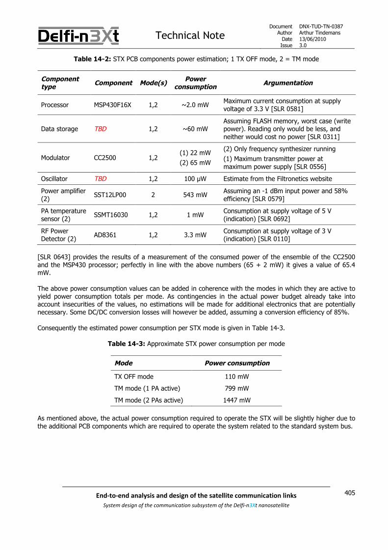
Technical NoteDocument
AuthorDateIssue
DNX-TUD-TN-0387Arthur Tindemans13/06/20103.0
405End-to-end analysis and design of the satellite communication links
System design of the communication subsystem of the Delfi-n3Xt nanosatellite
Table 14-2: STX PCB components power estimation; 1 TX OFF mode, 2 = TM mode
Componenttype
Component Mode(s)Power
consumptionArgumentation
Processor MSP430F16X 1,2 ~2.0 mWMaximum current consumption at supplyvoltage of 3.3 V [SLR 0581]
Data storage TBD 1,2 ~60 mWAssuming FLASH memory, worst case (writepower). Reading only would be less, andneither would cost no power [SLR 0311]
Modulator CC2500 1,2(1) 22 mW
(2) 65 mW
(2) Only frequency synthesizer running
(1) Maximum transmitter power atmaximum power supply [SLR 0556]
Oscillator TBD 1,2 100 μW Estimate from the Filtronetics website
Power amplifier(2)
SST12LP00 2 543 mWAssuming an -1 dBm input power and 58%efficiency [SLR 0579]
PA temperaturesensor (2)
SSMT16030 1,2 1 mWConsumption at supply voltage of 5 V(indication) [SLR 0692]
RF PowerDetector (2)
AD8361 1,2 3.3 mWConsumption at supply voltage of 3 V(indication) [SLR 0110]
[SLR 0643] provides the results of a measurement of the consumed power of the ensemble of the CC2500and the MSP430 processor; perfectly in line with the above numbers (65 + 2 mW) it gives a value of 65.4mW.
The above power consumption values can be added in coherence with the modes in which they are active toyield power consumption totals per mode. As contingencies in the actual power budget already take intoaccount insecurities of the values, no estimations will be made for additional electronics that are potentiallynecessary. Some DC/DC conversion losses will however be added, assuming a conversion efficiency of 85%.
Consequently the estimated power consumption per STX mode is given in Table 14-3.
Table 14-3: Approximate STX power consumption per mode
Mode Power consumption
TX OFF mode 110 mW
TM mode (1 PA active) 799 mW
TM mode (2 PAs active) 1447 mW
As mentioned above, the actual power consumption required to operate the STX will be slightly higher due tothe additional PCB components which are required to operate the system related to the standard system bus.

Technical NoteDocument
AuthorDateIssue
DNX-TUD-TN-0387Arthur Tindemans13/06/20103.0
406 End-to-end analysis and design of the satellite communication links
System design of the communication subsystem of the Delfi-n3Xt nanosatellite

Technical NoteDocument
AuthorDateIssue
DNX-TUD-TN-0387Arthur Tindemans13/06/20103.0
407End-to-end analysis and design of the satellite communication links
System design of the communication subsystem of the Delfi-n3Xt nanosatellite
15 Next steps
This document has so far presented the functionalities and requirements of the STX, and combined this withrequired theory and available hardware options to derive design options. As such it can be said that apreliminary STX design has been established. This chapter provides the concrete next steps to be done toultimately end up with a complete and working STX system on Delfi-n3Xt, based on the work to be done perCI presented in the end of each CI chapter.
On a level different of the STX itself, the S-band Antenna System [SLR 0036], the Delft S-band groundsegment [SLR 0014] and the confirmation of the S-band transmission frequencies and bandwidth are alsorequired to ultimately having a working S-band communication link between Delfi-n3Xt and the Delft GS.
All STX CIs are incorporated in Figure 15.1, with an indication of their priority level. These three priority levelsalso correspond to the three steps that are required to have working STX on Delfi-n3Xt.
STX
STX Processor(incl. Software)
lemon
STX Data Storage
lemon
STX HousekeepingSensors
lemon
STX Modulator
lemon
STX FrequencyUp-converter
lemon
STX PowerAmplifier
lemon
STX Support
STX TX
Priority: mediumPriority: medium
Priority: low
Priority: highPriority: high Priority: high
Figure 15.1: STX priorities
The three steps towards the Delfi-n3Xt STX are commented on below. In all cases electrical and functionalintegration and testing should be performed, in order to verify the correct operation.

Technical NoteDocument
AuthorDateIssue
DNX-TUD-TN-0387Arthur Tindemans13/06/20103.0
408 End-to-end analysis and design of the satellite communication links
System design of the communication subsystem of the Delfi-n3Xt nanosatellite
Step 1: STX TX – High priority
The number one priority within the STX lies with creating a working transmitter, or STX TX. In order to do so,the hardware diagram as presented as Figure 13.1 in chapter 13 can thereby be used and followed.
The STX Modulator and STX Frequency Up-converter are integrated, as explained, when using a CC2500. Inthat case just a crystal and some simple circuitry are required. In testing their use, the MSP430F16X can beused.
STX Modulator - most important: The confirmation of the CC2500 usage The integration of the CC2500 is a working transmitter section
STX Frequency Up-converter – most important: The selection of a preliminary crystal
STX Power Amplifier – most important: An up-to-date review of available amplifiers The acquisition of most notably the SSMT16030, and its consequent testing in a transmitter section
Suggested approachThe components most important to a working transmitter are the ones stated above. A quick up-to-datereassessment of the CC2500 should confirm its usage, or give a suitable replacement. A significant change ofcomponent is not advised, given the work performed on analyzing and testing the CC2500 already. Anupdated model could however be used.
A similar quick review of up-to-date alternatives to the PA should be performed and the resulting PA shouldbe acquired. A preliminary crystal, which is not required to be a highly stable or space-proven one, can beacquired to provide the required oscillator signal. Then, any MSP430F16X processor can be used and theresulting set of components should be interfaced to result in an ultimate working transmitter section.
In this manner, data storage is not yet required, neither is the confirmation of the exact MSP430F16Xprocessor or the writing of its complete software. Logically, this forms the next step.
Step 2: STX Processor and Data Storage – Medium priority
After a working transmitter section has been established, the focus can shift to creating the brains of thesystem, being the processor along with its data storage capability. This in turn will basically create a workingSTX. The STX should in this phase however not yet be customized for Delfi-n3Xt, in terms of operationalsoftware and final PCB integration. The focus at first shall remain on creating a working STX.
STX Data Storage: The selection of the data storage device
STX Processor: The selection of the processor (MSP430F16X), depending on the choice of data storage Writing the basic operational software
Suggested approachContinuing from work to be presented by [SLR 0300], a specific data storage device should be selectablerelatively straight-forwardly. Some research should be done with respect to radiation resistance at the sametime, and the interfaces with the MSP430F16X can be tested afterwards. Having selected the type of datastorage and having a working transmitter section, gives all the constraints required to set the processor type.

Technical NoteDocument
AuthorDateIssue
DNX-TUD-TN-0387Arthur Tindemans13/06/20103.0
409End-to-end analysis and design of the satellite communication links
System design of the communication subsystem of the Delfi-n3Xt nanosatellite
Step 3: Finalization of the Delfi-n3Xt STX – Low priority
The final step towards having a working Delfi-n3Xt STX is the customization effort required to prepare theSTX for integration on Delfi-n3Xt, assure the proper operation on Delfi-n3Xt and assuring bandwidth andtransmission frequency requirements are met by means of having proper filters and a stable oscillator. Therequired actions:
The exact crystal type should be confirmed or selected and implemented The exact required housekeeping variables to be measured should be confirmed and/or determined Depending on the variables, the hardware to take care of these measurements should be selected It should be determined whether additional filters are required to meet bandwidth specifications All components should be integrated on a PCB adhering to all system specified requirements The CC2500 software should be written, with the specified submode data rate presets included The operational software of the STX Processor should be written STX integrations tests on Delfi-n3Xt should be performed

Technical NoteDocument
AuthorDateIssue
DNX-TUD-TN-0387Arthur Tindemans13/06/20103.0
410 End-to-end analysis and design of the satellite communication links
System design of the communication subsystem of the Delfi-n3Xt nanosatellite

Technical NoteDocument
AuthorDateIssue
DNX-TUD-TN-0387Arthur Tindemans13/06/20103.0
411End-to-end analysis and design of the satellite communication links
System design of the communication subsystem of the Delfi-n3Xt nanosatellite
Appendix A Implementing an FPGA
A design option has been suggested to implement a field programmable gate array, or FPGA. FPGAs providecertain benefits over discrete component designs, most notably that of design and possible operationalflexibility. This appendix gives an introduction to FPGAs, and provides a comparison to application specificintegrated circuits (ASICs). The knowledge on FPGAs in this section is derived from [SLR 0384], unless statedotherwise. This section provides by no means a detailed research into FPGAs; only noteworthy specificationsare discussed in relation to a possible implementation in the STX.
The conclusion however is that FPGAs shall not be used in the STX system.
Subsection A.1 introduces the concept of an FPGA, after which subsection A.2 presents the different FPGAtypes. Subsection A.3 draws a comparison to ASICs, and finally subsection A.4 points the topic to the STX anddraws conclusions on the usability of FPGAs. The design option to produce a modular baseband module isalso assessed in light of FPGAs in the last subsection.
A.1 Field programmable gate arrays (FPGAs)
As the name indicates, FPGAs are field programmable, in other words they can be configured andreconfigured ‘in-the-field’, after production. FPGAs consist of a very sizeable number of gates, or transistors.Using a hierarchy of reconfigurable interconnects the gates can be wired to perform complex processorfunctionalities as well as represent simple logic. Software can be written in a language such as Verilog orVHDL, after which this software can be used to configure or reconfigure an FPGA. Consequently the biggestbenefit of an FPGA is the design freedom it offers.
Due to their flexibility FPGAs are nowadays widely used in prototyping systems, and consequently also in finalsystem designs. The FPGA configuration can also be changed during operations, as a means to change thefunctionality.
Implementing a program for an FPGA can range from relatively straight-forward to being very complicated.Programs can be written by oneself, but also preconfigured modules or intellectual property (IP) can bebought or obtained and be implemented. An FPGA configuration to implement for example processorfunctionality can be obtained. Also FPGAs usually have these common functionalities already implemented. Anoptimal program is written especially for the FPGA type and brand at hand; developing a completeconfiguration by oneself is very complicated and time consuming.

Technical NoteDocument
AuthorDateIssue
DNX-TUD-TN-0387Arthur Tindemans13/06/20103.0
412 End-to-end analysis and design of the satellite communication links
System design of the communication subsystem of the Delfi-n3Xt nanosatellite
A.2 Types of FPGA
Three types of FPGA are used nowadays. The three archetypes are explained in [SLR 0384], and the followingsummarizing Table A-1 is adapted from the same source.
Table A-1: FPGA programming technologies [adapted from SLR 0384]
Feature: SRAM Antifuse E2PROM/FLASH
Technology node State-of-the-artOne or moregenerations behind
One or moregenerations behind
Reprogrammable Yes (in system) NoYes (in system oroffline)
Reprogramming speed
(incl. erasing)Fast - 3x slower than SRAM
Volatile (must beprogrammed on power-up)
Yes NoNo (but can be ifrequired)
Requires externalconfiguration file
Yes No No
Good for prototyping Yes (very good) No Yes (reasonable)
Instant-on No Yes Yes
IP security Acceptable Very good Very good
Size of configuration cell Large (six transistors) Very smallMedium-small (twotransistors)
Power consumption Medium Low Medium
Radiation hard No Yes Not really
The radiation hardness of only the antifuse FPGAs is said to be good, which is an important requirement forspace application. This avoids the use of complicated and/or bulky shielding. While SRAM FPGAs are currentlystate-of-the-art they also require reconfiguration every time after power up. And while E2PROM/FLASH FPGAshave a similar technological back log as Antifuse FPGAs they are reconfigurable. Only antifuse FPGAs howeverhave low power consumption and are thus radiation hard. Also it mentioned in [SLR 0384] that antifuseFPGAs can achieve somewhat higher speeds, but this can be counteracted by the technological back log. Andantifuse FPGAs lack the reconfigurability of the other types. Size and consequently mass differences are lesseasily pronounced.
Very intelligent design of FPGA software, taking into account the exact hardware of the specific FPGA to beconfigured can lead to maximum processing speeds, minimum power consumption and minimum size.Nevertheless, for the current discussion aimed at relatively low-complexity designs this argument shall bediscarded. The resulting conclusion is that FPGA software can be written in a language such as Verilog orVHDL, after which any FPGA type can be configured. Therefore a reconfigurable FPGA can be used in thesystem design, after which an antifuse FPGA can be used for actual spaceflight.

Technical NoteDocument
AuthorDateIssue
DNX-TUD-TN-0387Arthur Tindemans13/06/20103.0
413End-to-end analysis and design of the satellite communication links
System design of the communication subsystem of the Delfi-n3Xt nanosatellite
Nevertheless, there is one big downside to antifuse FPGAs, and that is their cost. The AtmoCube team isimplementing an FPGA for their particle measurement tests; due to the clock frequencies at which they will beworking an FPGA apparently yields the best power consumption. Following the conclusions on radiation-hardantifuse FPGAs they wanted to include an Actel antifuse FPGA, but its cost was around $3000. In conclusionthey have decided to go for a non-antifuse FPGA with a triple redundancy check on most functions. TheseFPGAs have prices that are of little impact.
The main vendors for FPGAs are Xilinx, Actel, Altera and a number of others. Xilinx has already released aradiation tolerant, non-antifuse FPGA, the Virtex-4QV, whereas Actel is planning on releasing a similarradiation tolerant PROASIC3 FPGA. These FPGAs have a lower cost, with the added benefit that they retainreconfigurability.
A.3 Comparison between FPGAs and ASIC designs w.r.t. STX
The largest difference between FPGAs and application specific integrated circuits (ASICs) is the ability ofadopting changes. Whereas ASICs consist of dedicated circuits, FPGAs are reconfigurable through software.This involves different design processes and costs. Usually FPGAs are more cost and time efficient if they areused during actual development of a complex system. However, as a design is finalized and to be used formass production, losing the need for reconfigurability, ASICs show cost, size and/or power benefits.Consequently ASICs are used in phones, remote controls, radios, and an almost infinite number of otherapplications.
It is hard to give an exact estimate of the time efficiency or cost efficiency of using either approach but inlight of the application on satellites some relevant specifications can be addressed. On satellites importantaspects are mass, size, power requirements and environmental resistance, next to general important aspectssuch as cost and speed. The environmental resistance is expressed especially through radiation resistance, ashas been assessed above for multiple FPGA types.
It should be mentioned, that regular microprocessors as well as data storage devices do not automaticallyprovide radiation tolerance either. Nevertheless, as not all logic and signal processing is performed bychangeable sets of transistors, radiation tolerance is of lesser impact as it targets mainly the processingmemory. With FPGAs, everything can be seen as memory. Microprocessors such as the MSP430 family areand have been flown in space, and whether they are actually radiation tolerant or not they seem to beperforming well.
The conclusion on the topic of radiation tolerance is ambiguous. The most accurate conclusion is probablythat radiation tolerance should not be the main driver in the selection of FPGA usage or not. Other aspects asmentioned are the size, mass, power consumption, cost and speed achievable. The environmental resistanceof FPGAs other than its radiation resistance, thus varying operability under temperature changes, is notassumed to differ much from discrete components for FPGAs.
FPGAs can be very large, to implement many functions. Depending on the application at hand, a suitable sizecan be selected. Consequently, both size and mass are not serious consideration factors for the application ofFPGAs on satellites.
Power consumption is a more complicated factor. In general however, for an optimized discrete componentdesign with a minimal number of components the power consumption will be the least. This is especially trueif use is made of an exceptionally low power consuming microprocessor such as the MSP430 family [SLR0581]. The AtmoCube anecdote however demonstrated that at highly demanding speeds FPGA powerconsumption can be less; this will not likely be the case for the STX.

Technical NoteDocument
AuthorDateIssue
DNX-TUD-TN-0387Arthur Tindemans13/06/20103.0
414 End-to-end analysis and design of the satellite communication links
System design of the communication subsystem of the Delfi-n3Xt nanosatellite
In terms of speeds achievable, there is no real minimal requirement that would arise for use in the STX thatcannot be met both by FPGA usage and use of discrete components. There could be one interestingapplication of FPGAs, if their internal processing speed could be at the S-band transmission frequency; thishowever is not the case for current FPGAs. Therefore speed is not much of a factor.
Finally there is the aspect of cost. There is monetary cost, and timely cost. The monetary cost has beenaddressed quickly above, with the conclusion that antifuse FPGAs can be expensive, but more common FPGAshave acceptable price ranges, similar to discrete components. The timely cost, or development time costhowever poses large constraints on the possible usage of FPGAs in the STX, as a plethora of COTScomponents are available that can be used to develop a working STX system within a minimum time, whereasimplementation of an FPGA is far less transparent. The argument of development time and that ofreconfigurability will be addressed in light of the STX in the next subsection.
A.4 Conclusion with regard to the STX
As FPGAs do not seem to be able to achieve processing speeds of up to 2.4 GHz, an FPGA in the STX couldintegrate the components as illustrated in Figure A-1. An FPGA needs an external clock signal, especially as ahighly accurate crystal would be required for space operation under varying environmental conditions. FPGAsdo incorporate dedicated clock managers so that one oscillator signal should be enough for all functionalities.
Figure A-1: Possible FPGA functionalities in the STX
As in the STX, due to time constraints as well as priority establishment as has been assessed before, thechoice has been made for maximal usage of COTS components as opposed to in-house design, the motivationfor an implementation of an FPGA largely disappears. The design benefit that FPGAs offer, also during testingand tweaking, largely dissolves as the FPGA ‘functionality blocks’ would first have to be designed, or at leastbe bought or obtained and interfaced. The three required functionality blocks however, as shown in FigureA-1, are available as highly standardized COTS components as is shown in this document.
Another possibility for reconfiguration is during the actual mission operation. If no antifuse FPGA would beused, the FPGA could be reconfigured to perform different functionalities in space. Nevertheless this kind ofsetting changes can also be implemented by implementing software modes, as also the CC2500 allows foradapting its modulation scheme and data rate. Nevertheless any changing configuration is simply not part ofthe mission requirements, and as it would come at the cost of increased development time it is for the projectat hand not viable.
Technical NoteDocument
AuthorDateIssue
DNX-TUD-TN-0387Arthur Tindemans13/06/20103.0
415End-to-end analysis and design of the satellite communication links
System design of the communication subsystem of the Delfi-n3Xt nanosatellite
It has been suggested to create a modular baseband module; to basically have a circuit that can deliver asignal to be up-converted to any desired frequency in order to supplement radios in different frequencyranges. An FPGA could ideally deliver this, as is demonstrated in Figure A-1. It requires however, that theintegrated processing software and modulator are prepared for a number of modulation schemes and datarates in order to be truly modular. Especially the variable data rate is relevant as an important reason forselecting transmission frequencies is the required data rate. The mission and operational aspects havesignificant influence on the achievable data rates, by means of orbital altitude, encoding schemes,transmission power and receiver/transmitter antenna directivity patterns, amongst others. The resultingmodular baseband module is by no means impossible to create, but it would certainly require a dedicateddevelopment. As such, it is by no means a possible time investment within the current bounds of the Delfiprogramme.
Also, one would have to ask oneself what exactly would be the value of having a modular basebandtransmitter module. Applying an FPGA or not, this module would in this case just incorporate a processor, anoscillator and a modulator (and possibly data storage). A processor is in principle modular as it requiressoftware to specify its functionalities. Would it then be useful to have a modulator that can support a range ofmodulation schemes as well as data rates, just to be able to call the module modular? Possibly for atransceiver on the other hand a true modular IF system might be useful and worthwhile to develop, as morevariables can be supported. In any case again for the STX transmitter on Delfi-n3Xt a modular basebandmodule is not feasible within the project constraints.

Technical NoteDocument
AuthorDateIssue
DNX-TUD-TN-0387Arthur Tindemans13/06/20103.0
416 End-to-end analysis and design of the satellite communication links
System design of the communication subsystem of the Delfi-n3Xt nanosatellite

Thesis paperAuthor: Arthur Tindemans
Date: 21-06-2010
417End-to-end analysis and design of the satellite communication links
System design of the communication subsystem of the Delfi-n3Xt nanosatellite
Appendix C
COMMS – Antenna System Design
SLR 0036
The entire document has been written by the author.

Thesis paperAuthor: Arthur Tindemans
Date: 21-06-2010
418 End-to-end analysis and design of the satellite communication links
System design of the communication subsystem of the Delfi-n3Xt nanosatellite

Technical NoteDocument
AuthorDateIssue
DNX-TUD-TN-0036Arthur Tindemans18/06/20103.0
419End-to-end analysis and design of the satellite communication links
System design of the communication subsystem of the Delfi-n3Xt nanosatellite
COMMS - Antenna System Design
Description: This document describes the preliminary design of the antenna system.
Subsystem(s)involved: A
DC
S
CD
HS
CO
MM
S
EP
S
Mech
S
ST
S
TC
S
ITR
X
MP
S
T3μ
PS
SD
M
Sp
lash
GS
E
GS
N
La
un
ch
x x
Revision Record and Authorization
Issu
e
Date Author / Editor
Re
vie
we
r
ch
eck
ed
PM
ap
pro
ve
d
AffectedSection(s)
Description of change
1 05/09/2008 Martijn de Milliano JG JB All First issue
1.1 05/11/2008 Martijn de Milliano JG JB All Outdated changes
2.0 29/01/2009 Martijn de Milliano AT JB All Outdated changes
3.0 18/06/2010 Arthur Tindemans AT All:1-6Old chapters
Complete update:Completely new chaptersMoved to appendices

Technical NoteDocument
AuthorDateIssue
DNX-TUD-TN-0036Arthur Tindemans18/06/20103.0
420 End-to-end analysis and design of the satellite communication links
System design of the communication subsystem of the Delfi-n3Xt nanosatellite

Technical NoteDocument
AuthorDateIssue
DNX-TUD-TN-0036Arthur Tindemans18/06/20103.0
421End-to-end analysis and design of the satellite communication links
System design of the communication subsystem of the Delfi-n3Xt nanosatellite
Table of contents
1 INTRODUCTION _________________________________________________________________ 423
2 THE COMPONENTS OF THE ANTENNA SYSTEM ______________________________________ 425
2.1 Antenna System requirements _________________________________________ 425
2.2 Antenna System CI’s_________________________________________________ 426
3 THE UHF/VHF ANTENNA SYSTEM __________________________________________________ 429
3.1 The UHF/VHF antenna _______________________________________________ 429
3.2 Combination of the antennas __________________________________________ 429
3.3 Antenna configuration _______________________________________________ 432
3.4 Antenna connection _________________________________________________ 436
3.5 Phasing circuit _____________________________________________________ 436
3.6 Deployment and Antenna Board ________________________________________ 437
4 S-BAND ANTENNA SYSTEM _______________________________________________________ 439
4.1 Antenna type ______________________________________________________ 439
4.2 Antenna configuration _______________________________________________ 443
4.3 Integration options _________________________________________________ 4464.3.1 Two patches on TOP and BOP ____________________________________________________ 4464.3.2 Two patches on opposite long sides ________________________________________________ 4474.3.3 Conclusion ____________________________________________________________________ 447
5 ANTENNA WIRING_______________________________________________________________ 449
5.1 Wire connectors ____________________________________________________ 449
5.2 Wires ____________________________________________________________ 450
6 NEXT STEPS_____________________________________________________________________ 453
No appendices are included in the thesis version of this document.

Technical NoteDocument
AuthorDateIssue
DNX-TUD-TN-0036Arthur Tindemans18/06/20103.0
422 End-to-end analysis and design of the satellite communication links
System design of the communication subsystem of the Delfi-n3Xt nanosatellite

Technical NoteDocument
AuthorDateIssue
DNX-TUD-TN-0036Arthur Tindemans18/06/20103.0
423End-to-end analysis and design of the satellite communication links
System design of the communication subsystem of the Delfi-n3Xt nanosatellite
1 Introduction
The Antenna System is part of the Delfi-n3Xt communication system, or COMMS. The COMMS is introduced in[SLR 0014] along with its top-level design. The Antenna System and its design however are not discussed indetail; this document serves that purpose.
Two primary transceivers are to be flown on Delfi-n3Xt, being the PTRX and ITRX. Both radios should be ableto transmit and receive signals. More precisely, the VHF-band is to be used for transmission, and the UHFband for reception. Furthermore, a technology demonstration experiment called the STX is aimed to be flown,which is a high-speed transmitter using the S-band.
All three radios are integrated on PCB’s, and will have conduits for radio-frequency signals. In order toactually transmit or receive signals, a supporting Antenna System is required. As such, the resulting AntennaSystem can be sketched as Figure 1.1 below.
Figure 1.1: Components of the Antenna System and their interfaces
The Antenna System can be seen to be composed of two main and separate parts; the UHF/VHF AntennaSystem and the S-band Antenna System. Integrated on, but not actually part of the UHF/VHF AntennaSystem is the OLFAR experiment, if it will be flown.
The exact content of the Antenna System is first introduced in chapter 2, after a presentation of therequirements. The resulting antenna system components, the UHF/VHF Antenna System, the S-band AntennaSystem and the required Antenna Wiring are the topics of respectively chapter 3, 4 and 5. Next steps arediscussed in chapter 6.

Technical NoteDocument
AuthorDateIssue
DNX-TUD-TN-0036Arthur Tindemans18/06/20103.0
424 End-to-end analysis and design of the satellite communication links
System design of the communication subsystem of the Delfi-n3Xt nanosatellite
The design changes of Delfi-n3Xt have had significant effect on the Antenna System. In fact a detailedanalysis of the antenna system has been made (by the previous author, Martijn de Milliano) based on the oldsolar panel configuration of Delfi-n3Xt, that of having four solar panels in the same plane, on one side of thesatellite. This solar panel configuration was of course based on full pointing capability of Delfi-n3Xt.
The decision has been made to no longer rely on any pointing capability of Delfi-n3Xt. As a result: The solar panel configuration will have to be changed The S-band antenna system will no longer aim to be directional, but omnidirectional instead
Also, time has made clear that little resources are and will likely be available for the realization of the STX andits antenna system, so that the focus on COTS components has become even more important. This isimportant for the design of the S-band antennas for example.
In conclusion, all old chapters and sections of this document have been become severely outdated. In factdrastically so, so that all material in the chapters of this document is new. The old chapters have been movedto appendices. References are made to the old appendices on several accounts. The content of theappendices is as follows.
An introduction to antenna modeling software is given in Appendix A. Consequently, the influence the satellitegeometry has on the antenna gain patterns and the different antenna systems have on each other isdiscussed in Appendix B. Appendix C presents the determination of the old UHF/VHF antenna configuration.Appendix D and E discuss the S-band antenna system design in terms of its antenna and antennaconfiguration respectively. Afterwards, a description of a patch antenna design performed by using antennamodeling software named FEKO is given in Appendix F, and the effect of different mesh sizes in both FEKOand 4nec2 is discussed in Appendix G.
Finally, an updated derivation of the preferred S-band antenna system, based on the constrained pointingmodel of having continuous sun-pointing while trying to point with the STX has been added by the author.This text has however also been written before the Delfi-n3Xt design changes and is similarly outdated. It isincluded as Appendix H.
Of interest to the latest version of this document; Appendix B in fact demonstrates that the S-band antennasystem and the UHF/VHF antenna systems can be modeled separately, and have negligible influence on eachother.
In the version of this document as appended to the thesis paper, the appendices have been removed as theyare not relevant for the evaluation of the author’s work and would come at the cost of a large increase ofpaper weight.

Technical NoteDocument
AuthorDateIssue
DNX-TUD-TN-0036Arthur Tindemans18/06/20103.0
425End-to-end analysis and design of the satellite communication links
System design of the communication subsystem of the Delfi-n3Xt nanosatellite
2 The components of the Antenna System
In order to determine the exact elements and thus Configuration Items or CI’ that compose the AntennaSystem, this chapter states the requirements imposed on the Antenna System and looks at the functionalitiesto be performed by it. As such, section 2.1 presents the requirements, followed by the specification of the CIsin section 2.2.
2.1 Antenna System requirements
In [SLR 0014] generally applicable COMMS requirements as well as Antenna System requirements have beenpresented. These requirements are stated below in Table 2-1 and Table 2-2 below. Underneath each tablesome comments are made.
Table 2-1: Generally applicable Antenna System requirements
Category Req. # Requirement
CONSTRAINT SAT-C.01 All satellite systems shall comply with the mass budget, as given in [SLR 0018]
CONSTRAINT SAT-C.02 All satellite systems shall comply with the volume budget, as given in [SLR 0303]
CONSTRAINT SAT-C.03 All satellite systems shall comply with the power budget, as given in [SLR 0017]
CONSTRAINT SAT-C.04 All satellite systems shall comply with the data budget, as given in [SLR 0282]
CONSTRAINT SAT-C.05All satellite systems shall comply with power and data bus interfaces, as specified in [SLR0263]
CONSTRAINT SAT-C.06 All satellite systems shall be able to withstand the launch environment
CONSTRAINT SAT-C.07 All satellite systems shall be able to withstand the space environment
CONSTRAINT SAT.2-C.01 All satellite bus systems shall adhere to reliability standards, as specified in [SLR 0263]
CONSTRAINT SAT.2.3-C.05All UHF and VHF antenna connections and transmission lines on the satellite will have animpedance of 50 ohm
Most requirements in the table above are self-explanatory. The requirement with respect to the power anddata bus interfaces is important when using deployables, which are to be activated by means of the systembus.
Table 2-2: Antenna-System-specific requirements
Category Req. # Requirement
FUNCTIONAL SAT.2.3.3-F.01 The Antenna System shall be able to receive the uplink signal over the UHF frequencies
FUNCTIONAL SAT.2.3.3-F.02 The Antenna System shall be able to radiate the downlink signal over the VHF frequencies
FUNCTIONAL SAT.2.3.3-F.03 The Antenna System shall be able to radiate the downlink signal over the S-bandfrequencies
INTERFACE SAT.2.3.3-I.01 The Antenna System shall have an interface with the PTRX to forward and receive ananalogue data signal
INTERFACE SAT.2.3.3-I.02 The Antenna System shall have an interface with the ITRX to forward and receive ananalogue data signal
INTERFACE SAT.2.3.3-I.03 The Antenna System shall have an interface with the STX to forward an analogue datasignal
CONSTRAINT SAT.2.3.3-C.01 The polarization of the Antenna System shall be circular
CONSTRAINT SAT.2.3.3-C.02 A single antenna deployment failure should not cause loss of the link

Technical NoteDocument
AuthorDateIssue
DNX-TUD-TN-0036Arthur Tindemans18/06/20103.0
426 End-to-end analysis and design of the satellite communication links
System design of the communication subsystem of the Delfi-n3Xt nanosatellite
The table above demonstrates the main functionalities of the Antenna System, as well as the three resultinginterfaces. The requirement of circular polarization is necessary due to the fact that the satellite moves withrespect to the ground station and it is the only way to guarantee a working link. Finally the requirement ofhaving no antenna deployment being mission-critical is related to the general requirement of adhering toreliability standards, SAT.2-C.01.
2.2 Antenna System CI’s
From the requirements in the previous section it can be seen that the Antenna System has three mainfunctionalities, being to receive UHF signals, transmit VHF signals, and transmit S-band signals if the STX willbe flown. Therefore, the primary components required are:
Antennas: Antennas take care of the physical transmission of signals; dissipating energy in theform of radiation.
As antennas cannot be integrated on standard PCB’s, due to size constraints and the fact that they shouldpreferably be on the exterior of the satellite, some kind of connection should be designed. Furthermore, asthe length of the antenna will be at least 1/4th of the wavelength used, UHF and VHF antennas requirerelatively long antennas. As such, required are:
Antenna connections and deployment mechanisms
The use of multiple antennas requires some form of power splitters/combiners, and, when phasing is to beintroduced, phase shifters. Also, the impedance of the antenna should be matched to that of the cables sothat impedance matching circuitry is required. This leads to require:
Phasing circuit(s) and impedance matching circuitry
Finally, as antennas are not located at the same place on the satellite as the radios, the need for wires isintroduced, capable to transport the high-frequency RF signals. Thus, also required:
Antenna wires and antenna wire connectors
The UHF and VHF antennas are combined into one set of antennas, as further explained in the next chapter.This therefore creates a UHF/VHF Antenna System, necessitating the above components. A separate systemhowever is required for the STX, using frequencies of a different order and thus different antennas. Thereforeall components described above are effectively necessary for a UHF/VHF Antenna System and an S-bandAntenna System. The resulting CI tree can be seen in Figure 2.1 below.
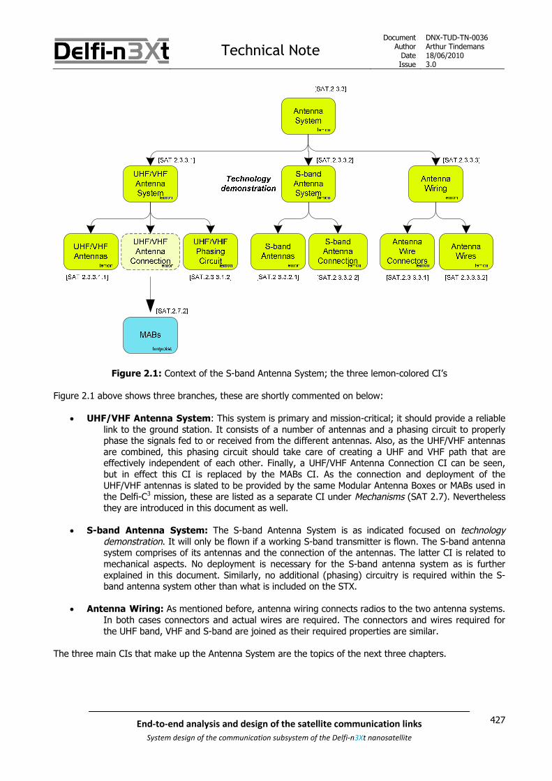
Technical NoteDocument
AuthorDateIssue
DNX-TUD-TN-0036Arthur Tindemans18/06/20103.0
427End-to-end analysis and design of the satellite communication links
System design of the communication subsystem of the Delfi-n3Xt nanosatellite
Figure 2.1: Context of the S-band Antenna System; the three lemon-colored CI’s
Figure 2.1 above shows three branches, these are shortly commented on below:
UHF/VHF Antenna System: This system is primary and mission-critical; it should provide a reliablelink to the ground station. It consists of a number of antennas and a phasing circuit to properlyphase the signals fed to or received from the different antennas. Also, as the UHF/VHF antennasare combined, this phasing circuit should take care of creating a UHF and VHF path that areeffectively independent of each other. Finally, a UHF/VHF Antenna Connection CI can be seen,but in effect this CI is replaced by the MABs CI. As the connection and deployment of theUHF/VHF antennas is slated to be provided by the same Modular Antenna Boxes or MABs used inthe Delfi-C3 mission, these are listed as a separate CI under Mechanisms (SAT 2.7). Neverthelessthey are introduced in this document as well.
S-band Antenna System: The S-band Antenna System is as indicated focused on technologydemonstration. It will only be flown if a working S-band transmitter is flown. The S-band antennasystem comprises of its antennas and the connection of the antennas. The latter CI is related tomechanical aspects. No deployment is necessary for the S-band antenna system as is furtherexplained in this document. Similarly, no additional (phasing) circuitry is required within the S-band antenna system other than what is included on the STX.
Antenna Wiring: As mentioned before, antenna wiring connects radios to the two antenna systems.In both cases connectors and actual wires are required. The connectors and wires required forthe UHF band, VHF and S-band are joined as their required properties are similar.
The three main CIs that make up the Antenna System are the topics of the next three chapters.

Technical NoteDocument
AuthorDateIssue
DNX-TUD-TN-0036Arthur Tindemans18/06/20103.0
428 End-to-end analysis and design of the satellite communication links
System design of the communication subsystem of the Delfi-n3Xt nanosatellite

Technical NoteDocument
AuthorDateIssue
DNX-TUD-TN-0036Arthur Tindemans18/06/20103.0
429End-to-end analysis and design of the satellite communication links
System design of the communication subsystem of the Delfi-n3Xt nanosatellite
3 The UHF/VHF Antenna System
The UHF/VHF antenna system is the primary antenna system. It is supposed to receive signals over the UHFband and transmit signals over the VHF band. This functionality is identical to that of the antennas of Delfi-C3.As such, it makes sense to make use of proven heritage of Delfi-C3, for a number of its components. Theantennas and their supportive systems have been tested and perfected for Delfi-C3, and there are noindications of unexpected performance reductions.
The UHF/VHF antenna itself is introduced in section 3.1. For Delfi-n3Xt, it is suggested to combine theUHF/VHF antennas, as explained in section 3.2. The resulting antenna configuration is presented in section3.3. The required antenna connection and phasing circuit are introduced in sections 3.4 and 3.5 respectively.Finally, section 3.6 discusses the Deployment and Antenna Board (DAB) on which the antenna componentswill be integrated.
3.1 The UHF/VHF antenna
The UHF/VHF antenna has in fact proven to be very simple of design. In the design of the Delfi-C3 antennasystem, it was found that regular metal measuring tape has proper electromagnetic characteristics. When cutto the proper length, this measuring tape could perfectly form an antenna for either UHF or VHF frequencies.
Antenna theory states that significant power transfer can be achieved using either a half-wavelength dipoleantenna fed in the middle, or a quarter-wavelength unipole antenna fed at one end. If the feed-point is neara conductive surface, the latter antenna will then behave as a half-wavelength dipole antenna. The latterapproach has been chosen for Delfi-C3, as it logically minimizes required antenna length while maximizingperformance. Antennas could similarly be chosen to have three-quarter wavelength, or one-and-a-quarterwavelength, etc. for equal power performance.
To illustrate, the final transmission frequencies of the Delfi-C3 downlink were 145.870 and 145.930 MHz.Dividing the speed of light by the frequencies yields the wavelength; ~2.056 and 2.054 m respectively. Aquarter-wavelength yields an approximate 51.4 cm. The final length of the measuring tape as measured onthe spare model in the clean room is ~51.2 cm. The latter is of course subject to slight measuring errors asthe antennas are partly enclosed by the MABs introduced below, and at the same time electrical connectionsto the antenna affect the apparent size. In conclusion however, the quarter-wavelength is near spot-on. Thesame holds for the uplink frequencies.
For Delfi-n3Xt, [SLR 0014] argues that the same transmission frequencies as used during the Delfi-C3 missioncan be used for both the up- and downlink. In other words, the exact same antennas as used on Delfi-C3 canbe used. A suggestion that has been made however is to combine the UHF and VHF antennas.
3.2 Combination of the antennas
For Delfi-C3, it was decided to have a total of eight deployable antennas, of which four were used for the VHFfrequencies and four for the UHF frequencies. The antennas belonging to the respective transmission bandshad lengths matching the optimum quarter-wavelength. The antenna configurations of the two separateantenna systems however, were identical. The antenna configuration refers to the relative positioning of thefour antennas. One side (top or bottom) of Delfi-C3 housed the UHF antennas, and the other side housed theVHF antennas. In both cases the antenna pointed away from the satellite; the configurations were in factmirrored with respect to each other. This antenna configuration (as introduced in section 3.3) together withthe phasing introduced to the signals (as introduced in section 3.5), in turn determines the antenna gainpattern.

Technical NoteDocument
AuthorDateIssue
DNX-TUD-TN-0036Arthur Tindemans18/06/20103.0
430 End-to-end analysis and design of the satellite communication links
System design of the communication subsystem of the Delfi-n3Xt nanosatellite
The antenna gain pattern is designed to be omnidirectional. In this case, the relative attitude of the satellite isunimportant. Given the fact that both the UHF and VHF antenna configurations were designed to approximatean omnidirectional pattern, the relative placement of the antennas on the satellite is unimportant. From alocation-point-of-view then, the antennas can then be combined.
For an electrical point-of-view, it is required that the antennas are suitable to receive both signals. Asexplained above, a single-quarter-wavelength antenna is similar in performance to a three-quarter-wavelength antenna. As it turns out, VHF transmission frequencies (~145 MHz) are almost perfectly three-quarters of UHF transmission frequencies (~435 MHz). Theoretically, the VHF antennas can then be used forreception of the UHF signals.
The advantages of combining the antennas are: Only four antennas and deployment mechanisms are required; this allows a volume saving of
about 10% of the satellite given the height of the MABs of about 3 cm, next to a reduction of massand complexity.
All components can be located on one side of the satellite; this additionally reduces theamount of components required and complexity involved. If the radios are placed near the antennasa minimal decrease of transmission line loss is also realized.
The effect of combining the antennas has two effects which should be prepared for:1) The length of the antennas of at least one of the two frequency ranges becomes slightly non-optimal,
as the ratio between the transmission frequencies is not exactly 3.2) The signal strength received by the antennas on different frequencies is changed due to the direct
connection.
Firstly, the effect of a changing antenna length with respect to the transmission frequency is a change ofimpedance. If this is not corrected for, an impedance mismatch loss will result. The impedance mismatch losscan however be prevented (for reasonable amounts of required correction) by introducing circuitry to adjustthe phasing loss.
Secondly, the received signals should not be allowed to disturb the desired signals. The actual transmissionfrequencies are logically spaced far apart, but harmonics of the frequencies are important. Ironically, thesame ratio of three that allows the antennas to function as both UHF and VHF antennas causes the thirdharmonic of the VHF signal to be close to the UHF frequencies that are to be received. Also, the downlinksignal of the transmitter is many orders larger than the signal to be received over the uplink.
The harmonics are in fact caused by the power amplifier or PA. All other harmonics incurred by for examplethe modulator are cut off by means of a 3.3 MHz filter in the transmission circuitry. After amplificationhowever, filtering would cause large signal loss.
A quantitative assessment of this second effect is given below.
The important values: Difference between uplink and downlink signal strength
According to the link budget [SLR 0106], the difference between the received signals is about116 dB (!) assuming a true omnidirectional gain pattern and a maximum satellite altitude.
Difference between the uplink and downlink transmission frequenciesThree times the (minimum) downlink frequency results in a centre frequency of 437.631 MHz.The uplink frequency however is between 435 and 436 MHz (not stated directly for reasons ofsecurity). As such, the third harmonic of the downlink signal is spaced apart from the uplinkfrequency by some 2 MHz.
Signal strength and bandwidth of the third harmonic of the VHF transmission frequencyThese values are illustrated by the measurement figures below.

Technical NoteDocument
AuthorDateIssue
DNX-TUD-TN-0036Arthur Tindemans18/06/20103.0
431End-to-end analysis and design of the satellite communication links
System design of the communication subsystem of the Delfi-n3Xt nanosatellite
The signal strength and bandwidth of the third harmonic of the transmission signal of the Delfi-C3 sparemodel are measured using a spectrum analyzer. The measured signal strength is illustrated by Figure 3.1 andFigure 3.2 below.
Figure 3.1: Signal strength (in the test set-up) of the third harmonic of the VHF downlink
Figure 3.2: Frequency spectrum of the third harmonic of the VHF downlink measured over a 25 kHz span

Technical NoteDocument
AuthorDateIssue
DNX-TUD-TN-0036Arthur Tindemans18/06/20103.0
432 End-to-end analysis and design of the satellite communication links
System design of the communication subsystem of the Delfi-n3Xt nanosatellite
The signal strength is illustrated by Figure 3.1. In fact, it is a figure that is taken on the same scale as figure7-17 in [SLR 0014]. In the latter figure the peak has a value of -20.20 dBm. In Figure 3.1, the peak can beseen to have a -78.20 dBm power value (indicated by the marker). As a result, the third harmonic ismeasured to have signal strength of -58.20 dBc.
Figure 3.2 zooms in on the third harmonic, to conclude on the bandwidth. It shows that within about 7vertical squares, or 17.5 kHz, the signal strength changes another -40 dB. For lower values of signal strength,the noise floor of the measurement equipment and set-up is an obstruction. In the set-up applied the Delfi-C3
spare model transmission is measured over a 1 m wireless channel and consequent reception by a simplemonopole antenna.
In conclusion, it can be seen that the overall signal strength of the third harmonic is -58.20 dBc, and it dropsoff to -98.20 dB within about 17.5 kHz. A total signal strength reduction of -116 dB within a 2 MHz bandwidthis required, to be able to resist the worst case. Indeed, it would seem this should be no problem.
A few notes: Signal strength drop-off in fact decreases with frequencies away from the carrier frequency; in other
words a doubled bandwidth will not result in halved signal strength. The additional -20 dB requiredfor a worst case will therefore still require a sizeable bandwidth.
A larger data rate will result in larger occupied bandwidth of the main carrier as well as its harmonics.
Still, it seems very unlikely that the third harmonic of the downlink signal will disturb the uplink signal in caseof a data rate of up to 9.6 kb/s; for (much) lower data rates the effects will surely be negligible. Of course,final integration tests are required to be absolutely sure; also to see if there are no other non-linear effectscausing signal strengths at reception frequencies.
Finally, the first effect of combining the antennas, as mentioned above is the resulting requirement ofadditional impedance matching circuitry. There are limits to what can be corrected for with circuitry, but giventhe fact that the above calculated 2 MHz is only ~1.4 % of the transmission frequency on the UHF band,circuitry is assumed to be able to correct for this. In fact, this has been done. Wolter van der Kant haspresented in [SLR 0715] that a phasing circuit can be designed that performs similarly (in terms of powerlosses) to that of Delfi-C3, but designed to support the combined antennas. This phasing circuit is furtherintroduced in section 3.5 below.
3.3 Antenna configuration
It has been argued above that the antennas can in fact be combined, at least assuming the same antennaconfiguration (and transmission frequencies) as those used for Delfi-C3. It then remains to confirm the reuseof the antenna configuration.
A very extensive trade-off of possible antenna configurations has been performed by Martijn de Milliano, butunfortunately this trade-off has been based on the old solar panel configuration of Delfi-n3Xt (this trade-offcan be found in Appendix C). The result of the trade-off however has been to:
Reuse the antenna configuration applied on Delfi-C3 for the VHF antennas Integrate the UHF antennas on the solar panels
The latter was chosen because the antennas that would be on the same side as the solar panels would benegatively influenced by the panels. Antennas oriented along the panels are minimally affected. As the UHFantennas are in fact small enough to be placed alongside of the panels, the UHF antennas were chosen to beintegrated with the panels as opposed to the VHF antennas. For the VHF antennas, it had then been decidedto opt for the use of heritage, giving good performance. The old solar panel configuration and the respectiveantenna configurations results are shown in Figure 3.3 below.

Technical NoteDocument
AuthorDateIssue
DNX-TUD-TN-0036Arthur Tindemans18/06/20103.0
433End-to-end analysis and design of the satellite communication links
System design of the communication subsystem of the Delfi-n3Xt nanosatellite
Figure 3.3: (Old) Delfi-n3Xt antenna configuration for the VHF antennas (left) and UHF antennas (right)
For the old solar panel configuration, the choice of having combined antennas would logically lead to havingall antennas located on the bottom of satellite, following the suggestion of the VHF antennas above.
As suggested above, the redefinition of Delfi-n3Xt has resulted in a change of the solar panel configuration.Unfortunately, the new solar panel configuration has not been determined yet. Currently, the investigationinto the reconfiguration is being performed by Johannes Bürkle. Two conclusions:
The old Delfi-n3Xt configuration is no option, due to its non-omnidirectional performance The Delfi-C3 configuration is an option, but is undesirable. This due to:
o A relatively low power generation (compared to more ambitious configurations), at the sametime being not enough for desired nominal operations
o The fact that it covers all long sides, which is undesirable for the T3μPS payload
As said, the investigation for new panels is currently ongoing. This research includes power impacts as well asimpacts related to mechanical aspects and complexity. Two concrete suggestions are however shown inFigure 3.4 below. All indicated solar panels are in fact double-sided.
Figure 3.4: Two suggestions for Delfi-n3Xt solar panel configurations
The exact fold-out angles in the above figure will not be given here. The suggested configurations serve toshow that larger fold angles will likely be used in order to ensure no blockage of the sides, and the use ofdouble-sided solar panels allows the generation of more power.
Given the above configurations, it is in fact rather hard to give a desired antenna configuration withoutfurther analysis. Nevertheless, some concrete conclusions for the UHF/VHF antenna system can be drawn.
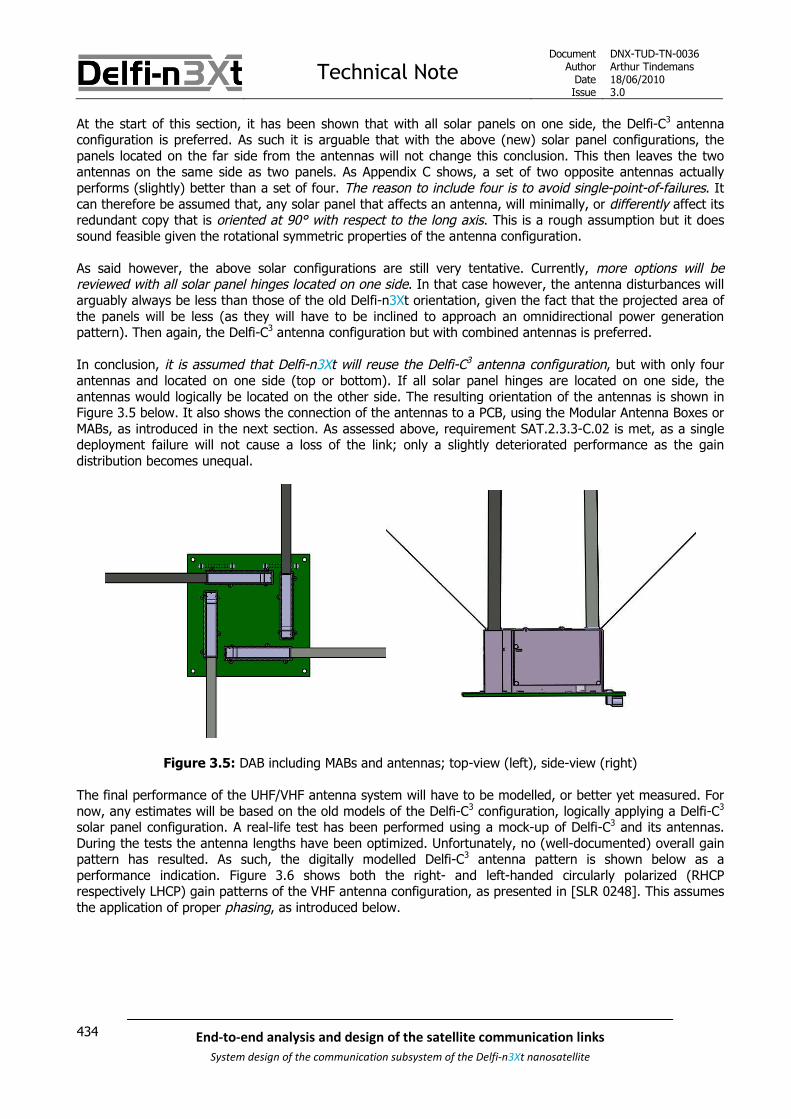
Technical NoteDocument
AuthorDateIssue
DNX-TUD-TN-0036Arthur Tindemans18/06/20103.0
434 End-to-end analysis and design of the satellite communication links
System design of the communication subsystem of the Delfi-n3Xt nanosatellite
At the start of this section, it has been shown that with all solar panels on one side, the Delfi-C3 antennaconfiguration is preferred. As such it is arguable that with the above (new) solar panel configurations, thepanels located on the far side from the antennas will not change this conclusion. This then leaves the twoantennas on the same side as two panels. As Appendix C shows, a set of two opposite antennas actuallyperforms (slightly) better than a set of four. The reason to include four is to avoid single-point-of-failures. Itcan therefore be assumed that, any solar panel that affects an antenna, will minimally, or differently affect itsredundant copy that is oriented at 90° with respect to the long axis. This is a rough assumption but it doessound feasible given the rotational symmetric properties of the antenna configuration.
As said however, the above solar configurations are still very tentative. Currently, more options will bereviewed with all solar panel hinges located on one side. In that case however, the antenna disturbances willarguably always be less than those of the old Delfi-n3Xt orientation, given the fact that the projected area ofthe panels will be less (as they will have to be inclined to approach an omnidirectional power generationpattern). Then again, the Delfi-C3 antenna configuration but with combined antennas is preferred.
In conclusion, it is assumed that Delfi-n3Xt will reuse the Delfi-C3 antenna configuration, but with only fourantennas and located on one side (top or bottom). If all solar panel hinges are located on one side, theantennas would logically be located on the other side. The resulting orientation of the antennas is shown inFigure 3.5 below. It also shows the connection of the antennas to a PCB, using the Modular Antenna Boxes orMABs, as introduced in the next section. As assessed above, requirement SAT.2.3.3-C.02 is met, as a singledeployment failure will not cause a loss of the link; only a slightly deteriorated performance as the gaindistribution becomes unequal.
Figure 3.5: DAB including MABs and antennas; top-view (left), side-view (right)
The final performance of the UHF/VHF antenna system will have to be modelled, or better yet measured. Fornow, any estimates will be based on the old models of the Delfi-C3 configuration, logically applying a Delfi-C3
solar panel configuration. A real-life test has been performed using a mock-up of Delfi-C3 and its antennas.During the tests the antenna lengths have been optimized. Unfortunately, no (well-documented) overall gainpattern has resulted. As such, the digitally modelled Delfi-C3 antenna pattern is shown below as aperformance indication. Figure 3.6 shows both the right- and left-handed circularly polarized (RHCPrespectively LHCP) gain patterns of the VHF antenna configuration, as presented in [SLR 0248]. This assumesthe application of proper phasing, as introduced below.

Technical NoteDocument
AuthorDateIssue
DNX-TUD-TN-0036Arthur Tindemans18/06/20103.0
435End-to-end analysis and design of the satellite communication links
System design of the communication subsystem of the Delfi-n3Xt nanosatellite
Figure 3.6: Theoretical RHCP (left) and LHCP (right) gain pattern of the VHF antennas on Delfi-C3
In the above figure the indicated values are rather small and unclear. The maximum indicated however is1.42 dB, with the minimum value on the scale being -11.7. The RHCP and LHCP gain pattern are exact mirrorimages. As the ground station is capable of receiving both RHCP and LHCP signals, the minimum gain valueof the superimposed gain patterns is important. In other words; that at an angle of 90° or -90° with respectto the Z-axis. This value (approximately -5 dB) is used in the link budget as the minimum gain value.
For the UHF antennas, the resulting gain patterns are shown in Figure 3.7 below.
Figure 3.7: Theoretical RHCP (left) and LHCP (right) gain pattern of the UHF antennas on Delfi-C3
In the above figure, the indicated maximum and minimum values are respectively 2.58 dB and -11.7 dB.Performance can be seen to be worse than for the VHF antennas. A value of -10 dB at an angle of 90°or -90° with respect to the Z-axis is taken as the minimum gain value.

Technical NoteDocument
AuthorDateIssue
DNX-TUD-TN-0036Arthur Tindemans18/06/20103.0
436 End-to-end analysis and design of the satellite communication links
System design of the communication subsystem of the Delfi-n3Xt nanosatellite
3.4 Antenna connection
All Delfi-C3 antennas were connected to the PCB using modular antenna boxes (MABs). These same MABswere used to deploy the antennas. These MABs have proven to work perfectly for Delfi-C3. Logically, theseare then reused for Delfi-n3Xt.
A modular antenna box works as follows. The (measurement tape) antenna is initially rolled up in the antennabox. The lid is held in place by a Dyneema wire. During deployment, the wire is melted by means of heating aresistor. Due to the force exerted by the metal strip the lid is opened. Due to the properties of themeasurement tape, the antenna surges out of the box and stretches to a linear shape. As there is no gravityin space, it will remain in this shape to form a perfect unipole antenna. An illustration of the MAB is shown inFigure 3.8.
Figure 3.8: Drawing of the modular antenna box
3.5 Phasing circuit
The Delfi-n3Xt phasing circuit has three purposes: Introduce proper phase shift between the antennas for the resulting gain pattern to be
omnidirectional and circularly polarized Isolate the UHF frequencies from the VHF frequencies Correct for the non-optimal length of the UHF antennas when combined with the VHF antennas
In case of Delfi-C3, the first two functionalities were also required. However, as the antennas were separated,the signal strengths of the UHF and VHF frequency bands were less strong on respectively the VHF and UHFantennas.
The required phasing circuit has actually been designed and tested (as a separated component) and isdescribed in [SLR 0715]. Some losses are incurred in the phasing circuit, but these are comparable to thoseon Delfi-C3. They have been taken into account in the link budget.

Technical NoteDocument
AuthorDateIssue
DNX-TUD-TN-0036Arthur Tindemans18/06/20103.0
437End-to-end analysis and design of the satellite communication links
System design of the communication subsystem of the Delfi-n3Xt nanosatellite
3.6 Deployment and Antenna Board
The Deployment and Antenna Board (DAB) is the PCB that houses all components as introduced above. Insummary:
Four MABs including quarter-length VHF antennas (~51.2 cm) The UHF/VHF Phasing Circuit
The DAB and the integration of the four MABs have in fact already been shown in Figure 3.5 above. In themiddle it can be seen sizeable area is available for the (electrical) integration of the phasing circuit.
As [SLR 0014] explains, a third component can in fact be integrated on the DAB: OLFAR
If OLFAR is to be flown, the DAB is the only logical location for it. As it involves only very little components, itshould likely pose no problem to integrate it on the DAB, not taking into account the increased complexity.With respect to the Delfi-C3 PCB similar to the DAB, the Delfi-n3Xt DAB has less required components if thesolar panel deployments systems are not integrated on the DAB.

Technical NoteDocument
AuthorDateIssue
DNX-TUD-TN-0036Arthur Tindemans18/06/20103.0
438 End-to-end analysis and design of the satellite communication links
System design of the communication subsystem of the Delfi-n3Xt nanosatellite

Technical NoteDocument
AuthorDateIssue
DNX-TUD-TN-0036Arthur Tindemans18/06/20103.0
439End-to-end analysis and design of the satellite communication links
System design of the communication subsystem of the Delfi-n3Xt nanosatellite
4 S-band Antenna System
The S-band antenna system is a secondary system; not required for essential operations. It serves to performtechnology demonstration in combination with the STX on-board of Delfi-n3Xt. It is completely separatedfrom the UHF/VHF antenna system.
It has been established in [SLR 0387] that one of the design goals of the STX is that it should assume the useof an omnidirectional antenna configuration. In other words, no pointing is assumed. Therefore, the antennagain pattern should provide this omnidirectional pattern for as far as possible.
S-band antenna types are introduced first in section 4.1. Also, the preferred antenna type, somerepresentative versions and their performance are presented. Section 4.2 then discusses the possibly antennaconfigurations that can be made using the S-band antenna versions, and introduces the preferredconfiguration. Section 4.3 concludes with an assessment of the integration options of the S-band antennasystem on Delfi-n3Xt.
4.1 Antenna type
There are several options for antennas in the S-band which are generally applied. It should be realized thatthe Delfi-n3Xt S-band frequencies are around 2400 MHz, so that the wavelength is only ~12.5 cm. Thequarter-wavelength is then some 3 cm. Different S-band antenna types are the:
Helical antenna
Wire antenna
Parabolic dish
Patch antenna
The helical antenna and parabolic antenna can be used to obtain a (highly) directive antenna gain pattern.They however require sizeable volume. Wire antennas and patch antennas are more low-profile. Patches havesome very favorable characteristics. For example, they are mechanically robust and they are very flexible interms of resonant frequency, polarization, pattern and impedance. Compared to wire antennas, they can beeasily body-mounted, as they are relatively flat, resulting in gain pattern perpendicular to the patch and thebody. A wire antenna would require a deployment mechanism. Patches are generally used on the S-bandwhenever size is available; although they are flat they require some area, patches with total areas of up to80x80 mm are introduced below.
A final argument for the use of S-band patches is delivered by a quick search for existing CubeSatapplications of S-band transmitters. In fact, all (three) successful CubeSats with S-band transmissioncapability have applied patch antennas. A number of larger microsatellites similarly did so. They in fact alsosuggest possible antenna configurations and are thus introduced in more detail below.
In conclusion, a short and simple trade-off leads to conclude that for Delfi-n3Xt, the use of S-band patches ispreferred. A more detailed trade-off could be performed to verify this, but is not deemed necessary.
As an omnidirectional gain pattern is preferred, the gain pattern resulting from a patch should also preferablybe as broad as possible. In fact, Martijn de Milliano has designed (in software) a patch antenna, but this waswith the goal to get one as directional as possible. This design (process) is described in Appendix D. Itsresults are taken along belong, but it should not be forgotten that these are theoretical values.

Technical NoteDocument
AuthorDateIssue
DNX-TUD-TN-0036Arthur Tindemans18/06/20103.0
440 End-to-end analysis and design of the satellite communication links
System design of the communication subsystem of the Delfi-n3Xt nanosatellite
An important focus within the S-band communication link design has come to lay with COTS products. S-bandpatches are generally available, but in little cases do websites offer detailed gain patterns over all angles. Alsogenerally, single patch antennas, or single-chip solutions (possibly including multiple internal patches) aresold, under the header of being ‘omnidirectional’. This then either holds for one axis, or actually means a verylow gain value (up to or below -10 dB) is accepted in some directions.
Two options have however been found:
SSTL patch: Of all the online shops selling CubeSat parts, one of them sells an S-band patchantenna; that of Surrey Satellite Technology Ltd. (SSTL). It is rather large and (relatively) heavy, butachieves high-directivity while retaining sizeable gain other directions. It is space-proven. At the sametime, this might make it (very) expensive.
SPECEMC patch (PA28-2450-120S): A website was found, ran by a company called SpectrumControl, Inc. that delivers custom made and standard patches. The respective website iswww.specemc.com. In a conversation with one of the design engineers, the measured performancedata of the most relevant patch was obtained. It is optimized to have a gain pattern as broad aspossible. It is not space proven, but much smaller than that of SSTL.
Even though these patches might not be those used in the end, the general performance of these patches willbe used as a guideline. In order to asses the performance of the patch antennas, the following Figure 4.1demonstrates the applied coordinate system. In the following, the patch antenna will be placed in thexy-plane.
Figure 4.1: Spherical coordinate system used below
is labeled the angle off-boresight. For different values of , the gain of the patches has been measured by
the manufacturer. At the same time, the gain values do not vary with . Of course this latter will never
perfectly hold but is assumed to hold with sufficient accuracy.
For both the SSTL and SPECEMC patches, the gain values are plotted for 90 90 in Figure 4.2
below. As the patch will be placed on a surface, the exact effect of the gain in reverse directions is unknown;potentially it could reflect to increase the transmitted signal slightly. Nevertheless, the gain values for
90 270 are negligibly low. Gain values are stated in dBic, which is the gain with respect to a
hypothetical isotropic circularly polarized antenna.
The values for the SSTL patch have been read from the plot given in [SLR 0472], whereas those for theSPECEMC plot are given in [SLR 0743]. It should however be noted that only the results on the first page ofthis latter document are actual measurement results, the other results in the file are theoretical (and wrong).

Technical NoteDocument
AuthorDateIssue
DNX-TUD-TN-0036Arthur Tindemans18/06/20103.0
441End-to-end analysis and design of the satellite communication links
System design of the communication subsystem of the Delfi-n3Xt nanosatellite
Figure 4.2: Gain values in dBic for different angles off-boresight of the SSTL and SPECEMC patches
In summary, the resulting gain values are stated in Table 4-1 below, for different values of . The gain
values of the theoretical patch antenna design are also given for comparison, these are indicated by italics.The angle that yields a gain of -2 dB for the two existing patches is also included, as it will be referred to inthe next section.
Table 4-1: dBm to watt conversion for some useful values
Angle off-boresight Gain value [dBic]
SSTL patch* SPECEMC patch Theoretical patch
0° 7.0 4.1 5.6
15° 6.5 3.9 5.0
30° 5.5 3.2 3.7
45° 3.5 2.0 1.9
55° 2.0 0.9 0.3
60° 1.5 0.3 -0.6
75° -1.5 -1.6 -2.7
78° -2.0 -2.0 -2.8
90° -5.0 -5.0 -3.0
*The values specified are read from a plot and are therefore of slightly less accuracy than those of theSPECEMC patch.

Technical NoteDocument
AuthorDateIssue
DNX-TUD-TN-0036Arthur Tindemans18/06/20103.0
442 End-to-end analysis and design of the satellite communication links
System design of the communication subsystem of the Delfi-n3Xt nanosatellite
Some characteristics of the different patches are summarized in Table 4-2 below. All antennas are preparedfor a 50 Ω antenna connection; somewhere at the back there is a pin connection to which a coax wire can beconnected. These characteristics will again be taken along in section 4.3 in a discussion of the integrationoptions.
Table 4-2: dBm to watt conversion for some useful values
SSTL patch[SLR 0742]
SPECEMC patch*[SLR 0744]
Theoretical patch[Appendix D]
Area 82x82 mm2 45x45 mm2 40x40 mm2
Thickness 20 mm 6.4 mm + ground plane < 3 mm
Mass < 80 g < 50 g (estimated) < 40 g (estimated)
Polarization RHCP or LHCP RHCP or LHCP RHCP
Bandwidth Tunable for 2.4-2.5 GHz 2450 MHz ± 50 MHz 2410 ± 24 MHz
Comments: Space proven Non-space proven Theoretical
To give some general conclusions:
The SSTL patch is the only space-proven one. It is directly available and can straight-forwardly beapplied. It is however very big, both in terms of area and thickness, and it might be (very) expensive.The SSTL patch has comparable performance to the SPECEMC patch, however with a higher peakvalue of almost 3 dB more. Although not interesting for an assumed omnidirectional pattern, thiswould yield extra functionality in case pointing will be achieved for Delfi-n3Xt.
The SPECEMC patch is smaller than the SSTL patch, and quite drastically so. In turn it yields lower
maximum gain, but similar gain at high angles of when compared to the SSTL patch. It is not
space-proven, so proper attention should be paid to the choice of materials. It is available as well,and a sample version has been ordered.
The theoretical patch seems to perform worse for low angles off-boresight, but better at higherangles off-boresight. It has been designed for minimal size, in order to fit on multiple locations ofDelfi-n3Xt. Nevertheless, it is completely theoretical and its actual values can deviate significantly.Also, significant effort will have to be made to actually produce and test the antenna, which is notdesirable for the S-band communication link.

Technical NoteDocument
AuthorDateIssue
DNX-TUD-TN-0036Arthur Tindemans18/06/20103.0
443End-to-end analysis and design of the satellite communication links
System design of the communication subsystem of the Delfi-n3Xt nanosatellite
4.2 Antenna configuration
The patch antennas presented above can be used to draw some quick conclusions on possible configurations.The discussion below focuses on determining the options for getting a proper S-band antenna system tosupport the main goal of demonstrating STX transmission capability, using COTS components and provendesign choices.
Three successful CubeSats have delivered working S-band transmitters to space to the best of the author’sknowledge, being GeneSat, PharmaSat and CanX-2. The first two are developed by the National Aeronauticsand Space Administration (NASA), and PharmaSat is the successor of the first one. The CanX-2 satellite is aresult of development by both the University of Toronto Institute for Aerospace Studies (UTIAS) and theSpace Flight Laboratory (SFL). Its (S-band) technology follows from the MOST microsatellite. The S-bandantenna approaches of the two different groups are introduced below.
GeneSat and PharmaSat: Both GeneSat and PharmaSat applied a single S-band patch [SLR 0745] (seeFigure 4.3 (left)). By using passive three-axis attitude control, the rotation of the satellite was dampened andthe orientation constrained. In result, the one patch would yield sporadic communication (more or less 50 %of the time) depending on the satellite orientation.
CanX-2: As said, the S-band design approach of CanX-2 is in fact based on and identical to the larger andheavier MOST (Microvariability and Oscillations of Stars) microsatellite (65x65x30 cm). Both satellites applytwo patches on opposite sides to approach an omnidirectional pattern [SLR 0746].
Figure 4.3: (S-band patch antenna) lay-out of CanX-2 (left) and PharmaSat/GeneSat (right)
In line with the MOST and CanX-2 satellites, a cube shaped (20 cm per side) microsatellite named TugSatalso applies two patches on opposite sides of the antenna. Finally, the data sheet of the SSTL patch [SLR0742] in fact suggests using two patches on opposite sides of the antenna.
In case of Delfi-n3Xt, it has been decided to aim for an antenna system that is independent of any pointingcapabilities that Delfi-n3Xt might have [SLR 0387]. In other words, the most desirable pattern would becomethe perfect omnidirectional one. Although this pattern would give no guaranteed positive directivity in anydirection, it assures communication for all possible attitudes. As illustrated by the UHF/VHF antenna systemhowever, a true omnidirectional pattern is impossible to obtain. In fact, in case of the VHF antenna pattern, itmeans accepting a -5 dB minimum gain value, and for the UHF antenna pattern even a -10 dB gain value.
In the discussion below, the possibility of attaining an omnidirectional pattern is assessed using theperformance of the existing patches introduced above.

Technical NoteDocument
AuthorDateIssue
DNX-TUD-TN-0036Arthur Tindemans18/06/20103.0
444 End-to-end analysis and design of the satellite communication links
System design of the communication subsystem of the Delfi-n3Xt nanosatellite
The satellite has six sides. Patches have been shown to only have a (relevant) gain pattern on the front sideof the patch. In other words, two options become possible to obtain an omnidirectional pattern:
Two patches on opposite sides with an hemispherical gain pattern Six patches on all sides with sufficient gain up until angles off-boresight of ~55°
Intuitively, one could think that for the last case only a gain pattern until an angle off-boresight of 45° wouldbe necessary, as four times 90° closes to 360°. However, if six of these rotationally symmetric patches areused to cover a three-dimensional spherical area, it can be seen that six cones would need to have higher
angles; if not, the ‘diagonal’ cones would not touch. The relation 1tan 2 55 then gives the proper
angle.
The gain values at the relevant angles have been presented for the different patches in the previous section.By applying and simultaneously operating a number of patches, an overall power loss per patch is incurred,resulting in a gain loss. The resulting minimum gain values of the gain patterns that can optimally be createdusing the patches presented above are shown in Table 4-3 below.
Table 4-3: Minimum gain values of the resulting gain pattern
# ofpatches
Gain lossper patch
SSTL patch SPECEMC patch Theoretical patch
2 -3 dB 90° -8 dB -8 dB -6 dB
6 -7.8 dB 55° -5.8 dB -6.9 dB -7.5 dB
It can be seen that for the already existing antennas, the patterns consisting of six patches perform slightlybetter. In reality however, this performance will be reduced due to the need for signal splitting and the needto feed the antennas exactly equally. In any case, complexity is largely increased. More importantly however,six patches cannot be integrated on Delfi-n3Xt:
Except for the case were solar panels are exactly at 45° with respect to their connecting surfaces,negative reflections will occur due to the solar panel configuration
It seems unlikely six sides will have space available for patches; this holds for area required as well asvolume due to the patch thickness
Six patches will have significant, volume and complexity effects
In conclusion, an omnidirectional pattern is only logically obtained using two patches, at opposite sides.Indeed, this has been the configuration suggested by CanX-2 amongst others introduced above.
The resulting minimum gain value is then some -8 dB for both existing patches. The theoretical patternoutperforms the other ones, but shall not be taken along due to its insecurity. The resulting -8 dB is theminimum predicted gain pattern for an omnidirectional S-band antenna system.
This knowledge can be combined with knowledge of the STX design as discussed in [SLR 0387]. It is shownin this document that the use of two patches can optimally be combined with the use of two separate poweramplifiers (PAs), so that:
The power output of the STX is effectively doubled The two different amplified signals do not have to be exactly in-phase as the signals will feed two
patches on opposite sides of the satellite.

Technical NoteDocument
AuthorDateIssue
DNX-TUD-TN-0036Arthur Tindemans18/06/20103.0
445End-to-end analysis and design of the satellite communication links
System design of the communication subsystem of the Delfi-n3Xt nanosatellite
Using this implementation, three options become possible, switchable by telecommand:
Omnidirectional pattern, two PAs activatedThis scenario assumes -8 dB gain but the use of two PAs effectively wins back 3 dB.
Near-omnidirectional pattern, two PAs activatedIt can be chosen to accept a certain range in which the link budget will not close. In this case, ahigher antenna gain value can be used. This option if further assessed below.
Hemispherical pattern, one PA activatedUsing the integrated on/off ports on the PA, one PA and thus one respective patch can also beused at a time, effectively allowing switching between the two patches. This lowers overall powerconsumption, but will not generate a higher gain. This option can ideally be used for satellitepointing, if the final Delfi-n3Xt ADCS will allow for it.
The latter option effectively would approach the approach of GeneSat and PharmaSat. In effect, the proposedsolution combines the options of all proven CubeSat S-band antenna systems. It also allows for someredundancy as the S-band communication link can still be tested (at least sporadically) if one patch or PAfails.
The only downside of choosing this set-up is that an omnidirectional pattern can only be achieved when bothPAs are activated. This has implications on the power budget. Nevertheless, the resulting power consumptionof the STX as presented in [SLR 0387] of 1.4 W should be acceptable, as it is less than the current PTRXpower consumption. This has been stated as one of the design goals of the STX.
A small explanation is given below with respect to the second option introduced above; of having a near-omnidirectional gain pattern. Its reasoning is based on the following. For the UHF/VHF antenna system,communication should be guaranteed for all angles. For the S-band antenna system, this criterion might bestretched a little; if a better performance comes at the cost of a small percentage of time where nocommunication is possible, this can be deemed acceptable.
For the presented patch gain patterns, gain drops off quickly for high values of . Although many different
values can be chosen, the angle that given a minimum gain value of -2 dB is selected here; 78 . The
resulting gain pattern when two patches are activated simultaneously is then -5 dB.
Assuming the satellite rotates without preference of direction, it can be calculated which percentage of timethe antenna system is then assumed to yield no communication. In fact this can be calculated by means ofthe solid angle. It is given by:
2 1 cos (4-1)
For 0 90 the percentage of time can then be calculated by dividing the solid angle by the maximum
solid angle of a hemisphere:
Percentage of time the link is closed 1 cos2
(4-1)
For a suggested value of 78 , this percentage of time becomes ~79%.
This option has been taken into account in the link budget as a second option; it offers a 3 dB gain at thecost of losing only ~20% of the communication time. In result, the second option delivers a minimumgain value of -5 dB for almost 80% of the time.

Technical NoteDocument
AuthorDateIssue
DNX-TUD-TN-0036Arthur Tindemans18/06/20103.0
446 End-to-end analysis and design of the satellite communication links
System design of the communication subsystem of the Delfi-n3Xt nanosatellite
In fact, the S-band communication link will be designed to support changing data rates. Therefore optimally,the data rate can be optimized for the satellite attitude during the monitored pass. At the same time, this canmean that the activation of only one patch at the same time is required. This is to be assessed at a laterpoint, when more about the final performance of the STX is known following its integration. The antennaconfiguration suggested above gives maximum flexibility, and satisfies all requirements. The mechanicalaspects and the respective required space on Delfi-n3Xt are assessed in the next section.
4.3 Integration options
It has been concluded that the preferred S-band antenna system consists of two S-band patches, applied ontwo opposite sides of Delfi-n3Xt. It remains to assess whether this is possible, and at which sides. Basicallytwo options exist:
One patch at the TOP, one patch at the BOP (top panel and bottom panel respectively; theseare the short sides of Delfi-n3Xt)
Two patches on opposite long sides
There are three aspects important for the possible integrations: Location of the solar panels Area available and area required Space available and thickness required
The first aspect has in fact been addressed in the last chapter for the UHF/VHF antenna system as well. Twopreliminary solar panel configurations have been shown, but are still very tentative. It has also been notedthat it is preferred to have a configuration with at least one of the panels not blocking the sides of Delfi-n3Xt,due to the inclusion of the T3μPS payload. Similarly, a solar panel with all mechanisms (hinges) on one sidewould be preferred. In fact, both preferences will then likely lead to having two opposite sides free due toreasons of symmetry. A general conclusion that shall be drawn is:
If all Delfi-n3Xt sides are covered by the solar panels (angles with respect to the surface of less than90°), the top and bottom panels are likely free. If however some sides are free, the top and bottompanels are likely constrained.
The conclusion then is that the solar panel configuration will likely allow only one of the two possibleintegration options. Which one that is remains to be confirmed. However, given the preference of the T3μPSpayload, the option of having two long sides free is more desirable. Nevertheless, both options are furtherevaluated below taking into account the two other aspects of area and space/thickness.
4.3.1 Two patches on TOP and BOP
In terms of area, both the TOP and BOP are constrained. They have a physical size of 10x10 cm. On the BOP, four MABs are placed. In the center of these four MABs, an area of 44x44 mm remains.
In other words, a patch (ground plane) of some 40x40 mm could theoretically be squeezed in.However, the MABs could be placed somewhat further apart; possibly, 80x80 mm can be availablegiven the width of 9 mm of the MABs.
On the TOP, the (old) Delfi-n3Xt design is pretty full. Of this area, about half (~45x90 mm) is takenup by the SDM experiment, and the other half (~45x90 mm) is required for the sun sensor. In fact,both occupations are currently unsure; the sun sensor might no longer be placed and the SDM canpossibly be moved to a side. The SDM however has a preference similar to the S-band patches; notbeing covered by a solar panel. Nevertheless, half the top panel might still be available.

Technical NoteDocument
AuthorDateIssue
DNX-TUD-TN-0036Arthur Tindemans18/06/20103.0
447End-to-end analysis and design of the satellite communication links
System design of the communication subsystem of the Delfi-n3Xt nanosatellite
In terms of space, the TOP and BOP are rather flexible: For the TOP, there is no reserved space underneath it. Given the large available volume on Delfi-n3Xt
after the removal of the MPS payload, a patch could be lowered into the TOP. For the BOP, the maximum space is defined by the distance from the top of the MABs to the
components on the DAB. MABs are some 3 cm high. Possibly, 2 cm is available.
In the above, it has been shown that it seems possible that a patch such as the SPECEMC patch can beintegrated on the TOP and BOP. The main uncertainties are the placement of both the SDM and a sun sensor,and the solar panel configuration. On the BOP, the ground plane can possibly be decreased in size (from45x45 mm to say 42x42 mm) to fit between the MABs in the current set-up.
The SSTL patch can possibly be integrated, but requires the maximum volume theoretically available on boththe TOP and BOP. This might not be very desirable if even possible.
4.3.2 Two patches on opposite long sides
Area is simply no problem on the sides, at least as long as the specific location is not constrained.
Space is a more difficult variable, as the patches will be placed effectively against the side of the PCB stack.The following distances are relevant:
3-4 mm available between the solar panel when folded and the exterior of Delfi-n3Xt 1 mm thickness of the Delfi-n3Xt outer shell 4 mm between the outer shell and the PCB stack; only one side will house the bus from top to
bottom.
In result, the sides would allow for limited thickness, but provide abundant area. Assuming the ground planeof the SPECEMC patch to be some 1 mm, the sides would allow for it but would require the patches to belowered into the inner body of Delfi-n3Xt. They would not touch the PCBs however. Of course some type ofconnection would also be required to constrain the patch with respect to the outer shell and inner structure.
A final note however; the theoretical patch has in fact been designed to fit within the 3 mm between theouter shell and the solar panel when folded in. In theory then, a smaller patch could be used in the S-bandantenna system. Unfortunately, such a patch is not (yet) found to be available commercially-off-the-shelf.
4.3.3 Conclusion
In conclusion, both options presented above of having two patches on the TOP/BOP or the long sides arepossible under certain circumstances. The SSTL patch is most likely problematic, at least for the long sidesand probably for the ‘short’ sides. A patch similar to the SPECEMC side would likely fit at different places, butwould require lowering it into the outer shell of Delfi-n3Xt.
The mechanical and integration aspects can be seen to be incorporated as the CI S-band AntennaConnection, which together with the S-band Antenna(s) make up the S-band Antenna System.
A test model of the SPECEMC patch has been requested and has been sent from the Germany office to theNetherlands.
Integrating the patches on the long sides of Delfi-n3Xt would give one other advantage; the STX can beplaced on the same height as the patches, requiring minimum cable length between the STX and the patches.On the S-band, signal attenuation per meter is sizeable. This is further assessed in the next chapter.

Technical NoteDocument
AuthorDateIssue
DNX-TUD-TN-0036Arthur Tindemans18/06/20103.0
448 End-to-end analysis and design of the satellite communication links
System design of the communication subsystem of the Delfi-n3Xt nanosatellite

Technical NoteDocument
AuthorDateIssue
DNX-TUD-TN-0036Arthur Tindemans18/06/20103.0
449End-to-end analysis and design of the satellite communication links
System design of the communication subsystem of the Delfi-n3Xt nanosatellite
5 Antenna Wiring
The final CI that makes up the total Delfi-n3Xt Antenna System next to the UHF/VHF and S-band AntennaSystems is that of the Antenna Wiring. Its two components are quickly addressed in the next two sections 5.1and 5.2. Nevertheless, near the final integration phases the mechanical and integration aspects should beassessed in more detail. For a communication point-of-view, losses are most important and are discussedbelow along with several cable and connector options.
5.1 Wire connectors
In case of Delfi-C3, two types of connectors were used at different places. The indicated diameter values arethe outer diameters of the plug.
SMA connectors (Ø ≈ 6.4 mm): These connectors were used to connect the coax cables betweenthe RAP and the antenna boards.
MMCX connectors (Ø ≈ 2.3 mm): These smaller connectors were used to connect the MABs to theantenna boards.
The main difference between the two types is the size and their method of connecting; SMA connectors havescrew thread, and the MMCX connectors are ‘clicked’. Similarly, the MMCX connectors require a certain forceto loosen them; logically this force is rather high to withstand launch loads for example. The disadvantage ofthis is that this force can damage the solder connections when integrating and testing, as has happened onsome occasions with Delfi-C3. Nevertheless, the size difference is sizeable, and proper handling (experience)lowers the negative impacts.
Smaller connectors generally have the disadvantage of less area to handle them, and slightly increased(theoretical) losses. These losses are however still relatively low and a general assumption is made in the linkbudget, due to the lack of detailed data, which covers all connector types.
Another significant impact of the chosen SMA connectors related to size is that of their orientation; they wereoriented vertically. In other words, the cable was inserted at the top of the connector. The effect of this wasthat the volume required for a connector (jack) and cable (plug) was already almost 3 cm. All other requiredcomponents on the radio PCBs can fit within a maximum of 2 cm.
For Delfi-C3, size was not an issue as volume was largely available. For Delfi-n3Xt this is less so, althoughvolume is not critical (anymore). Nevertheless, it seems desirable to reduce required volume, at least tocreate a more compact modular product. Some concrete suggestions for the large connectors used for theconnection between the PTRX/ITRX and DAB are given below.
Choose horizontally oriented SMA connectors as opposed to vertical ones. In this manner,some extra space is required horizontally, but the overall height can be limited to some 1 cm. Thedownsides of the increased horizontal size required can if necessary be compensated for by creatinga small cavity in the PCB.
Choose MMCX connectors or similar SMP connectors. The SMP connectors have not beenintroduced above but are very similar in size and configuration to MMCX connectors. The downside asmentioned above is the required force when assembling and disassembling. This can howeverpartially be compensated for by orienting these connectors vertically as well; in this manner the forceis still applied to the connection but also in the direction of the PCB as opposed to perpendicularly toit. A possible SMP integration is shown in Figure 5.1 below.

Technical NoteDocument
AuthorDateIssue
DNX-TUD-TN-0036Arthur Tindemans18/06/20103.0
450 End-to-end analysis and design of the satellite communication links
System design of the communication subsystem of the Delfi-n3Xt nanosatellite
Choose a Harwin connector with integrated coax connectors. The standard coax connectorshave a diameter of 2 mm and are clickable as well. Harwin connectors are used for all bus interfaces.Although it does not seem preferably to integrate the coax connections with the bus connector forreasons of modularity (testability), it might be an option to use connectors similarly sized as theHarwin bus connectors.
An illustration of a possible vertical SMP connector integration and that of the Delfi-C3 horizontal SMAconnector is shown as Figure 5.1.
Figure 5.1: Relative difference between a vertical SMA jack (bottom) and a horizontal SMP jack
5.2 Wires
For Delfi-C3 a specific type of wire was used, with type number: RG178BU. It has an impedance value of 50 Ωas required, and it has an outer diameter of almost 2 mm [SLR 0273]. It is a very flexible wire and hasreasonably low attenuation values.
For UHF and VHF frequencies the cable loss is less than -0.1 dB for both the up- and downlink,based on an assumed cable length of 10 cm.
For S-band frequencies the attenuation depends on the final cable length, but higher attenuationvalues per m are realized; some -2.3 dB per m. The datasheet however gives only attenuation valuesfor 1 GHz and 5 GHz (between -1.5 and -3.4 dB), so an assumption is made here. Depending on thefinal integration approach of the S-band patches, required cable length might or might not besignificant; between ~5 and ~20 cm. Given the above attenuation per m, the incurred losses couldamount to -0.5 dB.
The datasheet of the SPECEMC patch in fact suggests a standard cable to be connected to the patch, withtype number: RG-316. It similarly has an impedance of 50 Ω, and has a slightly increased diameter of 2.5mm. It can be assumed to be slightly less flexible than the RG178BU cable.
For UHF and VHF frequencies the datasheet [SLR 0747] gives slightly lower attenuation valuesthan those of the RG178BU. Given the short cable length however only gains of less than 0.05 dB canbe realized with respect to the cable type suggested above.
For S-band frequencies the RG-316 gives attenuation values of only 1.36 dB/m for S-bandfrequencies. This cable is preferred over the RG178BU as it gives up to 0.2 dB less loss than the oldcable over 20 cm.

Technical NoteDocument
AuthorDateIssue
DNX-TUD-TN-0036Arthur Tindemans18/06/20103.0
451End-to-end analysis and design of the satellite communication links
System design of the communication subsystem of the Delfi-n3Xt nanosatellite
The following Table 5-1 summarizes the results.
Table 5-1: Minimum gain values of the resulting gain pattern [SLR 0273 & 0747]
Cable typeAttenuation/m forVHF frequencies
Attenuation/m forUHF frequencies
Attenuation/m forS-band frequencies
RG178BU 0.49 dB/m 0.82 dB/m 2.30 dB/m
RG-316 0.30 dB/m 0.57 dB/m 1.36 dB/m
Of course thicker cables could also be applied with even lower loss values. An example is the RG142B/Ucable, which applies double shielding (two braided shields around the central conductor) and therefore has anincreased diameter of 5 mm. it attains losses of only 0.44 dB/m for 1 GHz signal frequencies (the highestvalue in the data budget) compared to 0.86 dB/m of the RG-316. For low frequencies its loss values are alsomore or less halved. Therefore, this type of cable could be used to achieve even lower attenuation losses, butof course at the cost of even lower flexibility.
In fact, the data sheet of the RG-316 states that the minimum bend circle is some 15 mm. The bend radius ofthe thicker RG142B/U cable however can be found to be about 1 inch, or 25.4 mm. This latter value issizeable and is assumed to be undesirable if the cables are relayed along the PCBs.
It is therefore concluded that the preferred cable for Delfi-n3Xt RF signal transmission is the RG-316. A non-exhaustive search has been executed based on a suggested option for the S-band. Its flexibility is deemedsufficient and it is only 20% thicker than the RG178BU applied on Delfi-C3 applied cable, but improves theattenuation performance by ~40% at S-band frequencies.
For the UHF/VHF frequencies, it can be concluded to reuse the RG178BU, given the lower absoluteattenuation at lower frequencies. It has the benefit of having slightly increased flexibility, and of course hasproven heritage although this argument is less important for a simple cable. In final integration it can bedecided which of the two types will be used for the UHF/VHF signal transmission.

Technical NoteDocument
AuthorDateIssue
DNX-TUD-TN-0036Arthur Tindemans18/06/20103.0
452 End-to-end analysis and design of the satellite communication links
System design of the communication subsystem of the Delfi-n3Xt nanosatellite

Technical NoteDocument
AuthorDateIssue
DNX-TUD-TN-0036Arthur Tindemans18/06/20103.0
453End-to-end analysis and design of the satellite communication links
System design of the communication subsystem of the Delfi-n3Xt nanosatellite
6 Next Steps
The Antenna System of Delfi-n3Xt has been shown to be directly divisible into three components or CIs: TheUHF/VHF antenna system, the S-band antenna system and support equipment in the form of wiring andconnectors. The next steps are then logically assessed again for each of these three CIs separately.
For the UHF/VHF antenna system, it has been shown that the UHF and VHF antennas can be combined,and that most likely the reuse of the Delfi-C3 configuration and hardware will provide sufficient or even bestperformance.
The main insecurity is: The new Delfi-n3Xt solar panel configuration
The next steps: When the new solar panel configuration is known, it should be confirmed whether the Delfi-C3
antenna configuration is still preferred. Most likely this can be done by applying common sense.However, a more detailed digital analysis can also be done.
Final integration tests should be performed, to confirm that:o The combination of the antennas and the new phasing circuit do not lead to unwanted
effectso The gain pattern of the final antennas is acceptable for all angles
For the S-band antenna system, it has been shown that the use of two patch antennas applied to twoopposite sides of Delfi-n3Xt is preferred.
The insecurities are: The new Delfi-n3Xt solar panel configuration The specific patch that will be used and its performance
The next steps: Depending on the new solar panel configuration, it should be decided whether the antenna patches
are applied to the TOP/BOP or to two opposite long sides of Delfi-n3Xt. The patch that will be used should be determined. Possibly, it can be either of the two patches
presented in chapter 4. One SPECEMC sample patch has been ordered and is on its way; it canconsequently be tested. If however, following a more in-depth research of available antenna patches,it is desired to choose another patch, it should most likely have a gain pattern similar to that of theSPECEMC and SSTL patches. Given the omnidirectional application, it is most important that the gainvalue at off-boresight angles of 90° is sufficient.
For the antenna wiring, concrete suggestions for the wires and connectors have been made. Whenevertesting and integration take place, the suggestions can be taken along and using arguments directly relevantto the integration the final decisions can be made.

Technical NoteDocument
AuthorDateIssue
DNX-TUD-TN-0036Arthur Tindemans18/06/20103.0
454 End-to-end analysis and design of the satellite communication links
System design of the communication subsystem of the Delfi-n3Xt nanosatellite

Thesis paperAuthor: Arthur Tindemans
Date: 21-06-2010
455End-to-end analysis and design of the satellite communication links
System design of the communication subsystem of the Delfi-n3Xt nanosatellite
Appendix D
Delfi-n3Xt Link Budget
SLR 0106
Note: the link budget Excel sheets are appended to the end of this document, in the following order:
1. PTRX downlink, orbit altitude = 600 km2. PTRX downlink, orbit altitude = 850 km3. PTRX uplink, orbit altitude = 600 km4. PTRX uplink, orbit altitude = 850 km5. STX downlink, optimistic scenario as introduced in [SLR 0014]
Within this document, the following sections are based on texts from the earlier versions of the projectdocumentation. These earlier versions have not been written by the author. Per section a short line explainsthe extent of the adoption. In all cases have the texts been updated and edited for correctness andrelevance.
Section 2.3 Channel losses (~3 pages)The content of the subsections on path loss, atmospheric and Ionospheric losses and polarizationmismatch loss (2.3.2-4) is largely based on the old texts.
Section 2.5: Received Eb/N0 (~1/2 page)The content of this section is based on the old content.
Link budget sheetsThe lay-out and content of the appended link budget sheets is based on the pre-existing sheets.

Thesis paperAuthor: Arthur Tindemans
Date: 21-06-2010
456 End-to-end analysis and design of the satellite communication links
System design of the communication subsystem of the Delfi-n3Xt nanosatellite
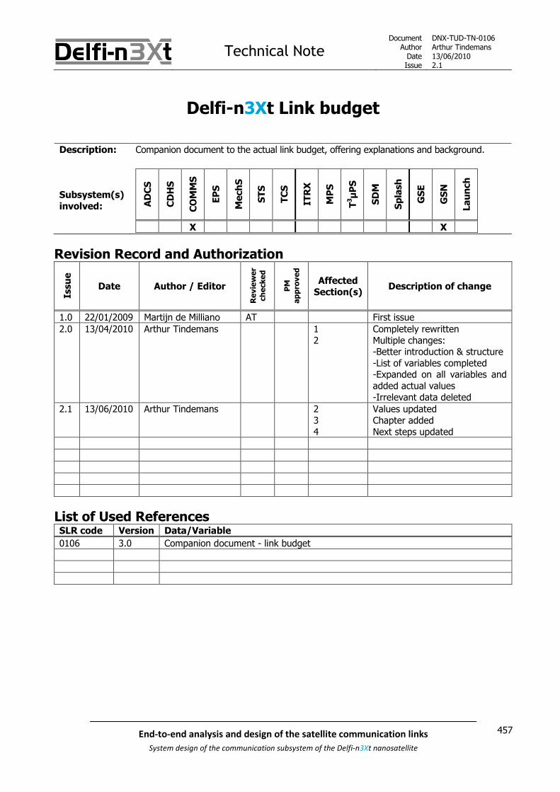
Technical NoteDocument
AuthorDateIssue
DNX-TUD-TN-0106Arthur Tindemans13/06/20102.1
457End-to-end analysis and design of the satellite communication links
System design of the communication subsystem of the Delfi-n3Xt nanosatellite
Delfi-n3Xt Link budget
Description: Companion document to the actual link budget, offering explanations and background.
Subsystem(s)involved: A
DC
S
CD
HS
CO
MM
S
EP
S
Mech
S
ST
S
TC
S
ITR
X
MP
S
T3μ
PS
SD
M
Sp
lash
GS
E
GS
N
La
un
ch
X X
Revision Record and Authorization
Issu
e
Date Author / Editor
Re
vie
we
r
ch
eck
ed
PM
ap
pro
ve
d
AffectedSection(s)
Description of change
1.0 22/01/2009 Martijn de Milliano AT First issue
2.0 13/04/2010 Arthur Tindemans 12
Completely rewrittenMultiple changes:-Better introduction & structure-List of variables completed-Expanded on all variables andadded actual values-Irrelevant data deleted
2.1 13/06/2010 Arthur Tindemans 234
Values updatedChapter addedNext steps updated
List of Used ReferencesSLR code Version Data/Variable
0106 3.0 Companion document - link budget

Technical NoteDocument
AuthorDateIssue
DNX-TUD-TN-0106Arthur Tindemans13/06/20102.1
458 End-to-end analysis and design of the satellite communication links
System design of the communication subsystem of the Delfi-n3Xt nanosatellite

Technical NoteDocument
AuthorDateIssue
DNX-TUD-TN-0106Arthur Tindemans13/06/20102.1
459End-to-end analysis and design of the satellite communication links
System design of the communication subsystem of the Delfi-n3Xt nanosatellite
Table of Contents
1 INTRODUCTION _________________________________________________________________ 461
2 LINK BUDGET PARAMETERS ______________________________________________________ 463
2.1 Power amplifier output_______________________________________________ 464
2.2 Transmitter/receiver gains and losses ___________________________________ 4642.2.1 Filter loss _____________________________________________________________________ 4642.2.2 Connector loss _________________________________________________________________ 4652.2.3 Transmission line loss ___________________________________________________________ 4652.2.4 Impedance mismatch loss ________________________________________________________ 4662.2.5 Phasing circuit loss______________________________________________________________ 4662.2.6 Antenna directivity______________________________________________________________ 4662.2.7 Coupler loss ___________________________________________________________________ 4672.2.8 Pre-amplifier loss _______________________________________________________________ 4672.2.9 Surge protector loss_____________________________________________________________ 468
2.3 Channel losses _____________________________________________________ 4692.3.1 Pointing loss___________________________________________________________________ 4692.3.2 Path loss______________________________________________________________________ 4702.3.3 Atmospheric and Ionospheric losses________________________________________________ 4722.3.4 Polarization mismatch loss _______________________________________________________ 473
2.4 System noise ______________________________________________________ 4742.4.1 VHF downlink __________________________________________________________________ 4752.4.2 UHF uplink ____________________________________________________________________ 4762.4.3 S-band downlink _______________________________________________________________ 477
2.5 Received Eb/N0 _____________________________________________________ 478
2.6 Required Eb/N0 _____________________________________________________ 479
2.7 Minimum link margin ________________________________________________ 479
3 VERIFICATION USING DELFI-C3___________________________________________________ 481
4 NEXT STEPS_____________________________________________________________________ 483

Technical NoteDocument
AuthorDateIssue
DNX-TUD-TN-0106Arthur Tindemans13/06/20102.1
460 End-to-end analysis and design of the satellite communication links
System design of the communication subsystem of the Delfi-n3Xt nanosatellite

Technical NoteDocument
AuthorDateIssue
DNX-TUD-TN-0106Arthur Tindemans13/06/20102.1
461End-to-end analysis and design of the satellite communication links
System design of the communication subsystem of the Delfi-n3Xt nanosatellite
1 Introduction
A large number of budgets are kept on the satellite level for Delfi-n3Xt, that is to say the volume budget,mass budget, power budget and data budget. The link budget is a special case, as in fact it is not kept on thesatellite level, but it describes the interface between the communication subsystem of Delfi-n3Xt and theground station. It can be used to:
Determine the final link margin Establish achievable data rates
The link budget is actually kept in a separate file with the same SLR code [SLR 0106], that and this file arecompanion files. This document introduces which sheets can be found in the other (spreadsheet) file, andmore importantly serves to explain the values that are integrated into the link budget.
Three transmission links should physically exist in case of the Delfi-n3Xt mission, being the VHF downlink, theUHF uplink and the S-band downlink. As currently the orbit altitude has not yet been determined, multiplesheets are kept to quickly demonstrate the differences. The data rate of the PTRX downlink and uplink whichcan be maximized can be changed on the sheets. In case of the STX, one sheet is kept as there are still manyvariables that should be considered. Finally, the link budget of the ITRX is not in the link budget file; this linkbudget is created and maintained not by the Delfi-n3Xt team but by the provider of this payload, ISIS B.V.
As a result, currently 5 actual link budget sheets are kept: PTRX downlink
1) 600 km2) 850 km
PTRX uplink3) 600 km4) 850 km
STX downlink5) Flexible link budget
The structure of this document is simple. Chapter 2 introduces and presents all link budget parameters.Chapter 3 then investigates the correctness of the VHF downlink link budget using data from Delfi-C3. Finallychapter 4 concludes by presenting the next steps required.
The results of the link budget calculations are not discussed in this document, but in [SLR 0014].

Technical NoteDocument
AuthorDateIssue
DNX-TUD-TN-0106Arthur Tindemans13/06/20102.1
462 End-to-end analysis and design of the satellite communication links
System design of the communication subsystem of the Delfi-n3Xt nanosatellite

Technical NoteDocument
AuthorDateIssue
DNX-TUD-TN-0106Arthur Tindemans13/06/20102.1
463End-to-end analysis and design of the satellite communication links
System design of the communication subsystem of the Delfi-n3Xt nanosatellite
2 Link budget parameters
The link budget is basically a sum of all losses and gains along a link. The starting point is the signal powerproduced by the power amplifier (PA) of the transmitter and the finishing point is the amplifier of thereceiver. Theoretically, using a perfect medium, any signal, however low in power content, can be receivedand amplified to have useful strength again. This however no longer applies due to noise present in alltransmission systems. Space, the main transmission channel, adds more less perfect Gaussian noise to thesignal, implying equal noise at all frequencies. However, transmitter and receiver add noise as well, due tohaving nonzero temperatures for example. In the end, it is then the ratio of signal-to-noise that is ofimportance, as amplification will take along the noise present. In case of a digital link, the signal-to-noiseratio is expressed as the bit-energy-to-noise spectral density ratio Eb/N0, being the energy contained withinone bit (duration) over the noise. The link budget is specified using decibel (dB) values.
The following Figure 2.1 illustrates all gains and losses incurred or possibly incurred in the Delfi-n3Xt-to-GStransmission link. This figure shall be used as a guideline to present the parameters incorporated in the linkbudget.
Figure 2.1: Losses incurred in a transmission link.
It can be seen that transmitter and receiver side are nearly identical, the only exception being the poweramplifier output on the transmitter side. Also not shown are coupler loss, pre-amplifier loss and surgeprotector loss, incurred in some links of the specific Delfi-n3Xt implementation case. The end-result of thetransmitter section, after the addition of the antenna directivity, gives the EIRP or effective isotropic radiatedpower which is a value often referred to.
Next to the transmitter/receiver sections, a channel section can be seen, where path loss and atmosphericand Ionospheric losses are incurred. Also pointing loss and polarization mismatch loss will be included in thiscategory; these losses can be said to be incurred in and due to the addition of the channel, but moreimportantly this allows to respect the usual convention of having the EIRP as the end-result of the transmittersection.
Using the power amplifier output values and the end-to-end gains and losses, the effectively received Eb/N0
can be calculated using the system incurred noise and data rate. Comparing this value to the required Eb/N0
for correct data interpretation gives the final remaining link margin. Usually, a minimum link margin is alsotaken into account.
The following sections will introduce all parameters of interest in calculating the link budget. At the sametime, the values applicable to Delfi-n3Xt scenarios are presented. The input, being the power amplifier output,is commented on in section 2.1. Section 2.2 discusses all transmitter/receiver gains and losses, including thethree Delfi-n3Xt specific losses at the end, and section 2.3 consequently describes channel losses. Section 2.4introduces signal noise. Section 2.5 then introduces the relation and parameters required to determine thereceived Eb/N0 after which section 2.6 presents the required Eb/N0. Knowledge of the latter two ratios logicallyresults in a final link margin, and thus a confirmation of whether the link closes or not. Section 2.7 finallyexplains the inclusion of a minimum link margin.
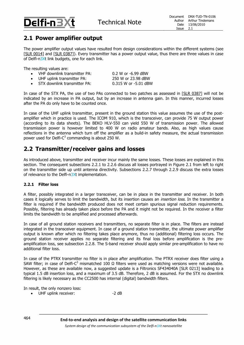
Technical NoteDocument
AuthorDateIssue
DNX-TUD-TN-0106Arthur Tindemans13/06/20102.1
464 End-to-end analysis and design of the satellite communication links
System design of the communication subsystem of the Delfi-n3Xt nanosatellite
2.1 Power amplifier output
The power amplifier output values have resulted from design considerations within the different systems (see[SLR 0014] and [SLR 0387]). Every transmitter has a power output value, thus there are three values in caseof Delfi-n3Xt link budgets, one for each link.
The resulting values are: VHF downlink transmitter PA: 0.2 W or -6.99 dBW UHF uplink transmitter PA: 250 W or 23.98 dBW STX downlink transmitter PA: 0.315 W or -5.01 dBW
In case of the STX PA, the use of two PAs connected to two patches as assessed in [SLR 0387] will not beindicated by an increase in PA output, but by an increase in antenna gain. In this manner, incurred lossesafter the PA do only have to be counted once.
In case of the UHF uplink transmitter, present in the ground station this value assumes the use of the post-amplifier which in practice is used. The ICOM 910, which is the transceiver, can provide 75 W output power(according to its data sheets). The BEKO HLV-550 can yield 550 W of transmission power. The allowedtransmission power is however limited to 400 W on radio amateur bands. Also, as high values causereflections in the antenna which turn off the amplifier as a build-in safety measure, the actual transmissionpower used for Delfi-C3 commanding is about 250 W.
2.2 Transmitter/receiver gains and losses
As introduced above, transmitter and receiver incur mainly the same losses. These losses are explained in thissection. The consequent subsections 2.2.1 to 2.2.6 discuss all losses portrayed in Figure 2.1 from left to righton the transmitter side up until antenna directivity. Subsections 2.2.7 through 2.2.9 discuss the extra lossesof relevance to the Delfi-n3Xt implementation.
2.2.1 Filter loss
A filter, possibly integrated in a larger transceiver, can be in place in the transmitter and receiver. In bothcases it logically serves to limit the bandwidth, but its insertion causes an insertion loss. In the transmitter afilter is required if the bandwidth produced does not meet certain spurious signal reduction requirements.Possibly, filtering has already taken place before the PA and it might not be required. In the receiver a filterlimits the bandwidth to be amplified and processed afterwards.
In case of all ground station receivers and transmitters, no separate filter is in place. The filters are insteadintegrated in the transceiver equipment. In case of a ground station transmitter, the ultimate power amplifieroutput is known after which no filtering takes place anymore, thus no (additional) filtering loss occurs. Theground station receiver applies no separate filtering and its final loss before amplification is the pre-amplification loss, see subsection 2.2.8. The S-band receiver should apply similar pre-amplification to have noadditional filter loss.
In case of the PTRX transmitter no filter is in place after amplification. The PTRX receiver does filter using aSAW filter; in case of Delfi-C3 mismatched 100 Ω filters were used as matching versions were not available.However, as these are available now, a suggested update is a Filtronics SF434040A [SLR 0213] leading to atypical 1.5 dB insertion loss, and a maximum of 3.5 dB. Therefore, 2 dB is assumed. For the STX no downlinkfiltering is likely necessary as the CC2500 has internal (digital) bandwidth filters.
In result, the only nonzero loss: UHF uplink receiver: -2 dB

Technical NoteDocument
AuthorDateIssue
DNX-TUD-TN-0106Arthur Tindemans13/06/20102.1
465End-to-end analysis and design of the satellite communication links
System design of the communication subsystem of the Delfi-n3Xt nanosatellite
2.2.2 Connector loss
As generally the physical transmitter and receiver are separate from the antenna, a connection between thetwo is necessary by means of a disconnectable wire. The ends of the wire then require connectors. Ashowever any connection is slightly imperfect a connector loss is incurred.
On Delfi-n3Xt, the connector types are still to be confirmed. Delfi-C3 however applied SMA connectorsbetween the RAP and the antenna boards, and smaller MMCX connectors between the antenna board and theMABs. Specific data for the connector losses is not available, but typical losses are in the range of a fewtenths of a dB depending on the RF. For UHF/VHF frequencies, -0.20 dB is then assumed for all threeconnectors, and -0.20 dB for S-band frequencies for a single connector and the patch antenna connection.
On the ground station, gold-plated N connectors are used. These have very little losses, with little exactspecification, but a maximum of -0.15 dB at 10 GHz stated at various sources. As UHF and VHF transmissionfrequencies are only 0.145 and 0.435 GHz, a conservative constant value of -0.10 dB for all connectors will beused, even though this impact drops below the actual accuracy of the link budget. For the S-band, -0.20 dBwill be assumed for two connectors in total.
Therefore the following values result: VHF downlink transmitter: -0.2 dB VHF downlink receiver: -0.1 dB UHF uplink transmitter: -0.1 dB UHF uplink receiver: -0.2 dB STX downlink transmitter: -0.2 dB STX downlink receiver: -0.2 dB
2.2.3 Transmission line loss
Next to the connectors, the wire or transmission line in between also causes losses to occur, which can besizeable for high-frequency RF signals. The loss depends on the length of the lines and the attenuation perunit length. The attenuation depends on the type of cable used, and increases with frequency. In case of allDelfi-n3Xt transmission lines, a thin, low-weight coax cable is used [SLR 0036]. On-ground, two cable types[SLR 0014] are used, separated by surge protectors. However, in case of the downlink a pre-amplifiereffectively takes the second type out of the equation, as is explained in section 2.2.8 below.
The total transmission lengths per cable type are given below. The actual loss is then calculated in Excel,using also the attenuation per meter for the transmission frequency at hand. For the UHF and VHF satellitecables, 0.10 m is taken per connection, assuming all radio are housed relatively close to the antennas. TheS-band cables are assumed to be 0.20 m. This assumes the maximum required length where the STX islocated in the middle of the satellite and cables run towards either the BOP, TOP or both. In result:
VHF downlink transmitter: RG178BU (0.1 m) VHF downlink receiver: AIRCELL 7 (5 m) UHF uplink transmitter: ECOFLEX 15 (20 m) & AIRCELL 7 (5 m) UHF uplink receiver: RG178BU (0.1 m) STX downlink transmitter: RG178BU (0.2 m)
For the STX ground station set-up, the loss incurred by the few metres of high-quality cable between theantenna and pre-amplifier would already be very significant, given losses of some -0.40 dB/m. Then, itbecomes important to have the pre-amplifier directly connected to the antenna. As however also a surgeprotector shall be required, some cabling might be necessary. As such, the transmission line loss for the S-band downlink receiver is set to a conservative 0.5 dB.
STX downlink receiver: -0.5 dB
Technical NoteDocument
AuthorDateIssue
DNX-TUD-TN-0106Arthur Tindemans13/06/20102.1
466 End-to-end analysis and design of the satellite communication links
System design of the communication subsystem of the Delfi-n3Xt nanosatellite
2.2.4 Impedance mismatch loss
A loss in power can occur due to a mismatch in impedance basically at all connections, but usually theinterface between the transmission line and the antenna is the most important and used to indicate thepossible impedance mismatch loss. The transmission wire can change the effective impedance of the signaland should be matched to the antenna, possibly by introducing additional circuitry. This can be done forexample by adding a tuning circuit consisting of passive components such as capacitors or inductors, in whichcase there is no (theoretical) loss and all power is put onto the antenna. For a patch antenna, matching canbe done by properly positioning the feed on the patch surface.
In case of both the VHF and UHF antenna systems, the impedance mismatch losses are incurred on thephasing circuit. As also other power losses are incurred on this phasing circuit, the losses are indicated asphasing circuit losses. These losses are explained in the next subsection. The UHF and VHF impedancemismatch are then zero. On the S-band antenna system, a value of -0.2 dB shall be assumed, assuming aVoltage Standing Wave Ratio of 1.5:1, as also used in a link budget of ISIS for their S-band link. On-ground50Ω matched COTS products are used and no extra losses are assumed other than already incurredconnector and transmission line losses.
The only resulting values: S-band downlink transmitter: -0.2 dB
2.2.5 Phasing circuit loss
In both transmitter and receiver on-board of Delfi-n3Xt (at least in case of the UHF/VHF link) a phasing circuitis used to properly phase the signals between the four antennas. This circuitry can also be seen as impedancematching circuitry; all losses can be allocated to the phasing circuit. The phasing circuit causes sizeable lossesto be incurred and should be taken along.
The phasing circuit losses for the UHF/VHF phasing circuit are stated in [SLR 0715]. For the STX a separatephasing circuit does not seem to be necessary. In result:
VHF downlink transmitter: -1.7 dB UHF downlink receiver: -2.15 dB
2.2.6 Antenna directivity
An antenna never is perfectly isotropic, or omnidirectional. As such, there is a direction of minimumdirectivity, and similarly a direction of maximum directivity. Some antennas aim to approach anomnidirectional pattern, and then apply no active pointing, such as the Delfi-n3Xt UHF/VHF antenna system.It that case, the minimum directivity should be used in the link budget, if permanent coverage is to beguaranteed. In other cases, active pointing is performed and the maximum directivity can be used, but apointing loss is introduced as introduced in the next section.
The UHF/VHF antenna patterns are commented on in [SLR 0036] and figures are presented from whichminima can be read. The UHF/VHF antenna gains on-ground can be read from the antenna specifications ofboth the VHF antenna M2 2M CP14 and UHF antenna M2 436CP30 [SLR 0734 and 0736]. However, thesevalues state the gain in dBdc, being the gain referenced to a half-wave dipole antenna. In order to convertthis to the required gain with respect to an isotropic (omnidirectional) antenna, 2.15 dB should simply beadded.
For the S-band antenna system on-board of the satellite, an omnidirectional directivity pattern shall also beapproximated, given the uncertain characteristics of the final ADCS. Two scenarios are described in [SLR0036]; that of having a -5 dB loss and a -2 dB loss (with a closed link in ~80% of the time).
Technical NoteDocument
AuthorDateIssue
DNX-TUD-TN-0106Arthur Tindemans13/06/20102.1
467End-to-end analysis and design of the satellite communication links
System design of the communication subsystem of the Delfi-n3Xt nanosatellite
On-ground, S-band signals are to be received by means of a parabolic reflector. ISIS will likely be responsiblefor the installation of the S-band ground segment, and they say that they are able to provide a 3 m dish. Asimilar dish is used for the reception of the MOST (Microvariability and Oscillation of Stars) satellite [SLR0738], and is said to have 35 dB maximum directivity. Similarly, [SLR 0219] mentions 3 m dishes to have 35dB maximum directivity. A second, back-up option is the dish already in possession at the faculty of EEMCS(although without operating mechanics). This dish has a diameter of 0.7 m, leading to a maximum directivityof 22.3 dB. As the difference is sizeable the first option is definitely preferred.
The resulting values: VHF downlink transmitter (minimum): -5 dB VHF downlink receiver (maximum): 12.35 dB UHF uplink transmitter (minimum): -6 dB UHF uplink receiver (maximum): 16.40 dB STX downlink transmitter:
o Fully omnidirectional: -5 dBo Achievable in ~80% of time: -2 dB
STX downlink receiver (maximum)o 3 m parabolic reflector: 35 dBo 0.7 m parabolic reflector: 22.3 dB
2.2.7 Coupler loss
In case of the PTRX transmitter and assumably the STX as well, a bidirectional coupler is used to extract dataon the signal strength right before transmission [SLR 0014]. In combination with a power detector this allowsto determine the power forwarded to and reflected by the antenna system; in turn yielding valuablehousekeeping data on operation and antenna deployment. In case of the PTRX this coupler also serves toprovide the transponder AGC with the final signal strength. Unfortunately, the addition of this componentafter final amplification comes at the cost of an additional insertion loss. According to the data sheet of theintegrated ADC-10-1R [SLR 0719], this loss is between 0.8 and 1.2 dB, thus assumed to be 1 dB, for VHFfrequencies. In case of S-band frequencies this loss rises to 0.9-1.5 dB, or 1.2 dB averaged.
In result: VHF downlink transmitter: -1.0 dB STX downlink transmitter: -1.2 dB
2.2.8 Pre-amplifier loss
In case of receiver systems were a significant distance exists between the actual receiver and the antennasystem, it is common to use a masthead pre-amplifier. It then makes sense to also see this amplifier as theend of the chain, even though some losses are still incurred and noise is still introduced behind the amplifier.But, as the later losses are incurred with respect to the new signal strength it makes sense to neglect thelater-incurred losses of the original signal as the orders of magnitude become very different.
However, this added pre-amplifier comes at the cost of an insertion loss. In case of the UHF downlink it isequal to 0.2 dB according to its specifications to be found on the internet (SP-2000 amplifier). In case of theS-band downlink a similar masthead pre-amplifier has not yet been specified. However, the pre-amplifier lossresembles the connector losses and surge protector losses in value, at least for the VHF downlink. Therefore,a value of -0.3 dB shall be assumed.
In result: VHF downlink receiver: -0.2 dB STX downlink receiver: -0.3 dB

Technical NoteDocument
AuthorDateIssue
DNX-TUD-TN-0106Arthur Tindemans13/06/20102.1
468 End-to-end analysis and design of the satellite communication links
System design of the communication subsystem of the Delfi-n3Xt nanosatellite
2.2.9 Surge protector loss
Finally, all ground station receivers as well as transmitters with antennas at elevated positions need lightningprotection systems. Therefore simple bandpass filters designed to ground lightning-incurred frequencies andvoltages, or surge protectors are inserted directly next to the antennas. Again, these cause an insertion lossto be incurred. In case of the VHF downlink and UHF uplink, the Telegärtner J01028A0037 is used [SLR 726],which is said to have an insertion loss of 0.2 dB for N-type connectors, for frequencies up to 2.5 GHz. Thesame surge protector can then be used for the S-band downlink.
Then: VHF downlink receiver: -0.2 dB UHF uplink receiver: -0.2 dB STX downlink receiver: -0.2 dB

Technical NoteDocument
AuthorDateIssue
DNX-TUD-TN-0106Arthur Tindemans13/06/20102.1
469End-to-end analysis and design of the satellite communication links
System design of the communication subsystem of the Delfi-n3Xt nanosatellite
2.3 Channel losses
The losses that have been defined as channel losses are the pointing loss, path loss, atmospheric andIonospheric loss and finally the polarization mismatch loss. These losses are discussed in subsections 2.3.1through 2.3.4 below.
2.3.1 Pointing loss
The pointing loss factor is the loss due to an error in pointing of both the spacecraft as well as the groundstation, if applicable. The error in pointing introduced is then the difference between the actual line-of-sightvector and the direction of the maximum of the antenna major lobe. The effect of a certain pointing errorincreases when the directivity of the antenna is higher, thus is most important on-ground. The UHF/VHFantenna system on Delfi-n3Xt will in any case not apply pointing, and similarly the S-band satellite antennasystem will no longer be assumed to. The ground station will apply pointing for all transmission links.
The pointing accuracy of the ground station antenna is limited by the TLE accuracy, antenna rotor mechanismand data processing delay as well as environmental conditions (e.g. oscillations due to strong winds).Consequently, a pointing error incurs a non-zero angle with respect to the point of maximum gain, and assuch the actual pointing loss is dependent on the exact antenna gain pattern.
In case of the UHF and VHF antennas, general assumptions are made, confirmed by Wouter Weggelaar (whodoes now manage the GS) to be representative for the Delft GS; these are -0.5 dB and -1 dB for respectivelythe VHF and UHF systems.
In case of the STX, the on-ground pointing capability can be estimated. Along with the promise of providing a3 m dish, ISIS seems to be confident to achieve 0.5° pointing accuracy with the tracking mechanism. To thispossible orbit errors and weather effects should be added. [SLR 0738] mentions that with the MOST mission,0.5° overall pointing accuracy was even achieved, while shutting off during unfavourable wind conditions. Fornow, an overall 1.5° pointing error shall be assumed. Heavy winds might cause the antenna system to be outof operation.
[SLR 0219] can be used to calculate the pointing loss given the pointing accuracy. For a 3 m parabolicreflector, an 0.5° pointing accuracy would yield 0.3 dB loss, whereas a more realistic 1.5° causes 3.2 dBpointing loss. Similarly 1.5° pointing accuracy would yield 0.2 dB loss for a 0.7 m parabolic reflector.
Resulting values: VHF downlink receiver: -0.5 dB UHF uplink transmitter: -1.0 dB STX downlink receiver
o 3 m parabolic reflector: -3.2 dBo 0.7 m parabolic reflector: -0.2 dB

Technical NoteDocument
AuthorDateIssue
DNX-TUD-TN-0106Arthur Tindemans13/06/20102.1
470 End-to-end analysis and design of the satellite communication links
System design of the communication subsystem of the Delfi-n3Xt nanosatellite
2.3.2 Path loss
The path loss pL is the loss in signal power resulting from an increasing distance between transmitter and
receiver. It is dependent on the wavelength of the signal, and is given by the following relation [SLR 0316]:
2
4pL
S
, (2-1)
Whereλ wavelength of the signalS distance between transmitting and receiving antenna (also called slant range)
The slant range S depends on the elevation of the satellite above the horizon [SLR 0316]:
2
2
2cos sin
R hS R
R
, (2-2)
Where
R radius of the Earth (6378 km)h orbit altitude in kmε satellite elevation above the local horizon in radians
The variation of the slant range over a range of elevation angles is shown in Figure 2.2 below for theDelfi-n3Xt range of orbit altitudes.
The resulting path loss in decibels versus elevation angle is plotted in Figure 2.3; a lower (negative) decibelvalue is actually worse, so these are plotted highest on the Y-axis. Losses become (significantly) lower withelevation angle, due to the similarly large decrease of slant range.
The distance typically used in calculating the path loss is the maximum slant range for which acommunication link with the satellite is desired, in other words by selecting a minimum elevation angle atwhich the link budget is supposed to close. This then assumes a constant data rate through the pass, or eventhe mission. Theory on selecting this minimum elevation angle by pursuing a maximum downloadable datavolume is presented in [SLR 0014].

Technical NoteDocument
AuthorDateIssue
DNX-TUD-TN-0106Arthur Tindemans13/06/20102.1
471End-to-end analysis and design of the satellite communication links
System design of the communication subsystem of the Delfi-n3Xt nanosatellite
Figure 2.2: Slant range versus elevation angle for the Delfi-n3Xt range of orbit altitudes
Figure 2.3: Path loss versus elevation angle for the Delfi-n3Xt range of orbit altitudes
Technical NoteDocument
AuthorDateIssue
DNX-TUD-TN-0106Arthur Tindemans13/06/20102.1
472 End-to-end analysis and design of the satellite communication links
System design of the communication subsystem of the Delfi-n3Xt nanosatellite
In case of the primary UHF/VHF link the link budget will de designed for maximum contact time; in otherwords assuming a worst case path loss. The consequence is that lower data rates can be achieved. Thischoice has been discussed in [SLR 0014], but results in maximum data yield when all (off-zenith) passes areutilized. Due to increasing atmosphere losses, antenna noise and obstructions at low elevation angles aminimum elevation angle of 10° is selected for all VHF and UHF communications.
For the STX, the data rate is supposed to be changeable. Then, the path loss value does not need to bebased on a worst case value. As data transfer is maximum for a zenith pass with a data rate based on aminimum elevation angle of about 40°, a worst case value and an optimum path loss value are given.
Also, in all cases the path loss depends on orbit altitude and Delfi-n3Xt orbit altitude is currently scheduled tobe between 600 and 850 km.
The resulting path losses in dB: VHF downlink, 600 km, 10° elevation angle: -141.40 dB VHF downlink 850 km, 10° elevation angle: -143.53 dB UHF uplink, 600 km, 10° elevation angle: -150.94 dB UHF uplink 850 km, 10° elevation angle: -153.07 dB S-band downlink, 600 km, 10° elevation angle: -165.77 dB S-band downlink, 850 km, 10° elevation angle: -167.90 dB S-band downlink, 600 km, 40° elevation angle: -158.97 dB S-band downlink, 850 km, 40° elevation angle: -161.83 dB
2.3.3 Atmospheric and Ionospheric losses
When the signal traverses space towards a massive body, two effects cause degradation of the signal: Absorption by atmospheric gasses Phase delay introduced and reflections caused by the ionosphere
The absorption of atmospheric gasses decreases with increasing elevation (the signal has to pass through lessatmosphere), and losses are approximately independent of transmission frequency up until 2 GHztransmission frequencies. This includes the UHF- and VHF-bands. For the S-band, a small rain attenuationcorrection (additional loss) shall be given below. Documented values are listed in Table 2.1.
Table 2.1: Losses due to the presence of atmospheric gasses [SLR 0219]
Elevation angle [°] Loss [dB]0 10.2
2.5 4.65 2.1
10 1.130 0.445 0.390 0.0
Ionospheric effects can be researched in large detail, but is not essential for UHF-, VHF- and S-bandfrequencies. These frequencies are far less influenced than lower transmission frequencies. As such, usableIonospheric attenuation values are given in Table 2.2.
Table 2.2: Ionospheric losses [SLR 0219]
Frequency [MHz] Loss [dB]
146 0.7438 0.4
2410 0.1

Technical NoteDocument
AuthorDateIssue
DNX-TUD-TN-0106Arthur Tindemans13/06/20102.1
473End-to-end analysis and design of the satellite communication links
System design of the communication subsystem of the Delfi-n3Xt nanosatellite
In case of high frequency signals, rain fall becomes very relevant. At S-band frequencies, this is onlymarginally so. The atmospheric losses take into account the presence of water in the atmosphere. However,one can imagine that the presence of clouds and rain distorts the figures. [SLR 0730] gives the losses per kmin which there is a rainfall of anywhere between 0.25 mm/h and 150 mm/h. In the Netherlands, with anaverage rainfall of not even one meter per year, 10 mm/h would already be very exceptional. For possibleSTX passes above other regions, the value might be higher. The resulting rain loss as presented in [SLR0730] for a 10 mm/h value is already off the chart; below 0.01 db/km. Assuming clouds to be not above 10km altitude, but taking into account low elevation angles, a conservative loss of 0.1 dB is taken into accountin the link budget.
The total atmospheric and Ionospheric losses relevant for the Delfi-n3Xt link budget can be obtained byadding the values presented above. In result:
VHF downlink, 10° elevation angle: -1.8 dB UHF uplink, 10° elevation angle: -1.5 dB S-band downlink, 10° elevation angle: -1.5 dB S-band downlink, 40° elevation angle: -0.5 dB
2.3.4 Polarization mismatch loss
The electric field of an electromagnetic wave can be seen as a vector in a plane perpendicular to the directionof travel. The vector can be decomposed into two orthogonal components, for example an Ex component andan Ey component, where the x and y direction are perpendicular. The relative amplitude of and the relativephase between these components determines the polarization of the wave. There are three types ofpolarization [SLR 0261]:
Linear polarization: the relative phase between the components is 0° or 180°
Circular polarization: the amplitude of both components is equal and the relative phase betweenthe components is 90° (left-hand polarized) or 270° (right-hand polarized)
Elliptical polarization: when the wave is neither linearly nor circularly polarized
The polarization of the receiver antenna must be matched to the polarization of the incoming wave. If thewave is linearly polarized, then the antenna must be linearly polarized for maximum energy transfer. If thepolarization directions of both antennas are perpendicular, no signal is theoretically received. Also, linearlypolarized signals will be elliptically polarized by the channel due to an incurred Faraday rotation of the Earth.
As the attitude of the satellite is not fixed with respect to the ground station, and due to the circularization ofthe Faraday rotation, circularly polarized signals will be used for communication between Delfi-n3Xt and theground. For the UHF and VHF systems, polarization mismatch shall be set to 0 as the minimum directivityvalues of the satellite have been taken at which circularly polarized transmission is achieved. On-ground, onecan switch between left-handed and right-handed circular polarization (LHCP and RHCP respectively),depending on satellite attitude. The S-band patch directivity values are similarly based on the RHCP directivitypattern.
In result: All links: 0 dB

Technical NoteDocument
AuthorDateIssue
DNX-TUD-TN-0106Arthur Tindemans13/06/20102.1
474 End-to-end analysis and design of the satellite communication links
System design of the communication subsystem of the Delfi-n3Xt nanosatellite
2.4 System noise
As is introduces in the next section, the combination of the Boltzmann’s constant and system noisetemperature gives the noise spectral density N0. System noise temperature values are not self-evident, thusare given more attention and explained here.
System noise can be expressed with respect to the LNA using the following equation [SLR 0219]:
2
0(1 ) ndStage
S a LNA
LNA
TT T T T
G
(2-3)
Where: Signal transmission efficiency between antenna and LNA (1 - total loss)
aT Antenna or sky temperature (not a physical temperature)
0T System temperature and reference temperature (physical temperature)
LNAT LNA noise temperature (not a physical temperature)
2ndStageT Noise temperature of the second amplifier (not a physical temperature)
LNAG Gain of the LNA
Signal transmission efficiency between LNA and second amplifier (1 - total loss)
In the relation above a number of temperature values are incorporated. However, in case of active devices,these are not actually physical temperature values, rather just representative values. For passive deviceshowever actual temperature values are used.
Also, it is shown that all noise is assumed to be incurred in the receiver, but taking into account skytemperature. Due to the large signal strength at the transmitter, noise incurred there is not relevant to totalsystem noise. Furthermore, a 2nd stage is shown, but no third stage; generally there are only two stagesassuming a pre-amplifier and the actual receiver. Nevertheless, a large number of mixers and IF amplifierscan increase the amount of stages. As however the extra incurred noise temperature for an additional stageis to be divided by the gains of all preceding amplifiers, third and later stages can safely be ignored with littleloss of precision.
It should also be noted that no decibel values should be entered in the above equation, rather just linearvalues. Decibel values can be recalculated to ‘normal’ linear values using the following relation:
(log)
10( ) 10X
X linear (2-4)
Also, in order to calculate noise temperatures XT using a given noise figure F of devices such as amplifiers,
the following relation can be used [SLR 0316]:
01XT F T (2-5)
As opposed to the procedure followed for signal losses and gains occurred in the system, the system noiseparameters will be discussed per case, being the VHF downlink, UHF uplink and S-band downlink. This is donein sections 2.4.1 through 2.4.3 below. For a good idea of the chain of components and their functionalitiesone is referred to [SLR 0014], where extensive diagrams are presented of GS, PTRX and STX receiverarchitectures.

Technical NoteDocument
AuthorDateIssue
DNX-TUD-TN-0106Arthur Tindemans13/06/20102.1
475End-to-end analysis and design of the satellite communication links
System design of the communication subsystem of the Delfi-n3Xt nanosatellite
2.4.1 VHF downlink
In case of the VHF downlink, the important section is the GS VHF receiver section. The first stage, up untilthe first amplifier, is formed by cables (plus connectors) between the antennas and amplifier, as well as aninserted surge protector. The second stage is formed by all cables and circuitry (power limiter andconnectors) and the ultimate receiver, the ICOM 910. The resulting values to be used in equation 2-3 areshown and explained below:
= 0.81 This value is a sum of all losses up until the pre-amplifier, as indicated in the link budget.
This includes connector, transmission line, surge protector and pre-amplifier insertionloss, summing up to -0.9 dB or 0.81 (using relation 2-4).
aT = 150 K Two sources, being SMAD [SLR 316] and TRASH (the radio amateur satellite handbook,
the latter being referred to via different websites) indicate a value of 150 K. In the firstsource, 150 K is indicated as a usual system noise temperature at 0.2 GHz, which is closeto the 0.146 GHz of the downlink. The other source indicates the same value for VHFfrequencies, but mentions it to be worst case value for direct pointing at the horizon atminimum elevation. Furthermore, the Delft GS is located very high up with little groundinterference. As such, 150 K seems to be a good, possibly slightly conservative value.
0T = 290 K The physical temperature of the cables is set to be 290 K.
LNAT = 58 K The LNA has an indicated noise figure of 0.8 dB; using 0T given above and relations 2-4
and 2-5 this can be calculated to yield 58 K
2ndStageT = 473 K The noise temperature of the ICOM 910 can be calculated using the sensitivity of the
transceiver, indicated in [SLR 0737] to be “0.11 μV for 10 dB signal-to-noise in 2.4 kHzbandwidth”. [SLR 0248] gives the rather lengthy calculation, and arrives at a noise figure
of 4.2 dB. Using again relations 2-4 and 2-5 and a 0T of 290 K gives a noise temperature
of 473 K.
LNAG = 20 [SLR 0725] indicates that a gain of 12-14 dB should be aimed for (which can be adjusted
on the amplifier). An intermediate 13 dB equals a gain of 20.
= 0.81 Summing all losses after the pre-amplifier, being additional connector losses (estimated
at -0.1 dB), transmission line losses (-0.7 dB based on cable attenuation data given in thelink budget spreadsheets) and finally the power limiter loss (-0.1 dB according to[SLR 721]) gives -1 dB, or 0.81.
The resulting ST or system noise temperature is 264 K.

Technical NoteDocument
AuthorDateIssue
DNX-TUD-TN-0106Arthur Tindemans13/06/20102.1
476 End-to-end analysis and design of the satellite communication links
System design of the communication subsystem of the Delfi-n3Xt nanosatellite
2.4.2 UHF uplink
In case of the UHF uplink, the section of relevance is that of the PTRX receiver. Its architecture can be seenin [SLR 0014], and clearly has a large number of stages. Nevertheless as explained above, two stages areenough to give an estimate of the noise temperature. A small margin will be implemented at the end toaccount for additional noise. The values of relevance:
= 0.23 This value is a sum of all losses up until the LNA, as indicated in the link budget. This
includes phasing circuit, impedance mismatch, connector, transmission line and filter loss,summing up to -6.41 dB or 0.23.
aT = 290 K SMAD [SLR 316] indicates a value of 290 K for all frequencies in between 0.2 and 20
GHz, as well as 40 GHz. In other words, the noise temperature is more or less constantand depends mainly on the Earth albedo. In fact, this value is based on a pointedantenna directed at the Earth, as opposed to an omnidirectional antenna as used in theUHF/VHF links. Therefore, the value should logically be less. Nevertheless, as aconservative value it is kept. Also, due to the high losses ( ) the noise temperature has
only limited impact on overall noise temperature.
0T = 313 K The physical temperature of the satellite systems generally should be between -40° C
and +80° C for correct operation. A rather high but reasonable temperature of 40° C willbe assumed here, or 313 K.
LNAT = 72 K The LNA (MAX2640) has an indicated noise figure of 0.9 dB [SLR 0138]; using 0T given
above and relations 2-4 and 2-5 this can be calculated to yield 72 K.
2ndStageT = 421 K The IF amplifier (MAX2630) has an indicated noise figure of 3.7 dB [SLR 0139]. This can
be calculated to yield 421 K.
LNAG = 32 [SLR 0138] indicates a gain of 15.1 dB for the MAX2640, equaling a value of 32.
= 0.15 After the first amplifier a filter and a mixer circuit are in place, next to negligible
connections. This leads to a filter loss of -2 dB, as the same filter is used as before thefirst amplifier, and a mixer circuit loss of -6.3 dB according to the data sheet of theRMS-1 [SLR 0724]. The total of -8.3 dB equals a value of 0.15.
The resulting ST or system noise temperature is 467 K. However, as said above a small margin for additional
stage losses will be taken, so that the total system noise temperature shall be set at 500 K.

Technical NoteDocument
AuthorDateIssue
DNX-TUD-TN-0106Arthur Tindemans13/06/20102.1
477End-to-end analysis and design of the satellite communication links
System design of the communication subsystem of the Delfi-n3Xt nanosatellite
2.4.3 S-band downlink
For the S-band downlink, again the receiver ground segment is important for the noise calculation. [SLR0014] presents the conceptual lay-out. Two stages shall be used in the noise calculation. The values ofrelevance:
= 0.79 The sum of the receiver connector loss, transmission line loss, surge protector loss and
pre-amplifier loss yields 1 dB total loss. This equals 0.79.
aT = 200 K SMAD [SLR 316] gives general antenna noise values of only 25 K above 2 GHz. This value
however does not properly take into account man-made noise, in turn highest at lowelevations. Also, the ISM-band is used for wireless internet applications, which might turnout to be a large source of noise on the ground station. Therefore, a conservative total200 K antenna noise temperature is assumed.
0T = 290 K The assumed physical temperature of the ground equipment.
LNAT = 51 K [SLR 0738] describes the use of low-noise amplifiers with a gain value of 30 dB and a
noise figure of 0.7 dB. The latter then yields a noise temperature of 51 K.
2ndStageT = 500 K Here again a large assumption is made. This second active device can be either a real
amplifier, or the actual receiver. In case of the VHF downlink, the ICOM 910 had a noisetemperature of 472 K, nearly 500 K. Therefore the latter value is assumed here, eventhough frequency bands are different.
LNAG = 30 As argued above, following the low-noise amplifier specifics given in [SLR 0738].
= 0.60 After the first amplifier some connectors and most notably a lengthy cable is in place. As
with the UHF and VHF systems, some 20 m is estimated to be necessary. Given theattenuation per meter for the high quality ECOFLEX 15 cable of -0.10 dB/m, this yields-2.0 dB. This value is decreased to -3.2 dB to account for connector losses. -3.2 dBequals about 0.60.
The resulting ST or system noise temperature is 298 K. Two large assumptions have been made:
A 200 K antenna noise temperature to account for man-made noise A 28 K second stage noise temperature, resulting from an estimated 500 K noise temperature of the
second active device; receiver or amplifier.
It can be seen that the impact of the second estimation is moderate, due to the large gain of the pre-amplifier. The antenna noise temperature is an important and tricky value. The link budget provided to theauthor by ISIS, describing their ground station implementation uses a more optimistic value of 100 K antennanoise. Furthermore, a 75 K amplifier noise value is used, but no more. The above calculation aims to be moredetailed given the insecurities, but also stays on the safe side.

Technical NoteDocument
AuthorDateIssue
DNX-TUD-TN-0106Arthur Tindemans13/06/20102.1
478 End-to-end analysis and design of the satellite communication links
System design of the communication subsystem of the Delfi-n3Xt nanosatellite
2.5 Received Eb/N0
The power amplifier output multiplied by all consequent losses on the link basically yields signal strength at
the receiver, or receiver power rP . In case decibels are used, which is generally the case in a link budget, all
losses are simply subtracted from (or added to, depending on the convention) the original power amplifieroutput. Taking into account the noise level at the receiver as well as the data rate of transmission, the overallreceived Eb/N0 can be calculated using the following equation 2.3.
The received bit energy over noise spectral density Eb/N0 is equal to [SLR 0316]:
0
b r
s
E P
N kT R (2-6)
Where:k Boltzmann’s constant (1.38·10-23 J/K)Ts The system noise temperature in KR The data rate in symbols/s (Baud)
Equation 2.3 can be expressed in its decibel equivalent, see equation 2.4:
10 10
0
10 log( ) 10 logbr s
EP kT R
N (2-7)
This equation is the generally referred to as the link equation or link budget.
An implementation loss has been used to account for slight additional losses, but the current high detail ofthe budget and the vagueness of such a loss are no longer preferred. Instead, only a minimum link margin isincorporated, which is interpreted as a value added to the required Eb/N0. These two parameters areintroduced in the next two sections.
Finally, note that the data rate is given in symbols/s as opposed to bits per second. The reason for this is thatManchester coding requires two symbols per bit. Also, if forward error correction coding is added, there is adistinction between data bits and coding bits; together they can just be seen as symbols.
Technical NoteDocument
AuthorDateIssue
DNX-TUD-TN-0106Arthur Tindemans13/06/20102.1
479End-to-end analysis and design of the satellite communication links
System design of the communication subsystem of the Delfi-n3Xt nanosatellite
2.6 Required Eb/N0
In order to properly demodulate a signal, a certain signal-to-noise ratio is required per bit duration, asintroduced before. If the received Eb/N0 is higher than the required Eb/N0, the signal can be demodulated withat least the preferred bit error rate or BER. In this case, a link margin is said to remain.
The required Eb/N0 values for different modulation schemes, as well as the choices for different modulationschemes have been commented on in [SLR 0014]. As such, for the three transmission links, being that of VHFdownlink, UHF uplink and S-band uplink, the following values can be stated for a BER of 10-5:
VHF downlink, differentially encoded BPSK or DEBPSK: 10.3 dB UHF uplink, noncoherent BFSK: 13.3 dB S-band downlink, MSK: 9.6 dB
Finally forward error correcting codes can be applied, so that a coding gain can be achieved. This can lowerthe required Eb/N0 sizeably as a number of dB’s can be subtracted from it. For the STX, [SLR 0014] arguesthat 2-4 dB coding gain can be achieved for low-complexity coding schemes, and 7 dB for a more advancedconcatenated coding scheme. As a result two options shall be kept for the S-band downlink:
S-band downlink, simple coding scheme: -3 dB S-band downlink, concatenated coding scheme: -7 dB
2.7 Minimum link margin
Subtracting the required Eb/N0 from the received Eb/N0 gives conclusion on whether the link closes and howmuch margin results. However, in order to account for inaccuracies in the link budget, a contingency is usedand added to the required Eb/N0. This contingency is called the minimum link margin.
The approach used in this link budget is slightly different from the approach that is often taken by link budgetdesigners. The common approach is to conclude that the link closes when the received Eb/N0 plus the valuethat is called the minimum link margin is higher than the required Eb/N0. For Delfi-n3Xt however it has beenchosen to explicitly state the minimum link margin, which leads to having just one resulting final link margin.
The minimum link margin is taken to be 3 dB for all links (REQ.2.3-P.03).
For the VHF/UHF systems this is based on the fact that heritage is available and the system is no longerexperimental.
As the STX is an experimental system, it might make sense for it to have a large link margin as theinsecurities are larger. However, a larger value would excessively limit the presented achievements and isdeemed over-conservative. More importantly, as its operations will include the option to change its data rate,a link budget that does not close can be fixed during the mission. The same can in fact be said for the 3 dBlink margin already in place; nevertheless some unexpected losses are still expected.

Technical NoteDocument
AuthorDateIssue
DNX-TUD-TN-0106Arthur Tindemans13/06/20102.1
480 End-to-end analysis and design of the satellite communication links
System design of the communication subsystem of the Delfi-n3Xt nanosatellite

Technical NoteDocument
AuthorDateIssue
DNX-TUD-TN-0106Arthur Tindemans13/06/20102.1
481End-to-end analysis and design of the satellite communication links
System design of the communication subsystem of the Delfi-n3Xt nanosatellite
3 Verification using Delfi-C3
As there is in fact one representative measure of the correctness of the link budget (for the VHF downlinkonly), this measure is shortly presented here. This is of course Delfi-C3.
In case of this downlink, little relevant changes are in place between the PTRX and RAP from a link budgetpoint of view. The ground station set-up as of now is completely the same, and on the satellite some smallcomponent losses such as those incurred in the phasing circuit are slightly different. Nevertheless, theseeffects are minor.
Figure 3.1 below shows the frequency spectrum as measured on the ground station, between the pre-amplifier and transceiver.
Figure 3.1: Measured frequency spectrum of the Delfi-C3 transmission during a near-overhead pass
The bandwidth characteristics of the above measurement are discussed in [SLR 0014]. In this discussion,what is of interest is the measured power value of the peak(s). It is indicated to be -91.40 dBm.
In case of the Delfi-n3Xt VHF downlink, a power value of -147.25 dBW results from the link budget, being thesum of the transmitted power, and the incurred channel and receiver losses. This is of course using a datarate of 1200 b/s. dBW and dBm are in fact related by a constant -30 dB difference; therefore the expectedworst case power value presently in the link budget is -117.25 dBm.
It can be seen, that the actual received power is much higher than the proposed worst case scenario.However, as is illustrated by Table 3.1 below, the difference is completely explainable.

Technical NoteDocument
AuthorDateIssue
DNX-TUD-TN-0106Arthur Tindemans13/06/20102.1
482 End-to-end analysis and design of the satellite communication links
System design of the communication subsystem of the Delfi-n3Xt nanosatellite
Table 3.1: Theoretical range of signal strength values in the measurement case
Power value according to current link budget -117.25 dBm
Pre-amplifier gain ~ 13 dB instead of 0 dB
Path loss (700 km) -132.64 dB instead of -141.46 dBDifferences inmeasurement case
Atmosphere loss -0.7 dB instead of -1.8 dB
Minimum theoretical signal strength value -94.33 dBm
TX antenna directivity -5 to 1.42 dB instead of -5 dBVariables
Pointing loss -0.5 to 0 dB instead of -0.5 dB
In the table above a number of differences in the measurement case and variables are stated. The formervalues arise because:
The satellite was in fact almost overhead. As the link budget is based on a minimum elevation angleof 10°, the path loss and atmosphere losses should be adapted for. A distance of 700 km is assumedfor the adaption.
A pre-amplifier increases the measured signal strength. In the link budget this value is not includedas it also increases the noise signal strength. As explained before, an intermediate 13 dB is taken.
The variables in the link budget, for which worst-case values are used normally, arise because:
The satellite attitude is unknown; its antenna might be oriented towards Delft with its point ofmaximum or minimum directivity. The actual maximum antenna directivity is shown in [SLR 0036].
The on-ground antenna has a variable pointing loss.
In result, it can be seen that the theoretical signal strength value according to the link budget is in the range-87.41 to -94.33 dBm. The measured value of -91.40 dBm is almost perfectly in the middle of this range.

Technical NoteDocument
AuthorDateIssue
DNX-TUD-TN-0106Arthur Tindemans13/06/20102.1
483End-to-end analysis and design of the satellite communication links
System design of the communication subsystem of the Delfi-n3Xt nanosatellite
4 Next Steps
For the link budget, the next steps are logically related to further specification of gain, losses and noisevalues. As there are three links, the next steps are assessed per link.
Both the VHF and UHF communication link budget can be said to be of reasonably high accuracy and detail.No significant improvements are required as the links generally close with a sufficient margin. Nevertheless, anumber of improvements can be suggested. The S-band link on the other hand is still subject to largeinsecurity. Although it will be closed for certain data rates and certain elevation angles, the exact data ratesachievable are still unclear.
The link budget of the S-band downlink should therefore be further specified. The S-band downlink isdiscussed first, followed by the VHF downlink and UHF uplink respectively.
S-band downlink
The following variables can be said to have the highest insecurity given their impact:
Ground antenna directivity and pointing lossDepending on the actual antenna (size), the antenna directivity can change by some 10-15 dB.The type of antenna combined with more information on the tracking system in turn can yield abetter estimate of the pointing loss.
Coding gainGiven different coding schemes, a gain of between 3 and 7 dB can be expected. The exact codingscheme that is to be applied should be determined, and its actual performance shouldconsequently be measured.
Satellite antenna directivityA current -5 dB directivity is assumed, but depending on the actual antenna system performanceand acceptable satellite attitudes this value might be somewhat different.
Antenna noise temperatureMost notably the effect of the many signals in the ISM band should be measured. The noiseeffects of these signals will also depend on the specific antenna (size). As data rates might bechanged given the elevation angle of the satellite, its dependence on the latter is also important.
Coupler lossCurrently a coupler loss of -1.2 dB is assumed. This bidirectional coupler is likely useful to monitorthe (power) performance of the patch antennas, given the experimental status of the STX.Nevertheless, it yields a large loss so its necessity should be assessed. At the very least it can bebetter specified, given its current specified range of -0.9 to -1.5 dB loss typically.
Pre-amplifier characteristicsThe current assumptions with respect to the noise figure and gain of the amplifier have beenbased on a certain amplifier used in a different mission. The actual specifics of the final solutionapplied should be determined.
Finally the values of a number of variables with lower impact should be confirmed:
Actual power amplifier output Actual impedance mismatch loss Actual transmission line loss based on the final cable lengths

Technical NoteDocument
AuthorDateIssue
DNX-TUD-TN-0106Arthur Tindemans13/06/20102.1
484 End-to-end analysis and design of the satellite communication links
System design of the communication subsystem of the Delfi-n3Xt nanosatellite
VHF downlink
The accuracy of the VHF downlink link budget can be said to be high. Most of the components along thechain have been used in case of Delfi-C3, and are thus available and proven. No remarkable discrepancies areapparent if the actual Delfi-C3 power performance is compared to the VHF downlink link budget. The linkbudget closes for maximum achievable data rates on the VHF band, with an additional 2 dB for an 850 kmaltitude. The priority of the proposed changes below is therefore low.
Currently, the ground station on which the link budget is based does not support higher downlink data rates(than 1.2 kb/s). Therefore this variable should in fact be updated:
Noise temperature of the transceiver (ICOM 910)Although the impact of this one variable is small (an added noise temperature value of 30 K), thecomponent cannot be used to receive higher data rate signals. Therefore, the noise temperatureof the future replacement should be determined.
A number of values belonging variables can be improved:
Satellite antenna directivityThe current (low) value of minimum antenna directivity has a large impact on the link budget.Therefore a better estimate can be determined, based on the actual antenna performance. ForDelfi-C3, functional tests have been performed for the integrated antenna system. The result ofthese measurements has been that antennas were shortened, due to conducting internal wires.The actual gain values over all angles were however not well measured or documented.
Antenna noise temperatureThis value is currently taken to be 150 K, but is subject to large inaccuracy. More importantly, thevalue will change with elevation and azimuth angles. It would be very interesting to obtain (time-averaged) values of the antenna noise as a function of these angles.
Pointing lossAlthough this might be a parameter that is very hard to determine, the actual pointing accuracyof the on-ground antenna system can be better specified. This would be a function of trackingerrors, weather impacts and antenna directivity pattern.
UHF uplink
The accuracy of this link can similarly be said to be rather high. More importantly, the accuracy of the linkbudget for this link is less important given the huge link margin of over 20 dB.
Nevertheless, a number of values can be better specified:
Satellite antenna directivityThe same holds as for the VHF downlink. In case of the UHF uplink however, a directivity of even-10 dB is assumed.
Pointing accuracySee VHF downlink.
Antenna noise temperatureA value of 290 K has now been assumed. This value is subject to large guesswork and could befurther specified. Given the fact that the satellite will logically operate in space, and applies anomnidirectional directivity pattern, its further specification is however very difficult.

Link parametersTransmission frequency 146 MHzPower amplifier output power 0,2 WOrbital altitude (circular orbit) 600 kmData rate 1200 symbols/sModulation scheme BPSKCoding gain 0 dB
Description Value UnitPower amplifier output -6,99 dBW*Coupler loss -1,00 dBConnector loss -0,20 dBTransmission line loss 0,05 dBPhasing circuit loss -1,70 dBAntenna directivity (minimum) -5,00 dBiTransmitted EIRP -14,84 dBW
Path loss -141,46 dB
Atmosphere loss -1,80 dB
Pointing loss -0,50 dB
Polarization mismatch loss 0,00 dBiTotal channel loss -143,76 dBAntenna directivity (maximum) 12,35 dBConnector loss -0,10 dBTransmission line loss -0,40 dB +*Surge protector loss -0,20 dB*Pre-amplifier loss -0,20 dBReceived power 11,46 dB
Total Eb (Total signal power divided by data rate) = -177,93 dBW
Receiver noise temperature 264 K
Total N0 (Noise temperature times Boltzmann's Constant) -204,39 dBW
+ 26,45 dB- 10,30 dB
Minimum link margin - 3,00 dB
PTRX downlink (600 km)Link budget
Genera
lT
ransm
itter
Link closes with final margin of 13,15 dB
Channel
+
Receiv
er
Conclusion
Received Eb/N0Required Eb/N0 for BER = 10^(-5)
Version: 3.0Date: 13-6-2010

Link parametersTransmission frequency 146 MHzPower amplifier output power 0,2 WOrbital altitude (circular orbit) 600 kmData rate 1200 symbols/sModulation scheme BPSKCoding gain 0 dB
Description Value UnitPower amplifier output -6,99 dBW*Coupler loss -1,00 dBConnector loss -0,20 dBTransmission line loss 0,05 dBPhasing circuit loss -1,70 dBAntenna directivity (minimum) -5,00 dBiTransmitted EIRP -14,84 dBW
Path loss -143,59 dB
Atmosphere loss -1,80 dB
Pointing loss -0,50 dB
Polarization mismatch loss 0,00 dBiTotal channel loss -145,89 dBAntenna directivity (maximum) 12,35 dBConnector loss -0,10 dBTransmission line loss -0,40 dB +*Surge protector loss -0,20 dB*Pre-amplifier loss -0,20 dBReceived power 11,46 dB
Total Eb (Total signal power divided by data rate) = -180,06 dBW
Receiver noise temperature 264 K
Total N0 (Noise temperature times Boltzmann's Constant) -204,39 dBW
+ 24,32 dB- 10,30 dB
Minimum link margin - 3,00 dB
Link closes with final margin of 11,02 dB
Channel
+
Receiv
er
Conclusion
Received Eb/N0Required Eb/N0 for BER = 10^(-5)
PTRX downlink (850 km)Link budget
Genera
lT
ransm
itter
Version: 3.0Date: 13-6-2010

Link parametersTransmission frequency 436 MHzPower amplifier output power 250 WOrbital altitude (circular orbit) 600 kmData rate 1200 symbols/sModulation scheme Man. FSKCoding gain 0 dB
Description Value UnitPower amplifier output 23,98 dBW*Surge protector loss -0,20 dBConnector loss -0,10 dBTransmission line loss -1,91 dBAntenna directivity (maximum) 16,40 dBiTransmitted EIRP 38,17 dBW
Pointing loss -1,00 dB
Path loss -150,96 dB
Atmosphere loss -1,50 dB
Polarization mismatch loss 0,00 dBiTotal channel loss -152,46 dBAntenna directivity (minimum) -10,00 dBPhasing Circuit loss -2,15 dBImpedance mismatch loss 0,00 dBConnector loss -0,20 dBTransmission line loss 0,08 dBFilter loss -2,00 dBReceived power -14,27 dB
Total Eb (Total signal power divided by data rate) = -159,34 dBW
Receiver noise temperature 500 K
Total N0 (Noise temperature times Boltzmann's Constant) -201,61 dBW
+ 42,27 dB- 13,30 dB
Minimum link margin - 3,00 dB
Tra
nsm
itter
+
PTRX uplink (600 km)Link budget
Genera
l
Link closes with final margin of 25,97 dB
Channel
+
Receiv
er
Conclusion
Received Eb/N0Required Eb/N0 for BER = 10^(-5)
Version: 3.0Date: 13-6-2010

Link parametersTransmission frequency 436 MHzPower amplifier output power 250 WOrbital altitude (circular orbit) 600 kmData rate 1200 symbols/sModulation scheme Man. FSKCoding gain 0 dB
Description Value UnitPower amplifier output 23,98 dBW*Surge protector loss -0,20 dBConnector loss -0,10 dBTransmission line loss -1,91 dBAntenna directivity (maximum) 16,40 dBiTransmitted EIRP 38,17 dBW
Pointing loss -1,00 dB
Path loss -153,09 dB
Atmosphere loss -1,50 dB
Polarization mismatch loss 0,00 dBiTotal channel loss -154,59 dBAntenna directivity (minimum) -10,00 dBPhasing Circuit loss -2,15 dBImpedance mismatch loss 0,00 dBConnector loss -0,20 dBTransmission line loss 0,08 dBFilter loss -2,00 dBReceived power -14,27 dB
Total Eb (Total signal power divided by data rate) = -161,47 dBW
Receiver noise temperature 500 K
Total N0 (Noise temperature times Boltzmann's Constant) -201,61 dBW
+ 40,14 dB- 13,30 dB
Minimum link margin - 3,00 dB
Link closes with final margin of 23,84 dB
Channel
+
Receiv
er
Conclusion
Received Eb/N0Required Eb/N0 for BER = 10^(-5)
Tra
nsm
itter
+
PTRX uplink (850 km)Link budget
Genera
l
Version: 3.0Date: 13-6-2010

Link parametersTransmission frequency 2400 MHzPower amplifier output power 0,315 WOrbital altitude (circular orbit) 600 kmData rate 93 ksymbols/sModulation scheme MSKCoding gain 7 dB
Description Value UnitPower amplifier output -5,02 dBW*Coupler loss -1,20 dBConnector loss -0,20 dBTransmission line loss -0,27 dBImpedance mismatch OR Phasing circuit loss -0,20 dBAntenna directivity (minimum) -5,00 dBiTransmitted EIRP -11,89 dBW
Path loss (minimum elevation: 10° or 40°) -165,77 dB
Atmosphere loss -1,50 dB
Pointing loss (on-ground) -3,20 dB
Polarization mismatch loss 0,00 dBiTotal channel loss -170,47 dBAntenna directivity (maximum) 35,00 dBConnector loss -0,20 dBTransmission line loss -0,50 dB +*Surge protector loss -0,20 dB*Pre-amplifier loss -0,30 dBReceived power 33,80 dB
Total Eb (Total signal power divided by data rate) = -198,25 dBW
Receiver noise temperature 298 K
Total N0 (Noise temperature times Boltzmann's Constant) -203,86 dBW
+ 5,61 dB- 2,60 dB
Minimum link margin - 3,00 dB
Link closes with final margin of 0,01 dB
Channel
+
Receiv
er
Conclusion
Received Eb/N0Required Eb/N0 for BER = 10^(-5)
STX downlinkLink budget
Genera
lT
ransm
itter
Version: 3.0Date: 13-6-2010