Encyclopedia of Attention Deficit Hyperactivity ... - MyBibleTeacher
Upload
khangminh22Category
view
0download
0
Encyclopedia of ElectronicComponents Volume 1
Charles Platt
Published by Make
Beijing ⋅ Cambridge ⋅ Farnham ⋅ Köln ⋅ Sebastopol ⋅ Tokyo

DEDICATION
To Mark Frauenfelder, who reacquainted me with the pleasures of Making.
PrefaceAt a time when information is widely and freely available in greater
quantities than ever before, the reader may wonder whether The
Encyclopedia of Electronic Components is really necessary. Surely,
anything you want to know can be found online?
Well, yes and no. Let’s consider the available resources.
1. DatasheetsDatasheets are indispensable, but they have limitations. Some are detailed;
others are skimpy. Some show you sample schematics as a guide to using a
component; many don’t. None of them tells you much about how a
component works, because that’s not their purpose. Often they don’t
mention other components that must be added. Some datasheets for DC-
DC converters, for instance, say nothing at all about bypass capacitors, even
though the capacitors may be essential. A datasheet for an optocoupler says
nothing about the pullup resistor required by the open-collector output.
Datasheets don’t facilitate comparison shopping. A datasheet from one
manufacturer will not compare its products with those from another
manufacturer, and may not even provide much guidance about alternatives
that are available from the same manufacturer. For example, a datasheet for
a linear voltage regulator won’t suggest that you might do better to use a
DC-DC converter in an application where high efficiency is important.
Most of all, datasheets don’t tell you how to avoid common mistakes. What
actually happens if you connect that tantalum capacitor the wrong way
around? A datasheet gives you the customary list of absolute maximum
values, and after that, you are on your own, burning things out,
encountering mysterious electronic behavior, and discovering limitations
that are so well known, the datasheet didn’t bother to mention them. In my

experience, relying on datasheets creates a significant risk of reinventing the
wheel.
2. WikipediaWikipedia’s coverage of electronics is impressive but inconsistent. Some
entries are elementary, while others are extremely technical. Some are
shallow, while others are deep. Some are well organized, while others run
off into obscure topics that may have interested one of the contributors but
are of little practical value to most readers. Many topics are distributed
over multiple entries, forcing you to hunt through several URLs. Overall,
Wikipedia tends to be good if you want theory, but not-so-good if you want
hands-on practicality.
3. Manufacturers' TutorialsA few helpful and enlightened manufacturers have compiled highly
authoritative, instructional overviews of the components that they sell.
Littelfuse, for instance, publishes an excellent series of documents telling
you everything you could possibly want to know about fuses. But now you
encounter a different problem: There is so much information, you’ll need a
couple of hours to dig through it all. Also, because the tutorials tend not to
receive high page rankings on Google, they can be hard to find. And if a
manufacturer has gaps in its product line, its tutorial is unlikely to mention
them. Consequently, you won’t know what’s missing.
4. Personal GuidesIt is a well-known attribute of the Web that many individuals feel the
impulse to share everything they know (or think they know) about a
particular topic. These personal guides can present surprisingly thorough
online coverage of relatively obscure issues, such as the types of capacitors
most suitable for loudspeaker crossover circuits, or the correct derivation of
amp-hour numbers for lead-acid batteries. Unfortunately, on some sites you
can also find errors, unsubstantiated opinions, plagiarism, and eccentricity.
My general rule is that three or more guides generally have to agree with
each other before their statements can be trusted—and even then, I have a
small residue of doubt. The search-inspect-and-verify process can take a
while.
So—yes, the information that you want usually does exist somewhere
online, but no, it may not be easy to find. The vastness of the Web is not
organized like an encyclopedia.
What about books? Generally speaking, they tend to be entry-level, or they
specialize in narrow areas. A few broad-ranging books are truly excellent,
but they are primarily educational, organized in an instructional sequence.
They are not reference books.
The Encyclopedic SolutionScarcity or inaccessibility of information ceased to be a problem many
years ago. Its vast quantity, inconsistency, and dispersal have become the
new barriers to acquiring knowledge. If you have to go hunting among
datasheets, Wikipedia, manufacturers' tutorials (which may or may not
exist), personal guides (which may have unrevealed bias), and multiple
educational books, the process will be inconvenient and time-consuming. If
you plan to revisit the topic in the future, you’ll have to remember which
URLs were useful and which ones weren’t—and you may find that many of
them are not even there anymore.
When I considered these issues during my own work as an electronics
columnist for Make magazine, I saw a real need for a fact-checked, cross-
referenced encyclopedia that would compile the basic information about
components concisely, in an organized, consistent format, with informative
photographs, schematics, and diagrams. It might save many people a lot of
search time if it could summarize how components work, how to use them,
what the alternatives are, and what the common errors and problems may
be.
That is the modest ambition of The Encyclopedia of Electronic
Components.
The AudienceLike any reference work, this one hopes to serve two categories of readers:
The informed and the not-yet-informed.
Perhaps you are learning electronics, and you see a part listed in a catalog.
It looks interesting, but the catalog doesn’t tell you exactly what the part
does or how it is commonly used. You need to look it up either by function
or by name, but you’re not sure where to start. An encyclopedic reference
can simplify the fact-finding process, can save you from ordering a part that
may be inappropriate, and can tell you how it should be used.
Perhaps, instead, you are an electronics engineer or hobbyist, thinking about
a new circuit. You remember using a component three or four years ago, but
your recollection may not be reliable. You need to refresh your memory
with a quick summary—and so, you open the encyclopedia, just to make
sure.
CompletenessObviously, this book cannot include every component that exists. Mouser
Electronics claims to have more than 2 million products listed in its online
database. The Encyclopedia of Electronic Components only has room for a
fraction of that number—but still, it can refer you to the primary types. The
electronic edition of this book should allow easy insertions and updates.
My hope is that it can become an ever-expanding resource.
AcknowledgmentsAny reference work draws inspiration from many sources, and this one is
no exception. Three were of special importance:
Practical Electronics for Inventors by Paul Scherz (second edition)
McGraw-Hill, 2007
Electronic Devices and Circuit Theory by Robert L. Boylestad and Louis
Nashelsky (ninth edition) Pearson Education Inc., 2006
The Art of Electronics by Paul Horowitz and Winfield Hill (second edition)
Cambridge University Press, 2006
I also made extensive use of information gleaned through Mouser
Electronics and Jameco Electronics. And where would any of us be without
Getting Started in Electronics by Forrest M. Mims III, or The TTL
Cookbook by Don Lancaster?
In addition, there were individuals who provided special assistance. My
editor, Brian Jepson, was immensely helpful in the development of the
project. Michael Butler contributed greatly to the early concept and its
structure. Josh Gates did resourceful research. My publishers, O’Reilly
Media, demonstrated their faith in my work. Kevin Kelly unwittingly
influenced me with his legendary interest in "access to tools."
Primary fact checkers were Eric Moberg, Chris Lirakis, Jason George, Roy
Rabey, Emre Tuncer, and Patrick Fagg. I am indebted to them for their help.
Any remaining errors are, of course, my responsibility.
Lastly I should mention my school friends from decades ago: Hugh
Levinson, Patrick Fagg, Graham Rogers, William Edmondson, and John
Witty, who helped me to feel that it was okay to be a nerdy kid building my
own audio equipment, long before the word "nerd" existed.
—Charles Platt, 2012
Chapter 1. How to Use ThisBookTo avoid misunderstandings regarding the purpose and method of this book,
here is a quick guide regarding the way in which it has been conceived and
organized.
Reference vs. TutorialAs its title suggests, this is a reference book, not a tutorial. In other words,
it does not begin with elementary concepts and build sequentially toward
concepts that are more advanced.
You should be able to dip into the text at any point, locate the topic that
interests you, learn what you need to know, and then put the book aside. If
you choose to read it straight through from beginning to end, you will not
find concepts being introduced in a sequential, cumulative manner.
My book Make:Electronics follows the tutorial approach. Its range,
however, is more circumscribed than that of this encyclopedia, because a
tutorial inevitably allocates a lot of space to step-by-step explanations and
instructions.
Theory and PracticeThis book is oriented toward practicality rather than theory. I am assuming
that the reader mostly wants to know how to use electronic components,
rather than why they work the way they do. Consequently I have not
included any proofs of formulae, any definitions rooted in electrical theory,
or any historical background. Units are defined only to the extent that is
necessary to avoid confusion.
Many books on electronics theory already exist, if theory is of interest to
you.
OrganizationThe encyclopedia is divided into entries, each entry being devoted to one
broad type of component. Two rules determine whether a component has
an entry all to itself, or is subsumed into another entry:
1. A component merits its own entry if it is (a) widely used or (b) not-
so-widely used but has a unique identity and maybe some historical
status. A widely used component would be a bipolar transistor, while
a not-so-widely-used component with a unique identity would be a
unijunction transistor.
2. A component does not merit its own entry if it is (a) seldom used or
(b) very similar in function to another component that is more widely
used. For example, the rheostat is subsumed into the potentiometersection, while silicon diode, Zener diode, and germanium diode are
combined together in the diode entry.
Inevitably, these guidelines required judgment calls that in some cases may
seem arbitrary. My ultimate decision was based on where I would expect to
find a component if I was looking for it myself.
Subject PathsEntries are not organized alphabetically. Instead they are grouped by
subject, in much the same way that books in the nonfiction section of a
library are organized by the Dewey Decimal System. This is convenient if
you don’t know exactly what you are looking for, or if you don’t know all
the options that may be available to perform a task that you have in mind.
Each primary category is divided into subcategories, and the subcategories
are divided into component types. This hierarchy is shown in Figure 1-1. It
is also apparent when you look at the top of the first page of each entry,
where you will find the path that leads to it. The capacitor entry, for
instance, is headed with this path:
power > moderation > capacitor


Figure 1-1. The subject-oriented organization of categories and entries in this encyclopedia.
Any classification scheme tends to run into exceptions. You can buy a chip
containing a resistor array, for instance. Technically, this is an analog
integrated circuit, but should it really be included with solid-state relays and
comparators? A decision was made to put it in the resistor section, because
this seemed more useful.
Some components have hybrid functions. In Volume 2, in the integrated
circuit subcategory, we will distinguish between those that are analog and
those that are digital. So where should an analog-digital converter be
listed? It will be found under analog, because that category seems better
associated with its primary function, and people may be more likely to look
for it there.
Inclusions and ExclusionsThere is also the question of what is, and what is not, a component. Is wire
a component? Not for the purposes of this encyclopedia. How about a DC-DC converter? Because converters are now sold in small packages by
component suppliers, they have been included as components.
Many similar decisions had to be made on a case-by-case basis.
Undoubtedly, some readers will disagree with the outcome, but reconciling
all the disagreements would have been impossible. Speaking personally, the
best I could do was create a book that is organized in the way that would
suit me best if I were using it myself.
Typographical ConventionsThroughout this encyclopedia, the names of components that have their own
entries are presented in bold type. Other important electronics terms or
component names are presented in italics where they first appear in any
one section.
The names of components, and the categories to which they belong, are all
set in lower-case type, except where a term is normally capitalized because
it is an acronym or a trademark. Trimpot, for instance, is trademarked by
Bourns, but trimmer is not. LED is an acronym, but cap (abbreviation for
capacitor) is not.
Where formulae are used, they are expressed in a format that will be
familiar to computer programmers but may be unfamiliar to others. The *
(asterisk) symbol is used in place of a multiplication sign, while the / (slash
symbol) is used to indicate division. Where pairs of parentheses are nested,
the most deeply nested pair identifies the operations that should be
performed first.
Volume ContentsPractical considerations relating to book length influenced the decision to
divide The Encyclopedia of Electronic Components into three volumes.
Each volume deals with broad subject areas as follows.
Volume 1
Power, electromagnetism, and discrete semiconductors.
The power category includes sources of power and methods to
distribute, store, interrupt, and modify power. The electromagnetism
category includes devices that exert force linearly, and others that create
a turning force. Discrete semiconductors include the main types of
diodes and transistors.
Volume 2
Integrated circuits, light sources, sound sources, heat sources, and high-
frequency sources.
Integrated circuits are divided into analog and digital components. Light
sources range from incandescent bulbs to LEDs and small display
screens; some reflective components, such as liquid-crystal displays and
e-ink, are also included. Sound sources are primarily electromagnetic.

Volume 3
Sensing devices.
The field of sensors has become so extensive, they easily merit a volume
to themselves. Sensing devices include those that detect light, sound,
heat, motion, pressure, gas, humidity, orientation, electricity,
proximity, force, and radiation.
At the time of writing, volumes 2 and 3 are still in preparation, but their
contents are expected to be as described above.
Safari® Books Online
NOTE
Safari Books Online is an on-demand digital library that lets you easily search over 7,500
technology and creative reference books and videos to find the answers you need quickly.
With a subscription, you can read any page and watch any video from our
library online. Read books on your cell phone and mobile devices. Access
new titles before they are available for print, and get exclusive access to
manuscripts in development and post feedback for the authors. Copy and
paste code samples, organize your favorites, download chapters, bookmark
key sections, create notes, print out pages, and benefit from tons of other
time-saving features.
O'Reilly Media has uploaded this book to the Safari Books Online service.
To have full digital access to this book and others on similar topics from
O'Reilly and other publishers, sign up for free at
http://my.safaribooksonline.com.
How to Contact UsPlease address comments and questions concerning this book to the
publisher:
MAKE

1005 Gravenstein Highway North
Sebastopol, CA 95472
800-998-9938 (in the United States or Canada)
707-829-0515 (international or local)
707-829-0104 (fax)
MAKE unites, inspires, informs, and entertains a growing community of
resourceful people who undertake amazing projects in their backyards,
basements, and garages. MAKE celebrates your right to tweak, hack, and
bend any technology to your will. The MAKE audience continues to be a
growing culture and community that believes in bettering ourselves, our
environment, our educational system—our entire world. This is much more
than an audience, it's a worldwide movement that Make is leading—we call
it the Maker Movement.
For more information about MAKE, visit us online:
MAKE magazine: http://makezine.com/magazine/
Maker Faire: http://makerfaire.com
Makezine.com: http://makezine.com
Maker Shed: http://makershed.com/
We have a web page for this book, where we list errata, examples, and any
additional information. You can access this page at:
http://oreil.ly/encyc_electronic_comp_v1
To comment or ask technical questions about this book, send email to:
For more information about our books, courses, conferences, and news, see
our website at http://www.oreilly.com.
Find us on Facebook: http://facebook.com/oreilly
Follow us on Twitter: http://twitter.com/oreillymedia
Watch us on YouTube: http://www.youtube.com/oreillymedia
Chapter 2. battery
power > source > battery
This entry covers electrochemical power sources. Electricity is most often generated
electromagnetically, but since these sources cannot be classified as components, they are
outside the scope of the encyclopedia. Electrostatic sources are excluded for similar reasons.
A battery is sometimes referred to as a cell or power cell, but can actually contain multiple cells,
as defined in this entry. It used to be called an accumulator or a pile, but those terms are now
archaic.
Other related components
capacitor (see Chapter 12)
What It DoesA battery contains one or more electrochemical cells in which chemical
reactions create an electrical potential between two immersed terminals.
This potential can be discharged as current passing through a load.
An electrochemical cell should not be confused with an electrolytic cell,
which is powered by an external source of electricity to promote
electrolysis, whereby chemical compounds are broken down to their
constituent elements. An electrolytic cell thus consumes electricity, while
an electrochemical cell produces electricity.
Batteries range in size from button cells to large lead-acid units that store
power generated by solar panels or windmills in locations that can be off the
grid. Arrays of large batteries can provide bridging power for businesses or
even small communities where conventional power is unreliable. Figure 2-1
shows a 60KW, 480VDC self-watering battery array installed in a corporate
data center, supplementing wind and solar sources and providing time-of-
day peak shaving of energy usage. Each lead-acid battery in this array
measures approximately 28" × 24" × 12" and weighs about 1,000 lb.
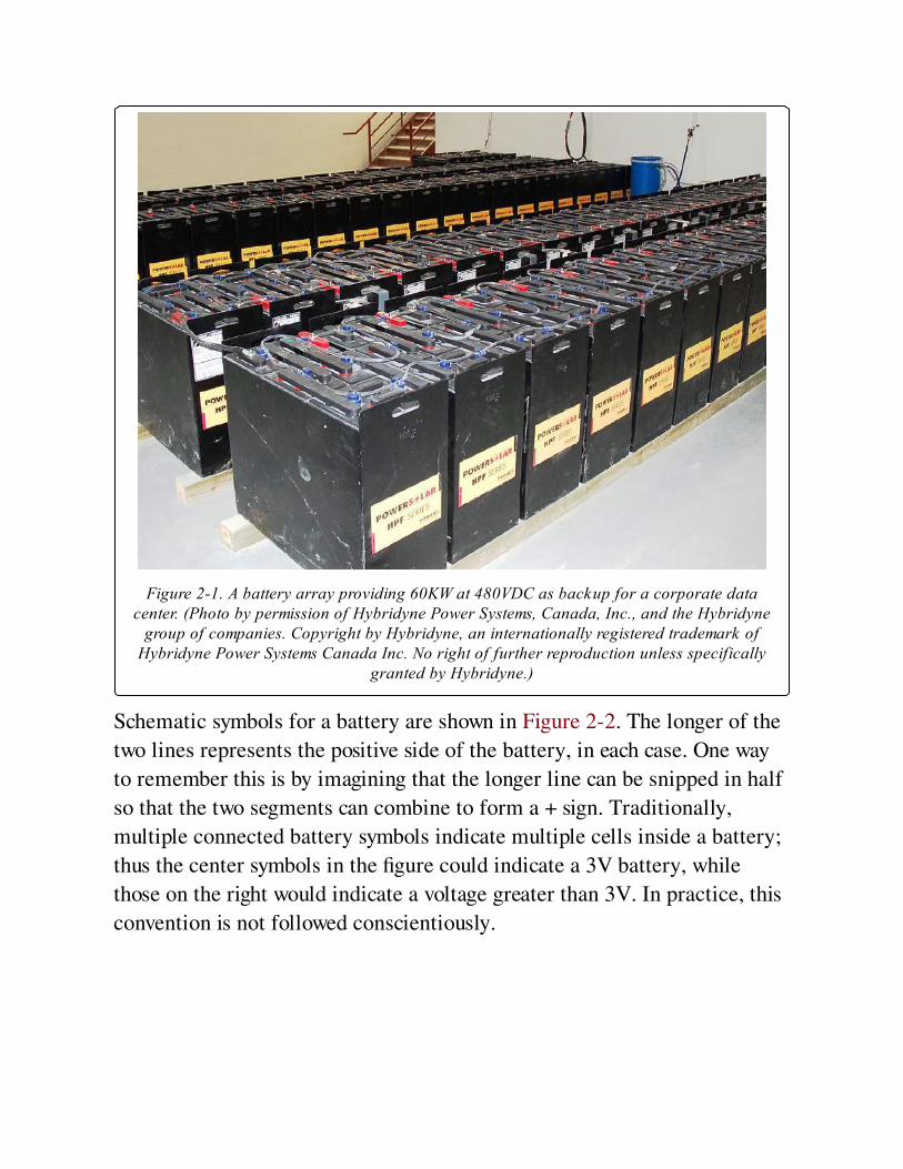
Figure 2-1. A battery array providing 60KW at 480VDC as backup for a corporate datacenter. (Photo by permission of Hybridyne Power Systems, Canada, Inc., and the Hybridyne
group of companies. Copyright by Hybridyne, an internationally registered trademark ofHybridyne Power Systems Canada Inc. No right of further reproduction unless specifically
granted by Hybridyne.)
Schematic symbols for a battery are shown in Figure 2-2. The longer of the
two lines represents the positive side of the battery, in each case. One way
to remember this is by imagining that the longer line can be snipped in half
so that the two segments can combine to form a + sign. Traditionally,
multiple connected battery symbols indicate multiple cells inside a battery;
thus the center symbols in the figure could indicate a 3V battery, while
those on the right would indicate a voltage greater than 3V. In practice, this
convention is not followed conscientiously.
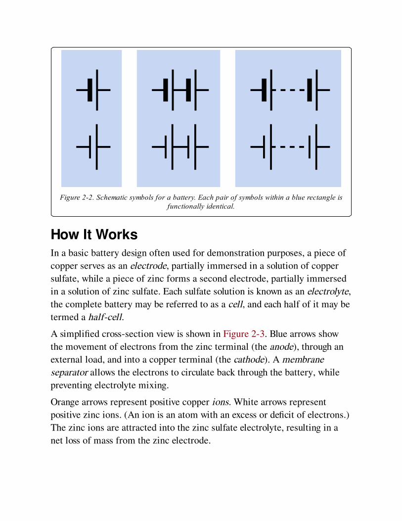
Figure 2-2. Schematic symbols for a battery. Each pair of symbols within a blue rectangle isfunctionally identical.
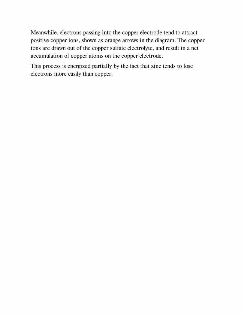
How It WorksIn a basic battery design often used for demonstration purposes, a piece of
copper serves as an electrode, partially immersed in a solution of copper
sulfate, while a piece of zinc forms a second electrode, partially immersed
in a solution of zinc sulfate. Each sulfate solution is known as an electrolyte,
the complete battery may be referred to as a cell, and each half of it may be
termed a half-cell.
A simplified cross-section view is shown in Figure 2-3. Blue arrows show
the movement of electrons from the zinc terminal (the anode), through an
external load, and into a copper terminal (the cathode). A membrane
separator allows the electrons to circulate back through the battery, while
preventing electrolyte mixing.
Orange arrows represent positive copper ions. White arrows represent
positive zinc ions. (An ion is an atom with an excess or deficit of electrons.)
The zinc ions are attracted into the zinc sulfate electrolyte, resulting in a
net loss of mass from the zinc electrode.
Meanwhile, electrons passing into the copper electrode tend to attract
positive copper ions, shown as orange arrows in the diagram. The copper
ions are drawn out of the copper sulfate electrolyte, and result in a net
accumulation of copper atoms on the copper electrode.
This process is energized partially by the fact that zinc tends to lose
electrons more easily than copper.

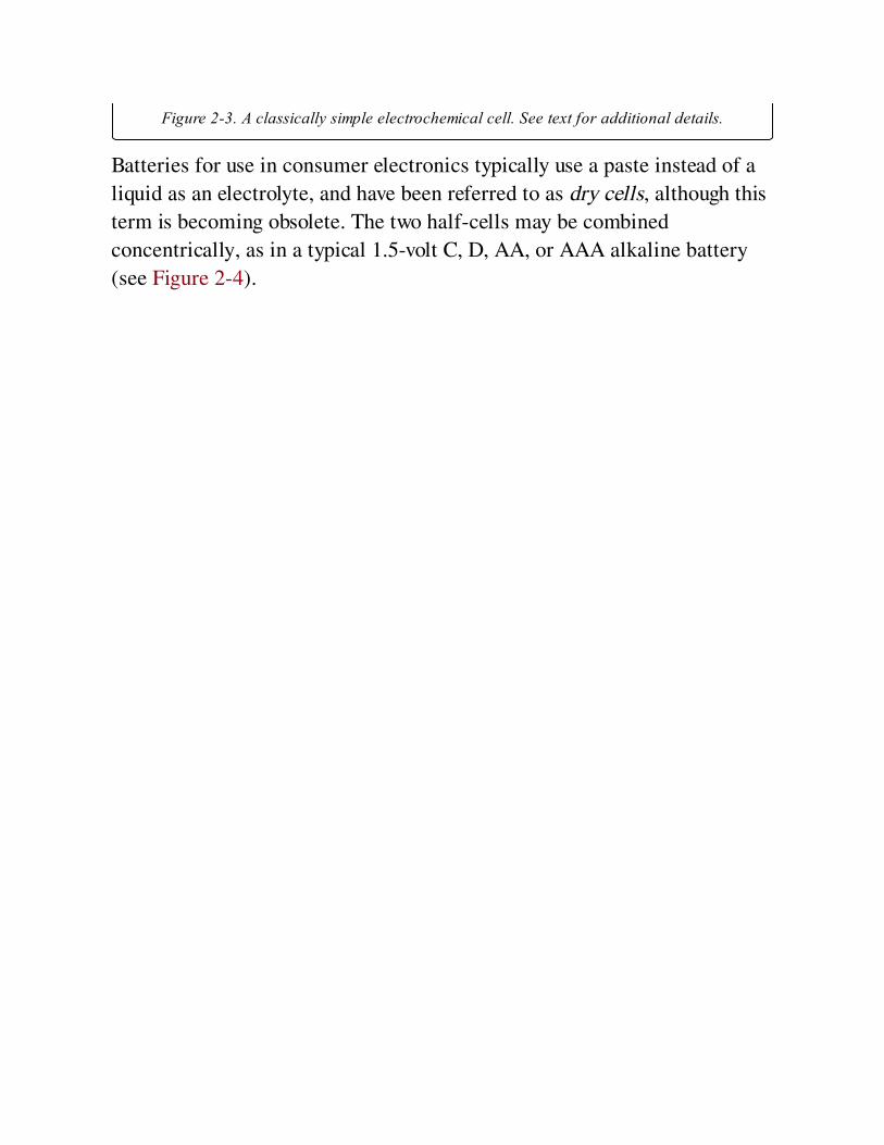
Figure 2-3. A classically simple electrochemical cell. See text for additional details.
Batteries for use in consumer electronics typically use a paste instead of a
liquid as an electrolyte, and have been referred to as dry cells, although this
term is becoming obsolete. The two half-cells may be combined
concentrically, as in a typical 1.5-volt C, D, AA, or AAA alkaline battery
(see Figure 2-4).
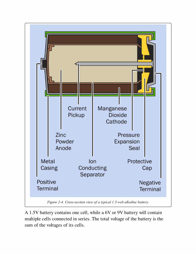
Figure 2-4. Cross-section view of a typical 1.5-volt alkaline battery.
A 1.5V battery contains one cell, while a 6V or 9V battery will contain
multiple cells connected in series. The total voltage of the battery is the
sum of the voltages of its cells.
Electrode TerminologyThe electrodes of a cell are often referred to as the anode and the cathode.
These terms are confusing because the electrons enter the anode inside the
cell and leave it outside the cell, while electrons enter the cathode from
outside the cell and leave it inside the cell. Thus, the anode is an electron
emitter if you look at it externally, but the cathode is an electron emitter if
you look at it internally.
Conventional current is imagined to flow in the opposite direction to
electrons, and therefore, outside the cell, this current flows from the
cathode to the anode, and from this perspective, the cathode can be thought
of as being “more positive” than the anode. To remember this, think of the
letter t in "cathode" as being a + sign, thus: ca+hode. In larger batteries, the
cathode is often painted or tagged red, while the anode may be painted or
tagged black or blue.
When a reusable battery is recharged, the flow of electrons reverses and the
anode and the cathode effectively trade places. Recognizing this, the
manufacturers of rechargeable batteries may refer to the more-positive
terminal as the anode. This creates additional confusion, exacerbated
further still by electronics manufacturers using the term "cathode" to
identify the end of a diode which must be “more negative”(i.e., at a lower
potential) than the opposite end.
To minimize the risk of errors, it is easiest to avoid the terms "anode" and
"cathode" when referring to batteries, and speak instead of the negative and
positive terminals. This encyclopedia uses the common convention of
reserving the term "cathode" to identify the "more negative" end of any
type of diode.
VariantsThree types of batteries exist.
1. Disposable batteries, properly (but infrequently) referred to as
primary cells. They are not reliably rechargeable because their
chemical reactions are not easily reversible.
2. Rechargeable batteries, properly (but infrequently) known as
secondary cells. They can be recharged by applying a voltage between
the terminals from an external source such as a battery charger. The
materials used in the battery, and the care with which the battery is
maintained, will affect the rate at which chemical degradation of the
electrodes gradually occurs as it is recharged repeatedly. Either way,
the number of charge/discharge cycles is limited.
3. Fuel Cells require an inflow of a reactive gas such as hydrogen to
maintain an electrochemical reaction over a long period. They are
beyond the scope of this encyclopedia.
A large capacitor may be substituted for a battery for some applications,
although it has a lower energy density and will be more expensive to
manufacture than a battery of equivalent power storage. A capacitor charges
and discharges much more rapidly than a battery because no chemical
reactions are involved, but a battery sustains its voltage much more
successfully during the discharge cycle. See Figure 2-5.
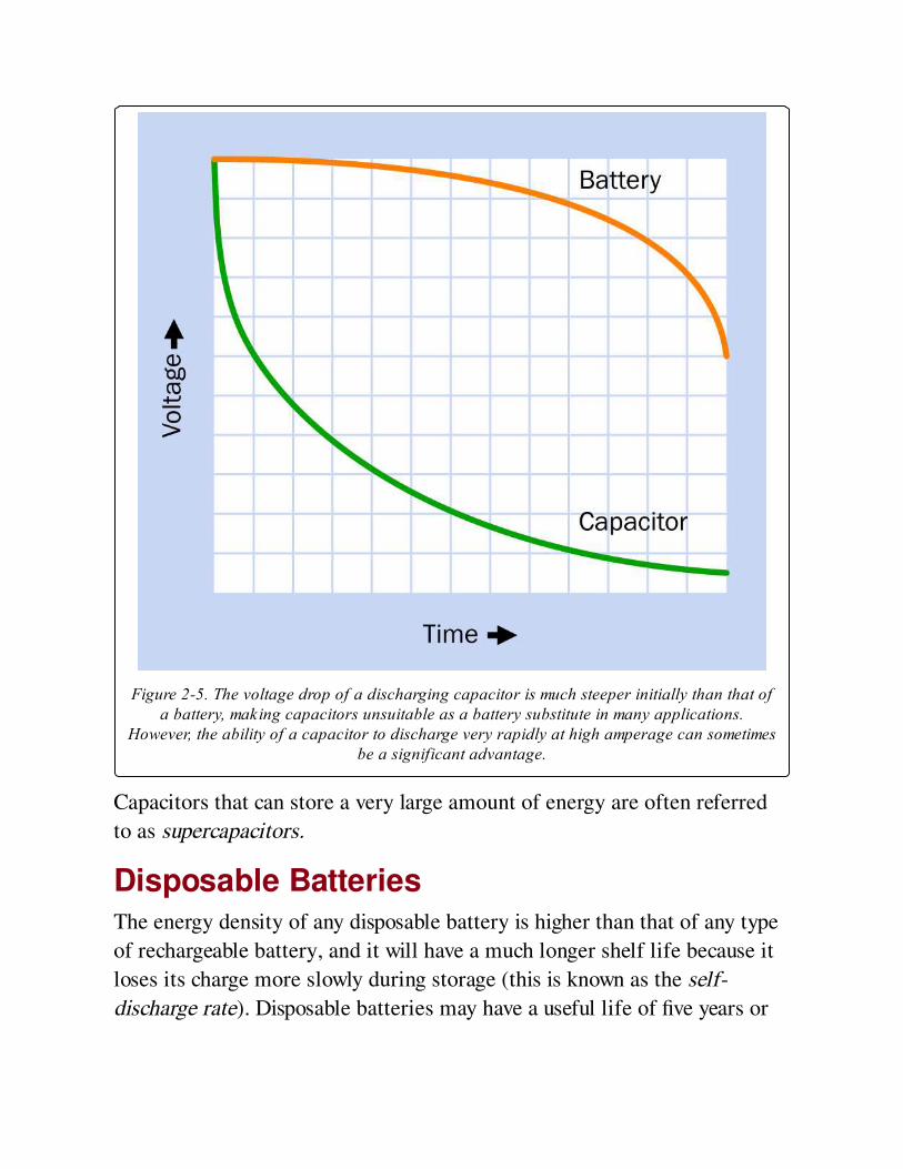
Figure 2-5. The voltage drop of a discharging capacitor is much steeper initially than that ofa battery, making capacitors unsuitable as a battery substitute in many applications.
However, the ability of a capacitor to discharge very rapidly at high amperage can sometimesbe a significant advantage.
Capacitors that can store a very large amount of energy are often referred
to as supercapacitors.
Disposable BatteriesThe energy density of any disposable battery is higher than that of any type
of rechargeable battery, and it will have a much longer shelf life because it
loses its charge more slowly during storage (this is known as the self-
discharge rate). Disposable batteries may have a useful life of five years or
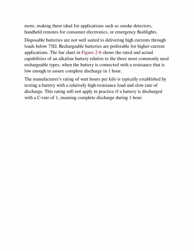
more, making them ideal for applications such as smoke detectors,
handheld remotes for consumer electronics, or emergency flashlights.
Disposable batteries are not well suited to delivering high currents through
loads below 75Ω. Rechargeable batteries are preferable for higher-current
applications. The bar chart in Figure 2-6 shows the rated and actual
capabilities of an alkaline battery relative to the three most commonly used
rechargeable types, when the battery is connected with a resistance that is
low enough to assure complete discharge in 1 hour.
The manufacturer’s rating of watt hours per kilo is typically established by
testing a battery with a relatively high-resistance load and slow rate of
discharge. This rating will not apply in practice if a battery is discharged
with a C-rate of 1, meaning complete discharge during 1 hour.
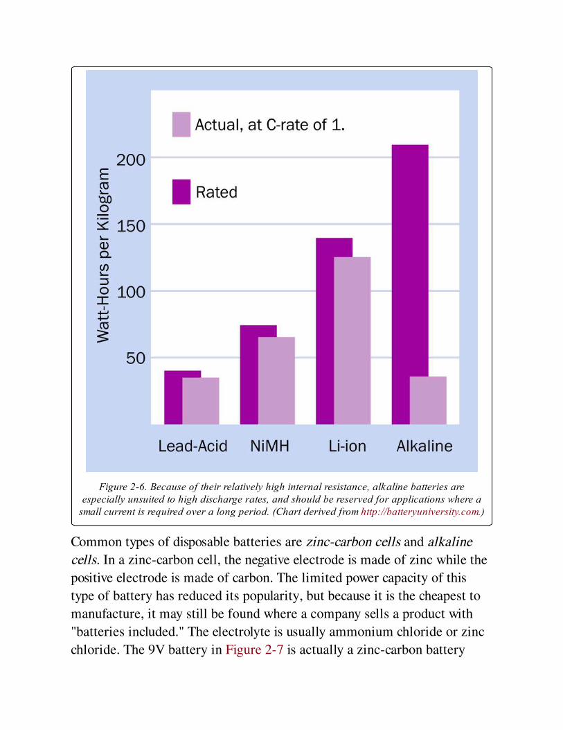
Figure 2-6. Because of their relatively high internal resistance, alkaline batteries areespecially unsuited to high discharge rates, and should be reserved for applications where a
small current is required over a long period. (Chart derived from http://batteryuniversity.com.)
Common types of disposable batteries are zinc-carbon cells and alkaline
cells. In a zinc-carbon cell, the negative electrode is made of zinc while the
positive electrode is made of carbon. The limited power capacity of this
type of battery has reduced its popularity, but because it is the cheapest to
manufacture, it may still be found where a company sells a product with
"batteries included." The electrolyte is usually ammonium chloride or zinc
chloride. The 9V battery in Figure 2-7 is actually a zinc-carbon battery
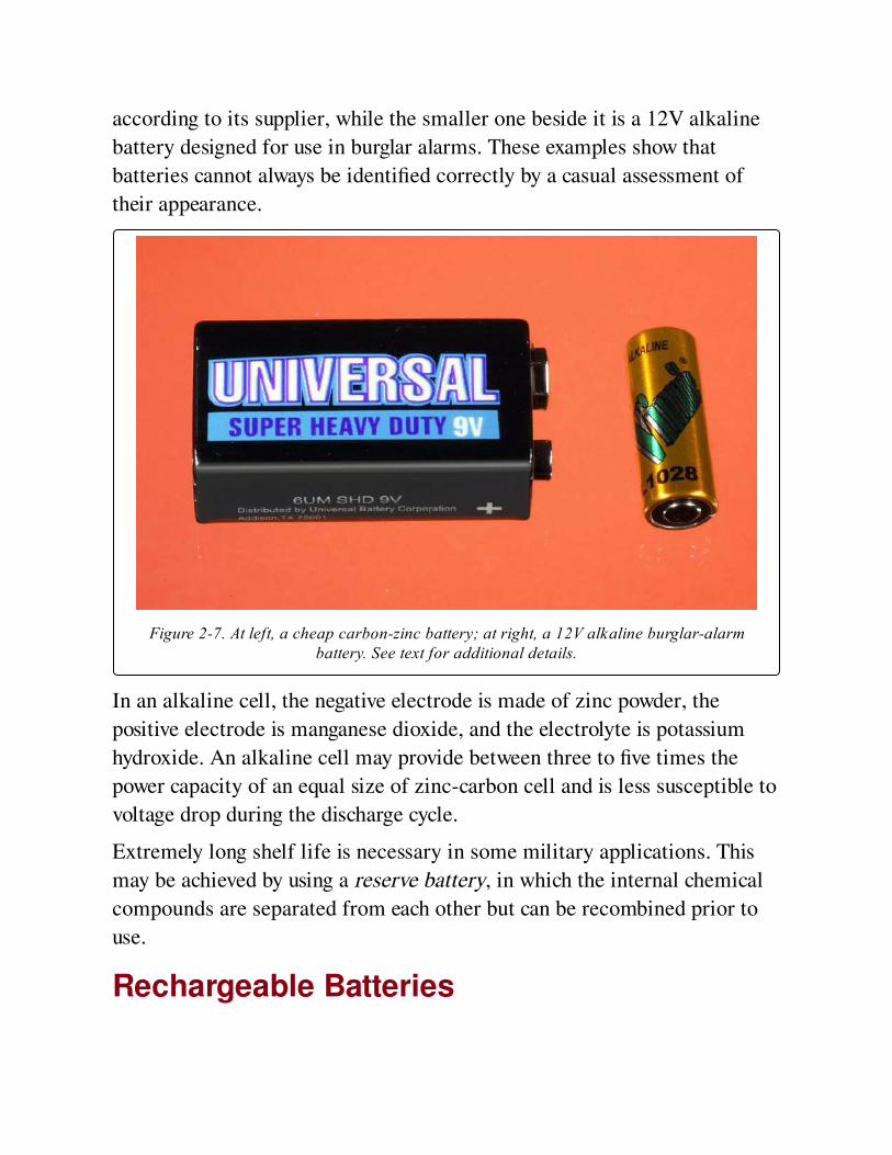
according to its supplier, while the smaller one beside it is a 12V alkaline
battery designed for use in burglar alarms. These examples show that
batteries cannot always be identified correctly by a casual assessment of
their appearance.
Figure 2-7. At left, a cheap carbon-zinc battery; at right, a 12V alkaline burglar-alarmbattery. See text for additional details.
In an alkaline cell, the negative electrode is made of zinc powder, the
positive electrode is manganese dioxide, and the electrolyte is potassium
hydroxide. An alkaline cell may provide between three to five times the
power capacity of an equal size of zinc-carbon cell and is less susceptible to
voltage drop during the discharge cycle.
Extremely long shelf life is necessary in some military applications. This
may be achieved by using a reserve battery, in which the internal chemical
compounds are separated from each other but can be recombined prior to
use.
Rechargeable Batteries
Commonly used types are lead-acid, nickel cadmium (abbreviated NiCad or
NiCd), nickel-metal hydride (abbreviated NiMH), lithium-ion (abbreviated
Li-ion), and lithium-ion polymer.
Lead-acid batteries have existed for more than a century and are still widely
used in vehicles, burglar alarms, emergency lighting, and large power
backup systems. The early design was described as flooded; it used a
solution of sulfuric acid (generically referred to as battery acid) as its
electrolyte, required the addition of distilled water periodically, and was
vented to allow gas to escape. The venting also allowed acid to spill if the
battery was tipped over.
The valve-regulated lead-acid battery (VRLA) has become widely used,
requiring no addition of water to the cells. A pressure relief valve is
included, but will not leak electrolyte, regardless of the position of the
battery. VRLA batteries are preferred for uninterruptible power supplies for
data-processing equipment, and are found in automobiles and in electric
wheelchairs, as their low gas output and security from spillage increases
their safety factor.
VRLA batteries can be divided into two types: absorbed glass mat (AGM)
and gel batteries. The electrolyte in an AGM is absorbed in a fiber-glass
mat separator. In a gel cell, the electrolyte is mixed with silica dust to form
an immobilized gel.
The term deep cycle battery may be applied to a lead-acid battery and
indicates that it should be more tolerant of discharge to a low level—
perhaps 20 percent of its full charge (although manufacturers may claim a
lower number). The plates in a standard lead-acid battery are composed of a
lead sponge, which maximizes the surface area available to acid in the
battery but can be physically abraded by deep discharge. In a deep cycle
battery, the plates are solid. This means they are more robust, but are less
able to supply high amperage. If a deep-discharge battery is used to start an
internal combustion engine, the battery should be larger than a regular lead-
acid battery used for this purpose.
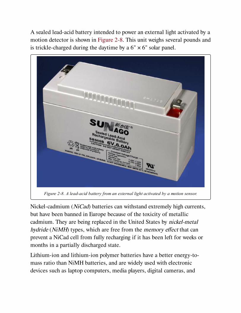
A sealed lead-acid battery intended to power an external light activated by a
motion detector is shown in Figure 2-8. This unit weighs several pounds and
is trickle-charged during the daytime by a 6" × 6" solar panel.
Figure 2-8. A lead-acid battery from an external light activated by a motion sensor.
Nickel-cadmium (NiCad) batteries can withstand extremely high currents,
but have been banned in Europe because of the toxicity of metallic
cadmium. They are being replaced in the United States by nickel-metal
hydride (NiMH) types, which are free from the memory effect that can
prevent a NiCad cell from fully recharging if it has been left for weeks or
months in a partially discharged state.
Lithium-ion and lithium-ion polymer batteries have a better energy-to-
mass ratio than NiMH batteries, and are widely used with electronic
devices such as laptop computers, media players, digital cameras, and
cellular phones. Large arrays of lithium batteries have also been used in
some electric vehicles.
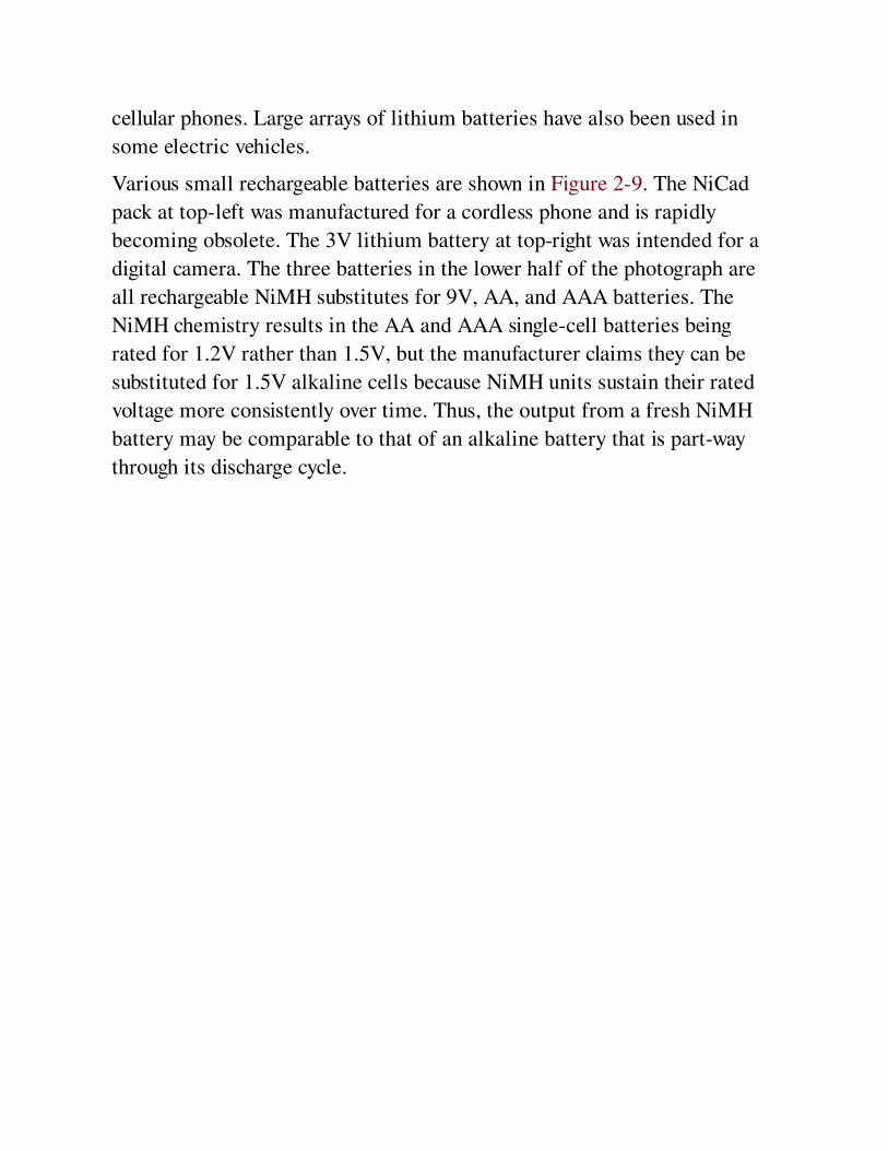
Various small rechargeable batteries are shown in Figure 2-9. The NiCad
pack at top-left was manufactured for a cordless phone and is rapidly
becoming obsolete. The 3V lithium battery at top-right was intended for a
digital camera. The three batteries in the lower half of the photograph are
all rechargeable NiMH substitutes for 9V, AA, and AAA batteries. The
NiMH chemistry results in the AA and AAA single-cell batteries being
rated for 1.2V rather than 1.5V, but the manufacturer claims they can be
substituted for 1.5V alkaline cells because NiMH units sustain their rated
voltage more consistently over time. Thus, the output from a fresh NiMH
battery may be comparable to that of an alkaline battery that is part-way
through its discharge cycle.
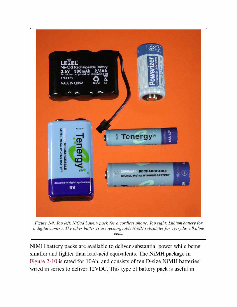
Figure 2-9. Top left: NiCad battery pack for a cordless phone. Top right: Lithium battery fora digital camera. The other batteries are rechargeable NiMH substitutes for everyday alkaline
cells.
NiMH battery packs are available to deliver substantial power while being
smaller and lighter than lead-acid equivalents. The NiMH package in
Figure 2-10 is rated for 10Ah, and consists of ten D-size NiMH batteries
wired in series to deliver 12VDC. This type of battery pack is useful in
robotics and other applications where a small motor-driven device must
have free mobility.
Figure 2-10. This NiMH battery pack is rated at 10Ah and delivers 12 volts from ten D-sizecells wired in series.
Values
AmperageThe current delivered by a battery will be largely determined by the
resistance of the external load placed between its terminals. However,
because ion transfer must occur inside the battery to complete the circuit,
the current will also be limited by the internal resistance of the battery.
This should be thought of as an active part of the circuit.
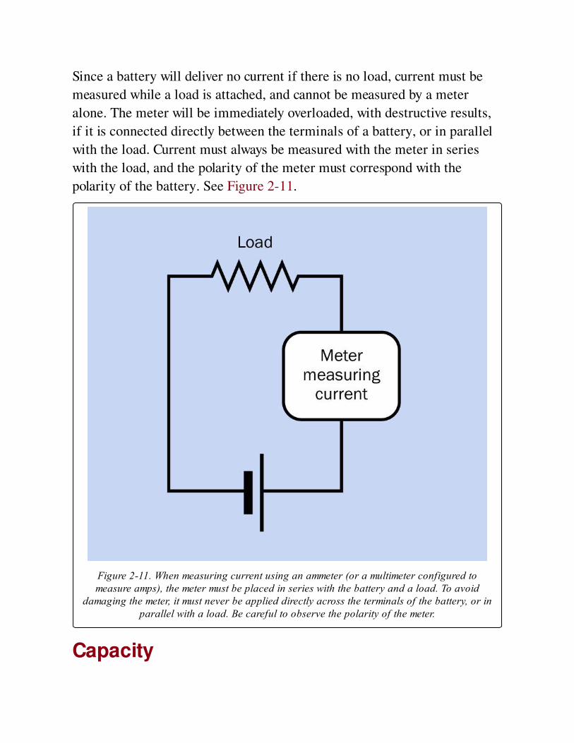
Since a battery will deliver no current if there is no load, current must be
measured while a load is attached, and cannot be measured by a meter
alone. The meter will be immediately overloaded, with destructive results,
if it is connected directly between the terminals of a battery, or in parallel
with the load. Current must always be measured with the meter in series
with the load, and the polarity of the meter must correspond with the
polarity of the battery. See Figure 2-11.
Figure 2-11. When measuring current using an ammeter (or a multimeter configured tomeasure amps), the meter must be placed in series with the battery and a load. To avoid
damaging the meter, it must never be applied directly across the terminals of the battery, or inparallel with a load. Be careful to observe the polarity of the meter.
Capacity
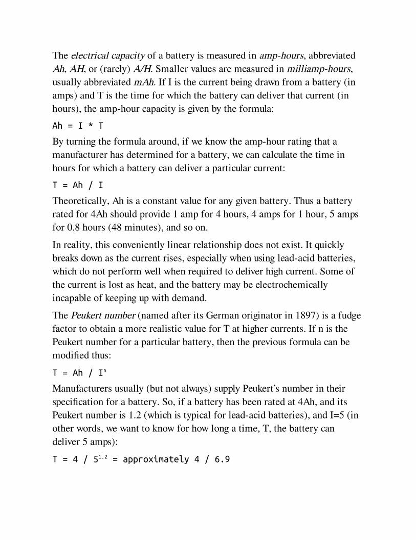
The electrical capacity of a battery is measured in amp-hours, abbreviated
Ah, AH, or (rarely) A/H. Smaller values are measured in milliamp-hours,
usually abbreviated mAh. If I is the current being drawn from a battery (in
amps) and T is the time for which the battery can deliver that current (in
hours), the amp-hour capacity is given by the formula:
Ah = I * T
By turning the formula around, if we know the amp-hour rating that a
manufacturer has determined for a battery, we can calculate the time in
hours for which a battery can deliver a particular current:
T = Ah / I
Theoretically, Ah is a constant value for any given battery. Thus a battery
rated for 4Ah should provide 1 amp for 4 hours, 4 amps for 1 hour, 5 amps
for 0.8 hours (48 minutes), and so on.
In reality, this conveniently linear relationship does not exist. It quickly
breaks down as the current rises, especially when using lead-acid batteries,
which do not perform well when required to deliver high current. Some of
the current is lost as heat, and the battery may be electrochemically
incapable of keeping up with demand.
The Peukert number (named after its German originator in 1897) is a fudge
factor to obtain a more realistic value for T at higher currents. If n is the
Peukert number for a particular battery, then the previous formula can be
modified thus:
T = Ah / In
Manufacturers usually (but not always) supply Peukert’s number in their
specification for a battery. So, if a battery has been rated at 4Ah, and its
Peukert number is 1.2 (which is typical for lead-acid batteries), and I=5 (in
other words, we want to know for how long a time, T, the battery can
deliver 5 amps):
T = 4 / 51.2 = approximately 4 / 6.9

This is about 0.58 hours, or 35 minutes—much less than the 48 minutes
that the original formula suggested.
Unfortunately, there is a major problem with this calculation. In Peukert’s
era, the amp-hour rating for a battery was established by a manufacturer by
drawing 1A and measuring the time during which the battery was capable of
delivering that current. If it took 4 hours, the battery was rated at 4Ah.
Today, this measurement process is reversed. Instead of specifying the
current to be drawn from the battery, a manufacturer specifies the time for
which the test will run, then finds the maximum current the battery can
deliver for that time. Often, the time period is 20 hours. Therefore, if a
battery has a modern 4Ah rating, testing has probably determined that it
delivered 0.2A for 20 hours, not 1A for 4 hours, which would have been the
case in Peukert’s era.
This is a significant distinction, because the same battery that can deliver
0.2A for 20 hours will not be able to satisfy the greater demand of 1A for 4
hours. Therefore the old amp-hour rating and the modern amp-hour rating
mean different things and are incompatible. If the modern Ah rating is
inserted into the old Peukert formula (as it was above), the answer will be
misleadingly optimistic. Unfortunately, this fact is widely disregarded.
Peukert’s formula is still being used, and the performance of many batteries
is being evaluated incorrectly.
The formula has been revised (initially by Chris Gibson of SmartGauge
Electronics) to take into account the way in which Ah ratings are
established today. Suppose that AhM is the modern rating for the battery’s
capacity in amp-hours, H is the duration in hours for which the battery was
tested when the manufacturer calibrated it, n is Peukert’s number (supplied
by the manufacturer) as before, and I is the current you hope to draw from
the battery. This is the revised formula to determine T:
T = H * (AhM / (I * H)n )
How do we know the value for H? Most (not all) manufacturers will supply
this number in their battery specification. Alternatively, and confusingly,
they may use the term C-rate, which can be defined as 1/H. This means you
can easily get the value for H if you know the C-rate:
H = 1 / C-rate
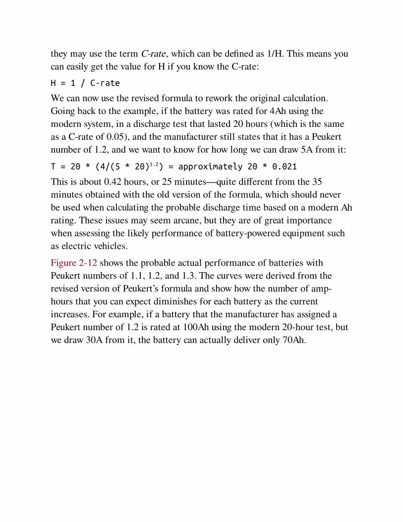
We can now use the revised formula to rework the original calculation.
Going back to the example, if the battery was rated for 4Ah using the
modern system, in a discharge test that lasted 20 hours (which is the same
as a C-rate of 0.05), and the manufacturer still states that it has a Peukert
number of 1.2, and we want to know for how long we can draw 5A from it:
T = 20 * (4/(5 * 20)1.2) = approximately 20 * 0.021
This is about 0.42 hours, or 25 minutes—quite different from the 35
minutes obtained with the old version of the formula, which should never
be used when calculating the probable discharge time based on a modern Ah
rating. These issues may seem arcane, but they are of great importance
when assessing the likely performance of battery-powered equipment such
as electric vehicles.
Figure 2-12 shows the probable actual performance of batteries with
Peukert numbers of 1.1, 1.2, and 1.3. The curves were derived from the
revised version of Peukert’s formula and show how the number of amp-
hours that you can expect diminishes for each battery as the current
increases. For example, if a battery that the manufacturer has assigned a
Peukert number of 1.2 is rated at 100Ah using the modern 20-hour test, but
we draw 30A from it, the battery can actually deliver only 70Ah.

Figure 2-12. Actual amp-hour performance that should be expected from three batteries ofPeukert numbers 1.1, 1.2, and 1.3 when they discharge currents ranging from 5 to 30 amps,assuming that the manufacturer has rated each battery at 100Ah using the modern system,
which usually entails a 20-hour test (a C-rate of 0.05).
One additional factor: For any rechargeable battery, the Peukert number
gradually increases with age, as the battery deteriorates chemically.
VoltageThe rated voltage of a fully charged battery is known as the open circuit
voltage (abbreviated OCV or Voc), defined as the potential that exists when
no load is imposed between the terminals. Because the internal resistance
of a volt meter (or a multimeter, when it is used to measure DC volts) is
very high, it can be connected directly between the battery terminals with
no other load present, and will show the OCV quite accurately, without risk
of damage to the meter. A fully charged 12-volt car battery may have an
OCV of about 12.6 volts, while a fresh 9-volt alkaline battery typically has
an OCV of about 9.5 volts. Be extremely careful to set a multimeter to
measure DC volts before connecting it across the battery. Usually this
entails plugging the wire from the red probe into a socket separately
reserved for measuring voltage, not amperage.
The voltage delivered by a battery will be pulled down significantly when a
load is applied to it, and will decrease further as time passes during a
discharge cycle. For these reasons, a voltage regulator is required when a
battery powers components such as digital integrated circuit chips, which
do not tolerate a wide variation in voltage.
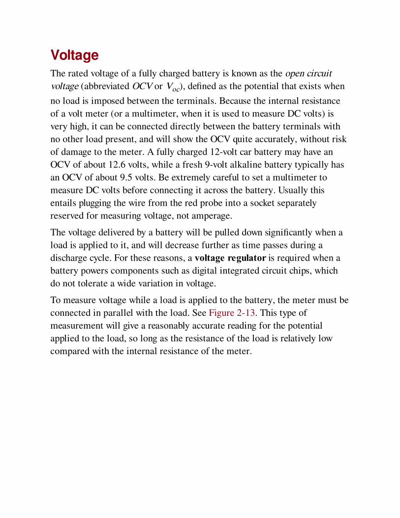
To measure voltage while a load is applied to the battery, the meter must be
connected in parallel with the load. See Figure 2-13. This type of
measurement will give a reasonably accurate reading for the potential
applied to the load, so long as the resistance of the load is relatively low
compared with the internal resistance of the meter.
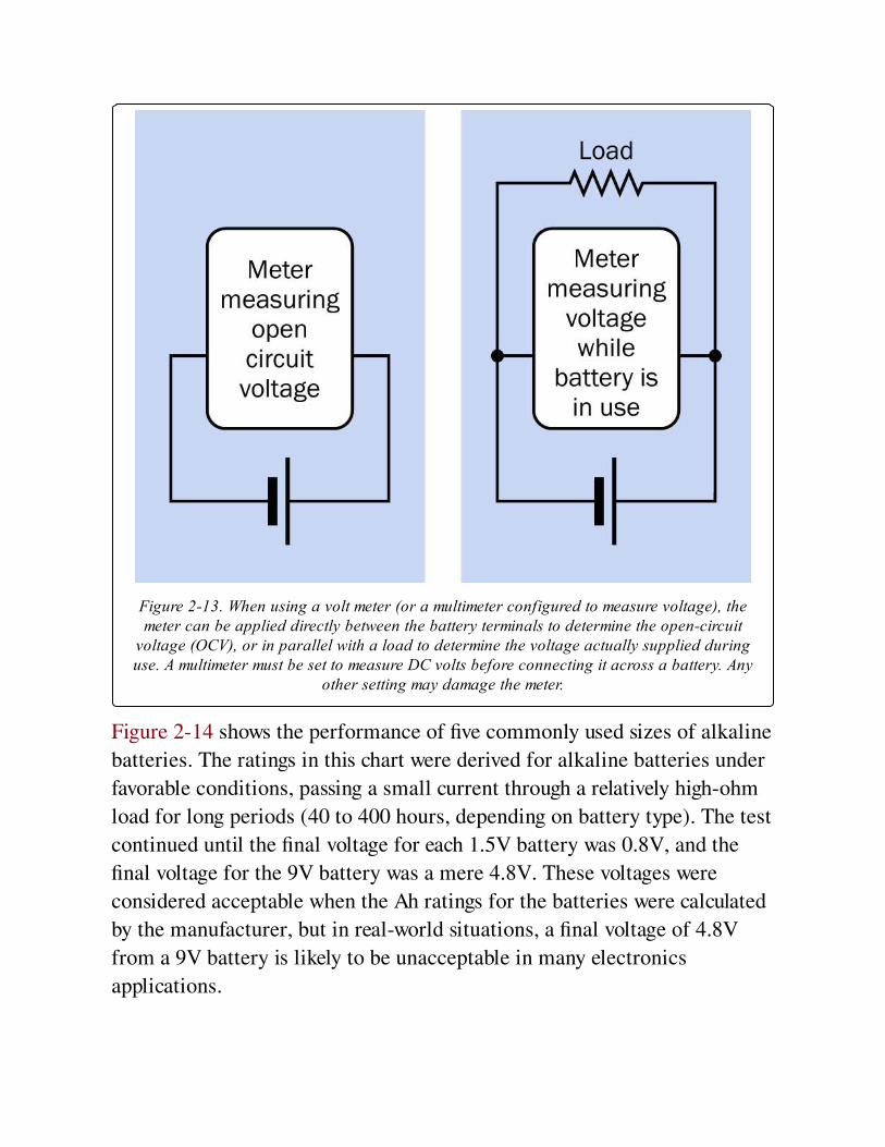
Figure 2-13. When using a volt meter (or a multimeter configured to measure voltage), themeter can be applied directly between the battery terminals to determine the open-circuit
voltage (OCV), or in parallel with a load to determine the voltage actually supplied duringuse. A multimeter must be set to measure DC volts before connecting it across a battery. Any
other setting may damage the meter.
Figure 2-14 shows the performance of five commonly used sizes of alkaline
batteries. The ratings in this chart were derived for alkaline batteries under
favorable conditions, passing a small current through a relatively high-ohm
load for long periods (40 to 400 hours, depending on battery type). The test
continued until the final voltage for each 1.5V battery was 0.8V, and the
final voltage for the 9V battery was a mere 4.8V. These voltages were
considered acceptable when the Ah ratings for the batteries were calculated
by the manufacturer, but in real-world situations, a final voltage of 4.8V
from a 9V battery is likely to be unacceptable in many electronics
applications.
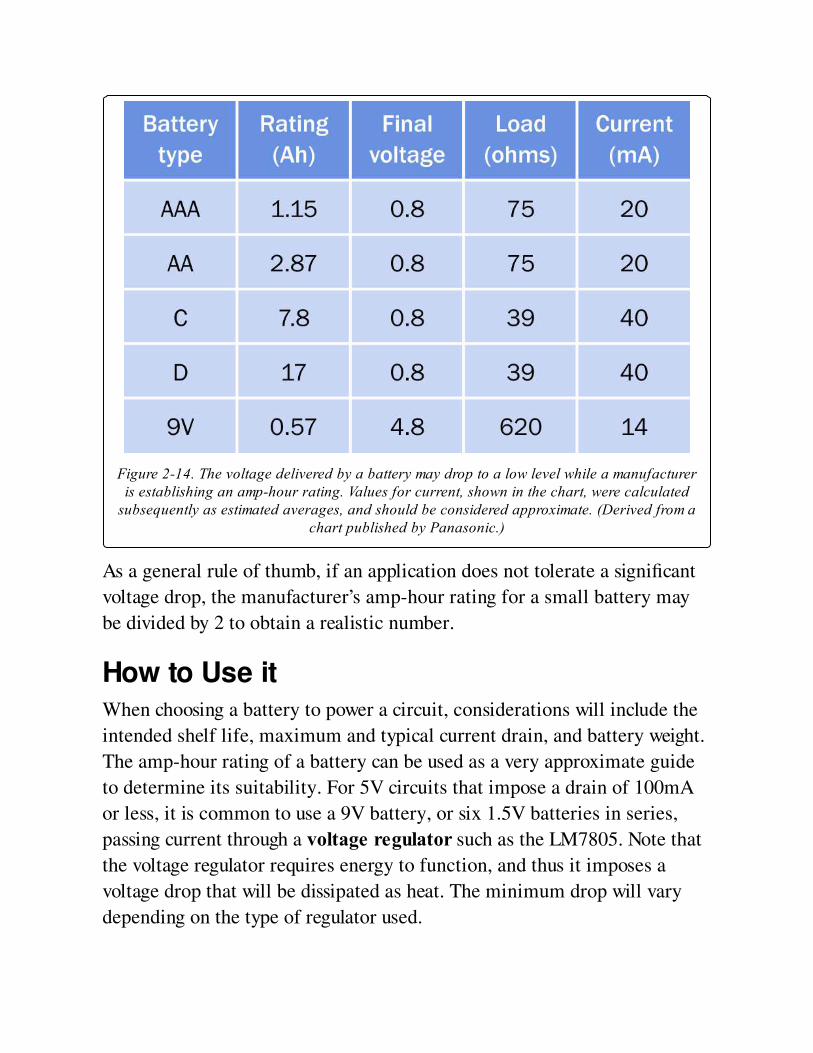
Figure 2-14. The voltage delivered by a battery may drop to a low level while a manufactureris establishing an amp-hour rating. Values for current, shown in the chart, were calculated
subsequently as estimated averages, and should be considered approximate. (Derived from achart published by Panasonic.)
As a general rule of thumb, if an application does not tolerate a significant
voltage drop, the manufacturer’s amp-hour rating for a small battery may
be divided by 2 to obtain a realistic number.
How to Use itWhen choosing a battery to power a circuit, considerations will include the
intended shelf life, maximum and typical current drain, and battery weight.
The amp-hour rating of a battery can be used as a very approximate guide
to determine its suitability. For 5V circuits that impose a drain of 100mA
or less, it is common to use a 9V battery, or six 1.5V batteries in series,
passing current through a voltage regulator such as the LM7805. Note that
the voltage regulator requires energy to function, and thus it imposes a
voltage drop that will be dissipated as heat. The minimum drop will vary
depending on the type of regulator used.
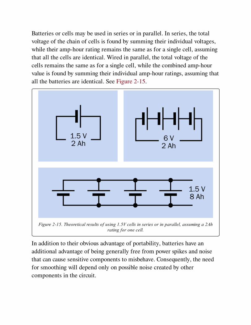
Batteries or cells may be used in series or in parallel. In series, the total
voltage of the chain of cells is found by summing their individual voltages,
while their amp-hour rating remains the same as for a single cell, assuming
that all the cells are identical. Wired in parallel, the total voltage of the
cells remains the same as for a single cell, while the combined amp-hour
value is found by summing their individual amp-hour ratings, assuming that
all the batteries are identical. See Figure 2-15.
Figure 2-15. Theoretical results of using 1.5V cells in series or in parallel, assuming a 2Ahrating for one cell.
In addition to their obvious advantage of portability, batteries have an
additional advantage of being generally free from power spikes and noise
that can cause sensitive components to misbehave. Consequently, the need
for smoothing will depend only on possible noise created by other
components in the circuit.

Motors or other inductive loads draw an initial surge that can be many
times the current that they use after they start running. A battery must be
chosen that will tolerate this surge without damage.
Because of the risk of fire, United States airline regulations limit the amp-
hour capacity of lithium-ion batteries in any electronic device in carry-on
or checked passenger baggage. If a device may be carried frequently as
passenger baggage (for example, emergency medical equipment), NiMH
batteries are preferred.
What Can Go Wrong
Short Circuits: Overheating and FireA battery capable of delivering significant current can overheat, catch fire, or
even explode if it is short-circuited. Dropping a wrench across the terminals
of a car battery will result in a bright flash, a loud noise, and some molten
metal. Even a 1.5-volt alkaline AA battery can become too hot to touch if
its terminals are shorted together. (Never try this with a rechargeable
battery, which has a much lower internal resistance, allowing much higher
flow of current.) Lithium-ion batteries are particularly dangerous, and
almost always are packaged with a current-limiting component that should
not be disabled. A short-circuited lithium battery can explode.
If a battery pack is used as a cheap and simple workbench DC power supply,
a fuse or circuit breaker should be included. Any device that uses significant
battery power should be fused.
Diminished Performance Caused by ImproperRechargingMany types of batteries require a precisely measured charging voltage and a
cycle that ends automatically when the battery is fully charged. Failure to
observe this protocol can result in chemical damage that may not be
reversible. A charger should be used that is specifically intended for the type
of battery. A detailed comparison of chargers and batteries is outside the
scope of this encyclopedia.
Complete Discharge of Lead-Acid BatteryComplete or near-complete discharge of a lead-acid battery will
significantly shorten its life (unless it is specifically designed for deep-cycle
use—although even then, more than an 80% discharge is not generally
recommended).
Inadequate CurrentChemical reactions inside a battery occur more slowly at low temperatures.
Consequently, a cold battery cannot deliver as much current as a warm
battery. For this reason, in winter weather, a car battery is less able to
deliver high current. At the same time, because engine oil becomes more
viscous as the temperature falls, the starter motor will demand more
current to turn the engine. This combination of factors explains the
tendency of car batteries to fail on cold winter mornings.
Incorrect PolarityIf a battery charger or generator is connected with a battery with incorrect
polarity, the battery may experience permanent damage. The fuse or circuit
breaker in a charger may prevent this from occurring and may also prevent
damage to the charger, but this cannot be guaranteed.
If two high-capacity batteries are connected with opposite polarity (as may
happen when a clumsy attempt is made to start a stalled car with jumper
cables), the results may be explosive. Never lean over a car battery when
attaching cables to it, and ideally, wear eye protection.
Reverse ChargingReverse charging can occur when a battery becomes completely discharged
while it is wired (correctly) in series with other batteries that are still
delivering current. In the upper section of the schematic at Figure 2-16 two

healthy 6V batteries, in series, are powering a resistive load. The battery on
the left applies a potential of 6 volts to the battery on the right, which adds
its own 6 volts to create a full 12 volts across the load. The red and blue
lines indicate volt meter leads, and the numbers show the reading that
should be observed on the meter.
In the second schematic, the battery on the left has become exhausted and
is now a "dead weight" in the circuit, indicated by its gray color. The battery
on the right still sustains a 6-volt potential. If the internal resistance of the
dead battery is approximately 1 ohm and the resistance of the load is
approximately 20 ohms, the potential across the dead battery will be about
0.3 volts, in the opposite direction to its normal charged voltage. Reverse
charging will result and can damage the battery. To avoid this problem, a
battery pack containing multiple cells should never be fully discharged.
SulfurizationWhen a lead-acid battery is partially or completely discharged and is
allowed to remain in that state, sulfur tends to build up on its metal plates.
The sulfur gradually tends to harden, forming a barrier against the
electrochemical reactions that are necessary to recharge the battery. For
this reason, lead-acid batteries should not be allowed to sit for long periods
in a discharged condition. Anecdotal evidence suggests that even a very
small trickle-charging current can prevent sulfurization, which is why some
people recommend attaching a small solar panel to a battery that is seldom
used—for example, on a sail boat, where the sole function of the battery is
to start an auxiliary engine when there is insufficient wind.
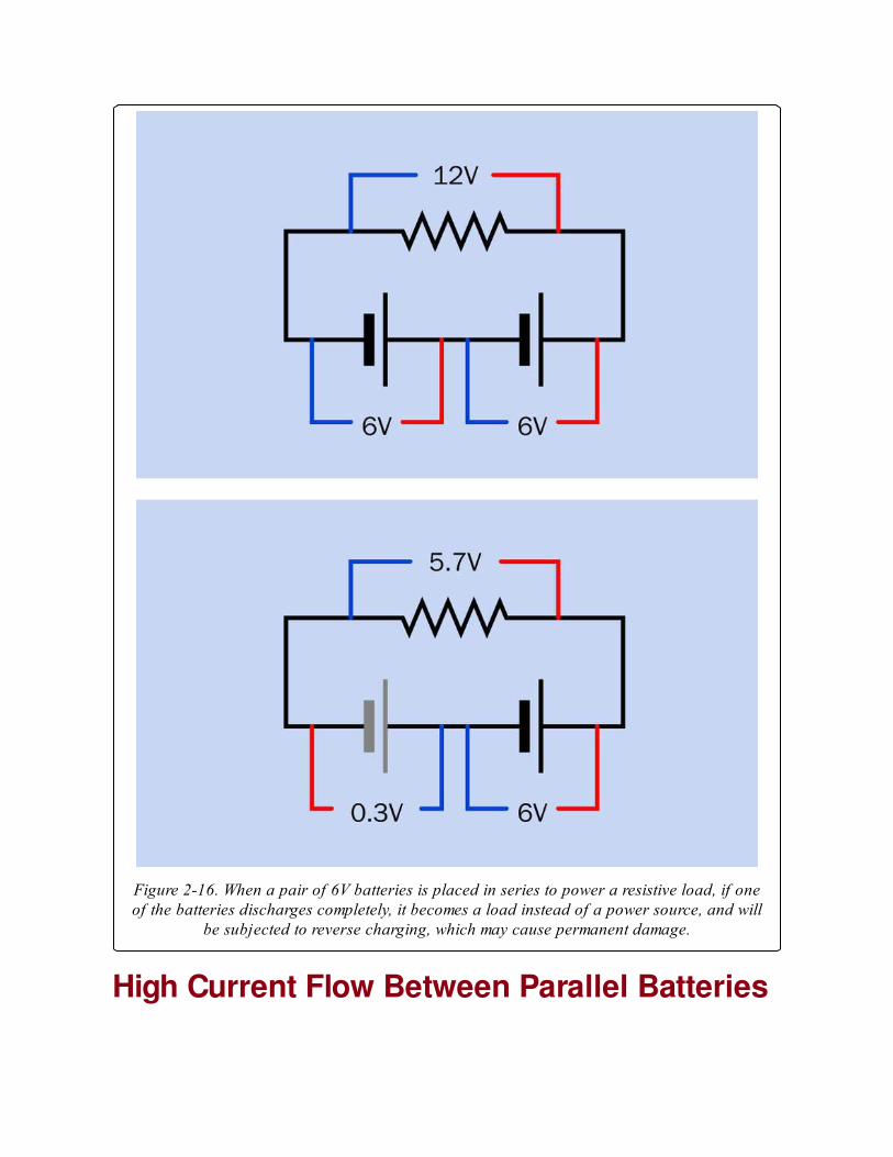
Figure 2-16. When a pair of 6V batteries is placed in series to power a resistive load, if oneof the batteries discharges completely, it becomes a load instead of a power source, and will
be subjected to reverse charging, which may cause permanent damage.
High Current Flow Between Parallel Batteries

If two batteries are connected in parallel, with correct polarity, but one of
them is fully charged while the other is not, the charged battery will attempt
to recharge its neighbor. Because the batteries are wired directly together,
the current will be limited only by their internal resistance and the
resistance of the cables connecting them. This may lead to overheating and
possible damage. The risk becomes more significant when linking batteries
that have high Ah ratings. Ideally they should be protected from one another
by high-current fuses.
Chapter 3. jumper
power > connection > jumper
A jumper may also be referred to as a jumper socket or a shunt. A jumper should not be
confused with jumper wires, which are not considered components for the purposes of this
encyclopedia.
Other related components
switch (See Chapter 6)
What It DoesA jumper is a low-cost substitute for a switch, where a connection has to be
made (or unmade) only a few times during the lifetime of a product.
Typically it allows a function or feature on a circuit board to be set on a
semipermanent basis, often at the time of manufacture. A DIP switch
performs the same function more conveniently. See DIP.
There is no standardized schematic symbol to represent a jumper.
How It WorksA jumper is a very small rectangular plastic tab containing two (or
sometimes more) metal sockets usually spaced either 0.1" or 2mm apart.
The sockets are connected electrically inside the tab, so that when they are
pushed over two (or more) pins that have been installed on a circuit board
for this purpose, the jumper shorts the pins together. The pins are usually
0.025" square and are often part of a header that is soldered into the board.
In a parts catalogue, jumpers may be found in a section titled "Headers and
Wire Housings" or similar.
Three jumpers are shown in Figure 3-1. The blue one contains two sockets
spaced 0.1" and is deep enough to enclose the pins completely. The red one
contains two sockets spaced 2mm and may allow the tips of the pins to
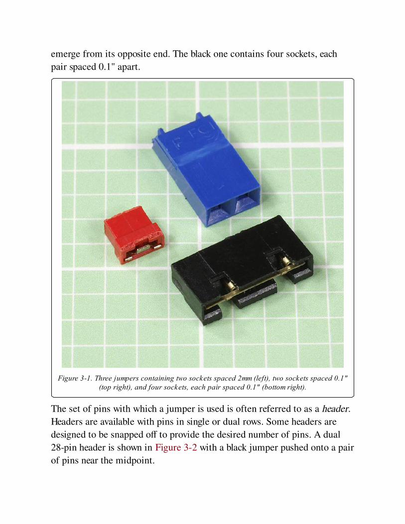
emerge from its opposite end. The black one contains four sockets, each
pair spaced 0.1" apart.
Figure 3-1. Three jumpers containing two sockets spaced 2mm (left), two sockets spaced 0.1"(top right), and four sockets, each pair spaced 0.1" (bottom right).
The set of pins with which a jumper is used is often referred to as a header.
Headers are available with pins in single or dual rows. Some headers are
designed to be snapped off to provide the desired number of pins. A dual
28-pin header is shown in Figure 3-2 with a black jumper pushed onto a pair
of pins near the midpoint.
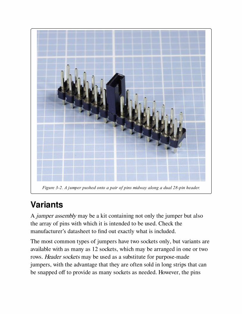
Figure 3-2. A jumper pushed onto a pair of pins midway along a dual 28-pin header.
VariantsA jumper assembly may be a kit containing not only the jumper but also
the array of pins with which it is intended to be used. Check the
manufacturer’s datasheet to find out exactly what is included.
The most common types of jumpers have two sockets only, but variants are
available with as many as 12 sockets, which may be arranged in one or two
rows. Header sockets may be used as a substitute for purpose-made
jumpers, with the advantage that they are often sold in long strips that can
be snapped off to provide as many sockets as needed. However, the pins
attached to header sockets must be manually connected by soldering small
lengths of wire between them.
In some jumpers, the plastic tab extends upward for about half an inch and
functions as a finger grip, making the jumper much easier to hold during
insertion and removal. This is a desirable feature if there is room to
accommodate it.
The sockets inside a jumper are often made from phosphor-bronze, copper-
nickel alloy, tin alloy, or brass alloy. They are usually gold-plated, but in
some instances are tin-plated.
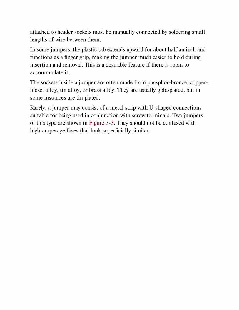
Rarely, a jumper may consist of a metal strip with U-shaped connections
suitable for being used in conjunction with screw terminals. Two jumpers
of this type are shown in Figure 3-3. They should not be confused with
high-amperage fuses that look superficially similar.
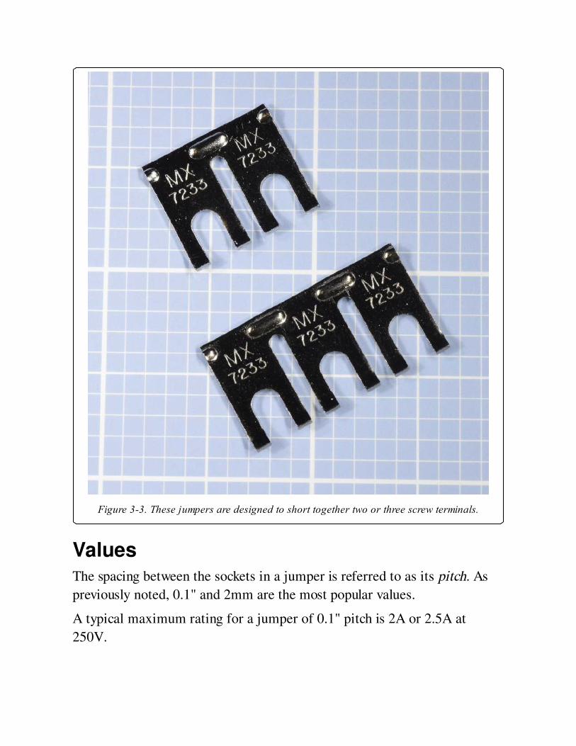
Figure 3-3. These jumpers are designed to short together two or three screw terminals.
ValuesThe spacing between the sockets in a jumper is referred to as its pitch. As
previously noted, 0.1" and 2mm are the most popular values.
A typical maximum rating for a jumper of 0.1" pitch is 2A or 2.5A at
250V.
How to Use itA jumper may activate a "set it and forget it" circuit function. An example
would be the factory configuration of a product to work with 115VAC or
230VAC power input. End users were expected to set jumpers in some
computer equipment sold during the 1980s, but this is no longer the case.
What Can Go WrongJumpers are easily dropped, easily lost, and easily placed incorrectly. When
purchasing jumpers, buy extras to compensate for their fragility and the
ease of losing them.
Any location where a jumper may be used should be clearly labelled to
define the function of each setting.
Cheap, poorly made jumpers may self-destruct from mechanical stresses
when removed from their pins. The plastic casing can come away, leaving
the sockets clinging naked to the pins protruding from the circuit board.
This is another reason why it is a good idea to have a small stock of spare
jumpers for emergencies.
Oxidation in jumpers where the contacts are not gold- or silver-plated can
create electrical resistance or unreliable connections.
Chapter 4. fuse
power > connection > fuse
The alternate spelling fuze is seldom used.
Other related components
None
What It DoesA fuse protects an electrical circuit or device from excessive current when a
metal element inside it melts to create an open circuit. With the exception
of resettable fuses (discussed separately in Resettable Fuses), a fuse must be
discarded and replaced after it has fulfilled its function.
When high current melts a fuse, it is said to blow or trip the fuse. (In the
case of a resettable fuse, only the word trip is used.)
A fuse can work with either AC or DC voltage, and can be designed for
almost any current. In residential and commercial buildings, circuit breakers
have become common, but a large cartridge fuse may still be used to
protect the whole system from short-circuits or from overcurrent caused by
lightning strikes on exposed power lines.
In electronic devices, the power supply is almost always fused.
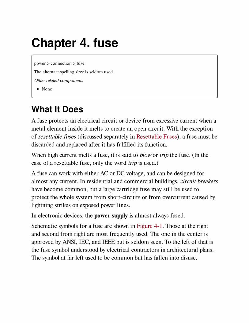
Schematic symbols for a fuse are shown in Figure 4-1. Those at the right
and second from right are most frequently used. The one in the center is
approved by ANSI, IEC, and IEEE but is seldom seen. To the left of that is
the fuse symbol understood by electrical contractors in architectural plans.
The symbol at far left used to be common but has fallen into disuse.
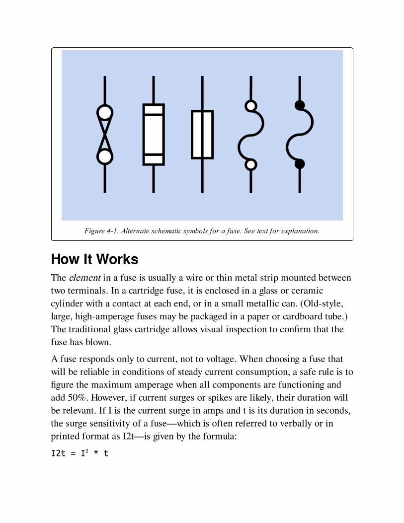
Figure 4-1. Alternate schematic symbols for a fuse. See text for explanation.
How It WorksThe element in a fuse is usually a wire or thin metal strip mounted between
two terminals. In a cartridge fuse, it is enclosed in a glass or ceramic
cylinder with a contact at each end, or in a small metallic can. (Old-style,
large, high-amperage fuses may be packaged in a paper or cardboard tube.)
The traditional glass cartridge allows visual inspection to confirm that the
fuse has blown.
A fuse responds only to current, not to voltage. When choosing a fuse that
will be reliable in conditions of steady current consumption, a safe rule is to
figure the maximum amperage when all components are functioning and
add 50%. However, if current surges or spikes are likely, their duration will
be relevant. If I is the current surge in amps and t is its duration in seconds,
the surge sensitivity of a fuse—which is often referred to verbally or in
printed format as I2t—is given by the formula:
I2t = I2 * t
Some semiconductors also have an I2t rating, and should be protected with
a similarly rated fuse.
Any fuse will present some resistance to the current flowing through it.
Otherwise, the current would not generate the heat that blows the fuse.
Manufacturer datasheets list the voltage drop that the internal resistance of
a fuse is likely to introduce into a circuit.
ValuesThe current rating or rated current of a fuse is usually printed or stamped
on its casing, and is the maximum flow that it should withstand on a
continuous basis, at the ambient temperature specified by the manufacturer
(usually 25 degrees Centigrade). The ambient temperature refers to the
immediate environment of the fuse, not the larger area in which it may be
located. Note that in an enclosure containing other components, the
temperature is usually significantly higher than outside the enclosure.
Ideally a fuse should function reliably and indefinitely at its rated maximum
amperage, but should blow just as reliably if the current rises by
approximately 20% beyond the maximum. In reality, manufacturers
recommend that continuous loading of a fuse should not exceed 75% of its
rating at 25 degrees Centigrade.
The voltage rating or rated voltage of a fuse is the maximum voltage at
which its element can be counted on to melt in a safe and predictable
manner when it is overloaded by excess current. This is sometimes known
as the breaking capacity. Above that rating, the remaining pieces of the fuse
element may form an arc that sustains some electrical conduction.
A fuse can always be used at a lower voltage than its rating. If it has a
breaking capacity of 250V, it will still provide the same protection if it is
used at 5V.
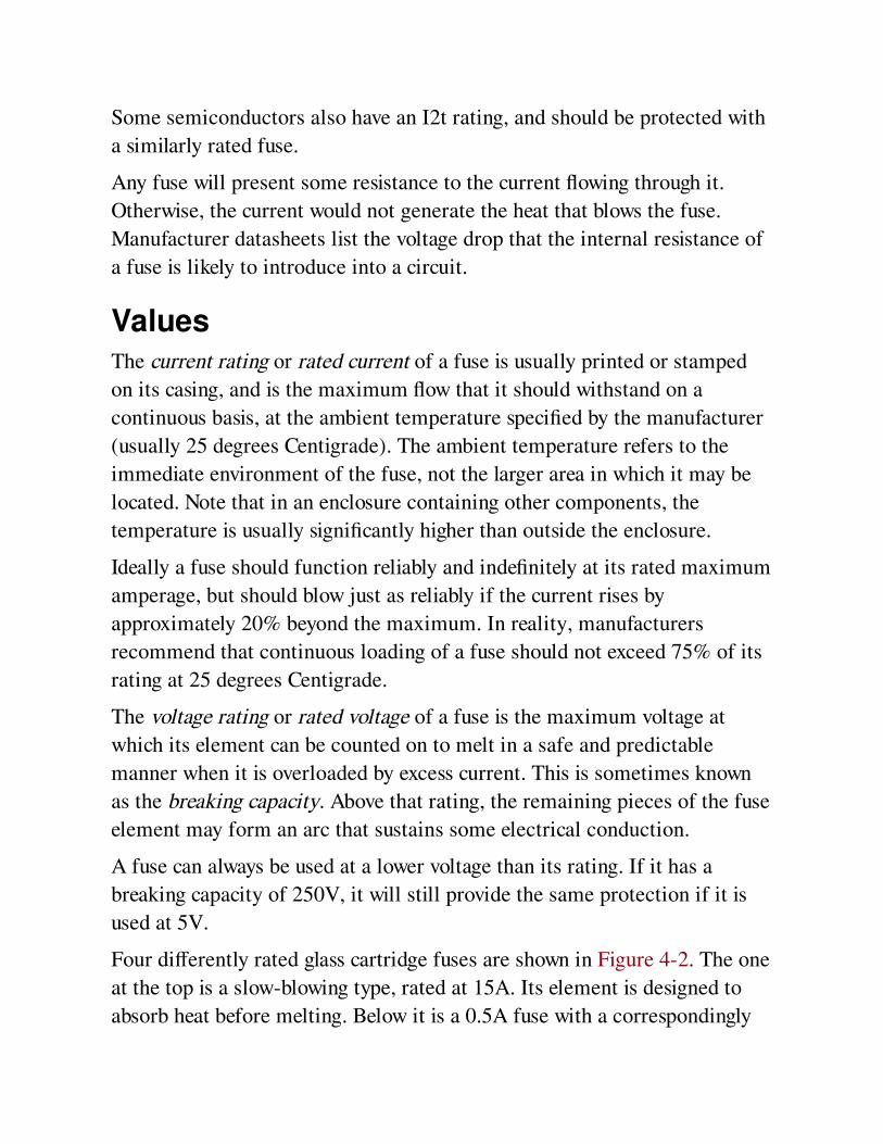
Four differently rated glass cartridge fuses are shown in Figure 4-2. The one
at the top is a slow-blowing type, rated at 15A. Its element is designed to
absorb heat before melting. Below it is a 0.5A fuse with a correspondingly
thinner element. The two smaller fuses are rated at 5A each. The center two
fuses have a maximum voltage rating of 250V, while the one at the top is
rated at 32V and the one at the bottom is rated at 350V. Clearly, the size of
a fuse should never be used as a guide to its ratings.
Figure 4-2. Four glass cartridge fuses. See text for details.
VariantsEarly power fuses in residential buildings consisted of bare nichrome wire
wrapped around a porcelain holder. In the 1890s, Edison developed plug
fuses in which the fuse was contained in a porcelain module with a screw
thread, compatible with the base of an incandescent bulb. This design
persisted in some U.S. urban areas for more than 70 years, is still found in
old buildings, and is still being manufactured.
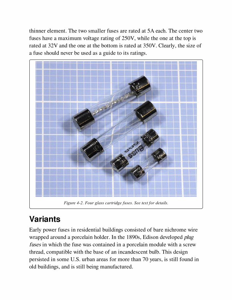
Small Cartridge FusesSmall cartridge fuses for appliances and electronics equipment—such as
those shown in Figure 4-2--are available in sizes tabulated in Figure 4-3.
With the exception of the 4.5mm diameter fuse (a European addition),
these sizes were originally measured in inches; today, they are often
described only with the equivalent metric measurement. Any cartridge fuse
is usually available with the option of a lead attached to it at each end, so
that it can be used as a through-hole component.
Figure 4-3. The approximate physical sizes of commonly used small glass or ceramic cartridgefuses are shown here with the codes that are often used to identify them.
Fuses may be fast acting, medium acting, or slow-blowing, the last of which
may alternatively be referred to as delay fuses. Extra-fast–acting fuses are
available from some manufacturers. The term Slo-Blo is often used but is
actually a trademark of Littelfuse. None of the terms describing the speed
of action of a fuse has been standardized with a specific time or time range.
Some cartridge fuses are available in a ceramic format as an alternative to
the more common glass cylinder. If accidental application of extremely
high current is possible (for example, in a multimeter that can be set to
measure amps, and may be accidentally connected across a powerful
battery), a ceramic cartridge is preferable because it contains a filler that
will help to stop an arc from forming. Also, if a fuse is physically destroyed
by application of very high current, ceramic fragments may be preferable to
glass fragments.
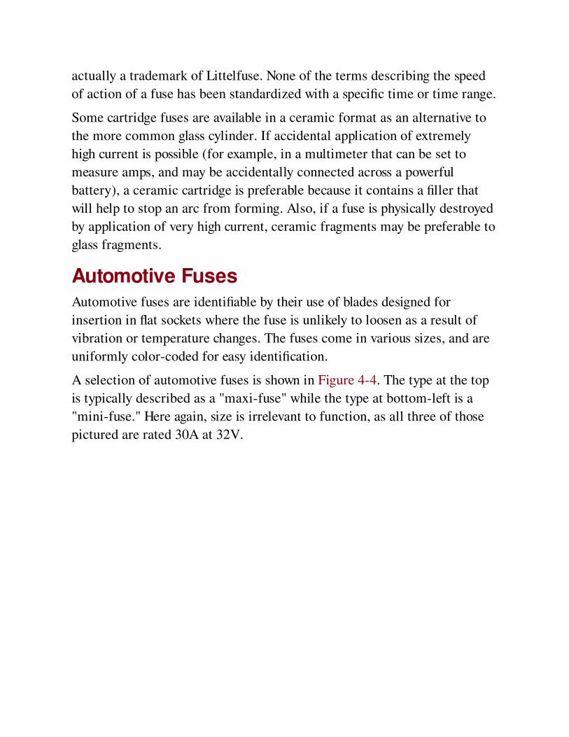
Automotive FusesAutomotive fuses are identifiable by their use of blades designed for
insertion in flat sockets where the fuse is unlikely to loosen as a result of
vibration or temperature changes. The fuses come in various sizes, and are
uniformly color-coded for easy identification.
A selection of automotive fuses is shown in Figure 4-4. The type at the top
is typically described as a "maxi-fuse" while the type at bottom-left is a
"mini-fuse." Here again, size is irrelevant to function, as all three of those
pictured are rated 30A at 32V.
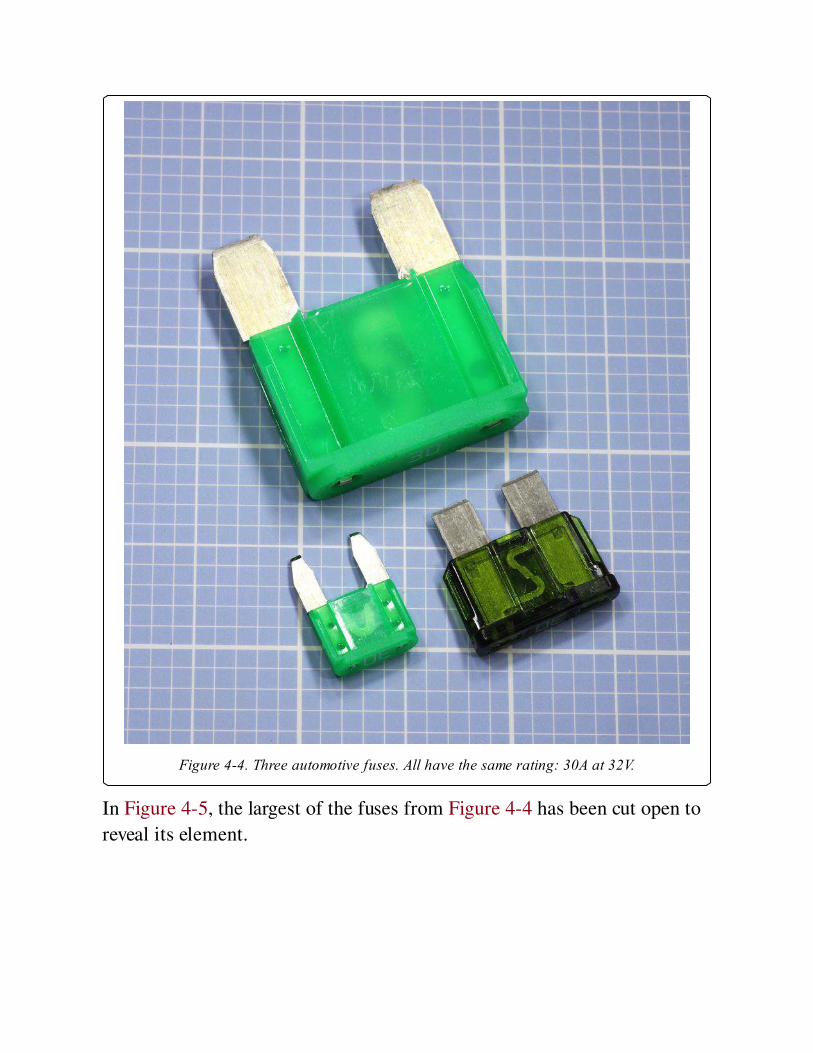
Figure 4-4. Three automotive fuses. All have the same rating: 30A at 32V.
In Figure 4-5, the largest of the fuses from Figure 4-4 has been cut open to
reveal its element.
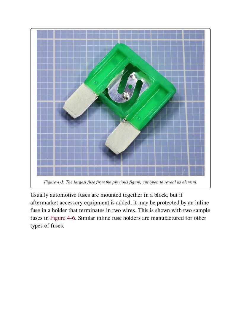
Figure 4-5. The largest fuse from the previous figure, cut open to reveal its element.
Usually automotive fuses are mounted together in a block, but if
aftermarket accessory equipment is added, it may be protected by an inline
fuse in a holder that terminates in two wires. This is shown with two sample
fuses in Figure 4-6. Similar inline fuse holders are manufactured for other
types of fuses.
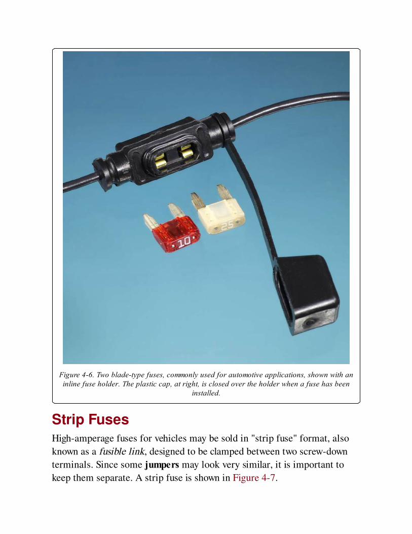
Figure 4-6. Two blade-type fuses, commonly used for automotive applications, shown with aninline fuse holder. The plastic cap, at right, is closed over the holder when a fuse has been
installed.
Strip FusesHigh-amperage fuses for vehicles may be sold in "strip fuse" format, also
known as a fusible link, designed to be clamped between two screw-down
terminals. Since some jumpers may look very similar, it is important to
keep them separate. A strip fuse is shown in Figure 4-7.
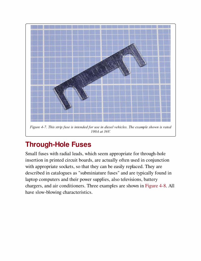
Figure 4-7. This strip fuse is intended for use in diesel vehicles. The example shown is rated100A at 36V.
Through-Hole FusesSmall fuses with radial leads, which seem appropriate for through-hole
insertion in printed circuit boards, are actually often used in conjunction
with appropriate sockets, so that they can be easily replaced. They are
described in catalogues as "subminiature fuses" and are typically found in
laptop computers and their power supplies, also televisions, battery
chargers, and air conditioners. Three examples are shown in Figure 4-8. All
have slow-blowing characteristics.
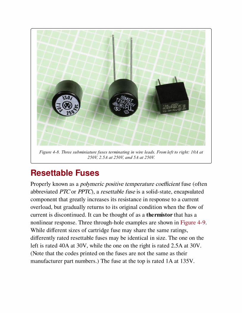
Figure 4-8. Three subminiature fuses terminating in wire leads. From left to right: 10A at250V, 2.5A at 250V, and 5A at 250V.
Resettable FusesProperly known as a polymeric positive temperature coefficient fuse (often
abbreviated PTC or PPTC), a resettable fuse is a solid-state, encapsulated
component that greatly increases its resistance in response to a current
overload, but gradually returns to its original condition when the flow of
current is discontinued. It can be thought of as a thermistor that has a
nonlinear response. Three through-hole examples are shown in Figure 4-9.
While different sizes of cartridge fuse may share the same ratings,
differently rated resettable fuses may be identical in size. The one on the
left is rated 40A at 30V, while the one on the right is rated 2.5A at 30V.
(Note that the codes printed on the fuses are not the same as their
manufacturer part numbers.) The fuse at the top is rated 1A at 135V.
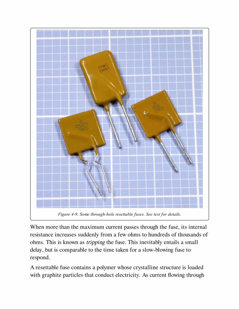
Figure 4-9. Some through-hole resettable fuses. See text for details.
When more than the maximum current passes through the fuse, its internal
resistance increases suddenly from a few ohms to hundreds of thousands of
ohms. This is known as tripping the fuse. This inevitably entails a small
delay, but is comparable to the time taken for a slow-blowing fuse to
respond.
A resettable fuse contains a polymer whose crystalline structure is loaded
with graphite particles that conduct electricity. As current flowing through
the fuse induces heat, the polymer transitions to an amorphous state,
separating the graphite particles and interrupting the conductive pathways.
A small current still passes through the component, sufficient to maintain
its amorphous state until power is disconnected. After the resettable fuse
cools, it gradually recrystallizes, although its resistance does not fall back
completely to its original value for more than an hour.
The maximum safe level of current for a resettable fuse is known as the
hold current, while the current that triggers its response is termed the trip
current. Resettable fuses are available with trip-current ratings from 20mA
to 100A. While conventional appliance and electronics fuses may be rated
as high as 600V, resettable fuses are seldom rated above 100V.
Typical cartridge fuses are affected only to a minor extent by temperature,
but the current rating of a resettable fuse may diminish to 75% of its
normal value at 50 degrees Centigrade and may drop to 50% of its normal
value at 80 degrees Centigrade. In other words, a fuse that is rated for 4A at
25 degrees may tolerate a maximum of only 3A when it operates at twice
that temperature. See Figure 4-10.
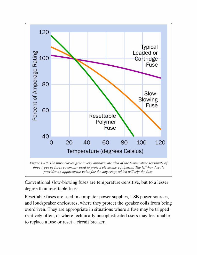
Figure 4-10. The three curves give a very approximate idea of the temperature sensitivity ofthree types of fuses commonly used to protect electronic equipment. The left-hand scale
provides an approximate value for the amperage which will trip the fuse.
Conventional slow-blowing fuses are temperature-sensitive, but to a lesser
degree than resettable fuses.
Resettable fuses are used in computer power supplies, USB power sources,
and loudspeaker enclosures, where they protect the speaker coils from being
overdriven. They are appropriate in situations where a fuse may be tripped
relatively often, or where technically unsophisticated users may feel unable
to replace a fuse or reset a circuit breaker.
Brand names for resettable fuses include PolySwitch, OptiReset, Everfuse,
Polyfuse, and Multifuse. They are available in surface-mount (SMT)
packages or as through-hole components, but not in cartridge format.
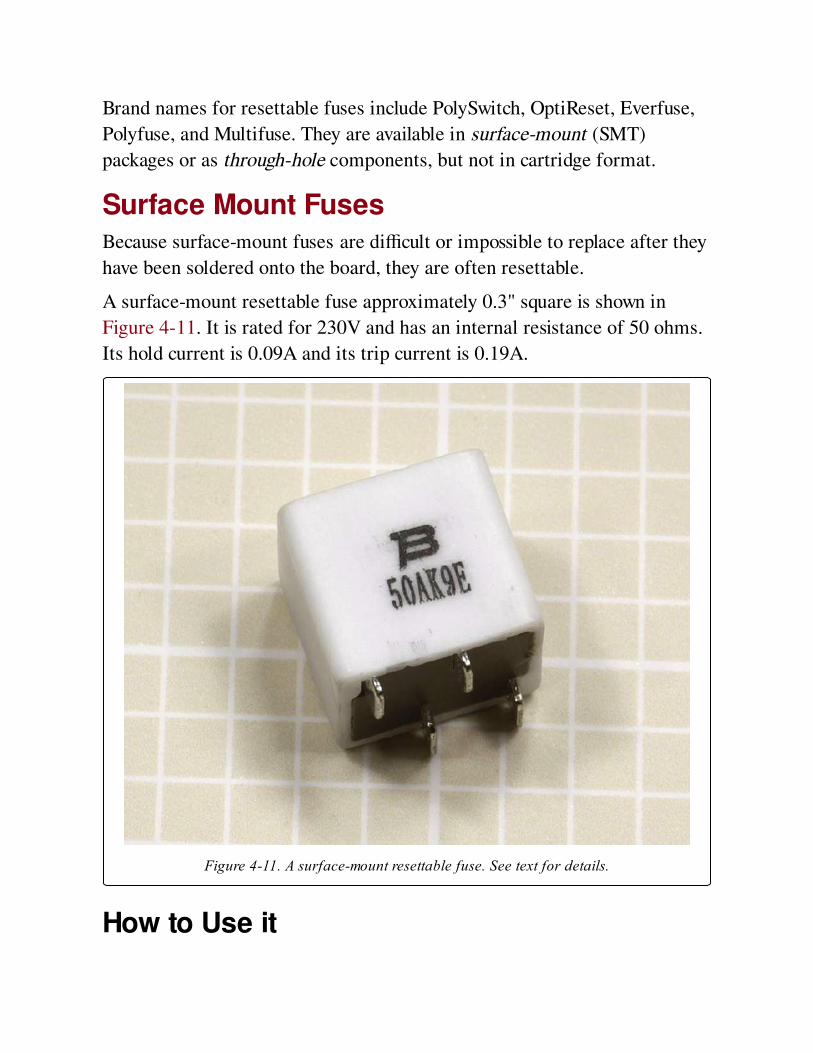
Surface Mount FusesBecause surface-mount fuses are difficult or impossible to replace after they
have been soldered onto the board, they are often resettable.
A surface-mount resettable fuse approximately 0.3" square is shown in
Figure 4-11. It is rated for 230V and has an internal resistance of 50 ohms.
Its hold current is 0.09A and its trip current is 0.19A.
Figure 4-11. A surface-mount resettable fuse. See text for details.
How to Use it
Any equipment that may be plugged into a wall outlet should be fused, not
only to protect its components but also to protect users who may open the
box and start investigating with a screwdriver.
Equipment that contains powerful motors, pumps, or other inductive loads
should be protected with slow-blowing fuses, as the initial surge of current
when the equipment is switched on is likely to rise well above the rating of
the fuse. A slow-blowing fuse will tolerate a surge for a couple of seconds.
Other fuses will not.
Conversely, fast-acting fuses should be used with electronic equipment,
especially integrated circuits that are quickly and easily damaged.
Any device using substantial battery power should be fused because of the
unpredictable and generally bad behavior of batteries when they are short-
circuited. Parallel connections between multiple large batteries should be
fused to avoid the possibility that a highly charged battery may attempt to
recharge its neighbor(s). Large "J size" fuses rated from 125A to 450A have
become common in the solar power community, where banks of lead-acid
batteries are often used. These fuses have a thick brass tab at each end,
drilled so that they can be bolted into place. Alternatively, they will push-fit
into an appropriate fuseholder.
For cartridge fuses up to 1/4" in diameter that don’t have leads attached,
appropriately sized fuseholders are available in several formats:
Panel mounted fuse enclosure is probably the most common, consisting of
a plastic tube with a spring-contact at the bottom, and a plastic cap with a
second contact inside. The cap either screws onto the tube of the fuse, or is
pushed down and turned to hold it in place. A nut is provided to secure the
fuseholder after it has been inserted into a hole drilled in the panel. The
fuse is dropped into the tube, and the cap is applied. This type of holder is
available in full-length or shorter, "low profile" formats. A low-profile
holder is shown in Figure 4-12. It is shown assembled at right, with its
component parts disassembled alongside.
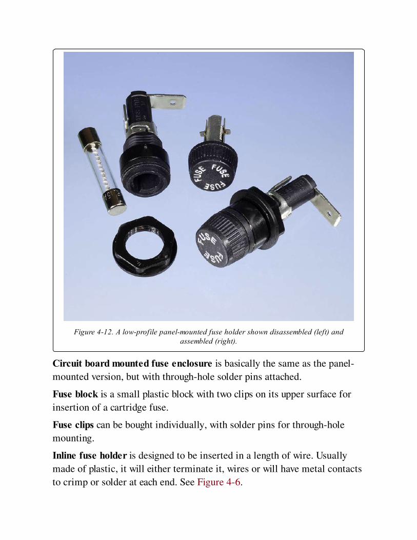
Figure 4-12. A low-profile panel-mounted fuse holder shown disassembled (left) andassembled (right).
Circuit board mounted fuse enclosure is basically the same as the panel-
mounted version, but with through-hole solder pins attached.
Fuse block is a small plastic block with two clips on its upper surface for
insertion of a cartridge fuse.
Fuse clips can be bought individually, with solder pins for through-hole
mounting.
Inline fuse holder is designed to be inserted in a length of wire. Usually
made of plastic, it will either terminate it, wires or will have metal contacts
to crimp or solder at each end. See Figure 4-6.
Through-hole fuse holders are available for subminiature fuses.
What Can Go Wrong
Repeated FailureWhen a fuse in a circuit blows frequently, this is known as nuisance
opening. Often it can result from failure to take into account all the aspects
of the circuit, such as a large filtering capacitor in a power supply that draws
a major surge of current when the power supply is switched on. The
formally correct procedure to address this problem is to measure the power
surge, properly known as peak inrush current, with an oscilloscope, calculate
the I2 * t of the wave form, and select a fuse with a rating at least 5 times
that value.
A fuse should never be replaced with an equivalent length of wire or any
other conductor.
Soldering DamageWhen a through-hole or surface-mount fuse is soldered into place, heat
from the soldering process can cause the soft metal element inside the fuse
to melt partially and reflow. This is likely to change the rating of the fuse.
Generally, fuses should be treated with the same caution as semiconductors
when they are fixed in place with solder.
PlacementA fuse should be placed close to the power source or power input point in a
circuit, so that it protects as much of the circuit as possible.
Chapter 5. pushbutton
power > connection > pushbutton
Often referred to as a pushbutton switch and sometimes as a momentary switch. In this
encyclopedia, a pushbutton is considered separately from a switch, which generally uses a
lever-shaped actuator rather than a button, and has at least one pole contact where a
pushbutton generally has contacts that are not distinguishable from each other.
Other related components
switch (See Chapter 6)
rotary switch (See Chapter 7)
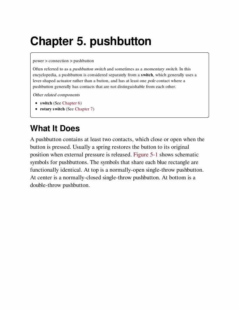
What It DoesA pushbutton contains at least two contacts, which close or open when the
button is pressed. Usually a spring restores the button to its original
position when external pressure is released. Figure 5-1 shows schematic
symbols for pushbuttons. The symbols that share each blue rectangle are
functionally identical. At top is a normally-open single-throw pushbutton.
At center is a normally-closed single-throw pushbutton. At bottom is a
double-throw pushbutton.
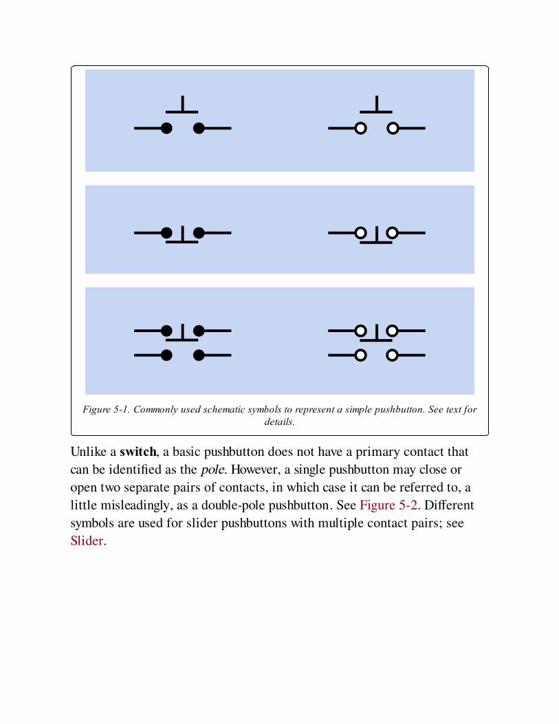
Figure 5-1. Commonly used schematic symbols to represent a simple pushbutton. See text fordetails.
Unlike a switch, a basic pushbutton does not have a primary contact that
can be identified as the pole. However, a single pushbutton may close or
open two separate pairs of contacts, in which case it can be referred to, a
little misleadingly, as a double-pole pushbutton. See Figure 5-2. Different
symbols are used for slider pushbuttons with multiple contact pairs; see
Slider.
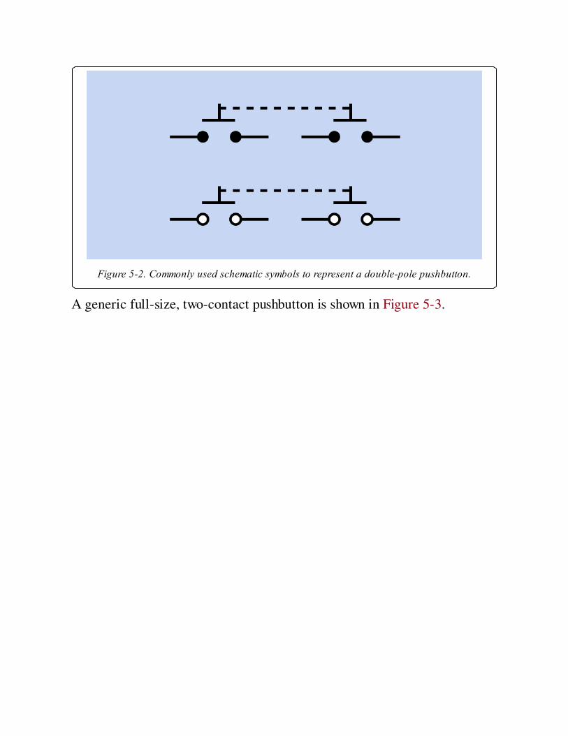
Figure 5-2. Commonly used schematic symbols to represent a double-pole pushbutton.
A generic full-size, two-contact pushbutton is shown in Figure 5-3.
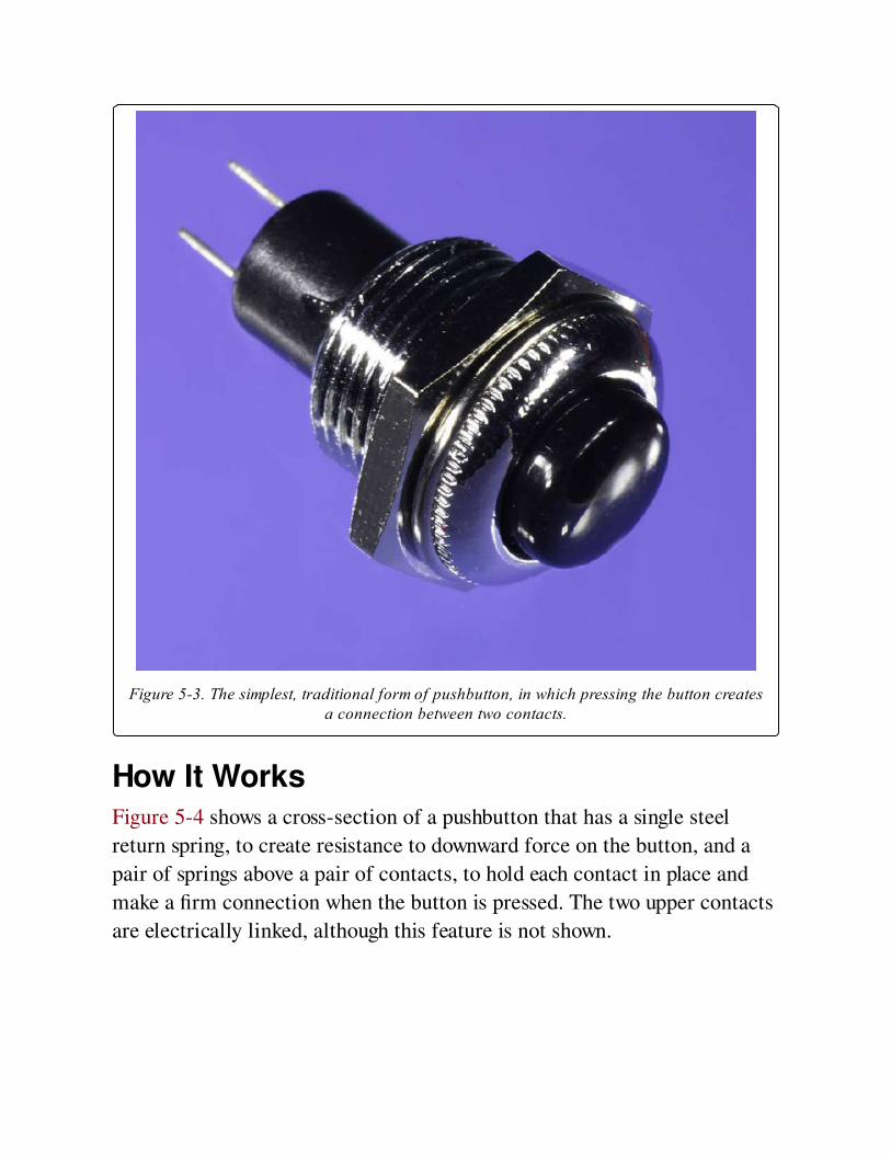
Figure 5-3. The simplest, traditional form of pushbutton, in which pressing the button createsa connection between two contacts.
How It WorksFigure 5-4 shows a cross-section of a pushbutton that has a single steel
return spring, to create resistance to downward force on the button, and a
pair of springs above a pair of contacts, to hold each contact in place and
make a firm connection when the button is pressed. The two upper contacts
are electrically linked, although this feature is not shown.
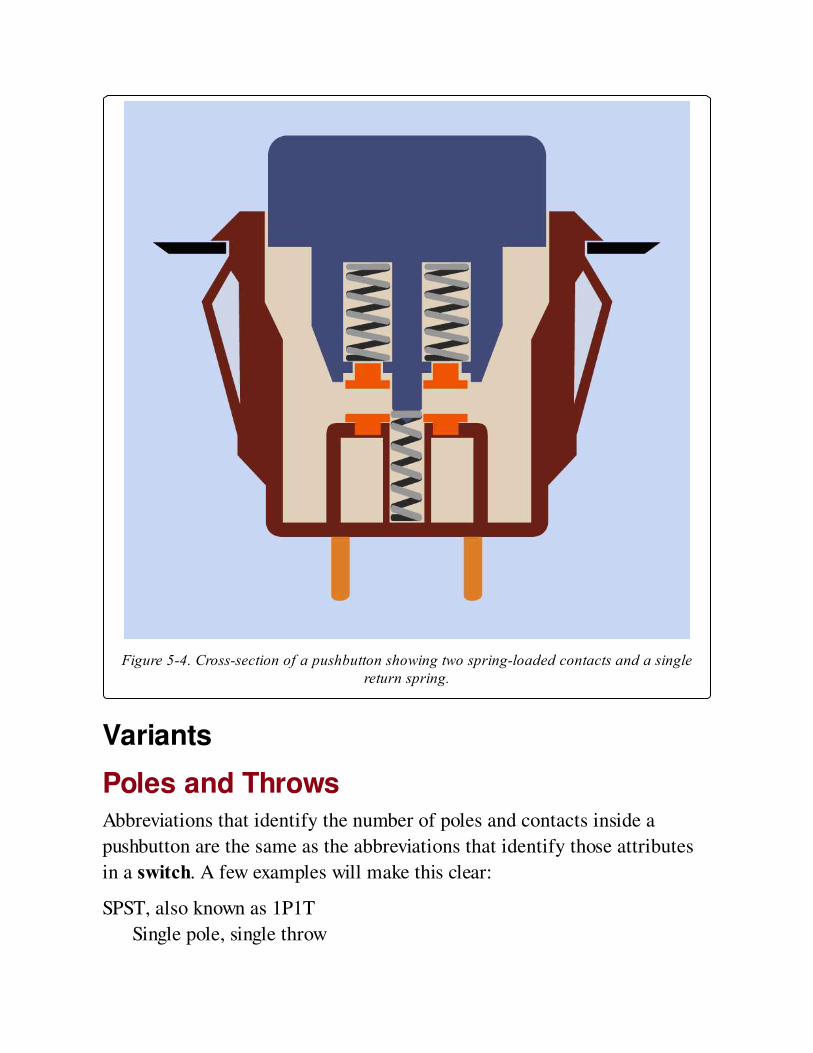
Figure 5-4. Cross-section of a pushbutton showing two spring-loaded contacts and a singlereturn spring.
Variants
Poles and ThrowsAbbreviations that identify the number of poles and contacts inside a
pushbutton are the same as the abbreviations that identify those attributes
in a switch. A few examples will make this clear:
SPST, also known as 1P1T
Single pole, single throw
DPST also known as 2P1T
Double pole, single throw
SPDT also known as 1P2T
Single pole, double throw
3PST also known as 3P1T
Three pole, single throw
While a switch may have an additional center position, pushbuttons
generally do not.
On-Off BehaviorParentheses are used to indicate the momentary state of the pushbutton
while it is pressed. It will return to the other state by default.
OFF-(ON) or (ON)-OFF
Contacts are normally open by default, and are closed only while the
button is pressed. This is sometimes described as a make-to-make
connection, or as a Form A pushbutton.
ON-(OFF) or (OFF)-ON
Contacts are normally closed by default, and are open only while the
button is pressed. This is sometimes described as a make-to-break
connection, or as a Form B pushbutton.
ON-(ON) or (ON)-ON
This is a double-throw pushbutton in which one set of contacts is
normally closed. When the button is pressed, the first set of contacts is
opened and the other set of contacts is closed, until the button is
released. This is sometimes described as a Form C pushbutton.
For a single-throw pushbutton, the terms NC or NO may be used to describe
it as normally closed or normally open.
Slider
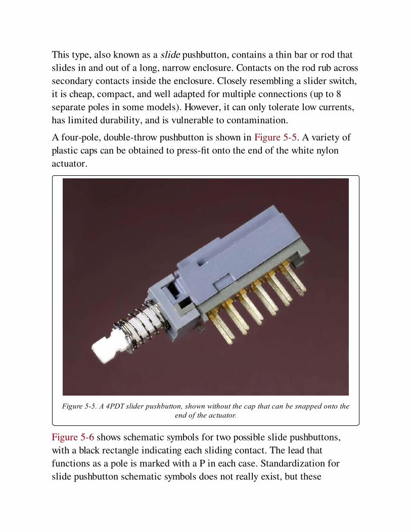
This type, also known as a slide pushbutton, contains a thin bar or rod that
slides in and out of a long, narrow enclosure. Contacts on the rod rub across
secondary contacts inside the enclosure. Closely resembling a slider switch,
it is cheap, compact, and well adapted for multiple connections (up to 8
separate poles in some models). However, it can only tolerate low currents,
has limited durability, and is vulnerable to contamination.
A four-pole, double-throw pushbutton is shown in Figure 5-5. A variety of
plastic caps can be obtained to press-fit onto the end of the white nylon
actuator.
Figure 5-5. A 4PDT slider pushbutton, shown without the cap that can be snapped onto theend of the actuator.
Figure 5-6 shows schematic symbols for two possible slide pushbuttons,
with a black rectangle indicating each sliding contact. The lead that
functions as a pole is marked with a P in each case. Standardization for
slide pushbutton schematic symbols does not really exist, but these
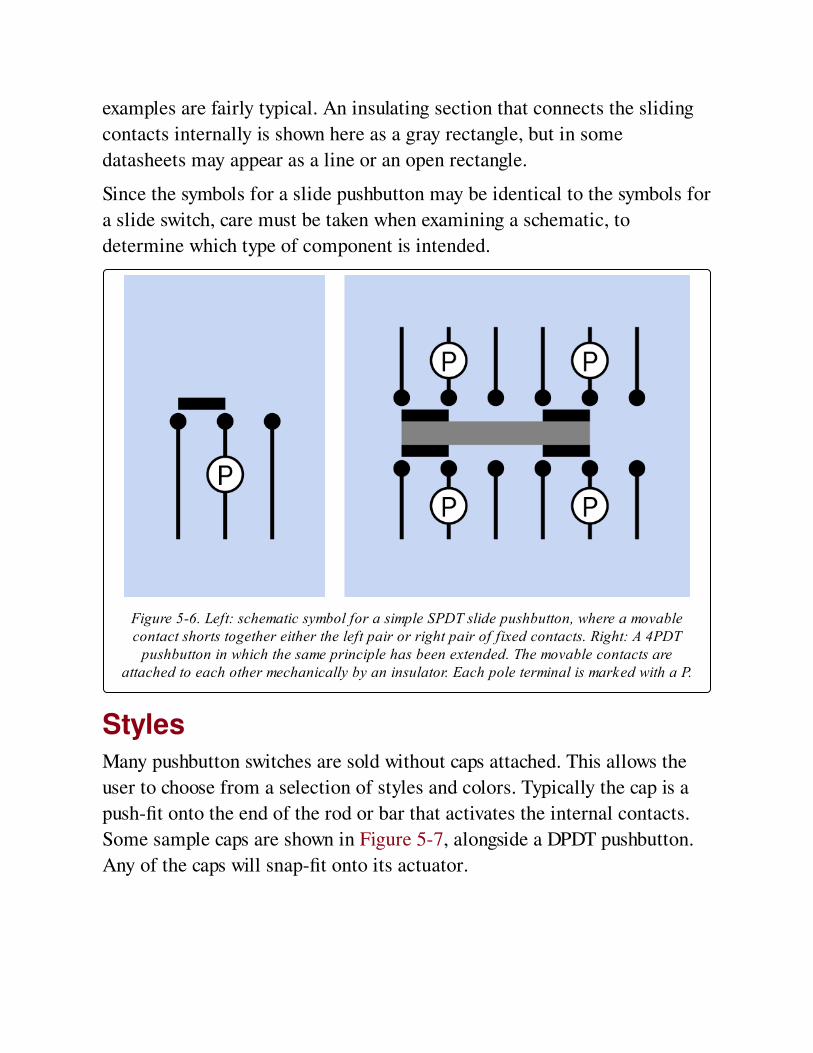
examples are fairly typical. An insulating section that connects the sliding
contacts internally is shown here as a gray rectangle, but in some
datasheets may appear as a line or an open rectangle.
Since the symbols for a slide pushbutton may be identical to the symbols for
a slide switch, care must be taken when examining a schematic, to
determine which type of component is intended.
Figure 5-6. Left: schematic symbol for a simple SPDT slide pushbutton, where a movablecontact shorts together either the left pair or right pair of fixed contacts. Right: A 4PDT
pushbutton in which the same principle has been extended. The movable contacts areattached to each other mechanically by an insulator. Each pole terminal is marked with a P.
StylesMany pushbutton switches are sold without caps attached. This allows the
user to choose from a selection of styles and colors. Typically the cap is a
push-fit onto the end of the rod or bar that activates the internal contacts.
Some sample caps are shown in Figure 5-7, alongside a DPDT pushbutton.
Any of the caps will snap-fit onto its actuator.
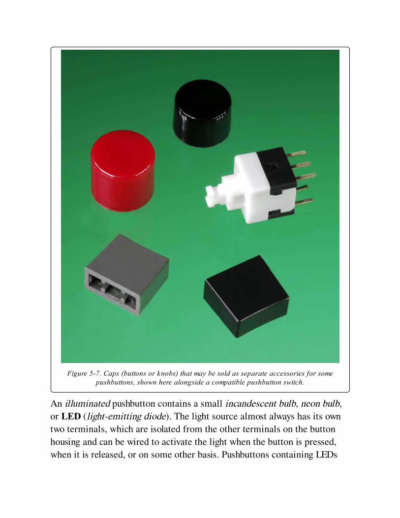
Figure 5-7. Caps (buttons or knobs) that may be sold as separate accessories for somepushbuttons, shown here alongside a compatible pushbutton switch.
An illuminated pushbutton contains a small incandescent bulb, neon bulb,
or LED (light-emitting diode). The light source almost always has its own
two terminals, which are isolated from the other terminals on the button
housing and can be wired to activate the light when the button is pressed,
when it is released, or on some other basis. Pushbuttons containing LEDs
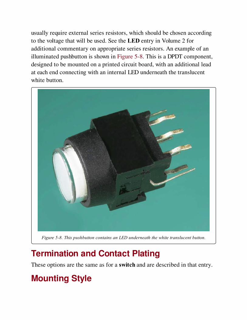
usually require external series resistors, which should be chosen according
to the voltage that will be used. See the LED entry in Volume 2 for
additional commentary on appropriate series resistors. An example of an
illuminated pushbutton is shown in Figure 5-8. This is a DPDT component,
designed to be mounted on a printed circuit board, with an additional lead
at each end connecting with an internal LED underneath the translucent
white button.
Figure 5-8. This pushbutton contains an LED underneath the white translucent button.
Termination and Contact PlatingThese options are the same as for a switch and are described in that entry.
Mounting Style
The traditional panel-mounted button is usually secured through a hole in
the panel by tightening a nut that engages with a thread on the bushing of
the pushbutton. Alternatively, a pushbutton housing can have flexible plastic
protrusions on either side, allowing it to be snapped into place in an
appropriate-sized panel cutout. This style is shown in Figure 5-4.
PC pushbuttons (pushbuttons mounted in a printed circuit board, or PCB)
are a common variant. After the component has been installed in the circuit
board, either the button must align with a cutout in the front panel and poke
through it when the device is assembled, or an external (non-electrical)
button that is part of the product enclosure must press on the actuator of
the pushbutton after assembly.
Surface-mount pushbuttons that allow direct fingertip access are
uncommon. However, about one-quarter of tactile switches are designed for
surface mount at the time of writing. They are typically found beneath
membranes that the user presses to activate the switch beneath—for
example, in remotes that are used to operate electronic devices.
Sealed or UnsealedA sealed pushbutton will include protection against water, dust, dirt, and
other environmental hazards, at some additional cost.
LatchingThis variant, also known as a press-twice pushbutton, contains a mechanical
ratchet, which is rotated each time the button is pressed. The first press
causes contacts to latch in the closed state. The second press returns the
contacts to the open state, after which, the process repeats. This press-twice
design is typically found on flashlights, audio equipment, and in automotive
applications. While latching is the most commonly used term, it is also
known as push-push, locking, push-lock push-release, push-on push-off, and
alternate.
In a latching pushbutton with lockdown, the button is visibly lower in the
latched state than in the unlatched state. However, buttons that behave this
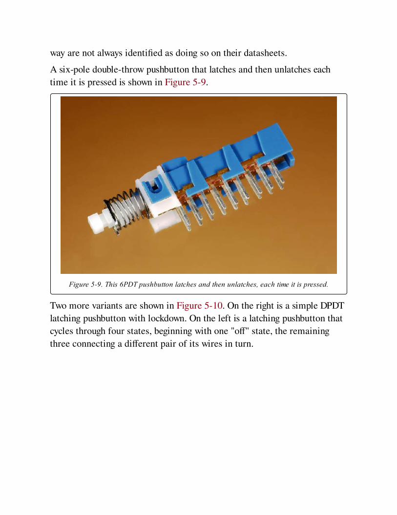
way are not always identified as doing so on their datasheets.
A six-pole double-throw pushbutton that latches and then unlatches each
time it is pressed is shown in Figure 5-9.
Figure 5-9. This 6PDT pushbutton latches and then unlatches, each time it is pressed.
Two more variants are shown in Figure 5-10. On the right is a simple DPDT
latching pushbutton with lockdown. On the left is a latching pushbutton that
cycles through four states, beginning with one "off" state, the remaining
three connecting a different pair of its wires in turn.
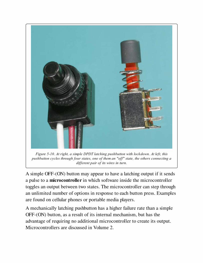
Figure 5-10. At right, a simple DPDT latching pushbutton with lockdown. At left, thispushbutton cycles through four states, one of them an "off" state, the others connecting a
different pair of its wires in turn.
A simple OFF-(ON) button may appear to have a latching output if it sends
a pulse to a microcontroller in which software inside the microcontroller
toggles an output between two states. The microcontroller can step through
an unlimited number of options in response to each button press. Examples
are found on cellular phones or portable media players.
A mechanically latching pushbutton has a higher failure rate than a simple
OFF-(ON) button, as a result of its internal mechanism, but has the
advantage of requiring no additional microcontroller to create its output.
Microcontrollers are discussed in Volume 2.
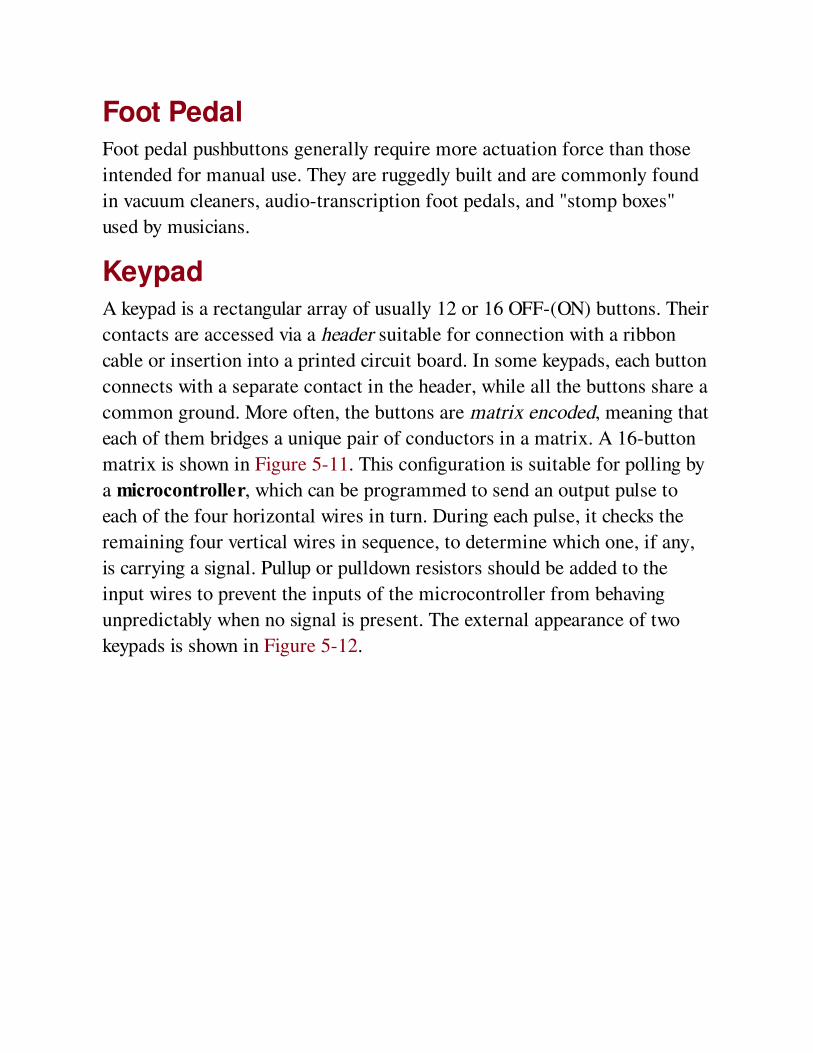
Foot PedalFoot pedal pushbuttons generally require more actuation force than those
intended for manual use. They are ruggedly built and are commonly found
in vacuum cleaners, audio-transcription foot pedals, and "stomp boxes"
used by musicians.
KeypadA keypad is a rectangular array of usually 12 or 16 OFF-(ON) buttons. Their
contacts are accessed via a header suitable for connection with a ribbon
cable or insertion into a printed circuit board. In some keypads, each button
connects with a separate contact in the header, while all the buttons share a
common ground. More often, the buttons are matrix encoded, meaning that
each of them bridges a unique pair of conductors in a matrix. A 16-button
matrix is shown in Figure 5-11. This configuration is suitable for polling by
a microcontroller, which can be programmed to send an output pulse to
each of the four horizontal wires in turn. During each pulse, it checks the
remaining four vertical wires in sequence, to determine which one, if any,
is carrying a signal. Pullup or pulldown resistors should be added to the
input wires to prevent the inputs of the microcontroller from behaving
unpredictably when no signal is present. The external appearance of two
keypads is shown in Figure 5-12.
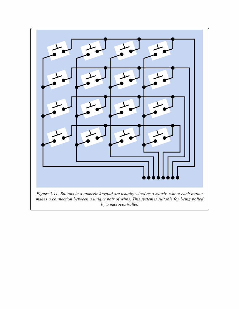
Figure 5-11. Buttons in a numeric keypad are usually wired as a matrix, where each buttonmakes a connection between a unique pair of wires. This system is suitable for being polled
by a microcontroller.
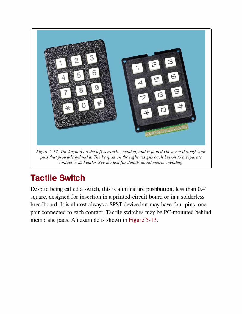
Figure 5-12. The keypad on the left is matrix-encoded, and is polled via seven through-holepins that protrude behind it. The keypad on the right assigns each button to a separate
contact in its header. See the text for details about matrix encoding.
Tactile SwitchDespite being called a switch, this is a miniature pushbutton, less than 0.4"
square, designed for insertion in a printed-circuit board or in a solderless
breadboard. It is almost always a SPST device but may have four pins, one
pair connected to each contact. Tactile switches may be PC-mounted behind
membrane pads. An example is shown in Figure 5-13.
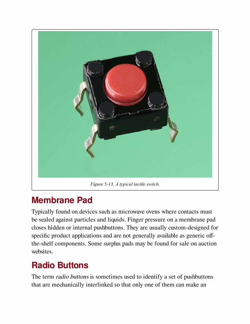
Figure 5-13. A typical tactile switch.
Membrane PadTypically found on devices such as microwave ovens where contacts must
be sealed against particles and liquids. Finger pressure on a membrane pad
closes hidden or internal pushbuttons. They are usually custom-designed for
specific product applications and are not generally available as generic off-
the-shelf components. Some surplus pads may be found for sale on auction
websites.
Radio ButtonsThe term radio buttons is sometimes used to identify a set of pushbuttons
that are mechanically interlinked so that only one of them can make an
electrical connection at a time. If one button is pressed, it latches. If a
second button is pressed, it latches while unlatching the first button. The
buttons can be pressed in any sequence. This system is useful for
applications such as component selection in a stereo system, where only
one input can be permitted at a time. However, its use is becoming less
common.
Snap-Action SwitchesA snap-action switch (described in detail in the switch section of this
encyclopedia) can be fitted with a pushbutton, as shown in Figure 5-14. This
provides a pleasingly precise action, high reliability, and capability of
switching currents of around 5A. However, snap-action switches are almost
always single-pole devices.
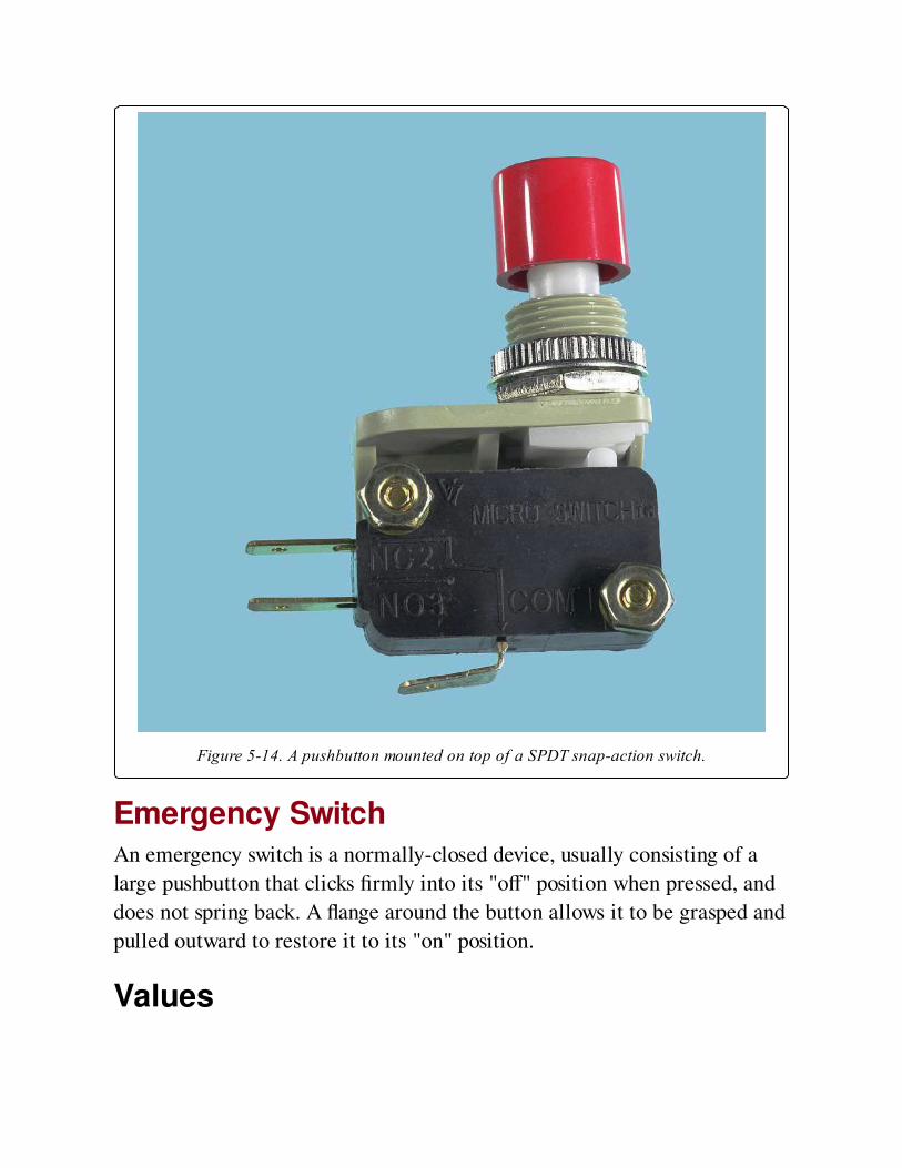
Figure 5-14. A pushbutton mounted on top of a SPDT snap-action switch.
Emergency SwitchAn emergency switch is a normally-closed device, usually consisting of a
large pushbutton that clicks firmly into its "off" position when pressed, and
does not spring back. A flange around the button allows it to be grasped and
pulled outward to restore it to its "on" position.
Values
Pushbutton current ratings range from a few mA to 20A or more. Many
pushbuttons have their current ratings printed on them but some do not.
Current ratings are usually specified for a particular voltage, and may differ
for AC versus DC.
How to Use itIssues such as appearance, tactile feel, physical size, and ease of product
assembly tend to dictate the choice of a pushbutton, after the fundamental
requirements of voltage, current, and durability have been satisfied. Like
any electromechanical component, a pushbutton is vulnerable to dirt and
moisture. The ways in which a device may be used or abused should be
taken into account when deciding whether the extra expense of a sealed
component is justified.
When a pushbutton controls a device that has a high inductive load, a
snubber can be added to minimize arcing. See Arcing in the switch entry of
this encyclopedia, for additional information.
What Can Go Wrong
No ButtonWhen ordering a pushbutton switch, read datasheets carefully to determine
whether a cap is included. Caps are often sold separately and may not be
interchangeable between switches from different manufacturers.
Mounting ProblemsIn a panel-mount pushbutton that is secured by turning a nut, the nut may
loosen with use, allowing the component to fall inside its enclosure when
the button is pressed. Conversely, overtightening the nut may strip the
threads on the pushbutton bushing, especially in cheaper components where
the threads are molded into plastic. Consider applying a drop of Loc-Tite or
similar adhesive before completely tightening the nut. Nut sizes vary widely,
and finding a replacement may be time-consuming.
LED IssuesWhen using a pushbutton containing an LED, be careful to distinguish the
LED power terminals from the switched terminals. The manufacturer’s
datasheet should clarify this distinction, but the polarity of the LED
terminals may not be clearly indicated. If a diode-testing meter function is
unavailable, a sample of the switch should be tested with a source of 3 to
5VDC and a 2K series resistor. Briefly touching the power to the LED
terminals, through the resistor, should cause the LED to flash dimly if the
polarity is correct, but should not be sufficient to burn out the LED if the
polarity is incorrect.
Other ProblemsProblems such as arcing, overload, short circuits, wrong terminal type, and
contact bounce are generally the same as those associated with a switch,
and are summarized in that entry in this encyclopedia.
Chapter 6. switch
power > connection > switch
The term switch refers here to a physically operated mechanical switch, controlled by flipping a
lever or sliding a knob. Although there is some overlap of function, rotary switches and
pushbuttons have their own separate entries. Solid-state switching components are described
in entries for bipolar transistor, unijunction transistor, and field-effect transistor. Integrated-
circuit switching devices will be found in Volume 2. Coaxial switches are used for high-
frequency signals, and are not included in this encyclopedia. Multidirectional switches
differentiate up, down, left, right, diagonal, rotational, and other finger inputs, and are not
included in this encyclopedia.
Other related components
pushbutton (See Chapter 5)
rotary switch (See Chapter 7)
What It DoesA switch contains at least two contacts, which close or open when an
external lever or knob is flipped or moved. Schematic symbols for the most
basic type of on-off switch are shown in Figure 6-1.
The most fundamental type of switch is a knife switch, illustrated in
Figure 6-2. Although it was common in the earliest days of electrical
discovery, today it is restricted to educational purposes in schools, and (in a
more robust format) to AC electrical supply panels, where the large contact
area makes it appropriate for conducting high amperages, and it can be used
for "hot switching" a substantial load.
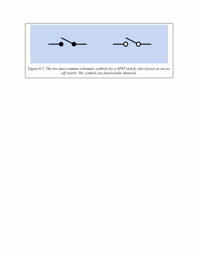
Figure 6-1. The two most common schematic symbols for a SPST switch, also known as an on-off switch. The symbols are functionally identical.
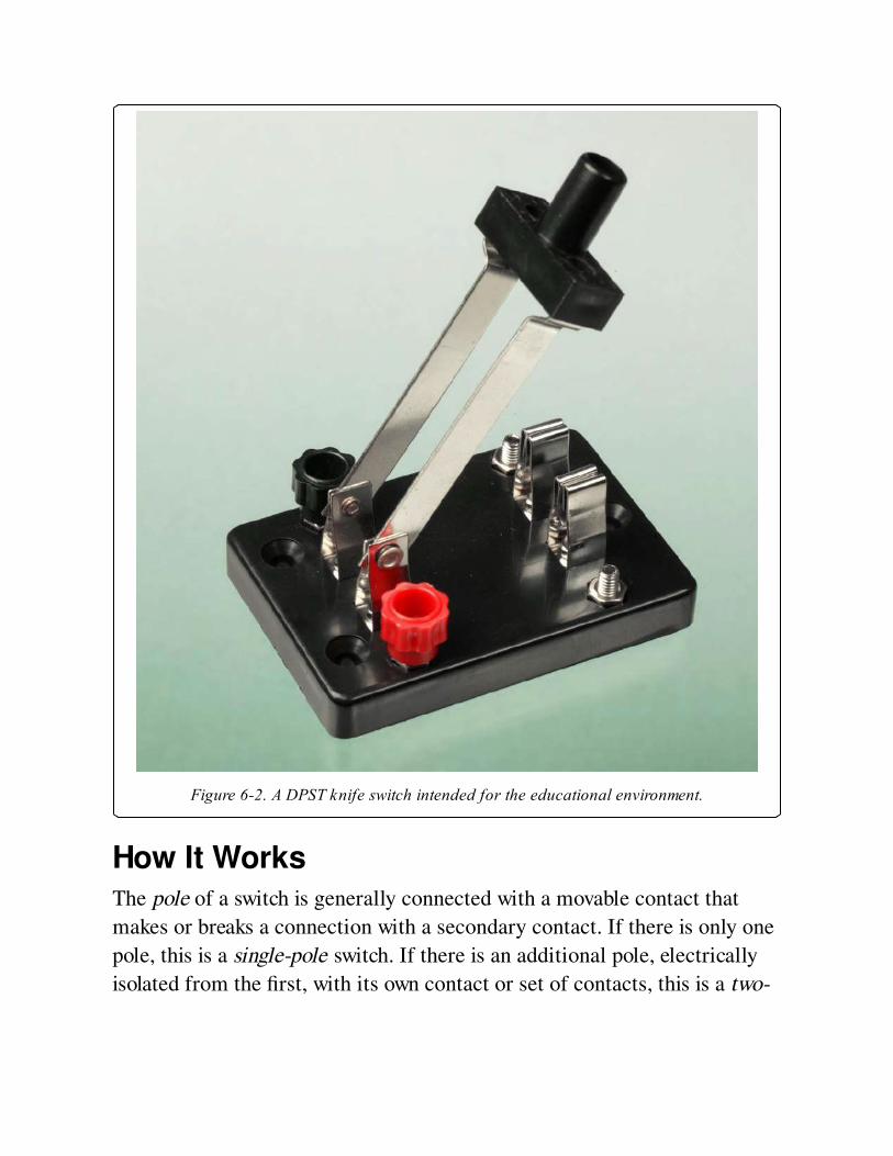
Figure 6-2. A DPST knife switch intended for the educational environment.
How It WorksThe pole of a switch is generally connected with a movable contact that
makes or breaks a connection with a secondary contact. If there is only one
pole, this is a single-pole switch. If there is an additional pole, electrically
isolated from the first, with its own contact or set of contacts, this is a two-
pole switch, also known as a double-pole switch. Switches with more than 4
poles are uncommon.
If there is only one secondary contact per pole, this is a single-throw or ST
switch, which may also be described as an on-off or off-on switch. If there
is an additional secondary contact per pole, and the pole of the switch
connects with the second contact while disconnecting from the first, this is
a double-throw or DT switch, also known as a two-way switch.
A double-throw switch may have an additional center position. This position
may have no connection (it is an "off" position) or in some cases it connects
with a third contact.
Where a switch is spring-loaded to return to one of its positions when
manual pressure is released, it functions like a pushbutton even though its
physical appearance may be indistinguishable from a switch.
VariantsFloat switch, mercury switch, reed switch, pressure switch, and Hall-effect
switch are considered as sensing devices, and will be found in Volume 3.
TerminologyMany different types of switches contain parts that serve the same common
functions. The actuator is the lever, knob, or toggle that the user turns or
pushes. A bushing surrounds the actuator on a toggle-type switch. The
common contact inside a switch is connected with the pole of the switch.
Usually a movable contact is attached to it internally, to touch the
secondary contact, also known as a stationary contact when the movable
contact is flipped to and fro.
Poles and ThrowsAbbreviations identify the number of poles and contacts inside a switch. A
few examples will make this clear:
SPST also known as 1P1T
Single pole, single throw
DPST also known as 2P1T
Double pole, single throw
SPDT also known as 1P2T
Single pole, double throw
3PST also known as 3P1T
Three pole, single throw
Other combinations are possible.
In Figure 6-3, schematic symbols are shown for double-throw switches with
1, 2, and 3 poles. The dashed lines indicate a mechanical connection, so
that all sections of the switch move together when the switch is turned. No
electrical connection exists between the poles.
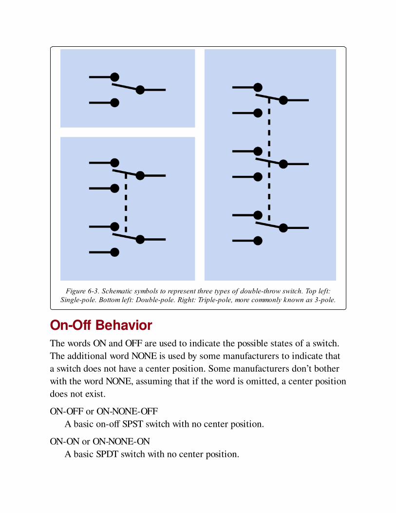
Figure 6-3. Schematic symbols to represent three types of double-throw switch. Top left:Single-pole. Bottom left: Double-pole. Right: Triple-pole, more commonly known as 3-pole.
On-Off BehaviorThe words ON and OFF are used to indicate the possible states of a switch.
The additional word NONE is used by some manufacturers to indicate that
a switch does not have a center position. Some manufacturers don’t bother
with the word NONE, assuming that if the word is omitted, a center position
does not exist.
ON-OFF or ON-NONE-OFF
A basic on-off SPST switch with no center position.
ON-ON or ON-NONE-ON
A basic SPDT switch with no center position.
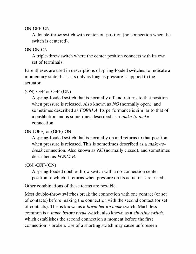
ON-OFF-ON
A double-throw switch with center-off position (no connection when the
switch is centered).
ON-ON-ON
A triple-throw switch where the center position connects with its own
set of terminals.
Parentheses are used in descriptions of spring-loaded switches to indicate a
momentary state that lasts only as long as pressure is applied to the
actuator.
(ON)-OFF or OFF-(ON)
A spring-loaded switch that is normally off and returns to that position
when pressure is released. Also known as NO (normally open), and
sometimes described as FORM A. Its performance is similar to that of
a pushbutton and is sometimes described as a make-to-make
connection.
ON-(OFF) or (OFF)-ON
A spring-loaded switch that is normally on and returns to that position
when pressure is released. This is sometimes described as a make-to-
break connection. Also known as NC (normally closed), and sometimes
described as FORM B.
(ON)-OFF-(ON)
A spring-loaded double-throw switch with a no-connection center
position to which it returns when pressure on its actuator is released.
Other combinations of these terms are possible.
Most double-throw switches break the connection with one contact (or set
of contacts) before making the connection with the second contact (or set
of contacts). This is known as a break before make switch. Much less
common is a make before break switch, also known as a shorting switch,
which establishes the second connection a moment before the first
connection is broken. Use of a shorting switch may cause unforeseen
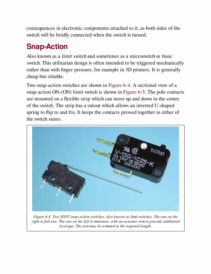
consequences in electronic components attached to it, as both sides of the
switch will be briefly connected when the switch is turned.
Snap-ActionAlso known as a limit switch and sometimes as a microswitch or basic
switch. This utilitarian design is often intended to be triggered mechanically
rather than with finger pressure, for example in 3D printers. It is generally
cheap but reliable.
Two snap-action switches are shown in Figure 6-4. A sectional view of a
snap-action ON-(ON) limit switch is shown in Figure 6-5. The pole contacts
are mounted on a flexible strip which can move up and down in the center
of the switch. The strip has a cutout which allows an inverted U-shaped
spring to flip to and fro. It keeps the contacts pressed together in either of
the switch states.
Figure 6-4. Two SPDT snap-action switches, also known as limit switches. The one on theright is full-size. The one on the left is miniature, with an actuator arm to provide additional
leverage. The arm may be trimmed to the required length.
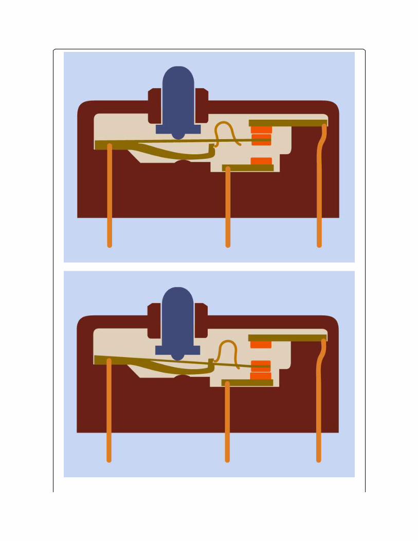
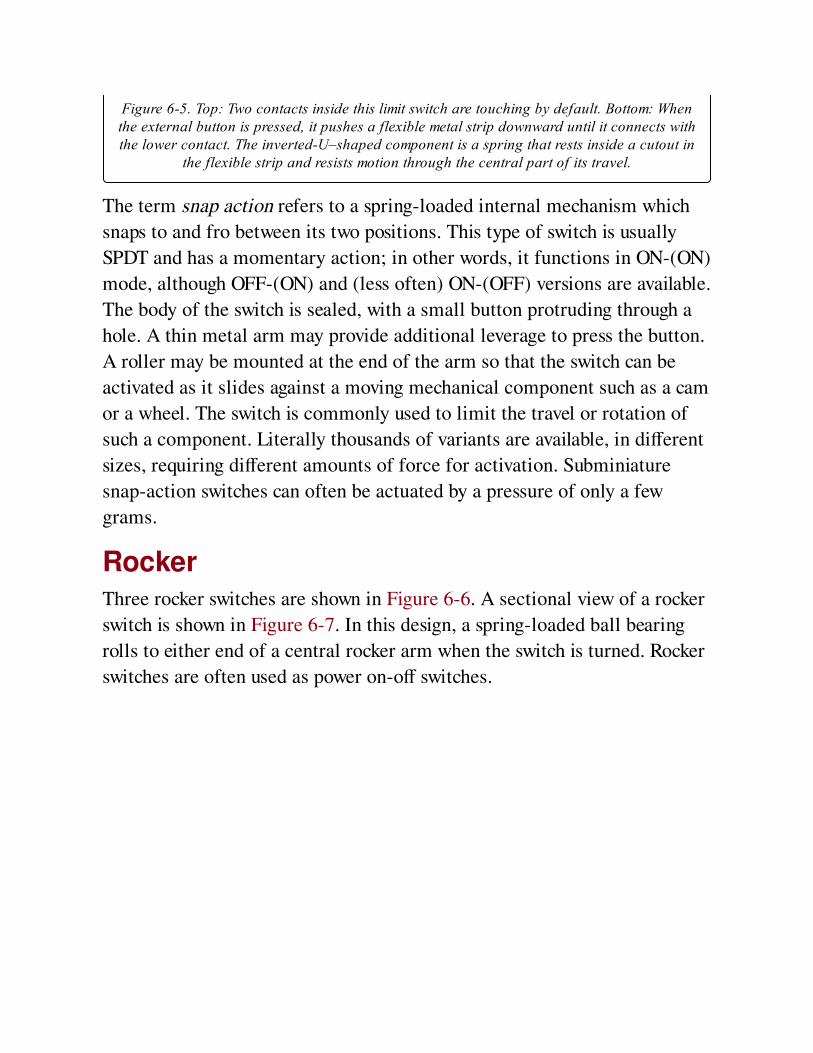
Figure 6-5. Top: Two contacts inside this limit switch are touching by default. Bottom: Whenthe external button is pressed, it pushes a flexible metal strip downward until it connects withthe lower contact. The inverted-U–shaped component is a spring that rests inside a cutout in
the flexible strip and resists motion through the central part of its travel.
The term snap action refers to a spring-loaded internal mechanism which
snaps to and fro between its two positions. This type of switch is usually
SPDT and has a momentary action; in other words, it functions in ON-(ON)
mode, although OFF-(ON) and (less often) ON-(OFF) versions are available.
The body of the switch is sealed, with a small button protruding through a
hole. A thin metal arm may provide additional leverage to press the button.
A roller may be mounted at the end of the arm so that the switch can be
activated as it slides against a moving mechanical component such as a cam
or a wheel. The switch is commonly used to limit the travel or rotation of
such a component. Literally thousands of variants are available, in different
sizes, requiring different amounts of force for activation. Subminiature
snap-action switches can often be actuated by a pressure of only a few
grams.
RockerThree rocker switches are shown in Figure 6-6. A sectional view of a rocker
switch is shown in Figure 6-7. In this design, a spring-loaded ball bearing
rolls to either end of a central rocker arm when the switch is turned. Rocker
switches are often used as power on-off switches.
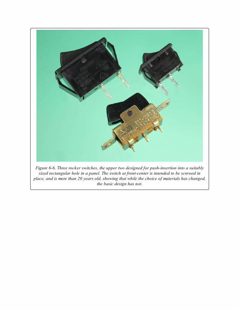
Figure 6-6. Three rocker switches, the upper two designed for push-insertion into a suitablysized rectangular hole in a panel. The switch at front-center is intended to be screwed in
place, and is more than 20 years old, showing that while the choice of materials has changed,the basic design has not.
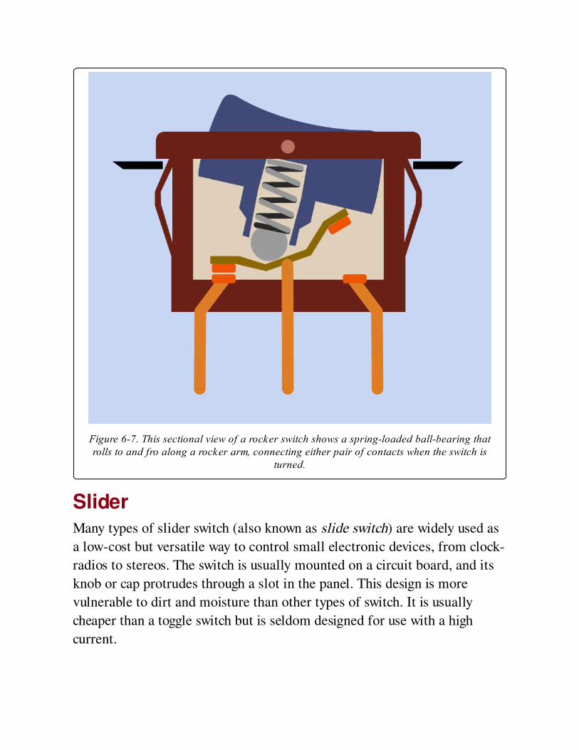
Figure 6-7. This sectional view of a rocker switch shows a spring-loaded ball-bearing thatrolls to and fro along a rocker arm, connecting either pair of contacts when the switch is
turned.
SliderMany types of slider switch (also known as slide switch) are widely used as
a low-cost but versatile way to control small electronic devices, from clock-
radios to stereos. The switch is usually mounted on a circuit board, and its
knob or cap protrudes through a slot in the panel. This design is more
vulnerable to dirt and moisture than other types of switch. It is usually
cheaper than a toggle switch but is seldom designed for use with a high
current.
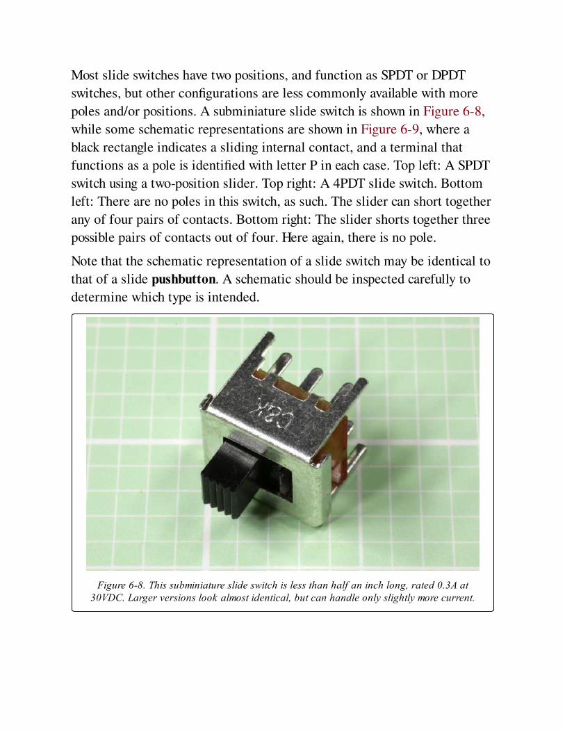
Most slide switches have two positions, and function as SPDT or DPDT
switches, but other configurations are less commonly available with more
poles and/or positions. A subminiature slide switch is shown in Figure 6-8,
while some schematic representations are shown in Figure 6-9, where a
black rectangle indicates a sliding internal contact, and a terminal that
functions as a pole is identified with letter P in each case. Top left: A SPDT
switch using a two-position slider. Top right: A 4PDT slide switch. Bottom
left: There are no poles in this switch, as such. The slider can short together
any of four pairs of contacts. Bottom right: The slider shorts together three
possible pairs of contacts out of four. Here again, there is no pole.
Note that the schematic representation of a slide switch may be identical to
that of a slide pushbutton. A schematic should be inspected carefully to
determine which type is intended.
Figure 6-8. This subminiature slide switch is less than half an inch long, rated 0.3A at30VDC. Larger versions look almost identical, but can handle only slightly more current.
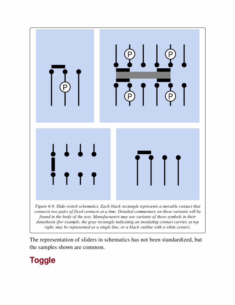
Figure 6-9. Slide switch schematics. Each black rectangle represents a movable contact thatconnects two pairs of fixed contacts at a time. Detailed commentary on these variants will be
found in the body of the text. Manufacturers may use variants of these symbols in theirdatasheets (for example, the gray rectangle indicating an insulating contact carrier, at top
right, may be represented as a single line, or a black outline with a white center).
The representation of sliders in schematics has not been standardized, but
the samples shown are common.
Toggle
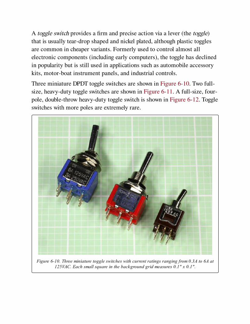
A toggle switch provides a firm and precise action via a lever (the toggle)
that is usually tear-drop shaped and nickel plated, although plastic toggles
are common in cheaper variants. Formerly used to control almost all
electronic components (including early computers), the toggle has declined
in popularity but is still used in applications such as automobile accessory
kits, motor-boat instrument panels, and industrial controls.
Three miniature DPDT toggle switches are shown in Figure 6-10. Two full-
size, heavy-duty toggle switches are shown in Figure 6-11. A full-size, four-
pole, double-throw heavy-duty toggle switch is shown in Figure 6-12. Toggle
switches with more poles are extremely rare.
Figure 6-10. Three miniature toggle switches with current ratings ranging from 0.3A to 6A at125VAC. Each small square in the background grid measures 0.1" x 0.1".
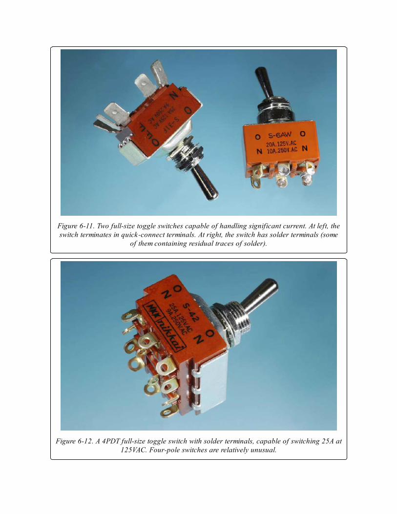
Figure 6-11. Two full-size toggle switches capable of handling significant current. At left, theswitch terminates in quick-connect terminals. At right, the switch has solder terminals (some
of them containing residual traces of solder).
Figure 6-12. A 4PDT full-size toggle switch with solder terminals, capable of switching 25A at125VAC. Four-pole switches are relatively unusual.
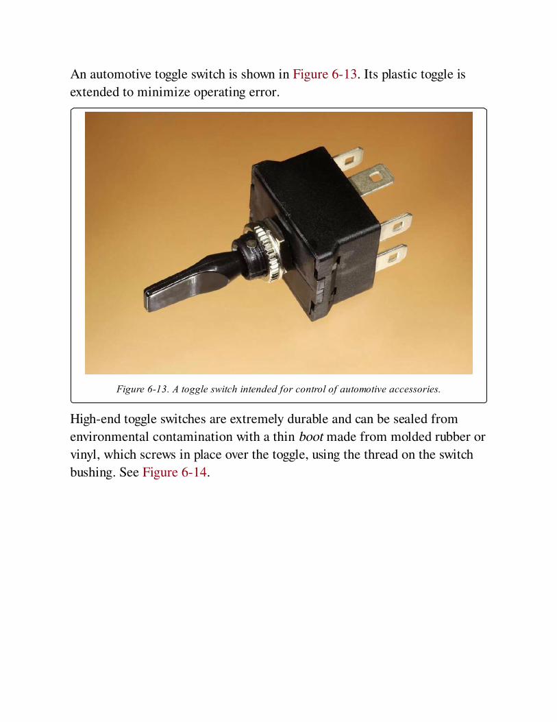
An automotive toggle switch is shown in Figure 6-13. Its plastic toggle is
extended to minimize operating error.
Figure 6-13. A toggle switch intended for control of automotive accessories.
High-end toggle switches are extremely durable and can be sealed from
environmental contamination with a thin boot made from molded rubber or
vinyl, which screws in place over the toggle, using the thread on the switch
bushing. See Figure 6-14.
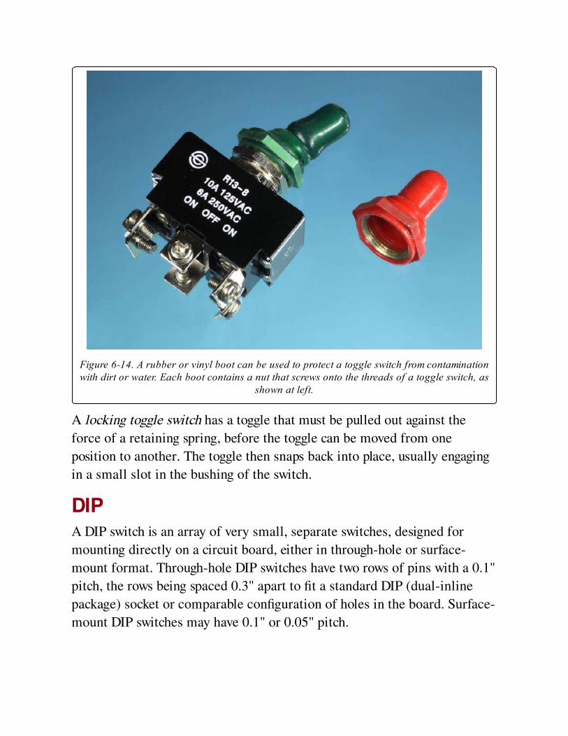
Figure 6-14. A rubber or vinyl boot can be used to protect a toggle switch from contaminationwith dirt or water. Each boot contains a nut that screws onto the threads of a toggle switch, as
shown at left.
A locking toggle switch has a toggle that must be pulled out against the
force of a retaining spring, before the toggle can be moved from one
position to another. The toggle then snaps back into place, usually engaging
in a small slot in the bushing of the switch.
DIPA DIP switch is an array of very small, separate switches, designed for
mounting directly on a circuit board, either in through-hole or surface-
mount format. Through-hole DIP switches have two rows of pins with a 0.1"
pitch, the rows being spaced 0.3" apart to fit a standard DIP (dual-inline
package) socket or comparable configuration of holes in the board. Surface-
mount DIP switches may have 0.1" or 0.05" pitch.
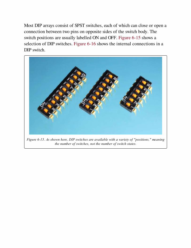
Most DIP arrays consist of SPST switches, each of which can close or open a
connection between two pins on opposite sides of the switch body. The
switch positions are usually labelled ON and OFF. Figure 6-15 shows a
selection of DIP switches. Figure 6-16 shows the internal connections in a
DIP switch.
Figure 6-15. As shown here, DIP switches are available with a variety of "positions," meaningthe number of switches, not the number of switch states.
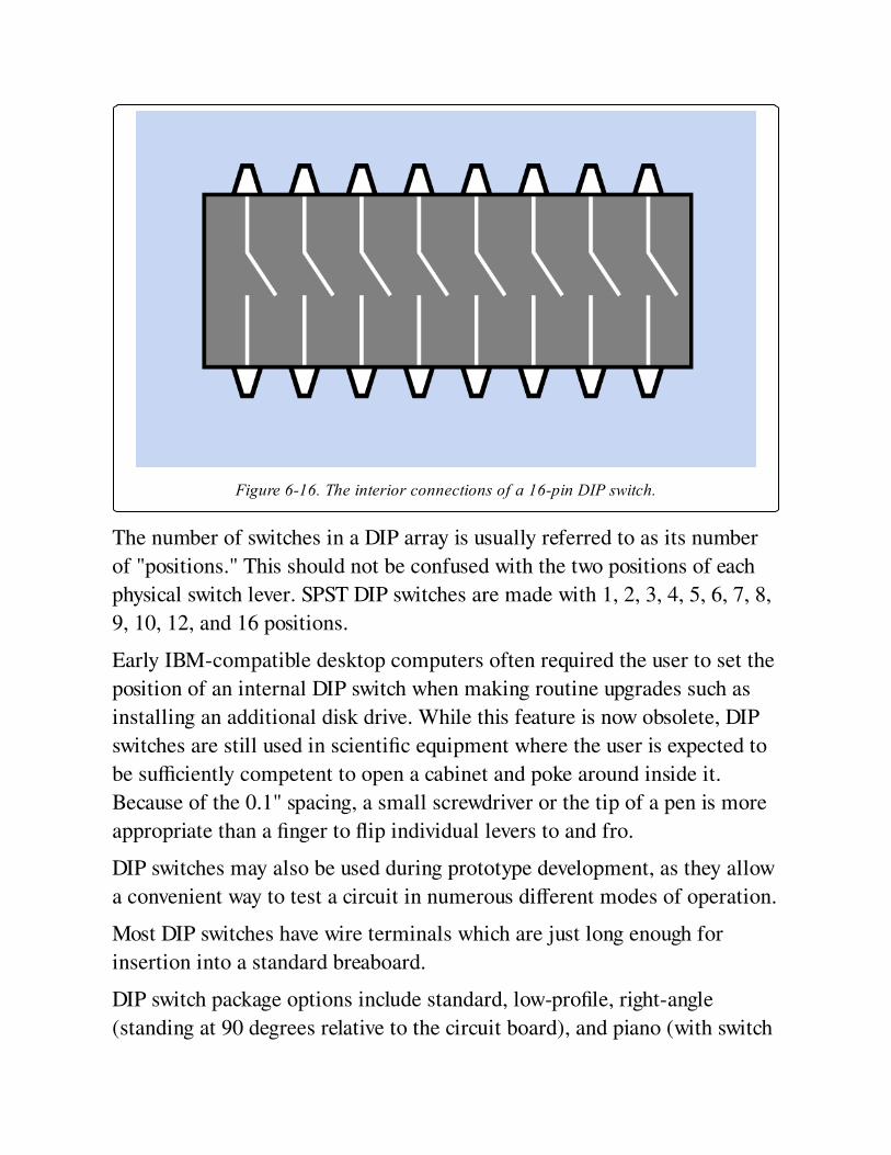
Figure 6-16. The interior connections of a 16-pin DIP switch.
The number of switches in a DIP array is usually referred to as its number
of "positions." This should not be confused with the two positions of each
physical switch lever. SPST DIP switches are made with 1, 2, 3, 4, 5, 6, 7, 8,
9, 10, 12, and 16 positions.
Early IBM-compatible desktop computers often required the user to set the
position of an internal DIP switch when making routine upgrades such as
installing an additional disk drive. While this feature is now obsolete, DIP
switches are still used in scientific equipment where the user is expected to
be sufficiently competent to open a cabinet and poke around inside it.
Because of the 0.1" spacing, a small screwdriver or the tip of a pen is more
appropriate than a finger to flip individual levers to and fro.
DIP switches may also be used during prototype development, as they allow
a convenient way to test a circuit in numerous different modes of operation.
Most DIP switches have wire terminals which are just long enough for
insertion into a standard breaboard.
DIP switch package options include standard, low-profile, right-angle
(standing at 90 degrees relative to the circuit board), and piano (with switch
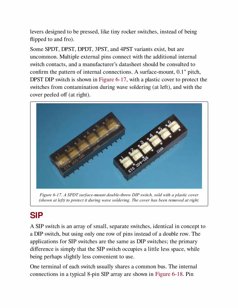
levers designed to be pressed, like tiny rocker switches, instead of being
flipped to and fro).
Some SPDT, DPST, DPDT, 3PST, and 4PST variants exist, but are
uncommon. Multiple external pins connect with the additional internal
switch contacts, and a manufacturer’s datasheet should be consulted to
confirm the pattern of internal connections. A surface-mount, 0.1" pitch,
DPST DIP switch is shown in Figure 6-17, with a plastic cover to protect the
switches from contamination during wave soldering (at left), and with the
cover peeled off (at right).
Figure 6-17. A SPDT surface-mount double-throw DIP switch, sold with a plastic cover(shown at left) to protect it during wave soldering. The cover has been removed at right.
SIPA SIP switch is an array of small, separate switches, identical in concept to
a DIP switch, but using only one row of pins instead of a double row. The
applications for SIP switches are the same as DIP switches; the primary
difference is simply that the SIP switch occupies a little less space, while
being perhaps slightly less convenient to use.
One terminal of each switch usually shares a common bus. The internal
connections in a typical 8-pin SIP array are shown in Figure 6-18. Pin
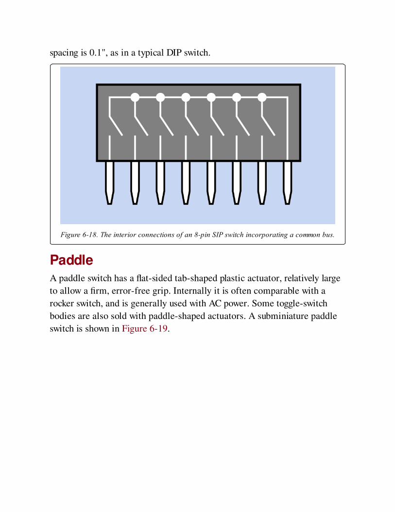
spacing is 0.1", as in a typical DIP switch.
Figure 6-18. The interior connections of an 8-pin SIP switch incorporating a common bus.
PaddleA paddle switch has a flat-sided tab-shaped plastic actuator, relatively large
to allow a firm, error-free grip. Internally it is often comparable with a
rocker switch, and is generally used with AC power. Some toggle-switch
bodies are also sold with paddle-shaped actuators. A subminiature paddle
switch is shown in Figure 6-19.
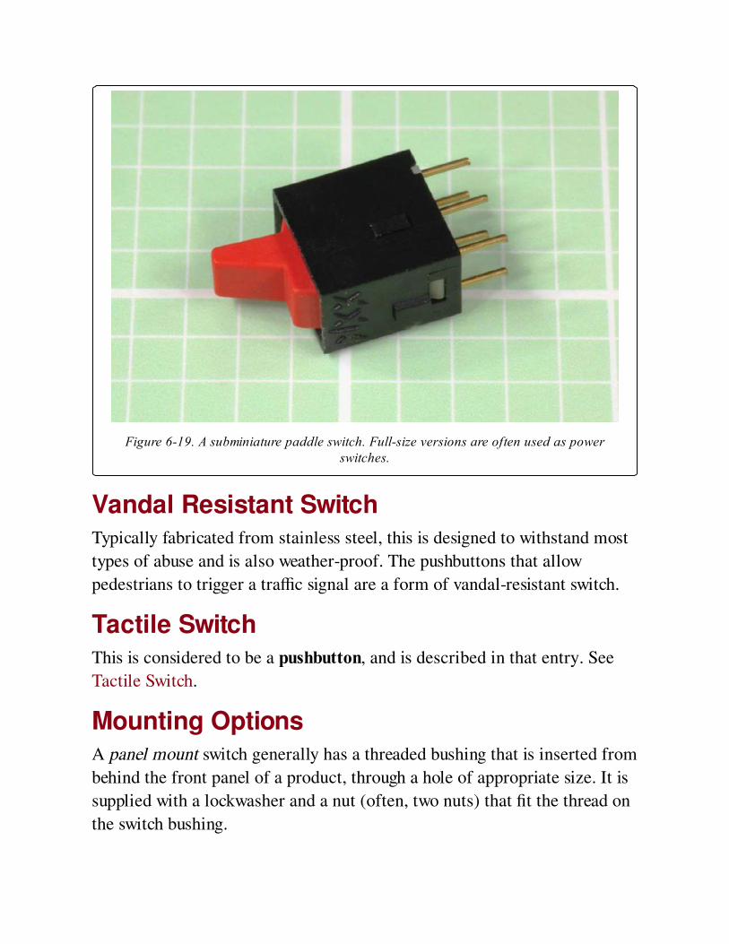
Figure 6-19. A subminiature paddle switch. Full-size versions are often used as powerswitches.
Vandal Resistant SwitchTypically fabricated from stainless steel, this is designed to withstand most
types of abuse and is also weather-proof. The pushbuttons that allow
pedestrians to trigger a traffic signal are a form of vandal-resistant switch.
Tactile SwitchThis is considered to be a pushbutton, and is described in that entry. See
Tactile Switch.
Mounting OptionsA panel mount switch generally has a threaded bushing that is inserted from
behind the front panel of a product, through a hole of appropriate size. It is
supplied with a lockwasher and a nut (often, two nuts) that fit the thread on
the switch bushing.
Front panel mount usually means that screws visible from the front of the
panel are attached to a bracket on the switch behind the panel. The actuator
of the switch is accessible through a cutout in the panel. This mounting style
is mostly used for rocker switches and sometimes for slide switches.
Subpanel mount means that the switch is attached to a separate plate or
chassis behind the control panel. The actuator of the switch is accessible
through a cutout.
Snap-in mount requires a switch with flexible plastic or metal tabs each
side, designed to push through a cutout in the panel, at which point the tabs
spring out and retain the switch.
PC mount switches have pins that are soldered into a printed circuit board.
They may have additional solderable lugs to provide mechanical support.
Surface mount switches are attached to a board in the same manner as
other surface-mount components.
TerminationSwitches (and pushbuttons) are available with a variety of terminals.
Solder lugs are small tabs, each usually perforated with a hole through
which the end of a wire can be inserted prior to soldering.
PC terminals are pins that protrude from the bottom of the switch, suitable
for insertion in a printed circuit board. This style is also known as a
through-hole. The terminals may have a right-angle bend to allow the
component to be mounted flat against the board, with the switch actuator
sticking out at the side. This termination style is known as right-angle PC.
Many manufacturers offer a choice of straight or bent pin terminals, but the
component may be listed in a catalog under either of those options, with no
indication that other options exist. Check manufacturer datasheets
carefully.
Quick connect terminals are spade-shaped to accept push-on connectors,
commonly used in automotive applications. Hybrid quick-connect
terminals that can also function as solder lugs are sometimes offered as an
option.
Screw terminals have screws premounted in flat terminals, for solderless
attachment of wires.
Wire leads are flexible insulated wires, often with stripped and tinned ends,
protruding at least an inch from the body of the component. This option is
becoming uncommon.
Contact Plating OptionsThe internal electrical contacts of a switch are usually plated with silver or
gold. Nickel, tin, and silver alloys are cheaper but less common. Other types
are relatively rare.
ValuesSwitches designed for electronic devices vary widely in power capability,
depending on their purpose. Rocker switches, paddle switches, and toggle
switches are often used to turn power on and off, and are typically rated for
10A at 125VAC, although some toggle switches go as high as 30A. Snap-
action or limit switches may be similarly rated, although miniature versions
will have reduced capability. Slide switches cannot handle significant power,
and are often rated around 0.5A (or less) at 30VDC. DIP and SIP switches
have a typical maximum rating of 100mA at 50V and are not designed for
frequent use. Generally they are used only when the power to the device is
off.
How to Use it
Power SwitchesWhen a simple SPST switch is used to turn DC power on and off, it
conventionally switches the positive side of the power supply, also
sometimes known as the high side. The primary reason for following this
convention is that it is widely used; thus, following it will reduce confusion.
More importantly, an on-off switch that controls AC power must be used on
the "live" side of the supply, not the "neutral" side. If you have any doubts
about these concepts (which go beyond the scope of this book), consult a
reference guide on this subject. Using a DPST component to switch both
sides of an AC supply may be a worthwhile additional precaution in some
applications. The ground wire of an AC supply should never be switched,
because the device should always be grounded when it is plugged into an
electric outlet.
Limit SwitchesAn application for two limit switches with a DC motor and two rectifier
diodes is shown in Figure 6-20. This diagram assumes that the motor turns
clockwise when its lower terminal is positive, and counter-clockwise when
its upper terminal is positive. Only two terminals are used (and shown) in
each limit switch; they are chosen to be normally-closed. Other terminals
inside a switch may exist, may be normally-open, and can be ignored.
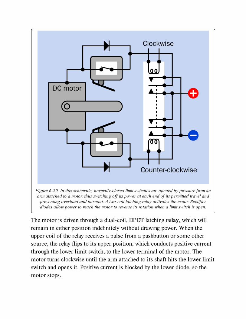
Figure 6-20. In this schematic, normally-closed limit switches are opened by pressure from anarm attached to a motor, thus switching off its power at each end of its permitted travel and
preventing overload and burnout. A two-coil latching relay activates the motor. Rectifierdiodes allow power to reach the motor to reverse its rotation when a limit switch is open.
The motor is driven through a dual-coil, DPDT latching relay, which will
remain in either position indefinitely without drawing power. When the
upper coil of the relay receives a pulse from a pushbutton or some other
source, the relay flips to its upper position, which conducts positive current
through the lower limit switch, to the lower terminal of the motor. The
motor turns clockwise until the arm attached to its shaft hits the lower limit
switch and opens it. Positive current is blocked by the lower diode, so the
motor stops.

When the lower coil of the relay is activated, the relay flips to its lower
position. Positive current can now reach the upper side of the motor through
the upper limit switch. The motor runs counter-clockwise until its arm
opens the upper limit switch, at which point the motor stops again. This
simple system allows a DC motor to be run in either direction by a button-
press of any duration, without risk of burnout when the motor reaches the
end of its travel. It has been used for applications such as raising and
lowering powered windows in an automobile.
A DPDT pushbutton could be substituted for the latching relay if manual
control, only, is acceptable. However, in this scenario, sustained pressure on
the pushbutton would be necessary to move the motor arm all the way to
the opposite end of its travel. A DPDT switch might be more appropriate
than a pushbutton.
Logic CircuitsLogic circuits that depend purely on switches can be constructed (for
example, to add binary numbers) but are rare and have no practical
applications. The most familiar and simplest example of manually switched
logic is a pair of SPDT switches in house wiring, one positioned at the top
of a flight of stairs and the other at the bottom, as shown in Figure 6-21.
Either switch will turn the light on if it is currently off, or off if it is
currently on. To extend this circuit by incorporating a third switch that has
the same function as the other two, a DPDT switch must be inserted. See
Figure 6-22.
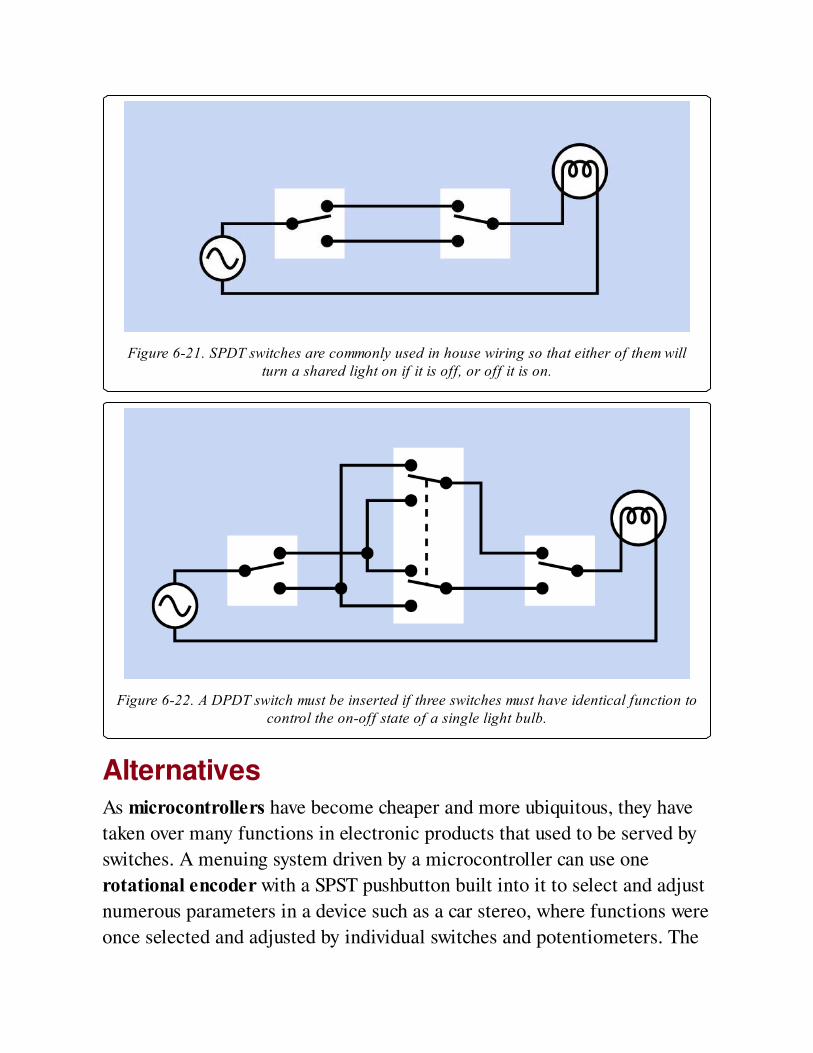
Figure 6-21. SPDT switches are commonly used in house wiring so that either of them willturn a shared light on if it is off, or off it is on.
Figure 6-22. A DPDT switch must be inserted if three switches must have identical function tocontrol the on-off state of a single light bulb.
AlternativesAs microcontrollers have become cheaper and more ubiquitous, they have
taken over many functions in electronic products that used to be served by
switches. A menuing system driven by a microcontroller can use one
rotational encoder with a SPST pushbutton built into it to select and adjust
numerous parameters in a device such as a car stereo, where functions were
once selected and adjusted by individual switches and potentiometers. The
rotational-encoder option takes up less space, is cheaper to build (assuming
a microcontroller is going to be used in the device for other purposes
anyway), and can be more reliable, as it reduces the number of
electromechanical parts. Whether it is easier to use is a matter of taste. Cost
and ergonomics may be the primary factors to consider when choosing
where and how to use switches.
What Can Go Wrong
ArcingThe contacts inside a switch will be rapidly eroded if arcing (pronounced
"arking") occurs. An electric arc is a spark that tends to form when a switch
is opened while conducting a high current or high voltage (typically 10A or
more and 100V or more). The most common cause is an inductive load that
generates back-EMF when it is switched on and forward-EMF when it is
switched off. The surge can be many times the amperage that the load draws
during continuous operation. In DC circuits, arcing can be reduced by using
a rectifier diode in parallel with the load (with its polarity blocking normal
current flow). This is often referred to as a flyback diode or freewheeling
diode. In AC circuits, where a diode cannot be used in this way, a snubber
(a simple combination of capacitor and resistor) may be placed around the
load. A snubber can also be used around the switch itself, in DC circuits.
See Snubber.
When switching an inductive load, it is generally prudent to use switches
rated for twice as much current as the circuit will normally draw.
Dry JointsSwitches that control significant current will have substantial terminals, and
these terminals will be attached to heavy-gauge wire. When using solder to
make this type of connection, the combined heat capacity of the wire and
the terminal will sink a lot more heat than a small component on a circuit
board. At least a 30W soldering iron should be used. Lower-wattage irons
may be incapable of melting the solder completely (even though they seem
to), and a "dry joint" will result, which can have a relatively high electrical
resistance and will be mechanically weak, liable to break later. Any good
solder joint should withstand flexing of the wire attached to it.
Short CircuitsBecause many switches are still wired in with solder tabs, screw terminals,
or quick-connect terminals, wires that become accidentally detached can be
a significant hazard. Heat-shrink tubing should be applied to enclose wires
and terminals at the rear of a power switch, as an additional precaution.
Power switches should always be used in conjunction with appropriate
fuses.
Contact ContaminationSealed switches should be used in any environment where dirt or water may
be present. Slide switches are especially vulnerable to contamination, and
are difficult to seal. Switches used in audio components will create
"scratchy" sounds if their contacts deteriorate.
Wrong Terminal TypeBecause switches are available with a wide variety of terminal types, it’s
easy to order the wrong type. Switches may be supplied with pins for
through-hole insertion in circuit boards; screw terminals; quick-disconnect
terminals; or solder lugs. Variants may also be available for surface mount.
If a project requires, for example, the insertion of pins in a printed circuit
board, and a switch is supplied with solder lugs, it will be unusable.
Part numbers generally include codes to identify each terminal variant, and
should be studied carefully.
Contact BounceAlso known as switch bounce. When two contacts snap together, extremely
rapid, microscopic vibrations occur that cause brief interruptions before the
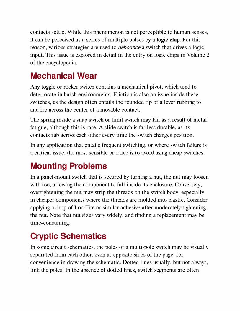
contacts settle. While this phenomenon is not perceptible to human senses,
it can be perceived as a series of multiple pulses by a logic chip. For this
reason, various strategies are used to debounce a switch that drives a logic
input. This issue is explored in detail in the entry on logic chips in Volume 2
of the encyclopedia.
Mechanical WearAny toggle or rocker switch contains a mechanical pivot, which tend to
deteriorate in harsh environments. Friction is also an issue inside these
switches, as the design often entails the rounded tip of a lever rubbing to
and fro across the center of a movable contact.
The spring inside a snap switch or limit switch may fail as a result of metal
fatigue, although this is rare. A slide switch is far less durable, as its
contacts rub across each other every time the switch changes position.
In any application that entails frequent switching, or where switch failure is
a critical issue, the most sensible practice is to avoid using cheap switches.
Mounting ProblemsIn a panel-mount switch that is secured by turning a nut, the nut may loosen
with use, allowing the component to fall inside its enclosure. Conversely,
overtightening the nut may strip the threads on the switch body, especially
in cheaper components where the threads are molded into plastic. Consider
applying a drop of Loc-Tite or similar adhesive after moderately tightening
the nut. Note that nut sizes vary widely, and finding a replacement may be
time-consuming.
Cryptic SchematicsIn some circuit schematics, the poles of a multi-pole switch may be visually
separated from each other, even at opposite sides of the page, for
convenience in drawing the schematic. Dotted lines usually, but not always,
link the poles. In the absence of dotted lines, switch segments are often

coded to indicate their commonality. For example, SW1(a) and SW1(b) are
almost certainly different parts of the same switch, with linked poles.
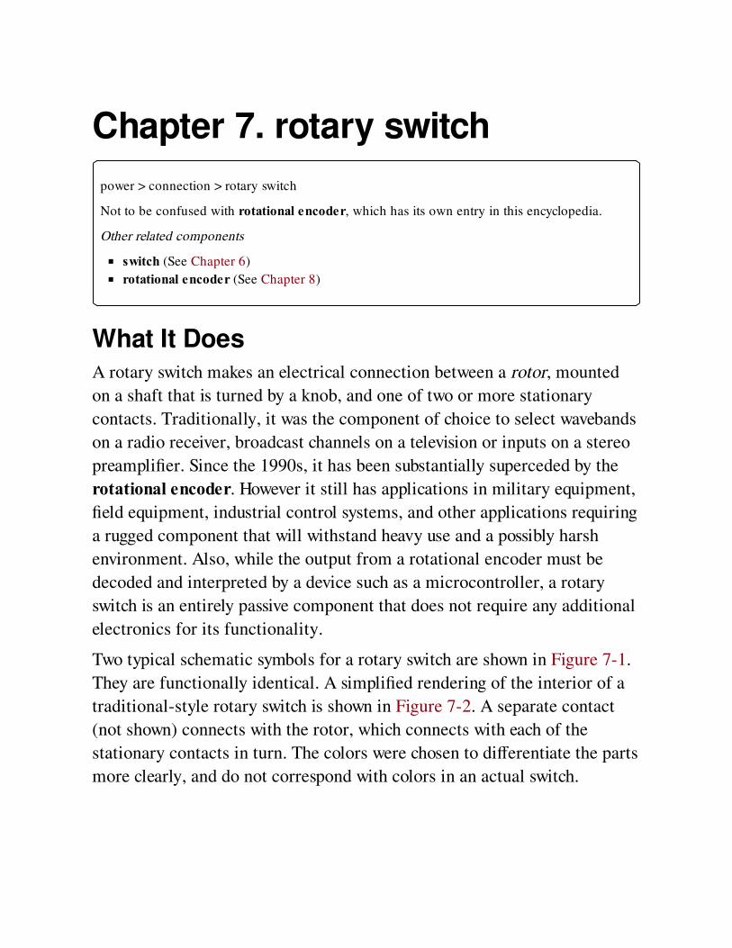
Chapter 7. rotary switch
power > connection > rotary switch
Not to be confused with rotational encoder, which has its own entry in this encyclopedia.
Other related components
switch (See Chapter 6)
rotational encoder (See Chapter 8)
What It DoesA rotary switch makes an electrical connection between a rotor, mounted
on a shaft that is turned by a knob, and one of two or more stationary
contacts. Traditionally, it was the component of choice to select wavebands
on a radio receiver, broadcast channels on a television or inputs on a stereo
preamplifier. Since the 1990s, it has been substantially superceded by the
rotational encoder. However it still has applications in military equipment,
field equipment, industrial control systems, and other applications requiring
a rugged component that will withstand heavy use and a possibly harsh
environment. Also, while the output from a rotational encoder must be
decoded and interpreted by a device such as a microcontroller, a rotary
switch is an entirely passive component that does not require any additional
electronics for its functionality.
Two typical schematic symbols for a rotary switch are shown in Figure 7-1.
They are functionally identical. A simplified rendering of the interior of a
traditional-style rotary switch is shown in Figure 7-2. A separate contact
(not shown) connects with the rotor, which connects with each of the
stationary contacts in turn. The colors were chosen to differentiate the parts
more clearly, and do not correspond with colors in an actual switch.
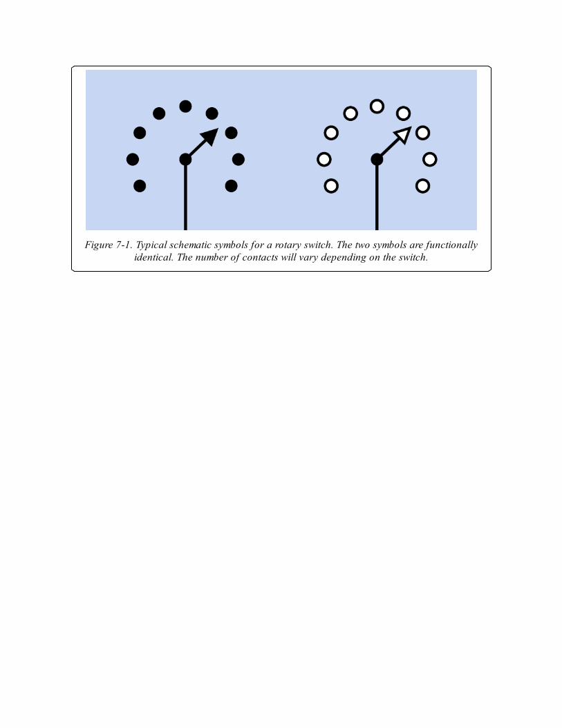
Figure 7-1. Typical schematic symbols for a rotary switch. The two symbols are functionallyidentical. The number of contacts will vary depending on the switch.

Figure 7-2. A simplified rendering of interior parts in a basic SP6T rotary switch. Arbitrarycolors have been added for clarity.
A selection of rotary switches is shown in Figure 7-3. At top-left is an open
frame switch, providing no protection to its contacts from contaminants.
This type of component is now rare. At top-right is a twelve-position, single-
pole switch rated 2.5A at 125VAC. At front-left is a four-position, single-
pole switch rated 0.3A at 16VDC or 100VAC. At front right is a two-
position, two-pole switch with the same rating as the one beside it. All the
sealed switches allow a choice of panel mounting or through-hole printed
circuit board mounting.
How It WorksA switch may have multiple poles, each connecting with its own rotor. The
rotors are likely to be on separate decks of the switch, but two, three, or
four rotors, pointing in different directions, may be combined on a single
deck if the switch has only a small number of positions.
Rotary switches are usually made with a maximum of twelve positions, but
include provision for limiting the number of positions with a stop. This is
typically a pin, which may be attached to a washer that fits around the
bushing of the switch. The pin is inserted into a choice of holes to prevent
the switch from turning past that point. For example, an eight-position
rotary switch can be configured so that it has only seven (or as few as two)
available positions.
A specification for a rotary switch usually includes the angle through which
the switch turns between one position and the next. A twelve-position switch
usually has a 30-degree turn angle.
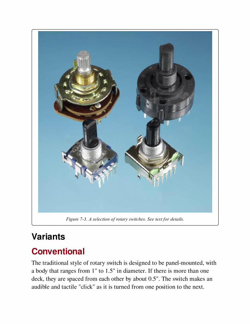
Figure 7-3. A selection of rotary switches. See text for details.
Variants
ConventionalThe traditional style of rotary switch is designed to be panel-mounted, with
a body that ranges from 1" to 1.5" in diameter. If there is more than one
deck, they are spaced from each other by about 0.5". The switch makes an
audible and tactile "click" as it is turned from one position to the next.
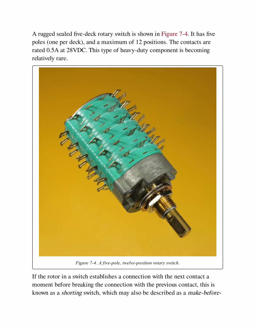
A rugged sealed five-deck rotary switch is shown in Figure 7-4. It has five
poles (one per deck), and a maximum of 12 positions. The contacts are
rated 0.5A at 28VDC. This type of heavy-duty component is becoming
relatively rare.
Figure 7-4. A five-pole, twelve-position rotary switch.
If the rotor in a switch establishes a connection with the next contact a
moment before breaking the connection with the previous contact, this is
known as a shorting switch, which may also be described as a make-before-
break switch. In a nonshorting or break-before-make switch, a tiny interval
separates one connection from the next. This can be of significant
importance, depending on the components that are connected with the
switch.
The shaft may be round, splined, or D-shaped in section. A knob is seldom
supplied with a switch and must be chosen to match the shaft. Some shaft
dimensions are metric, while others are measured in inches, with 1/4"
diameter being the oldest standard. Some switches with a splined shaft are
supplied with an adapter for a knob of D-shaped internal section; the
adapter can be slipped onto the shaft in any of 12 or more positions, to
minimize the inconvenience of positioning the body of the switch itself so
that the knob is correctly oriented in relation to positions printed on the
face of the panel.
Miniature rotary switches may be as small as 0.5" diameter, and usually
terminate in pins for through-hole mounting on a PC board. Miniature
switches usually have lower current ratings than full-size switches.
Rotary switches must be securely anchored to resist the high turning forces
that can be inflicted upon them by users. In a panel-mount design, a nut is
tightened around a thread on the bushing of the switch. Through-hole
versions can be secured to the PC board with the shaft protruding loosely
through a cutout in the panel. To minimize mechanical stress on the circuit
board, the detents in a PC-board switch are usually weaker than in a full-
size switch, and the knob is usually smaller, allowing less leverage.
Rotary DIPA conventional DIP switch is a linear array of miniature SPST switches
designed to fit a standard DIP (dual-inline package) layout of holes in a
circuit board. It is described in the switch entry of this encyclopedia. A
rotary DIP switch (also known as an encoded output rotary switch or a
coded rotary switch) does not conform with a DIP layout, despite its name.
It is approximately 0.4" square and usually has five pins, one of which can
be considered the input or common pin while the other four can function as

outputs. The pins are spaced at 0.1" pitch from one another. Pin function
and layout are not standardized.
A dial on top of the switch has either 10 positions (numbered 0 through 9)
or 16 positions (0 through 9 followed by letters A through F). One switch of
each type is shown in Figure 7-5.
Figure 7-5. A rotary DIP switch, also known as an encoded output rotary switch, may be usedas a substitute for a DIP switch in some applications.
Each position of the dial closes pairs of contacts inside the component to
create a unique binary-coded decimal pattern (in a 10-position switch) or
binary-coded hexadecimal pattern (in the 16-position switch) on the four
output pins. The pin states are shown in Figure 7-6. A rotary DIP switch is a

relatively flimsy device, and is not designed for frequent or heavy use. It is
more likely to be a "set it and forget it" device whose state is established
when it is installed in a circuit board.

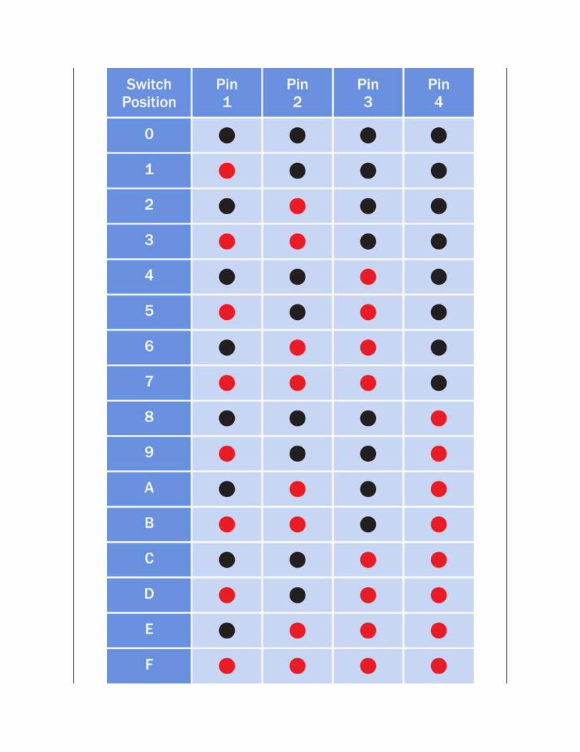
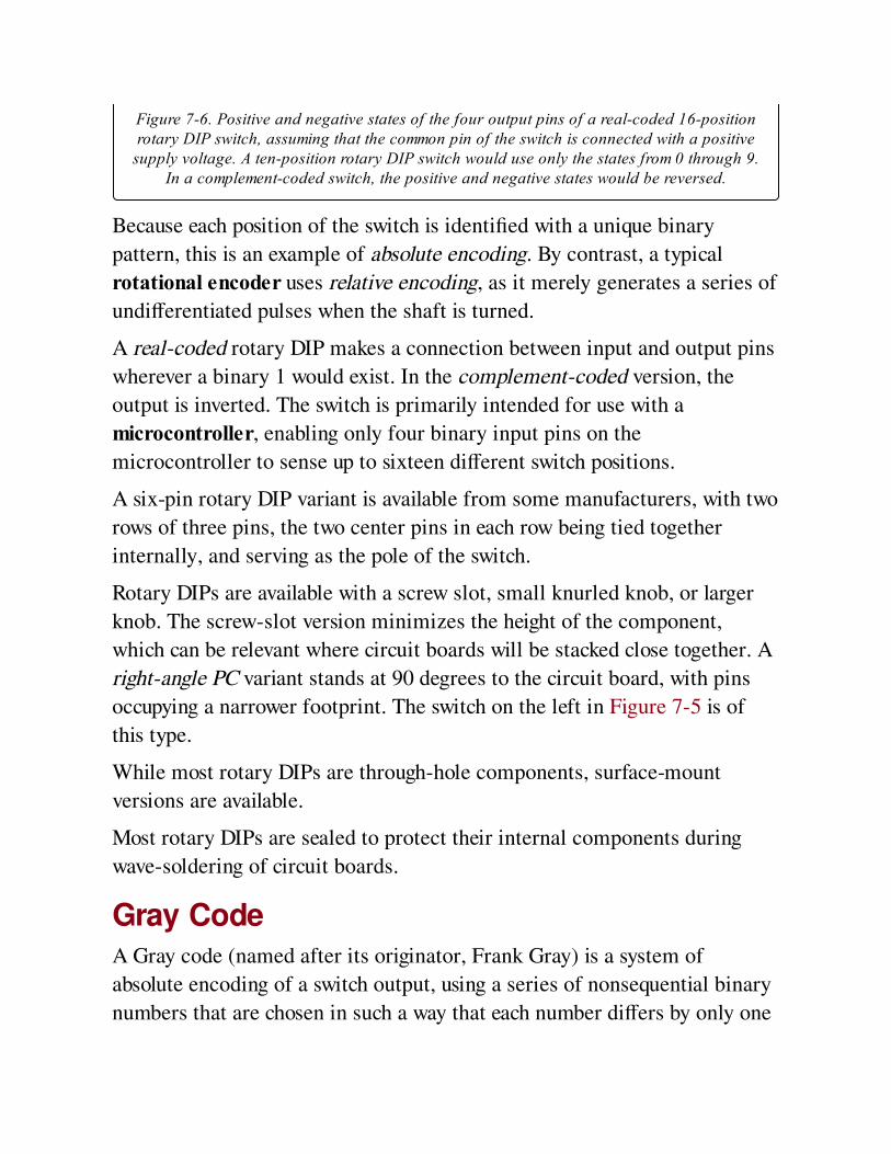
Figure 7-6. Positive and negative states of the four output pins of a real-coded 16-positionrotary DIP switch, assuming that the common pin of the switch is connected with a positive
supply voltage. A ten-position rotary DIP switch would use only the states from 0 through 9.In a complement-coded switch, the positive and negative states would be reversed.
Because each position of the switch is identified with a unique binary
pattern, this is an example of absolute encoding. By contrast, a typical
rotational encoder uses relative encoding, as it merely generates a series of
undifferentiated pulses when the shaft is turned.
A real-coded rotary DIP makes a connection between input and output pins
wherever a binary 1 would exist. In the complement-coded version, the
output is inverted. The switch is primarily intended for use with a
microcontroller, enabling only four binary input pins on the
microcontroller to sense up to sixteen different switch positions.
A six-pin rotary DIP variant is available from some manufacturers, with two
rows of three pins, the two center pins in each row being tied together
internally, and serving as the pole of the switch.
Rotary DIPs are available with a screw slot, small knurled knob, or larger
knob. The screw-slot version minimizes the height of the component,
which can be relevant where circuit boards will be stacked close together. A
right-angle PC variant stands at 90 degrees to the circuit board, with pins
occupying a narrower footprint. The switch on the left in Figure 7-5 is of
this type.
While most rotary DIPs are through-hole components, surface-mount
versions are available.
Most rotary DIPs are sealed to protect their internal components during
wave-soldering of circuit boards.
Gray CodeA Gray code (named after its originator, Frank Gray) is a system of
absolute encoding of a switch output, using a series of nonsequential binary
numbers that are chosen in such a way that each number differs by only one
digit from the preceding number. Such a series is useful because it
eliminates the risk that when a switch turns, some bits in the output will
change before others, creating the risk of erroneous interpretation. A
minority of rotary switches or rotational encoders are available with Gray-
coded outputs. Typically, a microcontroller must use a lookup table to
convert each binary output to an angular switch position.
PC Board Rotary SwitchMiniature switches with a conventional, non-encoded output are available
for printed-circuit board mounting, sometimes requiring a screwdriver or
hex wrench to select a position. A single-pole eight-position switch of this
type is shown in Figure 7-7. Its contacts are rated to carry 0.5A at 30VDC,
but it is not designed to switch this current actively.

Figure 7-7. This miniature switch is designed for insertion on a printed circuit board. It canbe used to make a setting before a device is shipped to the end user.
Mechanical EncoderA mechanical encoder functions similarly to a rotary DIP switch but is
intended for much heavier use. It outputs a binary-coded-decimal value
corresponding with its shaft position, is typically the size of a miniature
rotary switch, and is designed for panel mounting. The Grayhill Series 51
allows 12 positions, each generating a code among four terminals. The
Bourns EAW provides 128 positions, each generating a code among 8
terminals.
Pushwheel and ThumbwheelA pushwheel switch is a simple electromechanical device that enables an
operator to provide a code number as input to data processing equipment,
often in industrial process control. The decimal version contains a wheel on
which numbers are printed, usually in white on black, from 0 through 9,
visible one at a time through a window in the face of the switch. A button
above the wheel, marked with a minus sign, rotates it to the next lower
number, while a button below the wheel, marked with a plus sign, rotates it
to the next higher number. A connector at the rear of the unit includes a
common (input) pin and four output pins with values 1, 2, 4, and 8. An
additional set of pins with values 1, 2, 3, and 4 is often provided. The states
of the output pins sum to the value that is currently being displayed by the
wheel. Often two, three, or four pushwheels (each with an independent set
of connector pins) are combined in one unit, although individual
pushwheels are available and can be stacked in a row.
A thumbwheel switch operates like a pushwheel switch, except that it uses a
thumbwheel instead of two buttons. Miniaturized thumbwheel switches are
available for through-hole mounting on PC boards.
Hexadecimal versions are also available, with numbers from 0 through 9
followed by letters A through F, although they are less common than
decimal versions.
KeylockA keylock switch is generally a two-position rotary switch that can be turned
only after insertion of a key in a lock attached to the top of the shaft. This
type of switch almost always has an OFF-(ON) configuration and is used to
control power. Keylock switches are found in locations such as elevators, for
fire-department access; in cash registers; or on data-processing equipment
where switching power on or off is reserved for a system administrator.
ValuesA full-size rotary switch may be rated from 0.5A at 30VDC to 5A at
125VAC, depending on its purpose. A very few switches are rated 30A at
125VAC; these are high-quality, durable, expensive items.
A typical rotary DIP switch is rated 30mA at 30VDC and has a carrying
current rating (continuous current when no switching occurs) of no more
than 100mA at 50VDC.
How to Use itIn addition to its traditional purpose as a mode or option selector, a rotary
switch provides a user-friendly way to input data values. Three ten-position
switches, for instance, can allow user input of a decimal number ranging
from 000 to 999.
When used with a microcontroller, a rotary switch can have a resistor
ladder mounted around its contacts, like a multi-point voltage divider, so
that each position of the rotor provides a unique potential ranging between
the positive supply voltage and negative ground. This concept is illustrated
in Figure 7-8, where all the resistors have the same value. The voltage can
be used as an input to the microcontroller, so long as the microcontroller
shares a common ground with the switch. An analog-digital converter
inside the microcontroller translates the voltage into a digital value. The
advantage of this scheme is that it allows very rapid control by the user,
while requiring only one pin on the microcontroller to sense as many as
twelve input states.
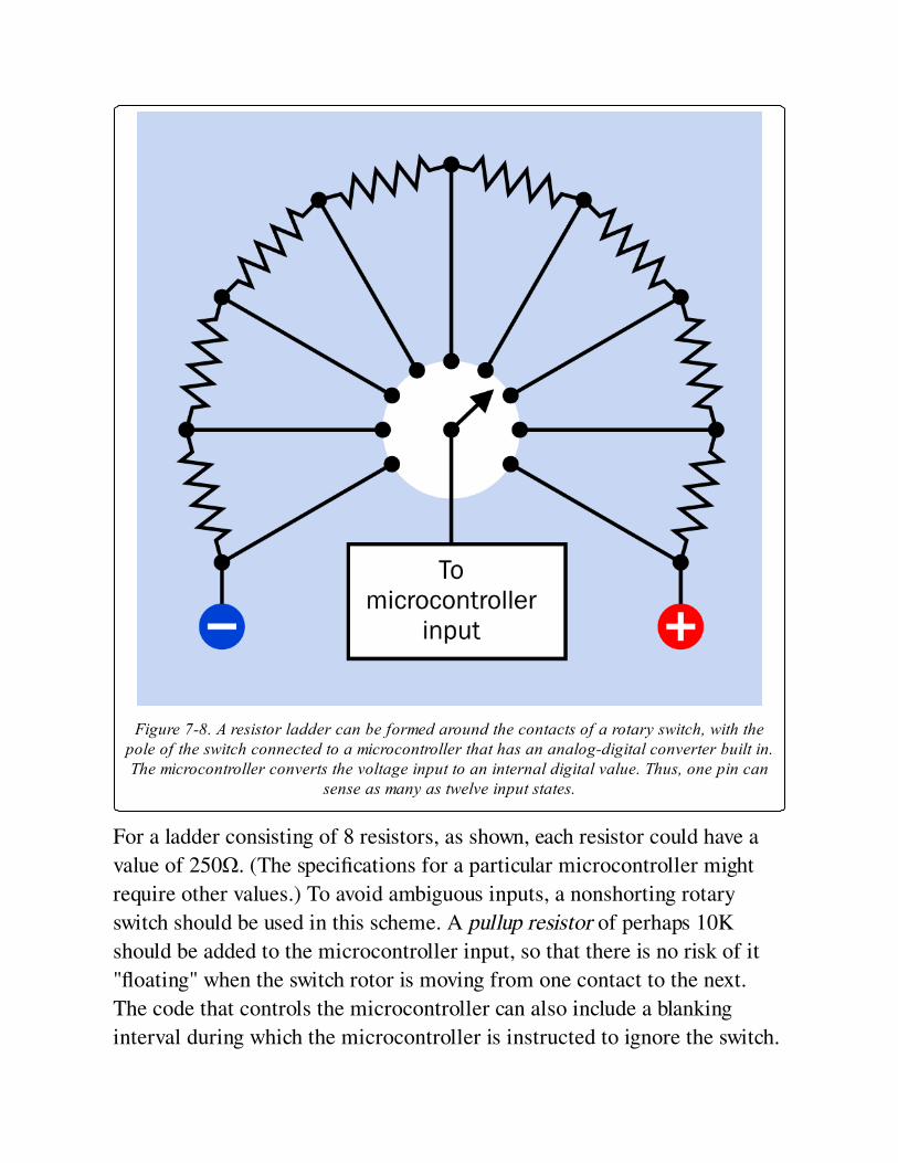
Figure 7-8. A resistor ladder can be formed around the contacts of a rotary switch, with thepole of the switch connected to a microcontroller that has an analog-digital converter built in.The microcontroller converts the voltage input to an internal digital value. Thus, one pin can
sense as many as twelve input states.
For a ladder consisting of 8 resistors, as shown, each resistor could have a
value of 250Ω. (The specifications for a particular microcontroller might
require other values.) To avoid ambiguous inputs, a nonshorting rotary
switch should be used in this scheme. A pullup resistor of perhaps 10K
should be added to the microcontroller input, so that there is no risk of it
"floating" when the switch rotor is moving from one contact to the next.
The code that controls the microcontroller can also include a blanking
interval during which the microcontroller is instructed to ignore the switch.
Because the rotary switch is an electromechanical device, it has typical
vulnerabilities to dirt and moisture, in addition to being bulkier, heavier,
and more expensive than a rotational encoder. Rotary switches have also
been partially replaced by pushbuttons wired to a microcontroller. This
option is found on devices ranging from digital alarm clocks to cellular
phones. In addition to being cheaper, the pushbutton alternative is
preferable where space on a control panel, and behind it, is limited.
What Can Go Wrong
Vulnerable ContactsMost modern rotary switches are sealed, but some are not. Any switch with
exposed contacts will be especially vulnerable to dirt and moisture, leading
to unreliable connections. This was an issue in old-fashioned TV sets,
where periodic contact cleaning of the channel selector switch was needed.
Exposed contacts are also more vulnerable to side-effects from temperature
cycling (when a device warms up and then cools down).
Contact OverloadThe contacts on a cheap rotary switch are especially vulnerable to arcing, as
the user may turn the switch slowly, causing gradual engagement and
disengagement of contacts instead of the snap-action that is characteristic
of a well-made toggle switch. If a rotary switch may control significant
currents or current surges, it must be appropriately rated, regardless of the
extra expense. For more information on arc suppression in switches, see
Arcing.
MisalignmentMost knobs for rotary switches consist of a pointer, or have a white line
engraved to provide clear visual indication of the position of the switch. If
this does not align precisely with indications printed on the panel, confusion
will result. For hand-built equipment, the switch can be installed first, after
which the control-panel indications can be glued or riveted in place on a
separate piece of laminated card, plastic, or metal for precise alignment. If
the switch is not secured tightly, its body may turn slightly under repeated
stress, leading to erroneous interpretation of the knob position.
Misidentified Shorting SwitchIf a shorting switch is used where a nonshorting switch was intended, the
results can be disconcerting or even destructive, as one terminal will be
briefly connected with the adjacent terminal while the switch is being
turned. Multiple functions of a circuit may be activated simultaneously, and
in a worst case scenario, adjacent terminals may be connected to opposite
sides of the same power supply.
User AbuseThe turning force that must be applied to a full-size conventional rotary
switch is significantly greater than the force that is applied to most other
types of panel-mounted switches. This encourages aggressive treatment, and
the turning motion is especially likely to loosen a nut holding the switch in
place. The lighter action characteristic of miniature rotary switches does
not necessarily solve this problem, as users who are accustomed to older-
style switches may still apply the same force anyway.
Rotary switches should be mounted in expectation of rough use. It is
prudent to use Loc-Tite or a similar compound to prevent nuts from
loosening, and a switch should not be mounted in a thin or flimsy panel.
When using a miniature rotary switch that has through-hole mounting in a
circuit board, the board must be sufficiently robust and properly secured.
Wrong Shaft, Wrong Knobs, Nuts That GetLost, Too Big to FitThese problems are identical to those that can be encountered with a
potentiometer, which are discussed in that entry in this encyclopedia.
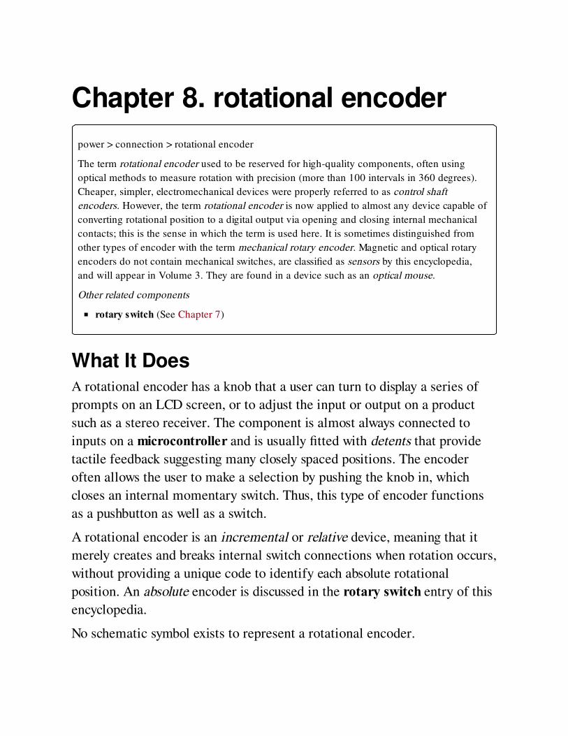
Chapter 8. rotational encoder
power > connection > rotational encoder
The term rotational encoder used to be reserved for high-quality components, often using
optical methods to measure rotation with precision (more than 100 intervals in 360 degrees).
Cheaper, simpler, electromechanical devices were properly referred to as control shaft
encoders. However, the term rotational encoder is now applied to almost any device capable of
converting rotational position to a digital output via opening and closing internal mechanical
contacts; this is the sense in which the term is used here. It is sometimes distinguished from
other types of encoder with the term mechanical rotary encoder. Magnetic and optical rotary
encoders do not contain mechanical switches, are classified as sensors by this encyclopedia,
and will appear in Volume 3. They are found in a device such as an optical mouse.
Other related components
rotary switch (See Chapter 7)
What It DoesA rotational encoder has a knob that a user can turn to display a series of
prompts on an LCD screen, or to adjust the input or output on a product
such as a stereo receiver. The component is almost always connected to
inputs on a microcontroller and is usually fitted with detents that provide
tactile feedback suggesting many closely spaced positions. The encoder
often allows the user to make a selection by pushing the knob in, which
closes an internal momentary switch. Thus, this type of encoder functions
as a pushbutton as well as a switch.
A rotational encoder is an incremental or relative device, meaning that it
merely creates and breaks internal switch connections when rotation occurs,
without providing a unique code to identify each absolute rotational
position. An absolute encoder is discussed in the rotary switch entry of this
encyclopedia.
No schematic symbol exists to represent a rotational encoder.
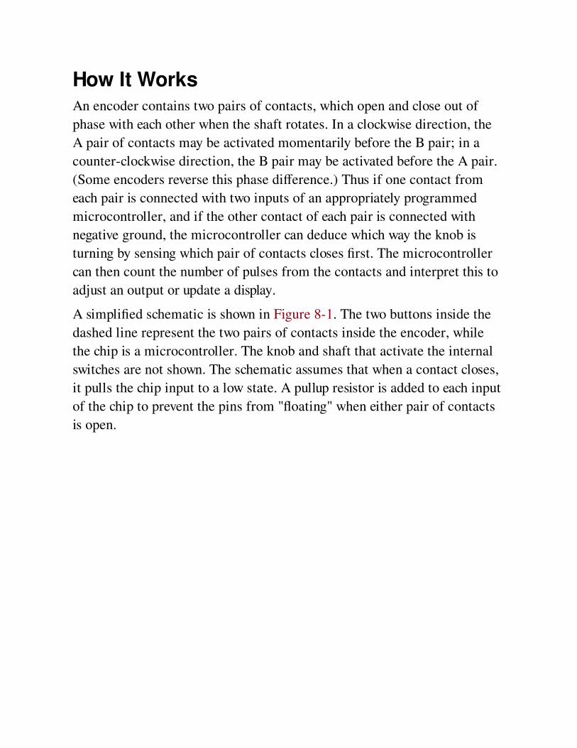
How It WorksAn encoder contains two pairs of contacts, which open and close out of
phase with each other when the shaft rotates. In a clockwise direction, the
A pair of contacts may be activated momentarily before the B pair; in a
counter-clockwise direction, the B pair may be activated before the A pair.
(Some encoders reverse this phase difference.) Thus if one contact from
each pair is connected with two inputs of an appropriately programmed
microcontroller, and if the other contact of each pair is connected with
negative ground, the microcontroller can deduce which way the knob is
turning by sensing which pair of contacts closes first. The microcontroller
can then count the number of pulses from the contacts and interpret this to
adjust an output or update a display.
A simplified schematic is shown in Figure 8-1. The two buttons inside the
dashed line represent the two pairs of contacts inside the encoder, while
the chip is a microcontroller. The knob and shaft that activate the internal
switches are not shown. The schematic assumes that when a contact closes,
it pulls the chip input to a low state. A pullup resistor is added to each input
of the chip to prevent the pins from "floating" when either pair of contacts
is open.
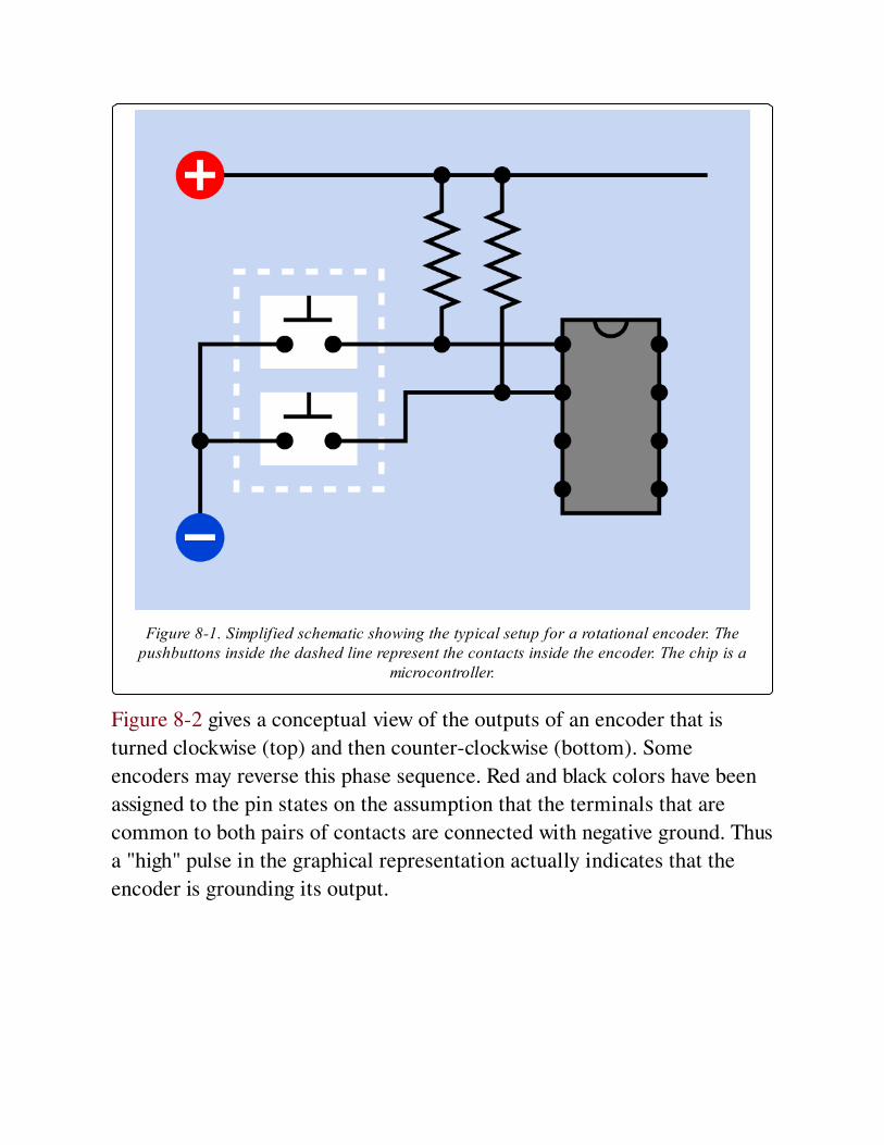
Figure 8-1. Simplified schematic showing the typical setup for a rotational encoder. Thepushbuttons inside the dashed line represent the contacts inside the encoder. The chip is a
microcontroller.
Figure 8-2 gives a conceptual view of the outputs of an encoder that is
turned clockwise (top) and then counter-clockwise (bottom). Some
encoders may reverse this phase sequence. Red and black colors have been
assigned to the pin states on the assumption that the terminals that are
common to both pairs of contacts are connected with negative ground. Thus
a "high" pulse in the graphical representation actually indicates that the
encoder is grounding its output.

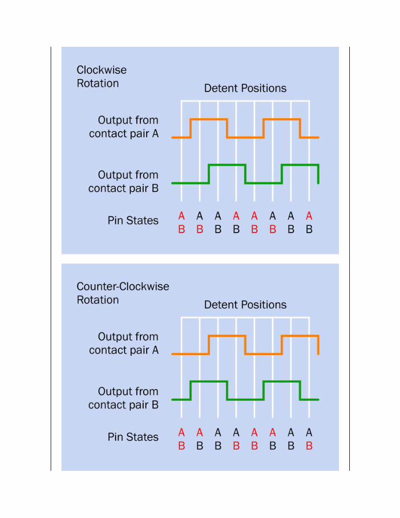

Figure 8-2. Hypothetical outputs from a rotational encoder, assuming that the commonterminals of the contact pairs are connected to negative ground. A high pulse in the graphical
representation therefore indicates that the contact pair is grounded. The number of detentsrelative to the number of pulses per rotation varies from one type of encoder to another.
Microcontrollers have become so ubiquitous, and rotational encoders are so
cheap, they have displaced rotary switches in many applications where a low
current is being switched. The combination of a rotational encoder and a
microcontroller is very versatile, allowing display and control of an almost
unlimited number of menus and options.
VariantsThere are two types of rotational encoders containing mechanical contacts:
absolute and relative. An absolute encoder generates a code corresponding
with each specific rotational position. The code is usually a binary output
among four or more pins. It is discussed under mechanical encoder in the
rotary switch section of this encyclopedia. The variants listed here are all
relative encoders.
Pulses and DetentsRotational encoders from different manufacturers may have as few as 4 or
as many as 24 pulses per rotation (PPR), with 12 to 36 detents (or no
detents at all, in a few models.) The relationship between pulses and
detents shown in Figure 8-2 is typical but is far from being universal. The
number of detents may be equal to, greater than, or less than the number of
pulses per rotation.
FormatRotational encoders are generally panel-mounted or through-hole devices.
In the latter category, most are horizontally mounted, with a minority being
at 90 degrees to the board.
Output
In an encoder containing two switches, four switch-state combinations are
possible: OFF-OFF, ON-OFF, OFF-ON, and ON-ON. This is known as a
quadrature output. All of the rotational encoders discussed here conform
with that system.
Rotational ResistanceRotational encoders vary widely in the resistance that they offer when the
user turns the knob. This is largely a function of the detents, if they are
included. Still, all rotational encoders generally offer less rotational
resistance than a rotary switch, and do not have the kind of heavy-duty
knobs that are typically used with rotary switches. Since an encoder creates
only a stream of pulses without any absolute positional information, a knob
with any kind of pointer on it is inappropriate.
ValuesVirtually all rotational encoders are designed to work with a low-voltage
supply, 12VDC or less. All of them are intended for low currents, reflecting
their purpose to drive microcontroller inputs. Some sample rotational
encoders are pictured in Figure 8-3. At rear: nine pulses per rotation (PPR),
36 detents, 10mA at 10VDC. Far left: 20PPR, 20 detents, with switch. Far
right: 24PPR, no detents, 1mA at 5VDC. Center (blue): 16PPR, no detents,
1mA at 5VDC. Front: 12PPR, 24 detents, 1mA at 10VDC, requires Allen
wrench or similar hexagonal shaft to engage with the rotor.
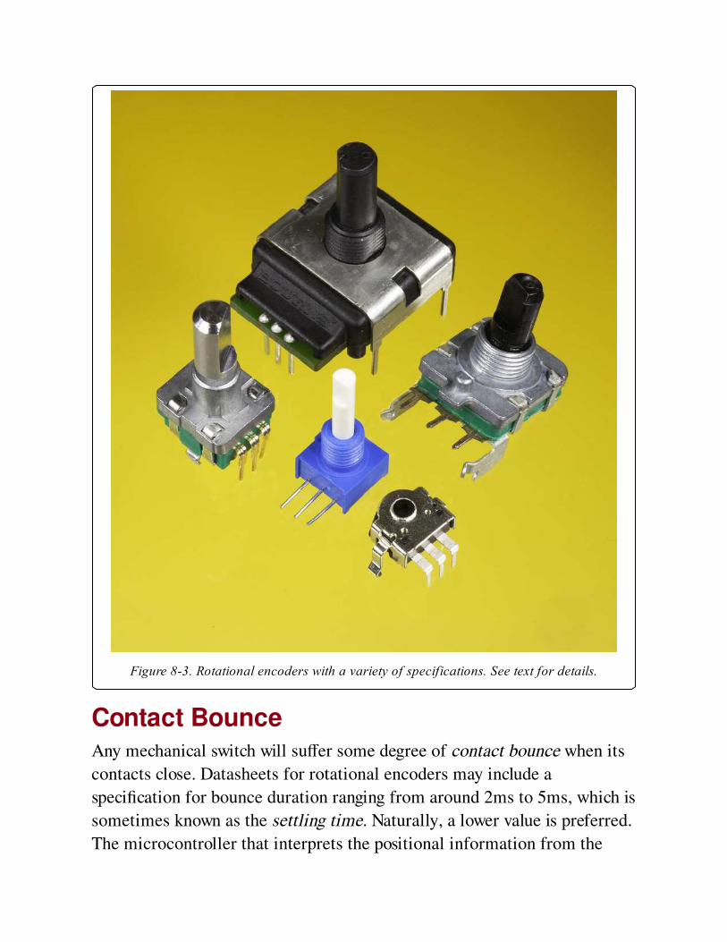
Figure 8-3. Rotational encoders with a variety of specifications. See text for details.
Contact BounceAny mechanical switch will suffer some degree of contact bounce when its
contacts close. Datasheets for rotational encoders may include a
specification for bounce duration ranging from around 2ms to 5ms, which is
sometimes known as the settling time. Naturally, a lower value is preferred.
The microcontroller that interprets the positional information from the
encoder can include a debouncing routine that simply disregards any signals
during the bounce period following switch closure.
Sliding NoiseSliding noise is the opposite of contact bounce. When two contacts have
made a connection and then rub across each other (as occurs inside a
rotational encoder while the knob is being turned), the connection may
suffer momentary lapses. Datasheets for rotational encoders generally do
not supply ratings for this.
How to Use itAs noted above, a rotational encoder can only be used in conjunction with a
microcontroller or similar device that is capable of interpreting the phase
difference between the pairs of contacts, and is capable of counting the
number of opening/closing events while the knob is being turned. (Some
dedicated chips are designed for this specific purpose.)
It can be adapted to be driven by a stepper motor, to provide feedback
regarding the rotation of the motor shaft, and its output can also be
interpreted to calculate angular acceleration.
Programming the microcontroller is the most significant obstacle. Generally
the program should follow a sequence suggested by this pseudocode:
Check:
If the encoder contains a pushbutton switch, check it. If the pushbutton is
being pressed, go to an appropriate subroutine.
The status of contacts A.
The status of contacts B.
Compare their status with previously saved states for A and B. If the status
has not changed, repeat from Check.
Debounce:

Recheck the contacts status rapidly and repeatedly for 50ms, and count
the states for contacts A and B. (The 50ms duration may be adjusted for
different encoders, as an encoder with a higher number of pulses per
rotation will tend to create shorter pulses.)
Compare the total number of changed states with unchanged states.
If the changed states are in a small minority, probably the signal was
erroneous, caused by bounce or sliding noise. Go back to Check and start
over.
Interpret:
Deduce the rotational direction from these four possibilities:
Contacts A were open and have closed.
Contacts A were closed and have opened.
Contacts B were open and have closed.
Contacts B were closed and have opened. (The specific type of encoder
will determine how these transitions are interpreted.)
Revise the variable storing the direction of rotation if necessary.
Depending on the direction of rotation, increment or decrement a
variable that counts pulses.
Take action that is appropriate to the direction of rotation and the
cumulative number of pulses.
Go back to Check again.
What Can Go Wrong
Switch BounceIn addition to a debouncing algorithm in the microcontroller, a 0.1μF
bypass capacitor can be used with each of the output terminals from the
encoder, to help reduce the problem of switch bounce.
Contact Burnout

Rotational encoders are TTL-compatible. They are not generally designed
to drive even a small output device, such as an LED. The contacts are
extremely delicate and will be easily damaged by any attempt to switch a
significant current.
Chapter 9. relay
power > connection > relay
Properly known as an electromagnetic armature relay to distinguish it from a solid-state relay.
However, the full term is very rarely used. It may also be described as an electromechanical
relay, but the term relay is normally understood to mean a device that is not solid state.
Other related components
solid state relay (Volume 2)
switch (See Chapter 6)
What It DoesA relay enables a signal or pulse of electricity to switch on (or switch off) a
separate flow of electricity. Often, a relay uses a low voltage or low current
to control a higher voltage and/or higher current. The low voltage/low
current signal can be initiated by a relatively small, economical switch, and
can be carried to the relay by relatively cheap, small-gauge wire, at which
point the relay controls a larger current near to the load. In a car, for
example, turning the ignition switch sends a signal to a relay positioned
close to the starter motor.
While solid-state switching devices are faster and more reliable, relays
retain some advantages. They can handle double-throw and/or multiple-pole
switching and can be cheaper when high voltages or currents are involved. A
comparison of their advantages relative to solid state relays and transistorsis tabulated in the entry on bipolar transistor in Figure 28-15.
Common schematic symbols for single-throw relays are shown in Figure 9-1
and for double-throw relays in Figure 9-2. The appearance and orientation
of the coil and contacts in the symbols may vary significantly, but the
functionality remains the same.
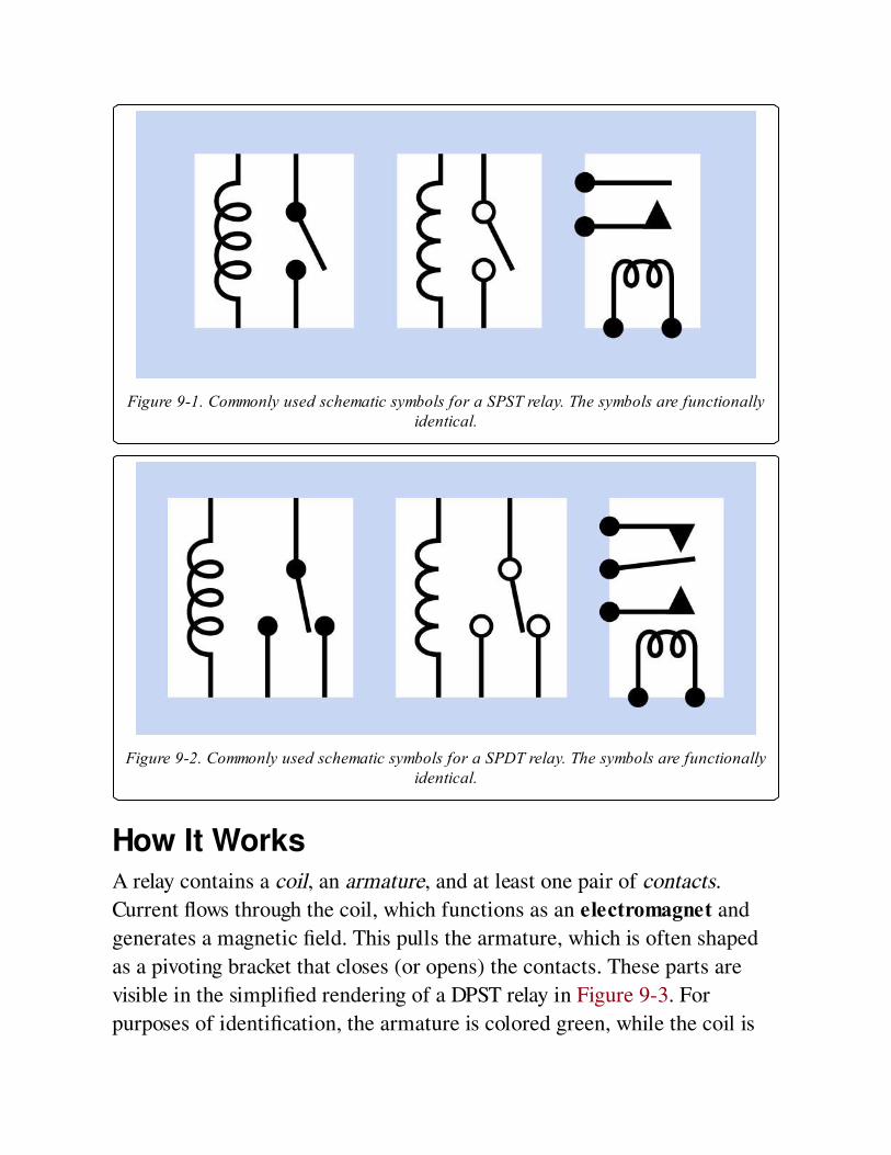
Figure 9-1. Commonly used schematic symbols for a SPST relay. The symbols are functionallyidentical.
Figure 9-2. Commonly used schematic symbols for a SPDT relay. The symbols are functionallyidentical.
How It WorksA relay contains a coil, an armature, and at least one pair of contacts.
Current flows through the coil, which functions as an electromagnet and
generates a magnetic field. This pulls the armature, which is often shaped
as a pivoting bracket that closes (or opens) the contacts. These parts are
visible in the simplified rendering of a DPST relay in Figure 9-3. For
purposes of identification, the armature is colored green, while the coil is
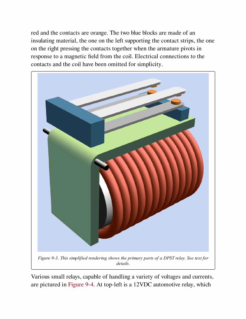
red and the contacts are orange. The two blue blocks are made of an
insulating material, the one on the left supporting the contact strips, the one
on the right pressing the contacts together when the armature pivots in
response to a magnetic field from the coil. Electrical connections to the
contacts and the coil have been omitted for simplicity.
Figure 9-3. This simplified rendering shows the primary parts of a DPST relay. See text fordetails.
Various small relays, capable of handling a variety of voltages and currents,
are pictured in Figure 9-4. At top-left is a 12VDC automotive relay, which
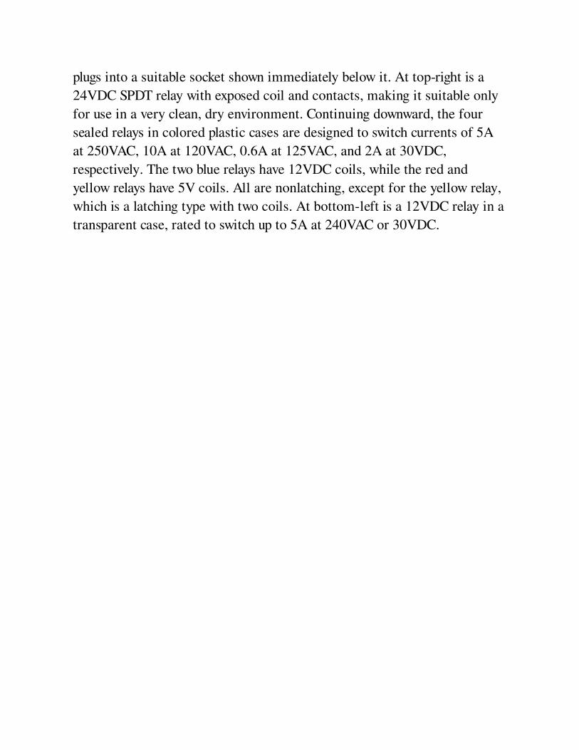
plugs into a suitable socket shown immediately below it. At top-right is a
24VDC SPDT relay with exposed coil and contacts, making it suitable only
for use in a very clean, dry environment. Continuing downward, the four
sealed relays in colored plastic cases are designed to switch currents of 5A
at 250VAC, 10A at 120VAC, 0.6A at 125VAC, and 2A at 30VDC,
respectively. The two blue relays have 12VDC coils, while the red and
yellow relays have 5V coils. All are nonlatching, except for the yellow relay,
which is a latching type with two coils. At bottom-left is a 12VDC relay in a
transparent case, rated to switch up to 5A at 240VAC or 30VDC.
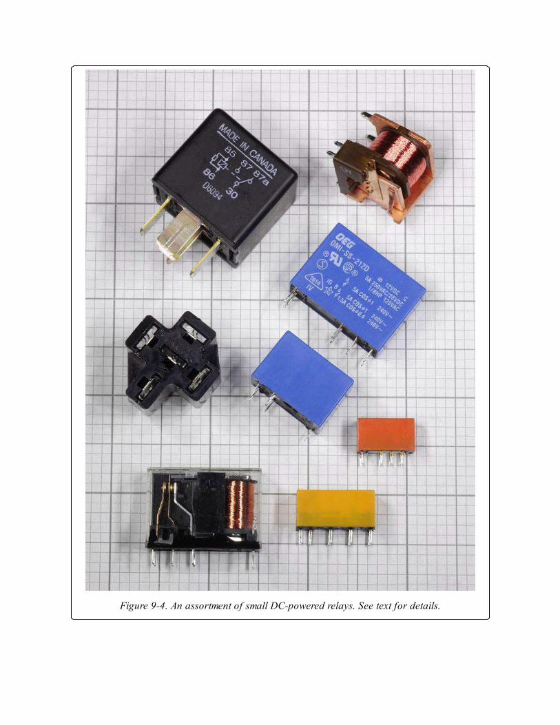
Figure 9-4. An assortment of small DC-powered relays. See text for details.
The configuration of a relay is specified using the same abbreviations that
apply to a switch. SP, DP, 3P, and 4P indicate 1, 2, 3, or 4 poles (relays with
more than 4 poles are rare). ST and DT indicate single-throw or double-
throw switching. These abbreviations are usually concatenated, as in 3PST
or SPDT. In addition, the terminology Form A (meaning normally open),
Form B (normally closed), and Form C (double-throw) may be used,
preceded by a number that indicates the number of poles. Thus "2 Form C"
means a DPDT relay.
Variants
LatchingThere are two basic types of relay: latching and nonlatching. A nonlatching
relay, also known as a single side stable type, is the most common, and
resembles a momentary switch or pushbutton in that its contacts spring
back to their default state when power to the relay is interrupted. This can be
important in an application where the relay should return to a known state
if power is lost. By contrast, a latching relay has no default state. Latching
relays almost always have double-throw contacts, which remain in either
position without drawing power. The relay only requires a short pulse to
change its status. In semiconductor terms, its behavior is similar to that of a
flip-flop.
In a single-coil latching relay, the polarity of voltage applied to the coil
determines which pair of contacts will close. In a dual-coil latching relay, a
second coil moves the armature between each of its two states.
Schematic symbols for a dual-coil latching relay are shown in Figure 9-5.
Some symbol styles do not make it clear which switch position each coil
induces. It may be necessary to read the manufacturer’s datasheet or test
the relay by applying its rated voltage to randomly selected terminal pairs
while testing for continuity between other terminal pairs.
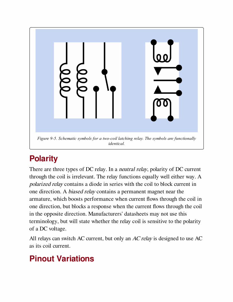
Figure 9-5. Schematic symbols for a two-coil latching relay. The symbols are functionallyidentical.
PolarityThere are three types of DC relay. In a neutral relay, polarity of DC current
through the coil is irrelevant. The relay functions equally well either way. A
polarized relay contains a diode in series with the coil to block current in
one direction. A biased relay contains a permanent magnet near the
armature, which boosts performance when current flows through the coil in
one direction, but blocks a response when the current flows through the coil
in the opposite direction. Manufacturers' datasheets may not use this
terminology, but will state whether the relay coil is sensitive to the polarity
of a DC voltage.
All relays can switch AC current, but only an AC relay is designed to use AC
as its coil current.
Pinout Variations
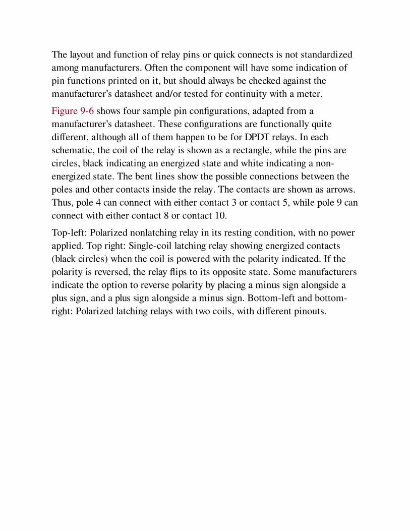
The layout and function of relay pins or quick connects is not standardized
among manufacturers. Often the component will have some indication of
pin functions printed on it, but should always be checked against the
manufacturer’s datasheet and/or tested for continuity with a meter.
Figure 9-6 shows four sample pin configurations, adapted from a
manufacturer’s datasheet. These configurations are functionally quite
different, although all of them happen to be for DPDT relays. In each
schematic, the coil of the relay is shown as a rectangle, while the pins are
circles, black indicating an energized state and white indicating a non-
energized state. The bent lines show the possible connections between the
poles and other contacts inside the relay. The contacts are shown as arrows.
Thus, pole 4 can connect with either contact 3 or contact 5, while pole 9 can
connect with either contact 8 or contact 10.
Top-left: Polarized nonlatching relay in its resting condition, with no power
applied. Top right: Single-coil latching relay showing energized contacts
(black circles) when the coil is powered with the polarity indicated. If the
polarity is reversed, the relay flips to its opposite state. Some manufacturers
indicate the option to reverse polarity by placing a minus sign alongside a
plus sign, and a plus sign alongside a minus sign. Bottom-left and bottom-
right: Polarized latching relays with two coils, with different pinouts.
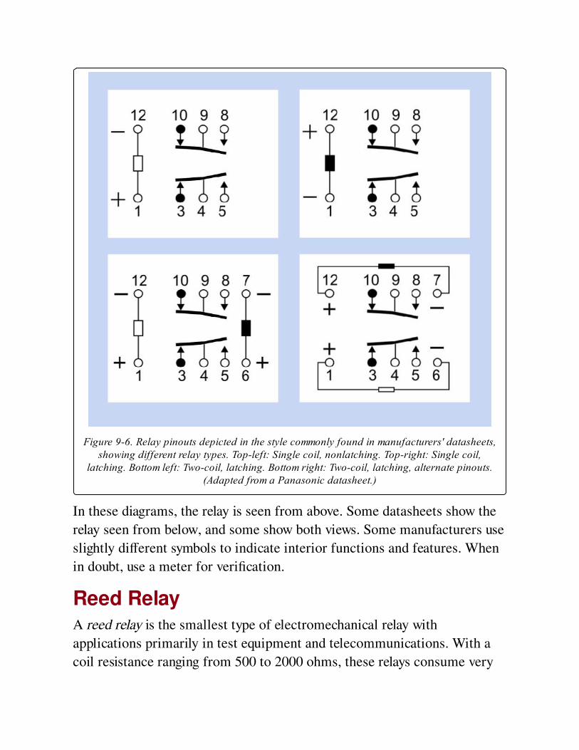
Figure 9-6. Relay pinouts depicted in the style commonly found in manufacturers' datasheets,showing different relay types. Top-left: Single coil, nonlatching. Top-right: Single coil,
latching. Bottom left: Two-coil, latching. Bottom right: Two-coil, latching, alternate pinouts.(Adapted from a Panasonic datasheet.)
In these diagrams, the relay is seen from above. Some datasheets show the
relay seen from below, and some show both views. Some manufacturers use
slightly different symbols to indicate interior functions and features. When
in doubt, use a meter for verification.
Reed RelayA reed relay is the smallest type of electromechanical relay with
applications primarily in test equipment and telecommunications. With a
coil resistance ranging from 500 to 2000 ohms, these relays consume very
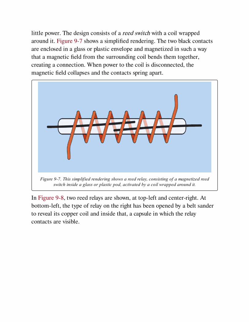
little power. The design consists of a reed switch with a coil wrapped
around it. Figure 9-7 shows a simplified rendering. The two black contacts
are enclosed in a glass or plastic envelope and magnetized in such a way
that a magnetic field from the surrounding coil bends them together,
creating a connection. When power to the coil is disconnected, the
magnetic field collapses and the contacts spring apart.
Figure 9-7. This simplified rendering shows a reed relay, consisting of a magnetized reedswitch inside a glass or plastic pod, activated by a coil wrapped around it.
In Figure 9-8, two reed relays are shown, at top-left and center-right. At
bottom-left, the type of relay on the right has been opened by a belt sander
to reveal its copper coil and inside that, a capsule in which the relay
contacts are visible.
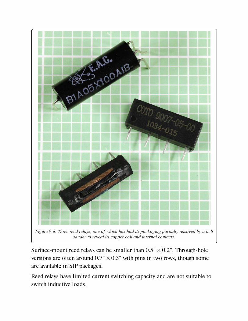
Figure 9-8. Three reed relays, one of which has had its packaging partially removed by a beltsander to reveal its copper coil and internal contacts.
Surface-mount reed relays can be smaller than 0.5" × 0.2". Through-hole
versions are often around 0.7" × 0.3" with pins in two rows, though some
are available in SIP packages.
Reed relays have limited current switching capacity and are not suitable to
switch inductive loads.
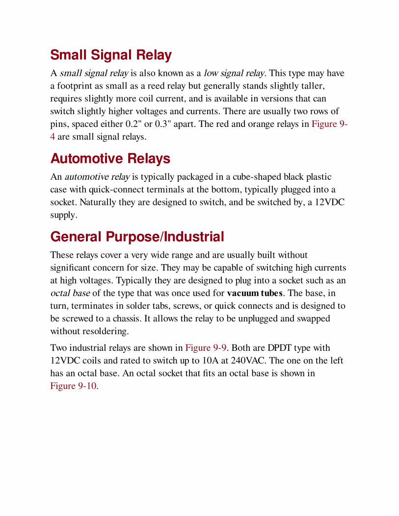
Small Signal RelayA small signal relay is also known as a low signal relay. This type may have
a footprint as small as a reed relay but generally stands slightly taller,
requires slightly more coil current, and is available in versions that can
switch slightly higher voltages and currents. There are usually two rows of
pins, spaced either 0.2" or 0.3" apart. The red and orange relays in Figure 9-
4 are small signal relays.
Automotive RelaysAn automotive relay is typically packaged in a cube-shaped black plastic
case with quick-connect terminals at the bottom, typically plugged into a
socket. Naturally they are designed to switch, and be switched by, a 12VDC
supply.
General Purpose/IndustrialThese relays cover a very wide range and are usually built without
significant concern for size. They may be capable of switching high currents
at high voltages. Typically they are designed to plug into a socket such as an
octal base of the type that was once used for vacuum tubes. The base, in
turn, terminates in solder tabs, screws, or quick connects and is designed to
be screwed to a chassis. It allows the relay to be unplugged and swapped
without resoldering.
Two industrial relays are shown in Figure 9-9. Both are DPDT type with
12VDC coils and rated to switch up to 10A at 240VAC. The one on the left
has an octal base. An octal socket that fits an octal base is shown in
Figure 9-10.
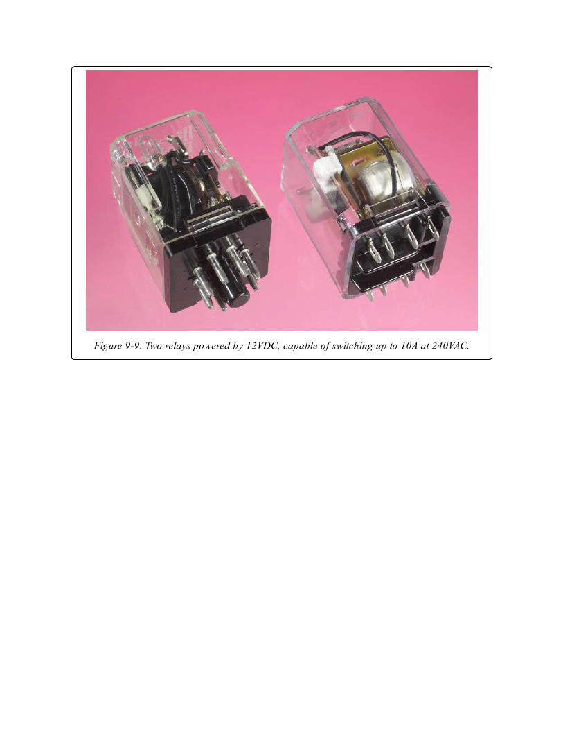
Figure 9-9. Two relays powered by 12VDC, capable of switching up to 10A at 240VAC.
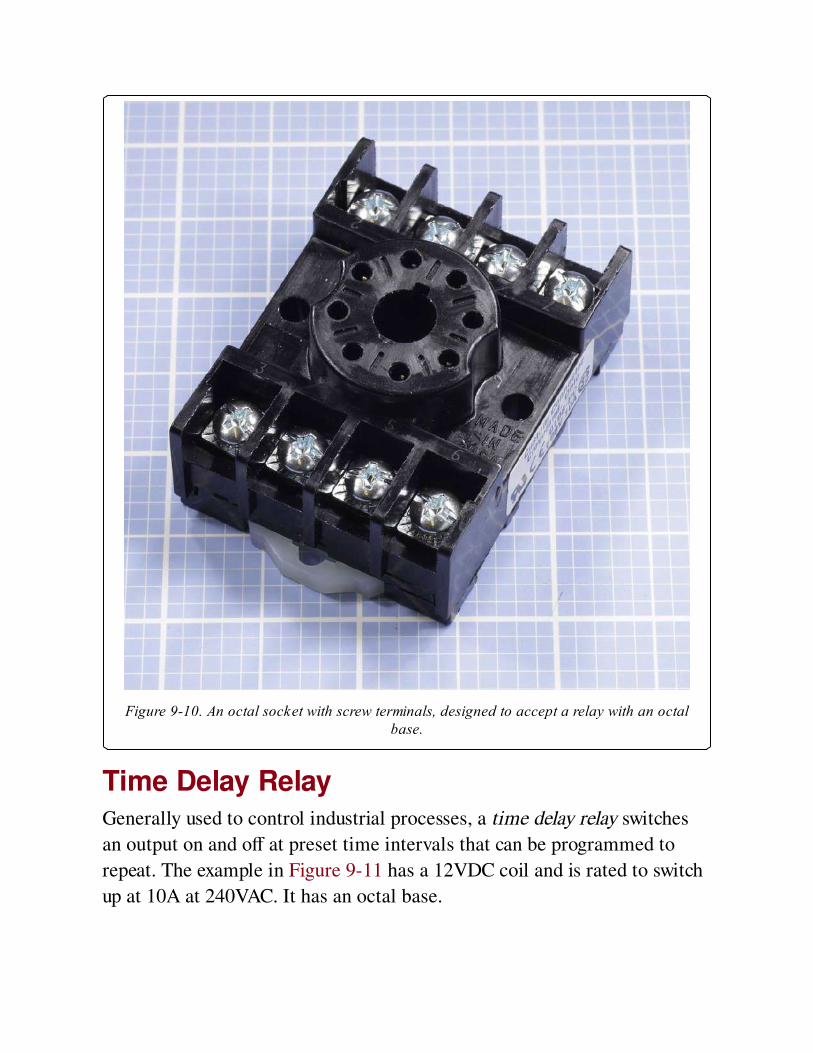
Figure 9-10. An octal socket with screw terminals, designed to accept a relay with an octalbase.
Time Delay RelayGenerally used to control industrial processes, a time delay relay switches
an output on and off at preset time intervals that can be programmed to
repeat. The example in Figure 9-11 has a 12VDC coil and is rated to switch
up at 10A at 240VAC. It has an octal base.
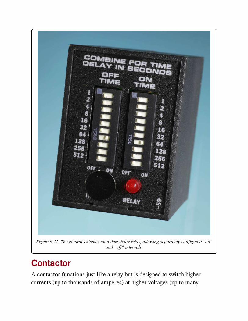
Figure 9-11. The control switches on a time-delay relay, allowing separately configured "on"and "off" intervals.
ContactorA contactor functions just like a relay but is designed to switch higher
currents (up to thousands of amperes) at higher voltages (up to many
kilovolts). It may range from being palm-sized to measuring more than one
foot in diameter, and may be used to control heavy loads such as very large
motors, banks of high-wattage lights, and heavy-duty power supplies.
ValuesDatasheets usually specify maximum voltage and current for the contacts,
and nominal voltage and current for the coil, although in some cases the
coil resistance is stated instead of nominal coil current. The approximate
current consumption can be estimated, if necessary, by using Ohm’s Law.
The minimum voltage that the relay needs for activation is sometimes
described as the Must Operate By voltage, while the Must Release By
voltage is the maximum coil voltage that the relay will ignore. Relays are
rated on the assumption that the coil may remain energized for long
periods, unless otherwise stated.
While the contact rating may suggest that a relay can switch a large load,
this is not necessarily true if the load has significant inductance.
Reed relays
Usually use a coil voltage of 5VDC and have a contact rating of up to
0.25A at 100V. Through-hole (PCB) versions may have a coil voltage of
5VDC, 6VDC, 12VDC, or 24VDC and in some cases claim to switch
0.5A to 1A at up to 100V, although this rating is strictly for a
noninductive load.
Small signal/low signal relays
Usually use a coil voltage ranging from 5VDC to 24VDC, drawing about
20mA. Maximum switching current for noninductive loads ranges from
1A to 3A.
Industrial/general purpose relays
A very wide range of possible values, with coil voltages ranging up to
48VDC or 125VAC to 250VAC. Contact rating is typically 5A to 30A.
Automotive relays
Coil voltage of 12VDC, and contact rating often 5A at up to 24VDC.
Timer relays
Usually these specify a coil voltage of 12VDC, 24VDC, 24VAC,
125VAC, or 230VAC. The timed interval can range from 0.1 sec to
9999 hours in some cases. Common values for contact ratings are 5A up
to 20A, with a voltage of 125V to 250V, AC or DC.
How to Use itRelays are found in home appliances such as dishwashers, washing
machines, refrigerators, air conditioners, photocopy machines, and other
products where a substantial load (such as a motor or compressor) has to be
switched on and off by a control switch, a thermostat, or an electronic
circuit.
Figure 9-12 shows a common small-scale application in which a signal
from a microcontroller (a few mA at 5VDC) is applied to the base of a
transistor, which controls the relay. In this way, a logic output can switch
10A at 125VAC. Note the rectifier diode wired in parallel with the relay
coil.
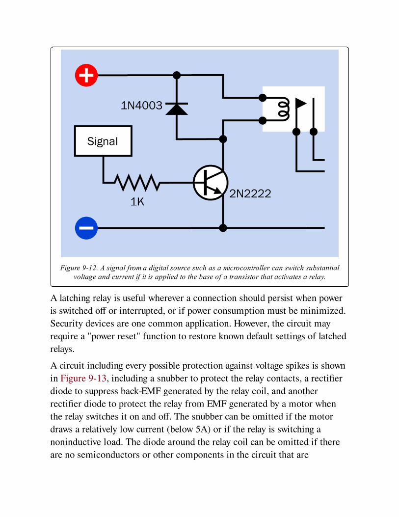
Figure 9-12. A signal from a digital source such as a microcontroller can switch substantialvoltage and current if it is applied to the base of a transistor that activates a relay.
A latching relay is useful wherever a connection should persist when power
is switched off or interrupted, or if power consumption must be minimized.
Security devices are one common application. However, the circuit may
require a "power reset" function to restore known default settings of latched
relays.
A circuit including every possible protection against voltage spikes is shown
in Figure 9-13, including a snubber to protect the relay contacts, a rectifier
diode to suppress back-EMF generated by the relay coil, and another
rectifier diode to protect the relay from EMF generated by a motor when
the relay switches it on and off. The snubber can be omitted if the motor
draws a relatively low current (below 5A) or if the relay is switching a
noninductive load. The diode around the relay coil can be omitted if there
are no semiconductors or other components in the circuit that are

vulnerable to voltage spikes. However, a spike can affect components in
adjacent circuits that appear to be electrically isolated. A severe spike can
even be transmitted back into 125VAC house wiring. For information on
using a resistor-capacitor combination to form a snubber, see Snubber.
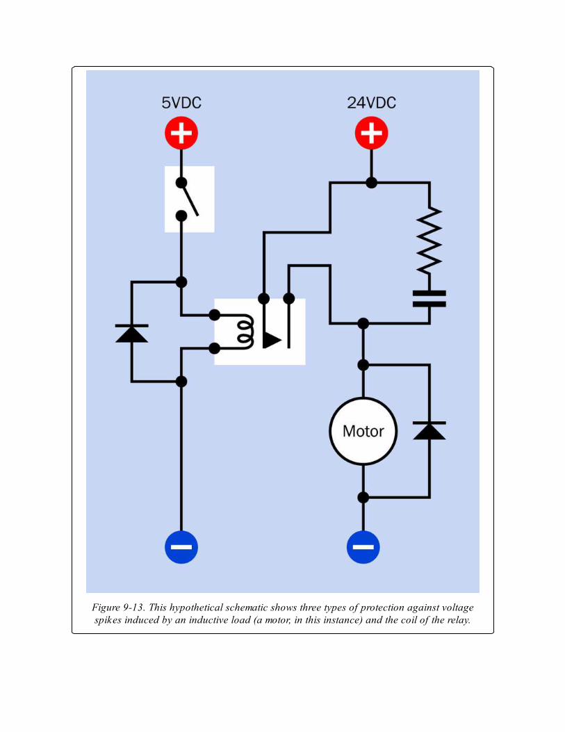
Figure 9-13. This hypothetical schematic shows three types of protection against voltagespikes induced by an inductive load (a motor, in this instance) and the coil of the relay.
What Can Go Wrong
Wrong PinoutsThe lack of standardization of relay pinouts can cause errors if one relay is
replaced with another that appears to be the same, but isn’t. In particular,
the pins that connect with normally-closed contacts may trade places with
pins connected with normally-open contacts, in relays from different
manufacturers.
Pinouts are also confusing in that some datasheets depict them from above,
some from below, and some from both perspectives.
Wrong OrientationSmall relays of through-hole type usually have pins spaced in multiples of
0.1". This allows them to be inserted the wrong way around in a perforated
board. Almost all relays have an identification mark molded into one end or
one corner of the plastic shell. Manufacturers do not standardize the
position and meaning of these marks, but they are usually replicated in
datasheets. When using a relay of a type that you have not used before, it is
a sensible precaution to test it with a meter to verify the functions of its
terminals before installing it.
Wrong TypeA latching relay may have exactly the same appearance as a nonlatching
relay from the same manufacturer, and the same two pins may energize the
coil. However, in a latching relay, the contacts won’t spring back to their
non-energized position, causing functional errors that may be difficult to
diagnose. The part numbers printed on latching and nonlatching versions of
the same relay may differ by only one letter or numeral and should be
checked carefully.
Wrong Polarity
A relay with a DC-energized coil may require power to be applied with
correct polarity and may malfunction otherwise.
AC and DCA relay coil designed to be powered by DC will not work from AC and vice-
versa. The contact rating of a relay is likely to be different depending
whether it is switching AC or DC.
ChatterThis is the noise created by relay contacts when they make rapid
intermittent connection. Chatter is potentially damaging to relay contacts
and should be avoided. It can also create electrical noise that interferes with
other components. Likely correctible causes of chatter include insufficient
voltage or power fluctuations.
Relay Coil Voltage SpikeA relay coil is an inductive device. Merely switching a large relay on and off
can create voltage spikes. To address this problem, a rectifier diode should
be placed across the coil terminals with polarity opposing the energizing
voltage.
ArcingThis problem is discussed in the switch entry of this encyclopedia. See
Arcing. Note that because the contacts inside a reed relay are so tiny, they
are especially susceptible to arcing and may actually melt and weld
themselves together if they are used to control excessive current or an
inductive load.
Magnetic FieldsRelays generate magnetic fields during operation and should not be placed
near components that are susceptible.

The reed switch inside a reed relay can be unexpectedly activated by an
external magnetic field. This type of relay may be enclosed in a metal shell
to provide some protection. The adequacy of this protection should be
verified by testing the relay under real-world conditions.
Environmental HazardsDirt, oxidation, or moisture on relay contacts is a significant problem. Most
relays are sealed and should remain sealed.
Relays are susceptible to vibration, which can affect the contacts and can
accelerate wear on moving parts. Severe vibration can even damage a relay
permanently. Solid-state relays (discussed in Volume 2) should be used in
harsh environments.
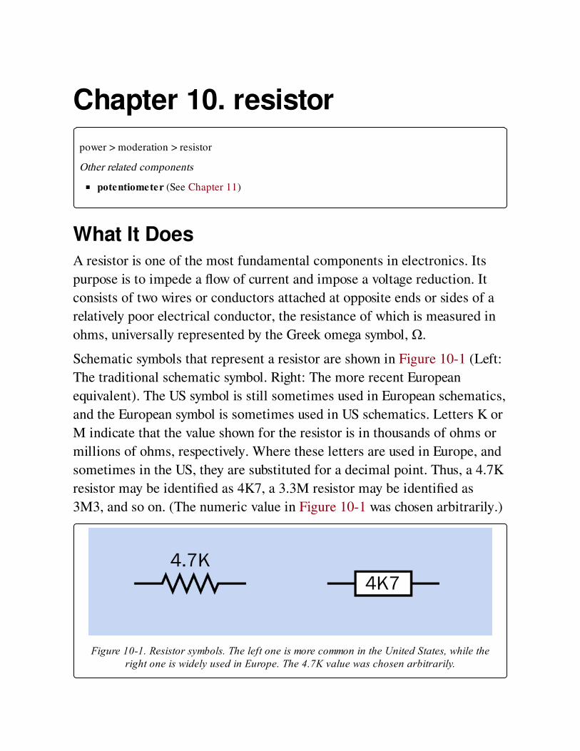
Chapter 10. resistor
power > moderation > resistor
Other related components
potentiometer (See Chapter 11)
What It DoesA resistor is one of the most fundamental components in electronics. Its
purpose is to impede a flow of current and impose a voltage reduction. It
consists of two wires or conductors attached at opposite ends or sides of a
relatively poor electrical conductor, the resistance of which is measured in
ohms, universally represented by the Greek omega symbol, Ω.
Schematic symbols that represent a resistor are shown in Figure 10-1 (Left:
The traditional schematic symbol. Right: The more recent European
equivalent). The US symbol is still sometimes used in European schematics,
and the European symbol is sometimes used in US schematics. Letters K or
M indicate that the value shown for the resistor is in thousands of ohms or
millions of ohms, respectively. Where these letters are used in Europe, and
sometimes in the US, they are substituted for a decimal point. Thus, a 4.7K
resistor may be identified as 4K7, a 3.3M resistor may be identified as
3M3, and so on. (The numeric value in Figure 10-1 was chosen arbitrarily.)
Figure 10-1. Resistor symbols. The left one is more common in the United States, while theright one is widely used in Europe. The 4.7K value was chosen arbitrarily.
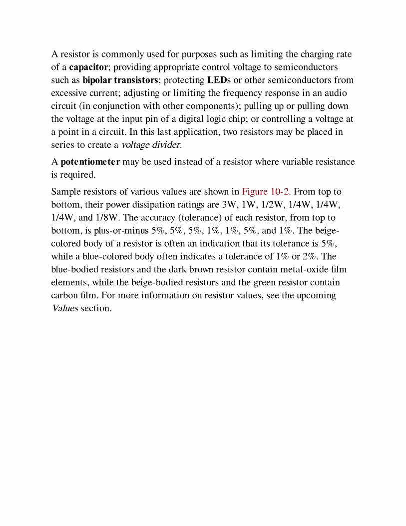
A resistor is commonly used for purposes such as limiting the charging rate
of a capacitor; providing appropriate control voltage to semiconductors
such as bipolar transistors; protecting LEDs or other semiconductors from
excessive current; adjusting or limiting the frequency response in an audio
circuit (in conjunction with other components); pulling up or pulling down
the voltage at the input pin of a digital logic chip; or controlling a voltage at
a point in a circuit. In this last application, two resistors may be placed in
series to create a voltage divider.
A potentiometer may be used instead of a resistor where variable resistance
is required.
Sample resistors of various values are shown in Figure 10-2. From top to
bottom, their power dissipation ratings are 3W, 1W, 1/2W, 1/4W, 1/4W,
1/4W, and 1/8W. The accuracy (tolerance) of each resistor, from top to
bottom, is plus-or-minus 5%, 5%, 5%, 1%, 1%, 5%, and 1%. The beige-
colored body of a resistor is often an indication that its tolerance is 5%,
while a blue-colored body often indicates a tolerance of 1% or 2%. The
blue-bodied resistors and the dark brown resistor contain metal-oxide film
elements, while the beige-bodied resistors and the green resistor contain
carbon film. For more information on resistor values, see the upcoming
Values section.

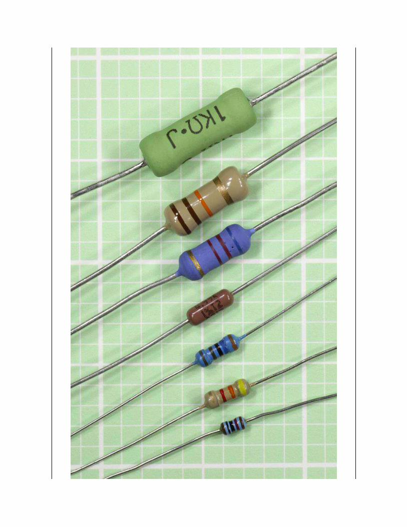
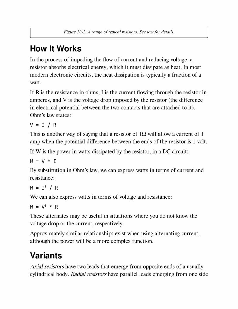
Figure 10-2. A range of typical resistors. See text for details.
How It WorksIn the process of impeding the flow of current and reducing voltage, a
resistor absorbs electrical energy, which it must dissipate as heat. In most
modern electronic circuits, the heat dissipation is typically a fraction of a
watt.
If R is the resistance in ohms, I is the current flowing through the resistor in
amperes, and V is the voltage drop imposed by the resistor (the difference
in electrical potential between the two contacts that are attached to it),
Ohm’s law states:
V = I / R
This is another way of saying that a resistor of 1Ω will allow a current of 1
amp when the potential difference between the ends of the resistor is 1 volt.
If W is the power in watts dissipated by the resistor, in a DC circuit:
W = V * I
By substitution in Ohm’s law, we can express watts in terms of current and
resistance:
W = I2 / R
We can also express watts in terms of voltage and resistance:
W = V2 * R
These alternates may be useful in situations where you do not know the
voltage drop or the current, respectively.
Approximately similar relationships exist when using alternating current,
although the power will be a more complex function.
VariantsAxial resistors have two leads that emerge from opposite ends of a usually
cylindrical body. Radial resistors have parallel leads emerging from one side
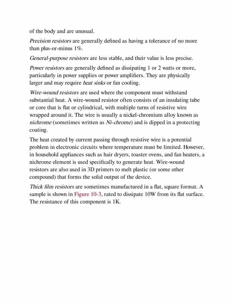
of the body and are unusual.
Precision resistors are generally defined as having a tolerance of no more
than plus-or-minus 1%.
General-purpose resistors are less stable, and their value is less precise.
Power resistors are generally defined as dissipating 1 or 2 watts or more,
particularly in power supplies or power amplifiers. They are physically
larger and may require heat sinks or fan cooling.
Wire-wound resistors are used where the component must withstand
substantial heat. A wire-wound resistor often consists of an insulating tube
or core that is flat or cylindrical, with multiple turns of resistive wire
wrapped around it. The wire is usually a nickel-chromium alloy known as
nichrome (sometimes written as Ni-chrome) and is dipped in a protecting
coating.
The heat created by current passing through resistive wire is a potential
problem in electronic circuits where temperature must be limited. However,
in household appliances such as hair dryers, toaster ovens, and fan heaters, a
nichrome element is used specifically to generate heat. Wire-wound
resistors are also used in 3D printers to melt plastic (or some other
compound) that forms the solid output of the device.
Thick film resistors are sometimes manufactured in a flat, square format. A
sample is shown in Figure 10-3, rated to dissipate 10W from its flat surface.
The resistance of this component is 1K.
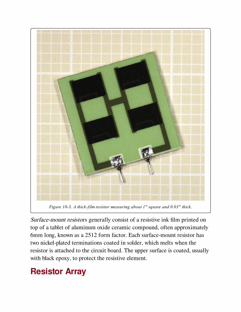
Figure 10-3. A thick-film resistor measuring about 1" square and 0.03" thick.
Surface-mount resistors generally consist of a resistive ink film printed on
top of a tablet of aluminum oxide ceramic compound, often approximately
6mm long, known as a 2512 form factor. Each surface-mount resistor has
two nickel-plated terminations coated in solder, which melts when the
resistor is attached to the circuit board. The upper surface is coated, usually
with black epoxy, to protect the resistive element.
Resistor Array

This is also known as a resistor network or resistor ladder, and consists of a
chip containing multiple equal-valued resistors.
A resistor array in a single-inline package (or SIP) may have three possible
internal configurations: isolated, common bus, and dual terminator. These
options are shown at top, center, and bottom, respectively, in Figure 10-4.
The isolated variant is commonly available in SIPs with 6, 8, or 10 pins. The
common-bus and dual-terminator configurations generally have 8, 9, 10, or
11 pins.

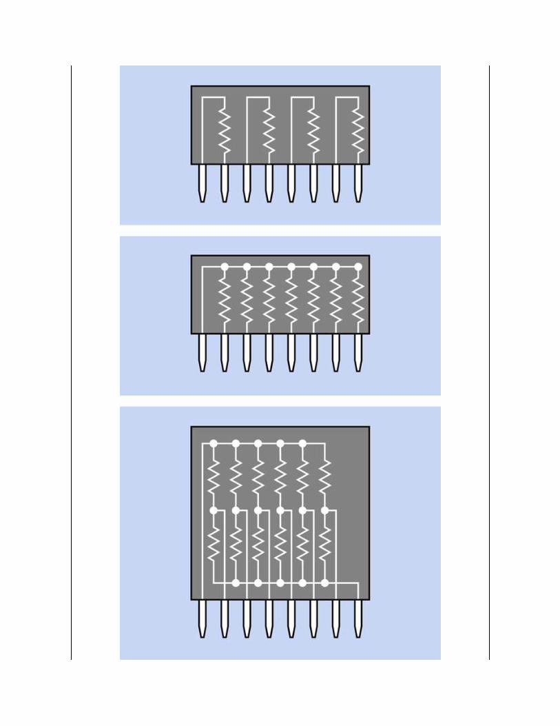
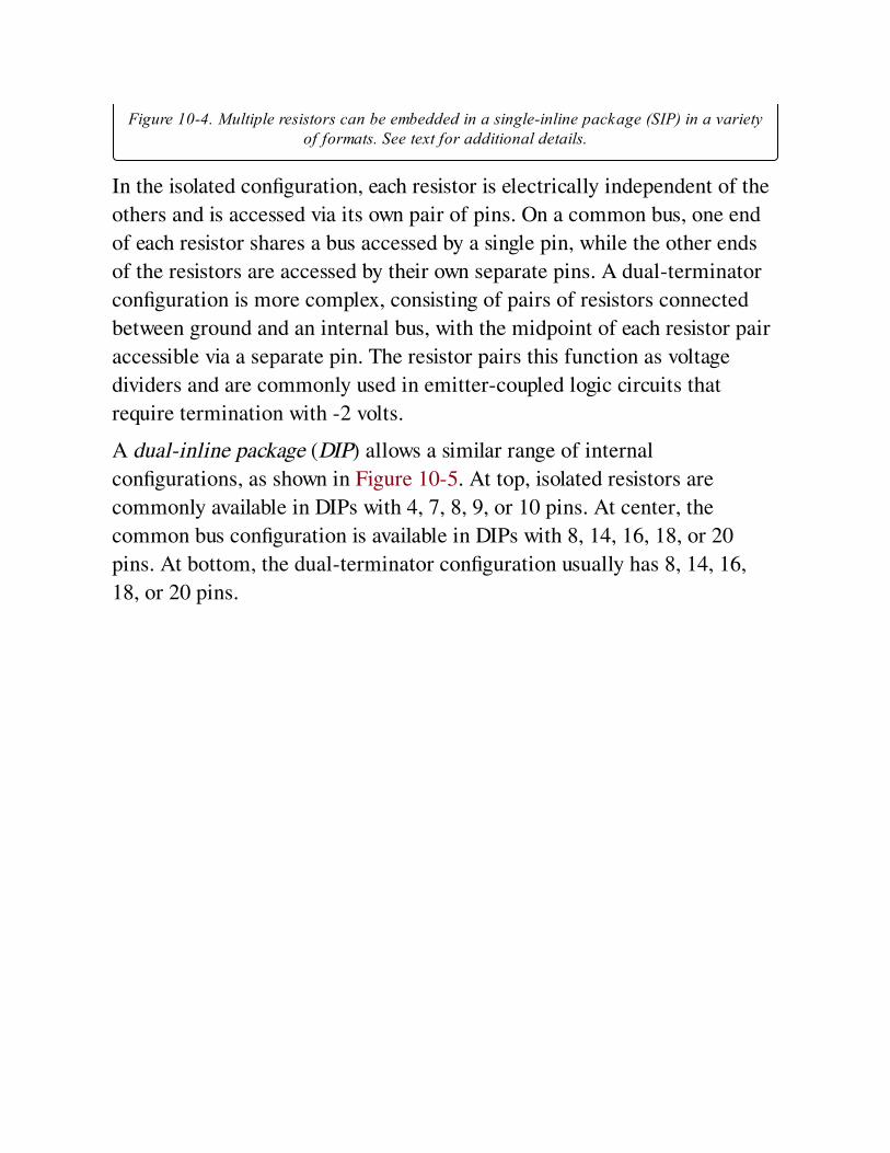
Figure 10-4. Multiple resistors can be embedded in a single-inline package (SIP) in a varietyof formats. See text for additional details.
In the isolated configuration, each resistor is electrically independent of the
others and is accessed via its own pair of pins. On a common bus, one end
of each resistor shares a bus accessed by a single pin, while the other ends
of the resistors are accessed by their own separate pins. A dual-terminator
configuration is more complex, consisting of pairs of resistors connected
between ground and an internal bus, with the midpoint of each resistor pair
accessible via a separate pin. The resistor pairs this function as voltage
dividers and are commonly used in emitter-coupled logic circuits that
require termination with -2 volts.
A dual-inline package (DIP) allows a similar range of internal
configurations, as shown in Figure 10-5. At top, isolated resistors are
commonly available in DIPs with 4, 7, 8, 9, or 10 pins. At center, the
common bus configuration is available in DIPs with 8, 14, 16, 18, or 20
pins. At bottom, the dual-terminator configuration usually has 8, 14, 16,
18, or 20 pins.

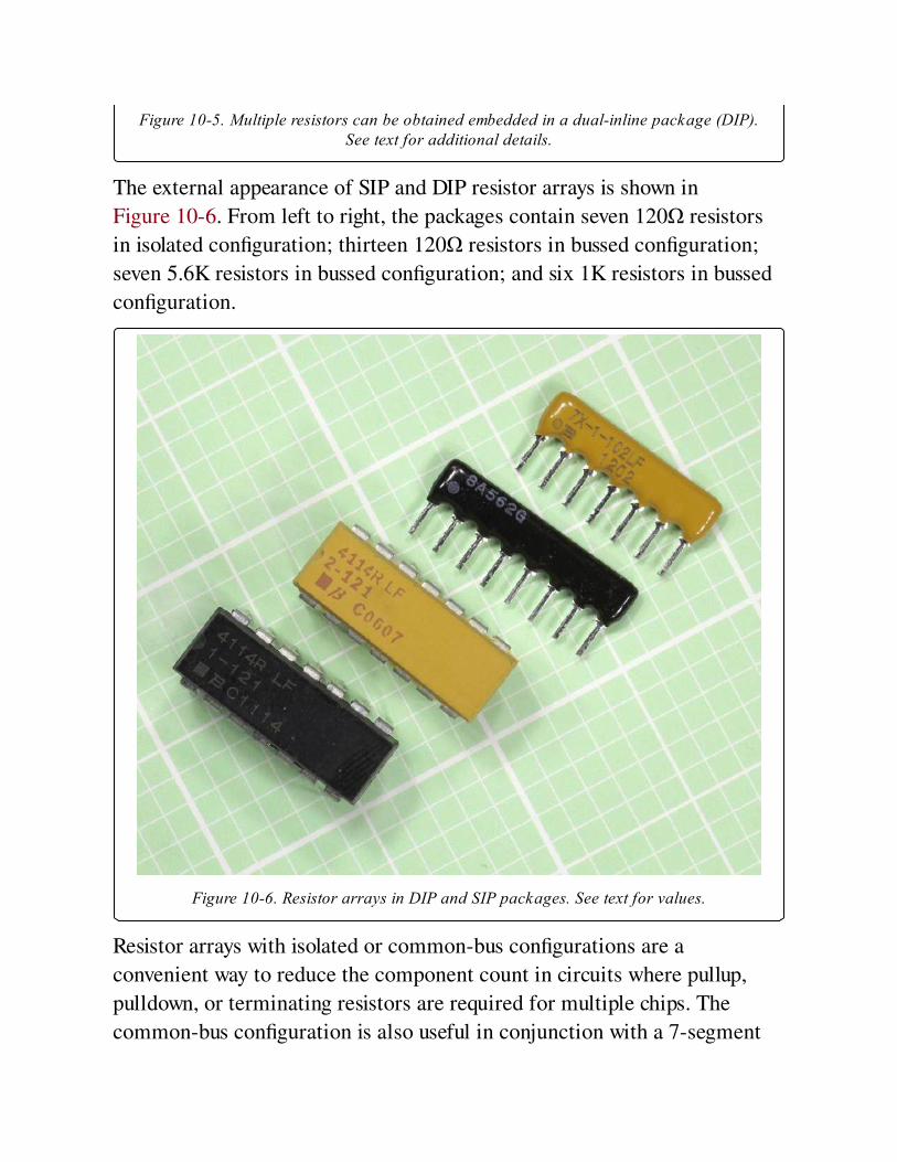
Figure 10-5. Multiple resistors can be obtained embedded in a dual-inline package (DIP).See text for additional details.
The external appearance of SIP and DIP resistor arrays is shown in
Figure 10-6. From left to right, the packages contain seven 120Ω resistors
in isolated configuration; thirteen 120Ω resistors in bussed configuration;
seven 5.6K resistors in bussed configuration; and six 1K resistors in bussed
configuration.
Figure 10-6. Resistor arrays in DIP and SIP packages. See text for values.
Resistor arrays with isolated or common-bus configurations are a
convenient way to reduce the component count in circuits where pullup,
pulldown, or terminating resistors are required for multiple chips. The
common-bus configuration is also useful in conjunction with a 7-segment
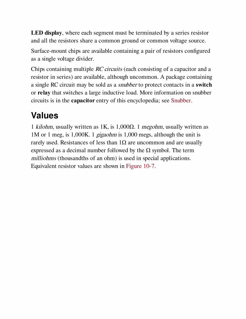
LED display, where each segment must be terminated by a series resistor
and all the resistors share a common ground or common voltage source.
Surface-mount chips are available containing a pair of resistors configured
as a single voltage divider.
Chips containing multiple RC circuits (each consisting of a capacitor and a
resistor in series) are available, although uncommon. A package containing
a single RC circuit may be sold as a snubber to protect contacts in a switchor relay that switches a large inductive load. More information on snubber
circuits is in the capacitor entry of this encyclopedia; see Snubber.
Values1 kilohm, usually written as 1K, is 1,000Ω. 1 megohm, usually written as
1M or 1 meg, is 1,000K. 1 gigaohm is 1,000 megs, although the unit is
rarely used. Resistances of less than 1Ω are uncommon and are usually
expressed as a decimal number followed by the Ω symbol. The term
milliohms (thousandths of an ohm) is used in special applications.
Equivalent resistor values are shown in Figure 10-7.
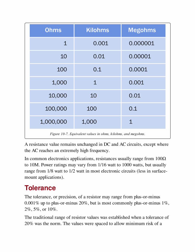
Figure 10-7. Equivalent values in ohms, kilohms, and megohms.
A resistance value remains unchanged in DC and AC circuits, except where
the AC reaches an extremely high frequency.
In common electronics applications, resistances usually range from 100Ω
to 10M. Power ratings may vary from 1/16 watt to 1000 watts, but usually
range from 1/8 watt to 1/2 watt in most electronic circuits (less in surface-
mount applications).
ToleranceThe tolerance, or precision, of a resistor may range from plus-or-minus
0.001% up to plus-or-minus 20%, but is most commonly plus-or-minus 1%,
2%, 5%, or 10%.
The traditional range of resistor values was established when a tolerance of
20% was the norm. The values were spaced to allow minimum risk of a
resistor at one end of its tolerance range having the same value as another
resistor at the opposite end of its tolerance range. The values were rounded
to 10, 15, 22, 33, 47, 68, and 100, as illustrated in Figure 10-8 where each
blue diamond represents the possible range of actual values of a 20%
resistor with a theoretical value shown by the white horizontal line at the
center of the diamond.
Resistor factors repeat themselves in multiples of 10. Thus, for example,
beginning with a resistor of 100Ω, subsequent increasing values will be 150,
220, 330, 470, 680, and 1K, whereas the range of resistors beginning with
1Ω will be 1.5, 2.2, 3.3, 4.7, 6.8, and 10Ω.

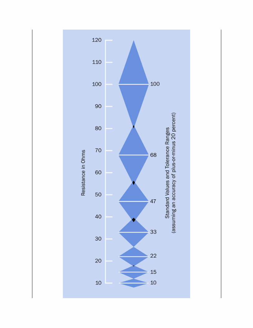
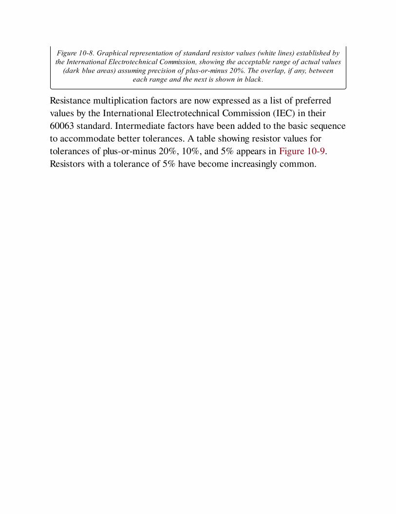
Figure 10-8. Graphical representation of standard resistor values (white lines) established bythe International Electrotechnical Commission, showing the acceptable range of actual values
(dark blue areas) assuming precision of plus-or-minus 20%. The overlap, if any, betweeneach range and the next is shown in black.
Resistance multiplication factors are now expressed as a list of preferred
values by the International Electrotechnical Commission (IEC) in their
60063 standard. Intermediate factors have been added to the basic sequence
to accommodate better tolerances. A table showing resistor values for
tolerances of plus-or-minus 20%, 10%, and 5% appears in Figure 10-9.
Resistors with a tolerance of 5% have become increasingly common.

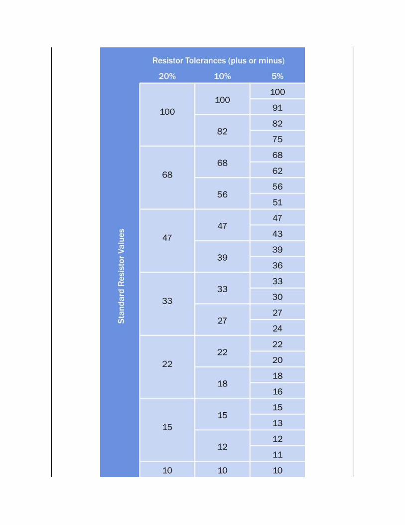
Figure 10-9. Standard values for resistors of different precisions. For resistors outside therange shown, values can be found by multiplying or dividing (repeatedly, if necessary) by a
factor of 10.
The IEC has established 3-digit preferred values for resistors with values
accurate to plus-or-minus 0.5%.
Because many capacitors still have a tolerance no better than 20%, their
values also conform with the old original set of resistance values, although
the units are expressed in farads or fractions of a farad. See the capacitorsentry in this encyclopedia for additional information.
Value CodingThrough-hole axial resistors are traditionally printed with a sequence of
three colored bands to express the value of the component, each of the first
two bands representing a digit from 0 through 9, while the third band
indicates the decimal multiplier (the number of zeroes, from 0 to 9, which
should be appended to the digits). A fourth band of silver or gold indicates
10% or 5% tolerance respectively. No fourth band would indicate 20%
tolerance, although this has become very rare.
Many resistors now have five color bands, to enable the representation of
intermediate or fractional values. In this scheme, the first three bands have
numeric values (using the same color system as before) while the fourth
band is the multiplier. A fifth band, at the opposite end of the resistor,
indicates its tolerance.
In Figure 10-10 the numeric or multiplier value of each color is shown as a
"spectrum" at the top of the figure. The tolerance, or precision of a resistor,
expressed as a plus-or-minus percentage, is shown using silver, gold, and
various colors, at the bottom of the figure.
Two sample resistors are shown. The upper one has a value of 1K, indicated
by the brown and black bands on the left (representing numeral 1 followed
by a numeral 0) and the third red band (indicating two additional zeroes).
The gold band at right indicates a precision of 5%. The lower one has a
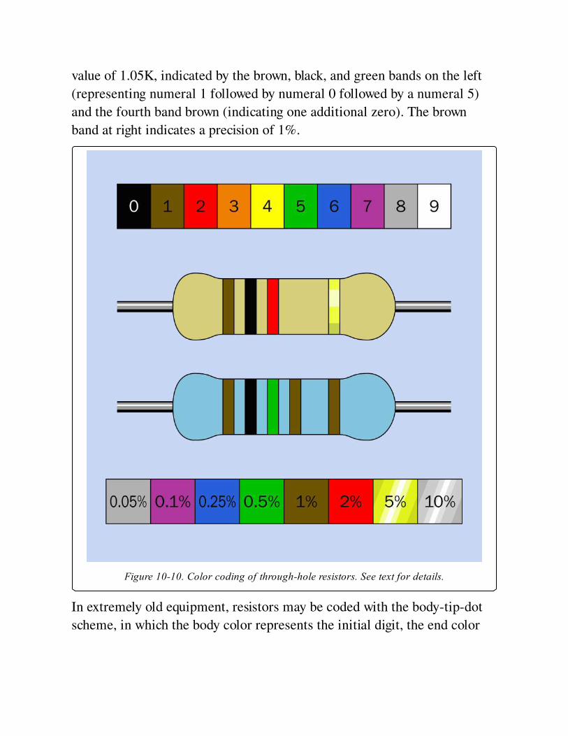
value of 1.05K, indicated by the brown, black, and green bands on the left
(representing numeral 1 followed by numeral 0 followed by a numeral 5)
and the fourth band brown (indicating one additional zero). The brown
band at right indicates a precision of 1%.
Figure 10-10. Color coding of through-hole resistors. See text for details.
In extremely old equipment, resistors may be coded with the body-tip-dot
scheme, in which the body color represents the initial digit, the end color
represents the second digit, and a dot represents the multiplier. The
numeric identities of the colors is the same as in the current color scheme.
In all modern schemes, the three or four bands that show the resistance
value are spaced close together, while a larger gap separates them from the
band that shows the tolerance. The resistor value should be read while
holding the resistor so that the group of closely-spaced numeric bands is on
the left.
Confusingly, some resistors may be found where the first three bands define
the value, using the old three-band convention; the fourth band indicates
tolerance; and a fifth band at the opposite end of the component indicates
reliability. However, this color scheme is uncommon.
Other color-coding conventions may be found in special applications, such
as military equipment.
It is common for through-hole carbon-film resistors to have a beige body
color, while through-hole metal-film resistors often have a blue body color.
However, in relatively rare instances, a blue body color may also indicate a
fusible resistor (designed to burn out harmlessly like a fuse, if it is
overloaded) while a white body may indicate a non-flammable resistor. Use
caution when replacing these special types.
Some modern resistors may have their values printed on them numerically.
Surface-mount resistors also have digits printed on them, but they are a
code, not a direct representation of resistance. The last digit indicates the
number of zeroes in the resistor value, while the preceding two or three
numbers define the value itself. Letter R is used to indicate a decimal point.
Thus a 3R3 surface-mount resistor has a value of 3.3Ω, while 330 would
indicate 33Ω, and 332 indicates 3,300Ω. A 2152 surface-mount resistor
would have a value of 21,500Ω.
A surface-mount resistor with a single zero printed on it is a zero ohm
component that has the same function as a jumper wire. It is used for
convenience, as it is easily inserted by automated production-line
equipment. It functions merely as a bridge between traces on the circuit
board.
When resistor values are printed on paper in schematics, poor reproduction
may result in omission of decimal points or introduction of specks that look
like decimal points. Europeans have addressed this issue by using the letter
as a substitute for a decimal point so that a 5.6K resistor will be shown as
5K6, or a 3.3M resistor will be shown as 3M3. This practice is followed
infrequently in the United States.
StabilityThis term describes the ability of a resistor to maintain an accurate value
despite factors such as temperature, humidity, vibration, load cycling,
current, and voltage. The temperature coefficient of a resistor (often
referred to as Tcr or Tc, not to be confused with the time constant of a
charging capacitor) is expressed in parts per million change in resistance for
each degree centigrade deviation from room temperature (usually assumed
to be 25 degrees Centigrade). Tc may be a positive or a negative value.
The voltage coefficient of resistance—often expressed as Vc—describes the
change of a resistor’s value that may occur as a function of changes in
voltage. This is usually significant only where the resistive element is
carbon-based. If V1 is the rated voltage of the resistor, R1 is its rated
resistance at that voltage, V2 is 10% of the rated voltage, and R2 is the
actual resistance at that voltage, the voltage coefficient, Vc, is given by this
formula:
Vc = (100 * (R1 - R2)) / (R2 * (V1 - V2))
MaterialsResistors are formed from a variety of materials.
Carbon composite. Particles of carbon are mixed with a binder. The density
of the carbon determines the end-to-end resistance, which typically ranges
from 5Ω to 10M. The disadvantages of this system are low precision (a 10%
tolerance is common), relatively high voltage coefficient of resistance, and
introduction of noise in sensitive circuits. However, carbon-composite
resistors have low inductance and are relatively tolerant of overload
conditions.
Carbon film. A cheap and popular type, made by coating a ceramic substrate
with a film of carbon compound. They are available in both through-hole
and surface-mount formats. The range of resistor values is comparable with
carbon-composite types, but the precision is increased, typically to 5%, by
cutting a spiral groove in the carbon-compound coating during the
manufacturing process. The carbon film suffers the same disadvantages of
carbon composite resistors, but to a lesser extent. Carbon film resistors
generally should not be substituted for metal film resistors in applications
where accuracy is important.
Metal film. A metallic film is deposited on a ceramic substrate, and has
generally superior characteristics to carbon-film resistors. During
manufacture, a groove may be cut in the metal film to adjust the end-to-end
resistance. This may cause the resistor to have higher inductance than
carbon-composite types, though it has lower noise. Tolerances of 5%, 2%,
and 1% are available. This type of resistor was originally more expensive
than carbon-film equivalents, but the difference is now fractional. They are
available in both through-hole and surface-mount formats. They are
available in lower-wattage variants (1/8 watt is common).
Thick-film resistors are spray-coated, whereas thin-film resistors are
sputtered nichrome. Thin-films enjoy a flatter temperature coefficient and
are typically used in environments that have a huge operational temperature
range, such as satellites.
Bulk metal foil. The type of foil used in metal film resistors is applied to a
ceramic wafer and etched to achieve the desired overall resistance.
Typically these resistors have axial leads. They can be extremely accurate
and stable, but have a limited maximum resistance.
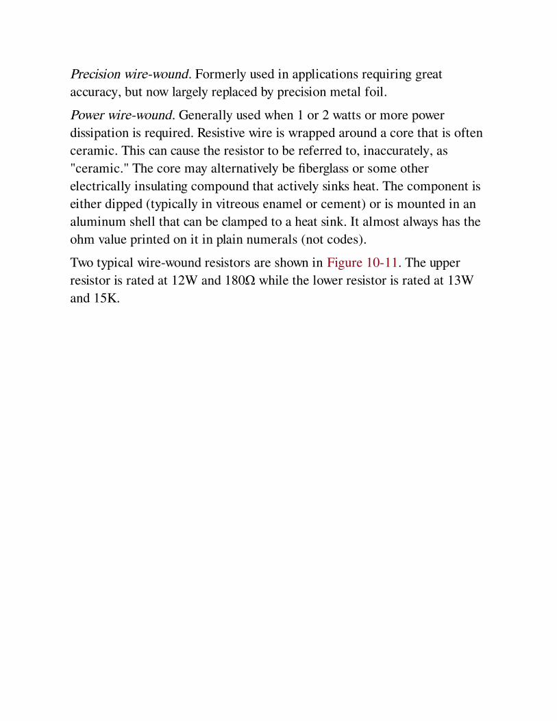
Precision wire-wound. Formerly used in applications requiring great
accuracy, but now largely replaced by precision metal foil.
Power wire-wound. Generally used when 1 or 2 watts or more power
dissipation is required. Resistive wire is wrapped around a core that is often
ceramic. This can cause the resistor to be referred to, inaccurately, as
"ceramic." The core may alternatively be fiberglass or some other
electrically insulating compound that actively sinks heat. The component is
either dipped (typically in vitreous enamel or cement) or is mounted in an
aluminum shell that can be clamped to a heat sink. It almost always has the
ohm value printed on it in plain numerals (not codes).
Two typical wire-wound resistors are shown in Figure 10-11. The upper
resistor is rated at 12W and 180Ω while the lower resistor is rated at 13W
and 15K.
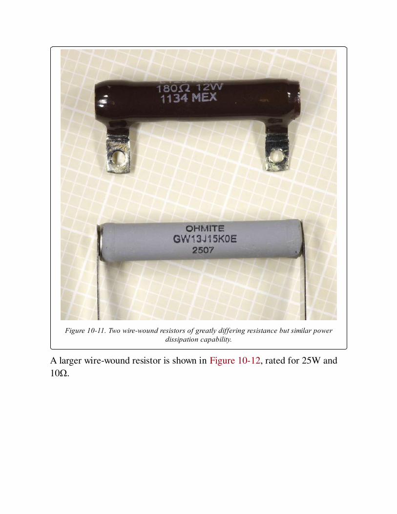
Figure 10-11. Two wire-wound resistors of greatly differing resistance but similar powerdissipation capability.
A larger wire-wound resistor is shown in Figure 10-12, rated for 25W and
10Ω.
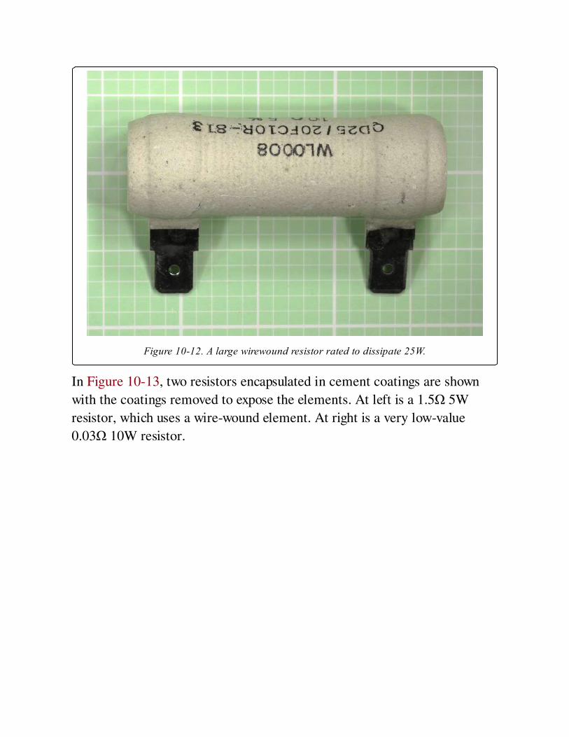
Figure 10-12. A large wirewound resistor rated to dissipate 25W.
In Figure 10-13, two resistors encapsulated in cement coatings are shown
with the coatings removed to expose the elements. At left is a 1.5Ω 5W
resistor, which uses a wire-wound element. At right is a very low-value
0.03Ω 10W resistor.
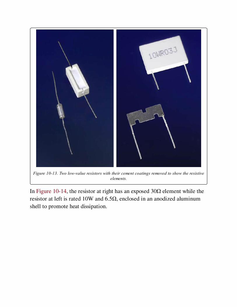
Figure 10-13. Two low-value resistors with their cement coatings removed to show the resistiveelements.
In Figure 10-14, the resistor at right has an exposed 30Ω element while the
resistor at left is rated 10W and 6.5Ω, enclosed in an anodized aluminum
shell to promote heat dissipation.
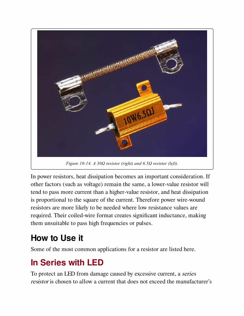
Figure 10-14. A 30Ω resistor (right) and 6.5Ω resistor (left).
In power resistors, heat dissipation becomes an important consideration. If
other factors (such as voltage) remain the same, a lower-value resistor will
tend to pass more current than a higher-value resistor, and heat dissipation
is proportional to the square of the current. Therefore power wire-wound
resistors are more likely to be needed where low resistance values are
required. Their coiled-wire format creates significant inductance, making
them unsuitable to pass high frequencies or pulses.
How to Use itSome of the most common applications for a resistor are listed here.
In Series with LEDTo protect an LED from damage caused by excessive current, a series
resistor is chosen to allow a current that does not exceed the manufacturer’s
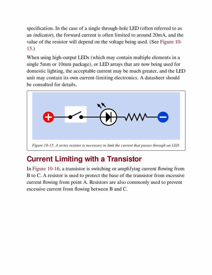
specification. In the case of a single through-hole LED (often referred to as
an indicator), the forward current is often limited to around 20mA, and the
value of the resistor will depend on the voltage being used. (See Figure 10-
15.)
When using high-output LEDs (which may contain multiple elements in a
single 5mm or 10mm package), or LED arrays that are now being used for
domestic lighting, the acceptable current may be much greater, and the LED
unit may contain its own current-limiting electronics. A datasheet should
be consulted for details.
Figure 10-15. A series resistor is necessary to limit the current that passes through an LED.
Current Limiting with a TransistorIn Figure 10-16, a transistor is switching or amplifying current flowing from
B to C. A resistor is used to protect the base of the transistor from excessive
current flowing from point A. Resistors are also commonly used to prevent
excessive current from flowing between B and C.
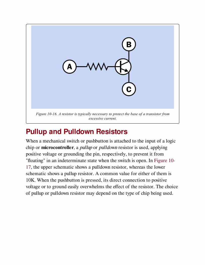
Figure 10-16. A resistor is typically necessary to protect the base of a transistor fromexcessive current.
Pullup and Pulldown ResistorsWhen a mechanical switch or pushbutton is attached to the input of a logic
chip or microcontroller, a pullup or pulldown resistor is used, applying
positive voltage or grounding the pin, respectively, to prevent it from
"floating" in an indeterminate state when the switch is open. In Figure 10-
17, the upper schematic shows a pulldown resistor, whereas the lower
schematic shows a pullup resistor. A common value for either of them is
10K. When the pushbutton is pressed, its direct connection to positive
voltage or to ground easily overwhelms the effect of the resistor. The choice
of pullup or pulldown resistor may depend on the type of chip being used.
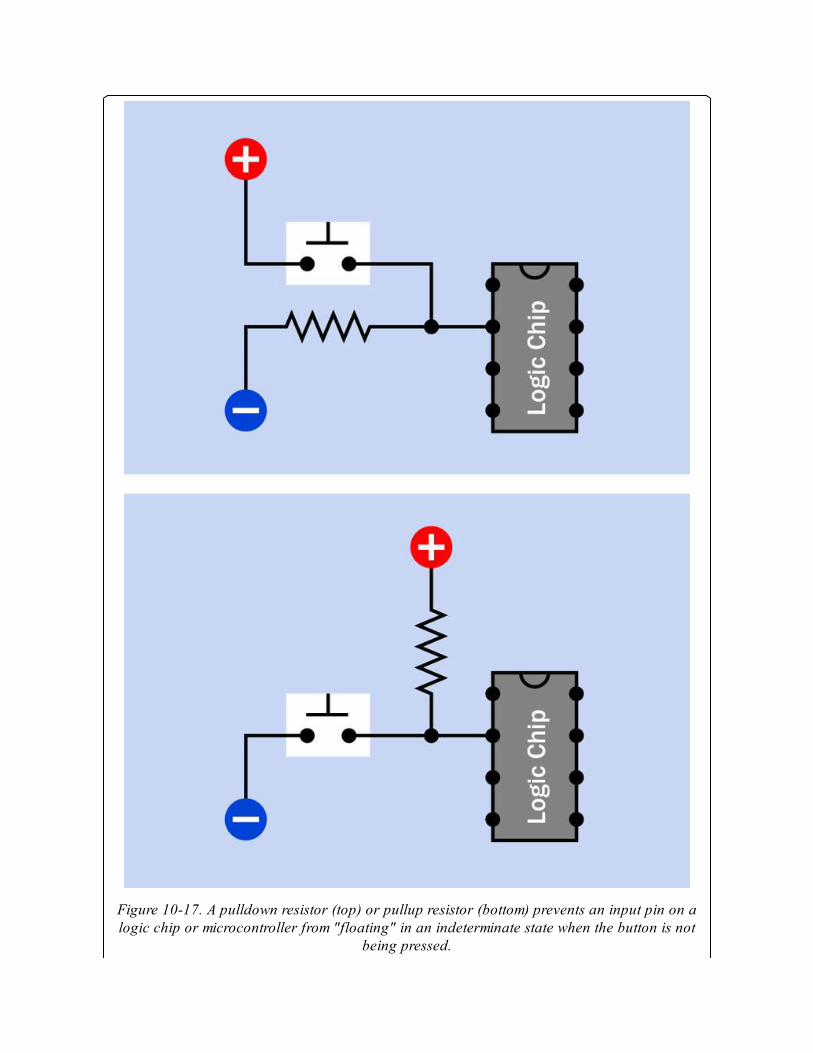
Figure 10-17. A pulldown resistor (top) or pullup resistor (bottom) prevents an input pin on alogic chip or microcontroller from "floating" in an indeterminate state when the button is not
being pressed.
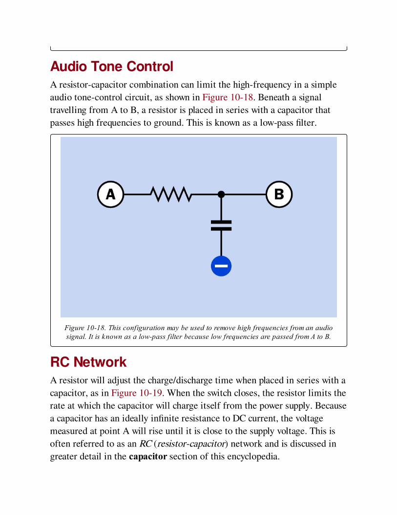
Audio Tone ControlA resistor-capacitor combination can limit the high-frequency in a simple
audio tone-control circuit, as shown in Figure 10-18. Beneath a signal
travelling from A to B, a resistor is placed in series with a capacitor that
passes high frequencies to ground. This is known as a low-pass filter.
Figure 10-18. This configuration may be used to remove high frequencies from an audiosignal. It is known as a low-pass filter because low frequencies are passed from A to B.
RC NetworkA resistor will adjust the charge/discharge time when placed in series with a
capacitor, as in Figure 10-19. When the switch closes, the resistor limits the
rate at which the capacitor will charge itself from the power supply. Because
a capacitor has an ideally infinite resistance to DC current, the voltage
measured at point A will rise until it is close to the supply voltage. This is
often referred to as an RC (resistor-capacitor) network and is discussed in
greater detail in the capacitor section of this encyclopedia.
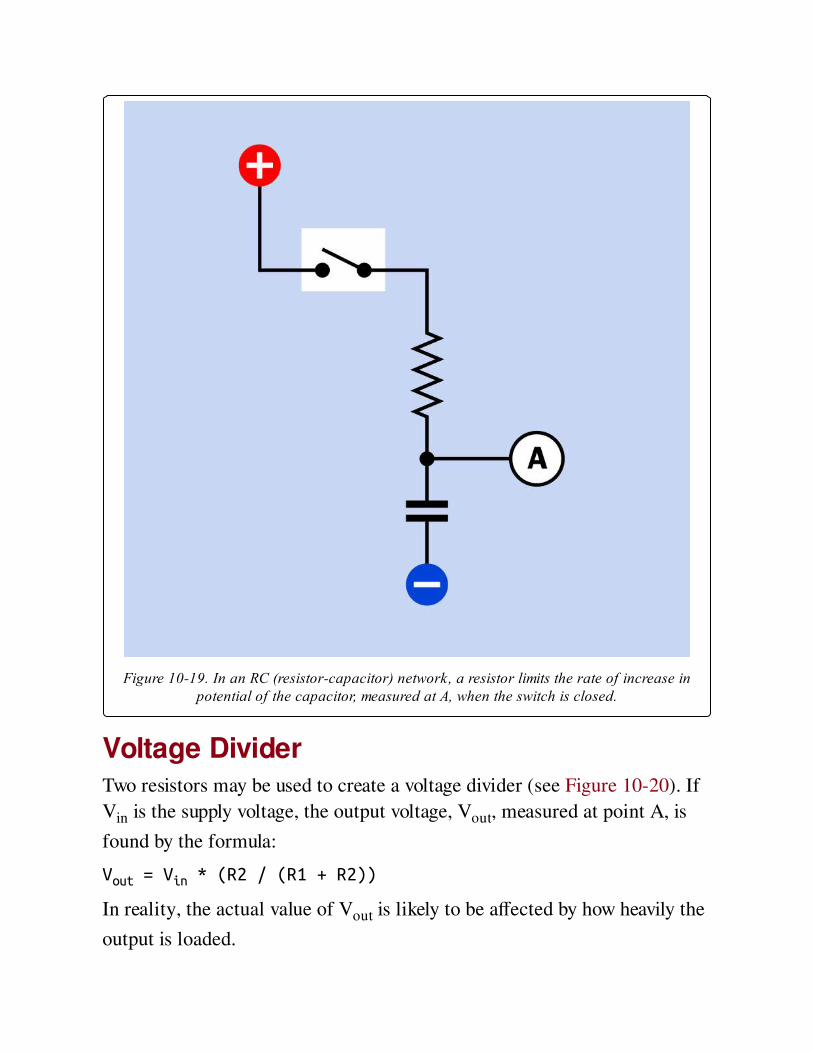
Figure 10-19. In an RC (resistor-capacitor) network, a resistor limits the rate of increase inpotential of the capacitor, measured at A, when the switch is closed.
Voltage DividerTwo resistors may be used to create a voltage divider (see Figure 10-20). If
Vin is the supply voltage, the output voltage, Vout, measured at point A, is
found by the formula:
Vout = Vin * (R2 / (R1 + R2))
In reality, the actual value of Vout is likely to be affected by how heavily the
output is loaded.

If the output node has a high impedance, such as the input to a logic chip or
comparator, it will be more susceptible to electrical noise, and lower-value
resistors may be needed in the voltage divider to maintain a higher current
flow and maintain stability in the attached device.
Figure 10-20. In a DC circuit, a pair of resistors may be placed in series to function as avoltage divider. The voltage measured at A will be lower than the supply voltage, but above
ground potential.
Resistors in SeriesIf resistors in series have values R1, R2, R3 . . . the total resistance, R, is
found by summing the individual resistances:
R = R1 + R2 + R3. . .
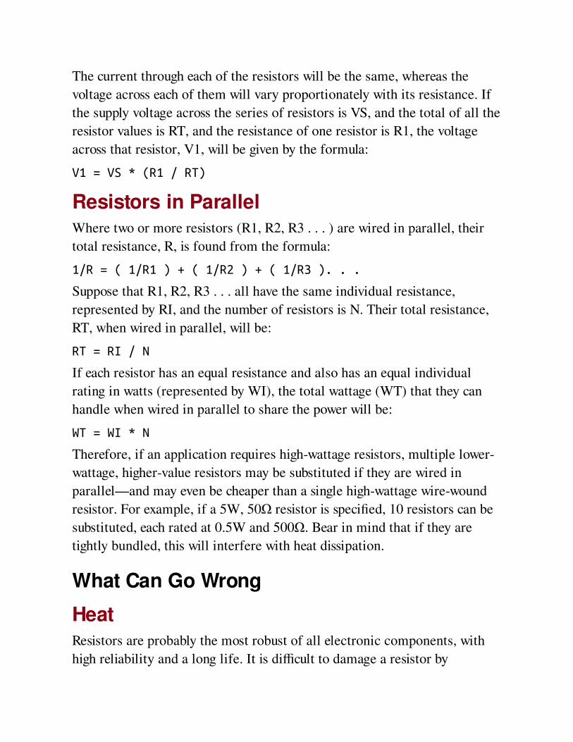
The current through each of the resistors will be the same, whereas the
voltage across each of them will vary proportionately with its resistance. If
the supply voltage across the series of resistors is VS, and the total of all the
resistor values is RT, and the resistance of one resistor is R1, the voltage
across that resistor, V1, will be given by the formula:
V1 = VS * (R1 / RT)
Resistors in ParallelWhere two or more resistors (R1, R2, R3 . . . ) are wired in parallel, their
total resistance, R, is found from the formula:
1/R = ( 1/R1 ) + ( 1/R2 ) + ( 1/R3 ). . .
Suppose that R1, R2, R3 . . . all have the same individual resistance,
represented by RI, and the number of resistors is N. Their total resistance,
RT, when wired in parallel, will be:
RT = RI / N
If each resistor has an equal resistance and also has an equal individual
rating in watts (represented by WI), the total wattage (WT) that they can
handle when wired in parallel to share the power will be:
WT = WI * N
Therefore, if an application requires high-wattage resistors, multiple lower-
wattage, higher-value resistors may be substituted if they are wired in
parallel—and may even be cheaper than a single high-wattage wire-wound
resistor. For example, if a 5W, 50Ω resistor is specified, 10 resistors can be
substituted, each rated at 0.5W and 500Ω. Bear in mind that if they are
tightly bundled, this will interfere with heat dissipation.
What Can Go Wrong
HeatResistors are probably the most robust of all electronic components, with
high reliability and a long life. It is difficult to damage a resistor by
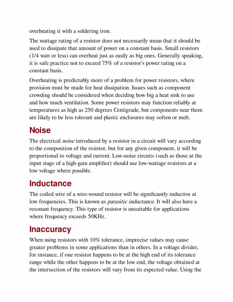
overheating it with a soldering iron.
The wattage rating of a resistor does not necessarily mean that it should be
used to dissipate that amount of power on a constant basis. Small resistors
(1/4 watt or less) can overheat just as easily as big ones. Generally speaking,
it is safe practice not to exceed 75% of a resistor’s power rating on a
constant basis.
Overheating is predictably more of a problem for power resistors, where
provision must be made for heat dissipation. Issues such as component
crowding should be considered when deciding how big a heat sink to use
and how much ventilation. Some power resistors may function reliably at
temperatures as high as 250 degrees Centigrade, but components near them
are likely to be less tolerant and plastic enclosures may soften or melt.
NoiseThe electrical noise introduced by a resistor in a circuit will vary according
to the composition of the resistor, but for any given component, it will be
proportional to voltage and current. Low-noise circuits (such as those at the
input stage of a high-gain amplifier) should use low-wattage resistors at a
low voltage where possible.
InductanceThe coiled wire of a wire-wound resistor will be significantly inductive at
low frequencies. This is known as parasitic inductance. It will also have a
resonant frequency. This type of resistor is unsuitable for applications
where frequency exceeds 50KHz.
InaccuracyWhen using resistors with 10% tolerance, imprecise values may cause
greater problems in some applications than in others. In a voltage divider,
for instance, if one resistor happens to be at the high end of its tolerance
range while the other happens to be at the low end, the voltage obtained at
the intersection of the resistors will vary from its expected value. Using the
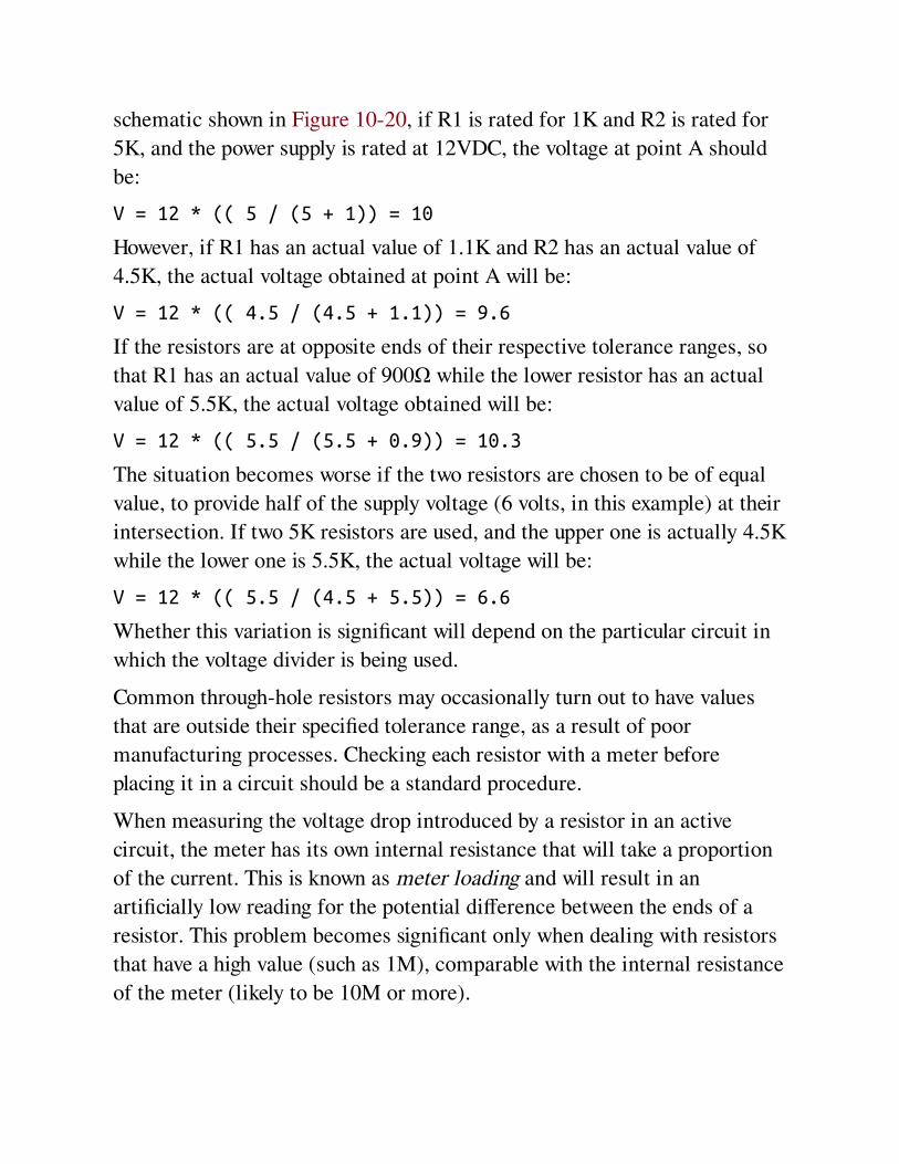
schematic shown in Figure 10-20, if R1 is rated for 1K and R2 is rated for
5K, and the power supply is rated at 12VDC, the voltage at point A should
be:
V = 12 * (( 5 / (5 + 1)) = 10
However, if R1 has an actual value of 1.1K and R2 has an actual value of
4.5K, the actual voltage obtained at point A will be:
V = 12 * (( 4.5 / (4.5 + 1.1)) = 9.6
If the resistors are at opposite ends of their respective tolerance ranges, so
that R1 has an actual value of 900Ω while the lower resistor has an actual
value of 5.5K, the actual voltage obtained will be:
V = 12 * (( 5.5 / (5.5 + 0.9)) = 10.3
The situation becomes worse if the two resistors are chosen to be of equal
value, to provide half of the supply voltage (6 volts, in this example) at their
intersection. If two 5K resistors are used, and the upper one is actually 4.5K
while the lower one is 5.5K, the actual voltage will be:
V = 12 * (( 5.5 / (4.5 + 5.5)) = 6.6
Whether this variation is significant will depend on the particular circuit in
which the voltage divider is being used.
Common through-hole resistors may occasionally turn out to have values
that are outside their specified tolerance range, as a result of poor
manufacturing processes. Checking each resistor with a meter before
placing it in a circuit should be a standard procedure.
When measuring the voltage drop introduced by a resistor in an active
circuit, the meter has its own internal resistance that will take a proportion
of the current. This is known as meter loading and will result in an
artificially low reading for the potential difference between the ends of a
resistor. This problem becomes significant only when dealing with resistors
that have a high value (such as 1M), comparable with the internal resistance
of the meter (likely to be 10M or more).

Wrong ValuesWhen resistors are sorted into small bins by the user, errors may be made,
and different values may be mixed together. This is another reason for
checking the values of components before using them. Identification errors
may be nontrivial and easily overlooked: the visible difference between a 1
megohm resistor and a 100Ω resistor is just one thin color band.
Chapter 11. potentiometer
power > moderation > potentiometer
Also known as a variable resistor; may be substituted for a rheostat.
Other related components
rotational encoder (see Chapter 8)
resistor (see Chapter 10)
What It DoesWhen a voltage is applied across a potentiometer, it can deliver a variable
fraction of that voltage. It is often used to adjust sensitivity, balance, input,
or output, especially in audio equipment and sensors such as motion
detectors.
A potentiometer can also be used to insert a variable resistance in a circuit,
in which case it should really be referred to as a variable resistor, although
most people will still call it a potentiometer.
It can be used to adjust the power supplied to a circuit, in which case it is
properly known as a rheostat, although this term is becoming obsolete.
Massive rheostats were once used for purposes such as dimming theatrical
lighting, but solid-state components have taken their place in most high-
wattage applications.
A full-size, classic-style potentiometer is shown in Figure 11-1.
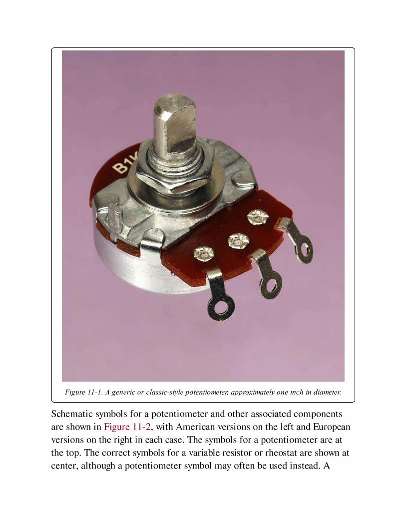
Figure 11-1. A generic or classic-style potentiometer, approximately one inch in diameter.
Schematic symbols for a potentiometer and other associated components
are shown in Figure 11-2, with American versions on the left and European
versions on the right in each case. The symbols for a potentiometer are at
the top. The correct symbols for a variable resistor or rheostat are shown at
center, although a potentiometer symbol may often be used instead. A

preset variable resistor is shown at the bottom, often referred to as a
trimmer or Trimpot. In these examples, each has an arbitrary rated
resistance of 4,700Ω. Note the European substitution of K for a decimal
point.
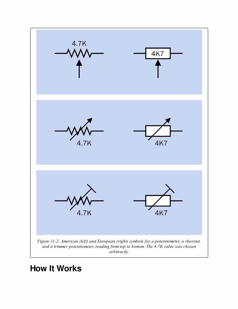
Figure 11-2. American (left) and European (right) symbols for a potentiometer, a rheostat,and a trimmer potentiometer, reading from top to bottom. The 4.7K value was chosen
arbitrarily.
How It Works

A potentiometer has three terminals. The outer pair connect with the
opposite ends of an internal resistive element, such as a strip of conductive
plastic, sometimes known as the track. The third center terminal connects
internally with a contact known as the wiper (or rarely, the pick-off), which
touches the strip and can be moved from one end of it to the other by
turning a shaft or screw, or by moving a slider.
If an electrical potential is applied between opposite ends of the resistive
element, the voltage "picked off" by the wiper will vary as it moves. In this
mode, the potentiometer works as a resistive voltage divider. For example,
in a potentiometer with a linear taper (see “Variants,” coming up), if you
attach the negative side of a 12V battery to the right-hand end terminal and
the positive side to the left-hand end terminal, you will find an 8V potential
at the center terminal when the potentiometer has rotated clockwise
through one-third of its range. In Figure 11-3, the base of the shaft (shown
in black) is attached to an arm (shown in green) that moves a wiper (orange)
along a resistive element (brown). The voltages shown assume that the
resistive element has a linear taper and will vary slightly depending on wire
resistance and other factors.

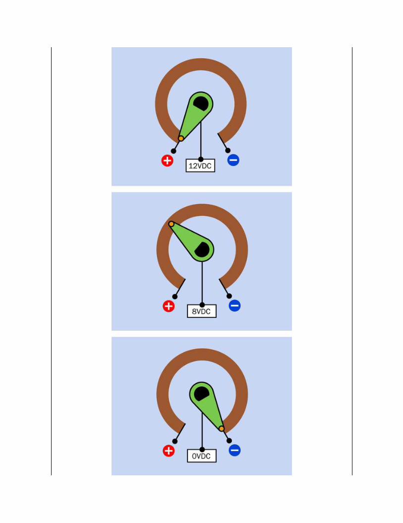
Figure 11-3. Inside a potentiometer. See text for details.
Because a potentiometer imposes a voltage reduction, it also reduces
current flowing through it, and therefore creates waste heat which must be
dissipated. In an application such as an audio circuit, small currents and low
voltages generate negligible heat. If a potentiometer is used for heavier
applications, it must be appropriately rated to handle the wattage and must
be vented to allow heat to disperse.
To use a potentiometer as a variable resistor or rheostat, one of its end
terminals may be tied to the center terminal. If the unused end terminal is
left unconnected, this raises the risk of picking up stray voltages or "noise"
in sensitive circuits. In Figure 11-4, a potentiometer is shown adjusting a
series resistance for an LED for demonstration purposes. More typically, a
trimmer would be used in this kind of application, since a user is unlikely to
need to reset it.
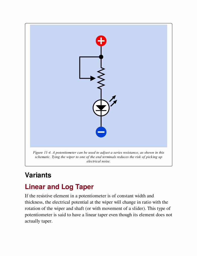
Figure 11-4. A potentiometer can be used to adjust a series resistance, as shown in thisschematic. Tying the wiper to one of the end terminals reduces the risk of picking up
electrical noise.
Variants
Linear and Log TaperIf the resistive element in a potentiometer is of constant width and
thickness, the electrical potential at the wiper will change in ratio with the
rotation of the wiper and shaft (or with movement of a slider). This type of
potentiometer is said to have a linear taper even though its element does not
actually taper.
For audio applications, because human hearing responds nonlinearly to
sound pressure, a potentiometer that has a linear taper may seem to have a
very slow action at one end of its scale and an abrupt effect at the other.
This problem used to be solved with a non-uniform or tapered resistive
element. More recently, a combination of resistive elements has been used
as a cheaper option. Such a potentiometer is said to have an audio taper or a
log taper (since the resistance may vary as a logarithm of the angle of
rotation). A reverse audio taper or antilog taper varies in the opposite
direction, but this type has become very uncommon.
Classic-style PotentiometerThis consists of a sealed circular can, usually between 0.5" and 1" in
diameter, containing a resistive strip that is shaped as a segment of a circle.
A typical example is shown in Figure 11-1, although miniaturized versions
have become more common. A shaft mounted on the can turns the internal
wiper that presses against the strip. For panel-mount applications, a
threaded bushing at the base of the shaft is inserted through a hole in the
front panel of the electronics enclosure, and a nut is tightened on the
bushing to hold the potentiometer in place. Often there is also a small offset
index pin that, when paired with a corresponding front panel hole, will keep
the pot from spinning freely.
Many modern potentiometers are miniaturized, and may be packaged in a
box-shaped plastic enclosure rather than a circular can. Their power ratings
are likely to be lower, but their principle of operation is unchanged. Two
variants are shown in Figure 11-5.
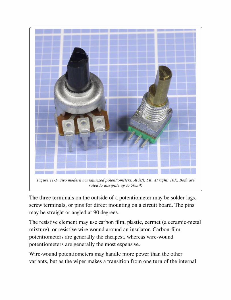
Figure 11-5. Two modern miniaturized potentiometers. At left: 5K. At right: 10K. Both arerated to dissipate up to 50mW.
The three terminals on the outside of a potentiometer may be solder lugs,
screw terminals, or pins for direct mounting on a circuit board. The pins
may be straight or angled at 90 degrees.
The resistive element may use carbon film, plastic, cermet (a ceramic-metal
mixture), or resistive wire wound around an insulator. Carbon-film
potentiometers are generally the cheapest, whereas wire-wound
potentiometers are generally the most expensive.
Wire-wound potentiometers may handle more power than the other
variants, but as the wiper makes a transition from one turn of the internal
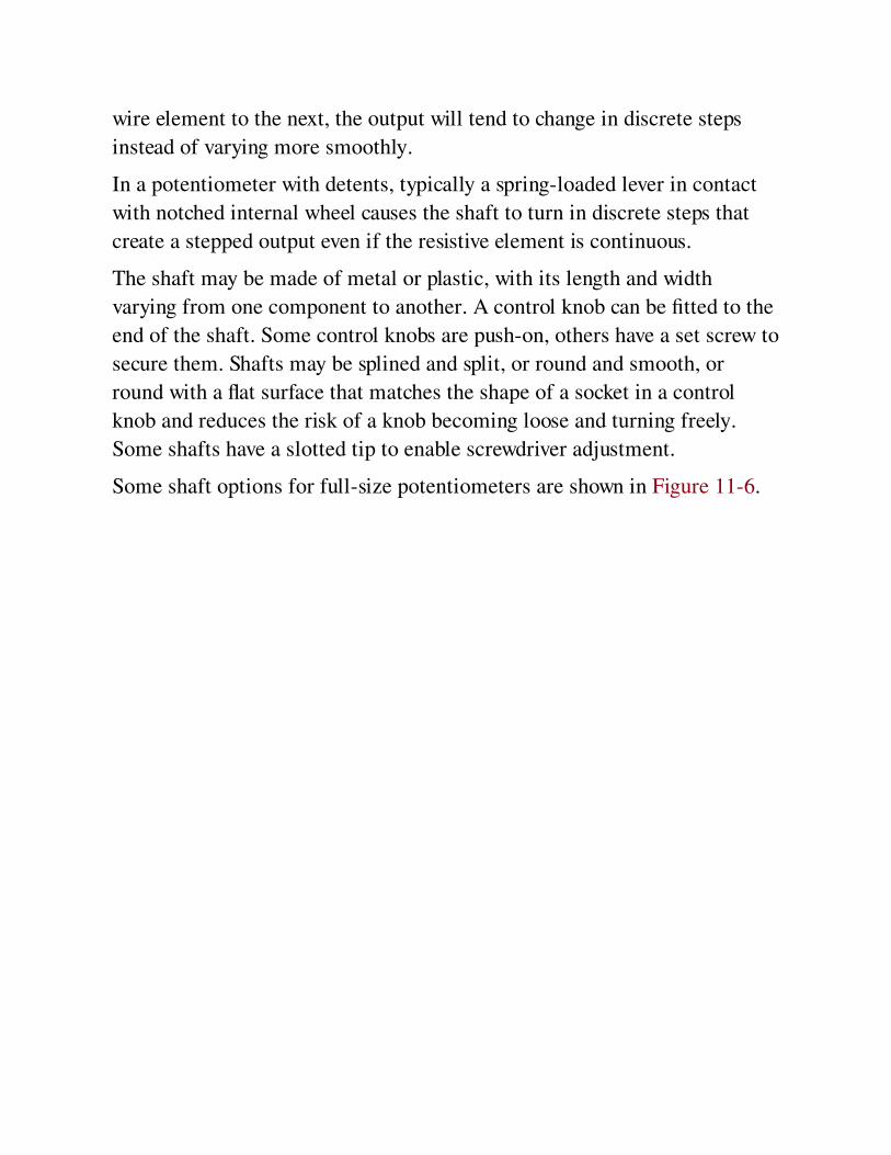
wire element to the next, the output will tend to change in discrete steps
instead of varying more smoothly.
In a potentiometer with detents, typically a spring-loaded lever in contact
with notched internal wheel causes the shaft to turn in discrete steps that
create a stepped output even if the resistive element is continuous.
The shaft may be made of metal or plastic, with its length and width
varying from one component to another. A control knob can be fitted to the
end of the shaft. Some control knobs are push-on, others have a set screw to
secure them. Shafts may be splined and split, or round and smooth, or
round with a flat surface that matches the shape of a socket in a control
knob and reduces the risk of a knob becoming loose and turning freely.
Some shafts have a slotted tip to enable screwdriver adjustment.
Some shaft options for full-size potentiometers are shown in Figure 11-6.
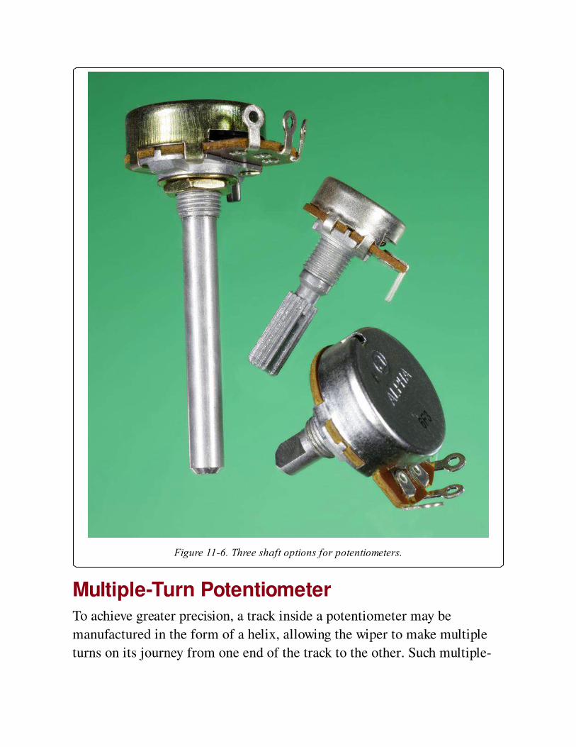
Figure 11-6. Three shaft options for potentiometers.
Multiple-Turn PotentiometerTo achieve greater precision, a track inside a potentiometer may be
manufactured in the form of a helix, allowing the wiper to make multiple
turns on its journey from one end of the track to the other. Such multiple-
turn potentiometers typically allow 3, 5, or 10 turns to move the wiper from
end to end. Other multiple-turn potentiometers may use a screw thread that
advances a wiper along a linear or circular track. The latter is comparable
with a trimmer where multiple turns of a screwdriver are used to rotate a
worm gear that rotates a wiper between opposite ends of a circular track.
Ganged PotentiometerTwo (or rarely, more) potentiometers can be stacked or combined so that
their resistive elements and wipers share the same shaft but can use
different voltages or have different taper. Each resistance-wiper assembly is
known as a cup, and the potentiometers are said to be ganged.
Flat ganged potentiometers combine two resistive elements in one
enclosure. Some dual ganged potentiometers are concentric, meaning that
the pots are controlled separately by two shafts, one inside the other.
Suitable concentric knobs must be used. You are unlikely to find these
potentiometers sold as components in limited quantities.
Switched PotentiometerIn this variant, when the shaft is turned clockwise from an initial position
that is fully counter-clockwise, it flips an internal switch connected to
external terminals. This can be used to power-up associated components
(for example, an audio amplifier). Alternatively, a switch inside a
potentiometer may be configured so that it is activated by pulling or
pushing the shaft.
Slider PotentiometerAlso known as a slide potentiometer. This uses a straight resistive strip and
a wiper that is moved to and fro linearly by a tab or lug fitted with a plastic
knob or finger-grip. Sliders are still found on some audio equipment. The
principle of operation, and the number of terminals, are identical to the
classic-style potentiometer. Sliders typically have solder tabs or PC pins. In
Figure 11-7, the large one is about 3.5" long, designed for mounting behind
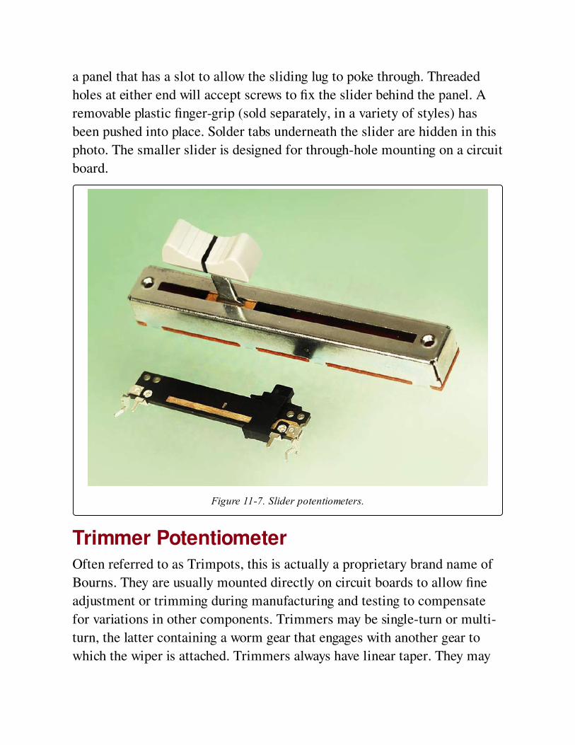
a panel that has a slot to allow the sliding lug to poke through. Threaded
holes at either end will accept screws to fix the slider behind the panel. A
removable plastic finger-grip (sold separately, in a variety of styles) has
been pushed into place. Solder tabs underneath the slider are hidden in this
photo. The smaller slider is designed for through-hole mounting on a circuit
board.
Figure 11-7. Slider potentiometers.
Trimmer PotentiometerOften referred to as Trimpots, this is actually a proprietary brand name of
Bourns. They are usually mounted directly on circuit boards to allow fine
adjustment or trimming during manufacturing and testing to compensate
for variations in other components. Trimmers may be single-turn or multi-
turn, the latter containing a worm gear that engages with another gear to
which the wiper is attached. Trimmers always have linear taper. They may
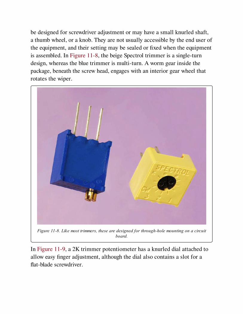
be designed for screwdriver adjustment or may have a small knurled shaft,
a thumb wheel, or a knob. They are not usually accessible by the end user of
the equipment, and their setting may be sealed or fixed when the equipment
is assembled. In Figure 11-8, the beige Spectrol trimmer is a single-turn
design, whereas the blue trimmer is multi-turn. A worm gear inside the
package, beneath the screw head, engages with an interior gear wheel that
rotates the wiper.
Figure 11-8. Like most trimmers, these are designed for through-hole mounting on a circuitboard.
In Figure 11-9, a 2K trimmer potentiometer has a knurled dial attached to
allow easy finger adjustment, although the dial also contains a slot for a
flat-blade screwdriver.
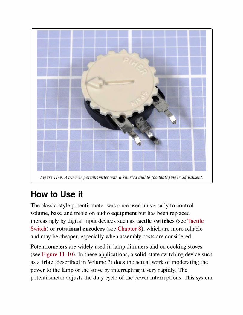
Figure 11-9. A trimmer potentiometer with a knurled dial to facilitate finger adjustment.
How to Use itThe classic-style potentiometer was once used universally to control
volume, bass, and treble on audio equipment but has been replaced
increasingly by digital input devices such as tactile switches (see Tactile
Switch) or rotational encoders (see Chapter 8), which are more reliable
and may be cheaper, especially when assembly costs are considered.
Potentiometers are widely used in lamp dimmers and on cooking stoves
(see Figure 11-10). In these applications, a solid-state switching device such
as a triac (described in Volume 2) does the actual work of moderating the
power to the lamp or the stove by interrupting it very rapidly. The
potentiometer adjusts the duty cycle of the power interruptions. This system
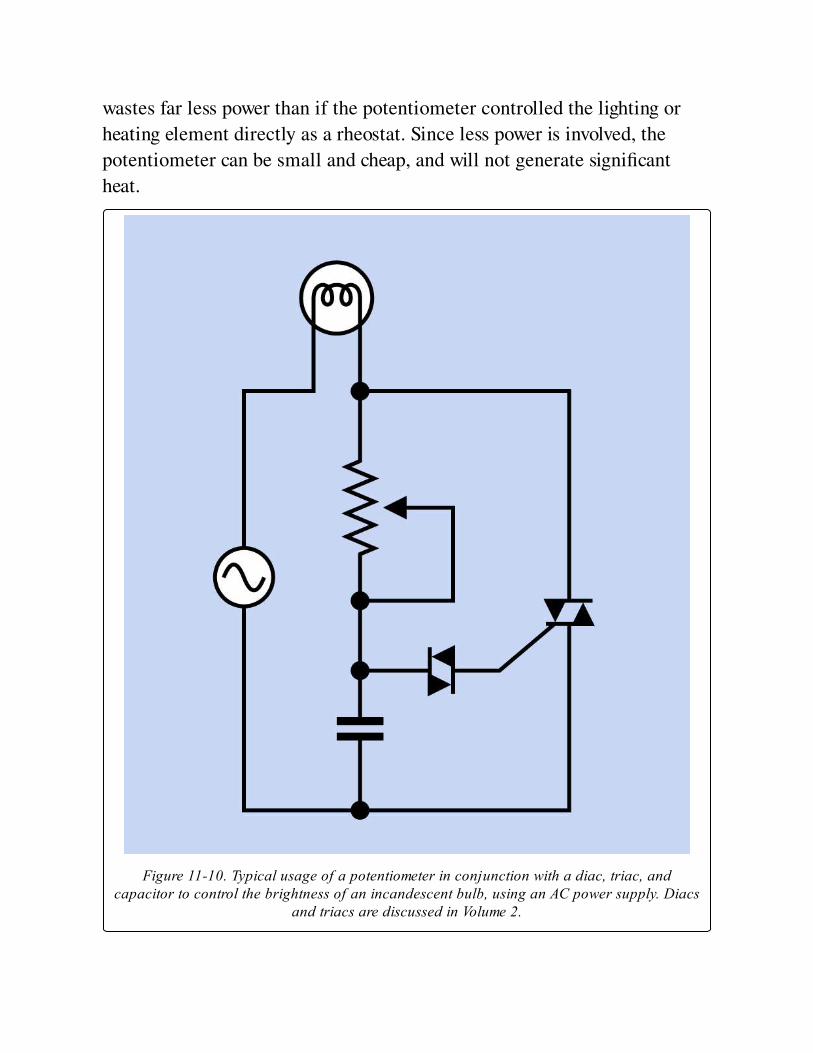
wastes far less power than if the potentiometer controlled the lighting or
heating element directly as a rheostat. Since less power is involved, the
potentiometer can be small and cheap, and will not generate significant
heat.
Figure 11-10. Typical usage of a potentiometer in conjunction with a diac, triac, andcapacitor to control the brightness of an incandescent bulb, using an AC power supply. Diacs
and triacs are discussed in Volume 2.
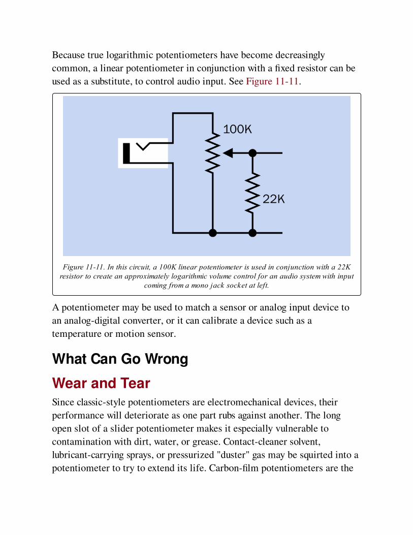
Because true logarithmic potentiometers have become decreasingly
common, a linear potentiometer in conjunction with a fixed resistor can be
used as a substitute, to control audio input. See Figure 11-11.
Figure 11-11. In this circuit, a 100K linear potentiometer is used in conjunction with a 22Kresistor to create an approximately logarithmic volume control for an audio system with input
coming from a mono jack socket at left.
A potentiometer may be used to match a sensor or analog input device to
an analog-digital converter, or it can calibrate a device such as a
temperature or motion sensor.
What Can Go Wrong
Wear and TearSince classic-style potentiometers are electromechanical devices, their
performance will deteriorate as one part rubs against another. The long
open slot of a slider potentiometer makes it especially vulnerable to
contamination with dirt, water, or grease. Contact-cleaner solvent,
lubricant-carrying sprays, or pressurized "duster" gas may be squirted into a
potentiometer to try to extend its life. Carbon-film potentiometers are the
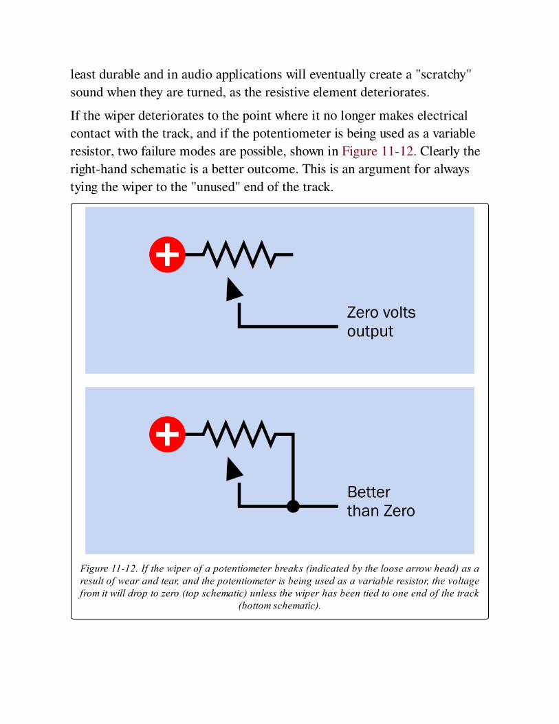
least durable and in audio applications will eventually create a "scratchy"
sound when they are turned, as the resistive element deteriorates.
If the wiper deteriorates to the point where it no longer makes electrical
contact with the track, and if the potentiometer is being used as a variable
resistor, two failure modes are possible, shown in Figure 11-12. Clearly the
right-hand schematic is a better outcome. This is an argument for always
tying the wiper to the "unused" end of the track.
Figure 11-12. If the wiper of a potentiometer breaks (indicated by the loose arrow head) as aresult of wear and tear, and the potentiometer is being used as a variable resistor, the voltagefrom it will drop to zero (top schematic) unless the wiper has been tied to one end of the track
(bottom schematic).
If you are designing a circuit board that will go through a production
process, temperature variations during wave soldering, and subsequent
washing to remove flux residues, create hostile conditions for
potentiometers, especially sliders where the internal parts are easily
contaminated. It will be safer to hand-mount potentiometers after the
automated process.
Knobs that Don’t FitControl knobs are almost always sold separately from potentiometers. Make
sure the shaft of the potentiometer (which may be round, round-with-flat,
or knurled) matches the knob of your choice. Note that some shaft
diameters are expressed in inches, while others are metric.
Nuts that Get LostFor panel-mounted potentiometers, a nut that fits the thread on the bushing
is almost always included with the potentiometer; an additional nut and
lock washer may also be supplied. Because there is no standardization of
threads on potentiometers, if you lose a nut, you may have some difficulty
finding an exact replacement.
A Shaft that Isn’t Long EnoughWhen choosing a shaft length, if in doubt, buy a potentiometer with a long
shaft that you can cut to the desired length.
Sliders with No Finger GripSlider potentiometers are often sold without a knob or plastic finger-grip,
which must be ordered separately and may be available in different styles.
The finger-grip usually push-fits onto the metal or plastic tab or lug that
moves the slider to and fro.
Too Big to Fit
Check the manufacturer’s datasheet if you need to know the physical size of
the potentiometer. Photographs may be misleading, as a traditional-style
potentiometer that is 0.5" in diameter looks much the same as one that is 1"
in diameter. High-wattage potentiometers will be more costly and
physically large (2 to 3 inches in diameter). See Figure 11-13.
OverheatingBe sure to leave sufficient air space around a high-wattage potentiometer.
Carefully calculate the maximum voltage drop and current that you may be
using, and choose a component that is appropriately rated. Note that if you
use the potentiometer as a rheostat, it will have to handle more current
when its wiper moves to reduce its resistance. For example, if 12VDC are
applied through a 10-ohm rheostat to a component that has a resistance of
20 ohms, current in the circuit will vary from 0.4 amps to 0.6 amps
depending on the position of the rheostat. At its maximum setting, the
rheostat will impose a 4V voltage drop and will therefore dissipate 1.6 watts
from the full length of its resistive element. If the rheostat is reset to
impose only a 4-ohm resistance, the voltage drop that it imposes will be 2V,
the current in the circuit will be 0.5 amps, and the rheostat will therefore
dissipate 1 watt from 4/10ths of the length of its resistive element. A wire-
wound potentiometer will be better able to handle high dissipation from a
short segment of its element than other types of rheostat. Add a fixed
resistor in series with a rheostat if necessary to impose a limit on the
current.
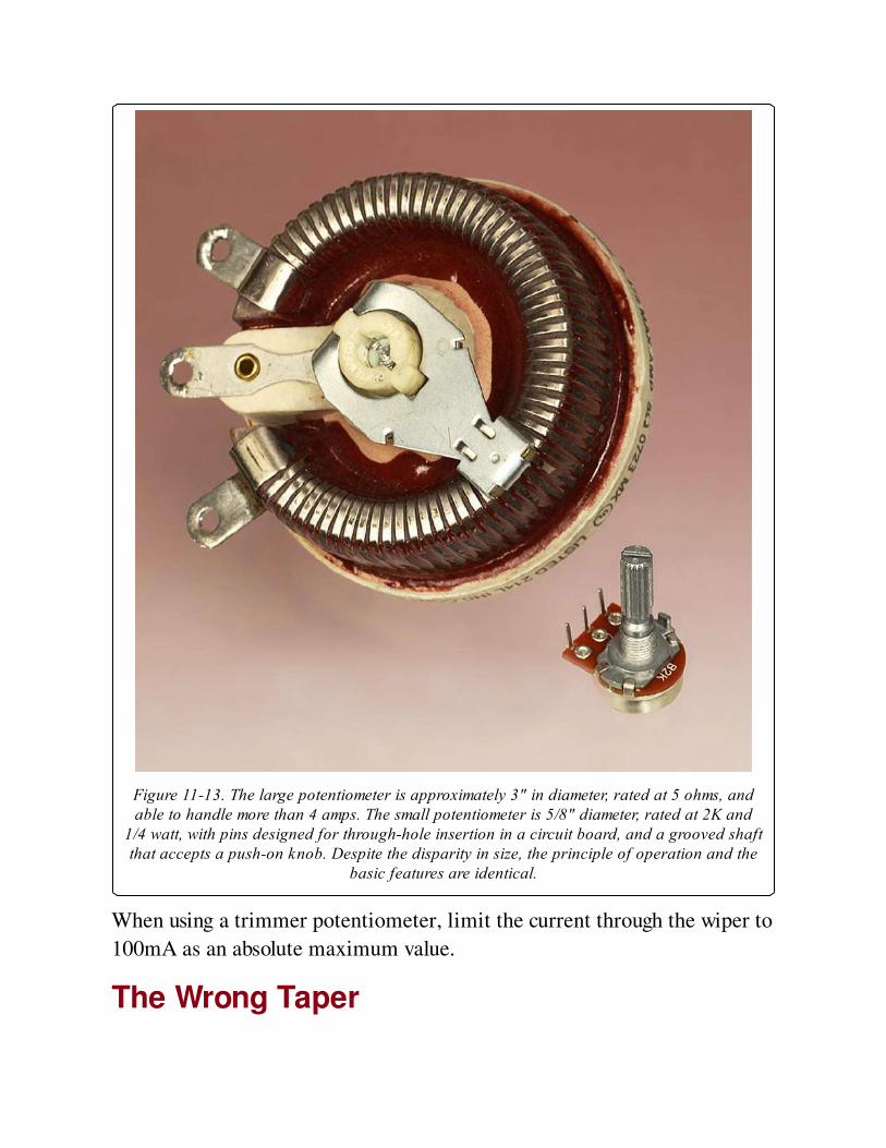
Figure 11-13. The large potentiometer is approximately 3" in diameter, rated at 5 ohms, andable to handle more than 4 amps. The small potentiometer is 5/8" diameter, rated at 2K and
1/4 watt, with pins designed for through-hole insertion in a circuit board, and a grooved shaftthat accepts a push-on knob. Despite the disparity in size, the principle of operation and the
basic features are identical.
When using a trimmer potentiometer, limit the current through the wiper to
100mA as an absolute maximum value.
The Wrong Taper
When buying a potentiometer, remember to check the specification to find
out whether it has linear or audio/log taper. If necessary, attach a meter,
with the potentiometer set to its center position, to verify which kind of
taper you have. While holding the meter probes in place, rotate the
potentiometer shaft to determine which way an audio/log taper is oriented.
Chapter 12. capacitor
power > moderation > capacitor
Quite often referred to as a cap. Formerly known (primarily in the United Kingdom) as a
condenser, but that term has become obsolete.
Other related components
variable capacitor (See Chapter 13)
battery (See Chapter 2)
What It DoesA capacitor connected across a DC power source will accumulate a charge,
which then persists after the source is disconnected. In this way, the
capacitor stores (and can then discharge) energy like a small rechargeable
battery. The charge/discharge rate is extremely fast but can be limited by a
series resistor, which enables the capacitor to be used as a timing
component in many electronic circuits.
A capacitor can also be used to block DC current while it passes pulses, or
electrical "noise," or alternating current, or audio signals, or other wave
forms. This capability enables it to smooth the output voltage provided by
power supplies; to remove spikes from signals that would otherwise tend to
cause spurious triggering of components in digital circuits; to adjust the
frequency response of an audio circuit; or to couple separate components or
circuit elements that must be protected from transmission of DC current.
Schematic symbols for capacitors are shown in Figure 12-1. At top-left is a
nonpolarized capacitor, while the other two indicate that a polarized
capacitor must be used, and must be oriented as shown. The variant at the
bottom is most commonly used in Europe. Confusingly, the nonpolarized
symbol may also be used to identify a polarized capacitor, if a + sign is
added. The polarized symbols are sometimes printed without + signs, but
the symbols still indicate that polarity must be observed.
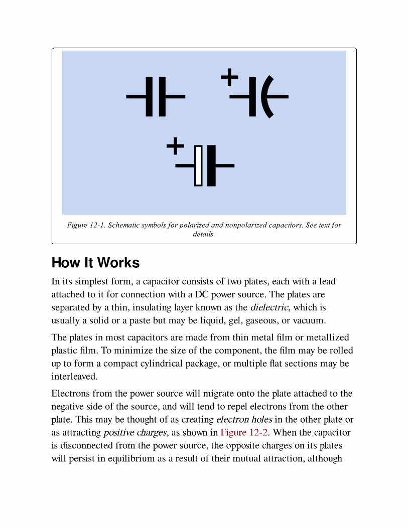
Figure 12-1. Schematic symbols for polarized and nonpolarized capacitors. See text fordetails.
How It WorksIn its simplest form, a capacitor consists of two plates, each with a lead
attached to it for connection with a DC power source. The plates are
separated by a thin, insulating layer known as the dielectric, which is
usually a solid or a paste but may be liquid, gel, gaseous, or vacuum.
The plates in most capacitors are made from thin metal film or metallized
plastic film. To minimize the size of the component, the film may be rolled
up to form a compact cylindrical package, or multiple flat sections may be
interleaved.
Electrons from the power source will migrate onto the plate attached to the
negative side of the source, and will tend to repel electrons from the other
plate. This may be thought of as creating electron holes in the other plate or
as attracting positive charges, as shown in Figure 12-2. When the capacitor
is disconnected from the power source, the opposite charges on its plates
will persist in equilibrium as a result of their mutual attraction, although

the voltage will gradually dissipate as a result of leakage, either through the
dielectric or via other pathways.
Figure 12-2. Because the plates of a capacitor are electrically conductive, they will becomepopulated with positive and negative charges when connected with a DC power source. As
opposite charges attract each other, they will tend to congregate on either side of thedielectric, which is an insulating layer. The battery symbol is shown here colored for clarity.
When a resistor is placed across the leads of a charged capacitor, the
capacitor will discharge itself through the resistor at a rate limited by the
resistance. Conversely, if a capacitor is charged through a resistor, the
resistor will limit the charging rate.
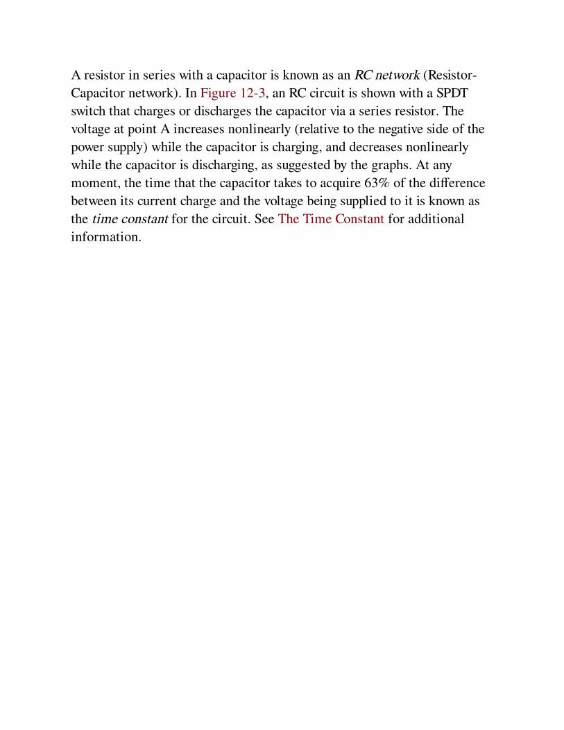
A resistor in series with a capacitor is known as an RC network (Resistor-
Capacitor network). In Figure 12-3, an RC circuit is shown with a SPDT
switch that charges or discharges the capacitor via a series resistor. The
voltage at point A increases nonlinearly (relative to the negative side of the
power supply) while the capacitor is charging, and decreases nonlinearly
while the capacitor is discharging, as suggested by the graphs. At any
moment, the time that the capacitor takes to acquire 63% of the difference
between its current charge and the voltage being supplied to it is known as
the time constant for the circuit. See The Time Constant for additional
information.

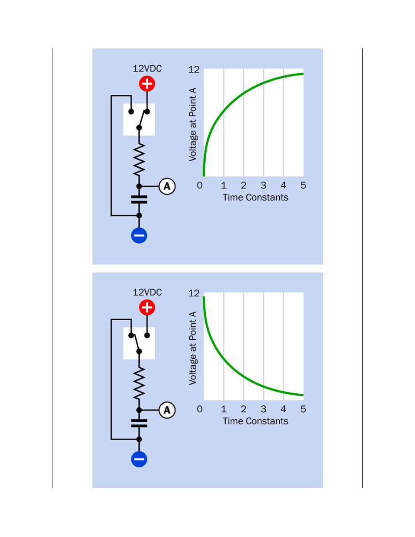
Figure 12-3. An RC (Resistor-Capacitor) network with a switch to control charge anddischarge of a capacitor. At top, the curve gives an approximate idea of the charging
behavior of the capacitor. At bottom, the curve illustrates its discharging behavior.
When a capacitor is connected across an AC voltage source, each surge of
electrons to one plate induces an equal and opposite positive surge to the
other plate, and when polarity of the power supply reverses, the charges on
the plates switch places. These surges may make it seem that the capacitor
is conducting AC current, even though the dielectric that separates the
plates is an insulator. See Figure 12-4. Often a capacitor is said to "pass"
AC, even though this is not really happening. For convenience, and because
the concept is widely established, this encyclopedia refers to capacitors as
"passing" AC.
Figure 12-4. In the left diagram, a source of alternating current charges the upper plate of acapacitor positively and the lower plate negatively. This process entails a flow of
conventional current shown by the arrows. A moment later, when the AC current flow reverses,the flow also reverses, creating the impression that the capacitor "passes" AC current.
Depending on the size of the capacitor, it will block some AC frequencies
while passing others. Generally speaking, a smaller capacitor will pass high
frequencies relatively efficiently, as each little surge of current fills each
plate. However, the situation is complicated by the inductive reactance
(which creates the effective series resistance) of a capacitor, as discussed
below. See Alternating Current and Capacitive Reactance.
Variants
FormatThe three most common packages for capacitors are cylindrical, disc, and
rectangular tablet.
A cylindrical capacitor may have axial leads (a wire attached to each end) or
radial leads (both wires emerging from one end). Radial capacitors are
more widely used as they allow easy insertion into a circuit board. The
capacitor is usually packaged in a small aluminum can, closed at one end,
capped with an insulating disc at the other end, and wrapped in a thin layer
of insulating plastic. Some samples are shown in Figure 12-5 and
Figure 12-6.
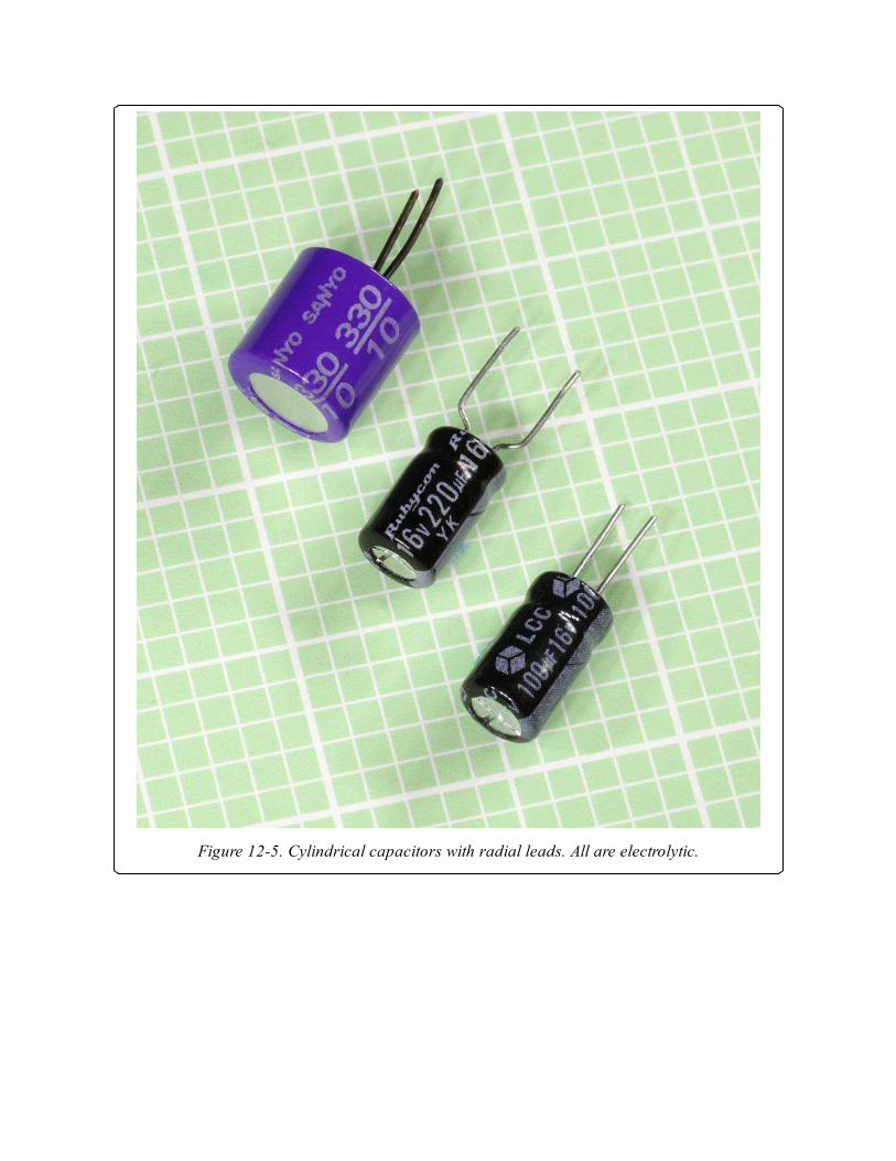
Figure 12-5. Cylindrical capacitors with radial leads. All are electrolytic.
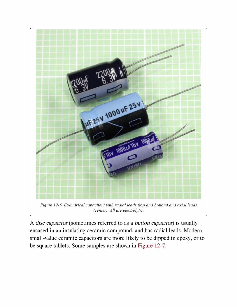
Figure 12-6. Cylindrical capacitors with radial leads (top and bottom) and axial leads(center). All are electrolytic.
A disc capacitor (sometimes referred to as a button capacitor) is usually
encased in an insulating ceramic compound, and has radial leads. Modern
small-value ceramic capacitors are more likely to be dipped in epoxy, or to
be square tablets. Some samples are shown in Figure 12-7.
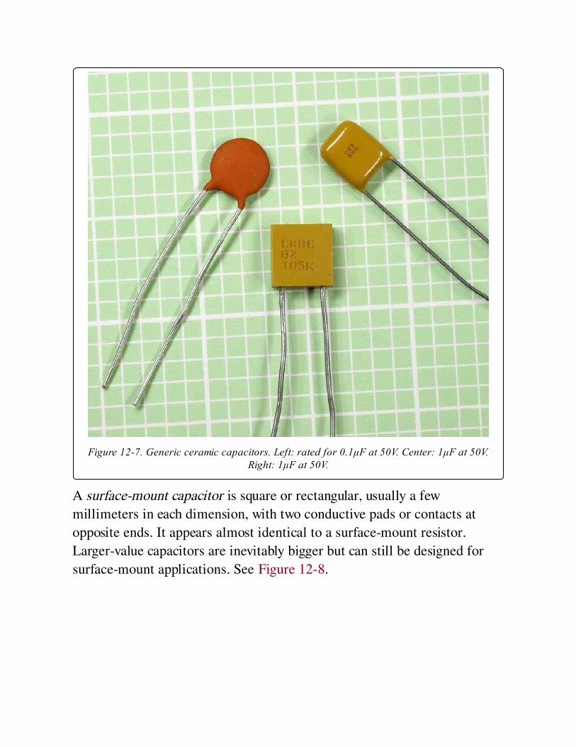
Figure 12-7. Generic ceramic capacitors. Left: rated for 0.1μF at 50V. Center: 1μF at 50V.Right: 1μF at 50V.
A surface-mount capacitor is square or rectangular, usually a few
millimeters in each dimension, with two conductive pads or contacts at
opposite ends. It appears almost identical to a surface-mount resistor.
Larger-value capacitors are inevitably bigger but can still be designed for
surface-mount applications. See Figure 12-8.
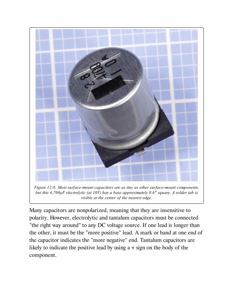
Figure 12-8. Most surface-mount capacitors are as tiny as other surface-mount components,but this 4,700μF electrolytic (at 10V) has a base approximately 0.6" square. A solder tab is
visible at the center of the nearest edge.
Many capacitors are nonpolarized, meaning that they are insensitive to
polarity. However, electrolytic and tantalum capacitors must be connected
"the right way around" to any DC voltage source. If one lead is longer than
the other, it must be the "more positive" lead. A mark or band at one end of
the capacitor indicates the "more negative" end. Tantalum capacitors are
likely to indicate the positive lead by using a + sign on the body of the
component.
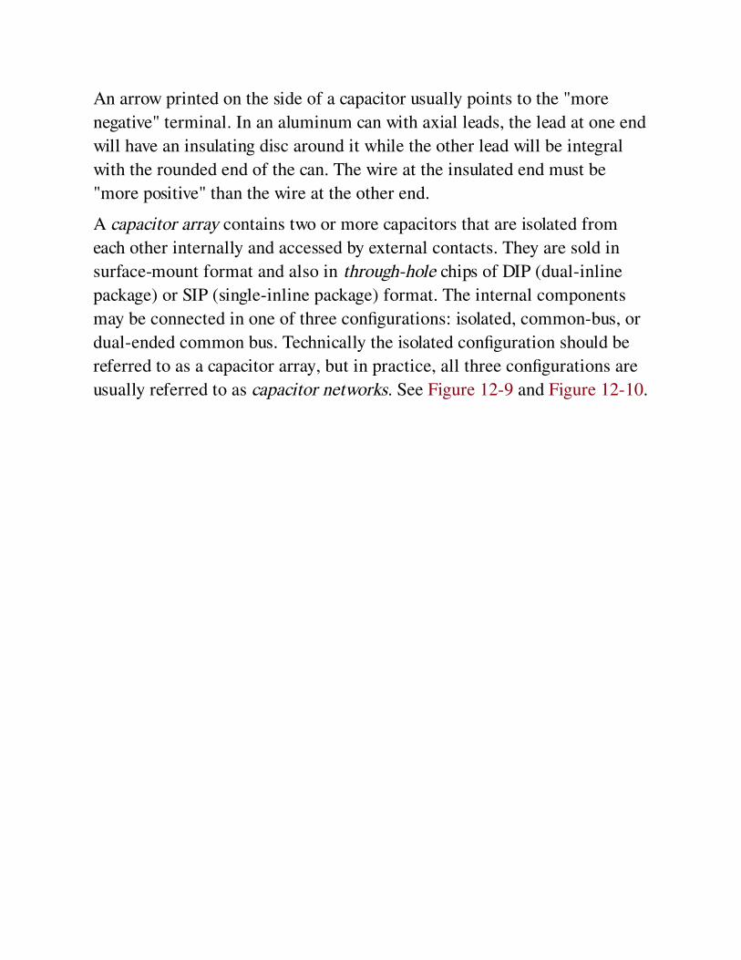
An arrow printed on the side of a capacitor usually points to the "more
negative" terminal. In an aluminum can with axial leads, the lead at one end
will have an insulating disc around it while the other lead will be integral
with the rounded end of the can. The wire at the insulated end must be
"more positive" than the wire at the other end.
A capacitor array contains two or more capacitors that are isolated from
each other internally and accessed by external contacts. They are sold in
surface-mount format and also in through-hole chips of DIP (dual-inline
package) or SIP (single-inline package) format. The internal components
may be connected in one of three configurations: isolated, common-bus, or
dual-ended common bus. Technically the isolated configuration should be
referred to as a capacitor array, but in practice, all three configurations are
usually referred to as capacitor networks. See Figure 12-9 and Figure 12-10.
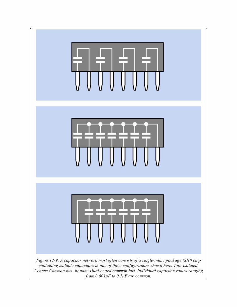
Figure 12-9. A capacitor network most often consists of a single-inline package (SIP) chipcontaining multiple capacitors in one of three configurations shown here. Top: Isolated.
Center: Common bus. Bottom: Dual-ended common bus. Individual capacitor values rangingfrom 0.001μF to 0.1μF are common.

Figure 12-10. A capacitor array in through-hole, SIP format.
Capacitor networks can reduce the component count in circuits where
digital logic chips require bypass capacitors. They are comparable in
concept to resistor arrays.
Chips containing RC circuits (multiple resistor-capacitor pairs) are
available, although uncommon.
Principal TypesElectrolytic capacitors are relatively cheap, compact, and available in large
values. These attributes have made them a popular choice in consumer
electronics, especially for power supplies. The capacitive capability of an
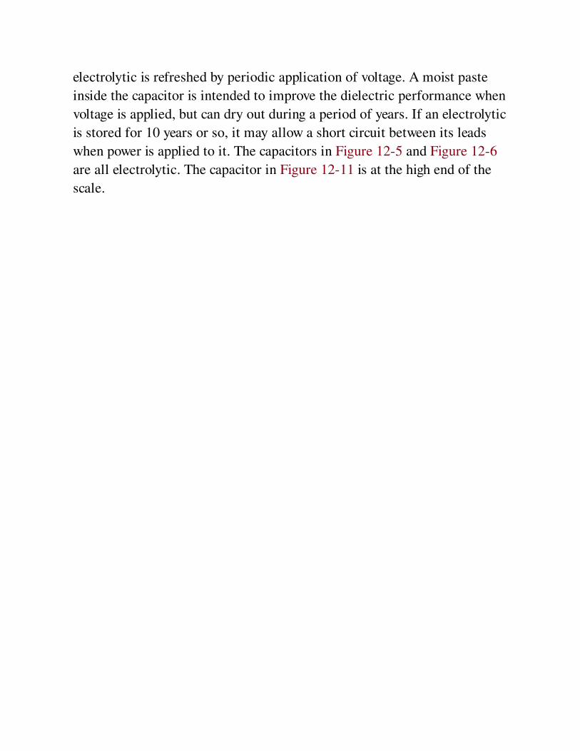
electrolytic is refreshed by periodic application of voltage. A moist paste
inside the capacitor is intended to improve the dielectric performance when
voltage is applied, but can dry out during a period of years. If an electrolytic
is stored for 10 years or so, it may allow a short circuit between its leads
when power is applied to it. The capacitors in Figure 12-5 and Figure 12-6
are all electrolytic. The capacitor in Figure 12-11 is at the high end of the
scale.

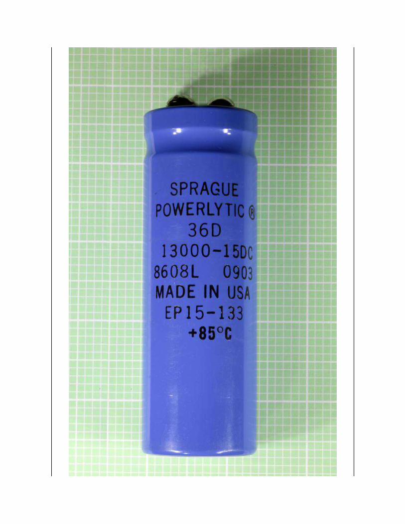
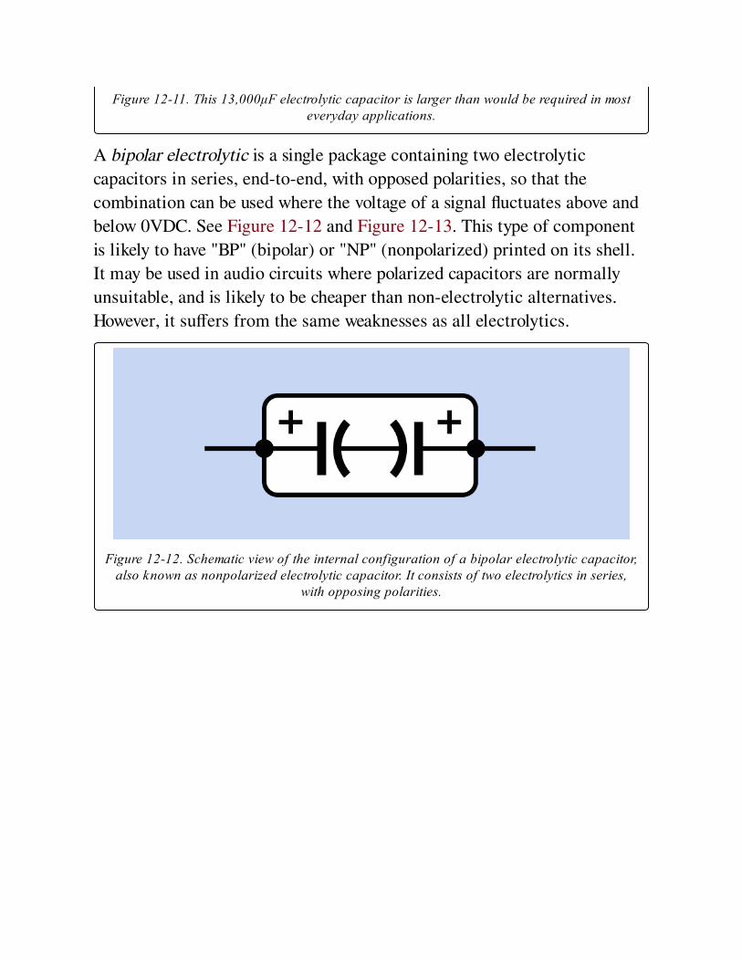
Figure 12-11. This 13,000μF electrolytic capacitor is larger than would be required in mosteveryday applications.
A bipolar electrolytic is a single package containing two electrolytic
capacitors in series, end-to-end, with opposed polarities, so that the
combination can be used where the voltage of a signal fluctuates above and
below 0VDC. See Figure 12-12 and Figure 12-13. This type of component
is likely to have "BP" (bipolar) or "NP" (nonpolarized) printed on its shell.
It may be used in audio circuits where polarized capacitors are normally
unsuitable, and is likely to be cheaper than non-electrolytic alternatives.
However, it suffers from the same weaknesses as all electrolytics.
Figure 12-12. Schematic view of the internal configuration of a bipolar electrolytic capacitor,also known as nonpolarized electrolytic capacitor. It consists of two electrolytics in series,
with opposing polarities.
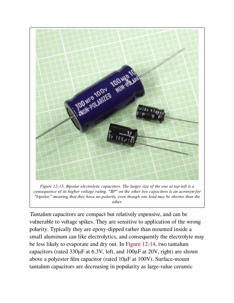
Figure 12-13. Bipolar electrolytic capacitors. The larger size of the one at top-left is aconsequence of its higher voltage rating. "BP" on the other two capacitors is an acronym for"bipolar," meaning that they have no polarity, even though one lead may be shorter than the
other.
Tantalum capacitors are compact but relatively expensive, and can be
vulnerable to voltage spikes. They are sensitive to application of the wrong
polarity. Typically they are epoxy-dipped rather than mounted inside a
small aluminum can like electrolytics, and consequently the electrolyte may
be less likely to evaporate and dry out. In Figure 12-14, two tantalum
capacitors (rated 330μF at 6.3V, left, and 100μF at 20V, right) are shown
above a polyester film capacitor (rated 10μF at 100V). Surface-mount
tantalum capacitors are decreasing in popularity as large-value ceramic
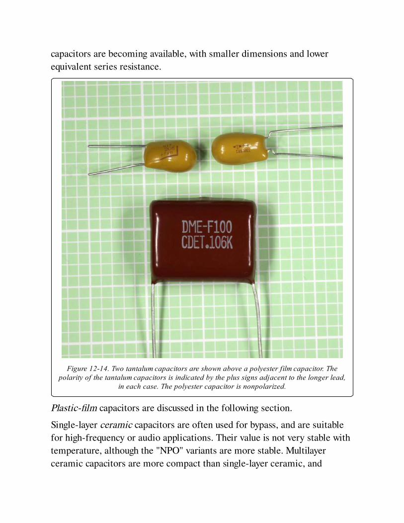
capacitors are becoming available, with smaller dimensions and lower
equivalent series resistance.
Figure 12-14. Two tantalum capacitors are shown above a polyester film capacitor. Thepolarity of the tantalum capacitors is indicated by the plus signs adjacent to the longer lead,
in each case. The polyester capacitor is nonpolarized.
Plastic-film capacitors are discussed in the following section.
Single-layer ceramic capacitors are often used for bypass, and are suitable
for high-frequency or audio applications. Their value is not very stable with
temperature, although the "NPO" variants are more stable. Multilayer
ceramic capacitors are more compact than single-layer ceramic, and
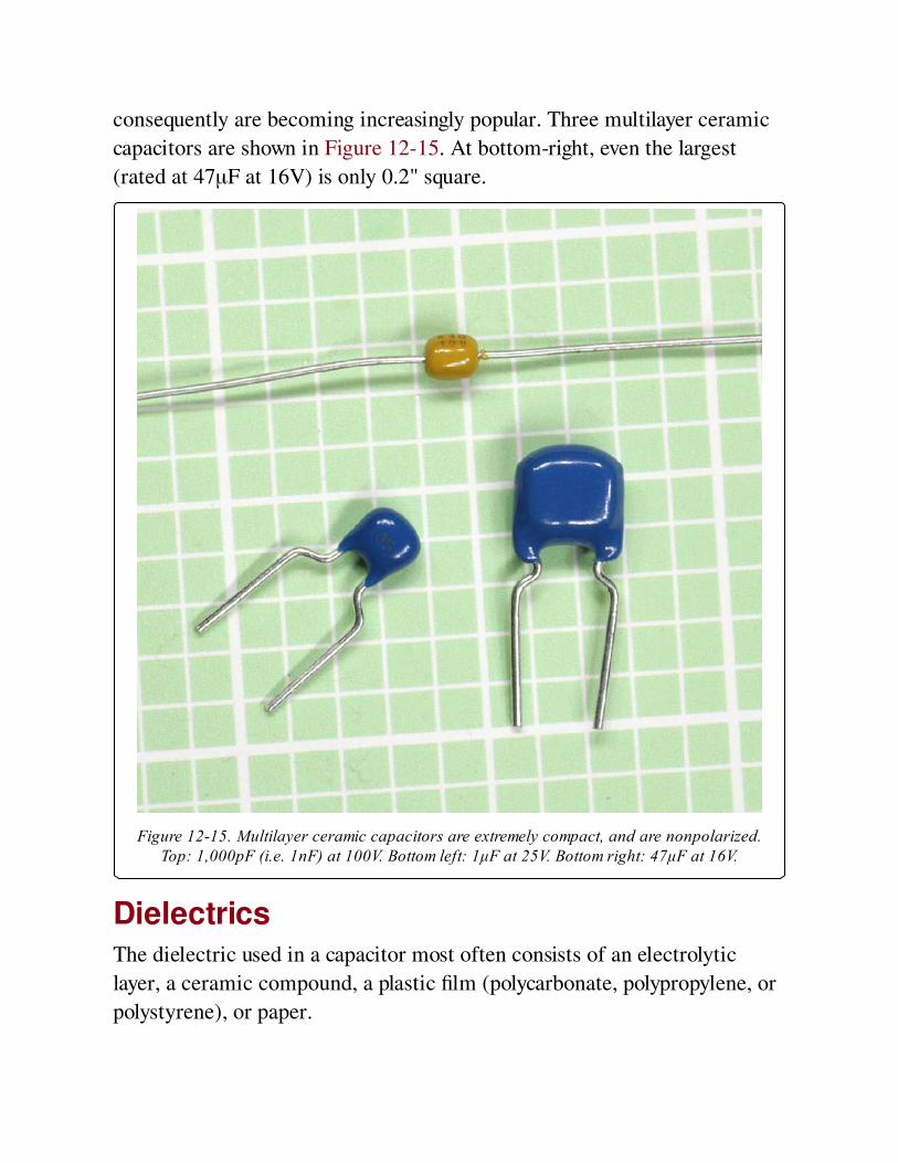
consequently are becoming increasingly popular. Three multilayer ceramic
capacitors are shown in Figure 12-15. At bottom-right, even the largest
(rated at 47μF at 16V) is only 0.2" square.
Figure 12-15. Multilayer ceramic capacitors are extremely compact, and are nonpolarized.Top: 1,000pF (i.e. 1nF) at 100V. Bottom left: 1μF at 25V. Bottom right: 47μF at 16V.
DielectricsThe dielectric used in a capacitor most often consists of an electrolytic
layer, a ceramic compound, a plastic film (polycarbonate, polypropylene, or
polystyrene), or paper.
An electrolytic layer in an electrolytic capacitor traditionally consists of
paper soaked in an electrolyte. It is interleaved with a thin film of aluminum
on which is deposited a layer of aluminum oxide. The layers are rolled up to
create a cylindrical component. The functioning dielectric is created when
voltage is applied.
Polyester
This is the most common type of plastic film, with the highest dielectric
constant, enabling highest capacitance per unit volume. Widely used in
DC applications, but the rolled layers create parasitic inductance. Often
used in decoupling, coupling, and bypass, but not so suitable for
situations requiring stability and low leakage. May not be suitable for
high current.
Polycarbonate
Thermally very stable, often specified for filters and timing circuits that
require a fixed frequency. An excellent type of capacitor, compatible for
mil-spec applications, but expensive.
Mylar, Polyester, and other plastic-film types are often used in audio
circuits, where their voltage limitation (typically less than 100VDC) is not a
problem, and their nonpolarized attribute is an advantage.
Polypropylene
Vulnerable to heat (a maximum of 85 degrees Centigrade is common),
and less thermally stable than polycarbonate. A very low power
dissipation factor allows it to handle higher power at higher frequencies.
Available with tolerances down to 1%. These capacitors are a popular
choice in crossover networks for loudspeaker combinations, and are
used in switching power supplies. They tend to be physically larger than
other capacitors using film dielectric.
Values
Farads
The electrical storage capacity of a capacitor is measured in farads,
universally represented by the letter F. A capacitor that can be charged with
a potential difference between its plates of 1 volt, in a time of 1 second,
during which it draws 1 amp, has a capacitance of 1 farad.
Because the farad is a large unit, capacitors in electronic circuits almost
always have fractional values: microfarads (μF), nanofarads (nF), and
picofarads (pF). The Greek letter μ (mu) should be used in the μF
abbreviation, but a lowercase letter u is often substituted. Thus, for
example, 10uF means the same as 10μF.
1F = 1,000,000μF, and 1μF = 1,000,000pF. Therefore, 1 farad is equivalent
to 1 trillion picofarads—a very wide range of possible values. See
Figure 12-16 and Figure 12-17 for charts showing equivalent values in
different units.
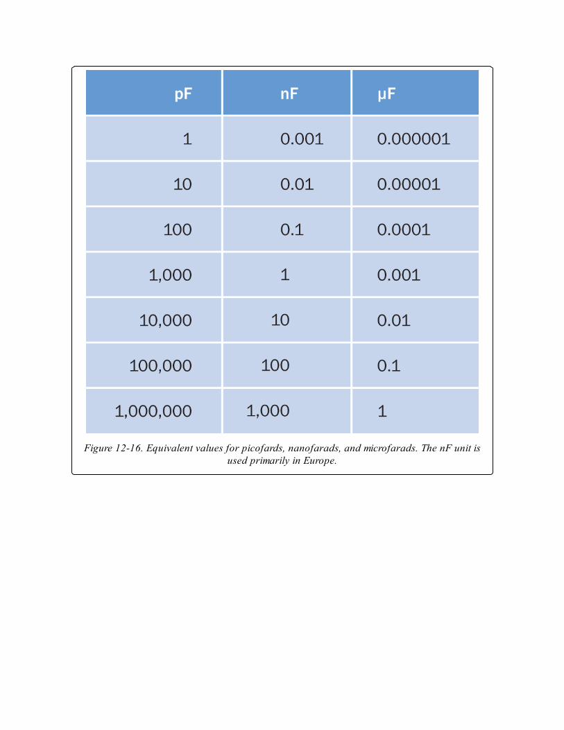
Figure 12-16. Equivalent values for picofards, nanofarads, and microfarads. The nF unit isused primarily in Europe.
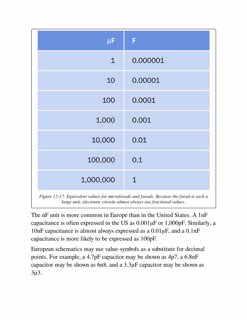
Figure 12-17. Equivalent values for microfarads and farads. Because the farad is such alarge unit, electronic circuits almost always use fractional values.
The nF unit is more common in Europe than in the United States. A 1nF
capacitance is often expressed in the US as 0.001μF or 1,000pF. Similarly, a
10nF capacitance is almost always expressed as a 0.01μF, and a 0.1nF
capacitance is more likely to be expressed as 100pF.
European schematics may use value-symbols as a substitute for decimal
points. For example, a 4.7pF capacitor may be shown as 4p7, a 6.8nF
capacitor may be shown as 6n8, and a 3.3μF capacitor may be shown as
3μ3.
Commonly Used ValuesThe traditional range of capacitor values was established on the same basis
as the traditional range of resistor values, by assuming an accuracy of plus-
or-minus 20% and choosing factors that would minimize the possible
overlap between adjacent tolerance ranges. The factors 1.0, 1.5, 2.2, 3.3,
4.7, 6.8, and 10 satisfy this requirement. See Chapter 10 for a more detailed
explanation, including a graphical representation of values and overlaps in
Figure 10-8. While many resistors are now manufactured with high
precision, 20% tolerance is still common for electrolytic capacitors. Other
types of capacitors are available with an accuracy of 10% or 5%, but are
more expensive.
While large-value capacitors are likely to have their actual value printed on
them, smaller capacitors are identified by a variety of different codes.
These codes are not standardized among manufacturers, and exist in
various colors and abbreviations. A multimeter that can measure
capacitance is a quicker, easier, and more reliable method of determining
the value of a component than trying to interpret the codes.
In addition to capacitance, a large capacitor is likely to have its working
voltage printed on it. Exceeding this value increases the risk of damaging
the dielectric. In the case of electrolytic capacitors, a voltage that is much
lower than the rated value should also be avoided, because these capacitors
require an electrical potential to maintain their performance.
In common electronics applications, values larger than 4,700μF or smaller
than 10pF are unusual.
Electrolytics are available at a moderate price in a wider range of values
than other commonly used capacitors. They range from 1μF to 4,700μF and
sometimes beyond. Working voltages typically range from 6.3VDC to
100VDC, but can be as high as 450VDC.
Tantalum capacitors are usually unavailable in sizes above 150μF or for
voltages above 35VDC.
Single-layer ceramic capacitors have small values ranging from 0.01μF to
0.22μF, with working voltages usually not exceeding 50VDC, although very
small-value capacitors may be rated much higher for special applications.
Poor tolerances of +80% to -20% are common.
Some variants of multi-layer ceramic capacitors are capable of storing up to
47μF, although 10μF is a more common upper limit. They are seldom rated
above 100VDC. Some are accurate to plus-or-minus 5%.
Dielectric ConstantIf A is the area of each plate in a capacitor (measured in square
centimeters), and T is the thickness of the dielectric (measured in
centimeters), and K is the dielectric constant of the capacitor, the
capacitance, C (measured in farads) will be obtained from the formula:
C = (0.0885 * K * A) / T
The dielectric constant of air is 1. Other dielectrics have different standard
values. Polyethylene, for instance, has a constant of approximately 2.3.
Thus a capacitor of 1 square centimeter plate area and polyethylene
dielectric 0.01 centimeters thick would have a capacitance of about 20pF. A
tantalum capacitor of equal plate area and dielectric thickness would have
capacitance closer to 100pF, since the dielectric constant of tantalum oxide
is much higher than that of polyethylene.
The Time ConstantWhen a capacitor is charged in series through a resistor (it is used in an RC
network), and it begins with no charge on its plates, the time constant is the
time, in seconds, required to charge the capacitor to 63% of the supply
voltage. After an additional, identical interval of time, the capacitor will
acquire 63% of the remaining difference between itself and the power
supply. In theory the capacitor gets closer and closer to a full charge, but
never quite reaches 100%. However, five time constants are sufficient for the
capacitor to reach 99%, which is regarded as close enough to being fully
charged for all practical purposes.
Refer to Figure 12-3 for a schematic of an RC network.
The time constant is a simple function of the resistance and the
capacitance. If R is the value of the resistor (in ohms), and C is the value of
the capacitor (in farads), the time constant, TC, will be obtained by the
formula:
TC = R * C
If we multiply the R value by 1,000 while dividing the C value by 1,000, the
time constant remains the same, and we can use the more convenient values
of kilohms for the resistance and μF for the capacitance. In other words, the
formula tells us that a 1K resistor in series with a 1,000μF capacitor has a
time constant of 1 second.
The formula suggests that if the value of R diminishes to zero, the capacitor
will charge instantly. In reality, the charging time will be rapid but finite,
limited by factors such as the electrical resistance of the materials used.
Multiple CapacitorsWhen two or more capacitors are wired in parallel, their total capacitance is
the sum of their separate capacitances. When two or more capacitors are
wired in series, the relationship between their total capacitance © and their
individual capacitances (C1, C2, C3 . . .) is given by this formula:
1 / C = (1/C1) + (1/C2) + (1/C3). . .
The formula to calculate the total capacitance of capacitors connected in
series resembles the one used to calculate the total resistance of resistors
connected in parallel. See Chapter 10.
Alternating Current and Capacitive ReactanceThe apparent resistance of a capacitor to AC is properly known as capacitive
reactance. In the following formula, capacitive reactance (XC, in ohms) is
derived as a function of capacitance (C, in farads) and AC frequency (f,
measured in hertz):
XC = 1 / (2 * π * f * C)
The formula shows that when frequency becomes zero, capacitive reactance
becomes infinite; in other words, a capacitor has theoretically infinite
resistance when DC current tries to flow through it. In reality, a dielectric
has a finite resistance, and thus always allows some leakage.
The formula also shows that capacitive reactance diminishes when the size
of the capacitor increases and/or the frequency being applied to it increases.
From this it appears that an AC signal will be attenuated less at higher
frequencies, especially if we use a small capacitor. However, a real-world
capacitor also exhibits some degree of inductive reactance. This value will
depend on its configuration (cylindrical vs. multiple flat plates), its physical
length, the materials from which it is fabricated, the lengths of its leads,
and other factors. Inductive reactance tends to increase with frequency, and
since capacitive reactance tends to decrease with frequency, at some point
the curves for the two functions intersect. This point represents the
capacitor’s self-resonant frequency, which is often referred to simply as its
resonant frequency. See Figure 12-18.
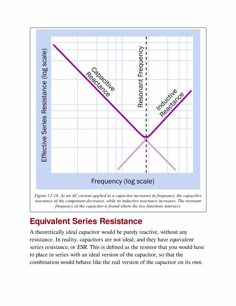
Figure 12-18. As an AC current applied to a capacitor increases in frequency, the capacitivereactance of the component decreases, while its inductive reactance increases. The resonant
frequency of the capacitor is found where the two functions intersect.
Equivalent Series ResistanceA theoretically ideal capacitor would be purely reactive, without any
resistance. In reality, capacitors are not ideal, and they have equivalent
series resistance, or ESR. This is defined as the resistor that you would have
to place in series with an ideal version of the capacitor, so that the
combination would behave like the real version of the capacitor on its own.
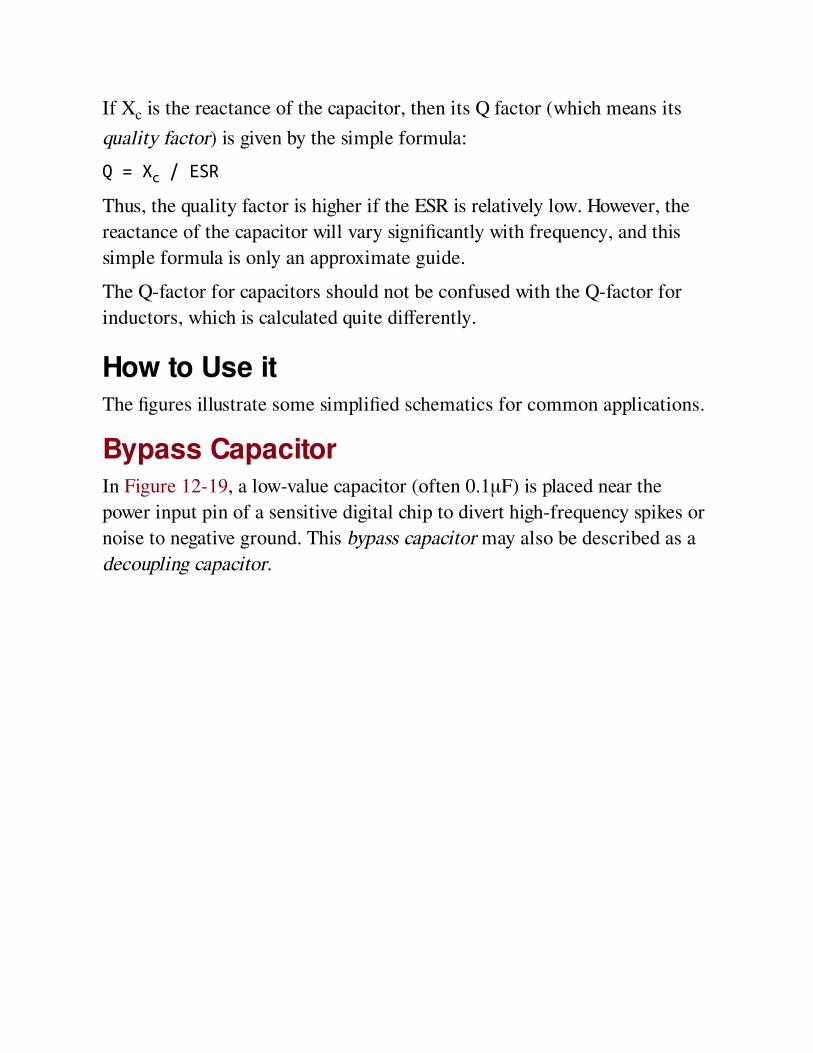
If Xc is the reactance of the capacitor, then its Q factor (which means its
quality factor) is given by the simple formula:
Q = Xc / ESR
Thus, the quality factor is higher if the ESR is relatively low. However, the
reactance of the capacitor will vary significantly with frequency, and this
simple formula is only an approximate guide.
The Q-factor for capacitors should not be confused with the Q-factor for
inductors, which is calculated quite differently.
How to Use itThe figures illustrate some simplified schematics for common applications.
Bypass CapacitorIn Figure 12-19, a low-value capacitor (often 0.1μF) is placed near the
power input pin of a sensitive digital chip to divert high-frequency spikes or
noise to negative ground. This bypass capacitor may also be described as a
decoupling capacitor.
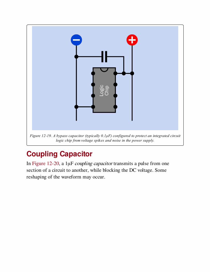
Figure 12-19. A bypass capacitor (typically 0.1μF) configured to protect an integrated circuitlogic chip from voltage spikes and noise in the power supply.
Coupling CapacitorIn Figure 12-20, a 1μF coupling capacitor transmits a pulse from one
section of a circuit to another, while blocking the DC voltage. Some
reshaping of the waveform may occur.
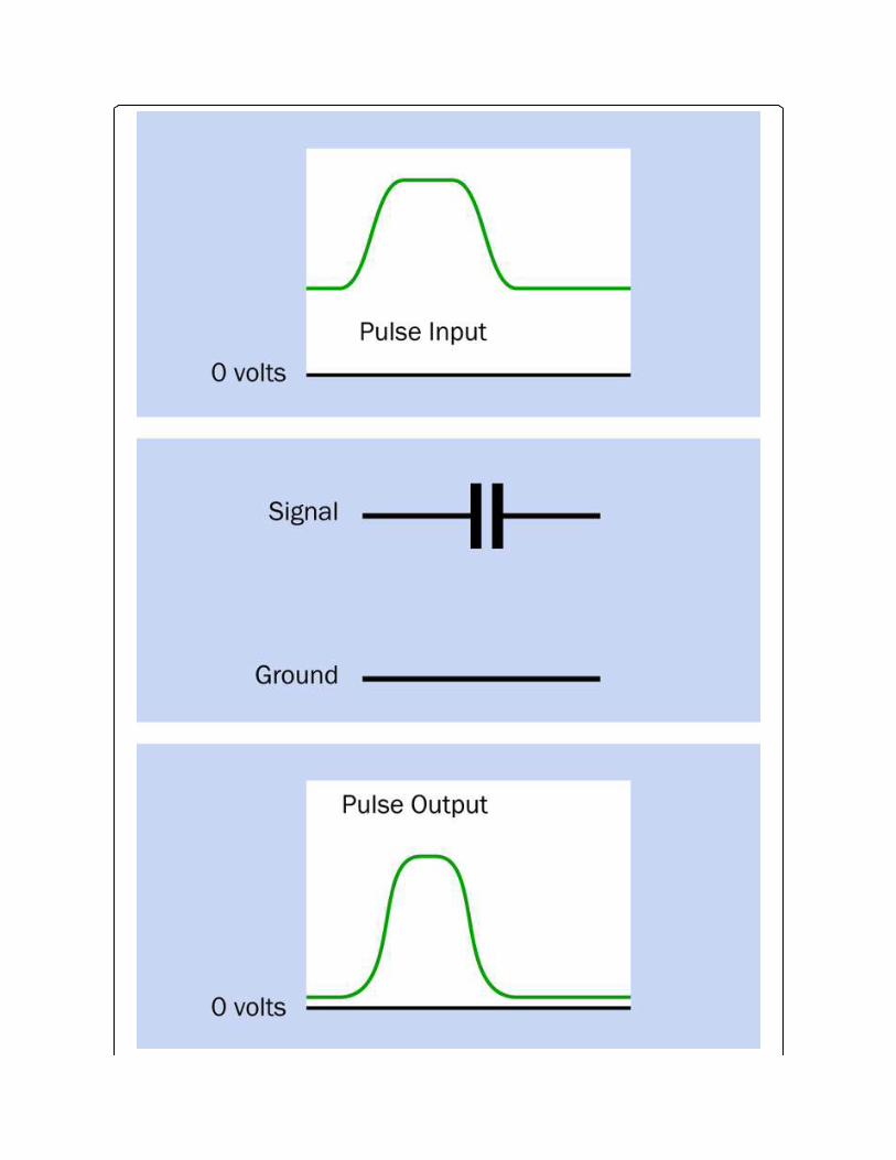
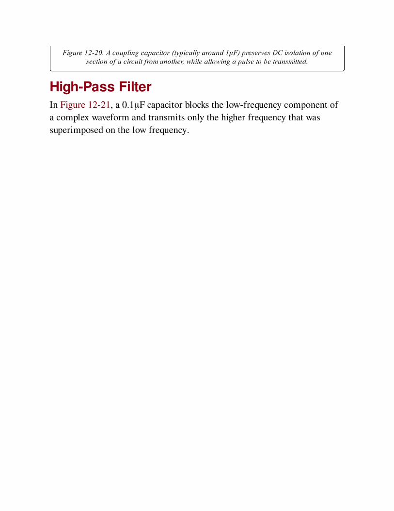
Figure 12-20. A coupling capacitor (typically around 1μF) preserves DC isolation of onesection of a circuit from another, while allowing a pulse to be transmitted.
High-Pass FilterIn Figure 12-21, a 0.1μF capacitor blocks the low-frequency component of
a complex waveform and transmits only the higher frequency that was
superimposed on the low frequency.
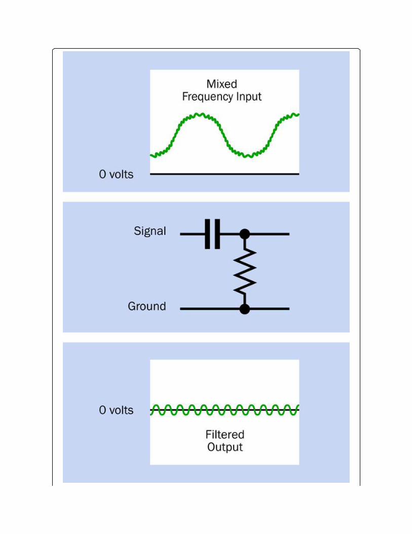
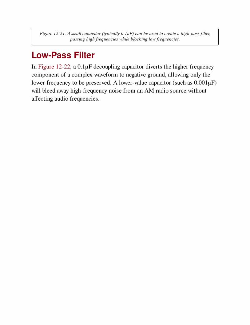
Figure 12-21. A small capacitor (typically 0.1μF) can be used to create a high-pass filter,passing high frequencies while blocking low frequencies.
Low-Pass FilterIn Figure 12-22, a 0.1μF decoupling capacitor diverts the higher frequency
component of a complex waveform to negative ground, allowing only the
lower frequency to be preserved. A lower-value capacitor (such as 0.001μF)
will bleed away high-frequency noise from an AM radio source without
affecting audio frequencies.
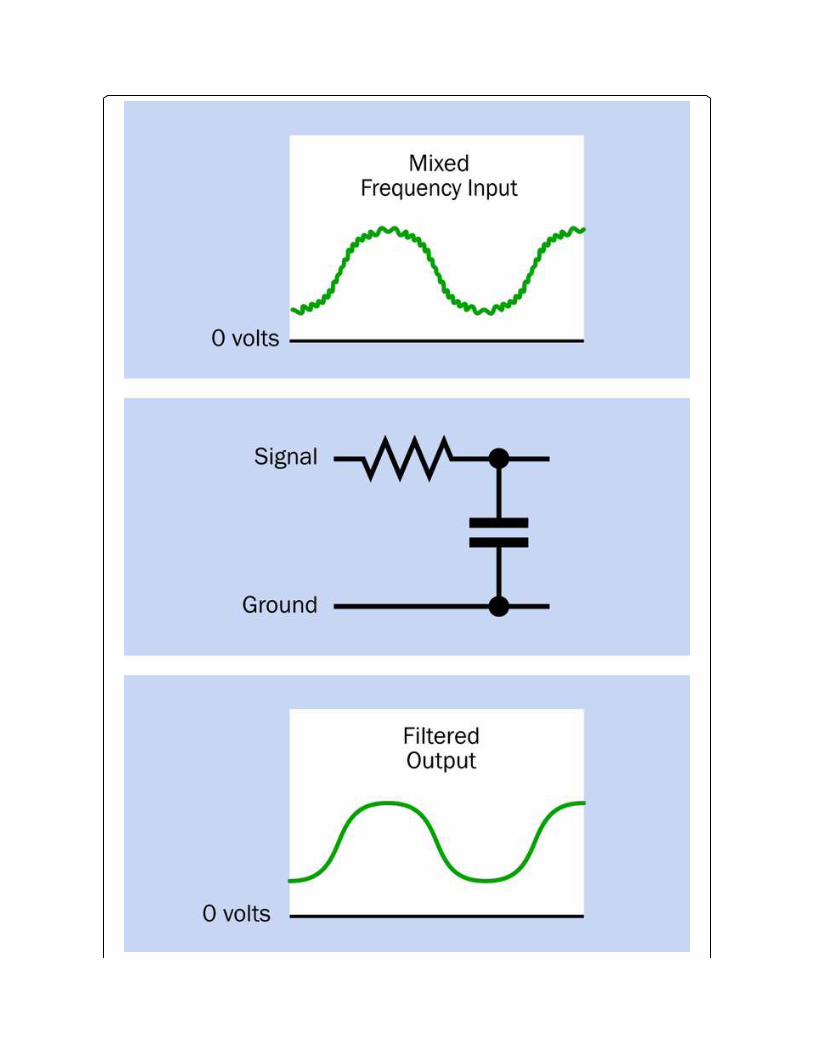
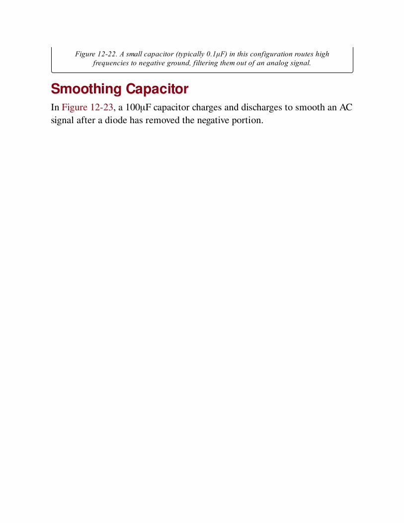
Figure 12-22. A small capacitor (typically 0.1μF) in this configuration routes highfrequencies to negative ground, filtering them out of an analog signal.
Smoothing CapacitorIn Figure 12-23, a 100μF capacitor charges and discharges to smooth an AC
signal after a diode has removed the negative portion.
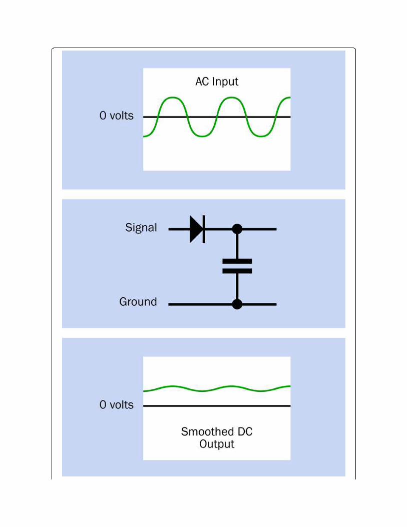
Figure 12-23. A capacitor of 100μF or more smooths the upper half of an AC signal that haspassed through a diode. The capacitor charges during each positive pulse and discharges to
"fill the gaps" between them.
SnubberIn Figure 12-24, an RC network (inside a white dashed line) is known as a
snubber when used to protect a switch from the problem of arcing
(pronounced "arking")—that is, a sustained spark that can quickly erode the
switch contacts. Arcing may occur in switches, pushbuttons, or relays that
control an inductive load, such as a large motor. This problem can become
significant at high DC currents (10A or more) or relatively high AC or DC
voltages (100V or more).
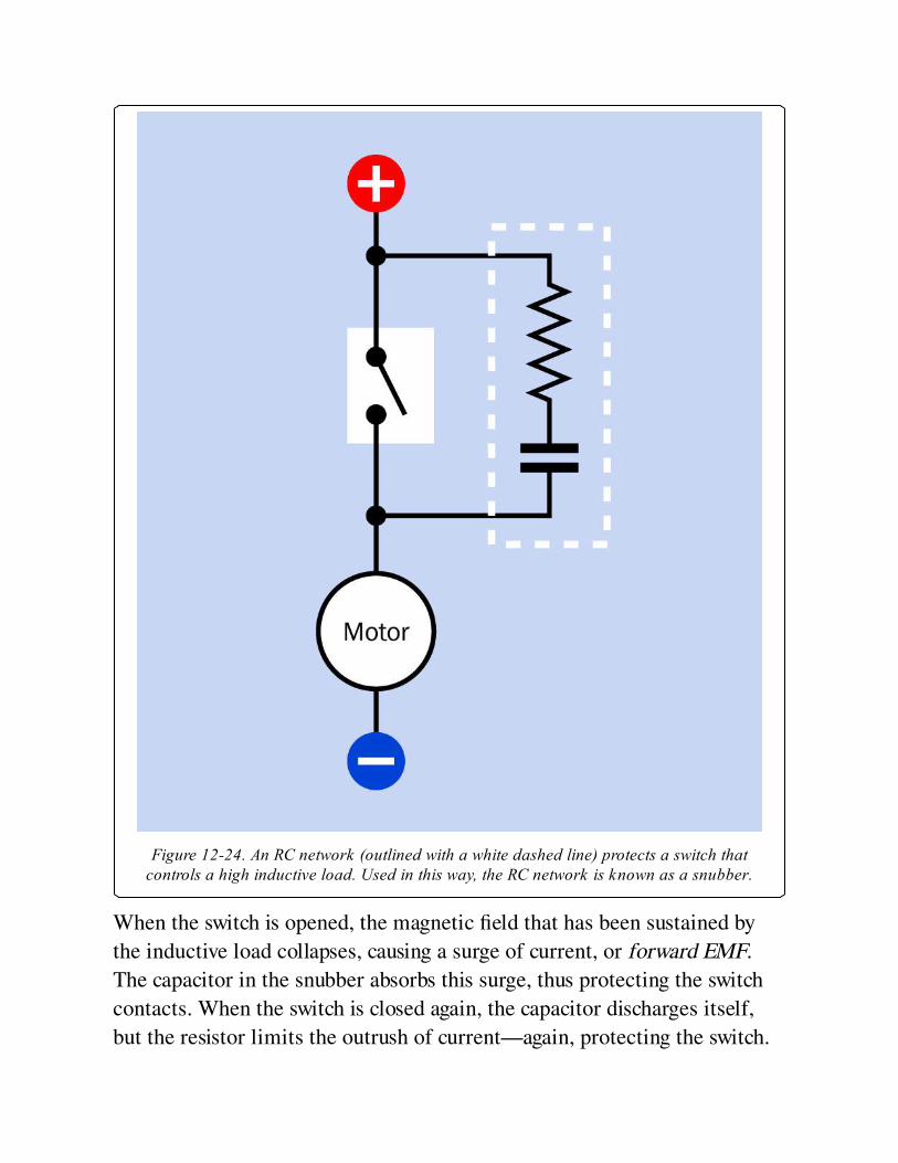
Figure 12-24. An RC network (outlined with a white dashed line) protects a switch thatcontrols a high inductive load. Used in this way, the RC network is known as a snubber.
When the switch is opened, the magnetic field that has been sustained by
the inductive load collapses, causing a surge of current, or forward EMF.
The capacitor in the snubber absorbs this surge, thus protecting the switch
contacts. When the switch is closed again, the capacitor discharges itself,
but the resistor limits the outrush of current—again, protecting the switch.
A snubber placed around the switch in a DC circuit could typically use a
0.1μF capacitor (polypropylene or polyester) rated for 125VAC/200VDC,
and a 100-ohm carbon resistor rated 0.5 watt or higher. Prepackaged
snubbers containing appropriate capacitor-resistor pairs are available from
some parts suppliers, primarily for industrial use.
In an AC circuit, a snubber can be placed around the inductive load itself.
Although a diode is often used this way in a DC circuit, it cannot be used
with AC.
Although solid-state switching devices such as a solid state relay contain
no mechanical contacts, they may still be damaged by substantial pulses of
back-EMF, and can be protected by a snubber where they are controlling
inductive loads that take 10A or more at 100V or more.
Capacitor as a Battery SubstituteA capacitor may be substituted for a battery for some applications, although
it has a lower energy density and will be more expensive to manufacture. A
capacitor charges and discharges much more rapidly than a battery because
no chemical reactions are involved, but a battery sustains its voltage much
more successfully during the discharge cycle.
Capacitors that can store a very large amount of energy are often referred
to as supercapacitors.
What Can Go WrongCommon problems associated with capacitors are age-related deterioration
(especially in electrolytics), inductive reactance (especially in cylindrical
formats), nonlinear response, resistivity, excessive current leakage, and
dielectric memory. Some of these problems are discussed below. A
manufacturer’s datasheet should be consulted carefully in conjunction with
the notes regarding compositions in the preceding Variants section before
making a commitment to a particular type of capacitor.
Wrong PolarityA polarized capacitor may offer virtually no resistance if it is connected the
wrong way around to a DC power source. A very high current can result,
damaging the capacitor and probably other components in the circuit.
Failing to observe the polarity of a tantalum capacitor can have destructive
or even explosive consequences, depending on the amperage.
Voltage OverloadIf the DC working voltage of a capacitor is exceeded, there is a risk of
breaking down the dielectric and allowing a spark, or arc, that will form a
short circuit. Note that the DC rating of a capacitor does not mean that it
can be used safely with an equivalent AC voltage. The maximum AC voltage
should be no greater than approximately 0.7 times the DC rated voltage. If
a DC-rated capacitor is used directly across an AC power line, it will create
an effective short circuit.
If capacitors are connected in series or in parallel, ideally the voltage rating
for each capacitor should be the same, and certainly no less than the supply
voltage.
Tantalum capacitors are easily damaged by current spikes that exceed their
maximum working voltage, and are unsuitable for high-frequency coupling
because of their inductance.
LeakageCharge leakage is a problem especially associated with electrolytic
capacitors, which are not suitable for storing a charge over a significant
interval. Polypropalene or polystyrene film capacitors are a better choice.
Dielectric MemoryAlso known as dielectric absorption, this is a phenomenon in which a
capacitor’s electrolyte displays some percentage of its former voltage after
the capacitor has been discharged and then disconnected from the circuit.
Single-layer ceramic capacitors especially tend to suffer from this problem.
Specific Electrolytic IssuesElectrolytic capacitors have high inductive reactance, are not manufactured
to close tolerances, and deteriorate significantly with age. While other
components may be stockpiled and used over a period of years, this is not a
sensible policy with electrolytics.
The "capacitor plague" affecting many of these capacitors manufactured
from 1999 onward provided a salutary lesson regarding their potential
weaknesses. Faulty composition of the dielectric allowed it to deteriorate,
liberating hydrogen gas, which eventually caused the aluminum shells of the
capacitors to bulge and burst. Circuit boards from major manufacturers
were affected. Because the problem took two years to become apparent,
literally millions of boards with faulty capacitors had been sold before the
fault was diagnosed and eventually corrected.
Unfortunately electrolytics cannot be easily replaced with other types of
capacitors in applications such as power supplies, because substitutes will
be considerably larger and more expensive.
HeatThe equivalent series resistance (ESR) of a large capacitor inevitably means
that it must dissipate some power as heat during use. Ripple current can also
create heat. Capacitor performance will change as the temperature
increases. A common maximum component temperature for electrolytic
capacitors is 85 degrees Centigrade.
VibrationIn a high-vibration environment, electrolytics should be protected by
clamping them mechanically in place, using a capacitor clamp, also known
as a c-clamp.

Misleading NomenclatureRarely, in the United States, the term "mF" may be used as a probable
alternative to μF. This can be a source of confusion and risk because mF is
properly (but very rarely) used to mean "millifarads." The term should
always be avoided.
Chapter 13. variable capacitor
power > moderation > variable capacitor
Formerly known (primarily in the United Kingdom) as a variable condenser. The term is now
obsolete.
Other related components
capacitor (See Chapter 12)
What It DoesA variable capacitor allows adjustment of capacitance in much the same
way that a potentiometer allows adjustment of resistance.
Large variable capacitors were developed primarily to tune radio receivers,
in which they were known as tuning capacitors. Cheaper, simpler, and more
reliable substitutes gradually displaced them, beginning in the 1970s. Today,
they are still used in semiconductor fabrication, in RF plastic welding
equipment, in surgical and dental tools, and in ham radio equipment.
Small trimmer capacitors are widely available and are mostly used to adjust
high-frequency circuits. Many of them look almost indistinguishable from
trimmer potentiometers.
The schematic symbols commonly used to represent a variable capacitor
and a trimmer capacitor are shown in Figure 13-1.
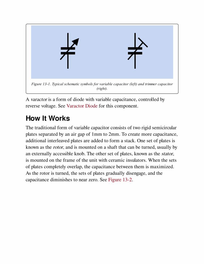
Figure 13-1. Typical schematic symbols for variable capacitor (left) and trimmer capacitor(right).
A varactor is a form of diode with variable capacitance, controlled by
reverse voltage. See Varactor Diode for this component.
How It WorksThe traditional form of variable capacitor consists of two rigid semicircular
plates separated by an air gap of 1mm to 2mm. To create more capacitance,
additional interleaved plates are added to form a stack. One set of plates is
known as the rotor, and is mounted on a shaft that can be turned, usually by
an externally accessible knob. The other set of plates, known as the stator,
is mounted on the frame of the unit with ceramic insulators. When the sets
of plates completely overlap, the capacitance between them is maximized.
As the rotor is turned, the sets of plates gradually disengage, and the
capacitance diminishes to near zero. See Figure 13-2.
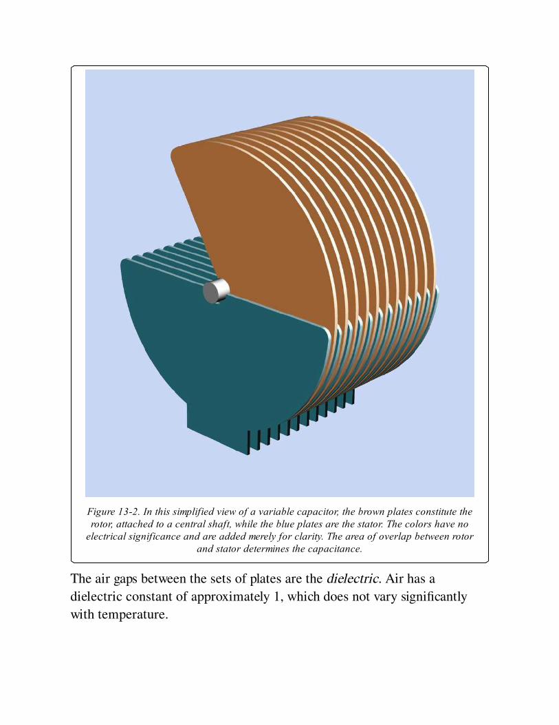
Figure 13-2. In this simplified view of a variable capacitor, the brown plates constitute therotor, attached to a central shaft, while the blue plates are the stator. The colors have no
electrical significance and are added merely for clarity. The area of overlap between rotorand stator determines the capacitance.
The air gaps between the sets of plates are the dielectric. Air has a
dielectric constant of approximately 1, which does not vary significantly
with temperature.

The most common shape of plate is a semicircle, which provides a linear
relationship between capacitance and the angle of rotation. Other shapes
have been used to create a nonlinear response.
Reduction gears may be used to enable fine tuning of a variable capacitor,
which means multiple turns of a knob can produce very small adjustments
of the capacitor. At the peak of variable capacitor design, units were
manufactured with high mechanical precision and included anti-backlash
gears. These consisted of a pair of equal-sized gears mounted flat against
each other with a spring between them that attempted to turn the gears in
opposite directions from each other. The pair of gears meshed with a single
pinion, eliminating the looseness, or backlash, that normally exists when
gear teeth interlock. A vintage capacitor with a spring creating anti-backlash
gearing (circled) is shown in Figure 13-3. This is a two-gang capacitor—it is
divided into two sections, one rated 0 to 35pF, the other rated 0 to 160pF.
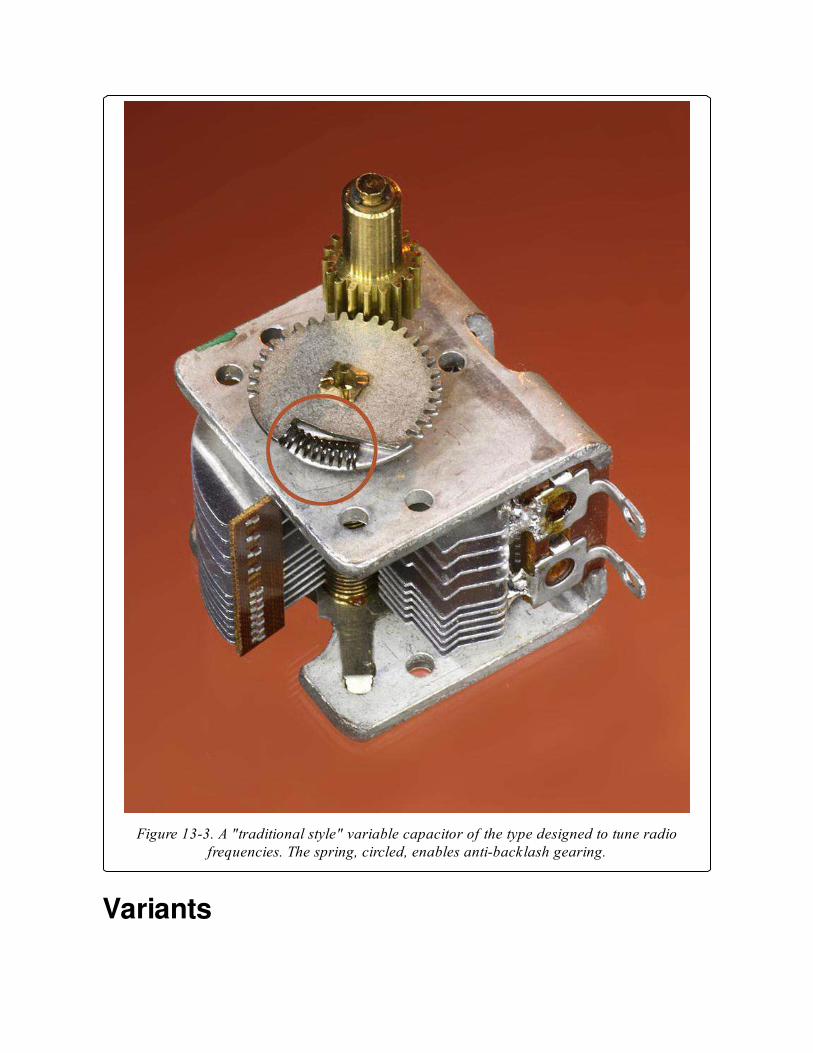
Figure 13-3. A "traditional style" variable capacitor of the type designed to tune radiofrequencies. The spring, circled, enables anti-backlash gearing.
Variants
The traditional variable capacitor, with exposed, air-spaced, rigid, rotating
vanes, is becoming hard to find. Small, modern variable capacitors are
entirely enclosed, and their plates, or vanes, are not visible. Some capacitors
use a pair of concentric cylinders instead of plates or vanes, with an
external thumb screw that moves one cylinder up or down to adjust its
overlap with the other. The overlap determines the capacitance.
Trimmer capacitors are available with a variety of dielectrics such as mica,
thin slices of ceramic, or plastic.
ValuesA large traditional capacitor can be adjusted down to a near-zero value; its
maximum will be no greater than 500pF, limited by mechanical factors.
(See Chapter 12 for an explanation of capacitance units.)
A maximum value for a trimmer capacitor is seldom greater than 150pF.
Trimmers may have their values printed on them or may be color-coded,
but there is no universal set of codes. Brown, for example, may indicate
either a maximum value around 2pF or 40pF, depending on the
manufacturer. Check datasheets for details.
The upper limit of a trimmer’s rated capacitance is usually no less than the
rated value, but can often be 50% higher.
FormatsAll trimmer capacitors are designed for mounting on circuit boards. Many
are surface-mount, with a minority being through-hole. Surface-mount
units may be 4mm × 4mm or smaller. Through-hole are typically 5mm ×
5mm or larger. Superficially, trimmer capacitors resemble single-turn
trimmer potentiometers with a screw head in the center of a square
package. A through-hole example is shown in Figure 13-4.

Figure 13-4. A trimmer capacitor rated 1.5pF to 7.0pF.
How to Use itA variable capacitor is often used to tune an LC circuit, so called because a
coil (with reactance customarily represented by letter L) is wired in parallel
with a variable capacitor (represented by letter C). The schematic in
Figure 13-5 shows an imaginary circuit to illustrate the principle. When the
switch is flipped upward, it causes a large fixed-value capacitor to be charged
from a DC power source. When the switch is flipped down, the capacitor
tries to pass current through the coil—but the coil’s reactance blocks the
current and converts the energy into a magnetic field. After the capacitor
discharges, the magnetic field collapses and converts its energy back into
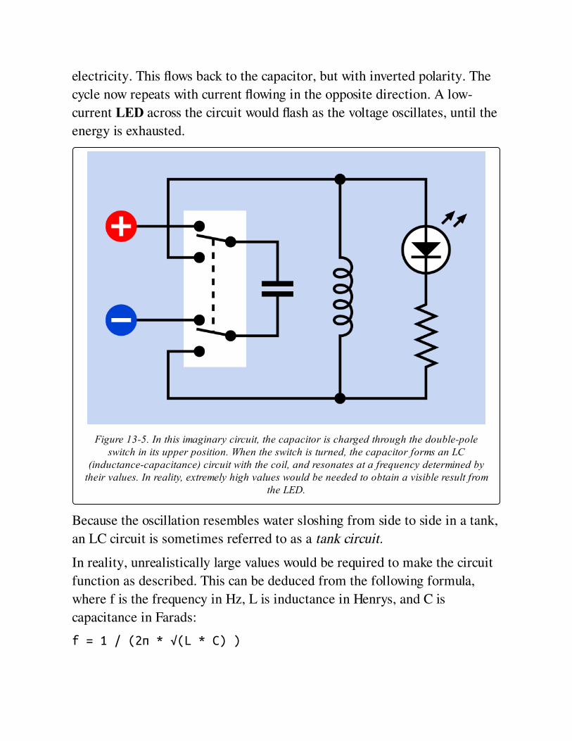
electricity. This flows back to the capacitor, but with inverted polarity. The
cycle now repeats with current flowing in the opposite direction. A low-
current LED across the circuit would flash as the voltage oscillates, until the
energy is exhausted.
Figure 13-5. In this imaginary circuit, the capacitor is charged through the double-poleswitch in its upper position. When the switch is turned, the capacitor forms an LC
(inductance-capacitance) circuit with the coil, and resonates at a frequency determined bytheir values. In reality, extremely high values would be needed to obtain a visible result from
the LED.
Because the oscillation resembles water sloshing from side to side in a tank,
an LC circuit is sometimes referred to as a tank circuit.
In reality, unrealistically large values would be required to make the circuit
function as described. This can be deduced from the following formula,
where f is the frequency in Hz, L is inductance in Henrys, and C is
capacitance in Farads:
f = 1 / (2π * √(L * C) )
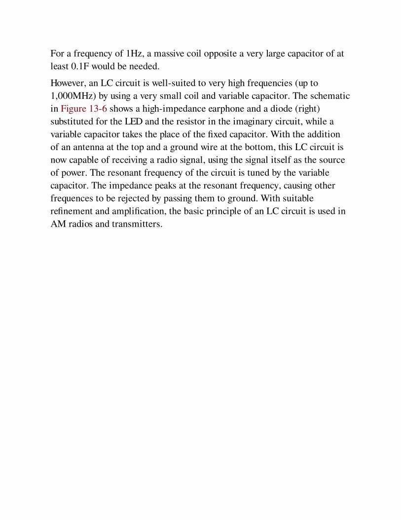
For a frequency of 1Hz, a massive coil opposite a very large capacitor of at
least 0.1F would be needed.
However, an LC circuit is well-suited to very high frequencies (up to
1,000MHz) by using a very small coil and variable capacitor. The schematic
in Figure 13-6 shows a high-impedance earphone and a diode (right)
substituted for the LED and the resistor in the imaginary circuit, while a
variable capacitor takes the place of the fixed capacitor. With the addition
of an antenna at the top and a ground wire at the bottom, this LC circuit is
now capable of receiving a radio signal, using the signal itself as the source
of power. The resonant frequency of the circuit is tuned by the variable
capacitor. The impedance peaks at the resonant frequency, causing other
frequences to be rejected by passing them to ground. With suitable
refinement and amplification, the basic principle of an LC circuit is used in
AM radios and transmitters.
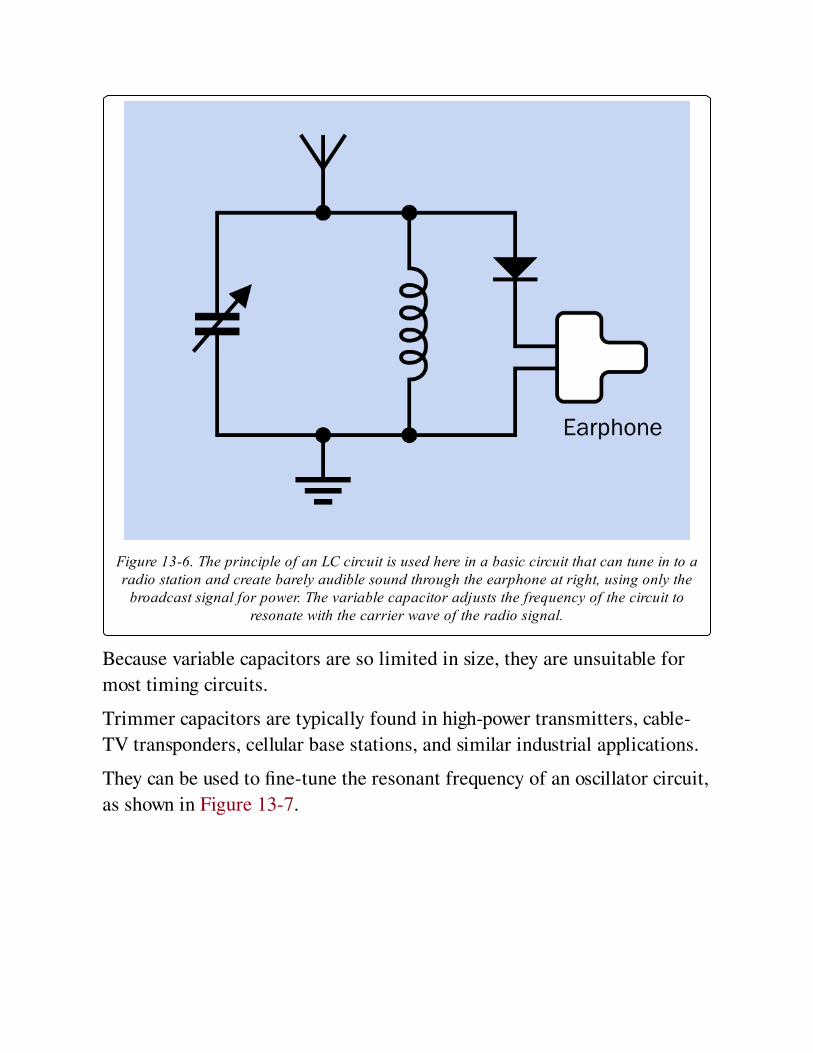
Figure 13-6. The principle of an LC circuit is used here in a basic circuit that can tune in to aradio station and create barely audible sound through the earphone at right, using only the
broadcast signal for power. The variable capacitor adjusts the frequency of the circuit toresonate with the carrier wave of the radio signal.
Because variable capacitors are so limited in size, they are unsuitable for
most timing circuits.
Trimmer capacitors are typically found in high-power transmitters, cable-
TV transponders, cellular base stations, and similar industrial applications.
They can be used to fine-tune the resonant frequency of an oscillator circuit,
as shown in Figure 13-7.
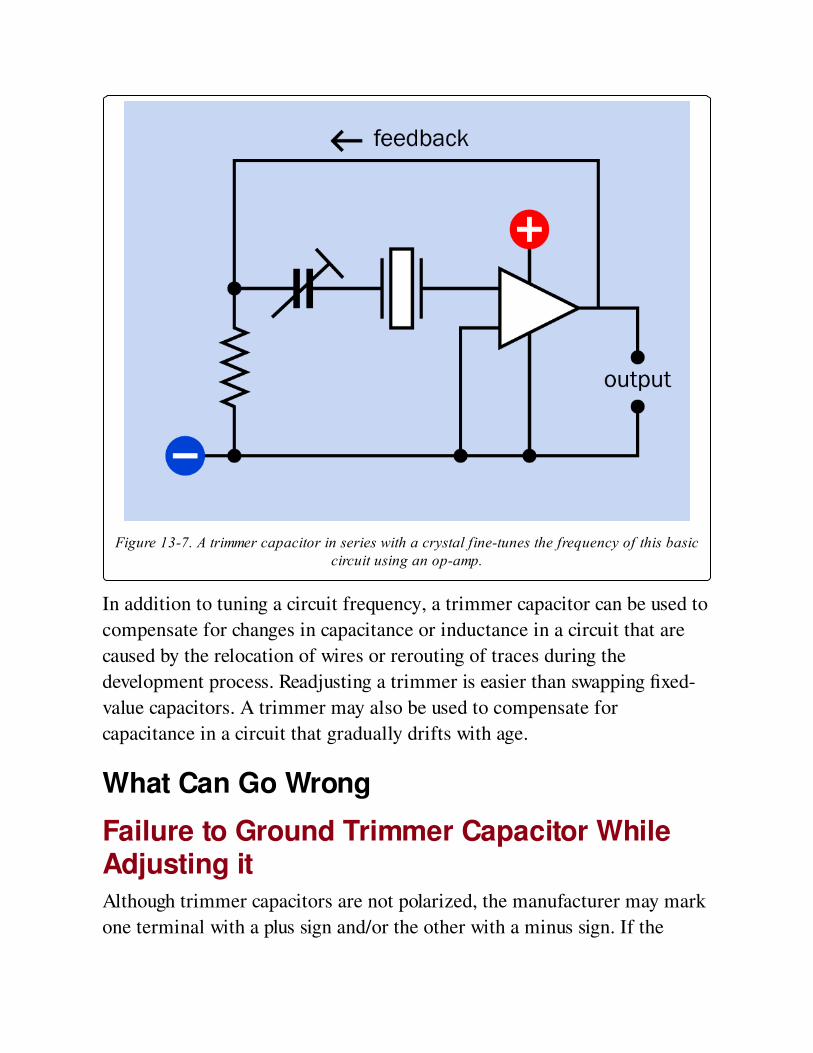
Figure 13-7. A trimmer capacitor in series with a crystal fine-tunes the frequency of this basiccircuit using an op-amp.
In addition to tuning a circuit frequency, a trimmer capacitor can be used to
compensate for changes in capacitance or inductance in a circuit that are
caused by the relocation of wires or rerouting of traces during the
development process. Readjusting a trimmer is easier than swapping fixed-
value capacitors. A trimmer may also be used to compensate for
capacitance in a circuit that gradually drifts with age.
What Can Go Wrong
Failure to Ground Trimmer Capacitor WhileAdjusting itAlthough trimmer capacitors are not polarized, the manufacturer may mark
one terminal with a plus sign and/or the other with a minus sign. If the
capacitor is adjusted while its negative terminal is floating or ungrounded, a
metal screwdriver blade will create erroneous readings. Always ground the
appropriate side of a trimmer capacitor before fine-tuning it, and preferably
use a plastic-bladed screwdriver.
Application of Overcoat Material or "LockPaint"Overcoat material is a rubbery adhesive that may be spread over assembled
components to immunize them against moisture or vibration. Lock paint is
a dab of paint that prevents a screw adjustment from turning after it has
been set. Most manufacturers advise against applying these materials to a
trimmer capacitor, because if penetration occurs, the capacitor can fail.
Lack of ShieldingVariable capacitors should be shielded during use, to protect them from
external capacitive effects. Merely holding one’s hand close to a variable
capacitor will change its value.
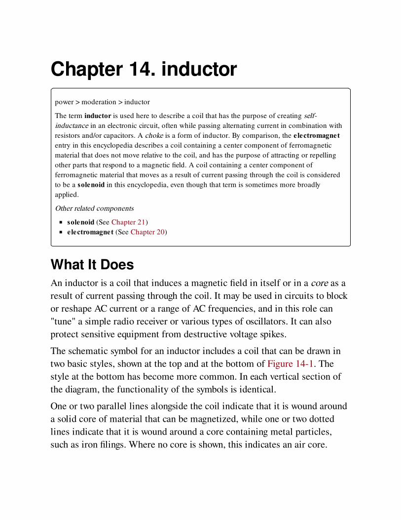
Chapter 14. inductor
power > moderation > inductor
The term inductor is used here to describe a coil that has the purpose of creating self-
inductance in an electronic circuit, often while passing alternating current in combination with
resistors and/or capacitors. A choke is a form of inductor. By comparison, the electromagnetentry in this encyclopedia describes a coil containing a center component of ferromagnetic
material that does not move relative to the coil, and has the purpose of attracting or repelling
other parts that respond to a magnetic field. A coil containing a center component of
ferromagnetic material that moves as a result of current passing through the coil is considered
to be a solenoid in this encyclopedia, even though that term is sometimes more broadly
applied.
Other related components
solenoid (See Chapter 21)
electromagnet (See Chapter 20)
What It DoesAn inductor is a coil that induces a magnetic field in itself or in a core as a
result of current passing through the coil. It may be used in circuits to block
or reshape AC current or a range of AC frequencies, and in this role can
"tune" a simple radio receiver or various types of oscillators. It can also
protect sensitive equipment from destructive voltage spikes.
The schematic symbol for an inductor includes a coil that can be drawn in
two basic styles, shown at the top and at the bottom of Figure 14-1. The
style at the bottom has become more common. In each vertical section of
the diagram, the functionality of the symbols is identical.
One or two parallel lines alongside the coil indicate that it is wound around
a solid core of material that can be magnetized, while one or two dotted
lines indicate that it is wound around a core containing metal particles,
such as iron filings. Where no core is shown, this indicates an air core.
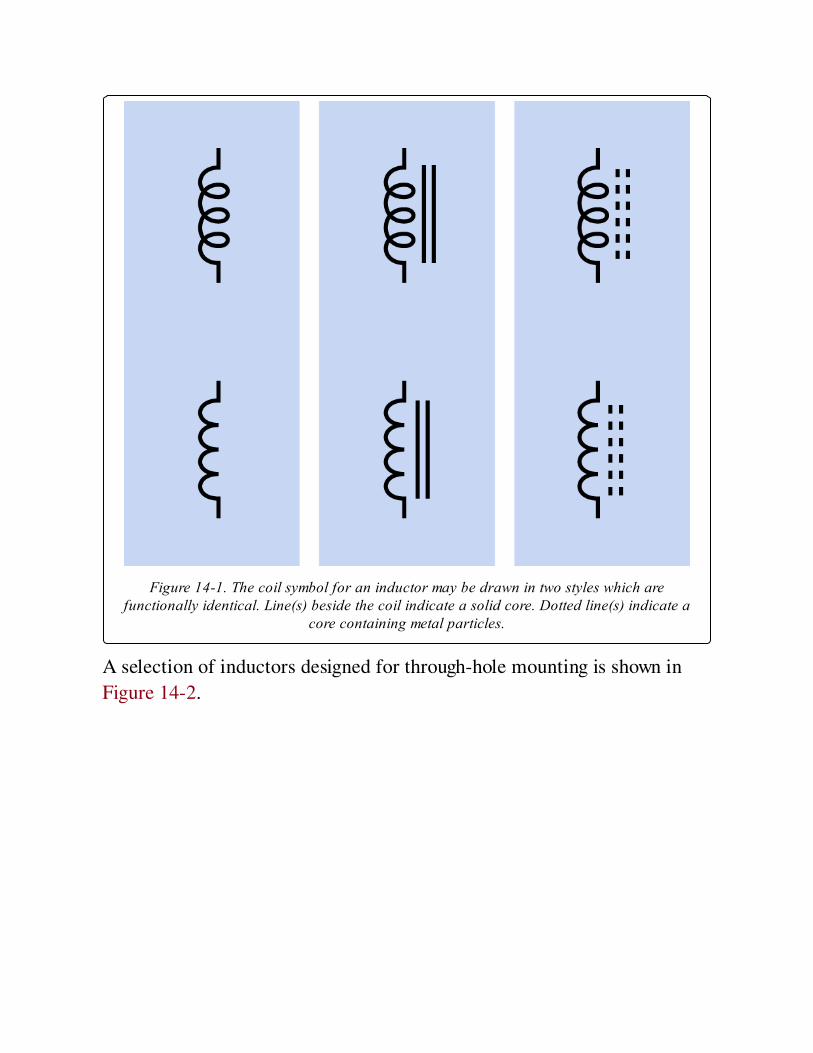
Figure 14-1. The coil symbol for an inductor may be drawn in two styles which arefunctionally identical. Line(s) beside the coil indicate a solid core. Dotted line(s) indicate a
core containing metal particles.
A selection of inductors designed for through-hole mounting is shown in
Figure 14-2.
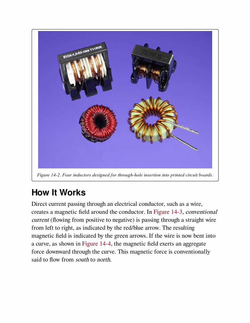
Figure 14-2. Four inductors designed for through-hole insertion into printed circuit boards.
How It WorksDirect current passing through an electrical conductor, such as a wire,
creates a magnetic field around the conductor. In Figure 14-3, conventional
current (flowing from positive to negative) is passing through a straight wire
from left to right, as indicated by the red/blue arrow. The resulting
magnetic field is indicated by the green arrows. If the wire is now bent into
a curve, as shown in Figure 14-4, the magnetic field exerts an aggregate
force downward through the curve. This magnetic force is conventionally
said to flow from south to north.
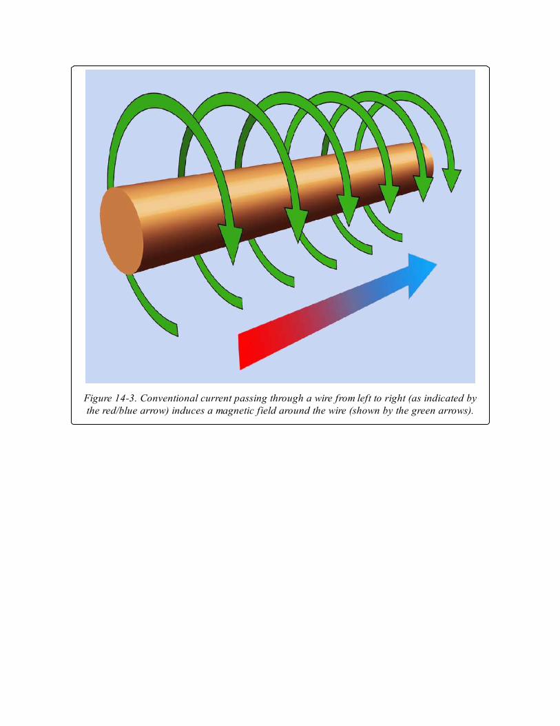
Figure 14-3. Conventional current passing through a wire from left to right (as indicated bythe red/blue arrow) induces a magnetic field around the wire (shown by the green arrows).
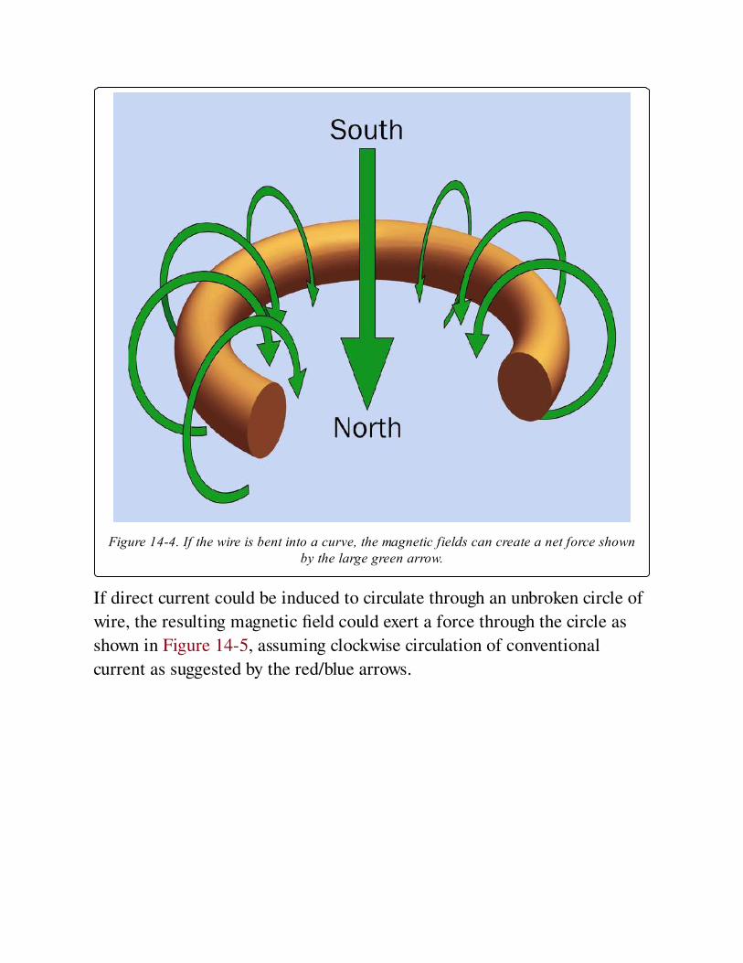
Figure 14-4. If the wire is bent into a curve, the magnetic fields can create a net force shownby the large green arrow.
If direct current could be induced to circulate through an unbroken circle of
wire, the resulting magnetic field could exert a force through the circle as
shown in Figure 14-5, assuming clockwise circulation of conventional
current as suggested by the red/blue arrows.
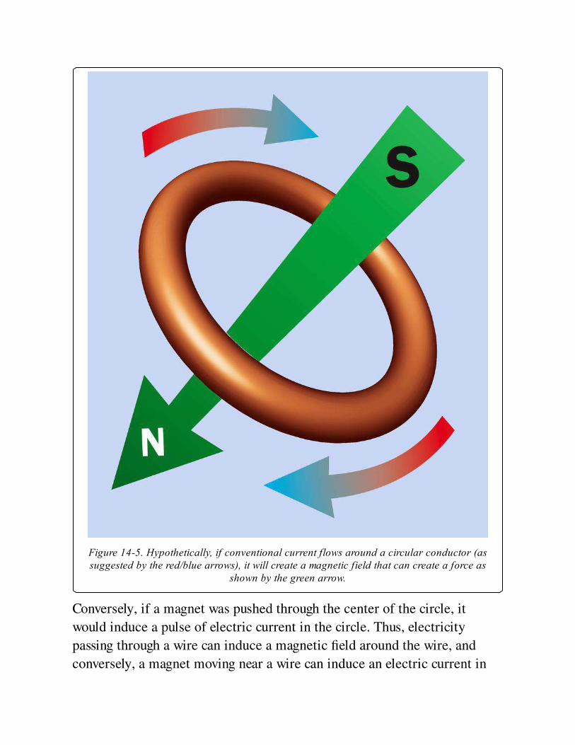
Figure 14-5. Hypothetically, if conventional current flows around a circular conductor (assuggested by the red/blue arrows), it will create a magnetic field that can create a force as
shown by the green arrow.
Conversely, if a magnet was pushed through the center of the circle, it
would induce a pulse of electric current in the circle. Thus, electricity
passing through a wire can induce a magnetic field around the wire, and
conversely, a magnet moving near a wire can induce an electric current in
the wire. This principle is used in an electrical generator, and also in a
transformer, where alternating current in the primary coil induces a
fluctuating magnetic field in the core, and the field in the core is turned
back into alternating current in the secondary coil.
Note that a static or unchanging magnetic field will not induce a flow of
electricity.
DC Through a CoilIf the wire is formed into a helix (a series of approximate circles) as shown
in Figure 14-6, and if DC current is passed through the wire, the aggregate
of the magnetic fields can create a force in the direction of the green arrow
in each example, depending whether the wire is wound clockwise or
counter-clockwise, and depending on the direction of the current. The helix
is usually referred to as a coil or a winding.
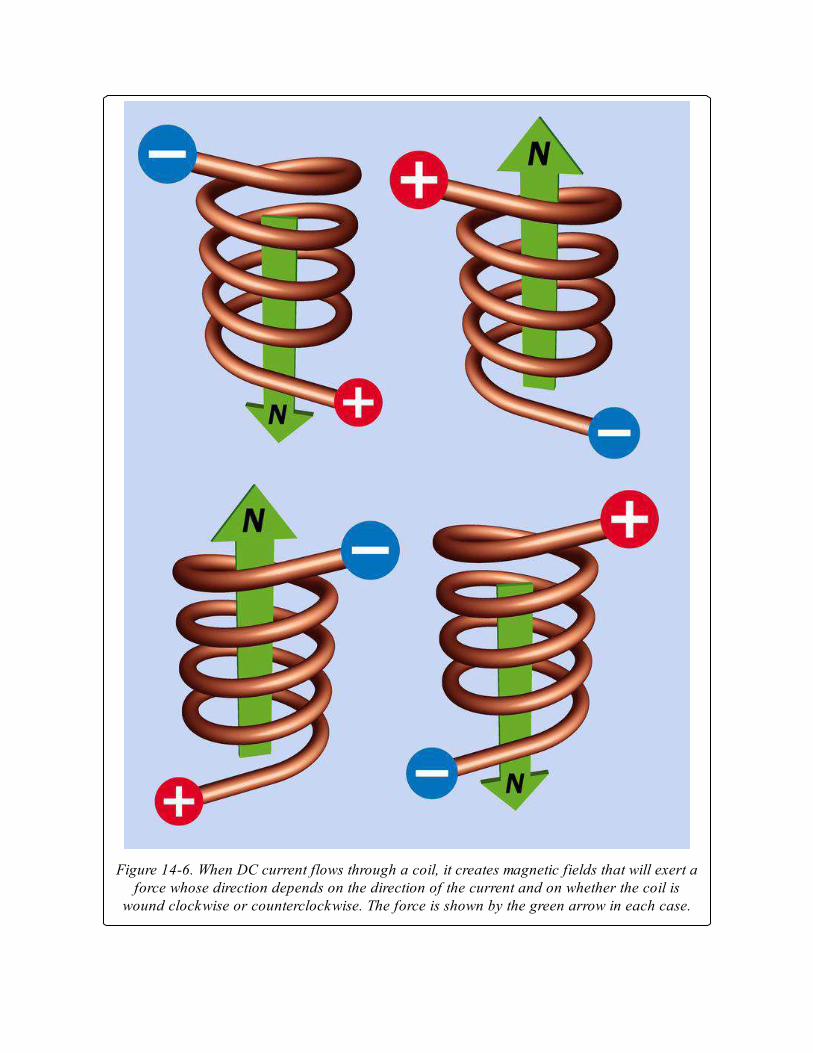
Figure 14-6. When DC current flows through a coil, it creates magnetic fields that will exert aforce whose direction depends on the direction of the current and on whether the coil is
wound clockwise or counterclockwise. The force is shown by the green arrow in each case.
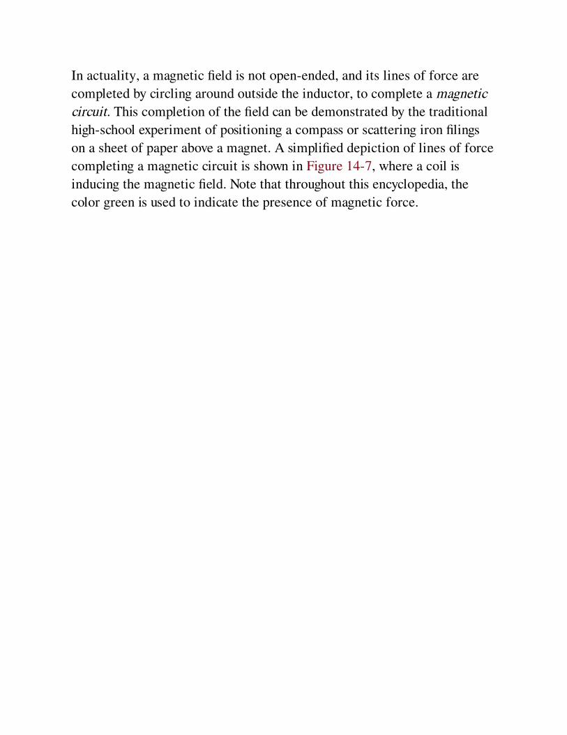
In actuality, a magnetic field is not open-ended, and its lines of force are
completed by circling around outside the inductor, to complete a magnetic
circuit. This completion of the field can be demonstrated by the traditional
high-school experiment of positioning a compass or scattering iron filings
on a sheet of paper above a magnet. A simplified depiction of lines of force
completing a magnetic circuit is shown in Figure 14-7, where a coil is
inducing the magnetic field. Note that throughout this encyclopedia, the
color green is used to indicate the presence of magnetic force.
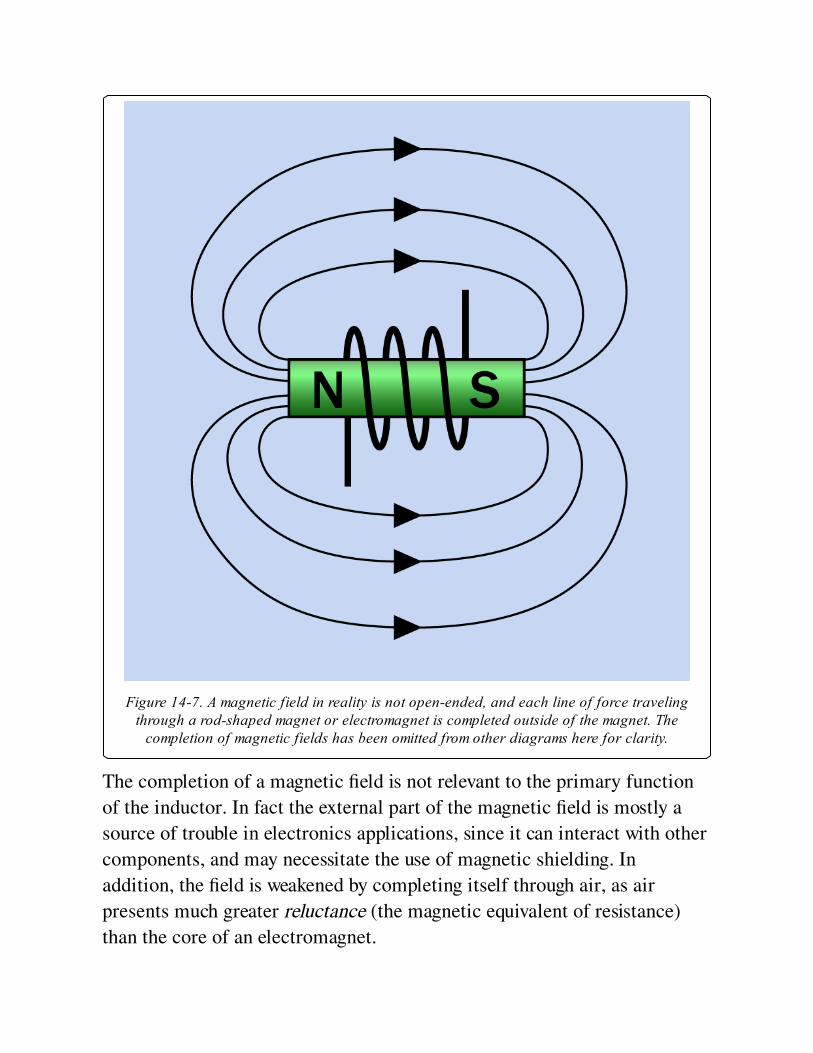
Figure 14-7. A magnetic field in reality is not open-ended, and each line of force travelingthrough a rod-shaped magnet or electromagnet is completed outside of the magnet. The
completion of magnetic fields has been omitted from other diagrams here for clarity.
The completion of a magnetic field is not relevant to the primary function
of the inductor. In fact the external part of the magnetic field is mostly a
source of trouble in electronics applications, since it can interact with other
components, and may necessitate the use of magnetic shielding. In
addition, the field is weakened by completing itself through air, as air
presents much greater reluctance (the magnetic equivalent of resistance)
than the core of an electromagnet.

The polarity of a magnetic field created by a coil can be demonstrated by
moving a small permanent magnet toward the coil, as shown in Figure 14-8.
If the magnet has opposite polarity to the coil, it will tend to be repelled, as
like poles repel. If it has the same polarity, it will tend to be attracted,
because opposite poles attract. This principle may be used in solenoids.
Figure 14-8. A permanent magnet (left) will either be drawn toward a DC-energized coil orrepelled from it, depending on the polarity of the two magnetic fields.
Magnetic CoreThe inductive power of a coil will be enhanced, and the saturation point
will be reduced, by using a magnetic core. The term "magnetic" in this
context does not mean that the core is a permanent magnet; it means that
the core can be magnetized briefly by a transient pulse of electricity through
the surrounding coil.
A core enhances the effectiveness of an inductor because it has a lower
reluctance than that of air. In other words, magnetic flux will flow much
more readily through the core than through air.
Roughly speaking, the permeability of a magnetic circuit is the opposite of
reluctance; it is a measure of how easily a magnetic field can be induced,
and is usually expressed relative to the permeability of air, which is
approximately 1. The permeability of different core types is discussed in the
following "Values" section.
The core of the coil contains magnetic domains that behave as tiny
magnets, with north and south poles. In the absence of a polarizing
magnetic field, the domains are randomly aligned. As a magnetic field is
introduced around them and grows stronger, the domains align themselves
with it, increasing the total magnetic force. When the domains are almost
all uniformly aligned, the core approaches magnetic saturation and ceases
adding to the net magnetic field. At this point the current in the inductor is
said to be continuous.
When power to the coil is disconnected, the domains revert partially to their
previous random orientation. Thus the core remains a weak permanent
magnet. This effect is known as hysteresis, while the weak residual field is
known as remanent magnetism.
EMF and Back-EMFWhen DC current is connected through an inductor, the creation of a
magnetic field takes a brief but measurable period of time. The field
induces an EMF (electro-motive force) in the wire. Since this force opposes
the supplied current, it is referred to as back-EMF. It lasts only so long as
the field is increasing to its full strength. After the field reaches a steady
state, current flows through the coil normally.
This transient resistive effect is caused by the self-inductance of the coil,
and is opposite to the behavior of a capacitor, which encourages an initial

inrush of direct current until it is fully charged, at which point it blocks
subsequent current flow.
When high-frequency alternating current attempts to flow through an
inductor, if each pulse is too brief to overcome the back-EMF, the coil will
block the current. A coil can thus be designed to block some frequencies but
not others.
Even a simple electrical circuit that does not contain a coil will still have
some self-inductance, simply because the circuit consists of wires, and even
a straight length of wire induces a magnetic field when the power is
switched on. However, these inductive effects are so small, they can
generally be ignored in practical applications.
The transient electrical resistance to alternating current caused by either an
inductor or a capacitor is known as reactance, although it occurs under
opposite electrical conditions, as the coil impedes an initial pulse of DC
current and then gradually allows it to pass, while a capacitor allows an
initial pulse of DC current and then impedes it.
When a flow of DC current through a coil is switched off, the magnetic field
that was created by the coil collapses and releases its stored energy. This
can cause a pulse of forward EMF, and like back-EMF, it can interfere with
other components in a circuit. Devices such as motors and large relays that
contain substantial coils can create problematic spikes of back-EMF and
forward-EMF. The forward-EMF that occurs when power to the coil is
interrupted is typically dealt with by putting a diode in parallel with the
coil, allowing current to circulate through it. This is known as clamping the
voltage transient. A diode-capacitor combination known as a snubber is also
commonly used. For a schematic and additional information on this topic,
see Snubber.
A schematic to demonstrate EMF and back-EMF is shown in Figure 14-9.
The coil can be a 100-foot spool of 26-gauge (or smaller) hookup wire, or
magnet wire. It will function more effectively if a piece of iron or steel,
such as half-inch galvanized pipe, is inserted through its center. When the

button is pressed, current is briefly impeded by the back-EMF created by
the coil, and is diverted through D1, making it flash briefly. Then the coil’s
reactance diminishes, allowing the current to flow through the coil and
bypass the LED. When the pushbutton is released, the coil’s magnetic field
collapses, and the consequent forward-EMF circulates through D2, causing
it to flash briefly. Note that the polarity of back-EMF and forward-EMF are
opposite, which is why the LEDs in the circuit are oriented with opposite
polarities.
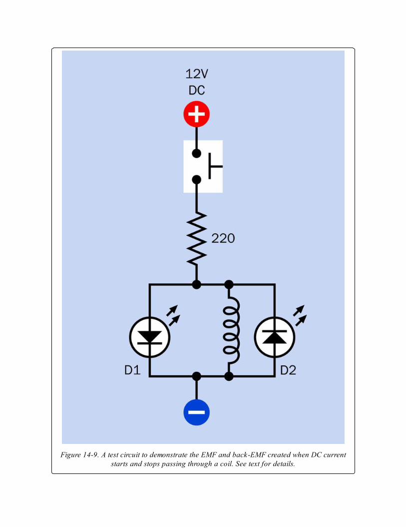
Figure 14-9. A test circuit to demonstrate the EMF and back-EMF created when DC currentstarts and stops passing through a coil. See text for details.
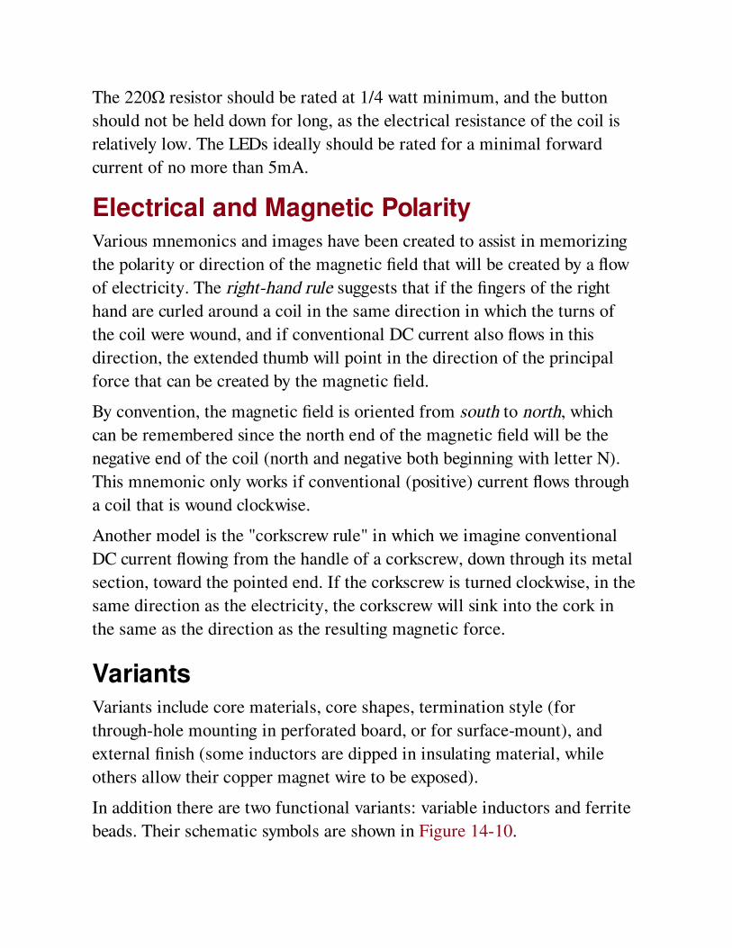
The 220Ω resistor should be rated at 1/4 watt minimum, and the button
should not be held down for long, as the electrical resistance of the coil is
relatively low. The LEDs ideally should be rated for a minimal forward
current of no more than 5mA.
Electrical and Magnetic PolarityVarious mnemonics and images have been created to assist in memorizing
the polarity or direction of the magnetic field that will be created by a flow
of electricity. The right-hand rule suggests that if the fingers of the right
hand are curled around a coil in the same direction in which the turns of
the coil were wound, and if conventional DC current also flows in this
direction, the extended thumb will point in the direction of the principal
force that can be created by the magnetic field.
By convention, the magnetic field is oriented from south to north, which
can be remembered since the north end of the magnetic field will be the
negative end of the coil (north and negative both beginning with letter N).
This mnemonic only works if conventional (positive) current flows through
a coil that is wound clockwise.
Another model is the "corkscrew rule" in which we imagine conventional
DC current flowing from the handle of a corkscrew, down through its metal
section, toward the pointed end. If the corkscrew is turned clockwise, in the
same direction as the electricity, the corkscrew will sink into the cork in
the same as the direction as the resulting magnetic force.
VariantsVariants include core materials, core shapes, termination style (for
through-hole mounting in perforated board, or for surface-mount), and
external finish (some inductors are dipped in insulating material, while
others allow their copper magnet wire to be exposed).
In addition there are two functional variants: variable inductors and ferrite
beads. Their schematic symbols are shown in Figure 14-10.
Figure 14-10. Schematic symbols for a ferrite bead (farthest right) and variable inductors (allother symbols, which are functionally identical).
Magnetic CoresA magnetic core may be made from solid iron, plates of iron or steel
separated by thin insulating material, powdered iron mixed with a binder,
or a ferrite compound derived from nickel, zinc, manganese, or a
combination. An iron core has at least 1,000 times the permeability of air,
while some ferrites are 10,000 times as permeable.
One major disadvantage of a magnetic core is hysteresis, which in this
context refers to the tendency of the core to retain some magnetic
"memory" as a cycle of alternating current changes from positive to
negative. This residual magnetism must be overcome by the next positive
pulse of AC. The tendency of the core to retain magnetic polarity is known
as its retentivity. Iron cores are especially retentive.
Another disadvantage of some magnetic cores is that they may host eddy
currents induced by the magnetic field of the coil. These electrical currents
tend to circulate through the core, reducing efficiency by generating waste
heat, especially if coil currents are high. Forming a core from iron or steel
plates, separated by thin layers of insulation, will inhibit these currents.
Powdered iron inhibits eddy currents because the particles have limited
contact. Ferrites are nonconductive, and are therefore immune to eddy
currents. They are widely used.
Hysteresis and eddy currents both incur energy losses with each AC cycle.
Therefore, the losses increase linearly as the AC frequency increases.
Consequently, inductor cores that suffer either of these problems are not
well-suited to high frequencies.
Nonmagnetic CoresThe problems associated with magnetic cores may be avoided by winding
the coil around a nonmagnetic core that may be hollow, ceramic, or plastic.
A hollow core is referred to as an air core. The permeability of ceramic and
plastic cores is close to that of air.
An inductor with a nonmagnetic core will be immune to eddy currents and
retentivity, but will have to be significantly larger than a magnetic-cored
coil with comparable inductance. In the case of a very primitive radio
receiver, such as a crystal set, the air-cored coil that selects a radio
frequency may be several inches in diameter. A basic circuit diagram for a
crystal set (so-called because it uses a diode containing a germanium
crystal) is shown in Figure 14-11. The antenna, at top, receives signals
broadcast from radio stations. The coil can be tapped (as indicated by the
black dots) as a simple way to select different inductance values, blocking
all but a narrow range of frequencies. The T-shaped white component at
right is a high-impedance earphone. The diode blocks the lower half of the
alternating current in a radio signal, and since the signal is amplitude-
modulated, the earphone responds to variations in intensity in the signal
and reproduces the sound encoded in it.
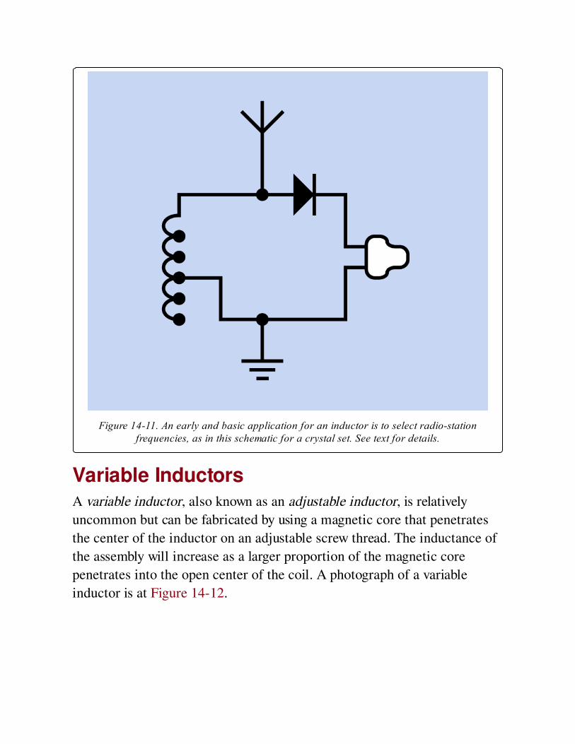
Figure 14-11. An early and basic application for an inductor is to select radio-stationfrequencies, as in this schematic for a crystal set. See text for details.
Variable InductorsA variable inductor, also known as an adjustable inductor, is relatively
uncommon but can be fabricated by using a magnetic core that penetrates
the center of the inductor on an adjustable screw thread. The inductance of
the assembly will increase as a larger proportion of the magnetic core
penetrates into the open center of the coil. A photograph of a variable
inductor is at Figure 14-12.
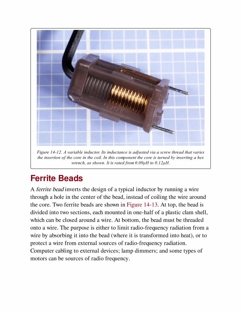
Figure 14-12. A variable inductor. Its inductance is adjusted via a screw thread that variesthe insertion of the core in the coil. In this component the core is turned by inserting a hex
wrench, as shown. It is rated from 0.09μH to 0.12μH.
Ferrite BeadsA ferrite bead inverts the design of a typical inductor by running a wire
through a hole in the center of the bead, instead of coiling the wire around
the core. Two ferrite beads are shown in Figure 14-13. At top, the bead is
divided into two sections, each mounted in one-half of a plastic clam shell,
which can be closed around a wire. At bottom, the bead must be threaded
onto a wire. The purpose is either to limit radio-frequency radiation from a
wire by absorbing it into the bead (where it is transformed into heat), or to
protect a wire from external sources of radio-frequency radiation.
Computer cabling to external devices; lamp dimmers; and some types of
motors can be sources of radio frequency.
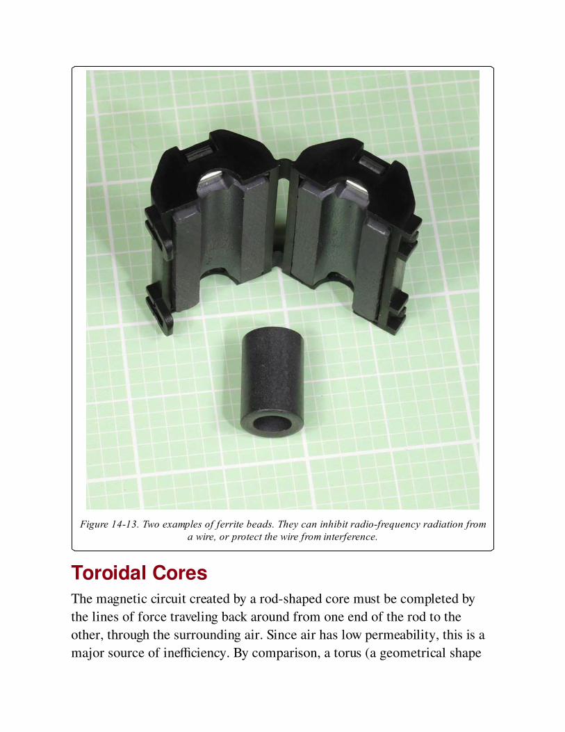
Figure 14-13. Two examples of ferrite beads. They can inhibit radio-frequency radiation froma wire, or protect the wire from interference.
Toroidal CoresThe magnetic circuit created by a rod-shaped core must be completed by
the lines of force traveling back around from one end of the rod to the
other, through the surrounding air. Since air has low permeability, this is a
major source of inefficiency. By comparison, a torus (a geometrical shape
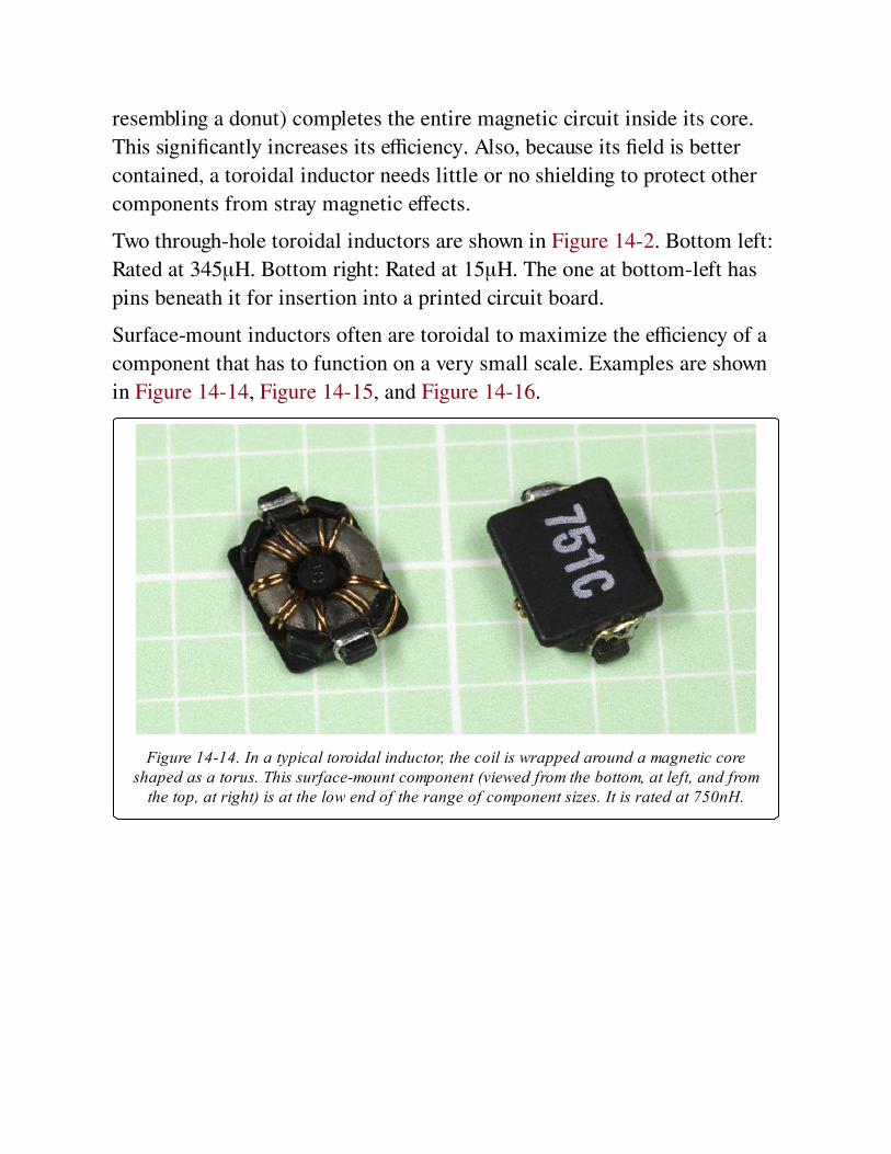
resembling a donut) completes the entire magnetic circuit inside its core.
This significantly increases its efficiency. Also, because its field is better
contained, a toroidal inductor needs little or no shielding to protect other
components from stray magnetic effects.
Two through-hole toroidal inductors are shown in Figure 14-2. Bottom left:
Rated at 345μH. Bottom right: Rated at 15μH. The one at bottom-left has
pins beneath it for insertion into a printed circuit board.
Surface-mount inductors often are toroidal to maximize the efficiency of a
component that has to function on a very small scale. Examples are shown
in Figure 14-14, Figure 14-15, and Figure 14-16.
Figure 14-14. In a typical toroidal inductor, the coil is wrapped around a magnetic coreshaped as a torus. This surface-mount component (viewed from the bottom, at left, and from
the top, at right) is at the low end of the range of component sizes. It is rated at 750nH.
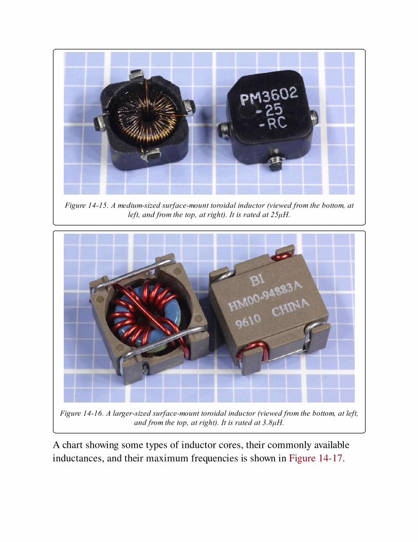
Figure 14-15. A medium-sized surface-mount toroidal inductor (viewed from the bottom, atleft, and from the top, at right). It is rated at 25μH.
Figure 14-16. A larger-sized surface-mount toroidal inductor (viewed from the bottom, at left,and from the top, at right). It is rated at 3.8μH.
A chart showing some types of inductor cores, their commonly available
inductances, and their maximum frequencies is shown in Figure 14-17.

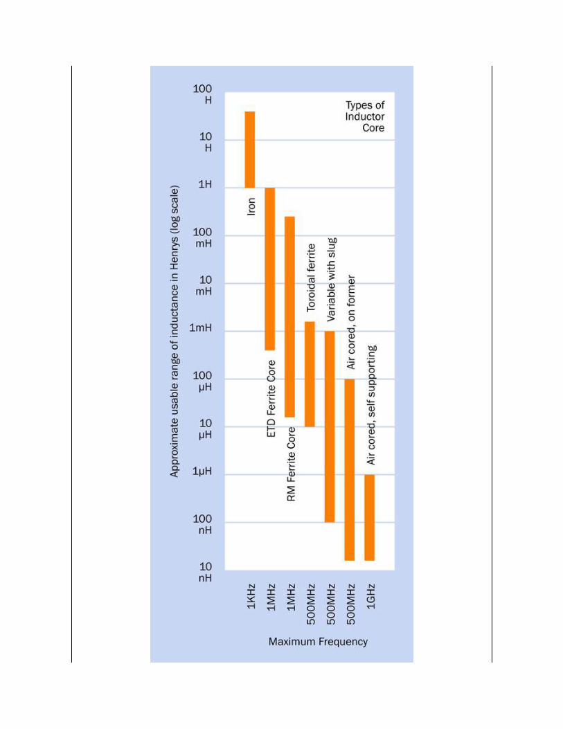
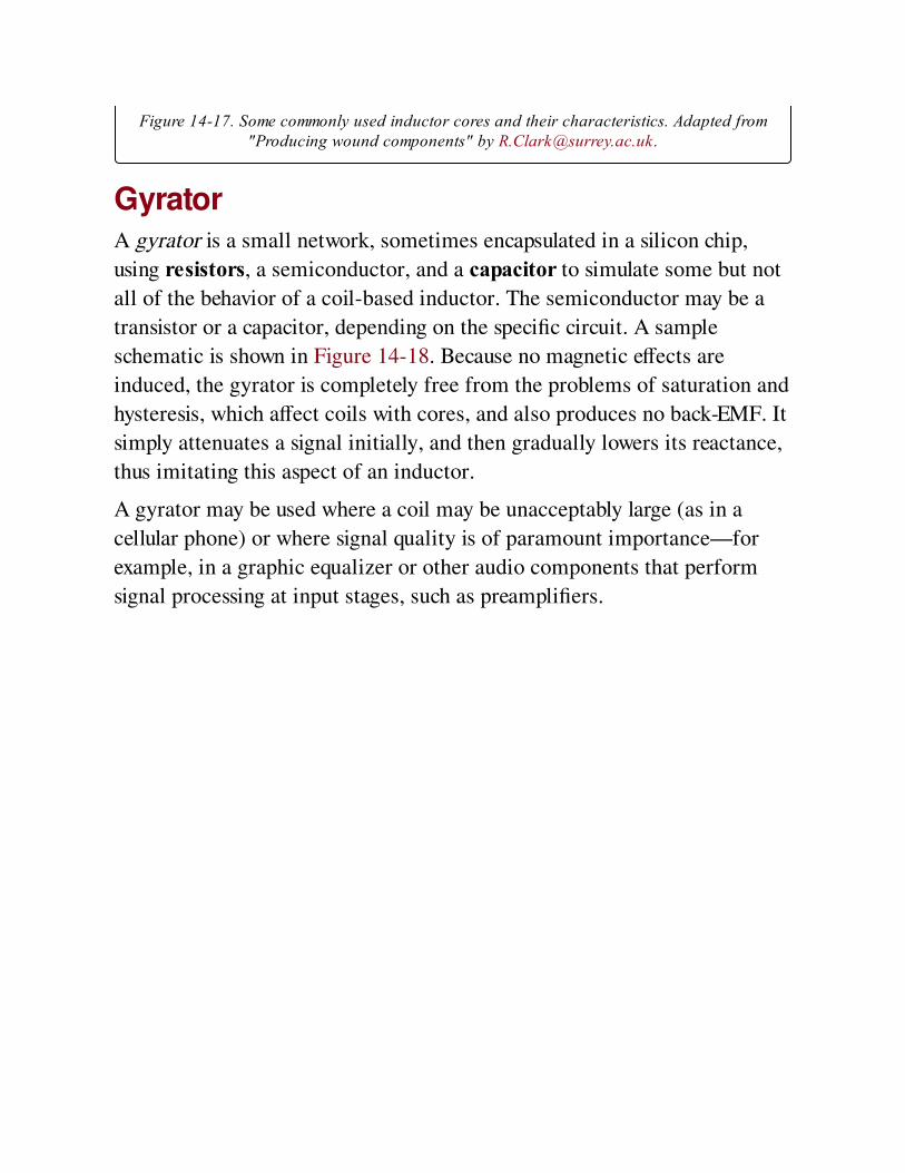
Figure 14-17. Some commonly used inductor cores and their characteristics. Adapted from"Producing wound components" by [email protected].
GyratorA gyrator is a small network, sometimes encapsulated in a silicon chip,
using resistors, a semiconductor, and a capacitor to simulate some but not
all of the behavior of a coil-based inductor. The semiconductor may be a
transistor or a capacitor, depending on the specific circuit. A sample
schematic is shown in Figure 14-18. Because no magnetic effects are
induced, the gyrator is completely free from the problems of saturation and
hysteresis, which affect coils with cores, and also produces no back-EMF. It
simply attenuates a signal initially, and then gradually lowers its reactance,
thus imitating this aspect of an inductor.
A gyrator may be used where a coil may be unacceptably large (as in a
cellular phone) or where signal quality is of paramount importance—for
example, in a graphic equalizer or other audio components that perform
signal processing at input stages, such as preamplifiers.
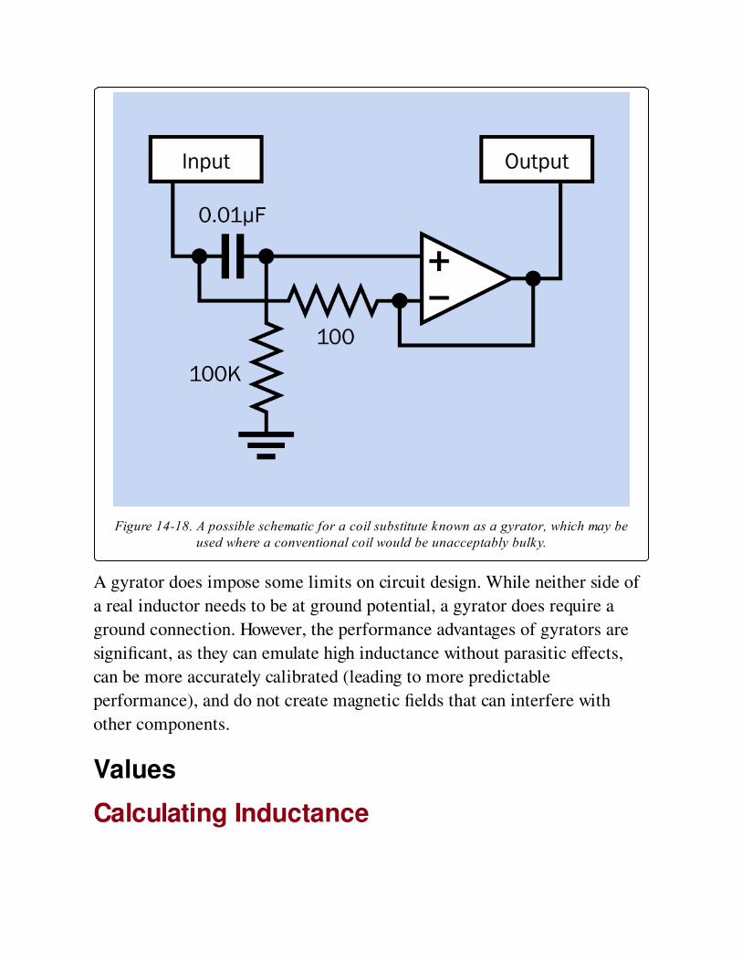
Figure 14-18. A possible schematic for a coil substitute known as a gyrator, which may beused where a conventional coil would be unacceptably bulky.
A gyrator does impose some limits on circuit design. While neither side of
a real inductor needs to be at ground potential, a gyrator does require a
ground connection. However, the performance advantages of gyrators are
significant, as they can emulate high inductance without parasitic effects,
can be more accurately calibrated (leading to more predictable
performance), and do not create magnetic fields that can interfere with
other components.
Values
Calculating Inductance
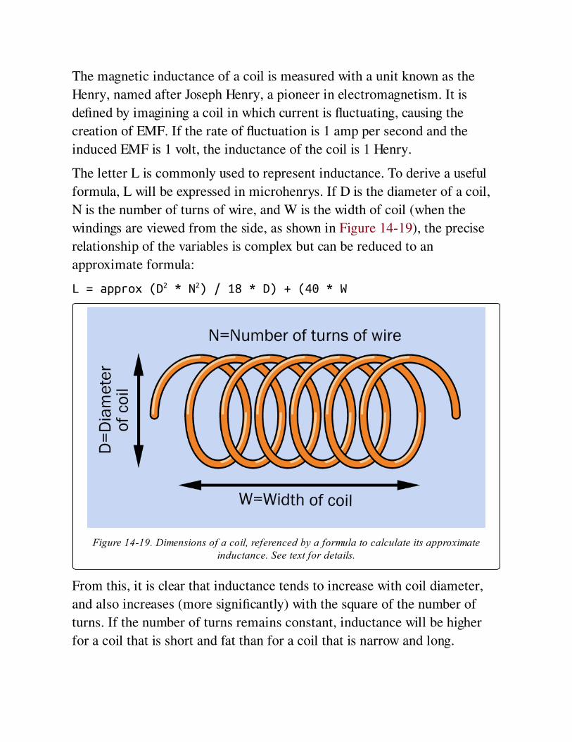
The magnetic inductance of a coil is measured with a unit known as the
Henry, named after Joseph Henry, a pioneer in electromagnetism. It is
defined by imagining a coil in which current is fluctuating, causing the
creation of EMF. If the rate of fluctuation is 1 amp per second and the
induced EMF is 1 volt, the inductance of the coil is 1 Henry.
The letter L is commonly used to represent inductance. To derive a useful
formula, L will be expressed in microhenrys. If D is the diameter of a coil,
N is the number of turns of wire, and W is the width of coil (when the
windings are viewed from the side, as shown in Figure 14-19), the precise
relationship of the variables is complex but can be reduced to an
approximate formula:
L = approx (D2 * N2) / 18 * D) + (40 * W
Figure 14-19. Dimensions of a coil, referenced by a formula to calculate its approximateinductance. See text for details.
From this, it is clear that inductance tends to increase with coil diameter,
and also increases (more significantly) with the square of the number of
turns. If the number of turns remains constant, inductance will be higher
for a coil that is short and fat than for a coil that is narrow and long.
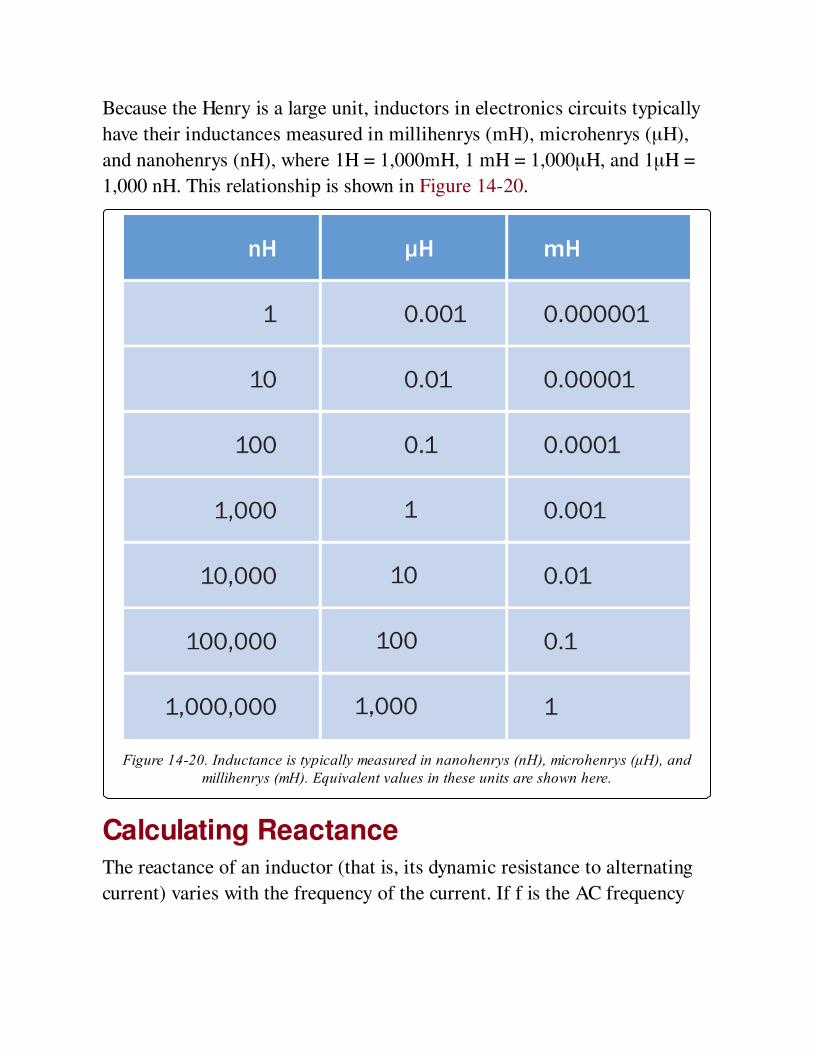
Because the Henry is a large unit, inductors in electronics circuits typically
have their inductances measured in millihenrys (mH), microhenrys (μH),
and nanohenrys (nH), where 1H = 1,000mH, 1 mH = 1,000μH, and 1μH =
1,000 nH. This relationship is shown in Figure 14-20.
Figure 14-20. Inductance is typically measured in nanohenrys (nH), microhenrys (μH), andmillihenrys (mH). Equivalent values in these units are shown here.
Calculating ReactanceThe reactance of an inductor (that is, its dynamic resistance to alternating
current) varies with the frequency of the current. If f is the AC frequency
(in Hertz), and L is the inductance (in Henrys), the reactance, XL in ohms,
is given by the formula:
XL = 2 * π * f * L
From this equation, it’s apparent that as the frequency tends toward zero
(DC current), or if the inductance tends toward zero (a short piece of
straight wire), the reactance will tend toward zero. Conversely, the inductor
will impede current increasingly as the frequency and/or the inductance
increases.
Calculating ReluctanceThe letter S is often used to represent reluctance, while Greek letter μ
customarily represents permeability (not to be confused with the use of μ as
a multiplication factor of 1/1,000,000, as in μF, meaning "microfarad"). If
A is the area of cross-section of the magnetic circuit and L is its length:
S = L / μ * A
Datasheet TerminologyA typical manufacturer’s datasheet should include an inductance index for
an inductor, expressed in μH per 100 turns of wire (assuming the wire is in
a single layer) for inductors with a powdered iron core, and mH per 1,000
turns of wire for inductors with ferrite cores.
The DCR is the DC resistance of an inductor, derived purely from the wire
diameter and its length.
The SRF is the self-resonant frequency. An inductor should be chosen so
that AC current passing through it will never get close to that frequency.
ISAT (or Isat) is the saturation current, which results in a magnetic core
losing its function as a result of magnetic saturation. When this occurs,
inductance drops and the charge current rate increases drastically.
Series and Parallel Configurations

Because the inductance of a coil conducting DC current is proportional to
the current, the calculations to derive the total inductance of coils in series
or in parallel are identical to the calculations used for resistors.
In series, all the coils inevitably pass the same current, and the total
inductance is therefore found by summing the individual inductances.
When coils are wired in parallel, the current distributes itself according to
the inductances; therefore, if L1 is the reluctance of the first coil, L2 is the
reluctance of the second coil, and so on, the total reluctance L of the
network is found from the formula:
1/L = 1/L1 + 1/L2 + 1/L3. . .
This is shown in Figure 14-21. In reality, differences between the coils
(such as their electrical resistance), and magnetic interaction between the
coils, will complicate this simple relationship.
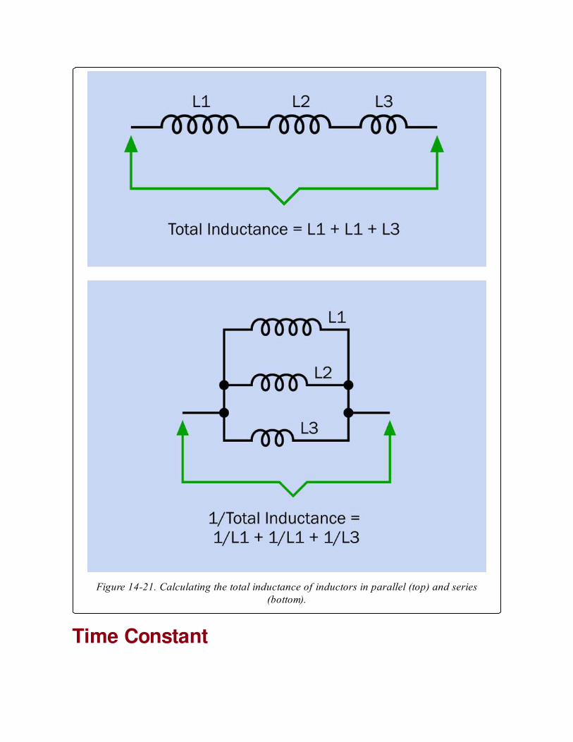
Figure 14-21. Calculating the total inductance of inductors in parallel (top) and series(bottom).
Time Constant
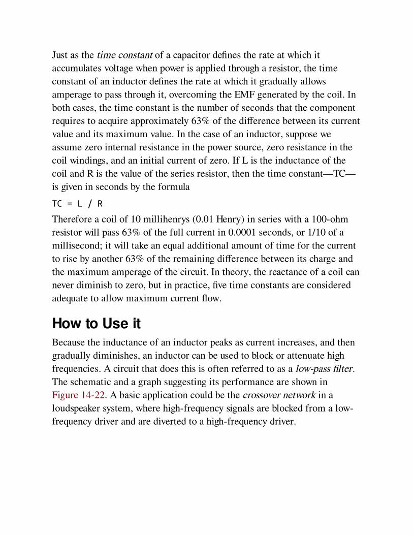
Just as the time constant of a capacitor defines the rate at which it
accumulates voltage when power is applied through a resistor, the time
constant of an inductor defines the rate at which it gradually allows
amperage to pass through it, overcoming the EMF generated by the coil. In
both cases, the time constant is the number of seconds that the component
requires to acquire approximately 63% of the difference between its current
value and its maximum value. In the case of an inductor, suppose we
assume zero internal resistance in the power source, zero resistance in the
coil windings, and an initial current of zero. If L is the inductance of the
coil and R is the value of the series resistor, then the time constant—TC—
is given in seconds by the formula
TC = L / R
Therefore a coil of 10 millihenrys (0.01 Henry) in series with a 100-ohm
resistor will pass 63% of the full current in 0.0001 seconds, or 1/10 of a
millisecond; it will take an equal additional amount of time for the current
to rise by another 63% of the remaining difference between its charge and
the maximum amperage of the circuit. In theory, the reactance of a coil can
never diminish to zero, but in practice, five time constants are considered
adequate to allow maximum current flow.
How to Use itBecause the inductance of an inductor peaks as current increases, and then
gradually diminishes, an inductor can be used to block or attenuate high
frequencies. A circuit that does this is often referred to as a low-pass filter.
The schematic and a graph suggesting its performance are shown in
Figure 14-22. A basic application could be the crossover network in a
loudspeaker system, where high-frequency signals are blocked from a low-
frequency driver and are diverted to a high-frequency driver.
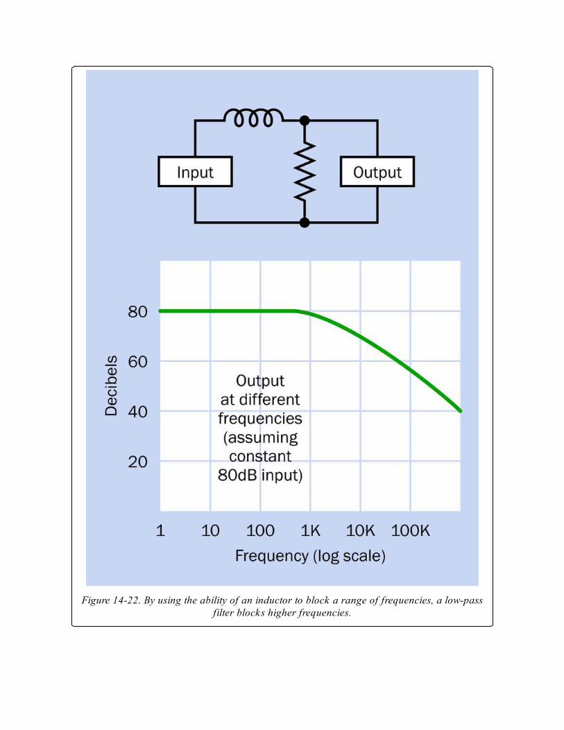
Figure 14-22. By using the ability of an inductor to block a range of frequencies, a low-passfilter blocks higher frequencies.

If the location of the inductor is shifted so that it shunts the signal away
from the output, the results are reversed, and the circuit becomes a high-
pass filter. The schematic and a graph suggesting its performance are shown
in Figure 14-23.
Figure 14-23. Here the inductor diverts low frequencies away from the output, allowing highfrequencies to pass through.
Note that capacitors may also be used to create frequency filters, but
because their function is roughly inverse to that of inductors, the placement
of a capacitor in a circuit would be opposite to the placement of the
inductor. Examples of filter circuits using capacitors are found in the entry
for that component in this encyclopedia.
An inductor can be combined with a capacitor to form a bandpass filter, as
shown in Figure 14-24. In this configuration, the inductor blocks the high
frequencies while the capacitor blocks the low frequencies, allowing only a
limited band of frequencies to get through.
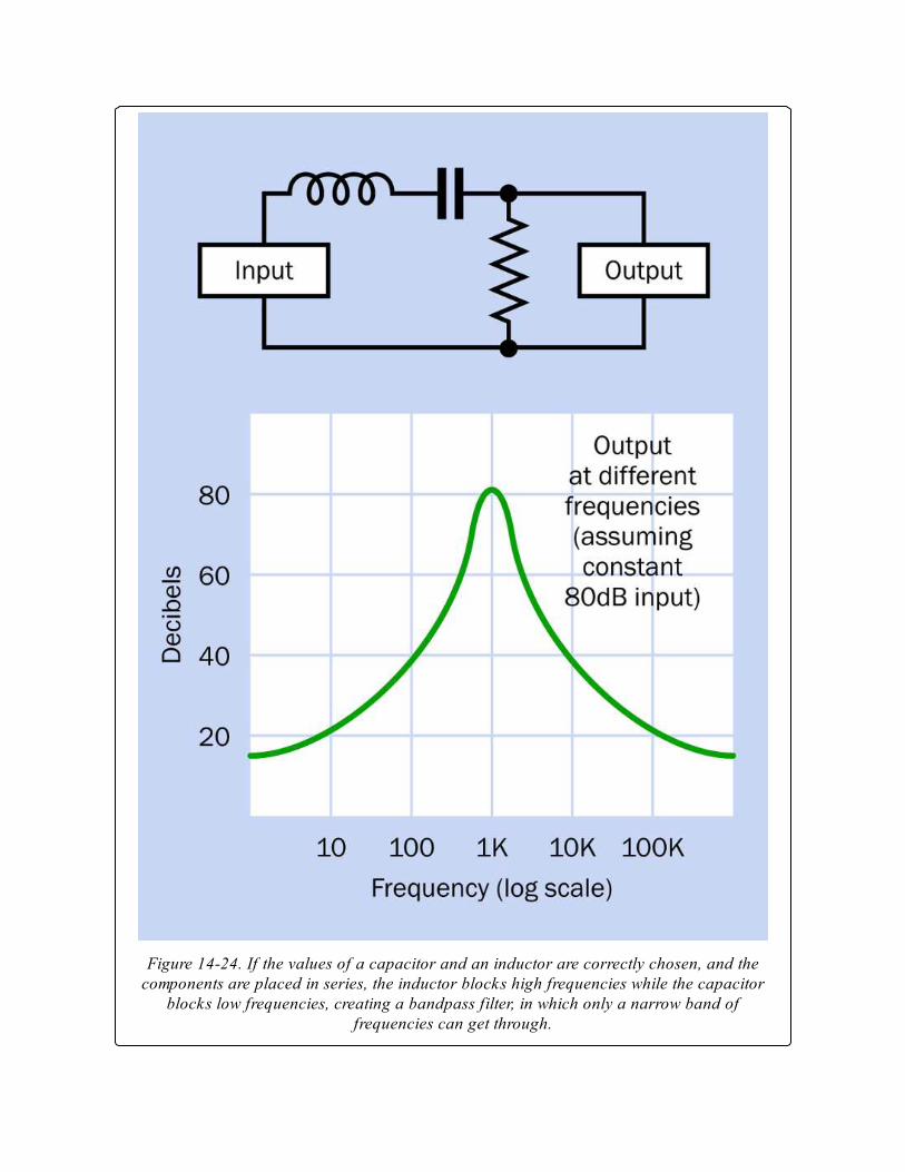
Figure 14-24. If the values of a capacitor and an inductor are correctly chosen, and thecomponents are placed in series, the inductor blocks high frequencies while the capacitor
blocks low frequencies, creating a bandpass filter, in which only a narrow band offrequencies can get through.
Once again if the location of the components is shifted to shunt the signal
away from the output, the results are reversed, as shown in Figure 14-25.
This is known as a notch filter.
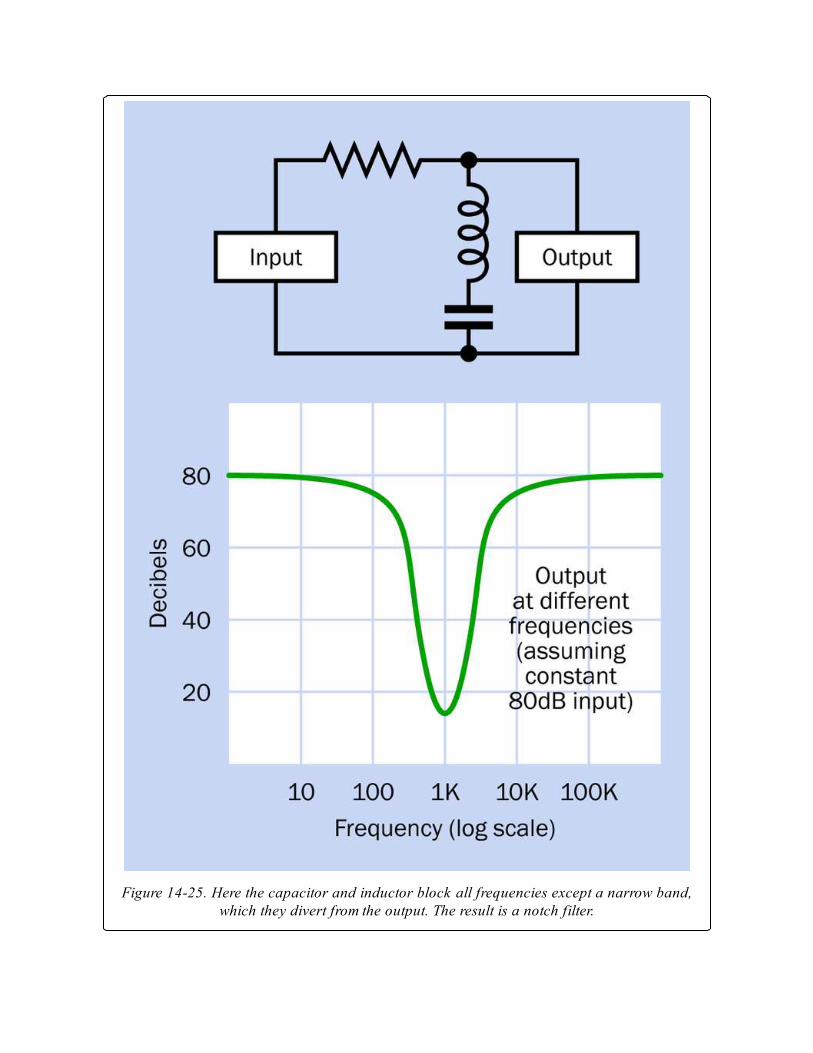
Figure 14-25. Here the capacitor and inductor block all frequencies except a narrow band,which they divert from the output. The result is a notch filter.
The performance of these filters will depend on the component values, and
in most applications, additional components will be necessary.
Sophisticated filter circuits are outside the scope of this encyclopedia.
Inductors are of great importance in DC-DC converters and AC-DCpower supplies where voltage changes are enabled by rapid switching. See
the relevant entries of this encyclopedia for additional details.
Generally, as electronic equipment has become increasingly miniaturized,
the unavoidable bulk of inductors has limited their application. However
they may still be used to tune oscillators, to block sudden spikes in power
supplies, and to protect equipment from sudden voltage spikes (they are
used, for example, in surge suppressors for computing equipment).
Core ChoicesAir-cored inductors have relatively low inductance, because of their low
permeability. However, they can be operated at very high frequencies up to
the gigahertz range, and can tolerate higher peak currents.
Inductors with an iron core suffer increasing power losses due to hysteresis
and eddy currents as the AC frequency passing through the inductor
increases. Consequently, iron-cored inductors are not suitable for
frequencies much above 10KHz.
MiniaturizationA low-value inductor can be formed by etching a spiral onto a circuit board,
in applications where size must be minimized. They may also be
incorporated in integrated circuit chips. However, in small devices such as
cellular phones, it is more common to use a coil substitute such as a
gyrator, as described previously.
What Can Go Wrong
Real-World Defects
The theoretically ideal inductor has no resistance or capacitance and suffers
no energy losses. In reality, an inductor possesses both resistance and
capacitance, also creates electrical noise, and may pick up electrical noise.
It tends to create stray magnetic fields, and generally is more troublesome
to deal with than its two cousins, the resistor and the capacitor.
Parasitic capacitance occurs between adjacent turns of wire. This
capacitance becomes more significant at higher frequencies, leading
ultimately to a situation where the coil becomes self resonant.
The workarounds for these problems involve coil geometries and choices of
core material that go beyond the scope of this encyclopedia.
A gyrator should be considered as a possible substitute where inductors are
troublesome or excessively expensive.
SaturationInductance increases as the current passing through a coil increases, but if a
magnetic core is used, its contribution to inductance will stop abruptly
when the core becomes magnetically saturated. In other words, when all of
the randomly distributed magnetic domains in the core have been induced
to align themselves with the pervasive magnetic field, the core cannot
become more highly magnetized, and ceases to contribute to the
inductance. Note that as a core approaches saturation levels, its hysteresis
increases because reversing its magnetization requires greater energy.
Antidotes to saturation would include a larger core, a lower current, a
smaller number of turns in the coil, and using a core with lower
permeability (such as air).
RF ProblemsRadio frequencies (RF) introduce various problems affecting the efficiency
of inductors. The skin effect is the tendency of high-frequency AC current
to flow primarily on the surface of a strand of wire. The proximity effect
refers to the tendency of the magnetic fields caused by adjacent wires to
introduce eddy currents in the coil. Both of these effects increase the

effective resistance of the coil. Various coil geometries have been developed
to minimize these effects, but are outside the scope of this encyclopedia.
The fundamental lesson is that coils specifically designed for RF are the
only ones that should be used with RF.
Chapter 15. AC-AC transformer
power > conversion > AC-AC transformer
Other related components
AC-DC power supply (See Chapter 16)
DC-DC converter (See Chapter 17)
DC-AC inverter (See Chapter 18)
What It DoesA transformer requires an input of alternating current (AC). It transforms
the input voltage to one or more output voltages that can be higher or lower.
Transformers range in size from tiny impedance-matching units in audio
equipment such as microphones, to multi-ton behemoths that supply high
voltage through the national power grids. Almost all electronic equipment
that is designed to be powered by municipal AC in homes or businesses
requires the inclusion of a transformer.
Two small power transformers are shown in Figure 15-1. The one at the
rear is rated to provide 36VAC at 0.8A when connected with a source of
125VAC. At front, the miniature transformer is a Radio Shack product
designed to provide approximately 12VAC at 300mA, although its voltage
will be more than 16VAC when it is not passing current through a load.
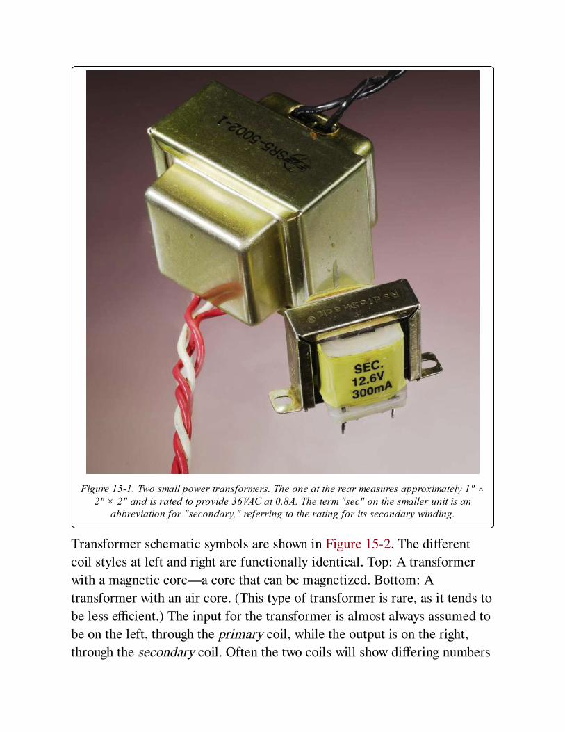
Figure 15-1. Two small power transformers. The one at the rear measures approximately 1" ×2" × 2" and is rated to provide 36VAC at 0.8A. The term "sec" on the smaller unit is an
abbreviation for "secondary," referring to the rating for its secondary winding.
Transformer schematic symbols are shown in Figure 15-2. The different
coil styles at left and right are functionally identical. Top: A transformer
with a magnetic core—a core that can be magnetized. Bottom: A
transformer with an air core. (This type of transformer is rare, as it tends to
be less efficient.) The input for the transformer is almost always assumed to
be on the left, through the primary coil, while the output is on the right,
through the secondary coil. Often the two coils will show differing numbers
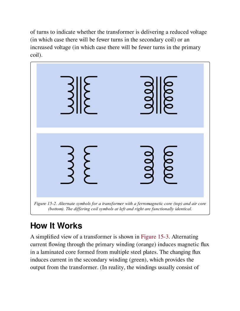
of turns to indicate whether the transformer is delivering a reduced voltage
(in which case there will be fewer turns in the secondary coil) or an
increased voltage (in which case there will be fewer turns in the primary
coil).
Figure 15-2. Alternate symbols for a transformer with a ferromagnetic core (top) and air core(bottom). The differing coil symbols at left and right are functionally identical.
How It WorksA simplified view of a transformer is shown in Figure 15-3. Alternating
current flowing through the primary winding (orange) induces magnetic flux
in a laminated core formed from multiple steel plates. The changing flux
induces current in the secondary winding (green), which provides the
output from the transformer. (In reality, the windings usually consist of
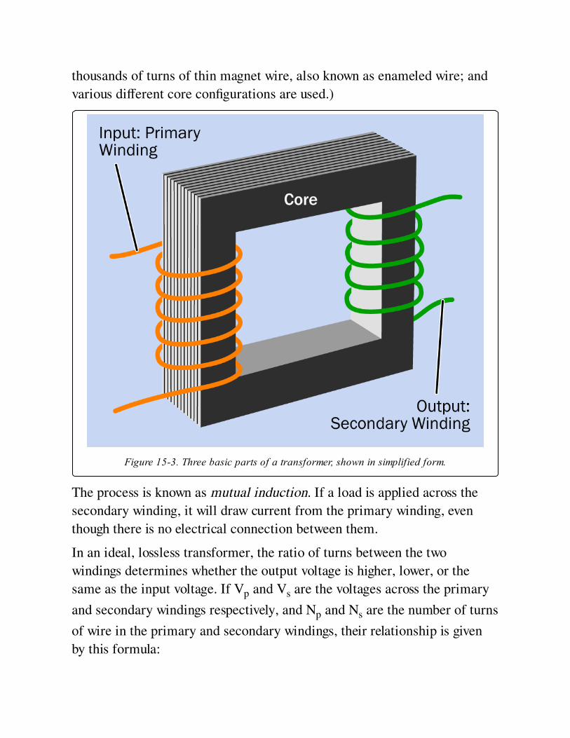
thousands of turns of thin magnet wire, also known as enameled wire; and
various different core configurations are used.)
Figure 15-3. Three basic parts of a transformer, shown in simplified form.
The process is known as mutual induction. If a load is applied across the
secondary winding, it will draw current from the primary winding, even
though there is no electrical connection between them.
In an ideal, lossless transformer, the ratio of turns between the two
windings determines whether the output voltage is higher, lower, or the
same as the input voltage. If Vp and Vs are the voltages across the primary
and secondary windings respectively, and Np and Ns are the number of turns
of wire in the primary and secondary windings, their relationship is given
by this formula:
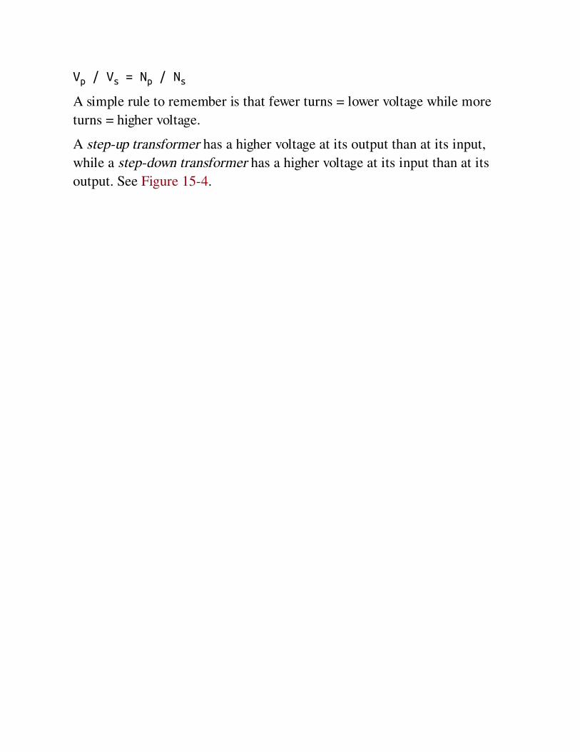
Vp / Vs = Np / Ns
A simple rule to remember is that fewer turns = lower voltage while more
turns = higher voltage.
A step-up transformer has a higher voltage at its output than at its input,
while a step-down transformer has a higher voltage at its input than at its
output. See Figure 15-4.
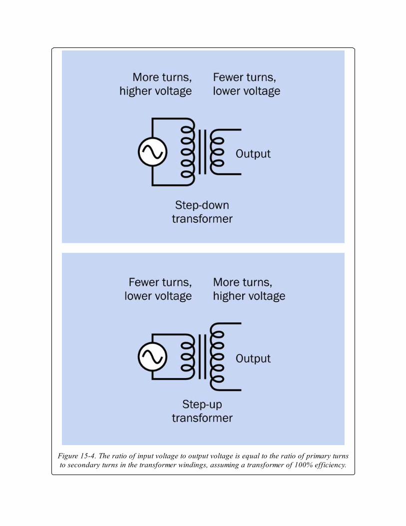
Figure 15-4. The ratio of input voltage to output voltage is equal to the ratio of primary turnsto secondary turns in the transformer windings, assuming a transformer of 100% efficiency.
In an ideal, lossless transformer, the power input would be equal to the
power output. If Vin and Vout are the input and output voltages, and Iin and
Iout are the input and output currents, their relationship is given by this
formula:
Vin * Iin = Vout * Iout
Therefore, if the transformer doubles the voltage, it allows only half as
much current to be drawn from the secondary winding; and if the voltage is
cut in half, the available current will double.
Transformers are not 100% efficient, but they can be more than 98%
efficient, and relationships between voltage, current, and the number of
turns in the windings are reasonably realistic.
When the transformer is not loaded, the primary winding behaves like a
simple inductor with reactance that inhibits the flow of current. Therefore a
power transformer will consume relatively little electricity if it is left
plugged in to an electrical outlet without any load connected to its output
side. The power that it does consume will be wasted as heat.
The CoreThe ferromagnetic core is often described as being made of iron, but in
reality is more often fabricated from high permeability silicon steel. To
reduce losses caused by eddy currents, the core is usually laminated—
assembled from a stack of plates separated from each other by thin layers of
varnish or a similar insulator. Eddy currents tend to be constrained within
the thickness of each plate.
Because a DC voltage would cause magnetic saturation of the core, all
transformers must operate with alternating current or pulses of current. The
windings and geometry of a transformer are optimized for the frequency
range, voltage, and current at which it is designed to operate. Deviating
significantly from these values can damage the transformer.
Taps

A tap on a transformer is a connection part-way through the primary or
(more often) the secondary coil. On the primary side, applying an input
between the start of a coil and a tap part-way through the coil will reduce
the number of turns to which the voltage is applied, therefore increasing the
ratio of output turns to input turns, and increasing the output voltage. On
the secondary side, taking an output between the start of a coil and a tap
part-way through the coil will reduce the number of turns from which the
voltage is taken, therefore decreasing the ratio of output turns to input
turns, and decreasing the output voltage. This can be summarized:
A tap on the primary side can increase output voltage.
A tap on the secondary side can provide a decreased output voltage.
In international power adapters, a choice of input voltages may be allowed
by using a double-throw switch to select either the whole primary winding,
or a tapped subsection of the winding. See Figure 15-5. Modern electronics
equipment often does not require a voltage adapter, because a voltageregulator or DC-DC converter inside the equipment will tolerate a wide
range of input voltages while providing a relatively constant output voltage.
Figure 15-5. An international power adapter can provide a fixed output voltage by using adouble-throw switch to apply 230VAC voltage across a transformer’s primary winding, or
115VAC to a tapped midpoint of the primary winding.

A transformer’s secondary winding is often tapped to provide a choice of
output voltages. In fact, most power transformers have at least two outputs,
since the cost of adding taps to the secondary winding is relatively small. As
an alternative to tapped outputs, two or more separate secondary windings
may be used, allowing the outputs to be electrically isolated from each
other. See Figure 15-6.
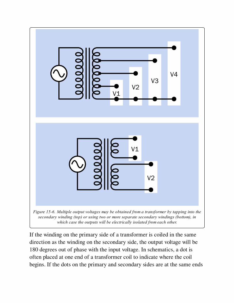
Figure 15-6. Multiple output voltages may be obtained from a transformer by tapping into thesecondary winding (top) or using two or more separate secondary windings (bottom), in
which case the outputs will be electrically isolated from each other.
If the winding on the primary side of a transformer is coiled in the same
direction as the winding on the secondary side, the output voltage will be
180 degrees out of phase with the input voltage. In schematics, a dot is
often placed at one end of a transformer coil to indicate where the coil
begins. If the dots on the primary and secondary sides are at the same ends
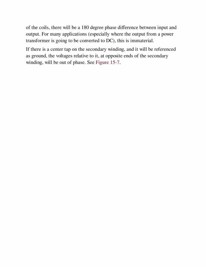
of the coils, there will be a 180 degree phase difference between input and
output. For many applications (especially where the output from a power
transformer is going to be converted to DC), this is immaterial.
If there is a center tap on the secondary winding, and it will be referenced
as ground, the voltages relative to it, at opposite ends of the secondary
winding, will be out of phase. See Figure 15-7.
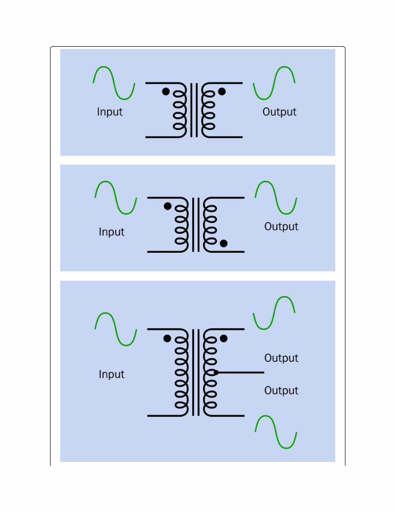
Figure 15-7. A dot indicates the start of each winding. Where primary and secondarywindings are in the same direction, the voltage output will be 180 degrees out of phase with
the input. Where the dots indicate windings in opposite directions, the voltage output will havethe same phase as the input. Where a center tap on the secondary winding serves as a
common ground, the voltages at opposite ends of the secondary winding will be opposite toeach other in phase.
Variants
Core ShapesThe shell core is a closed rectangle, as shown in Figure 15-3. This is the
most efficient but most costly to manufacture. A C-shaped core is another
option (three sides of the rectangle) and an E-I core is popular, consisting
of a stack of E-shaped plates with two coils wound around the top and
bottom legs of the E, or wound concentrically around the center leg of the
E. An additional stack of straight plates is added to close the gaps in the E
and form a magnetic circuit.
In Figure 15-8, the small transformer from Figure 15-1 has been sliced
open with a band saw and a belt sander to reveal a cross-section of its
windings. This clearly shows that its primary and secondary windings are
concentric. It also reveals the configuration of its core, which is in the E-I
format. In Figure 15-9, the E-I configuration is highlighted to show it more
clearly.
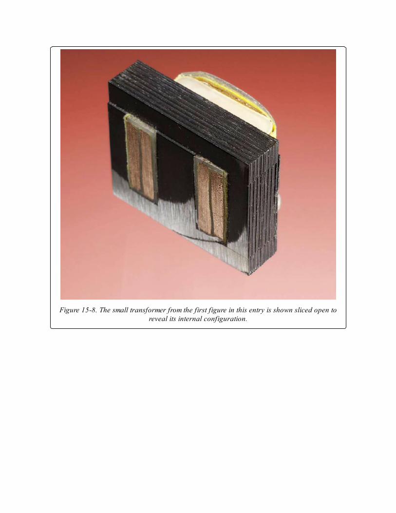
Figure 15-8. The small transformer from the first figure in this entry is shown sliced open toreveal its internal configuration.
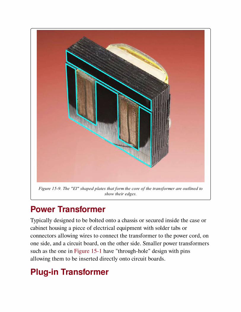
Figure 15-9. The "EI" shaped plates that form the core of the transformer are outlined toshow their edges.
Power TransformerTypically designed to be bolted onto a chassis or secured inside the case or
cabinet housing a piece of electrical equipment with solder tabs or
connectors allowing wires to connect the transformer to the power cord, on
one side, and a circuit board, on the other side. Smaller power transformers
such as the one in Figure 15-1 have "through-hole" design with pins
allowing them to be inserted directly onto circuit boards.
Plug-in Transformer
Usually sealed in a plastic housing that can be plugged directly into a wall
power outlet. They are visually identical to AC adapters but have an AC
output instead of a DC output.
Isolation TransformerAlso known as a 1:1 transformer because it has a 1:1 ratio between primary
and secondary windings, so that the output voltage will be the same as the
input voltage. When electrical equipment is plugged into the isolation
transformer, it is separated from the electrical ground of AC power wiring.
This reduces risk when working on "live" equipment, as there will be
negligible electrical potential between itself and ground. Consequently,
touching a grounded object while also touching a live wire in the equipment
should not result in potentially lethal current passing through the body.
AutotransformerThis variant uses only one coil that is tapped to provide output voltage.
Mutual induction occurs between the sections of the coil. An
autotransformer entails a common connection between its input and
output, unlike a two-coil transformer, which allows the output to be
electrically isolated from the input. See Figure 15-10. Autotransformers are
often used for impedance matching in audio circuits, and to provide output
voltages that differ only slightly from input voltages.
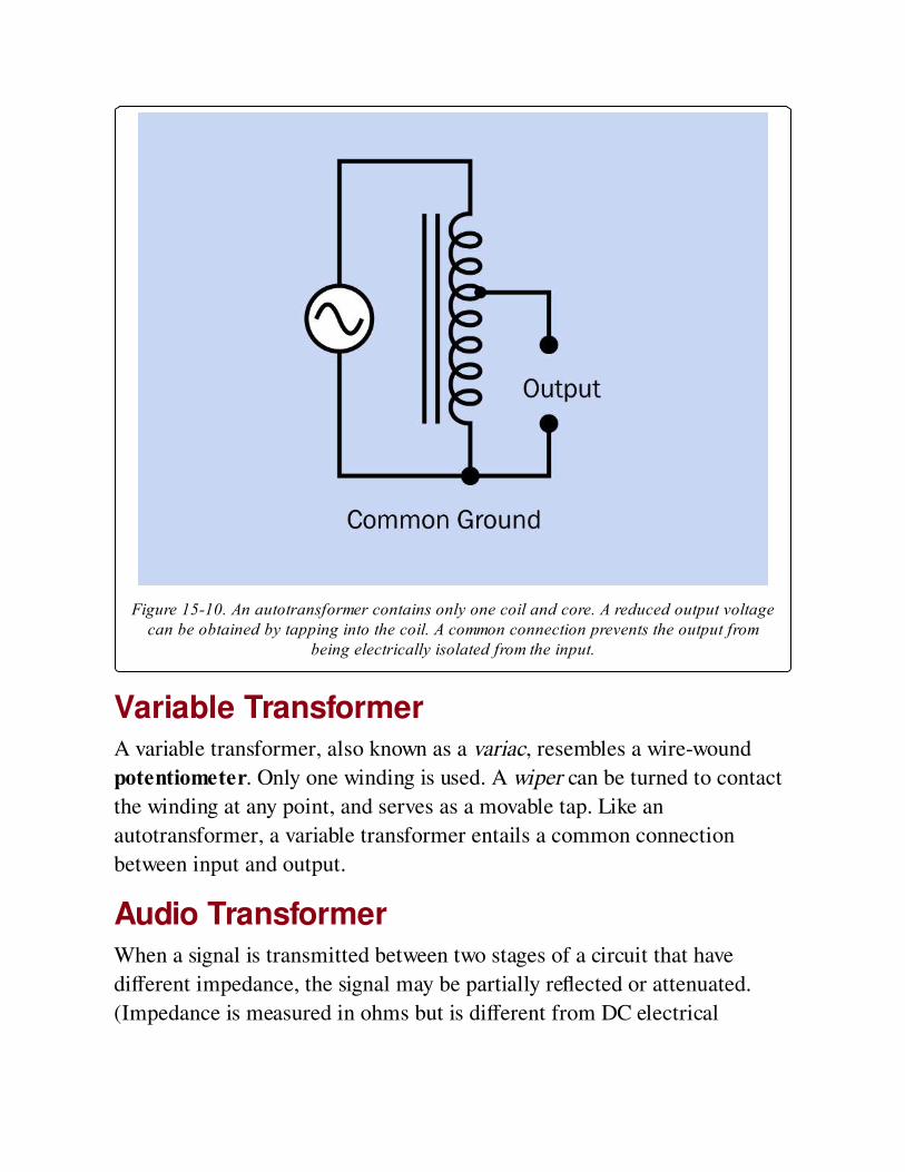
Figure 15-10. An autotransformer contains only one coil and core. A reduced output voltagecan be obtained by tapping into the coil. A common connection prevents the output from
being electrically isolated from the input.
Variable TransformerA variable transformer, also known as a variac, resembles a wire-wound
potentiometer. Only one winding is used. A wiper can be turned to contact
the winding at any point, and serves as a movable tap. Like an
autotransformer, a variable transformer entails a common connection
between input and output.
Audio TransformerWhen a signal is transmitted between two stages of a circuit that have
different impedance, the signal may be partially reflected or attenuated.
(Impedance is measured in ohms but is different from DC electrical
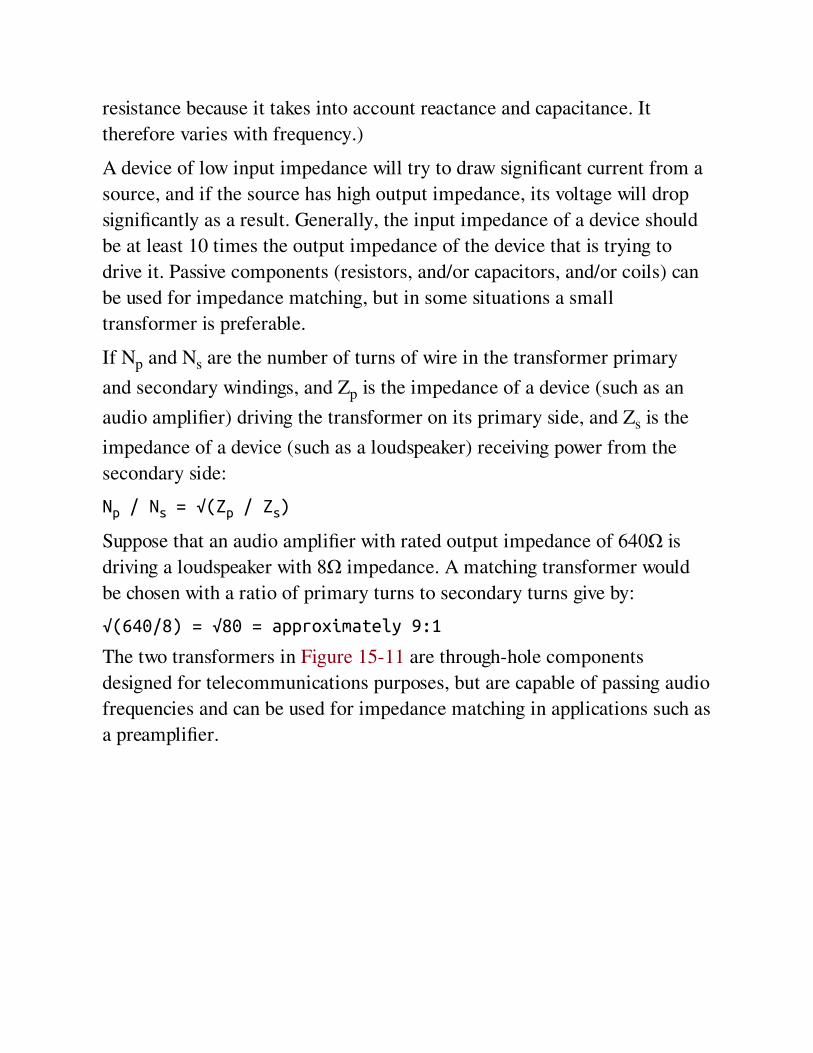
resistance because it takes into account reactance and capacitance. It
therefore varies with frequency.)
A device of low input impedance will try to draw significant current from a
source, and if the source has high output impedance, its voltage will drop
significantly as a result. Generally, the input impedance of a device should
be at least 10 times the output impedance of the device that is trying to
drive it. Passive components (resistors, and/or capacitors, and/or coils) can
be used for impedance matching, but in some situations a small
transformer is preferable.
If Np and Ns are the number of turns of wire in the transformer primary
and secondary windings, and Zp is the impedance of a device (such as an
audio amplifier) driving the transformer on its primary side, and Zs is the
impedance of a device (such as a loudspeaker) receiving power from the
secondary side:
Np / Ns = √(Zp / Zs)
Suppose that an audio amplifier with rated output impedance of 640Ω is
driving a loudspeaker with 8Ω impedance. A matching transformer would
be chosen with a ratio of primary turns to secondary turns give by:
√(640/8) = √80 = approximately 9:1
The two transformers in Figure 15-11 are through-hole components
designed for telecommunications purposes, but are capable of passing audio
frequencies and can be used for impedance matching in applications such as
a preamplifier.
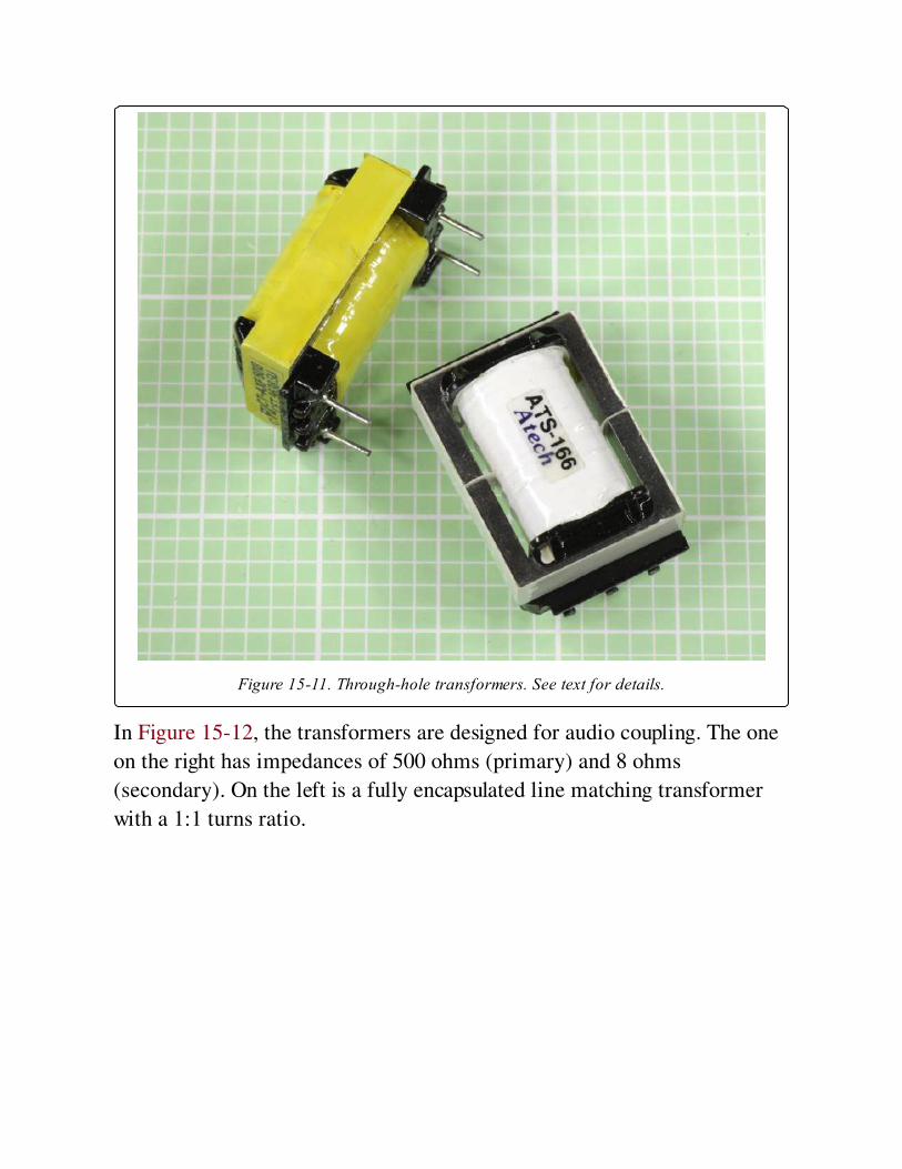
Figure 15-11. Through-hole transformers. See text for details.
In Figure 15-12, the transformers are designed for audio coupling. The one
on the right has impedances of 500 ohms (primary) and 8 ohms
(secondary). On the left is a fully encapsulated line matching transformer
with a 1:1 turns ratio.
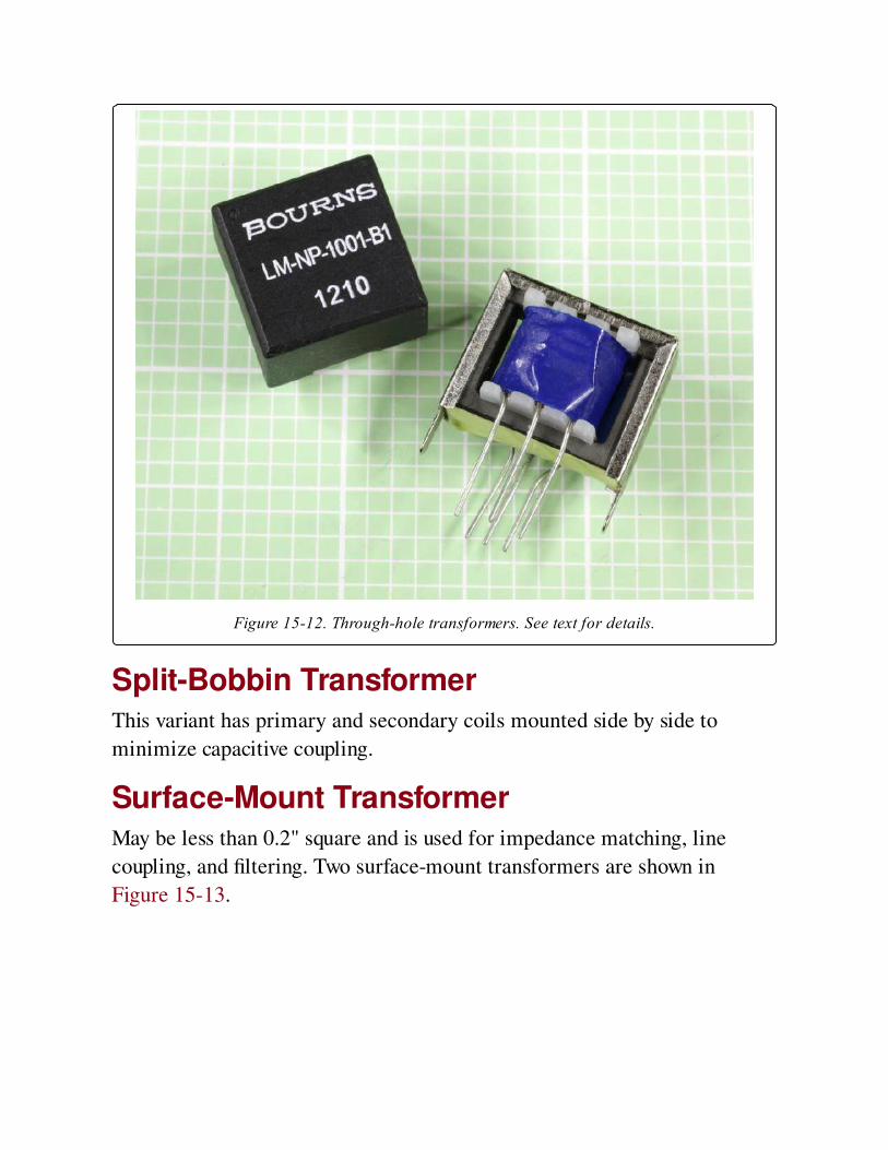
Figure 15-12. Through-hole transformers. See text for details.
Split-Bobbin TransformerThis variant has primary and secondary coils mounted side by side to
minimize capacitive coupling.
Surface-Mount TransformerMay be less than 0.2" square and is used for impedance matching, line
coupling, and filtering. Two surface-mount transformers are shown in
Figure 15-13.
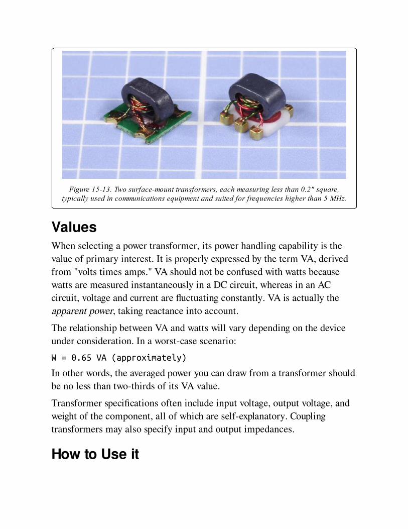
Figure 15-13. Two surface-mount transformers, each measuring less than 0.2" square,typically used in communications equipment and suited for frequencies higher than 5 MHz.
ValuesWhen selecting a power transformer, its power handling capability is the
value of primary interest. It is properly expressed by the term VA, derived
from "volts times amps." VA should not be confused with watts because
watts are measured instantaneously in a DC circuit, whereas in an AC
circuit, voltage and current are fluctuating constantly. VA is actually the
apparent power, taking reactance into account.
The relationship between VA and watts will vary depending on the device
under consideration. In a worst-case scenario:
W = 0.65 VA (approximately)
In other words, the averaged power you can draw from a transformer should
be no less than two-thirds of its VA value.
Transformer specifications often include input voltage, output voltage, and
weight of the component, all of which are self-explanatory. Coupling
transformers may also specify input and output impedances.
How to Use it
For most electronic circuits, a power transformer will be followed by a
rectifier to convert AC to DC, and capacitors to smooth fluctuations in the
supply. Using a prepackaged power supply or AC adapter that already
contains all the necessary components will be more time-effective and
probably more cost-effective than building a power supply from the ground
up. See Chapter 16.
What Can Go Wrong
Reversal of Input and OutputSuppose a transformer is designed to provide an output voltage of 10 volts
from domestic AC power of 115 volts. If the wrong side of the transformer
is connected with 115VAC by mistake, the output will now be more than
1,000 volts—easily enough to cause death, quite apart from destroying
components that are connected with it. Reversing the transformer in this
way may also destroy it. Extreme caution is advisable when making
connections with power transformers. A meter should be used to check
output voltage. All devices containing transformers should be fused on the
live side and grounded.
Shock Hazard from Common GroundWhen working on equipment that uses an autotransformer, the chassis will
be connected through the transformer to one side of 115VAC power. So
long as a plug is used that prevents reversed polarity, the chassis should be
"neutral." However, if an inappropriate power cord is used, or if the power
outlet has been wired incorrectly, the chassis can become live. For
protection, before working on any device that uses 115VAC power with an
autotransformer, plug the device into an isolation transformer, and plug the
isolation transformer into the wall outlet.
Accidental DC Input
If DC current is applied to the input side of a transformer, the relatively low
resistance of the primary coil will allow high current that can destroy the
component. Transformers should only be used with alternating current.
OverloadIf a transformer is overloaded, heat will be generated that may be sufficient
to destroy the thin layers of insulation between coil windings. Consequently,
input voltage can appear unexpectedly on the output side. Transformers
with a toroidal (circular) core are especially hazardous in this respect, as
their primary and secondary windings usually overlap.
Some (not all) power transformers contain a thermal fuse that melts when
it exceeds a temperature threshold. If the fuse is destroyed, the transformer
must be discarded.
The consequences of moderate overloading may not be obvious, and can be
cumulative over time. Ventilation or heat sinkage should be taken into
account when designing equipment around a power transformer.
Incorrect AC FrequencySingle-phase AC power in the United States fluctuates at 60Hz, but Great
Britain and some other countries use AC power at 50Hz. Many power
transformers are rated to be compatible with either frequency, but if a
transformer is specifically designed for 60Hz, it may eventually fail by
overheating if it is used with a 50Hz supply. (A 50Hz transformer can be
used safely with 60Hz AC.)
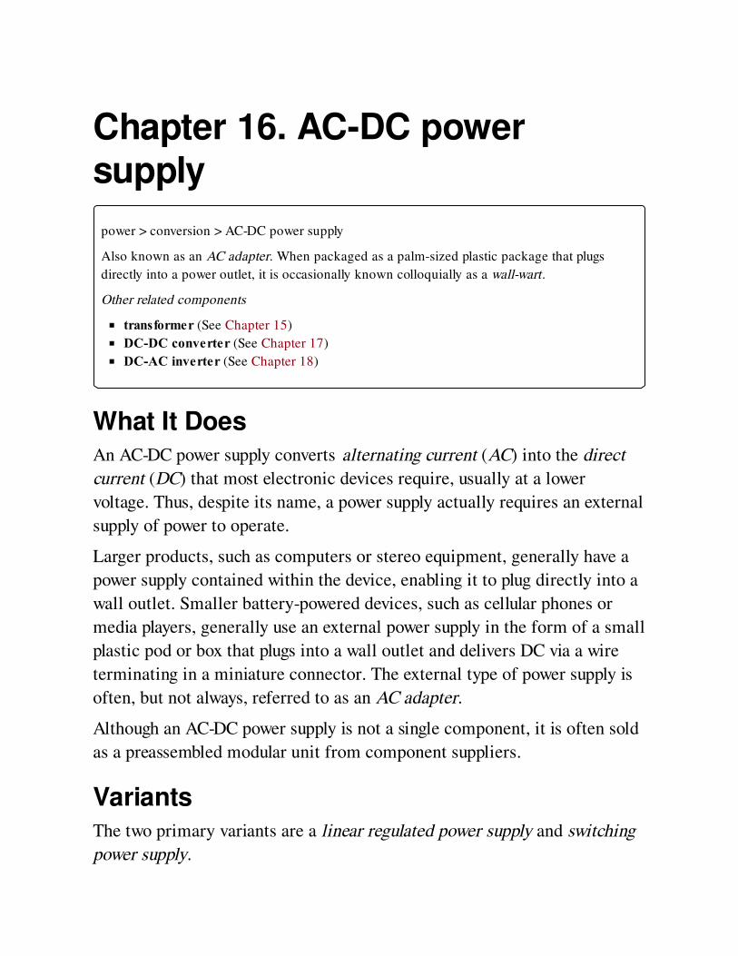
Chapter 16. AC-DC powersupply
power > conversion > AC-DC power supply
Also known as an AC adapter. When packaged as a palm-sized plastic package that plugs
directly into a power outlet, it is occasionally known colloquially as a wall-wart.
Other related components
transformer (See Chapter 15)
DC-DC converter (See Chapter 17)
DC-AC inverter (See Chapter 18)
What It DoesAn AC-DC power supply converts alternating current (AC) into the direct
current (DC) that most electronic devices require, usually at a lower
voltage. Thus, despite its name, a power supply actually requires an external
supply of power to operate.
Larger products, such as computers or stereo equipment, generally have a
power supply contained within the device, enabling it to plug directly into a
wall outlet. Smaller battery-powered devices, such as cellular phones or
media players, generally use an external power supply in the form of a small
plastic pod or box that plugs into a wall outlet and delivers DC via a wire
terminating in a miniature connector. The external type of power supply is
often, but not always, referred to as an AC adapter.
Although an AC-DC power supply is not a single component, it is often sold
as a preassembled modular unit from component suppliers.
VariantsThe two primary variants are a linear regulated power supply and switching
power supply.
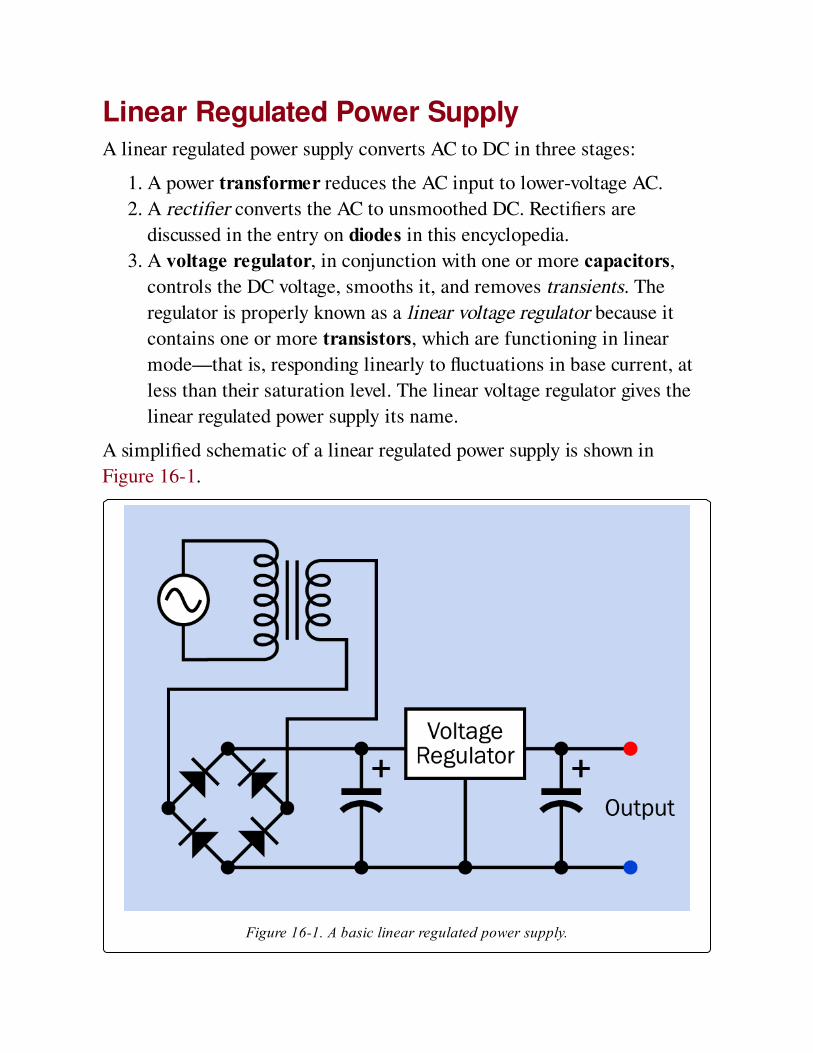
Linear Regulated Power SupplyA linear regulated power supply converts AC to DC in three stages:
1. A power transformer reduces the AC input to lower-voltage AC.
2. A rectifier converts the AC to unsmoothed DC. Rectifiers are
discussed in the entry on diodes in this encyclopedia.
3. A voltage regulator, in conjunction with one or more capacitors,
controls the DC voltage, smooths it, and removes transients. The
regulator is properly known as a linear voltage regulator because it
contains one or more transistors, which are functioning in linear
mode—that is, responding linearly to fluctuations in base current, at
less than their saturation level. The linear voltage regulator gives the
linear regulated power supply its name.
A simplified schematic of a linear regulated power supply is shown in
Figure 16-1.
Figure 16-1. A basic linear regulated power supply.
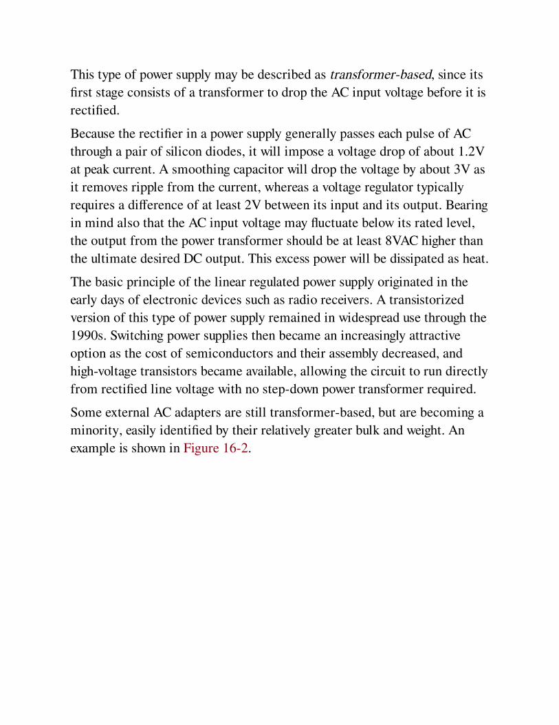
This type of power supply may be described as transformer-based, since its
first stage consists of a transformer to drop the AC input voltage before it is
rectified.
Because the rectifier in a power supply generally passes each pulse of AC
through a pair of silicon diodes, it will impose a voltage drop of about 1.2V
at peak current. A smoothing capacitor will drop the voltage by about 3V as
it removes ripple from the current, whereas a voltage regulator typically
requires a difference of at least 2V between its input and its output. Bearing
in mind also that the AC input voltage may fluctuate below its rated level,
the output from the power transformer should be at least 8VAC higher than
the ultimate desired DC output. This excess power will be dissipated as heat.
The basic principle of the linear regulated power supply originated in the
early days of electronic devices such as radio receivers. A transistorized
version of this type of power supply remained in widespread use through the
1990s. Switching power supplies then became an increasingly attractive
option as the cost of semiconductors and their assembly decreased, and
high-voltage transistors became available, allowing the circuit to run directly
from rectified line voltage with no step-down power transformer required.
Some external AC adapters are still transformer-based, but are becoming a
minority, easily identified by their relatively greater bulk and weight. An
example is shown in Figure 16-2.
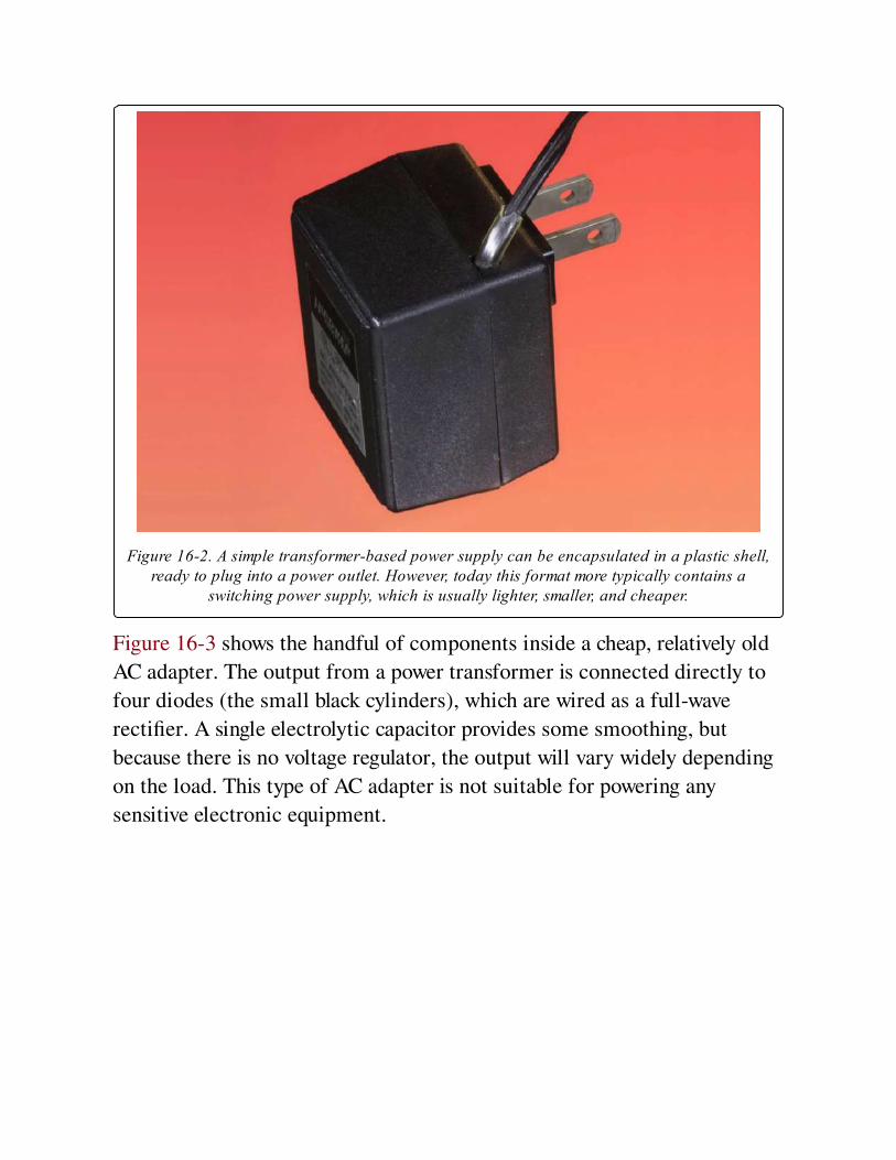
Figure 16-2. A simple transformer-based power supply can be encapsulated in a plastic shell,ready to plug into a power outlet. However, today this format more typically contains a
switching power supply, which is usually lighter, smaller, and cheaper.
Figure 16-3 shows the handful of components inside a cheap, relatively old
AC adapter. The output from a power transformer is connected directly to
four diodes (the small black cylinders), which are wired as a full-wave
rectifier. A single electrolytic capacitor provides some smoothing, but
because there is no voltage regulator, the output will vary widely depending
on the load. This type of AC adapter is not suitable for powering any
sensitive electronic equipment.
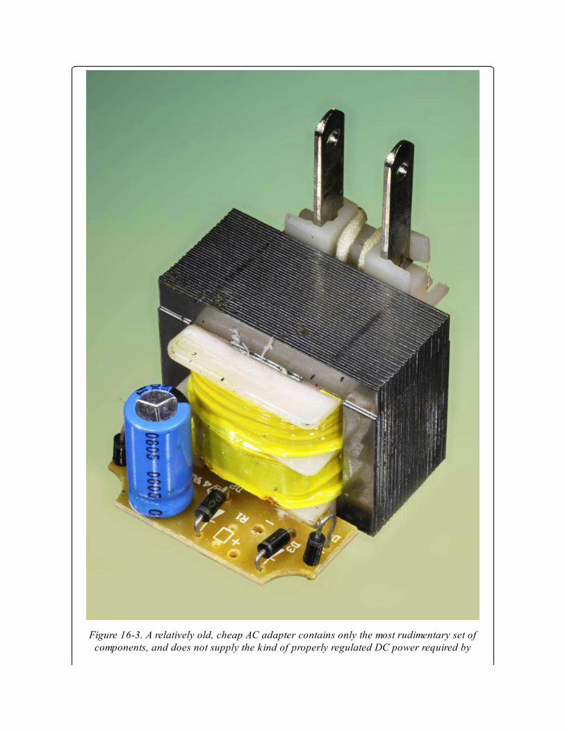
Figure 16-3. A relatively old, cheap AC adapter contains only the most rudimentary set ofcomponents, and does not supply the kind of properly regulated DC power required by

electronic equipment.
Switching Power SupplyAlso known as a switched-mode power supply, an SMPS, or switcher, it
converts AC to DC in two stages.
1. A rectifier changes the AC input to unsmoothed DC, without a power
transformer.
2. A DC-DC converter switches the DC on and off at a very high
frequency using pulse-width modulation to reduce its average effective
voltage. Often the converter will be the flyback type, containing a
transformer, but the high-frequency switching allows the transformer
to be much smaller than the power transformer required in a linear
regulated power supply. See the DC-DC converter entry in this
encyclopedia for an explanation of the working principles.
A simplified schematic of a switching power supply is shown in Figure 16-4.

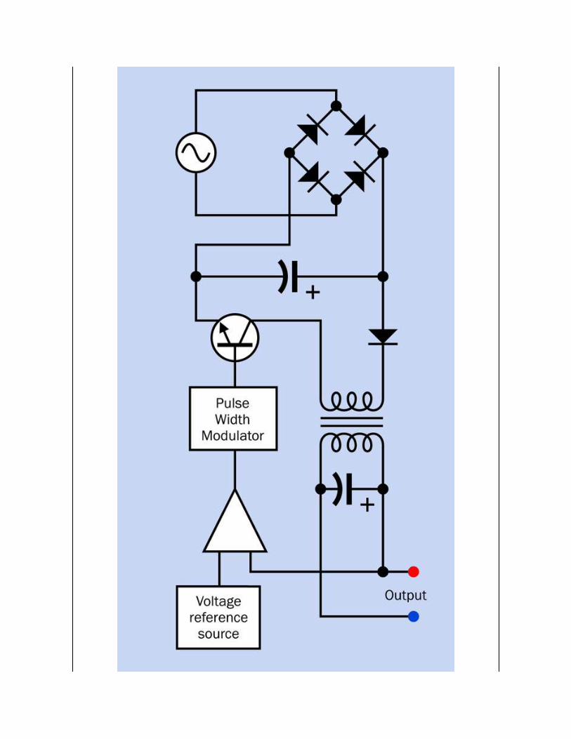
Figure 16-4. Greatly simplified schematic showing the principal components of a switchingpower supply. Note the absence of a 115VAC power transformer. The transformer that is
inserted subsequently in the circuit functions in conjunction with the high switchingfrequency, which allows it to be very much smaller, cheaper, and lighter.
The interior of a relatively early switching power supply designed to deliver
12VDC at up to 4A is shown in Figure 16-5. This supply generated
considerable waste heat, necessitating well-spaced components and a
ventilated enclosure.
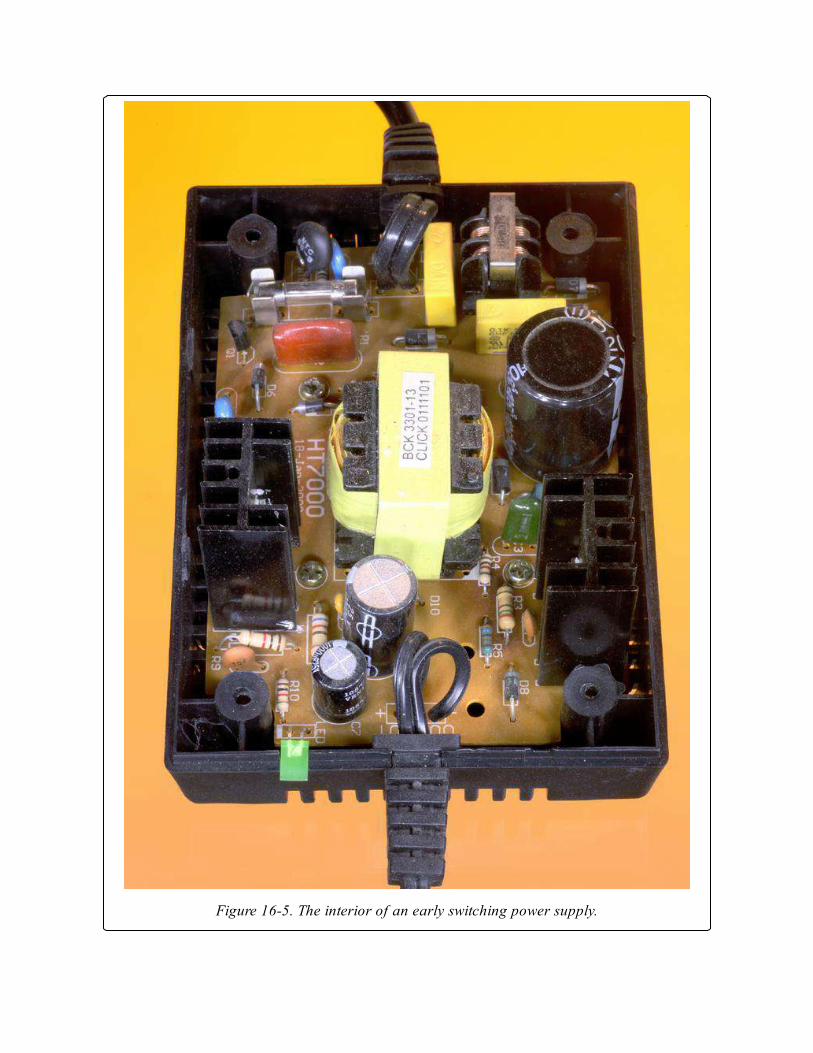
Figure 16-5. The interior of an early switching power supply.
The type of small switching power supply that is now almost universally
used to power laptop computers is shown in Figure 16-6. Note the smaller
enclosure and the higher component count than in the older power supply
shown in Figure 16-5. The modern unit also delivers considerably more
power, and generates less waste heat. Although this example is rated at 5A,
the transformer (hidden under the yellow wrapper at the center of the unit)
is smaller than the power transformer that would have been found in an old-
style AC adapter delivering just 500mA.
The modern power supply is completely sealed, where earlier versions
required ventilation. On the downside, the plastic case of the switching
supply requires a metal liner (removed for this photograph) to contain high-
frequency electromagnetic radiation.
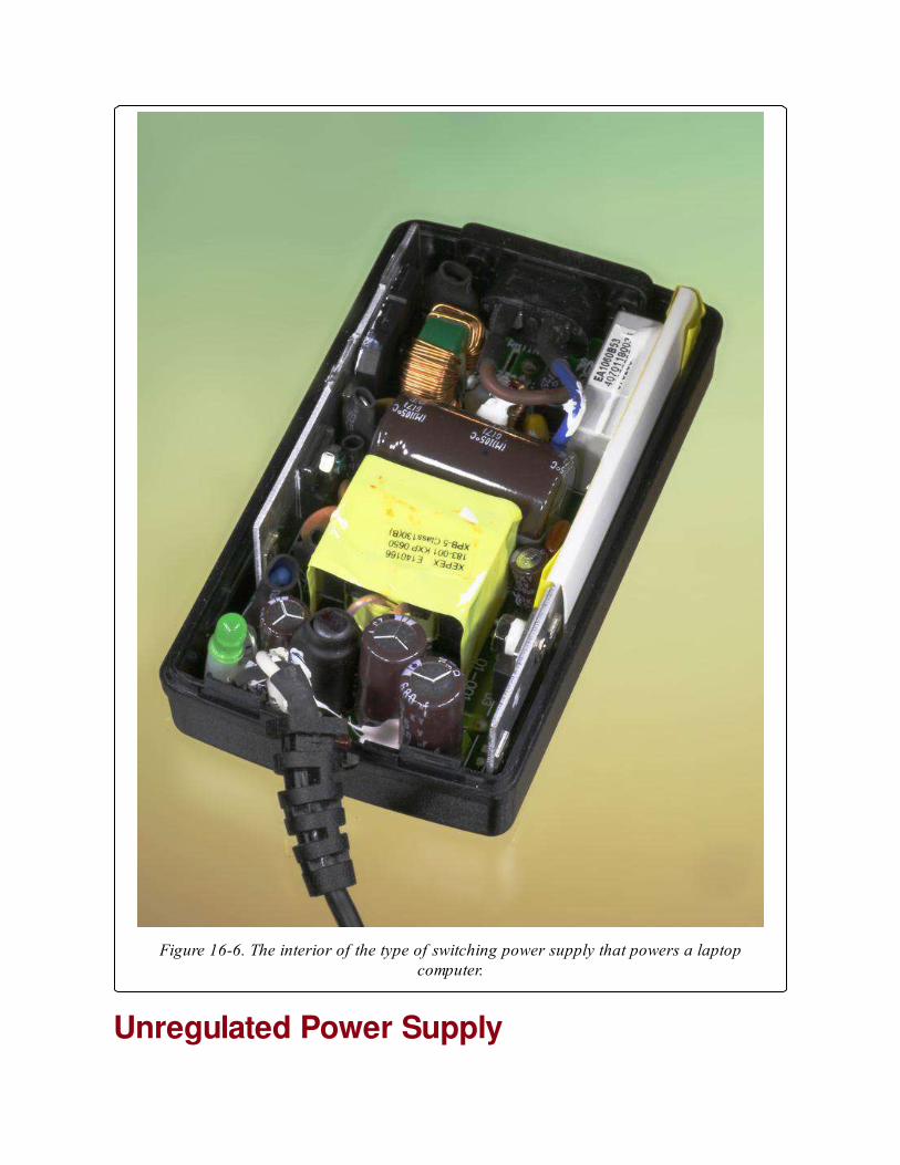
Figure 16-6. The interior of the type of switching power supply that powers a laptopcomputer.
Unregulated Power Supply

Typically this consists of a transformer and rectifying diodes with little or
no smoothing or voltage control of the output.
Adjustable Power SupplyThis is usually a linear power supply incorporating an adjustable voltageregulator. This type of supply has laboratory applications and is found as a
benchtop item to power electronics design projects during their
development.
Voltage MultiplierDevices such as photocopiers and laser printers, televisions, cathode-ray
tubes, and microwave ovens require voltages significantly higher than those
supplied by domestic AC power outlets. A voltage multiplier usually
contains a step-up transformer followed by DC conversion components, but
detailed consideration is outside the scope of this encyclopedia.
FormatsAn open frame power supply consists of components on a circuit board,
usually mounted on a metal chassis, with no enclosure or fan cooling.
A covered power supply is enclosed in a protective perforated metal box
with a cooling fan if needed. Power supplies sold for desktop computers are
usually in this format.
Power supplies are also available in rack-mount and DIN-rail formats.
How to Use itBecause a switching power supply contains no power transformer, it is
lighter and smaller, and may be cheaper than a linear power supply. It is
also more efficient and generates less waste heat. These advantages have
made switching power supplies the most popular option to provide DC
power for electronics devices. However, the high-frequency switching tends
to create electromagnetic interference (EMI), which must be filtered to
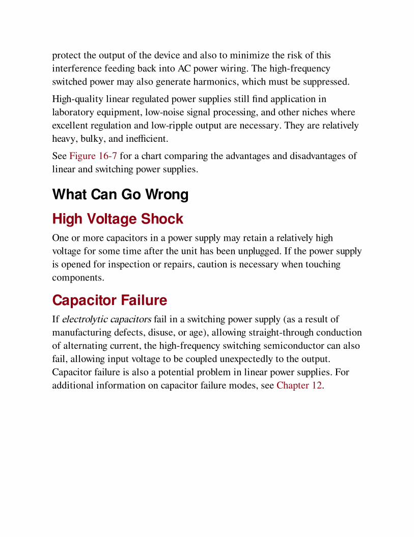
protect the output of the device and also to minimize the risk of this
interference feeding back into AC power wiring. The high-frequency
switched power may also generate harmonics, which must be suppressed.
High-quality linear regulated power supplies still find application in
laboratory equipment, low-noise signal processing, and other niches where
excellent regulation and low-ripple output are necessary. They are relatively
heavy, bulky, and inefficient.
See Figure 16-7 for a chart comparing the advantages and disadvantages of
linear and switching power supplies.
What Can Go Wrong
High Voltage ShockOne or more capacitors in a power supply may retain a relatively high
voltage for some time after the unit has been unplugged. If the power supply
is opened for inspection or repairs, caution is necessary when touching
components.
Capacitor FailureIf electrolytic capacitors fail in a switching power supply (as a result of
manufacturing defects, disuse, or age), allowing straight-through conduction
of alternating current, the high-frequency switching semiconductor can also
fail, allowing input voltage to be coupled unexpectedly to the output.
Capacitor failure is also a potential problem in linear power supplies. For
additional information on capacitor failure modes, see Chapter 12.
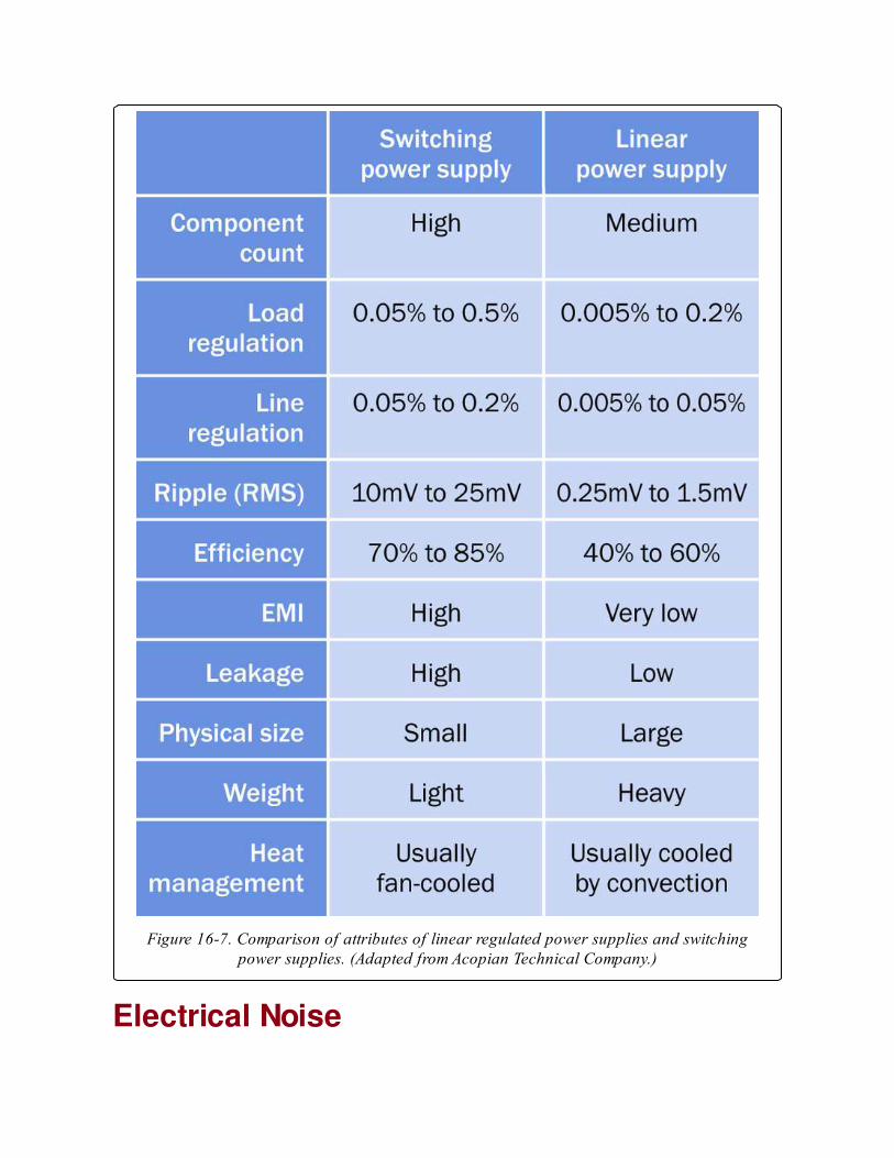
Figure 16-7. Comparison of attributes of linear regulated power supplies and switchingpower supplies. (Adapted from Acopian Technical Company.)
Electrical Noise
If electrolytic capacitors are used, their gradual deterioration over time will
permit more electrical noise associated with high-frequency switching in a
switching power supply.
Peak InrushA switching power supply allows an initial inrush or surge of current as its
capacitors accumulate their charge. This can affect other components in the
circuit, and requires fusing that tolerates brief but large deviations from
normal power consumption.
Chapter 17. DC-DC converter
power > conversion > DC-DC converter
Often referred to as a switching regulator, and sometimes as a switcher, not to be confused with
a switching power supply.
Other related components
AC-DC power supply (See Chapter 16)
voltage regulator (See Chapter 19)
DC-AC inverter (See Chapter 18)
What It DoesA DC-DC converter, often referred to simply as a converter, receives a DC
voltage as its input and converts it to a regulated DC voltage as its output.
The output voltage may be higher or lower than the input voltage, may be
user-adjustable by adding an external resistor, and may be completely
electrically isolated from the input, depending on the type of converter that
is used. The overall efficiency is not greatly affected by the difference
between input and output voltage, and can exceed 90%, minimizing waste
heat and enabling the unit to be extremely compact.
A DC-DC converter is an integrated circuit package that includes a high-
speed switching device (almost always, a MOSFET) in conjunction with an
oscillator circuit, an inductor, and a diode. By comparison, a linearregulator is usually based around bipolar transistors. Its input must always
be at a higher voltage than its output, and its efficiency will be inversely
proportional with the voltage drop that it imposes. See the voltageregulator entry in this encyclopedia for additional information.
There is no single symbol to represent a DC-DC converter. Some simplified
schematics showing the principles of operation of commonly used
converters are referenced under the following Variants section.
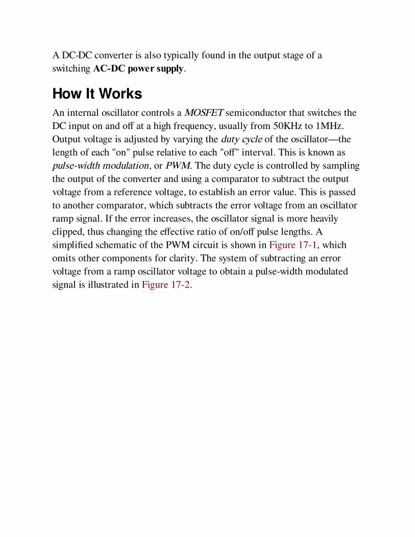
A DC-DC converter is also typically found in the output stage of a
switching AC-DC power supply.
How It WorksAn internal oscillator controls a MOSFET semiconductor that switches the
DC input on and off at a high frequency, usually from 50KHz to 1MHz.
Output voltage is adjusted by varying the duty cycle of the oscillator—the
length of each "on" pulse relative to each "off" interval. This is known as
pulse-width modulation, or PWM. The duty cycle is controlled by sampling
the output of the converter and using a comparator to subtract the output
voltage from a reference voltage, to establish an error value. This is passed
to another comparator, which subtracts the error voltage from an oscillator
ramp signal. If the error increases, the oscillator signal is more heavily
clipped, thus changing the effective ratio of on/off pulse lengths. A
simplified schematic of the PWM circuit is shown in Figure 17-1, which
omits other components for clarity. The system of subtracting an error
voltage from a ramp oscillator voltage to obtain a pulse-width modulated
signal is illustrated in Figure 17-2.
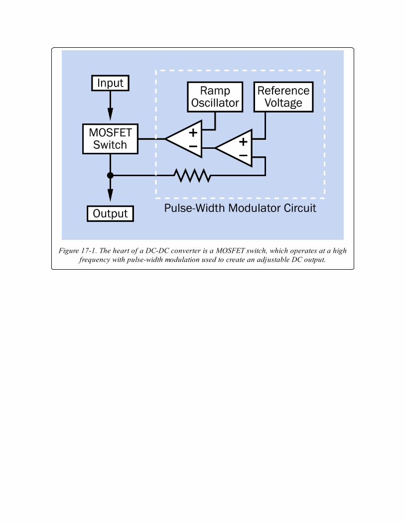
Figure 17-1. The heart of a DC-DC converter is a MOSFET switch, which operates at a highfrequency with pulse-width modulation used to create an adjustable DC output.
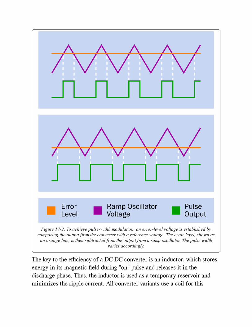
Figure 17-2. To achieve pulse-width modulation, an error-level voltage is established bycomparing the output from the converter with a reference voltage. The error level, shown as
an orange line, is then subtracted from the output from a ramp oscillator. The pulse widthvaries accordingly.
The key to the efficiency of a DC-DC converter is an inductor, which stores
energy in its magnetic field during "on" pulse and releases it in the
discharge phase. Thus, the inductor is used as a temporary reservoir and
minimizes the ripple current. All converter variants use a coil for this
purpose, although its placement varies in relation to the diode and capacitor
that complete the basic circuit.
VariantsFour basic switching circuits are used in DC-DC converters and are defined
in the coming sections, with a formula to determine the ratio between input
voltage (Vin) and output voltage (Vout) in each case. In these formulae,
variable D is the duty cycle in the pulse train generated through an internal
MOSFET switch. The duty cycle is the fraction of the total on-off cycle that
is occupied by each "on" pulse. In other words, if Ton is the duration of an
"on" pulse and Toff is the "off" time:
D = Ton / (Ton + Toff)
Buck ConverterSee Figure 17-3. The output voltage is lower than the input voltage. The
input and output share a common ground. For this circuit:
Vout = Vin * D
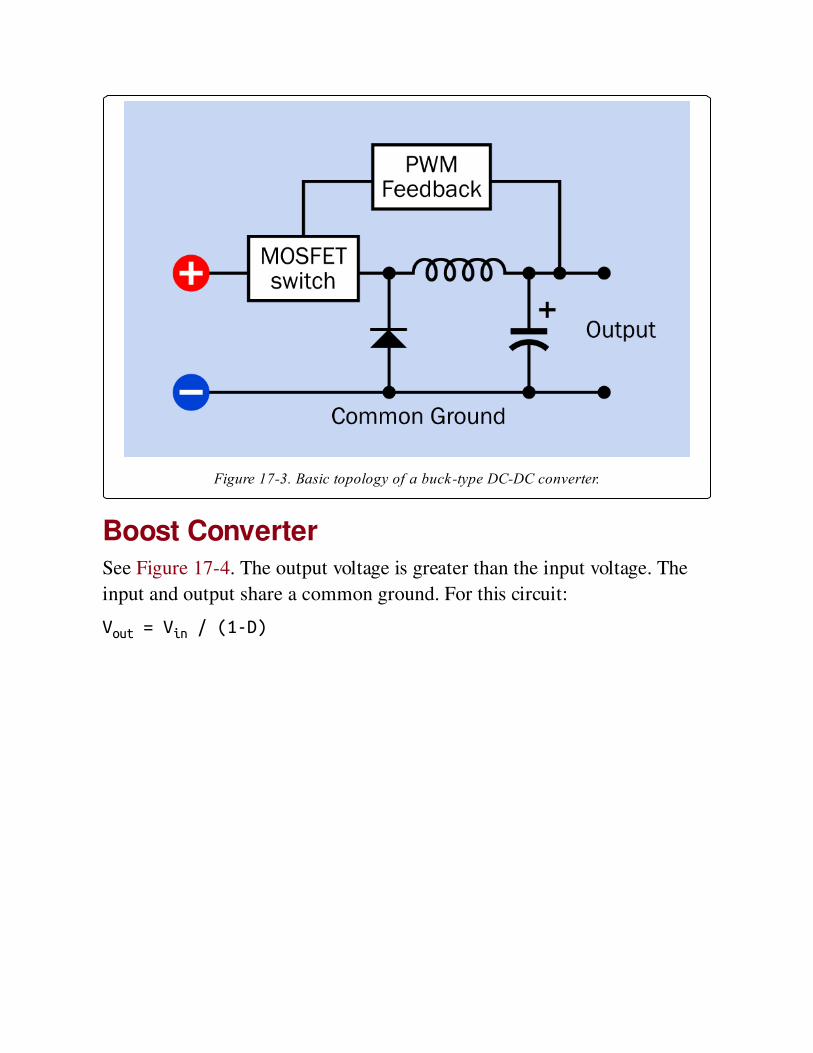
Figure 17-3. Basic topology of a buck-type DC-DC converter.
Boost ConverterSee Figure 17-4. The output voltage is greater than the input voltage. The
input and output share a common ground. For this circuit:
Vout = Vin / (1-D)
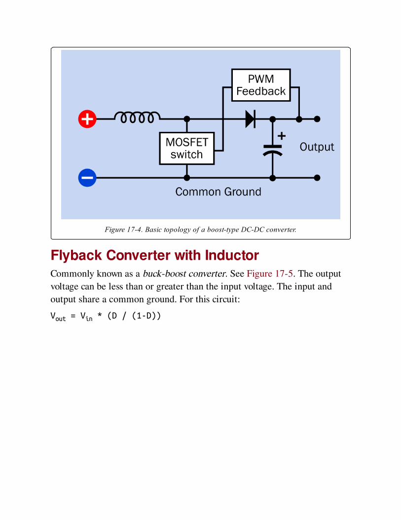
Figure 17-4. Basic topology of a boost-type DC-DC converter.
Flyback Converter with InductorCommonly known as a buck-boost converter. See Figure 17-5. The output
voltage can be less than or greater than the input voltage. The input and
output share a common ground. For this circuit:
Vout = Vin * (D / (1-D))
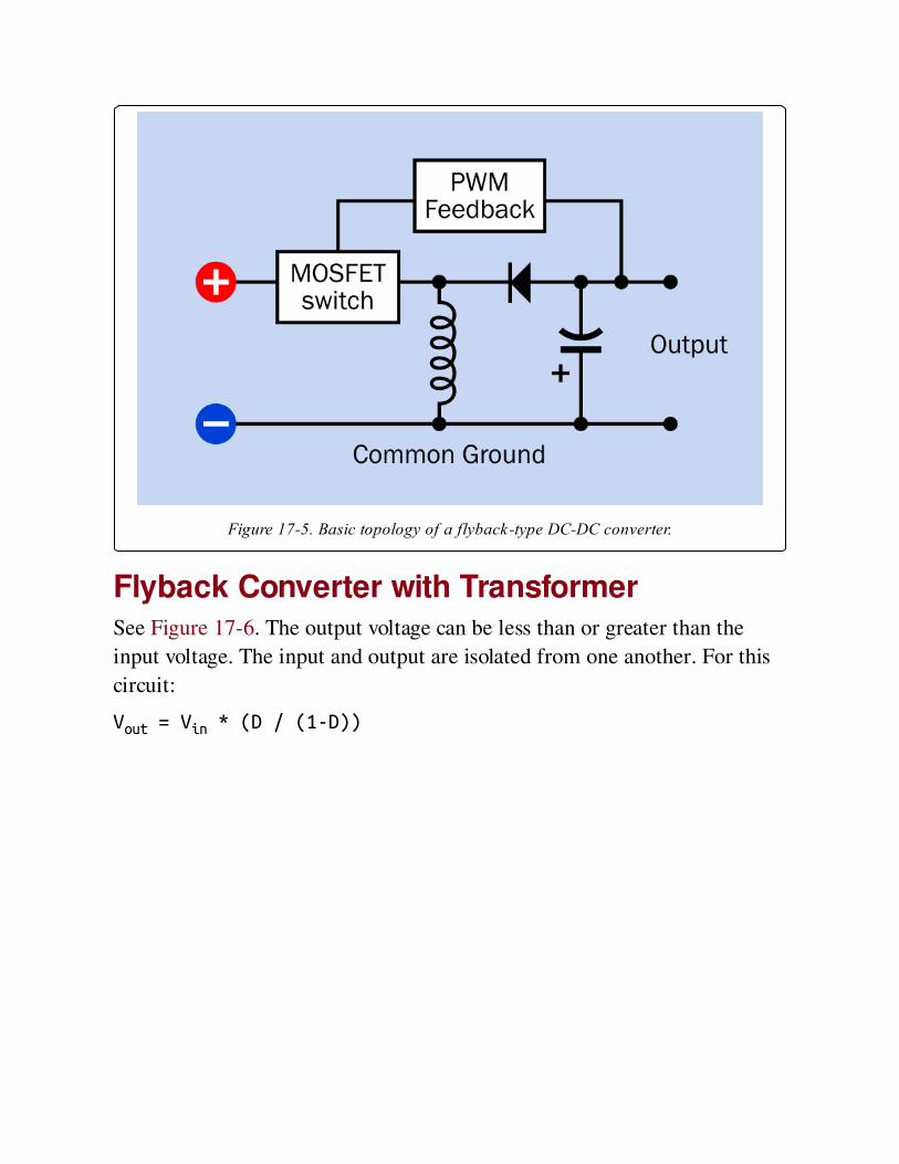
Figure 17-5. Basic topology of a flyback-type DC-DC converter.
Flyback Converter with TransformerSee Figure 17-6. The output voltage can be less than or greater than the
input voltage. The input and output are isolated from one another. For this
circuit:
Vout = Vin * (D / (1-D))
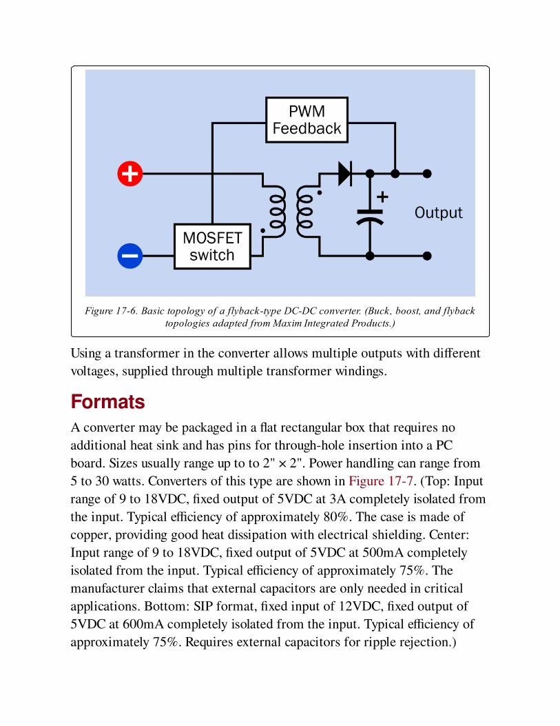
Figure 17-6. Basic topology of a flyback-type DC-DC converter. (Buck, boost, and flybacktopologies adapted from Maxim Integrated Products.)
Using a transformer in the converter allows multiple outputs with different
voltages, supplied through multiple transformer windings.
FormatsA converter may be packaged in a flat rectangular box that requires no
additional heat sink and has pins for through-hole insertion into a PC
board. Sizes usually range up to to 2" × 2". Power handling can range from
5 to 30 watts. Converters of this type are shown in Figure 17-7. (Top: Input
range of 9 to 18VDC, fixed output of 5VDC at 3A completely isolated from
the input. Typical efficiency of approximately 80%. The case is made of
copper, providing good heat dissipation with electrical shielding. Center:
Input range of 9 to 18VDC, fixed output of 5VDC at 500mA completely
isolated from the input. Typical efficiency of approximately 75%. The
manufacturer claims that external capacitors are only needed in critical
applications. Bottom: SIP format, fixed input of 12VDC, fixed output of
5VDC at 600mA completely isolated from the input. Typical efficiency of
approximately 75%. Requires external capacitors for ripple rejection.)
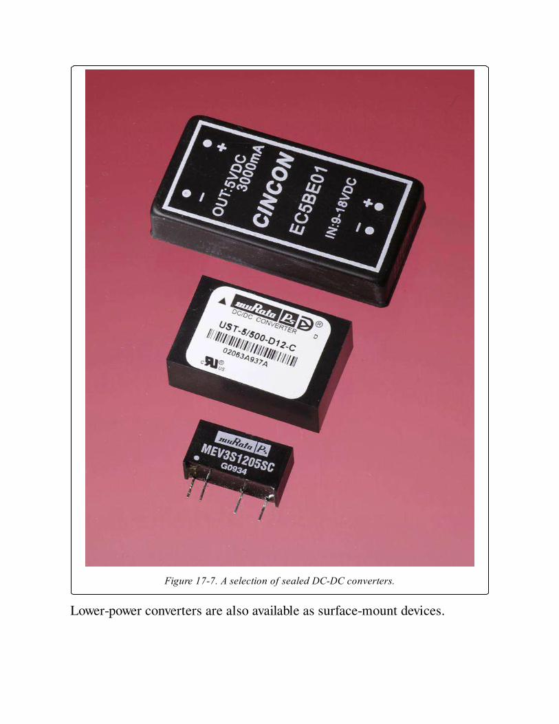
Figure 17-7. A selection of sealed DC-DC converters.
Lower-power converters are also available as surface-mount devices.
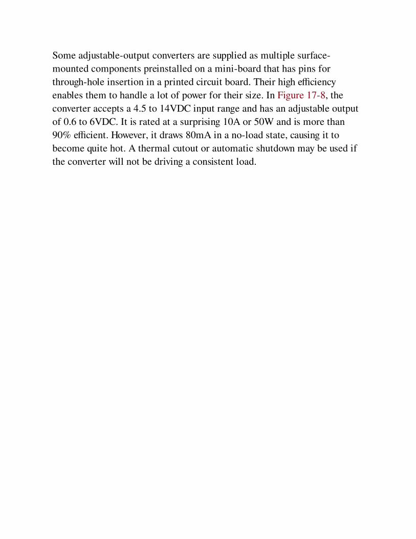
Some adjustable-output converters are supplied as multiple surface-
mounted components preinstalled on a mini-board that has pins for
through-hole insertion in a printed circuit board. Their high efficiency
enables them to handle a lot of power for their size. In Figure 17-8, the
converter accepts a 4.5 to 14VDC input range and has an adjustable output
of 0.6 to 6VDC. It is rated at a surprising 10A or 50W and is more than
90% efficient. However, it draws 80mA in a no-load state, causing it to
become quite hot. A thermal cutout or automatic shutdown may be used if
the converter will not be driving a consistent load.
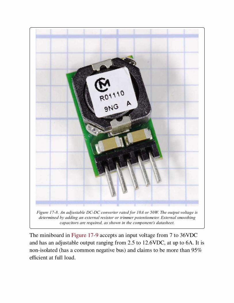
Figure 17-8. An adjustable DC-DC converter rated for 10A or 50W. The output voltage isdetermined by adding an external resistor or trimmer potentiometer. External smoothing
capacitors are required, as shown in the component’s datasheet.
The miniboard in Figure 17-9 accepts an input voltage from 7 to 36VDC
and has an adjustable output ranging from 2.5 to 12.6VDC, at up to 6A. It is
non-isolated (has a common negative bus) and claims to be more than 95%
efficient at full load.
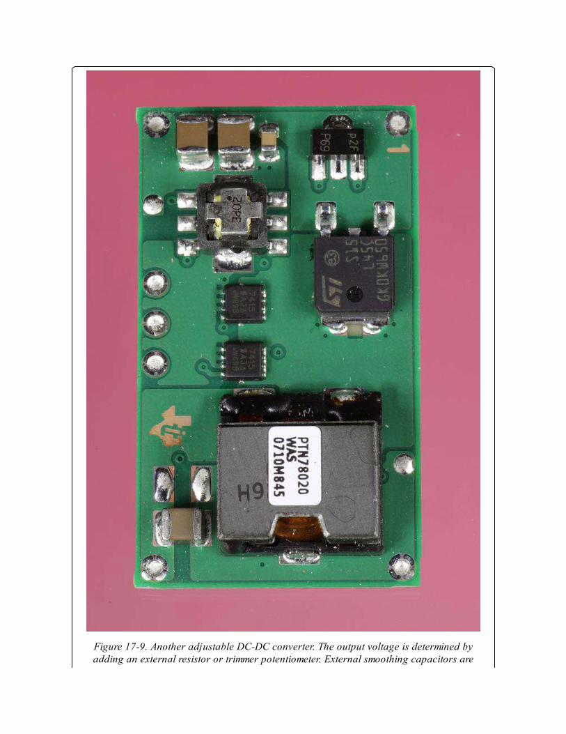
Figure 17-9. Another adjustable DC-DC converter. The output voltage is determined byadding an external resistor or trimmer potentiometer. External smoothing capacitors are

required, as shown in the component’s datasheet.
The miniboard in Figure 17-10 accepts an input voltage from 4.5 to 14VDC
and has an adjustable output ranging from 0.6 to 6VDC at up to 20A. It is
non-isolated (has a common negative bus) and claims to be more than 90%
efficient at full load.
Figure 17-10. Another adjustable DC-DC converter. The output voltage is determined byadding an external resistor or trimmer potentiometer. External smoothing capacitors are
required, as shown in the component’s datasheet.
ValuesRelevant values include:
Nominal Input Voltage and FrequencyA wide range of input voltages is often acceptable, as the PWM can vary
accordingly. Converters often allow equipment to be usable internationally,
on any voltage ranging from 100VAC to 250VAC, at a fequency of 50Hz or
60Hz, without any adaptation.
Output VoltageAs previously noted, many converters allow the output voltage to be
adjusted by adding an external resistor or potentiometer. Alternatively,
there may be multiple fixed output voltages, accessible via different pins on
the package. They may also provide a positive voltage and equally opposite
negative voltage relative to a ground pin.
Input Current and Output CurrentBecause input voltage and output voltage are likely to be different, the
current alone is not a reliable guide to power handling.
A datasheet should specify input current with no load (open circuit on the
output side). This current will have to be entirely dissipated as heat.
Load RegulationThis is usually expressed as a percentage and suggests the extent to which
output voltage may be pulled down when the load on a DC-DC converter
increases. If Vnil is the measured output voltage with no load, and Vmax is
the measured output voltage with the maximum rated load:
Load regulation = 100 * (Vnil - Vmax)/Vmax
However, note that some converters are designed with the expectation that
they will never be used with zero load across the output. In these cases, Vnil
will be the voltage at minimum rated load.
EfficiencyThis is a measure of how much input current must be dissipated as heat. A
converter with a 12-volt input, drawing a maximum 300mA input current,
will consume 3.6 watts (3,600mW). If it is 80% efficient, it will have to
dissipate roughly 20% of its power as heat, or 720mW.
Ripple and Noise
Sometimes abbreviated R/N, this may be measured in mV or as a
percentage. Check the specification carefully to determine whether the
ripple-and-noise values require use of external smoothing capacitors. Often,
this is the case.
Isolated or Non-IsolatedThis crucial piece of information is often found near the top of a datasheet,
not in the detailed specifications.
How to Use itBecause a converter creates electrical noise, it should be prevented from
affecting other components by adding substantial bypass capacitors as close
as possible to its input and output pins. For most converters, external
capacitors are mandatory, and their effective series resistance (ESR) should
be as low as possible (see the capacitor entry in this encyclopedia for an
explanation of ESR). Tantalum capacitors are preferable to electrolytics for
this reason, and are also more durable. Some manufacturers recommend
placing a tantalum capacitor in parallel with an electrolytic. A small
ceramic capacitor, typically 0.1μF, is often recommended in an addition to
larger-value capacitors on the output side.
The voltage rating of each capacitor should be twice the voltage at the point
in the circuit where it is used. The capacitance value will usually be higher
for higher-current converters. Values of 100μF are common, but for high
amperage, a value may be as high as 1,000μF.
While datasheets are often inadequate for some types of components,
datasheets for DC-DC converters usually include detailed instructions
regarding bypass capacitors. Following these instructions is essential. In the
relatively rare instances that a datasheet makes no mention of bypass
capacitors for a converter, this does not necessarily mean that the capacitors
are unnecessary. The manufacturer may assume that they will be used as a
matter of course.

Converters are used in a very wide range of devices, supplying power
ranging from a few milliamps to tens of amps. At the lower end of the scale,
devices such as cellular telephones, portable computers, and tablets contain
sub-circuits that require different voltages, some of which may be higher
than the voltage of a single battery or battery pack that powers the device. A
converter can satisfy this requirement. Because a converter can be designed
to maintain a fixed output in response to a range of input voltages, it can
also compensate for the gradual decline in voltage that occurs during
battery usage.
A boost-type converter can be used to double the voltage from a single 1.5V
battery in an LED flashlight where 3 volts are required to power the LED.
Similarly, a boost-type converter can provide the necessary voltage to run a
cold-cathode fluorescent tube that provides backlighting in an LCD
computer display.
On a circuit board that is primarily populated with 5VDC components and
is fed by a single 5VDC power supply, a converter can be used to supply
12VDC for one special purpose, such as an analog-digital converter or a
serial data connection.
If electromechanical relays or other inductive loads share a common
ground with components ,such as logic chips or microcontrollers, it may be
difficult to protect the sensitive components from voltage spikes. A A
flyback converter with a transformer separating the output from the input
can allow the "noisy" section of the circuit to be segregated, so long as the
converter itself does not introduce noise. Since the electromagnetic
interference (EMI) introduced by converters varies widely from one model
to another, specifications should be checked carefully.
Very low-power components can pick up EMI from the wires or traces
leading into and out of a converter. In this type of circuit, adequate noise
suppression may be impossible, and a converter may not be appropriate.
What Can Go Wrong
Electrical Noise in OutputElectrolytic capacitors may be inadequate to smooth the high frequencies
used. Multilayer ceramic capacitors or tantalum capacitors may be
necessary. Check the manufacturer’s datasheet for minimum and maximum
values. Also check the datasheet for advice regarding placement of
capacitors on the input side as well as across the output.
Excess Heat with No LoadSome converters generate substantial heat while they are powered without a
load. The manufacturer’s datasheet may not discuss this potential problem
very prominently or in any detail. Check the input rating, usually expressed
in mA, specified for a no-load condition. All of this current will have to be
dissipated as heat, and the very small size of many converters can result in
high localized temperatures, especially since many of them allow no
provision for a heat sink.
Inaccurate Voltage Output with Low LoadSome converters are designed to operate with at least 10% of full rated load
across their output at all times. Below this threshold, output voltage can be
grossly inaccurate. Read datasheets carefully for statements such as this:
“Lower than 10% loading will result in an increase in output voltage, which
may rise to typically double the specified output voltage if the output load
falls to less than 5%.” Always use a meter to verify the output voltage from
a converter at a variety of different loads, and perform this test before
installing the converter in a circuit.
Chapter 18. DC-AC inverter
power > conversion > DC-AC inverter
A power inverter must not be confused with a logic inverter, which functions as a digital
component in logic circuits to invert the state of a low-voltage DC input from high to low or
low to high. Logic inverters are discussed in Volume 2.
Other related components
AC-DC power supply (See Chapter 16)
DC-DC converter (See Chapter 17)
What It DoesA power inverter is included here as counterpoint to a power supply or AC
adapter, since it has the opposite function. The inverter receives an input of
direct current (typically 12VDC from a car battery) and delivers an output
of alternating current (AC) in the range 110VAC-120VAC or 220VAC-
240VAC, suitable to power many low-wattage appliances and devices. The
interior of a low-cost inverter is shown in Figure 18-1.
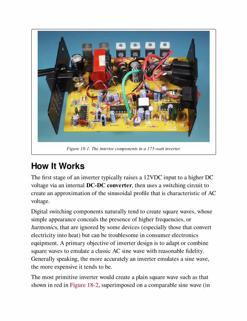
Figure 18-1. The interior components in a 175-watt inverter.
How It WorksThe first stage of an inverter typically raises a 12VDC input to a higher DC
voltage via an internal DC-DC converter, then uses a switching circuit to
create an approximation of the sinusoidal profile that is characteristic of AC
voltage.
Digital switching components naturally tend to create square waves, whose
simple appearance conceals the presence of higher frequencies, or
harmonics, that are ignored by some devices (especially those that convert
electricity into heat) but can be troublesome in consumer electronics
equipment. A primary objective of inverter design is to adapt or combine
square waves to emulate a classic AC sine wave with reasonable fidelity.
Generally speaking, the more accurately an inverter emulates a sine wave,
the more expensive it tends to be.
The most primitive inverter would create a plain square wave such as that
shown in red in Figure 18-2, superimposed on a comparable sine wave (in
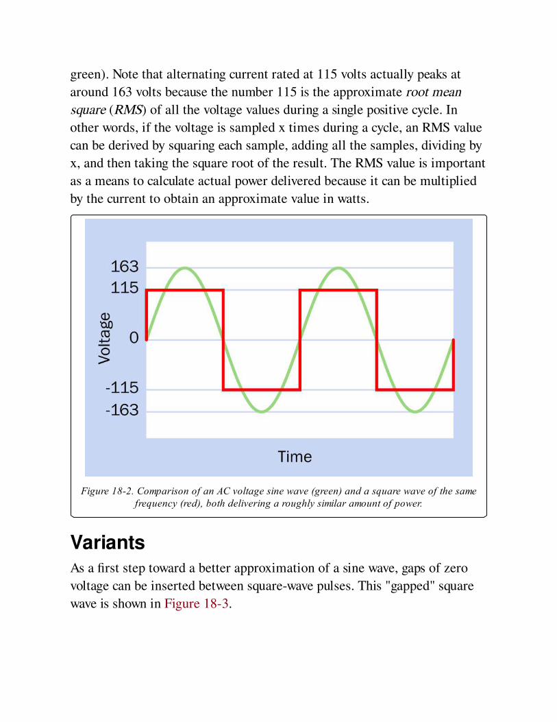
green). Note that alternating current rated at 115 volts actually peaks at
around 163 volts because the number 115 is the approximate root mean
square (RMS) of all the voltage values during a single positive cycle. In
other words, if the voltage is sampled x times during a cycle, an RMS value
can be derived by squaring each sample, adding all the samples, dividing by
x, and then taking the square root of the result. The RMS value is important
as a means to calculate actual power delivered because it can be multiplied
by the current to obtain an approximate value in watts.
Figure 18-2. Comparison of an AC voltage sine wave (green) and a square wave of the samefrequency (red), both delivering a roughly similar amount of power.
VariantsAs a first step toward a better approximation of a sine wave, gaps of zero
voltage can be inserted between square-wave pulses. This "gapped" square
wave is shown in Figure 18-3.
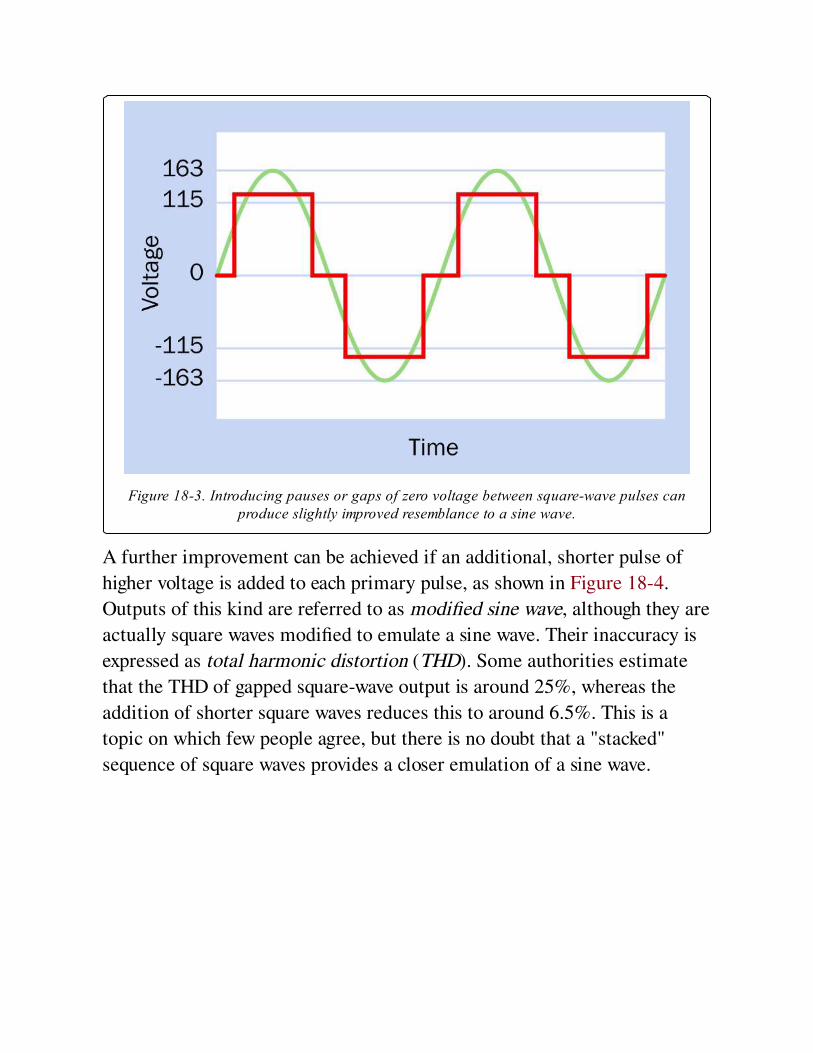
Figure 18-3. Introducing pauses or gaps of zero voltage between square-wave pulses canproduce slightly improved resemblance to a sine wave.
A further improvement can be achieved if an additional, shorter pulse of
higher voltage is added to each primary pulse, as shown in Figure 18-4.
Outputs of this kind are referred to as modified sine wave, although they are
actually square waves modified to emulate a sine wave. Their inaccuracy is
expressed as total harmonic distortion (THD). Some authorities estimate
that the THD of gapped square-wave output is around 25%, whereas the
addition of shorter square waves reduces this to around 6.5%. This is a
topic on which few people agree, but there is no doubt that a "stacked"
sequence of square waves provides a closer emulation of a sine wave.
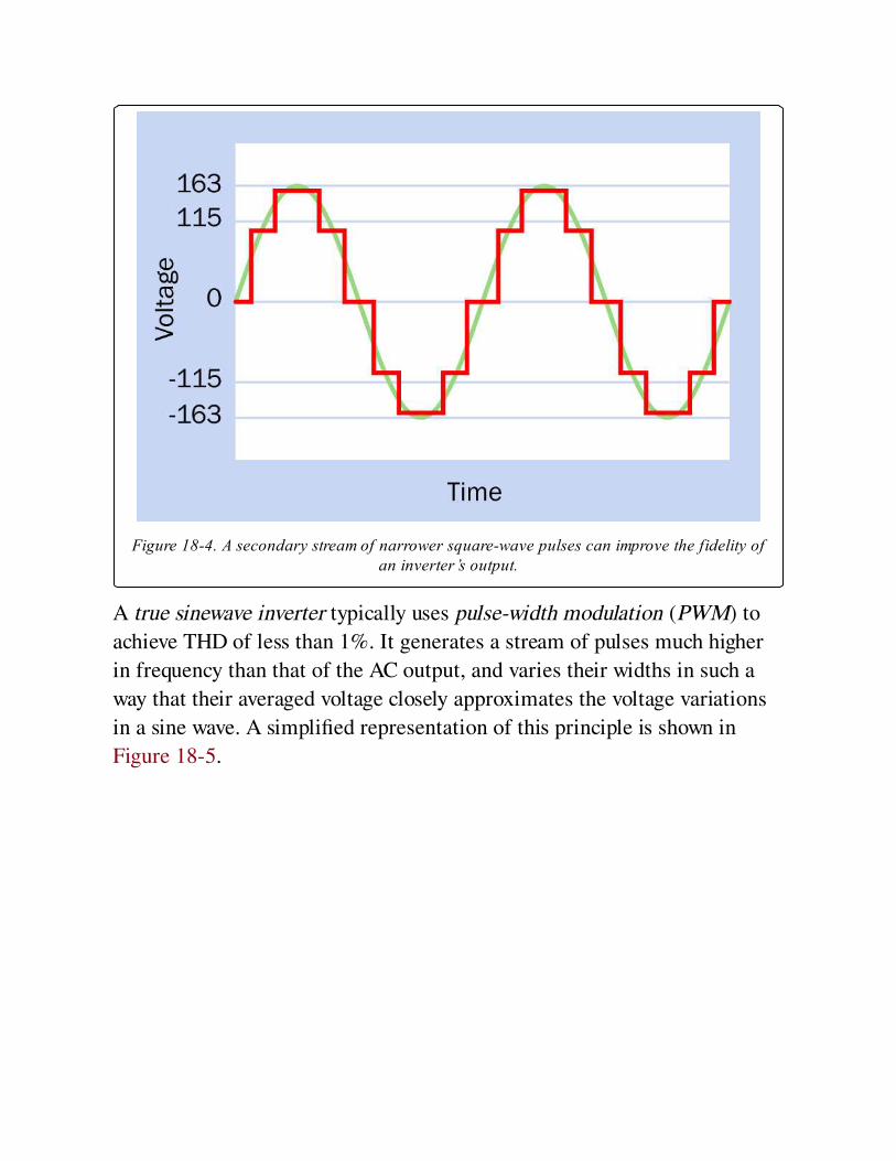
Figure 18-4. A secondary stream of narrower square-wave pulses can improve the fidelity ofan inverter’s output.
A true sinewave inverter typically uses pulse-width modulation (PWM) to
achieve THD of less than 1%. It generates a stream of pulses much higher
in frequency than that of the AC output, and varies their widths in such a
way that their averaged voltage closely approximates the voltage variations
in a sine wave. A simplified representation of this principle is shown in
Figure 18-5.
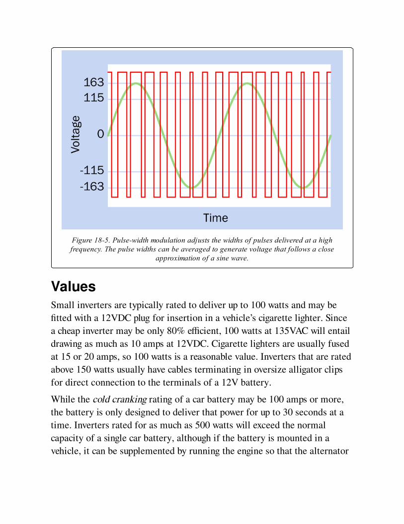
Figure 18-5. Pulse-width modulation adjusts the widths of pulses delivered at a highfrequency. The pulse widths can be averaged to generate voltage that follows a close
approximation of a sine wave.
ValuesSmall inverters are typically rated to deliver up to 100 watts and may be
fitted with a 12VDC plug for insertion in a vehicle’s cigarette lighter. Since
a cheap inverter may be only 80% efficient, 100 watts at 135VAC will entail
drawing as much as 10 amps at 12VDC. Cigarette lighters are usually fused
at 15 or 20 amps, so 100 watts is a reasonable value. Inverters that are rated
above 150 watts usually have cables terminating in oversize alligator clips
for direct connection to the terminals of a 12V battery.
While the cold cranking rating of a car battery may be 100 amps or more,
the battery is only designed to deliver that power for up to 30 seconds at a
time. Inverters rated for as much as 500 watts will exceed the normal
capacity of a single car battery, although if the battery is mounted in a
vehicle, it can be supplemented by running the engine so that the alternator
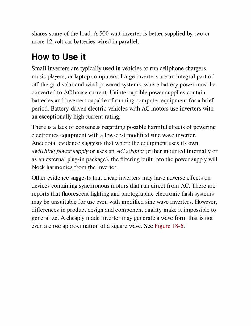
shares some of the load. A 500-watt inverter is better supplied by two or
more 12-volt car batteries wired in parallel.
How to Use itSmall inverters are typically used in vehicles to run cellphone chargers,
music players, or laptop computers. Large inverters are an integral part of
off-the-grid solar and wind-powered systems, where battery power must be
converted to AC house current. Uninterruptible power supplies contain
batteries and inverters capable of running computer equipment for a brief
period. Battery-driven electric vehicles with AC motors use inverters with
an exceptionally high current rating.
There is a lack of consensus regarding possible harmful effects of powering
electronics equipment with a low-cost modified sine wave inverter.
Anecdotal evidence suggests that where the equipment uses its own
switching power supply or uses an AC adapter (either mounted internally or
as an external plug-in package), the filtering built into the power supply will
block harmonics from the inverter.
Other evidence suggests that cheap inverters may have adverse effects on
devices containing synchronous motors that run direct from AC. There are
reports that fluorescent lighting and photographic electronic flash systems
may be unsuitable for use even with modified sine wave inverters. However,
differences in product design and component quality make it impossible to
generalize. A cheaply made inverter may generate a wave form that is not
even a close approximation of a square wave. See Figure 18-6.
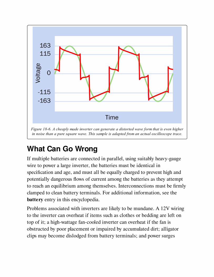
Figure 18-6. A cheaply made inverter can generate a distorted wave form that is even higherin noise than a pure square wave. This sample is adapted from an actual oscilloscope trace.
What Can Go WrongIf multiple batteries are connected in parallel, using suitably heavy-gauge
wire to power a large inverter, the batteries must be identical in
specification and age, and must all be equally charged to prevent high and
potentially dangerous flows of current among the batteries as they attempt
to reach an equilibrium among themselves. Interconnections must be firmly
clamped to clean battery terminals. For additional information, see the
battery entry in this encyclopedia.
Problems associated with inverters are likely to be mundane. A 12V wiring
to the inverter can overheat if items such as clothes or bedding are left on
top of it; a high-wattage fan-cooled inverter can overheat if the fan is
obstructed by poor placement or impaired by accumulated dirt; alligator
clips may become dislodged from battery terminals; and power surges

drawn by inductive loads such as motors may trigger the inverter’s breaker,
especially if they are used in conjunction with other equipment.
As always, high amperage should be treated with caution and respect,
regardless of it being delivered at "only 12 volts."
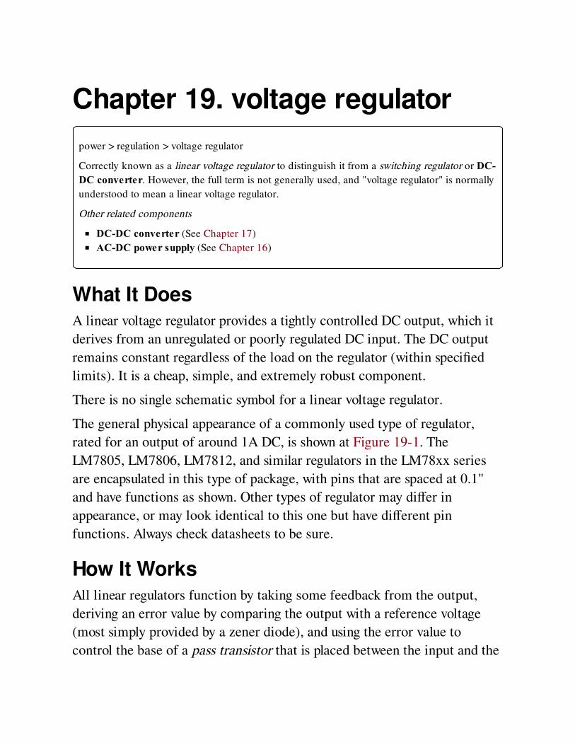
Chapter 19. voltage regulator
power > regulation > voltage regulator
Correctly known as a linear voltage regulator to distinguish it from a switching regulator or DC-DC converter. However, the full term is not generally used, and "voltage regulator" is normally
understood to mean a linear voltage regulator.
Other related components
DC-DC converter (See Chapter 17)
AC-DC power supply (See Chapter 16)
What It DoesA linear voltage regulator provides a tightly controlled DC output, which it
derives from an unregulated or poorly regulated DC input. The DC output
remains constant regardless of the load on the regulator (within specified
limits). It is a cheap, simple, and extremely robust component.
There is no single schematic symbol for a linear voltage regulator.
The general physical appearance of a commonly used type of regulator,
rated for an output of around 1A DC, is shown at Figure 19-1. The
LM7805, LM7806, LM7812, and similar regulators in the LM78xx series
are encapsulated in this type of package, with pins that are spaced at 0.1"
and have functions as shown. Other types of regulator may differ in
appearance, or may look identical to this one but have different pin
functions. Always check datasheets to be sure.
How It WorksAll linear regulators function by taking some feedback from the output,
deriving an error value by comparing the output with a reference voltage
(most simply provided by a zener diode), and using the error value to
control the base of a pass transistor that is placed between the input and the
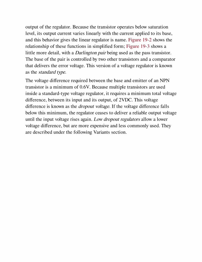
output of the regulator. Because the transistor operates below saturation
level, its output current varies linearly with the current applied to its base,
and this behavior gives the linear regulator is name. Figure 19-2 shows the
relationship of these functions in simplified form; Figure 19-3 shows a
little more detail, with a Darlington pair being used as the pass transistor.
The base of the pair is controlled by two other transistors and a comparator
that delivers the error voltage. This version of a voltage regulator is known
as the standard type.
The voltage difference required between the base and emitter of an NPN
transistor is a minimum of 0.6V. Because multiple transistors are used
inside a standard-type voltage regulator, it requires a minimum total voltage
difference, between its input and its output, of 2VDC. This voltage
difference is known as the dropout voltage. If the voltage difference falls
below this minimum, the regulator ceases to deliver a reliable output voltage
until the input voltage rises again. Low dropout regulators allow a lower
voltage difference, but are more expensive and less commonly used. They
are described under the following Variants section.
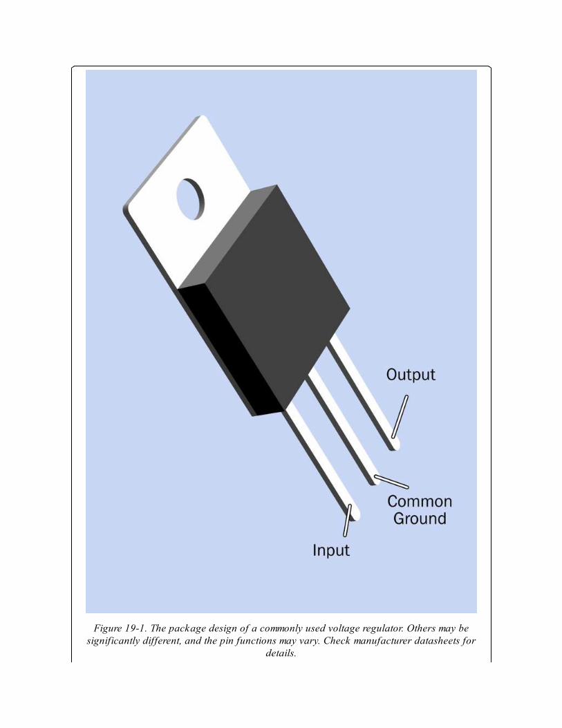
Figure 19-1. The package design of a commonly used voltage regulator. Others may besignificantly different, and the pin functions may vary. Check manufacturer datasheets for
details.
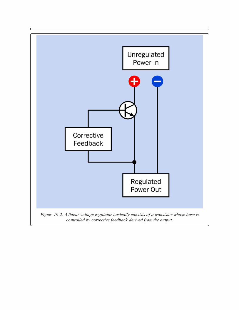
Figure 19-2. A linear voltage regulator basically consists of a transistor whose base iscontrolled by corrective feedback derived from the output.

Figure 19-3. The fundamental internal features of a standard-type voltage regulator,including a Darlington pair, two transistors, a voltage divider, comparator, and reference
voltage source, shown inside the dashed white line.
Discrete components could in theory be used to build a voltage regulator,
but this ceased to be cost-effective several decades ago. The term is now
understood to mean one small integrated package containing the basic
circuit augmented with additional, desirable features, such as automatic
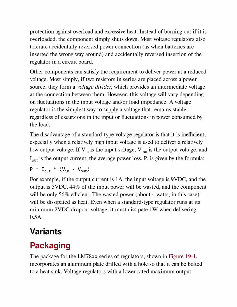
protection against overload and excessive heat. Instead of burning out if it is
overloaded, the component simply shuts down. Most voltage regulators also
tolerate accidentally reversed power connection (as when batteries are
inserted the wrong way around) and accidentally reversed insertion of the
regulator in a circuit board.
Other components can satisfy the requirement to deliver power at a reduced
voltage. Most simply, if two resistors in series are placed across a power
source, they form a voltage divider, which provides an intermediate voltage
at the connection between them. However, this voltage will vary depending
on fluctuations in the input voltage and/or load impedance. A voltage
regulator is the simplest way to supply a voltage that remains stable
regardless of excursions in the input or fluctuations in power consumed by
the load.
The disadvantage of a standard-type voltage regulator is that it is inefficient,
especially when a relatively high input voltage is used to deliver a relatively
low output voltage. If Vin is the input voltage, Vout is the output voltage, and
Iout is the output current, the average power loss, P, is given by the formula:
P = Iout * (Vin - Vout)
For example, if the output current is 1A, the input voltage is 9VDC, and the
output is 5VDC, 44% of the input power will be wasted, and the component
will be only 56% efficient. The wasted power (about 4 watts, in this case)
will be dissipated as heat. Even when a standard-type regulator runs at its
minimum 2VDC dropout voltage, it must dissipate 1W when delivering
0.5A.
Variants
PackagingThe package for the LM78xx series of regulators, shown in Figure 19-1,
incorporates an aluminum plate drilled with a hole so that it can be bolted
to a heat sink. Voltage regulators with a lower rated maximum output
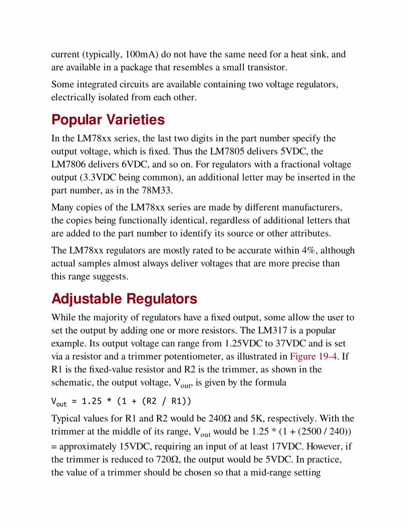
current (typically, 100mA) do not have the same need for a heat sink, and
are available in a package that resembles a small transistor.
Some integrated circuits are available containing two voltage regulators,
electrically isolated from each other.
Popular VarietiesIn the LM78xx series, the last two digits in the part number specify the
output voltage, which is fixed. Thus the LM7805 delivers 5VDC, the
LM7806 delivers 6VDC, and so on. For regulators with a fractional voltage
output (3.3VDC being common), an additional letter may be inserted in the
part number, as in the 78M33.
Many copies of the LM78xx series are made by different manufacturers,
the copies being functionally identical, regardless of additional letters that
are added to the part number to identify its source or other attributes.
The LM78xx regulators are mostly rated to be accurate within 4%, although
actual samples almost always deliver voltages that are more precise than
this range suggests.
Adjustable RegulatorsWhile the majority of regulators have a fixed output, some allow the user to
set the output by adding one or more resistors. The LM317 is a popular
example. Its output voltage can range from 1.25VDC to 37VDC and is set
via a resistor and a trimmer potentiometer, as illustrated in Figure 19-4. If
R1 is the fixed-value resistor and R2 is the trimmer, as shown in the
schematic, the output voltage, Vout, is given by the formula
Vout = 1.25 * (1 + (R2 / R1))
Typical values for R1 and R2 would be 240Ω and 5K, respectively. With the
trimmer at the middle of its range, Vout would be 1.25 * (1 + (2500 / 240))
= approximately 15VDC, requiring an input of at least 17VDC. However, if
the trimmer is reduced to 720Ω, the output would be 5VDC. In practice,
the value of a trimmer should be chosen so that a mid-range setting
provides approximately the desired output. This will enable fine adjustment
of the output voltage.
While the versatility of an adjustable regulator is desirable, its overall
power dissipation is still proportional to the difference between the input
voltage and the output voltage. To minimize heat loss, this difference should
not exceed the dropout voltage by a larger amount than is absolutely
necessary.
An adjustable regulator may require larger bypass capacitors than a
regulator with a fixed output. A manufacturer’s recommendations for the
LM317 are shown in Figure 19-4.
Negative and Positive RegulatorsWhile most linear voltage regulators are designed for "positive input"
(conventional current flow from input to output), some are intended for
"negative input." In this variant, the common terminal is positive, and the
input and output are negative in relation to it.
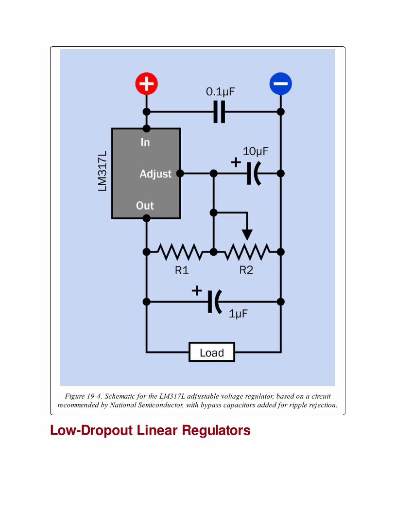
Figure 19-4. Schematic for the LM317L adjustable voltage regulator, based on a circuitrecommended by National Semiconductor, with bypass capacitors added for ripple rejection.
Low-Dropout Linear Regulators
Low-dropout regulators (sometimes referred to as LDO regulators) allow a
much lower dropout voltage by using a single PNP or MOSFET transistor.
LDO regulators are popularly used in battery-powered devices where
efficiency should be maximized and heat dissipation should be minimized.
For example, the LM330 is a regulator with a 5VDC output, tolerating a
dropout voltage of 0.6V, allowing it to be used with four AAA cells. In an
LDO regulator the dropout voltage actually varies with load current and
may diminish to as little as one-tenth of its rated value when the output
current is minimal.
The majority of low-dropout regulators are sold in surface-mount packages,
and are designed for maximum output of 100mA to 500mA. Only a few
exceptions exist. They tend to be slightly more expensive than regulators
with the typical 2V dropout rating.
Three voltage regulators are shown in Figure 19-5. From left to right, they
are rated 5VDC at 1A, 12VDC at 1A, and 5VDC at 7.5A. The two smaller
regulators are of the LM78xx series. The larger regulator claims a low
maximum dropout voltage of 1.5VDC, and its output voltage can be
adjusted with an external potentiometer and resistor.
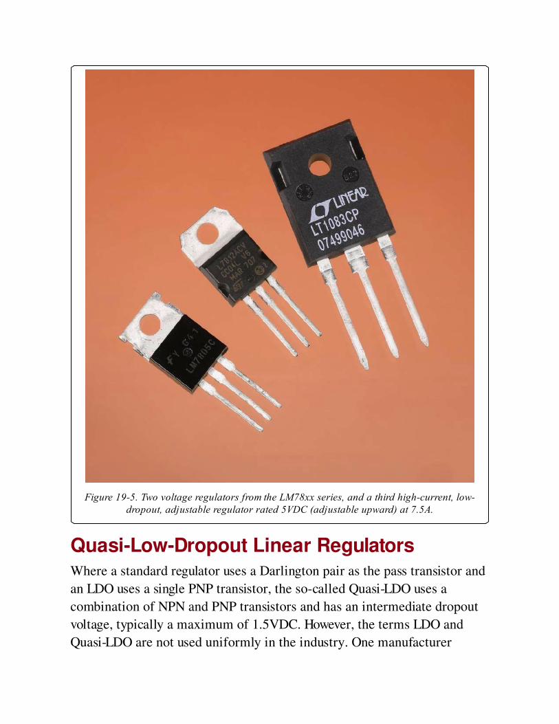
Figure 19-5. Two voltage regulators from the LM78xx series, and a third high-current, low-dropout, adjustable regulator rated 5VDC (adjustable upward) at 7.5A.
Quasi-Low-Dropout Linear RegulatorsWhere a standard regulator uses a Darlington pair as the pass transistor and
an LDO uses a single PNP transistor, the so-called Quasi-LDO uses a
combination of NPN and PNP transistors and has an intermediate dropout
voltage, typically a maximum of 1.5VDC. However, the terms LDO and
Quasi-LDO are not used uniformly in the industry. One manufacturer
markets Quasi-LDO regulators as LDO regulators, and describes its LDO
regulators as Very Low Dropout regulators. Consult datasheets to determine
the actual specification of the product, regardless of its classification.
Additional Pin FunctionsSome voltage regulators include an extra pin, typically known as an enable
pin, which switches off the device in response to a signal from a
microcontroller or logic gate.
Some regulators offer another option, an additional status pin that can
signal a microcontroller that an error mode exists if the regulator output
falls significantly below its rated value.
In battery-powered devices, a low-battery sensor is a desirable feature,
since a regulator may simply shut down without warning if the input voltage
is insufficient. A few regulators, such as the LP2953, provide a low-battery
warning output via an extra pin.
ValuesLinear voltage regulators with a single, fixed output are commonly available
to supply DC outputs of 3.3, 5, 6, 8, 9, 10, 12, 15, 18, and 24 volts, with a
few variants offering fractional values in between. The most commonly
used values are 5, 6, 9, 12, and 15 volts. The input voltage may be as high as
35VDC.
Maximum output current is typically 1A or 1.5A, in the traditional three-
pin, through-hole, TO-220 format. A surface-mount version is available.
Other surface-mount formats have lower power limits.
Accuracy may be expressed as a percentage or as a figure for load
regulation in mV. A typical load regulation value would be 50mV, while
voltage regulation accuracy ranges from 1% to 4%, depending on the
manufacturer and the component. While low-dropout regulators are
generally more efficient, they do require more ground-pin current. This is
not usually a significant factor.
How to Use itSome components, such as many old-design CMOS chips or the traditional
TTL version of the 555 timer, allow a wide range of acceptable input
voltages, but most modern logic chips and microcontrollers must have a
properly controlled power supply. Regulators such as the LM7805 are
traditionally used to provide this, especially in small and relatively simple
devices that draw a moderate amount of current, have a low component
count, and are powered via a battery or an AC adapter. A fully fledged
switching power supply is overkill in this kind of application.
A linear voltage regulator cannot respond instantly to changes in input
voltage. Therefore, if the input supply contains voltage spikes, these spikes
may pass through the regulator. Bypass capacitors should be applied
preventively. A sample schematic showing an LM7805 regulator with bypass
capacitors recommended by a manufacturer is shown in Figure 19-6.
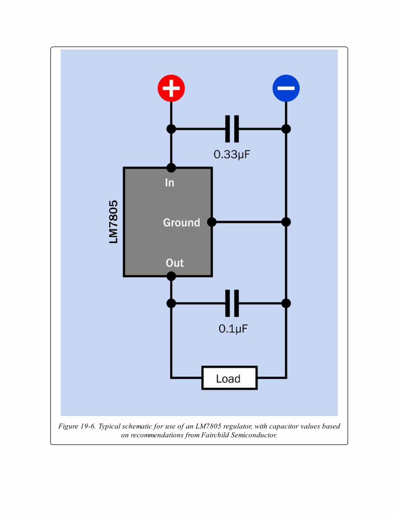
Figure 19-6. Typical schematic for use of an LM7805 regulator, with capacitor values basedon recommendations from Fairchild Semiconductor.
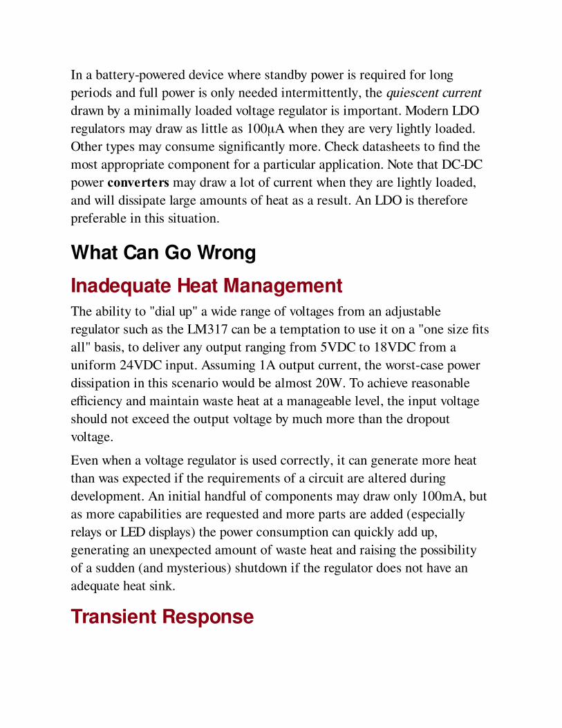
In a battery-powered device where standby power is required for long
periods and full power is only needed intermittently, the quiescent current
drawn by a minimally loaded voltage regulator is important. Modern LDO
regulators may draw as little as 100μA when they are very lightly loaded.
Other types may consume significantly more. Check datasheets to find the
most appropriate component for a particular application. Note that DC-DC
power converters may draw a lot of current when they are lightly loaded,
and will dissipate large amounts of heat as a result. An LDO is therefore
preferable in this situation.
What Can Go Wrong
Inadequate Heat ManagementThe ability to "dial up" a wide range of voltages from an adjustable
regulator such as the LM317 can be a temptation to use it on a "one size fits
all" basis, to deliver any output ranging from 5VDC to 18VDC from a
uniform 24VDC input. Assuming 1A output current, the worst-case power
dissipation in this scenario would be almost 20W. To achieve reasonable
efficiency and maintain waste heat at a manageable level, the input voltage
should not exceed the output voltage by much more than the dropout
voltage.
Even when a voltage regulator is used correctly, it can generate more heat
than was expected if the requirements of a circuit are altered during
development. An initial handful of components may draw only 100mA, but
as more capabilities are requested and more parts are added (especially
relays or LED displays) the power consumption can quickly add up,
generating an unexpected amount of waste heat and raising the possibility
of a sudden (and mysterious) shutdown if the regulator does not have an
adequate heat sink.
Transient Response
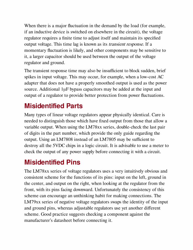
When there is a major fluctuation in the demand by the load (for example,
if an inductive device is switched on elsewhere in the circuit), the voltage
regulator requires a finite time to adjust itself and maintain its specified
output voltage. This time lag is known as its transient response. If a
momentary fluctuation is likely, and other components may be sensitive to
it, a larger capacitor should be used between the output of the voltage
regulator and ground.
The transient response time may also be insufficient to block sudden, brief
spikes in input voltage. This may occur, for example, when a low-cost AC
adapter that does not have a properly smoothed output is used as the power
source. Additional 1μF bypass capacitors may be added at the input and
output of a regulator to provide better protection from power fluctuations.
Misidentified PartsMany types of linear voltage regulators appear physically identical. Care is
needed to distinguish those which have fixed output from those that allow a
variable output. When using the LM78xx series, double-check the last pair
of digits in the part number, which provide the only guide regarding the
output. Using an LM7808 instead of an LM7805 may be sufficient to
destroy all the 5VDC chips in a logic circuit. It is advisable to use a meter to
check the output of any power supply before connecting it with a circuit.
Misidentified PinsThe LM78xx series of voltage regulators uses a very intuitively obvious and
consistent scheme for the functions of its pins: input on the left, ground in
the center, and output on the right, when looking at the regulator from the
front, with its pins facing downward. Unfortunately the consistency of this
scheme can encourage an unthinking habit for making connections. The
LM79xx series of negative voltage regulators swaps the identity of the input
and ground pins, whereas adjustable regulators use yet another different
scheme. Good practice suggests checking a component against the
manufacturer’s datasheet before connecting it.
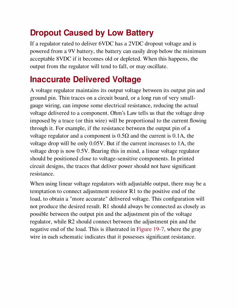
Dropout Caused by Low BatteryIf a regulator rated to deliver 6VDC has a 2VDC dropout voltage and is
powered from a 9V battery, the battery can easily drop below the minimum
acceptable 8VDC if it becomes old or depleted. When this happens, the
output from the regulator will tend to fall, or may oscillate.
Inaccurate Delivered VoltageA voltage regulator maintains its output voltage between its output pin and
ground pin. Thin traces on a circuit board, or a long run of very small-
gauge wiring, can impose some electrical resistance, reducing the actual
voltage delivered to a component. Ohm’s Law tells us that the voltage drop
imposed by a trace (or thin wire) will be proportional to the current flowing
through it. For example, if the resistance between the output pin of a
voltage regulator and a component is 0.5Ω and the current is 0.1A, the
voltage drop will be only 0.05V. But if the current increases to 1A, the
voltage drop is now 0.5V. Bearing this in mind, a linear voltage regulator
should be positioned close to voltage-sensitive components. In printed
circuit designs, the traces that deliver power should not have significant
resistance.
When using linear voltage regulators with adjustable output, there may be a
temptation to connect adjustment resistor R1 to the positive end of the
load, to obtain a "more accurate" delivered voltage. This configuration will
not produce the desired result. R1 should always be connected as closely as
possible between the output pin and the adjustment pin of the voltage
regulator, while R2 should connect between the adjustment pin and the
negative end of the load. This is illustrated in Figure 19-7, where the gray
wire in each schematic indicates that it possesses significant resistance.
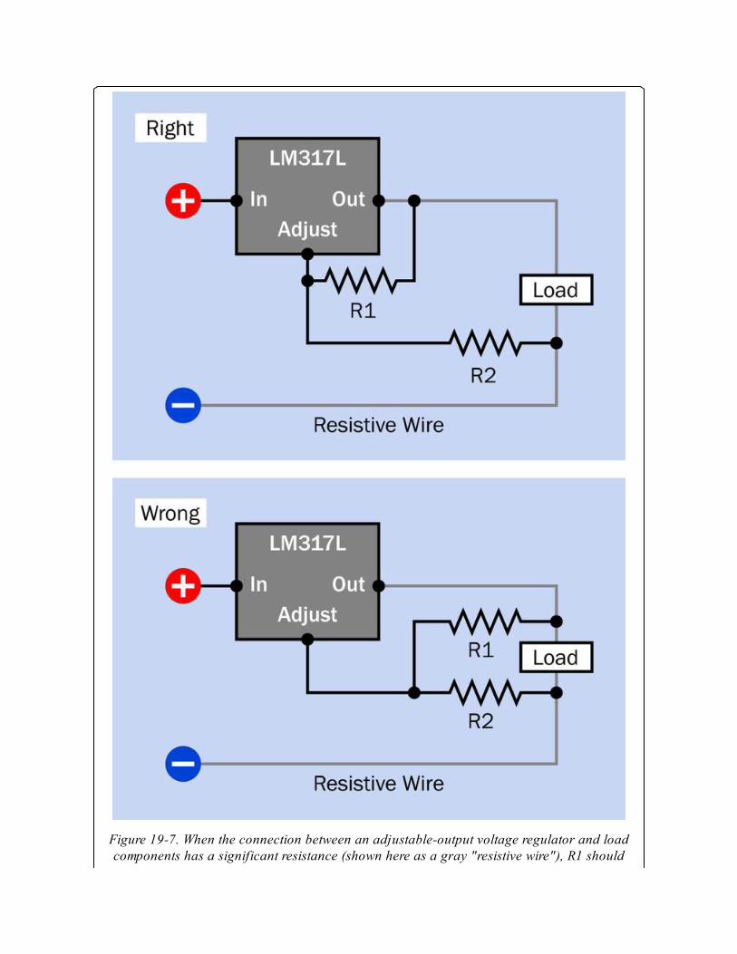
Figure 19-7. When the connection between an adjustable-output voltage regulator and loadcomponents has a significant resistance (shown here as a gray "resistive wire"), R1 should

always be connected as closely as possible to the pins of the regulator, as shown in the upperschematic. (Derived from schematics prepared by National Semiconductor.)
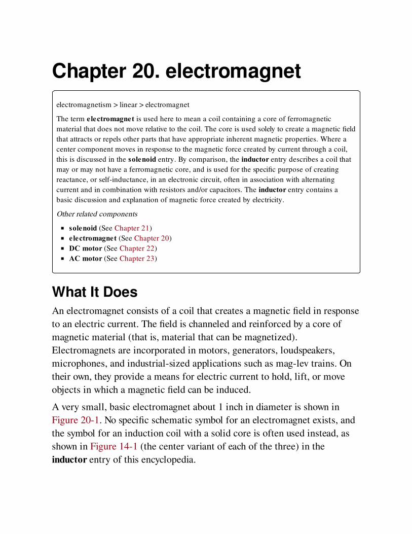
Chapter 20. electromagnet
electromagnetism > linear > electromagnet
The term electromagnet is used here to mean a coil containing a core of ferromagnetic
material that does not move relative to the coil. The core is used solely to create a magnetic field
that attracts or repels other parts that have appropriate inherent magnetic properties. Where a
center component moves in response to the magnetic force created by current through a coil,
this is discussed in the solenoid entry. By comparison, the inductor entry describes a coil that
may or may not have a ferromagnetic core, and is used for the specific purpose of creating
reactance, or self-inductance, in an electronic circuit, often in association with alternating
current and in combination with resistors and/or capacitors. The inductor entry contains a
basic discussion and explanation of magnetic force created by electricity.
Other related components
solenoid (See Chapter 21)
electromagnet (See Chapter 20)
DC motor (See Chapter 22)
AC motor (See Chapter 23)
What It DoesAn electromagnet consists of a coil that creates a magnetic field in response
to an electric current. The field is channeled and reinforced by a core of
magnetic material (that is, material that can be magnetized).
Electromagnets are incorporated in motors, generators, loudspeakers,
microphones, and industrial-sized applications such as mag-lev trains. On
their own, they provide a means for electric current to hold, lift, or move
objects in which a magnetic field can be induced.
A very small, basic electromagnet about 1 inch in diameter is shown in
Figure 20-1. No specific schematic symbol for an electromagnet exists, and
the symbol for an induction coil with a solid core is often used instead, as
shown in Figure 14-1 (the center variant of each of the three) in the
inductor entry of this encyclopedia.
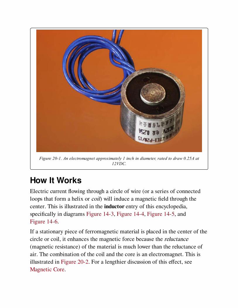
Figure 20-1. An electromagnet approximately 1 inch in diameter, rated to draw 0.25A at12VDC.
How It WorksElectric current flowing through a circle of wire (or a series of connected
loops that form a helix or coil) will induce a magnetic field through the
center. This is illustrated in the inductor entry of this encyclopedia,
specifically in diagrams Figure 14-3, Figure 14-4, Figure 14-5, and
Figure 14-6.
If a stationary piece of ferromagnetic material is placed in the center of the
circle or coil, it enhances the magnetic force because the reluctance
(magnetic resistance) of the material is much lower than the reluctance of
air. The combination of the coil and the core is an electromagnet. This is
illustrated in Figure 20-2. For a lengthier discussion of this effect, see
Magnetic Core.
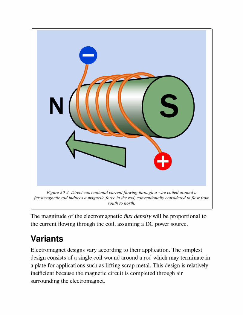
Figure 20-2. Direct conventional current flowing through a wire coiled around aferromagnetic rod induces a magnetic force in the rod, conventionally considered to flow from
south to north.
The magnitude of the electromagnetic flux density will be proportional to
the current flowing through the coil, assuming a DC power source.
VariantsElectromagnet designs vary according to their application. The simplest
design consists of a single coil wound around a rod which may terminate in
a plate for applications such as lifting scrap metal. This design is relatively
inefficient because the magnetic circuit is completed through air
surrounding the electromagnet.
A more efficient, traditional design consists of a U-shaped core around
which are wound one or two coils. If the U-shaped core is smoothly curved,
it resembles a horse-shoe magnet, as shown in Figure 20-3. This design has
become relatively uncommon, as it is cheaper to make windings across two
separate, straight vertical cores and bridge them. However, the horseshoe
configuration is extremely efficient, as the coils induce north and south
magnetic polarities in the open ends of the U-shaped core, and the
magnetic circuit is completed through any object that is attracted toward the
open ends and links them. The attracted object is shown as a rectangular
plate in Figure 20-3. Because a magnetic circuit will naturally attempt to
limit its extent, and because this goal will be achieved when the circuit is
completed, the attractive force of the U-shaped magnet is maximized.
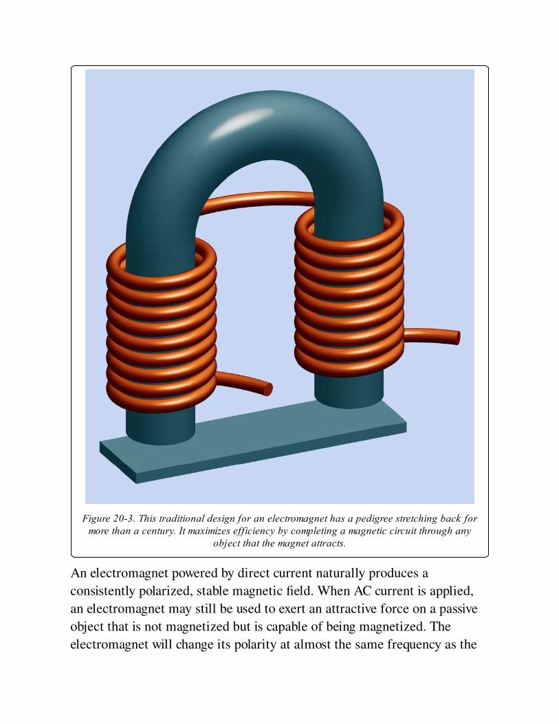
Figure 20-3. This traditional design for an electromagnet has a pedigree stretching back formore than a century. It maximizes efficiency by completing a magnetic circuit through any
object that the magnet attracts.
An electromagnet powered by direct current naturally produces a
consistently polarized, stable magnetic field. When AC current is applied,
an electromagnet may still be used to exert an attractive force on a passive
object that is not magnetized but is capable of being magnetized. The
electromagnet will change its polarity at almost the same frequency as the
AC, and will induce equal and opposite fluctuating polarity in the target,
causing mutual attraction. The core of the magnet will be composed of
plates separated by thin layers of insulation to inhibit the eddy currents
induced by the AC, but still an AC-powered electromagnet will be less
efficient than a comparable DC-powered electromagnet because it will also
suffer from hysteresis as power is consumed by repeatedly reversing the
polarity of the magnetic domains in the core.
Some electromagnets that are described as suitable for AC power actually
contain rectifiers that convert the AC to DC.
ValuesElectromagnets are typically calibrated in terms of their power
consumption and retaining force (the weight of an iron target that they can
support). The retaining force is usually measured in grams or kilograms.
How to Use itElectromagnets are used mostly as subassemblies in other components,
such as motors and generators, relays, loudspeakers, and disk drives. They
have also been used in audio (and video) tape recorders to magnetize ferric
oxide on tape, using a magnetic field of varying strength to record an audio
signal. In this application, a form of horseshoe magnet with an extremely
narrow gap is used, the width of the gap determining the highest frequency
that the electromagnet can record, in conjunction with the speed of the tape
moving past the head.
The tape recording process can be reversed when the electromagnet "reads"
the tape and turns the signal back into a weak alternating current that can be
amplified and reproduced through a loudspeaker.
A simple application for an electromagnet is in a traditional-style doorbell,
where one or two coils attract a spring-loaded lever, at the top of which is a
knob that hits a bell. When the lever is pulled toward the bell, it breaks a
contact that supplies power to the electromagnet. This allows the lever to
spring back to its original position, which re-establishes the circuit,
repeating the process for as long as power is applied to the bell. The bulk
and weight of the component parts in this type of doorbell are making it
obsolete, as electronic versions containing small loudspeakers become
relatively cheaper. However, a solenoid may still be used in the type of bell
that creates a single chime or pair of chimes.
In any device using a cathode-ray tube, electromagnetic coils are used to
form a yoke around the neck of the tube, to deflect the beam of electrons on
its way to the screen. A similar principle is used in electron microscopes. In
some cases, electrostatically charged plates are used to achieve the same
purpose.
An electromagnet may be used to activate a reed switch (the diagram in
Figure 9-7 shows such a switch). In this application, the combination of the
electromagnet and the switch are functioning as a relay.
When an electromagnet is energized by alternating current, it can be used to
degauss (in other words, to demagnetize) other objects. The AC is either
applied with diminishing current, so that the alternating magnetic polarities
gradually subside to zero, or the electromagnet is gradually moved away
from the target, again reducing the magnetic influence to (virtually) zero.
This latter procedure may be used periodically to demagnetize record and
replay heads on tape recorders, which otherwise tend to acquire residual
magnetism, inducing background hiss on the tape.
Traditional large-scale applications for electromagnets tend to involve
lifting and moving heavy objects or scrap metal, such as junked cars. A
more modern application is in magnetic resonance imaging (MRI), which
has revolutionized some areas of medicine.
Very large-scale applications for electromagnets include particle
accelerators, in which multiple magnetic coils are energized sequentially,
and fusion-power generators, where high-temperature plasma is contained
by a magnetic field.

What Can Go WrongBecause an electromagnet requires constant power to maintain its magnetic
force, yet it is not doing any actual work so long as its target remains
stationary (in contact with the core of the magnet), the current running
through the coil of the magnet must be dissipated entirely as heat. Further
discussion of this issue will be found at Heat in the solenoid section of this
encyclopedia.
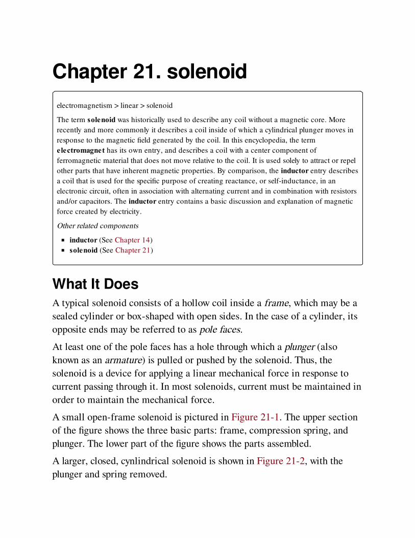
Chapter 21. solenoid
electromagnetism > linear > solenoid
The term solenoid was historically used to describe any coil without a magnetic core. More
recently and more commonly it describes a coil inside of which a cylindrical plunger moves in
response to the magnetic field generated by the coil. In this encyclopedia, the term
electromagnet has its own entry, and describes a coil with a center component of
ferromagnetic material that does not move relative to the coil. It is used solely to attract or repel
other parts that have inherent magnetic properties. By comparison, the inductor entry describes
a coil that is used for the specific purpose of creating reactance, or self-inductance, in an
electronic circuit, often in association with alternating current and in combination with resistors
and/or capacitors. The inductor entry contains a basic discussion and explanation of magnetic
force created by electricity.
Other related components
inductor (See Chapter 14)
solenoid (See Chapter 21)
What It DoesA typical solenoid consists of a hollow coil inside a frame, which may be a
sealed cylinder or box-shaped with open sides. In the case of a cylinder, its
opposite ends may be referred to as pole faces.
At least one of the pole faces has a hole through which a plunger (also
known as an armature) is pulled or pushed by the solenoid. Thus, the
solenoid is a device for applying a linear mechanical force in response to
current passing through it. In most solenoids, current must be maintained in
order to maintain the mechanical force.
A small open-frame solenoid is pictured in Figure 21-1. The upper section
of the figure shows the three basic parts: frame, compression spring, and
plunger. The lower part of the figure shows the parts assembled.
A larger, closed, cynlindrical solenoid is shown in Figure 21-2, with the
plunger and spring removed.
A 3D rendering showing a simplified, imaginary, cylindrical solenoid cut in
half appears in Figure 21-3. The diagram includes a gray cylindrical shell,
often described as the frame; the coil, shown in orange; the plunger, which
is pulled into the coil by its magnetic field; and the triangular stop, which
limits the plunger’s upward travel. The frame of the solenoid exists not
merely to protect the coil, but to provide a magnetic circuit, which is
completed through the plunger.
The lower end of the plunger is often fitted with a nonmagnetic yoke or
perforated plate for connection with other components. Stainless steel can
be used for this purpose. The stop may be fitted with a thrust rod (also
fabricated from stainless steel) if the solenoid is intended to "push" as well
as "pull." Springs to adjust the force of the plunger, or to return it to its
initial position when the current through the coil is interrupted, are not
shown in the rendering.


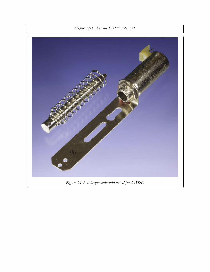
Figure 21-1. A small 12VDC solenoid.
Figure 21-2. A larger solenoid rated for 24VDC.

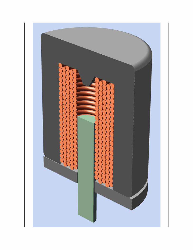
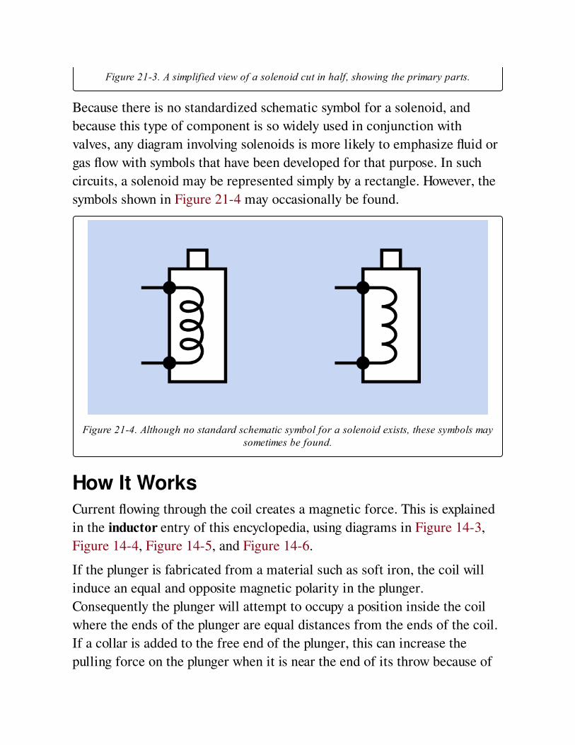
Figure 21-3. A simplified view of a solenoid cut in half, showing the primary parts.
Because there is no standardized schematic symbol for a solenoid, and
because this type of component is so widely used in conjunction with
valves, any diagram involving solenoids is more likely to emphasize fluid or
gas flow with symbols that have been developed for that purpose. In such
circuits, a solenoid may be represented simply by a rectangle. However, the
symbols shown in Figure 21-4 may occasionally be found.
Figure 21-4. Although no standard schematic symbol for a solenoid exists, these symbols maysometimes be found.
How It WorksCurrent flowing through the coil creates a magnetic force. This is explained
in the inductor entry of this encyclopedia, using diagrams in Figure 14-3,
Figure 14-4, Figure 14-5, and Figure 14-6.
If the plunger is fabricated from a material such as soft iron, the coil will
induce an equal and opposite magnetic polarity in the plunger.
Consequently the plunger will attempt to occupy a position inside the coil
where the ends of the plunger are equal distances from the ends of the coil.
If a collar is added to the free end of the plunger, this can increase the
pulling force on the plunger when it is near the end of its throw because of
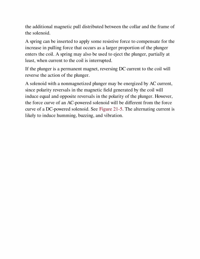
the additional magnetic pull distributed between the collar and the frame of
the solenoid.
A spring can be inserted to apply some resistive force to compensate for the
increase in pulling force that occurs as a larger proportion of the plunger
enters the coil. A spring may also be used to eject the plunger, partially at
least, when current to the coil is interrupted.
If the plunger is a permanent magnet, reversing DC current to the coil will
reverse the action of the plunger.
A solenoid with a nonmagnetized plunger may be energized by AC current,
since polarity reversals in the magnetic field generated by the coil will
induce equal and opposite reversals in the polarity of the plunger. However,
the force curve of an AC-powered solenoid will be different from the force
curve of a DC-powered solenoid. See Figure 21-5. The alternating current is
likely to induce humming, buzzing, and vibration.
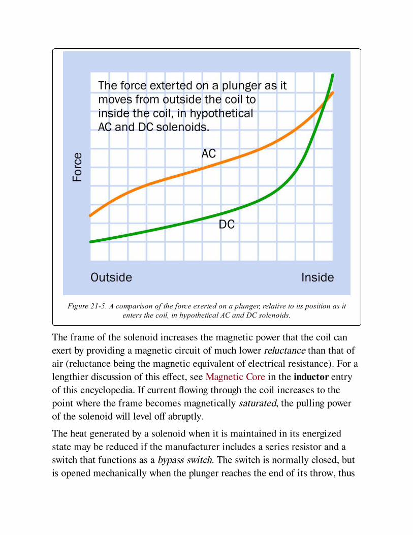
Figure 21-5. A comparison of the force exerted on a plunger, relative to its position as itenters the coil, in hypothetical AC and DC solenoids.
The frame of the solenoid increases the magnetic power that the coil can
exert by providing a magnetic circuit of much lower reluctance than that of
air (reluctance being the magnetic equivalent of electrical resistance). For a
lengthier discussion of this effect, see Magnetic Core in the inductor entry
of this encyclopedia. If current flowing through the coil increases to the
point where the frame becomes magnetically saturated, the pulling power
of the solenoid will level off abruptly.
The heat generated by a solenoid when it is maintained in its energized
state may be reduced if the manufacturer includes a series resistor and a
switch that functions as a bypass switch. The switch is normally closed, but
is opened mechanically when the plunger reaches the end of its throw, thus

diverting electricity through the series resistor. This itself will generate
some heat as a result of the current flowing through it, but by increasing the
total resistance of the system, the total heat output will be reduced. The
resistor value is chosen to provide the minimum power needed to retain the
plunger at the end of its throw.
VariantsThe most common variant is tubular, with open-frame as a secondary
option. A tubular solenoid has been shown in Figure 21-2.
Additional variants include:
Low ProfileA shorter, fatter solenoid which may be used if a short throw is acceptable.
LatchingA permanent magnet holds the plunger when it reaches the end of its travel,
and continues to hold it after power to the solenoid is disconnected. The
plunger itself is also a permanent magnet, and is released by running current
of reverse polarity through the coil.
RotaryThis variant is similar in principle to a brushless DC motor and causes the
armature to rotate through a fixed angle (typically ranging from 25 to 90
degrees) instead of moving linearly. It is used as a mechanical indicator in
control panels, although it is being displaced by purely electronic indicators.
Hinged ClapperInstead of a plunger, a small hinged panel (the "clapper") moves in when
the solenoid is active, and springs back when the power is interrupted.
Values
The stroke length, duty cycle, and holding force are the most significant
values found in solenoid datasheets.
Holding forces for DC solenoids can range from a few grams to hundreds
of kilograms. The holding force will be inversely proportional to the length
of the solenoid, if all other variables are equal. The force that the solenoid
can exert on its plunger also varies depending on the position of the plunger
in the length of its throw.
Duty cycle is of special importance because the solenoid continues to draw
power and create heat so long as it is holding the plunger at the end of its
throw (assuming the solenoid is not the latching type). The initial current
surge in an AC solenoid generates additional heat.
The duty cycle is simply calculated. If T1 is the time for which the solenoid
is on and T2 is the time for which the solenoid is off, the duty cycle, D, is
derived as a percentage from the formula
D = 100 * (T1 / (T1 + T2))
Some solenoids are designed to withstand a 100% duty cycle, but many are
not, and in those cases, there is a maximum value not only for D but for the
peak "on" time, regardless of the duty cycle. Suppose a solenoid is rated for
a 25% duty cycle. If the solenoid is appropriately switched on for one
second and off for three seconds, the heat will be allowed to dissipate
before it has time to reach overload levels. If the solenoid is switched on for
one minute and off for three minutes, the duty cycle is still 25%, but the
heat that may accumulate during a one-minute "on" cycle may overload the
component before the "off" cycle can allow it to dissipate.
Coil Size vs. PowerBecause additional windings in a coil will induce a greater magnetic force,
a larger solenoid tends to be more powerful than a smaller solenoid.
However this means that if a larger and a smaller solenoid are both designed
to generate the same force over the same distance, the smaller solenoid will
probably draw more current (and will therefore generate more heat) because
of its fewer coil windings.
How to Use itSolenoids are primarily used to operate valves in fluid and gas circuits. Such
circuits are found in laboratory and industrial process control, fuel
injectors, aircraft systems, military applications, medical devices, and
space vehicles. Solenoids may also be used in some electronic locks, in
pinball machines, and in robotics.
What Can Go Wrong
HeatOverheating is the principal concern when using solenoids, especially if the
maximum "on" time is exceeded, or the duty cycle is exceeded. If the
plunger is prevented from reaching the end of its throw, this can be another
cause of overheating.
Because coil resistance increases with heat, a hot solenoid passes less
current and therefore develops less power. This effect is more pronounced in
a DC solenoid than an AC solenoid. A manufacturer’s force curve should
show the solenoid performance at its maximum rated temperature, which is
typically around 75 degrees Centigrade, in a hypothetical ambient
temperature of 25 degrees Centigrade. Exceeding these values may result in
the solenoid failing to perform. As in all coils using magnet wire, there is
the risk of excessive heat melting the insulation separating the coil
windings, effectively shortening the coil, which will then pass more current,
generating more heat.
AC InrushWhen an AC solenoid reaches the end of its travel, the sudden stop of the
plunger results in forward EMF that generates additional heat. Generally
speaking, a longer stroke creates a greater surge. Rapid cycling will
therefore exacerbate coil heating.
Unwanted EMFLike any device containing a coil, a solenoid creates back EMF when power
is connected, and forward EMF when the power is disconnected. A
protection diode may be necessary to suppress power spikes that can affect
other components.
Loose PlungerThe plunger in many solenoids is not anchored or retained inside the frame
and may fall out if the solenoid is tilted or subjected to extreme vibration.
Chapter 22. DC motor
electromagnetism > rotational > DC motor
In this section, the term "traditional DC motor" is used to describe the oldest and simplest
design, which consists of two brushes delivering power via a rotating, sectioned commutator to
two or more electromagnetic coils mounted on the motor shaft. Brushless DC motors (in which
DC is actually converted to a pulse train) are also described here because "brushless DC" has
become a commonly used phrase, and the motor is powered by direct current, even though this
is modified internally via pulse-width modulation.
Other related components
AC motor (See Chapter 23)
stepper motor (See Chapter 25)
servo motor (See Chapter 24)
What It DoesA traditional DC motor uses direct current to create magnetic force, which
turns an output shaft. When the polarity of the DC voltage is reversed, the
motor reverses its direction of rotation. Usually, the force created by the
motor is equal in either direction.
How It WorksCurrent passes through two or more coils that are mounted on the motor
shaft and rotate with it. This assembly is referred to as the rotor. The
magnetic force produced by the current is concentrated via cores or poles
of soft iron or high-silicon steel, and interacts with fields created by
permanent magnets arrayed around the rotor in a fixed assembly known as
the stator.
Power to the coils is delivered through a pair of brushes, often made from a
graphite compound. Springs press the brushes against a sleeve that rotates
with the shaft and is divided into sections, connected with the coils. The
sleeve assembly is known as the commutator. As the commutator rotates,
its sections apply power from the brushes to the motor coils sequentially, in
a simple mechanical switching action.
The most elementary configuration for a traditional DC motor is shown in
Figure 22-1.
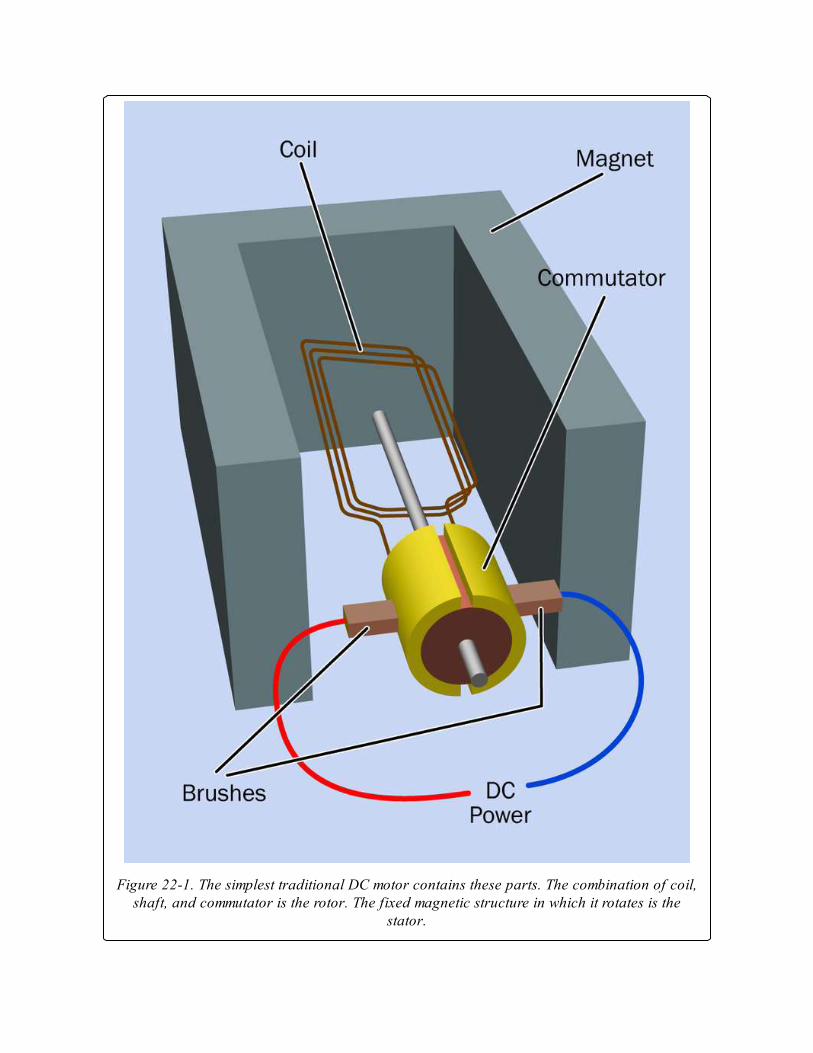
Figure 22-1. The simplest traditional DC motor contains these parts. The combination of coil,shaft, and commutator is the rotor. The fixed magnetic structure in which it rotates is the
stator.
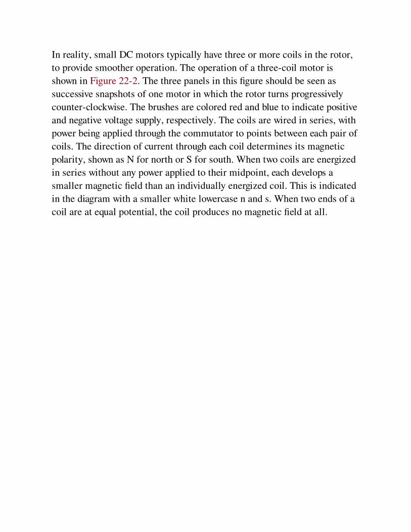
In reality, small DC motors typically have three or more coils in the rotor,
to provide smoother operation. The operation of a three-coil motor is
shown in Figure 22-2. The three panels in this figure should be seen as
successive snapshots of one motor in which the rotor turns progressively
counter-clockwise. The brushes are colored red and blue to indicate positive
and negative voltage supply, respectively. The coils are wired in series, with
power being applied through the commutator to points between each pair of
coils. The direction of current through each coil determines its magnetic
polarity, shown as N for north or S for south. When two coils are energized
in series without any power applied to their midpoint, each develops a
smaller magnetic field than an individually energized coil. This is indicated
in the diagram with a smaller white lowercase n and s. When two ends of a
coil are at equal potential, the coil produces no magnetic field at all.


Figure 22-2. Three sequential views of a typical three-coil DC motor viewed from the end ofits shaft (the shaft itself is not shown). Magnetic effects cause the rotor to turn, which
switches the current to the coils via the commutator at the center.
The stator consists of a cylindrical permanent magnet, which has two poles
—shown in the figure as two black semicircles separated by a vertical gap
for clarity—although in practice the magnet may be made in one piece.
Opposite magnetic poles on the rotor and stator attract each other, whereas
the same magnetic poles repel each other.
DC motors may be quite compact, as shown in Figure 22-3, where the
frame of the motor measures about 0.7" square. They can also be very
powerful for their size; the motor that is shown disassembled in Figure 22-4
is from a 12VDC bilge pump rated at 500 gallons per hour. Its output was
delivered by the small impeller attached to the rotor at right, and was
achieved by using two extremely powerful neodymium magnets, just visible
on the inside of the motor’s casing (at top-left) in conjunction with five
coils on the rotor.
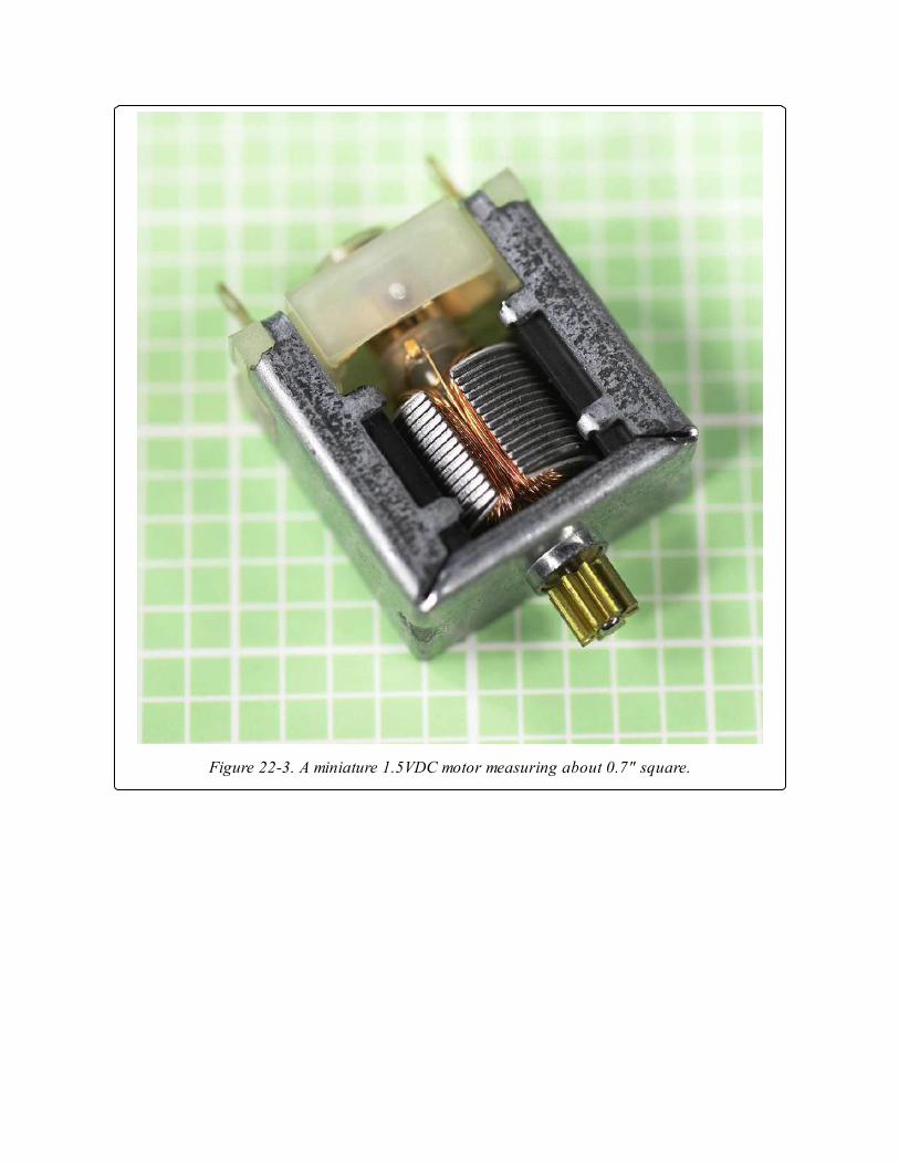
Figure 22-3. A miniature 1.5VDC motor measuring about 0.7" square.
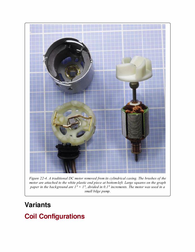
Figure 22-4. A traditional DC motor removed from its cylindrical casing. The brushes of themotor are attached to the white plastic end piece at bottom-left. Large squares on the graphpaper in the background are 1" × 1", divided in 0.1" increments. The motor was used in a
small bilge pump.
Variants
Coil Configurations
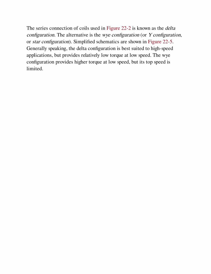
The series connection of coils used in Figure 22-2 is known as the delta
configuration. The alternative is the wye configuration (or Y configuration,
or star configuration). Simplified schematics are shown in Figure 22-5.
Generally speaking, the delta configuration is best suited to high-speed
applications, but provides relatively low torque at low speed. The wye
configuration provides higher torque at low speed, but its top speed is
limited.
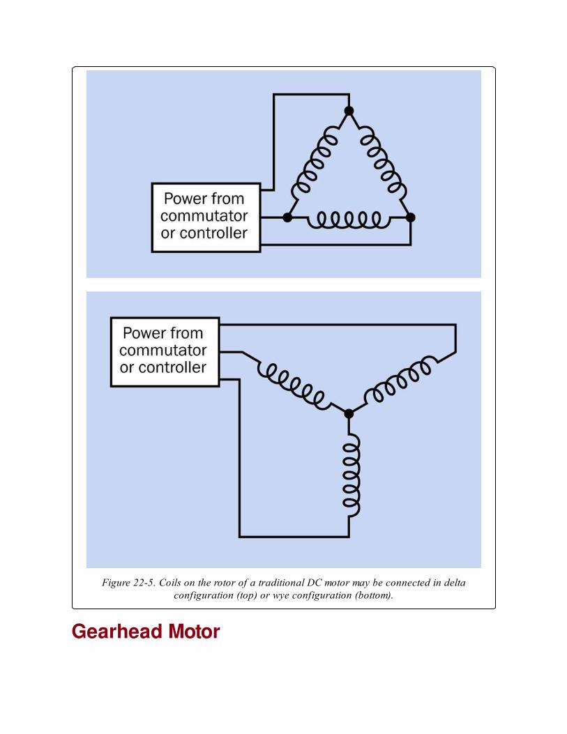
Figure 22-5. Coils on the rotor of a traditional DC motor may be connected in deltaconfiguration (top) or wye configuration (bottom).
Gearhead Motor
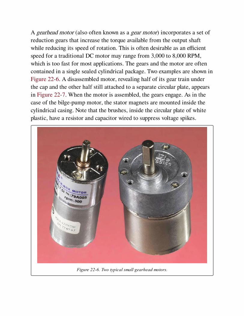
A gearhead motor (also often known as a gear motor) incorporates a set of
reduction gears that increase the torque available from the output shaft
while reducing its speed of rotation. This is often desirable as an efficient
speed for a traditional DC motor may range from 3,000 to 8,000 RPM,
which is too fast for most applications. The gears and the motor are often
contained in a single sealed cylindrical package. Two examples are shown in
Figure 22-6. A disassembled motor, revealing half of its gear train under
the cap and the other half still attached to a separate circular plate, appears
in Figure 22-7. When the motor is assembled, the gears engage. As in the
case of the bilge-pump motor, the stator magnets are mounted inside the
cylindrical casing. Note that the brushes, inside the circular plate of white
plastic, have a resistor and capacitor wired to suppress voltage spikes.
Figure 22-6. Two typical small gearhead motors.

Spur gears are widely used for speed reduction. Planetary gears (also known
as epicyclic gears) are a slightly more expensive option. Spur gears such as
those in Figure 22-8 may require three or more pairs in series. The total
speed reduction is found by multiplying the individual ratios. Thus, if three
pairs of gears have ratios of 37 : 13, 31 : 15, and 39 : 17, the total speed
reduction ® is obtained by:
R = ( 37 * 31 * 39 ) / ( 13 * 15 * 17 )
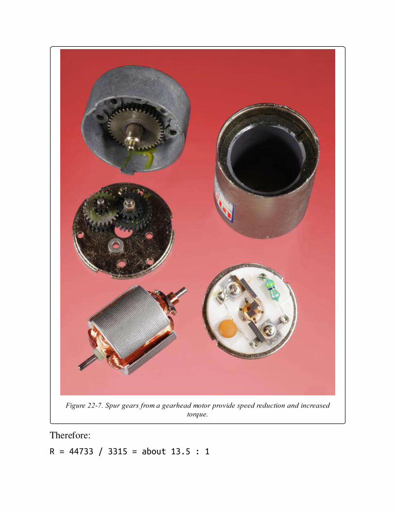
Figure 22-7. Spur gears from a gearhead motor provide speed reduction and increasedtorque.
Therefore:
R = 44733 / 3315 = about 13.5 : 1
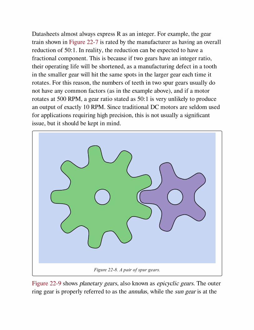
Datasheets almost always express R as an integer. For example, the gear
train shown in Figure 22-7 is rated by the manufacturer as having an overall
reduction of 50:1. In reality, the reduction can be expected to have a
fractional component. This is because if two gears have an integer ratio,
their operating life will be shortened, as a manufacturing defect in a tooth
in the smaller gear will hit the same spots in the larger gear each time it
rotates. For this reason, the numbers of teeth in two spur gears usually do
not have any common factors (as in the example above), and if a motor
rotates at 500 RPM, a gear ratio stated as 50:1 is very unlikely to produce
an output of exactly 10 RPM. Since traditional DC motors are seldom used
for applications requiring high precision, this is not usually a significant
issue, but it should be kept in mind.
Figure 22-8. A pair of spur gears.
Figure 22-9 shows planetary gears, also known as epicyclic gears. The outer
ring gear is properly referred to as the annulus, while the sun gear is at the
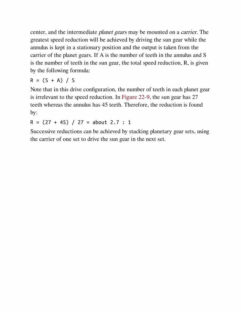
center, and the intermediate planet gears may be mounted on a carrier. The
greatest speed reduction will be achieved by driving the sun gear while the
annulus is kept in a stationary position and the output is taken from the
carrier of the planet gears. If A is the number of teeth in the annulus and S
is the number of teeth in the sun gear, the total speed reduction, R, is given
by the following formula:
R = (S + A) / S
Note that in this drive configuration, the number of teeth in each planet gear
is irrelevant to the speed reduction. In Figure 22-9, the sun gear has 27
teeth whereas the annulus has 45 teeth. Therefore, the reduction is found
by:
R = (27 + 45) / 27 = about 2.7 : 1
Successive reductions can be achieved by stacking planetary gear sets, using
the carrier of one set to drive the sun gear in the next set.
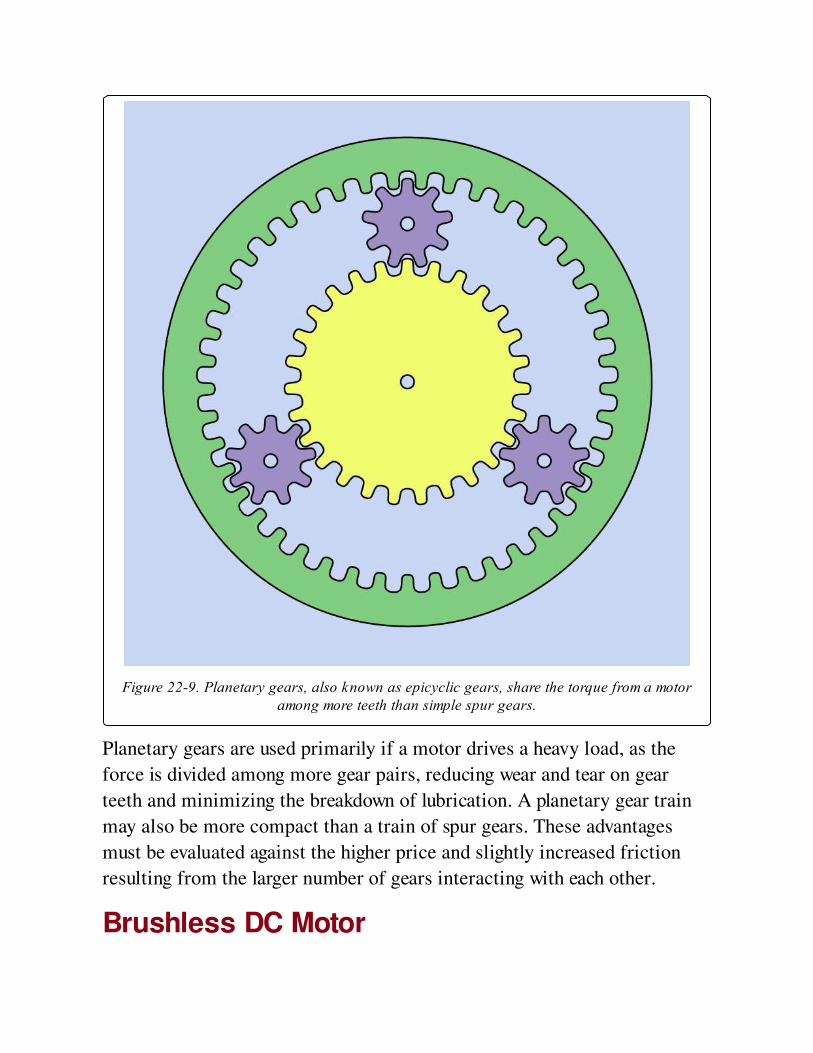
Figure 22-9. Planetary gears, also known as epicyclic gears, share the torque from a motoramong more teeth than simple spur gears.
Planetary gears are used primarily if a motor drives a heavy load, as the
force is divided among more gear pairs, reducing wear and tear on gear
teeth and minimizing the breakdown of lubrication. A planetary gear train
may also be more compact than a train of spur gears. These advantages
must be evaluated against the higher price and slightly increased friction
resulting from the larger number of gears interacting with each other.
Brushless DC Motor
In a brushless DC motor, sometimes referred to as a BLDC motor, the coils
are located in the stator and the permanent magnets are relocated in the
rotor. The great advantage of this design is that power can be applied
directly to the coils, eliminating the need for brushes, which are the
primary source of failure in DC motors as a result of wear and tear.
However, since there is no rotating commutator to switch the DC current to
the coils, the current must be switched by electronic components, which
add to the cost of the motor.
In the inrunner configuration the stator surrounds the rotor, whereas in the
outrunner configuration the stator is located in the center of the motor
while the rotor takes the form of a ring or cup that spins around the stator.
This is a common design for small cooling fans, where the blades are
attached to the outer circumference of a cup that is lined with permanent
magnets. An example is shown in Figure 22-10. In this picture, the stator
coils are normally hidden from view, being fixed to the fan housing (shown
at the top of the picture). Power is controlled by the surface-mount
components on the green circular circuit board. The cup attached to the fan
blades contains permanent magnets.

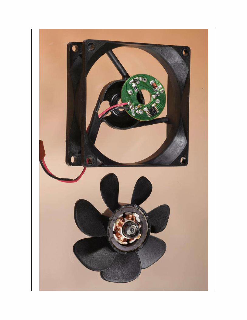

Figure 22-10. A typical brushless DC cooling fan uses stationary coils, with permanentmagnets rotating around them.
The use of a solid-state switching system to energize the coils sequentially
is known as electronic commutation. Hall effect sensors may be used to
detect the position of the rotor and feed this information back to the
frequency control circuit, so that it stays "one step ahead" of the rotor
(when bringing it up to speed) or is synchronized with the rotor (for a
constant running speed). The system is comparable to a reluctance motor or
synchronous motor. These variants are described in the AC motor section
of this encyclopedia.
While traditional DC motors have been commercially available since the
late 1800s, brushless DC motors were not introduced until the 1960s, when
the availability of solid-state control electronics began to make the motor
design economically viable.
Linear ActuatorLinear actuator is a generic term for any device that can exert a pushing or
pulling force in a straight line. In industrial applications, actuators may be
powered pneumatically or hydraulically, but smaller-scale units are usually
driven by a traditional DC motor. These are more properly (but not often)
referred to as electromechanical linear actuators.
The rotational force of the motor is typically converted to linear motion by
using a threaded motor shaft in conjunction with a nut or collar. The unit is
often mounted in an enclosure containing limit switches that stop the motor
automatically at the limits of travel. For an explanation of limit switches,
see Limit Switches in the switch entry in this encyclopedia.
ValuesA manufacturer’s datasheet should list the maximum operating voltage and
typical current consumption when a motor is moderately loaded, along with
the stall current that a motor draws when it is so heavily loaded that it stops
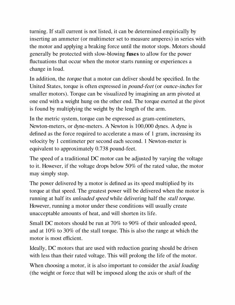
turning. If stall current is not listed, it can be determined empirically by
inserting an ammeter (or multimeter set to measure amperes) in series with
the motor and applying a braking force until the motor stops. Motors should
generally be protected with slow-blowing fuses to allow for the power
fluctuations that occur when the motor starts running or experiences a
change in load.
In addition, the torque that a motor can deliver should be specified. In the
United States, torque is often expressed in pound-feet (or ounce-inches for
smaller motors). Torque can be visualized by imagining an arm pivoted at
one end with a weight hung on the other end. The torque exerted at the pivot
is found by multiplying the weight by the length of the arm.
In the metric system, torque can be expressed as gram-centimeters,
Newton-meters, or dyne-meters. A Newton is 100,000 dynes. A dyne is
defined as the force required to accelerate a mass of 1 gram, increasing its
velocity by 1 centimeter per second each second. 1 Newton-meter is
equivalent to approximately 0.738 pound-feet.
The speed of a traditional DC motor can be adjusted by varying the voltage
to it. However, if the voltage drops below 50% of the rated value, the motor
may simply stop.
The power delivered by a motor is defined as its speed multiplied by its
torque at that speed. The greatest power will be delivered when the motor is
running at half its unloaded speed while delivering half the stall torque.
However, running a motor under these conditions will usually create
unacceptable amounts of heat, and will shorten its life.
Small DC motors should be run at 70% to 90% of their unloaded speed,
and at 10% to 30% of the stall torque. This is also the range at which the
motor is most efficient.
Ideally, DC motors that are used with reduction gearing should be driven
with less than their rated voltage. This will prolong the life of the motor.
When choosing a motor, it is also important to consider the axial loading
(the weight or force that will be imposed along the axis or shaft of the
motor) and radial loading (the weight or force that will be imposed
perpendicularly to the axis). Maximum values should be found in motor
datasheets.
In the hobby field, motors for model aircraft are typically rated in watts-
per-pound of motor weight (abbreviated w/lb). Values range from 50 to 250
w/lb, with higher values enabling better performance.
Relationships between torque, speed, voltage, and amperage in a traditional
DC motor can be described easily, assuming a hypothetical motor that is
100% efficient:
If the amperage is constant, the torque will also be constant, regardless of
the motor speed.
If the load applied to the motor remains constant (thus forcing the motor to
apply a constant torque), the speed of the motor will be determined by the
voltage applied to it.
If the voltage to the motor remains constant, the torque will be inversely
proportional with the speed.
How to Use itA traditional DC motor has the advantages of cheapness and simplicity, but
is only suitable for intermittent use, as its brushes and commutator will
tend to limit its lifetime. Its running speed will be approximate, making it
unsuitable for precise applications.
As the cost of control electronics has diminished, brushless DC motors
have replaced traditional DC motors. Their longevity and controllability
provide obvious advantages in applications such as hard disk drives,
variable-speed computer fans, CD players, and some workshop tools. Their
wide variety of available sizes, and good power-to-weight ratio, have
encouraged their adoption in toys and small vehicles, ranging from remote-
controlled model cars, airplanes, and helicopters to personal transportation
devices such as the Segway. They are also used in direct-drive audio
turntables.
Where an application requires the rotation of a motor shaft to be converted
to linear motion, a prepackaged linear actuator is usually more reliable and
simpler than building a crank and connecting rod, or cam follower, from
scratch. Large linear actuators are used in industrial automation, while
smaller units are popular with robotics hobbyists and can also be used to
control small systems in the home, such as a remote-controlled access door
to a home entertainment center.
Speed ControlA rheostat or potentiometer may be placed in series with a traditional DC
motor to adjust its speed, but will be inefficient, as it will achieve a voltage
drop by generating heat. Any rheostat must be rated appropriately, and
should probably be wire-wound. The voltage drop between the wiper and
the input terminal of the rheostat should be measured under a variety of
operating conditions, along with the amperage in the circuit, to verify that
the wattage rating is appropriate.
Pulse-width modulation (PWM) is preferable as a means of speed control
for a traditional DC motor. A circuit that serves this purpose is sometimes
referred to as a chopper, as it chops a steady flow of current into discrete
pulses. Usually the pulses have constant frequency while varying in
duration. The pulse width determines the average delivered power, and the
frequency is sufficiently high that it does not affect smoothness of operation
of the motor.
A programmable unijunction transistor or PUT can be used to generate a
train of pulses, adjustable with a potentiometer attached to its emitter.
Output from the transistor goes to a silicon-controlled rectifier (SCR),
which is placed in series with the motor, or can be connected directly to the
motor if the motor is small. See Figure 27-7.
Alternatively, a 555 timer can be used to create the pulse train, controlling a
MOSFET in series with the motor.

A microcontroller can also be used as a pulse source. Many
microcontrollers have PWM capability built in. The microcontroller will
require its own regulated power supply (typically 5VDC, 3.3VDC, or
sometimes less) and a switching component such as an insulated-gate
bipolar transistor (IGBT) to deliver sufficient power to the motor and to
handle the flyback voltage. These components will all add to the cost of the
system, but many modern devices incorporate microcontrollers anyway,
merely to process user input. Another advantage of using a microcontroller
is that its output can be varied by rewriting software, for example if a motor
is replaced with a new version that has different characteristics, or if
requirements change for other reasons. Additionally, a microcontroller
enables sophisticated features such as pre-programmed speed sequences,
stored memory of user preferences, and/or responses to conditions such as
excessive current consumption or heat in the motor.
A PWM schematic using a microcontroller and IGBT is shown in
Figure 22-11.
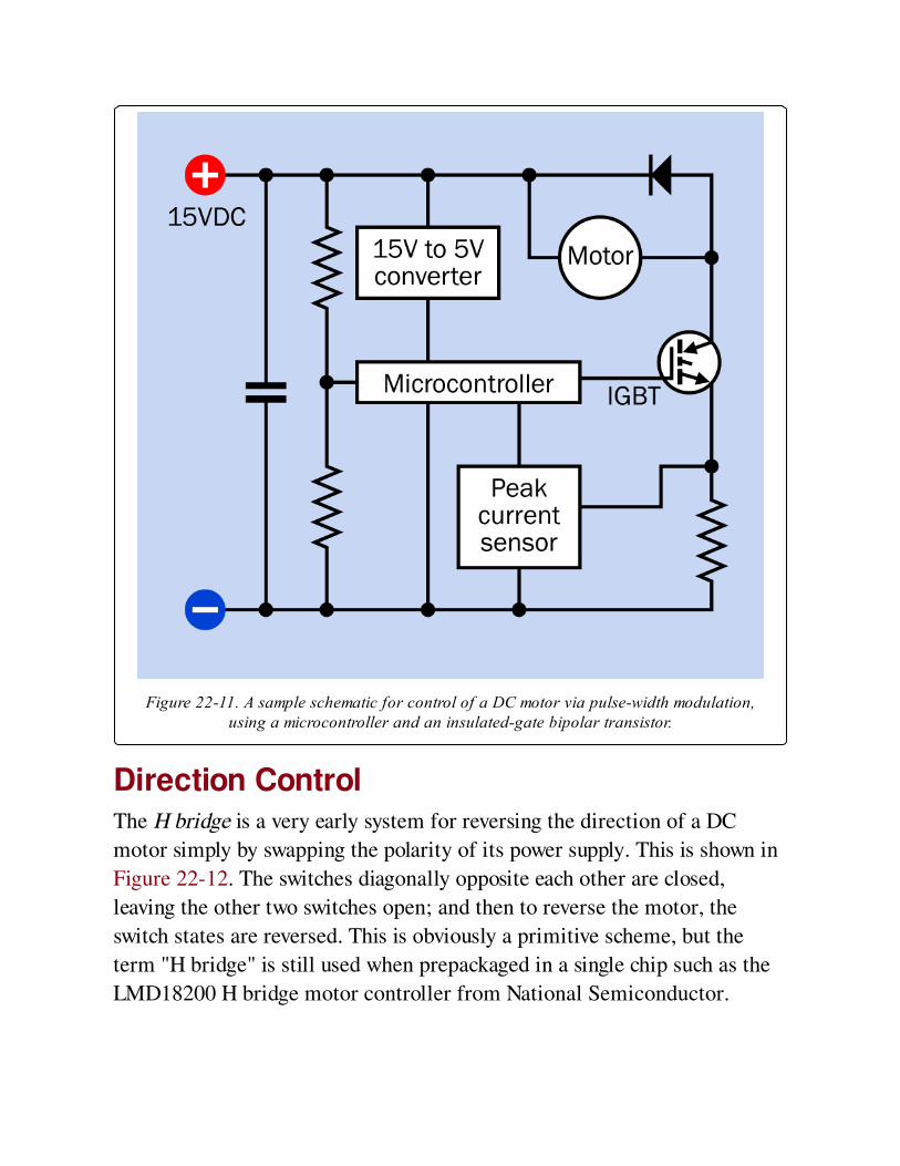
Figure 22-11. A sample schematic for control of a DC motor via pulse-width modulation,using a microcontroller and an insulated-gate bipolar transistor.
Direction ControlThe H bridge is a very early system for reversing the direction of a DC
motor simply by swapping the polarity of its power supply. This is shown in
Figure 22-12. The switches diagonally opposite each other are closed,
leaving the other two switches open; and then to reverse the motor, the
switch states are reversed. This is obviously a primitive scheme, but the
term "H bridge" is still used when prepackaged in a single chip such as the
LMD18200 H bridge motor controller from National Semiconductor.
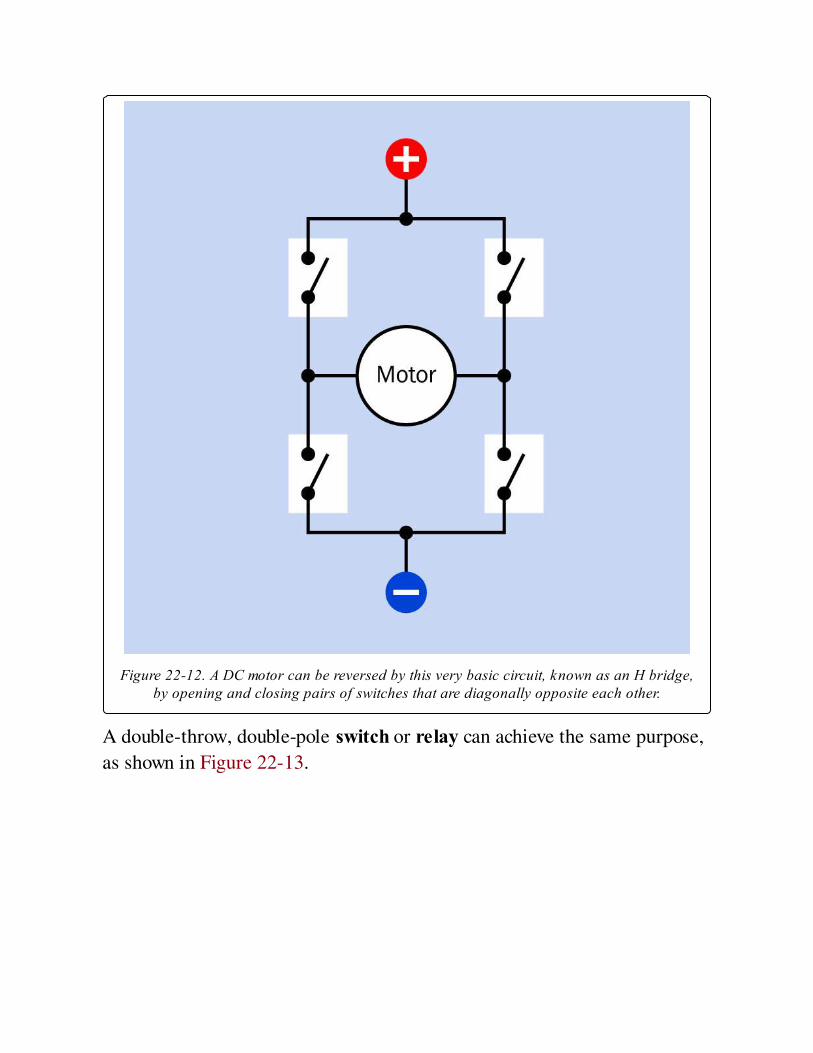
Figure 22-12. A DC motor can be reversed by this very basic circuit, known as an H bridge,by opening and closing pairs of switches that are diagonally opposite each other.
A double-throw, double-pole switch or relay can achieve the same purpose,
as shown in Figure 22-13.
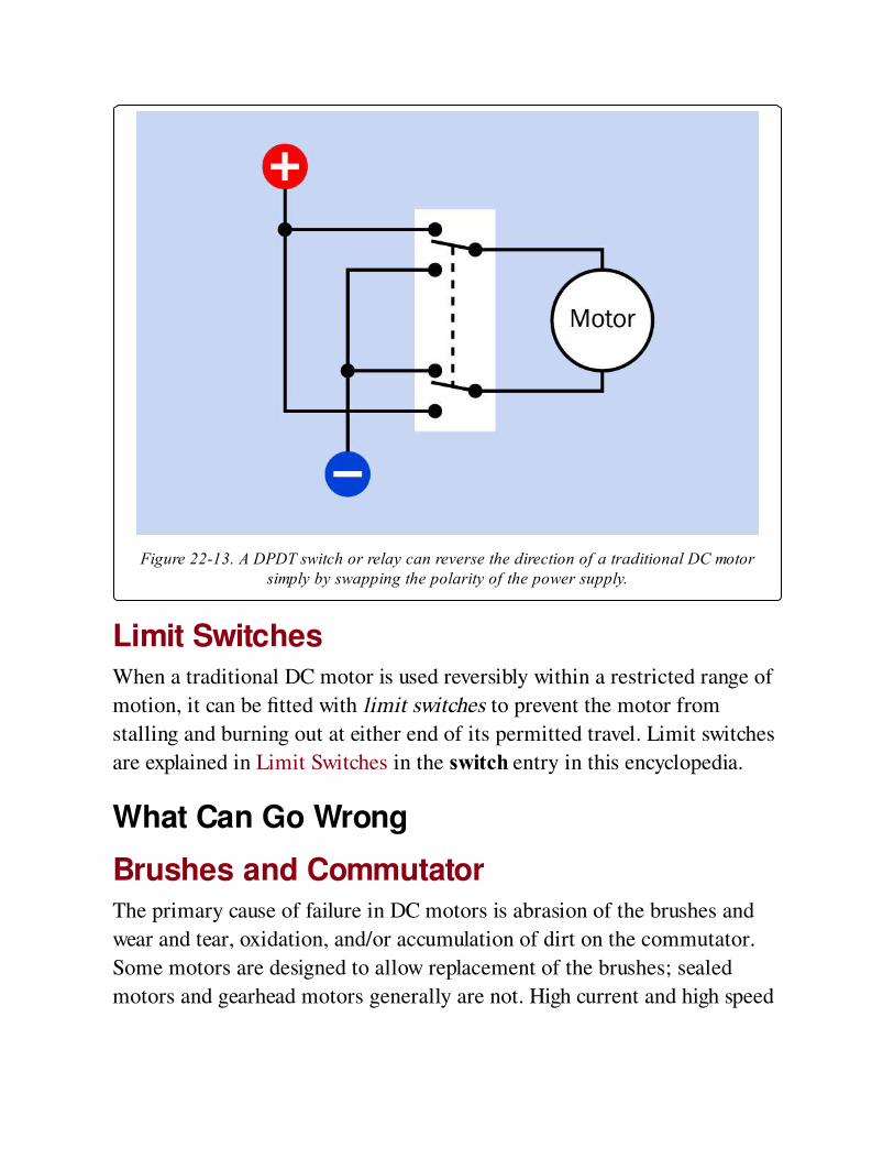
Figure 22-13. A DPDT switch or relay can reverse the direction of a traditional DC motorsimply by swapping the polarity of the power supply.
Limit SwitchesWhen a traditional DC motor is used reversibly within a restricted range of
motion, it can be fitted with limit switches to prevent the motor from
stalling and burning out at either end of its permitted travel. Limit switches
are explained in Limit Switches in the switch entry in this encyclopedia.
What Can Go Wrong
Brushes and CommutatorThe primary cause of failure in DC motors is abrasion of the brushes and
wear and tear, oxidation, and/or accumulation of dirt on the commutator.
Some motors are designed to allow replacement of the brushes; sealed
motors and gearhead motors generally are not. High current and high speed
will both tend to accelerate wear in the areas where the brushes meet the
commutator.
Electrical NoiseThe intermittent contact between the brushes and sections of the
commutator of a traditional DC motor can induce voltage spikes that may
travel back into the power supply for the motor and cause seemingly random
effects in other components. Sparking in the commutator can be a
significant source of electromagnetic interference (EMI), especially where
cheap or poorly fitted brushes are used. Even if the commutator is running
cleanly, the rapid creation of a magnetic field in a motor winding, following
by collapse of the field, can create spikes that feed back into the power
supply.
Wires that power a motor should be in twisted-pair configuration, so that
their radiated EMI tends to cancel itself out. They should be routed away
from data lines or encoder outputs, and may be shielded if necessary. Data
lines from sensors in brushless motors may also be shielded.
Installing a capacitor across the motor terminals can significantly reduce
EMI. Some motors have capacitors preinstalled. If the motor is in a sealed
casing, it may have to be disassembled to reveal whether a capacitor is
present.
Heat effectsSince all motors in the real world are less than 100% efficient, some power
is lost by the motor during normal operation, and will be dissipated as heat.
The resistance of motor windings, and consequently the magnetic force that
they generate, will decrease as the temperature rises. The motor becomes
less efficient, and will try to draw more current, worsening the situation. A
manufacturer’s rating for maximum temperature should be taken seriously.
The insulation of the coil windings is usually the most vulnerable part of a
motor if excess heat persists. Short circuits between adjacent coils as a
result of insulation breakdown will degrade the performance of the motor
while increasing its power consumption, which will create even more heat.
Where motor casings have protruding ridges, these cooling fins should be
exposed to ambient air.
Frequent starting, stopping, and reversing will tend to generate heat as a
result of power surges, and will reduce the lifetime of the motor.
Ambient ConditionsA warm, dry environment will tend to dry out bearing lubricants and
graphite brushes. Conversely, a very cold environment will tend to thicken
the bearing lubricants. If a motor will be used in unusual environmental
conditions, the manufacturer should be consulted.
Wrong Shaft Type or DiameterMotors have a variety of possible output shaft diameters, some measured in
inches and others in millimeters, and shafts may be long or short, or may
have a D-shaped cross section or splines to mate with appropriate
accessories such as gears, pulleys, or couplings. Careful examination of
datasheets and part numbers is necessary to determine compatibility. In the
hobby-electronics world, retailers may offer purpose-built discs or arms for
specific motor shafts.
Incompatible Motor MountsMounting lugs or flanges may or may not be provided, and may be
incompatible with the application for which the motor is intended. The
same motor may be available with a variety of mount options, differentiated
only by one letter or digit in the motor’s part number. A mount option that
was available in the past may become obsolete or may simply be out of
stock. Again, examination of datasheets is necessary.
Backlash
Backlash is the looseness or "slack" in a gear train that results from small
gaps between meshing gear teeth. Because backlash is cumulative when
gears are assembled in series, it can become significant in a slow-output
gearhead motor. When measured at the output shaft, it is generally in the
range of 1 to 7 degrees, tending to increase as the load increases. If a
geared motor is used as a positioning device, and is fitted with an encoder to
count rotations of the motor shaft, control electronics may cause the motor
to hunt to and fro in an attempt to overcome the hysteresis allowed by the
backlash. A stepper motor or servo motor is probably better suited to this
kind of application.
BearingsWhen using a motor that is not rated for significant axial loading, the
bearings may be damaged by applying excessive force to push-fit an output
gear or pulley onto the motor shaft. Even minor damage to bearings can
cause significant noise (see the following section) and a reduced lifetime
for the component.
In brushless DC motors, the most common cause of failure is the
deterioration of bearings. Attempting to revive the bearings by unsealing
them and adding lubricant is usually not worth the trouble.
Audible NoiseWhile electric motors are not generally thought of as being noisy devices,
an enclosure can act as a sounding board, and bearing noise is likely to
increase over time. Ball bearings become noisy over time, and gears are
inherently noisy.
If a device will contain multiple motors, or will be used in close proximity
to people who are likely to be sensitive to noise (for example, in a medical
environment), care should be taken to insure that motor shafts are properly
balanced, while the motors may be mounted on rubber bushings or in
sleeves that will absorb vibration.
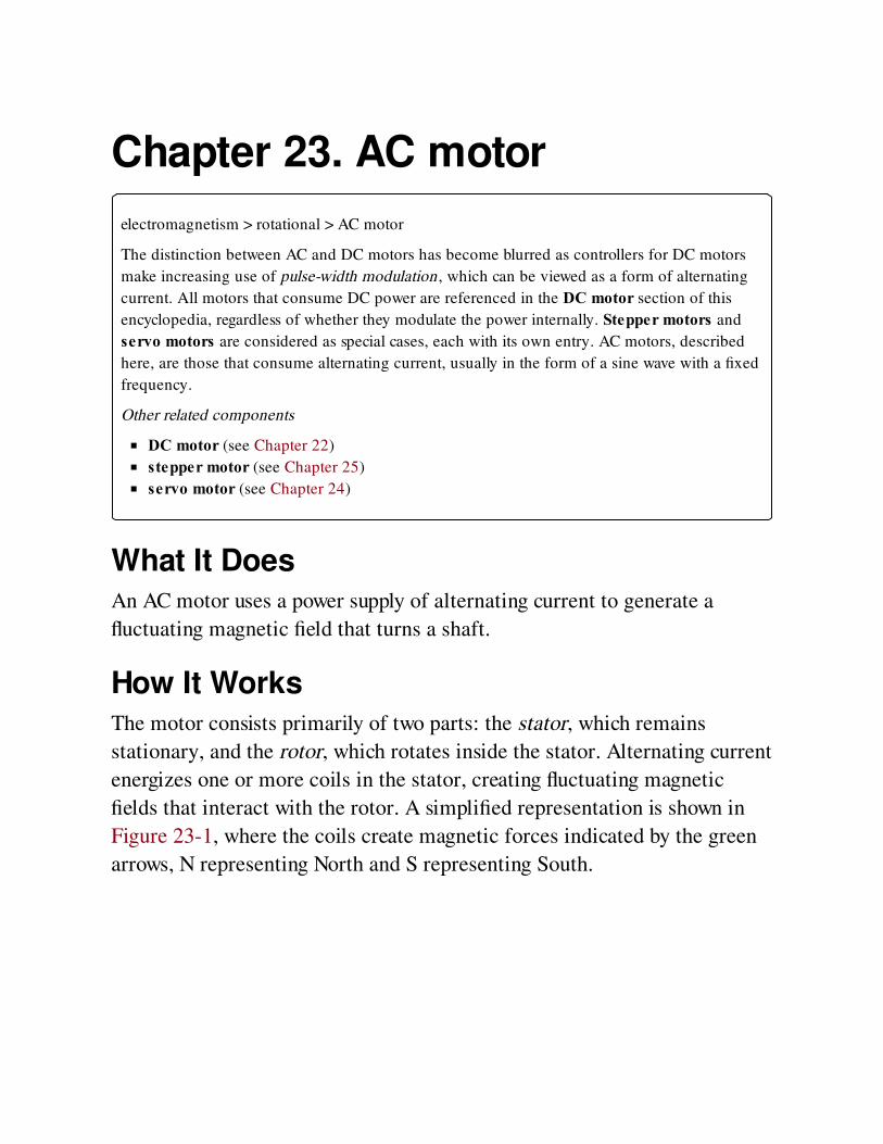
Chapter 23. AC motor
electromagnetism > rotational > AC motor
The distinction between AC and DC motors has become blurred as controllers for DC motors
make increasing use of pulse-width modulation, which can be viewed as a form of alternating
current. All motors that consume DC power are referenced in the DC motor section of this
encyclopedia, regardless of whether they modulate the power internally. Stepper motors and
servo motors are considered as special cases, each with its own entry. AC motors, described
here, are those that consume alternating current, usually in the form of a sine wave with a fixed
frequency.
Other related components
DC motor (see Chapter 22)
stepper motor (see Chapter 25)
servo motor (see Chapter 24)
What It DoesAn AC motor uses a power supply of alternating current to generate a
fluctuating magnetic field that turns a shaft.
How It WorksThe motor consists primarily of two parts: the stator, which remains
stationary, and the rotor, which rotates inside the stator. Alternating current
energizes one or more coils in the stator, creating fluctuating magnetic
fields that interact with the rotor. A simplified representation is shown in
Figure 23-1, where the coils create magnetic forces indicated by the green
arrows, N representing North and S representing South.

Figure 23-1. A simplified representation of a basic AC motor. The green arrows indicatemagnetic force.
Stator DesignPlug-in electric fans typically use AC motors. The stator from a large
electric fan is shown in Figure 23-2, where the large diameter of each coil
maximizes its magnetic effect. The stator from a smaller electric fan is
shown in Figure 23-3, in which only one coil is used. (The coil is wrapped
in black electrical tape.)
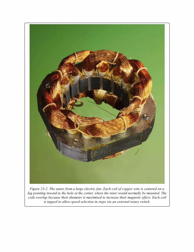
Figure 23-2. The stator from a large electric fan. Each coil of copper wire is centered on alug pointing inward to the hole at the center, where the rotor would normally be mounted. Thecoils overlap because their diameter is maximized to increase their magnetic effect. Each coil
is tapped to allow speed selection in steps via an external rotary switch.
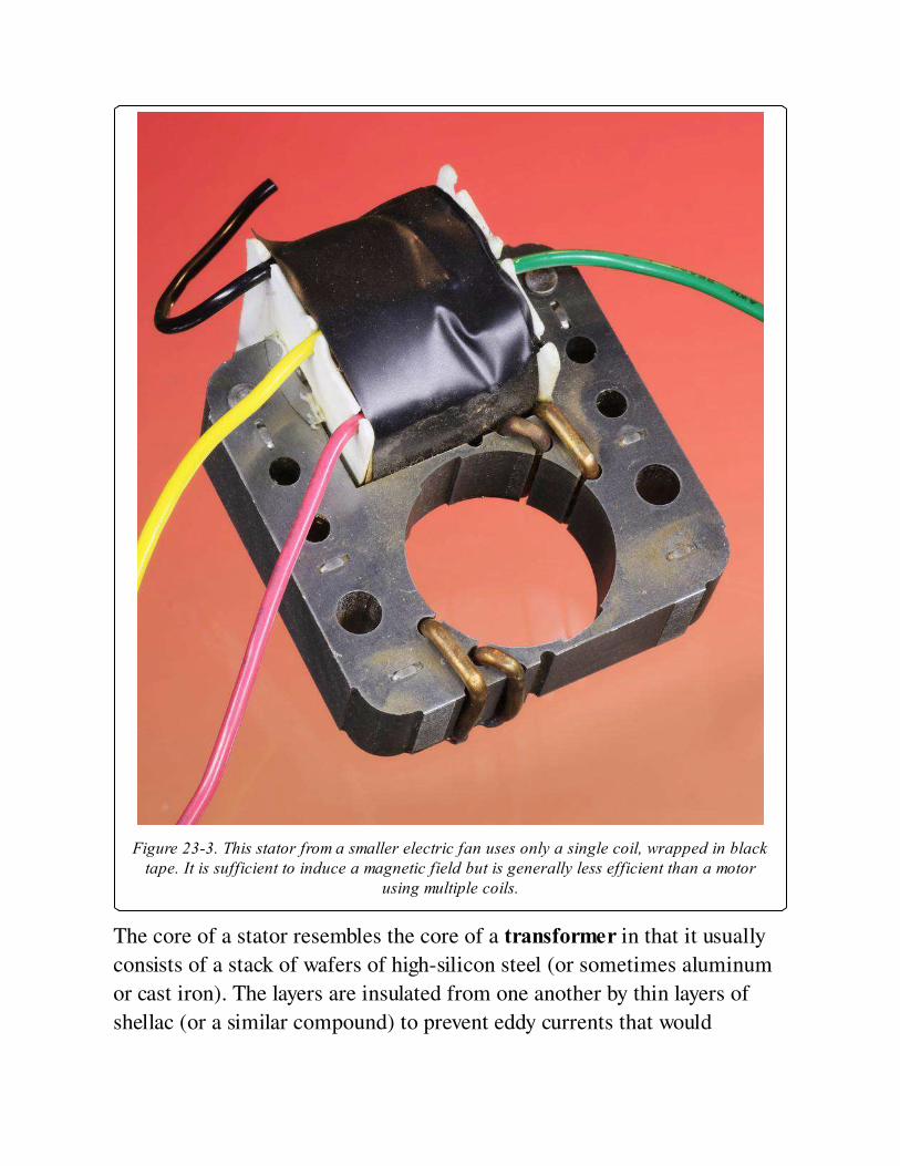
Figure 23-3. This stator from a smaller electric fan uses only a single coil, wrapped in blacktape. It is sufficient to induce a magnetic field but is generally less efficient than a motor
using multiple coils.
The core of a stator resembles the core of a transformer in that it usually
consists of a stack of wafers of high-silicon steel (or sometimes aluminum
or cast iron). The layers are insulated from one another by thin layers of
shellac (or a similar compound) to prevent eddy currents that would
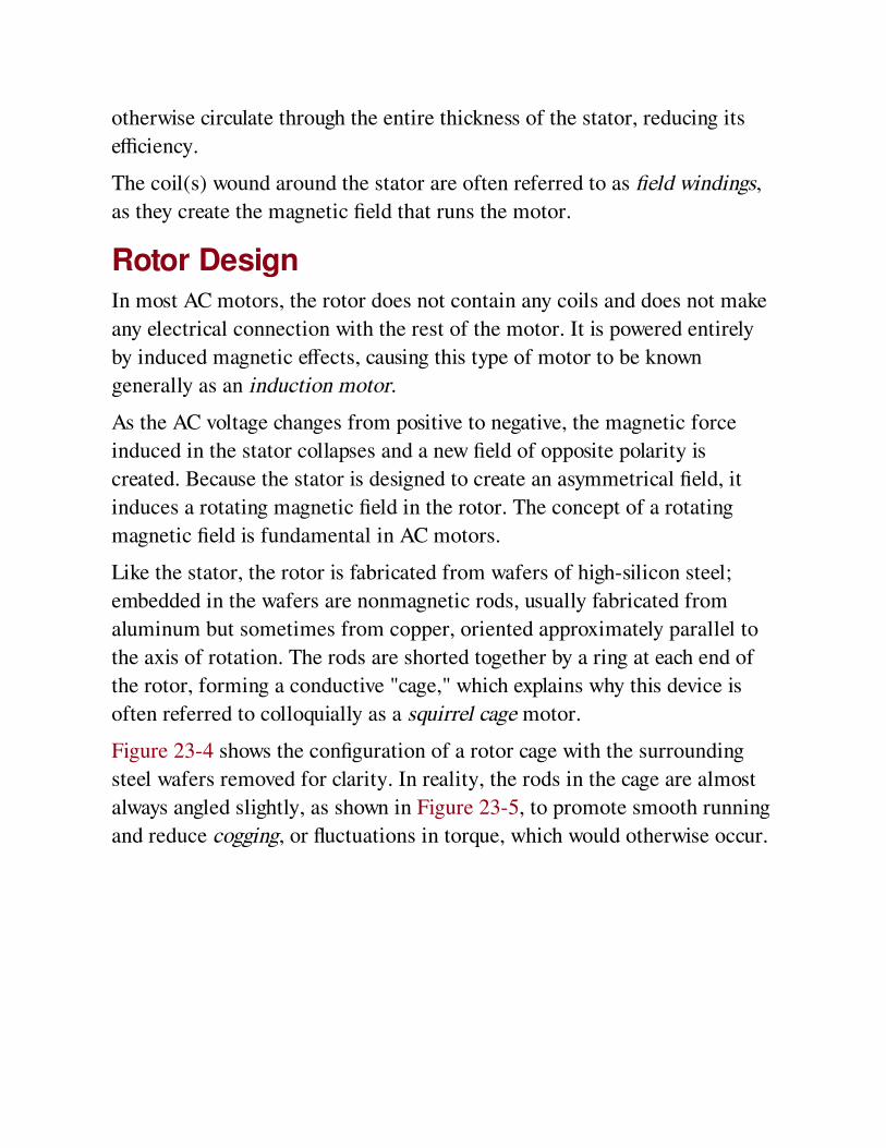
otherwise circulate through the entire thickness of the stator, reducing its
efficiency.
The coil(s) wound around the stator are often referred to as field windings,
as they create the magnetic field that runs the motor.
Rotor DesignIn most AC motors, the rotor does not contain any coils and does not make
any electrical connection with the rest of the motor. It is powered entirely
by induced magnetic effects, causing this type of motor to be known
generally as an induction motor.
As the AC voltage changes from positive to negative, the magnetic force
induced in the stator collapses and a new field of opposite polarity is
created. Because the stator is designed to create an asymmetrical field, it
induces a rotating magnetic field in the rotor. The concept of a rotating
magnetic field is fundamental in AC motors.
Like the stator, the rotor is fabricated from wafers of high-silicon steel;
embedded in the wafers are nonmagnetic rods, usually fabricated from
aluminum but sometimes from copper, oriented approximately parallel to
the axis of rotation. The rods are shorted together by a ring at each end of
the rotor, forming a conductive "cage," which explains why this device is
often referred to colloquially as a squirrel cage motor.
Figure 23-4 shows the configuration of a rotor cage with the surrounding
steel wafers removed for clarity. In reality, the rods in the cage are almost
always angled slightly, as shown in Figure 23-5, to promote smooth running
and reduce cogging, or fluctuations in torque, which would otherwise occur.

Figure 23-4. The rotor of a typical AC motor contains a cage of aluminum (or sometimescopper) in which eddy currents occur, as a result of the rotating magnetic field inside the steelbody of the rotor (which is omitted here for clarity). These currents cause their own magnetic
fields, which interact with the fields generated by coils in the stator.
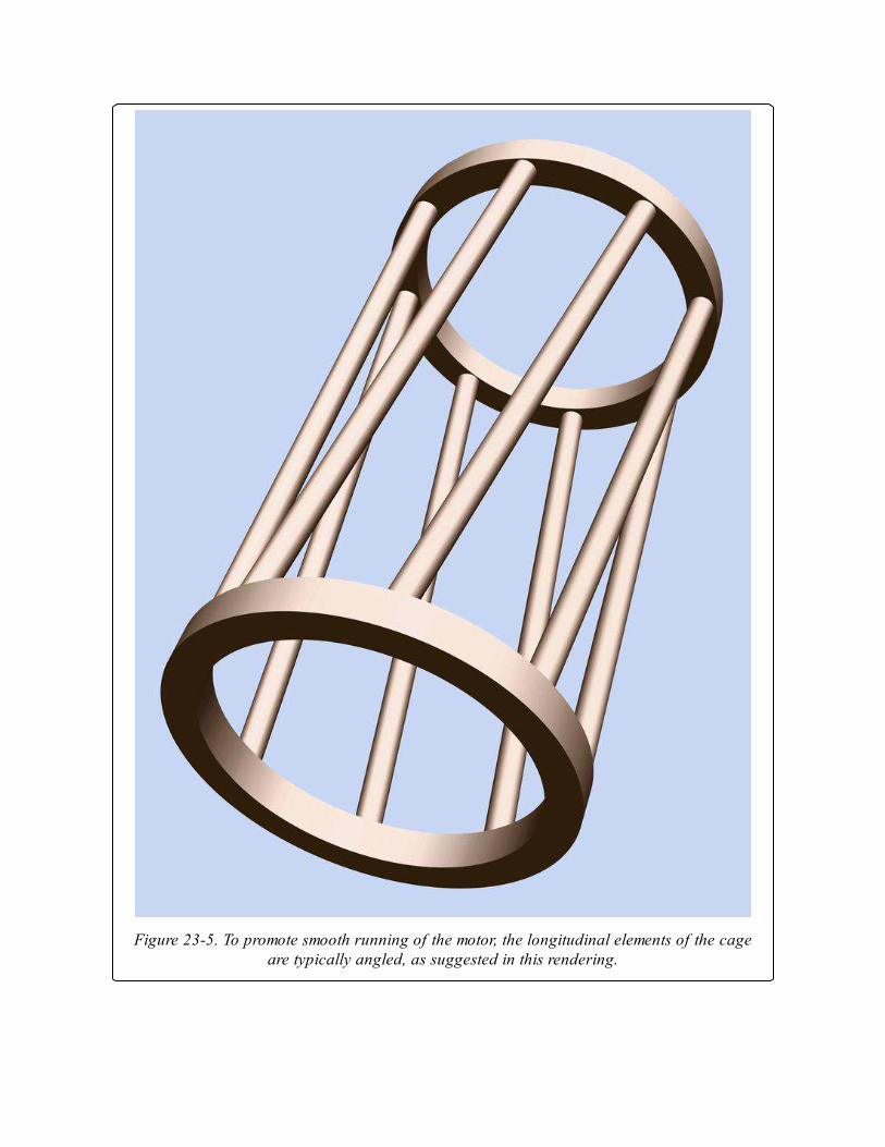
Figure 23-5. To promote smooth running of the motor, the longitudinal elements of the cageare typically angled, as suggested in this rendering.
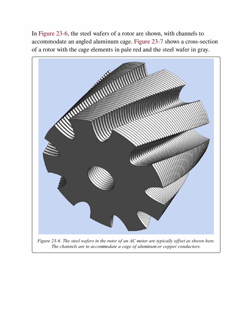
In Figure 23-6, the steel wafers of a rotor are shown, with channels to
accommodate an angled aluminum cage. Figure 23-7 shows a cross-section
of a rotor with the cage elements in pale red and the steel wafer in gray.
Figure 23-6. The steel wafers in the rotor of an AC motor are typically offset as shown here.The channels are to accommodate a cage of aluminum or copper conductors.
Figure 23-7. Cross-section of a rotor with steel shown in gray and embedded elements of analuminum cage shown in pale red.
The actual rotor from an induction motor is shown in Figure 23-8. This
rotor was removed from the stator shown in Figure 23-3. The bearings at
either end of the rotor were bolted to the stator until disassembly.
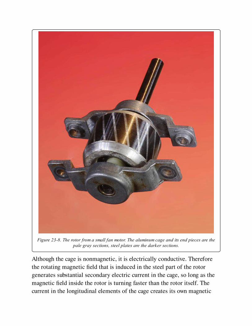
Figure 23-8. The rotor from a small fan motor. The aluminum cage and its end pieces are thepale gray sections, steel plates are the darker sections.
Although the cage is nonmagnetic, it is electrically conductive. Therefore
the rotating magnetic field that is induced in the steel part of the rotor
generates substantial secondary electric current in the cage, so long as the
magnetic field inside the rotor is turning faster than the rotor itself. The
current in the longitudinal elements of the cage creates its own magnetic
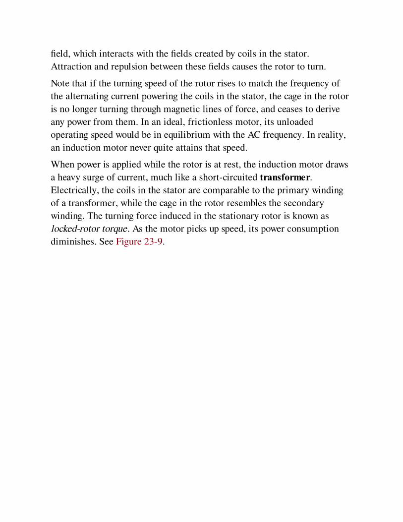
field, which interacts with the fields created by coils in the stator.
Attraction and repulsion between these fields causes the rotor to turn.
Note that if the turning speed of the rotor rises to match the frequency of
the alternating current powering the coils in the stator, the cage in the rotor
is no longer turning through magnetic lines of force, and ceases to derive
any power from them. In an ideal, frictionless motor, its unloaded
operating speed would be in equilibrium with the AC frequency. In reality,
an induction motor never quite attains that speed.
When power is applied while the rotor is at rest, the induction motor draws
a heavy surge of current, much like a short-circuited transformer.
Electrically, the coils in the stator are comparable to the primary winding
of a transformer, while the cage in the rotor resembles the secondary
winding. The turning force induced in the stationary rotor is known as
locked-rotor torque. As the motor picks up speed, its power consumption
diminishes. See Figure 23-9.
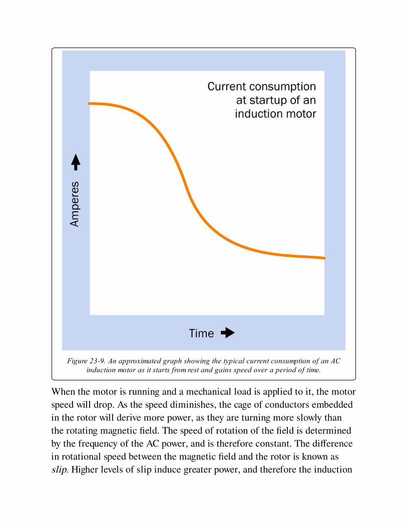
Figure 23-9. An approximated graph showing the typical current consumption of an ACinduction motor as it starts from rest and gains speed over a period of time.
When the motor is running and a mechanical load is applied to it, the motor
speed will drop. As the speed diminishes, the cage of conductors embedded
in the rotor will derive more power, as they are turning more slowly than
the rotating magnetic field. The speed of rotation of the field is determined
by the frequency of the AC power, and is therefore constant. The difference
in rotational speed between the magnetic field and the rotor is known as
slip. Higher levels of slip induce greater power, and therefore the induction
motor will automatically find an equilibrium for any load within its
designed range.
When running under full load, a small induction motor may have a slip
value from 4 to 6 percent. In larger motors, this value will be lower.
VariantsVariants of the generic induction motor described above are generally
designed to take advantage of either single-phase or three-phase alternating
current.
A synchronous motor is a variant in which the rotor maintains a constant
speed of rotation regardless of small fluctuations in load.
Some AC motors incorporate a commutator, which allows an external
connection to coils mounted on the rotor, and can enable variable speed
control.
A linear motor may consist of two rows of coils, energized by a sequence of
pulses that can move a permanent magnet or electromagnet between the
coils. Alternatively, the linear motor’s coils may move as a result of
magnetic interaction with a segmented fixed rail. Detailed description of
linear motors is outside the scope of this encyclopedia.
Single-Phase Induction MotorThe majority of induction motors run on single-phase alternating current
(typically, from domestic wall outlets). This type of motor is not innately
self-starting because the stator coils and rotor are symmetrical. This tends
to result in vibration rather than rotation.
To initiate rotation, the stator design is modified so that it induces an
asymmetrical magnetic field, which is more powerful in one direction than
the other. The simplest way to achieve this is by adding one or more
shorting coils to the stator. Each shorting coil is often just a circle of heavy-
gauge copper wire. This ploy reduces the efficiency of the motor and
impairs its starting torque, and is generally used in small devices such as
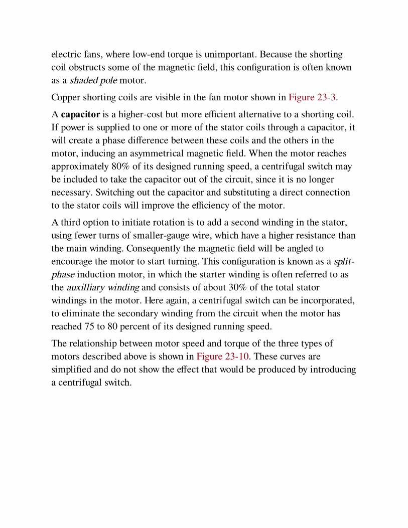
electric fans, where low-end torque is unimportant. Because the shorting
coil obstructs some of the magnetic field, this configuration is often known
as a shaded pole motor.
Copper shorting coils are visible in the fan motor shown in Figure 23-3.
A capacitor is a higher-cost but more efficient alternative to a shorting coil.
If power is supplied to one or more of the stator coils through a capacitor, it
will create a phase difference between these coils and the others in the
motor, inducing an asymmetrical magnetic field. When the motor reaches
approximately 80% of its designed running speed, a centrifugal switch may
be included to take the capacitor out of the circuit, since it is no longer
necessary. Switching out the capacitor and substituting a direct connection
to the stator coils will improve the efficiency of the motor.
A third option to initiate rotation is to add a second winding in the stator,
using fewer turns of smaller-gauge wire, which have a higher resistance than
the main winding. Consequently the magnetic field will be angled to
encourage the motor to start turning. This configuration is known as a split-
phase induction motor, in which the starter winding is often referred to as
the auxilliary winding and consists of about 30% of the total stator
windings in the motor. Here again, a centrifugal switch can be incorporated,
to eliminate the secondary winding from the circuit when the motor has
reached 75 to 80 percent of its designed running speed.
The relationship between motor speed and torque of the three types of
motors described above is shown in Figure 23-10. These curves are
simplified and do not show the effect that would be produced by introducing
a centrifugal switch.
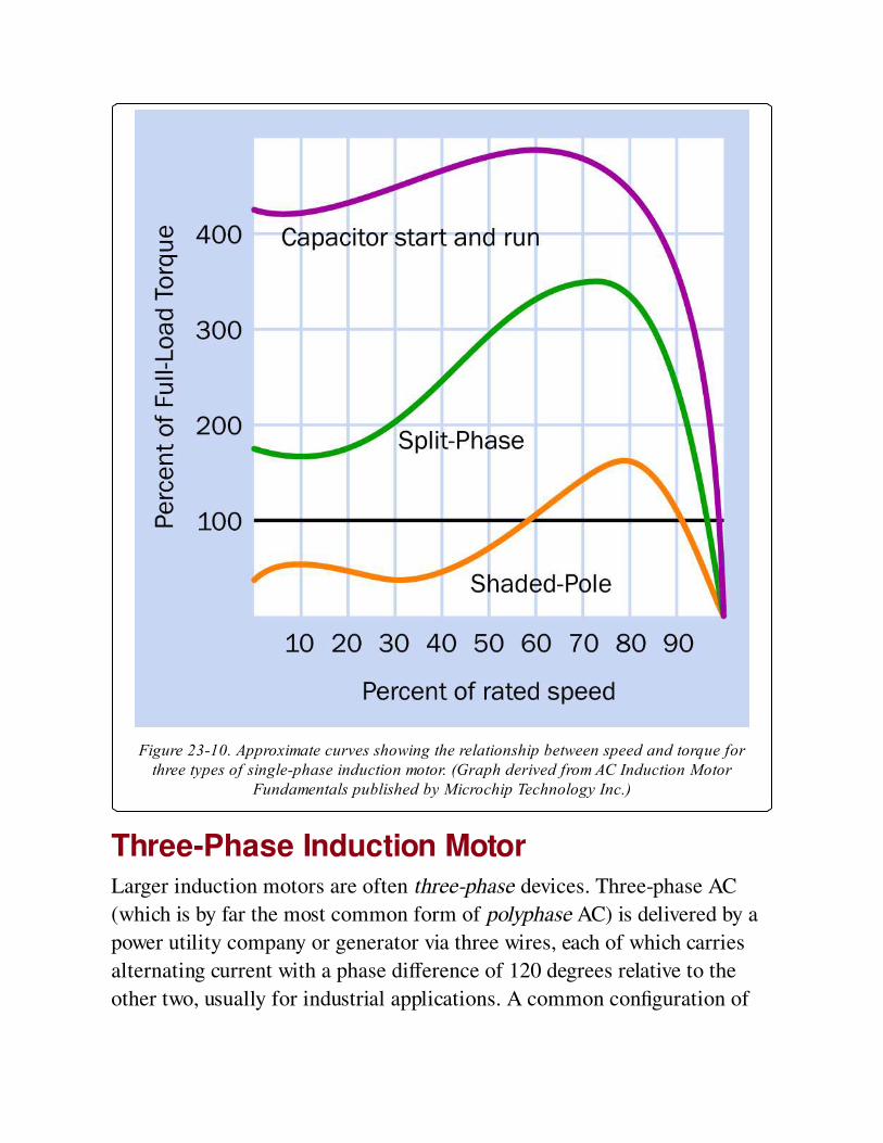
Figure 23-10. Approximate curves showing the relationship between speed and torque forthree types of single-phase induction motor. (Graph derived from AC Induction Motor
Fundamentals published by Microchip Technology Inc.)
Three-Phase Induction MotorLarger induction motors are often three-phase devices. Three-phase AC
(which is by far the most common form of polyphase AC) is delivered by a
power utility company or generator via three wires, each of which carries
alternating current with a phase difference of 120 degrees relative to the
other two, usually for industrial applications. A common configuration of
stator coils for a three-phase motor is shown in Figure 23-11. Since the
three wires take it in turns to deliver their peak voltage, they are ideally
suited to turn the stator of a motor via induction, and no shorting coil or
capacitor is needed for startup. Heavy-duty 3-phase induction motors are
extremely reliable, being brushless and generally maintenance-free.

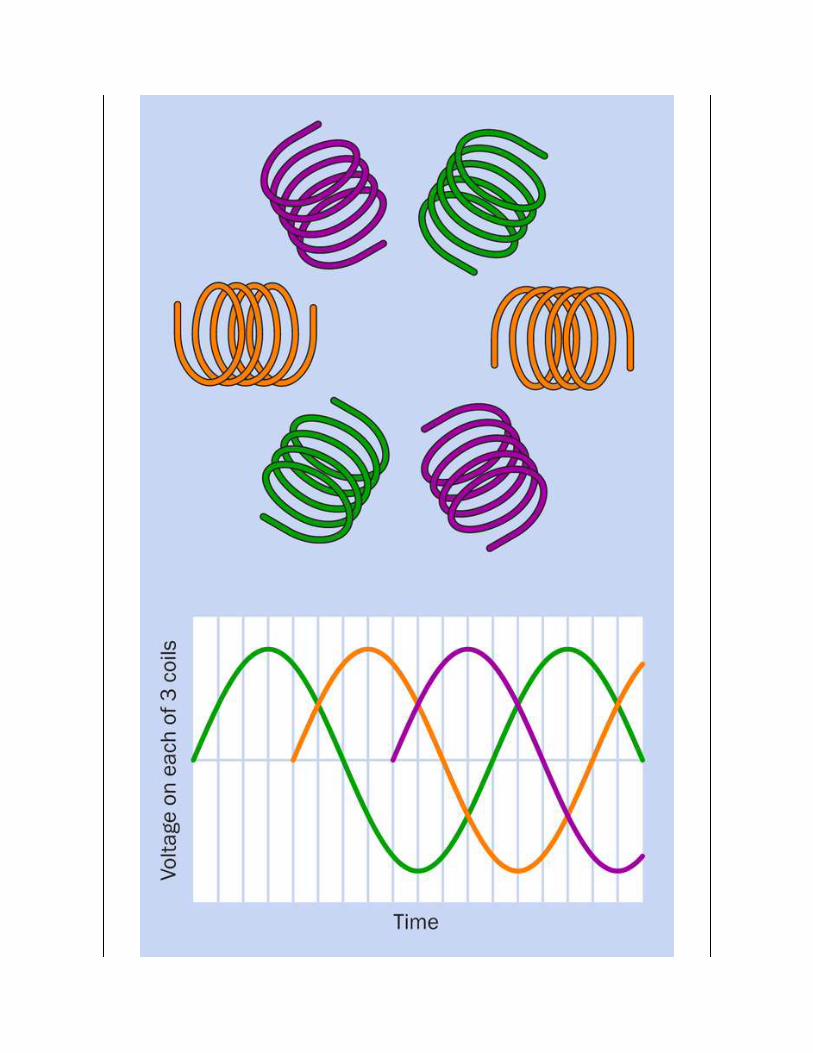
Figure 23-11. The graph shows voltage delivered via three wires constituting a three-phasepower supply. (The curve colors are arbitrary.) A three-phase motor contains a multiple ofthree coils—often six, as shown here diagrammatically. The three wires of the power supply
are connected directly to the coils, which induce a rotating magnetic field.
Synchronous MotorA synchronous motor is a form of induction motor that is designed to reach
and maintain equilibrium when the rotor is turning in perfect
synchronization with the AC power supply. The speed of the motor will
depend on the number of poles (magnetic coils) in the stator, and the
number of phases in the power supply. If R is the RPM of a synchronous
motor, f is the frequency of the AC current in Hz, and p is the number of
poles per phase:
R = (120 * f) / p
This formula assumes 60Hz AC current. In nations where 50Hz AC is used,
the number 120 should be replaced with the number 100.
Two basic types of synchronous motors exist: direct current excited, which
require external power to start turning, and non-excited, which are self-
starting. Since non-excited synchronous motors are more common in
electronic applications, this encyclopedia will not deal with direct current
excited variants.
A hysteresis motor is a synchronous motor containing a solid rotor cast
from cobalt steel, which has high coercivity, meaning that once it is
magnetized, a substantial field is required to reverse the magnetic polarity.
Consequently the polarity of the rotor lags behind the constantly changing
polarity of the stator, creating an attracting force that turns the rotor.
Because the lag angle is independent of motor speed, this motor delivers
constant torque from startup.
Reluctance MotorReluctance is the magnetic equivalent to electrical resistance. If a piece of
iron is free to move in a magnetic field, it will tend to align itself with the
field to reduce the reluctance of the magnetic circuit. This principle was
used in very early reluctance motors designed to work from AC and has
been revived as electronics to control variable frequency drives have
become cheaper.
The simplest reluctance motor consists of a soft iron rotor with projecting
lugs, rotating within a stator that is magnetically energized with its own set
of inwardly projecting poles. The rotor tends to turn until its lugs are
aligned with the poles of the stator, thus minimizing the reluctance.
A basic reluctance motor design is shown in Figure 25-2. It is located in the
stepper motor section of this encyclopedia, as stepper motors are a
primary application of the reluctance principle.
Although a reluctance motor can be used with polyphase fixed-frequency AC
power, a variable frequency drive greatly enhances its usefulness. The
timing of the frequency is adjusted by the speed of the motor, which is
detected by a sensor. Thus the energizing pulses can remain "one step
ahead" of the rotor. Since the rotor is not a magnet, it generates no back-
EMF, allowing it to reach very high speeds.
The simplicity of the motor itself is a compensating factor for the cost of
the electronics, as it requires no commutator, brushes, permanent magnets,
or rotor windings. Characteristics of reluctance motors include:
Cheap parts, easily manufactured, and high reliability.
Compact size and low weight.
Efficiencies greater than 90% possible.
Capable of high start-up torque and high speed operation.
Disadvantages include noise, cogging, and tight manufacturing tolerances,
as the air gap between the rotor and stator must be minimized.
A reluctance motor can function synchronously, if it is designed for that
purpose.
Variable Frequency Drive
A basic induction motor suffers from significant problems. The surge of
power that it draws when starting from rest can pull down the supply voltage
enough to affect other devices that share the AC power supply. (Hence, the
brief dimming of lights that may occur when the compressor in an air
conditioner or refrigerator starts running.) While the motor is turning, it
can introduce electrical noise, which feeds back into the power supply, once
again causing potential problems for other devices. In addition, the narrow
range of speed of an AC induction motor is a great disadvantage.
The advent of cheap solid-state technology encouraged the development of
variable-frequency power supplies for induction motors. Because the
impedance of the motor will diminish as the frequency diminishes, the
current drawn by the motor will tend to increase. To prevent this, a variable
frequency supply also varies the voltage that it delivers.
Wound-Rotor AC Induction MotorThe stator of this variant is basically the same as that of a single-phase
induction motor, but the rotor contains its own set of coils. These are
electrically accessible via a commutator and brushes, as in a DC motor.
Because the maximum torque (also known as pull-out torque) will be
proportional to the electrical resistance of the coils in the rotor, the
characteristics of the motor can be adjusted by adding or removing
resistance externally, via the commutator. A higher resistance will enable
greater torque at low speed when the slip between the rotor speed and
rotation of the magnetic field induced by the stator is greatest. This is
especially useful in corded power tools such as electric drills, where high
torque at low speed is desirable, yet the motor can accelerate to full speed
quickly when the external resistance is reduced. Typically, the resistance is
adjusted via the trigger of the drill.
Figure 23-12 shows a wound-rotor AC induction motor. The disadvantage
of this configuration is the brushes that supply power to the rotor will
eventually require maintenance. Much larger wound-rotor motors are also

used in industrial applications such as printing presses and elevators, where
the need for variable speed makes a simple three-phase motor unsuitable.

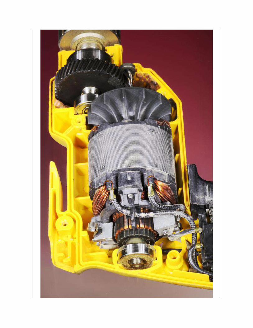

Figure 23-12. A motor in a corded electric drill uses coils in a brushed rotor to enablevariable speed output. In most AC motors, the speed is not adjustable and the rotor does not
make any electrical connection with the rest of the motor.
Universal MotorA wound-rotor motor may also be described as a universal motor if its
rotor and stator coils are connected in series. This configuration allows it to
be powered by either AC or DC.
DC supplied to the rotor and the stator will cause mutual magnetic
repulsion. When the rotor turns, the brushes touching the split commutator
reverse the polarity of voltage in the rotor coils, and the process repeats.
This configuration is very similar to that of a conventional DC motor,
except that the stator in a universal motor uses electromagnets instead of
the permanent magnets that are characteristic of a DC motor.
When powered by AC, the series connection between stator and rotor coils
insures that each pulse to the stator will be duplicated in the rotor, causing
mutual repulsion. The addition of a shorting coil in the stator provides the
necessary asymmetry in the magnetic field to make the motor start turning.
Universal motors are not limited by AC frequency, and are capable of
extremely high-speed operation. They have high starting torque, are
compact, and are cheap to manufacture. Applications include food blenders,
vacuum cleaners, and hair dryers. In a workshop, they are found in routers
and miniature power tools such as the Dremel series.
Because a universal motor requires commutator and brushes, it is only
suitable for intermittent use.
Inverted AC MotorsSome modern domestic appliances may seem to contain an AC motor, but
in fact the AC current is rectified to DC and is then processed with pulse-
width modulation to allow variable speed control. The motor is really a DCmotor; see the entry on this type of motor for additional information.

ValuesBecause a basic AC induction motor is governed by the frequency of the
power supply, the speed of a typical four-pole motor is limited to less than
1,800 RPM (1,500 RPM in nations where 50Hz AC is the norm).
Variable-frequency, universal, and wound-rotor motors overcome this
limitation, and can reach speeds of 10,000 to 30,000 RPM. Synchronous
motors typically run at 1,800 or 1,200 RPM, depending on the number of
poles in the motor. (They run at 1,500 or 1,000 RPM in locations where the
frequency of AC is 50Hz rather than 60Hz).
For a discussion of the torque that can be created by a motor, see Values in
the DC motor entry in this encyclopedia.
How to Use ItOld-fashioned record players (where a turntable supports a vinyl disc that
must rotate at a fixed speed) and electric clocks (of the analogue type) were
major applications for synchronous motors, which used the frequency of the
AC power supply to control motor speed. These applications have been
superceded by CD players (usually powered by brushless DC motors) and
digital clocks (which use crystal oscillators).
Many home appliances continue to use AC-powered induction motors.
Small cooling fans for use in electronic equipment are sometimes AC-
powered, reducing the current that must be provided by the DC power
supply. An induction motor generally tends to be heavier and less efficient
than other types, and its speed limit imposed by the frequency of the AC
power supply is a significant disadvantage.
A simple induction motor cannot provide the sophisticated control that is
necessary in modern devices such as CD or DVD players, ink-jet printers,
and scanners. A stepper motor, servo motor, and DC motors controlled
with pulse-width modulation are preferable in these applications.
A reluctance motor may find applications in high-speed, high-end
equipment including vacuum cleaners, fans, and pumps. Large variable
reluctance motors, with high amperage ratings, may be used to power
vehicles. Smaller variants are being used for power steering systems and
windshield wipers in some automobiles.
What Can Go WrongCompared with other devices that have moving parts, the brushless
induction motor is one of the most reliable and efficient devices ever
invented. However, there are many ways it can be damaged. General
problems affecting all types of motors are listed at Heat effects. Issues
relating specifically to AC motors are listed below.
Premature RestartLarge industrial three-phase induction motors can be damaged if power is
reapplied before the motor has stopped rotating.
Frequent RestartIf a motor is stopped and started repeatedly, the heat that is generated
during the initial surge of current is likely to be cumulative.
Undervoltage or Voltage ImbalanceA voltage drop can cause the motor to draw more current than it is rated to
handle. If this situation persists, overheating will result. Problems also are
caused in a three-phase motor where one phase is not voltage-balanced with
the others. The most common cause of this problem is an open circuit-
breaker, wiring fault, or blown fuse affecting just one of the three
conductors. The motor will try to run using the two conductors that are still
providing power, but the result is likely to be destructive.
Stalled Motor
When power is applied to an induction motor, if the motor is prevented
from turning, the conductors in the rotor will carry a large current that is
entirely dissipated as heat. This current surge will either burn out the motor
or blow a fuse or circuit breaker. Care should be taken, in equipment design,
to minimize the risk that an induction motor may stall or jam.
Protective RelaysSophisticated protective relays are available for industrial 3-phase motors,
and can guard against all of the faults itemized above. Their details are
outside the scope of this encyclopedia.
Excess TorqueAs has been previously noted, the torque of an induction motor increases
with the slip (speed difference) between the rotation of the magnetic field
and the rotation of the rotor. Consequently, if the motor is overloaded and
forced to run more slowly, it can deliver more rotational force. This can
destroy other parts attached to the motor, such as drive belts.
Internal BreakageAn overloaded induction motor may suffer some cracking or breakage of its
rotor. This may be obvious because of reduced power output or vibration,
but can also be detected if the motor’s power consumption changes
significantly.
Chapter 24. servo motor
electromagnetism > rotational > servo motor
Should be referred to as an RC servo if it is intended for use in small devices that are remote-
controlled and battery powered. However, in practice, the RC acronym is often omitted.
Other related components
AC motor (See Chapter 23)
DC motor (See Chapter 22)
stepper motor (See Chapter 25)
What It DoesA servo motor is actually a combination of a motor, reduction gearing, and
miniaturized control electronics, usually packaged together inside a very
compact sealed plastic case. The motor itself may be AC or DC, and if DC,
it may be brushed or brushless. What distinguishes a servo from other types
of motor is that it is not designed for continuous rotation. It is a position-
seeking device. Its rotational range may be more than 180 degrees but will
be significantly less than 360 degrees. Two typical RC servos are shown in
Figure 24-1. A side view of a motor is shown in Figure 24-2.
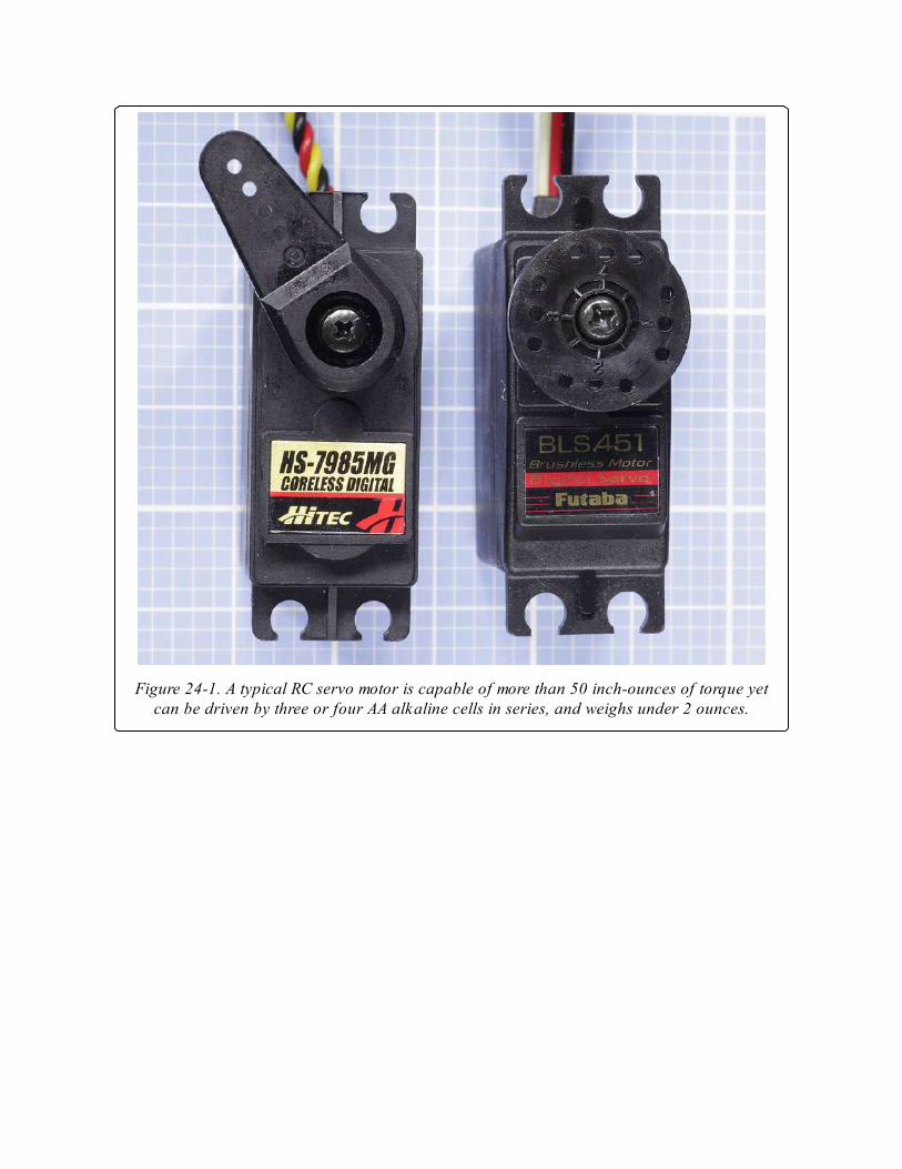
Figure 24-1. A typical RC servo motor is capable of more than 50 inch-ounces of torque yetcan be driven by three or four AA alkaline cells in series, and weighs under 2 ounces.
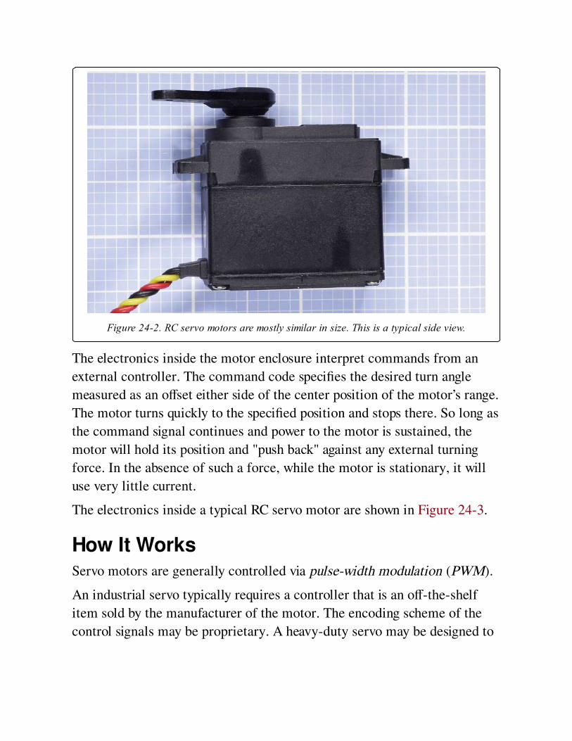
Figure 24-2. RC servo motors are mostly similar in size. This is a typical side view.
The electronics inside the motor enclosure interpret commands from an
external controller. The command code specifies the desired turn angle
measured as an offset either side of the center position of the motor’s range.
The motor turns quickly to the specified position and stops there. So long as
the command signal continues and power to the motor is sustained, the
motor will hold its position and "push back" against any external turning
force. In the absence of such a force, while the motor is stationary, it will
use very little current.
The electronics inside a typical RC servo motor are shown in Figure 24-3.
How It WorksServo motors are generally controlled via pulse-width modulation (PWM).
An industrial servo typically requires a controller that is an off-the-shelf
item sold by the manufacturer of the motor. The encoding scheme of the
control signals may be proprietary. A heavy-duty servo may be designed to
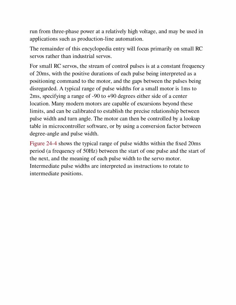
run from three-phase power at a relatively high voltage, and may be used in
applications such as production-line automation.
The remainder of this encyclopedia entry will focus primarily on small RC
servos rather than industrial servos.
For small RC servos, the stream of control pulses is at a constant frequency
of 20ms, with the positive durations of each pulse being interpreted as a
positioning command to the motor, and the gaps between the pulses being
disregarded. A typical range of pulse widths for a small motor is 1ms to
2ms, specifying a range of -90 to +90 degrees either side of a center
location. Many modern motors are capable of excursions beyond these
limits, and can be calibrated to establish the precise relationship between
pulse width and turn angle. The motor can then be controlled by a lookup
table in microcontroller software, or by using a conversion factor between
degree-angle and pulse width.
Figure 24-4 shows the typical range of pulse widths within the fixed 20ms
period (a frequency of 50Hz) between the start of one pulse and the start of
the next, and the meaning of each pulse width to the servo motor.
Intermediate pulse widths are interpreted as instructions to rotate to
intermediate positions.
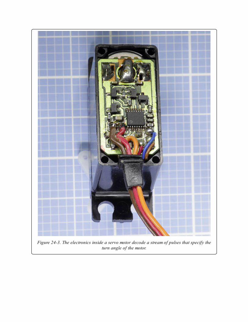
Figure 24-3. The electronics inside a servo motor decode a stream of pulses that specify theturn angle of the motor.
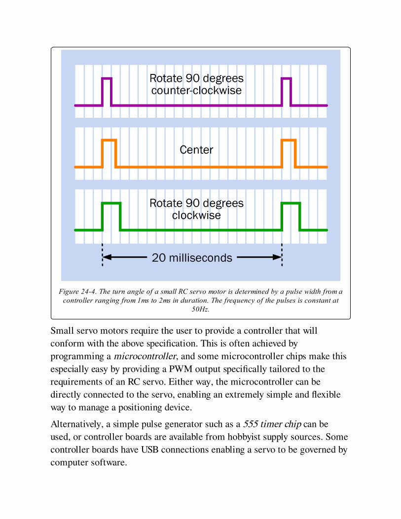
Figure 24-4. The turn angle of a small RC servo motor is determined by a pulse width from acontroller ranging from 1ms to 2ms in duration. The frequency of the pulses is constant at
50Hz.
Small servo motors require the user to provide a controller that will
conform with the above specification. This is often achieved by
programming a microcontroller, and some microcontroller chips make this
especially easy by providing a PWM output specifically tailored to the
requirements of an RC servo. Either way, the microcontroller can be
directly connected to the servo, enabling an extremely simple and flexible
way to manage a positioning device.
Alternatively, a simple pulse generator such as a 555 timer chip can be
used, or controller boards are available from hobbyist supply sources. Some
controller boards have USB connections enabling a servo to be governed by
computer software.
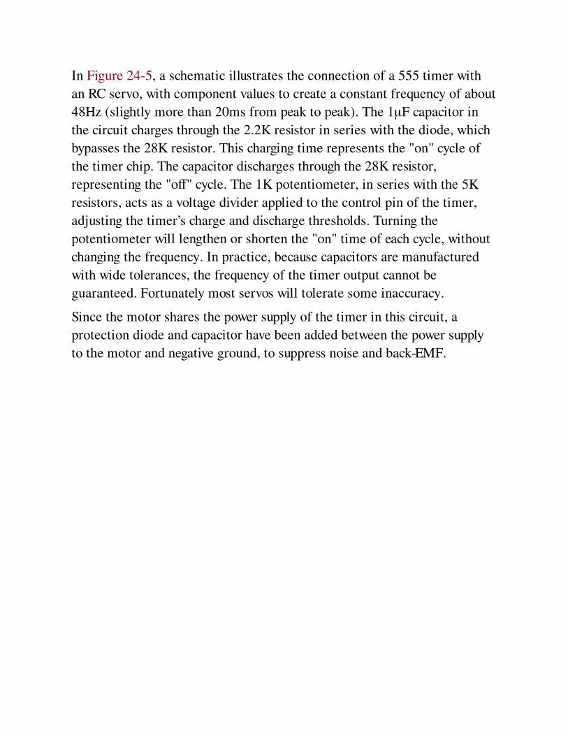
In Figure 24-5, a schematic illustrates the connection of a 555 timer with
an RC servo, with component values to create a constant frequency of about
48Hz (slightly more than 20ms from peak to peak). The 1μF capacitor in
the circuit charges through the 2.2K resistor in series with the diode, which
bypasses the 28K resistor. This charging time represents the "on" cycle of
the timer chip. The capacitor discharges through the 28K resistor,
representing the "off" cycle. The 1K potentiometer, in series with the 5K
resistors, acts as a voltage divider applied to the control pin of the timer,
adjusting the timer’s charge and discharge thresholds. Turning the
potentiometer will lengthen or shorten the "on" time of each cycle, without
changing the frequency. In practice, because capacitors are manufactured
with wide tolerances, the frequency of the timer output cannot be
guaranteed. Fortunately most servos will tolerate some inaccuracy.
Since the motor shares the power supply of the timer in this circuit, a
protection diode and capacitor have been added between the power supply
to the motor and negative ground, to suppress noise and back-EMF.
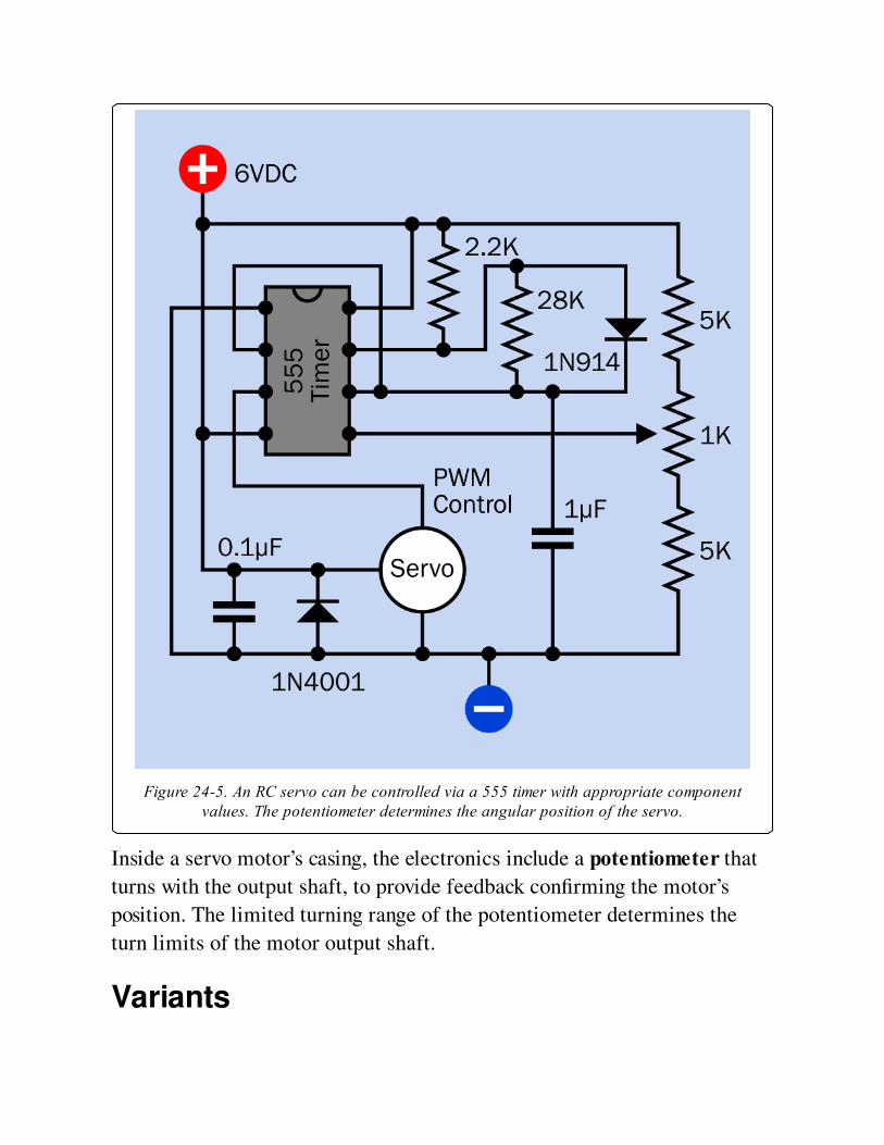
Figure 24-5. An RC servo can be controlled via a 555 timer with appropriate componentvalues. The potentiometer determines the angular position of the servo.
Inside a servo motor’s casing, the electronics include a potentiometer that
turns with the output shaft, to provide feedback confirming the motor’s
position. The limited turning range of the potentiometer determines the
turn limits of the motor output shaft.
Variants
Small servos may contain brushed or brushless DC motors. Naturally the
brushless motors have greater longevity and create less electrical noise. See
the DC motor entry in this encyclopedia for a discussion of brushed versus
brushless motors.
Servos may use nylon, "Karbonite," or metal reduction gearing. The nylon
gears inside a cheaper RC servo are shown in Figure 24-6.
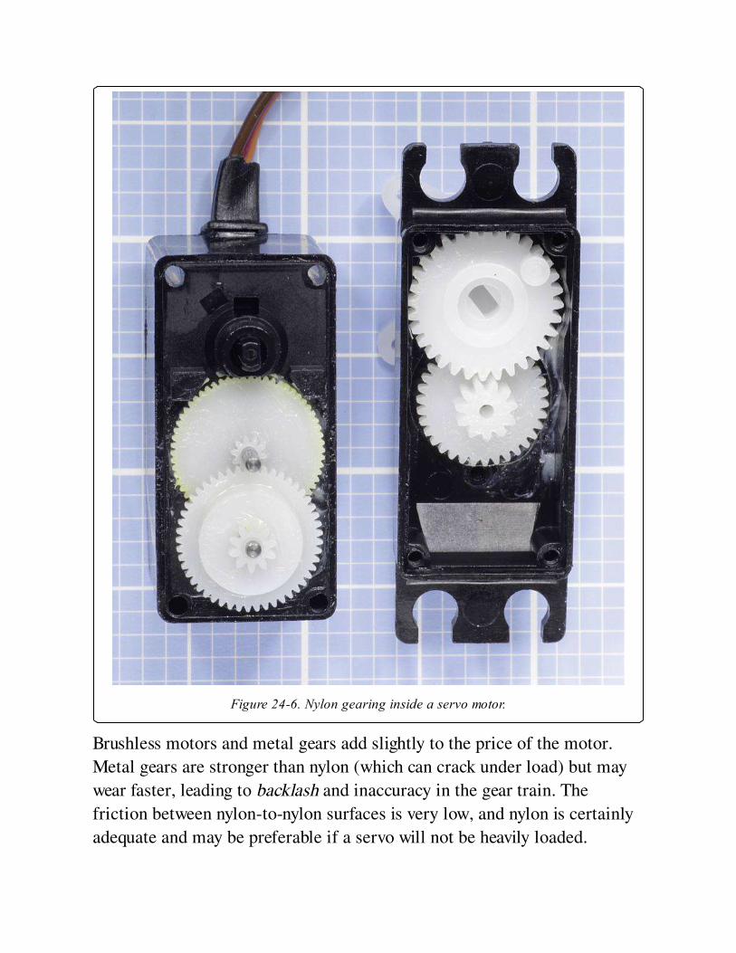
Figure 24-6. Nylon gearing inside a servo motor.
Brushless motors and metal gears add slightly to the price of the motor.
Metal gears are stronger than nylon (which can crack under load) but may
wear faster, leading to backlash and inaccuracy in the gear train. The
friction between nylon-to-nylon surfaces is very low, and nylon is certainly
adequate and may be preferable if a servo will not be heavily loaded.
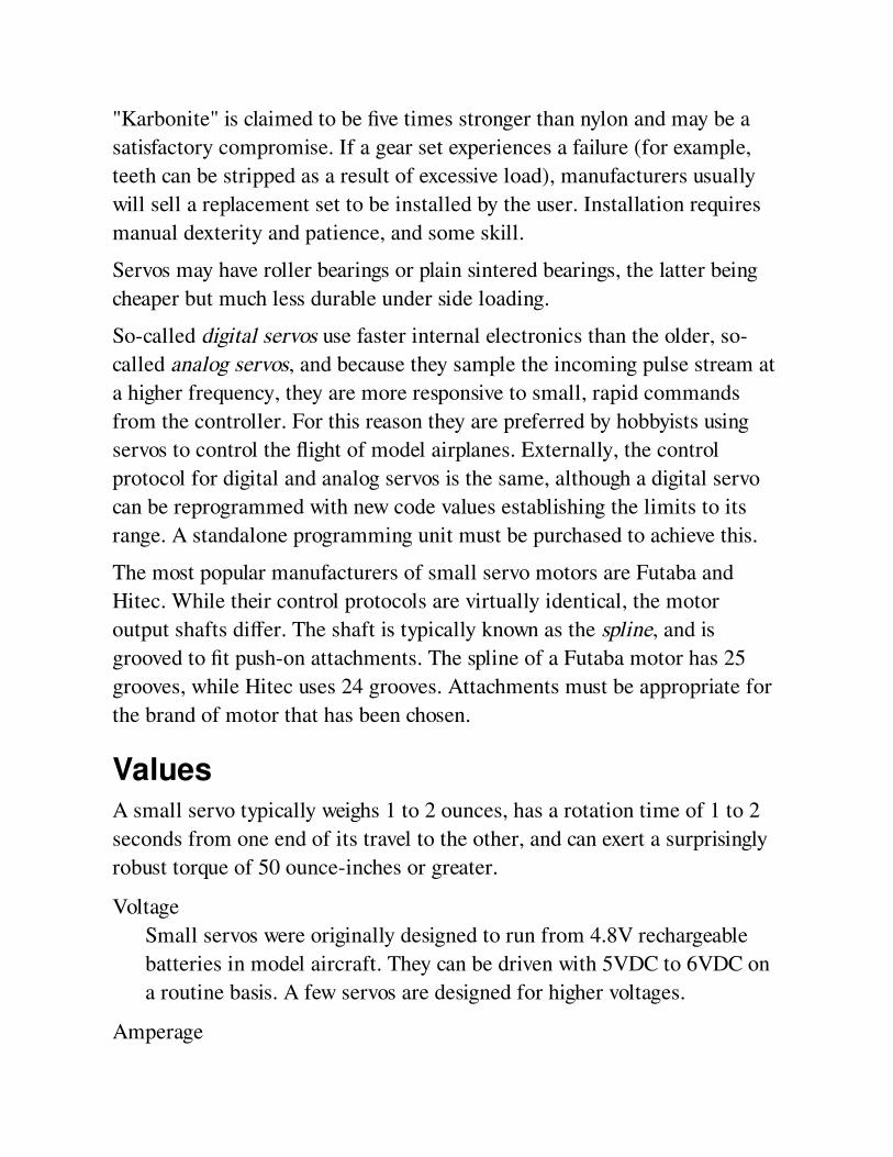
"Karbonite" is claimed to be five times stronger than nylon and may be a
satisfactory compromise. If a gear set experiences a failure (for example,
teeth can be stripped as a result of excessive load), manufacturers usually
will sell a replacement set to be installed by the user. Installation requires
manual dexterity and patience, and some skill.
Servos may have roller bearings or plain sintered bearings, the latter being
cheaper but much less durable under side loading.
So-called digital servos use faster internal electronics than the older, so-
called analog servos, and because they sample the incoming pulse stream at
a higher frequency, they are more responsive to small, rapid commands
from the controller. For this reason they are preferred by hobbyists using
servos to control the flight of model airplanes. Externally, the control
protocol for digital and analog servos is the same, although a digital servo
can be reprogrammed with new code values establishing the limits to its
range. A standalone programming unit must be purchased to achieve this.
The most popular manufacturers of small servo motors are Futaba and
Hitec. While their control protocols are virtually identical, the motor
output shafts differ. The shaft is typically known as the spline, and is
grooved to fit push-on attachments. The spline of a Futaba motor has 25
grooves, while Hitec uses 24 grooves. Attachments must be appropriate for
the brand of motor that has been chosen.
ValuesA small servo typically weighs 1 to 2 ounces, has a rotation time of 1 to 2
seconds from one end of its travel to the other, and can exert a surprisingly
robust torque of 50 ounce-inches or greater.
Voltage
Small servos were originally designed to run from 4.8V rechargeable
batteries in model aircraft. They can be driven with 5VDC to 6VDC on
a routine basis. A few servos are designed for higher voltages.
Amperage
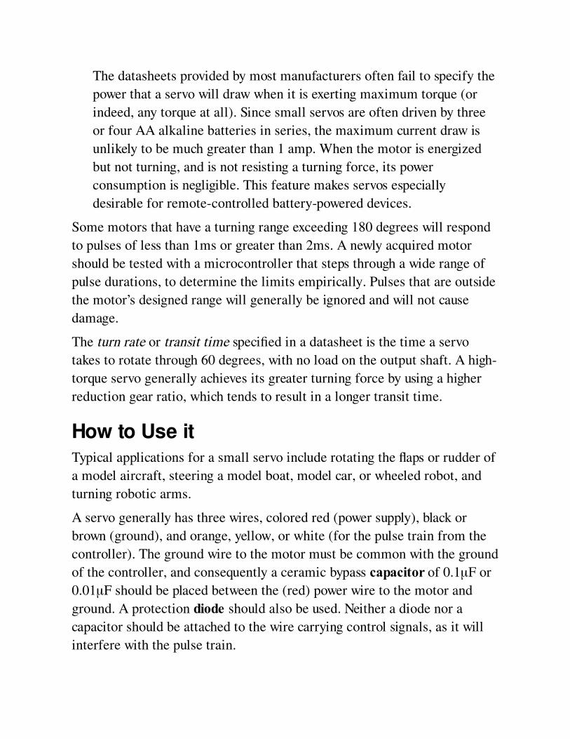
The datasheets provided by most manufacturers often fail to specify the
power that a servo will draw when it is exerting maximum torque (or
indeed, any torque at all). Since small servos are often driven by three
or four AA alkaline batteries in series, the maximum current draw is
unlikely to be much greater than 1 amp. When the motor is energized
but not turning, and is not resisting a turning force, its power
consumption is negligible. This feature makes servos especially
desirable for remote-controlled battery-powered devices.
Some motors that have a turning range exceeding 180 degrees will respond
to pulses of less than 1ms or greater than 2ms. A newly acquired motor
should be tested with a microcontroller that steps through a wide range of
pulse durations, to determine the limits empirically. Pulses that are outside
the motor’s designed range will generally be ignored and will not cause
damage.
The turn rate or transit time specified in a datasheet is the time a servo
takes to rotate through 60 degrees, with no load on the output shaft. A high-
torque servo generally achieves its greater turning force by using a higher
reduction gear ratio, which tends to result in a longer transit time.
How to Use itTypical applications for a small servo include rotating the flaps or rudder of
a model aircraft, steering a model boat, model car, or wheeled robot, and
turning robotic arms.
A servo generally has three wires, colored red (power supply), black or
brown (ground), and orange, yellow, or white (for the pulse train from the
controller). The ground wire to the motor must be common with the ground
of the controller, and consequently a ceramic bypass capacitor of 0.1μF or
0.01μF should be placed between the (red) power wire to the motor and
ground. A protection diode should also be used. Neither a diode nor a
capacitor should be attached to the wire carrying control signals, as it will
interfere with the pulse train.
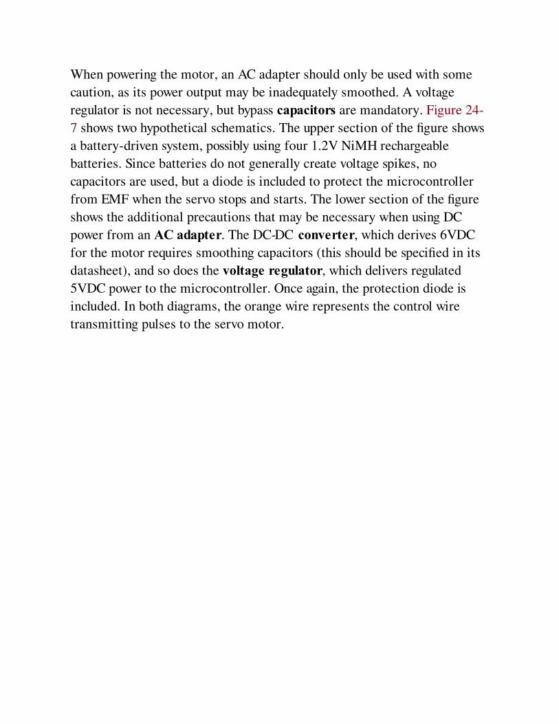
When powering the motor, an AC adapter should only be used with some
caution, as its power output may be inadequately smoothed. A voltage
regulator is not necessary, but bypass capacitors are mandatory. Figure 24-
7 shows two hypothetical schematics. The upper section of the figure shows
a battery-driven system, possibly using four 1.2V NiMH rechargeable
batteries. Since batteries do not generally create voltage spikes, no
capacitors are used, but a diode is included to protect the microcontroller
from EMF when the servo stops and starts. The lower section of the figure
shows the additional precautions that may be necessary when using DC
power from an AC adapter. The DC-DC converter, which derives 6VDC
for the motor requires smoothing capacitors (this should be specified in its
datasheet), and so does the voltage regulator, which delivers regulated
5VDC power to the microcontroller. Once again, the protection diode is
included. In both diagrams, the orange wire represents the control wire
transmitting pulses to the servo motor.
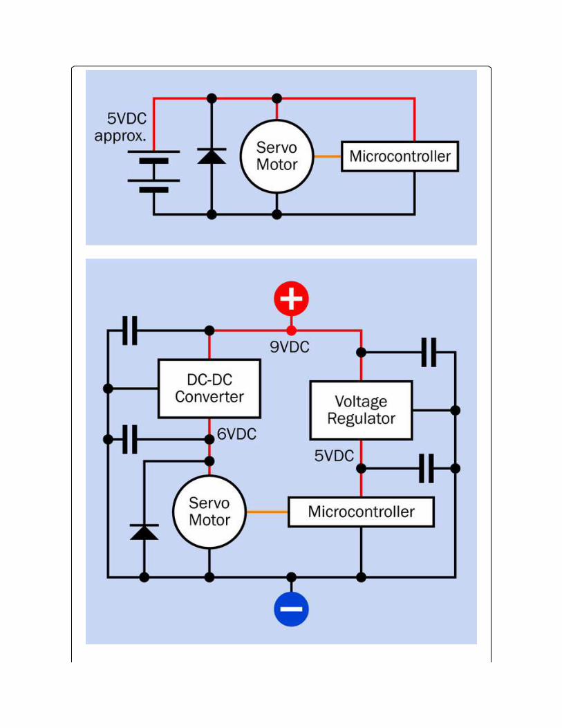
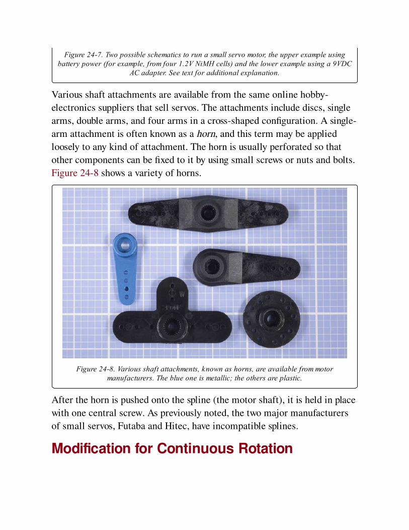
Figure 24-7. Two possible schematics to run a small servo motor, the upper example usingbattery power (for example, from four 1.2V NiMH cells) and the lower example using a 9VDC
AC adapter. See text for additional explanation.
Various shaft attachments are available from the same online hobby-
electronics suppliers that sell servos. The attachments include discs, single
arms, double arms, and four arms in a cross-shaped configuration. A single-
arm attachment is often known as a horn, and this term may be applied
loosely to any kind of attachment. The horn is usually perforated so that
other components can be fixed to it by using small screws or nuts and bolts.
Figure 24-8 shows a variety of horns.
Figure 24-8. Various shaft attachments, known as horns, are available from motormanufacturers. The blue one is metallic; the others are plastic.
After the horn is pushed onto the spline (the motor shaft), it is held in place
with one central screw. As previously noted, the two major manufacturers
of small servos, Futaba and Hitec, have incompatible splines.
Modification for Continuous Rotation
It is possible to modify a small servo motor so that it will rotate
continuously.
First the motor case must be opened, and the potentiometer must be
centered by using a controller to send some 1.5ms pulses. The
potentiometer must then be glued or otherwise secured with its wiper in this
precise center position, after which the potentiometer is disconnected from
the drive train.
Mechanical stops that would limit the rotation of the motor shaft must be
cut away, after which the motor is reassembled. Because the potentiometer
has been immobilized, the motor’s internal electronics will now "see" the
shaft as being in its center position at all times. If the controller sends a
pulse instructing the motor to seek a position clockwise or counter-
clockwise from center, the motor will rotate in an effort to reach that
position. Because the potentiometer will not provide feedback to signal that
the motor has achieved its goal, the shaft will continue to rotate
indefinitely.
In this mode, the primary distinguishing characteristic of the servo has
been disabled, in that it can no longer turn to a specific angle. Also,
stopping the servo may be problematic, as it must receive a command that
precisely matches the fixed position of the potentiometer. Since the
potentiometer may have moved fractionally during the process in which it
was immobilized, some trial and error may be needed to determine the
pulse width that corresponds with the potentiometer position.
The purpose of modifying a servo for continuous rotation is to take
advantage of its high torque, small size, light weight, and the ease of
controlling it with a microcontroller.
In response to the interest shown by hobbyists in modifying servos for
continuous rotation, some manufacturers now market servos with
continuous rotation as a built-in feature. Typically they include a trimmer
potentiometer to calibrate the motor, to establish its center-off position.
What Can Go Wrong
Incorrect WiringThe manufacturer’s datasheet should be checked to confirm the color
coding of the wires. While a simple DC motor can be reversed by inverting
the polarity of its power supply, this is totally inappropriate for a servo
motor.
Shaft/Horn MismatchAttachments for the spline of one brand of motor may not fit the spline of
another brand, and cannot be forced to fit.
Unrealistically Rapid Software CommandsMicrocontroller software that positions a servo must allow sufficient time
for the servo to respond before the software specifies a new position. It may
be necessary to insert delay loops or other wait times in the software.
JitterA servo arm that twitches unpredictably usually indicates that the pulse
train is being corrupted by external electrical noise. The control wire to the
servo should be as short as possible, and should not run closely adjacent to
conductors carrying AC or high frequency current switching, or control
wires for other servo motors.
Motor OverloadA servo capable of delivering 2 lbs of force 1 inch from its shaft can easily
generate enough torque, when it stalls, to break itself free from its mounts,
or bend or break any arm or linkage attached to its shaft. Ideally, a
relatively "weak link" should be included so that if breakage occurs, it will
be predictable and will be relatively easy and cheap to repair.
Unrealistic Duty Cycle
Small servos are designed for intermittent use. Constant cycling will cause
wear and tear, especially if the motor has a brushed commutator or metal
reduction gears.
Electrical NoiseBrushed motors are always a source of electrical interference, and any servo
will also tend to create a voltage dip or surge when it starts and stops. A
protection diode may be insufficient to isolate sensitive microcontrollers
and other integrated circuit chips. To minimize problems, the servo can be
driven by a source of positive voltage that is separate from the regulated
power supply used by the chips, and larger filter capacitors may be added to
the voltage supply of the microcontroller. A common ground between the
motor and the chips is unfortunately unavoidable.
Chapter 25. stepper motor
electromagnetism > rotational > stepper motor
Also often referred to as a stepping motor, and sometimes known as a step motor. It is a type
of induction motor but merits its own entry in this encyclopedia as it has acquired significant
and unique importance in electronics equipment where precise positioning of a moving part is
needed and digital control is available.
Other related components
DC motor (See Chapter 22)
AC motor (See Chapter 23)
servo motor (See Chapter 24)
What It DoesA stepper motor rotates its drive shaft in precise steps in response to a
timed sequence of pulses (usually one step per pulse). The pulses are
delivered to a series of coils or windings in the stator, which is the
stationary section of the motor, usually forming a ring around the rotor,
which is the part of the motor that rotates. Steps may also be referred to as
phases, and a motor that rotates in small steps may be referred to as having
a high phase count.
A stepper motor theoretically draws power for its stator coils at a constant
level that does not vary with speed. Consequently the torque tends to
decrease as the speed increases, and conversely, it is greatest when the
motor is stationary or locked.
The motor requires a suitable control system to provide the sequence of
pulses. The control system may consist of a small dedicated circuit, or a
microcontroller or computer with the addition of suitable driver transistors
capable of handling the necessary current. The torque curve of a motor can
be extended by using a controller that increases the voltage as the speed of
the control pulses increases.
Because the behavior of the motor is controlled by external electronics, and
its interior is usually symmetrical, a stepper motor can be driven backward
and forward with equal torque, and can also be held in a stationary position,
although the stator coils will continue to consume power in this mode.
How It WorksThe stator has multiple poles made from soft iron or other magnetic
material. Each pole is either energized by its own coil, or more commonly,
several poles share a single, large coil. In all types of stepper motor, sets of
stator poles are magnetized sequentially to turn the rotor and can remain
energized in one configuration to hold the rotor stationary.
The rotor may contain one or more permanent magnets, which interact
with the magnetic fields generated in the stator. Note that this is different
from a squirrel-cage AC motor in which a "cage" is embedded in the rotor
and interacts with a rotating magnetic field, but does not consist of
permanent magnets.
Three small stepper motors are shown in Figure 25-1. Clockwise from the
top-left, they are four-wire, five-wire, and six-wire types (this distinction is
explained in the following section). The motor at top-left has a threaded
shaft that can engage with a collar, so that as the motor shaft rotates
counter-clockwise and clockwise, the collar will be moved down and up.
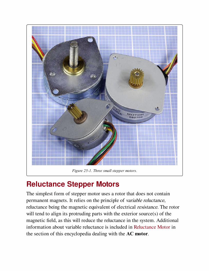
Figure 25-1. Three small stepper motors.
Reluctance Stepper MotorsThe simplest form of stepper motor uses a rotor that does not contain
permanent magnets. It relies on the principle of variable reluctance,
reluctance being the magnetic equivalent of electrical resistance. The rotor
will tend to align its protruding parts with the exterior source(s) of the
magnetic field, as this will reduce the reluctance in the system. Additional
information about variable reluctance is included in Reluctance Motor in
the section of this encyclopedia dealing with the AC motor.
A variable reluctance motor requires an external controller that simply
energizes the stator coils sequentially. This is shown in Figure 25-2, where
six poles (energized in pairs) are arrayed symmetrically around a rotor with
four protrusions, usually referred to as teeth. Six stator poles and four teeth
are the minimum numbers for reliable performance of a reluctance stepper
motor.

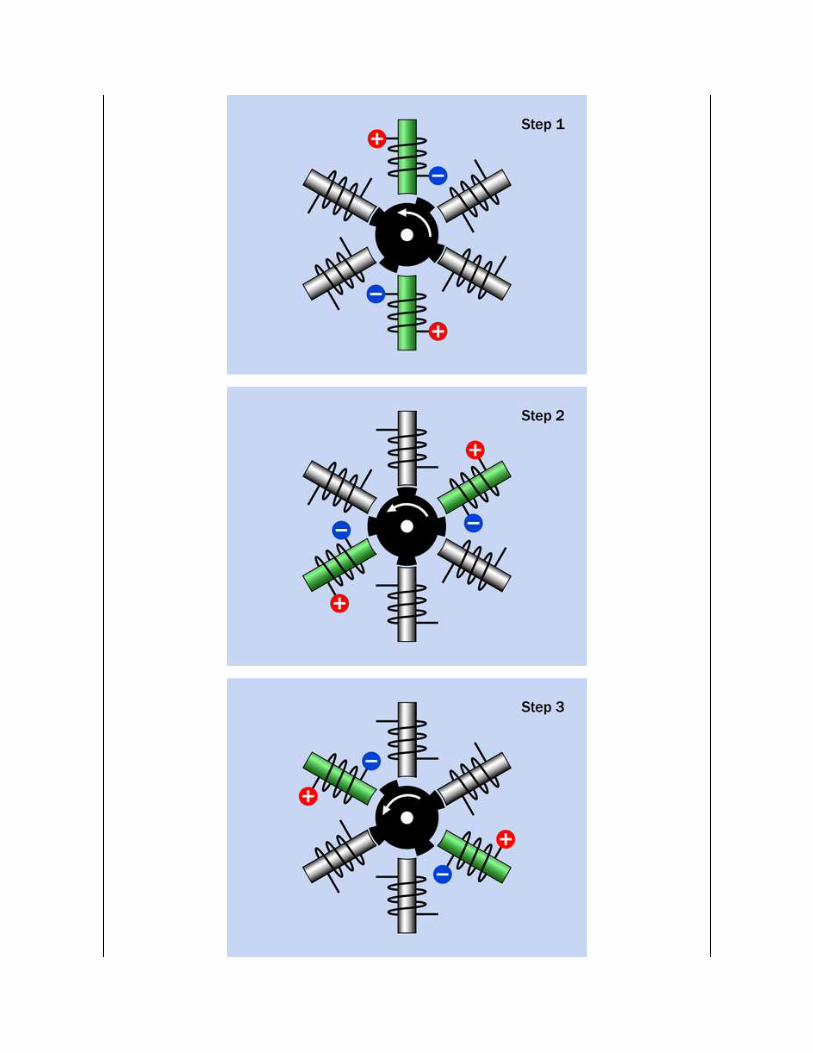

Figure 25-2. In a variable reluctance stepper motor, the rotor moves to minimize magneticreluctance each time the next pair of coils is energized. At each step, the coils have been
energized a moment before the rotor has had time to respond.
In the diagram, the core of each pole is tinted green when it is magnetized,
and is gray when it is not magnetized. In each section of this diagram, the
stator coils are shown when they have just been energized, and the rotor has
not yet had time to respond. External switching to energize the coils has
been omitted for simplicity. In a real motor, the rotor would have numerous
ridges, and the clearance between them and the stator would be extremely
narrow to maximize the magnetic effect.
In a 6-pole reluctance motor where the rotor has four teeth, each time the
controller energizes a new pair of poles, the rotor turns by 30 degrees
counter-clockwise. This is known as the step angle, and means that the
motor makes 12 steps in each full 360-degree rotation of its shaft. This
configuration is very similar to that of a 3-phase AC induction motor, as
shown in Figure 23-11 in the AC motor section of this encyclopedia.
However, the AC motor is designed to be plugged into a power source with a
constant frequency, and is intended to run smoothly and continuously, not
in discrete steps.
Generally, reluctance motors tend to be larger than those with magnetized
rotors, and often require feedback from a sensor that monitors shaft angle
and provides this information to control electronics. This is known as a
closed loop system. Most smaller stepper motors operate in an open loop
system, where positional feedback is considered unnecessary if the number
of pulses to the motor is counted as a means of tracking its position.
Permanent Magnet Stepper MotorsMore commonly, the rotor of a stepper motor contains permanent magnets,
which require the controller to be capable of reversing the magnetic field
created by each of the stator coils, so that they alternately attract and repel
the rotor magnets.

In a bipolar motor, the magnetic field generated by a coil is reversed simply
by reversing the current through it. This is shown diagrammatically in
Figure 25-3. In a unipolar motor, the magnetic field is reversed by applying
positive voltage to the center tap of a coil, and grounding one end or the
other. This is shown diagrammatically in Figure 25-4.
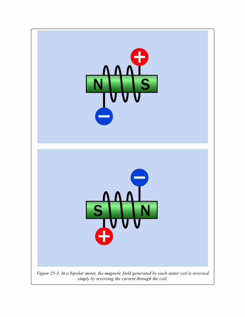
Figure 25-3. In a bipolar motor, the magnetic field generated by each stator coil is reversedsimply by reversing the current through the coil.
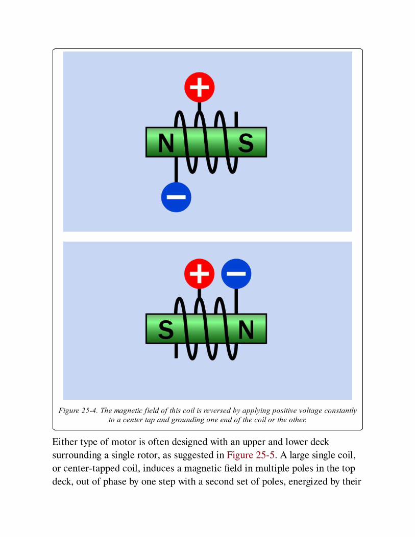
Figure 25-4. The magnetic field of this coil is reversed by applying positive voltage constantlyto a center tap and grounding one end of the coil or the other.
Either type of motor is often designed with an upper and lower deck
surrounding a single rotor, as suggested in Figure 25-5. A large single coil,
or center-tapped coil, induces a magnetic field in multiple poles in the top
deck, out of phase by one step with a second set of poles, energized by their
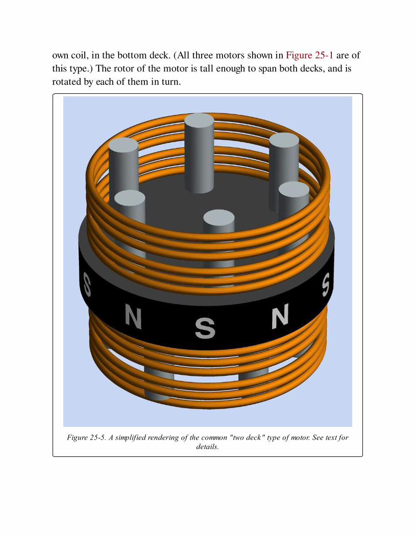
own coil, in the bottom deck. (All three motors shown in Figure 25-1 are of
this type.) The rotor of the motor is tall enough to span both decks, and is
rotated by each of them in turn.
Figure 25-5. A simplified rendering of the common "two deck" type of motor. See text fordetails.
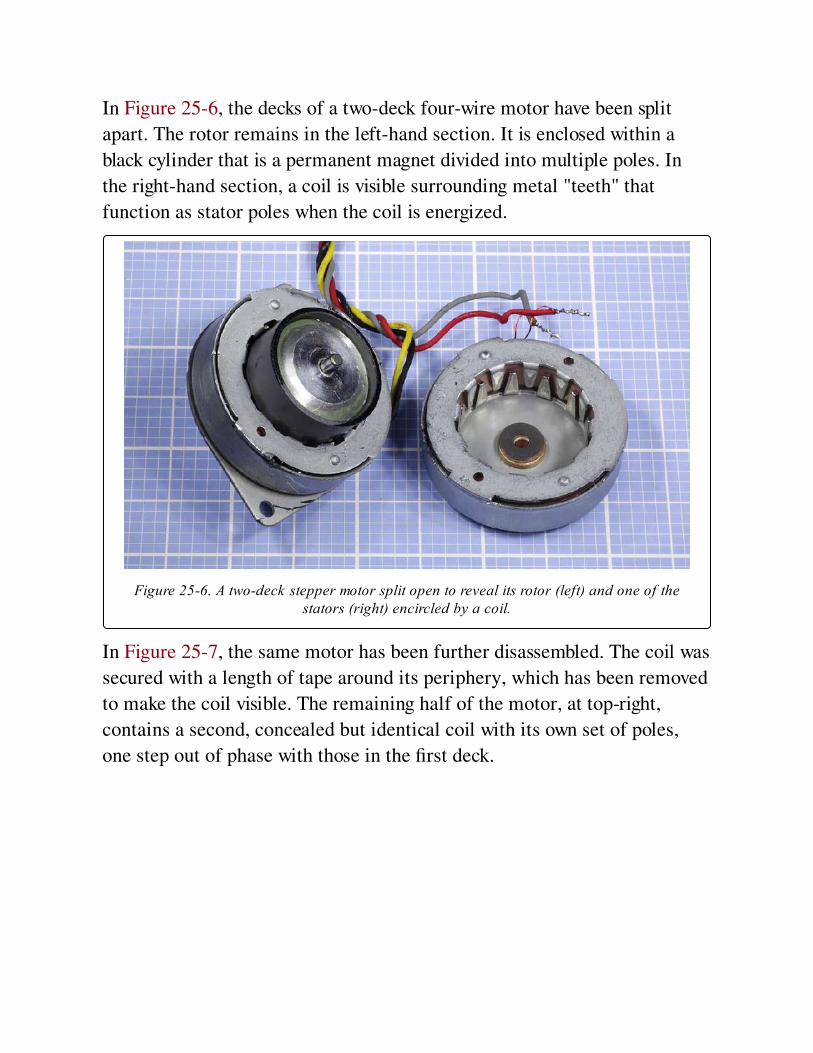
In Figure 25-6, the decks of a two-deck four-wire motor have been split
apart. The rotor remains in the left-hand section. It is enclosed within a
black cylinder that is a permanent magnet divided into multiple poles. In
the right-hand section, a coil is visible surrounding metal "teeth" that
function as stator poles when the coil is energized.
Figure 25-6. A two-deck stepper motor split open to reveal its rotor (left) and one of thestators (right) encircled by a coil.
In Figure 25-7, the same motor has been further disassembled. The coil was
secured with a length of tape around its periphery, which has been removed
to make the coil visible. The remaining half of the motor, at top-right,
contains a second, concealed but identical coil with its own set of poles,
one step out of phase with those in the first deck.

Figure 25-7. The stepper motor from the previous figure, further disassembled.
Because the field effects in a two-deck stepper motor are difficult to
visualize, the remaining diagrams show simplified configurations with a
minimum number of stator poles, each with its own coil.
Bipolar Stepper MotorsThe most basic way to reverse the current in a coil is by using an H-bridge
configuration of switches, as shown in Figure 25-8, where the green arrow
indicates the direction of the magnetic field. In actual applications, the
switches are solid-state. Integrated circuits are available containing all the
necessary components to control a bipolar stepper motor.
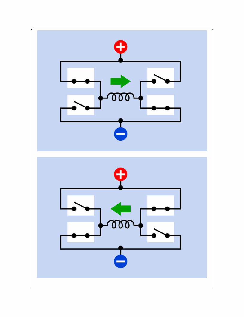
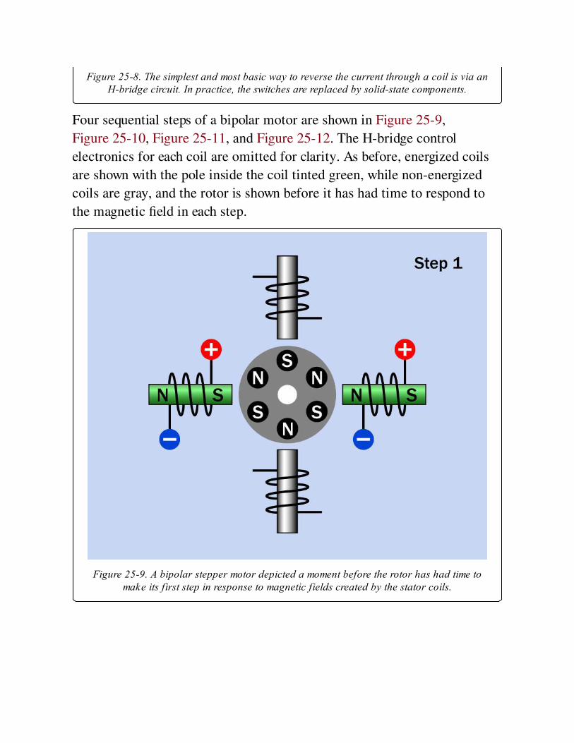
Figure 25-8. The simplest and most basic way to reverse the current through a coil is via anH-bridge circuit. In practice, the switches are replaced by solid-state components.
Four sequential steps of a bipolar motor are shown in Figure 25-9,
Figure 25-10, Figure 25-11, and Figure 25-12. The H-bridge control
electronics for each coil are omitted for clarity. As before, energized coils
are shown with the pole inside the coil tinted green, while non-energized
coils are gray, and the rotor is shown before it has had time to respond to
the magnetic field in each step.
Figure 25-9. A bipolar stepper motor depicted a moment before the rotor has had time tomake its first step in response to magnetic fields created by the stator coils.
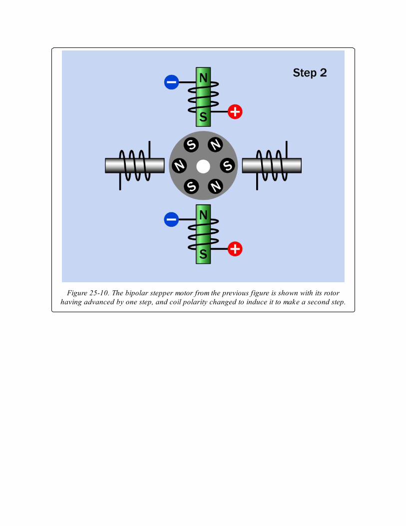
Figure 25-10. The bipolar stepper motor from the previous figure is shown with its rotorhaving advanced by one step, and coil polarity changed to induce it to make a second step.
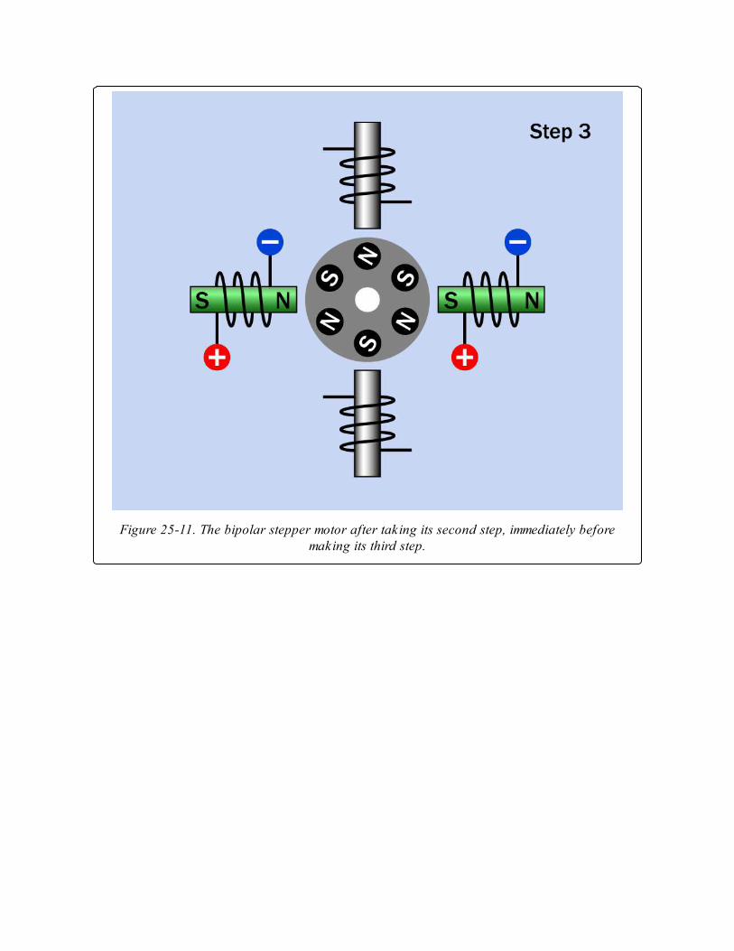
Figure 25-11. The bipolar stepper motor after taking its second step, immediately beforemaking its third step.
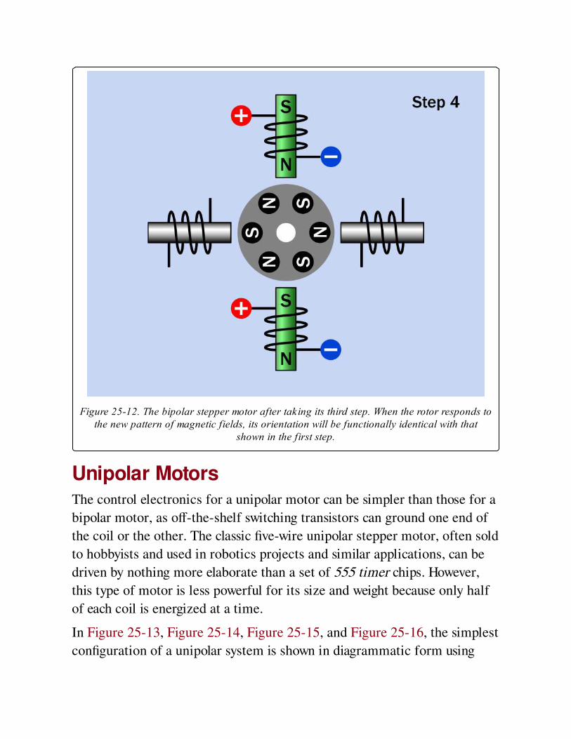
Figure 25-12. The bipolar stepper motor after taking its third step. When the rotor responds tothe new pattern of magnetic fields, its orientation will be functionally identical with that
shown in the first step.
Unipolar MotorsThe control electronics for a unipolar motor can be simpler than those for a
bipolar motor, as off-the-shelf switching transistors can ground one end of
the coil or the other. The classic five-wire unipolar stepper motor, often sold
to hobbyists and used in robotics projects and similar applications, can be
driven by nothing more elaborate than a set of 555 timer chips. However,
this type of motor is less powerful for its size and weight because only half
of each coil is energized at a time.
In Figure 25-13, Figure 25-14, Figure 25-15, and Figure 25-16, the simplest
configuration of a unipolar system is shown in diagrammatic form using
four stator coils and a rotor containing six magnetic poles. Each figure
shows the stator coils when they have just been energized, a moment before
the rotor has had time to move in response to them. Coils that are energized
are shown with the metal cores tinted green. Wires that are not conducting
current are shown in gray. The open and closed positions of switches a, b, c,
and d suggest the path that current is taking along the wires that are colored
black.
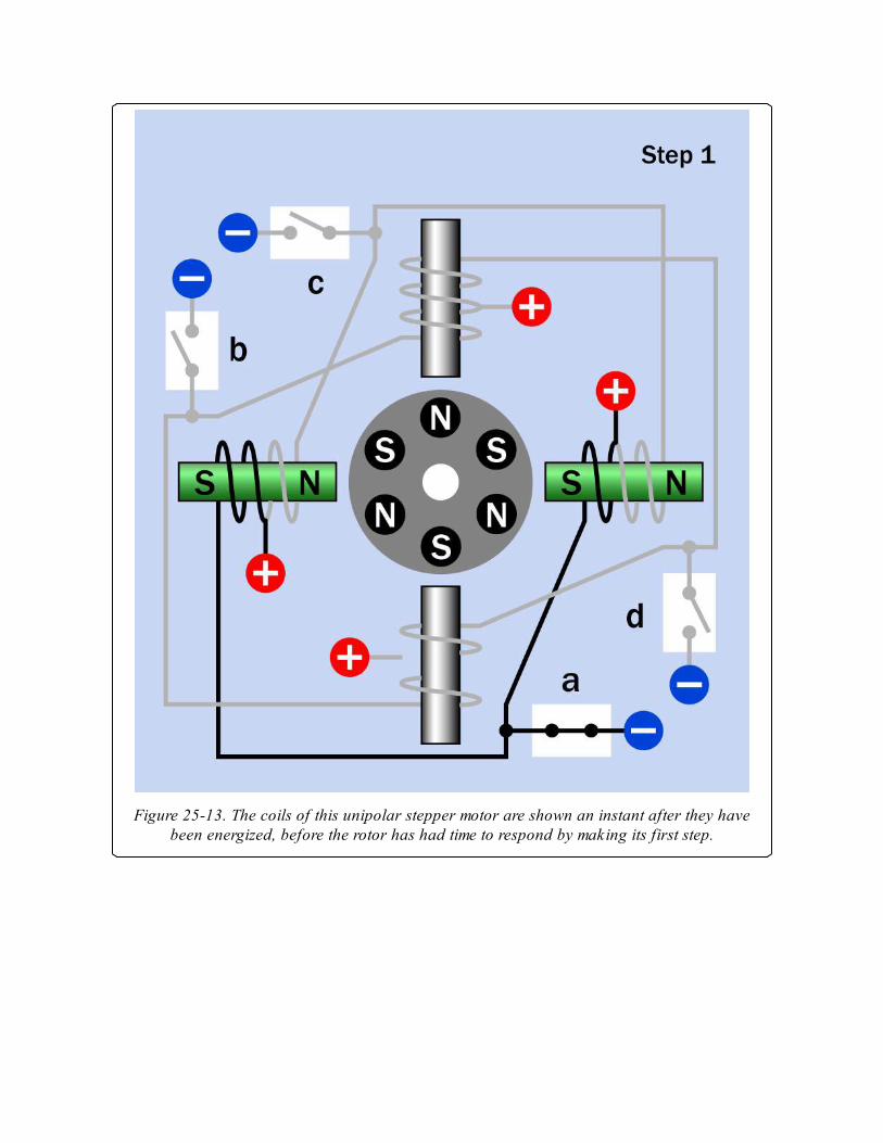
Figure 25-13. The coils of this unipolar stepper motor are shown an instant after they havebeen energized, before the rotor has had time to respond by making its first step.
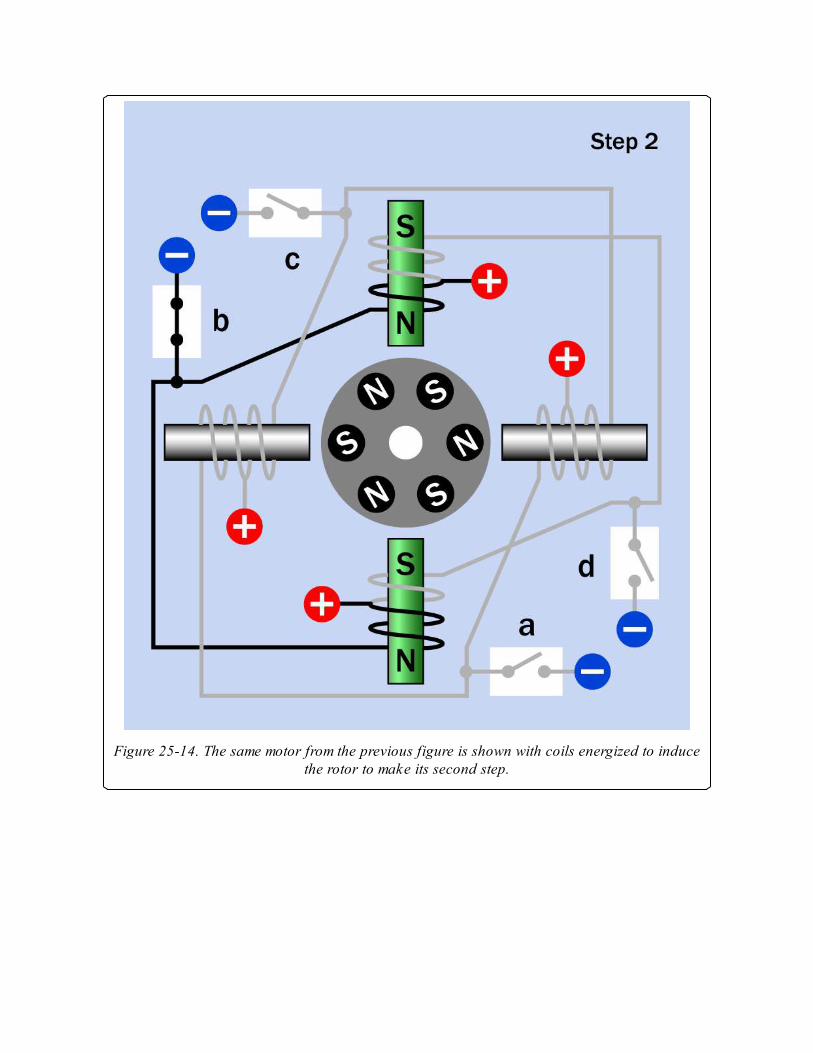
Figure 25-14. The same motor from the previous figure is shown with coils energized to inducethe rotor to make its second step.
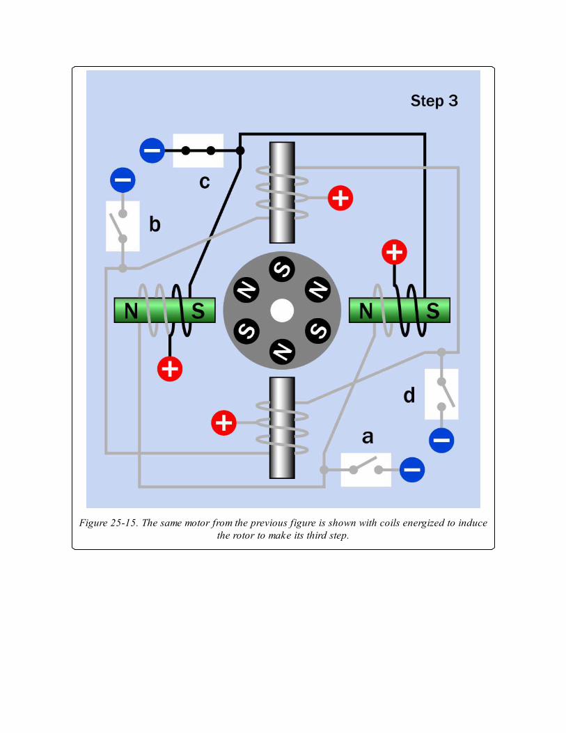
Figure 25-15. The same motor from the previous figure is shown with coils energized to inducethe rotor to make its third step.
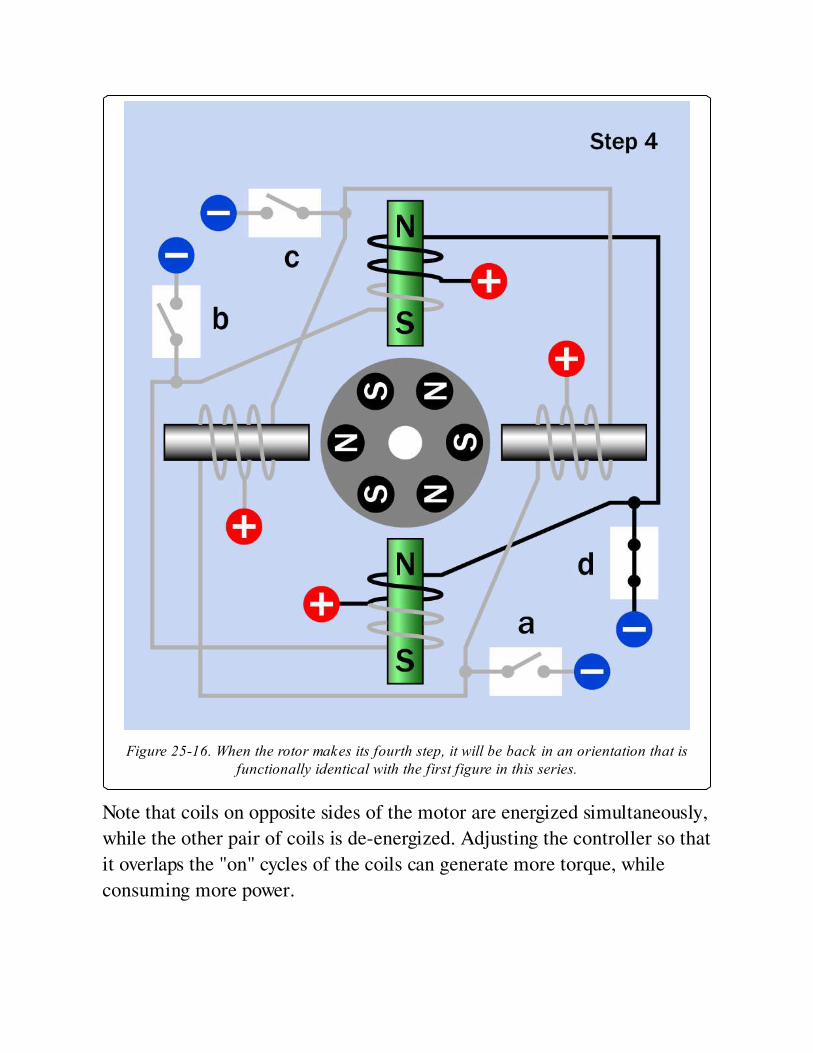
Figure 25-16. When the rotor makes its fourth step, it will be back in an orientation that isfunctionally identical with the first figure in this series.
Note that coils on opposite sides of the motor are energized simultaneously,
while the other pair of coils is de-energized. Adjusting the controller so that
it overlaps the "on" cycles of the coils can generate more torque, while
consuming more power.
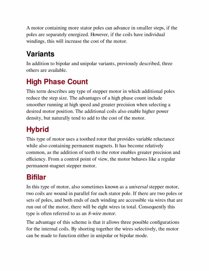
A motor containing more stator poles can advance in smaller steps, if the
poles are separately energized. However, if the coils have individual
windings, this will increase the cost of the motor.
VariantsIn addition to bipolar and unipolar variants, previously described, three
others are available.
High Phase CountThis term describes any type of stepper motor in which additional poles
reduce the step size. The advantages of a high phase count include
smoother running at high speed and greater precision when selecting a
desired motor position. The additional coils also enable higher power
density, but naturally tend to add to the cost of the motor.
HybridThis type of motor uses a toothed rotor that provides variable reluctance
while also containing permanent magnets. It has become relatively
common, as the addition of teeth to the rotor enables greater precision and
efficiency. From a control point of view, the motor behaves like a regular
permanent-magnet stepper motor.
BifilarIn this type of motor, also sometimes known as a universal stepper motor,
two coils are wound in parallel for each stator pole. If there are two poles or
sets of poles, and both ends of each winding are accessible via wires that are
run out of the motor, there will be eight wires in total. Consequently this
type is often referred to as an 8-wire motor.
The advantage of this scheme is that it allows three possible configurations
for the internal coils. By shorting together the wires selectively, the motor
can be made to function either in unipolar or bipolar mode.
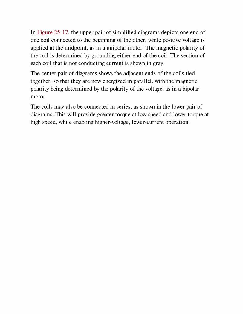
In Figure 25-17, the upper pair of simplified diagrams depicts one end of
one coil connected to the beginning of the other, while positive voltage is
applied at the midpoint, as in a unipolar motor. The magnetic polarity of
the coil is determined by grounding either end of the coil. The section of
each coil that is not conducting current is shown in gray.
The center pair of diagrams shows the adjacent ends of the coils tied
together, so that they are now energized in parallel, with the magnetic
polarity being determined by the polarity of the voltage, as in a bipolar
motor.
The coils may also be connected in series, as shown in the lower pair of
diagrams. This will provide greater torque at low speed and lower torque at
high speed, while enabling higher-voltage, lower-current operation.

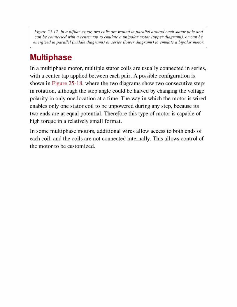
Figure 25-17. In a bifilar motor, two coils are wound in parallel around each stator pole andcan be connected with a center tap to emulate a unipolar motor (upper diagrams), or can be
energized in parallel (middle diagrams) or series (lower diagrams) to emulate a bipolar motor.
MultiphaseIn a multiphase motor, multiple stator coils are usually connected in series,
with a center tap applied between each pair. A possible configuration is
shown in Figure 25-18, where the two diagrams show two consecutive steps
in rotation, although the step angle could be halved by changing the voltage
polarity in only one location at a time. The way in which the motor is wired
enables only one stator coil to be unpowered during any step, because its
two ends are at equal potential. Therefore this type of motor is capable of
high torque in a relatively small format.
In some multiphase motors, additional wires allow access to both ends of
each coil, and the coils are not connected internally. This allows control of
the motor to be customized.

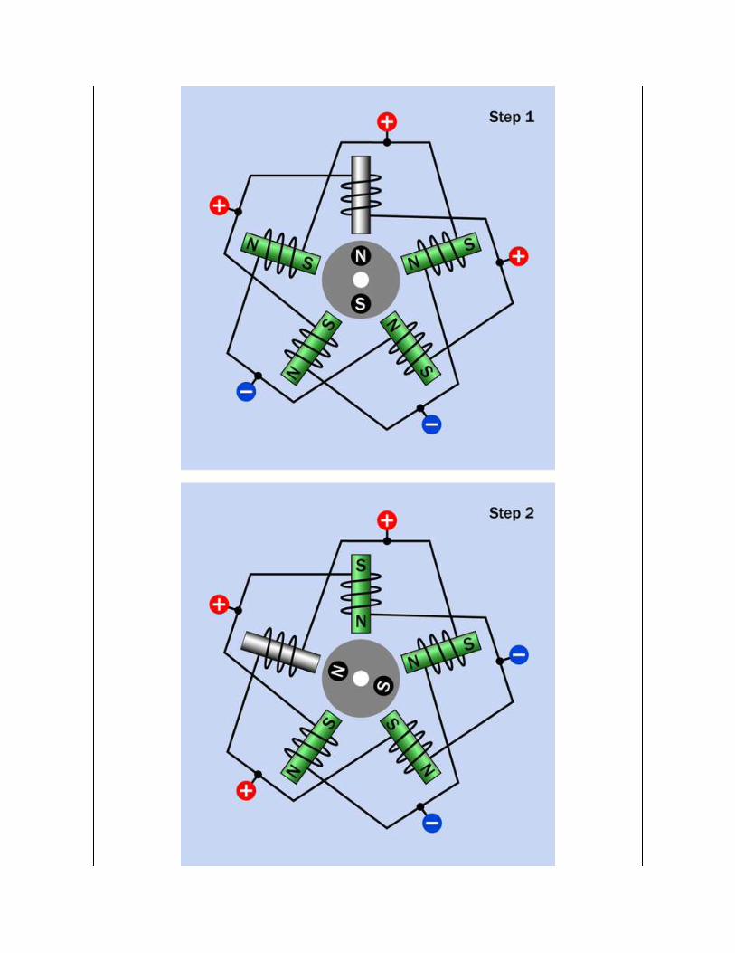
Figure 25-18. A multiphase stepper motor. By applying voltage in the pattern shown, only onecoil is not energized during each step. This enables high torque compared with the size of the
motor.
MicrosteppingAn appropriately designed stepper motor can be induced to make very
small, intermediate steps if the control voltage is modulated to intermediate
levels. Step angles as low as 0.007 degrees are claimed by some
manufacturers. However, a motor running in this mode is less able to
generate torque.
The simplest form of microstepping is half-stepping. To achieve this in a
unipolar motor, each coil passes through an "off" state before its magnetic
polarity is reversed.
Sensing and FeedbackSo long as the series of pulses to the motor allows the rotor ample time to
respond, no feedback mechanism from the rotor is necessary to confirm its
position, and an open-loop system is sufficient. If sudden acceleration,
deceleration, load fluctuations, and/or rotation reversal will occur, or if high
speeds are involved, a closed loop system, in which a sensor provides
positional feedback, may be necessary.
Voltage ControlRapid stepping of a motor requires rapid creation and collapse of magnetic
fields in the stator windings. Therefore, self-inductance of the windings can
limit the motor speed. One way to overcome this is to use a higher voltage.
A more sophisticated solution is to use a controller that provides a high
initial voltage, which is reduced or briefly interrupted when a sensor
indicates that coil current has increased sufficiently to overcome the self-
inductance of the windings and has reached its imposed limit. This type of
controller may be referred to as a chopper drive as the voltage is "chopped,"
usually by power transistors. It is a form of pulse width modulation.

ValuesThe step angle of a stepper motor is the angular rotation of its shaft, in
degrees, for each full step. This will be determined by the physical
construction of the motor. The coarsest step angle is 90 degrees, while
sophisticated motors may be capable of 1.8 degrees (without
microstepping).
The maximum torque that a motor can deliver is discussed in Values in the
DC motor entry of this encyclopedia.
Motor weight and size, shaft length, and shaft diameter are the principal
passive values of a stepper motor, which should be checked before it is
selected for use.
How to Use itStepper motors are used to control the seek action in disk drives, the print-
head movement and paper advance in computer printers, and the scanning
motion in document scanners and copiers.
Industrial and laboratory applications include the adjustment of optical
devices (modern telescopes are often oriented with stepper motors), and
valve control in fluid systems.
A stepper motor may be used to power a linear actuator, usually via a screw
thread (properly known as a lead screw) or worm gear. For more on linear
actuators, see Linear Actuator. While the stepper motor will enable greater
accuracy than a traditional DC motor, the gearing inevitably will introduce
some imprecision.
Advantages of stepper motors include:
Precise positioning, typically within 3 percent to 5 percent per step. The
percentage step error does not accumulate as the motor rotates
Able to run at a wide range of speeds, including very slow speeds
without reduction gearing
Trouble-free start, stop, and reverse action
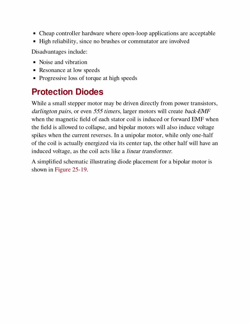
Cheap controller hardware where open-loop applications are acceptable
High reliability, since no brushes or commutator are involved
Disadvantages include:
Noise and vibration
Resonance at low speeds
Progressive loss of torque at high speeds
Protection DiodesWhile a small stepper motor may be driven directly from power transistors,
darlington pairs, or even 555 timers, larger motors will create back-EMF
when the magnetic field of each stator coil is induced or forward EMF when
the field is allowed to collapse, and bipolar motors will also induce voltage
spikes when the current reverses. In a unipolar motor, while only one-half
of the coil is actually energized via its center tap, the other half will have an
induced voltage, as the coil acts like a linear transformer.
A simplified schematic illustrating diode placement for a bipolar motor is
shown in Figure 25-19.
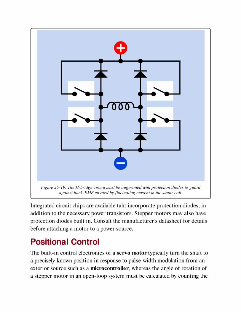
Figure 25-19. The H-bridge circuit must be augmented with protection diodes to guardagainst back-EMF created by fluctuating current in the stator coil.
Integrated circuit chips are available taht incorporate protection diodes, in
addition to the necessary power transistors. Stepper motors may also have
protection diodes built in. Consult the manufacturer’s datasheet for details
before attaching a motor to a power source.
Positional ControlThe built-in control electronics of a servo motor typically turn the shaft to
a precisely known position in response to pulse-width modulation from an
exterior source such as a microcontroller, whereas the angle of rotation of
a stepper motor in an open-loop system must be calculated by counting the
number of steps from an initial, home position. This limitation of a stepper
motor can be overcome by using a closed-loop system, but that will require
monitoring the motor, adding complexity to the external controller. The
choice between stepper and servo motors should be evaluated on a case-by-
case basis.
What Can Go WrongGeneral problems affecting all types of motors are listed in Heat effects.
Issues relating more specifically to stepper motors are listed in the
following sections.
Incorrect WiringBecause a stepper motor is driven via multiple conductors, there is a
significant risk of wiring errors, especially since many motors are not
identified with part numbers. The first challenge, then, may be to determine
what type of motor it is. When the motor is disconnected from any power,
and the shaft is rotated with finger and thumb, a magnetized-rotor motor
will not spin as freely as a reluctance motor, because the magnets in the
rotor will provide intermittent turning resistance.
If a unipolar motor is relatively small and is fitted with five wires, almost
certainly the motor contains two coils, each with a center tap, and their
function can be determined by applying positive voltage to the red wire and
grounding each of the other wires in turn. Attaching a small piece of tape to
the motor shaft will assist in viewing its orientation.
A multimeter set to measure ohms can also be useful in deducing the
internal coil connections of the motor, since the end-to-end resistance of a
coil should be approximately twice the resistance between the center tap
and either end of the coil.
A multiphase motor may have five wires, but in this case, the resistance
between any two non-adjacent wires will be 1.5 times the resistance
between any two adjacent wires.
Step LossIn an open-loop system, if the motor skips or misses pulses from the
controller, the controller no longer has an accurate assessment of the shaft
angle. This is known as step loss. Since this can be caused by sudden
changes in control frequency, the frequency should be increased (or
decreased) gradually. This is known as ramping the motor speed. Stepper
motors cannot respond instantly to changes in speed, because of inertia in
the rotor or in the device that the motor is driving.
Where the motor turns one or more steps beyond its commanded stopping
point, this is known as overshoot.
Step loss may also occur if the motor continues turning after power has
been interrupted (either intentionally or because of an external fault). In an
open-loop system, the controller should be designed to reset the motor
position when power is initiated.
Excessive TorqueWhen the motor is stationary and not powered, detent torque is the
maximum turning force that can be applied without causing the shaft to
turn. When the motor is stationary and the controller does deliver power to
it, holding torque is the maximum turning force that can be applied without
causing the shaft to turn, and pull-in torque is the maximum torque which
the motor can apply to overcome resistance and reach full speed. When the
motor is running, pull-out torque is the maximum torque the motor can
deliver without suffering step loss (pulling it out of sync with its controller).
Some or all of these values should be specified on the motor’s datasheet.
Exceeding any of them will result in step loss.
HysteresisWhen a controller directs a stepper motor to seek a specified position, the
term hysteresis is often used to mean the total error between the actual
position it reaches when turning clockwise, and the actual position it
reaches when turning counter-clockwise. This difference may occur because
a stepper motor tends to stop a fraction short of its intended position,
especially under significant load. Any design that requires precision should
be tested under real-world conditions to assess the hysteresis of the motor.
ResonanceA motor has a natural resonant frequency. If it is stepped near that
frequency, vibration will tend to be amplified, which can cause positional
errors, gear wear (if gears are attached), bearing wear, noise, and other
issues. A good datasheet should specify the resonant frequency of the
motor, and the motor should run above that frequency if possible. The
problem can be addressed by rubber motor mounts or by using a resilient
component, such as a drive belt, in conjunction with the drive shaft.
Damping the vibration may be attempted by adding weight to the motor
mount.
Note that if the motor has any significant weight attached directly to its
shaft, this will lower its resonant frequency, and should be taken into
account.
Resonance may also cause step loss (see preceding sections).
HuntingIn a closed-loop system, a sensor on the motor reports its rotational
position to the controller, and if necessary, the controller responds by
adjusting the position of the motor. Like any feedback system, this entails
some lag time, and at certain speeds the motor may start hunting or
oscillating as the controller over-corrects and must then correct its
correction. Some closed-loop controllers avoid this issue by running mostly
in open-loop mode, using correction only when the motor experiences
conditions (such as sudden speed changes), which are likely to cause step
loss.
Saturation
While it may be tempting to increase the torque from a stepper motor by
upping the voltage (which will increase the current through the stator coils),
in practice motors are usually designed so that the cores of the coils will be
close to saturation at the rated voltage. Therefore, increasing the voltage
may achieve very little increase in power, while causing a significant
increase in heat.
Rotor DemagnetizationThe permanent magnets in a rotor can be partially demagnetized by
excessive heat. Demagnetization can also occur if the magnets are exposed
to high-frequency alternating current when the rotor is stationary.
Therefore, attempting to run a stepper motor at high speed when the rotor
is stalled can cause irrevocable loss of performance.
Chapter 26. diode
discrete semiconductor > single junction > diode
The term diode almost always means a semiconductor device, properly known as a PN junction
diode, although the full term is not often used. It was formerly known as a crystal diode. Before
that, diode usually meant a type of vacuum tube, which is now rarely used outside of high-
wattage RF transmitters and some high-end audio equipment.
Other related components
rectifier (See Rectification)
unijunction transistor (See Chapter 27)
LED (light-emitting diode) (Volume 2)
What It DoesA diode is a two-terminal device that allows current to flow in one
direction, known as the forward direction, when the anode of the diode has
a higher positive potential than the cathode. In this state, the diode is said to
be forward biased. If the polarity of the voltage is reversed, the diode is now
reverse biased, and it will attempt to block current flow, within its rated
limits.
Diodes are often used as rectifiers to convert alternating current into direct
current. They may also be used to suppress voltage spikes or protect
components that would be vulnerable to reversed voltage, and they have
specialized applications in high-frequency circuits.
A Zener diode can regulate voltage, a varactor diode can control a high-
frequency oscillator, and tunnel diodes, Gunn diodes, and PIN diodes have
high-frequency applications appropriate to their rapid switching capability.
An LED (light-emitting diode) is a highly efficient light source, which is
discussed in Volume 2 of this encyclopedia. A photosensitive diode will
adjust its ability to pass current depending on the light that falls upon it,
and is included as a sensor in Volume 3.
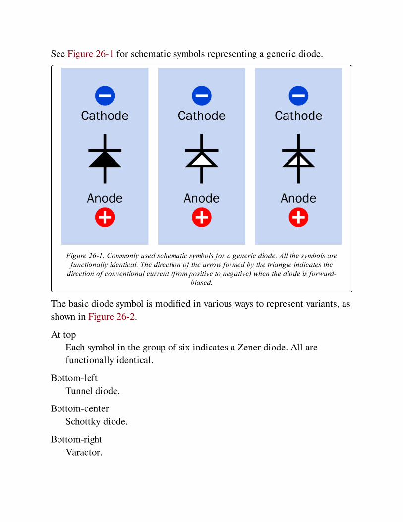
See Figure 26-1 for schematic symbols representing a generic diode.
Figure 26-1. Commonly used schematic symbols for a generic diode. All the symbols arefunctionally identical. The direction of the arrow formed by the triangle indicates the
direction of conventional current (from positive to negative) when the diode is forward-biased.
The basic diode symbol is modified in various ways to represent variants, as
shown in Figure 26-2.
At top
Each symbol in the group of six indicates a Zener diode. All are
functionally identical.
Bottom-left
Tunnel diode.
Bottom-center
Schottky diode.
Bottom-right
Varactor.
A triangle with an open center does not indicate any different function from
a triangle with a solid center. The direction of the arrow always indicates
the direction of conventional current, from positive to negative, when the
diode is forward-biased, although the functionality of Zener diodes and
varactors depends on them being reverse-biased, and thus they are used
with current flowing opposite to the arrow symbol. The bent line used in the
Zener symbol can be thought of as an opened letter Z, while the curled line
used in the Schottky diode symbol can be thought of as a letter S, although
these lines are sometimes drawn flipped left-to-right.
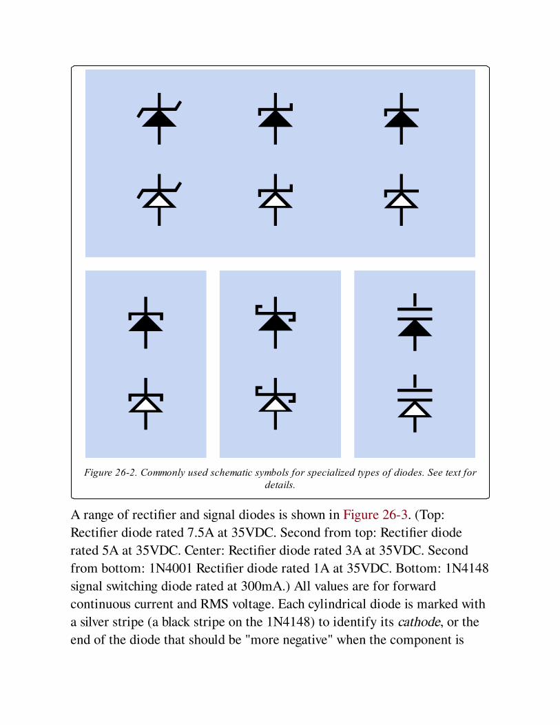
Figure 26-2. Commonly used schematic symbols for specialized types of diodes. See text fordetails.
A range of rectifier and signal diodes is shown in Figure 26-3. (Top:
Rectifier diode rated 7.5A at 35VDC. Second from top: Rectifier diode
rated 5A at 35VDC. Center: Rectifier diode rated 3A at 35VDC. Second
from bottom: 1N4001 Rectifier diode rated 1A at 35VDC. Bottom: 1N4148
signal switching diode rated at 300mA.) All values are for forward
continuous current and RMS voltage. Each cylindrical diode is marked with
a silver stripe (a black stripe on the 1N4148) to identify its cathode, or the
end of the diode that should be "more negative" when the component is

forward biased. Peak current can greatly exceed continuous current without
damaging the component. Datasheets will provide additional information.

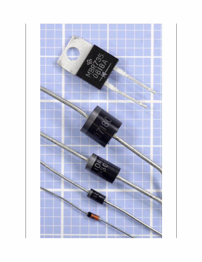

Figure 26-3. Diodes ranging in continuous forward-current capability from 7.5A (top) to300mA (bottom). See text for additional details.
How It WorksA PN diode is a two-layer semiconductor, usually fabricated from silicon,
sometimes from germanium, and rarely from other materials. The layers
are doped with impurities to adjust their electrical characteristics (this
concept is explained in more detail in Chapter 28). The N layer (on the
negative, cathode side) has a surplus of electrons, creating a net negative
charge. The P layer (on the positive, anode side) has a deficit of electrons,
creating a net positive charge. The deficit of electrons can also be thought of
as a surplus of "positive charges," or more accurately, a surplus of electron
holes, which can be considered as spaces that electrons can fill.
When the negative side of an external voltage source is connected with the
cathode of a diode, and the positive side is connected with the anode, the
diode is forward-biased, and electrons and electron holes are forced by
mutual repulsion toward the junction between the n and p layers (see
Figure 26-4). In a silicon diode, if the potential difference is greater than
approximately 0.6 volts, this is known as the junction threshold voltage, and
the charges start to pass through the junction. The threshold is only about
0.2 volts in a germanium diode, while in a Schottky diode it is about 0.4
volts.
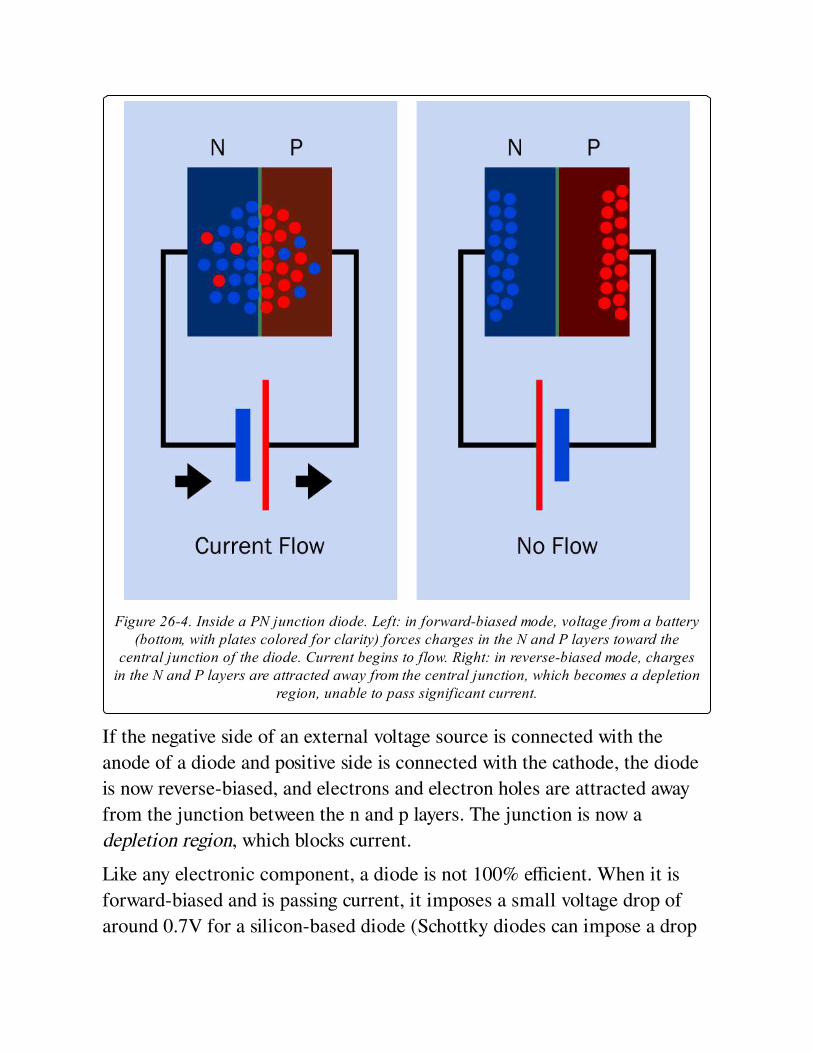
Figure 26-4. Inside a PN junction diode. Left: in forward-biased mode, voltage from a battery(bottom, with plates colored for clarity) forces charges in the N and P layers toward the
central junction of the diode. Current begins to flow. Right: in reverse-biased mode, chargesin the N and P layers are attracted away from the central junction, which becomes a depletion
region, unable to pass significant current.
If the negative side of an external voltage source is connected with the
anode of a diode and positive side is connected with the cathode, the diode
is now reverse-biased, and electrons and electron holes are attracted away
from the junction between the n and p layers. The junction is now a
depletion region, which blocks current.
Like any electronic component, a diode is not 100% efficient. When it is
forward-biased and is passing current, it imposes a small voltage drop of
around 0.7V for a silicon-based diode (Schottky diodes can impose a drop
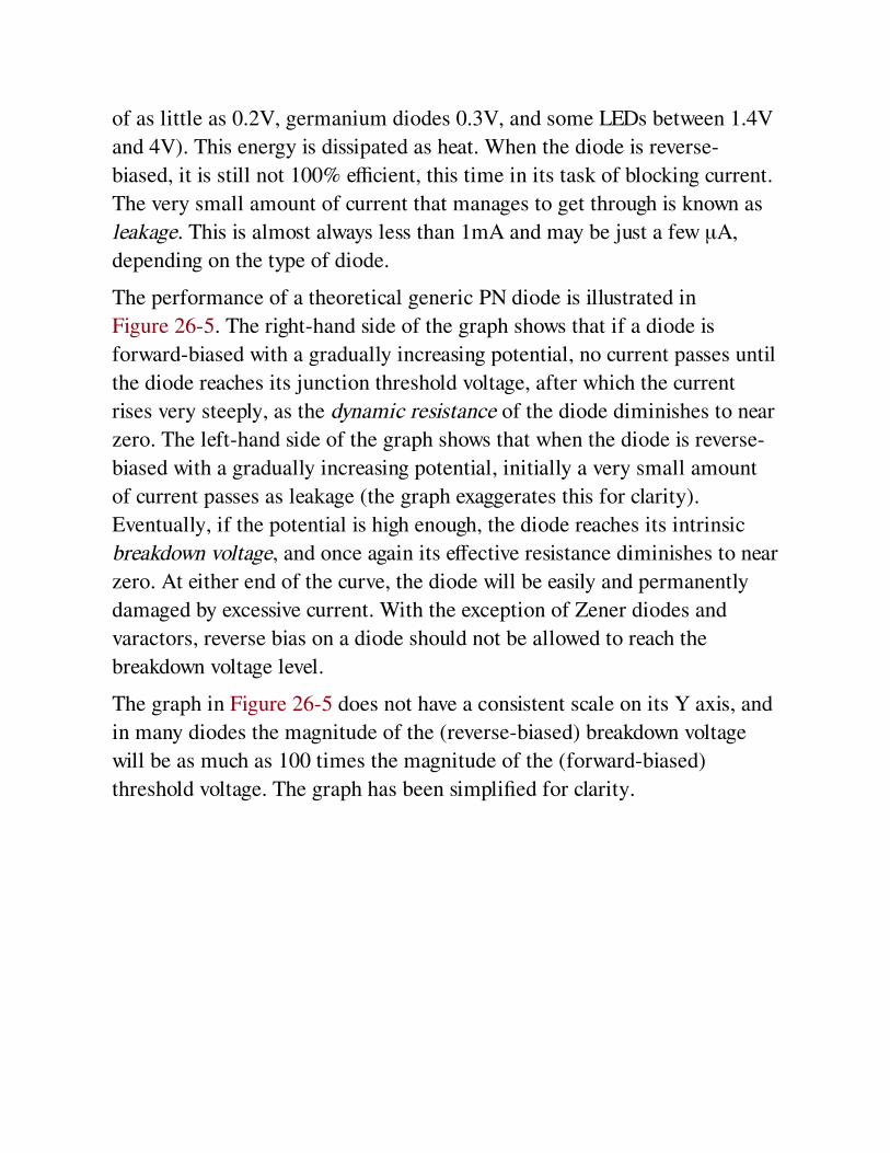
of as little as 0.2V, germanium diodes 0.3V, and some LEDs between 1.4V
and 4V). This energy is dissipated as heat. When the diode is reverse-
biased, it is still not 100% efficient, this time in its task of blocking current.
The very small amount of current that manages to get through is known as
leakage. This is almost always less than 1mA and may be just a few μA,
depending on the type of diode.
The performance of a theoretical generic PN diode is illustrated in
Figure 26-5. The right-hand side of the graph shows that if a diode is
forward-biased with a gradually increasing potential, no current passes until
the diode reaches its junction threshold voltage, after which the current
rises very steeply, as the dynamic resistance of the diode diminishes to near
zero. The left-hand side of the graph shows that when the diode is reverse-
biased with a gradually increasing potential, initially a very small amount
of current passes as leakage (the graph exaggerates this for clarity).
Eventually, if the potential is high enough, the diode reaches its intrinsic
breakdown voltage, and once again its effective resistance diminishes to near
zero. At either end of the curve, the diode will be easily and permanently
damaged by excessive current. With the exception of Zener diodes and
varactors, reverse bias on a diode should not be allowed to reach the
breakdown voltage level.
The graph in Figure 26-5 does not have a consistent scale on its Y axis, and
in many diodes the magnitude of the (reverse-biased) breakdown voltage
will be as much as 100 times the magnitude of the (forward-biased)
threshold voltage. The graph has been simplified for clarity.
Figure 26-5. As the forward voltage across a diode reaches the junction threshold, the diodebegins passing current. If the voltage across the diode is reversed, initially a small amount ofcurrent leakeage occurs. Excessive forward or reverse voltage will create sufficient current to
destroy the component.
Variants
PackagingSome diodes have no information at all printed on them, while others may
have a part number. Any additional information is rare. No convention
exists for indicating the electrical characteristics of the component by
colors or abbreviations. If one terminal is marked in any way, almost
certainly it is the cathode. One way to remember the meaning of a stripe on
the cathode end of a rectifier diode or signal diode is by thinking of it as
resembling the line in the diode schematic symbol.
Signal DiodesAlso known as switching diodes and high-speed diodes, their small size
provides a low junction capacitance, enabling fast response times. They are
not designed to withstand high currents. Signal diodes traditionally were
packaged with axial leads for through-hole installation (like traditional-
style resistors). Although this format still exists, signal diodes are now more
commonly available in surface-mount formats.
Rectifier DiodesPhysically larger than signal diodes, and capable of handling higher
currents. Their higher junction capacitance makes them unsuitable for fast
switching. Rectifier diodes often have axial leads, although different
package formats are used where higher currents are involved, and may
include a heat sink, or may have provision for being attached to a heat sink.
There are no generally agreed maximum or minimum ratings to distinguish
signal diodes from rectifier diodes.
Zener DiodeA Zener diode generally behaves very similarly to a signal or rectifier
diode, except that its breakdown voltage is lower.
The Zener is intended to be reverse-biased; that is, conventional current is
applied through it "in the wrong direction" compared with conventional
diodes. As the current increases, the dynamic resistance of the Zener diode
decreases. This relationship is shown in Figure 26-6, where the two colored
curves represent the performance of different possible Zener diodes. (The
curves are adapted from a manufacturer’s datasheet.) This behavior allows
the Zener to be used in simple voltage-regulator circuits, as it can allow a
reverse current to flow at a voltage limited by the diode’s breakdown
voltage. Other applications for Zener diodes are described in DC Voltage
Regulation and Noise Suppression. A typical Zener diode is shown in
Figure 26-7.
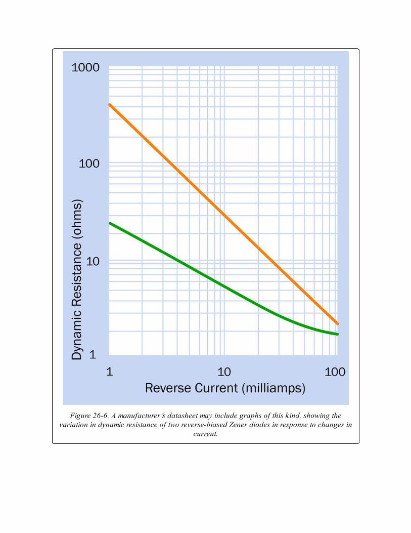
Figure 26-6. A manufacturer’s datasheet may include graphs of this kind, showing thevariation in dynamic resistance of two reverse-biased Zener diodes in response to changes in
current.
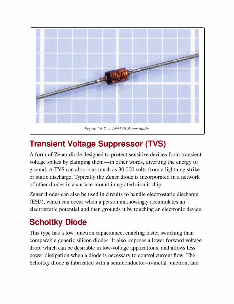
Figure 26-7. A 1N4740 Zener diode.
Transient Voltage Suppressor (TVS)A form of Zener diode designed to protect sensitive devices from transient
voltage spikes by clamping them—in other words, diverting the energy to
ground. A TVS can absorb as much as 30,000 volts from a lightning strike
or static discharge. Typically the Zener diode is incorporated in a network
of other diodes in a surface-mount integrated circuit chip.
Zener diodes can also be used in circuits to handle electrostatic discharge
(ESD), which can occur when a person unknowingly accumulates an
electrostatic potential and then grounds it by touching an electronic device.
Schottky DiodeThis type has a low junction capacitance, enabling faster switching than
comparable generic silicon diodes. It also imposes a lower forward voltage
drop, which can be desirable in low-voltage applications, and allows less
power dissipation when a diode is necessary to control current flow. The
Schottky diode is fabricated with a semiconductor-to-metal junction, and
tends to be slightly more expensive than generic silicon diodes with similar
voltage and current specifications.
Varactor DiodeAlso known as a varicap, this type of diode has variable capacitance
controlled by reverse voltage. While other diodes may exhibit this same
phenomenon, the varactor is specifically designed to exploit it at very high
frequencies. The voltage expands or contracts the depletion region in the
junction between the P and N regions, which can be thought of as analogous
to moving the plates of a capacitor nearer together or farther apart.
Because the capacitance of a varactor has a low maximum of about 100pF,
its uses are limited. It is used extensively in RF applications where its
voltage-controlled variable capacitance provides a uniquely useful way to
control the frequency of an oscillator circuit. In almost all radio, cellular,
and wireless receivers, a varactor controls a phase-locked loop oscillator. In
ham radio receivers, it can be used to adjust the tuning of a filter that tracks
an incoming radio frequency.
A varactor is always reverse-biased below its breakdown voltage, so that
there is no direct conduction. The voltage that controls a varactor must be
absolutely free from random fluctuations that would affect its resonant
frequency.
Tunnel Diode, Gunn Diode, PIN DiodeMostly used in very high frequency or microwave applications, where
ordinary diodes are unacceptable because they have insufficiently high
switching speeds.
Diode ArrayTwo or more diodes may be encapsulated in a single DIP or (more
commonly) surface-mount integrated circuit chip. The internal
configuration and the pinouts of the chip will vary from one device to
another. Diode arrays may be used for termination of data lines to reduce
reflection noise.
Bridge RectifierAlthough this is a diode array, it is commonly indexed in parts catalogues
under the term bridge rectifier. Numerous through-hole versions are
available with ratings as high as 25A, some designed for single-phase input
while others process three-phase AC. Screw-terminal components can
rectify more than 1,000 volts at 1,000 amps. The package does not usually
include any provision for smoothing or filtering the output. See
Rectification for more information on the behavior of a bridge rectifier.
ValuesA manufacturer’s datasheet for a typical generic diode should define the
following values, using abbreviations that may include those in the following
list.
Maximum sustained forward current: If or Io or IOmax
Forward voltage (the voltage drop imposed by the diode): Vf
Peak inverse DC voltage (may be referred to as maximum blocking
voltage or breakdown voltage): Piv or Vdc or Vbr
Maximum reverse current (also referred to as leakage): Ir
Datasheets may include additional values when the diode is used with
alternating current, and will also include information on peak forward surge
current and acceptable operating temperatures.
A typical signal diode is the 1N4148 (included at the bottom of Figure 26-
3), which is limited to about 300mA forward current while imposing a
voltage drop of about 1V. The component can tolerate a 75V peak inverse
voltage. These values may vary slightly among different manufacturers.
Rectifier diodes in the 1N4001/1N4002/1N4003 series have a maximum
forward current of 1A and will impose a voltage drop of slightly more than
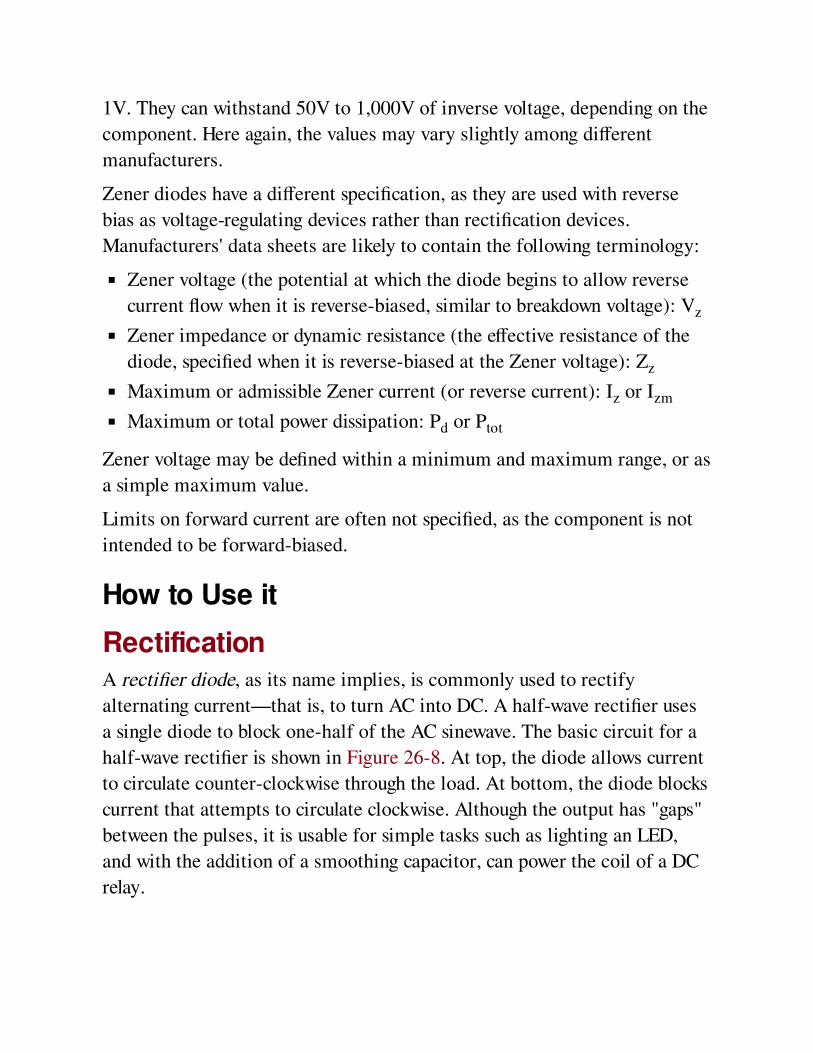
1V. They can withstand 50V to 1,000V of inverse voltage, depending on the
component. Here again, the values may vary slightly among different
manufacturers.
Zener diodes have a different specification, as they are used with reverse
bias as voltage-regulating devices rather than rectification devices.
Manufacturers' data sheets are likely to contain the following terminology:
Zener voltage (the potential at which the diode begins to allow reverse
current flow when it is reverse-biased, similar to breakdown voltage): Vz
Zener impedance or dynamic resistance (the effective resistance of the
diode, specified when it is reverse-biased at the Zener voltage): Zz
Maximum or admissible Zener current (or reverse current): Iz or Izm
Maximum or total power dissipation: Pd or Ptot
Zener voltage may be defined within a minimum and maximum range, or as
a simple maximum value.
Limits on forward current are often not specified, as the component is not
intended to be forward-biased.
How to Use it
RectificationA rectifier diode, as its name implies, is commonly used to rectify
alternating current—that is, to turn AC into DC. A half-wave rectifier uses
a single diode to block one-half of the AC sinewave. The basic circuit for a
half-wave rectifier is shown in Figure 26-8. At top, the diode allows current
to circulate counter-clockwise through the load. At bottom, the diode blocks
current that attempts to circulate clockwise. Although the output has "gaps"
between the pulses, it is usable for simple tasks such as lighting an LED,
and with the addition of a smoothing capacitor, can power the coil of a DC
relay.
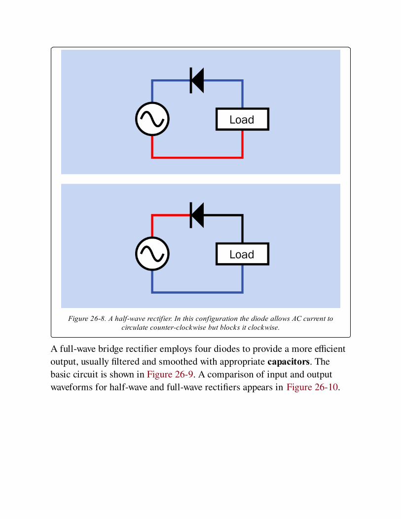
Figure 26-8. A half-wave rectifier. In this configuration the diode allows AC current tocirculate counter-clockwise but blocks it clockwise.
A full-wave bridge rectifier employs four diodes to provide a more efficient
output, usually filtered and smoothed with appropriate capacitors. The
basic circuit is shown in Figure 26-9. A comparison of input and output
waveforms for half-wave and full-wave rectifiers appears in Figure 26-10.
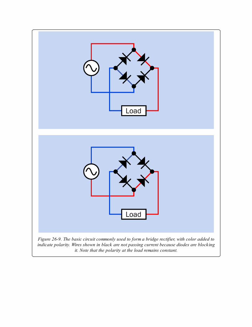
Figure 26-9. The basic circuit commonly used to form a bridge rectifier, with color added toindicate polarity. Wires shown in black are not passing current because diodes are blocking
it. Note that the polarity at the load remains constant.
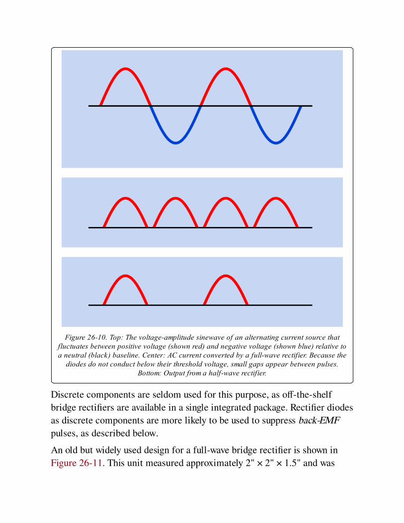
Figure 26-10. Top: The voltage-amplitude sinewave of an alternating current source thatfluctuates between positive voltage (shown red) and negative voltage (shown blue) relative toa neutral (black) baseline. Center: AC current converted by a full-wave rectifier. Because the
diodes do not conduct below their threshold voltage, small gaps appear between pulses.Bottom: Output from a half-wave rectifier.
Discrete components are seldom used for this purpose, as off-the-shelf
bridge rectifiers are available in a single integrated package. Rectifier diodes
as discrete components are more likely to be used to suppress back-EMF
pulses, as described below.
An old but widely used design for a full-wave bridge rectifier is shown in
Figure 26-11. This unit measured approximately 2" × 2" × 1.5" and was
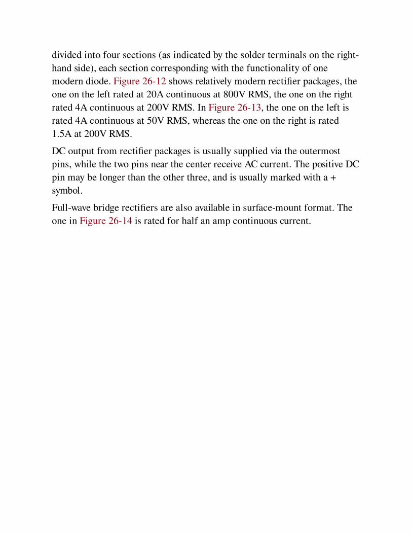
divided into four sections (as indicated by the solder terminals on the right-
hand side), each section corresponding with the functionality of one
modern diode. Figure 26-12 shows relatively modern rectifier packages, the
one on the left rated at 20A continuous at 800V RMS, the one on the right
rated 4A continuous at 200V RMS. In Figure 26-13, the one on the left is
rated 4A continuous at 50V RMS, whereas the one on the right is rated
1.5A at 200V RMS.
DC output from rectifier packages is usually supplied via the outermost
pins, while the two pins near the center receive AC current. The positive DC
pin may be longer than the other three, and is usually marked with a +
symbol.
Full-wave bridge rectifiers are also available in surface-mount format. The
one in Figure 26-14 is rated for half an amp continuous current.
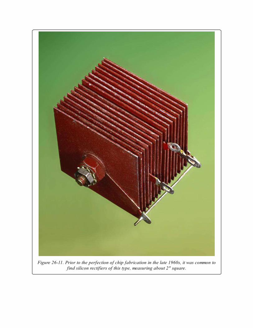
Figure 26-11. Prior to the perfection of chip fabrication in the late 1960s, it was common tofind silicon rectifiers of this type, measuring about 2" square.
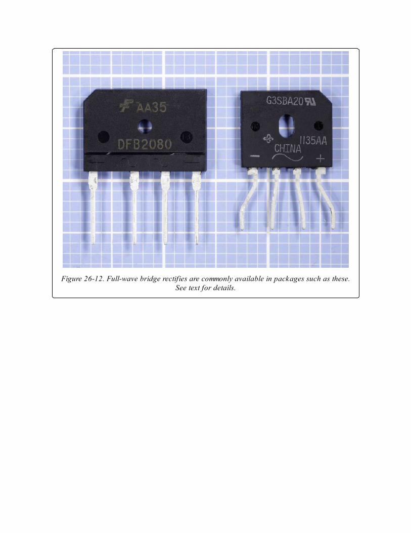
Figure 26-12. Full-wave bridge rectifies are commonly available in packages such as these.See text for details.
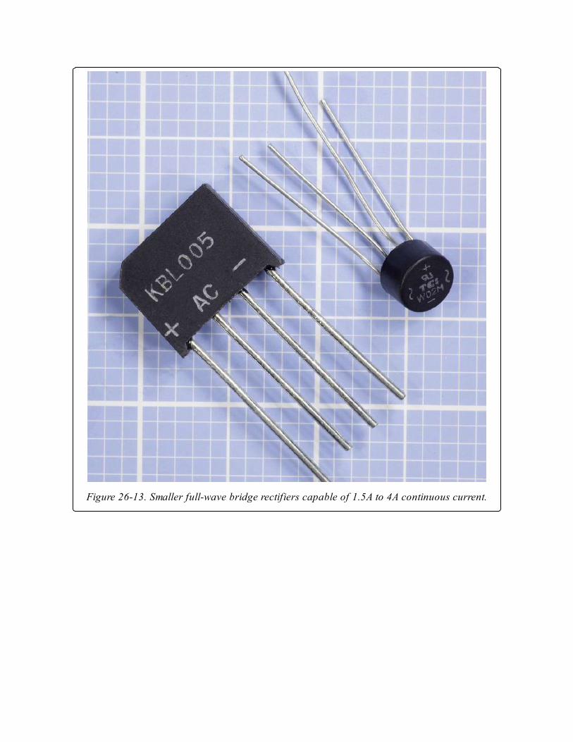
Figure 26-13. Smaller full-wave bridge rectifiers capable of 1.5A to 4A continuous current.
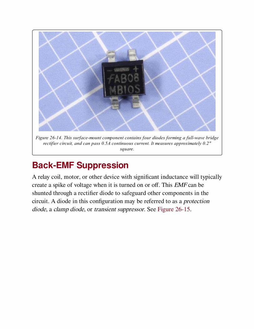
Figure 26-14. This surface-mount component contains four diodes forming a full-wave bridgerectifier circuit, and can pass 0.5A continuous current. It measures approximately 0.2"
square.
Back-EMF SuppressionA relay coil, motor, or other device with significant inductance will typically
create a spike of voltage when it is turned on or off. This EMF can be
shunted through a rectifier diode to safeguard other components in the
circuit. A diode in this configuration may be referred to as a protection
diode, a clamp diode, or transient suppressor. See Figure 26-15.
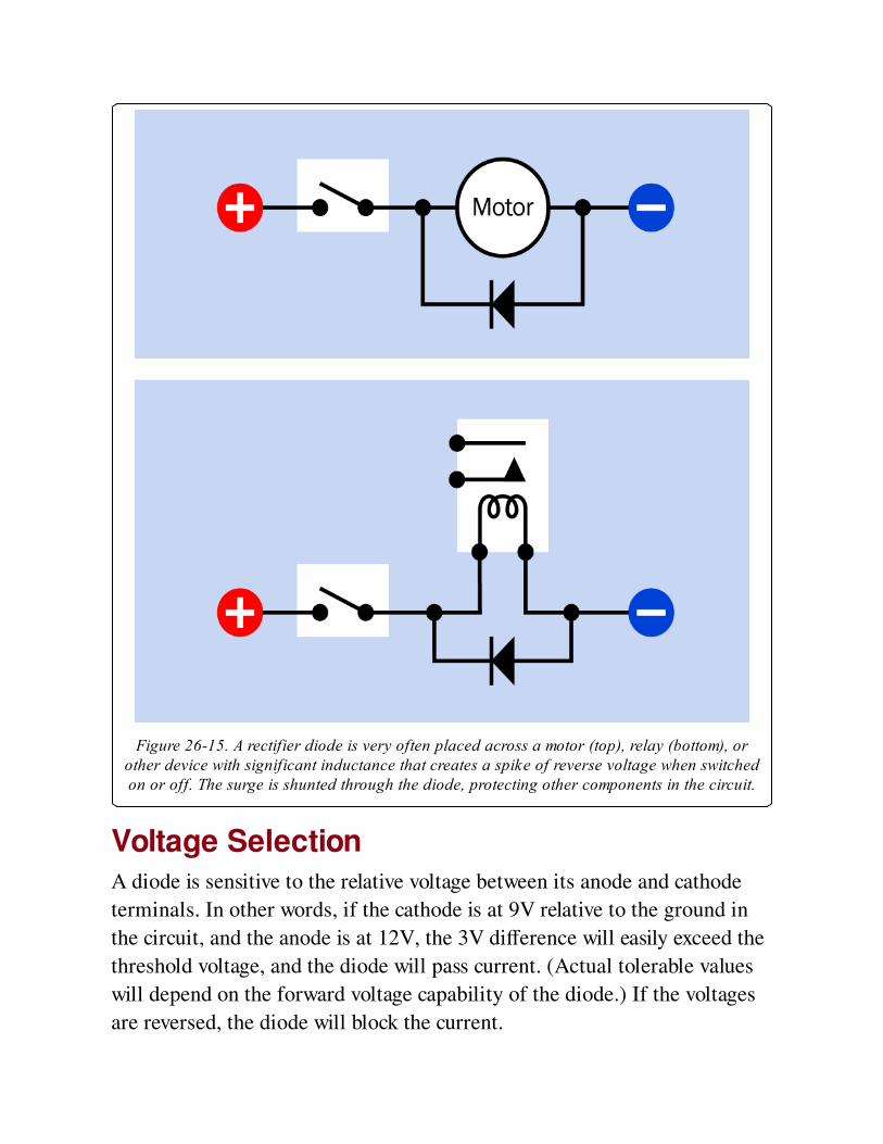
Figure 26-15. A rectifier diode is very often placed across a motor (top), relay (bottom), orother device with significant inductance that creates a spike of reverse voltage when switchedon or off. The surge is shunted through the diode, protecting other components in the circuit.
Voltage SelectionA diode is sensitive to the relative voltage between its anode and cathode
terminals. In other words, if the cathode is at 9V relative to the ground in
the circuit, and the anode is at 12V, the 3V difference will easily exceed the
threshold voltage, and the diode will pass current. (Actual tolerable values
will depend on the forward voltage capability of the diode.) If the voltages
are reversed, the diode will block the current.
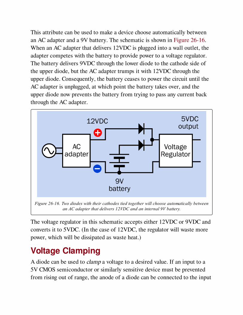
This attribute can be used to make a device choose automatically between
an AC adapter and a 9V battery. The schematic is shown in Figure 26-16.
When an AC adapter that delivers 12VDC is plugged into a wall outlet, the
adapter competes with the battery to provide power to a voltage regulator.
The battery delivers 9VDC through the lower diode to the cathode side of
the upper diode, but the AC adapter trumps it with 12VDC through the
upper diode. Consequently, the battery ceases to power the circuit until the
AC adapter is unplugged, at which point the battery takes over, and the
upper diode now prevents the battery from trying to pass any current back
through the AC adapter.
Figure 26-16. Two diodes with their cathodes tied together will choose automatically betweenan AC adapter that delivers 12VDC and an internal 9V battery.
The voltage regulator in this schematic accepts either 12VDC or 9VDC and
converts it to 5VDC. (In the case of 12VDC, the regulator will waste more
power, which will be dissipated as waste heat.)
Voltage ClampingA diode can be used to clamp a voltage to a desired value. If an input to a
5V CMOS semiconductor or similarly sensitive device must be prevented
from rising out of range, the anode of a diode can be connected to the input
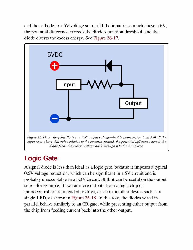
and the cathode to a 5V voltage source. If the input rises much above 5.6V,
the potential difference exceeds the diode’s junction threshold, and the
diode diverts the excess energy. See Figure 26-17.
Figure 26-17. A clamping diode can limit output voltage—in this example, to about 5.6V. If theinput rises above that value relative to the common ground, the potential difference across the
diode feeds the excess voltage back through it to the 5V source.
Logic GateA signal diode is less than ideal as a logic gate, because it imposes a typical
0.6V voltage reduction, which can be significant in a 5V circuit and is
probably unacceptable in a 3.3V circuit. Still, it can be useful on the output
side—for example, if two or more outputs from a logic chip or
microcontroller are intended to drive, or share, another device such as a
single LED, as shown in Figure 26-18. In this role, the diodes wired in
parallel behave similarly to an OR gate, while preventing either output from
the chip from feeding current back into the other output.
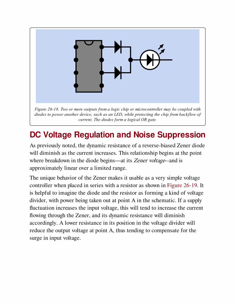
Figure 26-18. Two or more outputs from a logic chip or microcontroller may be coupled withdiodes to power another device, such as an LED, while protecting the chip from backflow of
current. The diodes form a logical OR gate.
DC Voltage Regulation and Noise SuppressionAs previously noted, the dynamic resistance of a reverse-biased Zener diode
will diminish as the current increases. This relationship begins at the point
where breakdown in the diode begins—at its Zener voltage--and is
approximately linear over a limited range.
The unique behavior of the Zener makes it usable as a very simple voltage
controller when placed in series with a resistor as shown in Figure 26-19. It
is helpful to imagine the diode and the resistor as forming a kind of voltage
divider, with power being taken out at point A in the schematic. If a supply
fluctuation increases the input voltage, this will tend to increase the current
flowing through the Zener, and its dynamic resistance will diminish
accordingly. A lower resistance in its position in the voltage divider will
reduce the output voltage at point A, thus tending to compensate for the
surge in input voltage.
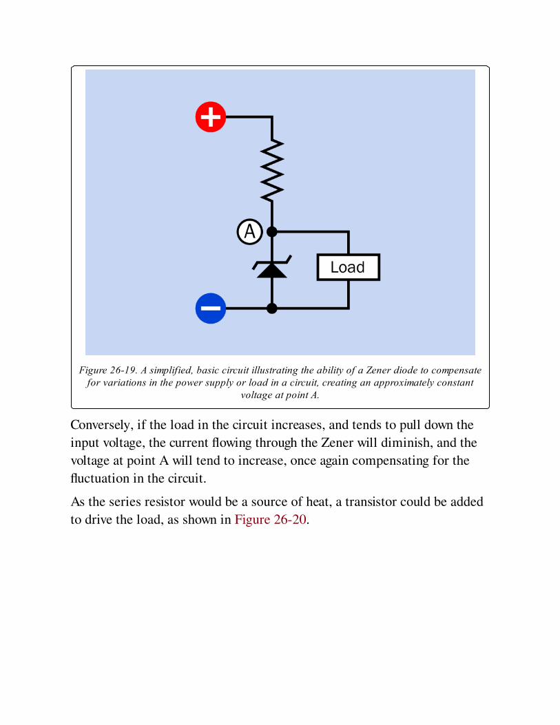
Figure 26-19. A simplified, basic circuit illustrating the ability of a Zener diode to compensatefor variations in the power supply or load in a circuit, creating an approximately constant
voltage at point A.
Conversely, if the load in the circuit increases, and tends to pull down the
input voltage, the current flowing through the Zener will diminish, and the
voltage at point A will tend to increase, once again compensating for the
fluctuation in the circuit.
As the series resistor would be a source of heat, a transistor could be added
to drive the load, as shown in Figure 26-20.
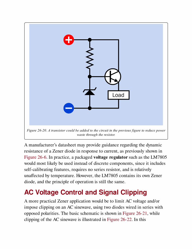
Figure 26-20. A transistor could be added to the circuit in the previous figure to reduce powerwaste through the resistor.
A manufacturer’s datasheet may provide guidance regarding the dynamic
resistance of a Zener diode in response to current, as previously shown in
Figure 26-6. In practice, a packaged voltage regulator such as the LM7805
would most likely be used instead of discrete components, since it includes
self-calibrating features, requires no series resistor, and is relatively
unaffected by temperature. However, the LM7805 contains its own Zener
diode, and the principle of operation is still the same.
AC Voltage Control and Signal ClippingA more practical Zener application would be to limit AC voltage and/or
impose clipping on an AC sinewave, using two diodes wired in series with
opposed polarities. The basic schematic is shown in Figure 26-21, while
clipping of the AC sinewave is illustrated in Figure 26-22. In this
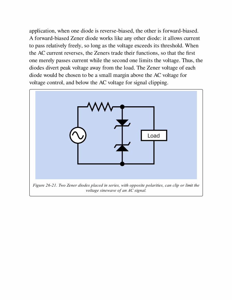
application, when one diode is reverse-biased, the other is forward-biased.
A forward-biased Zener diode works like any other diode: it allows current
to pass relatively freely, so long as the voltage exceeds its threshold. When
the AC current reverses, the Zeners trade their functions, so that the first
one merely passes current while the second one limits the voltage. Thus, the
diodes divert peak voltage away from the load. The Zener voltage of each
diode would be chosen to be a small margin above the AC voltage for
voltage control, and below the AC voltage for signal clipping.
Figure 26-21. Two Zener diodes placed in series, with opposite polarities, can clip or limit thevoltage sinewave of an AC signal.
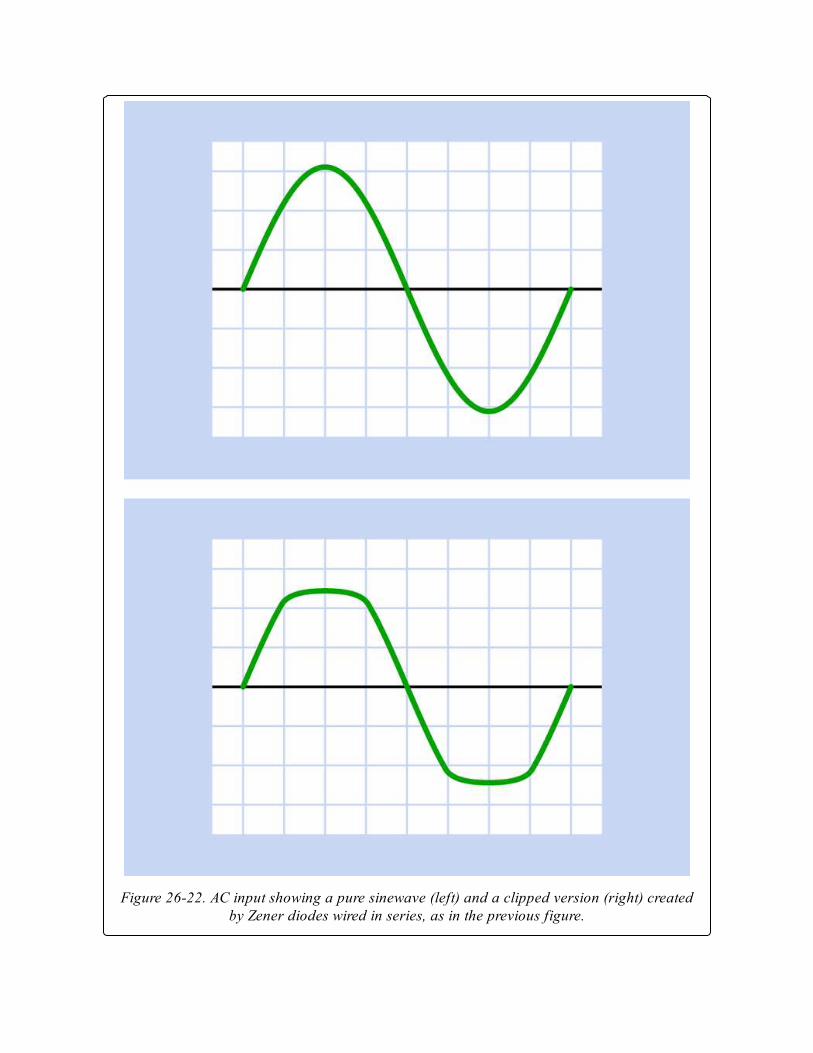
Figure 26-22. AC input showing a pure sinewave (left) and a clipped version (right) createdby Zener diodes wired in series, as in the previous figure.
Voltage SensingA Zener diode can be used to sense a small shift in voltage and provide a
switched output in response.
In Figure 26-23, the upper schematic shows a Zener diode preventing
voltage from reaching the emitter of a PNP transistor while the divided
input signal is below the Zener (breakdown) voltage of the diode. In this
mode, the transistor is relatively non-conductive, very little current flows
through it, and the output is now at near-zero voltage. As soon as the input
signal rises above the Zener voltage, the transistor switches on and power is
supplied to the output. The input is thus replicated in the output, as shown
in the upper portion of Figure 26-24.
In Figure 26-23, the lower schematic shows a Zener diode preventing
voltage from reaching the base of an NPN transistor while the input signal
is below the Zener (breakdown) voltage of the diode. In this mode, the
transistor is relatively non-conductive, and power is supplied to the output.
As soon as the input signal rises above the Zener voltage, the transistor is
activated, diverting the current to ground and bypassing the output, which is
now at near-zero voltage. The input is thus inverted, as shown in the lower
portion of Figure 26-24 (provided there is enough current to drive the
transistor into saturation).

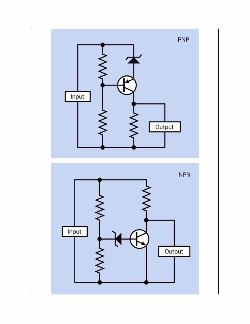

Figure 26-23. A Zener diode can be used in conjunction with a PNP transistor. See text fordetails.

Figure 26-24. Theoretical output from the transistors in the two previous schematics.
What Can Go Wrong
OverloadIf maximum forward current is exceeded, the heat generated is likely to
destroy the diode. If the diode is reverse-biased beyond its peak inverse
voltage limit, the current will overwhelm the diode’s ability to block it, and
an avalanche breakdown will occur, once again probably destroying the
component. The graph in Figure 26-5 illustrates the performance range of a
hypothetical generic diode.
Reversed PolarityZener diodes look almost identical to other types, and all diodes share the
same convention of marking the cathode for identification. Yet Zeners must
be reverse-biased while others are forward-biased. This creates a significant
risk of installing a diode "the wrong way around," with potentially
destructive or at least confusing results, especially when used in a power
supply. The very low resistance of a diode to forward current makes it
especially vulnerable to burnout if installed incorrectly.
Wrong Type of DiodeIf a Zener diode is used accidentally where a signal or rectifier diode is
appropriate, the circuit will malfunction, as the Zener will probably have a
much lower breakdown voltage, and therefore will not block reverse current.
Conversely, if a signal or rectifier diode is used where the circuit calls for a
Zener diode, reverse voltage will be clamped (or regulated at the diode’s
forward voltage value). Since diodes are often poorly marked, a sensible
precaution is to store Zener diodes separately from all other types.
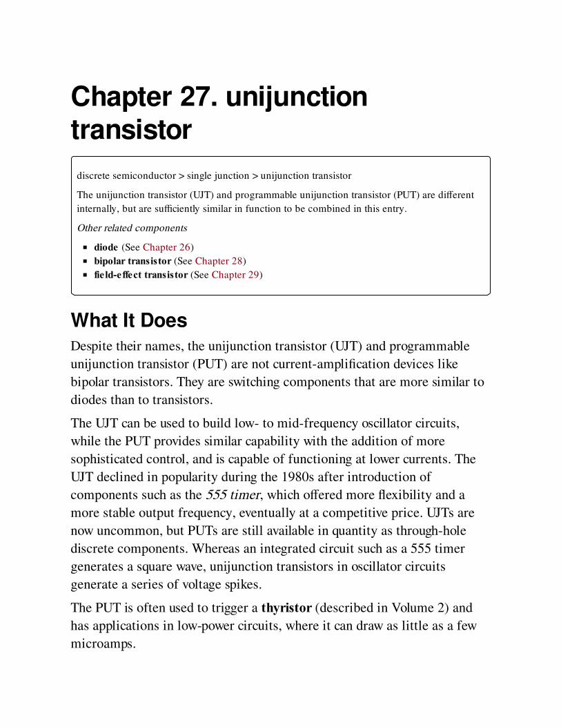
Chapter 27. unijunctiontransistor
discrete semiconductor > single junction > unijunction transistor
The unijunction transistor (UJT) and programmable unijunction transistor (PUT) are different
internally, but are sufficiently similar in function to be combined in this entry.
Other related components
diode (See Chapter 26)
bipolar transistor (See Chapter 28)
field-effect transistor (See Chapter 29)
What It DoesDespite their names, the unijunction transistor (UJT) and programmable
unijunction transistor (PUT) are not current-amplification devices like
bipolar transistors. They are switching components that are more similar to
diodes than to transistors.
The UJT can be used to build low- to mid-frequency oscillator circuits,
while the PUT provides similar capability with the addition of more
sophisticated control, and is capable of functioning at lower currents. The
UJT declined in popularity during the 1980s after introduction of
components such as the 555 timer, which offered more flexibility and a
more stable output frequency, eventually at a competitive price. UJTs are
now uncommon, but PUTs are still available in quantity as through-hole
discrete components. Whereas an integrated circuit such as a 555 timer
generates a square wave, unijunction transistors in oscillator circuits
generate a series of voltage spikes.
The PUT is often used to trigger a thyristor (described in Volume 2) and
has applications in low-power circuits, where it can draw as little as a few
microamps.
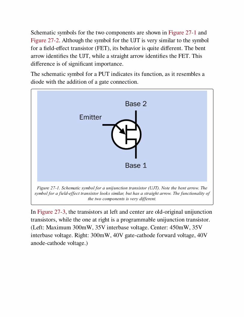
Schematic symbols for the two components are shown in Figure 27-1 and
Figure 27-2. Although the symbol for the UJT is very similar to the symbol
for a field-effect transistor (FET), its behavior is quite different. The bent
arrow identifies the UJT, while a straight arrow identifies the FET. This
difference is of significant importance.
The schematic symbol for a PUT indicates its function, as it resembles a
diode with the addition of a gate connection.
Figure 27-1. Schematic symbol for a unijunction transistor (UJT). Note the bent arrow. Thesymbol for a field-effect transistor looks similar, but has a straight arrow. The functionality of
the two components is very different.
In Figure 27-3, the transistors at left and center are old-original unijunction
transistors, while the one at right is a programmable unijunction transistor.
(Left: Maximum 300mW, 35V interbase voltage. Center: 450mW, 35V
interbase voltage. Right: 300mW, 40V gate-cathode forward voltage, 40V
anode-cathode voltage.)
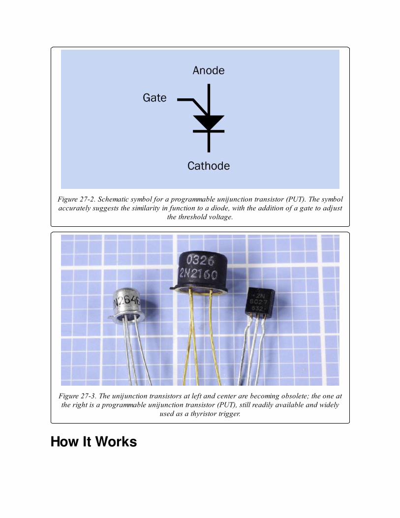
Figure 27-2. Schematic symbol for a programmable unijunction transistor (PUT). The symbolaccurately suggests the similarity in function to a diode, with the addition of a gate to adjust
the threshold voltage.
Figure 27-3. The unijunction transistors at left and center are becoming obsolete; the one atthe right is a programmable unijunction transistor (PUT), still readily available and widely
used as a thyristor trigger.
How It Works
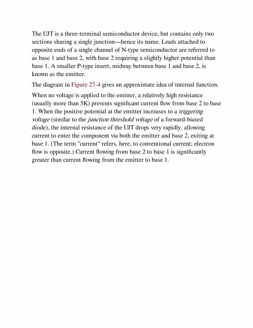
The UJT is a three-terminal semiconductor device, but contains only two
sections sharing a single junction—hence its name. Leads attached to
opposite ends of a single channel of N-type semiconductor are referred to
as base 1 and base 2, with base 2 requiring a slightly higher potential than
base 1. A smaller P-type insert, midway between base 1 and base 2, is
known as the emitter.
The diagram in Figure 27-4 gives an approximate idea of internal function.
When no voltage is applied to the emitter, a relatively high resistance
(usually more than 5K) prevents significant current flow from base 2 to base
1. When the positive potential at the emitter increases to a triggering
voltage (similar to the junction threshold voltage of a forward-biased
diode), the internal resistance of the UJT drops very rapidly, allowing
current to enter the component via both the emitter and base 2, exiting at
base 1. (The term "current" refers, here, to conventional current; electron
flow is opposite.) Current flowing from base 2 to base 1 is significantly
greater than current flowing from the emitter to base 1.

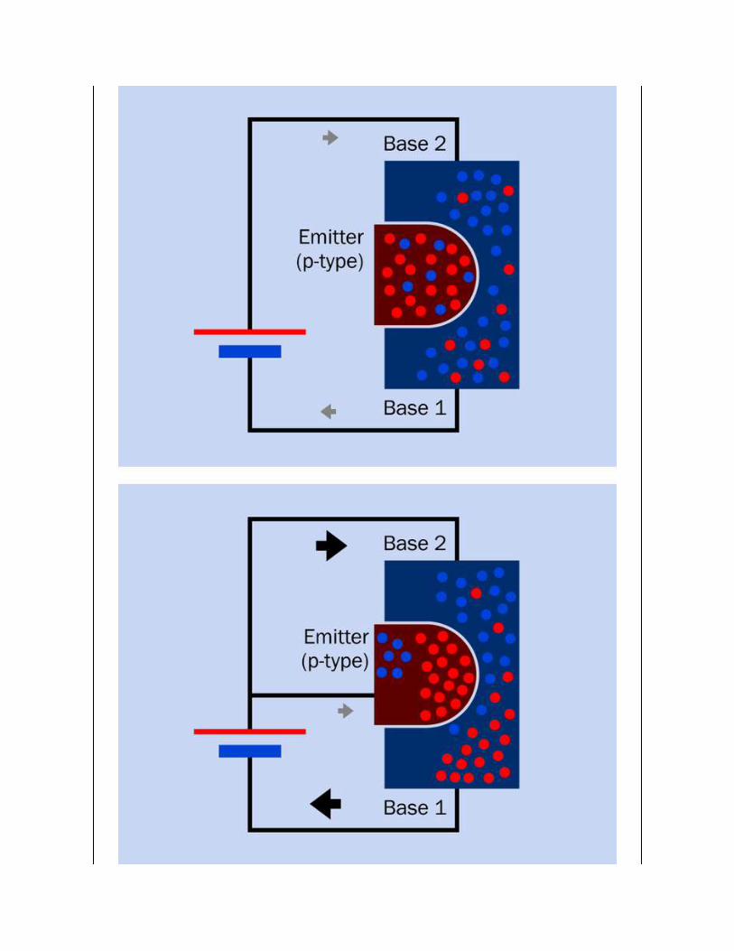
Figure 27-4. Internal workings of a unijunction transistor.
The graph in Figure 27-5 outlines the behavior of a UJT. As the voltage
applied to the emitter increases, current flowing into the component from
the emitter increases slightly, until the triggering voltage is reached. The
component’s internal resistance now drops rapidly. This pulls down the
voltage at the emitter, while the current continues to increase significantly.
Because of the drop in resistance, this is referred to as a negative resistance
region. The resistance actually cannot fall below zero, but its change is
negative. After emitter voltage drops to a minimum known as the valley
voltage, the current continues to increase with a small increase in voltage.
On datasheets, the peak current is often referred to as Ip while valley
current is Iv.
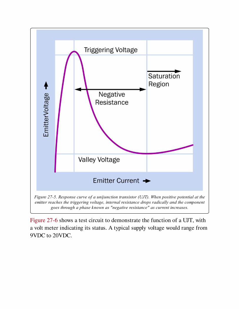
Figure 27-5. Response curve of a unijunction transistor (UJT). When positive potential at theemitter reaches the triggering voltage, internal resistance drops radically and the component
goes through a phase known as "negative resistance" as current increases.
Figure 27-6 shows a test circuit to demonstrate the function of a UJT, with
a volt meter indicating its status. A typical supply voltage would range from
9VDC to 20VDC.
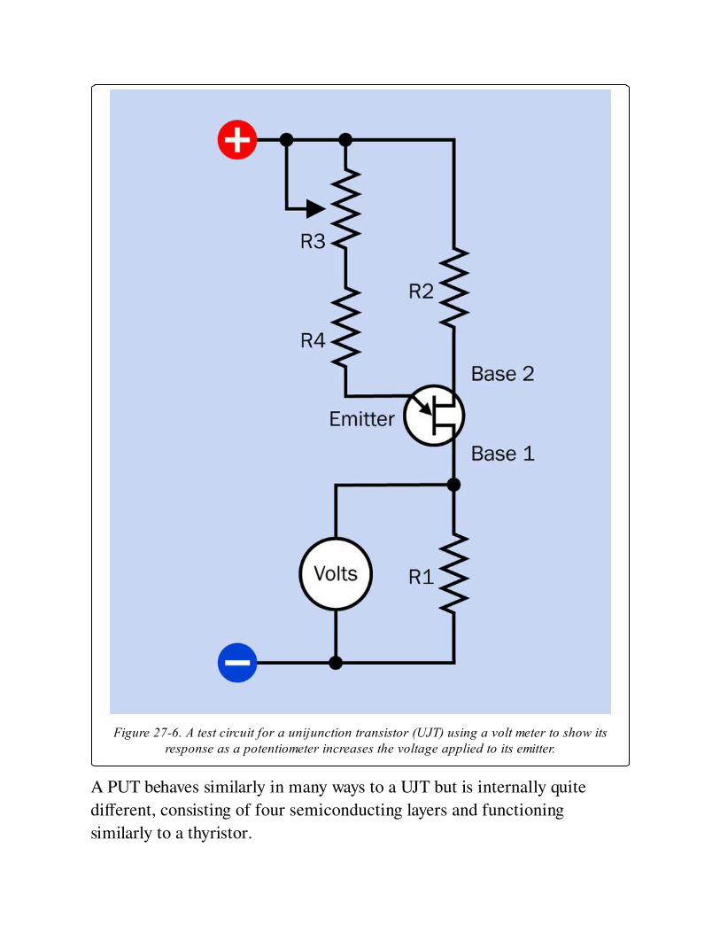
Figure 27-6. A test circuit for a unijunction transistor (UJT) using a volt meter to show itsresponse as a potentiometer increases the voltage applied to its emitter.
A PUT behaves similarly in many ways to a UJT but is internally quite
different, consisting of four semiconducting layers and functioning
similarly to a thyristor.
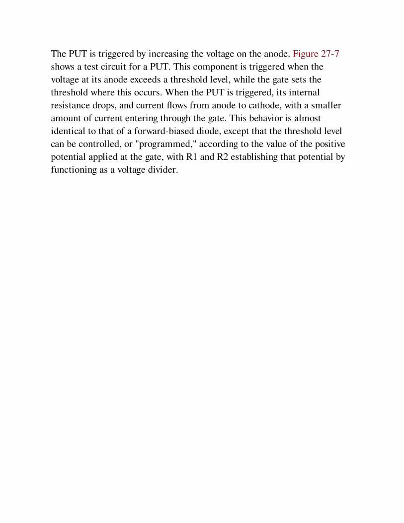
The PUT is triggered by increasing the voltage on the anode. Figure 27-7
shows a test circuit for a PUT. This component is triggered when the
voltage at its anode exceeds a threshold level, while the gate sets the
threshold where this occurs. When the PUT is triggered, its internal
resistance drops, and current flows from anode to cathode, with a smaller
amount of current entering through the gate. This behavior is almost
identical to that of a forward-biased diode, except that the threshold level
can be controlled, or "programmed," according to the value of the positive
potential applied at the gate, with R1 and R2 establishing that potential by
functioning as a voltage divider.
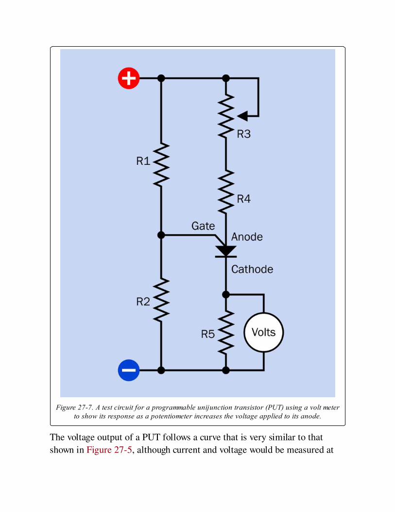
Figure 27-7. A test circuit for a programmable unijunction transistor (PUT) using a volt meterto show its response as a potentiometer increases the voltage applied to its anode.
The voltage output of a PUT follows a curve that is very similar to that
shown in Figure 27-5, although current and voltage would be measured at
the cathode.
VariantsPUTs and UJTs are not made as surface-mount components.
UJTs are usually packaged in black plastic, although older variants were
manufactured in cans. PUTs are almost all packaged in black plastic. With
the leads pointing downward and the flat side facing toward the viewer, the
lead functions of a PUT are usually anode, gate, and cathode, reading from
left to right.
ValuesThe triggering voltage of a UJT can be calculated from the values of R1 and
R2 in Figure 27-7 and the voltage at base 1. The term Rbb is often used to
represent the sum of R1 + R2, with Vbb representing the total voltage
across the two resistors (this is the same as the supply voltage in Figure 27-
6). Vt, the triggering voltage, is given by:
Vt = Vbb * (R1 / Rbb)
The term (R1/Rbb) is known as the standoff ratio, often represented by the
Greek letter ƍ.
Typically the standoff ratio in a UJT is at least 0.7, as R1 is chosen to be
larger than R2. Typical values for R1 and R2 could be 180Ω and 100Ω,
respectively. If R4 is 50K and a 100K linear potentiometer is used for R3,
the PUT should be triggered when the potentiometer is near the center of
its range. The emitter saturation voltage is typically from 2V to 4V.
If using a PUT, typical values in the test circuit could be supply voltage
ranging from 9VDC to 20VDC, with resistances 28K for R1 and 16K for
R2, 20Ω for R5, 280K for R4, and a 500K linear potentiometer for R3. The
PUT should be triggered when the potentiometer is near the center of its
range.
Sustained forward current from anode to cathode is usually a maximum of
150mA, while from gate to cathode the maximum is usually 50mA. Power
dissipation should not exceed 300mW. These values should be lower at
temperatures above 25 degrees Centigrade.
Depending on the PUT being used, power consumption can be radically
decreased by upping the resistor values by a multiple of 100, while supply
voltage can be decreased to 5V. The cathode output from the PUT would
then be connected with the base of an NPN transistor for amplification.
How to Use itFigure 27-8 shows a simple oscillator circuit built around a UJT, Figure 27-
9 shows a comparable circuit for a PUT. Initially the supply voltage charges
the capacitor, until the potential at the emitter of the UJT or the gate of the
PUT reaches the threshold voltage, at which point the capacitor discharges
through the emitter and the cycle repeats. Resistor values would be similar
to those used in the test circuits previously described, while a capacitor
value of 2.2μF would provide a visible pulse of the LED. Smaller capacitor
values would enable faster oscillation. In the PUT circuit, adjusting the
values of R1 and R2 would allow fine control of triggering the
semiconductor.
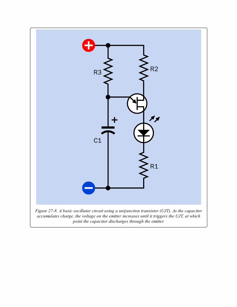
Figure 27-8. A basic oscillator circuit using a unijunction transistor (UJT). As the capacitoraccumulates charge, the voltage on the emitter increases until it triggers the UJT, at which
point the capacitor discharges through the emitter.
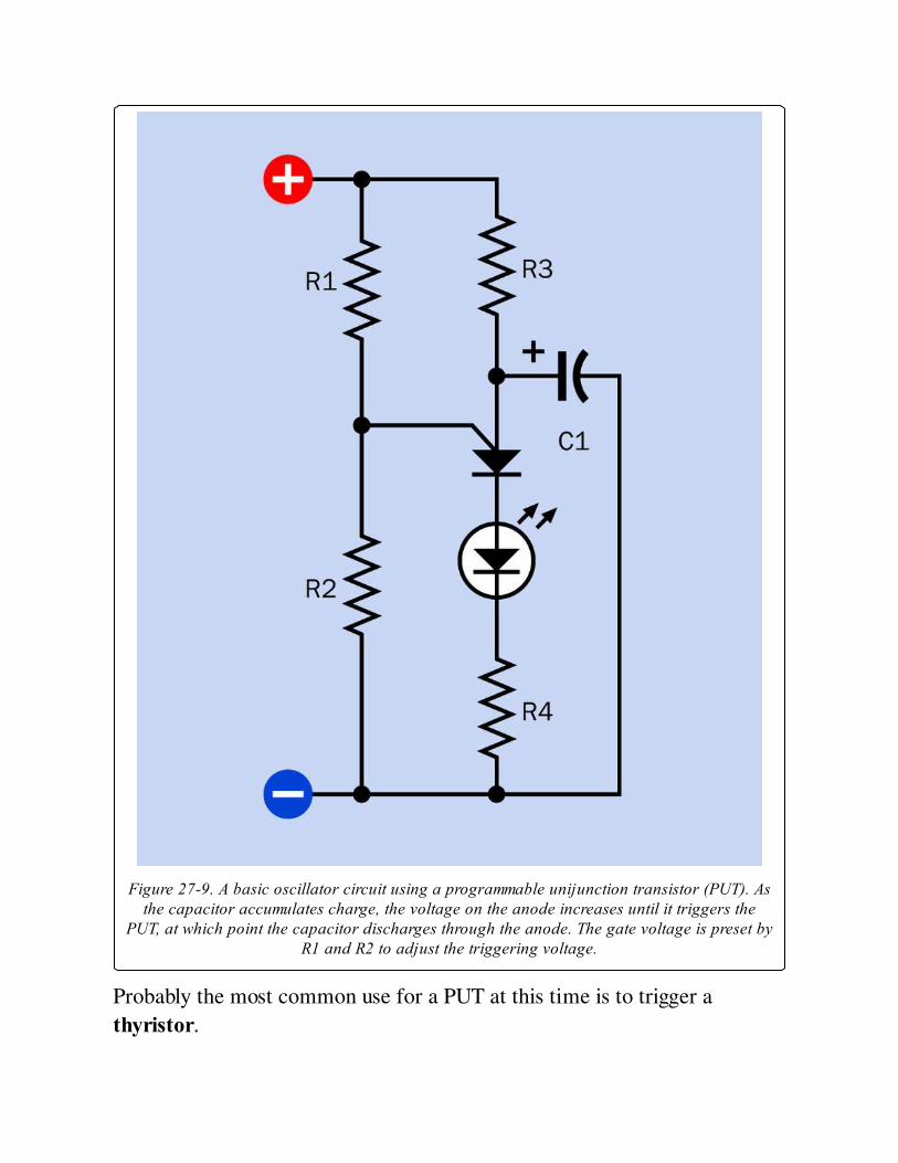
Figure 27-9. A basic oscillator circuit using a programmable unijunction transistor (PUT). Asthe capacitor accumulates charge, the voltage on the anode increases until it triggers the
PUT, at which point the capacitor discharges through the anode. The gate voltage is preset byR1 and R2 to adjust the triggering voltage.
Probably the most common use for a PUT at this time is to trigger a
thyristor.
What Can Go Wrong
Name ConfusionA programmable unijunction transistor (PUT) is sometimes referred to
simply as a "unijunction transistor" (UJT). Bearing in mind the totally
different modes of operation of UJT and PUT, the PUT should always be
identified by its acronym or by its full name. A circuit will not function if a
UJT is substituted for a PUT, or a PUT is substituted for a UJT.
Incorrect BiasNeither the UJT nor the PUT is designed to operate with reverse bias. In the
UJT, a small forward bias should be applied from base 2 to base 1 (that is,
base 2 should be at a higher potential relative to base 1) regardless of the
voltage on the emitter. The emitter voltage may vary from 0 volts upward.
The PUT must be forward biased between its anode and cathode (the anode
must have a higher potential relative to the cathode), with an intermediate
positive voltage at the gate established by resistors R1 and R2 functioning
as a voltage divider (see Figure 27-7). Failure to observe correct biasing will
result in unpredictable behavior and possible damage to the component.
OverloadLike any semiconductor, the UJT and the PUT must be protected from
excessive current, which can burn out the component. Never connect either
of these components directly across a power source without appropriate
resistances to limit current flow. Maximum continuous power dissipation
for UJTs and PUTs is usually 300mW.
Chapter 28. bipolar transistor
discrete semiconductor > multi-junction > bipolar transistor
The word transistor, on its own, is often used to mean bipolar transistor, as this was the type
that became most widely used in the field of discrete semiconductors. However, bipolar
transistor is the correct term. It is sometimes referred to as a bipolar junction transistor or BJT.
Other related components
unijunction transistor (See Chapter 27)
field-effect transistor (See Chapter 29)
diac (Volume 2)
triac (Volume 2)
relay (Volume 2)
solid-state relay (Volume 2)
What It DoesA bipolar transistor amplifies fluctuations in current or can be used to
switch current on and off. In its amplifying mode, it replaced the vacuum
tubes that were formerly used in the amplification of audio signals and
many other applications. In its switching mode it resembles a relay,
although in its "off" state the transistor still allows a very small amount of
current flow, known as leakage.
A bipolar transistor is described as a discrete semiconductor device when it
is individually packaged, with three leads or contacts. A package containing
multiple transistors is an integrated circuit. A Darlington pair actually
contains two transistors, but is included here as a discrete component
because it is packaged similarly and functions like a single transistor. Most
integrated circuits will be found in Volume 2 of this encyclopedia.
How It WorksAlthough the earliest transistors were fabricated from germanium, silicon
has become the most commonly used material. Silicon behaves like an
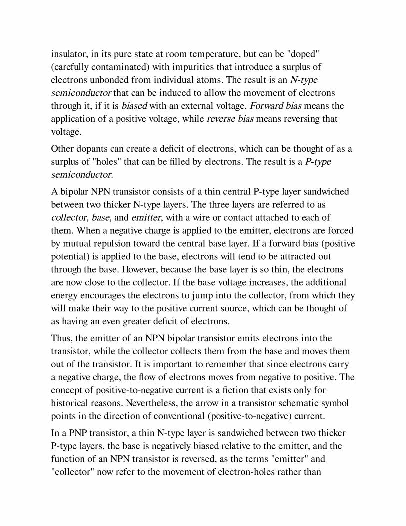
insulator, in its pure state at room temperature, but can be "doped"
(carefully contaminated) with impurities that introduce a surplus of
electrons unbonded from individual atoms. The result is an N-type
semiconductor that can be induced to allow the movement of electrons
through it, if it is biased with an external voltage. Forward bias means the
application of a positive voltage, while reverse bias means reversing that
voltage.
Other dopants can create a deficit of electrons, which can be thought of as a
surplus of "holes" that can be filled by electrons. The result is a P-type
semiconductor.
A bipolar NPN transistor consists of a thin central P-type layer sandwiched
between two thicker N-type layers. The three layers are referred to as
collector, base, and emitter, with a wire or contact attached to each of
them. When a negative charge is applied to the emitter, electrons are forced
by mutual repulsion toward the central base layer. If a forward bias (positive
potential) is applied to the base, electrons will tend to be attracted out
through the base. However, because the base layer is so thin, the electrons
are now close to the collector. If the base voltage increases, the additional
energy encourages the electrons to jump into the collector, from which they
will make their way to the positive current source, which can be thought of
as having an even greater deficit of electrons.
Thus, the emitter of an NPN bipolar transistor emits electrons into the
transistor, while the collector collects them from the base and moves them
out of the transistor. It is important to remember that since electrons carry
a negative charge, the flow of electrons moves from negative to positive. The
concept of positive-to-negative current is a fiction that exists only for
historical reasons. Nevertheless, the arrow in a transistor schematic symbol
points in the direction of conventional (positive-to-negative) current.
In a PNP transistor, a thin N-type layer is sandwiched between two thicker
P-type layers, the base is negatively biased relative to the emitter, and the
function of an NPN transistor is reversed, as the terms "emitter" and
"collector" now refer to the movement of electron-holes rather than
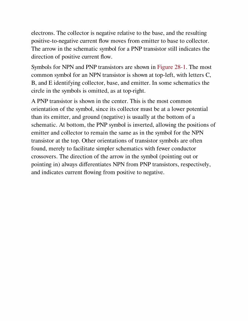
electrons. The collector is negative relative to the base, and the resulting
positive-to-negative current flow moves from emitter to base to collector.
The arrow in the schematic symbol for a PNP transistor still indicates the
direction of positive current flow.
Symbols for NPN and PNP transistors are shown in Figure 28-1. The most
common symbol for an NPN transistor is shown at top-left, with letters C,
B, and E identifying collector, base, and emitter. In some schematics the
circle in the symbols is omitted, as at top-right.
A PNP transistor is shown in the center. This is the most common
orientation of the symbol, since its collector must be at a lower potential
than its emitter, and ground (negative) is usually at the bottom of a
schematic. At bottom, the PNP symbol is inverted, allowing the positions of
emitter and collector to remain the same as in the symbol for the NPN
transistor at the top. Other orientations of transistor symbols are often
found, merely to facilitate simpler schematics with fewer conductor
crossovers. The direction of the arrow in the symbol (pointing out or
pointing in) always differentiates NPN from PNP transistors, respectively,
and indicates current flowing from positive to negative.
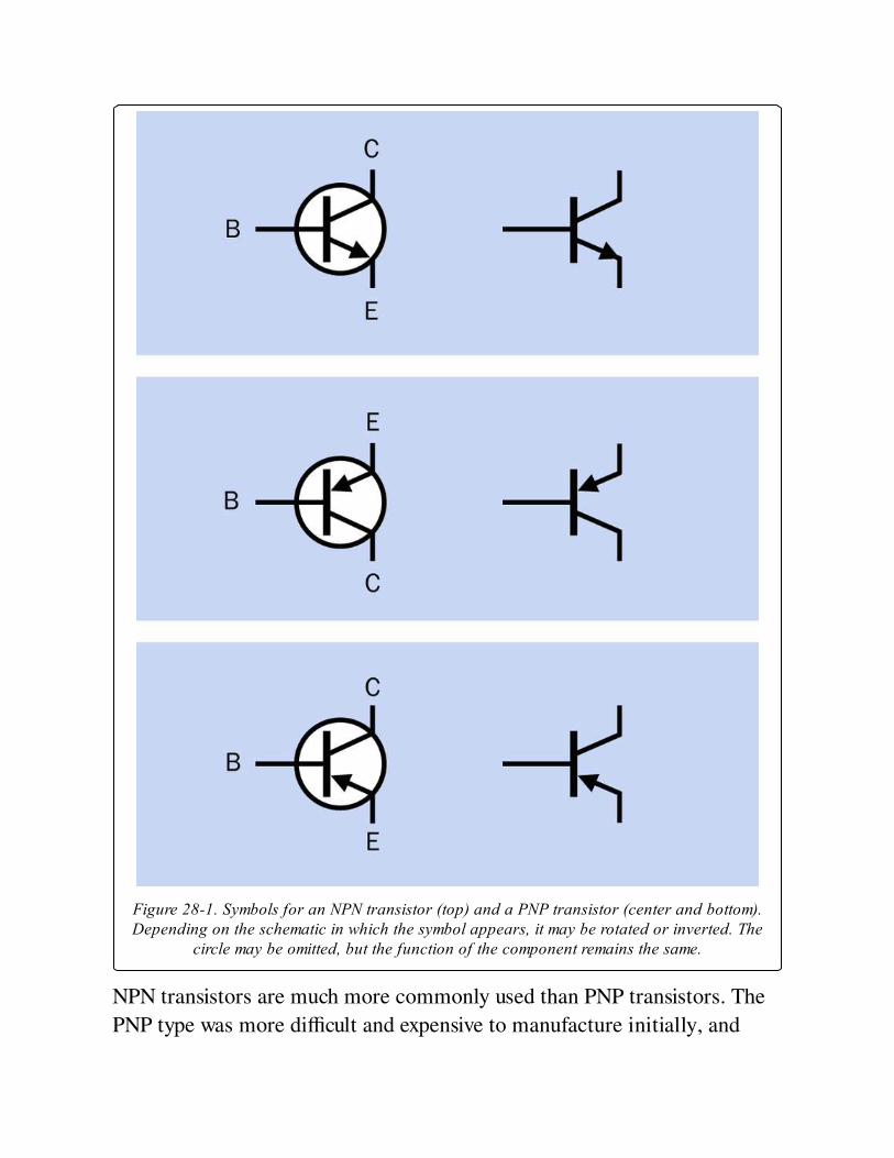
Figure 28-1. Symbols for an NPN transistor (top) and a PNP transistor (center and bottom).Depending on the schematic in which the symbol appears, it may be rotated or inverted. The
circle may be omitted, but the function of the component remains the same.
NPN transistors are much more commonly used than PNP transistors. The
PNP type was more difficult and expensive to manufacture initially, and
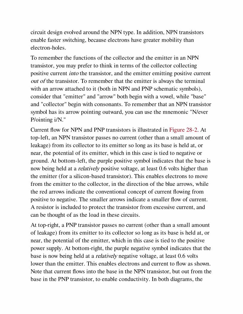
circuit design evolved around the NPN type. In addition, NPN transistors
enable faster switching, because electrons have greater mobility than
electron-holes.
To remember the functions of the collector and the emitter in an NPN
transistor, you may prefer to think in terms of the collector collecting
positive current into the transistor, and the emitter emitting positive current
out of the transistor. To remember that the emitter is always the terminal
with an arrow attached to it (both in NPN and PNP schematic symbols),
consider that "emitter" and "arrow" both begin with a vowel, while "base"
and "collector" begin with consonants. To remember that an NPN transistor
symbol has its arrow pointing outward, you can use the mnemonic "N/ever
P/ointing i/N."
Current flow for NPN and PNP transistors is illustrated in Figure 28-2. At
top-left, an NPN transistor passes no current (other than a small amount of
leakage) from its collector to its emitter so long as its base is held at, or
near, the potential of its emitter, which in this case is tied to negative or
ground. At bottom-left, the purple positive symbol indicates that the base is
now being held at a relatively positive voltage, at least 0.6 volts higher than
the emitter (for a silicon-based transistor). This enables electrons to move
from the emitter to the collector, in the direction of the blue arrows, while
the red arrows indicate the conventional concept of current flowing from
positive to negative. The smaller arrows indicate a smaller flow of current.
A resistor is included to protect the transistor from excessive current, and
can be thought of as the load in these circuits.
At top-right, a PNP transistor passes no current (other than a small amount
of leakage) from its emitter to its collector so long as its base is held at, or
near, the potential of the emitter, which in this case is tied to the positive
power supply. At bottom-right, the purple negative symbol indicates that the
base is now being held at a relatively negative voltage, at least 0.6 volts
lower than the emitter. This enables electrons and current to flow as shown.
Note that current flows into the base in the NPN transistor, but out from the
base in the PNP transistor, to enable conductivity. In both diagrams, the

resistor that would normally be included to protect the base has been
omitted for the sake of simplicity.
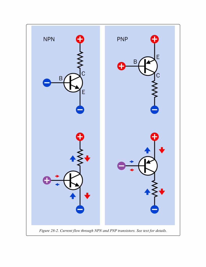
Figure 28-2. Current flow through NPN and PNP transistors. See text for details.
An NPN transistor amplifies its base current only so long as the positive
potential applied to the collector is greater than the potential applied to the
base, and the potential at the base must be greater than the potential at the
emitter by at least 0.6 volts. So long as the transistor is biased in this way,
and so long as the current values remain within the manufacturer’s specified
limits, a small fluctuation in current applied to the base will induce a much
larger fluctuation in current between the collector and the emitter. This is
why a transistor may be described as a current amplifier.
A voltage divider is often used to control the base potential and ensure that
it remains less than the potential on the collector and greater than the
potential at the emitter (in an NPN transistor). See Figure 28-3.
See Chapter 10 for additional information about the function of a voltage
divider.
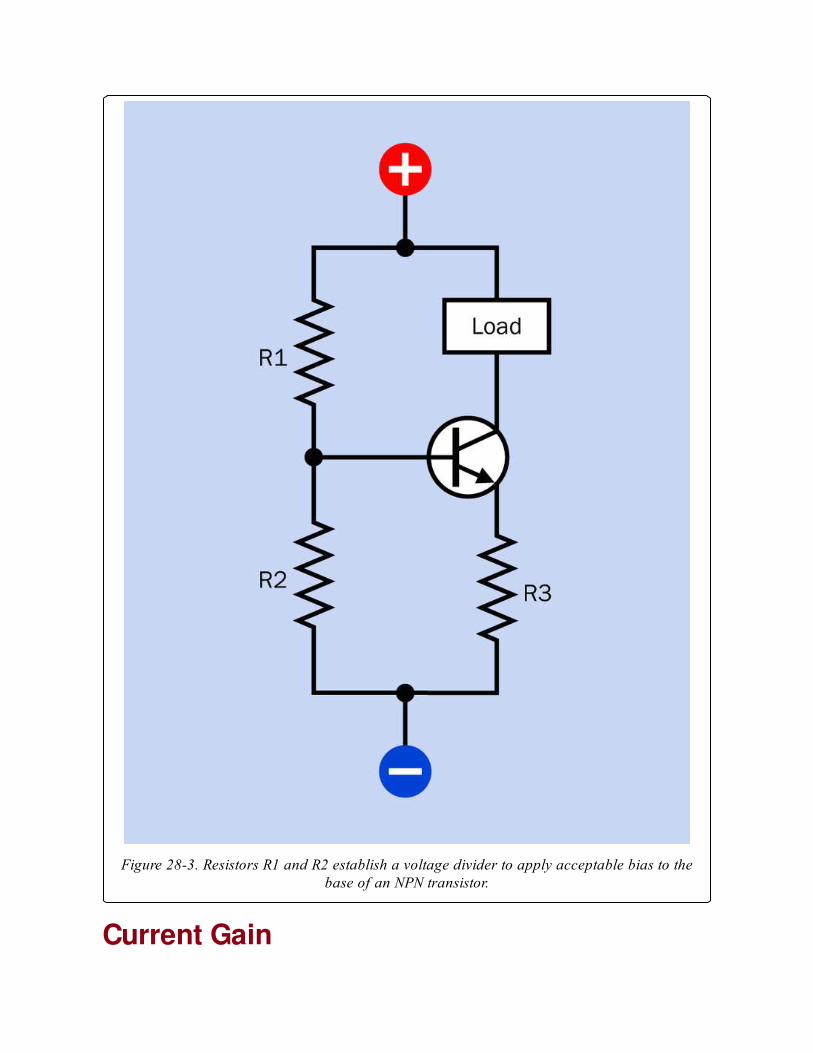
Figure 28-3. Resistors R1 and R2 establish a voltage divider to apply acceptable bias to thebase of an NPN transistor.
Current Gain
The amplification of current by a transistor is known as its current gain or
beta value, which can be expressed as the ratio of an increase in collector
current divided by the increase in base current that enables it. Greek letter β
is customarily used to represent this ratio. The formula looks like this:
β = ΔIc / ΔIb
where Ic is the collector current and Ib is the base current, and the Δ symbol
represents a small change in the value of the variable that follows it.
Current gain is also represented by the term hFE, where E is for the
common Emitter, F is for Forward current, and lowercase letter h refers to
the transistor as a "hybrid" device.
The beta value will always be greater than 1 and is often around 100,
although it will vary from one type of transistor to another. It will also be
affected by temperature, voltage applied to the transistor, collector current,
and manufacturing inaccuracies. When the transistor is used outside of its
design parameters, the formula to determine the beta value no longer
directly applies.
There are only two connections at which current can enter an NPN
transistor and one connection where it can leave. Therefore, if Ie is the
current from the emitter, Ic is the current entering the collector, and Ib is
the current entering the base:
Ie = Ic + Ib
If the potential applied to the base of an NPN transistor diminishes to the
point where it is less than 0.6V above the potential at the emitter, the
transistor will not conduct, and is in an "off" state, although a very small
amount of leakage from collector to emitter will still occur.
When the current flowing into the base of the transistor rises to the point
where the transistor cannot amplify the current any further, it becomes
saturated, at which point its internal impedance has fallen to a minimal
value. Theoretically this will allow a large flow of current; in practice, the
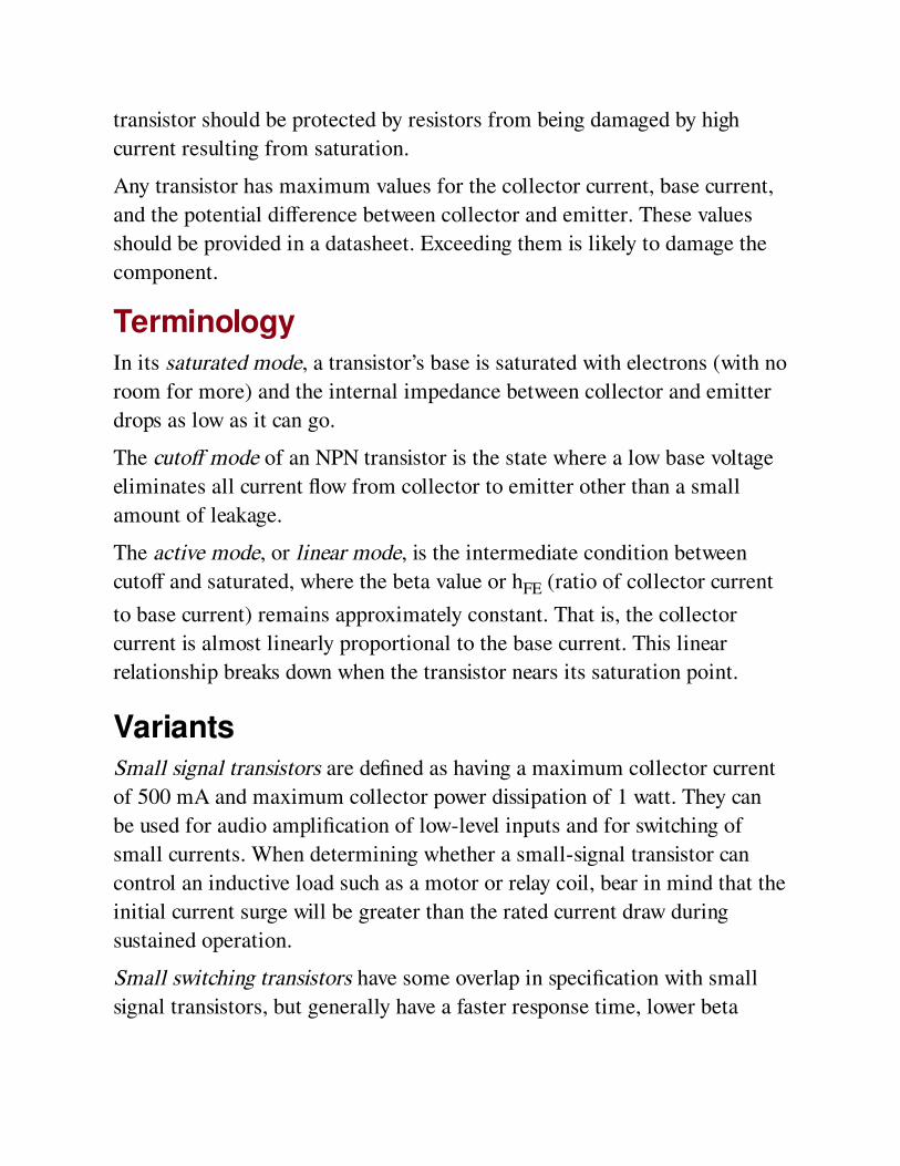
transistor should be protected by resistors from being damaged by high
current resulting from saturation.
Any transistor has maximum values for the collector current, base current,
and the potential difference between collector and emitter. These values
should be provided in a datasheet. Exceeding them is likely to damage the
component.
TerminologyIn its saturated mode, a transistor’s base is saturated with electrons (with no
room for more) and the internal impedance between collector and emitter
drops as low as it can go.
The cutoff mode of an NPN transistor is the state where a low base voltage
eliminates all current flow from collector to emitter other than a small
amount of leakage.
The active mode, or linear mode, is the intermediate condition between
cutoff and saturated, where the beta value or hFE (ratio of collector current
to base current) remains approximately constant. That is, the collector
current is almost linearly proportional to the base current. This linear
relationship breaks down when the transistor nears its saturation point.
VariantsSmall signal transistors are defined as having a maximum collector current
of 500 mA and maximum collector power dissipation of 1 watt. They can
be used for audio amplification of low-level inputs and for switching of
small currents. When determining whether a small-signal transistor can
control an inductive load such as a motor or relay coil, bear in mind that the
initial current surge will be greater than the rated current draw during
sustained operation.
Small switching transistors have some overlap in specification with small
signal transistors, but generally have a faster response time, lower beta
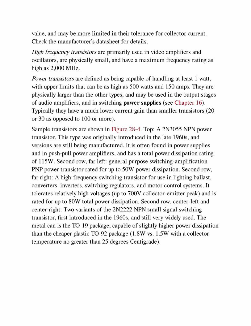
value, and may be more limited in their tolerance for collector current.
Check the manufacturer’s datasheet for details.
High frequency transistors are primarily used in video amplifiers and
oscillators, are physically small, and have a maximum frequency rating as
high as 2,000 MHz.
Power transistors are defined as being capable of handling at least 1 watt,
with upper limits that can be as high as 500 watts and 150 amps. They are
physically larger than the other types, and may be used in the output stages
of audio amplifiers, and in switching power supplies (see Chapter 16).
Typically they have a much lower current gain than smaller transistors (20
or 30 as opposed to 100 or more).
Sample transistors are shown in Figure 28-4. Top: A 2N3055 NPN power
transistor. This type was originally introduced in the late 1960s, and
versions are still being manufactured. It is often found in power supplies
and in push-pull power amplifiers, and has a total power dissipation rating
of 115W. Second row, far left: general purpose switching-amplification
PNP power transistor rated for up to 50W power dissipation. Second row,
far right: A high-frequency switching transistor for use in lighting ballast,
converters, inverters, switching regulators, and motor control systems. It
tolerates relatively high voltages (up to 700V collector-emitter peak) and is
rated for up to 80W total power dissipation. Second row, center-left and
center-right: Two variants of the 2N2222 NPN small signal switching
transistor, first introduced in the 1960s, and still very widely used. The
metal can is the TO-19 package, capable of slightly higher power dissipation
than the cheaper plastic TO-92 package (1.8W vs. 1.5W with a collector
temperature no greater than 25 degrees Centigrade).
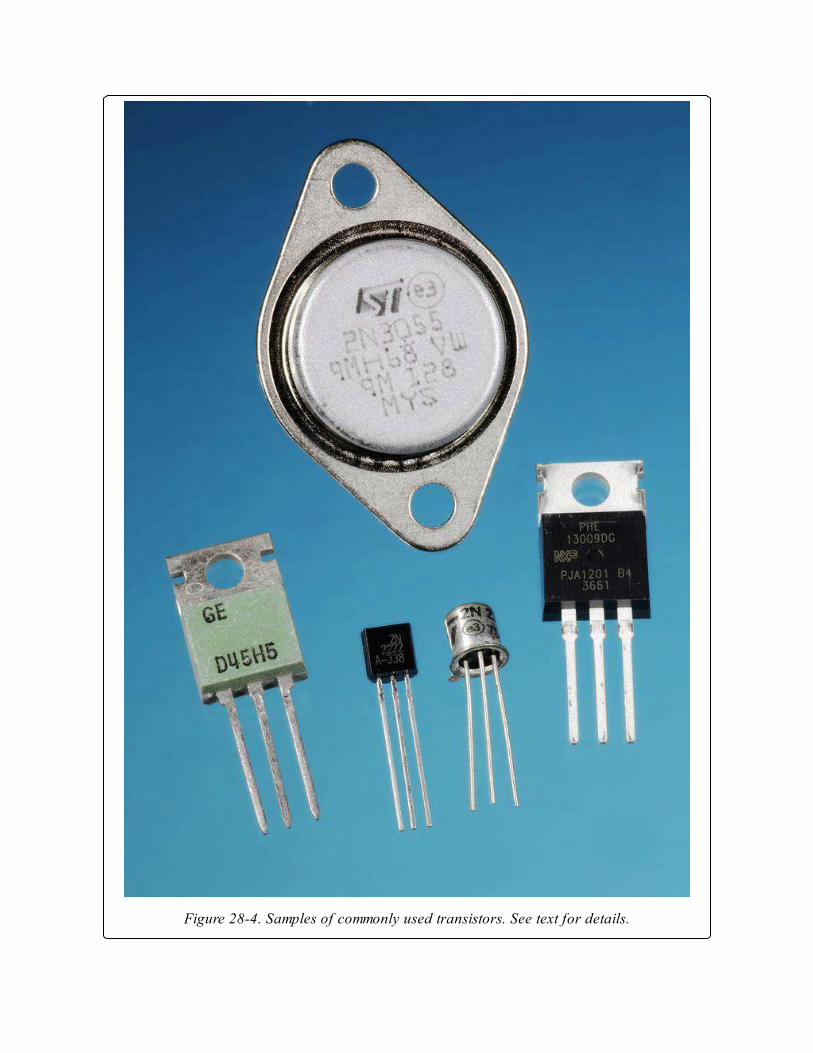
Figure 28-4. Samples of commonly used transistors. See text for details.
PackagingTraditionally, small-signal transistors were packaged in small aluminum
“cans” about 1/4" in diameter, and are still sometimes found in this form.
More commonly they are embedded in buds of black plastic. Power
transistors are packaged either in a rectangular module of black plastic with
a metal back, or in a round metal “button.” Both of these forms are
designed to dissipate heat by being screw-clamped to a heat sink.
ConnectionsOften a transistor package provides no clue as to which lead is the emitter,
which lead is the base, and which lead is the collector. Old can-style
packaging includes a protruding tab that usually points toward the emitter,
but not always. Where power transistors are packaged in a metal enclosure,
it is typically connected internally with the collector. In the case of surface-
mount transistors, look for a dot or marker that should identify the base of
a bipolar transistor or the gate of a field-effect transistor.
A through-hole transistor usually has its part number printed or engraved on
its package, although a magnifying glass may be necessary to see this. The
component’s datasheet may then be checked online. If a datasheet is
unavailable, meter-testing will be necessary to confirm the functions of the
three transistor leads. Some multimeters include a transistor-test function,
which may validate the functionality of a transistor while also displaying its
beta value. Otherwise, a meter can be put in diode-testing mode, and an
unpowered NPN transistor should behave as if diodes are connected
between its leads as shown in Figure 28-5. Where the identities of the
transistor’s leads are unknown, this test will be sufficient to identify the
base, after which the collector and emitter may be determined empirically
by testing the transistor in a simple low-voltage circuit such as that shown in
Figure 28-6.
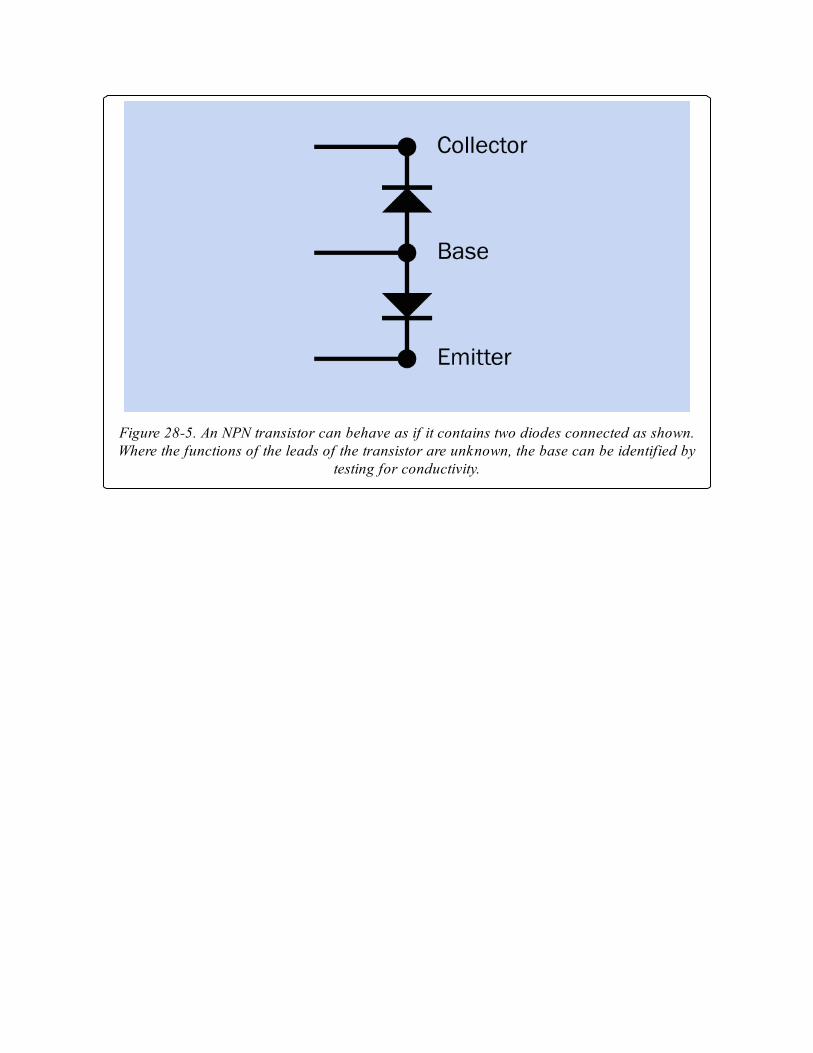
Figure 28-5. An NPN transistor can behave as if it contains two diodes connected as shown.Where the functions of the leads of the transistor are unknown, the base can be identified by
testing for conductivity.
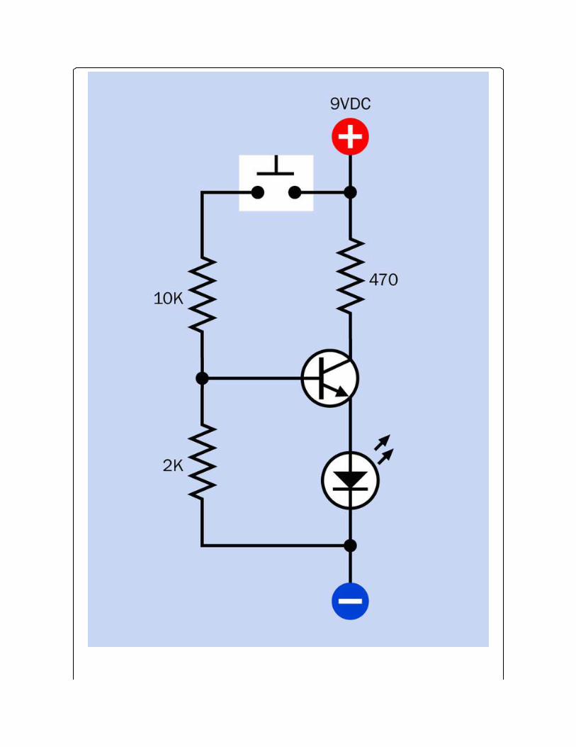
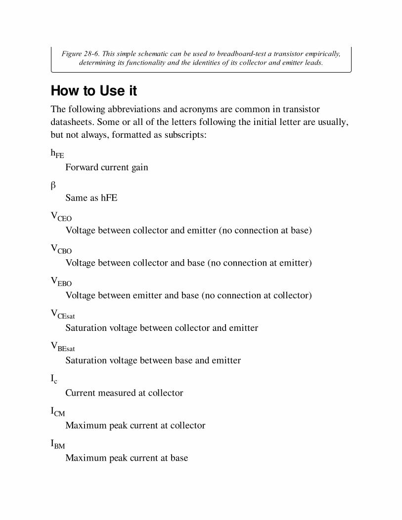
Figure 28-6. This simple schematic can be used to breadboard-test a transistor empirically,determining its functionality and the identities of its collector and emitter leads.
How to Use itThe following abbreviations and acronyms are common in transistor
datasheets. Some or all of the letters following the initial letter are usually,
but not always, formatted as subscripts:
hFE
Forward current gain
β
Same as hFE
VCEO
Voltage between collector and emitter (no connection at base)
VCBO
Voltage between collector and base (no connection at emitter)
VEBO
Voltage between emitter and base (no connection at collector)
VCEsat
Saturation voltage between collector and emitter
VBEsat
Saturation voltage between base and emitter
Ic
Current measured at collector
ICM
Maximum peak current at collector
IBM
Maximum peak current at base
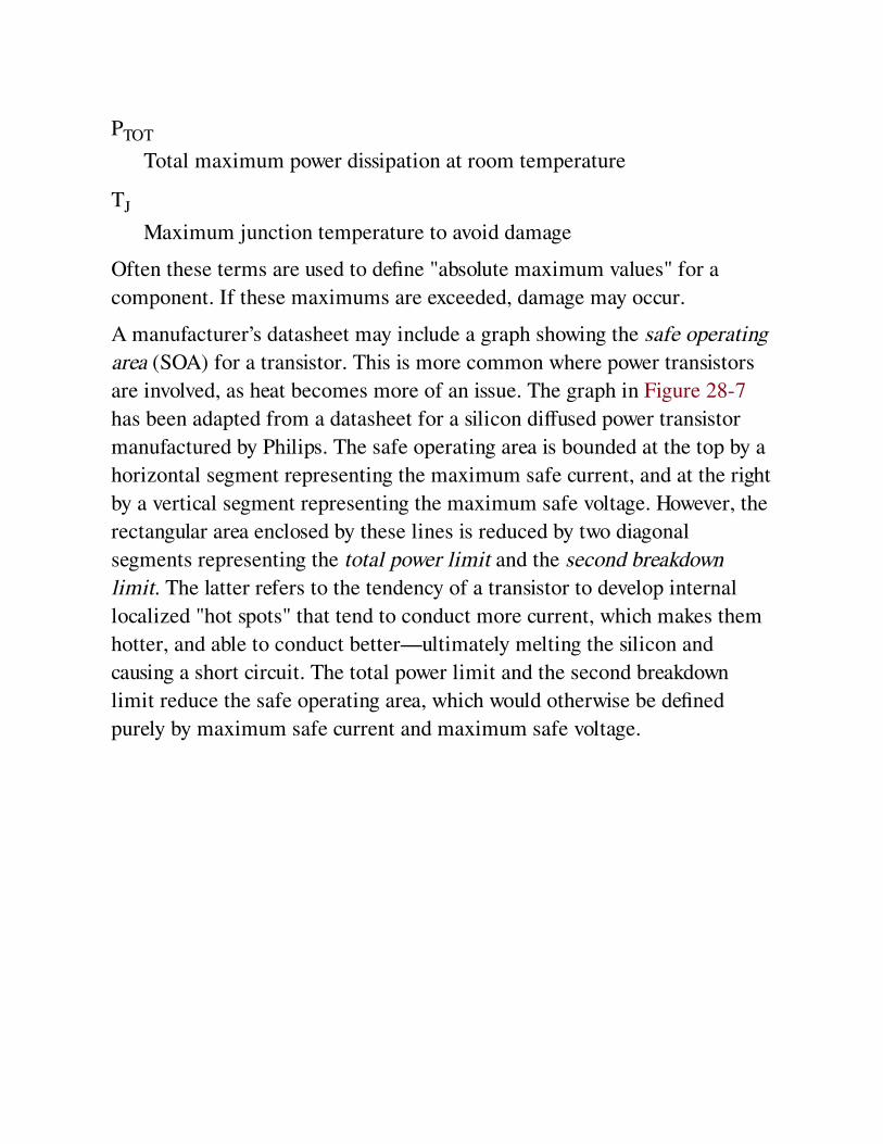
PTOT
Total maximum power dissipation at room temperature
TJ
Maximum junction temperature to avoid damage
Often these terms are used to define "absolute maximum values" for a
component. If these maximums are exceeded, damage may occur.
A manufacturer’s datasheet may include a graph showing the safe operating
area (SOA) for a transistor. This is more common where power transistors
are involved, as heat becomes more of an issue. The graph in Figure 28-7
has been adapted from a datasheet for a silicon diffused power transistor
manufactured by Philips. The safe operating area is bounded at the top by a
horizontal segment representing the maximum safe current, and at the right
by a vertical segment representing the maximum safe voltage. However, the
rectangular area enclosed by these lines is reduced by two diagonal
segments representing the total power limit and the second breakdown
limit. The latter refers to the tendency of a transistor to develop internal
localized "hot spots" that tend to conduct more current, which makes them
hotter, and able to conduct better—ultimately melting the silicon and
causing a short circuit. The total power limit and the second breakdown
limit reduce the safe operating area, which would otherwise be defined
purely by maximum safe current and maximum safe voltage.
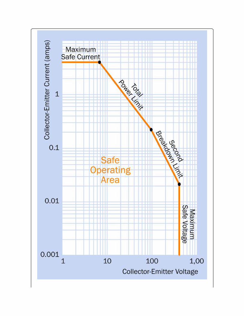
Figure 28-7. Adapted from a Philips datasheet for a power transistor, this graph defines asafe operating area (SOA) for the component. See text for details.
Uses for discrete transistors began to diminish when integrated circuits
became cheaper and started to subsume multi-transistor circuits. For
instance, an entire 5-watt audio amplifier, which used to be constructed
from multiple components can now be bought on a chip, requiring just a
few external capacitors. More powerful audio equipment typically uses
integrated circuits to process inputs, but will use individual power
transistors to handle high-wattage output.
Darlington PairsDiscrete transistors are useful in situations where current amplification or
switching is required at just one location in a circuit. An example would be
where one output pin from a microcontroller must switch a small motor on
and off. The motor may run on the same voltage as the microcontroller, but
requires considerably more current than the typical 20mA maximum
available from a microcontroller output. A Darlington pair of transistors
may be used in this application. The overall gain of the pair can be 100,000
or more. See Figure 28-8. If a power source feeding through a
potentiometer is substituted for the microcontroller chip, the circuit can
function as a motor speed control (assuming that a generic DC motor is
being used).
In the application shown here, the microcontroller chip must share a
common ground (not shown) with the transistors. The optional resistor may
be necessary to prevent leakage from the first transistor (when in its "off"
state) from triggering the second. The diode protects the transistors from
voltage transients that are likely when the motor stops and starts.
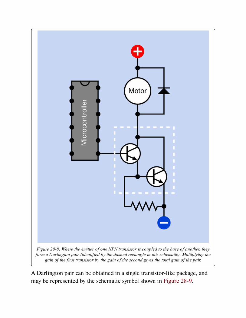
Figure 28-8. Where the emitter of one NPN transistor is coupled to the base of another, theyform a Darlington pair (identified by the dashed rectangle in this schematic). Multiplying the
gain of the first transistor by the gain of the second gives the total gain of the pair.
A Darlington pair can be obtained in a single transistor-like package, and
may be represented by the schematic symbol shown in Figure 28-9.
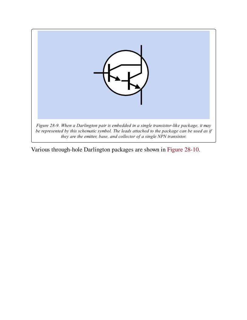
Figure 28-9. When a Darlington pair is embedded in a single transistor-like package, it maybe represented by this schematic symbol. The leads attached to the package can be used as if
they are the emitter, base, and collector of a single NPN transistor.
Various through-hole Darlington packages are shown in Figure 28-10.
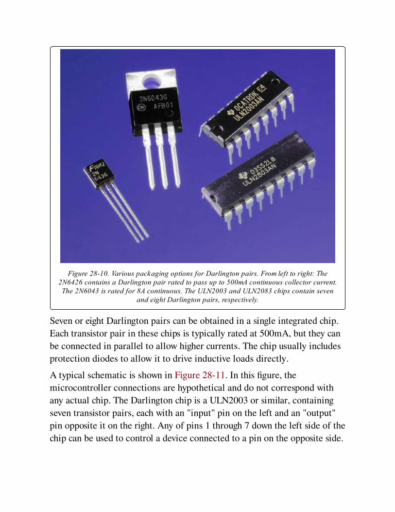
Figure 28-10. Various packaging options for Darlington pairs. From left to right: The2N6426 contains a Darlington pair rated to pass up to 500mA continuous collector current.The 2N6043 is rated for 8A continuous. The ULN2003 and ULN2083 chips contain seven
and eight Darlington pairs, respectively.
Seven or eight Darlington pairs can be obtained in a single integrated chip.
Each transistor pair in these chips is typically rated at 500mA, but they can
be connected in parallel to allow higher currents. The chip usually includes
protection diodes to allow it to drive inductive loads directly.
A typical schematic is shown in Figure 28-11. In this figure, the
microcontroller connections are hypothetical and do not correspond with
any actual chip. The Darlington chip is a ULN2003 or similar, containing
seven transistor pairs, each with an "input" pin on the left and an "output"
pin opposite it on the right. Any of pins 1 through 7 down the left side of the
chip can be used to control a device connected to a pin on the opposite side.
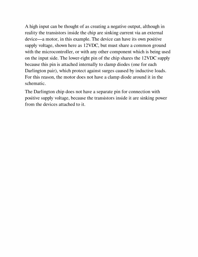
A high input can be thought of as creating a negative output, although in
reality the transistors inside the chip are sinking current via an external
device—a motor, in this example. The device can have its own positive
supply voltage, shown here as 12VDC, but must share a common ground
with the microcontroller, or with any other component which is being used
on the input side. The lower-right pin of the chip shares the 12VDC supply
because this pin is attached internally to clamp diodes (one for each
Darlington pair), which protect against surges caused by inductive loads.
For this reason, the motor does not have a clamp diode around it in the
schematic.
The Darlington chip does not have a separate pin for connection with
positive supply voltage, because the transistors inside it are sinking power
from the devices attached to it.
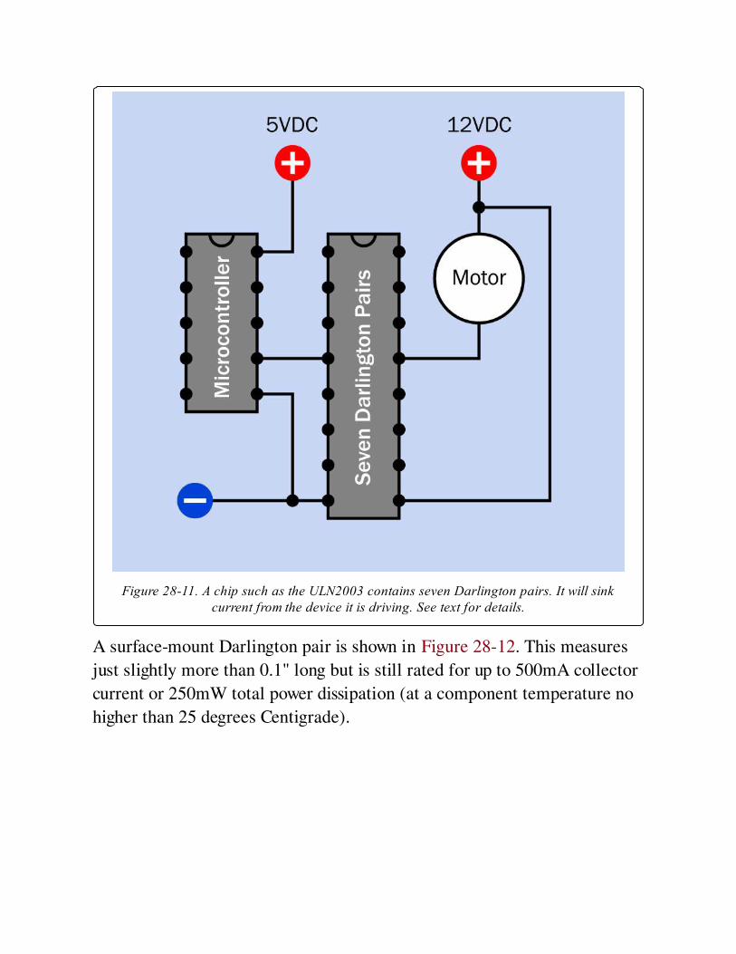
Figure 28-11. A chip such as the ULN2003 contains seven Darlington pairs. It will sinkcurrent from the device it is driving. See text for details.
A surface-mount Darlington pair is shown in Figure 28-12. This measures
just slightly more than 0.1" long but is still rated for up to 500mA collector
current or 250mW total power dissipation (at a component temperature no
higher than 25 degrees Centigrade).
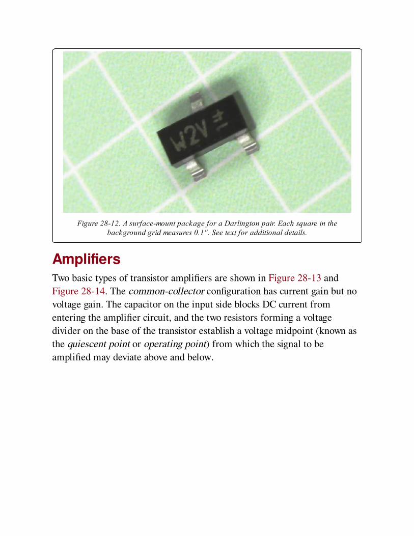
Figure 28-12. A surface-mount package for a Darlington pair. Each square in thebackground grid measures 0.1". See text for additional details.
AmplifiersTwo basic types of transistor amplifiers are shown in Figure 28-13 and
Figure 28-14. The common-collector configuration has current gain but no
voltage gain. The capacitor on the input side blocks DC current from
entering the amplifier circuit, and the two resistors forming a voltage
divider on the base of the transistor establish a voltage midpoint (known as
the quiescent point or operating point) from which the signal to be
amplified may deviate above and below.
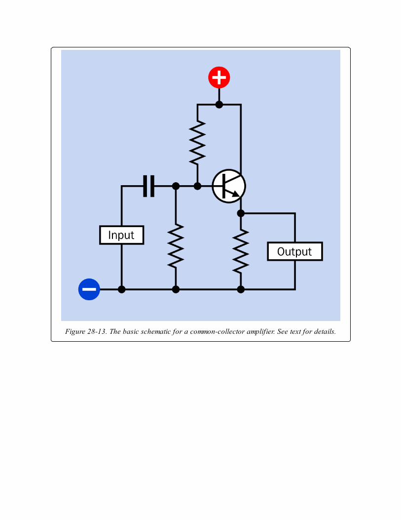
Figure 28-13. The basic schematic for a common-collector amplifier. See text for details.
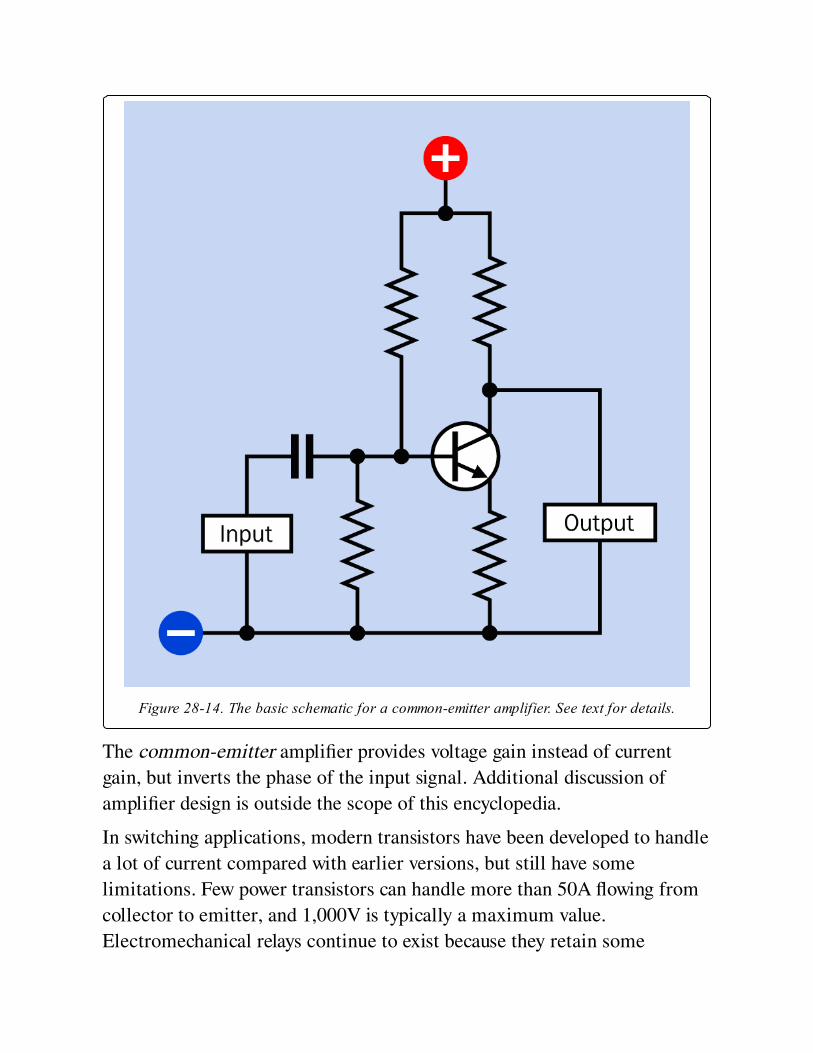
Figure 28-14. The basic schematic for a common-emitter amplifier. See text for details.
The common-emitter amplifier provides voltage gain instead of current
gain, but inverts the phase of the input signal. Additional discussion of
amplifier design is outside the scope of this encyclopedia.
In switching applications, modern transistors have been developed to handle
a lot of current compared with earlier versions, but still have some
limitations. Few power transistors can handle more than 50A flowing from
collector to emitter, and 1,000V is typically a maximum value.
Electromechanical relays continue to exist because they retain some

advantages, as shown in the table in Figure 28-15, which compares
switching capabilities of transistors, solid-state relays, and
electromechanical relays.

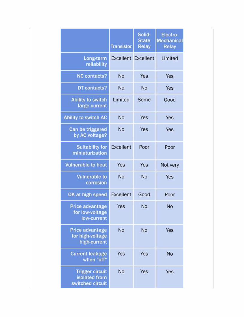
Figure 28-15. A comparison of characteristics of switching devices.
What Can Go Wrong
Wrong Connections on a Bipolar TransistorFailing to identify a transistor’s leads or contacts correctly can obviously be
a potential source of damage, but swapping the collector and emitter
accidentally will not necessarily destroy the transistor. Because of the
inherent symmetry of the device, it will in fact function with collector and
emitter connections reversed. Rohm, a large semiconductor manufacturer,
has included this scenario in its general information pages and concludes
that the primary indicator of transposed connections is that the β value, or
hFE , drops to about 1/10th of specification. If you are using a transistor that
works but provides much less amplification than you expect, check that the
emitter and collector leads are not transposed.
Wrong Connections on a Darlington Pair ChipWhile a single-component package for a Darlington pair functions almost
indistinguishably from a single transistor, multiple Darlington pairs in a
DIP package may create confusion because the component behaves
differently from most other chips, such as logic chips.
A frequent error is to ground the output device instead of applying positive
power to it. See Figure 28-11 and imagine an erroneous connection of
negative power instead of the 12VDC positive power.
Additional confusion may be caused by reading a manufacturer’s datasheet
for a Darlington pair chip such as the ULN2003. The datasheet depicts the
internal function of the chip as if it contains logic inverters. While the chip
can be imagined as behaving this way, in fact it contains bipolar transistors
that amplify the current applied to the base of each pair. The datasheet also
typically will not show the positive connection that should be made to the
common-diode pin (usually at bottom-right), to provide protection from
surges caused by inductive loads. This pin must be distinguished carefully
from the common-ground pin (usually at bottom-left). The positive
connection to the common-diode pin is optional; the common-ground
connection is mandatory.
Soldering DamageLike any semiconductor, transistors are vulnerable to heat and can be
damaged while soldering, although this seldom happens if a low-wattage
iron is used. A copper alligator clip can be applied as a heat sink to each
lead before it is soldered.
Excessive Current or VoltageDuring use, a transistor will be damaged if it is subjected to current or
voltage outside of its rated range. Passing current through a transistor
without any series resistance to protect it will almost certainly burn it out,
and the same thing can happen if incorrect resistor values are used.
The maximum wattage that a transistor can dissipate will be shown in its
datasheet. Suppose, for example, this figure is 200mW, and you are using a
12VDC supply. Ignoring the base current, the maximum collector current
will be 200 / 12 = approximately 15mA. If the transistor’s emitter is
connected to ground, and the load applied to the transistor output has a
high impedance, and if we ignore the transresistance, Ohm’s Law suggests
that a resistor that you place between the collector and the supply voltage
should have a resistance of at least 12 / 0.015 = 800 ohms.
When transistors are used in switching applications, it is customary for the
base current to be 1/5th of the collector current. In the example discussed
here, a 4.7K resistor might be appropriate. A meter should be used to verify
actual current and voltage values.
Excessive LeakageIn a Darlington pair, or any other configuration where the output from one
transistor is connected with the base of another, leakage from the first
transistor while in its "off" state can be amplified by the second transistor.
If this is unacceptable, a bypass resistor can be used to divert some of the
leakage from the base of the second transistor to ground. Of course the
resistor will also steal some of the base current when the first transistor is
active, but the resistor value is typically chosen so that it takes no more than
10% of the active current. See Figure 28-8 for an example of a bypass
resistor added to a Darlington pair.
Chapter 29. field effect transistor
discrete semiconductor > multi-junction > field effect transistor
The term field-effect transistor encompasses a family primarily consisting of the junction field-
effect transistor (or JFET, which is the simplest generic type) and the metal-oxide
semiconductor field-effect transistor (or MOSFET, also sometimes known as an insulated-gate
field-effect transistor, or IGFET). Because the principles of operation overlap considerably, the
entire -FET family is grouped in this entry.
Other related components
bipolar transitor (See Chapter 28)
unijunction transistor (See Chapter 27)
diode (See Chapter 26)
What It DoesA field-effect transistor creates an electric field to control current flowing
through a channel in a semiconductor. MOSFETs of microscopic size form
the basis of complementary metal oxide semiconductor (CMOS) integrated
circuit chips, while large discrete MOSFETs are capable of switching
substantial currents, in lamp dimmers, audio amplifiers, and motor
controllers. FETs have become indispensable in computer electronics.
A bipolar transistor is generally thought of as a current amplifier because
the current passing through it is controlled by a smaller amount of current
passing through the base. By contrast, all FETs are considered to be voltage
amplifiers, as the control voltage establishes field intensity, which requires
little or no current. The negligible leakage through the gate of an FET
makes it ideal for use in low-power applications such as portable hand-held
devices.
How It Works
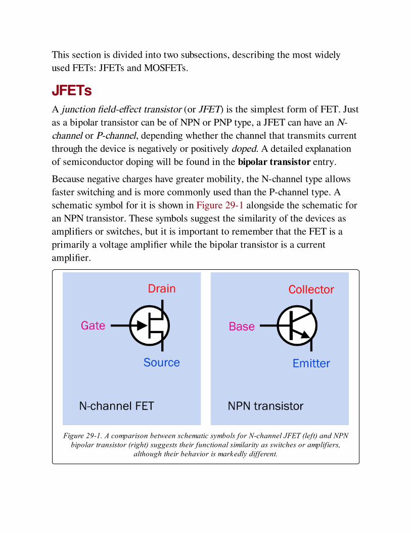
This section is divided into two subsections, describing the most widely
used FETs: JFETs and MOSFETs.
JFETsA junction field-effect transistor (or JFET) is the simplest form of FET. Just
as a bipolar transistor can be of NPN or PNP type, a JFET can have an N-
channel or P-channel, depending whether the channel that transmits current
through the device is negatively or positively doped. A detailed explanation
of semiconductor doping will be found in the bipolar transistor entry.
Because negative charges have greater mobility, the N-channel type allows
faster switching and is more commonly used than the P-channel type. A
schematic symbol for it is shown in Figure 29-1 alongside the schematic for
an NPN transistor. These symbols suggest the similarity of the devices as
amplifiers or switches, but it is important to remember that the FET is a
primarily a voltage amplifier while the bipolar transistor is a current
amplifier.
Figure 29-1. A comparison between schematic symbols for N-channel JFET (left) and NPNbipolar transistor (right) suggests their functional similarity as switches or amplifiers,
although their behavior is markedly different.
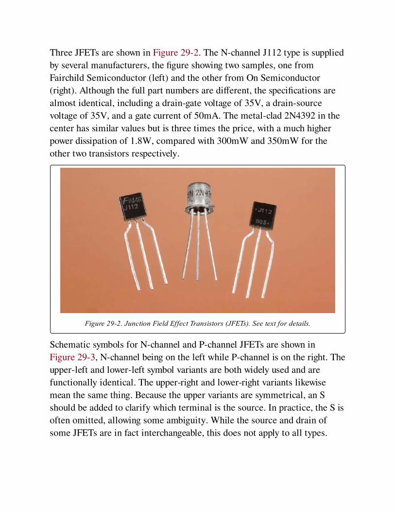
Three JFETs are shown in Figure 29-2. The N-channel J112 type is supplied
by several manufacturers, the figure showing two samples, one from
Fairchild Semiconductor (left) and the other from On Semiconductor
(right). Although the full part numbers are different, the specifications are
almost identical, including a drain-gate voltage of 35V, a drain-source
voltage of 35V, and a gate current of 50mA. The metal-clad 2N4392 in the
center has similar values but is three times the price, with a much higher
power dissipation of 1.8W, compared with 300mW and 350mW for the
other two transistors respectively.
Figure 29-2. Junction Field Effect Transistors (JFETs). See text for details.
Schematic symbols for N-channel and P-channel JFETs are shown in
Figure 29-3, N-channel being on the left while P-channel is on the right. The
upper-left and lower-left symbol variants are both widely used and are
functionally identical. The upper-right and lower-right variants likewise
mean the same thing. Because the upper variants are symmetrical, an S
should be added to clarify which terminal is the source. In practice, the S is
often omitted, allowing some ambiguity. While the source and drain of
some JFETs are in fact interchangeable, this does not apply to all types.
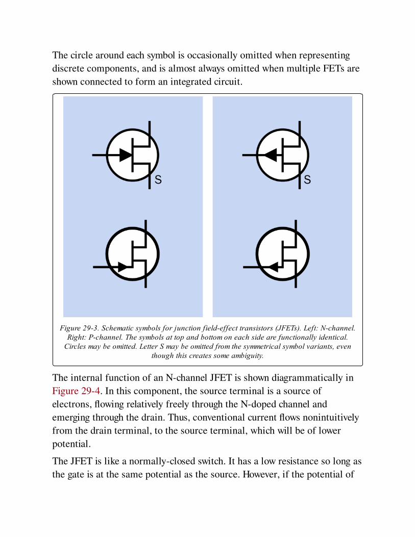
The circle around each symbol is occasionally omitted when representing
discrete components, and is almost always omitted when multiple FETs are
shown connected to form an integrated circuit.
Figure 29-3. Schematic symbols for junction field-effect transistors (JFETs). Left: N-channel.Right: P-channel. The symbols at top and bottom on each side are functionally identical.
Circles may be omitted. Letter S may be omitted from the symmetrical symbol variants, eventhough this creates some ambiguity.
The internal function of an N-channel JFET is shown diagrammatically in
Figure 29-4. In this component, the source terminal is a source of
electrons, flowing relatively freely through the N-doped channel and
emerging through the drain. Thus, conventional current flows nonintuitively
from the drain terminal, to the source terminal, which will be of lower
potential.
The JFET is like a normally-closed switch. It has a low resistance so long as
the gate is at the same potential as the source. However, if the potential of
the gate is reduced below the potential of the source—that is, the gate
acquires a more relatively negative voltage than the source—the current
flow is pinched off as a result of the field created by the gate. This is
suggested by the lower diagram in Figure 29-4.
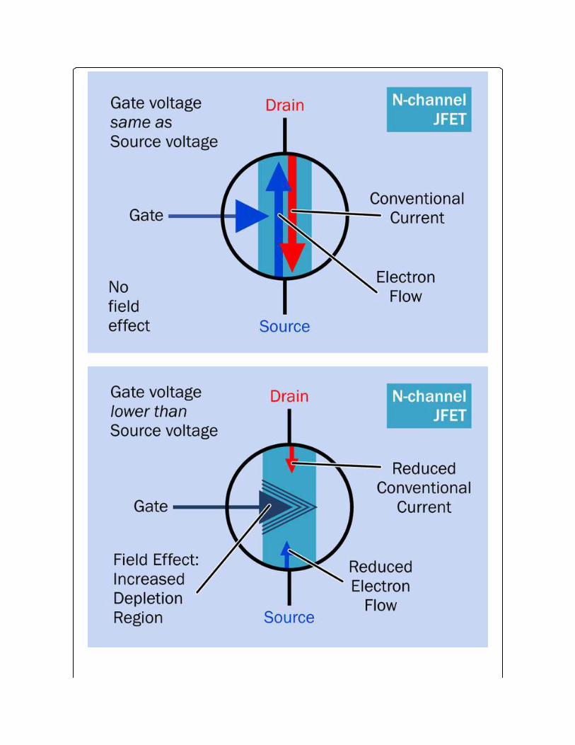
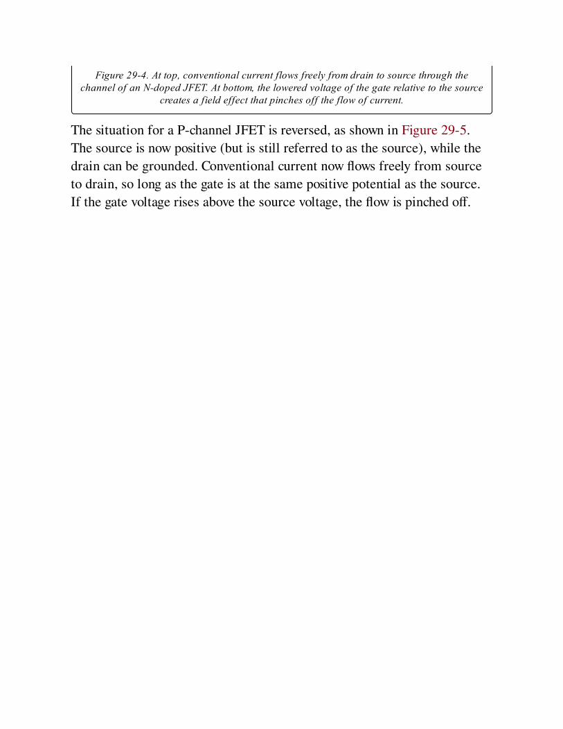
Figure 29-4. At top, conventional current flows freely from drain to source through thechannel of an N-doped JFET. At bottom, the lowered voltage of the gate relative to the source
creates a field effect that pinches off the flow of current.
The situation for a P-channel JFET is reversed, as shown in Figure 29-5.
The source is now positive (but is still referred to as the source), while the
drain can be grounded. Conventional current now flows freely from source
to drain, so long as the gate is at the same positive potential as the source.
If the gate voltage rises above the source voltage, the flow is pinched off.
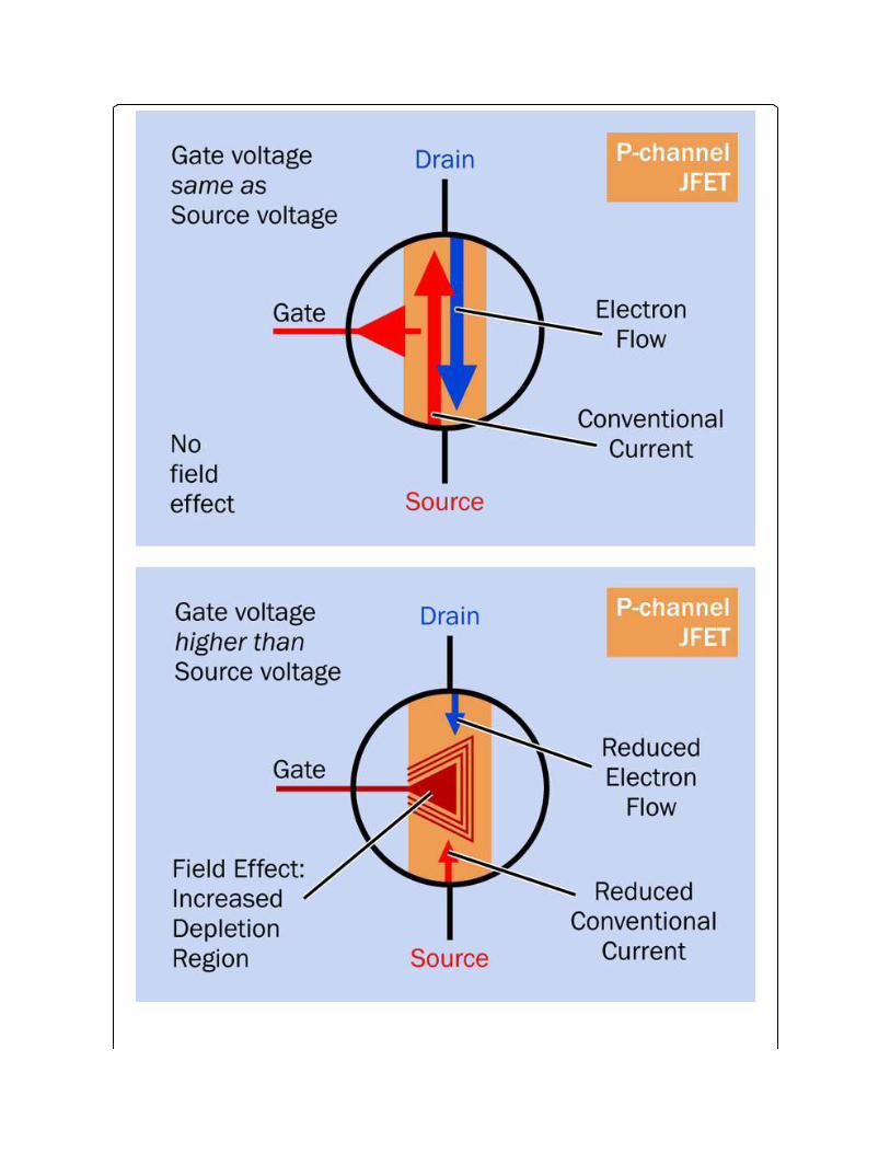
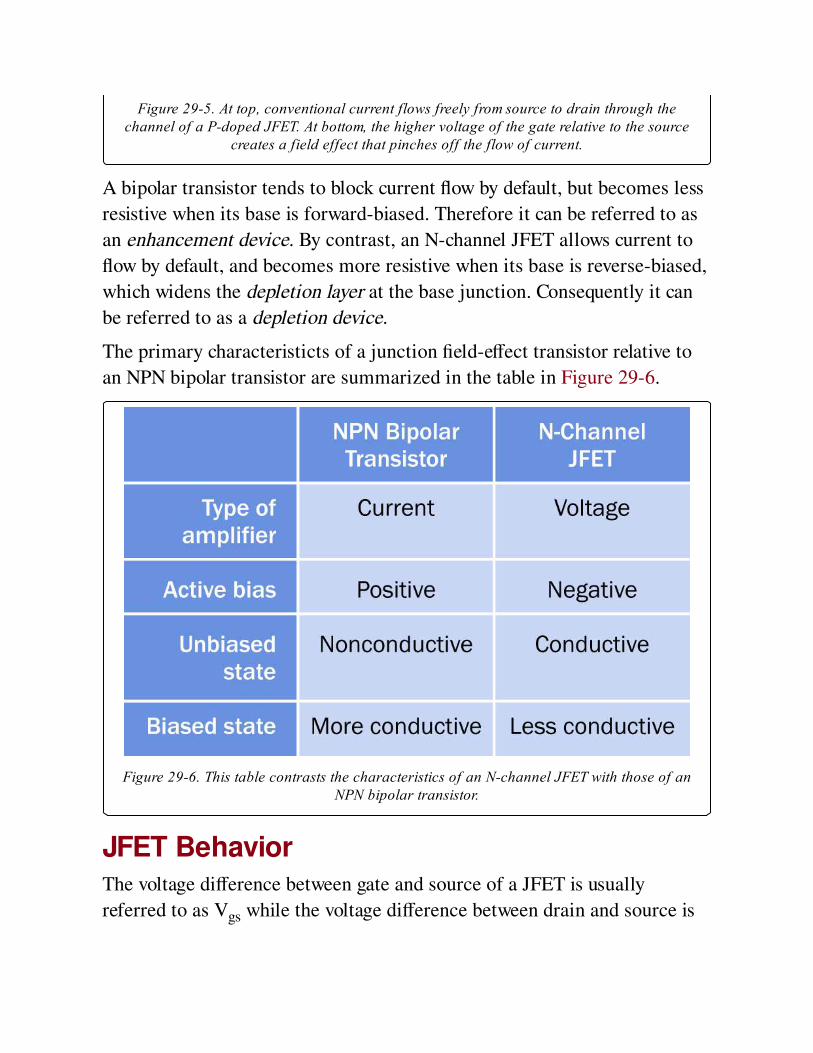
Figure 29-5. At top, conventional current flows freely from source to drain through thechannel of a P-doped JFET. At bottom, the higher voltage of the gate relative to the source
creates a field effect that pinches off the flow of current.
A bipolar transistor tends to block current flow by default, but becomes less
resistive when its base is forward-biased. Therefore it can be referred to as
an enhancement device. By contrast, an N-channel JFET allows current to
flow by default, and becomes more resistive when its base is reverse-biased,
which widens the depletion layer at the base junction. Consequently it can
be referred to as a depletion device.
The primary characteristicts of a junction field-effect transistor relative to
an NPN bipolar transistor are summarized in the table in Figure 29-6.
Figure 29-6. This table contrasts the characteristics of an N-channel JFET with those of anNPN bipolar transistor.
JFET BehaviorThe voltage difference between gate and source of a JFET is usually
referred to as Vgs while the voltage difference between drain and source is

referred to as Vds.
Suppose the gate of an N-channel JFET is connected with the source, so
that Vgs=0. Now if Vds increases, the current flowing through the channel of
the JFET also increases, approximately linearly with Vds. In other words,
initially the JFET behaves like a low-value resistor in which the voltage
across it, divided by the amperage flowing through it, is approximately
constant. This phase of the JFET’s behavior is known as its ohmic region.
While the unbiased resistance of the channel in a JFET depends on the
component type, it is generally somewhere between 10Ω and 1K.
If Vds increases still further, eventually no additional flow of current
occurs. At this point the channel has become saturated, and this plateau
zone is referred to as the saturation region, often abbreviated Idss, meaning
"the saturated drain current at zero bias." Although this is a nearly constant
value for any particular JFET, it may vary somewhat from one sample of a
component to another, as a result of manufacturing variations.
If Vds continues to increase, the component finally enters a breakdown
state, sometimes referred to by its full formal terminology as drain-source
breakdown. The current passing through the JFET will now be limited only
by capabilities of the external power source. This breakdown state can be
destructive to the component, and is comparable to the breakdown state of a
typical diode.
What if the voltage at the gate is reduced below the voltage at the source—
such as Vgs becomes negative? In its ohmic region, the component now
behaves as if it has a higher resistance, and it will reach its saturation region
at a lower current value (although around the same value for Vds).
Therefore, by reducing the voltage on the gate relative to the voltage at the
source, the effective resistance of the component increases, and in fact it
can behave as a voltage-controlled resistor.
The upper diagram in Figure 29-7 shows this graphically. Below it, the
corresponding graph for a P-channel JFET looks almost identical, except

that the current flow is reversed and is pinched off as the gate voltage rises
above the source voltage. Also, the breakdown region is reached more
quickly with a P-channel JFET than with an N-channel JFET.

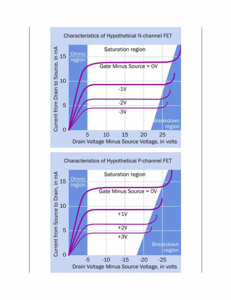
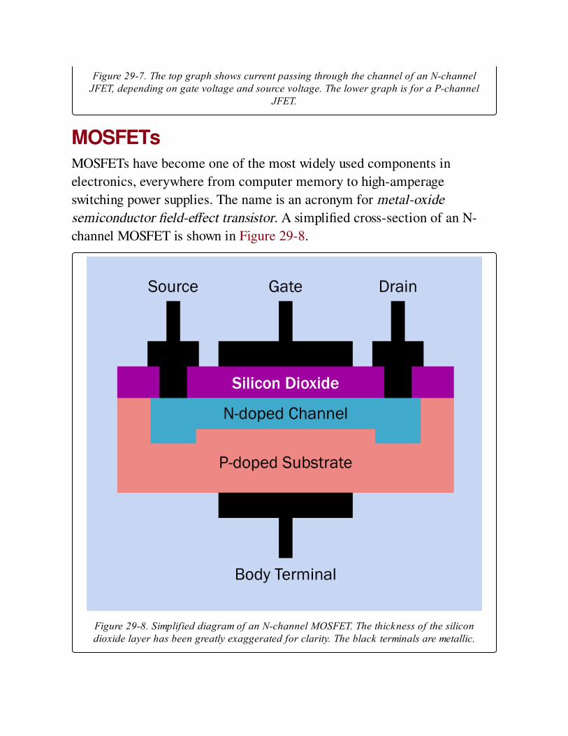
Figure 29-7. The top graph shows current passing through the channel of an N-channelJFET, depending on gate voltage and source voltage. The lower graph is for a P-channel
JFET.
MOSFETsMOSFETs have become one of the most widely used components in
electronics, everywhere from computer memory to high-amperage
switching power supplies. The name is an acronym for metal-oxide
semiconductor field-effect transistor. A simplified cross-section of an N-
channel MOSFET is shown in Figure 29-8.
Figure 29-8. Simplified diagram of an N-channel MOSFET. The thickness of the silicondioxide layer has been greatly exaggerated for clarity. The black terminals are metallic.

Two MOSFETs are shown in Figure 29-9.
Figure 29-9. Two MOSFETs. At left, the TO-220 package claims a drain current of up to 65Acontinuous, and a drain-to-source breakdown voltage 100V. At right, the smaller packageoffers a drain current of 175mA continuous, and a drain-to-source breakdown voltage of
300V.
Like a JFET, a MOSFET has three terminals, identified as drain, gate, and
source, and it functions by creating a field effect that controls current
flowing through a channel. (Some MOSFETS have a fourth terminal,
described later). However, it has a metal source and drain making contact
with each end of the channel (hence the term "metal" in its acronym) and
also has a thin layer of silicon dioxide (hence the term "oxide" in its
acronym) separating the gate from the channel, thus raising the impedance
at the gate to at least 100,000 gigaohms and reducing gate current
essentially to zero. The high gate impedance of a MOSFET allows it to be
connected directly to the output of a digital integrated circuit. The layer of
silicon dioxide is a dielectric, meaning that a field appled to one side creates
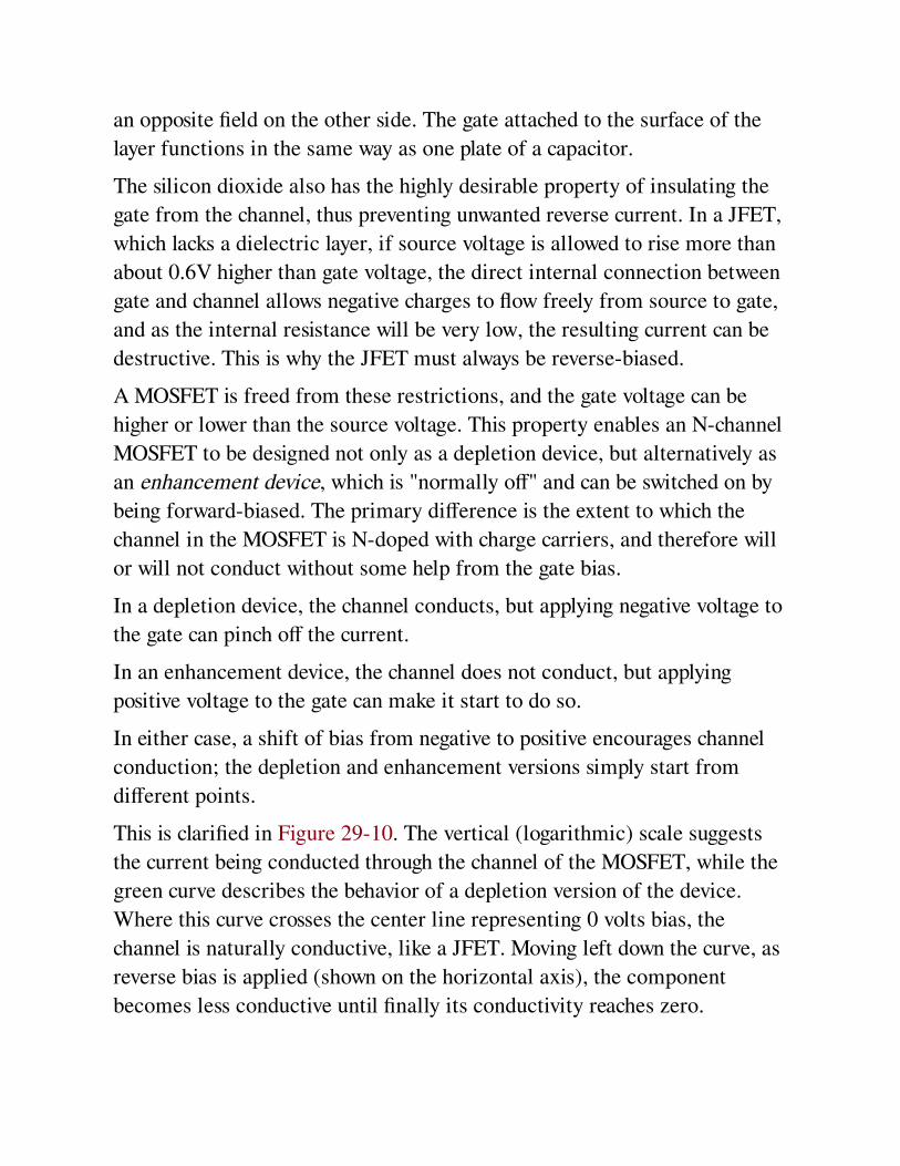
an opposite field on the other side. The gate attached to the surface of the
layer functions in the same way as one plate of a capacitor.
The silicon dioxide also has the highly desirable property of insulating the
gate from the channel, thus preventing unwanted reverse current. In a JFET,
which lacks a dielectric layer, if source voltage is allowed to rise more than
about 0.6V higher than gate voltage, the direct internal connection between
gate and channel allows negative charges to flow freely from source to gate,
and as the internal resistance will be very low, the resulting current can be
destructive. This is why the JFET must always be reverse-biased.
A MOSFET is freed from these restrictions, and the gate voltage can be
higher or lower than the source voltage. This property enables an N-channel
MOSFET to be designed not only as a depletion device, but alternatively as
an enhancement device, which is "normally off" and can be switched on by
being forward-biased. The primary difference is the extent to which the
channel in the MOSFET is N-doped with charge carriers, and therefore will
or will not conduct without some help from the gate bias.
In a depletion device, the channel conducts, but applying negative voltage to
the gate can pinch off the current.
In an enhancement device, the channel does not conduct, but applying
positive voltage to the gate can make it start to do so.
In either case, a shift of bias from negative to positive encourages channel
conduction; the depletion and enhancement versions simply start from
different points.
This is clarified in Figure 29-10. The vertical (logarithmic) scale suggests
the current being conducted through the channel of the MOSFET, while the
green curve describes the behavior of a depletion version of the device.
Where this curve crosses the center line representing 0 volts bias, the
channel is naturally conductive, like a JFET. Moving left down the curve, as
reverse bias is applied (shown on the horizontal axis), the component
becomes less conductive until finally its conductivity reaches zero.
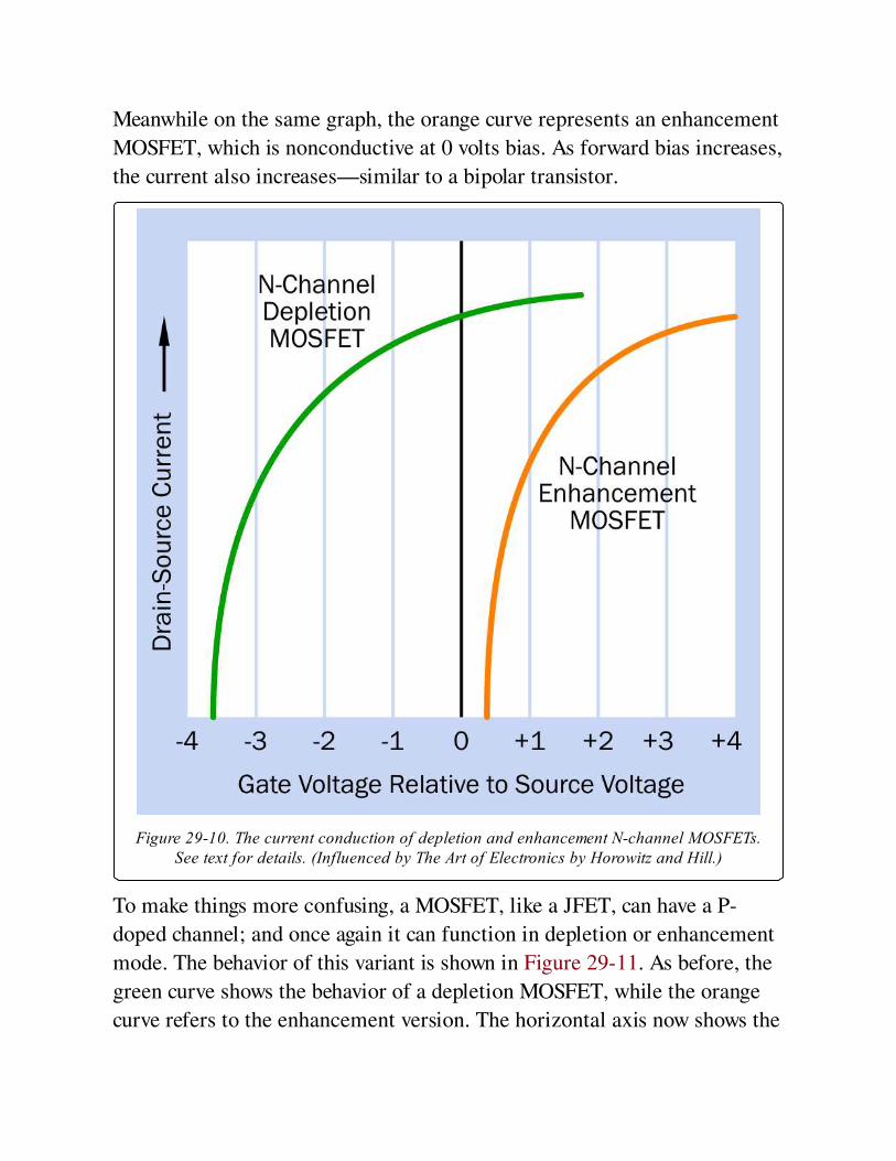
Meanwhile on the same graph, the orange curve represents an enhancement
MOSFET, which is nonconductive at 0 volts bias. As forward bias increases,
the current also increases—similar to a bipolar transistor.
Figure 29-10. The current conduction of depletion and enhancement N-channel MOSFETs.See text for details. (Influenced by The Art of Electronics by Horowitz and Hill.)
To make things more confusing, a MOSFET, like a JFET, can have a P-
doped channel; and once again it can function in depletion or enhancement
mode. The behavior of this variant is shown in Figure 29-11. As before, the
green curve shows the behavior of a depletion MOSFET, while the orange
curve refers to the enhancement version. The horizontal axis now shows the
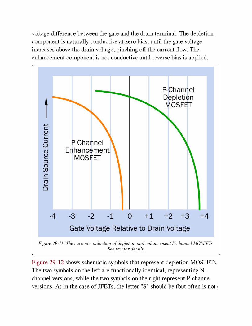
voltage difference between the gate and the drain terminal. The depletion
component is naturally conductive at zero bias, until the gate voltage
increases above the drain voltage, pinching off the current flow. The
enhancement component is not conductive until reverse bias is applied.
Figure 29-11. The current conduction of depletion and enhancement P-channel MOSFETs.See text for details.
Figure 29-12 shows schematic symbols that represent depletion MOSFETs.
The two symbols on the left are functionally identical, representing N-
channel versions, while the two symbols on the right represent P-channel
versions. As in the case of JFETs, the letter "S" should be (but often is not)
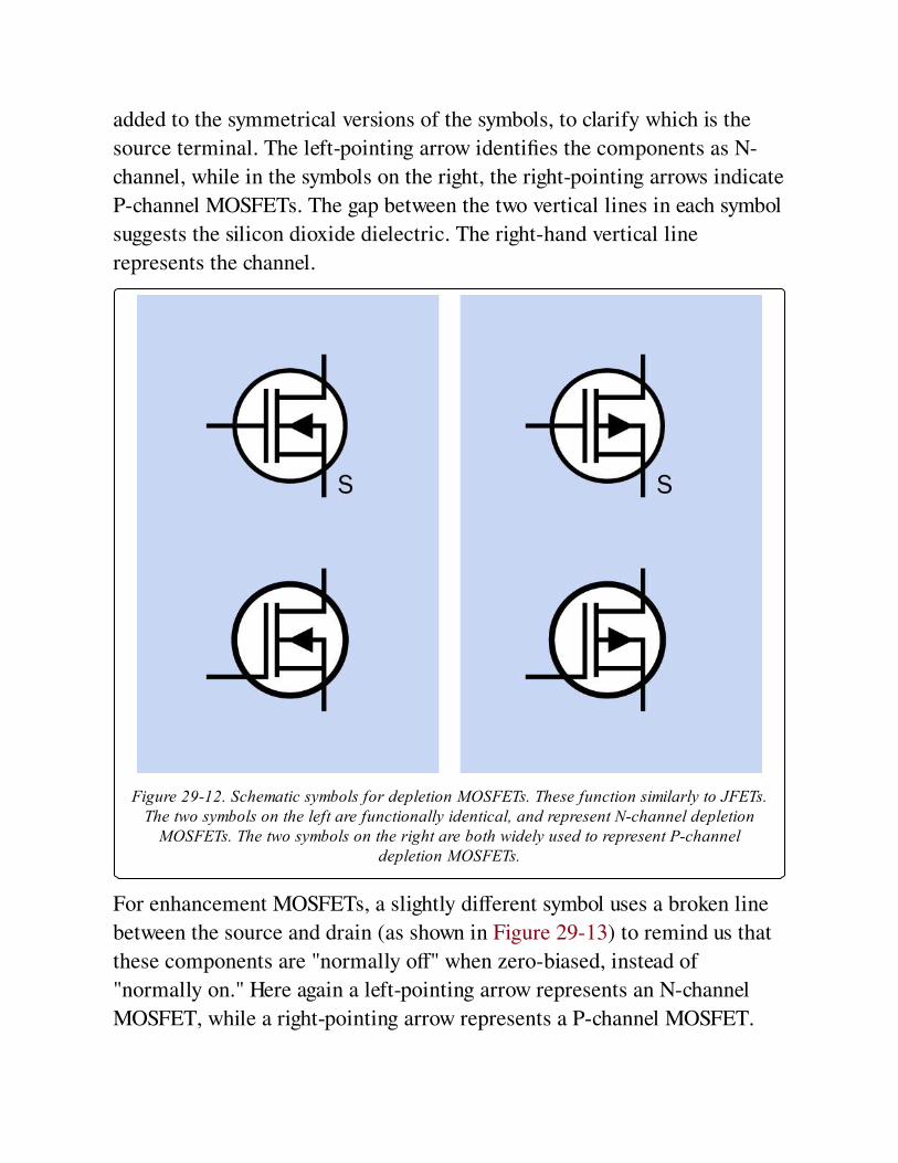
added to the symmetrical versions of the symbols, to clarify which is the
source terminal. The left-pointing arrow identifies the components as N-
channel, while in the symbols on the right, the right-pointing arrows indicate
P-channel MOSFETs. The gap between the two vertical lines in each symbol
suggests the silicon dioxide dielectric. The right-hand vertical line
represents the channel.
Figure 29-12. Schematic symbols for depletion MOSFETs. These function similarly to JFETs.The two symbols on the left are functionally identical, and represent N-channel depletion
MOSFETs. The two symbols on the right are both widely used to represent P-channeldepletion MOSFETs.
For enhancement MOSFETs, a slightly different symbol uses a broken line
between the source and drain (as shown in Figure 29-13) to remind us that
these components are "normally off" when zero-biased, instead of
"normally on." Here again a left-pointing arrow represents an N-channel
MOSFET, while a right-pointing arrow represents a P-channel MOSFET.
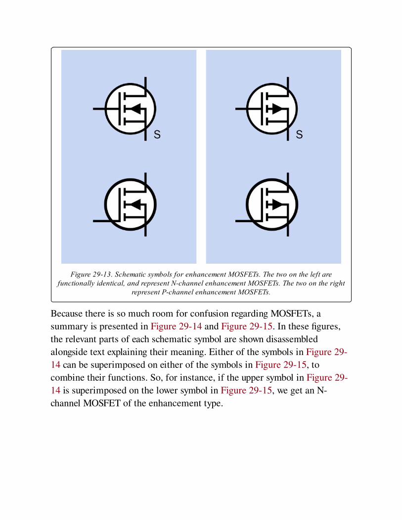
Figure 29-13. Schematic symbols for enhancement MOSFETs. The two on the left arefunctionally identical, and represent N-channel enhancement MOSFETs. The two on the right
represent P-channel enhancement MOSFETs.
Because there is so much room for confusion regarding MOSFETs, a
summary is presented in Figure 29-14 and Figure 29-15. In these figures,
the relevant parts of each schematic symbol are shown disassembled
alongside text explaining their meaning. Either of the symbols in Figure 29-
14 can be superimposed on either of the symbols in Figure 29-15, to
combine their functions. So, for instance, if the upper symbol in Figure 29-
14 is superimposed on the lower symbol in Figure 29-15, we get an N-
channel MOSFET of the enhancement type.
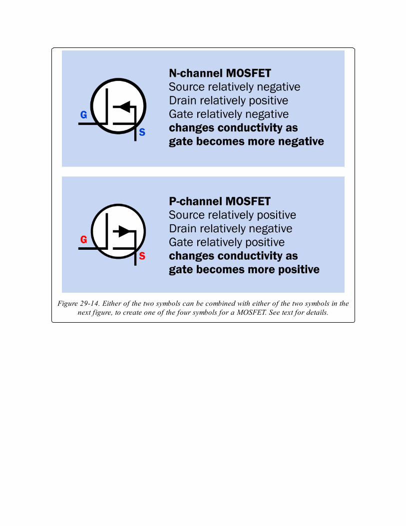
Figure 29-14. Either of the two symbols can be combined with either of the two symbols in thenext figure, to create one of the four symbols for a MOSFET. See text for details.
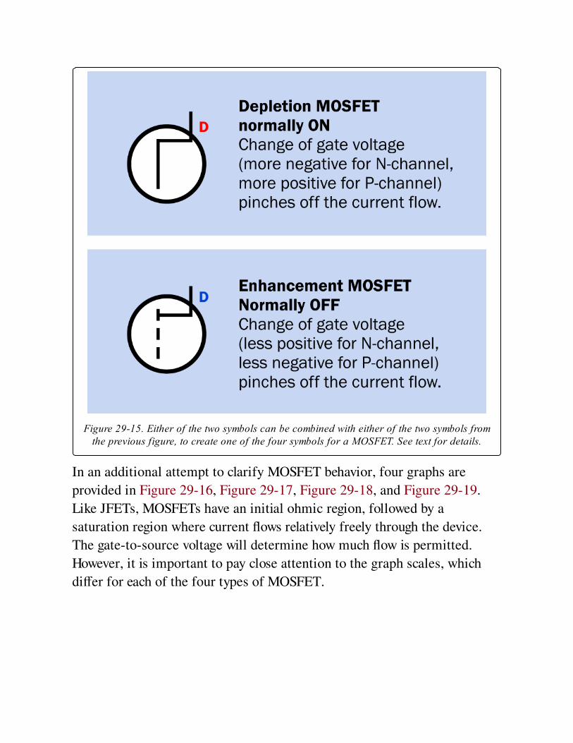
Figure 29-15. Either of the two symbols can be combined with either of the two symbols fromthe previous figure, to create one of the four symbols for a MOSFET. See text for details.
In an additional attempt to clarify MOSFET behavior, four graphs are
provided in Figure 29-16, Figure 29-17, Figure 29-18, and Figure 29-19.
Like JFETs, MOSFETs have an initial ohmic region, followed by a
saturation region where current flows relatively freely through the device.
The gate-to-source voltage will determine how much flow is permitted.
However, it is important to pay close attention to the graph scales, which
differ for each of the four types of MOSFET.
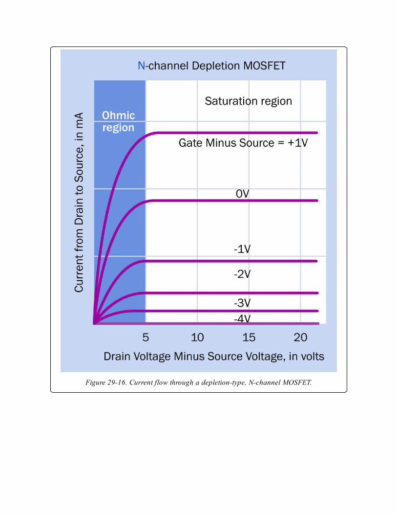
Figure 29-16. Current flow through a depletion-type, N-channel MOSFET.
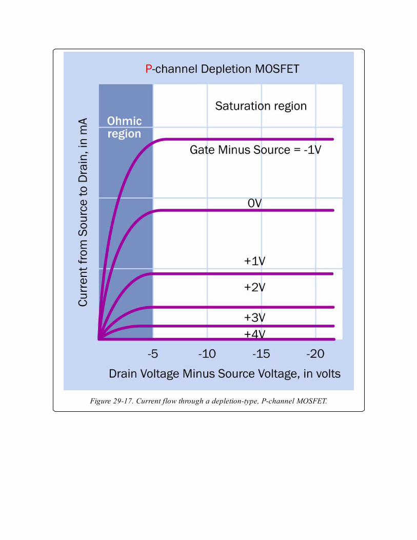
Figure 29-17. Current flow through a depletion-type, P-channel MOSFET.
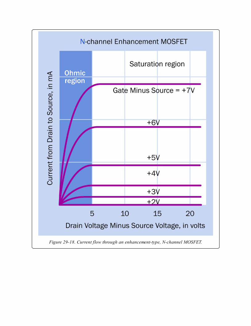
Figure 29-18. Current flow through an enhancement-type, N-channel MOSFET.
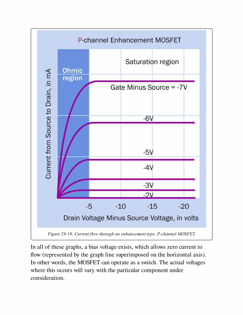
Figure 29-19. Current flow through an enhancement-type, P-channel MOSFET.
In all of these graphs, a bias voltage exists, which allows zero current to
flow (represented by the graph line superimposed on the horizontal axis).
In other words, the MOSFET can operate as a switch. The actual voltages
where this occurs will vary with the particular component under
consideration.
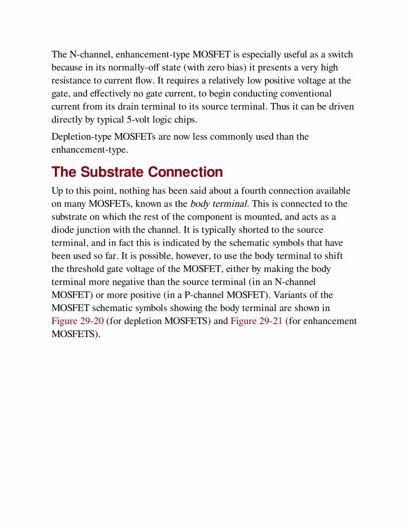
The N-channel, enhancement-type MOSFET is especially useful as a switch
because in its normally-off state (with zero bias) it presents a very high
resistance to current flow. It requires a relatively low positive voltage at the
gate, and effectively no gate current, to begin conducting conventional
current from its drain terminal to its source terminal. Thus it can be driven
directly by typical 5-volt logic chips.
Depletion-type MOSFETs are now less commonly used than the
enhancement-type.
The Substrate ConnectionUp to this point, nothing has been said about a fourth connection available
on many MOSFETs, known as the body terminal. This is connected to the
substrate on which the rest of the component is mounted, and acts as a
diode junction with the channel. It is typically shorted to the source
terminal, and in fact this is indicated by the schematic symbols that have
been used so far. It is possible, however, to use the body terminal to shift
the threshold gate voltage of the MOSFET, either by making the body
terminal more negative than the source terminal (in an N-channel
MOSFET) or more positive (in a P-channel MOSFET). Variants of the
MOSFET schematic symbols showing the body terminal are shown in
Figure 29-20 (for depletion MOSFETS) and Figure 29-21 (for enhancement
MOSFETS).
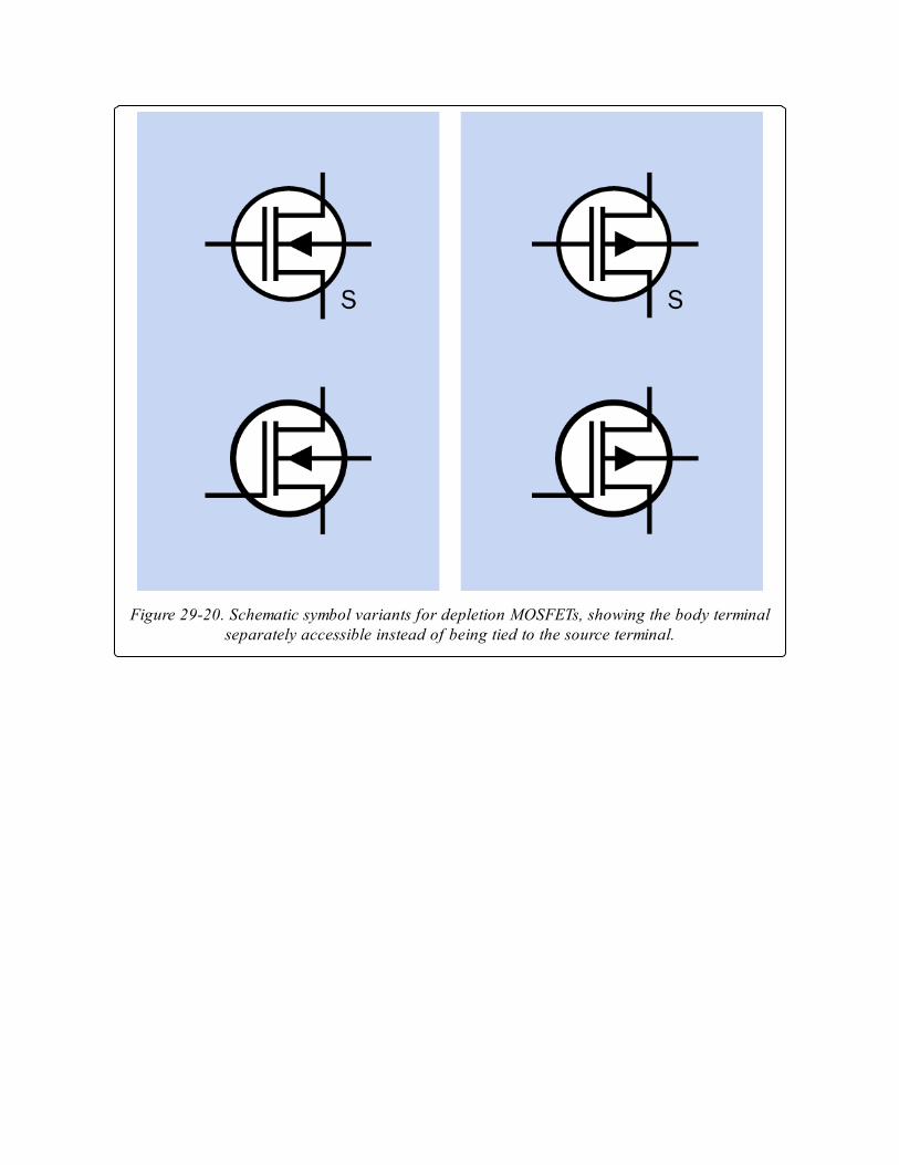
Figure 29-20. Schematic symbol variants for depletion MOSFETs, showing the body terminalseparately accessible instead of being tied to the source terminal.
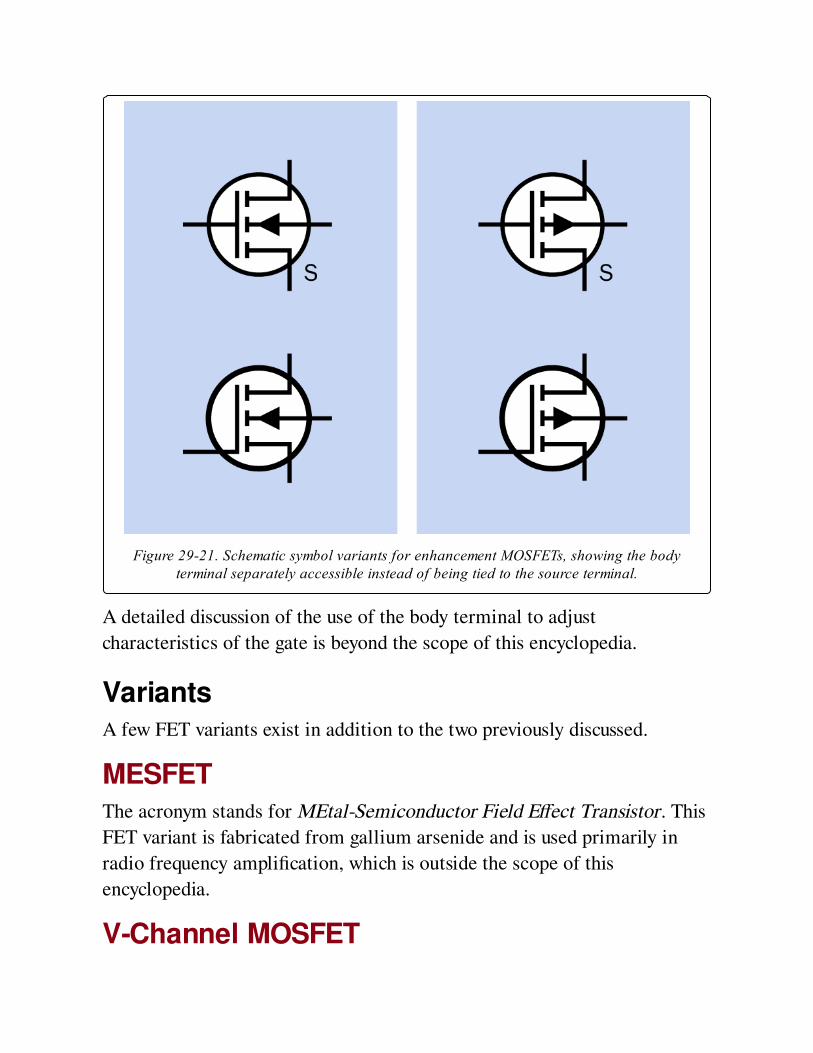
Figure 29-21. Schematic symbol variants for enhancement MOSFETs, showing the bodyterminal separately accessible instead of being tied to the source terminal.
A detailed discussion of the use of the body terminal to adjust
characteristics of the gate is beyond the scope of this encyclopedia.
VariantsA few FET variants exist in addition to the two previously discussed.
MESFETThe acronym stands for MEtal-Semiconductor Field Effect Transistor. This
FET variant is fabricated from gallium arsenide and is used primarily in
radio frequency amplification, which is outside the scope of this
encyclopedia.
V-Channel MOSFET
Whereas most FET devices are capable of handling only small currents, the
V-channel MOSFET (which is often abbreviated as a VMOS FET and has a
V-shaped channel as its name implies) is capable of sustained currents of at
least 50A and voltages as high as 1,000V. It is able to pass the high current
because its channel resistance is well under 1Ω. These devices, commonly
referred to as power MOSFETs, are available from all primary
semiconductor manufacturers and are commonly used in switching power
supplies.
Trench MOSThe TrenchMOS or Trenchgate MOS is a MOSFET variant that encourages
current to flow vertically rather than horizontally, and includes other
innovations that enable an even lower channel resistance, allowing high
currents with minimal heat generation. This device is finding applications
in the automobile industry as a replacement for electromechanical relays.
ValuesThe maximum values for JFETs, commonly found listed in datasheets, will
specify Vds (the drain-source voltage, meaning the potential difference
between drain and source); Vdg (the drain-gate voltage, meaning the
potential difference between drain and gate); Vgsr (the reverse gate-source
voltage); gate current; and total device dissipation in mW. Note that the
voltage differences are relative, not absolute. Thus a voltage of 50V on the
drain and 25V on the source might be acceptable in a component with a Vds
of 25V. Similarly, while a JFET’s "pinch-off" effect begins as the gate
becomes "more negative" than the source, this can be achieved if, for
example, the source has a potential of 6V and the gate has a potential of
3V.
JFETs and MOSFETs designed for low-current switching applications have
a typical channel resistance of just a few ohms, and a maximum switching
speed around 10Mhz.
The datasheet for a MOSFET will typically include values such as gate
threshold voltage, which may be abbreviated Vgs (or Vth) and establishes the
relative voltage at which the gate starts to play an active role; and the
maximum on-state drain current, which may be abbreviated Id(on) and
establishes the maximum limiting current (usually at 25 degree Centigrade)
between source and gate.
How to Use itThe combination of a very high gate impedance, very low noise, very low
quiescent power consumption in its off state, and very fast switching
capability makes the MOSFET suitable for many applications.
P-Channel DisadvantageP-channel MOSFETs are generally less popular than N-channel MOSFETS
because of the higher resistivity of P-type silicon, resulting from its lower
carrier mobility, putting it at a relative disadvantage.
Bipolar SubstitutionIn many instances, an appropriate enhancement-type MOSFET can be
substituted for a bipolar transistor with better results (lower noise, faster
action, much higher impedance, and probably less power dissipation).
Amplifier Front EndsWhile MOSFETs are well-suited for use in the front end of an audio
amplifier, chips containing MOSFETs are now available for this specific
purpose.
Voltage-Controlled ResistorA simple voltage-controlled resistor can be built around a JFET or
MOSFET, so long as its performance remains limited to the linear or
ohmic region.
Compatibility with Digital DevicesA JFET may commonly use power supplies in the range of 25VDC.
However, it can accept the high/low output from a 5V digital device to
control its gate. A 4.7K pullup resistor is an appropriate value to be used if
the FET is to be used in conjunction with a TTL digital chip that may have a
voltage swing of only approximately 2.5V between its low and high
thresholds.
What Can Go Wrong
Static ElectricityBecause the gate of a MOSFET is insulated from the rest of the component,
and functions much like a plate of a capacitor, it is especially likely to
accumulate static electricity. This static charge may then discharge itself
into the body of the component, destroying it. A MOSFET is particularly
vulnerable to electrostatic discharge because its oxide layer is so thin.
Special care should be taken either when handling the component, or when
it is in use. Always touch a grounded object or wear a grounded wrist band
when handling MOSFETs, and be sure that any circuit using MOSFETs
includes appropriate protection from static and voltage spikes.
A MOSFET should not be inserted or removed while the circuit in which it
performs is switched on or contains residual voltage from undischarged
capacitors.
HeatFailure because of overheating is of special concern when using power
MOSFETs. A Vishay Application Note (“Current Power Rating of Power
Semiconductors”) suggests that this kind of component is unlikely to
operate at less than 90 degrees Centigrade in real-world conditions, yet the
power handling capability listed in a datasheet usually assumes an industry
standard of 25 degrees Centigrade.
On the other hand, ratings for continuous power are of little relevance to
switching devices that have duty cycles well below 100%. Other factors also
play a part, such as the possibility of power surges, the switching frequency,
and the integrity of the connection between the component and its heat
sink. The heat sink itself creates uncertainty by tending to average the
temperature of the component, and of course there is no simple way to
know the actual junction temperature, moment by moment, inside a
MOSFET.
Bearing in mind the accumulation of unknown factors, power MOSFETs
should be chosen on an extremely conservative basis. According to a
tutorial in the EE Times, actual current switched by a MOSFET should be
less than half of its rated current at 25 degrees, while one-fourth to one-
third are common. Figure 29-22 shows the real-world recommended
maximum drain current at various temperatures. Exceeding this
recommendation can create additional heat, which cannot be dissipated,
leading to further accumulation of heat, and a thermal runaway condition,
causing eventual failure of the component.
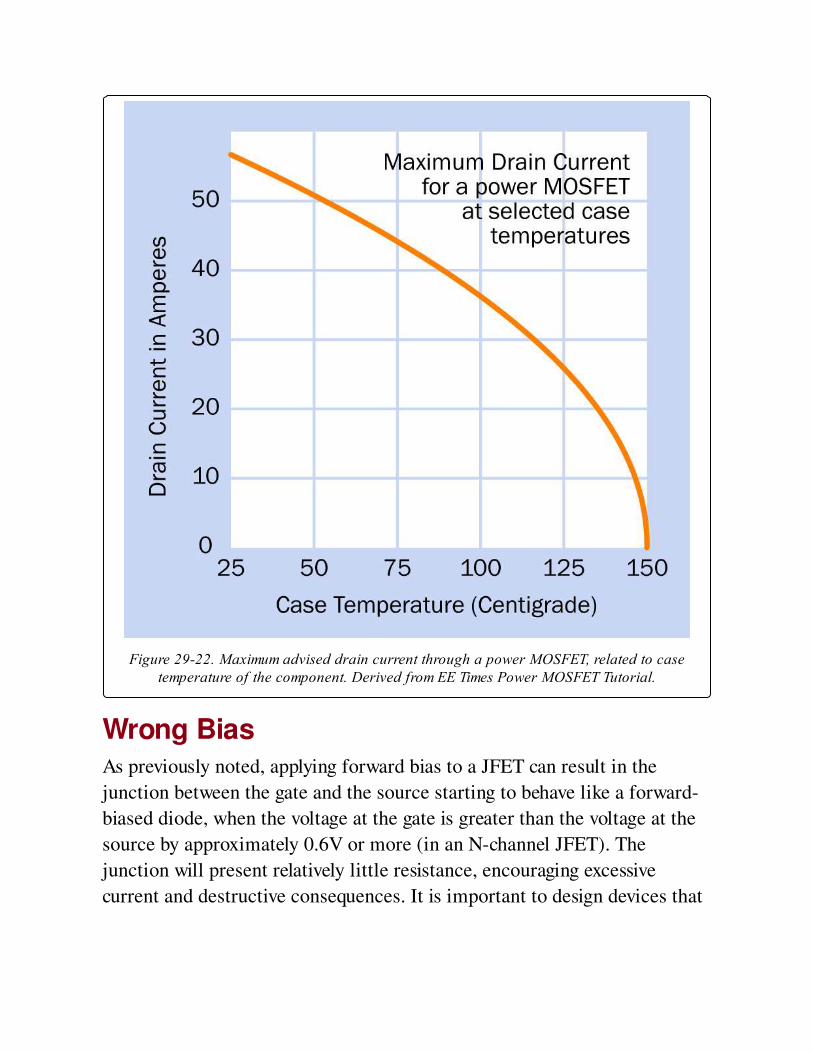
Figure 29-22. Maximum advised drain current through a power MOSFET, related to casetemperature of the component. Derived from EE Times Power MOSFET Tutorial.
Wrong BiasAs previously noted, applying forward bias to a JFET can result in the
junction between the gate and the source starting to behave like a forward-
biased diode, when the voltage at the gate is greater than the voltage at the
source by approximately 0.6V or more (in an N-channel JFET). The
junction will present relatively little resistance, encouraging excessive
current and destructive consequences. It is important to design devices that

allow user input in such a way that user error can never result in this
eventuality.
Appendix A. Schematic SymbolsThis section contains a compilation of schematic symbols for components
that have been described in this volume. They are sequenced primarily in
alphabetical order, as this section is intended for use as an index. However,
symbols that have a strong similarity are grouped together; thus
potentiometer is found adjacent to resistor, and all types of transistors are
in the same group.
The symbol variants shown in each blue rectangle are functionally identical.
Where a component has mandatory polarity or is commonly used with a
certain polarity, a red plus sign (+) has been added for guidance. This sign
is not part of the symbol. In the case of polarized capacitors, where a plus
sign is normally shown (or should be shown) with the symbol, the plus sign
is a part of the symbol and appears in black.
This is not intended to be an exhaustive compilation of symbol variants.
Some uncommon ones may not be here. However, the list should be
sufficient to enable identification of components in this volume.
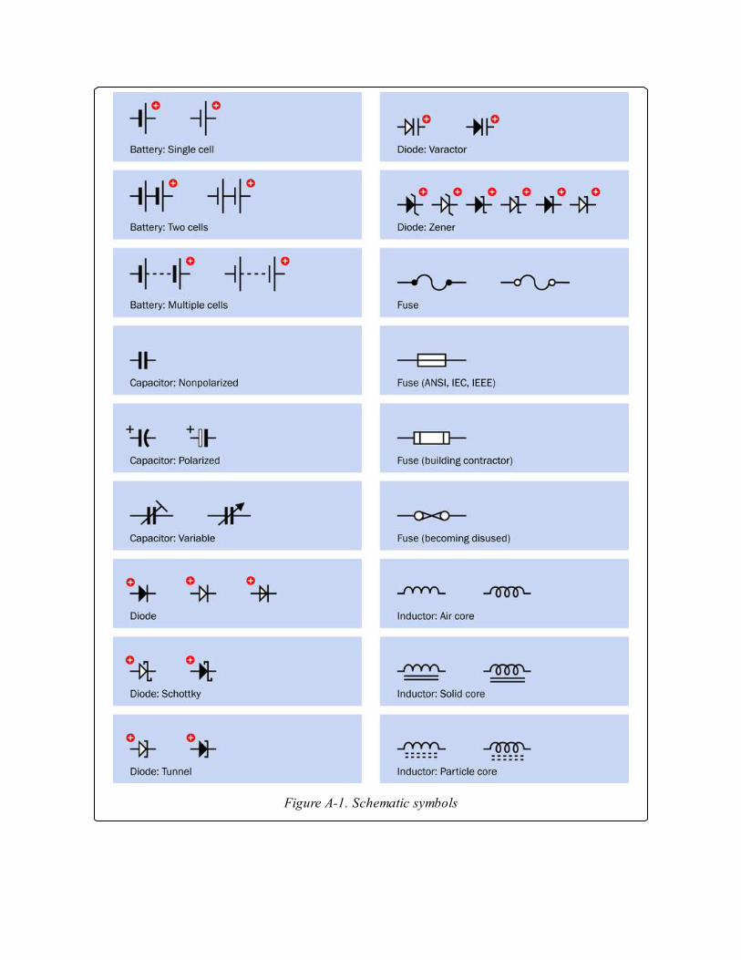
Figure A-1. Schematic symbols
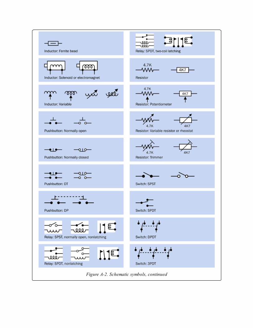
Figure A-2. Schematic symbols, continued
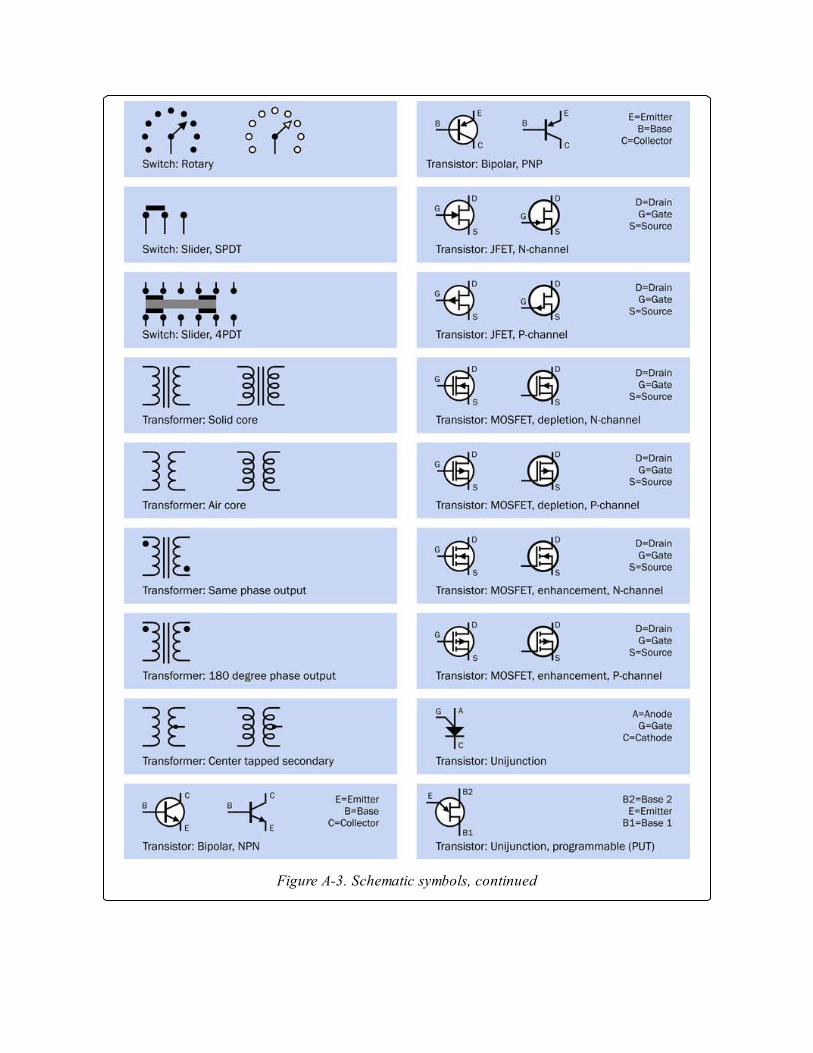
Figure A-3. Schematic symbols, continued
Index
A NOTE ON THE DIGITAL INDEX
A link in an index entry is displayed as the section title in which that entry appears. Because
some sections have multiple index markers, it is not unusual for an entry to have several links to
the same section. Clicking on any link will take you directly to the place in the text in which
the marker appears.
Symbols
18 * D) + (40 * W, Calculating Inductance
1:1 transformers, Isolation Transformer (see isolation transformers)
A
absolute encoding, Rotary DIP
AC adapters, How to Use it, AC-DC power supply, What It Does, How to
Use it
AC inrush, AC Inrush
AC motors, AC motor–Internal Breakage, What It Does, How It Works,
Variants, Values, How to Use It, What Can Go Wrong
design of, How It Works
function of, What It Does
potential problems, What Can Go Wrong
types of, Variants
use of, How to Use It
values for, Values
AC-AC transformers, AC-AC transformer–Incorrect AC Frequency, What
It Does, What It Does, How It Works, Core Shapes, Values, How to Use it,
Reversal of Input and Output
design of, How It Works
function of, What It Does
potential problems, Reversal of Input and Output
schematic symbol for, What It Does
types of, Core Shapes
use of, How to Use it
values for, Values
AC-DC power supplies, AC-DC power supply–Peak Inrush, What It Does,
Variants, How to Use it, High Voltage Shock
function of, What It Does
potential problems, High Voltage Shock
types of, Variants
use of, How to Use it
accumulators, battery
active mode, Terminology
actuators, Terminology
adjustable inductors, Variable Inductors
adjustable output converters, Formats
adjustable voltage regulators, Adjustable Regulators
Ah/AH/A/H, Capacity (see amp-hours)
air cores, Nonmagnetic Cores
alkaline cells, Disposable Batteries, Voltage
alternate pushbuttons, Latching
alternating current (AC), What It Does, What It Does, What It Does,
Three-Phase Induction Motor , What It Does
amp-hour capacity, Capacity, Capacity
amp-hours (Ah), Capacity
amplifiers, Amplifiers
amplitude-modulated, Nonmagnetic Cores
analog servo motors, Variants
annulus, Gearhead Motor
anodes, How It Works, What It Does
anti-backlash gears, How It Works
apparent power, Values
arcing, Arcing, Arcing, Snubber
armatures, How It Works
audio tone control, Audio Tone Control
audio transformers, Audio Transformer
audio-taper potentiometers, Linear and Log Taper, The Wrong Taper
automotive fuses, Automotive Fuses
automotive relays, Automotive Relays
autotransformers, Autotransformer
auxilliary winding, Single-Phase Induction Motor
avalanche breakdown, Overload
axial leads, Format
axial loading, Values
axial resistors, Variants
B
back EMF, Snubber, Protection Diodes, Rectification, Back-EMF
Suppression
backlash, Backlash, Variants
bandpass filters, How to Use it
basic switches, Snap-Action
batteries, battery–High Current Flow Between Parallel Batteries, What It
Does, What It Does, How It Works, Variants, Variants, Variants, Disposable
Batteries, Rechargeable Batteries, Amperage, Capacity, Voltage, How to
Use it, Short Circuits: Overheating and Fire, Capacitor as a Battery
Substitute, What Can Go Wrong
capacitors as, Capacitor as a Battery Substitute
capacity, Capacity
DC-AC inverters and, What Can Go Wrong
design of, How It Works
disposable, Variants, Disposable Batteries
fuel cells, Variants
function of, What It Does
potential problems, Short Circuits: Overheating and Fire
rechargeable, Variants, Rechargeable Batteries
schematic symbols for, What It Does
use of, How to Use it
values for, Amperage
voltage, Voltage
battery acid, Rechargeable Batteries
battery chargers, Variants
bearings, Bearings
failure of, Bearings
beta value (β), Current Gain
biased relays, Polarity
biased semiconductors, How It Works
bifilar motors, Bifilar
bipolar electrolytic capacitors, Principal Types
bipolar junction transistor (BJT), bipolar transistor (see bipolar transistors)
bipolar motors, Permanent Magnet Stepper Motors
bipolar stepper motors, Bipolar Stepper Motors
bipolar transistors, bipolar transistor–Excessive Leakage, What It Does,
How It Works, How It Works, Variants, How to Use it, Wrong Connections
on a Bipolar Transistor
design of, How It Works
function of, What It Does
potential problems, Wrong Connections on a Bipolar Transistor
schematic symbols for, How It Works
types of, Variants
use of, How to Use it
BLDC motors, Brushless DC Motor (see brushless DC motors)
blown fuses, What It Does, Repeated Failure
body terminals, The Substrate Connection
boost-type converters, Boost Converter, How to Use it

boots, Toggle
break-before-make switches, On-Off Behavior, Conventional
breakdown state, JFET Behavior
breakdown voltage, How It Works
breakers, What Can Go Wrong
breaking capacity, Values
bridge rectifiers, Bridge Rectifier
brushes, How It Works, Brushes and Commutator, Wound-Rotor AC
Induction Motor
brushless DC motors, Brushless DC Motor
buck converters, Buck Converter
buck-boost converters, Flyback Converter with Inductor (see flyback
converters)
bulk metal foil, Materials
bushings, Terminology
button capacitors, Format (see disk capacitors)
button cells, What It Does
bypass capacitors, Bypass Capacitor, How to Use it
bypass switches, How It Works
C
c-clamps, Vibration
C-rate, Capacity
capacitance, Dielectric Constant, Values
capacitive reactance, Alternating Current and Capacitive Reactance
capacitor arrays, Format
capacitor clamps, Vibration
capacitor networks, Format
capacitors, Variants, capacitor–Misleading Nomenclature, capacitor, What
It Does, What It Does, How It Works, Format, Farads, How to Use it, What
Can Go Wrong, Single-Phase Induction Motor
(see also variable capacitors)
as alternative to shorting coils, Single-Phase Induction Motor
design of, How It Works
function of, What It Does
potential problems, What Can Go Wrong
schematic symbols, What It Does
types of, Format
use of, How to Use it
values for, Farads
capacity, Capacity–Voltage
caps, capacitor (see capacitors)
carbon-composite resistors, Materials
carbon-film potentiometers, Wear and Tear
carbon-film resistors, Materials
carriers, Gearhead Motor
cartridge fuses, Small Cartridge Fuses
cathode-ray tubes, How to Use it
cathodes, How It Works, What It Does

cells, battery, How It Works
ceramic capacitors, Principal Types
charging, Diminished Performance Caused by Improper Recharging,
Reverse Charging
incorrect voltage and, Diminished Performance Caused by Improper
Recharging
reverse charging, Reverse Charging
chatter, Chatter
chokes, inductor
chopper drives, Voltage Control
circuit breakers, Incorrect Polarity, What It Does
circuits, Resistor Array
RC circuits, Resistor Array
clamp diodes, Voltage Clamping
closed-loop systems, Reluctance Stepper Motors, Sensing and Feedback
CMOS (complementary metal oxide semiconductor), What It Does
code samples, Safari® Books Online
digital access to, Safari® Books Online
coded rotary switches, Rotary DIP
cogging, Rotor Design
coils, How It Works, DC Through a Coil, What It Does, How It Works
cold cranking rating, Values
collectors, How It Works, Connections
common contacts, Terminology
common-bus configurations, Resistor Array
common-collector amplifiers, Amplifiers
common-emitter amplifier, Amplifiers
commutators, How It Works, Variants, Wound-Rotor AC Induction Motor
complement-coded rotary switches, Rotary DIP
complementary metal oxide semiconductor, What It Does (see CMOS)
components, Inclusions and Exclusions
definition of, Inclusions and Exclusions
condensers, capacitor (see capacitors)
contact bounce, Contact Bounce
contacts, Contact Contamination, Vulnerable Contacts, Contact Overload,
Contact Burnout, How It Works, Environmental Hazards
burnout of, Contact Burnout
contamination of, Contact Contamination, Environmental Hazards
overloading of, Contact Overload
relays and, How It Works
vulnerability of, Vulnerable Contacts
continuous inductors, Magnetic Core
contractors, Contactor
control shaft encoders, rotational encoder
conventional current, Electrode Terminology, How It Works
inductors and, How It Works
converters, What It Does (see DC-DC converters)
cores, What It Does, Core Choices, The Core, Core Shapes
coupling capacitors, Coupling Capacitor
covered power supplies, Formats
crossover networks, How to Use it
crystal diodes, diode (see diodes)
crystal sets, Nonmagnetic Cores
cup (potentiometer), Ganged Potentiometer
current, What It Does, Inadequate Current, Values
inadequate, Inadequate Current
stall current, Values
current amplifiers, How It Works, What It Does
current gain (hFE), Current Gain
current ratings, Values, Values, Values, Values, Values, Values
DC motors, Values
fuses, Values
pushbuttons, Values
relays, Values
rotary switches, Values
rotational encoders, Values
cutoff mode, Terminology
cylindrical capacitors, Format
D
damping, Resonance
Darlington chips, Darlington Pairs
Darlington pair chips, Wrong Connections on a Darlington Pair Chip
Darlington pairs, How It Works, Protection Diodes, What It Does,
Darlington Pairs
DC current, DC Through a Coil, Accidental DC Input
AC-AC tranformers and, Accidental DC Input
inductors and, DC Through a Coil
DC motors, DC motor–Audible Noise, What It Does, How It Works, Coil
Configurations, Values, How to Use it, Brushes and Commutator
current rating, Values
design of, How It Works
function of, What It Does
potential problems, Brushes and Commutator
types of, Coil Configurations
use of, How to Use it
DC-AC inverters, DC-AC inverter–What Can Go Wrong, What It Does,
How It Works, Variants, Values, How to Use it, What Can Go Wrong
design of, How It Works
function of, What It Does
potential problems, What Can Go Wrong
types of, Variants
use of, How to Use it
values for, Values
DC-DC converters, DC-DC converter–Inaccurate Voltage Output with Low
Load, What It Does, How It Works, Variants, Values, How to Use it,
Electrical Noise in Output
design of, How It Works
function of, What It Does
potential problems, Electrical Noise in Output
types of, Variants
use of, How to Use it
values for, Values
DCR (DC resistance), Datasheet Terminology
debounce, Contact Bounce
decks, How It Works
decoupling capacitors, Bypass Capacitor
deep cycle batteries, Rechargeable Batteries
degauss, How to Use it
delay fuses, Small Cartridge Fuses
delta configuration, Coil Configurations
demagnetization, Rotor Demagnetization
of rotors, Rotor Demagnetization
demagnetizing objects, How to Use it
depletion device, JFETs
depletion layer, JFETs
depletion region, How It Works
detent torque, Excessive Torque
detents, What It Does
dielectric absorption, Dielectric Memory
dielectric constant, Dielectric Constant
dielectric memory, Dielectric Memory
dielectrics, How It Works, Dielectrics, How It Works, MOSFETs
digital access, Safari® Books Online
code samples, Safari® Books Online
digital servo motors, Variants
diode arrays, Diode Array
diodes, Arcing, diode–Wrong Type of Diode, What It Does, What It Does,
How It Works, Packaging, Values, Rectification, Overload
DC circuits and, Arcing
design of, How It Works
function of, What It Does
potential problems, Overload
schematic symbol for, What It Does
types of, Packaging
use of, Rectification
values for, Values
DIP, Resistor Array (see dual-inline package)
DIP switches, What It Does, DIP, Rotary DIP
(see also rotary DIP switches)
vs. jumpers, What It Does
direct current (DC), What It Does, What It Does
direct current-excited motors, Synchronous Motor
discrete semiconductors, What It Does
disk capacitors, Format
disposable batteries, Variants, Disposable Batteries–Disposable Batteries
doping, JFETs
double-pole pushbuttons, What It Does
double-pole switches, How It Works
double-throw (DT) switches, How It Works
drain-source breakdown, JFET Behavior
dropout voltage, How It Works
dry cells, How It Works
dry joints, Dry Joints
dual-coil latching relays, Latching
dual-ganged potentiometers, Ganged Potentiometer
dual-inline package (DIP), Resistor Array
dynamic resistance, How It Works, Zener Diode
dyne-meters, Values
E
effective series resistance (ESR), How It Works, How to Use it
efficiency, Efficiency
converters and, Efficiency
8-wire motors, Bifilar
electrical capacity, Capacity (see capacity)
electrical noise, Noise, What It Does, Real-World Defects, Electrical Noise,
Electrical Noise in Output, Electrical Noise, DC Voltage Regulation and
Noise Suppression
electrical polarity, Electrical and Magnetic Polarity
electrochemical cells, What It Does
electrochemical power sources, battery
electrodes, How It Works, Electrode Terminology
electrolysis, What It Does
electrolytes, How It Works
electrolytic capacitors, Principal Types, Specific Electrolytic Issues,
Capacitor Failure
electrolytic cells, What It Does
electrolytic layer dielectrics, Dielectrics
electromagnetic armature relays, relay
electromagnetic interference (EMI), How to Use it, How to Use it,
Electrical Noise
electromagnets, electromagnet–What Can Go Wrong, What It Does, How It
Works, Variants, Values, How to Use it, What Can Go Wrong
function of, What It Does, How It Works
potential problems, What Can Go Wrong
types of, Variants
use of, How to Use it
values for, Values
electromechanical linear actuators, Linear Actuator
electromechanical relays, relay
electromotive force (EMF), AC Inrush, Protection Diodes, Rectification,
Back-EMF Suppression
electron holes, How It Works, How It Works
electronic commutation, Brushless DC Motor
electrostatic discharge (ESD), Transient Voltage Suppressor (TVS), Static
Electricity
element, How It Works
emergency switches, Emergency Switch
EMI, Electrical Noise (see electromagnetic interference)
emitters, How It Works, Connections
enable pins, Additional Pin Functions
encoded output rotary switches, Rotary DIP
enhancement devices, JFETs, MOSFETs
epicyclic gears, Gearhead Motor
equivalent series resistance (ESR), Heat
errata, web address for, How to Contact Us
ESD, Transient Voltage Suppressor (TVS) (see electrostatic discharge)
F
farads (F), Farads
ferrite beads, Ferrite Beads
ferromagnetic cores, The Core
field effect transistor (FET), What It Does, How It Works, Variants, Values,
How to Use it, Static Electricity
design of, How It Works
function of, What It Does
potential problems, Static Electricity
types of, Variants
use of, How to Use it
values for, Values
field windings, Stator Design
field-effect transistor (FET), field effect transistor–Wrong Bias
555 timer, Speed Control, How It Works, Unipolar Motors, Protection
Diodes, What It Does
flat-ganged potentiometers, Ganged Potentiometer
flip-flop behavior, Latching
flooded design, Rechargeable Batteries
flux density, How It Works
flyback converters, Flyback Converter with Inductor
flyback diodes, Arcing
flyback-type converters, Switching Power Supply
foot pedal pushbuttons, Foot Pedal
FORM A/B switches, On-Off Behavior
Form A/B/C pushbuttons, On-Off Behavior
formulae, Typographical Conventions
presentation of, Typographical Conventions
forward bias, How It Works
forward direction (diodes), What It Does
forward EMF, AC Inrush
frames, What It Does
freewheeling diodes, Arcing
front panel mount switches, Mounting Options
fuel cells, Variants
fuseholders, How to Use it
fuses, Incorrect Polarity, What It Does–Placement, What It Does, What It
Does, How It Works, Values, Values, Variants, How to Use it, Repeated
Failure, Placement
(see also circuit breakers)
current rating, Values
design of, How It Works
function of, What It Does
potential problems, Repeated Failure
schematic symbols for, What It Does
types of, Variants
use of, How to Use it, Placement
voltage rating, Values
fusible links, Strip Fuses
fusible resistors, Value Coding
G
ganged potentiometers, Ganged Potentiometer
gear motors, Gearhead Motor (see gearhead motors)
gearhead motors, Gearhead Motor, Backlash
gears, Variants
nylon vs. metal, Variants
general-purpose resistors, Variants
generators, How It Works
gigaohms, Values
Gray-coded outputs, Gray Code
grounding, Failure to Ground Trimmer Capacitor While Adjusting it, Shock
Hazard from Common Ground
common ground, Shock Hazard from Common Ground
variable capacitors and, Failure to Ground Trimmer Capacitor While
Adjusting it
Gunn diodes, What It Does, Tunnel Diode, Gunn Diode, PIN Diode
gyrators, Gyrator, Miniaturization
H
H bridge system, Direction Control
half-cells, How It Works
half-stepping mode, Microstepping
Hall effect sensors, Brushless DC Motor
harmonics, How It Works
header sockets, Variants
headers, How It Works, Keypad
heat, Materials, Heat, Heat, Excess Heat with No Load, Inadequate Heat
Management, Heat, Heat effects, Stalled Motor, Overload
AC motors and, Stalled Motor
capacitors and, Heat
converters and, Excess Heat with No Load
diodes and, Overload
effect on motors, Heat effects
power resistors and, Materials
resistors and, Heat
solenoids and, Heat
voltage regulators and, Inadequate Heat Management
heat sinks, Variants, Packaging
Henry units, Calculating Inductance
high phase count motors, High Phase Count
high side, Power Switches
high-frequency transistors, Variants
high-pass filters, High-Pass Filter , How to Use it
high-speed diodes, Signal Diodes
hold current, Resettable Fuses
holding torque, Excessive Torque
horse-shoe magnet design, Variants
hot switching, What It Does
hunting, Hunting
hybrid motors, Hybrid
hysteresis, Magnetic Core, Magnetic Cores, Variants, Hysteresis
hysteresis motors, Synchronous Motor
I
IGBT, Speed Control (see insulated-gate bipolar transistor)
illuminated pushbuttons, Styles
impedance, Audio Transformer
in-line fuse holders, Automotive Fuses
inaccuracy, Inaccuracy
resistors and, Inaccuracy
incandescent bulbs, Styles
incremental devices, What It Does
rotational encoders, What It Does
indicators, In Series with LED
inductance, Inductance, Calculating Inductance
inductance index, Datasheet Terminology
inductance-capacitance circuits, How to Use it (see LC circuits)
induction motors, Reluctance Stepper Motors
induction rotors, Rotor Design
inductive loads, Arcing, How to Use it
switch choices for, Arcing
voltage spikes and, How to Use it
inductive reactance, How It Works, Alternating Current and Capacitive
Reactance
inductors, inductor–RF Problems, What It Does, What It Does, How It
Works, Variants, Calculating Inductance, How to Use it, Real-World
Defects
design of, How It Works
function of, What It Does
potential problems, Real-World Defects
schematic symbol for, What It Does
types of, Variants
use of, How to Use it
values for, Calculating Inductance
inrunner configuration, Brushless DC Motor
insulated-gate bipolar transistor (IGBT), Speed Control
insulated-gate field-effect transistor (IGFET), field effect transistor
integrated circuits, What It Does
internal resistance, Amperage
inverted AC motors, Inverted AC Motors
ions, How It Works
ISAT (saturation current, Datasheet Terminology
isolated vs. non-isolated, Isolated or Non-Isolated
isolation transformers, Isolation Transformer
J
jumper assemblies, Variants
jumper sockets, jumper (see jumpers)
jumper wires, jumper
jumpers, jumper–What Can Go Wrong
junction field-effect transistor (JFET), field effect transistor, JFETs–JFET
Behavior
junction threshold voltage, How It Works, How It Works
K
Karbonite gears, Variants
keylock switches, Keylock

keypad pushbuttons, Keypad
kilohms, Values
knife switches, What It Does
L
latching pushbuttons, Latching
latching relays, Limit Switches, Latching
LC (inductance-capacitance) circuits, How to Use it
lead-acid batteries, What It Does, Rechargeable Batteries, Complete
Discharge of Lead-Acid Battery
leakage, How It Works, How It Works, What It Does, Excessive Leakage
LED (light-emitting diode), Styles, LED Issues, In Series with LED, What It
Does
pushbuttons and, Styles
resistors and, In Series with LED
limit switches, Snap-Action, Linear Actuator, Limit Switches
linear actuators, Linear Actuator, How to Use it, How to Use it
linear mode, Terminology
linear motors, Variants
linear regulated power supplies, Variants
linear taper potentiometers, Linear and Log Taper
linear voltage regulators, voltage regulator (see voltage regulators)
lithium-ion batteries (Li-ion), Rechargeable Batteries, Short Circuits:
Overheating and Fire
lithium-ion polymer batteries, Rechargeable Batteries
load regulation, Load Regulation
loads, What It Does
lock paint, Application of Overcoat Material or "Lock Paint"
locked-rotor torque, Rotor Design
locking pushbuttons, Latching
locking toggle switches, Toggle
log-taper potentiometers, Linear and Log Taper, The Wrong Taper
logarithmic volume control, How to Use it
logic chips, Contact Bounce, How to Use it
logic circuits, Logic Circuits, DC-AC inverter
logic gates, Logic Gate
logic inverters, DC-AC inverter
low-dropout voltage regulators, How It Works, Low-Dropout Linear
Regulators
low-pass filters, Low-Pass Filter , How to Use it
low-signal relays, Small Signal Relay
lubricants, Ambient Conditions
environmental effects on, Ambient Conditions
M
magnetic circuits, DC Through a Coil
magnetic cores, Magnetic Core, Magnetic Cores
magnetic domains, Magnetic Core, Saturation, Variants
magnetic fields, Magnetic Fields
magnetic polarity, Electrical and Magnetic Polarity
magnetic resistance, How It Works (see reluctance)
magnetic saturation, Magnetic Core
mAh, Capacity (see milliamp-hours)
MAKE magazine, How to Contact Us
contact information, How to Contact Us
make-before-break switches, On-Off Behavior, Conventional
make-to-break connections, On-Off Behavior, On-Off Behavior
make-to-make connections, On-Off Behavior
matrix encoded pushbuttons, Keypad
mechanical encoders, Mechanical Encoder
mechanical rotary encoders, rotational encoder
mechanical wear, Mechanical Wear, Wear and Tear
of switches, Mechanical Wear
potentiometers, Wear and Tear
megohms, Values
membrane pad pushbuttons, Membrane Pad
membrane separators, How It Works
memory effect, Rechargeable Batteries
MESFET (MEtal-Semiconductor Field Effect Transistor), MESFET
metal-film resistors, Materials
metal-oxide semiconductor field-effect transistor, field effect transistor (see
MOSFET)
meter loading, Inaccuracy
microcontrollers, Latching, Keypad, Alternatives, How to Use it, How It
Works, How to Use it, Speed Control, How It Works, Darlington Pairs
as alternative to switches, Alternatives
as pulse sources, Speed Control
increasing output of, Darlington Pairs
keypads and, Keypad
pushbuttons and, Latching
rotary switches and, How to Use it
rotational encoders and, How It Works, How to Use it
servo motors and, How It Works
microfarads (μF), Farads, Misleading Nomenclature
microhenrys (μH), Calculating Inductance
microstepping mode, Microstepping
microswitches, Snap-Action
milliamp-hours (mAh), Capacity
millihenrys (mH), Calculating Inductance
milliohms, Values
miniaturized potentiometers, Classic-style Potentiometer
modified sine waves, Variants
monetary switches, pushbutton, Latching
MOSFET (metal-oxide semiconductor field-effect transistor), What It
Does, Speed Control, field effect transistor, MOSFETs–The Substrate
Connection, Heat
movable contacts, Terminology
multiphase motors, Multiphase
multiple-turn potentiometers, Multiple-Turn Potentiometer
Must Operate By voltage, Values
Must Release By voltage, Values
mutual induction, How It Works
N
N layer, How It Works
N-channel, JFETs
N-type semiconductors, How It Works
nanofarads (nF), Farads
nanohenrys (nH), Calculating Inductance
negative resistance region, How It Works
negative voltage regulators, Negative and Positive Regulators
neon bulbs, Styles
neutral relays, Polarity
Newton-meters, Values
nichrome (Ni-chrome) elements, Variants
nickel-cadmium batteries (nicad/NiCd), Rechargeable Batteries,
Rechargeable Batteries
nickel-metal hydride batteries (NiMH), Rechargeable Batteries,
Rechargeable Batteries
noise, Noise, What It Does, Real-World Defects, Electrical Noise, Electrical
Noise in Output, Audible Noise, Electrical Noise, DC Voltage Regulation
and Noise Suppression
electrical, Noise, What It Does, Real-World Defects, Electrical Noise,
Electrical Noise in Output, Electrical Noise
reduction of, Audible Noise, DC Voltage Regulation and Noise
Suppression
non-excited synchronous motors, Synchronous Motor
non-flammable resistors, Value Coding
nonlatching relays, Latching
nonmagnetic cores, Nonmagnetic Cores
nonshorting switches, Conventional, Misidentified Shorting Switch
normally closed (NC), On-Off Behavior, On-Off Behavior
normally open (NO), On-Off Behavior, On-Off Behavior
notch filters, How to Use it
nuisance opening, Repeated Failure
nylon vs. metal gears, Variants
O
octal base, General Purpose/Industrial
OCV, Voltage (see open circuit voltage)
ohmic region, JFET Behavior
on-off switches, How It Works
open circuit voltage (OCV/Voc), Voltage
open-frame power supplies, Formats
open-frame switches, What It Does
open-loop systems, Reluctance Stepper Motors, Sensing and Feedback
operating point, Amplifiers
optical mouse, rotational encoder
oscillating, Hunting
ounce-inches, Values
output, Misidentified Parts
voltage regulators and, Misidentified Parts
outrunner configuration, Brushless DC Motor
overcoat material, Application of Overcoat Material or "Lock Paint"
overheating, Overheating, Overload, What Can Go Wrong, Heat
DC-AC inverters and, What Can Go Wrong
MOSFETs, Heat
potentiometers, Overheating
transformers and, Overload
overshoot, Step Loss
P
P layer, How It Works
P-channel, JFETs
P-type semiconductors, How It Works
paddle switches, Paddle
panel-mount switches, Mounting Options, Mounting Problems
panel-mounted pushbuttons, Mounting Style
parallel batteries, High Current Flow Between Parallel Batteries
high current flow, High Current Flow Between Parallel Batteries
parasitic capacitance, Real-World Defects

parasitic inductance, Inductance, Dielectrics
pass transistors, How It Works
PC board rotary switches, PC Board Rotary Switch
PC mount switches, Mounting Options
PC pushbuttons, Mounting Style
PC terminals, Termination
peak inrush, Peak Inrush, AC Inrush
peak inrush current, Repeated Failure
permanent magnet stepper motors, Permanent Magnet Stepper Motors
permeability, Magnetic Core
Peukert number, Capacity
phase count, What It Does
phases (steps), What It Does
pick-offs, How It Works
picofarads (pF), Farads
piles, battery
pin configurations, Pinout Variations, Wrong Pinouts, Misidentified Pins
correct identification of, Misidentified Pins
relays, Pinout Variations, Wrong Pinouts
PIN diodes, What It Does, Tunnel Diode, Gunn Diode, PIN Diode
pitch, Values
planetary gears, Gearhead Motor
plastic-film dielectrics, Dielectrics
plug fuses, Variants
plug-in transformers, Plug-in Transformer
plungers, What It Does
PN junction diodes, diode (see diodes)
polarity, Incorrect Polarity, Polarity, Wrong Polarity, Electrical and
Magnetic Polarity, Shock Hazard from Common Ground, Reversed Polarity
danger of incorrect, Incorrect Polarity, Wrong Polarity
danger of reversed, Reversed Polarity
DC relays and, Polarity
mnemonics for, Electrical and Magnetic Polarity
preventing reversed, Shock Hazard from Common Ground
polarized relays, Polarity
pole faces, What It Does
poles, What It Does, Poles and Throws, How It Works, Terminology, Poles
and Throws
polymeric positive temperature coefficient fuse, Resettable Fuses
polyphase AC, Three-Phase Induction Motor
positive charges, How It Works
positive voltage regulators, Negative and Positive Regulators
potentiometers, What It Does, potentiometer–The Wrong Taper, What It
Does, What It Does, How It Works, Linear and Log Taper, How to Use it,
Wear and Tear, Speed Control
design of, How It Works
function of, What It Does
potential problems, Wear and Tear
schematic symbols for, What It Does

types of, Linear and Log Taper
use of, How to Use it
pound-feet, Values
power cells, battery
power cords, Shock Hazard from Common Ground
correct choice of, Shock Hazard from Common Ground
power MOSFETs, V-Channel MOSFET
power resistors, Variants
power transformers, Power Transformer
power transistors, Variants
power wire-wound resistors, Materials
PPR, Pulses and Detents (see pulses per rotation)
precision resistors, Variants
precision wire-wound resistors, Materials
press-twice pushbuttons, Latching
primary cells, Variants
primary coils, What It Does
programmable unijunction transistor (PUT), unijunction transistor, Name
Confusion
protection diodes, Protection Diodes, Back-EMF Suppression
proximity effect, RF Problems
PTC/PPTC, Resettable Fuses (see polymeric positive temperature coefficient
fuse)
pull-in torque, Excessive Torque
pull-out torque, Excessive Torque
pulldown resistors, Pullup and Pulldown Resistors
pullup resistors, How to Use it, Pullup and Pulldown Resistors
pulse-width modulation (PWM), Switching Power Supply, How It Works,
Variants, Speed Control, How to Use It, How It Works, Voltage Control
pulses per rotation (PPR), Pulses and Detents
push-lock push-release pushbuttons, Latching
push-on push-off pushbuttons, Latching
push-push pushbuttons, Latching
pushbutton switches, pushbutton
pushbuttons, pushbutton–Other Problems, What It Does, What It Does,
How It Works, Poles and Throws, Values, How to Use it, No Button
current ratings, Values
design of, How It Works
function of, What It Does
potential problems, No Button
schematic symbol for, What It Does
types of, Poles and Throws
use of, How to Use it
pushwheel switches, Pushwheel and Thumbwheel
PUT (programmable unijunction transistor), unijunction transistor, Name
Confusion
PWM, Speed Control (see pulse-width modulation)
Q
quadrature output, Output
quality factor, Equivalent Series Resistance
quasi-low-dropout voltage regulators, Quasi-Low-Dropout Linear Regulators
quick connect terminals, Termination
quiescent current, How to Use it
quiescent point, Amplifiers
R
radial leads, Format
radial loading, Values
radial resistors, Variants
radio buttons, Radio Buttons
radio crystal set, Nonmagnetic Cores
radio frequencies (RF), RF Problems
ramping, Step Loss
rated current, Values
fuses, Values
rated voltage, Values
RC (resistor-capacitor) network, RC Network, How It Works
RC circuits, Resistor Array
RC servo motors, servo motor
reactance, How to Use it, EMF and Back-EMF, Calculating Reactance
real-coded rotary switches, Rotary DIP
rechargeable batteries, Variants, Rechargeable Batteries–Rechargeable
Batteries
rectified current, Inverted AC Motors
rectifier diodes, Rectifier Diodes, Rectification, Wrong Type of Diode
rectifiers, How to Use it, Linear Regulated Power Supply, Switching Power
Supply, Variants, What It Does
reed relays, Reed Relay, Arcing
reed switches, Reed Relay, How to Use it
relative devices, What It Does
rotational encoders, What It Does
relative encoding, Rotary DIP
relays, relay–Environmental Hazards, What It Does, What It Does, How It
Works, Latching, Latching, Values, How to Use it, Wrong Pinouts
current rating, Values
design of, How It Works
function of, What It Does
possible problems, Wrong Pinouts
schematic symbols for, What It Does, Latching
types of, Latching
use of, How to Use it
reluctance, DC Through a Coil, Calculating Reluctance, How It Works, How
It Works
reluctance motors, Brushless DC Motor, Reluctance Motor, How to Use It
reluctance stepper motors, Reluctance Stepper Motors
remanent magnetism, Magnetic Core
reserve batteries, Disposable Batteries
resettable fuses, What It Does, Resettable Fuses
resistance, Rotational Resistance, Reluctance Stepper Motors
rotational encoders, Rotational Resistance
resistor arrays, Resistor Array
resistor ladders, How to Use it
resistor networks/ladders, Resistor Array (see resistor arrays)
resistor-capacitor (RC) network, RC Network, How It Works
resistors, What It Does–Wrong Values, What It Does, What It Does, How It
Works, Variants, Values, Materials, How to Use it, Heat
design of, How It Works
function of, What It Does
materials, Materials
possible problems, Heat
schematic symbols for, What It Does
types of, Variants
use of, How to Use it
values for, Values
resistors in parallel, Resistors in Parallel
resistors in series, Resistors in Series
resonant frequency, Alternating Current and Capacitive Reactance,
Resonance
response curves, How It Works
retentivity, Magnetic Cores
reverse charging, Reverse Charging
rheostats, What It Does, Speed Control
right-angle PC rotary switch, Rotary DIP
right-angle PC terminals, Termination
right-hand rule, Electrical and Magnetic Polarity
ripple-and-noise values, Ripple and Noise
RMS, How It Works (see root mean square)
rocker switches, Rocker
root mean square (RMS), How It Works
rotary DIP switches, Rotary DIP
rotary switches, rotary switch–Wrong Shaft, Wrong Knobs, Nuts That Get
Lost, Too Big to Fit, What It Does, What It Does, How It Works,
Conventional, Values, How to Use it, Vulnerable Contacts
current rating, Values
design of, How It Works
function of, What It Does
potential problems, Vulnerable Contacts
schematic symbol for, What It Does
types of, Conventional
use of, How to Use it
rotational encoders, Alternatives, rotational encoder–Contact Burnout,
What It Does, How It Works, Variants, Values, How to Use it, Switch
Bounce
current rating, Values
design of, How It Works
function of, What It Does
potential problems, Switch Bounce
types of, Variants
use of, How to Use it
rotors, What It Does, How It Works, How It Works, How It Works, Rotor
Design, What It Does, Rotor Demagnetization
demagnetization of, Rotor Demagnetization
S
Safari Books Online, Safari® Books Online
safe operating area (SOA), How to Use it
saturated mode, Terminology
saturation, Saturation, Saturation, Current Gain
saturation current, Datasheet Terminology
saturation region (Idss), JFET Behavior
saturation, magnetic, How It Works
schematic symbols, What It Does, What It Does, What It Does, Slider,
Cryptic Schematics, What It Does, What It Does, Latching, What It Does,
Value Coding, What It Does, What It Does, What It Does, What It Does,
Taps, What It Does, What It Does, How It Works, MOSFETs, Schematic
Symbols
AC-AC transformers, What It Does, Taps
batteries, What It Does
bipolar transistors, How It Works
capacitors, What It Does
diodes, What It Does
fuses, What It Does
inductors, What It Does
MOFSET, MOSFETs
potentiometers, What It Does
pushbuttons, What It Does
relays, What It Does, Latching
resistors, What It Does, Value Coding
rotary switches, What It Does
slide switches, Slider
switches, Cryptic Schematics
unijunction transistors, What It Does
Schottky diodes, Schottky Diode
SCR, Speed Control (see silicon-controlled rectifier)
screw terminals, Termination
secondary cells, Variants
secondary coils, What It Does
self-discharge rate, Disposable Batteries
self-inductance, inductor, Voltage Control
self-resonance, Real-World Defects
self-resonant frequency, Alternating Current and Capacitive Reactance,
Datasheet Terminology
semiconductors, How It Works
series resistors, In Series with LED
servo motors, servo motor–Electrical Noise, What It Does, How It Works,
Variants, Values, How to Use it, Incorrect Wiring, Positional Control
design of, How It Works
function of, What It Does
potential problems, Incorrect Wiring
types of, Variants
use of, How to Use it
values for, Values
vs. stepper motors, Positional Control
settling time, Contact Bounce
shaded pole motors, Single-Phase Induction Motor
shell cores, Core Shapes
shielding, Lack of Shielding
variable capacitors and, Lack of Shielding
shock hazards, Shock Hazard from Common Ground, High Voltage Shock
AC-AC transformers and, Shock Hazard from Common Ground
AC-DC power supplies, High Voltage Shock
short-circuited batteries, Short Circuits: Overheating and Fire, How to Use
it
short-circuited switches, Short Circuits
shorting coils, Single-Phase Induction Motor
shorting switches, On-Off Behavior, Conventional, Misidentified Shorting
Switch
shunts, jumper (see jumpers)
signal clipping, AC Voltage Control and Signal Clipping
signal diodes, Signal Diodes, Wrong Type of Diode

silicon-controlled rectifier (SCR), Speed Control
single side stable relays, Latching
single-coil latching relays, Latching
single-inline package (SIP), Resistor Array
single-layer ceramic capicitors, Dielectric Memory
single-phase induction motors, Single-Phase Induction Motor
single-pole switches, How It Works
single-throw (ST) switches, How It Works
SIP, Resistor Array (see single-inline package)
SIP switches, SIP
skin effect, RF Problems
slide pushbuttons, Slider
slider potentiometers, Slider Potentiometer
slider pushbuttons, Slider
slider switches, Slider, Contact Contamination
sliding noise, Sliding Noise
slip, Rotor Design
Slo-Blo fuses, Small Cartridge Fuses
slow-blowing fuses, How to Use it
small cartridge fuses, Small Cartridge Fuses
small-signal relays, Small Signal Relay
small-signal transistors, Variants
small-switching transistors, Variants
SMPS, Switching Power Supply (see switching power supply)
SMT, Surface Mount Fuses (see surface-mount fuses)
snap-action switches, Snap-Action Switches, Snap-Action
snap-in mount switches, Mounting Options
snubbers, How to Use it, Arcing, Resistor Array, Snubber
SOA, How to Use it (see safe operating area)
solder lug terminals, Termination
soldering damage, Soldering Damage, Soldering Damage
solenoids, solenoid–Loose Plunger, What It Does, How It Works, Variants,
Values, How to Use it, Heat
design of, How It Works
function of, What It Does
potential problems, Heat
types of, Variants
use of, How to Use it
values for, Values
solid-state relays, relay
splines, Variants
split-bobbin transformers, Split-Bobbin Transformer
split-phase induction motors, Single-Phase Induction Motor
sponge (lead), Rechargeable Batteries
spur gears, Gearhead Motor
squirre-cage motors, Rotor Design
squirrel-cage motors, How It Works
SRF (self-resonant frequency, Datasheet Terminology
stability, Stability
resistors and, Stability
stall current, Values
stall torque, Values
standard type regulators, How It Works
star configuration, Coil Configurations
stationary contacts, Terminology
stators, How It Works, How It Works, How It Works, What It Does
status pins, Additional Pin Functions
step angle, Reluctance Stepper Motors
step loss, Step Loss
step motors, stepper motor (see stepper motors)
step-down transformers, How It Works
step-up transformers, How It Works
stepper motors, stepper motor–Rotor Demagnetization, What It Does, How
It Works, Variants, Values, How to Use it, What Can Go Wrong
design of, How It Works
function of, What It Does
potential problems, What Can Go Wrong
types of, Variants
use of, How to Use it
values for, Values
stepping motors, stepper motor (see stepper motors)
stops, How It Works
strip fuses, Strip Fuses
subject-oriented organization, Subject Paths
subminiature fuses, Through-Hole Fuses
subminiature paddle switches, Paddle
subminiature slide switches, Slider
subminiature switches, Snap-Action
subpanel mount switches, Mounting Options
substrate connections, The Substrate Connection
sulfurization, Sulfurization
sun gear, Gearhead Motor
supercapacitors, Variants, Capacitor as a Battery Substitute
surface mount switches, Mounting Options
surface-mount (SMT) fuses, Surface Mount Fuses
surface-mount capacitors, Format
surface-mount resistors, Variants
surface-mount transformers, Surface-Mount Transformer
surface-mounted pushbuttons, Mounting Style
surge sensitivity, How It Works
switch bounce, Contact Bounce, Switch Bounce
switched potentiometers, Switched Potentiometer
switched-mode power supply, Switching Power Supply (see switching power
supply)
switchers, Switching Power Supply, DC-DC converter (see DC-DC
converters) (see switching power supply)
switches, What It Does, switch–Cryptic Schematics, What It Does, How It
Works, Variants, Terminology, Values, Power Switches, Arcing, rotary
switch
(see also rotary switches)
design of, How It Works
function of, What It Does
potential problems, Arcing
terminology, Terminology
types of, Variants
use of, Power Switches
values for, Values
switching diodes, Signal Diodes
switching power supplies, Variants, Switching Power Supply, How to Use it
switching regulators, DC-DC converter (see DC-DC converters)
synchronous motors, Brushless DC Motor, Synchronous Motor
T
tactile swithes, Tactile Switch
tank circuits, How to Use it (see LC circuits)
tantalum capacitors, Principal Types, Voltage Overload
taps, Taps
Tcr/Tc, Stability (see temperature coefficient)
teeth (rotor), Reluctance Stepper Motors
temperature coefficient (Tcr/Tc), Stability
terminals, choosing correct, Wrong Terminal Type
terminals, for switches, Termination
THD, Variants (see total harmonic distortion)
thick-film resistors, Variants, Materials
thin-film resistors, Materials
three-phase induction motors, Three-Phase Induction Motor
through-hole chips (capacitors), Format
through-hole fuses, Through-Hole Fuses , Resettable Fuses
through-hole terminals, Termination
throws, Poles and Throws, Poles and Throws
thumbwheel switches, Pushwheel and Thumbwheel
time constant, The Time Constant, Time Constant
time-delay relay switches, Time Delay Relay
toggle switches, Toggle
tolerance, Tolerance
resistors, Tolerance
toroidal core inductors, Toroidal Cores
torque, Values, Rotor Design, Excess Torque, Excessive Torque
expression of, Values
fluctuations in, Rotor Design
motor overloading and, Excess Torque
stepper motors and, Excessive Torque
total harmonic distortion (THD), Variants
tracks, How It Works
transformer-based power supplies, Linear Regulated Power Supply
transient response, Transient Response
transient suppressors, Back-EMF Suppression
transient voltage suppressor (TVS), Transient Voltage Suppressor (TVS)
transients, Linear Regulated Power Supply
transistors, Current Limiting with a Transistor, bipolar transistor
(see also bipolar transistors)
resistors and, Current Limiting with a Transistor
transit time, Values
TrenchMOS, Trench MOS
triggering voltage, How It Works
trimmer capacitors, What It Does, Failure to Ground Trimmer Capacitor
While Adjusting it
trimmer potentiometers, What It Does, Trimmer Potentiometer, What It
Does
Trimpots, What It Does (see trimmer potentiometers)
trip current, Resettable Fuses
tripped fuses, What It Does
true sinewave inverters, Variants
tuning capacitors, What It Does
tunnel diodes, What It Does, Tunnel Diode, Gunn Diode, PIN Diode
turn rate, Values
TVS, Transient Voltage Suppressor (TVS) (see transient voltage suppressor)
two-contact pushbuttons, What It Does
two-pole switches, How It Works
two-way switches, How It Works
U
UJT, unijunction transistor (see unijunction transistor)
unijunction transistor (UJT), unijunction transistor–Overload, What It
Does, What It Does, How It Works, Variants, Values, How to Use it, Name
Confusion, Incorrect Bias
design of, How It Works
function of, What It Does
potential problems, Name Confusion
schematic symbol for, What It Does
types of, Variants
use of, How to Use it, Incorrect Bias
values for, Values
uninterruptible power supplies, Rechargeable Batteries
unipolar motors, Permanent Magnet Stepper Motors, Unipolar Motors
universal motors, Universal Motor
universal stepper motors, Bifilar (see bifilar motors)
unloaded speed, Values
V
V-channel MOSFET (VMOS FET), V-Channel MOSFET
VA, Values (see volts times amps)
vacuum tubes, diode, What It Does
valley voltage, How It Works
value coding, Value Coding, Wrong Values
resistors, Value Coding
valve-regulated lead-acid batteries (VRLA), Rechargeable Batteries
vandal resistant switches, Vandal Resistant Switch
varactor diodes, What It Does, Varactor Diode
variable capacitors, variable capacitor–Lack of Shielding, variable capacitor,
What It Does, How It Works, Variants, Values, How to Use it, Failure to
Ground Trimmer Capacitor While Adjusting it
(see also capacitors)
design of, How It Works
function of, What It Does
possible problems, Failure to Ground Trimmer Capacitor While
Adjusting it
types of, Variants
use of, How to Use it
values for, Values
variable condensers, variable capacitor (see variable capacitors)
variable frequency power supplies, Variable Frequency Drive
variable inductors, Variable Inductors
variable reluctance, Reluctance Stepper Motors
variable resistors, What It Does
variable transformers, Variable Transformer
variacs, Variable Transformer (see variable transformers)
varicaps, Varactor Diode (see varactor diodes)
Vc, Stability (see voltage coefficient)
Very Low Dropout voltage regulators, Quasi-Low-Dropout Linear
Regulators
vibration, Environmental Hazards, Vibration, Resonance
capacitors and, Vibration
damping of, Resonance
relays and, Environmental Hazards
Voc, Voltage (see open circuit voltage)
voltage, Voltage, Taps, Inaccurate Voltage Output with Low Load,
Inaccurate Delivered Voltage, Undervoltage or Voltage Imbalance, Voltage
Selection, DC Voltage Regulation and Noise Suppression, Voltage Sensing
automatic selection of, Voltage Selection
imbalance in AC motors, Undervoltage or Voltage Imbalance
inaccurate in converters, Inaccurate Voltage Output with Low Load
inaccurate in voltage regulators, Inaccurate Delivered Voltage
multiple outputs, Taps
regulation with diodes, DC Voltage Regulation and Noise Suppression
sensing with diodes, Voltage Sensing
voltage amplifiers, What It Does
voltage coefficient (Vc), Stability
voltage dividers, How to Use it, How to Use it, What It Does, Voltage
Divider, How It Works, How It Works
voltage multipliers, Voltage Multiplier
voltage overload, Voltage Overload, Excessive Current or Voltage
bipolar transistors and, Excessive Current or Voltage
capacitors and, Voltage Overload
voltage rating, Values
voltage regulators, voltage regulator–Inaccurate Delivered Voltage, What It
Does, How It Works, Packaging, Values, How to Use it, Inadequate Heat
Management, Inaccurate Delivered Voltage
design of, How It Works
function of, What It Does
potential problems, Inadequate Heat Management
types of, Packaging
use of, How to Use it, Inaccurate Delivered Voltage
values for, Values
voltage spikes, How to Use it, What It Does
protection against, How to Use it, What It Does
voltage-controlled resistors, JFET Behavior
volts times amps, Values
VRLA, Rechargeable Batteries (see valve-regulated lead-acid batteries)
W
wall-warts, AC-DC power supply
windings, DC Through a Coil, What It Does
wipers, How It Works, Variable Transformer
wire lead terminals, Termination
wire-wound resistors, Variants
wound-rotor AC induction motors, Wound-Rotor AC Induction Motor
wye configuration, Coil Configurations
Y
Y configuration, Coil Configurations
yokes, How to Use it
Z
Zener diodes, What It Does, Zener Diode, DC Voltage Regulation and
Noise Suppression, AC Voltage Control and Signal Clipping, Reversed
Polarity
Zener voltage, DC Voltage Regulation and Noise Suppression
zero ohm components, Value Coding
resistors, Value Coding
zinc-carbon cells, Disposable Batteries

About the AuthorCharles Platt became interested in computers when he acquired an Ohio
Scientific C4P in 1979. After writing and selling software by mail order, he
taught classes in BASIC programming, MS-DOS, and subsequently Adobe
Illustrator and Photoshop. He wrote five computer books during the 1980s.
He has also written science fiction novels such as The Silicon Man
(published originally by Wired books) and Protektor (from Avon Books). He
stopped writing science fiction when he started contributing to Wired
magazine in 1993, and became one of its three senior writers a couple of
years later.
Charles began contributing to Make magazine in its third issue and is
currently a contributing editor. Make: Electronics is his first book for Make
Books. Currently he is designing and building prototypes of medical
equipment in his workshop in a northern Arizona wilderness area.
Encyclopedia of Electronic Components Volume 1Charles PlattEditorBrian Jepson
Revision History
2012-10-03 First release
Copyright © 2012 Helpful Corporation
O’Reilly books may be purchased for educational, business, or sales promotional use. Online
editions are also available for most titles (http://my.safaribooksonline.com). For more information,
contact our corporate/institutional sales department: 800-998-9938 or [email protected].
Nutshell Handbook, the Nutshell Handbook logo, and the O’Reilly logo are registered trademarks
of O’Reilly Media, Inc. Encyclopedia of Electronic Components Volume 1, the cover images, and
related trade dress are trademarks of O’Reilly Media, Inc.
Many of the designations used by manufacturers and sellers to distinguish their products are
claimed as trademarks. Where those designations appear in this book, and O’Reilly Media, Inc.,
was aware of a trademark claim, the designations have been printed in caps or initial caps.
While every precaution has been taken in the preparation of this book, the publisher and authors
assume no responsibility for errors or omissions, or for damages resulting from the use of the
information contained herein.
Make
2012-10-17T13:45:22-07:00
Copyright © 2022 FDOKUMEN