Encl 2 (SER) to Ltr J Bondre, Transnuclear, Inc. Amendment No. 13 ...
140
UNITED STATES NUCLEAR REGULATORY COMMISSION WASHINGTON, D.C. 20555-0001 FINAL SAFETY EVALUATION REPORT TRANSNUCLEAR, INC. STANDARDIZED NUHOMS ® HORIZONTAL MODULAR STORAGE SYSTEM FOR IRRADIATED NUCLEAR FUEL DOCKET NO. 72-1004 AMENDMENT NO. 13
-
Upload
khangminh22 -
Category
Documents
-
view
2 -
download
0
Transcript of Encl 2 (SER) to Ltr J Bondre, Transnuclear, Inc. Amendment No. 13 ...
UNITED STATES NUCLEAR REGULATORY COMMISSION
WASHINGTON, D.C. 20555-0001
FINAL SAFETY EVALUATION REPORT
TRANSNUCLEAR, INC.
STANDARDIZED NUHOMS® HORIZONTAL MODULAR STORAGE
SYSTEM FOR IRRADIATED NUCLEAR FUEL
DOCKET NO. 72-1004
AMENDMENT NO. 13
i
TABLE OF CONTENTS
SUMMARY.…………………………………………………..………………………...………………...iv 1.0 GENERAL INFORMATION ............................................................................................... 1
1.1 Background ................................................................................................................... 1
1.2 Description of Major Changes ..................................................................................... 2
1.2.1 69BTH System ....................................................................................................... 2
1.2.2 37PTH System ....................................................................................................... 3
1.2.3 Changes to DSC Contents .................................................................................... 3
1.2.3.1 Changes to the 24PHB System ..................................................................... 3
1.2.3.2 Changes to the 32PT System ........................................................................ 4
1.2.3.3 Changes to the 61BTH and 24PTH Systems ................................................ 4
1.2.3.4 Changes to Allow BLEU Fuel as Authorized Contents ............................... 4
1.2.4 Changes to the HSM-HS ....................................................................................... 4
1.2.5 Extension of Use of the OS200TC for Additional DSCs ..................................... 4
1.3 Changes to Standardized NUHOMS® Technical Specifications ............................... 5
1.4 Changes to Standardized NUHOMS® Certificate of Compliance ............................. 5
1.5 37PTH and 69BTH System Drawings .......................................................................... 5
1.6 DSC System Contents .................................................................................................. 5
1.6.1 BLEU Fuel .............................................................................................................. 5
1.7 Technical Qualifications of Applicant ........................................................................ 5
1.8 Evaluation Findings ..................................................................................................... 6
1.9 References .................................................................................................................... 6
2 PRINCIPAL DESIGN CRITERIA ........................................................................................... 8
2.1 Structures, Systems and Components Important to Safety ..................................... 8
2.2 Design Basis for Structures, Systems and Components Important to Safety ....... 8
2.2.1 Spent Fuel Specifications ..................................................................................... 8
2.2.1.1 NUHOMS® 69BTH DSC Contents .................................................................. 8
2.2.1.2 NUHOMS® 37PTH DSC Contents .................................................................. 9
2.2.1.3 NUHOMS® 24PHB DSC Contents (Changes) ............................................... 9
2.2.1.4 NUHOMS® 32PT DSC Contents (Changes) .................................................. 9
2.2.1.5 NUHOMS® 61BTH DSC Contents (Changes) ............................................. 10
ii
2.2.1.6 NUHOMS® 24PTH DSC Contents (Changes) .............................................. 10
2.2.1.7 BLEU Fuel as Authorized Contents (24PHB, 24PTH, 32PT, 32PTH1, 37PTH, 61BT, 61BTH, and, 69BTH DSCs) ................................................................................. 10
2.3 External Conditions for the 69BTH and 37PTH DSCs ............................................. 10
2.4 Design Criteria for Safety Protection Systems for the 69BTH and 37PTH DSCs . 10
2.5 Evaluation Findings ................................................................................................... 11
2.6 References .................................................................................................................. 12
3.0 STRUCTURAL EVALUATION ........................................................................................ 13
3.1 Structural Evaluation Review Objective ................................................................... 13
3.2 Areas of Review .......................................................................................................... 13
3.3 Regulatory Requirements .......................................................................................... 13
3.4 Acceptance Criteria .................................................................................................... 13
3.5 Structural Design of the NUHOMS® 69BTH and NUHOMS® 37PTH Systems ........ 14
3.5.1 General Description ............................................................................................ 14
3.5.1.1 69 BTH DSC ...................................................................................................... 14
3.5.1.1.1 69BTH DSC Shell ............................................................................................. 14
3.5.1.1.2 69BTH Basket Assembly ................................................................................. 14
3.5.1.2 37PTH DSC ...................................................................................................... 15
3.5.1.2.1 37PTH DSC Shell ............................................................................................. 15
3.5.1.2.2 37PTH Basket Assembly ................................................................................. 15
3.5.1.3 HSM H and HSM HS ........................................................................................ 15
3.5.1.4 OS200/OS200FC Transfer Cask ..................................................................... 15
3.5.2 Materials .............................................................................................................. 15
3.5.2.1 Package Contents ........................................................................................... 15
3.5.2.1.1 BLEU ................................................................................................................. 15
3.5.2.1.2 High-Burn-Up Fuel and Advanced Cladding Materials ................................ 16
3.5.2.1.3 Irradiation Effects on Fuel Cladding .............................................................. 16
3.5.2.1.4 Control Components ....................................................................................... 17
3.5.2.2 Neutron Absorbers ...................................................................................... 17
3.5.2.3 Concrete ........................................................................................................ 17
3.5.2.4 Aluminum Railings and Sheaths ................................................................ 18
iii
3.5.2.5 Structural Materials ...................................................................................... 18
3.5.2.6 Nonstructural Materials ............................................................................... 18
3.5.2.7 Welds ............................................................................................................. 18
3.6 Normal and Off-Normal Conditions .......................................................................... 19
3.6.1 Operating Loads and Load Conditions ............................................................. 19
3.6.2 Analysis Methods ................................................................................................ 19
3.6.3 69BTH DSC .......................................................................................................... 20
3.6.4 37PTH DSC ........................................................................................................... 20
3.6.5 HSM-H and HSM-HS ............................................................................................ 20
3.6.6 Transfer Casks .................................................................................................... 20
3.7 Design Basis Accident Conditions, and Natural Phenomena ................................ 20
3.7.1 Load Conditions ................................................................................................. 21
3.7.1.1 Tornado Winds and Tornado Missile ............................................................. 21
3.7.1.2 Earthquake ................................................................................................... 22
3.7.1.2.1 Seismic Evaluation for the NUHOMS® 69 BTH DSC .................................. 22
3.7.1.2.1.1 69BTH Shell .................................................................................................. 22
3.7.1.2.1.2 69BTH Basket Assembly ............................................................................. 22
3.7.1.2.2 Seismic Evaluation for the NUHOMS® 37PTH DSC ................................... 22
3.7.1.2.2.1 37PTH DSC Shell .......................................................................................... 23
3.7.1.2.2.2 37PTH Basket Assembly ............................................................................. 23
3.7.1.2.3 Seismic Evaluation for DSCs in NUHOMS® HSM-H and HSM-HS ............... 24
3.7.1.2.4 Seismic Evaluation for the NUHOMS® OS200 Transfer Cask ...................... 25
3.7.1.3 Flood ................................................................................................................... 25
3.7.1.3.1 69BTH DSC System ......................................................................................... 25
3.7.1.3.2 37PTH DSC System ......................................................................................... 25
3.7.1.3.3 HSM and HSM-H ............................................................................................... 25
3.7.1.4 Transfer Cask Drop Events ............................................................................ 25
3.7.1.4.1 NUHOMS® 69BTH DSC System: ..................................................................... 25
3.7.1.4.1.1 69BTH Shell .................................................................................................. 26
3.7.1.4.1.2 69BTH Basket Assembly ............................................................................. 26
3.7.1.4.2 NUHOMS® 37PTH DSC System ....................................................................... 26
iv
3.7.1.4.2.1 37PTH DSC Shell .......................................................................................... 26
3.7.1.4.2.1 37PTH Basket Assembly ............................................................................. 27
3.7.1.4.3 OS200 Transfer Cask ....................................................................................... 27
3.8 Spent Fuel with M5® Zirconium Alloy Cladding Material ........................................ 27
3.9 Evaluation Findings ................................................................................................... 28
3.10 References .................................................................................................................. 29
4.0 THERMAL EVALUATION ............................................................................................... 31
4.1 Background and Application ..................................................................................... 31
4.1.1 Thermal Criteria ................................................................................................... 31
4.1.2 OS200/OS200-FC Transfer Cask (TC) ................................................................ 31
4.2 Thermal Evaluation of the 69BTH and 37PTH DSCs ............................................... 32
4.2.1 OS200/OS200FC TC (Transfer Cask) ................................................................. 36
4.2.2 Thermal Analyses (Storage and Transfer Cases) ............................................. 37
4.2.2.1 Heat Generation ........................................................................................... 38
4.2.2.2 Ambient Temperature Specifications ............................................................ 39
4.2.2.3 Air Flow Analysis ............................................................................................... 39
4.2.2.4 HSM Blocked Vent Model .................................................................................. 39
4.2.2.5 Hydrogen Generation .................................................................................. 40
4.2.3 69BTH and 37PTH DSCs under Storage/Transfer Conditions ........................ 40
4.2.3.1 Load Cases of 69BTH and 37PTH DSCs under Storage and Transfer Conditions ...................................................................................................................... 40
4.2.3.2 Results of Load Cases of 69BTH DSC under Storage and Transfer Conditions ...................................................................................................................... 42
4.2.3.3 37PTH DSC under Storage and Transfer Conditions................................ 44
4.2.3.4 Maximum Internal Pressures ...................................................................... 46
4.2.3.5 HSM Vent Blockage ..................................................................................... 47
4.2.3.6 Extreme Hot Ambient Temperatures under Off-Normal Conditions ....... 48
4.2.3.7 Damaged Fuel and Fuel Debris ................................................................... 49
4.2.3.8 Confirmatory Evaluation ................................................................................... 50
4.2.4 Loading/Unloading Conditions .......................................................................... 53
4.2.4.1 Loading Conditions for 69BTH and 37 PTH DSCs .......................................... 53
v
4.3 24PHB DSC for Storage of Damaged FAs ................................................................ 54
4.4 61BTH and 24PTH DSCs for Storage of Damaged/Failed FAs ............................... 55
4.4.1 Storage of Damaged/Failed Fuel Assemblies (FAs) in 61BTH DSC ............... 55
4.4.2 Storage of Damaged/Failed Fuel Assemblies (FAs) in 24PTH DSC ................ 55
4.5 Transfer of the 61BT, 61BTH, 32PT, and 24PTH DSCs in the OS200/OS200FC TC 56
4.5.1 Transfer of 61BT DSC in OS200 TC ................................................................... 57
4.5.2 Transfer of 61BTH DSC in OS200/OS200FC TCs .............................................. 58
4.5.3 Transfer of 32PT DSC in OS 200 TC .................................................................. 58
4.6 32PT DSC for Incorporation of High Burn-Up FAs .................................................. 60
4.7 Conclusions ................................................................................................................ 61
4.8 Evaluation Findings ................................................................................................... 62
4.9 References .................................................................................................................. 63
5.0 CONFINEMENT EVALUATION ...................................................................................... 64
5.1 Confinement Design Characteristics ............................................................................ 64
5.2 Confinement Monitoring Capability ............................................................................... 65
5.3 Nuclides with Potential Release .................................................................................... 65
5.4 Confinement Analysis ..................................................................................................... 66
5.4.1 Normal Conditions .................................................................................................... 66
5.4.2 Off-Normal Conditions ............................................................................................. 66
5.4.3 Design-Basis Accident Condition ........................................................................... 66
5.5 Supporting Information .................................................................................................. 66
5.6 Evaluation Findings ........................................................................................................ 67
5.7 References ....................................................................................................................... 67
6.0 SHIELDING EVALUATION ............................................................................................. 69
6.1 Shielding Design Features and Design Criteria....................................................... 69
6.1.1 Shielding Design Features ................................................................................. 70
6.1.1.1 NUHOMS® 69BTH DSC ................................................................................. 70
6.1.1.2 NUHOMS® 37PTH DSC ................................................................................. 71
6.2 Source Specification .................................................................................................. 72
6.2.1 NUHOMS® 69BTH DSC ........................................................................................ 72
vi
6.2.1.1 Gamma Source ............................................................................................. 73
6.2.1.2 Neutron Source ............................................................................................ 73
6.2.1.3 Reconstituted Fuel ....................................................................................... 74
6.2.1.4 BLEU Fuel ..................................................................................................... 74
6.2.1.5 Confirmatory Evaluation ............................................................................. 74
6.2.2 NUHOMS® 37PTH DSC ........................................................................................ 75
6.2.2.1 Gamma Source ............................................................................................. 75
6.2.2.2 Neutron Source ............................................................................................ 76
6.2.2.3 Confirmatory Evaluation ............................................................................. 76
6.3 Material Properties ..................................................................................................... 76
6.3.1 NUHOMS® 69BTH DSC ........................................................................................ 76
6.3.2 NUHOMS® 37PTH DSC ........................................................................................ 77
6.4 Shielding Evaluation .................................................................................................. 77
6.4.1 NUHOMS® 69BTH DSC ........................................................................................ 77
6.4.1.1 Computer Code and Shielding Configuration ........................................... 77
6.4.1.2 Flux-to-Dose-Rate Conversion ................................................................... 78
6.4.1.3 Normal Conditions ....................................................................................... 78
6.4.1.4 Accident Conditions .................................................................................... 78
6.4.1.5 Occupational Exposures ............................................................................. 78
6.4.1.6 Off-site Dose Calculations .......................................................................... 79
6.4.1.7 Confirmatory Calculations .......................................................................... 79
6.4.2 NUHOMS® 37PTH DSC ........................................................................................ 79
6.4.2.1 Computer Code and Shielding Configuration ........................................... 79
6.4.2.2 Flux-to-Dose-Rate Conversion ................................................................... 80
6.4.2.3 Normal Conditions ....................................................................................... 80
6.4.2.4 Accident Conditions .................................................................................... 81
6.4.2.5 Occupational Exposures ............................................................................. 81
6.4.2.6 Off-site Dose Calculations .......................................................................... 81
6.4.2.7 Confirmatory Calculations .......................................................................... 81
6.4.3 NUHOMS® 32PT DSC ........................................................................................... 82
6.4.4 NUHOMS® 24PHB DSC ........................................................................................ 82
vii
6.5 Evaluation Findings ................................................................................................... 83
6.6 References .................................................................................................................. 83
7.0 CRITICALITY EVALUATION .......................................................................................... 84
7.1 Criticality Design Criteria and Features ................................................................... 84
7.1.1 Criticality Design Criteria and Features of the NUHOMS® 69BTH .................. 84
7.1.2 Criticality Design Criteria and Features of the NUHOMS® 37PTH .................. 85
7.1.3 Criticality Design Criteria and Features of the NUHOMS® 24PHB .................. 85
7.1.4 Criticality Design Criteria and Features of the NUHOMS® 32PT ..................... 85
7.1.5 Criticality Design Criteria and Features of the NUHOMS® 61BTH .................. 86
7.1.6 Criticality Design Criteria and Features of the NUHOMS® 24PTH .................. 86
7.2 Fuel Specification ....................................................................................................... 86
7.2.1 Fuel Specification for NUHOMS® 69BTH ........................................................... 86
7.2.2 Fuel Specification for NUHOMS® 37PTH ........................................................... 86
7.2.3 Fuel Specification for NUHOMS® 24PHB ........................................................... 86
7.2.4 Fuel Specification for NUHOMS® 32PT .............................................................. 87
7.2.5 Fuel Specification for NUHOMS® 61BTH ........................................................... 87
7.2.6 Fuel Specification for NUHOMS® 24PTH ........................................................... 87
7.3 Criticality Analysis ..................................................................................................... 87
7.3.1 Criticality Analysis for NUHOMS® 69BTH ......................................................... 87
7.3.2 Criticality Analysis for NUHOMS® 37PTH .......................................................... 88
7.3.3 Criticality Analysis for NUHOMS® 24PHB ......................................................... 89
7.3.4 Criticality Analysis for NUHOMS® 32PT ............................................................ 90
7.3.5 Criticality Analysis for NUHOMS® 61BTH ......................................................... 90
7.3.6 Criticality Analysis for NUHOMS® 24PTH .......................................................... 91
7.4 Computer Programs ................................................................................................... 92
7.4.1 Computer Programs for NUHOMS® 69BTH ....................................................... 92
7.4.2 Computer Programs for NUHOMS® 37PTH ....................................................... 92
7.4.3 Computer Programs for NUHOMS® 24PHB ....................................................... 92
7.4.4 Computer Programs for NUHOMS® 32PT .......................................................... 92
7.4.5 Computer Programs for NUHOMS® 61BTH ....................................................... 93
7.4.6 Computer Programs for NUHOMS® 24PTH ....................................................... 93
viii
7.5 Benchmark Comparisons .......................................................................................... 93
7.5.1 Benchmark Comparisons for NUHOMS® 69BTH .............................................. 93
7.5.2 Benchmark Comparisons for NUHOMS® 37PTH .............................................. 93
7.5.3 Benchmark Comparisons for NUHOMS® 24PHB .............................................. 94
7.5.4 Benchmark Comparisons for NUHOMS® 32PT ................................................. 94
7.5.5 Benchmark Comparisons for NUHOMS® 61BTH .............................................. 94
7.5.6 Benchmark Comparisons for NUHOMS® 24PTH .............................................. 94
7.6 Evaluation Findings ................................................................................................... 95
7.7 References .................................................................................................................. 95
8.0 MATERIALS EVALUATION ............................................................................................ 96
9.0 OPERATING PROCEDURES ......................................................................................... 97
9.1 Cask Loading .............................................................................................................. 97
9.1.1 Fuel Loading ........................................................................................................ 97
9.1.2 Draining, Drying, Filling and Pressurization ..................................................... 97
9.1.2.1 Draining a loaded canister under inert atmosphere ................................. 97
9.1.2.2 Hydrogen monitoring ................................................................................... 98
9.1.2.3 Welding and Sealing ........................................................................................ 98
9.2 Cask Handling and Storage Operations ................................................................... 98
9.3 Cask Unloading .......................................................................................................... 99
9.4 Evaluation Findings ................................................................................................... 99
9.5 References ................................................................................................................ 100
10.0 ACCEPTANCE TESTS AND MAINTENANCE PROGRAM EVALUATION ................. 101
10.1 Acceptance Tests ..................................................................................................... 101
10.1.1 Neutron Absorbers ............................................................................................ 101
10.1.2 Cement Alternate Equivalent ........................................................................... 101
10.2 Evaluation Findings ................................................................................................. 101
11 RADIATION PROTECTION EVALUATION .................................................................. 103
11.1 NUHOMS® 69BTH DSC ............................................................................................. 103
11.1.1 Radiation Protection Design Criteria ............................................................... 103
11.1.1.1 Design Criteria ............................................................................................ 103
11.1.1.2 Design Features ......................................................................................... 103
ix
11.1.2 Occupational Exposures .................................................................................. 104
11.1.3 Public Exposures from Normal and Off-Normal Conditions ......................... 105
11.1.4 Off-Site Exposures from Accidents and Events ............................................. 106
11.1.5 ALARA ................................................................................................................ 106
11.2 NUHOMS® 37PTH DSC ............................................................................................. 107
11.2.1 Radiation Protection Design Criteria and Design Features .......................... 107
11.2.1.1 Design Criteria ............................................................................................ 107
11.2.1.2 Design Features ......................................................................................... 107
11.2.2 Occupational Exposures .................................................................................. 108
11.2.3 Off-Site Exposures from Normal and Off-Normal Conditions ....................... 108
11.2.4 ALARA ................................................................................................................ 110
11.2.5 Changes to NUHOMS® 32PT and 24PTH ......................................................... 110
11.3 Evaluation Findings ................................................................................................. 110
11.4 References ................................................................................................................ 111
12.0 ACCIDENT ANALYSIS EVALUATION ......................................................................... 112
12.1 Off-Normal Conditions ............................................................................................. 112
12.2 Accident Events and Conditions ............................................................................ 112
12.3 Evaluation Findings ................................................................................................. 114
12.4 References ................................................................................................................ 115
13.0 CONDITIONS FOR CASK USE - TECHNICAL SPECIFICATIONS (TS) ..................... 116
13.1 Conditions for Use .................................................................................................. 116
13.2 Changes to Technical Specifications ..................................................................... 116
13.2.1 Conforming Changes to the TS ....................................................................... 116
13.2.2 Other Major Changes to the TS ........................................................................ 122
13.2.3 Technical Editing/Administrative Changes to the TS .................................... 123
13.3 Changes to Standardized NUHOMS® Certificate of Compliance ......................... 124
13.4 Evaluation Findings ................................................................................................. 124
13.5 References ................................................................................................................ 124
14.0 QUALITY ASSURANCE EVALUATION ....................................................................... 126
15.0 CONCLUSION .............................................................................................................. 127
Appendix A……………………………………………………………………………………….. A-1
x
PRELIMINARY SAFETY EVALUATION REPORT
Docket No. 72-1004
Standardized NUHOMS® Horizontal Modular Storage System for Irradiated Nuclear Fuel Certificate of Compliance No. 1004
Amendment No. 13 SUMMARY By application dated February 9, 2011, and as supplemented (see Section 1.1 for details), Transnuclear, Inc. (TN) submitted an amendment request to amend Certificate of Compliance (CoC) No. 1004 for the Standardized NUHOMS® Horizontal Modular Storage System for Irradiated Nuclear Fuel, under the provisions of 10 CFR Part 72, Subparts K and L. TN requested a change to the CoC, including its attachments, and revision of the Final Safety Analysis Report (FSAR). The primary changes were: (1) to add a new dry shielded canister (DSC), the 69BTH, (2) to add a new DSC, the 37PTH, (3) to add control components other than burnable poison rod assemblies (BPRAs), damaged fuel assemblies, and non-zircaloy cladding/guide tubes, as approved contents to the 24PHB DSC, (4) to add high burn-up fuel assemblies with and without control components as approved contents to the 32PT DSC, (5) to add failed fuel as approved contents to the 61BTH and 24PTH DSCs, (6) to extend the use of the high-seismic horizontal storage module (HSM-HS) for storage of the 61BT, 32PT, 24PTH, 61BTH, 69BTH and 37PTH DSCs, (7) to extend the use of metal matrix composites (MMCs) as a neutron absorber material in the 61BTH Type 1 and Type 2 DSCs for higher heat loads, (8) to add blended low enriched uranium (BLEU) fuel assemblies as approved contents, (9) and other changes as described in this Safety Evaluation Report (SER). The U.S. Nuclear Regulatory Commission (NRC) staff has reviewed the application using the guidance provided in NUREG-1536, “Standard Review Plan for Dry Cask Storage Systems,” July 2010. Based on the statements and representations in the application, as supplemented, the staff concludes that the TN Standardized NUHOMS® System, as amended, meets the requirements of 10 CFR Part 72.
1
1.0 GENERAL INFORMATION 1.1 Background On February 9, 2011 (Ref. 1), as supplemented, Transnuclear, Inc. (TN) submitted an application to amend Certificate of Compliance (CoC) No. 1004 for the Standardized NUHOMS® Horizontal Modular Storage System for Irradiated Nuclear Fuel, under the provisions of 10 CFR Part 72, Subparts K and L. The application has been supplemented as follows:
- July 22, 2011 (ML11217A043 (non-proprietary) and ML11217A045 (proprietary)), Responses to the Request for Supplemental Information (RSI) (Ref. 2)
- March 19, 2012 (ML120960488 (package)), Response to the First Request for Additional Information (RAI) (Ref. 3)
- September 24, 2012 (ML122700151 (package)), Response to the Second Request for Additional Information (Ref. 4)
TN requested a change to the CoC, including its attachments, and revision of the Final Safety Analysis Report (FSAR). The application included the necessary engineering analyses and proposed FSAR page changes. The proposed FSAR revisions will be incorporated into the next Updated Final Safety Analysis Report (UFSAR). The changes were:
1. To add a new dry shielded canister (DSC), the 69BTH; 2. To add a new DSC, the 37PTH; 3. To add control components (CCs) other than burnable poison rod assemblies (BPRAs),
and damaged fuel assemblies, and allow non-zircaloy cladding (M5®)/guide tubes as approved contents to the 24PHB DSC;
4. To add high burn-up fuel assemblies with and without control components as approved contents to the 32PT DSC,
5. To add failed fuel as approved contents to the 61BTH and 24PTH DSCs; 6. To extend the use of the high-seismic horizontal storage module (HSM-HS) for storage
of the 61BT, 32PT, 24PTH, 61BTH, 69BTH and 37PTH DSCs; 7. To extend the use of metal matrix composites (MMCs) as a neutron absorber material in
the 61BTH Type 1 and Type 2 DSCs for higher heat loads; 8. To add blended low enriched uranium (BLEU) fuel material as approved contents. 9. Inlet vent shielding design modifications to achieve dose reductions for the HSM-H and
HSM-HS; 10. Extending the OS200TC to allow transfer of the 61BT, 32PT, 24PTH and 61BTH DSCs; 11. To allow the use of Type III cement as an alternate equivalent to the Type II cement
used in horizontal storage module (HSM) construction;
2
12. To change the Technical Specifications (TS) neutron absorber testing and acceptance requirements in order to remain consistent with similar requirements in other ongoing licensing actions, plus certain new changes in this area;
13. To make certain additional changes for consistency within the TS and the FSAR. The U.S. Nuclear Regulatory Commission (NRC) staff has reviewed the application using the guidance provided in NUREG-1536, “Standard Review Plan [SRP] for Dry Cask Storage Systems” (Ref. 5). The staff performed a detailed evaluation of the proposed changes, which is documented in this Safety Evaluation Report (SER). Only those SRP chapters with a corresponding applicant request for revision or changes are addressed in the staff’s SER. Note that there is no chapter related to Decommissioning in this SER because there were no related revisions in the application. Based on the statements and representations in the application, as supplemented, the staff concludes that the TN Standardized NUHOMS® System, as amended, meets the requirements of 10 CFR Part 72 (Ref. 6). 1.2 Description of Major Changes 1.2.1 69BTH System Appendix Y of the FSAR describes the 69BTH DSC and its authorized contents. According to the application, the NUHOMS® 69BTH system is designed to store up to 69 intact (or up to 24 damaged and the balance intact) boiling water reactor (BWR) fuel assemblies with uranium dioxide (UO2) (with or without channels). The fuel to be stored is limited to a maximum initial enrichment of 5.0 wt% U-235, a maximum assembly average burn-up of 62 GWd/MTU (Giga-Watt days/Metric Tons of Uranium), and a minimum cooling time of 3.0 years. According to the application, intact fuel assemblies may be reconstituted; that is, fuel assemblies containing up to 10 replacement irradiated stainless steel rods per assembly or 69 lower enrichment UO2 rods instead of zircaloy clad enriched UO2 rods. The reconstituted rods can be at any location in the fuel assemblies, but the maximum number of reconstituted fuel assemblies per DSC is limited. The application also analyzes the 69BTH DSC for storage of fuel assemblies containing BLEU fuel material. The 69BTH DSC is generally similar to the 61BTH DSC evaluated by staff under CoC No. 1004, Amendment No. 10, with an increased diameter of 69.75 inches, and an increased outside length of 197 inches. The NUHOMS® 69BTH system is designed to accommodate a maximum heat load of up to 35 kW per canister.
3
The 69BTH DSC is stored in the HSM-H, with a larger door opening, or in the HSM-HS, in areas with higher seismic activity. The application describes the 69BTH DSC being transferred to the appropriate HSM in either the OS200 Transfer Cask (TC), for heat loads up to 24 kW, or in the OS200FC TC, which can accommodate transfer of a loaded 69BTH DSC with heat loads up to 35kW (kilowatts).
1.2.2 37PTH System Appendix Z of the FSAR describes the 37PTH DSC system and its authorized contents. According to the application, the NUHOMS® 37PTH system is designed to store up to 37 intact (or up to four damaged, and the balance intact) pressurized water reactor (PWR) fuel assemblies with or without control components. The fuel to be stored is UO2 fuel assemblies, with a maximum assembly average initial enrichment of 5.0 wt. % U-235, a maximum assembly average burn-up of 62 GWd/MTU, and a minimum cooling time of 3.0 years. The 37PTH DSC can store up to 37 CCs, which include control spiders, BPRAs, thimble plug assemblies (TPAs), control rod assemblies (CRAs), rod cluster control assemblies (RCCAs), axial power shaping rod assemblies (APSRAs), orifice rod assemblies (ORAs), integral fuel burnable absorber (IFBA) assemblies, and neutron source assemblies (NSAs) and neutron sources. According to the application, the 37PTH can also store reconstituted PWR fuel assemblies containing up to 10 replacement rods (irradiated stainless steel rods) per assembly or unlimited lower enrichment UO2 rods instead of zircaloy clad enriched UO2 rods. The maximum number of reconstituted fuel assemblies per DSC is four with irradiated stainless steel rods or 37 with UO2 rods. The 37PTH DSC is also authorized to store fuel assemblies containing BLEU fuel material. The 37PTH DSC is stored in the HSM-H with a larger door opening, or in the HSM-HS, in areas with higher seismic activity. The 37PTH DSC is transferred to the appropriate HSM in either the OS200 TC for heat loads up to 22 kW, or in the OS200FC TC, which can accommodate transfer of a loaded 37PTH DSC with heat loads up to 30 kW. The 37PTH also has two alternate configurations depending on the canister length: a short (182-inch) DSC, designated the 37PTH-S, and a medium length (189.25-inch) DSC designated the 37PTH-M DSC.
1.2.3 Changes to DSC Contents
1.2.3.1 Changes to the 24PHB System Appendix N of the FSAR describes storage of control components other than BPRAs, storage of damaged fuel assemblies with up to four missing fuel rods, and storage of non-zircaloy cladding/guide tubes added to the authorized content of the NUHOMS® 24PHB DSC.
4
1.2.3.2 Changes to the 32PT System Appendix M of the FSAR describes an expansion of the authorized contents of the NUHOMS® 32PT DSC to add high burn-up fuel assemblies up to 55 GWd/MTU. The 32PT DSC system is designed to store 32 intact standard PWR fuel assemblies with or without CCs. The application also describes the addition of two additional basket types based on the 24-poison plate 0 poison rod assemblies (PRA) design.
1.2.3.3 Changes to the 61BTH and 24PTH Systems Appendix T of the FSAR describes the expansion of the authorized contents of the NUHOMS® 61BTH DSC to add up to 4 failed fuel cans loaded with failed fuel as part of the up to 16 damaged fuel assemblies, with the remainder intact BWR fuel assemblies. Appendix P of the FSAR describes the expansion of the authorized content of the NUHOMS® 24PTH DSC to add up to 8 failed fuel cans loaded with failed fuel as part of the up to 12 damaged fuel assemblies, with the remainder intact PWR fuel assemblies, with or without control components. Damaged and failed fuel assemblies are defined in the Fuel Specification tables (1-1l and 1-1t). In general, failed fuel assemblies cannot be handled by normal means, and must be loaded in failed fuel cans. Damaged fuel assemblies must be able to be handled by normal means, and retrievability must be assured following normal and off-normal conditions.
1.2.3.4 Changes to Allow BLEU Fuel as Authorized Contents Appendices N, P, U, K, and T, respectively, of the FSAR describe the expansion of the authorized contents of the 24PHB, 24PTH, 32PTH1, 61BT, and the 61BTH to allow BLEU fuel material.
1.2.4 Changes to the HSM-HS The HSM-HS is an upgraded version of the NUHOMS® HSM-H designed for use in higher seismic areas. It has been previously approved for use with the 32PTH1 DSC (with a heat load up to 40.8 kW), and in Appendices K, M, P, T, Y and Z, respectively, of the FSAR, has been analyzed for storage of the following DSCs: 61BT, 32PT, 24PTH, 61BTH, 69BTH, and 37PTH. Note that from a shielding standpoint, the HSM-HS is identical to the HSM-H.
1.2.5 Extension of Use of the OS200TC for Additional DSCs The OS200 TC is currently approved for on-site transfer of the 32PTH1. In Appendices K, M, P, and T, respectively, of the FSAR, the OS200 TC has been analyzed to allow transfer of the
5
61BT, 32PT, 24PTH and 61BTH with the addition of an inner sleeve to accommodate the smaller diameter DSCs. It is also evaluated for transfer of the new DSCs, the 37PTH and the 69BTH. 1.3 Changes to Standardized NUHOMS® Technical Specifications A full list of TS changes, and detail regarding each change is provided in Chapter 13 of this SER. 1.4 Changes to Standardized NUHOMS® Certificate of Compliance A full list of CoC changes and detail regarding each change is provided in Chapter 13 of this SER. 1.5 37PTH and 69BTH System Drawings The drawings for the 37PTH DSC system are provided in Appendix Z, Chapter 1 of the FSAR, and the drawings for the 69BTH DSC system are provided in Appendix Y, Chapter 1 of the FSAR. These include drawings of the structures, systems and components (SSCs) important to safety (ITS). The staff determined that the drawings contain sufficient detail on dimensions, materials, and specifications to allow for a thorough evaluation of the NUHOMS® 37PTH and 69BTH systems. Specific SSCs are analyzed in Sections 3 through 12 of this SER.
1.6 DSC System Contents 1.6.1 BLEU Fuel Appendices N, P, U, Z, K, T, and Z, respectively, of the FSAR analyze the storage of Blended Low Enriched Uranium (BLEU) fuel material in the 24PHB, 24PTH, 32PTH1, 37PTH, 61BT, 61BTH and 69BTH DSCs. Fuel pellets containing BLEU fuel are generally similar to UO2 fuel pellets except that they contain a larger quantity of cobalt. This cobalt impurity affects the gamma source term for fuel assemblies located on the periphery of the DSC. These fuel assemblies require additional cooling time to ensure that the source terms calculated for UO2 are bounding. 1.7 Technical Qualifications of Applicant Appendix Y, Section 1.3, and Appendix Z, Section 1.3, of the FSAR contain identification of agents and contractors. TN provides the design, analysis, licensing and quality assurance for the NUHOMS® 69BTH and NUHOMS® 37PTH systems. Fabrication of the casks is performed
6
by one or more fabricators qualified under TN’s quality assurance (QA) program. The TN QA program has been previously approved as part of the original application.
1.8 Evaluation Findings
F1.1 A general description of the Standardized NUHOMS® 69BTH DSC system is presented in Appendix Y of the FSAR, with special attention to design and operating characteristics, unusual or novel design features and principal considerations important to safety.
F1.2 A general description of the Standardized NUHOMS® 37PTH DSC system is presented
in Appendix Z of the FSAR, with special attention to design and operating characteristics, unusual or novel design features and principal considerations important to safety.
F1.3 Drawings for SSCs important to safety are presented in Appendices Y and Z of the
FSAR. F1.4 The staff concludes that the information presented in Chapter 1 of Appendix Y, and
Chapter 1 of Appendix Z of the FSAR satisfies the requirements for the general description under 10 CFR Part 72. This finding is reached on the basis of a review that considered the regulation itself and accepted practices.
1.9 References
1. Transnuclear, Inc., Application for Amendment 13 to Standardized NUHOMS® Certificate
of Compliance No. 1004 for Spent Fuel Storage Casks, Revision 0, February 9, 2011, (ML110460525 (letter), ML110460541 (package)).
2. Transnuclear, Inc., Revision 1 to Transnuclear, Inc. (TN) Application for Amendment 13 to Standardized NUHOMS® System, Response to Request for Supplemental Information (Docket No. 72-1004; TAC No. L24519), July 22, 2011 (ML11217A043 (non-proprietary) and ML11217A045 (proprietary)).
3. Transnuclear, Inc., Revision 2 to Transnuclear, Inc. (TN) Application for Amendment No. 13 to the Standardized NUHOMS® System, Response to First Request for Additional Information (Docket No. 72-1004; TAC No. L24519), March 19, 2012 (ML120960488 (package)).
4. Transnuclear, Inc., Revision 3 to Transnuclear, Inc. (TN) Application for Amendment No. 13 to the Standardized NUHOMS® System, Response to Second Request for Additional Information (Docket No. 72-1004, TAC No. L24519), September 24, 2012 (ML122700151 (package)).
5. U.S. Nuclear Regulatory Commission, NUREG-1536, “Standard Review Plan for Dry Cask Storage Systems,” 2010.

7
6. U.S. Code of Federal Regulations, Licensing Requirements for the Independent Storage of Spent Nuclear Fuel, High-Level Radioactive Waste, and Reactor - Related Greater than Class C Waste, Title 10, Part 72.
8
2 PRINCIPAL DESIGN CRITERIA The objective of evaluating the principal design criteria related to the system, structures, and components (SSC) important to safety is to ensure that the principal design criteria comply with the relevant general criteria established in 10 CFR Part 72, “Licensing Requirements for the Independent Storage of Spent Nuclear Fuel, High-Level Radioactive Waste and Reactor-Related Greater than Class C Waste” (Ref. 1). Further guidance can be found in NUREG/CR-6407, “Classification of Transportation Packaging and Dry Spent Fuel Storage System Components According to Importance to Safety” (Ref. 2). 2.1 Structures, Systems and Components Important to Safety The SSCs important to safety for the NUHOMS® 69BTH System and the NUHOMS® 37PTH System are discussed in the Final Safety Analysis Report (FSAR) Sections Y.2.3, and Z.2.3, respectively. These sections note that the quality category of components that are important to safety and those that are deemed not important to safety are shown in the drawings listed in FSAR Section Y.1.5 and Z.1.5 for the NUHOMS® 69BTH System and the NUHOMS® 37PTH System, respectively. The staff reviewed the quality category of the components as listed on the drawings, using the guidance provided in NUREG-6407 (Ref. 2), and concludes that the determinations regarding safety significance stated in the drawings in FSAR Sections Y.1.5, and Z.1.5, for the NUHOMS® 69BTH dry shielded canister and the NUHOMS® 37PTH DSC, respectively, are reasonable. The other changes described in the application did not impact the principle design criteria or SSCs important to safety for the affected DSCs.
2.2 Design Basis for Structures, Systems and Components Important to Safety
2.2.1 Spent Fuel Specifications
2.2.1.1 NUHOMS® 69BTH DSC Contents According to Section Y.1.2.3 and Table Y.6-2 of the FSAR, the allowable contents for the 69BTH DSC include up to 69 intact (or up to 24 damaged and the balance intact) boiling water reactor (BWR) fuel assemblies with uranium dioxide (UO2) (with and without channels). The fuel to be stored is limited to a maximum initial enrichment of 5.0 wt% U-235, a maximum assembly average burn-up of 62 GWd/MTU, and a minimum cooling time of 3.0 years. Section Y.2.1.1 of the FSAR describes that intact fuel assemblies may be reconstituted in the 69BTH DSC; that is, fuel assemblies containing up to 10 replacement irradiated stainless steel rods per assembly or 69 lower enrichment UO2 rods instead of zircaloy clad enriched UO2 rods. The reconstituted rods can be at any location in the fuel assemblies, but the maximum number of reconstituted fuel assemblies per DSC is limited.
9
Section Y.1.2.3 and Table Y.6-2 of the FSAR also describes the 69BTH DSC’s ability to store fuel assemblies containing BLEU fuel material. A detailed description of the allowable fuel and storage configurations is provided in Tables Y.2-1 through Y.2-16 in the FSAR. 2.2.1.2 NUHOMS® 37PTH DSC Contents According to Section Z.1.2.3 and Table Z.6-2 of the FSAR, the allowable contents for the 37PTH DSC includes up to 37 intact (or up to four damaged, and the balance intact) pressurized water reactor (PWR) fuel assemblies with or without control components. The fuel to be stored is UO2 fuel assemblies, with a maximum assembly average initial enrichment of 5.0 wt. % U-235, a maximum assembly average burn-up of 62 GWd/MTU, and a minimum cooling time of 3.0 years. The 37PTH DSC can store up to 37 CCs, which include control spiders, BPRAs, thimble plug assemblies (TPAs), control rod assemblies (CRAs), rod cluster control assemblies (RCCAs), axial power shaping rod assemblies (APSRAs), orifice rod assemblies (ORAs), integral fuel burnable absorber (IFBA) assemblies, and neutron source assemblies (NSAs) and neutron sources. According to the applicant, the 37PTH can also store reconstituted PWR fuel assemblies containing up to 10 replacement rods (irradiated stainless steel rods) per assembly or unlimited lower enrichment UO2 rods instead of zircaloy clad enriched UO2 rods. The maximum number of reconstituted fuel assemblies per DSC is four with irradiated stainless steel rods or 37 with UO2 rods. The 37PTH DSC is also authorized to store fuel assemblies containing BLEU fuel material. A detailed description of the allowable fuel and storage configurations is provided in Tables Z.2-1 through Z.2-10 in the FSAR.
2.2.1.3 NUHOMS® 24PHB DSC Contents (Changes) Appendix N of the FSAR describes additional control components other than BPRAs; and provides an allowance for damaged fuel assemblies with up to four missing fuel rods. Appendix N of the FSAR also provides for the addition of non-zircaloy cladding (M5®)/guide tubes to the authorized contents of the NUHOMS® 24PHB DSC. Previous amendments allowed only zircaloy-clad fuel rods. Zircaloy is a type of zirconium alloy that includes both Zircaloy-2 and Zircaloy-4 cladding, but does not include M5®. M5® is a different type of zirconium alloy, which does not contain any tin, as Zircaloy does, but which does contain some niobium.
2.2.1.4 NUHOMS® 32PT DSC Contents (Changes) Appendix M of the FSAR describes an expansion of the authorized contents of the NUHOMS® 32PT DSC to add high burn-up fuel assemblies up to 55 GWd/MTU. The 32PT DSC system is designed to store 32 intact standard PWR fuel assemblies with or without CCs.
10
2.2.1.5 NUHOMS® 61BTH DSC Contents (Changes) Appendix T of the FSAR describes an expansion of the authorized contents of the NUHOMS® 61BTH DSC to add up to 4 failed fuel cans loaded with failed fuel as part of the up to 16 damaged fuel assemblies, with the remainder intact BWR fuel assemblies.
2.2.1.6 NUHOMS® 24PTH DSC Contents (Changes) Appendix P of the FSAR expands the authorized content of the NUHOMS® 24PTH DSC to add up to 8 failed fuel cans loaded with failed fuel as part of the up to 12 damaged fuel assemblies, with the remainder intact PWR fuel assemblies, with or without control components.
2.2.1.7 BLEU Fuel as Authorized Contents (24PHB, 24PTH, 32PT, 32PTH1, 37PTH, 61BT, 61BTH, and, 69BTH DSCs) Appendices N, P, U, K, T, Z, and Y, respectively, of the FSAR describe the storage of Blended Low Enriched Uranium (BLEU) fuel in the NUHOMS® 24PHB, 24PTH, 32PT, 32PTH1, 37PTH, 61BT, 61BTH, and 69BTH DSCs under this application. Fuel pellets containing BLEU fuel are generally similar to UO2 fuel pellets except that they contain a larger quantity of cobalt. This cobalt impurity affects the gamma source term for fuel assemblies located on the periphery of the DSC. This is not expected to affect criticality, thermal, or structural analyses for fuel assemblies with BLEU fuel, but these fuel assemblies do require additional cooling time to ensure that the source terms calculated for UO2 are bounding.
2.3 External Conditions for the 69BTH and 37PTH DSCs Section Y.2.2 of the FSAR identifies the bounding site environmental conditions and natural phenomena for which the NUHOMS® 69BTH DSC system has been analyzed. Section Z.2.2 of the FSAR identifies the bounding site environmental conditions and natural phenomena for which the NUHOMS® 37PTH DSC system has been analyzed. Sections 3 through 12 of this SER evaluate the Amendment No. 13 design changes for these external conditions.
2.4 Design Criteria for Safety Protection Systems for the 69BTH and 37PTH DSCs A summary of the design criteria for the safety protection systems of the NUHOMS® 69BTH DSC is presented in Section Y.2.3 of the FSAR. Details of the design are provided in Sections Y.3 though Y.11 of the FSAR. A summary of the design criteria for the safety protection systems of the NUHOMS® 37PTH DSC are presented in Section Z.2.3 of the FSAR. Details of the design are provided in Sections Z.3 though Z.11 of the FSAR. The Standardized NUHOMS® System has been licensed by the NRC staff for 20 years of storage. According to the application, the 69BTH and 37PTH DSCs are designed to maintain a
11
subcritical configuration during loading, handling, storage, and accident conditions. A combination of fixed neutron absorbers and favorable geometry are employed for the NUHOMS® 69BTH DSC. A combination of soluble boron in the pool, fixed neutron absorbers, and favorable geometry are employed for the NUHOMS® 37PTH DSC. The FSAR states that the 69BTH and 32PTH DSC shells and basket structures are designed, fabricated and inspected in accordance with the American Society of Mechanical Engineers (ASME) Boiler and Pressure Vessel ( B&PV) Code, Section III, Subsections NB and NG, respectively, with a few alternative provisions (Ref. 3). The complete list of alternative provisions to the ASME Code and the corresponding justification for the 69BTH DSC shell and the basket structure are provided in Table Y.3.1-2 and Table Y.3.1-3, respectively. The complete list of alternative provisions to the ASME Code and the corresponding justification for the 37PTH DSC shell and the basket structure is provided in Table Z.3.1-1 and Table Z.3.1-2, respectively. The staff has reviewed the alternative provisions and found that they are acceptable because they were evaluated and accepted under previous amendment requests for the full range of DSCS in the Standardized NUHOMS® system. There are no differences in the 69BTH and 37PTH DSCs with respect to the alternate provisions that would limit the approval for the new DSCs.
2.5 Evaluation Findings
Based on the review of the submitted material, the staff makes the following findings. The findings here provide a summary of the evaluations done in Chapter 2, and in other chapters of this SER. F2.1 The application adequately identifies and characterizes the spent nuclear fuel to be
stored in the dry storage system in conformance with the requirements given in 10 CFR 72.236.
F2.2 The application relating to the design bases and criteria meets the general requirements
as given in 10 CFR 72.122(a), (b). (c), (f), (h)(1), (h)(4), (i) and (l). F2.3 The application relating to the design bases and criteria for structures categorized as
important to safety meets the general requirements as given in 10 CFR 72.122(a), (b)(1), (b)(2) and (b)(3). (c), (f), (h)(1), (h)(4), (i); and 10 CFR 72.236.
F2.4 The application meets the regulatory requirements for design bases and criteria for
thermal consideration as given in 10 CFR 72.122(a), (b)(1), (b)(2) and (b)(3). (c), (f), (h)(1), (h)(4), and (i). (Evaluation described in Chapter 4 of this SER.)
12
F2.5 The application relating to the design bases and criteria for shielding, confinement, radiation protection, and as low as reasonably achievable (ALARA) considerations meets the regulatory requirements as given in 10 CFR 72.104(a) and (b); 10 CFR 72.106(b); 10 CFR 72.122(a), (b), (c), (f), (h)(1), (h)(4), and (i); 10 CFR 72.126(a). (Evaluation described in Chapters 5, 6 and 11 of this SER.)
F2.6 The application relating to the design bases and criteria for criticality safety meets the
regulatory requirements as given in 10 CFR 72.124(a) and (b). (Evaluation described in Chapter 7 of this SER.)
F2.7 The staff concludes that the principal design criteria for the NUHOMS® 69BTH DSC and
37PTH DSC systems are acceptable with regard to meeting the regulatory requirements of 10 CFR Part 72. This finding is based on the NRC staff regulatory review, utilizing the regulation itself, appropriate regulatory guides, applicable codes and standards, and accepted engineering practices. A more detailed evaluation of design criteria and an assessment of compliance with those criteria are presented in Sections 3 through 14 of the SER.
2.6 References 1. U.S. Code of Federal Regulations, Licensing Requirements for the Independent Storage
of Spent Nuclear Fuel, High-Level Radioactive Waste, and Reactor - Related Greater than Class C Waste, Title 10, Part 72.
2. NUREG/CR-6407, “Classification of Transportation Packaging and Dry Spent Fuel Storage System Components According to Importance to Safety,” 1996
3. ASME Boiler and Pressure Vessel Code (B&PV), Section III, “Rules for Construction of Nuclear Power Plant Components”, American Society of Mechanical Engineers.
13
3.0 STRUCTURAL EVALUATION
3.1 Structural Evaluation Review Objective In this portion of the dry storage system review, the NRC staff evaluates aspects of the dry storage system design and analysis related to structural performance under normal and off-normal operations, accident conditions, and natural phenomena events. In conducting this evaluation, the NRC staff seeks a high degree of assurance that the cask system will maintain confinement, subcriticality, radiation shielding, and retrievability of the fuel under all credible loads for normal and off-normal conditions, accidents and natural phenomena events. The review objective was to evaluate the current application (Ref. 1) that adds the NUHOMS® 69BTH DSC and NUHOMS® 37PTH DSC systems as described in the FSAR Appendices Y and Z, respectively. Other changes described in the application for which there are changes to the structural and materials properties and analysis are also evaluated in this chapter. Compliance with the applicable 10 CFR Part 72 regulations related to design, analysis, and structural performance under normal, off-normal, accident conditions, and natural phenomena events were reviewed by the staff.
3.2 Areas of Review The following were reviewed for this application under various loading conditions: Structural design criteria and design features, Materials analysis, Structural analysis, and Methods of analysis for Dry Storage Systems
3.3 Regulatory Requirements The regulations pertinent to storage application are 10 CFR Part 72.124(a), 72.234(a), (b), 72.236(b), (c), (d), (g), (h), (i).
3.4 Acceptance Criteria The application followed the acceptance criteria that were applicable and described in NRC NUREG-1536, Revision 1, dated July 2010 (Ref. 2). According to Appendix Y of the FSAR, the 69BTH DSC (shell and closure) was designed and fabricated as a Class 1 component in accordance with the rules of the ASME Boiler and Pressure Vessel Code, Section III, Subsection NB (Ref. 3), and the alternative provisions to the ASME Code as described in Table Y.3.1-2. The principal design loadings for the 69BTH DSC were provided in Table Y.2-21. The applicable load combinations for the 69BTH DSC were presented in Table Y.2-18, and the corresponding stress criteria was presented in Table Y.2-20.
14
The application states that the 69BTH DSC design, fabrication and testing are covered by the TN Quality Assurance Program, which conforms to the criteria in Subpart G of 10 CFR Part 72. Appendix Z of the FSAR describes the 37PTH DSC (shell and closure) as designed and fabricated as a Class I component in accordance with the rules of the ASME Boiler and Pressure Vessel Code, Section III, Subsection NB [2.2] (Ref. 3), and the alternative provisions to the ASME Code as described in Table Z.3.1-1. The application states that the 37PTH DSC design, fabrication and testing were covered by the TN Quality Assurance Program, which conforms to the criteria in Subpart G of 10 CFR Part 72. The application also describes the 69BTH basket. The description provides that the basket was designed and fabricated in accordance with the rules of the ASME Boiler and Pressure Vessel Code, Section III, Subsection NG (Ref. 3) and the alternative provisions to the ASME Code as described in Table Y.3.1-2. The hypothetical impact accidents are analyzed as Level D conditions using the stress criteria of Section III, Appendix F of the ASME Code. The basket hold-down ring and the modified hold-down ring are designed, fabricated and inspected in accordance with ASME Code Subsections NF, and NG, respectively, to the maximum practical extent. The application also describes the 37PTH basket as one that is designed and fabricated in accordance with the rules of the ASME Boiler and Pressure Vessel Code, Section III, Subsection NG, and the alternative provisions to the ASME Code. The NRC staff finds that the acceptance criteria are consistent with NRC Regulatory Guide 3.48 (Ref. 4), and the design events identified by ANSI/ANS 57.9-1984 (Ref. 5).
3.5 Structural Design of the NUHOMS® 69BTH and NUHOMS® 37PTH Systems
3.5.1 General Description
3.5.1.1 69 BTH DSC
3.5.1.1.1 69BTH DSC Shell Section Y of the FSAR indicates that the 69BTH DSC is a dual purpose storage and transportation canister and is shown on drawing NUH69BTH-72-1001 through drawing NUH69BTH-72-1004 in Section Y.1.5 of the FSAR. The primary confinement boundary for the 69BTH DSC consists of the DSC shell, the top and bottom inner cover plates, the siphon and vent block, the siphon and vent port cover plates, and the associated welds. Table Y.3.2.1 shows the weights of various components of 69BTH DSC.
3.5.1.1.2 69BTH Basket Assembly According to Appendix Y of the FSAR, the 69BTH DSC basket structure consists of four outer six-fuel-compartment assemblies and five 3x3 stainless steel fuel compartment assemblies held in place by basket rails in combination with a hold-down ring provided at the top of the basket.
15
The four outer six-fuel-compartment assemblies and five 3x3 compartment assemblies are held together by welded stainless steel boxes wrapped around the fuel compartments. These boxes retain the neutron poison plates placed between the compartment assemblies. The transition rails support the fuel assemblies and transfer mechanical loads to the DSC shell. The 69BTH DSC basket is furnished with aluminum rails to accommodate the higher DSC heat loads of up to 35.0 kW.
3.5.1.2 37PTH DSC
3.5.1.2.1 37PTH DSC Shell Section Z of the FSAR describes the NUHOMS® 37PTH DSC system as a modular canister based spent fuel storage and transfer system. The NUHOMS® 37PTH DSC system consists of a dual purpose storage and transportation 37PTH DSC, with two alternate configurations, described in Section Z.1.2, which provides confinement, an inert environment, structural support, and criticality control for the 37 PWR fuel assemblies.
3.5.1.2.2 37PTH Basket Assembly According to Appendix Z of the FSAR, the 37PTH DSC basket is provided with solid aluminum rails for support and to facilitate heat transfer. For criticality control, the 37PTH basket is provided with three alternate neutron absorber plate materials: (1) borated aluminum alloy, (2) boron carbide/aluminum MMC, and (3) Boral.
3.5.1.3 HSM H and HSM HS Appendix Z of the FSAR explains that the HSM-H and HSM-HS modules for the 69BTH and 37PTH are the same as those described in Appendix P and Appendix U of the FSAR respectively, which were evaluated and accepted under previous amendment requests.
3.5.1.4 OS200/OS200FC Transfer Cask Appendix U of the FSAR describes that transfer casks OS200/OS200FC are used to load 69BTH and 37PTH DSCs.
3.5.2 Materials
3.5.2.1 Package Contents 3.5.2.1.1 BLEU The applicant requested the storage of fuel assemblies loaded with Blended Uranium Oxide (BLEU) fuel, a mixture of highly-enriched and low-enriched uranium oxide as authorized contents of the 24PHB, 24PTH, 32PTH1, 61BT, and the 61BTH.. The applicant cited the use of
16
BLEU fuel in an Environmental Assessment written for use by the Tennessee Valley Authority (TVA) (Ref. 6) as justification that the differences between conventional uranium oxide fuels and BLEU are inconsequential. After a review of the Interagency Agreement between TVA and DOE regarding the composition of BLEU fuel and comparing the Agreement with Areva NP Inc. specifications for conventional uranium dioxide pellets, the staff finds the applicant's justification acceptable; BLEU and conventional uranium oxide fuels are essentially identical for this application. Halogen contents are nominally higher in the BLEU fuel. The staff determined the nominal increase in halogen content will not affect the operation of the storage canisters. In conclusion, the staff finds that the analyses in the application bound any safety considerations regarding the storage of BLEU fuel in comparison to conventional uranium oxide fuel. 3.5.2.1.2 High-Burn-Up Fuel and Advanced Cladding Materials The applicant requested the storage of irradiated assemblies with burn-ups up to 62 GW/MtU loaded with BLEU and conventional uranium oxide in the 69BTH and the 37PTH. The applicant also requested to store assemblies fabricated with M5® claddings and zirconium alloy in the 24PHB DSC. After a review of the data provided in NUREG/CR-7024 (Ref. 7), NUREG/CR-6150 (Ref. 8), PNNL-17700 (Ref. 9), FAB10-449 (Ref, 10), and SmiRT-18 conference proceedings (Ref. 11), which estimates or provides measurements of the mechanical properties, (e.g., yield strength and elastic modulus) of high burnup cladding, and based on prior approvals of high burn-up fuels with uranium oxide fuel, the staff finds that the storage of these fuels in the 69BTH and the 37PTH is acceptable. The M5® cladding is a zirconium based alloy containing 1% niobium for corrosion control. Its composition is similar to Zirlo® cladding used in light water reactors (LWRs). The information provided in the references listed in this paragraph is insufficient for the staff to make an engineering decision whether the stress on the M5® cladding may exceed the yield or tensile strength of the cladding, during a drop accident. Yielding or potential fracture of the cladding during a drop accident may affect the retrievability of the individual fuel assemblies, but has limited safety significance since containment will be maintained, and retrievability is not required after an accident. Due to the limited data set, the mechanical properties provided to the staff for M5® storage cladding cannot be extrapolated for use in transportation packages, if later requested by the applicant under CoC 71-9302. 3.5.2.1.3 Irradiation Effects on Fuel Cladding The staff reviewed the material properties and models used to estimate the elongation of zirconium alloy assemblies from decay heat and irradiation. In Section Y.3.4.4.2.1 of the FSAR, the applicant cited estimates for these properties and models from NUREG/CR-7024 (Ref. 7). The applicant assumed that the maximum fuel assembly growth was 1.75 inches. After reviewing the information in NUREG/CR-7024 and applying engineering judgment, the staff finds an assembly growth of 1.75 inches acceptable given that the minimum gap distance between fuel assemblies and the DSC end cap is 2.79 inches under heated conditions, which is acceptable because the assembly growth is less than the minimum gap distance.
17
3.5.2.1.4 Control Components In Table Z.2-1 of the FSAR, the applicant also requested the storage of control components, which include (but are not limited to) Burnable Poison Rod Assemblies (BPRAs), Thimble Plug Assemblies (TPAs), Control Rod Assemblies (CRAs), Rod Cluster Control Assemblies (RCCAs), Axial Power Shaping Rod Assembly (APSRAs), Orifice Rod Assemblies (ORAs), Vibration Suppression Inserts (VSIs), Neutron Source Assemblies (NSAs) and Neutron Sources, Guide Tube or Instrument Tube Tie Rods or Anchors, Guide Tube Inserts, BPRA Spacer Plates. These and similar components are either positioned within the fuel assembly before or after reactor operation. The staff finds these components by their design to be benign to the used fuel assemblies during or after reactor operation, i.e., the materials of construction will not affect the fuel assembly in the dry inert environment of the DSC. Therefore there is no safety significance to inclusion of these components in the package contents. 3.5.2.2 Neutron Absorbers In Section Z.9.1.7.2 of the FSAR, the applicant requested the use of metal matrix composites produced by molten metal infiltration and clarified (in response to RAI #1(Ref. 12)) that the composites produced by this method will meet the same qualification requirements as neutron absorbers produced by permanent mold casting. The applicant also updated the current qualification and acceptance procedures for the neutron absorber materials so that they are consistent with previously approved Part 72 TN applications. The use of digital image analysis as a methodology to demonstrate the areal density of boron in the neutron absorber materials was removed from the proposed Amendment No. 13 Technical Specifications by the applicant in response to RAI #1 (Ref. 12)). Molten metal infiltration is a composite fabrication technique widely used in industry to produce metal matrix composites. The staff finds the use of this technique acceptable, as the final product must meet the same qualification test requirements as neutron absorbers produced using other methods. 3.5.2.3 Concrete The applicant requested the use of Type III Portland Cement for the construction of the HSMs. According to Section 4.2.3.1 of the FSAR, the acceptance of this cement will meet an appropriate code of construction, the American Concrete Institute (ACI-318), "Building Code Requirements for Structural Concrete and Commentary" (Ref. 13). The staff finds this code acceptable in accordance with the guidance in Section 3.4.3 of NUREG-1536. The applicant assumed a 10% reduction in concrete strength above the 350oF circumstance temperature for blocked vent conditions. This reduction in strength and the thermal properties of concrete and soil conductivity is consistent with previously approved Part 72 TN applications (e.g., TN NUHOMS® Amendment 10), and is therefore acceptable to staff.
18
3.5.2.4 Aluminum Railings and Sheaths The use of aluminum railings within dry storage casks are discussed in several sections of the FSAR, e.g., Section Y.2.2.5.1. The applicant clarified that only mechanical joining can be used to attach the railings. Brazing or welding is excluded. The staff found the thermal properties of aluminum cited by the applicant were acceptable by comparing them to the values in the ASME code. At temperatures above 204oC (400°F), the thermal property data used in the thermal models are not extrapolated, instead, the applicant used the thermal properties of aluminum alloys at 204oC (400°F). This approach is acceptable, as the thermal properties of the aluminum at this temperature result in a higher thermal profile than the extrapolated thermal properties of aluminum would have predicted, and thus, the analysis is bounding. 3.5.2.5 Structural Materials As identified, on the licensing drawings, the structural materials of the 69BTH and 37PTH DSCs consist of ASME Grade 304 austenitic stainless steels. The staff finds these materials acceptable because they have been approved in all previous amendments to the TN NUHOMS® system. The mechanical properties of the structural materials listed in the application conform to Section II Part D of the ASME code and are in accordance with the guidance in NUREG-1536. 3.5.2.6 Nonstructural Materials Appendices Y and Z of the FSAR indicate that the nonstructural materials include ASTM 6160 and 1100 aluminum alloys which are used as spacers and railings within the DSC. Aluminum-based neutron absorbers used for criticality control are also nonstructural. The top and bottom shield plugs may be made of ASTM A36 carbon steel or a 304 stainless steel. The ASTM industrial specification is commensurate with the safety function of the shield plugs, i.e., shielding. Other non-structural materials that are not important to safety are made of generic austenitic stainless steel or carbon steel. The staff finds the use of the nonstructural materials acceptable because there is no adverse interaction between these components and the structural components in the DSC. 3.5.2.7 Welds In the response to RAI 4-9 (Ref.14), and stated on the applicable licensing drawings, the applicant clarified that all welds for the DSC shall conform to the appropriate code of construction. The codes of construction, e.g., ASME Section III, Subsections NB, NF and NG, with the accompanying code exceptions were applied in accordance with the guidance in NUREG-1536 and with previously approved applications. For these reasons, the staff finds the materials and codes of construction acceptable.
19
3.6 Normal and Off-Normal Conditions Staff reviewed the structural analyses for normal and off-normal operating conditions for the NUHOMS® 69BTH system as presented in Section Y.3, and for normal and off-normal operating conditions for the 37PTH system as presented in Section Z.3.
3.6.1 Operating Loads and Load Conditions Staff reviewed the following normal operating loads for the NUHOMS® system components as described in relevant Sections of Appendix Y for the 69BTH DSC and Appendix Z for the 37PTH DSC, and, for the reasons described in further detail below, accepts their adequacies: 1. Dead Weight Loads 2. Design Basis Internal and External Pressure Loads 3. Design Basis Thermal Loads 4. Operational Handling Loads 5. Design Basis Live Loads
3.6.2 Analysis Methods The 69BTH and 37 PTH DSC shell assemblies were analyzed in Sections Y.3 and Z.3 respectively of the FSAR for normal and off-normal load conditions using ANSYS finite element models. The FSAR documents the analysis of the 69BTH DSC during normal and off-normal conditions. The 69BTH DSC shell assembly is analyzed using three ANSYS finite element models: a three-dimensional top-end model of the DSC shell assembly, a three-dimensional bottom-end model of the DSC shell assembly, and an axisymmetric two-dimensional model of the entire DSC shell assembly. These models were used to analyze stresses in the 69BTH DSC due to deadweight, design basis normal operation internal/external pressure loads, normal operation thermal loads, and normal operation handling loads. Table Y.3.6-4 summarizes the 69BTH DSC stresses for normal and off normal loads. The FSAR documents the analysis of the 37PTH DSC during normal and off-normal conditions. The 37PTH DSC shell assembly is analyzed using three ANSYS finite element models: a three-dimensional top-end model of the DSC shell assembly, a three-dimensional bottom-end model of the DSC shell assembly, and an axisymmetric two-dimensional model of the entire DSC shell assembly. These models were used to analyze stresses in the 37PTH DSC due to deadweight, design basis normal operation internal/external pressure loads, normal operation thermal loads, and normal operation handling loads. Table Z.3.6-2 summarizes the 37PTH DSC stresses for normal and off normal loads. The staff finds the analysis methods acceptable because all the resulting stresses were less than the ASME code allowables.
20
3.6.3 69BTH DSC Although, according to Appendix Y of the FSAR, the normal and off-normal internal pressures for the 69BTH DSC are slightly higher relative to the NUHOMS® 52B DSC, the range of pressure fluctuations due to seasonal temperature changes are essentially the same as those previously evaluated for the NUHOMS® 52B DSC. Similarly the normal and off-normal temperature fluctuations for the 69BTH DSC due to seasonal fluctuations were essentially the same as those calculated for the NUHOMS® 52B DSC. As this range of pressure fluctuations was approved by the staff in a previous amendment, they are also acceptable for the NUHOMS® 69BTH DSC.
3.6.4 37PTH DSC Internal pressures for the 37PTH DSC are developed as described in Section Z.4.7. The structural analyses are performed for bounding internal pressures of 15 psig and 20 psig for normal and off-normal conditions, respectively. External pressures include hydrostatic pressures during fuel loading and pressures due to vacuum drying operations. The staff finds these pressures acceptable because they bound the internal pressures within the DSC.
3.6.5 HSM-H and HSM-HS As explained in Section Z of the FSAR, for the 37PTH HSM-H and HSM-HS Off-Normal Loads the Structural Analyses were reconciled with the bounding 32PTH1 analysis previously approved by the staff. The Load Combination Evaluations presented in Section U.3.7.11.5 of the FSAR were applicable to the HSM-H and HSM-HS loaded with 37PTH DSCs as they were conservative, and hence were found acceptable by the staff.
3.6.6 Transfer Casks For the OS200/OS200FC loaded with the 69BTH DSC, the on-site TC analysis remains unchanged from what was presented in Section U.3.6.1.5 of the FSAR, and the results bound the results for the OS200/OS200FC loaded with the 69BTH DSC. For the 37PTH, as shown in Section U.3.6.1.5.4 of the FSAR, the results bound the results for the OS 200TC loaded with the 37PTH DSC. The staff finds the analysis acceptable, because the results of the previous analysis approved by the staff will bound the analysis for the transfer casks.
3.7 Design Basis Accident Conditions, and Natural Phenomena Staff reviewed and determined, for the reasons described below, that the applicant has incorporated relevant postulated accident conditions for the 69BTH DSC (shell and basket), the
21
37PTH DSC (shell and basket), the HSM-H, the HSM-HS, and the OS-200 Transfer Cask, and they are addressed in the FSAR Appendices Y and Z, respectively.
Each accident condition was analyzed to demonstrate that the requirements of 10 CFR 72.122 are met, and that adequate safety margins exist for the standardized NUHOMS® system design. The resulting accident condition stresses in the NUHOMS® system components were analyzed and compared with the applicable code limits set forth in Section 3.2 and Chapter Y.2, and Z.2 as applicable of the FSAR. Where appropriate, these accident condition stresses were combined with those normal operating loads in accordance with the load combinations defined.
In Appendix Y of the FSAR, the 69BTH DSC shell assembly was analyzed for the accident load conditions using three ANSYS finite element models: a three-dimensional top-end model of the DSC shell assembly, a three-dimensional bottom-end model of the DSC shell assembly, and an axisymmetric two-dimensional model of the entire DSC shell assembly. These models were used to analyze stresses in the 69BTH DSC due to deadweight, design basis normal operation internal/external pressure loads, normal operation thermal loads, and normal operation handling loads. Table Y.3.6-4 summarizes the 69BTH DSC stresses for normal and off normal loads.
In Appendix Z of the FSAR, the 37PTH DSC shell assembly was analyzed for the accident load conditions using three ANSYS finite element models: a three-dimensional top-end model of the DSC shell assembly, a three-dimensional bottom-end model of the DSC shell assembly, and an axisymmetric two-dimensional model of the entire DSC shell assembly. These models were used to analyze stresses in the 37PTH DSC due to deadweight, design basis normal operation internal/external pressure loads, normal operation thermal loads, and normal operation handling loads. Table Z.3.6-2 summarizes the 37PTH DSC stresses for normal and off normal loads.
3.7.1 Load Conditions The accident conditions analyzed were as follows: • Tornado winds and tornado generated missiles, • Design basis earthquake, • Design basis flood, • Transfer Cask drop events.
3.7.1.1 Tornado Winds and Tornado Missile As the results presented in Appendix P and Appendix U of the FSAR are still bounding, staff finds that for 69BTH and 37PTH [DSC as well as HSM, HSM-H and HSM-HS], the applicable requirements of 10 CFR Part 72.122 for tornado winds and tornado missile are met.
22
3.7.1.2 Earthquake
3.7.1.2.1 Seismic Evaluation for the NUHOMS® 69 BTH DSC
3.7.1.2.1.1 69BTH Shell The applicant has reported in Appendix Y of the FSAR that the maximum calculated design basis seismic accelerations for the DSC inside the HSM-H are 0.36g axial in the horizontal direction, 0.25g in the vertical direction, and 0.41g in the transverse direction. An equivalent static analysis using these seismic accelerations was performed by the applicant that showed that the DSC will not lift off the support rails inside the HSM-H. Staff reviewed this analysis and found it acceptable as it demonstrated the DSC will not lift off.
The stability of the DSC inside the HSM-HS for the high seismic load criteria was analyzed by the applicant by performing seismic non-linear (contact) time history analyses using an LS-DYNA model of the HSM-HS loaded with a 32PTH1 DSC, as described in Section U.3.7.2.4.2 of the FSAR that was previously approved by the staff. Based on the results of the LS DYNA analyses, the DSC is shown to maintain its position and remain within the DSC support structure. Differences between the 32PTH1 DSC weight and the weight of the 69BTH DSC are judged insignificant by the staff, with regard to stability within the HSM-HS. Moreover, axial spacers are used by the applicant, at the back end of the HSM-HS rail to accommodate differences in DSC length. Therefore, the staff determined that the results presented in Section U.3.7.2.4.2 of the previously approved FSAR are bounding, and as such are also applicable to the 69BTH DSC.
3.7.1.2.1.2 69BTH Basket Assembly The basket seismic analysis was performed using the models which were developed for normal and off-normal analyses. A description of the seismic models, applied loads and associated results was presented in Section Y.3.6.1.3.4 B. The load combination for the high seismic load case using 1.6g axial + 2.0g transverse +3.46g vertical was used. Basket assembly component seismic analysis results were summarized in the tables provided in Section Y.3.6.1.3.4 B. As all stresses reported are less than the pertinent ASME allowables, the staff found them acceptable.
3.7.1.2.2 Seismic Evaluation for the NUHOMS® 37PTH DSC As explained in Appendix Z of the FSAR, the seismic criteria for the 37PTH DSC consist of the RG. 1.60 (Ref. 15) response spectral amplifications anchored to maximum accelerations of 0.30g horizontal and 0.25g vertical. For the NUHOMS® system components that were analyzed in accordance with the ASME B&PV Code (Ref. 3) the resulting seismic stresses were compared to the ASME Code Service Level C allowable. As all stresses reported are less than the pertinent ASME allowables, the staff found them acceptable.
23
3.7.1.2.2.1 37PTH DSC Shell The 37PTH DSC, HSM-H and OS200 TC were also analyzed with respect to a higher seismic design criteria consisting of an "enhanced" Regulatory Guide 1.60 response spectrum, anchored to 1.0g maximum horizontal and vertical direction accelerations, as described in Section Z.2.2.3 of the FSAR. The HSM-H design, modified to accommodate higher seismic accelerations, is the HSM-HS. No design modifications were required for the 37PTH DSC or the OS200 TC to accommodate higher seismic loads as the design of these NUHOMS® components was controlled by the accident drop loads. The resulting seismic stresses of the 37PTH DSC and OS200 TC due to the higher seismic criteria were compared to the ASME Code Service Level D allowable.
A damping value of three percent, which is consistent with NRC RG 1.61 (Ref. 16) guidance, was considered for the 37PTH DSC seismic analysis. The applicant determined the amplified accelerations associated with the design basis seismic response spectra and used the calculated values for the structural analysis of the NUHOMS® 37PTH DSC. For the HSM-H, the maximum calculated design basis seismic accelerations for the DSC inside the HSM-H were 0.41g transverse and 0.36g axial in the horizontal directions and 0.25g in the vertical direction. An equivalent static analysis using these seismic accelerations showed that the DSC will not lift off the support rails inside the HSM-H.
The stability of the DSC against lifting off from one of the support rails during a design basis seismic event was analyzed by the applicant using a static equilibrium method previously approved by the staff. The horizontal equivalent static acceleration of 0.41g was applied laterally to the center of gravity of the DSC. The point of rigid body rotation of the DSC was correctly assumed to be the center of the support rail. Since the stabilizing moment calculated was greater than that of the applied moment, the DSC will not lift off the DSC support structure inside the HSM-H. The factor of safety against DSC lift off from the DSC support rails inside the HSM-H obtained from this bounding analysis was 1.05. Staff concludes that the bounding analysis performed by the applicant in section Z.3.7.2.1 of the FSAR is reasonable, and as the factor of safety is greater than one, per the ASME code it is acceptable to the staff.
The stability of the DSC inside the HSM-HS for the high seismic Level D loads was analyzed by performing seismic non-linear time history analyses using an LS-DYNA model of the HSM-HS loaded with a 37PTH DSC, as described in Section Z.3.7.2.1 of the FSAR. Based on the results of the LS-DYNA analyses, the DSC was shown to maintain its position and remain within the DSC support structure.
3.7.1.2.2.2 37PTH Basket Assembly According to Appendix Z of the FSAR, for each seismic load case, the vertical and transverse loads from the fuel assemblies were simulated as pressures on the horizontal and vertical panels of the basket. The pressures were calculated using bounding (amplified) acceleration values. The inertia load due to the basket, rails and canister was simulated by applying the
24
appropriate accelerations in the vertical, transverse and axial directions. Where not modeled, the weight of the aluminum plates was accounted for by increasing the basket and rail densities. To calculate the axial stress due to the axial acceleration, one side of the basket was restrained in the z-direction. A row of canister nodes at one of the HSM rail locations was held in circumferential direction to avoid rigid-body motion of the model. The gap element conditions for the deadweight analysis were used for the seismic load analysis. The loads and boundary conditions for the Level C seismic loading condition are shown in Figure Z.3.7-3 of the FSAR. The Level D models were similar. Stress analyses were conducted using ANSYS to compute the stresses in the basket models
3.7.1.2.3 Seismic Evaluation for DSCs in NUHOMS® HSM-H and HSM-HS According to Appendix Y of the FSAR, the "high seismic" accelerations used for the HSM-HS were 1.0g in the horizontal directions and 1.0g in the vertical direction. These seismic accelerations were further amplified based on the results of the frequency analysis of the HSM-HS. Using the spectral values associated with the appropriate damping ratios, the resulting accelerations applicable to the HSM-HS analysis were 1.6g, 2.0g and 1.0g in the axial, transverse and vertical directions, respectively. A damping value of seven percent was used for analysis of the concrete components of the HSM-H. The amplified accelerations associated with the design basis seismic response spectra were determined by the applicant, and used for the structural analysis of the NUHOMS® HSM-H, HSM-HS, OS200 TC and 37PTH DSC. Staff accepts these damping values used by the applicant as they are in accordance with the guidance in RG 1.61 (Ref. 16). The HSM-H and OS200 TC were also analyzed with respect to a higher seismic design criteria consisting of an "enhanced" Regulatory Guide 1.60 response spectrum, anchored to 1.0g maximum horizontal and vertical direction accelerations, as described in Section Z.2.2.3 of the FSAR. The HSM-H design, modified to accommodate higher seismic accelerations, is the HSM-HS. No design modifications were required for the 37PTH DSC or the OS200 TC to accommodate higher seismic loads as the design of these NUHOMS® components were controlled by the accident drop loads. The resulting seismic stresses of the 37PTH DSC and OS200 TC due to the higher seismic criteria were analyzed with respect to the ASME Code Service Level D allowable. The HSM-H axial retainer was qualified for a maximum DSC weight of 110 kips in Appendix P. The maximum DSC weight is 104 kips for the 69BTH DSC. Therefore, staff concludes that the results described in Section P.3.7.11.6.7 of the UFSAR that was previously approved by the staff for the HSM-H axial retainer are bounding. The HSM-HS axial retainer is qualified for a maximum DSC weight of 110 kips in Appendix U of the previously approved UFSAR. Therefore, staff concludes that the Section U.3.7.11.6.7 results previously approved by the staff for the HSM-HS axial retainer are bounding.
25
3.7.1.2.4 Seismic Evaluation for the NUHOMS® OS200 Transfer Cask The seismic analysis for the OS200/OS200FC TC shown in Section U.3.7.2 of the previously approved UFSAR by the staff, was based on a DSC weight of 110 kips. The weight of the 69BTH DSC is 104 kips, which is less than 110 kips, hence staff concludes that the results from the prior review are still bounding for OS200/OS200FC TC loaded with the 69BTH DSC. The seismic analysis for the OS200/OS200FC TC shown in Section U.3.7.2, was based on a DSC weight of 110 kips. The weight of the 37PTH DSC is 108.1 kips, which is less than 110 kips, hence staff concludes that the results from the prior review are still bounding for OS200/OS200FC TC loaded with the 37PTH DSC.
3.7.1.3 Flood The design basis flooding load was specified in Section 3.2.2 of the FSAR as a 50 foot static load of water and a maximum flow velocity of 15 feet per second. As the source of flooding is site specific, the source, or quantity of flood water will be established by the individual licensee. The licensee will confirm that this represents a bounding design for their site during the 72.212 evaluation.
3.7.1.3.1 69BTH DSC System For the 69BTH DSC for flood, the analysis in Section Y.3.7.3 is acceptable to staff because the maximum membrane plus bending stress in the top cover plate is 3.3 ksi, which is considerably less than the ASME Service Level C allowable of 31.5 ksi.
3.7.1.3.2 37PTH DSC System For the 37PTH DSC for flood, the analysis in Section Z.3.7.3 is acceptable to staff because the maximum membrane plus bending stress in the top cover plate is 3.3 ksi, which is considerably less than the ASME Service Level C allowable of 31.5 ksi.
3.7.1.3.3 HSM and HSM-H There was no change in the HSM and HSM-H flooding analysis and the analysis previously approved under Amendment 10 is also bounding for both the 37PTH and the 69BTH DSCs.
3.7.1.4 Transfer Cask Drop Events
3.7.1.4.1 NUHOMS® 69BTH DSC System:
Appendix Y of the FSAR explains that the deceleration g loads used for the NUHOMS® 52B analyses were the same loads used for the 69BTH DSC analyses. The drop scenarios selected for design are same as those that TN used in the past for NUHOMS® Amendment No. 10 that were reviewed and accepted by the staff. Therefore, the staff accepts that the previously approved analysis is applicable to the NUHOMS® 69BTH DSC
26
3.7.1.4.1.1 69BTH Shell Appendix Y of the FSAR explains that the stress intensities in the DSC at various critical locations for the appropriate normal operating condition loads were combined with the stress intensities experienced by the DSC during postulated accident conditions. Tables Y.3.7-1 through Y.3.7-11 of the FSAR tabulate the maximum stress intensity for each component of the DSC (shell and basket assemblies) calculated for the enveloping normal operating, off-normal, and accident load combinations. For comparison, the appropriate ASME Code allowable stress intensities were also presented in these tables.
3.7.1.4.1.2 69BTH Basket Assembly According to Appendix Y of the FSAR, the NUHOMS® 69BTH DSC basket stress analyses were performed using ANSYS finite element models. The applicant performed the finite element analysis (FEA) of the DSC basket assembly during the accidental cask drop. The structural integrity analyses of the Standardized NUHOMS® internal basket assembly were reviewed by the staff and the results were found acceptable because all calculated stresses were less than the ASME code allowables. A nonlinear stress analysis of the structural basket was conducted by the applicant for the horizontal and vertical drop accidents. The same ANSYS finite element model described for normal conditions was used to analyze the 69BTH basket assembly for accident conditions. The stress summary of the basket due to side drop loads and the stress summary of the basket due to end drop loads are provided in the FSAR. Staff found the results of the analysis acceptable as all calculated stresses are less than the ASME code allowables.
3.7.1.4.2 NUHOMS® 37PTH DSC System The application documents the analysis of the 37PTH DSC and its internal basket assembly when subjected to postulated transfer cask drop accident conditions. The NUHOMS® 37PTH DSC is heavier than the NUHOMS® 24P DSC, therefore, the expected g loads for the postulated drop accidents would be lower. However, for conservatism, the g loads used for the NUHOMS® 24P DSC analyses were also used for the NUHOMS® 37PTH DSC analyses. The applicant performed ANSYS FEA stress analysis of the DSC shell assembly. A summary of the calculated maximum stresses for the DSC components for drop accident loads was provided in Appendix Z of the FSAR.
3.7.1.4.2.1 37PTH DSC Shell For the 37 PTH DSC system the applicant combined the stress intensities in the DSC at various critical locations for the appropriate normal operating condition loads with the stress intensities experienced by the DSC during postulated accident conditions. FSAR Tables Z.3.7-1 through Z.3.7-9 tabulate the maximum stress intensity for each component of the DSC calculated for the enveloping normal operating, off-normal, and accident load combinations. For comparison, the
27
appropriate ASME Code allowable was also presented in these tables. As all actual stress intensities were less than the ASME code allowable stress intensities, staff finds the analysis acceptable.
3.7.1.4.2.1 37PTH Basket Assembly A three-dimensional LS-DYNA finite element model of the 37PTH canister shell, the internal basket assembly, aluminum rails, and fuel assemblies (inside the transfer cask) was created by the applicant to analyze the 37PTH DSC basket assembly during a horizontal transfer cask drop accident (Z.3.7.4.3.1). The underlying soil and concrete surface (target), was also included in this integral LS-DYNA model. The cask was assumed to be traveling in a downward direction (in addition to gravitational forces) at a velocity of 248 inches/second, which corresponds to an 80 inch drop height. Since all the calculated stresses in the applicant’s analysis using LS-DYNA, are less than the ASME code allowable, the applicant has demonstrated the adequacy of the basket structural performance, and hence the analysis is acceptable to the staff.
3.7.1.4.3 OS200 Transfer Cask Section U.3.7.4.4 of the UFSAR (reviewed and approved under Amendment 10) presents the structural analyses of the OS200 Transfer Cask body due to accident side and end drops. The results are based on a DSC weight of 110 kips which bounds the weight of the 69BTH DSC, as well as the 37PTH DSC. Therefore, the results presented in Section U.3.7.4.4 of the UFSAR are applicable to the OS200 TC when loaded with the 69BTH DSC or 37PTH DSC.
3.8 Spent Fuel with M5® Zirconium Alloy Cladding Material The application requests the use of M5® cladding, in addition to Zircaloy-2 and Zircaloy-4. Zircaloy-2 and Zircaloy-4 are zirconium-tin alloys. The M5® is a zirconium-niobium alloy. The application continues to use the ANSYS code to perform the 80-inch fuel rod side drop analyses. Table Z.3.5-4 of the FSAR summarizes the calculated clad stresses for various fuel types including those with the M5® cladding. The resulting maximum stress was 58,768 psi for the M5® clad fuel. Plastic deformation of the M5® cladding may occur during the analyzed side drop, but has minimal safety significance as the cladding does not provide primary containment of the radionuclides. The application continues to use the LSDYNA code to perform the 80-inch fuel rod corner drop analyses. The strain ductility demand for the B&W 15 x 15 fuels is calculated to be 0.242%. The staff concludes, with reasonable assurance that the cladding will deform elastically during a corner drop condition and the fuel configuration will continue to be preserved after the drop accidents. Appendix N of the TN NUHOMS® FSAR specifically addresses the NUHOMS® 24PHB system. Staff noted that as a result of the above mentioned analysis, Tables N.2-1, through Table N.2-5 of Appendix N have included B&W 15x15 Mark B11 and Mark B11A fuels as fuels to be stored
28
in the NUHOMS® 24PHB. Storage of these fuels with M5® cladding in the NUHOMS® 24PHB DSC is acceptable to the staff. The staff evaluated the fuel cladding material properties and based on review of the application, and review of the RAI responses, staff has determined that generic zirconium alloy fuel cladding materials will have similar mechanical properties and physical characteristics as Zircaloy fuel claddings necessary to meet the regulatory requirements for storage of spent nuclear fuel. This permits loading the Babcock and Wilcox (B&W) Mark B11 and Mark B11A fuel fabricated with M5® zirconium alloy into the 24PHB DSC in the configuration analyzed in the application. 3.9 Evaluation Findings F3.1 The applicant has met the requirements of 10 CFR 72.236(b) for the 69BTH and 37PTH
DSCs. The SSCs important to safety are designed to accommodate the combined loads of normal or off-normal operating conditions and accidents or natural phenomena events with an adequate margin of safety. Stresses at various locations of the cask for various design loads are determined by analysis. Total stresses for the combined loads of normal, off-normal, accident, and natural phenomena events are acceptable and are found to be within limits of applicable codes, standards and specifications.
F3.2 The applicant has met the requirements of 10 CFR 72.236(c) for the 69BTH and 37PTH
DSCs for maintaining subcritical conditions. The structural design and fabrication of the dry storage system includes structural margins of safety for those SSCs important to nuclear criticality safety. The applicant has demonstrated adequate structural safety for the handling, packaging, transfer and storage under normal, off-normal, and accident conditions.
F3.3 The applicant has met the requirements of 10 CFR 72.236 for the 69BTH and 37PTH
DSCs with regard to inclusion of the following provisions in the structural design: design, fabrication, erection and testing to acceptable quality standards; adequate structural protection against environmental conditions and natural phenomena, fires and explosions; appropriate inspection, maintenance and testing; adequate accessibility in emergencies; a confinement barrier that acceptably protects the cladding during storage; structures that are compatible with appropriate monitoring systems; and structural designs that are compatible with retrievability of spent nuclear fuel.
F3.4 The applicant has met the requirements of 10 CFR 72.236(g) and (h) as they apply to
the structural design for the 69BTH and 37PTH DSCs for spent fuel storage cask approval. The cask system structural design acceptably provides for the following required provisions: storage of the spent fuel for the minimum required years, and compatibility with wet loading and unloading facilities.
29
F3.5 All structural analyses, with regard to the FEA, that were submitted, have adequately confirmed that the new 69BTH and 37PTH DSC designs are acceptable, and in compliance with the requirements of 10 CFR Part 72.
F3.6 The staff concludes that the structural analyses of the structures, systems, and
components of the NUHOMS® 69BTH DSC and 37PTH DSC systems, and the application changes for the 24PHB, 24PTH, 32PTH1, 61BT, and the 61BTH DSCs, are in compliance with 10 CFR Part 72, and that the applicable design and acceptance criteria have been satisfied. The evaluation of the structural analyses provides reasonable assurance that the NUHOMS® 69BTH DSC and 37PTH DSC systems, and the application changes for the other DSCs, will allow safe storage of SNF for a licensed (certified) life of 20 years. This finding is reached on the basis of a review that considered the regulation itself, appropriate regulatory guides, applicable codes and standards, and accepted engineering practices.
F3.7 The staff concludes the material properties of the structures, systems, and components
of the NUHOMS® 69BTH DSC and 37PTH DSC systems, and the application changes for the 24PHB, 24PTH, 32PTH1, 61BT, and the 61BTH DSCs are in compliance with 10 CFR Part 72, and that the applicable design and acceptance criteria have been satisfied. The evaluation of the material properties provides reasonable assurance the NUHOMS® 69BTH DSC and 37PTH DSC systems, and the application changes for the other DSCs will allow safe storage of SNF for a licensed (certified) life of 20 years. This finding is reached on the basis of a review that considered the regulation itself, appropriate regulatory guides, applicable codes and standards, and accepted engineering practices.
3.10 References
1. Transnuclear, Inc., Application for Amendment 13 to Standardized NUHOMS® Certificate of Compliance No. 1004 for Spent Fuel Storage Casks, Revision 0, February 9, 2011, (ML110460525 (letter), ML110460541 (package)).
2. U.S. Nuclear Regulatory Commission, NUREG-1536, “Standard Review Plan for Dry Cask Storage Systems,” 2010.
3. ASME Boiler and Pressure Vessel Code, Section III, “Rules for Construction of Nuclear Power Plant Components”, American Society of Mechanical Engineers
4. U.S. Nuclear Regulatory Commission, Regulatory Guide 3.48, “Standard Format and Content for the Safety Analysis Report for an Independent Spent Fuel Storage Installation or Monitored Retrievable Storage Installation (Dry Storage),” Rev. 1, 1989.
5. ANSI/ANS 57.9-1984, “Design Criteria for an Independent Spent Fuel Storage Installation (Dry Type),” Reaffirmed 2000.
6. Tennessee Valley Authority, “Additional Use of Blended Low Enriched Uranium (BLEU) in Reactors at TVA’s Browns Ferry and Sequoyah Nuclear Plants,” May 2011 (http://www.tva.gov/environment/reports/heu/ea.pdf)
30
7. U.S. Nuclear Regulatory Commission, NUREG/CR-7024, “Material Property Correlations: Comparisons between FRAPCON-3.4, FRAPTRAN 1.4, and MATPRO,” August 2010 (ML102930504).
8. U.S. Nuclear Regulatory Commission, NUREG/CR-6150, “SCDAP/RELAP5/MOD 3.3, Code Manual” 2001.
9. K.J. Geelhood, C.E. Beyer, and W.G. Luscher, PNNL, “Stress/Strain Correlation for Zircaloy,” PNNL-17700, July 2008.
10. Transmittal of M5 Data for Application to Oconee Spent Fuel, FAB10-449. May 19, 2010. (Proprietary)
11. SmiRT18-C02-1, 18th International Conference on Structural Mechanics in Reactor Technology (SMiRT 18) Beijing, China. Cazalis et al. Page 383-393. August 7-12, 2005.
12. Transnuclear, Inc., Revision 1 to Transnuclear, Inc. (TN) Application for Amendment 13 to Standardized NUHOMS® System, Response to Request for Supplemental Information (Docket No. 72-1004; TAC No. L24519), July 22, 2011 (ML11217A043 (non-proprietary) and ML11217A045 (proprietary)).
13. American Concrete Institute (ACI-318), "Building Code Requirements for Structural Concrete and Commentary," 2008.
14. Transnuclear, Inc., Revision 2 to Transnuclear, Inc. (TN) Application for Amendment No. 13 to the Standardized NUHOMS® System, Response to First Request for Additional Information (Docket No. 72-1004; TAC No. L24519), March 19, 2012 (ML120960488 (package)).
15. U.S. Nuclear Regulatory Commission, Regulatory Guide 1.60, “Design Response Spectra for Seismic Design of Nuclear Power Plants,” Revision 1; December, 1973.
16. U.S. Nuclear Regulatory Commission, Regulatory Guide 1.61 “Damping Values for Seismic Design of Nuclear Power Plants,” Revision 1, December 2007.
31
4.0 THERMAL EVALUATION
4.1 Background and Application The thermal review ensures that the cask and fuel material temperatures of the dry storage system will remain within the allowable values or criteria for normal, off-normal, and accident conditions. This objective includes confirmation that the temperatures of the fuel cladding (fission product barrier) will be maintained throughout the storage period to protect the cladding against degradation that could lead to gross rupture. Also confirmed is the use by the applicant of acceptable analytical and/or testing methods in the application when evaluating the dry storage system thermal design. The applicant’s thermal analyses, contained in Sections Y.4 and Z.4 of the FSAR, demonstrate that (a) the NUHOMS® 69BTH DSC and 37PTH DSC systems and (b) the storage of failed fuel in 61BTH and 24PTH DSCs, and (c) the use of OS200 TC to transfer 61BT, 32PT, 24PTH and 61BTH DSCs meet all thermal design criteria for the NUHOMS® dry cask storage system. The staff has conducted the thermal review and performed confirmatory analyses to determine if the application meets the regulations in 10 CFR Part 72. The staff’s review is documented in this SER chapter.
4.1.1 Thermal Criteria The applicant stated in Sections Y.4.1 and Z.4.1 of the FSAR that the maximum fuel cladding temperature limit of 400°C (752°F) is applicable for the normal conditions of storage and the short term operations/transfer from the spent fuel pool to the ISFSI pad per NUREG-1536 (Ref. 1). The short term operations include vacuum drying and helium backfill of the DSC. In addition, NUREG-1536 does not permit repeated thermal cycling of the fuel cladding (limited to less than 10 cycles) with cladding temperature differences greater than 65°C (117°F) during DSC drying, backfilling and transfer operations. The maximum fuel cladding temperature limit of 570°C (1058°F) is applicable to accidents or off-normal storage thermal transients.
4.1.2 OS200/OS200-FC Transfer Cask (TC) According to Section 1.3.2.1 of the FSAR, the TC for the NUHOMS® system provides shielding and protection from potential hazards during DSC closure operations and transfer to the HSM-H or HSM-HS. According to the applicant, the OS200/OS200FC TC is designed to passively remove the decay heat load from the DSCs under normal, off-normal, and accident conditions while maintaining fuel cladding temperatures and DSC internal pressures within the specified regulatory limits. The OS200/OS200FC TC system described in this application is categorized as having:
a liquid neutron shield,
a cavity diameter large enough to accommodate the larger-diameter 32PTH1, 69BTH, and 37PTH DSCs, and
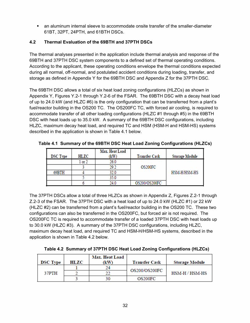
32
an aluminum internal sleeve to accommodate onsite transfer of the smaller-diameter 61BT, 32PT, 24PTH, and 61BTH DSCs.
4.2 Thermal Evaluation of the 69BTH and 37PTH DSCs
The thermal analyses presented in the application include thermal analysis and response of the 69BTH and 37PTH DSC system components to a defined set of thermal operating conditions. According to the applicant, these operating conditions envelope the thermal conditions expected during all normal, off-normal, and postulated accident conditions during loading, transfer, and storage as defined in Appendix Y for the 69BTH DSC and Appendix Z for the 37PTH DSC. The 69BTH DSC allows a total of six heat load zoning configurations (HLZCs) as shown in Appendix Y, Figures Y.2-1 through Y.2-6 of the FSAR. The 69BTH DSC with a decay heat load of up to 24.0 kW (and HLZC #6) is the only configuration that can be transferred from a plant’s fuel/reactor building in the OS200 TC. The OS200FC TC, with forced air cooling, is required to accommodate transfer of all other loading configurations (HLZC #1 through #5) in the 69BTH DSC with heat loads up to 35.0 kW. A summary of the 69BTH DSC configurations, including HLZC, maximum decay heat load, and required TC and HSM (HSM-H and HSM-HS) systems described in the application is shown in Table 4.1 below.
Table 4.1 Summary of the 69BTH DSC Heat Load Zoning Configurations (HLZCs)
The 37PTH DSCs allow a total of three HLZCs as shown in Appendix Z, Figures Z.2-1 through Z.2-3 of the FSAR. The 37PTH DSC with a heat load of up to 24.0 kW (HLZC #1) or 22 kW (HLZC #2) can be transferred from a plant’s fuel/reactor building in the OS200 TC. These two configurations can also be transferred in the OS200FC, but forced air is not required. The OS200FC TC is required to accommodate transfer of a loaded 37PTH DSC with heat loads up to 30.0 kW (HLZC #3). A summary of the 37PTH DSC configurations, including HLZC, maximum decay heat load, and required TC and HSM-H/HSM-HS systems, described in the application is shown in Table 4.2 below.
Table 4.2 Summary of 37PTH DSC Heat Load Zoning Configurations (HLZCs)
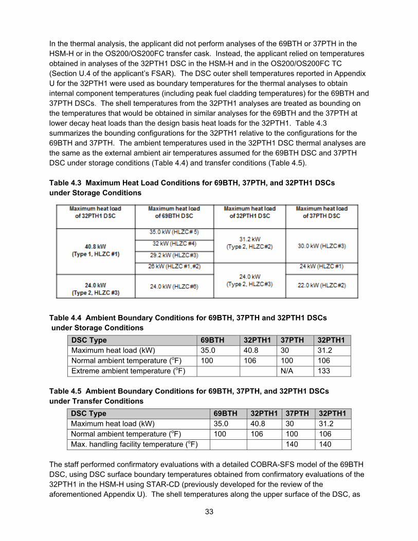
33
In the thermal analysis, the applicant did not perform analyses of the 69BTH or 37PTH in the HSM-H or in the OS200/OS200FC transfer cask. Instead, the applicant relied on temperatures obtained in analyses of the 32PTH1 DSC in the HSM-H and in the OS200/OS200FC TC (Section U.4 of the applicant’s FSAR). The DSC outer shell temperatures reported in Appendix U for the 32PTH1 were used as boundary temperatures for the thermal analyses to obtain internal component temperatures (including peak fuel cladding temperatures) for the 69BTH and 37PTH DSCs. The shell temperatures from the 32PTH1 analyses are treated as bounding on the temperatures that would be obtained in similar analyses for the 69BTH and the 37PTH at lower decay heat loads than the design basis heat loads for the 32PTH1. Table 4.3 summarizes the bounding configurations for the 32PTH1 relative to the configurations for the 69BTH and 37PTH. The ambient temperatures used in the 32PTH1 DSC thermal analyses are the same as the external ambient air temperatures assumed for the 69BTH DSC and 37PTH DSC under storage conditions (Table 4.4) and transfer conditions (Table 4.5). Table 4.3 Maximum Heat Load Conditions for 69BTH, 37PTH, and 32PTH1 DSCs under Storage Conditions
Table 4.4 Ambient Boundary Conditions for 69BTH, 37PTH and 32PTH1 DSCs under Storage Conditions
DSC Type 69BTH 32PTH1 37PTH 32PTH1 Maximum heat load (kW) 35.0 40.8 30 31.2 Normal ambient temperature (oF) 100 106 100 106 Extreme ambient temperature (oF) N/A 133
Table 4.5 Ambient Boundary Conditions for 69BTH, 37PTH, and 32PTH1 DSCs under Transfer Conditions
DSC Type 69BTH 32PTH1 37PTH 32PTH1 Maximum heat load (kW) 35.0 40.8 30 31.2 Normal ambient temperature (oF) 100 106 100 106 Max. handling facility temperature (oF) 140 140
The staff performed confirmatory evaluations with a detailed COBRA-SFS model of the 69BTH DSC, using DSC surface boundary temperatures obtained from confirmatory evaluations of the 32PTH1 in the HSM-H using STAR-CD (previously developed for the review of the aforementioned Appendix U). The shell temperatures along the upper surface of the DSC, as
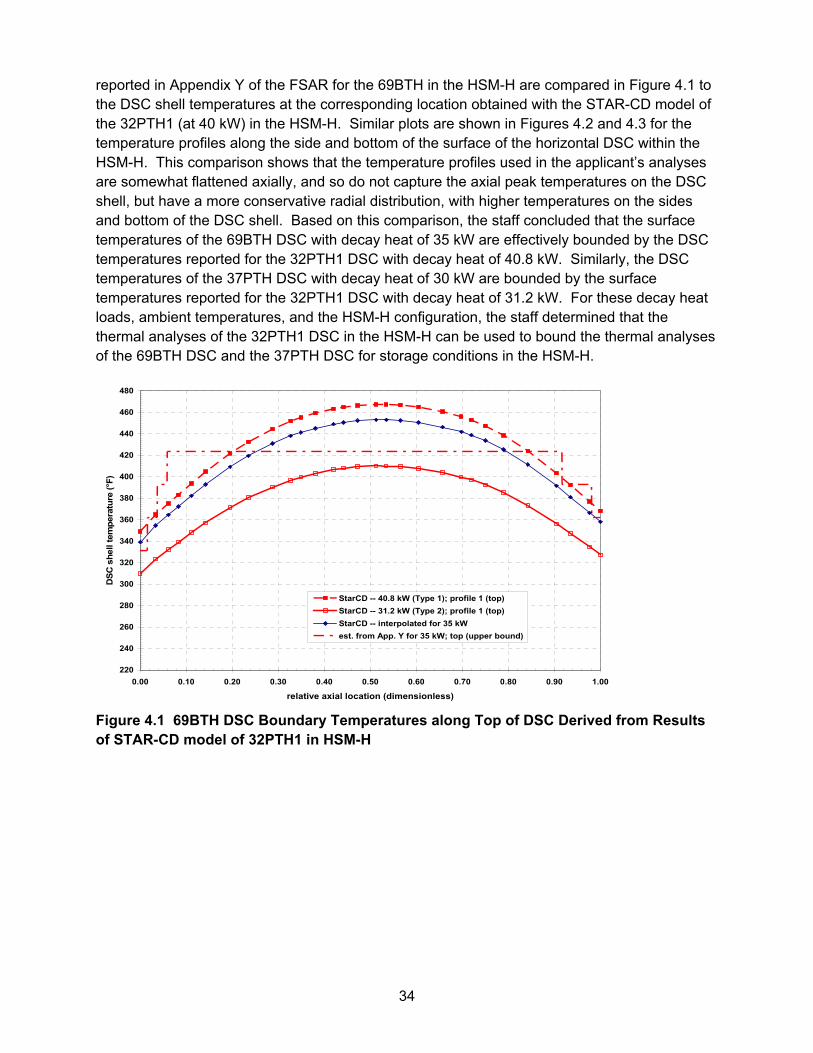
34
reported in Appendix Y of the FSAR for the 69BTH in the HSM-H are compared in Figure 4.1 to the DSC shell temperatures at the corresponding location obtained with the STAR-CD model of the 32PTH1 (at 40 kW) in the HSM-H. Similar plots are shown in Figures 4.2 and 4.3 for the temperature profiles along the side and bottom of the surface of the horizontal DSC within the HSM-H. This comparison shows that the temperature profiles used in the applicant’s analyses are somewhat flattened axially, and so do not capture the axial peak temperatures on the DSC shell, but have a more conservative radial distribution, with higher temperatures on the sides and bottom of the DSC shell. Based on this comparison, the staff concluded that the surface temperatures of the 69BTH DSC with decay heat of 35 kW are effectively bounded by the DSC temperatures reported for the 32PTH1 DSC with decay heat of 40.8 kW. Similarly, the DSC temperatures of the 37PTH DSC with decay heat of 30 kW are bounded by the surface temperatures reported for the 32PTH1 DSC with decay heat of 31.2 kW. For these decay heat loads, ambient temperatures, and the HSM-H configuration, the staff determined that the thermal analyses of the 32PTH1 DSC in the HSM-H can be used to bound the thermal analyses of the 69BTH DSC and the 37PTH DSC for storage conditions in the HSM-H.
Figure 4.1 69BTH DSC Boundary Temperatures along Top of DSC Derived from Results of STAR-CD model of 32PTH1 in HSM-H
220
240
260
280
300
320
340
360
380
400
420
440
460
480
0.00 0.10 0.20 0.30 0.40 0.50 0.60 0.70 0.80 0.90 1.00
relative axial location (dimensionless)
DS
C s
hell
tem
pera
ture
(°F
)
StarCD -- 40.8 kW (Type 1); profile 1 (top)
StarCD -- 31.2 kW (Type 2); profile 1 (top)
StarCD -- interpolated for 35 kW
est. from App. Y for 35 kW; top (upper bound)
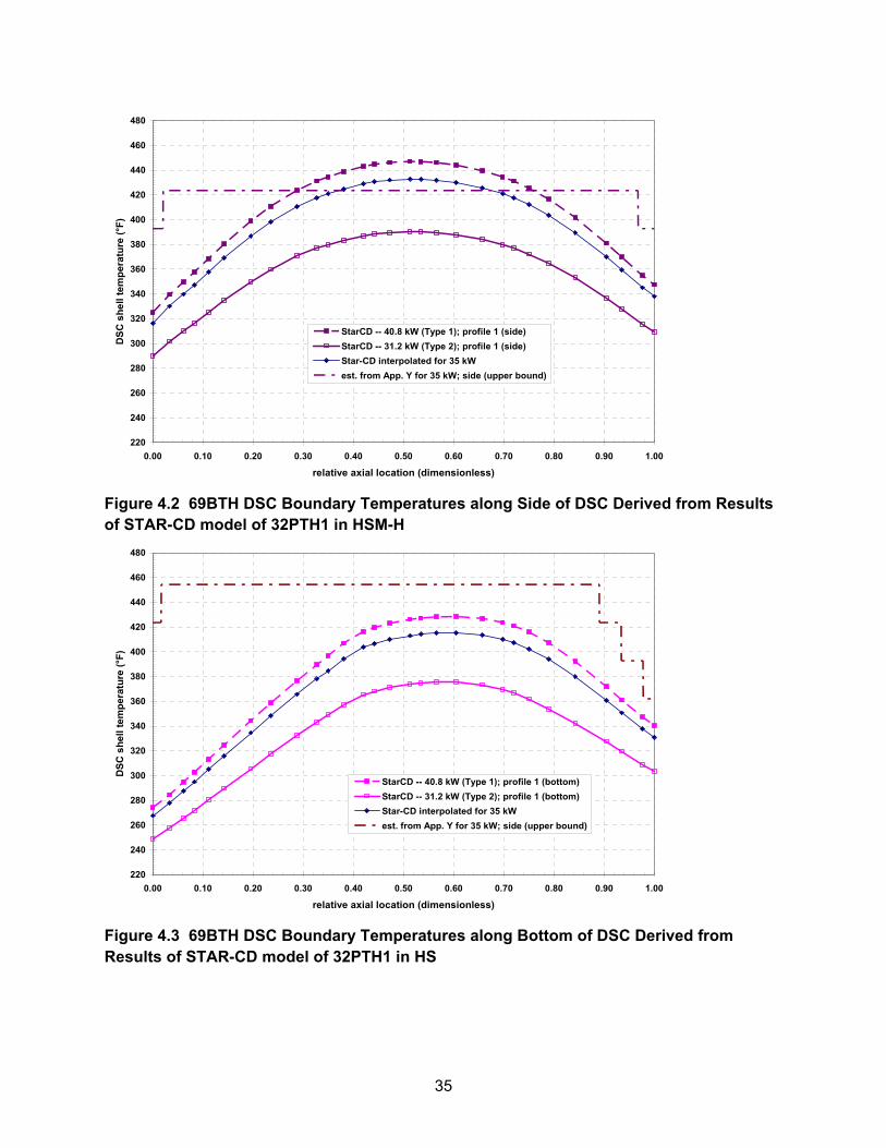
35
Figure 4.2 69BTH DSC Boundary Temperatures along Side of DSC Derived from Results of STAR-CD model of 32PTH1 in HSM-H
Figure 4.3 69BTH DSC Boundary Temperatures along Bottom of DSC Derived from Results of STAR-CD model of 32PTH1 in HS
220
240
260
280
300
320
340
360
380
400
420
440
460
480
0.00 0.10 0.20 0.30 0.40 0.50 0.60 0.70 0.80 0.90 1.00
relative axial location (dimensionless)
DS
C s
hell
tem
pera
ture
(°F
)
StarCD -- 40.8 kW (Type 1); profile 1 (side)
StarCD -- 31.2 kW (Type 2); profile 1 (side)
Star-CD interpolated for 35 kW
est. from App. Y for 35 kW; side (upper bound)
220
240
260
280
300
320
340
360
380
400
420
440
460
480
0.00 0.10 0.20 0.30 0.40 0.50 0.60 0.70 0.80 0.90 1.00
relative axial location (dimensionless)
DS
C s
hell
tem
pera
ture
(°F
)
StarCD -- 40.8 kW (Type 1); profile 1 (bottom)
StarCD -- 31.2 kW (Type 2); profile 1 (bottom)
Star-CD interpolated for 35 kW
est. from App. Y for 35 kW; side (upper bound)
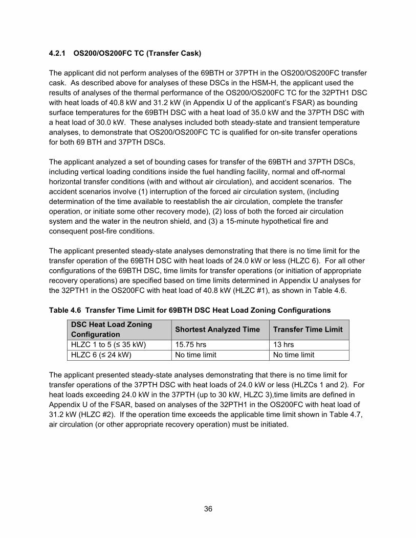
36
4.2.1 OS200/OS200FC TC (Transfer Cask) The applicant did not perform analyses of the 69BTH or 37PTH in the OS200/OS200FC transfer cask. As described above for analyses of these DSCs in the HSM-H, the applicant used the results of analyses of the thermal performance of the OS200/OS200FC TC for the 32PTH1 DSC with heat loads of 40.8 kW and 31.2 kW (in Appendix U of the applicant’s FSAR) as bounding surface temperatures for the 69BTH DSC with a heat load of 35.0 kW and the 37PTH DSC with a heat load of 30.0 kW. These analyses included both steady-state and transient temperature analyses, to demonstrate that OS200/OS200FC TC is qualified for on-site transfer operations for both 69 BTH and 37PTH DSCs. The applicant analyzed a set of bounding cases for transfer of the 69BTH and 37PTH DSCs, including vertical loading conditions inside the fuel handling facility, normal and off-normal horizontal transfer conditions (with and without air circulation), and accident scenarios. The accident scenarios involve (1) interruption of the forced air circulation system, (including determination of the time available to reestablish the air circulation, complete the transfer operation, or initiate some other recovery mode), (2) loss of both the forced air circulation system and the water in the neutron shield, and (3) a 15-minute hypothetical fire and consequent post-fire conditions. The applicant presented steady-state analyses demonstrating that there is no time limit for the transfer operation of the 69BTH DSC with heat loads of 24.0 kW or less (HLZC 6). For all other configurations of the 69BTH DSC, time limits for transfer operations (or initiation of appropriate recovery operations) are specified based on time limits determined in Appendix U analyses for the 32PTH1 in the OS200FC with heat load of 40.8 kW (HLZC #1), as shown in Table 4.6. Table 4.6 Transfer Time Limit for 69BTH DSC Heat Load Zoning Configurations
DSC Heat Load Zoning Configuration
Shortest Analyzed Time Transfer Time Limit
HLZC 1 to 5 (≤ 35 kW) 15.75 hrs 13 hrs HLZC 6 (≤ 24 kW) No time limit No time limit
The applicant presented steady-state analyses demonstrating that there is no time limit for transfer operations of the 37PTH DSC with heat loads of 24.0 kW or less (HLZCs 1 and 2). For heat loads exceeding 24.0 kW in the 37PTH (up to 30 kW, HLZC 3),time limits are defined in Appendix U of the FSAR, based on analyses of the 32PTH1 in the OS200FC with heat load of 31.2 kW (HLZC #2). If the operation time exceeds the applicable time limit shown in Table 4.7, air circulation (or other appropriate recovery operation) must be initiated.
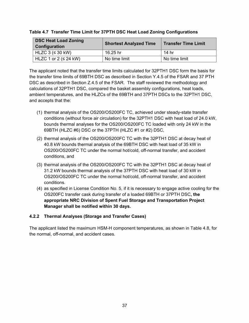
37
Table 4.7 Transfer Time Limit for 37PTH DSC Heat Load Zoning Configurations
DSC Heat Load Zoning Configuration
Shortest Analyzed Time Transfer Time Limit
HLZC 3 (≤ 30 kW) 16.25 hr 14 hr HLZC 1 or 2 (≤ 24 kW) No time limit No time limit
The applicant noted that the transfer time limits calculated for 32PTH1 DSC form the basis for the transfer time limits of 69BTH DSC as described in Section Y.4.5 of the FSAR and 37 PTH DSC as described in Section Z.4.5 of the FSAR. The staff reviewed the methodology and calculations of 32PTH1 DSC, compared the basket assembly configurations, heat loads, ambient temperatures, and the HLZCs of the 69BTH and 37PTH DSCs to the 32PTH1 DSC, and accepts that the:
(1) thermal analysis of the OS200/OS200FC TC, achieved under steady-state transfer conditions (without force air circulation) for the 32PTH1 DSC with heat load of 24.0 kW, bounds thermal analyses for the OS200/OS200FC TC loaded with only 24 kW in the 69BTH (HLZC #6) DSC or the 37PTH (HLZC #1 or #2) DSC,
(2) thermal analysis of the OS200/OS200FC TC with the 32PTH1 DSC at decay heat of 40.8 kW bounds thermal analysis of the 69BTH DSC with heat load of 35 kW in OS200/OS200FC TC under the normal hot/cold, off-normal transfer, and accident conditions, and
(3) thermal analysis of the OS200/OS200FC TC with the 32PTH1 DSC at decay heat of 31.2 kW bounds thermal analysis of the 37PTH DSC with heat load of 30 kW in OS200/OS200FC TC under the normal hot/cold, off-normal transfer, and accident conditions.
(4) as specified in License Condition No. 5, if it is necessary to engage active cooling for the OS200FC transfer cask during transfer of a loaded 69BTH or 37PTH DSC, the appropriate NRC Division of Spent Fuel Storage and Transportation Project Manager shall be notified within 30 days.
4.2.2 Thermal Analyses (Storage and Transfer Cases) The applicant listed the maximum HSM-H component temperatures, as shown in Table 4.8, for the normal, off-normal, and accident cases.
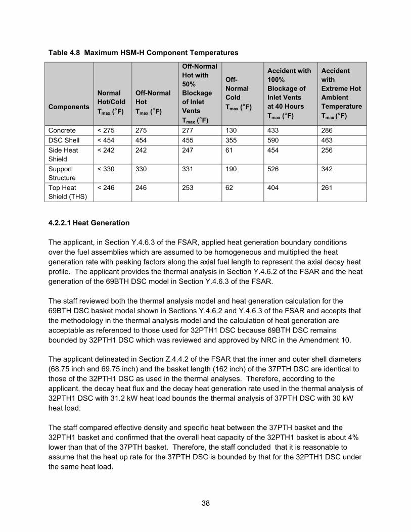
38
Table 4.8 Maximum HSM-H Component Temperatures
Components
Normal Hot/Cold
Tmax (°F)
Off-Normal Hot
Tmax (°F)
Off-Normal Hot with 50% Blockage of Inlet Vents
Tmax (°F)
Off-Normal Cold
Tmax (°F)
Accident with 100% Blockage of Inlet Vents at 40 Hours
Tmax (°F)
Accident with Extreme Hot Ambient Temperature
Tmax (°F)
Concrete < 275 275 277 130 433 286
DSC Shell < 454 454 455 355 590 463
Side Heat Shield
< 242 242 247 61 454 256
Support Structure
< 330 330 331 190 526 342
Top Heat Shield (THS)
< 246 246 253 62 404 261
4.2.2.1 Heat Generation The applicant, in Section Y.4.6.3 of the FSAR, applied heat generation boundary conditions over the fuel assemblies which are assumed to be homogeneous and multiplied the heat generation rate with peaking factors along the axial fuel length to represent the axial decay heat profile. The applicant provides the thermal analysis in Section Y.4.6.2 of the FSAR and the heat generation of the 69BTH DSC model in Section Y.4.6.3 of the FSAR. The staff reviewed both the thermal analysis model and heat generation calculation for the 69BTH DSC basket model shown in Sections Y.4.6.2 and Y.4.6.3 of the FSAR and accepts that the methodology in the thermal analysis model and the calculation of heat generation are acceptable as referenced to those used for 32PTH1 DSC because 69BTH DSC remains bounded by 32PTH1 DSC which was reviewed and approved by NRC in the Amendment 10. The applicant delineated in Section Z.4.4.2 of the FSAR that the inner and outer shell diameters (68.75 inch and 69.75 inch) and the basket length (162 inch) of the 37PTH DSC are identical to those of the 32PTH1 DSC as used in the thermal analyses. Therefore, according to the applicant, the decay heat flux and the decay heat generation rate used in the thermal analysis of 32PTH1 DSC with 31.2 kW heat load bounds the thermal analysis of 37PTH DSC with 30 kW heat load. The staff compared effective density and specific heat between the 37PTH basket and the 32PTH1 basket and confirmed that the overall heat capacity of the 32PTH1 basket is about 4% lower than that of the 37PTH basket. Therefore, the staff concluded that it is reasonable to assume that the heat up rate for the 37PTH DSC is bounded by that for the 32PTH1 DSC under the same heat load.
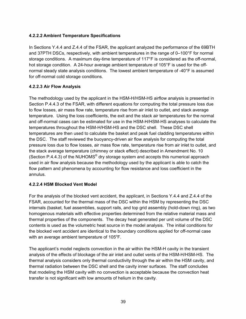
39
4.2.2.2 Ambient Temperature Specifications In Sections Y.4.4 and Z.4.4 of the FSAR, the applicant analyzed the performance of the 69BTH and 37PTH DSCs, respectively, with ambient temperatures in the range of 0–100°F for normal storage conditions. A maximum day-time temperature of 117°F is considered as the off-normal, hot storage condition. A 24-hour average ambient temperature of 105°F is used for the off-normal steady state analysis conditions. The lowest ambient temperature of -40°F is assumed for off-normal cold storage conditions.
4.2.2.3 Air Flow Analysis The methodology used by the applicant in the HSM-H/HSM-HS airflow analysis is presented in Section P.4.4.3 of the FSAR, with different equations for computing the total pressure loss due to flow losses, air mass flow rate, temperature rise from air inlet to outlet, and stack average temperature. Using the loss coefficients, the exit and the stack air temperatures for the normal and off-normal cases can be estimated for use in the HSM-H/HSM-HS analyses to calculate the temperatures throughout the HSM-H/HSM-HS and the DSC shell. These DSC shell temperatures are then used to calculate the basket and peak fuel cladding temperatures within the DSC. The staff reviewed the buoyancy-driven air flow analysis for computing the total pressure loss due to flow losses, air mass flow rate, temperature rise from air inlet to outlet, and the stack average temperature (chimney or stack effect) described in Amendment No. 10 (Section P.4.4.3) of the NUHOMS® dry storage system and accepts this numerical approach used in air flow analysis because the methodology used by the applicant is able to catch the flow pattern and phenomena by accounting for flow resistance and loss coefficient in the annulus.
4.2.2.4 HSM Blocked Vent Model For the analysis of the blocked vent accident, the applicant, in Sections Y.4.4 and Z.4.4 of the FSAR, accounted for the thermal mass of the DSC within the HSM by representing the DSC internals (basket, fuel assemblies, support rails, and top grid assembly (hold-down ring), as two homogenous materials with effective properties determined from the relative material mass and thermal properties of the components. The decay heat generated per unit volume of the DSC contents is used as the volumetric heat source in the model analysis. The initial conditions for the blocked vent accident are identical to the boundary conditions applied for off-normal case with an average ambient temperature of 105oF. The applicant’s model neglects convection in the air within the HSM-H cavity in the transient analysis of the effects of blockage of the air inlet and outlet vents of the HSM-H/HSM-HS. The thermal analysis considers only thermal conductivity through the air within the HSM cavity, and thermal radiation between the DSC shell and the cavity inner surfaces. The staff concludes that modeling the HSM cavity with no convection is acceptable because the convection heat transfer is not significant with low amounts of helium in the cavity.
40
4.2.2.5 Hydrogen Generation As explained in Sections Y.3.4.1 and Z.3.4.1 of the FSAR, the applicant conducted experimental testing to determine the hydrogen generation rate within the basket during wet loading operations. Test specimens were submerged in de-ionized water for 12 hours at 70°F to represent the period of initial submersion and fuel loading within the spent fuel pool. This was followed by 12 hours at 150°F to represent the period after the fuel is loaded, until the water is drained for vacuum drying operations. The hydrogen generation rate measured during each period is shown in Table 4.9 below. These measurements are applicable to both the 69BTH and 37PTH DSCs, since they are constructed of the same materials. Table 4.9 Hydrogen Generated before and after the Fuel is Loaded into 69BTH DSC and 37PTH DSC
The applicant further calculated the hydrogen generation rate to ensure that the hydrogen concentration is below the NRC-accepted limit of 2.4% (Ref. 2) in the 69BTH and 37PTH DSCs. Monitoring of the hydrogen concentration before and during welding operations is required to ensure that the hydrogen concentration does not exceed a safety limit of 2.4%. If the concentration exceeds 2.4%, the welding operations will be stopped and the DSC cavity purged with helium to reduce the hydrogen concentration safely below the 2.4% limit, as described in Sections Y.8 and Z.8 of the FSAR, and as directed in Technical Specification 5.2.6. After reviewing the parameters and the calculations presented in Section Y.3.4.1 of the FSAR for the 69BTH DSC and Section Z.3.4.1 of the FSAR for the 37PTH DSC, the staff finds that the calculations of hydrogen generation are acceptable and the predicted hydrogen concentration in the DSCs will be below 2.4% and will not result in a significant flammable gas mixture within the 69BTH or 37PTH DSCs.
4.2.3 69BTH and 37PTH DSCs under Storage/Transfer Conditions
4.2.3.1 Load Cases of 69BTH and 37PTH DSCs under Storage and Transfer Conditions In Sections Y.4.6.10 and Z.4.6.11 of the FSAR, the applicant calculated the maximum internal pressures of the 69BTH DSC with a decay heat of 35.0 kW and 37PTH DSC with a heat load of 30.0 kW for normal, off-normal, and accident storage and transfer conditions. This analysis accounted for the canister free volume, the quantities of canister backfill gas, the fuel rod fill gas, the fission products, and the average canister cavity gas temperature. The applicant assumed that 1%, 10%, and 100% of fuel rods rupture under normal, off-normal, and accident cases, respectively, and considered that 100% of the fuel rod helium fill gas and 30% of the fission gases were released into the DSC cavity. The load cases for the 69BTH and 37PTH
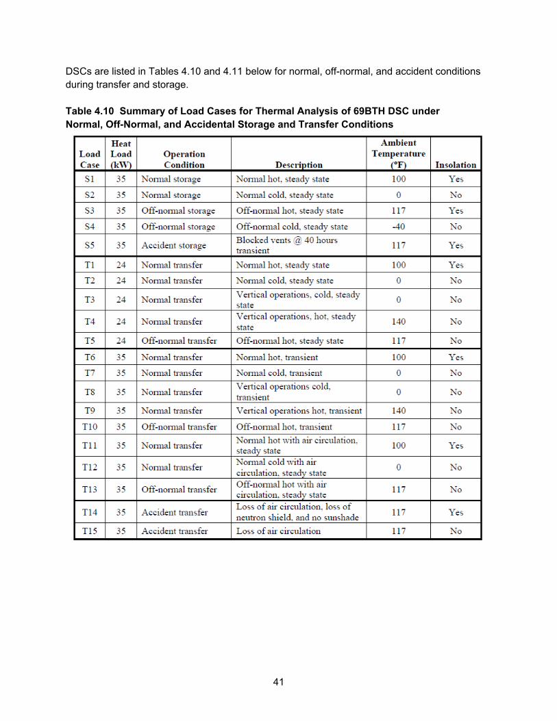
41
DSCs are listed in Tables 4.10 and 4.11 below for normal, off-normal, and accident conditions during transfer and storage. Table 4.10 Summary of Load Cases for Thermal Analysis of 69BTH DSC under Normal, Off-Normal, and Accidental Storage and Transfer Conditions
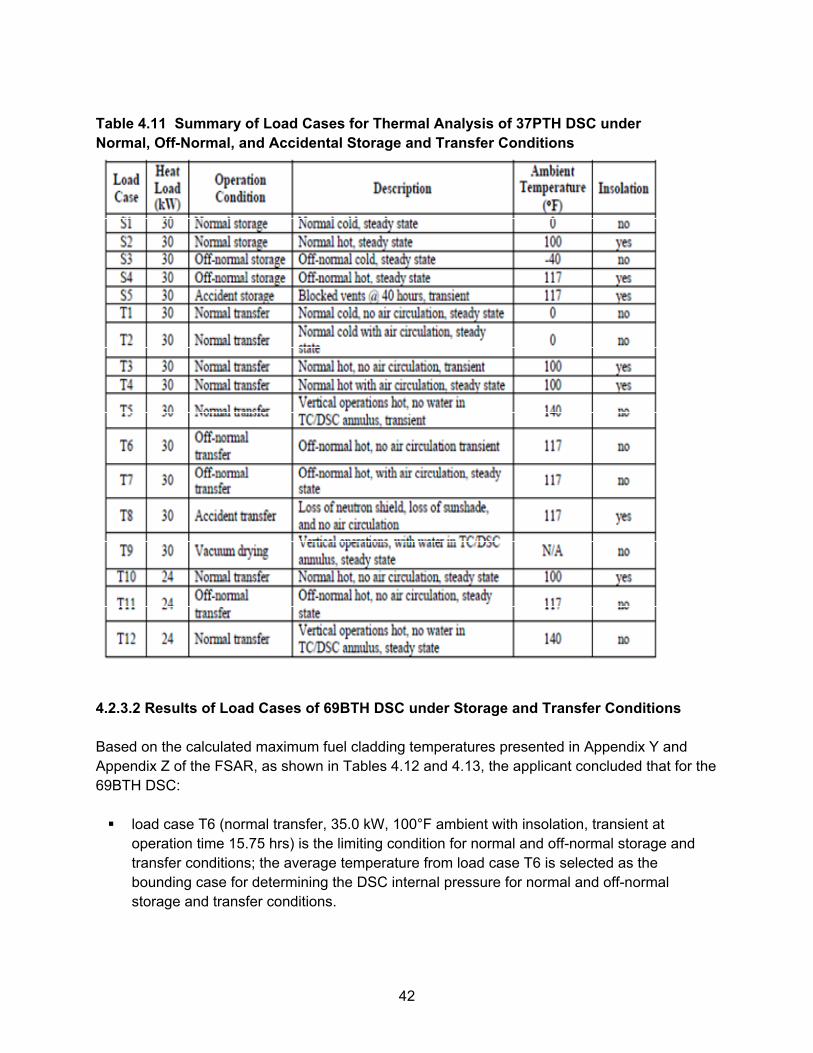
42
Table 4.11 Summary of Load Cases for Thermal Analysis of 37PTH DSC under Normal, Off-Normal, and Accidental Storage and Transfer Conditions
4.2.3.2 Results of Load Cases of 69BTH DSC under Storage and Transfer Conditions Based on the calculated maximum fuel cladding temperatures presented in Appendix Y and Appendix Z of the FSAR, as shown in Tables 4.12 and 4.13, the applicant concluded that for the 69BTH DSC: load case T6 (normal transfer, 35.0 kW, 100°F ambient with insolation, transient at
operation time 15.75 hrs) is the limiting condition for normal and off-normal storage and transfer conditions; the average temperature from load case T6 is selected as the bounding case for determining the DSC internal pressure for normal and off-normal storage and transfer conditions.
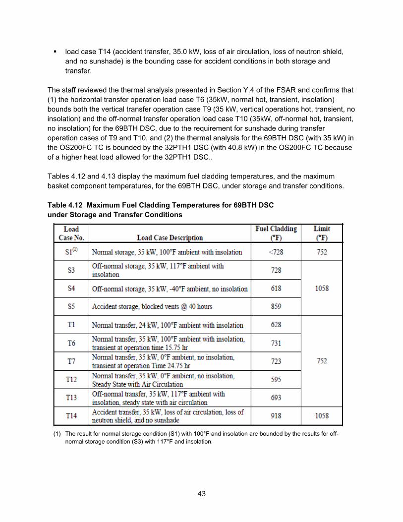
43
load case T14 (accident transfer, 35.0 kW, loss of air circulation, loss of neutron shield, and no sunshade) is the bounding case for accident conditions in both storage and transfer.
The staff reviewed the thermal analysis presented in Section Y.4 of the FSAR and confirms that (1) the horizontal transfer operation load case T6 (35kW, normal hot, transient, insolation) bounds both the vertical transfer operation case T9 (35 kW, vertical operations hot, transient, no insolation) and the off-normal transfer operation load case T10 (35kW, off-normal hot, transient, no insolation) for the 69BTH DSC, due to the requirement for sunshade during transfer operation cases of T9 and T10, and (2) the thermal analysis for the 69BTH DSC (with 35 kW) in the OS200FC TC is bounded by the 32PTH1 DSC (with 40.8 kW) in the OS200FC TC because of a higher heat load allowed for the 32PTH1 DSC.. Tables 4.12 and 4.13 display the maximum fuel cladding temperatures, and the maximum basket component temperatures, for the 69BTH DSC, under storage and transfer conditions. Table 4.12 Maximum Fuel Cladding Temperatures for 69BTH DSC under Storage and Transfer Conditions
(1) The result for normal storage condition (S1) with 100°F and insolation are bounded by the results for off-
normal storage condition (S3) with 117°F and insolation.
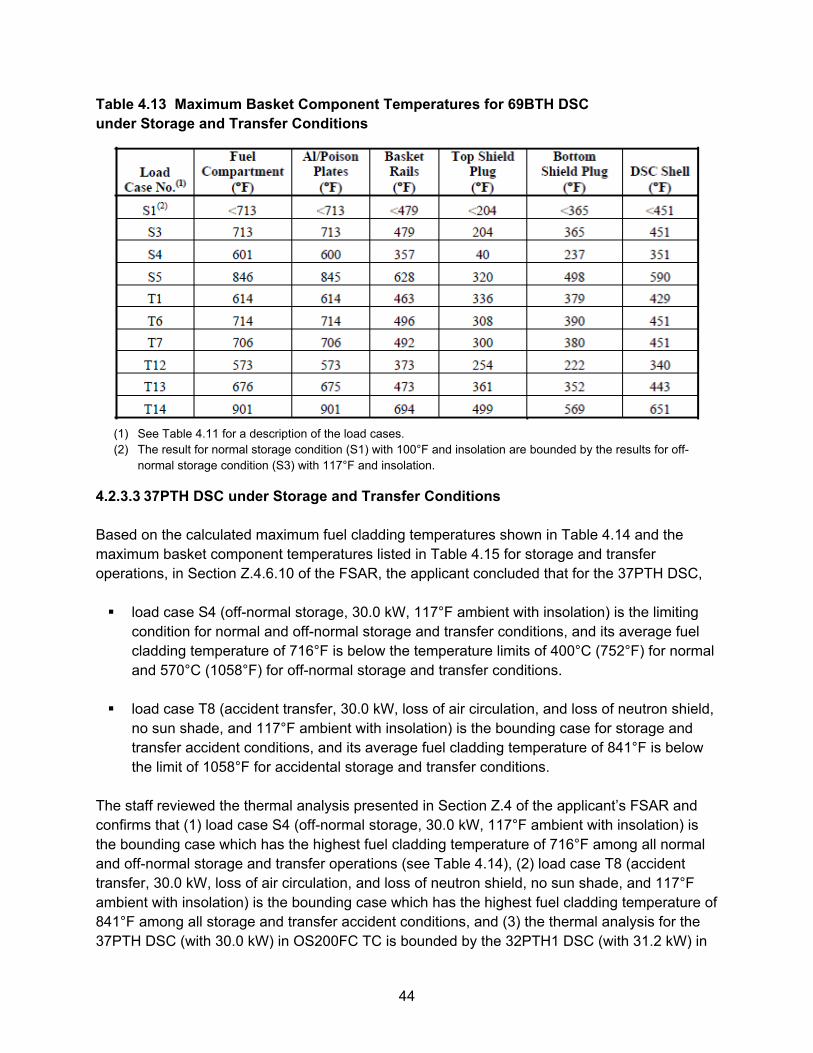
44
Table 4.13 Maximum Basket Component Temperatures for 69BTH DSC under Storage and Transfer Conditions
(1) See Table 4.11 for a description of the load cases. (2) The result for normal storage condition (S1) with 100°F and insolation are bounded by the results for off-
normal storage condition (S3) with 117°F and insolation.
4.2.3.3 37PTH DSC under Storage and Transfer Conditions Based on the calculated maximum fuel cladding temperatures shown in Table 4.14 and the maximum basket component temperatures listed in Table 4.15 for storage and transfer operations, in Section Z.4.6.10 of the FSAR, the applicant concluded that for the 37PTH DSC, load case S4 (off-normal storage, 30.0 kW, 117°F ambient with insolation) is the limiting
condition for normal and off-normal storage and transfer conditions, and its average fuel cladding temperature of 716°F is below the temperature limits of 400°C (752°F) for normal and 570°C (1058°F) for off-normal storage and transfer conditions.
load case T8 (accident transfer, 30.0 kW, loss of air circulation, and loss of neutron shield,
no sun shade, and 117°F ambient with insolation) is the bounding case for storage and transfer accident conditions, and its average fuel cladding temperature of 841°F is below the limit of 1058°F for accidental storage and transfer conditions.
The staff reviewed the thermal analysis presented in Section Z.4 of the applicant’s FSAR and confirms that (1) load case S4 (off-normal storage, 30.0 kW, 117°F ambient with insolation) is the bounding case which has the highest fuel cladding temperature of 716°F among all normal and off-normal storage and transfer operations (see Table 4.14), (2) load case T8 (accident transfer, 30.0 kW, loss of air circulation, and loss of neutron shield, no sun shade, and 117°F ambient with insolation) is the bounding case which has the highest fuel cladding temperature of 841°F among all storage and transfer accident conditions, and (3) the thermal analysis for the 37PTH DSC (with 30.0 kW) in OS200FC TC is bounded by the 32PTH1 DSC (with 31.2 kW) in
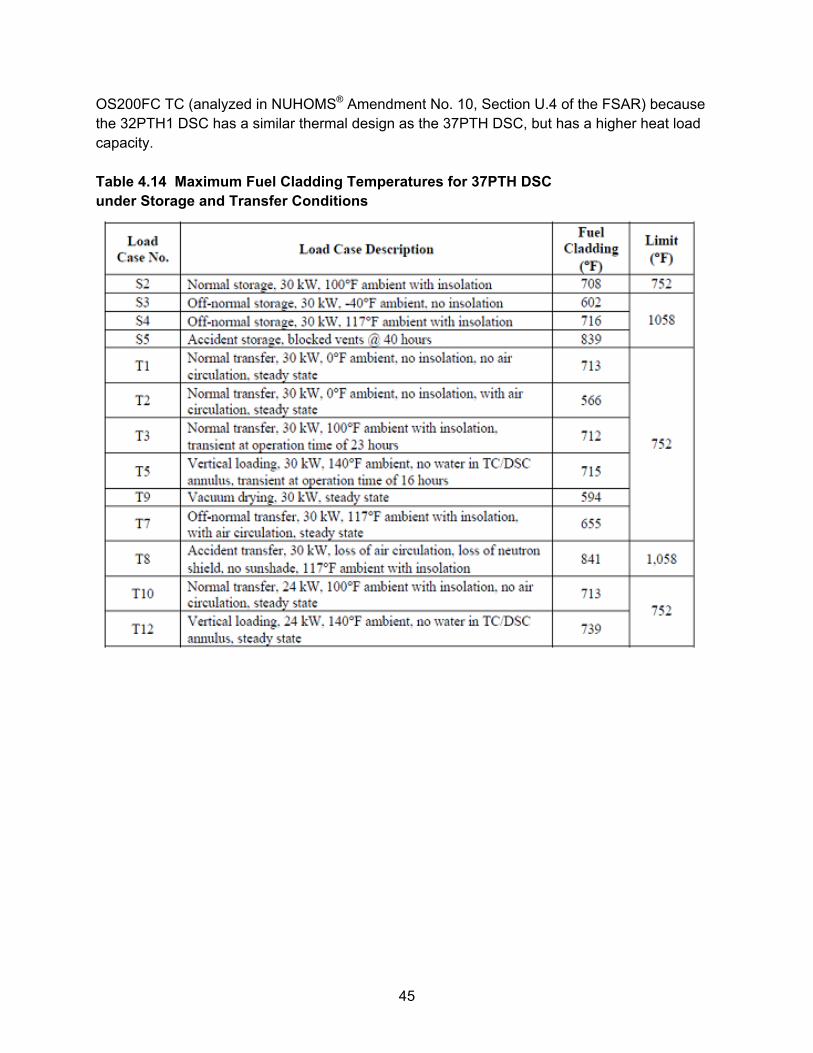
45
OS200FC TC (analyzed in NUHOMS® Amendment No. 10, Section U.4 of the FSAR) because the 32PTH1 DSC has a similar thermal design as the 37PTH DSC, but has a higher heat load capacity. Table 4.14 Maximum Fuel Cladding Temperatures for 37PTH DSC under Storage and Transfer Conditions
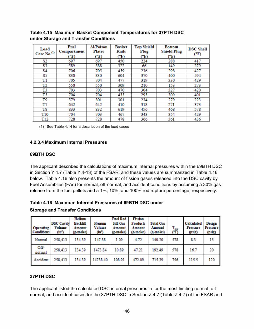
46
Table 4.15 Maximum Basket Component Temperatures for 37PTH DSC under Storage and Transfer Conditions
(1) See Table 4.14 for a description of the load cases
4.2.3.4 Maximum Internal Pressures 69BTH DSC The applicant described the calculations of maximum internal pressures within the 69BTH DSC in Section Y.4.7 (Table Y.4-13) of the FSAR, and these values are summarized in Table 4.16 below. Table 4.16 also presents the amount of fission gases released into the DSC cavity by Fuel Assemblies (FAs) for normal, off-normal, and accident conditions by assuming a 30% gas release from the fuel pellets and a 1%, 10%, and 100% rod rupture percentage, respectively. Table 4.16 Maximum Internal Pressures of 69BTH DSC under
Storage and Transfer Conditions
37PTH DSC The applicant listed the calculated DSC internal pressures in for the most limiting normal, off-normal, and accident cases for the 37PTH DSC in Section Z.4.7 (Table Z.4-7) of the FSAR and
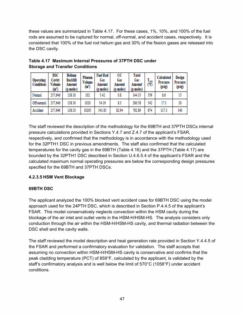
47
these values are summarized in Table 4.17. For these cases, 1%, 10%, and 100% of the fuel rods are assumed to be ruptured for normal, off-normal, and accident cases, respectively. It is considered that 100% of the fuel rod helium gas and 30% of the fission gases are released into the DSC cavity.
Table 4.17 Maximum Internal Pressures of 37PTH DSC under Storage and Transfer Conditions
The staff reviewed the description of the methodology for the 69BTH and 37PTH DSCs internal pressure calculations provided in Sections Y.4.7 and Z.4.7 of the applicant’s FSAR, respectively, and confirmed that the methodology is in accordance with the methodology used for the 32PTH1 DSC in previous amendments. The staff also confirmed that the calculated temperatures for the cavity gas in the 69BTH (Table 4.16) and the 37PTH (Table 4.17) are bounded by the 32PTH1 DSC described in Section U.4.6.5.4 of the applicant’s FSAR and the calculated maximum normal operating pressures are below the corresponding design pressures specified for the 69BTH and 37PTH DSCs.
4.2.3.5 HSM Vent Blockage 69BTH DSC The applicant analyzed the 100% blocked vent accident case for 69BTH DSC using the model approach used for the 24PTH DSC, which is described in Section P.4.4.5 of the applicant’s FSAR. This model conservatively neglects convection within the HSM cavity during the blockage of the air inlet and outlet vents in the HSM-H/HSM-HS. The analysis considers only conduction through the air within the HSM-H/HSM-HS cavity, and thermal radiation between the DSC shell and the cavity walls. The staff reviewed the model description and heat generation rate provided in Section Y.4.4.5 of the FSAR and performed a confirmatory evaluation for validation. The staff accepts that assuming no convection within HSM-H/HSM-HS cavity is conservative and confirms that the peak cladding temperature (PCT) of 859°F, calculated by the applicant, is validated by the staff’s confirmatory analysis and is well below the limit of 570°C (1058°F) under accident conditions.
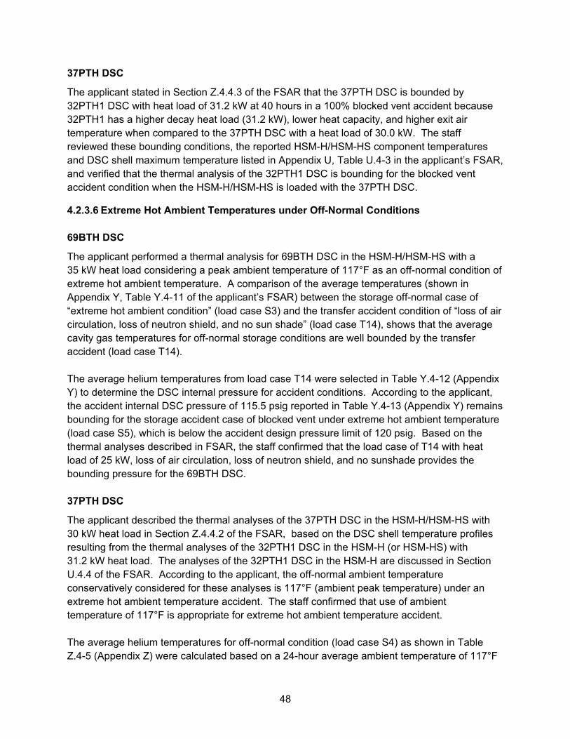
48
37PTH DSC
The applicant stated in Section Z.4.4.3 of the FSAR that the 37PTH DSC is bounded by 32PTH1 DSC with heat load of 31.2 kW at 40 hours in a 100% blocked vent accident because 32PTH1 has a higher decay heat load (31.2 kW), lower heat capacity, and higher exit air temperature when compared to the 37PTH DSC with a heat load of 30.0 kW. The staff reviewed these bounding conditions, the reported HSM-H/HSM-HS component temperatures and DSC shell maximum temperature listed in Appendix U, Table U.4-3 in the applicant’s FSAR, and verified that the thermal analysis of the 32PTH1 DSC is bounding for the blocked vent accident condition when the HSM-H/HSM-HS is loaded with the 37PTH DSC.
4.2.3.6 Extreme Hot Ambient Temperatures under Off-Normal Conditions 69BTH DSC
The applicant performed a thermal analysis for 69BTH DSC in the HSM-H/HSM-HS with a 35 kW heat load considering a peak ambient temperature of 117°F as an off-normal condition of extreme hot ambient temperature. A comparison of the average temperatures (shown in Appendix Y, Table Y.4-11 of the applicant’s FSAR) between the storage off-normal case of “extreme hot ambient condition” (load case S3) and the transfer accident condition of “loss of air circulation, loss of neutron shield, and no sun shade” (load case T14), shows that the average cavity gas temperatures for off-normal storage conditions are well bounded by the transfer accident (load case T14). The average helium temperatures from load case T14 were selected in Table Y.4-12 (Appendix Y) to determine the DSC internal pressure for accident conditions. According to the applicant, the accident internal DSC pressure of 115.5 psig reported in Table Y.4-13 (Appendix Y) remains bounding for the storage accident case of blocked vent under extreme hot ambient temperature (load case S5), which is below the accident design pressure limit of 120 psig. Based on the thermal analyses described in FSAR, the staff confirmed that the load case of T14 with heat load of 25 kW, loss of air circulation, loss of neutron shield, and no sunshade provides the bounding pressure for the 69BTH DSC. 37PTH DSC
The applicant described the thermal analyses of the 37PTH DSC in the HSM-H/HSM-HS with 30 kW heat load in Section Z.4.4.2 of the FSAR, based on the DSC shell temperature profiles resulting from the thermal analyses of the 32PTH1 DSC in the HSM-H (or HSM-HS) with 31.2 kW heat load. The analyses of the 32PTH1 DSC in the HSM-H are discussed in Section U.4.4 of the FSAR. According to the applicant, the off-normal ambient temperature conservatively considered for these analyses is 117°F (ambient peak temperature) under an extreme hot ambient temperature accident. The staff confirmed that use of ambient temperature of 117°F is appropriate for extreme hot ambient temperature accident. The average helium temperatures for off-normal condition (load case S4) as shown in Table Z.4-5 (Appendix Z) were calculated based on a 24-hour average ambient temperature of 117°F
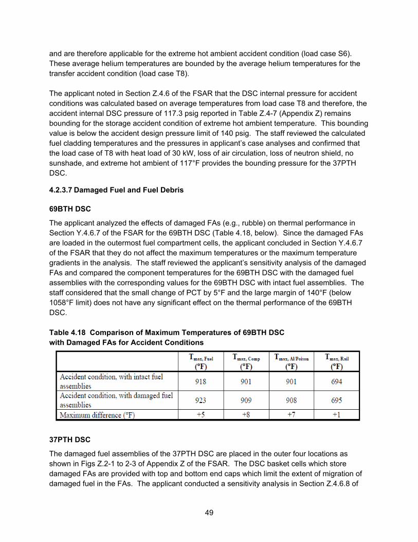
49
and are therefore applicable for the extreme hot ambient accident condition (load case S6). These average helium temperatures are bounded by the average helium temperatures for the transfer accident condition (load case T8). The applicant noted in Section Z.4.6 of the FSAR that the DSC internal pressure for accident conditions was calculated based on average temperatures from load case T8 and therefore, the accident internal DSC pressure of 117.3 psig reported in Table Z.4-7 (Appendix Z) remains bounding for the storage accident condition of extreme hot ambient temperature. This bounding value is below the accident design pressure limit of 140 psig. The staff reviewed the calculated fuel cladding temperatures and the pressures in applicant’s case analyses and confirmed that the load case of T8 with heat load of 30 kW, loss of air circulation, loss of neutron shield, no sunshade, and extreme hot ambient of 117°F provides the bounding pressure for the 37PTH DSC.
4.2.3.7 Damaged Fuel and Fuel Debris
69BTH DSC
The applicant analyzed the effects of damaged FAs (e.g., rubble) on thermal performance in Section Y.4.6.7 of the FSAR for the 69BTH DSC (Table 4.18, below). Since the damaged FAs are loaded in the outermost fuel compartment cells, the applicant concluded in Section Y.4.6.7 of the FSAR that they do not affect the maximum temperatures or the maximum temperature gradients in the analysis. The staff reviewed the applicant’s sensitivity analysis of the damaged FAs and compared the component temperatures for the 69BTH DSC with the damaged fuel assemblies with the corresponding values for the 69BTH DSC with intact fuel assemblies. The staff considered that the small change of PCT by 5°F and the large margin of 140°F (below 1058°F limit) does not have any significant effect on the thermal performance of the 69BTH DSC. Table 4.18 Comparison of Maximum Temperatures of 69BTH DSC with Damaged FAs for Accident Conditions
37PTH DSC
The damaged fuel assemblies of the 37PTH DSC are placed in the outer four locations as shown in Figs Z.2-1 to 2-3 of Appendix Z of the FSAR. The DSC basket cells which store damaged FAs are provided with top and bottom end caps which limit the extent of migration of damaged fuel in the FAs. The applicant conducted a sensitivity analysis in Section Z.4.6.8 of
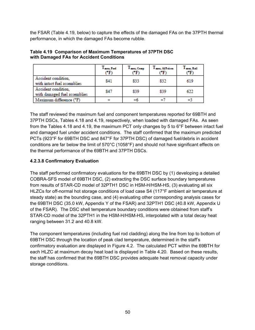
50
the FSAR (Table 4.19, below) to capture the effects of the damaged FAs on the 37PTH thermal performance, in which the damaged FAs become rubble.
Table 4.19 Comparison of Maximum Temperatures of 37PTH DSC with Damaged FAs for Accident Conditions
The staff reviewed the maximum fuel and component temperatures reported for 69BTH and 37PTH DSCs, Tables 4.18 and 4.19, respectively, when loaded with damaged FAs. As seen from the Tables 4.18 and 4.19, the maximum PCT only changes by 5 to 6°F between intact fuel and damaged fuel under accident conditions. The staff confirmed that the maximum predicted PCTs (923°F for 69BTH DSC and 847°F for 37PTH DSC) of damaged fuel/debris in accident conditions are far below the limit of 570°C (1058°F) and should not have significant effects on the thermal performance of the 69BTH and 37PTH DSCs.
4.2.3.8 Confirmatory Evaluation The staff performed confirmatory evaluations for the 69BTH DSC by (1) developing a detailed COBRA-SFS model of 69BTH DSC, (2) extracting the DSC surface boundary temperatures from results of STAR-CD model of 32PTH1 DSC in HSM-H/HSM-HS, (3) evaluating all six HLZCs for off-normal hot storage conditions of load case S4 (117°F ambient air temperature at steady state) as the bounding case, and (4) evaluating other corresponding analysis cases for the 69BTH DSC (35.0 kW, Appendix Y of the FSAR) and 32PTH1 DSC (40.8 kW, Appendix U of the FSAR). The DSC shell temperature boundary conditions were obtained from staff’s STAR-CD model of the 32PTH1 in the HSM-H/HSM-HS, interpolated with a total decay heat ranging between 31.2 and 40.8 kW. The component temperatures (including fuel rod cladding) along the line from top to bottom of 69BTH DSC through the location of peak clad temperature, determined in the staff’s confirmatory evaluation are displayed in Figure 4.2. The calculated PCT within the 69BTH for each HLZC at maximum decay heat load is displayed in Table 4.20. Based on these results, the staff has confirmed that the 69BTH DSC provides adequate heat removal capacity under storage conditions.
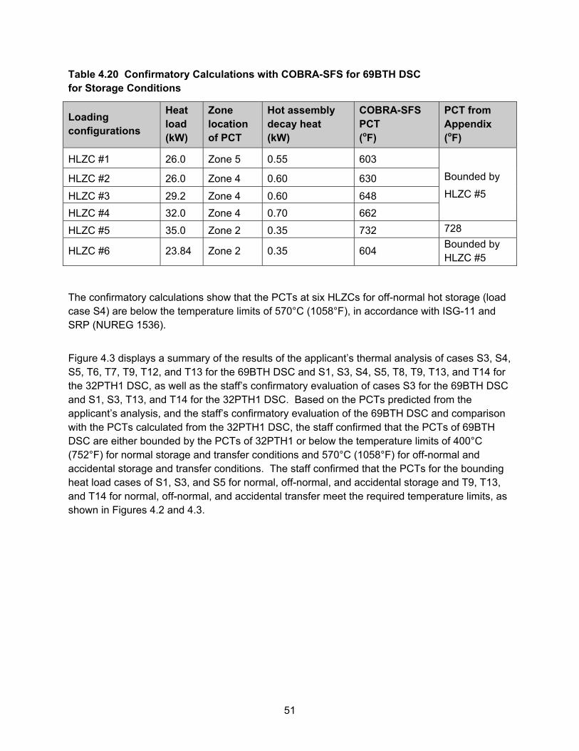
51
Table 4.20 Confirmatory Calculations with COBRA-SFS for 69BTH DSC for Storage Conditions
Loading configurations
Heat load (kW)
Zone location of PCT
Hot assembly decay heat (kW)
COBRA-SFS PCT (oF)
PCT from Appendix (oF)
HLZC #1 26.0 Zone 5 0.55 603
HLZC #2 26.0 Zone 4 0.60 630 Bounded by
HLZC #3 29.2 Zone 4 0.60 648 HLZC #5
HLZC #4 32.0 Zone 4 0.70 662
HLZC #5 35.0 Zone 2 0.35 732 728
HLZC #6 23.84 Zone 2 0.35 604 Bounded by HLZC #5
The confirmatory calculations show that the PCTs at six HLZCs for off-normal hot storage (load case S4) are below the temperature limits of 570°C (1058°F), in accordance with ISG-11 and SRP (NUREG 1536).
Figure 4.3 displays a summary of the results of the applicant’s thermal analysis of cases S3, S4, S5, T6, T7, T9, T12, and T13 for the 69BTH DSC and S1, S3, S4, S5, T8, T9, T13, and T14 for the 32PTH1 DSC, as well as the staff’s confirmatory evaluation of cases S3 for the 69BTH DSC and S1, S3, T13, and T14 for the 32PTH1 DSC. Based on the PCTs predicted from the applicant’s analysis, and the staff’s confirmatory evaluation of the 69BTH DSC and comparison with the PCTs calculated from the 32PTH1 DSC, the staff confirmed that the PCTs of 69BTH DSC are either bounded by the PCTs of 32PTH1 or below the temperature limits of 400°C (752°F) for normal storage and transfer conditions and 570°C (1058°F) for off-normal and accidental storage and transfer conditions. The staff confirmed that the PCTs for the bounding heat load cases of S1, S3, and S5 for normal, off-normal, and accidental storage and T9, T13, and T14 for normal, off-normal, and accidental transfer meet the required temperature limits, as shown in Figures 4.2 and 4.3.
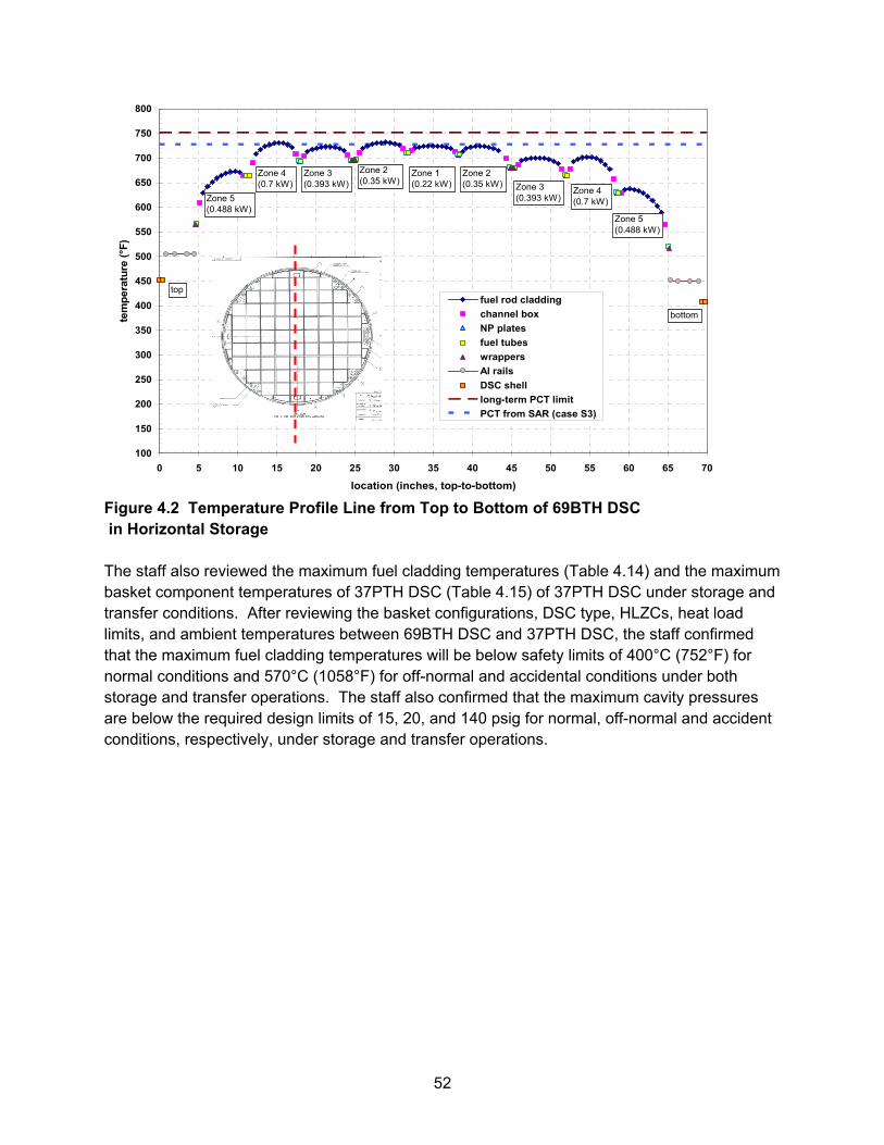
52
Figure 4.2 Temperature Profile Line from Top to Bottom of 69BTH DSC in Horizontal Storage The staff also reviewed the maximum fuel cladding temperatures (Table 4.14) and the maximum basket component temperatures of 37PTH DSC (Table 4.15) of 37PTH DSC under storage and transfer conditions. After reviewing the basket configurations, DSC type, HLZCs, heat load limits, and ambient temperatures between 69BTH DSC and 37PTH DSC, the staff confirmed that the maximum fuel cladding temperatures will be below safety limits of 400°C (752°F) for normal conditions and 570°C (1058°F) for off-normal and accidental conditions under both storage and transfer operations. The staff also confirmed that the maximum cavity pressures are below the required design limits of 15, 20, and 140 psig for normal, off-normal and accident conditions, respectively, under storage and transfer operations.
100
150
200
250
300
350
400
450
500
550
600
650
700
750
800
0 5 10 15 20 25 30 35 40 45 50 55 60 65 70
location (inches, top-to-bottom)
tem
pera
ture
(°F
)
fuel rod cladding
channel box
NP plates
fuel tubes
wrappers
Al rails
DSC shell
long-term PCT limit
PCT from SAR (case S3)
Zone 5(0.488 kW)
Zone 5(0.488 kW)
Zone 4(0.7 kW)
Zone 4(0.7 kW)
Zone 3(0.393 kW) Zone 3
(0.393 kW)
Zone 2(0.35 kW)
Zone 2(0.35 kW)
Zone 1(0.22 kW)
top
bottom
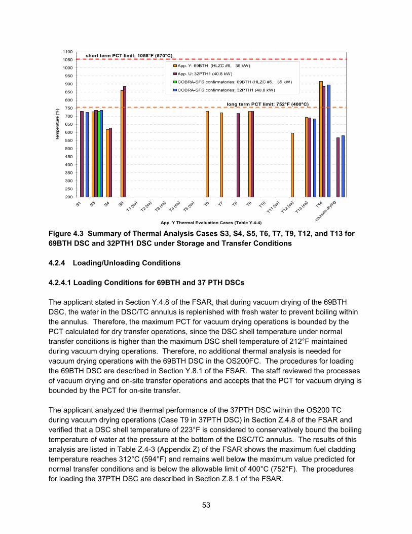
53
Figure 4.3 Summary of Thermal Analysis Cases S3, S4, S5, T6, T7, T9, T12, and T13 for 69BTH DSC and 32PTH1 DSC under Storage and Transfer Conditions 4.2.4 Loading/Unloading Conditions 4.2.4.1 Loading Conditions for 69BTH and 37 PTH DSCs The applicant stated in Section Y.4.8 of the FSAR, that during vacuum drying of the 69BTH DSC, the water in the DSC/TC annulus is replenished with fresh water to prevent boiling within the annulus. Therefore, the maximum PCT for vacuum drying operations is bounded by the PCT calculated for dry transfer operations, since the DSC shell temperature under normal transfer conditions is higher than the maximum DSC shell temperature of 212°F maintained during vacuum drying operations. Therefore, no additional thermal analysis is needed for vacuum drying operations with the 69BTH DSC in the OS200FC. The procedures for loading the 69BTH DSC are described in Section Y.8.1 of the FSAR. The staff reviewed the processes of vacuum drying and on-site transfer operations and accepts that the PCT for vacuum drying is bounded by the PCT for on-site transfer. The applicant analyzed the thermal performance of the 37PTH DSC within the OS200 TC during vacuum drying operations (Case T9 in 37PTH DSC) in Section Z.4.8 of the FSAR and verified that a DSC shell temperature of 223°F is considered to conservatively bound the boiling temperature of water at the pressure at the bottom of the DSC/TC annulus. The results of this analysis are listed in Table Z.4-3 (Appendix Z) of the FSAR shows the maximum fuel cladding temperature reaches 312°C (594°F) and remains well below the maximum value predicted for normal transfer conditions and is below the allowable limit of 400°C (752°F). The procedures for loading the 37PTH DSC are described in Section Z.8.1 of the FSAR.
200
250
300
350
400
450
500
550
600
650
700
750
800
850
900
950
1000
1050
1100
S1 S3 S4 S5
T1 (s
s)
T2 (s
s)
T3 (s
s)
T4 (s
s)
T5 (s
s) T6 T7 T8 T9 T10
T11 (ss)
T12 (ss)
T13 (ss)
T14
vacu
um drying
App. Y Thermal Evaluation Cases (Table Y.4-4)
Tem
per
ature
(°F
)
App. Y: 69BTH (HLZC #5, 35 kW)
App. U: 32PTH1 (40.8 kW)
COBRA-SFS confirmatories: 69BTH (HLZC #5, 35 kW)
COBRA-SFS confirmatories: 32PTH1 (40.8 kW)
long term PCT limit; 752°F (400°C)
short term PCT limit; 1058°F (570°C)
54
4.2.4.2 Unloading Conditions for 69BTH and 37PTH DSCs The bounding unloading operation considered is the re-flood of the DSCs with water for both the 69BTH and 37PTH DSCs. The applicant’s analysis to determine the maximum fuel cladding temperature during re-flood predicts a value that is significantly less than the value predicted for vacuum drying conditions, owing to the presence of water/steam in the canister cavity. Based on the above rationale, the applicant assumed that the maximum cladding temperature during unloading operation is bounded by the maximum fuel cladding temperature for the vacuum drying operations for the 69BTH and 37PTH DSCs. The procedures for unloading the 69BTH and 37PTH DSCs are described in Sections Y.8.2 and Z.8.2 of the FSAR, respectively. The applicant has documented procedures for controlling the flow rate of the re-flood water and monitoring the maximum internal pressure during re-flood operations, such that the internal pressure in the canister cavity does not exceed the maximum pressure of 20 psig. This applies to both the 69BTH and 37PTH DSCs under re-flooding operations, as described in Sections Y.8.2.2 and Z.8.2.2 of the FSAR, respectively. The staff reviewed the design criteria and verified that the design pressure of 140 psig is well above the specified pressure limit of 20 psig during re-flood operations, and that there is sufficient margin in the DSC internal pressure during the re-flood procedure to assure that the canister will not be over pressurized. The staff reviewed the cask loading, unloading, vacuum drying, and transfer conditions, and the heat removal capability in these operations. After referencing the fuel loading and unloading conditions included in Amendment No. 10 of the NUHOMS® system, the staff confirmed that loading/vacuum drying conditions are bounded by the transfer condition. The unloading condition is bounded by the vacuum drying operation, and therefore is also bounded by the transfer condition for both the 69BTH and 37PTH DSCs. The staff concludes that both the 69BTH and 37PTH DSCs meet the design criteria for loading and unloading conditions. 4.3 24PHB DSC for Storage of Damaged FAs The applicant provided a thermal analysis of the 24PHB DSC with damaged fuel assemblies in Section N.4.8 of the FSAR. The applicant noted that the heat load of the damaged FAs is identical to the heat load of the intact FAs in the same locations shown in Figures N.4-5 through N.4-8 of Appendix N, and the effect of the rubble on the maximum fuel cladding temperature is negligible. A similar condition was analyzed for the 61BT DSC reported in Section K.4.8.2 of the FSAR. The analysis of the 61BT DSC demonstrates that the fuel rubble has negligible impact (less than 1°F) on the maximum fuel cladding and basket component temperatures. Due to similarities between the locations of the damaged FAs in the 24PHB DSC and 61BT DSC, the applicant derived that the same conclusions remain valid for the 24PHB DSC. The staff reviewed the similarity of basket configuration and the heat load locations between 61BT DSC (Appendix K) and 24PHB DSC (Appendix N), and confirmed that the effect of
55
damaged FAs located in the four corner guide sleeves on the maximum component temperatures is not significant (less than 1°F). Therefore use of the 24PHB DSC for storage of damaged fuel assemblies is acceptable per thermal features involved. 4.4 61BTH and 24PTH DSCs for Storage of Damaged/Failed FAs
4.4.1 Storage of Damaged/Failed Fuel Assemblies (FAs) in 61BTH DSC
The applicant proposed to place damaged and failed FAs, 45 intact and 16 damaged FAs (with up to 4 Failed Fuel Cans) in the outermost fuel compartment cells which have negligible impact on intact fuel and basket components maximum temperatures when compared with the all-intact FA case for normal/off-normal conditions of storage and transfer as discussed in Section K.4.8 of the FSAR. The applicant performed thermal analysis to assess the effect of all damaged/failed FAs becoming rubble during the worst accident conditions. The staff checked Table T.4-21 in Section T.4.6.9.4 of the FSAR for the bounding transfer accident condition with loss of sun shade, neutron shield and air circulation with the 61BTH DSC with 31.2 kW heat load (HLZC #7). The staff reviewed the predicted peak cladding temperature (PCT) of 814°F for 45 intact/16 rubble FAs is lower than 824°F for 61 intact FAs, and confirmed that the PCT of the 61BTH DSC with rubble FAs remains bounded by the PCT of the 61BTH DSC with intact FAs and is below the accident PCT limit of 1058°F (Ref 1). 4.4.2 Storage of Damaged/Failed Fuel Assemblies (FAs) in 24PTH DSC The applicant proposed that the 24PTH DSC can accommodate up to 24 FAs of which up to 4 damaged FAs and/or up to 8 failed FAs may be stored at the outermost periphery cells, as shown in Figure P.2-6 (Appendix P) of the FSAR. The failed fuel assemblies are to be encapsulated in individual failed fuel cans (FFCs). The applicant stated in Section P.4.6.9 of the FSAR that since damaged and failed FAs are loaded in the outermost periphery cells, they do not affect the maximum temperature or maximum temperature gradients for normal/off-normal conditions of storage and transfer. The applicant analyzed the effect of fuel rubble because damaged and failed FAs may become rubble during accident conditions. The DSC shell temperature profile calculated for accident transfer (loss of sunshield, neutron shield and air circulation) for the 24PTH DSC with HLZC#1 (40.8 kW) and HLZC#5 (24 kW) are conservatively used for the 24PTH DSC model with damaged/ failed FAs.
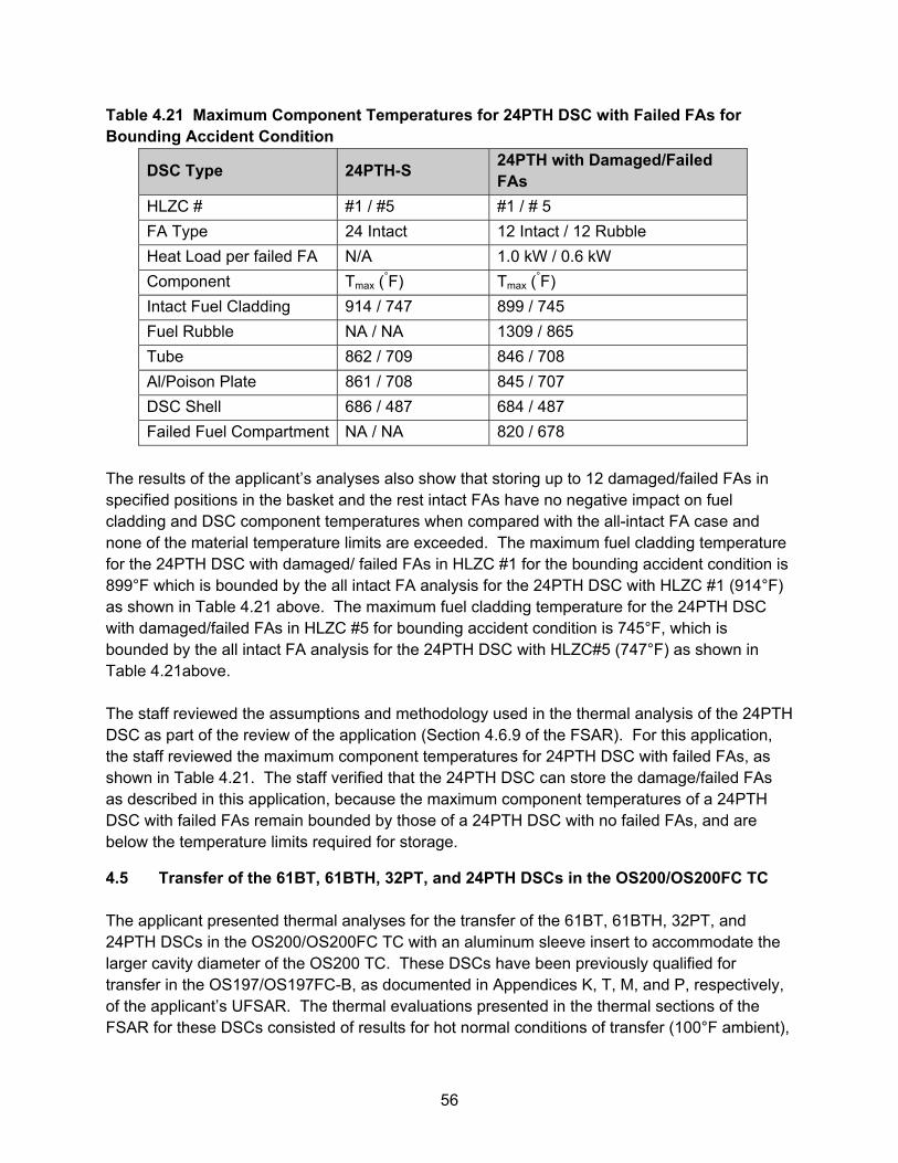
56
Table 4.21 Maximum Component Temperatures for 24PTH DSC with Failed FAs for Bounding Accident Condition
DSC Type 24PTH-S 24PTH with Damaged/Failed FAs
HLZC # #1 / #5 #1 / # 5
FA Type 24 Intact 12 Intact / 12 Rubble
Heat Load per failed FA N/A 1.0 kW / 0.6 kW
Component Tmax (°F) Tmax (
°F)
Intact Fuel Cladding 914 / 747 899 / 745
Fuel Rubble NA / NA 1309 / 865
Tube 862 / 709 846 / 708
Al/Poison Plate 861 / 708 845 / 707
DSC Shell 686 / 487 684 / 487
Failed Fuel Compartment NA / NA 820 / 678
The results of the applicant’s analyses also show that storing up to 12 damaged/failed FAs in specified positions in the basket and the rest intact FAs have no negative impact on fuel cladding and DSC component temperatures when compared with the all-intact FA case and none of the material temperature limits are exceeded. The maximum fuel cladding temperature for the 24PTH DSC with damaged/ failed FAs in HLZC #1 for the bounding accident condition is 899°F which is bounded by the all intact FA analysis for the 24PTH DSC with HLZC #1 (914°F) as shown in Table 4.21 above. The maximum fuel cladding temperature for the 24PTH DSC with damaged/failed FAs in HLZC #5 for bounding accident condition is 745°F, which is bounded by the all intact FA analysis for the 24PTH DSC with HLZC#5 (747°F) as shown in Table 4.21above. The staff reviewed the assumptions and methodology used in the thermal analysis of the 24PTH DSC as part of the review of the application (Section 4.6.9 of the FSAR). For this application, the staff reviewed the maximum component temperatures for 24PTH DSC with failed FAs, as shown in Table 4.21. The staff verified that the 24PTH DSC can store the damage/failed FAs as described in this application, because the maximum component temperatures of a 24PTH DSC with failed FAs remain bounded by those of a 24PTH DSC with no failed FAs, and are below the temperature limits required for storage.
4.5 Transfer of the 61BT, 61BTH, 32PT, and 24PTH DSCs in the OS200/OS200FC TC The applicant presented thermal analyses for the transfer of the 61BT, 61BTH, 32PT, and 24PTH DSCs in the OS200/OS200FC TC with an aluminum sleeve insert to accommodate the larger cavity diameter of the OS200 TC. These DSCs have been previously qualified for transfer in the OS197/OS197FC-B, as documented in Appendices K, T, M, and P, respectively, of the applicant’s UFSAR. The thermal evaluations presented in the thermal sections of the FSAR for these DSCs consisted of results for hot normal conditions of transfer (100°F ambient),
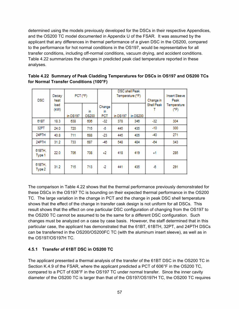
57
determined using the models previously developed for the DSCs in their respective Appendices, and the OS200 TC model documented in Appendix U of the FSAR. It was assumed by the applicant that any differences in thermal performance of a given DSC in the OS200, compared to the performance for hot normal conditions in the OS197, would be representative for all transfer conditions, including off-normal conditions, vacuum drying, and accident conditions. Table 4.22 summarizes the changes in predicted peak clad temperature reported in these analyses. Table 4.22 Summary of Peak Cladding Temperatures for DSCs in OS197 and OS200 TCs for Normal Transfer Conditions (100°F)
The comparison in Table 4.22 shows that the thermal performance previously demonstrated for these DSCs in the OS197 TC is bounding on their expected thermal performance in the OS200 TC. The large variation in the change in PCT and the change in peak DSC shell temperature shows that the effect of the change in transfer cask design is not uniform for all DSCs. This result shows that the effect on one particular DSC configuration of changing from the OS197 to the OS200 TC cannot be assumed to be the same for a different DSC configuration. Such changes must be analyzed on a case by case basis. However, the staff determined that in this particular case, the applicant has demonstrated that the 61BT, 61BTH, 32PT, and 24PTH DSCs can be transferred in the OS200/OS200FC TC (with the aluminum insert sleeve), as well as in the OS197/OS197H TC. 4.5.1 Transfer of 61BT DSC in OS200 TC The applicant presented a thermal analysis of the transfer of the 61BT DSC in the OS200 TC in Section K.4.9 of the FSAR, where the applicant predicted a PCT of 606°F in the OS200 TC, compared to a PCT of 638°F in the OS197 TC under normal transfer. Since the inner cavity diameter of the OS200 TC is larger than that of the OS197/OS197H TC, the OS200 TC requires
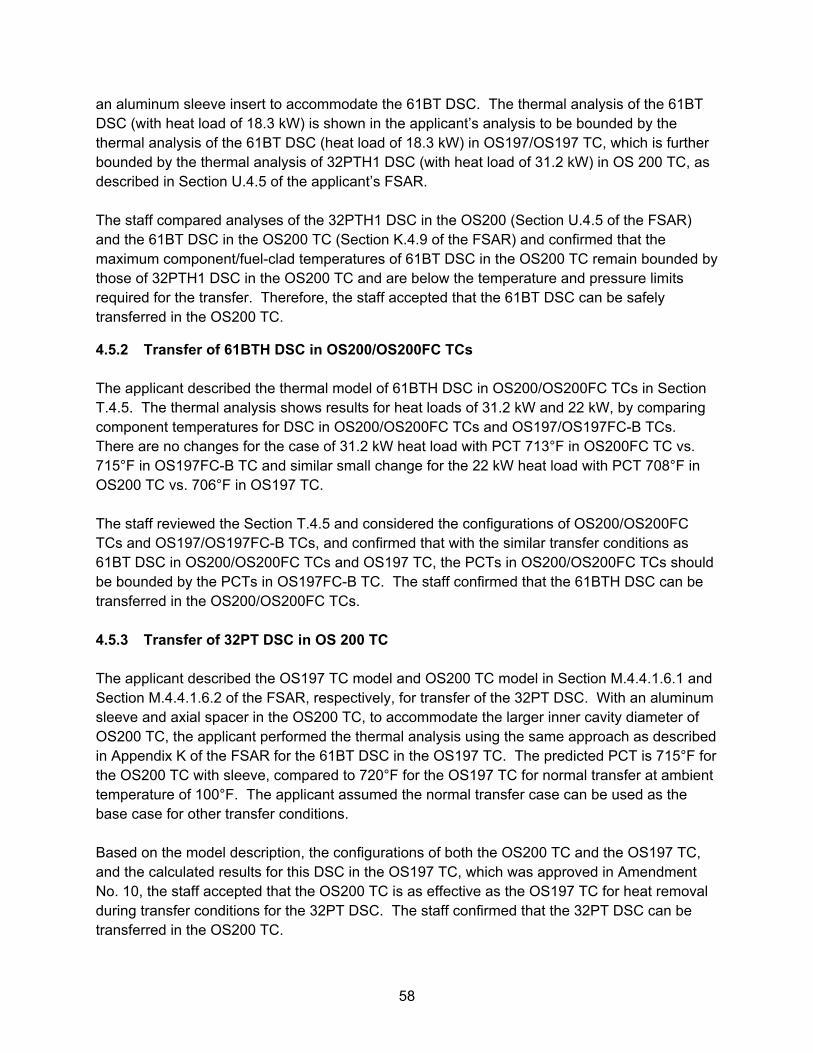
58
an aluminum sleeve insert to accommodate the 61BT DSC. The thermal analysis of the 61BT DSC (with heat load of 18.3 kW) is shown in the applicant’s analysis to be bounded by the thermal analysis of the 61BT DSC (heat load of 18.3 kW) in OS197/OS197 TC, which is further bounded by the thermal analysis of 32PTH1 DSC (with heat load of 31.2 kW) in OS 200 TC, as described in Section U.4.5 of the applicant’s FSAR. The staff compared analyses of the 32PTH1 DSC in the OS200 (Section U.4.5 of the FSAR) and the 61BT DSC in the OS200 TC (Section K.4.9 of the FSAR) and confirmed that the maximum component/fuel-clad temperatures of 61BT DSC in the OS200 TC remain bounded by those of 32PTH1 DSC in the OS200 TC and are below the temperature and pressure limits required for the transfer. Therefore, the staff accepted that the 61BT DSC can be safely transferred in the OS200 TC.
4.5.2 Transfer of 61BTH DSC in OS200/OS200FC TCs The applicant described the thermal model of 61BTH DSC in OS200/OS200FC TCs in Section T.4.5. The thermal analysis shows results for heat loads of 31.2 kW and 22 kW, by comparing component temperatures for DSC in OS200/OS200FC TCs and OS197/OS197FC-B TCs. There are no changes for the case of 31.2 kW heat load with PCT 713°F in OS200FC TC vs. 715°F in OS197FC-B TC and similar small change for the 22 kW heat load with PCT 708°F in OS200 TC vs. 706°F in OS197 TC. The staff reviewed the Section T.4.5 and considered the configurations of OS200/OS200FC TCs and OS197/OS197FC-B TCs, and confirmed that with the similar transfer conditions as 61BT DSC in OS200/OS200FC TCs and OS197 TC, the PCTs in OS200/OS200FC TCs should be bounded by the PCTs in OS197FC-B TC. The staff confirmed that the 61BTH DSC can be transferred in the OS200/OS200FC TCs. 4.5.3 Transfer of 32PT DSC in OS 200 TC The applicant described the OS197 TC model and OS200 TC model in Section M.4.4.1.6.1 and Section M.4.4.1.6.2 of the FSAR, respectively, for transfer of the 32PT DSC. With an aluminum sleeve and axial spacer in the OS200 TC, to accommodate the larger inner cavity diameter of OS200 TC, the applicant performed the thermal analysis using the same approach as described in Appendix K of the FSAR for the 61BT DSC in the OS197 TC. The predicted PCT is 715°F for the OS200 TC with sleeve, compared to 720°F for the OS197 TC for normal transfer at ambient temperature of 100°F. The applicant assumed the normal transfer case can be used as the base case for other transfer conditions. Based on the model description, the configurations of both the OS200 TC and the OS197 TC, and the calculated results for this DSC in the OS197 TC, which was approved in Amendment No. 10, the staff accepted that the OS200 TC is as effective as the OS197 TC for heat removal during transfer conditions for the 32PT DSC. The staff confirmed that the 32PT DSC can be transferred in the OS200 TC.
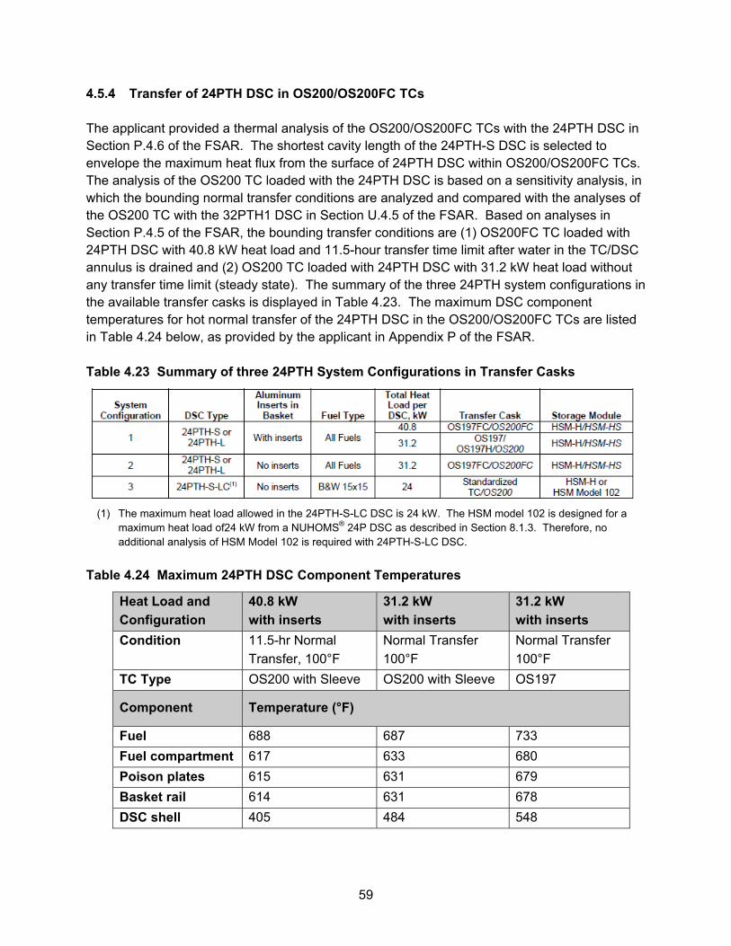
59
4.5.4 Transfer of 24PTH DSC in OS200/OS200FC TCs The applicant provided a thermal analysis of the OS200/OS200FC TCs with the 24PTH DSC in Section P.4.6 of the FSAR. The shortest cavity length of the 24PTH-S DSC is selected to envelope the maximum heat flux from the surface of 24PTH DSC within OS200/OS200FC TCs. The analysis of the OS200 TC loaded with the 24PTH DSC is based on a sensitivity analysis, in which the bounding normal transfer conditions are analyzed and compared with the analyses of the OS200 TC with the 32PTH1 DSC in Section U.4.5 of the FSAR. Based on analyses in Section P.4.5 of the FSAR, the bounding transfer conditions are (1) OS200FC TC loaded with 24PTH DSC with 40.8 kW heat load and 11.5-hour transfer time limit after water in the TC/DSC annulus is drained and (2) OS200 TC loaded with 24PTH DSC with 31.2 kW heat load without any transfer time limit (steady state). The summary of the three 24PTH system configurations in the available transfer casks is displayed in Table 4.23. The maximum DSC component temperatures for hot normal transfer of the 24PTH DSC in the OS200/OS200FC TCs are listed in Table 4.24 below, as provided by the applicant in Appendix P of the FSAR. Table 4.23 Summary of three 24PTH System Configurations in Transfer Casks
(1) The maximum heat load allowed in the 24PTH-S-LC DSC is 24 kW. The HSM model 102 is designed for a
maximum heat load of24 kW from a NUHOMS® 24P DSC as described in Section 8.1.3. Therefore, no additional analysis of HSM Model 102 is required with 24PTH-S-LC DSC.
Table 4.24 Maximum 24PTH DSC Component Temperatures
Heat Load and
Configuration
40.8 kW
with inserts
31.2 kW
with inserts
31.2 kW
with inserts
Condition 11.5-hr Normal
Transfer, 100°F
Normal Transfer
100°F
Normal Transfer
100°F
TC Type OS200 with Sleeve OS200 with Sleeve OS197
Component Temperature (°F)
Fuel 688 687 733
Fuel compartment 617 633 680
Poison plates 615 631 679
Basket rail 614 631 678
DSC shell 405 484 548
60
The staff reviewed the applicant’s results, as summarized in Table 4.24, above and compared with the maximum OS200 TC component temperatures resulting from the above conditions to the values resulting from analysis of the 24PTH DSC in the OS197 TC which was previously approved in Amendment No. 10. The staff confirmed that the OS200 TC can be used to transfer the 24PTH DSC because the maximum OS200 TC component temperatures remain bounded by those of OS197 TC and are below the temperature limits required for transfer. 4.6 32PT DSC for Incorporation of High Burn-Up FAs The applicant proposed to incorporate high burn-up FAs (55 GWd/MTU) in 32PT DSC and performed the thermal analyses in Section M.4.4 of the FSAR. The staff reviewed these analyses and verified that the maximum DSC cavity internal pressures are below the design pressures of 15.0, 30.0, and 125 psig under normal, off-normal, and accident conditions, respectively, for high burn-up FAs (55 GWd/MTU). The average helium temperatures of 545°F and 703°F are also below the corresponding safety limits of 400°C (752°F) for normal storage/transfer conditions and 570°C (1058°F) for off-normal and accident storage/transfer conditions (Ref. 1). The staff accepts that the incorporation of high burn-up FAs (55 GWd/MTU) as contents for the 32PT DSC does not cause a significant risk in regards to the thermal performance of the DSC. 4.7 Use of MMCs as Neutron Absorber Material in 61BTH Type 1 and Type 2 DSCs for Higher Heat Loads The applicant proposed to extend use of MMCs as a neutron absorber material in the 61BTH DSCs for higher heat loads (22.0 kW for Type 1 and 31.2 kW for Type 2). It can be an MMC single piece or MMC paired with aluminum. The MMC is a composite of aluminum alloy mixed with boron carbide particles. The thermal conductivity of the MMC is dependent on the amount of B4C put into the composite and is likely to slowly rise with increasing temperature. The applicant listed the thermal conductivity of MMCs in Appendix T.4.3 of the FSAR. The thermal conductivity of the MMC may decrease below the values specified in Appendix T.4.3 of the FSAR at elevated temperatures. The applicant performed a sensitivity analysis (Ref. 3) to evaluate the effect of decreasing the MMC poison plate thermal conductivity on the peak cladding temperature (PCT) for the 61BTH DSC (Table 4.25 below).
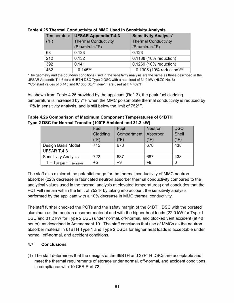
61
Table 4.25 Thermal Conductivity of MMC Used in Sensitivity Analysis Temperature(°F)
UFSAR Appendix T.4.3 Thermal Conductivity (Btu/min-in-°F)
Sensitivity Analysis* Thermal Conductivity (Btu/min-in-°F)
68 0.123 0.123 212 0.132 0.1188 (10% reduction) 392 0.141 0.1269 (10% reduction) 482 0.145** 0.1305 (10% reduction)**
*The geometry and the boundary conditions used in the sensitivity analysis are the same as those described in the UFSAR Appendix T.4.6 for a 61BTH DSC Type 2 DSC with a heat load of 31.2 kW (HLZC No. 6) **Constant values of 0.145 and 0.1305 Btu/min-in-°F are used at T > 482°F
As shown from Table 4.26 provided by the applicant (Ref. 3), the peak fuel cladding temperature is increased by 7°F when the MMC poison plate thermal conductivity is reduced by 10% in sensitivity analysis, and is still below the limit of 752°F. Table 4.26 Comparison of Maximum Component Temperatures of 61BTH Type 2 DSC for Normal Transfer (100°F Ambient and 31.2 kW)
Fuel Cladding (°F)
Fuel Compartment(°F)
Neutron Absorber (°F)
DSC Shell (°F)
Design Basis Model UFSAR T.4.3
715 678 678 438
Sensitivity Analysis 722 687 687 438 �T = TUFSAR - TSensitivity +5 +9 +9 0
The staff also explored the potential range for the thermal conductivity of MMC neutron absorber (22% decrease in fabricated neutron absorber thermal conductivity compared to the analytical values used in the thermal analysis at elevated temperatures) and concludes that the PCT will remain within the limit of 752°F by taking into account the sensitivity analysis performed by the applicant with a 10% decrease in MMC thermal conductivity. The staff further checked the PCTs and the safety margin of the 61BTH DSC with the borated aluminum as the neutron absorber material and with the higher heat loads (22.0 kW for Type 1 DSC and 31.2 kW for Type 2 DSC) under normal, off-normal, and blocked vent accident (at 40 hours), as described in Amendment 10. The staff concludes that use of MMCs as the neutron absorber material in 61BTH Type 1 and Type 2 DSCs for higher heat loads is acceptable under normal, off-normal, and accident conditions.
4.7 Conclusions (1) The staff determines that the designs of the 69BTH and 37PTH DSCs are acceptable and
meet the thermal requirements of storage under normal, off-normal, and accident conditions, in compliance with 10 CFR Part 72.
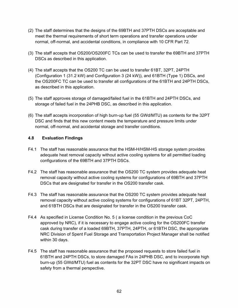
62
(2) The staff determines that the designs of the 69BTH and 37PTH DSCs are acceptable and meet the thermal requirements of short term operations and transfer operations under normal, off-normal, and accidental conditions, in compliance with 10 CFR Part 72.
(3) The staff accepts that OS200/OS200FC TCs can be used to transfer the 69BTH and 37PTH
DSCs as described in this application. (4) The staff accepts that the OS200 TC can be used to transfer 61BT, 32PT, 24PTH
(Configuration 1 (31.2 kW) and Configuration 3 (24 kW)), and 61BTH (Type 1) DSCs, and the OS200FC TC can be used to transfer all configurations of the 61BTH and 24PTH DSCs, as described in this application.
(5) The staff approves storage of damaged/failed fuel in the 61BTH and 24PTH DSCs, and
storage of failed fuel in the 24PHB DSC, as described in this application. (6) The staff accepts incorporation of high burn-up fuel (55 GWd/MTU) as contents for the 32PT
DSC and finds that this new content meets the temperature and pressure limits under normal, off-normal, and accidental storage and transfer conditions.
4.8 Evaluation Findings F4.1 The staff has reasonable assurance that the HSM-H/HSM-HS storage system provides
adequate heat removal capacity without active cooling systems for all permitted loading configurations of the 69BTH and 37PTH DSCs.
F4.2 The staff has reasonable assurance that the OS200 TC system provides adequate heat
removal capacity without active cooling systems for configurations of 69BTH and 37PTH DSCs that are designated for transfer in the OS200 transfer cask.
F4.3 The staff has reasonable assurance that the OS200 TC system provides adequate heat
removal capacity without active cooling systems for configurations of 61BT 32PT, 24PTH, and 61BTH DSCs that are designated for transfer in the OS200 transfer cask.
F4.4 As specified in License Condition No. 5 ( a license condition in the previous CoC
approved by NRC), if it is necessary to engage active cooling for the OS200FC transfer cask during transfer of a loaded 69BTH, 37PTH, 24PTH, or 61BTH DSC, the appropriate NRC Division of Spent Fuel Storage and Transportation Project Manager shall be notified within 30 days.
F4.5 The staff has reasonable assurance that the proposed requests to store failed fuel in
61BTH and 24PTH DSCs, to store damaged FAs in 24PHB DSC, and to incorporate high burn-up (55 GWd/MTU) fuel as contents for the 32PT DSC have no significant impacts on safety from a thermal perspective.
63
F4.6 As directed in Technical Specification 5.2.6, and required as a license condition for other types of DSCs in the previous CoC approved by NRC, monitoring of the hydrogen concentration before and during welding operations is required to ensure that the hydrogen concentration does not exceed a safety limit of 2.4% (or a flammability limit of 4.0%). If the hydrogen concentration exceeds 2.4%, the welding operations will be stopped and the DSC cavity purged with helium to reduce the hydrogen concentration safely below the 2.4% limit.
F4.7 The staff has reasonable assurance that spent fuel cladding will be protected against
degradation that leads to gross ruptures by maintaining the clad temperature below maximum allowable limits and by providing an inert environment in the cask cavity under normal, off-normal, and accidental storage conditions for the DSCs reviewed for this application.
F4.8 The staff finds that the thermal design of the 69BTH and 37PTH DSC systems are in
compliance with 10 CFR Part 72, and that the applicable design and acceptance criteria have been satisfied; The evaluation of the thermal design provides reasonable assurance that the system will allow safe storage of spent fuel for a certified life of 40 years. This finding is reached on the basis of a review that considered the regulation itself, appropriate regulatory guides, applicable codes and standards, and accepted engineering practices.
4.9 References
1. U.S. Nuclear Regulatory Commission, NUREG-1536, “Standard Review Plan for Dry
Cask Storage Systems,” 2010. 2. U.S. Nuclear Regulatory Commission Bulletin 96-04. “Chemical, Galvanic or Other
Reactions in Spent Fuel Storage and Transportation Casks,” July 5, 1996.
64
5.0 CONFINEMENT EVALUATION The confinement review of the NUHOMS® 69BTH and NUHOMS® 37PTH systems ensures that radiological releases to the environment will be within the limits established by the regulations and that the spent fuel cladding and fuel assemblies will be sufficiently protected during storage against degradation that might otherwise lead to gross ruptures. The staff reviewed the information provided in Sections Y.7 and Z.7 of the FSAR to determine whether the NUHOMS® 69BTH and NUHOMS® 37PTH systems fulfill the applicable regulatory requirements in Part 72 and the acceptance criteria listed in Section 5.4 of NUREG 1536, “Standard Review Plan for Dry Storage Systems at a General License Facility” (Ref. 1).
5.1 Confinement Design Characteristics A description of the confinement boundary for the NUHOMS® 69BTH and NUHOMS® 37PTH systems is provided in Sections Y.3.1.2.1, Y.7.1, Z.3.1.2.1 and Z.7.1 of the Final Safety Analysis Report (FSAR). The confinement boundary for both systems consists of the dry shielded canister (DSC) shell, the inner bottom cover plate, the inner top cover plate, the siphon/vent block, and the siphon/vent port cover plate, and the associated welds. Figures Y.3.1-1 and Z.3.1-1 of the FSAR provide a representation of the confinement boundary and redundant sealing. All confinement boundary components are important to safety (ITS) category A in accordance with NUREG/CR-6407, “Classification of Transportation Packaging and Dry Spent Fuel Storage System Components According to Importance to Safety,” (Ref. 2). An outer top cover plate is welded into place to provide redundant sealing, satisfying the requirements of 10 CFR 72.236(e). The confinement boundary contains two penetrations, the vent and siphon ports, for draining, vacuum drying, and backfilling the DSC cavity. The vent and siphon ports are located in the siphon/vent block and are closed with welded cover plates. An outer top cover plate is installed with a single penetration test port to leak test the closure welds. This test port is closed with a test port plug and seal, and welded in place after testing to complete the redundant sealing of the confinement boundary. The applicant has classified the test port plug as ITS Category B, although NUREG/CR-6407 recommends that it be ITS Category A. Staff determined that because the failure of the welded test port plug would have to be in conjunction with the failure of an additional item in order to result in an unsafe condition, and because the test port plug does not provide a shielding function during transfer or storage, the ITS Category B classification for the test port plug is justified for this application, according to the description of Classification Categories A, B, and C in Table 2 of NUREG/CR 6407. The welds forming the confinement boundary for the NUHOMS® 69BTH and NUHOMS® 37PTH systems are described in Sections Y.3.1.2.1, Y.7.1.3, Z.3.1.2.1 and Z.7.1.3 of the FSAR. These welds are performed and inspected in accordance to the ASME Code as described in Sections Y.7.1.3 and Z.7.1.3 of the FSAR. There are no bolted closures or mechanical seals providing closure of the confinement boundary.
65
The applicant states that the DSC is designed, fabricated, and tested in accordance with the applicable requirements of the ASME Boiler and Pressure Vessel Code, Division 1, Section III, Subsection NB (Ref. 4) to the maximum extent applicable. Alternatives to the ASME Code are detailed in Sections Y.3.1.2.3 and Z.3.1.2.3 of the FSAR. The DSC shell, inner bottom plate and associated welds are pressure tested in accordance with the ASME code, Section III, NB-6300 and leak tested to meet the ANSI N14.5 leaktight criteria during fabrication. After loading the DSC, the inner top cover plate and the vent and siphon port cover plates are welded into place and are tested to meet the leaktight criteria of ANSI N14.5 (Ref. 5) using the test port in the outer top cover plate as described in Sections Y.7.1.1 and Z.7.1.1 of the FSAR. The staff reviewed the proposed procedures for drying and evacuating the cask interior during loading operations to ensure that the design is acceptable for the pressures and temperatures that may be experienced during storage. The procedure employed is referenced in Limiting Condition for Operation (LCO) 3.1.1 of the Technical Specifications, and indicates a 30 minute vacuum drying at a vacuum pressure of 3 mm Hg or below. The staff finds this vacuum drying procedure acceptable to provide reasonable assurance that the moisture content in the NUHOMS® 69BTH and NUHOMS® 37PTH systems will be acceptably low during their service lives and satisfies the regulatory requirements of 10 CFR 72.122(h)(1). The applicant states that the NUHOMS® 69BTH and NUHOMS® 37PTH systems are designed to be leaktight and are tested to a leak rate of 1x10⁻⁷
ref cm3/s, as defined in ANSI N14.5-1997. This testing confirms that the amount of helium lost from the DSC over the approved storage period is negligible. Thus, the staff concludes an adequate amount of helium will remain in the systems’ canisters to maintain an inert atmosphere and to support heat transfer during the storage period.
5.2 Confinement Monitoring Capability Section 5.4.2 of NUREG 1536 states that, for redundant seal welded closures, continuous monitoring of the closure is not required. The application provides that periodic surveillance and monitoring of the storage module thermal performance, as well as the licensee’s use of radiation monitors are adequate to ensure the continued effectiveness of the confinement boundary. The staff finds this adequate to enable the licensee to detect any closure degradation and take appropriate corrective actions to maintain safe storage conditions.
5.3 Nuclides with Potential Release Sections Y.7.2.1 and Z.7.2.1 of the FSAR state that, since the NUHOMS® 69BTH and NUHOMS® 37PTH systems are designed, fabricated, and tested to meet the leaktight criteria of ANSI N14.5-1997, there is no contribution to radiological consequences due to a potential release of canister contents. The staff reviewed this information and determined that it was acceptable because of the ANSI N14.5 definition of leaktight and the leakage rate testing that will be performed.
66
5.4 Confinement Analysis The confinement boundaries of the NUHOMS® 69BTH and NUHOMS® 37PTH systems are designed, fabricated and tested to meet the leaktight criteria of ANSI N14.5-1997. Therefore, the applicant concludes that there is no release of radioactive material under normal and off-normal conditions of storage, as documented in Sections Y.3.7.8 and Z.3.7.7 of the FSAR. The staff reviewed this information and determined that it was acceptable because the analysis of the NUHOMS® 69BTH and NUHOMS® 37PTH systems meet the applicable stress limits.
5.4.1 Normal Conditions For normal conditions of storage, the maximum internal pressure for the NUHOMS® 69BTH DSC is 8.2 psig as reported in Appendix Y, Table Y.4-13 of the FSAR. The maximum internal pressure for the NUHOMS® 37PTH DSC for normal conditions is 8.6 psig as reported in Appendix Z, Table Z.4-7 of the FSAR. Both pressures remain below their respective design pressures.
5.4.2 Off-Normal Conditions For off-normal conditions of storage the maximum internal pressure for the NUHOMS® 69BTH DSC is 15.9 psig as reported in Appendix Y, Table Y.4-13 of the FSAR. The maximum internal pressure for the NUHOMS® 37PTH DSC for off-normal conditions is 17.1 psig as reported in Appendix Z, Table Z.4-7 of the FSAR. Both pressures remain below their respective design pressures.
5.4.3 Design-Basis Accident Condition For accident conditions of storage the maximum internal pressure for the NUHOMS® 69BTH DSC is 105.6 psig as reported in Appendix Y, Table Y.4-13 of the FSAR. The maximum internal pressure for the NUHOMS® 37PTH DSC for accident conditions is 117.3 psig as reported in Appendix Z, Table Z.4-7 of the FSAR. Both pressures remain below their respective design pressures. The staff concludes that the analysis presented in Section Y.3.7.9 and Section Z.3.7.8 of the FSAR demonstrates that the confinement boundary (pressure boundary) is not compromised following hypothetical accident conditions. Therefore, there is no release of radioactive material under hypothetical accident conditions of storage.
5.5 Supporting Information Supporting information or documentation can be found in Sections Y.3.1.2.1 and Z.3.1.2.1 of the FSAR, and includes drawings of the NUHOMS® 69BTH and NUHOMS® 37PTH confinement boundary and applicable pages from referenced documents.
67
5.6 Evaluation Findings F5.1 Sections Y.3.1.2.1, Y.7.1, Z.3.1.2.1 and Z.7.1 of the FSAR describe confinement
structures, systems, and components important to safety in sufficient detail to permit evaluation of their effectiveness. F5.2 The design of the NUHOMS® 69BTH and NUHOMS® 37PTH DSC adequately protects the spent fuel cladding against degradation that might otherwise lead to gross ruptures. Chapter 4, “Thermal Evaluation” of the SER discusses the relevant temperature
considerations. F5.3 The design of the NUHOMS® 69BTH and NUHOMS® 37PTH DSC provides redundant sealing of the confinement system closure joints by using dual welds on the canister lid
and closure as required by 10 CFR 72.236(e). F5.4 The NUHOMS® 69BTH and NUHOMS® 37PTH DSCs have no bolted closures or mechanical seals. The confinement boundary contains no external penetrations for pressure monitoring or overpressure protection. Since the DSC for the NUHOMS®
69BTH and NUHOMS® 37PTH uses an entirely welded redundant closure system, no direct monitoring of the closure is required.
F5.5 The confinement system is leaktight for normal conditions and anticipated occurrences,
thus the confinement system will reasonably maintain confinement of radioactive material. Chapter 11, “Radiation Protection Evaluation” of the SER shows that the NUHOMS® 69BTH and NUHOMS® 37PTH DSCs satisfy the regulatory requirements of 10 CFR 72.104(a) and 10 CFR 72.106(b).
F5.6 The confinement system has been evaluated by analysis. Based on successful completion of specified leakage tests and examination procedures, the staff concludes that the confinement system will reasonably maintain confinement of radioactive material under normal, off-normal, and credible accident conditions. F5.7 The staff concludes that the design of the confinement systems of the NUHOMS® 69BTH and NUHOMS® 37PTH DSC is in compliance with 10 CFR Part 72 and that the applicable design and acceptance criteria have been satisfied. The evaluation of the confinement system design provides reasonable assurance that the NUHOMS® 69BTH and NUHOMS® 37PTH will allow safe storage of spent fuel. This finding is reached on
the basis of a review that considered the regulation itself, appropriate regulatory guides, applicable codes and standards, the applicant’s analyses, and acceptable engineering
practices.
5.7 References
1. U.S. NRC, NUREG-1536, "Standard Review Plan for Spent Fuel Dry Storage Systems at a General License Facility," Revision 1, July 2010
68
2. NUREG/CR-6407, “Classification of Transportation Packaging and Dry Spent Fuel Storage System Components According to Importance to Safety,” 1996
3. U.S. Code of Federal Regulations, “Licensing Requirements for the Independent Storage of Spent Nuclear Fuel, High-Level Radioactive Waste, and Reactor-Related Greater Than Class C Waste,” Part 72, Title 10, “Energy.”
4. ASME “Boiler and Pressure Vessel Code,” Section III, Division 1, Subsections NB and NC, Class 1 Components, Rules for Construction of Nuclear Facility Components, American Society of Mechanical Engineers (ASME), 2007
5. ANSI N14.5-1997, “Radioactive Materials – Leakage Tests on Packages for Shipment,” American National Standards Institute, 1998
69
6.0 SHIELDING EVALUATION The shielding review evaluates the ability of the proposed shielding features to provide adequate protection against direct radiation from the dry storage system contents. The shielding features must limit the dose to the operating staff and members of the public so that the dose remains within regulatory requirements during normal operating, off-normal, and design-basis accident conditions. The review seeks to ensure that the shielding design is sufficient and reasonably capable of meeting the operational dose requirements of 10 CFR 72.104 and 72.106 in accordance with 10 CFR 72.236(d). The staff reviewed the shielding analysis for the NUHOMS® 69BTH and the NUHOMS® 37PTH DSCs to determine if these components provide adequate protection against direct radiation from the canister contents when used with the Standardized NUHOMS® System as well as:
• evaluation of the 24PHB DSC to accommodate control components other than BPRAs, and allow for storage of damaged fuel assemblies,
• evaluation of the 32PT DSC for incorporation of high burn-up fuel assemblies with and without control components (CCs),
• evaluation of the 61 BTH and 24PTH DSCs for storage of failed fuel, • evaluation of DSCs for the addition of BLEU fuel assemblies as authorized contents, • evaluation of the OS200 TC (transfer cask) to allow transfer of the 61 BT, 32PT, 24PTH,
and 61BTH DSCs, • evaluation of the dose reduction hardware for the HSM-H/HSM-HS to achieve enhanced
shielding performance, and, • evaluation of the additional changes for consistency within the TS and the FSAR.
The regulatory requirements for providing adequate radiation protection to licensee personnel and members of the public include 10 CFR Part 20 (Ref. 1), 10 CFR 72.104(a) (Ref. 2), 10 CFR 72.106(b), 10 CFR 72.212(b), and 10 CFR 72.236(d). Because 10 CFR Part 72 dose requirements for members of the public include direct radiation, effluent releases, and radiation from other uranium fuel-cycle operations, an overall assessment of compliance with these regulatory limits is evaluated in Section 11 of this SER. This application was also reviewed to determine whether the 32PT, 24PTH, 61BTH, and 32PTH1 DSCs fulfill the acceptance criteria listed in Section 6 of NUREG-1536, “Standard Review Plan for Dry Cask Storage Systems” (Ref. 3).
6.1 Shielding Design Features and Design Criteria The applicant requested addition of two new 69BTH and 37PTH DSCs to the Standardized NUHOMS® System. The 69BTH DSC and 37PTH are described in Appendix Y and Z of the FSAR respectively. The NUHOMS® 69BTH DSC will be used to store up to 69 BWR fuel assemblies (including reconstituted) or up to 24 damaged and balance intact BWR fuel assemblies with uranium dioxide (UO2). These configurations are described in Figures Y.2-1, through Y.2-6 of the FSAR Appendix Y. The location of damaged fuel assemblies inside the 69BTH DSC is described in
70
Figure Y2.7. Table Y.2-2 of FSAR Appendix Y lists the BWR fuel assembly design characteristics for the NUHOMS® 69BTH DSC. The heat loads for this DSC range from 24.0 kW to the maximum of 35 kW. The NUHOMS® 37PTH DSC will be used to store up to 37 PWR fuel assemblies and up to 4 damaged and balance intact fuel assemblies, or BLEU fuel, in one of two alternative design configurations (short and medium length), in one of three fuel configurations. These configurations are described in Figures Z.2-1 through Z.2-3 of the FSAR Appendix Z. Table Z.2-3 of FSAR Appendix Z lists the PWR fuel assembly design characteristics for the NUHOMS® 37PTH DSC. The maximum heat load for the 37PTH DSC is 30 kW. The applicant requested evaluation of the 24PHB DSC to accommodate control components other than BPRAs; allow for damaged fuel assemblies with up to four missing fuel rods, and allow non-zircaloy cladding/guide tubes The applicant requested evaluation of the 32PT DSC for incorporation of high burn-up fuel assemblies with and without control components (CCs) and to include two additional basket types based on the 24-poison plate configuration and Poison Rod Assemblies (PRA) design. The NUHOMS® 32PT DSCs are designed to safely store 32 intact standard PWR fuel assemblies with or without CCs. The applicant requested shielding evaluation of the dose reduction hardware for the HSM-H/HSM-HS to achieve enhanced shielding performance. The applicant also requested the evaluation of the OS200 Transfer Cask (TC) to allow transfer of the 61BT, 32PT, 24PTH, 37PTH and 61BTH DSCs. The OS200 is currently approved for on-site transfer operations of the 32PTH1 DSC as documented in the FSAR Appendix U.
6.1.1 Shielding Design Features
6.1.1.1 NUHOMS® 69BTH DSC The NUHOMS® 69BTH DSC, when used with the Standardized NUHOMS® System provides both gamma and neutron shielding during loading/unloading, transfer, and storage operations. Each 69BTH DSC consists of a DSC shell assembly (cylindrical shell, canister bottom and top cover plates and shield plugs or shield plug assemblies) and a basket assembly. The NUHOMS® 69BTH DSC is very similar to the NUHOMS® 61BTH Type 2 DSC analyzed in Appendix T of the FSAR, except for an outer diameter increase from 67.25” to 69.75” for additional capacity. The 69BTH DSC allows for an increase in heat load from 31.2 kW to 35 kW, and maximum burn-up of 62,000 MWd/MTU. The 69BTH DSC is designed to store up to 69 intact (including reconstituted) or up to 24 damaged and balance intact BWR fuel assemblies with uranium dioxide (UO2). The fuel to be stored is limited to a maximum initial lattice average initial enrichment of 5.0 wt%, a maximum assembly average burn-up of 62 GWd/MTU, and a minimum cooling time of 3.0 years.
71
The 5.0 wt% U-235 maximum lattice average enrichment is retained from the 61BTH. Staff evaluated the information provided in the application, and has confirmed that reconstituted assemblies containing up to 10 replacement stainless steel rods per assembly (or unlimited lower enrichment UO2 rods instead of zircaloy clad enriched UO2 rods) are acceptable for storage in 69BTH DSC as intact fuel assemblies with a slightly longer cooling time than that required for a standard assembly. The maximum number of reconstituted fuel assemblies per DSC is four with stainless steel rods or 69 with UO2 rods. The 69BTH DSC is transferred to HSM-H or the HSM-HS module for storage using either the OS200 or the OS200FC TC. The staff evaluated the NUHOMS® 69BTH DSC shielding design features and found it acceptable because the applicant’s analysis provides reasonable assurance that the shielding design of the NUHOMS® 69BTH DSC, when used with the Standardized NUHOMS® System, meets the regulatory requirements of 10 CFR Part 20, 10 CFR 72.104(a), and 10 CFR 72.106(b).
6.1.1.2 NUHOMS® 37PTH DSC According to Section Z.5 of the FSAR, the NUHOMS® 37PTH DSC, when used with the Standardized NUHOMS® System provides both gamma and neutron shielding during loading/unloading, transfer, and storage operations. The NUHOMS® 37PTH system is a modular canister based spent fuel storage and transfer system. The NUHOMS® 37PTH DSC has two alternate configurations depending on the canister length: a short length (182.00 inches) DSC designated as the 37PTH-S DSC, and a medium length (189.25 inches) DSC designated as the 37PTH-M DSC. The 37PTH DSC is designed for a maximum heat load of 30.0 kW. The 37PTH DSC basket is provided with solid aluminum rails for support and to facilitate heat transfer. The design requirements for the 37PTH DSC are described in Section Z.2 of the FSAR. It is designed to accommodate up to 37 intact (or up to 4 damaged and balance intact) PWR fuel assemblies with or without control components (CCs), with characteristics as described in Appendix Z. of the FSAR. The CCs include burnable poison rod assemblies (BPRAs), control rod assemblies (CRAs), rod cluster control assemblies (RCCAs), thimble plug assemblies (TPAs), axial power shaping rod assemblies (APSRAs), orifice rod assemblies (ORAs), vibration suppression inserts (VSIs), neutron sources, and neutron source assemblies (NSAs). Section Z.5 of the FSAR states that the NUHOMS® 37PTH DSC is also designed to store fuel assemblies containing Blended Low Enriched Uranium (BLEU) fuel material. The fuel pellets containing BLEU fuel material have 80 ppm of cobalt-59 impurity compared to 2 ppm in typical UO2 fuel pellets. The cobalt impurity only affects the gamma source terms for fuel assemblies located in the DSC periphery and the decay heat and the neutron source terms are not affected. The Fuel Qualification Tables (1-8a through 1-8e) for the 37PTH DSC in the Technical Specifications include a note that requires additional cooling time of three years for assemblies containing BLEU fuel to ensure that the source terms calculated with UO2 material are
72
bounding. The staff evaluated the applicant’s supporting calculations in the application, and found them acceptable because the applicant’s analysis provides reasonable assurance that the pellets containing BLEU fuel materials are bounded by the UO2 fuel pellets. The NUHOMS® 37PTH system consists of the following components: a 37PTH dry shielded canister (DSC), with two alternate configurations, described in detail in Section Z. of the FSAR, which provides confinement, an inert environment, structural support, and criticality control for the 37 PWR fuel assemblies. A modified HSM-H or HSM-HS module, described in Section Z, which provides for environmental protection, shielding and heat rejection during storage, and an OS200 or OS200FC TC for onsite transfer of the 37PTH DSCs. The staff evaluated the NUHOMS® 37PTH DSC shielding design features and found them acceptable because the applicant’s analysis provides reasonable assurance that the shielding design of the NUHOMS® 37PTH DSC, when used with the Standardized NUHOMS® System, meets the regulatory requirements of 10 CFR Part 20, 10 CFR 72.104(a), and 10 CFR 72.106(b).
6.2 Source Specification
6.2.1 NUHOMS® 69BTH DSC The source specification for the NUHOMS® 69BTH DSC is presented in Section Y.5.2 of the FSAR Appendix Y. The applicant performed gamma and neutron source term calculations with the SAS2H/ORIGEN-S modules of the SCALE 4.4 computer code. The fuel types used in these calculations are listed in Table Y.2-2. The GE-2, 3 7x7 Type G2A assembly type was selected as the design basis fuel assembly because of its assembly weight, and because it has the highest initial heavy metal loading of 0.198 MTU. The applicant generated fuel qualification tables for the individual heat loads specified for Zone 1 through 6, with fuel from Heat Load Zoning Configurations 1 through 6, represented in Figures Y.2-1 through Y.2-8. The applicant used SAS2H and the 44-group ENDF/B-V library to verify each fuel combination listed in Tables Y.2-5 through Y.2-16, resulted in decay source terms below the individual assembly heat limits. The location of damaged fuel is depicted in Figure Y.2.7. The applicant used ANISN, a 1-D discrete ordinates particle transport code, to examine the relative source strength of each fuel combination, based on the resulting ANISN dose. The applicant subsequently determined the design-basis source term for bounding shielding calculations of the HSM and TC. The design basis source terms are defined as the burn-up/initial enrichment/cooling time combination given in the fuel qualification tables that result in the maximum dose rate on the surface of the HSM or TC. This approach is the same method used to determine the fuel qualification tables for the Standardized NUHOMS® 24PTH described in Section P.5. As discussed in Section Y.5.2 of the FSAR, the applicant calculated dose rates on the surface of the HSM-H and TC for the six Heat Load Zoning Configurations with ANISN. The material densities used for the various modeling regions are listed in Table T.5-20. The ANISN model used the CASK-81 22 neutron, 18 gamma cross section library and
73
ANSI/ANS-6.1.1-1977 flux-to-dose conversion factors. An example ANISN input file is included in Section T.5.5.5 of the FSAR. Based on the ANISN calculated doses determined for fuel of various burn-up/enrichment/cool time combinations in the OS197FC TC, the applicant determined the configuration that resulted in bounding dose rates for the TC. Canister total source terms were then calculated for the design basis assembly for the design basis burn-up/enrichment/cooling time combinations and the loading configuration described in Figures Y.2-1 through Y2-6. The design-basis burn-up/enrichment/cooling time combinations, including model locations, are listed on page Y.5-2 of Appendix Y of the FSAR. The bounding gamma and neutron source terms were then combined in the shielding models to calculate the dose rates.
6.2.1.1 Gamma Source The applicant performed four SAS2H/ORIGEN-S runs for each combination, bottom, in-fuel, plenum and top, after the design basis burn-up/enrichment/cooling time combinations had been determined for each shielding configuration of interest. The gamma source terms were then determined for the four fuel assembly regions (i.e., bottom, in-fuel, plenum and top). Gamma source terms for the in-core region include contributions from actinides, fission products, and activation products. The bottom, plenum and top nozzle regions include the contribution from the activation products in the specified region only. The SAS2H/ORIGEN-S gamma ray source was output in the CASK-81 energy group structure. An artificial heat zoning configuration containing 25 fuel assemblies (FA) in zones 1 through 3 at 0.49 kW/FA and 44 fuel assemblies in zones 4 and 5 at 0.70 kW/FA was used for the bounding shielding configuration with a total load of 46.55 kW/DSC, which is greater than that allowed. Sources are presented in Tables Y.5-9 through Y.5-13 of the FSAR. Design basis gamma source terms are calculated for each burn-up/enrichment combination for the shielding analysis of the 69BTH design basis DSC are depicted in Tables Y.5-9 through Y.5-13. Bounding radiological sources for the shielding analysis of the 69BTH design basis DSC in a transfer cask are also depicted in Tables Y.5-12 and Table Y.5-13. Design basis source terms used for the shielding analysis of the 69BTH design basis DSC in HSM-H are shown in Table Y.5-9, Table Y.5-10 and Table Y.5-11 of the FSAR.
6.2.1.2 Neutron Source Neutron source terms are calculated for each burn-up/enrichment combination and are listed in the FSAR. The applicant calculated the neutron source terms for use in the shielding models by multiplying the individual assembly sources by the number of assemblies in the region and then dividing by the appropriate region volume. The magnitude of the neutron sources used in shielding are provided in Tables Y.5-9 through Y.5-13 of the FSAR. Neutron source terms are calculated by multiplying the fuel assembly
74
source by the number of assemblies in the in-core region and summing the terms from all the radial zones for use in the MCNP shielding models.
6.2.1.3 Reconstituted Fuel Each fuel assembly may have up to 10 solid stainless steel rods that replace fuel rods as described in Section Y.2 of the FSAR. The application provides that reconstituted fuel assemblies generate lower decay heat than a standard assembly because fuel is replaced with steel but they produce higher dose rates due to the irradiated stainless steel that contains a strong Co-60 source. After 10 years, the Co-60 activity in the stainless steel rods is reduced by approximately a factor of four due to a half-life of 5.27 years, and the reconstituted assembly no longer generates higher dose rates than an equivalent standard fuel assembly. The fuel qualification tables require an additional 5 years of cooling time for reconstituted fuel assemblies for the bounding condition. The SAS2H model for reconstituted fuel is very similar to the model for standard fuel assemblies but with five years longer cooling time. The reconstituted fuel is assumed to be irradiated during the second and third cycles because the first cycle will always correspond to fresh fuel that cannot be loaded with reconstituted rods. To generate the SAS2H model for reconstituted fuel, the following changes are implemented in the applicant model and were confirmed by staff. First, the number of fuel rods is decreased from 49 to 39. Second, the power is adjusted to maintain the desired burn-up corresponding to the initial heavy metal loading of 0.198 MTU*39/49, or 0.158 MTU. Lastly, using the material masses shown in Table Y.5-5 the SAS2H light elements are modified to account for the 10 fuel rods that have been replaced with stainless steel rods.
6.2.1.4 BLEU Fuel According to Section Y.5.2 of the FSAR, the NUHOMS® 69BTH DSC can be loaded with fuel assemblies containing BLEU fuel pellets. BLEU fuel has higher cobalt impurity with respect to typical UO2 (80 ppm Cobalt in BLEU fuel compared to 3 ppm Cobalt in typical UO2). This higher cobalt impurity affects only the gamma source terms for fuel assemblies located in the DSC periphery. The applicant indicated that with an additional 3 years cooling, the results of the source term response function analyses with BLEU fuel are identical to the gamma source terms of UO2 fuel. The Fuel Qualification Tables (1-7a through 1-7l) for the 69BTH DSC in the Technical Specifications include a note that requires additional cooling time of three years for assemblies containing BLEU fuel pellets.
6.2.1.5 Confirmatory Evaluation The staff performed confirmatory source term evaluations using the SCALE 5.1 computer code with the SAS2H/ORIGEN-S isotopic depletion and decay sequence with the 44-group ENDF/B-V cross section library. Using irradiation parameter assumptions similar to the applicant’s the staff obtained bounding source terms that were similar to, or bounded by, those determined by
75
the applicant. Therefore, the staff concludes that the exterior dose rates are adequately controlled by limits in the CoC for cooling time, and enrichment.
6.2.2 NUHOMS® 37PTH DSC The source specification for the NUHOMS® 37PTH DSC is presented in Section Z.5.2 of the FSAR. The applicant performed gamma and neutron source term calculations with the SAS2H/ORIGEN-S modules of the SCALE 4.4 computer code. The fuel types considered in this application are listed in Table Z.2.2. The B&W 15x15 assembly type was selected as the bounding fuel assembly for shielding because it has the highest initial heavy metal loading (0.475) and Co-60 content as compared to other fuel assemblies listed in Section Z.2 of the FSAR. According to the application, the neutron flux during reactor operation peaks in the in-core region of the fuel assembly and drops off rapidly outside the in-core region. Much of the fuel assembly hardware is outside of the in-core region of the fuel assembly. The applicant divided the fuel assembly into four exposure regions bottom (nozzle) region, the fuel (in-core) region, the (gas) plenum region, and the top (nozzle) region) to account for this reduction in neutron flux as listed in Table Z.5-4. These masses are irradiated in the appropriate fuel assembly region in the SAS2H/ORIGEN-S models. To account for the reduction in neutron flux outside the in-core regions, neutron flux (fluence) scaling factors are applied to light element composition for each region. The neutron flux scaling factors are depicted in Table Z.5-6. The applicant generated fuel qualification tables for the individual heat loads specified for Configurations 1, 2, and 3 depicted in Figures Z.2-1 through Z.2-3. The applicant used SAS2H/ORIGEN-S to verify that each fuel combination listed in the FSAR, including CCs, resulted in decay source terms below the individual assembly heat limits. The applicant used ANISN, a 1-D discrete ordnance code, to examine the relative source strength of each fuel combination, based on the resulting ANISN dose. The applicant subsequently determined the design-basis source term for bounding shielding calculations of the HSM and TC. An example ANISN input file is included in Section Z.5.of the FSAR. Based on the ANISN calculated doses, the applicant determined the configuration that resulted in bounding dose rates for both the HSM-H and TC. Canister total source terms were then calculated for the design basis assembly for the design basis burn-up/enrichment/cooling time combinations and the loading configuration described in Figure Z.2-1 through Z.2-3. The design-basis burn-up/enrichment/cooling time combinations, including model locations, are listed on page Z.5-2 of Appendix U of the FSAR. The bounding gamma and neutron source terms were then combined in the shielding models to calculate the dose rates.
6.2.2.1 Gamma Source The applicant performed four SAS2H/ORIGEN-S runs for each combination, bottom, in-fuel, plenum and top, after the design basis burn-up/enrichment/cooling time combinations had been determined for each shielding configuration of interest. The gamma source terms were
76
determined for the four fuel assembly regions (i.e., bottom, in-fuel, plenum and top). The hardware activation analysis considered the cobalt impurities in the assembly hardware, including in the bounding CCs. The activated hardware source terms are calculated using the hardware masses listed in the FSAR. In the application, a design basis source is developed for each decay heat (0.4, 0.7, and 1.2 kW) and shielding structure combination used in the shielding analysis. The bounding configuration examined in the shielding analyses is based on four radial zones. Radial zone 1 is comprised of the center fuel compartments of the 37PTH DSC, radial zone 2 is comprised of the inner middle 8 assemblies, and the outer middle 12 assemblies are in radial zone 3, as listed in the FSAR.
6.2.2.2 Neutron Source The applicant calculated the total neutron source terms for each burn-up/enrichment combination using SAS2H/ORIGEN-S as listed in the FSAR. The applicant calculated the neutron source terms for use in the shielding models by multiplying the individual assembly sources by the number of assemblies in the region and then dividing by the appropriate region volume. 6.2.2.3 Confirmatory Evaluation The staff performed confirmatory source term evaluations using the SCALE 6 computer code with the SAS2H/ORIGEN-S isotopic depletion and decay sequence with the 44-group ENDF/B-V cross section library. Using irradiation parameter assumptions similar to the applicant’s, the staff obtained bounding source terms that were similar to, or bounded by, those determined by the applicant. Therefore, the staff concludes that the exterior dose rates are adequately controlled by limits in the CoC for cooling time, and enrichment.
6.3 Material Properties
6.3.1 NUHOMS® 69BTH DSC The applicant presented in Table Y 5.5 the material weights used to calculate material densities for four regions, in-core, plenum, top, and bottom of the fuel assembly for shielding analysis in the FSAR. The materials used in all Monte Carlo n-particle transport code (MCNP) models are represented in Table Y.5-8 of the FSAR. The staff evaluated the shielding models and found them acceptable because the material compositions and densities used were appropriate and provide reasonable assurance that the DSC was adequately modeled. In addition, the methodologies used are similar to those previously used to support NUHOMS® storage and transportation applications, and have been accepted by the staff in the past.
77
6.3.2 NUHOMS® 37PTH DSC The applicant presented in Table Z 5.4 the material weights used to calculate material densities for four regions, in-core, plenum, top, and bottom of the fuel assembly for shielding analysis in the FSAR. The materials used in all MCNP code models are represented in Table Z.5-15 of the FSAR. The staff evaluated the shielding models and found them acceptable because the material compositions and densities used were appropriate and provide reasonable assurance that the DSC was adequately modeled. In addition, the methodologies used are similar to those previously used to support NUHOMS® storage and transportation applications, and have been accepted by the staff in the past.
6.4 Shielding Evaluation
6.4.1 NUHOMS® 69BTH DSC
6.4.1.1 Computer Code and Shielding Configuration According to the application, the MCNP 5 computer code was used for all bounding external dose rate calculations. The MCNP three dimensional Monte Carlo neutral particle transport code is a standard in the nuclear industry for performing neutron and photon shielding analyses. The off-site dose models include various storage module arrays loaded with design basis loads. Dose rate contributions from the bottom, in core, plenum and top regions, as appropriate, from 69 BWR fuel assemblies and at various locations on and around the transfer casks (TC) and horizontal storage modules (HSM-H), respectively loaded with 69 BTH DSCs are calculated using design basis source terms determined in Section Y.5.2 of the FSAR. The radiation source is modeled as an explicit basket with smeared fuel compositions within the basket cells. Conservative material compositions and axial peaking factors are applied. A number of other simplifications and bounding assumptions, that reduce the amount of actual shielding, are discussed in the application. The analysis includes streaming paths through the HSM air vents and the TC-DSC gap. The staff confirmed that the code and cross-section data used by the applicant are appropriate for this particular application and fuel system because it is consistent with industry standards and is therefore acceptable to NRC staff. The staff performed confirmatory source term evaluations using the SCALE 5.1 computer code with the SAS2H/ORIGEN-S isotopic depletion and decay sequence with the 44-group ENDF/B-V cross section library. The staff confirms that the dose rates are comparable to the applicant’s results.
78
6.4.1.2 Flux-to-Dose-Rate Conversion The FSAR uses the ANSI/ANS Standard 6.1.1-1977 flux-to-dose rate conversion factors to calculate dose rates. NRC staff finds this method of calculating dose rates acceptable because it correctly uses an established industry standard.
6.4.1.3 Normal Conditions Appendix Y of the FSAR presents calculated dose rates for normal condition design-basis dose rates for the HSM and TC. The dose rates for the HSM are dominated by the gamma component. This is expected due to the thick concrete walls of the HSM. Due to the conservatism in the analysis, the staff has reasonable assurance that dose rates will be below the dose rate criteria specified in the TS. For the transfer cask, there is a significant contribution from neutron radiation to the dose rates, in addition to the more dominant gamma component. Two dose rate calculations were performed for the TC during fuel loading operations, one each for decontamination and welding, as discussed in Section Y.5.4.9 of the FSAR. Table Y.5-4 of the FSAR gives the surface peak dose rate at the top of the DSC as approximately 2040 mrem/hr during welding operations. Exposure from localized peak dose rate may be mitigated by the actual locations of personnel and the use of temporary shielding during loading/unloading operations. The dose profiles for the TC at various distances show that the dose rates significantly decrease from peak locations to the edges of the top, bottom, and sides of the cask. The calculated average dose rates are below the dose rate criteria specified in the TS, thus the staff has reasonable assurance that the user will be able to meet the TS limits for the transfer cask dose rates.
6.4.1.4 Accident Conditions Appendix Y of the FSAR does not identify an accident that significantly degrades the shielding of the HSM. The bounding accident condition for the TC considers loss of the neutron shield and steel neutron shield jacket from the TC. This accident causes a significant increase in the external dose rates. Table Y.5-3 of the FSAR shows that the maximum dose rate for this accident is approximately 2830 mrem/hr at 1 meter from the cask surface. For an 8 hour recovery time, the estimated dose rate to a member of the public at 500 meters is less than 1 mrem, (7.17E-4 mrem/hr) which meets the regulatory requirements.
6.4.1.5 Occupational Exposures The analysis in Appendix Y of the FSAR used the design basis fuel to estimate occupational exposures for the NUHOMS® system. Section Y.10 of the FSAR presents the estimated occupational exposures that are based on dose rate calculations in Section 5 of Appendix Y to the FSAR. The staff’s evaluation of the occupational exposures is in Section 11 of this SER.
79
6.4.1.6 Off-site Dose Calculations Section Y.10 of the FSAR estimates the offsite dose rates from various cask arrays. Section Y.10 presents the calculated offsite annual doses for these arrays at distances of 6 to 600 meters based on 100% occupancy exposure time. These generic off-site calculations demonstrate that the NUHOMS® system is capable of meeting the offsite dose criteria of 10 CFR 72.104(a). Section 11 of this SER evaluates the overall off-site dose rates from the NUHOMS® system. The staff has reasonable assurance that compliance with 10 CFR 72.104(a) can be achieved by general licensees. The general licensee must perform a site-specific evaluation, as required by 10 CFR 72.212(b), to demonstrate compliance. The actual doses to individuals beyond the controlled area boundary depend on several site specific conditions such as fuel characteristics, cask-array configurations, topography, demographics, and atmospheric conditions. In addition, 10 CFR 72.104(a) includes doses from other fuel cycle activities such as reactor operations. Consequently, final determination of compliance with 10 CFR 72.104(a) is the responsibility of the general licensee. A general licensee will also have an established radiation protection program as required by 10 CFR Part 20, Subpart B, and will demonstrate compliance with dose limits to individual members of the public as required by evaluation and measurements.
6.4.1.7 Confirmatory Calculations The staff performed confirmatory evaluations of selected dose rates using the MAVRIC sequence of the SCALE 5.1 code system, with the Monaco three dimensional Monte Carlo shielding analysis code. The staff based its evaluation on the design features and model specifications presented in the drawings shown in FSAR Appendix Y. Limiting fuel characteristics, and burn-up and cooling time, are included in the TS, as are the dose rates of the TC and HSM. The staff’s calculated dose rates were similar to the application values, or were generally lower due to the applicant’s conservative loading assumptions to meet 25 mrem/y for the whole body, 75 mrem/y for thyroid and 25 mrem/y for other critical organ for an individual located beyond the controlled area and the nearest boundary of the controlled area of at least 100 m. The staff found that the application has adequately demonstrated that the NUHOMS® 69BTH DSC is designed to meet the criteria of 10 CFR 72.104(a) and 72.106.
6.4.2 NUHOMS® 37PTH DSC
6.4.2.1 Computer Code and Shielding Configuration According to the application, for all external dose rate calculations, the Monte Carlo n-particle transport code (MCNP) computer code was used. The off-site dose models include various storage module arrays loaded with design basis fuel assemblies. The radiation source is modeled as an explicit basket with smeared fuel compositions within the basket cells. Conservative material compositions and axial peaking factors are applied. A
80
number of other simplifications and bounding assumptions, that reduce the amount of actual shielding, are discussed in the application. The analysis includes streaming paths through the HSM air vents and the TC-DSC gap. The applicant used MCNP for all bounding external dose rate calculations. The MCNP three dimensional Monte Carlo neutral particle transport code is a standard in the nuclear industry for performing neutron and photon shielding analyses. The staff verified that the code and cross-section data used by the applicant are appropriate for this particular application and fuel system because it is based upon the industry standard and is therefore acceptable to NRC staff. The staff performed confirmatory source term evaluations using the SCALE 5.1 computer code with the SAS2H/ORIGEN-S isotopic depletion and decay sequence with the 44-group ENDF/B-V cross section library. The staff concluded that the dose rates are comparable to the applicant’s calculations.
6.4.2.2 Flux-to-Dose-Rate Conversion The application uses the ANSI/ANS Standard 6.1.1-1977 flux-to-dose rate conversion factors to calculate dose rates. NRC staff finds this method of calculating dose rates acceptable because it correctly uses an established industry standard.
6.4.2.3 Normal Conditions Appendix Z of the FSAR presents calculated dose rates for normal condition design-basis dose rates for the HSM and TC. The dose rates for the HSM are dominated by the gamma component. This is expected due to the thick concrete walls of the HSM. Due to the conservatism in the analysis, the staff has reasonable assurance that dose rates will be below the dose rate criteria specified in the TS. For the transfer cask, there is a significant contribution from neutron radiation to the dose rates, in addition to the more dominant gamma component. Two dose rate calculations were performed for the TC during fuel loading operations, one each for decontamination and welding, as discussed in Section Z.5.4.9 of the FSAR. Table Z.5-3 gives the surface peak dose rate at the top of the DSC as approximately 833 mrem/hr during decontamination operations. Exposure from localized peak dose rate may be mitigated by the actual locations of personnel and use of temporary shielding during loading/unloading operations. The dose profiles for the TC at various distances show that the dose rates significantly decrease from peak locations to the edges of the top, bottom, and sides of the cask. The calculated average dose rates are below the dose rate criteria specified in the TS, thus the staff has reasonable assurance that the user will be able to meet the TS limits for the transfer cask dose rates.
81
6.4.2.4 Accident Conditions Appendix Z of the FSAR does not identify an accident that significantly degrades the shielding of the HSM. The bounding accident condition for the TC considers loss of the neutron shield and steel neutron shield jacket from the TC. This accident causes a significant increase in the external dose rates. Table Z.5-2 of the FSAR shows that the maximum dose rate for this accident is approximately 3920 mrem/hr at 1 meter from the cask surface. For an 8 hour recovery time, the estimated dose rate to a member of the public at 500 meters is less than 1 mrem (3.92E-03mrem/hr), which meets the regulatory requirements.
6.4.2.5 Occupational Exposures The analysis in Appendix Z of the FSAR used the design basis fuel to estimate occupational exposures for the NUHOMS® system. Section Z.10 of the FSAR presents the estimated occupational exposures that are based on dose rate calculations in Section 5 of Appendix Y of the FSAR. The staff’s evaluation of the occupational exposures is in Section 11 of this SER.
6.4.2.6 Off-site Dose Calculations Section Z.10 of the FSAR estimates the offsite dose rates from various cask arrays. Section Z.10 presents the calculated offsite annual doses for these arrays at distances of 6 to 600 meters based on 100% occupancy exposure time. The applicant determined that these generic off-site calculations demonstrate that the NUHOMS® system is capable of meeting the offsite dose criteria of 10 CFR 72.104(a). This determination was confirmed by NRC staff as discussed in Section 6.4.2.7, below. Section 11 of this SER evaluates the overall off-site dose rates from the NUHOMS® system. The staff has reasonable assurance that compliance with 10 CFR 72.104(a) can be achieved by general licensees. The general licensee must perform a site-specific evaluation, as required by 10 CFR 72.212(b), to demonstrate compliance. The actual doses to individuals beyond the controlled area boundary depend on several site specific conditions such as fuel characteristics, cask-array configurations, topography, demographics, and atmospheric conditions. In addition, 10 CFR 72.104(a) includes doses from other fuel cycle activities such as reactor operations. Consequently, final determination of compliance with 10 CFR 72.104(a) is the responsibility of the general licensee. A general licensee will also have an established radiation protection program as required by 10 CFR Part 20, Subpart B, and will demonstrate compliance with dose limits to individual members of the public as required by evaluation and measurements. Any engineered feature for radiological protection, such as a berm, is considered important to safety and must be evaluated to determine the applicable quality assurance category.
6.4.2.7 Confirmatory Calculations The staff performed confirmatory evaluations of selected dose rates using the MAVRIC sequence of the SCALE 5.1 code system, with the Monaco three dimensional Monte Carlo
82
shielding analysis code. The staff based its evaluation on the design features and model specifications presented in the drawings shown in the FSAR Appendix Z. Limiting fuel characteristics, and the burn-up and cooling time, are included in the TS, as are the dose rates of the TC and HSM. The staff’s calculated dose rates were similar to the FSAR values or were generally lower due to the applicant’s conservative loading assumptions, therefore, the staff finds that the application has adequately demonstrated that the NUHOMS® 37PTH DSC is designed to meet the criteria of 10 CFR 72.104(a) and 72.106.
6.4.3 NUHOMS® 32PT DSC The applicant revised the allowable contents to allow the following control components (CCs): Control Rod Assemblies (CRAs), Rod Cluster Control Assemblies (RCCAs), Thimble Plug Assemblies (TPAs), Axial Power Shaping Rod Assemblies (APSRAs), Orifice Rod Assemblies (ORAs), Vibration Suppression Inserts (VSIs), Neutron Source Assemblies (NSAs), and Neutron Sources. According to the application, the source terms for these additional CCs will be bounded by the source term energy distribution for the previously approved Burnable Poison Rod Assemblies (BPRAs), which is given in Table M.5-12 of the FSAR, and by the maximum gamma source per assembly in Table 1-1ee of the TS.
6.4.4 NUHOMS® 24PHB DSC The NUHOMS® 24PHB System is designed to store B&W 15x15 fuel, with or without CCs, as described in Section N.2.1of the FSAR. The 24P DSCs containing high burn-up fuel (fuel with burn-up greater than 45,000 MWd/MTU) are designated as NUHOMS® 24PHBS for standard cavity and NUHOMS®-24PHBL for long cavity DSC designs. The 24PHB DSC is qualified for storage of up to 24 intact (or up to 4 damaged and balance intact) PWR fuel assemblies with characteristics as described in Chapter N.2. The NUHOMS® 24PHBL DSC may also store Control Components (CCs) with B&W fuel only. The NUHOMS® 24PHB DSC is also authorized to store fuel assemblies containing BLEU fuel as requested in the application. Fuel pellets containing BLEU fuel are no different than UO2 fuel pellets except for the presence of a higher quantity of cobalt impurity. The consideration of cobalt impurity only affects the gamma source terms for fuel assemblies located in the DSC periphery. This does not affect any criticality, thermal or structural analysis inputs for evaluation of fuel assemblies with BLEU material. The qualification of fuel assemblies containing BLEU fuel pellets will require an additional cooling time of three years to ensure that the source terms calculated with UO2 material are bounding. The Fuel Qualification Tables (1-2n through 1-2p) for the 24PHB DSC in the Technical Specifications include a note that requires additional cooling time of three years for assemblies containing BLEU fuel pellets. The 24PHB DSC also allows storage of WE 17x17, WE 15x15, WE 14x14 and CE 14x14 fuel assemblies without BPRAs. The applicant determined that B&W 15x5 fuel assembly is the bounding assembly for shielding analysis because it has the highest initial heavy metal loading.
This conclusion was confirmed by NRC staff in an independent evaluation.
83
The design basis PWR fuel source terms are derived from the bounding fuel, B&W 15x15 Mark B 10 assembly design as described in Section N.5.2
6.5 Evaluation Findings F6.1 Sections Y.5 and Z.5 of the FSAR sufficiently describe the shielding SSCs important to
safety in sufficient detail to allow evaluation of their effectiveness. F6.2 Sections Y.5 and Y.6 of the FSAR demonstrate that the radiation shielding features are
sufficient to meet the radiation protection requirements of 10 CFR Part 20, 10 CFR 72.104, and 10 CFR 72.106.
F6.3 The staff concludes that the design of the shielding systems of the NUHOMS® 32PT,
24PTH, 69BTH, and 37PTH DSCs, when used with the appropriate HSM and TC, are in compliance with 10 CFR Part 72, and that the applicable design and acceptance criteria have been satisfied. The evaluation of the shielding system design provides reasonable assurance that the NUHOMS® 32PT, and 24PHB DSCs will provide safe storage of spent fuel in accordance with 10 CFR 72.236(d). This finding is based on a review that considered the regulation itself, the appropriate regulatory guides, applicable codes and standards, the applicant’s analyses, the staff’s confirmatory evaluations, and acceptable engineering practices.
F.6.4 The Fuel Qualification Tables require an additional 5 years of cooling time for
reconstituted fuel assemblies for the bounding condition and 3 years additional cooling for fuel pellets containing BLEU fuel.
6.6 References 1. U.S. Code of Federal Regulations, Standards for Protection against Radiation, Title 10,
Part 20. 2. U.S. Code of Federal Regulations, Licensing Requirements for the Independent Storage
of Spent Nuclear Fuel, High-Level Radioactive Waste, and Reactor - Related Greater Than Class C Waste, Title 10, Part 72.
3. U.S. Nuclear Regulatory Commission, NUREG-1536, “Standard Review Plan for Dry Cask Storage Systems at a General Licensee Facility,” July 2010.
84
7.0 CRITICALITY EVALUATION The criticality review and evaluation ensures that the spent nuclear fuel to be placed into the dry storage system remains subcritical under normal, off-normal and accident conditions involving handling, packaging transfer and storage. The criticality review is designed to fulfill the strategic outcome of no inadvertent criticality events, part of the NRC’s strategic goal of safety. The staff reviewed the applicable sections of the application and the relevant appendices to the Standardized NUHOMS® System to evaluate the six changes proposed by the applicant. These changes include the addition of the 69BTH DSC, addition of the 37PTH DSC, changes to the 24PHB DSC, addition of two new basket types and high-burn-up fuel to the 32PT DSC, the storage of failed fuel in the 61BTH and 24PTH DSCs, and a number of additional changes that were grouped together and address: high-seismic DSCs, use of Metal Matrix Composites (MMC’s) in the 61BTH, addition of BLEU fuel, an inner sleeve to be used in the transfer cask, as well as updating the requirements for neutron absorber material testing and acceptance. The main focus of this section of the SER is on the two new cask designs; the NUHOMS® 69BTH and the NUHOMS® 37PTH, and evaluation of their ability to maintain subcriticality under normal and accident conditions according to 10 CFR Part 72. The other proposed changes are incorporated in the following evaluation as necessary to also ensure that these previously approved designs continue to maintain their subcriticality.
7.1 Criticality Design Criteria and Features The applicant requested the addition of two new storage canisters, the 69BTH dry shielded canister (DSC) and the 37PTH DSC for use with the Standardized NUHOMS® System, which includes the HSM-H and HSM-HS, as well as the transfer cask (TC). The 69BTH relies on both fixed neutron absorbers and favorable geometry, while the 37PTH relies on the same, in addition to the soluble boron present in the spent fuel pool. According to the application, burn-up credit is not taken for either design type, and fresh fuel is assumed in both. The 24PHB DSC relies on soluble boron in the pool and favorable geometry to maintain subcriticality and is proposed to be stored without control components (CCs), except for intact and up to 4 damaged B&W 15x15 fuel assemblies, which may use CCs. 7.1.1 Criticality Design Criteria and Features of the NUHOMS® 69BTH According to the application (Appendix Y of the FSAR), the 69BTH will be used to transport and store up to 69 BWR uranium oxide fuel assemblies, with or without fuel channels, as either intact or damaged fuel assemblies as authorized contents in the Standardized NUHOMS® System, which includes the HSM-H and HSM-HS, as well as the TC. The 69BTH relies on both fixed neutron absorbers and favorable geometry. Up to 24 damaged fuel assemblies may be loaded into the four partial 3x3 arrays located in the corners of the basket. The 69BTH utilizes fixed poison plates for criticality control incorporated into the stainless steel inner basket consisting of tubular fuel compartments that are connected to the perimeter rail
85
assemblies. The poison plates are confined between the tubular fuel compartments and the group compartments as shown in Appendix Y of the FSAR. The typical cask consists of an inner stainless steel shell, a lead gamma shield, a stainless steel structural shell, and a hydrogenous neutron shield, all similar to previous NUHOMS® cask designs. 7.1.2 Criticality Design Criteria and Features of the NUHOMS® 37PTH According to the application (Appendix Z of the FSAR), the 37PTH will be used to transfer and store up to 37 PWR uranium oxide fuel assemblies and has two different basket designs. Option 1 uses an L-shaped aluminum plate and two poison plates in each of the 37 basket compartments. Option 2 uses an L-shaped poison plate in each basket compartment. The poison plates are either MMC or borated aluminum, for which 90% credit is taken, or Boral, for which only 75% credit is taken. The system also relies on the soluble boron concentration of the pool to be between 2000 and 3000 ppm. The application describes the basket as an assembly of welded stainless steel plates to make up a grid of 37 compartments, each of which can accommodate the appropriate neutron absorbing plates based on applicability. The typical cask consists of an inner stainless steel shell, a lead gamma shield, a stainless steel structural shell, and a hydrogenous neutron shield, all similar to previous NUHOMS® cask designs. The DSC may also include CCs contained within the respective fuel assemblies. 7.1.3 Criticality Design Criteria and Features of the NUHOMS® 24PHB
The previously approved 24PHB DSC, described in Appendix N of the FSAR, relies on soluble boron in the pool and favorable geometry to maintain subcriticality and is proposed to be stored without CCs, except for intact and up to 4 damaged B&W 15x15 fuel assemblies, which may use CCs. 7.1.4 Criticality Design Criteria and Features of the NUHOMS® 32PT The previously approved 32PT DSC, described in Appendix M of the FSAR, relies on soluble boron in the pool, fixed neutron absorbers, and favorable geometry. The proposed change in this application is to allow up to 16 Poison Rod Assemblies (PRAs) in four basket types (no PRAs in Type A, 4 in Type B, 8 in Type C, and 16 in Type D), all of which have a minimum 10B content of 0.007 gm/cm2. Two additional basket types use a higher minimum boron content (0.015 for Type A1 and 0.020 for Type A2) and may use up to 24 poison plates with no PRAs. 90% credit is taken for all boron loadings. The 32PT uses several different configurations of poison plates, and maintains the typical cask design of an inner stainless steel shell, a lead gamma shield, a stainless steel structural shell and a hydrogenous neutron shield.
86
7.1.5 Criticality Design Criteria and Features of the NUHOMS® 61BTH The previously approved 61BTH DSC, described in Appendix T of the FSAR, relies on both fixed neutron absorbers and favorable geometry. This application seeks to modify the contents to allow up to a maximum of 4 failed fuel assemblies contained within individual failed fuel cans and located around the outer periphery of the DSC. 7.1.6 Criticality Design Criteria and Features of the NUHOMS® 24PTH The previously approved 24PTH DSC, described in Appendix P of the FSAR, relies on both fixed and soluble poisons and favorable geometry. This application seeks to modify the contents to contain up to 8 failed fuel assemblies contained within a failed fuel canister located at specific positions within the basket structure as well as Pyrex burnable absorber assemblies and wet annular burnable absorber assemblies as well as other equivalent BPRA types 7.2 Fuel Specification
7.2.1 Fuel Specification for NUHOMS® 69BTH
According to the application (Appendix Y of the FSAR), the 69BTH DSC is designed to store up to 69 intact UO2 BWR fuel assemblies enriched up to 5.0 wt%, with or without fuel channels, as authorized contents, which are listed in Table Y.6-2 of the FSAR. The maximum enrichments allowed in the canister are dependent on the poison plate type and the number of damaged fuel assemblies contained in that configuration, which can range from 4 to 24 damaged assemblies, and can be found in Table Y.6-1.
7.2.2 Fuel Specification for NUHOMS® 37PTH According to the application (Appendix Z of the FSAR), the 37PTH DSC is designed to store up to 37 intact PWR fuel assemblies of various types, which are listed in Table Z.6-2 of the FSAR, up to a maximum enrichment of 5.0 wt.%. Control components are also included as authorized contents for intact fuel assemblies, however they are evaluated as 11B4C as replacing the borated water for the purposes of their analysis. 7.2.3 Fuel Specification for NUHOMS® 24PHB
The applicant seeks to add up to four damaged Babcock and Wilcox (B&W) 15x15 Mark B fuel assemblies, either with or without control components, as authorized contents of the 24PHB DSC. These assemblies are stored in fuel cells on the periphery of the DSC as shown in Figure N.6-11 of the FSAR. All other allowable fuel types are intact, and only the B&W 15x15 fuel assemblies are allowed to have control components. In addition, M5® cladding was analyzed for two types of B&W 15x15 Mark B11 fuel assemblies.
87
7.2.4 Fuel Specification for NUHOMS® 32PT
According to Appendix M of the FSAR, the 32PT DSC is designed to store intact PWR fuel assemblies with up to 5.0 wt.% enrichment, based on the poison plate configuration, the number of PRAs, and the soluble boron loading levels. The fuel types and restrictions are found in Table M.6-1 of the FSAR. Fuel assemblies may also contain various control components, such as burnable poison rod assemblies, control rod assemblies, rod cluster control assemblies, thimble plug assemblies, axial power shaping rod assemblies, orifice rod assemblies, vibration suppressor inserts, neutron source assemblies, and neutron sources. 7.2.5 Fuel Specification for NUHOMS® 61BTH According to Appendix T of the FSAR, the 61BTH DSC is designed to store both intact and damaged BWR fuel assemblies, with or without fuel channels, with the alternate Type 2 DSC specifically designed to hold up to 4 failed fuel assemblies in failed fuel cans and placed at the outer edge of the DSC. The acceptable types of fuel are shown in Table T.6-3 of the FSAR. No changes were made to the allowable fuel types, only the addition of the failed fuel, which is limited to the Type 2 DSC only. 7.2.6 Fuel Specification for NUHOMS® 24PTH
The 24PTH DSC is designed to store both intact and damaged PWR fuel assemblies up to 5.0 wt% 235U. No changes were made to the allowable fuel types, only the addition of allowing up to 8 canisterized failed fuel assemblies in the peripheral locations of the basket, as described in Appendix P of the FSAR.
7.3 Criticality Analysis
7.3.1 Criticality Analysis for NUHOMS® 69BTH
The applicant modeled the 69BTH assuming reflective boundary conditions on all sides under the most reactive configuration for all credible parameters loaded with GE12 10x10 fuel assemblies, as described in Appendix Y of the FSAR. The 69BTH uses fixed poison plates as part of its design. The GE fuel assemblies contain 92 fuel rods and two large water holes, which was found to be bounding by the applicant for this basket type, and confirmed by comparing to several ABB SVEA fuel designs and Framatome ANP designs.
Several parameters were varied by the applicant to obtain the most reactive configuration for the bounding fuel type, including the gaps between the poison plates and the basket internal structure, the fuel cladding outer diameter, and the assembly-to-assembly pitch. For the damaged fuel assemblies model, either 4, 8 or 24 damaged fuel assemblies are modeled in the corners of the basket, with the assumption that one row of fuel rods is sheared off and slid 15 inches above the poison plates, using double ended shear, and varied fuel assembly pitch to determine the optimum rod pitch. Conservatisms were built into the applicant’s criticality analysis, including: neglecting the grid plates, spacers and non-fissile hardware of the
88
assembly, unirradiated fuel, uniform enrichment, water flooding, optimum moderation, and using the most reactive configuration and gap. For the damaged fuel, the single and double ended shear cases fuel is modeled as maximum peak pellet enrichment.
To determine the most reactive configuration for intact fuel, the applicant performed a series of thirteen analyses varying parameters that could affect the overall reactivity of the system. Based on these analyses, the applicant developed their KENO model as the basis for the rest of their analysis, and incorporated uniform fuel enrichment in lieu of actual variable enrichment, minimum fuel cladding outer diameter, minimum fuel compartment inner width, maximum fuel compartment wall thickness, bounding poison plate thicknesses, centered fuel assemblies, nominal canister shell thickness (which gave a slightly higher keff than the minimum and maximum thicknesses), optimum transversal and axial gaps, and full internal moderator density, all of which yielded the greatest reactivity for the system The effect of the aluminum rails were analyzed by comparing solid uranium rails to full, 10%, 1%, and 0.1% density water, and found that solid aluminum rails yielded the highest keff. Using this conservative model, the applicant analyzed the maximum enrichment as a function of the fixed neutron poison loading to determine that the maximum keff is 0.9399 for 4.8 wt.% fuel with a boron loading of 0.0477 g B-10/cm2 and full external moderation.
Using these bounding results for intact fuel, the applicant performed a series of calculations to determine the most reactive configuration for damaged fuel assemblies. Five separate configurations were analyzed for the single and double ended shearing scenarios, and assumed severe cladding damage, a peak pellet enrichment of 4.7 wt.%, and a lattice average enrichment of 4.1 wt.%. Based on these analyses, 4 damaged assemblies in off-center corner outer locations were found to be bounding. Staff reviewed the criticality models and the assumptions that were used for the 69BTH and has reasonable assurance that the most reactive configurations were analyzed. Staff performed confirmatory calculations by modeling the cask system independently utilizing the description of the cask system and contents provided in the application for the most reactive configurations of intact and damaged fuel cases and found in all instances that the calculated keffs aligned with those of the applicant. 7.3.2 Criticality Analysis for NUHOMS® 37PTH The applicant explicitly modeled the 37PTH and employed several different models to analyze the effect on reactivity, including the fabrication tolerances of the canister, basket, fuel clad outer diameter, fuel assembly locations, fuel assembly type, initial enrichments, and the storage of CCs with several allowable assembly classes. All basket dimensions for the 37PTH are described in Table Z.6-4 of the FSAR, with the borated poison plates shown in Figure Z.6-1 of the FSAR.
A series of fuel loading optimizations were analyzed by the applicant, including the most reactive fuel type, the most reactive fuel configuration for both intact and damaged fuel, fuel
89
compartment inner dimension, rod pitch, missing fuel rods, single shear, double shear, and shifting of fuel past the fixed poison plates.
The applicant first modeled the 37PTH with reflective boundary conditions with each fuel compartment containing either MMC poison plates with a 10B areal density of 18 mg/cm2, or with both aluminum and poison plates in the compartment. Using nominal dimensions at an initial enrichment of 4.50 wt%, the applicant determined the most reactive fuel lattice. Using the most reactive fuel type of Westinghouse 17x17 RFA assemblies, parameters were varied to determine the most reactive configuration of poison plates, tolerances, and fuel lattice placement. To determine the most reactive damaged DSC fuel configuration, the 17x17 RFA fuel was placed in 33 of the locations, with 4 damaged 17x17 RFA assemblies placed in the locations identified in the application. The damaged assemblies were analyzed for rod pitch variation, single and double shear configurations, shifting of the poison plates, missing fuel rods, and the fuel compartment inner width. The results of this analysis were used to develop the design base model for determining the maximum enrichment allowed for each assembly class as a function of soluble boron concentration, both with and without BPRAs. The BPRA contents were modeled as 100 percent 11B4C; no credit is taken for the residual 10B in the BPRAs
Based on these analyses, the applicant determined the bounding cask design for intact fuel assemblies, which are listed in Table Z.6-1 of the FSAR. The highest keff+2σ found is for the Combustion Engineering (CE) 15x15 fuel assembly without BPRAs at an initial enrichment of 4.05 wt% at 2000 ppm boron in the aluminum-poison plate configuration. For allowance of up to 4 damaged fuel assemblies, the bounding results are found in Table Z.6-40 of the FSAR, and were found to be the same fuel type, enrichment, and boron concentration.
The maximum allowed initial enrichment for each intact and damaged fuel assembly type as a function of soluble boron concentration is presented in Table Z.6-1 of the FSAR.
Staff reviewed the criticality models and the assumptions that were used in the models and has reasonable assurance that the most reactive configurations were analyzed. Staff performed confirmatory calculations by modeling the cask system independently utilizing the description of the cask system and contents provided in the application for the most reactive configurations of intact and damaged fuel cases and found in all instances that the calculated keffs were reasonable and conservative. 7.3.3 Criticality Analysis for NUHOMS® 24PHB
The analyses in Appendix N of the FSAR supporting the addition of 4 damaged fuel assemblies and M5® cladding material were built upon the previously approved contents with a few new assumptions, including modeling the M5® material as Zircaloy-4, modeling the BPRAs as 11B4C instead of aluminum, keeping the cladding around the damaged fuel, varying rod pitch, and rod shearing. The most reactive Babcock and Wilcox (B&W) 15x15 assembly described in Section N.6.3.1 of the FSAR was modified to account for the various damaged fuel configurations.
90
To analyze the potential damaged fuel configurations, three models were developed by the applicant to understand the reactivity effects of the rod pitch variation, single and double ended shear in the four locations of the 24PHB. Rod pitch was varied from the minimum to the maximum allowed by the guide sleeve inner dimensions, which was found to yield the maximum reactivity. Rods were then added and subtracted to analyze their effects on reactivity, both at the maximum and nominal rod pitch, and found that one extra rod at the maximum pitch was bounding. For the single-ended rod shear, the maximum reactivity was found to be at a rod pitch of 1.44272 cm with and 40% internal water density at a 2350 ppm boron concentration. For the double-ended shear, the same internal moderation and boron levels were found to be most reactive, with 0.17526 cm between the assemblies. Using these bounding results, a boron loading table for damaged fuel loaded in the 24PHB at various enrichments was developed by the applicant and is shown in Table N.6-36. Staff evaluated the analysis provided by the applicant and found that the modeling performed accurately describes the system and that the applicant incorporated numerous conservatisms in their methodology and provides reasonable assurance of maintaining subcriticality of the system. 7.3.4 Criticality Analysis for NUHOMS® 32PT
The applicant performed a criticality analysis for all of the allowable fuel assembly types by explicitly modeling the fuel assemblies with varying levels of soluble boron and the various borated plate configurations for the B&W 15x15, Westinghouse (WE) 17x17, CE 15x15, WE 15x15, WE 14x14, and CE 14x14 fuel types. The applicant also analyzed various cask enrichments for configurations both with and without BPRAs. Optimum moderator density was identified and parametric studies of the effects of fuel assembly location, basket dimensions, poison plate thickness, and soluble boron concentration were performed. Based on these analyses, the applicant developed a maximum initial enrichment table for each configuration, which is shown in Table M.6-1 of the FSAR. In addition, the basket designations as a function of the number of BPRAs and the required B-10 loading for the metallic poison plates is identified by the following table presented in Section M.6 of the FSAR. In all cases the applicant found the maximum keff to be subcritical with adequate safety margins for all of the identified configurations. Staff evaluated the analysis provided by the applicant and found that the modeling performed accurately describes the system and that the applicant incorporated numerous conservatisms in their methodology and provides reasonable assurance of maintaining subcriticality of the 32PT. 7.3.5 Criticality Analysis for NUHOMS® 61BTH For the addition of the 4 failed fuel assemblies in cans, the applicant performed additional calculations based on the previously approved authorized contents, which are based on the model created for the DSC loaded with 57 intact and 4 damaged fuel assemblies, instead replacing the damaged fuel locations with 4 compartments with failed fuel in the four 2x2 arrays
91
in the corner of the basket. Additionally, a model was also created using 45 intact, 12 damaged assemblies, and 4 canned damaged fuel assemblies.
In the applicant’s analysis, the 61BTH is modeled over the entire active fuel height with reflective boundary conditions, and incorporated conservatisms based on parametric studies, including maximizing gaps between poison plates, solid aluminum rail structure, water in the holes in all corner locations, and neglecting the neutron shield and cask shell. The failed fuel model is based on the previous damaged fuel assembly models.
To determine the most reactive configuration of the failed fuel assemblies, the applicant analyzed the effects of the cell width, fuel rod pitch, and missing fuel rods using bounding GE 10x10 fuel assemblies. The applicant also conservatively used a 16-inch axial region outside the basket to cover the top grid space. Boron loading was analyzed as a function of lattice average enrichment using the most reactive failed fuel configuration of optimum moderation and cladding removed coupled with the most active intact and failed fuel loaded in the remainder of the 61BTH. In all instances, the applicant found that the 61BTH remained subcritical for the proposed loading configurations and poison plate boron loading. Staff evaluated the analysis provided by the applicant and found that the modeling performed accurately describes the system and that the applicant incorporated numerous conservatisms in their methodology and that the 61BTH has reasonable assurance of continuing to remain subcritical. 7.3.6 Criticality Analysis for NUHOMS® 24PTH
For the 24PTH the applicant performed additional calculations based on their previously evaluated damaged fuel model by replacing the original 12 damaged fuel locations located around the periphery of the DSC with 8 failed fuel canisters and 4 intact fuel assemblies. In addition, a 6-inch region outside of the basket was analyzed to encompass any failed fuel that may have moved axially. Based on the most reactive cases for the various assembly types, the applicant found that the most reactive configuration occurs when the fuel rods are close to optimum pitch with the guide and instrument tubes locations filled with fuel, minimum fuel compartment ID, minimum basket structure thickness, and minimum assembly-to-assembly pitch. Three different boron levels in the poison plates are analyzed for the 24PTH, 7.0, 15.0, and 32.0 mg B-10/cm2, with the soluble boron level ranging from 2100 to 3000 ppm. The maximum enrichment is assumed to be 5.0 wt%.
Based on the analysis for damaged fuel, the applicant found that the maximum allowed initial enrichment as a function of soluble boron concentration and fixed poison loading was found to be appropriate for damaged fuel as well in the failed fuel locations (i.e., up to 8 locations), and is shown in Table P.6-4-a of the FSAR. For damaged fuel in more than 8 locations, Table P.6-4 must be used, up to a maximum of 12 damaged fuel locations. Based on the results of the analysis, the highest keff was found for Westinghouse 15x15 fuel assemblies with an enrichment of 4.4 wt%, 8 damaged/failed fuel assemblies in the DSC at the specified locations, 2300ppm boron, and poison plates loaded at 15.0 mg B-10/cm2.
92
Staff evaluated the analysis provided by the applicant and found that the modeling performed accurately describes the system and that the applicant incorporated numerous conservatisms in their methodology. The addition of failed fuel locations as identified provides reasonable assurance of the continued subcriticality of the 24PTH DSC.
7.4 Computer Programs 7.4.1 Computer Programs for NUHOMS® 69BTH
The applicant used the CSAS25 module of the SCALE4.4 system of codes with KENO V.a and the 44-group ENDF/B-V cross section library to perform all of their keff calculations for the 69BTH. Staff evaluated the code and cross-section set used by the applicant and determined that it is appropriate for this system. Staff performed independent confirmatory calculations using information provided in the application for the most reactive cases using the SCALE6 code package and the 44-group cross-section set for comparison. 7.4.2 Computer Programs for NUHOMS® 37PTH The applicant used the CSAS25 module of the SCALE6 system of codes with KENO V.a and the 44-group ENDF/B-V cross section library to perform all of their keff calculations for the 37PTH. The staff evaluated the code and cross-section set used by the applicant and determined that it is appropriate for the 37PTH system. Staff performed its independent criticality calculations using the SCALE6 code package using the 44-group cross-section set for comparison. 7.4.3 Computer Programs for NUHOMS® 24PHB
The applicant used the CSAS25 module of the SCALE4.4 system of codes with KENO V.a and the 44-group ENDF/B-V cross section library to perform all of their keff calculations for the 37PTH. The staff evaluated the code and cross-section set used by the applicant and determined that it is appropriate for the 24PHB system. Staff performed its independent criticality calculations using the SCALE5.1 code package using the 44-group cross-section set for comparison. 7.4.4 Computer Programs for NUHOMS® 32PT
The applicant used the CSAS25 module of the SCALE4.4 system of codes with KENO V.a and the 44-group ENDF/B-V cross section library to perform all of their keff calculations for the 32PT. The staff evaluated the code and cross-section set used by the applicant and determined that it is appropriate for the 32PT system. Staff performed its independent criticality calculations using the SCALE5.1 code package using the 44-group cross-section set for comparison.
93
7.4.5 Computer Programs for NUHOMS® 61BTH The applicant used the CSAS25 module of SCALE4.4 system of codes with KENO V.a and the 44-group ENDF/B-V cross section library to perform all of their keff calculations for the 61BTH. Staff evaluated the code and cross-section set used by the applicant and determined that it is appropriate for this system. Staff performed independent confirmatory calculations using information provided in the application for the most reactive cases using the SCALE5.1 code package and the 44-group cross-section set for comparison. 7.4.6 Computer Programs for NUHOMS® 24PTH
The applicant used the CSAS25 module of SCALE4.4 system of codes with KENO V.a and the 44-group ENDF/B-V cross section library to perform all of their keff calculations for the 24PTH. Staff evaluated the code and cross-section set used by the applicant and determined that it is appropriate for this system. Staff performed independent confirmatory calculations using information provided in the application for the most reactive cases using the SCALE5.1 code package and the 44-group cross-section set for comparison. 7.5 Benchmark Comparisons 7.5.1 Benchmark Comparisons for NUHOMS® 69BTH The applicant performed a benchmark comparison for all UO2 fuel using 122 benchmark calculations to determine the Upper Subcritical Limit (USL). The benchmarks used were representative of arrays of commercial light water reactor (LWR) fuels with similar characteristics, including water moderation, boron neutron absorbers, unirradiated LWR fuel, and close reflection. Using the guidance in NUREG/CR-6361 (Ref. 1), the applicant determined that the USL is 0.9415. Staff reviewed the benchmark comparisons in the application and determined that the computer code used for the analysis was adequately benchmarked using critical experiments representative of the 69BTH system. Staff also reviewed the applicant’s method for determining the USL and found it to be acceptable and conservative because it is consistent with the guidance in NUREG-6361 (Ref. 1). 7.5.2 Benchmark Comparisons for NUHOMS® 37PTH The applicant performed a benchmark comparison for all UO2 fuel using 102 benchmark calculations to determine the USL. The benchmarks used were representative of arrays of commercial LWR fuels with similar characteristics. Using the guidance in NUREG/CR-6361 (Ref. 1), the applicant determined that the USL is 0.9407. Staff reviewed the benchmark comparisons in the application and determined that the computer code used for the analysis was adequately benchmarked using critical experiments representative of the 37PTH system. Staff also reviewed the applicant’s method for determining the USL and found it to be acceptable and conservative because it is consistent with the guidance in NUREG-6361 (Ref. 1).
94
7.5.3 Benchmark Comparisons for NUHOMS® 24PHB
The benchmark comparison was unchanged from the previously approved benchmark analysis performed for the 24PHB which is appropriate since no new materials were added to support the damaged fuel configurations, and therefore remains acceptable and conservative for this analysis. 7.5.4 Benchmark Comparisons for NUHOMS® 32PT
The applicant’s benchmark comparison for determining the USL remains unchanged from the previously approved benchmark analysis performed for the 32 PT. The benchmarks used were representative of arrays of commercial LWR fuels with similar characteristics. Using the guidance in NUREG/CR-6361 (Ref. 1), the applicant determined that the USL is 0.9411. Staff reviewed the benchmark comparisons in the application and determined that the computer code used for the analysis was adequately benchmarked using critical experiments representative of the 32PT system. Staff also reviewed the applicant’s method for determining the USL and found it to be acceptable and conservative because it is consistent with the guidance in NUREG-6361 (Ref. 1). 7.5.5 Benchmark Comparisons for NUHOMS® 61BTH
The applicant’s benchmark comparison for determining the USL remains unchanged from the previously approved benchmark analysis performed for the 61BTH. The benchmarks used were representative of arrays of commercial LWR fuels with similar characteristics. Using the guidance in NUREG/CR-6361 (Ref. 1), the applicant determined that the USL is 0.9415. Staff reviewed the benchmark comparisons in the application and verified that the computer code used for the analysis was adequately benchmarked using critical experiments representative of the 61BTH system. Staff also reviewed the applicant’s method for determining the USL and found it to be acceptable and conservative because it is consistent with the guidance in NUREG-6361 (Ref. 1). 7.5.6 Benchmark Comparisons for NUHOMS® 24PTH The applicant’s benchmark comparison for determining the USL remains unchanged from the previously approved benchmark analysis performed for the 24PTH. The benchmarks used were representative of arrays of commercial LWR fuels with similar characteristics. Using the guidance in NUREG/CR-6361 (Ref. 1), the applicant determined that the USL is 0.9411. Staff reviewed the benchmark comparisons in the application and verified that the computer code used for the analysis was adequately benchmarked using critical experiments representative of the 24PTH system. Staff also reviewed the applicant’s method for determining the USL and found it to be acceptable and conservative because it is consistent with the guidance in NUREG-6361 (Ref. 1).
95
7.6 Evaluation Findings F7.1 The cask and its spent fuel transfer systems are designed to be subcritical under all
credible conditions. F7.2 The criticality design is based on favorable geometry and soluble poisons in the spent
fuel pool. Based on the information provided in the application and the staff’s own confirmatory calculations, the staff concludes that the NUHOMS® System for the 69BTH, 37PTH, 24PHB, 32PT, 61BTH and 24PTH DSCs meet the acceptance criteria specified in 10 CFR Part 72.
F7.3 The staff reviewed the applicant’s benchmark analysis for the various DSCs and verified
that the critical experiments chosen are relevant to the cask design. The staff found the applicant’s method for determining the USL acceptable. The staff also verified that only the biases that increase keff have been applied.
F7.4 The staff concludes that the criticality design features for the NUHOMS® system for the
69BTH, 37PTH, 24PHB, 32PT, 61BTH and 24PTH DSCs are in compliance with 10 CFR Part 72, and the applicable design and acceptance criteria have been satisfied. The evaluation of the criticality design provides reasonable assurance that the changes proposed by the applicant will allow for the safe storage of spent fuel. This finding is reached on the basis of a review that considered the regulation itself, appropriate regulatory guides, applicable codes and standards, and accepted engineering practices.
7.7 References
1. U.S. NRC, NUREG/CR-6361, “Criticality Benchmark Guide for Light-Water-Reactor Fuel in Transportation and Storage Packages,” 1997

96
8.0 MATERIALS EVALUATION The materials evaluation is provided as part of Chapter 3 of this SER.
97
9.0 OPERATING PROCEDURES The operating procedures review ensures that the application presents acceptable operating sequences, guidance, and generic procedures for key operations. The review also ensures that the application incorporates and is compatible with the applicable operating control limits in the technical specifications. The procedures for the 69BTH DSC and 37PTH DSC, as described in Sections Y.8 and Z.8 of the FSAR, respectively, are very similar to those previously approved by the staff for the Standardized NUHOMS® System.
9.1 Cask Loading The loading procedures described in Sections Y.8.1 and Z.8.1 of the FSAR include appropriate preparation and inspection provisions to be accomplished before cask loading. These include cleaning and decontaminating the transfer cask and other equipment as necessary, and performing an inspection of the 69BTH and 37PTH DSCs to identify any damage that may have occurred since receipt inspection.
9.1.1 Fuel Loading The procedures described in Section Y.8.1.2 of the FSAR for the 69BTH DSC and Section Z.8.1.2 of the FSAR for the 37PTH DSC provide for fuel handling operations to be performed in accordance with the general licensee's 10 CFR Part 50 license and specify independent, dual verification, of each fuel assembly loaded into the 69BTH and 37PTH DSCs. It outlines appropriate procedural and administrative controls to preclude a cask misloading.
9.1.2 Draining, Drying, Filling and Pressurization Sections Y.8.1.3 and Z.8.1.3 of the FSAR describe draining, drying, filling and pressurization procedures for the 69BTH and 37PTH DSCs, respectively. These procedures provide reasonable assurance that an acceptable level of moisture remains in the cask and the fuel is stored in an inert atmosphere. The procedures for helium backfill pressure (TS 3.1.2) are the same as those previously approved by the staff for the Standardized NUHOMS® System. Sealing operations for dye penetrant testing of the closure welds are performed in accordance with TS 5.2.4(b), which are the same as those previously approved by staff for the Standardized NUHOMS® system.
9.1.2.1 Draining a loaded canister under inert atmosphere During the canister loading/unloading process, an inert environment must be maintained to prevent excessive oxidation of any fuel pellets that may be exposed to the external environment due to cladding breaches. Guidance provided in ISG-22 (Ref. 1) describes staff approved measures to avoid oxidation of any fuel pellets that may be exposed. The applicant has specified in the loading procedures and TS that water removal (or water introduction during unloading) must be accomplished with a helium backfill to preclude air entry. The applicant’s procedures satisfy the staff guidance of ISG-22.
98
The staff finds this operating method to comply with 10 CFR 72.122(h) because it is consistent with the procedures outlined in staff guidance in ISG-22.
9.1.2.2 Hydrogen monitoring According to Appendices Y and Z of the FSAR, during the phases of the loading/unloading operations when water is in the fuel canister, some amount of hydrogen may be evolved as a result of radiolysis and/or the insignificant amount of corrosion which occurs to canister internals. Generally, the amount of hydrogen produced is not significant, but when confined beneath the closure lids, a burnable concentration could accumulate if substantial operational delays occurred while water is in the canister and the lid is in place. To alleviate this potential problem, hydrogen monitoring and mitigation is specified by the loading/unloading procedures provided in FSAR Chapters Y.8 and Z.8 for the 69BTH and 37PTH, respectively, and is specified in Technical Specification No. 5.2.6. The staff finds this precaution to be acceptable because following the procedures and requirements as specified will ensure that a burnable concentration of hydrogen will not be produced.
9.1.2.3 Welding and Sealing Welding and sealing operations of the 69BTH and 37PTH DSCs are similar to those previously approved by the staff for other DSCs used with the Standardized NUHOMS® System. The procedures include monitoring for hydrogen during welding operations. As discussed in Section 5 of this SER, leak checks performed according to TS 5.2.4(c) for the 69BTH and 37PTH DSCs, demonstrate that the inner top cover plate is leaktight as defined by ANSI N14.5 - 1997 (Ref. 2). Sealing operations invoke TS 5.2.4(b) for dye penetrant testing of the closure welds.
9.2 Cask Handling and Storage Operations All handling and transportation events applicable to moving the 69BTH and 37PTH DSCs to the storage location are similar to those previously reviewed by the staff for the Standardized NUHOMS® System and are described in Sections Y.11 and Z.11 of the FSAR for the 69BTH and 37PTH DSCs, respectively. Technical Specification 3.1.3 provides time limits for the completion of transfer operations for the 69BTH and 37PTH DSCs. Monitoring operations include daily surveillance of the HSM or HSM-H air inlets and outlets in accordance with Technical Specification No. 5.2.5. Occupational and public exposure estimates are analyzed in Sections Y.10 and Z.10 of the FSAR for the 69BTH and 37PTH DSCs, respectively. Each cask user will need to develop detailed cask handling and storage procedures that incorporate ALARA objectives of their site-specific radiation protection program in accordance with 72.104(b).
99
9.3 Cask Unloading Sections Y.8 and Z.8 of the FSAR provide similar unloading procedures for the 69BTH DSC and 37PTH DSCs, respectively, as those previously approved by the staff for use with the Standardized NUHOMS® System. The procedures provide a caution on re-flooding the DSC to ensure that the vent pressure does not exceed 20 psig to prevent damage to the canister. Sections Y.8 and Z.8 of the FSAR provide some discussion of ALARA practices that are recommended during unloading operations for the 69BTH and 37PTH DSCs, respectively; however, detailed procedures to minimize personnel exposure must be developed by each user in accordance with 72.104(b).
9.4 Evaluation Findings Based on a review of the submitted material, staff makes the following findings: F9.1 The 69BTH and 37PTH DSCs are compatible with wet loading and unloading. General
procedure descriptions for these operations are summarized in Sections Y.8 and Z.8 of the applicant's FSAR for the 69BTH and 37PTH, respectively. Detailed procedures will be developed and evaluated on a site-specific basis as required by Technical Specification No. 5.1.
F9.2 The DSC geometry and general operating procedures facilitate decontamination. Only
routine decontamination will be necessary after the cask is removed from the spent fuel pool.
F9.3 No significant radioactive effluents are produced during storage. Any radioactive
effluents generated during the cask loading will be governed by the applicant’s 10 CFR Part 50 license conditions.
F9.4 The content of the general operating procedures described in the application are
adequate to protect health and minimize danger to life and property. Detailed procedures will need to be developed and evaluated on a site-specific basis as required by Technical Specification No. 5.1.
F9.5 Section 11 of the SER assesses the operational restrictions to meet the limits of 10 CFR
Part 20. Additional site-specific restrictions may also be established by the site licensee. F9.6 The staff concludes that the generic procedures and guidance for the operation of the
NUHOMS® 69BTH and 37PTH systems are in compliance with 10 CFR Part 72 and that the applicable acceptance criteria have been satisfied. The analysis of the operating procedure descriptions provided in the application offers reasonable assurance that the cask will enable safe storage of spent fuel. This finding is based on a review that considered the regulations, appropriate regulatory guides, applicable codes and standards, and accepted practices.
100
9.5 References 1. Interim Staff Guidance -22 (ISG-22), "Potential Rod Splitting Due to Exposure to an
Oxidizing Atmosphere During Short-Term Cask Loading Operations in LWR or Other Uranium Oxide Based Fuel,” May 2006
2. American National Standards Institute, ANSI N14.5-1997, “Leakage tests on Packages for Shipments,” January 1997.
101
10.0 ACCEPTANCE TESTS AND MAINTENANCE PROGRAM EVALUATION
10.1 Acceptance Tests The acceptance tests and maintenance program review ensures that the application includes the appropriate acceptance tests and maintenance programs for the system. A clear specific listing of these commitments will help avoid ambiguities concerning design, fabrication and operational testing requirements when the NRC staff conducts subsequent inspections. The acceptance test procedures applicable to the NUHOMS® 69BTH and NUHOMS® 37PTH systems are similar to those previously reviewed by the staff for the Standardized NUHOMS® System and are discussed in Sections Y.9 and Z.9 of the FSAR for the 69BTH and 37PTH DSCs, respectively. Acceptance tests for the use of Type III cement as an alternate equivalent to the Type II cement previously approved for use in HSM construction are discussed in Section 4 of the FSAR.
10.1.1 Neutron Absorbers Acceptance procedure changes for neutron absorbers are discussed in Section 3.5.2.2 of the SER. The applicant requested the use of metal matrix composites produced by molten metal infiltration and stated that the composites produced by this method will meet the same qualification requirements as neutron absorbers produced by permanent mold casting. The applicant also updated the current qualification and acceptance procedures for the neutron absorber materials so that they are consistent with previously approved Part 72 TN applications. The staff finds the use of this technique acceptable, as the final product must meet the same qualification test requirements as neutron absorbers produced using other methods.
10.1.2 Cement Alternate Equivalent Acceptance procedures for use of Type III cement as an alternate equivalent to Type II cement for use in HSM construction are discussed in Section 3.5.2.3 3 of the SER. Staff determined that this cement will meet an appropriate code of construction, which staff finds acceptable in accordance with the guidance in Section 3.4.3 of NUREG-1536. The applicant assumed a 10% reduction in concrete strength above the 350oF circumstance temperature for blocked vent conditions. This reduction in strength and the thermal properties of concrete and soil conductivity are consistent with previously approved Part 72 TN applications (e.g., Section T.4.4. in TN NUHOMS® Amendment 10), and is therefore acceptable to staff.
10.2 Evaluation Findings F10.1 The staff finds that the appropriate controls for manufacturing and testing are imposed.
There is reasonable assurance that the consistency of these proprietary materials will remain unchanged.

102
F10.2 The staff concludes that the acceptance tests and maintenance program for the NUHOMS® 69BTH DSC and 37PTH DSC systems are in compliance with 10 CFR Part 72 and that the applicable acceptance criteria have been satisfied. The evaluation of the acceptance tests and maintenance program provides reasonable assurance that the cask will allow safe storage of spent fuel throughout its licensed or certified term. This finding is reached on the basis of a review that considered the regulation itself, appropriate regulatory guides, applicable codes and standards, and accepted practices.
103
11 RADIATION PROTECTION EVALUATION This chapter describes the radiation protection evaluation requirements and considerations for the proposed dry storage system. As used here, radiation protection refers to organizational, design and operational elements that are primarily intended to limit radiation exposures from normal operations and accidents. The staff reviewed Section 7 of the FSAR regarding the radiation protection design features, design criteria, and operating procedures of the Standardized NUHOMS® System (hereafter referred to as NUHOMS®) to ensure that it will continue to meet the regulatory dose requirements of 10 CFR Part 20 (Ref. 1), 10 CFR 72.104(a), 10 CFR 72.106(b), 10 CFR 72.212(b), and 10 CFR 72.236(d) (Ref. 2). The application was also reviewed to determine whether the NUHOMS® System continues to fulfill the acceptance criteria listed in Section 10 of NUREG-1536, “Standard Review Plan for Dry Cask Storage Systems” (Ref. 3). The staff’s reviews are based on information provided in the application (Ref. 4). 11.1 NUHOMS® 69BTH DSC
11.1.1 Radiation Protection Design Criteria
11.1.1.1 Design Criteria
The radiological protection design criteria are the limits and requirements of 10 CFR Part 20, 10 CFR 72.104, and 10 CFR 72.106. As required by 10 CFR Part 20 and 10 CFR 72.212, each general licensee is responsible for demonstrating site-specific compliance with these requirements. The TSs also establish dose limits for the TC and HSM that are based on calculated dose rate values which are used to determine occupational and off-site exposures. The TS also establish exterior contamination limits for the DSC to keep contamination levels below 2,200 dpm/100 cm2 for beta and gamma radiation, and 220 dpm/100 cm2 for alpha radiation.
11.1.1.2 Design Features
Chapter 7.1 Table 7.4-1 of the Standardized NUHOMS® System FSAR, and Section Y.10 of the FSAR, define the radiological protection design features which provide radiation protection to operations personnel and members of the public. According to the application, the radiation protection design features include the following:
• the thick-walled and concrete-roofed HSM that provides radiation shielding and minimizes the on-site and off-site doses from the ISFSI,
• the design of the HSM air inlet paths which includes sharp bends to preclude radiation streaming,
104
• a recess in the HSM access opening to dock and secure the transfer cask during DSC transfer to reduce occupational exposure,
• the thick canister shield plugs on both ends of the canister that provide occupational shielding during loading, unloading and transfer operations,
• the confinement system that consists of multiple welded barriers to prevent atmospheric release of radionuclides, and is designed to maintain confinement of fuel during accident conditions,
• the system design that allows for water in the DSC/TC annulus, which is then sealed to
reduce occupational dose rates and minimize contamination of the DSC exterior,
• the use of water in the DSC cavity (except when drained to use the crane), to reduce occupational dose rates,
• the low-maintenance design that reduces occupational exposures during ISFSI operation,
• the implementation of ALARA principles in the cask design and operating procedures
that reduce occupational exposures, and
• the heavily shielded transfer cask for DSC handling and transfer operations which minimizes dose to plant and ISFSI workers. (For the OS197L TC, supplemental shielding, remote crane operations and optical targets are required by Technical Specification No. 4.4 and Technical Specification No. 5.2.4.)
The design features that address process instrumentation and controls, control of airborne contaminants, decontamination, radiation monitoring, auxiliary shielding devices and other ALARA considerations were reviewed and approved in Amendment 11. Therefore, no changes were required for this review. The staff evaluated the radiation protection design features and design criteria for the NUHOMS® 69BTH DSC as used with the HSM and found them acceptable because the analysis in the application provides reasonable assurance that dose rates calculated for HSM-H in Appendix T of the FSAR are bounding for the NUHOMS® 69BTH DSC in the HSM-H or HSM-HS and can meet the regulatory requirements in 10 CFR Part 20, 10 CFR 72.104(a), and 10 CFR 72.106(b). Sections 5, 6, and 9 of the SER discuss staff’s evaluations of the confinement systems, shielding features, and operating procedures, respectively. This section of the SER discusses staff evaluations of the capability of the shielding and confinement features during off-normal and accident conditions.
11.1.2 Occupational Exposures
Section Y.8 of the FSAR discusses general operating procedures that general licensees will use for fuel loading, DSC/TC operations, DSC transfer into the HSM, and fuel unloading. Table Y.10-1 of the FSAR shows the estimated number of personnel, the estimated time, the
105
estimated dose rates, the tasks involved, and the estimated doses to load one canister. The estimated occupational doses are based on estimations from the direct radiation calculations in the shielding analysis in Section Y.5 of the FSAR, the generic operating procedures in Section Y.8 of the FSAR, and on operational experience. The dose estimates indicate that the total occupational dose in loading a single canister with design basis fuel into the HSM is approximately 2 person-rem. The application indicated that the general licensees may choose to modify the sequence of operations, and will also use site specific ALARA practices to mitigate occupational exposure.
11.1.3 Public Exposures from Normal and Off-Normal Conditions
Section Y.10.2 of the FSAR presents the calculated direct radiation dose rates at distances from 6.1 meters (20 feet) to 600 meters from each face of two arrays of HSMs: a 2x10 back-to-back array of HSM-Hs loaded with design basis fuel in NUHOMS® 69BTH DSCs, and two 1x10 front-to-front arrays of HSM-Hs loaded with design-basis fuel in NUHOMS® 69BTH DSCs. The DSC design basis heat load configuration for each of these analyses is contained in Section Y.2 of the FSAR. The total annual exposure for each ISFSI layout as a function of distance from each face is given in Table Y.10-2 of the FSAR. These data are also plotted in Figure Y.10-1 of the FSAR. The total annual exposure estimates assume 100% occupancy for 365 days. The staff evaluated the public dose estimates during normal and off-normal conditions and found them acceptable. The primary dose pathway to individuals beyond the controlled area during normal and off-normal conditions is from direct radiation (including skyshine). The canister is leaktight and the confinement function is not affected by normal or off-normal conditions; therefore, no discernable leakage is credible. A discussion of the staff’s evaluation and confirmatory evaluation of the shielding calculations are presented in Section 6 of the SER. The staff has reasonable assurance that compliance with 10 CFR 72.104(a) can be achieved by each general licensee. The general licensee using the NUHOMS® 69BTH DSC with the HSM must perform a site-specific evaluation, as required by 10 CFR 72.212(b), to demonstrate compliance with 10 CFR 72.104(a). The actual doses to individuals beyond the controlled area boundary depend on several site-specific conditions, such as fuel characteristics, cask-array configurations, topography, demographics, and use of engineered features (e.g., berms). In addition, the dose limits in 10 CFR 72.104(a) include doses from other fuel cycle activities, such as reactor operations. Consequently, final determination of compliance with 10 CFR 72.104(a) is the responsibility of each general licensee. Additionally, the engineered features (e.g. earthen berms, shield walls) that are used to ensure compliance with 10 CFR 72.104(a) by each general licensee are to be considered important to safety and must be appropriately evaluated under 10 CFR 72.212(b). The general licensee must establish a radiation protection program as required by 10 CFR Part 20, Subpart B, and demonstrate compliance with dose limits to individual members of the public, as required in 10 CFR Part 20, Subpart D by evaluations and measurements.
106
11.1.4 Off-Site Exposures from Accidents and Events
Section Y.11 of the FSAR summarizes the calculated dose rates for accident conditions and natural phenomena events to individuals beyond the controlled area boundary. The confinement function of the canister is not affected by design-basis accidents or natural phenomena events, thus there is no release of contents. The applicant’s analysis indicates that the worst case shielding consequences result in a dose at the controlled area boundary that meets the regulatory requirements of 10 CFR 72.106(b). Section 11 of the FSAR discusses corrective actions for each design-basis accident. The generic ISFSI analyses are performed with a 2x10 back-to-back array and two 1x10 front-to-front arrays of HSM-Hs loaded with design basis fuel in 69BTH DSCs (DSC design basis heat load configuration from Section Y.2 of the FSAR). These analyses provide results for distances ranging from 6.1 meters (20 feet) to 600 meters from each face of the two arrays of HSMs. The total annual exposure for each array as a function of distance from each face is given in Table Y.10-2.of the FSAR. These data are also plotted in Figure Y.10-1 of the FSAR. The total annual exposure estimates assumes 100% occupancy for 365 days The staff evaluated the public dose estimates from direct radiation from accident conditions and natural phenomena events and found them acceptable. A discussion of the staff’s evaluation and any confirmatory calculations for the confinement and shielding analyses are presented in Sections 5 and 6 of this SER. As described in Sections 5 and 6 of the SER, the staff has reasonable assurance that the effects of direct radiation from bounding design basis accidents and natural phenomena will be below the regulatory limits in 10 CFR 72.106(b).
11.1.5 ALARA
Sections Y.5, Y.7, and Y.10 of the FSAR show evidence that the NUHOMS® 69BTH DSC radiation protection design features and design criteria address ALARA requirements, consistent with 10 CFR Part 20 and Regulatory Guides 8.8 (Ref. 5) and 8.10 (Ref. 6). The overall ALARA requirements are discussed in the Standardized NUHOMS® UFSAR, and were not reviewed again for this application. Each general licensee will apply its existing site-specific ALARA policies, procedures, and practices for cask operations to ensure that personnel exposure requirements in 10 CFR Part 20 are met. The staff evaluated the ALARA assessment for the NUHOMS® 69BTH DSC and found it acceptable because it meets exposure requirements in 10 CFR Part 20. Operational ALARA policies, procedures, and practices are the responsibility of the site licensee as required by 10 CFR Part 20. In addition, the TS established dose rates and surface contamination limits ensure that occupational exposures are maintained ALARA.
107
11.2 NUHOMS® 37PTH DSC
11.2.1 Radiation Protection Design Criteria and Design Features
11.2.1.1 Design Criteria
The radiological protection design criteria are the limits and requirements of 10 CFR Part 20, 10 CFR 72.104, and 10 CFR 72.106. As required by 10 CFR Part 20 and 10 CFR 72.212, each general licensee is responsible for demonstrating site-specific compliance with these requirements. The TS also establish dose limits for the TC and HSM that are based on calculated dose rate values which are used to determine occupational and off-site exposures. Technical Specification No. 5.2.4(d) also establishes exterior contamination limits for the DSC to keep contamination levels below 2,200 dpm/100 cm2 for beta and gamma radiation, and 220 dpm/100 cm2 for alpha radiation. These levels were previously approved under Amendment 10 to the Standardized NUHOMS® system.
11.2.1.2 Design Features
Section 7.4.1 of the Standardized NUHOMS® System FSAR, and Section Z.10 of the FSAR, define the radiological protection design features which provide radiation protection to operational personnel and members of the public. According to the application, the radiation protection design features include the following:
• the thick-walled and concrete-roofed HSM that provides radiation shielding and minimizes the on-site and off-site doses from the ISFSI,
• the design of the HSM air inlet paths which includes sharp bends to preclude radiation
streaming,
• a recess in the HSM access opening to dock and secure the transfer cask during DSC transfer to reduce occupational exposure,
• the thick canister shield plugs on both ends of the canister that provide occupational
shielding during loading, unloading and transfer operations, • the confinement system that consists of multiple welded barriers to prevent atmospheric
release of radionuclides, and is designed to maintain confinement of fuel during accident conditions,
• the system design that allows for water in the DSC/TC annulus which is then sealed to reduce occupational dose rates and minimize contamination of the DSC exterior,
• the use of water in the DSC cavity (except when drained to use the crane) to reduce
occupational dose rates,
108
• the low-maintenance design that reduces occupational exposures during ISFSI operation,
• the implementation of ALARA principles in the cask design and operating procedures
that reduce occupational exposures, and,
• the heavily shielded transfer cask for DSC handling and transfer operations which minimizes dose to plant and ISFSI workers. (For the OS197L TC, approved under Amendment 11, supplemental shielding, remote crane operations and optical targets are required by Technical Specification No. 4.4 and Technical Specification No. 5.2.4.)
The design features that address process instrumentation and controls, control of airborne contaminants, decontamination, radiation monitoring, auxiliary shielding devices, and other ALARA considerations were reviewed and approved in previous amendments. Therefore, these were not reviewed again. The staff evaluated the radiation protection design features and design criteria for the NUHOMS® 37PT DSC as used with the HSM and found them acceptable because they meet the requirements in 72.104 and 72.106. The analysis in the application provides reasonable assurance that use of the NUHOMS® 37PTH DSC can meet the regulatory requirements in 10 CFR Part 20, 10 CFR 72.104(a), and 10 CFR 72.106(b). Chapters 5, 6, and 9 of the SER discuss staff’s evaluations of the confinement systems, shielding features, and operating procedures, respectively. This section of the SER discusses staff evaluations of the capability of the shielding and confinement features during off-normal and accident conditions.
11.2.2 Occupational Exposures
Section Z.8 of the FSAR discusses general operating procedures that general licensees will use for fuel loading, DSC/TC operations, DSC transfer into the HSM, and fuel unloading. Table Z.10-1 of the FSAR shows the estimated number of personnel, estimated time, estimated dose rates, tasks involved, and the estimated dose to load one canister. The estimated occupational doses are based on the direct radiation calculations in Section U.5 of the FSAR, the generic operating procedures in Section U.8 of the FSAR, and on operational experience. The dose estimates indicate that the total occupational dose in loading a single canister with design basis fuel into the HSM is approximately 2 person-rem.
11.2.3 Off-Site Exposures from Normal and Off-Normal Conditions
Section Z.10.2 of the FSAR presents the calculated direct radiation dose rates at distances from 6.1 meters (20 feet) to 600 meters from each face of two arrays of HSMs: a 2x10 back-to-back array of HSM-Hs loaded with design basis fuel in NUHOMS® 37PTH DSCs, and two 1x10 front-to-front arrays of HSM-Hs loaded with design-basis fuel in NUHOMS® 37PTH DSCs. The DSC design basis heat load configuration for each of these analyses is contained in Section Z.2 of the FSAR. The total annual exposure for each ISFSI layout as a function of distance from each face is given in Table Z.10-2 of the FSAR. These data are also plotted in Figure Z.10-1, which shows that dose rates are below regulatory limits at around 300 meters from an array of
109
20 NUHOMS® 37PTH DSCs loaded with design basis fuel. The total annual exposure estimates assume 100% occupancy for 365 days. The staff evaluated the public dose estimates during normal and off-normal conditions and found them acceptable. The primary dose pathway to individuals beyond the controlled area during normal and off-normal conditions is from direct radiation (including skyshine). The canister is leaktight and the confinement function is not affected by normal or off-normal conditions; therefore, no discernable leakage is credible. A discussion of the staff’s evaluation and confirmatory calculations for the shielding analyses are presented in Section 6 of the SER. The staff has reasonable assurance that compliance with 10 CFR 72.104(a) can be achieved by each general licensee. The general licensee using the NUHOMS® 37PTH DSC with the HSM must perform a site-specific evaluation, as required by 10 CFR 72.212(b) to demonstrate compliance with 10 CFR 72.104(a). The actual doses to individuals beyond the controlled area boundary depend on several site-specific conditions, such as fuel characteristics, cask-array configurations, topography, demographics, and use of engineered features (e.g., berms). In addition, the dose limits in 10 CFR 72.104(a) include doses from other fuel cycle activities, such as reactor operations. Consequently, final determination of compliance with 10 CFR 72.104(a) is the responsibility of each general licensee. Additionally, engineered features (e.g. earthen berms, shield walls) that are used to ensure compliance with 10 CFR 72.104(a) by each general licensee are to be considered important to safety and must be appropriately evaluated under 10 CFR 72.212(b). The general licensee must establish a radiation protection program as required by 10 CFR Part 20, Subpart B, and will demonstrate compliance with dose limits to individual members of the public, as required in 10 CFR Part 20, Subpart D, by evaluations and measurements. Section Z.11 of the FSAR summarizes the calculated dose rates for accident conditions and natural phenomena events to individuals beyond the controlled area. The confinement function of the canister is not affected by design-basis accidents or natural phenomena events, thus there is no release of contents. The applicant’s analysis indicates the worst case shielding consequences result in a dose at the controlled area boundary that meets the regulatory requirements of 10 CFR 72.106(b). Section 11 of the FSAR discusses corrective actions for each design-basis accident. The staff evaluated the public dose estimates from direct radiation from accident conditions and natural phenomena events and found them acceptable. A discussion of the staff’s evaluation and any confirmatory calculations for the confinement and shielding analyses are presented in Sections 5 and 6 of this SER. A discussion of the staff’s evaluation of the accident conditions and recovery actions are presented in Section 12 of the SER. As explained in those sections, the staff has reasonable assurance that the effects of direct radiation from bounding design basis accidents and natural phenomena will be below the regulatory limits in 10 CFR 72.106(b).
110
11.2.4 ALARA
Sections Z.5, Z.7, and Z10 of the FSAR show evidence that the NUHOMS® 37PTH DSC radiation protection design features and design criteria address ALARA requirements, consistent with 10 CFR Part 20 and Regulatory Guides 8.8 (Ref. 5) and 8.10 (Ref. 6). The overall ALARA requirements are discussed in the Standardized NUHOMS® UFSAR, and were not reviewed again for this application. Each general licensee will apply its existing site-specific ALARA policies, procedures, and practices for cask operations to ensure that personnel exposure requirements in 10 CFR Part 20 are met, as required by 72.104(b). The staff evaluated the ALARA assessment of the NUHOMS® 37PTH DSC and found it acceptable. Operational ALARA policies, procedures, and practices are the responsibility of the general licensee as required by 10 CFR Part 20. In addition, the TS also establish dose limits in Technical Specification No. 5.2.4 for the TC and HSM that are based on calculated dose rate values which are used to determine occupational and off-site exposures. Technical Specification 5.2.4(d) also establishes exterior contamination limits for the DSC to keep contamination levels below 2,200 dpm/100 cm2 for beta and gamma radiation, and 220 dpm/100 cm2 for alpha radiation. 11.2.5 Changes to NUHOMS® 32PT and 24PTH The changes made to the allowable contents for the NUHOMS® 32PT and 24PTH DSCs are not expected to affect the radiation protection analysis. The external dose rates for the NUHOMS® 32PT and 24PTH systems with revised contents are bounded by those previously determined for the systems, as stated by the applicant and confirmed by NRC staff.
11.3 Evaluation Findings F11.1 The application sufficiently describes the radiation protection design bases and design
criteria for the SSCs important to safety. F11.2 Radiation shielding and confinement features are sufficient to meet the radiation
protection requirements of 10 CFR Part 20, 10 CFR 72.104, and 10 CFR 72.106. F11.3 The application adequately analyzes the NUHOMS® 69BTH and 37PTH DSCs and their
systems that are important to safety to demonstrate that they will reasonably maintain confinement of radioactive material under normal, off-normal, and accident conditions.
F11.4 The application sufficiently describes the means for controlling and limiting occupational
exposures within the dose and ALARA requirements of 10 CFR Part 20. F11.5 Operational restrictions necessary to meet dose and ALARA requirements in 10 CFR
Part 20, 10 CFR 72.104, and 10 CFR 72.106 are the responsibility of the general
111
licensee. The NUHOMS® 37PT DSC and 69BTH are designed to assist in meeting those requirements.
F11.6 The staff concludes that the design of the radiation protection system of the NUHOMS®
37PTH and 69BTH DSCs, when used with the HSM, is in compliance with 10 CFR Part 72 and the applicable design and acceptance criteria have been satisfied. The evaluation of the radiation protection system design provides reasonable assurance that the NUHOMS® 37PTH and 69BTH DSCs will provide safe storage of spent fuel. This finding is based on a review that considered the regulation itself, the appropriate regulatory guides, applicable codes and standards, the applicant’s analyses, the staff’s confirmatory calculations, and acceptable engineering practices.
11.4 References 1. U.S. Code of Federal Regulations, Standards for Protection Against Radiation, Title 10,
Part 20. 2. U.S. Code of Federal Regulations, Licensing Requirements for the Independent Storage
of Spent Nuclear Fuel, High-Level Radioactive Waste, and Reactor - Related Greater Than Class C Waste, Title 10, Part 72.
3. U.S. Nuclear Regulatory Commission, NUREG-1536, “Standard Review Plan for Dry Cask Storage Systems at a General License Facility,” July 2010.
4. Transnuclear, Safety Analysis Report of the Standardized NUHOMS® Modular Storage System for Irradiated Nuclear Fuel, January 2010, Amendment 13.
5. U.S. Nuclear Regulatory Commission, Information Relevant to Ensuring that Occupational Radiation Exposures Will Be As Low As is Reasonably Achievable, Regulatory Guide 8.8, Revision 3, June 1978.
6. U. S. Nuclear Regulatory Commission, Operating Philosophy for Maintaining Occupational Radiation Exposures As Low As is Reasonably Achievable, Regulatory Guide 8.10, Revision 1-R, May 1977.
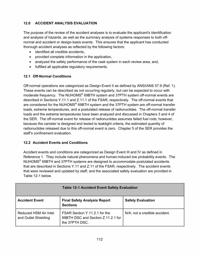
112
12.0 ACCIDENT ANALYSIS EVALUATION The purpose of the review of the accident analyses is to evaluate the applicant's identification and analysis of hazards, as well as the summary analysis of systems responses to both off-normal and accident or design-basis events. This ensures that the applicant has conducted thorough accident analyses as reflected by the following factors:
• identified all credible accidents, • provided complete information in the application, • analyzed the safety performance of the cask system in each review area, and, • fulfilled all applicable regulatory requirements.
12.1 Off-Normal Conditions Off-normal operations are categorized as Design Event II as defined by ANSI/ANS 57.9 (Ref. 1). These events can be described as not occurring regularly, but can be expected to occur with moderate frequency. The NUHOMS® 69BTH system and 37PTH system off-normal events are described in Sections Y.11.1 and Z.11.1 of the FSAR, respectively. The off-normal events that are considered for the NUHOMS® 69BTH system and the 37PTH system are off-normal transfer loads, extreme temperatures, and a postulated release of radionuclides. The off-normal transfer loads and the extreme temperatures have been analyzed and discussed in Chapters 3 and 4 of the SER. The off-normal event for release of radionuclides assumes failed fuel rods; however, because the canister is designed and tested to leaktight criteria, the estimated quantity of radionuclides released due to this off-normal event is zero. Chapter 5 of the SER provides the staff’s confinement evaluation. 12.2 Accident Events and Conditions Accident events and conditions are categorized as Design Event III and IV as defined in Reference 1. They include natural phenomena and human-induced low probability events. The NUHOMS® 69BTH and 37PTH systems are designed to accommodate postulated accidents that are described in Sections Y.11 and Z.11 of the FSAR, respectively. The accident events that were reviewed and updated by staff, and the associated safety evaluation are provided in Table 12-1 below.
Table 12-1 Accident Event Safety Evaluation
Accident Event Final Safety Analysis Report Sections
Safety Evaluation
Reduced HSM Air Inlet and Outlet Shielding
FSAR Section Y.11.2.1 for the 69BTH DSC and Section Z.11.2.1 for the 37PTH DSC.
N/A; not a credible accident.
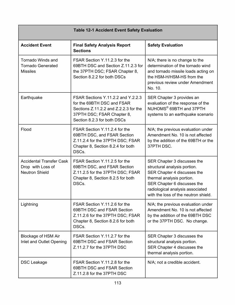
113
Table 12-1 Accident Event Safety Evaluation
Accident Event Final Safety Analysis Report Sections
Safety Evaluation
Tornado Winds and Tornado Generated Missiles
FSAR Section Y.11.2.3 for the 69BTH DSC and Section Z.11.2.3 for the 37PTH DSC; FSAR Chapter 8, Section 8.2.2 for both DSCs
N/A; there is no change to the determination of the tornado wind and tornado missile loads acting on the HSM-H/HSM-HS from the previous review under Amendment No. 10.
Earthquake FSAR Sections Y.11.2.2 and Y.2.2.3 for the 69BTH DSC and FSAR Sections Z.11.2.2 and Z.2.2.3 for the 37PTH DSC; FSAR Chapter 8, Section 8.2.3 for both DSCs
SER Chapter 3 provides an evaluation of the response of the NUHOMS® 69BTH and 37PTH systems to an earthquake scenario
Flood FSAR Section Y.11.2.4 for the 69BTH DSC, and FSAR Section Z.11.2.4 for the 37PTH DSC; FSAR Chapter 8, Section 8.2.4 for both DSCs.
N/A; the previous evaluation under Amendment No. 10 is not affected by the addition of the 69BTH or the 37PTH DSC.
Accidental Transfer Cask Drop with Loss of Neutron Shield
FSAR Section Y.11.2.5 for the 69BTH DSC, and FSAR Section Z.11.2.5 for the 37PTH DSC; FSAR Chapter 8, Section 8.2.5 for both DSCs.
SER Chapter 3 discusses the structural analysis portion. SER Chapter 4 discusses the thermal analysis portion. SER Chapter 6 discusses the radiological analysis associated with the loss of the neutron shield.
Lightning FSAR Section Y.11.2.6 for the 69BTH DSC and FSAR Section Z.11.2.6 for the 37PTH DSC; FSAR Chapter 8, Section 8.2.6 for both DSCs.
N/A; the previous evaluation under Amendment No. 10 is not affected by the addition of the 69BTH DSC or the 37PTH DSC. No change.
Blockage of HSM Air Inlet and Outlet Opening
FSAR Section Y.11.2.7 for the 69BTH DSC and FSAR Section Z.11.2.7 for the 37PTH DSC
SER Chapter 3 discusses the structural analysis portion. SER Chapter 4 discusses the thermal analysis portion.
DSC Leakage FSAR Section Y.11.2.8 for the 69BTH DSC and FSAR Section Z.11.2.8 for the 37PTH DSC
N/A; not a credible accident.
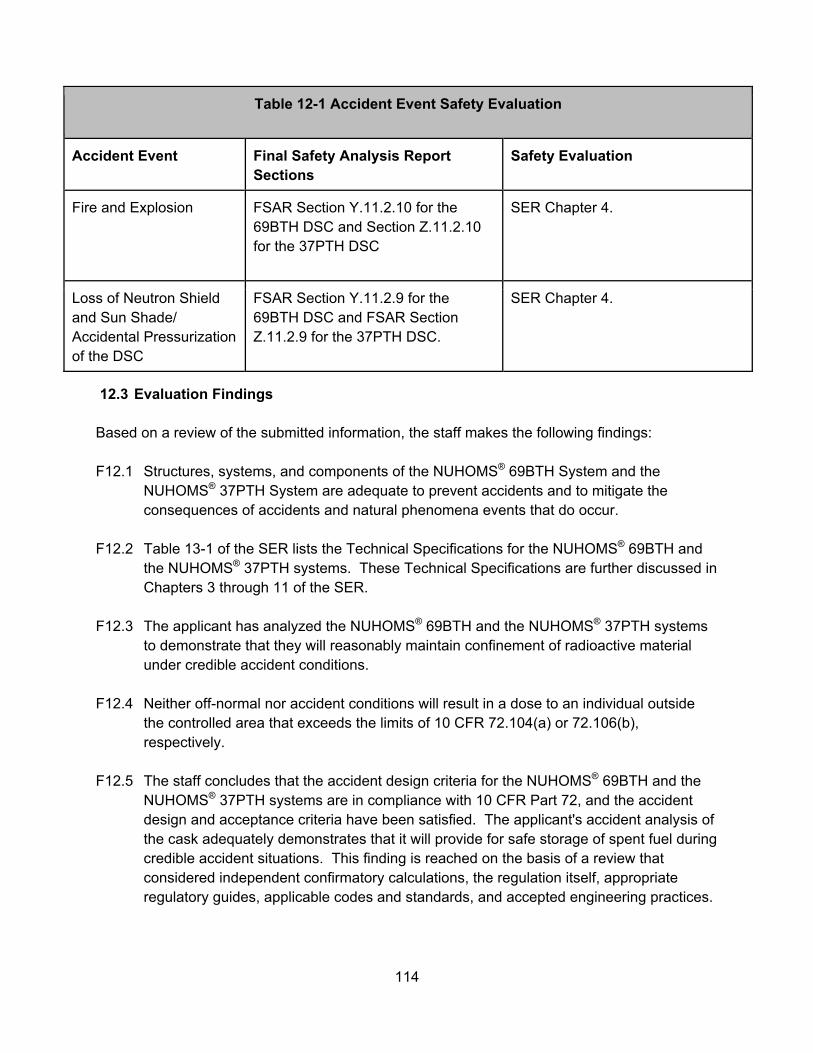
114
Table 12-1 Accident Event Safety Evaluation
Accident Event Final Safety Analysis Report Sections
Safety Evaluation
Fire and Explosion FSAR Section Y.11.2.10 for the 69BTH DSC and Section Z.11.2.10 for the 37PTH DSC
SER Chapter 4.
Loss of Neutron Shield and Sun Shade/ Accidental Pressurization of the DSC
FSAR Section Y.11.2.9 for the 69BTH DSC and FSAR Section Z.11.2.9 for the 37PTH DSC.
SER Chapter 4.
12.3 Evaluation Findings Based on a review of the submitted information, the staff makes the following findings: F12.1 Structures, systems, and components of the NUHOMS® 69BTH System and the
NUHOMS® 37PTH System are adequate to prevent accidents and to mitigate the consequences of accidents and natural phenomena events that do occur.
F12.2 Table 13-1 of the SER lists the Technical Specifications for the NUHOMS® 69BTH and
the NUHOMS® 37PTH systems. These Technical Specifications are further discussed in Chapters 3 through 11 of the SER.
F12.3 The applicant has analyzed the NUHOMS® 69BTH and the NUHOMS® 37PTH systems
to demonstrate that they will reasonably maintain confinement of radioactive material under credible accident conditions.
F12.4 Neither off-normal nor accident conditions will result in a dose to an individual outside
the controlled area that exceeds the limits of 10 CFR 72.104(a) or 72.106(b), respectively.
F12.5 The staff concludes that the accident design criteria for the NUHOMS® 69BTH and the
NUHOMS® 37PTH systems are in compliance with 10 CFR Part 72, and the accident design and acceptance criteria have been satisfied. The applicant's accident analysis of the cask adequately demonstrates that it will provide for safe storage of spent fuel during credible accident situations. This finding is reached on the basis of a review that considered independent confirmatory calculations, the regulation itself, appropriate regulatory guides, applicable codes and standards, and accepted engineering practices.
115
12.4 References 1. ANSI/ANS 57.9-1984, “Design Criteria for an Independent Spent Fuel Storage
Installation (Dry Type),” Reaffirmed 2000.
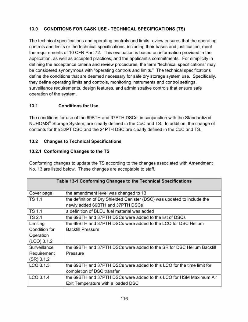
116
13.0 CONDITIONS FOR CASK USE - TECHNICAL SPECIFICATIONS (TS) The technical specifications and operating controls and limits review ensures that the operating controls and limits or the technical specifications, including their bases and justification, meet the requirements of 10 CFR Part 72. This evaluation is based on information provided in the application, as well as accepted practices, and the applicant’s commitments. For simplicity in defining the acceptance criteria and review procedures, the term “technical specifications” may be considered synonymous with “operating controls and limits.” The technical specifications define the conditions that are deemed necessary for safe dry storage system use. Specifically, they define operating limits and controls, monitoring instruments and control settings, surveillance requirements, design features, and administrative controls that ensure safe operation of the system. 13.1 Conditions for Use The conditions for use of the 69BTH and 37PTH DSCs, in conjunction with the Standardized NUHOMS® Storage System, are clearly defined in the CoC and TS. In addition, the change of contents for the 32PT DSC and the 24PTH DSC are clearly defined in the CoC and TS. 13.2 Changes to Technical Specifications
13.2.1 Conforming Changes to the TS Conforming changes to update the TS according to the changes associated with Amendment No. 13 are listed below. These changes are acceptable to staff.
Table 13-1 Conforming Changes to the Technical Specifications
Cover page the amendment level was changed to 13 TS 1.1 the definition of Dry Shielded Canister (DSC) was updated to include the
newly added 69BTH and 37PTH DSCs TS 1.1 a definition of BLEU fuel material was added TS 2.1 the 69BTH and 37PTH DSCs were added to the list of DSCs Limiting Condition for Operation (LCO) 3.1.2
the 69BTH and 37PTH DSCs were added to the LCO for DSC Helium Backfill Pressure
Surveillance Requirement (SR) 3.1.2
the 69BTH and 37PTH DSCs were added to the SR for DSC Helium Backfill Pressure
LCO 3.1.3 the 69BTH and 37PTH DSCs were added to this LCO for the time limit for completion of DSC transfer
LCO 3.1.4 the 69BTH and 37PTH DSCs were added to this LCO for HSM Maximum Air Exit Temperature with a loaded DSC
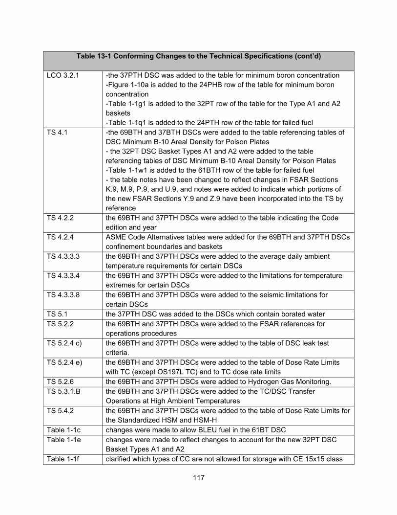
117
Table 13-1 Conforming Changes to the Technical Specifications (cont’d)
LCO 3.2.1 -the 37PTH DSC was added to the table for minimum boron concentration
-Figure 1-10a is added to the 24PHB row of the table for minimum boron concentration -Table 1-1g1 is added to the 32PT row of the table for the Type A1 and A2 baskets -Table 1-1q1 is added to the 24PTH row of the table for failed fuel
TS 4.1 -the 69BTH and 37BTH DSCs were added to the table referencing tables of DSC Minimum B-10 Areal Density for Poison Plates - the 32PT DSC Basket Types A1 and A2 were added to the table referencing tables of DSC Minimum B-10 Areal Density for Poison Plates -Table 1-1w1 is added to the 61BTH row of the table for failed fuel - the table notes have been changed to reflect changes in FSAR Sections K.9, M.9, P.9, and U.9, and notes were added to indicate which portions of the new FSAR Sections Y.9 and Z.9 have been incorporated into the TS by reference
TS 4.2.2 the 69BTH and 37PTH DSCs were added to the table indicating the Code edition and year
TS 4.2.4 ASME Code Alternatives tables were added for the 69BTH and 37PTH DSCs confinement boundaries and baskets
TS 4.3.3.3 the 69BTH and 37PTH DSCs were added to the average daily ambient temperature requirements for certain DSCs
TS 4.3.3.4 the 69BTH and 37PTH DSCs were added to the limitations for temperature extremes for certain DSCs
TS 4.3.3.8 the 69BTH and 37PTH DSCs were added to the seismic limitations for certain DSCs
TS 5.1 the 37PTH DSC was added to the DSCs which contain borated water TS 5.2.2 the 69BTH and 37PTH DSCs were added to the FSAR references for
operations procedures TS 5.2.4 c) the 69BTH and 37PTH DSCs were added to the table of DSC leak test
criteria. TS 5.2.4 e) the 69BTH and 37PTH DSCs were added to the table of Dose Rate Limits
with TC (except OS197L TC) and to TC dose rate limits TS 5.2.6 the 69BTH and 37PTH DSCs were added to Hydrogen Gas Monitoring. TS 5.3.1.B the 69BTH and 37PTH DSCs were added to the TC/DSC Transfer
Operations at High Ambient Temperatures TS 5.4.2 the 69BTH and 37PTH DSCs were added to the table of Dose Rate Limits for
the Standardized HSM and HSM-H Table 1-1c changes were made to allow BLEU fuel in the 61BT DSC Table 1-1e changes were made to reflect changes to account for the new 32PT DSC
Basket Types A1 and A2 Table 1-1f clarified which types of CC are not allowed for storage with CE 15x15 class
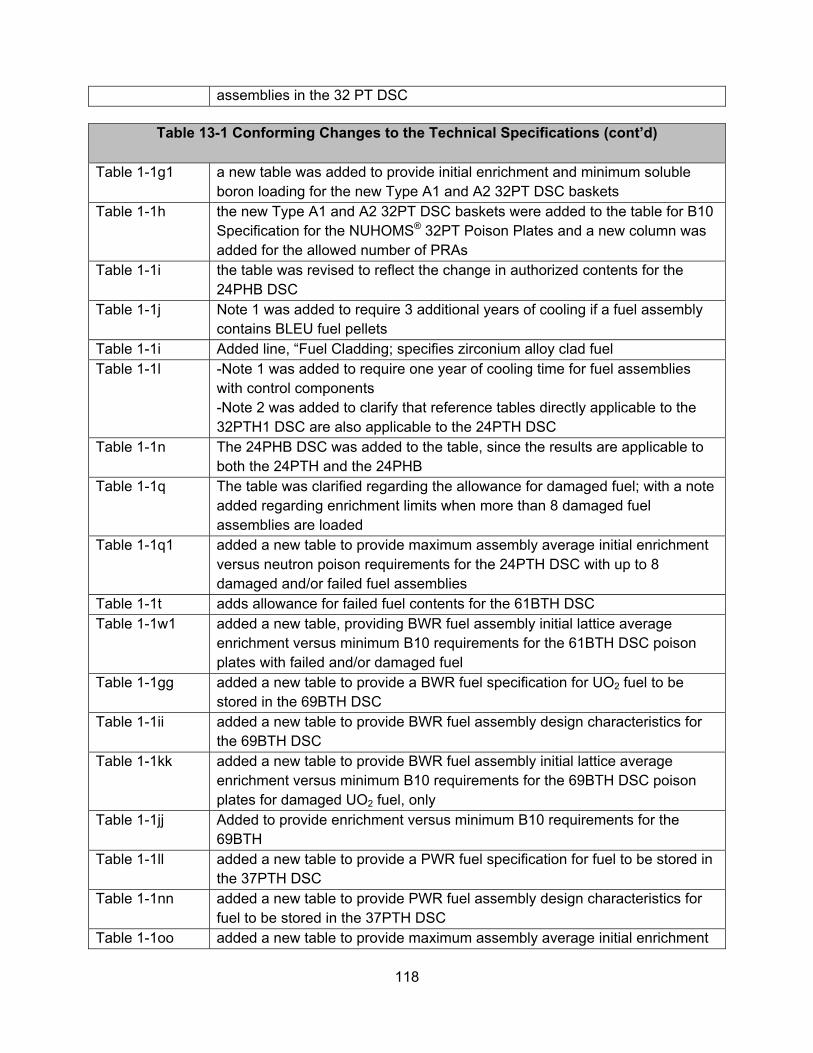
118
assemblies in the 32 PT DSC
Table 13-1 Conforming Changes to the Technical Specifications (cont’d) Table 1-1g1 a new table was added to provide initial enrichment and minimum soluble
boron loading for the new Type A1 and A2 32PT DSC baskets Table 1-1h the new Type A1 and A2 32PT DSC baskets were added to the table for B10
Specification for the NUHOMS® 32PT Poison Plates and a new column was added for the allowed number of PRAs
Table 1-1i the table was revised to reflect the change in authorized contents for the 24PHB DSC
Table 1-1j Note 1 was added to require 3 additional years of cooling if a fuel assembly contains BLEU fuel pellets
Table 1-1i Added line, “Fuel Cladding; specifies zirconium alloy clad fuel Table 1-1l -Note 1 was added to require one year of cooling time for fuel assemblies
with control components -Note 2 was added to clarify that reference tables directly applicable to the 32PTH1 DSC are also applicable to the 24PTH DSC
Table 1-1n The 24PHB DSC was added to the table, since the results are applicable to both the 24PTH and the 24PHB
Table 1-1q The table was clarified regarding the allowance for damaged fuel; with a note added regarding enrichment limits when more than 8 damaged fuel assemblies are loaded
Table 1-1q1 added a new table to provide maximum assembly average initial enrichment versus neutron poison requirements for the 24PTH DSC with up to 8 damaged and/or failed fuel assemblies
Table 1-1t adds allowance for failed fuel contents for the 61BTH DSC Table 1-1w1 added a new table, providing BWR fuel assembly initial lattice average
enrichment versus minimum B10 requirements for the 61BTH DSC poison plates with failed and/or damaged fuel
Table 1-1gg added a new table to provide a BWR fuel specification for UO2 fuel to be stored in the 69BTH DSC
Table 1-1ii added a new table to provide BWR fuel assembly design characteristics for the 69BTH DSC
Table 1-1kk added a new table to provide BWR fuel assembly initial lattice average enrichment versus minimum B10 requirements for the 69BTH DSC poison plates for damaged UO2 fuel, only
Table 1-1jj Added to provide enrichment versus minimum B10 requirements for the 69BTH
Table 1-1ll added a new table to provide a PWR fuel specification for fuel to be stored in the 37PTH DSC
Table 1-1nn added a new table to provide PWR fuel assembly design characteristics for fuel to be stored in the 37PTH DSC
Table 1-1oo added a new table to provide maximum assembly average initial enrichment
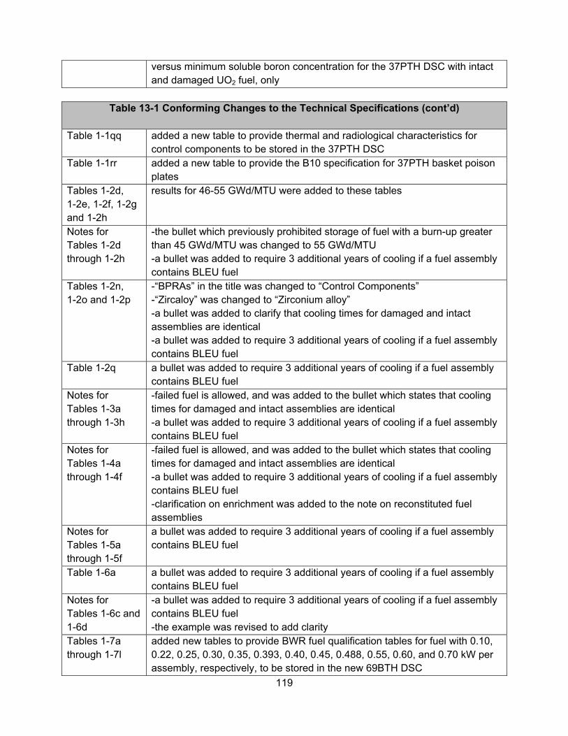
119
versus minimum soluble boron concentration for the 37PTH DSC with intact and damaged UO2 fuel, only
Table 13-1 Conforming Changes to the Technical Specifications (cont’d)
Table 1-1qq added a new table to provide thermal and radiological characteristics for
control components to be stored in the 37PTH DSC Table 1-1rr added a new table to provide the B10 specification for 37PTH basket poison
plates Tables 1-2d, 1-2e, 1-2f, 1-2g and 1-2h
results for 46-55 GWd/MTU were added to these tables
Notes for Tables 1-2d through 1-2h
-the bullet which previously prohibited storage of fuel with a burn-up greater than 45 GWd/MTU was changed to 55 GWd/MTU -a bullet was added to require 3 additional years of cooling if a fuel assembly contains BLEU fuel
Tables 1-2n, 1-2o and 1-2p
-“BPRAs” in the title was changed to “Control Components” -“Zircaloy” was changed to “Zirconium alloy” -a bullet was added to clarify that cooling times for damaged and intact assemblies are identical -a bullet was added to require 3 additional years of cooling if a fuel assembly contains BLEU fuel
Table 1-2q a bullet was added to require 3 additional years of cooling if a fuel assembly contains BLEU fuel
Notes for Tables 1-3a through 1-3h
-failed fuel is allowed, and was added to the bullet which states that cooling times for damaged and intact assemblies are identical -a bullet was added to require 3 additional years of cooling if a fuel assembly contains BLEU fuel
Notes for Tables 1-4a through 1-4f
-failed fuel is allowed, and was added to the bullet which states that cooling times for damaged and intact assemblies are identical -a bullet was added to require 3 additional years of cooling if a fuel assembly contains BLEU fuel -clarification on enrichment was added to the note on reconstituted fuel assemblies
Notes for Tables 1-5a through 1-5f
a bullet was added to require 3 additional years of cooling if a fuel assembly contains BLEU fuel
Table 1-6a a bullet was added to require 3 additional years of cooling if a fuel assembly contains BLEU fuel
Notes for Tables 1-6c and 1-6d
-a bullet was added to require 3 additional years of cooling if a fuel assembly contains BLEU fuel -the example was revised to add clarity
Tables 1-7a through 1-7l
added new tables to provide BWR fuel qualification tables for fuel with 0.10, 0.22, 0.25, 0.30, 0.35, 0.393, 0.40, 0.45, 0.488, 0.55, 0.60, and 0.70 kW per assembly, respectively, to be stored in the new 69BTH DSC

120
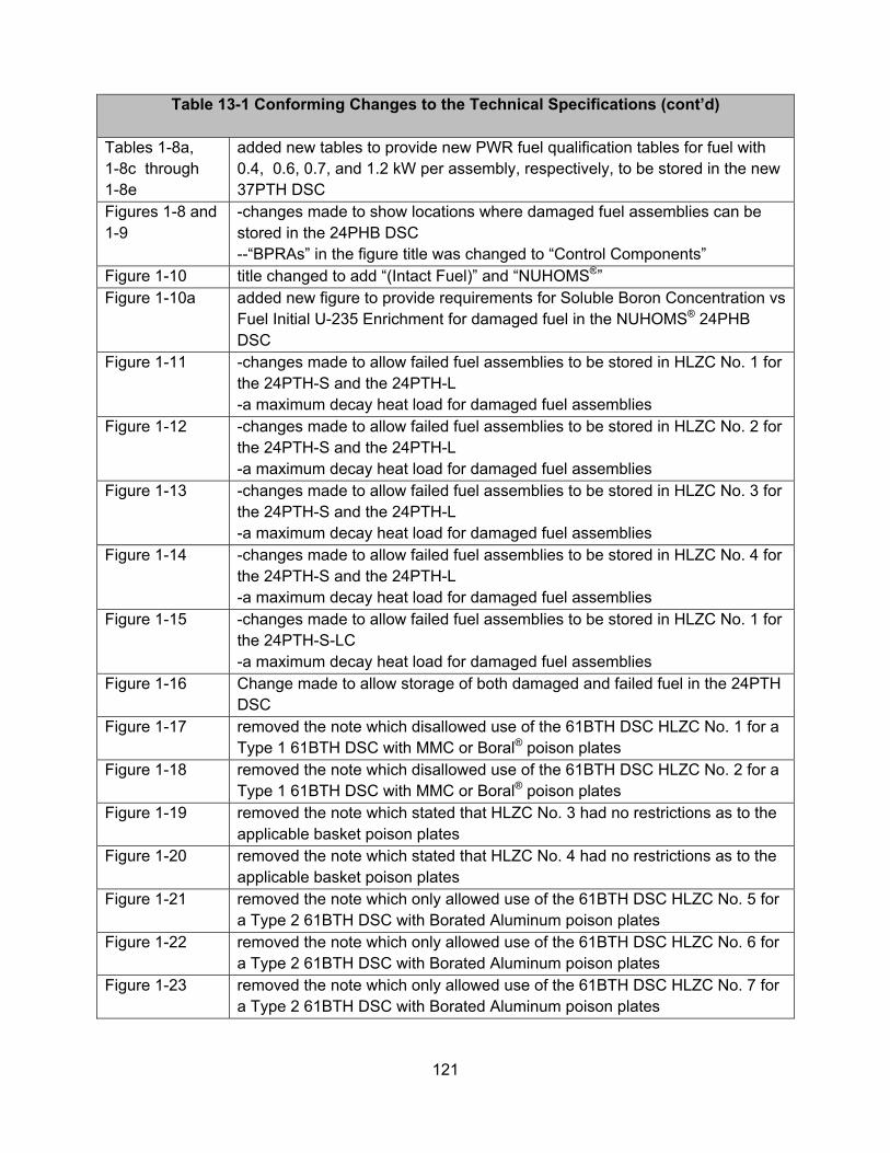
121
Table 13-1 Conforming Changes to the Technical Specifications (cont’d) Tables 1-8a, 1-8c through 1-8e
added new tables to provide new PWR fuel qualification tables for fuel with 0.4, 0.6, 0.7, and 1.2 kW per assembly, respectively, to be stored in the new 37PTH DSC
Figures 1-8 and 1-9
-changes made to show locations where damaged fuel assemblies can be stored in the 24PHB DSC --“BPRAs” in the figure title was changed to “Control Components”
Figure 1-10 title changed to add “(Intact Fuel)” and “NUHOMS®” Figure 1-10a added new figure to provide requirements for Soluble Boron Concentration vs
Fuel Initial U-235 Enrichment for damaged fuel in the NUHOMS® 24PHB DSC
Figure 1-11 -changes made to allow failed fuel assemblies to be stored in HLZC No. 1 for the 24PTH-S and the 24PTH-L -a maximum decay heat load for damaged fuel assemblies
Figure 1-12 -changes made to allow failed fuel assemblies to be stored in HLZC No. 2 for the 24PTH-S and the 24PTH-L -a maximum decay heat load for damaged fuel assemblies
Figure 1-13 -changes made to allow failed fuel assemblies to be stored in HLZC No. 3 for the 24PTH-S and the 24PTH-L -a maximum decay heat load for damaged fuel assemblies
Figure 1-14 -changes made to allow failed fuel assemblies to be stored in HLZC No. 4 for the 24PTH-S and the 24PTH-L -a maximum decay heat load for damaged fuel assemblies
Figure 1-15 -changes made to allow failed fuel assemblies to be stored in HLZC No. 1 for the 24PTH-S-LC -a maximum decay heat load for damaged fuel assemblies
Figure 1-16 Change made to allow storage of both damaged and failed fuel in the 24PTH DSC
Figure 1-17 removed the note which disallowed use of the 61BTH DSC HLZC No. 1 for a Type 1 61BTH DSC with MMC or Boral® poison plates
Figure 1-18 removed the note which disallowed use of the 61BTH DSC HLZC No. 2 for a Type 1 61BTH DSC with MMC or Boral® poison plates
Figure 1-19 removed the note which stated that HLZC No. 3 had no restrictions as to the applicable basket poison plates
Figure 1-20 removed the note which stated that HLZC No. 4 had no restrictions as to the applicable basket poison plates
Figure 1-21 removed the note which only allowed use of the 61BTH DSC HLZC No. 5 for a Type 2 61BTH DSC with Borated Aluminum poison plates
Figure 1-22 removed the note which only allowed use of the 61BTH DSC HLZC No. 6 for a Type 2 61BTH DSC with Borated Aluminum poison plates
Figure 1-23 removed the note which only allowed use of the 61BTH DSC HLZC No. 7 for a Type 2 61BTH DSC with Borated Aluminum poison plates
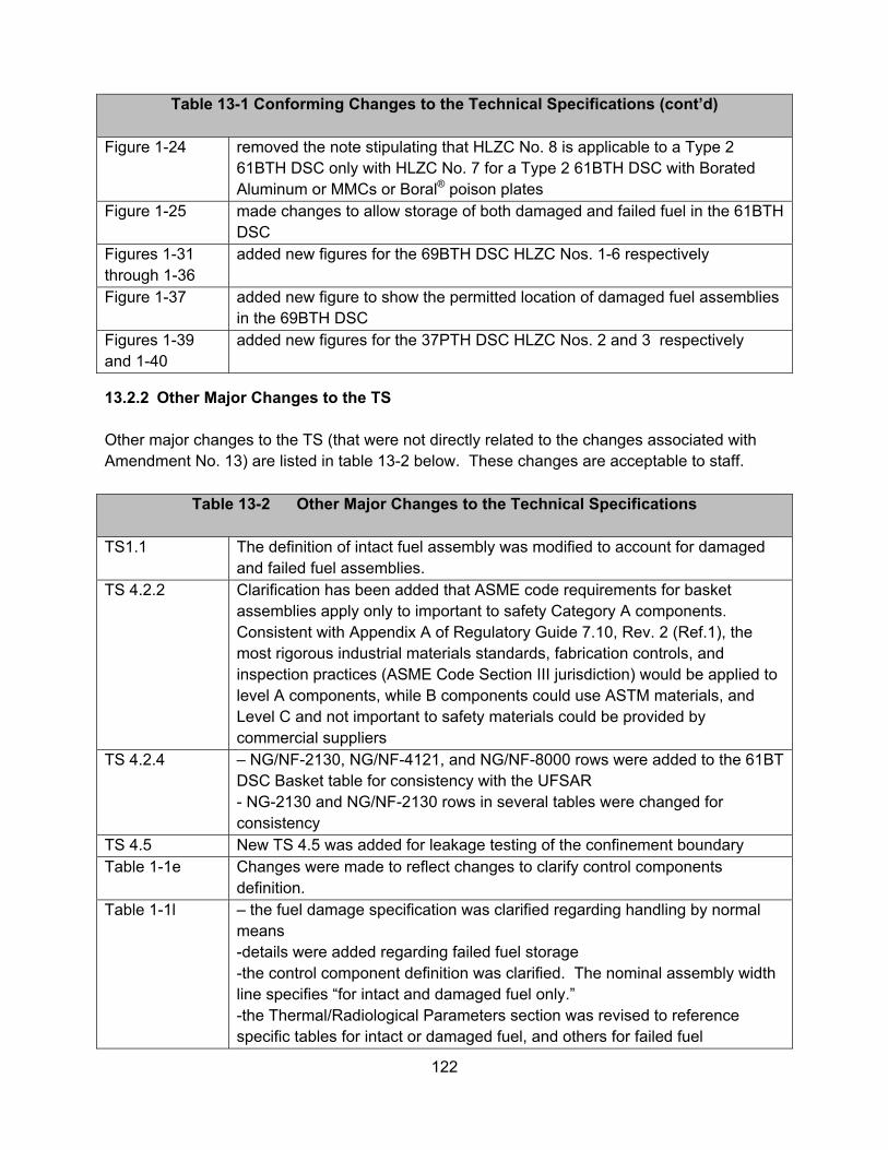
122
Table 13-1 Conforming Changes to the Technical Specifications (cont’d) Figure 1-24 removed the note stipulating that HLZC No. 8 is applicable to a Type 2
61BTH DSC only with HLZC No. 7 for a Type 2 61BTH DSC with Borated Aluminum or MMCs or Boral® poison plates
Figure 1-25 made changes to allow storage of both damaged and failed fuel in the 61BTH DSC
Figures 1-31 through 1-36
added new figures for the 69BTH DSC HLZC Nos. 1-6 respectively
Figure 1-37 added new figure to show the permitted location of damaged fuel assemblies in the 69BTH DSC
Figures 1-39 and 1-40
added new figures for the 37PTH DSC HLZC Nos. 2 and 3 respectively
13.2.2 Other Major Changes to the TS Other major changes to the TS (that were not directly related to the changes associated with Amendment No. 13) are listed in table 13-2 below. These changes are acceptable to staff.
Table 13-2 Other Major Changes to the Technical Specifications
TS1.1 The definition of intact fuel assembly was modified to account for damaged and failed fuel assemblies.
TS 4.2.2 Clarification has been added that ASME code requirements for basket assemblies apply only to important to safety Category A components. Consistent with Appendix A of Regulatory Guide 7.10, Rev. 2 (Ref.1), the most rigorous industrial materials standards, fabrication controls, and inspection practices (ASME Code Section III jurisdiction) would be applied to level A components, while B components could use ASTM materials, and Level C and not important to safety materials could be provided by commercial suppliers
TS 4.2.4 – NG/NF-2130, NG/NF-4121, and NG/NF-8000 rows were added to the 61BT DSC Basket table for consistency with the UFSAR - NG-2130 and NG/NF-2130 rows in several tables were changed for consistency
TS 4.5 New TS 4.5 was added for leakage testing of the confinement boundary Table 1-1e Changes were made to reflect changes to clarify control components
definition. Table 1-1l – the fuel damage specification was clarified regarding handling by normal
means -details were added regarding failed fuel storage -the control component definition was clarified. The nominal assembly width line specifies “for intact and damaged fuel only.” -the Thermal/Radiological Parameters section was revised to reference specific tables for intact or damaged fuel, and others for failed fuel

123
Table 13-2 Other Major Changes to the Technical Specifications (cont’d)
Table 1-1t The fuel damage specification was clarified regarding cladding damage to be
consistent with other DSCs Table 1-1aa -the specification for fuel damage has been revised to allow missing fuel
rods, and to require top and bottom end fittings or nozzles or tie plates consistent with the CoC No. 9302 MP197HB Part 71 application -the definition of control components was clarified
Tables 1-2d, 1-2e, 1-2f, 1-2g and 1-2h
-“Fuel with or without CCs” added to title -explanatory notes previously provided on each table moved to Table 1-2h
Notes for Tables 1-2d through 1-2h
The example provided was revised for greater clarity
Table 1-2i, 1-2j, 1-2k, 1-2l and 1-2m
Deleted
Table 1-4f The previous 0.55 kW fuel qualification table was conservatively used for the 0.7 kW/FA FQT in a previous amendment; that 0.55 kW table has been replaced with the 0.7 kW table
Tables 1-5a through 1-5f
Titles changed to delete “Fuel without CCs”
Table 1-6a -a statement referring to UFSAR Appendix W tables was removed -a statement indicating that the bulleted notes apply to Tables 1-6a and 1-6b was added -the example was revised to add clarity
Table 1-6b -a statement referring to UFSAR Appendix W tables was removed -a statement indicating that the bulleted notes apply to Tables 1-6a and 1-6b was added -the title was revised to specify that the table applies to “0.17 kW” assemblies
Table 1-6c Notes which originally followed this table moved to Table 1-6d Figure 1-27 Removed inadvertently duplicated figure
13.2.3 Technical Editing/Administrative Changes to the TS Minor changes to the TS are listed in table 13-3 below. These changes are acceptable to staff.
Table 13-3 Administrative Changes to the Technical Specifications General The Table of Contents has been updated. TS 4.1 In the 61BTH DSC row, “and” has been changed to “or” for clarity
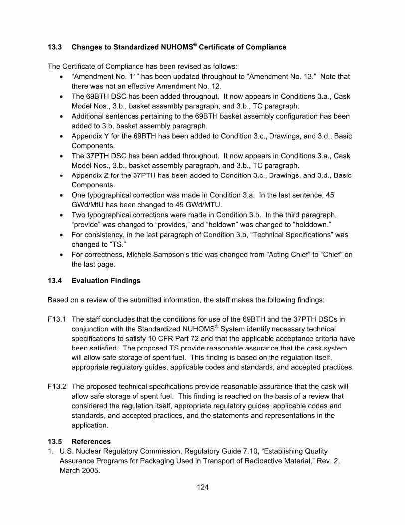
124
13.3 Changes to Standardized NUHOMS® Certificate of Compliance The Certificate of Compliance has been revised as follows:
• “Amendment No. 11” has been updated throughout to “Amendment No. 13.” Note that there was not an effective Amendment No. 12.
• The 69BTH DSC has been added throughout. It now appears in Conditions 3.a., Cask Model Nos., 3.b., basket assembly paragraph, and 3.b., TC paragraph.
• Additional sentences pertaining to the 69BTH basket assembly configuration has been added to 3.b, basket assembly paragraph.
• Appendix Y for the 69BTH has been added to Condition 3.c., Drawings, and 3.d., Basic Components.
• The 37PTH DSC has been added throughout. It now appears in Conditions 3.a., Cask Model Nos., 3.b., basket assembly paragraph, and 3.b., TC paragraph.
• Appendix Z for the 37PTH has been added to Condition 3.c., Drawings, and 3.d., Basic Components.
• One typographical correction was made in Condition 3.a. In the last sentence, 45 GWd/MtU has been changed to 45 GWd/MTU.
• Two typographical corrections were made in Condition 3.b. In the third paragraph, “provide” was changed to “provides,” and “holdown” was changed to “holddown.”
• For consistency, in the last paragraph of Condition 3.b, “Technical Specifications” was changed to “TS.”
• For correctness, Michele Sampson’s title was changed from “Acting Chief” to “Chief” on the last page.
13.4 Evaluation Findings Based on a review of the submitted information, the staff makes the following findings: F13.1 The staff concludes that the conditions for use of the 69BTH and the 37PTH DSCs in
conjunction with the Standardized NUHOMS® System identify necessary technical specifications to satisfy 10 CFR Part 72 and that the applicable acceptance criteria have been satisfied. The proposed TS provide reasonable assurance that the cask system will allow safe storage of spent fuel. This finding is based on the regulation itself, appropriate regulatory guides, applicable codes and standards, and accepted practices.
F13.2 The proposed technical specifications provide reasonable assurance that the cask will
allow safe storage of spent fuel. This finding is reached on the basis of a review that considered the regulation itself, appropriate regulatory guides, applicable codes and standards, and accepted practices, and the statements and representations in the application.
13.5 References 1. U.S. Nuclear Regulatory Commission, Regulatory Guide 7.10, “Establishing Quality
Assurance Programs for Packaging Used in Transport of Radioactive Material,” Rev. 2, March 2005.

125

126
14.0 QUALITY ASSURANCE EVALUATION The purpose of this review and evaluation is to determine whether TN has a quality assurance program that complies with the requirements of 10 CFR Part 20, Subpart G. The staff has previously reviewed and accepted the TN quality assurance program. There are no changes associated with the current application. .
127
15.0 CONCLUSION
The NRC staff has performed a comprehensive review of the application and has found that the following changes do not reduce the safety margin for the Standardized NUHOMS® System:
1. Addition of a new dry shielded canister (DSC), the 69BTH; 2. Addition of a new DSC, the 37PTH; 3. Addition of control components (CCs) other than burnable poison rod assemblies
(BPRAs), and damaged fuel assemblies, and allow non-zircaloy cladding/guide tubes as approved contents to the 24PHB DSC;
4. Addition of high burn-up fuel assemblies with and without control components as approved contents to the 32PT DSC,
5. Addition of failed fuel as approved contents to the 61BTH and 24PTH DSCs; 6. Extended use of the high-seismic horizontal storage module (HSM-HS) for storage of the
61BT, 32PT, 24PTH, 61BTH, 69BTH and 37PTH DSCs; 7. Extended use of metal matrix composites (MMCs) as a neutron absorber material in the
61BTH Type 1 and Type 2 DSCs for higher heat loads; 8. Addition of blended low enriched uranium (BLEU) fuel material as approved contents. 9. Inlet vent shielding design modifications to achieve dose reductions for the HSM-H and
HSM-HS; 10. Extended use of the OS200TC to allow transfer of the 61BT, 32PT, 24PTH and 61BTH
DSCs; 11. Allow use of Type III cement as an alternate equivalent to the Type II cement used in
HSM construction; 12. Technical Specifications (TS) changes to neutron absorber testing and acceptance
requirements in order to remain consistent with similar requirements in other ongoing licensing actions.
The areas of review addressed in NUREG-1536, “Standard Review Plan for Dry Cask Storage Systems,” July 2010, are consistent with the applicant’s proposed changes. The certificate of compliance has been revised to include TN’s requested changes. Based on the statements and representations contained in TN’s application, as supplemented, the staff concludes that the changes described above to the approved contents of the Standardized NUHOMS® System meet the requirements of 10 CFR Part 72. Issued with Certificate of Compliance No. 1004, Amendment No. 13 on May 23, 2014.
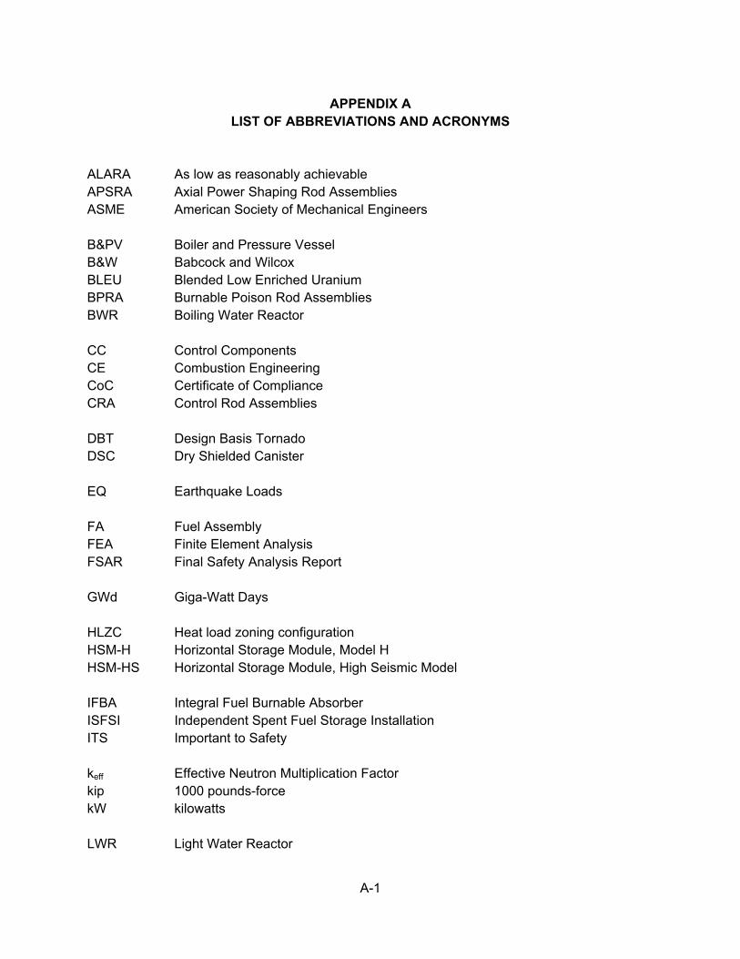
A-1
APPENDIX A
LIST OF ABBREVIATIONS AND ACRONYMS ALARA As low as reasonably achievable APSRA Axial Power Shaping Rod Assemblies ASME American Society of Mechanical Engineers B&PV Boiler and Pressure Vessel B&W Babcock and Wilcox BLEU Blended Low Enriched Uranium BPRA Burnable Poison Rod Assemblies BWR Boiling Water Reactor CC Control Components CE Combustion Engineering CoC Certificate of Compliance CRA Control Rod Assemblies DBT Design Basis Tornado DSC Dry Shielded Canister EQ Earthquake Loads FA Fuel Assembly FEA Finite Element Analysis FSAR Final Safety Analysis Report GWd Giga-Watt Days HLZC Heat load zoning configuration HSM-H Horizontal Storage Module, Model H HSM-HS Horizontal Storage Module, High Seismic Model IFBA Integral Fuel Burnable Absorber ISFSI Independent Spent Fuel Storage Installation ITS Important to Safety keff Effective Neutron Multiplication Factor kip 1000 pounds-force kW kilowatts LWR Light Water Reactor
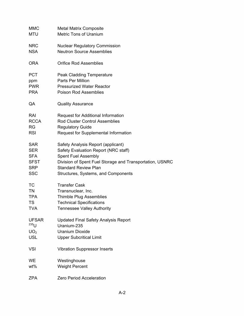
A-2
MMC Metal Matrix Composite MTU Metric Tons of Uranium NRC Nuclear Regulatory Commission NSA Neutron Source Assemblies ORA Orifice Rod Assemblies PCT Peak Cladding Temperature ppm Parts Per Million PWR Pressurized Water Reactor PRA Poison Rod Assemblies QA Quality Assurance RAI Request for Additional Information RCCA Rod Cluster Control Assemblies RG Regulatory Guide RSI Request for Supplemental Information SAR Safety Analysis Report (applicant) SER Safety Evaluation Report (NRC staff) SFA Spent Fuel Assembly SFST Division of Spent Fuel Storage and Transportation, USNRC SRP Standard Review Plan SSC Structures, Systems, and Components TC Transfer Cask TN Transnuclear, Inc. TPA Thimble Plug Assemblies TS Technical Specifications TVA Tennessee Valley Authority UFSAR Updated Final Safety Analysis Report 235U Uranium-235 UO2 Uranium Dioxide USL Upper Subcritical Limit VSI Vibration Suppressor Inserts WE Westinghouse wt% Weight Percent ZPA Zero Period Acceleration


![Samsung SCX-4521F LTR [USA33839] Rep.pdf](https://static.fdokumen.com/doc/165x107/63192fdf1a1adcf65a0e8beb/samsung-scx-4521f-ltr-usa33839-reppdf.jpg)