ENABLING FORM TO BE ADJUSTED BASED ON PERFORMANCE. Performance-based parametric design approach for...
10
M. A. Schnabel (ed.), Cutting Edge: 47 th International Conference of the Architectural Science Associa- tion, pp. 217–226. © 2013, The Architectural Science Association (ANZAScA), Australia ENABLING FORM TO BE ADJUSTED BASED ON PERFORMANCE Performance-based parametric design approach for high-rise buildings' integrated wind turbines FARID ABDOLHOSSEIN-POUR, MATIN ALAGHMANDAN, and ROBERT J. KRAWCZYK Illinois institute of technology, Chicago, USA {fabdolho, malaghma, krawczyk}@iit.edu Abstract. Attempts to integrate performance analysis with architectural design process have been commonly restricted to final design stage assessments when it is too late for major modifications in buildings’ form. Similarly, enhancement of wind power production in high-rise architecture via optimization of buildings’ aerodynamic behaviour has been problematically incorporated in the schematic design stage. Therefore, these efforts have not been resulted in creation of a design agenda and aerodynamic guidelines for form generation in early design phases. This paper, accordingly, discusses a parametric design procedure to optimize wind power production in high-rise office buildings via aerodynamic transformations and refinement of form. The paper’s intention also includes the development of fundamental architectural strategies and guidelines for the design process of tall office buildings integrated wind turbines. Keywords. Parametric design; Optimization; Building integrated wind turbine (BIWT); High-rise office; Performance. 1. Introduction The building sector is currently the largest contributor to the energy and cli- mate crisis (DOE, 2012). A newly emerging way to promote sustainability in the built environment is through integration of renewable energy generators such as wind power in buildings. Thus, in a distributed generation concept, buildings transform to renewable power units with minimum transmission / distribution losses. However, the effectiveness of the proposed solutions is seriously dependent on early integration with architectural design process.
Transcript of ENABLING FORM TO BE ADJUSTED BASED ON PERFORMANCE. Performance-based parametric design approach for...
M. A. Schnabel (ed.), Cutting Edge: 47th International Conference of the Architectural Science Associa-tion, pp. 217–226. © 2013, The Architectural Science Association (ANZAScA), Australia
ENABLING FORM TO BE ADJUSTED BASED ON
PERFORMANCE
Performance-based parametric design approach for high-rise
buildings' integrated wind turbines
FARID ABDOLHOSSEIN-POUR, MATIN ALAGHMANDAN, and
ROBERT J. KRAWCZYK
Illinois institute of technology, Chicago, USA
{fabdolho, malaghma, krawczyk}@iit.edu
Abstract. Attempts to integrate performance analysis with architectural design process have been commonly restricted to final design stage assessments when it is too late for major modifications in buildings’ form. Similarly, enhancement of wind power production in high-rise architecture via optimization of buildings’ aerodynamic behaviour has been problematically incorporated in the schematic design stage. Therefore, these efforts have not been resulted in creation of a design agenda and aerodynamic guidelines for form generation in early design phases. This paper, accordingly, discusses a parametric design procedure to optimize wind power production in high-rise office buildings via aerodynamic transformations and refinement of form. The paper’s intention also includes the development of fundamental architectural strategies and guidelines for the design process of tall office buildings integrated wind turbines.
Keywords. Parametric design; Optimization; Building integrated wind turbine (BIWT); High-rise office; Performance.
1. Introduction
The building sector is currently the largest contributor to the energy and cli-
mate crisis (DOE, 2012). A newly emerging way to promote sustainability in
the built environment is through integration of renewable energy generators
such as wind power in buildings. Thus, in a distributed generation concept,
buildings transform to renewable power units with minimum transmission /
distribution losses. However, the effectiveness of the proposed solutions is
seriously dependent on early integration with architectural design process.
218 ABDOLHOSSEIN-POUR., ALAGHMANDAN AND KRAWCZYK
Recently, “Parametric design” (PD) and “Building performance simula-
tion (BPS)” have been deeply restructuring the design process. Architects are
able to predict building performance and adoptively adjust the building char-
acteristics in early design stage, when fundamental changes are still possible.
An interactive communication between BPS (Computational Fluid Dynamic
(CFD), for this paper) and PD can be developed to inform architects during
the evolution of the geometry based on performative criteria.
2. Research statement
Air-flow patterns around buildings are considerably influenced by buildings’
geometrical characteristic. This is apparent in buildings taller than average
urban terrain. Hypothetically, aerodynamic modification of buildings form
can turn this unstructured phenomenon to a massive concentrator effect, ca-
pable of boosting wind power production in taller buildings (Mertens, 2006).
Accordingly, this research seeks to enhance wind power production in
high-rise offices via aerodynamic refinements of form (using mathematical
models and CFD analysis) within an evolutionary parametric design process.
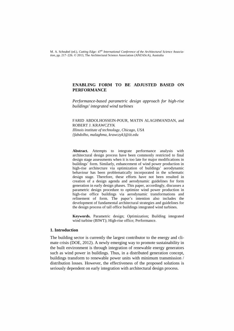
There are particular limits associated with use of PD and CFD (Figure 1).
A smart data exchange between PD and CFD in an optimization platform
develops a decision mechanism to collect the architectural concepts with im-
proved acceleration / concentration of flow over turbines. The mechanism is
reinforced with optimization technique such as Genetic Algorithm (GA).
2.1. RESEARCH OBJECTIVES
Classify tall buildings’ characteristics influencing wind,
Study PD to produce parametric transformations of models
Explore appropriate PD, mathematical models and CFD tools
Develop a mechanism to enable form to be adjusted by performance
Figure 1. Research statement, limits associated with use of PD and BPS in design process (Abdolhossein pour et al., 2012) adopted from (Yi, 2008) & (Ilgin and Günel, 2007)
ENABLING FORM TO BE ADJUSTED BASED ON PERFORMANCE 219
2.2. RESEARCH HYPOTHESIS
Wind velocity escalates as altitude rises. This is beneficial as turbine’s output
power is proportional with the cube of velocity, equation (1).
High-rise buildings provide tall and economical structures for turbines.
The concentrator effect results in faster flow and larger pressure difference
across the bodies. This significantly increases turbine power, equation (3).
Onsite production minimizes power losses realized in transmission process.
2.3. RESEARCH LIMITATION / FUTURE STUDIES
The research scope is limited to the study of tall office buildings and related
criteria. The turbulence effects of surrounding buildings, vibration, structural
& façade issues, BIWT economy, lifecycle cost and development of math-
models for the study are not parts of this paper and remain for future studies.
3. Background discussion
3.1. WIND BEHAVIOR CLASSIFICATION AROUND OBSTACLES
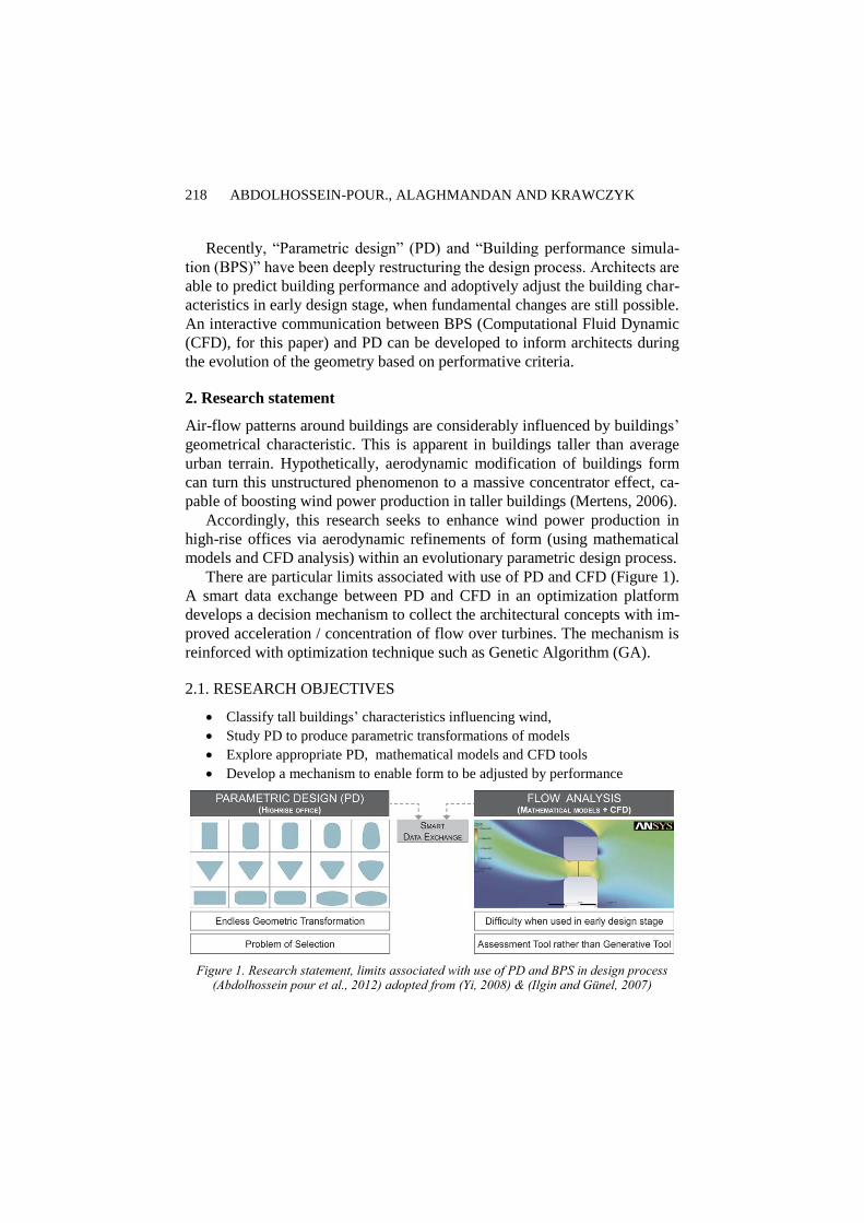
As wind approaches a building, the surrounding flow patterns are noticeably
dependent on the body’s dimensional ratio. Bodies with similar dimensional
sizes bend the flows in a 3D pattern (Figure 2). But, bodies with one length
noticeably larger than others mostly deflect the flows around the smaller
body’s section (Mertens, 2006, Hoerner and Borst, 1975). Wind deflection
often raises the velocity of flow. 2D bodies experience larger induced veloci-
ties than 3D bodies as air has to move on only one surface (Batchelor, 2000).
Figure 2. Flow pattern over 3D, left and 2D bodies, right
3.1.1. Flow separation and Sharpe edges effect
When wind hits a building, the fluid moves up on the body’s upwind side,
but has difficulty staying attached to the downhill surface. When flow is fast
enough, it separates from the surface and creates a wake behind the body.
220 ABDOLHOSSEIN-POUR., ALAGHMANDAN AND KRAWCZYK
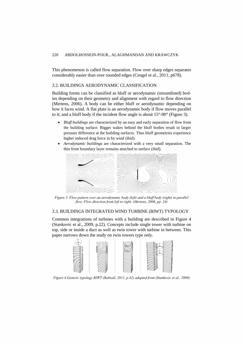
This phenomenon is called flow separation. Flow over sharp edges separates
considerably easier than over rounded edges (Cengel et al., 2011, p678).
3.2. BUILDINGS AERODYNAMIC CLASSIFICATION
Building forms can be classified as bluff or aerodynamic (streamlined) bod-
ies depending on their geometry and alignment with regard to flow direction
(Mertens, 2006). A body can be either bluff or aerodynamic depending on
how it faces wind. A flat plate is an aerodynamic body if flow moves parallel
to it; and a bluff body if the incident flow angle is about 15°-90° (Figure 3).
Bluff buildings are characterized by an easy and early separation of flow from
the building surface. Bigger wakes behind the bluff bodies result in larger
pressure difference at the building surfaces. Thus bluff geometries experience
higher induced drag force in by wind (ibid).
Aerodynamic buildings are characterized with a very small separation. The
thin front boundary layer remains attached to surface (ibid).
Figure 3. Flow pattern over an aerodynamic body (left) and a bluff body (right) in parallel flow. Flow direction from left to right. (Mertens, 2006, pp. 24)
3.3. BUILDINGS INTEGRATED WIND TURBINE (BIWT) TYPOLOGY
Common integrations of turbines with a building are described in Figure 4
(Stankovic et al., 2009, p.22). Concepts include single tower with turbine on
top, side or inside a duct as well as twin tower with turbine in between. This
paper narrows down the study on twin towers type only.
Figure 4.Generic typology BIWT (Babsail, 2011, p.42) adopted from (Stankovic et al., 2009)
ENABLING FORM TO BE ADJUSTED BASED ON PERFORMANCE 221
3.4. WIND TURBINE PHYSICS (POWER EQUATION)
The power content (PWind) of an air parcel is found by equation (1) where V
is free-stream velocity, A is equal to turbine swept area and ρ is air density.
However, when flow passes a turbine, only portion of its kinetic energy is
captured. Turbines’ power coefficient (CP) is defined by ratio of the captured
turbine power (PT) to wind power content (Sathyajith, 2006), equation (2).
Turbines slow down wind by extracting its kinetic energy. This negative ac-
celeration originates in resisting forces generated by blades (second law of
Newton). If turbine is pushing wind, air reacts equally in opposite way (third
law of newton). If velocity on turbine is VT, then power (energy per second)
for a turbine is found from (3) where F is the reaction force and ΔP is the
pressure drop across turbine. Betz's law proves CP,Max for a bare horizontal
axis turbine cannot exceed 16/27~0.593(Hau and von Renouard, 2013).
PWind = ½ ρ. A.V3 (1)
CP = PT / (½ ρ. A.V3) (2)
PT = F.VT = (ΔP. A).VT (3)
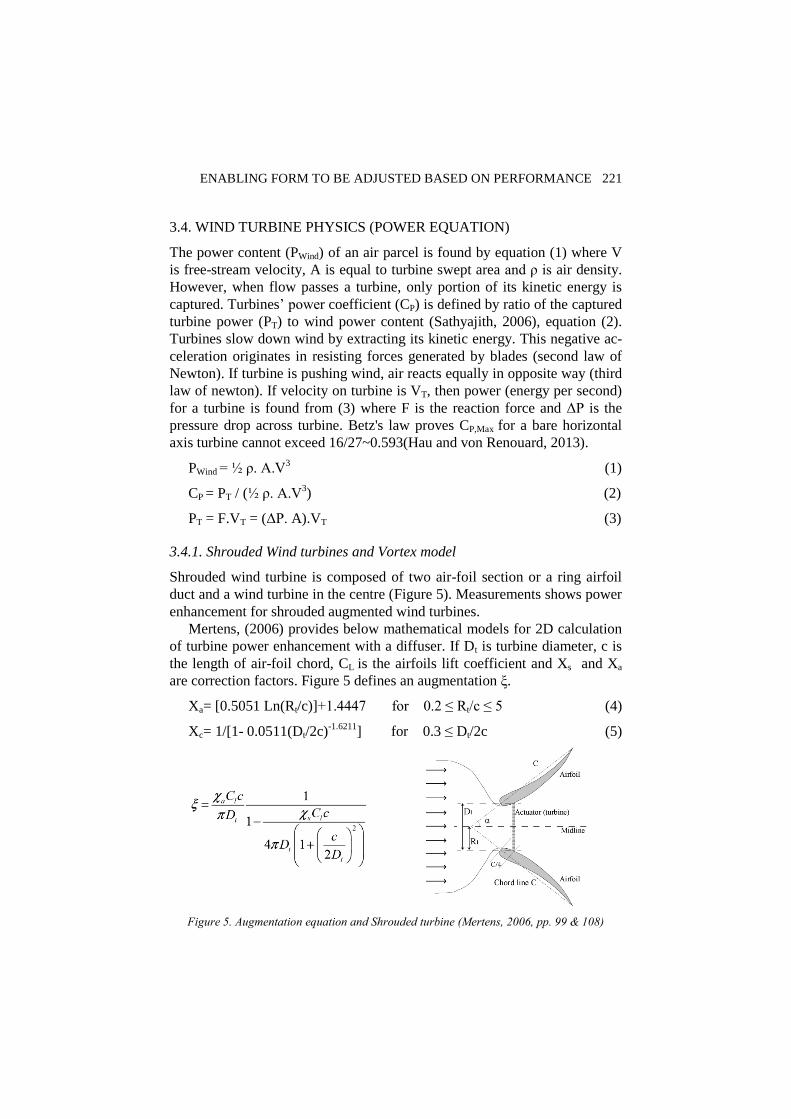
3.4.1. Shrouded Wind turbines and Vortex model
Shrouded wind turbine is composed of two air-foil section or a ring airfoil
duct and a wind turbine in the centre (Figure 5). Measurements shows power
enhancement for shrouded augmented wind turbines.
Mertens, (2006) provides below mathematical models for 2D calculation
of turbine power enhancement with a diffuser. If Dt is turbine diameter, c is
the length of air-foil chord, CL is the airfoils lift coefficient and Xs and Xa
are correction factors. Figure 5 defines an augmentation ξ.
Xa= [0.5051 Ln(Rt/c)]+1.4447 for 0.2 ≤ Rt/c ≤ 5 (4)
Xc= 1/[1- 0.0511(Dt/2c)-1.6211
] for 0.3 ≤ Dt/2c (5)
Figure 5. Augmentation equation and Shrouded turbine (Mertens, 2006, pp. 99 & 108)

222 ABDOLHOSSEIN-POUR., ALAGHMANDAN AND KRAWCZYK
ξ = Xa.CL.c/(π.Dt)/(1- Xs.CL.c/(4π.Dt (1+(c/2Dt) 2))) (6)
Equation (6) is the equivalent of the augmentation equation shown in
Figure 5. According to (6) shrouded turbine CP,Max is calculated by (7).
CP,Max = 16/27 (1+ ξ) (7)
In equation (7), the fraction 16/27 is the Betz’ constant studied in section
4. So, in ideal situation, CP,Max of a shrouded turbine can exceed Betz’ limits.
4. Discussion on research methodology
The integration of airflow analysis with early design stage was discussed in
Figure 1. The gap between design process and building aerodynamic has not
been studied well enough. Also above studies on aerodynamic, turbines
physics and BIWT raise a demand for an “Integrated Design-Research
Method”. The following steps provide an insight for this process.
4.1. CRITERIA DEFINITION (SURVEY OF THE KEY PARAMETERS)
First step is to collect the criteria driving the BIWT design from variety of
related fields including geometrical, functional /architectural, urban and cli-
mate fields. The parameters are then classified in three categories (Table 1)
depending on their impact on BIWT’s performance.
Variable Parameters affect airflow patterns across buildings’ bodies and are
typically associated with overall building geometries, corner modifications or
tower arrangements. This research studies only a limited number of variable
parameters and their effect on flow across tall building. The rest of variable
Parameters are kept unchanged during the study and left for future inquiries.
Table 1. Survey of BIWT key criteria, only variable parameters shown in black are studied
Variable Parameters Constant Parameters Controlling Parameters
- Geometrical
Footprint geometry
Extrusion,
Taper, Twist
- Arrangement (Twin towers)
Distance between towers
Turbine placement
- Duct Opening (single tower)
Duct profile geometry
Height & location of turbine
- Architectural
Floor to floor height
Number of floors, Gross area
Building orientation
- Climate
Site location
wind direction
- Urban
Terrain roughness
Adjacent tall building
- Architectural, functional
Lease span
Core planning
Max tower aspect ratio
Min allowable distance
between buildings
ENABLING FORM TO BE ADJUSTED BASED ON PERFORMANCE 223
Constant Parameters include those influencing the BIWT performance, but
not the building form itself. Constant parameters are not in the research
scope; hence their values are constant throughout the study (Table 1).
Controlling parameters are design functional criteria, limiting the range of
incremental changes found in variable parameters, to assure that the result of
3D alternatives fall within allowable ranges for high-rise architecture.
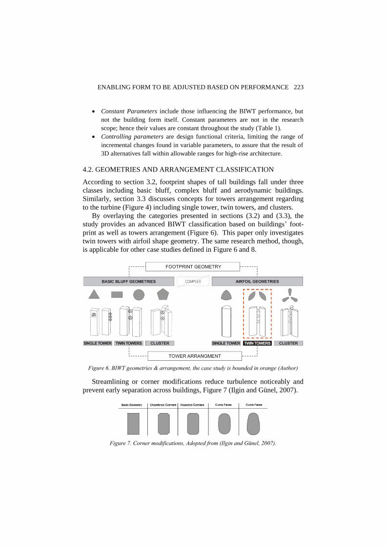
4.2. GEOMETRIES AND ARRANGEMENT CLASSIFICATION
According to section 3.2, footprint shapes of tall buildings fall under three
classes including basic bluff, complex bluff and aerodynamic buildings.
Similarly, section 3.3 discusses concepts for towers arrangement regarding
to the turbine (Figure 4) including single tower, twin towers, and clusters.
By overlaying the categories presented in sections (3.2) and (3.3), the
study provides an advanced BIWT classification based on buildings’ foot-
print as well as towers arrangement (Figure 6). This paper only investigates
twin towers with airfoil shape geometry. The same research method, though,
is applicable for other case studies defined in Figure 6 and 8.
Figure 6. BIWT geometries & arrangement, the case study is bounded in orange (Author)
Streamlining or corner modifications reduce turbulence noticeably and
prevent early separation across buildings, Figure 7 (Ilgin and Günel, 2007).
Figure 7. Corner modifications, Adopted from (Ilgin and Günel, 2007).
224 ABDOLHOSSEIN-POUR., ALAGHMANDAN AND KRAWCZYK
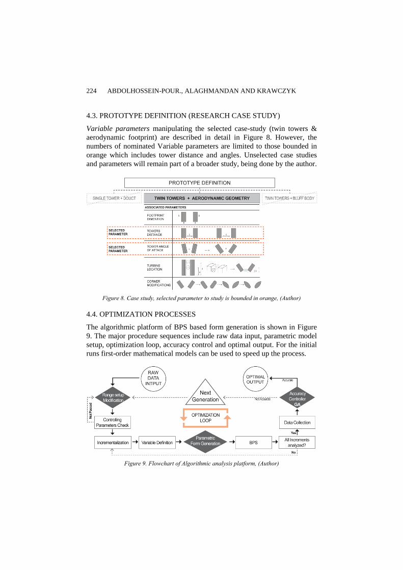
4.3. PROTOTYPE DEFINITION (RESEARCH CASE STUDY)
Variable parameters manipulating the selected case-study (twin towers &
aerodynamic footprint) are described in detail in Figure 8. However, the
numbers of nominated Variable parameters are limited to those bounded in
orange which includes tower distance and angles. Unselected case studies
and parameters will remain part of a broader study, being done by the author.
Figure 8. Case study, selected parameter to study is bounded in orange, (Author)
4.4. OPTIMIZATION PROCESSES
The algorithmic platform of BPS based form generation is shown in Figure
9. The major procedure sequences include raw data input, parametric model
setup, optimization loop, accuracy control and optimal output. For the initial
runs first-order mathematical models can be used to speed up the process.
Figure 9. Flowchart of Algorithmic analysis platform, (Author)
ENABLING FORM TO BE ADJUSTED BASED ON PERFORMANCE 225
Afterward, CFD simulation (e.g. ASNSYS Workbench) will precisely
predict the results. Workbench is capable of running parametric CFD simula-
tion while parametrically updating the geometry and mesh.
5. Discoveries and Conclusion
5.1. VERIFICATION OF THE CONCEPT
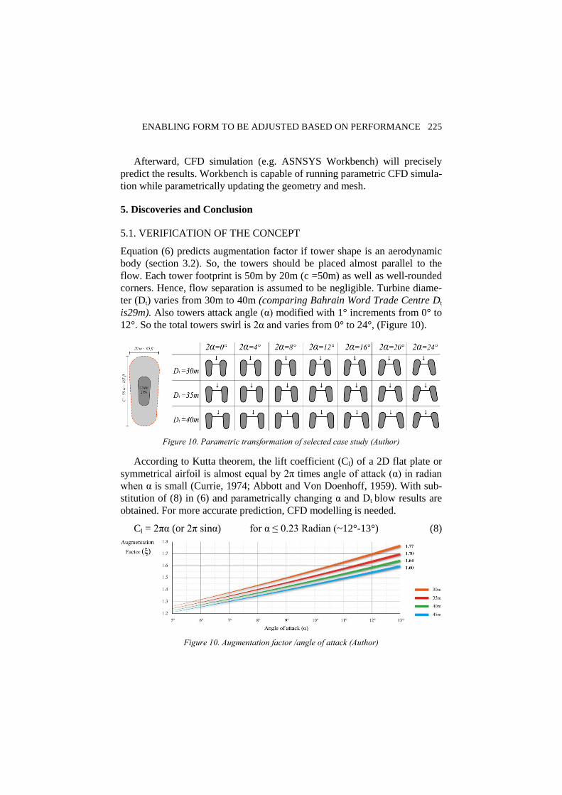
Equation (6) predicts augmentation factor if tower shape is an aerodynamic
body (section 3.2). So, the towers should be placed almost parallel to the
flow. Each tower footprint is 50m by 20m (c =50m) as well as well-rounded
corners. Hence, flow separation is assumed to be negligible. Turbine diame-
ter (Dt) varies from 30m to 40m (comparing Bahrain Word Trade Centre Dt
is29m). Also towers attack angle (α) modified with 1° increments from 0° to
12°. So the total towers swirl is 2α and varies from 0° to 24°, (Figure 10).
Figure 10. Parametric transformation of selected case study (Author)
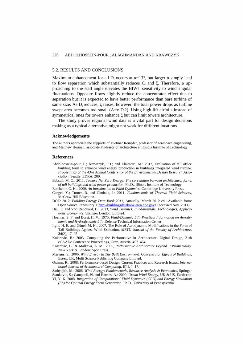
According to Kutta theorem, the lift coefficient (Cl) of a 2D flat plate or
symmetrical airfoil is almost equal by 2π times angle of attack (α) in radian
when α is small (Currie, 1974; Abbott and Von Doenhoff, 1959). With sub-
stitution of (8) in (6) and parametrically changing α and Dt blow results are
obtained. For more accurate prediction, CFD modelling is needed.
Cl = 2πα (or 2π sinα) for α ≤ 0.23 Radian (~12°-13°) (8)
Figure 10. Augmentation factor /angle of attack (Author)
226 ABDOLHOSSEIN-POUR., ALAGHMANDAN AND KRAWCZYK
5.2. RESULTS AND CONCLUSIONS
Maximum enhancement for all Dt occurs at α=13°, but larger α simply lead
to flow separation which substantially reduces Cl and ξ. Therefore, α ap-
proaching to the stall angle elevates the BIWT sensitivity to wind angular
fluctuations. Opposite flows slightly reduce the concentrator effect due to
separation but it is expected to have better performance than bare turbine of
same size. As Dt reduces, ξ raises, however, the total power drops as turbine
swept area becomes too small (A=π Dt2). Using high-lift airfoils instead of
symmetrical ones for towers enhance ξ but can limit towers architecture.
The study proves regional wind data is a vital part for design decisions
making as a typical alternative might not work for different locations.
Acknowledgements
The authors appreciate the supports of Dietmar Rempfer, professor of aerospace engineering, and Matthew Herman, associate Professor of architecture at Illinois Institute of Technology.
References
Abdolhossein-pour, F.; Krawczyk, R.J.; and Elnimeiri, M.: 2012, Evaluation of tall office building form to enhance wind energy production in buildings integrated wind turbine. Proceedings of the 43rd Annual Conference of the Environmental Design Research Asso-ciation, Seattle: EDRA, 289.
Babsail, M. O.: 2011, Toward Net Zero Energy: The correlation between architectural forms of tall buildings and wind power production, Ph.D., Illinois Institute of Technology.
Batchelor, G. K.: 2000, An Introduction to Fluid Dynamics, Cambridge University Press. Cengel, Y.; Turner, R. and Cimbala, J.: 2011, Fundamentals of Thermal-Fluid Sciences,
McGraw-Hill Education. DOE: 2012, Building Energy Data Book 2011, Annually. March 2012 ed.: Available from:
Open Source Repository < http://buildingsdatabook.eren.doe.gov> (accessed Nov. 2011). Hau, E. and Von Renouard, H.: 2013, Wind Turbines: Fundamentals, Technologies, Applica-
tions, Economics, Springer London, Limited. Hoerner, S. F. and Borst, H. V.: 1975, Fluid-Dynamic Lift, Practical Information on Aerody-
namic and Hydrodynamic Lift, Defense Technical Information Center. Ilgin, H. E. and Günel, M. H.: 2007, The Role of Aerodynamic Modifications in the Form of
Tall Buildings Against Wind Excitation, METU Journal of the Faculty of Architecture, 24(2), 17–25
Kolarevic, B.: 2003, Computing the Performative in Architecture. Digital Design, 21th eCAADe Conference Proceedings, Graz, Austria, 457–464
Kolarevic, B.; & Malkawi, A. M.: 2005, Performative Architecture Beyond Instrumentality. New York & London: Spon Press.
Mertens, S.: 2006, Wind Energy In The Built Environment: Concentrator Effects of Buildings, Essex, UK, Multi Science Publishing Company Limited.
Oxman, R.: 2008, Performance-based Design: Current Practices and Research Issues. Interna-tional Journal of Architectural Computing, 6(1), 1–17.
Sathyajith, M.: 2006, Wind Energy: Fundamentals, Resource Analysis & Economics, Springer Stankovic, S.; Campbell, N. and Harries, A.: 2009, Urban Wind Energy, UK & US, Earthscan Yi, Y. K. 2008. Integration of Computational Fluid Dynamics (CFD) and Energy Simulation
(ES) for Optimal Energy Form Generation. Ph.D., University of Pennsylvania.