Ahora anadiremos el proyecto de Open Erp al IDE Eclipse y configuraremos el Open ERP
Upload
khangminh22Category
view
1download
0
ADVANCED ENGINE MANAGEMENT INC. 2205 126th Street Unit A Hawthorne, CA. 90250 Phone: (310) 484-2322 Fax: (310) 484-0152
Http://www.aempower.com Instruction Part Number: 10-6300
2009 Advanced Engine Management, Inc.
Page 1 of 12
Installation Instructions for: EMS P/N 30-6300
1990-1994 Eclipse Turbo,
Talon Tsi, Laser RS
Galant VR4
WARNING:
�!
This installation is not for the tuning novice nor the PC illiterate! Use this system with EXTREME caution! The AEM EMS System allows for total flexibility in engine tuning. Misuse of this product can destroy your engine! If you are not well versed in engine dynamics and the tuning of management systems or are not PC literate, please do not attempt the installation. Refer the installation to an AEM-trained tuning shop. A list of tuners can be found in the “AEM EMS Tuning” subsection of the AEM Electronics Forums at http://www.aempower.com or by calling 800-423-0046. NOTE: AEM holds no responsibility for any engine damage that results from the misuse of this product!
This product is legal in California for racing vehicles only and should never be used on public highways.

Page 2 of 12
Thank you for purchasing an AEM Engine Management System. The AEM Engine Management System (EMS) is the result of extensive development on a wide variety of cars. Each system is engineered for the particular application. The AEM EMS differs from all others in several ways. The EMS is a stand alone system, which completely replaces the factory ECU and features unique Plug and Play Technology, which means that each system is configured especially for your make and model of car without any jumper harnesses. There is no need to modify your factory wiring harness and in most cases your car may be returned to stock in a matter of minutes. For stock and slightly modified vehicles, the supplied startup calibrations are configured to work with OEM sensors, providing a solid starting point for beginner tuning. For more heavily modified cars, the EMS can be reconfigured to utilize aftermarket sensors and has many spare inputs and outputs allowing the elimination of add-on rev-limiters, boost controllers, nitrous controllers, fuel computers, etc. It also includes a configurable onboard 1MB data logger that can record any 16 EMS parameters at up to 250 samples per second. Every EMS comes with all functions installed and activated; there is no need to purchase options or upgrades to unlock the full potential of your unit. The installation of the AEM EMS on the supported vehicles uses the stock sensors and actuators. After installing the AEMTuner software, the startup calibration will be saved to the following folder on your PC: C:\Program Files\AEM\AEMTuner\Calibrations\Mitsubishi-DSM\ Multiple calibrations may be supplied for each EMS; additional details of the test vehicle used to generate each calibration can be found in the Calibration Notes section for that file. Please visit the AEM Performance Electronics Forum at http://www.aempower.com and register. We always post the most current strategy release, PC Software and startup calibrations online. On the forum, you can find and share many helpful hints/tips to make your EMS perform its best.
TUNING NOTES AND WARNING: While the supplied startup calibration may be a good starting point and can save considerable time and money, it will not replace the need to tune the EMS for your specific application. AEM startup calibrations are not intended to be driven aggressively before tuning. We strongly recommend that every EMS be tuned by someone who is already familiar with the AEM software and has successfully tuned vehicles using an AEM EMS. Most people make mistakes as part of the learning process; be warned that using your vehicle as a learning platform can damage your engine, your vehicle, and your EMS.

Page 3 of 12
Read and understand these instructions BEFORE attempting to install this product.
1) Install AEMTuner software onto your PC The latest version of the AEMTuner software can be downloaded from the AEMTuner section of the AEM Performance Electronics forums. Series 2 units are not supported by the older AEMPro tuning software.
2) Remove the Stock Engine Control Unit
a) Access the stock Engine Control Unit (ECU). The location of the ECU on the 1G DSM vehicles is behind the radio in the center console.
b) Carefully disconnect the wiring harness from the ECU. Avoid excessive stress or pulling on the wires, as this may damage the wiring harness. Some factory ECUs use a bolt to retain the factory connectors, and it must be removed before the harness can be disconnected. There may be more than one connector, and they must all be removed without damage to work properly with the AEM ECU. Do not cut any of the wires in the factory wiring harness to remove them.
c) Remove the fasteners securing the ECU to the car body, and set them aside. Do not destroy or discard the factory ECU, as it can be reinstalled easily for street use and troubleshooting.
3) Install the AEM Engine Management System a) Plug the factory wiring harness into the AEM EMS and position it so the wires are
not pulled tight or stressed in any manner. Secure the EMS with the provided Velcro fasteners.
b) Plug the comms cable into the EMS and into your PC. c) Turn the ignition on but do not attempt to start the engine. d) The USB drivers must be installed the first time you connect to a Series 2 EMS with
an onboard USB port. When the Series 2 EMS is connected to the PC’s USB port and receiving power from the vehicle, the “Found New Hardware” window will appear. Select “Install from a list of specific location (Advanced)” and browse to the following folder: C:\Program Files\AEM\AEMTuner\USB Drivers (Series 2)\
e) With the AEMTuner software open, select ECU>>Upload Calibration to upload the
startup calibration file (.cal) that most closely matches the vehicle’s configuration to be tuned. Check the Notes section of the calibration for more info about the vehicle it was configured for. These files can be found in the following folder: C:\Program Files\AEM\AEMTuner\Calibrations\Mitsubishi-DSM\

Page 4 of 12
f) Set the throttle range: Select Wizards>>Set Throttle Range and follow the on-screen instructions. When finished, check that the ‘Throttle’ channel never indicates less than 0.2% or greater than 99.8%, this is considered a sensor error and may cause some functions including idle feedback and acceleration fuel to operate incorrectly.
4) Ready to begin tuning the vehicle. a) Before starting the engine, verify that the fuel pump runs for a couple of seconds
when the key is turned on and there is sufficient pressure at the fuel rail. If a MAP sensor is installed, check that the Engine Load indicates something near atmospheric pressure (approximately 101kPa or 0 PSI at sea level) with the key on and engine off. Press the throttle and verify that the ‘Throttle’ channel responds but the Engine Load channel continues to measure atmospheric pressure correctly.
b) Start the engine and make whatever adjustments may be needed to sustain a safe and reasonably smooth idle. Verify the ignition timing: Select Wizards>>Ignition Timing Sync from the pull-down menu. Click the ‘Lock Ignition Timing’ checkbox and set the timing to a safe and convenient value (for instance, 10 degrees BTDC). Use a timing light and compare the physical timing numbers to the timing value you selected. Use the Sync Adjustment Increase/Decrease buttons to make the physical reading match the timing number you selected.
c) Note: This calibration needs to be properly tuned before driving the vehicle. It is intended for racing vehicles and may not operate smoothly at idle or part-throttle. NEVER TUNE THE VEHICLE WHILE DRIVING
5) Troubleshooting an engine that will not start
a) Double-check all the basics first… engines need air, fuel, compression, and a correctly-timed spark event. If any of these are lacking, we suggest checking simple things first. Depending on the symptoms, it may be best to inspect fuses, sufficient battery voltage, properly mated wiring connectors, spark using a timing light or by removing the spark plug, wiring continuity tests, measure ECU pinout voltages, replace recently-added or untested components with known-good spares. Check that all EMS sensor inputs measure realistic temperature and/or pressure values.
b) If the EMS is not firing the coils or injectors at all, open the Start tab and look for the ‘Stat Sync’d’ channel to turn ON when cranking. This indicates that the EMS has detected the expected cam and crank signals; if Stat Sync’d does not turn on, monitor the Crank Tooth Period and T2PER channels which indicate the time between pulses on the Crank and T2 (Cam) signals. Both of these channels should respond when the engine is cranking, if either signal is not being detected or measuring an incorrect number of pulses per engine cycle the EMS will not fire the coils or injectors.
c) If the Engine Load changes when the throttle is pressed this usually indicates that there is a problem with the MAP sensor wiring or software calibration (when the EMS detects that the MAP Volts are above or below the min/max limits it will run in a failsafe mode using the TPS-to-Load table to generate an artificial Engine Load signal using the Throttle input). This may allow the engine to sputter or start but not continue running properly.

Page 5 of 12
Application Notes for EMS P/N 30-6300 1990-1994 Eclipse Turbo, Talon Tsi,
Laser RS, Galant VR4
Make: DSM (Mitsubishi/Eagle) Spare Injector Drivers: Inj 5, Pin 77 Model: Various, see list above Spare Injector Drivers: Inj 6, Pin 78 Years Covered: 1990-1994 Spare Injector Drivers: Inj 7, Pin 79 Engine Displacement: 2.0L Spare Injector Drivers: Inj 8, Pin 80 Engine Configuration: Inline 4 Spare Injector Drivers: Inj 9, Pin 3 Firing Order: 1-3-4-2 N/A, S/C or T/C: Turbocharged Spare Coil Drivers: Coil 3, Pin 11 Load Sensor Type: Karman Vortex MAF Spare Coil Drivers: Coil 4, Pin 104 Boost Solenoid: PW 2, Pin 105 # Coils: 2 (wasted spark) EMS Ignition driver type: 0-5V, Falling Edge trigger EGT #1 Location: Pin 71 EGT #2 Location: Pin 72 # Injectors: 4 (P&H drivers: Inj1-4) EGT #3 Location: Pin 73 Factory Injectors: 450cc/min low-impedance EGT #4 Location: Pin 74 Factory Inj Resistors: Yes, 6 ohm resistor pack Injection Mode: Sequential Spare 0-5V Channels: MAP, Pin 12 Knock Sensors used: 1 Lambda Sensors used: 2 (aftermarket wideband: Spare Low Side Driver: Low Side 5, Pin 81 factory O2 not supported) Spare Low Side Driver: Low Side 6, Pin 82 Idle Motor Type: Stepper Check Engine Light: Low Side 10, Pin 64 Main Relay Control: Yes Crank Pickup Type: Optical Spare High Side Driver: High Side 1, Pin 1 Crank Teeth/Cycle: 4 Spare High Side Driver: High Side 2, Pin 15 Cam Pickup Type: Optical Spare High Side Driver: High Side 3, Pin 2 Cam Teeth/Cycle: 2, variable length Transmissions Offered: M/T, A/T A/C Switch Input: Switch 2, Pin 7* Trans Supported: M/T Only Spare Switch Input: Switch 3, Pin 109** Drive Options: FWD/AWD Spare Switch Input: Switch 4, Pin 14** Supplied Connectors: 12-pin expansion w/ pins Spare Switch Input: Switch 5, Pin 5**
WARNING: * The factory A/C request switch sends 12V power to signal an A/C request and the 30-6300 EMS has been designed to accept 12V power on this switched input. If users desire to re-wire a new switch to trigger the Switch 2 input the switch should connect to 12V power when the switch is on. The pin can be left floating (disconnected) when the switch is off, it is not required to send ground to this pin. **All other switch input pins must connect to ground; the switch should not provide 12V power to the EMS because that will not be detected as on or off. Connecting 12V power to the Switch 3, Switch 4 or Switch 5 pins may damage your EMS and void your warranty. ***Idle control valve wiring is different for 1990 vs 1991+ models (pins 67, 68), please use appropriate base calibration or change the (Idle Invert) option until your ISCV operates properly. The function of the following pins have been changed from the original 30-1300 EMS, please see pinout chart for more info: 7, 13, 14, 73, 74, 109
Page 6 of 12
Primary Load Sensor, EMS Fuel Strategy The factory MAF (mass air flow) sensor can be removed to help decrease intake air restriction; the EMS can be configured to use a MAP sensor to determine engine load. It is recommended to use a 3.5 bar MAP sensor or higher (P/N 30-2130-50).Please be aware that the IAT (intake air temperature) sensor is integrated into the factory MAF sensor. If the factory MAF / IAT sensor is removed, you may wish to install an AEM IAT Sensor Kit (P/N 30-2010), which includes a sensor, wire connector, and aluminum weld-in bung. While the factory MAF sensor locates the IAT sensor upstream of the turbocharger inlet, it may be preferable to install an IAT sensor downstream of the intercooler to accurately measure charge temperatures. The factory Mass Air Flow and Intake Air Temperature sensors can be used as the primary load input for the AEM EMS if desired. Please check the Notes section of each calibration for more info about the vehicle setup and fuel strategy that calibration was configured to use. EMS Fuel Map, Boost Fuel Trim Table The 30-6300 maps provided utilize the “Boost Fuel Trim Table” to provide a 1:1 fuel compensation above and below atmospheric pressure. In the startup calibration, the “Boost Fuel TrimTable” is configured to provide twice as much fuel when the manifold pressure is twice as high and half the fuel when the manifold pressure is half as high; this should help simplify the tuning process for different vacuum and boost levels. Notice the values in the main “Fuel Map” do not change above 100 kPa (0 psi boost), the fuel correction is being made by the “Boost Fuel Trim Table.” Note: the “Boost Fuel Trim Table” must be adjusted if a different MAP sensor is installed or if the Load breakpoints are adjusted. The Boost Fuel Correct value should be set to -90 at 10kPa, 0 at 100 kPa, +100 at 200 kPa, +200 at 300 kPa, etc…
Page 7 of 12
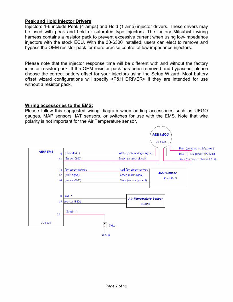
Peak and Hold Injector Drivers Injectors 1-6 include Peak (4 amps) and Hold (1 amp) injector drivers. These drivers may be used with peak and hold or saturated type injectors. The factory Mitsubishi wiring harness contains a resistor pack to prevent excessive current when using low-impedance injectors with the stock ECU. With the 30-6300 installed, users can elect to remove and bypass the OEM resistor pack for more precise control of low-impedance injectors. Please note that the injector response time will be different with and without the factory injector resistor pack. If the OEM resistor pack has been removed and bypassed, please choose the correct battery offset for your injectors using the Setup Wizard. Most battery offset wizard configurations will specify <P&H DRIVER> if they are intended for use without a resistor pack. Wiring accessories to the EMS: Please follow this suggested wiring diagram when adding accessories such as UEGO gauges, MAP sensors, IAT sensors, or switches for use with the EMS. Note that wire polarity is not important for the Air Temperature sensor.

Page 8 of 12
Connection Diagram for EMS P/N 30-6300 1990-1994 Eclipse Turbo, Talon Tsi, Laser RS, Galant VR4
Pin # 1G DSM AEM EMS 30-6300 I/O Availability
1 Data Link High Side Driver 1 Output Avail, Switched +12v, 1.5A Max
2 Data Link High Side Driver 3 Output Avail, Switched +12v, 1.5A Max
3 Boost Gauge (turbo only) Injector 9 Output Avail, Switched Ground, 1.5A Max
4 O2 Sensor O2 #1 Input Dedicated, 0-5V signal
5 P/S Pressure Switch Switch 5 Input Available, Switched GND Input
6 MAF Reset (turbo only) Low Side Driver 7 Output Avail, Switched Ground, 1.5A Max
7 A/C Request Switch 2 Input PnP for A/C request switch
8 AIT AIT Input PnP for Air Intake Temp Sensor
9 Knock Sensor (turbo only) Knock 1 Input Available, software knock filter
10 Karman Vortex MAF T4 (Spare Speed) Input PnP for frequency MAF input
11 ABS In (92 AWD Only) Coil 3 Output Avail, Coil output, rising edge trigger
12 Ignition Timing Adjustment MAP Input Avail, MAP sensor input
13 Fuel Pump on confirmation CAN1H --- Dedicated
14 TPS Closed Switch Switch 4 Input Available, Switched GND Input
15 EGR Temp (Ca only) High Side Driver 2 Output Avail, Switched +12V, 1.5A Max
16 Baro Sensor Baro Volts Input Available, 0-5V input
17 Sensor Ground Sensor Ground Output Dedicated, sensors only
18 VSS Vehicle Speed Input PnP for Vehicle Speed Sensor
19 TPS TPS Input PnP for Throttle Position
20 Coolant Coolant Input PnP for Engine Coolant Temp
21 Crank Crank Input Dedicated, Crankshaft Sensor
22 Cam Cam Input Dedicated, Camshaft Sensor
23 5 Volts sensor reference power +5V Sensor Output Dedicated, sensors only
24 Sensor Ground Sensor Ground Output Dedicated, sensors only

Page 9 of 12
Pin # 1G DSM AEM EMS 30-6300 I/O Availability
51 Injector 1 Injector 1 Output PnP Injector 1 (P&H 4A/1A driver)
52 Injector 2 Injector 2 Output PnP Injector 2 (P&H 4A/1A driver)
53 EGR Solenoid Low Side Driver 2 Output Avail, Switched Ground, 1.5A Max
54 Coil 2 Coil 2 Output PnP Coil 2, rising edge trigger
55 Coil 1 Coil 1 Output PnP Coil 1, rising edge trigger
56 Fuel Pump Relay Low Side Driver 11 Output PnP for Fuel Pump
57 Fuel Press Sol (turbo only) Low Side Driver 1 Output PnP for Fuel Pressure Solenoid
58 Idle 3 Idle 1 Output PnP for Idle Motor
59 Idle 4 Idle 2 Output PnP for Idle Motor
60 Injector 3 Injector 3 Output PnP Injector 3 (P&H 4A/1A driver)
61 Injector 4 Injector 4 Output PnP Injector 4 (P&H 4A/1A driver)
62 EVAP Purge Sol Low Side Driver 4 Output Avail, Switched Ground, 1.5A Max
63 MFI Relay Control Main Relay (Coil 5) Output Dedicated, activates relay w switched GND
64 Check Engine Light Low Side Driver 10 Output Avail, Switched Ground, 1.5A Max
65 A/C Relay Low Side Driver 3 Output PnP for A/C Compressor
66 MFI On O2 #2 Input Dedicated, 0-5V signal
67 Idle 1*** Idle 3 Output PnP for Idle Motor
68 Idle 2*** Idle 4 Output PnP for Idle Motor

Page 10 of 12
Pin # 1G DSM AEM EMS 30-6300 I/O Availability
71 N/A EGT 1 Input Avail, jumper set for 0-5V Input
72 N/A EGT 2 Input Avail, jumper set for 0-5V Input
73 N/A EGT 3 Input Avail, jumper set for 0-5V Input
74 N/A EGT 4 Input Avail, jumper set for 0-5V Input
75 N/A CAN1L --- Dedicated
76 N/A PW 1 Output Avail, Switched Ground duty cycle output
77 N/A Injector 5 Output Avail, Inj output 1.5A max (not peak/hold)
78 N/A Injector 6 Output Avail, Inj output 1.5A max (not peak/hold)
79 N/A Injector 7 Output Avail, Inj output 1.5A max (not peak/hold)
80 N/A Injector 8 Output Avail, Inj output 1.5A max (not peak/hold)
81 N/A Low Side Driver 5 Output Avail, switched ground, 1.5A max
82 N/A Low Side Driver 6 Output Avail, switched ground, 1.5A max
Pin # 1G DSM AEM EMS 30-6300 I/O Availability
101 Ground In Ground Input Dedicated
102 12V IN (MFI Relay) +12V Switched Input Dedicated, 12V power when relay is on
103 Perm 12V Permanent +12V Input Dedicated, used to store internal datalog
104 (GND for vehicles) Coil 4 Output Avail, Coil or 1.5A switched output
105 Wastegate Solenoid PW 2 Output PnP for Wastegate Control Solenoid
106 Ground In Ground Input Dedicated
107 12V IN (MFI Relay) +12V Switched Input Dedicated, 12V power when relay is on
108 Cranking Main Relay circuit (Start switch) Input Dedicated, activates Switch 1 input
109 Tach In Switch 3 Input Avail, switch must connect to ground
110 Ignition Switch Main Relay circuit (Ign switch) Input Dedicated, activates Switch 1 input
Page 11 of 12
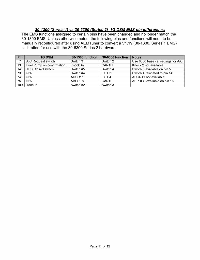
30-1300 (Series 1) vs 30-6300 (Series 2) 1G DSM EMS pin differences: The EMS functions assigned to certain pins have been changed and no longer match the 30-1300 EMS. Unless otherwise noted, the following pins and functions will need to be manually reconfigured after using AEMTuner to convert a V1.19 (30-1300, Series 1 EMS) calibration for use with the 30-6300 Series 2 hardware.
Pin 1G DSM 30-1300 function 30-6300 function Notes
7 A/C Request switch Switch 3 Switch 2 Use 6300 base cal settings for A/C 13 Fuel Pump on confirmation Knock #2 CAN1H Knock 2 not available 14 TPS Closed switch Switch #5 Switch 4 Switch 5 available on pin 5 73 N/A Switch #4 EGT 3 Switch 4 relocated to pin 14 74 N/A ADCR11 EGT 4 ADCR11 not available 75 N/A ABPRES CAN1L ABPRES available on pin 16 109 Tach In Switch #2 Switch 3

Page 12 of 12
AEM Electronics Warranty Advanced Engine Management Inc. warrants to the consumer that all AEM Electronics products will be free from defects in material and workmanship for a period of twelve months from date of the original purchase. Products that fail within this 12-month warranty period will be repaired or replaced when determined by AEM that the product failed due to defects in material or workmanship. This warranty is limited to the repair or replacement of the AEM part. In no event shall this warranty exceed the original purchase price of the AEM part nor shall AEM be responsible for special, incidental or consequential damages or cost incurred due to the failure of this product. Warranty claims to AEM must be transportation prepaid and accompanied with dated proof of purchase. This warranty applies only to the original purchaser of product and is non-transferable. All implied warranties shall be limited in duration to the said 12-month warranty period. Improper use or installation, accident, abuse, unauthorized repairs or alterations voids this warranty. AEM disclaims any liability for consequential damages due to breach of any written or implied warranty on all products manufactured by AEM. Warranty returns will only be accepted by AEM when accompanied by a valid Return Merchandise Authorization (RMA) number. Product must be received by AEM within 30 days of the date the RMA is issued. Please note that before AEM can issue an RMA for any electronic product, it is first necessary for the installer or end user to contact the tech line at 1-800-423-0046 to discuss the problem. Most issues can be resolved over the phone. Under no circumstances should a system be returned or a RMA requested before the above process transpires. AEM will not be responsible for electronic products that are installed incorrectly, installed in a non approved application, misused, or tampered with. Any AEM electronics product can be returned for repair if it is out of the warranty period. There is a minimum charge of $50.00 for inspection and diagnosis of AEM electronic parts. Parts used in the repair of AEM electronic components will be extra. AEM will provide an estimate of repairs and receive written or electronic authorization before repairs are made to the product.
Copyright © 2022 FDOKUMEN