Phaser 6300/6350/6360 Color Laser Printer Service Manual
564
Service Manual Phaser ® 6300/6350/6360 701P45775 Color Laser Printer
-
Upload
khangminh22 -
Category
Documents
-
view
0 -
download
0
Transcript of Phaser 6300/6350/6360 Color Laser Printer Service Manual
Service Manual
Phaser® 6300/6350/6360
701P45775
Color Laser Printer


Service Manual701P45775
Phaser®6300/6350/6360Color Laser Printer
WarningThe following servicing instructions are for use by qualified service personnel only. To avoid personal injury, do not perform any servicing other than that contained in the operating instructions, unless you are qualified to do so.
First Printing: January 2007

ii Phaser 6300/6350/6360 Color Laser Printer Service Manual
Prepared By:
Xerox Corporation
XOG Worldwide Product Training and Information
26600 SW Parkway
Wilsonville, OR 97070
Copyright © 2007 Xerox Corporation. All Rights Reserved. Unpublished rights reserved under the copyright laws of the United States. Contents of this publication may not be reproduced in any form without permission of Xerox Corporation.
Copyright protection claimed includes all forms of matters of copyrightable materials and information now allowed by statutory or judicial law or hereinafter granted, including without limitation, material generated from the software programs which are displayed on the screen such as styles, templates, icons, screen displays, looks, etc.
Xerox technical training materials and service manuals are intended for use by authorized Xerox service technicians and service partners only and are not for resale. These materials may not be distributed, copied or otherwise reproduced without prior written consent from Xerox Corporation.
XEROX®, The Document Company®, the digital X®, CentreWare®, infoSMART®, Made For Each Other®, PagePack™, Phaser®,
PhaserSMART®, and Walk-Up™ are trademarks of Xerox Corporation in the United States and/or other countries.
Acrobat®, Adobe® Reader®, Adobe Type Manager®, ATM™, Illustrator®, PageMaker®, Photoshop®, PostScript®, Adobe Brilliant® Screens,
Adobe Garamond®, Adobe Jenson™, Birch®, Carta®, IntelliSelect®, Mythos®, Quake®, and Tekton® are trademarks of Adobe Systems Incorporated in the United States and/or other countries.
Apple®, AppleTalk®, Bonjour®, EtherTalk®, LaserWriter®, LocalTalk®, Macintosh®, Mac OS®, TrueType®, Apple Chancery®, Chicago®,
Geneva®, Monaco®, New York®, and QuickDraw® are trademarks of Apple Computer, Inc. in the United States and/or other countries.
HP-GL®, HP-UX®, and PCL®are trademarks of Hewlett-Packard Corporation in the United States and/or other countries.
IBM® and AIX® are trademarks of International Business Machines Corporation in the United States and/or other countries.
Windows®, Vista™, Windows Server™, and Wingdings® are trademarks of Microsoft Corporation in the United States and/or other countries.
Novell®, NetWare®, NDPS®, NDS®, Novell Directory Services®, IPX™, and Novell Distributed Print Services™are trademarks of Novell, Incorporated in the United States and/or other countries.
SunSM, Sun Microsystems™, and Solaris™ are trademarks of Sun Microsystems, Incorporated in the United States and/or other countries.
SWOP® is a trademark of SWOP, Inc.
UNIX® is a trademark in the United States and other countries, licensed exclusively through X/Open Company Limited.
As an ENERGY STAR® partner, Xerox Corporation has determined that this product meets the ENERGY STAR guidelines for energy efficiency. The ENERGY STAR name and logo are registered U.S. marks.
PANTONE® Colors generated may not match PANTONE-identified standards. Consult current PANTONE Publications for accurate color.
PANTONE® and other Pantone, Inc. trademarks are the property of Pantone, Inc. © Pantone, Inc., 2000.

Phaser 6300/6350/6360 Color Laser Printer Service Manual iii
Service Terms
Manual Terms
Various terms are used throughout this manual to either provide additional information on a specific topic or to warn of possible danger present during a procedure or action. Be aware of all symbols and terms when they are used, and always read NOTE, CAUTION, and WARNING statements.
Common Acronyms:
The following list defines the acronyms that may be found in this manual.
NoteA note indicates an operating or maintenance procedure, practice or condition that is necessary to efficiently accomplish a task. A note can provide additional information related to a specific subject or add a comment on the results achieved through a previous action.
CautionA caution indicates an operating or maintenance procedure, practice or condition that, if not strictly observed, results in damage to, or destruction of, equipment.
WarningA warning indicates an operating or maintenance procedure, practice or condition that, if not strictly observed, results in injury or loss of life.
Product Terms
Caution: A personal injury hazard exists that may not be apparent. For example, a panel may cover the hazardous area.
Danger: A personal injury hazard exists in the area where you see the sign.
ADC: Automatic Density Control MCU: Engine Control BoardBTR: Bias Transfer Roller NCS: Non-Contact SensorCRUM: Customer Replaceable Unit Monitor
PHD: Imaging Unit
CTD: Toner Density Control PL: Corresponds to the FRU Parts List.ESD: Electrostatic Discharge ROS: Laser Scanning UnitIDT: Intermediate Transfer Unit RTC: Charge Roller

iv Phaser 6300/6350/6360 Color Laser Printer Service Manual
Symbols Marked on the Product
Warning Labels
Read and obey all posted warning labels. Throughout the printer, warning labels are displayed on potentially dangerous components. As you service the printer, check to make certain that all warning labels remain in place.
Use caution (or draws attention to a particular component). Refer to the manual(s) for information.
Do not burn.
Allow component to cool for the indicated number of minutes.
Hot surface on or in the printer. Use caution to avoid personal injury.
The surface is hot while the printer is running. After turning off the power, wait the indicated number of minutes.
Do not expose to light.
Do not touch
0
30

Phaser 6300/6350/6360 Color Laser Printer Service Manual v
Power Safety Precautions
Power Source
For 115 VAC printers, do not apply more than 135 volts RMS between the supply conductors or between either supply conductor and ground. For 230 VAC printers, do not apply more than 254 volts RMS between the supply conductors or between either supply conductor and ground. Use only the specified power cord and connector. This manual assumes that the reader is a qualified service technician.
Plug the three-wire power cord (with grounding prong) into a grounded AC outlet only. If necessary, contact a licensed electrician to install a properly grounded outlet. If the product loses its ground connection, contact with conductive parts may cause an electrical shock. A protective ground connection by way of the grounding conductor in the power cord is essential for safe operation.
Disconnecting Power
WarningTurning the power off using the power switch does not completely de-energize the printer. You must also disconnect the power cord from the printer’s AC inlet. Disconnect the power cord by pulling the plug, not the cord.
Disconnect the power cord in the following cases:
if the power cord or plug is frayed or otherwise damaged,
if any liquid or foreign material is spilled into the product,
if the printer is exposed to any excess moisture,
if the printer is dropped or damaged,
if you suspect that the product needs servicing or repair,
whenever you clean the product.

vi Phaser 6300/6350/6360 Color Laser Printer Service Manual
Electrostatic Discharge (ESD) Precautions
Some semiconductor components, and the respective sub-assemblies that contain them, are vulnerable to damage by Electrostatic discharge (ESD). These components include Integrated Circuits (ICs), Large-Scale Integrated circuits (LSIs), field-effect transistors and other semiconductor chip components. The following techniques will reduce the occurrence of component damage caused by static electricity.
Be sure the power is off to the chassis or circuit board, and observe all other safety precautions.
Immediately before handling any semiconductor components assemblies, drain the electrostatic charge from your body. This can be accomplished by touching an earth ground source or by wearing a wrist strap device connected to an earth ground source. Wearing a wrist strap will also prevent accumulation of additional bodily static charges. Be sure to remove the wrist strap before applying power to the unit under test to avoid potential shock.
After removing a static sensitive assembly from its anti-static bag, place it on a grounded conductive surface. If the anti-static bag is conductive, you may ground the bag and use it as a conductive surface.
Do not use freon-propelled chemicals. These can generate electrical charges sufficient to damage some devices.
Do not remove a replacement component or electrical sub-assembly from its protective package until you are ready to install it.
Immediately before removing the protective material from the leads of a replacement device, touch the protective material to the chassis or circuit assembly into which the device will be installed.
Minimize body motions when handling unpacked replacement devices. Motion such as your clothes brushing together, or lifting a foot from a carpeted floor can generate enough static electricity to damage an electro-statically sensitive device
Handle IC’s and EPROM’s carefully to avoid bending pins.
Pay attention to the direction of parts when mounting or inserting them on Printed Circuit Boards (PCB’s).

Phaser 6300/6350/6360 Color Laser Printer Service Manual vii
Service Safety Summary
General Guidelines
For qualified service personnel only: Refer also to the preceding Power Safety Precautions.
Avoid servicing alone: Do not perform internal service or adjustment of this product unless another person capable of rendering first aid or resuscitation is present.
Use care when servicing with power: Dangerous voltages may exist at several points in this product. To avoid personal injury, do not touch exposed connections and components while power is on. Disconnect power before removing the power supply shield or replacing components.
Do not wear jewelry: Remove jewelry prior to servicing. Rings, necklaces and other metallic objects could come into contact with dangerous voltages and currents.
Safety Interlocks
Make sure all covers are in place and all interlock switches are functioning correctly after you have completed a printer service call. If you bypass an interlock switch during a service call, use extreme caution when working on or around the printer.
CLASS 1 LASER PRODUCT
The Phaser 6300/6350/6360 Color Laser Printer is certified to comply with Laser Product Performance Standards set by the U.S. Department of Health and Human Services as a Class 1 Laser Product. This means that this product does not emit hazardous laser radiation; which is possible only because the laser beam is totally enclosed during all modes of customer operation. When servicing the printer or laser unit, follow the procedures specified in this manual and there will be no hazards from the laser.

viii Phaser 6300/6350/6360 Color Laser Printer Service Manual
Servicing Electrical Components
Before starting any service procedure, switch off the printer power and unplug the power cord from the wall outlet. If you must service the printer with power applied, be aware of the potential for electrical shock.
WarningDo not touch any electrical component unless you are instructed to do so by a service procedure.
Servicing Mechanical Components
When servicing mechanical components within the printer, manually rotate drive assemblies, rollers, and gears.
WarningDo not try to manually rotate or manually stop the drive assemblies while any printer motor is running.
Servicing Fuser Components
WarningThis printer uses heat to fuse the toner image to media. The Fuser is VERY HOT. Turn the printer power off and wait at least 10 minutes for the Fuser to cool before you attempt to service the Fuser or adjacent components.
S7300-02
S7300-03

Phaser 6300/6350/6360 Color Laser Printer Service Manual ix
Regulatory Specifications
Xerox has tested this product to electromagnetic emission and immunity standards. These standards are designed to mitigate interference caused or received by this product in a typical office environment.
United States (FCC Regulations)
The Phaser 6360 has been tested and found to comply with the limits for a Class A digital device pursuant to Part 15 of the FCC Rules. The Phaser 6300/6350 has been tested and found to comply with the limits for a Class B digital device pursuant to Part 15 of the FCC Rules. These limits are designed to provide reasonable protection against harmful interference in a commercial (Class A), or residential (Class B) installation. This equipment generates, uses, and can radiate radio frequency energy. If it is not installed and used in accordance with these instructions, it may cause harmful interference to radio communications. Operation of Class A equipment in a residential area is likely to cause harmful interference in which case the user will be required to correct the interference at his/her own expense. There is no guarantee that interference will not occur in a particular installation.
If this equipment does cause harmful interference to radio or television reception, which can be determined by turning the equipment off and on, the user is encouraged to try to correct the interference by one or more of the following measures:
Reorient or relocate the receiver (device being interfered with).
Increase the separation between the printer and the receiver.
Connect the equipment into an outlet on a circuit different from that which the receiver is connected.
Consult the dealer or an experienced radio/television technician for help.
Any changes or modifications not expressly approved by Xerox could void the user's authority to operate the equipment. To ensure compliance with Part 15 of the FCC rules, use shielded interface cables.
Canada (Regulations)
6360
This Class A digital apparatus complies with Canadian ICES-003.
Cet appareil numérique de la classe A est conforme à la norme NMB-003 du Canada.
6300/6350
This Class B digital apparatus complies with Canadian ICES-003.
Cet appareil numérique de la classe B est conforme à la norme NMB-003 du Canada.

x Phaser 6300/6350/6360 Color Laser Printer Service Manual
European Union
The Phaser 6360 is a class A product. In a domestic environment this product may cause radio interference in which case the user may be required to take adequate measures.
The CE mark applied to this product symbolizes Xerox’s declaration of conformity with the following applicable Directives of the European Union as of the dates indicated:
January 1, 1995: Low Voltage Directive 73/23/EEC as amended by 93/68/EEC
January 1, 1996: Electromagnetic Compatibility Directive 89/336/EEC
March 9, 1999: Radio & Telecommunications Terminal Equipment Directive 1999/5/EC
This product, if used properly in accordance with the user's instructions, is neither dangerous for the consumer nor for the environment.
To ensure compliance with European Union regulations, use shielded interface cables.
A signed copy of the Declaration of Conformity for this product can be obtained from Xerox.

Phaser 6300/6350/6360 Color Laser Printer Service Manual xi
Manual Organization
The Phaser 6300/6350/6360 Color Laser Printer Service Manual is the primary document used for repairing, maintaining, and troubleshooting the printer. Use this manual as your primary resource for understanding the operational characteristics of the printer and all available options. This manual describes specifications, theory, and the diagnosis and repair of problems occurring in the print engine and attached options. Also included are detailed replacement procedures, parts lists, and wiring diagrams.
The Phaser 6300/6350/6360 Color Laser Printer Service Manual includes these sections:
Introductory, Safety, and Regulatory Information: This section contains important safety information and regulatory requirements.
Section 1 - General Information: This section contains an overview of the printer’s operation, configuration, specifications, and consumables.
Section 2 - Theory of Operation: This section contains detailed functional information on print engine components.
Section 3 - Error Codes and Messages: This section provides detailed troubleshooting procedures for error messages and codes generated by resident diagnostics.
Section 4 - General Troubleshooting: Troubleshooting discussions cover the operation of Power On Self Test (POST), Service Diagnostics, In addition, this section includes troubleshooting methods for situations where no error indicator is available.
Section 5 - Print-Quality Troubleshooting: This section focuses on techniques to correct image quality problems associated with printer output.
Section 6 - Adjustments and Calibrations: This section provides procedures for the adjustment of print engine components.
Section 7 - Cleaning and Maintenance: This section provides periodic cleaning procedures for the printer.
Section 8 - Service Parts Disassembly: This section contains removal procedures for spare parts listed in the Parts List. A replacement procedure is included when necessary.
Section 9 - Parts List: This section contains exploded views of the print engine and option FRUs, as well as part numbers for orderable parts.
Section 10 - Wiring Diagrams: This section contains the plug/jack locations and the wiring diagrams for the print engine.
Appendix A - Reference: This section provides an illustration of the printer’s menu structure, a listing of printer status codes, and a list of Service Diagnostics tests.

xii Phaser 6300/6350/6360 Color Laser Printer Service Manual

Phaser 6300/6350/6360 Color Laser Printer Service Manual xiii
Contents
ContentsService Terms . . . . . . . . . . . . . . . . . . . . . . . . . . . . . . . . . . . . . . . . . . . . . . . . . . . . . . . . . . . . . . . . . . . . . . . . . . . . . . . . iiiSymbols Marked on the Product . . . . . . . . . . . . . . . . . . . . . . . . . . . . . . . . . . . . . . . . . . . . . . . . . . . . . . . . . . . . . . . . . . ivPower Safety Precautions . . . . . . . . . . . . . . . . . . . . . . . . . . . . . . . . . . . . . . . . . . . . . . . . . . . . . . . . . . . . . . . . . . . . . . . . vElectrostatic Discharge (ESD) Precautions . . . . . . . . . . . . . . . . . . . . . . . . . . . . . . . . . . . . . . . . . . . . . . . . . . . . . . . . . . viService Safety Summary . . . . . . . . . . . . . . . . . . . . . . . . . . . . . . . . . . . . . . . . . . . . . . . . . . . . . . . . . . . . . . . . . . . . . . . . viiRegulatory Specifications . . . . . . . . . . . . . . . . . . . . . . . . . . . . . . . . . . . . . . . . . . . . . . . . . . . . . . . . . . . . . . . . . . . . . . . ixManual Organization . . . . . . . . . . . . . . . . . . . . . . . . . . . . . . . . . . . . . . . . . . . . . . . . . . . . . . . . . . . . . . . . . . . . . . . . . . . xi
1 General InformationPrinter Introduction and Overview . . . . . . . . . . . . . . . . . . . . . . . . . . . . . . . . . . . . . . . . . . . . . . . . . . . . . . . . . . . . . . . . 1-2
Printer Configurations . . . . . . . . . . . . . . . . . . . . . . . . . . . . . . . . . . . . . . . . . . . . . . . . . . . . . . . . . . . . . . . . . . 1-3Metered Printing . . . . . . . . . . . . . . . . . . . . . . . . . . . . . . . . . . . . . . . . . . . . . . . . . . . . . . . . . . . . . . . . . . . . . . 1-4Parts of the Printer . . . . . . . . . . . . . . . . . . . . . . . . . . . . . . . . . . . . . . . . . . . . . . . . . . . . . . . . . . . . . . . . . . . . 1-5Control Panel . . . . . . . . . . . . . . . . . . . . . . . . . . . . . . . . . . . . . . . . . . . . . . . . . . . . . . . . . . . . . . . . . . . . . . . . . 1-6Rear Panel . . . . . . . . . . . . . . . . . . . . . . . . . . . . . . . . . . . . . . . . . . . . . . . . . . . . . . . . . . . . . . . . . . . . . . . . . . . 1-7Image Processor Board . . . . . . . . . . . . . . . . . . . . . . . . . . . . . . . . . . . . . . . . . . . . . . . . . . . . . . . . . . . . . . . . . 1-7
Printer Options. . . . . . . . . . . . . . . . . . . . . . . . . . . . . . . . . . . . . . . . . . . . . . . . . . . . . . . . . . . . . . . . . . . . . . . . . . . . . . . 1-8Hard Drive . . . . . . . . . . . . . . . . . . . . . . . . . . . . . . . . . . . . . . . . . . . . . . . . . . . . . . . . . . . . . . . . . . . . . . . . . . . 1-8Additional Memory . . . . . . . . . . . . . . . . . . . . . . . . . . . . . . . . . . . . . . . . . . . . . . . . . . . . . . . . . . . . . . . . . . . . 1-8Configuration Card . . . . . . . . . . . . . . . . . . . . . . . . . . . . . . . . . . . . . . . . . . . . . . . . . . . . . . . . . . . . . . . . . . . . 1-8550-Sheet Feeder . . . . . . . . . . . . . . . . . . . . . . . . . . . . . . . . . . . . . . . . . . . . . . . . . . . . . . . . . . . . . . . . . . . . . 1-91100-Sheet Feeder . . . . . . . . . . . . . . . . . . . . . . . . . . . . . . . . . . . . . . . . . . . . . . . . . . . . . . . . . . . . . . . . . . . . 1-9
Maintenance Items. . . . . . . . . . . . . . . . . . . . . . . . . . . . . . . . . . . . . . . . . . . . . . . . . . . . . . . . . . . . . . . . . . . . . . . . . . . 1-10Consumables . . . . . . . . . . . . . . . . . . . . . . . . . . . . . . . . . . . . . . . . . . . . . . . . . . . . . . . . . . . . . . . . . . . . . . . . . . . . . . . 1-11
Consumable Life Counter Behavior . . . . . . . . . . . . . . . . . . . . . . . . . . . . . . . . . . . . . . . . . . . . . . . . . . . . . . . 1-11Specifications . . . . . . . . . . . . . . . . . . . . . . . . . . . . . . . . . . . . . . . . . . . . . . . . . . . . . . . . . . . . . . . . . . . . . . . . . . . . . . 1-12
Memory Specifications . . . . . . . . . . . . . . . . . . . . . . . . . . . . . . . . . . . . . . . . . . . . . . . . . . . . . . . . . . . . . . . . 1-12Electrical Specifications. . . . . . . . . . . . . . . . . . . . . . . . . . . . . . . . . . . . . . . . . . . . . . . . . . . . . . . . . . . . . . . . 1-12Physical Dimensions and Clearances . . . . . . . . . . . . . . . . . . . . . . . . . . . . . . . . . . . . . . . . . . . . . . . . . . . . . 1-13Functional Specifications. . . . . . . . . . . . . . . . . . . . . . . . . . . . . . . . . . . . . . . . . . . . . . . . . . . . . . . . . . . . . . . 1-14Image Specifications . . . . . . . . . . . . . . . . . . . . . . . . . . . . . . . . . . . . . . . . . . . . . . . . . . . . . . . . . . . . . . . . . . 1-15Imaging Unit Cleaning Cycle Intervals . . . . . . . . . . . . . . . . . . . . . . . . . . . . . . . . . . . . . . . . . . . . . . . . . . . . . 1-16Environmental Specifications . . . . . . . . . . . . . . . . . . . . . . . . . . . . . . . . . . . . . . . . . . . . . . . . . . . . . . . . . . . 1-16First Print Output Time . . . . . . . . . . . . . . . . . . . . . . . . . . . . . . . . . . . . . . . . . . . . . . . . . . . . . . . . . . . . . . . . 1-17Media and Tray Specifications. . . . . . . . . . . . . . . . . . . . . . . . . . . . . . . . . . . . . . . . . . . . . . . . . . . . . . . . . . . 1-18
2 Theory of OperationPhaser 6300/6350/6360 Operational Overview . . . . . . . . . . . . . . . . . . . . . . . . . . . . . . . . . . . . . . . . . . . . . . . . . . . . . . 2-2
Summary of the Printing Process . . . . . . . . . . . . . . . . . . . . . . . . . . . . . . . . . . . . . . . . . . . . . . . . . . . . . . . . . 2-3Print-Quality Modes. . . . . . . . . . . . . . . . . . . . . . . . . . . . . . . . . . . . . . . . . . . . . . . . . . . . . . . . . . . . . . . . . . . . 2-6
Printer Controls . . . . . . . . . . . . . . . . . . . . . . . . . . . . . . . . . . . . . . . . . . . . . . . . . . . . . . . . . . . . . . . . . . . . . . . . . . . . . . 2-7Paper Size Control . . . . . . . . . . . . . . . . . . . . . . . . . . . . . . . . . . . . . . . . . . . . . . . . . . . . . . . . . . . . . . . . . . . . . 2-7Selective Control; Paper Pick. . . . . . . . . . . . . . . . . . . . . . . . . . . . . . . . . . . . . . . . . . . . . . . . . . . . . . . . . . . . . 2-7Laser Light Intensity Control . . . . . . . . . . . . . . . . . . . . . . . . . . . . . . . . . . . . . . . . . . . . . . . . . . . . . . . . . . . . . 2-7Process Control . . . . . . . . . . . . . . . . . . . . . . . . . . . . . . . . . . . . . . . . . . . . . . . . . . . . . . . . . . . . . . . . . . . . . . . 2-8LED Light Density CTD (ADC) Control Sensor . . . . . . . . . . . . . . . . . . . . . . . . . . . . . . . . . . . . . . . . . . . . . . . 2-11Color Registration Control . . . . . . . . . . . . . . . . . . . . . . . . . . . . . . . . . . . . . . . . . . . . . . . . . . . . . . . . . . . . . . 2-12Transfer Roller Control . . . . . . . . . . . . . . . . . . . . . . . . . . . . . . . . . . . . . . . . . . . . . . . . . . . . . . . . . . . . . . . . 2-13Toner Control . . . . . . . . . . . . . . . . . . . . . . . . . . . . . . . . . . . . . . . . . . . . . . . . . . . . . . . . . . . . . . . . . . . . . . . 2-14Fuser Control . . . . . . . . . . . . . . . . . . . . . . . . . . . . . . . . . . . . . . . . . . . . . . . . . . . . . . . . . . . . . . . . . . . . . . . . 2-15
Paper Path of the Printer . . . . . . . . . . . . . . . . . . . . . . . . . . . . . . . . . . . . . . . . . . . . . . . . . . . . . . . . . . . . . . . . . . . . . . 2-16Paper Path Route. . . . . . . . . . . . . . . . . . . . . . . . . . . . . . . . . . . . . . . . . . . . . . . . . . . . . . . . . . . . . . . . . . . . . 2-17

xiv Phaser 6300/6350/6360 Service Manual
Contents
Sensors . . . . . . . . . . . . . . . . . . . . . . . . . . . . . . . . . . . . . . . . . . . . . . . . . . . . . . . . . . . . . . . . . . . . . . . . . . . . . . . . . . . 2-18Sensor Types. . . . . . . . . . . . . . . . . . . . . . . . . . . . . . . . . . . . . . . . . . . . . . . . . . . . . . . . . . . . . . . . . . . . . . . . 2-18Sensors in the Paper Path . . . . . . . . . . . . . . . . . . . . . . . . . . . . . . . . . . . . . . . . . . . . . . . . . . . . . . . . . . . . . . 2-19
Print Engine Assemblies . . . . . . . . . . . . . . . . . . . . . . . . . . . . . . . . . . . . . . . . . . . . . . . . . . . . . . . . . . . . . . . . . . . . . . 2-22Drive Assemblies. . . . . . . . . . . . . . . . . . . . . . . . . . . . . . . . . . . . . . . . . . . . . . . . . . . . . . . . . . . . . . . . . . . . . 2-22Registration Roller Assembly . . . . . . . . . . . . . . . . . . . . . . . . . . . . . . . . . . . . . . . . . . . . . . . . . . . . . . . . . . . 2-30Chute Assembly In. . . . . . . . . . . . . . . . . . . . . . . . . . . . . . . . . . . . . . . . . . . . . . . . . . . . . . . . . . . . . . . . . . . . 2-32Chute Assembly Out . . . . . . . . . . . . . . . . . . . . . . . . . . . . . . . . . . . . . . . . . . . . . . . . . . . . . . . . . . . . . . . . . . 2-33Transfer Roller and Fuser . . . . . . . . . . . . . . . . . . . . . . . . . . . . . . . . . . . . . . . . . . . . . . . . . . . . . . . . . . . . . . 2-36Tray 1 (MPT) . . . . . . . . . . . . . . . . . . . . . . . . . . . . . . . . . . . . . . . . . . . . . . . . . . . . . . . . . . . . . . . . . . . . . . . . 2-38Tray 2 . . . . . . . . . . . . . . . . . . . . . . . . . . . . . . . . . . . . . . . . . . . . . . . . . . . . . . . . . . . . . . . . . . . . . . . . . . . . . 2-39Tray 2 Paper Pick Assembly . . . . . . . . . . . . . . . . . . . . . . . . . . . . . . . . . . . . . . . . . . . . . . . . . . . . . . . . . . . . 2-40Xerographics . . . . . . . . . . . . . . . . . . . . . . . . . . . . . . . . . . . . . . . . . . . . . . . . . . . . . . . . . . . . . . . . . . . . . . . . 2-41Toner Cartridge Holder Assembly . . . . . . . . . . . . . . . . . . . . . . . . . . . . . . . . . . . . . . . . . . . . . . . . . . . . . . . . 2-43Electrical . . . . . . . . . . . . . . . . . . . . . . . . . . . . . . . . . . . . . . . . . . . . . . . . . . . . . . . . . . . . . . . . . . . . . . . . . . . 2-45
1100-Sheet Feeder Assemblies . . . . . . . . . . . . . . . . . . . . . . . . . . . . . . . . . . . . . . . . . . . . . . . . . . . . . . . . . . . . . . . . . 2-47Paper Pick Assemblies . . . . . . . . . . . . . . . . . . . . . . . . . . . . . . . . . . . . . . . . . . . . . . . . . . . . . . . . . . . . . . . . 2-48Electrical . . . . . . . . . . . . . . . . . . . . . . . . . . . . . . . . . . . . . . . . . . . . . . . . . . . . . . . . . . . . . . . . . . . . . . . . . . . 2-49Drive . . . . . . . . . . . . . . . . . . . . . . . . . . . . . . . . . . . . . . . . . . . . . . . . . . . . . . . . . . . . . . . . . . . . . . . . . . . . . . 2-50Drive Gears . . . . . . . . . . . . . . . . . . . . . . . . . . . . . . . . . . . . . . . . . . . . . . . . . . . . . . . . . . . . . . . . . . . . . . . . . 2-51
550-Sheet Feeder Assemblies . . . . . . . . . . . . . . . . . . . . . . . . . . . . . . . . . . . . . . . . . . . . . . . . . . . . . . . . . . . . . . . . . . 2-52Tray 3 Feeder. . . . . . . . . . . . . . . . . . . . . . . . . . . . . . . . . . . . . . . . . . . . . . . . . . . . . . . . . . . . . . . . . . . . . . . . 2-53Electrical . . . . . . . . . . . . . . . . . . . . . . . . . . . . . . . . . . . . . . . . . . . . . . . . . . . . . . . . . . . . . . . . . . . . . . . . . . . 2-54Drive . . . . . . . . . . . . . . . . . . . . . . . . . . . . . . . . . . . . . . . . . . . . . . . . . . . . . . . . . . . . . . . . . . . . . . . . . . . . . . 2-55Drive Gears . . . . . . . . . . . . . . . . . . . . . . . . . . . . . . . . . . . . . . . . . . . . . . . . . . . . . . . . . . . . . . . . . . . . . . . . . 2-56
3 Error Messages and CodesIntroduction . . . . . . . . . . . . . . . . . . . . . . . . . . . . . . . . . . . . . . . . . . . . . . . . . . . . . . . . . . . . . . . . . . . . . . . . . . . . . . . . . 3-2
Accessing Fault History . . . . . . . . . . . . . . . . . . . . . . . . . . . . . . . . . . . . . . . . . . . . . . . . . . . . . . . . . . . . . . . . . 3-2Status Page . . . . . . . . . . . . . . . . . . . . . . . . . . . . . . . . . . . . . . . . . . . . . . . . . . . . . . . . . . . . . . . . . . . . . . . . . . 3-3Service Usage Profile. . . . . . . . . . . . . . . . . . . . . . . . . . . . . . . . . . . . . . . . . . . . . . . . . . . . . . . . . . . . . . . . . . . 3-3
Servicing Instructions . . . . . . . . . . . . . . . . . . . . . . . . . . . . . . . . . . . . . . . . . . . . . . . . . . . . . . . . . . . . . . . . . . . . . . . . . 3-4Messages, Codes, and Procedures . . . . . . . . . . . . . . . . . . . . . . . . . . . . . . . . . . . . . . . . . . . . . . . . . . . . . . . . . . . . . . . 3-5
Error Message Abbreviations. . . . . . . . . . . . . . . . . . . . . . . . . . . . . . . . . . . . . . . . . . . . . . . . . . . . . . . . . . . . . 3-5Error Message Summary. . . . . . . . . . . . . . . . . . . . . . . . . . . . . . . . . . . . . . . . . . . . . . . . . . . . . . . . . . . . . . . . 3-6Using the Troubleshooting Procedures . . . . . . . . . . . . . . . . . . . . . . . . . . . . . . . . . . . . . . . . . . . . . . . . . . . . . 3-9Measurement Techniques . . . . . . . . . . . . . . . . . . . . . . . . . . . . . . . . . . . . . . . . . . . . . . . . . . . . . . . . . . . . . . . 3-9
Jam Error Procedures . . . . . . . . . . . . . . . . . . . . . . . . . . . . . . . . . . . . . . . . . . . . . . . . . . . . . . . . . . . . . . . . . . . . . . . . 3-11Jam at Fuser: Jam F . . . . . . . . . . . . . . . . . . . . . . . . . . . . . . . . . . . . . . . . . . . . . . . . . . . . . . . . . . . . . . . . . . 3-11Jam at Duplex: Jam D . . . . . . . . . . . . . . . . . . . . . . . . . . . . . . . . . . . . . . . . . . . . . . . . . . . . . . . . . . . . . . . . . 3-13Jam at Registration Roller: Jam RR. . . . . . . . . . . . . . . . . . . . . . . . . . . . . . . . . . . . . . . . . . . . . . . . . . . . . . . 3-15Misfeed at Tray 1 (MPT): Jam T1 . . . . . . . . . . . . . . . . . . . . . . . . . . . . . . . . . . . . . . . . . . . . . . . . . . . . . . . . 3-17Misfeed at Tray 2: Jam T2 . . . . . . . . . . . . . . . . . . . . . . . . . . . . . . . . . . . . . . . . . . . . . . . . . . . . . . . . . . . . . . 3-20Misfeed at Tray 3: Jam T3 . . . . . . . . . . . . . . . . . . . . . . . . . . . . . . . . . . . . . . . . . . . . . . . . . . . . . . . . . . . . . . 3-23Misfeed at Tray 4: Jam T4 . . . . . . . . . . . . . . . . . . . . . . . . . . . . . . . . . . . . . . . . . . . . . . . . . . . . . . . . . . . . . . 3-26Misfeed at Tray 5: Jam T5 . . . . . . . . . . . . . . . . . . . . . . . . . . . . . . . . . . . . . . . . . . . . . . . . . . . . . . . . . . . . . . 3-29
Door and Cover Error Procedures . . . . . . . . . . . . . . . . . . . . . . . . . . . . . . . . . . . . . . . . . . . . . . . . . . . . . . . . . . . . . . . 3-32Close Front Door . . . . . . . . . . . . . . . . . . . . . . . . . . . . . . . . . . . . . . . . . . . . . . . . . . . . . . . . . . . . . . . . . . . . . 3-32
Consumable/Routine Maintenance Procedures . . . . . . . . . . . . . . . . . . . . . . . . . . . . . . . . . . . . . . . . . . . . . . . . . . . . . 3-33Install or Reseat Imaging Unit . . . . . . . . . . . . . . . . . . . . . . . . . . . . . . . . . . . . . . . . . . . . . . . . . . . . . . . . . . . 3-33Replace Imaging Unit or
Imaging Unit Is Near End of Life . . . . . . . . . . . . . . . . . . . . . . . . . . . . . . . . . . . . . . . . . . . . . . . . . . . . . . 3-34Install or Reseat Transfer Roller . . . . . . . . . . . . . . . . . . . . . . . . . . . . . . . . . . . . . . . . . . . . . . . . . . . . . . . . . 3-35Replace Transfer Roller or

Phaser 6300/6350/6360 Color Laser Printer Service Manual xv
Contents
Transfer Roller Is at End of Life . . . . . . . . . . . . . . . . . . . . . . . . . . . . . . . . . . . . . . . . . . . . . . . . . . . . . . . 3-37Install or Reseat Fuser . . . . . . . . . . . . . . . . . . . . . . . . . . . . . . . . . . . . . . . . . . . . . . . . . . . . . . . . . . . . . . . . . 3-38Replace Fuser . . . . . . . . . . . . . . . . . . . . . . . . . . . . . . . . . . . . . . . . . . . . . . . . . . . . . . . . . . . . . . . . . . . . . . . 3-39Install or Lock [Y] [M] [C] [K] Toner Cartridge . . . . . . . . . . . . . . . . . . . . . . . . . . . . . . . . . . . . . . . . . . . . . . 3-41Replace [Y] [M] [C] [K] Toner Cartridge or
[Y] [M] [C] [K] Toner Is Low . . . . . . . . . . . . . . . . . . . . . . . . . . . . . . . . . . . . . . . . . . . . . . . . . . . . . . . . . 3-42Dusty Density Sensor . . . . . . . . . . . . . . . . . . . . . . . . . . . . . . . . . . . . . . . . . . . . . . . . . . . . . . . . . . . . . . . . . 3-44Remove Ribbon from [Y] [M] [C] [K] Toner Cartridge . . . . . . . . . . . . . . . . . . . . . . . . . . . . . . . . . . . . . . . . 3-45Tray 2 Paper Is Low. . . . . . . . . . . . . . . . . . . . . . . . . . . . . . . . . . . . . . . . . . . . . . . . . . . . . . . . . . . . . . . . . . . 3-46Tray [3] [4] [5] Paper Is Low. . . . . . . . . . . . . . . . . . . . . . . . . . . . . . . . . . . . . . . . . . . . . . . . . . . . . . . . . . . . 3-47Replace Non-Xerox [Y] [M] [C] [K] Toner Cartridge . . . . . . . . . . . . . . . . . . . . . . . . . . . . . . . . . . . . . . . . . . 3-49Non-Phaser 6300/6350/6360 Fuser. . . . . . . . . . . . . . . . . . . . . . . . . . . . . . . . . . . . . . . . . . . . . . . . . . . . . . . 3-50Replace Maintenance Kit . . . . . . . . . . . . . . . . . . . . . . . . . . . . . . . . . . . . . . . . . . . . . . . . . . . . . . . . . . . . . . . 3-52Non-Xerox Imaging Unit . . . . . . . . . . . . . . . . . . . . . . . . . . . . . . . . . . . . . . . . . . . . . . . . . . . . . . . . . . . . . . . 3-53Metered Toner Is not Enabled . . . . . . . . . . . . . . . . . . . . . . . . . . . . . . . . . . . . . . . . . . . . . . . . . . . . . . . . . . . 3-54
Tray and Media Errors . . . . . . . . . . . . . . . . . . . . . . . . . . . . . . . . . . . . . . . . . . . . . . . . . . . . . . . . . . . . . . . . . . . . . . . . 3-55Insert Tray [2] or Tray [2] Missing . . . . . . . . . . . . . . . . . . . . . . . . . . . . . . . . . . . . . . . . . . . . . . . . . . . . . . . 3-55Insert Tray [3] [4] [5] or Tray [3] [4] [5] Missing . . . . . . . . . . . . . . . . . . . . . . . . . . . . . . . . . . . . . . . . . . . . 3-56Out of Paper; Load Tray 1 (MPT) with [size] [type] . . . . . . . . . . . . . . . . . . . . . . . . . . . . . . . . . . . . . . . . . . . 3-58Out of Paper; Load Tray [2][3][4][5] with [size][type] . . . . . . . . . . . . . . . . . . . . . . . . . . . . . . . . . . . . . . . . 3-59Output Tray Is Full, Unload Paper . . . . . . . . . . . . . . . . . . . . . . . . . . . . . . . . . . . . . . . . . . . . . . . . . . . . . . . . 3-61
Media Mismatch Errors . . . . . . . . . . . . . . . . . . . . . . . . . . . . . . . . . . . . . . . . . . . . . . . . . . . . . . . . . . . . . . . . . . . . . . . 3-62Wrong Paper Size or Paper Not Availabe; Load Tray 1 (MPT) with [size][type] . . . . . . . . . . . . . . . . . . . . . 3-62Wrong Paper Size or Paper Not Availabe; Load Tray 2 with [size][type] . . . . . . . . . . . . . . . . . . . . . . . . . . . 3-63Wrong Paper Size or Paper Not Availabe; Load Tray [3][4][5] with [size][type] . . . . . . . . . . . . . . . . . . . . . 3-64
Configuration Errors . . . . . . . . . . . . . . . . . . . . . . . . . . . . . . . . . . . . . . . . . . . . . . . . . . . . . . . . . . . . . . . . . . . . . . . . . 3-65Invalid or Missing Configuration Card . . . . . . . . . . . . . . . . . . . . . . . . . . . . . . . . . . . . . . . . . . . . . . . . . . . . . 3-65Duplicate IP Address Detected . . . . . . . . . . . . . . . . . . . . . . . . . . . . . . . . . . . . . . . . . . . . . . . . . . . . . . . . . . 3-66Unsupported Configuration . . . . . . . . . . . . . . . . . . . . . . . . . . . . . . . . . . . . . . . . . . . . . . . . . . . . . . . . . . . . . 3-66
Fatal Error Procedures . . . . . . . . . . . . . . . . . . . . . . . . . . . . . . . . . . . . . . . . . . . . . . . . . . . . . . . . . . . . . . . . . . . . . . . . 3-67Laser Failure . . . . . . . . . . . . . . . . . . . . . . . . . . . . . . . . . . . . . . . . . . . . . . . . . . . . . . . . . . . . . . . . . . . . . . . . 3-67Density Sensor Failure. . . . . . . . . . . . . . . . . . . . . . . . . . . . . . . . . . . . . . . . . . . . . . . . . . . . . . . . . . . . . . . . . 3-68Fuser Failure . . . . . . . . . . . . . . . . . . . . . . . . . . . . . . . . . . . . . . . . . . . . . . . . . . . . . . . . . . . . . . . . . . . . . . . . 3-69Fuser Failure . . . . . . . . . . . . . . . . . . . . . . . . . . . . . . . . . . . . . . . . . . . . . . . . . . . . . . . . . . . . . . . . . . . . . . . . 3-70Fuser Failure . . . . . . . . . . . . . . . . . . . . . . . . . . . . . . . . . . . . . . . . . . . . . . . . . . . . . . . . . . . . . . . . . . . . . . . . 3-71Fuser Fan Failure . . . . . . . . . . . . . . . . . . . . . . . . . . . . . . . . . . . . . . . . . . . . . . . . . . . . . . . . . . . . . . . . . . . . . 3-72Rear Fan Failure. . . . . . . . . . . . . . . . . . . . . . . . . . . . . . . . . . . . . . . . . . . . . . . . . . . . . . . . . . . . . . . . . . . . . . 3-73LVPS Fan Failure . . . . . . . . . . . . . . . . . . . . . . . . . . . . . . . . . . . . . . . . . . . . . . . . . . . . . . . . . . . . . . . . . . . . . 3-74Fan Failure . . . . . . . . . . . . . . . . . . . . . . . . . . . . . . . . . . . . . . . . . . . . . . . . . . . . . . . . . . . . . . . . . . . . . . . . . . 3-75Fuser Firmware Failure . . . . . . . . . . . . . . . . . . . . . . . . . . . . . . . . . . . . . . . . . . . . . . . . . . . . . . . . . . . . . . . . 3-76Engine Firmware Failure . . . . . . . . . . . . . . . . . . . . . . . . . . . . . . . . . . . . . . . . . . . . . . . . . . . . . . . . . . . . . . . 3-77Engine Firmware Failure . . . . . . . . . . . . . . . . . . . . . . . . . . . . . . . . . . . . . . . . . . . . . . . . . . . . . . . . . . . . . . . 3-78Engine NVRAM Failure. . . . . . . . . . . . . . . . . . . . . . . . . . . . . . . . . . . . . . . . . . . . . . . . . . . . . . . . . . . . . . . . . 3-78[Y] [M] [C] [K] Toner Cartridge Failure . . . . . . . . . . . . . . . . . . . . . . . . . . . . . . . . . . . . . . . . . . . . . . . . . . . . 3-80Environmental Sensor Failure . . . . . . . . . . . . . . . . . . . . . . . . . . . . . . . . . . . . . . . . . . . . . . . . . . . . . . . . . . . 3-81Fuser Motor Failure . . . . . . . . . . . . . . . . . . . . . . . . . . . . . . . . . . . . . . . . . . . . . . . . . . . . . . . . . . . . . . . . . . . 3-82Developer Motor Failure . . . . . . . . . . . . . . . . . . . . . . . . . . . . . . . . . . . . . . . . . . . . . . . . . . . . . . . . . . . . . . . 3-83Main Motor Failure . . . . . . . . . . . . . . . . . . . . . . . . . . . . . . . . . . . . . . . . . . . . . . . . . . . . . . . . . . . . . . . . . . . 3-84Motor Failure . . . . . . . . . . . . . . . . . . . . . . . . . . . . . . . . . . . . . . . . . . . . . . . . . . . . . . . . . . . . . . . . . . . . . . . . 3-85Disk Failure . . . . . . . . . . . . . . . . . . . . . . . . . . . . . . . . . . . . . . . . . . . . . . . . . . . . . . . . . . . . . . . . . . . . . . . . . 3-86Image Density Failure . . . . . . . . . . . . . . . . . . . . . . . . . . . . . . . . . . . . . . . . . . . . . . . . . . . . . . . . . . . . . . . . . 3-87

xvi Phaser 6300/6350/6360 Service Manual
Contents
4 General TroubleshootingIntroduction . . . . . . . . . . . . . . . . . . . . . . . . . . . . . . . . . . . . . . . . . . . . . . . . . . . . . . . . . . . . . . . . . . . . . . . . . . . . . . . . . 4-2System Startup . . . . . . . . . . . . . . . . . . . . . . . . . . . . . . . . . . . . . . . . . . . . . . . . . . . . . . . . . . . . . . . . . . . . . . . . . . . . . . 4-2Power On Self Test (POST) . . . . . . . . . . . . . . . . . . . . . . . . . . . . . . . . . . . . . . . . . . . . . . . . . . . . . . . . . . . . . . . . . . . . . 4-3
POST Soft Fault Messages . . . . . . . . . . . . . . . . . . . . . . . . . . . . . . . . . . . . . . . . . . . . . . . . . . . . . . . . . . . . . . 4-4POST Hard Fault Messages . . . . . . . . . . . . . . . . . . . . . . . . . . . . . . . . . . . . . . . . . . . . . . . . . . . . . . . . . . . . . . 4-5Fault Isolation . . . . . . . . . . . . . . . . . . . . . . . . . . . . . . . . . . . . . . . . . . . . . . . . . . . . . . . . . . . . . . . . . . . . . . . . 4-5
Service Diagnostics . . . . . . . . . . . . . . . . . . . . . . . . . . . . . . . . . . . . . . . . . . . . . . . . . . . . . . . . . . . . . . . . . . . . . . . . . . . 4-6Using Service Diagnostics . . . . . . . . . . . . . . . . . . . . . . . . . . . . . . . . . . . . . . . . . . . . . . . . . . . . . . . . . . . . . . . 4-6Service Diagnostics Controls. . . . . . . . . . . . . . . . . . . . . . . . . . . . . . . . . . . . . . . . . . . . . . . . . . . . . . . . . . . . . 4-7
Service Diagnostics Utilities. . . . . . . . . . . . . . . . . . . . . . . . . . . . . . . . . . . . . . . . . . . . . . . . . . . . . . . . . . . . . . . . . . . . . 4-9Status . . . . . . . . . . . . . . . . . . . . . . . . . . . . . . . . . . . . . . . . . . . . . . . . . . . . . . . . . . . . . . . . . . . . . . . . . . . . . . 4-9Test Prints . . . . . . . . . . . . . . . . . . . . . . . . . . . . . . . . . . . . . . . . . . . . . . . . . . . . . . . . . . . . . . . . . . . . . . . . . . . 4-9Diagnostic Fault History. . . . . . . . . . . . . . . . . . . . . . . . . . . . . . . . . . . . . . . . . . . . . . . . . . . . . . . . . . . . . . . . . 4-9
Control Panel Troubleshooting . . . . . . . . . . . . . . . . . . . . . . . . . . . . . . . . . . . . . . . . . . . . . . . . . . . . . . . . . . . . . . . . . 4-12No Control Panel Display after Power Is Turned On . . . . . . . . . . . . . . . . . . . . . . . . . . . . . . . . . . . . . . . . . . 4-12Control Panel LED Is On, Control Panel Display Is Blank. . . . . . . . . . . . . . . . . . . . . . . . . . . . . . . . . . . . . . . 4-12
Inoperable Printer Troubleshooting . . . . . . . . . . . . . . . . . . . . . . . . . . . . . . . . . . . . . . . . . . . . . . . . . . . . . . . . . . . . . . 4-13Engine Power-Up Sequence . . . . . . . . . . . . . . . . . . . . . . . . . . . . . . . . . . . . . . . . . . . . . . . . . . . . . . . . . . . . 4-13Printer Continually Displays Warming Up.... . . . . . . . . . . . . . . . . . . . . . . . . . . . . . . . . . . . . . . . . . . . . . . . . 4-13Printer Continually Displays Install or Reseat Imaging Unit. . . . . . . . . . . . . . . . . . . . . . . . . . . . . . . . . . . . . 4-13Printer Displays Reseat Contoller Board . . . . . . . . . . . . . . . . . . . . . . . . . . . . . . . . . . . . . . . . . . . . . . . . . . . 4-13Printer Does Not Come to a Ready State . . . . . . . . . . . . . . . . . . . . . . . . . . . . . . . . . . . . . . . . . . . . . . . . . . . 4-13
Paper Size Switch Assembly . . . . . . . . . . . . . . . . . . . . . . . . . . . . . . . . . . . . . . . . . . . . . . . . . . . . . . . . . . . . . . . . . . . 4-14Power Supply. . . . . . . . . . . . . . . . . . . . . . . . . . . . . . . . . . . . . . . . . . . . . . . . . . . . . . . . . . . . . . . . . . . . . . . . . . . . . . . 4-14AC Power Supply Troubleshooting . . . . . . . . . . . . . . . . . . . . . . . . . . . . . . . . . . . . . . . . . . . . . . . . . . . . . . . . . . . . . . 4-15DC Power Supply Troubleshooting . . . . . . . . . . . . . . . . . . . . . . . . . . . . . . . . . . . . . . . . . . . . . . . . . . . . . . . . . . . . . . 4-15RAM Memory Fault Isolation . . . . . . . . . . . . . . . . . . . . . . . . . . . . . . . . . . . . . . . . . . . . . . . . . . . . . . . . . . . . . . . . . . . 4-17Media Jams and the Paper Path. . . . . . . . . . . . . . . . . . . . . . . . . . . . . . . . . . . . . . . . . . . . . . . . . . . . . . . . . . . . . . . . . 4-19
Media-Based Problems . . . . . . . . . . . . . . . . . . . . . . . . . . . . . . . . . . . . . . . . . . . . . . . . . . . . . . . . . . . . . . . . 4-19Multiple-Sheet Pick . . . . . . . . . . . . . . . . . . . . . . . . . . . . . . . . . . . . . . . . . . . . . . . . . . . . . . . . . . . . . . . . . . . 4-19Mis-Pick . . . . . . . . . . . . . . . . . . . . . . . . . . . . . . . . . . . . . . . . . . . . . . . . . . . . . . . . . . . . . . . . . . . . . . . . . . . 4-19Skewed Image . . . . . . . . . . . . . . . . . . . . . . . . . . . . . . . . . . . . . . . . . . . . . . . . . . . . . . . . . . . . . . . . . . . . . . . 4-20Damaged Prints. . . . . . . . . . . . . . . . . . . . . . . . . . . . . . . . . . . . . . . . . . . . . . . . . . . . . . . . . . . . . . . . . . . . . . 4-20Wrinkled Envelopes . . . . . . . . . . . . . . . . . . . . . . . . . . . . . . . . . . . . . . . . . . . . . . . . . . . . . . . . . . . . . . . . . . . 4-20Fuser Jams . . . . . . . . . . . . . . . . . . . . . . . . . . . . . . . . . . . . . . . . . . . . . . . . . . . . . . . . . . . . . . . . . . . . . . . . . 4-21Exit Jams. . . . . . . . . . . . . . . . . . . . . . . . . . . . . . . . . . . . . . . . . . . . . . . . . . . . . . . . . . . . . . . . . . . . . . . . . . . 4-21
Operating System and Application Problems. . . . . . . . . . . . . . . . . . . . . . . . . . . . . . . . . . . . . . . . . . . . . . . . . . . . . . . 4-22Macintosh Printing Problems . . . . . . . . . . . . . . . . . . . . . . . . . . . . . . . . . . . . . . . . . . . . . . . . . . . . . . . . . . . 4-22Windows Printing Problems . . . . . . . . . . . . . . . . . . . . . . . . . . . . . . . . . . . . . . . . . . . . . . . . . . . . . . . . . . . . 4-23
Network Problems . . . . . . . . . . . . . . . . . . . . . . . . . . . . . . . . . . . . . . . . . . . . . . . . . . . . . . . . . . . . . . . . . . . . . . . . . . . 4-24Network Diagnostics . . . . . . . . . . . . . . . . . . . . . . . . . . . . . . . . . . . . . . . . . . . . . . . . . . . . . . . . . . . . . . . . . . 4-24Network Logging . . . . . . . . . . . . . . . . . . . . . . . . . . . . . . . . . . . . . . . . . . . . . . . . . . . . . . . . . . . . . . . . . . . . . 4-26USB Port Testing . . . . . . . . . . . . . . . . . . . . . . . . . . . . . . . . . . . . . . . . . . . . . . . . . . . . . . . . . . . . . . . . . . . . . 4-27
5 Print-Quality TroubleshootingPrint-Quality Problems Overview . . . . . . . . . . . . . . . . . . . . . . . . . . . . . . . . . . . . . . . . . . . . . . . . . . . . . . . . . . . . . . . . . 5-2
Defects Associated with Specific Printer Components . . . . . . . . . . . . . . . . . . . . . . . . . . . . . . . . . . . . . . . . . 5-3Test Prints . . . . . . . . . . . . . . . . . . . . . . . . . . . . . . . . . . . . . . . . . . . . . . . . . . . . . . . . . . . . . . . . . . . . . . . . . . . . . . . . . . 5-5
Test Print 1: CMYK Sample Page. . . . . . . . . . . . . . . . . . . . . . . . . . . . . . . . . . . . . . . . . . . . . . . . . . . . . . . . . . 5-5Test Print 2: RGB Test Print. . . . . . . . . . . . . . . . . . . . . . . . . . . . . . . . . . . . . . . . . . . . . . . . . . . . . . . . . . . . . . 5-6Test Print 3: Test Patterns . . . . . . . . . . . . . . . . . . . . . . . . . . . . . . . . . . . . . . . . . . . . . . . . . . . . . . . . . . . . . . . 5-7600 x 600 Test Print . . . . . . . . . . . . . . . . . . . . . . . . . . . . . . . . . . . . . . . . . . . . . . . . . . . . . . . . . . . . . . . . . . . 5-9
Engine Test Print . . . . . . . . . . . . . . . . . . . . . . . . . . . . . . . . . . . . . . . . . . . . . . . . . . . . . . . . . . . . . . . . . . . . . . . . . . . . 5-10

Phaser 6300/6350/6360 Color Laser Printer Service Manual xvii
Contents
Print-Quality Troubleshooting . . . . . . . . . . . . . . . . . . . . . . . . . . . . . . . . . . . . . . . . . . . . . . . . . . . . . . . . . . . . . . . . . . 5-11Light Prints . . . . . . . . . . . . . . . . . . . . . . . . . . . . . . . . . . . . . . . . . . . . . . . . . . . . . . . . . . . . . . . . . . . . . . . . . 5-11Light Print in Only One Color. . . . . . . . . . . . . . . . . . . . . . . . . . . . . . . . . . . . . . . . . . . . . . . . . . . . . . . . . . . . 5-13Blank Prints . . . . . . . . . . . . . . . . . . . . . . . . . . . . . . . . . . . . . . . . . . . . . . . . . . . . . . . . . . . . . . . . . . . . . . . . . 5-15Black Prints with White Margin Border . . . . . . . . . . . . . . . . . . . . . . . . . . . . . . . . . . . . . . . . . . . . . . . . . . . . 5-16Solid Dark or Dirty Prints, No Border . . . . . . . . . . . . . . . . . . . . . . . . . . . . . . . . . . . . . . . . . . . . . . . . . . . . . 5-17Horizontal Bands, Voids Or Streaks in Any or All Colors . . . . . . . . . . . . . . . . . . . . . . . . . . . . . . . . . . . . . . . 5-18Vertical Bands, Voids or Streaks in Any or All Colors . . . . . . . . . . . . . . . . . . . . . . . . . . . . . . . . . . . . . . . . . 5-20Repeating and/or Random Spots. . . . . . . . . . . . . . . . . . . . . . . . . . . . . . . . . . . . . . . . . . . . . . . . . . . . . . . . . 5-22Background Contamination . . . . . . . . . . . . . . . . . . . . . . . . . . . . . . . . . . . . . . . . . . . . . . . . . . . . . . . . . . . . . 5-24Residual Image, Ghosting or Hot Offset . . . . . . . . . . . . . . . . . . . . . . . . . . . . . . . . . . . . . . . . . . . . . . . . . . . 5-26Incomplete Fusing or Cold Offset . . . . . . . . . . . . . . . . . . . . . . . . . . . . . . . . . . . . . . . . . . . . . . . . . . . . . . . . 5-28Mis-Registration, Color Layers Not Correctly Registered . . . . . . . . . . . . . . . . . . . . . . . . . . . . . . . . . . . . . . 5-29Dirty Vertical Streaks on the Edges of the Page. . . . . . . . . . . . . . . . . . . . . . . . . . . . . . . . . . . . . . . . . . . . . . 5-30Repeating Defect on Right Side of Page at 34 MM Intervals . . . . . . . . . . . . . . . . . . . . . . . . . . . . . . . . . . . . 5-31
6 Adjustments and CalibrationsCalibrations . . . . . . . . . . . . . . . . . . . . . . . . . . . . . . . . . . . . . . . . . . . . . . . . . . . . . . . . . . . . . . . . . . . . . . . . . . . . . . . . . 6-2
Color Calibration . . . . . . . . . . . . . . . . . . . . . . . . . . . . . . . . . . . . . . . . . . . . . . . . . . . . . . . . . . . . . . . . . . . . . . 6-2Margin Calibration . . . . . . . . . . . . . . . . . . . . . . . . . . . . . . . . . . . . . . . . . . . . . . . . . . . . . . . . . . . . . . . . . . . . . 6-2
Adjustments. . . . . . . . . . . . . . . . . . . . . . . . . . . . . . . . . . . . . . . . . . . . . . . . . . . . . . . . . . . . . . . . . . . . . . . . . . . . . . . . . 6-3Vertical and Horizontal Color Registration . . . . . . . . . . . . . . . . . . . . . . . . . . . . . . . . . . . . . . . . . . . . . . . . . . . 6-3
Resetting NVRAM . . . . . . . . . . . . . . . . . . . . . . . . . . . . . . . . . . . . . . . . . . . . . . . . . . . . . . . . . . . . . . . . . . . . . . . . . . . . 6-4Restore Factory Registration Settings (6300/6350 Only) . . . . . . . . . . . . . . . . . . . . . . . . . . . . . . . . . . . . . . . 6-4Restore Factory Color Settings . . . . . . . . . . . . . . . . . . . . . . . . . . . . . . . . . . . . . . . . . . . . . . . . . . . . . . . . . . . 6-4Restore Previous Color Settings . . . . . . . . . . . . . . . . . . . . . . . . . . . . . . . . . . . . . . . . . . . . . . . . . . . . . . . . . . 6-4Restore Factory Margins Settings . . . . . . . . . . . . . . . . . . . . . . . . . . . . . . . . . . . . . . . . . . . . . . . . . . . . . . . . . 6-5Resetting Connection Setup Defaults . . . . . . . . . . . . . . . . . . . . . . . . . . . . . . . . . . . . . . . . . . . . . . . . . . . . . . 6-5Resetting Paper Handling Defaults (6300/6350 Only) . . . . . . . . . . . . . . . . . . . . . . . . . . . . . . . . . . . . . . . . . . 6-5Resetting PostScript Setup Defaults (6300/6350 Only) . . . . . . . . . . . . . . . . . . . . . . . . . . . . . . . . . . . . . . . . . 6-6Resetting PCL Setup Values to Default (6300/6350 Only) . . . . . . . . . . . . . . . . . . . . . . . . . . . . . . . . . . . . . . . 6-6Resetting Control Panel Setup Values to Default (6300/6350 Only) . . . . . . . . . . . . . . . . . . . . . . . . . . . . . . . 6-6Resetting Printer Controls Values to Default (6300/6350 Only). . . . . . . . . . . . . . . . . . . . . . . . . . . . . . . . . . . 6-6Resetting All Printer Defaults (PostScript NVRAM) . . . . . . . . . . . . . . . . . . . . . . . . . . . . . . . . . . . . . . . . . . . . 6-7Developer Assembly Life Count Resets . . . . . . . . . . . . . . . . . . . . . . . . . . . . . . . . . . . . . . . . . . . . . . . . . . . . . 6-7Maintenance Kit Life Count Resets . . . . . . . . . . . . . . . . . . . . . . . . . . . . . . . . . . . . . . . . . . . . . . . . . . . . . . . . 6-7
Service Diagnostics NVRAM Utilities . . . . . . . . . . . . . . . . . . . . . . . . . . . . . . . . . . . . . . . . . . . . . . . . . . . . . . . . . . . . . . 6-8Postscript NVRAM Reset. . . . . . . . . . . . . . . . . . . . . . . . . . . . . . . . . . . . . . . . . . . . . . . . . . . . . . . . . . . . . . . . 6-8Engine Control Board NVRAM Save/Restore . . . . . . . . . . . . . . . . . . . . . . . . . . . . . . . . . . . . . . . . . . . . . . . . . 6-8Toner Install Dates. . . . . . . . . . . . . . . . . . . . . . . . . . . . . . . . . . . . . . . . . . . . . . . . . . . . . . . . . . . . . . . . . . . . . 6-8Toner CRUM Check . . . . . . . . . . . . . . . . . . . . . . . . . . . . . . . . . . . . . . . . . . . . . . . . . . . . . . . . . . . . . . . . . . . . 6-9CRU Life Reset . . . . . . . . . . . . . . . . . . . . . . . . . . . . . . . . . . . . . . . . . . . . . . . . . . . . . . . . . . . . . . . . . . . . . . . 6-9CRU Life Read . . . . . . . . . . . . . . . . . . . . . . . . . . . . . . . . . . . . . . . . . . . . . . . . . . . . . . . . . . . . . . . . . . . . . . . . 6-9
7 Cleaning and MaintenanceService Maintenance Procedures . . . . . . . . . . . . . . . . . . . . . . . . . . . . . . . . . . . . . . . . . . . . . . . . . . . . . . . . . . . . . . . . . 7-2Cleaning . . . . . . . . . . . . . . . . . . . . . . . . . . . . . . . . . . . . . . . . . . . . . . . . . . . . . . . . . . . . . . . . . . . . . . . . . . . . . . . . . . . . 7-2
Cleaning the Imaging Unit . . . . . . . . . . . . . . . . . . . . . . . . . . . . . . . . . . . . . . . . . . . . . . . . . . . . . . . . . . . . . . . 7-3Cleaning the Developer Assemblies. . . . . . . . . . . . . . . . . . . . . . . . . . . . . . . . . . . . . . . . . . . . . . . . . . . . . . . . 7-3Cleaning the Laser Windows . . . . . . . . . . . . . . . . . . . . . . . . . . . . . . . . . . . . . . . . . . . . . . . . . . . . . . . . . . . . . 7-4
Maintenance . . . . . . . . . . . . . . . . . . . . . . . . . . . . . . . . . . . . . . . . . . . . . . . . . . . . . . . . . . . . . . . . . . . . . . . . . . . . . . . . 7-4RIP (Repair, Inspect, and Prevent) Procedures . . . . . . . . . . . . . . . . . . . . . . . . . . . . . . . . . . . . . . . . . . . . . . . 7-4Long-Life Maintenance Kit Installation . . . . . . . . . . . . . . . . . . . . . . . . . . . . . . . . . . . . . . . . . . . . . . . . . . . . . 7-4

xviii Phaser 6300/6350/6360 Service Manual
Contents
8 Service Parts DisassemblyOverview . . . . . . . . . . . . . . . . . . . . . . . . . . . . . . . . . . . . . . . . . . . . . . . . . . . . . . . . . . . . . . . . . . . . . . . . . . . . . . . . . . . 8-2
6360 Parts Differences . . . . . . . . . . . . . . . . . . . . . . . . . . . . . . . . . . . . . . . . . . . . . . . . . . . . . . . . . . . . . . . . . 8-2Standard Orientation of the Printer . . . . . . . . . . . . . . . . . . . . . . . . . . . . . . . . . . . . . . . . . . . . . . . . . . . . . . . . 8-4Preparation . . . . . . . . . . . . . . . . . . . . . . . . . . . . . . . . . . . . . . . . . . . . . . . . . . . . . . . . . . . . . . . . . . . . . . . . . . 8-4Notations in the Disassembly Text. . . . . . . . . . . . . . . . . . . . . . . . . . . . . . . . . . . . . . . . . . . . . . . . . . . . . . . . . 8-5Fastener Types . . . . . . . . . . . . . . . . . . . . . . . . . . . . . . . . . . . . . . . . . . . . . . . . . . . . . . . . . . . . . . . . . . . . . . . 8-6
Maintenance Items and Consumables . . . . . . . . . . . . . . . . . . . . . . . . . . . . . . . . . . . . . . . . . . . . . . . . . . . . . . . . . . . . . 8-7Transfer Roller Removal . . . . . . . . . . . . . . . . . . . . . . . . . . . . . . . . . . . . . . . . . . . . . . . . . . . . . . . . . . . . . . . . 8-7Imaging Unit Removal . . . . . . . . . . . . . . . . . . . . . . . . . . . . . . . . . . . . . . . . . . . . . . . . . . . . . . . . . . . . . . . . . . 8-7Fuser Removal. . . . . . . . . . . . . . . . . . . . . . . . . . . . . . . . . . . . . . . . . . . . . . . . . . . . . . . . . . . . . . . . . . . . . . . . 8-7Toner Cartridge Removal. . . . . . . . . . . . . . . . . . . . . . . . . . . . . . . . . . . . . . . . . . . . . . . . . . . . . . . . . . . . . . . . 8-8
Print Engine Disassembly . . . . . . . . . . . . . . . . . . . . . . . . . . . . . . . . . . . . . . . . . . . . . . . . . . . . . . . . . . . . . . . . . . . . . . 8-9Covers . . . . . . . . . . . . . . . . . . . . . . . . . . . . . . . . . . . . . . . . . . . . . . . . . . . . . . . . . . . . . . . . . . . . . . . . . . . . . . . . . . . . 8-11
Top Main Cover (PL1.1.4) . . . . . . . . . . . . . . . . . . . . . . . . . . . . . . . . . . . . . . . . . . . . . . . . . . . . . . . . . . . . . . 8-11Front Cover (PL1.1.6) . . . . . . . . . . . . . . . . . . . . . . . . . . . . . . . . . . . . . . . . . . . . . . . . . . . . . . . . . . . . . . . . . 8-12Control Panel (PL1.1.5) . . . . . . . . . . . . . . . . . . . . . . . . . . . . . . . . . . . . . . . . . . . . . . . . . . . . . . . . . . . . . . . . 8-13Right Side Cover (PL1.1.20) . . . . . . . . . . . . . . . . . . . . . . . . . . . . . . . . . . . . . . . . . . . . . . . . . . . . . . . . . . . . 8-14Left Side Cover (PL1.1.30) . . . . . . . . . . . . . . . . . . . . . . . . . . . . . . . . . . . . . . . . . . . . . . . . . . . . . . . . . . . . . 8-15Door C (PL1.1.8) . . . . . . . . . . . . . . . . . . . . . . . . . . . . . . . . . . . . . . . . . . . . . . . . . . . . . . . . . . . . . . . . . . . . . 8-16Rear Cover (PL1.1.17). . . . . . . . . . . . . . . . . . . . . . . . . . . . . . . . . . . . . . . . . . . . . . . . . . . . . . . . . . . . . . . . . 8-17Right Front Cover (PL1.1.22) . . . . . . . . . . . . . . . . . . . . . . . . . . . . . . . . . . . . . . . . . . . . . . . . . . . . . . . . . . . 8-18Left Front Cover (PL1.1.28). . . . . . . . . . . . . . . . . . . . . . . . . . . . . . . . . . . . . . . . . . . . . . . . . . . . . . . . . . . . . 8-19Front Feeder Frame Cover (PL3.1.1) . . . . . . . . . . . . . . . . . . . . . . . . . . . . . . . . . . . . . . . . . . . . . . . . . . . . . . 8-20
Universal Tray . . . . . . . . . . . . . . . . . . . . . . . . . . . . . . . . . . . . . . . . . . . . . . . . . . . . . . . . . . . . . . . . . . . . . . . . . . . . . . 8-21Retard Assembly (PL2.1.12) . . . . . . . . . . . . . . . . . . . . . . . . . . . . . . . . . . . . . . . . . . . . . . . . . . . . . . . . . . . . 8-21
Paper Feeder . . . . . . . . . . . . . . . . . . . . . . . . . . . . . . . . . . . . . . . . . . . . . . . . . . . . . . . . . . . . . . . . . . . . . . . . . . . . . . . 8-22Feeder Chute (PL3.1.2) . . . . . . . . . . . . . . . . . . . . . . . . . . . . . . . . . . . . . . . . . . . . . . . . . . . . . . . . . . . . . . . . 8-22Tray Rear Cover (PL3.1.3) . . . . . . . . . . . . . . . . . . . . . . . . . . . . . . . . . . . . . . . . . . . . . . . . . . . . . . . . . . . . . . 8-23
Printer Chassis. . . . . . . . . . . . . . . . . . . . . . . . . . . . . . . . . . . . . . . . . . . . . . . . . . . . . . . . . . . . . . . . . . . . . . . . . . . . . . 8-24Paper Size Switch Assembly (PL3.2.24) . . . . . . . . . . . . . . . . . . . . . . . . . . . . . . . . . . . . . . . . . . . . . . . . . . . 8-28Option Feeder Harness (PL3.2.11) . . . . . . . . . . . . . . . . . . . . . . . . . . . . . . . . . . . . . . . . . . . . . . . . . . . . . . . 8-29Paper Pick Assembly (PL3.3.1) . . . . . . . . . . . . . . . . . . . . . . . . . . . . . . . . . . . . . . . . . . . . . . . . . . . . . . . . . . 8-30No Paper Sensor (PL3.3.7) . . . . . . . . . . . . . . . . . . . . . . . . . . . . . . . . . . . . . . . . . . . . . . . . . . . . . . . . . . . . . 8-31Low Paper Sensor (PL3.3.7) . . . . . . . . . . . . . . . . . . . . . . . . . . . . . . . . . . . . . . . . . . . . . . . . . . . . . . . . . . . . 8-32Upper Chute (PL3.3.15). . . . . . . . . . . . . . . . . . . . . . . . . . . . . . . . . . . . . . . . . . . . . . . . . . . . . . . . . . . . . . . . 8-33Low Paper Sensor Actuator (PL3.3.14) . . . . . . . . . . . . . . . . . . . . . . . . . . . . . . . . . . . . . . . . . . . . . . . . . . . . 8-34Feed Roller (PL3.3.18). . . . . . . . . . . . . . . . . . . . . . . . . . . . . . . . . . . . . . . . . . . . . . . . . . . . . . . . . . . . . . . . . 8-35No Paper Sensor Actuator (PL3.3.20) . . . . . . . . . . . . . . . . . . . . . . . . . . . . . . . . . . . . . . . . . . . . . . . . . . . . . 8-36
Retard and Registration . . . . . . . . . . . . . . . . . . . . . . . . . . . . . . . . . . . . . . . . . . . . . . . . . . . . . . . . . . . . . . . . . . . . . . . 8-37Registration Chute (PL4.1.5) . . . . . . . . . . . . . . . . . . . . . . . . . . . . . . . . . . . . . . . . . . . . . . . . . . . . . . . . . . . . 8-37Registration Sensor Actuator (PL4.1.1). . . . . . . . . . . . . . . . . . . . . . . . . . . . . . . . . . . . . . . . . . . . . . . . . . . . 8-38Registration Sensor (PL4.1.3) . . . . . . . . . . . . . . . . . . . . . . . . . . . . . . . . . . . . . . . . . . . . . . . . . . . . . . . . . . . 8-39Retard Holder Assembly (PL4.1.16) . . . . . . . . . . . . . . . . . . . . . . . . . . . . . . . . . . . . . . . . . . . . . . . . . . . . . . 8-40Registration Roller Assembly (PL4.2.1) . . . . . . . . . . . . . . . . . . . . . . . . . . . . . . . . . . . . . . . . . . . . . . . . . . . 8-41
Tray 1 (MPT) . . . . . . . . . . . . . . . . . . . . . . . . . . . . . . . . . . . . . . . . . . . . . . . . . . . . . . . . . . . . . . . . . . . . . . . . . . . . . . . 8-42Tray 1 (MPT) (PL1.1.23) . . . . . . . . . . . . . . . . . . . . . . . . . . . . . . . . . . . . . . . . . . . . . . . . . . . . . . . . . . . . . . . 8-42Tray 1 (MPT) Cover (PL1.1.27) . . . . . . . . . . . . . . . . . . . . . . . . . . . . . . . . . . . . . . . . . . . . . . . . . . . . . . . . . . 8-43Tray 1 (MPT) Feed Solenoid (PL5.3.9) . . . . . . . . . . . . . . . . . . . . . . . . . . . . . . . . . . . . . . . . . . . . . . . . . . . . 8-44Tray 1 (MPT) No Paper Sensor and Actuator (PL5.3.14). . . . . . . . . . . . . . . . . . . . . . . . . . . . . . . . . . . . . . . 8-47Tray 1 (MPT) Feed Roller (PL5.3.20). . . . . . . . . . . . . . . . . . . . . . . . . . . . . . . . . . . . . . . . . . . . . . . . . . . . . . 8-51

Phaser 6300/6350/6360 Color Laser Printer Service Manual xix
Contents
Chute Assemblies . . . . . . . . . . . . . . . . . . . . . . . . . . . . . . . . . . . . . . . . . . . . . . . . . . . . . . . . . . . . . . . . . . . . . . . . . . . 8-54Full Stack Sensor (PL5.4.1). . . . . . . . . . . . . . . . . . . . . . . . . . . . . . . . . . . . . . . . . . . . . . . . . . . . . . . . . . . . . 8-54Full Stack Actuator (PL5.4.2). . . . . . . . . . . . . . . . . . . . . . . . . . . . . . . . . . . . . . . . . . . . . . . . . . . . . . . . . . . . 8-55Duplex Jam Sensor (PL5.4.1) and Actuator (PL5.4.13). . . . . . . . . . . . . . . . . . . . . . . . . . . . . . . . . . . . . . . . 8-56Duplex Motor (PL5.4.5). . . . . . . . . . . . . . . . . . . . . . . . . . . . . . . . . . . . . . . . . . . . . . . . . . . . . . . . . . . . . . . . 8-59Chute Assembly In (PL5.2.1). . . . . . . . . . . . . . . . . . . . . . . . . . . . . . . . . . . . . . . . . . . . . . . . . . . . . . . . . . . . 8-60Chute Assembly Out (PL5.3.1) . . . . . . . . . . . . . . . . . . . . . . . . . . . . . . . . . . . . . . . . . . . . . . . . . . . . . . . . . . 8-62
Xerographics . . . . . . . . . . . . . . . . . . . . . . . . . . . . . . . . . . . . . . . . . . . . . . . . . . . . . . . . . . . . . . . . . . . . . . . . . . . . . . . 8-67Fuser Fan (PL5.3.31) . . . . . . . . . . . . . . . . . . . . . . . . . . . . . . . . . . . . . . . . . . . . . . . . . . . . . . . . . . . . . . . . . . 8-67Fuser (PL5.1.1) . . . . . . . . . . . . . . . . . . . . . . . . . . . . . . . . . . . . . . . . . . . . . . . . . . . . . . . . . . . . . . . . . . . . . . 8-68Fuser Exit Sensor Actuator (PL5.1.2) . . . . . . . . . . . . . . . . . . . . . . . . . . . . . . . . . . . . . . . . . . . . . . . . . . . . . 8-69Fuser Lock Lever (PL5.2.2) . . . . . . . . . . . . . . . . . . . . . . . . . . . . . . . . . . . . . . . . . . . . . . . . . . . . . . . . . . . . . 8-70Transfer Roller (PL5.1.4). . . . . . . . . . . . . . . . . . . . . . . . . . . . . . . . . . . . . . . . . . . . . . . . . . . . . . . . . . . . . . . 8-71CTD (ADC) Sensor (PL5.2.19) . . . . . . . . . . . . . . . . . . . . . . . . . . . . . . . . . . . . . . . . . . . . . . . . . . . . . . . . . . . 8-72Toner Full Sensor (PL5.2.20) . . . . . . . . . . . . . . . . . . . . . . . . . . . . . . . . . . . . . . . . . . . . . . . . . . . . . . . . . . . 8-73Laser Unit (PL6.1.2) . . . . . . . . . . . . . . . . . . . . . . . . . . . . . . . . . . . . . . . . . . . . . . . . . . . . . . . . . . . . . . . . . . 8-77Housing Assembly Bias (PL6.1.7) . . . . . . . . . . . . . . . . . . . . . . . . . . . . . . . . . . . . . . . . . . . . . . . . . . . . . . . . 8-78
Development . . . . . . . . . . . . . . . . . . . . . . . . . . . . . . . . . . . . . . . . . . . . . . . . . . . . . . . . . . . . . . . . . . . . . . . . . . . . . . . 8-79Developer Frame Assembly (PL7.1.1) . . . . . . . . . . . . . . . . . . . . . . . . . . . . . . . . . . . . . . . . . . . . . . . . . . . . . 8-79CRUM Connector (PL7.1.4). . . . . . . . . . . . . . . . . . . . . . . . . . . . . . . . . . . . . . . . . . . . . . . . . . . . . . . . . . . . . 8-81Developer Assembly (PL7.1.17~20) . . . . . . . . . . . . . . . . . . . . . . . . . . . . . . . . . . . . . . . . . . . . . . . . . . . . . . 8-82CRUM Reader (PL7.2.12) . . . . . . . . . . . . . . . . . . . . . . . . . . . . . . . . . . . . . . . . . . . . . . . . . . . . . . . . . . . . . . 8-84Toner Cartridge Holder (PL7.2.1~4) . . . . . . . . . . . . . . . . . . . . . . . . . . . . . . . . . . . . . . . . . . . . . . . . . . . . . . 8-86No Toner Sensor (Y), (M), and (C) (PL7.2.5) . . . . . . . . . . . . . . . . . . . . . . . . . . . . . . . . . . . . . . . . . . . . . . . 8-88No Toner Sensor (K) (PL7.2.5) . . . . . . . . . . . . . . . . . . . . . . . . . . . . . . . . . . . . . . . . . . . . . . . . . . . . . . . . . . 8-89Toner CTG-IN Actuator and Switch Bracket (PL7.2.7) . . . . . . . . . . . . . . . . . . . . . . . . . . . . . . . . . . . . . . . . . 8-90Toner Cartridge Holder Assembly . . . . . . . . . . . . . . . . . . . . . . . . . . . . . . . . . . . . . . . . . . . . . . . . . . . . . . . . 8-91
Drive . . . . . . . . . . . . . . . . . . . . . . . . . . . . . . . . . . . . . . . . . . . . . . . . . . . . . . . . . . . . . . . . . . . . . . . . . . . . . . . . . . . . . 8-94Developer Drive Assembly (PL8.1.1) . . . . . . . . . . . . . . . . . . . . . . . . . . . . . . . . . . . . . . . . . . . . . . . . . . . . . . 8-94Main Drive Assembly (PL8.1.2). . . . . . . . . . . . . . . . . . . . . . . . . . . . . . . . . . . . . . . . . . . . . . . . . . . . . . . . . . 8-96Fuser Drive Assembly (PL5.2.25) . . . . . . . . . . . . . . . . . . . . . . . . . . . . . . . . . . . . . . . . . . . . . . . . . . . . . . . . 8-97
Electrical . . . . . . . . . . . . . . . . . . . . . . . . . . . . . . . . . . . . . . . . . . . . . . . . . . . . . . . . . . . . . . . . . . . . . . . . . . . . . . . . . . 8-99Image Processor Board (PL9.1.3) . . . . . . . . . . . . . . . . . . . . . . . . . . . . . . . . . . . . . . . . . . . . . . . . . . . . . . . . 8-99LVPS (PL9.1.4) . . . . . . . . . . . . . . . . . . . . . . . . . . . . . . . . . . . . . . . . . . . . . . . . . . . . . . . . . . . . . . . . . . . . . 8-100Interlock Switch (PL9.1.11). . . . . . . . . . . . . . . . . . . . . . . . . . . . . . . . . . . . . . . . . . . . . . . . . . . . . . . . . . . . 8-102Rear Fan (PL1.1.19) . . . . . . . . . . . . . . . . . . . . . . . . . . . . . . . . . . . . . . . . . . . . . . . . . . . . . . . . . . . . . . . . . 8-103LVPS Fan (PL1.1.31) . . . . . . . . . . . . . . . . . . . . . . . . . . . . . . . . . . . . . . . . . . . . . . . . . . . . . . . . . . . . . . . . . 8-104EEPROM Board (PL9.1.12) . . . . . . . . . . . . . . . . . . . . . . . . . . . . . . . . . . . . . . . . . . . . . . . . . . . . . . . . . . . . 8-105Engine Control Board (PL9.1.16). . . . . . . . . . . . . . . . . . . . . . . . . . . . . . . . . . . . . . . . . . . . . . . . . . . . . . . . 8-106Temperature/Humidity Sensor (PL9.1.20). . . . . . . . . . . . . . . . . . . . . . . . . . . . . . . . . . . . . . . . . . . . . . . . . 8-110HVPS (PL9.1.21) . . . . . . . . . . . . . . . . . . . . . . . . . . . . . . . . . . . . . . . . . . . . . . . . . . . . . . . . . . . . . . . . . . . . 8-111

xx Phaser 6300/6350/6360 Service Manual
Contents
Optional 1100-Sheet Feeder Disassembly . . . . . . . . . . . . . . . . . . . . . . . . . . . . . . . . . . . . . . . . . . . . . . . . . . . . . . . . 8-112Docking (PL12.1.1) . . . . . . . . . . . . . . . . . . . . . . . . . . . . . . . . . . . . . . . . . . . . . . . . . . . . . . . . . . . . . . . . . . 8-112Front Covers (PL12.1.6) . . . . . . . . . . . . . . . . . . . . . . . . . . . . . . . . . . . . . . . . . . . . . . . . . . . . . . . . . . . . . . 8-113Left Cover (PL12.1.2) . . . . . . . . . . . . . . . . . . . . . . . . . . . . . . . . . . . . . . . . . . . . . . . . . . . . . . . . . . . . . . . . 8-114Right Cover (PL12.1.3) . . . . . . . . . . . . . . . . . . . . . . . . . . . . . . . . . . . . . . . . . . . . . . . . . . . . . . . . . . . . . . . 8-115Foot (PL12.1.10) . . . . . . . . . . . . . . . . . . . . . . . . . . . . . . . . . . . . . . . . . . . . . . . . . . . . . . . . . . . . . . . . . . . . 8-116Feeder Chute (PL12.2.7) . . . . . . . . . . . . . . . . . . . . . . . . . . . . . . . . . . . . . . . . . . . . . . . . . . . . . . . . . . . . . . 8-117Left Feeder Assemblies (PL12.2.1) . . . . . . . . . . . . . . . . . . . . . . . . . . . . . . . . . . . . . . . . . . . . . . . . . . . . . . 8-118Right Feeder Assemblies (PL12.2.4) . . . . . . . . . . . . . . . . . . . . . . . . . . . . . . . . . . . . . . . . . . . . . . . . . . . . . 8-119Paper Size Switch (PL12.2.6) . . . . . . . . . . . . . . . . . . . . . . . . . . . . . . . . . . . . . . . . . . . . . . . . . . . . . . . . . . 8-120OPTFDR 2 Harness (PL12.3.1) . . . . . . . . . . . . . . . . . . . . . . . . . . . . . . . . . . . . . . . . . . . . . . . . . . . . . . . . . 8-121Circuit Board HCF (PL12.3.3) . . . . . . . . . . . . . . . . . . . . . . . . . . . . . . . . . . . . . . . . . . . . . . . . . . . . . . . . . . 8-122Drive Assembly (PL12.3.9) . . . . . . . . . . . . . . . . . . . . . . . . . . . . . . . . . . . . . . . . . . . . . . . . . . . . . . . . . . . . 8-123Paper Pick Assembly HCF T1 (PL12.4.1). . . . . . . . . . . . . . . . . . . . . . . . . . . . . . . . . . . . . . . . . . . . . . . . . . 8-124Paper Pick Assembly HCF T2 (PL12.5.1). . . . . . . . . . . . . . . . . . . . . . . . . . . . . . . . . . . . . . . . . . . . . . . . . . 8-126No Paper Sensor (PL12.5.7) . . . . . . . . . . . . . . . . . . . . . . . . . . . . . . . . . . . . . . . . . . . . . . . . . . . . . . . . . . . 8-129Low Paper Sensor (PL12.5.7) . . . . . . . . . . . . . . . . . . . . . . . . . . . . . . . . . . . . . . . . . . . . . . . . . . . . . . . . . . 8-130Low Paper Sensor Actuator (PL12.5.14) . . . . . . . . . . . . . . . . . . . . . . . . . . . . . . . . . . . . . . . . . . . . . . . . . . 8-131Feed Rollers (PL12.4.19). . . . . . . . . . . . . . . . . . . . . . . . . . . . . . . . . . . . . . . . . . . . . . . . . . . . . . . . . . . . . . 8-132No Paper Sensor Actuator (PL12.5.20) . . . . . . . . . . . . . . . . . . . . . . . . . . . . . . . . . . . . . . . . . . . . . . . . . . . 8-133Retard Roller Assembly (PL12.6.13) . . . . . . . . . . . . . . . . . . . . . . . . . . . . . . . . . . . . . . . . . . . . . . . . . . . . . 8-134
Optional 550-Sheet Feeder Disassembly . . . . . . . . . . . . . . . . . . . . . . . . . . . . . . . . . . . . . . . . . . . . . . . . . . . . . . . . . 8-135Docking (PL11.1.1) . . . . . . . . . . . . . . . . . . . . . . . . . . . . . . . . . . . . . . . . . . . . . . . . . . . . . . . . . . . . . . . . . . 8-135Right Cover (PL11.1.11) . . . . . . . . . . . . . . . . . . . . . . . . . . . . . . . . . . . . . . . . . . . . . . . . . . . . . . . . . . . . . . 8-136Left Cover (PL11.1.7) . . . . . . . . . . . . . . . . . . . . . . . . . . . . . . . . . . . . . . . . . . . . . . . . . . . . . . . . . . . . . . . . 8-137OPTFDR 1 Harness (PL11.1.6) . . . . . . . . . . . . . . . . . . . . . . . . . . . . . . . . . . . . . . . . . . . . . . . . . . . . . . . . . 8-138Circuit Board LTA (PL11.1.10) . . . . . . . . . . . . . . . . . . . . . . . . . . . . . . . . . . . . . . . . . . . . . . . . . . . . . . . . . 8-139OPTPLG 2 Harness (PL11.1.13) . . . . . . . . . . . . . . . . . . . . . . . . . . . . . . . . . . . . . . . . . . . . . . . . . . . . . . . . 8-140Paper Size Switch (PL11.2.6) . . . . . . . . . . . . . . . . . . . . . . . . . . . . . . . . . . . . . . . . . . . . . . . . . . . . . . . . . . 8-141Paper Pick Assembly (PL11.3.1) . . . . . . . . . . . . . . . . . . . . . . . . . . . . . . . . . . . . . . . . . . . . . . . . . . . . . . . . 8-142No Paper Sensor (PL11.3.7) . . . . . . . . . . . . . . . . . . . . . . . . . . . . . . . . . . . . . . . . . . . . . . . . . . . . . . . . . . . 8-144Low Paper Sensor (PL11.3.7) . . . . . . . . . . . . . . . . . . . . . . . . . . . . . . . . . . . . . . . . . . . . . . . . . . . . . . . . . . 8-145Drive Assembly (PL11.3.15) . . . . . . . . . . . . . . . . . . . . . . . . . . . . . . . . . . . . . . . . . . . . . . . . . . . . . . . . . . . 8-147Low Paper Sensor Actuator (PL11.3.16) . . . . . . . . . . . . . . . . . . . . . . . . . . . . . . . . . . . . . . . . . . . . . . . . . . 8-148Feed Rollers (PL11.3.20). . . . . . . . . . . . . . . . . . . . . . . . . . . . . . . . . . . . . . . . . . . . . . . . . . . . . . . . . . . . . . 8-149No Paper Sensor Actuator (PL11.3.22) . . . . . . . . . . . . . . . . . . . . . . . . . . . . . . . . . . . . . . . . . . . . . . . . . . . 8-150Retard Roller Assembly (PL11.4.12) . . . . . . . . . . . . . . . . . . . . . . . . . . . . . . . . . . . . . . . . . . . . . . . . . . . . . 8-152
9 Parts ListSerial Number Format . . . . . . . . . . . . . . . . . . . . . . . . . . . . . . . . . . . . . . . . . . . . . . . . . . . . . . . . . . . . . . . . . . . . . . . . . 9-2Using the Parts List . . . . . . . . . . . . . . . . . . . . . . . . . . . . . . . . . . . . . . . . . . . . . . . . . . . . . . . . . . . . . . . . . . . . . . . . . . . 9-3Print Engine Parts . . . . . . . . . . . . . . . . . . . . . . . . . . . . . . . . . . . . . . . . . . . . . . . . . . . . . . . . . . . . . . . . . . . . . . . . . . . . 9-4
Parts List 9.1 Electrical . . . . . . . . . . . . . . . . . . . . . . . . . . . . . . . . . . . . . . . . . . . . . . . . . . . . . . . . . . . . . . . . 9-34Optional 550-Sheet Feeder. . . . . . . . . . . . . . . . . . . . . . . . . . . . . . . . . . . . . . . . . . . . . . . . . . . . . . . . . . . . . . . . . . . . . 9-38Optional 1100-Sheet Feeder. . . . . . . . . . . . . . . . . . . . . . . . . . . . . . . . . . . . . . . . . . . . . . . . . . . . . . . . . . . . . . . . . . . . 9-46Xerox Supplies and Accessories . . . . . . . . . . . . . . . . . . . . . . . . . . . . . . . . . . . . . . . . . . . . . . . . . . . . . . . . . . . . . . . . 9-58Service Kits . . . . . . . . . . . . . . . . . . . . . . . . . . . . . . . . . . . . . . . . . . . . . . . . . . . . . . . . . . . . . . . . . . . . . . . . . . . . . . . . 9-61
Feed Roller Kit . . . . . . . . . . . . . . . . . . . . . . . . . . . . . . . . . . . . . . . . . . . . . . . . . . . . . . . . . . . . . . . . . . . . . . . 9-61Spring Kit . . . . . . . . . . . . . . . . . . . . . . . . . . . . . . . . . . . . . . . . . . . . . . . . . . . . . . . . . . . . . . . . . . . . . . . . . . 9-61Sensor Acutator Kit . . . . . . . . . . . . . . . . . . . . . . . . . . . . . . . . . . . . . . . . . . . . . . . . . . . . . . . . . . . . . . . . . . . 9-62Long-Life Maintenance Kit. . . . . . . . . . . . . . . . . . . . . . . . . . . . . . . . . . . . . . . . . . . . . . . . . . . . . . . . . . . . . . 9-62Hardware Kit . . . . . . . . . . . . . . . . . . . . . . . . . . . . . . . . . . . . . . . . . . . . . . . . . . . . . . . . . . . . . . . . . . . . . . . . 9-63Chute Assembly Gear Kit . . . . . . . . . . . . . . . . . . . . . . . . . . . . . . . . . . . . . . . . . . . . . . . . . . . . . . . . . . . . . . . 9-63Harness Kit . . . . . . . . . . . . . . . . . . . . . . . . . . . . . . . . . . . . . . . . . . . . . . . . . . . . . . . . . . . . . . . . . . . . . . . . . 9-64

Phaser 6300/6350/6360 Color Laser Printer Service Manual xxi
Contents
10 Wiring DiagramsPlug/Jack Locator Diagrams . . . . . . . . . . . . . . . . . . . . . . . . . . . . . . . . . . . . . . . . . . . . . . . . . . . . . . . . . . . . . . . . . . . 10-2
Print Engine Plug/Jack Designators. . . . . . . . . . . . . . . . . . . . . . . . . . . . . . . . . . . . . . . . . . . . . . . . . . . . . . . 10-2Print Engine Plug/Jack Locators . . . . . . . . . . . . . . . . . . . . . . . . . . . . . . . . . . . . . . . . . . . . . . . . . . . . . . . . . 10-51100-Sheet Feeder Plug/Jack Designators . . . . . . . . . . . . . . . . . . . . . . . . . . . . . . . . . . . . . . . . . . . . . . . . . 10-91100-Sheet Feeder Plug/Jack Locator . . . . . . . . . . . . . . . . . . . . . . . . . . . . . . . . . . . . . . . . . . . . . . . . . . . . 10-10550-Sheet Feeder Plug/Jack Designators . . . . . . . . . . . . . . . . . . . . . . . . . . . . . . . . . . . . . . . . . . . . . . . . . 10-11550-Sheet Feeder Plug/Jack Locator . . . . . . . . . . . . . . . . . . . . . . . . . . . . . . . . . . . . . . . . . . . . . . . . . . . . . 10-12
Wiring Diagrams . . . . . . . . . . . . . . . . . . . . . . . . . . . . . . . . . . . . . . . . . . . . . . . . . . . . . . . . . . . . . . . . . . . . . . . . . . . 10-13Notations Used in Wiring Diagrams. . . . . . . . . . . . . . . . . . . . . . . . . . . . . . . . . . . . . . . . . . . . . . . . . . . . . . 10-13
Print Engine Wiring Diagrams . . . . . . . . . . . . . . . . . . . . . . . . . . . . . . . . . . . . . . . . . . . . . . . . . . . . . . . . . . . . . . . . . 10-15Print Engine General Wiring (1/2) . . . . . . . . . . . . . . . . . . . . . . . . . . . . . . . . . . . . . . . . . . . . . . . . . . . . . . . 10-15Print Engine General Wiring (2/2) . . . . . . . . . . . . . . . . . . . . . . . . . . . . . . . . . . . . . . . . . . . . . . . . . . . . . . . 10-16Power . . . . . . . . . . . . . . . . . . . . . . . . . . . . . . . . . . . . . . . . . . . . . . . . . . . . . . . . . . . . . . . . . . . . . . . . . . . . 10-17Tray 2 . . . . . . . . . . . . . . . . . . . . . . . . . . . . . . . . . . . . . . . . . . . . . . . . . . . . . . . . . . . . . . . . . . . . . . . . . . . . 10-18Drive Section . . . . . . . . . . . . . . . . . . . . . . . . . . . . . . . . . . . . . . . . . . . . . . . . . . . . . . . . . . . . . . . . . . . . . . . 10-19Developer (1/2) . . . . . . . . . . . . . . . . . . . . . . . . . . . . . . . . . . . . . . . . . . . . . . . . . . . . . . . . . . . . . . . . . . . . . 10-20Developer (2/2) . . . . . . . . . . . . . . . . . . . . . . . . . . . . . . . . . . . . . . . . . . . . . . . . . . . . . . . . . . . . . . . . . . . . . 10-21Fuser . . . . . . . . . . . . . . . . . . . . . . . . . . . . . . . . . . . . . . . . . . . . . . . . . . . . . . . . . . . . . . . . . . . . . . . . . . . . . 10-22Laser Unit . . . . . . . . . . . . . . . . . . . . . . . . . . . . . . . . . . . . . . . . . . . . . . . . . . . . . . . . . . . . . . . . . . . . . . . . . 10-23Xerographics (1/2) . . . . . . . . . . . . . . . . . . . . . . . . . . . . . . . . . . . . . . . . . . . . . . . . . . . . . . . . . . . . . . . . . . 10-24Xerographics (2/2) . . . . . . . . . . . . . . . . . . . . . . . . . . . . . . . . . . . . . . . . . . . . . . . . . . . . . . . . . . . . . . . . . . 10-25Paper Feed. . . . . . . . . . . . . . . . . . . . . . . . . . . . . . . . . . . . . . . . . . . . . . . . . . . . . . . . . . . . . . . . . . . . . . . . . 10-26Image Processor Board . . . . . . . . . . . . . . . . . . . . . . . . . . . . . . . . . . . . . . . . . . . . . . . . . . . . . . . . . . . . . . . 10-27Control Panel . . . . . . . . . . . . . . . . . . . . . . . . . . . . . . . . . . . . . . . . . . . . . . . . . . . . . . . . . . . . . . . . . . . . . . . 10-28
1100-Sheet Feeder Wiring Diagrams . . . . . . . . . . . . . . . . . . . . . . . . . . . . . . . . . . . . . . . . . . . . . . . . . . . . . . . . . . . . 10-291100-Sheet Feeder General Wiring . . . . . . . . . . . . . . . . . . . . . . . . . . . . . . . . . . . . . . . . . . . . . . . . . . . . . . 10-29Drive . . . . . . . . . . . . . . . . . . . . . . . . . . . . . . . . . . . . . . . . . . . . . . . . . . . . . . . . . . . . . . . . . . . . . . . . . . . . . 10-30Upper Tray. . . . . . . . . . . . . . . . . . . . . . . . . . . . . . . . . . . . . . . . . . . . . . . . . . . . . . . . . . . . . . . . . . . . . . . . . 10-31Lower Tray . . . . . . . . . . . . . . . . . . . . . . . . . . . . . . . . . . . . . . . . . . . . . . . . . . . . . . . . . . . . . . . . . . . . . . . . 10-32
550-Sheet Feeder Wiring Diagrams . . . . . . . . . . . . . . . . . . . . . . . . . . . . . . . . . . . . . . . . . . . . . . . . . . . . . . . . . . . . . 10-33550-Sheet Feeder General Wiring . . . . . . . . . . . . . . . . . . . . . . . . . . . . . . . . . . . . . . . . . . . . . . . . . . . . . . . 10-33Drive . . . . . . . . . . . . . . . . . . . . . . . . . . . . . . . . . . . . . . . . . . . . . . . . . . . . . . . . . . . . . . . . . . . . . . . . . . . . . 10-34Tray . . . . . . . . . . . . . . . . . . . . . . . . . . . . . . . . . . . . . . . . . . . . . . . . . . . . . . . . . . . . . . . . . . . . . . . . . . . . . . 10-35
ReferencePhaser 6300/6350 Menu Map . . . . . . . . . . . . . . . . . . . . . . . . . . . . . . . . . . . . . . . . . . . . . . . . . . . . . . . . . . . . . . . . . . . A-2Phaser 6360 Menu Map. . . . . . . . . . . . . . . . . . . . . . . . . . . . . . . . . . . . . . . . . . . . . . . . . . . . . . . . . . . . . . . . . . . . . . . . A-4Printer Status Codes . . . . . . . . . . . . . . . . . . . . . . . . . . . . . . . . . . . . . . . . . . . . . . . . . . . . . . . . . . . . . . . . . . . . . . . . . . A-66300/6350 Service Diagnostics Menu Map . . . . . . . . . . . . . . . . . . . . . . . . . . . . . . . . . . . . . . . . . . . . . . . . . . . . . . . . A-126360 Service Diagnostics Menu Map. . . . . . . . . . . . . . . . . . . . . . . . . . . . . . . . . . . . . . . . . . . . . . . . . . . . . . . . . . . . . A-13Service Diagnostics Tests . . . . . . . . . . . . . . . . . . . . . . . . . . . . . . . . . . . . . . . . . . . . . . . . . . . . . . . . . . . . . . . . . . . . . A-14Mode Select Port . . . . . . . . . . . . . . . . . . . . . . . . . . . . . . . . . . . . . . . . . . . . . . . . . . . . . . . . . . . . . . . . . . . . . . . . . . . . A-21Obtaining Serial Back Channel Traces . . . . . . . . . . . . . . . . . . . . . . . . . . . . . . . . . . . . . . . . . . . . . . . . . . . . . . . . . . . . A-22Preparing the Printer for Shipment . . . . . . . . . . . . . . . . . . . . . . . . . . . . . . . . . . . . . . . . . . . . . . . . . . . . . . . . . . . . . . A-23
Index

xxii Phaser 6300/6350/6360 Service Manual
Contents

1Chapter
General InformationIn this chapter... Printer Introduction and Overview
Printer Options
Maintenance Items
Consumables
Specifications

1-2 Phaser 6300/6350/6360 Color Laser Printer Service Manual
General Information
Printer Introduction and Overview
The Phaser 6300/6350/6360 Color Laser Printer combines a single-pass, tandem color laser design, with an image processor supporting PostScript 3 and PCL5c page description languages. The printer is a high performance, Letter or A4, 25 (Phaser 6300), 36 (Phaser 6350) or 42 (Phaser 6360) page per minute (ppm), desktop color laser printer supporting resolutions up to 2400 x 600 dots-per-inch (dpi). The printer features USB and 10/100baseT Ethernet ports. The Phaser 6300/6350/6360 printer provides a 150-sheet Tray 1 (MPT) from which specialty media, card stock, and envelopes are fed. Tray 1 (MPT) also supports manual feeding. An additional tray, Tray 2 provides 550 sheets of capacity. The Output Tray holds 250 sheets facedown.
Phaser 6300/6350/6360 printer options add memory, paper capacity and functionality. For configurations not originally equipped, an internal Hard Drive is available for font storage, storing print files, job collation, proof, personal, and secure print support. A selection of RAM memory upgrades are available to raise the installed quantity to the 1 GB maximum. A 1100-Sheet Feeder is available with two, 550-sheet universal trays. A 550-Sheet Feeder (Tray 3) is also available. However, the installation of two 550-Sheet feeders is not supported. One 1100-Sheet and one 550-Sheet feeder is the maximum configuration. A Configuration Card enables Auto-duplexing (2-sided) printing.
CautionSeveral electrical, chassis, and xerographic parts are unique to the 6360 model. When ordering or installing replacement parts, use the Parts Lists in Section 9 to find the correct part number for the model being repaired.
Phaser 6360 Printer with Optional 550- and 1100-Sheet Feeders
s6360-011

Phaser 6300/6350/6360 Color Laser Printer Service Manual 1-3
General Information
Printer Configurations
The Phaser 6300/6350/6360 printer is available in five configurations. The main differences are standard memory, optional high-capacity feeders, duplexing (2-sided printing) capabilities, and optional internal hard drive. The following table lists the available configurations.
Features
Printer Configuration
6300N/6360N
6300DN/6360DN 6350DP
6350DT/6360DT
6350DX/6360DX
Max Print Speed (ppm) color/mono
26/3642/42
26/3642/42
36/36 36/3642/42
36/3642/42
Hard Drive Optional Optional Optional Optional Yes
Standard Memory*
256 MB 256 MB 256 MB 512 MB 512 MB
USB Port Yes Yes Yes Yes Yes
10/100 Ethernet Yes Yes Yes Yes Yes
RAM Collation Yes Yes Yes Yes Yes
Duplex Unit No Yes Yes Yes Yes
PostScript and PCL Fonts
Yes Yes Yes Yes Yes
Banner Sizes Yes Yes Yes Yes Yes
Photo Mode** Yes/No
Yes/No
Yes Yes/No
Yes/No
Resolutions (dpi):
Standard Enhanced Photo**
1200x600 2400x600 1200x1200
1200x600 2400x600 1200x1200
1200x600 2400x600 1200x1200
1200x600 2400x600 1200x1200
1200x600 2400x600 1200x1200
Tray 1 (MPT) Yes Yes Yes Yes Yes
Tray 2 Yes Yes Yes Yes Yes
550-Sheet Feeder***
Optional Optional Optional Yes Optional
1100-Sheet Feeder***
Optional Optional Optional Optional Yes
* All configurations have two memory slots supporting 256 MB and 512 MB cards, to a maximum of 1 GB.
** Photo Mode not available on Phaser 6360***Trays 1 and 2 are standard on all configurations. All configurations support additional
paper trays in the following combinations:One 550-sheet feeder (Tray 3)One 1100-sheet high-capacity feeder (Trays 3 and 4 or 4 and 5)One 550-sheet feeder (Tray 3) and one 1100-sheet feeder (Trays 4 and 5)

1-4 Phaser 6300/6350/6360 Color Laser Printer Service Manual
General Information
Metered Printing
Metered printing (PagePack), involves the combination of control software and specialized Toner Cartridges to meter printer activity for billing purposes. The Configuration page lists Metered Toner as Enabled when metering is enabled.
Metered Operation
When a metered printer is initialized at first power-up, the customer sets the printer to Metered operation using a unique, factory-supplied, 4-digit PIN. The customer may use the Control Panel or SNMP to set the PIN. Once set to Metered operation, the control software performs the following:
1. The Mode and PIN-entered values in Engine Control Board NVRAM are set.
2. The Control Panel momentarily displays “Metered Toner is now enabled”, then returns to “Ready” (if no other errors).
3. The First Time Tips pages and the Configuration page are printed.
If an incorrect PIN is entered, “Incorrect Numeric Password, n Retries Remaining” displays with a prompt “Retry” or “Do not retry.” Retry returns to the enter prompt, “Do not retry” returns to the Replace [C][M][Y][K] Toner Cartridge error message.
For 6360 models, the customer is allowed five attempts to set the correct PIN. After the fifth unsuccessful attempt, the message “Password Entry is Locked” is displayed. PIN entry remains locked for 24 hours. The lock persists until the correct PIN is entered.
NoteThe Hidden Service menu provides an Enable Metered Toner option to restore the Metered mode parameters to NVRAM should they become lost or corrupt.
Metered Toner Cartridges
To support metered printing, metered Toner Cartridges are available in all four colors. When a metered Toner Cartridge is installed in a printer not set for Metered operation, the printer displays the “Replace [C][M][Y][K] Toner Cartridge” error. If a metered Toner Cartridge is placed into a printer manufactured before metering was available, the printer displays “Replace Incorrect Toner Cartridge.” All other combinations of normal or metered printer and cartridges are accepted without warning or error.
NoteMetered Toner Cartridges for 6360 models are keyed differently from those available for 6300/6350 models. Toner Cartridges are not interchangeable.

Phaser 6300/6350/6360 Color Laser Printer Service Manual 1-5
General Information
Diagnostics Mode
Service Diagnostics does not provide the utilities to set or clear Metered NVRAM values. Service Diagnostics does not check these values and does not display the current status of these values. However, the Configuration page does identify the printer setting as mentioned above.
NoteWhen replacing the Engine Control Board from a metered printer, exchange NVRAM devices or use the Save/Restore utilities in Service Diagnostics to preserve the NVRAM settings. The Mode and PIN-entered values are not affected by NVRAM reset utilities.
Parts of the Printer
1. Top Cover (Output Tray) 6. Optional Feeders (Tray 3 / Tray 4 and 5)
2. Control Panel 7. Door B Latch
3. Front Cover 8. Door A Latch
4. Tray 1 (MPT) Latch 9. Power Switch
5. Tray 2 (Universal Paper Tray)
s6360-099
1
2
3
4
7
8
9
5
6

1-6 Phaser 6300/6350/6360 Color Laser Printer Service Manual
General Information
Control Panel
The Control Panel contains one tricolor LED, a display window, and six function buttons. These buttons navigate the menu system shown in the display window, perform various functions, and select modes of operation for the printer.
LED Indicators:
Control Panel Button Descriptions
Control Panel Shortcuts
LED State Printer State
Green Ready to Print
Flashing Yellow Warning (but can still print)
Flashing Green In Power Saver mode or busy (receiving or processing data)
Flashing Red Error; cannot print
1 LED (Power/Status) 5 Up Arrow Button - scrolls up the menu
2 Control Panel Display 6 Down Arrow Button - scrolls down the menu
3 Cancel Button 7 OK (select) Button
4 Back Button 8 Help (?) Button - for explanation or help
Action Press this at Power On
Skip Execution of POST Diagnostics OK
Print Service Diagnostics Menu Map Help (?)
Reset PostScript NVRAM Back + OK
Password Bypass Up Arrow + Down Arrow
Enter Service Diagnostics Back + Help (?)
s6360-0131
3
2
5
4 6 87
READY TO PRINT
CMYK
Walk-Up FeaturesInformationPaper Tray SetupPrinter SetupTroubleshooting

Phaser 6300/6350/6360 Color Laser Printer Service Manual 1-7
General Information
Rear Panel
Image Processor Board
Transfer the following components, if installed, to the new board when replacing the Image Processor Board.
CautionThe Image Processor Board used in the 6360 model is unique to that model. Use care to select the correct replacement part for the model being repaired.
1. Mode Select Port 4. USB Port
2. Serial Debug Port 5. Configuration Card Port
3. Ethernet Port 6. Test Print Button
s6360-3631 2 3 4 5 6
RAM
NVRAM
Hard Drive
Configuration Card s6360-380

1-8 Phaser 6300/6350/6360 Color Laser Printer Service Manual
General Information
Printer Options
Phaser 6300/6350/6360 printer options include:
Hard Drive
Additional Memory
Configuration Card
1100-Sheet Feeder
550-Sheet Feeder
Options are common for all models. However, the Configuration Cards are unique for each model and configuration.
Hard Drive
A Hard Drive is available to enable the Job Collation, Saved Jobs, Proof, Personal, and Secure Print options. The Hard Drive installs on the Image Processor Board with stand-offs and connects to the board with a single data/power connector. Hard Drive utilization appears on the Configuration page.
Additional Memory
The printer features two slots that accept 256 or 512 MB of high-speed DDR RAM. All combinations are allowed for 256, 512, 768 MB and 1 GB. Memory modules must have the following characteristics:
DDR PC2700 Memory Standard
200-Pin SODIMM
Unbuffered, Non-parity
Serial Presence Detect
2.5 Volt
CL 2.5
The Startup page and the Configuration page list the amount of RAM installed in the printer. Installed memory not meeting the above specifications, is ignored by the printer.
Configuration Card
A Configuration Card identifies the printer configuration, stores shadowed non-CRUM consumable data, consumable life counts, and network configuration parameters.

Phaser 6300/6350/6360 Color Laser Printer Service Manual 1-9
General Information
550-Sheet Feeder
The 550-Sheet Feeder (Tray 3) increases the input capacity of the printer. The feeder attaches below Tray 2 with four screws. When used in combination with the 1100-Sheet Feeder, the 550-Sheet Feeder is installed between the printer and 1100-Sheet Feeder. Only one 550-Sheet Feeders per printer is allowed. Electrical connection to the printer is made by a single interface connector.
1100-Sheet Feeder
The 1100-Sheet Feeder adds two, 550-sheet trays. Control signals reach the sheet feeder by a single connection. The sheet feeder is secured to the print engine or 550-Sheet Feeder with four screws located under the front and rear edges of the tray.
s6360-018
s6300-019

1-10 Phaser 6300/6350/6360 Color Laser Printer Service Manual
General Information
Maintenance Items
A maintenance item is a printer part or assembly that has a limited life, and requires periodic replacement.
NoteThe 6360 model Fuser is different than the Fuser used in the 6300/6350 models. Also for 6360 models, two Envelope Feed Rollers have been added to the Tray 1 (MPT) shaft.
1. Transfer Roller 3. Fuser
2. Imaging Unit 4. Feed Rollers
3
4 s6360-016
21

Phaser 6300/6350/6360 Color Laser Printer Service Manual 1-11
General Information
Consumables
Consumables consist of the four toner cartridges used in the printer. Toner Cartridges used in the 6360 model are keyed differently from those used in the 6300/6350 models.
NoteToner Cartridges installed at the time of manufacture contain sufficient additional toner to prime the Auger Tubes without reducing the 4K life expectancy. These specialty cartridges are not available as replacement parts.
Consumable Life Counter Behavior
Internal counters track Consumables and Maintenance Items life usage. The Image Processor Board monitors these counters in order to display the near end-of-life and end-of-use messages.
s6300-017

1-12 Phaser 6300/6350/6360 Color Laser Printer Service Manual
General Information
Life ratings are based on A-size sheets at 5% coverage. Imaging Unit life ratings are based on average 5 page job length.
Specifications
Memory Specifications
Electrical Specifications
Toner Cartridges Print Life
Black-CapacityColor CapacityMetered (PagePack) Capacity (all colors)
9000 standard, 18,000 high capacity 5000 standard, 12,000 high capacity18,000 high capacity
Maintenance Items
Imaging Unit 35,000
Fuser 100,000
Transfer Roller and Waste Box 35,000
Feed Roller Kit up to 100,000
Long-Life Maintenance Kit up to 300,000
Characteristic Specification
Minimum RAM 256 MB
Maximum RAM 1 GB
Supported RAM SODIMM 200-pin module of 256 or 512 MB. All combinations are allowed for configurations of 256, 512, 768 MB, and 1 GB.
NVRAM Single chip of either PPROM or StrataFlash 16 MB
Characteristic Specification
Primary line voltages
110-127 V Printer - (90 - 135 V) 13 amp circuit 220-240 V Printer - (198 - 254 V) 7-8 amp circuit
Primary line voltagefrequency range
100-120 V Printer - 50/60 Hz + 3 Hz220-240 V Printer - 50/60 Hz + 3 Hz
NOTE Power the printer directly from the wall outlet. Do not use “Power Strips” as they may limit available current.
In-rush Current
100A, and 10m sec (half cycle) or less. at rated voltage: ±10%
Power consumption at rated voltage input
Mode Print Mode Ready Mode Sleep Mode
Condition Maximum Fuser On Fuser Off
100/120 VAC 1300 W or less 180 W or less 45 W or less
220/240 VAC 1300 W or less 180 W or less 45 W or less

Phaser 6300/6350/6360 Color Laser Printer Service Manual 1-13
General Information
Physical Dimensions and Clearances
Minimum Clearances
Print Engine Value
Height: 513 mm (20.20 in.)
Width: 429 mm (16.88 in.)
Depth: 580 mm (22.83 in.)
Weight: Approximately 34.6 kg (76.1 lb.) Print engine Approximately 56.5 kg (124.5 lb.) with Paper Tray(s)
1100-Sheet Feeder Value
Height: 341 mm (13.42 in.) Optional Paper Tray Assembly
Width: 429 mm (16.88 in.)
Depth: 509 mm (20.04 in.)
Weight: Approximately 17.6 kg (38.72 lb.)
550-Sheet Feeder Value
Height: 130 mm (5.12 in.) Optional Paper Tray Assembly
Width: 429 mm (16.88 in.)
Depth: 509 mm (20.04 in.)
Weight: 6.3 kg (13.9 lb.)
Surface Value
Tilt tolerance: Within 10 mm front to back or 5 mm side to side.
10 cm(4 in.)
10 cm(4 in.)
10 cm(4 in.)
35 cm(14 in.)
60 cm(24 in.)
135 cm(53 in.)
69 cm(27 in.)
s6360-373

1-14 Phaser 6300/6350/6360 Color Laser Printer Service Manual
General Information
Functional Specifications
Functional Specifications
Characteristic Specification
Printing Process
Imaging System: - 4-tandem drums, electro-photographic system using intermediate drum transfer rolls (IDTs).Exposure System: - Semiconductor laser, simultaneous scan by 4 beams.Development System: - Dry type 2-component developer.Fusing System: - Heat fusing, free nip-belt system.
Color Medium Yellow, Magenta, Cyan, and Black Toner Cartridges
Resolution / Addressability
Standard Enhanced Photo
1200 x 600 dpi (default) 2400 x 600 dpi 1200 x 1200 dpi (not on 6360)
Operating Modes
Print Mode: Print Engine capable of making prints immediately.Ready Mode: 20 seconds from completion of a print.Sleep/ Low Power/ Power Saver Mode: Entered after a specified period of inactivity since completion of the last print.
Maximum Color Coverage
6300N and DN configurations is 240% at 26 ppm 6350DP, DT, and DX configurations is 200% at 36 ppm 6360 all configurations is 200% at 42 ppm
Print Speed Phaser 6350DP, 6350DT, and 6350DX Configurations
Resolution Letter/A4 Letter/A4 Duplex (ipm)
Legal Legal Duplex (ipm)
Standard: Enhanced: Photo: Transparencies 100-163 g/m2
163-216 g/m2
36/35 26/24 18/18 12 18/18 12
21/20 15/15 11/11 N/A 11/11 N/A
29 20 12 N/A 12 8
20 13 8 N/A 8 N/A
Print Speed Phaser 6300N and 6300DN Configurations
Resolution Letter/A4 Letter/A4 Duplex (ipm)
Legal Legal Duplex (ipm)
Standard: Enhanced: Photo: Transparencies 100-163 g/m2
163-216 g/m2
26/24 26/24 18/18 12 18/18 12
15/15 15/15 11/11 N/A 11/11 N/A
20 20 12 N/A 12 8
13 13 8 N/A 8 N/A

Phaser 6300/6350/6360 Color Laser Printer Service Manual 1-15
General Information
Image Specifications
Print Speed Phaser 6360 All Configurations
Resolution Letter/A4 Letter/A4 Duplex (ipm)
Legal Legal Duplex (ipm)
Standard: Enhanced: Transparencies 100-163 g/m2
163-216 g/m2
42/40 36/35 14/13 21/20 14/13
24.5/24.0 21.3/21.8 N/A 13.5/13.1 N/A
33 28 N/A 14 9
23 18 N/A 9 N/A
Warm-up Time Less than 45 seconds from cold start (power off condition)Less than 30 seconds from (standby)
Characteristic Specification
Maximum Print Areaa
Guaranteed Print Areab
a. Set margin area within 2.5 mm from each of side edge and 2.0 mm from each of top/bottom edge.
b. The printer prints images meeting the Print Quality Specification except the margin area, which is 4.0 mm inside each edge of the paper.
210.9 mm (8.3 inches) x 890 mm (35 inches)
207.9 mm (8.2 inches) x 347.6 mm (13.7 inches)
Skew ± 1.2 mm across 190 mm image
RegistrationLeading EdgeSide EdgeDuplex (front to back)
± 2.0 mm± 2.5 mm± 4.0 mm
Parallelism ± 1.2 mm across 234 mm image
LinearityVerticalHorizontalSlant
± 0.5 mm across 234 mm image± 0.5 mm across 190 mm image± 1.2 mm across 269 mm image
Functional Specifications (Continued)
Characteristic Specification

1-16 Phaser 6300/6350/6360 Color Laser Printer Service Manual
General Information
Imaging Unit Cleaning Cycle Intervals
Cleaning cycle intervals decrease as the Imaging Unit print volume (life count) increases. Other factors, such as print mode, environment, temperature, relative humidity, and area of coverage per print can also increase the frequency of cleaning cycles irrespective of the Imaging Unit life count.
a. 42 ppm (6360 standard mode)b. 36 ppm (6350 standard mode)c. 26 ppm (6300 standard & Enhanced mode)d. 18 ppm (Most specialty medias and Photo mode)e. 12 ppm (Thick Card & envelopes)
Environmental Specifications
Imaging Unit Print Volume
Cleaning Cycle Interval
B/W Speed Color Speed
42 ppm
36 ppm
18 ppm
12 ppm
42 ppm
36 ppm
26 ppm
18 ppm
12 ppm
0 - 5120 108 108 54 39 72 72 52 36 26
5121 - 10240 72 72 36 26 48 48 35 34 17
10241 - 15360 72 72 36 26 48 48 35 34 17
15361 - 20480 72 72 36 26 48 48 35 34 17
20481 - 25600 54 54 27 20 36 36 26 18 13
25601 - 30720 54 54 27 20 36 36 26 18 13
above 30721 54 54 27 20 36 36 26 18 13
Characteristic Specification
Temperature:
Operating
Optimal Print Quality Range
5o C to 32o C (41o F to 90o F)15o -28oC (60o to 82o F)
Storage12 month maximum
48 hours maximum Normal: 0o C to 35o C (32o F to 95o F), at 15% - 85% RHSevere: -20o C to 40o C (-4o F to 104o F) at 5% - 95% RH
Humidity (RH)OperatingOptimal Print Quality Range
15% - 85% RH20% to 70% RH
AltitudeOperatingTransportation
0 - 3,100 meters (10,170 ft.)0 - 15,000 meters (30,000 ft.) in pressurized containers.
Acoustic Noise (Lwa)IdlePrinting
Printer Only With Feeder Option5.0 B or less 5.0 B or less6.65 B or less (Full Speed) 7.35 B or less (Full Speed)6.65 B or less (Half Speed) 7.30 B or less (Half Speed)

Phaser 6300/6350/6360 Color Laser Printer Service Manual 1-17
General Information
First Print Output Time
First Print Output Time (FPOT) is defined as a time from receipt of the print command in Ready mode until the first page sourced from either Tray 1 or Tray 2 is delivered to the Output Tray. Sourcing media from the optional trays increases FPOT.
NoteThis does not include the execution times for the Boot Loader or POST which vary depending on printer configuration.
These conditions apply to the values in the table above:* At Fuser ready and Laser Unit Motor is rotating normally.** At Fuser stand-by and Laser Unit Motor Off.A4 SEF paperPlain paper mode
Process Speed
First Print Out Time (seconds)
Simplex6300-6350 / 6360
Duplex6300-6350 / 6360
Laser Ready* Laser Off** Laser Ready* Laser Off**
Full 6.0 / 5.4 10.5 / 9.9 10.0 / 8.8 14.5 / 13.3
High 8.0 / 6.0 12.5 / 10.5 13.5 / 10.0 18.0 / 14.5
Mid 10.5 / 9.2 15.0 / 15.0 17.5 / 15.2 22.0 / 22.0
Low 15.0 / 13.2 19.5 / 19.5 25.5 / 21.7 30.0 / 30.0

1-18 Phaser 6300/6350/6360 Color Laser Printer Service Manual
General Information
Media and Tray Specifications
Print the Paper Tips page for a complete listing of supported media types and sizes.
Media and Tray Specifications
Specification Trays
Media Sizes
Paper TypeLetter Legal Executive Statement US Folio A4 A5 A6 B5 JIS ISO B5 Custom Size & Banner
Size8.5 x 11 in. 8.5 x 14 in. 7.25 x 10.5 in. 5.5 x 8.5 in. 8.5 x 13 in. 210 x 297 mm 148 x 210 mm 105 x 148 mm 182 x 257 mm 176 x 250 mm 8.5 x 36.0 in.
All Trays All Trays All Trays All trays All Trays All Trays All Trays Tray 1 Only All Trays Tray 1 Only Tray 1 Only
Media Types and Weights
TypePlain Paper
Heavy Plain Paper
Xerox Premium Transparency Film (Only) Thin Card Stock
Thick Card Stock
Labels Letterhead
Glossy Coated Paper Digital Photo Paper
Phaser Premium Post-
cardsPre-printed
Pre-punched
Special
Weight65 - 90 g/m2 (17 - 24 lb. Bond) 85 - 120 g/m2 (22 - 32 lb. Bond) 100-163 g/m2 (36 - 60 lb.) 160 - 216 g/m2 (59 - 80 lb.) N/A 85 - 120 g/m2 (22 - 32 lb. Bond) 100 - 163 g/m2 (81 - 110 lb. Text) 163 g/m2 (60 lb. Cover) 176 g/m2 (65 lb. Cover) 65 - 90 g/m2 (17 - 24 lb. Bond)65 - 90 g/m2(17 - 24 lb. Bond)100 - 163 g/m2 (30 - 60 lb. Cover
All Trays
All Trays
All Trays All trays
Tray 1 Only All Trays All Trays
All Trays
Tray 1 Only
Tray 1 Only
All trays All trays
All trays
Envelope*
Envelopes Weight Commercial #10 Monarch Envelope A7 Envelope Custom DL Envelope C5 Envelope C6 Envelope B5 Envelope
20 - 24 lb. Bond 4.12 x 9.5 in. 3.87 x 7.5 in. 5.25 x 7.25 in 110 x 220 mm 162 x 229 mm 114 x 162 mm 175 x 250 mm
Tray 1 Only
NOTE Do not use envelopes with hot melt glue, windows, or metal clasps.

Phaser 6300/6350/6360 Color Laser Printer Service Manual 1-19
General Information
NoteFor duplex configured printers, auto-duplex operation is available through all trays. Refer to the Paper Tips page for information on which paper types can be used for 2-sided printing.
Special Media
Xerox Premium Transparencies
Letter A4
(Other sizes through Tray 1 using custom size option.) Phaser Premium Postcards
Letter A4
216 x 279 mm (8.5 x 11 in.)210 x 297 mm (8.27 x 11.69 in.)
216 x 279 mm (8.5 x 11 in.) 210 x 297 mm (8.27 x 11.69 in.)
All trays
Tray 1 Only Tray 1 Only
Tray Capacity*
Standard PaperTransparencyEnvelopes
Universal Tray 550 Sheets 100 Sheets N/A
Tray 1 MPT100 Sheets 50 Sheets 10 each
* Some wrinkling and embossing may occur when printing envelopes.** To avoid Jams be sure to follow the paper weight guidelines for the Universal Tray
capacity: Up to 90 g/m2 paper - load the tray to the top fill line. Between 90 ~ 163 g/m2 - load the tray to the lower fill line only.
Media and Tray Specifications (Continued)
Specification Trays

1-20 Phaser 6300/6350/6360 Color Laser Printer Service Manual
General Information

2Chapter
Theory of OperationIn this chapter... Phaser 6300/6350/6360 Operational Overview
Printer Controls
Paper Path of the Printer
Sensors
Print Engine Assemblies
1100-Sheet Feeder Assemblies
550-Sheet Feeder Assemblies

2-2 Phaser 6300/6350/6360 Color Laser Printer Service Manual
Theory of Operation
Phaser 6300/6350/6360 Operational Overview
The Phaser 6300/6350/6360 Color Laser Printer is a full-color laser printer that utilizes electrophotographic recording principals to place a full color image onto the print media. The system, as it appears in the following illustration, contains a drum and developing unit for each color [yellow, magenta, cyan and black (YMCK)], and places the toner image of each color onto print media producing full-color prints through three transfer units (primary transfer units [IDT1 (2 ea) and secondary transfer unit IDT2 (1 ea)].
Print Process Block Diagram
Drum Y
Charged with electricity
Drum M Drum C Drum K
Transfer Roller
( IDT1 & IDT2)
s6300-020
(1)
Exposure(2)
Secondary transfer(5)
( IDT2 & Paper)Tertiary transfer(7)
(6)
(8)
(6)
Develop-ment(3)
Cleaning( IDT1)
Cleaning ( IDT2)
(9) Static elimination
(10) Fixing
Paper
(11)Cleaning(general)
Intermediatetransfer unit
( IDT1)
Intermediatetransfer unit
( IDT2)
Cleaning( IDT1)
Intermediatetransfer unit
( IDT1)
(4) Primary transfer(Drum & IDT1)
Primary transfer(Drum & IDT1) (4)
Charged with electricity(1)
Exposure(2)
Develop-ment(3)
Charged with electricity(1)
Exposure(2)
Develop-ment(3)
Charged with electricity(1)
Exposure(2)
Develop-ment(3)

Phaser 6300/6350/6360 Color Laser Printer Service Manual 2-3
Theory of Operation
Summary of the Printing Process
The printing process is summarized in the following steps. While reading the summary, refer to the figures on pages 2-2, 2-5, and 2-6. These diagrams show process flow and indicate the relative position of the components involved. The diagrams also include reference numbers that correspond to each numbered step.
1. Charging: The charge roller (RTC) is negatively charged by the High Voltage Power Supply (HVPS) and is kept in contact with the drum surface to provide a uniform negative charge on the drum as it rotates at a constant speed. This occurs simultaneously for YMCK. The refresher is a conductive brush that is also negatively charged by the HVPS to pick off any toner particles left on the drum after image transfer to the IDT.
2. Exposure: The Laser Unit uses a system of mirrors and lenses to scan the drum surface in response to image data from the Image Processor. Where the laser exposes (writes) the drum surface it reduces the negative charge to form an invisible latent image. This process is preformed simultaneously for YMCK.
3. Development: Toner is electrostatically attached to the invisible latent image on the drum surface to form the visible image on the drum. Toner is fed into the developer using the agitator in the Toner Cartridge and auger system in the Toner Cartridge Holder. The toner and the carrier in the developer form a homogeneous layer on the magnet roller in the Developer Assembly. The magnet roller turns against the surface of the drum and is kept at a constant negative potential. At areas on the drum surface where the negative charge has not been reduced by the impact of laser light, potential between the drum and the toner particles is lower than that between the magnet roller and the toner particles. At areas where the drum charge has been reduced, the potential between the particles and drum is higher than between the magnet roller and toner particles are attracted to the drum. A thin semiconducting sleeve on the magnet roller is vibrated by an AC voltage to encourage migration of the toner particles to the drum. When the toner particles attach to the drum, the negative charge of the particles reduces drum potential at that point, thus reducing the attraction of additional toner particles. This process occurs simultaneously for YMCK.
The electrostatic characteristics of the carrier deteriorate due to surface contamination by toner or scratches during agitation. In order to maintain electrostatic characteristics, a slight amount of carrier is mixed with the toner in the toner cartridge.The deteriorated carrier is collected in the Imaging Unit.

2-4 Phaser 6300/6350/6360 Color Laser Printer Service Manual
Theory of Operation
a. The toner and the carrier are moved by the two Augers in the Developer Assembly.
b. As carrier reaches point A, it’s deposited into the carrier chute.c. The carrier is then transported toward the Imaging Unit by the nozzle
mounted on the Developer Frame Assembly.d. The carrier collected in the Imaging Unit is leveled by another Auger
that deposits the carrier at the center of the reservoir.
4. Primary Transfer (drum --> IDT1): The toner image formed on the individual drum surface is transferred onto the surface of the IDT1 (Intermediate Drum Transfer 1: intermediate transfer roller 1). There are two IDT1’s: one for yellow and magenta and one for cyan and black. IDT1 is conductive and receives a high positive charge from the HVPS. The negatively charged toner image on the drum surface is attracted by the high positive potential and transfers to IDT1. During this transfer, the remaining negative charge on the drum is neutralized by the high positive charge on IDT1.
5. Secondary Transfer (IDT1 --> IDT2): The toner images formed on both IDT1 surfaces are then transferred onto the surface of IDT 2 to create a complete, 4-color toner image. IDT2 is biased at a higher positive potential than IDT1 thus attracting the toner image and transferring it from IDT1 to IDT2.
6. Cleaning: The IDT1 cleaner consists of a conductive roller brush rotating in contact with IDT1 after the point where the toner is transferred to IDT2. The cleaner receives a high positive voltage from the HVPS allowing it to electrically attract any toner particles remaining on IDT1. Toner remaining on both IDT1’s after the image transfer to IDT2 is temporarily stored in the IDT1 cleaners.
7. Tertiary Transfer: The finished toner image on IDT2 is transferred onto the print media using the biasing charges supplied by the Transfer Roller. The conductive Transfer Roller receives a high positive voltage from the HVPS that puts it at a higher potential than IDT2. Since the Transfer Roller is located behind the print media, the 4-color toner image is attracted to the high potential and transfers to the surface of the print media.
s6360-386
A
Imaging Unit
Nozzle
Developer

Phaser 6300/6350/6360 Color Laser Printer Service Manual 2-5
Theory of Operation
8. Cleaning: The IDT2 cleaner consists of a conductive roller brush rotating in contact with IDT2 after the point where the toner is transferred to the print media. The cleaner receives a high positive voltage from the HVPS allowing it to electrically attract any toner particles remaining on IDT2. Toner remaining on IDT 2 after the image transfer to the print media is temporarily stored in the IDT2 cleaner.
9. Static Elimination: The positive charge on the print media can cause image quality problems by scattering toner. To prevent this, negative DC voltage from the HVPS is applied to the back side of the print media by the Detack Saw, located on the Transfer Roller. This negative charge neutralizes and eliminates the static charge on the print media resulting from the tertiary transfer.
10. Fixing: The initial image is unstable and easily smeared. To fix the image, the print media goes through the Fuser where it passes between a pressure belt and the heat roller. The toner is fused onto the print media by the combination of heat and pressure.
11. Cleaning: During the general cleaning process, the voltage applied to the IDT rollers and drums go through a cycle of changes to move the negative and positive charged toner particles from the cleaners and IDTs and then the Transfer Roller. The toner stored in the IDT1 cleaner, the IDT 2 cleaner is removed and deposited into the Imaging Unit waste toner reservoir. Toner from the Transfer Roller, charge roller and refresher is also removed and deposited into the Transfer Roller waste toner reservoir. In each case the voltage at the point of attraction is set high and the voltage at the point of disposal is set to 0V with the result that the toner is moved to the high potential until at last it is deposited on the Transfer Roller. Toner is removed from the Transfer Roller by the attached cleaning blade and deposited in the attached waste toner reservoir. Print Process Components
The relative position of the components involved in the printing process, the tray and duplex paper paths, and numbered references to the “Print Process Block Diagram” on page 2-2, appear in the following figure.
Y Toner Cartridge[(3) Development]
M Toner Cartridge[(3) Development]
C Toner Cartridge[(3) Development]
K Toner Cartridge[(3) Development]
Laser Unit [(2) Exposure]
Developer Frame Assembly
Imaging Unit
Fuser[(10) Fixing]
Transfer Roller[(7) Tertiary transfer][(11) Cleaning]
: Laser beam: Paper transfer
s6300-021

2-6 Phaser 6300/6350/6360 Color Laser Printer Service Manual
Theory of Operation
The Developer Frame Assembly, Imaging Unit, and numbered references to the “Print Process Block Diagram” on page 2-2, are detailed in the following figure.
Print-Quality Modes
There are four print-quality modes on the 6300 and 6350, three on the 6360:
:
Print-Quality Mode Description
Automatic Automatically selects the optimal print-quality mode for the paper type selected. For example, Photo print-quality mode is used when printing on Glossy Paper and Standard print-quality mode is used when printing on Plain Paper. (This setting is only available in the printer driver.)
Standard 1200 X 600 dpi resolution. High-speed, general-purpose mode for crisp, bright, color prints. Recommended for most office use and quick prints.
Enhanced 2400 X 600 dpi resolution. High-quality mode for fine lines and detail. Recommended for vibrant, saturated, color prints. Balances printing speed with quality.
Photo (Not on 6360)
1200 X 1200 dpi resolution. Highest-quality mode for color prints and smoothest light colors. Recommended for photographs, smooth shaded drawings, and vibrant color.
IDT1[(4) Primary transfer][(5) Secondary transfer]
IDT2[(5) Primary transfer][(7) Secondary transfer]
IDT1[(4) Primary transfer][(5) Secondary transfer]
IDT2 Cleaner [(8) Cleaning]
IDT1 Cleaner [(6) Cleaning]
IDT1 Cleaner [(6) Cleaning]
:RTC [(1) Changingwith electricity]
Developer Frame Assembly Imaging Unit
s6300-022
Developer[(3) Development]
Drum (Y)Drum (M)
Drum (C)
Drum (K):Refresher

Phaser 6300/6350/6360 Color Laser Printer Service Manual 2-7
Theory of Operation
Printer Controls
Paper Size Control
The paper size detection for Trays 2, 3, 4, and 5 is determined by the Paper Size Switch, composed of three microswitches, located in each paper tray slot. The switch condition is set by moving the paper guide in the tray. This in turn sets the plastic actuators on the side of the paper tray to a specific position that activates the switch combination indicating the media size.
Selective Control; Paper Pick
Unless changed in printer setup, the default tray is Tray 2. Trays in the optional 1100-Sheet Feeder are identified as Tray 3 and Tray 4. The tray in the optional 550-Sheet Feeder is identified as Tray 3. If both optional Feeders are installed, the 550-Sheet Feeder tray is identified as Tray 3, and the trays of the 1100-Sheet Feeder are identified as Tray 4 and Tray 5.
NoteThe Phaser 6300/6350/6360 printer supports the installation of only one 550-Sheet Feeder. Attempting to install a second results in an unsupported configuration error.
Laser Light Intensity Control
The Laser Unit in the Phaser 6300/6350/6360 printer has four laser diodes: one each for yellow, magenta, cyan, and black. The diode control circuitry adjusts the light intensity for each color automatically. Image data is transmitted to the laser diodes in the Laser Unit as digital signals. The laser diodes convert the image data from digital signals to optical signals. The Laser Unit monitors and adjusts the intensity of the laser beams to attain a stable electrostatic image.
Paper Size Switches Indicated as SW1, SW2, and SW3
Paper Size Paper Size Switch
SW1 SW2 SW3
Legal 14" On On On
US Folio (Legal 13") On On Off
Executive On Off On
B5 On Off Off
A4 Off On On
A5 (Tray 1(MPT) only) Off On Off
Letter Off Off On
No Tray Off Off Off
SW 1
SW 2
SW 3
s6360-385

2-8 Phaser 6300/6350/6360 Color Laser Printer Service Manual
Theory of Operation
The data path of image data is shown in the following figure.
Process Control
For stable printing, the parameters related to forming both the electrostatic and toner image are continuously monitored and adjusted by the printer. Parameter correction and control over the entire printing process is called “process control”. There are two main areas of control:
Bias Control
Toner Density Control
To supplement these two controls, the following are provided:
High-Area Coverage Mode Control
Admix Mode Control
Toner Density Control (CTD) Sensor (ADC - Automatic Density Control) LED light density setting.
s6300-043
Host (Electric Signal)
Printer Controller (Electric Signal)
Engine Control Circuit Board (Electric Signal)
Laser Unit (Laser Beams)
Electrostatic Latent On Drum (Invisible Image)
Toner Image On Drum
Toner Image On Intermediate Transfer Unit(IDT1)
Toner Image On Intermediate Transfer Unit(IDT2)
Toner Image On Paper
Print Image On Paper

Phaser 6300/6350/6360 Color Laser Printer Service Manual 2-9
Theory of Operation
Bias Control
To attain stable image density, toner density is monitored for each color and the drum charging voltage and biasing DC voltages are adjusted accordingly.
The bias control adjustment is made immediately before the start of printing, if any of the following conditions is satisfied:
First print produced after the power on.
Cumulative print count exceeds 16 since power on.
A cleaning cycle is executed during continuous printing.
Bias control operates as follows:
1. The Temperature/Humidity Sensor provides input to establish target values of the drum charging voltage and biasing DC voltage.
2. Bias control test patches (see the adjacent figure for patch configuration) of each of the four toner colors (yellow, magenta, cyan, and black) are generated and transferred to the Transfer Roller.
3. The CTD (ADC) Sensor compares an area on the Transfer Roller where no toner is present with the test patches to determine toner density for each of the four colors.
4. The density measured in Step 3 is compared with the target value set in Step 1 and the resulting difference is used to adjust the drum charging voltage and the biasing DC voltage for each toner color.
Toner Density Control
Toner density is kept constant to maintain a stable print image. To achieve this, the rate at which toner is dispensed is adjusted to exactly match the rate at which it is consumed. There are two systems that work together to control toner density: the Pixel Count Dispense Control (PCDC) and the Toner Density Control (CTD). (The CTD uses data from the ADC sensor, measured as described in the preceding paragraphs covering bias control.)
PCDC: The amount of toner consumed in the developing process is determined by counting the digital pulses applied to the Laser Unit as part of the Image data transfer. Based on this count, the toner motor is driven to dispense an equivalent amount of toner to compensate for the loss.
CTD (ADC): Toner test patches of each color (yellow, magenta, cyan, and black), are generated and applied to the Transfer Roller as described in the Bias Control discussion. The CTD (ADC) Sensor is used to measure the density of each patch. The CTD (ADC) Sensor signal indicates how much to adjust the toner dispense time (Toner Motor rotation) for each color. The CTD adjustment is made following completion of printing under either the following conditions:
Cumulative print count since power on exceeds 16 pages.
When a cleaning cycle is executed during continuous printing.
If an adjustment to the toner quantity is necessary, a Dispense Count is calculated and executed as a specific number of Toner Motor rotations.
Y
M
C
K
About 11 mm
About 57 mm
s6360-066
About 12 mm
About 3 mm

2-10 Phaser 6300/6350/6360 Color Laser Printer Service Manual
Theory of Operation
The Dispense Count is implemented over the next eight prints. For example, if the Dispense Count is 16, two dispense counts are added during each of the next eight prints. This is in addition to any counts added or subtracted during each print as a result of PCDC.
If the CTD (ADC) Sensor indicates that toner density is too high and that 16 Dispense Counts are required to return toner density to normal, the adjustment is accomplished by subtracting two counts from the calculated PCDC count over each of the next eight prints. If the excess amount cannot be subtracted in 8 print cycles, it is subtracted in the ninth and subsequent prints. The following figure illustrates this process.
High Area Coverage Mode
The High Area Coverage mode delays page feeding giving the printer additional time to dispense toner. This mode compensates for images whose toner density exceeds the printer’s toner dispense capabilities. This typically occurs during continuous runs of images that drop the toner density for any color Developer below the reference value.
Admix Mode
If High Area Coverage mode fails to compensate for the reduction in Developer toner density, or if the printer is moved to an environment with a different humidity level changing the reference value, Admix mode dispenses toner immediately to restore toner density levels if needed.
Total Dispense Counts
Correction Amount By ADC +16
Dispense Counts By PCDC
Correction Amount By ADC -8
Total Dispense Counts
2 3 1 2 0 0 1 2 3 2
Even Allotment In First 8 Prints4 5 3 4 2 2 3 4 3 2
1 2 0 1 0 0 0 0 2 2s6360-067

Phaser 6300/6350/6360 Color Laser Printer Service Manual 2-11
Theory of Operation
LED Light Density CTD (ADC) Control Sensor
The CTD (ADC) Sensor is a photo-reflective sensor that emits light from an LED and detects the reflected light returning from the Transfer Roller. The CTD (ADC) Sensor reference voltage (reflected light density) is established when both the sensor and the Transfer Roller are clean and free of defects. The light emitted from the LED is controlled so that the reflected light density meets the reference value.
LED light emission control is implemented in two ways:
Sets the light density so that the light reflected satisfies a specific value.
Adjusts the subsequent light density to be within a specific tolerance value.
1. Light Density Setting
The reflected light density can vary greatly if the Transfer Roller has just been replaced or the CTD (ADC) Sensor has just been cleaned, or is dusty with waste toner. To compensate with this variance, the light density is reset each time the power is turned on or a door is opened.
When the output of the CTD (ADC) Sensor does not meet the reference value, the intensity of the LED light emissions are increased gradually and the Light Density Setting is adjusted. If the light density is increased to the maximum and output of the CTD (ADC) Sensor does not reach the reference value, a warning message indicates the sensor is dirty. If the sensor output remains above the reference value, a fatal error reports that the sensor is faulty.
2. Light Density Adjustment
At the execution of Automatic Density Control, the Light Density Adjustment is made just before the toner patches for toner density control are generated.
Light is emitted from the LED using the current Light Density Setting, to check if the output value of the CTD (ADC) Sensor is within the specified range. If the output value is low, light density is increased. If the output value is high, light density is decreased.
If the output value is less than the first lower limit, a warning message indicates the sensor is dirty. If the output value is less than the second lower limit, a Fatal Error signals that the sensor is faulty and the printer stops printing.

2-12 Phaser 6300/6350/6360 Color Laser Printer Service Manual
Theory of Operation
Color Registration Control
The printer uses a quad system where drums and developers are used exclusively for each of the four colors (yellow, magenta, cyan, and black). Images are formed on the drums, in the respective colors, and then layered to form one image. To avoid a positional shift between the different color images, the color registration control calculates how much the registration has shifted by comparing each of the other color patches in the registration string to the black bar that precedes it. Shift is corrected by adjusting the laser write timing to compensate.
Color registration control is made depending on the internal temperature and print count at the execution of process control.
This control is outlined below:
1. With no toner on the Transfer Roller, the output value of the CTD (ADC) Sensor is measured to determine the reference value.
2. Patches for color registration control are generated on the Transfer Roller. These patches are composed of 10 mm lines of each toner color in the following order: K, C, K, M, K. The string of patches is led by a black trigger patch that is larger than the registration patches.
3. The density of patches generated is measured by the CTD (ADC) Sensor.
4. The amount of registration shift is calculated from the reference value determined in Step 1 and the patch density measured in Step 3.
5. The laser write timing is changed to compensate for any registration shift.
10 mm
About One TurnOf Transfer Roller
s6360-068
KKCKMKY

Phaser 6300/6350/6360 Color Laser Printer Service Manual 2-13
Theory of Operation
Transfer Roller Control
Detecting the Transfer Roller
The CTD (ADC) Sensor is used to detect the presence of the Transfer Roller. This determination is made whenever power is turned on, or a door is opened and closed.
If the output of the CTD (ADC) Sensor is greater than the reference value the controller signals that the Transfer Roller is present. If the sensor output is lower than the reference, a Fatal Error indicates that the Transfer Roller is not installed.
If printing is stopped by a jam, a latent image remains on the Transfer Roller. To prevent a false error, the controller rotates the Transfer Roller a half turn. If the sensor output remains below the reference, a Transfer Roller missing error is generated. Otherwise, the sensor output indicates that the Transfer Roller is present and no additional error is reported.
Detecting Transfer Roller Life
The Transfer Roller consists of a bias transfer roller and a waste toner recovery space. Transfer Roller end of life occurs when the Toner Full Sensor detects that the waste toner recovery space is full.
1. Status of the waste toner reservoir is checked:
a. When the power is turned on.b. When a door is opened and closed.c. When paper exits the print engine.
2. Transfer Roller is at End of Life warning message is generated when the Toner Full Sensor detects the waste toner reservoir is full.
3. Replace Transfer Roller error message is generated if the print count and the toner dispense time are counted and the total count exceeds 15,000 prints.
4. Transfer Roller is at End of Life warning and Replace Transfer Roller error messages are reset if the Toner Full Sensor does not detect a full waste toner reservoir when power is turned on, or a door is opened and closed.

2-14 Phaser 6300/6350/6360 Color Laser Printer Service Manual
Theory of Operation
Toner Control
Toner Cartridge presence is detected by a combination of the Toner Sensor Actuator and CRUM Reader. Presence of toner in the cartridge is detected by the No Toner Sensor. These sensors are provided for each toner color (CMYK), and detection is made for each individually.
No Toner Sensor
The No Toner Sensor located on each Toner Cartridge Holder checks one color every 3.5 seconds, requiring 14 seconds to detect all four colors. The sensor detects toner as it’s dispensed from the toner cartridge into the auger tube.
To prevent false errors resulting from toner obscuring the sensor, a film attached near the auger in the Toner Cartridge Holder cleans the sensor surface whenever toner is dispensed. False errors related to toner detection are avoided by the printer’s internal Toner Presence Control.
Toner Presence Control
1. Checks for toner presence when the power is turned on, or after a door is opened and closed. Checks every 14 seconds when printing.
2. The "Replace [CMYK] Toner Cartridge" error displays when the counter on the Customer Replaceable Unit Monitor (CRUM) indicates that the toner is empty.
3. The "Replace Toner Cartridge” error displays when the No Toner Sensor detects that a cartridge is empty.
4. When a new Toner Cartridge is installed prior to receipt of a "Replace Toner Cartridge” error, toner is dispensed for 1.7 seconds. At the next toner presence control sampling, if the No Toner Sensor detects toner present, all Toner “Warnings", and "Errors" are reset. When toner is dispensed and the No Toner Sensor detects toner present three or more times consecutively, the controller regards this status as "Toner Present".
5. If the No Toner Sensor does not detect toner, toner is dispensed for 1.7 seconds again 5 seconds later. If toner present is not detected after executing toner dispense three times and if Toner Cartridge dispense time is 0, the “Remove Ribbon From ‘x’ Cartridge” error displays.

Phaser 6300/6350/6360 Color Laser Printer Service Manual 2-15
Theory of Operation
Fuser Control
Fuser Temperature Control
During Fuser temperature control the printer’s target temperature is set based on the media type. The Heat Roller surface temperature is controlled to match the target temperature by turning the heater lamp On and Off.
The Heat Roller surface temperature is detected by two sensors. A Non-Contact Sensor (NCS) in the middle of the roller and the Temperature Sensor at the edge of the roller. These sensors are checked every 10 ms to maintain an even temperature across the Heat Roller. If the readings indicate the temperature is higher than the target, the heater lamp is turned Off. If the readings fall below the target temperature, the heater lamp is turned On.
For the target temperature, different temperatures are set for standby, printing, and process control. The target temperature is also changed according to the inside temperature detected with the Temperature/Humidity Sensor, print count, print mode, input power supply voltage and paper type.
Cool Down
During printing, the temperature distribution of the Heat Roller becomes uneven. To compensate, a wait time is provided and the heater lamp is kept Off. When Heat Roller temperature stabilizes, printing resumes.

2-16 Phaser 6300/6350/6360 Color Laser Printer Service Manual
Theory of Operation
Paper Path of the Printer
Paper path components and routing for the printer and the optional 1100-Sheet High-Capacity Feeder are shown in the following figure.
s6360-078
Retard Roller
Feed Roller Assembly
Turn RollerFeeder Chute
Tray 1 Feed Roller
Retard Roller
Tray 1 Turn Roller
Rubber Registration Roller
Metal Registration Roller
Duplex Roller
Transfer Roller
Exit Roller
Retard RollerTurn RollerFeeder Chute
Retard RollerTurn RollerFeeder Chute
: Paper transfer

Phaser 6300/6350/6360 Color Laser Printer Service Manual 2-17
Theory of Operation
Paper Path Route
s6360-077
Paper Feed From Tray 4
Paper Feed By"Tray 4 Feed Roller"
Paper Feed From Tray 3 Paper Feed From Tray 2 Paper Feed From Tray 1
Paper Feed By"Tray 1 Feed Roller"
And "Retard Roller"
Paper Feed By"Tray 3 Feed Roller"
Paper Feed By"Tray 2 Feed Roller"
Paper Feed By"Roller Assy"
And"Tray 4 Feed Roller"
Paper Transfer By"Tray 4 Turn Roller"
And"Tray 4 Turn Chute"
Paper Feed By"Roller Assy"
And"Tray 3 Feed Roller"
Paper Feed By"Roller Assy"
And"Tray 2 Feed Roller"
Paper Transfer By "Tray 3 Turn Roller"And "Tray 3 Feeder Chute Assembly"
Paper Transfer By "Turn Roller" And "Feeder Chute"
Paper Transfer By "Tray 1 Turn Roller" And "Turn Pinch Roller"
Paper Transfer By "Rubber Regi Roller" And "Metal Regi Roller" Of Registration Chute Assembly
Paper Transfer By "IDT2" Of Imaging Unit And "Transfer Roller"
Paper Transfer By "Heat Roller" And "Fuser Belt"
Paper Transfer By "Exit Roller Assembly" And "Fuser Pinch Roller"
Paper Transfer By "Exit Roller" And "Exit Pinch Roller" Of Chute Assembly Out
Print Output Paper Transfer To Duplex Path By Reversing "Exit Roller"
Paper Transfer By "Duplex Roller"And "Duplex Pinch Roller"

2-18 Phaser 6300/6350/6360 Color Laser Printer Service Manual
Theory of Operation
Sensors
The printer contains sensors of various types that perform a variety of functions. One group of sensors track the progress of the paper along the paper path, and detects if a paper jam occurs. Other sensors detect the presence of the Toner Cartridges, stop printer activity if a door is open (interlock), detect the presence and size of media in the trays, and monitor the fusing temperature.
Sensor Types
The types of sensors used vary with function. In general, there are three types in use:
Photo Sensors
Two types of photo sensors are used, photo-reflective and photo-receptive. Photo-reflective sensors use light reflected back from an object to detect its presence. Photo-receptive sensors use an actuator or the object itself to block the light path to detect an object or condition.
Photo-reflective sensors have the light emitter and light receiver aligned on a single surface. Output of the photo-receptor is High (> +4.5 V) when light is being reflected back and Low (< +.3 V) when it isn’t. Photo-receptive sensors consist of a LED in one arm of a U-shaped holder, and a photo-transistor in the other arm. When the sensing area is vacant, nothing is between the arms of the sensor, light falls on the photo-receptor sending the signal High. If the light is interrupted, the photo-transistor goes Low.
Microswitches
Microswitches are used primarily as paper size sensors and cover interlocks. They are in a normally open state, and close when actuated. A bank of microswitches is used to detect paper size in the universal trays. Microswitches also employ hooks or catches for retention in the bracket or frame.
Thermistors
Thermistors have a known value of resistance whose value varies with temperature. Used primarily in the Fuser for temperature sensing.

Phaser 6300/6350/6360 Color Laser Printer Service Manual 2-19
Theory of Operation
Sensors in the Paper Path
The following illustration identifies the various sensors located along the paper path. Error reporting is dependent on these designators. Error detection is based on paper transport timing through the sensing area.
Low Paper Sensor
Full Stack SensorFuser Exit SensorDuplex Jam Sensor
Tray 1 (MPT) No Paper Sensor
No Paper Sensor
Registration Sensor
Paper Size Sensor
s6360-340

2-20 Phaser 6300/6350/6360 Color Laser Printer Service Manual
Theory of Operation
Paper Path Sensor Locations
The following diagrams show the relative position of sensors located along the paper path.
Fuser Exit Sensor
Full Stack Sensor
Interlock Switch
Tray 1 (MPT) No Paper Sensor
Duplex Jam Sensor
Registration Sensor
Low Paper Sensor Paper Size Switch
No Paper Sensor
s6360-362

Phaser 6300/6350/6360 Color Laser Printer Service Manual 2-21
Theory of Operation
Xerographic Sensor Locations
The following diagrams show the relative position of xerographic sensors.
s6360-374
Temperature/Humidity Sensor
Toner Full SensorCTD (ADC) Sensor
CRUM Connector
No Toner Sensors
Toner Cartridge In Sensor

2-22 Phaser 6300/6350/6360 Color Laser Printer Service Manual
Theory of Operation
Print Engine Assemblies
The following section describes the major functional components of the print engine.
Drive Assemblies
NoteThe drive assemblies used in the 6360 model are different than those used in the 6300/6350 models. Use care when selecting the replacement part.
Developer Drive Assembly Drives the Developer Frame Assembly.
Main Drive Assembly Drives the following parts:
Paper Pick Assembly
Chute Assembly Out (MPT position)
Registration Roller Assembly
Tray 1 (MPT) Retard Roller
Imaging Unit
Transfer Roller
Fuser Drive Assembly Drives the Fuser Assembly.
s6360-064
Developer Drive Assembly
Fuser Drive Assembly Main Drive Assembly

Phaser 6300/6350/6360 Color Laser Printer Service Manual 2-23
Theory of Operation
Developer Drive Assembly
The Developer Drive Motor drives the four developers housed in the Developer Unit. The drive transmission route differs depending on the print mode. For monochrome printing, the developer for the K drum is activated as shown in the following figure.
Deve Assy (K)
Developer Drive Motor
Gear D2-IN
Gear D5 (1 Way Clutch)
Gear D7
Gear D8
Gear Developer Input (K)
Mag Roll (K)
s6360-342

2-24 Phaser 6300/6350/6360 Color Laser Printer Service Manual
Theory of Operation
The following figure shows the relative positions of the gears being driven during monochrome printing.
s6360-052
DeveloperDrive Motor
Drive MotorGear
Gear D2-In
Gear D5
Gear D7
Gear D8
Gear DeveloperInput (K)
Front

Phaser 6300/6350/6360 Color Laser Printer Service Manual 2-25
Theory of Operation
When printing in full color, the Developer Drive Assembly uses a series of gears to drive all four developers to support the Y, M, C, and K drums. The following figure diagrams the transmission path of the Developer Drive Assembly in full color printing.
Gear D3 (1 Way Clutch)
Gear D2-Out
Gear D2-In
Developer Drive Motor
Developer Assy (K)
Gear D7
Gear D8
Gear D5 (1 Way Clutch)
Gear Deve Input (K)
Mag Roller (K)
Developer Assy (C)
Gear D8
Gear Deve Input (C)
Mag Roller (C)
Developer Assy (M)
Gear D6
Gear D8
Gear D4 (1 Way Clutch)
Gear Deve Input (M)
Mag Roller (M)
Developer Assy (Y)
Gear D6
Gear D8
Gear Deve Input (Y)
Mag Roller (Y)
s6300-045

2-26 Phaser 6300/6350/6360 Color Laser Printer Service Manual
Theory of Operation
The following figure shows the relative positions of the gears being driven during full color printing.
s6360-053
DeveloperDrive Motor
Full Color Mode
Drive MotorGear
Gear D3
Gear D2-In
Gear D2-Out
Gear D5
Gear D7
Gear D6Gear D6
Gear D4
Gear D8
Gear DeveloperInput (K)
Front
Gear D8
Gear DeveloperInput (C)
Gear D8
Gear DeveloperInput (M)
Gear D8
Gear DeveloperInput (Y)

Phaser 6300/6350/6360 Color Laser Printer Service Manual 2-27
Theory of Operation
Main Drive Assembly
The Main Drive Motor drives the Imaging Unit, Transfer Roller, Registration Chute, and paper feed. The following figure diagrams the relationship of the Main Drive Motor, the gear set, and printer functions.
Main Drive Assembly
Gear Idler In
Registration Chute Assembly
Paper Feeder
Registration Clutch
Feed Roller Assembly
Turn Clutch
s6300-044
Imaging Unit
IDT2
Rubber Regi RollerGear Idler Feed Tray 1(MPT) Turn Roller
Metal Regi RollerGear Feed 2
Gear Feed H2
Feed Roller Assembly
Transfer Roller
Retard Roller
Gear Feed H1
Gear Feed 2
Gear Idler Turn
Gear Turn
Turn Roller Assembly
Roller Assembly
IDT1 (2)
Drum (4)
Gear P1
Chute Assembly Out
Gear (MPT)
Feed Roller Assembly

2-28 Phaser 6300/6350/6360 Color Laser Printer Service Manual
Theory of Operation
The following figure shows the location of the various components driven by the Main Drive Assembly.
A number of other motors are used to drive rollers, move paper, and supply toner. These motors are described in detail in subsequent sections that highlight printer function in more detail.
s6360-049
Chute Assembly Out
Imaging Unit
Gear Idler In
Main DriveAssembly
Gear Idler Feed/ Gear Feed 2
Gear Feed 2
Gear Feed H2/ Gear Feed H1
Transfer Roller
Tray 1 Gear
Paper Pick Assembly
Front
Retard Roller

Phaser 6300/6350/6360 Color Laser Printer Service Manual 2-29
Theory of Operation
Fuser Drive Assembly
Supplies the drive to the Fuser as shown in the following figure.
Fuser Drive Assembly
Heat Roll
s6360-343
Fuser
Gear Exit
Fuser Exit Roller

2-30 Phaser 6300/6350/6360 Color Laser Printer Service Manual
Theory of Operation
Registration Roller Assembly
Shown in the following figure are the components associated with aligning the paper in preparation for image transfer (Registration), and feeding paper from Tray 1 (MPT). The Registration, Turn and Retard rollers are driven by the Main Drive Motor.
NoteThe Registration Roller Assembly used in the 6360 model is different than the roller assembly used in 6300/6350 models. Use care when selecting the replacement part.
Registration Sensor Detects the when the media’s leading edge has reached the Registration Chute.
Rubber Registration Roller Driven by the Main Drive Assembly through the Registration Clutch, the
s6360-058
Retard Roller Assembly
Metal Registration Roller
Rubber Registration Roller
Tray 1 (MPT) Turn Roller
Registration Clutch
Turn Clutch
Registration Sensor

Phaser 6300/6350/6360 Color Laser Printer Service Manual 2-31
Theory of Operation
Rubber Registration Roller works with the Metal Registration Roller to correct media skew and transport media.
Metal Registration Roller Works in conjunction with the Rubber Registration Roller. When the leading edge of the paper arrives at the registration rollers, the rollers are not turning and the paper buckles against the rollers to correct any skew at the leading edge.
Turn Roller The Turn Roller is rotated by the Main Drive Assembly, through the Turn Clutch to feed paper from Tray 1 (MPT) to the Registration Chute.
Turn Clutch Transfers drive from the Main Drive Assembly to the Turn Roller through a friction clutch.
Registration Clutch Transfers drive from the Main Drive Assembly to the Rubber Registration Roller, and transports the paper from Tray 1 (MPT) and the duplex path toward the Imaging Unit.
s6360-050
Main Drive Assembly
Registration Clutch
Gear P1
Turn Clutch
Gear Idler Turn
Paper Pick Assembly
Registration Chute Assembly
Gear Turn
Front

2-32 Phaser 6300/6350/6360 Color Laser Printer Service Manual
Theory of Operation
Chute Assembly In
NoteThe Chute Assembly In used in the 6360 model is different than the assembly used in 6300/6350 models. However, some sub-components of the assembly are common for all models. Use care when selecting the replacement parent assembly or component part.
CTD (ADC) Sensor Checks image registration, detects the presence of the Transfer Roller, and monitors the density of toner on the surface of the Transfer Roller.
Toner Full Sensor Detects when the waste toner reservoir in the Transfer Roller is full.
Fuser Sets the image using pressure and heat to bond the toner to the media.
s6360-059
Fuser
Fuser Drive Assembly
CTD (ADC) Sensor HolderToner Full Sensor

Phaser 6300/6350/6360 Color Laser Printer Service Manual 2-33
Theory of Operation
Chute Assembly Out
NoteThe Chute Assembly Out used in the 6360 model is different than the assembly used in 6300/6350 models. However, some sub-components of the assembly are common for all models. Use care when selecting the replacement parent assembly or component part.
Full Stack (Output Tray Full) Sensor Detects a full output tray. This is only checked when paper is fed into the exit.
Duplex Jam Sensor Detects when print media has reached the Duplex Roller.
Full Stack Sensor
Duplex Jam Sensor
Tray 1 (MPT) No Paper Sensor
Exit Roller
Duplex Motor
Tray 1 (MPT) Feed SolenoidGear (MPT)
Envelope Rollers
Duplex Roller
Tray 1 (MPT) Feed Roller
s6360-060

2-34 Phaser 6300/6350/6360 Color Laser Printer Service Manual
Theory of Operation
Duplex Motor Drives the Exit and Duplex rollers as shown in the following figure. A different version of this motor is used in the 6360 model.
Duplex Roller Driven by the Duplex Motor, the Duplex Roller feeds the print media returned from the Exit Roller to the Turn and Retard Rollers.
Feed Roller When the Tray 1 (MPT) Feed Solenoid energizes, the Gear MPT and Idler gear are engaged. The Feed Roller rotates feeding paper from Tray 1. After rotating one turn, the Gear MPT and the Idler gear disengage, and the Feed Roller stops, allowing only one sheet of paper to be fed through at a time.
Envelope Rollers These rollers assist in transporting envelopes or other custom media sizes through Tray 1 (MPT).
Tray 1 (MPT) No Paper Sensor Detects whether print media is present.
Tray 1 Feed Solenoid Controls the operation (rotation/stop) of the Tray 1 (MPT) Feed Roller.
Exit Roller Driven by the Duplex Motor, the Exit Roller moves the fused print media partially into the output tray where it then reverses in duplex mode and feeds the print media (fused on one side) in the direction of the Registration Chute.
Duplex Motor
Chute Assembly Out
Gear 40/66H
Gear 52
Gear 40/66H
Gear 41
Gear Exit/Dup Gear 41
Exit Roller Gear Exit/Dup
Duplex Roller
s6360-344

Phaser 6300/6350/6360 Color Laser Printer Service Manual 2-35
Theory of Operation
The position of the Chute Assembly Out gears is shown in the following figure.
NoteThese gears are spared as part of the Chute Assembly Gear Kit PL5.4.99
s6360-051
Duplex Motor
Chute Assembly Out
Gear 52
Gear Exit / Duplex
Gear Exit / Duplex
Gear 40 / 66H
Gear 40 / 66H
Gear 41
Gear 41
Front

2-36 Phaser 6300/6350/6360 Color Laser Printer Service Manual
Theory of Operation
Transfer Roller and Fuser
NoteThe Fuser used in the 6360 model is different than those used in the 6300/6350 models. Use care when selecting the replacement part.
Exit Sensor Detects passage of the print media after fusing.
Transfer Roller Consists of the Transfer Roller and a waste toner recovery system. The Transfer Roller transfers the image from IDT2 in the Imaging Unit onto the print media.
Fuser Fan Cools the Fuser Assembly to prevent overheating.
Fuser Using heat and pressure, the Fuser fixes the transferred toner onto print media.
Fuser
Fuser Fan
Transfer Roller Assembly
Fuser Exit Sensor
s6360-061

Phaser 6300/6350/6360 Color Laser Printer Service Manual 2-37
Theory of Operation
The following figure shows how the Heat Roller and belt compress the paper and applied toner to fuse the image to the media.
Fuser Assembly Components
Component Function
Heat Roller The Heat Roller is a metal tube with a coated surface and a Heater Assembly inside. As paper passes between the Heat Roller and Pressure Roller, the heat fuses the toner to the paper.
Belt The Belt maintains pressure on the paper passing between it and the Heat Roller. Pressure bonds the melted toner to the paper.
Heater Lamps The Heater Rods are glass tubes containing heater coils. The Main Heater Rod heats the entire length of the Heat Roller, and the Dual Sub-Heater Rods heat the center.
Fuser Exit Roller Transports media out of the Fuser.
Non-Contact Sensor
This sensor detects the center temperature of the Heat Roller.
Thermistors These sensors monitor the Heat Roller outside edge temperature.
Thermostat The Thermostat provides a second-level of protection. If the Heat Roller temperature exceeds the preset temperature, the Thermostat cuts off the AC power to the Heater Lamps.
CRUM Maintains Fuser usage information.
Fuser Exit Sensor This sensor detects paper at the exit area behind the Fuser. When paper is present, the signal /EXIT is Low.
Paper
Unfixed Toner
Fixed Toner
s6360-040
Sheet
Belt Frame
Felt
BeltNip Head
Spring Nip
Heat Roll
Heater Lamp
Pad

2-38 Phaser 6300/6350/6360 Color Laser Printer Service Manual
Theory of Operation
Tray 1 (MPT)
NoteEnvelope Feed Rollers have been added to the Tray 1 (MPT) Shaft for the 6360 model. These rollers are clipped to the shaft and held in place by moulded pins that engage holes in the shaft.
Feed Roller When the Tray 1 (MPT) Feed Solenoid energizes, the Gear MPT and the Idler Gear are engaged by the force of the solenoid spring. The Feed Roller rotates from the drive of the Main Drive Assembly and feeds paper from Tray 1. After rotating one turn, the Gear MPT and the Idler Gear are disengaged, the Main Drive Assembly and Feed Roller stop, allowing only one sheet of paper to be fed through at a time.
Envelope Feed Rollers These rollers, present on 6360 models, assist in transporting envelopes or other custom media sizes through Tray 1 (MPT).
Tray 1 (MPT) No Paper Sensor Detects whether print media is present.
Tray 1 (MPT) Feed Solenoid Controls the operation (rotation/stop) of the Tray 1 (MPT) Feed Roller.
Size Guides Indicates the paper width, maximum capacity, and holds the paper in proper alignment for feeding.
No Paper Sensor
Envelope Rollers
Feed Solenoid Gear MPT s6360-350
Tray 1 (MPT) Feed Roller

Phaser 6300/6350/6360 Color Laser Printer Service Manual 2-39
Theory of Operation
Tray 2
Retard Roller The Retard Roller limits paper pickup 1 sheet at a time. The Retard Roller and the Nudge Roller are interchangeable parts in all universal trays.
Side Guides Right and Left The side guides move against media to align or register the width of print media in the paper feed direction.
Rear Guide The Rear Guide moves to determine the length of print media in the paper feed direction. The Rear Guide contacts the Paper Size Switch actuators to detect the paper size loaded in the tray.
Side Guide
Bottom Plate
Side Guide
Rear Guide
Retard Roller
Paper SizeSwitch Actuators
s6360-056

2-40 Phaser 6300/6350/6360 Color Laser Printer Service Manual
Theory of Operation
Tray 2 Paper Pick Assembly
Temperature/Humidity Sensor Detects temperature and humidity inside the printer to adjust the charge voltage (the voltage supplied to the Transfer Roller and the developing bias).
No Paper Sensor Detects presence or absence of print media in the tray based on the position of the Actuator.
Feed Rollers When the Feed Solenoid energizes, the Spring Feed force engages the Gear Feed and the Gear Idler Feed to turn and feed the paper from the paper tray. This activates the Paper Pick Assembly. After completion of one turn, determined by a cutout in the Gear Feed, the Gear Feed and the Gear Idler Feed are disengaged stopping the paper Retard Feed Roller. This allows one sheet to be fed at a time.
Turn Clutch Transfers the drive energy from the Main Drive Motor to the Turn Roller.
Paper Size Switches Detects print media size using the position of the side and rear guides, and presence of the paper tray.
Gear Feed See Feed Rollers.
Spring Feed See Feed Rollers.
Gear Idler Feed See Feed Rollers.
s6360-057Feed Roller
Turn Roller Low Paper Sensor
Paper Size Switch
Feed Solenoid
Power Switch
No Paper Sensor
Temperature/Humidity Sensor

Phaser 6300/6350/6360 Color Laser Printer Service Manual 2-41
Theory of Operation
Feed Solenoid Controls the operation (rotation/stop) of the Feed Roller Assembly by controlling the rotations of the Gear Feed.
Low Paper Sensor The actuator lowers as print media is used in the tray. When the actuator lowers to a pre-determined position, it blocks the sensor beam to trigger a low paper status. The actuator position can be seen from the front of the paper tray allowing confirmation of the print media quantity.
Turn Roller The Turn Roller receives drive energy from the Main Drive Motor through the Turn Clutch and transports the print media out of the paper tray to the Registration Roller.
Xerographics
NoteThe Laser Unit used in the 6360 model is different than the Laser Unit used in 6300/6350 models. Use care when selecting the replacement part.
Developer Assemblies The Developer Assemblies receive toner from the Toner Cartridge and through electrostatic attraction, transfer toner to the latent image on each of the four color drums.
s6360-062
Developer Assemblies
Developer Frame Assembly Laser Unit
Imaging Unit
Waste Toner Reservoir

2-42 Phaser 6300/6350/6360 Color Laser Printer Service Manual
Theory of Operation
Imaging Unit The Imaging Unit carries out the operations of the printing process, such as charging, primary and secondary transfer. The Imaging Unit consists of the following parts:
Laser Unit The Laser Unit receives image data from the Engine Control Board and generates laser beams to form an electrostatic latent image on the surface of each of the four imaging unit drums. The Laser Unit consists of the following parts:
The components of the Laser Unit appear in the following figure.
Drum (Y M C K) Refresher (Y M C K) Charge Roller (Y M C K) IDT2 IDT1 (2) IDT2 Cleaner IDT1 Cleaner (2) Waste Toner Reservoir
Quad-beam Laser Diode Scanner Motor SOS Board Lenses Polygon Mirror Window
s6360-026
Quad-beamLaser Diode
Polygon Mirror
Lenses
Mirrors
Mirrors
Mirrors
Drum (Y)
Drum (M)
Drum (C)
Drum (K)
: Laser beams (M): Laser beams (Y)
: Laser beams (C): Laser beams (K)

Phaser 6300/6350/6360 Color Laser Printer Service Manual 2-43
Theory of Operation
Toner Cartridge Holder Assembly
The Toner Cartridge Holder is responsible for transporting toner from the four Toner Cartridges to the Developer Assemblies. The following figure shows the location of each major component.
NoteThe Toner Cartridges, Toner Cartridge Holders and CRUM Reader used in the 6360 model are different than those used in 6300/6350 models. However, some sub-components of the holders are common for all models. Use care when selecting the replacement parent assembly or component part. When servicing components of the Toner Cartridge Holders, CRUM Reader, and cartridge sensors, avoid disconnecting the Auger Tubes from the Developer Frame Assembly. All repairs, excluding replacement of the holder itself and removal of the Developer Frame Assembly, are possible with the Auger Tubes attached. Once the Top Main Cover is removed, re-install the Toner Cartridges to help avoid toner spills.
No Toner Sensors [Y] [M] [C] [K] Detects level of toner at the mouth of each auger tube.
Toner Cartridge In Sensors [Y] [M] [C] [K] Detects the presence of the Toner Cartridge in the holder.
CRUM Reader Reads the information contained in the Toner Cartridge CRUM.
Toner Cartridge In Sensor
s6360-063CRUM Reader
Toner Cartridges
Toner Motors
No Toner Sensors

2-44 Phaser 6300/6350/6360 Color Laser Printer Service Manual
Theory of Operation
Toner Cartridges [Y] [M] [C] [K] Individual Toner Cartridges containing a toner mixture.
Toner Motors [Y] [M] [C] [K] The Toner Cartridge Holder Assemblies each contain a Toner Motor which drives the Agitator in the Toner Cartridges and the Auger in the Toner Cartridge Holder, supplying toner through the Auger Tube to the Developer Assembly.
Toner Cartridge Holder
Toner Motor
Gear
Toner Cartridge
Gear
Auger
Auger
Film Agitator
s6360-046
s6360-345
Agitator Assembly
Toner MotorAuger Assembly
Auger Tube

Phaser 6300/6350/6360 Color Laser Printer Service Manual 2-45
Theory of Operation
Electrical
NoteMany of the electrical components used in the 6360 model differ from those used in 6300/6350 models. The LVPS Fan is only used in 6360 models. Use care when selecting the replacement parent assembly or component part
Image Processor Board Receives data from the workstation or host, rasterizes the data and passes it on to the Engine Control Board. The microprocessors on the Image Processor Board, generate the control signals used by the Engine Control Board. Also located on the Image Processor Board are the system NVRAM chip, Memory, and optional Hard Drive.
EEPROM Board Consumable use (Fuser and Imaging Unit NVRAM data) information is stored and communicated to the Engine Control Board.
Rear and LVPS Fans Remove heat from the printer to prevent over-heating.
Power Switch An actuator and linkage is used to activate the Power Switch located on the Low-Voltage Power Supply.
High-Voltage Power Supply Board (HVPS) Supplies high-voltage to the Transfer Roller and Imaging Unit.
s6360-065
High Voltage Power Supply Board
Engine Control Board
Image Processor Board
Low Voltage Power Supply
Power Switch Actuator
EEPROM Board
Rear Fan
Memory
LVPS Fan
Hard Drive
Engine Control BoardNVRAM
I/P BoardNVRAM
Power Switch Link
Power Switch
AC Switch Harness

2-46 Phaser 6300/6350/6360 Color Laser Printer Service Manual
Theory of Operation
Low-Voltage Power Supply Board (LVPS) Supplies AC power from the power source to the Fuser heater. Generates and supplies stable low-voltage DC power (+3.3 VDC, +5 VDC, and +24 VDC) to be used for the logic and other circuits within the printer. The LVPS includes the LVPS Board with attached Power Switch, the AC Harness, and the box enclosure.
Engine Control Board Controls printing operation based on the communication with the Image Processor Board and input from the sensors and switches.
Major Functions:
Communicates with the Image Processor Board
Receives information from the sensors and/or switches.
Generates the video for the laser based on information from the Image Processor Board.
Controls high-voltage sent to the Imaging Unit to perform charging, development, primary and secondary transfer.
Distributes the low-voltage DC power from the Low-Voltage Power Supply.
Controls the motor in the Main Drive Assembly, Developer Drive Assembly, Fuser Drive Assembly, Duplex Motor Assembly and the Toner Cartridge Holder.

Phaser 6300/6350/6360 Color Laser Printer Service Manual 2-47
Theory of Operation
1100-Sheet Feeder Assemblies
The 1100-Sheet Feeder forms a base for the printer and adds two, 550-sheet, universal trays. Control signals reach the sheet feeder by a single connection. The sheet feeder is secured to the print engine with four screws located under Tray 2.
Major functional components of the optional 1100-Sheet Feeder are described below.
No Paper Sensor Detects presence or absence of print media in the tray based on the position of the Actuator.
Feed Rollers When the Feed Solenoid energizes, the Spring Feed force engages the Gear Feed and the Gear Idler Feed to turn and feed the paper from the paper tray. This activates the Paper Pick Assembly. After completion of one turn, determined by a cutout in the Gear Feed, the Gear Feed and the Gear Idler Feed are disengaged stopping the paper Retard Roller. This allows one sheet to be fed at a time.
Turn Clutch Transfers the drive energy from the main drive assembly to the roll turn assembly.
Paper Size Switch Detects print media size and installation of the paper tray.
Feed Solenoid Controls the operation (rotation/stop) of the Feed Roller Assembly by controlling the rotations of the Gear Feed.
Turn Roller The Turn Roller receives drive energy from the Drive Assembly through the Turn Clutch and transports the print media out of the paper tray to the printer’s Registration Rollers.

2-48 Phaser 6300/6350/6360 Color Laser Printer Service Manual
Theory of Operation
Paper Pick Assemblies
s6360-079
Turn Roller
Feed Roller No Paper Sensor
Feed Solenoid
Paper Size Switch
Low Paper Sensor
Turn Clutch

Phaser 6300/6350/6360 Color Laser Printer Service Manual 2-49
Theory of Operation
Electrical
Circuit Board HCF (OPTFDR 2) Controls the paper pickup operation of each tray based on communication with the Engine Control Board and information from the sensors and switches.
Major Functions:
Communicates with the Engine Control Board.
Receives information transmitted from the sensors and switches.
Controls the Feeder Drive Assembly.
Controls the paper pick process.
Distributes the DC voltage from the printer’s LVPS to each component.
Drive Assembly Drives the Pickup Assemblies.
Low Paper Sensors The actuator lowers as print media is used in the tray. When the actuator blocks the sensor, low paper status is indicated.
s6360-080
UpperCircuit Board HCF
Lower Circuit Board HCF
Feeder Drive Assembly

2-50 Phaser 6300/6350/6360 Color Laser Printer Service Manual
Theory of Operation
Drive
The Drive Assembly incorporates a stepper motor to power the gear train as shown in the following figure.
Idle Gear 21/29
Gear 24
Feeder Drive Assembly
Upper Paper Pick Assembly
Turn Clutch
Turn Roller Feed Roller
Feed Gear H1
Feed Gear 2
Feed Roller
Gear Idler Feed
Feed Gear 2
Feed Gear H2
s6360-075
Idle Gear 21/29
Lower Paper Pick Assembly
Turn Clutch
Turn Roller Feed Roller
Feed Gear H1
Feed Gear 2
Feed Roller
Gear 24
Gear Idler Feed
Feed Gear 2
Feed Gear H2

Phaser 6300/6350/6360 Color Laser Printer Service Manual 2-51
Theory of Operation
Drive Gears
The gears involved in feeding print media into the printer are identified in the following figure.
s6360-076
Feeder Drive Assy
Turn Clutch Assy
Idle Gear 21/29
Idle Gear 21/29
Gear 24
Gear 24
Feed Gear 2
Feed Gear 2
Gear Idler Feed
Feed Gear 2
Gear Idler Feed
Feed Gear H1
Feed Gear H2
Front
Turn Clutch Assy
Feed Gear 2Feed Gear H1Feed Gear H2

2-52 Phaser 6300/6350/6360 Color Laser Printer Service Manual
Theory of Operation
550-Sheet Feeder Assemblies
The 550-Sheet Feeder forms a base for the printer and adds a 550-sheet, universal tray. Control signals reach the sheet feeder by a single connection. The sheet feeder is secured to the print engine with four screws located under Tray 2.
Major functional components of the optional 1100-Sheet Feeder are described below.
No Paper Sensor Detects presence or absence of print media in the tray based on the position of the Actuator.
Feed Rollers When the Feed Solenoid energizes, the Spring Feed force engages the Gear Feed and the Gear Idler Feed to turn and feed the paper from the paper tray. This activates the Paper Pick Assembly. After completion of one turn, determined by a cutout in the Gear Feed, the Gear Feed and the Gear Idler Feed are disengaged stopping the paper Retard Roller. This allows one sheet to be fed at a time.
Turn Clutch Transfers the drive energy from the main drive assembly to the roll turn assembly.
Paper Size Switch Detects print media size and installation of the paper tray.
Feed Solenoid Controls the operation (rotation/stop) of the Feed Roller Assembly by controlling the rotations of the Gear Feed.
Turn Roller The Turn Roller receives drive energy from the Drive Assembly through the Turn Clutch and transports the print media out of the paper tray to the printer’s Registration Rollers.
NoteThe Phaser 6300/6350/6360 supports the installation of only one 550-Sheet Feeder. However, an 1100-Sheet Feeder is available to increase the tray count to the maximum of five.

Phaser 6300/6350/6360 Color Laser Printer Service Manual 2-53
Theory of Operation
Tray 3 Feeder
NoteThe Tray 2 Paper Pick Assembly has a different part number than the 550-Sheet Feeder’s Paper Pick Assembly.
s6360-073
Turn Roller
Feed Roller
Turn Clutch
No Paper Sensor
Feed Solenoid
Paper Size Switch
Low Paper Sensor

2-54 Phaser 6300/6350/6360 Color Laser Printer Service Manual
Theory of Operation
Electrical
Circuit Board LTA (OPTFDR 1) Controls the paper pickup operation based on communication with the Engine Control Board and information from the sensors and switches.
Major Functions:
Communicates with the Engine Control Board.
Receives information transmitted from the sensors and switches.
Controls the Feeder Drive Assembly.
Controls the paper pick process.
Distributes the DC voltage from the printer’s LVPS to each component.
Drive Assembly Drives the Paper Pick Assembly.
Low Paper Sensors The actuator lowers as print media is used in the tray. When the actuator blocks the sensor, low paper status is indicated.
s6360-074Feeder Drive Assembly
Circuit Board LTA

Phaser 6300/6350/6360 Color Laser Printer Service Manual 2-55
Theory of Operation
Drive
The Drive Assembly incorporates a stepper motor to power the gear train as shown in the following figure.
Idle Gear 21/29
Gear 24
Feeder Drive Assembly
Paper Pick Assembly
Turn Clutch
Turn Roller Feed Roller
Feed Gear H1
Feed Gear 2
Feed Roller
Gear Idler Feed
Feed Gear 2
Feed Gear H2
s6360-069

2-56 Phaser 6300/6350/6360 Color Laser Printer Service Manual
Theory of Operation
Drive Gears
The gears involved in feeding print media into the printer are identified in the following figure.
s6360-070
Feeder Drive Assembly
Turn Clutch Assembly
Idle Gear 21/29
Gear 24
Feed Gear 2
Feed Gear 2
Gear Idler Feed
Feed Gear H1Feed Gear H2Front

3Chapter
Error Messages and Codes
In this chapter... Introduction
Servicing Instructions
Messages, Codes, and Procedures
Jam Error Procedures
Door and Cover Error Procedures
Consumable/Routine Maintenance Procedures
Tray and Media Errors
Media Mismatch Errors
Configuration Errors
Fatal Error Procedures

3-2 Phaser 6300/6350/6360 Color Laser Printer Service Manual
Error Messages and Codes
Introduction
This section describes error messages and numeric codes displayed on the Control Panel, listed on the Status page, or logged in the Service Usage Profile. These error indications serve as the entry point into the troubleshooting process. Along with the error message itself, help text including the associated code is available by pressing the Help (?) button. Printer problems not directly indicated by, or associated with an error message or code are covered in Chapter 4, “General Troubleshooting.” Print-quality problems are covered in Chapter 5, “Print-Quality Troubleshooting.”
The printer tracks and reports errors in a number of ways. The three types of error reporting discussed in this Section include:
Error messages and help text displayed on the Control Panel.
Fault Descriptions and Codes listed on the Status page.
Engine (fatal) and Jam Error logs displayed on the Control Panel or listed in the Service Usage Profile.
Messages indicating the occurrence of either a fatal or jam error appear on the Control Panel and include their related code within the help text. Warning messages also appear, but in most cases do not have a corresponding code.
Accessing Fault History
Listed below are three ways in which you can access fault history records.
1. Print (if possible) the Status page from the Troubleshooting menu --> Service Tools. The fault history is listed on the second page of the report.
2. View the printer’s fault history on the Control Panel. Go to Troubleshooting --> Service Tools --> Engine Error History.
NoteDefinitions of the codes that appear in the fault history are given in “Printer Status Codes” on page A-6.
3. If the printer is connected to a network and has a TCP/IP address, view the printer’s web page using a web browser.
a. Open a web browser.b. Enter the printer’s IP address as the URL.c. Select the Support --> Troubleshooting --> Diagnostics Logs and
the fault history displays.If additional information is required, print the Service Usage Profile from Troubleshooting --> Service Tools.

Phaser 6300/6350/6360 Color Laser Printer Service Manual 3-3
Error Messages and Codes
Status Page
The Status page is a two-page report that provides general information about the printer, the consumables, the status of routine maintenance items, registration and color test patterns. The first page includes general information about the printer including firmware versions, page count, feature set, and consumables. Page 1 also provides color registration, calibration, and print target examples.
The second page provides a log of the last 50 errors with date, page count, description, and code. For a complete listing of all possible codes, refer to the “Printer Status Codes” on page A-6.
To print the Status page, go to the Troubleshooting menu, and then select Service Tools. The Status page appears as an option on the Service Tools menu.
Service Usage Profile
The Service Usage Profile tracks printer activity, consumable usage and printer status. This data is stored in NVRAM. Service Usage Profile data includes error logs that retain detail on the type, date, location and frequency of both engine and jam errors. While the Service Usage Profile includes data on all aspects of the printer, this section focuses on accessing these two error logs to review printer fault history. Only Engine (fatal) and jam errors are recorded in these two logs. Other errors and warnings are recorded elsewhere in the Service Usage Profile. Print the Status page for a complete history. The Error Message Summary table beginning on (page 3-6) lists all errors, their respective codes, and the page where the troubleshooting procedure begins.
Interpreting Error Logs
Error logs appear on the Control Panel as a list of semi-colon separated value pairs of the form <code>, <pg_count>;. The Engine and Jam Error Logs record the last 30 events. Log entries move top to bottom. Note that a value of 0 (zero) or “--“ in a log indicates no data and <pg_count> is the Total Page count when the error occurred.
For example, the following provides a partial example of the Engine Error Log as it might appear on the display:
105,1460;
0,0;
0,0;
0,0;
0,0;
The 105,1460 pair indicates the printer recorded a Main Motor failure, represented by the code 105, at total page count 1460. The 0,0 pairs indicate no error activity, A printed log consists of several lines in the Service Usage Profile report (typically 2-5 lines). Each log typically includes an event code, a corresponding date, a corresponding page, and a total event counter. In the case of fatal errors, there are four lines (261-264). In the case of jams, there are five lines (291-295 and 298).

3-4 Phaser 6300/6350/6360 Color Laser Printer Service Manual
Error Messages and Codes
Servicing Instructions
The service checklist below is an overview of the path a service technician should take when servicing the printer and printer optional equipment.
Step 1 - Identify the Problem1. Verify the reported problem does exist. Verify failure symptoms/behavior/
noises with customer/end user.2. Check for any error codes and write them down.3. Print normal customer prints and service test prints.4. Make note of any print quality problems in the test prints.5. Make note of any mechanical or electrical abnormalities present.6. Make note of any unusual noise or smell coming from the printer.7. Print a Status page, if the printer is able to print.8. View the fault history under the Service Tools Menu.9. Verify the AC input power supply is within proper specifications.Step 2 - Inspect and Clean the Printer1. Switch Off printer power.2. Disconnect the AC power cord from the wall outlet.3. Verify the power cord is serviceable.4. Remove the Imaging Unit and protect it from light.5. Inspect the printer interior and remove any foreign matter, dust or loose
toner. Do not use solvents or chemical cleaners to clean the printer interior. Do not use any type of oil or lubricant on printer parts. Do not use canned air to clean spilled toner or dust from the printer. Use only an approved toner vacuum.6. Clean all rubber rollers with a lint-free cloth, dampened slightly with cold
water.7. Inspect the interior of the printer for damaged wires, loose connections,
toner leakage, and damaged or obviously worn parts.8. Replace damaged or empty Toner Cartridges with new, customer-supplied
ones.Step 3 - Find the Cause of the Problem1. Read and understand the theory of how the printer operates.2. Use the troubleshooting procedures to find the cause of the problem.3. Use Service Diagnostics to check printer and optional components.4. Use the wiring diagrams and plug/jack locator to locate test points.5. Take voltage readings at various test points as instructed in the appropriate
troubleshooting procedure.6. Use the "Engine Test Print" on page 5-10, to isolate problems to the Engine
or the Image Processor Board.Step 4 - Correct the Problem1. Use the Parts List to locate a part number.2. Use the Disassembly Procedures to replace the part.Step 5 - Final CheckTest the printer to be sure you have corrected the initial problem and verify there are no additional problems present.

Phaser 6300/6350/6360 Color Laser Printer Service Manual 3-5
Error Messages and Codes
Messages, Codes, and Procedures
The error messages and codes generated by the printer’s operating system are the lead-in to the troubleshooting procedures that follow in subsequent pages. This section correlates the output of the printer’s diagnostic aids and provides the troubleshooting procedure to locate and correct reported errors.
Error Message Abbreviations
Due to limited display space, some error messages include abbreviations. The most common abbreviations used throughout this chapter are listed here.
Term Definition Comment
Reg or REGI
Registration Used in designators such as Reg SNR
SNR Sensor Often seen as SNR1 or Reg SNR
DUP Duplex Optional for 2-sided printing
I/P Board Image Processor Image Processor Board
LTA Lower Tray Assembly Optional 550-Sheet Feeder (Tray 3)
HCF High-Capacity Feeder Optional 1100-Sheet Feeder
MSI or MPT
Multi-Sheet Input Used to describe Tray 1 (MPT)
P/J Plug/Jack Plug (P) and or Jack (J) designators
SW Switch Appears as a designator.
NVM Non-volatile Memory Used instead of NVRAM.
CRUM Customer-Replaceable Unit Monitor
Device used to store usage information on the Imaging Unit and Toner Cartridges.
Comm Communication As in Comm Error
TNR Toner Used as an abbreviation for Toner
FDR Feeder Used as an abbreviation for Feeder
FSR Fuser Used as an abbreviation for Fuser
CTD/ADC Toner Density Control Designator for the CTD/ADC Sensor
LVPS Low-Voltage Power Supply
Primary power supply
PWB Printed Wire Board Used to describe a circuit board
HVPS High-Voltage Power Supply
Supplies voltages to the Imaging and Laser units

3-6 Phaser 6300/6350/6360 Color Laser Printer Service Manual
Error Messages and Codes
Error Message Summary
The Error Message Summary table lists possible errors, along with the corresponding code, and page reference for the corrective procedure. The Control Panel Message column shows the message as it appears on the printer’s display when the error occurs during normal operation. The Code column lists codes listed on the printer Status page, logged by the Service Usage Profile, and displayed by the Diagnostic Fault History utility. For fatal and jam errors, these codes also appear in Help text. The Go to Page column references the procedure related to the error. Use this table to identify the proper procedure to clear the reported error.
NoteAppendix A includes a complete list of Codes arranged in numeric order.
Error Message Summary
Control Panel Message Code Go to Page
Jam Errors
Jam at Fuser; Open Front Door B to Clear 152 3-11
Jam at Duplex; Open Front Door B to Clear 153 3-13
Jam at Registration Roller 154 3-15
Misfeed at Tray 1 (MPT); Open Front Door A to ClearMisfeed at Tray 2; Open Tray and Front Door A to ClearMisfeed at Tray 3; Open Tray and Front Door A to ClearMisfeed at Tray 4; Open Tray and Front Door A to ClearMisfeed at Tray 5; Open Tray and Front Door A to Clear
155156157158159
3-173-203-233-263-29
Door and Cover Errors
Close Front Door - Front Door Open 150 3-32
Consumable/Routine Maintenance Item Errors
Non-Xerox 6300/6350/6360 Fuser 94 3-50
Non-Xerox Imaging Unit 95 3-53
Replace Non-Xerox [C][M][Y][K] Toner Cartridge 90, 91, 92, 9396, 97, 98, 99
3-49
Replace Maintenance Kit 101 3-52
Dusty Density Sensor 151 3-44
Replace [C][M][Y][K] Toner Cartridge 202, 203, 204, 205
3-42
Replace Metered [C][M][Y][K] Toner Cartridge 224, 225, 226, 227
3-42
Replace Imaging Unit 196 3-34
Replace Transfer Roller 197 3-37
Replace Transfer Roller 206 3-37
Replace Fuser 207 3-39

Phaser 6300/6350/6360 Color Laser Printer Service Manual 3-7
Error Messages and Codes
Consumable/Routine Maintenance Item Errors (Continued)
Install or Lock [C][M][Y][K] Toner Cartridge 208, 209, 210, 211
3-41
Install or Reseat Imaging Unit 212 3-33
Install or Reseat Transfer Roller 213 3-35
Install or Reseat Fuser 214 3-38
Remove Ribbon from [C][M][Y][K] Toner Cartridge; Unlock And Lock Cartridge To Clear
215, 216, 217, 218
3-45
Metered Toner is not Enabled 223 3-54
Tray and Media Errors
Insert Tray 2Insert Tray [3][4][5]
160161, 162, 163
3-553-56
Out of Paper Load Tray 1(MPT) with [size] [type]Out of Paper Load Tray [2][3][4][5] with [size] [type]
165166, 167, 168,
169
3-583-59
Manual Feed [size] [type] 170
Output Tray is Full, Unload Paper (Unload Output Tray) 191 3-61
Media Mismatch Errors
Wrong Paper Size Load Tray 1 (MPT) with [size] [type]Wrong Paper Size Load Tray 2 with [size] [type]Wrong Paper Size Load Tray [3][4][5] with [size] [type]]
176177
178, 179, 180
3-623-633-64
Paper Not Available Load Tray 1(MPT) with [size] [type]Paper Not Available Load Tray 2 with [size] [type]Paper Not Available Load Tray [3][4][5] with [size] [type
186187
188, 189, 190
3-623-633-64
Configuration Errors
Invalid Configuration Card _ 3-65
Configuration Card Missing _ 3-65
Fatal Errors
Laser Failure [code] 7, 8, 9, 10, 11 3-67
Density Sensor Failure [code] 13, 14, 15, 16 3-68
Fuser Failure [code]Fuser Failure 44Fuser Failure [code]
40, 41, 42, 4344
45, 46, 47
3-693-703-71
Fuser Fan Failure 50 3-72
Rear Fan Failure 51 3-73
Fan Failure 52 3-75
Power Supply Fan Failure (LVPS Fan) 53 3-74
Fuser Firmware Failure 76 3-76
Error Message Summary (Continued)
Control Panel Message Code Go to Page

3-8 Phaser 6300/6350/6360 Color Laser Printer Service Manual
Error Messages and Codes
NoteWarning messages do not have assigned codes. However, for reporting reasons, the Replace Maintenance Kit and Unsupported Configuration warnings have been assigned codes.
Fatal Errors (Continued)
Engine Firmware Failure [code] Engine Firmware Failure [code]
70, 71, 73, 74, 75, 78, 79
72
3-77
3-78
Image Density Error (Low Density Failure) 77 3-87
Disk Failure 80 3-86
Engine NVRAM Failure 83 3-78
[C][M][Y][K] Toner Cartridge Failure 86, 87, 88, 89 3-80
Environmental Sensor Failure 102 3-81
Fuser Motor Failure 103 3-82
Developer Motor Failure 104 3-83
Main Motor Failure 105 3-84
Motor Failure 106 3-85
Warning Messages
Tray 2 is missingTray [3][4][5] is missing
_ 3-553-56
No Paper in Tray [2][3][4][5] _ 3-59
Tray 2 Paper is LowTray [3][4][5] Paper is Low
_ 3-463-47
[C][M][Y][K] Toner is Low _ 3-42
Dusty Density Sensor _ 3-44
Imaging Unit is Near End of Life _ 3-34
Transfer Roller is at End of Life _ 3-37
Replace Fuser _ 3-39
Non-Xerox [C][M][Y][K] Toner Cartridge _ 3-49
Replace Maintenance Kit 101 3-52
Unsupported Configuration 164 3-66
Duplicate IP address detected _ 3-66
Error Message Summary (Continued)
Control Panel Message Code Go to Page

Phaser 6300/6350/6360 Color Laser Printer Service Manual 3-9
Error Messages and Codes
Using the Troubleshooting Procedures
1.Applicable Status Code(s) lists the error message(s) addressed by each troubleshooting procedure.
2.Applicable Parts and Wiring and Plug/Jack References assist you in locating information available for a particular part or procedure.
3.Follow each Step in a troubleshooting procedure sequentially in the order given until the problem is fixed or resolved.
4.The Actions and Questions box instructs you to perform a certain action or procedure. Also included are precautions and/or additional procedures you must follow to isolate the problem.
5.When a procedure instructs you to test a component using Service Diagnostics, see “Service Diagnostics” on page 4-6 for the detailed steps and functions for testing parts, assemblies, or subsystems of the printer.
6.Some actions are followed by a question. If your response to the question is Yes, then follow the instructions for a Yes reply. If your response to the question is No, then follow the instructions for a No reply.
7.Note that two types of photo sensors are used: photo-reflective and photo-receptive. Photo-reflective sensors use light reflected back from an object to detect its presence or absence. Photo-receptive sensors use an actuator or the object itself to block the light path to detect an object or condition.
8.Troubleshooting procedures frequently ask you to take voltage readings or test for continuity or resistance at certain test points. The Wiring and Plug/Jack References table provides pointers to the diagrams that provide this information.
9.Troubleshooting procedures often ask you to replace a printer component. When instructed to replace a non-spared component and that component is part of a parent assembly, replace the entire parent assembly.
Measurement Techniques
1. Unless indicated otherwise, the instruction “switch On printer power” means for you to switch On printer power and let the printer proceed through Power On Self Test (POST) to a ‘Ready’ condition.
2. Conventions used in this manual to represent connectors
3. When instructed to take voltage, continuity or resistance readings on wiring harness, proceed as follows; Check P/J 232–1 to P/J 210–5 by placing the red probe (+) of your meter on pin 1 of P/J 232, and place the black probe (–) of your meter on pin 5 of P/J 210.
4. When you are instructed to take resistance readings between “P/J 232 <=> P/J 210” (without specified pin numbers), check all pins. Refer to the section "Wiring Diagrams" on page 10-13 for the location of all wiring harnesses and pins.
5. When you are instructed to run a test, run the Service Diagnostics test associated with the component being examined.
6. When you are instructed to take a voltage reading, the black probe (–) is generally connected to a pin that is either RTN (Return) or SG (Signal Ground). You can substitute any RTN pin or test point in the printer, and you can use FG (frame ground) in place of any SG pin or test point.
s6360-081
PlugJack

3-10 Phaser 6300/6350/6360 Color Laser Printer Service Manual
Error Messages and Codes
7. Before measuring voltages make sure the printer is switched On, the Imaging Unit and the paper trays are in place, and the interlock switch is actuated, unless a troubleshooting procedure instructs otherwise.
8. All voltage values given in the troubleshooting procedures are approximate values. The main purpose of voltage readings is to determine whether or not a component is receiving the correct voltage value from the power supply and if gating (a voltage drop) occurs during component actuation. Gating signals may be nothing more than a pulse, resulting in a momentary drop in voltage that may be difficult or impossible to read on the average multi-meter.
9. When a troubleshooting procedure instructs you to replace a non-spared component and that component is part of a parent assembly, you should replace the entire parent assembly.
10. Ensure that you are using a supported media size and type, refer to “Media and Tray Specifications” on page 1-18.
11. Power and signal grounds are connected to the frame ground. All circuit troubleshooting can be performed using the metal frame (chassis) as the grounding point. To locate connectors or test points, refer to the section "Plug/Jack Locator Maps" on page 10-2 or "Wiring Diagrams" on page 10-13 for more information.
Unless otherwise specified, the following voltage tolerances are used within this section:
Stated Measured
+3.3 VDC +3.135 to +3.465 VDC
+5.0 VDC +4.75 to +5.25 VDC
+24.0 VDC +21.6 to +26.4 VDC
0.0 VDC Less than +0.5 VDC

Phaser 6300/6350/6360 Color Laser Printer Service Manual 3-11
Error Messages and Codes
Jam Error Procedures
Jam at Fuser: Jam F
Paper did not reach the Exit Sensor on time or the Exit Sensor indicates that paper remains in the Fuser Exit Roller.
Applicable Status Code:
Code 152: Jam at Fuser
Initial Actions:
Remove the Fuser and check for any obstructions, media, damage, or debris.
Cycle printer power.
If the problem persists, follow the procedure below.
WarningTo avoid the potential of electric shock, ensure the power to the printer is off and the power cord is disconnected from the wall outlet prior to performing Step 2 of the following troubleshooting procedure.
CautionAllow adequate time for the Fuser to cool before servicing the printer.
Troubleshooting Reference Table
Applicable Parts Wiring and Plug/Jack References
Fuser, PL5.1.1 Exit Sensor Actuator, PL5.1.2 Fuser Drive, PL5.2.25
Print Engine LVPS and Drive (page 10-6) Print Engine Drive Wiring Diagram (page 10-19) Print Engine Fuser Wiring (page 10-22)
Troubleshooting Procedures Table
Step Action and Questions Yes No
1 Check the following for evidence of fault or damage: Exit Actuator and Sensor, PL5.1.2
and PL5.1.3 Fuser Assembly, PL5.1.1 Front Cover, PL1.1.6 Chute Assembly In, PL5.2.1 Transfer Roller, PL5.1.4 Imaging Unit, PL6.1.1Is there any damage?
Replace any damaged parts.
Go to Step 2.

3-12 Phaser 6300/6350/6360 Color Laser Printer Service Manual
Error Messages and Codes
2 Remove the Fuser and check for broken or bent pins.
Replace the parts concerned.
Go to Step 3.
3 Reinstall the Fuser.Does error recur after the Fuser Assembly has been replaced?
Go to Step 4. Complete
4 Test the Exit Sensor.Run the Service Diagnostics Exit Sensor Test.Does the sensor function correctly?
Go to Step 7. Go to Step 5.
5 Check the Exit Sensor Signal.Insert a sheet of paper into the Fuser. Is the voltage across J361-A5 <=> J361-A6 0 V?
Go to Step 7. Go to Step 6.
6 Check all pins on the FSR/ADC Harness PL5.2.28 for continuity.1. Disconnect P/J361 and P/J36.2. Check continuity between
J361<=>J36.
Go to Step 7. Replace the FSR/ADC Harness.
7 If possible print one sheet of paper. Does the Fuser Motor Turn?
Inspect and replace defective gear(s).
Go to Step 8.
8 Test the Fuser Drive Assembly.Run the Service Diagnostics Fuser Motor test.Does the Fuser Motor function correctly?
Replace the Engine Control Board (page 8-106).
Go to Step 10.
9 Check for +24 V to the Fuser Motor.Disconnect P/J521.Is there +24 V across J521-10 <=> ground?
Go to Step 11. Replace the Engine Control Board (page 8-106).
10 Replace the Fuser Drive Assembly.Does the Fuser Motor function correctly?
Complete Go to Step 11.
11 Check TNRFULL/FSR Harness continuity.1. Disconnect P/J52 and P/J521.2. Check continuity between J52 <=>
J521.
Replace the Engine Control Board (page 8-106).
Replace the TNRFULL/FSR Harness.
Troubleshooting Procedures Table (Continued)
Step Action and Questions Yes No

Phaser 6300/6350/6360 Color Laser Printer Service Manual 3-13
Error Messages and Codes
Jam at Duplex: Jam D
The Duplex Jam Sensor indicates that paper did not reach the sensor on time or that paper remains in the Chute Assembly Out.
Applicable Status Code:
Code 153: Jam at Duplex
Initial Actions:
Check for obstructions or debris in the Chute Assembly Out or paper path.
Cycle printer power.
If the problem persists, follow the procedure below.
Troubleshooting Reference Table
Applicable Parts Wiring and Plug/Jack References
Duplex Jam Sensor, PL5.4.1 Jam Sensor Actuator, PL5.4.13 Duplex Motor Assembly,
PL5.4.5 FRONT/DUP Harness,
PL5.3.28 Chute Assembly Out, PL5.3.1
Print Engine Map 1 P/J Locator (page 10-5) Print Engine Drive Wiring Diagram (page 10-19) Print Engine Paper Feed Wiring (page 10-26)
Troubleshooting Procedures Table
Step Action and Questions Yes No
1 Check the following for evidence of fault or damage: Duplex Motor Assembly, PL5.4.5 JAM Sensor Actuator, PL5.4.13 Chute Assembly Out, PL5.3.1Are there any defects?
Replace any damaged part.
Go to Step 2.
2 Test the Duplex Jam Sensor.Run the Service Diagnostics Jam Sensor test.Does the sensor function correctly?
Go to Step 7. Replace the Duplex Jam Sensor and Go to Step 3.
3 Check printer function.Does the printer function correctly after replacing the Duplex Jam Sensor?
Complete Go to Step 4.
4 Check the Duplex Jam Sensor signal.Block the Duplex Jam Sensor.Is the voltage across J133-1 <=> J133-2 0 V?
Go to Step 6. Go to Step 5.

3-14 Phaser 6300/6350/6360 Color Laser Printer Service Manual
Error Messages and Codes
5 Check FRONT/DUP Harness continuity.1. Disconnect P/J133 and P/J13.2. Check continuity between J133 <=>
J13
Go to Step 6. Replace the FRONT/DUP Harness.
6 Print a Test Print in Duplex modeDoes the sheet reverse in the printer?
Replace the Chute Assembly Out (page 8-62).
Go to Step 7.
7 Test the Duplex Motor.1. Close the Interlock Switch during
the test.2. Run the Service Diagnostics Duplex
Motor test.Does the Duplex Motor function correctly?
Replace the Chute Assembly Out (page 8-62).
Go to Step 8.
8 Check for +24 V to the Duplex Motor.Disconnect P/J501.Is there +24 V across P501-6 <=> ground?
Go to Step 9. Replace the Engine Control Board (page 8-106).
9 Check all pins on the FRONT/DUP Harness PL5.3.28 for continuity.1. Disconnect P/J13 and P/J501.2. Check continuity between J13 <=>
P501.
Got to Step 10. Replace the FRONT/DUP Harness.
10 Replace the Duplex Motor.Does the error persist?
Replace the Engine Control Board (page 8-106).
Complete
Troubleshooting Procedures Table (Continued)
Step Action and Questions Yes No

Phaser 6300/6350/6360 Color Laser Printer Service Manual 3-15
Error Messages and Codes
Jam at Registration Roller: Jam RR
The Registration Sensor indicates that paper did not reach the sensor on time or that paper remains in the Registration Chute.
Applicable Status Code:
Code 154: Registration Jam
Initial Actions:
Ask the customer about the paper types being used. If not on the recommended list, determine if this is contributing to the problem. Recycled, multi-purpose or copier paper tends to contaminate the paper path. Constant use of special papers such as labels or business cards can also contribute to jamming.
Ensure the correct tray loading and setup procedures are followed (securing the guides, selecting the correct paper type, fanning the paper, etc.).
Make sure the printer is plugged directly into an electrical outlet. Using extension cords or a power strip is not recommended.
Make every attempt to establish a jam rate prior to starting any work. If possible print a Status page or Usage Profile report and note the page count between jams.
Determine if jamming is occurring in one tray but not another. This helps to identify any dirty or defective parts.
Clear the paper path of any Jams and paper debris. Start at the Turn Chute and work up to the Registration Chute Assembly.
Clean the paper Feed and Pick Rollers in the paper tray and tray slot using a slightly damp (water only) lint free cloth.
Cycle printer power.
If the problem persists, follow the procedure below.
NoteIn some instances the error will clear after power is cycled, but reappears with the next print. Check for a piece of paper fan-folded behind the Feeder Chute (PL3.1.2) or below the Registration Roller Assembly (PL4.2.1).
Troubleshooting Reference Table
Applicable Parts Wiring and Plug/Jack References
Registration Sensor, PL4.1.3 Registration Sensor Actuator,
PL4.1.1 Registration Roller Assembly,
PL4.2.1
Print Engine Map 3 P/J Locator (page 10-7) Print Engine Paper Feed Wiring (page 10-26)

3-16 Phaser 6300/6350/6360 Color Laser Printer Service Manual
Error Messages and Codes
Troubleshooting Procedure Table
Step Action and Questions Yes No
1 Check the following for damage. Registration Sensor Actuator,
PL4.1.1 Registration Roller Assembly,
PL4.2.1Is there any damage?
Clean or replace as needed.
Go to Step 2.
2 Test the Registration Sensor.Run the Service Diagnostics Registration Sensor test.Does the sensor function correctly?
Go to Step 6. Go to Step 3.
3 Check the Registration Sensor connection.Is the Registration Sensor connected to the harness?
Go to Step 4. Reconnect.
4 Check all pins on the REGISNS Harness PL 4.1.4 for continuity.1. Disconnect P/J181 and P/J18.2. Check continuity between J181 <=>
J18.
Go to Step 5. Replace the Registration Sensor Harness.
5 Check the Registration Sensor signal.Block the Registration Sensor.Verify the voltage between P/J18-3 <=> P/J18-2 on the Engine Control Board is 0 VDC.
Go to Step 6. Replace the Registration Sensor (page 8-39).
6 Test the Registration Clutch.1. Close the Interlock Switch while
testing.2. Run the Service Diagnostics
Registration Clutch test.Does the clutch function correctly?
Go to Step 8. Go to Step 7.
7 Check the Registration Clutch resistance.Disconnect connector P/J192. Is the resistance between J192-1 <=> J192-2 less than 200Ω?
Go to Step 8. Replace the Registration Clutch (Part of the Registration Roller Assembly)
8 Check for +24 V to the Registration Clutch.1. Disconnect P/J192.2. Close the Interlock Switch while
testing.Is there +24 V across P192-3 <=> ground?
Replace the Registration Chute (page 8-41).
Replace the Engine Control Board (page 8-106).

Phaser 6300/6350/6360 Color Laser Printer Service Manual 3-17
Error Messages and Codes
Misfeed at Tray 1 (MPT): Jam T1
Paper fed from Tray 1 (MPT) did not reach the Registration Sensor on time.
Applicable Status Code:
Code 155: Misfeed at Tray 1
Initial Actions:
Ensure that Tray 1(MPT) is securely attached to the printer.
Try picking paper from a different tray.
Check the paper path for obstructions or debris.
Ensure that the media guides are set correctly.
Cycle printer power.
If the problem persists, follow the procedure below.
Troubleshooting Reference Table
Applicable Parts Wiring and Plug/Jack References
Feed Roller Assembly MPT, PL5.3.20
Interlock Switch, PL9.1.11 Registration Sensor, PL4.1.3 Feed Solenoid, PL5.3.9 Registration Roller Assembly,
PL4.2.1 Main Drive Assembly, PL8.1.2
Print Engine Map 1 P/J Locator (page 10-5) Print Engine Power Wiring Diagram
(page 10-17) Print Engine Drive Wiring Diagram
(page 10-19) Print Engine Paper Feed Wiring
(page 10-26)
Troubleshooting Procedure Table
Step Actions and Questions Yes No
1 Check the following for evidence of fault or damage: Feed Roller Assembly MPT,
PL5.3.20 Tray 1 (MPT) Registration Sensor, PL4.1.3 Main Drive Assembly, PL8.1.2Remove any foreign objects or paper debris from the paper path.Is there any damage?
Replace any damaged or excessively worn parts.
Go to Step 2.
2 Test the Registration Sensor.Run the Service Diagnostics Registration Sensor test.Does the sensor function correctly?
Go to Step 6. Go to Step 3.

3-18 Phaser 6300/6350/6360 Color Laser Printer Service Manual
Error Messages and Codes
3 Check the Registration Sensor connection.Is the Registration Sensor connected to the harness?
Go to Step 4. Connect the sensor.
4 Check all pins of the REGISNR Harness PL4.1.4 for continuity.1. Disconnect P/J181 and P/J18.2. Check continuity between J181 <=>
J18.
Go to Step 5. Replace the Registration Sensor Harness.
5 Check the Registration Sensor signal.Block the Registration Sensor.Verify the voltage between P/J18-3 <=> P/J18-2 on the Engine Control Board is 0 VDC.
Replace Registration Sensor (page 8-39).
Go to Step 6.
6 If possible, print a Test Print from Tray 1 (MPT).Does the Main Motor function properly?
Go to Step 16 Go to Step 7
7 Test the Main Drive Assembly.Run the Service Diagnostics Main Motor test.Does the Main Motor turn?
Replace the Engine Control Board (page 8-106).
Go to Step 8.
8 Check for +24 V to the Main Drive Motor1. Disconnect P/J481.2. Close the Interlock Switch while
testing.Is there +24 V across J481-10 <=> J481-8?
Go to Step 12. Go to Step 9.
9 Test the Interlock Switch.Run the Service Diagnostics Interlock Switch test.Does the Interlock Switch function correctly?
Go to Step 11. Go to Step 10.
10 Check for +5 V to the Interlock SwitchDisconnect P/J161.Is there +5 V across P161-1 <=> P161-2?
Replace the LVPS. Replace the Interlock Switch (page 8-102).
11 Check FAN/PHD/MOT Harness continuity.1. Disconnect P/J48 and P/J481.2. Check continuity between J48 <=>
J481
Replace Main Drive Motor
Replace FAN/PHD/MOT Harness.
Troubleshooting Procedure Table (Continued)
Step Actions and Questions Yes No

Phaser 6300/6350/6360 Color Laser Printer Service Manual 3-19
Error Messages and Codes
12 Check Turn Roller function.1. Perform Steps 1 ~ 3 on (page 8-22). 2. Open and close the front door. 3. Observe the Turn Roller.Does the Turn Roller turn while the machine is warming up?
Go to Step 16. Go to Step 13.
13 Test the Turn Clutch.1. Run the Service Diagnostics
Tray 1 (MPT) Turn Clutch test.2. Close the Interlock Switch while
testing.Does the Turn Clutch function normally?
Check that the Clutch doesn’t slip. Check the gears for damage.
Go to Step 14.
14 Check for +24 V to the Turn Clutch.1. Disconnect P/J191.2. Close the Interlock Switch while
testing.Is there +24 V across P191-2 <=> ground?
Go to Step 15. Replace the Engine Control Board (page 8-106).
15 Check Turn Clutch resistance.Disconnect P/J191.Is the resistance between J191-1 <=> J191-2 less than 200Ω?
Go to Step 16. Replace the Turn Clutch (Part of the Registration Roller Assembly).
16 If possible, print a Test print from Tray 1 (MPT). Check the Feed Gear operation.Does the gear function normally?
Check for damage or obstructions in the paper path.
Go to Step 17.
17 Test the Feed Solenoid. 1. Close the Interlock Switch while
testing.2. Run the Service Diagnostics Tray 1
(MPT) Feed Solenoid test.Does the Feed Solenoid function normally?
Check that the Feed Solenoid spring and stopper disengage correctly.
Go to Step 18.
18 Check all pins on the FRONT/DUP Harness PL5.3.28 for continuity.1. Disconnect P/J132 and P/J13.2. Check continuity between J13 <=>
P132.
Go to Step 19. Replace the FRONT/DUP Harness Assembly.
19 Check Feed Solenoid resistance.Disconnect connector P/J132.Is the resistance between J132-1 <=> J132-2 less than 100Ω?
Replace the Engine Control Board (page 8-106).
Replace the Feed Solenoid.
Troubleshooting Procedure Table (Continued)
Step Actions and Questions Yes No

3-20 Phaser 6300/6350/6360 Color Laser Printer Service Manual
Error Messages and Codes
Misfeed at Tray 2: Jam T2
Paper fed from Tray 2 did not reach the Registration Sensor on time.
Applicable Status Code:
Code 156: Misfeed at Tray 2
Initial Actions:
Try picking paper from a different tray.
Ensure that Tray 2 is installed properly and the paper guides are set correctly.
Remove, fan, and reload supported media in Tray 2.
Remove any obstructions or debris in the paper path and cycle printer power.
If the problem persists, follow the procedure below.
Troubleshooting Reference Table
Applicable Parts Wiring and Plug/Jack References
Feed Rollers, PL3.3.18 Interlock Switch, PL9.1.11 Registration Sensor, PL4.1.3 Registration Roller PL4.2.1 Main Drive Assembly, PL8.1.2 Tray 2 Paper Pick Assembly,
PL3.3.1
Print Engine Map 1 P/J Locator (page 10-5) Print Engine Map 4 Tray 2 P/J Locator
(page 10-8) Print Engine Tray 2 Wiring (page 10-18) Print Engine Drive Wiring Diagram
(page 10-19) Print Engine Paper Feed Wiring (page 10-26)
Troubleshooting Procedure Table
Step Actions and Questions Yes No
1 Check the following for evidence of fault or damage: Feed Rollers, PL3.3.18 Paper Pick Assembly, PL3.3.1 Tray 2, PL2.1.1 Registration Sensor, PL4.1.3 Main Drive Assembly, PL8.1.2
Replace any damaged or excessively worn parts.
Go to Step 2.
2 Test the Registration Sensor.Run the Service Diagnostics Registration Sensor test.Does the sensor function correctly?
Go to Step 6. Go to Step 3.
3 Check the Registration Sensor connection.Is the Registration Sensor connected to the harness?
Go to Step 4. Connect the sensor.

Phaser 6300/6350/6360 Color Laser Printer Service Manual 3-21
Error Messages and Codes
4 Check all pins on the REGISNS Harness PL4.1.4 for continuity.1. Disconnect P/J181 and P/J18.2. Check continuity between J181 <=>
J18
Go to Step 5. Replace the Registration Sensor Harness.
5 Check the Registration Sensor signal.Block the Registration Sensor.Is the voltage across P/J18-3 <=> P/J18-2 0 V?
Replace Registration Sensor (page 8-39).
Go to Step 6.
6 If possible, print a Test Print from Tray 1 (MPT).Does the Main Motor function properly?
Go to Step 16. Go to Step 7.
7 Test the Main Drive Assembly.Run the Service Diagnostics Main Motor test.Does the Main Motor turn?
Replace the Engine Control Board (page 8-106).
Go to Step 8.
8 Check for +24 V to the Main Drive Motor1. Disconnect P/J481.2. Close the Interlock Switch while
testing.Is there +24 V across J481-10 <=> J481-8?
Go to Step 12. Go to Step 9.
9 Test the Interlock Switch.Run the Service Diagnostics Interlock Switch test.Does the Interlock Switch function correctly?
Go to Step 11. Replace the parts concerned.
10 Check for +5 V to the Interlock SwitchDisconnect P/J161.Is there +5 V across P161-1 <=> P161-2?
Replace the LVPS. Replace the Interlock Switch (page 8-102).
11 Check all pins on the FAN/PHD/MOT Harness PL10.1.9 for continuity.1. Disconnect P/J48 and P/J481.2. Check continuity between J48 <=>
J481.
Replace Main Drive Motor
Replace FAN/PHD/MOT Harness.
12 Check Turn Roller function.1. Perform Steps 1 through 3 on
(page 8-22). 2. Open and close the front door. 3. Observe the Turn Roller.Does the Turn Roller turn while the machine is warming up?
Go to Step 16. Go to Step 13
Troubleshooting Procedure Table (Continued)
Step Actions and Questions Yes No

3-22 Phaser 6300/6350/6360 Color Laser Printer Service Manual
Error Messages and Codes
13 Test the Turn Clutch.1. Close the Interlock Switch while
testing.2. Run the Service Diagnostics
Tray 1 (MPT) Turn Clutch test.Does the Turn Clutch function normally?
Check that the Clutch doesn’t slip. Check the gears for damage.
Go to Step 14.
14 Check for +24 V to the Turn Clutch.1. Disconnect P/J191.2. Close the Interlock Switch while
testing.Is there +24 V across P191-2 <=> ground?
Go to Step 15. Replace the Engine Control Board (page 8-106).
15 Check all pins on the FRONTCLH Harness PL4.1.21 for continuity.1. Disconnect P/J191 and P/J19.2. Check continuity between J19 <=>
P191.
Go to Step 16. Replace the FRONTCLH Harness Assembly.
16 Check Turn Clutch resistance.Disconnect P/J191.Is the resistance between J191-1 <=> J191-2 less than 200Ω?
Replace the Engine Control Board (page 8-106).
Replace the Turn Clutch (Part of the Registration Roller Assembly).
17 Check the Tray 2 Feed Solenoid.If possible, print a Test print from Tray 2.Does the Feed Gear operate correctly?
Replace any damaged or excessively worn parts.
Go to Step 18.
18 Test the Tray 2 Feed Solenoid.1. Close the Interlock Switch while
testing.2. Run the Service Diagnostics Tray 2
Feed Solenoid test.Does the Feed Solenoid function normally?
Check the Solenoid Feed spring and stopper.
Go to Step 19.
19 Check all pins on the FDR Harness PL3.3.22 for continuity.1. Disconnect P/J474 and P/J47.2. Check continuity between J47 <=>
P474.
Go to Step 20. Replace the FDR Harness.
20 Check Feed Solenoid resistance.Disconnect connector P/J474.Is the resistance between J474-1 <=> J474-2 less than 100Ω?
Replace the Engine Control Board (page 8-106).
Replace Tray 2 Feed Solenoid (Part of the Tray 2 Paper Pick Assembly).
Troubleshooting Procedure Table (Continued)
Step Actions and Questions Yes No

Phaser 6300/6350/6360 Color Laser Printer Service Manual 3-23
Error Messages and Codes
Misfeed at Tray 3: Jam T3
Paper being fed from either the 550-Sheet Feeder or the top tray of the 1100-Sheet Feeder did not reach the Registration Sensor on time.
Applicable Status Code:
Code 157: Feed Jam
Initial Actions:
Try picking paper from a different tray.
Ensure that Tray 3 is installed properly and the paper guides are set correctly.
Remove, fan, and reload supported media in Tray 3.
Remove any obstructions or debris in the paper path and cycle printer power.
If the problem persists, follow the procedure below.
Troubleshooting Reference Table
Applicable Parts Wiring and Plug/Jack References
For 550-Sheet Feeder: Feed Rollers, PL11.3.20 Paper Pick Assembly, PL11.3.1 Drive Assembly, PL11.3.15 OPFDR Harness, PL11.3.24 OPTFDR Board, PL11.1.10 OPFPLG Harness, PL11.1.13
For 1100-Sheet Feeder: Feed Rollers, PL12.4.19 Paper Pick Assembly, PL12.4.1 Drive Assembly, PL12.3.9 OPFDR Harness, PL12.3.7 OPTFDR Board, PL12.3.3 OPFREC2 Harness, PL12.3.1
550-Sheet Feeder P/J Locator (page 10-12) 550-Sheet Feeder Tray 3 Wiring (page 10-35) 550-Sheet Feeder Drive Wiring (page 10-34) 1100-Sheet Feeder P/J Locator (page 10-10) 1100-Sheet Feeder Tray 3 Wiring (page 10-31) 1100-Sheet Feeder Drive Wiring (page 10-30)
Troubleshooting Procedure Table
Step Actions and Questions Yes No
1 Check the printer paper path.Does paper feed correctly from Tray 2?
Go to Step 2. See "Misfeed at Tray 2 Jam T2" on page 3-20.
2 If possible, print a Test print from Tray 3.Does the Drive Assembly operate?
Go to Step 9. Go to Step 3.

3-24 Phaser 6300/6350/6360 Color Laser Printer Service Manual
Error Messages and Codes
3 Test the Drive Motor.1. Close the Interlock Switch while testing.2. Run the Service Diagnostics HCF/LTA
Motor test.Does the Drive Motor function correctly?
Replace the Engine Control Board (page 8-106).
Go to Step 4.
4 Check for +24 V to the Drive Motor.1. Disconnect P/J82.2. Close the Interlock Switch while testing.Is the voltage between P82-1 <=> ground on the OPTFDR Board +24 V?
Go to Step 7. Go to Step 5.
5 Check for +24 V to the OPTFDR 1 Board.1. Disconnect P/J83.2. Close the Interlock Switch while testing.Is the voltage between P83-3 <=> P83-4 on the OPTFDR Board +24 V?
Replace the OPTFDR Board.
Go to Step 6
6 Check the Feeder Interface continuity.1. Disconnect P/J171 or P/J172 and P/
J83.2. Check continuity between J171/2 <=>
P83
Go to Step 7. Replace the OPFREC Harness.
7 Replace the Drive Assembly. Does the error persist?
Go to Step 8. Complete
8 Perform Steps 1 through 3 on page 8-115.1. Open and close the front door. 2. Observe the Turn Roller.Does the Turn Roller turn while the printer is warming up?
Go to Step 13. Go to Step 9.
9 Test the Turn Clutch.1. Close the Interlock Switch while testing.2. Run the Service Diagnostics Turn Clutch
test.Does the Tray 3 Turn Clutch function correctly?
Check the Clutch for slipping or the gear for damage.
Go to Step 10.
10 Check for +24 V to the Turn Clutch.1. Disconnect P/J8252. Close the Interlock Switch while testing.Is there +24 V across P825-2 <+>ground?
Go to Step 11. Replace the OPTFDR 1 Board.
11 Check all pins on the OPFDR Harness PL11.3.24 for continuity.1. Disconnect P/J85 and P/J825.2. Check continuity between J85 <=>
P825.
Go to Step 12. Replace the OPFDR Harness.
Troubleshooting Procedure Table (Continued)
Step Actions and Questions Yes No

Phaser 6300/6350/6360 Color Laser Printer Service Manual 3-25
Error Messages and Codes
12 Check Turn Clutch resistance.Disconnect P/J825.Is the resistance between J825-1 <=> J825-2 less than 200Ω?
Go to Step 13. Replace the Turn Clutch (Part of the Paper Pick Assembly) (page 8-124).
13 Check the Feed Gear.Does the Feed Gear in the Paper Pick Assembly turn when printing a sheet of paper?
Check the Feed Solenoid for damage.
Go to Step 14.
14 Test the Feed Solenoid.Run the Service Diagnostics Feed Solenoid test.Does the solenoid function correctly?
Check the feed solenoid stopper and replace if necessary.
Go to Step 15.
15 Check for +24 V to the Feed Solenoid.1. Disconnect P/J8242. Close the Interlock Switch while testing.Is there +24 V across P824-2 <=>ground?
Go to Step 17. Go to Step 16.
16 Check all pins on the OPFDR Harness PL11.3.24 for continuity.1. Disconnect P/J85 and P/J824.2. Check continuity between J85 <=> P824
Go to Step 17. Replace the OPFDR Harness.
17 Test the Feed Solenoid resistance.Disconnect P/J824.Is J824-1 <=> J824-2 less than 100Ω?
Go to Step 17. Replace the Feed Solenoid (Part of the Paper Pick Assembly) (page 8-124).
18 Check all pins on the OPFPLG Harness PL3.2.11 for continuity.1. Disconnect P/J171 and P/J17.2. Check continuity between P171 <=>
J17.
Replace the Engine Control Board (page 8-106).
Replace the OPFPLG Harness (page 8-29).
Troubleshooting Procedure Table (Continued)
Step Actions and Questions Yes No

3-26 Phaser 6300/6350/6360 Color Laser Printer Service Manual
Error Messages and Codes
Misfeed at Tray 4: Jam T4
Paper being fed from the 1100-Sheet Feeder did not reach the Registration Sensor on time.
Applicable Status Code:
Code 158: Feed Jam
Initial Actions:
Try picking paper from a different tray.
Ensure that Tray 4 is installed properly and the paper guides are set correctly.
Remove, fan, and reload supported media in Tray 4.
Remove any obstructions or debris in the paper path and cycle printer power.
If the problem persists, follow the procedure below.
Troubleshooting Reference Table
Applicable Parts Wiring and Plug/Jack References
Feed Rollers, PL12.5.18 Paper Pick Assembly, PL12.5.1 Drive Assembly, PL12.3.9 OPFDR Harness, PL12.3.7 OPTFDR Board, PL12.3.3 OPFREC2 Harness, PL12.3.1
1100-Sheet Feeder P/J Locator (page 10-10) 1100-Sheet Feeder Tray Wiring (page 10-31) 1100-Sheet Feeder Drive Wiring (page 10-30)
Troubleshooting Procedure Table
Step Actions and Questions Yes No
1 Check the printer paper path.Does paper feed correctly from Tray 2?
Go to Step 2. See "Misfeed at Tray 2 Jam T2" on page 3-20.
2 If possible, print a Test print from Tray 4.Does the Drive Assembly operate?
Go to Step 9. Go to Step 3.
3 Test the Drive Assembly.Run the Service Diagnostics HCF/LTA Motor test.Does the Drive Motor function correctly?
Replace the Engine Control Board, page 8-106.
Go to Step 4.
4 Check for +24 V to the Drive Motor.1. Disconnect P/J82.2. Close the Interlock Switch while testing.Is the voltage between P82-1 <=> ground on the Upper Circuit Board HCF +24 V?
Go to Step 7. Go to Step 5.

Phaser 6300/6350/6360 Color Laser Printer Service Manual 3-27
Error Messages and Codes
5 Check for +24 V to the OPTFDR Board.1. Disconnect P/J83.2. Close the Interlock Switch while testing.Is the voltage between P83-3 <=> P83-4 on the Lower Feeder Circuit Board +24 V?
Replace the Lower Circuit Board HCF.
Go to Step 6
6 Check all pins on the OPFREC2 Harness PL12.3.1 for continuity.1. Disconnect P/J172 and P/J83.2. Check continuity between J172 <=>
P83.
Go to Step 7. Replace the OPFREC2 Harness.
7 Replace the Drive Assembly (page 8-123).Does the error persist?
Go to Step 8. Complete
8 Perform Steps 1 through 3 on page 8-115. Open and close the front door. Observe the Turn Roller.Does the Turn Roller turn while the printer is warming up?
Go to Step 13. Go to Step 9.
9 Test the Turn Clutch.1. Close the Interlock Switch while testing.2. Run the Service Diagnostics Turn Clutch
test.Does the Tray 4 Turn Clutch function correctly?
Check the Clutch for slipping or the gear for damage.
Go to Step 10.
10 Check for +24 V to the Turn Clutch.1. Disconnect P/J8252. Close the Interlock Switch while testing.Is there +24 V across P85-2 <+>ground?
Go to Step 11. Replace the Circuit Board HCF.
11 Check all pins on the OPFDR2 Harness PL12.3.7 for continuity.1. Disconnect P/J85 and P/J825.2. Check continuity between J85 <=>
P825.
Go to Step 12. Replace the OPFDR2 Harness.
12 Check Turn Clutch resistance.Disconnect P/J825.Is the resistance between J825-1 <=> J825-2 less than 200Ω?
Go to Step 13. Replace the Turn Clutch (Part of the Paper Pick Assembly) (page 8-124).
13 Check the Feed Gear.Does the Feed Gear in the Paper Pick Assembly turn when printing a sheet of paper?
Check the Feed Solenoid for damage.
Go to Step 14.
Troubleshooting Procedure Table (Continued)
Step Actions and Questions Yes No

3-28 Phaser 6300/6350/6360 Color Laser Printer Service Manual
Error Messages and Codes
14 Test the Feed Solenoid.Run the Service Diagnostics Feed Solenoid test.Does the solenoid function correctly?
Check the feed solenoid stopper and replace if necessary.
Go to Step 15.
15 Check for +24 V to the Feed Solenoid.1. Disconnect P/J8242. Close the Interlock Switch while testing.Is there +24 V across P824-2 <+>ground?
Go to Step 17. Go to Step 16.
16 Check all pins on the OPFDR Harness PL12.3.7 for continuity.1. Disconnect P/J85 and P/J824.2. Check continuity between J85 <=>
P824.
Go to Step 17. Replace the OPFDR Harness.
17 Test the Feed Solenoid resistance.Disconnect P/J824.Is J824-1 <=> J824-2 less than 100Ω?
Go to Step 17. Replace the Feed Solenoid (Part of the Paper Pick Assembly).
18 Check all pins on the OPFPLG Harness PL3.2.11 for continuity.1. Disconnect P/J171 and P/J17.2. Check continuity between P171 <=>
J17.
Replace the Engine Control Board (page 8-106).
Replace the OPFPLG Harness (page 8-29).
Troubleshooting Procedure Table (Continued)
Step Actions and Questions Yes No

Phaser 6300/6350/6360 Color Laser Printer Service Manual 3-29
Error Messages and Codes
Misfeed at Tray 5: Jam T5
Paper being fed from the 1100-Sheet Feeder did not reach the Registration Sensor on time.
Applicable Status Code:
Code 159: Feed Jam
Initial Actions:
Try picking paper from a different tray.
Ensure that Tray 5 is installed properly and the paper guides are set correctly.
Remove, fan, and reload supported media in Tray 5.
Remove any obstructions or debris in the paper path and cycle printer power.
If the problem persists, follow the procedure below.
Troubleshooting Reference Table
Applicable Parts Wiring and Plug/Jack References
Feed Rollers, PL12.5.18 Paper Pick Assembly,
PL12.5.1 Drive Assembly, PL12.3.9 OPFDR2 Harness, PL12.3.7 OPTFDR Board, PL12.3.3 OPFREC2 Harness, PL12.3.1
1100-Sheet Feeder P/J Locator (page 10-10) 1100-Sheet Feeder Drive Wiring (page 10-30) 1100-Sheet Feeder Lower Tray Wiring
(page 10-32)
Troubleshooting Procedure Table
Step Actions and Questions Yes No
1 Check the printer paper path.Does paper feed correctly from Tray 2?
Go to Step 2. See "Misfeed at Tray 2 Jam T2" on page 3-20.
2 If possible, print a Test print from Tray 5.Does the Drive Assembly operate?
Go to Step 9. Go to Step 3.
3 Test the Drive Assembly.Run the Service Diagnostics HCF/LTA Motor test.Does the Drive Motor function correctly?
Replace the Engine Control Board, page 8-106.
Go to Step 4.
4 Check for +24 V to the Drive Motor.1. Disconnect P/J82.2. Close the Interlock Switch while testing.Is the voltage between P82-1 <=> ground on the Upper Circuit Board HCF +24 V?
Go to Step 7. Go to Step 5.

3-30 Phaser 6300/6350/6360 Color Laser Printer Service Manual
Error Messages and Codes
5 Check for +24 V to the OPTFDR Board.1. Disconnect P/J83.2. Close the Interlock Switch while testing.Is the voltage between P83-3 <=> P83-4 on the Lower Feeder Circuit Board +24 V?
Replace the Lower Circuit Board HCF.
Go to Step 6
6 Check all pins on the OPFREC2 Harness PL12.3.1 for continuity.1. Disconnect P/J172 and P/J83.2. Check continuity between J172 <=>
P83.
Go to Step 7. Replace the OPFREC2 Harness.
7 Replace the Drive Assembly (page 8-123).Does the error persist?
Go to Step 8. Complete
8 Check the Turn Roller.1. Perform Steps 1 through 3 on
page 8-115. Open and close the front door.
2. Observe the Turn Roller.Does the Turn Roller turn while the printer is warming up?
Go to Step 13. Go to Step 9.
9 Test the Turn Clutch.1. Close the Interlock Switch while testing.2. Run the Service Diagnostics Turn Clutch
test.Does the Tray 4 Turn Clutch function correctly?
Check the Clutch for slipping or the gear for damage.
Go to Step 10.
10 Check for +24 V to the Turn Clutch.1. Disconnect P/J8252. Close the Interlock Switch while testing.Is there +24 V across P85-2 <+>ground?
Go to Step 11. Replace the Circuit Board HCF.
11 Check all pins on the OPFDR2 Harness PL12.3.7 for continuity.1. Disconnect P/J85 and P/J825.2. Check continuity between J85 <=>
P825.
Go to Step 12. Replace the OPFDR2 Harness.
12 Check Turn Clutch resistance.Disconnect P/J825.Is the resistance between J825-1 <=> J825-2 less than 200Ω?
Go to Step 13. Replace the Turn Clutch (Part of the Paper Pick Assembly) (page 8-126).
13 Check the Feed Gear.Does the Feed Gear in the Paper Pick Assembly turn when printing a sheet of paper?
Check the Feed Solenoid for damage.
Go to Step 14.
Troubleshooting Procedure Table (Continued)
Step Actions and Questions Yes No

Phaser 6300/6350/6360 Color Laser Printer Service Manual 3-31
Error Messages and Codes
14 Test the Feed Solenoid.Run the Service Diagnostics Feed Solenoid test.Does the solenoid function correctly?
Check the feed solenoid stopper and replace if necessary.
Go to Step 15.
15 Check for +24 V to the Feed Solenoid.1. Disconnect P/J8242. Close the Interlock Switch while testing.Is there +24 V across P824-2 <+>ground?
Go to Step 17. Go to Step 16.
16 Check all pins on the OPFDR Harness PL11.3.24 for continuity.1. Disconnect P/J85 and P/J824.2. Check continuity between J85 <=>
P824.
Go to Step 17. Replace the OPFDR Harness.
17 Test the Feed Solenoid resistance.Disconnect P/J824.Is J824-1 <=> J824-2 less than 100Ω?
Go to Step 17. Replace the Feed Solenoid (Part of the Paper Pick Assembly).
18 Check all pins on the OPFPLG Harness PL3.2.11 for continuity.1. Disconnect P/J171 and P/J17.2. Check continuity between P171 <=>
J17.
Replace the Engine Control Board (page 8-106).
Replace the OPFPLG Harness (page 8-29).
Troubleshooting Procedure Table (Continued)
Step Actions and Questions Yes No

3-32 Phaser 6300/6350/6360 Color Laser Printer Service Manual
Error Messages and Codes
Door and Cover Error Procedures
Close Front Door
The Interlock Switch indicates that Door A or B is open.
Applicable Status Code:
Code 150: Front Door is open
Initial Actions:
Ensure that the doors are free of obstructions and fully closed.
Verify that the Interlock Switch Actuator is not broken.
Cycle printer power.
If the problem persists, follow the procedure below.
Troubleshooting Reference Table
Applicable Parts Wiring and Plug/Jack References
Front Cover, PL1.1.6 Interlock Switch, PL9.1.11 LVPS, PL9.1.6 LV Harness, PL10.1.2
Print Engine Map 2 - P/J Locator (page 10-6) Print Engine Power Wiring (page 10-17)
Troubleshooting Procedure Table
Step Actions and Questions Yes No
1 Check the following for evidence of fault or damage: Front Cover, PL1.1.6 Interlock Switch, PL9.1.11
Replace any damaged parts.
Go to Step 2.
2 Test the Interlock Switch.Run the Service Diagnostics Interlock Switch test.Does the switch function correctly?
Replace Engine Control Board (page 8-106).
Go to Step 3.
3 Check the Interlock Switch for +5 V. 1. Close the Interlock Switch while
testing.2. Disconnect P/J161 and P/J163.Does P/J161-1 <=> P/J163-2 = +5 V?Does P/J161-3 <=> P/J163-2 = +5 V?
Go to Step 4 Replace the Interlock Switch (page 8-102).
4 Check the Interlock open signal.Disconnect P/J61.Does J61-8 <=> J61-16 = 0 V?
Replace Engine Control Board (page 8-106).
Go to Step 5.
5 Check the LVPS.Disconnect P/J165.Does J165-11 <=> J165-3 = 0 V?
Replace the LV Harness.
Replace the LVPS

Phaser 6300/6350/6360 Color Laser Printer Service Manual 3-33
Error Messages and Codes
Consumable/Routine Maintenance Procedures
Install or Reseat Imaging Unit
The Imaging Unit CRUM fails to detect the Imaging Unit.
Applicable Status Code:
Code 212: Install or Reseat Imaging Unit
Initial Actions:
Remove and reseat the Imaging Unit.
Ensure that Door C is fully closed.
Cycle printer power.
If the problem persists, follow the procedure below
Troubleshooting Reference Table
Applicable Parts Wiring and Plug/Jack References
Imaging Unit, PL6.1.1 CRUM Connector, PL7.1.4 PHD2 Harness, PL7.1.7 FAN/PHD/MOT Harness, PL10.1.9
Print Engine Map 2 - P/J Locator (page 10-6)
Print Engine Laser Unit Wiring (page 10-23)
Troubleshooting Procedure Table
Step Actions and Questions Yes No
1 Remove the Imaging Unit.Inspect the printer cavity for damage, debris, and toner under the auger area preventing the Imaging Unit from being seated properly. Is there foreign material or damage?
Remove foreign material.Vacuum out loose toner if found.
Go to Step 2.
2 Inspect and reseat the Imaging Unit. Does the error persist?.
Go to Step 3. Complete
3 Check Imaging Unit CRUM connection.Are P/J710 and P/J484 connected?
Go to Step 4. Reconnect the CRUM.
4 Check all pins on the PHD2 Harness PL7.1.7 for continuity.1. Disconnect P/J710 and P/J484.2. Check continuity between
J484<=>J710.
Go to Step 5 Replace PHD2 Harness.

3-34 Phaser 6300/6350/6360 Color Laser Printer Service Manual
Error Messages and Codes
Replace Imaging Unit or Imaging Unit Is Near End of Life
The Imaging Unit Life counter indicates the Imaging Unit is near or has reached its end of life.
Applicable Status Code:
Code 196: Replace Imaging Unit Warning: Imaging Unit Near End of Life
Initial Actions:
Print the Supplies Usage page and verify life remaining and date Imaging Unit was installed.
Cycle printer power.
If the problem persists, follow the procedure below
NoteThe “Imaging Unit is Near End of Life” is a warning. “Replace Imaging Unit” is a hard stop.
5 Check all pins on the FAN/PHD/MOT Harness PL10.1.9 for continuity.1. Disconnect P/J484 and P/J48.2. Check continuity between J48 <=>
P484.
Go to Step 6 Replace the FAN/PHD/MOT Harness
6 Replace the Imaging Unit.Does the error persist?
Replace the Engine Control Board (page 8-106).
Complete
Troubleshooting Reference Table
Applicable Parts Wiring and Plug/Jack References
Imaging Unit, PL6.1.1 CRUM Connector, PL7.1.4 PHD2 Harness, PL7.1.7 FAN/PHD/MOT Harness, PL10.1.9
Print Engine Map 2 - P/J Locator (page 10-6)
Print Engine Laser Unit Wiring (page 10-23)
Troubleshooting Procedure Table (Continued)
Step Actions and Questions Yes No

Phaser 6300/6350/6360 Color Laser Printer Service Manual 3-35
Error Messages and Codes
Install or Reseat Transfer Roller
The printer does not detect the presence of the Transfer Roller.
Applicable Status Code:
Code 213: Install or Reseat Transfer Roller
Initial Actions:
Ensure the CTD (ADC) Sensor is clean and the Transfer Roller is installed correctly.
Cycle printer power.
If the problem persists, follow the procedure below.
Troubleshooting Procedure Table
Step Actions and Questions Yes No
1 Check the following for evidence of fault or damage: Imaging Unit PL6.1.1 CRUM Connector PL7.1.4Is there any damage?
Replace any damaged parts.
Go to Step 2.
2 Replace the Imaging Unit.Does the error persist?
Go to Step 3. Complete
3 Check Imaging Unit CRUM connection.Are P/J710 and P/J484 connected?
Go to Step 4. Reconnect the CRUM Connector.
4 Check all pins on the PHD2 Harness PL7.1.7 for continuity.1. Disconnect P/J710 and P/J484.2. Check continuity between
J484<=>J710
Go to Step 5. Replace the PHD2 Harness.
5 Check all pins on the FAN/PHD/MOT Harness for continuity.1. Disconnect P/J484 and P/J48.2. Check continuity between J48 <=>
P484
Replace the Engine Control Board (page 8-106).
Replace the FAN/PHD/MOT Harness
Troubleshooting Reference Table
Applicable Parts Wiring and Plug/Jack References
CTD (ADC) Sensor, PL5.2.19 Transfer Roller, PL5.1.4 FSR/ADC Harness, PL5.2.28
Print Engine Map 2 - P/J Locator (page 10-6) Print Engine Wiring Xerographics (1/2)
(page 10-24)

3-36 Phaser 6300/6350/6360 Color Laser Printer Service Manual
Error Messages and Codes
Troubleshooting Procedure Table
Step Actions and Questions Yes No
1 Check the following for evidence of fault or damage: Transfer Roller PL5.1.4 CTD (ADC) Sensor PL5.2.19Is there any damage?
Replace any damaged parts.
Go to Step 2.
2 Clean the CTD (ADC) Sensor.Does this fix the problem?
Complete Go to Step 3.
3 Test the CTD (ADC) Sensor.Run the Service Diagnostics CTD (ADC) Sensor test.Does the sensor function correctly?
Go to Step 4. Go to Step 5.
4 Replace the Transfer Roller.Does the error persist?
Go to Step 5. Complete
5 Check the CTD (ADC) Sensor connection.Is P/J136 connected to the harness?
Go to Step 6. Connect the sensor.
6 Check all pins on the FSR/ADC Harness PL5.2.28 for continuity.1. Disconnect P/J36 and P/J136.2. Check continuity between J36 <=>
J136.
Go to Step 7. Replace the FSR/ADC Harness.
7 Check the CTD (ADC) Sensor signal.Disconnect P/J36.Does J36-2 <=> J36-5 = 0 V?
Replace the CTD (ADC) Sensor (page 8-72).
Replace the Engine Control Board (page 8-106).

Phaser 6300/6350/6360 Color Laser Printer Service Manual 3-37
Error Messages and Codes
Replace Transfer Roller or Transfer Roller Is at End of Life
The Toner Full Sensor indicates that the Transfer Roller requires replacement.
Applicable Status Code:
Code 206: Replace Transfer Roller Warning: Transfer Roller is at End of Life
Initial Actions:
Print the Supplies Usage page to verify the remaining life and Transfer Roller install date.
Cycle printer power.
If the problem persists, follow the procedure below.
NoteLook at the clear plastic window on the Transfer Roller. If toner is present in the center of the window, the Transfer Roller is at end of life and needs to be replaced. If no toner is visible, try cleaning the CTD (ADC) Sensor. The Transfer Roller is at End of Life is a warning. Replace Transfer Roller is a hard stop.
Troubleshooting Reference Table
Applicable Parts Wiring and Plug/Jack References
Toner Full Sensor, PL5.2.20 Transfer Roller, PL5.1.4 TNRFULL/FSR Harness,
PL5.2.30
Print Engine Map 2 - P/J Locator (page 10-6) Print Engine Wiring Xerographics (1/2)
(page 10-24)
Troubleshooting Procedure Table
Step Actions and Questions Yes No
1 Check the following for evidence of fault or damage: Transfer Roller PL5.1.4 Toner Full Sensor PL5.2.20
Replace any damaged parts.
Go to Step 2.
2 Test the Toner Full Sensor.Run the Service Diagnostics Transfer Roller Toner Full Sensor test.Does the sensor function correctly?
Go to Step 5 Go to Step 3.

3-38 Phaser 6300/6350/6360 Color Laser Printer Service Manual
Error Messages and Codes
Install or Reseat Fuser
The printer does not detect the presence of the Fuser.
Applicable Status Code:
Code 214: Install or Reseat Fuser
Initial Actions:
Ensure that the Fuser latches are fully latched and cycle printer power.
If the problem persists, follow the procedure below.
WarningTo avoid the potential of electric shock, ensure the power to the printer is off and the power cord is disconnected from the wall outlet prior to performing Step 2 of the following troubleshooting procedure.
CautionAllow adequate time for the Fuser to cool before servicing the printer.
3 Check the Toner Full Sensor signal.1. Remove the Transfer Roller
Assembly.2. Disconnect P/J142.Does the voltage between J142-2 <=> J142-3 = 0 V?
Go to Step 5. Go to Step 4.
4 Check all pins on the TNRFULL/FSR Harness PL5.2.30 for continuity.1. Disconnect P/J52 and P/J142.2. Check continuity between J52 <=>
J142.
Replace Sensor Toner Full.
Replace Toner Full/FSR Harness.
5 Replace the Transfer Roller.Does the error persist?
Replace the Engine Control Board (page 8-106).
Complete
Troubleshooting Reference Table
Applicable Parts Wiring and Plug/Jack References
Fuser, PL5.1.1 FSR/ADC Harness PL5.2.28
Print Engine Map 2 - P/J Locator (page 10-6) Print Engine Wiring Fuser (page 10-22)
Troubleshooting Procedure Table (Continued)
Step Actions and Questions Yes No

Phaser 6300/6350/6360 Color Laser Printer Service Manual 3-39
Error Messages and Codes
Replace Fuser
The Fuser Life counter indicates that the Fuser has reached its end of life. Fuser replacement is necessary to avoid print quality problems.
NoteThere is no hard stop associated with the Replace Fuser message.
Applicable Status Code:
Code 207: Replace Fuser
Initial Actions:
Print the Supplies Usage page to verify remaining life and Fuser install date.
Cycle printer power.
If the problem persists, follow the procedure below.
Troubleshooting Procedure Table
Step Actions and Questions Yes No
1 Cycle power to the printer.Does the error persist?
Go to Step 2. Complete
2 Check the Fuser for damage.Is the Fuser damaged?
Replace the Fuser, then cycle power.
Go to Step 3.
3 Check Fuser resistance.1. Remove the Fuser.2. Disconnect J361.3. Is the resistance between P361-B5
<=> P361-B4 less than 400KΩ?4. Is the resistance between P361-B5
<=> P361-B4 less than 7MΩ?
Go to Step 4. Replace the Fuser (page 8-68).
4 Check all pins on the FSR/ADC Harness PL5.2.28 for continuity.1. Disconnect P/J36 and J361.2. Check continuity between J36 <=>
J361.
Replace the Engine Control Board (page 8-106).
Replace the FSR/ADC Harness.

3-40 Phaser 6300/6350/6360 Color Laser Printer Service Manual
Error Messages and Codes
WarningAvoid the potential of electric shock by removing the power cord from the wall outlet prior to performing the following procedure.
CautionAllow adequate time for the Fuser to cool before servicing the printer.
Troubleshooting Reference Table
Applicable Parts Wiring and Plug/Jack References
Fuser, PL5.1.1 FSR/ADC Harness PL5.2.28 EEPROM Board, PL 9.1.12 EEPROM Harness,
PL10.1.8
Print Engine Map 2 - P/J Locator (page 10-6) Print Engine Map 3 - P/J Locator (page 10-7) Print Engine Fuser Wiring (page 10-22) Print Engine Xerographics (1/2) Wiring (page 10-24
Troubleshooting Procedure Table
Step Actions and Questions Yes No
1 Check the Fuser connector for damage. Re-establish proper connection or replace the parts concerned.Power cycle the printer.
Go to Step 2.
2 Replace the Fuser.Does the error persist?
Go to Step 3. Complete
3 Replace the EEPROM Board (page 8-105)Does the error persist?
Go to Step 4. Complete
4 Check all pins on the EEPROM Harness PL10.1.8 for continuity.1. Disconnect P/J191 and P/J144.2. Check continuity between
J191<=>J144.
Go to Step 5. Replace the EEPROM Harness.
5 Check all pins on the FSR/ADC Harness PL5.2.28 for continuity.1. Disconnect P/J36 and J361.2. Check continuity between J36 <=>
J361.
Replace the Engine Control Board (page 8-106).
Replace the FSR/ADC Harness.

Phaser 6300/6350/6360 Color Laser Printer Service Manual 3-41
Error Messages and Codes
Install or Lock [Y] [M] [C] [K] Toner Cartridge
The printer does not detect the presence of one of the Toner Cartridges.
Applicable Status Codes:
Code 208: Install or Lock Cyan Toner Cartridge Code 209: Install or Lock Magenta Toner Cartridge Code 210: Install or Lock Yellow Toner Cartridge Code 211: Install or Lock Black Toner Cartridge
Initial Actions:
Check that the Toner Cartridges are fully seated and locked into position.
Check that all ribbon tape is removed from the cartridges.
Cycle printer power.
If the problem persists, follow the procedure below.
NoteUse the steps as appropriate for the color indicated in the error message.
Troubleshooting Reference Table
Applicable Parts Wiring and Plug/Jack References
Toner Present Switch Bracket, PL7.2.6
Toner Present Actuator, PL7.2.7 TNR Harness, PL7.2.18 CRUM Reader, PL7.2.12
Print Engine Map 1 - P/J Locator (page 10-5) Print Engine Map 3- P/J Locator (page 10-7) Print Engine Developer (1/2) Wiring
(page 10-20)
Troubleshooting Procedure Table
Step Actions and Questions Yes No
1 Test the Toner Cartridge Sensor.Run the Service Diagnostics Toner Cartridge present test.Does the Toner Cartridge Switch function normally?
Replace the Engine Control Board (page 8-106).
Go to Step 2.
2 For the problem color, are any of the following parts damaged? Toner Cartridge Toner Present Switch Bracket
PL7.2.6 Toner Present Switch Actuator
PL7.2.7 Toner Cartridge Switch Connector
Replace any damaged parts.
Go to Step 3.

3-42 Phaser 6300/6350/6360 Color Laser Printer Service Manual
Error Messages and Codes
Replace [Y] [M] [C] [K] Toner Cartridge or [Y] [M] [C] [K] Toner Is Low
An empty cartridge (Code 202~205), a metered cartridge installed in a non-metered printer, an unsupported high-capacity cartridge (Code 224~227), or a fatal error within the cartridge or printer can cause this error condition. Check for an error code in the help text prior to troubleshooting this error message. For codes 90~99, a different troubleshooting procedure is provided on page 3-49.
When no jobs are being sent to the printer, the [Y] [M] [C] [K] Toner Cartridge Empty message displays on the Control Panel. This warning allows continued printing in black and white (Run Black) mode for a short period of time. Once the color cartridges are empty, the message changes to Replace [Y] [M] [C] [K] Toner Cartridge, and the printer enters a hard stop condition.
Note[Y] [M] [C] [K] Toner Is Low is a warning condition. Replace [Y] [M] [C] [K] Toner Cartridge is an error condition.
Applicable Status Codes:
Code 202, 224: Replace Cyan Toner Cartridge Code 203, 225: Replace Magenta Toner Cartridge Code 204, 226: Replace Yellow Toner Cartridge Code 205, 227: Replace Black Toner Cartridge Warning: Cyan Toner Cartridge is Low Warning: Magenta Toner Cartridge is Low Warning: Yellow Toner Cartridge is Low Warning: Black Toner Cartridge is Low
3 Check the Toner Present signal.Disconnect P/J342.Does P342-5 <=> P342-4 [Y], 3 [M], 2 [C], 1 [K] read 0 V?
Go to Step 5. Go to Step 4.
4 Check the Toner Present Switch continuity. Depress each switch to test,Is P342-5 <=> P342-4 [Y], 3 [M], 2 [C], 1 [K]?
Go to Step 5. Replace the CRUM Reader (page 8-94).
5 Check all pins on the TNR Harness PL7.2.18 for continuity.1. Disconnect P/J51 and P/J342.2. Check continuity between
J51<=>J342.
Replace the Engine Control Board (page 8-106).
Replace the TNR Harness.
Troubleshooting Procedure Table (Continued)
Step Actions and Questions Yes No

Phaser 6300/6350/6360 Color Laser Printer Service Manual 3-43
Error Messages and Codes
Initial Actions:
Print the Supplies Usage page to verify remaining cartridge life and install date.
Replace the affected cartridge and cycle printer power.
If the problem persists, follow the procedure below.
Troubleshooting Reference Table
Applicable Parts Wiring and Plug/Jack References
No Toner Sensor, PL7.2.5 Toner Cartridge Holder, PL7.2.1 TNR Harness, PL7.2.18
Print Engine Map 1 - P/J Locator (page 10-5) Print Engine Developer (1/2) Wiring
(page 10-20)
Troubleshooting Procedure Table
Step Actions and Questions Yes No
1 Replace the affected Toner Cartridge.Does the error persist?
Go to Step 2. Complete
2 Check the No Toner Sensor signals.Disconnect P/J51.Is the signal less than +0.2 V for the affected sensor?
J51-A8 <=> J51-A7 YellowJ51-A5 <=> J51-A4 MagentaJ51-A2 <=> J51-A1 CyanJ51-A11 <=> J51-A10 Black
Go to Step 5 Go to Step 3
3 Check the TNR Harness sensor connections J701 (Y), J702 (M), J703 (C), J704 (K) <=> J51 for continuity.
Go to Step 4 Replace the TNR Harness.
4 Test the No Toner Sensor.Run the Service Diagnostics Toner Low/Empty test on the affected cartridge.If the test fails, check the sensor connector, if the connector is ok, replace the Toner Sensor. Does the error persist?
Go to Step 5. Complete
5 Test the Toner Motor.1. Close the Interlock Switch while
testing.NOTE Run this test for ONLY 5 seconds to
avoid packing the toner.
2. Run the Service Diagnostics Toner Motor test for the affected cartridge.
Does the Toner Motor function correctly?
Check the toner stirring auger or gear for damage. Replace if necessary.
Go to Step 6.

3-44 Phaser 6300/6350/6360 Color Laser Printer Service Manual
Error Messages and Codes
Dusty Density Sensor
The printer detects an accumulation of dust on the CTD (ADC) Sensor.
Applicable Status Code:
Code 151: Dusty Density Sensor
Initial Actions:
Cycle printer power.
Clean the CTD (ADC) Sensor.
If the problem persists, follow the procedure below.
6 Is the auger tube of the problem color full of toner near the hopper end?
Go to Step 7. Inspect the toner cartridge for dispense problems.
7 Check the Engine Control Board.Disconnect P/J51.1. Close the Interlock Switch while
testing.2. Is there +24 V for the Toner Motor?
P51-B21 <=> ground YellowP51-B26 <=> ground MagentaP51-B31 <=> ground CyanJ51-B36 <=> ground Black
Is there +24 V to the affected Toner Motor?
Go to Step 8. Replace the Engine Control Board (page 8-106).
8 Check the TNR Harness Toner Motor connections for continuity.Disconnect P/J51 and P511 (Y), P512 (M), P513 (C), 514 (K).Is the harness conductive?
Go to Step 9 Replace the Toner Harness.
9 Replace the Toner Cartridge Holder for the affected color.Does the error persist?
Replace the Engine Control Board (page 8-106).
Complete
Troubleshooting Reference Table
Applicable Parts Wiring and Plug/Jack References
CTD (ADC) Sensor, PL5.2.19
FSR/ADC Harness, PL5.2.28
Print Engine Map 2 - P/J Locator (page 10-6) Print Engine Xerographics (1/2) Wiring
(page 10-24)
Troubleshooting Procedure Table (Continued)
Step Actions and Questions Yes No

Phaser 6300/6350/6360 Color Laser Printer Service Manual 3-45
Error Messages and Codes
Remove Ribbon from [Y] [M] [C] [K] Toner Cartridge
The printer detected that one of the Toner Cartridge ribbons has not been removed.
Applicable Status Codes:
Code 215: Remove Ribbon from Cyan Toner Cartridge Code 216: Remove Ribbon from Magenta Toner Cartridge Code 217: Remove Ribbon from Yellow Toner Cartridge Code 218: Remove Ribbon from Black Toner Cartridge
Initial Actions:
Remove the Toner Cartridge and ensure that the ribbon tape has been completely removed.
Inspect the mouth of the toner auger for obstructions or debris.
Test the affected Toner Motor.
Cycle printer power.
If the problem persists, follow the procedure below.
Troubleshooting Procedure Table
Step Actions and Questions Yes No
1 Check the following for evidence of fault or damage: Transfer Roller Assembly, PL5.1.4 CTD (ADC) Sensor, PL5.2.19
Replace the damaged parts.
Go to Step 2.
2 Check the CTD (ADC) Sensor connection.Is P/J136 connected to the harness?
Go to Step 3. Reconnect the sensor.
3 Replace the CTD (ADC) Sensor (page 8-72).Does the error persist?
Go to Step 4. Complete.
4 Check all pins on the FSR/ADC Harness PL5.2.28 for continuity.1. Disconnect P/J36 and P/J136.2. Check continuity between J36 <=>
J136.
Go to Step 5. Replace the FSR/ADC Harness.
5 Check the CTD (ADC) Sensor signal.Disconnect P/J136.Does P136-4 <=> P136-1 = 0 V?
Replace the CTD (ADC) Sensor (page 8-72).
Replace the Engine Control Board (page 8-106).

3-46 Phaser 6300/6350/6360 Color Laser Printer Service Manual
Error Messages and Codes
Tray 2 Paper Is Low
The tray’s Low Paper Sensor indicates a Low Paper condition.
Applicable Status Code:
Warning: Tray 2 is Low
Initial Actions:
Check that Tray 2 is at least half full of paper and free of obstructions.
Insert the tray and cycle printer power.
If the problem persists, follow the procedure below.
Troubleshooting Reference Table
Applicable Parts Wiring and Plug/Jack References
Pertinent toner cartridge, PL7.2.8~11
Troubleshooting Procedure Table
Step Actions and Questions Yes No
1 Has the shipping ribbon been completely removed from the Toner Cartridge?
Go to Step 2. Remove the ribbon and cycle printer power.
2 Open and close Door A.Does the error persist?
Go to Step 3. Complete
3 Test the affected Toner Motor.Run the Service Diagnostics Toner Motor test for the affected color.Verify the Auger rotates and the Auger system is unobstructed.Does the error persist?
Refer to "Install or Lock [Y] [M] [C] [K] Toner Cartridge" on (page 3-41).
Complete
Troubleshooting Reference Table
Applicable Parts Wiring and Plug/Jack References
Low Paper Sensor, PL3.3.7 Low Paper Sensor Actuator,
PL3.3.14 FDR Harness, PL3.3.22
Print Engine Map 4 - P/J Locator (page 10-8) Print Engine Tray 2 Wiring (page 10-18)

Phaser 6300/6350/6360 Color Laser Printer Service Manual 3-47
Error Messages and Codes
Tray [3] [4] [5] Paper Is Low
An optional tray’s Low Paper Sensor indicates a Low Paper condition.
Applicable Status Codes:
Warning: Tray 3 is Low Warning: Tray 4 is Low Warning: Tray 5 is Low
Initial Actions:
Check that Tray 2 is at least half full of paper and free of obstructions.
Insert the tray and cycle printer power.
If the problem persists, follow the procedure below.
Troubleshooting Procedure Table
Step Actions and Questions Yes No
1 Fill the tray with paper.Does the error occur if the tray is full?
Go to Step 2. Complete
2 Check the following for evidence of fault or damage: Low Paper Sensor, PL3.3.7 Low Paper Actuator, PL3.3.14Is there any damage?
Replace any damaged parts.
Go to Step 3.
3 Test the Low Paper Sensor.Run the Service Diagnostics Tray 2 Low Paper Sensor test.Does the sensor and actuator function properly?
Replace the Engine Control Board (page 8-106).
Go to Step 4.
4 Check the Low Paper Sensor signal.Is there +3.3 V between J473-1 <=> J473-2?
Replace the Low Paper Sensor (page 8-32).
Go to Step 5.
5 Check all pins on the FDR Harness PL3.3.22 for continuity.1. Disconnect P/J47 and P/J471.2. Check continuity between J47 <=>
J471.
Replace the Engine Control Board (page 8-106).
Replace the FDR Harness.

3-48 Phaser 6300/6350/6360 Color Laser Printer Service Manual
Error Messages and Codes
Troubleshooting Reference Table
Applicable Parts Wiring and Plug/Jack References
For 550-Sheet Feeder: Low Paper Sensor, PL11.3.7 Low Paper Actuator, PL11.3.16 OPTFDR Board, PL11.1.10 LOWP Harness, PL11.3.25
For 1100-Sheet Feeder: Low Paper Sensor, PL12.4.7 Low Paper Actuator, PL12.4.15 OPTFDR Board, PL12.3.3 LOWP Harness, PL12.3.6
550-Sheet Feeder P/J Locator (page 10-12) 550-Sheet Feeder Tray Wiring (page 10-35) 1100-Sheet Feeder P/J Locator (page 10-10) 1100-Sheet Feeder Tray Wiring (page 10-31)
Troubleshooting Procedure Table
Step Actions and Questions Yes No
1 Fill the tray with paper.Does the error occur if the tray is full?
Go to Step 2. Complete
2 Check the following for evidence of fault or damage: Low Paper Sensor Low Paper ActuatorIs there any damage?
Replace any damaged parts.
Go to Step 3.
3 Test the Low Paper Sensor.Run the Service Diagnostics Low Paper Sensor test.Does the sensor function properly?
Replace the Engine Control Board (page 8-106).
Go to Step 4.
4 Check the Low Paper Sensor signal.Is there +3.3 V between J823-1 <=> J473-2?
Replace the Low Paper Sensor for the affected tray.
Go to Step 5.
5 Check all pins on the LOWP Harness PL12.3.6 for continuity.1. Disconnect P/J81 and P/J823.2. Check continuity between J81 <=>
J471.
Replace the OPTFDR Board for the affected tray.
Replace the LOWP Harness.

Phaser 6300/6350/6360 Color Laser Printer Service Manual 3-49
Error Messages and Codes
Replace Non-Xerox [Y] [M] [C] [K] Toner Cartridge
The CRUM Reader detected a CRUM ID error or a Non-Xerox Toner Cartridge.
An empty or non-genuine Xerox cartridge, a fatal cartridge error, or a fatal printer error can cause this error. Check for an error code in the help text prior to troubleshooting. If a code in the range of 232~235 appears, or no code is present, see “Replace [Y] [M] [C] [K] Toner Cartridge or [Y] [M] [C] [K] Toner Is Low” on page 3-42.
A Non-Xerox Toner Cartridge warning message occurs when the printer detects the presence of Non-Xerox Toner. The customer can continue to print by selecting use it on the Control Panel when queried whether to use the Non-Xerox cartridge. If the customer chooses Do Not Use, the warning message is replaced by the Replace [C] [M] [Y] [K] Toner Cartridge error message and the associate codes (96 ~ 99) appear in the help text.
Applicable Status Codes:
Code 90: Cyan CRUM ID Error Code 91: Magenta CRUM ID Error Code 92: Yellow CRUM ID Error Code 93: Black CRUM ID Error Code 96: Non-Xerox Cyan Toner Cartridge Detected Code 97: Non-Xerox Magenta Toner Cartridge Detected Code 98: Non-Xerox Yellow Toner Cartridge Detected Code 99: Non-Xerox Black Toner Cartridge Detected
Initial Actions:
Check that the Toner Cartridges are fully seated and locked into position.
Check that the Toner Cartridge is appropriate for the model.
Cycle printer power.
If the problem persists, follow the procedure below.
Troubleshooting Reference Table
Applicable Parts Wiring and Plug/Jack References
Toner Cartridge, PL7.2.8 RFID Harness, PL7.2.17 RFID2 Harness, PL7.2.16 CRUM Reader, PL7.2.12
Print Engine Map 1 - P/J Locator (page 10-5) Print Engine Developer (1/2) Wiring
(page 10-20)
Troubleshooting Procedure Table
Step Actions and Questions Yes No
1 Check Toner Cartridge installation.Are the Toner Cartridges properly installed?
Go to Step 2. Correct the installation.

3-50 Phaser 6300/6350/6360 Color Laser Printer Service Manual
Error Messages and Codes
Non-Phaser 6300/6350/6360 Fuser
A CRUM-ID error indicates that a non-Phaser Fuser is installed.
Applicable Status Code:
Code 94: Fuser CRUM ID Error
Initial Actions:
Check that the Fuser latches are fully latched and cycle printer power.
Check that the Fuser is the appropriate type for the model.
If the problem persists, follow the procedure below.
2 Replace the affected Toner Cartridge.Does the error persist after a genuine Xerox Toner Cartridge is installed?
Go to Step 3. Complete
3 Check the CRUM Reader Board connection.Is P/J341 connected to the harness?
Go to Step 4. Reconnect the CRUM Reader Board
4 Replace the CRUM Reader Board.Does the error persist?
Go to Step 5. Complete
5 Check all pins on the RFID2 Harness PL7.2.16 for continuity.1. Disconnect P/J341 and P/J3411.2. Check continuity between
J341<=>J3411.
Go to Step 6. Replace the RFID2 Harness.
6 Check all pins on the RFID Harness PL7.2.17 for continuity. 1. Disconnect P/J3411 and P/J34.2. Check continuity between
P3411<=>J34.
Replace the Engine Control Board (page 8-106).
Replace the RFID Harness.
Troubleshooting Procedure Table (Continued)
Step Actions and Questions Yes No

Phaser 6300/6350/6360 Color Laser Printer Service Manual 3-51
Error Messages and Codes
WarningAvoid the potential of electric shock by removing the power cord from the wall outlet prior to performing the following procedure.
CautionAllow adequate time for the Fuser to cool before servicing the printer.
Troubleshooting Reference Table
Applicable Parts Wiring and Plug/Jack References
Fuser, PL5.1.1 FSR/ADC Harness, PL5.2.28 Engine Control Board, PL9.1.16
Print Engine Map 2 - P/J Locator (page 10-6) Print Engine Map 3- P/J Locator (page 10-7) Print Engine Fuser Wiring (page 10-22)
Troubleshooting Procedure Table
Step Actions and Questions Yes No
1 Check the Fuser part number.Is the Fuser a genuine Xerox part.
Go to Step 2. Replace the Fuser (page 8-7).
2 Check the Fuser for damage.Is the Fuser damaged?
Replace the Fuser. Go to Step 3.
3 Check Fuser installation.Remove and reinstall the Fuser. Does the error persist?
Go to Step 4 Complete
4 Replace the Fuser.Does the error persist?
Go to Step 5. Complete
5 Check all pins on the FSR/ADC Harness PL5.2.28 for continuity.1. Disconnect P/J36 and P/J361.2. Check continuity between
J36<=>J361.
Replace the Engine Control Board (page 8-106).
Replace the FSR/ADC Harness.

3-52 Phaser 6300/6350/6360 Color Laser Printer Service Manual
Error Messages and Codes
Replace Maintenance Kit
The Printer detected an error condition that indicates the parts listed below need to be replaced. This will ensure the rated engine life of 600,000 prints is achievable.
NoteTwo versions of the Long Life Maintenance Kit are available. The 6300/6350 requires P/N 650-4363-00, while the 6360 uses P/N 604K48020. See “Xerox Supplies and Accessories” on page 9-58.
Applicable Status Code:
Code 101: Replace Maintenance Kit
Troubleshooting Reference Table
Applicable Parts Wiring and Plug/Jack References
Long-Life Maintenance Kit
Troubleshooting Procedure Table
Step Actions and Questions Yes No
1 Follow the procedure starting on page 7-4 and replace all concerned parts.Have all parts outlined in the procedure been replaced?
Go to the Hidden Service menu on the Control Panel and Reset the Maintenance Kit Life count.
Replace all concerned parts.

Phaser 6300/6350/6360 Color Laser Printer Service Manual 3-53
Error Messages and Codes
Non-Xerox Imaging Unit
An Imaging Unit CRUM I.D. error indicates that a non-Xerox Imaging Unit is installed.
Applicable Status Code:
Code 95: CRUM I.D. error.
Troubleshooting Reference Table
Applicable Parts Wiring and Plug/Jack References
Imaging Unit, PL6.1.1 CRUM Board, PL7.1.4 PHD2 Harness, PL7.1.7 FAN/PHD/MOT Harness,
PL10.1.9
Print Engine Map 2 - P/J Locator (page 10-6) Print Engine Map 3 - P/J Locator (page 10-7) Print Engine Laser Unit Wiring (page 10-23)
Troubleshooting Procedure Table
Step Actions and Questions Yes No
1 Check the Imaging Unit part number.Is the Imaging Unit a genuine Xerox Phaser part?
Go to Step 2. Replace the Imaging Unit.
2 Check the Imaging Unit for damage.Is the Imaging Unit damaged?
Replace the Imaging Unit (page 8-7).
Go to Step 4.
3 Replace the Imaging Unit.Does the error persist?
Go to Step 5. Complete
4 Check the CRUM connection.Is P/J710 connected to the harness?
Go to Step 3. Connect the CRUM
5 Check all pins on the PHD2 Harness PL7.1.7 for continuity.1. Disconnect P/J710 and P/J484.2. Check continuity between J710 <=>
J484.
Go to Step 4. Replace the PHD2 Harness.
6 Check all pins on the FAN/PHD/MOT Harness PL10.1.9 for continuity.1. Disconnect P/J48 and P/J484.2. Check continuity between
J48<=>P484.
Go to Step 5. Replace the FAN/PHD/MOT Harness.
7 Replace the Imaging Unit.Does the error persist?
Replace the Engine Control Board (page 8-106).
Complete

3-54 Phaser 6300/6350/6360 Color Laser Printer Service Manual
Error Messages and Codes
Metered Toner Is not Enabled
A metered toner cartridge is installed while metered toner is not enabled.
Initial Actions:
Ensure that the Toner Cartridge installed matches the printer's configuration.
Cycle the printer's power.
If the problem persists follow the procedure below.
Applicable Status Code:
Code 223: Metered Toner Is not Enabled
Troubleshooting Reference Table
Applicable Parts Wiring and Plug/Jack References
Toner Cartridge (Y) PL7.2.8 Toner Cartridge (M) PL7.2.9 Toner Cartridge (C) PL7.2.10 Toner Cartridge (K) PL7.2.11
Troubleshooting Procedure Table
Step Actions and Questions Yes No
1 Check the configuration of the Printer.Is the printer covered under a Metered Toner contract?
Enable the Metered Toner via the front Panel (page 1-4).
Replace the affected Toner Cartridge with a Non-Metered Toner Cartridge.

Phaser 6300/6350/6360 Color Laser Printer Service Manual 3-55
Error Messages and Codes
Tray and Media Errors
When a tray is pulled out that prevents printing during a print job, an error condition exists.When a tray is pulled out while no job is printing or that does not prevent printing during a print job, a warning condition exists.
Insert Tray [2] or Tray [2] Missing
The Tray 2 Paper Size Switch indicates that Tray 2 is not installed.
Applicable Status Codes:
Code 160: Insert Tray 2 Warning: Tray 2 is missing
Initial Actions:
Remove the tray and inspect the tray cavity to ensure that it is free of obstructions or debris.
Reinstall the tray and cycle printer power.
Check that the tray is fulled seated.
If the problem persists, follow the procedure below.
Troubleshooting Reference Table
Applicable Parts Wiring and Plug/Jack References
Paper Size Switch, PL3.2.5 Paper Tray, PL2.1.1
Paper Size Switch Signals table (page 2-7) Print Engine Map 4 - P/J Locator (page 10-8) Print Engine Tray 2 Wiring (page 10-18)
Troubleshooting Procedure Table
Step Actions and Questions Yes No
1 Check the following for evidence of fault or damage: Tray 2 Paper Size Switch, PL3.2.5 Tray 2 Paper Size Switch Actuators,
PL2.1.10 Paper Tray, PL2.1.1Is there any damage?
Replace any damaged parts.
Go to Step 2.
2 Test the Tray 2 Paper Size Switches.Run the Service Diagnostics Paper Size Switch test. Use the table on (page 2-7).Do the switches function correctly?
Replace the Engine Control Board (page 8-106).
Go to Step 3.

3-56 Phaser 6300/6350/6360 Color Laser Printer Service Manual
Error Messages and Codes
Insert Tray [3] [4] [5] or Tray [3] [4] [5] Missing
The tray’s Paper Size Switch indicates that the reported tray is not installed.
Applicable Status Codes:
Code 160: Insert Tray 3 Code 162: Insert Tray 4 Code 163: Insert Tray 5 Warning: Tray 3 is missing Warning: Tray 4 is missing Warning: Tray 5 is missing
Initial Actions:
Remove the affected tray and inspect the tray cavity to ensure that it is free of obstructions or debris.
Reinstall the tray and cycle printer power.
Check that the tray is fulled seated.
If the problem persists, follow the procedure below.
3 Check the Paper Size Switch signals.1. Disconnect P/J47.2. Verify +3.3 V on pins
P/J47-1 <=> P47-3P/J47-2 <=> P47-3P/J47-4 <=> P47-3
Is there +3.3 V when actuated?
Go to Step 4 Replace the Paper Size Switch (page 8-28).
4 Check all pins on the FDR Harness for continuity.1. Disconnect P/J47 and P/J471.2. Check continuity between J47 <=>
J471.
Replace the Engine Control Board (page 8-106).
Replace the FDR Harness.
Troubleshooting Procedure Table (Continued)
Step Actions and Questions Yes No

Phaser 6300/6350/6360 Color Laser Printer Service Manual 3-57
Error Messages and Codes
Troubleshooting Reference Table
Applicable Parts Wiring and Plug/Jack References
For 550-Sheet Feeder: Paper Size Switch, PL11.2.6 Paper Tray, PL11.4.1 SIZE Harness, PL11.2.8 OPFREC Harness, PL11.1.6
For 1100-Sheet Feeder: Paper Size Switch, PL12.2.6 Paper Tray, PL12.6.1 SIZE2 Harness, PL12.3.5 OPFREC2 Harness, PL12.3.1
Paper Size Switch Signals table (page 2-7) 550-Sheet Feeder P/J Locator (page 10-12) 550-Sheet Feeder Tray Wiring (page 10-35) 1100-Sheet Feeder P/J Locator (page 10-10) 1100-Sheet Feeder Tray Wiring (page 10-31)
Troubleshooting Procedure Table
Step Actions and Questions Yes No
1 Check the affected tray for damage: Paper Size Switch, PL11.2.6, PL12.2.6 Paper Size Switch Actuators,
PL11.4.10, PL12.6.10 Paper Tray, PL11.4.1, PL12.6.1Is there any damage?
Replace the damaged parts.
Go to Step 2.
2 Test the affected Paper Size Switch.Run the Service Diagnostics Paper Size Switch test.Use the table on (page 2-7).Do the switches function correctly?
Replace the Engine Control Board (page 8-106).
Go to Step 3.
3 Check the Paper Size Switch signals.Verify +3.3 V on pins:
P/J821-1 <=> P/J80-4P/J821-3 <=> P/J80-2P/J821-4 <=> P/J80-1
Is there +3.3 V when actuated?
Go to Step 4 Replace the affected Paper Size Switch (page 8-28).
4 Check all pins on the SIZE Harness for continuity.1. Disconnect P/J80 and P/J821.2. Check continuity between J80 <=> J821
Go to Step 5. Replace the SIZE Harness.
5 Check all pins on the OPFREC Harness for continuity.1. Disconnect P/J171 or P/J172 and P/
J83.2. Check continuity between J171/2 <=>
P83
Replace the Engine Control Board (page 8-106).
Replace the affected OPFREC Harness.

3-58 Phaser 6300/6350/6360 Color Laser Printer Service Manual
Error Messages and Codes
Out of Paper; Load Tray 1 (MPT) with [size] [type]
The Tray 1 (MPT) No Paper Sensor indicates Tray 1 (MPT) is empty.
Applicable Status Code:
Code 165: Out of Paper; Load Tray 1 (MPT)
Initial Actions:
Inspect the tray to ensure that it is free of obstructions, is loaded with supported media, and the guides are adjusted correctly.
Cycle printer power.
If the problem persists, follow the procedure below.
Troubleshooting Reference Table
Applicable Parts Wiring and Plug/Jack References
No Paper Sensor, PL5.3.14 No Paper Sensor Actuator,
PL5.3.15 FRONT/DUP Harness, PL5.3.28
Print Engine Map 1 - P/J Locator (page 10-5) Print Engine Paper Feed Wiring (page 10-26)
Troubleshooting Procedure Table
Step Actions and Questions Yes No
1 Fill Tray 1 (MPT) with paper.Does the error persist?
Go to Step 2. Complete.
2 Check the following for evidence of fault or damage: Tray 1 (MPT) No Paper Sensor,
PL5.3.14 Sensor Actuator, PL5.3.15Is there any damage?
Replace any damaged parts.
Go to Step 3.
3 Test the Tray 1 (MPT) No Paper Sensor.Run the Service Diagnostics Tray 1 (MPT) No Paper Sensor test.Does the sensor function correctly?
Replace the Engine Control Board (page 8-106).
Go to Step 4.
4 Check the Tray 1 (MPT) No Paper Sensor signal.Is there +3.3 V across P/J135-1 <=> P/J135-2?
Replace the sensor (page 8-47).
Go to Step 5.
5 Check all pins on the FRONT/DUP Harness PL5.3.28 for continuity.1. Disconnect P/J13 and P/J135.2. Check continuity between J13 <=>
J134.
Replace the Engine Control Board (page 8-106).
Replace the FRONT/DUP Harness.

Phaser 6300/6350/6360 Color Laser Printer Service Manual 3-59
Error Messages and Codes
Out of Paper; Load Tray [2][3][4][5] with [size][type]
The No Paper Sensor for the indicated tray reports the tray is empty.
Applicable Status Codes:
Code 166: Out of Paper; Load Tray 2 Code 167: Out of Paper; Load Tray 3 Code 168: Out of Paper; Load Tray 4 Code 169: Out of Paper; Load Tray 5 Warning: No Paper in Tray 2 Warning: No Paper in Tray 3 Warning: No Paper in Tray 4 Warning: No Paper in Tray 5
Initial Actions:
Inspect the tray to ensure that it is free of obstructions, is loaded with supported media and the guides are adjusted correctly.
Cycle printer power.
If the problem persists, follow the procedure below.
Troubleshooting Reference Table
Applicable Parts Wiring and Plug/Jack References
For Tray 2: No Paper Sensor, PL3.3.7 No Paper Actuator, PL3.3.20 FDR Harness, 3.3.22
For 550-Sheet Feeder: No Paper Sensor, PL11.3.7 No Paper Actuator, PL11.3.22 OPFDR Harness, 11.3.24
For 1100-Sheet Feeder: No Paper Sensor, PL12.4.7 No Paper Actuator, PL12.3.22 OPFDR2 Harness, 12.3.7
Print Engine Map 4 - P/J Locator (page 10-8) Print Engine Tray 2 Wiring (page 10-18) 550-Sheet Feeder P/J Locator (page 10-12) 550-Sheet Feeder Tray Wiring (page 10-35) 1100-Sheet Feeder P/J Locator (page 10-10) 1100-Sheet Feeder Tray Wiring (page 10-31)

3-60 Phaser 6300/6350/6360 Color Laser Printer Service Manual
Error Messages and Codes
Troubleshooting Procedure Table
Step Actions and Questions Yes No
1 Fill the tray.Does the error occur even if the tray is full?
Go to Step 2. Complete
2 Check the following for evidence of fault or damage: No Paper Sensor, PL3.3.7, PL11.3.7,
PL12.4.7 No Paper Actuator, PL3.3.20, PL11.3.22,
PL12.3.22Is there any damage?
Replace any damaged parts.
Go to Step 3.
3 Test the No Paper Sensor. for the affected tray.Run the Service Diagnostics No Paper Sensor test.Does the sensor function correctly?
Replace the Engine Control Board (page 8-106).
Go to Step 4.
4 Check the No Paper Sensor signal.For Tray 2:Is there +3.3 V across P/J472-1 <=> P/J472?
For Tray 3, 4, and 5:Is there +3.3 V across P/J822-1 <=> P/J822-2?
Go to Step 5. Replace the No Paper Sensor.
5 Check all pins on the FDR Harness for continuity.For Tray 2:1. Disconnect P/J47 and P/J472.2. Check continuity between J47 <=> J472.
For Tray 3, 4, 5:1. Disconnect P/J85 and P/J822.2. Check continuity between J85 <=> J822.
Replace the Engine Control Board (page 8-106).
Replace the FDR Harness.

Phaser 6300/6350/6360 Color Laser Printer Service Manual 3-61
Error Messages and Codes
Output Tray Is Full, Unload Paper
The Full Stack Sensor indicates the output tray is full.
Applicable Status Code:
Code 191: Output Tray is Full
Initial Actions:
Ensure that the output tray is empty and the actuator is in the correct position.
Cycle printer power.
If the problem persists, follow the procedure below.
Troubleshooting Reference Table
Applicable Parts Wiring and Plug/Jack References
Full Stack Sensor, PL5.4.1 Full Stack Actuator, PL5.4.2 FRONT/DUP Harness, PL5.3.28
Print Engine Map 1 - P/J Locator (page 10-5) Print Engine Map 3 - P/J Locator (page 10-7) Print Engine Paper Feed Wiring (page 10-26)
Troubleshooting Procedure Table
Step Actions and Questions Yes No
1 Check the following for evidence of fault or damage: Full Stack Sensor, PL5.4.1 Full Stack Sensor Actuator, PL5.4.2
Replace the parts concerned.
Go to Step 2.
2 Test the Full Stack Sensor.Run the Service Diagnostics Full Stack Sensor test.Does the sensor function correctly?
Replace the Engine Control Board (page 8-106).
Go to Step 3.
3 Check the Full Stack Sensor connection.Is P/J134 connected to the harness?
Go to Step 4. Reconnect the sensor.
4 Replace the Full Stack Sensor.Does the error persist?
Go to Step 5. Complete
5 Check all pins on the FRONT/DUP Harness PL5.3.28 for continuity.1. Disconnect P/J13 and P/J134.2. Check continuity between J13 <=>
J134.
Replace the Engine Control Board (page 8-106).
Replace the FRONT/DUP Harness.

3-62 Phaser 6300/6350/6360 Color Laser Printer Service Manual
Error Messages and Codes
Media Mismatch Errors
Wrong Paper Size or Paper Not Availabe; Load Tray 1 (MPT) with [size][type]
Tray 1 (MPT) Paper Size mismatch error.
Applicable Status Code:
Code 176: Wrong Paper Size; Load Tray 1 (MPT) with [size] [type] Code 186: Paper Not Available; Load Tray 1 (MPT) with [size] [type]
Initial Actions:
Inspect the tray to ensure that it is free of obstructions, is loaded with supported media, and the guides are adjusted correctly.
Cycle printer power.
If the problem persists, follow the procedure below.
Troubleshooting Reference Table
Applicable Parts Wiring and Plug/Jack References
Tray 1 (MPT) No Paper Sensor, PL3.2.5
Paper Size Switch Signals table (page 2-7) Print Engine Map 1 - P/J Locator (page 10-5) Print Engine Paper Feed Wiring (page 10-26)
Troubleshooting Procedure Table
Step Actions and Questions Yes No
1 Check the Tray 1 (MPT) No Paper Sensor for evidence of fault or damage:Is there any damage?
Replace any damaged parts.
Go to Step 2.
2 Test the Tray 1 (MPT) No Paper SensorRun the Service Diagnostics Tray 1 (MPT) No Paper Sensor test. Does the sensor function correctly?
Go to Step 4. Go to Step 3.
3 Check all pins on the FRONT/DUP Harness for continuity.1. Disconnect P/J13 and P/J135.2. Check continuity between
J13<=>J135.
Go to Step 4. Replace the FRONT/DUP Harness.
4 Check the No Paper Sensor signal at the Engine Control Board.Is there 3.3V at P13-15 when actuated?
Replace the No Paper Sensor (page 8-47)
Replace the Engine Control Board (page 8-106).

Phaser 6300/6350/6360 Color Laser Printer Service Manual 3-63
Error Messages and Codes
Wrong Paper Size or Paper Not Availabe; Load Tray 2 with [size][type]
Tray 2 Paper Size mismatch error.
Applicable Status Code:
Code 177: Wrong Paper Size; Load Tray 2 with [size] [type] Code 187: Paper Not Available; Load Tray 2 with [size] [type]
Initial Actions:
Inspect the tray to ensure that it is free of obstructions, is loaded with supported media, and the guides are adjusted correctly.
Cycle printer power.
If the problem persists, follow the procedure below.
Troubleshooting Reference Table
Applicable Parts Wiring and Plug/Jack References
Paper Size Switch, PL3.2.5 Paper Tray, PL2.1.1
Paper Size Switch Signals table (page 2-7) Print Engine Map 4 - P/J Locator (page 10-8) Print Engine Tray 2 Wiring (page 10-18)
Troubleshooting Procedure Table
Step Actions and Questions Yes No
1 Check the following for evidence of fault or damage: Tray 2 Paper Size Switch, PL3.2.5 Tray 2 Size Actuators, PL2.1.10 Tray 2 Paper Tray, PL2.1.1Is there any damage?
Replace any damaged parts.
Go to Step 2.
2 Test the Tray 2 Paper Size Switches.Run the Service Diagnostics Paper Size Switch test. Use the table on (page 2-7).Do the switches function correctly?
Replace the Engine Control Board (page 8-106).
Go to Step 3.
3 Check the Paper Size Switch signals.Disconnect P/J47.Verify +3.3 V on pins
P/J47-1 <=> P47-3P/J47-2 <=> P47-3P/J47-4 <=> P47-3
Is there +3.3 V when actuated?
Go to Step 4 Replace the Paper Size Switch (page 8-28).
4 Check all pins on the FDR Harness for continuity.1. Disconnect P/J47 and P/J471.2. Check continuity between
J47<=>J471.
Replace the Engine Control Board (page 8-106).
Replace the FDR Harness.

3-64 Phaser 6300/6350/6360 Color Laser Printer Service Manual
Error Messages and Codes
Wrong Paper Size or Paper Not Availabe; Load Tray [3][4][5] with [size][type]
Tray [3] [4] [5] paper size mismatch error.
Applicable Status Codes:
Code 178: Wrong Paper Size; Load Tray 3 with [size] [type] Code 179: Wrong Paper Size; Load Tray 4 with [size] [type] Code 180: Wrong Paper Size; Load Tray 5 with [size] [type] Code 188: Paper Not Available; Load Tray 3 with [size] [type] Code 189: Paper Not Available; Load Tray 4 with [size] [type] Code 190: Paper Not Available; Load Tray 5 with [size] [type]
Initial Actions:
Inspect the tray to ensure that it is free of obstructions, is loaded with supported media, and the guides are adjusted correctly.
Cycle printer power.
If the problem persists, follow the procedure below.
Troubleshooting Reference Table
Applicable Parts Wiring and Plug/Jack References
For 550-Sheet Feeder: Paper Size Switch, PL11.2.6 Paper Tray, PL11.4.1 SIZE Harness, PL11.2.8
For 1100-Sheet Feeder: Paper Size Switch, PL12.2.6 Paper Tray, PL12.6.1 SIZE2 Harness, PL12.3.5
Paper Size Switch Signal Definitions table (page 2-7)
550-Sheet Feeder P/J Locator (page 10-12) 550-Sheet Feeder Tray Wiring (page 10-35) 1100-Sheet Feeder P/J Locator (page 10-10) 1100-Sheet Feeder Tray Wiring (page 10-31)
Troubleshooting Procedure Table
Step Actions and Questions Yes No
1 Check the affected tray for damaged parts: Paper Size Switch, PL11.2.6, PL12.2.6 Paper Tray, PL11.4.1, PL12.6.1Are any parts damaged?
Replace damaged parts.
Go to Step 2.
2 Test the affected Paper Size Switch.Run the Service Diagnostics Paper Size Switch test. Use the table on (page 2-7).Do the switches function correctly?
Replace the Engine Control Board (page 8-106).
Go to Step 3.

Phaser 6300/6350/6360 Color Laser Printer Service Manual 3-65
Error Messages and Codes
Configuration Errors
Invalid or Missing Configuration Card
The printer’s Configuration Card is missing or defective.
3 Check the Paper Size Switch signals.Verify +3.3 V on pins:
P/J821-1 <=> P/J80-4P/J821-3 <=> P/J80-2P/J821-4 <=> P/J80-1
Is there +3.3 V when actuated?
Go to Step 4. Replace the affected Paper Size Switch (page 8-28).
4 Check all pins on the SIZE Harness for continuity.1. Disconnect P/J80 and P/J821.2. Check continuity between J80 <=>
J821.
Go to Step 5. Replace the Size Harness.
5 Check all pins on the OPFREC Harness continuity.1. Disconnect P/J171 or P/J172 and P/
J83.2. Check for continuity between J171/2
<=> P83.
Replace the Engine Control Board (page 8-106).
Replace the affected OPFREC Harness.
Troubleshooting Reference Table
Applicable Parts Wiring and Plug/Jack References
Configuration Card, PL9.1.31 Image Processor Board, PL9.1.3
Troubleshooting Procedure Table
Step Actions and Questions Yes No
1 Check the Configuration Card installation.Remove and reinsert the Configuration Card.Does the error still occur?
Replace the Configuration Card. If the problem persists, replace the I/P Board (page 8-99).
Problem solved.
Troubleshooting Procedure Table (Continued)
Step Actions and Questions Yes No

3-66 Phaser 6300/6350/6360 Color Laser Printer Service Manual
Error Messages and Codes
Duplicate IP Address Detected
Another device on the network is using the IP address assigned to this printer.
Unsupported Configuration
More than one 550-Sheet Feeder is detected. Stacking more than one 550-Sheet Feeder is not supported and results in this error condition.
Initial Actions:
Ensure that only one 550 sheet feeder is installed.
Clean the CTD (ADC) Sensor, then cycle the printer's power.
If the problem persists follow the procedure below.
Applicable Status Code:
Code 164: Unsupported Configuration.
Troubleshooting Reference Table
Applicable Parts Wiring and Plug/Jack References
Image Processor Board, PL9.1.3
Troubleshooting Procedure Table
Step Actions and Questions Yes No
1 Check the TCP/IP Address stored in the printer’s NVRAM.Is the address correct for the printer?
Advise the customer of the address conflict.
Enter the correct IP address.
Troubleshooting Reference Table
Applicable Parts Wiring and Plug/Jack References
550-Sheet Feeder w/ tray, PL11.1.1
550-Sheet Feeder P/J Locator (page 10-12) 550-Sheet Feeder Drive Wiring (page 10-34)
Troubleshooting Procedure Table
Step Actions and Questions Yes No
1 Check the configuration of the Printer.Is more than one 550-Sheet Feeder installed?
Remove one of the 550-Sheet Feeders.
Go to Step 2.
2 Replace the 550-Sheet Feeder.Does the error persist?
Replace the Engine Control Board (page 8-106).
Complete

Phaser 6300/6350/6360 Color Laser Printer Service Manual 3-67
Error Messages and Codes
Fatal Error Procedures
Laser Failure
An error was detected in the Laser Unit.
Applicable Status Codes:
Code 07: Laser power has failed Code 08: Start of Scan (SOS) failure 1 Code 09: Start of Scan (SOS) failure 2 Code 10: Warm up failure Code 11: This is the generic laser fault used by the engine if a lower level error cannot be reported to the controller.
Troubleshooting Reference Table
Applicable Parts Wiring and Plug/Jack References
Laser Unit, PL6.1.2 ROS Harness, PL6.1.3 Engine Control Board, PL9.1.16
Print Engine Map 3 - P/J locator (page 10-7) Print Engine Laser Unit Wiring (page 10-23)
Troubleshooting Procedure Table
Step Actions and Questions Yes No
1 Check the Laser Unit connections.Are P/J15 and P/J151 connected?
Go to Step 2. Connect the Laser Unit.
2 Remove and reseat ROS Harness connector J151 to the Laser Unit.Does the error persist?
Go to Step 3. Complete
3 Replace the Laser Unit (page 8-77).Does the error persist?
Go to Step 4. Complete
4 Check all pins on the ROS Harness PL6.1.3 for continuity.1. Disconnect P/J15 and P/J151.2. Check continuity between J15 <=>
J151.
Replace the Engine Control Board (page 8-106).
Replace the ROS Harness.

3-68 Phaser 6300/6350/6360 Color Laser Printer Service Manual
Error Messages and Codes
Density Sensor Failure
An error was detected in the CTD (ADC) sensor.
Applicable Status Codes:
Code 13: Density Sensor Failure. Code 14: Density Limit Over Output. Code 15: Density Limit. Code 16: This is the generic fault used by the engine if a lower level error
cannot be reported to the controller.
Troubleshooting Reference Table
Applicable Parts Wiring and Plug/Jack References
Transfer Roller, PL5.1.4 FSR/ADC Harness, PL5.2.28 CTD(ADC) Sensor Holder, PL5.2.19
Print Engine Map 2 - P/J Locator (page 10-6) Print Engine Wiring Xerographics (1/2)
(page 10-24)
Troubleshooting Procedure Table
Step Actions and Questions Yes No
1 Check the following for evidence of fault or damage: Transfer Roller, PL5.1.4 CTD (ADC) Sensor Holder, PL5.2.19Are any parts damaged?
Replace any damaged parts.
Go to Step 2.
2 Clean the CTD (ADC) Sensor.Does the error persist?
Go to Step 3. Complete
3 Test the CTD (ADC) Sensor.Run the Service Diagnostics CTD (ADC) Sensor test.Does the sensor function correctly?
Go to Step 4. Go to Step 5.
4 Replace the Transfer Roller.Does the error persist?
Go to Step 5. Complete
5 Check all pins on the FSR/ADC Harness PL5.2.28 for continuity.1. Disconnect P/J36 and P/J136.2. Check continuity between J36 <=>
J136.
Go to Step 6. Replace the FSR/ADC Harness.
6 Check the CTD (ADC) Sensor signal.Disconnect P/J136.Is there 0 V across P136-4 <=> P136-1?
Replace the CTD (ADC) Sensor Holder (page 8-72).
Replace the Engine Control Board (page 8-106).

Phaser 6300/6350/6360 Color Laser Printer Service Manual 3-69
Error Messages and Codes
Fuser Failure
The Fuser temperature regulation has failed.
Applicable Status Codes:
Code 40: The temperature sensor sensed an overheat condition. Code 41: The temperature sensor sensed a low temperature condition. Code 42: Temperature sensor not providing an output. Code 43: Warm up failure.
Initial Actions:
Reseat the Fuser and cycle printer power.
WarningAvoid the potential of electric shock by removing the power cord from the wall outlet prior to performing the following procedure.
CautionAllow adequate time for the Fuser to cool before servicing the printer.
Troubleshooting Reference Table
Applicable Parts Wiring and Plug/Jack References
Fuser, PL5.1.1 FSR/ADC Harness, PL5.2.28 LVPS, PL9.1.6 Engine Control Board, PL9.1.16
Print Engine Map 2 - P/J Locator (page 10-6) Print Engine Map 3- P/J Locator (page 10-7) Print Engine Fuser Wiring (page 10-22)
Troubleshooting Procedure Table
Step Actions and Questions Yes No
1 Check the Fuser label for the correct rating.Is the Fuser properly rated (110v / 220v)?
Go to Step 2. Replace the Fuser (page 8-7).
2 Check the Fuser for damage.Is the Fuser connector damaged?
Replace the Fuser (page 8-7).
Go to Step 3.
3 Replace the Fuser (page 8-7).Does the error persist?
Go to Step 4. Complete
4 Replace the LVPS (page 8-100). Does the error persist?
Go to Step 5. Complete
5 Check all pins on the FSR/ADC Harness PL5.2.28 for continuity.1. Disconnect P/J36 and P/J361.2. Check continuity between J36 <=>
J361.
Replace the Engine Control Board (page 8-106).
Replace the FSR/ADC Harness.

3-70 Phaser 6300/6350/6360 Color Laser Printer Service Manual
Error Messages and Codes
Fuser Failure
The Fuser heater control circuitry has failed.
Applicable Status Code:
Code 44: Heater Control failure.
Initial Actions:
Reseat the Fuser and cycle printer power.
WarningAvoid the potential of electric shock by removing the power cord from the wall outlet prior to performing the following procedure.
CautionAllow adequate time for the Fuser to cool before servicing the printer.
Troubleshooting Reference Table
Applicable Parts Wiring and Plug/Jack References
Fuser, PL5.1.1 FSR/ADC Harness, PL5.2.28 LVPS, PL9.1.6 Engine Control Board, PL9.1.16 LV Harness, PL10.1.2
Print Engine Map 2 - P/J Locator (page 10-6) Print Engine Map 3- P/J Locator (page 10-7) Print Engine Fuser Wiring (page 10-22)
Troubleshooting Procedure Table
Step Actions and Questions Yes No
1 Check the Fuser label for the correct rating.Is the Fuser properly rated (110v / 220v)?
Go to Step 2. Replace the Fuser (page 8-7).
2 Check the Fuser for damage.Is the Fuser connector damaged?
Replace any damaged parts.
Go to Step 3.
3 Replace the Fuser (page 8-7).Does the error persist?
Go to Step 4. Complete
4 Replace the LVPS (page 8-100). Does the error persist?
Go to Step 5. Complete
5 Check all pins on the FSR/ADC Harness PL5.2.28 for continuity.1. Disconnect P/J162 and P/J361.2. Check continuity between
J162<=>J361.
Go to Step 6. Replace the FSR/ADC Harness.

Phaser 6300/6350/6360 Color Laser Printer Service Manual 3-71
Error Messages and Codes
Fuser Failure
The non contact (NC) circuitry has failed, or the LVPS heater control relay has tripped.
Applicable Status Codes:
Code 45: NC Sensor circuit failureCode 46: LVPS heater control relay tripped or failedCode 47: This is the generic Fuser code displayed when the printer cannot
generate a specific error. This error code can represent any Fuser error code from 40 through 47. In this instance, all of the Fuser Failure troubleshooting procedures need to be completed until the error is resolved.
Initial Actions:
Reseat the Fuser and cycle printer power.
WarningAvoid the potential of electric shock by removing the power cord from the wall outlet prior to performing the following procedure.
CautionAllow adequate time for the Fuser to cool before servicing the printer.
6 Check all pins on the LV Harness PL10.1.2 for continuity.1. Disconnect P/J61 and P/J165.2. Check continuity between J61 <=>
J165.
Replace the Engine Control Board (page 8-106).
Replace the LV Harness.
Troubleshooting Reference Table
Applicable Parts Wiring and Plug/Jack References
Fuser, PL5.1.1 FSR/ADC Harness, PL5.2.28 LVPS, PL9.1.6 Engine Control Board, PL9.1.16
Print Engine Map 2 - P/J Locator (page 10-6) Print Engine Map 3- P/J Locator (page 10-7) Print Engine Fuser Wiring (page 10-22)
Troubleshooting Procedure Table
Step Actions and Questions Yes No
1 Check the Fuser label for the correct rating.Is the Fuser properly rated (110v/220v)?
Go to Step 2. Replace the Fuser (page 8-7).
Troubleshooting Procedure Table (Continued)
Step Actions and Questions Yes No

3-72 Phaser 6300/6350/6360 Color Laser Printer Service Manual
Error Messages and Codes
Fuser Fan Failure
The Fuser Fan rotation signal indicates to the Engine Control Board that the fan is no longer operational.
Applicable Status Code:
Code 50: Fuser Fan Failure
2 Check the Fuser for damage.Is the Fuser connector damaged?
Repair or replace the Fuser.
Go to Step 3.
3 Replace the Fuser (page 8-7).Does the error persist?
Go to Step 4. Complete
4 Check all pins on the FSR/ADC Harness PL5.2.28 for continuity.1. Disconnect P/J36 and P/J361.2. Check continuity between J36 <=>
J361.
Replace the Engine Control Board (page 8-106).
Replace the FSR/ADC Harness.
Troubleshooting Reference Table
Applicable Parts Wiring and Plug/Jack References
Fuser Fan, PL5.3.31 FAN/PHD/MOT Harness, PL10.1.9 Engine Control Board, PL9.1.16
Print Engine Map 1 - P/J Locator (page 10-5) Print Engine Drive Wiring (page 10-19)
Troubleshooting Procedure Table
Step Actions and Questions Yes No
1 Check the Fuser Fan for damage.Remove the Front Cover.Is the fan damaged?
Replace the Fuser Fan (page 8-67).
Go to Step 2.
2 Check the Fuser Fan connection.Is P/J482 connected to the harness?
Go to Step 2. Reconnect the Fan.
3 Check orientation of the Fuser Fan.Does the Fan’s label face into the chute?
Go to Step 3. Correct the installation.
4 Test the Fuser Fan.Run the Service Diagnostics Fuser Fan test.Does the Fan operate.
Go to Step 6. Go to Step 5.
Troubleshooting Procedure Table (Continued)
Step Actions and Questions Yes No

Phaser 6300/6350/6360 Color Laser Printer Service Manual 3-73
Error Messages and Codes
Rear Fan Failure
The Rear Fan rotation signal indicates the fan is no longer operational.
Applicable Status Code:
Code 51: Rear Fan Failure
5 Check all pins on the FAN/PHD/MOT Harness PL10.1.9 for continuity.1. Disconnect P/J48 and P/J482.2. Check continuity between J48 <=>
P483.
Go to Step 5. Replace the FAN/PHD/MOT Harness.
6 Check the fan rotation signal.Print one sheet.Is there +3.3 V across P/J48-A12 <=> P/J48-A13?
Replace the Engine Control Board (page 8-106).
Replace the Fuser Fan (page 8-67).
Troubleshooting Reference Table
Applicable Parts Wiring and Plug/Jack References
Rear Fan, PL1.1.19 LVPS, PL9.1.6 Engine Control Board, PL9.1.16 LV Harness, PL10.1.2
Print Engine Map 2 - P/J Locator (page 10-6) Print Engine Power Wiring (page 10-17)
Troubleshooting Procedure Table
Step Actions and Questions Yes No
1 Check the Rear Fan for damage.Remove the Rear Cover.Is the fan damaged?
Replace the Rear Fan (page 8-103).
Go to Step 2.
2 Check the Rear Fan connection.Is P/J166 connected to the harness?
Go to Step 3. Connect the Fan.
3 Check orientation of the Rear Fan.Does the Fan’s label face inwards?
Go to Step 4. Correct the installation.
4 Test the Rear Fan.Run the Service Diagnostics Rear Fan test.Does the fan operate?
Go to Step 6. Go to Step 5.
5 Check for +24 V to the fan.Disconnect P/J166.Is there +24 V across P166-1 <=> P166-3?
Replace the Rear Fan (page 8-103).
Replace the LVPS (page 8-100).
Troubleshooting Procedure Table
Step Actions and Questions Yes No

3-74 Phaser 6300/6350/6360 Color Laser Printer Service Manual
Error Messages and Codes
LVPS Fan Failure
The LVPS Fan rotation signal indicates the fan is no longer operational.
NoteThe LVPS Fan is installed on 6360 models only.
Applicable Status Code:
Code 53: LVPS Fan Failure
6 Check the fan rotation signal to the LVPS.Print one sheet.Is there +3.3 V between P/J166-1 <=> P/J166-3?
Replace the Rear Fan (page 8-103).
Go to Step 7.
7 Check the rotation signal from the LVPS.Print one sheet.Is there +3.3 V between P/J165-15 <=> P/J165-3?
Replace the LVPS (page 8-100).
Go to Step 8.
8 Check the fan rotation signal at the Engine Control Board.Print one sheet.Is there +3.3 V between P/J61-4 <=> P/J61-16?
Replace the LV Harness
Replace the Engine Control Board (page 8-106).
Troubleshooting Reference Table
Applicable Parts Wiring and Plug/Jack References
LVPS Fan, PL1.1.31 LVPS, PL9.1.6 Engine Control Board, PL9.1.16 LV Harness, PL10.1.2
Print Engine Map 2 - P/J Locator (page 10-6) Print Engine Power Wiring (page 10-17)
Troubleshooting Procedure Table
Step Actions and Questions Yes No
1 Check the LVPS Fan for damage.Remove the Rear Cover.Is the fan damaged?
Replace the LVPS Fan (page 8-104).
Go to Step 2.
2 Check the Rear Fan connection.Is P/J167 connected to the harness?
Go to Step 3. Connect the Fan.
3 Check orientation of the LVPS Fan.Does the Fan’s label face inwards?
Go to Step 4. Correct the installation.
Troubleshooting Procedure Table (Continued)
Step Actions and Questions Yes No

Phaser 6300/6350/6360 Color Laser Printer Service Manual 3-75
Error Messages and Codes
Fan Failure
One of fans has failed resulting in a fatal error.
Applicable Status Code:
Code 52: This is a generic fan error, generated by the fan control circuit.
4 Test the LVPS Fan.Run the Service Diagnostics LVPS Fan test.Does the fan operate?
Go to Step 6. Go to Step 5.
5 Check for +24 V to the fan.Disconnect P/J167.Is there +24 V across P167-1 <=> P167-3?
Replace the LVPS Fan (page 8-104).
Replace the LVPS (page 8-100).
6 Check the fan rotation signal to the LVPS.Print one sheet.Is there +3.3 V between P/J167-2 <=> P/J167-3?
Replace the LVPS Fan (page 8-104).
Go to Step 7.
7 Check the rotation signal from the LVPS.Print one sheet.Is there +3.3 V between P/J165-18 <=> P/J165-3
Replace the LVPS (page 8-100).
Go to Step 8.
8 Check the fan rotation signal at the Engine Control Board.Print one sheet.Is there +3.3 V between P/J61-4 <=> P/J61-16?
Replace the LV Harness
Replace the Engine Control Board (page 8-106).
Troubleshooting Reference Table
Applicable Parts Wiring and Plug/Jack References
Rear Fan, PL1.1.19 Fuser Fan, PL5.3.31 LVPS Fan, PL1.1.31
Print Engine Map 1 - P/J Locator (page 10-5) Print Engine Map 2 - P/J Locator (page 10-6) Print Engine Drive Wiring (page 10-19) Print Engine Power Wiring (page 10-17)
Troubleshooting Procedure Table (Continued)
Step Actions and Questions Yes No

3-76 Phaser 6300/6350/6360 Color Laser Printer Service Manual
Error Messages and Codes
Fuser Firmware Failure
A failure was detected in the Fuser Firmware.
Applicable Status Code:
Code 76: Fuser Firmware (CRUM) Failure.
Initial Actions:
Reseat the Fuser and cycle printer power.
WarningAvoid the potential of electric shock by removing the power cord from the wall outlet prior to performing the following procedure.
CautionAllow adequate time for the Fuser to cool before servicing the printer.
Troubleshooting Procedure Table
Step Actions and Questions Yes No
1 Check the fans for damage or debris: Fuser Fan, PL1.1.19 Rear Fan, PL5.3.31 LVPS Fan, PL1.1.31Is either fan damaged?
Replace the defective fan.
Go to Step 3.
2 Replace the defective fan.Does the error persist?
Go to Step 3 Complete
3 Test the fans.Run the Service Diagnostics fan tests to isolate the defective fan.Did one of the fans fail?
Go to the troubleshooting procedure for the specific fan.
If both fans pass, replace the Engine Control Board (page 8-106).
Troubleshooting Reference Table
Applicable Parts Wiring and Plug/Jack References
Fuser, PL5.1.1 FSR/ADC Harness, PL5.2.28 Engine Control Board, PL9.1.16
Print Engine Map 2 - P/J Locator (page 10-6) Print Engine Map 3- P/J Locator (page 10-7) Print Engine Fuser Wiring (page 10-22)
Troubleshooting Procedure Table
Step Actions and Questions Yes No
1 Check the Fuser for damage.Is the Fuser damaged?
Replace the Fuser (page 8-7).
Go to Step 2.

Phaser 6300/6350/6360 Color Laser Printer Service Manual 3-77
Error Messages and Codes
Engine Firmware Failure
The Engine Control Board detected a firmware error. This error can result from faults occurring in the CRUMs for the Imaging Unit or Fuser. Errors in the EEPROM Board may also produce this message.
Applicable Status Codes:
Code 70: Fuser Temperature Control Failure Code 71: Long Cleaning Count Error Code 74: ASIC Error Code 75: Engine Firmware Failure Code 78: CRUM Data ErrorCode 79: This is a generic Engine Firmware Failure code generated when
any other Engine Firmware Failure code fails to report to the controller properly.
Initial Actions:
Reseat the Imaging Unit and Fuser, then cycle printer power.
Check the EEPROM Board connection P/J144.
2 Check the Fuser connection for damage.Any broken or bent pins?
Repair or replace the parts.
Go to Step 3.
3 Replace the Fuser.Does the error persist?
Go to Step 4. Complete
4 Check all pins on the FSR/ADC Harness PL5.2.28 for continuity.1. Disconnect P/J36 and P/J361.2. Check continuity between J36 <=>
J361.
Replace the Engine Control Board (page 8-106).
Replace the FSR/ADC Harness.
Troubleshooting Reference Table
Applicable Parts Wiring and Plug/Jack References
Engine Control Board, PL9.1.16 Print Engine Map 3- P/J Locator (page 10-7)
Troubleshooting Procedure Table
Step Actions and Questions Yes No
1 Does the error persist after the printer power is cycled?
Replace the Engine Control Board (page 8-106).
Complete
Troubleshooting Procedure Table
Step Actions and Questions Yes No

3-78 Phaser 6300/6350/6360 Color Laser Printer Service Manual
Error Messages and Codes
Engine Firmware Failure
The Engine Control Board detected a firmware error.
Applicable Status Codes:
Code 72: NVRAM error
Engine NVRAM Failure
This error condition indicates the Engine NVRAM is corrupted or is receiving incomplete or corrupted data from one or more of the CRUM’s within the printer’s consumables. Closing Door C with the Imaging Unit not fully seated can cause a misalignment of the CRUM connectors within the Imaging Unit and the engine resulting in damage to the Imaging Unit’s CRUM connector. This damage consists of deformed plastic within the connector that prevents proper reading of the CRUM data.
Applicable Status Code:
Code 83: Engine NVRAM Failure
Initial Actions:
Remove the Imaging Unit and inspect the printer cavity for obstructions that prevent the Imaging Unit from fully seating.
Troubleshooting Reference Table
Applicable Parts Wiring and Plug/Jack References
Engine Control Board, Pl9.1.16 EEPROM Board, PL9.1.12
Print Engine Map 3 - P/J Locator (page 10-7) Print Engine Xerographics (1/2) Wiring
(page 10-24)
Troubleshooting Procedure Table
Step Actions and Questions Yes No
1 Cycle printer power.Does the error persist?
Go to Step 2. Complete
2 Is P/J144 on the EEPROM Board properly seated and defect free?
Go to Step 3. Reseat P/J144 or replace the EEPROM Board (page 8-105).
3 Turn printer power off and then back on.Does the error persist?
Replace the Engine Control Board (page 8-106).
Complete

Phaser 6300/6350/6360 Color Laser Printer Service Manual 3-79
Error Messages and Codes
Check the Imaging Unit and print engine CRUM connections for damage or misalignment. See page 8-81. Inspect the Imaging Unit connector for any damage. If damage is found, use tweezers, or similar device, to gently remove any deformed plastic from the connector housing. Install the Imaging Unit and gently push down on the top of the Imaging Unit to seat it in the printer. Close and latch Door C.
Close all remaining doors and cycle printer power.
Troubleshooting Reference Table
Applicable Parts Wiring and Plug/Jack References
EEPROM Board, PL9.1.12 Imaging Unit, PL6.1.1 CRUM Connector, PL7.1.4 Fuser, PL5.1.1 Engine Control Board, PL9.1.16
Print Engine Map 2- P/J Locator (page 10-6) Print Engine Map 3- P/J Locator (page 10-7) Print Engine Xerographics (1./2) Wiring
(page 10-24)
Troubleshooting Procedure Table
Step Actions and Questions Yes No
1 Cycle printer power.Does the error persist?
Go to Step 2. Complete
2 Reinstall the Imaging Unit and Fuser.Cycle printer power.Does the error persist?
Go to Step 3. Complete
3 Check NVRAM write status.1. Run the MCU NVRAM store/
Restore utiltiy from Service Diagnostics to save the engine NVRAM data. The utility may indicate which consumable life count (CRUM data) it cannot read.
2. Replace any consumable identified as "unable to read".
Does the error persist?
Go to Step 4. Complete
4 Replace the Imaging Unit (page 8-7).Cycle printer power.Does the error persist?
Go to Step 5. Complete
5 Replace the Fuser (page 8-7).Cycle printer power.Does the error persist?
Go to Step 6. Complete
6 Replace the EEPROM Board (page 8-105).Cycle printer power.Does the error persist?
Replace the Engine Control Board (page 8-106).
Complete

3-80 Phaser 6300/6350/6360 Color Laser Printer Service Manual
Error Messages and Codes
[Y] [M] [C] [K] Toner Cartridge Failure
A CRUM error has occurred for the indicated Toner Cartridge.
Applicable Status Codes:
Code 86: Cyan Toner Cartridge Failure Code 87: Magenta Toner Cartridge Failure Code 88: Yellow Toner Cartridge Failure Code 89: Black Toner Cartridge Failure
Initial Actions:
Check that the Toner Cartridges are fully seated and locked into position.
Check that the Toner Cartridges are appropriate for the model.
Check that all ribbon tape has been removed from the cartridges and cycle printer power.
If the problem persists, follow the procedure below.
Troubleshooting Reference Table
Applicable Parts Wiring and Plug/Jack References
Toner Cartridge, PL7.2.8 RFID Harness, PL7.2.17 RFID2 Harness, PL7.2.16 CRUM Reader, PL7.2.12
Print Engine Map 1 - P/J Locator (page 10-5) Print Engine Developer (1/2) Wiring (page 10-20)
Troubleshooting Procedure Table
Step Actions and Questions Yes No
1 Check Toner Cartridge installation.Are the Toner Cartridges properly installed?
Go to Step 2. Correct the installation.
2 Replace the affected Toner Cartridge.Does the error persist after a genuine Xerox Toner Cartridge is installed?
Go to Step 3. Complete
3 Check the CRUM Reader connection.Is P/J341 connected to the harness?
Go to Step 4. Connect the CRUM Reader Board
4 Replace the CRUM Reader.Does the error persist?
Go to Step 5. Complete
5 Check all pins on the RFID2 Harness PL7.2.16 for continuity.1. Disconnect P/J341 and P/J3411.2. Check continuity between J341 <=>
J3411.
Go to Step 6. Replace the RFID2 Harness.

Phaser 6300/6350/6360 Color Laser Printer Service Manual 3-81
Error Messages and Codes
Environmental Sensor Failure
An error was detected in the Environmental Sensor circuitry.
Applicable Status Code:
Code 102: Environmental Sensor Error
6 Check all pins on the RFID Harness PL7.2.17 for continuity. 1. Disconnect P/J3411 and P/J34.2. Check continuity between P3411
<=> J34.
Replace the Engine Control Board (page 8-106).
Replace the RFID Harness.
Troubleshooting Reference Table
Applicable Parts Wiring and Plug/Jack References
Temp/Humidity Sensor, PL9.1.20 TMP Harness, PL10.1.4
Print Engine Map 4 - P/J Locator (page 10-8) Print Engine Fuser Wiring (page 10-22)
Troubleshooting Procedure Table
Step Actions and Questions Yes No
1 Test the Temperature/Humidity Sensor.Run the Service Diagnostics Temperature/Humidity Sensor test.Does the sensor function correctly?
Go to Step 2. Replace the Temp/Hum Sensor (page 8-110).
2 Check the Humidity signal.Disconnect P/J231.Is the voltage across P/J231-2 <=> P/J231-3 less than +3 V and above +0.5 V.
Go to Step 4. Go to Step 3.
3 Check the Temperature signal.Disconnect P/J231.Is the voltage across P/J231-4 <=> P/J231-3 greater than +2.5 V?
Go to Step 4. Replace the Engine Control Board (page 8-106).
4 Check for +5 V to the Temperature/Humidity Sensor.Disconnect P/J231.Is there +5 V across P/J231-1 <=> P/J231-3?
Replace the Temp/Hum Sensor (page 8-110).
Replace the Engine Control Board (page 8-106).
Troubleshooting Procedure Table (Continued)
Step Actions and Questions Yes No

3-82 Phaser 6300/6350/6360 Color Laser Printer Service Manual
Error Messages and Codes
Fuser Motor Failure
The Fuser Motor rotation signal indicates that the motor is no longer operational.
Applicable Status Code:
Code 103: Fuser Motor Failure
Initial Actions:
Ensure that the Fuser is fully seated and locked in position.
Cycle printer power.
If the problem persists, follow the procedure below.
WarningAvoid the potential of electric shock by removing the power cord from the wall outlet prior to performing the following procedure.
CautionAllow adequate time for the Fuser to cool before servicing the printer.
Troubleshooting Reference Table
Applicable Parts Wiring and Plug/Jack References
Fuser Drive Assembly, PL5.2.25 TNRFULL/FSR Harness, PL5.2.30 Engine Control Board, PL9.1.16 Interlock Switch, PL9.1.1
Print Engine Map 2 - P/J Locator (page 10-6) Print Engine Wiring Fuser (page 10-22)
Troubleshooting Procedure Table
Step Actions and Questions Yes No
1 Check the Fuser Drive Assembly for damage.Are any parts of the Fuser Drive Assembly damaged or excessively worn?
Replace the Fuser Drive Assembly (page 8-97).
Go to Step 2.
2 Check the Fuser Motor connection.Is P/J521 connected to the harness?
Go to Step 3. Reconnect the Fuser Motor.
3 Test the Fuser Motor.1. Close the Interlock Switch while
testing.2. Run the Service Diagnostics Fuser
Motor test.Does the motor operate?
Go to Step 5. Go to Step 4.

Phaser 6300/6350/6360 Color Laser Printer Service Manual 3-83
Error Messages and Codes
Developer Motor Failure
The Developer Motor rotation signal indicates that the motor is no longer operational.
Applicable Status Code:
Code 104: Developer Motor Failure
4 Check for +24 V to the Fuser Motor.Is the +24 V across P/J521-10 <=> P/J 521-8?
Go to Step 6. Go to Step 5.
5 Test the Interlock Switch.Run the Service Diagnostics Interlock Switch test.Does the switch function correctly?
Go to Step 6. Replace the Interlock Switch (page 8-102).
6 Check all pins on the TNRFULL/FSR Harness PL5.2.30 for continuity.1. Disconnect P/J52 and P/J521.2. Check continuity between J52 <=>
J521.
Replace the Engine Control Board (page 8-106).
Replace the FSR/ADC Harness.
Troubleshooting Reference Table
Applicable Parts Wiring and Plug/Jack References
Developer Drive Assembly, PL8.1.1
Engine Control Board, PL9.1.16 Interlock Switch, PL9.1.11 FAN/PHD/MOT Harness, PL10.1.9
Print Engine Map 2 - P/J Locator (page 10-6) Print Engine Drive Wiring (page 10-19)
Troubleshooting Procedure Table
Step Actions and Questions Yes No
1 Check the Developer Drive Assembly for damage.Are any parts of the Developer Drive Assembly damaged or excessively worn?
Replace the Developer Drive Assy (page 8-94).
Go to Step 2.
2 Check the Developer Motor connection.Is P/J491 connected to the harness?
Go to Step 3. Reconnect the Developer Motor.
Troubleshooting Procedure Table (Continued)
Step Actions and Questions Yes No

3-84 Phaser 6300/6350/6360 Color Laser Printer Service Manual
Error Messages and Codes
Main Motor Failure
The Main Motor rotation signal indicates that the motor is no longer operational.
Applicable Status Code:
Code 105: Main Motor Failure
3 Test the Developer Motor.1. Close the Interlock Switch while
testing.2. Run the Service Diagnostics
Developer Motor test.Does the motor operate?
Go to Step 5. Go to Step 4.
4 Check for +24 V to the Developer Motor.Is the +24 V across P/J491-1 <=> P/J 481-5?
Go to Step 6. Go to Step 5.
5 Test the Interlock Switch.Run the Service Diagnostics Interlock Switch test.Does the switch function correctly?
Go to Step 6. Replace the Interlock Switch (page 8-102).
6 Check all pins on the FAN/PHD/MOT Harness PL10.1.9 for continuity.1. Disconnect P/J48 and P/J491.2. Check continuity between J48 <=>
J491.
Replace the Engine Control Board (page 8-106).
Replace the FAN/PHD/MOT Harness.
Troubleshooting Reference Table
Applicable Parts Wiring and Plug/Jack References
Main Drive Assembly, PL8.1.2 Engine Control Board, PL9.1.16 FAN/PHD/MOT Harness, PL10.1.9
Print Engine Map 2 - P/J Locator (page 10-6) Print Engine Drive Wiring (page 10-19)
Troubleshooting Procedure Table
Step Actions and Questions Yes No
1 Check the Main Drive Assembly for damage.Are any parts damaged?
Replace the Main Drive Assembly (page 8-96).
Go to Step 2.
2 Check the Main Motor connection.Is P/J481 connected to the harness?
Go to Step 3. Reconnect the Main Motor.
Troubleshooting Procedure Table (Continued)
Step Actions and Questions Yes No

Phaser 6300/6350/6360 Color Laser Printer Service Manual 3-85
Error Messages and Codes
Motor Failure
One of the primary drive motors has failed.
Applicable Status Code:
Code 106: Motor Failure
3 Test the Main Motor.1. Close the Interlock Switch while
testing.2. Run the Service Diagnostics Main
Motor test.Does the motor operate?
Go to Step 5. Go to Step 4.
4 Check for +24 V to the Main Motor.Is there +24 V across P/J481-10 <=> P/J 481-8?
Go to Step 6. Go to Step 5.
5 Test the Interlock Switch.Run the Service Diagnostics Interlock Switch test.Does the switch function correctly?
Go to Step 6. Replace the Interlock Switch (page 8-102).
6 Check all pins on the FAN/PHD/MOT Harness, PL10.1.9 for continuity.1. Disconnect P/J48 and P/J481.2. Check continuity between J48 <=>
J481.
Replace the Engine Control Board (page 8-106).
Replace the FAN/PHD/MOT Harness.
Troubleshooting Reference Table
Applicable Parts Wiring and Plug/Jack References
Main Drive Assembly, PL8.1.2 Developer Drive Assembly,
PL8.1.1 Fuser Drive Assembly, PL5.2.25 Engine Control Board, PL9.1.16 Interlock Switch, PL9.1.11
Print Engine Map 2 - P/J Locator (page 10-6) Print Engine Drive Wiring (page 10-19) Print Engine Wiring Fuser (page 10-22)
Troubleshooting Procedure Table
Step Actions and Questions Yes No
1 Check the motors.Run the Service Diagnostics motor tests to determine the failed part.Is the failed part the Main Drive Motor?
Go to (page 3-84).
Test the Fuser Motor.
Troubleshooting Procedure Table (Continued)
Step Actions and Questions Yes No

3-86 Phaser 6300/6350/6360 Color Laser Printer Service Manual
Error Messages and Codes
Disk Failure
An error was detected in the Hard Disk.
Applicable Status Code:
Code 80: Disk Failure
Initial Actions:
Cycle the printer's power.
If the problem persists follow the procedure below.
2 Is the failed part the Fuser Drive Motor?
Go to (page 3-85).
Test the Developer Motor.
3 Is the failed part the Developer Drive Motor?
Go to (page 3-85).
Replace the Engine Control Board (page 8-106).
Troubleshooting Reference Table
Applicable Parts Wiring and Plug/Jack References
Hard Drive PL9.1.25 Image Processor Board PL9.1.3
Troubleshooting Procedure Table
Step Actions and Questions Yes No
1 Check the Hard Drive installation.Is the Hard Drive properly installed?
Go to Step 2. Correct the installation.
2 Replace the Internal Hard Drive.Does the error persist?
Replace the Image Processor Board (page 8-99)
Complete
Troubleshooting Procedure Table (Continued)
Step Actions and Questions Yes No

Phaser 6300/6350/6360 Color Laser Printer Service Manual 3-87
Error Messages and Codes
Image Density Failure
The engine detected a low-density image condition.
Applicable Status Code:
Code 77: Low Density Failure
Initial Actions:
Ensure the Transfer Roller and surrounding area is free of waste toner.
Clean the CTD (ADC) Sensor.
Cycle the printer's power.
If the problem persists follow the procedure below.
Troubleshooting Reference Table
Applicable Parts Wiring and Plug/Jack References
Transfer Roller, PL5.1.4 CTD (ADC) Sensor PL5.2.19 Engine Control Board PL9.1.16 FSR/ADC Harness PL5.2.28
Print Engine Map 2 - P/J Locator (page 10-6) Print Engine Xerographics (1/2) (page 10-24) Print Engine Xerographics (2/2) (page 10-25)
Troubleshooting Procedure Table
Step Actions and Questions Yes No
1 Clean the CTD (ADC) Sensor.Does the error persist?
Go to Step 2. Complete
2 Check the following for evidence of fault or damage:Transfer Roller Assembly, PL5.1.4CTD (ADC) Sensor, PL5.2.19
Replace any damaged parts.
Go to Step 3.
3 Check the CTD (ADC) Sensor connector.Is P/J136 connected to the harness?
Go to Step 4. Reseat the connector to the sensor.
4 Replace the CTD (ADC) Sensor.Does the error persist?
Go to Step 5. Complete
5 Check all pins on the FSR/ADC Harness PL5.2.28 for continuity.1. Disconnect P/J36 and P/J1362. Check continuity between J36 <=> J136
Replace the Engine Control Board (page 8-106)
Replace the FSR/ADC Harness.

3-88 Phaser 6300/6350/6360 Color Laser Printer Service Manual
Error Messages and Codes

4Chapter
General TroubleshootingIn this chapter... Introduction
System Startup
Power On Self Test (POST)
Service Diagnostics
Service Diagnostics Utilities
Control Panel Troubleshooting
Inoperable Printer Troubleshooting
Paper Size Switch Assembly
Power Supply
AC Power Supply Troubleshooting
DC Power Supply Troubleshooting
RAM Memory Fault Isolation
Media Jams and the Paper Path
Operating System and Application Problems
Network Problems

4-2 Phaser 6300/6350/6360 Service Manual
General Troubleshooting
Introduction
This section covers the start-up, Power On Self Test (POST), Service Diagnostics, and power supply operations of the printer to aid in troubleshooting problems not associated with a reported error. For problems associated with an error message or code, see “Error Messages and Codes” on page 3-1. Troubleshooting tips are available at: www.xerox.com/office/support.
Troubleshooting procedures isolate a problem to a specific component or subassembly. If you go through the procedures and are still unable to solve the problem, re-read the “Theory of Operation” section for the problem area to understand how that section of the printer functions.
System Startup
Listed here is a typical startup routine from a cold start. The printer requires approximately 45 seconds to complete this sequence.
1. When the power switch is turned On, the ‘Health’ LED on the Image Processor Board turns on immediately.
2. System RAM is tested. If an error is detected, RAM ERROR displays and one or both of the Control Panel and Health LEDs alternately blink at 1/2 second intervals.
3. The Boot Loader then loads and runs POST diagnostics.
4. POST turns off the Health LED.
5. POST checks the Control Panel.
6. POST checks the keypad buffer. If a shortcut has been selected, the printer displays Processing Input and the shortcut executes. If a random button is pushed, or there is an indication of a button press, Processing Input displays and POST continues. If no buttons have been pushed, POST continues execution.
7. The display is reset (addressable area turns “Gray”).
8. The Control Panel LED cycles: Green, Yellow, Red, and then off.
9. The display backlight turns on (high intensity), with nominal contrast display.
10. The display area is turned on, dark black for 1 second.
11. The display is cleared.
12. The display backlight turns on with nominal intensity.
13. The POST Vn.nn message displays, and tests are quickly executed.
14. For Hard Faults, the display indicates the last test run and “CALL SERVICE”.
15. After the POST tests have successfully finished, the Xerox ‘splash screen’ displays on the Control Panel and PostScript begins initialization.
16. The Control Panel LED turns Green and the display reads Warming up - Please wait.
17. The Control Panel LED turns Green and the display reads Ready to Print.

Phaser 6300/6350/6360 Service Manual 4-3
General Troubleshooting
Power On Self Test (POST)
POST diagnostics provide a quick means of isolating a defective subsystem associated with the Image Processor Board and SDRAM. There are two kinds of POST faults: soft and hard. A soft fault is any fault that allows the operating system to initialize. Soft faults do not stop printer operation and are reported on the Startup page after the system is running. A hard fault prevents the operating system from initializing stopping further printer operation. Hard faults are indicated with blinking LEDs and the failed test appearing on the display.
The following tests execute when the printer is powered on after the Boot Loader runs, and before the operating system is loaded and initialized. Bypass POST by pressing the OK button at power on until the splash screen displays.
POST Test Descriptions
Test Fault Code
Fault Type Description
SDRAM 1 Hard This test fails if the boot loader finds no or faulty RAM (Run prior to POST.). The boot loader displays “RAM ERROR” and blinks the Health and Control Panel LEDs.
Control Panel
Hard This test checks the Control Panel connection and firmware. A fault is indicated on the Health LED.
Extended Memory
7 This test does a write compare test to each 32-bit word in extended memory.
EEPROM 10 Hard This test checks addressing of the EEPROM.
Ethernet 11 Soft This test checks the ethernet core.
CPU Interrupts
12 Hard This test checks that each interrupt to the CPU is functioning.
USB 13 Soft This test checks that the USB core is functioning properly.
Real-Time Clock
14 Soft The real-time clock is tested.
RAM DIMM 15 Soft This test checks RAM compatibility.
Min. RAM 16 Hard Checks that there is at least 128 Mbytes installed. Control Panel displays “Install More RAM” on failure.
Max. RAM 17 Soft Checks that there is no more than 1 GB installed.
IDE Disk 20 Soft Checks for a hard drive, then checks the disk controller core.
Engine Command
22 Hard Checks communications between the Engine Control and Image Processor boards.

4-4 Phaser 6300/6350/6360 Service Manual
General Troubleshooting
POST Soft Fault Messages
When POST detects a soft error, the printer continues the startup process. Before the printer reaches its “Ready” state, the Startup page is printed with soft errors appearing in a red box. The box contains all soft faults encountered, with the upper left corner of the box in the center of the Startup page, and extending to the right margin, similar to the one shown here.
These messages are substituted for <device>:
Ethernet
USB
Real-Time Clock
RAM Memory Slot 1 Checksum
RAM Memory Slot 2 Checksum
RAM Memory Slot 1 Rejected
RAM Memory Slot 2 Rejected
Max RAM Limit
IDE Disk
For Ethernet, USB, and Real-Time Clock errors, replace the Image Processor Board. For IDE Disk errors, replace the Hard Drive. For memory errors, see “RAM Memory Fault Isolation” on page 4-17.
Hardware Failure:<device>:
General Failure

Phaser 6300/6350/6360 Service Manual 4-5
General Troubleshooting
POST Hard Fault Messages
POST indicates a hard fault by displaying a message on the Control Panel and blinking the fault code on the Health and Control Panel LEDs. There are long and short blinks. A long blink is worth 5 and a short blink is worth 1. As an example, a blink pattern flashed as long, long, short, short, represents fault code 5+5+1+1=12, indicating a failure in the CPU interrupt test. Along with the blinking LEDs, the failed test also displays as:
POWER ON SELF TEST ERROR12:CPU INTERRUPTS
CALL SERVICE SUPPORTThe exception to this reporting scheme is a RAM test error. The Boot Loader executes a RAM test prior to loading POST. If the Boot Loader encounters a RAM error, POST does not load.
Fault Isolation
Isolate a fault to the print engine or Image Processor Board by printing an Engine Test Print (page 5-10).
If the printer successfully prints the Print Engine Test Print, replace the Image Processor Board (page 8-99).
If the Printer fails to print the Print Engine Test Print, troubleshoot the print engine starting with the AC power supply on (page 4-15).
Hard Error LED Blink Patterns and Messages
LED Blink Pattern
Control Panel Message Action
1 RAM ERROR No RAM present, or faulty RAM. Alternate 1/2 second interval blink at Control Panel and Health LEDs if the controller has initialized the FPGA. Otherwise, only the Health LED blinks.
1+1 Control Panel disconnected or defective.
5+5 10: EEPROM 1. Switch Off printer power. 2. Remove and re-install the NVRAM EEPROM. 3. Switch On printer power. 4. If the error message persists, replace NVRAM ,
and then the Image Processor Board.
5+5+1+1 12: CPU INTERRUPTS
Replace Image Processor Board (page 8-99).
5+5+5+1 16: Min RAM Add additional RAM memory.
5+5+5+5+1+1
22: Engine Command
If a failure is detected, Reseat Controller Board is displayed (page 4-13).

4-6 Phaser 6300/6350/6360 Service Manual
General Troubleshooting
Service Diagnostics
Service Diagnostics provides tests for most electro-mechanical components in the printer. Service Diagnostics also contains test prints, printer status and some NVRAM access. If confronted with an error that requires more than a cursory investigation to clear or when directed by a troubleshooting procedure, use Service Diagnostics to exercise selected sub-assemblies of parts in the vicinity of the reported error. Tests are controlled from the Control Panel and are described in detail in the Appendix.
The Service Diagnostics Main menu offers the options listed in the following table.
Using Service Diagnostics
The printer’s operating system monitors sensors located throughout the print engine and attached options. Sensor signals are used to monitor paper handling and mechanical activity along the entire paper path. As a sheet travels along the paper path, sensors change state temporarily to indicate the sheet’s presence. If the pattern of sensor state changes differs from the expected timing for a particular paper size and path, the sensor where the timing difference occurs identifies the error to report.
However, having the error message information doesn’t necessarily pinpoint the problem. Sensor signals locate where, but often cannot identify why. Motors, belts, gears, solenoids, and numerous other parts are involved in paper transport. The Service Diagnostics’ suite of tests and utilities are the best tools available to pinpoint the root cause behind the reported error.
Service Diagnostics Main Menu
Menu Item Test Target
Print Service Menu Map Prints the Service Diagnostics menu map.
General Status Query information about the status, versions, and counts.
Test Prints Isolate problems with Xerographics and paper handling.
Motors/Fan Tests These tests exercise each motor or fan.
Sensor/Switch Test Tests sensor status and operation.
Clutch Tests Tests clutch function.
Solenoid Tests Tests solenoid function.
Maintenance Clean the IDT rollers in the Imaging Unit.
NVRAM Access Reset PostScript or all NVRAM.
IP Controller Diagnostics Tests the Image Processor Board.
Exit Exits Service Diagnostics and reboots the printer.

Phaser 6300/6350/6360 Service Manual 4-7
General Troubleshooting
Access Service Diagnostics one of two ways:
Entering Diagnostics Without Rebooting the Printer:
1. On the Control panel, select Troubleshooting, and then press the OK button.
2. Select Service Tools, and then press the OK button.
3. Hold down both the Up Arrow and Down Arrow buttons for about three seconds. When the Hidden Service menu displays, scroll to Run Service Diagnostics, and then press the OK button.
Entering Diagnostics by Rebooting the Printer:
1. Turn the printer power Off.
2. Hold down the Back and Help (?) buttons simultaneously and turn the printer On.
3. Continue to hold the buttons until “Entering Service Diagnostics” is displayed.
During initialization, Service Diagnostics checks communication between the Engine Control and Image Processor Boards. This communications test may take as long as 90 seconds to complete. During this period, the version of Service Diagnostics and the string Initializing… is displayed. Following successful completion of the test, the Service Diagnostics menu displays.
If an error is detected during this test, 22:Reseat Controller Board and Call Customer Support display. In this event, see (page 4-13).
Print a Service Diagnostics Menu Map by selecting Print Service Menu Map, and then pressing the OK button. The printer executes POST and returns to Ready. You will need to re-enter Service Diagnostics. For convenience, the Service Diagnostics Menu Map is reproduced on page A-12.
Service Diagnostics Controls
Use the Control Panel buttons to interact with Service Diagnostics’ tests and utilities.
Button Function
Back Returns to the prior higher level menu structure, if available. If help text is displayed, pressing Back restores the current menu item.
Cancel Terminates the current test or cancels current Help (?) display.
Help (?) Provides help information, if available. Pressing Help (?) again restores the current menu item and removes the help text.
Up Arrow Scrolls up one menu item within a menu list. This control does not ‘wrap’. Used to increment data in tests requiring user input.
Down Arrow Scrolls down one menu item within a menu list. This control does not ‘wrap’, the end of a menu list is designated by three asterisks. Used to decrement data in tests requiring user input.
OK Enters the highlighted menu. Executes the current test item. Used to select a data value entered by the user.

4-8 Phaser 6300/6350/6360 Service Manual
General Troubleshooting
Control Panel Shortcuts
The following are Control Panel button sequences that provide shortcuts to specific commands when pressed while turning On the printer’s power.
NoteThe best method of exiting Service Diagnostics is to cycle printer power. This insures all printer components are reset. Also, an occasional paper jam is normal on the first print if clutch or solenoid tests were run.
Hidden Service Menu
The Hidden Service menu includes a list of functions providing direct access to Service Diagnostics, the Developer Assembly counters, and the Enable Metered Toner routine. Access the Hidden Service menu as follows:
1. Highlight Troubleshooting --> Service Tools.
2. With the cursor at the top of the Service Tools menu, press both the Up Arrow and Down Arrow buttons.
Mode Buttons Pressed at Power On
Skip POST Diagnostics OK
Print Service Diagnostics Menu Map
Help (?)
Reset PostScript NVRAM Back + OK
Password Bypass Up Arrow + Down Arrow
Enter Service Diagnostics Back + Help (?)
Control Panel Language Cancel + Help (?)

Phaser 6300/6350/6360 Service Manual 4-9
General Troubleshooting
Service Diagnostics Utilities
Three Service Diagnostics utilities are especially useful for troubleshooting:
Status
Test Prints
Diagnostic Fault History
What follows is an overview that describes the function and proper application of each utility.
Status
Located in the General Status menu, Status reports on the condition of the printer. Status reports either No Status to Report, or sequentially lists error conditions occurring since power-up. Conditions that prevent printing are listed before warnings. Status listings are not stored. If the printer reaches Ready, the list is cleared. Some applications of status are:
Provides an initial condition from boot to begin troubleshooting.
Captures static or dynamic events.
Confirms diagnostic test results and subsequent repairs.
Test Prints
Test Prints can isolate printing problems to the Engine Control or Image Processor Board by eliminating image data transfer between the two. Test Prints does not exercise any Image Processor Board circuitry. Test Prints gets its image data from ROM. This allows the examination of Engine Control Board function in isolation.
Test Prints is also useful for stimulating asynchronous (dynamic) events related to the print process, or as a test for paper path and media related problems. Some other key features of Test Prints:
Is the only diagnostic utility to exercise the entire print cycle.
Isolated from the operating system (PostScript). Runs from firmware.
Isolates the Image Processor Board from Engine Control Board.
Captures static or dynamic events.
Helps to isolate events that cause print artifacts or prevents printing.
Diagnostic Fault History
The Diagnostic Fault History utility records a list of engine-generated error events that occur during diagnostic testing. Use this utility to record error events that occur while executing tests in Diagnostic Mode. The Diagnostic Fault History utility captures asynchronous (transient) events only. For static (continuous), or pre-existing events, rely on the Status utility.

4-10 Phaser 6300/6350/6360 Service Manual
General Troubleshooting
When executed from the Service Diagnostics General Status menu, the Diagnostic Fault History displays on the Control Panel and updates as each error event is detected. Fault History events are recorded only when no pre-existing errors are present. The second and subsequent occurrences of the same event are not recorded. The maximum number of events recorded is 25. Once the list is full, additional new events are lost until the log is cleared by either a printer reboot or by selecting Fault History Master Clear from the Fault History menu. New events occurring after the list is cleared are recorded.
For display, the list combines a line number, a code, and potentially a test precondition indicated by a letter P for events requiring a power cycle, a U for unknown event sequence, an M for more entries, or a string of asterisks ***** to indicate the last error recorded.
As an example:
<Fault History Display>
1 [150]
2 [42]P
3 [198]P
4 [T2]M
Press CANCEL to exit
The example shows a single screen displaying four events. Lines 2 and 3 include the precondition indicator P directing a reboot before component testing continues. Line 4 includes an abbreviated Misfeed at Tray 2 code, and the continuation notation M indicating more events appear on subsequent pages. Pressing OK calls up the next page. Pressing Cancel exits the utility and displays the Fault History menu.
NoteJam codes are abbreviated for display. The word “Jam” is removed from the code leaving only the location designator (F, D, RR, T1~5).
Events typically appear in the order detected. However, occasionally the event’s sequence is indeterminate. As is the case with simultaneous events. In these cases, a U is appended to the event to indicate an unknown sequence. While event sequence can be important in determining cause, the event itself provides a starting point for investigation.
For those events listed with a P, testing of a specific component may not require the indicated power cycle. For example, if the log lists a motor failure, it’s reasonable to go directly to the appropriate motor test to confirm the failure without first power cycling the printer. For events involving components, such as the Fuser, Transfer Roller, or Toner Cartridges, power cycling is recommended before additional testing is performed.

Phaser 6300/6350/6360 Service Manual 4-11
General Troubleshooting
Using Diagnostic Fault History
The general approach to using the Diagnostic Fault History utility is as follows:
1. Determine the diagnostic test necessary to reproduce a suspected transient event.
2. Determine if the current logged events are important to understanding the problem. If so, examine or record the events currently in the log, perform whatever analysis is appropriate, and then clear the log.
3. Perform the selected test.
4. Re-examine the event list.
5. Identify an abnormal or suspicious event based on the test performed. For example, a door open event while printing a test print when the door remained closed.
6. As an example, assume the Interlock Switch is suspect. The process to gain access to the switch will produce a number of events unrelated to switch function. Therefore, you would:
7. Override the interlock function to provide power.
8. Access to the Interlock Switch actuator.
9. Clear the list with Fault History Master Clear.
10. Restart Diagnostic Fault History and manipulate the component or connecting wires as required to reveal the switch’s condition.

4-12 Phaser 6300/6350/6360 Service Manual
General Troubleshooting
Control Panel Troubleshooting
No Control Panel Display after Power Is Turned On
1. Remove and reseat the Image Processor Board (page 8-99).
2. Print an Engine Test Print (page 5-10).
3. Replace the Image Processor Board (page 8-99) (if Step 2 passes).
4. See “DC Power Supply Troubleshooting” on (page 4-15).
5. Replace the Control Panel (page 8-13).
6. Replace the Control Panel wiring harness (page 8-13).
Control Panel LED Is On, Control Panel Display Is Blank
1. Remove and reseat the Image Processor Board (page 8-99).
2. Replace the Control Panel (page 8-13).
3. Replace the Control Panel wiring harness.
4. Replace the Image Processor Board (page 8-99).

Phaser 6300/6350/6360 Service Manual 4-13
General Troubleshooting
Inoperable Printer Troubleshooting
Engine Power-Up Sequence
1. Engine Control Board logic check
2. Imaging Unit (Missing, NVRAM (CRUM) Error, CRUM ID, Life Over)
3. Fuser (Missing, NVRAM (CRUM) Error, Life Over)
4. Toner Cartridge (Missing, Life Over)
5. Transfer Roller (Missing, Life Over)
6. CTD (ADC) Sensor (Error)
7. All paper sensor (Jam)
8. Door(s) (Open)
9. Environment Sensor (Error)
10. NVRAM (NVRAM error)
11. Image Processor Board POST Diagnostic check
Printer Continually Displays Warming Up...
1. Verify the correct Fuser (110 V vs 220 V) is installed in the printer.
2. See the Engine Power-Up Sequence on page 4-13.
Printer Continually Displays Install or Reseat Imaging Unit
1. See “Install or Reseat Imaging Unit” on page 3-33.
Printer Displays Reseat Contoller Board
1. Turn Off printer power.
2. Remove the Image Processor Board (page 8-99).
3. Check the condition of P/J120. Reseat the Image Processor Board and completely tighten the screws that secure the Rear Panel to the frame.
4. Reboot the printer. If the error persists, turn Off printer power and verify the 3.3 VDC supplied from the LVPS. See “DC Power Supply Troubleshooting” on page 4-15.
5. Reboot the printer. If the error persists, turn Off printer power and replace the Image Processor Board (page 8-99).
6. Reboot the printer. If the error persists, turn Off printer power and replace the Engine Control Board (page 8-106).
Printer Does Not Come to a Ready State
See “AC Power Supply Troubleshooting” on page 4-15.
See "Fault Isolation" on page 4-5.

4-14 Phaser 6300/6350/6360 Service Manual
General Troubleshooting
Paper Size Switch Assembly
Paper size and tray presence is detected by the state of the upper, middle, and lower switches of the Paper Size Switch. A failed or jammed switch effects the printer’s ability to accurately detect paper size or the presence of the paper tray.
Power Supply
LVPS Overcurrent Protection Circuit
This circuit stops all outputs if the 24 VDC, 5 VDC or 3.3 VDC power supply is shorted. The circuit is reset when the short is removed, the power is turned off, and then on again.
NoteThe 5V supply to the Image Processor Board is excluded. This circuit is protected by a fuse (F101) which if blown, must be replaced.
LVPS Overvoltage Protection Circuit
This circuit stops all outputs if the 24 VDC, 5 VDC or 3.3 VDC power supply exceeds the specified voltage. The operating point is 32 VDC or more for 24 VDC, 7 VDC or more for 5 VDC, or 6 VDC or more for 3.3 VDC.
NoteThe circuit resets after a short period of time, approximately 5 minutes, after the printer power is cycled.
Fan Output Circuit
For the Fan Rear On(H) and Fan LVPS On(H) signals, the output voltage varies depending on the status of FAN LOW signal and FanStop signal from the Fan Control circuit on the LVPS (refer to “Power” on page 10-17).
Paper Size Switches
Upper Middle Lower
Legal 14" On On On
US Folio (Legal 13)" On On Off
Executive On Off On
B5 On Off Off
A4 Off On On
A5 (for reference, supported in Tray 1(MPT) only)
Off On Off
Letter Off Off On
No Tray Off Off Off

Phaser 6300/6350/6360 Service Manual 4-15
General Troubleshooting
+24 VDC Output Stopped By Interlock Switch
Opening Door A or B opens the Interlock Switch. This shuts off the +24 VDC supplied to the motors, clutches, and solenoids.
AC Power Supply Troubleshooting
DC Power Supply Troubleshooting
NoteIf an internal short has occurred, the LVPS requires several minutes to reset.
Troubleshooting Reference Table
Applicable Parts Wiring and Plug/Jack References
LVPS, PL9.1.6 Print Engine Power Wiring Diagram (page 10-17)
Troubleshooting Procedure Table
Step Action and Questions Yes No
1 Check the voltage at the AC wall outlet.Is there approximately 110 VAC (or 220 VAC if the printer is a 220 V configuration) at the AC wall outlet?
Go to Step 2. Notify the customer of improper AC output from the outlet.
2 Check the power cord for defects or a loose connection.
Replace or reseat the power cord.
Replace the LVPS (page 8-100).
Troubleshooting Reference Table
Applicable Parts Wiring and Plug/Jack References
LVPS, PL9.1.6 Print Engine LVPS and Drive P/J Locator (page 10-6) Print Engine Power Wiring Diagram (page 10-17).
Troubleshooting Procedure Table
Step Action and Questions Yes No
1 Perform the AC power supply troubleshooting procedure.Does the problem persist?
Go to Step 2. Complete
2 Turn the AC power Switch Off.Is the fuse (F101) on the low-voltage power supply board open?
Replace the LVPS (page 8-100).
Go to Step 3.

4-16 Phaser 6300/6350/6360 Service Manual
General Troubleshooting
3 1. Disconnect the connectors J163, J164 and J165 from the LVPS.
2. Turn the AC power switch On.3. Verify the DC voltages between the
following pins on the LVPS:P163-1 <=> P163-2 = +24 VDC?P164-1 <=> P164-4 = +3.3 VDC?P165-2 <=> P165-3 = +5 VDC?P165-4 <=> P165-5 = +3.3 VDC?
Go to Step 4. Replace the LVPS (page 8-100).
4 1. Turn the AC power switch Off.2. Connect J164 to the LVPS then turn
the AC power switch On.P/J164-1 <=>P/J164-4 = +3.3 VDC?
Go to Step 7. Go to Step 5.
5 Check the following parts for fault or damage: LVRPG Harness, PL10.1.3. Engine Control Board, PL9.1.16
Replace if damaged or defective.
Go to Step 7.
6 Does the problem recur? Go to Step 7 Complete
7 1. Turn the AC power switch Off.2. Connect J165 to the LVPS then turn
the AC power switch On.3. Verify the DC voltages between the
following pins on the LVPS: P/J165-2 <=> P/J165-3 = +5 VDC?P/J165-3 <=> P/J165-4 = +3.3 VDC?
Go to Step 10. Go to Step 8.
8 Check the LV Harness, PL10.1.2 for fault or damage.
Replace if damaged or defective.
Go to Step 10.
9 Does the error recur? Go to Step 10. Complete
10 Turn the AC power Switch OFFConnect J163 to the LVPS then turn the AC power switch ON.P/J163-1 <->P/J163-2 = +24 VDC?
Complete Go to Step 11.
11 Check the 24V Harness, PL10.1.1 for fault or damage.
Replace if damaged or defective.
Complete
Troubleshooting Procedure Table (Continued)
Step Action and Questions Yes No

Phaser 6300/6350/6360 Service Manual 4-17
General Troubleshooting
RAM Memory Fault Isolation
Image Processor Board RAM memory has failed or is not installed. A minimum of 256 MB of RAM must be installed for proper printer operation. The printer supports DDR PC2700 in 200-pin SODIMM form. The printer accepts modules of 256 or 512 MB in combinations up to 1 GB.
Errors appearing on the Startup page:
Hardware Failure: RAM Memory Slot 1 Checksum
Hardware Failure: RAM Memory Slot 2 Checksum
Hardware Failure: RAM Memory Slot 1 Rejected
Hardware Failure: RAM Memory Slot 2 Rejected
Errors appearing on the Control Panel:
Power On Self Test Error 15: RAM DIMM
Power On Self Test Error 16: Minimum RAM Limit
Power On Self Test Error RAM ERROR
Initial Actions:
Check that the RAM devices are making positive contact with their connectors.
1.Power off the printer.
2.Remove and re-install the RAM memory after verifying it meets the Xerox specifications. See “Memory Specifications” on page 1-12. If the problem persists, use the following procedure to correct it.
Troubleshooting Reference Table
Applicable Parts Wiring and Plug/Jack References
SDRAM Memory, PL9.1.26 Image Processor Board, PL9.1.3
Print Engine Map 3- P/J Locator (page 10-7)
Troubleshooting Procedure Table
Step Action and Questions Yes No
1 Power on the printer. Is RAM ERROR displayed on the Control Panel?
Go to Step 5. Go to Step 2.
2 Is 15: RAM DIMM displayed on the Control Panel?
Go to Step 5. Go to Step 3.
3 Is 16: Min RAM Limit displayed on the Control Panel?
Go to Step 5. Go to Step 4.

4-18 Phaser 6300/6350/6360 Service Manual
General Troubleshooting
4 Print a Startup Page and review the contents. Does the Startup Page identify a failed memory DIMM?
Replace the DIMM and go to Step 9.
Go to Step 5.
5 Are there two DIMMs installed in the printer?
Go to Step 6. Go to Step 8.
6 Determine Memory condition.1. Power off the printer and remove
one of the DIMMs. 2. Power on the printer. Is a memory fault message displayed?
Go to Step 8. Go to Step 7.
7 1. Power off the printer and remove the first DIMM.
2. Install the second DIMM and power on the printer.
Is a memory fault message displayed?
Go to Step 8. Go to Step 9.
8 1. Power off the printer and move the suspected defective DIMM to the other memory socket.
2. Power on the printer. Does the DIMM fail in the new location?
Replace the DIMM and go to Step 9.
Replace the I/P board(page 8-99).
9 Install all of the DIMMs and power on the printer. Is a memory fault message displayed?
Replace the I/P board(page 8-99).
Complete
Troubleshooting Procedure Table (Continued)
Step Action and Questions Yes No

Phaser 6300/6350/6360 Service Manual 4-19
General Troubleshooting
Media Jams and the Paper Path
Media-Based Problems
1. Check that the correct type of media is being used; for the correct media types and weights, see "Media Specifications" on page 1-18. The customer should be using a quality laser printer paper. The printer may have trouble picking glossy or overly smooth paper.
2. Use only Xerox Premium Transparency Film in this printer.
3. Inspect the paper for bent, torn, or folded corners.
4. Check the paper path for obstructions or debris.
5. Ensure that the correct media type is set in the Control Panel.
6. Ensure that the paper guides are set correctly.
7. Ensure that the media is a supported type for the tray. See “Media and Tray Specifications” on page 1-18, for the correct media types, sizes and weights for each tray.
8. Load a fresh ream of paper in the tray.
Multiple-Sheet Pick
1. Ensure that the paper is in good condition and is listed on the Paper Tips page as supported media; quality office laser printer paper works best.
2. Ensure that the printer is printing within its environmental specifications by printing and reviewing the Status page.
3. Remove the tray and remove, fan, and reload the media. Ensure that the guides are securely against the paper and the tray has not been over filled.
4. Try loading paper from a fresh ream, fan the paper, and then insert into the tray or flip existing paper over.
5. Check the tray’s Retard Roller for damage.
6. Clean the Feed Rollers with a clean, dry, lint-free wipe.
7. Replace the Feed Rollers.
8. Replace the paper tray.
Mis-Pick
1. Check that the correct type of media for the tray is being used and the paper guides are set correctly.
2. Remove, fan, and reload the media. Ensure that the tray has not been over filled.
3. Try loading paper from a fresh ream, fan the paper, and then insert into the tray or flip existing paper over.
4. Clean the Feed Rollers with a clean, dry, lint-free wipe.
5. Troubleshoot the Paper Pick Assembly.

4-20 Phaser 6300/6350/6360 Service Manual
General Troubleshooting
Skewed Image
1. The image area is not parallel, Skewed, with the sides of the page but the printer neither jams nor displays an error code.
2. Remove the tray and ensure the paper guides are set correctly.
3. Check that the correct type of media for the tray is being used.
4. Ensure that the tray has not been over filled. (Skewed images are a common defect when Tray 1 (MPT) is overfilled.)
5. Verify the Feed Rollers are installed correctly.
6. Clean the Feed Rollers with a clean, dry, lint-free wipe.
7. Troubleshoot the Paper Pick Assembly.
Damaged Prints
The printed page exits the printer either wrinkled, creased, or torn. The printer neither jams nor displays an error code.
1. Stop the page at various points in the paper path to determine where the media becomes damaged. See “Paper Path Route” on page 2-17 for more information.
2. Try using the next heaviest type of paper. For more information print the Paper Tips Page from the printer’s Information Pages menu.
3. Feed paper through the printer from each of the available trays. Is the paper damaged when fed out of one tray but not when fed out of the others? If so, inspect the tray for damage, ensure that the media guides are set correctly and verify that the proper media is being used.
4. If media shows damage from all trays, check for a problem in Registration Roller Assembly area.
5. Inspect the paper tray and path for debris or broken components.
Wrinkled Envelopes
Envelope wrinkling of varying severity can sometimes occur. In general, envelope wrinkling is considered a laser technology limitation due to the fusing process which relies on heat and pressure to bond toner to the media. The #10 Commercial envelopes are particularly susceptible to wrinkling.
Testing different manufacturer’s envelopes demonstrated that some brands of #10 Commercial envelopes exhibit less wrinkling when loaded face down with the flap oriented to the right side of Tray 1 (MPT) not the left as indicated on the tray label.
1. Check the paper path for obstructions or debris.
2. Check that the paper guides are set correctly.
3. Check that the Tray 1 (MPT) has not been over filled.
4. Test envelopes from other manufacturers to find the best result.
NoteDepending on the customer's application, it may not be possible to rotate the image in order to accommodate a face down, right side flap orientetation. This workaround may or may not be an acceptable compromise to reduce envelope wrinkling.

Phaser 6300/6350/6360 Service Manual 4-21
General Troubleshooting
Fuser Jams
1. Check that the Fuser is properly seated, locked, and operates normally.
2. Ensure that the paper is in good condition and is listed on the Paper Tips page as supported media. Try loading new media from a fresh ream.
3. Ensure that only supported transparency film is being used.
4. Check that the printer is operating within its environmental specifications by using the Printer Status Page.
5. Ensure that the loaded media matches the Control Panel settings.
6. Are the margins on the page greater than 5 mm?
7. Check the Fuser area for debris.
8. Visually inspect the Fuser baffle for burrs.
9. Test the Fuser Motor using Service Diagnostics.
10. See “Jam at Fuser Jam F” on page 3-11 for troubleshooting Fuser Jams.
Exit Jams
1. Ensure the paper is in good condition and is the correct type for the printer. See “Media and Tray Specifications” on page 1-18 for the correct media types, sizes and weights for each tray.
2. Ensure the printer is within its operating environmental specifications.
3. If media is showing excessive curl when exiting, try turning the media over, loading new media from a fresh ream, or a different type of media.
4. Ensure that the loaded media matches the Control Panel settings.
5. Is the jam caused by a heavy, stiff paper being used for two-sided printing? In such cases, a lighter grade of paper should be used, see the printer’s Paper Tips page.
6. If debris is visible, clean all exit locations in the Fuser and the Chute Assembly, with a clean, dry, lint-free wipe.
7. Does the Exit Roller turn? Test the Duplex Motor using Service Diagnostics. For information on Service Diagnostics, see "Service Diagnostics" on page 4-6.
8. See “Jam at Duplex Jam D” on page 3-13 for troubleshooting duplex jams if the Duplex Motor test fails.

4-22 Phaser 6300/6350/6360 Service Manual
General Troubleshooting
Operating System and Application Problems
Print a Status page to ensure the problem is not printer related. See “Status Page” on page 3-3. Troubleshooting tips and additional information are also available on the Xerox web site at: www.xerox.com/office/support.
Macintosh Printing Problems
Image Never Prints
NoteThe following steps are for diagnosing a networked printer running Mac OS X, version10.2.6 or later, and assume that CentreWare® access is enabled. If you are using Mac OS X, but an earlier version than 10.2.6, upgrade first.
1. Cycle power to the printer Off and On, and then try printing again.
2. Determine the printer’s IP address from the Control Panel or Startup page. Return the Control Panel to the initial menu, and then check to make sure it indicates Ready to Print. If it does not indicate Ready to Print, correct that first.
3. Make sure you can connect to the printer via network from the host: Open a Safari or Internet Explorer window to the printer IP address. Once you have established basic network connectivity, proceed to Step 4.
a. If you can not see the CentreWare IS page from the printer CentreWare IS web server, the printer may be Off, on a different network, or the host is not networked correctly. Try Steps b through f to correct the problem. If you make any changes to the network, try printing the job again.
b. Open System Preferences, select Network, and select the TCP/IP tab. Make sure you have a valid IP address. Correct the settings and retry if needed.
c. If you are on a network with a proxy server, ensure the local connections are excluded from the proxy. Check System Preferences, Proxies tab – in the Bypass proxy settings for these Hosts and Domains, to ensure the local network devices are excluded from proxy redirection. For example: If you open Safari to the printer IP and get an error message similar to Error – the request item could not be loaded by the proxy, you are probably accessing the proxy server for a local address. This is incorrect.
d. Open the Terminal tool located at Applications --> Utilities at the root of the Mac OS X boot disk, and select New Window. Once you have a prompt, try network connectivity using the Ping command. For example: ping 13.62.70.112 will check for echo replies from the printer with that IP address.
e. In the Terminal tool, try using Traceroute to determine if you are on the same subnet as your printer. For example: traceroute 13.62.70.112 should produce exactly one hop before completing the trace. Correct as needed, and retry your print job.

Phaser 6300/6350/6360 Service Manual 4-23
General Troubleshooting
f. If you still cannot connect to the printer via network, try another computer.
4. In Mac OS X, open Printer Setup Utility, located at Applications => Utilities at the root of the Mac OS X boot disk. Check to make sure the printer status does not indicate Stopped. If it does, check your network and ensure the host system is on the same subnet as the printer. Correct if needed. Delete all jobs in the queue for the printer by double-clicking the printer name, selecting each job, and clicking Delete. Restart the print queue by clicking Start Jobs. Try your print job again.
5. In the Printer Setup Utility, select your printer. In the Printers menu, select Show Info. From the pull-down menu in Printer Info, make sure the configuration shown for the printer is correct. If the configuration is wrong, click the configuration in the pull-down menu, and re-install. Check the Installable Options and make sure they match the printer’s configuration. If any changes are made, retry your print job.
6. If there is still no output, try printing from a simple application. Open TextEdit located at the Applications folder, select New File, and create a small test document. Select Print from the File menu.
7. If an error message displays or there is no output, try turning on the PostScript error status from CentreWare IS or the printer’s Control Panel. PostScript will now output an error page if an error occurred during the print job, assuming the printer received it.
8. Try printing again using the TextEdit tool located at the Applications folder. Once you have opened a document or created a new document, select Print from the File menu. Click on the Printer pull-down menu, and then select Edit Printer List. Click the add button, or pick Add Printer from the Printers menu (The add button is configurable, so it may not be there). Select IP Printing from the pull-down menu. Put the IP address of your printer in the Printer’s Address text area. Click on the Printer Configuration pull-down menu, and then select XEROX. A scrolling list should display. Pick the correct Xerox Phaser 6300 or 6350 configuration. You can check the exact configuration on the printer’s Startup page in the upper right corner. The newly added printer displays in bold on the printer list, indicating it is the default printer. When you are done adding the new printer, close the Printer List dialog. Now select your printer from the Printer pull-down menu, and then click Print in the dialog box.
9. If you can print from the TextEdit tool, but cannot print from your application, the problem is likely in your application. Check for upgrade availability or contact the application vendor for further diagnosis.
Windows Printing Problems
Image never prints
1. Try printing a test page from the printer driver’s Properties dialog box.
2. Try printing from another application.
3. Try printing to another network/PostScript printer.
4. Try printing from another computer.
5. If the error returns, turn On the PostScript error handler through the Control Panel PostScript Error Info in the Support menu, or CentreWare IS and print the document again. Take note of the information on the error page that just printed.

4-24 Phaser 6300/6350/6360 Service Manual
General Troubleshooting
Network Problems
The Phaser 6300/6350/6360 printers include diagnostic tools to help resolve networking problems that prevent printing. Located in the Troubleshooting menu is the Network Problems menu. The Network Problems menu lists the Network Diagnostics test and the Network Log Pages. Use these tools to verify network connectivity.
Initial Actions:
Check that the driver software is properly installed on the host.
Make sure the network cable is connected at both ends and is serviceable.
Print a Configuration page to verify the correct IP address, network mask, and gateway are entered into the printer’s NVRAM.
Reboot the printer to clear the network logs.
If the problem persists, follow the procedure below.
Network Diagnostics
Selecting Network Diagnostics runs a test on the TCP/IP connection (Ethernet Port) and displays the results. If no errors are detected, the message Network diagnostics completed, No problem detected displays, along with options for Help or printing either the Connection Setup or Configuration page. The Connection Setup and Configuration pages list current network parameters stored in the printer’s NVRAM. If Network Diagnostics detects an error, the error message displays with menu options to assist in correcting the error. Pressing Help (?) provides help text listing steps to help diagnose and clear the error.
In situations where Network Diagnostics completes without an error, but printing continues to fail, test the printer’s Ethernet Port directly using a cross-over cable and a second, known good, Ethernet Port. A successful test using this procedure eliminates the printer’s networking hardware as the root cause.
NoteThe Ethernet Port verification procedures were developed for Windows XP or Mac OS X. If a different operating system is in use, adapt the steps as necessary.

Phaser 6300/6350/6360 Service Manual 4-25
General Troubleshooting
Windows Ethernet Port Verification
1. Connect a crossover cable between the printer and computer’s Ethernet Ports.
2. Verify that the printer is Ready To Print.
3. Click Start, and then Run at the computer to access the Run dialog.
4. Type in cmd and click OK on the Run dialog to launch the MS-DOS command window.
5. Type in ipconfig at the MS_DOS command prompt and press Enter to display the computer’s IP address, subnet mask, and gateway.
6. Print the Configuration page to verify that TCP/IP is enabled and obtain the current TCP/IP values stored in the printer’s NVRAM.
NoteConfigure the printer’s TCP/IP network parameters to enable direct communication with the computer.
7. Disable DHCP/BOOTP and AutoIP on the printer.
8. Select an IP address for the printer that matches the computer, except for the last field, which must be unique.
9. Edit the printer’s gateway and subnet mask to match the computer.
10. Type ping followed by a space and the printer’s IP address at the MS_DOS command prompt, and then press Enter. If the number of packets sent and received match, the Ethernet Port is functional. If the request times out and fails to reply, either the cable or the port is defective.
Mac OS X Ethernet Port Verification
1. Turn the printer on and wait until it is Ready to Print.
2. To check the computer’s TCP/IP settings, use the Apple menu to select System Preferences.
3. Select Network.
4. Select Show Built-in Ethernet.
5. Click the TCP/IP tab and record the computer’s IP address, subnet mask, and gateway.
6. Print the Configuration page and verify that TCP/IP is enabled on the printer.
7. Select an IP address for the printer that matches the computer, except for the last field, which must be unique.
8. Edit the printer’s gateway and subnet mask to exactly match the computer’s.
9. Connect a crossover cable between the Ethernet ports on the printer and the Mac.
10. Test the application using Network Utility by double-clicking the hard drive icon.
11. Select Applications --> Utilities --> Network Utility.
12. Click the PING tab.
13. Enter the printer’s IP address.
14. Configure the utility to PING the printer four times. The test will end after four attempts.
15. Click the PING button to complete the test.

4-26 Phaser 6300/6350/6360 Service Manual
General Troubleshooting
16. If the number of packets sent and received match, the test was successful and the Ethernet port is functioning. If the request times out and fails, the cable or the port are malfunctioning.
Network Logging
Four logs are stored in the printer that detail network functions. The logs contain TCP/IP and AppleTalk initialization and runtime events. The logs can also be accessed remotely via CentreWare IS.The logs list events chronologically. Each log is limited in length; when the log is full the printer stops recording data to the log. The logs are cleared each time the printer’s power is cycled.
To print the network logs:
1.On the Control Panel, select Troubleshooting, and then press the OK button.
2.Select the Network Problems menu, and then press the OK button.
3. Select the Network Log Pages menu, and then press the OK button..
4. Select the desired log, and then press the OK button.

Phaser 6300/6350/6360 Service Manual 4-27
General Troubleshooting
USB Port Testing
In situations where USB communications fail, test the printer’s USB Port directly using a USB cable and a second, known good, USB Port. A successful test using this procedure eliminates the printer’s USB Port as the root cause.
Initial Actions:
Check that the driver software is properly installed on the host.
Make sure the USB cable is connected at both ends and is serviceable.
Print a Configuration page and verify that USB 2.0 is enabled in the printer’s NVRAM.
Reboot the printer.
If the problem persists, follow the procedure below.
NoteThe testing procedure was developed for Windows XP. If a different operating system is in use, adapt the steps as necessary.
1. Verify that the printer is Ready To Print.
2. Insert the Phaser 6300/6350/6360 Installer and Utilities CD-ROM into the computer.
3. If the installer autoruns, exit the installer window.
4. Connect a USB cable between the printer and computer’s USB Ports. The computer automatically detects the new hardware and creates a driver.
NoteIf the driver is not installed on the computer, locate the driver files on the CD-ROM. Once the files are located, the computer installs the driver and automatically configures it to match the printer’s feature set.
5. Open the Printers and Faxes window on the computer by clicking Start, Settings, and then Printers and Faxes.
6. Locate the correct entry for the printer being tested and display its properties from the File menu pull-down.
7. Open the General tab and click the Print Test Page button to generate the test print. If the test page prints, the USB port is functioning normally.

4-28 Phaser 6300/6350/6360 Service Manual
General Troubleshooting

5Chapter
Print-Quality Troubleshooting
In this chapter... Print-Quality Problems Overview
Test Prints
Engine Test Print
Print-Quality Troubleshooting

5-2 Phaser 6300/6350/6360 Color Laser Printer Service Manual
Print-Quality Troubleshooting
Print-Quality Problems Overview
Print-quality defects can be attributed to printer components, consumables, media, internal software, external software applications, and environmental conditions. To successfully troubleshoot print-quality problems, eliminate as many variables as possible. The first step is to generate prints using printable pages embedded in the printer on laser paper from the supported media list. Use paper from an fresh ream that is acclimated to room temperature and humidity.
See “Media and Tray Specifications” on page 1-18 or the Paper Tips page for media that has been tested and approved for use in Phaser 6300/6350/6360 printers. If the print-quality defect is still present when printing on approved media from an unopened ream, then investigate software applications and environmental conditions.
Print the Status or Configuration page to determine the temperature and humidity under which the printer is operating. Compare this to the “Environmental Specifications” on page 1-16. Temperature and humidity extremes can adversely effect the xerographic and fusing characteristics of the printer.
Phaser 6300/6350/6360 printers use separate Developer Assemblies to develop a latent image for each color on the Imaging Unit where the colors are combined to form the final image. In most cases, print-quality defects are the result of one particular component in the print engine, See the Repeating Defects chart under “Defects Associated with Specific Printer Components” on page 5-3 or print the Repeating Defects page from the Control Panel. When a single component of the Imaging Unit is causing a print-quality defect, replace the Imaging Unit.
When analyzing a print-quality defect, first determine if the defect occurs in all colors or only one color and if it is repeating or random. Continuous defects in the process direction, such as voids and lines, are the most difficult to diagnose. Inspect the visible surfaces of all rollers for obvious defects. If no defects are observed, replace the Imaging Unit, Developer Assembly, Transfer Roller, and Fuser one at a time until the defect is eliminated.

Phaser 6300/6350/6360 Color Laser Printer Service Manual 5-3
Print-Quality Troubleshooting
Defects Associated with Specific Printer Components
Some print-quality problems can be associated with specific assemblies, the most common problems and the associated assemblies are listed below. Also, refer to the printer’s Troubleshooting Print Quality Problems pages or a specific print-quality troubleshooting procedure for more information.
Developer Assembly
Blank Prints
Light Prints
Uneven Density
Voids (White spots)
Streaks (Dark/ light)
Repeating Defects
Imaging Unit
Streaks
Ghosting
Fine Lines
Banding in Process Direction
Uneven Density
Voids
Repeating Defects
NoteSee “Cleaning the Imaging Unit” on page 7-3 for instructions on how to clean the Imaging Unit rollers.
Transfer Roller
Toner on the back side of the printed page (simplex mode)
Light Prints
Repeating Defects

5-4 Phaser 6300/6350/6360 Color Laser Printer Service Manual
Print-Quality Troubleshooting
Fuser
Hot or Cold Offsetting
Repeating Defects
Repeating Defects
Maintenance Item Component Distance between Defects
Developer Assembles Magnetic (Mag) Roller [YMCK]
34 mm (1.34 in.)
Imaging Unit Drum Charge (RTC) Rollers 31 mm (1.22 in.)
OPC Drum Rollers 74 mm (2.91 in.)
IDT Rollers 132 mm (5.20 in.)
Transfer Roller Transfer Roller 64 mm (2.52 in.)
Fuser 6300/6350 Heat Roller 83 mm (3.26 in.)
Belt 94 mm (3.70 in.)
Fuser 6360 Heat Roller 99 mm (3.89 in.)
Belt 94 mm (3.70 in.)

Phaser 6300/6350/6360 Color Laser Printer Service Manual 5-5
Print-Quality Troubleshooting
Test Prints
A variety of test prints are available to aid in determining the quality of output from the printer and to assist in troubleshooting problems. This section shows how to select and analyze test prints.
On the Control Panel, select Troubleshooting, select Service Tools, and then Service Test Pages.
Test Print 1: CMYK Sample Page
This page consists of four 25% tint primary color bands.
Analyzing the Test Print
Repeating defects
Missing Color(s)
Streaks
Voids
Banding
s6360-101
Xerox Phaser 6300DPService Prints[Page 1/3]Media Type: Paper, Letter

5-6 Phaser 6300/6350/6360 Color Laser Printer Service Manual
Print-Quality Troubleshooting
Test Print 2: RGB Test Print
This page consists of 80% solid fill in RGBK Bands.
Analyzing the Test Print
Wrinkling
Creases
Roller marks
Scratches
Cold Offset
s6360-102
Xerox Phaser 6300DPService Prints[Page 2/3]Media Type: Paper, Letter

Phaser 6300/6350/6360 Color Laser Printer Service Manual 5-7
Print-Quality Troubleshooting
Test Print 3: Test Patterns
s6360-103
1
2
3
4
5
6
6 6
6
Phaser 6360DP
Phaser 6360DPXerox Phaser 6360DPService Prints[Page 3/3]Media Type: Paper, Letter

5-8 Phaser 6300/6350/6360 Color Laser Printer Service Manual
Print-Quality Troubleshooting
Analyzing the Test Patterns
1. Color Registration (Horizontal): The colored lines should match up as shown below. Perform the color registration procedure. See “Vertical and Horizontal Color Registration” on page 6-3.
2. Color Registration (Vertical): The colored lines should match up as shown below. Vertical printing issues are corrected automatically when the Color Registration page is printed.
3. Uniform RGB: The secondary color squares should be uniformly colored with no mottling.
4. Density: The color bars should have even density from top to bottom.
5. Margins: Should be 8 mm from the edge of the paper to the line.
6. Image Size: the image height should be 261 mm between the top and bottom lines. The image width should be 192 mm between the left and right lines.
GoodGood Bad
s6360-104
s6360-105
Good
Good
Bad

Phaser 6300/6350/6360 Color Laser Printer Service Manual 5-9
Print-Quality Troubleshooting
600 x 600 Test Print
This test print is used to verify margins and color registration. The colors should be aligned vertically and horizontally.
Correctly Aligned Registration Example
s6360-106
Black (K)Yellow (Y)Cyan (C)Magenta (M)128 dot
128 dot
About 2 mm
About 2 mm

5-10 Phaser 6300/6350/6360 Color Laser Printer Service Manual
Print-Quality Troubleshooting
Engine Test Print
Isolate printer hardware problems to either the Engine Control or Image Processor Board by running the Engine Test print. If the print is successfully printed, focus on the Image Processor Board or its components (RAM, Hard Drive, Configuration Card, etc.). If the print fails, refer to Section 4 for print engine troubleshooting help.
1. Press the Test Print button located on the Rear Panel.
2. The printer prints the 600 x 600 test print unless an error status from the Engine Control Board is present.
Test Print Button s6360-364

Phaser 6300/6350/6360 Color Laser Printer Service Manual 5-11
Print-Quality Troubleshooting
Print-Quality Troubleshooting
Light Prints
The overall image density is too light.
Initial Actions
Verify the media used is supported by this printer.
Verify the media settings are correct at the Control Panel.
Run the color calibration routine prior to using this troubleshooting procedure.
Troubleshooting Reference Table
Applicable Parts Example Print
Imaging Unit, PL6.1.1 Developer Assemblies, PL7.1.17~20 Laser Unit, PL6.1.2 Transfer Roller, PL5.1.4 HVPS, PL9.1.21 Engine Control Board, PL9.1.16
Troubleshooting Procedure Table
Step Actions and Questions Yes No
1 Check the Imaging Unit and Transfer Roller for correct installation, damage, contamination, and life remaining.
Replace or reinstall the affected component.
Go to Step 2.
2 Replace the Imaging Unit (page 8-7).Does the image quality improve?
Complete Go to Step 3.
3 Replace the Transfer Roller (page 8-7).Does the image quality improve?
Complete Go to Step 4.
4 Replace the Laser Unit (page 8-77).Does the image quality improve?
Complete Go to Step 5.
s6360-108

5-12 Phaser 6300/6350/6360 Color Laser Printer Service Manual
Print-Quality Troubleshooting
5 Replace the Engine Control Board (page 8-106).Does the image quality improve?
Complete Go to Step 6.
6 Replace the HVPS (page 8-111). Does the image quality improve?
Complete Go to Step 7.
7 Check the Developer Assembly gear train, PL8.1.1, if the symptom is light density or missing color. Symptoms can be all colors, only one color, and only CMY color. If CMY color only is bad (black is good), this is most likely the root cause.Does the image quality improve?
Complete Go to Step 8.
8 Replace the Developer Assemblies for the affected colors.Does the image quality improve?
Complete Go to Step 9.
9 Replace the Toner Dispense Assembly (Toner Cartridge Holder) for the affected colors (page 8-86).Does the image quality improve?
Complete Go to Step 10.
10 Check the Wire Assembly BTR continuity.J138 <=> J139.
Go to Step 5. Replace the defective wire.
Troubleshooting Procedure Table (Continued)
Step Actions and Questions Yes No

Phaser 6300/6350/6360 Color Laser Printer Service Manual 5-13
Print-Quality Troubleshooting
Light Print in Only One Color
Only one color; yellow, magenta, cyan, or black, is too light on the printed image. The test print is 25% coverage.
Initial Actions
Verify that color calibration has been performed prior to using this troubleshooting procedure.
Check that the Toner Cartridge pull strip is completely removed from the affected color.
Troubleshooting Reference Table
Applicable Parts Example Print
Imaging Unit, PL6.1.1 Developer Assemblies, PL7.1.17~20 Laser Unit, PL6.1.2 Engine Control Board, PL9.1.16 Toner Supply Housing Assembly Bias, PL6.1.7
Troubleshooting Procedure Table
Step Actions and Questions Yes No
1 Is the affected color(s) toner supply empty? (Check the top of the auger tube for the affected color.)
Replace the affected Toner Cartridge (page 8-8).
Go to Step 2.
2 Check the Imaging Unit for correct installation, damage or contamination.Verify the shipping seals are completely removed.
Replace the Imaging Unit (page 8-7).
Go to Step 3.
s6360-109

5-14 Phaser 6300/6350/6360 Color Laser Printer Service Manual
Print-Quality Troubleshooting
3 Test the Toner Motor and Auger system.1. Run the Service Diagnostics
Toner Motor test for the affected color.
2. Vacuum out the Auger Tube from both ends, reinstall, and and run the Toner Motor to refill the Auger Tube.
3. Check that the shutter at the end of the Auger Tube operates correctly.
Does the problem persist?
Go to Step 4. Complete
4 Inspect the Developer Bias spring of the affected color. Compare it to the other colors. Check for contamination or damage.
Go to Step 5. Replace the Housing Assembly Bias (page 8-78).
5 Check for any obstructions or debris in the laser beam path between the Laser Unit and the Imaging Unit.
Remove obstructions or debris.
Go to Step 6.
6 Warning: Turn printer power Off and disconnect the AC power cord before proceeding with the following checks.
Check the affected colors connection between the HVPS and Housing Assembly Bias for continuity and damage.JP101/102 <=>DA Y contact JP103/104 <=>DB M contact JP105/106 <=>DC C contact JP107/108 <=>DD K contact
Go to Step 7. Replace the Housing Assembly Bias (page 8-78).
7 Check the Developer Assembly gear train, PL8.1.1. Symptoms can be all colors, only one color, and only CMY color. IF CMY color only is bad (black is good), this is most likely the root cause.Does the image quality improve?
Complete Go to Step 8.
8 Replace the affected color’s Developer Assembly.Does the image quality improve?
Complete Go to Step 9.
9 Replace the Laser Unit (page 8-77).Does the image quality improve?
Complete Replace the Engine Control Board (page 8-106).
Troubleshooting Procedure Table (Continued)
Step Actions and Questions Yes No

Phaser 6300/6350/6360 Color Laser Printer Service Manual 5-15
Print-Quality Troubleshooting
Blank Prints
Initial Actions
Run the Engine Test print to help isolate the problem between the Image Processor Board and the Engine Control Board.
Troubleshooting Reference Table
Applicable Parts Example Print
Imaging Unit, PL6.1.1 Developer Frame Assembly, PL7.1.1 Developer Drive Assembly, PL8.1.1 Laser Unit, PL6.1.2 Engine Control Board, PL9.1.16
Troubleshooting Procedure Table
Step Actions and Questions Yes No
1 Check for obstructions or debris in the beam path between the Laser and the Imaging Units.
Remove any obstruction.
Go to Step 2.
2 Replace the Imaging Unit (page 8-7). Did the image quality improve?
Complete Go to Step 3.
3 Replace the Transfer Roller (page 8-7). Did the imaging quality improve?
Complete Go to Step 4.
4 Replace the Laser Unit (page 8-77). Does the image quality improve?
Complete Go to Step 5.
5 Replace the HVPS (page 8-111). Does the image quality improve?
Complete Go to Step 7.
6 Check the Developer Drive, PL8.1.1, for damage or wear. Symptoms can be all colors, only one color, and only CMY color. If CMY color only is bad (black is good), this is likely the root cause.
Complete Go to Step 8.
7 Replace the Developer Frame Assembly (page 8-79).Does the image quality improve?
Complete Replace the Engine Control Board (page 8-106).
s6360-110

5-16 Phaser 6300/6350/6360 Color Laser Printer Service Manual
Print-Quality Troubleshooting
Black Prints with White Margin Border
The entire image area, except the margins, are black.Troubleshooting Reference Table
Applicable Parts Example Print
Imaging Unit, PL6.1.1 Developer Frame Assembly, PL7.1.1 Laser Unit, PL6.1.2 HVPS, PL9.1.21 Engine Control Board, PL9.1.16
Troubleshooting Procedure Table
Step Actions and Questions Yes No
1 Print an Engine Test Print. See (page 5-10). Does the output match the example on page 5-9?
Replace the Image Processor Board (page 8-99).
Go to Step 2.
2 Block the laser path with a sheet of paper. Does the image change?
Replace the Engine Control Board (page 8-106).
Go to Step 3.
3 Replace the Imaging Unit (“Imaging Unit Removal” on page 8-7). Does the image quality improve if the Imaging Unit is replaced?
Complete Go to Step 4.
4 Replace the Laser Unit (page 8-77). Does the image quality improve?
Complete Go to Step 5.
5 Replace the HVPS. Did the image quality improve?
Complete Go to Step 6.
6 Replace the Developer Frame Assembly (page 8-79).Does the image quality improve?
Complete Replace the Engine Control Board (page 8-106).
s6360-111

Phaser 6300/6350/6360 Color Laser Printer Service Manual 5-17
Print-Quality Troubleshooting
Solid Dark or Dirty Prints, No Border
This print-quality symptom is a composite image of all colors with no margin. This is caused by a charge voltage or cleaning system failure.Troubleshooting Reference Table
Applicable Parts Example Print
Imaging Unit, PL6.1.1 Developer Frame Assembly, PL7.1.1 HVPS, PL9.1.21 Engine Control Board, PL9.1.16 Housing Assembly Bias, PL6.1.7
Troubleshooting Procedure Table
Step Actions and Questions Yes No
1 Replace the Imaging Unit (page 8-7).Is the problem resolved after replacing the Imaging Unit?
Complete Go to Step 2.
2 Replace the Transfer Roller (page 8-7). Did the imaging quality improve?
Complete Go to Step 3.
3 Warning: Turn printer power Off and disconnect the AC power cord before proceeding with the following checks.
Inspect the Imaging Unit charge voltage contacts and the Housing Assembly Bias for any damage or defects.
Complete Go to Step 4.
4 Replace the HVPS (page 8-111).Is the problem resolved after replacing the HVPS?NOTE After replacing any component
in Step 2 or 3, run the Clean the Imaging Unit from the Maintenance section of Service Diagnostics. See “Service Diagnostics” on page 4-6.
Complete Replace the Engine Control Board (page 8-106).
s6360-112

5-18 Phaser 6300/6350/6360 Color Laser Printer Service Manual
Print-Quality Troubleshooting
Horizontal Bands, Voids Or Streaks in Any or All Colors
There are areas of the image that are extremely light or missing entirely. These missing areas form bands parallel to the leading edge.
Initial Actions
Confirm that the paper is supported. Poor quality papers can contribute to this type of problem.
Ask the customer about their typical printing habits. Continuously printing long print jobs with heavy coverage can temporarily cause banding.
Troubleshooting Reference Table
Applicable Parts Example Print
Imaging Unit, PL6.1.1 Fuser, PL5.1.1 Transfer Roller, PL5.1.4 Laser Unit, PL6.1.2 HVPS, PL9.1.21 Image Processor Board, PL9.1.3 Engine Control Board, PL9.1.16
Troubleshooting Procedure Table
Step Actions and Questions Yes No
1 Is the paper wrinkled or dimpled? Is the problem resolved by loading fresh, dry paper?
Complete Go to Step 2.
2 Print a Repeating Defects page. Do the defects correspond to a maintenance Item?See “Repeating Defects” on page 5-4
Replace the maintenance items indicated.
Go to Step 3.
3 Replace the Imaging Unit (page 8-7).Does the image quality improve?
Complete Go to Step 4.
4 Replace the Transfer Roller (page 8-7). Does the image quality improve?
Complete Go to Step 5.
5 Replace the Fuser (page 8-7). Does the image quality improve?
Complete Go to Step 6.
s6360-113

Phaser 6300/6350/6360 Color Laser Printer Service Manual 5-19
Print-Quality Troubleshooting
6 Replace the HVPS (page 8-111). Does the image quality improve if the HVPS is replaced?
Complete Go to Step 7.
7 Replace the Laser Unit (page 8-77). Does the image quality improve if the Laser Unit is replaced?
Complete Replace the Engine Control Board (page 8-106).
Troubleshooting Procedure Table (Continued)
Step Actions and Questions Yes No

5-20 Phaser 6300/6350/6360 Color Laser Printer Service Manual
Print-Quality Troubleshooting
Vertical Bands, Voids or Streaks in Any or All Colors
There are areas of the image that are extremely light or missing entirely. These missing areas form bands that run along the paper from the leading edge to the trailing edge, in the direction of paper travel.
Initial Actions
Using a flashlight, carefully examine the area around the Laser window and the openings between the Developer Assemblies. Small obstructions, such as hair or fibers, can create streaks.
Troubleshooting Reference Table
Applicable Parts Example Print
Imaging Unit, PL6.1.1 Fuser, PL5.1.1 Transfer Roller, PL5.1.4 Developer Frame Assembly, PL7.1.1 Engine Control Board, PL9.1.16
Troubleshooting Procedure Table
Step Actions and Questions Yes No
1 Check for obstructions between the Laser Unit and the Imaging Unit.Remove the Imaging Unit and inspect each OPC Drum and corresponding area. Remove any debris such as hair, foam or paper.
Remove the obstruction or debris.
Go to Step 2.
2 Replace the Imaging Unit (page 8-7).Does the image quality improve?
Complete Go to Step 3.
3 Replace the Transfer Roller (page 8-7).Does the imaging quality improve?
Complete Go to Step 4.
4 Replace the Fuser (page 8-7). Does the image quality improve?
Complete Go to Step 5.
s6360-114

Phaser 6300/6350/6360 Color Laser Printer Service Manual 5-21
Print-Quality Troubleshooting
5 CAUTION: Do not clean the Developer Assembly rollers with a cloth. Carefully remove debris from the rollers using tweezers or similar tool.
Remove the Developer Frame Assembly (page 8-79). Using a lint free cloth, carefully clean the Laser window and between each Developer Assembly.Does the image quality improve?
Complete Go to Step 6.
6 Replace the Developer Frame Assembly (page 8-79).Does the image quality improve?
Complete Go to Step 7.
7 Replace the Laser Unit (page 8-77). Does the image quality improve?
Complete Replace the Engine Control Board (page 8-106).
Troubleshooting Procedure Table (Continued)
Step Actions and Questions Yes No

5-22 Phaser 6300/6350/6360 Color Laser Printer Service Manual
Print-Quality Troubleshooting
Repeating and/or Random Spots
Spots of toner are randomly scattered across the page or at a fixed repeating interval.
Initial Actions
Verify the Imaging Unit and Transfer Roller are not at or near end of life. Waste toner especially from the Transfer Roller can cause random spots to appear on the page.
NoteDepending on the type of paper and environmental conditions, some light amount of random background spotting (backgrounding) is normal. The whiter and glossier the paper, the more noticeable it will be.
Troubleshooting Reference Table
Applicable Parts Example Print
Imaging Unit, PL6.1.1 Fuser, PL5.1.1 Transfer Roller, PL5.1.4
Troubleshooting Procedure Table
Step Actions and Questions Yes No
1 Print the Repeating Defects page from the Troubleshooting ->Print Quality Problems menu. Do the defects correspond to a maintenance Item? See “Repeating Defects” on page 5-4.
Replace the maintenance item indicated.
Go to Step 2.
2 Clean the Imaging Unit rollers (page 7-3).Does the image quality improve?
Complete Go to Step 3.
3 Check each Developer Assembly roller for debris or damage,Does the image quality improve?
Complete Go to Step 4.
s6360-115

Phaser 6300/6350/6360 Color Laser Printer Service Manual 5-23
Print-Quality Troubleshooting
4 Replace the Imaging Unit (page 8-7).Does the image quality improve?
Complete Go to Step 5.
5 Replace the Transfer Roller (page 8-7).Does the image quality improve?
Complete Go to Step 6.
6 Replace the Fuser (page 8-7).Does the image quality improve?
Complete Go to Step 7.
7 Check that the springs on the Housing Assembly Bias PL6.1.7 are not damaged and are correctly aligned to ensure contact with the Imaging Unit.Are the springs in contact?
Go to Step 8. Repair or replace the Housing Assembly Bias.
8 Replace the HVPS (page 8-111). Does the image quality improve?
Complete Replace the Engine Control Board (page 8-106).
Troubleshooting Procedure Table (Continued)
Step Actions and Questions Yes No

5-24 Phaser 6300/6350/6360 Color Laser Printer Service Manual
Print-Quality Troubleshooting
Background Contamination
There is toner contamination on all or most of the page. The contamination appears as a very light gray dusting. The printer displays no error code.
NoteDepending on the type of paper and environmental conditions, some light amount of random background spotting (backgrounding) is normal. The whiter and glossier the paper, the more noticeable it will be.
Initial Actions:
Ensure color correction is not set to None in the printer’s dialog box.
Ask the customer about their typical printing habits. A high daily duty cycle can temporarily fatigue the OPC drums within the Imaging Unit and contribute to unwanted background toner.
Troubleshooting Reference Table
Applicable Parts Example Print
Imaging Unit, PL6.1.1 Fuser, PL5.1.1 Transfer Roller, PL5.1.4 Developer Frame Assembly, PL7.1.1 HVPS, PL9.1.21 Engine Control Board, PL9.1.16
Troubleshooting Procedure Table
Step Actions and Questions Yes No
1 Check the Imaging Unit, Fuser, and Transfer Roller for correct installation, damage or contamination.
Replace or reinstall the affected component.
Go to Step 2.
2 Inspect the surface of the Transfer Roller for waste toner. The roller should appear black and shiny. Is the roller contaminated with waste toner?
Replace the Transfer Roller (page 8-7).
Go to Step 4.
3 Replace the Transfer Roller (page 8-7).Does the image quality improve?
Complete Go to Step 4.
s6360-116

Phaser 6300/6350/6360 Color Laser Printer Service Manual 5-25
Print-Quality Troubleshooting
4 Replace the Imaging Unit (page 8-7). Does the image quality improve?
Complete Go to Step 5.
5 Replace the Developer Frame Assembly (page 8-79).Does the image quality improve?
Complete Go to Step 6.
6 Replace the Fuser (page 8-7). Does image quality improve?
Complete Go to Step 7.
7 Replace the Laser Unit (page 8-77).Does the image quality improve?
Complete Go to Step 8.
8 Replace the High Voltage Power Supply (page 8-111). Does the image quality improve?
Complete Replace the Engine Control Board (page 8-106).
Troubleshooting Procedure Table (Continued)
Step Actions and Questions Yes No

5-26 Phaser 6300/6350/6360 Color Laser Printer Service Manual
Print-Quality Troubleshooting
Residual Image, Ghosting or Hot Offset
There are faint, ghostly images appearing on the page. The images may be either from a previous page or from the page currently printed. The printer displays no error code. This type of artifact can be related to the percent coverage called out in the file being printed.
Hot Offset: A light image of the print is repeated and offset 82 mm. See “Repeating Defects” on page 5-4.
Initial Actions:
Verify the correct media type is set at the Control Panel
Make sure the customer is using color correction (limiting color to max 240%). Other graphic applications can exceed 240%.
NoteFor Phaser 6350 and 6360 configurations printing color at 36 ppm and above limits color coverage to a maximum of 200%.
Try printing with fresh media from a recently opened ream.
Troubleshooting Reference Table
Applicable Parts Example Print
Imaging Unit, PL6.1.1 Fuser, PL5.1.1 Transfer Roller, PL5.1.4 LVPS, PL9.1.6 Temp/Humidity Sensor, PL9.1.20 Engine Control Board, PL9.1.16
Troubleshooting Procedure Table
Step Actions and Questions Yes No
1 Was the customer printing numerous copies of the same image?
Avoid long runs of the same image.
Go to Step 2.
2 Set the paper type to the next heaviest type. Does this resolve the problem?
Complete Go to Step 3.
3 Replace the Fuser (page 8-7).Does the image quality improve?
Complete Go to Step 4.
s6360-117

Phaser 6300/6350/6360 Color Laser Printer Service Manual 5-27
Print-Quality Troubleshooting
4 Replace the Transfer Roller (page 8-7).Does the imaging quality improve?
Complete Go to Step 5.
5 Replace the LVPS (page 8-100).Does the image quality improve?
Complete Go to Step 6.
6 Print a Status page, do the temperature and humidity values reported seem to agree with the actual conditions?
Replace the Engine Control Board (page 8-106).
Replace the Temperature/Humidity Sensor (page 8-110).
Troubleshooting Procedure Table (Continued)
Step Actions and Questions Yes No

5-28 Phaser 6300/6350/6360 Color Laser Printer Service Manual
Print-Quality Troubleshooting
Incomplete Fusing or Cold Offset
The toner is not completely fused to the paper and easily rubs or flakes off.
Initial Actions:
Verify the correct media type is set at the printer’s Control Panel.
Troubleshooting Reference Table
Applicable Parts Example Prints
Fuser, PL5.1.1
Troubleshooting Procedure Table
Step Actions and Questions Yes No
1 Is the problem resolved by running “Remove Print Smears” from the Troubleshooting ->Print Quality Problems menu.Is the problem resolved by changing the paper type setting on the printer?Hot offset: One type lighter.Cold offset / Incomplete fusing: One type heavier.
Complete Go to Step 2.
2 Check the paper setting for the tray. Does the loaded paper type/size match the setting displayed on the Control Panel?
Go to Step 3. Correct the setting.
3 Replace the Fuser (page 8-7).Does the problem persist?
Replace the LVPS (page 8-100).
Complete.
s6360-118
Xerox Phaser 6300DPService Prints[Page 2/3]Media Type: Paper, Letter
s6360-119

Phaser 6300/6350/6360 Color Laser Printer Service Manual 5-29
Print-Quality Troubleshooting
Mis-Registration, Color Layers Not Correctly Registered
The four colors of the image are not registered correctly into one image.
Initial Actions:
If the mis-registration is in the horizontal direction, perform the color registration adjustment, see (page 6-3).
If the mis-registration is in the vertical direction, clean the CTD (ADC) Sensor, and then print the Color Registration page.
Troubleshooting Reference Table
Applicable Parts Example Print
Imaging Unit, PL6.1.1 Laser Unit, PL6.1.2 CTD Sensor, PL5.2.19 Transfer Roller, PL5.1.4 HVPS, PL9.1.21 Image Processor Board, PL9.1.3 Engine Control Board, PL9.1.16
Troubleshooting Procedure Table
Step Actions and Questions Yes No
1 Reseat the Imaging Unit. Latch Door C, and check that the Transfer Roller is fully seated and clipped in place.Is the problem resolved?
Complete Go to Step 2.
2 Clean the CTD (ADC) Sensor.Is the problem resolved?
Complete Go to Step 3.
3 Replace the CTD (ADC) Sensor (page 8-72).Is the problem resolved?
Complete Go to Step 4.
4 Print the 600 x 600 Service Test Print.Are all the colors aligned both vertically and horizontally?
Replace the Image Processor Board (page 8-99).
Go to Step 5.
5 Replace the Laser Unit, (page 8-77).Does the image quality improve?
Complete Replace the Engine Control Board (page 8-106).
s6360-120

5-30 Phaser 6300/6350/6360 Color Laser Printer Service Manual
Print-Quality Troubleshooting
Dirty Vertical Streaks on the Edges of the Page
Simplex Print: Streaks are on the back side of the page.
Duplex Print: Streaks are on both sides of the page.
NoteThe most likely cause of this artifact is high clay content paper. This component in the paper gums up the Transfer Roller cleaning blade. It can also be caused by a full Transfer Roller waste toner reservoir and other problems. If the problem appears in a single color, check the affected color’s developer for toner accumulation at either end. Clean if necessary. If the problem doesn’t clear, replace the affected Developer Assembly.
Troubleshooting Reference Table
Applicable Parts Example Print
Imaging Unit, PL6.1.1 Transfer Roller, PL5.1.4 Developer, PL7.1.17~20
Troubleshooting Procedure Table
Step Actions and Questions Yes No
1 Is the problem resolved by using different media?
Complete Replace the Transfer Roller (page 8-7).
2 Replace the Transfer Roller (page 8-7).Does the imaging quality improve?
Complete Replace the Imaging Unit (page 8-7).
s6360-121

Phaser 6300/6350/6360 Color Laser Printer Service Manual 5-31
Print-Quality Troubleshooting
Repeating Defect on Right Side of Page at 34 MM Intervals
Spots of toner are at a fixed repeating interval of approximately 34mm along the right side of the page, close to or outside of the margin.
Initial Actions:
Verify the correct paper type is selected.
Verify usage environment, very high or very low Temperature and Relative Humidity can contribute to this repeating defect.
Check printer clearances. Improper clearance allows heat to build-up which contributes to the repeating defect.
Discuss daily usage patterns with the customer. Questions such as daily print volume, frequency of use, and average coverage, can reveal high volume usage patterns. High volume printing, especially over the rated duty cycle for multiple consecutive days, limits the printer’s ability to properly clean and cool itself that might result in repeating defects.
Have the customer reduce the daily print volume. Eliminate high usage on consecutive days (for example: small jobs in between big jobs spread out over a few days).
Troubleshooting Reference Table
Applicable Parts Example Print
Developer, PL7.1.17~20
Maximum Duty Cycle by Model
Model Rated Pages per Month
6300 100,000 maximum
6350 120,000 maximum
6360 90,000 maximum

5-32 Phaser 6300/6350/6360 Color Laser Printer Service Manual
Print-Quality Troubleshooting
If the customer must print high volumes, have the customer alternate between two or more Imaging Units. For example, if a customer needs to print reports with high volume usage for a few days every quarter, suggest the customer alternate imaging units every 1000 to 1500 pages to help reduce process temperatures.
If high volume usage is black only or monochrome, have the customer select "Black & White" Color Correction mode in the printer driver (6360 only).
NoteIn some cases it may be necessary to adjust the usage pattern and replace the Developers in order to recover from the damage caused by repeated high volume usage.
Troubleshooting Procedure Table
Step Actions and Questions Yes No
1 Verify the customer’s usage (see Initial Actions). Do they print high volume for consecutive days?
Advise the customer of the recommended usage. Printing above these usage rates may induce this print artifact. This should be considered a product limitation.
Replace the affected Developer Assembly (page 8-82).

6Chapter
Adjustments and Calibrations
In this chapter... Calibrations
Adjustments
Resetting NVRAM
Service Diagnostics NVRAM Utilities

6-2 Phaser 6300/6350/6360 Color Laser Printer Service Manual
Adjustments and Calibrations
Calibrations
Color Calibration
Color calibration procedures adjust the printer for optimal color output. Color settings may need adjustment:
On initial printer setup.
When Toner Cartridges and Imaging Units are replaced.
When the printer environment changes.
If the printer has been stored for some time.
If the printer has not received significant use.
There are two procedures; lighten/darken colors and balance colors.
If the overall image appears either too light or dark, use the lighten/darken colors procedure. If a finer adjustment of the primary colors, cyan, magenta and yellow, is needed, continue with the balance colors procedure.
Print the Color Calibration Colors Tutorial page from the printer’s Control Panel Troubleshooting --> Print Quality Problems menu and follow the instructions detailed on the page.
Margin Calibration
The Calibrate Margins menu allows you to adjust the printer’s imaging area relative to the edges of the paper. The imaging area is shown as a dashed rectangle on the front side of the print, the printer will not print outside this rectangle. The dashed rectangle should line up with the solid rectangle printed on the back side of the page. Hold up to strong light for verification.
Print the Calibrate Margins page for the appropriate tray from the Troubleshooting --> Print Quality Problems menu and follow the instructions detailed on the page.

Phaser 6300/6350/6360 Color Laser Printer Service Manual 6-3
Adjustments and Calibrations
Adjustments
Vertical and Horizontal Color Registration
Vertical Color Registration
Vertical color registration adjustment is performed automatically when the Color Registration page is printed or when a different Imaging Unit is detected. No process for manual vertical color registration adjustment is available. See the procedure on page 5-29 if problems persist with vertical registration. Vertical color registration settings are stored in the Engine Control Board’s NVRAM.
Horizontal Color Registration
There are two adjustment options for horizontal color registration, automatic and manual. The values for these settings are stored in the Image Processor Board’s NVRAM.
Automatic registration calibration uses the CTD (ADC) Sensor to measure the distance between black in relation to the other colors placed on the Transfer Roller. The accuracy of this process is 2400 dpi (four times more accurate than the manual process). However, if the horizontal registration alignment is too far out of adjustment, the automatic process fails (the sensor does not detect the colors and fails to correctly align the colors). In this case, adjust the horizontal registration manually.
The manual registration calibration process has an accuracy of 600 dpi. Use this procedure whenever the Laser Unit has been removed or replaced or the automatic process fails.
The Color Registration menu is used to adjust the registration of cyan, magenta and yellow against black. Settings range from -7 to +7 (left to right). Zero(0) indicates the current color registration setting.
Print the Color Registration page from the Troubleshooting --> Print Quality Problems menu.
s6360-122
-7 -6 -5 -4 -3 -2 -1 0 +1
+2
+3
+4
+5
+6
+7
-7 -6 -5 -4 -3 -2 -1 0 +1
+2
+3
+4
+5
+6
+7
-7 -6 -5 -4 -3 -2 -1 0 +1
+2
+3
+4
+5
+6
+7

6-4 Phaser 6300/6350/6360 Color Laser Printer Service Manual
Adjustments and Calibrations
Resetting NVRAM
Printer configuration settings are maintained in non-volitile devices located on the Engine Control Board, Image Processor Board, and the Configuration Card.
NoteSome differences in NVRAM management capabilities exist between the 6300/6350 and the 6360 models. Procedures marked (6300/6350) are only available on those models. See Menu Maps on page A-2 for the NVRAM reset options available on each model.
Restore Factory Registration Settings (6300/6350 Only)
To reset settings for color registration to the factory-default values:
1. On the Control Panel, select Troubleshooting, and then press the OK button.
2. Select Print Quality Problems menu, and then press the OK button.
3. Select Color Registration, and then press the OK button.
4. Select Restore Factory Settings, and then press the OK button to reset the color settings to factory defaults.
Restore Factory Color Settings
To reset settings for density and color balance to the factory-default values:
1. On the Control Panel, select Troubleshooting, and then press the OK button.
2. Select Print Quality Problems menu, and then press the OK button.
3. Select Calibrate Colors menu, and then press the OK button.
4. Select Restore Factory Settings, and then press the OK button.
5. Select Restore Factory Settings NOW, and then press the OK button to reset the color settings to factory defaults.
Restore Previous Color Settings
To restore the color settings to the ones that existed before you saved the last color balance adjustments.
1. On the Control Panel, select Troubleshooting, and then press the OK button.
2. Select Print Quality Problems menu, and then press the OK button.
3. Select Calibrate Colors menu, and then press the OK button.
4. Select Restore Previous Settings, and then press the OK button.
5. Select Restore Previous Settings NOW, and then press the OK button to reset the color settings to the previously set values.

Phaser 6300/6350/6360 Color Laser Printer Service Manual 6-5
Adjustments and Calibrations
Restore Factory Margins Settings
You can reset margin settings to the factory-default values.
CautionUse caution when resetting your margins to the factory-default settings. Changing these settings back to factory defaults may not be the last-saved settings if you have previously calibrated your margins.
1. On the Control Panel, select Troubleshooting, and then press the OK button.
2. Select Print Quality Problems menu, and then press the OK button.
3. Select Calibrate Margins menu, and then press the OK button.
4. Select Restore Factory Settings, and then press the OK button to reset the margin settings.
Resetting Connection Setup Defaults
Resetting the Connection Setup values sets TCP/IP address, TCP/IP address menu settings (gateway, broadcast, etc.), CentreWare IS, EtherTalk, Netware, set IPX frame type, IPP, Ethernet speed, Wait Timeout, Page Description Language, and USB Port selection to their default values.
CautionMake note of the current network settings or print a Configuration page to provide a record of the customer’s current network settings before resetting the connection setup to the factory default values.
1. On the Control Panel, select Printer Setup, and then press the OK button.
2. Select Connection Setup, and then press the OK button.
3. Select Reset Connection Setup, and then press the OK button to reset connection defaults.
Resetting Paper Handling Defaults (6300/6350 Only)
Resetting the Paper Handling defaults resets the paper source, 2-sided printing, tray setup, load paper timeout, tray sequence, custom units and jam recovery settings to their default values.
1. On the Control Panel, select Paper Tray Setup, and then press the OK button.
2. Select Paper Handling Setup, and then press the OK button.
3. Select Reset Paper Handling Setup, and then press the OK button.
4. Select Reset Paper Handling Setup NOW, and then press the OK button to reset the paper handling defaults.

6-6 Phaser 6300/6350/6360 Color Laser Printer Service Manual
Adjustments and Calibrations
Resetting PostScript Setup Defaults (6300/6350 Only)
Resetting the PostScript setup values resets PostScript Error Information, Print-Quality Mode, Color Options, and Image Smoothing, to their default values.
1. On the Control Panel, select Printer Setup, and then press the OK button.
2. Select PostScript Setup, and then press the OK button.
3. Select Reset PostScript Setup, and then press the OK button.
4. Select Reset PostScript Setup NOW, and then press the OK button to reset the defaults.
Resetting PCL Setup Values to Default (6300/6350 Only)
Resetting the PCL setup values resets the default font, pitch, size, symbol set, orientation, form length, and line termination settings to their default values.
1. On the Control Panel, select Printer Setup, and then press the OK button.
2. Select PCL Setup, and then press the OK button.
3. Select Reset PCL Setup, and then press the OK button.
4. Select Reset PCL Setup NOW, and then press the OK button to reset the defaults.
Resetting Control Panel Setup Values to Default (6300/6350 Only)
Resetting the Control Panel Setup values resets the Control Panel language, brightness, contrast and accessibility controls to their default values.
1. On the Control Panel, select Printer Setup, and then press the OK button.
2. Select Control Panel Setup, and then press the OK button.
3. Select Reset Control Panel Setup, and then press the OK button.
4. Select Reset Control Panel Setup NOW, and then press the OK button to reset the defaults.
Resetting Printer Controls Values to Default (6300/6350 Only)
Resetting the Printer Controls values resets the startup page, power saver timeout, low toner warning level, date and time, intelligent ready, metric defaults, and power saver to their default values.
1. On the Control Panel, select Printer Setup, and then press the OK button.
2. Select Printer Controls, and then press the OK button.
3. Select Reset Printer Controls, and then press the OK button.
4. Select Reset Printer Controls NOW , and then press the OK button to reset the defaults.

Phaser 6300/6350/6360 Color Laser Printer Service Manual 6-7
Adjustments and Calibrations
Resetting All Printer Defaults (PostScript NVRAM)
Resetting NVRAM returns all the Image Processor Board NVRAM-stored parameters to their factory default values. The print counts and the Adobe firmware serial number are not affected by this reset.
1. On the Control Panel, select Troubleshooting, and then press the OK button.
2. Select Service Tools, and then press the OK button.
3. Select Reset NVRAM, and then press the OK button.
4. Select Reset NVRAM and Reset Printer NOW , and then press the OK button to reset all the settings to their factory default values.
Developer Assembly Life Count Resets
Reset Developer Assembly life counts whenever any developer assembly is replaced. Use the following procedure to reset individual Developer Assembly counters and installation dates.
1. On the Control Panel, select Troubleshooting, and then press the OK button.
2. Select Service Tools, and then press the OK button.
3. Hold down both the Up Arrow and Down Arrow buttons until the Hidden Service menu displays.
4. Select the Reset Developer Page Count for the appropriate Developer Assembly color, and then press the OK button. This resets the life count to 100% and installation date to the current date for that color. The display then returns to the Service Tools menu.
Maintenance Kit Life Count Resets
Reset the Long Life Maintenance Kit count when the kit has been replaced. Use the following procedure to reset the Maintenance Kit Life counter.
1. On the Control Panel, select Troubleshooting, and then press the OK button.
2. Select Service Tools, and then press the OK button.
3. Hold down both the Up Arrow and Down Arrow buttons until the Hidden Service menu displays.
4. Select the Reset Maintenance Kit, and then press the OK button. This resets the life count on all Developers to 100% and resets the installation dates to the current date.The display then returns to the Service Tools menu.

6-8 Phaser 6300/6350/6360 Color Laser Printer Service Manual
Adjustments and Calibrations
Service Diagnostics NVRAM Utilities
Postscript NVRAM Reset
Resetting the NVRAM restores all printer values stored in the IP controller NVRAM including network, printer setup, job defaults, color, margin, and calibrations to their factory default values. The print counts and the Adobe firmware serial number are not affected by this reset.
1. Enter Service Diagnostics.
2. Select NVRAM Access, and then press the OK button.
3. Select PostScript NVRAM Reset, and then press the OK button.
4. Resetting NVRAM! Are you sure? is displayed. Select Yes, and then press the OK button.
The printer exits Service Diagnostics and reboots. While booting, NVRAM is reset.
Engine Control Board NVRAM Save/Restore
Save Engine NVRAM
Stores critical Engine Control Board parameters, obtained from currently installed Engine Control Board, to the Image Processor Board’s NVRAM. Use this utility to preserve existing NVRAM data in a defective Engine Control Board before removal. A successful operation is indicated when the message Controller NVRAM write confirmed displays.
Restore Engine NVRAM
Restores critical Engine Control Board parameters from the Image Processor Board’s NVRAM to the replacement Engine Control Board after installation. It is assumed that the Save Engine NVRAM function has previously been performed. A successful operation is indicated when the message Engine Parameters Restored displays.
Toner Install Dates
Displays the installation date currently stored in the Toner Cartridge CRUM. This utility sets the month, day and year and writes the new value to the CRUM. The display updates to reflect the new settings.
Use this utility when the current installation date is corrupt, or the current installation date is obviously incorrect.

Phaser 6300/6350/6360 Color Laser Printer Service Manual 6-9
Adjustments and Calibrations
Toner CRUM Check
This utility checks the identity of the Toner Cartridges to verify if the cartridge is a genuine Xerox Toner Cartridge. The utility reports <color> Toner Cartridge is not a genuine Xerox product on the first improper Toner Cartridge detected. Otherwise, Genuine Xerox Toner displays.
CRU Life Reset
Sets the life count of the following components to Zero. The display updates to reflect the revised status of the life count.
Transfer Roller Life
NoteThis function also resets the Transfer Roller installation date.
Cyan, Magenta, Yellow, and Black Developer Life
NoteThese functions reset the developer life count only. Use the utilities provided in the Hidden Service menu to reset the developer life count and install date.
CRU Life Read
Displays current life count of the Toner Cartridges, Developer Assemblies, Fuser, Imaging Unit, and Transfer Roller. CRU Life Read also provides the option to display the current Total Page Count.
Read Printer Page Count
Displays the current Total Page count. A simplex page increments the count by one. A duplex page increments the count by two. Pages do not necessarily represent marked pages.
Imaging Unit
Although the Imaging Unit is treated as a single logical component, it has five sub-units each with an individual life count. The expiration of any of these five sub-unit life counts results in a error requiring Imaging Unit replacement.
Fuser Life
Displays the life count from Engine Control Board NVRAM. Units are sheets.

6-10 Phaser 6300/6350/6360 Color Laser Printer Service Manual
Adjustments and Calibrations

7Chapter
Cleaning and MaintenanceIn this chapter... Service Maintenance Procedures
Cleaning
Maintenance

7-2 Phaser 6300/6350/6360 Color Laser Printer Service Manual
Cleaning and Maintenance
Service Maintenance Procedures
Perform the following procedures whenever you check, service, or repair a printer. Cleaning the printer, as outlined in the following steps, assures proper operation of the printer and reduces the probability of having to service the printer in the future.
The frequency of use, Average Monthly Print Volume (AMPV), type of media printed on, and operating environment are factors in determining how critical cleaning the machine is and how often it is necessary. Record the number of sheets printed.
Recommended Tools
Toner vacuum cleaner
Clean water
Clean, dry, lint-free cloth
Black, light protective bag
Cleaning
Perform the following general cleaning steps as indicated by the printer’s operating environment.
CautionNever apply alcohol or other chemicals to any parts in the printer. Never use a damp cloth to clean up toner. If you remove the Imaging Unit, place it in a light protective bag or otherwise protect it as exposure to light can quickly degrade performance and result in early failure.
1. Record number of sheets printed.
2. Print several sheets of paper to check for problems or defects.
3. Turn off the printer.
4. Remove the Toner Cartridges, Imaging Unit, and side covers before cleaning.
5. Remove the Front Cover and clean the Fuser Fan to remove excess dust.
6. Remove the Rear Cover and clean the Rear Fan with a brush or dry cloth.
7. Ensure that all cover vents are clean and free of obstructions.
8. Remove any debris or foreign objects from the Transfer Roller, Fuser, and Imaging Unit.
9. Vacuum loose toner from the printer interior using a Type II toner vacuum only.
10. Remove and clean the paper trays.
11. Clean all rubber rollers with a lint-free cloth slightly dampened with cold water.

Phaser 6300/6350/6360 Color Laser Printer Service Manual 7-3
Cleaning and Maintenance
Cleaning the Imaging Unit
Cleaning the Developer Assemblies
1. Open Door A and Door C.
2. Remove the Imaging Unit and place it light-proof container.
3. Using a flashlight, inspect each Developer Roller and gap between each Developer Assembly. Items, such as foam, paper debris, or hair, can cause print quality defects. Using tweezers, carefully remove any such items.
s6360-369
s6360-368
1. Open Door A and Door C.If the original orange protective shields are available for the Imaging Cartridge, install these when removing from theprinter to protect from light and prevent roller damage. Cleaning the multiple roller side should be done with the unitupright, to protect the accumulator roller from damage. If the cartridge must be laid down without shields, position it withthe accumulator roller facing up, and cover it with paper or a black bag.
Working quickly to reduce light exposure, clean each rubber roller of foreign matter using a lint-free cloth. Thoroughlyclean the entire surface of each roller by rotating the roller using the grey thumbwheel.
2.
3.

7-4 Phaser 6300/6350/6360 Color Laser Printer Service Manual
Cleaning and Maintenance
Cleaning the Laser Windows
The four laser windows are positioned behind the Developer Frame Assembly. To clean the windows, remove the Developer Frame Assembly by following the procedure begining on (page 8-79), and then gently wiping each window with a lint free cloth.
Maintenance
RIP (Repair, Inspect, and Prevent) Procedures
Perform these routine maintenance procedures during the course of servicing the printer.
Clean the feed rollers, exit rollers, and guides; replace if necessary.
Remove and clean all paper trays.
Clean the image density sensor [CTD (ADC) Sensor].
Print a Status page, diagnose, and repair any problems as indicated.
Check the print engine and image processor firmware version. Update if necessary.
Check cleanliness of interior and exterior, including fans; if necessary clean (dust or vacuum) these areas.
Review proper printer operation using a customer file, if possible. Check with the customer regarding any special applications they may be running.
Review with the customer all work that was performed; also discuss proper printer care.
Long-Life Maintenance Kit Installation
The Long-Life Maintenance Kit extends printer life up to 600,000 prints. Install the Long-Life Maintenance Kit when the printer displays the Replace Maintenance Kit error message. The Long-Life Maintenance Kit provides these replacement parts:
Developer Assemblies, PL7.1.17~20
Registration Roller Assembly, PL4.2.1
Retard Roller Assembly, PL4.1.13
Tray 1 (MPT) Feed Roller, PL5.3.20
Paper Feed Roller Kit, PL2.1.12 and PL3.3.18
Access the Developer Assemblies by removing the Top Main Cover, Right and Left Side Covers, Door C, the Imaging Unit, and the Developer Frame Assembly. Use the following steps to install the Long-Life Maintenance Kit.
CautionAllow adequate time for the Fuser to cool before servicing the printer.

Phaser 6300/6350/6360 Color Laser Printer Service Manual 7-5
Cleaning and Maintenance
1. Switch printer power Off and disconnect the power cord.
2. Remove the Top Cover
3. Open the Door A.
4. Open Door C.
5. Remove the Toner Cartridges.
NoteAfter removal of the Top Main Cover, re-install the Toner Cartridges to reduce the amount of toner spillage and contamination.
6. Remove 2 screws (self-tapping, plastic 10 mm) that secure the Top Main Cover.
7. Release the 2 hooks at the rear of the cover.
8. Hold Door C open slightly. Pull out and remove the Top Main Cover toward the back of the printer.
9. Replace and lock the four Toner Cartridges into their respective holders.
10. Remove the screw (metal, 6 mm) that secures the Right Side Cover.
11. Release the hook at the front that holds the Right Side Cover.
s6360-125
Top Main Cover

7-6 Phaser 6300/6350/6360 Color Laser Printer Service Manual
Cleaning and Maintenance
12. Lift the cover and remove it from the printer.
s6360-131
Hook

Phaser 6300/6350/6360 Color Laser Printer Service Manual 7-7
Cleaning and Maintenance
13. Remove the screw (metal with flange, 6 mm) that secures the Left Side Cover.
14. Release the hook on the front that holds the Left Side Cover and slide the cover rearward to remove.
s6360-136
Hook

7-8 Phaser 6300/6350/6360 Color Laser Printer Service Manual
Cleaning and Maintenance
15. Pull out the left and right pins that secure Door C.
16. Spread the bosses on the Developer Frame Assembly guides that fit in the left and right notches of Door C and remove the door.
17. Remove the Imaging Unit and place it in a light-proof container.s6360-128
Door C

Phaser 6300/6350/6360 Color Laser Printer Service Manual 7-9
Cleaning and Maintenance
18. Remove the 2 screws (self-tapping, plastic 10 mm) and 3 screws (metal, 6 mm) that secure the HVPS to the frame.
19. Move the HVPS left to release the retaining hooks on the front edge of the board.
20. Unplug connectors (P/J139, 140, 141) and remove the HVPS.
NoteTo avoid spilling toner, do not tilt the Developer Frame Assembly backwards (away from the rollers) once it is removed from the printer. Be sure to store the removed Developer Frame Assembly upright on a flat surface with it's handle upward.
s6360-223
P/J140P/J139
P/J141
6 mm
10 mm

7-10 Phaser 6300/6350/6360 Color Laser Printer Service Manual
Cleaning and Maintenance
21. Unplug the Imaging Unit CRUM connector (P/J484) at the top of the Developer Frame Assembly.
22. Release the hooks to disconnect the 4 toner nozzles attached to the Developer Frame Assembly.
NoteCheck that the toner nozzle shutter is closed. If the shutter is open; close it immediately.
23. Holding the handle of the Developer Frame Assembly, remove it upward.
NoteToner will spill from openings in the Developer Assemblies. Prepare a location to replace the Developer Assemblies by covering a flat surface with paper or other material to capture Toner spilled during the replacement procedure.
s6360-196
P/J484

Phaser 6300/6350/6360 Color Laser Printer Service Manual 7-11
Cleaning and Maintenance
24. Open the replacement Developer Assembly packaging and remove the shipping plugs and roller cover from each assembly. Use the plugs, cover and packaging to repack the expended part for return.
25. Release the left and right white stoppers for each Developer Assembly by sliding each stopper upwards to the unlock position and replace all four Developer Assemblies.
NoteInspect each Developer Assembly slot prior to installing the replacement to ensure the left and right tracking spring (PL7.1.13) is securely attached to the Developer Frame Assembly. There should be 2 tracking springs per Developer Assembly.
s6360-379
s6360-198

7-12 Phaser 6300/6350/6360 Color Laser Printer Service Manual
Cleaning and Maintenance
26. Re-install the Developer Frame Assembly, the HVPS, and Door C.
NoteMatch the colors of the 4 toner nozzles to the correct positions on the Developer Frame Assembly before attaching them. Before reinserting the pins for Door C, verify that the shoulders on the end of each pin faces out and the bosses on the Developer Frame Assembly guides are set in the notches provided in Door C.
27. Remove 4 screws (self-tapping, plastic 10 mm) that secure the Registration Roller.
NoteObserve the wire routing between the Registration Roller and Engine Control Board. Route the wires in the same manner upon re-installation.
28. Disconnect the two connectors connected to Registration Chute.
29. Move the Registration Roller Assembly to the left and lift it up to remove.
NoteBe sure to re-install the wiring harness and connectors between the Registration Roller and Engine Control Board as noted in Step 26. Failure to correctly route the wiring can interfere with the Imaging Unit. Insert the Registration Clutch into the opening first. Lower the opposite end as the Registration and Turn clutches engage the gears.
30. Install the replacement Registration Roller Assembly.
s6360-159

Phaser 6300/6350/6360 Color Laser Printer Service Manual 7-13
Cleaning and Maintenance
31. Replace the Imaging Unit.
32. Lift the Retard Holder Assembly upward.
33. Move the assembly to the right to release the Retard Roller from the frame and install the replacement.
34. Close Door A.
35. Open Door B.
s6360-15

7-14 Phaser 6300/6350/6360 Color Laser Printer Service Manual
Cleaning and Maintenance
36. Release the 3 hooks that secure the Left Front Cover and remove.
37. Release the hook that secures the nylon Stopper Strap to Door B.
38. Close Door B.
s6360-135
s6360-175

Phaser 6300/6350/6360 Color Laser Printer Service Manual 7-15
Cleaning and Maintenance
39. Remove the Spring and Link on the left side of the frame.
CautionAs you re-open the Door B latch, hold Door B to prevent the door from falling open. Gently lower the door to a supporting surface.
40. Fully open Door B.
s6360-176

7-16 Phaser 6300/6350/6360 Color Laser Printer Service Manual
Cleaning and Maintenance
41. Release the hook that holds the left side Roll Core retainer on the shaft and slide it to the left.
42. Note the orientation of the Feed Roller and slide the Feed Roller left until the pin on the shaft appears and rotate the Feed Roller to remove it from the shaft.
NoteWith the Solenoid engaged, the flat portion of the Feed roller should face the Bottom Plate.
43. Replace the left side Link and Spring, the Stopper Strap, and the Left Front Cover.
44. Close Door B.
45. Remove Tray 2.
s6360-177

Phaser 6300/6350/6360 Color Laser Printer Service Manual 7-17
Cleaning and Maintenance
46. Release the locks that secure the Feed Rollers to the Feed and Nudger shafts and remove the rollers.
47. Install the replacement rollers and replace the tray.
48. Install the Universal Paper Tray Retard Roller Assembly (Part of the Paper Feed Roller Kit).
49. Remove the Toner Cartridges.
50. Replace the Left, Right, and Top Main Covers.
51. Re-install the Toner Cartridges and Top Cover.
52. Reattach the power cord and switch printer power On .
53. Reset the Maintenance Kit Life counter:a. Press OK to access the Control Panel menus.b. Select Troubleshooting --> Service Tools.c. Press the Up Arrow and Down Arrow buttons simultaneously to
access the Hidden Service menu.d. Select Reset Maintenance Kit to reset the page count and
installation date.
54. Test printer operation by printing the Status page.
s6360-152

7-18 Phaser 6300/6350/6360 Color Laser Printer Service Manual
Cleaning and Maintenance

8Chapter
Service Parts DisassemblyIn this chapter... Overview
Maintenance Items and Consumables
Print Engine Disassembly
Optional 1100-Sheet Feeder Disassembly
Optional 550-Sheet Feeder Disassembly

8-2 Phaser 6300/6350/6360 Color Laser Printer Service Manual
Service Parts Disassembly
Overview
This section contains the removal procedures for field-replaceable parts of the printer listed in the Parts List. In most cases, the replacement procedure is simply the reverse of the removal procedure. In some instances, replacement may require additional steps or specific procedures. These are noted at the end of each disassembly procedure.
6360 Parts Differences
The addition of the 6360 model has added several unique parts to the Parts List. In most cases, these parts appear identical to their 6300/6350 equivalents and the disassembly procedures remain the same. The following illustrations identify the major components that are revised for the 6360 model.
s6360-387
Developer Drive Assembly
Fuser Drive Assembly
Top Cover
Laser Unit
Toner Cartridge Holders
Toner Cartridges
Door C
Engine Control Board
LVPS Fan Duct
IP Board
LVPS
Duplex Resistor
Main Drive Assembly

Phaser 6300/6350/6360 Color Laser Printer Service Manual 8-3
Service Parts Disassembly
Also note that parent assemblies including unique components have unique part numbers. For example, the Chute Assembly In for the 6360 model includes a different Fuser Drive Assembly than the same part for the 6300/6350 model. So for this parent assembly, two part numbers are listed as shown in this example:
The Chute Assembly Out and Chute Assembly Duplex are other parent assemblies that include unique 6360 parts. Parts common to all models do not include the model-specific desgination. For specific assemblies and parts, see the Parts List on page 9-4.
ID No Part Number Name/Description
1. 116-1989-00054K38040
Chute Assy In (with 2~30), (6300/6350) Chute Assy In (with 2~31), (6360)
s6360-388
Front Left Cover
HVPS
CRUM Reader
Registration Chute Assembly
LVPS Fan
Rear Cover
Fuser
Control Panel
Front Cover
Developer FrameAssembly
DeveloperAssemblies

8-4 Phaser 6300/6350/6360 Color Laser Printer Service Manual
Service Parts Disassembly
Standard Orientation of the Printer
When needed, the orientation of the printer is called out in the procedure as an aid to locating printer parts. Refer to the following figure to identify the right, left, front, and back sides of the printer.
Preparation
Before you begin any removal and replacement procedure:
1. Switch Off the printer power and disconnect the power cord from the wall outlet.
2. Remove the Imaging Unit and protect it from exposure to light by covering it with a light proof bag or by placing it in a light-tight container. Disconnect all computer interface cables from the printer.
3. Wear an electrostatic discharge wrist strap to help prevent damage to the sensitive electronics of the printer circuit boards.
4. Remove the Fuser or wait at least 5 minutes after you have switched Off the printer power for the Fuser to cool before you work on or around the Fuser.
s6360-124
Left
Rear
Right
Front

Phaser 6300/6350/6360 Color Laser Printer Service Manual 8-5
Service Parts Disassembly
NoteNames of parts that appear in the removal and replacement procedures may not match the names that appear in the Parts List. For example, a part called the Registration Chute Assembly in a removal procedure may appear on the Parts List as Assembly, Chute REGI. When working on a removal procedure, ignore any prerequisite procedure for parts already removed.
CautionMany parts are secured by plastic tabs DO NOT over Flex or force these parts. Do not over torque the screws threaded into plastic parts. Always use the correct type and size screw. Using the wrong screw can damage tapped holes. Do not use excessive force to remove or install either a screw or a printer part.
WarningUnplug the AC power cord from the wall outlet before removing any printer part.
Notations in the Disassembly Text
The notation “(item X)” points to a numbered callout in the illustration corresponding to the disassembly procedure being performed.
The notation “PLX.X.X” indicates that this component is listed in the Parts List.
Bold arrows in an illustration show direction of movement when removing or replacing a component.
The notation “(self-tapping, plastic 10 mm)” or “(metal, 6 mm)” refer to the type of screw being removed.
NoteNotes within disassembly procedures provide information specific to the replacement step, part or assembly.
Replacement NoteReplacement Notes provide considerations or additional steps needed for reassembly.

8-6 Phaser 6300/6350/6360 Color Laser Printer Service Manual
Service Parts Disassembly
Fastener Types
The following table lists the primary types of Posi-Drive screws used to assemble the printer. The procedures provide dimensional specifications for screws being removed.
CautionUse care when installing self-tapping screws in plastic. To properly start the screw in plastic, turn the screw counter-clockwise in the hole until you feel the screw engage the threads, then tighten as usual. Failure to properly align or over tighten the screw can result in damage to previously tapped threads.
Posi-Drive Screw Types used in the Printer
Type Application Shape Characteristics
Self-tapping, plastic
1. Silver colored2. Screw thread is coarse
compared to metal screw.3. Screw tip is thin.
Self-tapping, plastic
1. Black colored2. Screw thread is coarse
compared to metal screw.3. Screw tip is thin.
Self-tapping, plastic with flange
1. Silver colored2. It has a flange.3. Screw thread is coarse
compared to metal screw.4. Screw tip is thin
Sheet Metal, silver
1. Silver colored2. Diameter is uniform3. Typically 6 mm in length
Sheet Metal. with flange
1. Silver colored2. It has a flange.3. Diameter is uniform
Sheet Metal, silver with lock washer
1. Silver colored2. Includes a toothed washer3. Diameter is uniform4. Used for grounding
terminals.
Parts etc Plastic
Coarse
Parts etc Plastic
Coarse
Parts etc Plastic
Coarse
Parts etc Sheet metal
Parts etc Sheet metal
Parts etc Sheet metal

Phaser 6300/6350/6360 Color Laser Printer Service Manual 8-7
Service Parts Disassembly
Maintenance Items and Consumables
Maintenance items include the Transfer Roller, Imaging Unit, and Fuser. The Paper Feed Rollers are also routine maintenance items, but individual procedures for their removal and replacement are provided on page 8-20 and page 8-57. Consumables consist of the four toner cartridges.
Transfer Roller Removal
WarningIf the printer has been in operation recently the Fuser may be hot. Be careful when you release the latches on the Transfer Roller not to come into contact with the hot Fuser.
1. Power down the printer.
2. Open Door A.
3. Squeeze the latch at each end of the Transfer Roller and pivot the latch up.
4. Lift the Transfer Roller out of the printer.
Imaging Unit Removal
1. Power down the printer.
2. Open Door A.
3. Open Door C.
4. Grasp the handle on the top of the Imaging Unit and lift it out of the printer.
5. Place the Imaging Unit in a light proof bag or other light proof container.
CautionLeaving the Imaging Unit exposed to light for periods in excess of a 10 minutes can quickly degrade its performance and result in early failure.
Fuser Removal
WarningThe Fuser may be hot. Turn off power and allow at least 10 minutes for the Fuser to cool before removal.
1. Power down the printer.
2. Open Door B.
3. Lift the Lock Lever on each side of the Fuser, grasp the handles and lift the Fuser straight up off the mounting studs.

8-8 Phaser 6300/6350/6360 Color Laser Printer Service Manual
Service Parts Disassembly
Toner Cartridge Removal
CautionClean up any toner spills using a Type II Toner Vacuum only. Never use a damp cloth to clean up spilled toner. If you are removing a Toner Cartridge to facilitate removal of other components, replace the Toner Cartridge as soon as those components have been removed. Keeping the Toner Cartridges locked into place prevents contamination of the toner system and spillage.
1. Power down the printer.
2. Using the lips on both sides, lift the Top Cover (Output Tray) off of the printer.
3. Rotate the locking lever on the end of the cartridge (or cartridges) being removed to the back unlocked (closed) position and lift the cartridge out of the printer.
NoteSome toner adheres to the bottom of the cartridge, so do not set the cartridge on any surface that can be damaged by the toner.

Phaser 6300/6350/6360 Color Laser Printer Service Manual 8-9
Service Parts Disassembly
Print Engine Disassembly
Print Engine disassembly is presented in the following procedures organized in the following categories:
Covers
Trays
Feeders
Retard and Registration
Input and Output Chute Assemblies
Xerographics
Development
Drive
Electrical
For convenience, it is recommended that you remove the Top Cover, Imaging Unit, and trays and place them where they do not interfere with the repair. (Note that servicing can be done with these parts in place depending on the location of the procedure being performed.) Also, cover the exposed rollers of the Developer Assemblies with a sheet of paper or other similar material to avoid the transfer of Toner to clothing or other parts of the printer.

8-10 Phaser 6300/6350/6360 Color Laser Printer Service Manual
Service Parts Disassembly
CautionDo not expose the Imaging Unit to light for more than 10 minutes. After removal, cover the Imaging Unit to minimize the amount of light striking the rollers. Prolonged exposure to light significantly reduces Imaging Unit performance.
s6360-123
Top CoverImaging Unit
Door A
Door C
Tray

Phaser 6300/6350/6360 Color Laser Printer Service Manual 8-11
Service Parts Disassembly
Covers
Top Main Cover (PL1.1.4)
1. Remove the Top Cover.
2. Open the Door A.
3. Remove the Toner Cartridges.
4. Open Door C.
5. Remove 2 screws (self-tapping, plastic 10 mm) that secure the Top Main Cover.
6. Release the 2 hooks at the rear of the cover.
7. Hold Door C open slightly. Pull out and remove the Top Main Cover toward the back of the printer.
NoteAfter removal of the Top Main Cover, replace the Toner Cartridges to reduce the amount of toner spillage and contamination.
s6360-125
Top Main Cover

8-12 Phaser 6300/6350/6360 Color Laser Printer Service Manual
Service Parts Disassembly
Front Cover (PL1.1.6)
The Control Panel harness is connected between the Front Cover and Door B. Be careful not damage the harness while removing the cover. Also, the Upper Exit Cover is not captive to the Chute Assembly Out and can fall as the Front Cover is removed.
1. Open Door B.
2. Remove 2 screws (self-tapping, plastic 10 mm) that secure the Front Cover to Door B.
3. Release the 4 hooks that secure the Front Cover to Door B.
4. Unplug connector (P/J220) from the Control Panel. and remove the Front Cover.
s6360-127
P/J220
Chute Assembly Out Chute Assembly Out

Phaser 6300/6350/6360 Color Laser Printer Service Manual 8-13
Service Parts Disassembly
Control Panel (PL1.1.5)
1. Remove the Front Cover (page 8-12).
2. Release the 2 hooks that secure the Control Panel to the Front Cover.
s6360-126
Control Panel
Front Cover

8-14 Phaser 6300/6350/6360 Color Laser Printer Service Manual
Service Parts Disassembly
Right Side Cover (PL1.1.20)
NoteThe Right Side Cover is secured with a metal, 6 mm flange screw. This is a different fastener than the one used on the Left Side Cover.
1. Remove the Top Main Cover (page 8-11).
2. Open Door A.
3. Remove the screw (metal, 6 mm with flange) that secures the Right Side Cover.
4. Release the hook at the front that holds the Right Side Cover.
5. Lift the cover and remove it from the printer.
s6360-131
Hook

Phaser 6300/6350/6360 Color Laser Printer Service Manual 8-15
Service Parts Disassembly
Left Side Cover (PL1.1.30)
1. Remove the Top Main Cover (page 8-11).
2. Remove the screw (plastic, 10 mm) that fixes the Left Side Cover.
3. Slide the cover rearward to release the hook on the front that also holds the Left Side Cover and remove.
s6360-136
Hook

8-16 Phaser 6300/6350/6360 Color Laser Printer Service Manual
Service Parts Disassembly
Door C (PL1.1.8)
1. Remove the Top Main Cover (page 8-11).
2. Remove the Right Side Cover (page 8-14).
3. Remove the Left Side Cover (page 8-15).
4. Open Door A.
5. Open Door C.
6. Pull out the left and right Studs that secure Door C.
7. Spread the bosses on the Developer Frame Assembly Guides that fit in the left and right notches of Door C and remove the door.
Replacement NoteBefore reinserting the Studs, verify that the shoulders on the end of the pins face out and the Developer Frame Assembly Guide bosses are in the notches provided in Door C.
s6360-128
Door C

Phaser 6300/6350/6360 Color Laser Printer Service Manual 8-17
Service Parts Disassembly
Rear Cover (PL1.1.17)
The Rear Fan is attached to the Rear Cover. When removing the Rear Cover, use care not to damage the Rear Fan harness.
NoteOn 6360 versions, the LVPS Fan is also attached to the Rear Cover. These models have two vents as shown in the illustration.
1. Remove the Top Main Cover (page 8-11).
2. Remove the Right Side Cover (page 8-14).
3. Remove the Left Side Cover (page 8-15).
4. Unplug the Rear Fan connector (P/J166) and if present, the LVPS Fan connector (P/J167) from the LVPS.
5. Release the 3 harness clamps to remove the fan harnesses.
6. Lift the Rear Cover slightly to release the 4 hooks and 2 tabs from the frame and remove the Rear Cover.
s6360-129
Clamps
P/J167
P/J166
Tabs
Hooks

8-18 Phaser 6300/6350/6360 Color Laser Printer Service Manual
Service Parts Disassembly
Right Front Cover (PL1.1.22)
1. Open Door A.
2. Remove the screw (self-tapping, plastic 10 mm) that secures the Right Front Cover.
3. Open Door A fully, and with Door B partially opened, release the 2 hooks to remove the Right Front Cover.
s6360-132

Phaser 6300/6350/6360 Color Laser Printer Service Manual 8-19
Service Parts Disassembly
Left Front Cover (PL1.1.28)
1. Open Door B.
2. Release the 3 hooks that secure the Left Front Cover and remove.
s6360-135

8-20 Phaser 6300/6350/6360 Color Laser Printer Service Manual
Service Parts Disassembly
Front Feeder Frame Cover (PL3.1.1)
1. Remove Tray 2.
2. Release the four hooks that secure the Front Feeder Frame Cover to the printer.
s6360-35

Phaser 6300/6350/6360 Color Laser Printer Service Manual 8-21
Service Parts Disassembly
Universal Tray
Retard Assembly (PL2.1.12)
1. Remove the tray.
2. Release the 2 tabs at the left and right of the Turn Chute by pushing inward and open the chute.
3. Rotate the Retard Holder 90 degrees.
4. Slide the Retard Assembly to the left to remove it from the 2 bosses, and then lift upward.
s6360-138

8-22 Phaser 6300/6350/6360 Color Laser Printer Service Manual
Service Parts Disassembly
Paper Feeder
Feeder Chute (PL3.1.2)
1. Remove Tray 2.
2. Push in and then down at the two recesses located at the left and right of the Feeder Chute and swing the Feeder Chute downward.
3. Pull the Feeder Chute forward past the detent, and then down to release the bosses located at each end.
Replacement NoteInsert the left side boss of the Feeder Chute first.
s6360-139

Phaser 6300/6350/6360 Color Laser Printer Service Manual 8-23
Service Parts Disassembly
Tray Rear Cover (PL3.1.3)
1. Pivot and lift the top of the Tray Rear Cover to remove it from the printer.
s6360-140

8-24 Phaser 6300/6350/6360 Color Laser Printer Service Manual
Service Parts Disassembly
Printer Chassis
Removal of the printer chassis is required to service the following components:
Tray 2 Paper Size Switch
Option Feeder Harness
Tray 2 Paper Pick Assembly
Tray 2 No Paper Sensor and Actuator
CautionTwo people are required to separate the chassis from the Tray 2 Feeder.
1. Remove Tray 2.
2. Remove the Top Main Cover (page 8-11).
3. Remove the Right Side Cover (page 8-14).
4. Remove the Left Side Cover (page 8-15).
5. Remove the Rear Cover (page 8-17).
6. Remove the Feeder Chute (page 8-22).
7. Remove the Front Feeder Frame Cover (page 8-20)
8. Perform steps 1 and 2 of the I/P Board removal procedure (page 8-99).
9. Remove the LVPS Fan Duct.
10. Remove the HVPS (page 8-111).
11. Remove the Temperature/Humidity Sensor Bracket (page 8-110).
12. Unplug connectors (P/J161, 162, 163, 164, and 165) from the LVPS. See the locator diagram on page 10-6.

Phaser 6300/6350/6360 Color Laser Printer Service Manual 8-25
Service Parts Disassembly
13. Remove the 4 screws (metal, 6 mm) that secure the printer frame to the LVPS Box. Three of these screws are located on the rear side of the LVPS Box. The forth is located in a cutout at the front, center of the LVPS circuit board.
s6360-382

8-26 Phaser 6300/6350/6360 Color Laser Printer Service Manual
Service Parts Disassembly
14. Remove the 1 screw (silver, 6 mm) that fixes the Power Switch Link Support Bracket and remove the bracket.
15. Unplug connectors (P/J17 and P/J47) from the Engine Control Board.
16. Remove the 4 screws (self-tapping, plastic 10 mm) located around the perimeter of the chassis.
s6360-383
47 6017

Phaser 6300/6350/6360 Color Laser Printer Service Manual 8-27
Service Parts Disassembly
16. Remove 3 long screws that secure the chassis at the rear left corner, front left corner near the base of Door A, and the front right corner.
17. Remove the Registration Roller Assembly (page 8-41).
18. Loosen the Registration Chute (page 8-37) to provide access to the screw (metal, 6 mm) located directly underneath that secures the printer frame to the Tray 2 Paper Pick Assembly.
19. Loosen the harnesses of (P/J17) and (P/J47) from the slit in the bottom plate.
20. Lift the chassis by the frame and separate it from Tray 2.
Replacement NoteVerify that the Power Switch linkage is in place prior to securing the support.
s6360-384

8-28 Phaser 6300/6350/6360 Color Laser Printer Service Manual
Service Parts Disassembly
Paper Size Switch Assembly (PL3.2.24)
1. Remove the Printer Chassis (page 8-24).
2. Remove the screw (self-tapping, plastic 10 mm) that secures the Paper Size Switch to the Right Feeder.
3. Release the Latch and lift the Paper Size Switch from the feeder.
4. Unplug connector (P/J471) from the Paper Size Switch.
Replacement NoteHook the Paper Size Switch latch to the feeder housing before locating and securing the screw.
s6360-142
P/J471
Latch

Phaser 6300/6350/6360 Color Laser Printer Service Manual 8-29
Service Parts Disassembly
Option Feeder Harness (PL3.2.11)
The option connector located at the end of the Option Feeder Harness may be disconnected from the replacement harness and used to repair a damaged connector. The connector’s construction allows for replacement without removal of the printer chassis. Remove the Right Cover, Disconnect P/J17 at the Engine Control Board to provide slack in the harness, then move the printer so the connector overhangs the edge of the supporting surface and squeeze the hooks to release the damaged connector from the frame.
When replacing the entire harness, follow this procedure:
1. Remove the Printer Chassis (page 8-24).
2. Remove the Option Feeder harness from the harness guide of the Right Feeder.
3. Release the 2 hooks that secure the Option Feeder harness connector to the Right Feeder.
4. Remove the Option Feeder harness from the bottom of the Right Feeder.
s6360-144

8-30 Phaser 6300/6350/6360 Color Laser Printer Service Manual
Service Parts Disassembly
Paper Pick Assembly (PL3.3.1)
1. Remove the Printer Chassis (page 8-24).
2. Remove the plug (P471) from the Paper Size Switch.
3. Loosen the harness to the Paper Pick Assembly from the Feeder harness guide.
4. Remove the 2 screws (self-tapping, plastic 10 mm) that secure the Paper Pick Assembly to the Feeder and remove.
s6360-145

Phaser 6300/6350/6360 Color Laser Printer Service Manual 8-31
Service Parts Disassembly
No Paper Sensor (PL3.3.7)
1. Remove the Printer Chassis (page 8-24).
2. Remove the Paper Pick Assembly (page 8-30).
3. Unplug connector (P/J472) from the No Paper Sensor.
4. Release the 3 hooks on the sensor to release it from the Paper Pick Assembly.
s6360-147
P/J472

8-32 Phaser 6300/6350/6360 Color Laser Printer Service Manual
Service Parts Disassembly
Low Paper Sensor (PL3.3.7)
Remove the Low Paper Sensor from the Paper Pick Assembly by reaching in from the front of the printer and squeezing the side hooks of the sensor.
1. Remove Tray 2.
2. Remove the Feeder Chute (page 8-22).
3. Remove the Upper Chute (page 8-33).
4. Release the 3 hooks and disconnect (P/J473) from the Low Paper Sensor.
Replacement NoteInsert the sensor end hook first, and then lock the side hooks.
s6360-148

Phaser 6300/6350/6360 Color Laser Printer Service Manual 8-33
Service Parts Disassembly
Upper Chute (PL3.3.15)
1. Remove the tray.
2. Release the 2 hooks that secure the Upper Chute to the Paper Pick Assembly. Slide the Upper Chute first to the back, release the 4 hooks, and then remove the Upper Chute downward.
s6360-151
Note
Hooks

8-34 Phaser 6300/6350/6360 Color Laser Printer Service Manual
Service Parts Disassembly
Low Paper Sensor Actuator (PL3.3.14)
1. Remove the Upper Chute (page 8-33).
2. Release the hook of the Upper Chute that secures the Low Paper Sensor Actuator, and move the actuator in the direction of the arrow (2) to remove.
Replacement NoteWhile holding the Upper Chute, insert the flag downward from the top.
s6360-150

Phaser 6300/6350/6360 Color Laser Printer Service Manual 8-35
Service Parts Disassembly
Feed Roller (PL3.3.18)
1. Remove the tray.
2. Release the locks that secure the Feed Rollers to the Feed and Nudger Shafts, and then remove the rollers.
s6360-152

8-36 Phaser 6300/6350/6360 Color Laser Printer Service Manual
Service Parts Disassembly
No Paper Sensor Actuator (PL3.3.20)
1. Remove the Printer Chassis (page 8-24).
2. Remove the Feeder Chute (page 8-22).
3. Remove the Paper Pick Assembly (page 8-30).
4. Turn the Paper Pick Assembly over.
5. Release the hook that secures the No Paper Sensor Actuator to the Paper Pick Assembly.
6. Pull the actuator out slightly, and then shift the thin section of the shaft from the hole to the slot side. (No Paper Sensor removed for simplification.)
7. Remove the No Paper Sensor Actuator shaft out of the hole in the Paper Pick Assembly while moving the hook side of the actuator forward.
s6360-153

Phaser 6300/6350/6360 Color Laser Printer Service Manual 8-37
Service Parts Disassembly
Retard and Registration
CautionAfter removal of the Imaging Unit, protect the Developer Assemblies by covering the rollers with a sheet of paper or other similar technique.
Registration Chute (PL4.1.5)
1. Open Door A.
2. Remove the Imaging Unit.
3. Remove the Registration Roller Assembly (page 8-41).
4. Release the sensor wiring from the bottom harness guides.
5. Remove the connector (P/J181) of Registration Sensor on the Registration Chute.
6. Lift the rear part of Registration Chute and pull it out rearward to remove.
s6360-156

8-38 Phaser 6300/6350/6360 Color Laser Printer Service Manual
Service Parts Disassembly
Registration Sensor Actuator (PL4.1.1)
CautionAfter removal of the Imaging Unit, protect the Developer Assemblies by covering the rollers with a sheet of paper or other similar technique.
1. Open Door A.
2. Remove the Imaging Unit.
3. Remove the Registration Roller Assembly (page 8-41).
4. Remove the Registration Chute (page 8-37).
5. Move the actuator beyond the notch to near vertical, and then lift the left end of the actuator shaft and move the shaft right to remove it from the mounting hole.
6. Remove the actuator spring.
s6360-154

Phaser 6300/6350/6360 Color Laser Printer Service Manual 8-39
Service Parts Disassembly
Registration Sensor (PL4.1.3)
CautionAfter removal of the Imaging Unit, protect the Developer Assemblies by covering the rollers with a sheet of paper or other similar technique.
1. Open Door A.
2. Remove the Imaging Unit.
3. Remove the Registration Chute (page 8-41).
4. Remove the Registration Chute In (page 8-37).
5. Disconnect the connector (P/J181) from the Registration Sensor.
6. Release the 3 hooks that secure the Registration Sensor to the Registration Chute In and remove the sensor.
s6360-155

8-40 Phaser 6300/6350/6360 Color Laser Printer Service Manual
Service Parts Disassembly
Retard Holder Assembly (PL4.1.16)
1. Open the Door A.
2. Remove the Transfer Roller.
3. Turn the Retard Holder Assembly upward.
4. Move the Retard Holder Assembly to the right to release the shaft and remove the Retard Holder Assembly.
s6360-158

Phaser 6300/6350/6360 Color Laser Printer Service Manual 8-41
Service Parts Disassembly
Registration Roller Assembly (PL4.2.1)
CautionAfter removal of the Imaging Unit, protect the Developer Assemblies by covering the rollers with a sheet of paper or other similar technique.
1. Open Door A.
2. Remove the Imaging Unit.
3. Remove 4 screws (self-tapping, plastic 10 mm) that secure the Registration Roller Assembly.
4. Disconnect the two connectors connected to Registration Roller Assembly.
5. Move the Registration Roller Assembly to the left and lift it up to remove.
Replacement NoteInsert the Registration Clutch into the opening first. Lower the opposite end as the clutches mesh with the gears. Carefully re-route the sensor harnesses through the bottom harness guides to prevent damage to the wiring or Imaging Unit seating errors.
s6360-159

8-42 Phaser 6300/6350/6360 Color Laser Printer Service Manual
Service Parts Disassembly
Tray 1 (MPT)
Tray 1 (MPT) (PL1.1.23)
NoteTray 1 (MPT) has been updated for use on all models. When replacing the Tray 1 (MPT), use P/N 802K74593. Do not use P/N 116-1973-00.
1. Remove the Left Front Cover (page 8-19).2. Spread the right and left slots of the Tray 1 (MPT) Cover outward, pull out
the left and right bosses to release Tray 1 (MPT) from the cover.3. Open Door B.4. Release the left side boss of Tray 1 (MPT) by rotating the Left Tray Holder
clockwise to remove it. Note
The right side bushing is not captive. Note the Bearing’s orientation as you remove it.
5. Move Tray 1 (MPT) to the right to release the left boss from the frame and pull the right boss and bushing from the right side to remove the tray.
Replacement NoteRotate the Tray Holder beyond the stop to lock it in place.
s6360-133

Phaser 6300/6350/6360 Color Laser Printer Service Manual 8-43
Service Parts Disassembly
Tray 1 (MPT) Cover (PL1.1.27)
1. Open Tray 1 (MPT).
2. Spread the right and left slots of the Tray 1 (MPT) Cover outward, pull out the left and right bosses of Tray 1 (MPT).
3. Move the cover to the right to release the two bosses at the bottom of the Tray 1 (MPT) Cover.
s6360-134

8-44 Phaser 6300/6350/6360 Color Laser Printer Service Manual
Service Parts Disassembly
Tray 1 (MPT) Feed Solenoid (PL5.3.9)
1. Remove the Top Main Cover (page 8-11).
2. Remove the Left Side Cover (page 8-15).
3. Remove the Right Front Cover (page 8-18).
4. Remove the Right Side Cover (page 8-14).
5. Open Door B.
6. Remove the Tray 1 (MPT) Feed Solenoid connector (P/J132) from the Front Harness Guide on the right side of the printer and disconnect the connector.
CautionUse care when cutting the cable tie binding the harness bundle.
7. Cut the cable tie binding the harness at the right front corner of the printer and remove the Tray 1 (MPT) Feed Solenoid harness from the bundle.
8. Disconnect the Control Panel Harness (P22) from the Engine Control Board and remove the harness from the Front Harness Guide.
s6360-171
P/J132

Phaser 6300/6350/6360 Color Laser Printer Service Manual 8-45
Service Parts Disassembly
9. Remove the Spring and Link on the left side of the frame.
10. Remove the Spring and Link from the right side of the printer.
11. Release the Stopper Strap.

8-46 Phaser 6300/6350/6360 Color Laser Printer Service Manual
Service Parts Disassembly
12. Lower Door B to a supporting surface.
13. Remove the Gear MPT and attached spring from the shaft. Leave the spring attached to the printer.
14. Remove the screw that secures the Tray 1 (MPT) Feed Solenoid and the ground wire to the Chute Assembly Out.
15. Remove the Tray 1 (MPT) Feed Solenoid.
Replacement NoteAfter servicing the Feed Solenoid, replace the cable tie and verify routing of the harness bundle. Make certain that repeated door operation does not abrade the harness bundle.
s6360-172

Phaser 6300/6350/6360 Color Laser Printer Service Manual 8-47
Service Parts Disassembly
Tray 1 (MPT) No Paper Sensor and Actuator (PL5.3.14)
1. Remove the Top Main Cover (page 8-11).
2. Remove the Left Side Cover (page 8-15).
3. Open Door B.
4. Release the hook to remove the Stopper Strap from Door B.
5. Close Door B.
CautionHold the Door B after releasing the Link and spring to prevent it from falling open. Gently lower Door B to the supporting surface.
s6360-175

8-48 Phaser 6300/6350/6360 Color Laser Printer Service Manual
Service Parts Disassembly
6. Remove the Spring and Link on the left side of the frame.
7. Fully open Door B.s6360-176

Phaser 6300/6350/6360 Color Laser Printer Service Manual 8-49
Service Parts Disassembly
8. Release the 4 hooks that secure the actuator cover to the Chute Assembly Out.
9. Remove the No Paper Sensor Actuator from the notch of the Chute Assembly Out and pull out the other end of the actuator through mounting hole to remove it.
s6360-174
NOTE

8-50 Phaser 6300/6350/6360 Color Laser Printer Service Manual
Service Parts Disassembly
10. Release the hooks that secures the Tray 1 (MPT) No Paper Sensor to the Chute Assembly Out and remove the sensor with the harness.
11. Unplug connector (P/J135) from the Tray 1 (MPT) No Paper Sensor.
s6360-173

Phaser 6300/6350/6360 Color Laser Printer Service Manual 8-51
Service Parts Disassembly
Tray 1 (MPT) Feed Roller (PL5.3.20)
NoteIn 6360 models, two Envelope Feed Rollers (PL5.3.38) are attached to the shaft. These rollers snap on the shaft on either side of the Pick Roller and are removed through the openings provided in the chute. A pin moulded into the roller engages a hole in the shaft.
1. Remove the Left Front Cover (page 8-19).
2. Remove the Left Side Cover (page 8-15).
3. Open Door B.
4. Release the hook to remove the Strap from Door B.
5. Close Door B.
CautionHold the Chute Assembly Out after releasing the Link and spring to prevent the chute from falling open. Gently lower the chute to the supporting surface.
s6360-175

8-52 Phaser 6300/6350/6360 Color Laser Printer Service Manual
Service Parts Disassembly
6. Remove the Spring and Link on the left side of the frame.
7. Fully open Door B.s6360-176

Phaser 6300/6350/6360 Color Laser Printer Service Manual 8-53
Service Parts Disassembly
8. Release the hook that holds the left side Roll Core on the shaft, move the Roll Core to the left.
9. Move the Feed Roller left until the pin on the shaft appears and remove the Feed Roller.
Replacement NoteWith the Solenoid engaged, the flat portion of the Feed roller should face the Bottom Plate.
s6360-177

8-54 Phaser 6300/6350/6360 Color Laser Printer Service Manual
Service Parts Disassembly
Chute Assemblies
Full Stack Sensor (PL5.4.1)
1. Remove the Front Cover (page 8-12).
2. Unplug connector (P/J134) from the Full Stack Sensor.
3. Lift the actuator to clear the sensing area and release the 3 hooks that secure the Full Stack Sensor to the Chute Assembly Out.
s6360-178

Phaser 6300/6350/6360 Color Laser Printer Service Manual 8-55
Service Parts Disassembly
Full Stack Actuator (PL5.4.2)
1. Remove the Front Cover (page 8-12).
2. Bend the middle of the Full Stack Actuator somewhat and remove the left and right ends from the mounting holes.
s6360-181

8-56 Phaser 6300/6350/6360 Color Laser Printer Service Manual
Service Parts Disassembly
Duplex Jam Sensor (PL5.4.1) and Actuator (PL5.4.13)
1. Open Tray 1 (MPT).
2. Open Door B.
3. Release the 3 hooks that secure the Duplex Jam Sensor Holder to the Chute Assembly Out.
s6360-179

Phaser 6300/6350/6360 Color Laser Printer Service Manual 8-57
Service Parts Disassembly
4. Unplug connector (P/J133) from the Duplex Jam Sensor.
5. Release the 3 hooks that secure the Duplex Jam Sensor to the holder.
6. Press the shaft of the actuator through the 2 holes in the holder with a miniature screwdriver to remove the Duplex Jam Sensor Actuator.
s6360-180

8-58 Phaser 6300/6350/6360 Color Laser Printer Service Manual
Service Parts Disassembly
7. Remove the spring from the actuator.
Replacement NoteVerify the proper orientation, attachment of the spring and function of the actuator.
s6360-183

Phaser 6300/6350/6360 Color Laser Printer Service Manual 8-59
Service Parts Disassembly
Duplex Motor (PL5.4.5)
1. Remove the Front Cover (page 8-12).
2. Release the hook on the Exit Gear that secures it to the Exit Roller and remove it.
3. Remove Gear 52.
4. Release the hook on Exit Gear that secures it to the Duplex Roller and remove it.
5. Remove the two Gear 41s.
6. Remove the two screws (silver, 6mm) that secure the Gear Cover and remove the two Gears 40/66H that engage the Duplex Motor.
7. Unplug connector (P/J501) from the Duplex Motor harness.
8. Remove 2 screws (silver, 6mm) that secure the Duplex Motor to the Chute Assembly Out.
Replacement NoteA duplex gear arrangement diagram appears on (page 2-35).
s6360-182
Exit Gear
Gear 52
Gear 40/66H
Gear 41s

8-60 Phaser 6300/6350/6360 Color Laser Printer Service Manual
Service Parts Disassembly
Chute Assembly In (PL5.2.1)
1. Remove the Top Main Cover (page 8-11).
2. Remove the Front Cover (page 8-12).
3. Remove the Right Front Cover (page 8-18).
4. Remove the Left Front Cover (page 8-19).
5. Remove the Right Side Cover (page 8-14).
6. Remove the Left Side Cover (page 8-15).
7. Remove Tray 1 (MPT) (page 8-42).
8. Remove the Tray 1 (MPT) Cover (page 8-43).
9. Remove the Fuser (page 8-68).
10. Remove the Transfer Roller (page 8-71).
11. Remove the Chute Assembly Out (page 8-62).
12. Remove a screw (silver, provided with external tooth washer, 5 mm) that secures the ground wire on the right side of the bottom plate.
13. Unplug connector (P/J162) from the LVPS.
14. Remove the Harness Guide Clamp from the Rear Harness Guide.
15. Remove the two screws (self-tapping, plastic 10 mm) that secure the Front Harness Guide and remove the guide.
16. Remove the FSR Harness from the Front and Rear Harness Guides.
17. Holding the Chute Assembly In, push in the right and left pivot pins and remove the Chute Assembly In.
NoteInstall the shorter of the two pivot pins into the left side of the printer.
s6300-186
P/J162
LVPS

Phaser 6300/6350/6360 Color Laser Printer Service Manual 8-61
Service Parts Disassembly
s6360-188

8-62 Phaser 6300/6350/6360 Color Laser Printer Service Manual
Service Parts Disassembly
Chute Assembly Out (PL5.3.1)
1. Remove the Top Main Cover (page 8-11).
2. Remove the Front Cover (page 8-12).
3. Remove the Right Front Cover (page 8-19).
4. Remove the Left Front Cover (page 8-19).
5. Remove the Right Side Cover (page 8-14).
6. Remove the Left Side Cover (page 8-15).
7. Remove Tray 1 (MPT) (page 8-42).
8. Remove the Tray 1 (MPT) Cover (page 8-43).
9. Remove the screw (metal with tooth washer, 5 mm) that secures the Tray 1 Feed Solenoid ground wire to the right side of the bottom plate and remove the wire from the Front Harness Guide.
10. Disconnect P/J710 (Imaging Unit CRUM connector), Developer Drive Assembly (P/J491), and the Main Drive Assembly (P/J481) and remove the harnesses from the Front and Rear Cable Guides.
s6360-189

Phaser 6300/6350/6360 Color Laser Printer Service Manual 8-63
Service Parts Disassembly
11. Unplug connectors (P/J13 and P/J22) from the Engine Control Board and remove the harnesses from the Front Harness Guide.
NoteIf removing the Chute Assembly In, also unplug connectors (P/J36, P/J48, and P/J52) and remove these harnesses from the Front Harness Guide.
Engine Control Board Bracket
s6360-347
P/J13
P/J22
P/J52
P/J36
P/J48
Engine Control Board

8-64 Phaser 6300/6350/6360 Color Laser Printer Service Manual
Service Parts Disassembly
12. Remove the Link Spring from the left side of the printer.
15. Remove the boss from the hole of the center of the Link on the left side of the printer.
16. Release the hook that fixes the Stopper strap and remove the Stopper.
s6360-176

Phaser 6300/6350/6360 Color Laser Printer Service Manual 8-65
Service Parts Disassembly
17. Remove 2 E-rings that secure the Right and Left Pivot Shafts from the underside of Chute Assembly Out.
18. Close Door A if open.
19. Holding the Chute Assembly Out, push the Right and Left Pivot Shafts in by approximately half their length.
Replacement NoteInstall the shorter of the two pivot pins into the left side of the printer.
s6360-191

8-66 Phaser 6300/6350/6360 Color Laser Printer Service Manual
Service Parts Disassembly
20. Release the latch of the Chute Assembly Out.
21. Remove the Chute Assembly Out.
s6360-192

Phaser 6300/6350/6360 Color Laser Printer Service Manual 8-67
Service Parts Disassembly
Xerographics
Fuser Fan (PL5.3.31)
1. Remove the Front Cover (page 8-12).
2. Disconnect the Fuser Fan connector (P/J482) and remove the harness from the harness guide.
3. Remove two screws (self-tapping, plastic 20 mm) that secure the Fuser Fan to the Chute Assembly Out.
4. Lift the Fuser Fan from the mounting.
Replacement NoteReplace the fan with its label facing down.
s6360-193
Label
P/J482

8-68 Phaser 6300/6350/6360 Color Laser Printer Service Manual
Service Parts Disassembly
Fuser (PL5.1.1)
CautionAllow adequate time for the Fuser to cool before servicing the printer.
1. Open Door B.
2. Lift the amber gold levers at each end of the Fuser.
3. Grasp both handles and remove the Fuser.
Replacement NoteAfter Fuser replacement, power cycle the printer to clear the Reseat Fuser error.
s6360-165

Phaser 6300/6350/6360 Color Laser Printer Service Manual 8-69
Service Parts Disassembly
Fuser Exit Sensor Actuator (PL5.1.2)
CautionAllow adequate time for the Fuser to cool before servicing the printer.
1. Open Door B.2. Lift the levers at each end of the Fuser and remove the Fuser.3. Remove the 2 hex-head screws (self-tapping, plastic 10 mm) that secure
the Fuser fingers.4. Remove the 2 hex-head screws (self-tapping, plastic 10 mm) that secure
the Fuser Cover.5. Remove the Fuser Exit Roller by unsnapping the shaft from the cover.
Replacement NoteReturn the wiring to the recess provided and make sure the Spring is retained on the Fuser cover. After Fuser replacement, power cycle the printer.
s6360-366

8-70 Phaser 6300/6350/6360 Color Laser Printer Service Manual
Service Parts Disassembly
Fuser Lock Lever (PL5.2.2)
CautionAllow adequate time for the Fuser to cool before servicing the printer.
1. Open Door B.
2. Lift the locks at each end of the Fuser.
3. Grasp both handles and remove the Fuser.
4. From underneath the Lock, reach in with needle nose pliers or similar tool and release the Spring from the catch in the frame.
Replacement NoteAngle the Lock into the frame so the “heel” of the Lock slips under the partition in the Lock seat. After Fuser replacement, power cycle the printer.
s6360-370

Phaser 6300/6350/6360 Color Laser Printer Service Manual 8-71
Service Parts Disassembly
Transfer Roller (PL5.1.4)
CautionAllow adequate time for the Fuser to cool before servicing the printer.
1. Open Door A.
2. Push the levers at each side of the Transfer Roller inwards and rotate the Transfer Roller towards the rear of the printer to remove it.
s6360-166

8-72 Phaser 6300/6350/6360 Color Laser Printer Service Manual
Service Parts Disassembly
CTD (ADC) Sensor (PL5.2.19)
1. Open Door A.
2. Remove the Transfer Roller (page 8-71).
NoteThe spring providing tension to the CTD (ADC) Sensor is not captive. Use care when removing the sensor to avoid the spring falling into the printer.
3. Pinch the 2 hooks that secure the CTD (Toner Density Control) (ADC) Sensor to the Chute Assembly In and remove it.
4. Unplug connector (P/J136) from the CTD (ADC) Sensor and release the harness from the cable guide.
s6360-167

Phaser 6300/6350/6360 Color Laser Printer Service Manual 8-73
Service Parts Disassembly
Toner Full Sensor (PL5.2.20)
1. Remove the Top Main Cover (page 8-11).
2. Remove the Left Side Cover (page 8-15).
3. Open Door B.
4. Remove the Fuser (page 8-68).
5. Release the hook to remove the Stopper Strap from Door B.
CautionHold Door B after releasing the link and spring to prevent it from falling open. Gently lower the door to the supporting surface.
s6360-175

8-74 Phaser 6300/6350/6360 Color Laser Printer Service Manual
Service Parts Disassembly
8. Remove the Spring and Link on the left side of the frame.
9. Gently lower Door B to a supporting surface.s6360-176
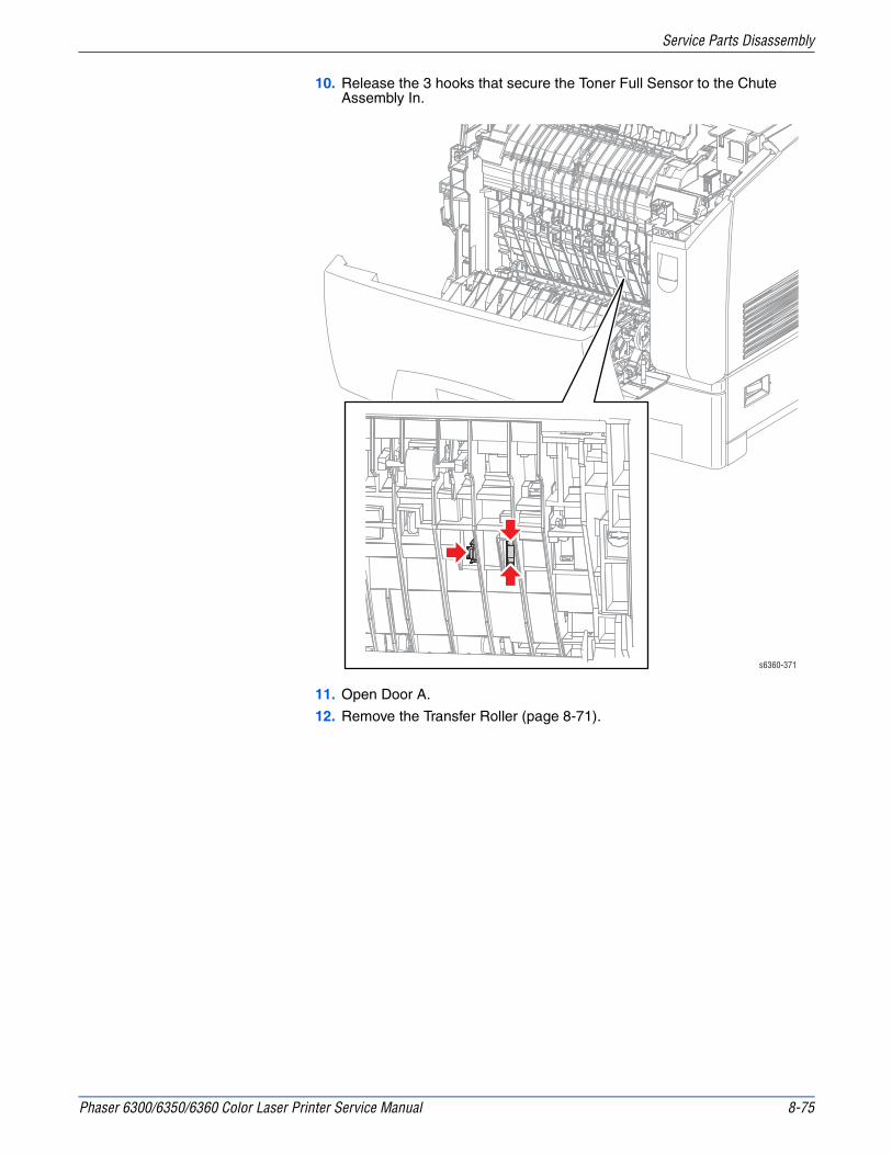
Phaser 6300/6350/6360 Color Laser Printer Service Manual 8-75
Service Parts Disassembly
10. Release the 3 hooks that secure the Toner Full Sensor to the Chute Assembly In.
11. Open Door A.
12. Remove the Transfer Roller (page 8-71).
s6360-371

8-76 Phaser 6300/6350/6360 Color Laser Printer Service Manual
Service Parts Disassembly
13. Unplug connector (P/J142) from the Toner Full Sensor and remove it.
s6360-168

Phaser 6300/6350/6360 Color Laser Printer Service Manual 8-77
Service Parts Disassembly
Laser Unit (PL6.1.2)
Access the upper Laser Unit screw by loosening the Toner Cartridge Holder Assembly and raising it.
CautionHandle the Laser Unit carefully. Components within the Laser Unit are sensitive to shock and could be damaged.
1. Remove the Top Main Cover (page 8-11).
2. Remove the Right Side Cover (page 8-14).
3. Remove the Left Side Cover (page 8-15).
4. Remove the Rear Cover (page 8-17).
5. Remove the HVPS (page 8-111).
6. Remove the 2 wires from the harness guide on the CRUM Reader.
7. Disconnect (P/J342) from the CRUM Reader on the left side and remove the harness from the guide at the forward end of the CRUM Reader.
8. Disconnect the Interlock Switch harness (P/J161) from the LVPS.
9. Remove the LVPS Fan Duct.
10. Loosen the Toner Cartridge Holder Assembly (page 8-91).
11. Unplug connector (P/J151) that is connected to the Laser Unit.
12. Remove 2 screws (self-tapping, plastic 10 mm) that secure the Laser Unit at each side.
13. Hold the Laser Unit and raise the Toner Cartridge Holder Assembly enough to remove the Laser Unit upper screw (self-tapping, plastic 10 mm).
14. Move the Laser Unit rearward to remove it.
s6360-194

8-78 Phaser 6300/6350/6360 Color Laser Printer Service Manual
Service Parts Disassembly
Housing Assembly Bias (PL6.1.7)
1. Remove the Top Main Cover (page 8-11).
2. Remove the Left Front Cover (page 8-19).
3. Remove the Left Side Cover (page 8-15).
4. Remove the HVPS (page 8-111).
5. Remove the 2 wires from the harness guide on the Housing Assembly Bias.
6. Remove the 4 screws (self-tapping, plastic 10 mm) that secure the Housing Assembly Bias to the printer and remove.
Replacement NoteThe contact springs must protrude through to the inside of the printer.
s6360-195

Phaser 6300/6350/6360 Color Laser Printer Service Manual 8-79
Service Parts Disassembly
Development
Developer Frame Assembly (PL7.1.1)
When removing the Developer Frame Assembly, cover the entire assembly with paper to help prevent toner from spilling onto your clothing. Also, store the Developer Frame Assembly on a flat surface with its handle upward.
NoteToner will spill from the toner nozzles and the rear of the Developer Frame Assembly. Keep the assembly vertical to reduce the amount of Toner spillage. Following the repair, use an approved Type II Toner Vacuum to clean spilled toner from the printer and around the work area.
1. Remove the Top Main Cover (page 8-11).
2. Remove the Left Side Cover (page 8-15).
3. Remove the HVPS (page 8-111).
4. Open Door A.
5. Open Door C.
6. Unplug the Imaging Unit CRUM connector (P/J484) at the top of the Developer Frame Assembly.
7. Release the hooks to disconnect the 4 toner nozzles attached to the Developer Frame Assembly.
NoteCheck that the toner nozzle shutter at the end of each Auger Tube is closed. If the shutter is open; close it.

8-80 Phaser 6300/6350/6360 Color Laser Printer Service Manual
Service Parts Disassembly
7. Lift the Developer Frame Assembly to remove.
Replacement NoteCarefully match the colors of the 4 toner nozzles to the correct positions. Check that each nozzle is locked to the Developer Frame Assembly before replacing the covers. Also, reset the Developer Life Counters after replacing the Developer Assemblies.
s6360-196
P/J484

Phaser 6300/6350/6360 Color Laser Printer Service Manual 8-81
Service Parts Disassembly
CRUM Connector (PL7.1.4)
1. Open Door A.
2. Remove the Imaging Unit.
3. Disconnect (P/J710) from the CRUM connector and remove the harness from the guide.
4. Open the hook that secures the CRUM connector to its holder on the upper left side of Developer Frame Assembly and remove the connector.
Replacement NoteEngage the two front connector guides, and then snap the connector into place.
s6360-197Hooks

8-82 Phaser 6300/6350/6360 Color Laser Printer Service Manual
Service Parts Disassembly
Developer Assembly (PL7.1.17~20)
Since all four Developer Assemblies are removed in the same manner, use this procedure for any of the four colors.
NoteToner will spill from the rear of the Developer Frame Assembly. Keep the assembly vertical to reduce the amount of Toner spillage. Prepare a location to replace the Developer Assemblies by covering a flat surface with paper or other material to capture Toner spilled during the replacement procedure. Following the repair, use an approved Type II Toner Vacuum to clean spilled toner from within the printer and around the work area.
1. Remove the Top Main Cover (page 8-11).
2. Remove the Left Front Cover (page 8-19).
3. Remove the Left Side Cover (page 8-15).
4. Remove the HVPS (page 8-111).
5. Remove the Developer Frame Assembly (page 8-79).
6. Open the replacement Developer Assembly packaging and transfer the shipping plugs and roller cover from the new assembly to the old. Use the plugs, cover, and packaging to repack the old part for return.
s6360-379

Phaser 6300/6350/6360 Color Laser Printer Service Manual 8-83
Service Parts Disassembly
7. Release the left and right stoppers located on the Developer Frame Assembly and remove the Developer Assembly.
Replacement NoteInspect each Developer Assembly slot prior to installing the replacement to ensure the left and right tracking spring (PL7.1.13) is securely attached to the Developer Frame Assembly. There should be 2 tracking springs per Developer Assembly. Be sure to carefully match the colors of the 4 toner nozzles to the correct positions and that each nozzle is locked to the Developer Frame Assembly before replacing the covers.
s6360-198

8-84 Phaser 6300/6350/6360 Color Laser Printer Service Manual
Service Parts Disassembly
CRUM Reader (PL7.2.12)
1. Remove the Top Main Cover (page 8-11).
NoteControl toner spillage by replacing the cartridges after removing the Top Main Cover.
2. Remove the Right Side Cover (page 8-14).
3. Remove the Left Side Cover (page 8-15).
4. Remove the Rear Cover (page 8-17).
5. Remove the 2 wires (red) from the harness guides on the CRUM Reader.
6. Remove the screw (metal, 6 mm) and the screw (self-tapping, plastic 10 mm) that secure each end of the CRUM Reader to the frame.
7. Remove the 4 screws (self-tapping, plastic 10 mm) that secure the Toner Cartridge Holders to the CRUM Reader.
8. Release the boss on each Toner Cartridge Holder from the CRUM Reader.
s6360-367
HVPS

Phaser 6300/6350/6360 Color Laser Printer Service Manual 8-85
Service Parts Disassembly
9. From the rear of the printer, unplug the CRUM Reader connector (P/J3411).
10. Disconnect (P/J342) from the CRUM Reader on the left side and remove the harness from the guide at the forward end of the CRUM Reader.
11. Separate the CRUM Reader from the Toner Cartridge Holders by grasping all four Toner Cartridge locks and tipping the CRUM Reader towards the center to release the hooks on the underside of the holders from the CRUM Reader.
Replacement NoteSupport the CRUM Reader from underneath and slide it into position. Position each cartridge holder, working from Yellow to Black and slide the CRUM to the right to lock the cartridge holders in place and engage the bosses.
s6360-208
P/J342

8-86 Phaser 6300/6350/6360 Color Laser Printer Service Manual
Service Parts Disassembly
Toner Cartridge Holder (PL7.2.1~4)
The procedure for removal of the Toner Cartridge Holder is the same for all colors.
NoteTo control Toner spillage, do not disconnect the Auger Tube from the Developer Frame Assembly unless absolutely necessary to perform the repair. Remove the HVPS to access the Auger Tube connections.
1. Remove the CRUM Reader (page 8-84).
NoteWith the CRUM Reader removed, any of the four Toner Cartridge Holders are available for removal and servicing.
2. Disconnect the appropriate Toner Motor and No Toner Sensor connections from the holder being removed.
3. Remove the harness from the clamp mounted directly above the motor.
4. Remove the screw (metal, 6 mm) that secures the end of the Toner Cartridge Holder to the Toner Cartridge Holder Assembly.
5. Release the T-shaped hook near the Toner Motor to release the Toner Cartridge Holder from the assembly.
6. Disconnect the Auger Tube.

Phaser 6300/6350/6360 Color Laser Printer Service Manual 8-87
Service Parts Disassembly
Replacement NoteWhen replacing a holder located between two other colors, spread the installed holders slightly as you insert the replacement. Lock all four Toner Cartridge Holders into the CRUM Reader. To refill the new Auger Tube, run the Service Diagnostics Toner Motor test for the appropriate color continuously for a period of no more than 90 seconds.
s6360-201
P/J701
P/J511

8-88 Phaser 6300/6350/6360 Color Laser Printer Service Manual
Service Parts Disassembly
No Toner Sensor (Y), (M), and (C) (PL7.2.5)
The procedure for removing the No Toner Sensor from the (Y), (M), or (C) Toner Cartridge Holder is essentially the same. The procedure described below applies to all three.
NoteTo control toner spillage, do not disconnect the Auger Tube from the Developer Frame Assembly unless absolutely necessary to perform the repair. Remove the HVPS to access the Auger Tube connections.
1. Remove the CRUM Reader (page 8-84).
2. Remove the Toner Cartridge Holder (page 8-86).
3. Spread the 4 hooks on the Toner Cartridge Holder that secure the No Toner Sensor.
4. Unplug the connector from the No Toner Sensor and remove the sensor.
Replacement NoteLock all four Toner Cartridge Holders into the CRUM Reader.
s6360-205

Phaser 6300/6350/6360 Color Laser Printer Service Manual 8-89
Service Parts Disassembly
No Toner Sensor (K) (PL7.2.5)
1. Remove the Top Main Cover (page 8-11).
2. Remove the Right Side Cover (page 8-14).
3. Remove the Left Side Cover (page 8-15).
4. Remove the Rear Cover (page 8-17).
5. Unplug connector (P/J704) from the No Toner Sensor.
6. Spread the 4 hooks on the Toner Cartridge Holder that secure the sensor.
7. Remove the No Toner Sensor from the Toner Cartridge Holder.
s6360-206
P/J704

8-90 Phaser 6300/6350/6360 Color Laser Printer Service Manual
Service Parts Disassembly
Toner CTG-IN Actuator and Switch Bracket (PL7.2.7)
The following procedure applies to all four Toner CTG-IN Actuators and brackets.
NoteTo control toner spillage, do not disconnect the Auger Tube from the Developer Frame Assembly unless absolutely necessary to perform the repair. Remove the HVPS to access the Auger Tube connections. Use care when handling the holder to avoid Toner leaking from the tube.
1. Remove the CRUM Reader (page 8-84).
2. Unlock and remove the Toner Cartridge.
3. Remove the Toner Cartridge Holder (page 8-86).
4. Release the 2 hooks that secure the bracket to the Toner Cartridge Holder with a miniature screwdriver or similar tool and remove the bracket.
5. Release the bracket hooks and remove the Actuator.
Replacement NoteLock all four Toner Cartridge Holders into the CRUM Reader.
s6300-207
Sensor Actuator
Hooks

Phaser 6300/6350/6360 Color Laser Printer Service Manual 8-91
Service Parts Disassembly
Toner Cartridge Holder Assembly
Complete removal of the Toner Cartridge Holder Assembly is not required to access the upper most Laser Unit screw. Use the following procedure to loosen the assembly and lift it approximately 0.5 inch it to allow access to the Laser Unit screw without disconnecting the Auger Tubes or removing the Toner Cartridges.
WarningBe sure to clean up any residual toner on the Toner Cartridge Holder Assembly with a dedicated toner vacuum cleaner. Do not clean up toner with a general-purpose vacuum cleaner to avoid the risk of explosion by igniting the fine powder. As an additional precaution, be sure to attach a ground cable to the toner vacuum cleaner to discharge static electricity.
CautionTake care not to allow toner dust to adhere to the photo sensors located on the Toner Cartridge Holder Assembly. Toner adhering to the photo sensors reduces their efficiency and could cause erroneous errors.
1. Remove the Top Main Cover (page 8-11).
NoteTo control toner spillage, after removing the Top Main Cover, replace the Toner Cartridges and lock them into place.
2. Remove the Right Side Cover (page 8-14).
3. Remove the Left Side Cover (page 8-15).
4. Remove the Rear Cover (page 8-17).
5. Remove the 2 wires (red) from the harness guide on the CRUM Reader.

8-92 Phaser 6300/6350/6360 Color Laser Printer Service Manual
Service Parts Disassembly
6. Remove the Interlock Switch from the clamp on the Toner Cartridge Holder Assembly.
s6360-199
P/J161
P/J3411

Phaser 6300/6350/6360 Color Laser Printer Service Manual 8-93
Service Parts Disassembly
7. Remove the 4 screws (2 metal, 6 mm) and (2 self-tapping, plastic 10mm) that secure the Toner Cartridge Holder Assembly.
8. Remove the LVPS Fan Duct.
9. Gently lift the Toner Cartridge Holder Assembly and the CRUM Reader to provide access to the Laser Unit screw.
s6360-200
10 mm
10 mm
6 mm
6 mm

8-94 Phaser 6300/6350/6360 Color Laser Printer Service Manual
Service Parts Disassembly
Drive
Developer Drive Assembly (PL8.1.1)
1. Remove the Top Main Cover (page 8-11).
2. Remove the Right Side Cover (page 8-14).
3. Remove the four Harness Guide Clamps from the Rear Harness Guide and remove the harnesses.
4. Release the clamps on the Developer Drive Assembly and remove the Interlock Switch harness.
5. Remove the 2 screws (silver, tap 10 mm) that secure the Rear Harness Guide and move the guide to the rear to release the front hook from the Developer Drive Assembly.
6. Remove the Rear Harness Guide.
s6360-209
Clamps

Phaser 6300/6350/6360 Color Laser Printer Service Manual 8-95
Service Parts Disassembly
7. Unplug connector (P/J491) from the Developer Drive Assembly.
8. Remove the 3 screws (silver, tap 10 mm) that secure the Developer Drive Assembly to the printer and remove.
Replacement NotePosition the Interlock Switch on the boss provided on the frame. Also, when replacing the motor, rotate the motor housing to engage the drive gears. Verify that the gears are engaged before installing the screws
s6360-210
P/J491

8-96 Phaser 6300/6350/6360 Color Laser Printer Service Manual
Service Parts Disassembly
Main Drive Assembly (PL8.1.2)
1. Remove the Top Main Cover (page 8-11).
2. Remove the Right Side Cover (page 8-14).
3. Disconnect the Main Drive Assembly connector (P/J481).
4. Remove the 4 screws (silver, tap 10 mm) that secure the Main Drive Assembly to the printer.
5. Remove the Main Drive Assembly.
Replacement NoteWhen replacing the motor, rotate the motor housing to engage the Main Drive gears. Verify that the gears are engaged before installing the mounting screws.
s6360-211
P/J481

Phaser 6300/6350/6360 Color Laser Printer Service Manual 8-97
Service Parts Disassembly
Fuser Drive Assembly (PL5.2.25)
1. Remove the Top Main Cover (page 8-11).
2. Remove the Right Front Cover (page 8-18).
3. Remove the Right Side Cover (page 8-14).
4. Remove the Link Arm Spring and Link Arm.
s6360-169

8-98 Phaser 6300/6350/6360 Color Laser Printer Service Manual
Service Parts Disassembly
6. Remove the 3 screws (self-tapping, plastic 10 mm) that secure the Fuser Drive Assembly to the Chute Assembly In.
7. Pull the Fuser Drive Assembly away from the frame to release the gears.
8. Remove the screw (silver, 5 mm) that secures the ground wire to the Fuser Drive Assembly.
9. Unplug connector (P/J521) and remove the Fuser Drive Assembly.
s6300-170
P/J521

Phaser 6300/6350/6360 Color Laser Printer Service Manual 8-99
Service Parts Disassembly
Electrical
Image Processor Board (PL9.1.3)
1. Remove the Tray Rear Cover (page 8-23).
2. Remove the 6 screws that secure the Rear Panel to the printer and pull to remove.
3. Transfer the installed Memory, NVRAM, Configuration Card, and Hard Drive from the old board to the new board.
NotePrint a Configuration page after the new board is installed to verify the customers configuration is restored.
Notch
s6360-365

8-100 Phaser 6300/6350/6360 Color Laser Printer Service Manual
Service Parts Disassembly
LVPS (PL9.1.4)
The Low Voltage Power Supply (LVPS) assembly consists of the power supply, attached power switch, the AC Inlet Harness, and the surrounding enclosure.
1. Remove the Top Main Cover (page 8-11).
2. Remove the Right Side Cover (page 8-14).
3. Remove the Left Side Cover (page 8-15).
4. Remove the Rear Cover (page 8-17).
5. Unplug connectors (P/J161, 162, 163, 164, 165) from the LVPS.
6. Remove the 1 screw (silver, 6 mm) that fixes the Power Switch Link Support Bracket and remove the bracket.
7. Remove the 2 screws (1 metal, 6 mm, and 1 plastic, 10 mm) that secure the LVPS to the Toner Cartridge Holder Assembly.
8. Remove the LVPS Fan Duct.
9. Remove the 3 screws (metal, 6 mm) that secure the LVPS to the printer chassis.
10. Remove the screw (self-tapping, plastic 10mm) located at the bottom of the LVPS, that secures it to Tray 2.
11. Remove the harnesses from the Rear Cable Guide.
12. Remove the screw (self-tapping, plastic 10mm) that secures the Power Switch Link Shaft support and remove the support.
NoteIn the following step, do not remove the Switch Link Shaft from the printer.
13. Release the Power Switch Link Shaft from the notch in the LVPS and lift up to remove the LVPS.
Replacement NoteAlign the bosses at the base of the LVPS to those on the frame.

Phaser 6300/6350/6360 Color Laser Printer Service Manual 8-101
Service Parts Disassembly
s6360-213
6 mm
6 mm
6 mm
10 mm
6 mm
6 mm
10 mm
162
164
165
163
161

8-102 Phaser 6300/6350/6360 Color Laser Printer Service Manual
Service Parts Disassembly
Interlock Switch (PL9.1.11)
1. Remove the Top Main Cover (page 8-11).
2. Remove the Right Side Cover (page 8-14).
3. Unplug the Interlock Switch connector (P/J161) from the LVPS.
4. Remove the Interlock Switch harness from the clamp on the LVPS.
5. Release the two clamps on the Developer Drive Assembly that secure the Interlock Switch harness.
6. Remove the Developer Drive Assembly (page 8-94).
7. Remove the Interlock Switch from the printer.
Replacement NotePosition the Interlock Switch on the boss provided on the frame. Also, when replacing the motor, rotate the motor housing to engage the drive gears. Verify that the gears are engaged before installing the screws.
s6360-216
P/J161

Phaser 6300/6350/6360 Color Laser Printer Service Manual 8-103
Service Parts Disassembly
Rear Fan (PL1.1.19)
1. Remove the Top Main Cover (page 8-11).
2. Remove the Right Side Cover (page 8-14).
3. Remove the Left Side Cover (page 8-15).
4. Remove the Rear Cover (page 8-17).
5. Remove 2 screws (self-tapping, plastic 35 mm) that secure the Rear Fan to the Rear Cover.
Replacement NoteUpon reassembly, attach the Rear Fan so its label faces towards the inside of the printer and the tabs of the Rear Cover engage the frame.
s6360-130
TabLabel

8-104 Phaser 6300/6350/6360 Color Laser Printer Service Manual
Service Parts Disassembly
LVPS Fan (PL1.1.31)
1. Remove the Top Main Cover (page 8-11).
2. Remove the Right Side Cover (page 8-14).
3. Remove the Left Side Cover (page 8-15).
4. Remove the Rear Cover (page 8-17).
5. Remove 2 screws (self-tapping, plastic 35 mm) that secure the LVPS Fan to the Rear Cover.
Replacement NoteUpon reassembly, attach the LVPS Fan so its label faces towards the inside of the printer and the tabs of the Rear Cover engage the frame.
s6360-381

Phaser 6300/6350/6360 Color Laser Printer Service Manual 8-105
Service Parts Disassembly
EEPROM Board (PL9.1.12)
1. Remove the Top Main Cover (page 8-11).
2. Remove the Right Side Cover (page 8-14).
3. Remove the 4 clamps that hold the harness in the Rear Harness Guide and remove the harness.
4. Remove the 2 screws (self-tapping, plastic 10 mm) that secure the Rear Harness Guide.
5. Unplug connector (P/J144) from the EEPROM Board.
6. Remove the screw (self-tapping, plastic 10 mm) that secures the EEPROM Board and remove.
s6360-217
Clamps
P/J144

8-106 Phaser 6300/6350/6360 Color Laser Printer Service Manual
Service Parts Disassembly
Engine Control Board (PL9.1.16)
CautionCritical printer-specific information is stored in the NVRAM device located on the Engine Control Board. You can either save this information to the Image Processor Board using the Service Diagnostic Store/Restore utilities or exchange the NVRAM devices between the new and old boards.
1. If the printer is functional, save the NVRAM data using the Service Diagnostic utilities before starting disassembly.
CautionObserve proper ESD procedures when handling any circuit board.
2. Remove the Top Main Cover (page 8-11).
3. Remove the Right Side Cover (page 8-14).
4. Remove the Left Side Cover (page 8-15).
5. Remove the Rear Cover (page 8-17).
6. Remove the Image Processor Board (page 8-99).
7. Remove the Imaging Unit.
NoteCover the Developer Frame Assembly with paper to avoid damage to the rollers and Toner spillage. Also, take care not to allow the unplugged connectors to be drawn inside the printer.
8. Push down to release the 2 hooks of the Electrical Cover and remove the cover.
9. Unplug the 3 harnesses on the Engine Control Board accessible from inside the Electrical Cover.
10. Remove the screw (metal, 6 mm) that secures the Engine Control Board Bracket underneath the Electrical Cover.
11. Disconnect connectors P/J151, P/J141, and P/J3411 connected to the Laser Unit, HVPS, and CRUM Reader.
12. Push these harnesses to the clamp located directly beneath the Laser Unit to provide slack to extract the Engine Control Board.

Phaser 6300/6350/6360 Color Laser Printer Service Manual 8-107
Service Parts Disassembly
Replacement NoteConnectors P20, P21, and P30 on the Engine Control Board are not used. Also, in the 6360 model, connector P21 has been removed from the board as shown above.
s6360-219
P/J24
P30
P20P/J18
P/J19
Hooks

8-108 Phaser 6300/6350/6360 Color Laser Printer Service Manual
Service Parts Disassembly
13. Disconnect P/J17, P/J22, P/J47, P/J52, and P/J60 from the Engine Control Board.
14. Remove the screw (metal, 6 mm) that secures the Engine Control Board Bracket to the right side of the printer.
15. Lift the right edge of the board slightly and pull the Engine Control Board out from the printer while removing connections as they are exposed.
Replacement NoteWhen replacing the Engine Control Board, either replace the NVRAM device on the new board with the one removed from the old board, or restore the data saved in Step 1 by using the Restore utility included in Service Diagnostics. Also, reconnect P/J15, P/J16, and P/J34 before reinserting the board into the printer. In addition, connectors P/J13 and P/J36 have an equal number of Pins. These connectors are keyed differently but use care to make certain that the proper connection is being made. Use care re-routing the harnesses after replacing the board.
s6300-220
P52P48
P13 P47P17
P60
P16P24
P154P34
P191
P19P18P21
P30
P22
P51P36
P61P14
P311P31
P15
P20
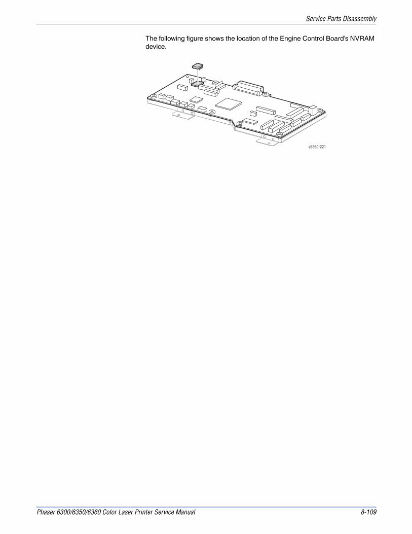
Phaser 6300/6350/6360 Color Laser Printer Service Manual 8-109
Service Parts Disassembly
The following figure shows the location of the Engine Control Board’s NVRAM device.
s6360-221

8-110 Phaser 6300/6350/6360 Color Laser Printer Service Manual
Service Parts Disassembly
Temperature/Humidity Sensor (PL9.1.20)
1. Remove the Top Main Cover (page 8-11).
2. Remove the Left Side Cover (page 8-15).
3. Press down the knob mounted on the left side of the printer to release the bracket that holds the sensor.
4. Lift the bracket from the printer chassis.
5. Release the 4 hooks that secure the Temperature/Humidity Sensor to the bracket and remove the sensor.
6. Unplug the Temperature/Humidity Sensor connector (CN1).
s6360-22
CN1
Boss

Phaser 6300/6350/6360 Color Laser Printer Service Manual 8-111
Service Parts Disassembly
HVPS (PL9.1.21)
1. Remove the Top Main Cover (page 8-11).
2. Remove the Left Side Cover (page 8-15).
3. Unplug connectors P/J139, P/J140, P/J141.
4. From the left side of the printer remove the 2 screws (self-tapping, plastic 10 mm) and 3 screws (metal, 6 mm) that secure the HVPS to the frame.
5. Move the HVPS left to release the retaining hooks on the front edge of the board.
Replacement NoteVerify that the two bosses are aligned and the two retaining hooks are locked on the board before tightening the mounting screws.
s6360-223
P/J140P/J139
P/J141
6 mm
10 mm

8-112 Phaser 6300/6350/6360 Color Laser Printer Service Manual
Service Parts Disassembly
Optional 1100-Sheet Feeder Disassembly
Docking (PL12.1.1)
CautionLifting the printer requires two people. Use care when removing the printer from the 1100-Sheet Feeder.
1. Pull Tray 2 from the printer.
2. Remove four screws that secure the 1100-Sheet Feeder to the frame of the printer.
3. Lift the printer from the 1100-Sheet Feeder.
s6360-250

Phaser 6300/6350/6360 Color Laser Printer Service Manual 8-113
Service Parts Disassembly
Front Covers (PL12.1.6)
1. Remove the trays.
2. Carefully pry up from the bottom the 2 tabs that secure each cover.
s6360-253

8-114 Phaser 6300/6350/6360 Color Laser Printer Service Manual
Service Parts Disassembly
Left Cover (PL12.1.2)
1. Remove the trays.
2. Remove the Front Covers (page 8-113).
3. Remove the 5 screws (metal, flanged, 8 mm) securing the Left Cover.
4. Holding both ends of the cover, lift the cover and move left and right, flexing slightly, to release the tabs from the holes in the frame.
s6360-251

Phaser 6300/6350/6360 Color Laser Printer Service Manual 8-115
Service Parts Disassembly
Right Cover (PL12.1.3)
1. Remove the trays.
2. Remove the Front Covers (page 8-113).
3. Remove the 5 screws (metal, flanged, 8 mm) securing the Right Cover.
4. Holding both ends of the cover, lift the cover and move left and right, flexing slightly, to release the tabs from the holes in the frame.
s6360-252

8-116 Phaser 6300/6350/6360 Color Laser Printer Service Manual
Service Parts Disassembly
Foot (PL12.1.10)
Because the procedure for removing both feet is the same, the procedure to remove the right side Foot is described below.
1. Remove the Front Covers (page 8-113).
2. Remove the Right Cover (page 8-115).
3. Remove the 2 screws that secure the Foot to the frame.
4. Remove the Foot by pulling it out of the frame.
s6360-287

Phaser 6300/6350/6360 Color Laser Printer Service Manual 8-117
Service Parts Disassembly
Feeder Chute (PL12.2.7)
1. Remove the tray.
2. Push inward on the concaved sections at the left and the right sides and swing the Feeder Chute downward.
3. Release the retainer at one end of the Feeder Chute to release the boss from the Feeder Assembly.
4. Pull the Feeder Chute out, and then down to remove it from the frame.

8-118 Phaser 6300/6350/6360 Color Laser Printer Service Manual
Service Parts Disassembly
Left Feeder Assemblies (PL12.2.1)
1. Remove the Front Covers (page 8-113).
2. Remove the Left Cover (page 8-114).
3. Remove the Feeder Chute (page 8-117).
4. Remove the Tray Rear Cover (page 8-23).
5. Remove 6 screws (self-tapping, plastic 8 mm) that secure each Left Feeder Assembly to the frame.
6. Remove the Left Feeder Assembly from the front.
s6360-25

Phaser 6300/6350/6360 Color Laser Printer Service Manual 8-119
Service Parts Disassembly
Right Feeder Assemblies (PL12.2.4)
CautionMove the sensor flags upwards before attempting to remove the feeders.
1. Remove the Front Covers (page 8-113).
2. Remove the Right Cover (page 8-115).
3. Remove the Feeder Chute (page 8-117).
4. Remove the Tray Rear Cover (page 8-23).
NotePerform Step 5 only when removing the upper Right Feeder Assembly.
5. Remove the Drive Assembly (page 8-123).
6. Remove the Paper Size Switch connector (P/J821).
7. Remove 6 screws (self-tapping, plastic 8 mm) that secure the Right Feeder.
8. Tilt the Right Feeder Assembly and remove it from the front.
NoteReplace the Upper Right Feeder before replacing the Drive Motor.
s6360-255

8-120 Phaser 6300/6350/6360 Color Laser Printer Service Manual
Service Parts Disassembly
Paper Size Switch (PL12.2.6)
1. Remove the Front Covers (page 8-113).
2. Remove the Right Cover (page 8-115).
3. Remove the Chute Assembly (page 8-117).
4. Remove the Tray Rear Cover (page 8-23).
5. Remove the Right Feeder Assembly (page 8-119).
6. Remove a screw (self-tapping, plastic 8 mm) that secures the Paper Size Switch to the Right Feeder Assembly and remove the switch.
s6360-256

Phaser 6300/6350/6360 Color Laser Printer Service Manual 8-121
Service Parts Disassembly
OPTFDR 2 Harness (PL12.3.1)
1. Separate the 1100-Sheet Feeder from the printer (page 8-112).
2. Remove the Front Covers (page 8-113).
3. Remove the Right Cover (page 8-115).
4. Remove connector (P/J83) on the upper Circuit Board HCF.
5. Remove the OPTFDR 2 Harness from clamps.
6. Release two hooks that secure (J172), and remove OPTFDR 2 Harness.
s6360-258

8-122 Phaser 6300/6350/6360 Color Laser Printer Service Manual
Service Parts Disassembly
Circuit Board HCF (PL12.3.3)
1. Remove the Front Covers (page 8-113).
2. Remove the Right Cover (page 8-115).
3. Remove all connections to the Circuit Board HCF.
4. Remove the 3 screws (metal, 6mm) that secure the Circuit Board HCF to the frame, and remove.
P80
P81
P82
P83 P84
P85
P80
P81
P82 Not Connected
P83
P84 Not Connected
P85
P86 Not Connected
P86 Not Connected
s6360-259

Phaser 6300/6350/6360 Color Laser Printer Service Manual 8-123
Service Parts Disassembly
Drive Assembly (PL12.3.9)
1. Remove the Front Covers (page 8-113).
2. Remove the Right Cover (page 8-115).
3. Remove connector (P/J82) that is connected to the upper Circuit Board HCF.
4. Remove the Drive Assembly harness from the Clamps.
5. Remove the 3 screws (metal, 6mm) that secure the Drive Assembly to the frame.
s6300-260

8-124 Phaser 6300/6350/6360 Color Laser Printer Service Manual
Service Parts Disassembly
Paper Pick Assembly HCF T1 (PL12.4.1)
1. Separate the 1100-Sheet Feeder from the printer (page 8-112).
2. Remove the Front Covers (page 8-113).
3. Remove the Right Cover (page 8-115).
4. Remove the Left Cover (page 8-114).
5. Remove the Feeder Chute (page 8-117).
6. Remove the Upper Chute (page 8-33).
7. Remove 2 screws (self-tapping, plastic 8 mm) that secure Paper Guide to the Paper Pick Assembly HCF T1 and remove the Paper Guide.
8. Remove the upper Left Feeder Assembly (page 8-118).
9. Remove the upper Right Feeder Assembly (page 8-119).
10. Remove the Drive Assembly (page 8-123).
11. Disconnect the connector (P/J81) from the upper Circuit Board HCF, and remove the harness from clamp.
12. Disconnect the No Paper Sensor connector (P/J822) on upper Paper Pick Assembly.
13. Disconnect the Feed Solenoid connector (P/J824) and remove the harness from the clamp.
s6360-262

Phaser 6300/6350/6360 Color Laser Printer Service Manual 8-125
Service Parts Disassembly
14. Disconnect the Turn Roller Clutch connector (P/J825) and remove the harness from the clamp.
15. Remove 3 screws (metal, 6 mm) that secure the Paper Pick Assembly HCF T1 to the frame, and remove the assembly from the right.
s6360-261
P/J822P/J825 P/J81P/J824
s6360-263

8-126 Phaser 6300/6350/6360 Color Laser Printer Service Manual
Service Parts Disassembly
Paper Pick Assembly HCF T2 (PL12.5.1)
With the proper tools, the lower Paper Pick Assembly HCF T2 can be removed from the 1100-Sheet Feeder without removing the Top or the Paper Pick Assembly HCF T1. If a stubby screwdriver is not available, use this procedure:
1. Remove the Paper Pick Assembly HCF T1 (page 8-124).
2. Remove 9 screws (metal, 6 mm) that secure the Top, and remove it.
3. Remove 2 screws (self-tapping, plastic 8 mm) that secure the Paper Pick Assembly HCF T2 Paper Guide.
4. Disconnect the connector (P/J81) from the lower Circuit Board HCF, and remove the harness from clamp.
5. Disconnect the No Paper Sensor connector (P/J822) on Paper Pick Assembly HCF T2.
6. Disconnect the Feed Solenoid connector (P/J824) and remove the harness from the clamp.
7. Disconnect the Turn Roller Clutch connector (P/J825) and remove the harness from the clamp.
s6360-273

Phaser 6300/6350/6360 Color Laser Printer Service Manual 8-127
Service Parts Disassembly
s6360-274
P/J824
P/J81
P/J822
P/J825

8-128 Phaser 6300/6350/6360 Color Laser Printer Service Manual
Service Parts Disassembly
18. Remove three screws (metal, 6 mm) that secure the Paper Pick Assembly HCF T2 to the frame, and remove the Paper Pick Assembly HCF T2 from the right.
s6360-275

Phaser 6300/6350/6360 Color Laser Printer Service Manual 8-129
Service Parts Disassembly
No Paper Sensor (PL12.5.7)
1. Remove the Front Covers (page 8-113).
2. Remove the Right Cover (page 8-115).
3. Disconnect the No Paper Sensor connector (P/J822).
4. Lift the actuator and use a small screwdriver to release the 3 hooks and remove the No Paper Sensor.
s6360-237
Actuator
P/J822

8-130 Phaser 6300/6350/6360 Color Laser Printer Service Manual
Service Parts Disassembly
Low Paper Sensor (PL12.5.7)
1. Remove the Paper Pick Assembly (page 8-124).
2. Disconnect the Low Paper Sensor connector (P/J823).
3. Release the 3 hooks on the Low Paper Sensor and remove the sensor.
s6360-267

Phaser 6300/6350/6360 Color Laser Printer Service Manual 8-131
Service Parts Disassembly
Low Paper Sensor Actuator (PL12.5.14)
1. Remove the Upper Chute (page 8-33).
2. Turn over the Upper Chute.
3. Release the hook of Upper Chute that secures the Low Paper Sensor Actuator and move the shaft on one side to remove the actuator.
s6360-150

8-132 Phaser 6300/6350/6360 Color Laser Printer Service Manual
Service Parts Disassembly
Feed Rollers (PL12.4.19)
1. Remove the tray from the printer.
2. Release the lock that fixes each Feed Roller to the shaft and remove the roller.
s6360-152

Phaser 6300/6350/6360 Color Laser Printer Service Manual 8-133
Service Parts Disassembly
No Paper Sensor Actuator (PL12.5.20)
1. Remove the Paper Pick Assembly (page 8-124).
2. Release the hook that secures the No Paper Sensor Actuator to the Paper Pick Assembly.
3. Push the actuator shaft slightly away from the sensor to move the shaft to the larger opening in the slot.
4. Remove the actuator out of the slot of Paper Pick Assembly while moving the hook side of actuator toward you.
s6360-153

8-134 Phaser 6300/6350/6360 Color Laser Printer Service Manual
Service Parts Disassembly
Retard Roller Assembly (PL12.6.13)
1. Remove the tray.
2. Release the 2 hooks at the left and right of the Turn Chute by pushing inward and open the chute.
3. Rotate the Retard Holder 90 degrees.
4. Slide the Retard Roller Assembly to the left and remove it from the 2 bosses, and then lift it upward.
s6360-138

Phaser 6300/6350/6360 Color Laser Printer Service Manual 8-135
Service Parts Disassembly
Optional 550-Sheet Feeder Disassembly
Docking (PL11.1.1)
CautionLifting the printer requires two people. Use care when removing the printer from the Feeder.
1. Remove Tray 2.
2. Remove four screws that secure the Tray 3 Feeder to the printer.
3. Lift the printer from the Tray 3 Feeder.
s6360-225

8-136 Phaser 6300/6350/6360 Color Laser Printer Service Manual
Service Parts Disassembly
Right Cover (PL11.1.11)
1. Remove Tray 3 from the printer.
2. Remove 2 screws (self-tapping, flanged, plastic, 8mm) that secure the Right Cover.
3. Release two hooks at the rear to remove the Right Cover.
s6360-228

Phaser 6300/6350/6360 Color Laser Printer Service Manual 8-137
Service Parts Disassembly
Left Cover (PL11.1.7)
1. Remove Tray 3 from the printer.
2. Remove 2 screws (self-tapping, flanged, plastic, 8mm) that secure the Left Cover.
3. Release two hooks at the rear and remove the cover.
s6360-231

8-138 Phaser 6300/6350/6360 Color Laser Printer Service Manual
Service Parts Disassembly
OPTFDR 1 Harness (PL11.1.6)
1. Remove the 550-Sheet Feeder (page 8-135).
2. Remove the Right Cover (page 8-136).
3. Remove the screw (metal, 6 mm) in the Connector Plate and the screw in the OPTFDR 1 Board.
4. Remove the assembly from the Feeder.
5. Disconnect the harness (P/J83) from the OPTFDR 1 Board.
6. Release two hooks that hold the OPTFDR 1 Harness from the rear side of Connector Plate, and remove the harness.
s6360-226

Phaser 6300/6350/6360 Color Laser Printer Service Manual 8-139
Service Parts Disassembly
Circuit Board LTA (PL11.1.10)
1. Remove the Right Cover (page 8-136).
2. Remove all connectors on the OPTFDR 1 Board.
3. Remove 2 screws (metal, 6 mm) the secure the OPTFDR 1 Board to the bracket.
4. Remove OPTFDR 1 Board from the notches in the Feeder frame.
s6360-227
P83
P80
P86
P84
P81
P85
P82

8-140 Phaser 6300/6350/6360 Color Laser Printer Service Manual
Service Parts Disassembly
OPTPLG 2 Harness (PL11.1.13)
1. Remove the 550-Sheet Feeder (page 8-135).
2. Remove the Right Cover (page 8-136).
3. Remove the screw (metal, 6 mm) in the Connector Plate and the screw (self-tapping, plastic 8 mm) in the OPTFDR 1 Board.
4. Remove the assembly from the Feeder.
5. Remove the OPTPLG 2 Harness connector (P/J84) from OPTFDR 1 Board.
6. Release the hooks, at two positions, securing the option plug to the frame.
s6360-229

Phaser 6300/6350/6360 Color Laser Printer Service Manual 8-141
Service Parts Disassembly
Paper Size Switch (PL11.2.6)
1. Remove the 550-Sheet Feeder (page 8-135).
2. Disconnect the Paper Size Switch connector (P/J821).
3. Remove a screw (self-tapping, plastic 8 mm) that secures the Paper Size Switch to the Right Feeder and remove the switch.
s6360-232
P/J821

8-142 Phaser 6300/6350/6360 Color Laser Printer Service Manual
Service Parts Disassembly
Paper Pick Assembly (PL11.3.1)
1. Remove the 550-Sheet Feeder (page 8-135).
2. Remove the Right Cover (page 8-136).
3. Remove the Left Cover (page 8-137).
4. Remove the Drive Assembly (page 8-147).
5. Remove two long screws and five short screws (metal, 6 mm) that secure the Top Frame Assembly, and remove it from the Feeder.
s6360-233

Phaser 6300/6350/6360 Color Laser Printer Service Manual 8-143
Service Parts Disassembly
6. Remove the sensor connectors (P/J81, P/J85) on the OPTFDR 1 Board.
7. Remove 4 screws (self-tapping, plastic 8 mm) that secures the Paper Pick Assembly to the Feeder.
s6360-234
P/J81
P/J85

8-144 Phaser 6300/6350/6360 Color Laser Printer Service Manual
Service Parts Disassembly
No Paper Sensor (PL11.3.7)
1. Remove the 550-Sheet Feeder (page 8-135).
2. Remove the Right Cover (page 8-136).
3. Remove the Left Cover (page 8-137).
4. Remove the Drive Assembly (page 8-147).
5. Remove Paper Pick Assembly (page 8-142).
6. Disconnect the No Paper Sensor connector (P/J822).
7. Lift the No Paper Sensor Actuator and release the three hooks to remove the sensor.
s6360-237
Actuator
P/J822

Phaser 6300/6350/6360 Color Laser Printer Service Manual 8-145
Service Parts Disassembly
Low Paper Sensor (PL11.3.7)
1. Remove the 550-Sheet Feeder (page 8-135).
2. Remove the Right Cover (page 8-136).
3. Remove the Left Cover (page 8-137).
4. Remove the Upper Chute (page 8-33).
5. Remove two long screws and five short screws (metal, 6 mm) that secure the Top Frame Assembly, and remove it from the Feeder.
s6360-233

8-146 Phaser 6300/6350/6360 Color Laser Printer Service Manual
Service Parts Disassembly
6. Disconnect the Low Paper Sensor connector (P/J823).
7. Release the three hooks and remove the Low Paper Sensor.
s6360-239
P/J823

Phaser 6300/6350/6360 Color Laser Printer Service Manual 8-147
Service Parts Disassembly
Drive Assembly (PL11.3.15)
1. Remove the Right Cover (page 8-136).
2. Disconnect the Drive Assembly connector (P/J82) from the OPTFDR 1 Board.
3. Remove the Drive Assembly harness from the harness guides.
4. Remove 3 screws (metal, 6 mm) that secure the Drive Assembly to the frame.
s6360-241
P/J82

8-148 Phaser 6300/6350/6360 Color Laser Printer Service Manual
Service Parts Disassembly
Low Paper Sensor Actuator (PL11.3.16)
1. Remove the Upper Chute (page 8-33).
2. Turn over Upper Chute.
3. Release the hook that secures the Low Paper Sensor Actuator and remove the end of the actuator shaft from the Upper Chute.
s6360-150

Phaser 6300/6350/6360 Color Laser Printer Service Manual 8-149
Service Parts Disassembly
Feed Rollers (PL11.3.20)
1. Remove the tray from the printer.
2. Release the lock that fixes Nudger Roller to the shaft and remove the Nudger Roller.
s6360-15

8-150 Phaser 6300/6350/6360 Color Laser Printer Service Manual
Service Parts Disassembly
No Paper Sensor Actuator (PL11.3.22)
1. Remove the 550-Sheet Feeder (page 8-135).
2. Remove the Right Cover (page 8-136).
3. Remove the Left Cover (page 8-137).
4. Remove the Drive Assembly (page 8-147).
5. Remove Paper Pick Assembly (page 8-142).
6. Remove 2 screws (self-tapping, plastic 8 mm) that secure the Paper Guide to the Paper Pick Assembly.
s6360-245

Phaser 6300/6350/6360 Color Laser Printer Service Manual 8-151
Service Parts Disassembly
7. Turn over the Paper Pick Assembly.
8. Release the hook that secures the No Paper Sensor Actuator to the Paper Pick Assembly.
9. Push the actuator shaft slightly away from the sensor to move the shaft to the larger opening in the slot.
10. Remove the actuator out of the slot of Paper Pick Assembly while moving the hook side of actuator toward you.
s6360-153

8-152 Phaser 6300/6350/6360 Color Laser Printer Service Manual
Service Parts Disassembly
Retard Roller Assembly (PL11.4.12)
1. Remove the tray.
2. Release the 2 hooks at the left and right of the Turn Chute by pushing inward and open the chute.
3. Rotate the Retard Holder 90 degrees.
4. Slide the Retard Roller Assembly to the left and remove it from the 2 bosses, and then lift it upward.
s6360-138

9Chapter
Parts ListIn this chapter... Serial Number Format
Using the Parts List
Print Engine Parts
Optional 550-Sheet Feeder
Optional 1100-Sheet Feeder
Xerox Supplies and Accessories
Service Kits

9-2 Phaser 6300/6350/6360 Color Laser Printer Service Manual
Parts List
Serial Number Format
Changes to Xerox products are made to accommodate improved components as they become available. As improvements are made, part numbers may change from those appearing in this section. To get the latest part, provide the following information when ordering:
Component's part number
Product type or configuration number
Serial number of the printer
The serial number is coded as follows:
The text “S/N” followed by the serial number in the barcode.
The barcode does not include a field identifier.
The nine digit serial number format PPPRSSSSS where:
PPP - Is the alphanumeric Product Code
R - Is the numeric revision digit. Changes at major product updates or when the serial number is reset to a starting value or (30001, 60001, or 90001).
SSSSS - Is the five digit numeric serial number.
For example:
S/N WHH453072 WHH = Product code for the 6300, configuration N or DN, 110 V Printer4 = Revision level53072 = Serial number for 6300 N
Product Configuration Voltage Product Code
6300 N, DN 110 V WHH
6300 N, DN 220 V WHK
6350 DP, DT, DX 110 V WNN
6350 DP, DT, DX 220 V WNP
6360 N, DN, DT, DX 110 V DBY
6360 N, DN, DT, DX 220 V DCA
s6360-352
S/N: WHH453072
Nov, 2006

Phaser 6300/6350/6360 Color Laser Printer Service Manual 9-3
Parts List
Using the Parts List
Only those parts listed with part numbers are available for order. Parts listed without part numbers are only available as part of a parent assembly or Service Kit.
1. ID No.: The item number reference to the parts list diagram.
2. Part Number: The material part number used to order specific parts.
NoteParts specific to a particular model are listed as shown in this example:
Alphanumeric part numbers (054K38040) are either 6360-unique, as indicated above, or common for all models. 6300/6350-unique part numbers use the numeric, hyphenated form (116-1989-00).
3. Name/Description: Name of the part and number supplied per order.
4. Parts throughout this manual are referenced PL#.#.#; For example, PL3.1.10 means the part is item 10 of Parts List 3.1.
5. In the exploded view diagrams, a black triangle preceding a number followed by a parenthetical statement indicates the item is a parent assembly, made up of the parts listed in parentheses and enclosed by a dashed line.
6. The notation “(with X~Y)” following a part name indicates an assembly includes components X through Y. For example, “1 (with 2~4)” means assembly number 1 consists of parts 2, 3, and 4.
7. The notation “J1<>J2 and P2” is attached to a wire harness. It indicates that connector Jack 1 is attached to one end of the wire harness and connector J2 is attached to the other end that is plugged into P2.
ID No Part Number Name/Description
1. 116-1989-00054K38040
Chute Assy In (with 2~30), (6300/6350) Chute Assy In (with 2~31), (6360)
Legend:
Identifier Meaning
C C-ring
E E-ring
KL K-clip
S Screw

9-4 Phaser 6300/6350/6360 Color Laser Printer Service Manual
Parts List
Print Engine Parts
Parts List 1.1 Covers
s6360-288
1 (with 2, 3)
17 (with 18, 19, 31)
25 (with 26, 27)
8 (with 9-16)
6 (with 7)
22
5
4
7910
91016
18
19
31
20
21
242627
28
29
2322
21 14 15
12
30
11
13
3
(J166)
Front
6300/6350 Only6360 Only

Phaser 6300/6350/6360 Color Laser Printer Service Manual 9-5
Parts List
Parts List 1.1 Covers - Service Parts List
No. Part Number Name/Description
1. 116-1964-00 Cover Assy Top (with 2,3), (6300/6350)
2. 802E95621 Cover, Top, (6360)
3. 116-2044-00 Cover Top Stopper
4. 802E76574 Cover Top Main
5. 848K06281848K06292101E28720
Control Panel, (6300) Control Panel, (6350) Control Panel, (6360)
6. 116-1966-00802K91992
Cover Assy Front (with 7), (6300/6350) Cover Assy Front (with 7), (6360)
7. Lever Out
8. 116-1967-00802K98890
Cover Assy Top (Door C) (with 9~16), (6300/6350) Cover Assy Top (Door C) (with 9~16), (6360)
9. Spring L/R
10. Plunger
11. Cover Top Phd
12. Latch Top L
13. Shaft Latch
14. Latch Top Ir R
15. Latch Top R
16. Spring Stopper Bottom
17. Cover Assy Rear (with 18,19)
18. 116-1968-00802E95631
Cover Rear, (6300/6350) Cover Rear, (6360)
19. 127E83840 Fan Rear
20. 802K74543 Cover Side Right
21. Stud Top
22. 802E75932 Cover Front Right
23. 050K58270 Tray 1 (MPT) Base
24. Part of Tray Holder Kit
Holder Tray Right
25. 802K74593 Tray 1 (MPT) (with 26, 27)
26. Tray 1 (MPT) Slide
27. Cover Tray 1 (MPT)
28. 116-1974-00802K91050
Cover Front Left, (6300/6350) Cover Front Left, (6360)
29. Part of Tray Holder Kit
Holder, Tray Left
30. 802K74534 Cover Side Left
31. 127E84830 LVPS Fan (6360)

9-6 Phaser 6300/6350/6360 Color Laser Printer Service Manual
Parts List
Parts List 2.1 Tray 2
1 (with 2~27)
12 (with 13~16)
3
4
57 9
10
11
20
21
4
6
8
17
1314
15
27
1622
2324
2523
226
26
s6360-289Front

Phaser 6300/6350/6360 Color Laser Printer Service Manual 9-7
Parts List
Parts List 2.1 Casette, Paper - Service Parts List
ID No. Part Number Name/Description
1. 604K28854 Universal Paper Tray (with 2~27)
2. Plate Bottom
3. Pad Bottom
4. Spring N/f
5. Guide Side Assy L
6. Gear Manual
7. Guide Side Assy R
8. Guide End Assy
9. Actuator Guide End
10. Actuator Size
11. 054E27130 Chute Turn
12. Part of Paper Feed Roller Kit
Universal Tray Retard Roller Assy (See Maintenance Items)
13. Roll Assy
14. Clutch Assy Friction
15. Shaft Retard
16. Holder Retard
17. Spring Retard
18.
19.
20. Housing Cst 500
21. Handle Cst
22. Holder Spring Retard
23. Roll PB
24. Stopper Link PB R
25. Stopper Link PB L
26. Spacer Plate BTM
27. Stopper Block

9-8 Phaser 6300/6350/6360 Color Laser Printer Service Manual
Parts List
Parts List 3.1 Feeder (1/3)
Ref PL3.3.1
Ref PL3.2
Ref PL3.2
1
6
s6360-290
7 (with 2~5,PL3.2,PL3.3)
3
4
5
2
Front

Phaser 6300/6350/6360 Color Laser Printer Service Manual 9-9
Parts List
Parts List 3.1 Feeder (1/3) - Service Parts List
ID No. Part Number Name/Description
1. 802E76632 Frame Feeder Front
2. 054K28372 Feeder Chute Assy
3. 802E78002 Cover Paper Tray Rear
4. Frame Feeder Bottom Rear
5. Frame Feeder Bottom Front
6. Support Link SW
7. 059K47071 Feeder Assy (with 2~5, PL3.2, PL3.3)

9-10 Phaser 6300/6350/6360 Color Laser Printer Service Manual
Parts List
Parts List 3.2 Paper Feeder (2/3)
s6360-291
2
6
5
(P471)
(P171)
(J17)
3
4
4
7
4
4
10
8
11Front

Phaser 6300/6350/6360 Color Laser Printer Service Manual 9-11
Parts List
Parts List 3.2 Paper Feeder (2/3) - Service Parts List
ID No. Part Number Name/Description
1. - -
2. Feeder L
3. 003E56900 Stopper, Paper Tray
4. 017E96630 Printer Feet (4 ea. per order)
5. 110K12160 Paper Size Switch
6. Feeder R
7. S/W Holder
8. Power Switch Link Shaft
9. - -
10. Power Switch Actuator
11. Part of Wiring Harness Kit
Harness Assy OPFPLG (J17-P171)

9-12 Phaser 6300/6350/6360 Color Laser Printer Service Manual
Parts List
Parts List 3.3 Paper Feeder (3/3)
s6360-292
2
34
3
3
13
22
23
14
15
16
16
17
18
18
12
10
1 1
98
8
56
19
20
21
16
1 (with 2~21,23)
(J471)
(J47)
(J474)
(P472)
(P473)
(J473)
(J472)
(P474)
7 No Paper Sensor
7 Low Paper Sensor
Front

Phaser 6300/6350/6360 Color Laser Printer Service Manual 9-13
Parts List
Parts List 3.3 Paper Feeder (3/3) - Service Parts List
ID No. Part Number Name/Description
1. 130K69023 Tray 2 (Main Tray) Paper Pick Assy (with 2~21, 23)
2. Roll Assy Turn
3. Bearing metal
4. Gear Turn
5. Gear Idler Turn
6. Gear Idler In
7. 130E87090 Sensor Photo (Low Paper, No Paper Sensor)
8. Gear Feed 2
9. Gear Idler Feed
10. Part of Spring Kit
Spring Feed H
11. Solenoid Feed
12. Gear Feed H2
13. Gear Feed H1
14. Part of Actutor Kit
Actuator Low Paper
15. Chute Upper
16. Bearing black
17. Shaft Assy Feed
18. Part of Paper Feed Roller Kit
Roll Assy Feed x 2
19. Shaft Assy Nudger
20. Part of Actutor Kit
Actuator No Paper
21. Frame Assy Drive
22. Part of Wiring Harness Kit
Harness Assy FDR (J47-J471,J472,J473,P474)
23. Guide Paper

9-14 Phaser 6300/6350/6360 Color Laser Printer Service Manual
Parts List
Parts List 4.1 Retard and Registration Assemblies
PL4.2.1
1 2
21
45
61415
16
17
18
(P181)
(J181)
(J192)
(J19)(P192)
(J190)(P190)
(J18)
20 (with 1~6)
13 (with 14~17)
19
s6360-293
3 Registration Sensor
Front

Phaser 6300/6350/6360 Color Laser Printer Service Manual 9-15
Parts List
Parts List 4.1 Retard and Registration Assemblies - Service Parts List
ID No. Part Number Name/Description
1. Part of Actuator Kit
Actuator Regi
2. Part of Spring Kit Spring Sensor Regi
3. 130E87090 Sensor Photo (Registration Sensor)
4. Harness Assy Regi SNS(J18-J181)
5. Chute Regi In
6. Chute Cover Media
7.
8.
9.
10.
11.
12.
13. 019K07120 Tray 1 (MPT) Retard Roller Assembly (with 14~17)
14. Shaft Retard
15. Clutch Assy Friction
16. Roll Assy Retard
17. Holder Retard
18. Holder Spring Retard
19. Spring Retard
20. 054K32112 Registration Chute Assy (with 1~6)
21. Part of Wiring Harness Kit
Harness Assy FRONTCLH (J19-J191,J192)

9-16 Phaser 6300/6350/6360 Color Laser Printer Service Manual
Parts List
Parts List 4.2 Registration Roller Assembly
Front
15
1213
14
56
7
98
5
10
1 1
1 (with 2-17)
12
s6360-294
3
2
16
4
16
2
(J192)
(J190)
17
(J19)
(P192)
(P190)

Phaser 6300/6350/6360 Color Laser Printer Service Manual 9-17
Parts List
Parts List 4.2 Registration Roller Assembly - Service Parts List
ID No. Part Number Name/Description
1. 116-1987-00054K31053
Registration Roller Assy (with 2~15), (6300/6350) Registration Roller Assy (with 2~17), (6360)
2. Spring Regi
3. Roll Regi Metal
4. Roll Regi Rubber
5. Bearing
6. Bearing Metal R
7. Clutch Regi
8. Gear P1
9. Turn Clutch MPT
10. Roll Turn MPT
11. Chute Regi
12. Bearing Earth
13. Gear Regi Rubber
14. Gear Regi Metal
15. Bearing Metal L
16. Plate REGI
17. Harness, Front Clutch (J19-P190,P192)

9-18 Phaser 6300/6350/6360 Color Laser Printer Service Manual
Parts List
Parts List 5.1 Chute Assembly In and Out
Front
2 3
4
5
678
1 (with 2, 3)
67
9
Ref PL5.2.1
Ref PL5.3.1
s6360-295

Phaser 6300/6350/6360 Color Laser Printer Service Manual 9-19
Parts List
Parts List 5.1 Chute Assembly In and Out - Service Parts List
ID No. Part Number Name/Description
1. 115R00035115R00036115R00055115R00056
Fuser Assy 110V (with 2,3), (6300/6350) Fuser Assy 220V (with 2,3), (6300/6350) Fuser Assy 110V (with 2,3), (6360) Fuser Assy 220V (with 2,3), (6360)
2. Part of Actuator Kit
Actuator Exit
3. 809E34550 Spring Actuator
4. 108R00646 Transfer Roller (Unit) (BTR)
5. 003E63190 Stopper Strap
6. Part of Spring Kit Spring Link
7. 012E12034 Link
8. Shaft Pivot R
9. Shaft Pivot L

9-20 Phaser 6300/6350/6360 Color Laser Printer Service Manual
Parts List
Parts List 5.2 Chute Assembly In
Front
Toner Full Sensor
s6360-296
23
4
2
3
8
9
1011
1213
15
16
17
19
18
2223
26
31
27
28
24
5
6
7
(P136)
(J136)
(P142)
(J521)
(J52)
(J142)
(J235)
(P521)
(J234)
(J36)
(J162)
(J361)
1 (with 2-31)
25 (with 26)
30
20

Phaser 6300/6350/6360 Color Laser Printer Service Manual 9-21
Parts List
Parts List 5.2 Chute Assembly In - Service Parts List
ID No Part Number Name/Description
1. 116-1989-00054K33370
Chute Assy In (with 2~30), (6300/6350) Chute Assy In (with 2~31), (6360)
2. 011E16891 Fuser Lock Lever
3. Part of Spring Kit Spring Lever
4. Shaft Latch
5. Chute FSR In
6. 107E24210 Diode F
7. Part of Spring Kit Spring Diode F
8. Roll Pinch Dup
9. Spring Pinch Dup
10. Chute Dup In
11. Latch L
12. Part of Spring Kit Spring Latch
13. Spring BTR L
14. - -
15. Spring Pinch T
16. Roll Pinch Turn
17. Chute Turn In
18. Part of Spring Kit Spring ADC
19. 019K07146 CDT (ADC) Sensor Holder Assy (includes sensor)
20. 130E87512 Toner Full Sensor
21. - -
22. Part of Spring Kit Spring Bias DTC
23. Spring BTR R
24. Stopper BTR R
25. 116-1993-00007K94370
Fuser Drive Assembly (with 26), (6300/6350) Fuser Drive Assembly (with 26), (6360)
26. Wire Assy FSR Earth
27. Latch R
28. Part of Wiring Harness Kit
Harness Assy FSR/ADC (J36-J136,J162,J361)
29. - -
30. Part of Wiring Harness Kit
Harness Assy TNRFULL/FSR (J52-J142,J521)
31. Clamp

9-22 Phaser 6300/6350/6360 Color Laser Printer Service Manual
Parts List
Parts List 5.3 Chute Assembly Out
Tray 1 (MPT) No Paper Sensor
s6360-297Front
32
2
27
31
33
34
28
3
4
6
5
47
8
9
11
12
1536
37
37
13
16 17
18 38
38
1920
1917 21
29
10
11
10
5
26
30
[Ref PL5.4]
(J220)
(J133)
(J482)
(J134)
(J135)
(J132)
(J22)
(J13)
(J1322)(J1321)
(P501)
(P132)
(P135)
32
35
14
1 (with 2-38, PL5.4, PL10.1.9)

Phaser 6300/6350/6360 Color Laser Printer Service Manual 9-23
Parts List
Parts List 5.3 Chute Assembly Out - Service Parts List
ID No. Part Number Name/Description
1. 116-1994-00054K33312
Chute Assy Out (With 2~35,PL5.4), (6300/6350) Chute Assy Out (With 2~38,PL5.4, PL10.1.9), (6360)
2. Plate Latch3. Spring Latch4. Part of Spring Kit Spring Bias IDT1-l5. Latch MPT6. 116-1995-00
103K81310Resistor Gs1 50m, (6300/6350) Resistor Dup Out, (6360)
7. Gear MPT8. Part of Spring Kit Spring Feed MPT9. 121E92901 Feed Solenoid MPT10. Arm MPT11. Part of Spring Kit Spring N/F MPT12. Follower R13. Follower L14. 130E87090 Sensor Photo No Paper (MPT)15. Part of Actuator
KitActuator No Paper MPT
16. Bearing17. Cam MPT18. Shaft MPT19. Roll Core MPT20. 059K36730 Feed Roller Assy MPT21. Bearing Earth22. - -23. - -24. - -25. - -26. Holder MPT L27. 962K28260 Harness Assy Control Panel (OPEPANE2) (J22-J220)28. Part of Wiring
Harness KitHarness Assy FRONT/DUP (J13-P132,J133,J134,J135,P501) )
29. Wire Assy Dup Earth (J1321-J1322)30. 802E51351 Lower Cover31. 127E83860 Fuser Fan32. 054E26831 Feed Chute33. Part of Spring Kit Spring Earth Out234. Part of Spring Kit Spring No Paper MPT35. 015K67343 Assy, Plate Bottom 36. Roll Actuator No Paper37. Pin MSI38. 059K45860 Roll Assy Env (6360)

9-24 Phaser 6300/6350/6360 Color Laser Printer Service Manual
Parts List
Parts List 5.4 Chute Assembly Duplex
Full Stack Sensor
Front
10
7
6
26
8
9
911
12
1314
15
16
7 23
5
24
3
18
19
26
22
21
20
(J501)
(P134)
(P133)
1
1 Jam Sensor
25 (with 1,12-14) s6360-298
24

Phaser 6300/6350/6360 Color Laser Printer Service Manual 9-25
Parts List
Parts List 5.4 Chute Assembly Duplex - Service Parts List
ID No. Part Number Name/Description
1. 130E87090 Sensor Photo (Full Stack Sensor)
2. Part of Actuator Kit
Actuator Full Stack
3. Part of Spring Kit Spring Pinch Exit
4. Roll Pinch Exit
5. 116-2002-00127K49770
Duplex Motor Assy, (6300/6350) Duplex Motor Assy, (6360)
6. Part of Gear Kit Gear 52
7. Gear 40/66h
8. Bearing
9. Gear Exit/dup
10. Gear 41
11. Chute Dup Out
12. Holder Sensor Dup
13. 116-1421-00 Actuator Duplex Jam (Part of Actuator Kit)
14. 116-1423-00 Actuator Spring Duplex Jam (Part of Spring Kit)
15. Roll Dup
16. Roll Exit
17. - -
18. Eliminator Exit
19. Bearing Earth
20. Holder Roll
21. Roll Corrugate
22. Spring Corrugate
23. Cover Gear Dupout
24. Upper Exit Cover - Not included with PL5.3.1
25. Jam Sensor Assy (1, 12~14)
26. Bearing, Exit

9-26 Phaser 6300/6350/6360 Color Laser Printer Service Manual
Parts List
Parts List 6.1 Xerographics
(J151)
(J15)
3
45
6
4
2
7
1
[Ref PL7.1]
s6360-299Front

Phaser 6300/6350/6360 Color Laser Printer Service Manual 9-27
Parts List
Parts List 6.1 Xerographics - Service Parts List
ID No. Part Number Name/Description
1. 108R00645 Imaging Unit (PHD)
2. 116-2003-00062K17233
Laser Unit (ROS), (6300/6350) Laser Unit (ROS), (6360)
3. 962K09390 Harness Assy Ros (J15-J151)
4. Part of Spring Kit Spring Release
5. 003K13710 Lever Stopper Right
6. 003K13720 Lever Stopper Left
7. 802K67234 Housing Assy Bias

9-28 Phaser 6300/6350/6360 Color Laser Printer Service Manual
Parts List
Parts List 7.1 Development (1/2)
23
45
6
5
6
7
8
9
10
1112
1615
14
22
1313
17
(J710)
(J484)
18
19
20
21
1 (with 2~16)
s6360-300Front

Phaser 6300/6350/6360 Color Laser Printer Service Manual 9-29
Parts List
Parts List 7.1 Development (1/2) - Service Parts List
ID No. Part Number Name/Description
1. 116-2007-00801K28980
Developer Frame Assy (with 2~16), (6300/6350)Developer Frame Assy (with 2~16), (6360)
2. Spring L
3. Stopper Deve L
4. 130K60470 CRUM Connector
5. Spring Plunger
6. Plunger Frame
7. 962K38550 Harness Assy PHD2 (J484-J710)
8. Frame Deve
9. Cover Assy Frame
10. Gear Assy Duct
11. Spring R
12. Stopper Deve R
13. 809E58680 Spring Tracking (Qty. 1)
14. Shutter Duct
15. Spring Shutter Duct
16. Nozzle Assy Duct
17. 116-2008-00848K03840
Developer Assy (Y), (6300/6350)Developer Assy (Y), (6360)
18. 116-2009-00848K03850
Developer Assy (M), (6300/6350)Developer Assy (M), (6360)
19. 116-2010-00848K03860
Developer Assy (C), (6300/6350)Developer Assy (C), (6360)
20. 116-2011-00848K03870
Developer Assy (K), (6300/6350)Developer Assy (K), (6360)
21. 032E22532 Guide Frame Deve Left
22. 032E22522 Guide Frame Deve Right

9-30 Phaser 6300/6350/6360 Color Laser Printer Service Manual
Parts List
Parts List 7.2 Development (2/2)
No Toner Sensor
5
Front
(J512) (M)(J511) (Y)
(J513) (C)(J514) (K)
(P701) (Y)
(P341)
(J341)
(J3411)
(J34)
(P3411)
(J342)
(J704)
(P514)(P513)
(P512)(P511)
(J51)
(J703)(J702)
(J701)
(P342)
(P702) (M)(P703) (C)(P704) (K)
67
13
14
15
17
18
20
19
21
16
19
12 (with 13-16)
23
12
34
89
1011
22 (with 1-7,12-16,18-21)
1 (with 6,7) (Y)2 (with 6,7) (M)3 (with 6,7) (C)4 (with 6,7) (K)
s6360-301

Phaser 6300/6350/6360 Color Laser Printer Service Manual 9-31
Parts List
Parts List 7.2 Development (2/2) - Service Parts List
ID No. Part Number Name/Description
1. 116-2014-00604K38410
Holder, Toner Cartridge Assy, Yellow (with 5~7) (6300/6350) Holder, Toner Cartridge Assy, Yellow (with 5~7) (6360)
2. 116-2015-00604K38420
Holder, Toner Cartridge Assy, Magenta (with 5~7)(6300/6350) Holder, Toner Cartridge Assy, Magenta (with 5~7) (6360)
3. 116-2016-00604K38430
Holder, Toner Cartridge Assy, Cyan (with 5~7) (6300/6350) Holder, Toner Cartridge Assy, Cyan (with 5~7) (6360)
4. 116-2017-00604K38440
Holder, Toner Cartridge Assy, Black (with 5~7) (6300/6350)Holder, Toner Cartridge Assy, Black (with 5~7) (6360)
5. 130E88130 Sensor No Toner
6. 849E04740 Switch Bracket, Toner CTG-IN
7. 020E36250 Actuator Toner CTG-IN
8. See (page 9-60)
Toner Cartridge (Y)
9. See (page 9-60)
Toner Cartridge (M)
10. See (page 9-60)
Toner Cartridge (C)
11. See (page 9-60)
Toner Cartridge (K)
12. 116-2018-00101K53960
Box Assy CRUM Reader (With 13~16) (6300/6350) Box Assy CRUM Reader (With 13~16) (6360)
13. Cover Holder CRUM
14. Coil Assy CRUM Reader
15. Hsg Base CRUM
16. Harness Assy RFID2 (J341-J3411)
17. 962K28000 Harness Assy RFID (J34-P3411)
18. Part of Wiring Harness Kit
Harness Assy TNR(J51-J342,P511,P512,P513,P514,J701,J702,J703,J704) )
19. Clamp Mini-sdl
20. Bracket Holder Dsp
21. Saddle Bush
22. Dispenser Toner Hi Assy (With 1-7,12-21)
23. 054E30181 LV Fan Duct (6360)

9-32 Phaser 6300/6350/6360 Color Laser Printer Service Manual
Parts List
Parts List 8.1 Drive
s6360-3022
(P481)
(P491)
13 3
Front

Phaser 6300/6350/6360 Color Laser Printer Service Manual 9-33
Parts List
Parts List 8.1 Drive - Service Parts List
ID No. Part Number Name/Description
1 116-2019-00007K94361
Developer Drive Assembly (6300/6350) Developer Drive Assembly (6360)
2 116-2020-00007K94351
Main Drive Assembly (6300/6350) Main Drive Assembly (6360)
3 Clamp

9-34 Phaser 6300/6350/6360 Color Laser Printer Service Manual
Parts List
Parts List 9.1 Electrical
4
1213
11
6
7
10
6
13
14
15
16
17
18
1920
21
9 9(J160)
(CN1)
(J161)
(P144)
28
30
2
29
31(P27)
s6360-303
3 (2,28~31)
25 26 2722, 23, 24
Front

Phaser 6300/6350/6360 Color Laser Printer Service Manual 9-35
Parts List
Parts List 9.1 Electrical - Service Parts List
ID No. Part Number Name/Description
1. - -2. Plate Assy Rear3. 650-4365-00
960K41680Image Processor Board (with 2, 28~31) (6300/6350) Image Processor Board (with 2, 28~31) (6360)
4. Box Assy LVPS5. -6a. 6b.
116-2037-00604K38460
116-2038-00604K38470
Low Voltage Power Supply (LVPS), 110V (with 4, 7) Low Voltage Power Supply (LVPS), 110V (with 4, 7) (6360)Low Voltage Power Supply (LVPS), 220V (with 4, 7) Low Voltage Power Supply (LVPS), 230V (with 4, 7) (6360)
7. Harness Assy AC Inlet8. - -9. Clamp10. 675K17830
675K05330Power Cord 110V (6300/ 6350/6360) Power Cord 220V (6360)
11. 962K28211 Interlock Switch Assy12. 960K05780 EEPROM Circuit Board13. 019E49010 Clamp Guide Harness14. Guide Harness R15. Guide Harness F16. 116-2036-00
604K38453Engine Control (MCU) Circuit Board (with 17) (6300/6350) Engine Control (MCU) Circuit Board (with 17) (6360)
17. Bracket Assy MCU18. Cover Elec19. Bracket Temp20. 130E87990 Temperature/Humidity Sensor21. 116-2041-00
105K22062High Voltage Power Supply (HVPS) Board (6300/6350) High Voltage Power Supply (HVPS) Board (6360)
22. 163-1521-00069E00510
Configuration Card, N configuration (6300) Configuration Card, N configuration (6360)
23. 163-1525-00069E00520
Configuration Card, DN configuration (6300) Configuration Card, DN configuration (6360)
24. 163-1522-00 Configuration Card, DP configuration (6350)25. 807E23330 Internal Hard Drive 26. 237E23640 256 MB, DIMM DDR Lead Free27. 237E23650 512 MB, DIMM DDR Lead Free28. 163-1459-00
237E24050IP Board NVRAM (6300/6350) IP Board NVRAM (6360)
29. PWB Bracket Left30. PWB Bracket Right31. Block PWB

9-36 Phaser 6300/6350/6360 Color Laser Printer Service Manual
Parts List
Parts List 10.1 Harness Assemblies
(P52)
(P48)
(P13) (P47)
(P60)
(P17)
(J60)
(J163)
(P161)
(P166)
(P163)
(P167)
(P165)
(P164)
(P162)
(P141)
(P160)
(P16)
(P24)
(P154)
(P34)
(P191)
(P19)(P18)
(P20)
(P21)(P30)
(P22)
(P51)
(P36)
(P61)
(P14)
(P311)(P31)
(P15)
(P140)
(P139)
[Ref PL9.1.21]
[Ref PL9.1.6]
[Ref PL9.1.16]
(J61)
(J165)
(J24)
(J16)
(J311)
(J164)
(J231)
(J141)(J191)
(J137)
(J138)
(J48)
(J481)
(J491)
(P484)(P482)
(J144)
(J140)
(J139)
1
2
6
7
8
9
3
4
5
s6360-304

Phaser 6300/6350/6360 Color Laser Printer Service Manual 9-37
Parts List
Parts List 10.1 - Harness Assemblies - Service Parts List
ID No. Part Number Name/Description
1. Part of Wiring Harness Kit
Harness Assy 24V (J60-J163)
2. Part of Wiring Harness Kit
Harness Assy LV (J61-J165)
3. Part of Wiring Harness Kit
Harness Assy LV RPG (J164-J311)
4. Part of Wiring Harness Kit
Harness Assy TMP (J24-J231)
5. Part of Wiring Harness Kit
Harness Assy HVPS (J16-J141)
6. Part of Wiring Harness Kit
Wire Assy BTR (J138-J139)
7. Part of Wiring Harness Kit
Wire Assy Regi (J137-J140)
8. Part of Wiring Harness Kit
Harness Assy EEPROM (J191-J1911)
9. Part of Wiring Harness Kit
Harness Assy FAN/PHD/MOT (J48-J481,J482,J484,J491)

9-38 Phaser 6300/6350/6360 Color Laser Printer Service Manual
Parts List
Optional 550-Sheet Feeder
Parts List 11.1 550-Sheet Feeder (1/2)
(P83)
(P80)
(P86)
(P84)(P81)
(J171)
(J83)
(P172)
(J84)
(P85)
(P82)
1 (with 2~17, PL11.2-11.4)
8 (with 9, 10)3
4
2
2
5
67
9
10
17
11
12
13
14
2
2
15
16
[Ref PL11.3.1]
[Ref PL11.4.1]
[Ref PL11.2.1]
[Ref PL11.2.5]
s6360-305
Front

Phaser 6300/6350/6360 Color Laser Printer Service Manual 9-39
Parts List
Parts List 11.1 550-Sheet Feeder (1/2) - Service Parts List
ID No. Part Number Name/Description
1. 675K31747 550-Sheet Feeder (with 2-17,PL11.2~11.4)
2. Screw Joint
3. Cover Front
4. Frame Assy Top Front
5. Frame Assy Top Rear
6. Part of Wiring Harness Kit
Harness Assy OPFREC (J83-J171)
7. Plate Connector
8. PWB Assy (with 9,10)
9. Plate PWBA
10. 960K03290 PWBA OPTFDR
11. Cover Right
12. Plate Bottom Rear
13. Harness Assy OPFPLG2 (J84-P172)
14. Plate Bottom Front
15. 054K28372 Feeder Chute
16. Cover Left
17. 802E78002 Cover, Paper Tray Rear

9-40 Phaser 6300/6350/6360 Color Laser Printer Service Manual
Parts List
Parts List 11.2 550-Sheet Feeder (2/2)
3
4
4
4
4
2
7
6
8
(P821)
(J821)
(J80)
1 (with 2~4)
5 (with 4, 6, 7)
s6360-306
Front

Phaser 6300/6350/6360 Color Laser Printer Service Manual 9-41
Parts List
Parts List 11.2 550-Sheet Feeder (2/2) - Service Parts List
ID No. Part Number Name/Description
1. Feeder Assy Left (with 2~4)
2. Housing Left
3. 003E56900 Stopper, Paper Tray
4. 017E96630 Printer Feet (4 ea. per order)
5. Feeder Assy Right (with 4,6,7)
6. 110K12160 Paper Size Switch Assy
7. Housing Right
8. Harness Assy SIZE (J80-J821)

9-42 Phaser 6300/6350/6360 Color Laser Printer Service Manual
Parts List
Parts List 11.3 Tray 3 Paper Pick Assembly
2
34
3
3
13
14
17
15
18
18
19
20
20
12
10
11
98
8
56
21
22
24
25
26
18
1 (with 2~14,16~23,26)
(J824)
(P824)
(P825)
(J823)
(J85)
(J822)
(J81)
(J82)
(P822)
(P823)
(J825)
16
7 No PaperSensor
7 Low PaperSensor
23
s6360-307
Front

Phaser 6300/6350/6360 Color Laser Printer Service Manual 9-43
Parts List
Parts List 11.3 Tray 3 Paper Pick Assembly - Service Parts List
ID No. Part Number Name/Description
1. Paper Pick (Pickup Assy) Assembly (with 2~14,16~23, 26)
2. Roll Assy Turn
3. Bearing (F6xL8)/Metal
4. Clutch Assy
5. Gear Idle 21/29
6. Stopper Clutch
7. 130E87090 Sensor Photo (No Paper, Low Paper Sensor)
8. Gear Feed2
9. Gear Idler Feed
10. Part of Spring Kit Spring Feed H
11. Solenoid Feed
12. Gear Feed H2
13. Gear Feed H1
14. Gear 24
15. Drive Assy
16. Part of Actuator Kit
Actuator Low Paper
17. Chute Upper
18. Bearing (F6xL8)/Black
19. Shaft Assy Feed
20. Part of Paper Feed Roller Kit
Roll Assy Nudger x 2
21. Shaft Assy Nudger
22. Part of Actuator Kit
Actuator No Paper
23. Frame Assy Pickup
24. Harness Assy OPFDR (J85-J822,P824,P825)
25. Harness Assy LOWP (J81-J823)
26. Guide Paper

9-44 Phaser 6300/6350/6360 Color Laser Printer Service Manual
Parts List
Parts List 11.4 Universal Paper Tray
1 (with 2~27)
12 (with 13~16)
3
4
57 9
10
11
20
21
4
6
8
17
1314
15
27
1622
2324
2523
226
26
s6360-289Front

Phaser 6300/6350/6360 Color Laser Printer Service Manual 9-45
Parts List
Parts List 11.4 Universal Paper Tray - Service Parts List
ID No. Part Number Name/Description
1. 604K28854 Universal Paper Tray (with 2~27)
2. Plate Assy Btm
3. Pad Bottom
4. Spring N/F
5. Guide Assy Side L
6. Gear Manual
7. Guide Assy Side R
8. Guide Assy End
9. Actuator Guide End
10. Actuator Size
11. 054E27130 Chute Turn
12. Part of Paper Feed Roller Kit
Retard Assy (with 13~16)
13. Roll Assy Retard
14. Clutch Assy Friction
15. Shaft Assy Retard
16. Holder Retard
17. Spring Retard
18. - -
19. - -
20. Housing Cst 500
21. Handle Cst
22. Holder Spring Retard
23. Roll PB
24. Stopper Link PB R
25. Stopper Link PB L
26. Spacer Plate Btm
27. Stopper Block

9-46 Phaser 6300/6350/6360 Color Laser Printer Service Manual
Parts List
Optional 1100-Sheet Feeder
Parts List 12.1 1100-Sheet Feeder Covers
[Ref PL12.6.1]
1 (with 2~14, PL12.2-12.6)
2
3
4
4
8
12
11
7
7
7
8
7
s6360-309
9
9
6
6
6
13
13
14
14
Front

Phaser 6300/6350/6360 Color Laser Printer Service Manual 9-47
Parts List
Parts List 12.1 1100-Sheet Feeder Covers - Service Parts List
ID No. Part Number Name/Description
1. 675K31138 1100-Sheet Feeder (with 2~12,PL12.2~PL12.6)
2. 802K77363 Cover Left
3. 802K77352 Cover Right
4. 417W41449 Caster (Non-locking)
5. - -
6. Cover Front
7. Screw Joint
8. 417W41349 Caster (Locking)
9. 802E78002 Cover, Paper Tray Rear
10.
11. Caster Stopper 1
12. Caster Stopper 2
13. 017K93433 Foot Assy A
14. 017K93443 Foot Assy B

9-48 Phaser 6300/6350/6360 Color Laser Printer Service Manual
Parts List
Parts List 12.2 Feeders
s6360-310
[Ref PL12.4.1]
[Ref PL12.5.1]
1 (with 2, 3)4 (with 5, 6)
4 (with 5, 6)1 (with 2, 3)
3
3
2
7
5
6
8
8
7
(P821)
2
5
6
(P821)
Front

Phaser 6300/6350/6360 Color Laser Printer Service Manual 9-49
Parts List
Parts List 12.2 Feeders - Service Parts List
ID No. Part Number Name/Description
1. Feeder Assy Left (with 2,3)
2. Guide Cst L
3. 003E56900 Stopper Paper Tray
4. Feeder Assy Right (with 5,6)
5. Guide Cst R
6. 110K12160 Paper Size Switch Assy
7. 054K28372 Feeder Chute
8. Guide Paper

9-50 Phaser 6300/6350/6360 Color Laser Printer Service Manual
Parts List
Parts List 12.3 Harness
(P824)
(J85)
(J822) (J821)
(J80)
(J81)
(J823)
(P824)
(P825)
(J85)
(J822) (J821)
(J80)
(J81)
(J823)
(P83)
(P80)
(P84)
(J84)
(J172)
(J83)
(J82)
(P81)
(P86)(P82)
(P85)
(J83)4
5
6
7
(P825)
5
6
78
8
9
10
118
8
8
1
2
3
2
3
11
s6360-311Front

Phaser 6300/6350/6360 Color Laser Printer Service Manual 9-51
Parts List
Parts List 12.3 Harness - Service Parts List
ID No. Part Number Name/Description
1. Part of Wiring Harness Kit
Harness Assy OPFREC2 (J83-J172)
2. Spacer
3. 960K03290 Circuit Board HCF (OPTFDR 2 PWBA)
4. Harness Assy OPF23 (J83-J84)
5. Harness Assy SIZE2 (J80-J821)
6. Harness Assy LOWP2 (J81-J823)
7. Harness Assy OPFDR2 (J85-J822, P824, P825)
8. Clamp Saddle
9. 005K07320 Drive Assy HCF
10. Gear 24
11. Clamp

9-52 Phaser 6300/6350/6360 Color Laser Printer Service Manual
Parts List
Parts List 12.4 Paper Pick Assembly HCF T1
2
34
3
3
13
14
16
17
17
18
19
19
12
10
11
98
8
56
20
21
22
17
1 (with 2~18, 20~22)
(J824)
(P822)
(J825)
15
(P823)
7 No PaperSensor
7 Low PaperSensor
s6360-312Front

Phaser 6300/6350/6360 Color Laser Printer Service Manual 9-53
Parts List
Parts List 12.4 Paper Pick Assembly HCF T1 - Service Parts List
ID No. Part Number Name/Description
1. 604K28602 Paper Pick Assembly HCF T1 (with 2~18, 20~22)
2. Roll Assy Turn
3. Bearing (F6xL8)/Metal
4. Clutch Assy
5. Gear Idle 21/29
6. Stopper Clutch
7. 130E87090 Sensor Photo (No Paper, Low Paper Sensor)
8. Gear Feed2
9. Gear Idler Feed
10. Part of Spring Kit Spring Feed H
11. Solenoid Feed
12. Gear Feed H2
13. Gear Feed H1
14. Gear 24
15. Part of Actuator Kit
Actuator Low Paper
16. Chute Upper
17. Bearing (F6xL8)/Black
18. Shaft Assy Feed
19. Part of Paper Feed Roller Kit
Roll Assy Nudger x 2
20. Shaft Assy Nudger
21. Part of Actuator Kit
Actuator No Paper
22. Frame Assy Pickup

9-54 Phaser 6300/6350/6360 Color Laser Printer Service Manual
Parts List
Parts List 12.5 Paper Pick Assembly HCF T2
s6360-313
2
3
4
3
3
13
15
16
16
17
18
18
12
10
11
98
8
19
20 16
1 (with 2~17, 19~21)
(J824)
(P822)
(J825)
14
(P823)
56
7 No PaperSensor
7 Lower PaperSensor
22
Front

Phaser 6300/6350/6360 Color Laser Printer Service Manual 9-55
Parts List
Parts List 12.5 Paper Pick Assembly HCF T2 - Service Parts List
ID No. Part Number Name/Description
1. 604K28612 Paper Pick (Pickup Assy) Assembly HCF T2 (with 2~17, 19~21)
2. Roll Assy Turn
3. Bearing (F6xL8)/Metal
4. Clutch Assy
5. Gear Idle 21/29
6. Stopper Clutch
7. 130E87090 Sensor Photo (No Paper, Low Paper Sensor)
8. Gear Feed2
9. Gear Idler Feed
10. Spring Feed H
11. Solenoid Feed
12. Gear Feed H2
13. Gear Feed H1
14. Part of Actuator Kit
Actuator Low Paper
15. Chute Upper
16. Bearing (F6xL8)/Black
17. Shaft Assy Feed
18. Part of Paper Feed Roller Kit
Roll Assy Nudger x 2
19. Shaft Assy Nudger
20. Part of Actuator Kit
Actuator No Paper
21. Frame Assy Pickup 4th

9-56 Phaser 6300/6350/6360 Color Laser Printer Service Manual
Parts List
Parts List 12.6 Universal Paper Tray
1 (with 2~27)
12 (with 13~16)
3
4
57 9
10
11
20
21
4
6
8
17
1314
15
27
1622
2324
2523
226
26
s6360-289Front
This page intentionally left blank

Phaser 6300/6350/6360 Color Laser Printer Service Manual 9-57
Parts List
This page intentionally left blank

9-58 Phaser 6300/6350/6360 Color Laser Printer Service Manual
Parts List
Xerox Supplies and Accessories
Repair Kits, World Kits and Repacking Kits
Description Part Number
Kit, Spring 116-2031-00 604K38480 (6360)
Kit, Sensor Actuator 116-2032-00 604K38490 (6360)
Kit, Tray Holder 604K24151
Kit, Assorted Hardware (screws, E-rings) 604K24200
Kit, Paper Feed Roller 604K25823
Kit, Chute Assy Gear 604K24191
Kit, Harness 116-2040-00 604K38500 (6360)
World Kit 061-4511-00 650K27610 (6360)
Main Shipping Box 004-5506-00 004-5721-00 (6360)
Repackaging Kit 065-0637-00 604K48010 (6360)
Repackaging Kit, High-Cap Feeder 065-0638-00
Repackaging Kit, 550-Sheet Feeder 065-0639-00
Developer Assembly Shipping Restraint 108K91121
Phaser 6300/6350/6360 Maintenance Items
Description Part Number
Imaging Unit 108R00645
Fuser, 6300/6350 110 V 220 V Fuser, 6360 110 V 220 V
115R00035 115R00036 115R00055 115R00056
Transfer Roller 108R00646
Universal Paper Tray (2, 3, 4, 5) 604K28854
Paper Feed Roller Kit 604K25823
Long-Life Maintenance Kit Long-Life Maintenance Kit, 6360
650-4363-00 604K48020

Phaser 6300/6350/6360 Color Laser Printer Service Manual 9-59
Parts List
Power Cords
Description Part Number
Cable PWR, 115 V, 98, 0L 117E29520
Cable PWR EURO 220V , 99L 117E29500
Cable PWR U.K. 240 V, 96L 117E29510
Cable PWR AUST 240 V, 96L 117E29490
Cable Assy SWISS 220/240 V, 50 Hz 117E35050
Cable Assy PWR. DANISH, 250 V 117E29460
Cable Assy PWR, PRC 117E35030
Power, 240 V, ARGENTINA 117E35040
Upgrade Kits and Options
Description Part Number
Internal Hard Drive 807E23330
Memory:256 MB, DIMM DDR Lead Free 512 MB, DIMM DDR Lead Free
237E23640 237E23650
1100-Sheet Feeder w/ Trays 675K31138
1100- Sheet Feeder Casters Non-Locking 417W41449
1100- Sheet Feeder Casters Locking 417W41349
550-Sheet Feeder w/ Tray 675K31747
Wireless Network Adapter with N/A Power Converter 110V 097S03740
Wireless Network Adapter with Euro Power Converter 220V 097S03741
Wireless Network Adapter with UK Power Converter 220V 097S03742
Optional Feeder Label Kit (3, 4, and 5) 893E65400
Printer Feet 017E96630
Configuration Card, N configuration - 6300 Only Configuration Card, N configuration - 6360 Only
163-1521-00 069E00510
Configuration Card, DN configuration - 6300 Only Configuration Card, DN configuration - 6360 Only
163-1525-00 069E00520
Configuration Card, DP configuration - 6350 Only 163-1522-00
I/P Board NVRAM I/P Board NVRAM, 6360
163-1459-00 237E24050

9-60 Phaser 6300/6350/6360 Color Laser Printer Service Manual
Parts List
NoteToner Cartridges installed at the time of manufacture contain sufficient toner to prime the Auger Tubes without reducing life expectancy.
Toner Cartridge Consumables
Description (capacity) Part Number
Yellow Toner Cartridge, Standard-Capacity 6300/6350 (4K) Yellow Toner Cartridge, Standard-Capacity 6360 (5K) Yellow Toner Cartridge, High-Capacity 6300 (7K) Yellow Toner Cartridge, High-Capacity 6350 (10K) Yellow Toner Cartridge, High-Capacity 6360 (12K)Yellow Toner Cartridge, Metered 6300/6350 (10K) Yellow Toner Cartridge, Metered 6360 (12K)
106R01075 106R01216106R01084106R01146 106R01220106R01088 106R01224
Magenta Toner Cartridge, Standard Capacity 6300/6350 (4K) Magenta Toner Cartridge, Standard Capacity 6360 (5K) Magenta Toner Cartridge, High-Capacity 6300 (7K) Magenta Toner Cartridge, High-Capacity 6350 (10K) Magenta Toner Cartridge, High-Capacity 6360 (12K)Magenta Toner Cartridge, Metered 6300/6350 (10K) Magenta Toner Cartridge, Metered 6360 (12K)
106R01074 106R01215106R01083106R01145 106R01219106R01087 106R01223
Cyan Toner Cartridge, Standard-Capacity 6300/6350 (4K) Cyan Toner Cartridge, Standard-Capacity 6360 (5K) Cyan Toner Cartridge, High-Capacity 6300 (7K) Cyan Toner Cartridge, High-Capacity 6350 (10K) Cyan Toner Cartridge, High-Capacity 6360 (12K)Cyan Toner Cartridge, Metered 6300/6350 (10K) Cyan Toner Cartridge, Metered 6360 (12K)
106R01073 106R01214106R01082106R01144 106R01218106R01086 106R01222
Black Toner Cartridge, Standard-Capacity 6300/6350 (4K)Black Toner Cartridge, Standard-Capacity 6360 (5K) Black Toner Cartridge, High-Capacity 6300 (7K) Black Toner Cartridge, High-Capacity 6350 (10K) Black Toner Cartridge, High-Capacity 6360 (12K)Black Toner Cartridge, Metered 6300/6350 (10K) Black Toner Cartridge, Metered 6360 (12K)
106R01076 106R01217106R01085106R01147 106R01221106R01089 106R01225

Phaser 6300/6350/6360 Color Laser Printer Service Manual 9-61
Parts List
Service Kits
Service kits are available as an easy means to obtain spare parts normally associated with larger assemblies. The following tables list each kit’s contents.
Feed Roller Kit
The Feed Roller Kit provides replacements for the Paper Pick and Retard Roller Assemblies.
Spring Kit
Two versions of the Spring Kit are available. For 6300/6350 models, use P/N 116-2031-00. For 6360 models use P/N 604K38480.
Feed Roller Kit Contents - 604K25823
Part Reference Name/Description Quantity
PL2.1.12 Universal Retard Roller Assembly 1
PL3.3.18 Feed Rollers 2
071-0942-00 Installation Instructions 1
Spring Kit Contents - 116-2031-00 or 604K38480
Part Reference Name/Description Quantity
PL3.3.10 Feed Spring H 2
PL4.1.2 Registration Roller Spring 1
PL5.1.6 Link Spring 1
PL5.2.3 Fuser Lock Lever Spring 1
PL5.2.7 Diode Spring F 1
PL5.2.12 Latch Spring 1
PL5.2.18 CTD (ADC) Sensor Spring 1
PL5.2.22 DTC Bias Spring 1
PL5.3.4 IDT1-1 Bias Spring 1
PL5.3.8 MPT Feed Spring 1
PL5.3.11 MPT N/F Spring 1
PL5.3.33 Earth Out2 Spring 1
PL5.3.34 MPT No Paper Sensor Actuator Spring 1
PL5.4.3 Exit Pinch Roller Springs 2
PL5.4.14 Duplex Jam Sensor Actuator Spring 1
PL6.1.4 Stopper Lever Release Spring 1

9-62 Phaser 6300/6350/6360 Color Laser Printer Service Manual
Parts List
Sensor Acutator Kit
The Sensor Actuator Kit provides replacement actuators for the key paper path sensors. Two versions of the Sensor Actuator Kit are available. For 6300/6350 models, use P/N 116-2032-00. For 6360 models use P/N 604K38490. Repalcement springs for most of these actuators are included in the Kit.
Long-Life Maintenance Kit
Install the Long-Life Maintenance Kit when the printer displays the Replace Maintenance Kit error message. Two versions of the Long Life Maintenance Kit are available. For 6300/6350 models, use P/N 650-4363-00. For 6360 models use P/N 604K48020.
Sensor Actuator Kit Contents - 116-2032-00 or 604K38490
Part Reference Name/Description Quantity
PL3.3.14 Low Paper Sensor Actuator 2
PL3.3.20 No Paper Sensor Actuator 2
PL4.1.1 Registration Sensor Actuator 1
PL5.1.2 Fuser Exit Sensor Actuator 1
PL5.3.15 Tray 1 (MPT) No Paper Sensor Actuator 1
PL5.4.2 Full Stack Sensor Actuator 1
PL5.4.13 Duplex Jam Sensor Actuator 1
Long-Life Maintenance Kit Contents - 650-4363-00 or 604K48020
Part Reference Name/Description Quantity
PL2.1.12 Universal Tray Retard Roller Assembly 1
PL4.1.13 Tray 1 (MPT) Retard Roller Assembly 1
PL4.2.1 Registration Roller Assembly 1
PL5.3.20 Tray 1 (MPT) Feed Roller 1
PL7.1.17 Developer Assembly - Y 1
PL7.1.18 Developer Assembly - M 1
PL7.1.19 Developer Assembly - C 1
PL7.1.20 Developer Assembly - K 1

Phaser 6300/6350/6360 Color Laser Printer Service Manual 9-63
Parts List
Hardware Kit
Chute Assembly Gear Kit
The Chute Assembly Gear Kit provides a replacement set of gears for the Duplex Chute Assembly.
Hardware Kit Contents - 604K24200
Part Number Name/Description Quantity
112W27678 Screw Deltite S 4
112W27698 SEMS Machine Screw 2
158W35878 Screw DEL TP 2
153W17888 Screw Tap WP 2
153W27878 Screw-Tap BIND 4
153W28078 Screw-Tap BIND 8
826E10100 Screw Set 2
826E12480 Screw M3X6B 6
826E12570 Screw-DT FL4X10J 2
826E12580 Screw Round Tip 2
354W21278 E-ring 2
354W24251 E-ring 2
354W24254 KL-ring 2
354W27278 E-ring 4
Gear Kit Contents - 604K24191
Part Reference Name/Description Quantity
PL5.4.6 Gear 52 1
PL5.4.7 Gear 40/66h 1
PL5.4.9 Gear Exit/Dup 2
PL5.4.10 Gear 41 2

9-64 Phaser 6300/6350/6360 Color Laser Printer Service Manual
Parts List
Harness Kit
Two versions of the Harness Kit are available. For 6300/6350 models, use P/N 116-2040-00. For 6360 models use P/N 604K38500.
Harness Kit Contents - 116-2040-00 or 604K38500
Part Reference Name/Description Quantity
PL3.2.11 Harness Assy OPFPLG (J17-P171) 1
PL3.3.22 Harness Assy FDR (J47-J471,J472,J473,P474) 1
PL4.1.21 Harness Assy FRONTCLH (J19-J191,J192) 1
PL5.2.28 Harness Assy FSR/ADC (J36-J136,J162,J361) 1
PL5.2.30 Harness Assy TNRFULL/FSR (J52-J142,J521) 1
PL5.3.28 Harness Assy FRONT/DUP (J13-P132, J133, J134, J135, P501)
1
PL7.2.18 Harness Assy TNR (J51-J342, P511, P512, P513, P514, J701,J702,J703,J704)
1
PL10.1.1 Harness Assy 24V (J60-J163) 1
PL10.1.2 Harness Assy LV (J61-J165) 1
PL10.1.3 Harness Assy LV RPG (J164-J311) 1
PL10.1.4 Harness Assy TMP (J24-J231) 1
PL10.1.5 Harness Assy HVPS (J16-J141) 1
PL10.1.6 Wire Assy BTR (J138-J139) 1
PL10.1.7 Wire Assy Regi (J137-J140) 1
PL10.1.8 Harness Assy EEPROM (J191-J1911) 1
PL10.1.9 Harness Assy FAN/PHD/MOT (J48-J481, J482, J484, J491)
1
PL11.1.6 Harness Assy OPFREC (J83-P171) 1
PL12.3.1 Harness Assy OPFREC2 (J83-J172) 1

10Chapter
Wiring DiagramsIn this chapter... Plug/Jack Locator Diagrams
Wiring Diagrams
Print Engine Wiring Diagrams
1100-Sheet Feeder Wiring Diagrams
550-Sheet Feeder Wiring Diagrams

10-2 Phaser 6300/6350/6360 Service Manual
Wiring Diagrams
Plug/Jack Locator Diagrams
The P/J Locator diagrams show the location of primary connections within the printer. and optional sheet feeders. Use these illustrations to locate connections called out in the troubleshooting procedures presented in Sections 3, 4, and 5.
To find the location of a Plug or Jack:
1. Locate the P/J connector designator in the first column of the table.
2. With this information, go to the map listed in the second column.
3. Use the coordinates to quickly locate the connection indicated on the map with its P/J designation number.
Print Engine Plug/Jack Designators
Print Engine Plug/Jack Designators
P/J Map Coordinates Remarks
13 3 H-143 Connects the Engine Control Board and FRONT/DUP Harness.
14 3 G-142 Connects the Engine Control Board and Image Processor Board.
15 3 F-142 Connects the Engine Control Board and Laser Unit Harness.
16 3 F-142 Connects the Engine Control Board and HVPS Harness.
17 3 I-143 Connects the Engine Control Board and OPFPLG Harness.
18 3 F-143 Connects the Engine Control Board and REGI SNS Harness.
19 3 F-143 Connects the Engine Control Board and FRONTCLH Harness.
20 3 F-143 Not Connected
21 3 E-142 Not Connected
22 3 I-143 Connects the Engine Control Board and OPEPANE2 Harness.
24 3 E-142 Connects the Engine Control Board and TMP Harness.
30 3 E-142 Flash Write
31 3 F-142 Test Print
34 3 F-142 Connects the Engine Control Board and RFID Harness.
36 3 H-143 Connects the Engine Control Board and FSR/ADC Harness.
47 3 H-143 Connects the Engine Control Board and Feeder Harness.
48 3 H-143 Connects Engine Control Board and FAN/PHD/MOT Harness.
51 3 H-143 Connects the Engine Control Board and Toner Harness.

Phaser 6300/6350/6360 Service Manual 10-3
Wiring Diagrams
52 3 H-143 Connects Engine Control Board and TNRFULL/FSR Harness.
60 3 I-143 Connects the Engine Control Board and 24 V Harness.
61 3 H-143 Connects the Engine Control Board and LV Harness.
120 3 G-137 Connects the Engine Control and Image Processor Boards.
132 1 H-109 Connects the Tray 1 Feed Solenoid and FRONT/DUP Harness.
133 1 D-108 Connects the Duplex Jam Sensor and FRONT/DUP Harness.
134 1 F-106 Connects the Full Stack Sensor and FRONT/DUP Harness.
135 1 E-109 Connects Tray 1 No Paper Sensor and FRONT/DUP Harness.
136 2 D-122 Connects the CTD (ADC) Sensor and FSR/ADC Harness.
137 3 B-137 Connects the Wire Assy Regi to the Registration Roller Assy.
138 3 B-136 Connects the Wire Assembly BTR to the Transfer Roller.
139 3 E-133 Connects the HVPS and Wire Assembly BTR.
140 3 E-133 Connects the HVPS and Wire Assembly Regi.
141 3 E-135 Connects the HVPS and HVPS Harness.
142 2 E-122 Connects the Toner Full Sensor and TNR FULL/FSR Harness.
144 2 H-121 Connects the EEPROM Board and EEPROM Harness.
151 2 H-120 Connects the Laser Unit and ROS Harness.
154 3 F-142 Not Connected
160 2 I-128 Connects the LVPS and AC Inlet.
161 2 I-126 Connects the LVPS and Interlock Switch.
162 2 I-128 Connects the LVPS and FSR/ADC Harness.
163 2 I-126 Connects the LVPS and 24 V Harness.
164 2 I-127 Connects the LVPS and LV PRG Harness.
165 2 I-127 Connects the LVPS and LV Harness.
166 2 I-126 Connects the LVPS and Rear Fan.
167 2 I-126 Connects the LVPS Fan to the LVPS. (6360 only)
171 4 G-154 Connects the Option Feeder and OPFPLG Harness.
181 3 E-138 Connects the Registration Sensor and REGI SNS Harness.
190 3 F-138 Connects the Tray 1 (MPT) Turn Clutch and FRONTCLH.
191 3 G-143 Connects the Engine Control Board and EEPROM Harness.
192 3 F138 Connects the Registration Clutch and FRONTCLH Harness.
Print Engine Plug/Jack Designators (Continued)
P/J Map Coordinates Remarks

10-4 Phaser 6300/6350/6360 Service Manual
Wiring Diagrams
220 1 C-106 Connects the Control Panel and Control Panel Harness.
CN1 4 B-153 Connects the Temperature/Humidity Sensor and TMP Harness.
311 3 G-142 Connects the Engine Control Board and LV RPG Harness.
341 1 E-105 Connects the CRUM Antenna and RFID2 Harness.
342 1 E-105 Connects the CRUM Antenna and TNR Harness.
361 2 F-122 Connects the Fuser and FSR/ADC Harness.
471 4 H-154 Connects the Paper Size Switch and FDR Harness.
472 4 G-153 Connects the No Paper Sensor and FDR Harness.
473 4 F-153 Connects the Low Paper Sensor and FDR Harness.
474 4 G-153 Connects the Feed Solenoid and FDR Harness.
481 2 G-123 Connects the Main Motor and FAN/PHD/MOT Harness.
482 1 E-107 Connects the Fuser Fan and FAN/PHD/MOT Harness.
484 2 E-119 Connects the PHD2 Harness and FAN/PHD/MOT Harness.
491 2 H-123 Connects the Developer Motor and FAN/PHD/MOT Harness.
501 1 C-107 Connects the Duplex Motor and FRONT/DUP Harness.
511 1 H-106 Connects the Toner Motor (Y) and TNR Harness.
512 1 I-106 Connects the Toner Motor (M) and TNR Harness.
513 1 I-106 Connects the Toner Motor (C) and TNR Harness.
514 1 J-106 Connects the Toner Motor (K) and TNR Harness.
521 2 F-123 Connects the Fuser Motor and TNRFULL/FSR Harness.
701 1 G-106 Connects the No Toner Sensor (Y) and TNR Harness.
702 1 H-106 Connects the No Toner Sensor (M) and TNR Harness.
703 1 H-106 Connects the No Toner Sensor (C) and TNR Harness.
704 1 I-105 Connects the No Toner Sensor (K) and TNR Harness.
710 2 D-119 Connects the CRUM and PHD2 Harness.
910 3 H-136 Serial Debug Port
920 3 I-137 Mode Select Port
3411 1 F-106 Connects the RFID2 Harness and RFID Harness.
Print Engine Plug/Jack Designators (Continued)
P/J Map Coordinates Remarks

Phaser 6300/6350/6360 Service Manual 10-5
Wiring Diagrams
Print Engine Plug/Jack Locators
The following maps indicate the location of key connections within the printer. Connections are referenced by their P/J designation.
Map 1 - Xerographics
A
102
103
104
105
106
107
108
109
110
111
112
113
114
115
101
B C D E F G H I J K L
s6360-315
220
501
342
3413411 701
702703
704
511
512
513
514
132
134135
133482

10-6 Phaser 6300/6350/6360 Service Manual
Wiring Diagrams
Map 2 - LVPS and Drive
710
484 151
144
491
481521142 361
136
A
117
118
119
120
121
122
123
124
125
126
127
128
129
130
116
B C D E F G H I J K L
161
166163167165164162
160
s6360-316

Phaser 6300/6350/6360 Service Manual 10-7
Wiring Diagrams
Map 3 - Engine Control Board
141
A
132
133
134
135
136
137
138
139
140
141
142
143
144
145
131
B C D E F G H I J K L
192
190
910
120
920
181
524813
47
60
17
1624
154
34
191191820
21
30
22
51
36611431131 15
s6360-317
140139
138
137

10-8 Phaser 6300/6350/6360 Service Manual
Wiring Diagrams
Map 4 - Tray 2 Paper Pick Assembly
CN1
473472
474
471
171
A
147
148
149
150
151
152
153
154
155
156
157
158
159
160
146
B C D E F G H I J K L
s6360-318

Phaser 6300/6350/6360 Service Manual 10-9
Wiring Diagrams
1100-Sheet Feeder Plug/Jack Designators
1000-Sheet Feeder Plug/Jack Designators
P/J Coordinates Remarks
Upper Tray
80 I-303 Connects the Upper OPTFDR Board and SIZE2 Harness.
81 J-303 Connects the Upper OPTFDR Board and LOWP Harness.
82 J-303 Connects the Upper OPTFDR Board and Drive Assembly.
83 J-303 Connects the Upper OPTFDR Board and OPFREC2 Harness.
84 J-303 Connects the Upper OPTFDR Board and OPF23 Harness.
85 J-303 Connects the Upper OPTFDR Board and OPFDR2 Harness.
86 J-303 Not Connected
172 G-306 Connects to Print Engine or Option Tray Module
821 H-307 Connects the Paper Size Switch and SIZE2 Harness.
822 G-307 Connects the No Paper Sensor and OPFDR2 Harness.
823 F-307 Connects the Low Paper Sensor and LOWP Harness.
824 H-308 Connects the Feed Solenoid and OPFDR2 Harness.
825 F-308 Connects the Turn Clutch and OPFDR2 Harness.
Lower Tray
80 I-312 Connects the Lower OPTFDR Board and SIZE2 Harness.
81 J-311 Connects the Lower OPTFDR Board and LOWP Harness.
82 J-312 Not Connected
83 J-312 Connects the Lower OPTFDR Board and OPF23 Harness.
84 J-311 Not Connected
85 J-312 Connects the Lower OPTFDR Board and OPFDR2 Harness.
86 J-312 Not Connected
821 H-309 Connects the Paper Size Switch and SIZE2 Harness.
822 G-308 Connects the No Paper Sensor and OPFDR2 Harness.
823 F-308 Connects the Low Paper Sensor and LOWP Harness.
824 H-309 Connects the Feed Solenoid and OPFDR2 Harness.
825 F-310 Connects the Turn Clutch and OPFDR2 Harness.

10-10 Phaser 6300/6350/6360 Service Manual
Wiring Diagrams
1100-Sheet Feeder Plug/Jack Locator
822
824
825
821
823 172
83
80
86
8481
8582
83
80
86
8481
8582
A
302
303
304
305
306
307
308
309
310
311
312
313
314
315
301
B C D E F G H I J K L
825824
822821
823
s6360-335

Phaser 6300/6350/6360 Service Manual 10-11
Wiring Diagrams
550-Sheet Feeder Plug/Jack Designators
550-Sheet Feeder Plug/Jack Designators
P/J Coordinates Remarks
80 I-205 Connects the OPTFDR Board and SIZE Harness.
81 J-204 Connects the OPTFDR Board and LOWP Harness.
82 J-205 Connects the OPTFDR Board and Drive Assembly.
83 I-205 Connects the OPTFDR Board and OPFREC Harness.
84 I-205 Connects the OPTFDR Board and OPFPLG2 Harness.
85 J-204 Connects the OPTFDR Board and OPFDR Harness.
86 I-205 Not Connected
171 G-208 Connects the Optional Feeder to the Print Engine.
172 G-210 Connects the Optional Feeders.
821 H-209 Connects the Paper Size Switch and SIZE2 Harness.
822 G-209 Connects the No Paper Sensor and OPFDR2 Harness.
823 F-209 Connects the Low Paper Sensor and LOWP Harness.
824 H-209 Connects the Feed Solenoid and OPFDR2 Harness.
825 G-209 Connects the Turn Clutch and OPFDR2 Harness.

10-12 Phaser 6300/6350/6360 Service Manual
Wiring Diagrams
550-Sheet Feeder Plug/Jack Locator
A
202
203
204
205
206
207
208
209
210
211
212
213
214
215
201
B C D E F G H I J K L
s6360-331
171822
821824
825172823
83
80
86
8481
8582

Phaser 6300/6350/6360 Service Manual 10-13
Wiring Diagrams
Wiring Diagrams
Notations Used in Wiring Diagrams
The following describes the legend used in the wiring diagrams shown on the following pages.
Symbol Description
Denotes a plug.
Denotes a jack.
Denotes Pin yy and Jack yy of the connector Pxx and Jxx.
Denotes a Jumper Point (JPxxx/xxx). Each end of the Jumper connection has a numeric designation.
Denotes the parts.PL X.Y.Z implies the item "Z" of plate (PL) "X.Y" in Parts List.
Denotes functional parts attached with functional parts name.
Denotes the control and its outline in PWB.
Denotes a connection between parts with harnesses or wires, attached with signal name/contents.
Denotes the function, and logic value of the signal to operate the function (Low: L, High: H).The given voltage is for signal in high status.The arrow indicates the direction of signal.
Denotes the function, and logic value of the signal when the function operated (Low: L, High: H).The given voltage is for signal in high status.The arrow indicates the direction of signal.
Denotes a connection between wires.
P/JXX
YY
JPxxx
FuserPL X.Y.Z
Heater
Control
DEVE_A
CLUTCH ON(L)+24VDC
EXIT SENSED(L)+3.3VDC

10-14 Phaser 6300/6350/6360 Service Manual
Wiring Diagrams
Denotes a Clutch or Solenoid.
Denotes a Motor.
Denotes a photo sensor.
I/L +24VDC Denotes DC voltage when the interlock switch in Engine Control Board turns on.
+5VDC+3.3VDC
Denotes DC voltage.
SG Denotes signal ground.
Symbol Description
M

Phaser 6300/6350/6360 Service Manual 10-15
Wiring Diagrams
Print Engine Wiring Diagrams
Print Engine General Wiring (1/2)
Interlock HarnessPL9.1.11
No Paper SensorPL3.3.7
Paper Size SwitchPL3.2.5
EngineControlBoardPL9.1.16
P/J471
Low Paper SensorPL3.3.7
Feed Solenoid PL3.3.11
Laser UnitPL6.1.2 P/J151
P/J24Humidity SensorPL9.1.20 CN1
P/J36CTD (ADC) HolderPL5.2.19 P/J136
LVPSPL9.1.6
P/J166Rear FanPL1.1.19
P/J161
P/J163
P/J167LVPS FanPL1.1.31
P/J165
P/J164
Fuser AssemblyPL5.1.1
P/J361
P/J162
P/J15
P/J474
P/J473
P/J472
P/J60
P/J61
P/J311
P/J36
P/J47
P/J48CRUMPL7.1.4 P/J484P/J710
AC Inlet HarnessPL9.1.7 P/J160
P/J52Toner Full SensorPL5.2.20 P/J142
P/J191EEPROM BoardPL9.1.12 P/J144
s6360-348
Power
Fuser
Laser Unit
Xerographics (1/2)Tray 2
1
2
3
45

10-16 Phaser 6300/6350/6360 Service Manual
Wiring Diagrams
Print Engine General Wiring (2/2)
CONTROL PANELPL1.1.5
ESSPL9.1.3
Main Drive AssemblyPL8.1.2
Fuser Drive AssemblyPL5.2.25
Toner Motor (Y)
Toner Motor (M)
Toner Motor (C)
Toner Motor (K)P/J514
Duplex Jam SensorPL5.4.1 P/J133
Stack Full SensorPL5.4.1 P/J134
Tray 1 (MPT)No Paper SensorPL5.3.14
P/J135
Tray 1 (MPT)Feed Solenoid PL5.3.9
P/J132
Registration SensorPL4.1.3 P/J181
P/J14
P/J22P/J220
P/J18
P/J513
P/J512
P/J511
P/J52
P/J48
J521
J481
Fuser FanPL 5.3.31P482
Developer Drive AssemblyPL8.1.1J491
Tray 1 (MPT)Turn Roller ClutchPL4.2.9
P/J190
Registration ClutchPL4.2.7 P/J192 P/J19
P/J20
P/J13
Duplex Motor AssemblyPL5.4.5P/J13 P/J501
EngineControlBoardPL9.1.16
s6360-349
8
Paper Feed
12
Control Panel
10
Developer (2/2)
No Toner Sensor (Y)PL7.2.5P/J51
CRUM Coil AssemblyReaderPL7.2.14
P/J342
P/J701
No Toner Sensor (M)PL7.2.5P/J702
No Toner Sensor (C)PL7.2.5P/J703
No Toner Sensor (K)PL7.2.5P/J704
P/J341P/J3411P/J34
9
Developer (1/2)
7
Drive Section
NC
11
Image Processor Board
JP203JP204JP303JP304JP201JP202JP301JP302JP307JP308JP305JP306
JP101JP102JP103JP104JP105JP106JP107JP108
HOUSING
BIAS
ASSEMBLY
6HVPSPL9.1.21
P/J16P/J141IDT2
IDT2 Cleaner
IDT1
IDT1 Cleaner
RFB
HTC
Deve Y
Deve M
Deve C
Deve K
BTR
Imaging UnitPL6.1.1
TransferRollerPL5.1.4
Xerographics (2/2)
DeveloperAssembly
P/J138P/J139
RegistrationRollerAssemblyPL4.2.1
P/J137P/J140

Phaser 6300/6350/6360 Service Manual 10-17
Wiring Diagrams
Power
Engine ControlBoardPL9.1.16
1
P/J1613
P/J161
I/L_+5VDC
+5VDC
1234
P/J163
123
P/J166
Rear FanPL1.1.19
24V_FAN_REARALM_FAN_REAR
SG
123
P/J167
LVPS FanPL1.1.31
24V_FAN_LVALM_FAN_LV
SG
P/J1641234
I/L_+24VDC
5
P/J165123456789101112131415161718
P/J601234
SGI/L_+24VDC
SG
P/J61181716151413121110987654321
P/J31112345
3.3V_ESS3.3V_ESS5V_ESS
GND_ESSGND_ESS
Interlock HarnessPL9.1.11
5V24V_OSC_OFF
SG3.3VSG
HEAT1xHEAT1HEAT2
xHEAT2HEAT_ENIL_OPENSLEEP
xREAR_FAN_STOPxREAR_FAN_LOW
ROTATION_FAN_REARxFRONT_FAN_STOP
LV_TYPEALM_FAN_LVPS
FanControl
+5V
+3.3V_C
+24V
Interlock+24VDC
AC Inlet HarnessPL9.1.7P/J160
13
21 P/J16264
Heater Control
+3.3V_M
+3VDC
+5VDC
+5VDC
+3.3VDC
Sub
Main
LVPSPL9.1.6
AC SW
s6360-320
1
1

10-18 Phaser 6300/6350/6360 Service Manual
Wiring Diagrams
Tray 2
P/J4723
Engine Control BoardPL9.1.16 P/J47
1
2
4
3
+3.3VDC
Paper Size SwitchPL3.2.5
CST1 SIZE0 SWITCH ON(L)+3.3VDC
CST1 SIZE1 SWITCH ON(L)+3.3VDC
SG
CST1 SIZE2 SWITCH ON(L)+3.3VDC
P/J4714
3
1
2
No Paper SensorPL3.3.7
2
1
P/J475
6
7
PULL UP +3.3VDC
SG
CST1 NO PAPER SENSED(H)+3.3VDC
P/J4733
Low Paper SensorPL3.3.7
2
1
P/J478
9
10
PULL UP +3.3VDC
SG
CST1 LOW PAPER SENSED(H)+3.3VDC
P/J4711
12
Tray 1 (MPT)Feed Solenoid PL3.3.11
P4742
J4741
1 2
I/L +24VDC
CST1 FEED SOL ON(L)+24VDC
+3.3VDC
Interlock+24VDC
s6360-321

Phaser 6300/6350/6360 Service Manual 10-19
Wiring Diagrams
Drive Section
I/L +24VDC
Engine Control BoardPL9.1.16
P/J48A1A2
A3A4A5
Main Drive AssemblyPL8.1.2
P/J48A11A12A13
Fuser FanPL5.3.31
A6
A7A8A9
A10
I/L +24VDCI/L +24VDC
SGSGSG
+5VDC
xMAIN_MOT_STARTROTATION_MOT_MAIN
CLK_MAIN_MOTMAIN_H/L
24V_FAN_FRONTROTATION_FAN_FRONT
SG
P482321
P/J48B34B33
B32B31B30
Developer Drive AssyPL8.1.1
B29
B28B27B26B25
I/L +24VDCI/L +24VDC
SGSGSG
+5VDC
xDEVE_MOT_STARTROTATION_MOT_DEVE
CLK_DEVE_MOTDEVE_H/L
P/J5212
345
Fuser Drive AssemblyPL5.2.25
M
6
789
10
I/L +24VDCI/L +24VDC
SGSGSG
+5VDC
xFSR_MOT_STARTROTATION_MOT_FSR
CLK_FSR_MOTFSR_H/L
B24xDEVE_CW
P/J13123456
P501654321
J501123456
Duplex MotorAssemblyPL5.4.5
M
M
M
I/L +24VDCDUP_ADUP_B
DUP_XADUP_XB
Interlock+24VDC
Interlock+24VDC
Interlock+24VDC
+5VDC
+5VDC
Interlock+24VDC
+5VDC
P/J48110958764321
J482123
Interlock+24VDC
P/J491126345789
1011
P/J52110958764321
s6360-322

10-20 Phaser 6300/6350/6360 Service Manual
Wiring Diagrams
Developer (1/2)
Engine Control Board PL9.1.16
P/J3424
P/J51A14
TCRU_Y (L)+3.3VDC
3A15TCRU_M(L)+3.3VDC
2A16TCRU_C(L)+3.3VDC
A13 51
SGA17
TCRU_K(L)+3.3VDC
No Toner Sensor (Y)PL7.2.5
P/J701123
P/J51A9
A7SG
NOTNR_Y(H)+3.3VDCA8
+5VDC
+5VDC
PL7.2.5
P/J702123
P/J51A6
A4SG
NOTNR_M(H)+3.3VDCA5
+5VDC
+5VDC
PL7.2.5
P/J703123
P/J51A3
A1SG
NOTNR_C(H)+3.3VDCA2
+5VDC
+5VDC
PL7.2.5
P/J704123
P/J51A12
A10SG
NOTNR_K(H)+3.3VDCA11
+5VDC
+5VDC
CRUM Coil Assembly ReaderPL7.2.14
P/J34112
J34112
P34111
12
P/J3421
ANT_OUTANT_IN
Y
M
C
K
Antenna
s6360-323
No Toner Sensor (M)
No Toner Sensor (C)
No Toner Sensor (K)

Phaser 6300/6350/6360 Service Manual 10-21
Wiring Diagrams
Developer (2/2)
Engine Control BoardPL9.1.16
P/J51B21
B22
B23
B24
B25
Interlock+24VDC
I/L +24VDC
TMOT_Y_A
TMOT_Y_B
TMOT_Y_XA
TMOT_Y_XB
M
P/J51B26
B27
B28
B29
B30
Interlock+24VDC
I/L +24VDC
TMOT_M_A
TMOT_M_B
TMOT_M_XA
TMOT_M_XB
M
P/J51B31
B32
B33
B34
B35
Interlock+24VDC
I/L +24VDC
TMOT_C_A
TMOT_C_B
TMOT_C_XA
TMOT_C_XB
M
P/J51B36
B37
B38
B39
B40
Interlock+24VDC
I/L +24VDC
TMOT_K_A
TMOT_K_B
TMOT_K_XA
TMOT_K_XB
M
Toner Motor (Y)
Toner Motor (M)
Toner Motor (C)
Toner Motor (K)
Toner Cartridge HolderPL7.2.3
Toner Cartridge HolderPL7.2.2
Toner Cartridge HolderPL7.2.1
Toner Cartridge HolderPL7.2.4
P5145
4
3
2
1
J5141
2
3
4
5
P5135
4
3
2
1
J5131
2
3
4
5
P5125
4
3
2
1
J5121
2
3
4
5
P5115
4
3
2
1
J5111
2
3
4
5
s6360-324

10-22 Phaser 6300/6350/6360 Service Manual
Wiring Diagrams
Fuser
Note:P/J numbers within the Fuser block are all internal to the Fuser Assembly.
P/J160 1 3
AC InletHarnessPL9.1.7
HeaterControl
P/J1626
1
LVPSPL9.1.6
FuserPL5.1.1
AC N SUB
AC L(120V)
Heater
Thermostat
EngineControlBoardPL9.1.16
P/J366
J361A7A6A5
J361B3
P361A1A2A3
P361B4
78
P/J361617 B2 B5
Exit Sensor
PULL UP +3.3VDCSG
EXIT PAPER SENSED(L)+3.3VDC
STSSGFUSER_STS
+3.3VDC
P/J61
10
P/J1659
4 AC N MAIN
P/J36151413
J361B4B5B6
P361B3B2B1
NCS_VD
SG Fuser NCSNCS_VC
11
1213
8
A4A5A6A7 1
23
P/J1444
FuserEEPROM
2 AC L(230V)
23
1
P/J3614
P/J369
101112 SG A1
A2A3
J361A4
+3.3VDCEEPROM CLOCKEEPROM DATA
P3233
J3231
21
23
P/J327321
P/J244321
CN11234
+5VDCRHVSGTH2
Temperature/Humidity SensorPL9.1.20
+5VDC
76
xHEAT2HEAT2
HEAT1xHEAT1
P331123
J331321
P32121
J32112
P36131
P36111
P36121
+3.3VDC
s6360-325

Phaser 6300/6350/6360 Service Manual 10-23
Wiring Diagrams
Laser Unit
Engine Control Board PL9.1.16
Laser UnitPL6.1.2
123456789
10111213141516171819
P/J1520
201918171615141312111098765432
P/J1511
SGSCANNER MOTOR ON(L)+5VDC
SGI/L +24VDC
SOS SENSED(L) +3.3VDCSCANNER MOTOR CLOCK
LD_+5VSG
VL1_D_KVL1_C_CVL1_B_MVL1_A_YMO_D_KMO_C_CMO_B_MMO_A_Y
XPDATA_D_KXPDATA_C_CXPDATA_B_MXPDATA_A_Y
Interlock+24VDC
B21B20B19
P/J48B18
B22B23
QBLD PWB ScannerMotor
M
SOS PWB
CRUM
CRUM
Imaging UnitPL6.1.1
ConnectorPL7.1.4
P484654321
J484123456
345
P/J7106
21
3456
21
LD_+5VCRUM DATA
CRUM CLOCK+3.3VDC
SG+5VDC
+3.3VDC
+5VDC
P/J1521234567
P/J153123
123
s6360-326

10-24 Phaser 6300/6350/6360 Service Manual
Wiring Diagrams
Xerographics (1/2)
Engine ControlBoardPL9.1.16
P/J361234
+5VDC
P/J52131211
P/J142123
+5VDCBTR_TONER_FULL(L)+3.3VDC
SGToner Full SensorPL5.2.20
4
P/J1913
21
1
P/J1442
34
EEPROM BoardPL9.1.12
SG+3.3VDC
CLOCKDATA
5 1234
P/J1365
SGADC_VMON
GLEDADC_VOUT
+5VDC
CTD (ADC) HolderPL5.2.19
+5VDC
+3.3VDC
s6360-327

Phaser 6300/6350/6360 Service Manual 10-25
Wiring Diagrams
Xerographics (2/2)
Engine Control BoardPL9.1.16
P/J1612345678
HVPSPL9.1.21
P/J14187654321
RG
TR
ID2
CL2
ID1
CL1
RF
CF
DA
DB
DC
DD
I/L +24VDCSG+5VSG
+3.3VCLOCKDATA
HV_MON_BTR_V
IDT1
IDT2
Imaging UnitPL6.1.1
Developer Assembly PL7.1.1
Transfer RollerPL5.1.4
Registration ChuteAssemblyPL4.2.1
BTR
IDT1
Interlock+24VDC
s6360-328
DEVE KDEVE C
DEVE MDEVE Y
HTCRFB
IDT1 CleanerIDT1
IDT2 CleanerIDT2
BTR
Registration Roller
+5VDC
+3.3VDC
JP203JP204JP303JP304JP201JP202JP301JP302JP307JP308JP305JP306JP101JP102JP103JP104JP105JP106JP107JP108
HOUSING
BIAS
ASSEMBLY
P/J140
P/J139
P/J138
P/J137

10-26 Phaser 6300/6350/6360 Service Manual
Wiring Diagrams
Paper Feed
Engine ControlBoardPL9.1.16
P/J13789
P/J133321
Duplex Jam SensorPL5.4.1
PULL UP +3.3VDC
+3.3VDC
SGDUP JAM SENSED(L)+3.3VDC
P/J13101112
P/J134321
Stack Full SensorPL5.4.1
PULL UP +3.3VDCSG
FULL STACK SENSED(L)+3.3VDC
+3.3VDC
P/J13131415
P/J135321
Tray 1 (MPT) No Paper SensorPL5.3.14
PULL UP +3.3VDCSG
MSI NO PAPER SENSED(H)+3.3VDC
+3.3VDC
P/J131617
P1322
J1321
1 2
Tray 1 (MPT)Feed SolenoidPL5.3.9
I/L +24VDCMSI FEED SOL ON(L)+24VDC
Interlock+24VDC
2J191
11 2
Tray 1 (MPT)Turn RollerClutchPL4.2.9
3J192
12 2
RegistrationClutchPL4.2.7
NC
P/J18123
PULL UP +3.3VDC
+3.3VDC
SGREGI PAPER SENSED(L)+3.3VDC
P/J181321
Registration SensorPL4.1.3
P/J1934
I/L +24VDC
1 35
REGI CLUTCH ON(L)+24VDC
Interlock+24VDC
P/J1912
I/L +24VDCMSI TURN CLUTCH ON(L)+24VDC
Interlock+24VDC
P191
P192
s6360-329

Phaser 6300/6350/6360 Service Manual 10-27
Wiring Diagrams
Image Processor Board
I/P BoardP/J120
1
12345
60
Engine Control Board
VX_RXDN/C3.3V
VX_TXDGND
J920
Serial Debug Port
Test Print
s6360-372
Mode Select Port
12345
GNDSW1SW2SW3
/Reset
6GND
J910

10-28 Phaser 6300/6350/6360 Service Manual
Wiring Diagrams
Control Panel
Engine Control BoardPL9.1.16
P/J141
60
ESS
7
8
9
10
11
12
13
7
8
9
10
11
12
13
Control Panel
P/J22 P/J220
s6360-330

Phaser 6300/6350/6360 Service Manual 10-29
Wiring Diagrams
1100-Sheet Feeder Wiring Diagrams
1100-Sheet Feeder General Wiring
Engine ControlBoardPL9.1.16
PWBA OPTFDR 2TPL12.3.3
P/J80 Paper Size Switch PL12.2.6P/J821
P/J81 Low Paper SensorPL12.4.7
P/J823
P/J82 Drive Assy PL12.3.9
P/J85 Turn Roller Clutch PL12.4.4
P/J825
Feed Solenoid PL12.4.11P/J824
No Paper Sensor PL12.4.7
Paper Size Switch PL12.2.6
Low Paper SensorPL12.4.7
Turn Roller Clutch PL12.4.4
Feed Solenoid PL12.4.11
No Paper Sensor PL12.4.7
P/J822
P/J83J172P/J17
Lower OPTFDRBoardPL12.3.3
P/J80 P/J821
P/J81 P/J823
P/J85 P/J825
P/J824
P/J83
P/J84
P/J822
P/J172
P171
P/J172From Single Feeder Unit
s6360-336
7
Drive Section
12
Upper Tray
13
Lower Tray

10-30 Phaser 6300/6350/6360 Service Manual
Wiring Diagrams
Drive
Upper OPTFDR 2BoardPL12.3.3
P/J8212345
I/L +24VDCFDR_AFDR_B
FDR_XAFDR_XB
Drive AssyPL12.3.9
Engine ControlBoardPL9.1.16
P/J1710987654321
P/J83123456789
10
I/L+24VDCSG
I/L+24VDCSGSG
+3.3VDCSG
TRY_SNSTXDRXD
P1711
J17210
2 93 84 75 66 57 48 39 2
10 1
+3.3VDC
Interlock+24VDC
Interlock+24VDC
+3.3VDC
P/J83123456789
10
J17210987654321
P172123456789
10
From Single Feeder Unit
s6360-337

Phaser 6300/6350/6360 Service Manual 10-31
Wiring Diagrams
Upper Tray
P/J8233
Upper OPTFDR 2BoardPL12.3.3
P/J801243
Paper SizeSwitchPL12.2.6
OPTION TRAY2 SIZE0 ON(L) +3.3VDCOPTION TRAY2 SIZE1 ON(L) +3.3VDC
5
SG
NC
OPTION TRAY2 SIZE2 ON(L) +3.3VDC
P/J8214312
Low Paper SensorPL12.4.7
21
P/J81123
PULL UP +3.3VDCSG
OPTION TRAY2 LOW PAPER ON(H) +3.3VDC
P/J8512
I/L +24VDCOPTION TRAY2_TURN ON(L) +24VDC
P/J8534
Feed Solenoid PL12.4.11
P8242
J8241
1 2
I/L +24VDCOPTION TRAY2 FEED ON(L) +24VDC
P82521
J82512
Turn RollerClutchPL12.4.4
P/J8223
No Paper SensorPL12.4.7
21
P/J85567
PULL UP +3.3VDCSG
OPTION TRAY2 NO PAPER ON(H) +3.3VDC
P/J84123456789
1011
P/J8310987654321
NC
RXDTXD
TRY_SNS_2SG
+3.3VDCSGSG
I/L +24VDCSG
I/L +24VDC
+3.3VDC
Interlock+24VDC
+3.3VDC
Interlock+24VDC
Interlock+24VDC
+3.3VDC
s6360-338

10-32 Phaser 6300/6350/6360 Service Manual
Wiring Diagrams
Lower Tray
P/J8233
P/J801243
Paper SizeSwitchPL12.2.6
Option Tray3 Size0 On(L) +3.3VDCOption Tray3 Size1 On(L) +3.3VDC
5
SG
NC
Option Tray3 Size2 On(L) +3.3VDC
P/J8214312
Low Paper SensorPL12.5.7
21
P/J81123
Pull Up +3.3VDCSG
Option Tray3 Low Paper On(H) +3.3VDC
P/J8512
I/L +24VDCOption Tray3_Turn On(L) +24VDC
P/J8534
Feed SolenoidPL12.5.11
P8242
J8241
1 2
I/L +24VDCOption Tray3 Feed On(L) +24VDC
P82521
J82512
Turn RollerClutchPL12.5.4
P/J8223
No Paper SensorPL12.5.7
21
P/J85567
Pull Up +3.3VDCSG
Option Tray3 No Paper On(H) +3.3VDC
P/J84123456789
1011
P/J83
10987654321
NC
UpperOPTFDR 2BoardPL12.3.3
LowerOPTFDR 2BoardPL12.3.3
+3.3VDC
Interlock+24VDC
Interlock+24VDC
+3.3VDC
s6360-339

Phaser 6300/6350/6360 Service Manual 10-33
Wiring Diagrams
550-Sheet Feeder Wiring Diagrams
550-Sheet Feeder General Wiring
Engine ControlBoardPL9.1.16
P/J17 P/J171
OPTFDR 1 BoardPL11.1.10
P/J83
P/J80 Paper Size Switch PL11.2.6
P/J821
P/J81 Low Paper Sensor PL11.3.7
P/J823
P/J82 Drive Assy PL11.3.15
P/J85 Turn Roller Clutch PL11.3.4
P/J825
Feed Solenoid PL11.3.11P/J824
No Paper Sensor PL11.3.7
P/J822
P/J84
P/J172
To 1100 Sheet Feeder s6360-332
Drive
Tray
7
Drive Section
14
Tray

10-34 Phaser 6300/6350/6360 Service Manual
Wiring Diagrams
Drive
OPTFDR 1 BoardPL11.1.10
P/J8212345
I/L +24VDCFDR_AFDR_B
FDR_XAFDR_XB
Drive AssyPL11.3.15
Engine ControlBoardPL9.1.16
P/J1710987654321
P/J83123456789
10
I/L+24VDCSG
I/L+24VDCSGSG
+3.3VDCSG
TRY_SNSTXDRXD
P1711
J17110
2 93 84 75 66 57 48 39 2
101
+3.3VDC
Interlock+24VDC
Interlock+24VDC
+3.3VDC
s6360-333

Phaser 6300/6350/6360 Service Manual 10-35
Wiring Diagrams
Tray
P/J8233
OPTFDR 1 BoardPL11.1.9
P/J801
2
4
3
Paper SizeSwitchPL11.2.6
OPTION TRAY2 SIZE0 ON(L) +3.3VDC
OPTION TRAY2 SIZE1 ON(L) +3.3VDC
5
SG
NC
OPTION TRAY2 SIZE2 ON(L) +3.3VDC
P/J8214
3
1
2
Low Paper SensorPL11.3.7
2
1
P/J811
2
3
PULL UP +3.3VDC
SG
OPTION TRAY2 LOW PAPER ON(L) +3.3VDC
P/J851
2
I/L +24VDC
OPTION TRAY2_TURN ON(L) +24VDC
P/J8534
Feed SolenoidPL11.3.11
P8242
J8241
1 2
I/L +24VDCOPTION TRAY2 FEED ON(L) +24VDC
P8252
1
J8251
2
Turn Roller ClutchPL11.3.4
P/J8223
No Paper SensorPL11.3.7
2
1
P/J855
6
7
PULL UP +3.3VDC
SG
OPTION TRAY2 NO PAPER ON(H) +3.3VDC
P/J841
2
3
4
5
6
7
8
9
10
11
P/J172
10
9
8
7
6
5
4
3
2
1
NC
RXD
TXD
TRY_SNS_2
SG
+3.3VDC
SG
SG
I/L +24VDC
SG
I/L +24VDC
+3.3VDC
Interlock+24VDC
+3.3VDC
Interlock+24VDC
Interlock+24VDC
+3.3VDC
To 1100 Sheet Feeder
s6360-334

10-36 Phaser 6300/6350/6360 Service Manual
Wiring Diagrams

AAppendix
ReferenceContents... Phaser 6300/6350 Menu Map
Phaser 6360 Menu Map
Printer Status Codes
6300/6350 Service Diagnostics Menu Map
6360 Service Diagnostics Menu Map
Service Diagnostics Tests
Mode Select Port
Obtaining Serial Back Channel Traces
Preparing the Printer for Shipment

A-2 Phaser 6300/6350/6360 Color Laser Printer Service Manual
Reference
Phaser 6300/6350 Menu Map

Phaser 6300/6350/6360 Color Laser Printer Service Manual A-3
Reference

A-4 Phaser 6300/6350/6360 Color Laser Printer Service Manual
Reference
Phaser 6360 Menu Map
Control Panel Buttons:Main Menu:Up Arrow
OK
HelpBack
Cancel
Down Arrow
Walk-Up FeaturesInformationPaper Tray SetupPrinter Setup
Walk-Up FeaturesInformationPaper Tray SetupPrinter Setup
Ready To PrintReady To Print
Walk-Up Features
Information
Personal Print Jobs
Personal Saved Print Jobs
Secure Print Jobs
Proof Print Jobs
Saved Print Jobs
Walk-Up Printing
Select for Installation
Menu Map
Printer Identification
Information Pages
Sample Pages
Supplies Info
Billing Meters
Firmware Versions
Paper Tray Setup
Tray 1 (MPT) Paper
Tray 2 Paper
Tray 3 Paper
Tray 4 Paper
Tray 5 Paper
Tray 1 (MPT) Mode
Tray 1 (MPT) Prompt
Tray 2-N Mode
Tray 2-N Prompt
Duplex UnitHard Drive
***
Requires:
Graphics Demonstration
Office Demonstration
2-Sided Demonstration*
CMYK Sampler Pages
RGB Sampler Pages
Model
Printer Name
IP Address
Serial #
Activation Date
Supplies Usage Page
Cyan Toner Life
Magenta Toner Life
Yellow Toner Life
Black Toner Life
Imaging Unit Life
Fuser Life
Transfer Roller Life
Total Print Count
Serial #
Total Impressions
Color Impressions
Black Impressions
Color Large Impressions
Black Large Impressions
OS x.xx
PS x.xx
Eng x.xx
Net xx.xx.mm.dd.yyyy
Configuration Page
Paper Tips Page
Supplies Usage Page
Connection Setup Page
Startup Page
Usage Profile
PostScript Font List
PCL Font List
Disk Directory
Use current setup
Change setup
= prints an information page.
Optional lower trays.
Use when installing a Windows printer driver.
Access to print jobs using the Walk-Up printer driver.
Displays when print jobs are stored on the hard drive.**
Displays information about the message or menu.

Phaser 6300/6350/6360 Color Laser Printer Service Manual A-5
Reference
Troubleshooting
Paper Jams
Print Quality Problems
Network Problems
Service Tools
Configuration Page
Connection Setup
Paper Handling Setup
Printer Setup
Duplex UnitHard Drive
***
Requires:
PostScript Setup
PCL Setup
Control Panel Setup
Printer Controls
File Security**
Paper Tips Page
Troubleshoot Jams
Troubleshooting Print Quality Page
Repeating Defects Page
Remove Print Smears
Color Registration
Calibrate Colors
Calibrate Margins
Printer Status Page
Engine Error History
Jam History
Hexadecimal Mode
Service Usage Profile
Email Service Report
Reset NVRAM
Network Diagnostics
Clear ARP Table
Clear DNS Cache
Network Log Pages
PostScript Error Info
Print-Quality Mode
TekColor Correction
Image Smoothing
User Defined Screens
Font Number
Pitch
Point Size
Symbol Set
Orientation
Form Length
Line Termination
Color Mode
Wide A4
Language
Control Panel Brightness
Control Panel Contrast
Accessible Control Panel
Menu Timeout
Startup Page
Power Saver Timeout
Low Toner Warning Level
Low Paper Warning
Date and Time
Intelligent Ready
Metric Defaults
Power Saver
Overwrite Removals
Remove Job Files
Daily Removal
Remove At HH:MM
Age-based Removal
Remove At Age
Connection Setup Page
Network Setup
USB Setup
Reset Connection Setup
TCP/IP Setup
Ethernet Speed
EtherTalk
USB Port
Wait Timeout
Page Description Language
TCP/IP
DHCP/BOOTP
AutoIP
TCP/IP Address
TCP/IP Network Mask
TCP/IP Gateway
Port 9100
LPR
IPP
SLP
SSDP
CentreWare IS
Paper Source
2-Sided Printing*
Load Paper Timeout
Letter/A4 Substitution
Custom Units
Reprint Jammed Pages
Service Diagnostics Menu Map
Run Service Diagnostics
Reset Maintenance Kit
Reset Cyan Developer Page Count
Reset Magenta Developer Page
Count
Reset Yellow Developer Page
Count
Reset Black Developer Page Count
Reset All Developer Page Counts
Enable Metered Toner
Service Tools: Up and Down
Arrows: Hidden Service Menu

A-6 Phaser 6300/6350/6360 Color Laser Printer Service Manual
Reference
Printer Status Codes
Printer status codes that appear in the Service Usage Profile at line 237, on the printer Status page, and output by the Diagnostic Fault History utility are defined in the following table. Refer to the “Messages, Codes, and Procedures” on page 3-5 for additional information.
Printer Status Codes
Code Description
7 Laser Failure 7. Laser power failure.
8 Laser Failure 8. Laser Start of Scan error 1.
9 Laser Failure 9. Laser Start of Scan error 2.
10 Laser Failure 10. Laser warm-up error.
11 Laser Failure 11. General Laser Unit error.
13 Density Sensor Failure 13. CTD (ADC) Sensor failure.
14 Density Sensor Failure 14. CTD (ADC) Sensor Toner Density Control signal is over limit.
15 Density Sensor Failure 15. CTD (ADC) Sensor Toner Density Control signal is at limit.
16 Density Sensor Failure 16. General CTD (ADC) Sensor error.
40 Fuser Failure 40. Fuser exceeding temperature range.
41 Fuser Failure 41. Fuser below temperature range.
42 Fuser Failure 42. Fuser Temperature Sensor error.
43 Fuser Failure 43. Fuser did not reach warm-up temperature in time.
44 Fuser Failure 44. Fuser heater failure.
45 Fuser Failure 45. Fuser heater regulation failure.
46 Fuser Failure 46. LVPS heater control relay tripped or failed.
47 Fuser Failure 47. General Fuser error.
50 Fuser Fan Failure. Fuser Fan rotation signal error.
51 Rear Fan Failure. Rear Fan rotation signal error.
52 Fan Failure. General Fan error.
53 LVPS Fan Failure. The LVPS Fan has failed.
70 Engine Firmware Failure 70. Fuser temperature firmware error.
71 Engine Firmware Failure 71. Cleaning count firmware error.
72 Engine Firmware Failure 72. NVRAM failure.
73 Engine Firmware Failure 73. NVRAM Checksum error.
74 Engine Firmware Failure 74. ASIC failure.
75 Engine Firmware Failure 75.
76 Fuser Firmware Failure. Fuser NVRAM failure.

Phaser 6300/6350/6360 Color Laser Printer Service Manual A-7
Reference
77 Image Density Error. Density firmware failure.
78 Engine Firmware Failure 78. CRUM data firmware failure.
79 Engine Firmware Failure 79. Generic firmware failure.
80 Hard Drive Failure. IDE Hard Disk failure.
81 Engine Communication Failure. Unable to properly communicate with the Engine Control Board.
83 Engine NVRAM Failure. Engine Control Board NVRAM error.
86 Cyan Toner Cartridge Failure. Cyan cartridge CRUM data error.
87 Magenta Toner Cartridge Failure. Magenta cartridge CRUM data error.
88 Yellow Toner Cartridge Failure. Yellow cartridge CRUM data error.
89 Black Toner Cartridge Failure. Black cartridge CRUM data error.
90 Replace Cyan Toner Cartridge. The Cyan Toner Cartridge CRUM indicates that the cartridge is not a Xerox product (CRUM ID error).
91 Replace Magenta Toner Cartridge. The Magenta Toner Cartridge CRUM indicates that the cartridge is not a Xerox product (CRUM ID error).
92 Replace Yellow Toner Cartridge. The Yellow Toner Cartridge CRUM indicates that the cartridge is not a Xerox product (CRUM ID error).
93 Replace Black Toner Cartridge. The Black Toner Cartridge CRUM indicates that the cartridge is not a Xerox product (CRUM ID error).
94 Non-Phaser 6300 Fuser. The Fuser CRUM indicates that the installed Fuser is not a 6300/6350 replacement part (Fuser CRUM ID error).
95 Non-Xerox Imaging Unit. The Imaging Unit CRUM indicates that the Imaging Unit is not a genuine Xerox replacement part.
96 Replace Non-Xerox Cyan Toner Cartridge. User selected to not to use a third-party Toner Cartridge when prompted.
97 Replace Non-Xerox Magenta Toner Cartridge. User selected to not to use a third-party Toner Cartridge when prompted.
98 Replace Non-Xerox Yellow Toner Cartridge. User selected to not to use a third-party Toner Cartridge when prompted.
99 Replace Non-Xerox Black Toner Cartridge. User selected to not to use a third-party Toner Cartridge when prompted.
101 Replace Maintenance Kit. A Developer Assembly has reached its End of Life count of approx. 300K. At 360K, the error becomes a hard stop.
102 Environment Sensor Failure. This indicates a Temperature/Humidity Sensor signal failure.
103 Fuser Motor Failure. This indicates a Fuser Motor rotation signal error.
104 Developer Motor Failure. This indicates a Developer Motor rotation signal error.
105 Main Motor Failure. This indicates a Main Drive Motor rotation signal error.
106 Motor Failure. General motor error.
150 Close Front Door. The Interlock Switch indicates that Door A or B is open.
Printer Status Codes (Continued)
Code Description

A-8 Phaser 6300/6350/6360 Color Laser Printer Service Manual
Reference
151 Dusty Density Sensor. The CTD (ADC) Sensor does not reach reference voltage.
152 Jam at Fuser. The Fuser Exit Sensor indicates that paper remains in the Fuser.
153 Jam at Duplex. The Duplex Jam Sensor indicates that paper remains in the chute.
154 Jam at Registration Roller. The Registration Sensor indicates paper in the rollers.
155 Misfeed at Tray 1 (MPT). Paper from Tray 1 did not reach the Registration Sensor on time.
156 Misfeed at Tray 2. Paper from Tray 2 did not reach the Registration Sensor on time.
157 Misfeed at Tray 3. Paper from Tray 3 did not reach the Registration Sensor on time.
158 Misfeed at Tray 4. Paper from Tray 4 did not reach the Registration Sensor on time.
159 Misfeed at Tray 5. Paper from Tray 5 did not reach the Registration Sensor on time.
160 Insert Tray 2. The Tray 2 Paper Size Switch indicates Tray 2 is missing.
161 Insert Tray 3. The Tray 3 Paper Size Switch indicates Tray 3 is missing.
162 Insert Tray 4. The Tray 4 Paper Size Switch indicates Tray 4 is missing.
163 Insert Tray 5. The Tray 5 Paper Size Switch indicates Tray 5 is missing.
164 Unsupported Configuration. Indicates more than one 550-Sheet Feeder is installed.
165 Out of paper: Load Tray 1 (MPT) with [size] [type]. The print job requests paper from Tray 1, but the Tray 1 (MPT) No Paper Sensor indicates an empty tray.
166 Out of paper: Load Tray 2 with [size] [type]. The print job requests paper from Tray 2, but the Tray 2 No Paper Sensor indicates an empty tray.
167 Out of paper: Load Tray 3 with [size] [type]. The print job requests paper from Tray 3, but the Tray 3 No Paper Sensor indicates an empty tray.
168 Out of paper: Load Tray 4 with [size] [type]. The print job requests paper from Tray 4, but the Tray 4 No Paper Sensor indicates an empty tray.
169 Out of paper: Load Tray 5 with [size] [type]. The print job requests paper from Tray 5, but the Tray 5 No Paper Sensor indicates an empty tray.
170 Manual Feed [size] [type]. The print job requests a manual feed of [size] [type].
171 Paper Not Available Load Tray 1 (MPT) with [size] [type]. The Paper Size Switch indicates that the paper loaded in Tray 1 (MPT) does not match the size specified by the print job.
172 Paper Not Available Load Tray 2 with [size] [type]. The Paper Size Switch indicates that the paper loaded in Tray 2 does not match the size specified by the print job.
173 Paper Not Available Load Tray 3 with [size] [type]. The Paper Size Switch indicates that the paper loaded in Tray 3 does not match the size specified by the print job.
Printer Status Codes (Continued)
Code Description

Phaser 6300/6350/6360 Color Laser Printer Service Manual A-9
Reference
174 Paper Not Available Load Tray 4 with [size] [type]. The Paper Size Switch indicates that the paper loaded in Tray 4 does not match the size specified by the print job.
175 Paper Not Available Load Tray 5 with [size] [type]. The Paper Size Switch indicates that the paper loaded in Tray 5 does not match the size specified by the print job.
176 Wrong paper size: Load Tray 1 (MPT) with [size] [type]. The Paper Size Switch indicates that the paper loaded in Tray 1 (MPT) does not match the size specified by the print job.
177 Wrong paper size: Load Tray 2 with [size] [type]. The Paper Size Switch indicates that the paper loaded in Tray 2 does not match the size specified by the print job.
178 Wrong paper size: Load Tray 3 with [size] [type]. The Paper Size Switch indicates that the paper loaded in Tray 3 does not match the size specified by the print job.
179 Wrong paper size: Load Tray 4 with [size] [type]. The Paper Size Switch indicates that the paper loaded in Tray 4 does not match the size specified by the print job.
180 Wrong paper size: Load Tray 5 with [size] [type]. The Paper Size Switch indicates that the paper loaded in Tray 5 does not match the size specified by the print job.
181 Wrong paper size: Load Tray 1 (MPT) with [size] [type]. The Paper Size Switch indicates that the paper loaded in Tray 1 (MPT) does not match the size specified by the print job.
182 Wrong paper size: Load Tray 2 with [size] [type]. The Paper Size Switch indicates that the paper loaded in Tray 2 does not match the size specified by the print job.
183 Wrong paper size: Load Tray 3 with [size] [type]. The Paper Size Switch indicates that the paper loaded in Tray 3 does not match the size specified by the print job.
184 Wrong paper size: Load Tray 4 with [size] [type]. The Paper Size Switch indicates that the paper loaded in Tray 4 does not match the size specified by the print job.
185 Wrong paper size: Load Tray 5 with [size] [type]. The Paper Size Switch indicates that the paper loaded in Tray 5 does not match the size specified by the print job.
186 Paper Not Available Load Tray 1 (MPT) with [size] [type]. The Paper Size Switch indicates that the paper loaded in Tray 1 (MPT) does not match the size specified by the print job.
187 Paper Not Available Load Tray 2 with [size] [type]. The Paper Size Switch indicates that the paper loaded in Tray 2 does not match the size specified by the print job.
188 Paper Not Available Load Tray 3 with [size] [type]. The Paper Size Switch indicates that the paper loaded in Tray 3 does not match the size specified by the print job.
189 Paper Not Available Load Tray 4 with [size] [type]. The Paper Size Switch indicates that the paper loaded in Tray 4 does not match the size specified by the print job.
190 Paper Not Available Load Tray 5 with [size] [type]. The Paper Size Switch indicates that the paper loaded in Tray 5 does not match the size specified by the print job.
Printer Status Codes (Continued)
Code Description

A-10 Phaser 6300/6350/6360 Color Laser Printer Service Manual
Reference
191 Output Tray is Full Unload Paper. The Full Stack Sensor indicates a full Output Tray.
192 Replace Cyan Toner Cartridge. Cyan cartridge life counter is at end of life.
193 Replace Magenta Toner Cartridge. Magenta cartridge life counter is at end of life.
194 Replace Yellow Toner Cartridge. Yellow cartridge life counter is at end of life.
195 Replace Black Toner Cartridge. Black cartridge life counter is at end of life.
196 Replace Imaging Unit. Imaging Unit life counter is at end of life.
197 Replace Transfer Roller. The Toner Full Sensor indicates the waste toner reservoir is full.
198 Cyan Developer Empty. Cyan Developer Assembly life counter is at end of life.
199 Magenta Developer Empty. Magenta Developer Assembly life counter is at end of life.
200 Yellow Developer Empty. Yellow Developer Assembly life counter is at end of life.
201 Black Developer Empty. Black Developer Assembly life counter is at end of life.
202 Replace Cyan Toner Cartridge. Cyan cartridge life counter is at end of life.
203 Replace Magenta Toner Cartridge. Magenta cartridge life counter is at end of life.
204 Replace Yellow Toner Cartridge. Yellow cartridge life counter is at end of life.
205 Replace Black Toner Cartridge. Black cartridge life counter is at end of life.
206 Replace Transfer Roller. The Toner Full Sensor indicates the waste toner reservoir is full.
207 Replace Fuser. The Fuser life count is at end of life.
208 Install or Lock Cyan Toner Cartridge. The Toner Cartridge In Sensor indicates the Cyan cartridge is absent.
209 Install or Lock Magenta Toner Cartridge. The Toner Cartridge In Sensor indicates the Magenta cartridge is absent.
210 Install or Lock Yellow Toner Cartridge. The Toner Cartridge In Sensor indicates the Yellow cartridge is absent.
211 Install or Lock Black Toner Cartridge. The Toner Cartridge In Sensor indicates the Black cartridge is absent.
212 Install or Reseat Imaging Unit. The Imaging Unit CRUM does not detect the Imaging Unit.
213 Install or Reseat Transfer Roller. The CTD (ADC) Sensor does not detect the Transfer Roller.
214 Install or Reseat Fuser. Fuser CRUM not detected.
215 Remove Ribbon From Cyan Toner Cartridge. The No Toner Sensor indicates the Ribbon is present on the Cyan cartridge.
216 Remove Ribbon From Magenta Toner Cartridge. The No Toner Sensor indicates the Ribbon is present on the Magenta cartridge.
217 Remove Ribbon From Yellow Toner Cartridge. The No Toner Sensor indicates the Ribbon is present on the Yellow cartridge.
Printer Status Codes (Continued)
Code Description

Phaser 6300/6350/6360 Color Laser Printer Service Manual A-11
Reference
218 Remove Ribbon From Black Toner Cartridge. The No Toner Sensor indicates the Ribbon is present on the Black cartridge.
219 The Cyan Toner Cartridge is not a genuine Xerox product. The Toner Cartridge CRUM indicates the Cyan cartridge is not a Xerox product.
220 The Magenta Toner Cartridge is not a genuine Xerox product. The Toner Cartridge CRUM indicates the Magenta cartridge is not a Xerox product.
221 The Yellow Toner Cartridge is not a genuine Xerox product. The Toner Cartridge CRUM indicates the Yellow cartridge is not a Xerox product.
222 The Black Toner Cartridge is not a genuine Xerox product. The Toner Cartridge CRUM indicates the Black cartridge is not a Xerox product.
223 Metered Toner is not Enabled. Set metered (PagePack) PIN for metered operation.
224 Replace Cyan Toner Cartridge. The Toner Cartridge CRUM indicates that the Cyan Cartridge is a metered cartridge for use in metered (PagePack) printers, or is the wrong Phaser 63XX series configuration type.
225 Replace Magenta Toner Cartridge. The Toner Cartridge CRUM indicates that the Magenta Cartridge is a metered cartridge for use in metered (PagePack) printers, or is the wrong Phaser 63XX series configuration type.
226 Replace Yellow Toner Cartridge. The Toner Cartridge CRUM indicates that the Yellow Cartridge is a metered cartridge for use in metered (PagePack) printers, or is the wrong Phaser 63XX series configuration type.
227 Replace Black Toner Cartridge. The Toner Cartridge CRUM indicates that the Black Cartridge is a metered cartridge for use in metered (PagePack) printers, or is the wrong Phaser 63XX series configuration type.
228 Unknown Error. An error has been reported without specific interpretation by the software.
229 Replace Cyan Toner Cartridge. The Toner CRUM indicates that the cartridge is the wrong Phaser Series configuration type.
230 Replace Magenta Toner Cartridge. The Toner CRUM indicates that the cartridge is the wrong Phaser Series configuration type.
231 Replace Yellow Toner Cartridge. The Toner CRUM indicates that the cartridge is the wrong Phaser Series configuration type.
232 Replace Black Toner Cartridge. The Toner CRUM indicates that the cartridge is the wrong Phaser Series configuration type.
233 Replace Non-Phaser 6300/6350/6360 Fuser. The Fuser CRUM indicates that the installed Fuser is not a 6300/6350/6360 replacement part.
234 Replace Non-Phaser 6300/6350/6360 Imaging Unit. The Imaging Unit CRUM indicates that the Imaging Unit is not a 6300/6350/6360 replacement part.
Printer Status Codes (Continued)
Code Description

A-12 Phaser 6300/6350/6360 Color Laser Printer Service Manual
Reference
6300/6350 Service Diagnostics Menu Map
Phaser® 6300/ 6350 Service Diagnostic Menu Map
Print Service Menu Map Prints a service diagnostics Sensor/ Switch Tests - cont'd-
menu map. Tray 3 No Paper Sensor
Tray 4 No Paper Sensor
General Status Provides the following print engine status Tray 5 No Paper Sensor
Status. Transfer Roller Toner Full Sensor
Engine Board ROM Version:<Version> Image Unit Installed/ Not Installed
Printer configuration Fuser Fan Rotation Sensor
Ambient Temp/ Humidity Rear Fan Rotation Sensor
Fuser Temperature Motor Rotation Sensor(s) Main, Developer, Fuser
Fault History ADC (CTD) Sensor
Fuser NC Sensor
Test Prints Prints Test Prints stored in the MCU. Fuser STS Sensor
The prints are used by the service personnel to Fuser NC Sensor Amplifier
identify, repair, and validate the operability of the printer. Fuser Temp Compensation
Blank Page Print
Standard Test Print Clutch Tests Tests the functionality of the clutches by giving the
Custom Test Print service personnel the ability to energize/ de-energize one clutch at
Current Custom Test Print Setup a time.
Custom Test Print Parameters Registration Clutch
Tray 1 (MPT) Turn Clutch
Motor/ Fan Tests Tests the functionality of Tray 3 Turn Clutch
motors and fans by giving service personnel the ability to Tray 4 Turn Clutch
energize/ de-energize the motor and fans one at a time. Tray 5 Turn Clutch
Main Motor
Duplex Motor Solenoid Tests Tests the functionality of the solenoids by giving the
Fuser Motor service personnel the ability to energize/ de-energize one solenoid at
Developer Motor a time.
HCF/ LTA Motors 1 & 2 Tray 1 (MPT) Feed Solenoid
Toner Motors (Y) (M) (C) (K) Tray 2 Feed Solenoid
Rear Fan Tray 3 Feed Solenoid
Fuser Fan Tray 4 Feed Solenoid
Tray 5 Feed Solenoid
Sensor/ Switch Tests Tests the functionality of sensors
and switches by giving service personnel the ability to Maintenance Cleans the IDT rollers within the Imaging Unit
input actuation and state changes of all sensors and switches. Clean the Imaging Unit IDT Rollers
Interlock Switch
Registration Sensor NVRAM Access This menu lets you read, set or reset the following
Exit Sensor values.
Duplex Sensor PostScript NVRAM Reset
Full Stack Sensor MCU NVRAM Store/ Restore
Toner Low Sensors (B) (C) (M) (Y) Toner Install Dates
Black Toner Cart Present Switch Toner CRUM Check
Cyan Toner Cart Present Switch CRU Life Reset
Magenta Toner Cart Present Switch CRU Life Read
Yellow Toner Cart Present Switch
Black Toner CRUM Sensor IP Controller diagnostics Tests the basic functionality of the
Cyan Toner CRUM Sensor the IP Controller board.
Magenta Toner CRUM Sensor RAM Read/ Write Test
Yellow Toner CRUM Sensor
Tray 2 Low Paper Sensor Exit Exits service diagnostics and reboots the printer.
Tray 3 Low Paper Sensor
Tray 4 Low Paper Sensor For Authorized Service Personnel Use Only
Tray 5 Low Paper Sensor The Service Menu functions are to be used by Xerox service
Tray 1 (MPT) No Paper Sensor personnel and authorized service providers only. The printer can
Tray 2 No Paper Sensor damaged by the improper use of the built-in service tests.

Phaser 6300/6350/6360 Color Laser Printer Service Manual A-13
Reference
6360 Service Diagnostics Menu Map
PhaserÆ 6360 Service Diagnostic Menu Map
Print Service Menu Map Prints this menu map and exits service diagnostics.
General Status Provides the following print engine status.StatusEngine Board ROM VersionPrinter ConfigurationAmbient Temp/HumidityFuser TemperatureFault History
Test Prints Prints Test Prints. Use the prints to identify, repair, and validate printer operation.
Blank Page PrintStandard Test PrintCustom Test PrintCurrent Custom Test Print Set-upCustom Test Print Parameters
Motors/Fans Tests Tests the motors and fans by energizing/de-energizing one at a time.
Main MotorDuplex MotorFuser MotorDeveloper MotorHCF/LTA Motor 1HCF/LTA Motor 2Toner Motor YellowToner Motor MagentaToner Motor CyanToner Motor BlackRear FanFuser FanLVPS Fan
Sensor/Switch Tests Test the sensors and switches by actuation and state changes of all sensors and switches.
Interlock SwitchRegistration SensorExit SensorDuplex SensorFull Stack SensorBlack Toner (K) Low/Empty Sensor Cyan Toner (C) Low/Empty Sensor Magenta Toner (M) Low/Empty Sensor Yellow Toner (Y) Low/Empty Sensor Black Toner Cart Present SwitchCyan Toner Cart Present SwitchMagenta Toner Cart Present SwitchYellow Toner Cart Present SwitchBlack Toner CRUM SensorCyan Toner CRUM SensorMagenta Toner CRUM SensorYellow Toner CRUM SensorTray 2 Low Paper SensorTray 3 Low Paper SensorTray 4 Low Paper SensorTray 5 Low Paper Sensor
Sensor/Switch Tests -contíd- Tray 1 (MPT) No Paper SensorTray 2 No Paper SensorTray 3 No Paper SensorTray 4 No Paper SensorTray 5 No Paper SensorTransfer Roller Toner Full SensorImage Unit Installed/Not InstalledFuser Fan Rotation SensorRear Fan Rotation SensorLVPS Fan Rotation SensorMotor Rotation Sensor Main, Developer, FuserADC (CTD) SensorFuser NC Sensor Fuser STS Sensor Fuser NC Sensor AmplifierFuser Temp Compensation
Clutch Tests Tests the functionality of the clutches by energizing/de-energizing one clutch at a time.
Registration ClutchTray 1 (MPT) Turn ClutchTray 2 Turn ClutchTray 3 Turn ClutchTray 4 Turn ClutchTray 5 Turn Clutch
Solenoid Tests Tests the solenoids by energizing/de-energizing one solenoid at a time.
Tray 1 (MPT) Feed SolenoidTray 2 Feed SolenoidTray 3 Feed SolenoidTray 4 Feed SolenoidTray 5 Feed Solenoid
Maintenance Cleans the Imaging Unit IDT rollers.Clean Imaging Unit IDT Rollers
NVRAM Access Read, set, or reset these values:PostScript NVRAM ResetMCU NVRAM Store/ Restore Toner Install DatesToner CRUM CheckCRU Life ResetCRU Life Read
IP Controller Diagnostics Tests basic functions of the Image Processor Controller Board.
RAM Read/Write Test
Exit Exits service diagnostics and reboots the printer.
For Authorized Service Personnel Use Only. Service Menu functions are to be used by Xerox service personnel and authorized service providers only. The printer can be damaged by improper use of the built-in service tests.

A-14 Phaser 6300/6350/6360 Color Laser Printer Service Manual
Reference
Service Diagnostics Tests
Service Diagnostics Tests and Utilities
Test Control Panel Display and Test Definition
Print Service Menu Map - Prints the Service Diagnostics menu then exits diagnostic mode.
General Status - Provides the following print engine status:
General Engine Status No Status To Report -or one or morePrinter Status Messages (page A-6)NOTE This is current non-sequential status
since entering diagnostics. If Ready is reached, Status is cleared.
No Status to Report = the printer is online and ready to print.Displays an engine status that will prevent printing. Status is displayed one line at a time.
Engine Board ROM Version
Engine FW: #.#.# or UnknownEngine NVRAM: #.#.# or UnknownOption Feeder: #.#.# or Unknown
Displays the engine/feeder firmware version installed, if known.
Printer Configuration Memory: ###MB Hard Drive: Not Installed or Installed HCF/LTA: Installed or Not Installed
Displays current memory installed. Detects presence of Hard Drive. Detects presence of option feeder. Reboot printer to update option status. Do not lift engine from optional tray to test.
Ambient Temperature/Humidity
Temperature: ## oCTemperature: ## oFHumidity: ## %
Displays the current Temperature and Humidity for the printer.
Fuser Temperature Temperature: ## oCTemperature: ## oF
Displays the printer’s current Fuser temperature.
Fault History Fault History Display Fault History Master ClearList Cleared
Displays Fault occurrence since last power cycle. Cycle Power displays following Master Clear.
Test Prints - Prints test prints stored in the Engine Control Board.
Blank Page Print Continuously prints blank pages until Cancel is pressed.
See “Test Prints” on page 5-5, “Adjustments” on page 6-3, and “Resetting NVRAM” on page 6-4, for specific test print information.Standard Test Print Continuously prints the Step pattern
until Cancel is pressed.
Custom Test Print Prints the test pattern using the custom print parameters until Cancel is pressed.
Current Custom Test Print Setup
Displays the print setup for the Current Test Print.
Custom Test Print Parameters
Set Custom Test Print parameters.

Phaser 6300/6350/6360 Color Laser Printer Service Manual A-15
Reference
Set Default Print Parameters
Sets print parameters to default values: Color Mode: 4 Color, Print Mode: Simplex, Resolution: 600 dpi, Media Type: Plain Paper, Media Source: Tray 2, Media Coating: Normal, Media Size: Letter. Use 'Custom Test Print' to start printing.
Motors/Fans Tests - Tests the motors and fans one at a time.
Main Motor High SpeedNormal SpeedHalf SpeedOne Third SpeedHigh Speed ContinuousNormal Speed ContinuousHalf Speed ContinuousOne Third Speed Continuous
Audible verification of motor function.The motor tests are pulsed or continuous.
Duplex Motor Forward High SpeedForward Normal SpeedForward Half SpeedForward Slow SpeedForward Double High SpeedForward Double SpeedReverse High SpeedReverse Normal SpeedReverse Half SpeedReverse Slow SpeedReverse Double High SpeedReverse Double SpeedFwd Fast Speed ContinuousFwd Normal Speed ContinuousFwd Half Speed ContinuousFwd Slow Speed ContinuousFwd Double High Speed ContinuousFwd Double Speed ContinuousRev High Speed ContinuousRev Normal Speed ContinuousRev Half Speed ContinuousRev Slow Speed ContinuousRev Double High Speed ContinuousRev Double Speed Continuous
Audible verification of motor function.
Fuser Motor High SpeedNormal SpeedHalf SpeedSlow SpeedNormal Speed ContinuousNormal Speed ContinuousHalf Speed ContinuousSlow Speed Continuous
Audible verification of motor function.
Service Diagnostics Tests and Utilities (Continued)
Test Control Panel Display and Test Definition

A-16 Phaser 6300/6350/6360 Color Laser Printer Service Manual
Reference
Developer Motor High SpeedNormal SpeedHalf SpeedSlow SpeedReverse High SpeedReverse Normal SpeedReverse Half SpeedReverse Slow Speed
Audible verification of motor function.CAUTION: Only run the developer motor
test once per power cycle to avoid excessive amounts of toner being forced inside the developer.
HCF/LTA Motor 1
High SpeedNormal SpeedHalf SpeedSlow SpeedHigh Speed ContinuousNormal Speed ContinuousHalf Speed ContinuousSlow Speed ContinuousDouble High SpeedDouble Normal SpeedDouble Half SpeedDouble Slow SpeedDouble High Speed ContinuousDouble Normal Speed ContinuousDouble Half Speed ContinuousDouble Slow Speed Continuous
Audible verification of motor function.
HCF/LTA Motor 2
High SpeedNormal SpeedHalf SpeedSlow SpeedHigh Speed ContinuousNormal Speed ContinuousHalf Speed ContinuousSlow Speed ContinuousDouble High SpeedDouble Normal SpeedDouble Half SpeedDouble Slow SpeedDouble High Speed ContinuousDouble Normal Speed ContinuousDouble Half Speed ContinuousDouble Slow Speed Continuous
Audible verification of motor function.
Toner Motor YellowToner Motor MagentaToner Motor CyanToner Motor Black
Normal Speed Audible verification of motor functionality.CAUTION: Run the test just long enough
to verify operation (<5 sec.) except when priming Auger Tubes.
Rear Fan High Speed Low Speed High Speed Continuous Low Speed Continuous
Audible verification of motor function.Check for airflow.
Service Diagnostics Tests and Utilities (Continued)
Test Control Panel Display and Test Definition

Phaser 6300/6350/6360 Color Laser Printer Service Manual A-17
Reference
LVPS Fan High Speed High Speed Continuous
Audible verification of motor function.Check for airflow.
Fuser Fan High Speed Low Speed High Speed Continuous Low Speed Continuous
Audible verification of motor functionality.Check for airflow.
Sensor/Switch Tests - Tests the functionality of the sensors and switches.
Interlock Switch Sensor is On Sensor is Off
Door A or B is open Door A or B is closed
Registration Sensor Sensor is Off Sensor is On
This test continuously cycles paper. The sensor state changes as paper passes the sensor. NOTE This test can also be used as a
paper path transport test when troubleshooting Jam conditions.
Exit Sensor Sensor is Off Sensor is On
Move the Exit Actuator (PL5.1.2) to toggle the sensor state.
Duplex Sensor Sensor is Off Sensor is On
Move the Duplex Jam Actuator (PL5.4.13) to toggle the sensor.
Full Stack Sensor Sensor is Off Sensor is On
Move the Full Stack Actuator (PL5.4.2) to toggle the sensor.
[Y][M][C][K] Toner Low
Toner is LowToner is NOT Low
Displays current state of the sensor.
[Y][M][C][K] Toner Cartridge Present
Sensor is Off Sensor is On
Move the Toner Cartridge In switch (PL7.2.7) to change the sensor.Toner Cartridge is LOCKED.Toner Cartridge is UNLOCKED.
[Y][M][C][K] CRUM Sensor
Sensor is Off Sensor is On
Move the Toner Cartridge In switch (PL7.2.7) to change the sensor.Toner Cartridge is LOCKED.Toner Cartridge is UNLOCKED.
Tray [2] [3] [4] [5] Low Paper Sensor
Size: XXXXPaper is Not LowPaper is Low
Move the Tray Rear Guide or maunally toggle the Paper Size Switch Acutators to the desired paper size and verify the sensor output.
Fill tray with paper to the fill line. Insert one sheet of paper in tray to change the sensor.
Tray 1 (MPT) No Paper Sensor
Paper is Not PresentPaper is Present
Move the Tray 1 No Paper Actuator (PL5.3.15) to change sensor state.
Tray [2] [3] [4] [5] No Paper Sensor
Paper is Not PresentPaper is Present
Insert Tray [2] [3] [4] [5] with an adequate amount of paper.Toggle the No Paper Actuator.
Service Diagnostics Tests and Utilities (Continued)
Test Control Panel Display and Test Definition

A-18 Phaser 6300/6350/6360 Color Laser Printer Service Manual
Reference
Transfer Roller Toner Full Sensor
Toner Waste [Not] Full Block the Toner Full Sensor (PL5.2.20) to change the sensor state.
Image Unit Not Installed Sensor
Image Unit is [Not] Present Open Door C to change the state of the Switch.
Fuser Fan Rotation Signal
Fuser Fan Rotation Sensor is: OK Failure
Status only
Rear Fan Rotation Signal
Rear Fan Rotation Sensor is: OK Failure
Status only
LVPS Fan Rotation Signal
Rear Fan Rotation Sensor is: OK Failure
Status only
CTD (ADC) Sensor Dark Value: # Light Value: ### Sensor OK
Status onlyRemove the Transfer Roller to observe change of state.
Fuser NC Sensor <Fuser NC Sensor>Fuser (Not) ReadySensor (Failure) is OK
Remove Fuser to change sensor state.
Fuser STS Sensor <Fuser STS Sensor>Fuser (Not) ReadySensor (Failure) is OK
Remove Fuser to change sensor state.
Fuser NC Sensor Amplifier
<Fuser NC Sensor Amplifier>Fuser (Not) ReadyTemperature Amplifier (Failure) is OK
Remove Fuser to change sensor state.
Fuser Temp Compensation
<Fuser Temp Compensation>Fuser (Not) ReadyCompensation (Failure) is OK
Remove Fuser to change sensor state.
Main Motor Rotation Signal
Main Motor Rotation Sensor is: OK Failure
Status only
Developer Motor Rotation Signal
Developer Motor Rotation Sensor is: OK Failure
Status only
Fuser Motor Rotation Signal
Fuser Motor Rotation Sensor is: OK Failure
Status only
Clutch Tests - Tests the functionality of the clutches.
Registration ClutchTray 1 (MPT) Turn Clutch (PL4.2.9)Tray 3 Turn ClutchTray 4 Turn ClutchTray 5 Turn Clutch
Clutch is OnClutch is Off
Audible verification of Clutch functionality. You should hear a continuous clicking until the test is ended by pressing Cancel.
Service Diagnostics Tests and Utilities (Continued)
Test Control Panel Display and Test Definition

Phaser 6300/6350/6360 Color Laser Printer Service Manual A-19
Reference
Solenoid Tests - Tests the functionality of the solenoids.
Tray [1 (MPT)][2][3] [4][5] Feed Solenoid
Solenoid is On Solenoid is Off
Audible verification of the Solenoid function.
Maintenance - Cleans the Intermediate Transfer Unit within the Imaging Unit.
Clean Imaging Unit IDT 1Clean Imaging Unit IDT 2
Printing..... Printing displays during the IDT cleaning cycle.The test continuously cycles paper until Cancel is pressed.
NVRAM Access - This menu lets you read, set or reset the following values:
PostScript NVRAM Reset
Resetting PostScript NVRAM...Are you sure? Yes / NO
Restores the printer’s setup values to their factory defaults.
MCU NVRAM Store/Restore
Save Engine NVRAM
Restore Engine NVRAM
Saves printer installation date, printer page count, imaging unit life count, transfer roller life count to Image Processor Board.Restores previously saved data to the Engine Control Board.
Toner Install Dates Black Toner Install DateCyan Toner Install DateMagenta Toner Install DateYellow Toner Install Date
Allows toner cartridge install dates to be viewed, or changed.
Toner CRUM Check (<Color> Not) Genuine Xerox Toner Verifies that genuine Xerox toner is installed in the printer.
CRU Life Reset Resets life count of selected item.Confirmed Reset or Unconfirmed ResetTransfer Roller Life Reset value: 0 Units: PagesBlack Developer (K) Life Reset value: 0 Units: RevolutionsCyan Developer (C) Life Reset value: 0 Units: RevolutionsMagenta Developer (M) Life Reset value: 0 Units: RevolutionsYellow Developer (Y) Life Reset value: 0 Units: Revolutions
Sets Transfer Roller life to unused and resets the installation date to the current date indicated by the printer.NOTE Toner CRUM life counts cannot be
modified.
Resets component life count.
Service Diagnostics Tests and Utilities (Continued)
Test Control Panel Display and Test Definition

A-20 Phaser 6300/6350/6360 Color Laser Printer Service Manual
Reference
CRU Life Read Black Toner (K) LifeRange: 0-9001 Units: Auger turnsCyan Toner (C) LifeRange: 0-9001 Units: Auger turnsMagenta Toner (M) LifeRange: 0-9001 Units: Auger turnsYellow Toner (Y) LifeRange: 0-9001 Units: Auger turnsTransfer Roller LifeRange: 0-35100 Units: PagesRead Printer Page CountImaging Unit Count 1:Range: 0-38500 Units: PageCount 2:Range: 0-257000 Units: RotationsCount 3:Range: 0-144189 Units: Total Dispense TimeCount 4:Range: 0-560 Units: Toner bottle exchangeCount 5:Range: 0-8492 Units: Total Dispense Time relative to Count 4.Fuser Life Range value: 0-100000 Units: pagesBlack Developer (K) LifeRange: 0-1608601 Units: RotationsCyan Developer (C) LifeRange: 0-1608601 Units: RotationsMagenta Developer (M) LifeRange: 0-1608601 Units: RotationsYellow Developer (K) LifeRange: 0-1608601 Units: Rotations
Accesses the various life counts stored in NVRAM.Use the normal customer mode features for resolving consumable life issues rather than to rely upon this test. This is due to special algorithms used by the controller when operating in customer mode as well as past consumable state history that is unavailable to diagnostics.NOTE This test reads the current static
information from the engine. The test does not access history that may have been stored while operating in customer mode.
IP Controller Diagnostics - Tests basic functionality of the Image Processor Board.
RAM Read/Write Test Executing.....Passed
Does an extended memory test on the Image Processor Board.NOTE Cycle power to the printer after
executing this test.
Exit - Exits Service Diagnostics and reboots the printer.
Service Diagnostics Tests and Utilities (Continued)
Test Control Panel Display and Test Definition

Phaser 6300/6350/6360 Color Laser Printer Service Manual A-21
Reference
Mode Select Port
The Mode Select Port (J910), accessible from the Rear Panel, is a 6-pin port used to place the printer in one of two operational modes or to reset the Image Processor Board. To access these modes, turn off the power and connect a jumper between the pin or pins indicated in the following table and either pin1 or 6. When power is restored, the printer boots in the selected mode.The Mode Select Port pins are arranged in numeric order with Pin 1 nearest the power cord connection. Pins 1 and 6 are tied to a common ground with the Rear Panel.
CautionTo reset the Image Processor Board, momentarily ground pin 5, and then immediately re-open the connection. Grounding pin 5 for more than a few seconds could damage the processor.
Reset is a hardware reset of the Image Processor Board.
Customer Mode is the normal mode for printing. The Serial Debug Port is receiving PostScript back channel information.
Service Mode inhibits printing of the Startup page and causes POST to treat all errors as Hard Faults. See “Power On Self Test (POST)” on page 4-3. Service Mode also switches the Serial Debug Port from PostScript back channel information to the printer’s operating system console. Jumper pins 3 and 4 to enter Service Mode.
Mode Select Port Settings
Mode 1 2 3 4 5 6
Printer Reset GND GND GND
Customer GND GND
Service GND GND GND GND

A-22 Phaser 6300/6350/6360 Color Laser Printer Service Manual
Reference
Obtaining Serial Back Channel Traces
In rare cases the printer may exhibit unusual behavior that is difficult to troubleshoot. In such cases, if feasible, it can be useful to obtain a back channel trace from the printer’s Serial Debug Port. The back channel trace, lists step-by-step what the printer is doing up to the point that an error occurs. The trace may offer clues to help troubleshoot the problem. You need the following:
Computer with a serial port
Serial Cable, part number 012-1535-00
Level Adaptor, part number 012-1543-00
To obtain a trace:
1. Connect the Serial Cable and Level Adaptor, then connect the Serial Cable to your PC. Serial port settings are COM1, 19.2 kbaud, 8 bits, no parity, 1 stop bit, and hardware control.
2. Turn off the printer.
3. Connect the Level Adaptor with adapter’s THIS SIDE UP label facing upwards to the Serial Debug Port located on the printer’s Rear Panel.
4. Start up a terminal program such as in Window’s HyperTerminal (usually located in Programs -- > Accessories --> Communications --> HyperTerminal). Verify the serial port settings are correct, usually COM1:.
5. Set the printer to Service Mode by grounding the appropriate Mode Select Port pins (3 and 4).
NoteService Mode inhibits automatic Startup page printing. Also, the Mode Select Port jumpers must remain in place to display the printer’s operating system console.
6. Turn on the printer.
The trace should appear in the terminal window. Examine the trace to troubleshoot the problem. Save the trace as a file, if necessary.

Phaser 6300/6350/6360 Color Laser Printer Service Manual A-23
Reference
Preparing the Printer for Shipment
Use either the original packing materials or the Repackaging Kit to package the printer for shipment. The Repackaging Kit includes detailed instructions to prepare the printer for shipment. If the original packaging is available, follow these instructions:
CautionDo not remove the Toner Cartridges from the printer. Make sure each cartridge is securely locked in its holder before sealing the box. Failure to secure the Toner Cartridges in their holders for transport can result in irreversible damage to the printer.
1. Remove the Transfer Roller and place in sealed bag.
2. Remove the Imaging Unit and place in sealed, light-restrictive bag.
3. Install the orange Developer Assembly Shipping Restraint, part number 116-2043-00.
4. Secure the printer in the box using the original foam and cardboard inserts.
5. Securely seal and properly label the printer for shipment.

A-24 Phaser 6300/6350/6360 Color Laser Printer Service Manual
Reference

Phaser 6300/6350/6360 Color Laser Printer Service Manual I – 1
Index
Numerics
1100-Sheet Feeder, 1-9Circuit Board HCF, 2-49
connections, 10-10part number, 9-51
components, 2-47dimensions, 1-13docking, 8-112Drive Motor, 2-49
connector location, 10-10drive train, 2-50part number, 9-51removal, 8-123wiring, 10-30
gearing, 2-51Paper Pick Assemblies, 2-48Paper Pick Assembly T1
part number, 9-53removal, 8-124
Paper Pick Assembly T2part number, 9-55removal, 8-126
part number, 9-59tray designations, 2-7wiring diagram, 10-29
550-Sheet Feeder, 1-9Circuit Board LTA, 2-54
connections, 10-12components, 2-52dimensions, 1-13docking, 8-135Drive Motor, 2-54
connector location, 10-12drive train, 2-55removal, 8-147wiring, 10-34
gearing, 2-56Paper Pick Assembly, 2-53
part number, 9-43removal, 8-142
part number, 9-59tray designation, 2-7unsupported configuration, 2-7wiring diagram, 10-33
6360 Unique Parts, 8-2
A
abbreviations, 3-5AC power, 2-46
consumption, 1-12input specifications, 1-12LVPS part number, 9-35power cord, 9-35
Power Switch, 2-45troubleshooting, 4-15wiring, 10-17
Actuator Kit, 9-62addressability, 1-14adjustments, 6-3
color balance, 6-2color calibration, 6-2color intensity, 6-2color registration, 6-3image area, 6-2margins, 6-2
Agitator, 2-44Auger Tube, 2-44
connecting, 8-80precautions, 2-43
automatic mode, 2-6
B
back channel trace, A-22belt, Fuser, 2-37blank prints, 5-15boot
boot sequence, 4-2command shortcuts, 1-6
Boot Loader, 4-5button functions, 1-6
C
calibrationcalibrate colors page, 6-2color, 6-2margins, 6-2
Chute AssemblyGear Kit, 9-63
Chute Assembly DuplexGear Kit, 9-58
Chute Assembly In, 2-32part number, 9-21removal, 8-60
Chute Assembly Out, 2-33duplex jam error, 3-6part number, 9-23removal, 8-62
Circuit Board HCF, 2-49part number, 9-51removal, 8-122
Circuit Board LTA, 2-54removal, 8-139
cleaning cycle, 2-5frequency, 1-16

I – 2 Phaser 6300/6350/6360 Color Laser Printer Service Manual
cleaning procedures, 7-2Developer Assemblies, 7-3Imaging Unit, 7-3laser windows, 7-4
cleaning utility, A-19clearances, minimum, 1-13Clutch tests, A-18codes
error, 3-6status, A-6
colorbalance, 6-2calibration tutorial page, 6-2density, 5-8intensity, 6-2registration verification, 5-8restore defaut settings, 6-4
color registration, 2-12Configuration Card, 1-8
configuration card missing, 3-7failure, 3-65invalid configuration card, 3-7location, 1-7part number, 9-35upgrades, 9-59
Configuration pageHard Drive usage, 1-8memory statistics, 1-8metered operation, 1-5
connectordesignators, 10-2locations, 10-5representation, 3-9
consumable, 1-11errors, 3-6life counts, 1-11
Control Panel, 1-66300/6350 menu, A-26360 menu, A-4buttons, 1-6command shortcuts, 1-6connector location, 10-5error log format, 3-3error messages, 3-6harness assembly, 9-23LED, 1-6part number, 9-5POST testing, 4-3removal, 8-13reset defaults, 6-6troubleshooting, 4-12wiring, 10-28
countersDeveloper Assembly life reset, 6-7Fuser life, 6-9Imaging Unit life, 6-9life counts, 1-11Long-Life Maintenance Kit, 6-7reset, A-19status page, 3-3storage, 1-8Toner Cartridge life, 6-9
total page count, 6-9Transfer Roller life, 2-13
CPU interrupts error, 4-5crossover cable, 4-25CRUM, 3-5CRUM Connector
location, 2-21part number, 9-29removal, 8-81wiring, 10-23
CRUM Reader, 2-43connector location, 10-5location, 2-43part number, 9-31removal, 8-84testing, A-17wiring, 10-20
CTD (ADC) Sensor, 2-11connector location, 10-6dusty density sensor error, 3-6dusty density sensor warning, 3-8failure error, 3-7image density error, 3-8location, 2-21part number, 9-21removal, 8-72testing, A-18wiring, 10-24
customer mode, A-21
D
DC power, 2-46LVPS part number, 9-35troubleshooting, 4-16wiring, 10-17
Developer Assembly, 2-41cleaning, 7-3life count reset, 6-7part number, 9-29removal, 8-83shipping restraint, 9-58
Developer Drive Motor, 2-23connector location, 10-6drive train, 2-25failure error, 3-8part number, 9-33precautions, A-16removal, 8-94wiring, 10-19
Developer Frame Assembly, 2-41frame guides, 9-29part number, 9-29precautions, 8-79removal, 8-79
Diagnostic Fault History, 4-9display format, 4-10fault history menu, A-14operation, 4-11

Phaser 6300/6350/6360 Color Laser Printer Service Manual I – 3
Door A, 1-5close front door error, 3-6Link
part number, 9-19removal, 8-97
location, 1-5Door B, 1-5
close front door error, 3-6location, 1-5Stopper Strap, 8-51
part number, 9-19Door C
location, 8-10part number, 9-5removal, 8-16
Duplex Jam Sensor, 2-33actuator, 8-58location, 2-20part number, 9-25removal, 8-56testing, A-17wiring, 10-26
Duplex Motor, 2-34connector location, 10-5drive train, 2-34gear kit, 9-63gearing, 8-59location, 2-34part number, 9-25removal, 8-59
duplicate IP address, 3-66
E
EEPROM Board, 2-45connector location, 10-6location, 2-45part number, 9-35removal, 8-105wiring, 10-24
EEPROM error, 4-5Engine Control Board, 2-46
connectors, 10-7fault isolation, 4-5firmware failure error, 3-8location, 2-45NVRAM
failure error, 3-8location, 8-109removal, 8-109
part number, 9-35removal, 8-106save/restore data, A-19
engine error history, 3-3engine error log, 3-3
display, 3-3format, 3-3
engine test print, 5-10enhanced mode, 2-6
Envelope Roller, 2-34part number, 9-23removal, 8-51
envelopessupported sizes, 1-18wrinkling, 4-20
error message summary, 3-6error messages
abbreviations used, 3-5Control Panel, 3-6fatal errors, 3-7jam errors, 3-6list of errors, 3-6POST, 4-3printer status, A-6Status page, 3-3warnings, 3-8
Ethernet Port, 1-2configuration, 6-5location, 1-7operational testing, 4-24, 4-27POST testing, 4-3
F
FanFuser Fan, 2-36
connector location, 10-5fan failure error, 3-7part number, 9-23removal, 8-67wiring, 10-19
LVPS Fan, 2-45connector location, 10-6control circuit, 4-14failure error, 3-7part number, 9-5removal, 8-104wiring, 10-17
Rear Fan, 2-45connector location, 10-6control circuit, 4-14failure error, 3-7part number, 9-5removal, 8-103wiring, 10-17
testing, A-15fasteners
Hardware Kit, 9-63harness guide clamps, 9-35precautions, 8-5screws, 8-6
fatal errors, 3-7Feed Roller
life count, 1-12location, 1-10operation, 2-40removal, 8-35Tray 1 (MPT)
location, 2-34part number, 9-23

I – 4 Phaser 6300/6350/6360 Color Laser Printer Service Manual
Feed Roller Kitcontents, 9-61part number, 9-58
Feed Solenoid, 2-41Feeder Chute
part number, 9-9removal, 8-22
fontsreset defaults, 6-6supplied fonts, 1-2
Front Coverpart number, 9-5removal, 8-12
Full Stack Sensor, 2-33actuator removal, 8-55connector location, 10-5location, 2-20output tray full error, 3-7part number, 9-25removal, 8-54testing, A-17wiring, 10-26
Fuser, 2-36belt, 2-37components, 2-37connector location, 10-6Drive Assembly, 2-29
part number, 9-21removal, 8-97
Exit Roller, 2-37Exit Sensor, 2-37
actuator removal, 8-69location, 2-20
failure error, 3-7Fan, 2-36
connector location, 10-5location, 2-36part number, 9-23wiring, 10-19
firmware failure error, 3-7Heat Roller, 2-37install or reseat error, 3-7jam error, 3-6life count, 1-12location, 1-10Lock Lever
part number, 9-21removal, 8-70
non-6300 fuser error, 3-6Non-contact Sensor, 2-37part number, 9-19removal, 8-7replace fuser error, 3-6temperature
regulation, 2-15sensing, 2-18
testing, A-18view life count, 6-9wiring diagram, 10-22
Fuser Exit Sensor, 2-37actuator removal, 8-69testing, A-17
Fuser Fan, 2-36connector location, 10-5failure error, 3-7removal, 8-67testing, A-15wiring, 10-19
Fuser Motor, 2-29connector location, 10-6drive train, 2-29failure error, 3-8location, 2-32part number, 9-21removal, 8-97wiring, 10-19
G
Gear Kitcontents, 9-63installation, 8-59part number, 9-58
Gear MPT, 2-38location, 2-33
general status, A-14guides, 2-39
H
Hard Drive, 1-8failure error, 3-8IDE disk error, 4-4location, 2-45part number, 9-35POST testing, 4-3
Hardware Kitcontents, 9-63part number, 9-58
Harness Kitcontents, 9-64part number, 9-58
Health LED, 4-2Heat Roller, 2-37heater lamp, 2-37help text, 3-2hidden service menu, 4-8horizontal color registration, 6-3Housing Assembly Bias
part number, 9-27removal, 8-78wiring, 10-25
HVPS, 2-45connectors, 10-7location, 2-45part number, 9-35removal, 8-111wiring, 10-25

Phaser 6300/6350/6360 Color Laser Printer Service Manual I – 5
I
IDE disk error, 4-4image intensity, 6-2Image Processor Board, 2-45
connectors, 10-7CPU interrupts error, 4-5fault isolation, 4-5location, 2-45NVRAM
location, 8-99part number, 9-35removal, 8-99
NVRAM (EEPROM) error, 4-5part number, 9-35removal, 8-99reseat controller board error, 4-7reset, A-21wiring diagram, 10-27
image size, 5-8Imaging Unit, 2-42
cleaning, 7-3components, 2-42harness assembly, 9-29install or reseat error, 3-7life count, 1-12location, 1-10non-Xerox imaging unit error, 3-6part number, 9-27precautions, 8-10removal, 8-7replace imaging unit error, 3-6view life counts, 6-9waste toner reservoir, 2-5wiring, 10-25
Interlock Switch, 4-15connector location, 10-6location, 2-20operation, 4-15part number, 9-35removal, 8-102testing, A-17wiring, 10-17
J
jam error log, 3-3format, 3-3
jam errors, 3-6jam history, 3-3job collation, 1-2
L
Laser Unit, 2-42cleaning, 7-4components, 2-42failure error, 3-7
operation, 2-7part number, 9-27precautions, 8-77removal, 8-77wiring diagram, 10-23
LEDblink patterns, 4-5color definitions, 1-6Health LED, 4-2
Linkpart number, 9-19removal, 8-60
Long-Life Maintenance Kit, 7-4contents, 9-62installation, 7-4life count, 1-12part number, 9-58replace maintenenace kit error, 3-8reset counter, 6-7
Low Paper Sensor, 2-41connector location, 10-8part number, 9-13removal, 8-32
LVPS, 2-46connectors, 10-6location, 2-45overcurrent protection, 4-14overvoltage protection, 4-14part number, 9-35removal, 8-100troubleshooting, 4-15wiring diagram, 10-17
LVPS Fan, 2-45connector location, 10-6control circuit, 4-14failure error, 3-7part number, 9-5removal, 8-104wiring, 10-17
M
Macintosh printing problems, 4-22Main Drive Motor, 2-27
connector location, 10-6drive train, 2-28motor failure error, 3-8part number, 9-33removal, 8-96wiring, 10-19
marginsadjustment, 6-2restore defaults, 6-5
measurement techniques, 3-9media errors, 3-7Memory, 1-12
errors, 4-3location, 2-45maximum, 1-12minimum, 1-12

I – 6 Phaser 6300/6350/6360 Color Laser Printer Service Manual
options, 1-8POST testing, 4-3supported types, 1-12upgrades, 9-59
Menu Map6300/6350 menu, A-26360 menu, A-4
metered printing, 1-4Microswitch, 2-18Mode, A-21Mode Select Port, A-21
location, 1-7operation, A-21wiring, 10-27
modesprint quality, 2-6
Motor1100-Sheet Feeder
Drive, 2-50550-Sheet Feeder
Drive, 2-55Developer Drive, 2-23
connector location, 10-6location, 2-22motor failure error, 3-8removal, 8-94wiring, 10-19
Duplex, 2-34connector location, 10-5location, 2-34removal, 8-59wiring, 10-19
Fuser, 2-32connector location, 10-6location, 2-32motor failure error, 3-8removal, 8-97wiring, 10-19
Main Drive, 2-27connector location, 10-6location, 2-22motor failure error, 3-8removal, 8-96wiring, 10-19
testing, A-15Toner
connector location, 10-5drive train, 2-44location, 2-43wiring, 10-21
N
networkApple troubleshooting, 4-22Ethernet Port, 1-7log format, 4-26logging, 4-26remote access, 4-26restore defaults, 6-5
troubleshooting, 4-24Network Diagnostics, 4-24No Paper Sensor, 2-40
connector location, 10-8part number, 9-13removal, 8-31testing, A-17
No Toner Sensor, 2-43connector location, 10-5part number, 9-31removal, 8-88wiring, 10-20
Non-contact Sensor, 2-37NVRAM
location, 2-45POST testing, 4-3reset postscript, 6-8save and restore, 6-8supported types, 1-12utilities, A-19
O
Option Feeder Harness (OPFPLG)connector location, 10-8part number, 9-11removal, 8-29
options, 1-8output tray, 1-2
P
PagePack, 1-4password, 1-4PIN, 1-4
Paper Feed Roller, Tray, 8-21paper guides, 2-39paper path, 2-16
flow diagram, 2-17sensing, 2-19sensor locations, 2-20
Paper Pick Assembly, 2-40components, 2-40connector locations, 10-8operation, 2-40
paper size detection, 2-7Paper Size Switch
connector location, 10-8part number, 9-11removal, 8-28size indication, 2-7
Parts Differences, 8-2personal print, 1-2photo mode, 2-6power cord, 9-35Power On Self Test (POST)
bypass testing, 4-3description, 4-3error indications, 4-3

Phaser 6300/6350/6360 Color Laser Printer Service Manual I – 7
fault types, 4-3hard faults, 4-5
error display, 4-5LED blink patterns, 4-5types, 4-5
Health LED, 4-2indicators, 4-2memory error correction, 4-17soft faults, 4-4
corrective actions, 4-4Startup page format, 4-4types, 4-4
version, 4-2power requirements, 1-12power saver mode, 1-14Power Switch, 2-45preventative maintenance, 7-4print quality
analyzing test prints, 5-8CMYK test print, 5-5defect analysis, 5-2defects by component, 5-3margins, 5-9paper tips page, 5-2registration, 5-9repeating defects, 5-2troubleshooting, 5-2
Printer, 1-26300/6350 menu map, A-26360 menu map, A-4boot sequence, 4-2chassis removal, 8-24cleaning, 7-2color calibration, 6-2configurations, 1-3dimensions, 1-13error reporting, 3-2image area, 1-15memory configurations, 1-8metered operation, 1-4operational characteristics, 1-14operational modes
customer mode, A-21service mode, A-21
options, 1-8paper path, 2-16power consumption, 1-12power requirements, 1-12required minimum clearances, 1-13sensor types, 2-18status codes, A-6view total page count, 6-9
print-quality modes, 2-6proof print, 1-2
R
Rear Fan, 2-45connector location, 10-6control circuit, 4-14
failure error, 3-7location, 2-45removal, 8-103testing, A-15wiring, 10-17
Rear Panel, 1-7layout, 1-7
registration, 5-8color registration page, 6-3horizontal adjustment, 6-3restore defaults, 6-4
Registration Chute, 2-31part number, 9-15removal, 8-37
Registration Roller, 2-30components, 2-30jam error, 3-6part number, 9-17removal, 8-41
Registration Sensor, 2-30actuator removal, 8-38connector location, 10-7location, 2-20part number, 9-15removal, 8-39testing, A-17wiring, 10-26
resolution, 1-14routine maintenance, 7-4
errors, 3-6life counts, 1-11
S
screw types, 8-6secure print, 1-2Sensor, 2-18
CTD (ADC) Sensor, 2-11connector location, 10-6location, 2-21part number, 9-21removal, 8-72testing, A-18
Duplex Jam Sensor, 2-33location, 2-20removal, 8-56testing, A-17
Full Stack Sensor, 2-33location, 2-20part number, 9-25removal, 8-54testing, A-17
Fuser Exit Sensor, 2-36location, 2-20testing, A-17
Low Paper Sensor, 2-41location, 2-20part number, 9-13testing, A-17
microswitch, 2-18

I – 8 Phaser 6300/6350/6360 Color Laser Printer Service Manual
No Paper Sensor, 2-40location, 2-20part number, 9-13testing, A-17
No Toner Sensor, 2-14connector location, 10-5location, 2-21part number, 9-31removal, 8-88wiring, 10-20
Non-contact Sensor, 2-37photo-receptive, 2-18photo-reflective, 2-18Registration Sensor, 2-30
connector location, 10-7location, 2-20part number, 9-15removal, 8-39testing, A-17
Temp/Humidity Sensor, 2-40location, 2-21part number, 9-35removal, 8-110
testing, A-17thermistor, 2-18Toner Cartridge In, 2-43
location, 2-21removal, 8-90testing, A-17
Toner Full Sensor, 2-13connector location, 10-6location, 2-21part number, 9-21removal, 8-73testing, A-18
types, 2-18Sensor Acutator Kit
contents, 9-62part number, 9-58
Serial Debug Port, 1-7back channel trace, A-22location, 1-7operation, A-21wiring, 10-27
serial numberlocation, 9-2
Service Diagnostics, 4-66300/6350 menu map, A-126360 menu map, A-13button functions, 4-7diagnostic fault history, 4-9exiting, 4-8main menu, 4-6print menu map, 4-7reseat controller board error, 4-7starting, 4-7status reporting, 4-9test descriptions, A-14test print generation, 4-9
Service Kits, 9-61Chute Assy Gear Kit
part number, 9-58
Feed Roller Kitcontents, 9-61part number, 9-58
Gear Kitcontents, 9-63
Hardware Kitcontents, 9-63part number, 9-58
Harness Kitcontents, 9-64part number, 9-58
Long-Life Maintenance Kitcontents, 9-62part number, 9-58
Sensor Acutator Kitcontents, 9-62part number, 9-58
Spring Kitcontents, 9-61part number, 9-58
Tray Holder Kitpart number, 9-58
service mode, A-21Service Usage Profile, 3-3
description, 3-3engine error log, 3-3
display format, 3-3error logging, 3-3
Solenoid tests, A-19Specifications, 1-12
electrical, 1-12environmental, 1-16functional, 1-14image, 1-15media, 1-18memory, 1-12
Spring Kitcontents, 9-61part number, 9-58
standard mode, 2-6Startup page
network parameters, 4-22POST error reports, 4-4
startup process, 4-2status codes, A-6Status page, 3-3Stopper Strap
part number, 9-19removal, 8-51
T
Temp/Humidity Sensor, 2-40connector location, 10-8location, 2-21part number, 9-35removal, 8-110sensor failure error, 3-8wiring, 10-22
test pattern sample, 5-7

Phaser 6300/6350/6360 Color Laser Printer Service Manual I – 9
test print, 5-5600 x 600 test print, 5-9analyzing, 5-8CMYK test print, 5-5engine test print, 5-10Service Diagnostics test prints, A-14service test print, 5-9setting test parameters, A-15
Test Print Button, 5-10location, 1-7operation, 5-10
Thermistor, 2-18Toner
density control, 2-11life count, 1-12metered, 1-4presence detect, 2-14transport, 2-44
Toner Cartridge, 2-43failure error, 3-8metered cartridges, 1-4part number, 9-60presence detect, 2-14removal, 8-8remove ribbon error, 3-7validation, 6-9view life count, 6-9
Toner Cartridge Assembly, 2-43Toner Cartridge Holder, 2-43
components, 2-43part number, 9-31removal, 8-86
Toner Cartridge In Sensor, 2-43actuator part number, 9-31bracket part number, 9-31removal, 8-90
Toner Full Sensor, 2-32connector location, 10-6location, 2-21part number, 9-21removal, 8-73testing, A-18wiring, 10-24
Toner Motor, 2-44connector location, 10-5drive train, 2-44location, 2-43precautions, A-16testing, A-16wiring, 10-21
Transfer Roller, 2-36install or reseat error, 3-7life count, 1-12life count reset, 6-9location, 1-10part number, 9-19presence detect, 2-13removal, 8-7replace transfer roller error, 3-6Toner Full Sensor, 2-13waste toner reservoir, 2-5
status, 2-13
Tray, 2-39capacity, 1-19components, 2-39Feed Roller
removal, 8-35replacement kit, 9-61
Feeder Chutepart number, 9-9
guides, 2-39insert Tray 2~5 error, 3-7Label Kit, 9-59Low Paper Sensor
connector location, 10-8part number, 9-13removal, 8-32testing, A-17
misfeed (jam T2~5) error, 3-6No Paper Sensor
part number, 9-13removal, 8-31
numbering, 2-7optional trays, 1-9out of paper, load tray 2~5 error, 3-7paper handling, 6-5paper is low error, 3-8paper not available, load tray 2~5 error, 3-7Paper Pick Assembly
part number, 9-13part number, 9-7Rear Cover
part number, 9-9removal, 8-23
Retard Rollerpart number, 9-7removal, 8-21
tray missing warning, 3-8wrong paper size, load tray 2~5 error, 3-7
Tray 1 (MPT), 8-43components, 2-38Envelope Feed Rollers, 2-38Feed Roller, 2-38
part number, 9-23removal, 8-51
Feed Solenoid, 2-38connector location, 10-5location, 2-33part number, 9-23removal, 8-44wiring, 10-26
misfeed (jam T1) error, 3-6No Paper Sensor, 2-38
connector location, 10-5part number, 9-23removal, 8-47testing, A-17wiring, 10-26
operation, 2-38out of paper, load tray error, 3-7paper handling, 6-5paper not available, load tray error, 3-7Retard Roller, 2-30
part number, 9-15

I – 10 Phaser 6300/6350/6360 Color Laser Printer Service Manual
removal, 8-40wrong paper size, load tray error, 3-7
Tray Holder Kitpart number, 9-58
troubleshootingback channel trace, A-22boot errors, 4-3color calibration, 6-2damaged prints, 4-20diagnostic testing, 4-6error messages, 3-6Fuser jams, 4-21Image Processor Board, 4-5margins, 6-2measurement techniques, 3-9media-based problems, 4-19mis-picks, 4-19multiple-sheet picks, 4-19network connection, 4-24power supply problems, 4-14printing defects, 5-3procedural instructions, 3-9repeating print defects, 5-2skewed images, 4-20
Turn Chute, 8-21Turn Clutch, 2-40Turn Roller, 2-41
U
Unique Parts, 8-2Universal tray, 2-39
part number, 9-58
unsupported configuration, 3-8Upper Chute, 8-33
removal, 8-33USB Port, 1-7
configuration, 6-5location, 1-7operational testing, 4-27POST testing, 4-3
V
vertical color registration, 6-3voltage
frequency ranges, 1-12input requirements, 1-12measured tolerances, 3-10
W
warm-up time, 1-15warning messages, 3-8waste toner reservoir, 2-5web browsing, 3-2web support, 4-2Windows printing problems, 4-23
X
Xerox Supplies and Accessories, 9-58


701P45775