em-t-mobile-032-210430_filing_mainst.pdf - CT.gov
148
Centerline Communications Ryan Clark 750 West Center Street, Floor 3 West Bridgewater, MA 02379 203-300-7310 [email protected] April 30, 2021 Members of the Siting Council Connecticut Siting Council Ten Franklin Square New Britain, CT 06051 Notice of Exempt Modification 1712 Main Street Coventry, CT 06238 Latitude: 41.77983333 Longitude:-72.31005556 Sprint/T-Mobile Site#: CTHA616A_Sprint Keep Dear Ms. Bachman: Sprint/T-Mobile currently maintains six (6) antennas at the 180-foot level of the existing 190-foot self-support tower at 1712 Main Street Coventry, CT 06238. The 190-foot tower and property is owned by the Town of Coventry. Sprint/ T-Mobile now intends to replace six (6) of its existing antennas and add an additional (3) three antennas. The new antennas would be installed at the 180-foot level of the tower. New mounts are to be installed as recommended in the attached Mount Analysis. The proposed modifications will make the site available for 5G at some point in the future. Planned Modifications: Remove and Replace: (3) RFS APXVTM14-ALU-I20 (Remove) - (3) APX16DWV-16DWV-S-E-A20 (Replace) (3) Commscope NNVV-65B-R4 (Remove) – (3) APXVAALL24_43-U-NA20 (Replace) (3) Acatel-Lucent TD-RRH 8x20-25 (Remove) - (3) RRU 4449 B12/B71 (Replace) (3) Alcatel-Lucent RRH 4x45-1900 (Remove)- (3) RRU 4415 B66A (Replace) (3) Alcatel-Lucent RRH 2x50-800 (Remove)- (3) RRU 4424 B25 (Replace) Install New: (3) AIR6449 B41 Antennas (3) Fiber Hybrid Line Remove: (6) 1-5/8” Coax Ground: (1) Proposed underground conduit runs (1) Replace cabinet
-
Upload
khangminh22 -
Category
Documents
-
view
1 -
download
0
Transcript of em-t-mobile-032-210430_filing_mainst.pdf - CT.gov

Centerline Communications Ryan Clark 750 West Center Street, Floor 3 West Bridgewater, MA 02379 203-300-7310 [email protected]
April 30, 2021
Members of the Siting Council Connecticut Siting Council Ten Franklin Square New Britain, CT 06051 Notice of Exempt Modification 1712 Main Street Coventry, CT 06238 Latitude: 41.77983333 Longitude:-72.31005556 Sprint/T-Mobile Site#: CTHA616A_Sprint Keep
Dear Ms. Bachman: Sprint/T-Mobile currently maintains six (6) antennas at the 180-foot level of the existing 190-foot self-support tower at 1712 Main Street Coventry, CT 06238. The 190-foot tower and property is owned by the Town of Coventry. Sprint/ T-Mobile now intends to replace six (6) of its existing antennas and add an additional (3) three antennas. The new antennas would be installed at the 180-foot level of the tower. New mounts are to be installed as recommended in the attached Mount Analysis. The proposed modifications will make the site available for 5G at some point in the future.
Planned Modifications:
Remove and Replace:
(3) RFS APXVTM14-ALU-I20 (Remove) - (3) APX16DWV-16DWV-S-E-A20 (Replace)
(3) Commscope NNVV-65B-R4 (Remove) – (3) APXVAALL24_43-U-NA20 (Replace)
(3) Acatel-Lucent TD-RRH 8x20-25 (Remove) - (3) RRU 4449 B12/B71 (Replace)
(3) Alcatel-Lucent RRH 4x45-1900 (Remove)- (3) RRU 4415 B66A (Replace)
(3) Alcatel-Lucent RRH 2x50-800 (Remove)- (3) RRU 4424 B25 (Replace)
Install New:
(3) AIR6449 B41 Antennas
(3) Fiber Hybrid Line
Remove:
(6) 1-5/8” Coax
Ground:
(1) Proposed underground conduit runs
(1) Replace cabinet

This facility was not originally approved by the Siting Council due to the fact it is owned by a municipality. I have attached the previous Decision Letter in regards to the Sprint/T-Mobile facility.
Please accept this letter as notification pursuant to Regulations of Connecticut State Agencies§ 16- SOj-73, for construction that constitutes an exempt modification pursuant to R.C.S.A. § 16-50j-72(b)(2). In accordance with R.C.SA. § 16-SOj-73, a copy of this letter is being sent to Town Manager John Elsesser Chief Elected Official and Eric Trott, Director of Land Use for the Town of Coventry as well as the property owner and the tower owner.
The planned modifications to the facility fall squarely within those activities explicitly provided for in
R.C.S;A. § 16-50j-72(b)(2).
1. The proposed modifications will not result in an increase in the height of the existing structure.
2. The proposed modifications will not require the extension of the site boundary.
3. The proposed modifications will not increase noise levels at the facility by six decibels or more, or to
levels that exceed state and local criteria.
4. The operation of the replacement antennas will not increase radio frequency emissions at the facility
to a level at or above the Federal Communications Commission safety standard.
5. The proposed modifications will not cause a change or alteration in the physical or environmental
characteristics of the site.
6. The existing structure and its foundation can support the proposed loading.
For the foregoing reasons, Sprint/T-Mobile respectfully submits that the proposed modifications to the above
referenced telecommunications facility constitute an exempt modification under
R.C.S.A. § 16-50j-72(b)(2).
Sincerely,
Ryan Clark Mobile: 203-300-7310 Fax: 508-819-3017 Office: 750 West Center Street, Floor 3 West Bridgewater, MA 02379 Email: [email protected]
Attachments
cc: Town Manager John Elsesser- Chief Elected Official Eric Trott, Director of Land Use
Town of Coventry- Tower and Property Owner


Exhibit A
Facility Approval


Exhibit B
Property Card

Location 1712 MAIN ST Mblu 29/ / 159/ /
Acct# R30305 Owner COVENTRY TOWN OF
PBN Assessment $16,333,700
Appraisal $23,333,600 PID 6578
Building Count 5
Owner COVENTRY TOWN OFCo-OwnerAddress 1712 MAIN ST
COVENTRY, CT 06238
Sale Price $0CertificateBook & Page 0100/0064
Sale Date 01/06/1960Instrument 29
Year Built: 1962Living Area: 6,036Replacement Cost: $1,464,038Building Percent Good: 69
1712 MAIN ST
Current Value
Appraisal
Valuation Year Improvements Land Total
2019 $20,161,600 $3,172,000 $23,333,600
Assessment
Valuation Year Improvements Land Total
2019 $14,113,300 $2,220,400 $16,333,700
Owner of Record
Ownership History
Ownership History
Owner Sale Price Certificate Book & Page Instrument Sale Date
COVENTRY TOWN OF $0 0100/0064 29 01/06/1960
Building Information
Building 1 : Section 1

Replacement Cost Less Depreciation: $1,010,200
Building Attributes
Field Description
Style City/Town Hall
Model Comm/Ind
Grade C
Stories: 1
Occupancy 1.00
Exterior Wall 1 Brick
Exterior Wall 2
Roof Structure Gable
Roof Cover Asphalt Shingl
Interior Wall 1 Drywall
Interior Wall 2
Interior Floor 1 Asphalt Tile
Interior Floor 2 Carpet
Heating Fuel Oil
Heating Type Forced Air
AC Type Central
Struct Class
Bldg Use Town MDL-94
Total Rooms 0
Usrfld 216
Total Baths
Usrfld 218
Usrfld 219
1st Floor Use: 201
Heat/AC HEAT/AC PKGS
Frame Type MASONRY
Baths/Plumbing AVERAGE
Ceiling/Wall SUS-CEIL & WL
Rooms/Prtns AVERAGE
Wall Height 9.00
% Comn Wall 0.00
Usrfld 100
Usrfld 302
Usrfld 301
Usrfld 303
Usrfld 103
Usrfld 107
Legend
Building Photo
(http://images.vgsi.com/photos/CoventryCTPhotos//\00\00\55\03.jpg)
Building Layout
(ParcelSketch.ashx?pid=6578&bid=6578)
Building Sub-Areas (sq ft)
Code DescriptionGross Area
Living Area
BAS First Floor 6,036 6,036
FEP Porch, Enclosed 48 0
FLL Fin. Lower Level 6,036 0
FOP Porch, Open 240 0
12,360 6,036

Usrfld 304
Usrfld 104
Usrfld 105
Usrfld 101
Usrfld 225
Usrfld 300
Usrfld 220
Usrfld 221
Usrfld 102
Usrfld 701
Usrfld 106
Usrfld 305
Usrfld 900 No
Usrfld 901 No
Year Built: 1970Living Area: 1,152Replacement Cost: $151,027Building Percent Good: 72Replacement Cost Less Depreciation: $108,700
Building Attributes : Bldg 2 of 5
Field Description
Style Office
Model Comm/Ind
Grade C
Stories: 1
Occupancy 1.00
Exterior Wall 1 Vinyl
Exterior Wall 2
Roof Structure Gable
Roof Cover Asphalt Shingl
Interior Wall 1 Drywall
Interior Wall 2
Interior Floor 1 Carpet
Interior Floor 2
Heating Fuel Gas
Heating Type Forced Air
AC Type Central
Struct Class
Bldg Use Town MDL-94
Legend
Building Photo
(http://images.vgsi.com/photos/CoventryCTPhotos//\00\00\55\04.jpg)
Building Layout
(ParcelSketch.ashx?pid=6578&bid=20111)
Building Sub-Areas (sq ft)
Code DescriptionGross Area
Living Area
BAS First Floor 1,152 1,152
Building 2 : Section 1

Total Rooms 0
Usrfld 216
Total Baths
Usrfld 218
Usrfld 219
1st Floor Use: 201
Heat/AC HEAT/AC SPLIT
Frame Type WOOD FRAME
Baths/Plumbing AVERAGE
Ceiling/Wall SUS-CEIL & WL
Rooms/Prtns AVERAGE
Wall Height 8.00
% Comn Wall 0.00
Usrfld 100
Usrfld 302
Usrfld 301
Usrfld 303
Usrfld 103
Usrfld 107
Usrfld 304
Usrfld 104
Usrfld 105
Usrfld 101
Usrfld 225
Usrfld 300
Usrfld 220
Usrfld 221
Usrfld 102
Usrfld 701
Usrfld 106
Usrfld 305
Usrfld 900 No
Usrfld 901 No
1,152 1,152
Year Built: 1999Living Area: 4,324Replacement Cost: $400,359Building Percent Good: 86Replacement Cost Less Depreciation: $344,300
Building Attributes : Bldg 3 of 5
Building 3 : Section 1
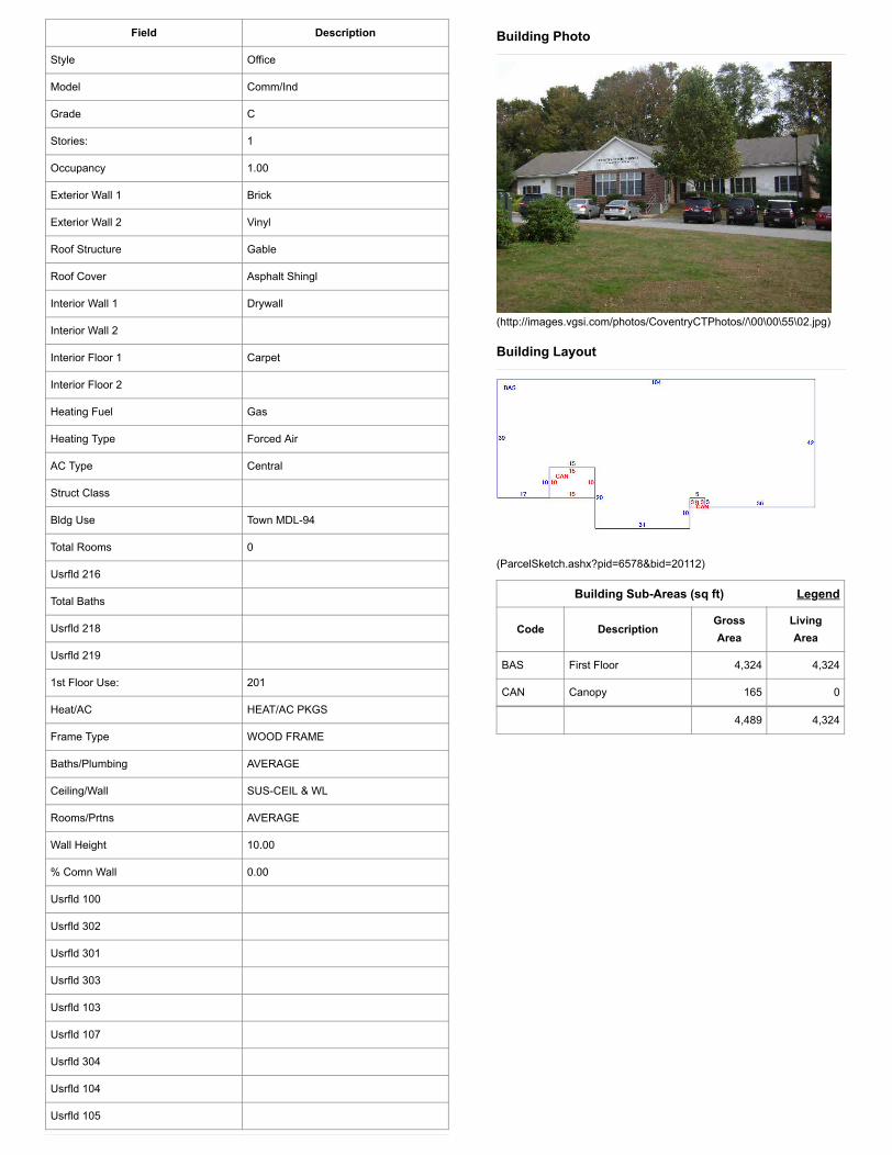
Field Description
Style Office
Model Comm/Ind
Grade C
Stories: 1
Occupancy 1.00
Exterior Wall 1 Brick
Exterior Wall 2 Vinyl
Roof Structure Gable
Roof Cover Asphalt Shingl
Interior Wall 1 Drywall
Interior Wall 2
Interior Floor 1 Carpet
Interior Floor 2
Heating Fuel Gas
Heating Type Forced Air
AC Type Central
Struct Class
Bldg Use Town MDL-94
Total Rooms 0
Usrfld 216
Total Baths
Usrfld 218
Usrfld 219
1st Floor Use: 201
Heat/AC HEAT/AC PKGS
Frame Type WOOD FRAME
Baths/Plumbing AVERAGE
Ceiling/Wall SUS-CEIL & WL
Rooms/Prtns AVERAGE
Wall Height 10.00
% Comn Wall 0.00
Usrfld 100
Usrfld 302
Usrfld 301
Usrfld 303
Usrfld 103
Usrfld 107
Usrfld 304
Usrfld 104
Usrfld 105
Legend
Building Photo
(http://images.vgsi.com/photos/CoventryCTPhotos//\00\00\55\02.jpg)
Building Layout
(ParcelSketch.ashx?pid=6578&bid=20112)
Building Sub-Areas (sq ft)
Code DescriptionGross Area
Living Area
BAS First Floor 4,324 4,324
CAN Canopy 165 0
4,489 4,324

Usrfld 101
Usrfld 225
Usrfld 300
Usrfld 220
Usrfld 221
Usrfld 102
Usrfld 701
Usrfld 106
Usrfld 305
Usrfld 900 No
Usrfld 901 No
Year Built: 1961Living Area: 131,671Replacement Cost: $15,905,105Building Percent Good: 69Replacement Cost Less Depreciation: $10,974,500
Building Attributes : Bldg 4 of 5
Field Description
Style Schools-Public
Model Comm/Ind
Grade C
Stories:
Occupancy
Exterior Wall 1 Brick
Exterior Wall 2
Roof Structure Flat
Roof Cover Tar + Gravel
Interior Wall 1 Drywall
Interior Wall 2 Minimum
Interior Floor 1 Asphalt Tile
Interior Floor 2
Heating Fuel Oil
Heating Type Hot Water
AC Type None/partial
Struct Class
Bldg Use Town School
Total Rooms 0
Usrfld 216
Total Baths
Legend
Building Photo
(http://images.vgsi.com/photos/CoventryCTPhotos//\00\00\55\06.jpg)
Building Layout
(ParcelSketch.ashx?pid=6578&bid=20113)
Building Sub-Areas (sq ft)
Building 4 : Section 1

Usrfld 218
Usrfld 219
1st Floor Use: 201
Heat/AC HEAT ONLY
Frame Type STEEL
Baths/Plumbing AVERAGE
Ceiling/Wall CEIL & WALLS
Rooms/Prtns AVERAGE
Wall Height 10.00
% Comn Wall 0.00
Usrfld 100
Usrfld 302
Usrfld 301
Usrfld 303
Usrfld 103
Usrfld 107
Usrfld 304
Usrfld 104
Usrfld 105
Usrfld 101
Usrfld 225
Usrfld 300
Usrfld 220
Usrfld 221
Usrfld 102
Usrfld 701
Usrfld 106
Usrfld 305
Usrfld 900 No
Usrfld 901 No
Code DescriptionGross Area
Living Area
BAS First Floor 131,671 131,671
FOP Porch, Open 840 0
GRN Greenhouse 297 0
PTO Patio 5,362 0
138,170 131,671
Year Built: 1962Living Area: 75,960Replacement Cost: $9,998,986Building Percent Good: 69Replacement Cost Less Depreciation: $6,899,300
Building Attributes : Bldg 5 of 5
Field Description
Style Schools-Public
Model Comm/Ind
Building 5 : Section 1

Grade C
Stories: 1
Occupancy 1.00
Exterior Wall 1 Brick
Exterior Wall 2
Roof Structure Flat
Roof Cover Tar + Gravel
Interior Wall 1 Drywall
Interior Wall 2
Interior Floor 1 Asphalt Tile
Interior Floor 2
Heating Fuel Oil
Heating Type Hot Water
AC Type None/partial
Struct Class
Bldg Use Town School
Total Rooms 0
Usrfld 216
Total Baths
Usrfld 218
Usrfld 219
1st Floor Use: 201
Heat/AC HEAT ONLY
Frame Type MASONRY
Baths/Plumbing AVERAGE
Ceiling/Wall SUS-CEIL & WL
Rooms/Prtns AVERAGE
Wall Height 12.00
% Comn Wall 0.00
Usrfld 100
Usrfld 302
Usrfld 301
Usrfld 303
Usrfld 103
Usrfld 107
Usrfld 304
Usrfld 104
Usrfld 105
Usrfld 101
Usrfld 225
Usrfld 300
Legend
Building Photo
(http://images.vgsi.com/photos/CoventryCTPhotos//\00\00\55\05.jpg)
Building Layout
(ParcelSketch.ashx?pid=6578&bid=20114)
Building Sub-Areas (sq ft)
Code DescriptionGross Area
Living Area
BAS First Floor 75,960 75,960
FOP Porch, Open 1,502 0
PTO Patio 1,664 0
WDK Wood Deck 201 0
79,327 75,960

Usrfld 220
Usrfld 221
Usrfld 102
Usrfld 701
Usrfld 106
Usrfld 305
Usrfld 900 No
Usrfld 901 No
Legend
Land Use
Use Code 901Description Town MDL-94 Zone GR40Neighborhood GAlt Land Appr NoCategory
Land Line Valuation
Size (Acres) 98.00FrontageDepthAssessed Value $2,220,400Appraised Value $3,172,000
Legend
Extra Features
Extra Features
Code Description Size Value Bldg #
SP Solar Panel 18.00 UNITS $0 2
A/C Air Condition 3240.00 S.F. $4,500 5
SPR1 Sprinklers-Wet 76920.00 S.F. $42,500 5
SP Solar Panel 320.00 UNITS $0 5
SPR1 Sprinklers-Wet 138169.00 S.F. $76,300 4
A/C Air Condition 35390.00 S.F. $48,800 4
MEZ1 Mezzanine-Unf 1984.00 S.F. $11,000 4
Land
Outbuildings
Outbuildings
Code Description Sub Code Sub Description Size Value Bldg #
FGR1 Garage 2400.00 S.F. $48,000 4
PAV1 Paving 5000.00 S.F. $6,300 5
SHD5 Cell Shed 288.00 S.F. $82,100 1
PAV1 Paving 26000.00 S.F. $32,800 4
PAV1 Paving 20000.00 S.F. $25,200 1
TEN Tennis Court 3.00 UNITS $42,000 5
TNK1 Elevated Tank 10000.00 GALS $16,600 4
BHS1 Bathhouse 510.00 S.F. $7,800 4
FNC Fence M Metal 1500.00 L.F. $20,000 5

(c) 2021 Vision Government Solutions, Inc. All rights reserved.
SHD1 Shed 600.00 S.F. $4,800 1
FOP Open Porch 304.00 S.F. $5,800 4
SHD5 Cell Shed 200.00 S.F. $57,000 1
SHD1 Shed 384.00 S.F. $3,600 4
FNC Fence M Metal 1500.00 L.F. $14,700 5
SHD1 Shed 96.00 S.F. $900 1
TEN Tennis Court 3.00 UNITS $57,000 4
FCP Carport 5712.00 S.F. $40,000 5
FGR1 Garage 2000.00 S.F. $47,500 4
FNC Fence M Metal 200.00 L.F. $2,700 1
LT1 Light 1 34.00 UNITS $64,600 1
OFSD Off/Studio 960.00 S.F. $41,000 4
LT2 Light 2 7.00 UNITS $19,300 1
LNT Lean-to 192.00 S.F. $900 4
LNT Lean-to 192.00 S.F. $900 4
LT3 Light 3 0.00 UNITS $0 4
Valuation History
Appraisal
Valuation Year Improvements Land Total
2018 $20,573,300 $2,360,800 $22,934,100
2018 $20,573,300 $2,360,800 $22,934,100
2017 $20,573,300 $2,360,800 $22,934,100
Assessment
Valuation Year Improvements Land Total
2018 $14,401,400 $1,652,600 $16,054,000
2018 $14,401,400 $1,652,600 $16,054,000
2017 $14,401,400 $1,652,600 $16,054,000

Exhibit C
Construction Drawings

- MobileTNORTHEAST LLC
SITE NAME:
SITE ID:
SITE ADDRESS:
SHEET TITLE:
DRAWING:
CTHA616A
CT03XC206
1712 MAIN STCOVENTRY, CT 06238
T-1
TITLE SHEET
PROJECT INFORMATION
PROJECT DIRECTORY
Know what's below. Call before you dig.
R
GENERAL NOTES
THESE DRAWINGS ARE FORMATTED TO BE FULL SIZE AT 22"x34". CONTRACTORSHALL VERIFY ALL PLANS & EXISTING DIMENSIONS & CONDITIONS ON THE JOBSITE & SHALL IMMEDIATELY NOTIFY THE ENGINEER IN WRITING OF ANYDISCREPANCIES BEFORE PROCEEDING WITH THE WORK OR BE RESPONSIBLEFOR SAME.
DRAWING SCALE NOTES:
N
PROJECTLOCATION
PROJECTLOCATION
SITE NAME:
SITE NUMBER:
SITE ADDRESS:
COUNTY
MUNICIPALITY:
ZONING:
LATITUDE:
LONGITUDE:
TYPE OF SITE:
STRUCTURE HEIGHT:
ANTENNA CENTER:
GROUND ELEVATION:
BUILDING OWNER NAME:
BUILDING OWNERADDRESS:
APPLICANT:
APPLICANT PHONE:
APPLICANT FAX:
SCOPE OF WORK
NORTHEAST LLC
750 W CENTER ST, SUITE 301WEST BRIDGEWATER, MA 02379
PHONE: 781.713.4725
T-MOBILE NORTHEAST, LLC.15 COMMERCE WAY, SUITE B
NORTON, MA 02766PHONE: (508) 286-2700
FAX: (508) 286-2893
- MobileT
CARRIER:T-MOBILE NORTHEAST, LLC.15 COMMERCE WAY, SUITE BNORTON, MA 02766PHONE: (508) 286-2700FAX: (508) 286-2893
ENGINEERING FIRM:CENTERLINE COMMUNICATIONS750 WEST CENTER ST, SUITE 301WEST BRIDGEWATER, MA 02379DEREK CREASER (617) 306-3034
NO. DESCRIPTION
DRAWING INDEX
SITE NAME: CT03XC206SITE ID: CTHA616AADDRESS: 1712 MAIN ST.
COVENTRY, CT 06238
TECHNOLOGY: 67D5998C_1xAIR+1QP+10P (GSM ONLY)MODIFICATION: NEW BUILD SPRINT KEEP
CT03XC206
CTHA616A
1712 MAIN STCOVENTRY, CT 06238
TOLLAND
COVENTRY
C2
41.77983333
-72.31005556
SELF SUPPORT TOWER
190'-0" AGL
180'-0" AGL
140.0'
TOWN OF COVENTRY
1712 MAIN STCOVENTRY, CT 06238
T-MOBILE NORTHEAST, LLC.15 COMMERCE WAY, SUITE BNORTON, MASSACHUSETTS 02766
(508) 286-2700
(508) 286-2893
..\..\..\..\..\..\..\..\Technical Information\Stamps\DCS Stamps PDFs\DCS Stamps PDFs\ct-seal.gif
DATE: 04/30/21
IT IS A VIOLATION OF LAW FOR ANY PERSON UNLESS THEY ARE ACTING UNDER THEDIRECTION OF A LICENSED PROFESSIONAL ENGINEER TO ALTER THIS DOCUMENT.
UNLESS EXPLICITLY AGREED TO BY THE ENGINEER IN WRITING, THE ENGINEERDISCLAIMS ALL LIABILITY ASSOCIATED WITH THE REUSE, ALTERATION OR
MODIFICATION OF THE CONTENTS HEREIN.
AutoCAD SHX Text
VICINITY MAP
AutoCAD SHX Text
N.T.S.
AutoCAD SHX Text
LOCATION MAP
AutoCAD SHX Text
1. THIS DOCUMENT IS THE CREATION, DESIGN, PROPERTY AND COPYRIGHTED WORK OF T-MOBILE. ANY DUPLICATION OR USE WITHOUT EXPRESS WRITTEN CONSENT IS STRICTLY PROHIBITED. DUPLICATION AND USE BY GOVERNMENT AGENCIES FOR THE PURPOSE OF CONDUCTING THEIR LAWFULLY AUTHORIZED REGULATORY AND ADMINISTRATIVE FUNCTIONS IS SPECIFICALLY ALLOWED. 2. THE FACILITY IS AN UNMANNED PRIVATE AND SECURED EQUIPMENT INSTALLATION. IT IS ONLY ACCESSED BY TRAINED TECHNICIANS FOR PERIODIC ROUTINE MAINTENANCE AND THEREFORE DOES NOT REQUIRE ANY WATER OR SANITARY SEWER SERVICE. THE FACILITY IS NOT GOVERNED BY REGULATIONS REQUIRING PUBLIC ACCESS PER ADA REQUIREMENTS. 3. CONTRACTOR SHALL VERIFY ALL PLANS AND EXISTING DIMENSIONS AND CONDITIONS ON THE JOB SITE AND SHALL IMMEDIATELY NOTIFY THE T-MOBILE REPRESENTATIVE IN WRITING OF DISCREPANCIES BEFORE PROCEEDING WITH THE WORK OR BE RESPONSIBLE FOR SAME.
AutoCAD SHX Text
1. REMOVE AND REPLACE SIX EXISTING ANTENNAS W/NINE NEW ANTENNAS REMOVE AND REPLACE SIX EXISTING ANTENNAS W/NINE NEW ANTENNAS 2. REMOVE ALL EXISTING RRUs REMOVE ALL EXISTING RRUs 3. INSTALL NINE NEW RRUS INSTALL NINE NEW RRUS 4. INSTALL THREE NEW 6x24 HYBRID CABLES INSTALL THREE NEW 6x24 HYBRID CABLES 5. INSTALL THREE NEW ANTENNA PIPE MOUNT ASSEMBLIES INSTALL THREE NEW ANTENNA PIPE MOUNT ASSEMBLIES 6. REMOVE ALL UNUSED CABLES AND EQUIPMENT REMOVE ALL UNUSED CABLES AND EQUIPMENT 7. REMOVE EXISTING PPC PANEL AND INSTALL NEW 200A PANEL REMOVE EXISTING PPC PANEL AND INSTALL NEW 200A PANEL 8. INSTALL 6230 CABINET ON 6230 RACKINSTALL 6230 CABINET ON 6230 RACK
AutoCAD SHX Text
ISSUED FOR REVIEW
AutoCAD SHX Text
A
AutoCAD SHX Text
04/05/21
AutoCAD SHX Text
MK
AutoCAD SHX Text
TRP
AutoCAD SHX Text
TRP
AutoCAD SHX Text
REVISIONS
AutoCAD SHX Text
REV
AutoCAD SHX Text
DATE
AutoCAD SHX Text
DESCRIPTION
AutoCAD SHX Text
BY
AutoCAD SHX Text
APPROVED BY:
AutoCAD SHX Text
DESIGNED BY:
AutoCAD SHX Text
ISSUED FOR CONSTRUCTION
AutoCAD SHX Text
0
AutoCAD SHX Text
04/29/21
AutoCAD SHX Text
MJS
AutoCAD SHX Text
CHANGED ADDRESS
AutoCAD SHX Text
1
AutoCAD SHX Text
04/30/21
AutoCAD SHX Text
MJS
AutoCAD SHX Text
N.T.S.
AutoCAD SHX Text
T-1
AutoCAD SHX Text
COMPOUND PLAN
AutoCAD SHX Text
TITLE SHEET
AutoCAD SHX Text
NORTHEAST ELEVATION
AutoCAD SHX Text
GROUNDING DETAILS & ONE LINE DIAGRAM
AutoCAD SHX Text
GN-1
AutoCAD SHX Text
GENERAL NOTES, RF NOTES, CABLING NOTES
AutoCAD SHX Text
A-1
AutoCAD SHX Text
A-3
AutoCAD SHX Text
E-1
AutoCAD SHX Text
EQUIPMENT LAYOUT
AutoCAD SHX Text
A-2
AutoCAD SHX Text
ANTENNA PLANS & SCHEDULE
AutoCAD SHX Text
A-4
AutoCAD SHX Text
STRUCTURAL NOTES & SPECIAL INSPECTIONS
AutoCAD SHX Text
SN-1
AutoCAD SHX Text
DETAILS
AutoCAD SHX Text
A-5
AutoCAD SHX Text
ANTENNA AND RRU MOUNT DETAILS
AutoCAD SHX Text
A-6
AutoCAD SHX Text
PROPOSED PPC PRODUCT SPECS
AutoCAD SHX Text
A-7
AutoCAD SHX Text
C
AutoCAD SHX Text
I
AutoCAD SHX Text
L
AutoCAD SHX Text
E
AutoCAD SHX Text
E
AutoCAD SHX Text
S
AutoCAD SHX Text
N
AutoCAD SHX Text
D
AutoCAD SHX Text
C
AutoCAD SHX Text
I
AutoCAD SHX Text
R
AutoCAD SHX Text
O
AutoCAD SHX Text
F
AutoCAD SHX Text
I
AutoCAD SHX Text
S
AutoCAD SHX Text
O
AutoCAD SHX Text
N
AutoCAD SHX Text
A
AutoCAD SHX Text
E
AutoCAD SHX Text
L
AutoCAD SHX Text
G
AutoCAD SHX Text
N
AutoCAD SHX Text
I
AutoCAD SHX Text
O
AutoCAD SHX Text
F
AutoCAD SHX Text
T
AutoCAD SHX Text
E
AutoCAD SHX Text
R
AutoCAD SHX Text
E
AutoCAD SHX Text
N
AutoCAD SHX Text
E
AutoCAD SHX Text
C
AutoCAD SHX Text
E
AutoCAD SHX Text
N
AutoCAD SHX Text
T
AutoCAD SHX Text
O
AutoCAD SHX Text
N
AutoCAD SHX Text
C
AutoCAD SHX Text
E
AutoCAD SHX Text
S
AutoCAD SHX Text
K
AutoCAD SHX Text
.
AutoCAD SHX Text
J
AutoCAD SHX Text
C
AutoCAD SHX Text
P
AutoCAD SHX Text
U
AutoCAD SHX Text
T
AutoCAD SHX Text
A
AutoCAD SHX Text
T
AutoCAD SHX Text
No.28551
AutoCAD SHX Text
E
AutoCAD SHX Text
D
AutoCAD SHX Text
R
AutoCAD SHX Text
E
AutoCAD SHX Text
E
AutoCAD SHX Text
R
AutoCAD SHX Text
A
AutoCAD SHX Text
S
AutoCAD SHX Text
S
AutoCAD SHX Text
E
AutoCAD SHX Text
R
RF NOTES
ABBREVIATIONS
1. ACTUAL LENGTHS SHALL BE DETERMINED PER SITE CONDITION BYSUBCONTRACTOR
2. THE DESIGN IS BASED ON RF DATA SHEETS, SIGNED AND APPROVED.
3. RADIO SIGNAL CABLE AND RACEWAY SHALL COMPLY WITH THEREQUIREMENTS OF THE NATIONAL ELECTRICAL CODE (NEC, NFPA 70),CHAPTER 8.
4. ALL SPECIFIED MATERIAL FOR EACH LOCATION (E.G. OUT DOORS-OCCUPIED,INDOORS-UNOCCUPIED, PLENUMS, RISER SHAFTS, ETC.) SHALL BEAPPROVED, LISTED, OR LABELED AS REQUIRED BY THE NEC.
5. RADIO SIGNAL CABLE SHALL BE SUPPORTED AT MINIMUM OF EVERY THREE (3)FEET EXCEPT INSIDE MONOPOLES OR MONOPOLES WHERE CABLE ANDCONNECTOR MANUFACTURERS SUPPORT RECOMMENDATIONS SHALL BEFOLLOWED. MANUFACTURER RECOMMENDATION CABLES SUPPORTACCESSORIES SHALL BE USED.
6. THE OUTDOOR CABLE SUPPORT SYSTEM SHALL BE PROVIDED WITH AN ICESHIELD TO SUPPORT AND PROTECT ANTENNA CABLE RUNS.
7. DRIP LOOPS SHALL BE REQUIRED ON ALL OUTSIDE CABLES. CABLES SHALLBE SLOPED AWAY FROM BUILDING OR OUTDOOR BTS CABINETS TO PREVENTWATER FROM ENTERING THROUGH THE COAXIAL CABLE PORT.
8. ALL FEEDER LINE AND JUMPER CONNECTORS SHALL BE 7/16 DIN CABLECONNECTORS THAT MEET IP68 STANDARDS.
9. 7/16 DIN CONNECTORS REQUIRE NO ADDITIONAL WEATHER PROOFING ININDOOR APPLICATIONS IF INSTALLED AND TORQUED PROPERLY. IN OUTDOORAPPLICATIONS WEATHER PROOFING IS REQUIRED AND THE FOLLOWINGPROCEDURE SHOULD BE FOLLOWED.
10. USING WEATHERPROOFING KIT APPROVED BY CABLE MANUFACTURER ANDCONTRACTOR START TAPE APPROXIMATELY 5 INCHES FROM THECONNECTOR, AND WRAP 2 INCHES TOWARD THE CONNECTOR, THENREVERSE THE TAPE SO THAT THE STICKY SIDE IS UP. TAPE OVER THECONNECTOR OR SURGE ARRESTOR UNTIL THREE (3) TO FOUR (4) INCHESBEYOND THE CONNECTOR AND REVERSE AGAIN WITH THE STICKY SIDE DOWNFOR ANOTHER INCH OR TWO. PASS THE BUTYL RUBBER AND FINISH WITH AFINAL LAYER OF TAPE.
11. ANTENNAS SHALL BE PAINTED,WHEN REQUIRED, BY THE LANDLORD ORAUTHORITY OF HAVING JURISDICTION IN ACCORDANCE WITH ANTENNAMANUFACTURERS' SURFACES PREPARATION AND PAINTING REQUIREMENTS.
12. CABLE SHIELDS AND TOWER CONDUITS SHALL BE GROUNDED AT THE TOP OFTHE TOWER WITHIN 10 FEET OF THEIR CONNECTORS, AND AT THE BOTTOMOF THE TOWER ABOUT 6 INCHES BEFORE THEY TURN TOWARD THE FACILITY.THEY SHALL BE GROUNDED AT THE MIDPOINT OF THE TOWERS THAT AREBETWEEN 60 FEET AND 200 FEET HIGH, AND AT INTERVALS OF 60 FEET ORLESS ON TOWERS THAT ARE HIGHER THAN 200 FEET.
1. SUBCONTRACTOR SHALL VERIFY THE ACTUAL LENGTH IN THE FIELD BEFOREINSTALLATION.
2. TAG AND COLOR CODE ALL MAIN CABLES AT LOCATIONS PER T-MOBILEANTENNA CABLE MARKING STANDARD:
· TOP OF TOWER END OF MAIN COAX· BOTTOM OF TOWER END OF MAIN COAX· DIRECTLY BEFORE AND AFTER RF EQUIPMENT· END OF JUMPERS AT BTS EQUIPMENT
3. ANTENNAS SHALL BE PROCURED AND INSTALLED WITH DOWN TILT MOUNTINGBRACKETS SUPPLIED BY ANTENNA MANUFACTURER.
4. PRIOR APPROVAL IS REQUIRED BEFORE PERFORMING ANY WORK ON EXISTINGCELL SITE EQUIPMENT.
SITE NAME:
SITE ID:
SITE ADDRESS:
SHEET TITLE:
DRAWING:
CTHA616A
CT03XC206
1712 MAIN STCOVENTRY, CT 06238
GN-1
GENERAL NOTES, RF NOTES,CABLING NOTES
1. FOR THE PURPOSE OF CONSTRUCTION DRAWING, THE FOLLOWINGDEFINITIONS SHALL APPLY: CONTRACTOR - CENTERLINE COMMUNICATIONS SUBCONTRACTOR - GENERAL CONTRACTOR (CONSTRUCTION) OWNER - T-MOBILE MOBILITY
2. PRIOR TO THE SUBMISSION OF BIDS, THE BIDDING SUBCONTRACTORSHALL VISIT THE CELL SITE TO FAMILIARIZE WITH THE EXISTING CONDITIONSAND TO CONFIRM THAT THE WORK CAN BE ACCOMPLISHED AS SHOWN ONTHE CONSTRUCTION DRAWINGS. ANY DISCREPANCY FOUND SHALL BEBROUGHT TO THE ATTENTION OF CONTRACTOR.
3. ALL MATERIALS FURNISHED AND INSTALLED SHALL BE IN STRICTACCORDANCE WITH ALL APPLICABLE CODES, REGULATIONS, ANDORDINANCES. SUBCONTRACTOR SHALL ISSUE ALL APPROPRIATE NOTICESAND COMPLY WITH ALL LAWS, ORDINANCES, RULES, REGULATIONS, ANDLAWFUL ORDERS OF ANY PUBLIC AUTHORITY REGARDING THEPERFORMANCE OF THE WORK. ALL WORK CARRIED OUT SHALL COMPLY WITHALL APPLICABLE MUNICIPAL AND UTILITY COMPANY SPECIFICATIONS ANDLOCAL JURISDICTIONAL CODES, ORDINANCES AND APPLICABLEREGULATIONS.
4. DRAWINGS PROVIDED HERE ARE NOT TO BE SCALED AND ARE INTENDEDTO SHOW OUTLINE ONLY.
5. UNLESS NOTED OTHERWISE, THE WORK SHALL INCLUDE FURNISHINGMATERIALS, EQUIPMENT, APPURTENANCES, AND LABOR NECESSARY TOCOMPLETE ALL INSTALLATIONS AS INDICATED ON THE DRAWINGS.
6. "KITTING LIST" SUPPLIED WITH THE BID PACKAGE IDENTIFIES ITEMS THATWILL BE SUPPLIED BY CONTRACTOR. ITEMS NOT INCLUDED IN THE BILL OFMATERIALS AND KITTING LIST SHALL BE SUPPLIED BY THE SUBCONTRACTOR.
7. THE SUBCONTRACTOR SHALL INSTALL ALL EQUIPMENT AND MATERIALS INACCORDANCE WITH MANUFACTURER'S RECOMMENDATIONS UNLESSSPECIFICALLY STATED OTHERWISE.
8. IF THE SPECIFIED EQUIPMENT CANNOT BE INSTALLED AS SHOWN ONTHESE DRAWINGS, THE SUBCONTRACTOR SHALL PROPOSE AN ALTERNATIVEINSTALLATION SPACE FOR APPROVAL BY THE CONTRACTOR.
9. SUBCONTRACTOR SHALL DETERMINE ACTUAL ROUTING OF CONDUIT,POWER AND T1 CABLES, GROUNDING CABLES AS SHOWN ON THE POWER,GROUNDING AND TELCO PLAN DRAWING. SUBCONTRACTOR SHALL UTILIZEEXISTING TRAYS AND/OR SHALL ADD NEW TRAYS AS NECESSARY.SUBCONTRACTOR SHALL CONFIRM THE ACTUAL ROUTING WITH THECONTRACTOR.
10. THE SUBCONTRACTOR SHALL PROTECT EXISTING IMPROVEMENTS,PAVEMENTS, CURBS, LANDSCAPING AND STRUCTURES. ANY DAMAGED PARTSHALL BE REPAIRED AT SUBCONTRACTOR'S EXPENSE TO THE SATISFACTIONOF OWNER.
11. SUBCONTRACTOR SHALL LEGALLY AND PROPERLY DISPOSE OF ALLSCRAP MATERIALS SUCH AS COAXIAL CABLES AND OTHER ITEMS REMOVEDFROM THE EXISTING FACILITY. ANTENNAS REMOVED SHALL BE RETURNEDTO THE OWNER'S DESIGNATED LOCATION.
12. SUBCONTRACTOR SHALL LEAVE PREMISES IN CLEAN CONDITION.
13. ALL CONCRETE REPAIR WORK SHALL BE DONE IN ACCORDANCE WITHAMERICAN CONCRETE INSTITUTE (ACI) 301.
14. ANY NEW CONCRETE NEEDED FOR THE CONSTRUCTION SHALL BEAIR-ENTRAINED AND SHALL HAVE 4000 PSI STRENGTH AT 28 DAYS. ALLCONCRETE WORK SHALL BE DONE IN ACCORDANCE WITH ACI 318 CODEREQUIREMENTS.
GENERAL NOTESANTENNA CABLE &SCHEDULING NOTES
NORTHEAST LLC
750 W CENTER ST, SUITE 301WEST BRIDGEWATER, MA 02379
PHONE: 781.713.4725
T-MOBILE NORTHEAST, LLC.15 COMMERCE WAY, SUITE B
NORTON, MA 02766PHONE: (508) 286-2700
FAX: (508) 286-2893
- MobileT
2015 INTERNATIONAL BUILDING CODE2015 INTERNATIONAL EXISTING BUILDING CODE2015 INTERNATIONAL PLUMBING CODE2015 INTERNATIONAL MECHANICAL CODE2015 INTERNATIONAL ENERGY CONSERVATION CODE2017 NATIONAL ELECTRICAL CODE (NFPA 70)2018 CONNECTICUT STATE BUILDING CODE
AGL ABOVE GROUND LEVEL
AWG AMERICAN WIRE GAGE
BCW BARE COPPER WIRE
BTS BASE TRANSCEIVER STATION
EG EQUIPMENT GROUND
EGR EQUIPMENT GROUND RING
G.C. GENERAL CONTRACTOR
GRC GALVANIZED RIDGID CONDUIT
MGB MASTER GROUND BUSS
MIN MINIMUM
NEC NATIONAL ELEC. CODE
NTS NOT TO SCALE
REF REFERENCE
REQ REQUIRED
RF RADIO FREQUENCY
R&R REMOVE AND REPLACE
TBR TO BE REMOVED
TYP TYPICAL
15. ALL STRUCTURAL STEEL WORK SHALL BE DETAILED, FABRICATED ANDERECTED IN ACCORDANCE WITH AISC SPECIFICATIONS. ALL STRUCTURALSTEEL SHALL BE ASTM A36 (Fy = 36 ksi) UNLESS OTHERWISE NOTED. PIPESSHALL BE ASTM A53 TYPE E (Fy = 36 ksi). ALL STEEL EXPOSED TO WEATHERSHALL BE HOT DIPPED GALVANIZED. TOUCHUP ALL SCRATCHES AND OTHERMARKS IN THE FIELD AFTER STEEL IS ERECTED USING A COMPATIBLE ZINCRICH PAINT.
16. CONSTRUCTION SHALL COMPLY WITH SPECIFICATIONS AND "GENERALCONSTRUCTION SERVICES FOR CONSTRUCTION OF T-MOBILE MOBILITYSITES."
17. SUBCONTRACTOR SHALL VERIFY ALL EXISTING DIMENSIONS ANDCONDITIONS PRIOR TO COMMENCING ANY WORK. ALL DIMENSIONS OFEXISTING CONSTRUCTION SHOWN ON THE DRAWINGS MUST BE VERIFIED.SUBCONTRACTOR SHALL NOTIFY THE CONTRACTOR OF ANY DISCREPANCIESPRIOR TO ORDERING MATERIAL OR PROCEEDING WITH CONSTRUCTION.
18. THE EXISTING CELL SITE IS IN FULL COMMERCIAL OPERATION. ANYCONSTRUCTION WORK BY SUBCONTRACTOR SHALL NOT DISRUPT THEEXISTING NORMAL OPERATION. ANY WORK ON EXISTING EQUIPMENT MUSTBE COORDINATED WITH CONTRACTOR. ALSO, WORK SHOULD BESCHEDULED FOR AN APPROPRIATE MAINTENANCE WINDOW USUALLY IN LOWTRAFFIC PERIODS AFTER MIDNIGHT.
19. SINCE THE CELL SITE IS ACTIVE, ALL SAFETY PRECAUTIONS MUST BETAKEN WHEN WORKING AROUND HIGH LEVELS OF ELECTROMAGNETICRADIATION. EQUIPMENT SHOULD BE SHUTDOWN PRIOR TO PERFORMINGANY WORK THAT COULD EXPOSE THE WORKERS TO DANGER. PERSONAL RFEXPOSURE MONITORS ARE ADVISED TO BE WORN TO ALERT OF ANYDANGEROUS EXPOSURE LEVELS.
20. APPLICABLE BUILDING CODES:SUBCONTRACTOR'S WORK SHALL COMPLY WITH ALL APPLICABLE NATIONAL,STATE, AND LOCAL CODES AS ADOPTED BY THE LOCAL AUTHORITY HAVINGJURISDICTION (AHJ) FOR THE LOCATION. THE EDITION OF THE AHJ ADOPTEDCODES AND STANDARDS IN EFFECT ON THE DATE OF CONTRACT AWARDSHALL GOVERN THE DESIGN.
SUBCONTRACTOR'S WORK SHALL COMPLY WITH THE LATEST EDITION OF THEFOLLOWING STANDARDS:
AMERICAN CONCRETE INSTITUTE (ACI) 318; BUILDING CODE REQUIREMENTS FOR STRUCTURAL CONCRETE;
AMERICAN INSTITUTE OF STEEL CONSTRUCTION (AISC)
MANUAL OF STEEL CONSTRUCTION, ASD, FOURTEENTH EDITION;
TELECOMMUNICATIONS INDUSTRY ASSOCIATION (TIA) 222-G, STRUCTURAL STANDARDS FOR STEEL
ANTENNA TOWER AND ANTENNA SUPPORTING STRUCTURES; REFER TO ELECTRICAL DRAWINGS FOR SPECIFIC ELECTRICAL STANDARDS.
FOR ANY CONFLICTS BETWEEN SECTIONS OF LISTED CODES ANDSTANDARDS REGARDING MATERIAL, METHODS OF CONSTRUCTION, OROTHER REQUIREMENTS, THE MOST RESTRICTIVE REQUIREMENT SHALLGOVERN. WHERE THERE IS CONFLICT BETWEEN A GENERAL REQUIREMENTAND A SPECIFIC REQUIREMENT, THE SPECIFIC REQUIREMENT SHALLGOVERN.
..\..\..\..\..\..\..\..\Technical Information\Stamps\DCS Stamps PDFs\DCS Stamps PDFs\ct-seal.gif
DATE: 04/30/21
IT IS A VIOLATION OF LAW FOR ANY PERSON UNLESS THEY ARE ACTING UNDER THEDIRECTION OF A LICENSED PROFESSIONAL ENGINEER TO ALTER THIS DOCUMENT.
UNLESS EXPLICITLY AGREED TO BY THE ENGINEER IN WRITING, THE ENGINEERDISCLAIMS ALL LIABILITY ASSOCIATED WITH THE REUSE, ALTERATION OR
MODIFICATION OF THE CONTENTS HEREIN.
AutoCAD SHX Text
ISSUED FOR REVIEW
AutoCAD SHX Text
A
AutoCAD SHX Text
04/05/21
AutoCAD SHX Text
MK
AutoCAD SHX Text
TRP
AutoCAD SHX Text
TRP
AutoCAD SHX Text
REVISIONS
AutoCAD SHX Text
REV
AutoCAD SHX Text
DATE
AutoCAD SHX Text
DESCRIPTION
AutoCAD SHX Text
BY
AutoCAD SHX Text
APPROVED BY:
AutoCAD SHX Text
DESIGNED BY:
AutoCAD SHX Text
ISSUED FOR CONSTRUCTION
AutoCAD SHX Text
0
AutoCAD SHX Text
04/29/21
AutoCAD SHX Text
MJS
AutoCAD SHX Text
CHANGED ADDRESS
AutoCAD SHX Text
1
AutoCAD SHX Text
04/30/21
AutoCAD SHX Text
MJS
AutoCAD SHX Text
C
AutoCAD SHX Text
I
AutoCAD SHX Text
L
AutoCAD SHX Text
E
AutoCAD SHX Text
E
AutoCAD SHX Text
S
AutoCAD SHX Text
N
AutoCAD SHX Text
D
AutoCAD SHX Text
C
AutoCAD SHX Text
I
AutoCAD SHX Text
R
AutoCAD SHX Text
O
AutoCAD SHX Text
F
AutoCAD SHX Text
I
AutoCAD SHX Text
S
AutoCAD SHX Text
O
AutoCAD SHX Text
N
AutoCAD SHX Text
A
AutoCAD SHX Text
E
AutoCAD SHX Text
L
AutoCAD SHX Text
G
AutoCAD SHX Text
N
AutoCAD SHX Text
I
AutoCAD SHX Text
O
AutoCAD SHX Text
F
AutoCAD SHX Text
T
AutoCAD SHX Text
E
AutoCAD SHX Text
R
AutoCAD SHX Text
E
AutoCAD SHX Text
N
AutoCAD SHX Text
E
AutoCAD SHX Text
C
AutoCAD SHX Text
E
AutoCAD SHX Text
N
AutoCAD SHX Text
T
AutoCAD SHX Text
O
AutoCAD SHX Text
N
AutoCAD SHX Text
C
AutoCAD SHX Text
E
AutoCAD SHX Text
S
AutoCAD SHX Text
K
AutoCAD SHX Text
.
AutoCAD SHX Text
J
AutoCAD SHX Text
C
AutoCAD SHX Text
P
AutoCAD SHX Text
U
AutoCAD SHX Text
T
AutoCAD SHX Text
A
AutoCAD SHX Text
T
AutoCAD SHX Text
No.28551
AutoCAD SHX Text
E
AutoCAD SHX Text
D
AutoCAD SHX Text
R
AutoCAD SHX Text
E
AutoCAD SHX Text
E
AutoCAD SHX Text
R
AutoCAD SHX Text
A
AutoCAD SHX Text
S
AutoCAD SHX Text
S
AutoCAD SHX Text
E
AutoCAD SHX Text
R
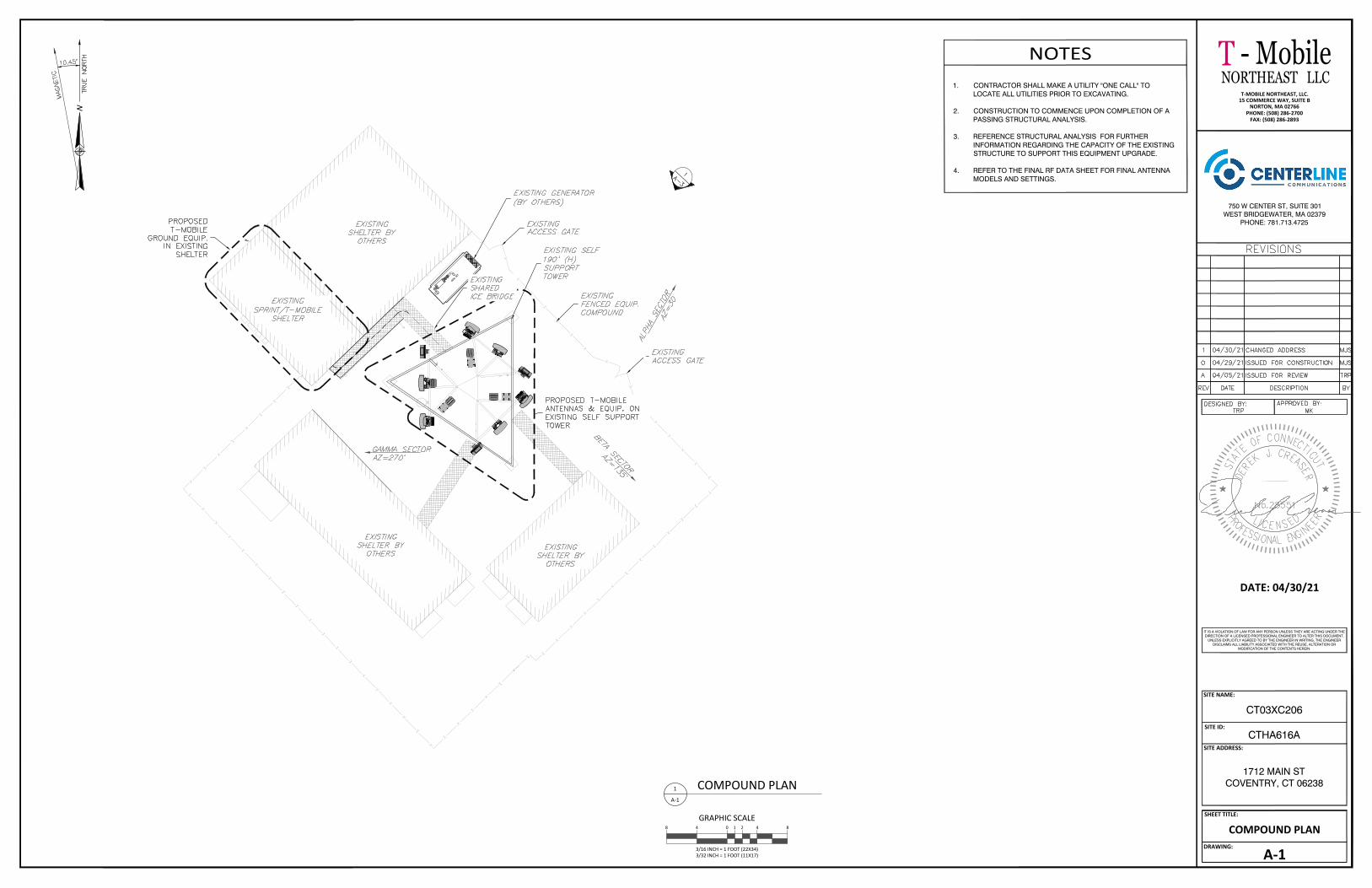
GEN. SET
GEN. SET
SITE NAME:
SITE ID:
SITE ADDRESS:
SHEET TITLE:
DRAWING:
CTHA616A
CT03XC206
1712 MAIN STCOVENTRY, CT 06238
A-1
COMPOUND PLAN
NOTES1. CONTRACTOR SHALL MAKE A UTILITY "ONE CALL" TO
LOCATE ALL UTILITIES PRIOR TO EXCAVATING.
2. CONSTRUCTION TO COMMENCE UPON COMPLETION OF APASSING STRUCTURAL ANALYSIS.
3. REFERENCE STRUCTURAL ANALYSIS FOR FURTHERINFORMATION REGARDING THE CAPACITY OF THE EXISTINGSTRUCTURE TO SUPPORT THIS EQUIPMENT UPGRADE.
4. REFER TO THE FINAL RF DATA SHEET FOR FINAL ANTENNAMODELS AND SETTINGS.
NNORTHEAST LLC
750 W CENTER ST, SUITE 301WEST BRIDGEWATER, MA 02379
PHONE: 781.713.4725
T-MOBILE NORTHEAST, LLC.15 COMMERCE WAY, SUITE B
NORTON, MA 02766PHONE: (508) 286-2700
FAX: (508) 286-2893
- MobileT
GRAPHIC SCALE
3/16 INCH = 1 FOOT (22X34)3/32 INCH = 1 FOOT (11X17)
0 4 848 21
1
A-1
COMPOUND PLAN
..\..\..\..\..\..\..\..\Technical Information\Stamps\DCS Stamps PDFs\DCS Stamps PDFs\ct-seal.gif
DATE: 04/30/21
IT IS A VIOLATION OF LAW FOR ANY PERSON UNLESS THEY ARE ACTING UNDER THEDIRECTION OF A LICENSED PROFESSIONAL ENGINEER TO ALTER THIS DOCUMENT.
UNLESS EXPLICITLY AGREED TO BY THE ENGINEER IN WRITING, THE ENGINEERDISCLAIMS ALL LIABILITY ASSOCIATED WITH THE REUSE, ALTERATION OR
MODIFICATION OF THE CONTENTS HEREIN.
AutoCAD SHX Text
PROPOSED T-MOBILE ANTENNAS & EQUIP. ON EXISTING SELF SUPPORT TOWER
AutoCAD SHX Text
EXISTING SPRINT/T-MOBILE SHELTER
AutoCAD SHX Text
EXISTING SHELTER BY OTHERS
AutoCAD SHX Text
EXISTING SHELTER BY OTHERS
AutoCAD SHX Text
EXISTING SHELTER BY OTHERS
AutoCAD SHX Text
EXISTING SELF 190' (H) SUPPORT TOWER
AutoCAD SHX Text
EXISTING FENCED EQUIP. COMPOUND
AutoCAD SHX Text
EXISTING ACCESS GATE
AutoCAD SHX Text
EXISTING ACCESS GATE
AutoCAD SHX Text
EXISTING GENERATOR (BY OTHERS)
AutoCAD SHX Text
PROPOSED T-MOBILE GROUND EQUIP. IN EXISTING SHELTER
AutoCAD SHX Text
GAMMA SECTOR AZ=270°
AutoCAD SHX Text
BETA SECTOR AZ=135°
AutoCAD SHX Text
ALPHA SECTOR AZ=30°
AutoCAD SHX Text
EXISTING SHARED ICE BRIDGE
AutoCAD SHX Text
10.45°
AutoCAD SHX Text
TRUE NORTH
AutoCAD SHX Text
MAGNETIC
AutoCAD SHX Text
1
AutoCAD SHX Text
A-3
AutoCAD SHX Text
ISSUED FOR REVIEW
AutoCAD SHX Text
A
AutoCAD SHX Text
04/05/21
AutoCAD SHX Text
MK
AutoCAD SHX Text
TRP
AutoCAD SHX Text
TRP
AutoCAD SHX Text
REVISIONS
AutoCAD SHX Text
REV
AutoCAD SHX Text
DATE
AutoCAD SHX Text
DESCRIPTION
AutoCAD SHX Text
BY
AutoCAD SHX Text
APPROVED BY:
AutoCAD SHX Text
DESIGNED BY:
AutoCAD SHX Text
ISSUED FOR CONSTRUCTION
AutoCAD SHX Text
0
AutoCAD SHX Text
04/29/21
AutoCAD SHX Text
MJS
AutoCAD SHX Text
CHANGED ADDRESS
AutoCAD SHX Text
1
AutoCAD SHX Text
04/30/21
AutoCAD SHX Text
MJS
AutoCAD SHX Text
C
AutoCAD SHX Text
I
AutoCAD SHX Text
L
AutoCAD SHX Text
E
AutoCAD SHX Text
E
AutoCAD SHX Text
S
AutoCAD SHX Text
N
AutoCAD SHX Text
D
AutoCAD SHX Text
C
AutoCAD SHX Text
I
AutoCAD SHX Text
R
AutoCAD SHX Text
O
AutoCAD SHX Text
F
AutoCAD SHX Text
I
AutoCAD SHX Text
S
AutoCAD SHX Text
O
AutoCAD SHX Text
N
AutoCAD SHX Text
A
AutoCAD SHX Text
E
AutoCAD SHX Text
L
AutoCAD SHX Text
G
AutoCAD SHX Text
N
AutoCAD SHX Text
I
AutoCAD SHX Text
O
AutoCAD SHX Text
F
AutoCAD SHX Text
T
AutoCAD SHX Text
E
AutoCAD SHX Text
R
AutoCAD SHX Text
E
AutoCAD SHX Text
N
AutoCAD SHX Text
E
AutoCAD SHX Text
C
AutoCAD SHX Text
E
AutoCAD SHX Text
N
AutoCAD SHX Text
T
AutoCAD SHX Text
O
AutoCAD SHX Text
N
AutoCAD SHX Text
C
AutoCAD SHX Text
E
AutoCAD SHX Text
S
AutoCAD SHX Text
K
AutoCAD SHX Text
.
AutoCAD SHX Text
J
AutoCAD SHX Text
C
AutoCAD SHX Text
P
AutoCAD SHX Text
U
AutoCAD SHX Text
T
AutoCAD SHX Text
A
AutoCAD SHX Text
T
AutoCAD SHX Text
No.28551
AutoCAD SHX Text
E
AutoCAD SHX Text
D
AutoCAD SHX Text
R
AutoCAD SHX Text
E
AutoCAD SHX Text
E
AutoCAD SHX Text
R
AutoCAD SHX Text
A
AutoCAD SHX Text
S
AutoCAD SHX Text
S
AutoCAD SHX Text
E
AutoCAD SHX Text
R

SITE NAME:
SITE ID:
SITE ADDRESS:
SHEET TITLE:
DRAWING:
CTHA616A
CT03XC206
1712 MAIN STCOVENTRY, CT 06238
A-2
EQUIP. LAYOUT
NORTHEAST LLC
750 W CENTER ST, SUITE 301WEST BRIDGEWATER, MA 02379
PHONE: 781.713.4725
T-MOBILE NORTHEAST, LLC.15 COMMERCE WAY, SUITE B
NORTON, MA 02766PHONE: (508) 286-2700
FAX: (508) 286-2893
- MobileT
GRAPHIC SCALE
3/8 INCH = 1 FOOT (22X34)3/16 INCH = 1 FOOT (11X17)
0 4 84 21
1
A-2
EXISTING EQUIP. LAYOUT
GRAPHIC SCALE
3/8 INCH = 1 FOOT (22X34)3/16 INCH = 1 FOOT (11X17)
04 21
2
A-2
PROPOSED EQUIP. LAYOUT
..\..\..\..\..\..\..\..\Technical Information\Stamps\DCS Stamps PDFs\DCS Stamps PDFs\ct-seal.gif
DATE: 04/30/21
IT IS A VIOLATION OF LAW FOR ANY PERSON UNLESS THEY ARE ACTING UNDER THEDIRECTION OF A LICENSED PROFESSIONAL ENGINEER TO ALTER THIS DOCUMENT.
UNLESS EXPLICITLY AGREED TO BY THE ENGINEER IN WRITING, THE ENGINEERDISCLAIMS ALL LIABILITY ASSOCIATED WITH THE REUSE, ALTERATION OR
MODIFICATION OF THE CONTENTS HEREIN.
AutoCAD SHX Text
EXISTING SPRINT/T-MOBILE SHELTER
AutoCAD SHX Text
TO TOWER
AutoCAD SHX Text
EXISTING SHARED ICE BRIDGE
AutoCAD SHX Text
EXISTING ELECTRIC METER BANK W/T-MOBILE METER
AutoCAD SHX Text
EXISTING ACCESS DOOR
AutoCAD SHX Text
EXISTING ELECTRIC DISCONNECT (BY OTHERS)
AutoCAD SHX Text
EXISTING ELECTRIC METER (BY OTHERS)
AutoCAD SHX Text
EXISTING SPRINT BTS EQUIP. CABINET (TO BE REMOVED AND REPLACED)
AutoCAD SHX Text
EXISTING T-MOBILE H-FRAME W/FIBER J-BOX (TO REMAIN)
AutoCAD SHX Text
EXISTING T-MOBILE H-FRAME (TO REMAIN)
AutoCAD SHX Text
EXISTING CABLE ENTRY PANEL
AutoCAD SHX Text
EXISTING T-MOBILE ELEC. PNL. (TO BE UPGRADED TO PROPOSED 200A)
AutoCAD SHX Text
TO TOWER
AutoCAD SHX Text
EXISTING SHARED ICE BRIDGE
AutoCAD SHX Text
EXISTING CABLE ENTRY PANEL
AutoCAD SHX Text
PROPOSED T-MOBILE 6230 ON PROPOSED EQUIP RACK (REF. 3/A-5 FOR SPECS.)
AutoCAD SHX Text
PROPOSED T-MOBILE 2416 CABINET (REF. 4/A-5 FOR SPECS.)
AutoCAD SHX Text
EXISTING T-MOBILE PPC PANEL TO BE REPLACED WITH PROPOSED 200A PPC (SEE SHEET A-7 FOR SPECS)
AutoCAD SHX Text
ISSUED FOR REVIEW
AutoCAD SHX Text
A
AutoCAD SHX Text
04/05/21
AutoCAD SHX Text
MK
AutoCAD SHX Text
TRP
AutoCAD SHX Text
TRP
AutoCAD SHX Text
REVISIONS
AutoCAD SHX Text
REV
AutoCAD SHX Text
DATE
AutoCAD SHX Text
DESCRIPTION
AutoCAD SHX Text
BY
AutoCAD SHX Text
APPROVED BY:
AutoCAD SHX Text
DESIGNED BY:
AutoCAD SHX Text
ISSUED FOR CONSTRUCTION
AutoCAD SHX Text
0
AutoCAD SHX Text
04/29/21
AutoCAD SHX Text
MJS
AutoCAD SHX Text
CHANGED ADDRESS
AutoCAD SHX Text
1
AutoCAD SHX Text
04/30/21
AutoCAD SHX Text
MJS
AutoCAD SHX Text
C
AutoCAD SHX Text
I
AutoCAD SHX Text
L
AutoCAD SHX Text
E
AutoCAD SHX Text
E
AutoCAD SHX Text
S
AutoCAD SHX Text
N
AutoCAD SHX Text
D
AutoCAD SHX Text
C
AutoCAD SHX Text
I
AutoCAD SHX Text
R
AutoCAD SHX Text
O
AutoCAD SHX Text
F
AutoCAD SHX Text
I
AutoCAD SHX Text
S
AutoCAD SHX Text
O
AutoCAD SHX Text
N
AutoCAD SHX Text
A
AutoCAD SHX Text
E
AutoCAD SHX Text
L
AutoCAD SHX Text
G
AutoCAD SHX Text
N
AutoCAD SHX Text
I
AutoCAD SHX Text
O
AutoCAD SHX Text
F
AutoCAD SHX Text
T
AutoCAD SHX Text
E
AutoCAD SHX Text
R
AutoCAD SHX Text
E
AutoCAD SHX Text
N
AutoCAD SHX Text
E
AutoCAD SHX Text
C
AutoCAD SHX Text
E
AutoCAD SHX Text
N
AutoCAD SHX Text
T
AutoCAD SHX Text
O
AutoCAD SHX Text
N
AutoCAD SHX Text
C
AutoCAD SHX Text
E
AutoCAD SHX Text
S
AutoCAD SHX Text
K
AutoCAD SHX Text
.
AutoCAD SHX Text
J
AutoCAD SHX Text
C
AutoCAD SHX Text
P
AutoCAD SHX Text
U
AutoCAD SHX Text
T
AutoCAD SHX Text
A
AutoCAD SHX Text
T
AutoCAD SHX Text
No.28551
AutoCAD SHX Text
E
AutoCAD SHX Text
D
AutoCAD SHX Text
R
AutoCAD SHX Text
E
AutoCAD SHX Text
E
AutoCAD SHX Text
R
AutoCAD SHX Text
A
AutoCAD SHX Text
S
AutoCAD SHX Text
S
AutoCAD SHX Text
E
AutoCAD SHX Text
R

SITE NAME:
SITE ID:
SITE ADDRESS:
SHEET TITLE:
DRAWING:
CTHA616A
CT03XC206
1712 MAIN STCOVENTRY, CT 06238
A-3
NORTHEAST ELEVATION
NORTHEAST LLC
750 W CENTER ST, SUITE 301WEST BRIDGEWATER, MA 02379
PHONE: 781.713.4725
T-MOBILE NORTHEAST, LLC.15 COMMERCE WAY, SUITE B
NORTON, MA 02766PHONE: (508) 286-2700
FAX: (508) 286-2893
- MobileT
GRAPHIC SCALE
3/32 INCH = 1 FOOT (22X34)3/64 INCH = 1 FOOT (11X17)
0 4 8 16816 21
1
A-3
NORTHEAST ELEVATION
..\..\..\..\..\..\..\..\Technical Information\Stamps\DCS Stamps PDFs\DCS Stamps PDFs\ct-seal.gif
DATE: 04/30/21
IT IS A VIOLATION OF LAW FOR ANY PERSON UNLESS THEY ARE ACTING UNDER THEDIRECTION OF A LICENSED PROFESSIONAL ENGINEER TO ALTER THIS DOCUMENT.
UNLESS EXPLICITLY AGREED TO BY THE ENGINEER IN WRITING, THE ENGINEERDISCLAIMS ALL LIABILITY ASSOCIATED WITH THE REUSE, ALTERATION OR
MODIFICATION OF THE CONTENTS HEREIN.
AutoCAD SHX Text
OF PROPOSED T-MOBILE ANTENNAS 180'-0" AGL
AutoCAD SHX Text
EXISTING ANTENNAS (BY OTHERS)
AutoCAD SHX Text
T-MOBILE EQUIP. SHELTER (REF. 2/A-2 FOR LAYOUT)
AutoCAD SHX Text
EXISTING GROUND LINE 0'-0"
AutoCAD SHX Text
(3) PROPOSED T-MOBILE ANTENNAS (REF. 2/A-4 FOR LAYOUT & 1/A-6 FOR MOUNTING DETAIL)
AutoCAD SHX Text
EXISTING DI-POLE ANTENNA (BY OTHERS) (TYP.)
AutoCAD SHX Text
EXISTING SHARED ICE BRIDGE
AutoCAD SHX Text
EXISTING FENCED EQUIP. COMPOUND
AutoCAD SHX Text
EXISTING EQUIP. SHELTER (BY OTHERS)
AutoCAD SHX Text
EXISTING SELF SUPPORT TOWER
AutoCAD SHX Text
T.O. TOWER TOWER 190'-0" AGL
AutoCAD SHX Text
(2) PROPOSED T-MOBILE RRUS MOUNTED BEHIND ANTENNA (TYP PER SECTOR) (REF. 2/A-4 FOR LAYOUT & 1/A-6 FOR MOUNTING 2/A-4 FOR LAYOUT & 1/A-6 FOR MOUNTING DETAIL)
AutoCAD SHX Text
PROPOSED T-MOBILE ANTENNA PIPE MOUNT (TYP PER SECTOR) (REF. 1/A-6 FOR DETAIL) 1/A-6 FOR DETAIL)
AutoCAD SHX Text
ISSUED FOR REVIEW
AutoCAD SHX Text
A
AutoCAD SHX Text
04/05/21
AutoCAD SHX Text
MK
AutoCAD SHX Text
TRP
AutoCAD SHX Text
TRP
AutoCAD SHX Text
REVISIONS
AutoCAD SHX Text
REV
AutoCAD SHX Text
DATE
AutoCAD SHX Text
DESCRIPTION
AutoCAD SHX Text
BY
AutoCAD SHX Text
APPROVED BY:
AutoCAD SHX Text
DESIGNED BY:
AutoCAD SHX Text
ISSUED FOR CONSTRUCTION
AutoCAD SHX Text
0
AutoCAD SHX Text
04/29/21
AutoCAD SHX Text
MJS
AutoCAD SHX Text
CHANGED ADDRESS
AutoCAD SHX Text
1
AutoCAD SHX Text
04/30/21
AutoCAD SHX Text
MJS
AutoCAD SHX Text
C
AutoCAD SHX Text
I
AutoCAD SHX Text
L
AutoCAD SHX Text
E
AutoCAD SHX Text
E
AutoCAD SHX Text
S
AutoCAD SHX Text
N
AutoCAD SHX Text
D
AutoCAD SHX Text
C
AutoCAD SHX Text
I
AutoCAD SHX Text
R
AutoCAD SHX Text
O
AutoCAD SHX Text
F
AutoCAD SHX Text
I
AutoCAD SHX Text
S
AutoCAD SHX Text
O
AutoCAD SHX Text
N
AutoCAD SHX Text
A
AutoCAD SHX Text
E
AutoCAD SHX Text
L
AutoCAD SHX Text
G
AutoCAD SHX Text
N
AutoCAD SHX Text
I
AutoCAD SHX Text
O
AutoCAD SHX Text
F
AutoCAD SHX Text
T
AutoCAD SHX Text
E
AutoCAD SHX Text
R
AutoCAD SHX Text
E
AutoCAD SHX Text
N
AutoCAD SHX Text
E
AutoCAD SHX Text
C
AutoCAD SHX Text
E
AutoCAD SHX Text
N
AutoCAD SHX Text
T
AutoCAD SHX Text
O
AutoCAD SHX Text
N
AutoCAD SHX Text
C
AutoCAD SHX Text
E
AutoCAD SHX Text
S
AutoCAD SHX Text
K
AutoCAD SHX Text
.
AutoCAD SHX Text
J
AutoCAD SHX Text
C
AutoCAD SHX Text
P
AutoCAD SHX Text
U
AutoCAD SHX Text
T
AutoCAD SHX Text
A
AutoCAD SHX Text
T
AutoCAD SHX Text
No.28551
AutoCAD SHX Text
E
AutoCAD SHX Text
D
AutoCAD SHX Text
R
AutoCAD SHX Text
E
AutoCAD SHX Text
E
AutoCAD SHX Text
R
AutoCAD SHX Text
A
AutoCAD SHX Text
S
AutoCAD SHX Text
S
AutoCAD SHX Text
E
AutoCAD SHX Text
R

SITE NAME:
SITE ID:
SITE ADDRESS:
SHEET TITLE:
DRAWING:
CTHA616A
CT03XC206
1712 MAIN STCOVENTRY, CT 06238
A-4
ANTENNA PLANS &SCHEDULE
ANTENNA & CABLE NOTES:
1. REFERENCE STRUCTURAL ANALYSIS BY CENTERLINE COMMUNICATIONS FOR FURTHER INFORMATIONREGARDING THE CAPACITY OF THE EXISTING STRUCTURE TO SUPPORT THIS EQUIPMENT UPGRADE.
2. REFERENCE MOUNT ANALYSIS BY CENTERLINE COMMUNICATIONS FOR FURTHER INFORMATIONREGARDING THE CAPACITY OF THE EXISTING STRUCTURE TO SUPPORT THIS EQUIPMENT UPGRADE.
3. REFER TO THE FINAL RF DATA SHEET FOR FINAL ANTENNA SETTINGS.
4. REMOVE ALL UNUSED CABLE, RRUs AND TMAs.NNORTHEAST LLC
750 W CENTER ST, SUITE 301WEST BRIDGEWATER, MA 02379
PHONE: 781.713.4725
T-MOBILE NORTHEAST, LLC.15 COMMERCE WAY, SUITE B
NORTON, MA 02766PHONE: (508) 286-2700
FAX: (508) 286-2893
- MobileT
NOT TO SCALE1
A-4
EXISTING ANTENNA PLANNOT TO SCALE
2
A-4
PROPOSED ANTENNA PLAN
TOTAL 6x24 HYBRID CABLE
A-2
180'-0" PROPOSED 0° 2°RFS-APX16DWV-16DVW-S-E-A20L210030°A-1
±720'
ALPH
ABE
TAGA
MM
A
(4) 10' COAX JUMPERS - RRU-4415 B66A 6x24 HYBRID 240'
2°/2°RFS-APXVAALL24_43-U-NA20
L700 L600 N600 L1900G1900 - RRU-4449 B71+B85
RRU-4424 B25 SHARED -
B-2
135°B-1
C2
270°C1
CABLE SIZE CABLELENGTHDIPLEXERSCABLES
ANTENNA & CABLE SCHEDULELOCATION AZIMUTH RAD
CENTER STATUS TECHNOLOGY ANTENNA MODEL MECH.DOWN-TILT
ELEC.DOWN-TILT TMA/RRU MODEL
NOTE: DARK TEXT IN TABLE ABOVE DENOTES PROPOSED EQUIPMENT
A-3 2°AIR6449 B41L2500 N2500 - - -
30°
30°
180'-0" PROPOSED
180'-0" PROPOSED
180'-0" PROPOSED
180'-0" PROPOSED
180'-0" PROPOSED
180'-0" PROPOSED
180'-0" PROPOSED
180'-0" PROPOSEDC3
B-3
0°
0°
(8) 10' COAX JUMPERS
SHARED -
135°
135°
0° 2°RFS-APX16DWV-16DVW-S-E-A20L2100 (4) 10' COAX JUMPERS - RRU-4415 B66A 6x24 HYBRID 240'
2°/2°RFS-APXVAALL24_43-U-NA20
L700 L600 N600 L1900G1900 - RRU-4449 B71+B85
RRU-4424 B25 SHARED -
2°AIR6449 B41L2500 N2500 - - -
0°
0°
(8) 10' COAX JUMPERS
SHARED -
0° 2°RFS-APX16DWV-16DVW-S-E-A20L2100 (4) 10' COAX JUMPERS - RRU-4415 B66A 6x24 HYBRID 240'
2°/2°RFS-APXVAALL24_43-U-NA20
L700 L600 N600 L1900G1900 - RRU-4449 B71+B85
RRU-4424 B25 SHARED -
2°AIR6449 B41L2500 N2500 - - -
0°
0°
(8) 10' COAX JUMPERS
SHARED -
270°
270°
STRUCTURAL NOTES:
CONCLUSION:
THE RESULTS OF THE ANALYSIS CONCLUDED THAT THE EXISTING STRUCTURE ISADEQUATE TO SUPPORT THE PROPOSED AND EXISTING T-MOBILE EQUIPMENTLOADING.
THE RESULTS OF THE ANALYSIS CONCLUDED THAT THE EXISTING MOUNTS AREADEQUATE TO SUPPORT THE EXISTING AND PROPOSED T-MOBILE EQUIPMENTLOADING UPON COMPLETION OF THE FOLLOWING MODIFICATIONS. CENTERLINERECOMMENDS THE FOLLOWING:
· INSTALL (1) 2" STD. x8'-0" LONG MOUNTING PIPE USING (2) SITE PRO 1 UB1212U-BOLTS AT POSITION 2 OF EACH SECTOR.
..\..\..\..\..\..\..\..\Technical Information\Stamps\DCS Stamps PDFs\DCS Stamps PDFs\ct-seal.gif
DATE: 04/30/21
IT IS A VIOLATION OF LAW FOR ANY PERSON UNLESS THEY ARE ACTING UNDER THEDIRECTION OF A LICENSED PROFESSIONAL ENGINEER TO ALTER THIS DOCUMENT.
UNLESS EXPLICITLY AGREED TO BY THE ENGINEER IN WRITING, THE ENGINEERDISCLAIMS ALL LIABILITY ASSOCIATED WITH THE REUSE, ALTERATION OR
MODIFICATION OF THE CONTENTS HEREIN.
AutoCAD SHX Text
A2
AutoCAD SHX Text
B2
AutoCAD SHX Text
C2
AutoCAD SHX Text
A1
AutoCAD SHX Text
B1
AutoCAD SHX Text
GAMMA SECTOR AZ=270°
AutoCAD SHX Text
BETA SECTOR AZ=135°
AutoCAD SHX Text
ALPHA SECTOR AZ=30°
AutoCAD SHX Text
EXISTING 190'-0" (H)
AutoCAD SHX Text
C1
AutoCAD SHX Text
(1) EXISTING SPRINT ANTENNA TO BE REMOVED & REPLACED (TYP PER SECTOR)
AutoCAD SHX Text
(1) EXISTING SPRINT ANTENNA TO BE REMOVED & REPLACED (TYP PER SECTOR)
AutoCAD SHX Text
(1) EXISTING T-MOBILE DI-POLE ANTENNA TO REMAIN
AutoCAD SHX Text
(1) EXISTING SPRINT RRU TO BE REMOVED (TYP OF 1 PER SECTOR, 3 TOTAL)
AutoCAD SHX Text
(1) EXISTING SPRINT RRU TO BE REMOVED (TYP OF 1 PER SECTOR, 3 TOTAL)
AutoCAD SHX Text
(2) EXISTING SPRINT RRUs TO BE REMOVED (TYP OF 2 PER SECTOR, 6 TOTAL)
AutoCAD SHX Text
EXISTING SECTOR FRAMES (TO BE REUSED)
AutoCAD SHX Text
A1
AutoCAD SHX Text
A2
AutoCAD SHX Text
A3
AutoCAD SHX Text
B1
AutoCAD SHX Text
B2
AutoCAD SHX Text
B3
AutoCAD SHX Text
C2
AutoCAD SHX Text
C3
AutoCAD SHX Text
GAMMA SECTOR AZ=270°
AutoCAD SHX Text
BETA SECTOR AZ=135°
AutoCAD SHX Text
ALPHA SECTOR AZ=30°
AutoCAD SHX Text
EXISTING 190'-0" (H)
AutoCAD SHX Text
C1
AutoCAD SHX Text
(1) PROPOSED T-MOBILE AIR6449 B-1 ANTENNA (TYP PER SECTOR) (REF. 1/A-5 FOR SPECS & 1/A-6 FOR MOUNTING DETAIL)
AutoCAD SHX Text
(1) PROPOSED T-MOBILE RFS-APXVAALL24_43-U-NA20 ANTENNA (TYP PER SECTOR) (REF. 1/A-5 FOR SPECS & 1/A-6 FOR MOUNTING DETAIL)
AutoCAD SHX Text
(1) PROPOSED T-MOBILE RFS-APXV16DW-16DWV-S-E-A20 ANTENNA (TYP PER SECTOR) (REF. 1/A-5 FOR SPECS & 1/A-6 FOR MOUNTING DETAIL)
AutoCAD SHX Text
(1) PROPOSED T-MOBILE 4449 B71+B85 RRU & (1) PROPOSED T-MOBILE 4424 B25 RRU (TYP PER SECTOR) (REF. 2/A-5 FOR SPECS & 1/A-6 FOR MOUNTING DETAIL)
AutoCAD SHX Text
(1) PROPOSED T-MOBILE 4415 B66A RRU (TYP PER SECTOR) (REF. 2/A-5 FOR SPECS & 1/A-6 FOR MOUNTING DETAIL)
AutoCAD SHX Text
(1) PROPOSED 2" STD. (2.375" O.D.) x 8'-0" LONG MOUNTING PIPE WITH SITE PRO 1 #UB1212 U-BOLTS (TYP PER SECTOR) (REF 1/A-6 FOR DETAIL)
AutoCAD SHX Text
EXISTING SECTOR FRAMES (TO BE REUSED)
AutoCAD SHX Text
10.45°
AutoCAD SHX Text
TRUE NORTH
AutoCAD SHX Text
MAGNETIC
AutoCAD SHX Text
ISSUED FOR REVIEW
AutoCAD SHX Text
A
AutoCAD SHX Text
04/05/21
AutoCAD SHX Text
MK
AutoCAD SHX Text
TRP
AutoCAD SHX Text
TRP
AutoCAD SHX Text
REVISIONS
AutoCAD SHX Text
REV
AutoCAD SHX Text
DATE
AutoCAD SHX Text
DESCRIPTION
AutoCAD SHX Text
BY
AutoCAD SHX Text
APPROVED BY:
AutoCAD SHX Text
DESIGNED BY:
AutoCAD SHX Text
ISSUED FOR CONSTRUCTION
AutoCAD SHX Text
0
AutoCAD SHX Text
04/29/21
AutoCAD SHX Text
MJS
AutoCAD SHX Text
CHANGED ADDRESS
AutoCAD SHX Text
1
AutoCAD SHX Text
04/30/21
AutoCAD SHX Text
MJS
AutoCAD SHX Text
C
AutoCAD SHX Text
I
AutoCAD SHX Text
L
AutoCAD SHX Text
E
AutoCAD SHX Text
E
AutoCAD SHX Text
S
AutoCAD SHX Text
N
AutoCAD SHX Text
D
AutoCAD SHX Text
C
AutoCAD SHX Text
I
AutoCAD SHX Text
R
AutoCAD SHX Text
O
AutoCAD SHX Text
F
AutoCAD SHX Text
I
AutoCAD SHX Text
S
AutoCAD SHX Text
O
AutoCAD SHX Text
N
AutoCAD SHX Text
A
AutoCAD SHX Text
E
AutoCAD SHX Text
L
AutoCAD SHX Text
G
AutoCAD SHX Text
N
AutoCAD SHX Text
I
AutoCAD SHX Text
O
AutoCAD SHX Text
F
AutoCAD SHX Text
T
AutoCAD SHX Text
E
AutoCAD SHX Text
R
AutoCAD SHX Text
E
AutoCAD SHX Text
N
AutoCAD SHX Text
E
AutoCAD SHX Text
C
AutoCAD SHX Text
E
AutoCAD SHX Text
N
AutoCAD SHX Text
T
AutoCAD SHX Text
O
AutoCAD SHX Text
N
AutoCAD SHX Text
C
AutoCAD SHX Text
E
AutoCAD SHX Text
S
AutoCAD SHX Text
K
AutoCAD SHX Text
.
AutoCAD SHX Text
J
AutoCAD SHX Text
C
AutoCAD SHX Text
P
AutoCAD SHX Text
U
AutoCAD SHX Text
T
AutoCAD SHX Text
A
AutoCAD SHX Text
T
AutoCAD SHX Text
No.28551
AutoCAD SHX Text
E
AutoCAD SHX Text
D
AutoCAD SHX Text
R
AutoCAD SHX Text
E
AutoCAD SHX Text
E
AutoCAD SHX Text
R
AutoCAD SHX Text
A
AutoCAD SHX Text
S
AutoCAD SHX Text
S
AutoCAD SHX Text
E
AutoCAD SHX Text
R

SITE NAME:
SITE ID:
SITE ADDRESS:
SHEET TITLE:
DRAWING:
CTHA616A
CT03XC206
1712 MAIN STCOVENTRY, CT 06238
A-5
DETAILS
NOT TO SCALE1
A-5
ANTENNA DETAILS
NOT TO SCALE2
A-5
RADIO DETAILS
NORTHEAST LLC
750 W CENTER ST, SUITE 301WEST BRIDGEWATER, MA 02379
PHONE: 781.713.4725
T-MOBILE NORTHEAST, LLC.15 COMMERCE WAY, SUITE B
NORTON, MA 02766PHONE: (508) 286-2700
FAX: (508) 286-2893
- MobileT
NOT TO SCALE3
A-5
EQUIP. RACK SPECS.
6230 POWER PLANT EQUIPMENT RACK
NOT TO SCALE4
A-5
2416 CABINET SPECS.
24.00"
25.25"
24.00"
12.28"
9.43"
16.67"
25.24"
FRONT SIDE
TOP
..\..\..\..\..\..\..\..\Technical Information\Stamps\DCS Stamps PDFs\DCS Stamps PDFs\ct-seal.gif
DATE: 04/30/21
IT IS A VIOLATION OF LAW FOR ANY PERSON UNLESS THEY ARE ACTING UNDER THEDIRECTION OF A LICENSED PROFESSIONAL ENGINEER TO ALTER THIS DOCUMENT.
UNLESS EXPLICITLY AGREED TO BY THE ENGINEER IN WRITING, THE ENGINEERDISCLAIMS ALL LIABILITY ASSOCIATED WITH THE REUSE, ALTERATION OR
MODIFICATION OF THE CONTENTS HEREIN.
AutoCAD SHX Text
FRONT
AutoCAD SHX Text
SIDE
AutoCAD SHX Text
PLAN
AutoCAD SHX Text
RFS APX16DWV
AutoCAD SHX Text
MODEL #
AutoCAD SHX Text
APX16DWV-16DWV-S-E- A20 (QUAD)
AutoCAD SHX Text
MANUF.
AutoCAD SHX Text
RFS
AutoCAD SHX Text
HEIGHT
AutoCAD SHX Text
55.9"
AutoCAD SHX Text
WIDTH
AutoCAD SHX Text
13.3"
AutoCAD SHX Text
DEPTH
AutoCAD SHX Text
3.15"
AutoCAD SHX Text
WEIGHT
AutoCAD SHX Text
18.5 LBS
AutoCAD SHX Text
ISSUED FOR REVIEW
AutoCAD SHX Text
A
AutoCAD SHX Text
04/05/21
AutoCAD SHX Text
MK
AutoCAD SHX Text
TRP
AutoCAD SHX Text
TRP
AutoCAD SHX Text
REVISIONS
AutoCAD SHX Text
REV
AutoCAD SHX Text
DATE
AutoCAD SHX Text
DESCRIPTION
AutoCAD SHX Text
BY
AutoCAD SHX Text
APPROVED BY:
AutoCAD SHX Text
DESIGNED BY:
AutoCAD SHX Text
ISSUED FOR CONSTRUCTION
AutoCAD SHX Text
0
AutoCAD SHX Text
04/29/21
AutoCAD SHX Text
MJS
AutoCAD SHX Text
CHANGED ADDRESS
AutoCAD SHX Text
1
AutoCAD SHX Text
04/30/21
AutoCAD SHX Text
MJS
AutoCAD SHX Text
SIDE
AutoCAD SHX Text
FRONT
AutoCAD SHX Text
TOP
AutoCAD SHX Text
RADIO 4415 DIMENSIONS
AutoCAD SHX Text
MODEL #
AutoCAD SHX Text
RADIO 4415 B66A RADIO 4415 B25
AutoCAD SHX Text
MANUF.
AutoCAD SHX Text
ERICSSON
AutoCAD SHX Text
WIDTH
AutoCAD SHX Text
13.47"
AutoCAD SHX Text
DEPTH
AutoCAD SHX Text
5.9"
AutoCAD SHX Text
HEIGHT
AutoCAD SHX Text
16.54"
AutoCAD SHX Text
WEIGHT
AutoCAD SHX Text
49.6 LBS
AutoCAD SHX Text
RADIO 4449 DIMENSIONS
AutoCAD SHX Text
MODEL #
AutoCAD SHX Text
RADIO 4449 B71+B12 (WITH FILTER)
AutoCAD SHX Text
MANUF.
AutoCAD SHX Text
ERICSSON
AutoCAD SHX Text
HEIGHT
AutoCAD SHX Text
17.91"
AutoCAD SHX Text
WIDTH
AutoCAD SHX Text
13.18"
AutoCAD SHX Text
DEPTH
AutoCAD SHX Text
10.63"
AutoCAD SHX Text
WEIGHT
AutoCAD SHX Text
91.09 LBS
AutoCAD SHX Text
RFS APXVAARR24_43-U-NA20
AutoCAD SHX Text
MODEL #
AutoCAD SHX Text
APXVAARR24_43-U-NA20 (OCTA)
AutoCAD SHX Text
MANUF.
AutoCAD SHX Text
RFS
AutoCAD SHX Text
HEIGHT
AutoCAD SHX Text
95.9"
AutoCAD SHX Text
WIDTH
AutoCAD SHX Text
24"
AutoCAD SHX Text
DEPTH
AutoCAD SHX Text
8.7"
AutoCAD SHX Text
WEIGHT
AutoCAD SHX Text
128/153.3 LBS with Mounting Hardware
AutoCAD SHX Text
ERICSSON AIR6449-B41 ANTENNA DETAILS
AutoCAD SHX Text
MODEL #
AutoCAD SHX Text
AIR6449
AutoCAD SHX Text
MANUF.
AutoCAD SHX Text
ERICSSON
AutoCAD SHX Text
WIDTH
AutoCAD SHX Text
20.6"(1'-8 ")12")
AutoCAD SHX Text
DEPTH (W/ DOOR)
AutoCAD SHX Text
8.6" (8 ")12")
AutoCAD SHX Text
HEIGHT
AutoCAD SHX Text
33.1"(2'9 ")18")
AutoCAD SHX Text
WEIGHT
AutoCAD SHX Text
104± LBS
AutoCAD SHX Text
(INSTALL PER MANUFACTURER'S INSTALLATION GUIDELINES)
AutoCAD SHX Text
SIDE
AutoCAD SHX Text
FRONT
AutoCAD SHX Text
TOP
AutoCAD SHX Text
SIDE
AutoCAD SHX Text
FRONT
AutoCAD SHX Text
TOP
AutoCAD SHX Text
SIDE
AutoCAD SHX Text
FRONT
AutoCAD SHX Text
TOP
AutoCAD SHX Text
RADIO 4424 DIMENSIONS
AutoCAD SHX Text
MODEL #
AutoCAD SHX Text
RADIO 4424 B25
AutoCAD SHX Text
MANUF.
AutoCAD SHX Text
ERICSSON
AutoCAD SHX Text
WIDTH
AutoCAD SHX Text
13.2"
AutoCAD SHX Text
DEPTH
AutoCAD SHX Text
5.4"
AutoCAD SHX Text
HEIGHT
AutoCAD SHX Text
14.9"
AutoCAD SHX Text
WEIGHT
AutoCAD SHX Text
46.3 LBS
AutoCAD SHX Text
SIDE
AutoCAD SHX Text
FRONT
AutoCAD SHX Text
TOP
AutoCAD SHX Text
2416 CABINET DIMENSIONS
AutoCAD SHX Text
MODEL #
AutoCAD SHX Text
2416 CABINET
AutoCAD SHX Text
MANUF.
AutoCAD SHX Text
ERICSSON
AutoCAD SHX Text
WIDTH
AutoCAD SHX Text
24"
AutoCAD SHX Text
DEPTH (W/ DOOR)
AutoCAD SHX Text
16"
AutoCAD SHX Text
HEIGHT
AutoCAD SHX Text
24"
AutoCAD SHX Text
WEIGHT
AutoCAD SHX Text
ENCLOSURE 64 LBS., WITHOUT FOUR(4) BATTERIES: 36LBS. TOTAL
AutoCAD SHX Text
(INSTALL PER MANUFACTURER'S INSTALLATION GUIDELINES)
AutoCAD SHX Text
C
AutoCAD SHX Text
I
AutoCAD SHX Text
L
AutoCAD SHX Text
E
AutoCAD SHX Text
E
AutoCAD SHX Text
S
AutoCAD SHX Text
N
AutoCAD SHX Text
D
AutoCAD SHX Text
C
AutoCAD SHX Text
I
AutoCAD SHX Text
R
AutoCAD SHX Text
O
AutoCAD SHX Text
F
AutoCAD SHX Text
I
AutoCAD SHX Text
S
AutoCAD SHX Text
O
AutoCAD SHX Text
N
AutoCAD SHX Text
A
AutoCAD SHX Text
E
AutoCAD SHX Text
L
AutoCAD SHX Text
G
AutoCAD SHX Text
N
AutoCAD SHX Text
I
AutoCAD SHX Text
O
AutoCAD SHX Text
F
AutoCAD SHX Text
T
AutoCAD SHX Text
E
AutoCAD SHX Text
R
AutoCAD SHX Text
E
AutoCAD SHX Text
N
AutoCAD SHX Text
E
AutoCAD SHX Text
C
AutoCAD SHX Text
E
AutoCAD SHX Text
N
AutoCAD SHX Text
T
AutoCAD SHX Text
O
AutoCAD SHX Text
N
AutoCAD SHX Text
C
AutoCAD SHX Text
E
AutoCAD SHX Text
S
AutoCAD SHX Text
K
AutoCAD SHX Text
.
AutoCAD SHX Text
J
AutoCAD SHX Text
C
AutoCAD SHX Text
P
AutoCAD SHX Text
U
AutoCAD SHX Text
T
AutoCAD SHX Text
A
AutoCAD SHX Text
T
AutoCAD SHX Text
No.28551
AutoCAD SHX Text
E
AutoCAD SHX Text
D
AutoCAD SHX Text
R
AutoCAD SHX Text
E
AutoCAD SHX Text
E
AutoCAD SHX Text
R
AutoCAD SHX Text
A
AutoCAD SHX Text
S
AutoCAD SHX Text
S
AutoCAD SHX Text
E
AutoCAD SHX Text
R

SITE NAME:
SITE ID:
SITE ADDRESS:
SHEET TITLE:
DRAWING:
CTHA616A
CT03XC206
1712 MAIN STCOVENTRY, CT 06238
A-6
ANTENNA AND RRUMOUNT DETAILS
NORTHEAST LLC
750 W CENTER ST, SUITE 301WEST BRIDGEWATER, MA 02379
PHONE: 781.713.4725
T-MOBILE NORTHEAST, LLC.15 COMMERCE WAY, SUITE B
NORTON, MA 02766PHONE: (508) 286-2700
FAX: (508) 286-2893
- MobileT
NOT TO SCALE1
A-6
ANTENNA MOUNTING DETAIL
NOTES FOR ANTENNA MOUNTS:
1. AIR6449-B41: P/N# SXK 109 2064/1 &P/N# SXK109 2065/1 MOUNTING KIT.
2. APXVAALL24_43-U-NA20 : APM40-5E PIPEMOUNT KIT
3. RFS-APX16DWV-16DWV-S-E-A20: MOUNTKIT = APM40-2 + APM40-E2
NOTES
1. ANTENNA MOUNT DETAIL FOR POSITION A1, B1, &G1.
NOTES
1. ANTENNA MOUNT DETAIL FOR POSITION A2, B2, &G2.
NOTES
1. ANTENNA MOUNT DETAIL FOR POSITION A3, B3, &G3.
..\..\..\..\..\..\..\..\Technical Information\Stamps\DCS Stamps PDFs\DCS Stamps PDFs\ct-seal.gif
DATE: 04/30/21
IT IS A VIOLATION OF LAW FOR ANY PERSON UNLESS THEY ARE ACTING UNDER THEDIRECTION OF A LICENSED PROFESSIONAL ENGINEER TO ALTER THIS DOCUMENT.
UNLESS EXPLICITLY AGREED TO BY THE ENGINEER IN WRITING, THE ENGINEERDISCLAIMS ALL LIABILITY ASSOCIATED WITH THE REUSE, ALTERATION OR
MODIFICATION OF THE CONTENTS HEREIN.
AutoCAD SHX Text
EXISTING MOUNTING PIPE
AutoCAD SHX Text
PROPOSED ERICSSON AIR 6449 B41 ANTENNA
AutoCAD SHX Text
PROPOSED P/N # SXK 109 2064/1 & P/N # SXK109 2065/1 MOUNT KIT
AutoCAD SHX Text
EXISTING MOUNTING PIPE
AutoCAD SHX Text
PROPOSED RFS-APX16DWV-16DWV-S-E-A20 ANTENNA
AutoCAD SHX Text
PROPOSED AMP40-2 + APM40-E2 MOUNT KIT
AutoCAD SHX Text
PROPOSED 4415 B66A RRU (MOUNTED PER MFG. SPECS,)
AutoCAD SHX Text
POSITION 1 (TYP. PER SECTOR)
AutoCAD SHX Text
POSITION 3 (TYP. PER SECTOR)
AutoCAD SHX Text
POSITION 2 (TYP. PER SECTOR)
AutoCAD SHX Text
PROPOSED RFS-APXVAALL24-43-U-NA20 ANTENNA
AutoCAD SHX Text
PROPOSED AMP40-5E MOUNT KIT
AutoCAD SHX Text
EXISTING ANTENNA MOUNT ASSEMBLY
AutoCAD SHX Text
EXISTING ANTENNA MOUNT ASSEMBLY
AutoCAD SHX Text
EXISTING ANTENNA MOUNT ASSEMBLY
AutoCAD SHX Text
PROPOSED 2" STD. (2.375" O.D.) x 8'-0" LONG MOUNTING PIPE
AutoCAD SHX Text
PROPOSED SITE PRO 1 #UB1212 U-BOLT (TYP.)
AutoCAD SHX Text
ISSUED FOR REVIEW
AutoCAD SHX Text
A
AutoCAD SHX Text
04/05/21
AutoCAD SHX Text
MK
AutoCAD SHX Text
TRP
AutoCAD SHX Text
TRP
AutoCAD SHX Text
REVISIONS
AutoCAD SHX Text
REV
AutoCAD SHX Text
DATE
AutoCAD SHX Text
DESCRIPTION
AutoCAD SHX Text
BY
AutoCAD SHX Text
APPROVED BY:
AutoCAD SHX Text
DESIGNED BY:
AutoCAD SHX Text
ISSUED FOR CONSTRUCTION
AutoCAD SHX Text
0
AutoCAD SHX Text
04/29/21
AutoCAD SHX Text
MJS
AutoCAD SHX Text
CHANGED ADDRESS
AutoCAD SHX Text
1
AutoCAD SHX Text
04/30/21
AutoCAD SHX Text
MJS
AutoCAD SHX Text
C
AutoCAD SHX Text
I
AutoCAD SHX Text
L
AutoCAD SHX Text
E
AutoCAD SHX Text
E
AutoCAD SHX Text
S
AutoCAD SHX Text
N
AutoCAD SHX Text
D
AutoCAD SHX Text
C
AutoCAD SHX Text
I
AutoCAD SHX Text
R
AutoCAD SHX Text
O
AutoCAD SHX Text
F
AutoCAD SHX Text
I
AutoCAD SHX Text
S
AutoCAD SHX Text
O
AutoCAD SHX Text
N
AutoCAD SHX Text
A
AutoCAD SHX Text
E
AutoCAD SHX Text
L
AutoCAD SHX Text
G
AutoCAD SHX Text
N
AutoCAD SHX Text
I
AutoCAD SHX Text
O
AutoCAD SHX Text
F
AutoCAD SHX Text
T
AutoCAD SHX Text
E
AutoCAD SHX Text
R
AutoCAD SHX Text
E
AutoCAD SHX Text
N
AutoCAD SHX Text
E
AutoCAD SHX Text
C
AutoCAD SHX Text
E
AutoCAD SHX Text
N
AutoCAD SHX Text
T
AutoCAD SHX Text
O
AutoCAD SHX Text
N
AutoCAD SHX Text
C
AutoCAD SHX Text
E
AutoCAD SHX Text
S
AutoCAD SHX Text
K
AutoCAD SHX Text
.
AutoCAD SHX Text
J
AutoCAD SHX Text
C
AutoCAD SHX Text
P
AutoCAD SHX Text
U
AutoCAD SHX Text
T
AutoCAD SHX Text
A
AutoCAD SHX Text
T
AutoCAD SHX Text
No.28551
AutoCAD SHX Text
E
AutoCAD SHX Text
D
AutoCAD SHX Text
R
AutoCAD SHX Text
E
AutoCAD SHX Text
E
AutoCAD SHX Text
R
AutoCAD SHX Text
A
AutoCAD SHX Text
S
AutoCAD SHX Text
S
AutoCAD SHX Text
E
AutoCAD SHX Text
R

SITE NAME:
SITE ID:
SITE ADDRESS:
SHEET TITLE:
DRAWING:
CTHA616A
CT03XC206
1712 MAIN STCOVENTRY, CT 06238
NORTHEAST LLC
750 W CENTER ST, SUITE 301WEST BRIDGEWATER, MA 02379
PHONE: 781.713.4725
T-MOBILE NORTHEAST, LLC.15 COMMERCE WAY, SUITE B
NORTON, MA 02766PHONE: (508) 286-2700
FAX: (508) 286-2893
- MobileT
A-6
PROPOSED PPC PRODUCTSPECS
AutoCAD SHX Text
ISSUED FOR REVIEW
AutoCAD SHX Text
A
AutoCAD SHX Text
04/05/21
AutoCAD SHX Text
MK
AutoCAD SHX Text
TRP
AutoCAD SHX Text
TRP
AutoCAD SHX Text
REVISIONS
AutoCAD SHX Text
REV
AutoCAD SHX Text
DATE
AutoCAD SHX Text
DESCRIPTION
AutoCAD SHX Text
BY
AutoCAD SHX Text
APPROVED BY:
AutoCAD SHX Text
DESIGNED BY:
AutoCAD SHX Text
ISSUED FOR CONSTRUCTION
AutoCAD SHX Text
0
AutoCAD SHX Text
04/29/21
AutoCAD SHX Text
MJS
AutoCAD SHX Text
CHANGED ADDRESS
AutoCAD SHX Text
1
AutoCAD SHX Text
04/30/21
AutoCAD SHX Text
MJS

STRUCTURAL NOTES &SPECIAL INSPECTIONS
SITE NAME:
SITE ID:
SITE ADDRESS:
SHEET TITLE:
DRAWING:
CTHA616A
CT03XC206
1712 MAIN STCOVENTRY, CT 06238
SN-1
NORTHEAST LLC
750 W CENTER ST, SUITE 301WEST BRIDGEWATER, MA 02379
PHONE: 781.713.4725
T-MOBILE NORTHEAST, LLC.15 COMMERCE WAY, SUITE B
NORTON, MA 02766PHONE: (508) 286-2700
FAX: (508) 286-2893
- MobileTSTRUCTURAL NOTES:
SPECIAL INSPECTIONS (REFERENCE IBC CHAPTER 17):
NOTES:
NOTES:
BEFORE CONSTRUCTION
DURING CONSTRUCTION
REQUIRED
4
5
AFTER CONSTRUCTION
REQUIRED MODIFICATION INSPECTOR REDLINEOR RECORD DRAWINGS 6
REQUIRED PHOTOGRAPHS
..\..\..\..\..\..\..\..\Technical Information\Stamps\DCS Stamps PDFs\DCS Stamps PDFs\ct-seal.gif
DATE: 04/30/21
IT IS A VIOLATION OF LAW FOR ANY PERSON UNLESS THEY ARE ACTING UNDER THEDIRECTION OF A LICENSED PROFESSIONAL ENGINEER TO ALTER THIS DOCUMENT.
UNLESS EXPLICITLY AGREED TO BY THE ENGINEER IN WRITING, THE ENGINEERDISCLAIMS ALL LIABILITY ASSOCIATED WITH THE REUSE, ALTERATION OR
MODIFICATION OF THE CONTENTS HEREIN.
AutoCAD SHX Text
ISSUED FOR REVIEW
AutoCAD SHX Text
A
AutoCAD SHX Text
04/05/21
AutoCAD SHX Text
MK
AutoCAD SHX Text
TRP
AutoCAD SHX Text
TRP
AutoCAD SHX Text
REVISIONS
AutoCAD SHX Text
REV
AutoCAD SHX Text
DATE
AutoCAD SHX Text
DESCRIPTION
AutoCAD SHX Text
BY
AutoCAD SHX Text
APPROVED BY:
AutoCAD SHX Text
DESIGNED BY:
AutoCAD SHX Text
ISSUED FOR CONSTRUCTION
AutoCAD SHX Text
0
AutoCAD SHX Text
04/29/21
AutoCAD SHX Text
MJS
AutoCAD SHX Text
CHANGED ADDRESS
AutoCAD SHX Text
1
AutoCAD SHX Text
04/30/21
AutoCAD SHX Text
MJS
AutoCAD SHX Text
1. DESIGN REQUIREMENTS ARE PER STATE BUILDING CODE AND APPLICABLE SUPPLEMENTS, DESIGN REQUIREMENTS ARE PER STATE BUILDING CODE AND APPLICABLE SUPPLEMENTS, INTERNATIONAL BUILDING CODE, EIA/TIA-222-G STRUCTURAL STANDARDS FOR STEEL ANTENNA, TOWERS AND ANTENNA SUPPORTING STRUCTURES. 2. CONTRACTOR SHALL VERIFY ALL DIMENSIONS AND CONDITIONS IN THE FIELD PRIOR TO CONTRACTOR SHALL VERIFY ALL DIMENSIONS AND CONDITIONS IN THE FIELD PRIOR TO FABRICATION AND ERECTION OF ANY MATERIAL. ANY UNUSUAL CONDITIONS SHALL BE REPORTED TO THE ATTENTION OF THE CONSTRUCTION MANAGER AND ENGINEER OF RECORD. 3. DESIGN AND CONSTRUCTION OF STRUCTURAL STEEL SHALL CONFORM TO THE AMERICAN DESIGN AND CONSTRUCTION OF STRUCTURAL STEEL SHALL CONFORM TO THE AMERICAN INSTITUTE OF STEEL CONSTRUCTION "SPECIFICATION FOR THE DESIGN, FABRICATION AND ERECTION OF STRUCTURAL STEEL FOR BUILDINGS". 4. STRUCTURAL STEEL SHALL CONFORM TO ASTM A992 (Fy=50 ksi), MISCELLANEOUS STEEL STRUCTURAL STEEL SHALL CONFORM TO ASTM A992 (Fy=50 ksi), MISCELLANEOUS STEEL SHALL CONFORM TO ASTM A36 UNLESS OTHERWISE INDICATED. 5. STEEL PIPE SHALL CONFORM TO ASTM A500 "COLD-FORMED WELDED & SEAMLESS CARBON STEEL PIPE SHALL CONFORM TO ASTM A500 "COLD-FORMED WELDED & SEAMLESS CARBON STEEL STRUCTURAL TUBING", GRADE B, OR ASTM A53 PIPE STEEL BLACK AND HOT-DIPPED ZINC-COATED WELDED AND SEAMLESS TYPE E OR S, GRADE B. PIPE SIZES INDICATED ARE NOMINAL. ACTUAL OUTSIDE DIAMETER IS LARGER. 6. STRUCTURAL CONNECTION BOLTS SHALL BE HIGH STRENGTH BOLTS (BEARING TYPE) AND STRUCTURAL CONNECTION BOLTS SHALL BE HIGH STRENGTH BOLTS (BEARING TYPE) AND CONFORM TO ASTM A325 TYPE-X "HIGH STRENGTH BOLTS FOR STRUCTURAL JOINTS, INCLUDING SUITABLE NUTS AND PLAIN HARDENED WASHERS". ALL BOLTS SHALL BE 3/4" DIA UON. 7. ALL STEEL MATERIALS SHALL BE GALVANIZED AFTER FABRICATION IN ACCORDANCE WITH ASTM ALL STEEL MATERIALS SHALL BE GALVANIZED AFTER FABRICATION IN ACCORDANCE WITH ASTM A123 "ZINC (HOT-DIP GALVANIZED) COATINGS ON IRON AND STEEL PRODUCTS", UNLESS OTHERWISE NOTED. 8. ALL BOLTS, ANCHORS AND MISCELLANEOUS HARDWARE SHALL BE GALVANIZED IN ACCORDANCE ALL BOLTS, ANCHORS AND MISCELLANEOUS HARDWARE SHALL BE GALVANIZED IN ACCORDANCE WITH ASTM A153 "ZINC-COATING (HOT-DIP) ON IRON AND STEEL HARDWARE", UNLESS OTHERWISE NOTED. 9. FIELD WELDS, DRILL HOLES, SAW CUTS AND ALL DAMAGED GALVANIZED SURFACES SHALL BE FIELD WELDS, DRILL HOLES, SAW CUTS AND ALL DAMAGED GALVANIZED SURFACES SHALL BE REPAIRED WITH AN ORGANIC ZINC REPAIR PAINT COMPLYING WITH REQUIREMENTS OF ASTM A780. GALVANIZING REPAIR PAINT SHALL HAVE 65 PERCENT ZINC BY WEIGHT, ZIRP BY DUNCAN GALVANIZING, GALVA BRIGHT PREMIUM BY CROWN OR EQUAL. THICKNESS OF APPLIED GALVANIZING REPAIR PAINT SHALL BE NOT NOT LESS THAN 4 COATS (ALLOW TIME TO DRY BETWEEN COATS) WITH A RESULTING COATING THICKNESS REQUIRED BY ASTM A123 OR A153 AS APPLICABLE. 10. CONTRACTOR SHALL COMPLY WITH AWS CODE FOR PROCEDURES, APPEARANCE AND QUALITY CONTRACTOR SHALL COMPLY WITH AWS CODE FOR PROCEDURES, APPEARANCE AND QUALITY OF WELDS, AND FOR METHODS USED IN CORRECTING WELDING. ALL WELDERS AND WELDING PROCESSES SHALL BE QUALIFIED IN ACCORDANCE WITH AWS "STANDARD QUALIFICATION PROCEDURES". ALL WELDING SHALL BE DONE USING E70XX ELECTRODES AND WELDING SHALL CONFORM TO AISC AND DI.I. WHERE FILLET WELD SIZES ARE NOT SHOWN, PROVIDE THE MINIMUM SIZE PER TABLE J2.4 IN THE AISC "STEEL CONSTRUCTION MANUAL". 14TH EDITION. 11. INCORRECTLY FABRICATED, DAMAGED OR OTHERWISE MISFITTING OR NON-CONFORMING INCORRECTLY FABRICATED, DAMAGED OR OTHERWISE MISFITTING OR NON-CONFORMING MATERIALS OR CONDITIONS SHALL BE REPORTED TO THE CONSTRUCTION MANAGER PRIOR TO REMEDIAL OR CORRECTIVE ACTION. ANY SUCH ACTION SHALL REQUIRE CONSTRUCTION MANAGER APPROVAL. 12. UNISTRUT SHALL BE FORMED STEEL CHANNEL STRUT FRAMING AS MANUFACTURED BY UNISTRUT SHALL BE FORMED STEEL CHANNEL STRUT FRAMING AS MANUFACTURED BY UNISTRUT CORP., WAYNE, MI OR EQUAL. STRUT MEMBERS SHALL BE 1 5/8"x1 5/8"x12GA, UNLESS OTHERWISE NOTED, AND SHALL BE HOT-DIP GALVANIZED AFTER FABRICATION. 13. EPOXY ANCHOR ASSEMBLY SHALL CONSIST OF STAINLESS STEEL ANCHOR ROD WITH NUTS & EPOXY ANCHOR ASSEMBLY SHALL CONSIST OF STAINLESS STEEL ANCHOR ROD WITH NUTS & WASHERS. AN INTERNALLY THREADED INSERT, A SCREEN TUBE AND A EPOXY ADHESIVE. THE ANCHORING SYSTEM SHALL BE THE HILTI-HIT HY-270 AND OR HY-200 SYSTEMS (AS SPECIFIED IN DWG.) OR ENGINEERS APPROVED EQUAL. 14. EXPANSION BOLTS SHALL CONFORM TO FEDERAL SPECIFICATION FF-S-325, GROUP II, TYPE 4, EXPANSION BOLTS SHALL CONFORM TO FEDERAL SPECIFICATION FF-S-325, GROUP II, TYPE 4, CLASS I, HILTI KWIK BOLT III OR APPROVED EQUAL. INSTALLATION SHALL BE IN ACCORDANCE WITH THE MANUFACTURER'S RECOMMENDATIONS. 15. LUMBER SHALL COMPLY WITH THE REQUIREMENTS OF THE AMERICAN INSTITUTE OF TIMBER LUMBER SHALL COMPLY WITH THE REQUIREMENTS OF THE AMERICAN INSTITUTE OF TIMBER CONSTRUCTION AND THE NATIONAL FOREST PRODUCTS ASSOCIATION'S NATIONAL DESIGN SPECIFICATION FOR WOOD CONSTRUCTION. ALL LUMBER SHALL BE PRESSURE TREATED AND SHALL BE STRUCTURAL GRADE NO. 2 OR BETTER. 16. WHERE ROOF PENETRATIONS ARE REQUIRED, THE CONTRACTOR SHALL CONTACT AND WHERE ROOF PENETRATIONS ARE REQUIRED, THE CONTRACTOR SHALL CONTACT AND COORDINATE RELATED WORK WITH THE BUILDING OWNER AND THE EXISTING ROOF INSTALLER. WORK SHALL BE PERFORMED IN SUCH A MANNER AS TO NOT VOID THE EXISTING ROOF WARRANTY. ROOF SHALL BE WATERTIGHT. 17. ALL FIBERGLASS MEMBERS USED ARE AS MANUFACTURED BY STRONGWELL COMPANY OF ALL FIBERGLASS MEMBERS USED ARE AS MANUFACTURED BY STRONGWELL COMPANY OF BRISTOL, VA 24203. ALL DESIGN CRITERIA FOR THESE MEMBERS IS BASED ON INFORMATION PROVIDED IN THE DESIGN MANUAL. ALL REQUIREMENTS PUBLISHED IN SAID MANUAL MUST BE STRICTLY ADHERED TO. 18. NO MATERIALS TO BE ORDERED AND NO WORK TO BE COMPLETED UNTIL SHOP DRAWINGS NO MATERIALS TO BE ORDERED AND NO WORK TO BE COMPLETED UNTIL SHOP DRAWINGS HAVE BEEN REVIEWED AND APPROVED IN WRITING. 19. SUBCONTRACTOR SHALL FIREPROOF ALL STEEL TO PRE-EXISTING CONDITIONS.SUBCONTRACTOR SHALL FIREPROOF ALL STEEL TO PRE-EXISTING CONDITIONS.
AutoCAD SHX Text
GENERAL: WHERE APPLICATION IS MADE FOR CONSTRUCTION, THE OWNER OR THE REGISTERED DESIGN PROFESSIONAL WHERE APPLICATION IS MADE FOR CONSTRUCTION, THE OWNER OR THE REGISTERED DESIGN PROFESSIONAL IN RESPONSIBLE CHARGE ACTING AS THE OWNER'S AGENT SHALL EMPLOY ONE OR MORE APPROVED AGENCIES TO PERFORM INSPECTIONS DURING CONSTRUCTION ON THE TYPES OF WORK LISTED IN THE INSPECTION CHECKLIST ABOVE. THE REGISTERED DESIGN PROFESSIONAL IN RESPONSIBLE CHARGE AND ENGINEERS OF RECORD INVOLVED IN THE DESIGN OF THE PROJECT ARE PERMITTED TO ACT AS THE APPROVED AGENCY AND THEIR PERSONNEL ARE PERMITTED TO ACT AS THE SPECIAL INSPECTOR FOR THE WORK DESIGNED BY THEM, PROVIDED THOSE PERSONNEL MEET THE QUALIFICATION REQUIREMENTS. STATEMENT OF SPECIAL INSPECTIONS: THE APPLICANT SHALL SUBMIT A STATEMENT OF SPECIAL INSPECTIONS PREPARED BY THE REGISTERED DESIGN PROFESSIONAL IN RESPONSIBLE CHARGE IN ACCORDANCE WITH SECTION 107.1 AS A CONDITION FOR ISSUANCE. THIS STATEMENT SHALL BE IN ACCORDANCE WITH SECTION 1705. REPORT REQUIREMENT: SPECIAL INSPECTORS SHALL KEEP RECORDS OF INSPECTIONS. THE SPECIAL INSPECTOR SHALL FURNISH INSPECTION REPORTS TO THE BUILDING OFFICIAL, AND TO THE REGISTERED DESIGN PROFESSIONAL IN RESPONSIBLE CHARGE. REPORTS SHALL INDICATE THAT WORK INSPECTED WAS OR WAS NOT COMPLETED IN CONFORMANCE TO APPROVED CONSTRUCTION DOCUMENTS. DISCREPANCIES SHALL BE BROUGHT TO THE IMMEDIATE ATTENTION OF THE CONTRACTOR FOR CORRECTION. IF THEY ARE NOT CORRECTED, THE DISCREPANCIES SHALL BE BROUGHT TO THE ATTENTION OF THE BUILDING OFFICIAL AND TO THE REGISTERED DESIGN PROFESSIONAL IN RESPONSIBLE CHARGE. A FINAL REPORT DOCUMENTING REQUIRED SPECIAL INSPECTIONS SHALL BE SUBMITTED.
AutoCAD SHX Text
1. ALL CONNECTIONS TO BE SHOP WELDED & FIELD BOLTED ALL CONNECTIONS TO BE SHOP WELDED & FIELD BOLTED USING 3/4" A325-X BOLTS, UNLESS OTHERWISE NOTIFIED.2. SHOP DRAWING ENGINEER REVIEW & APPROVAL REQUIRED SHOP DRAWING ENGINEER REVIEW & APPROVAL REQUIRED BEFORE ORDERING MATERIAL. 3. SHOP DRAWING ENGINEER REVIEW & APPROVAL REQUIRED SHOP DRAWING ENGINEER REVIEW & APPROVAL REQUIRED PRIOR TO STEEL FABRICATION. 4. VERIFICATION OF EXISTING ROOF CONSTRUCTION IS VERIFICATION OF EXISTING ROOF CONSTRUCTION IS REQUIRED PRIOR TO THE INSTALLATION OF THE ROOF PLATFORM. ENGINEER OF RECORD IS TO APPROVE EXISTING CONDITIONS IN ORDER TO MOVE FORWARD. 5. CENTERLINE OF PROPOSED STEEL PLATFORM SUPPORT CENTERLINE OF PROPOSED STEEL PLATFORM SUPPORT COLUMNS TO BE CENTRALLY LOCATED OVER THE EXISTING BUILDING COLUMNS. 6. EXISTING BRICK MASONRY COLUMNS/BEARING TO BE EXISTING BRICK MASONRY COLUMNS/BEARING TO BE REPAIRED/REPLACED AT ALL PROPOSED PLATFORM SUPPORT POINTS. ENGINEER OF RECORD TO REVIEW AND APPROVE.
AutoCAD SHX Text
1. REQUIRED FOR ANY NEW SHOP FABRICATED FRP OR STEEL. REQUIRED FOR ANY NEW SHOP FABRICATED FRP OR STEEL. NEW SHOP FABRICATED FRP OR STEEL. SHOP FABRICATED FRP OR STEEL. 2. PROVIDED BY MANUFACTURER, REQUIRED IF HIGH STRENGTH PROVIDED BY MANUFACTURER, REQUIRED IF HIGH STRENGTH BOLTS OR STEEL. 3. PROVIDED BY GENERAL CONTRACTOR; PROOF OF MATERIALS. PROVIDED BY GENERAL CONTRACTOR; PROOF OF MATERIALS. 4. HIGH WIND ZONE INSPECTION CATB 120MPH OR CAT C,D HIGH WIND ZONE INSPECTION CATB 120MPH OR CAT C,D 110MPH INSPECT FRAMING OF WALLS, ANCHORING, FASTENING SCHEDULE. 5. ADHESIVE FOR REBAR AND ANCHORS SHALL HAVE BEEN ADHESIVE FOR REBAR AND ANCHORS SHALL HAVE BEEN TESTED IN ACCORDANCE WITH ACI 355.4 AND ICC-ES AC308 FOR CRACKED CONCRETE AND SEISMIC APPLICATIONS. DESIGN ADHESIVE BOND STRENGTH HAS BEEN BASED ON ACI 355.4 TEMPERATURE CATEGORY B WITH INSTALLATIONS INTO DRY HOLES DRILLED USING A CARBIDE BIT INTO CRACKED CONCRETE THAT HAS CURED FOR AT LEAST 21 DAYS. ADHESIVE ANCHORS REQUIRING CERTIFIED INSTALLATIONS SHALL BE INSTALLED BY A CERTIFIED ADHESIVE ANCHOR INSTALLER PER ACI 318-11 D.9.2.2. INSTALLATIONS REQUIRING CERTIFIED INSTALLERS SHALL BE INSPECTED PER ACI 318-11 D.8.2.4. 6. AS REQUIRED; FOR ANY FIELD CHANGES TO THE ITEMS IN AS REQUIRED; FOR ANY FIELD CHANGES TO THE ITEMS IN THIS TABLE.
AutoCAD SHX Text
SPECIAL INSPECTION CHECKLIST
AutoCAD SHX Text
CONSTRUCTION/INSTALLATION INSPECTIONS AND TESTING REQUIRED (COMPLETED BY ENGINEER OF RECORD)
AutoCAD SHX Text
REPORT ITEM
AutoCAD SHX Text
N/A
AutoCAD SHX Text
ENGINEER OF RECORD APPROVED SHOP DRAWINGS 1
AutoCAD SHX Text
N/A
AutoCAD SHX Text
MATERIAL SPECIFICATIONS REPORT 2
AutoCAD SHX Text
N/A
AutoCAD SHX Text
FABRICATOR NDE INSPECTION
AutoCAD SHX Text
N/A
AutoCAD SHX Text
PACKING SLIPS 3
AutoCAD SHX Text
ADDITIONAL TESTING AND INSPECTIONS:
AutoCAD SHX Text
CONSTRUCTION/INSTALLATION INSPECTIONS AND TESTING REQUIRED (COMPLETED BY ENGINEER OF RECORD)
AutoCAD SHX Text
REPORT ITEM
AutoCAD SHX Text
STEEL INSPECTIONS
AutoCAD SHX Text
N/A
AutoCAD SHX Text
HIGH STRENGTH BOLT INSPECTIONS
AutoCAD SHX Text
N/A
AutoCAD SHX Text
HIGH WIND ZONE INSPECTIONS
AutoCAD SHX Text
N/A
AutoCAD SHX Text
FOUNDATION INSPECTIONS
AutoCAD SHX Text
N/A
AutoCAD SHX Text
CONCRETE COMP. STRENGTH, SLUMP TESTS AND PLACEMENT
AutoCAD SHX Text
N/A
AutoCAD SHX Text
POST INSTALLED ANCHOR VERIFICATION
AutoCAD SHX Text
N/A
AutoCAD SHX Text
GROUT VERIFICATION
AutoCAD SHX Text
N/A
AutoCAD SHX Text
CERTIFIED WELD INSPECTION
AutoCAD SHX Text
N/A
AutoCAD SHX Text
EARTHWORK: LIFT AND DENSITY
AutoCAD SHX Text
N/A
AutoCAD SHX Text
ON SITE COLD GALVANIZING VERIFICATION
AutoCAD SHX Text
N/A
AutoCAD SHX Text
GUY WIRE TENSION REPORT
AutoCAD SHX Text
ADDITIONAL TESTING AND INSPECTIONS:
AutoCAD SHX Text
CONSTRUCTION/INSTALLATION INSPECTIONS AND TESTING REQUIRED (COMPLETED BY ENGINEER OF RECORD)
AutoCAD SHX Text
REPORT ITEM
AutoCAD SHX Text
N/A
AutoCAD SHX Text
POST INSTALLED ANCHOR PULL-OUT TESTING
AutoCAD SHX Text
ADDITIONAL TESTING AND INSPECTIONS:
AutoCAD SHX Text
C
AutoCAD SHX Text
I
AutoCAD SHX Text
L
AutoCAD SHX Text
E
AutoCAD SHX Text
E
AutoCAD SHX Text
S
AutoCAD SHX Text
N
AutoCAD SHX Text
D
AutoCAD SHX Text
C
AutoCAD SHX Text
I
AutoCAD SHX Text
R
AutoCAD SHX Text
O
AutoCAD SHX Text
F
AutoCAD SHX Text
I
AutoCAD SHX Text
S
AutoCAD SHX Text
O
AutoCAD SHX Text
N
AutoCAD SHX Text
A
AutoCAD SHX Text
E
AutoCAD SHX Text
L
AutoCAD SHX Text
G
AutoCAD SHX Text
N
AutoCAD SHX Text
I
AutoCAD SHX Text
O
AutoCAD SHX Text
F
AutoCAD SHX Text
T
AutoCAD SHX Text
E
AutoCAD SHX Text
R
AutoCAD SHX Text
E
AutoCAD SHX Text
N
AutoCAD SHX Text
E
AutoCAD SHX Text
C
AutoCAD SHX Text
E
AutoCAD SHX Text
N
AutoCAD SHX Text
T
AutoCAD SHX Text
O
AutoCAD SHX Text
N
AutoCAD SHX Text
C
AutoCAD SHX Text
E
AutoCAD SHX Text
S
AutoCAD SHX Text
K
AutoCAD SHX Text
.
AutoCAD SHX Text
J
AutoCAD SHX Text
C
AutoCAD SHX Text
P
AutoCAD SHX Text
U
AutoCAD SHX Text
T
AutoCAD SHX Text
A
AutoCAD SHX Text
T
AutoCAD SHX Text
No.28551
AutoCAD SHX Text
E
AutoCAD SHX Text
D
AutoCAD SHX Text
R
AutoCAD SHX Text
E
AutoCAD SHX Text
E
AutoCAD SHX Text
R
AutoCAD SHX Text
A
AutoCAD SHX Text
S
AutoCAD SHX Text
S
AutoCAD SHX Text
E
AutoCAD SHX Text
R

SITE NAME:
SITE ID:
SITE ADDRESS:
SHEET TITLE:
DRAWING:
CTHA616A
CT03XC206
1712 MAIN STCOVENTRY, CT 06238
E-1
NORTHEAST LLC
750 W CENTER ST, SUITE 301WEST BRIDGEWATER, MA 02379
PHONE: 781.713.4725
T-MOBILE NORTHEAST, LLC.15 COMMERCE WAY, SUITE B
NORTON, MA 02766PHONE: (508) 286-2700
FAX: (508) 286-2893
- MobileT
GROUNDING DETAILS &ONE LINE DIAGRAM
NOT TO SCALE6
E-1
ONE LINE DIAGRAMNOT TO SCALE
3
E-1
ANTENNA/RRU GROUNDING DETAILNOT TO SCALE
5
E-1
GROUND WIRE SCHEDULE
NOT TO SCALE2
E-1
GROUND LUG DETAIL
NOT TO SCALE4
E-1
GROUND BAR DETAIL
NOT TO SCALE1
E-1
GROUNDING RISER DIAGRAM
..\..\..\..\..\..\..\..\Technical Information\Stamps\DCS Stamps PDFs\DCS Stamps PDFs\ct-seal.gif
DATE: 04/30/21
IT IS A VIOLATION OF LAW FOR ANY PERSON UNLESS THEY ARE ACTING UNDER THEDIRECTION OF A LICENSED PROFESSIONAL ENGINEER TO ALTER THIS DOCUMENT.
UNLESS EXPLICITLY AGREED TO BY THE ENGINEER IN WRITING, THE ENGINEERDISCLAIMS ALL LIABILITY ASSOCIATED WITH THE REUSE, ALTERATION OR
MODIFICATION OF THE CONTENTS HEREIN.
AutoCAD SHX Text
ISSUED FOR REVIEW
AutoCAD SHX Text
A
AutoCAD SHX Text
04/05/21
AutoCAD SHX Text
MK
AutoCAD SHX Text
TRP
AutoCAD SHX Text
TRP
AutoCAD SHX Text
REVISIONS
AutoCAD SHX Text
REV
AutoCAD SHX Text
DATE
AutoCAD SHX Text
DESCRIPTION
AutoCAD SHX Text
BY
AutoCAD SHX Text
APPROVED BY:
AutoCAD SHX Text
DESIGNED BY:
AutoCAD SHX Text
ISSUED FOR CONSTRUCTION
AutoCAD SHX Text
0
AutoCAD SHX Text
04/29/21
AutoCAD SHX Text
MJS
AutoCAD SHX Text
CHANGED ADDRESS
AutoCAD SHX Text
1
AutoCAD SHX Text
04/30/21
AutoCAD SHX Text
MJS
AutoCAD SHX Text
GROUND BAR (AT ROOFTOP/TOWER LEVEL) (REF. 4/E-1)
AutoCAD SHX Text
GROUNDING LUG (REF. 2/E-1) (TYP)
AutoCAD SHX Text
STANDARD GROUND KIT (TYP)
AutoCAD SHX Text
CONNECTION ENCLOSURE SIZED BY CABLE (TYCO Quick-SealTM OR APPROVED EQUAL)TM OR APPROVED EQUAL)OR APPROVED EQUAL))
AutoCAD SHX Text
ANTENNA CABLE
AutoCAD SHX Text
WEATHERPROOF CONNECTOR (TYP)
AutoCAD SHX Text
NOTES: 1. DO NOT INSTALL CABLE GROUND KIT AT BEND IN CABLE. 2. GROUND CABLES DIRECTLY TO CIGBE 3. JUMPER REQUIRED ONLY WHEN CABLE IS 1 1/4" OR LARGER
AutoCAD SHX Text
FROM ANTENNA/RRU
AutoCAD SHX Text
FROM EQUIP.
AutoCAD SHX Text
%%UEACH GROUND CONDUCTOR TERMINATING ON ANY GROUND BAR SHALL HAVE
AutoCAD SHX Text
%%UAN IDENTIFICATION TAG ATTACHED AT EACH END THAT WILL IDENTIFY ITS
AutoCAD SHX Text
%%UORIGIN AND DESTINATION.
AutoCAD SHX Text
%%USECTION "P" - SURGE PRODUCERS
AutoCAD SHX Text
CABLE ENTRY PORTS (HATCH PLATES) (#2)
AutoCAD SHX Text
GENERATOR FRAMEWORK (IF AVAILABLE) (#2)
AutoCAD SHX Text
TELCO GROUND BAR
AutoCAD SHX Text
COMMERCIAL POWER COMMON NEUTRAL/GROUND BOND (#2)
AutoCAD SHX Text
+24V POWER SUPPLY RETURN BAR (#2)
AutoCAD SHX Text
-48V POWER SUPPLY RETURN BAR (#2)
AutoCAD SHX Text
RECTIFIER FRAMES.
AutoCAD SHX Text
%%USECTION "A" - SURGE ABSORBERS
AutoCAD SHX Text
INTERIOR GROUND RING (#2)
AutoCAD SHX Text
EXTERNAL EARTH GROUND FIELD (BURIED GROUND RING) (#2)
AutoCAD SHX Text
METALLIC COLD WATER PIPE (IF AVAILABLE) (#2)
AutoCAD SHX Text
BUILDING STEEL (IF AVAILABLE) (#2)
AutoCAD SHX Text
SECTION "A-A"
AutoCAD SHX Text
GROUNDING LUG NOTES: 1. DO NOT DOUBLE UP OR STACK LUGS. DO NOT DOUBLE UP OR STACK LUGS. 2. OXIDE INHIBITING COMPOUND TO BE APPLIED TO ALL LUGS. OXIDE INHIBITING COMPOUND TO BE APPLIED TO ALL LUGS. 3. ALL LUGS ARE TO BE EXOTHERMIC WELDED TO GROUNDING CONDUCTORS. ALL LUGS ARE TO BE EXOTHERMIC WELDED TO GROUNDING CONDUCTORS. 4. FOR INSOLATED GROUNDING CONDUCTORS, EXPOSED BARE COPPER TO BE KEPT FOR INSOLATED GROUNDING CONDUCTORS, EXPOSED BARE COPPER TO BE KEPT TO ABSOLUTE MINIMUM. 5. NO INSULATION IS ALLOWED WITHIN THE BARREL OF THE COMPRESSION TERMINAL. NO INSULATION IS ALLOWED WITHIN THE BARREL OF THE COMPRESSION TERMINAL.
AutoCAD SHX Text
A
AutoCAD SHX Text
A
AutoCAD SHX Text
GROUND BAR (REF. 4/E-1)
AutoCAD SHX Text
(2) HOLE GROUND LUG
AutoCAD SHX Text
GROUNDING CONDUCTOR
AutoCAD SHX Text
3/8" S.S. FLAT WASHER
AutoCAD SHX Text
3/8" S.S. LOCK WASHER
AutoCAD SHX Text
3/8" S.S. HEX NUT
AutoCAD SHX Text
3/8" S.S. FLAT WASHER
AutoCAD SHX Text
GROUND BAR (SITEPRO 1 P/N MG41860-K OR APPROVED EQUAL)
AutoCAD SHX Text
MOUNTING BRACKET (INCLUDED FROM MFG.) (TYP. OF (2))OF (2))
AutoCAD SHX Text
CERAMIC ISOLATOR (INCLUDED FROM MFG.) (TYP. OF (2))
AutoCAD SHX Text
GROUNDING RISER NOTE: : UNLESS OTHERWISE SPECIFIED ALL GROUNDING CONDUCTORS ARE TO BE #2AWG BCW
AutoCAD SHX Text
TOWER/ROOFTOP
AutoCAD SHX Text
M
AutoCAD SHX Text
UTILITY METER
AutoCAD SHX Text
CABLE TRAY
AutoCAD SHX Text
EXISTING EQUIP. CABINET
AutoCAD SHX Text
PROPOSED EQUIP. CABINET
AutoCAD SHX Text
PPC
AutoCAD SHX Text
TELCO/ FIBER CABINET
AutoCAD SHX Text
ROOFTOP/TOWER GROUND BAR (REF. 2/E-1)
AutoCAD SHX Text
EQUIP. GROUND BAR (REF. 2/E-1)
AutoCAD SHX Text
MAIN GROUND BAR (REF. 2/E-1)
AutoCAD SHX Text
EXOTHERMIC WELD (TYP.)
AutoCAD SHX Text
GROUND LUG (REF. 4/E-1)
AutoCAD SHX Text
RRU
AutoCAD SHX Text
ANTENNA
AutoCAD SHX Text
CONC. EQUIP. PAD/ EQUIP PLATFORM
AutoCAD SHX Text
3/8"X 1 1/2" S.S. HEX BOLT
AutoCAD SHX Text
EXOTHERMIC WELD
AutoCAD SHX Text
GROUND BAR (REF. 4/E-1)
AutoCAD SHX Text
GROUNDING CONDUCTOR
AutoCAD SHX Text
EXOTHERMIC WELD
AutoCAD SHX Text
(2)HOLE GROUND LUGHOLE GROUND LUG
AutoCAD SHX Text
#2AWG BCW
AutoCAD SHX Text
TOWER LIGHTS
AutoCAD SHX Text
GENERATOR
AutoCAD SHX Text
FAN
AutoCAD SHX Text
60A-2P
AutoCAD SHX Text
20A-1P
AutoCAD SHX Text
20A-1P
AutoCAD SHX Text
EXISTING GFCI SERVICE RECEPTACLE
AutoCAD SHX Text
20A-1P
AutoCAD SHX Text
TELCO GFI
AutoCAD SHX Text
20A-1P
AutoCAD SHX Text
PROPOSED 6230
AutoCAD SHX Text
M
AutoCAD SHX Text
EXISTING 200A METER
AutoCAD SHX Text
PROPOSED 200A PPC
AutoCAD SHX Text
200A MAIN BKR. (FROM UTILITY)
AutoCAD SHX Text
FROM UTILITY PROVIDER
AutoCAD SHX Text
25A-2P
AutoCAD SHX Text
25A-2P
AutoCAD SHX Text
25A-2P
AutoCAD SHX Text
25A-2P
AutoCAD SHX Text
25A-2P
AutoCAD SHX Text
25A-2P
AutoCAD SHX Text
PROPOSED 25A-2P BREAKER (TYP. OF (6))
AutoCAD SHX Text
PROPOSED 2" DIA. WITH 3 20 AWG THHN AND (1) #6 AWG THHN GREEN GROUND
AutoCAD SHX Text
SURGE PROTECTION
AutoCAD SHX Text
60A-2P
AutoCAD SHX Text
C
AutoCAD SHX Text
I
AutoCAD SHX Text
L
AutoCAD SHX Text
E
AutoCAD SHX Text
E
AutoCAD SHX Text
S
AutoCAD SHX Text
N
AutoCAD SHX Text
D
AutoCAD SHX Text
C
AutoCAD SHX Text
I
AutoCAD SHX Text
R
AutoCAD SHX Text
O
AutoCAD SHX Text
F
AutoCAD SHX Text
I
AutoCAD SHX Text
S
AutoCAD SHX Text
O
AutoCAD SHX Text
N
AutoCAD SHX Text
A
AutoCAD SHX Text
E
AutoCAD SHX Text
L
AutoCAD SHX Text
G
AutoCAD SHX Text
N
AutoCAD SHX Text
I
AutoCAD SHX Text
O
AutoCAD SHX Text
F
AutoCAD SHX Text
T
AutoCAD SHX Text
E
AutoCAD SHX Text
R
AutoCAD SHX Text
E
AutoCAD SHX Text
N
AutoCAD SHX Text
E
AutoCAD SHX Text
C
AutoCAD SHX Text
E
AutoCAD SHX Text
N
AutoCAD SHX Text
T
AutoCAD SHX Text
O
AutoCAD SHX Text
N
AutoCAD SHX Text
C
AutoCAD SHX Text
E
AutoCAD SHX Text
S
AutoCAD SHX Text
K
AutoCAD SHX Text
.
AutoCAD SHX Text
J
AutoCAD SHX Text
C
AutoCAD SHX Text
P
AutoCAD SHX Text
U
AutoCAD SHX Text
T
AutoCAD SHX Text
A
AutoCAD SHX Text
T
AutoCAD SHX Text
No.28551
AutoCAD SHX Text
E
AutoCAD SHX Text
D
AutoCAD SHX Text
R
AutoCAD SHX Text
E
AutoCAD SHX Text
E
AutoCAD SHX Text
R
AutoCAD SHX Text
A
AutoCAD SHX Text
S
AutoCAD SHX Text
S
AutoCAD SHX Text
E
AutoCAD SHX Text
R

Exhibit D
Structural Analysis Report

Revised Structural Analysis Report
Site ID: CTHA616A Site Name: CT03XC206
Project Name: Sprint Retain Address: 1712 Main Street
Coventry, CT 06238
Client:
NORTHEAST, LLC
15 Commerce Way, Suite B Norton, MA 02766
Date: 4/29/2021 (Rev. 1) 4/28/2021

Scope of Work:
Centerline Communications was authorized by T-Mobile Northeast LLC to perform an analysis of the existing structure to determine its capacity to support the proposed and existing T-Mobile equipment/appurtenances listed in this report. Existing & Proposed Equipment:
Carrier Mounting Level (ft)
Center Line
Elevation (ft)
Number of Appurtenances
Antenna Manufacturer Appurtenance Model Feed Lines
(in)
-
192.0 202.0 2 - ASP-705
(2) 1-1/4 (2) 1/2 (5) 7/8
192.0 202.0 1 - DB420 192.0 196.0 1 - PD1142-3 192.0 192.0 1 - Halo 192.0 192.0 2 - Obstruction Lights
190.0 190.0 1 - 3’ Yagi 192.0 1 - 4’x3” Dia. Omni 190.0 1 - 3’ Yagi
188.0 188.0 3 Pirod 4’ Side Mount Standoff
187.0 187.0 3 - Paraflector - 187.0 195.0 1 - PD1142-3 (1) 1/2
T-Mobile 180.0 180.0
3 RFS APX16DWV-16DWV-S-E-A20
(3) 6x24 Hybrid
3 RFS APXVAALL24_43-U-NA20
3 Ericsson AIR 6449 B41 3 Ericsson 4415 B66A RRH
3 Ericsson Radio 4449 B71+B85 RRH
3 Ericsson 4424 B25 RRH 3 - Sector Frame
- 156.0
166.0 2 - ASP-705 (6) 1-5/8 (3) 7/8
156.0 1 - 3’ Grid Dish
156.0 2 Pirod 4’ Side Mount Standoff
Verizon 150.0 150.0
6 - LNX-6514DS-T4M
(20) 1-5/8
6 - HBXX-6517DS-A2M 3 - RRH2x60-AWS 3 - RRH2x60-PCS 2 - DB-T1-6Z-8AB-0Z 3 Pirod 12’ Sector Mount

-
144.0 144.0 2 - Paraflector
(2) 7/8 (2) 1/2
142.0 142.0
1 - DB230-2A 1 - DB264-A 1 - DB436-C
2 Pirod 4’ Side Mount Standoff
- 136.0 139.0 1 - Single Dipole (1) 1/2
- 113.0 116.0 1 - Dipole
(1) 7/8 (1) 1/2 113.0 1 Pirod 4’ Side Mount
Standoff - 110.0 110.0 1 - PD320 -
- 109.0 116.0 1 - 14’x3” Dia. Omni
(1) 7/8 109.0 1 Pirod 4’ Side Mount
Standoff
- 103.0 110.0 1 - 14’x3” Dia. Omni
(1) 7/8 103.0 1 Pirod 4’ Side Mount
Standoff
- 102.0 102.0 1 - GPS
(1) 1/2 1 - 1’ Standoff Mount
- 94.0 94.0 1 - DB212 Single Dipole (1) 1/2 - 92.0 92.0 1 - 15’ Single Dipole (1) 7/8 - 74.0 74.0 1 - PD320 (1) 7/8 - 70.0 70.0 1 - 15’ Single Dipole (1) 1/2 - 50.0 50.0 1 - 15’ Single Dipole (1) 1/2 - 50.0 50.0 1 - DB212 Single Dipole (1) 1/2 - 32.0 32.0 1 - DB212 Single Dipole (1) 1/2 - 31.0 31.0 1 - 15’ Single Dipole (1) 1/2
-
17.0 23.0 1 - PD400
(1) 1/2 17.0
21.0 1 - 3’ Yagi
17.0 1 Pirod 4’ Side Mount Standoff
Note: Proposed equipment shown in bold.

Design Criteria:
Design Codes: 2018 Connecticut State Building Code 2015 International Building Code ASCE 7-10 TIA-222-G Standards
Ultimate Design Wind Speed (Vult) 130 mph Wind Speed with Ice 50 mph Ice Thickness 1.00 in. Exposure Category B Topographic Category 1 Risk Category II Site Soil Class (Assumed) D – Stiff Soil Seismic Design Category B Spectral Response Acceleration Parameter at a Short Periods, SS 0.176 g Spectral Response Acceleration Parameter at a Period of 1 Second, S1 0.063 g Short Period Site Coefficient, Fa 1.60 Long Period Site Coefficient, Fv 2.40
*Refer to calculations for additional design criteria.

Conclusion:
Section Capacity (Summary) Section
No. Elevation
ft Component
Type Size Critical
Element P lb
øPallow
lb %
Capacity Pass Fail
T1 190 - 180 Leg ROHN 2 STD 2 -5001.40 31617.20 15.8 Pass T2 180 - 160 Leg ROHN 2.5 STD 20 -41175.80 63560.30 64.8 Pass T3 160 - 140 Leg ROHN 3 EH 53 -
102224.00 119117.00 85.8 Pass
T4 140 - 136 Leg ROHN 3.5 EH 86 -114843.00
149924.00 76.6 Pass
T5 136 - 132 Leg ROHN 3.5 EH 98 -123691.00
149924.00 82.5 Pass
T6 132 - 128 Leg ROHN 3.5 EH 107 -130879.00
149926.00 87.3 Pass
T7 128 - 124 Leg ROHN 3.5 EH 116 -138161.00
149924.00 92.2 Pass
T8 124 - 120 Leg ROHN 3.5 EH 125 -144551.00
161228.00 89.7 Pass
T9 120 - 100 Leg ROHN 4 EH 137 -177379.00
192061.00 92.4 Pass
T10 100 - 80 Leg ROHN 5 EH 176 -210036.00
239388.00 87.7 89.7 (b)
Pass
T11 80 - 60 Leg ROHN 5 EH 197 -241316.00
265136.00 91.0 Pass
T12 60 - 40 Leg 6.0 EHS + HALF HSS7.625x0.375
227 -276335.00
400079.00 69.1 77.6 (b)
Pass
T13 40 - 20 Leg ROHN 6 EH 248 -304630.00
356741.00 85.4 Pass
T14 20 - 0 Leg ROHN 8 EHS 269 -335912.00
386395.00 86.9 Pass
T1 190 - 180 Diagonal L1 3/4x1 3/4x3/16 10 -1962.67 10333.60 19.0 33.5 (b)
Pass
T2 180 - 160 Diagonal L1 3/4x1 3/4x3/16 24 -4018.07 11446.10 35.1 67.6 (b)
Pass
T3 160 - 140 Diagonal L2x2x1/4 58 -7835.10 19074.20 41.1 80.5 (b)
Pass
T4 140 - 136 Diagonal L1 3/4x1 3/4x3/16 94 -4603.01 10909.60 42.2 73.3 (b)
Pass
T5 136 - 132 Diagonal L1 3/4x1 3/4x3/16 102 -4142.98 10379.70 39.9 69.3 (b)
Pass
T6 132 - 128 Diagonal L1 3/4x1 3/4x3/16 111 -4112.45 9859.69 41.7 67.1 (b)
Pass
T7 128 - 124 Diagonal L1 3/4x1 3/4x3/16 120 -4107.76 9280.71 44.3 67.5 (b)
Pass
T8 124 - 120 Diagonal L1 3/4x1 3/4x3/16 129 -4541.07 8567.74 53.0 73.3 (b)
Pass
T9 120 - 100 Diagonal L2x2x3/16 150 -5804.58 8389.57 69.2 78.4 (b)
Pass
T10 100 - 80 Diagonal L2 1/2x2 1/2x3/16 180 -6159.41 9563.61 64.4 72.5 (b)
Pass
T11 80 - 60 Diagonal L2 1/2x2 1/2x1/4 201 -7310.48 9369.88 78.0 Pass T12 60 - 40 Diagonal L3x3x1/4 231 -7846.91 13252.80 59.2
66.8 (b) Pass
T13 40 - 20 Diagonal L3 1/2x3 1/2x1/4 252 -9243.54 14151.80 65.3 77.6 (b)
Pass
T14 20 - 0 Diagonal L3 1/2x3 1/2x1/4 273 -10310.00 12139.10 84.9 Pass T8 124 - 120 Secondary
Horizontal L2x2x1/4 135 -1419.66 13968.10 10.2 Pass
T9 120 - 100 Secondary Horizontal
L2x2x1/4 165 -1870.27 12814.60 14.6 Pass
T11 80 - 60 Secondary Horizontal
L2 1/2x2 1/2x1/4 216 -1937.64 11663.90 16.6 Pass

T13 40 - 20 Secondary Horizontal
L3x3x5/16 258 -1837.27 13884.10 13.2 Pass
T1 190 - 180 Top Girt L1 3/4x1 3/4x3/16 5 -447.98 6477.07 6.9 7.1 (b)
Pass
T4 140 - 136 Top Girt L1 3/4x1 3/4x3/16 90 -560.33 6683.02 8.4 Pass Summary Leg (T9) 92.4 Pass Diagonal
(T14) 84.9 Pass
Secondary Horizontal
(T11)
16.6 Pass
Top Girt (T4) 8.4 Pass Bolt Checks 89.7 Pass RATING = 92.4 Pass
Structure Rating (max from all components) = 92.4%
Foundation Capacity (Summary)
Component % Capacity Pass/Fail Soil Rating 63.5% Pass
Foundation Rating (max from all components) = 63.5%
Recommendations: The existing tower has sufficient capacity to support the existing and proposed loading for the final loading configuration. Modifications to the tower structure are not required. Reference Documents:
T-Mobile RFDS CTHA616A_Sprint Retain_1, dated January 15, 2021 Construction Drawings by Maser Consulting, dated July 27, 2018 Structural and Mount Analysis and Modifications by Maser Consulting, dated July 23, 2018
Assumptions and Limitations:
The tower and structures were built and maintained with the manufacturer’s specifications. The configuration of antennas, transmission cables, mounts and other appurtenances are as
specified in this report and the referenced drawings.

Design Calculations

ASCE 7 Hazards ReportAddress:1660 Main StCoventry, Connecticut06238
Standard: ASCE/SEI 7-10
Risk Category: II
Soil Class: D - Stiff Soil
Elevation: 692.83 ft (NAVD 88)
Latitude:Longitude:
41.778476
-72.309981
Wind
Results:
Wind Speed: 126 Vmph
10-year MRI 78 Vmph
25-year MRI 87 Vmph
50-year MRI 95 Vmph
100-year MRI 103 Vmph
Data Source: ASCE/SEI 7-10, Fig. 26.5-1A and Figs. CC-1–CC-4, and Section 26.5.2, incorporating errata of March 12, 2014
Date Accessed: Tue Apr 27 2021
Value provided is 3-second gust wind speeds at 33 ft above ground for Exposure C Category, based on linear interpolation between contours. Wind speeds are interpolated in accordance with the 7-10 Standard. Wind speeds correspond to approximately a 7% probability of exceedance in 50 years (annual exceedance probability = 0.00143, MRI = 700 years).
Site is in a hurricane-prone region as defined in ASCE/SEI 7-10 Section 26.2. Glazed openings need not be protected against wind-borne debris.
Page 1 of 4https://asce7hazardtool.online/ Tue Apr 27 2021

SS : 0.175
S1 : 0.063
Fa : 1.6
Fv : 2.4
SMS : 0.28
SM1 : 0.151
SDS : 0.187
SD1 : 0.101
TL : 6
PGA : 0.088
PGA M : 0.14
FPGA : 1.6
Ie : 1
Design Response Spectrum
S (g) vs T(s)a
MCE Response SpectrumR
S (g) vs T(s)a
Seismic
Site Soil Class:
Results:
Seismic Design Category
D - Stiff Soil
B
Data Accessed:
Date Source:
Tue Apr 27 2021USGS Seismic Design Maps based on ASCE/SEI 7-10, incorporating Supplement 1 and errata of March 31, 2013, and ASCE/SEI 7-10 Table 1.5-2. Additional data for site-specific ground motion procedures in accordance with ASCE/SEI 7-10 Ch. 21 are available from USGS.
Page 2 of 4https://asce7hazardtool.online/ Tue Apr 27 2021

Ice
Results:
Data Source:
Date Accessed:
Ice Thickness: 1.00 in.
Concurrent Temperature: 5 F
Gust Speed: 50 mph
Standard ASCE/SEI 7-10, Figs. 10-2 through 10-8
Tue Apr 27 2021
Ice thicknesses on structures in exposed locations at elevations higher than the surrounding terrain and in valleys and gorges may exceed the mapped values.
Values provided are equivalent radial ice thicknesses due to freezing rain with concurrent 3-second gust speeds, for a 50-year mean recurrence interval, and temperatures concurrent with ice thicknesses due to freezing rain. Thicknesses for ice accretions caused by other sources shall be obtained from local meteorological studies. Ice thicknesses in exposed locations at elevations higher than the surrounding terrain and in valleys and gorges may exceed the mapped values.
Snow
Results:
Ground Snow Load, p : 30 lb/ftg
2
Elevation: 692.8 ft
Data Source: ASCE/SEI 7-10, Fig. 7-1.
Date Accessed: Tue Apr 27 2021
Values provided are ground snow loads. In areas designated "case study required," extreme local variations in ground snow loads preclude mapping at this scale. Site-specific case studies are required to establish ground snow loads at elevations not covered.
Page 3 of 4https://asce7hazardtool.online/ Tue Apr 27 2021

The ASCE 7 Hazard Tool is provided for your convenience, for informational purposes only, and is provided “as is” and without warranties of any kind. The location data included herein has been obtained from information developed, produced, and maintained by third party providers; or has been extrapolated from maps incorporated in the ASCE 7 standard. While ASCE has made every effort to use data obtained from reliable sources or methodologies, ASCE does not make any representations or warranties as to the accuracy, completeness, reliability, currency, or quality of any data provided herein. Any third-party links provided by this Tool should not be construed as an endorsement, affiliation, relationship, or sponsorship of such third-party content by or from ASCE.
ASCE does not intend, nor should anyone interpret, the results provided by this Tool to replace the sound judgment of a competent professional, having knowledge and experience in the appropriate field(s) of practice, nor to substitute for the standard of care required of such professionals in interpreting and applying the contents of this Tool or the ASCE 7 standard.
In using this Tool, you expressly assume all risks associated with your use. Under no circumstances shall ASCE or its officers, directors, employees, members, affiliates, or agents be liable to you or any other person for any direct, indirect, special, incidental, or consequential damages arising from or related to your use of, or reliance on, the Tool or any information obtained therein. To the fullest extent permitted by law, you agree to release and hold harmless ASCE from any and all liability of any nature arising out of or resulting from any use of data provided by the ASCE 7 Hazard Tool.
Page 4 of 4https://asce7hazardtool.online/ Tue Apr 27 2021

Centerline Communications 750 West Center Street, Suite 301
West Bridgewater, MA 02379 Phone: (781) 713-4725
FAX:
Job: CTHA616A Project: ANCHOR Client: T-MOBILE Drawn by: Joshua Gildert App'd:
Code: TIA-222-G Date: 04/28/21 Scale: NTS Path:
C:\Users\Joshua Gildert\Box\Projects\New England Projects\T-Mobile\SITES\CT\CTHA616A-CT03XC206\Anchor\Structural\Working Files\Structural Analysis\Analysis\tnx\CTHA616A.eri
Dwg No. E-1
190.0 ft
180.0 ft
160.0 ft
140.0 ft
136.0 ft
132.0 ft
128.0 ft
124.0 ft
120.0 ft
100.0 ft
80.0 ft
60.0 ft
40.0 ft
20.0 ft
0.0 ft
REACTIONS - 101 mph WINDTORQUE 53612 lb-ft
52544 lbSHEAR
5473057 lb-ftMOMENT
50457 lbAXIAL
50 mph WIND - 1.0000 in ICETORQUE 12488 lb-ft
18264 lbSHEAR
1994199 lb-ftMOMENT
186974 lbAXIAL
SHEAR: 29484 lbUPLIFT: -302758 lb
SHEAR: 33053 lbDOWN: 344137 lb
MAX. CORNER REACTIONS AT BASE:
ARE FACTOREDALL REACTIONS
Se
ctio
nT
1T
2T
3T
4T
5T
6T
7T
8T
9T
10T
11T
12T
13T
14
Le
gs
AR
OH
N 2
.5 S
TD
RO
HN
3 E
HR
OH
N 3
.5 E
HR
OH
N 4
EH
RO
HN
5 E
HB
RO
HN
6 E
HR
OH
N 8
EH
S
Le
g G
rad
eA
57
2-5
0
Dia
go
na
lsL
1 3
/4x1
3/4
x3/1
6L
2x2
x1/4
L1
3/4
x1 3
/4x3
/16
L2
x2x3
/16
L2
1/2
x2 1
/2x3
/16
L2
1/2
x2 1
/2x1
/4L
3x3
x1/4
L3
1/2
x3 1
/2x1
/4
Dia
go
na
l Gra
de
A3
6A
57
2-5
0
To
p G
irts
CN
.A.
CN
.A.
Se
c. H
ori
zon
tals
N.A
.L
2x2
x1/4
N.A
.L
2 1
/2x2
1/2
x1/4
N.A
.L
3x3
x5/1
6N
.A.
Fa
ce W
idth
(ft)
4.6
54
.69
4.7
25
.13
5.5
45
.94
6.3
56
.76
8.8
31
0.8
31
2.9
21
4.8
51
6.9
91
9
# P
an
els
@ (
ft)2
@ 5
15
@ 4
4 @
59
@ 6
.66
66
74
@ 1
0
We
igh
t (lb
)32
8.0
774.
712
67.4
273.
924
6.8
251.
125
5.6
326.
118
27.9
2001
.828
09.2
3542
.037
74.6
3579
.02
12
58
.1
SYMBOL LISTMARK MARKSIZE SIZE
A ROHN 2 STD
B 6.0 EHS + HALF HSS7.625x0.375
C L1 3/4x1 3/4x3/16
MATERIAL STRENGTHGRADE GRADEFy FyFu Fu
A572-50 50 ksi 65 ksi A36 36 ksi 58 ksi
TOWER DESIGN NOTES1. Tower is located in Tolland County, Connecticut.2. Tower designed for Exposure B to the TIA-222-G Standard.3. Tower designed for a 101 mph basic wind in accordance with the TIA-222-G Standard.4. Tower is also designed for a 50 mph basic wind with 1.00 in ice. Ice is considered to
increase in thickness with height.5. Deflections are based upon a 60 mph wind.6. Tower Structure Class II.7. Topographic Category 1 with Crest Height of 0.00 ft8. TOWER RATING: 92.4%

Centerline Communications 750 West Center Street, Suite 301
West Bridgewater, MA 02379 Phone: (781) 713-4725
FAX:
Job: CTHA616A Project: ANCHOR Client: T-MOBILE Drawn by: Joshua Gildert App'd:
Code: TIA-222-G Date: 04/28/21 Scale: NTS Path:
C:\Users\Joshua Gildert\Box\Projects\New England Projects\T-Mobile\SITES\CT\CTHA616A-CT03XC206\Anchor\Structural\Working Files\Structural Analysis\Analysis\tnx\CTHA616A.eri
Dwg No. E-1
190.0 ft
180.0 ft
160.0 ft
140.0 ft
136.0 ft
132.0 ft
128.0 ft
124.0 ft
120.0 ft
100.0 ft
80.0 ft
60.0 ft
40.0 ft
20.0 ft
0.0 ft
Se
ctio
nT
1T
2T
3T
4T
5T
6T
7T
8T
9T
10T
11T
12T
13T
14
Le
gs
AR
OH
N 2
.5 S
TD
RO
HN
3 E
HR
OH
N 3
.5 E
HR
OH
N 4
EH
RO
HN
5 E
HB
RO
HN
6 E
HR
OH
N 8
EH
S
Le
g G
rad
eA
57
2-5
0
Dia
go
na
lsL
1 3
/4x1
3/4
x3/1
6L
2x2
x1/4
L1
3/4
x1 3
/4x3
/16
L2
x2x3
/16
L2
1/2
x2 1
/2x3
/16
L2
1/2
x2 1
/2x1
/4L
3x3
x1/4
L3
1/2
x3 1
/2x1
/4
Dia
go
na
l Gra
de
A3
6A
57
2-5
0
To
p G
irts
CN
.A.
CN
.A.
Se
c. H
ori
zon
tals
N.A
.L
2x2
x1/4
N.A
.L
2 1
/2x2
1/2
x1/4
N.A
.L
3x3
x5/1
6N
.A.
Fa
ce W
idth
(ft)
4.6
54
.69
4.7
25
.13
5.5
45
.94
6.3
56
.76
8.8
31
0.8
31
2.9
21
4.8
51
6.9
91
9
# P
an
els
@ (
ft)2
@ 5
15
@ 4
4 @
59
@ 6
.66
66
74
@ 1
0
We
igh
t (lb
)32
8.0
774.
712
67.4
273.
924
6.8
251.
125
5.6
326.
118
27.9
2001
.828
09.2
3542
.037
74.6
3579
.02
12
58
.1
(2) Obstruction Lights 192 PD1142-3 192 ASP-705 192 ASP-705 192 DB420 192 Halo 192 4'x3" Dia. Omni 190 3' Yagi 190 3' Yagi 190 Pirod 4' Side Mount Standoff 188 Pirod 4' Side Mount Standoff 188 Pirod 4' Side Mount Standoff 188 Paraflector 187 PD1142-3 187 APX16DWV-16DWV-S-E-A20 (T-Mobile)
180 APX16DWV-16DWV-S-E-A20 (T-Mobile)
180 APX16DWV-16DWV-S-E-A20 (T-Mobile)
180 APXVAALL24_43-U-NA20 (T-Mobile) 180 APXVAALL24_43-U-NA20 (T-Mobile) 180 APXVAALL24_43-U-NA20 (T-Mobile) 180 AIR 6449 B41 (T-Mobile) 180 AIR 6449 B41 (T-Mobile) 180 AIR 6449 B41 (T-Mobile) 180 4415 B66A (T-Mobile) 180 4415 B66A (T-Mobile) 180 4415 B66A (T-Mobile) 180 RADIO 4449 B71+B85 (T-Mobile) 180 RADIO 4449 B71+B85 (T-Mobile) 180 RADIO 4449 B71+B85 (T-Mobile) 180 4424 B25 (T-Mobile) 180 4424 B25 (T-Mobile) 180 4424 B25 (T-Mobile) 180 (3) Sector Frames (Sprint) 179.92 Pirod 4' Side Mount Standoff 156 ASP-705 156 Pirod 4' Side Mount Standoff 156 ASP-705 156 3' Dish 156 Pirod 12' T-Frame Sector Mount (VZW) 150 Pirod 12' T-Frame Sector Mount (VZW) 150 Pirod 12' T-Frame Sector Mount (VZW) 150 LNX-6514DS-T4M (VZW) 150 HBXX-6517DS-A2M (VZW) 150 LNX-6514DS-T4M (VZW) 150 HBXX-6517DS-A2M (VZW) 150 LNX-6514DS-T4M (VZW) 150 HBXX-6517DS-A2M (VZW) 150 LNX-6514DS-T4M (VZW) 150 HBXX-6517DS-A2M (VZW) 150 LNX-6514DS-T4M (VZW) 150 HBXX-6517DS-A2M (VZW) 150 LNX-6514DS-T4M (VZW) 150 HBXX-6517DS-A2M (VZW) 150 RRH2x60-AWS (VZW) 150 RRH2x60-AWS (VZW) 150 RRH2x60-AWS (VZW) 150 RRH 2x60-PCS (VZW) 150 RRH 2x60-PCS (VZW) 150 RRH 2x60-PCS (VZW) 150 DB-T1-6Z-8AB-0Z (VZW) 150 DB-T1-6Z-8AB-0Z (VZW) 150 Paraflector 144 Pirod 4' Side Mount Standoff 142 DB264-A 142 DB436-C 142 DB230-2A 142 Pirod 4' Side Mount Standoff 142 Paraflector 140 Single Dipole 136 Dipole 113 Pirod 4' Side Mount Standoff 113 PD320 110 Pirod 4' Side Mount Standoff 109 14'x3" Dia. Omni 109 Pirod 4' Side Mount Standoff 103 14'x3" Dia. Omni 103 GPS 102 1' Standoff Mount 102 DB212 Single Dipole 94 15' Single Dipole 92 PD320 74 15' Single Dipole 70 15' Single Dipole 50 DB212 Single Dipole 50 DB212 Single Dipole 32 15' Single Dipole 31 Pirod 4' Side Mount Standoff 17 PD400 17 3' Yagi 17DESIGNED APPURTENANCE LOADINGTYPE TYPEELEVATION ELEVATION
(2) Obstruction Lights 192
PD1142-3 192
ASP-705 192
ASP-705 192
DB420 192
Halo 192
4'x3" Dia. Omni 190
3' Yagi 190
3' Yagi 190
Pirod 4' Side Mount Standoff 188
Pirod 4' Side Mount Standoff 188
Pirod 4' Side Mount Standoff 188
Paraflector 187
PD1142-3 187
APX16DWV-16DWV-S-E-A20 (T-Mobile)
180
APX16DWV-16DWV-S-E-A20 (T-Mobile)
180
APX16DWV-16DWV-S-E-A20 (T-Mobile)
180
APXVAALL24_43-U-NA20 (T-Mobile) 180
APXVAALL24_43-U-NA20 (T-Mobile) 180
APXVAALL24_43-U-NA20 (T-Mobile) 180
AIR 6449 B41 (T-Mobile) 180
AIR 6449 B41 (T-Mobile) 180
AIR 6449 B41 (T-Mobile) 180
4415 B66A (T-Mobile) 180
4415 B66A (T-Mobile) 180
4415 B66A (T-Mobile) 180
RADIO 4449 B71+B85 (T-Mobile) 180
RADIO 4449 B71+B85 (T-Mobile) 180
RADIO 4449 B71+B85 (T-Mobile) 180
4424 B25 (T-Mobile) 180
4424 B25 (T-Mobile) 180
4424 B25 (T-Mobile) 180
(3) Sector Frames (Sprint) 179.92
Pirod 4' Side Mount Standoff 156
ASP-705 156
Pirod 4' Side Mount Standoff 156
ASP-705 156
3' Dish 156
Pirod 12' T-Frame Sector Mount (VZW) 150
Pirod 12' T-Frame Sector Mount (VZW) 150
Pirod 12' T-Frame Sector Mount (VZW) 150
LNX-6514DS-T4M (VZW) 150
HBXX-6517DS-A2M (VZW) 150
LNX-6514DS-T4M (VZW) 150
HBXX-6517DS-A2M (VZW) 150
LNX-6514DS-T4M (VZW) 150
HBXX-6517DS-A2M (VZW) 150
LNX-6514DS-T4M (VZW) 150
HBXX-6517DS-A2M (VZW) 150
LNX-6514DS-T4M (VZW) 150
HBXX-6517DS-A2M (VZW) 150
LNX-6514DS-T4M (VZW) 150
HBXX-6517DS-A2M (VZW) 150
RRH2x60-AWS (VZW) 150
RRH2x60-AWS (VZW) 150
RRH2x60-AWS (VZW) 150
RRH 2x60-PCS (VZW) 150
RRH 2x60-PCS (VZW) 150
RRH 2x60-PCS (VZW) 150
DB-T1-6Z-8AB-0Z (VZW) 150
DB-T1-6Z-8AB-0Z (VZW) 150
Paraflector 144
Pirod 4' Side Mount Standoff 142
DB264-A 142
DB436-C 142
DB230-2A 142
Pirod 4' Side Mount Standoff 142
Paraflector 140
Single Dipole 136
Dipole 113
Pirod 4' Side Mount Standoff 113
PD320 110
Pirod 4' Side Mount Standoff 109
14'x3" Dia. Omni 109
Pirod 4' Side Mount Standoff 103
14'x3" Dia. Omni 103
GPS 102
1' Standoff Mount 102
DB212 Single Dipole 94
15' Single Dipole 92
PD320 74
15' Single Dipole 70
15' Single Dipole 50
DB212 Single Dipole 50
DB212 Single Dipole 32
15' Single Dipole 31
Pirod 4' Side Mount Standoff 17
PD400 17
3' Yagi 17
SYMBOL LISTMARK MARKSIZE SIZE
A ROHN 2 STD
B 6.0 EHS + HALF HSS7.625x0.375
C L1 3/4x1 3/4x3/16
MATERIAL STRENGTHGRADE GRADEFy FyFu Fu
A572-50 50 ksi 65 ksi A36 36 ksi 58 ksi

Centerline Communications 750 West Center Street, Suite 301
West Bridgewater, MA 02379 Phone: (781) 713-4725
FAX:
Job: CTHA616A Project: ANCHOR Client: T-MOBILE Drawn by: Joshua Gildert App'd:
Code: TIA-222-G Date: 04/28/21 Scale: NTS Path:
C:\Users\Joshua Gildert\Box\Projects\New England Projects\T-Mobile\SITES\CT\CTHA616A-CT03XC206\Anchor\Structural\Working Files\Structural Analysis\Analysis\tnx\CTHA616A.eri
Dwg No. E-3
<- Minimum -0 Maximum ->
<- Minimum -0 Maximum ->
-500000
-500000
500000
500000
TIA-222-G - 101 mph/50 mph 1.0000 in Ice Exposure B
Leg Capacity Leg Compression (lb)
190.00 190.00
180.00 180.00
160.00 160.00
140.00 140.00
136.00 136.00
132.00 132.00
128.00 128.00
124.00 124.00
120.00 120.00
100.00 100.00
80.00 80.00
60.00 60.00
40.00 40.00
20.00 20.00
0.00 0.00
Ele
va
tio
n (
ft)

Centerline Communications 750 West Center Street, Suite 301
West Bridgewater, MA 02379 Phone: (781) 713-4725
FAX:
Job: CTHA616A Project: ANCHOR Client: T-MOBILE Drawn by: Joshua Gildert App'd:
Code: TIA-222-G Date: 04/28/21 Scale: NTS Path:
C:\Users\Joshua Gildert\Box\Projects\New England Projects\T-Mobile\SITES\CT\CTHA616A-CT03XC206\Anchor\Structural\Working Files\Structural Analysis\Analysis\tnx\CTHA616A.eri
Dwg No. E-4
0
0
50000
50000
100000
100000
Global Mast Shear (lb)190.00
180.00
160.00
140.00
136.00
132.00
128.00
124.00
120.00
100.00
80.00
60.00
40.00
20.00
0.00
Ele
va
tio
n (
ft)
0
0
5e+006
5e+006
1e+007
1e+007
Global Mast Moment (lb-ft)190.00
180.00
160.00
140.00
136.00
132.00
128.00
124.00
120.00
100.00
80.00
60.00
40.00
20.00
0.00
TIA-222-G - 101 mph/50 mph 1.0000 in Ice Exposure B Maximum Values
Vx Vz Mx Mz

Centerline Communications 750 West Center Street, Suite 301
West Bridgewater, MA 02379 Phone: (781) 713-4725
FAX:
Job: CTHA616A Project: ANCHOR Client: T-MOBILE Drawn by: Joshua Gildert App'd:
Code: TIA-222-G Date: 04/28/21 Scale: NTS Path:
C:\Users\Joshua Gildert\Box\Projects\New England Projects\T-Mobile\SITES\CT\CTHA616A-CT03XC206\Anchor\Structural\Working Files\Structural Analysis\Analysis\tnx\CTHA616A.eri
Dwg No. E-5
TIA-222-G - Service - 60 mph Maximum Values
0
0
5
5
10
10
Deflection (in)190.00
180.00
160.00
140.00
136.00
132.00
128.00
124.00
120.00
100.00
80.00
60.00
40.00
20.00
0.00
Ele
va
tio
n (
ft)
0
0
0.5
0.5
Tilt (deg)0
0
0.05
0.05
0.1
0.1
Twist (deg)190.00
180.00
160.00
140.00
136.00
132.00
128.00
124.00
120.00
100.00
80.00
60.00
40.00
20.00
0.00

Centerline Communications 750 West Center Street, Suite 301
West Bridgewater, MA 02379 Phone: (781) 713-4725
FAX:
Job: CTHA616A Project: ANCHOR Client: T-MOBILE Drawn by: Joshua Gildert App'd:
Code: TIA-222-G Date: 04/28/21 Scale: NTS Path:
C:\Users\Joshua Gildert\Box\Projects\New England Projects\T-Mobile\SITES\CT\CTHA616A-CT03XC206\Anchor\Structural\Working Files\Structural Analysis\Analysis\tnx\CTHA616A.eri
Dwg No. E-7
Feed Line Plan
Round Flat App In Face App Out Face
AB
C
(12) LDF7-50A (1-5/8 FOAM) (VZW)(2) LDF7-50A (1-5/8 FOAM) (VZW)
(6) LDF7-50A (1-5/8 FOAM) (VZW)
1/21/21/2(2) 7/8
1/21/21 1/41/21/2 7/87/81/27/81/2
(2) 7/8
1/2
7/87/8
7/87/
87/
81/21/
21/
27/
87/
81/2
1 1/
4 7/81/
2
(6) 1 5/8
(3) 6x12 (T-Mobile)
Feedline Ladder (Af)
Feedline Ladder (Af)
Feedline Ladder (Af)
Feedli
ne L
adde
r (Af)
Feedline Ladder (Af)

Centerline Communications 750 West Center Street, Suite 301
West Bridgewater, MA 02379 Phone: (781) 713-4725
FAX:
Job: CTHA616A Project: ANCHOR Client: T-MOBILE Drawn by: Joshua Gildert App'd:
Code: TIA-222-G Date: 04/28/21 Scale: NTS Path:
C:\Users\Joshua Gildert\Box\Projects\New England Projects\T-Mobile\SITES\CT\CTHA616A-CT03XC206\Anchor\Structural\Working Files\Structural Analysis\Analysis\tnx\CTHA616A.eri
Dwg No. E-8
Stress Distribution Chart0' - 190'
> 100% 90%-100% 75%-90% 50%-75% < 50% Overstress
Face A Face B Face C
180.00
160.00
140.00
136.00
132.00
128.00
124.00
120.00
100.00
80.00
60.00
40.00
20.00
0.00
190.00
Ele
va
tio
n (
ft)
180.00
160.00
140.00
136.00
132.00
128.00
124.00
120.00
100.00
80.00
60.00
40.00
20.00
0.00
190.00
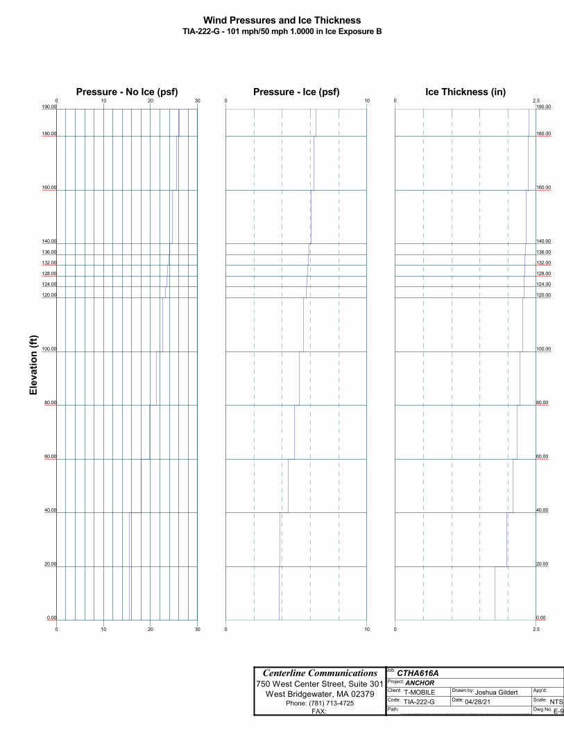
Centerline Communications 750 West Center Street, Suite 301
West Bridgewater, MA 02379 Phone: (781) 713-4725
FAX:
Job: CTHA616A Project: ANCHOR Client: T-MOBILE Drawn by: Joshua Gildert App'd:
Code: TIA-222-G Date: 04/28/21 Scale: NTS Path:
C:\Users\Joshua Gildert\Box\Projects\New England Projects\T-Mobile\SITES\CT\CTHA616A-CT03XC206\Anchor\Structural\Working Files\Structural Analysis\Analysis\tnx\CTHA616A.eri
Dwg No. E-9
Wind Pressures and Ice ThicknessTIA-222-G - 101 mph/50 mph 1.0000 in Ice Exposure B
0
0
10
10
20
20
30
30
Pressure - No Ice (psf)190.00
180.00
160.00
140.00
136.00
132.00
128.00
124.00
120.00
100.00
80.00
60.00
40.00
20.00
0.00
Ele
va
tio
n (
ft)
0
0
10
10
Pressure - Ice (psf)0
0
2.5
2.5
Ice Thickness (in)190.00
180.00
160.00
140.00
136.00
132.00
128.00
124.00
120.00
100.00
80.00
60.00
40.00
20.00
0.00

ttnnxxTToowweerr Job
CTHA616A
Page
1 of 40
Centerline Communications
750 West Center Street, Suite 301
Project
ANCHOR Date
18:18:24 04/28/21 West Bridgewater, MA 02379
Phone: (781) 713-4725 FAX:
Client T-MOBILE
Designed by
Joshua Gildert
Tower Input Data The main tower is a 3x free standing tower with an overall height of 190.00 ft above the ground line. The base of the tower is set at an elevation of 0.00 ft above the ground line. The face width of the tower is 4.65 ft at the top and 19.00 ft at the base. This tower is designed using the TIA-222-G standard. The following design criteria apply:
Tower is located in Tolland County, Connecticut. ASCE 7-10 Wind Data is used (wind speeds converted to nominal values). Basic wind speed of 101 mph. Structure Class II. Exposure Category B. Topographic Category 1. Crest Height 0.00 ft. Nominal ice thickness of 1.0000 in. Ice thickness is considered to increase with height. Ice density of 56 pcf. A wind speed of 50 mph is used in combination with ice. Temperature drop of 50 °F. Deflections calculated using a wind speed of 60 mph. A non-linear (P-delta) analysis was used. Pressures are calculated at each section. Stress ratio used in tower member design is 1. Local bending stresses due to climbing loads, feed line supports, and appurtenance mounts are not considered.
Options
Consider Moments - Legs Distribute Leg Loads As Uniform Use ASCE 10 X-Brace Ly Rules Consider Moments - Horizontals Assume Legs Pinned Calculate Redundant Bracing Forces Consider Moments - Diagonals √ Assume Rigid Index Plate Ignore Redundant Members in FEA Use Moment Magnification √ Use Clear Spans For Wind Area SR Leg Bolts Resist Compression
√ Use Code Stress Ratios √ Use Clear Spans For KL/r All Leg Panels Have Same Allowable √ Use Code Safety Factors - Guys Retension Guys To Initial Tension Offset Girt At Foundation Escalate Ice √ Bypass Mast Stability Checks √ Consider Feed Line Torque Always Use Max Kz √ Use Azimuth Dish Coefficients √ Include Angle Block Shear Check Use Special Wind Profile √ Project Wind Area of Appurt. Use TIA-222-G Bracing Resist. Exemption
√ Include Bolts In Member Capacity Autocalc Torque Arm Areas Use TIA-222-G Tension Splice Exemption Leg Bolts Are At Top Of Section Add IBC .6D+W Combination Poles
√ Secondary Horizontal Braces Leg √ Sort Capacity Reports By Component Include Shear-Torsion Interaction Use Diamond Inner Bracing (4 Sided) Triangulate Diamond Inner Bracing Always Use Sub-Critical Flow SR Members Have Cut Ends Treat Feed Line Bundles As Cylinder Use Top Mounted Sockets SR Members Are Concentric Ignore KL/ry For 60 Deg. Angle Legs Pole Without Linear Attachments Pole With Shroud Or No Appurtenances Outside and Inside Corner Radii Are
Known

ttnnxxTToowweerr Job
CTHA616A
Page
2 of 40
Centerline Communications
750 West Center Street, Suite 301
Project
ANCHOR Date
18:18:24 04/28/21 West Bridgewater, MA 02379
Phone: (781) 713-4725 FAX:
Client T-MOBILE
Designed by
Joshua Gildert
Leg B Leg C
Leg A
Face
A Face B
Face C
Triangular To wer
Wind Norma l
Wind 90
Wind 180
Z
X
Tower Section Geometry
Tower Section
Tower Elevation
ft
Assembly Database
Description Section Width
ft
Number of
Sections
Section Length
ft
T1 190.00-180.00 4.65 1 10.00 T2 180.00-160.00 4.65 1 20.00 T3 160.00-140.00 4.69 1 20.00 T4 140.00-136.00 4.72 1 4.00 T5 136.00-132.00 5.13 1 4.00 T6 132.00-128.00 5.54 1 4.00 T7 128.00-124.00 5.94 1 4.00 T8 124.00-120.00 6.35 1 4.00 T9 120.00-100.00 6.76 1 20.00
T10 100.00-80.00 8.83 1 20.00 T11 80.00-60.00 10.83 1 20.00 T12 60.00-40.00 12.92 1 20.00 T13 40.00-20.00 14.85 1 20.00 T14 20.00-0.00 16.99 1 20.00
Tower Section Geometry (cont’d)
Tower Section
Tower Elevation
ft
Diagonal Spacing
ft
Bracing Type
Has K Brace
End Panels
Has Horizontals
Top Girt Offset
in
Bottom Girt Offset
in
T1 190.00-180.00 5.00 X Brace No Yes 0.0000 0.0000

ttnnxxTToowweerr Job
CTHA616A
Page
3 of 40
Centerline Communications
750 West Center Street, Suite 301
Project
ANCHOR Date
18:18:24 04/28/21 West Bridgewater, MA 02379
Phone: (781) 713-4725 FAX:
Client T-MOBILE
Designed by
Joshua Gildert
Tower Section
Tower Elevation
ft
Diagonal Spacing
ft
Bracing Type
Has K Brace
End Panels
Has Horizontals
Top Girt Offset
in
Bottom Girt Offset
in
T2 180.00-160.00 4.00 X Brace No No 0.0000 0.0000 T3 160.00-140.00 4.00 X Brace No Yes 0.0000 0.0000 T4 140.00-136.00 4.00 X Brace No Yes 0.0000 0.0000 T5 136.00-132.00 4.00 X Brace No Yes 0.0000 0.0000 T6 132.00-128.00 4.00 X Brace No Yes 0.0000 0.0000 T7 128.00-124.00 4.00 X Brace No Yes 0.0000 0.0000 T8 124.00-120.00 4.00 X Brace No Yes 0.0000 0.0000 T9 120.00-100.00 5.00 X Brace No Yes 0.0000 0.0000
T10 100.00-80.00 6.67 X Brace No Yes 0.0000 0.0000 T11 80.00-60.00 6.67 X Brace No Yes 0.0000 0.0000 T12 60.00-40.00 6.67 X Brace No Yes 0.0000 0.0000 T13 40.00-20.00 10.00 X Brace No Yes 0.0000 0.0000 T14 20.00-0.00 10.00 X Brace No Yes 0.0000 0.0000
Tower Section Geometry (cont’d)
Tower Elevation
ft
Leg Type
Leg Size
Leg Grade
Diagonal Type
Diagonal Size
Diagonal Grade
T1 190.00-180.00 Pipe ROHN 2 STD A572-50 (50 ksi)
Single Angle L1 3/4x1 3/4x3/16 A36 (36 ksi)
T2 180.00-160.00 Pipe ROHN 2.5 STD A572-50 (50 ksi)
Single Angle L1 3/4x1 3/4x3/16 A36 (36 ksi)
T3 160.00-140.00 Pipe ROHN 3 EH A572-50 (50 ksi)
Single Angle L2x2x1/4 A36 (36 ksi)
T4 140.00-136.00 Pipe ROHN 3.5 EH A572-50 (50 ksi)
Single Angle L1 3/4x1 3/4x3/16 A36 (36 ksi)
T5 136.00-132.00 Pipe ROHN 3.5 EH A572-50 (50 ksi)
Single Angle L1 3/4x1 3/4x3/16 A36 (36 ksi)
T6 132.00-128.00 Pipe ROHN 3.5 EH A572-50 (50 ksi)
Single Angle L1 3/4x1 3/4x3/16 A36 (36 ksi)
T7 128.00-124.00 Pipe ROHN 3.5 EH A572-50 (50 ksi)
Single Angle L1 3/4x1 3/4x3/16 A36 (36 ksi)
T8 124.00-120.00 Pipe ROHN 3.5 EH A572-50 (50 ksi)
Single Angle L1 3/4x1 3/4x3/16 A36 (36 ksi)
T9 120.00-100.00 Pipe ROHN 4 EH A572-50 (50 ksi)
Single Angle L2x2x3/16 A36 (36 ksi)
T10 100.00-80.00 Pipe ROHN 5 EH A572-50 (50 ksi)
Single Angle L2 1/2x2 1/2x3/16 A36 (36 ksi)
T11 80.00-60.00 Pipe ROHN 5 EH A572-50 (50 ksi)
Single Angle L2 1/2x2 1/2x1/4 A36 (36 ksi)
T12 60.00-40.00 Arbitrary Shape 6.0 EHS + HALF HSS7.625x0.375
A572-50 (50 ksi)
Single Angle L3x3x1/4 A572-50 (50 ksi)
T13 40.00-20.00 Pipe ROHN 6 EH A572-50 (50 ksi)
Single Angle L3 1/2x3 1/2x1/4 A572-50 (50 ksi)
T14 20.00-0.00 Pipe ROHN 8 EHS A572-50 (50 ksi)
Single Angle L3 1/2x3 1/2x1/4 A572-50 (50 ksi)
Tower Section Geometry (cont’d)

ttnnxxTToowweerr Job
CTHA616A
Page
4 of 40
Centerline Communications
750 West Center Street, Suite 301
Project
ANCHOR Date
18:18:24 04/28/21 West Bridgewater, MA 02379
Phone: (781) 713-4725 FAX:
Client T-MOBILE
Designed by
Joshua Gildert
Tower Elevation
ft
Top Girt Type
Top Girt Size
Top Girt Grade
Bottom Girt Type
Bottom Girt Size
Bottom Girt Grade
T1 190.00-180.00 Equal Angle L1 3/4x1 3/4x3/16 A36 (36 ksi)
Flat Bar A36 (36 ksi)
T4 140.00-136.00 Equal Angle L1 3/4x1 3/4x3/16 A36 (36 ksi)
Flat Bar A36 (36 ksi)
Tower Section Geometry (cont’d)
Tower Elevation
ft
Secondary Horizontal Type
Secondary Horizontal Size
Secondary Horizontal
Grade
Inner Bracing Type
Inner Bracing Size
Inner Bracing Grade
T8 124.00-120.00 Equal Angle L2x2x1/4 A36 (36 ksi)
Solid Round A572-50 (50 ksi)
T9 120.00-100.00 Equal Angle L2x2x1/4 A36 (36 ksi)
Solid Round A572-50 (50 ksi)
T11 80.00-60.00 Equal Angle L2 1/2x2 1/2x1/4 A36 (36 ksi)
Solid Round A572-50 (50 ksi)
T13 40.00-20.00 Equal Angle L3x3x5/16 A36 (36 ksi)
Solid Round A572-50 (50 ksi)
Tower Section Geometry (cont’d)
Tower Elevation
ft
Gusset Area
(per face)
ft2
Gusset Thickness
in
Gusset Grade Adjust. Factor Af
Adjust. Factor
Ar
Weight Mult.
Double Angle Stitch Bolt Spacing
Diagonals in
Double Angle Stitch Bolt Spacing
Horizontals in
Double Angle Stitch Bolt Spacing
Redundants in
T1 190.00-180.00
0.00 0.0000 A36 (36 ksi)
1 1 1.05 30.0000 30.0000 36.0000
T2 180.00-160.00
0.00 0.0000 A36 (36 ksi)
1 1 1.05 36.0000 36.0000 36.0000
T3 160.00-140.00
0.00 0.0000 A36 (36 ksi)
1 1 1.05 36.0000 36.0000 36.0000
T4 140.00-136.00
0.00 0.0000 A36 (36 ksi)
1 1 1.05 36.0000 36.0000 36.0000
T5 136.00-132.00
0.00 0.0000 A36 (36 ksi)
1 1 1.05 36.0000 36.0000 36.0000
T6 132.00-128.00
0.00 0.0000 A36 (36 ksi)
1 1 1.05 36.0000 36.0000 36.0000
T7 128.00-124.00
0.00 0.0000 A36 (36 ksi)
1 1 1.05 36.0000 36.0000 36.0000
T8 124.00-120.00
0.00 0.0000 A36 (36 ksi)
1 1 1.05 36.0000 36.0000 36.0000
T9 120.00-100.00
0.00 0.0000 A36 (36 ksi)
1 1 1.05 36.0000 36.0000 36.0000
T10 100.00-80.00
0.00 0.0000 A36 (36 ksi)
1 1 1.05 36.0000 36.0000 36.0000
T11 80.00-60.00
0.00 0.0000 A36 (36 ksi)
1 1 1.05 36.0000 36.0000 36.0000
T12 60.00-40.00
0.00 0.0000 A36 (36 ksi)
1 1 1.05 36.0000 36.0000 36.0000
T13 0.00 0.0000 A36 1 1 1.05 36.0000 36.0000 36.0000

ttnnxxTToowweerr Job
CTHA616A
Page
5 of 40
Centerline Communications
750 West Center Street, Suite 301
Project
ANCHOR Date
18:18:24 04/28/21 West Bridgewater, MA 02379
Phone: (781) 713-4725 FAX:
Client T-MOBILE
Designed by
Joshua Gildert
Tower Elevation
ft
Gusset Area
(per face)
ft2
Gusset Thickness
in
Gusset Grade Adjust. Factor Af
Adjust. Factor
Ar
Weight Mult.
Double Angle Stitch Bolt Spacing
Diagonals in
Double Angle Stitch Bolt Spacing
Horizontals in
Double Angle Stitch Bolt Spacing
Redundants in
40.00-20.00 (36 ksi) T14 20.00-0.00 0.00 0.0000 A36
(36 ksi) 1 1 1.05 36.0000 36.0000 36.0000
Tower Section Geometry (cont’d)
K Factors1
Tower Elevation
ft
Calc K
Single Angles
Calc K
Solid Rounds
Legs X Brace Diags
X Y
K Brace Diags
X Y
Single Diags
X Y
Girts
X Y
Horiz.
X Y
Sec. Horiz.
X Y
Inner Brace
X Y
T1 190.00-180.00
Yes Yes 1 1 1
1 1
1 1
1 1
1 1
1 1
1 1
T2 180.00-160.00
Yes Yes 1 1 1
1 1
1 1
1 1
1 1
1 1
1 1
T3 160.00-140.00
Yes Yes 1 1 1
1 1
1 1
1 1
1 1
1 1
1 1
T4 140.00-136.00
Yes Yes 1 1 1
1 1
1 1
1 1
1 1
1 1
1 1
T5 136.00-132.00
Yes Yes 1 1 1
1 1
1 1
1 1
1 1
1 1
1 1
T6 132.00-128.00
Yes Yes 1 1 1
1 1
1 1
1 1
1 1
1 1
1 1
T7 128.00-124.00
Yes Yes 1 1 1
1 1
1 1
1 1
1 1
1 1
1 1
T8 124.00-120.00
Yes Yes 1 1 1
1 1
1 1
1 1
1 1
1 1
1 1
T9 120.00-100.00
Yes Yes 1 1 1
1 1
1 1
1 1
1 1
1 1
1 1
T10 100.00-80.00
Yes Yes 1 1 1
1 1
1 1
1 1
1 1
1 1
1 1
T11 80.00-60.00
Yes Yes 1 1 1
1 1
1 1
1 1
1 1
1 1
1 1
T12 60.00-40.00
Yes Yes 1 1 1
1 1
1 1
1 1
1 1
1 1
1 1
T13 40.00-20.00
Yes Yes 1 1 1
1 1
1 1
1 1
1 1
1 1
1 1
T14 20.00-0.00
Yes Yes 1 1 1
1 1
1 1
1 1
1 1
1 1
1 1
1Note: K factors are applied to member segment lengths. K-braces without inner supporting members will have the K factor in the out-of-plane direction applied to the overall length.
Tower Section Geometry (cont’d)

ttnnxxTToowweerr Job
CTHA616A
Page
6 of 40
Centerline Communications
750 West Center Street, Suite 301
Project
ANCHOR Date
18:18:24 04/28/21 West Bridgewater, MA 02379
Phone: (781) 713-4725 FAX:
Client T-MOBILE
Designed by
Joshua Gildert
Tower Elevation
ft
Leg Diagonal Top Girt Bottom Girt Mid Girt Long Horizontal Short Horizontal
Net Width Deduct
in
U
Net Width Deduct
in
U
Net Width Deduct
in
U
Net Width
Deduct in
U
Net Width
Deduct in
U
Net Width
Deduct in
U
Net Width
Deduct in
U
T1 190.00-180.00
0.0000 1 0.0000 0.75 0.0000 0.75 0.0000 0.75 0.0000 0.75 0.0000 0.75 0.0000 0.75
T2 180.00-160.00
0.0000 1 0.0000 0.75 0.0000 0.75 0.0000 0.75 0.0000 0.75 0.0000 0.75 0.0000 0.75
T3 160.00-140.00
0.0000 1 0.0000 0.75 0.0000 0.75 0.0000 0.75 0.0000 0.75 0.0000 0.75 0.0000 0.75
T4 140.00-136.00
0.0000 1 0.0000 0.75 0.0000 0.75 0.0000 0.75 0.0000 0.75 0.0000 0.75 0.0000 0.75
T5 136.00-132.00
0.0000 1 0.0000 0.75 0.0000 0.75 0.0000 0.75 0.0000 0.75 0.0000 0.75 0.0000 0.75
T6 132.00-128.00
0.0000 1 0.0000 0.75 0.0000 0.75 0.0000 0.75 0.0000 0.75 0.0000 0.75 0.0000 0.75
T7 128.00-124.00
0.0000 1 0.0000 0.75 0.0000 0.75 0.0000 0.75 0.0000 0.75 0.0000 0.75 0.0000 0.75
T8 124.00-120.00
0.0000 1 0.0000 0.75 0.0000 0.75 0.0000 0.75 0.0000 0.75 0.0000 0.75 0.0000 0.75
T9 120.00-100.00
0.0000 1 0.0000 0.75 0.0000 0.75 0.0000 0.75 0.0000 0.75 0.0000 0.75 0.0000 0.75
T10 100.00-80.00
0.0000 1 0.0000 0.75 0.0000 0.75 0.0000 0.75 0.0000 0.75 0.0000 0.75 0.0000 0.75
T11 80.00-60.00
0.0000 1 0.0000 0.75 0.0000 0.75 0.0000 0.75 0.0000 0.75 0.0000 0.75 0.0000 0.75
T12 60.00-40.00
0.0000 1 0.0000 0.75 0.0000 0.75 0.0000 0.75 0.0000 0.75 0.0000 0.75 0.0000 0.75
T13 40.00-20.00
0.0000 1 0.0000 0.75 0.0000 0.75 0.0000 0.75 0.0000 0.75 0.0000 0.75 0.0000 0.75
T14 20.00-0.00 0.0000 1 0.0000 0.75 0.0000 0.75 0.0000 0.75 0.0000 0.75 0.0000 0.75 0.0000 0.75
Tower Section Geometry (cont’d)
Tower Elevation
ft
Leg Connection
Type
Leg Diagonal Top Girt Bottom Girt Mid Girt Long Horizontal Short Horizontal
Bolt Size in
No. Bolt Size in
No. Bolt Size in
No. Bolt Size in
No. Bolt Size in
No. Bolt Size in
No. Bolt Size in
No.
T1 190.00-180.00
Flange 0.6250 A325N
4 0.6250 A325N
1 0.6250 A325N
1 0.6250 A325N
0 0.6250 A325N
0 0.6250 A325N
0 0.6250 A325N
0
T2 180.00-160.00
Flange 0.7500 A325N
4 0.6250 A325N
1 0.6250 A325N
0 0.6250 A325N
0 0.6250 A325N
0 0.6250 A325N
0 0.6250 A325N
0
T3 160.00-140.00
Flange 0.8750 A325N
4 0.6250 A325N
1 0.6250 A325N
0 0.6250 A325N
0 0.6250 A325N
0 0.6250 A325N
0 0.6250 A325N
0
T4 140.00-136.00
Flange 1.0000 A325N
0 0.6250 A325N
1 0.6250 A325N
1 0.6250 A325N
0 0.6250 A325N
0 0.6250 A325N
0 0.6250 A325N
0
T5 136.00-132.00
Flange 1.0000 A325N
0 0.6250 A325N
1 0.6250 A325N
0 0.6250 A325N
0 0.6250 A325N
0 0.6250 A325N
0 0.6250 A325N
0
T6 132.00-128.00
Flange 1.0000 A325N
0 0.6250 A325N
1 0.6250 A325N
0 0.6250 A325N
0 0.6250 A325N
0 0.6250 A325N
0 0.6250 A325N
0
T7 128.00-124.00
Flange 1.0000 A325N
0 0.6250 A325N
1 0.6250 A325N
0 0.6250 A325N
0 0.6250 A325N
0 0.6250 A325N
0 0.6250 A325N
0
T8 124.00-120.00
Flange 1.0000 A325N
4 0.6250 A325N
1 0.6250 A325N
0 0.6250 A325N
0 0.6250 A325N
0 0.6250 A325N
0 0.6250 A325N
0

ttnnxxTToowweerr Job
CTHA616A
Page
7 of 40
Centerline Communications
750 West Center Street, Suite 301
Project
ANCHOR Date
18:18:24 04/28/21 West Bridgewater, MA 02379
Phone: (781) 713-4725 FAX:
Client T-MOBILE
Designed by
Joshua Gildert
Tower Elevation
ft
Leg Connection
Type
Leg Diagonal Top Girt Bottom Girt Mid Girt Long Horizontal Short Horizontal
Bolt Size in
No. Bolt Size in
No. Bolt Size in
No. Bolt Size in
No. Bolt Size in
No. Bolt Size in
No. Bolt Size in
No.
T9 120.00-100.00
Flange 1.0000 A325N
4 0.6250 A325N
1 0.6250 A325N
0 0.6250 A325N
0 0.6250 A325N
0 0.6250 A325N
0 0.6250 A325N
2
T10 100.00-80.00
Flange 1.0000 A325N
4 0.6250 A325N
1 0.6250 A325N
0 0.6250 A325N
0 0.6250 A325N
0 0.6250 A325N
0 0.6250 A325N
0
T11 80.00-60.00
Flange 1.0000 A325N
6 0.6250 A325N
1 0.6250 A325N
0 0.6250 A325N
0 0.6250 A325N
0 0.6250 A325N
0 0.6250 A325N
2
T12 60.00-40.00
Flange 1.0000 A325N
6 0.6250 A325N
1 0.6250 A325N
0 0.6250 A325N
0 0.6250 A325N
0 0.6250 A325N
0 0.6250 A325N
2
T13 40.00-20.00
Flange 1.0000 A325N
8 0.6250 A325N
1 0.6250 A325N
0 0.6250 A325N
0 0.6250 A325N
0 0.6250 A325N
0 0.6250 A325N
2
T14 20.00-0.00 Flange 1.0000 A325N
8 0.7500 A325N
1 0.6250 A325N
0 0.6250 A325N
0 0.6250 A325N
0 0.6250 A325N
0 0.6250 A325N
0
Feed Line/Linear Appurtenances - Entered As Round Or Flat
Description Face or
Leg
Allow Shield
Exclude From
Torque Calculation
Component Type
Placement
ft
Face Offset
in
Lateral Offset
(Frac FW)
# # Per Row
Clear Spacing
in
Width or Diameter
in
Perimeter
in
Weight
plf
LDF7-50A (1-5/8 FOAM)
(VZW)
B No No Ar (CaAa) 150.00 - 8.00
-2.0000 -0.3 12 12 1.0000 1.9800 1.04
LDF7-50A (1-5/8 FOAM)
(VZW)
A No No Ar (CaAa) 150.00 - 8.00
0.0000 0.28 2 2 1.0000 1.9800 1.04
LDF7-50A (1-5/8 FOAM)
(VZW)
A No No Ar (CaAa) 150.00 - 8.00
0.0000 0.35 6 6 1.0000 1.9800 1.04
*** 1/2 A No No Ar (CaAa) 50.00 - 8.00 0.0000 0.07 1 1 0.5800 0.5800 0.25 1/2 A No No Ar (CaAa) 70.00 - 8.00 0.0000 0.06 1 1 0.5800 0.5800 0.25 1/2 A No No Ar (CaAa) 94.00 - 8.00 0.0000 0.05 1 1 0.5800 0.5800 0.25 7/8 A No No Ar (CaAa) 156.00 -
8.00 0.0000 0.03 2 2 1.1100 1.1100 0.54
1/2 A No No Ar (CaAa) 185.00 - 8.00
0.0000 -0.02 1 1 0.5800 0.5800 0.25
1/2 A No No Ar (CaAa) 32.00 - 8.00 0.0000 -0.03 1 1 0.5800 0.5800 0.25 1 1/4 A No No Ar (CaAa) 190.00 -
8.00 0.0000 -0.05 1 1 1.5500 1.5500 0.66
1/2 A No No Ar (CaAa) 190.00 - 8.00
0.0000 -0.06 1 1 0.5800 0.5800 0.25
1/2 A No No Ar (CaAa) 17.00 - 8.00 0.0000 -0.07 1 1 0.5800 0.5800 0.25 7/8 B No No Ar (CaAa) 92.00 - 8.00 0.0000 0.08 1 1 1.1100 1.1100 0.54 7/8 B No No Ar (CaAa) 142.00 -
8.00 0.0000 0.07 1 1 1.1100 1.1100 0.54
1/2 B No No Ar (CaAa) 142.00 - 8.00
0.0000 0.06 1 1 0.5800 0.5800 0.25
7/8 B No No Ar (CaAa) 156.00 - 8.00
0.0000 0.05 1 1 1.1100 1.1100 0.54
1/2 B No No Ar (CaAa) 190.00 - 8.00
0.0000 0.04 1 1 0.5800 0.5800 0.25
7/8 B No No Ar (CaAa) 190.00 - 8.00
0.0000 0.025 2 2 1.1100 1.1100 0.54
1/2 B No No Ar (CaAa) 102.00 - 0.0000 -0.02 1 1 0.5800 0.5800 0.25

ttnnxxTToowweerr Job
CTHA616A
Page
8 of 40
Centerline Communications
750 West Center Street, Suite 301
Project
ANCHOR Date
18:18:24 04/28/21 West Bridgewater, MA 02379
Phone: (781) 713-4725 FAX:
Client T-MOBILE
Designed by
Joshua Gildert
Description Face or
Leg
Allow Shield
Exclude From
Torque Calculation
Component Type
Placement
ft
Face Offset
in
Lateral Offset
(Frac FW)
# # Per Row
Clear Spacing
in
Width or Diameter
in
Perimeter
in
Weight
plf
8.00 7/8 B No No Ar (CaAa) 190.00 -
8.00 0.0000 -0.05 1 1 1.1100 1.1100 0.54
7/8 B No No Ar (CaAa) 109.00 - 8.00
0.0000 -0.06 1 1 1.1100 1.1100 0.54
7/8 C No No Ar (CaAa) 190.00 - 8.00
0.0000 0.06 1 1 1.1100 1.1100 0.54
7/8 C No No Ar (CaAa) 119.00 - 8.00
0.0000 0.05 1 1 1.1100 1.1100 0.54
7/8 C No No Ar (CaAa) 190.00 - 8.00
0.0000 0.04 1 1 1.1100 1.1100 0.54
1/2 C No No Ar (CaAa) 136.00 - 8.00
0.0000 0.03 1 1 0.5800 0.5800 0.25
1/2 C No No Ar (CaAa) 113.00 - 8.00
0.0000 0.02 1 1 0.5800 0.5800 0.25
1/2 C No No Ar (CaAa) 142.00 - 8.00
0.0000 -0.02 1 1 0.5800 0.5800 0.25
7/8 C No No Ar (CaAa) 142.00 - 8.00
0.0000 -0.03 1 1 1.1100 1.1100 0.54
7/8 C No No Ar (CaAa) 103.00 - 8.00
0.0000 -0.05 1 1 1.1100 1.1100 0.54
1/2 C No No Ar (CaAa) 31.00 - 8.00 0.0000 -0.06 1 1 0.5800 0.5800 0.25 1 1/4 C No No Ar (CaAa) 190.00 -
8.00 0.0000 -0.04 1 1 1.5500 1.5500 0.66
7/8 C No No Ar (CaAa) 74.00 - 8.00 0.0000 -0.07 1 1 1.1100 1.1100 0.54 1/2 C No No Ar (CaAa) 50.00 - 8.00 0.0000 -0.08 1 1 0.5800 0.5800 0.25
1 5/8 A No No Ar (CaAa) 150.00 - 8.00
0.0000 0.28 6 6 1.0000 1.9800 1.90
*** 6x12
(T-Mobile) A No No Ar (CaAa) 180.00 -
8.00 0.0000 0 3 3 1.0000 1.9800 1.04
*** Feedline
Ladder (Af) B No No Af (CaAa) 150.00 -
8.00 0.0000 -0.29 1 1 3.0000 2.5000 8.40
Feedline Ladder (Af)
A No No Af (CaAa) 150.00 - 8.00
0.0000 0.34 1 1 3.0000 2.5000 8.40
Feedline Ladder (Af)
A No No Af (CaAa) 180.00 - 8.00
0.0000 0 1 1 3.0000 2.5000 8.40
Feedline Ladder (Af)
C No No Af (CaAa) 190.00 - 8.00
0.0000 0 1 1 3.0000 2.5000 8.40
Feedline Ladder (Af)
B No No Af (CaAa) 190.00 - 8.00
0.0000 0 1 1 3.0000 2.5000 8.40
Feed Line/Linear Appurtenances Section Areas Tower Section
Tower Elevation
ft
Face AR
ft2
AF
ft2
CAAA
In Face ft2
CAAA
Out Face ft2
Weight
lb T1 190.00-180.00 A
B C
0.000 0.000 0.000
0.000 0.000 0.000
2.420 8.077 7.937
0.000 0.000 0.000
10.35 102.70 101.40
T2 180.00-160.00 A B C
0.000 0.000 0.000
0.000 0.000 0.000
25.633 16.153 15.873
0.000 0.000 0.000
253.60 205.40 202.80
T3 160.00-140.00 A B
0.000 0.000
0.000 0.000
61.072 46.194
0.000 0.000
552.08 424.42

ttnnxxTToowweerr Job
CTHA616A
Page
9 of 40
Centerline Communications
750 West Center Street, Suite 301
Project
ANCHOR Date
18:18:24 04/28/21 West Bridgewater, MA 02379
Phone: (781) 713-4725 FAX:
Client T-MOBILE
Designed by
Joshua Gildert
Tower Section
Tower Elevation
ft
Face AR
ft2
AF
ft2
CAAA
In Face ft2
CAAA
Out Face ft2
Weight
lb C 0.000 0.000 16.211 0.000 204.38
T4 140.00-136.00 A B C
0.000 0.000 0.000
0.000 0.000 0.000
18.769 15.521 3.851
0.000 0.000 0.000
167.52 129.92 43.72
T5 136.00-132.00 A B C
0.000 0.000 0.000
0.000 0.000 0.000
18.769 15.521 4.083
0.000 0.000 0.000
167.52 129.92 44.72
T6 132.00-128.00 A B C
0.000 0.000 0.000
0.000 0.000 0.000
18.769 15.521 4.083
0.000 0.000 0.000
167.52 129.92 44.72
T7 128.00-124.00 A B C
0.000 0.000 0.000
0.000 0.000 0.000
18.769 15.521 4.083
0.000 0.000 0.000
167.52 129.92 44.72
T8 124.00-120.00 A B C
0.000 0.000 0.000
0.000 0.000 0.000
18.769 15.521 4.083
0.000 0.000 0.000
167.52 129.92 44.72
T9 120.00-100.00 A B C
0.000 0.000 0.000
0.000 0.000 0.000
93.847 78.722 23.609
0.000 0.000 0.000
837.60 654.96 238.73
T10 100.00-80.00 A B C
0.000 0.000 0.000
0.000 0.000 0.000
94.659 82.319 26.013
0.000 0.000 0.000
841.10 671.88 250.20
T11 80.00-60.00 A B C
0.000 0.000 0.000
0.000 0.000 0.000
95.587 83.207 27.567
0.000 0.000 0.000
845.10 676.20 257.76
T12 60.00-40.00 A B C
0.000 0.000 0.000
0.000 0.000 0.000
96.747 83.207 28.813
0.000 0.000 0.000
850.10 676.20 263.50
T13 40.00-20.00 A B C
0.000 0.000 0.000
0.000 0.000 0.000
98.023 83.207 30.031
0.000 0.000 0.000
855.60 676.20 268.75
T14 20.00-0.00 A B C
0.000 0.000 0.000
0.000 0.000 0.000
59.614 49.924 18.332
0.000 0.000 0.000
516.81 405.72 162.60
Feed Line/Linear Appurtenances Section Areas - With Ice Tower Section
Tower Elevation
ft
Face or
Leg
Ice Thickness
in
AR
ft2
AF
ft2
CAAA
In Face ft2
CAAA
Out Face ft2
Weight
lb T1 190.00-180.00 A
B C
2.376 0.000 0.000 0.000
0.000 0.000 0.000
14.301 32.595 26.947
0.000 0.000 0.000
253.07 604.09 584.10
T2 180.00-160.00 A B C
2.356 0.000 0.000 0.000
0.000 0.000 0.000
87.237 64.811 53.574
0.000 0.000 0.000
1657.00 1195.00 1155.24
T3 160.00-140.00 A B C
2.327 0.000 0.000 0.000
0.000 0.000 0.000
186.017 134.457 55.304
0.000 0.000 0.000
3402.27 2584.81 1174.03
T4 140.00-136.00 A B C
2.308 0.000 0.000 0.000
0.000 0.000 0.000
53.933 42.911 14.927
0.000 0.000 0.000
988.88 826.77 299.08
T5 136.00-132.00 A B C
2.301 0.000 0.000 0.000
0.000 0.000 0.000
53.861 42.855 16.967
0.000 0.000 0.000
985.85 824.16 331.25
T6 132.00-128.00 A B C
2.294 0.000 0.000 0.000
0.000 0.000 0.000
53.787 42.799 16.928
0.000 0.000 0.000
982.74 821.48 329.82

ttnnxxTToowweerr Job
CTHA616A
Page
10 of 40
Centerline Communications
750 West Center Street, Suite 301
Project
ANCHOR Date
18:18:24 04/28/21 West Bridgewater, MA 02379
Phone: (781) 713-4725 FAX:
Client T-MOBILE
Designed by
Joshua Gildert
Tower Section
Tower Elevation
ft
Face or
Leg
Ice Thickness
in
AR
ft2
AF
ft2
CAAA
In Face ft2
CAAA
Out Face ft2
Weight
lb T7 128.00-124.00 A
B C
2.287 0.000 0.000 0.000
0.000 0.000 0.000
53.711 42.740 16.888
0.000 0.000 0.000
979.54 818.72 328.35
T8 124.00-120.00 A B C
2.279 0.000 0.000 0.000
0.000 0.000 0.000
53.633 42.680 16.847
0.000 0.000 0.000
976.27 815.90 326.85
T9 120.00-100.00 A B C
2.256 0.000 0.000 0.000
0.000 0.000 0.000
266.915 218.523 102.565
0.000 0.000 0.000
4829.27 4139.06 1931.20
T10 100.00-80.00 A B C
2.211 0.000 0.000 0.000
0.000 0.000 0.000
271.537 238.327 114.456
0.000 0.000 0.000
4839.71 4409.72 2101.62
T11 80.00-60.00 A B C
2.156 0.000 0.000 0.000
0.000 0.000 0.000
276.297 239.861 119.853
0.000 0.000 0.000
4835.05 4361.67 2154.18
T12 60.00-40.00 A B C
2.085 0.000 0.000 0.000
0.000 0.000 0.000
281.584 236.101 124.717
0.000 0.000 0.000
4810.32 4202.99 2174.25
T13 40.00-20.00 A B C
1.981 0.000 0.000 0.000
0.000 0.000 0.000
285.036 230.633 129.479
0.000 0.000 0.000
4704.87 3977.59 2155.68
T14 20.00-0.00 A B C
1.775 0.000 0.000 0.000
0.000 0.000 0.000
168.400 131.871 73.709
0.000 0.000 0.000
2599.95 2129.70 1136.14
Feed Line Center of Pressure
Section Elevation
ft
CPX
in
CPZ
in
CPX
Ice in
CPZ
Ice in
T1 190.00-180.00 1.1597 0.8122 1.0465 0.7832 T2 180.00-160.00 -1.0190 -0.8290 -0.8891 -0.5316 T3 160.00-140.00 -1.2093 -8.1671 -0.9817 -5.7879 T4 140.00-136.00 -1.0115 -11.3865 -0.3939 -7.3277 T5 136.00-132.00 -1.1015 -12.5308 -0.5105 -8.7765 T6 132.00-128.00 -1.1306 -13.3526 -0.5292 -9.4742 T7 128.00-124.00 -1.1588 -14.1574 -0.5470 -10.1583 T8 124.00-120.00 -1.0909 -14.0824 -0.4747 -9.3744 T9 120.00-100.00 -1.0827 -15.7773 -0.4045 -10.8800
T10 100.00-80.00 -0.8496 -19.4487 0.3178 -14.0910 T11 80.00-60.00 -0.7281 -20.6493 0.3691 -15.3815 T12 60.00-40.00 -0.7159 -20.7320 0.0904 -17.0795 T13 40.00-20.00 -0.9802 -24.8563 -0.3442 -19.0583 T14 20.00-0.00 -0.9850 -22.0857 -0.9003 -17.9714
Shielding Factor Ka
Tower Section
Feed Line Record No.
Description Feed Line Segment Elev.
Ka No Ice
Ka Ice
T1 9 1/2 180.00 - 185.00
0.6000 0.4572

ttnnxxTToowweerr Job
CTHA616A
Page
11 of 40
Centerline Communications
750 West Center Street, Suite 301
Project
ANCHOR Date
18:18:24 04/28/21 West Bridgewater, MA 02379
Phone: (781) 713-4725 FAX:
Client T-MOBILE
Designed by
Joshua Gildert
Tower Section
Feed Line Record No.
Description Feed Line Segment Elev.
Ka No Ice
Ka Ice
T1 11 1 1/4 180.00 - 190.00
0.6000 0.4572
T1 12 1/2 180.00 - 190.00
0.6000 0.4572
T1 18 1/2 180.00 - 190.00
0.6000 0.4572
T1 19 7/8 180.00 - 190.00
0.6000 0.4572
T1 21 7/8 180.00 - 190.00
0.6000 0.4572
T1 23 7/8 180.00 - 190.00
0.6000 0.4572
T1 25 7/8 180.00 - 190.00
0.6000 0.4572
T1 32 1 1/4 180.00 - 190.00
0.6000 0.4572
T1 46 Feedline Ladder (Af) 180.00 - 190.00
0.6000 0.4572
T1 47 Feedline Ladder (Af) 180.00 - 190.00
0.6000 0.4572
T2 9 1/2 160.00 - 180.00
0.6000 0.4653
T2 11 1 1/4 160.00 - 180.00
0.6000 0.4653
T2 12 1/2 160.00 - 180.00
0.6000 0.4653
T2 18 1/2 160.00 - 180.00
0.6000 0.4653
T2 19 7/8 160.00 - 180.00
0.6000 0.4653
T2 21 7/8 160.00 - 180.00
0.6000 0.4653
T2 23 7/8 160.00 - 180.00
0.6000 0.4653
T2 25 7/8 160.00 - 180.00
0.6000 0.4653
T2 32 1 1/4 160.00 - 180.00
0.6000 0.4653
T2 41 6x12 160.00 - 180.00
0.6000 0.4653
T2 45 Feedline Ladder (Af) 160.00 - 180.00
0.6000 0.4653
T2 46 Feedline Ladder (Af) 160.00 - 180.00
0.6000 0.4653
T2 47 Feedline Ladder (Af) 160.00 - 180.00
0.6000 0.4653
T3 1 LDF7-50A (1-5/8 FOAM) 140.00 - 150.00
0.6000 0.4493
T3 2 LDF7-50A (1-5/8 FOAM) 140.00 - 150.00
0.6000 0.4493
T3 3 LDF7-50A (1-5/8 FOAM) 140.00 - 150.00
0.6000 0.4493
T3 8 7/8 140.00 - 156.00
0.6000 0.4493
T3 9 1/2 140.00 - 160.00
0.6000 0.4493
T3 11 1 1/4 140.00 - 160.00
0.6000 0.4493
T3 12 1/2 140.00 - 160.00
0.6000 0.4493
T3 15 7/8 140.00 - 142.00
0.6000 0.4493

ttnnxxTToowweerr Job
CTHA616A
Page
12 of 40
Centerline Communications
750 West Center Street, Suite 301
Project
ANCHOR Date
18:18:24 04/28/21 West Bridgewater, MA 02379
Phone: (781) 713-4725 FAX:
Client T-MOBILE
Designed by
Joshua Gildert
Tower Section
Feed Line Record No.
Description Feed Line Segment Elev.
Ka No Ice
Ka Ice
T3 16 1/2 140.00 - 142.00
0.6000 0.4493
T3 17 7/8 140.00 - 156.00
0.6000 0.4493
T3 18 1/2 140.00 - 160.00
0.6000 0.4493
T3 19 7/8 140.00 - 160.00
0.6000 0.4493
T3 21 7/8 140.00 - 160.00
0.6000 0.4493
T3 23 7/8 140.00 - 160.00
0.6000 0.4493
T3 25 7/8 140.00 - 160.00
0.6000 0.4493
T3 28 1/2 140.00 - 142.00
0.6000 0.4493
T3 29 7/8 140.00 - 142.00
0.6000 0.4493
T3 32 1 1/4 140.00 - 160.00
0.6000 0.4493
T3 35 1 5/8 140.00 - 150.00
0.6000 0.4493
T3 41 6x12 140.00 - 160.00
0.6000 0.4493
T3 43 Feedline Ladder (Af) 140.00 - 150.00
0.6000 0.4493
T3 44 Feedline Ladder (Af) 140.00 - 150.00
0.6000 0.4493
T3 45 Feedline Ladder (Af) 140.00 - 160.00
0.6000 0.4493
T3 46 Feedline Ladder (Af) 140.00 - 160.00
0.6000 0.4493
T3 47 Feedline Ladder (Af) 140.00 - 160.00
0.6000 0.4493
T4 1 LDF7-50A (1-5/8 FOAM) 136.00 - 140.00
0.6000 0.3640
T4 2 LDF7-50A (1-5/8 FOAM) 136.00 - 140.00
0.6000 0.3640
T4 3 LDF7-50A (1-5/8 FOAM) 136.00 - 140.00
0.6000 0.3640
T4 8 7/8 136.00 - 140.00
0.6000 0.3640
T4 9 1/2 136.00 - 140.00
0.6000 0.3640
T4 11 1 1/4 136.00 - 140.00
0.6000 0.3640
T4 12 1/2 136.00 - 140.00
0.6000 0.3640
T4 15 7/8 136.00 - 140.00
0.6000 0.3640
T4 16 1/2 136.00 - 140.00
0.6000 0.3640
T4 17 7/8 136.00 - 140.00
0.6000 0.3640
T4 18 1/2 136.00 - 140.00
0.6000 0.3640
T4 19 7/8 136.00 - 140.00
0.6000 0.3640
T4 21 7/8 136.00 - 140.00
0.6000 0.3640
T4 23 7/8 136.00 - 140.00
0.6000 0.3640

ttnnxxTToowweerr Job
CTHA616A
Page
13 of 40
Centerline Communications
750 West Center Street, Suite 301
Project
ANCHOR Date
18:18:24 04/28/21 West Bridgewater, MA 02379
Phone: (781) 713-4725 FAX:
Client T-MOBILE
Designed by
Joshua Gildert
Tower Section
Feed Line Record No.
Description Feed Line Segment Elev.
Ka No Ice
Ka Ice
T4 25 7/8 136.00 - 140.00
0.6000 0.3640
T4 28 1/2 136.00 - 140.00
0.6000 0.3640
T4 29 7/8 136.00 - 140.00
0.6000 0.3640
T4 32 1 1/4 136.00 - 140.00
0.6000 0.3640
T4 35 1 5/8 136.00 - 140.00
0.6000 0.3640
T4 41 6x12 136.00 - 140.00
0.6000 0.3640
T4 43 Feedline Ladder (Af) 136.00 - 140.00
0.6000 0.3640
T4 44 Feedline Ladder (Af) 136.00 - 140.00
0.6000 0.3640
T4 45 Feedline Ladder (Af) 136.00 - 140.00
0.6000 0.3640
T4 46 Feedline Ladder (Af) 136.00 - 140.00
0.6000 0.3640
T4 47 Feedline Ladder (Af) 136.00 - 140.00
0.6000 0.3640
T5 1 LDF7-50A (1-5/8 FOAM) 132.00 - 136.00
0.6000 0.4893
T5 2 LDF7-50A (1-5/8 FOAM) 132.00 - 136.00
0.6000 0.4893
T5 3 LDF7-50A (1-5/8 FOAM) 132.00 - 136.00
0.6000 0.4893
T5 8 7/8 132.00 - 136.00
0.6000 0.4893
T5 9 1/2 132.00 - 136.00
0.6000 0.4893
T5 11 1 1/4 132.00 - 136.00
0.6000 0.4893
T5 12 1/2 132.00 - 136.00
0.6000 0.4893
T5 15 7/8 132.00 - 136.00
0.6000 0.4893
T5 16 1/2 132.00 - 136.00
0.6000 0.4893
T5 17 7/8 132.00 - 136.00
0.6000 0.4893
T5 18 1/2 132.00 - 136.00
0.6000 0.4893
T5 19 7/8 132.00 - 136.00
0.6000 0.4893
T5 21 7/8 132.00 - 136.00
0.6000 0.4893
T5 23 7/8 132.00 - 136.00
0.6000 0.4893
T5 25 7/8 132.00 - 136.00
0.6000 0.4893
T5 26 1/2 132.00 - 136.00
0.6000 0.4893
T5 28 1/2 132.00 - 136.00
0.6000 0.4893
T5 29 7/8 132.00 - 136.00
0.6000 0.4893
T5 32 1 1/4 132.00 - 136.00
0.6000 0.4893
T5 35 1 5/8 132.00 - 136.00
0.6000 0.4893

ttnnxxTToowweerr Job
CTHA616A
Page
14 of 40
Centerline Communications
750 West Center Street, Suite 301
Project
ANCHOR Date
18:18:24 04/28/21 West Bridgewater, MA 02379
Phone: (781) 713-4725 FAX:
Client T-MOBILE
Designed by
Joshua Gildert
Tower Section
Feed Line Record No.
Description Feed Line Segment Elev.
Ka No Ice
Ka Ice
T5 41 6x12 132.00 - 136.00
0.6000 0.4893
T5 43 Feedline Ladder (Af) 132.00 - 136.00
0.6000 0.4893
T5 44 Feedline Ladder (Af) 132.00 - 136.00
0.6000 0.4893
T5 45 Feedline Ladder (Af) 132.00 - 136.00
0.6000 0.4893
T5 46 Feedline Ladder (Af) 132.00 - 136.00
0.6000 0.4893
T5 47 Feedline Ladder (Af) 132.00 - 136.00
0.6000 0.4893
T6 1 LDF7-50A (1-5/8 FOAM) 128.00 - 132.00
0.6000 0.5084
T6 2 LDF7-50A (1-5/8 FOAM) 128.00 - 132.00
0.6000 0.5084
T6 3 LDF7-50A (1-5/8 FOAM) 128.00 - 132.00
0.6000 0.5084
T6 8 7/8 128.00 - 132.00
0.6000 0.5084
T6 9 1/2 128.00 - 132.00
0.6000 0.5084
T6 11 1 1/4 128.00 - 132.00
0.6000 0.5084
T6 12 1/2 128.00 - 132.00
0.6000 0.5084
T6 15 7/8 128.00 - 132.00
0.6000 0.5084
T6 16 1/2 128.00 - 132.00
0.6000 0.5084
T6 17 7/8 128.00 - 132.00
0.6000 0.5084
T6 18 1/2 128.00 - 132.00
0.6000 0.5084
T6 19 7/8 128.00 - 132.00
0.6000 0.5084
T6 21 7/8 128.00 - 132.00
0.6000 0.5084
T6 23 7/8 128.00 - 132.00
0.6000 0.5084
T6 25 7/8 128.00 - 132.00
0.6000 0.5084
T6 26 1/2 128.00 - 132.00
0.6000 0.5084
T6 28 1/2 128.00 - 132.00
0.6000 0.5084
T6 29 7/8 128.00 - 132.00
0.6000 0.5084
T6 32 1 1/4 128.00 - 132.00
0.6000 0.5084
T6 35 1 5/8 128.00 - 132.00
0.6000 0.5084
T6 41 6x12 128.00 - 132.00
0.6000 0.5084
T6 43 Feedline Ladder (Af) 128.00 - 132.00
0.6000 0.5084
T6 44 Feedline Ladder (Af) 128.00 - 132.00
0.6000 0.5084
T6 45 Feedline Ladder (Af) 128.00 - 132.00
0.6000 0.5084
T6 46 Feedline Ladder (Af) 128.00 - 132.00
0.6000 0.5084

ttnnxxTToowweerr Job
CTHA616A
Page
15 of 40
Centerline Communications
750 West Center Street, Suite 301
Project
ANCHOR Date
18:18:24 04/28/21 West Bridgewater, MA 02379
Phone: (781) 713-4725 FAX:
Client T-MOBILE
Designed by
Joshua Gildert
Tower Section
Feed Line Record No.
Description Feed Line Segment Elev.
Ka No Ice
Ka Ice
T6 47 Feedline Ladder (Af) 128.00 - 132.00
0.6000 0.5084
T7 1 LDF7-50A (1-5/8 FOAM) 124.00 - 128.00
0.6000 0.5250
T7 2 LDF7-50A (1-5/8 FOAM) 124.00 - 128.00
0.6000 0.5250
T7 3 LDF7-50A (1-5/8 FOAM) 124.00 - 128.00
0.6000 0.5250
T7 8 7/8 124.00 - 128.00
0.6000 0.5250
T7 9 1/2 124.00 - 128.00
0.6000 0.5250
T7 11 1 1/4 124.00 - 128.00
0.6000 0.5250
T7 12 1/2 124.00 - 128.00
0.6000 0.5250
T7 15 7/8 124.00 - 128.00
0.6000 0.5250
T7 16 1/2 124.00 - 128.00
0.6000 0.5250
T7 17 7/8 124.00 - 128.00
0.6000 0.5250
T7 18 1/2 124.00 - 128.00
0.6000 0.5250
T7 19 7/8 124.00 - 128.00
0.6000 0.5250
T7 21 7/8 124.00 - 128.00
0.6000 0.5250
T7 23 7/8 124.00 - 128.00
0.6000 0.5250
T7 25 7/8 124.00 - 128.00
0.6000 0.5250
T7 26 1/2 124.00 - 128.00
0.6000 0.5250
T7 28 1/2 124.00 - 128.00
0.6000 0.5250
T7 29 7/8 124.00 - 128.00
0.6000 0.5250
T7 32 1 1/4 124.00 - 128.00
0.6000 0.5250
T7 35 1 5/8 124.00 - 128.00
0.6000 0.5250
T7 41 6x12 124.00 - 128.00
0.6000 0.5250
T7 43 Feedline Ladder (Af) 124.00 - 128.00
0.6000 0.5250
T7 44 Feedline Ladder (Af) 124.00 - 128.00
0.6000 0.5250
T7 45 Feedline Ladder (Af) 124.00 - 128.00
0.6000 0.5250
T7 46 Feedline Ladder (Af) 124.00 - 128.00
0.6000 0.5250
T7 47 Feedline Ladder (Af) 124.00 - 128.00
0.6000 0.5250
T8 1 LDF7-50A (1-5/8 FOAM) 120.00 - 124.00
0.6000 0.4230
T8 2 LDF7-50A (1-5/8 FOAM) 120.00 - 124.00
0.6000 0.4230
T8 3 LDF7-50A (1-5/8 FOAM) 120.00 - 124.00
0.6000 0.4230
T8 8 7/8 120.00 - 124.00
0.6000 0.4230

ttnnxxTToowweerr Job
CTHA616A
Page
16 of 40
Centerline Communications
750 West Center Street, Suite 301
Project
ANCHOR Date
18:18:24 04/28/21 West Bridgewater, MA 02379
Phone: (781) 713-4725 FAX:
Client T-MOBILE
Designed by
Joshua Gildert
Tower Section
Feed Line Record No.
Description Feed Line Segment Elev.
Ka No Ice
Ka Ice
T8 9 1/2 120.00 - 124.00
0.6000 0.4230
T8 11 1 1/4 120.00 - 124.00
0.6000 0.4230
T8 12 1/2 120.00 - 124.00
0.6000 0.4230
T8 15 7/8 120.00 - 124.00
0.6000 0.4230
T8 16 1/2 120.00 - 124.00
0.6000 0.4230
T8 17 7/8 120.00 - 124.00
0.6000 0.4230
T8 18 1/2 120.00 - 124.00
0.6000 0.4230
T8 19 7/8 120.00 - 124.00
0.6000 0.4230
T8 21 7/8 120.00 - 124.00
0.6000 0.4230
T8 23 7/8 120.00 - 124.00
0.6000 0.4230
T8 25 7/8 120.00 - 124.00
0.6000 0.4230
T8 26 1/2 120.00 - 124.00
0.6000 0.4230
T8 28 1/2 120.00 - 124.00
0.6000 0.4230
T8 29 7/8 120.00 - 124.00
0.6000 0.4230
T8 32 1 1/4 120.00 - 124.00
0.6000 0.4230
T8 35 1 5/8 120.00 - 124.00
0.6000 0.4230
T8 41 6x12 120.00 - 124.00
0.6000 0.4230
T8 43 Feedline Ladder (Af) 120.00 - 124.00
0.6000 0.4230
T8 44 Feedline Ladder (Af) 120.00 - 124.00
0.6000 0.4230
T8 45 Feedline Ladder (Af) 120.00 - 124.00
0.6000 0.4230
T8 46 Feedline Ladder (Af) 120.00 - 124.00
0.6000 0.4230
T8 47 Feedline Ladder (Af) 120.00 - 124.00
0.6000 0.4230
T9 1 LDF7-50A (1-5/8 FOAM) 100.00 - 120.00
0.6000 0.5058
T9 2 LDF7-50A (1-5/8 FOAM) 100.00 - 120.00
0.6000 0.5058
T9 3 LDF7-50A (1-5/8 FOAM) 100.00 - 120.00
0.6000 0.5058
T9 8 7/8 100.00 - 120.00
0.6000 0.5058
T9 9 1/2 100.00 - 120.00
0.6000 0.5058
T9 11 1 1/4 100.00 - 120.00
0.6000 0.5058
T9 12 1/2 100.00 - 120.00
0.6000 0.5058
T9 15 7/8 100.00 - 120.00
0.6000 0.5058
T9 16 1/2 100.00 - 120.00
0.6000 0.5058

ttnnxxTToowweerr Job
CTHA616A
Page
17 of 40
Centerline Communications
750 West Center Street, Suite 301
Project
ANCHOR Date
18:18:24 04/28/21 West Bridgewater, MA 02379
Phone: (781) 713-4725 FAX:
Client T-MOBILE
Designed by
Joshua Gildert
Tower Section
Feed Line Record No.
Description Feed Line Segment Elev.
Ka No Ice
Ka Ice
T9 17 7/8 100.00 - 120.00
0.6000 0.5058
T9 18 1/2 100.00 - 120.00
0.6000 0.5058
T9 19 7/8 100.00 - 120.00
0.6000 0.5058
T9 20 1/2 100.00 - 102.00
0.6000 0.5058
T9 21 7/8 100.00 - 120.00
0.6000 0.5058
T9 22 7/8 100.00 - 109.00
0.6000 0.5058
T9 23 7/8 100.00 - 120.00
0.6000 0.5058
T9 24 7/8 100.00 - 119.00
0.6000 0.5058
T9 25 7/8 100.00 - 120.00
0.6000 0.5058
T9 26 1/2 100.00 - 120.00
0.6000 0.5058
T9 27 1/2 100.00 - 113.00
0.6000 0.5058
T9 28 1/2 100.00 - 120.00
0.6000 0.5058
T9 29 7/8 100.00 - 120.00
0.6000 0.5058
T9 30 7/8 100.00 - 103.00
0.6000 0.5058
T9 32 1 1/4 100.00 - 120.00
0.6000 0.5058
T9 35 1 5/8 100.00 - 120.00
0.6000 0.5058
T9 41 6x12 100.00 - 120.00
0.6000 0.5058
T9 43 Feedline Ladder (Af) 100.00 - 120.00
0.6000 0.5058
T9 44 Feedline Ladder (Af) 100.00 - 120.00
0.6000 0.5058
T9 45 Feedline Ladder (Af) 100.00 - 120.00
0.6000 0.5058
T9 46 Feedline Ladder (Af) 100.00 - 120.00
0.6000 0.5058
T9 47 Feedline Ladder (Af) 100.00 - 120.00
0.6000 0.5058
T10 1 LDF7-50A (1-5/8 FOAM) 80.00 - 100.00 0.6000 0.6000 T10 2 LDF7-50A (1-5/8 FOAM) 80.00 - 100.00 0.6000 0.6000 T10 3 LDF7-50A (1-5/8 FOAM) 80.00 - 100.00 0.6000 0.6000 T10 7 1/2 80.00 - 94.00 0.6000 0.6000 T10 8 7/8 80.00 - 100.00 0.6000 0.6000 T10 9 1/2 80.00 - 100.00 0.6000 0.6000 T10 11 1 1/4 80.00 - 100.00 0.6000 0.6000 T10 12 1/2 80.00 - 100.00 0.6000 0.6000 T10 14 7/8 80.00 - 92.00 0.6000 0.6000 T10 15 7/8 80.00 - 100.00 0.6000 0.6000 T10 16 1/2 80.00 - 100.00 0.6000 0.6000 T10 17 7/8 80.00 - 100.00 0.6000 0.6000 T10 18 1/2 80.00 - 100.00 0.6000 0.6000 T10 19 7/8 80.00 - 100.00 0.6000 0.6000 T10 20 1/2 80.00 - 100.00 0.6000 0.6000 T10 21 7/8 80.00 - 100.00 0.6000 0.6000 T10 22 7/8 80.00 - 100.00 0.6000 0.6000 T10 23 7/8 80.00 - 100.00 0.6000 0.6000

ttnnxxTToowweerr Job
CTHA616A
Page
18 of 40
Centerline Communications
750 West Center Street, Suite 301
Project
ANCHOR Date
18:18:24 04/28/21 West Bridgewater, MA 02379
Phone: (781) 713-4725 FAX:
Client T-MOBILE
Designed by
Joshua Gildert
Tower Section
Feed Line Record No.
Description Feed Line Segment Elev.
Ka No Ice
Ka Ice
T10 24 7/8 80.00 - 100.00 0.6000 0.6000 T10 25 7/8 80.00 - 100.00 0.6000 0.6000 T10 26 1/2 80.00 - 100.00 0.6000 0.6000 T10 27 1/2 80.00 - 100.00 0.6000 0.6000 T10 28 1/2 80.00 - 100.00 0.6000 0.6000 T10 29 7/8 80.00 - 100.00 0.6000 0.6000 T10 30 7/8 80.00 - 100.00 0.6000 0.6000 T10 32 1 1/4 80.00 - 100.00 0.6000 0.6000 T10 35 1 5/8 80.00 - 100.00 0.6000 0.6000 T10 41 6x12 80.00 - 100.00 0.6000 0.6000 T10 43 Feedline Ladder (Af) 80.00 - 100.00 0.6000 0.6000 T10 44 Feedline Ladder (Af) 80.00 - 100.00 0.6000 0.6000 T10 45 Feedline Ladder (Af) 80.00 - 100.00 0.6000 0.6000 T10 46 Feedline Ladder (Af) 80.00 - 100.00 0.6000 0.6000 T10 47 Feedline Ladder (Af) 80.00 - 100.00 0.6000 0.6000 T11 1 LDF7-50A (1-5/8 FOAM) 60.00 - 80.00 0.6000 0.6000 T11 2 LDF7-50A (1-5/8 FOAM) 60.00 - 80.00 0.6000 0.6000 T11 3 LDF7-50A (1-5/8 FOAM) 60.00 - 80.00 0.6000 0.6000 T11 6 1/2 60.00 - 70.00 0.6000 0.6000 T11 7 1/2 60.00 - 80.00 0.6000 0.6000 T11 8 7/8 60.00 - 80.00 0.6000 0.6000 T11 9 1/2 60.00 - 80.00 0.6000 0.6000 T11 11 1 1/4 60.00 - 80.00 0.6000 0.6000 T11 12 1/2 60.00 - 80.00 0.6000 0.6000 T11 14 7/8 60.00 - 80.00 0.6000 0.6000 T11 15 7/8 60.00 - 80.00 0.6000 0.6000 T11 16 1/2 60.00 - 80.00 0.6000 0.6000 T11 17 7/8 60.00 - 80.00 0.6000 0.6000 T11 18 1/2 60.00 - 80.00 0.6000 0.6000 T11 19 7/8 60.00 - 80.00 0.6000 0.6000 T11 20 1/2 60.00 - 80.00 0.6000 0.6000 T11 21 7/8 60.00 - 80.00 0.6000 0.6000 T11 22 7/8 60.00 - 80.00 0.6000 0.6000 T11 23 7/8 60.00 - 80.00 0.6000 0.6000 T11 24 7/8 60.00 - 80.00 0.6000 0.6000 T11 25 7/8 60.00 - 80.00 0.6000 0.6000 T11 26 1/2 60.00 - 80.00 0.6000 0.6000 T11 27 1/2 60.00 - 80.00 0.6000 0.6000 T11 28 1/2 60.00 - 80.00 0.6000 0.6000 T11 29 7/8 60.00 - 80.00 0.6000 0.6000 T11 30 7/8 60.00 - 80.00 0.6000 0.6000 T11 32 1 1/4 60.00 - 80.00 0.6000 0.6000 T11 33 7/8 60.00 - 74.00 0.6000 0.6000 T11 35 1 5/8 60.00 - 80.00 0.6000 0.6000 T11 41 6x12 60.00 - 80.00 0.6000 0.6000 T11 43 Feedline Ladder (Af) 60.00 - 80.00 0.6000 0.6000 T11 44 Feedline Ladder (Af) 60.00 - 80.00 0.6000 0.6000 T11 45 Feedline Ladder (Af) 60.00 - 80.00 0.6000 0.6000 T11 46 Feedline Ladder (Af) 60.00 - 80.00 0.6000 0.6000 T11 47 Feedline Ladder (Af) 60.00 - 80.00 0.6000 0.6000 T12 1 LDF7-50A (1-5/8 FOAM) 40.00 - 60.00 0.6000 0.6000 T12 2 LDF7-50A (1-5/8 FOAM) 40.00 - 60.00 0.6000 0.6000 T12 3 LDF7-50A (1-5/8 FOAM) 40.00 - 60.00 0.6000 0.6000 T12 5 1/2 40.00 - 50.00 0.6000 0.6000 T12 6 1/2 40.00 - 60.00 0.6000 0.6000 T12 7 1/2 40.00 - 60.00 0.6000 0.6000 T12 8 7/8 40.00 - 60.00 0.6000 0.6000 T12 9 1/2 40.00 - 60.00 0.6000 0.6000 T12 11 1 1/4 40.00 - 60.00 0.6000 0.6000 T12 12 1/2 40.00 - 60.00 0.6000 0.6000 T12 14 7/8 40.00 - 60.00 0.6000 0.6000 T12 15 7/8 40.00 - 60.00 0.6000 0.6000

ttnnxxTToowweerr Job
CTHA616A
Page
19 of 40
Centerline Communications
750 West Center Street, Suite 301
Project
ANCHOR Date
18:18:24 04/28/21 West Bridgewater, MA 02379
Phone: (781) 713-4725 FAX:
Client T-MOBILE
Designed by
Joshua Gildert
Tower Section
Feed Line Record No.
Description Feed Line Segment Elev.
Ka No Ice
Ka Ice
T12 16 1/2 40.00 - 60.00 0.6000 0.6000 T12 17 7/8 40.00 - 60.00 0.6000 0.6000 T12 18 1/2 40.00 - 60.00 0.6000 0.6000 T12 19 7/8 40.00 - 60.00 0.6000 0.6000 T12 20 1/2 40.00 - 60.00 0.6000 0.6000 T12 21 7/8 40.00 - 60.00 0.6000 0.6000 T12 22 7/8 40.00 - 60.00 0.6000 0.6000 T12 23 7/8 40.00 - 60.00 0.6000 0.6000 T12 24 7/8 40.00 - 60.00 0.6000 0.6000 T12 25 7/8 40.00 - 60.00 0.6000 0.6000 T12 26 1/2 40.00 - 60.00 0.6000 0.6000 T12 27 1/2 40.00 - 60.00 0.6000 0.6000 T12 28 1/2 40.00 - 60.00 0.6000 0.6000 T12 29 7/8 40.00 - 60.00 0.6000 0.6000 T12 30 7/8 40.00 - 60.00 0.6000 0.6000 T12 32 1 1/4 40.00 - 60.00 0.6000 0.6000 T12 33 7/8 40.00 - 60.00 0.6000 0.6000 T12 34 1/2 40.00 - 50.00 0.6000 0.6000 T12 35 1 5/8 40.00 - 60.00 0.6000 0.6000 T12 41 6x12 40.00 - 60.00 0.6000 0.6000 T12 43 Feedline Ladder (Af) 40.00 - 60.00 0.6000 0.6000 T12 44 Feedline Ladder (Af) 40.00 - 60.00 0.6000 0.6000 T12 45 Feedline Ladder (Af) 40.00 - 60.00 0.6000 0.6000 T12 46 Feedline Ladder (Af) 40.00 - 60.00 0.6000 0.6000 T12 47 Feedline Ladder (Af) 40.00 - 60.00 0.6000 0.6000 T13 1 LDF7-50A (1-5/8 FOAM) 20.00 - 40.00 0.6000 0.6000 T13 2 LDF7-50A (1-5/8 FOAM) 20.00 - 40.00 0.6000 0.6000 T13 3 LDF7-50A (1-5/8 FOAM) 20.00 - 40.00 0.6000 0.6000 T13 5 1/2 20.00 - 40.00 0.6000 0.6000 T13 6 1/2 20.00 - 40.00 0.6000 0.6000 T13 7 1/2 20.00 - 40.00 0.6000 0.6000 T13 8 7/8 20.00 - 40.00 0.6000 0.6000 T13 9 1/2 20.00 - 40.00 0.6000 0.6000 T13 10 1/2 20.00 - 32.00 0.6000 0.6000 T13 11 1 1/4 20.00 - 40.00 0.6000 0.6000 T13 12 1/2 20.00 - 40.00 0.6000 0.6000 T13 14 7/8 20.00 - 40.00 0.6000 0.6000 T13 15 7/8 20.00 - 40.00 0.6000 0.6000 T13 16 1/2 20.00 - 40.00 0.6000 0.6000 T13 17 7/8 20.00 - 40.00 0.6000 0.6000 T13 18 1/2 20.00 - 40.00 0.6000 0.6000 T13 19 7/8 20.00 - 40.00 0.6000 0.6000 T13 20 1/2 20.00 - 40.00 0.6000 0.6000 T13 21 7/8 20.00 - 40.00 0.6000 0.6000 T13 22 7/8 20.00 - 40.00 0.6000 0.6000 T13 23 7/8 20.00 - 40.00 0.6000 0.6000 T13 24 7/8 20.00 - 40.00 0.6000 0.6000 T13 25 7/8 20.00 - 40.00 0.6000 0.6000 T13 26 1/2 20.00 - 40.00 0.6000 0.6000 T13 27 1/2 20.00 - 40.00 0.6000 0.6000 T13 28 1/2 20.00 - 40.00 0.6000 0.6000 T13 29 7/8 20.00 - 40.00 0.6000 0.6000 T13 30 7/8 20.00 - 40.00 0.6000 0.6000 T13 31 1/2 20.00 - 31.00 0.6000 0.6000 T13 32 1 1/4 20.00 - 40.00 0.6000 0.6000 T13 33 7/8 20.00 - 40.00 0.6000 0.6000 T13 34 1/2 20.00 - 40.00 0.6000 0.6000 T13 35 1 5/8 20.00 - 40.00 0.6000 0.6000 T13 41 6x12 20.00 - 40.00 0.6000 0.6000 T13 43 Feedline Ladder (Af) 20.00 - 40.00 0.6000 0.6000 T13 44 Feedline Ladder (Af) 20.00 - 40.00 0.6000 0.6000 T13 45 Feedline Ladder (Af) 20.00 - 40.00 0.6000 0.6000

ttnnxxTToowweerr Job
CTHA616A
Page
20 of 40
Centerline Communications
750 West Center Street, Suite 301
Project
ANCHOR Date
18:18:24 04/28/21 West Bridgewater, MA 02379
Phone: (781) 713-4725 FAX:
Client T-MOBILE
Designed by
Joshua Gildert
Tower Section
Feed Line Record No.
Description Feed Line Segment Elev.
Ka No Ice
Ka Ice
T13 46 Feedline Ladder (Af) 20.00 - 40.00 0.6000 0.6000 T13 47 Feedline Ladder (Af) 20.00 - 40.00 0.6000 0.6000 T14 1 LDF7-50A (1-5/8 FOAM) 8.00 - 20.00 0.6000 0.6000 T14 2 LDF7-50A (1-5/8 FOAM) 8.00 - 20.00 0.6000 0.6000 T14 3 LDF7-50A (1-5/8 FOAM) 8.00 - 20.00 0.6000 0.6000 T14 5 1/2 8.00 - 20.00 0.6000 0.6000 T14 6 1/2 8.00 - 20.00 0.6000 0.6000 T14 7 1/2 8.00 - 20.00 0.6000 0.6000 T14 8 7/8 8.00 - 20.00 0.6000 0.6000 T14 9 1/2 8.00 - 20.00 0.6000 0.6000 T14 10 1/2 8.00 - 20.00 0.6000 0.6000 T14 11 1 1/4 8.00 - 20.00 0.6000 0.6000 T14 12 1/2 8.00 - 20.00 0.6000 0.6000 T14 13 1/2 8.00 - 17.00 0.6000 0.6000 T14 14 7/8 8.00 - 20.00 0.6000 0.6000 T14 15 7/8 8.00 - 20.00 0.6000 0.6000 T14 16 1/2 8.00 - 20.00 0.6000 0.6000 T14 17 7/8 8.00 - 20.00 0.6000 0.6000 T14 18 1/2 8.00 - 20.00 0.6000 0.6000 T14 19 7/8 8.00 - 20.00 0.6000 0.6000 T14 20 1/2 8.00 - 20.00 0.6000 0.6000 T14 21 7/8 8.00 - 20.00 0.6000 0.6000 T14 22 7/8 8.00 - 20.00 0.6000 0.6000 T14 23 7/8 8.00 - 20.00 0.6000 0.6000 T14 24 7/8 8.00 - 20.00 0.6000 0.6000 T14 25 7/8 8.00 - 20.00 0.6000 0.6000 T14 26 1/2 8.00 - 20.00 0.6000 0.6000 T14 27 1/2 8.00 - 20.00 0.6000 0.6000 T14 28 1/2 8.00 - 20.00 0.6000 0.6000 T14 29 7/8 8.00 - 20.00 0.6000 0.6000 T14 30 7/8 8.00 - 20.00 0.6000 0.6000 T14 31 1/2 8.00 - 20.00 0.6000 0.6000 T14 32 1 1/4 8.00 - 20.00 0.6000 0.6000 T14 33 7/8 8.00 - 20.00 0.6000 0.6000 T14 34 1/2 8.00 - 20.00 0.6000 0.6000 T14 35 1 5/8 8.00 - 20.00 0.6000 0.6000 T14 41 6x12 8.00 - 20.00 0.6000 0.6000 T14 43 Feedline Ladder (Af) 8.00 - 20.00 0.6000 0.6000 T14 44 Feedline Ladder (Af) 8.00 - 20.00 0.6000 0.6000 T14 45 Feedline Ladder (Af) 8.00 - 20.00 0.6000 0.6000 T14 46 Feedline Ladder (Af) 8.00 - 20.00 0.6000 0.6000 T14 47 Feedline Ladder (Af) 8.00 - 20.00 0.6000 0.6000
Discrete Tower Loads
Description Face or
Leg
Offset Type
Offsets: Horz
Lateral Vert
ft ft ft
Azimuth Adjustment
°
Placement
ft
CAAA Front
ft2
CAAA Side
ft2
Weight
lb
Pirod 4' Side Mount Standoff A From Leg 2.00 0.00 0.00
0.0000 188.00 No Ice 1/2'' Ice 1'' Ice
2.72 4.91 7.10
2.72 4.91 7.10
50.00 89.00
128.00

ttnnxxTToowweerr Job
CTHA616A
Page
21 of 40
Centerline Communications
750 West Center Street, Suite 301
Project
ANCHOR Date
18:18:24 04/28/21 West Bridgewater, MA 02379
Phone: (781) 713-4725 FAX:
Client T-MOBILE
Designed by
Joshua Gildert
Description Face or
Leg
Offset Type
Offsets: Horz
Lateral Vert
ft ft ft
Azimuth Adjustment
°
Placement
ft
CAAA Front
ft2
CAAA Side
ft2
Weight
lb
Pirod 4' Side Mount Standoff B From Leg 2.00 0.00 0.00
0.0000 188.00 No Ice 1/2'' Ice 1'' Ice
2.72 4.91 7.10
2.72 4.91 7.10
50.00 89.00
128.00 Pirod 4' Side Mount Standoff C From Leg 2.00
0.00 0.00
0.0000 188.00 No Ice 1/2'' Ice 1'' Ice
2.72 4.91 7.10
2.72 4.91 7.10
50.00 89.00
128.00 (2) Obstruction Lights C From Leg 0.00
0.00 0.00
0.0000 192.00 No Ice 1/2'' Ice 1'' Ice
0.18 0.25 0.32
0.18 0.25 0.32
10.00 10.00 10.00
PD1142-3 C From Leg 0.00 0.00 4.00
0.0000 192.00 No Ice 1/2'' Ice 1'' Ice
0.48 0.55 0.62
0.48 0.55 0.62
10.00 10.00 10.00
3' Yagi C From Leg 1.00 0.00 0.00
0.0000 190.00 No Ice 1/2'' Ice 1'' Ice
2.08 3.79 5.50
2.08 3.79 5.50
30.00 50.00 70.00
PD1142-3 C From Leg 4.00 0.00 8.00
0.0000 187.00 No Ice 1/2'' Ice 1'' Ice
0.48 0.55 0.62
0.48 0.55 0.62
10.00 10.00 10.00
Pirod 4' Side Mount Standoff C From Leg 2.00 0.00 0.00
0.0000 156.00 No Ice 1/2'' Ice 1'' Ice
2.72 4.91 7.10
2.72 4.91 7.10
50.00 89.00
128.00 ASP-705 C From Leg 4.00
0.00 10.00
0.0000 156.00 No Ice 1/2'' Ice 1'' Ice
5.88 8.01 10.14
5.88 8.01 10.14
30.00 70.00
110.00 DB230-2A C From Leg 1.00
0.00 0.00
0.0000 142.00 No Ice 1/2'' Ice 1'' Ice
3.00 5.40 7.80
3.00 5.40 7.80
11.00 15.00 19.00
PD320 C From Leg 1.00 0.00 0.00
0.0000 110.00 No Ice 1/2'' Ice 1'' Ice
2.03 4.58 7.13
2.03 4.58 7.13
10.00 30.00 50.00
Pirod 4' Side Mount Standoff C From Leg 2.00 0.00 0.00
0.0000 103.00 No Ice 1/2'' Ice 1'' Ice
2.72 4.91 7.10
2.72 4.91 7.10
50.00 89.00
128.00 14'x3'' Dia. Omni C From Leg 4.00
0.00 7.00
0.0000 103.00 No Ice 1/2'' Ice 1'' Ice
4.20 5.63 7.06
4.20 5.63 7.06
40.00 70.00
100.00 15' Single Dipole C From Leg 1.00
0.00 0.00
0.0000 92.00 No Ice 1/2'' Ice 1'' Ice
3.00 6.00 9.00
3.00 6.00 9.00
40.00 60.00 80.00
PD320 C From Leg 1.00 0.00 0.00
0.0000 74.00 No Ice 1/2'' Ice 1'' Ice
2.03 4.58 7.13
2.03 4.58 7.13
10.00 30.00 50.00
15' Single Dipole C From Leg 1.00 0.00 0.00
0.0000 50.00 No Ice 1/2'' Ice 1'' Ice
3.00 6.00 9.00
3.00 6.00 9.00
40.00 60.00 80.00
15' Single Dipole C From Leg 1.00 0.00 0.00
0.0000 31.00 No Ice 1/2'' Ice 1'' Ice
3.00 6.00 9.00
3.00 6.00 9.00
40.00 60.00 80.00
ASP-705 B From Leg 1.00 0.00 10.00
0.0000 192.00 No Ice 1/2'' Ice 1'' Ice
5.88 8.01 10.14
5.88 8.01 10.14
30.00 70.00
110.00 ASP-705 B From Leg 4.00
0.00 10.00
0.0000 192.00 No Ice 1/2'' Ice 1'' Ice
5.88 8.01 10.14
5.88 8.01 10.14
30.00 70.00
110.00 Paraflector B From Leg 4.00
0.00 0.00
0.0000 144.00 No Ice 1/2'' Ice 1'' Ice
8.90 10.70 12.50
8.90 10.70 12.50
40.00 60.00 80.00

ttnnxxTToowweerr Job
CTHA616A
Page
22 of 40
Centerline Communications
750 West Center Street, Suite 301
Project
ANCHOR Date
18:18:24 04/28/21 West Bridgewater, MA 02379
Phone: (781) 713-4725 FAX:
Client T-MOBILE
Designed by
Joshua Gildert
Description Face or
Leg
Offset Type
Offsets: Horz
Lateral Vert
ft ft ft
Azimuth Adjustment
°
Placement
ft
CAAA Front
ft2
CAAA Side
ft2
Weight
lb
Paraflector B From Leg 4.00 0.00 0.00
0.0000 140.00 No Ice 1/2'' Ice 1'' Ice
8.90 10.70 12.50
8.90 10.70 12.50
40.00 60.00 80.00
Pirod 4' Side Mount Standoff B From Leg 2.00 0.00 0.00
0.0000 142.00 No Ice 1/2'' Ice 1'' Ice
2.72 4.91 7.10
2.72 4.91 7.10
50.00 89.00
128.00 Pirod 4' Side Mount Standoff B From Leg 2.00
0.00 0.00
0.0000 109.00 No Ice 1/2'' Ice 1'' Ice
2.72 4.91 7.10
2.72 4.91 7.10
50.00 89.00
128.00 14'x3'' Dia. Omni B From Leg 4.00
0.00 7.00
0.0000 109.00 No Ice 1/2'' Ice 1'' Ice
4.20 5.63 7.06
4.20 5.63 7.06
40.00 70.00
100.00 GPS B From Leg 1.00
0.00 0.00
0.0000 102.00 No Ice 1/2'' Ice 1'' Ice
1.00 1.50 2.00
1.00 1.50 2.00
10.00 10.00 10.00
1' Standoff Mount B From Leg 0.50 0.00 0.00
0.0000 102.00 No Ice 1/2'' Ice 1'' Ice
0.16 0.23 0.30
0.16 0.23 0.30
10.00 15.00 20.00
DB212 Single Dipole B From Leg 1.00 0.00 0.00
0.0000 94.00 No Ice 1/2'' Ice 1'' Ice
1.60 3.20 4.80
1.60 3.20 4.80
30.00 40.00 50.00
15' Single Dipole B From Leg 1.00 0.00 0.00
0.0000 70.00 No Ice 1/2'' Ice 1'' Ice
3.00 6.00 9.00
3.00 6.00 9.00
40.00 60.00 80.00
DB212 Single Dipole B From Leg 1.00 0.00 0.00
0.0000 50.00 No Ice 1/2'' Ice 1'' Ice
1.60 3.20 4.80
1.60 3.20 4.80
30.00 40.00 50.00
DB212 Single Dipole B From Leg 1.00 0.00 0.00
0.0000 32.00 No Ice 1/2'' Ice 1'' Ice
1.60 3.20 4.80
1.60 3.20 4.80
30.00 40.00 50.00
Pirod 4' Side Mount Standoff B From Leg 2.00 0.00 0.00
0.0000 17.00 No Ice 1/2'' Ice 1'' Ice
2.72 4.91 7.10
2.72 4.91 7.10
50.00 89.00
128.00 PD400 B From Leg 4.00
0.00 6.00
0.0000 17.00 No Ice 1/2'' Ice 1'' Ice
3.14 4.48 5.82
3.14 4.48 5.82
20.00 40.00 60.00
3' Yagi B From Leg 1.00 0.00 0.00
0.0000 17.00 No Ice 1/2'' Ice 1'' Ice
2.08 3.79 5.50
2.08 3.79 5.50
30.00 50.00 70.00
Paraflector B From Leg 4.00 0.00 0.00
0.0000 187.00 No Ice 1/2'' Ice 1'' Ice
8.90 10.70 12.50
8.90 10.70 12.50
40.00 60.00 80.00
Pirod 4' Side Mount Standoff B From Leg 2.00 0.00 0.00
0.0000 156.00 No Ice 1/2'' Ice 1'' Ice
2.72 4.91 7.10
2.72 4.91 7.10
50.00 89.00
128.00 ASP-705 B From Leg 4.00
0.00 10.00
0.0000 156.00 No Ice 1/2'' Ice 1'' Ice
5.88 8.01 10.14
5.88 8.01 10.14
30.00 70.00
110.00 DB420 A From Leg 1.00
0.00 10.00
0.0000 192.00 No Ice 1/2'' Ice 1'' Ice
3.33 5.99 8.65
3.33 5.99 8.65
30.00 40.00 50.00
4'x3'' Dia. Omni A From Leg 4.00 0.00 2.00
0.0000 190.00 No Ice 1/2'' Ice 1'' Ice
1.00 1.25 1.50
1.00 1.25 1.50
20.00 20.00 20.00
Halo A From Leg 4.00 0.00 0.00
0.0000 192.00 No Ice 1/2'' Ice 1'' Ice
4.00 5.60 7.20
4.00 5.60 7.20
10.00 30.00 50.00

ttnnxxTToowweerr Job
CTHA616A
Page
23 of 40
Centerline Communications
750 West Center Street, Suite 301
Project
ANCHOR Date
18:18:24 04/28/21 West Bridgewater, MA 02379
Phone: (781) 713-4725 FAX:
Client T-MOBILE
Designed by
Joshua Gildert
Description Face or
Leg
Offset Type
Offsets: Horz
Lateral Vert
ft ft ft
Azimuth Adjustment
°
Placement
ft
CAAA Front
ft2
CAAA Side
ft2
Weight
lb
3' Yagi A From Leg 1.00 0.00 0.00
0.0000 190.00 No Ice 1/2'' Ice 1'' Ice
2.08 3.79 5.50
2.08 3.79 5.50
30.00 50.00 70.00
Pirod 4' Side Mount Standoff A From Leg 2.00 0.00 0.00
0.0000 142.00 No Ice 1/2'' Ice 1'' Ice
2.72 4.91 7.10
2.72 4.91 7.10
50.00 89.00
128.00 DB264-A A From Leg 4.00
0.00 0.00
0.0000 142.00 No Ice 1/2'' Ice 1'' Ice
3.16 5.69 8.22
3.16 5.69 8.22
40.00 50.00 60.00
DB436-C A From Leg 4.00 0.00 0.00
0.0000 142.00 No Ice 1/2'' Ice 1'' Ice
0.45 0.81 1.17
0.45 0.81 1.17
10.00 10.00 10.00
Single Dipole A From Leg 4.00 0.00 3.00
0.0000 136.00 No Ice 1/2'' Ice 1'' Ice
1.60 3.20 4.80
1.60 3.20 4.80
30.00 40.00 50.00
Pirod 4' Side Mount Standoff A From Leg 2.00 0.00 0.00
0.0000 113.00 No Ice 1/2'' Ice 1'' Ice
2.72 4.91 7.10
2.72 4.91 7.10
50.00 89.00
128.00 Dipole A From Leg 4.00
0.00 3.00
0.0000 113.00 No Ice 1/2'' Ice 1'' Ice
3.16 5.69 8.22
3.16 5.69 8.22
40.00 50.00 60.00
*** (3) Sector Frames
(Sprint) C None 0.0000 179.92 No Ice
1/2'' Ice 1'' Ice
52.00 61.90 71.80
52.00 61.90 71.80
1750.00 2190.00 2630.00
*** Pirod 12' T-Frame Sector
Mount (VZW)
A From Leg 0.00 0.00 0.00
0.0000 150.00 No Ice 1/2'' Ice 1'' Ice
13.60 18.40 23.20
13.60 18.40 23.20
465.00 600.00 735.00
Pirod 12' T-Frame Sector Mount (VZW)
B From Leg 0.00 0.00 0.00
0.0000 150.00 No Ice 1/2'' Ice 1'' Ice
13.60 18.40 23.20
13.60 18.40 23.20
465.00 600.00 735.00
Pirod 12' T-Frame Sector Mount (VZW)
C From Leg 0.00 0.00 0.00
0.0000 150.00 No Ice 1/2'' Ice 1'' Ice
13.60 18.40 23.20
13.60 18.40 23.20
465.00 600.00 735.00
LNX-6514DS-T4M (VZW)
A From Leg 4.00 -6.00 0.00
0.0000 150.00 No Ice 1/2'' Ice 1'' Ice
8.20 8.66 9.13
5.42 5.88 6.35
31.30 81.94
138.72 HBXX-6517DS-A2M
(VZW) A From Leg 4.00
-4.00 0.00
0.0000 150.00 No Ice 1/2'' Ice 1'' Ice
8.53 9.00 9.48
5.24 5.71 6.18
43.00 93.49
150.23 LNX-6514DS-T4M
(VZW) A From Leg 4.00
0.00 0.00
0.0000 150.00 No Ice 1/2'' Ice 1'' Ice
8.20 8.66 9.13
5.42 5.88 6.35
31.30 81.94
138.72 HBXX-6517DS-A2M
(VZW) A From Leg 4.00
4.00 0.00
0.0000 150.00 No Ice 1/2'' Ice 1'' Ice
8.53 9.00 9.48
5.24 5.71 6.18
43.00 93.49
150.23 LNX-6514DS-T4M
(VZW) B From Leg 4.00
-6.00 0.00
0.0000 150.00 No Ice 1/2'' Ice 1'' Ice
8.20 8.66 9.13
5.42 5.88 6.35
31.30 81.94
138.72 HBXX-6517DS-A2M
(VZW) B From Leg 4.00
-4.00 0.00
0.0000 150.00 No Ice 1/2'' Ice 1'' Ice
8.53 9.00 9.48
5.24 5.71 6.18
43.00 93.49
150.23 LNX-6514DS-T4M
(VZW) B From Leg 4.00
0.00 0.00
0.0000 150.00 No Ice 1/2'' Ice 1'' Ice
8.20 8.66 9.13
5.42 5.88 6.35
31.30 81.94
138.72 HBXX-6517DS-A2M B From Leg 4.00 0.0000 150.00 No Ice 8.53 5.24 43.00

ttnnxxTToowweerr Job
CTHA616A
Page
24 of 40
Centerline Communications
750 West Center Street, Suite 301
Project
ANCHOR Date
18:18:24 04/28/21 West Bridgewater, MA 02379
Phone: (781) 713-4725 FAX:
Client T-MOBILE
Designed by
Joshua Gildert
Description Face or
Leg
Offset Type
Offsets: Horz
Lateral Vert
ft ft ft
Azimuth Adjustment
°
Placement
ft
CAAA Front
ft2
CAAA Side
ft2
Weight
lb
(VZW) 4.00 0.00
1/2'' Ice 1'' Ice
9.00 9.48
5.71 6.18
93.49 150.23
LNX-6514DS-T4M (VZW)
C From Leg 4.00 -6.00 0.00
0.0000 150.00 No Ice 1/2'' Ice 1'' Ice
8.20 8.66 9.13
5.42 5.88 6.35
31.30 81.94
138.72 HBXX-6517DS-A2M
(VZW) C From Leg 4.00
-4.00 0.00
0.0000 150.00 No Ice 1/2'' Ice 1'' Ice
8.53 9.00 9.48
5.24 5.71 6.18
43.00 93.49
150.23 LNX-6514DS-T4M
(VZW) C From Leg 4.00
0.00 0.00
0.0000 150.00 No Ice 1/2'' Ice 1'' Ice
8.20 8.66 9.13
5.42 5.88 6.35
31.30 81.94
138.72 HBXX-6517DS-A2M
(VZW) C From Leg 4.00
4.00 0.00
0.0000 150.00 No Ice 1/2'' Ice 1'' Ice
8.53 9.00 9.48
5.24 5.71 6.18
43.00 93.49
150.23 RRH2x60-AWS
(VZW) A From Leg 4.00
4.00 0.00
0.0000 150.00 No Ice 1/2'' Ice 1'' Ice
1.73 1.90 2.07
1.33 1.48 1.64
50.00 66.28 85.25
RRH2x60-AWS (VZW)
B From Leg 4.00 4.00 0.00
0.0000 150.00 No Ice 1/2'' Ice 1'' Ice
1.73 1.90 2.07
1.33 1.48 1.64
50.00 66.28 85.25
RRH2x60-AWS (VZW)
C From Leg 4.00 4.00 0.00
0.0000 150.00 No Ice 1/2'' Ice 1'' Ice
1.73 1.90 2.07
1.33 1.48 1.64
50.00 66.28 85.25
RRH 2x60-PCS (VZW)
A From Leg 4.00 -4.00 0.00
0.0000 150.00 No Ice 1/2'' Ice 1'' Ice
1.87 2.05 2.23
1.18 1.33 1.48
40.00 55.63 73.92
RRH 2x60-PCS (VZW)
B From Leg 4.00 -4.00 0.00
0.0000 150.00 No Ice 1/2'' Ice 1'' Ice
1.87 2.05 2.23
1.18 1.33 1.48
40.00 55.63 73.92
RRH 2x60-PCS (VZW)
C From Leg 4.00 -4.00 0.00
0.0000 150.00 No Ice 1/2'' Ice 1'' Ice
1.87 2.05 2.23
1.18 1.33 1.48
40.00 55.63 73.92
DB-T1-6Z-8AB-0Z (VZW)
A From Leg 2.00 0.00 0.00
0.0000 150.00 No Ice 1/2'' Ice 1'' Ice
5.60 5.92 6.24
2.33 2.56 2.79
60.00 80.00
100.00 DB-T1-6Z-8AB-0Z
(VZW) B From Leg 2.00
0.00 0.00
0.0000 150.00 No Ice 1/2'' Ice 1'' Ice
5.60 5.92 6.24
2.33 2.56 2.79
60.00 80.00
100.00 ***
APX16DWV-16DWV-S-E-A20
(T-Mobile)
A From Leg 3.00 0.00 0.00
0.0000 180.00 No Ice 1/2'' Ice 1'' Ice
6.46 6.83 7.21
2.15 2.49 2.84
40.70 73.65
111.47 APX16DWV-16DWV-S-E-A
20 (T-Mobile)
B From Leg 3.00 0.00 0.00
0.0000 180.00 No Ice 1/2'' Ice 1'' Ice
6.46 6.83 7.21
2.15 2.49 2.84
40.70 73.65
111.47 APX16DWV-16DWV-S-E-A
20 (T-Mobile)
C From Leg 3.00 0.00 0.00
0.0000 180.00 No Ice 1/2'' Ice 1'' Ice
6.46 6.83 7.21
2.15 2.49 2.84
40.70 73.65
111.47 APXVAALL24_43-U-NA20
(T-Mobile) A From Leg 3.00
0.00 0.00
0.0000 180.00 No Ice 1/2'' Ice 1'' Ice
20.24 20.89 21.54
8.89 9.49 10.09
153.30 265.89 387.02
APXVAALL24_43-U-NA20 (T-Mobile)
B From Leg 3.00 0.00 0.00
0.0000 180.00 No Ice 1/2'' Ice 1'' Ice
20.24 20.89 21.54
8.89 9.49 10.09
153.30 265.89 387.02
APXVAALL24_43-U-NA20 (T-Mobile)
C From Leg 3.00 0.00 0.00
0.0000 180.00 No Ice 1/2'' Ice 1'' Ice
20.24 20.89 21.54
8.89 9.49 10.09
153.30 265.89 387.02

ttnnxxTToowweerr Job
CTHA616A
Page
25 of 40
Centerline Communications
750 West Center Street, Suite 301
Project
ANCHOR Date
18:18:24 04/28/21 West Bridgewater, MA 02379
Phone: (781) 713-4725 FAX:
Client T-MOBILE
Designed by
Joshua Gildert
Description Face or
Leg
Offset Type
Offsets: Horz
Lateral Vert
ft ft ft
Azimuth Adjustment
°
Placement
ft
CAAA Front
ft2
CAAA Side
ft2
Weight
lb
AIR 6449 B41 (T-Mobile)
A From Leg 3.00 0.00 0.00
0.0000 180.00 No Ice 1/2'' Ice 1'' Ice
5.68 5.98 6.29
2.49 2.72 2.95
104.00 143.12 186.46
AIR 6449 B41 (T-Mobile)
B From Leg 3.00 0.00 0.00
0.0000 180.00 No Ice 1/2'' Ice 1'' Ice
5.68 5.98 6.29
2.49 2.72 2.95
104.00 143.12 186.46
AIR 6449 B41 (T-Mobile)
C From Leg 3.00 0.00 0.00
0.0000 180.00 No Ice 1/2'' Ice 1'' Ice
5.68 5.98 6.29
2.49 2.72 2.95
104.00 143.12 186.46
4415 B66A (T-Mobile)
A From Leg 3.00 0.00 0.00
0.0000 180.00 No Ice 1/2'' Ice 1'' Ice
1.84 2.01 2.19
0.82 0.94 1.07
46.00 60.07 76.66
4415 B66A (T-Mobile)
B From Leg 3.00 0.00 0.00
0.0000 180.00 No Ice 1/2'' Ice 1'' Ice
1.84 2.01 2.19
0.82 0.94 1.07
46.00 60.07 76.66
4415 B66A (T-Mobile)
C From Leg 3.00 0.00 0.00
0.0000 180.00 No Ice 1/2'' Ice 1'' Ice
1.84 2.01 2.19
0.82 0.94 1.07
46.00 60.07 76.66
RADIO 4449 B71+B85 (T-Mobile)
A From Leg 3.00 0.00 0.00
0.0000 180.00 No Ice 1/2'' Ice 1'' Ice
1.63 1.79 1.95
1.00 1.13 1.27
74.00 89.91
108.43 RADIO 4449 B71+B85
(T-Mobile) B From Leg 3.00
0.00 0.00
0.0000 180.00 No Ice 1/2'' Ice 1'' Ice
1.63 1.79 1.95
1.00 1.13 1.27
74.00 89.91
108.43 RADIO 4449 B71+B85
(T-Mobile) C From Leg 3.00
0.00 0.00
0.0000 180.00 No Ice 1/2'' Ice 1'' Ice
1.63 1.79 1.95
1.00 1.13 1.27
74.00 89.91
108.43 4424 B25
(T-Mobile) A From Leg 3.00
0.00 0.00
0.0000 180.00 No Ice 1/2'' Ice 1'' Ice
2.05 2.23 2.42
1.61 1.77 1.94
86.00 106.93 130.84
4424 B25 (T-Mobile)
B From Leg 3.00 0.00 0.00
0.0000 180.00 No Ice 1/2'' Ice 1'' Ice
2.05 2.23 2.42
1.61 1.77 1.94
86.00 106.93 130.84
4424 B25 (T-Mobile)
C From Leg 3.00 0.00 0.00
0.0000 180.00 No Ice 1/2'' Ice 1'' Ice
2.05 2.23 2.42
1.61 1.77 1.94
86.00 106.93 130.84
***
Dishes
Description Face or
Leg
Dish Type
Offset Type
Offsets: Horz
Lateral Vert
ft
Azimuth Adjustment
°
3 dB Beam Width
°
Elevation
ft
Outside Diameter
ft
Aperture Area
ft2
Weight
lb 3' Dish C Paraboloid w/o
Radome From Leg
4.00 0.00 0.00
0.0000 156.00 3.00 No Ice 1/2'' Ice 1'' Ice
3.14 3.41 3.68
80.00 100.00 120.00

ttnnxxTToowweerr Job
CTHA616A
Page
26 of 40
Centerline Communications
750 West Center Street, Suite 301
Project
ANCHOR Date
18:18:24 04/28/21 West Bridgewater, MA 02379
Phone: (781) 713-4725 FAX:
Client T-MOBILE
Designed by
Joshua Gildert
Load Combinations Comb.
No. Description
1 Dead Only 2 1.2 Dead+1.6 Wind 0 deg - No Ice 3 1.2D+1.6W (pattern 1) 0 deg - No Ice 4 1.2D+1.6W (pattern 2) 0 deg - No Ice 5 0.9 Dead+1.6 Wind 0 deg - No Ice 6 1.2 Dead+1.6 Wind 30 deg - No Ice 7 1.2D+1.6W (pattern 1) 30 deg - No Ice 8 1.2D+1.6W (pattern 2) 30 deg - No Ice 9 0.9 Dead+1.6 Wind 30 deg - No Ice
10 1.2 Dead+1.6 Wind 60 deg - No Ice 11 1.2D+1.6W (pattern 1) 60 deg - No Ice 12 1.2D+1.6W (pattern 2) 60 deg - No Ice 13 0.9 Dead+1.6 Wind 60 deg - No Ice 14 1.2 Dead+1.6 Wind 90 deg - No Ice 15 1.2D+1.6W (pattern 1) 90 deg - No Ice 16 1.2D+1.6W (pattern 2) 90 deg - No Ice 17 0.9 Dead+1.6 Wind 90 deg - No Ice 18 1.2 Dead+1.6 Wind 120 deg - No Ice 19 1.2D+1.6W (pattern 1) 120 deg - No Ice 20 1.2D+1.6W (pattern 2) 120 deg - No Ice 21 0.9 Dead+1.6 Wind 120 deg - No Ice 22 1.2 Dead+1.6 Wind 150 deg - No Ice 23 1.2D+1.6W (pattern 1) 150 deg - No Ice 24 1.2D+1.6W (pattern 2) 150 deg - No Ice 25 0.9 Dead+1.6 Wind 150 deg - No Ice 26 1.2 Dead+1.6 Wind 180 deg - No Ice 27 1.2D+1.6W (pattern 1) 180 deg - No Ice 28 1.2D+1.6W (pattern 2) 180 deg - No Ice 29 0.9 Dead+1.6 Wind 180 deg - No Ice 30 1.2 Dead+1.6 Wind 210 deg - No Ice 31 1.2D+1.6W (pattern 1) 210 deg - No Ice 32 1.2D+1.6W (pattern 2) 210 deg - No Ice 33 0.9 Dead+1.6 Wind 210 deg - No Ice 34 1.2 Dead+1.6 Wind 240 deg - No Ice 35 1.2D+1.6W (pattern 1) 240 deg - No Ice 36 1.2D+1.6W (pattern 2) 240 deg - No Ice 37 0.9 Dead+1.6 Wind 240 deg - No Ice 38 1.2 Dead+1.6 Wind 270 deg - No Ice 39 1.2D+1.6W (pattern 1) 270 deg - No Ice 40 1.2D+1.6W (pattern 2) 270 deg - No Ice 41 0.9 Dead+1.6 Wind 270 deg - No Ice 42 1.2 Dead+1.6 Wind 300 deg - No Ice 43 1.2D+1.6W (pattern 1) 300 deg - No Ice 44 1.2D+1.6W (pattern 2) 300 deg - No Ice 45 0.9 Dead+1.6 Wind 300 deg - No Ice 46 1.2 Dead+1.6 Wind 330 deg - No Ice 47 1.2D+1.6W (pattern 1) 330 deg - No Ice 48 1.2D+1.6W (pattern 2) 330 deg - No Ice 49 0.9 Dead+1.6 Wind 330 deg - No Ice 50 1.2 Dead+1.0 Ice+1.0 Temp 51 1.2 Dead+1.0 Wind 0 deg+1.0 Ice+1.0 Temp 52 1.2 Dead+1.0 Wind 30 deg+1.0 Ice+1.0 Temp 53 1.2 Dead+1.0 Wind 60 deg+1.0 Ice+1.0 Temp 54 1.2 Dead+1.0 Wind 90 deg+1.0 Ice+1.0 Temp 55 1.2 Dead+1.0 Wind 120 deg+1.0 Ice+1.0 Temp 56 1.2 Dead+1.0 Wind 150 deg+1.0 Ice+1.0 Temp 57 1.2 Dead+1.0 Wind 180 deg+1.0 Ice+1.0 Temp 58 1.2 Dead+1.0 Wind 210 deg+1.0 Ice+1.0 Temp 59 1.2 Dead+1.0 Wind 240 deg+1.0 Ice+1.0 Temp

ttnnxxTToowweerr Job
CTHA616A
Page
27 of 40
Centerline Communications
750 West Center Street, Suite 301
Project
ANCHOR Date
18:18:24 04/28/21 West Bridgewater, MA 02379
Phone: (781) 713-4725 FAX:
Client T-MOBILE
Designed by
Joshua Gildert
Comb. No.
Description
60 1.2 Dead+1.0 Wind 270 deg+1.0 Ice+1.0 Temp 61 1.2 Dead+1.0 Wind 300 deg+1.0 Ice+1.0 Temp 62 1.2 Dead+1.0 Wind 330 deg+1.0 Ice+1.0 Temp 63 Dead+Wind 0 deg - Service 64 Dead+Wind 30 deg - Service 65 Dead+Wind 60 deg - Service 66 Dead+Wind 90 deg - Service 67 Dead+Wind 120 deg - Service 68 Dead+Wind 150 deg - Service 69 Dead+Wind 180 deg - Service 70 Dead+Wind 210 deg - Service 71 Dead+Wind 240 deg - Service 72 Dead+Wind 270 deg - Service 73 Dead+Wind 300 deg - Service 74 Dead+Wind 330 deg - Service
Maximum Reactions
Location Condition Gov. Load
Comb.
Vertical lb
Horizontal, X lb
Horizontal, Z lb
Leg C Max. Vert 34 342056.96 27988.51 -17234.85 Max. Hx 34 342056.96 27988.51 -17234.85 Max. Hz 13 -301564.11 -24956.92 15468.19 Min. Vert 13 -301564.11 -24956.92 15468.19 Min. Hx 13 -301564.11 -24956.92 15468.19 Min. Hz 34 342056.96 27988.51 -17234.85
Leg B Max. Vert 18 344137.45 -28069.85 -17451.72 Max. Hx 45 -302758.26 24984.22 15654.71 Max. Hz 45 -302758.26 24984.22 15654.71 Min. Vert 45 -302758.26 24984.22 15654.71 Min. Hx 18 344137.45 -28069.85 -17451.72 Min. Hz 18 344137.45 -28069.85 -17451.72
Leg A Max. Vert 2 331618.90 156.71 31354.15 Max. Hx 39 19292.35 4303.60 1173.79 Max. Hz 2 331618.90 156.71 31354.15 Min. Vert 29 -284573.25 -157.40 -27651.50 Min. Hx 15 19462.80 -4314.40 1183.53 Min. Hz 29 -284573.25 -157.40 -27651.50
Tower Mast Reaction Summary
Load Combination
Vertical
lb
Shearx
lb
Shearz
lb
Overturning Moment, Mx
lb-ft
Overturning Moment, Mz
lb-ft
Torque
lb-ft Dead Only 42047.89 -0.04 0.56 -29432.58 174.88 0.00 1.2 Dead+1.6 Wind 0 deg - No Ice
50457.43 101.02 -48968.36 -5179867.20 -15990.96 5277.71
1.2D+1.6W (pattern 1) 0 deg - No Ice
50457.43 101.02 -48707.43 -5130366.72 -15973.49 4450.76
1.2D+1.6W (pattern 2) 0 deg - No Ice
50457.45 55.56 -27610.48 -2998200.17 -8682.67 3186.98
0.9 Dead+1.6 Wind 0 deg - No Ice
37843.08 101.02 -48968.91 -5160532.16 -16003.74 5276.46
1.2 Dead+1.6 Wind 30 deg - No 50457.43 23292.91 -40249.38 -4307888.36 -2475386.67 -3159.13

ttnnxxTToowweerr Job
CTHA616A
Page
28 of 40
Centerline Communications
750 West Center Street, Suite 301
Project
ANCHOR Date
18:18:24 04/28/21 West Bridgewater, MA 02379
Phone: (781) 713-4725 FAX:
Client T-MOBILE
Designed by
Joshua Gildert
Load Combination
Vertical
lb
Shearx
lb
Shearz
lb
Overturning Moment, Mx
lb-ft
Overturning Moment, Mz
lb-ft
Torque
lb-ft Ice 1.2D+1.6W (pattern 1) 30 deg - No Ice
50457.44 23162.45 -40023.41 -4265027.57 -2450619.42 -4112.56
1.2D+1.6W (pattern 2) 30 deg - No Ice
50457.46 13150.06 -22724.23 -2500749.31 -1427967.96 -6358.16
0.9 Dead+1.6 Wind 30 deg - No Ice
37843.08 23293.18 -40249.84 -4290243.14 -2470388.64 -3121.43
1.2 Dead+1.6 Wind 60 deg - No Ice
50457.43 42440.06 -24502.77 -2619069.48 -4474416.09 -30377.40
1.2D+1.6W (pattern 1) 60 deg - No Ice
50457.43 42214.10 -24372.31 -2594332.31 -4431538.37 -31200.32
1.2D+1.6W (pattern 2) 60 deg - No Ice
50457.45 23929.13 -13815.48 -1523137.34 -2576226.07 -33714.05
0.9 Dead+1.6 Wind 60 deg - No Ice
37843.07 42440.53 -24503.05 -2604919.02 -4465440.12 -30311.92
1.2 Dead+1.6 Wind 90 deg - No Ice
50457.43 52544.02 -47.54 -43491.90 -5472883.93 -51048.31
1.2D+1.6W (pattern 1) 90 deg - No Ice
50457.43 52283.10 -47.54 -43500.01 -5423384.48 -51520.49
1.2D+1.6W (pattern 2) 90 deg - No Ice
50457.45 29577.11 -26.15 -39941.86 -3143278.00 -53611.86
0.9 Dead+1.6 Wind 90 deg - No Ice
37842.48 52544.26 -47.79 -34531.32 -5462036.45 -50973.99
1.2 Dead+1.6 Wind 120 deg - No Ice
50457.43 45005.59 25867.36 2652221.64 -4687787.00 -35343.80
1.2D+1.6W (pattern 1) 120 deg - No Ice
50457.43 44779.62 25736.89 2627473.72 -4644918.52 -35340.19
1.2D+1.6W (pattern 2) 120 deg - No Ice
50457.45 25340.14 14566.00 1509342.53 -2693624.46 -36590.38
0.9 Dead+1.6 Wind 120 deg - No Ice
37843.07 45006.07 25867.63 2655803.50 -4678463.44 -35279.91
1.2 Dead+1.6 Wind 150 deg - No Ice
50457.43 23591.20 40863.54 4297844.58 -2501556.44 -13515.22
1.2D+1.6W (pattern 1) 150 deg - No Ice
50457.44 23460.74 40637.57 4254979.00 -2476794.46 -13036.61
1.2D+1.6W (pattern 2) 150 deg - No Ice
50457.46 13314.10 23062.04 2463185.04 -1442381.53 -13093.21
0.9 Dead+1.6 Wind 150 deg - No Ice
37843.08 23591.46 40863.99 4297964.92 -2496516.41 -13479.19
1.2 Dead+1.6 Wind 180 deg - No Ice
50457.43 20.15 46252.98 4891182.83 -2806.32 -5052.31
1.2D+1.6W (pattern 1) 180 deg - No Ice
50457.44 20.15 45992.06 4841677.94 -2786.59 -4225.89
1.2D+1.6W (pattern 2) 180 deg - No Ice
50457.46 11.08 26117.06 2807356.73 -1435.62 -3063.59
0.9 Dead+1.6 Wind 180 deg - No Ice
37843.08 20.15 46253.50 4890068.34 -2847.19 -5050.93
1.2 Dead+1.6 Wind 210 deg - No Ice
50457.44 -23198.62 40246.66 4236351.09 2460851.45 3506.87
1.2D+1.6W (pattern 1) 210 deg - No Ice
50457.44 -23068.15 40020.69 4193469.29 2436119.41 4460.39
1.2D+1.6W (pattern 2) 210 deg - No Ice
50457.46 -13098.18 22722.76 2429347.57 1420198.87 6549.52
0.9 Dead+1.6 Wind 210 deg - No Ice
37843.08 -23198.88 40247.11 4236587.61 2455793.34 3469.46
1.2 Dead+1.6 Wind 240 deg - No Ice
50457.43 -44708.25 25812.33 2648971.77 4650134.02 30379.15
1.2D+1.6W (pattern 1) 240 deg - No Ice
50457.43 -44482.28 25681.87 2624206.09 4607276.87 31202.86
1.2D+1.6W (pattern 2) 240 deg - No Ice
50457.45 -25176.61 14535.73 1507536.16 2673103.63 33722.31

ttnnxxTToowweerr Job
CTHA616A
Page
29 of 40
Centerline Communications
750 West Center Street, Suite 301
Project
ANCHOR Date
18:18:24 04/28/21 West Bridgewater, MA 02379
Phone: (781) 713-4725 FAX:
Client T-MOBILE
Designed by
Joshua Gildert
Load Combination
Vertical
lb
Shearx
lb
Shearz
lb
Overturning Moment, Mx
lb-ft
Overturning Moment, Mz
lb-ft
Torque
lb-ft 0.9 Dead+1.6 Wind 240 deg - No Ice
37843.08 -44708.73 25812.60 2652553.38 4640795.01 30316.68
1.2 Dead+1.6 Wind 270 deg - No Ice
50457.43 -52494.50 -32.71 -40686.95 5465493.98 50699.26
1.2D+1.6W (pattern 1) 270 deg - No Ice
50457.43 -52233.57 -32.72 -40695.37 5415994.41 51171.43
1.2D+1.6W (pattern 2) 270 deg - No Ice
50457.45 -29549.88 -18.00 -38400.13 3139396.20 53419.75
0.9 Dead+1.6 Wind 270 deg - No Ice
37842.48 -52494.73 -32.97 -31734.80 5454564.57 50625.04
1.2 Dead+1.6 Wind 300 deg - No Ice
50457.43 -42593.39 -24614.57 -2631374.15 4490145.29 35113.59
1.2D+1.6W (pattern 1) 300 deg - No Ice
50457.43 -42367.43 -24484.11 -2606620.82 4447275.39 35109.90
1.2D+1.6W (pattern 2) 300 deg - No Ice
50457.45 -24013.46 -13876.97 -1529889.65 2585073.07 36456.29
0.9 Dead+1.6 Wind 300 deg - No Ice
37843.07 -42593.86 -24614.84 -2617200.31 4481038.53 35046.60
1.2 Dead+1.6 Wind 330 deg - No Ice
50457.43 -23593.25 -40862.33 -4368864.79 2502192.67 13519.08
1.2D+1.6W (pattern 1) 330 deg - No Ice
50457.43 -23462.79 -40636.36 -4325988.61 2477449.93 13040.53
1.2D+1.6W (pattern 2) 330 deg - No Ice
50457.45 -13315.25 -23061.35 -2534274.43 1442928.83 13092.86
0.9 Dead+1.6 Wind 330 deg - No Ice
37843.08 -23593.52 -40862.79 -4351112.20 2497048.89 13478.83
1.2 Dead+1.0 Ice+1.0 Temp 186973.80 -0.02 0.55 -154757.26 635.01 0.05 1.2 Dead+1.0 Wind 0 deg+1.0 Ice+1.0 Temp
186973.79 23.28 -17175.57 -1994196.24 -3164.87 2183.72
1.2 Dead+1.0 Wind 30 deg+1.0 Ice+1.0 Temp
186973.79 8609.27 -14888.03 -1749286.79 -922126.28 -704.49
1.2 Dead+1.0 Wind 60 deg+1.0 Ice+1.0 Temp
186973.79 15437.01 -8912.52 -1100947.93 -1637918.54 -7640.33
1.2 Dead+1.0 Wind 90 deg+1.0 Ice+1.0 Temp
186973.79 18254.80 -11.77 -156908.46 -1921454.18 -12487.50
1.2 Dead+1.0 Wind 120 deg+1.0 Ice+1.0 Temp
186973.79 15828.34 9111.66 803278.32 -1666714.16 -9921.36
1.2 Dead+1.0 Wind 150 deg+1.0 Ice+1.0 Temp
186973.80 8684.83 15043.15 1452531.99 -927401.81 -4589.81
1.2 Dead+1.0 Wind 180 deg+1.0 Ice+1.0 Temp
186973.80 2.73 16839.31 1659135.74 211.62 -2135.34
1.2 Dead+1.0 Wind 210 deg+1.0 Ice+1.0 Temp
186973.80 -8589.01 14887.53 1439343.32 920095.99 778.95
1.2 Dead+1.0 Wind 240 deg+1.0 Ice+1.0 Temp
186973.80 -15680.22 9053.02 800005.29 1654658.36 7594.86
1.2 Dead+1.0 Wind 270 deg+1.0 Ice+1.0 Temp
186973.79 -18244.17 -5.40 -155791.80 1920999.00 12412.13
1.2 Dead+1.0 Wind 300 deg+1.0 Ice+1.0 Temp
186973.79 -15559.78 -8986.56 -1106686.86 1648336.29 9917.53
1.2 Dead+1.0 Wind 330 deg+1.0 Ice+1.0 Temp
186973.79 -8685.30 -15042.80 -1762344.48 928749.08 4589.85
Dead+Wind 0 deg - Service 42047.89 22.28 -10800.85 -1162850.92 -3384.52 1165.11 Dead+Wind 30 deg - Service 42047.89 5137.68 -8877.72 -970751.16 -545156.17 -696.45 Dead+Wind 60 deg - Service 42047.89 9360.94 -5404.53 -598723.61 -985537.42 -6691.71 Dead+Wind 90 deg - Service 42047.89 11589.54 -10.49 -31334.18 -1205513.44 -11242.52 Dead+Wind 120 deg - Service 42047.89 9926.79 5705.51 562504.45 -1032548.83 -7788.45 Dead+Wind 150 deg - Service 42047.89 5203.46 9013.21 924974.78 -550921.68 -2982.77 Dead+Wind 180 deg - Service 42047.89 4.44 10201.95 1055663.20 -481.28 -1115.10 Dead+Wind 210 deg - Service 42047.89 -5116.87 8877.14 911416.37 542222.26 773.39 Dead+Wind 240 deg - Service 42047.89 -9861.21 5693.38 561775.98 1024511.31 6693.59 Dead+Wind 270 deg - Service 42047.89 -11578.61 -7.22 -30717.37 1204136.72 11165.40

ttnnxxTToowweerr Job
CTHA616A
Page
30 of 40
Centerline Communications
750 West Center Street, Suite 301
Project
ANCHOR Date
18:18:24 04/28/21 West Bridgewater, MA 02379
Phone: (781) 713-4725 FAX:
Client T-MOBILE
Designed by
Joshua Gildert
Load Combination
Vertical
lb
Shearx
lb
Shearz
lb
Overturning Moment, Mx
lb-ft
Overturning Moment, Mz
lb-ft
Torque
lb-ft Dead+Wind 300 deg - Service 42047.89 -9394.76 -5429.19 -601424.80 989260.09 7736.03 Dead+Wind 330 deg - Service 42047.89 -5203.93 -9012.92 -984177.04 551332.04 2982.59
Solution Summary
Load Comb.
Sum of Applied Forces Sum of Reactions % Error PX
lb PY lb
PZ lb
PX lb
PY lb
PZ lb
1 0.00 -42047.89 -0.00 0.04 42047.89 -0.56 0.001% 2 101.02 -50457.47 -48970.32 -101.02 50457.43 48968.36 0.003% 3 101.02 -50457.47 -48709.36 -101.02 50457.43 48707.43 0.003% 4 55.56 -50457.47 -27611.68 -55.56 50457.45 27610.48 0.002% 5 101.02 -37843.10 -48970.32 -101.02 37843.08 48968.91 0.002% 6 23293.94 -50457.47 -40251.05 -23292.91 50457.43 40249.38 0.003% 7 23163.46 -50457.47 -40025.05 -23162.45 50457.44 40023.41 0.003% 8 13150.67 -50457.47 -22725.25 -13150.06 50457.46 22724.23 0.002% 9 23293.94 -37843.10 -40251.05 -23293.18 37843.08 40249.84 0.002%
10 42441.86 -50457.47 -24503.82 -42440.06 50457.43 24502.77 0.003% 11 42215.86 -50457.47 -24373.34 -42214.10 50457.43 24372.31 0.003% 12 23930.20 -50457.47 -13816.10 -23929.13 50457.45 13815.48 0.002% 13 42441.86 -37843.10 -24503.82 -42440.53 37843.07 24503.05 0.002% 14 52546.11 -50457.47 -47.62 -52544.02 50457.43 47.54 0.003% 15 52285.15 -50457.47 -47.62 -52283.10 50457.43 47.54 0.003% 16 29578.37 -50457.47 -26.19 -29577.11 50457.45 26.15 0.002% 17 52546.11 -37843.10 -47.62 -52544.26 37842.48 47.79 0.003% 18 45007.33 -50457.47 25868.34 -45005.59 50457.43 -25867.36 0.003% 19 44781.34 -50457.47 25737.86 -44779.62 50457.43 -25736.89 0.003% 20 25341.21 -50457.47 14566.59 -25340.14 50457.45 -14566.00 0.002% 21 45007.33 -37843.10 25868.34 -45006.07 37843.07 -25867.63 0.002% 22 23592.13 -50457.47 40865.26 -23591.20 50457.43 -40863.54 0.003% 23 23461.65 -50457.47 40639.26 -23460.74 50457.44 -40637.57 0.003% 24 13314.68 -50457.47 23063.07 -13314.10 50457.46 -23062.04 0.002% 25 23592.13 -37843.10 40865.26 -23591.46 37843.08 -40863.99 0.002% 26 20.15 -50457.47 46254.98 -20.15 50457.43 -46252.98 0.003% 27 20.15 -50457.47 45994.02 -20.15 50457.44 -45992.06 0.003% 28 11.08 -50457.47 26118.25 -11.08 50457.46 -26117.06 0.002% 29 20.15 -37843.10 46254.98 -20.15 37843.08 -46253.50 0.002% 30 -23199.54 -50457.47 40248.36 23198.62 50457.44 -40246.66 0.003% 31 -23069.06 -50457.47 40022.37 23068.15 50457.44 -40020.69 0.003% 32 -13098.75 -50457.47 22723.77 13098.18 50457.46 -22722.76 0.002% 33 -23199.54 -37843.10 40248.36 23198.88 37843.08 -40247.11 0.002% 34 -44709.98 -50457.47 25813.32 44708.25 50457.43 -25812.33 0.003% 35 -44483.98 -50457.47 25682.84 44482.28 50457.43 -25681.87 0.003% 36 -25177.66 -50457.47 14536.33 25176.61 50457.45 -14535.73 0.002% 37 -44709.98 -37843.10 25813.32 44708.73 37843.08 -25812.60 0.002% 38 -52496.58 -50457.47 -32.79 52494.50 50457.43 32.71 0.003% 39 -52235.62 -50457.47 -32.79 52233.57 50457.43 32.72 0.003% 40 -29551.13 -50457.47 -18.04 29549.88 50457.45 18.00 0.002% 41 -52496.58 -37843.10 -32.79 52494.73 37842.48 32.97 0.003% 42 -42595.19 -50457.47 -24615.61 42593.39 50457.43 24614.57 0.003% 43 -42369.19 -50457.47 -24485.13 42367.43 50457.43 24484.11 0.003% 44 -24014.53 -50457.47 -13877.59 24013.46 50457.45 13876.97 0.002% 45 -42595.19 -37843.10 -24615.61 42593.86 37843.07 24614.84 0.002% 46 -23594.29 -50457.47 -40864.01 23593.25 50457.43 40862.33 0.003% 47 -23463.81 -50457.47 -40638.02 23462.79 50457.43 40636.36 0.003% 48 -13315.86 -50457.47 -23062.38 13315.25 50457.45 23061.35 0.002% 49 -23594.29 -37843.10 -40864.01 23593.52 37843.08 40862.79 0.002% 50 0.00 -186973.80 -0.00 0.02 186973.80 -0.55 0.000%

ttnnxxTToowweerr Job
CTHA616A
Page
31 of 40
Centerline Communications
750 West Center Street, Suite 301
Project
ANCHOR Date
18:18:24 04/28/21 West Bridgewater, MA 02379
Phone: (781) 713-4725 FAX:
Client T-MOBILE
Designed by
Joshua Gildert
Load
Comb.
Sum of Applied Forces Sum of Reactions % Error PX
lb PY lb
PZ lb
PX lb
PY lb
PZ lb
51 23.28 -186973.80 -17176.22 -23.28 186973.79 17175.57 0.000% 52 8609.57 -186973.80 -14888.59 -8609.27 186973.79 14888.03 0.000% 53 15437.54 -186973.80 -8912.87 -15437.01 186973.79 8912.52 0.000% 54 18255.42 -186973.80 -11.81 -18254.80 186973.79 11.77 0.000% 55 15828.88 -186973.80 9111.93 -15828.34 186973.79 -9111.66 0.000% 56 8685.14 -186973.80 15043.63 -8684.83 186973.80 -15043.15 0.000% 57 2.74 -186973.80 16839.87 -2.73 186973.80 -16839.31 0.000% 58 -8589.30 -186973.80 14888.01 8589.01 186973.80 -14887.53 0.000% 59 -15680.75 -186973.80 9053.28 15680.22 186973.80 -9053.02 0.000% 60 -18244.79 -186973.80 -5.45 18244.17 186973.79 5.40 0.000% 61 -15560.31 -186973.80 -8986.91 15559.78 186973.79 8986.56 0.000% 62 -8685.60 -186973.80 -15043.36 8685.30 186973.79 15042.80 0.000% 63 22.28 -42047.89 -10801.22 -22.28 42047.89 10800.85 0.001% 64 5137.87 -42047.89 -8878.04 -5137.68 42047.89 8877.72 0.001% 65 9361.26 -42047.89 -5404.72 -9360.94 42047.89 5404.53 0.001% 66 11589.92 -42047.89 -10.50 -11589.54 42047.89 10.49 0.001% 67 9927.11 -42047.89 5705.69 -9926.79 42047.89 -5705.51 0.001% 68 5203.64 -42047.89 9013.51 -5203.46 42047.89 -9013.21 0.001% 69 4.44 -42047.89 10202.30 -4.44 42047.89 -10201.95 0.001% 70 -5117.04 -42047.89 8877.44 5116.87 42047.89 -8877.14 0.001% 71 -9861.53 -42047.89 5693.56 9861.21 42047.89 -5693.38 0.001% 72 -11578.99 -42047.89 -7.23 11578.61 42047.89 7.22 0.001% 73 -9395.08 -42047.89 -5429.38 9394.76 42047.89 5429.19 0.001% 74 -5204.11 -42047.89 -9013.24 5203.93 42047.89 9012.92 0.001%
Non-Linear Convergence Results
Load Combination
Converged? Number of Cycles
Displacement Tolerance
Force Tolerance
1 Yes 6 0.00000001 0.00012694 2 Yes 13 0.00004271 0.00009807 3 Yes 13 0.00004269 0.00009791 4 Yes 13 0.00000001 0.00010104 5 Yes 13 0.00000001 0.00007124 6 Yes 13 0.00004446 0.00010200 7 Yes 13 0.00004440 0.00010175 8 Yes 13 0.00000001 0.00010346 9 Yes 13 0.00000001 0.00007496
10 Yes 13 0.00004591 0.00010507 11 Yes 13 0.00004583 0.00010475 12 Yes 13 0.00000001 0.00010526 13 Yes 13 0.00000001 0.00007795 14 Yes 13 0.00004421 0.00010112 15 Yes 13 0.00004415 0.00010087 16 Yes 13 0.00000001 0.00010278 17 Yes 13 0.00000001 0.00007429 18 Yes 13 0.00004254 0.00009759 19 Yes 13 0.00004252 0.00009742 20 Yes 13 0.00000001 0.00010077 21 Yes 13 0.00000001 0.00007083 22 Yes 13 0.00004445 0.00010201 23 Yes 13 0.00004439 0.00010176 24 Yes 13 0.00000001 0.00010358 25 Yes 13 0.00000001 0.00007494 26 Yes 13 0.00004604 0.00010559 27 Yes 13 0.00004595 0.00010526

ttnnxxTToowweerr Job
CTHA616A
Page
32 of 40
Centerline Communications
750 West Center Street, Suite 301
Project
ANCHOR Date
18:18:24 04/28/21 West Bridgewater, MA 02379
Phone: (781) 713-4725 FAX:
Client T-MOBILE
Designed by
Joshua Gildert
28 Yes 13 0.00000001 0.00010579 29 Yes 13 0.00000001 0.00007831 30 Yes 13 0.00004447 0.00010210 31 Yes 13 0.00004442 0.00010185 32 Yes 13 0.00000001 0.00010363 33 Yes 13 0.00000001 0.00007501 34 Yes 13 0.00004254 0.00009759 35 Yes 13 0.00004252 0.00009742 36 Yes 13 0.00000001 0.00010073 37 Yes 13 0.00000001 0.00007085 38 Yes 13 0.00004419 0.00010107 39 Yes 13 0.00004414 0.00010082 40 Yes 13 0.00000001 0.00010272 41 Yes 13 0.00000001 0.00007427 42 Yes 13 0.00004591 0.00010504 43 Yes 13 0.00004582 0.00010472 44 Yes 13 0.00000001 0.00010522 45 Yes 13 0.00000001 0.00007794 46 Yes 13 0.00004442 0.00010187 47 Yes 13 0.00004437 0.00010162 48 Yes 13 0.00000001 0.00010336 49 Yes 13 0.00000001 0.00007486 50 Yes 12 0.00000001 0.00010003 51 Yes 15 0.00000001 0.00007789 52 Yes 15 0.00000001 0.00007812 53 Yes 15 0.00000001 0.00007836 54 Yes 15 0.00000001 0.00007759 55 Yes 15 0.00000001 0.00007646 56 Yes 15 0.00000001 0.00007561 57 Yes 15 0.00000001 0.00007531 58 Yes 15 0.00000001 0.00007525 59 Yes 15 0.00000001 0.00007596 60 Yes 15 0.00000001 0.00007717 61 Yes 15 0.00000001 0.00007812 62 Yes 15 0.00000001 0.00007802 63 Yes 13 0.00000001 0.00008122 64 Yes 13 0.00000001 0.00008200 65 Yes 13 0.00000001 0.00008255 66 Yes 13 0.00000001 0.00008168 67 Yes 13 0.00000001 0.00008114 68 Yes 13 0.00000001 0.00008213 69 Yes 13 0.00000001 0.00008286 70 Yes 13 0.00000001 0.00008207 71 Yes 13 0.00000001 0.00008102 72 Yes 13 0.00000001 0.00008156 73 Yes 13 0.00000001 0.00008247 74 Yes 13 0.00000001 0.00008197
Maximum Tower Deflections - Service Wind
Section No.
Elevation
ft
Horz. Deflection
in
Gov. Load
Comb.
Tilt °
Twist °
T1 190 - 180 8.351 66 0.4621 0.0520 T2 180 - 160 7.387 66 0.4561 0.0464 T3 160 - 140 5.528 66 0.4108 0.0399 T4 140 - 136 3.920 66 0.3362 0.0414 T5 136 - 132 3.641 66 0.3180 0.0415 T6 132 - 128 3.378 66 0.3002 0.0409 T7 128 - 124 3.129 66 0.2826 0.0400

ttnnxxTToowweerr Job
CTHA616A
Page
33 of 40
Centerline Communications
750 West Center Street, Suite 301
Project
ANCHOR Date
18:18:24 04/28/21 West Bridgewater, MA 02379
Phone: (781) 713-4725 FAX:
Client T-MOBILE
Designed by
Joshua Gildert
Section No.
Elevation
ft
Horz. Deflection
in
Gov. Load
Comb.
Tilt °
Twist °
T8 124 - 120 2.895 66 0.2652 0.0388 T9 120 - 100 2.676 66 0.2481 0.0373
T10 100 - 80 1.757 66 0.1796 0.0284 T11 80 - 60 1.080 66 0.1322 0.0207 T12 60 - 40 0.602 66 0.0864 0.0142 T13 40 - 20 0.274 66 0.0588 0.0085 T14 20 - 0 0.076 66 0.0269 0.0041
Critical Deflections and Radius of Curvature - Service Wind
Elevation
ft
Appurtenance Gov. Load
Comb.
Deflection
in
Tilt °
Twist °
Radius of Curvature
ft 192.00 (2) Obstruction Lights 66 8.351 0.4621 0.0520 192417 190.00 3' Yagi 66 8.351 0.4621 0.0520 192417 188.00 Pirod 4' Side Mount Standoff 66 8.158 0.4614 0.0509 192417 187.00 PD1142-3 66 8.061 0.4610 0.0504 192417 180.00 APX16DWV-16DWV-S-E-A20 66 7.387 0.4561 0.0464 87397 179.92 (3) Sector Frames 66 7.379 0.4560 0.0464 86384 156.00 3' Dish 66 5.181 0.3980 0.0403 16250 150.00 Pirod 12' T-Frame Sector Mount 66 4.684 0.3769 0.0408 14689 144.00 Paraflector 66 4.215 0.3533 0.0413 13400 142.00 DB230-2A 66 4.066 0.3449 0.0414 12923 140.00 Paraflector 66 3.920 0.3362 0.0414 12249 136.00 Single Dipole 66 3.641 0.3180 0.0415 11559 113.00 Pirod 4' Side Mount Standoff 66 2.322 0.2208 0.0343 16431 110.00 PD320 66 2.182 0.2102 0.0329 17285 109.00 Pirod 4' Side Mount Standoff 66 2.136 0.2068 0.0325 17583 103.00 Pirod 4' Side Mount Standoff 66 1.878 0.1880 0.0297 19594 102.00 GPS 66 1.837 0.1851 0.0293 19941 94.00 DB212 Single Dipole 66 1.531 0.1644 0.0259 21549 92.00 15' Single Dipole 66 1.460 0.1596 0.0251 21808 74.00 PD320 66 0.918 0.1177 0.0187 25783 70.00 15' Single Dipole 66 0.819 0.1080 0.0174 27563 50.00 15' Single Dipole 66 0.421 0.0715 0.0113 36196 32.00 DB212 Single Dipole 66 0.179 0.0465 0.0067 35961 31.00 15' Single Dipole 66 0.168 0.0449 0.0064 35550 17.00 Pirod 4' Side Mount Standoff 66 0.059 0.0224 0.0035 37293
Maximum Tower Deflections - Design Wind
Section No.
Elevation
ft
Horz. Deflection
in
Gov. Load
Comb.
Tilt °
Twist °
T1 190 - 180 37.912 14 2.0947 0.2356 T2 180 - 160 33.539 14 2.0691 0.2104 T3 160 - 140 25.103 14 1.8657 0.2126 T4 140 - 136 17.803 14 1.5262 0.2129 T5 136 - 132 16.534 14 1.4440 0.2096 T6 132 - 128 15.341 14 1.3632 0.2048 T7 128 - 124 14.212 14 1.2832 0.1984 T8 124 - 120 13.150 14 1.2043 0.1909

ttnnxxTToowweerr Job
CTHA616A
Page
34 of 40
Centerline Communications
750 West Center Street, Suite 301
Project
ANCHOR Date
18:18:24 04/28/21 West Bridgewater, MA 02379
Phone: (781) 713-4725 FAX:
Client T-MOBILE
Designed by
Joshua Gildert
Section No.
Elevation
ft
Horz. Deflection
in
Gov. Load
Comb.
Tilt °
Twist °
T9 120 - 100 12.152 14 1.1268 0.1824 T10 100 - 80 7.979 14 0.8157 0.1378 T11 80 - 60 4.905 14 0.6006 0.0994 T12 60 - 40 2.733 14 0.3924 0.0681 T13 40 - 20 1.244 14 0.2670 0.0408 T14 20 - 0 0.346 14 0.1220 0.0198
Critical Deflections and Radius of Curvature - Design Wind
Elevation
ft
Appurtenance Gov. Load
Comb.
Deflection
in
Tilt °
Twist °
Radius of Curvature
ft 192.00 (2) Obstruction Lights 14 37.912 2.0947 0.2356 39974 190.00 3' Yagi 14 37.912 2.0947 0.2356 39974 188.00 Pirod 4' Side Mount Standoff 14 37.036 2.0917 0.2308 39974 187.00 PD1142-3 14 36.598 2.0901 0.2284 39974 180.00 APX16DWV-16DWV-S-E-A20 14 33.539 2.0691 0.2104 19569 179.92 (3) Sector Frames 14 33.504 2.0687 0.2102 19398 156.00 3' Dish 14 23.530 1.8072 0.2140 3589 150.00 Pirod 12' T-Frame Sector Mount 14 21.270 1.7112 0.2153 3235 144.00 Paraflector 14 19.142 1.6042 0.2147 2944 142.00 DB230-2A 14 18.464 1.5659 0.2140 2840 140.00 Paraflector 14 17.803 1.5262 0.2129 2697 136.00 Single Dipole 14 16.534 1.4440 0.2096 2561 113.00 Pirod 4' Side Mount Standoff 14 10.546 1.0028 0.1668 3625 110.00 PD320 14 9.908 0.9548 0.1600 3809 109.00 Pirod 4' Side Mount Standoff 14 9.702 0.9394 0.1578 3874 103.00 Pirod 4' Side Mount Standoff 14 8.528 0.8541 0.1443 4316 102.00 GPS 14 8.342 0.8410 0.1421 4393 94.00 DB212 Single Dipole 14 6.952 0.7466 0.1254 4745 92.00 15' Single Dipole 14 6.630 0.7252 0.1214 4802 74.00 PD320 14 4.168 0.5345 0.0895 5674 70.00 15' Single Dipole 14 3.720 0.4903 0.0832 6067 50.00 15' Single Dipole 14 1.913 0.3249 0.0538 7968 32.00 DB212 Single Dipole 14 0.811 0.2112 0.0318 7917 31.00 15' Single Dipole 14 0.764 0.2038 0.0308 7827 17.00 Pirod 4' Side Mount Standoff 14 0.267 0.1015 0.0168 8213
Bolt Design Data
Section No.
Elevation
ft
Component Type
Bolt Grade
Bolt Size
in
Number Of
Bolts
Maximum Load
per Bolt lb
Allowable Load
per Bolt lb
Ratio Load
Allowable
Allowable Ratio
Criteria
T1 190 Leg A325N 0.6250 4 1084.95 20708.70 0.052 1 Bolt Tension Diagonal A325N 0.6250 1 1946.68 5811.33 0.335 1 Member Block
Shear Top Girt A325N 0.6250 1 414.77 5811.33 0.071 1 Member Block
Shear T2 180 Leg A325N 0.7500 4 9114.85 29820.60 0.306 1 Bolt Tension
Diagonal A325N 0.6250 1 3925.89 5811.33 0.676 1 Member Block Shear

ttnnxxTToowweerr Job
CTHA616A
Page
35 of 40
Centerline Communications
750 West Center Street, Suite 301
Project
ANCHOR Date
18:18:24 04/28/21 West Bridgewater, MA 02379
Phone: (781) 713-4725 FAX:
Client T-MOBILE
Designed by
Joshua Gildert
Section No.
Elevation
ft
Component Type
Bolt Grade
Bolt Size
in
Number Of
Bolts
Maximum Load
per Bolt lb
Allowable Load
per Bolt lb
Ratio Load
Allowable
Allowable Ratio
Criteria
T3 160 Leg A325N 0.8750 4 23126.00 40589.10 0.570 1 Bolt Tension Diagonal A325N 0.6250 1 7334.04 9107.81 0.805 1 Member Block
Shear T4 140 Diagonal A325N 0.6250 1 4261.46 5811.33 0.733 1 Member Block
Shear Top Girt A325N 0.6250 1 436.11 5811.33 0.075 1 Member Block
Shear T5 136 Diagonal A325N 0.6250 1 4026.23 5811.33 0.693 1 Member Block
Shear T6 132 Diagonal A325N 0.6250 1 3901.45 5811.33 0.671 1 Member Block
Shear T7 128 Diagonal A325N 0.6250 1 3921.89 5811.33 0.675 1 Member Block
Shear T8 124 Leg A325N 1.0000 4 32877.60 53014.40 0.620 1 Bolt Tension
Diagonal A325N 0.6250 1 4257.32 5811.33 0.733 1 Member Block Shear
T9 120 Leg A325N 1.0000 4 40224.00 53014.40 0.759 1 Bolt Tension Diagonal A325N 0.6250 1 5353.39 6830.86 0.784 1 Member Block
Shear Secondary
Horizontal A325N 0.6250 2 995.18 8224.22 0.121 1 Member Block
Shear T10 100 Leg A325N 1.0000 4 47544.70 53014.40 0.897 1 Bolt Tension
Diagonal A325N 0.6250 1 5675.77 7830.00 0.725 1 Member Bearing T11 80 Leg A325N 1.0000 6 36183.40 53014.40 0.683 1 Bolt Tension
Diagonal A325N 0.6250 1 6679.63 10440.00 0.640 1 Member Bearing Secondary
Horizontal A325N 0.6250 2 1017.73 9583.59 0.106 1 Member Block
Shear T12 60 Leg A325N 1.0000 6 41158.20 53014.40 0.776 1 Bolt Tension
Diagonal A325N 0.6250 1 7817.10 11700.00 0.668 1 Member Bearing T13 40 Leg A325N 1.0000 8 33753.40 53014.40 0.637 1 Bolt Tension
Diagonal A325N 0.6250 1 9643.24 12425.20 0.776 1 Bolt Shear Secondary
Horizontal A325N 0.6250 2 918.63 12425.20 0.074 1 Bolt Shear
T14 20 Leg A325N 1.0000 8 37024.30 53014.40 0.698 1 Bolt Tension Diagonal A325N 0.7500 1 9145.29 14137.50 0.647 1 Member Bearing
Compression Checks
Leg Design Data (Compression) Section
No. Elevation
ft
Size
L
ft
Lu
ft
Kl/r
A
in2
Pu
lb
Pn
lb
Ratio Pu
Pn T1 190 - 180 ROHN 2 STD 10.00 5.00 76.2
K=1.00 1.0745 -5001.40 31617.20 0.158 1
T2 180 - 160 ROHN 2.5 STD 20.00 4.00 50.7 K=1.00
1.7040 -41175.80 63560.30 0.648 1
T3 160 - 140 ROHN 3 EH 20.00 4.00 42.2 K=1.00
3.0159 -102224.00 119117.00 0.858 1
T4 140 - 136 ROHN 3.5 EH 4.01 4.01 36.8 K=1.00
3.6784 -114843.00 149924.00 0.766 1
T5 136 - 132 ROHN 3.5 EH 4.01 4.01 36.8 3.6784 -123691.00 149924.00 0.825 1

ttnnxxTToowweerr Job
CTHA616A
Page
36 of 40
Centerline Communications
750 West Center Street, Suite 301
Project
ANCHOR Date
18:18:24 04/28/21 West Bridgewater, MA 02379
Phone: (781) 713-4725 FAX:
Client T-MOBILE
Designed by
Joshua Gildert
Section No.
Elevation
ft
Size
L
ft
Lu
ft
Kl/r
A
in2
Pu
lb
Pn
lb
Ratio Pu
Pn K=1.00
T6 132 - 128 ROHN 3.5 EH 4.01 4.01 36.8 K=1.00
3.6784 -130879.00 149926.00 0.873 1
T7 128 - 124 ROHN 3.5 EH 4.01 4.01 36.8 K=1.00
3.6784 -138161.00 149924.00 0.922 1
T8 124 - 120 ROHN 3.5 EH 4.01 2.07 19.0 K=1.00
3.6784 -144551.00 161228.00 0.897 1
T9 120 - 100 ROHN 4 EH 20.04 2.58 21.0 K=1.00
4.4074 -177379.00 192061.00 0.924 1
T10 100 - 80 ROHN 5 EH 20.03 6.68 43.6 K=1.00
6.1120 -210036.00 239388.00 0.877 1
T11 80 - 60 ROHN 5 EH 20.04 3.43 22.4 K=1.00
6.1120 -241316.00 265136.00 0.910 1
T12 60 - 40 6.0 EHS + HALF HSS7.625x0.375
20.03 6.68 37.5 K=1.00
9.8520 -276335.00 400079.00 0.691 1
T13 40 - 20 ROHN 6 EH 20.04 5.17 28.3 K=1.00
8.4049 -304630.00 356741.00 0.854 1
T14 20 - 0 ROHN 8 EHS 20.03 10.02 41.2 K=1.00
9.7193 -335912.00 386395.00 0.869 1
1 P u / Pn controls
Diagonal Design Data (Compression) Section
No. Elevation
ft
Size
L
ft
Lu
ft
Kl/r
A
in2
Pu
lb
Pn
lb
Ratio Pu
Pn T1 190 - 180 L1 3/4x1 3/4x3/16 6.83 3.15 112.5
K=1.02 0.6211 -1962.67 10333.60 0.190 1
T2 180 - 160 L1 3/4x1 3/4x3/16 6.16 2.81 103.5 K=1.06
0.6211 -4018.07 11446.10 0.351 1
T3 160 - 140 L2x2x1/4 6.18 2.78 94.1 K=1.10
0.9380 -7835.10 19074.20 0.411 1
T4 140 - 136 L1 3/4x1 3/4x3/16 6.35 2.97 107.8 K=1.04
0.6211 -4603.01 10909.60 0.422 1
T5 136 - 132 L1 3/4x1 3/4x3/16 6.67 3.13 112.1 K=1.02
0.6211 -4142.98 10379.70 0.399 1
T6 132 - 128 L1 3/4x1 3/4x3/16 7.00 3.30 116.4 K=1.01
0.6211 -4112.45 9859.69 0.417 1
T7 128 - 124 L1 3/4x1 3/4x3/16 7.33 3.47 121.2 K=1.00
0.6211 -4107.76 9280.71 0.443 1
T8 124 - 120 L1 3/4x1 3/4x3/16 7.68 3.65 127.4 K=1.00
0.6211 -4541.07 8567.74 0.530 1
T9 120 - 100 L2x2x3/16 9.48 4.56 138.8 K=1.00
0.7150 -5804.58 8389.57 0.692 1
T10 100 - 80 L2 1/2x2 1/2x3/16 12.44 6.02 146.0 K=1.00
0.9020 -6159.41 9563.61 0.644 1
T11 80 - 60 L2 1/2x2 1/2x1/4 14.23 6.93 169.4 K=1.00
1.1900 -7310.48 9369.88 0.780 1
T12 60 - 40 L3x3x1/4 15.99 7.73 156.7 K=1.00
1.4400 -7846.91 13252.80 0.592 1
T13 40 - 20 L3 1/2x3 1/2x1/4 19.26 9.50 164.3 K=1.00
1.6900 -9243.54 14151.80 0.653 1
T14 20 - 0 L3 1/2x3 1/2x1/4 21.03 10.26 177.3 K=1.00
1.6900 -10310.00 12139.10 0.849 1

ttnnxxTToowweerr Job
CTHA616A
Page
37 of 40
Centerline Communications
750 West Center Street, Suite 301
Project
ANCHOR Date
18:18:24 04/28/21 West Bridgewater, MA 02379
Phone: (781) 713-4725 FAX:
Client T-MOBILE
Designed by
Joshua Gildert
1 P u / Pn controls
Secondary Horizontal Design Data (Compression) Section
No. Elevation
ft
Size
L
ft
Lu
ft
Kl/r
A
in2
Pu
lb
Pn
lb
Ratio Pu
Pn T8 124 - 120 L2x2x1/4 6.55 6.22 121.5
K=0.99 0.9380 -1419.66 13968.10 0.102 1
T9 120 - 100 L2x2x1/4 7.53 6.76 128.1 K=0.96
0.9380 -1870.27 12814.60 0.146 1
T11 80 - 60 L2 1/2x2 1/2x1/4 11.86 11.01 151.8 K=0.88
1.1900 -1937.64 11663.90 0.166 1
T13 40 - 20 L3x3x5/16 16.44 15.49 170.2 K=0.84
1.7800 -1837.27 13884.10 0.132 1
1 P u / Pn controls
Top Girt Design Data (Compression) Section
No. Elevation
ft
Size
L
ft
Lu
ft
Kl/r
A
in2
Pu
lb
Pn
lb
Ratio Pu
Pn T1 190 - 180 L1 3/4x1 3/4x3/16 4.65 4.21 147.2
K=1.00 0.6211 -447.98 6477.07 0.069 1
T4 140 - 136 L1 3/4x1 3/4x3/16 4.72 4.15 144.9 K=1.00
0.6211 -560.33 6683.02 0.084 1
1 P u / Pn controls
Tension Checks
Leg Design Data (Tension) Section
No. Elevation
ft
Size
L
ft
Lu
ft
Kl/r
A
in2
Pu
lb
Pn
lb
Ratio Pu
Pn T1 190 - 180 ROHN 2 STD 10.00 5.00 76.2 1.0745 4339.79 48353.90 0.090 1 T2 180 - 160 ROHN 2.5 STD 20.00 4.00 50.7 1.7040 36459.40 76682.30 0.475 1 T3 160 - 140 ROHN 3 EH 20.00 4.00 42.2 3.0159 92504.10 135717.00 0.682 1 T4 140 - 136 ROHN 3.5 EH 4.01 4.01 36.8 3.6784 104239.00 165529.00 0.630 1 T5 136 - 132 ROHN 3.5 EH 4.01 4.01 36.8 3.6784 112335.00 165529.00 0.679 1 T6 132 - 128 ROHN 3.5 EH 4.01 4.01 36.8 3.6784 119056.00 165529.00 0.719 1 T7 128 - 124 ROHN 3.5 EH 4.01 4.01 36.8 3.6784 125735.00 165529.00 0.760 1 T8 124 - 120 ROHN 3.5 EH 4.01 1.94 17.8 3.6784 131639.00 165529.00 0.795 1 T9 120 - 100 ROHN 4 EH 20.04 2.43 19.7 4.4074 161030.00 198335.00 0.812 1
T10 100 - 80 ROHN 5 EH 20.03 6.68 43.6 6.1120 190179.00 275039.00 0.691 1 T11 80 - 60 ROHN 5 EH 20.04 3.25 21.2 6.1120 217289.00 275039.00 0.790 1

ttnnxxTToowweerr Job
CTHA616A
Page
38 of 40
Centerline Communications
750 West Center Street, Suite 301
Project
ANCHOR Date
18:18:24 04/28/21 West Bridgewater, MA 02379
Phone: (781) 713-4725 FAX:
Client T-MOBILE
Designed by
Joshua Gildert
Section No.
Elevation
ft
Size
L
ft
Lu
ft
Kl/r
A
in2
Pu
lb
Pn
lb
Ratio Pu
Pn T12 60 - 40 6.0 EHS + HALF
HSS7.625x0.375 20.03 6.68 37.5 9.8520 246949.00 443340.00 0.557 1
T13 40 - 20 ROHN 6 EH 20.04 4.85 26.5 8.4049 270294.00 378222.00 0.715 1 T14 20 - 0 ROHN 8 EHS 20.03 10.02 41.2 9.7193 296194.00 437369.00 0.677 1
1 P u / Pn controls
Diagonal Design Data (Tension) Section
No. Elevation
ft
Size
L
ft
Lu
ft
Kl/r
A
in2
Pu
lb
Pn
lb
Ratio Pu
Pn T1 190 - 180 L1 3/4x1 3/4x3/16 6.83 3.15 73.1 0.3604 1946.68 15675.30 0.124 1 T2 180 - 160 L1 3/4x1 3/4x3/16 6.16 2.81 65.4 0.3604 3925.89 15675.30 0.250 1 T3 160 - 140 L2x2x1/4 6.18 2.78 57.2 0.5629 7334.04 24485.10 0.300 1 T4 140 - 136 L1 3/4x1 3/4x3/16 6.35 2.97 69.1 0.3604 4261.46 15675.30 0.272 1 T5 136 - 132 L1 3/4x1 3/4x3/16 6.67 3.13 72.7 0.3604 4026.23 15675.30 0.257 1 T6 132 - 128 L1 3/4x1 3/4x3/16 7.00 3.30 76.4 0.3604 3901.45 15675.30 0.249 1 T7 128 - 124 L1 3/4x1 3/4x3/16 7.33 3.47 80.2 0.3604 3921.89 15675.30 0.250 1 T8 124 - 120 L1 3/4x1 3/4x3/16 7.68 3.65 84.1 0.3604 4257.32 15675.30 0.272 1 T9 120 - 100 L2x2x3/16 9.48 4.56 90.9 0.4308 5353.39 18739.00 0.286 1
T10 100 - 80 L2 1/2x2 1/2x3/16 11.88 5.75 90.5 0.5710 5675.77 24839.90 0.228 1 T11 80 - 60 L2 1/2x2 1/2x1/4 13.62 6.63 105.3 0.7519 6679.63 32706.60 0.204 1 T12 60 - 40 L3x3x1/4 15.99 7.73 101.3 0.9394 7817.10 45794.50 0.171 1 T13 40 - 20 L3 1/2x3 1/2x1/4 18.35 9.05 101.0 1.1269 8537.11 54935.20 0.155 1 T14 20 - 0 L3 1/2x3 1/2x1/4 21.03 10.26 114.4 1.1034 9145.29 53792.60 0.170 1
1 P u / Pn controls
Secondary Horizontal Design Data (Tension) Section
No. Elevation
ft
Size
L
ft
Lu
ft
Kl/r
A
in2
Pu
lb
Pn
lb
Ratio Pu
Pn T8 124 - 120 L2x2x1/4 6.55 6.22 122.5 0.9380 1467.09 30391.20 0.048 1 T9 120 - 100 L2x2x1/4 7.53 6.76 140.9 0.5629 1990.36 24485.10 0.081 1
T11 80 - 60 L2 1/2x2 1/2x1/4 11.86 11.01 177.9 0.7519 2035.46 32706.60 0.062 1 T13 40 - 20 L3x3x5/16 15.37 14.42 192.8 1.1592 1811.18 50426.00 0.036 1
1 P u / Pn controls
Top Girt Design Data (Tension) Section
No. Elevation
ft
Size
L
ft
Lu
ft
Kl/r
A
in2
Pu
lb
Pn
lb
Ratio Pu
Pn T1 190 - 180 L1 3/4x1 3/4x3/16 4.65 4.21 99.5 0.3604 414.77 15675.30 0.026 1
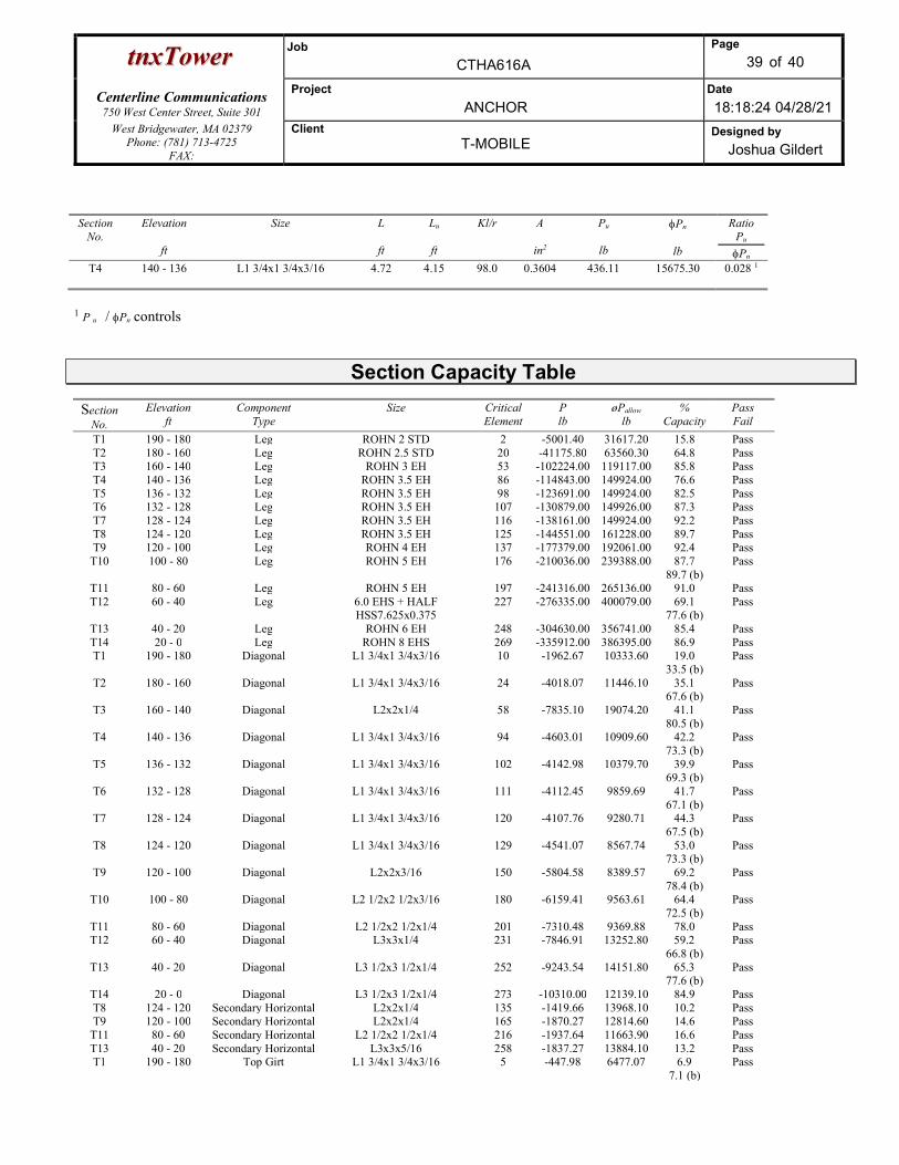
ttnnxxTToowweerr Job
CTHA616A
Page
39 of 40
Centerline Communications
750 West Center Street, Suite 301
Project
ANCHOR Date
18:18:24 04/28/21 West Bridgewater, MA 02379
Phone: (781) 713-4725 FAX:
Client T-MOBILE
Designed by
Joshua Gildert
Section No.
Elevation
ft
Size
L
ft
Lu
ft
Kl/r
A
in2
Pu
lb
Pn
lb
Ratio Pu
Pn T4 140 - 136 L1 3/4x1 3/4x3/16 4.72 4.15 98.0 0.3604 436.11 15675.30 0.028 1
1 P u / Pn controls
Section Capacity Table
Section No.
Elevation ft
Component Type
Size Critical Element
P lb
øPallow
lb %
Capacity Pass Fail
T1 190 - 180 Leg ROHN 2 STD 2 -5001.40 31617.20 15.8 Pass T2 180 - 160 Leg ROHN 2.5 STD 20 -41175.80 63560.30 64.8 Pass T3 160 - 140 Leg ROHN 3 EH 53 -102224.00 119117.00 85.8 Pass T4 140 - 136 Leg ROHN 3.5 EH 86 -114843.00 149924.00 76.6 Pass T5 136 - 132 Leg ROHN 3.5 EH 98 -123691.00 149924.00 82.5 Pass T6 132 - 128 Leg ROHN 3.5 EH 107 -130879.00 149926.00 87.3 Pass T7 128 - 124 Leg ROHN 3.5 EH 116 -138161.00 149924.00 92.2 Pass T8 124 - 120 Leg ROHN 3.5 EH 125 -144551.00 161228.00 89.7 Pass T9 120 - 100 Leg ROHN 4 EH 137 -177379.00 192061.00 92.4 Pass
T10 100 - 80 Leg ROHN 5 EH 176 -210036.00 239388.00 87.7 89.7 (b)
Pass
T11 80 - 60 Leg ROHN 5 EH 197 -241316.00 265136.00 91.0 Pass T12 60 - 40 Leg 6.0 EHS + HALF
HSS7.625x0.375 227 -276335.00 400079.00 69.1
77.6 (b) Pass
T13 40 - 20 Leg ROHN 6 EH 248 -304630.00 356741.00 85.4 Pass T14 20 - 0 Leg ROHN 8 EHS 269 -335912.00 386395.00 86.9 Pass T1 190 - 180 Diagonal L1 3/4x1 3/4x3/16 10 -1962.67 10333.60 19.0
33.5 (b) Pass
T2 180 - 160 Diagonal L1 3/4x1 3/4x3/16 24 -4018.07 11446.10 35.1 67.6 (b)
Pass
T3 160 - 140 Diagonal L2x2x1/4 58 -7835.10 19074.20 41.1 80.5 (b)
Pass
T4 140 - 136 Diagonal L1 3/4x1 3/4x3/16 94 -4603.01 10909.60 42.2 73.3 (b)
Pass
T5 136 - 132 Diagonal L1 3/4x1 3/4x3/16 102 -4142.98 10379.70 39.9 69.3 (b)
Pass
T6 132 - 128 Diagonal L1 3/4x1 3/4x3/16 111 -4112.45 9859.69 41.7 67.1 (b)
Pass
T7 128 - 124 Diagonal L1 3/4x1 3/4x3/16 120 -4107.76 9280.71 44.3 67.5 (b)
Pass
T8 124 - 120 Diagonal L1 3/4x1 3/4x3/16 129 -4541.07 8567.74 53.0 73.3 (b)
Pass
T9 120 - 100 Diagonal L2x2x3/16 150 -5804.58 8389.57 69.2 78.4 (b)
Pass
T10 100 - 80 Diagonal L2 1/2x2 1/2x3/16 180 -6159.41 9563.61 64.4 72.5 (b)
Pass
T11 80 - 60 Diagonal L2 1/2x2 1/2x1/4 201 -7310.48 9369.88 78.0 Pass T12 60 - 40 Diagonal L3x3x1/4 231 -7846.91 13252.80 59.2
66.8 (b) Pass
T13 40 - 20 Diagonal L3 1/2x3 1/2x1/4 252 -9243.54 14151.80 65.3 77.6 (b)
Pass
T14 20 - 0 Diagonal L3 1/2x3 1/2x1/4 273 -10310.00 12139.10 84.9 Pass T8 124 - 120 Secondary Horizontal L2x2x1/4 135 -1419.66 13968.10 10.2 Pass T9 120 - 100 Secondary Horizontal L2x2x1/4 165 -1870.27 12814.60 14.6 Pass
T11 80 - 60 Secondary Horizontal L2 1/2x2 1/2x1/4 216 -1937.64 11663.90 16.6 Pass T13 40 - 20 Secondary Horizontal L3x3x5/16 258 -1837.27 13884.10 13.2 Pass T1 190 - 180 Top Girt L1 3/4x1 3/4x3/16 5 -447.98 6477.07 6.9
7.1 (b) Pass

ttnnxxTToowweerr Job
CTHA616A
Page
40 of 40
Centerline Communications
750 West Center Street, Suite 301
Project
ANCHOR Date
18:18:24 04/28/21 West Bridgewater, MA 02379
Phone: (781) 713-4725 FAX:
Client T-MOBILE
Designed by
Joshua Gildert
Section No.
Elevation ft
Component Type
Size Critical Element
P lb
øPallow
lb %
Capacity Pass Fail
T4 140 - 136 Top Girt L1 3/4x1 3/4x3/16 90 -560.33 6683.02 8.4 Pass Summary Leg (T9) 92.4 Pass Diagonal
(T14) 84.9 Pass
Secondary Horizontal
(T11)
16.6 Pass
Top Girt (T4)
8.4 Pass
Bolt Checks 89.7 Pass RATING = 92.4 Pass
Program Version 8.0.7.5 - 8/3/2020 File:C:/Users/Joshua Gildert/Box/Projects/New England Projects/T-Mobile/SITES/CT/CTHA616A-CT03XC206/Anchor/Structural/Working Files/Structural Analysis/Analysis/tnx/CTHA616A.eri

5473.057 ft-kips Capacity Demand Rating Check
50.457 kips 235.96 52.54 22.3% Pass
52.544 kips 6.00 2.47 41.2% Pass
344.137 kips 8997.76 5709.51 63.5% Pass
33.053 kips 1284.52 0.00 0.0% Pass
302.758 kips 789.06 0.00 0.0% Pass
29.484 kips #DIV/0! 0.00 0.0% Pass
190 ft
19 ft
0 in
in 4162.34 0.00 0.0% Pass
0.164 0.000 0.0% Pass
4162.34 0.00 0.0% Pass
Square
0.0 ft
0.00 ft Soil Rating: 63.5%
in
4.50 ft
32.00 ft
4.50 ft
in
60 ksi
3 ksi
150 pcf
120 pcf
8.000 ksf <-- Toggle between Gross and Net
ksf
30 degrees
0.3
0.0 ft
N/A ft
Top & Bot. Pad Rein. Different?:
Anchor Bolt Circle, BC: Flexural 2-way (Comp) (kip*ft)
Flexural 2-way (Tension) (kip*ft)
Pad Shear - Tension 2-way (ksi)
Lateral (Sliding) (kips)
Foundation Analysis Checks
Tower Centroid Offset?:
Pier Properties
Global Moment, M:
Leg Uplift. Shear, Vu_uplift:
BP Dist. Above Fdn, bpdist:
Block Foundation?:
Pier Compression (kip)
Pier Flexure (Comp.) (kip*ft)
Tower Height, H:
Base Face Width, BW:
Leg Uplift, Puplift: Pier Flexure (Tension) (kip*ft)
Bearing Pressure (ksf)
Overturning (kip*ft)
SST Unit Base Foundation
BU # :
Site Name:
Leg Compression, Pcomp:
TIA-222 Revision:
App. Number:
Superstructure Analysis Reactions
G
Global Axial, P:
Global Shear, V:
CTHA616A
Leg Comp. Shear, Vu_comp:
Pier Diameter, dpier:
Pier Rebar Quantity, mc:
Pier Tie/Spiral Size, St:
Pier Clear Cover, ccpier:
Neglected Depth, N:
Pier Shape:
Pier Rebar Size, Sc:
Pier Reinforcement Type:
Ext. Above Grade, E:
Pier Tie/Spiral Quantity, mt:
Pad Width, W:
Pad Thickness, T:
Pad Rebar Size (Bottom), Sp:
Foundation Bearing on Rock?
Pad Properties
Groundwater Depth, gw:
Base Friction, μ:
Cohesion, Cu:
Friction Angle, ϕ:
Total Soil Unit Weight, γ:
Ultimate Gross Bearing, Qult:
SPT Blow Count, Nblows:
Soil Properties
Depth, D:
Pad Clear Cover, ccpad:
Dry Concrete Density, δc:
Pad Rebar Quantity (Bottom), mp:
Rebar Grade, Fy:
Concrete Compressive Strength, F'c:
Material Properties
Version 3.2.0

Exhibit E
Mount Analysis

Revised Mount Analysis Report
Site Address 1712 Main Street
Coventry, CT 06238 Site Name CT03XC206 Site ID CTHA616A Project Name Sprint Retain Design Codes 2015 International Building Code
ASCE 7-10 TIA-222-G Standards 2018 CT State Building Code
Stress Ratio Overall Result Existing Mount 98% PASS
Client:
NORTHEAST, LLC
15 Commerce Way, Suite B Norton, MA 02766
Date: 4/29/2021 (Rev. 1) 4/28/2021

Scope of Work: Centerline Communications was authorized by T-Mobile Northeast LLC to perform an analysis of the existing antenna mounts to determine their capacity to support the proposed T-Mobile equipment listed in this report. These mounts were analyzed using RISA 3D v17.0.4. Final Appurtenances Configuration:
Elevation (ft)
Position1 Azimuth (degrees)
Quantity Appurtenance Sector
180 MP1 30 1 APX16DWV-16DWV-S-E-A20 Antenna
Sector 1
180 MP2 30 1 APXVAALL24_43-U-NA20 Antenna 180 MP3 30 1 AIR6449 B41 RRH 180 MP1 30 1 4415 B66A RRH 180 MP4 30 1 4449 B71+B85 RRH 180 MP4 30 1 4424 B25 RRH 180 - 135 1 APX16DWV-16DWV-S-E-A20 Antenna
Sector 2
180 - 135 1 APXVAALL24_43-U-NA20 Antenna 180 - 135 1 AIR6449 B41 RRH 180 - 135 1 4415 B66A RRH 180 - 135 1 4449 B71+B85 RRH 180 - 135 1 4424 B25 RRH 180 - 270 1 APX16DWV-16DWV-S-E-A20 Antenna
Sector 3
180 - 270 1 APXVAALL24_43-U-NA20 Antenna 180 - 270 1 AIR6449 B41 RRH 180 - 270 1 4415 B66A RRH 180 - 270 1 4449 B71+B85 RRH 180 - 270 1 4424 B25 RRH
Notes:
1. MP represent Mount Pipe. 2. Existing Appurtenance 3. Proposed Appurtenance

Design Criteria:
Design Codes: 2015 International Building Code ASCE 7-10 TIA-222-G Standards 2018 CT State Building Code
Ultimate Wind Speed 130 mph Nominal Wind Speed 101 mph Wind Speed with Ice 50 mph Ice Thickness 1.0 in. Exposure Category B Topographic Category 1 Structure Class II Site Soil Class (Assumed) D-Stiff Soil Seismic Design Category B Spectral Response Acceleration Parameter at a Short Periods, SS 0.176 g Spectral Response Acceleration Parameter at a Period of 1 Second, S1 0.063 g Short Period Site Coefficient, Fa 1.6 Long Period Site Coefficient, Fv 2.4
*Refer to calculations for additional design criteria. Conclusion: The results of the analysis concluded that the existing T-Mobile mounts are adequate to support the proposed T-Mobile equipment loading upon completion of the following modifications. Centerline recommends the following: Alpha, Beta & Gamma:
Install (1) 2” STD. x 8.0 ft long mount pipes using (2) Site Pro 1 UB1212 U-bolts at Position 2.
Stress Ratio Overall Result
Existing Mount 98% PASS
Reference Documents:
T-Mobile RFDS CTHA616A_Sprint Retain_1_draft, dated 01/15/2021
Structural Analysis by Maser, dated 07/23/2018
Construction Drawings by Maser, dated 07/27/2018
Mount Analysis by Maser, dated 07/23/2018
Site Photos and Notes by Centerline Communications, dated 04/22/2021
Assumptions and Limitations:
The calculations performed by Centerline Communications are limited to the structural members in these calculations only.
Structural calculations in this report do not check the adequacy of the supporting structure, other mounts, or coax mounting attachments.
The calculation assumes all structural members to be in good condition i.e. no damage, rust, or other defects.

Photos:
Existing Alpha Sector
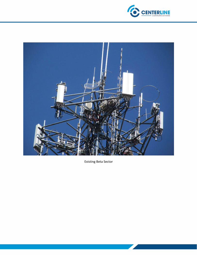
Existing Beta Sector

Existing Gamma Sector

Overall

Design Calculations

Site Name Ultimate Wind Speed, VULT 130 mph
Carrier Nominal Wind Speed, V 101 mph
City, State Wind Speed with Ice, Vi 50 mph
Project Design Ice Thickness, ti 1 in
Structural Class II
Exposure Category B
Mount Type Site Soil Class
Mount Height, z 180 ft
Number of Sectors 3
Tower Type Building Code
Tower Height, h 190 ft TIA Code
ASCE Code
Topographic Category
Feature Importance Factor, I (Wind no Ice) 1.00
Crest Height, H N/A ft Importance Factor, I (Ice Thickness) 1.00
Distance from Crest, x N/A ft Importance Factor, I (wind with Ice) 1.00
Slope (H/L) N/A Wind Direction Prob. Factor, Kd 0.95
Topographic Factor, Kzt 1.00 Velocity Pressure Coefficient, Kz 1.17
Gust Effect Factor, Gh 1.00
Design Ice Thickness, tiz 2.37 in
Importance Factor, IE 1 Velocity Pressure, qz 29.00 psf
Short Period Spectral Acceleration, Ss 0.176 g Velocity Pressure with Ice, qzi 7.11 psf
1 Second Period Spectral Acceleration, S1 0.063 g Shielding Factor, Ka 1.00
Long-Period Transition Period, TL 6 Flat Velocity Pressure (Ca =2.0) 58.00 psf
Design Category B Round Velocity Pressure (Ca = 1.2) 34.80 psf
Short Period Site Coefficient, Fa 1.60 Round Velocity Pressure with Ice (Ca = 1.2) 8.53 psf
Long-Period Site Coefficient, Fv 2.4 Engineer Initials AP
Site Details Site Parameters
Mount Details
Topographic Factors
CT03XC206
T-Mobile
Coventry, CT
7-10
1
Flat
Seismic Factors
Site Constants
Code
D-Stiff Soil (Assumed)
Sprint Retain
Sector Frame
SST 2015 IBC
TIA-222-G

Member Label Shape Type w, lbs/ft qz, psf wi, lbs/ft qzi, psf Vs, lbs/ft
Horizontal L2.5x2.5x3 Beam 3.07 58.00 17.10 8.53 0.38
Standoff L2x2x3 Beam 2.46 58.00 15.05 8.53 0.31
Horizontal Diagonal Brace L2x2x2 Beam 1.67 58.00 15.05 8.53 0.21
Horizontal Vertical Brace L1.75x1.75x2 Beam 1.44 58.00 14.03 8.53 0.18
Standoff Brace L1.75x1.75x2 Beam 1.44 58.00 14.03 8.53 0.18
Mount Pipe PIPE_2.0 Beam 3.47 34.80 13.74 8.53 0.43
Tieback PIPE_2.0 Beam 3.47 34.80 13.74 8.53 0.43
Members Forces

Dimensions Weights
Appurtenances Rad. Ht., ftFront
EPA ft2
Side EPA
ft2
0° Force
lbs.
90°
Force
lbs.
H\W\D, in Wt.\Wt.ice, lbs.
APX16DWV-16DWV-S-E-A20 Antenna 180 6.59 2.15 191.01 62.35 55.9\13.3\3.15 40.7\203.79
APXVAALL24_43-U-NA20 Antenna 180 20.27 8.90 587.74 258.10 96\24\8.7 153.3\611.38
AIR6449 B41 RRH 180 5.68 2.49 164.78 72.23 33.1\20.6\8.6 104\224.47
4415 B66A RRH 180 1.86 0.82 53.84 23.85 16.54\13.47\5.9 49.6\91.01
4449 B71+B85 RRH 180 1.97 1.59 57.05 46.01 17.91\13.18\10.63 91.09\120.84
4424 B25 RRH 180 1.64 0.67 47.53 19.44 14.9\13.2\5.4 46.3\81.35
Wind Force
Sector 1
*Dish force coefficient is calculated per Annex C.2 of TIA-222-G, if available.

Rad. Ht., ftFront EPA
ft2
Side
EPA ft2
0°
Force
lbs.
90°
Force
lbs.
0° Force
lbs.
90° Force
lbs.
180 5.46 2.71 85.64 34.53 16.85 5.50
180 14.52 7.63 247.26 117.45 51.85 22.77
180 4.66 2.48 73.51 35.33 14.54 6.37
180 1.88 1.10 26.58 13.67 4.75 2.10
180 1.97 1.69 28.00 23.30 5.03 4.06
180 1.71 0.97 23.82 11.65 4.19 1.72
Sector 1 Continue…
Vs, lbs
5.09
19.19
13.02
6.21
11.40
5.79
Seismic ForceWind Force V = 30 mph
Appurtenances
APX16DWV-16DWV-S-E-A20 Antenna
APXVAALL24_43-U-NA20 Antenna
AIR6449 B41 RRH
4415 B66A RRH
4449 B71+B85 RRH
4424 B25 RRH
Wind Force with Ice

Existing Mount Results

Centerline Communcation...
AP CTHA616A_MA
Rendered
Apr 27, 2021 at 2:29 PM
CTHA616A_MA.r3d
Y
XZ
Ashim Pant
Text Box
Install (1) 2” STD. x 8.0 ft long mount pipes using (2) Site Pro 1 UB1212 U-bolts at Position 2.
Ashim Pant
Line

Centerline Communcation...
AP CTHA616A_MA
Wireframe
Apr 27, 2021 at 2:29 PM
CTHA616A_MA.r3d
N1
N2
N3
N4
N5
N6
N7
N8
N9
N10
N11
N12
N13
N14
N15
N16
N17
N18 N21
N22
N23 N24
N23A
N24A
N25
N26
N27
N28
N29
N30
N31
N32
N37
N38
N39
N40
N41
N42
N39A
N40A
N43
N44
N43A
N44A
N45
N46 N47
N48
N49
N50
N51
N52
N53 N54
M1
M2
M3
M4
M5
M6
M7
M8
M9
M10
M11
M12
M13
M14 M
15
M16
M17
M18
M19
M21
M22
M23
M24
M25
M28
M29
MP
2
MP
3
MP
1M
31
M32
MP
4
M34
M35MP5
Y
XZ

Centerline Communcation...
AP CTHA616A_MA
Section Sets
Apr 27, 2021 at 2:30 PM
CTHA616A_MA.r3d
Mount P
ipe
Horizontal
Horizontal
StandoffRIGID Standoff
StandoffHorizonta
l V
ert
ical B
race
StandoffStandoff
Standoff Brace
Standoff
RIG
ID
Mount P
ipe
Horizontal
Sta
ndoff B
race
RIG
ID
Horizontal
Horizontal
RIGID
Standoff Brace
Standoff
RIG
ID
RIGID Standoff
Sta
ndoff
Standoff
RIG
ID
Mount P
ipe
Standoff
Standoff
Standoff
Horizontal Diagonal Brace
Standoff
RIGID
Horizontal
Sta
ndof
f Bra
ce
Horizontal
RIG
IDStandoff Brace
Mount P
ipe
Sta
ndoff
Sta
ndoff
Mount P
ipe
Standoff
RIG
IDS
tandoff
RIGID
RIG
ID
Horizontal
Sta
ndoff B
race
Sta
ndoff
Horizontal RIG
ID
Mount P
ipe
Sta
ndoff
Sta
ndoff
RIG
ID
Sta
ndoff
Mount P
ipe
Horizontal D
iagonal Brace
Sta
ndoff Tieback
Sta
ndoff B
race
Horizontal
RIGID
Horizontal
Horizontal
Sta
ndoff
Mount P
ipe
Horizonta
l V
ert
ical B
raceRIG
ID
Horizontal
Horizontal
Horizontal
Mount P
ipe
Y
XZ
Section Sets
Horizontal
Standoff
Horizontal Diagonal Brace
Horizontal Vertical Brace
Standoff Brace
Mount Pipe
Tieback
RIGID

Centerline Communcation...
AP CTHA616A_MA
Member Shape
Apr 27, 2021 at 2:30 PM
CTHA616A_MA.r3d
L2.5x2.5x3
L2.5x2.5x3
L2x2x3
L2x2x3 L2x2x3
L2x2
x3
L2x2x3
L2x2x3
L2x2x2
L2x2x2
L1.7
5x1.7
5x2
L1.7
5x1.7
5x2
L1.75x1.75x2
L1.7
5x1.7
5x2
L1.75x1.75x2
L1.7
5x1.
75x2
L1.7
5x1.7
5x2
L1.7
5x1.7
5x2
L1.75x1.75x2
PIPE_2.0
PIP
E_2.0
PIP
E_2.0
PIP
E_2.0
Y
XZ

Centerline Communcation...
AP CTHA616A_MA
Material Sets
Apr 27, 2021 at 2:30 PM
CTHA616A_MA.r3d
A36 Gr.36
A36 Gr.36
A36 Gr.36
A36 Gr.36
A36 G
r.36
A36 G
r.36
A36 Gr.3
6
A36 Gr.3
6
A36 Gr.36
A36 G
r.36
A36 G
r.36
A36 G
r.36
A36 Gr.3
6
A36 G
r.36
A36 Gr.36
A36
Gr.36
A36 G
r.36
A36 G
r.36
A36 Gr.36
A53 Gr.B
RIGID
RIGID
RIGID
RIGID
RIGID
RIGID
A53 G
r.B
A53 G
r.B
A53 G
r.B
RIG
ID
RIG
IDR
IGID
RIG
ID
RIG
IDRIGID
Y
XZ

Centerline Communcation...
AP CTHA616A_MA
Member Length
Apr 27, 2021 at 2:30 PM
CTHA616A_MA.r3d
158
158
83
83
83
83
44.5
44.5
78.39
78.39
31
31
50.071
31 50.071
54.2
33
50.0
71
31
50.071
109
3
3
3
3
3
3
96
120
120
31
31
26
31
31
13
Y
XZ
Member Length (in) Displayed

Centerline Communcation...
AP CTHA616A_MA
Dead Load
Apr 27, 2021 at 2:30 PM
CTHA616A_MA.r3d
-76.65lb
-76.65lb
-52lb
-52lb
-20.35lb
-49.6lb
-20.35lb
-91.09lb-46.3lb
Y
XZ
Loads: BLC 1, Dead Load

Centerline Communcation...
AP CTHA616A_MA
Wind 0
Apr 27, 2021 at 2:30 PM
CTHA616A_MA.r3d
-293.87lb
-293.87lb
-82.39lb
-82.39lb
-95.5lb
-53.84lb
-95.5lb
-57.05lb
-47.53lb
Y
XZ
Loads: BLC 2, Wind 0

Centerline Communcation...
AP CTHA616A_MA
Wind 90
Apr 27, 2021 at 2:31 PM
CTHA616A_MA.r3d
-129.05lb
-129.05lb
-36.11lb
-36.11lb
-31.17lb
-23.85lb
-31.17lb
-46.01lb
-19.44lb
Y
XZ
Loads: BLC 5, Wind 90

Centerline Communcation...
AP CTHA616A_MA
Ice Weight
Apr 27, 2021 at 2:31 PM
CTHA616A_MA.r3d
-17.097lb/ft
-17.097lb/ft
-15.05lb/ft
-15.05lb/ft
-15.05lb/ft
-15.05lb/ft
-15.05lb/ft
-15.05lb/ft
-15.05lb/ft
-15.05lb/ft
-14.026lb/ft
-14.026lb/ft
-14.026lb/ft-14.026lb/ft-14.026lb/ft
-14.026lb/ft
-14.026lb/ft-14.026lb/ft-14.026lb/ft
-13.737lb/ft
-13.737lb/ft
-13.737lb/ft
-13.737lb/ft
-305.69lb
-305.69lb
-112.23lb
-112.23lb
-101.9lb
-91.01lb
-101.9lb
-120.84lb
-81.35lb
Y
XZ
Loads: BLC 9, Ice Weight

Centerline Communcation...
AP CTHA616A_MA
Ice + Wind 0
Apr 27, 2021 at 2:31 PM
CTHA616A_MA.r3d
-123.63lb
-123.63lb
-36.76lb
-36.76lb
-42.82lb
-26.58lb
-42.82lb
-28lb
-23.82lb
Y
XZ
Loads: BLC 10, Ice + Wind 0

Centerline Communcation...
AP CTHA616A_MA
Ice + Wind 90
Apr 27, 2021 at 2:31 PM
CTHA616A_MA.r3d
-58.72lb
-58.72lb
-17.66lb
-17.66lb
-17.27lb
-13.67lb
-17.27lb
-23.3lb
-11.65lb
Y
XZ
Loads: BLC 13, Ice + Wind 90

Centerline Communcation...
AP CTHA616A_MA
Distr. Wind 0
Apr 27, 2021 at 2:31 PM
CTHA616A_MA.r3d
-12.083lb/ft
-12.083lb/ft
-8.223lb/ft
-8.223lb/ft
-8.223lb/ft
-8.223lb/ft
-9.667lb/ft
-9.667lb/ft
-8.458lb/ft
-8.458lb/ft
-7.704lb/ft-8.458lb/ft-7.704lb/ft
-4.835lb/ft
-7.704lb/ft-8.458lb/ft-7.704lb/ft
-6.888lb/ft
-6.888lb/ft
-6.888lb/ft
Y
XZ
Loads: BLC 17, Distri. Wind Z

Centerline Communcation...
AP CTHA616A_MA
Distr. Wind 90
Apr 27, 2021 at 2:31 PM
CTHA616A_MA.r3d
-5.082lb/ft
-5.082lb/ft
-5.082lb/ft
-5.082lb/ft
-9.667lb/ft
-9.667lb/ft
-3.823lb/ft
-3.823lb/ft
-8.458lb/ft
-8.458lb/ft
-6.294lb/ft-8.458lb/ft-6.294lb/ft
-8.458lb/ft
-6.294lb/ft-8.458lb/ft-6.294lb/ft
-6.888lb/ft
-6.888lb/ft
-6.888lb/ft
-6.888lb/ft
Y
XZ
Loads: BLC 18, Distri. Wind X
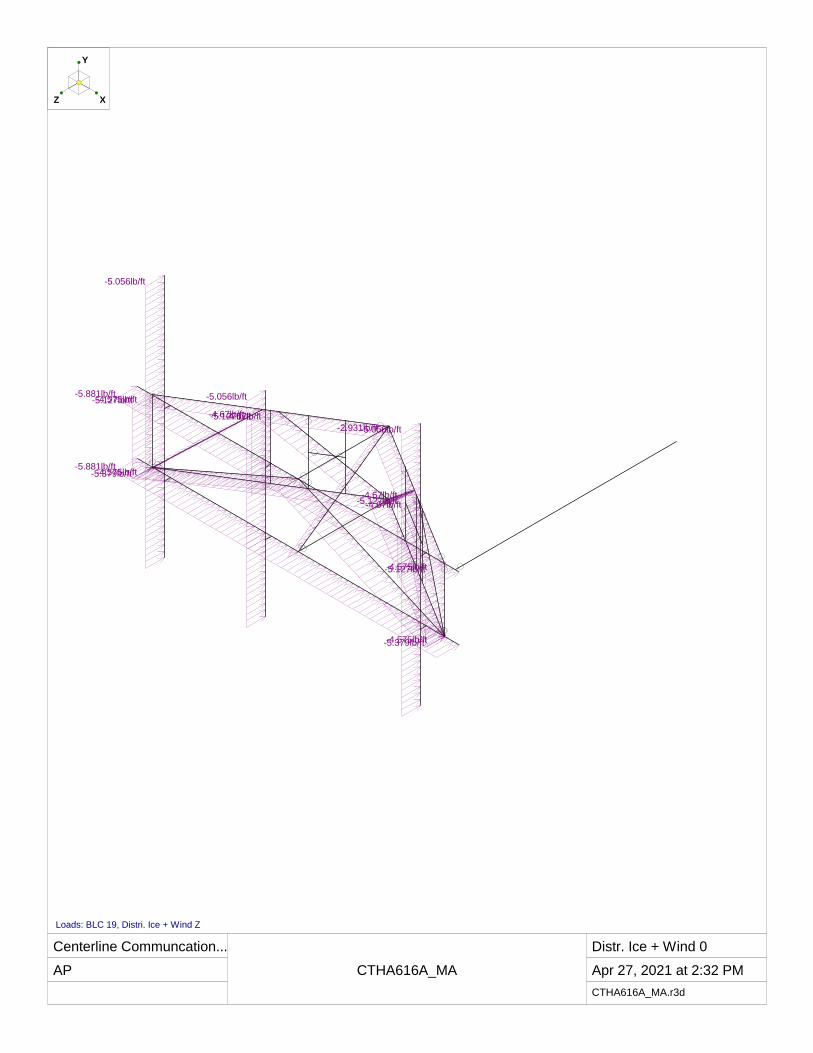
Centerline Communcation...
AP CTHA616A_MA
Distr. Ice + Wind 0
Apr 27, 2021 at 2:32 PM
CTHA616A_MA.r3d
-5.881lb/ft
-5.881lb/ft
-4.575lb/ft
-4.575lb/ft
-4.575lb/ft
-4.575lb/ft
-5.379lb/ft
-5.379lb/ft
-5.127lb/ft
-5.127lb/ft
-4.67lb/ft-5.127lb/ft-4.67lb/ft
-2.931lb/ft
-4.67lb/ft-5.127lb/ft-4.67lb/ft
-5.056lb/ft
-5.056lb/ft
-5.056lb/ft
Y
XZ
Loads: BLC 19, Distri. Ice + Wind Z

Centerline Communcation...
AP CTHA616A_MA
Distr. Ice + Wind 90
Apr 27, 2021 at 2:32 PM
CTHA616A_MA.r3d
-2.828lb/ft
-2.828lb/ft
-2.828lb/ft
-2.828lb/ft
-5.379lb/ft
-5.379lb/ft
-2.127lb/ft
-2.127lb/ft
-5.127lb/ft
-5.127lb/ft
-3.816lb/ft-5.127lb/ft-3.816lb/ft
-5.127lb/ft
-3.816lb/ft-5.127lb/ft-3.816lb/ft
-5.056lb/ft
-5.056lb/ft
-5.056lb/ft
-5.056lb/ft
Y
XZ
Loads: BLC 20, Distrr. Ice + Wind X

Centerline Communcation...
AP CTHA616A_MA
Seismic Z
Apr 27, 2021 at 2:32 PM
CTHA616A_MA.r3d
-.384lb/ft
-.384lb/ft
-.307lb/ft
-.307lb/ft
-.307lb/ft
-.307lb/ft
-.307lb/ft
-.307lb/ft
-.209lb/ft
-.209lb/ft
-.18lb/ft
-.18lb/ft
-.18lb/ft-.18lb/ft-.18lb/ft
-.18lb/ft
-.18lb/ft-.18lb/ft-.18lb/ft
-.434lb/ft
-.434lb/ft
-.434lb/ft
-.434lb/ft
-9.593lb
-9.593lb
-6.508lb
-6.508lb
-2.547lb
-6.208lb
-2.547lb
-11.4lb
-5.795lb
Y
XZ
Loads: BLC 21, Seismic Load Z

Centerline Communcation...
AP CTHA616A_MA
Seismic X
Apr 27, 2021 at 2:32 PM
CTHA616A_MA.r3d
-.384lb/ft
-.384lb/ft
-.307lb/ft
-.307lb/ft
-.307lb/ft
-.307lb/ft
-.307lb/ft
-.307lb/ft
-.209lb/ft
-.209lb/ft
-.18lb/ft
-.18lb/ft
-.18lb/ft-.18lb/ft-.18lb/ft
-.18lb/ft
-.18lb/ft-.18lb/ft-.18lb/ft
-.434lb/ft
-.434lb/ft
-.434lb/ft
-.434lb/ft
-9.593lb
-9.593lb
-6.508lb
-6.508lb
-2.547lb
-6.208lb
-2.547lb
-11.4lb
-5.795lb
Y
XZ
Loads: BLC 22, Seismic Load X

Centerline Communcation...
AP CTHA616A_MA
Live Load 1
Apr 27, 2021 at 2:32 PM
CTHA616A_MA.r3d
-250lb
Y
XZ
Loads: BLC 23, Live Load 1

Centerline Communcation...
AP CTHA616A_MA
Live Load 2
Apr 27, 2021 at 2:32 PM
CTHA616A_MA.r3d
-250lb
Y
XZ
Loads: BLC 24, Live Load 2

Centerline Communcation...
AP CTHA616A_MA
Live Load 3
Apr 27, 2021 at 2:32 PM
CTHA616A_MA.r3d
-250lb
Y
XZ
Loads: BLC 25, Live Load 3

Company : Centerline Communcations, LLC Apr 27, 20212:33 PMDesigner : AP
Job Number : Checked By: JGModel Name : CTHA616A_MA
Hot Rolled Steel Properties
Label E [ksi] G [ksi] Nu Therm (/... Density[lb/ft^3] Yield[ksi] Ry Fu[ksi] Rt
1 A992 29000 11154 .3 .65 490 50 1.1 65 1.12 A36 Gr.36 29000 11154 .3 .65 490 36 1.5 58 1.23 A572 Gr.50 29000 11154 .3 .65 490 50 1.1 65 1.14 A500 Gr.B RND 29000 11154 .3 .65 527 42 1.4 58 1.35 A500 Gr.B Rect 29000 11154 .3 .65 527 46 1.4 58 1.36 A53 Gr.B 29000 11154 .3 .65 490 35 1.6 60 1.27 A1085 29000 11154 .3 .65 490 50 1.25 65 1.158 A913 Gr.65 29000 11154 .3 .65 490 65 1.1 80 1.1
Hot Rolled Steel Section Sets
Label Shape Type Design List Material Design ... A [in2] Iyy [in4] Izz [in4] J [in4]
1 Horizontal L2.5x2.5x3 Beam Single Angle A36 Gr.36 Typical .901 .535 .535 .0112 Standoff L2x2x3 Beam Single Angle A36 Gr.36 Typical .722 .271 .271 .0093 Horizontal Diagon... L2x2x2 Beam Single Angle A36 Gr.36 Typical .491 .189 .189 .0034 Horizontal Vertical... L1.75x1.75x2 Beam Single Angle A36 Gr.36 Typical .422 .126 .126 .0025 Standoff Brace L1.75x1.75x2 Beam Single Angle A36 Gr.36 Typical .422 .126 .126 .0026 Mount Pipe PIPE_2.0 Beam Pipe A53 Gr.B Typical 1.02 .627 .627 1.257 Tieback PIPE_2.0 Beam Pipe A53 Gr.B Typical 1.02 .627 .627 1.25
Joint Coordinates and Temperatures
Label X [in] Y [in] Z [in] Temp [F] Detach From Diap...
1 N1 0 0 0 02 N2 0 31 0 03 N3 79 0 0 04 N4 79 31 0 05 N5 158 0 0 06 N6 158 31 0 07 N7 7 0 0 08 N8 7 31 0 09 N9 151 0 0 010 N10 151 31 0 011 N11 79 0 -44.5 012 N12 79 31 -44.5 013 N13 43 31 -22.25 014 N14 43 0 -22.25 015 N15 40.448033 31 -20.672742 0
RISA-3D Version 17.0.4 Page 1 [C:\...\Ashim Pant\Desktop\Projects\Active\CTHA616A\CTHA616A_MA.r3d]

Company : Centerline Communcations, LLC Apr 27, 20212:33 PMDesigner : AP
Job Number : Checked By: JGModel Name : CTHA616A_MA
Joint Coordinates and Temperatures (Continued)
Label X [in] Y [in] Z [in] Temp [F] Detach From Diap...
16 N16 40.448033 0 -20.672742 017 N17 45.551888 31 -23.827209 018 N18 45.551888 0 -23.827209 019 N21 115 31 -22.25 020 N22 115 0 -22.25 021 N23 117.551967 31 -20.672742 022 N24 112.448112 31 -23.827209 023 N23A 156 31 0 024 N24A 156 31 -109 025 N25 16 0 0 026 N26 16 31 0 027 N27 16 0 3 028 N28 16 31 3 029 N29 142 0 0 030 N30 142 31 0 031 N31 142 0 3 032 N32 142 31 3 033 N37 66 0 0 034 N38 66 31 0 035 N39 66 0 3 036 N40 66 31 3 037 N41 66 63.5 3 038 N42 66 -32.5 3 039 N39A 16 87.5 3 040 N40A 16 -32.5 3 041 N43 142 87.5 3 042 N44 142 -32.5 3 043 N43A 122.078151 31 -17.875309 044 N44A 122.078151 0 -17.875309 045 N45 99.961444 31 -31.544663 046 N46 99.961444 0 -31.544663 047 N47 122.078151 15.5 -17.875309 048 N48 99.961444 15.5 -31.544663 049 N49 54.635986 31 -29.441686 050 N50 54.635986 0 -29.441686 051 N51 65.69434 31 -36.276363 052 N52 65.69434 0 -36.276363 053 N53 54.635986 15.5 -29.441686 054 N54 65.69434 15.5 -36.276363 0
RISA-3D Version 17.0.4 Page 2 [C:\...\Ashim Pant\Desktop\Projects\Active\CTHA616A\CTHA616A_MA.r3d]

Company : Centerline Communcations, LLC Apr 27, 20212:33 PMDesigner : AP
Job Number : Checked By: JGModel Name : CTHA616A_MA
Envelope Joint Reactions
Joint X [lb] LC Y [lb] LC Z [lb] LC MX [lb-ft] LC MY [lb-ft] LC MZ [lb-ft] LC
1 N12 max 1146.938 12 1357.249 20 1474.614 10 4.257 2 6.037 13 3.165 62 min -1042.134 51 -5.812 9 -6187.101 22 -3.247 15 -2.977 2 -1.307 93 N11 max 1178.89 54 3214.827 16 5880.093 16 2.812 8 4.996 6 1.797 94 min -870.271 43 291.875 13 -336.335 15 -2.615 9 -2.78 9 -3.303 65 N24A max 50.35 12 81.717 20 6.233 23 0 78 0 78 0 786 min 0 22 14.186 30 -929.435 5 0 1 0 1 0 17 Totals: max 1968.487 5 4476.831 22 3527.368 28 min 0 9 762.963 9 -3527.365 15
Joint Boundary Conditions
Joint Label X [k/in] Y [k/in] Z [k/in] X Rot.[k-ft/rad] Y Rot.[k-ft/rad] Z Rot.[k-ft/rad]
1 N12 Reaction Reaction Reaction Reaction Reaction Reaction2 N11 Reaction Reaction Reaction Reaction Reaction Reaction3 N24A Reaction Reaction Reaction
Hot Rolled Steel Design Parameters
Label Shape Length[in] Lbyy[in] Lbzz[in] Lcomp top[in]Lcomp bot[in] L-torq... Kyy Kzz Cb Function
1 M1 Horizontal 158 79 Lbyy Lateral
2 M2 Horizontal 158 79 Lbyy Lateral
3 M3 Standoff 84.642 Lbyy Lateral
4 M4 Standoff 84.642 Lbyy Lateral
5 M5 Standoff 84.642 Lbyy Lateral
6 M6 Standoff 84.642 Lbyy Lateral
7 M7 Standoff 44.5 Lbyy Lateral
8 M8 Standoff 44.5 Lbyy Lateral
9 M9 Horizontal ... 78.39 Lbyy Lateral
10 M10 Horizontal ... 78.39 Lbyy Lateral
11 M11 Horizontal V... 31 Lbyy Lateral
12 M12 Horizontal V... 31 Lbyy Lateral
13 M13 Standoff Br... 50.071 Lbyy Lateral
14 M14 Standoff Br... 31 Lbyy Lateral
15 M15 Standoff Br... 50.071 Lbyy Lateral
16 M16 Standoff Br... 54.233 Lbyy Lateral
17 M17 Standoff Br... 50.071 Lbyy Lateral
18 M18 Standoff Br... 31 Lbyy Lateral
19 M19 Standoff Br... 50.071 Lbyy Lateral
RISA-3D Version 17.0.4 Page 3 [C:\...\Ashim Pant\Desktop\Projects\Active\CTHA616A\CTHA616A_MA.r3d]

Company : Centerline Communcations, LLC Apr 27, 20212:33 PMDesigner : AP
Job Number : Checked By: JGModel Name : CTHA616A_MA
Hot Rolled Steel Design Parameters (Continued)
Label Shape Length[in] Lbyy[in] Lbzz[in] Lcomp top[in]Lcomp bot[in] L-torq... Kyy Kzz Cb Function
20 M21 Tieback 109 Lbyy Lateral
21 MP2 Mount Pipe 96 Lbyy Lateral
22 MP3 Mount Pipe 120 Lbyy Lateral
23 MP1 Mount Pipe 120 Lbyy Lateral
Member Primary Data
Label I Joint J Joint K Joint Rotate(deg) Section/Shape Type Design List Material Design Rules
1 M1 N2 N6 180 Horizontal Beam Single Angle A36 Gr.36 Typical2 M2 N1 N5 270 Horizontal Beam Single Angle A36 Gr.36 Typical3 M3 N8 N12 Standoff Beam Single Angle A36 Gr.36 Typical4 M4 N7 N11 90 Standoff Beam Single Angle A36 Gr.36 Typical5 M5 N10 N12 270 Standoff Beam Single Angle A36 Gr.36 Typical6 M6 N9 N11 180 Standoff Beam Single Angle A36 Gr.36 Typical7 M7 N4 N12 Standoff Beam Single Angle A36 Gr.36 Typical8 M8 N3 N11 90 Standoff Beam Single Angle A36 Gr.36 Typical9 M9 N7 N4 180 Horizontal Dia... Beam Single Angle A36 Gr.36 Typical10 M10 N9 N4 90 Horizontal Dia... Beam Single Angle A36 Gr.36 Typical11 M11 N8 N7 90 Horizontal Vert... Beam Single Angle A36 Gr.36 Typical12 M12 N10 N9 Horizontal Vert... Beam Single Angle A36 Gr.36 Typical13 M13 N15 N7 90 Standoff Brace Beam Single Angle A36 Gr.36 Typical14 M14 N13 N14 Standoff Brace Beam Single Angle A36 Gr.36 Typical15 M15 N17 N11 90 Standoff Brace Beam Single Angle A36 Gr.36 Typical16 M16 N12 N3 Standoff Brace Beam Single Angle A36 Gr.36 Typical17 M17 N23 N9 180 Standoff Brace Beam Single Angle A36 Gr.36 Typical18 M18 N21 N22 Standoff Brace Beam Single Angle A36 Gr.36 Typical19 M19 N24 N11 180 Standoff Brace Beam Single Angle A36 Gr.36 Typical20 M21 N23A N24A Tieback Beam Pipe A53 Gr.B Typical21 M22 N28 N26 RIGID None None RIGID Typical22 M23 N27 N25 RIGID None None RIGID Typical23 M24 N32 N30 RIGID None None RIGID Typical24 M25 N31 N29 RIGID None None RIGID Typical25 M28 N40 N38 RIGID None None RIGID Typical26 M29 N39 N37 RIGID None None RIGID Typical27 MP2 N41 N42 Mount Pipe Beam Pipe A53 Gr.B Typical28 MP3 N39A N40A Mount Pipe Beam Pipe A53 Gr.B Typical29 MP1 N43 N44 Mount Pipe Beam Pipe A53 Gr.B Typical30 M31 N43A N44A RIGID None None RIGID Typical31 M32 N45 N46 RIGID None None RIGID Typical32 MP4 N47 N48 RIGID None None RIGID Typical
RISA-3D Version 17.0.4 Page 4 [C:\...\Ashim Pant\Desktop\Projects\Active\CTHA616A\CTHA616A_MA.r3d]

Company : Centerline Communcations, LLC Apr 27, 20212:33 PMDesigner : AP
Job Number : Checked By: JGModel Name : CTHA616A_MA
Member Primary Data (Continued)
Label I Joint J Joint K Joint Rotate(deg) Section/Shape Type Design List Material Design Rules
33 M34 N49 N50 RIGID None None RIGID Typical34 M35 N51 N52 RIGID None None RIGID Typical35 MP5 N53 N54 RIGID None None RIGID Typical
Member Advanced Data
Label I Release J Release I Offset[in] J Offset[in] T/C Only Physical Defl Rat...Analysis ... Inactive Seismic...
1 M1 Yes None2 M2 Yes None3 M3 BenPIN BenPIN .821 .821 Yes None4 M4 BenPIN BenPIN .821 .821 Yes None5 M5 BenPIN BenPIN .821 .821 Yes None6 M6 BenPIN BenPIN .821 .821 Yes None7 M7 BenPIN BenPIN Yes None8 M8 BenPIN BenPIN Yes None9 M9 BenPIN BenPIN Yes None10 M10 BenPIN BenPIN Yes None11 M11 BenPIN BenPIN Yes None12 M12 BenPIN BenPIN Yes None13 M13 BenPIN BenPIN Yes None14 M14 BenPIN BenPIN Yes None15 M15 BenPIN BenPIN Yes None16 M16 BenPIN BenPIN Yes None17 M17 BenPIN BenPIN Yes None18 M18 BenPIN BenPIN Yes None19 M19 BenPIN BenPIN Yes None20 M21 BenPIN Yes Default None21 M22 Yes ** NA ** None22 M23 Yes ** NA ** None23 M24 Yes ** NA ** None24 M25 Yes ** NA ** None25 M28 Yes ** NA ** None26 M29 Yes ** NA ** None27 MP2 Yes None28 MP3 Yes None29 MP1 Yes Default None30 M31 BenPIN BenPIN Yes ** NA ** None31 M32 BenPIN BenPIN Yes ** NA ** None32 MP4 BenPIN BenPIN Yes ** NA ** None33 M34 BenPIN BenPIN Yes ** NA ** None
RISA-3D Version 17.0.4 Page 5 [C:\...\Ashim Pant\Desktop\Projects\Active\CTHA616A\CTHA616A_MA.r3d]
Company : Centerline Communcations, LLC Apr 27, 20212:33 PMDesigner : AP
Job Number : Checked By: JGModel Name : CTHA616A_MA
Member Advanced Data (Continued)
Label I Release J Release I Offset[in] J Offset[in] T/C Only Physical Defl Rat...Analysis ... Inactive Seismic...
34 M35 BenPIN BenPIN Yes ** NA ** None35 MP5 BenPIN BenPIN Yes ** NA ** None
Basic Load Cases
BLC Description Category X Gravity Y Gravity Z Gravity Joint Point Distributed Area(Me... Surface(P...
1 Dead Load DL -1 92 Wind 0 WLZ 183 Wind 30 None 184 Wind 60 None 185 Wind 90 WLX 186 Wind 120 None 187 Wind 150 None 188 Wind 180 WLZ 189 Ice Weight DL 9 3510 Ice + Wind 0 WLZ 1811 Ice + Wind 30 None 1812 Ice + Wind 60 None 1813 Ice + Wind 90 WLX 1814 Ice + Wind 120 None 1815 Ice + Wind 150 None 1816 Ice + Wind 180 WLZ 1817 Distri. Wind Z WLZ 3518 Distri. Wind X WLX 3519 Distri. Ice + Wind Z WLZ 3520 Distrr. Ice + Wind X WLX 3521 Seismic Load Z ELZ 9 3522 Seismic Load X ELX 9 3523 Live Load 1 LL 124 Live Load 2 LL 125 Live Load 3 LL 1
Load Combinations
Description Solve P... S... B... Fa... B... Fa... B... Fa... B... Fa... B... Fa... B... Fa... B... Fa... B... Fa... B... Fa... B... Fa...
1 1.4D Yes Y 1 1.42 1.2D + 1.6W 0° Yes Y 1 1.2 2 1.6 17 1.6 183 1.2D + 1.6W 30° Yes Y 1 1.2 3 1.6 17 1.3... 18 .84 1.2D + 1.6W 60° Yes Y 1 1.2 4 1.6 17 .8 18 1.3...
RISA-3D Version 17.0.4 Page 6 [C:\...\Ashim Pant\Desktop\Projects\Active\CTHA616A\CTHA616A_MA.r3d]

Company : Centerline Communcations, LLC Apr 27, 20212:33 PMDesigner : AP
Job Number : Checked By: JGModel Name : CTHA616A_MA
Load Combinations (Continued)
Description Solve P... S... B... Fa... B... Fa... B... Fa... B... Fa... B... Fa... B... Fa... B... Fa... B... Fa... B... Fa... B... Fa...
5 1.2D + 1.6W 90° Yes Y 1 1.2 5 1.6 17 18 1.66 1.2D + 1.6W 120° Yes Y 1 1.2 6 1.6 17 -.8 18 1.3...
7 1.2D + 1.6W 150° Yes Y 1 1.2 7 1.6 17 -1.... 18 .88 1.2D + 1.6W 180° Yes Y 1 1.2 8 1.6 17 -1.6 189 0.9D + 1.6W 0° Yes Y 1 .9 2 1.6 17 1.6 1810 0.9D + 1.6W 30° Yes Y 1 .9 3 1.6 17 1.3... 18 .811 0.9D + 1.6W 60° Yes Y 1 .9 4 1.6 17 .8 18 1.3...
12 0.9D + 1.6W 90° Yes Y 1 .9 5 1.6 17 18 1.613 0.9D + 1.6W 120° Yes Y 1 .9 6 1.6 17 -.8 18 1.3...
14 0.9D + 1.6W 150° Yes Y 1 .9 7 1.6 17 -1.... 18 .815 0.9D + 1.6W 180° Yes Y 1 .9 8 1.6 17 -1.6 1816 1.2D + 1.0Di + 1.0Wi 0° Yes Y 1 1.2 9 1 10 1 19 1 2017 1.2D + 1.0Di + 1.0Wi 3... Yes Y 1 1.2 9 1 11 1 19 .866 20 .518 1.2D + 1.0Di + 1.0Wi 6... Yes Y 1 1.2 9 1 12 1 19 .5 20 .866
19 1.2D + 1.0Di + 1.0Wi 9... Yes Y 1 1.2 9 1 13 1 19 20 120 1.2D + 1.0Di + 1.0Wi 1... Yes Y 1 1.2 9 1 14 1 19 -.5 20 .866
21 1.2D + 1.0Di + 1.0Wi 1... Yes Y 1 1.2 9 1 15 1 19 -.866 20 .522 1.2D + 1.0Di + 1.0Wi 1... Yes Y 1 1.2 9 1 16 1 19 -1 2023 1.2D + 1.0Eh 0° Yes Y 1 1.2 21 1 2224 1.2D + 1.0Eh 30° Yes Y 1 1.2 21 .866 22 .525 1.2D + 1.0Eh 60° Yes Y 1 1.2 21 .5 22 .866
26 1.2D + 1.0Eh 90° Yes Y 1 1.2 21 22 127 1.2D + 1.0Eh 120° Yes Y 1 1.2 21 -.5 22 .866
28 1.2D + 1.0Eh 150° Yes Y 1 1.2 21 -.866 22 .529 1.2D + 1.0Eh 180° Yes Y 1 1.2 21 -1 2230 0.9D + 1.0Eh 0° Yes Y 1 .9 21 1 2231 0.9D + 1.0Eh 30° Yes Y 1 .9 21 .866 22 .532 0.9D + 1.0Eh 60° Yes Y 1 .9 21 .5 22 .866
33 0.9D + 1.0Eh 90° Yes Y 1 .9 21 22 134 0.9D + 1.0Eh 120° Yes Y 1 .9 21 -.5 22 .866
35 0.9D + 1.0Eh 150° Yes Y 1 .9 21 -.866 22 .536 0.9D + 1.0Eh 180° Yes Y 1 .9 21 -1 2237 1.0D +1.5Lv + 1.0W (6... Yes Y 1 1 23 1.5 2 .316 17 .316 1838 1.0D +1.5Lv + 1.0W (6... Yes Y 1 1 23 1.5 3 .316 17 .273 18 .158
39 1.0D +1.5Lv + 1.0W (6... Yes Y 1 1 23 1.5 4 .316 17 .158 18 .273
40 1.0D +1.5Lv + 1.0W (6... Yes Y 1 1 23 1.5 5 .316 17 18 .316
41 1.0D +1.5Lv + 1.0W (6... Yes Y 1 1 23 1.5 6 .316 17 -.158 18 .273
42 1.0D +1.5Lv + 1.0W (6... Yes Y 1 1 23 1.5 7 .316 17 -.273 18 .158
43 1.0D +1.5Lv + 1.0W (6... Yes Y 1 1 23 1.5 8 .316 17 -.316 1844 1.0D +1.5Lv + 1.0W (6... Yes Y 1 1 24 1.5 2 .316 17 .316 18
RISA-3D Version 17.0.4 Page 7 [C:\...\Ashim Pant\Desktop\Projects\Active\CTHA616A\CTHA616A_MA.r3d]

Company : Centerline Communcations, LLC Apr 27, 20212:33 PMDesigner : AP
Job Number : Checked By: JGModel Name : CTHA616A_MA
Load Combinations (Continued)
Description Solve P... S... B... Fa... B... Fa... B... Fa... B... Fa... B... Fa... B... Fa... B... Fa... B... Fa... B... Fa... B... Fa...
45 1.0D +1.5Lv + 1.0W (6... Yes Y 1 1 24 1.5 3 .316 17 .273 18 .158
46 1.0D +1.5Lv + 1.0W (6... Yes Y 1 1 24 1.5 4 .316 17 .158 18 .273
47 1.0D +1.5Lv + 1.0W (6... Yes Y 1 1 24 1.5 5 .316 17 18 .316
48 1.0D +1.5Lv + 1.0W (6... Yes Y 1 1 24 1.5 6 .316 17 -.158 18 .273
49 1.0D +1.5Lv + 1.0W (6... Yes Y 1 1 24 1.5 7 .316 17 -.273 18 .158
50 1.0D +1.5Lv + 1.0W (6... Yes Y 1 1 24 1.5 8 .316 17 -.316 1851 1.0D +1.5Lv + 1.0W (6... Yes Y 1 1 25 1.5 2 .316 17 .316 1852 1.0D +1.5Lv + 1.0W (6... Yes Y 1 1 25 1.5 3 .316 17 .273 18 .158
53 1.0D +1.5Lv + 1.0W (6... Yes Y 1 1 25 1.5 4 .316 17 .158 18 .273
54 1.0D +1.5Lv + 1.0W (6... Yes Y 1 1 25 1.5 5 .316 17 18 .316
55 1.0D +1.5Lv + 1.0W (6... Yes Y 1 1 25 1.5 6 .316 17 -.158 18 .273
56 1.0D +1.5Lv + 1.0W (6... Yes Y 1 1 25 1.5 7 .316 17 -.273 18 .158
57 1.0D +1.5Lv + 1.0W (6... Yes Y 1 1 25 1.5 8 .316 17 -.316 1858 1.2D + 1.0Lv + 1.0W (... Yes Y 1 1.2 23 1 2 .088 17 .088 1859 1.2D + 1.0Lv + 1.0W (... Yes Y 1 1.2 23 1 3 .088 17 .076 18 .044
60 1.2D + 1.0Lv + 1.0W (... Yes Y 1 1.2 23 1 4 .088 17 .044 18 .076
61 1.2D + 1.0Lv + 1.0W (... Yes Y 1 1.2 23 1 5 .088 17 18 .088
62 1.2D + 1.0Lv + 1.0W (... Yes Y 1 1.2 23 1 6 .088 17 -.044 18 .076
63 1.2D + 1.0Lv + 1.0W (... Yes Y 1 1.2 23 1 7 .088 17 -.076 18 .044
64 1.2D + 1.0Lv + 1.0W (... Yes Y 1 1.2 23 1 8 .088 17 -.088 1865 1.2D + 1.0Lv + 1.0W (... Yes Y 1 1.2 24 1 2 .088 17 .088 1866 1.2D + 1.0Lv + 1.0W (... Yes Y 1 1.2 24 1 3 .088 17 .076 18 .044
67 1.2D + 1.0Lv + 1.0W (... Yes Y 1 1.2 24 1 4 .088 17 .044 18 .076
68 1.2D + 1.0Lv + 1.0W (... Yes Y 1 1.2 24 1 5 .088 17 18 .088
69 1.2D + 1.0Lv + 1.0W (... Yes Y 1 1.2 24 1 6 .088 17 -.044 18 .076
70 1.2D + 1.0Lv + 1.0W (... Yes Y 1 1.2 24 1 7 .088 17 -.076 18 .044
71 1.2D + 1.0Lv + 1.0W (... Yes Y 1 1.2 24 1 8 .088 17 -.088 1872 1.2D + 1.0Lv + 1.0W (... Yes Y 1 1.2 25 1 2 .088 17 .088 1873 1.2D + 1.0Lv + 1.0W (... Yes Y 1 1.2 25 1 3 .088 17 .076 18 .044
74 1.2D + 1.0Lv + 1.0W (... Yes Y 1 1.2 25 1 4 .088 17 .044 18 .076
75 1.2D + 1.0Lv + 1.0W (... Yes Y 1 1.2 25 1 5 .088 17 18 .088
76 1.2D + 1.0Lv + 1.0W (... Yes Y 1 1.2 25 1 6 .088 17 -.044 18 .076
77 1.2D + 1.0Lv + 1.0W (... Yes Y 1 1.2 25 1 7 .088 17 -.076 18 .044
78 1.2D + 1.0Lv + 1.0W (... Yes Y 1 1.2 25 1 8 .088 17 -.088 18
RISA-3D Version 17.0.4 Page 8 [C:\...\Ashim Pant\Desktop\Projects\Active\CTHA616A\CTHA616A_MA.r3d]

Company : Centerline Communcations, LLC Apr 27, 20212:33 PMDesigner : AP
Job Number : Checked By: JGModel Name : CTHA616A_MA
Envelope AISC 14th(360-10): LRFD Steel Code Checks
Member Shape Code Check Loc[in] LC Shear Check Loc[in] Dir LC phi*P... phi*P... phi*M...phi*M... ... Eqn
1 M4 L2x2x3 .979 55.333 22 .029 54.4... z 16 3582.... 23392...557.7... 1156.... ... H2-12 M6 L2x2x3 .856 41.5 22 .058 41.5 y 19 3582.... 23392...557.7... 1021.... ... H2-13 M3 L2x2x3 .815 44.958 16 .160 41.5 y 16 3582.... 23392...557.7... 1128.... ... H2-14 M1 L2.5x2.5... .787 79 8 .102 151.... z 5 7577.... 29192...872.5... 1032.... 1 H2-15 M5 L2x2x3 .758 44.958 16 .195 44.0... z 19 3582.... 23392...557.7... 1167.... ... H2-16 M2 L2.5x2.5... .741 67.479 20 .119 79 z 20 7577.... 29192...872.5... 1803.... ... H2-17 M19 L1.75x1.... .721 25.557 22 .007 0 y 22 4572.... 13668...300.3... 515.17 ... H2-18 MP2 PIPE_2.0 .706 63 2 .052 32 2 14916...32130 1871.... 1871.... ... H1-1b
9 M15 L1.75x1.... .610 25.557 22 .010 50.0... z 20 4572.... 13668...300.3... 515.17 ... H2-110 M9 L2x2x2 .486 38.378 16 .023 0 z 8 2759.... 15908...402.5... 569.9... ... H2-111 M10 L2x2x2 .404 38.378 19 .018 0 y 8 2759.... 15908...402.5... 569.9... ... H2-112 M16 L1.75x1.... .291 27.117 16 .011 54.2... y 17 3897.... 13668...300.3... 501.9... ... H2-113 MP1 PIPE_2.0 .287 56.25 8 .078 57.5 13 9836.... 32130 1871.... 1871.... ... H1-1b
14 MP3 PIPE_2.0 .286 57.5 8 .086 57.5 2 9836.... 32130 1871.... 1871.... ... H1-1b
15 M13 L1.75x1.... .258 25.036 16 .010 0 z 16 4572.... 13668...300.3... 515.17 ... H2-116 M17 L1.75x1.... .255 25.036 17 .007 50.0... y 18 4572.... 13668...300.3... 515.17 ... H2-117 M8 L2x2x3 .230 22.25 16 .018 0 z 22 11745...23392...557.7... 1123.... ... H2-118 M21 PIPE_2.0 .108 54.5 20 .009 109 19 11922...32130 1871.... 1871.... ... H1-1b
19 M7 L2x2x3 .088 22.25 3 .008 0 z 7 11745...23392...557.7... 1123.... ... H2-120 M11 L1.75x1.... .072 16.792 21 .016 31 y 2 8790.... 13668...300.3... 584.4... ... H2-121 M12 L1.75x1.... .064 16.792 18 .019 31 y 13 8790.... 13668...300.3... 584.4... ... H2-122 M14 L1.75x1.... .052 15.5 2 .013 31 z 16 8790.... 13668...300.3... 584.4... ... H2-123 M18 L1.75x1.... .052 15.5 4 .005 31 y 19 8790.... 13668...300.3... 584.4... ... H2-1
RISA-3D Version 17.0.4 Page 9 [C:\...\Ashim Pant\Desktop\Projects\Active\CTHA616A\CTHA616A_MA.r3d]

Exhibit F
Power Density/RF Emissions Report

EBI Consulting
environmental | engineering | due diligence
21 B Street, Burlington, MA 01803 . Tel: (781) 273.2500 . Fax: (781) 273.3311
RADIO FREQUENCY EMISSIONS ANALYSIS REPORT
EVALUATION OF HUMAN EXPOSURE POTENTIAL
TO NON-IONIZING EMISSIONS
T-Mobile Existing Facility
Site ID: CTHA616A
CT03XC206
1660 Main Street
Coventry, Connecticut 06238
April 29, 2021
EBI Project Number: 6221002087
Site Compliance Summary
Compliance Status: COMPLIANT
Site total MPE% of FCC general population
allowable limit:
12.54%

EBI Consulting
environmental | engineering | due diligence
21 B Street, Burlington, MA 01803 . Tel: (781) 273.2500 . Fax: (781) 273.3311
April 29, 2021
T-Mobile Attn: Jason Overbey, RF Manager 35 Griffin Road South Bloomfield, Connecticut 06002
Emissions Analysis for Site: CTHA616A - CT03XC206
EBI Consulting was directed to analyze the proposed T-Mobile facility located at 1660 Main Street in Coventry, Connecticut for the purpose of determining whether the emissions from the Proposed T-Mobile Antenna Installation located on this property are within specified federal limits.
All information used in this report was analyzed as a percentage of current Maximum Permissible Exposure (% MPE) as listed in the FCC OET Bulletin 65 Edition 97-01and ANSI/IEEE Std C95.1. The FCC regulates Maximum Permissible Exposure in units of microwatts per square centimeter (µW/cm2). The number of µW/cm2 calculated at each sample point is called the power density. The exposure limit for power density varies depending upon the frequencies being utilized. Wireless Carriers and Paging Services use different frequency bands each with different exposure limits; therefore, it is necessary to report results and limits in terms of percent MPE rather than power density.
All results were compared to the FCC (Federal Communications Commission) radio frequency exposure rules, 47 CFR 1.1307(b)(1) – (b)(3), to determine compliance with the Maximum Permissible Exposure (MPE) limits for General Population/Uncontrolled environments as defined below.
General population/uncontrolled exposure limits apply to situations in which the general population may be exposed or in which persons who are exposed as a consequence of their employment may not be made fully aware of the potential for exposure or cannot exercise control over their exposure. Therefore, members of the general population would always be considered under this category when exposure is not employment related, for example, in the case of a telecommunications tower that exposes persons in a nearby residential area.
Public exposure to radio frequencies is regulated and enforced in units of microwatts per square centimeter (μW/cm2). The general population exposure limits for the 600 MHz and 700 MHz frequency bands are approximately 400 μW/cm2 and 467 μW/cm2, respectively. The general population exposure limit for the 1900 MHz (PCS), 2100 MHz (AWS) and 11 GHz frequency bands is 1000 μW/cm2. Because each carrier will be using different frequency bands, and each frequency band has different exposure limits, it is necessary to report percent of MPE rather than power density.

EBI Consulting
environmental | engineering | due diligence
21 B Street, Burlington, MA 01803 . Tel: (781) 273.2500 . Fax: (781) 273.3311
Occupational/controlled exposure limits apply to situations in which persons are exposed as a consequence of their employment and in which those persons who are exposed have been made fully aware of the potential for exposure and can exercise control over their exposure. Occupational/controlled exposure limits also apply where exposure is of a transient nature as a result of incidental passage through a location where exposure levels may be above general population/uncontrolled limits (see below), as long as the exposed person has been made fully aware of the potential for exposure and can exercise control over his or her exposure by leaving the area or by some other appropriate means.
Additional details can be found in FCC OET 65.
CALCULATIONS
Calculations were done for the proposed T-Mobile Wireless antenna facility located at 1660 Main Street in Coventry, Connecticut using the equipment information listed below. All calculations were performed per the specifications under FCC OET 65. Since T-Mobile is proposing highly focused directional panel antennas, which project most of the emitted energy out toward the horizon, all calculations were performed assuming a lobe representing the maximum gain of the antenna per the antenna manufacturer’s supplied specifications, minus 10 dB for directional panel antennas and 20 dB for highly focused parabolic microwave dishes, was focused at the base of the tower. For this report, the sample point is the top of a 6-foot person standing at the base of the tower. For power density calculations, the broadcast footprint of the AIR6449 antenna has been considered. Due to the beamforming nature of this antenna, the actual beam locations vary depending on demand and are narrow in nature. Using the broadcast footprint accounts for the potential location of beams at any given time.
For all calculations, all equipment was calculated using the following assumptions:
1) 2 LTE channels (600 MHz Band) were considered for each sector of the proposed installation. These Channels have a transmit power of 30 Watts per Channel.
2) 1 NR channel (600 MHz Band) was considered for each sector of the proposed installation. This Channel has a transmit power of 80 Watts.
3) 2 LTE channels (700 MHz Band) were considered for each sector of the proposed installation.
These Channels have a transmit power of 30 Watts per Channel.
4) 4 GSM channels (PCS Band - 1900 MHz) were considered for each sector of the proposed installation. These Channels have a transmit power of 30 Watts per Channel.
5) 2 LTE channels (PCS Band - 1900 MHz) were considered for each sector of the proposed installation. These Channels have a transmit power of 60 Watts per Channel.

EBI Consulting
environmental | engineering | due diligence
21 B Street, Burlington, MA 01803 . Tel: (781) 273.2500 . Fax: (781) 273.3311
6) 2 LTE channels (AWS Band – 2100 MHz) were considered for each sector of the proposed installation. These Channels have a transmit power of 60 Watts per Channel.
7) 1 LTE channel (BRS Band - 2500 MHz) was considered for each sector of the proposed installation. This Channel has a transmit power of 120 Watts.
8) 1 NR channel (BRS Band - 2500 MHz) was considered for each sector of the proposed
installation. This Channel has a transmit power of 120 Watts.
9) All radios at the proposed installation were considered to be running at full power and were uncombined in their RF transmissions paths per carrier prescribed configuration. Per FCC OET Bulletin No. 65 - Edition 97-01 recommendations to achieve the maximum anticipated value at each sample point, all power levels emitting from the proposed antenna installation are increased by a factor of 2.56 to account for possible in-phase reflections from the surrounding environment. This is rarely the case, and if so, is never continuous.
10) For the following calculations, the sample point was the top of a 6-foot person standing at the base of the tower. The maximum gain of the antenna per the antenna manufacturer’s supplied specifications, minus 10 dB for directional panel antennas and 20 dB for highly focused parabolic microwave dishes, was used in this direction. This value is a very conservative estimate as gain reductions for these particular antennas are typically much higher in this direction.
11) The antennas used in this modeling are the RFS APX16DWV-16DWV-S-E-A20 for the 2100
MHz channel(s), the RFS APXVAALL24_43-U-NA20 for the 600 MHz / 600 MHz / 700 MHz / 1900 MHz / 1900 MHz channel(s), the Ericsson AIR 6449 for the 2500 MHz / 2500 MHz channel(s) in Sector A, the RFS APX16DWV-16DWV-S-E-A20 for the 2100 MHz channel(s), the RFS APXVAALL24_43-U-NA20 for the 600 MHz / 600 MHz / 700 MHz / 1900 MHz / 1900 MHz channel(s), the Ericsson AIR 6449 for the 2500 MHz / 2500 MHz channel(s) in Sector B, the RFS APX16DWV-16DWV-S-E-A20 for the 2100 MHz channel(s), the RFS APXVAALL24_43-U-NA20 for the 600 MHz / 600 MHz / 700 MHz / 1900 MHz / 1900 MHz channel(s), the Ericsson AIR 6449 for the 2500 MHz / 2500 MHz channel(s) in Sector C. This is based on feedback from the carrier with regard to anticipated antenna selection. All Antenna gain values and associated transmit power levels are shown in the Site Inventory and Power Data table below. The maximum gain of the antenna per the antenna manufacturer’s supplied specifications, minus 10 dB for directional panel antennas and 20 dB for highly focused parabolic microwave dishes, was used for all calculations. This value is a very conservative estimate as gain reductions for these particular antennas are typically much higher in this direction.

EBI Consulting
environmental | engineering | due diligence
21 B Street, Burlington, MA 01803 . Tel: (781) 273.2500 . Fax: (781) 273.3311
12) The antenna mounting height centerline of the proposed antennas is 180 feet above ground level (AGL).
13) Emissions values for additional carriers were taken from the Connecticut Siting Council active database. Values in this database are provided by the individual carriers themselves.
14) All calculations were done with respect to uncontrolled / general population threshold limits.

EBI Consulting
environmental | engineering | due diligence
21 B Street, Burlington, MA 01803 . Tel: (781) 273.2500 . Fax: (781) 273.3311
T-Mobile Site Inventory and Power Data
Sector: A Sector: B Sector: C Antenna #: 1 Antenna #: 1 Antenna #: 1
Make / Model: RFS APX16DWV-16DWV-S-E-A20 Make / Model: RFS APX16DWV-
16DWV-S-E-A20 Make / Model: RFS APX16DWV-16DWV-S-E-A20
Frequency Bands: 2100 MHz Frequency Bands: 2100 MHz Frequency Bands: 2100 MHz
Gain: 15.9 dBd Gain: 15.9 dBd Gain: 15.9 dBd Height (AGL): 180 feet Height (AGL): 180 feet Height (AGL): 180 feet
Channel Count: 2 Channel Count: 2 Channel Count: 2 Total TX Power (W): 120 Watts Total TX Power (W): 120 Watts Total TX Power (W): 120 Watts
ERP (W): 4,668.54 ERP (W): 4,668.54 ERP (W): 4,668.54 Antenna A1 MPE %: 0.55% Antenna B1 MPE %: 0.55% Antenna C1 MPE %: 0.55%
Antenna #: 2 Antenna #: 2 Antenna #: 2
Make / Model: RFS
APXVAALL24_43-U-NA20
Make / Model: RFS
APXVAALL24_43-U-NA20
Make / Model: RFS
APXVAALL24_43-U-NA20
Frequency Bands: 600 MHz / 600 MHz
/ 700 MHz / 1900 MHz / 1900 MHz
Frequency Bands: 600 MHz / 600 MHz
/ 700 MHz / 1900 MHz / 1900 MHz
Frequency Bands: 600 MHz / 600 MHz
/ 700 MHz / 1900 MHz / 1900 MHz
Gain: 12.95 dBd / 12.95 dBd / 13.65 dBd / 15.45 dBd / 15.45
dBd Gain:
12.95 dBd / 12.95 dBd / 13.65 dBd / 15.45 dBd / 15.45
dBd Gain:
12.95 dBd / 12.95 dBd / 13.65 dBd / 15.45 dBd / 15.45
dBd Height (AGL): 180 feet Height (AGL): 180 feet Height (AGL): 180 feet
Channel Count: 11 Channel Count: 11 Channel Count: 11 Total TX Power (W): 440 Watts Total TX Power (W): 440 Watts Total TX Power (W): 440 Watts
ERP (W): 12,569.87 ERP (W): 12,569.87 ERP (W): 12,569.87 Antenna A2 MPE %: 2.17% Antenna B2 MPE %: 2.17% Antenna C2 MPE %: 2.17%
Antenna #: 3 Antenna #: 3 Antenna #: 3 Make / Model: Ericsson AIR 6449 Make / Model: Ericsson AIR 6449 Make / Model: Ericsson AIR 6449
Frequency Bands: 2500 MHz / 2500
MHz Frequency Bands:
2500 MHz / 2500 MHz
Frequency Bands: 2500 MHz / 2500
MHz Gain: 17.3 dBd / 17.3 dBd Gain: 17.3 dBd / 17.3 dBd Gain: 17.3 dBd / 17.3 dBd
Height (AGL): 180 feet Height (AGL): 180 feet Height (AGL): 180 feet Channel Count: 2 Channel Count: 2 Channel Count: 2
Total TX Power (W): 240 Watts Total TX Power (W): 240 Watts Total TX Power (W): 240 Watts ERP (W): 12,888.76 ERP (W): 12,888.76 ERP (W): 12,888.76
Antenna A3 MPE %: 1.53% Antenna B3 MPE %: 1.53% Antenna C3 MPE %: 1.53%

EBI Consulting
environmental | engineering | due diligence
21 B Street, Burlington, MA 01803 . Tel: (781) 273.2500 . Fax: (781) 273.3311
Site Composite MPE % Carrier MPE %
T-Mobile (Max at Sector A): 4.26% Sprint 1.82%
Unknown 3.11% Verizon 2.49%
Metro PCS 0.86% Site Total MPE % : 12.54%
T-Mobile MPE % Per Sector
T-Mobile Sector A Total: 4.26% T-Mobile Sector B Total: 4.26% T-Mobile Sector C Total: 4.26%
Site Total MPE % : 12.54%
• NOTE: Totals may vary by approximately 0.01% due to summation of remainders in calculations.
T-Mobile Maximum MPE Power Values (Sector A)
T-Mobile Frequency Band / Technology (Sector A)
# Channels
Watts ERP (Per
Channel)
Height (feet)
Total Power Density
(µW/cm²)
Frequency (MHz)
Allowable MPE (µW/cm²)
Calculated % MPE
T-Mobile 2100 MHz LTE 2 2334.27 180.0 5.54 2100 MHz LTE 1000 0.55%
T-Mobile 600 MHz LTE 2 591.73 180.0 1.41 600 MHz LTE 400 0.35%
T-Mobile 600 MHz NR 1 1577.94 180.0 1.87 600 MHz NR 400 0.47%
T-Mobile 700 MHz LTE 2 695.22 180.0 1.65 700 MHz LTE 467 0.35%
T-Mobile 1900 MHz GSM 4 1052.26 180.0 5.00 1900 MHz GSM 1000 0.50%
T-Mobile 1900 MHz LTE 2 2104.51 180.0 5.00 1900 MHz LTE 1000 0.50%
T-Mobile 2500 MHz LTE 1 6444.38 180.0 7.65 2500 MHz LTE 1000 0.77%
T-Mobile 2500 MHz NR 1 6444.38 180.0 7.65 2500 MHz NR 1000 0.77%
Total: 4.26%

EBI Consulting
environmental | engineering | due diligence
21 B Street, Burlington, MA 01803 . Tel: (781) 273.2500 . Fax: (781) 273.3311
Summary
All calculations performed for this analysis yielded results that were within the allowable limits for general population exposure to RF Emissions.
The anticipated maximum composite contributions from the T-Mobile facility as well as the site composite emissions value with regards to compliance with FCC’s allowable limits for general population exposure to RF Emissions are shown here:
T-Mobile Sector Power Density Value (%) Sector A: 4.26% Sector B: 4.26% Sector C: 4.26%
T-Mobile Maximum MPE % (Sector A):
4.26%
Site Total: 12.54%
Site Compliance Status: COMPLIANT
The anticipated composite MPE value for this site assuming all carriers present is 12.54% of the allowable FCC established general population limit sampled at the ground level. This is based upon values listed in the Connecticut Siting Council database for existing carrier emissions.
FCC guidelines state that if a site is found to be out of compliance (over allowable thresholds), that carriers over a 5% contribution to the composite value will require measures to bring the site into compliance. For this facility, the composite values calculated were well within the allowable 100% threshold standard per the federal government.

Exhibit G
Mailing Receipts/Proof of Notice

4/30/2021 UPS CampusShip | UPS - United States
https://www.campusship.ups.com/cship/create?ActionOriginPair=default___PrintWindowPage&key=labelWindow&type=html&loc=en_US&instr=A&do… 1/1
UPS CampusShip: View/Print Label
1. Ensure there are no other shipping or tracking labels attached to your package. Select the Print button on theprint dialog box that appears. Note: If your browser does not support this function select Print from the File menu toprint the label.
2. Fold the printed label at the solid line below. Place the label in a UPS Shipping Pouch. If you do not have a pouch,affix the folded label using clear plastic shipping tape over the entire label.
3. GETTING YOUR SHIPMENT TO UPS Customers with a Daily PickupYour driver will pickup your shipment(s) as usual. Customers without a Daily PickupTake your package to any location of The UPS Store®, UPS Access Point(TM) location, UPS Drop Box, UPSCustomer Center, Staples® or Authorized Shipping Outlet near you. Items sent via UPS Return Services(SM)(including via Ground) are also accepted at Drop Boxes. To find the location nearest you, please visit the Resourcesarea of CampusShip and select UPS Locations.Schedule a same day or future day Pickup to have a UPS driver pickup all your CampusShip packages.Hand the package to any UPS driver in your area.
UPS Access Point UPS Access Point UPS Access PointTIENDA ECUADOR THE UPS STORE CVS STORE # 110972 LAKE AVE 42 LAKE AVENUE EXT 7 DURANT AVEDANBURY ,CT 06810 DANBURY ,CT 06811 BETHEL ,CT 06801
FOLD HERE
TM TM TM