em-at_t-028-190215_filing_oldhartfordrd.pdf - CT.gov
89
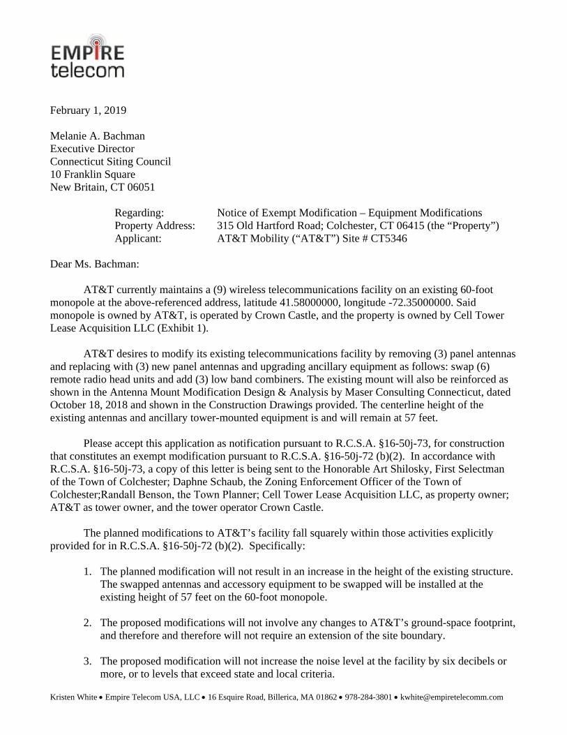
Kristen White Empire Telecom USA, LLC 16 Esquire Road, Billerica, MA 01862 978-284-3801 [email protected] February 1, 2019 Melanie A. Bachman Executive Director Connecticut Siting Council 10 Franklin Square New Britain, CT 06051 Regarding: Notice of Exempt Modification – Equipment Modifications Property Address: 315 Old Hartford Road; Colchester, CT 06415 (the “Property”) Applicant: AT&T Mobility (“AT&T”) Site # CT5346 Dear Ms. Bachman: AT&T currently maintains a (9) wireless telecommunications facility on an existing 60-foot monopole at the above-referenced address, latitude 41.58000000, longitude -72.35000000. Said monopole is owned by AT&T, is operated by Crown Castle, and the property is owned by Cell Tower Lease Acquisition LLC (Exhibit 1). AT&T desires to modify its existing telecommunications facility by removing (3) panel antennas and replacing with (3) new panel antennas and upgrading ancillary equipment as follows: swap (6) remote radio head units and add (3) low band combiners. The existing mount will also be reinforced as shown in the Antenna Mount Modification Design & Analysis by Maser Consulting Connecticut, dated October 18, 2018 and shown in the Construction Drawings provided. The centerline height of the existing antennas and ancillary tower-mounted equipment is and will remain at 57 feet. Please accept this application as notification pursuant to R.C.S.A. §16-50j-73, for construction that constitutes an exempt modification pursuant to R.C.S.A. §16-50j-72 (b)(2). In accordance with R.C.S.A. §16-50j-73, a copy of this letter is being sent to the Honorable Art Shilosky, First Selectman of the Town of Colchester; Daphne Schaub, the Zoning Enforcement Officer of the Town of Colchester;Randall Benson, the Town Planner; Cell Tower Lease Acquisition LLC, as property owner; AT&T as tower owner, and the tower operator Crown Castle. The planned modifications to AT&T’s facility fall squarely within those activities explicitly provided for in R.C.S.A. §16-50j-72 (b)(2). Specifically: 1. The planned modification will not result in an increase in the height of the existing structure. The swapped antennas and accessory equipment to be swapped will be installed at the existing height of 57 feet on the 60-foot monopole. 2. The proposed modifications will not involve any changes to AT&T’s ground-space footprint, and therefore and therefore will not require an extension of the site boundary. 3. The proposed modification will not increase the noise level at the facility by six decibels or more, or to levels that exceed state and local criteria.
-
Upload
khangminh22 -
Category
Documents
-
view
1 -
download
0
Transcript of em-at_t-028-190215_filing_oldhartfordrd.pdf - CT.gov
Kristen White Empire Telecom USA, LLC 16 Esquire Road, Billerica, MA 01862 978-284-3801 [email protected]
February 1, 2019
Melanie A. Bachman Executive Director Connecticut Siting Council 10 Franklin Square New Britain, CT 06051
Regarding: Notice of Exempt Modification – Equipment Modifications Property Address: 315 Old Hartford Road; Colchester, CT 06415 (the “Property”) Applicant: AT&T Mobility (“AT&T”) Site # CT5346
Dear Ms. Bachman:
AT&T currently maintains a (9) wireless telecommunications facility on an existing 60-foot monopole at the above-referenced address, latitude 41.58000000, longitude -72.35000000. Said monopole is owned by AT&T, is operated by Crown Castle, and the property is owned by Cell Tower Lease Acquisition LLC (Exhibit 1).
AT&T desires to modify its existing telecommunications facility by removing (3) panel antennas and replacing with (3) new panel antennas and upgrading ancillary equipment as follows: swap (6) remote radio head units and add (3) low band combiners. The existing mount will also be reinforced as shown in the Antenna Mount Modification Design & Analysis by Maser Consulting Connecticut, dated October 18, 2018 and shown in the Construction Drawings provided. The centerline height of the existing antennas and ancillary tower-mounted equipment is and will remain at 57 feet.
Please accept this application as notification pursuant to R.C.S.A. §16-50j-73, for construction that constitutes an exempt modification pursuant to R.C.S.A. §16-50j-72 (b)(2). In accordance with R.C.S.A. §16-50j-73, a copy of this letter is being sent to the Honorable Art Shilosky, First Selectman of the Town of Colchester; Daphne Schaub, the Zoning Enforcement Officer of the Town of Colchester;Randall Benson, the Town Planner; Cell Tower Lease Acquisition LLC, as property owner; AT&T as tower owner, and the tower operator Crown Castle.
The planned modifications to AT&T’s facility fall squarely within those activities explicitly provided for in R.C.S.A. §16-50j-72 (b)(2). Specifically:
1. The planned modification will not result in an increase in the height of the existing structure.The swapped antennas and accessory equipment to be swapped will be installed at theexisting height of 57 feet on the 60-foot monopole.
2. The proposed modifications will not involve any changes to AT&T’s ground-space footprint,and therefore and therefore will not require an extension of the site boundary.
3. The proposed modification will not increase the noise level at the facility by six decibels ormore, or to levels that exceed state and local criteria.

Kristen White Empire Telecom USA, LLC 16 Esquire Road, Billerica, MA 01862 978-284-3801 [email protected]
4. The operation of the modified facility will not increase radio frequency (RF) emissions at thefacility to a level at or above Federal Communications Commission (FCC) safety standard.An RF emissions calculation (Exhibit 4) for AT&T’s modified facility is herein provided.
5. The proposed modifications will not cause a change or alteration in the physical orenvironmental characteristics of the site.
6. The existing structure and its foundation can support AT&T’s proposed modifications. Pleasesee enclosed structural analysis completed by Jacobs Engineering Group dated January 3,2019 (Exhibit 3), which takes into account the Antenna Mount Modification Design &Analysis by Maser Consulting Connecticut, dated October 18, 2018 (Exhibit 5)
7. Proof of mailing to the municipal officials and property owners specified below is alsoprovided.
For the foregoing reasons, AT&T respectfully requests that the proposed installation be allowed within the exempt modifications under R.C.S.A. §16-50j-72 (b)(2).
Sincerely,
Kristen WhiteKristen White Site Acquisition Specialist Empire Telecom USA, LLC [email protected]
Enclosures: Exhibit 1 – Field Card and GIS Map Exhibit 2 – Construction Drawings Exhibit 3 – Structural Analysis Exhibit 4 – RF Emissions Analysis Report Evaluation Exhibit 5 - Antenna Mount Modification Design & Analysis
cc:
Hon. Art Shilosky First Selectman’s Office 127 Norwich Ave. Colchester, CT 06415
Daphne Schaub Colchester Zoning Department 127 Norwich Ave. Colchester, CT 06415
AT&T Mobility ATT Tax Manager 909 Chestnut St. St. Louis, MO 63101
Crown Castle 3 Corporate Park Drive Suite 101 Clifton Park, NY 12065 Attn: Paul Pedicone
Cell Tower Lease Acquisition LLC C/O CT Corporation System, Agent 155 Federal Street, Suite 700 Boston, MA, 02110
Randall BensonColchester, CT Town Planner127 Norwich Ave. Colchester, CT 06415

EXHIBIT 1


��������� ����� �
���������������� ���������� ���� ����� ������� !"�#�!$%��&��� ���
'()*�(+�,(-./01203�4���� �����!���� ���56����74!58�$ ������������������
9������� ��5� ����������%��������:;<�=>?,@;>:AB�C�DE'>,A�EF�@>;G>@>'H�I����� ��������� �������������������6��!������������� ����������������J�6 �����9�������� ��������KL�����J������ ���K6� 6������I���I�M����N��������� ������ �������� ����� ����������� ��������K���6������������� ����� �����������
kwhite
Oval

EXHIBIT 2

16 ESQUIRE ROADBILLERICA, MA 01862
\luj\Pro
ject
s\2018\1
8963000A
\18963026A
\Const
ruct
ion\R
ev
0\F
A#
10070973_A
E201_180827_C
T5346_R
EV
A_C
D.d
wg\
T-1
B
y: A
CO
IA
REV DATE DESCRIPTION
SHEET TITLE :
DRAWNBY
CHECKEDBY
PROTECT YOURSELF
Know what'sbelow.before you dig.Call
R
ALL STATES REQUIRE NOTIFICATION OF
EXCAVATORS, DESIGNERS, OR ANY PERSONPREPARING TO DISTURB THE EARTH'S
SURFACE ANYWHERE IN ANY STATE
FOR STATE SPECIFIC DIRECT PHONE NUMBERS VISIT:WWW.CALL811.COM
IT IS A VIOLATION OF LAW FOR ANY PERSON, UNLESSTHEY ARE ACTING UNDER THE DIRECTION OF THE
RESPONSIBLE LICENSED PROFFESIONAL ENGINEER, TO
ALTER THIS DOCUMENT.
SITE NAME:
SCALE : JOB NUMBER :
SHEET NUMBER :
COLCHESTER NORTHCENTRAL
FA# 10070973SITE# CT5346
315 OLD HARTFORD ROAD
COLCHESTER, CT 06415NEW LONDON COUNTY
AS SHOWN 18963026A
1 09/06/18 ISSUED FOR REVIEW MSG RA
2 09/18/18 REVISED PER COMMENTS AJC RA
0 10/22/18 STRUCTURAL MODS AJC RA
. . . . .
. . . . .
. . . . .
. . . . .
. . . . .
_____________________________
PETROS E. TSOUKALASCONNECTICUT PROFESSIONAL
ENGINEER - LICENSE NUMBER: 32577
RED BANK OFFICE331 Newman Springs Road
Suite 203Red Bank NJ 07701-5699
Phone: .732.383.1950
Fax: .732.383.1984
email: [email protected]
Customer Loyalty through Client Satisfactionw w w . m a s e r c o n s u l t i n g . c o m
Engineers Planners SurveyorsLandscape Architects Environmental Scientists
Copyright © 2018. Maser Consulting Connecticut All Rights Reserved. This drawing and all theinformation contained herein is authorized for use only by the party for whom the services were
contracted or to whom it is certified. This drawing may not be copied, reused, disclosed,
distributed or relied upon for any other purpose without the express written consent of MaserConsulting Connecticut.
TITLE SHEET
T-1
· INSTALL (5) NEW RRU'S AT GRADE· INSTALL (6) NEW RRU'S, (2) PER SECTOR
· REMOVE (3) EXISTING RRU'S, (1) PER SECTOR· INSTALL (3) NEW PANEL ANTENNAS, (1) PER SECTOR· INSTALL NEW HANDRAIL KIT, (1) PER SECTOR· REMOVE (3) EXISTING PANEL ANTENNAS, (1) PER SECTOR
· REMOVE (12) DIPLEXERS· INSTALL (3) LOW BAND COMBINERS, (1) PER SECTOR· INSTALL (3) LOW BAND COMBINERS AT GRADE
· INSTALL (2) NEW DC-6 SURGE SUPPRESSION DOME· INSTALL (1) NEW 18-PAIR FIBER TRUNK· INSTALL (4) NEW 6/C DC CABLES
· DECOMMISSION GSM 850/1900· DECOMMISSION UMTS RRU 850/1900· SWAP DUS's WITH (1) 5216 AND INSTALL 2ND 5216· INSTALL 2ND XMU AND IDLe
· ADD (1) RBS 6630 TO LTE CABINET· INSTALL (2) DC12 BOX AT GRADE
PROPOSED PROJECT SCOPE BASED ON RFDS ID# 2325793, VERSION
3.00, LAST UPDATED 08/13/2018.
PROJECT LOCATION
COPYRIGHT © 2018, MASERCONSULTING CONNECTICUT ALL
RIGHTS RESERVEDTHIS DRAWING AND ALL THE INFORMATION CONTAINED HEREIN ISAUTHORIZED FOR USE ONLY BY THE PARTY FOR WHOM THE WORKWAS CONTRACTED OR TO WHOM IT IS CERTIFIED. THIS DRAWING
MAY NOT BE COPIED, REUSED, DISCLOSED, DISTRIBUTED OR RELIEDUPON FOR ANY OTHER PURPOSE WITHOUT THE EXPRESS WRITTEN
CONSENT OF MASER CONSULTING CONNECTICUT.
VICINITY MAPN
S
EW
NO
RT
H
PROJECT NOTES
CODE COMPLIANCE
SITE NAME: COLCHESTER NORTH CENTRALFA NUMBER: 10070973SITE NUMBER: CT5346
3C -MRCTB0323094C - MRCTB0322795C - MRCTB0322306C - MRCTB032273
RETROFIT - MRCTB032284315 OLD HARTFORD ROAD
COLCHESTER, CT 06415NEW LONDON COUNTY
SHEET DESCRIPTION
SHEET INDEX
GENERAL NOTESGN-1
C-1
C-2
GROUNDING DETAILS AND NOTES
A-1
EQUIPMENT LAYOUT AND ELEVATION VIEW
CONSTRUCTION DETAILS
C-3 ANTENNA LAYOUTS AND ANTENNA SCHEDULE
PROJECT DESCRIPTION/SCOPE OF WORK
G-1
RF PLUMBING DIAGRAM
COMPOUND PLAN
1. SITE INFORMATION OBTAINED FROM THE FOLLOWING:
A. PLAN ENTITLED "COLCHESTER" PREPARED BY COM EXCONSULTANTS OF MOUTAIN LAKES, NJ LAST REVISED
02/08/2016.
B. LIMITED FIELD OBSERVATION BY MASER CONSULTINGON 06/14/2018.
2. THE CONTRACTOR SHALL COMPLY WITH ALL APPLICABLE
CODES, ORDINANCES, LAWS AND REGULATIONS OF ALLMUNICIPALITIES, UTILITY COMPANIES OR OTHERPUBLIC/GOVERNING AUTHORITIES.
3. THE CONTRACTOR SHALL BE RESPONSIBLE FOR OBTAININGALL PERMITS AND INSPECTIONS THAT MAY BE REQUIRED BYANY FEDERAL, STATE, COUNTY OR MUNICIPAL AUTHORITIES.
4. THE CONTRACTOR SHALL NOTIFY THE CONSTRUCTIONMANAGER, IN WRITING, OF ANY CONFLICTS, ERRORS OROMISSIONS PRIOR TO THE SUBMISSION OF BIDS ORPERFORMANCE OF WORK.
5. THE CONTRACTOR SHALL BE RESPONSIBLE FOR PROTECTINGALL EXISTING SITE IMPROVEMENTS PRIOR TO COMMENCINGCONSTRUCTION. THE CONTRACTOR SHALL REPAIR ANY
DAMAGE AS A RESULT OF CONSTRUCTION OF THIS FACILITYAT THE CONTRACTOR'S EXPENSE TO THE SATISFACTION OFTHE OWNER.
6. THE SCOPE OF WORK FOR THIS PROJECT SHALL INCLUDEPROVIDING ALL MATERIALS, EQUIPMENT AND LABORREQUIRED TO COMPLETE THIS PROJECT. ALL EQUIPMENTSHALL BE INSTALLED IN ACCORDANCE WITH
MANUFACTURER'S RECOMMENDATIONS.
7. THE CONTRACTOR SHALL VISIT THE PROJECT SITE PRIOR TOSUBMITTING THE BID TO VERIFY THAT THE PROJECT CAN BE
CONSTRUCTED IN ACCORDANCE WITH THE CONTRACTDOCUMENTS AND CONSTRUCTION DRAWINGS.
8. THE CONTRACTOR SHALL VERIFY ALL EXISTING DIMENSIONS
AND CONDITIONS PRIOR TO COMMENCING ANY WORK. ALLDIMENSIONS OF EXISTING CONSTRUCTION SHOWN ONTHESE DRAWINGS MUST BE VERIFIED. THE CONTRACTORSHALL NOTIFY THE CONSTRUCTION MANAGER OF ANY
DISCREPANCIES PRIOR TO ORDERING MATERIAL ORPROCEEDING WITH CONSTRUCTION.
9. SINCE THE CELL SITE MAY BE ACTIVE, ALL SAFETY
PRECAUTIONS MUST BE TAKEN WHEN WORKING AROUNDHIGH LEVELS OF ELECTROMAGNETIC RADIATION. EQUIPMENTSHOULD BE SHUTDOWN PRIOR TO PERFORMING ANY WORK
THAT COULD EXPOSE THE WORKERS TO DANGER. PERSONALRF EXPOSURE MONITORS ARE REQUIRED TO BE WORN TOALERT OF ANY POTENTIALLY DANGEROUS EXPOSURE LEVELS.
10. THE PROPOSED FACILITY WILL CAUSE AN INSIGNIFICANT OR
"DE-MINIMUS" INCREASE IN STORM WATER RUNOFF,THEREFORE, NO DRAINAGE STRUCTURES ARE PROPOSED.
11. NO NOISE, SMOKE, DUST OR ODOR WILL RESULT FROM THIS
FACILITY AS TO CAUSE A NUISANCE.
12. THE FACILITY IS UNMANNED AND NOT FOR HUMANHABITATION (NO HANDICAP ACCESS IS REQUIRED).
13. THE FACILITY DOES NOT REQUIRE POTABLE WATER ORSANITARY SERVICE.
14. CONTRACTOR SHALL VERIFY ANTENNA ELEVATION ANDAZIMUTHS WITH RF ENGINEERING PRIOR TO INSTALLATION.
15. THE TOWER, MOUNTS AND ANTENNAS SHALL BE DESIGNEDTO MEET EIA/TIA-222-G AS PER IBC REQUIREMENTS.
16. ALL STRUCTURAL ELEMENTS SHALL BE HOT DIPPED
GALVANIZED STEEL.
17. CONTRACTOR MUST FIELD LOCATE ALL EXISTINGUNDERGROUND UTILITIES PRIOR TO ANY EXCAVATION.
18. CONSTRUCTION SHALL NOT COMMENCE UNTIL COMPLETION
OF A PASSING STRUCTURAL ANALYSIS CERTIFIED BY ALICENSED PROFESSIONAL ENGINEER. THE STRUCTURALANALYSIS IS TO BE PERFORMED BY OTHERS.
SITE INFORMATION
LATITUDE: 41.5806919° N
LONGITUDE: 72.3503989° WJURISDICTION: NEW LONDON COUNTY
APPLICANT/LESSEE
COMPANY: NEW CINGULAR WIRELESS PCS, LLCADDRESS: 550 COCHITUATE ROAD
CITY, STATE, ZIP: FRAMINGHAM, MA 01701
TOWER OWNER
COMPANY: AT&T MOBILITYADDRESS: 550 COCHITUATE ROAD, SUITE 550 13 & 14
CITY, STATE, ZIP: FRAMINGHAM, MA 01701
CLIENT REPRESENTATIVE
COMPANY: EMPIRE TELECOMADDRESS: 16 ESQUIRE ROADCITY, STATE, ZIP: BILLERICA, MA 01862
CONTACT: DAVID COOPER
E-MAIL: [email protected]
SITE ACQUISITION
COMPANY: EMPIRE TELECOM
ADDRESS: 16 ESQUIRE ROADCITY, STATE, ZIP: BILLERICA, MA 01862CONTACT: DAVID COOPER
E-MAIL: [email protected]
ENGINEER
COMPANY: MASER CONSULTING CONNECTICUTADDRESS: 331 NEWMAN SPRINGS ROAD, SUITE 203CITY, STATE, ZIP: RED BANK, NJ 07701-5699
CONTACT: ROBERT ANDREWSPHONE: (856) 797-0412
E-MAIL: [email protected]
PROJECT INFORMATION
ALL WORK AND MATERIALS SHALL BE PERFORMED AND INSTALLED IN ACCORDANCE WITH THE CURRENT EDITIONS OFTHE FOLLOWING CODES AS ADOPTED BY THE LOCAL GOVERNING AUTHORITIES. NOTHING IN THESE PLANS IS TO BECONSTRUED TO PERMIT WORK NOT CONFORMING TO THE LATEST EDITIONS OF THE FOLLOWING CODES.
1. 2016 CONNECTICUT STATE BUILDING CODE,INCORPORATING THE 2012 IBC
8. INSTITUTE FOR ELECTRICAL AND ELECTRONICSENGINEERS 81 IEEE C2 LATEST EDITION
2. 2014 NATIONAL ELECTRICAL CODE - NFPA 70 9 TELCORDIA GR-1275
3. 2012 NFPA 101 10. ANSI T1.311
4. AMERICAN INSTITUTE OF STEEL CONSTRUCTION360-10
11. PROPOSED USE: UNMANNED TELECOM FACILITY
5. AMERICAN CONCRETE INSTITUTE 12. HANDICAP REQUIREMENTS: FACILITY IS UNMANNEDAND NOT FOR HUMAN HABITATION. HANDICAPPED
ACCESS NOT REQUIRED.
6. TIA-222-G 13. CONSTRUCTION TYPE: IIB
7. TIA 607 FOR GROUNDING 14. USE GROUP: U
TITLE SHEETT-1
A-2 CONSTRUCTION DETAILS
A-3 CONSTRUCTION DETAILS
A-4 CONSTRUCTION DETAILS
A-5
STRUCTURAL DETAILSS-1
16 ESQUIRE ROADBILLERICA, MA 01862
\luj\Pro
ject
s\2018\1
8963000A
\18963026A
\Const
ruct
ion\R
ev
0\F
A#
10070973_A
E201_180827_C
T5346_R
EV
A_C
D.d
wg\
GN
-1
By:
AC
OIA
REV DATE DESCRIPTION
SHEET TITLE :
DRAWNBY
CHECKEDBY
PROTECT YOURSELF
Know what'sbelow.before you dig.Call
R
ALL STATES REQUIRE NOTIFICATION OF
EXCAVATORS, DESIGNERS, OR ANY PERSONPREPARING TO DISTURB THE EARTH'S
SURFACE ANYWHERE IN ANY STATE
FOR STATE SPECIFIC DIRECT PHONE NUMBERS VISIT:WWW.CALL811.COM
IT IS A VIOLATION OF LAW FOR ANY PERSON, UNLESSTHEY ARE ACTING UNDER THE DIRECTION OF THE
RESPONSIBLE LICENSED PROFFESIONAL ENGINEER, TO
ALTER THIS DOCUMENT.
SITE NAME:
SCALE : JOB NUMBER :
SHEET NUMBER :
COLCHESTER NORTHCENTRAL
FA# 10070973SITE# CT5346
315 OLD HARTFORD ROAD
COLCHESTER, CT 06415NEW LONDON COUNTY
AS SHOWN 18963026A
1 09/06/18 ISSUED FOR REVIEW MSG RA
2 09/18/18 REVISED PER COMMENTS AJC RA
0 10/22/18 STRUCTURAL MODS AJC RA
. . . . .
. . . . .
. . . . .
. . . . .
. . . . .
_____________________________
PETROS E. TSOUKALASCONNECTICUT PROFESSIONAL
ENGINEER - LICENSE NUMBER: 32577
RED BANK OFFICE331 Newman Springs Road
Suite 203Red Bank NJ 07701-5699
Phone: .732.383.1950
Fax: .732.383.1984
email: [email protected]
Customer Loyalty through Client Satisfactionw w w . m a s e r c o n s u l t i n g . c o m
Engineers Planners SurveyorsLandscape Architects Environmental Scientists
Copyright © 2018. Maser Consulting Connecticut All Rights Reserved. This drawing and all theinformation contained herein is authorized for use only by the party for whom the services were
contracted or to whom it is certified. This drawing may not be copied, reused, disclosed,
distributed or relied upon for any other purpose without the express written consent of MaserConsulting Connecticut.
GN-1
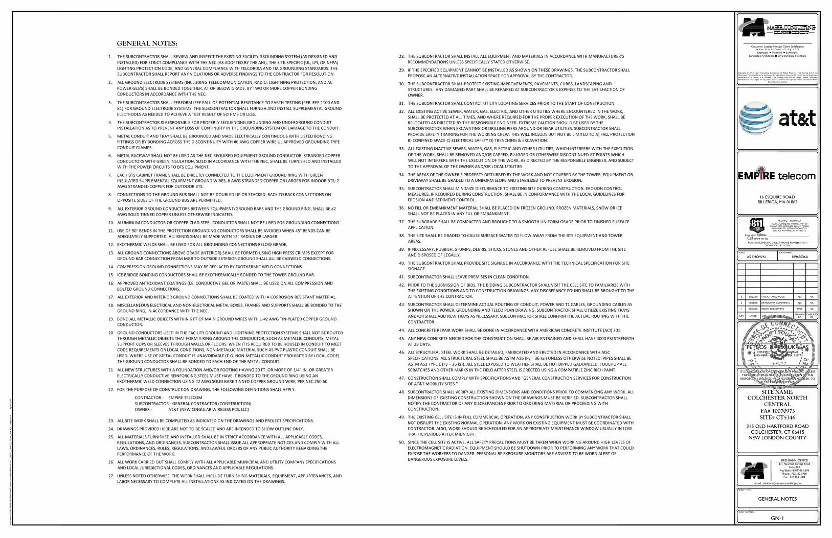
GENERAL NOTES
1. THE SUBCONTRACTOR SHALL REVIEW AND INSPECT THE EXISTING FACILITY GROUNDING SYSTEM (AS DESIGNED ANDINSTALLED) FOR STRICT COMPLIANCE WITH THE NEC (AS ADOPTED BY THE AHJ), THE SITE-SPECIFIC (UL, LPI, OR NFPA)LIGHTING PROTECTION CODE, AND GENERAL COMPLIANCE WITH TELCORDIA AND TIA GROUNDING STANDARDS. THESUBCONTRACTOR SHALL REPORT ANY VIOLATIONS OR ADVERSE FINDINGS TO THE CONTRACTOR FOR RESOLUTION.
2. ALL GROUND ELECTRODE SYSTEMS (INCLUDING TELECOMMUNICATION, RADIO, LIGHTNING PROTECTION, AND ACPOWER GES'S) SHALL BE BONDED TOGETHER, AT OR BELOW GRADE, BY TWO OR MORE COPPER BONDINGCONDUCTORS IN ACCORDANCE WITH THE NEC.
3. THE SUBCONTRACTOR SHALL PERFORM IEEE FALL-OF-POTENTIAL RESISTANCE TO EARTH TESTING (PER IEEE 1100 AND81) FOR GROUND ELECTRODE SYSTEMS. THE SUBCONTRACTOR SHALL FURNISH AND INSTALL SUPPLEMENTAL GROUNDELECTRODES AS NEEDED TO ACHIEVE A TEST RESULT OF 5O HMS OR LESS.
4. THE SUBCONTRACTOR IS RESPONSIBLE FOR PROPERLY SEQUENCING GROUNDING AND UNDERGROUND CONDUITINSTALLATION AS TO PREVENT ANY LOSS OF CONTINUITY IN THE GROUNDING SYSTEM OR DAMAGE TO THE CONDUIT.
5. METAL CONDUIT AND TRAY SHALL BE GROUNDED AND MADE ELECTRICALLY CONTINUOUS WITH LISTED BONDINGFITTINGS OR BY BONDING ACROSS THE DISCONTINUITY WITH #6 AWG COPPER WIRE UL APPROVED GROUNDING TYPECONDUIT CLAMPS.
6. METAL RACEWAY SHALL NOT BE USED AS THE NEC REQUIRED EQUIPMENT GROUND CONDUCTOR. STRANDED COPPERCONDUCTORS WITH GREEN INSULATION, SIZED IN ACCORDANCE WITH THE NEC, SHALL BE FURNISHED AND INSTALLEDWITH THE POWER CIRCUITS TO BTS EQUIPMENT.
7. EACH BTS CABINET FRAME SHALL BE DIRECTLY CONNECTED TO THE EQUIPMENT GROUND RING WITH GREENINSULATED SUPPLEMENTAL EQUIPMENT GROUND WIRES, 6 AWG STRANDED COPPER OR LARGER FOR INDOOR BTS; 2AWG STRANDED COPPER FOR OUTDOOR BTS.
8. CONNECTIONS TO THE GROUND BUS SHALL NOT BE DOUBLED UP OR STACKED. BACK TO BACK CONNECTIONS ONOPPOSITE SIDES OF THE GROUND BUS ARE PERMITTED.
9. ALL EXTERIOR GROUND CONDUCTORS BETWEEN EQUIPMENT/GROUND BARS AND THE GROUND RING, SHALL BE #2AWG SOLID TINNED COPPER UNLESS OTHERWISE INDICATED.
10. ALUMINUM CONDUCTOR OR COPPER CLAD STEEL CONDUCTOR SHALL NOT BE USED FOR GROUNDING CONNECTIONS.
11. USE OF 90° BENDS IN THE PROTECTION GROUNDING CONDUCTORS SHALL BE AVOIDED WHEN 45° BENDS CAN BEADEQUATELY SUPPORTED. ALL BENDS SHALL BE MADE WITH 12" RADIUS OR LARGER.
12. EXOTHERMIC WELDS SHALL BE USED FOR ALL GROUNDING CONNECTIONS BELOW GRADE.
13. ALL GROUND CONNECTIONS ABOVE GRADE (INTERIOR) SHALL BE FORMED USING HIGH PRESS CRIMPS EXCEPT FORGROUND BAR CONNECTION FROM MGB TO OUTSIDE EXTERIOR GROUND SHALL ALL BE CADWELD CONNECTIONS.
14. COMPRESSION GROUND CONNECTIONS MAY BE REPLACED BY EXOTHERMIC WELD CONNECTIONS.
15. ICE BRIDGE BONDING CONDUCTORS SHALL BE EXOTHERMICALLY BONDED TO THE TOWER GROUND BAR.
16. APPROVED ANTIOXIDANT COATINGS (I.E. CONDUCTIVE GEL OR PASTE) SHALL BE USED ON ALL COMPRESSION ANDBOLTED GROUND CONNECTIONS.
17. ALL EXTERIOR AND INTERIOR GROUND CONNECTIONS SHALL BE COATED WITH A CORROSION RESISTANT MATERIAL.
18. MISCELLANEOUS ELECTRICAL AND NON-ELECTRICAL METAL BOXES, FRAMES AND SUPPORTS SHALL BE BONDED TO THEGROUND RING, IN ACCORDANCE WITH THE NEC.
19. BOND ALL METALLIC OBJECTS WITHIN 6 FT OF MAIN GROUND WIRES WITH 1-#2 AWG TIN-PLATED COPPER GROUNDCONDUCTOR.
20. GROUND CONDUCTORS USED IN THE FACILITY GROUND AND LIGHTNING PROTECTION SYSTEMS SHALL NOT BE ROUTEDTHROUGH METALLIC OBJECTS THAT FORM A RING AROUND THE CONDUCTOR, SUCH AS METALLIC CONDUITS, METALSUPPORT CLIPS OR SLEEVES THROUGH WALLS OR FLOORS. WHEN IT IS REQUIRED TO BE HOUSED IN CONDUIT TO MEETCODE REQUIREMENTS OR LOCAL CONDITIONS, NON-METALLIC MATERIAL SUCH AS PVC PLASTIC CONDUIT SHALL BEUSED. WHERE USE OF METAL CONDUIT IS UNAVOIDABLE (E.G. NON-METALLIC CONDUIT PROHIBITED BY LOCAL CODE)THE GROUND CONDUCTOR SHALL BE BONDED TO EACH END OF THE METAL CONDUIT.
21. ALL NEW STRUCTURES WITH A FOUNDATION AND/OR FOOTING HAVING 20 FT. OR MORE OF 1/4" IN. OR GREATERELECTRICALLY CONDUCTIVE REINFORCING STEEL MUST HAVE IT BONDED TO THE GROUND RING USING ANEXOTHERMIC WELD CONNECTION USING #2 AWG SOLID BARE TINNED COPPER GROUND WIRE, PER NEC 250.50.
22. FOR THE PURPOSE OF CONSTRUCTION DRAWING, THE FOLLOWING DEFINITIONS SHALL APPLY:
CONTRACTOR - EMPIRE TELECOMSUBCONTRACTOR - GENERAL CONTRACTOR (CONSTRUCTION)OWNER - AT&T (NEW CINGULAR WIRELESS PCS, LLC)
23. ALL SITE WORK SHALL BE COMPLETED AS INDICATED ON THE DRAWINGS AND PROJECT SPECIFICATIONS.
24. DRAWINGS PROVIDED HERE ARE NOT TO BE SCALED AND ARE INTENDED TO SHOW OUTLINE ONLY.
25. ALL MATERIALS FURNISHED AND INSTALLED SHALL BE IN STRICT ACCORDANCE WITH ALL APPLICABLE CODES,REGULATIONS, AND ORDINANCES. SUBCONTRACTOR SHALL ISSUE ALL APPROPRIATE NOTICES AND COMPLY WITH ALLLAWS, ORDINANCES, RULES, REGULATIONS, AND LAWFUL ORDERS OF ANY PUBLIC AUTHORITY REGARDING THEPERFORMANCE OF THE WORK.
26. ALL WORK CARRIED OUT SHALL COMPLY WITH ALL APPLICABLE MUNICIPAL AND UTILITY COMPANY SPECIFICATIONSAND LOCAL JURISDICTIONAL CODES, ORDINANCES AND APPLICABLE REGULATIONS.
27. UNLESS NOTED OTHERWISE, THE WORK SHALL INCLUDE FURNISHING MATERIALS, EQUIPMENT, APPURTENANCES, ANDLABOR NECESSARY TO COMPLETE ALL INSTALLATIONS AS INDICATED ON THE DRAWINGS.
28. THE SUBCONTRACTOR SHALL INSTALL ALL EQUIPMENT AND MATERIALS IN ACCORDANCE WITH MANUFACTURER'SRECOMMENDATIONS UNLESS SPECIFICALLY STATED OTHERWISE.
29. IF THE SPECIFIED EQUIPMENT CANNOT BE INSTALLED AS SHOWN ON THESE DRAWINGS, THE SUBCONTRACTOR SHALLPROPOSE AN ALTERNATIVE INSTALLATION SPACE FOR APPROVAL BY THE CONTRACTOR.
30. THE SUBCONTRACTOR SHALL PROTECT EXISTING IMPROVEMENTS, PAVEMENTS, CURBS, LANDSCAPING ANDSTRUCTURES. ANY DAMAGED PART SHALL BE REPAIRED AT SUBCONTRACTOR'S EXPENSE TO THE SATISFACTION OFOWNER.
31. THE SUBCONTRACTOR SHALL CONTACT UTILITY LOCATING SERVICES PRIOR TO THE START OF CONSTRUCTION.
32. ALL EXISTING ACTIVE SEWER, WATER, GAS, ELECTRIC, AND OTHER UTILITIES WHERE ENCOUNTERED IN THE WORK,SHALL BE PROTECTED AT ALL TIMES, AND WHERE REQUIRED FOR THE PROPER EXECUTION OF THE WORK, SHALL BERELOCATED AS DIRECTED BY THE RESPONSIBLE ENGINEER. EXTREME CAUTION SHOULD BE USED BY THESUBCONTRACTOR WHEN EXCAVATING OR DRILLING PIERS AROUND OR NEAR UTILITIES. SUBCONTRACTOR SHALLPROVIDE SAFETY TRAINING FOR THE WORKING CREW. THIS WILL INCLUDE BUT NOT BE LIMITED TO A) FALL PROTECTIONB) CONFINED SPACE C) ELECTRICAL SAFETY D) TRENCHING & EXCAVATION.
33. ALL EXISTING INACTIVE SEWER, WATER, GAS, ELECTRIC AND OTHER UTILITIES, WHICH INTERFERE WITH THE EXECUTIONOF THE WORK, SHALL BE REMOVED AND/OR CAPPED, PLUGGED OR OTHERWISE DISCONTINUED AT POINTS WHICHWILL NOT INTERFERE WITH THE EXECUTION OF THE WORK, AS DIRECTED BY THE RESPONSIBLE ENGINEER, AND SUBJECTTO THE APPROVAL OF THE OWNER AND/OR LOCAL UTILITIES.
34. THE AREAS OF THE OWNER'S PROPERTY DISTURBED BY THE WORK AND NOT COVERED BY THE TOWER, EQUIPMENT ORDRIVEWAY SHALL BE GRADED TO A UNIFORM SLOPE AND STABILIZED TO PREVENT EROSION.
35. SUBCONTRACTOR SHALL MINIMIZE DISTURBANCE TO EXISTING SITE DURING CONSTRUCTION. EROSION CONTROLMEASURES, IF REQUIRED DURING CONSTRUCTION, SHALL BE IN CONFORMANCE WITH THE LOCAL GUIDELINES FOREROSION AND SEDIMENT CONTROL.
36. NO FILL OR EMBANKMENT MATERIAL SHALL BE PLACED ON FROZEN GROUND. FROZEN MATERIALS, SNOW OR ICESHALL NOT BE PLACED IN ANY FILL OR EMBANKMENT.
37. THE SUBGRADE SHALL BE COMPACTED AND BROUGHT TO A SMOOTH UNIFORM GRADE PRIOR TO FINISHED SURFACEAPPLICATION.
38. THE SITE SHALL BE GRADED TO CAUSE SURFACE WATER TO FLOW AWAY FROM THE BTS EQUIPMENT AND TOWERAREAS.
39. IF NECESSARY, RUBBISH, STUMPS, DEBRIS, STICKS, STONES AND OTHER REFUSE SHALL BE REMOVED FROM THE SITEAND DISPOSED OF LEGALLY.
40. THE SUBCONTRACTOR SHALL PROVIDE SITE SIGNAGE IN ACCORDANCE WITH THE TECHNICAL SPECIFICATION FOR SITESIGNAGE.
41. SUBCONTRACTOR SHALL LEAVE PREMISES IN CLEAN CONDITION.
42. PRIOR TO THE SUBMISSION OF BIDS, THE BIDDING SUBCONTRACTOR SHALL VISIT THE CELL SITE TO FAMILIARIZE WITHTHE EXISTING CONDITIONS AND TO CONSTRUCTION DRAWINGS. ANY DISCREPANCY FOUND SHALL BE BROUGHT TO THEATTENTION OF THE CONTRACTOR.
43. SUBCONTRACTOR SHALL DETERMINE ACTUAL ROUTING OF CONDUIT, POWER AND T1 CABLES, GROUNDING CABLES ASSHOWN ON THE POWER, GROUNDING AND TELCO PLAN DRAWING. SUBCONTRACTOR SHALL UTILIZE EXISTING TRAYSAND/OR SHALL ADD NEW TRAYS AS NECESSARY. SUBCONTRACTOR SHALL CONFIRM THE ACTUAL ROUTING WITH THECONTRACTOR.
44. ALL CONCRETE REPAIR WORK SHALL BE DONE IN ACCORDANCE WITH AMERICAN CONCRETE INSTITUTE (ACI) 301.
45. ANY NEW CONCRETE NEEDED FOR THE CONSTRUCTION SHALL BE AIR-ENTRAINED AND SHALL HAVE 4000 PSI STRENGTHAT 28 DAYS.
46. ALL STRUCTURAL STEEL WORK SHALL BE DETAILED, FABRICATED AND ERECTED IN ACCORDANCE WITH AISCSPECIFICATIONS. ALL STRUCTURAL STEEL SHALL BE ASTM A36 (Fy = 36 ksi) UNLESS OTHERWISE NOTED. PIPES SHALL BEASTM A53 TYPE E (Fy = 36 ksi). ALL STEEL EXPOSED TO WEATHER SHALL BE HOT DIPPED GALVANIZED. TOUCHUP ALLSCRATCHES AND OTHER MARKS IN THE FIELD AFTER STEEL IS ERECTED USING A COMPATIBLE ZINC RICH PAINT.
47. CONSTRUCTION SHALL COMPLY WITH SPECIFICATIONS AND "GENERAL CONSTRUCTION SERVICES FOR CONSTRUCTIONOF AT&T MOBILITY SITES."
48. SUBCONTRACTOR SHALL VERIFY ALL EXISTING DIMENSIONS AND CONDITIONS PRIOR TO COMMENCING ANY WORK. ALLDIMENSIONS OF EXISTING CONSTRUCTION SHOWN ON THE DRAWINGS MUST BE VERIFIED. SUBCONTRACTOR SHALLNOTIFY THE CONTRACTOR OF ANY DISCREPANCIES PRIOR TO ORDERING MATERIAL OR PROCEEDING WITHCONSTRUCTION.
49. THE EXISTING CELL SITE IS IN FULL COMMERCIAL OPERATION, ANY CONSTRUCTION WORK BY SUBCONTRACTOR SHALLNOT DISRUPT THE EXISTING NORMAL OPERATION. ANY WORK ON EXISTING EQUIPMENT MUST BE COORDINATED WITHCONTRACTOR. ALSO, WORK SHOULD BE SCHEDULED FOR AN APPROPRIATE MAINTENANCE WINDOW USUALLY IN LOWTRAFFIC PERIODS AFTER MIDNIGHT.
50. SINCE THE CELL SITE IS ACTIVE, ALL SAFETY PRECAUTIONS MUST BE TAKEN WHEN WORKING AROUND HIGH LEVELS OFELECTROMAGNETIC RADIATION. EQUIPMENT SHOULD BE SHUTDOWN PRIOR TO PERFORMING ANY WORK THAT COULDEXPOSE THE WORKERS TO DANGER. PERSONAL RF EXPOSURE MONITORS ARE ADVISED TO BE WORN ALERT OFDANGEROUS EXPOSURE LEVELS.
GENERAL NOTES:

N
SE
W
16 ESQUIRE ROADBILLERICA, MA 01862
\luj\Pro
ject
s\2018\1
8963000A
\18963026A
\Const
ruct
ion\R
ev
0\F
A#
10070973_A
E201_180827_C
T5346_R
EV
A_C
D.d
wg\
C-1
B
y: A
CO
IA
REV DATE DESCRIPTION
SHEET TITLE :
DRAWNBY
CHECKEDBY
PROTECT YOURSELF
Know what'sbelow.before you dig.Call
R
ALL STATES REQUIRE NOTIFICATION OF
EXCAVATORS, DESIGNERS, OR ANY PERSONPREPARING TO DISTURB THE EARTH'S
SURFACE ANYWHERE IN ANY STATE
FOR STATE SPECIFIC DIRECT PHONE NUMBERS VISIT:WWW.CALL811.COM
IT IS A VIOLATION OF LAW FOR ANY PERSON, UNLESSTHEY ARE ACTING UNDER THE DIRECTION OF THE
RESPONSIBLE LICENSED PROFFESIONAL ENGINEER, TO
ALTER THIS DOCUMENT.
SITE NAME:
SCALE : JOB NUMBER :
SHEET NUMBER :
COLCHESTER NORTHCENTRAL
FA# 10070973SITE# CT5346
315 OLD HARTFORD ROAD
COLCHESTER, CT 06415NEW LONDON COUNTY
AS SHOWN 18963026A
1 09/06/18 ISSUED FOR REVIEW MSG RA
2 09/18/18 REVISED PER COMMENTS AJC RA
0 10/22/18 STRUCTURAL MODS AJC RA
. . . . .
. . . . .
. . . . .
. . . . .
. . . . .
_____________________________
PETROS E. TSOUKALASCONNECTICUT PROFESSIONAL
ENGINEER - LICENSE NUMBER: 32577
RED BANK OFFICE331 Newman Springs Road
Suite 203Red Bank NJ 07701-5699
Phone: .732.383.1950
Fax: .732.383.1984
email: [email protected]
Customer Loyalty through Client Satisfactionw w w . m a s e r c o n s u l t i n g . c o m
Engineers Planners SurveyorsLandscape Architects Environmental Scientists
Copyright © 2018. Maser Consulting Connecticut All Rights Reserved. This drawing and all theinformation contained herein is authorized for use only by the party for whom the services were
contracted or to whom it is certified. This drawing may not be copied, reused, disclosed,
distributed or relied upon for any other purpose without the express written consent of MaserConsulting Connecticut.
C-1
COMPOUND PLAN
COMPOUND PLAN
(SEE ELEVATION VIEW ON SHEET C-2)
(4) PROPOSED 6/C DCCABLES TO PROPOSED
DC12 BOX
(SEE EQUIPMENT LAYOUT ON SHEET C-2)
0 42 21.6 1.2 0.8 0.4 1
SCALE : 1" = 2' FOR 22"X34"(SCALE : 1" = 4' FOR 11"X17")
(1) 18-PAIRFIBER TRUNK
(5) PROPOSED RRU'S (2) DC-12BOXES AND (1) DC6 BOXMOUNTED TO EXISTING
CABLE BRIDGE POSTS WITHPROPOSED UNISTRUT
(2) PROPOSED 6/C DC
CABLES TO PROPOSEDDC6 BOX
(4) PROPOSED 6/C DCCABLES FROMPROPOSED DC12 BOX
TO PROPOSED DC6DOMES
(3) PROPOSED LOW
BAND COMBINERSMOUNTED UNDER
EXISTING CABLE BRIDGE

16 ESQUIRE ROADBILLERICA, MA 01862
\luj\Pro
ject
s\2018\1
8963000A
\18963026A
\Const
ruct
ion\R
ev
0\F
A#
10070973_A
E201_180827_C
T5346_R
EV
A_C
D.d
wg\
C-2
B
y: A
CO
IA
REV DATE DESCRIPTION
SHEET TITLE :
DRAWNBY
CHECKEDBY
PROTECT YOURSELF
Know what'sbelow.before you dig.Call
R
ALL STATES REQUIRE NOTIFICATION OF
EXCAVATORS, DESIGNERS, OR ANY PERSONPREPARING TO DISTURB THE EARTH'S
SURFACE ANYWHERE IN ANY STATE
FOR STATE SPECIFIC DIRECT PHONE NUMBERS VISIT:WWW.CALL811.COM
IT IS A VIOLATION OF LAW FOR ANY PERSON, UNLESSTHEY ARE ACTING UNDER THE DIRECTION OF THE
RESPONSIBLE LICENSED PROFFESIONAL ENGINEER, TO
ALTER THIS DOCUMENT.
SITE NAME:
SCALE : JOB NUMBER :
SHEET NUMBER :
COLCHESTER NORTHCENTRAL
FA# 10070973SITE# CT5346
315 OLD HARTFORD ROAD
COLCHESTER, CT 06415NEW LONDON COUNTY
AS SHOWN 18963026A
1 09/06/18 ISSUED FOR REVIEW MSG RA
2 09/18/18 REVISED PER COMMENTS AJC RA
0 10/22/18 STRUCTURAL MODS AJC RA
. . . . .
. . . . .
. . . . .
. . . . .
. . . . .
_____________________________
PETROS E. TSOUKALASCONNECTICUT PROFESSIONAL
ENGINEER - LICENSE NUMBER: 32577
RED BANK OFFICE331 Newman Springs Road
Suite 203Red Bank NJ 07701-5699
Phone: .732.383.1950
Fax: .732.383.1984
email: [email protected]
Customer Loyalty through Client Satisfactionw w w . m a s e r c o n s u l t i n g . c o m
Engineers Planners SurveyorsLandscape Architects Environmental Scientists
Copyright © 2018. Maser Consulting Connecticut All Rights Reserved. This drawing and all theinformation contained herein is authorized for use only by the party for whom the services were
contracted or to whom it is certified. This drawing may not be copied, reused, disclosed,
distributed or relied upon for any other purpose without the express written consent of MaserConsulting Connecticut.
C-2
EQUIPMENT LAYOUT AND
ELEVATION VIEW
N
S
E
W
EQUIPMENT LAYOUT ELEVATION VIEW04 4 8
SCALE : 1" = 4' FOR 22"X34"
3.2 2.4 1.6 0.8 2
(SCALE : 1" = 8' FOR 11"X17")
0 42 21.6 1.2 0.8 0.4 1
SCALE : 1" = 2' FOR 22"X34"(SCALE : 1" = 4' FOR 11"X17")
(4)PROPOSED 6/C DC CABLESTO PROPOSED DC12 BOX
(1) 18-PAIRFIBER TRUNK
(5) PROPOSED RRU'S AND (2) DC-12 BOXES
MOUNTED TO EXISTING CABLE BRIDGEPOSTS WITH PROPOSED UNISTRUT
(2) PROPOSED RRUS-4478 B14 MOUNTED TO EXISTING
CABLE BRIDGE POSTS WITH PROPOSED UNISTRUT(ALPHA AND GAMMA TO SHARE (1) B14)
SWAP DUS WITH 5216, INSTALL2ND 5216, INSTALL 2ND XMU + IDLe
AND ADD (1) RBS 6630
CENTERLINE OF EXISTING AND PROPOSED AT&T ANTENNAS
@ 57'-0"± AGL
PROPOSED DC-6 SURGE SUPPRESSION DOME
MOUNTED TO EXISTING SECTOR ARM(TYP. OF 2)
PROPOSED AT&T ANTENNA
MOUNTED ON AN EXISTING PIPE MAST(TYP. OF 3, 1 PER SECTOR)
(4) PROPOSED 6/C DC CABLES AND
(1) 18-PAIR FIBER TRUNK TO FOLLOWEXISTING CABLES ROUTED INSIDEMONOPOLE TO PROPOSED DC-6'S
PROPOSED RRUS-8843 B2/B66A MOUNTED ON A PROPOSEDERICSSON SXK1250461/1 B2B RRU MOUNTING BRACKET(TYP. OF 3, 1 PER SECTOR)
PROPOSED RRUS-32 MOUNTED ON A PROPOSEDERICSSON SXK1250461/1 B2B RRU MOUNTING BRACKET
(TYP. OF 3, 1 PER SECTOR)
PROPOSED LOW BAND COMBINERSMOUNTED ON EXISTING UNISTRUT
(TYP. OF 3)
(2) PROPOSED 6/C DCCABLES TO PROPOSED
DC6 BOX
(4) PROPOSED 6/C DCCABLES FROM PROPOSEDDC12 BOX TO PROPOSED
DC6 DOMES
PROPOSED HAND RAIL KIT
SITE PRO 1 P/N: HRK14-U
PROPOSED PLATFORM REINFORCEMENT KICKERS KIT
SITE PRO 1 P/N: PRK-1245L(SEE SHEET S-1 FOR DETAILS)
1'-4"
4'-0" 1'-4"
16 ESQUIRE ROADBILLERICA, MA 01862
\luj\Pro
ject
s\2018\1
8963000A
\18963026A
\Const
ruct
ion\R
ev
0\F
A#
10070973_A
E201_180827_C
T5346_R
EV
A_C
D.d
wg\
C-3
B
y: A
CO
IA
REV DATE DESCRIPTION
SHEET TITLE :
DRAWNBY
CHECKEDBY
PROTECT YOURSELF
Know what'sbelow.before you dig.Call
R
ALL STATES REQUIRE NOTIFICATION OF
EXCAVATORS, DESIGNERS, OR ANY PERSONPREPARING TO DISTURB THE EARTH'S
SURFACE ANYWHERE IN ANY STATE
FOR STATE SPECIFIC DIRECT PHONE NUMBERS VISIT:WWW.CALL811.COM
IT IS A VIOLATION OF LAW FOR ANY PERSON, UNLESSTHEY ARE ACTING UNDER THE DIRECTION OF THE
RESPONSIBLE LICENSED PROFFESIONAL ENGINEER, TO
ALTER THIS DOCUMENT.
SITE NAME:
SCALE : JOB NUMBER :
SHEET NUMBER :
COLCHESTER NORTHCENTRAL
FA# 10070973SITE# CT5346
315 OLD HARTFORD ROAD
COLCHESTER, CT 06415NEW LONDON COUNTY
AS SHOWN 18963026A
1 09/06/18 ISSUED FOR REVIEW MSG RA
2 09/18/18 REVISED PER COMMENTS AJC RA
0 10/22/18 STRUCTURAL MODS AJC RA
. . . . .
. . . . .
. . . . .
. . . . .
. . . . .
_____________________________
PETROS E. TSOUKALASCONNECTICUT PROFESSIONAL
ENGINEER - LICENSE NUMBER: 32577
RED BANK OFFICE331 Newman Springs Road
Suite 203Red Bank NJ 07701-5699
Phone: .732.383.1950
Fax: .732.383.1984
email: [email protected]
Customer Loyalty through Client Satisfactionw w w . m a s e r c o n s u l t i n g . c o m
Engineers Planners SurveyorsLandscape Architects Environmental Scientists
Copyright © 2018. Maser Consulting Connecticut All Rights Reserved. This drawing and all theinformation contained herein is authorized for use only by the party for whom the services were
contracted or to whom it is certified. This drawing may not be copied, reused, disclosed,
distributed or relied upon for any other purpose without the express written consent of MaserConsulting Connecticut.
C-3
ANTENNA LAYOUT AND
ANTENNA SCHEDULE
N
S
EW
N
S
EW
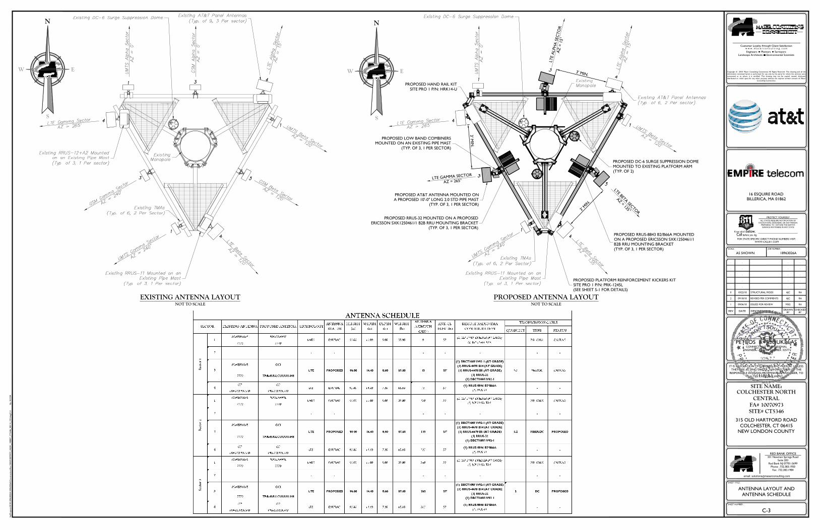
EXISTING ANTENNA LAYOUTNOT TO SCALE
PROPOSED ANTENNA LAYOUTNOT TO SCALE
PROPOSED DC-6 SURGE SUPPRESSION DOME
MOUNTED TO EXISTING PLATFORM ARM(TYP. OF 2)
PROPOSED AT&T ANTENNA MOUNTED ONA PROPOSED 10'-0" LONG 2.0 STD PIPE MAST
(TYP. OF 3, 1 PER SECTOR)
PROPOSED RRUS-8843 B2/B66A MOUNTEDON A PROPOSED ERICSSON SXK1250461/1B2B RRU MOUNTING BRACKET
(TYP. OF 3, 1 PER SECTOR)
PROPOSED RRUS-32 MOUNTED ON A PROPOSED
ERICSSON SXK1250461/1 B2B RRU MOUNTING BRACKET(TYP. OF 3, 1 PER SECTOR)
LT
E A
LPH
A S
EC
TO
RA
Z =
15°
LTE BETA SEC
TOR
AZ = 135°
LTE GAMMA SECTOR
AZ = 265°
PROPOSED LOW BAND COMBINERSMOUNTED ON AN EXISTING PIPE MAST
(TYP. OF 3, 1 PER SECTOR)
3' MIN.
3' M
IN.
3' M
IN.
PROPOSED HAND RAIL KIT
SITE PRO 1 P/N: HRK14-U
PROPOSED PLATFORM REINFORCEMENT KICKERS KITSITE PRO 1 P/N: PRK-1245L(SEE SHEET S-1 FOR DETAILS)

16 ESQUIRE ROADBILLERICA, MA 01862
\luj\Pro
ject
s\2018\1
8963000A
\18963026A
\Const
ruct
ion\R
ev
0\F
A#
10070973_A
E201_180827_C
T5346_R
EV
A_C
D.d
wg\
A-1
B
y: A
CO
IA
REV DATE DESCRIPTION
SHEET TITLE :
DRAWNBY
CHECKEDBY
PROTECT YOURSELF
Know what'sbelow.before you dig.Call
R
ALL STATES REQUIRE NOTIFICATION OF
EXCAVATORS, DESIGNERS, OR ANY PERSONPREPARING TO DISTURB THE EARTH'S
SURFACE ANYWHERE IN ANY STATE
FOR STATE SPECIFIC DIRECT PHONE NUMBERS VISIT:WWW.CALL811.COM
IT IS A VIOLATION OF LAW FOR ANY PERSON, UNLESSTHEY ARE ACTING UNDER THE DIRECTION OF THE
RESPONSIBLE LICENSED PROFFESIONAL ENGINEER, TO
ALTER THIS DOCUMENT.
SITE NAME:
SCALE : JOB NUMBER :
SHEET NUMBER :
COLCHESTER NORTHCENTRAL
FA# 10070973SITE# CT5346
315 OLD HARTFORD ROAD
COLCHESTER, CT 06415NEW LONDON COUNTY
AS SHOWN 18963026A
1 09/06/18 ISSUED FOR REVIEW MSG RA
2 09/18/18 REVISED PER COMMENTS AJC RA
0 10/22/18 STRUCTURAL MODS AJC RA
. . . . .
. . . . .
. . . . .
. . . . .
. . . . .
_____________________________
PETROS E. TSOUKALASCONNECTICUT PROFESSIONAL
ENGINEER - LICENSE NUMBER: 32577
RED BANK OFFICE331 Newman Springs Road
Suite 203Red Bank NJ 07701-5699
Phone: .732.383.1950
Fax: .732.383.1984
email: [email protected]
Customer Loyalty through Client Satisfactionw w w . m a s e r c o n s u l t i n g . c o m
Engineers Planners SurveyorsLandscape Architects Environmental Scientists
Copyright © 2018. Maser Consulting Connecticut All Rights Reserved. This drawing and all theinformation contained herein is authorized for use only by the party for whom the services were
contracted or to whom it is certified. This drawing may not be copied, reused, disclosed,
distributed or relied upon for any other purpose without the express written consent of MaserConsulting Connecticut.
A-1
DETAILS
13.2"
10.9"
14.9
"
RRUS-8843 B2/B66A DIMENSIONS
(H X W X D): 14.9" X 13.2" X 10.9"WEIGHT: 72 LBS
RRUS-4478 B14 DETAILNOT TO SCALE
8.3"
13.4"
18.1
"
DIMENSIONS (H X W X D): 18.1"H X 13.4"W X 8.3"D (INCLUDES SUNSHIELD)WEIGHT: 59.4 LBS
RRU-4478-B5 DETAILNOT TO SCALE
7.7"
16.5"
13.4
"
DIMENSIONS (H X W X D): 16.5"H X 13.4"W X 7.7"D (INCLUDES SUNSHIELD)WEIGHT: 59.9 LBS
RRUS-32 DETAIL
RRUS-32 DIMENSIONS (H X W X D): 27.2" X 12.1" X 7.0" (INCLUDES SUNSHIELD)WEIGHT: 53 LBS
NOT TO SCALE
7.0"
12.1"
27.2
"
8.6"
96"
14.4"
WEIGHT =75 LBS
CCI TPA-65R-LCUUUU-H8
ANTENNA DETAIL
RRUS-8843 B2/B66A DETAILNOT TO SCALE
POLE MOUNTED RRU
PIPE MOUNTADAPTER
MOUNTING PIPE
RRU MOUNTING DETAILNOT TO SCALE PROPOSED ERICSSON
SXK1250461/1 B2B RRU
MOUNTING BRACKET
PROPOSED PIPE
MOUNT
PROPOSED RRU1'-9"
PROPOSED RRU
I
N
D
E
X
S
C
A
L
E
O
N
L
Y
PROPOSED ANTENNA
PROPOSED MOUNTING
BRACKET (TYP.)
PROPOSED PIPE TO PIPEMOUNTING KIT (SITE PRO1 P/NDCP12K OR APPROVED EQUAL)
PROPOSED 10'-0" LONG2.0 STD PIPE MAST
6"
ANTENNA MOUNTING DETAILNOT TO SCALE
8" MIN.
PROPOSED RRU
8" MIN.
REQUIRED 8" MIN.SEPERATION BETWEENANTENNA AND EQUIPMENT
PROPOSED HAND RAIL KIT
SITE PRO 1 P/N: HRK14-U

16 ESQUIRE ROADBILLERICA, MA 01862
\luj\Pro
ject
s\2018\1
8963000A
\18963026A
\Const
ruct
ion\R
ev
0\F
A#
10070973_A
E201_180827_C
T5346_R
EV
A_C
D.d
wg\
A-2
B
y: A
CO
IA
REV DATE DESCRIPTION
SHEET TITLE :
DRAWNBY
CHECKEDBY
PROTECT YOURSELF
Know what'sbelow.before you dig.Call
R
ALL STATES REQUIRE NOTIFICATION OF
EXCAVATORS, DESIGNERS, OR ANY PERSONPREPARING TO DISTURB THE EARTH'S
SURFACE ANYWHERE IN ANY STATE
FOR STATE SPECIFIC DIRECT PHONE NUMBERS VISIT:WWW.CALL811.COM
IT IS A VIOLATION OF LAW FOR ANY PERSON, UNLESSTHEY ARE ACTING UNDER THE DIRECTION OF THE
RESPONSIBLE LICENSED PROFFESIONAL ENGINEER, TO
ALTER THIS DOCUMENT.
SITE NAME:
SCALE : JOB NUMBER :
SHEET NUMBER :
COLCHESTER NORTHCENTRAL
FA# 10070973SITE# CT5346
315 OLD HARTFORD ROAD
COLCHESTER, CT 06415NEW LONDON COUNTY
AS SHOWN 18963026A
1 09/06/18 ISSUED FOR REVIEW MSG RA
2 09/18/18 REVISED PER COMMENTS AJC RA
0 10/22/18 STRUCTURAL MODS AJC RA
. . . . .
. . . . .
. . . . .
. . . . .
. . . . .
_____________________________
PETROS E. TSOUKALASCONNECTICUT PROFESSIONAL
ENGINEER - LICENSE NUMBER: 32577
RED BANK OFFICE331 Newman Springs Road
Suite 203Red Bank NJ 07701-5699
Phone: .732.383.1950
Fax: .732.383.1984
email: [email protected]
Customer Loyalty through Client Satisfactionw w w . m a s e r c o n s u l t i n g . c o m
Engineers Planners SurveyorsLandscape Architects Environmental Scientists
Copyright © 2018. Maser Consulting Connecticut All Rights Reserved. This drawing and all theinformation contained herein is authorized for use only by the party for whom the services were
contracted or to whom it is certified. This drawing may not be copied, reused, disclosed,
distributed or relied upon for any other purpose without the express written consent of MaserConsulting Connecticut.
A-2
DETAILS
RRU/DC-12 MOUNTING DETAIL (AT GRADE)NOT TO SCALE
V.I.F.
GRADE
V.I.F
.
UNISTRUT END
CAP (TYP)
NOTES:
1. INSTALL VERTICAL UNISTRUT CHANNELS AS REQUIRED TO ALIGN FRAME WITHEQUIPMENT MOUNTING HOLES. FASTEN UNISTRUT CHANNELS TOGETHERWITH 3/8" UNISTRUT BOLTING HARDWARE AND SPRING NUTS.
2. MOUNT RRU'S TO UNISTRUT PER MANUFACTURER'S SPECIFICATIONS.
3. MOUNT FRAME AS CLOSE TO PLATFORM AS POSSIBLE.
4. NO PAINTING OF THE RRUS IS ALLOWED.
PROPOSED RRUS MOUNTEDPER MANUFACTURERSPECIFICATIONS (TYP.)
℄
℄
℄ ℄
1'-0"
(MIN
.)
2'-6"
(MIN
.)
V.I.F
.
℄
℄
UNISTRUT P1000 CHANNELOR EQUIVALENT (TYP.)
PROPOSED DC-12 MOUNTED
ON PROPOSED UNISTRUT(TYP. OF 2)
PROPOSED RRU'S MOUNTED ONPROPOSED UNISTRUT
(TYP. OF 5)
4"(MIN.)
4"(MIN.)
21.00"
20.00"
18.17"
℄ ℄
20.0
6"
14.0
0"
℄
℄
6.37"
20.0
6"
BOTTOM VIEW
℄℄WEIGHT = 56.3lbs
RIGHT SIDE VIEWFRONT VIEW
℄
℄
NOT TO SCALE
DC12-48-60-25E OVERVOLTAGE PROTECTION & POWERMANAGEMENT JUNCTION BOX

16 ESQUIRE ROADBILLERICA, MA 01862
\luj\Pro
ject
s\2018\1
8963000A
\18963026A
\Const
ruct
ion\R
ev
0\F
A#
10070973_A
E201_180827_C
T5346_R
EV
A_C
D.d
wg\
A-3
B
y: A
CO
IA
REV DATE DESCRIPTION
SHEET TITLE :
DRAWNBY
CHECKEDBY
PROTECT YOURSELF
Know what'sbelow.before you dig.Call
R
ALL STATES REQUIRE NOTIFICATION OF
EXCAVATORS, DESIGNERS, OR ANY PERSONPREPARING TO DISTURB THE EARTH'S
SURFACE ANYWHERE IN ANY STATE
FOR STATE SPECIFIC DIRECT PHONE NUMBERS VISIT:WWW.CALL811.COM
IT IS A VIOLATION OF LAW FOR ANY PERSON, UNLESSTHEY ARE ACTING UNDER THE DIRECTION OF THE
RESPONSIBLE LICENSED PROFFESIONAL ENGINEER, TO
ALTER THIS DOCUMENT.
SITE NAME:
SCALE : JOB NUMBER :
SHEET NUMBER :
COLCHESTER NORTHCENTRAL
FA# 10070973SITE# CT5346
315 OLD HARTFORD ROAD
COLCHESTER, CT 06415NEW LONDON COUNTY
AS SHOWN 18963026A
1 09/06/18 ISSUED FOR REVIEW MSG RA
2 09/18/18 REVISED PER COMMENTS AJC RA
0 10/22/18 STRUCTURAL MODS AJC RA
. . . . .
. . . . .
. . . . .
. . . . .
. . . . .
_____________________________
PETROS E. TSOUKALASCONNECTICUT PROFESSIONAL
ENGINEER - LICENSE NUMBER: 32577
RED BANK OFFICE331 Newman Springs Road
Suite 203Red Bank NJ 07701-5699
Phone: .732.383.1950
Fax: .732.383.1984
email: [email protected]
Customer Loyalty through Client Satisfactionw w w . m a s e r c o n s u l t i n g . c o m
Engineers Planners SurveyorsLandscape Architects Environmental Scientists
Copyright © 2018. Maser Consulting Connecticut All Rights Reserved. This drawing and all theinformation contained herein is authorized for use only by the party for whom the services were
contracted or to whom it is certified. This drawing may not be copied, reused, disclosed,
distributed or relied upon for any other purpose without the express written consent of MaserConsulting Connecticut.
A-3
DETAILS

16 ESQUIRE ROADBILLERICA, MA 01862
\luj\Pro
ject
s\2018\1
8963000A
\18963026A
\Const
ruct
ion\R
ev
0\F
A#
10070973_A
E201_180827_C
T5346_R
EV
A_C
D.d
wg\
A-4
B
y: A
CO
IA
REV DATE DESCRIPTION
SHEET TITLE :
DRAWNBY
CHECKEDBY
PROTECT YOURSELF
Know what'sbelow.before you dig.Call
R
ALL STATES REQUIRE NOTIFICATION OF
EXCAVATORS, DESIGNERS, OR ANY PERSONPREPARING TO DISTURB THE EARTH'S
SURFACE ANYWHERE IN ANY STATE
FOR STATE SPECIFIC DIRECT PHONE NUMBERS VISIT:WWW.CALL811.COM
IT IS A VIOLATION OF LAW FOR ANY PERSON, UNLESSTHEY ARE ACTING UNDER THE DIRECTION OF THE
RESPONSIBLE LICENSED PROFFESIONAL ENGINEER, TO
ALTER THIS DOCUMENT.
SITE NAME:
SCALE : JOB NUMBER :
SHEET NUMBER :
COLCHESTER NORTHCENTRAL
FA# 10070973SITE# CT5346
315 OLD HARTFORD ROAD
COLCHESTER, CT 06415NEW LONDON COUNTY
AS SHOWN 18963026A
1 09/06/18 ISSUED FOR REVIEW MSG RA
2 09/18/18 REVISED PER COMMENTS AJC RA
0 10/22/18 STRUCTURAL MODS AJC RA
. . . . .
. . . . .
. . . . .
. . . . .
. . . . .
_____________________________
PETROS E. TSOUKALASCONNECTICUT PROFESSIONAL
ENGINEER - LICENSE NUMBER: 32577
RED BANK OFFICE331 Newman Springs Road
Suite 203Red Bank NJ 07701-5699
Phone: .732.383.1950
Fax: .732.383.1984
email: [email protected]
Customer Loyalty through Client Satisfactionw w w . m a s e r c o n s u l t i n g . c o m
Engineers Planners SurveyorsLandscape Architects Environmental Scientists
Copyright © 2018. Maser Consulting Connecticut All Rights Reserved. This drawing and all theinformation contained herein is authorized for use only by the party for whom the services were
contracted or to whom it is certified. This drawing may not be copied, reused, disclosed,
distributed or relied upon for any other purpose without the express written consent of MaserConsulting Connecticut.
A-4
DETAILS
9.00"
9.25"
17.5
0"
9.56"
26.1
3"
TOP VIEW
SIDE VIEW DC6-48-60-18-8C
9.5
6"
10.38"
BOTTOM VIEWDC6-48-60-18-8C
FIBER SIDE
POWER SIDE
NOTE:
REMOVE CABLE SEALING GLAND AND INSTALL M32x1.5METRIC-TO-1" NPT ADAPTER (COOPER CROUSE-HINES P/N CAP
740 994 OR EQUIVALENT MFR) WHEN CONNECTING CONDUITTO OVP.
DC TRUNKINGRESS PORT
(12 PR) FIBER TRUNKINGRESS
(6 PR) FIBER TRUNKINGRESS
POWER SIDE
BOTTOM VIEWDC6-48-60-0-8C
WEIGHT = 32.8lbs (EACH)
DC6 SURGE SUPPRESSION DOME DETAILNOT TO SCALE
CLIP LUGS FOR ATTACHINGDEVICE TO BASE ASSEMBLY
FIBER CABLE OVAL INGRESS PORTS
FIBER JUMPERS (5)(SEE NOTE)
DOME COVERSECURING BAND
AIR VALVE
DOME COVER
SECURING BAND
RAYCAP DC6OVER VOLTAGE PROTECTOR
DOME COVER
RAYCAP SUPPLIED SECURINGBAND FOR ATTACHING
DOME COVER TO DC6 OVER
VOLTAGE PROTECTOR
CLOSED PORT
DC JUMPERS
CLIP LUGS FOR ATTACHINGDEVICE TO BASE ASSEMBLY
(TYP 4)
CLOSED PORT(TYP 5)
DC TRUNKINGRESS PORT
ALARM
DOME COVERSECURING BAND
DC JUMPERS
OPTIONAL ONE-HOLE GASKET FOR 18PR FIBER TRUNK CABLE NOT SHOWN
FIBER JUMPER (4)
FIBER JUMPER (5)
QUANTITY OF HOLES INGASKET (TYP)
DC JUMPERS
DOME COVERSECURING BAND
ALARM
CLIP LUGS FORATTACHING DEVICE
TO BASE ASSEMBLY
(TYP 4)
OPTION
PORT
FIBER JUMPER (4)
FIBER JUMPER (5)
DC JUMPERS
ISOMETRIC
PLANTOP PLATE
1"1" 8"
1"
8"
1"
5"
5"
1"
8"
1"
PLANBOTTOM PLATE
1" 8" 1"
1'-4"
2" STD.
GALVANIZED PIPE
1" 1
1/2
"
ELEVATION
℄
℄
℄
℄
℄
℄
℄℄
℄℄
RAYCAP DC6 W/POLE
MOUNTING BRACKETS
1/2"Ø WEEPHOLE
(4) 1/2"ØGALVANIZED
THREADED RODS
10"x10"x1/2"
GALVANIZED TOP PLATE
10"x10"x1/2" GALVANIZEDBOTTOM PLATE
TUBULAR ANTENNAPLATFORM ARM
TUBULAR ANTENNA STIFFARM
10"x10"x1/2"
GALVANIZED TOPPLATE
2" STD. x 16" LONGGALVANIZED PIPE
(4) 1/2"Ø GALVANIZEDTHREADED RODS
3/16
9/16"Ø HOLE (4 TYP)
10"x10"x1/2" GALVANIZED
BOTTOM PLATE
9/16"Ø HOLE (4 TYP)
10"x10"x1/2" GALVANIZEDTOP PLATE
2" SCH. 40 x 16" LONG
GALVANIZED PIPE
1/2"Ø WEEP HOLE
DC6 SURGE SUPPRESSION DOME MOUNTING DETAIL (TUBE)NOT TO SCALE

16 ESQUIRE ROADBILLERICA, MA 01862
\luj\Pro
ject
s\2018\1
8963000A
\18963026A
\Const
ruct
ion\R
ev
0\F
A#
10070973_A
E201_180827_C
T5346_R
EV
A_C
D.d
wg\
A-5
B
y: A
CO
IA
REV DATE DESCRIPTION
SHEET TITLE :
DRAWNBY
CHECKEDBY
PROTECT YOURSELF
Know what'sbelow.before you dig.Call
R
ALL STATES REQUIRE NOTIFICATION OF
EXCAVATORS, DESIGNERS, OR ANY PERSONPREPARING TO DISTURB THE EARTH'S
SURFACE ANYWHERE IN ANY STATE
FOR STATE SPECIFIC DIRECT PHONE NUMBERS VISIT:WWW.CALL811.COM
IT IS A VIOLATION OF LAW FOR ANY PERSON, UNLESSTHEY ARE ACTING UNDER THE DIRECTION OF THE
RESPONSIBLE LICENSED PROFFESIONAL ENGINEER, TO
ALTER THIS DOCUMENT.
SITE NAME:
SCALE : JOB NUMBER :
SHEET NUMBER :
COLCHESTER NORTHCENTRAL
FA# 10070973SITE# CT5346
315 OLD HARTFORD ROAD
COLCHESTER, CT 06415NEW LONDON COUNTY
AS SHOWN 18963026A
1 09/06/18 ISSUED FOR REVIEW MSG RA
2 09/18/18 REVISED PER COMMENTS AJC RA
0 10/22/18 STRUCTURAL MODS AJC RA
. . . . .
. . . . .
. . . . .
. . . . .
. . . . .
_____________________________
PETROS E. TSOUKALASCONNECTICUT PROFESSIONAL
ENGINEER - LICENSE NUMBER: 32577
RED BANK OFFICE331 Newman Springs Road
Suite 203Red Bank NJ 07701-5699
Phone: .732.383.1950
Fax: .732.383.1984
email: [email protected]
Customer Loyalty through Client Satisfactionw w w . m a s e r c o n s u l t i n g . c o m
Engineers Planners SurveyorsLandscape Architects Environmental Scientists
Copyright © 2018. Maser Consulting Connecticut All Rights Reserved. This drawing and all theinformation contained herein is authorized for use only by the party for whom the services were
contracted or to whom it is certified. This drawing may not be copied, reused, disclosed,
distributed or relied upon for any other purpose without the express written consent of MaserConsulting Connecticut.
A-5
RF PLUMBING DIAGRAM
RF PLUMBING DIAGRAMS
ALPHA SECTOR BETA SECTOR GAMMA SECTOR
BASED ON: RF ENGINEERING DESIGN ENTITLED "NEW-ENGLAND_CONNECTICUT_CTL05346_2019-LTE-Next-Carrier_LTE_mm093q_2051A0GWHX_10070973_25960_04-10-2018_As-Built-In-Progress_v3.00", LAST REVISED 08/13/2018.

16 ESQUIRE ROADBILLERICA, MA 01862
\luj\Pro
ject
s\2018\1
8963000A
\18963026A
\Const
ruct
ion\R
ev
0\F
A#
10070973_A
E201_180827_C
T5346_R
EV
A_C
D.d
wg\
G-1
B
y: A
CO
IA
REV DATE DESCRIPTION
SHEET TITLE :
DRAWNBY
CHECKEDBY
PROTECT YOURSELF
Know what'sbelow.before you dig.Call
R
ALL STATES REQUIRE NOTIFICATION OF
EXCAVATORS, DESIGNERS, OR ANY PERSONPREPARING TO DISTURB THE EARTH'S
SURFACE ANYWHERE IN ANY STATE
FOR STATE SPECIFIC DIRECT PHONE NUMBERS VISIT:WWW.CALL811.COM
IT IS A VIOLATION OF LAW FOR ANY PERSON, UNLESSTHEY ARE ACTING UNDER THE DIRECTION OF THE
RESPONSIBLE LICENSED PROFFESIONAL ENGINEER, TO
ALTER THIS DOCUMENT.
SITE NAME:
SCALE : JOB NUMBER :
SHEET NUMBER :
COLCHESTER NORTHCENTRAL
FA# 10070973SITE# CT5346
315 OLD HARTFORD ROAD
COLCHESTER, CT 06415NEW LONDON COUNTY
AS SHOWN 18963026A
1 09/06/18 ISSUED FOR REVIEW MSG RA
2 09/18/18 REVISED PER COMMENTS AJC RA
0 10/22/18 STRUCTURAL MODS AJC RA
. . . . .
. . . . .
. . . . .
. . . . .
. . . . .
_____________________________
PETROS E. TSOUKALASCONNECTICUT PROFESSIONAL
ENGINEER - LICENSE NUMBER: 32577
RED BANK OFFICE331 Newman Springs Road
Suite 203Red Bank NJ 07701-5699
Phone: .732.383.1950
Fax: .732.383.1984
email: [email protected]
Customer Loyalty through Client Satisfactionw w w . m a s e r c o n s u l t i n g . c o m
Engineers Planners SurveyorsLandscape Architects Environmental Scientists
Copyright © 2018. Maser Consulting Connecticut All Rights Reserved. This drawing and all theinformation contained herein is authorized for use only by the party for whom the services were
contracted or to whom it is certified. This drawing may not be copied, reused, disclosed,
distributed or relied upon for any other purpose without the express written consent of MaserConsulting Connecticut.
G-1
GROUNDING DETAILS
3
4
2"
LEGEND
1"
1
7/16"
5
3/4"
2
1- TINNED COPPER GROUND BAR, 1/4"x4"x20", NEWTON INSTRUMENT CO. CAT. NO. B-6142 OR EQUAL. HOLE CENTERS TO MATCH NEMA DOUBLE LUG CONFIGURATION.
2- INSULATORS, NEWTON INSTRUMENT CAT. NO. 3061-4
3- 5/8" LOCKWASHERS, NEWTON INSTRUMENT CO. CAT. NO. 3015-8
4- WALL MOUNTING BRACKET, NEWTON INSTRUMENT CO.
CAT NO. A-5056
5- 5/8-11 X 1" HHCS BOLTS, NEWTON INSTRUMENT CO. CAT NO. 3012-1
6- EACH GROUND CONDUCTOR TERMINATING ON ANY GROUND BAR HAVE AN
IDENTIFICATION TAG ATTACHED AT EACH END THAT WILL IDENTIFY ITS ORIGIN AND DESTINATION.
SECTION "P" - SURGE PRODUCERS
CABLE ENTRY PORTS (HATCH PLATES) (#2)
GENERATOR FRAMEWORK (IF AVAILABLE) (#2) TELCO GROUND BAR COMMERCIAL POWER COMMON NEUTRAL/GROUND BOND (#2) +24V POWER SUPPLY RETURN BAR (#2)
-48V POWER SUPPLT RETURN BAR (#2) RECTIFIER FRAMES.
SECTION "A" - SURGE ABSORBERS
INTERIOR GROUND RING (#2) EXTERNAL EARTH GROUND FIELD (BURIED GROUND RING) (#2)
METALLIC COLD WATER PIPE (IF AVAILABLE) (#2) BUILDING STEEL (IF AVAILABLE) (#2)
CADWELD DETAILSNOT TO SCALE
MASTER GROUND BARNOT TO SCALE
ANTENNA GROUNDINGNOT TO SCALE
RRU GROUNDINGNOT TO SCALE
NO. 2 SOLID SOFT-DRAWN BARE
COPPER CONDUCTOR
GTC-161T CADWELD CONNECTIONWITH C150 WELD METAL
NO. 5810, 5/8"X10' COPPER CLADGROUND ROD
SSC1T CADWELD MOLD WITH
C32 WELD METAL
NO. 2 SOLID SOFT-DRAWN BARECOPPER CONDUCTOR
NO. 2 SOLID SOFT-DRAWNCOPPERCONDUCTOR
VCS1TV3C CADWELD
CONNECTION FOR 1 1/4"-4"Ø STEELPIPE WITH C45 WELD METAL
PCC1T1T CADWELD MOLDWITH C45 WELD METAL
NO. 2 SOLID SOFT BARECOPPER CONDUCTOR
MECHANICAL DOWNTILTANTENNA MOUNTING
BRACKET
PROPOSED PANELANTENNA
#2 AWG THW OR TW STRANDED GROUNDLEAD ATTACHED TO ANTENNA PER
MANUFACTURERS RECOMMENDATION
TO SECTOR GROUND BARANTENNA MOUNTINGBRACKET
#2 AWG THW OR TW STRANDEDGROUND LEAD ATTACHED TO PIPEWITH EXOTHERMIC WELD
PIPE MAST
TO SECTOR GROUND BAR
RRUS (TYP.- ONE SHOWN FORCLARITY)
#6 AWG GROUNDLEAD ATTACHED TO RRUS PER
MANUFACTURERS RECOMMENDATION
PIPE MAST
TO SECTOR GROUND BAR
(TYP. FOR EACH RRUS)
RX2 RX1/TX1
TO ANTENNAS
COAX JUMPER
CONNECTORWEATHERPROOFING
KIT (TYP.)SEE NOTE 2
ANTENNA CABLETO BTS EQUIPMENT
(TYP.)
WEATHERPROOFINGKIT (TYP.)
GROUND KIT (TYP.)
ANTENNA GROUND BAR
NOTES:
1. DO NOT INSTALL CABLE GROUND KIT AT A BEND AND ALWAYS DIRECTGROUND WIRE DOWN TO ANTENNA GROUND BAR.
2. WEATHER PROOFING SHALL BE TWO-PART TAPE KIT, COLD SHRINK SHALLNOT BE USED.
SECTION A-A
ELEVATION
TWO HOLE COPPERCOMPRESSION TERMINAL
STAINLESS STEELHARDWARE
FLAT WASHER (TYP.)
1/2"x1 1/2" HEX BOLT(STAINLESS STEEL)
GROUNDING BAR
EXPOSED BARE COPPER TO BE KEPT TO
ABSOLUTE MINIMUM, NO INSULATIONALLOWED WITH THE COMPRESSIONTERMINAL (TYP.)
GROUNDING CABLE
NUT (TYP.)
LOCK WASHER (TYP.)
TYPICAL GROUND BARCONNECTION DETAIL
TYPICAL GROUND WIRETO GROUNDING BAR
#6 AWG (TYP.)
ALPHASECTOR
ANTENNA
RRU RRU RRU
ANTENNAMAST
ANTENNAMAST
ANTENNAMAST
GND BAR(CIGBE)
GND BAR(CIGBE)
GND BAR(CIGBE)
NEARANTENNAS
NEARANTENNAS
NEARANTENNAS
#2 AWG (TYP.)
SURGESUPPRESSOR
GND BAR
(CIGBE)(MASTER)
BETASECTOR
ANTENNA
GAMMASECTOR
ANTENNA
NOT TO SCALE
NOT TO SCALE
SCHEMATIC DIAGRAM GROUNDING SYSTEM
#2 AWG THW OR TWSTRANDED GROUND LEAD
#2 AWG THW OR TWSTRANDED GROUND LEAD

16 ESQUIRE ROADBILLERICA, MA 01862
\luj\Pro
ject
s\2018\1
8963000A
\18963026A
\Const
ruct
ion\R
ev
0\F
A#
10070973_A
E201_180827_C
T5346_R
EV
A_C
D.d
wg\
S-1
By:
AC
OIA
REV DATE DESCRIPTION
SHEET TITLE :
DRAWNBY
CHECKEDBY
PROTECT YOURSELF
Know what'sbelow.before you dig.Call
R
ALL STATES REQUIRE NOTIFICATION OF
EXCAVATORS, DESIGNERS, OR ANY PERSONPREPARING TO DISTURB THE EARTH'S
SURFACE ANYWHERE IN ANY STATE
FOR STATE SPECIFIC DIRECT PHONE NUMBERS VISIT:WWW.CALL811.COM
IT IS A VIOLATION OF LAW FOR ANY PERSON, UNLESSTHEY ARE ACTING UNDER THE DIRECTION OF THE
RESPONSIBLE LICENSED PROFFESIONAL ENGINEER, TO
ALTER THIS DOCUMENT.
SITE NAME:
SCALE : JOB NUMBER :
SHEET NUMBER :
COLCHESTER NORTHCENTRAL
FA# 10070973SITE# CT5346
315 OLD HARTFORD ROAD
COLCHESTER, CT 06415NEW LONDON COUNTY
AS SHOWN 18963026A
1 09/06/18 ISSUED FOR REVIEW MSG RA
2 09/18/18 REVISED PER COMMENTS AJC RA
0 10/22/18 STRUCTURAL MODS AJC RA
. . . . .
. . . . .
. . . . .
. . . . .
. . . . .
_____________________________
PETROS E. TSOUKALASCONNECTICUT PROFESSIONAL
ENGINEER - LICENSE NUMBER: 32577
RED BANK OFFICE331 Newman Springs Road
Suite 203Red Bank NJ 07701-5699
Phone: .732.383.1950
Fax: .732.383.1984
email: [email protected]
Customer Loyalty through Client Satisfactionw w w . m a s e r c o n s u l t i n g . c o m
Engineers Planners SurveyorsLandscape Architects Environmental Scientists
Copyright © 2018. Maser Consulting Connecticut All Rights Reserved. This drawing and all theinformation contained herein is authorized for use only by the party for whom the services were
contracted or to whom it is certified. This drawing may not be copied, reused, disclosed,
distributed or relied upon for any other purpose without the express written consent of MaserConsulting Connecticut.
S-1
STRUCTURAL DETAILS
15 12 G12065
1/2'' x 6-1/2" HDG HEX BOLT GR5 FULL THREAD 6 1/2 in
0.41 4.91
14 6 G5802
5/8" x 2" HDG HEX BOLT GR5
0.27 1.62
13 6 X-253992 T-BRACKET FOR REINFORCEMENT KIT 13.55 81.27
12 6 X-254923 PLATFORM REINFORCEMENT KIT ANGLE 84 in 22.83 137.00
11 6 G58NUT
5/8'' HDG HEAVY 2H HEX NUT
0.13 0.78
10 3 SCX4 CROSSOVER PLATE
8 1/2 in
6.02 18.06
9 12 G12NUT
1/2'' HDG HEAVY 2H HEX NUT
0.07 0.86
8 12 G12LW
1/2" HDG LOCKWASHER
0.01 0.17
7 24 G12FW
1/2" HDG USS FLATWASHER
0.03 0.82
6 12 A58FW
5/8" HDG A325 FLATWASHER
0.03 0.41
5 12 A58234
5/8'' x 2-3/4" HDG A325 HEX BOLT 2 3/4 in
0.36 4.27
4 9 G58R-48
5/8" x 48" THREADED ROD (HDG.)
0.55 4.94
4 9 G58R-24
5/8" x 24" THREADED ROD (HDG.)
0.55 4.94
3 30 A58NUT
5/8'' HDG A325 HEX NUT
0.13 3.90
2 36 G58LW
5/8" HDG LOCKWASHER
0.03 0.94
1 3 X-LWRM RING MOUNT WELDMENT 68.81 206.42
ITEM QTY PART NO. PART DESCRIPTION LENGTH UNIT WT. NET WT.
PARTS LIST
NOT TO SCALE
SITE PRO1 P/N:PRK-1245L

EXHIBIT 3

tnxTower Report - version 8.0.4.0
Date: January 03, 2019
Rebecca KleinCrown Castle 5449 Bells Ferry Road3530 Toringdon Way Acworth, GA 30102Charlotte, NC 28277 770-701-2500
Subject: Structural Analysis Report
Carrier Designation: AT&T Mobility Co-LocateCarrier Site Number: CT5346Carrier Site Name: COLCHESTER NORTH CENTRAL
Crown Castle Designation: Crown Castle BU Number: 842860Crown Castle Site Name: COLCHESTER NORTH CENTRALCrown Castle JDE Job Number: 550197Crown Castle Work Order Number: 1676752Crown Castle Order Number: 472822 Rev. 0
Engineering Firm Designation: Jacobs Engineering Group, Inc. Project Number: 1676752
Site Data: 315 OLD HARTFORD ROAD, COLCHESTER, New London County, CTLatitude 41° 34' 49.69'', Longitude -72° 21' 0.07''60 Foot - Monopole Tower
Dear Rebecca Klein,
Jacobs Engineering Group, Inc. is pleased to submit this “Structural Analysis Report” to determine thestructural integrity of the above mentioned tower.
The purpose of the analysis is to determine acceptability of the tower stress level. Based on our analysis we havedetermined the tower stress level for the structure and foundation, under the following load case, to be:
LC5: Proposed Equipment Configuration Sufficient Capacity
This analysis utilizes an ultimate 3-second gust wind speed of 128 mph as required by the 2018 Connecticut StateBuilding Code. Applicable Standard references and design criteria are listed in Section 2 - Analysis Criteria.
Structural analysis prepared by:
Jhon Michael FelisminoStructural Engineer
Respectfully submitted by:
Paul L. Mucci, P.E.Senior Project Engineer

January 03, 201960 Ft Monopole Tower Structural Analysis CCI BU No 842860Project Number 1676752, Order 472822, Revision 0 Page 2
tnxTower Report - version 8.0.4.0
TABLE OF CONTENTS
1) INTRODUCTION
2) ANALYSIS CRITERIATable 1 - Proposed Equipment ConfigurationTable 2 - Other Considered Equipment
3) ANALYSIS PROCEDURETable 3 - Documents Provided3.1) Analysis Method3.2) Assumptions
4) ANALYSIS RESULTSTable 4 - Section Capacity (Summary)Table 5 - Tower Component Stresses vs. Capacity4.1) Recommendations
5) APPENDIX AtnxTower Output
6) APPENDIX BBase Level Drawing
7) APPENDIX CAdditional Calculations
January 03, 201960 Ft Monopole Tower Structural Analysis CCI BU No 842860Project Number 1676752, Order 472822, Revision 0 Page 3
tnxTower Report - version 8.0.4.0
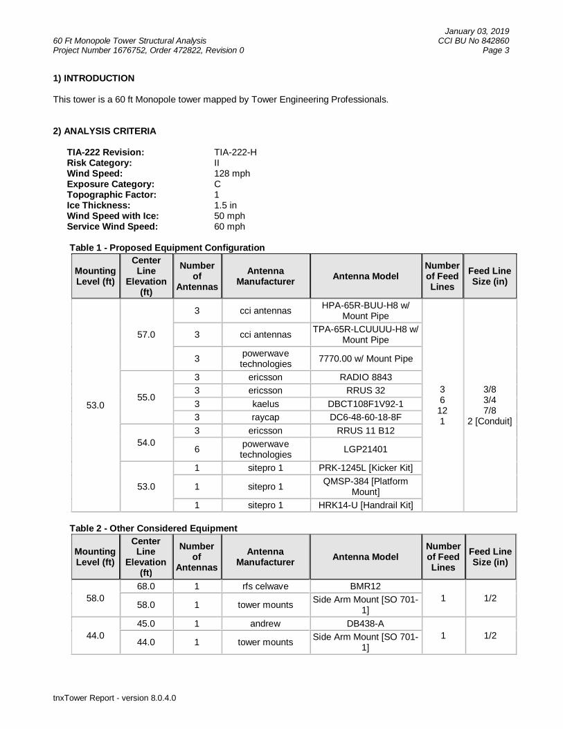
1) INTRODUCTION
This tower is a 60 ft Monopole tower mapped by Tower Engineering Professionals.
2) ANALYSIS CRITERIA
TIA-222 Revision: TIA-222-H Risk Category: II Wind Speed: 128 mph Exposure Category: C Topographic Factor: 1 Ice Thickness: 1.5 in Wind Speed with Ice: 50 mph Service Wind Speed: 60 mph
Table 1 - Proposed Equipment Configuration
MountingLevel (ft)
CenterLine
Elevation(ft)
Numberof
AntennasAntenna
Manufacturer Antenna ModelNumberof FeedLines
Feed LineSize (in)
53.0
57.0
3 cci antennasHPA-65R-BUU-H8 w/
Mount Pipe
36
121
3/83/47/8
2 [Conduit]
3 cci antennasTPA-65R-LCUUUU-H8 w/
Mount Pipe
3powerwavetechnologies
7770.00 w/ Mount Pipe
55.0
3 ericsson RADIO 8843
3 ericsson RRUS 32
3 kaelus DBCT108F1V92-1
3 raycap DC6-48-60-18-8F
54.03 ericsson RRUS 11 B12
6powerwavetechnologies
LGP21401
53.0
1 sitepro 1 PRK-1245L [Kicker Kit]
1 sitepro 1QMSP-384 [Platform
Mount]
1 sitepro 1 HRK14-U [Handrail Kit]
Table 2 - Other Considered Equipment
MountingLevel (ft)
CenterLine
Elevation(ft)
Numberof
AntennasAntenna
Manufacturer Antenna ModelNumberof FeedLines
Feed LineSize (in)
58.068.0 1 rfs celwave BMR12
1 1/258.0 1 tower mounts
Side Arm Mount [SO 701-1]
44.045.0 1 andrew DB438-A
1 1/244.0 1 tower mounts
Side Arm Mount [SO 701-1]

January 03, 201960 Ft Monopole Tower Structural Analysis CCI BU No 842860Project Number 1676752, Order 472822, Revision 0 Page 4
tnxTower Report - version 8.0.4.0
MountingLevel (ft)
CenterLine
Elevation(ft)
Numberof
AntennasAntenna
Manufacturer Antenna ModelNumberof FeedLines
Feed LineSize (in)
31.032.0
1 andrew DB438-A
2 1/21 pctel MYA1505K
31.0 1 tower mountsSide Arm Mount [SO 701-
1]3) ANALYSIS PROCEDURE
Table 3 - Documents Provided
Document Remarks Reference Source
4-GEOTECHNICAL REPORTS Dr. Clarence Welti, P.E., P.C. 5142093 CCISITES
4-TOWER FOUNDATIONDRAWINGS/DESIGN/SPECS
Tower Engineering Professionals(Mapped)
6060632 CCISITES
4-TOWER MANUFACTURERDRAWINGS
Tower Engineering Professionals(Mapped)
6041767 CCISITES
MOUNT ANALYSIS Maser Consulting Connecticut 18963026ACROWN
CASTLE EMAIL
3.1) Analysis Method
tnxTower (version 8.0.4.0), a commercially available analysis software package, was used to create athree-dimensional model of the tower and calculate member stresses for various loading cases.Selected output from the analysis is included in Appendix A.
3.2) Assumptions
1) Tower and structures were built and maintained in accordance with the manufacturer’sspecifications.
2) The configuration of antennas, transmission cables, mounts and other appurtenances are asspecified in Tables 1 and 2 and the referenced drawings.
3) Material grades were not provided at the time of analysis. The following were assumed in thisanalysis:
Component GradeBase Plate A572-50
Anchor Rods A615-75Concrete Strength f’c = 3,000 psi
Foundation Steel Reinforcement fy = 60 ksi
This analysis may be affected if any assumptions are not valid or have been made in error. JacobsEngineering Group, Inc. should be notified to determine the effect on the structural integrity of the tower.

January 03, 201960 Ft Monopole Tower Structural Analysis CCI BU No 842860Project Number 1676752, Order 472822, Revision 0 Page 5
tnxTower Report - version 8.0.4.0
4) ANALYSIS RESULTS
Table 4 - Section Capacity (Summary)Section
No. Elevation (ft) ComponentType Size Critical
Element P (K) SF*P_allow(K)
%Capacity Pass / Fail
L1 60 - 36 Pole TP32.125x27.375x0.1875 1 -6.47 1132.72 21.5 Pass
L2 36 - 0 Pole TP37.875x32.125x0.2188 2 -10.62 1549.94 43.8 Pass
Summary
Pole (L2) 43.8 Pass
Rating = 43.8 Pass
Table 5 - Tower Component Stresses vs. Capacity - LC5
Notes Component Elevation (ft) % Capacity Pass / Fail
1 Anchor Rods 0 39.1 Pass
1 Base Plate 0 12.9 Pass
1Base Foundation
Structural0 22.8 Pass
1Base FoundationSoil Interaction
0 16.0 Pass
Structure Rating (max from all components) = 43.8%Notes:1) See additional documentation in “Appendix C – Additional Calculations” for calculations supporting the % capacity.
4.1) Recommendations
The tower and its foundation have sufficient capacity to carry the proposed load configuration. Nomodifications are required at this time.

January 03, 201960 Ft Monopole Tower Structural Analysis CCI BU No 842860Project Number 1676752, Order 472822, Revision 0 Page 6
tnxTower Report - version 8.0.4.0
APPENDIX A
TNXTOWER OUTPUT

ASCE 7 Hazards ReportAddress:No Address at This Location
Standard: ASCE/SEI 7-10
Risk Category: II
Soil Class: D - Stiff Soil
Elevation: 420.23 ft (NAVD 88)
Latitude:Longitude:
41.580469
-72.350019
Wind
Results:
Data Source:
Date Accessed:
Wind Speed: 128 Vmph
10-year MRI 78 Vmph
25-year MRI 88 Vmph
50-year MRI 96 Vmph
100-year MRI 105 Vmph
ASCE/SEI 7-10, Fig. 26.5-1A and Figs. CC-1–CC-4, incorporating errata of March 12, 2014
Wed Jan 02 2019
Value provided is 3-second gust wind speeds at 33 ft above ground for Exposure C Category, based on linear interpolation between contours. Wind speeds are interpolated in accordance with the 7-10 Standard. Wind speeds correspond to approximately a 7% probability of exceedance in 50 years (annual exceedance probability = 0.00143, MRI = 700 years).
Site is in a hurricane-prone region as defined in ASCE/SEI 7-10 Section 26.2. Glazed openings need not be protected against wind-borne debris.
Mountainous terrain, gorges, ocean promontories, and special wind regions should be examined for unusual wind conditions.
Page 1 of 3https://asce7hazardtool.online/ Wed Jan 02 2019
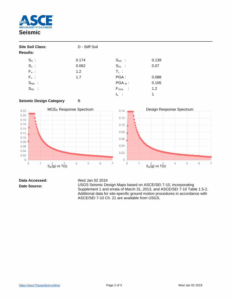
SS : 0.174
S1 : 0.062
Fa : 1.2
Fv : 1.7
SMS :
SM1 :
SDS : 0.139
SD1 : 0.07
TL :
PGA : 0.088
PGA M : 0.105
FPGA : 1.2
Ie : 1
Design Response Spectrum
S (g) vs T(s)a
MCE Response SpectrumR
S (g) vs T(s)a
Seismic
Site Soil Class:
Results:
Seismic Design Category
D - Stiff Soil
B
Data Accessed:
Date Source:
Wed Jan 02 2019USGS Seismic Design Maps based on ASCE/SEI 7-10, incorporating Supplement 1 and errata of March 31, 2013, and ASCE/SEI 7-10 Table 1.5-2. Additional data for site-specific ground motion procedures in accordance with ASCE/SEI 7-10 Ch. 21 are available from USGS.
Page 2 of 3https://asce7hazardtool.online/ Wed Jan 02 2019

Ice
Results:
Data Source:
Date Accessed:
Ice Thickness: 0.75 in.
Concurrent Temperature: 15 F
Gust Speed: 50 mph
Standard ASCE/SEI 7-10, Figs. 10-2 through 10-8
Wed Jan 02 2019
Ice thicknesses on structures in exposed locations at elevations higher than the surrounding terrain and in valleys and gorges may exceed the mapped values.
Values provided are equivalent radial ice thicknesses due to freezing rain with concurrent 3-second gust speeds, for a 50-year mean recurrence interval, and temperatures concurrent with ice thicknesses due to freezing rain. Thicknesses for ice accretions caused by other sources shall be obtained from local meteorological studies. Ice thicknesses in exposed locations at elevations higher than the surrounding terrain and in valleys and gorges may exceed the mapped values.
The ASCE 7 Hazard Tool is provided for your convenience, for informational purposes only, and is provided “as is” and without warranties of any kind. The location data included herein has been obtained from information developed, produced, and maintained by third party providers; or has been extrapolated from maps incorporated in the ASCE 7 standard. While ASCE has made every effort to use data obtained from reliable sources or methodologies, ASCE does not make any representations or warranties as to the accuracy, completeness, reliability, currency, or quality of any data provided herein. Any third-party links provided by this Tool should not be construed as an endorsement, affiliation, relationship, or sponsorship of such third-party content by or from ASCE.
ASCE does not intend, nor should anyone interpret, the results provided by this Tool to replace the sound judgment of a competent professional, having knowledge and experience in the appropriate field(s) of practice, nor to substitute for the standard of care required of such professionals in interpreting and applying the contents of this Tool or the ASCE 7 standard.
In using this Tool, you expressly assume all risks associated with your use. Under no circumstances shall ASCE or its officers, directors, employees, members, affiliates, or agents be liable to you or any other person for any direct, indirect, special, incidental, or consequential damages arising from or related to your use of, or reliance on, the Tool or any information obtained therein. To the fullest extent permitted by law, you agree to release and hold harmless ASCE from any and all liability of any nature arising out of or resulting from any use of data provided by the ASCE 7 Hazard Tool.
Page 3 of 3https://asce7hazardtool.online/ Wed Jan 02 2019

Jacobs Engineering Group, Inc. 5449 Bells Ferry Road Acworth, GA 30102
Phone: 770-701-2500 FAX: 770-701-2501
Job: COLCHESTER NORTH CENTRAL Project: BU#842860 WO#1676752 Client: Crown Castle Drawn by: Jhon MIchael Felismino App'd:
Code: TIA-222-H Date: 01/03/19 Scale: NTS Path:
I:\PSIF\Projects\PH_WORKSHARE\PH_WS_053\Technical\JPPI_Crown_Castle\JPPI_WO\842860 COLCHESTER NORTH CENTRAL\WO 1676752\Analysis\LC5\BU842860_WO1676752_LC5_20190103.eri
Dwg No. E-1
60.0 ft
36.0 ft
0.0 ft
REACTIONS - 128 mph WINDTORQUE 3 kip-ft
11 KSHEAR
517 kip-ftMOMENT
11 KAXIAL
50 mph WIND - 1.2750 in ICETORQUE 1 kip-ft
3 KSHEAR
131 kip-ftMOMENT
19 KAXIAL
ARE FACTOREDALL REACTIONS
Sec
tion
12
Leng
th(f
t)24
.000
036
.000
0
Num
ber
ofS
ides
1818
Thi
ckne
ss(in
)0.
1875
0.21
88
Top
Dia
(in)
27.3
750
32.1
250
Bot
Dia
(in)
32.1
250
37.8
750
Gra
deA
572-
60
Wei
ght(
K)
1.4
3.0
4.4
MATERIAL STRENGTHGRADE GRADEFy FyFu Fu
A572-60 60 ksi 75 ksi
TOWER DESIGN NOTES1. Tower is located in New London County, Connecticut.2. Tower designed for Exposure C to the TIA-222-H Standard.3. Tower designed for a 128 mph basic wind in accordance with the TIA-222-H Standard.4. Tower is also designed for a 50 mph basic wind with 1.27 in ice. Ice is considered to increase
in thickness with height.5. Deflections are based upon a 60 mph wind.6. Tower Risk Category II.7. Topographic Category 1 with Crest Height of 0.0000 ft8. TIA-222-H Annex S9. TOWER RATING: 43.8%
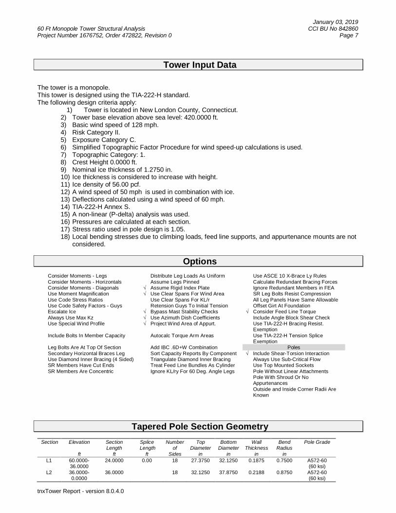
January 03, 201960 Ft Monopole Tower Structural Analysis CCI BU No 842860Project Number 1676752, Order 472822, Revision 0 Page 7
tnxTower Report - version 8.0.4.0
Tower Input Data
The tower is a monopole.This tower is designed using the TIA-222-H standard.The following design criteria apply:
1) Tower is located in New London County, Connecticut.2) Tower base elevation above sea level: 420.0000 ft.3) Basic wind speed of 128 mph.4) Risk Category II.5) Exposure Category C.6) Simplified Topographic Factor Procedure for wind speed-up calculations is used.7) Topographic Category: 1.8) Crest Height 0.0000 ft.9) Nominal ice thickness of 1.2750 in.10) Ice thickness is considered to increase with height.11) Ice density of 56.00 pcf.12) A wind speed of 50 mph is used in combination with ice.13) Deflections calculated using a wind speed of 60 mph.14) TIA-222-H Annex S.15) A non-linear (P-delta) analysis was used.16) Pressures are calculated at each section.17) Stress ratio used in pole design is 1.05.18) Local bending stresses due to climbing loads, feed line supports, and appurtenance mounts are not
considered.
Options Consider Moments - Legs Distribute Leg Loads As Uniform Use ASCE 10 X-Brace Ly Rules Consider Moments - Horizontals Assume Legs Pinned Calculate Redundant Bracing Forces Consider Moments - Diagonals √ Assume Rigid Index Plate Ignore Redundant Members in FEA Use Moment Magnification √ Use Clear Spans For Wind Area SR Leg Bolts Resist Compression Use Code Stress Ratios Use Clear Spans For KL/r All Leg Panels Have Same Allowable Use Code Safety Factors - Guys Retension Guys To Initial Tension Offset Girt At Foundation Escalate Ice √ Bypass Mast Stability Checks √ Consider Feed Line Torque Always Use Max Kz √ Use Azimuth Dish Coefficients Include Angle Block Shear Check Use Special Wind Profile √ Project Wind Area of Appurt. Use TIA-222-H Bracing Resist.
Exemption Include Bolts In Member Capacity Autocalc Torque Arm Areas Use TIA-222-H Tension Splice
Exemption Leg Bolts Are At Top Of Section Add IBC .6D+W Combination Poles Secondary Horizontal Braces Leg Sort Capacity Reports By Component √ Include Shear-Torsion Interaction Use Diamond Inner Bracing (4 Sided) Triangulate Diamond Inner Bracing Always Use Sub-Critical Flow SR Members Have Cut Ends Treat Feed Line Bundles As Cylinder Use Top Mounted Sockets SR Members Are Concentric Ignore KL/ry For 60 Deg. Angle Legs Pole Without Linear Attachments
Pole With Shroud Or NoAppurtenances
Outside and Inside Corner Radii AreKnown
Tapered Pole Section Geometry Section Elevation
ft
SectionLength
ft
Splice Length
ft
Numberof
Sides
TopDiameter
in
BottomDiameter
in
WallThickness
in
BendRadius
in
Pole Grade
L1 60.0000-36.0000
24.0000 0.00 18 27.3750 32.1250 0.1875 0.7500 A572-60(60 ksi)
L2 36.0000-0.0000
36.0000 18 32.1250 37.8750 0.2188 0.8750 A572-60(60 ksi)

January 03, 201960 Ft Monopole Tower Structural Analysis CCI BU No 842860Project Number 1676752, Order 472822, Revision 0 Page 8
tnxTower Report - version 8.0.4.0
Tapered Pole Properties Section Tip Dia.
inAreain2
Iin4
rin
Cin
I/Cin3
Jin4
It/Qin2
win
w/t
L1 27.7684 16.1800 1510.9617 9.6516 13.9065 108.6515 3023.9116 8.0915 4.4880 23.93632.5917 19.0068 2449.3362 11.3378 16.3195 150.0865 4901.8953 9.5052 5.3240 28.395
L2 32.5868 22.1529 2849.1789 11.3267 16.3195 174.5874 5702.1069 11.0786 5.2690 24.08738.4255 26.1452 4683.8571 13.3680 19.2405 243.4374 9373.8774 13.0751 6.2810 28.713
Tower Elevation
ft
GussetArea
(per face)
ft2
GussetThickness
in
Gusset Grade Adjust. FactorAf
Adjust.Factor
Ar
Weight Mult. Double AngleStitch BoltSpacing
Diagonalsin
Double AngleStitch BoltSpacing
Horizontalsin
Double AngleStitch BoltSpacing
Redundantsin
L1 60.0000-36.0000
1 1 1
L2 36.0000-0.0000
1 1 1
Feed Line/Linear Appurtenances - Entered As Round Or FlatDescription Sector Exclude
FromTorque
Calculation
Component
Type
Placement
ft
TotalNumber
NumberPer Row
Start/End
Position
Width orDiamete
rin
Perimeter
in
Weight
plf
***Safety Line 3/8 B No Surface Af
(CaAa)60.0000 -
0.00001 1 -0.400
-0.4000.0000 0.7500 0.22
***
Feed Line/Linear Appurtenances - Entered As AreaDescription Face
orLeg
AllowShield
ExcludeFrom
TorqueCalculation
Component
Type
Placement
ft
TotalNumber
CAAA
ft2/ft
Weight
plf
LDF4-50A(1/2'') C No No Inside Pole 58.0000 -8.0000
1 No Ice1/2'' Ice1'' Ice2'' Ice
0.00000.00000.00000.0000
0.150.150.150.15
LDF5-50A(7/8) C No No Inside Pole 53.0000 -8.0000
12 No Ice1/2'' Ice1'' Ice2'' Ice
0.00000.00000.00000.0000
0.330.330.330.33
FB-L98B-034-XXX(3/8)
C No No Inside Pole 53.0000 -8.0000
3 No Ice1/2'' Ice1'' Ice2'' Ice
0.00000.00000.00000.0000
0.060.060.060.06
WR-VG86ST-BRD(3/4'')
C No No Inside Pole 53.0000 -8.0000
6 No Ice1/2'' Ice1'' Ice2'' Ice
0.00000.00000.00000.0000
0.580.580.580.58
LDF4-50A(1/2'') C No No Inside Pole 44.0000 -8.0000
1 No Ice1/2'' Ice1'' Ice2'' Ice
0.00000.00000.00000.0000
0.150.150.150.15
LDF4-50A(1/2'') C No No Inside Pole 31.0000 -8.0000
2 No Ice1/2'' Ice1'' Ice2'' Ice
0.00000.00000.00000.0000
0.150.150.150.15
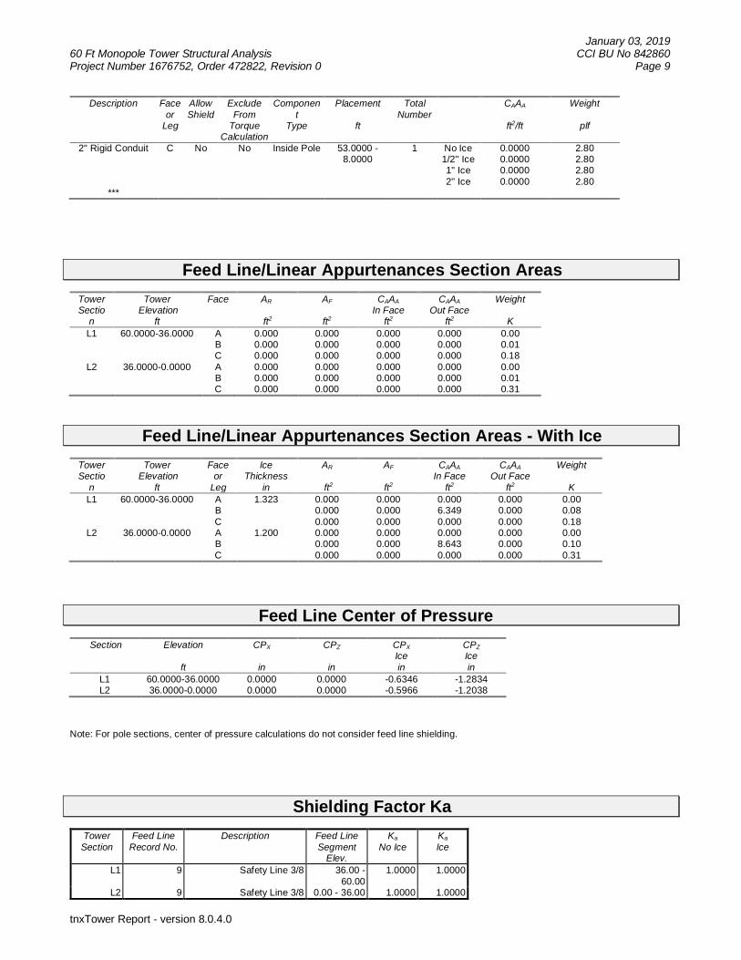
January 03, 201960 Ft Monopole Tower Structural Analysis CCI BU No 842860Project Number 1676752, Order 472822, Revision 0 Page 9
tnxTower Report - version 8.0.4.0
Description Faceor
Leg
AllowShield
ExcludeFrom
TorqueCalculation
Component
Type
Placement
ft
TotalNumber
CAAA
ft2/ft
Weight
plf
2'' Rigid Conduit C No No Inside Pole 53.0000 -8.0000
1 No Ice1/2'' Ice1'' Ice2'' Ice
0.00000.00000.00000.0000
2.802.802.802.80
***
Feed Line/Linear Appurtenances Section AreasTowerSectio
n
Tower Elevation
ft
Face AR
ft2
AF
ft2
CAAAIn Face
ft2
CAAAOut Face
ft2
Weight
KL1 60.0000-36.0000 A
BC
0.0000.0000.000
0.0000.0000.000
0.0000.0000.000
0.0000.0000.000
0.000.010.18
L2 36.0000-0.0000 ABC
0.0000.0000.000
0.0000.0000.000
0.0000.0000.000
0.0000.0000.000
0.000.010.31
Feed Line/Linear Appurtenances Section Areas - With IceTowerSectio
n
Tower Elevation
ft
Faceor
Leg
IceThickness
in
AR
ft2
AF
ft2
CAAAIn Face
ft2
CAAAOut Face
ft2
Weight
KL1 60.0000-36.0000 A
BC
1.323 0.0000.0000.000
0.0000.0000.000
0.0006.3490.000
0.0000.0000.000
0.000.080.18
L2 36.0000-0.0000 ABC
1.200 0.0000.0000.000
0.0000.0000.000
0.0008.6430.000
0.0000.0000.000
0.000.100.31
Feed Line Center of Pressure Section Elevation
ft
CPX
in
CPZ
in
CPXIcein
CPZIcein
L1 60.0000-36.0000 0.0000 0.0000 -0.6346 -1.2834L2 36.0000-0.0000 0.0000 0.0000 -0.5966 -1.2038
Note: For pole sections, center of pressure calculations do not consider feed line shielding.
Shielding Factor KaTowerSection
Feed LineRecord No.
Description Feed LineSegment
Elev.
Ka
No IceKa
Ice
L1 9 Safety Line 3/8 36.00 -60.00
1.0000 1.0000
L2 9 Safety Line 3/8 0.00 - 36.00 1.0000 1.0000

January 03, 201960 Ft Monopole Tower Structural Analysis CCI BU No 842860Project Number 1676752, Order 472822, Revision 0 Page 10
tnxTower Report - version 8.0.4.0
Discrete Tower LoadsDescription Face
orLeg
OffsetType
Offsets:Horz
LateralVert
ftftft
AzimuthAdjustmen
t
°
Placement
ft
CAAAFront
ft2
CAAASide
ft2
Weight
K
Lightning Rod 5/8''x8' C From Leg 0.00000.004.00
0.0000 60.0000 No Ice1/2''Ice
1'' Ice2'' Ice
0.50001.31352.14373.6130
0.50001.31352.14373.6130
0.010.020.030.07
*** Level 58 ***BMR12 B From Leg 4.0000
0.0010.00
0.0000 58.0000 No Ice1/2''Ice
1'' Ice2'' Ice
6.936115.323617.403820.7954
6.936115.323617.403820.7954
0.120.210.310.56
Side Arm Mount [SO 701-1]
B From Leg 2.00000.000.00
0.0000 58.0000 No Ice1/2''Ice
1'' Ice2'' Ice
0.85001.14001.43002.0100
1.67002.34003.01004.3500
0.070.080.090.12
*** Level 53 ***Platform Mount [LP 403-1] C None 0.0000 53.0000 No Ice
1/2''Ice
1'' Ice2'' Ice
18.850024.300029.750040.6500
18.850024.300029.750040.6500
1.501.802.092.69
Miscellaneous [NA 509-3] C None 0.0000 53.0000 No Ice1/2''Ice
1'' Ice2'' Ice
11.840016.960022.080032.3200
11.840016.960022.080032.3200
0.280.300.320.36
Miscellaneous [NA 507-1] C None 0.0000 53.0000 No Ice1/2''Ice
1'' Ice2'' Ice
4.80006.70008.600012.4000
4.80006.70008.600012.4000
0.250.290.340.44
7770.00 w/ Mount Pipe A From Leg 4.00000.004.00
0.0000 53.0000 No Ice1/2''Ice
1'' Ice2'' Ice
5.74606.17916.60677.4880
4.25435.01375.71097.1553
0.060.100.160.29
7770.00 w/ Mount Pipe B From Leg 4.00000.004.00
0.0000 53.0000 No Ice1/2''Ice
1'' Ice2'' Ice
5.74606.17916.60677.4880
4.25435.01375.71097.1553
0.060.100.160.29
7770.00 w/ Mount Pipe C From Leg 4.00000.004.00
0.0000 53.0000 No Ice1/2''Ice
1'' Ice2'' Ice
5.74606.17916.60677.4880
4.25435.01375.71097.1553
0.060.100.160.29
HPA-65R-BUU-H8 w/Mount Pipe
A From Leg 4.00000.004.00
0.0000 53.0000 No Ice1/2''Ice
1'' Ice2'' Ice
13.588114.189714.798316.0364
10.795812.124413.166915.2853
0.080.180.290.54
HPA-65R-BUU-H8 w/Mount Pipe
B From Leg 4.00000.004.00
0.0000 53.0000 No Ice1/2''Ice
1'' Ice
13.588114.189714.798316.0364
10.795812.124413.166915.2853
0.080.180.290.54

January 03, 201960 Ft Monopole Tower Structural Analysis CCI BU No 842860Project Number 1676752, Order 472822, Revision 0 Page 11
tnxTower Report - version 8.0.4.0
Description Faceor
Leg
OffsetType
Offsets:Horz
LateralVert
ftftft
AzimuthAdjustmen
t
°
Placement
ft
CAAA
Front
ft2
CAAA
Side
ft2
Weight
K
2'' IceHPA-65R-BUU-H8 w/
Mount PipeC From Leg 4.0000
0.004.00
0.0000 53.0000 No Ice1/2''Ice
1'' Ice2'' Ice
13.588114.189714.798316.0364
10.795812.124413.166915.2853
0.080.180.290.54
TPA-65R-LCUUUU-H8 w/Mount Pipe
A From Leg 4.00000.004.00
0.0000 53.0000 No Ice1/2''Ice
1'' Ice2'' Ice
13.535314.238014.949516.3081
10.959712.486114.036716.3910
0.110.220.330.59
TPA-65R-LCUUUU-H8 w/Mount Pipe
B From Leg 4.00000.004.00
0.0000 53.0000 No Ice1/2''Ice
1'' Ice2'' Ice
13.535314.238014.949516.3081
10.959712.486114.036716.3910
0.110.220.330.59
TPA-65R-LCUUUU-H8 w/Mount Pipe
C From Leg 4.00000.004.00
0.0000 53.0000 No Ice1/2''Ice
1'' Ice2'' Ice
13.535314.238014.949516.3081
10.959712.486114.036716.3910
0.110.220.330.59
(2) DC6-48-60-18-8F A From Leg 4.00000.002.00
0.0000 53.0000 No Ice1/2''Ice
1'' Ice2'' Ice
0.91671.45831.64312.0417
0.91671.45831.64312.0417
0.030.050.070.12
DC6-48-60-18-8F B From Leg 4.00000.002.00
0.0000 53.0000 No Ice1/2''Ice
1'' Ice2'' Ice
0.91671.45831.64312.0417
0.91671.45831.64312.0417
0.030.050.070.12
(2) LGP21401 A From Leg 4.00000.001.00
0.0000 53.0000 No Ice1/2''Ice
1'' Ice2'' Ice
1.10401.23881.38101.6877
0.20700.27380.34750.5208
0.010.020.030.05
(2) LGP21401 B From Leg 4.00000.001.00
0.0000 53.0000 No Ice1/2''Ice
1'' Ice2'' Ice
1.10401.23881.38101.6877
0.20700.27380.34750.5208
0.010.020.030.05
(2) LGP21401 C From Leg 4.00000.001.00
0.0000 53.0000 No Ice1/2''Ice
1'' Ice2'' Ice
1.10401.23881.38101.6877
0.20700.27380.34750.5208
0.010.020.030.05
DBCT108F1V92-1 A From Leg 4.00000.002.00
0.0000 53.0000 No Ice1/2''Ice
1'' Ice2'' Ice
0.63720.74010.85041.0932
0.60420.70500.81331.0519
0.030.040.040.07
DBCT108F1V92-1 B From Leg 4.00000.002.00
0.0000 53.0000 No Ice1/2''Ice
1'' Ice2'' Ice
0.63720.74010.85041.0932
0.60420.70500.81331.0519
0.030.040.040.07
DBCT108F1V92-1 C From Leg 4.00000.002.00
0.0000 53.0000 No Ice1/2''Ice
1'' Ice2'' Ice
0.63720.74010.85041.0932
0.60420.70500.81331.0519
0.030.040.040.07
RRUS 32 A From Leg 4.00000.002.00
0.0000 53.0000 No Ice1/2''Ice
1'' Ice
2.85713.08303.31633.8052
1.77661.96772.16582.5829
0.060.080.100.16

January 03, 201960 Ft Monopole Tower Structural Analysis CCI BU No 842860Project Number 1676752, Order 472822, Revision 0 Page 12
tnxTower Report - version 8.0.4.0
Description Faceor
Leg
OffsetType
Offsets:Horz
LateralVert
ftftft
AzimuthAdjustmen
t
°
Placement
ft
CAAA
Front
ft2
CAAA
Side
ft2
Weight
K
2'' IceRRUS 32 B From Leg 4.0000
0.002.00
0.0000 53.0000 No Ice1/2''Ice
1'' Ice2'' Ice
2.85713.08303.31633.8052
1.77661.96772.16582.5829
0.060.080.100.16
RRUS 32 C From Leg 4.00000.002.00
0.0000 53.0000 No Ice1/2''Ice
1'' Ice2'' Ice
2.85713.08303.31633.8052
1.77661.96772.16582.5829
0.060.080.100.16
RADIO 8843 A From Leg 4.00000.002.00
0.0000 53.0000 No Ice1/2''Ice
1'' Ice2'' Ice
3.50003.74263.99264.5148
2.35932.56582.77943.2370
0.090.110.150.22
RADIO 8843 B From Leg 4.00000.002.00
0.0000 53.0000 No Ice1/2''Ice
1'' Ice2'' Ice
3.50003.74263.99264.5148
2.35932.56582.77943.2370
0.090.110.150.22
RADIO 8843 C From Leg 4.00000.002.00
0.0000 53.0000 No Ice1/2''Ice
1'' Ice2'' Ice
3.50003.74263.99264.5148
2.35932.56582.77943.2370
0.090.110.150.22
RRUS 11 B12 A From Leg 4.00000.001.00
0.0000 53.0000 No Ice1/2''Ice
1'' Ice2'' Ice
2.83333.04263.25933.7148
1.18211.32991.48481.8259
0.050.070.100.15
RRUS 11 B12 B From Leg 4.00000.001.00
0.0000 53.0000 No Ice1/2''Ice
1'' Ice2'' Ice
2.83333.04263.25933.7148
1.18211.32991.48481.8259
0.050.070.100.15
RRUS 11 B12 C From Leg 4.00000.001.00
0.0000 53.0000 No Ice1/2''Ice
1'' Ice2'' Ice
2.83333.04263.25933.7148
1.18211.32991.48481.8259
0.050.070.100.15
***DB438-A B From Leg 4.0000
0.001.00
0.0000 44.0000 No Ice1/2''Ice
1'' Ice2'' Ice
0.62220.73020.84691.1062
0.62220.73020.84691.1062
0.010.010.020.05
Side Arm Mount [SO 701-1]
B From Leg 2.00000.000.00
0.0000 44.0000 No Ice1/2''Ice
1'' Ice2'' Ice
0.85001.14001.43002.0100
1.67002.34003.01004.3500
0.070.080.090.12
***DB438-A B From Face 4.0000
0.000.00
1.0000 31.0000 No Ice1/2''Ice
1'' Ice2'' Ice
0.62220.73020.84691.1062
0.62220.73020.84691.1062
0.010.010.020.05
MYA1506K B From Face 0.00000.000.00
1.0000 31.0000 No Ice1/2''Ice
1'' Ice2'' Ice
0.31250.48980.67451.0662
1.10291.70182.30813.5428
0.010.120.240.51
Side Arm Mount [SO 701-1]
B From Face 2.00000.00
0.0000 31.0000 No Ice 0.85001.1400
1.67002.3400
0.070.08

January 03, 201960 Ft Monopole Tower Structural Analysis CCI BU No 842860Project Number 1676752, Order 472822, Revision 0 Page 13
tnxTower Report - version 8.0.4.0
Description Faceor
Leg
OffsetType
Offsets:Horz
LateralVert
ftftft
AzimuthAdjustmen
t
°
Placement
ft
CAAA
Front
ft2
CAAA
Side
ft2
Weight
K
0.00 1/2''Ice
1'' Ice2'' Ice
1.43002.0100
3.01004.3500
0.090.12
***
Load CombinationsComb.
No.Description
1 Dead Only2 1.2 Dead+1.0 Wind 0 deg - No Ice3 0.9 Dead+1.0 Wind 0 deg - No Ice4 1.2 Dead+1.0 Wind 30 deg - No Ice5 0.9 Dead+1.0 Wind 30 deg - No Ice6 1.2 Dead+1.0 Wind 60 deg - No Ice7 0.9 Dead+1.0 Wind 60 deg - No Ice8 1.2 Dead+1.0 Wind 90 deg - No Ice9 0.9 Dead+1.0 Wind 90 deg - No Ice10 1.2 Dead+1.0 Wind 120 deg - No Ice11 0.9 Dead+1.0 Wind 120 deg - No Ice12 1.2 Dead+1.0 Wind 150 deg - No Ice13 0.9 Dead+1.0 Wind 150 deg - No Ice14 1.2 Dead+1.0 Wind 180 deg - No Ice15 0.9 Dead+1.0 Wind 180 deg - No Ice16 1.2 Dead+1.0 Wind 210 deg - No Ice17 0.9 Dead+1.0 Wind 210 deg - No Ice18 1.2 Dead+1.0 Wind 240 deg - No Ice19 0.9 Dead+1.0 Wind 240 deg - No Ice20 1.2 Dead+1.0 Wind 270 deg - No Ice21 0.9 Dead+1.0 Wind 270 deg - No Ice22 1.2 Dead+1.0 Wind 300 deg - No Ice23 0.9 Dead+1.0 Wind 300 deg - No Ice24 1.2 Dead+1.0 Wind 330 deg - No Ice25 0.9 Dead+1.0 Wind 330 deg - No Ice26 1.2 Dead+1.0 Ice27 1.2 Dead+1.0 Wind 0 deg+1.0 Ice28 1.2 Dead+1.0 Wind 30 deg+1.0 Ice29 1.2 Dead+1.0 Wind 60 deg+1.0 Ice30 1.2 Dead+1.0 Wind 90 deg+1.0 Ice31 1.2 Dead+1.0 Wind 120 deg+1.0 Ice32 1.2 Dead+1.0 Wind 150 deg+1.0 Ice33 1.2 Dead+1.0 Wind 180 deg+1.0 Ice34 1.2 Dead+1.0 Wind 210 deg+1.0 Ice35 1.2 Dead+1.0 Wind 240 deg+1.0 Ice36 1.2 Dead+1.0 Wind 270 deg+1.0 Ice37 1.2 Dead+1.0 Wind 300 deg+1.0 Ice38 1.2 Dead+1.0 Wind 330 deg+1.0 Ice39 Dead+Wind 0 deg - Service40 Dead+Wind 30 deg - Service41 Dead+Wind 60 deg - Service42 Dead+Wind 90 deg - Service43 Dead+Wind 120 deg - Service44 Dead+Wind 150 deg - Service45 Dead+Wind 180 deg - Service46 Dead+Wind 210 deg - Service47 Dead+Wind 240 deg - Service48 Dead+Wind 270 deg - Service49 Dead+Wind 300 deg - Service

January 03, 201960 Ft Monopole Tower Structural Analysis CCI BU No 842860Project Number 1676752, Order 472822, Revision 0 Page 14
tnxTower Report - version 8.0.4.0
Comb.No.
Description
50 Dead+Wind 330 deg - Service
Maximum Member ForcesSectio
nNo.
Elevationft
ComponentType
Condition Gov.Load
Comb.
Axial
K
Major AxisMoment
kip-ft
Minor AxisMoment
kip-ftL1 60 - 36 Pole Max Tension 1 0.00 0.00 0.00
Max. Compression 26 -12.58 -3.17 -0.75Max. Mx 8 -6.47 -155.33 0.13Max. My 14 -6.47 -0.78 -154.99Max. Vy 8 8.51 -155.33 0.13Max. Vx 14 8.55 -0.78 -154.99
Max. Torque 5 -2.30L2 36 - 0 Pole Max Tension 1 0.00 0.00 0.00
Max. Compression 26 -18.99 -4.12 -0.09Max. Mx 8 -10.62 -515.35 0.63Max. My 14 -10.62 -0.75 -516.86Max. Vy 8 11.38 -515.35 0.63Max. Vx 14 11.45 -0.75 -516.86
Max. Torque 17 2.51
Maximum ReactionsLocation Condition Gov.
LoadComb.
VerticalK
Horizontal, XK
Horizontal, ZK
Pole Max. Vert 30 18.99 -2.83 0.00Max. Hx 21 7.97 11.37 -0.01Max. Hz 2 10.62 -0.01 11.44Max. Mx 2 516.49 -0.01 11.44Max. Mz 8 515.35 -11.37 0.01
Max. Torsion 17 2.51 5.69 -9.91Min. Vert 23 7.97 9.85 5.72Min. Hx 8 10.62 -11.37 0.01Min. Hz 14 10.62 0.01 -11.44Min. Mx 14 -516.86 0.01 -11.44Min. Mz 20 -512.21 11.37 -0.01
Min. Torsion 5 -2.51 -5.69 9.91
Tower Mast Reaction SummaryLoad
CombinationVertical
K
Shearx
K
Shearz
K
OverturningMoment, Mx
kip-ft
OverturningMoment, Mz
kip-ft
Torque
kip-ftDead Only 8.85 0.00 0.00 0.16 -1.29 -0.001.2 Dead+1.0 Wind 0 deg -No Ice
10.62 0.01 -11.44 -516.49 -2.39 2.48
0.9 Dead+1.0 Wind 0 deg -No Ice
7.97 0.01 -11.44 -515.47 -1.99 2.49
1.2 Dead+1.0 Wind 30 deg -No Ice
10.62 5.69 -9.91 -447.67 -259.17 2.50
0.9 Dead+1.0 Wind 30 deg -No Ice
7.97 5.69 -9.91 -446.80 -258.24 2.51
1.2 Dead+1.0 Wind 60 deg -No Ice
10.62 9.85 -5.72 -258.86 -446.92 1.85
0.9 Dead+1.0 Wind 60 deg -No Ice
7.97 9.85 -5.72 -258.37 -445.61 1.86
1.2 Dead+1.0 Wind 90 deg -No Ice
10.62 11.37 -0.01 -0.63 -515.35 0.71
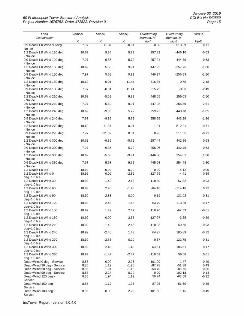
January 03, 201960 Ft Monopole Tower Structural Analysis CCI BU No 842860Project Number 1676752, Order 472822, Revision 0 Page 15
tnxTower Report - version 8.0.4.0
LoadCombination
Vertical
K
Shearx
K
Shearz
K
OverturningMoment, Mx
kip-ft
OverturningMoment, Mz
kip-ft
Torque
kip-ft0.9 Dead+1.0 Wind 90 deg -No Ice
7.97 11.37 -0.01 -0.68 -513.89 0.71
1.2 Dead+1.0 Wind 120 deg- No Ice
10.62 9.85 5.72 257.82 -446.10 -0.63
0.9 Dead+1.0 Wind 120 deg- No Ice
7.97 9.85 5.72 257.24 -444.79 -0.63
1.2 Dead+1.0 Wind 150 deg- No Ice
10.62 5.68 9.91 447.23 -257.75 -1.80
0.9 Dead+1.0 Wind 150 deg- No Ice
7.97 5.68 9.91 446.27 -256.83 -1.80
1.2 Dead+1.0 Wind 180 deg- No Ice
10.62 -0.01 11.44 516.86 -0.75 -2.48
0.9 Dead+1.0 Wind 180 deg- No Ice
7.97 -0.01 11.44 515.75 -0.36 -2.49
1.2 Dead+1.0 Wind 210 deg- No Ice
10.62 -5.69 9.91 448.05 256.03 -2.50
0.9 Dead+1.0 Wind 210 deg- No Ice
7.97 -5.69 9.91 447.08 255.89 -2.51
1.2 Dead+1.0 Wind 240 deg- No Ice
10.62 -9.85 5.72 259.23 443.78 -1.85
0.9 Dead+1.0 Wind 240 deg- No Ice
7.97 -9.85 5.72 258.65 443.26 -1.86
1.2 Dead+1.0 Wind 270 deg- No Ice
10.62 -11.37 0.01 1.01 512.21 -0.71
0.9 Dead+1.0 Wind 270 deg- No Ice
7.97 -11.37 0.01 0.96 511.55 -0.71
1.2 Dead+1.0 Wind 300 deg- No Ice
10.62 -9.85 -5.72 -257.44 442.96 0.63
0.9 Dead+1.0 Wind 300 deg- No Ice
7.97 -9.85 -5.72 -256.96 442.45 0.63
1.2 Dead+1.0 Wind 330 deg- No Ice
10.62 -5.68 -9.91 -446.86 254.61 1.80
0.9 Dead+1.0 Wind 330 deg- No Ice
7.97 -5.68 -9.91 -445.98 254.48 1.80
1.2 Dead+1.0 Ice 18.99 0.00 0.00 0.09 -4.12 -0.001.2 Dead+1.0 Wind 0deg+1.0 Ice
18.99 0.00 -2.86 -127.79 -4.41 0.89
1.2 Dead+1.0 Wind 30deg+1.0 Ice
18.99 1.42 -2.48 -110.80 -67.82 0.93
1.2 Dead+1.0 Wind 60deg+1.0 Ice
18.99 2.46 -1.43 -64.10 -114.16 0.72
1.2 Dead+1.0 Wind 90deg+1.0 Ice
18.99 2.83 -0.00 -0.19 -131.02 0.31
1.2 Dead+1.0 Wind 120deg+1.0 Ice
18.99 2.45 1.43 63.79 -113.88 -0.17
1.2 Dead+1.0 Wind 150deg+1.0 Ice
18.99 1.42 2.47 110.70 -67.33 -0.61
1.2 Dead+1.0 Wind 180deg+1.0 Ice
18.99 -0.00 2.86 127.97 -3.85 -0.89
1.2 Dead+1.0 Wind 210deg+1.0 Ice
18.99 -1.42 2.48 110.98 59.55 -0.93
1.2 Dead+1.0 Wind 240deg+1.0 Ice
18.99 -2.46 1.43 64.27 105.89 -0.72
1.2 Dead+1.0 Wind 270deg+1.0 Ice
18.99 -2.83 0.00 0.37 122.75 -0.31
1.2 Dead+1.0 Wind 300deg+1.0 Ice
18.99 -2.45 -1.43 -63.61 105.61 0.17
1.2 Dead+1.0 Wind 330deg+1.0 Ice
18.99 -1.42 -2.47 -110.52 59.06 0.61
Dead+Wind 0 deg - Service 8.85 0.00 -2.25 -101.29 -1.47 0.49Dead+Wind 30 deg - Service 8.85 1.12 -1.95 -87.78 -51.88 0.49Dead+Wind 60 deg - Service 8.85 1.94 -1.13 -50.70 -88.75 0.36Dead+Wind 90 deg - Service 8.85 2.24 -0.00 -0.00 -102.18 0.14Dead+Wind 120 deg -Service
8.85 1.94 1.12 50.74 -88.58 -0.12
Dead+Wind 150 deg -Service
8.85 1.12 1.95 87.93 -51.60 -0.35
Dead+Wind 180 deg -Service
8.85 -0.00 2.25 101.60 -1.15 -0.49
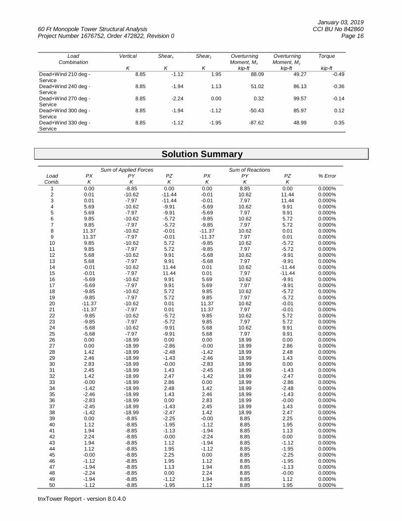
January 03, 201960 Ft Monopole Tower Structural Analysis CCI BU No 842860Project Number 1676752, Order 472822, Revision 0 Page 16
tnxTower Report - version 8.0.4.0
LoadCombination
Vertical
K
Shearx
K
Shearz
K
OverturningMoment, Mx
kip-ft
OverturningMoment, Mz
kip-ft
Torque
kip-ftDead+Wind 210 deg -Service
8.85 -1.12 1.95 88.09 49.27 -0.49
Dead+Wind 240 deg -Service
8.85 -1.94 1.13 51.02 86.13 -0.36
Dead+Wind 270 deg -Service
8.85 -2.24 0.00 0.32 99.57 -0.14
Dead+Wind 300 deg -Service
8.85 -1.94 -1.12 -50.43 85.97 0.12
Dead+Wind 330 deg -Service
8.85 -1.12 -1.95 -87.62 48.99 0.35
Solution Summary
LoadComb.
Sum of Applied Forces Sum of Reactions% ErrorPX
KPYK
PZK
PXK
PYK
PZK
1 0.00 -8.85 0.00 0.00 8.85 0.00 0.000%2 0.01 -10.62 -11.44 -0.01 10.62 11.44 0.000%3 0.01 -7.97 -11.44 -0.01 7.97 11.44 0.000%4 5.69 -10.62 -9.91 -5.69 10.62 9.91 0.000%5 5.69 -7.97 -9.91 -5.69 7.97 9.91 0.000%6 9.85 -10.62 -5.72 -9.85 10.62 5.72 0.000%7 9.85 -7.97 -5.72 -9.85 7.97 5.72 0.000%8 11.37 -10.62 -0.01 -11.37 10.62 0.01 0.000%9 11.37 -7.97 -0.01 -11.37 7.97 0.01 0.000%10 9.85 -10.62 5.72 -9.85 10.62 -5.72 0.000%11 9.85 -7.97 5.72 -9.85 7.97 -5.72 0.000%12 5.68 -10.62 9.91 -5.68 10.62 -9.91 0.000%13 5.68 -7.97 9.91 -5.68 7.97 -9.91 0.000%14 -0.01 -10.62 11.44 0.01 10.62 -11.44 0.000%15 -0.01 -7.97 11.44 0.01 7.97 -11.44 0.000%16 -5.69 -10.62 9.91 5.69 10.62 -9.91 0.000%17 -5.69 -7.97 9.91 5.69 7.97 -9.91 0.000%18 -9.85 -10.62 5.72 9.85 10.62 -5.72 0.000%19 -9.85 -7.97 5.72 9.85 7.97 -5.72 0.000%20 -11.37 -10.62 0.01 11.37 10.62 -0.01 0.000%21 -11.37 -7.97 0.01 11.37 7.97 -0.01 0.000%22 -9.85 -10.62 -5.72 9.85 10.62 5.72 0.000%23 -9.85 -7.97 -5.72 9.85 7.97 5.72 0.000%24 -5.68 -10.62 -9.91 5.68 10.62 9.91 0.000%25 -5.68 -7.97 -9.91 5.68 7.97 9.91 0.000%26 0.00 -18.99 0.00 0.00 18.99 0.00 0.000%27 0.00 -18.99 -2.86 -0.00 18.99 2.86 0.000%28 1.42 -18.99 -2.48 -1.42 18.99 2.48 0.000%29 2.46 -18.99 -1.43 -2.46 18.99 1.43 0.000%30 2.83 -18.99 -0.00 -2.83 18.99 0.00 0.000%31 2.45 -18.99 1.43 -2.45 18.99 -1.43 0.000%32 1.42 -18.99 2.47 -1.42 18.99 -2.47 0.000%33 -0.00 -18.99 2.86 0.00 18.99 -2.86 0.000%34 -1.42 -18.99 2.48 1.42 18.99 -2.48 0.000%35 -2.46 -18.99 1.43 2.46 18.99 -1.43 0.000%36 -2.83 -18.99 0.00 2.83 18.99 -0.00 0.000%37 -2.45 -18.99 -1.43 2.45 18.99 1.43 0.000%38 -1.42 -18.99 -2.47 1.42 18.99 2.47 0.000%39 0.00 -8.85 -2.25 -0.00 8.85 2.25 0.000%40 1.12 -8.85 -1.95 -1.12 8.85 1.95 0.000%41 1.94 -8.85 -1.13 -1.94 8.85 1.13 0.000%42 2.24 -8.85 -0.00 -2.24 8.85 0.00 0.000%43 1.94 -8.85 1.12 -1.94 8.85 -1.12 0.000%44 1.12 -8.85 1.95 -1.12 8.85 -1.95 0.000%45 -0.00 -8.85 2.25 0.00 8.85 -2.25 0.000%46 -1.12 -8.85 1.95 1.12 8.85 -1.95 0.000%47 -1.94 -8.85 1.13 1.94 8.85 -1.13 0.000%48 -2.24 -8.85 0.00 2.24 8.85 -0.00 0.000%49 -1.94 -8.85 -1.12 1.94 8.85 1.12 0.000%50 -1.12 -8.85 -1.95 1.12 8.85 1.95 0.000%

January 03, 201960 Ft Monopole Tower Structural Analysis CCI BU No 842860Project Number 1676752, Order 472822, Revision 0 Page 17
tnxTower Report - version 8.0.4.0
Non-Linear Convergence ResultsLoad
CombinationConverged? Number
of CyclesDisplacement
ToleranceForce
Tolerance1 Yes 4 0.00000001 0.000000012 Yes 4 0.00000001 0.000084693 Yes 4 0.00000001 0.000052254 Yes 4 0.00000001 0.000123315 Yes 4 0.00000001 0.000076056 Yes 4 0.00000001 0.000063927 Yes 4 0.00000001 0.000039338 Yes 4 0.00000001 0.000029019 Yes 4 0.00000001 0.0000178710 Yes 4 0.00000001 0.0000472011 Yes 4 0.00000001 0.0000283512 Yes 4 0.00000001 0.0000965613 Yes 4 0.00000001 0.0000593014 Yes 4 0.00000001 0.0000843315 Yes 4 0.00000001 0.0000520116 Yes 4 0.00000001 0.0000783417 Yes 4 0.00000001 0.0000485818 Yes 4 0.00000001 0.0001031819 Yes 4 0.00000001 0.0000636920 Yes 4 0.00000001 0.0000292121 Yes 4 0.00000001 0.0000180422 Yes 4 0.00000001 0.0000615623 Yes 4 0.00000001 0.0000375924 Yes 4 0.00000001 0.0000565425 Yes 4 0.00000001 0.0000347926 Yes 4 0.00000001 0.0000000127 Yes 4 0.00000001 0.0000238028 Yes 4 0.00000001 0.0000273029 Yes 4 0.00000001 0.0000202930 Yes 4 0.00000001 0.0000110531 Yes 4 0.00000001 0.0000000132 Yes 4 0.00000001 0.0000182833 Yes 4 0.00000001 0.0000239834 Yes 4 0.00000001 0.0000237835 Yes 4 0.00000001 0.0000206436 Yes 4 0.00000001 0.0000099537 Yes 4 0.00000001 0.0000000138 Yes 4 0.00000001 0.0000149139 Yes 4 0.00000001 0.0000000140 Yes 4 0.00000001 0.0000000141 Yes 4 0.00000001 0.0000000142 Yes 4 0.00000001 0.0000000143 Yes 4 0.00000001 0.0000000144 Yes 4 0.00000001 0.0000000145 Yes 4 0.00000001 0.0000000146 Yes 4 0.00000001 0.0000000147 Yes 4 0.00000001 0.0000000148 Yes 4 0.00000001 0.0000000149 Yes 4 0.00000001 0.0000000150 Yes 4 0.00000001 0.00000001
Maximum Tower Deflections - Service WindSection
No.Elevation
ft
Horz.Deflection
in
Gov.Load
Comb.
Tilt
°
Twist
°L1 60 - 36 1.754 42 0.2165 0.0034L2 36 - 0 0.729 42 0.1750 0.0018

January 03, 201960 Ft Monopole Tower Structural Analysis CCI BU No 842860Project Number 1676752, Order 472822, Revision 0 Page 18
tnxTower Report - version 8.0.4.0
Critical Deflections and Radius of Curvature - Service WindElevation
ft
Appurtenance Gov.Load
Comb.
Deflection
in
Tilt
°
Twist
°
Radius ofCurvature
ft60.0000 Lightning Rod 5/8''x8' 42 1.754 0.2165 0.0034 5128458.0000 BMR12 42 1.660 0.2143 0.0033 5128453.0000 Platform Mount [LP 403-1] 42 1.426 0.2084 0.0029 3663144.0000 DB438-A 42 1.031 0.1944 0.0023 1602631.0000 DB438-A 42 0.574 0.1583 0.0015 12407
Maximum Tower Deflections - Design WindSection
No.Elevation
ft
Horz.Deflection
in
Gov.Load
Comb.
Tilt
°
Twist
°L1 60 - 36 8.808 4 1.0801 0.0174L2 36 - 0 3.676 4 0.8803 0.0090
Critical Deflections and Radius of Curvature - Design WindElevation
ft
Appurtenance Gov.Load
Comb.
Deflection
in
Tilt
°
Twist
°
Radius ofCurvature
ft60.0000 Lightning Rod 5/8''x8' 4 8.808 1.0801 0.0174 1030758.0000 BMR12 4 8.336 1.0698 0.0167 1030753.0000 Platform Mount [LP 403-1] 4 7.168 1.0423 0.0148 736244.0000 DB438-A 4 5.188 0.9754 0.0116 322031.0000 DB438-A 4 2.897 0.7969 0.0075 2493
Compression Checks
Pole Design DataSection
No.Elevation
ft
Size L
ft
Lu
ft
Kl/r A
in2
Pu
K
fPn
K
RatioPu
fPn
L1 60 - 36 (1) TP32.125x27.375x0.1875 24.0000
0.0000 0.0 19.0068
-6.47 1078.78 0.006
L2 36 - 0 (2) TP37.875x32.125x0.2188 36.0000
0.0000 0.0 26.1452
-10.62 1476.13 0.007
Pole Bending Design DataSection
No.Elevation
ft
Size Mux
kip-ft
fMnx
kip-ft
RatioMux
fMnx
Muy
kip-ft
fMny
kip-ft
RatioMuy
fMny
L1 60 - 36 (1) TP32.125x27.375x0.1875 155.55 709.88 0.219 0.00 709.88 0.000L2 36 - 0 (2) TP37.875x32.125x0.2188 517.28 1145.35 0.452 0.00 1145.35 0.000

January 03, 201960 Ft Monopole Tower Structural Analysis CCI BU No 842860Project Number 1676752, Order 472822, Revision 0 Page 19
tnxTower Report - version 8.0.4.0
SectionNo.
Elevation
ft
Size Mux
kip-ft
fMnx
kip-ft
RatioMux
fMnx
Muy
kip-ft
fMny
kip-ft
RatioMuy
fMny
Pole Shear Design DataSection
No.Elevation
ft
Size ActualVuK
fVn
K
RatioVu
fVn
ActualTu
kip-ft
fTn
kip-ft
RatioTu
fTn
L1 60 - 36 (1) TP32.125x27.375x0.1875 8.55 307.91 0.028 1.85 851.12 0.002L2 36 - 0 (2) TP37.875x32.125x0.2188 11.43 423.55 0.027 2.50 1380.58 0.002
Pole Interaction Design DataSection
No.Elevation
ft
RatioPu
fPn
RatioMux
fMnx
RatioMuy
fMny
RatioVu
fVn
RatioTu
fTn
Comb.StressRatio
Allow.StressRatio
Criteria
L1 60 - 36 (1) 0.006 0.219 0.000 0.028 0.002 0.226 1.0504.8.2
L2 36 - 0 (2) 0.007 0.452 0.000 0.027 0.002 0.460 1.0504.8.2
Section Capacity TableSection
No.Elevation
ftComponent
TypeSize Critical
ElementPK
øPallowK
%Capacity
PassFail
L1 60 - 36 Pole TP32.125x27.375x0.1875 1 -6.47 1132.72 21.5 PassL2 36 - 0 Pole TP37.875x32.125x0.2188 2 -10.62 1549.94 43.8 Pass
SummaryPole (L2) 43.8 Pass
RATING = 43.8 Pass

January 03, 201960 Ft Monopole Tower Structural Analysis CCI BU No 842860Project Number 1676752, Order 472822, Revision 0 Page 20
tnxTower Report - version 8.0.4.0
APPENDIX B
BASE LEVEL DRAWING

BA
SE
LEVE
LD
RA
WIN
G
PL
OT
DA
TE
:F
ILEN
AM
E:
SH
EE
TN
UM
BE
R
SH
EE
TT
ITLE
SIT
EA
DD
RE
SS
BU
SIN
ES
SU
NIT
NU
MB
ER
SIT
EN
AM
E
SITEN
AME:
SITEN
UM
BER:
DR
AW
ING
DA
TE
:C
HE
CK
ED
BY
:D
RA
WN
BY
:R
JC15/08/14
CO
LCH
ESTERN
OR
THCENTRAL
842860
315O
LDH
AR
TFORD
ROAD
CO
LCH
ESTER,C
T06415
NEW
LON
DO
NCO
UNTYU
SA CR
OW
NR
EGIO
NADDRESS
USA
1/1
4/2
016
84
28
60
_B
AS
EL
EV
EL.D
WG

January 03, 201960 Ft Monopole Tower Structural Analysis CCI BU No 842860Project Number 1676752, Order 472822, Revision 0 Page 21
tnxTower Report - version 8.0.4.0
APPENDIX C
ADDITIONAL CALCULATIONS
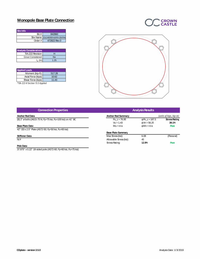
Monopole Base Plate Connection
*TIA-222-H Section 15.5 Applied
Anchor Rod Data Anchor Rod Summary (units of kips, kip-in)(8) 2" ø bolts (A615-75 N; Fy=75 ksi, Fu=100 ksi) on 41" BC Pu_c = 76.95 φPn_c = 187.5 Stress Rating
Vu = 1.43 φVn = 56.25 39.1%Base Plate Data Mu = n/a φMn = n/a Pass42" OD x 2.5" Plate (A572-50; Fy=50 ksi, Fu=65 ksi)
Base Plate SummaryStiffener Data Max Stress (ksi): 6.08 (Flexural)N/A Allowable Stress (ksi): 45
Stress Rating: 12.9% PassPole Data37.875" x 0.22" 18-sided pole (A572-60; Fy=60 ksi, Fu=75 ksi)
BU # 842860
Applied Loads
Site Name COLCHESTER NORTH CENTRAL
Order # 472822 Rev.0
Analysis Considerations
Site Info
TIA-222 Revision HGrout Considered: No
Analysis ResultsConnection Properties
Iar (in) 1.25
Moment (kip-ft) 517.28Axial Force (kips) 10.62
Shear Force (kips) 11.43
CCIplate - version 3.5.0 Analysis Date: 1/3/2019

TIA
-222 Revison:
Check P
ier Capacity only at location of M
ax Mom
ent?N
oT
ower T
ype:
Soil Lateral CapacityC
ompression
Uplift
Com
p.U
plift6.26
-517.28
5.55-
10.62590.13
-11.43
22.8%-
Soil Vertical CapacityC
ompression
Uplift
1304.49-
3ksi
597.30-
60ksi
101.54-
1901.79-
112.16-
16.83ft
5.6%-
0.17ft
Reinforced Concrete CapacityC
ompression
Uplift
6.32-
590.11-
6.5ft
3509.01-
1616.0%
-12
8.625in
3*R
ating per TIA
-222-H S
ection 15.5
n/aft
# of Layers2
FA
LSE
10
55
165150
0.0000.000
FA
LSE
25
16.8311.83
165150
320.000
0.0007.20
7.2024
Cohesionless
Cohesionless
22.8%16.0%
Soil Interaction Rating*Structural Foundation Rating*
Analysis Results
Drilled Pier Foundation
BU
# :Site N
ame:
Order N
umber:
Monopole
Applied Loads
Material Properties
Pier Design D
ata
H
842860C
OLC
HE
ST
ER
NO
RT
H C
EN
TR
AL
472822 Rev.0
Mom
ent (kip-ft)A
xial Force (kips)
Shear F
orce (kips)
Concrete S
trength,f'c:
Dv=0 (ft from
TOC)
Soil Safety FactorM
ax Mom
ent (kip-ft)Rating*
Skin Friction (kips)
Rebar S
izeC
lear Cover to T
iesT
ie S
ize
Ultim
ate SkinFriction U
pliftO
verride (ksf)
Groundw
ater Depth
Soil Profile
Soil TypeSPT Blow
Count
Ult. GrossBearingCapacity
(ksf)
γsoil
(pcf)γ
concrete
(pcf)Cohesion
(ksf)
Angle ofFriction
(degrees)
CalculatedU
ltimate Skin
Friction Uplift
(ksf)
CalculatedU
ltimate Skin
Friction Comp
(ksf)
LayerTop(ft)
Bottom(ft)
Thickness(ft)
Ultim
ate SkinFriction Com
pO
verride(ksf)
Rating*
Weight of Concrete (kips)
Depth
Ext. A
bove Grade
Critical Depth (ft from TO
C)Critical M
oment (kip-ft)
Critical Mom
ent CapacityRating*
Pier Section 1From
0.17' above grade to 16.83' below grade
Rebar S
trength, Fy:
End Bearing (kips)
Total Capacity (kips)Axial (kips)
Check Lim
itationA
pply TIA
-222-H S
ection 15.5:
Pier D
iameter
Rebar Q
uantity
Version 2.0.2

EXHIBIT 4

Centerline Communications, LLC 95 Ryan Drive, Suite 1 Raynham MA 02767
Radio Frequency Emissions Analysis Report
AT&T Existing Facility
Site ID: CT5346
FA#: 10070973
Colchester North Central
315 Old Hartford Road
Colchester, CT 06415
January 3, 2019
Centerline Communications Project Number: 950006-164
Site Compliance Summary
Compliance Status: COMPLIANT
Site total MPE% of
FCC general
population
allowable limit:
36.50 %

Centerline Communications, LLC 95 Ryan Drive, Suite 1 Raynham MA 02767
January 3, 2019
AT&T Mobility – New England
Attn: John Benedetto, RF Manager
550 Cochituate Road
Suite 550 – 13&14
Framingham, MA 06040
Emissions Analysis for Site: CT5346 – Colchester North Central
Centerline Communications, LLC (“Centerline”) was directed to analyze the proposed AT&T facility
located at 315 Old Hartford Road, Colchester, CT, for the purpose of determining whether the
emissions from the Proposed AT&T Antenna Installation located on this property are within specified
federal limits.
All information used in this report was analyzed as a percentage of current Maximum Permissible
Exposure (% MPE) as listed in the FCC OET Bulletin 65 Edition 97-01and ANSI/IEEE Std C95.1. The
FCC regulates Maximum Permissible Exposure in units of microwatts per square centimeter (W/cm2).
The number of W/cm2 calculated at each sample point is called the power density. The exposure limit
for power density varies depending upon the frequencies being utilized. Wireless Carriers and Paging
Services use different frequency bands each with different exposure limits, therefore it is necessary to
report results and limits in terms of percent MPE rather than power density.
All results were compared to the FCC (Federal Communications Commission) radio frequency exposure
rules, 47 CFR 1.1307(b)(1) – (b)(3), to determine compliance with the Maximum Permissible Exposure
(MPE) limits for General Population/Uncontrolled environments as defined below.
General population/uncontrolled exposure limits apply to situations in which the general population may
be exposed or in which persons who are exposed as a consequence of their employment may not be made
fully aware of the potential for exposure or cannot exercise control over their exposure. Therefore,
members of the general population would always be considered under this category when exposure is not
employment related, for example, in the case of a telecommunications tower that exposes persons in a
nearby residential area.
Population exposure to radio frequencies is regulated and enforced in units of microwatts per square
centimeter (μW/cm2). The general population exposure limits for the 700 and 850 MHz Bands are
approximately 467 μW/cm2 and 567 μW/cm2 respectively. The general population exposure limit for the
1900 MHz (PCS), 2100 MHz (AWS) and 2300 MHz (WCS) bands is 1000 μW/cm2. Because each carrier
will be using different frequency bands, and each frequency band has different exposure limits, it is
necessary to report percent of MPE rather than power density.

Centerline Communications, LLC 95 Ryan Drive, Suite 1 Raynham MA 02767
Occupational/controlled exposure limits apply to situations in which persons are exposed as a
consequence of their employment and in which those persons who are exposed have been made fully
aware of the potential for exposure and can exercise control over their exposure. Occupational/controlled
exposure limits also apply where exposure is of a transient nature as a result of incidental passage through
a location where exposure levels may be above general population/uncontrolled limits (see below), as
long as the exposed person has been made fully aware of the potential for exposure and can exercise
control over his or her exposure by leaving the area or by some other appropriate means.
Additional details can be found in FCC OET 65.
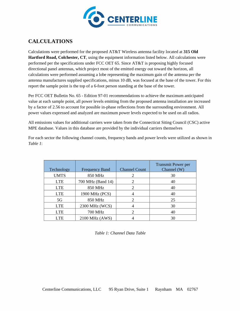
Centerline Communications, LLC 95 Ryan Drive, Suite 1 Raynham MA 02767
CALCULATIONS
Calculations were performed for the proposed AT&T Wireless antenna facility located at 315 Old
Hartford Road, Colchester, CT, using the equipment information listed below. All calculations were
performed per the specifications under FCC OET 65. Since AT&T is proposing highly focused
directional panel antennas, which project most of the emitted energy out toward the horizon, all
calculations were performed assuming a lobe representing the maximum gain of the antenna per the
antenna manufactures supplied specifications, minus 10 dB, was focused at the base of the tower. For this
report the sample point is the top of a 6-foot person standing at the base of the tower.
Per FCC OET Bulletin No. 65 - Edition 97-01 recommendations to achieve the maximum anticipated
value at each sample point, all power levels emitting from the proposed antenna installation are increased
by a factor of 2.56 to account for possible in-phase reflections from the surrounding environment. All
power values expressed and analyzed are maximum power levels expected to be used on all radios.
All emissions values for additional carriers were taken from the Connecticut Siting Council (CSC) active
MPE database. Values in this database are provided by the individual carriers themselves
For each sector the following channel counts, frequency bands and power levels were utilized as shown in
Table 1:
Technology Frequency Band Channel Count
Transmit Power per
Channel (W)
UMTS 850 MHz 2 30
LTE 700 MHz (Band 14) 2 40
LTE 850 MHz 2 40
LTE 1900 MHz (PCS) 4 40
5G 850 MHz 2 25
LTE 2300 MHz (WCS) 4 30
LTE 700 MHz 2 40
LTE 2100 MHz (AWS) 4 30
Table 1: Channel Data Table

Centerline Communications, LLC 95 Ryan Drive, Suite 1 Raynham MA 02767
The following antennas listed in Table 2 were used in the modeling for transmission in the 700 MHz, 850
MHz, 1900 MHz (PCS), 2100 MHz (AWS) and 2300 MHz (WCS) frequency bands. This is based on
feedback from the carrier with regards to anticipated antenna selection. Maximum gain values for all
antennas are listed in the Inventory and Power Data table below. The maximum gain of the antenna per
the antenna manufactures supplied specifications, minus 10 dB, was used for all calculations. This value
is a very conservative estimate as gain reductions for these particular antennas are typically much higher
in this direction.
Sector
Antenna
Number Antenna Make / Model
Antenna
Centerline
(ft)
A 1 Powerwave 7770 57
A 2 CCI TPA-65R-LCUUUU-H8 57
A 3 CCI HPA-65R-BUU-H8 57
B 1 Powerwave 7770 57
B 2 CCI TPA-65R-LCUUUU-H8 57
B 3 CCI HPA-65R-BUU-H8 57
C 1 Powerwave 7770 57
C 2 CCI TPA-65R-LCUUUU-H8 57
C 3 CCI HPA-65R-BUU-H8 57
Table 2: Antenna Data
All calculations were done with respect to uncontrolled / general population threshold limits.

Centerline Communications, LLC 95 Ryan Drive, Suite 1 Raynham MA 02767
RESULTS
Per the calculations completed for the proposed AT&T configurations Table 3 shows resulting emissions
power levels and percentages of the FCC’s allowable general population limit.
Antenna
ID Antenna Make / Model Frequency Bands
Antenna Gain
(dBd)
Chann
el
Count
Total TX
Power (W) ERP (W) MPE %
Antenna
A1
Powerwave
7770 850 MHz 11.4 2 60 828.23 2.02
Antenna
A2
CCI
TPA-65R-LCUUUU-H8
700 MHz (Band 14) /
850 MHz /
1900 MHz (PCS) /
2300 MHz (WCS)
12.95 / 13.45 /
13.75 / 14.45 12 490 11,592.50 21.55
Antenna
A3
CCI
HPA-65R-BUU-H8
700 MHz /
2100 MHz (AWS)
13.15 / 15.25 /
0 / 0 6 200 5,671.89 10.45
Sector A Composite MPE% 34.01
Antenna
B1
Powerwave
7770 850 MHz 11.4 2 60 828.23 2.02
Antenna
B2
CCI
TPA-65R-LCUUUU-H8
700 MHz (Band 14) /
850 MHz /
1900 MHz (PCS) /
2300 MHz (WCS)
12.95 / 13.45 /
13.75 / 14.45 12 490 11,592.50 21.55
Antenna
B3
CCI
HPA-65R-BUU-H8
700 MHz /
2100 MHz (AWS)
13.15 / 15.25 /
0 / 0 6 200 5,671.89 10.45
Sector B Composite MPE% 34.01
Antenna
C1
Powerwave
7770 850 MHz 11.4 2 60 828.23 2.02
Antenna
C2
CCI
TPA-65R-LCUUUU-H8
700 MHz (Band 14) /
850 MHz /
1900 MHz (PCS) /
2300 MHz (WCS)
12.95 / 13.45 /
13.75 / 14.45 12 490 11,592.50 21.55
Antenna
C3
CCI
HPA-65R-BUU-H8
700 MHz /
2100 MHz (AWS)
13.15 / 15.25 /
0 / 0 6 200 5,671.89 10.45
Sector C Composite MPE% 34.01
Table 3: AT&T Emissions Levels

Centerline Communications, LLC 95 Ryan Drive, Suite 1 Raynham MA 02767
The Following table (table 4) shows all additional carriers on site and their MPE% as recorded in the
CSC active MPE database for this facility along with the newly calculated maximum AT&T MPE
contributions per this report. FCC OET 65 specifies that for carriers utilizing directional antennas that the
highest recorded sector value be used for composite site MPE values due to their greatly reduced
emissions contributions in the directions of the adjacent sectors. For this site, all three sectors have the
same configuration yielding the same results on all three sectors. Table 5 below shows a summary for
each AT&T Sector as well as the composite MPE value for the site.
Table 4: All Carrier MPE Contributions
Table 5: Site MPE Summary
Site Composite MPE%
Carrier MPE%
AT&T – Max Per Sector Value 34.01 %
Ken-Tronics 2.49 %
Site Total MPE %: 36.50 %
AT&T Sector A Total: 34.01 %
AT&T Sector B Total: 34.01 %
AT&T Sector C Total: 34.01 %
Site Total: 36.50 %

Centerline Communications, LLC 95 Ryan Drive, Suite 1 Raynham MA 02767
FCC OET 65 specifies that for carriers utilizing directional antennas that the highest recorded sector value
be used for composite site MPE values due to their greatly reduced emissions contributions in the
directions of the adjacent sectors. Table 6 below details a breakdown by frequency band and technology
for the MPE power values for the maximum calculated AT&T sector(s). For this site, all three sectors
have the same configuration yielding the same results on all three sectors.
Table 6: AT&T Maximum Sector MPE Power Values
AT&T _ Frequency Band /
Technology
Max Power Values
(Per Sector)
#
Channels
Watts ERP
(Per Channel)
Height
(feet)
Total Power
Density
(W/cm2)
Frequency
(MHz)
Allowable
MPE
(W/cm2)
Calculated
% MPE
AT&T 850 MHz UMTS 2 414.12 57 11.45 850 MHz 567 2.02%
AT&T 700 MHz LTE 2 788.97 57 21.81 700 MHz 467 4.67%
AT&T 850 MHz LTE 2 885.24 57 24.47 850 MHz 567 4.32%
AT&T 1900 MHz (PCS) LTE 4 948.55 57 52.44 1900 MHz (PCS) 1000 5.24%
AT&T 850 MHz 5G 2 553.27 57 15.29 850 MHz 567 2.70%
AT&T 2300 MHz (WCS) LTE 4 835.84 57 46.21 2300 MHz (WCS) 1000 4.62%
AT&T 700 MHz LTE 2 826.15 57 22.84 700 MHz 467 4.89%
AT&T 2100 MHz (AWS) LTE 4 1,004.90 57 55.56 2100 MHz (AWS) 1000 5.56%
Total: 34.01%

Centerline Communications, LLC 95 Ryan Drive, Suite 1 Raynham MA 02767
Summary
All calculations performed for this analysis yielded results that were within the allowable limits for
general population exposure to RF Emissions.
The anticipated maximum composite contributions from the AT&T facility as well as the site composite
emissions value with regards to compliance with FCC’s allowable limits for general population exposure
to RF Emissions are shown here:
AT&T Sector Power Density Value (%)
Sector A: 34.01 %
Sector B: 34.01 %
Sector C: 34.01 %
AT&T Maximum Total
(per sector): 34.01 %
Site Total: 36.50 %
Site Compliance Status: COMPLIANT
The anticipated composite MPE value for this site assuming all carriers present is 36.50 % of the
allowable FCC established general population limit sampled at the ground level. This is based upon
values listed in the Connecticut Siting Council database for existing carrier emissions.
FCC guidelines state that if a site is found to be out of compliance (over allowable thresholds), that
carriers over a 5% contribution to the composite value will require measures to bring the site into
compliance. For this facility, the composite values calculated were well within the allowable 100%
threshold standard per the federal government.
Scott Heffernan RF Engineering Director
Centerline Communications, LLC
95 Ryan Drive, Suite 1
Raynham, MA 02767

EXHIBIT 5

Antenna Mount Modification
Design & Analysis
FOR
CT5346 – Colchester North Central FA # 10070973
315 Old Hartford Road
Colchester, CT 06415
New London County
3C – MRCTB032309
4C - MRCTB032279
5C - MRCTB032230
6C - MRCTB032273
Retrofit – MRCTB032284
Mount Utilization (Without Modification): 150.7% Mount Utilization (With Modification): 82.2%
Cost Estimate: $2,000-$3,000
October 18, 2018
Prepared For
AT&T 550 Cochituate Road
Framingham, MA 01701
Prepared By
Maser Consulting Connecticut
331 Newman Springs Road, Suite 203
Red Bank, NJ 07701
T: 732.383.1950
___________________________
Petros E. Tsoukalas, P.E.
Geographic Discipline Leader
Connecticut License No. 32557
MC Project No. 18963026A

10/18/2018 Page 2 of 4
Prepared by CB Checked by SMS
Objective: The objective of this report is to determine the capacity of the existing antenna support mount with the proposed modification at the subject facility for the final wireless telecommunications configuration, per the applicable codes and standards.
Introduction: Maser Consulting Connecticut has performed limited field observations on June 13, 2018 to verify the existing condition of the structure and to locate and quantify the existing wireless appurtenances where possible, from ground level. Maser Consulting Connecticut has reviewed the following documents in completing this report: • RFDS 2325793 provided by Empire, dated August 13, 2018. • Mount Mapping provided by provided by Empire. • As-Built Construction Drawings provided by Empire, dated May 12, 2016. • Previous Construction Drawings prepared by Hudson Design Group LLC, Rev 1, dated November 12, 2008. The existing and proposed AT&T equipment is to be supported on the existing antenna support platform mount with the proposed modification constructed of structural steel antenna support pipes supported by pipes, angles and tubes at a centerline of approximately 57’-0” above ground level. This report is based only upon this information.
Codes, Standards and Loading: Maser Consulting Connecticut utilized the following codes and standards:
• 2016 Connecticut State Building Code, Incorporating The 2012 IBC
• Structural Standards for Antenna Supporting Structures and Antennas ANSI/TIA-222-G o Ultimate Wind Speed – 130 mph o Nominal Wind Speed – 101 mph o Exposure Category – C o Structural Class – II o Topographic Category – 1 o Ice Wind – 50 mph o Ice Thickness – 0.75”
• Specification for Structural Steel Buildings ANSI/AISC 360-05, American Institute of Steel Construction (AISC)
Loading used in this analysis is found in Appendix A of this report.
Analysis Approach & Assumptions: The analysis approach used in this structural analysis is based on the premise that if the existing antenna support platform mount with the proposed modification is structurally adequate to support the proposed and existing equipment per the aforementioned codes and standards, or if the increase in the forces in the structure is deemed to be negligible or acceptable, then the proposed equipment can be installed as intended. The existing antenna support mount with the proposed modification has been modeled in RISA-3D, a comprehensive structural analysis program, as the controlling condition. The program performs design checks of structures under user specified loads. The user specified loads have been calculated separately based on the requirements of the above referenced codes. The program performs an analysis based on the steel code to determine the adequacy of the members, and produces the reactions at the connection points of the mounts to the existing structure.

10/18/2018 Page 3 of 4
Prepared by CB Checked by SMS
General Site Design Assumption: • All engineering services are performed on the basis that the information used is current and
correct.
• It is assumed that the telecommunication equipment supports, antenna supports, and existing structure have been designed by a registered licensed professional engineer for the existing loads acting on the structure, as required by all applicable codes, prior to the proposed modifications listed within this report, if any.
• It is assumed that information provided by the client regarding the structure itself, the antenna models, feed lines, and other relevant information is current and correct.
• It is the responsibility of the client to ensure that the information provided to Maser Consulting Connecticut and used in the performance of our engineering services is correct and complete. In the absence of information to the contrary, we assume that the original design, material production, fabrication, and erection of the existing structure was performed in accordance with accepted industry design standards and in accordance with all applicable codes. Further, it is assumed that the existing structure and appurtenances have been properly maintained in accordance with all applicable codes and manufacturer’s specifications and no structural defects and/or deterioration to the structural members has occurred.
• It is assumed all other existing appurtenances, antennas, cables, etc. belonging to others have been installed and supported per code and per specifications so as not to damage any existing structural support members, and that any contributing loads from adjacent equipment has been taken into consideration for their design.
• All services are performed, results obtained, and recommendations made in accordance with generally accepted engineering principles and practices. Maser Consulting Connecticut is not responsible for the conclusion, opinions, and recommendations made by others based on the information we supply.
Site Specific Assumptions and Design Parameters: The following assumptions have been utilized in this report:
• The existing platform mount is a SitePro1 Quick-Pick Full Walkway Monopole Platform (Part Number: QMSP-384)
• Handrail Kit (SitePro1 P/N: HRK14-U) is installed at 48” vertical distance from the bottom horizontal face members.
• Structural Steel Tubes are constructed of A500 Grade B Steel
• Structural Steel Pipes are constructed of A53 Grade B Steel
• Structural Steel Angles are constructed of A36 Steel The following design parameters have been utilized in this report:
• The proposed antennas in position 3 in all sectors shall replace the existing antennas, on three (3) proposed 10’-0” long 2.5 STD pipe masts, which shall be attached to the horizontal mount face tube via crossover plates.
• The proposed RRUS 8843 B66A B2 and RRUS-32 shall be installed back to back, on three (3) proposed RRU Mount Brackets (Ericsson P/N: SXK1250461/1 B2B) which shall be attached to the proposed antenna pipes in position 3 in all sectors.
• The proposed RRUS 4478 B14 and RRUS 4478 B5 shall be installed on the existing Unistrut frames, at the ground level.
• The proposed DC-6’s shall be installed on two (2) proposed 16” long 2.0 STD pipes, which shall be attached to the existing standoff tubes, via a 10”x10”x1/2” galvanized plates, in the Alpha & Beta sectors.
• The proposed DBCT108F1V92-1 Diplexers shall be installed on the proposed antenna pipes in position 3 in all sectors.

10/18/2018 Page 4 of 4
Prepared by CB Checked by SMS
The proposed modification consists of the following:
• Install one (1) proposed Platform Reinforcement Kickers Kit (SitePro1 P/N: PRK-1245L), which shall be attached to the existing standoff HSS at 1’-6” from the corner edge, and shall be installed 4 ft below the existing platform’s collar attachment to monopole.
Please refer to the final drawings prepared by Maser Consulting Connecticut for more details.
Calculations: The calculations are found in Appendix A of this report.
Conclusion: Maser Consulting Connecticut has determined the existing antenna support platform mount with the proposed modification has ADEQUATE structural capacity to support the existing and proposed loadings. The existing antenna support mount with the proposed modification has been determined to be stressed to a maximum of 82.2% of its structural capacity with the maximum usage occurring at the existing grating support angles. Therefore, the proposed AT&T installation CAN be installed as intended, once the proposed modification is installed as intended. The conclusions reached by Maser Consulting Connecticut in this evaluation are only applicable for the existing and proposed structural members supporting the proposed AT&T telecommunications installation described herein. Further, no structural qualifications are made or implied by this document for the existing structure. The existing mount was checked up to, and including, the bolts that attach to the mount’s collar. However, no structural qualifications are made or implied by this document for the existing mount collar. Maser Consulting Connecticut reserves the right to amend this report if additional information about the existing members is provided. The conclusions reached by Maser Consulting Connecticut in this report are only valid for the appurtenances listed in this report. Any change to the installation will require a revision to this structural analysis. We appreciate the opportunity to be of service on this project. If you should have any questions or require any additional information, please do not hesitate to call our office. Sincerely, Maser Consulting Connecticut
\\maserconsulting.com\luj\Projects\2018\18963000A\18963026A\Structural\Mount Analysis - Mods\Rev 0\Word\Report.docx
Petros E. Tsoukalas, P.E. Geographic Discipline Leader
Clara Basanti Engineer

APPENDIX A

Client: ATT Computed By:
Site Name: CTL05436 - Colchester North Central Date:
Project No. Verified By:
Title: Antenna Mount Modification Design & Analysis Page:
LOADING SUMMARY
Quantity Manufacturer Antenna/ Appurtenance Status Sector
3 POWERWAVE 7770 Existing Alpha, Beta, & Gamma
3 CCI HPA-65R-BUU-H8 Existing Alpha, Beta, & Gamma
3 CCI TPA-65R-LCUUUU-H8 Proposed Alpha, Beta, & Gamma
3 ERICSSON RRUS 11 Existing Alpha, Beta, & Gamma
2 ERICSSON RRUS 4478 B14 Proposed Alpha & Beta (At Grade)
3 ERICSSON RRUS 4478 B5 Proposed Alpha, Beta, & Gamma (At Grade)
3 ERICSSON RRUS 32 Proposed Alpha, Beta, & Gamma
3 ERICSSON RRUS 8843 B2 B66A Proposed Alpha, Beta, & Gamma
6 POWERWAVE LGP 21401 TMA Existing Alpha, Beta, & Gamma
3 RAYCAP DC6-48-60-18-8C Existing/Proposed Alpha, Beta, & Gamma
6 KAELUSDBCT108F1V92-1 Low-Band
CombinerProposed Alpha, Beta, & Gamma
Gamma Sector
Quantity Manufacturer Antenna/ Appurtenance Status
1 POWERWAVE 7770 Existing
1 CCI HPA-65R-BUU-H8 Existing
1 CCI TPA-65R-LCUUUU-H8 Proposed
1 ERICSSON RRUS 11 Existing
1 ERICSSON RRUS 4478 B5 Proposed
1 ERICSSON RRUS 32 Proposed
1 ERICSSON RRUS 8843 B2 B66A Proposed
2 POWERWAVE LGP 21401 TMA Existing
1 RAYCAP DC6-48-60-18-8C Existing/Proposed
2 KAELUSDBCT108F1V92-1 Low-Band Combiner Proposed
CB
10/18/2018
SMS
1
18963026A
Version 4.0
The worst case loading occurs in the

Client: ATT Computed By: CB
Site Name: CTL05436 - Colchester North Central Date: 10/18/2018
Project No. Verified By: SMS
Title: Antenna Mount Modification Design & Analysis Page: 2
I. DESIGN INPUTS
Reference Equation
Wind Load Inputs Parameters
Antenna Centerline z 57 ft
Ultimate Wind Speed VU 130 mph
Nominal Wind Speed (3 sec. Gust): V 101 mph Ref. 1, Eqn. 16-33
Nominal Wind Speed with Ice (3 sec. gust): Vi 50.0 mph (Figure a5-2a, p. 233)
Maintenance Wind Speed: Vm 30.0 mph
Service Wind Speed: Vs 60.0 mph (Figure a5-2a, p. 233)
Design Ice Thickness: ti 0.75 in (Figure A1-2a, p. 233)
Exposure Category: C Ref. 3, Section 2.6.5.1
Structure Class: II Ref. 3, Table 2-1
Gust Effect Factor: Gh 1.10 Ref. 3, Section 2.6.7
Wind Directionality Factor: Kd 0.95 Ref. 3, Table 2-2
Topographic Category: 1 Ref. 3, Section 2.6.6.2
373
Wind Load Coefficients
Importance Factors:
Non-Iced: I 1 Ref. 3, Table 2-3
Iced: Iice 1 (Table 2-3, P. 39)
Exposure Category Coefficients:
3-s Gust-Speed Power Law Exponent: α 9.5 Ref. 3, Table 2-4
Nominal Height of the Atmospheric Boundary Layer: Zg 900 ft Ref. 3, Table 2-4
Min. Value for kz: Kzmin 0.85 Ref. 3, Table 2-4
Terrain Constant: Ke 1.00 Ref. 3, Table 2-4
Velocity Pressure Exposure Coefficient: Kz 1.124 Ref. 3, Section 2.6.5.2 =2.01·(z/zg )2/α
Topographic Category Coefficients:
Topographic Constant: Kt N/A Ref. 3, Table 2-5
Height Attenuation Factor: f N/A Ref. 3, Table 2-5
Height Reduction Factor: Kh N/A Ref. 3, Section 2.6.6.4 =e(f·z/H)
Topographic Factor: Kzt 1.00 Ref.3, Section 2.6.6.4 =[1+(K e ·K t /K h )]²
Ice Accumulation:
Ice Velocity Pressure Exposure Coefficient: Kiz 1.06 =(z/33)0.10
Factored Ice Thickness: tiz 1.58 in (Section 2.6.8, p. 16) =2.0·t i ·I·K iz · K zt
Ice Density: ρi 56.00 pcf
Design Wind Pressures:
Velocity Pressure: qz 27.73 psf Ref. 3, Section 2.6.9.6 =0.00256·K z ·K zt ·K d ·V2·I
Velocity Pressure (With Ice): qzi 6.84 psf (Section 2.6.9.6, P. 25) =.00256·K z ·K zt ·K d ·V i²·I
Velocity Pressure (Maintenance): qzm 2.46 psf (Section 2.6.9.6, P. 25) =.00256·K z ·K zt ·K d ·V m²·I
Velocity Pressure (Service): qzs 9.84 psf (Section 2.6.9.6, P. 25) =.00256·K z ·K zt ·K d ·V i²·I
18963026A
Calculations for gravity and lateral loading on equipment and support mounts are determined as per the ANSI/TIA-222-
G Code, Addendum 2

Client: ATT CB
Site Name: CTL05436 - Colchester North Central 10/18/2018
Project No. SMS
Title: Antenna Mount Modification Design & Analysis 3
II. CALCULATIONS
▪ Wind Load on Appurtenances
Dimensions and Force Coefficients
Antenna/
Appurtenance
Force
Coefficient
Force
Coefficient
Ca Ca Front Ca Side Ca Ca Front Ca Side
7770 72.0 2.375 1.200 55.00 11.00 5.00 1.31 1.53 75.2 5.5 0.946 58.17 14.17 8.17 1.27 1.40
HPA-65R-BUU-H8 108.0 2.375 1.200 92.80 14.40 7.30 1.38 1.59 111.2 5.5 1.090 95.97 17.57 10.47 1.33 1.47
TPA-65R-LCUUUU-H8 120.0 2.875 1.200 96.00 14.40 8.60 1.39 1.54 123.2 6.0 1.097 99.17 17.57 11.77 1.34 1.45
RRUS 11 0.0 0.000 0.000 19.70 17.00 7.20 1.20 1.21 0.0 0.0 0.000 22.87 20.17 10.37 1.20 1.20
RRUS 32 0.0 0.000 0.000 27.20 12.00 7.00 1.20 1.26 0.0 0.0 0.000 30.37 15.17 10.17 1.20 1.22
RRUS 8843 B2 B66A 0.0 0.000 0.000 14.90 13.20 10.90 1.20 1.20 0.0 0.0 0.000 18.07 16.37 14.07 1.20 1.20
LGP 21401 TMA 0.0 0.000 0.000 13.80 14.40 3.70 1.20 1.25 0.0 0.0 0.000 16.97 17.57 6.87 1.20 1.20
DC6-48-60-18-8C 16.0 2.375 0.794 31.40 10.20 10.20 0.71 0.71 19.2 5.5 0.721 34.57 13.37 13.37 0.70 0.70
DBCT108F1V92-1 Low-Band Combiner 0.0 0.000 0.000 8.00 6.20 6.50 1.20 1.20 0.0 0.0 0.000 11.17 9.37 9.67 1.20 1.20
Antenna/
Appurtenance
FN FT FN FT FN FT
7770 2 89.1 66.4 17.5 30.3 27.7 64.1 7.9 5.9
HPA-65R-BUU-H8 2 199.2 146.7 32.8 61.3 56.2 137.2 17.7 13.0
TPA-65R-LCUUUU-H8 2 211.5 178.4 43.8 65.5 65.4 146.8 18.8 15.8
RRUS 11 1 85.1 36.4 55.7 28.9 14.9 73.9 7.6 3.2 (RRUS 11 is partially shielded by antenna from side wind)
RRUS 32 1 83.0 50.9 52.9 28.9 19.7 75.8 7.4 4.5
RRUS 8843 B2 B66A 1 50.0 41.3 72.0 18.5 15.9 54.5 4.4 3.7
LGP 21401 TMA 1 50.5 13.6 30.0 18.7 7.3 45.0 4.5 1.2
DC6-48-60-18-8C 1 48.4 54.7 26.2 16.9 20.9 65.7 4.3 4.9
DBCT108F1V92-1 Low-Band Combiner 1 12.6 13.2 18.3 6.6 6.8 19.0 1.1 1.2
* ALL CALCULATED LOADS ARE PER MOUNTING BRACKET. TO GET THE TOTAL EQUIPMENT LOAD, MULTIPLY THE INDIVIDUAL LOADS BY THE NUMBER OF BRACKETS
▪ Wind Load on Framing Members
Ca Ca
Pipe Pipe 2.0 108 Round 2.38 1.20 7.24 5.54 5.54 111.17 1.09 3.79 7.66
Pipe Pipe 3.0 54 Round 3.50 0.99 8.78 6.67 6.67 57.17 0.83 3.49 9.84
Square HSS HSS 4X4 47 Square 4.00 1.56 15.84 7.17 7.17 50.17 1.40 6.29 14.02
Pipe Pipe 2.5 120 Round 2.88 1.20 8.77 6.04 6.04 123.17 1.10 4.15 8.63
Pipe Pipe 2.0 170 Round 2.38 1.20 7.24 5.54 5.54 173.17 1.20 4.17 7.66
Grating 17.12
Double Angle 2L2.5x2.5 80 Square 5.00 1.70 21.60 8.17 5.67 83.17 1.51 7.71 13.89
0.64
0.78
1.41
0.78
0.64
psf
1.92
Width
(in)
Maintenance Condition
Wind Load (plf)
Wind Force (lbs.)
Depth
(in)
(RRUS 8843 B2 B66A is shielded by RRUS 32 from front wind)
(RRUS 8843 B2A B66A & RRUS 32 are partially shielded by antenna from side wind)
Member
Category
Gravity (lbs.)
18963026A
Length
(in)
Diameter
(in)
Height
(in)
Width
(in)
Member
ShapeLength (in) Exposed Wind
Height (in)
Wind Force (lbs.)# of Brackets
Iced ConditionNon-Iced Condition
Wind Force (lbs.)
Mounting Pipe
Verified By:
Date:
Computed By:
Iced Condition
Wind Load
(plf)
Height
(in)
Page:
EquipmentMounting Pipe
Length
(in)
Diameter
(in)
Maintenance Condition
Force Coefficient
Non-Iced Condition
Member
Surface
Non-Iced Condition
Force
Coefficient
Equipment
Force Coefficient
Iced Condition
Length
(in)
Exposed
Wind Height
(in)
Depth
(in)
Force
Coefficient Ice Weight
(plf)
Depth
(in)
Wind Load
(plf)
Gravity (lbs.)

Client: ATT Computed By: CB
Site Name: CTL05436 - Colchester North Central Date: 10/18/2018
Project No. Verified By: SMS
Title: Antenna Mount Modification Design & Analysis Page: 4
BASIC EQUATIONS
ANSI/TIA-222-G Reference
Importance Factor: Table 2-3, Pg. 39
Force Coefficient: Table 2-8, P. 42
(Square)
Force Coefficient: Table 2-8, P. 42
(Round)
Terrain Exposure Constants: Table 2-4, P. 40
18963026A

Client: ATT Computed By: CB
Site Name: CTL05436 - Colchester North Central Date: 10/18/2018
Project No. Verified By: SMS
Title: Antenna Mount Modification Design & Analysis Page: 5
BASIC EQUATIONS
ANSI/TIA-222-G Reference
Velocity Pressure Coefficient:
Section 2.6.5, P. 13
Section 2.6.6.4, p. 14
Table 2-4 p. 40
Table 2-5 p. 40
Table 2-5 p. 40
Section 2.6.6.4, P. 14
Section 2.6.6.4, P. 14
Velocity Pressure: Section 2.6.9.6, P. 25
18963026A

Client: ATT Computed By: CB
Site Name: CTL05436 - Colchester North Central Date: 10/18/2018
Project No. Verified By: SMS
Title: Antenna Mount Modification Design & Analysis Page: 6
LOAD EQUATIONS
WIND LOAD
Area (Normal):
Area (Side):
Force Coefficient (Normal):
Force Coefficient (Side):
Pipe Area (Normal):
Pipe Area (Side):
Force Coefficient (Normal):
Normal Effective Projected Area:
Side Effective Projected Area:
Effective Projected Area:
Wind Force:
ICE DEAD LOAD
Largest Out-to-Out Dimension:
Cross Sectional Area of Ice:
Total Ice Dead Load:
ICE WIND LOAD
Dimensions:
Area (Normal):
Area (Side):
Force Coefficient (Normal):
Force Coefficient (Side):
Pipe Area (Normal):
Pipe Area (Side):
Force Coefficient (Normal):
Normal Effective Projected Area:
Side Effective Projected Area:
Effective Projected Area:
Wind Force:
18963026A
������ = ��� · ���
������ = ��� · ��
��� = ��������(���,���)
��� = max (��− ���) ∗ � , 0
��� = ��������(���, ��)
��� = �� · �
��� = �������(��, �)
��� = ��� · ������ + (��� · ���)
�� = ��� · ������ + (��� · ���)
#� = $�% ���, ��&�� = �' · () · #�
�� = ��* +���
*
�+,�_��= . · +' · ( �� + +' )
�+,�_��= ρi · (�+,�_��
· ��� )
�/����� = �+_��·�+_��
�/����� = �+_��· +_��
�+�� = ��������(�+_��,�+_��
)
��� = max (�+� −�+_��) ∗ +� , 0
�+�� = ��������(�+_��, +_��
)
��� = �+� · +�
��� = �������(�+�, +�)
��+� = �+�� · ������ + (��� · ���)
��+ = �+�� · ������ + (��� · ���)
#�+ = $�% ��+�, ��+&+_��
= �' · () · #�+
�+012
= ��� + 2+'
�+012
=��� + 2+'
+012
= �� + 2+'

Client: ATT Computed By: CB
Site Name: CTL05436 - Colchester North Central Date: 10/18/2018
Project No. Verified By: SMS
Title: Antenna Mount Modification Design & Analysis Page: 7
III. ATTACHMENTS
18963026A

Client: ATT Computed By: CB
Site Name: CTL05436 - Colchester North Central Date: 10/18/2018
Project No. Verified By: SMS
Title: Antenna Mount Modification Design & Analysis Page: 8
RISA MODEL
18963026A

Client: ATT Computed By: CB
Site Name: CTL05436 - Colchester North Central Date: 10/18/2018
Project No. Verified By: SMS
Title: Antenna Mount Modification Design & Analysis Page: 9
PROPOSED MODIFICATION MEMBERS
18963026A

Client: ATT Computed By: CB
Site Name: CTL05436 - Colchester North Central Date: 10/18/2018
Project No. Verified By: SMS
Title: Antenna Mount Modification Design & Analysis Page: 10
RISA WORST CASE LOADING
18963026A

Client: ATT Computed By: CB
Site Name: CTL05436 - Colchester North Central Date: 10/18/2018
Project No. Verified By: SMS
Title: Antenna Mount Modification Design & Analysis Page: 11
RISA CODE CHECK
18963026A

Maser Consulting P.A.2000 Midlantic DriveSuite 100Mt. Laurel, NJ 08054
Connection Check Page 1 Date: 10/15/2018 11:38 AM
Connection Check.xmcdMaser Project No. 18963026A
Mount to Tower Connection Check:
Applied Tension: Rx 5537.9 lbf⋅:= From Risa 3D LRFD Loading
Applied Shear: Ry 676.2lbf:= From Risa 3D LRFD Loading
Applied Shear: Rz 4845.3 lbf⋅:= From Risa 3D LRFD Loading
Applied Torque: Mx 820.3 lbf⋅ ft⋅:= From Risa 3D LRFD Loading
Applied Moment: My 2131.9lbf ft⋅:= From Risa 3D LRFD Loading
Applied Moment: Mz 718.9 lbf⋅ ft⋅:= From Risa 3D LRFD Loading
Number of Bolts: n 4:= Per Mapping
Bolts Vertical Spacing: S1 4in:= Per Mapping
S2 4in:= Per MappingBolts Horizontal Spacing:
Applied Tension at Bolt: Pa.tRx
n
2My
n S2⋅+
2Mz
n S1⋅+ 5660.7 lbf=:=
Applied Shear at Bolt: Pa.vRy
2Rz
2+n
2Mx
S12
S22+
+ 4703.3 lbf=:=
Bolt Type Used: A325N
Nominal Tensile Stress, Fnt: Fn.t 90ksi:= AISC, Table J3-2, P. 16.1-104
Nominal Shear Stress, Fnv: Fn.v 54ksi:= AISC, Table J3-2, P. 16.1-104
Nominal Bolt Diameter: db5
8in:= Per Mapping
Gross Area of the Bolt: Ab.g 0.307in2:= AISC, Table 7-18, P. 7-83
Net Area of the Bolt: Ab.n 0.226in2:= AISC, Table 7-18, P. 7-83
Strength Reduction Factor, ϕ: ϕ 0.75:=

Maser Consulting P.A.2000 Midlantic DriveSuite 100Mt. Laurel, NJ 08054
Connection Check Page 2 Date: 10/15/2018 11:38 AM
Connection Check.xmcdMaser Project No. 18963026A
Combined Tension And Shear Check
Nominal Tensile Reduced Fntr Fn.t.r 1.3 Fn.t⋅Fn.t
ϕ Fn.v⋅
Pa.v
Ab.g
⋅− 83 ksi⋅=:= AISC Eq. J3-3a, P. 16.1-109
Nominal Shear Reduced Fntv Fn.v.r 1.3 Fn.v⋅Fn.v
ϕ Fn.t⋅
Pa.t
Ab.g
⋅− 55.4 ksi⋅=:= AISC Eq. J3-3a, P. 16.1-109
Bolt Nominal Tensive Strength Rn.t Fn.t Ab.g⋅ 27.6 kip⋅=:=
Tension Check Check "OK" ϕ Rn.t⋅ Pa.t≥if
"NOT GOOD" otherwise
:=
Check "OK"=
Tension Ratio Ratiot
Pa.t
ϕ Rn.t⋅:= Ratiot 27.3 %⋅=
Bolt Nominal Shear Strength Rn.v Fn.v Ab.g⋅ 16.6 kip⋅=:=
Check "OK" ϕ Rn.v⋅ Pa.v≥if
"NOT GOOD" otherwise
:=Shear Check
Check "OK"=
Ratiov
Pa.v
ϕ Rn.v⋅:= Ratiov 37.8 %⋅=
Shear Ratio

P
Cut on dotted line.
Instructions Click-N-Ship® Label Record
Electronic R
ate Approved #038555749
Thank you for shipping with the United States Postal Service!Check the status of your shipment on the USPS Tracking® page at usps.com
SH
IPTO
:
1. Each Click-N-Ship® label is unique. Labels are to beused as printed and used only once. DO NOT PHOTOCOPY OR ALTER LABEL.
2. Place your label so it does not wrap around the edge ofthe package.
3. Adhere your label to the package. A self-adhesive labelis recommended. If tape or glue is used, DO NOT TAPEOVER BARCODE. Be sure all edges are secure.
4. To mail your package with PC Postage®, youmay schedule a Package Pickup online, hand toyour letter carrier, take to a Post Office™, ordrop in a USPS collection box.
5. Mail your package on the "Ship Date" youselected when creating this label.
Priority Mail® Postage:
From:
To:
Print Date:Ship Date:
Click-N
-Ship®
Trans. #:
Expected Delivery Date:
usps.com
US PO
STAG
E
* Retail Pricing Priority Mail rates apply. There is no fee for USPS Tracking® service on Priority Mail service with use of this electronic rate shipping label. Refunds for unused postage paid labels can be requested online 30 days from the print date.
Carrier -- Leave if N
o Response
USPS TR
AC
KIN
G #
$7.35
FIR
ST
SE
LEC
TM
AN
AR
T S
HILO
SK
Y
9405 5036 9930 0404 0181 29
KRISTEN WHITEEMPIRE TELECOM16 ESQUIRE RDN BILLERICA MA 01862-2527
9405 5036 9930 0404 0181 29 0073 5001 0020 6415
PRIO
RITY M
AIL 2-D
AY™C
001
9405 5036 9930 0404 0181 29
Mailed from
01862
Total455614529
Expected D
elivery Date: 02/02/19
0006
CO
LCH
ES
TE
R C
T 06415-1230
127 NO
RW
ICH
AV
E
062S0000001311
01/31/2019
USPS TRACKING # :
01/31/2019
KR
IST
EN
WH
ITE
EM
PIR
E T
ELE
CO
M16 E
SQ
UIR
E R
DN
BILLE
RIC
A M
A 01862-2527
Flat R
ate Env
01/31/2019
ART SHILOSKY127 NORWICH AVEFIRST SELECTMANCOLCHESTER CT 06415-1230
$7.35$7.35
02/02/2019
1 lb 0 oz
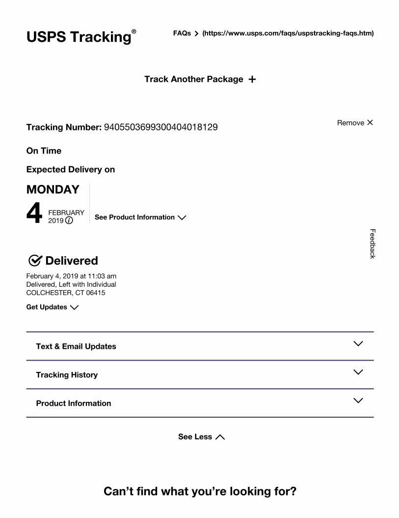
USPS Tracking FAQs (https://www.usps.com/faqs/uspstracking-faqs.htm)®
Track Another Package ++
See Less
Tracking Number: 9405503699300404018129
On Time
Expected Delivery on
MONDAY
4 FEBRUARY2019 See Product Information
DeliveredFebruary 4, 2019 at 11:03 amDelivered, Left with IndividualCOLCHESTER, CT 06415
Get Updates
Text & Email Updates
Tracking History
Product Information
Can’t find what you’re looking for?
Remove
Feedback
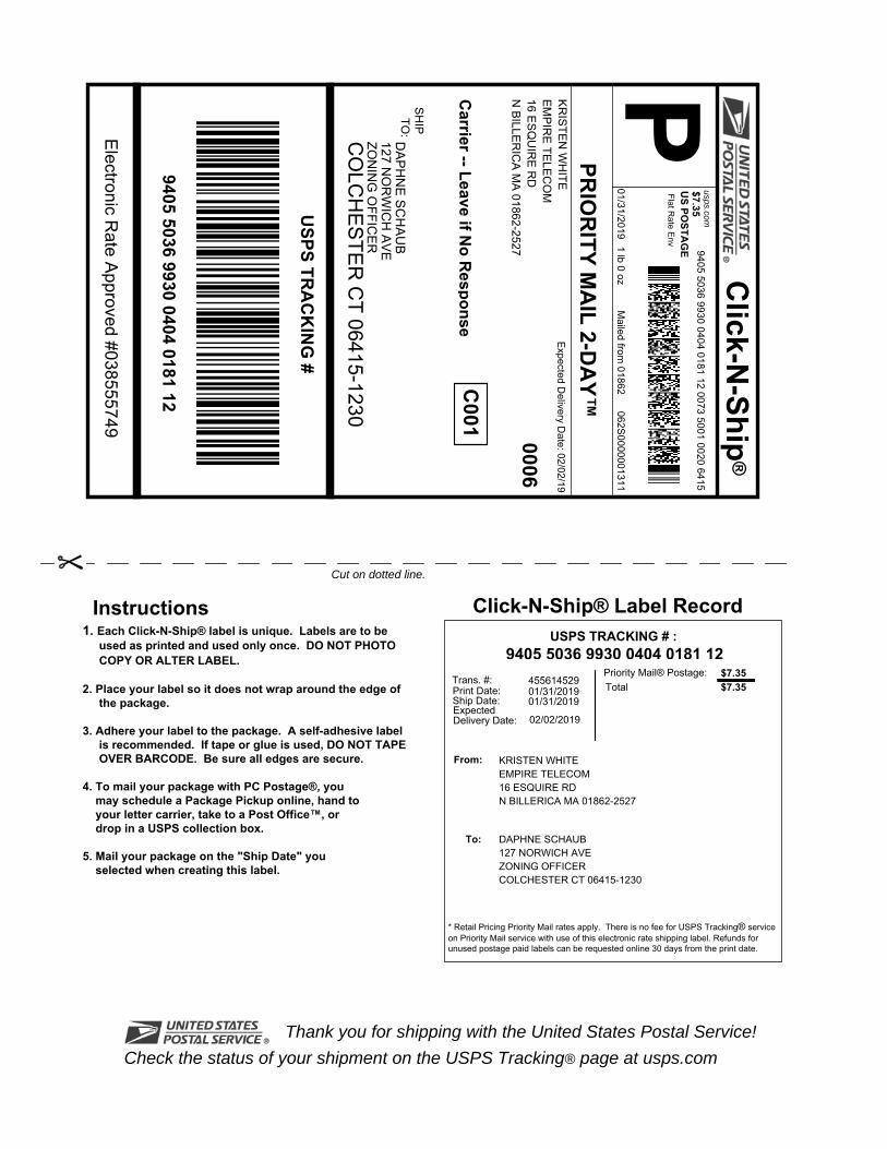
P
Cut on dotted line.
Instructions Click-N-Ship® Label Record
Electronic R
ate Approved #038555749
Thank you for shipping with the United States Postal Service!Check the status of your shipment on the USPS Tracking® page at usps.com
SH
IPTO
:
1. Each Click-N-Ship® label is unique. Labels are to beused as printed and used only once. DO NOT PHOTOCOPY OR ALTER LABEL.
2. Place your label so it does not wrap around the edge ofthe package.
3. Adhere your label to the package. A self-adhesive labelis recommended. If tape or glue is used, DO NOT TAPEOVER BARCODE. Be sure all edges are secure.
4. To mail your package with PC Postage®, youmay schedule a Package Pickup online, hand toyour letter carrier, take to a Post Office™, ordrop in a USPS collection box.
5. Mail your package on the "Ship Date" youselected when creating this label.
Priority Mail® Postage:
From:
To:
Print Date:Ship Date:
Click-N
-Ship®
Trans. #:
Expected Delivery Date:
usps.com
US PO
STAG
E
* Retail Pricing Priority Mail rates apply. There is no fee for USPS Tracking® service on Priority Mail service with use of this electronic rate shipping label. Refunds for unused postage paid labels can be requested online 30 days from the print date.
Carrier -- Leave if N
o Response
USPS TR
AC
KIN
G #
$7.35
ZON
ING
OFFIC
ER
DA
PH
NE
SC
HA
UB
9405 5036 9930 0404 0181 12
KRISTEN WHITEEMPIRE TELECOM16 ESQUIRE RDN BILLERICA MA 01862-2527
9405 5036 9930 0404 0181 12 0073 5001 0020 6415
PRIO
RITY M
AIL 2-D
AY™C
001
9405 5036 9930 0404 0181 12
Mailed from
01862
Total455614529
Expected D
elivery Date: 02/02/19
0006
CO
LCH
ES
TER
CT 06415-1230
127 NO
RW
ICH
AV
E
062S0000001311
01/31/2019
USPS TRACKING # :
01/31/2019
KR
ISTE
N W
HITE
EM
PIR
E TE
LEC
OM
16 ES
QU
IRE
RD
N B
ILLER
ICA
MA
01862-2527
Flat Rate E
nv
01/31/2019
DAPHNE SCHAUB127 NORWICH AVEZONING OFFICERCOLCHESTER CT 06415-1230
$7.35$7.35
02/02/2019
1 lb 0 oz

USPS Tracking FAQs (https://www.usps.com/faqs/uspstracking-faqs.htm)®
Track Another Package ++
See Less
Tracking Number: 9405503699300404018112
On Time
Expected Delivery on
MONDAY
4 FEBRUARY2019 See Product Information
DeliveredFebruary 4, 2019 at 11:03 amDelivered, Left with IndividualCOLCHESTER, CT 06415
Get Updates
Text & Email Updates
Tracking History
Product Information
Can’t find what you’re looking for?
Remove
Feedback
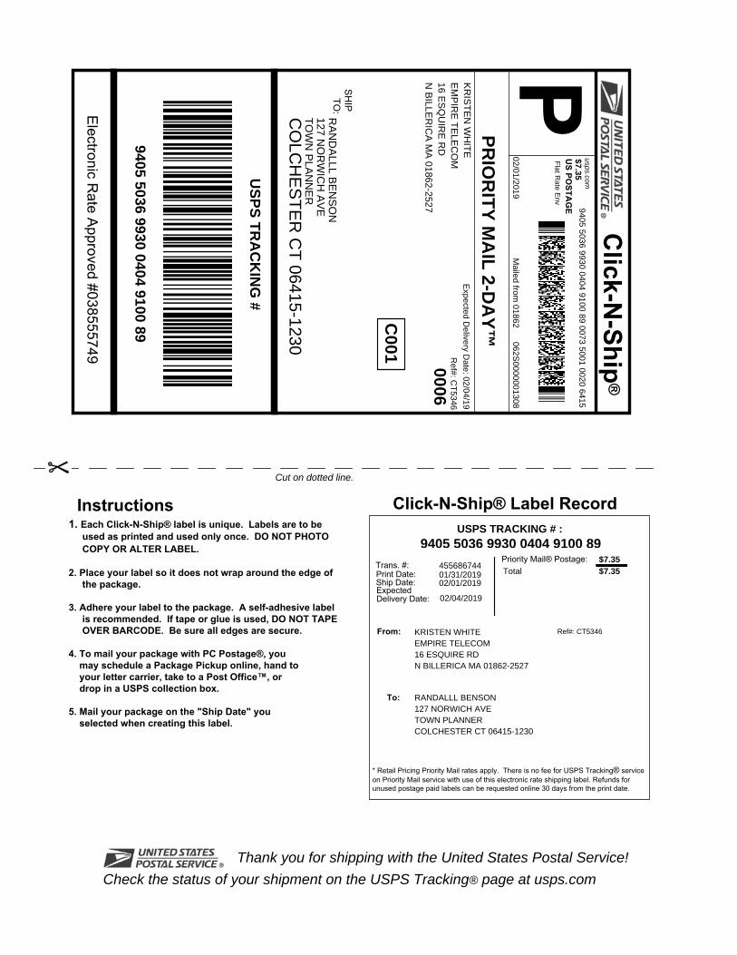
P
Cut on dotted line.
Instructions
Click-N-Ship® Label Record
Electronic R
ate Approved #038555749
Thank you for shipping with the United States Postal Service!Check the status of your shipment on the USPS Tracking® page at usps.com
SH
IPTO
:
1. Each Click-N-Ship® label is unique. Labels are to be used as printed and used only once. DO NOT PHOTO COPY OR ALTER LABEL.
2. Place your label so it does not wrap around the edge of
the package. 3. Adhere your label to the package. A self-adhesive label
is recommended. If tape or glue is used, DO NOT TAPE OVER BARCODE. Be sure all edges are secure.
4. To mail your package with PC Postage®, you may schedule a Package Pickup online, hand to your letter carrier, take to a Post Office™, or drop in a USPS collection box. 5. Mail your package on the "Ship Date" you selected when creating this label.
Priority Mail® Postage:
From:
To:
Print Date:Ship Date:
Click-N
-Ship®
Trans. #:
Expected Delivery Date:
usps.com
US PO
STAG
E
* Retail Pricing Priority Mail rates apply. There is no fee for USPS Tracking® service on Priority Mail service with use of this electronic rate shipping label. Refunds for unused postage paid labels can be requested online 30 days from the print date.
Ref#: C
T5346
USPS TR
AC
KIN
G #
$7.35
TO
WN
PLA
NN
ER
RA
ND
ALLL B
EN
SO
N
9405 5036 9930 0404 9100 89
KRISTEN WHITEEMPIRE TELECOM16 ESQUIRE RDN BILLERICA MA 01862-2527
9405 5036 9930 0404 9100 89 0073 5001 0020 6415
PRIO
RITY M
AIL 2-D
AY™C
001
9405 5036 9930 0404 9100 89
Mailed from
01862
Total455686744
Expected D
elivery Date: 02/04/19
0006
CO
LCH
ES
TE
R C
T 06415-1230
127 NO
RW
ICH
AV
E
Ref#: CT5346
062S0000001308
02/01/2019
USPS TRACKING # :
01/31/2019
KR
IST
EN
WH
ITE
EM
PIR
E T
ELE
CO
M16 E
SQ
UIR
E R
DN
BILLE
RIC
A M
A 01862-2527
Flat R
ate Env
02/01/2019
RANDALLL BENSON127 NORWICH AVETOWN PLANNERCOLCHESTER CT 06415-1230
$7.35$7.35
02/04/2019

USPS Tracking FAQs (https://www.usps.com/faqs/uspstracking-faqs.htm)®
Track Another Package ++
See Less
Tracking Number: 9405503699300404910089
On Time
Expected Delivery on
MONDAY
4 FEBRUARY2019 See Product Information
DeliveredFebruary 4, 2019 at 11:03 amDelivered, Left with IndividualCOLCHESTER, CT 06415
Get Updates
Text & Email Updates
Tracking History
Product Information
Can’t find what you’re looking for?
Remove
Feedback

UPS CampusShip: View/Print Label
1. Ensure there are no other shipping or tracking labels attached to your package. Select the Print button on theprint dialog box that appears. Note: If your browser does not support this function select Print from the File menu toprint the label.
2. Fold the printed label at the solid line below. Place the label in a UPS Shipping Pouch. If you do not have a pouch,affix the folded label using clear plastic shipping tape over the entire label.
3. GETTING YOUR SHIPMENT TO UPS Customers with a Daily PickupYour driver will pickup your shipment(s) as usual. Customers without a Daily PickupTake your package to any location of The UPS Store®, UPS Access Point(TM) location, UPS Drop Box, UPSCustomer Center, Staples® or Authorized Shipping Outlet near you. Items sent via UPS Return Services(SM)(including via Ground) are also accepted at Drop Boxes. To find the location nearest you, please visit the Resourcesarea of CampusShip and select UPS Locations.Schedule a same day or future day Pickup to have a UPS driver pickup all your CampusShip packages.Hand the package to any UPS driver in your area.
UPS Access Point UPS Access Point UPS Access PointMACLF-LOCKR-STOP & SHOP #480 JERRY'S VARIETY THE UPS STORE299 CHELMSFORD ST 1172 LAWRENCE ST 101 GREAT RDCHELMSFORD ,MA 01824 LOWELL ,MA 01852 BEDFORD ,MA 01730
FOLD HERE
TM TM TM
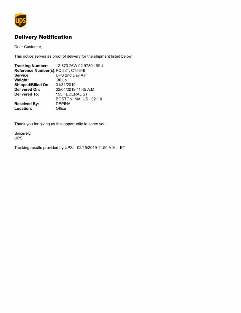
Delivery Notification Dear Customer, This notice serves as proof of delivery for the shipment listed below. Tracking Number: 1Z 870 26W 02 9739 199 4Reference Number(s):PC 321, CT5346Service: UPS 2nd Day AirWeight: .30 LbShipped/Billed On: 01/31/2019Delivered On: 02/04/2019 11:45 A.M.Delivered To: 155 FEDERAL ST
BOSTON, MA, US 02110Received By: DEPINALocation: Office
Thank you for giving us this opportunity to serve you. Sincerely, UPS Tracking results provided by UPS: 02/15/2019 11:50 A.M. ET
P
Cut on dotted line.
Instructions
Click-N-Ship® Label Record
Electronic R
ate Approved #038555749
Thank you for shipping with the United States Postal Service!Check the status of your shipment on the USPS Tracking® page at usps.com
SH
IPTO
:
1. Each Click-N-Ship® label is unique. Labels are to be used as printed and used only once. DO NOT PHOTO COPY OR ALTER LABEL.
2. Place your label so it does not wrap around the edge of
the package. 3. Adhere your label to the package. A self-adhesive label
is recommended. If tape or glue is used, DO NOT TAPE OVER BARCODE. Be sure all edges are secure.
4. To mail your package with PC Postage®, you may schedule a Package Pickup online, hand to your letter carrier, take to a Post Office™, or drop in a USPS collection box. 5. Mail your package on the "Ship Date" you selected when creating this label.
Priority Mail® Postage:
From:
To:
Print Date:Ship Date:
Click-N
-Ship®
Trans. #:
Expected Delivery Date:
usps.com
US PO
STAG
E
* Retail Pricing Priority Mail rates apply. There is no fee for USPS Tracking® service on Priority Mail service with use of this electronic rate shipping label. Refunds for unused postage paid labels can be requested online 30 days from the print date.
Carrier -- Leave if N
o Response
Ref#: C
T5346
USPS TR
AC
KIN
G #
$7.35
909 CH
ES
TN
UT
ST
AT
&T
MO
BILIT
Y
9405 5036 9930 0404 9133 87
KRISTEN WHITEEMPIRE TELECOM16 ESQUIRE RDN BILLERICA MA 01862-2527
9405 5036 9930 0404 9133 87 0073 5000 0066 3101
PRIO
RITY M
AIL 2-D
AY™C
074
9405 5036 9930 0404 9133 87
Mailed from
01862
Total455686852
Expected D
elivery Date: 02/04/19
0006
SA
INT
LOU
IS M
O 63101-2017
AT
T T
AX
MA
NA
GE
R
Ref#: CT5346
062S0000001310
01/31/2019
USPS TRACKING # :
01/31/2019
KR
IST
EN
WH
ITE
EM
PIR
E T
ELE
CO
M16 E
SQ
UIR
E R
DN
BILLE
RIC
A M
A 01862-2527
Flat R
ate Env
01/31/2019
AT&T MOBILITYATT TAX MANAGER909 CHESTNUT STSAINT LOUIS MO 63101-2017
$7.35$7.35
02/04/2019
USPS Tracking FAQs (https://www.usps.com/faqs/uspstracking-faqs.htm)®
Track Another Package ++
See Less
Tracking Number: 9405503699300404913387
On Time
Expected Delivery on
MONDAY
4 FEBRUARY2019 See Product Information
DeliveredFebruary 4, 2019 at 9:47 amDelivered, Front Desk/Reception/Mail RoomSAINT LOUIS, MO 63101
Get Updates
Text & Email Updates
Tracking History
Product Information
Can’t find what you’re looking for?
Remove
Feedback

UPS CampusShip: View/Print Label
1. Ensure there are no other shipping or tracking labels attached to your package. Select the Print button on theprint dialog box that appears. Note: If your browser does not support this function select Print from the File menu toprint the label.
2. Fold the printed label at the solid line below. Place the label in a UPS Shipping Pouch. If you do not have a pouch,affix the folded label using clear plastic shipping tape over the entire label.
3. GETTING YOUR SHIPMENT TO UPSCustomers with a Daily PickupYour driver will pickup your shipment(s) as usual.
Customers without a Daily PickupTake your package to any location of The UPS Store®, UPS Access Point(TM) location, UPS Drop Box, UPSCustomer Center, Staples® or Authorized Shipping Outlet near you. Items sent via UPS Return Services(SM)(including via Ground) are also accepted at Drop Boxes. To find the location nearest you, please visit the Resourcesarea of CampusShip and select UPS Locations.Schedule a same day or future day Pickup to have a UPS driver pickup all your CampusShip packages.Hand the package to any UPS driver in your area.
UPS Access Point UPS Access Point UPS Access PointMACLF-LOCKR-STOP & SHOP #480 JERRY'S VARIETY THE UPS STORE299 CHELMSFORD ST 1172 LAWRENCE ST 101 GREAT RDCHELMSFORD ,MA 01824 LOWELL ,MA 01852 BEDFORD ,MA 01730
FOLD HERE
TM TM TM

Proof of DeliveryDear Customer,
This notice serves as proof of delivery for the shipment listed below.
Thank you for giving us this opportunity to serve you. Details are only available for shipments delivered withinthe last 120 days. Please print for your records if you require this information after 120 days.
Sincerely,
UPS
Tracking results provided by UPS: 02/15/2019 11:48 A.M. EST
Tracking Number1Z87026W0296693580
Weight0.30 LBS
Service
UPS 2nd Day Air®
Shipped / Billed On01/31/2019
CLIFTON PARK, NY, US
Delivered On
02/04/2019 10:58 A.M.
Delivered To
Received By
RHOADES
Left AtInside Delivery