
new haven rail line - CT.gov
106
A STUDY OF THE FEASIBILITY OF UTILIZING FUEL CELLS TO GENERATE POWER FOR THE NEW HAVEN RAIL LINE AUGUST 2007 A REPORT BY THE CONNECTICUT ACADEMY OF SCIENCE AND ENGINEERING FOR THE CONNECTICUT DEPARTMENT OF TRANSPORTATION
-
Upload
khangminh22 -
Category
Documents
-
view
1 -
download
0
Transcript of new haven rail line - CT.gov

A Study of the feASibility of utilizing fuel CellS to generAte Power for the new hAven rAil line
AuguSt 2007
A rePort by
the ConneCtiCut ACAdemy of SCienCe
And engineering
for
the ConneCtiCut dePArtment of
trAnSPortAtion


A Study of the feASibility of utilizing fuel CellS
to generAte Power for the new hAven rAil line
A rePort by
the ConneCtiCut ACAdemy of SCienCe And engineering
Origin Of inquiry: COnneCtiCut Department Of
transpOrtatiOn
Date inquiry establisheD: nOvember 1, 2006 Date respOnse releaseD: august 29, 2007
© Copyright, 2007. Connecticut Academy of Science and Engineering, Inc. All rights reserved

feasibility Of utilizing fuel Cells fOr the new haven rail line
ii COnneCtiCut aCaDemy Of sCienCe anD engineering
This study was initiated at the request of the Connecticut Department of Transportation on November 1, 2006. The project was conducted by an Academy Study Committee with the support of Joseph M. King, Project Study Manager. The content of this report lies within the province of the Academy’s Transportation Systems Technical Board. The report has been reviewed by Academy Members Alan C. Eckbreth, PhD and Matthew S. Mashikian, PhD. Martha Sherman, the Academy’s Managing Editor, edited the report. The report is hereby released with the approval of the Academy Council.
Richard H. Strauss Executive Director
Disclaimer
The contents of this report reflect the views of the authors, who are responsible for the facts and accuracy of the data presented herein. The contents do not necessarily reflect the official views or policies of the Connecticut Department of Transportation. The report does not constitute a standard, specification, or regulation.

Technical Report Documentation Page
1. Report No.
92-616-F-07-5
2. Government Accession No. 3. Recipients Catalog No.
5. Report Date
August 2007
4. Title and Subtitle
A Study of the Feasibility of Utilizing Fuel Cells
to Generate Power for the New Haven Rail Line 6. Performing Organization Code
92-616
7. Author(s)
Joseph M. King, Jr., Project Study Manager
8. Performing Organization Report
No.
CT-92-616-F-07-5
10. Work Unit No. (TRIS)
11. Contract or Grant No.
CT Study No. 92-616
9. Performing Organization Name and Address
Connecticut Academy of Science &
Engineering
179 Allyn Street, Suite 512
Hartford, CT 06103 13. Type of Report and Period
Covered
Final Report
November 2006 – August 2007
14. Sponsoring Agency Code
92-616
12. Sponsoring Agency Name and Address
Connecticut Department of Transportation
2800 Berlin Turnpike
Newington, CT 06131-7546
15. Supplementary Notes Project partners: Connecticut DOT - Bureau of Engineering and Highway Operations, Bureau of
Public Transportation, and Division of Research; Connecticut Academy of Science and Engineering.
16. Abstract
Stationary fuel cell power plants have been deployed in commercial operation
since the early 1990’s. The Connecticut General Assembly seeks to determine the
feasibility of using fuel cells for the New Haven commuter rail line. Ongoing
rail infrastructure improvements provide a window of opportunity to use fuel cell
products manufactured in Connecticut as a clean and efficient power source while
simultaneously growing the Connecticut economy. Two Connecticut companies,
FuelCell Energy and UTC Power, are currently the only companies that offer
commercial products with ratings above 100 kilowatts, a level deemed appropriate
for most rail line applications.
This report defines New Haven rail line candidate applications; determines
technical feasibility of utilizing fuel cell power plants to meet these
requirements; identifies economic consequences of using fuel cells; recommends
appropriate utilization of fuel cells, and; identifies additional effort required
to prepare and issue a request for fuel cell bids.
17. Key Words
Fuel cells, rail car traction
power, catenary system power, rail
station power, rail maintenance
yard power, emergency power.
18. Distribution Statement
No restrictions. This document is available
to the public through the National Technical
Information Service, Springfield, VA 22161
19. Security Classif.
(Of this report)
Unclassified
20. Security Classif.(Of
this page)
Unclassified
21. No. of
Pages
102
20. Price
Form DOT F 1700.7 (8-72) Reproduction of completed page authorized

feasibility Of utilizing fuel Cells fOr the new haven rail line
iv COnneCtiCut aCaDemy Of sCienCe anD engineering

feasibility Of utilizing fuel Cells fOr the new haven rail line
vCOnneCtiCut aCaDemy Of sCienCe anD engineering
MEMBERS OF THE
CONNECTICUT ACADEMY OF SCIENCE AND ENGINEERING STUDY COMMITTEE ON
A STUDY OF THE FEASIBILITY OF UTILIZING FUEL CELLS TO GENERATE POWER FOR THE NEW HAVEN RAIL LINE
reSeArCh teAm
STUDY MANAGERJoseph M. King, Jr.
Consultant
ACADEMY PROJECT STAFFRichard H. Strauss
Academy Executive Director
A. George Foyt (Academy Member)Manager of Electronics Research
United Technologies Research Center (ret.)
Trent M. MolterResearch Scientist &
Business Development OfficerConnecticut Global Fuel Cell Center
University of Connecticut
Kenneth L. Reifsnider, PhD (Academy Member)
ChairmanDirector, Solid Oxide Fuel Program and
Professor of Mechanical Engineering and Educational Foundation University Professor,
University of South CarolinaFormerly, Pratt & Whitney Professor of Design
and ReliabilityDirector, Connecticut Global Fuel Cell Center
University of Connecticut
Alan J. RiceTechnical Services Manager
AIG Global Marine and Energy
Keith A. SpitznagelSenior Vice President, Marketing & Sales
LOGANEnergy Corporation
Robert W. WalkerDirector – Operating Capital Projects
Metro North Railroad
Rich WalshSenior Account Executive
Connecticut Light & Power
George R. Wisner (Academy Member)Principal
Wisner Associates

feasibility Of utilizing fuel Cells fOr the new haven rail line
vi COnneCtiCut aCaDemy Of sCienCe anD engineering

feasibility Of utilizing fuel Cells fOr the new haven rail lineexeCutive summary
COnneCtiCut aCaDemy Of sCienCe anD engineering vii
EXECUTIVE SUMMARY
STATEMENT OF INQUIRY
Background
The New Haven Rail Line, operated by Metro-North Commuter Railroad (MNR) for the Connecticut Department of Transportation (ConnDOT), is a key element of Connecticut’s transportation infrastructure. The line involves over 100 miles of track in the main and branch lines, nearly 35 million passengers per year and over 300 trains daily, including 282 operated by MNR and 37 operated by Amtrak.
Significant improvements to this component of Connecticut’s transportation system are occurring over the next decade in accordance with recommendations made by the Connecticut Transportation Strategy Board (“Moving Forward, Connecticut’s Transportation Strategy, Report and Recommendations of the Transportation Strategy Board,” January, 2007). When these upgrades are completed, the line will be responsible for electricity consumption equal to 0.7% of the total electric energy consumption of the state. Since this consumption is concentrated in the southwestern region of the state, where transmission congestion is a problem, alternative approaches to providing power for the New Haven Line could be constructive.
Stationary fuel cell power plants have been deployed in commercial operation since the early 1990s, and two Connecticut companies—FuelCell Energy and UTC Power—are currently the only companies to offer commercial products with ratings in excess of 100 kilowatts (kW) appropriate to use in New Haven Line applications. The New Haven Line infrastructure improvements provide a valuable window of opportunity to use fuel cell products manufactured in Connecticut to provide clean, efficient power to serve the increasing electricity needs of the New Haven Line, while at the same time accelerating deployment of fuel cell power plants with the attendant growth in the Connecticut economy.
In 2006, the Connecticut General Assembly, in Public Act No. 06-136, mandated a study of “the feasibility of building a fuel cell power station to generate power for the New Haven Line.”
Study Description
This study was conducted for ConnDOT by the Connecticut Academy of Science andEngineering (CASE), with ConnDOT required to report the study’s findings and recommendations to the General Assembly on or before January 1, 2008.
The objectives of the study are to define the applications for electric power on the New Haven Line; to determine the technical feasibility of fuel cell power plants to meet these requirements; to identify the economic consequences of using fuel cells; to recommend the best applications for use of fuel cells; and to identify additional effort required preparatory to issuing a request for bids on the most promising fuel cell applications.

COnneCtiCut aCaDemy Of sCienCe anD engineeringviii
feasibility Of utilizing fuel Cells fOr the new haven rail lineexeCutive summary
The scope of applications considered included the following:
Primary power from natural gas-fueled fuel cell power plants operating in parallel with • power from the utility network in which one parallel source maintains power to critical loads if an outage occurs in the other source. This concept was applied to traction power, maintenance yard power and large passenger stations.
Back-up power for emergency power needs of small passenger stations using hydrogen-• fueled fuel cell power plants.
SUMMARY OF FINDINGS
Electric Power Requirements
With completion of expansion of the New Haven maintenance yard in 2015 and addition of passenger stations in West Haven, Milford and Fairfield, the total electric power demand of the New Haven Line is estimated to be nearly 50,000 kW and annual electric energy consumption is estimated to be over 200 million kilowatt hours (kWh).
Table ES-1 summarizes the characteristics of the different power applications on the New Haven Line and summarizes the current cost of power and the potential cost of power from fuel cells meeting manufacturer cost goals. Traction power for the trains is responsible for 61% of the total demand, with maintenance yard power, station power and control and signal power accounting for 33%, 6% and less than 1%, respectively.
Traction Maintenance Yards
Passenger Stations
Control and Signaling
Power Demand (kW) >30,300 Growing to 16,000 >3,000 100Power Form
(Frequency/Number Phases/voltage)
60/ 1/12,500 60/3/480 60/3/480 100/1/12,500
Load Factor (%) 35 - 45 35 - 55 50 - 70 Not AvailableUse for Heat No Yes Yes NoCritical Power Needs No Yes Yes YesPower Demand Increasing?
Yes Yes (New
construction)
Yes (New
Construction)
No
Current Cost of Electricity (cents per kWh)
11.3 14.7 - 15.7 12.5 - 13 Not Available
Cost of Electricity from Fuel Cell (cents per kWh)*
13 - 27 13 - 16 13 - 16 Not Available
Availability of space for fuel cell
Limited Will probably require roof mounting
Constrained Available
*At cost goal of $2,000/kW installed. Will be reduced with environmental and congestion incentives, which depend on specific situation, market factors and which in some cases require application and evaluation.
table es-1: new haven line eleCtriC pOwer requirements

feasibility Of utilizing fuel Cells fOr the new haven rail lineexeCutive summary
COnneCtiCut aCaDemy Of sCienCe anD engineering ix
Commercial fuel cell power plants produce three-phase power at a frequency of 60 Hz (cycles per second) for use in the United States and at a frequency of 50 Hz to serve electric applications in Europe and many other portions of the world. This form of power is consistent with power used in maintenance yard and passenger station facilities. The single-phase, high-voltage power used in the traction power system will require modification to the electrical output of the fuel cell power plant. This modification will not involve new technology, but rather a design change which could be as simple as use of two inverter systems instead of one. In summary, there are no issues with technical feasibility of fuel cells in New Haven Line applications.
Fuel cell power plants produce both power and heat. Applications which operate the fuel cell at full electrical capacity and which utilize a high percentage of available fuel cell heat improve the prospects for fuel cell power plant economics. Another factor improving the prospects is the ability of the fuel cell, combined with the electric network, to provide critical power at lower cost than by adding emergency generators or uninterruptible power systems. Table ES-1 shows that passenger stations and maintenance yards have characteristics which are favorable to fuel cell power economics, but that traction power has characteristics which are less favorable to the cost of fuel cell power.
Installation of fuel cells during construction of new facilities will reduce installation cost and time, so the fact that power demand is increasing is favorable in most of the applications. Power requirements in the New Haven yard are expected to increase by a factor of ten, from 1,270 kW to 15,000 kW, with many new buildings being constructed between 2008 and 2015. An expansion of the parking garage facilities at the New Haven station is another situation where the construction may facilitate fuel cell installation.
Traction power is expected to increase to accommodate increasing passenger loads and design of the cars to provide better access for passengers with disabilities. However, this need for increased power will be accommodated by an already planned additional supply point. Installation of fuel cells distributed along the line between supply points would provide more uniform voltage levels along the line and improved power security. If improved power security becomes a key issue with regard to traction power, fuel cells distributed along the line could provide a more robust electrical system. Another factor which could enhance the suitability of fuel cells for the traction application is the development of Energy Improvement Districts along the line, which would provide a use for and an economic benefit from the product heat produced by fuel cell power plants.
Another important application factor is availability of space to install fuel cell power plants. Traction power fuel cells would have to be installed adjacent to the utility line, and this area is very congested. This could lead to significant cost and approval issues in this application. Passenger station and yard applications involve land already owned by the state for rail purposes, so this presents somewhat lesser concerns regarding land acquisition costs and approval issues. For new maintenance buildings in the rail yard at New Haven, rooftop installation would present fewer siting issues.
Fuel cell power plants are in early stages of commercial deployment and cost is high, in part, because production volume is still low. At historic fuel cell costs of $4,000 to $5,000 per kW, fuel cells are not competitive in New Haven Line applications. Fuel cell manufacturers have cost goals of $2,000/kW which they expect to achieve with higher production rates and

COnneCtiCut aCaDemy Of sCienCe anD engineeringx
feasibility Of utilizing fuel Cells fOr the new haven rail lineexeCutive summary
further technology advances. Table ES-1 shows that power plants meeting these cost goals are competitive for some New Haven Line applications without benefit of incentives, but will require incentives to be competitive for the traction power application. Fuel cell electricity costs in Table ES-1 do not include the benefit of substantial incentives for the environmental features of fuel cells or their ability to defer transmission line investment in congested areas. Capturing these incentives, coupled with avoidance of investment in back-up power in situations where it is required, could make fuel cells at the cost goal competitive in all applications. Capturing the incentives would also make fuel cell power plants costing more than the $2,000/kW goal competitive in some New Haven Line applications.
Fuel Cell Characteristics
The two Connecticut manufacturers, who are the only producers of commercial stationary fuel cell power plants with ratings in excess of 100 kW, made presentations on the characteristics of their power plants to the CASE Study Committee and also provided additional information. In addition, information was developed on fuel cells in the development stage by other manufacturers. Table ES-2 compares characteristics of molten carbonate fuel cells from FuelCell Energy and phosphoric acid fuel cells from UTC Power.
FuelCell Energy UTC Power
Fuel Cell Technology Molten Carbonate Phosphoric Acid
Power Plant Ratings (kW) 300, 1,200, 2,400 200, 400
Electrical Generation Efficiency (%-Lower Heating Value)
47 40 to 42
Total Heat Available (BTU/kWh electricity delivered)*
2,670 4,000+
High Grade Heat Available*(BTU/kWh electricity delivered)
1,580 - 1,920 2,580 - 2,700
High Grade Heat Temperature (Degrees F)
Heat exchange with a gas stream ranging from 250 - 700
250
Footprint(ft2/kW)
2.2 - 4.2 2.3 - 3.5
Start Time(hours)
72 5
Response to Load Change 8 hours, instantaneous with load absorber
Instantaneous
Water required (gallons/kWh) 0.18 None
Stack Life in years Current/Projected
3/5 5/10
* Total heat available includes high-grade heat, which is at temperatures of 250º F or above, as well as low-grade heat available at lower temperatures.
table es-2: summary Of fuel Cell CharaCteristiCs
feasibility Of utilizing fuel Cells fOr the new haven rail lineexeCutive summary
COnneCtiCut aCaDemy Of sCienCe anD engineering xi
The value of the differences in fuel cell characteristics shown in summary form in this table and in more detail in the body of this report depends on the specifics of the situation. Results of bids to detailed specifications will be required to determine which power plant is best suited to a specific application.
Because this study may lead to a procurement action, the fuel cell companies were not asked to provide cost information. However, other sources indicate that current fuel cell costs are in the range of $4,000 to $5,000 per kW and the manufacturers have cost goals of $2,000/kW which they expect to reach with higher production rates and continued improvement in designs and technology.
Significant experience with fuel cell power plants in applications similar to yard power and station power applications on the New Haven Line has been accumulated since the early 1990s, and unattended fuel cell power plants have availability of 95%, which is equal to or greater than central station power plants with a three-shift operating and maintenance staff. Multi-Megawatt installations of fuel cell power plants have been used in other applications. However, the single-phase, high-voltage requirements of the traction power application would require a straightforward design modification to current fuel cell power plant products.
Economic Incentives
Because the fuel cell operates efficiently and cleanly in ratings consistent with individual loads, it contributes to a cleaner environment and more dependable power. Consequently, a number of incentives are available which improve the economics of fuel cell power plants installed in Connecticut. These incentives include sale of Renewable Energy Certificates to meet Connecticut Renewable Portfolio standards, capacity credits from ISO New England, incentives from the Connecticut Clean Energy Fund for On-Site Renewable Distributed Generation and a Federal Income Tax Credit. These incentives could reduce cost of fuel cell electricity significantly.
Federal Support
The federal government has significant programs in support of fuel cell power plants for stationary and vehicle power. However, an initial review of programs of the US Department of Energy, Department of Homeland Security and Department of Transportation did not identify any programs which have funds specifically available for stationary fuel cell power plants which have been deployed on a commercial basis. While allocation from grants to Connecticut from the Department of Homeland Security or Department of Transportation is possible, this would be at the expense of allocations to other projects where these funds are historically applied, and stationary fuel cell power plant projects may not meet criteria for use of these funds. The Department of Homeland Security has not made power reliability for transportation infrastructure a high priority objective and consequently, no funds from that source are expected.
Suggested Fuel Cell Applications
The best application of fuel cells to New Haven Line electrical power appears to be for new maintenance buildings in the New Haven yard. These buildings provide good use for the power plant heat, and use of fuel cells would reduce or eliminate the cost of back-up power.

COnneCtiCut aCaDemy Of sCienCe anD engineeringxii
feasibility Of utilizing fuel Cells fOr the new haven rail lineexeCutive summary
Because the yard involves only one meter, excess power from one building will be used in other buildings in the complex and no export to the utility will occur. New construction will minimize the cost of fuel cell installation. A number of buildings appear to be good candidates and multiple installations at this site are possible over the next decade. The best use of fuel cells in the New Haven yard would be as a source of critical power for new buildings. A total of 2,200 kW of fuel cell capacity would be required to serve this application, which would require a number of fuel cell power plants to be located at individual buildings. The economics of these fuel cells would be enhanced by recovery of a significant portion of their product heat.
Fuel cell power plant installation at the new parking garage at the New Haven passenger station should also be considered. This application also involves new construction and the possibility of avoiding the cost of a standby generator.
A recent study of the adequacy of the traction power supply resulted in plans to add a fourth supply point where power is provided from the utility network. With this change, electric power will not be a constraint even with increased traffic on the Line through 2020. Consequently, other than economics, the only benefit of using fuel cells for traction power would be a reduction in line losses and improved voltage control along the line. The economics of fuel cell power for traction are less favorable than the economics for yard power or passenger station power because there is no need for heat or for critical power and no need for additional electric power facilities. Integrating the electrical load of the traction power system with thermal loads of facilities adjacent to the New Haven Rail Line would improve economics of fuel cells in traction power applications, and implementation of Energy Improvement Districts facilitated by action of the General Assembly in 2007 could achieve this result.
If fuel cell power plants are applied to traction power, they could be used in combination with the utility network to provide greater power reliability in emergency situations. Depending on the amount of fuel cell power installed, this would permit partial to full passenger service in the event of a utility power outage.
If emergency power for smaller passenger stations becomes a requirement, hydrogen- fueled fuel cell power plants for this application should be considered.
Fuel cell power plants are still in the early stages of commercialization and historic costs of fuel cell power plants do not yield competitive economics unless a significant portion of the incentives for environmental characteristics and avoidance of transmission congestion described above are captured. Experience with fuel cell production is increasing, and further technology improvements which could make fuel cell economics more competitive in the future are expected. A firm understanding of fuel cell economics will require analysis of bids for a specific application.
Use of fuel cells in maintenance yard and passenger station facilities is consistent with actions in Public Act 07-242 to establish a strategic plan to improve energy management in state buildings and to provide bonding in accordance with implementation of that strategic plan.
Alternative forms of ownership including state ownership and ownership by third parties should be considered in order to establish the best economic approach for providing fuel cell power on the New Haven Line.

feasibility Of utilizing fuel Cells fOr the new haven rail lineexeCutive summary
COnneCtiCut aCaDemy Of sCienCe anD engineering xiii
Suggested Action
This report provides an initial assessment of the technical and economic feasibility of stationary fuel cell power for the New Haven Line, and indicates the most attractive applications. However, more information is needed to assess specific applications. Some of this information will be developed as design of the new buildings in the New Haven yard and the new parking garage at the New Haven Station proceeds. Other information will require a study of line losses on the catenary system. Section 6 of this report provides detail on the additional information and action required prior to issuing a request for bids, and suggests information which should be requested from the bidders as well as suggestions for evaluating the bids.

feasibility Of utilizing fuel Cells fOr the new haven rail line
xiv COnneCtiCut aCaDemy Of sCienCe anD engineering

feasibility Of utilizing fuel Cells fOr the new haven rail line
COnneCtiCut aCaDemy Of sCienCe anD engineering xv
TABLE OF CONTENTS
EXECUTIVE SUMMARY ......................................................................................vii
TABLE OF CONTENTS ..........................................................................................xv
1. INTRODUCTION ................................................................................................ 1
2.. REQUIREMENTS ANALYSIS .......................................................................... 5
3. PRELIMINARY IDENTIFICATION OF FUEL CELL CHARACTERISTICS FOR PRIMARY POWER APPLICATION .... 19
4. PRELIMINARY IDENTIFICATION OF HYDROGEN-Fueled FUEL CELL CHARACTERISTICS FOR EMERGENCY POWER AND PEAKING POWER ............................. 31
5. FUEL CELLS APPLICATION ANALYSIS ..................................................... 33
6. IDENTIFICATION OF ADDITIONAL INFORMATION REQUIRED FOR BID PACKAGE SPECIFICATION .......................... 55 7. SUMMARY OF FINDINGS AND CONCLUDING REMARKS .................... 57
GLOSSARY ....................................................................................................................61
ACKNOWLEDGEMENTS ..........................................................................................69
APPENDICES .......................................................................................................... 71
Appendix A: Use of Fuel Cells as an Onboard Traction Power Source .... 71 Appendix B: Electrical Load Duration Curves for Traction Power Supply Points ................................................................................................. 72
Appendix C: Detailed Description of Stamford Station Complex ............ 74
Appendix D: Power Plant Installation Layouts........................................... 76
Appendix E: Summary of Solid Oxide Fuel Cell Activity .......................... 83 Appendix F: Cost of Electricity Calculations ............................................... 84 Appendix G: Possible Locations for Fuel Cell Power Plants Serving the Traction Power System ........................................................... 86

feasibility Of utilizing fuel Cells fOr the new haven rail line
xvi COnneCtiCut aCaDemy Of sCienCe anD engineering

feasibility Of utilizing fuel Cells fOr the new haven rail line intrODuCtiOn
COnneCtiCut aCaDemy Of sCienCe anD engineering 1
1. INTRODUCTION
This study of the feasibility of the application of stationary fuel cells to power needs on the New Haven Line was conducted by the Connecticut Academy of Science and Engineering (CASE) at the request of the Connecticut Department of Transportation (ConnDOT).
The study was mandated by the 2006 Connecticut General Assembly in Public Act No. 06-136, Section 19 from which states:
“The Department of Transportation shall study the feasibility of building a fuel cell power station to generate power for the New Haven Line. Such study shall include, but need not be limited to, a plan for generating a large percentage of the line’s peak power needs, as well as serving as a back-up in times of emergencies. On or before January 1, 2008, the Department of Transportation shall report its findings and recommendations, in accordance with the provisions of section 11-4a of the general statute, to the joint standing committees of the General Assembly having cognizance of matters relating to transportation and the budgets of state agencies.”
In response to the legislation, CASE and ConnDOT defined a scope of study which considered the following applications:
Primary power from natural gas-fueled fuel cell power plants operating in parallel • with power from the utility network in which the utility provides emergency power to critical loads if a fuel cell outage occurs.
Applications considered included traction power, power for maintenance yard • facilities and large passenger stations at New Haven and Stamford.
In the case of maintenance yards and large passenger stations, fuel cell power • plants would provide a portion of the electric load consistent with critical power needs.
In the case of traction power, installation sizing ranged from base-load operation • to the ability to meet the normal peak power needs of the traction power system.
Use of power plant heat for maintenance yard facilities, passenger station • facilities and facilities adjacent to the rail line
Back-up power for emergency power needs of small passenger stations using hydrogen-• fueled fuel cell power plants.
The Connecticut portion of the New Haven Line runs 46 miles from the New York State border to New Haven, Connecticut. Trains on the main New Haven Line are electric, powered in Connecticut through an overhead catenary. The New Haven Line has branches to New Canaan (7.9 miles), Danbury (23.3 miles) and Waterbury (26.9 miles). The New Canaan branch is
COnneCtiCut aCaDemy Of sCienCe anD engineering2
feasibility Of utilizing fuel Cells fOr the new haven rail lineintrODuCtiOn
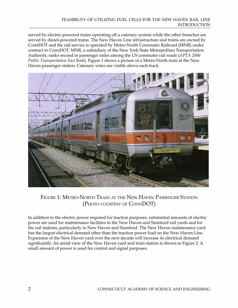
served by electric-powered trains operating off a catenary system while the other branches are served by diesel-powered trains. The New Haven Line infrastructure and trains are owned by ConnDOT and the rail service is operated by Metro-North Commuter Railroad (MNR) under contract to ConnDOT. MNR, a subsidiary of the New York State Metropolitan Transportation Authority, ranks second in passenger miles among the US commuter rail roads (APTA 2006 Public Transportation Fact Book). Figure 1 shows a picture of a Metro-North train at the New Haven passenger station. Catenary wires are visible above each track.
figure 1: metrO-nOrth train at the new haven passenger statiOn (phOtO COurtesy Of COnnDOt)
In addition to the electric power required for traction purposes, substantial amounts of electric power are used for maintenance facilities in the New Haven and Stamford rail yards and for the rail stations, particularly in New Haven and Stamford. The New Haven maintenance yard has the largest electrical demand other than the traction power load on the New Haven Line. Expansion of the New Haven yard over the next decade will increase its electrical demand significantly. An aerial view of the New Haven yard and train station is shown in Figure 2. A small amount of power is used for control and signal purposes.

feasibility Of utilizing fuel Cells fOr the new haven rail line intrODuCtiOn
COnneCtiCut aCaDemy Of sCienCe anD engineering 3
figure 2: new haven rail yarD aerial phOtO - nOvember 2006 (phOtO COurtesy Of COnnDOt)
Approximately 32 million passengers use the main line service annually with 2.2 million passengers per year carried on the branch lines. (“Moving Forward, Connecticut’s Transportation Strategy, Report and Recommendations of the Transportation Strategy Board,” January, 2007).
The electrically propelled railcars used on the Line include M2, M4 and M6 multiple unit commuter cars as well as Amtrak AEM-7 and Acela electric locomotives. The M2 cars, which are the oldest, entered service in the 1970s. New M8 cars are scheduled to begin entering service in 2008 (ConnDOT website: www.ct.gov/dot/cwp/view.asp?a=1390&q=316752.)
Currently, there are 319 trains operating each weekday on the New Haven Line. Of these, 282 are operated by MNR; 242 of the MNR trains are electric and the remaining trains are diesel powered (private communication from Bob Walker, MNR). In addition, 37 Amtrak electric trains operate over the New Haven Line each day.
The New Haven Line connects to Amtrak-owned facilities in New Haven for service to Boston via Amtrak, to New London via Shore Line East and to Amtrak facilities for service to Hartford and Springfield.

COnneCtiCut aCaDemy Of sCienCe anD engineering4
feasibility Of utilizing fuel Cells fOr the new haven rail lineintrODuCtiOn
A study of the traction loads of the New Haven Line by Systra Engineering (“Metro-North Railroad Traction Power Study, New Haven Line AC Territory Final Report (Version 1)” Systra Engineering, January 25, 2006) provides information on the performance and power requirements of train cars operated on the New Haven Line. The MNR cars are limited to 80 amps current at 12,500 volts or 1,000 kilovolt amperes (kVA). A top speed of 90 mph can be achieved in 90 to 160 seconds depending on the specific car model; power demand at speeds of 70 mph is 400 to 700 kilowatts (kW), again depending on the specific car model. Since the trains make many stops and travel at less than top speed much of the time, the average load imposed by a train is much lower than the peak power demands described above. Commuter cars on the New Haven Line have auxiliary loads for lighting, air conditioning and heating of 64 kW per car and some of these auxiliary loads, particularly heating, will be imposed in winter when the cars are in the yards overnight to keep water in the cars from freezing.
Increases in train traffic and the average number of cars in each train are expected in order to accommodate
increased passenger traffic;•
reduced car capacity associated with increased size of rest rooms to meet American’s • with Disability Act requirements;
relocation of equipment now outside the car to the car interior to improve reliability; • this also reduces passenger capacity per car.
This will increase electrical loads for traction. In addition to the increases in number of trains and cars per train, the newer cars will be heavier because of the addition of redundant equipment, which will lead to further increases in power demand.
Significant investment in improvements to the rail cars, the New Haven yard facilities and individual stations are recommended in the report of the Connecticut Transportation Strategy Board (TSB). These improvements provide an opportunity to install fuel cells in a new, rather than a retrofit, situation. (“Moving Forward, Connecticut’s Transportation Strategy, Report and Recommendations of the Transportation Strategy Board,” January, 2007)
While fuel cell power onboard rail cars is not within the scope of this study, there are efforts in Japan to develop and demonstrate this fuel cell application for commuter rail, and there is an effort in the United States to demonstrate the application to a yard switcher. This application requires higher durability and reliability than applications to light-duty vehicles or transit buses, and is not likely to be considered seriously until fuel cells have been proven in these less demanding applications. These efforts are summarized in Appendix A.

COnneCtiCut aCaDemy Of sCienCe anD engineering 5
feasibility Of utilizing fuel Cells fOr the new haven rail linerequirements analysis
2. REQUIREMENTS ANALYSIS
The New Haven Line requires power for four essential purposes:
traction (power to drive the trains)•
signaling•
stations•
rail yards•
A summary of the total power requirements and power forms for these different applications is provided in Table 1. The consumption of electric energy for all power applications associated with the New Haven Line is estimated to exceed 150 million kilowatt hours (kWh) annually (equivalent to 15,000 homes) and this total will grow by about 40% with completion of the New Haven rail yard expansion. This represents on the order of 0.5% - 0.7% of the current total electricity consumption in Connecticut, which in 2005 was 33 billion kWh (Energy Information Agency, US Department of Energy).
Application Total Demand (kW) Power Form
Traction The sum of demands of individual supply points is 48,000 kW. The coincident demand of the supply points is 30,300 kW
25 kilovolts (kV), 60 Hz, single-phase, center tapped with catenary voltage at 12.5 kV
Stations 3,000 kW. Will increase with new garages in New Haven and West Haven
Three-phase, 480 volts or single-phase 120 volts
Control and Signal Power 100 kW 12,000 Volts, 100 Hz, single-phase reduced at utilization to 120 Volts
Rail yards Approximately 16,000 kW with completion of expansion of New Haven yard
480 Volts, 60 Hz, three-phase
Total 49,000 kW Various (see above)
table 1: new haven line pOwer DemanDs
The scope of this study does not include the use of fuel cell power onboard the rail cars. However, experiments with this type of fuel cell application are underway in Japan, the United States and other countries. These demonstration projects are described in Appendix A. This could be a future consideration for cars operating on the Danbury and Waterbury branches of the New Haven Line, Shore Line East and the New Haven to Hartford and Springfield Line.

COnneCtiCut aCaDemy Of sCienCe anD engineering6
feasibility Of utilizing fuel Cells fOr the new haven rail linerequirements analysis
TRACTION POWER
Operating the trains on the Connecticut portion of the New Haven Line requires a coincident power demand of approximately 30 Megawatts (30,000 kW) at the point of maximum power demand. The electrical load varies widely, from a minimum during the period from 2 - 4 am to a peak during the 6 - 9 am peak traffic period. Power is supplied to the trains through a single-phase, 60 Hz catenary at 12.5 kilovolts (kV). Pantographs located on cars on the train contact the catenary. The circuit is completed through contact with the rails, which operate at ground potential. The power is purchased from the utility network at transmission voltage. It is delivered through transformers connected to two phases of the transmission system and transformed to the lower voltage of 25 kV at three existing supply points within the Connecticut portion of the New Haven Line. Another supply point will be added in the near future. The Systra study indicates that with this addition, the traction power system will meet traffic needs through 2020. The single-phase is “center tapped” to form a ground and two 12.5 kV power legs. One of these legs powers the catenary and the other powers a feeder wire. At thirteen wayside substations along the Connecticut section of the New Haven Line, the feeder wire connects to the catenary through an autotransformer to provide power and voltage support. Ratings for these wayside substations range from 4,000 - 12,000 (kVA). Multiple transformers with ratings between 2,000 – 4,000 kVA make up the substation capacity. Figure 3 shows a simplified electrical diagram of the system. The traction power substations connect the feeder wire to the catenary through a transformer to provide more uniform voltage between power supply points. Figure 4 shows the connection between the feeder wire and the catenary at the wayside substations.

COnneCtiCut aCaDemy Of sCienCe anD engineering 7
feasibility Of utilizing fuel Cells fOr the new haven rail linerequirements analysis
N.C
.
AØBØ
CØ
N.C
.
BØBØ
CØCØ
BØ
COS
COB
WAT
ERSI
DE
GLE
NBR
OO
K
COS
COB
NO
RWA
LK
HBR FL
AX
HIL
L
NO
RWA
LK
HAWT
HORN
WES
TON
OLDT
OWN
BAIR
DD
EVO
NTI
E
N.U
. SU
PPLY
SASC
O C
REEK
DARI
EN
SOU
TH E
ND
GREEN
SIGNAL HOUSE
STAMFORD
DARIEN
SOUTH NORWALK
PORT
BISHOP AVE
DEVON
WOODMONT
NEW HAVEN
EAST NORWALK
N.U
. SU
PPLY
N.U
. SU
PPLY
BPT.
HBR
. &PE
QU
ON
NO
CKA
SHCR
EEK
BARN
UM
DEV
ON
RAIL
ROA
D
DEV
ON
WEST STAMFORD
E. STAMFORD
STATE STREET
UNION AVE
WEST RIVER
SELLECK
TB
AØ B
Ø
N.O
.N
.O.
TB
HARRISON
MAMARONECK
EAST SHELL
SHELL
MOUNT VERNON
BØAØ
CON
ED
ISO
N S
UPP
LYM
OU
NT
VERN
ON
SASCO CREEK
EAST PORTCHESTER
PIKE
BURR ROAD
CENTRAL
COS COB
FAIR STREET
AMTRAK RESCUE
SIG
NA
L H
OU
SE
MO
D C
ON
TRO
L H
OU
SE
SUBS
TATI
ON
SHELL MP 15.85
PHELHAM
MP
WEST DEVON
EAST SHELL
NEW CANNAN MP 7 (NOT IN SERVICE)
DESI
GNER
-POW
ER D
ESIG
N
SR. E
NGIN
EER-
POW
ER
ranc
oDE
SCRI
PTIO
NDA
TE#
#DA
TEDE
SCRI
PTIO
N
DATE
SCAL
E
SHEE
T
DRAW
ING
#
SCAN
Pow
er D
epar
tmen
tDI
RECT
OR-P
OWER
SYST
EMS
SR. E
NGIN
EER-
POW
ER
ON
E LI
NE
DIA
GRA
MRA
ILRO
AD
UTI
LITY
FEE
DS
MO
UN
T VE
RNO
N T
O N
EW H
AVEN
9/17
/200
0N
ON
E
1 O
F 1
NH
-001
4PO
WER
\SEC
TIO
NA
LIZI
NG
\NH
210
-10-
2006
BULL
ETIN
NH
-06-
28A
S PE
R FI
ELD
INSP
ECTI
ON
17-
24-2
006
fig
ur
e 3:
sim
plif
ieD
ele
Ctr
iCa
l D
iag
ra
m f
Or t
ra
Cti
On
pO
wer
a
nD
CO
ntr
Ol
an
D s
ign
al
pOw
er l
OC
ati
On
s - s
yst
ra
rep
Or
t
(fig
ur
e C
Ou
rte
sy O
f m
nr
)

COnneCtiCut aCaDemy Of sCienCe anD engineering8
feasibility Of utilizing fuel Cells fOr the new haven rail linerequirements analysis
FF
FF
2W2E
4W4E
BT 3
FW
BW
2000KVA60 H
Z2000KVA
60 HZ
RAIL
EAST TRO
LLEY BUS
WEST TRO
LLEY BUS
F3F1F2F4
T3T1T2T4
BBFE
3E FF3W
F1EF1W
BE
3W3E
2W2E
BT 41W
1E
4E4W
EAST TRO
LLEY BUS
60 HZ
2000KVA
1E F
F4 F2 F1 F3
4E4W F
2WF
F2E F
1W F
T4
60 HZ
2000KVA
BFW
RAIL
BFE
WEST TRO
LLEY BUS
BT 3
BW
2W2E
3E3W
BE
4BT
4E4W
3W F3E F
1W1E
T3T2 T1
L1X
L1
TROLLEY
RAIL
FEEDER
F3F2F4 F1
F3F2F4 F1
POW
ER\TRAIN
ING
\ED-003
SENIO
R ENG
INEER
DESCRIPTIO
NR
EV
ISIO
NS
ranco
DESIGN ENGINEER POWER
DATE
#
ED-003
9/19/97
METRO
NO
RTHTH
REE WIRE SYSTEM
POWER DEPARTMENTA
PPROVED
H&H / N.H. LINESA
PPROVED
NO
.
SHEET
SCALE
DW
G.
DRW
N
1 O
F 1N
TS
DATE
fig
ur
e 4: sim
plifieD eleC
triC
al D
iag
ra
m fO
r wa
ysiD
e su
bstatiO
ns
CO
nn
eCtin
g feeD
er lin
e tO Ca
tena
ry
(fig
ur
e CO
ur
tesy Of m
nr
)

COnneCtiCut aCaDemy Of sCienCe anD engineering 9
feasibility Of utilizing fuel Cells fOr the new haven rail linerequirements analysis
Switch snow melting power is provided through the traction power system. The total connected load for switch snow melting is approximately 6 MW, which is connected at 14 locations along the Line (“Metro-North Railroad Traction Power Study, New Haven Line AC Territory Final Report (Version 1)” Systra Engineering, January 25, 2006). The peak demand for snow melting will be less than the connected load by a significant amount and the average demand will be even lower. This does not constitute a fuel cell opportunity separate from the traction system load.
The traction power system is presently connected to three power supply points — Cos Cob, Sasco Creek (Westport) and Devon. Additionally, a supply point in New Haven will be added in the next several years. The catenary power system on the customer side of the supply points in Connecticut is normally connected. However, this connection can be broken at two points along the traction power system (East Norwalk & East Bridgeport) using motor-operated disconnect switches or circuit breakers. A phase break at the Cos Cob supply point separates the bulk of the Connecticut catenary system from the catenary system west of Cos Cob.
Issues with the traction power system include the following:
Imposition of imbalanced loads on the three phases of the utility network. This does not • seem to be a problem (Discussion with Richard Walsh of Connecticut Light & Power [CL&P]).
Imposition of a low power factor load on the utility network. This can cause additional • costs on the utility network, and higher rates are charged to MNR to compensate for these costs. However, the power factor seems low only at one of the power supply points.
When other utility loads at the western end of the line cause power delivery problems, • the catenary system can act as a parallel system for transmitting utility power from the east to the power deficient area. This can overload the catenary and feeder circuits of the New Haven Line; the motor-operated disconnect switches can be used to prevent this power transfer.
Traction power demand is increasing because of the high demand of Acela electric • trains operated by Amtrak over the New Haven Line and the increasing number of cars as well as car weight of MNR commuter trains as discussed above.
The New Haven Line connects to the utility grid at transmission voltage and is • connected as a single-phase load across two of the phases of the transmission grid.
The traction power load involves DC motor drives on each MNR rail car. These drives • introduce harmonic currents on the power system and the third and fifth harmonic (180 Hz and 300 Hz) exceed IEEE Standard 519 for connection to the utility system. These harmonics can be filtered at the point of common coupling to the grid.
Voltages along the catenary power system can reach quite low (10 kV) levels during • contingency conditions and current demand from the trains must be controlled during rush hour periods to avoid reaching limits of the protection equipment.
An analytical model of the New Haven Line power flow has been developed for MNR by Systra Engineering and could be used to model the effects of adding fuel cell power to the traction

COnneCtiCut aCaDemy Of sCienCe anD engineering10
feasibility Of utilizing fuel Cells fOr the new haven rail linerequirements analysis
power system. The model can be used to identify power supply deficiencies and the effects of adding supply at points throughout the system, and in planning for future increases associated with longer trains (more cars per train). This model has been used to identify the need for a supply point in the New Haven area. With the additional supply point, the electrical power system will meet projected needs through 2020, so power will not constrain efforts to increase service. The consequence of this finding is that the effects of adding fuel cells will be limited to reducing voltage losses and, if economics are favorable, meeting the need for power at lower cost.
The daily and annual variation of power demand at the three power supply points has been obtained from Northeast Utilities (Data provided by Rich Walsh, Senior Account Executive, CL&P). Typical daily and weekend profiles as well as the profile for a peak day for the supply point with highest power demand are shown in Figure 5.
figure 5: Daily pOwer prOfile fOr DevOn supply pOint (green –maximum annual Day, reD—average weekDay, blue—average weekenD)
(figure COurtesy Of Cl&p)
The annual load duration curve for the same supply point is shown in Figure 6. This load duration curve shows the percentage of time during the period that the load demand exceeds a particular amount of power. In Figure 6, the electrical load always exceeds 4,000 kW. This means a 4,000 kW fuel cell installation at this point could operate continuously at rated capacity without ever exporting power to the utility grid. Additionally, this load duration curve also shows the load rarely exceeds 14,000 kW although it reaches 19,000 kW for very brief periods. This indicates that sizing a fuel cell to meet the annual peak demand would result in a power plant that would either operate at a low percentage of available capacity or, if operated at full capacity would export more than half of its output energy to the utility network.

COnneCtiCut aCaDemy Of sCienCe anD engineering 11
feasibility Of utilizing fuel Cells fOr the new haven rail linerequirements analysis
figure 6: annual lOaD DuratiOn Curve fOr DevOn supply pOint (figure COurtesy Of Cl&p)
Load duration curves for all three supply points are provided in Appendix B. A summary of key information for the three supply points is shown in Table 2 below. Billing for the New Haven Line is based on the diversified demand of the three supply points and key parameters for the diversified billing load are also shown in Table 2. These key parameters include Average Power, Maximum Power, Power Factor, Maximum Reactive power and Load Factor.
Power factor indicates the degree to which the voltage and current of the load are “out of phase” (peaks and valleys of the alternating current are not coincident with those for the alternating voltage). In a purely resistive load, the voltage and current rise and fall together and the power factor is 1.0. If an inductive load, such as a motor driving an air conditioner is present, the current will lag the voltage and the power factor will be less than 1.0. With an inductive load, the power supply must provide both real power (the product of voltage, current and power factor) as well as reactive power to accommodate the out-of-phase relationship of voltage and current. Another way to consider this is that the conductors and power supply must provide for both the peak current and the peak real power.
Load factor indicates the shape of the power profile: a high load factor indicates a fairly constant load and a low load factor indicates a widely varying load. A fuel cell sized to match the maximum demand would have high capital cost contribution to the cost of electricity because it would operate at maximum power only briefly. Therefore, a fuel cell sized lower than the peak demand would have improved economics because it would operate closer to its maximum capacity. A higher load factor would permit use of a fuel cell sized nearer the peak demand with good economics and with less likelihood that the unit will export power to the utility network.

COnneCtiCut aCaDemy Of sCienCe anD engineering12
feasibility Of utilizing fuel Cells fOr the new haven rail linerequirements analysis
Supply Point
Average Power (kW)
Maximum Power(kW)
Power Factor at Maximum
Power(%)
Maximum Reactive Power
(kVAR)
Load factor(%)#
Cos Cob * 3,560 13,536 78 14,448 26
Sasco ** 5,717 15,569 96 5,391 37
Devon ** 8,583 19,030 95 7,970 45
Diversified Demand
16,300 30,300 n/a n/a 54
# Average power divided by maximum power * Based on 100 day period in first half of 2007**Annual Data for 2006
table 2: COmparisOn Of pOwer prOfiles at Current supply pOints alOng with COinCiDent DiversifieD DemanD
Several factors should be considered with regard to Table 2, the power profiles of Figure 5 and the load duration curves of Figure 6 and Appendix B:
The introduction of a new power purchase point at New Haven will reduce power 1. demand for the existing purchase points, especially the Devon and Sasco purchase points, which are closer to New Haven.
The utility transmission system and the catenary and feeder lines for the New Haven 2. Line operate in parallel. The distribution of power supplied at each purchase point is influenced by the strength of the utility transmission system at that point and the impedances of the catenary and feeder power circuits on the New Haven Line power system. Therefore, power can be transferred along the single-phase system of the New Haven Line, which reduces the power flow from the utility to the New Haven Line at the Cos Cob purchase point and could lead to reverse power flow to the utility transmission system. If this reverse power flow is a problem, phase breaks along the system can be opened to eliminate the problem. The utility transmission system in Southwest Connecticut is constrained. As the utility transmission system is strengthened, power purchased at Cos Cob may increase.
There is no explanation for the lower power factor at the Cos Cob supply point.3.
The diversified demand of the traction load is only 63% of the sum of the loads at the individual supply points. This results from the movement of trains through the supply points that occurs over a one-hour period. A train leaving New Haven early in the morning will impose maximum demand first on Devon, then Sasco Creek, and then Cos Cob. By the time that train reaches Stamford, the load imposed by that train on supply stations East of Cos Cob will be minimal.

COnneCtiCut aCaDemy Of sCienCe anD engineering 13
feasibility Of utilizing fuel Cells fOr the new haven rail linerequirements analysis
SIGNAL POWER
At three Signal Power generating stations shown in Figure 3, power is purchased from the utility grid and converted to 100 Hz through motor-generator sets; this power then is provided to the control and signaling system. An audio-frequency overlay at approximately 500 Hz is used for some control and signal power functions, and fuel cell output power must avoid harmonics which would interfere with this function. Signal power is delivered at 12,000 volts, single-phase, 100 Hz. Total load is small (on the order of 100 kW). One purchase location supplies the entire system; however, two other locations provide back-up to the primary station. Step-down transformers along the entire New Haven Line reduce the voltage down to 120 volts, 100 Hz for the operation of the signal system and track switches. The use of fuel cells for this purpose would require design of a special power plant for this single, low-load-rated application, which is a critical load requiring substantial demonstration of reliability. Consequently, it doesn’t constitute a near-term fuel cell application opportunity and will not be considered further.
STATION POWER
There are 19 stations on the Connecticut section of the main New Haven Line and 17 stations on the branch lines. Station power is purchased locally from a utility company. Stations at New Haven and Stamford represent the largest electrical loads. These stations have large waiting areas, a number of tenants for food service, newsstands, bus service facilities and offices. Other stations involve smaller loads, except for a parking garage at the South Norwalk Station. While there is a parking garage with access to the Bridgeport Station, this garage is some distance from the station and also serves the Harbor Yard Arena. Station load characteristics for the two large stations and two smaller stations are provided in Table 3. Total power demand of all the stations is estimated at 3,000 kW
The New Haven and Stamford station buildings use natural gas for heating. This provides an opportunity to use fuel cells in a combined heat and power (CHP) application (also may be referred to as cogeneration) in which the fuel cell power plants produce both heat and electricity. When there is no demand for heat, as is the case for the traction power application, the heat is rejected through a radiator or with the exhaust air. However, when there is a demand for heat, the heat available from the fuel cell can be used to offset some of the natural gas used to supply that heat. This results in better utilization of resources; lower emissions, including emissions of greenhouse gases; and improved economics for the fuel cell installation.
The thermal-to-electric ratio is obtained by dividing annual energy value of natural gas consumed by the annual energy value of electricity consumed. A higher ratio indicates a higher value will be obtained from the product heat from a fuel cell in that application. Only the main station buildings have loads that could be satisfied by heat recovered from the fuel cells, and the ratio of thermal-to-electric energy for these buildings is low compared to commercial buildings (more than 80% of the potential commercial building market has thermal to electric ratios greater than 0.5). (“Application Guide for Fuel Cells in Commercial Buildings,” Annual Report, Follow-on 40-kW Field Test Support Program; Report to Gas Research Institute on Contract No. 5080-344-0308 by G. P. Merten and S. P. Breen, International Fuel Cells [now UTC Power], December 1985). Presumably, this is because the stations’ operations involve significant interior and exterior lighting as well as intense elevator and escalator loads compared to commercial buildings.

COnneCtiCut aCaDemy Of sCienCe anD engineering14
feasibility Of utilizing fuel Cells fOr the new haven rail linerequirements analysis
Station Maximum Billing Demand (kW)
Average Demand (kW)
Load Factor(%)
Thermal to Electric Energy Ratio
New Haven Station Complex
New Haven—Station Building
552 273 50 0.56
New Haven Parking Garage
157 113 72 0
MNR Load at New Haven Station
110 67 61 0
Stamford Station Complex
Stamford Station MainBuilding
310 232 75 0.48
Stamford Station Gateway Area
146 66 45 Electric Heat
Stamford Parking Garage
251 178 71 0
MNR Load at Stamford Station
15.6 12.8 82 0
Riverside 2.5 1.13 45 0
Southport NA 1.2 NA 0
Notes: Table 3 data are derived from billing information provided by MNR, ConnDOT and New Haven Parking Authority.
table 3: typiCal statiOn pOwer CharaCteristiCs
New Haven Station
The New Haven station facilities have three electric meters and corresponding distribution panels, with the sum of the individual demands totaling over 800 kW. These demands are likely to involve a high degree of coincidence, so the diversified demand would not be expected to be much lower. Electric and gas billing information for this station was obtained from the New Haven Parking Authority ( Paul Wydra), which operates both the station and the parking garage, and MNR (Joe Capozzoli). In addition to lighting, the electrical load includes air conditioning, escalator and elevator loads plus some minor cooking loads. The station building includes offices for ConnDOT, MNR, Amtrak, Shore Line East, New Haven Parking Authority and other organizations, so the electrical load is much higher than passenger facilities alone would require. The MNR load at the New Haven Station is for platform lighting. The station building has an emergency generator set that can provide power for lighting, elevators, pumps, boilers and associated peripheral equipment. The station building consumes 4.5 million cubic

COnneCtiCut aCaDemy Of sCienCe anD engineering 15
feasibility Of utilizing fuel Cells fOr the new haven rail linerequirements analysis feet of natural gas per year for heating purposes. All consumption occurs during the period between October and June.
The parking garage has spaces for 887 cars and a new garage on the site of the current surface lot to the east of the existing garage is expected to add spaces for up to 1,200 cars. The new parking garage electrical load would be expected to be about 200 kW peak demand; with the addition of this garage, the New Haven Station complex will have a total electrical demand of 1,000 kW or more.
The New Haven Station complex is congested, but with the completion of the new parking garage, some of the surface parking spaces behind the station building may be able to be used for a fuel cell power plant installation. Location of the fuel cell in this area should provide reasonable access to the main electrical distribution panel and the heating system.
Stamford Station
Electrical power and natural gas usage information for the Stamford Station at 30 Station Place and the Stamford Parking Garage on Atlantic Street were obtained from ConnDOT (Joseph Spagna, Accounts Payable) Northeast Utilities (Richard Walsh) and MNR (Joe Capozzoli).
The station complex consists of three connected buildings: the main station, a smaller building referred to as the Gateway area and a large (2,100 vehicle) parking garage. Four electric meters are associated with distribution panels serving different buildings and loads within the Stamford Station complex. The total demand exceeds 900 kW. A 275 kW emergency generator provides power for lighting, escalators and elevators during power outages. The station is heated with warm air furnaces integrated with air conditioning units on the roof of the building. There is space available near the main station, Gateway area and MNR distribution panels which could be used to install a fuel cell power plant. The location also has straightforward access to the heating system so that fuel cell heat could offset natural gas purchased for heating purposes. The natural gas consumption is 2.2 million cubic feet per year.
A further description of the Stamford Station is provided in Appendix C.
Riverside and Southport
Riverside and Southport have electric energy consumption similar to a single family home and are typical of most of the stations on the New Haven Line. The load is probably primarily lighting. The load factor at Riverside is lower than that for either of the larger stations. One possible explanation is that the load is primarily outdoor lighting which is switched on and off by a sensor. Neither of these smaller stations have any emergency power equipment other than small batteries for the lighting.
The Transportation Strategy Board has recommended that new stations be added at West Haven, Orange and Fairfield. The West Haven facility is projected to have a 450-550-car parking garage and a station building. The electrical load of the parking garage would probably be about half that of the current New Haven parking garage. The station building load will probably be similar to the loads at Riverside and Southport. Fairfield will have a manned ticket office in a nearby building.

COnneCtiCut aCaDemy Of sCienCe anD engineering16
feasibility Of utilizing fuel Cells fOr the new haven rail linerequirements analysis
YARD POWER
Yards for storage of electric-powered cars are located at Stamford, Bridgeport and New Haven. Maintenance shops are located at New Haven and Stamford. The maintenance shops operate on a three-shift basis. Information on the power used in these facilities is shown in Table 4.
The Stamford maintenance shop electrical and thermal loads were obtained from MNR (Joe Capozzolli and Al Adamo) and CL&P (Rich Walsh). The peak electrical demand for the Stamford yard shop is 640 kW, with an average load of 224 KW. The load exceeds 183 kW 80% of the time, so a fuel cell sized at 28% of the peak demand would have most of the electricity it produces consumed on site. The electrical load totals for the maintenance shop at the Stamford yard are shown in Table 4.
Yard Peak power (kW)
Average power (kW)
Load Factor(%)
Thermal to Electric Energy
ratio
Stamford yard maintenance shop
640 224 35. 0.53
New Haven yard(current)
1,270 705 56 Not available
New Haven yard(projected)
15,000 Not available Not available Not available
table 4: yarD pOwer requirements
The annual natural gas consumption at the Stamford yard shop is 3,177 million cubic feet. The monthly consumption pattern indicates most of this gas is used for heating, with the winter months accounting for most of the consumption. The Stamford yard shop building was constructed in 1995 and will be more representative of the new construction in the New Haven yard as compared to the current New Haven yard buildings, most of which were constructed much earlier.
The electricity totals for the current New Haven yard, which contains seventeen buildings or electrical loads, are shown in Table 4 (these data were obtained from Al Adamo and Joe Capozzoli of MNR). The New Haven yard has heavy-duty equipment and a diversity of buildings, which probably accounts for the higher load factor compared to the Stamford yard shop. Hourly electrical load data are not available for the New Haven yard facilities. However, the higher load factor indicates the percentage of electrical peak demand which could be served with a fuel cell power plant operating at full load would be higher than that for the Stamford shop building. In addition, a fuel cell providing electricity and heat for one building in the New Haven yard can export electricity to other buildings in the yard without exporting power to the utility network, because the entire yard is served through a distribution system owned by ConnDOT and only one electric bill is provided for the entire yard. Natural gas consumption has been obtained for one building within the New Haven yard, but because electrical

COnneCtiCut aCaDemy Of sCienCe anD engineering 17
feasibility Of utilizing fuel Cells fOr the new haven rail linerequirements analysis information for that building has not been obtained, it can not be used to estimate benefits of fuel cell heat recovery.
Four of the seventeen current buildings in the New Haven yard are probably the best candidates for fuel cell power. These include the M2 shop, the M2 Overhaul Shop and the Running Repair Shop, and the Shore Line East Shop. Unfortunately, individual electrical demands or load profiles are not available for these existing buildings.
At New Haven, a major expansion of the yard facilities will take place over the period through 2015. Power demand for the existing yard facilities, together with projected power demand for the yard after expansion has been completed, are shown in Table 4.
The New Haven yard expansion is an attractive application for fuel cell power. The expansion includes 11 separate facilities which are to begin construction between 2008 and 2013 with completion from 2009 through 2015. Many of the facilities are very large with high heating loads. Some have significant amounts of critical power. Table 5 provides information on the larger facilities associated with the New Haven yard expansion.
Estimates of the electrical demand of the new yard buildings have been made by the design contractor, Parsons Brinkerhoff (PB), with the critical load for these buildings being estimated at approximately 20% of the projected electrical demand.
Three forms of critical power are noted: (1) life safety power, which is required by building code; (2) loss prevention power, which is required by the insurance underwriter; and (3) UPS or uninterruptible power, which is required for information and communication equipment. The loss prevention power is associated with “jockey pumps” which are used to boost the low water pressure in this area of New Haven to the levels required for proper operation of the sprinkler systems. The component change-out facility has a number of functions which may require no-break power back-up as noted. These functions include replacing modular systems in railcars and repair of these systems; administrative, training, security and communications activities; and a situation room for managing emergency situations.
Heating requirements for yard buildings are expected to be high because many are large, open buildings which are opened frequently to admit trains for maintenance. However, based on the heating and electrical demand relationship for the Stamford yard shop, the heat demand will not be large in comparison to commercial buildings with similar electrical load demand.
The New Haven yard is tightly packed, so land adjacent to these buildings will be at a premium and fuel cell power plants would probably need to be located on roofs of buildings. Structurally, the buildings will be designed in many cases for high capacity bridge cranes so roof mounting should not be a problem.
Making a decision to install fuel cell power plants in the expanded New Haven yard facilities prior to commencement of construction would minimize design changes and retrofit costs and, ideally, would occur early in the final design of the buildings. However, a later decision can be accommodated with somewhat higher design costs.

COnneCtiCut aCaDemy Of sCienCe anD engineering18
feasibility Of utilizing fuel Cells fOr the new haven rail linerequirements analysis
Facility Construction Period Projected Electrical Demand *
(kW)
Comments
Running Repair 1,350
Independent Wheel True May ‘08 - Nov. ‘09 800
Component Change- out Oct ‘08 - Nov ‘11 2,600 Includes security, communication, training, administration offices which require critical power
Service and Inspection July ‘10 - April ‘13 2,800
Car Wash Aug ’13 -Aug ‘15 1,350 Cold water wash
Engineering 550
Parking Garage 1,600
* Based on estimates provided by Parsons Brinckerhoff, ConnDOT’s design contractor for the New Haven yard expansion, and an assumption of 0.9 power factor for the electrical load
table 5: CharaCteristiCs Of builDings tO be COnstruCteD at the new haven rail yarD
Power is supplied to the facilities within the yard at three-phase, 480 volts. Distribution to the facilities is at 13.8 kV and there are redundant feeders to the substation serving the yard. When the facility expansion takes place, an additional substation and feeder will be added to permit yard operation even if one feeder and/or substation experiences an outage. Within the yard, power will be distributed with a combination of three loops and nine radial feeders. Since the yard electrical billing is based on one meter for the entire yard, sharing of the output of fuel cells within buildings over the distribution system on the yard side of the meter will not result in export of power to the utility and consequently, will permit operating the fuel cell power plants at rated capacity without an economic penalty associated with exporting power at wholesale electric rates.
Storage of diesel-powered cars is accommodated at Danbury. Electrical power is supplied to cars stored overnight to avoid freezing of water in the car lavatories. The estimated maximum electrical load for this heating demand is 720 kW (estimate from R. Walker, Director, Operating Capital Projects, MNR), but the load is probably significantly less than the maximum during the 4.5 hours each winter night that the heating system is active. This is not an effective fuel cell load, although a fuel cell used to serve this off-peak load could supply capacity to the grid during the peak load portion of the day.

COnneCtiCut aCaDemy Of sCienCe anD engineering 19
feasibility Of utilizing fuel Cells fOr the new haven rail linepreliminary iDentifiCatiOn Of fuel Cell CharaCteristiCs fOr primary pOwer appliCatiOn
3. PRELIMINARY IDENTIFICATION OF FUEL CELL CHARACTERISTICS FOR PRIMARY POWER APPLICATION
Fuel cell power plants are similar to other power generation technologies in that they consume fuel and an oxidant to produce electric power and heat. However, they differ in that conversion from the chemical energy in the fuel to electricity is through an electrochemical process rather than a thermal process. Because of that difference, fuel cell power plants produce power efficiently, cleanly and quietly.
The fuel cell conversion process takes place in a single cell consisting of a fuel electrode, an oxygen electrode and an electrolyte. The electrodes are thin, flat, porous structures that are separated by the electrolyte, which may be a solid or a liquid trapped in a porous matrix. At the fuel electrode, which is called an anode, the fuel reacts, giving up an electron. The electron travels through an electrical load to the oxidant electrode, called a cathode, where it combines with oxygen. An ion travels between the electrodes, through the electrolyte, to complete the circuit. Since fuel cells appropriate for New Haven Line applications use hydrogen fuel at the anode, the overall reaction of the fuel cell is hydrogen + ½ oxygen, yielding water, direct current electricity and heat. There are many different types of fuel cells, and they are referred to by the chemistry of the electrolyte, because this determines their operating temperature, performance and construction materials. The different fuel cell reactions are described on the website of the United States Fuel Cell Council (www.usfcc.com). In addition to the three fundamental elements, a cell will incorporate other elements to distribute the fuel and oxygen to the anode and cathode.
A single fuel cell generates less than a volt and hundreds of amperes per square foot. To provide practical voltage and power, multiple fuel cells are stacked together in what is referred to as a cell stack or power section. Separators between the cells conduct electricity from cell to cell within the cell stack. For stationary applications, there usually will be hundreds of individual cells in a stack and there may be multiple cell stacks in a power plant.
Fuel cell power plants for space craft application and fuel cell power plants for powering vehicles such as automobiles or buses use hydrogen fuel and deliver direct current (DC) power. For stationary power applications, current fuel cell power plants operate on natural gas fuel and deliver alternating current (AC) power. This means that a complete power plant will include fuel processing to convert the natural gas to hydrogen and a power conditioner to convert the DC power to AC power of the form (voltage, number of phases, frequency) required by the electrical load. Additional components are included to manage fuel flow, air flow, heat and to control the power plant. A 2002 CASE report provides a more complete description of fuel cells (A Study of Fuel Cell Systems, October 2002, a report by CASE for the Connecticut Department of Economic and Community Development and the Connecticut Economic Resource Center). Additional information is provided on the United States Fuel Cell Council website (www.usfcc.com), which also includes links to other organizations in the fuel cell field that describe the current status of their efforts.
These same references also discuss fuel cell characteristics and their benefits. Table 6 below illustrates how these characteristics provide benefit to stationary power applications on the New Haven Line, as discussed in Section 2.

COnneCtiCut aCaDemy Of sCienCe anD engineering20
feasibility Of utilizing fuel Cells fOr the new haven rail linepreliminary iDentifiCatiOn Of fuel Cell CharaCteristiCs fOr
primary pOwer appliCatiOn The fuel cell characteristics in Table 6 can have economic benefit, as discussed in Sections 5.1.2 and 5.1.3.
Characteristic Benefit to New Haven Line Applications
High Electrical Generation Efficiency
Reduced fuel cost o Reduced use of resourceso Reduced output of greenhouse gaseso
By-product Heat Available at Useful Temperatures
Further reduction in operating cost and resource use by o displacing fuel normally consumed to produce heat Further reduction in production of greenhouse gaseso
Characteristics Independent of Rating
Power plant benefits apply to the range of ratings for New o Haven Line stationary power applications
Low Scheduled Maintenance Frequency and Low Outage Rate
Minimizes maintenance cost in distributed generation o applications
Quiet Operation with No Vibration or Odor
Permits power plant location adjacent to buildings, reducing o need for transmission and distribution investment Eases transmission congestion and facilitates use of heato
Rapid Response to Load Change
Facilitates use in operation independent of the utility network o to provide high reliability power to critical loads
Negligible Emissions Qualifies for Renewable Portfolio Standard benefitso Reduces adverse environmental effects of energy productiono
table 6: funDamental fuel Cell CharaCteristiCs anD benefits
Current commercial products are designed to operate on natural gas or waste gas fuels, and they also produce significant quantities of useful heat. The plants are factory assembled and tested, and installation is not much different than installing an engine generator set. Remote monitoring, diagnostics and control are routine with commercial power plants.
Power plants are simple to parallel with other fuel cell power plants and/or with the utility network. Fuel cells can operate in parallel with the utility and be switched to a crucial load if a utility outage occurs. If no-break power is required for loads such as information technology equipment, which can’t tolerate any interruption, fuel cell power plants can be connected to the grid with auxiliary equipment that provides transparent transfer of critical electrical loads between the utility network and the fuel cell, providing extremely high power reliability.
The power plants designed for operation on natural gas do not start quickly — at least several hours is required to start from cold. Consequently, they are not suited for emergency or peaking power applications, but rather are best used in continuous duty operation.
After startup, some fuel cell power plants respond virtually instantaneously to changes in load demand. This makes them well suited to providing power to critical loads during outages of the electric utility network. Other fuel cell power plants require significant time to respond to a load

COnneCtiCut aCaDemy Of sCienCe anD engineering 21
feasibility Of utilizing fuel Cells fOr the new haven rail linepreliminary iDentifiCatiOn Of fuel Cell CharaCteristiCs fOr primary pOwer appliCatiOn change. Load absorbers can be used to permit these power plants to respond to load changes. While load absorber operation will be inefficient, that may not be an issue for short-term operation in a demand-responsive mode.
Several hundred natural gas fuel cell power plants have been operating around the world for many years, and the operating experience of these unattended power plants has been good. Overall availability levels, which account for outages associated with planned or unplanned maintenance, are now in the 95% range, which is high even in comparison to central station power plants with three-shift maintenance coverage.
Three fuel cell technologies are being considered for applications like those on the New Haven Line: molten carbonate fuel cells (MCFC), phosphoric acid fuel cells (PAFC) and solid oxide fuel cells (SOFC). Connecticut companies produce the only commercial stationary fuel cell products consistent with the primary power needs of the New Haven Line. Power applications on the New Haven Line require ratings in the 100 kW-plus range and only FuelCell Energy (FCE) and UTC Power (UTC) produce commercial products with suitable ratings. FCE produces MCFC power plants and UTC produces PAFC power plants. While SOFC power plants or power plants with other technologies from other manufacturers may be deployed in this market in the future, they are currently in the research and development stage, so they were not evaluated in detail. SOFC power plants are unlikely to be at the same levels of maturity and dependability currently demonstrated in MCFC and PAFC fuel cells for at least a decade, perhaps longer.
Alkaline fuel cell power plants were provided by UTC for the Apollo space vehicle and for the current space shuttle vehicle, but this technology is not suited to stationary power applications. Proton exchange membrane fuel cells (PEM) are in development for smaller stationary primary power applications, and with hydrogen fuel, for back-up power and transportation applications (these are discussed in Section 4); however, there are no current attempts to develop this technology for large, primary power applications like those on the New Haven Line.
Table 7 compares the three fuel cell technologies which are targeted at primary power applications with natural gas fuel: MCFC, PAFC and SOFC technologies. Connecticut companies FCE and UTC have dominant positions in MOFC and PAFC technologies; these technologies are associated with the only fuel cell power plants commercially available for use in primary power applications like the New Haven Line. Both FCE and UTC are also involved in SOFC, which are at an earlier stage of development and may be available for these applications in the future.
Both MCFC and SOFC operate at high temperatures, which permit thermal integration of the fuel processor with the cell stack, resulting in higher electrical efficiency, higher temperature product heat and the possibility of using that product heat in a gas turbine or other bottoming cycle to achieve greater efficiency if there is no other use for the heat. While demonstrations of fuel cells with bottoming cycles have been completed, there are no commercial products available at this time. PAFC stack temperature permits use of the cell stack heat to raise steam for the fuel processor, which provides an efficiency advantage over the lower temperature PEM in primary power applications with natural gas fuel.

COnneCtiCut aCaDemy Of sCienCe anD engineering22
feasibility Of utilizing fuel Cells fOr the new haven rail linepreliminary iDentifiCatiOn Of fuel Cell CharaCteristiCs fOr
primary pOwer appliCatiOn
While FCE and UTC are now the only companies who offer commercial products with ratings in excess of 100 kW, a number of companies are involved with the earlier developmental stage of SOFC, MCFC and PAFC technologies.
Cell Type Molten Carbonate Phosphoric Acid Solid Oxide
Operating Temperature (°F)
1,300 350 - 400 1,300 - 2,000
Electrode Materials Nickel/Nickel Oxide Graphite/Platinum Ceramic
Primary Cell Stack Structure
Stainless Steel Graphite Ceramics, High temperature metals
Fuel Processing Integral with cell stack External to stack Integral with cell stack
Status Commercial Deployment
Commercial Deployment
Research and Development
Key Companies FuelCell EnergyGenCell
UTC PowerHydroGen
Corporation
Siemens,GE,
Versa (FuelCell Energy Investment),
Accumentrics, Cummins Power
Generation, Delphi Automotive
Systems,Ceramic Fuel Cells Ltd.UTC Research Center
tAble 7: ComPAriSon of fuel Cell teChnologieS for PrimAry StAtionAry Power with rAtingS in hundredS of KilowAttS
Both FCE and UTC briefed the study committee on their products; information from that briefing material is discussed below. The company websites provide additional information (www.fce.com and www.utcpower.com). Both companies responded to requests for information on installation and operating characteristics and on experience with their products:
FuelCell Energy provided characteristics of three power plants which are currently • available.
UTC Power provided characteristics of its 200 kW unit, which is currently available and • which will be upgraded with a cell stack with 10-year life in 2008, and a 400 kW unit which will be available in 2009.
The installation characteristics provided by the fuel cell companies are provided in Table 8.

COnneCtiCut aCaDemy Of sCienCe anD engineering 23
feasibility Of utilizing fuel Cells fOr the new haven rail linepreliminary iDentifiCatiOn Of fuel Cell CharaCteristiCs fOr primary pOwer appliCatiOn
Product FCE DFC300MA™
FCE DFC1500™
FCE DVC3000™
UTCPureCell™200
UTC PureCell™400
Rating (kW) 300 1,200 2,400 200 400
Availability Now Now Now Now/upgrade 2008
2009
Number of Skids
3 10 6 2 1
Additional Equipment
Heat Recovery Heat Recovery
Heat Recovery
None None
Total weight shipped (lb/kW)
256 251 178 208 159
Footprint Including Access Space(ft2/kW)
4.0 3.7 2.2 3.5 2.3
Gas Supply Pressure(psig)
15 15 15 0.5 0.5
Water Consumed(gpm)
0.9 3.5 7 None* None*
Water Discharge(gpm)
0.45 1.7 3.5 None None
Certification Yes Yes Yes Yes Yes
(*) Water Consumed during operation. Water would have to be provided for an initial fill of the water system during installation and during some maintenance actions. This could be provided with a permanent plumbing connection or through tank supply.
table 8: installatiOn CharaCteristiCs Of fuelCell energy anD utC fuel Cell pOwer plants
Total weight and number of skids indicate the installation effort required. FCE does not provide a packaged CHP heat recovery system. However, heat recovery systems for cogeneration of steam or hot water are commercially available and adapt easily for integration with the DFC power plants. These systems are available from a variety of manufacturers for similar commercial and industrial applications and are specified by the end user or FCE distributor based upon site-specific heat uses. UTC power plants incorporate heat recovery equipment which interfaces with a customer water loop.
Footprint indicates the amount of land required to site the power plants. Since space is at a premium around the New Haven Line, this is an important consideration. Appendix D provides layouts for single unit installations of each of the power plants in Table 8. This appendix also provides plot plan for a 12 MW installation of five DFC3000 power plants with a footprint of

COnneCtiCut aCaDemy Of sCienCe anD engineering24
feasibility Of utilizing fuel Cells fOr the new haven rail linepreliminary iDentifiCatiOn Of fuel Cell CharaCteristiCs fOr
primary pOwer appliCatiOn 1.83 ft2/kW and an 8 MW installation of 20 PureCell 400 power plants with a footprint of 2.4 ft2/kW. Gas supply pressure requirements may result in the need for a compressor if the fuel cell requirements are above available distribution pressures.
Fuel cell power plants are certified in accordance with FC-1, a Standard of the American National Standards Institute (ANSI) and the Canadian Standards Association (CSA); certification is important in facilitating building permits.
Consumption of water incurs some operating cost and discharge of water may require permitting. FCE’s DFC power plants contain an onboard Water Treatment System (WTS) to provide high-purity water for the fuel cell stack. This system includes pretreatment filters, an anti-scalant injection system, a reverse osmosis (RO) unit, an electro-deionization (EDI) polishing system, and a storage tank. This system allows the power plant to operate with a variety of different water sources, including most municipal and some well and surface water sources. Average wastewater discharge from the WTS will contain the impurities contained in feed water to the power plant, concentrated by a factor that depends on the reject rate (which depends on the quality of the incoming water). To date, DFC end users have not experienced any issues permitting the WTS discharge.
The UTC power plants do not require continuous make-up water. They incorporate water recovery from the exhaust and treat this water internally using a WTS including ion exchange resins, which require replacement twice per year. UTC is investigating improvements which will reduce the frequency of resin bed replacement.
Figures 7 and 8 show rooftop installations of single FuelCell Energy and UTC power plants, respectively. Figure 9 shows an installation of the 1,200 kW FCE power plant and Figure 10 shows an installation of seven of UTC’s 200 kW power plants totaling 1,400 kW.

COnneCtiCut aCaDemy Of sCienCe anD engineering 25
feasibility Of utilizing fuel Cells fOr the new haven rail linepreliminary iDentifiCatiOn Of fuel Cell CharaCteristiCs fOr primary pOwer appliCatiOn
figure 7: rOOftOp installatiOn Of 250 kw fuelCell energy pOwer plant - sheratOn hOtel, new yOrk City, ny (phOtO COurtesy Of fuel Cell energy)
figure 8: rOOftOp installatiOn Of 200 kw utC pOwer plant – COrOna yarD, ny
(phOtO COurtesy Of utC pOwer)

COnneCtiCut aCaDemy Of sCienCe anD engineering26
feasibility Of utilizing fuel Cells fOr the new haven rail linepreliminary iDentifiCatiOn Of fuel Cell CharaCteristiCs fOr
primary pOwer appliCatiOn
figure 9: installatiOn Of 1,200 kw fuelCell energy pOwer plant – DfC 1500ma, tOrringtOn, Ct (phOtO COurtesy Of fuelCell energy)
figure 10: installatiOn Of seven utC 200 kw pOwer plants fOr tOtal CapaCity Of 1,400 kw – verizOn’s garDen City, ny installatiOn
(phOtO COurtesy Of utC pOwer)

COnneCtiCut aCaDemy Of sCienCe anD engineering 27
feasibility Of utilizing fuel Cells fOr the new haven rail linepreliminary iDentifiCatiOn Of fuel Cell CharaCteristiCs fOr primary pOwer appliCatiOn
Table 9, below, provides power plant operating characteristics for the same power plants.
Product FCE DFC300MA™
FCE DFC1500™
FCE DVC3000™
UTCPureCell™200
UTC PureCell™400
Rating (kW) 300 1,200 2,400 200 400
Maximum Heat Output*
800/2670 3,200/2670 6,400/2670 800/4,000§ 1,600/4,000§
High Grade Heat*
480/1,920(from a stream cooling from 700°F - 250°F)
1,900/1,580(from a stream cooling from 700°F - 280°F)
3,800/1,580(from a stream cooling from 700°F - 290°F)
540/2,700(@ 250°F)
990/2,475(@ 250°F)
Electrical Generation Efficiency**(%)
47 47 47 40 42
Cogeneration (CHP) Efficiency***(%)
83 83 83 85 - 90 85 - 90
Start Time/Average Power /gas consumed(hours/kW/scf)
72/70/0 72/70/4,680 72/110/6,480 5/35/720 5/70/1,440
Step Load Transient
8 hrs. Instantaneous
with load absorber
8 hrs.Instantaneous
with load absorber
8 hrs.Instantaneous
with load absorber
Instantaneous Instantaneous
Emissions(Compliance with CARB 2007)#
Yes Yes Yes Yes Yes
Noise(dB(A))
72 @ 10 ft.Option for 65
72 @ 10 ft.Option for 65
72 @ 10 ft.Option for 65
60 @ 30 ft. 65 @ 30 ft.
Cell Stack Life in years (Current/Future)
3/5 3/5 3/5 5/10 NA/10
* Thousand BTU per hour/BTU per kWh electrical output at beginning of life—includes both high-grade and low-grade heat.** Lower Heating Value Basis at Beginning of Life*** Output of Electricity plus Heat divided by Fuel Lower Heating Value§Low grade heat is at 140°F# California Air Resources Board 2000 Emission Standards
table 9: Operating CharaCteristiCs Of fuelCell energy anD utC pOwer fuel Cell pOwer plants

COnneCtiCut aCaDemy Of sCienCe anD engineering28
feasibility Of utilizing fuel Cells fOr the new haven rail linepreliminary iDentifiCatiOn Of fuel Cell CharaCteristiCs fOr
primary pOwer appliCatiOn Fuel cell power plants produce electricity and both high-grade and low-grade heat. For the purposes of this discussion, high-grade heat is considered to be heat at a temperature which can raise steam at 15 psig. Low-grade heat is available at temperatures below 250º F. Much of the low-grade heat is associated with condensing water from the fuel cell exhaust. Temperature and quantity of the high- and low-grade heat depends on the cell technology and system design; in some cases, the heat delivery temperature will determine the amount of heat that can be utilized. Generally, the station and yard buildings will require heat for space heating and small amounts for domestic hot water. Domestic hot water is usually heated from a water main, with a temperature of about 60°F, to 130°F. Hot air space heating temperatures are not much different than those for domestic hot water. Hot water space heating systems require heat at temperatures between 160°F - 200°F. Generally buildings do not utilize heat at temperatures greater than 250°F because this would entail design and construction according to the pressure piping code, which would add expense. Temperatures higher than 250°F would be useful in driving absorption air conditioning, but there are no absorption air conditioners in the buildings associated with the New Haven Line.
The maximum overall efficiency or Combined Heat and Power (CHP) efficiency is rarely achieved in practice because it is difficult to find buildings with a year-round use for all the fuel cell heat.
Fuel cell systems have components that operate at cell stack temperature; in the case of the PAFC, the fuel processor operates above stack temperature. Consequently, primary power fuel cells operating on natural gas fuel require significant time and energy to start. This means they are not good candidates for short-term peaking loads, but are well suited to continuous duty applications.
If the fuel cell is to be used in load following service, rapid response to load changes is required. The UTC power plants based on the PAFC technology respond instantly to changes in load. While the MCFC offered by FCE have an inherent slow response, a load leveler can be used for infrequent load following situations. Operation of a load leveler for a high percentage of the time would reduce electric efficiency significantly.
Fuel cells have lower emissions and noise levels than other technologies used in distributed generation applications, which eases restrictions on installation and contributes to a cleaner environment. Fuel cells operating on natural gas do emit carbon dioxide, but since their electric generation efficiency is high, the amount is less than many other forms of power generation. For example, for power plants fueled with natural gas, a fuel cell operating at 40% efficiency will produce 27% percent more carbon dioxide than a 55% efficient, combined-cycle central station with 7.5% transmission and distribution losses. However, a 40% fuel cell which makes use of all the waste heat will produce 24% less carbon dioxide than a combined-cycle central station operating on natural gas and an 85% efficient boiler generating the equivalent amount of heat that the fuel cell produces. A coal central station produces 85% more carbon dioxide than a natural gas power plant of equal efficiency, so fuel cells produce much less carbon dioxide than coal central plants even without the use of fuel cell power plant heat. Elimination of transmission and distribution losses associated with central station power (typically 5% - 10%) also contributes to reduced greenhouse gas emissions.
Many routine maintenance tasks for fuel cell power plants can be performed while the unit is operating, and only infrequent scheduled shutdowns are required. The most expensive
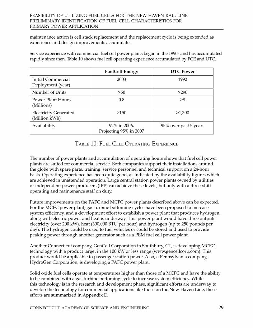
COnneCtiCut aCaDemy Of sCienCe anD engineering 29
feasibility Of utilizing fuel Cells fOr the new haven rail linepreliminary iDentifiCatiOn Of fuel Cell CharaCteristiCs fOr primary pOwer appliCatiOn maintenance action is cell stack replacement and the replacement cycle is being extended as experience and design improvements accumulate.
Service experience with commercial fuel cell power plants began in the 1990s and has accumulated rapidly since then. Table 10 shows fuel cell operating experience accumulated by FCE and UTC.
FuelCell Energy UTC Power
Initial Commercial Deployment (year)
2003 1992
Number of Units >50 >290
Power Plant Hours (Millions)
0.8 >8
Electricity Generated (Million kWh)
>150 >1,300
Availability 92% in 2006, Projecting 95% in 2007
95% over past 5 years
table 10: fuel Cell Operating experienCe
The number of power plants and accumulation of operating hours shows that fuel cell power plants are suited for commercial service. Both companies support their installations around the globe with spare parts, training, service personnel and technical support on a 24-hour basis. Operating experience has been quite good, as indicated by the availability figures which are achieved in unattended operation. Large central station power plants owned by utilities or independent power producers (IPP) can achieve these levels, but only with a three-shift operating and maintenance staff on duty.
Future improvements on the PAFC and MCFC power plants described above can be expected. For the MCFC power plant, gas turbine bottoming cycles have been proposed to increase system efficiency, and a development effort to establish a power plant that produces hydrogen along with electric power and heat is underway. This power plant would have three outputs: electricity (over 200 kW), heat (300,000 BTU per hour) and hydrogen (up to 250 pounds per day). The hydrogen could be used to fuel vehicles or could be stored and used to provide peaking power through another generator such as a PEM fuel cell power plant.
Another Connecticut company, GenCell Corporation in Southbury, CT, is developing MCFC technology with a product target in the 100 kW or less range (www.gencellcorp.com). This product would be applicable to passenger station power. Also, a Pennsylvania company, HydroGen Corporation, is developing a PAFC power plant.
Solid oxide fuel cells operate at temperatures higher than those of a MCFC and have the ability to be combined with a gas turbine bottoming cycle to increase system efficiency. While this technology is in the research and development phase, significant efforts are underway to develop the technology for commercial applications like those on the New Haven Line; these efforts are summarized in Appendix E.

COnneCtiCut aCaDemy Of sCienCe anD engineering30
feasibility Of utilizing fuel Cells fOr the new haven rail linepreliminary iDentifiCatiOn Of fuel Cell CharaCteristiCs fOr
primary pOwer appliCatiOn
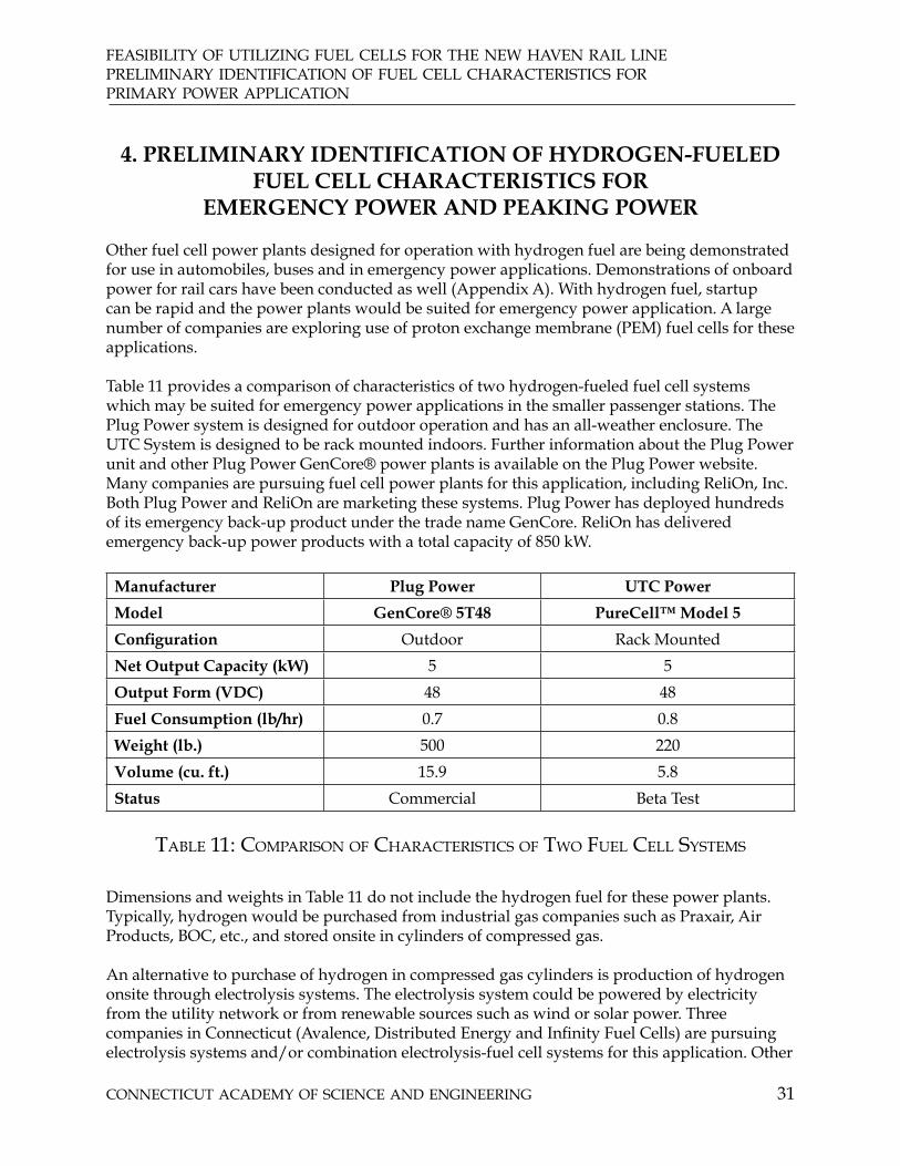
COnneCtiCut aCaDemy Of sCienCe anD engineering 31
feasibility Of utilizing fuel Cells fOr the new haven rail linepreliminary iDentifiCatiOn Of fuel Cell CharaCteristiCs fOr primary pOwer appliCatiOn
4. PRELIMINARY IDENTIFICATION OF HYDROGEN-FUELED FUEL CELL CHARACTERISTICS FOR
EMERGENCY POWER AND PEAKING POWER
Other fuel cell power plants designed for operation with hydrogen fuel are being demonstrated for use in automobiles, buses and in emergency power applications. Demonstrations of onboard power for rail cars have been conducted as well (Appendix A). With hydrogen fuel, startup can be rapid and the power plants would be suited for emergency power application. A large number of companies are exploring use of proton exchange membrane (PEM) fuel cells for these applications.
Table 11 provides a comparison of characteristics of two hydrogen-fueled fuel cell systems which may be suited for emergency power applications in the smaller passenger stations. The Plug Power system is designed for outdoor operation and has an all-weather enclosure. The UTC System is designed to be rack mounted indoors. Further information about the Plug Power unit and other Plug Power GenCore® power plants is available on the Plug Power website. Many companies are pursuing fuel cell power plants for this application, including ReliOn, Inc. Both Plug Power and ReliOn are marketing these systems. Plug Power has deployed hundreds of its emergency back-up product under the trade name GenCore. ReliOn has delivered emergency back-up power products with a total capacity of 850 kW.
Manufacturer Plug Power UTC Power
Model GenCore® 5T48 PureCell™ Model 5
Configuration Outdoor Rack Mounted
Net Output Capacity (kW) 5 5
Output Form (VDC) 48 48
Fuel Consumption (lb/hr) 0.7 0.8
Weight (lb.) 500 220
Volume (cu. ft.) 15.9 5.8
Status Commercial Beta Test
table 11: COmparisOn Of CharaCteristiCs Of twO fuel Cell systems
Dimensions and weights in Table 11 do not include the hydrogen fuel for these power plants. Typically, hydrogen would be purchased from industrial gas companies such as Praxair, Air Products, BOC, etc., and stored onsite in cylinders of compressed gas.
An alternative to purchase of hydrogen in compressed gas cylinders is production of hydrogen onsite through electrolysis systems. The electrolysis system could be powered by electricity from the utility network or from renewable sources such as wind or solar power. Three companies in Connecticut (Avalence, Distributed Energy and Infinity Fuel Cells) are pursuing electrolysis systems and/or combination electrolysis-fuel cell systems for this application. Other

COnneCtiCut aCaDemy Of sCienCe anD engineering32
feasibility Of utilizing fuel Cells fOr the new haven rail linepreliminary iDentifiCatiOn Of hyDrOgen-fueleD fuel Cells fOr
emergenCy pOwer anD peaking pOwer
companies, including Hydrogenics in Canada, are also involved with this application. The status of efforts of these companies is provided in Table 12.
Company Location Product Status Web site
Avalence, LLC CT High pressure electrolysis
Field Testing www.avalence.com
Distributed Energy Systems Corporation
CT Electrolysis Systems and Electrolysis-Fuel Cell Systems
Commercial for Electrolysis, Demonstration for Regenerative Systems
www.distributed-energy.com
Hydrogenics Ontario, Canada
Electrolysis Systems
Commercial www.hydrogenics.com
Infinity Fuel Cell and Hydrogen, Inc.
CT Electrolysis-Fuel Cell Systems
Demonstration with solar-powered electrolysis
www.infinityfuel.com
table 12: COmpanies invOlveD with small fuel Cell, eleCtrOlysis Or regenerative systems fOr emergenCy baCk-up pOwer
Table 13 provides further characteristics for electrolysis systems from Avalence, LLC, and Distributed Energy Systems Corporation. It’s important to note that the low pressure unit would require compression with its attendant power consumption and equipment, and that a more detailed comparison would be required to provide a complete assessment of these alternatives. Further information on these and other electrolysis units is available on each company’s website.
Manufacturer Avalance, LLC Distributed Energy Systems Corporation
Model Hydrofiller 50 Hogen®S 40
Rated Hydrogen Output (scfh) 53 40
Delivery Pressure (psig) Up to 6,500 200
Input Power (kWh/kg Hydrogen)
62 75
Status Development and Demonstration
Commercial
table 13: COmparisOn Of eleCtrOlysis systems

COnneCtiCut aCaDemy Of sCienCe anD engineering 33
feasibility Of utilizing fuel Cells fOr the new haven rail linefuel Cell appliCatiOn analysis
5. FUEL CELL APPLICATION ANALYSIS
Analysis of fuel cell applications to New Haven Line electrical power and heat needs requires integration of the following information:
application requirements from chapter 21.
fuel cell characteristics from chapters 3 and 42.
factors affecting the cost of electricity3.
environmental, power supply and homeland security implications, and4.
site-specific considerations such as availability of space for the fuel cells, ability to 5. secure land, availability of natural gas, ability to secure building permits
The discussion which follows in Section 5.1 discusses
traditional economic factors;•
fuel cell-specific economic factors;•
power reliability and security factors.•
Section 5.2 describes the broad application considerations for traction power, station power and yard power. Section 5.3 discusses more detailed application considerations for traction, station and yard power.
5.1 FACTORS AFFECTING COST OF ELECTRICITY
Traditional contributions to the cost of electricity include capital, fuel, maintenance and credit for fuel cell product heat utilized in the application. In addition to these traditional contributions, renewable energy credits and net metering to encourage more environmentally benign energy production, and capacity credits to encourage addition of distributed energy in areas with transmission congestion will influence application economics.
5.1.1 Traditional Cost of Electricity
The traditional cost of electricity is determined by fuel cell installed cost, efficiency and maintenance cost, and the application and heat load of a building. Capital cost includes the cost of the power plant at the factory, shipping, site design, permitting and installation. Efficiency determines the amount of fuel consumed. Maintenance cost includes the cost of planned and unplanned maintenance and replacement of power plant components during the life of the power plant. Since fuel cells operate unattended, there is no cost for plant operation. Use of power plant heat will provide a credit equal to the cost of fuel which would normally be burned to provide the same amount of heat. A preliminary assessment of these factors was made using a number of simplifying assumptions. One key assumption is that the capital cost contribution

COnneCtiCut aCaDemy Of sCienCe anD engineering34
feasibility Of utilizing fuel Cells fOr the new haven rail linefuel Cell appliCatiOn analysis
to electricity cost per kWh—which includes depreciation, cost of money and taxes—is equivalent to a five-year payback period. These assumptions are appropriate for initial screening of the applications, which is the purpose of this study. However, for a final decision regarding solicitation of bids for fuel cell power plants, further analysis with additional information on energy requirements, details of rates for purchase of electricity and natural gas, installation cost including land acquisition and cost of alternative critical power approaches is required.
Table 14 illustrates the influence of primary application factors on cost of electricity. Figure 11 is a simplified graphical presentation of the same information. A further breakdown showing individual contributions to the cost of electricity and a discussion of the simplifying assumptions is provided in Appendix F.
Installed cost($/kW)
Efficiency Capacity Factor(%)
Heat Utilization(%)
Cost of electricity(cents/kWh)
Historic Fuel Cell Cost
5,000 40 50 0 34.89
50 100 100 19.08
Fuel Cell Cost Goal
2,000 40 100 100 12.15
40 100 0 18.01
40 50 100 16.72
50 100 100 11.23
50 100 0 15.62
table 14: effeCt Of pOwer plant COst anD appliCatiOn faCtOrs On COst Of eleCtriCity frOm fuel Cell pOwer plants

COnneCtiCut aCaDemy Of sCienCe anD engineering 35
feasibility Of utilizing fuel Cells fOr the new haven rail linefuel Cell appliCatiOn analysis
figure 11: illustratiOn Of the effeCts Of teChnOlOgy anD appliCatiOn faCtOrs On COst Of eleCtriCity frOm fuel Cell pOwer plants
While fuel cell companies were not asked to provide capital cost information, a recent article (New York Times, March 4, 2007 “Is the State Selling its Fuel Cell Business Short?” by Jan Ellen Spiegel) indicated current costs of MCFC from FCE are in the range of $4,800 per kW. The US Department of Energy website (www.fe.doe.gov/programs/powersystems/fuelcells/fuelscells_phosacid.html) states the current cost of PAFC is $4,000 to $4,500 per kW.
Additionally, the New York Times article states that the FCE goal for competition with conventional power is $2,000 per kW. Similar goals of $2,000 - $2,500 per kW installed have been expressed for UTC fuel cells (private communication from R. Roche, UTC Power). The ability to achieve the cost goal is based on both improvements in technology and design as well as increases in production volume. Power plant price for a specific fuel cell project will depend on the experience of the manufacturer and the specific situation associated with a project, and can be determined only through responses to a request for bid. Table 14 shows that reduction in the cost of electricity associated with technology improvements and production rate increases, which reduce capital cost from $5,000/kW to $2,000/kW, would reduce the cost of electricity by 40%.
Application factors can affect cost of electricity from a fuel cell to a similar degree.
Table 14 indicates that for a fuel cell at the $2,000 per kW cost goal and 40% efficiency, increasing the capacity factor from 40% to 100% (average power divided by peak power capacity) can reduce the cost of electricity by nearly 40% and the ability to utilize waste heat can reduce the cost of electricity by nearly 50%. Using a fuel cell with 50% rather than 40% efficiency would reduce electricity cost by 11% - 14% depending on heat utilization. This shows the strong influence of application factors on economics for a fuel cell meeting competitive goals.

COnneCtiCut aCaDemy Of sCienCe anD engineering36
feasibility Of utilizing fuel Cells fOr the new haven rail linefuel Cell appliCatiOn analysis
5.1.2 Economic Factors Associated with Environment and Capacity Considerations
In addition to the traditional economic factors discussed in Section 5.1.1, the clean fuel cell operation and the ability to locate fuel cells at the electrical load brings into play a number of special incentives associated with achieving a clean environment, reducing dependence on foreign sources of energy, and easing congestion on the electricity transmission and distribution network. These incentives have been established by the state of Connecticut, the Independent System Operator for New England (ISO-NE) and the federal government.
The incentives include net metering, avoidance of back-up power charges in some situations, renewable energy credits, capacity credits and tax credits. If an installation is able to capture these incentives, the economic benefit can be substantial. These factors are affected by specifics of the power plant installation and, in many cases, require application and evaluation by either Connecticut government entities or ISO-NE. Table 15 summarizes these additional factors. The value of these incentives in most cases depends on market factors or on evaluation by third parties, and there are limitations on the extent of the incentives. Consequently, the incentives must be evaluated on the details of the specific application.

COnneCtiCut aCaDemy Of sCienCe anD engineering 37
feasibility Of utilizing fuel Cells fOr the new haven rail linefuel Cell appliCatiOn analysis
Incentive Program Effect on Economics Limitations Value
“Net Metering” Values excess power exported to utility at avoided wholesale cost
Up to 2,000 kW Exported energy valued at retail rate unless net energy is exported to the utility network in which case, the net energy exported is valued at the avoided whole- sale cost. Demand charges still apply
Back-up power charges
Eliminates a portion of demand charge if fuel cell outage occurs entirely in off-peak periods
Only for off-peak outages
Avoids back-up demand charges for some outages
Renewable Energy Certificates
Credit for environmental benefit of power delivered
Maximum is 5.5 cents per kWh based on penalty for failure to meet Renewable Portfolio Standards
Value determined by market. Has varied from $10 - $50 per megawatt hour (1 - 5 cents per kWh)
Distributed Generation Incentives through Connecticut Clean Energy Fund (CCEF)
Capital cost subsidy and subsidy for kWh delivered in Southwest Connecticut
Up to $4,700 per kW,Additional 1.5 cents per kWh in Southwest Connecticut.$4 million limit for an installation over its life cycle
Depends on CCEF evaluation of site specific factors, including use of fuel cell heat. Amount of incentive will likely be less than $4,500 per kW
Distributed Generation Incentive through Department of Utility Control (DPUC)
Capital cost subsidy Only available if facility does not qualify for CCEF incentive;limited to congestion charge avoidance
$200 - $500 per kW depending on site- specific factors
Forward Capacity Market through ISO-New England
Monthly credit for power capacity
Fixed schedule through 2010, then defined by auction,1 - 5 year contract
Currently $3.10 per kW per month. Depends on need, ISO-NE decision
Federal Income tax credit
Tax credit Up to 30% of project cost or $1,000 per kW, whichever is less.Efficiency must be 30% or higher.
Depends on legislation to extend beyond December 2008. Applies only to facilities owned by profit-making entities.
table 15: aDDitiOnal eCOnOmiC faCtOrs
Net metering: The term “net metering” refers to the value of energy exported to the utility from a distributed generator located on the customer side of the utility meter. Net metering allows for the customer to offset grid energy delivery with onsite production at retail rates up to a
COnneCtiCut aCaDemy Of sCienCe anD engineering38
feasibility Of utilizing fuel Cells fOr the new haven rail linefuel Cell appliCatiOn analysis
net energy consumption of zero kilowatt hours for the period considered. Above this (i.e., net exporter of energy to the grid), the net exported energy for the true up period is compensated at wholesale rates. The latest energy bill extends the true up period to one year. The demand charge is still in effect. The 2007 General Assembly enacted a bill which extends net metering to all customers with generation capacity up to two megawatts, and set the period over which net energy is determined at one year (Public Act 07-242, “An Act Concerning Electricity and Energy Efficiency,” Section 39). Net metering minimizes the economic penalty for exporting power to the utility grid and it could be eliminated in some cases. It permits larger fuel cell power plants to be installed without incurring a significant penalty for exporting power.
Back-up power charges: A recent act of the 2007 General Assembly waives the distribution demand charge portion of back-up power demand charges for outages which are completely within off-peak periods (Public Act 07-242, “An Act Concerning Electricity and Energy Efficiency,” Section 118). Since a maintenance event for fuel cell outages would normally extend beyond off-peak periods, this provision will provide a benefit only for a portion of the outages.
Renewable Energy Certificates (RECs) are a mechanism whereby utilities and other power providers can use RECs to meet renewable portfolio standards (RPS) that require a certain percentage of electricity delivered to be from renewable sources. Connecticut legislation classifies fuel cells operating on natural gas as a Class 1 renewable energy source, so each kilowatt hour generated with fuel cells creates a renewable energy credit which can be sold for the purposes of meeting RPS in Connecticut. REC prices are quite volatile; in New England, prices vary from as low as $0.70 per megawatt hour for existing renewables to as high as $49 per megawatt hour for new renewable energy sources (Emerging Markets for Renewable Energy Certificates: Opportunities and Challenges, NREL/tp-620-37388 by Ed Holt and Lori Bird, January 2005, published by National Renewable Energy Laboratory). Generally RECs purchased for RPS compliance purposes are priced higher than RECs purchased on a voluntary basis (“The Value of RECs in Renewable Project Financing,” by Karlynn Cory, NREL at Renewable Energy Marketing Conference in San Francisco, December 5, 2006). For example, voluntary clean energy options offered to customers of the electric utilities in Connecticut are priced at approximately $11 per megawatt hour (www.ctinnovations.com/funding/ccef/about.php).
Customer-side of the meter funding incentives for distributed generation are offered by the Connecticut Clean Energy Fund (CCEF). The amount of the incentive depends on details of the project, including the net energy efficiency, which includes effects of the use of heat from the fuel cell power plant. Credits are capped at $4,700/kW. In addition to the $4,700/kW, an additional premium of 1.5 cents/kWh is available for projects located in Southwestern Connecticut. The program offers grants of up to $50,000 per installation to support site-specific technical and financial feasibility studies. The total limit of funding for a single project is $ 4 million over the life of the project. Applications are considered on a rolling submission basis. CCEF staff evaluates and selects projects, which are then submitted to the CCEF Board for funding approval (“Call for Applications for On-site Renewable Energy Generation Projects,” Program Opportunity # CCEF-OSDG-001, Connecticut Clean Energy Fund, Program Release December 1, 2005).
Customer side of the meter funding incentives for distributed generation capacity are also offered in the amount of $200 - $500 per kilowatt by the Department of Public Utility Control (DPUC). For fuel cells, these incentives are available only if the project fails to qualify under

COnneCtiCut aCaDemy Of sCienCe anD engineering 39
feasibility Of utilizing fuel Cells fOr the new haven rail linefuel Cell appliCatiOn analysis the CCEF program, and therefore this incentive is not additive with the CCEF incentive. The amount of the DPUC award must be less than the projected reduction in federally mandated congestion charges (General Statues, Title 16, Section 243i).
ISO-NE purchases “behind the meter capacity” at fixed prices under its Forward Capacity Market: in the current transition period, capacity rates are set at $3.05 per kW per month through May 2008 and will increase to $4.10 per kW per month in June 2009 through May 2010. Contracts are for between 1 and 5 years. Following the transition period, capacity rates will be determined by an auction (“Demand Resources as Qualified Capacity in the New England Forward Capacity Market,” Henry Yoshimura, ISO New England Inc. Presented to the Restructuring Roundtable, September 22, 2006).
Federal Income Tax Credit through December 31, 2008: Federal Tax credit is available for fuel cell installations having greater than 30% efficiency and with rating greater than 0.5 kW (Energy Policy Act of 2005, Section 1336). The tax credit is calculated as 30% of total project cost or $1,000/kW of installed nameplate capacity, whichever is less. There are efforts to extend this credit beyond 2008 in the current session of the US Congress. This Federal Income Tax credit would not apply to a facility owned by the State of Connecticut.
5.1.3 Power reliability and Security Considerations
Fuel cell power plants can be located at the electrical load; multiple units can be installed to provide redundancy or an ability to provide critical loads even if one of the units is out of service and power from the utility network is unavailable. Power reliability and security is important for
life safety; •
fire protection; •
continuity of operation for critical power needs such as control and signaling and • system operations;
continuity of service in the event of security threats. •
Emergency power for life safety applications is governed by the National Fire Protection Association (NFPA) Standard for Emergency and Standby Power Systems, NFPA 110. In this application, the fuel cell power plant(s) operate continuously, either independent from or in parallel with the utility supply network. If the fuel cell power plant fails, power is provided from the utility grid. If the fuel cell is operating in parallel with the utility grid and the grid fails, the fuel cell switches to grid-independent operation and continues to supply the electrical load. Transitions from normal operation to emergency operation can be made within seconds with mechanical switchgear or virtually instantaneously using electronic switching. NFPA recognizes the utility system as a suitable emergency power system for a site where the primary power source is an on-site energy conversion device, and recognizes fuel cells as an acceptable onsite energy conversion system (NFPA 110 Standard for Emergency and Standby Power Systems, 2002 edition, Sections 115.1.4 and A.5.1.4). A number of fuel cell installations of this type are in operation. The larger passenger stations at New Haven and Stamford and buildings in the New Haven yard have applications of this type.

COnneCtiCut aCaDemy Of sCienCe anD engineering40
feasibility Of utilizing fuel Cells fOr the new haven rail linefuel Cell appliCatiOn analysis
Natural gas-fueled systems are acceptable for emergency power except in locations with severe seismic problems. In some natural gas systems, locally stored peak shave gas is used during periods of peak demand. The predominant form of peak shave gas is liquefied natural gas, but there are some locations where propane-air peak shaving is still used. Fuel cell power plants are usually designed so that they will not operate with propane-air peak shave gas, although they can—and have—been designed to operate with this gas as well. Locations along the New Haven Line are not expected to be exposed to propane-air peak shave gas, but this should be checked as part of any more detailed study leading to implementation of fuel cell power.
Some mission-critical operations require even higher reliability and can not tolerate any interruption in power. These include information systems serving real time applications such as credit card processing, mail processing facilities and industrial control operations. In these situations, redundant fuel cell power plants are used along with the utility network to provide “no-break” (uninterruptible) power with very high levels of reliability. Several fuel cell installations of this type are also in operation. As noted in Section 2, the New Haven yard has significant critical power applications of this type.
With the emergence of terrorist attacks on transportation infrastructure such as occurred in London and Madrid, the need for power security and reliability is now being considered. The first emphasis of Homeland Security considerations for transportation is to prevent attacks and to ensure public safety during and after an attack (National Infrastructure Protection Plan, Department of Homeland Security, 2006). Longer term, since commuter rail serves thousands of professionals involved with finance and commerce, minimizing disruption associated with an attack may also be a consideration. The track network itself is the most important asset in maintaining continuity of service, but electric power is essential to operation of the system. Distributing electric power widely to minimize the disruption associated with an attack on one facility would be one way to achieve improved security, and fuel cell power plants are well suited to this application. However, this study found no information to indicate that providing more secure traction power is a security objective with specific funds allocated for this purpose.
In considering fuel cell power plants for power reliability and security applications, the cost of fuel cells and their operation, as well as their effectiveness, would be compared to alternative approaches including engine-generator sets, gas turbine generators, batteries, uninterruptible power systems, or combinations of these systems. The comparison would require specifying the level of reliability, permissible transition time, outage duration, etc.
5.2 General Comparison of Applications
Table 16 provides a general comparison of applications in terms of application, economic and fuel cell product factors.

COnneCtiCut aCaDemy Of sCienCe anD engineering 41
feasibility Of utilizing fuel Cells fOr the new haven rail linefuel Cell appliCatiOn analysis
Application Power Plant Changes
Load Factor(%)
Ability to use heat
Uses Emergency Generators
Need for additional power
Current Cost of Electricity(cents/kWh)
Traction Power
Single-phase inverter, high voltage transformer
35 - 45 No, unless combined with buildings along track
No Yes, to accommodate new trains for MNR and Amtrak
11.3
Station Power
None 50 - 70 Yes Yes Limited 12.5 - 13
Station Emergency Power
None Essentially Zero
No Yes Limited Note 1
Yard Power None 35 - 55 Yes Yes New Haven yard
14.7 - 15.7
Note 1: Economics are based on cost of emergency generator set, batteries plus generator set or uninterruptible power system.
table 16: general COmparisOn Of pOwer appliCatiOns On new haven line
Table 16 shows that the traction power application is most challenging in terms of changes to the fuel cell power plant, application factors and the cost of electricity. However, it is by far the largest use of electric power on the New Haven Line, and use of fuel cell power in this application would have the greatest effect on reducing transmission congestion in Southwest Connecticut. Yard power and station power have more favorable economics; the yard expansion at New Haven provides significant opportunity to install fuel cells in new construction, which would have the lowest installation cost. Station emergency power considerations would provide a more attractive economic situation for large stations at New Haven and Stamford, which currently have emergency generators, and for many, if not all, of the new buildings in the New Haven yard. Smaller passenger facilities currently have no emergency power provisions other than possibly battery-powered lighting. If a fuel cell is installed in a new building, it may avoid the need for purchase of other emergency power equipment, thus improving the economic competitiveness of fuel cell power plants.
The current cost of electricity shown in Table 16 is the average cost at these locations based on electric bills for a recent 12-month period. The cost of power has been increasing significantly. For example, billing data for traction power were obtained for the years 2000 through 2006 from MNR; the cost of electricity for the month of December increased by 75% during the period. Part of the reason for higher power cost is higher cost for natural gas, which also affects the cost of power from fuel cell power plants. The cost of power displaced by a fuel cell operating at constant load will be somewhat less than is shown in the Table, and this factor should be considered in final purchase decisions.

COnneCtiCut aCaDemy Of sCienCe anD engineering42
feasibility Of utilizing fuel Cells fOr the new haven rail linefuel Cell appliCatiOn analysis
5.3 DISCUSSION OF SPECIFIC APPLICATIONS
This study assesses stationary fuel cell power plants as an alternative to purchasing power from the electric utility network. Other power plant technologies such as reciprocating engines or gas turbines were not considered, although they may provide strong competition to fuel cells if the application were strictly emergency power. The predominant commercial use of stationary fuel cells is a continuous power application with natural gas fuel, which is the primary application considered in this report. In this application, the fuel cell will usually share the load with the utility, with the ability for either source to supply the load independently if the other source is not available. For smaller-rated applications, hydrogen-fueled standby fuel cell power plants are being considered; these are discussed in Section 5.3.3. Larger hydrogen-fueled standby power plants may be considered in the future, but there is no present activity in this area.
5.3.1 Traction Power Discussion
5.3.1.1 Technical considerations
Because the traction power application requires single-phase power at 12.5 to 25 kV, the standard fuel cell power plants offered commercially by FuelCell Energy or UTC Power will require modifications to the DC to AC inverter and the output transformer. The inverter modifications might be as simple as using two of the current inverters in parallel, or they may require a new single-phase inverter design. These changes do not involve new technology, just a straightforward design of new equipment. The voltage difference will be accommodated simply by adding a transformer. If export of power to buildings along the line is desired, a control system and switchgear will have to be added, but this is a straightforward design activity utilizing standard equipment.

COnneCtiCut aCaDemy Of sCienCe anD engineering 43
feasibility Of utilizing fuel Cells fOr the new haven rail linefuel Cell appliCatiOn analysis
5.3.1.2 Traction Application Alternatives
The alternative traction power applications for fuel cells are compared in Table 17.
Application Maximum Installation Power
Economic Prospects Other Factors
Central Location > 30,000 kW Low Load Factor unless sized to base load
Probably requires changes to catenary and feeder circuit to permit power flow; requires large plot of land
At Current Supply Points
13,000 - 20,000 kW Low Load Factor unless sized to base load
Land Availability
Between Supply Points
2,000 - 12,000 kW Low Load Factor unless sized to base load. May reduce resistance losses
Land Availability
Between Supply Points with Energy Improvement Districts
2,000 - 12,000 kW May permit use of product heat in buildings adjacent to track
Land Availability
table 17: traCtiOn pOwer appliCatiOns
Table 17 identifies four broad areas of application. All these applications share issues associated with available land, with this issue being most difficult at the Central location and offering more opportunities as the location moves to the most decentralized location. Distribution of power along the catenary system between supply points involves a high impedance circuit and, with the three supply points currently in use, voltages can be unacceptable under some contingency failure conditions. Therefore, a significant modification of the catenary system would have to be considered in order to move to a single supply point; however, this is counter to current plans to add a fourth supply point to eliminate the low voltage under contingency situations. Further, because centralizing the power supply would reduce system power security, this application will not be considered further.
Providing fuel cells at the current supply points would ease some of the issues associated with a single, central installation. However, because this application would not provide any advantages associated with use of fuel cells, this application will not be considered further.
Locating fuel cell installations between supply points is considered to be the best approach for traction power. Line losses on the catenary system will be reduced; the extent of the reduction can be determined through analysis, which is beyond the scope of this study. The power plants could be located at some of the current wayside substations or at intermediate locations. If an intermediate location is selected, a feeder to the current wayside substation locations may be necessary, but intermediate locations may provide better land availability and may also offer an opportunity to utilize fuel cell heat in adjacent building(s), perhaps as part of an Energy Improvement District authorized by the 2007 General Assembly.

COnneCtiCut aCaDemy Of sCienCe anD engineering44
feasibility Of utilizing fuel Cells fOr the new haven rail linefuel Cell appliCatiOn analysis
This application may also provide an opportunity to integrate the fuel cell with waste water treatment plants located along the rail line. At least one water treatment plant is located adjacent to the New Haven Line west of the Green Farms passenger station. While the amount of digester gas will not be sufficient to meet the waste water plant needs when consumed in a fuel cell, natural gas could be blended with the digester gas from the treatment plant to produce power for both the treatment plant and for traction power purposes. Also, power plant heat could be used in the treatment plant process, and there may be land available for power plant installation.
Another integration possibility would be the use of a new type of power plant being investigated by FCE in which the power plant generates electric power, heat and hydrogen. A power plant of this type could be located at service plazas along I-95 which are adjacent to the New Haven Line. The hydrogen could be used to fuel hydrogen vehicles and the electric power could be provided to the New Haven Line. Several possible sites have been identified as discussed in Appendix G. The economics of this type of installation have not been assessed.
5.3.1.3 Traction Power Installation Ratings
Selecting the ratings for power plant installations serving the traction power need depends on the desired objective. Alternative objectives could include
Providing power security for full service capability by installing 48,000 kW. 1.
Providing power security for a somewhat reduced level of service by installing 26,000 2. kW.
Reducing line losses at locations providing the most benefit by installing between 2,000 3. kW and 13,500 kW operating at load factors in excess of 80% to provide good operating economics. This application would also provide some ability to provide traction power in the event of a power outage on the utility network.
While meeting these objectives would permit rail service on the Connecticut portion of the New Haven Line, similar actions would be necessary on the New York portion of the New Haven Line in order to permit transit to and from Grand Central Terminal.
In all cases, the power plant installations would be located along the line between the supply points, and would operate in parallel with the utility network power supply. Individual installations could range from 2,000 kW, which is the rating of individual transformers at wayside substations, to the typical wayside substation ratings of 4,000kW, 8,000kW and 12,000 kW. Distributing the power supply among a number of sites would reduce vulnerability to service outages compared to the limited number of supply points associated with the present system. Table 18 compares the characteristics of these three installation capacity scenarios.

COnneCtiCut aCaDemy Of sCienCe anD engineering 45
feasibility Of utilizing fuel Cells fOr the new haven rail linefuel Cell appliCatiOn analysis
Scenario Total Capacity(1,000 kW)
Equip.Capital (Million $) #
Capacity Factor(%)
Load Follow Req’d?
SitingDifficulty
Heat RecoveryOpportunity
Power Cost(cents/kWh) ##
Full Service Power Security
48* >96 34 Yes High No 25 - 27
ReducedServicePowerSecurity
26** >52 >50 Yes High No 19 - 21
Base Load –Some Power Security
2 - 13.5*** >4 - >27 80 - 100 Lowest Lowest Moderate 16 - 19 with no heat recovery and to as low as 13 - 15 with 50% heat recovery
Notes:* Sum of Maximum Demand at three supply points (see Table 2)** Sum of Load Exceeded only 10% of time at three supply points (from load duration curves in Appendix B)*** Sum of loads which are exceeded over 80% of time at three supply points (from load duration curves in Appendix B)# Includes only the cost of the fuel cell at $2,000/kW cost goal. Land acquisition and connection lines not included. Installation cost will probably add to these figures.## Based on calculations using approach and assumptions in Appendix F. Does not include cost of utility back-up power.
table 18: COmparisOn Of traCtiOn pOwer sCenariOs
Three scenarios are depicted in Table 18:
Scenario #1: If the installation is to provide full power security, total installed power • would be the sum of the maximum demands at each of the current purchase points, or 48,000 kW. This amount of power would satisfy all traction power needs even if the utility network were unavailable. Additional power would be required at passenger stations and the New Haven yard to provide passenger safety and operating capability.
Scenario #2: A reduced power capability would provide full service except for 10% • of the time. This would require moving on-peak trains to off-peak in order to remain within the power supply capability.
Scenario #3: This scenario involves providing fuel cell power at locations which would • reduce voltage losses and provide opportunity for heat recovery to adjacent buildings. The maximum amount of installed power for this scenario insures a fuel cell capacity factor of 80% without export to the grid. The lower amount of power would insure a 100% fuel cell capacity factor. In this application, power would be up to about 13% of the peak power demand, permitting a minimal amount of rail service in the event of a utility power interruption.

COnneCtiCut aCaDemy Of sCienCe anD engineering46
feasibility Of utilizing fuel Cells fOr the new haven rail linefuel Cell appliCatiOn analysis
In all three scenarios, the fuel cell installations would be along the line at locations between the supply points chosen on the basis of reducing line losses and siting considerations.
Capital investments for the fuel cell equipment at a price of $2,000 per kW are provided in the Table. These costs do not include land acquisition or electric power lines to connect the fuel cell installations to existing wayside substations. Much further information on specifics is needed to assess these additional costs.
The fuel cell capacity factor is an important determinant of the cost of electricity. It is dictated by the load duration curves provided for each supply point in Appendix B and the installed fuel cell capacity. For the smaller amounts of power, the capacity factor will reach 100%. Avoiding export of power to the utility network will require load following for the first two scenarios. A load absorber will not result in good power plant efficiency in this situation.
Siting difficulty will be highest for the first two scenarios. The third scenario doesn’t need as much land and should be satisfied more readily.
Similarly, the third scenario may be able to use fuel cell product heat in adjacent buildings, although this may require the creation of Energy Improvement Districts as were authorized by the 2007 General Assembly. Finding a use for heat from a 2,000 kW power plant will require integration with thermal loads of buildings of significant size. A power plant of this size will produce 5 to 7 million BTU per hour of heat. Estimates for heat use in buildings indicate a range of 8,500 to 15,000 BTU per hour per 1,000 square feet on an annual average (based on data in Application Guide for Fuel Cells in Commercial Buildings, December 1985). A recent article on commercial development in Stamford on the same block as the Stamford Station (The Advocate, July 31, 2007, “Metro Green Gets Nod”) indicates an office building of 325,000 square feet and a 240 unit apartment complex are planned. The annual average heat demand of these buildings is estimated at 7 million BTU per hour. This heat demand would provide a good opportunity for use of heat from a 2,000 kW fuel cell power plant.
The cost of power from the fuel cell was determined using the assumptions and approach of Appendix F along with the capacity factors indicated in the Table. This estimate of cost of power from the fuel cell is made using simplifying assumptions; a more detailed analysis would be required for a final decision. However, the analysis is adequate for the purposes of initial screening of applications in this study.
Incentives described in Section 5.1.2 could reduce the cost of power from the fuel cells significantly. Renewable Energy Certificates at the mid-range of historic market prices would provide a 1.5 - 3.5 cent per kWh credit. Capacity payments from ISO-NE could be applied as a capital cost credit which would range from $37 - $185 per kW for the range of contracts between 1 and 5 years. While it wouldn’t be considered in an investment decision, additional credits could be obtained if the ISO-NE contracts were renewed after the contract period. At 100% load factor, this capacity credit would reduce cost of fuel cell electricity by 0.4 cents per kWh. The incentives available under the Connecticut Clean Energy Fund program are capped at $4 million per installation. For the first two scenarios, this cap limits capital cost credit to $80 - $150 per kW. For the third scenario, with a 2,000 kW installation, it could be as high as $2,000 per kW; however, the actual amount awarded would be the result of an evaluation process.

COnneCtiCut aCaDemy Of sCienCe anD engineering 47
feasibility Of utilizing fuel Cells fOr the new haven rail linefuel Cell appliCatiOn analysis Even with these incentives described in Section 5.1.2, the cost of power in the first two scenarios exceeds the current cost of purchased power for traction purposes of 11.3 cents per kwh (See Table 16) These scenarios could only be justified if power reliability and security considerations were paramount, as discussed in Section 5.1.3; however, there is no indication that either the state or federal government would support these costs to increase power security.
The third scenario offers the best opportunity to break even or benefit economically from installation of fuel cells for traction power. With heat recovery, the incentives associated with Renewable Energy Certificates and capacity credits from ISO-NE and the Connecticut Clean Energy Fund, the opportunity for breakeven with conventional power costs exists for this scenario. The incentives from Connecticut Clean Energy Fund, if captured, may make fuel cells economic before the cost goals are reached. For these reasons, the third scenario is suggested for future consideration. In such a consideration, a more detailed economic analysis would be required, including determination of the effects on purchased electricity cost with the fuel cell serving part of the load.
Analysis of the electrical power system performance for the New Haven Line was conducted by Systra Engineering (“Metro-North Railroad Traction Power Study, New Haven Line AC Territory Final Report,” January 25, 2006). That analysis showed locations where low voltage or protection system constraints occurred under conditions where equipment has failed, leading to the decision to add power purchases in the New Haven area to alleviate these constraints. The same analysis could be used to identify benefits of locating fuel cell power plants along the line in order to reduce voltage and power losses during normal conditions and to alleviate constraints under equipment outage conditions; such an analysis could help focus efforts to identify the best location for fuel cell installations. Note that a reduction in losses would be an economic benefit of locating fuel cells at or near wayside substation locations.
Determining availability of land, access to sites, and community reaction, and securing necessary permits from local government(s) will require significant effort, and may limit the number of sites where a fuel cell installation can be achieved. Appendix G provides an initial assessment of land availability based on maps, real estate information and aerial photographs available from public sources. This initial assessment must be extended, with detailed analysis of specific sites as the next step in the site evaluation process.
The New Haven Line runs primarily through congested areas of the Connecticut coastline. While this makes availability and acquisition of land difficult, it also means that natural gas availability should not be a significant constraint. It also provides many opportunities to connect the fuel cells to utility lines for the purposes of exporting to the utility network any power in excess of the railroad’s needs. City streets run along much of the line and power could be exported to the distribution network which runs along these streets. Generally, distributed resources up to 10% -15% of the distribution line capacity do not cause problems on the distribution system. Above this level, load flow analysis will be required to verify that there are no problems (Reference; discussion with Daniel Rastler, Technical Leader, Distributed Energy Resources Program, Electric Power Research Institute). There are also many miles of track where electricity transmission lines run along the railroad right of way, providing opportunities to connect to the transmission system.

COnneCtiCut aCaDemy Of sCienCe anD engineering48
feasibility Of utilizing fuel Cells fOr the new haven rail linefuel Cell appliCatiOn analysis
5.3.2 Large Station Power Discussion
The large stations on the New Haven Line can utilize the standard power output of commercial fuel cell products and no modifications to the power plants would be needed for this application.
5.3.2.1 New Haven Station
The total demand of this site when the new parking garage is added will approach 1,000 kW. While detailed electrical load profiles are not available, the 50% - 60% load factor for loads associated with the station building and shoulder and off-peak demand records indicate a 200 - 250 kW fuel cell could be operated at rated power without exporting power to the utility network. If the station and parking lot loads were combined, the higher load factor of the parking garage indicates the base load could be considerably in excess of 250 kW. In any event, with the extension of net metering to 2,000 kW installations as provided in Public Act 07-242, this would not be a factor.
A preliminary analysis of the utilization of heat from a fuel cell located at this facility indicated heat utilization from a 200 kW fuel cell power plant with 40% efficiency could approach 50%, and 75% of the current natural gas use would be displaced by heat produced by the fuel cell. A higher efficiency fuel cell would achieve 50% use of its heat with a higher-rated power plant.
Addition of a new parking garage may present an opportunity to install a fuel cell at this site. Several parking spaces would be lost if the power plant were located behind the station building. A new parking garage may alleviate demand for these spaces. Other locations which could be considered are above the tunnel to the train platform or west of the existing parking garage.
5.3.2.2 Stamford Station
The Stamford station has a total electrical demand exceeding 900 kW. The load is provided through a number of electric meters, and the load for each of these meters has a high load factor. The need for heat is limited to winter space heating; a screening analysis indicates 30% of the heat for a 40% efficiency, 200 kW fuel cell could be utilized while displacing nearly all of the natural gas purchased at this site. A higher efficiency fuel cell with somewhat higher rating could utilize 30% or more of its product heat.
Replacement of the older section of the parking garage at this station provides an opportunity for consideration of a fuel cell installation at this site.
The other stations on the New Haven Line in Connecticut do not appear to be candidates for primary power fuel cells, as their demand is quite low compared to current fuel cell products. Even the proposed West Haven station, which has an associated parking garage, would not have a demand in excess of 100 kW. While future smaller molten carbonate fuel cell products from GenCell or solid oxide fuel cell products from other manufacturers suitable for the West Haven electric power demand may be available, no opportunity for heat utilization will exist.

COnneCtiCut aCaDemy Of sCienCe anD engineering 49
feasibility Of utilizing fuel Cells fOr the new haven rail linefuel Cell appliCatiOn analysis
5.3.2.3 Economics of fuel cell power plants at passenger stations in New Haven and Stamford
The most competitive approach to application of fuel cells to passenger stations would be to operate the power plant at 100% capacity factor and recover 30% - 50% of the waste heat. In this mode, a fuel cell power plant meeting the $2,000 per kW cost goal would provide power at a cost of 13.4 - 16.3 cents per kWh depending on fuel cell efficiency (40% - 50%) and heat recovery. If the fuel cell were installed in New Haven and would eliminate the cost of an emergency generator, net cost of power could be reduced by 0.9 cents per kWh. The incentives for Renewable Energy Certificates and capacity payments by ISO-NE could reduce net cost of power by another 1.5 - 3.9 cents per kWh. Therefore, the net cost of power with the incentives and a credit for avoiding the need for an emergency generator could be as low as 8.6 - 11.2 cents per kWh. This range of power cost compares favorably to the current cost of power at the New Haven and Stamford stations, which ranges from 12.5 - 13 cents per kWh. Incentives from the Connecticut Clean Energy Fund were not included, but could be used to make a fuel cell power plant economic for these stations even if cost did not meet the goal of $2,000 per kW.
5.3.3 Hydrogen-fueled fuel cell power plants for emergency power
Most of the passenger stations along the New Haven Line require only a few kilowatts of power for platform and parking lot lighting, in some cases a ticket office, and surveillance cameras. Currently these stations do not have emergency generators. Should the need for emergency generators occur in the future, this function could be provided by small PEM fuel cell power plants operating on stored hydrogen fuel. The hydrogen could be purchased in high pressure cylinders or generated onsite in electrolysis units. If sustainable, clean energy were a part of the design criteria, solar power could be used for input to the electrolysis systems. The fuel cell and electrolysis system candidates for these systems are discussed in Section 4.
Generally, these systems are not now competitive with batteries or engine generators except in situations where both a battery and engine generator are employed to provide no-break, high-quality emergency power for long periods. A Pacific Northwest National Laboratory study for the Federal Energy Management Program of hydrogen fueled PEM fuel cells in this type of application indicated that a fuel cell power plant would compare favorably with batteries on a life-cycle cost basis if emergency power were required for a 48 hour period (Fuel Cells in Backup Power Applications, Technology Installation Review, DOE/EE-0310, August 2005). This type of application was also considered, with similar conclusions, in a recent report by Battelle for DOE (“Identification and Characterization of Near-Term Direct Hydrogen Proton Exchange Membrane Fuel Cell Market,” a report by K Mahadevan, et.al. of Battelle for DOE Golden Field Office under DOE Contract No. DE-FC36-03GO13110, April 2007).
Should a need for emergency power at the smaller stations be identified in the future or if high-reliability, no-break emergency power were identified for critical systems associated with operations functions elsewhere in the New Haven Line operations, the use of small, hydrogen-fueled PEM fuel cells to meet this need should be considered.

COnneCtiCut aCaDemy Of sCienCe anD engineering50
feasibility Of utilizing fuel Cells fOr the new haven rail linefuel Cell appliCatiOn analysis
5.3.4 Yard Power
Yard power needs are consistent with the characteristics of current fuel cell products; there are similar applications of current fuel cell products in operation around the world. There are yard buildings which could benefit from the heat by-product of the fuel cell power plant and the capability of fuel cells, combined with utility power, to provide very high power reliability. The New Haven and Stamford yard locations have maintenance buildings with significant power needs. The only building in the Stamford yard is a maintenance shop that is metered for both electricity and gas, which provides good information for analysis. The Stamford yard shop is the most modern of the current shops in New Haven and Stamford, and therefore is the best current representation of the new buildings to be added to the New Haven yard.
An estimate of the ability to utilize fuel cell heat is important for analyzing fuel cell economics and for determining the applicability of incentive payments for energy conservation. Only the Stamford yard maintenance facility has both electrical and heat demand information. For that building, with an 85% efficient heating system, average thermal use during the 252 days of the heating season is 680 BTU per hour per peak kilowatt demand. If a fuel cell were sized at 20% of the 640 kW peak demand, all the fuel cell heat could be consumed during the heating season and about 70% of the heat would be utilized on an annual basis. Larger fuel cell power plants would find use for less of the available heat.
Estimates of total electric power demand and critical electric power demand for seven of the new buildings in the New Haven yard are provided in Table 5. With the exception of the parking garage, these buildings will require significant heat in winter months and, with the possible exception of the car wash facility, they will require back-up power. The peak electrical demands of these buildings range from 550 – 2,800 kW and the critical load demand is expected to range between 110 – 560 kW. Based on heat use analysis of the Stamford yard maintenance building, a power plant sized to the critical load should be able to utilize over 50% of its available heat annually. Therefore, these buildings will have fuel cell economics similar to that described above for the New Haven station, resulting in a power cost of 8.6 - 11 cents per kWh. This compares favorably to the current cost of yard power, which ranges from 14.7 - 15.7 cents per kWh (Table 16). The net cost of fuel cell power noted above includes a credit for avoidance of an engine generator set, which was estimated to cost $400/kW. In some of the yard buildings, more expensive uninterruptible power systems (UPS) will be required, making the economic situation even more favorable. Finally, as noted in Section 2, existing facilities in the New Haven and Stamford yard could also be considered for fuel cell application The fact that there is significant expansion of New Haven yard facilities in the design phase provides an opportunity for designing fuel cell installations into the buildings, rather than a more expensive retrofit scenario. It should be noted that the designs will be reaching the 60% completion point in the summer and fall of 2007 and will reach the 90% and 100% design points in the second half of 2007 or the first half of 2008. Construction is expected to take place during the period from January 2008 through August 2015. If fuel cells are to be used most effectively, a decision to incorporate fuel cell power plants in current designs or make provisions for future fuel cell power plants should be made in a timely manner.

COnneCtiCut aCaDemy Of sCienCe anD engineering 51
feasibility Of utilizing fuel Cells fOr the new haven rail linefuel Cell appliCatiOn analysis
5.4 SUMMARY OF ASSESSMENT
There are no technology limitations which would preclude the use of fuel cell power plants for power needs on the New Haven Line. At historic costs of $4,000 to $5,000 per kW, fuel cells are not economic for broad application for New Haven Line power. However, if fuel cell power plants meet manufacturer cost goals of $2,000/kW, the economics of the maintenance yard and station power applications should be competitive with current power supply approaches and, with incentives offered for environmental and capacity relief benefits, could be superior. Unless a use can be found for power plant heat, fuel cells will not be competitive, even at the cost goal, in traction power applications without incentives associated with their environmental characteristics and ability to ease transmission constraints. Predicting when fuel cells will meet the competitive goals is not possible; however, some incentives, if applicable, would make fuel cell power economically competitive at prices consistent with current manufacturing costs.
It is suggested that expansion of the yard facilities in New Haven, the parking facilities at New Haven and replacement of a portion of the parking facilities in Stamford are attractive opportunities for installation of fuel cell power plants.
Traction power applications are feasible. However, it should be expected that
additional costs for design of modifications to current commercial fuel cell power plant • designs will be incurred;
additional installation costs to accommodate higher voltage output will be incurred;•
there may be significant constraints with regard to installation locations.•
Availability of space for fuel cell installations is a significant issue for all fuel cell applications, particularly traction power applications, and this constraint could affect economics significantly. On the other hand, finding a use for power plant heat, possibly as a result of the Energy Improvement District legislation passed by the 2007 General Assembly, would enhance the traction power application.
Suggested installation parameters as well as rough capital outlay estimates are provided for all three applications in Table 19. Please note that the economic prospects and capital outlays represent fuel cell power plants meeting the competitive goals of $2,000/kW. Actual capital requirements could be significantly higher in the absence of supporting incentives and/or for fuel cells produced at current low production volumes. Environmental characteristics, alleviating transmission congestion, and power reliability and security are other factors which should be considered in a fuel cell implementation decision.
Table 19 indicates opportunities where fuel cells should be considered. Generally, these opportunities are associated with
new construction events where use of fuel cells could avoid an alternative capital • investment (for example, a standby electric generator in the case of the New Haven station or new buildings in the New Haven yard);

COnneCtiCut aCaDemy Of sCienCe anD engineering52
feasibility Of utilizing fuel Cells fOr the new haven rail linefuel Cell appliCatiOn analysis
an opportunity to plan the fuel cell installation as part of a broader construction project, • which would reduce the cost to install the fuel cell power plant (for example, the new parking garage at New Haven, replacement of a portion of the parking garage at Stamford or construction of new buildings at the New Haven yard);
formation of an Energy Improvement District which would improve the economics for • a traction power application.
The total amount of power involved is also provided. This may be for a single power plant in the case of the stations, or for a number of power plants in different buildings in the case of the New Haven yard. In all cases, the power plant ratings required would be consistent with power plants described in Section 3. The total for the traction power case is the range for the base-load case described in Table 18.
The opportunity for good application economics is highest when the fuel cell heat can be utilized and when the fuel cell can avoid investment for alternative critical power equipment. The table also shows the economic prospects which have been described in earlier portions of Section 5. Finally, the minimum capital cost is indicated. Capital cost is based on purchase of fuel cell power plants meeting cost goals; therefore, they are the minimum costs which could be expected. Incentives available from ISO-NE, Connecticut Clean Energy Fund or Connecticut Department of Public Utility Control could reduce these values or permit purchase of fuel cell power plants which do not meet the goals.
Application Opportunity Total Power(kW)
Heat Recovery
Need for new standby power equipment
Economic Prospects
Minimum Capital Investment(Million dollars)
New Haven Station
New Parking Garage
200 - 300
Yes Yes Good 0.5 - 1
Stamford Station
Replacement of a portion of parking garage
200 - 300
Yes No Good 0.5 - 1.0
New Haven yard
Yard Expansion during 2007 - 2015
500 - 2,200 or more
Yes Yes Good 1.0 - 4.5
Traction Power
Benefit of additional power supply points between purchase points
2,000 - 13,500
No No Fair for small amount of power. Poor for larger amounts
4 - 27
Traction Power
Formation of Energy Improvement Districts
2,000 -13,500
Yes Maybe Fair 4 - 27
table 19: suggesteD fuel Cell installatiOn OppOrtunities
COnneCtiCut aCaDemy Of sCienCe anD engineering 53
feasibility Of utilizing fuel Cells fOr the new haven rail linefuel Cell appliCatiOn analysis
Connecticut investment in fuel cells for the maintenance yard and passenger station applications is consistent with Public Act 07-242. In Section 101 of this act, the Office of Policy and Management, in consultation with the Department of Public Works, is directed to prepare a strategic plan to improve energy management in state buildings, including consideration of improved efficiency, distributed generation, etc. Section 73 of this act authorizes up to $30 million in state bonds to implement projects consistent with results of Section 101.
State ownership is one approach which could be considered. However, ownership by a third party should also be considered. This may result in improved economics because, for example, federal tax credits may be used by profit-making entities. If third-party ownership is selected, the state could lease the facility or could purchase energy in accordance with an energy service contract. In all cases, maintenance agreements are another item to be considered in implementing use of fuel cells to meet New Haven Line needs.
5.5 OPPORTUNITY FOR FEDERAL FUNDING OFFSETS
Stationary fuel cell power plants provide many benefits to society, including
low emissions of controlled pollutants; •
reduced emission of greenhouse gases compared to alternative generation of electric • power from natural gas because they eliminate transmission and distribution losses and can be located at the load to provide an opportunity for the use of power plant heat;
use in critical power applications, since they increase power reliability significantly.•
These benefits have caused Connecticut and the federal government to provide significant incentives to improve economics of fuel cell power plants and accelerate their deployment. These incentives are discussed in Section 5.1.2. The federal government is currently funding development and demonstration of fuel cell automobiles through the Department of Energy, and demonstration of fuel cell buses through the Department of Transportation. Currently the Department of Defense is providing some funding for demonstration of a yard switcher locomotive powered by fuel cells, although the Department of Energy has no program in this regard.
A brief review of US government programs in the Department of Energy, Department of Homeland Security and Department of Transportation does not indicate any specific programs which would support deployment of stationary fuel cells for the applications considered in this study. Information on possible areas of support of these individual agencies is discussed below.
Department of Energy: The Department of Energy has two offices which support activity in fuel cell power plants. These include the Office of Energy Efficiency and Renewable Energy (EERE) and the Office of Fossil Energy.
EERE conducts a program on Hydrogen, Fuel Cells and Infrastructure Technologies and is also responsible for the Federal Energy Management Program (FEMP) (www.eere.energy.gov). The Hydrogen, Fuel Cells and Infrastructure Program focuses on the Hydrogen Economy, including use of fuel cells in light-duty vehicles and development of the hydrogen vehicle

COnneCtiCut aCaDemy Of sCienCe anD engineering54
feasibility Of utilizing fuel Cells fOr the new haven rail linefuel Cell appliCatiOn analysis
fueling infrastructure, from hydrogen generation through dispensing of hydrogen at fueling stations. As one aspect of the hydrogen infrastructure program, EERE has funded FuelCell Energy’s development of a version of the company’s MCFC power plant which produces a hydrogen by-product that could be used for fueling hydrogen vehicles. It is possible that funds for demonstration of a power plant of this design could be obtained from EERE. FEMP focuses on advancing energy efficiency and environmental improvements at federal buildings through use of distributed and renewable energy, and has demonstrated hydrogen-fueled back-up power systems in federal facilities. FEMP funds are directed at energy use in federal buildings, so their programs would not appear to be available for any applications on the New Haven Line.
FE conducts fuel cell activities under its clean coal and natural gas power system efforts. Most of these efforts are focused on research on solid oxide fuel cells although the Office of Fossil Energy has sponsored work on MCFCs and PAFCs prior to the time they were deployed commercially. A recent activity with FuelCell Energy investigated a combined-cycle MCFC power plant.
Department of Homeland Security: The Department of Homeland Security (DHS) has a National Infrastructure Protection Plan which includes mass transit and rail among the 17 Sectors for which Sector-Specific Plans are to be developed (www.dhs.gov/xlibrary/assets/NIPP_SectorOverview.pdf). A DHS website provides information on “Securing Our Nation’s Rail Systems” (www.dhs.gov/xprevprot/programs/editorial_0895.shtm), which describes funding of $110 million for major rail systems and $375 million for mass transit systems under the Transit Security Grant Program. The availability of funds from the Department of Homeland Security is determined by federal legislative and executive priorities for each state and/or region. The individual projects within each region are then allocated based on a determination of benefit to homeland security and the cost of the project. Continuity of service on commuter rail is a recognized homeland security need, but funding of any project will require a benefit/cost assessment that ranks it high enough within the many projects in transportation and other areas which compete for these funds (discussion with Sean Ryan, MNR).
Department of Transportation: The Department of Transportation funds fuel cell transit bus programs through the Federal Transit Administration. The Federal Railroad Administration provides financial assistance for transportation infrastructure and conducts research on high-speed rail and rail safety issues. No information has been found indicating there are specific funds for efforts such as improving the electric supply infrastructure for rail operations.

COnneCtiCut aCaDemy Of sCienCe anD engineering 55
feasibility Of utilizing fuel Cells fOr the new haven rail lineiDentify aDDitiOnal infOrmatiOn requireD fOr biD paCkage speCifiCatiOn
6. IDENTIFICATION OF ADDITIONAL INFORMATION REQUIRED FOR BID PACKAGE SPECIFICATION
The following activities are suggested as part of the process of making a final decision as to whether or not to proceed with a fuel cell application project, and for the preparation of a bid package specification:
YARD POWER
Update and expand estimates of electric power requirements for new facilities in the • New Haven yard, including characterization of the critical power needs.
Assess thermal energy utilization possibilities for new facilities in New Haven. •
Assess feasibility of roof installations of fuel cell power plants of planned facilities.•
Develop information on use of power and heat in existing buildings in the New Haven • yard.
STATION POWER
Identify locations for fuel cell power plants at New Haven and Stamford stations.•
Assess possibility of integrating electrical loads for parking facilities, station buildings • and platform lighting, which currently have separate connections to the electric utility.
Monitor need for power reliability and security at passenger stations.•
TRACTION POWER
Assess the benefits of providing an additional power source at locations between • supply points in regard to distribution losses along the catenary and feeder lines and constraints of the protection system.
Assess installation at sites owned by ConnDOT with distribution of power, if necessary, • to current wayside substations or creation of new substations. The assessment should include estimates of land acquisition cost, probability of community approval and estimated installation cost.
Assess installation at other sites along the New Haven Line.•
Monitor activity regarding the creation of Energy Improvement Districts which could • have a positive impact on the economic analysis for the use of fuel cells for the traction power.
Monitor need for improved traction power reliability and security. •

COnneCtiCut aCaDemy Of sCienCe anD engineering56
feasibility Of utilizing fuel Cells fOr the new haven rail lineiDentify aDDitiOnal infOrmatiOn requireD fOr biD paCkage speCifiCatiOn
GENERAL
Select applications which show promise to meet ConnDOT objectives from one or more • of the yard power, station power or traction power applications for detailed analysis.
Establish estimates of power plant cost, installation cost and maintenance cost from fuel • cell manufacturers and possibly from third-party installers.
Determine approach to ownership and maintenance of the fuel cell power plants.•
Conduct preliminary design and economic assessment for selected applications, • including definition of effects on cost of power and natural gas purchased from utilities as well as initial assessment of the value of incentives and probability of capturing incentives.
Make final determination of projects on which bids will be requested and prepare bid • packages.
BID INFORMATION
It is suggested that information requested from bidders include the following:
a complete description of the installation and permitting requirements for the power • plants as well as a description of past experience in installations similar to those specified
capital cost, installation cost and maintenance costs•
a description of available installation and maintenance agreements along with warranty • information
complete power plant specifications including both electrical and thermal outputs•
specifics of purchase, lease, energy service options available•
an assessment of the level and probability of incentives •
BID EVALUATION
Since the competing manufacturers will use different power plant ratings to meet the application needs, it is suggested that the bid evaluation include an assessment of overall capital cost as well as annual cost of operation and maintenance for the power plants on a cents per kWh basis.

feasibility Of utilizing fuel Cells fOr the new haven rail linesummary Of finDings anD COnCluDing remarks
COnneCtiCut aCaDemy Of sCienCe anD engineering 57
7. SUMMARY OF FINDINGS AND CONCLUDING REMARKS
The New Haven Line is an important Connecticut asset with a long history. The electrical load of this asset is significant and its location in the southwest area of the state, where power supply systems are congested, could provide an opportunity for stationary fuel cell power plants to improve the electric supply in that portion of the state. Significant physical constraints are associated with the line because of its design history and the density of development around the line. Practically, for fuel cell power plants, these constraints primarily involve finding adequate available space for installing the power plants.
A number of improvements to the yard facilities and passenger station will provide a window of opportunity during the next few years for installing fuel cells in new facilities at costs which will be lower than retrofitted installations made following the completion of the improvements. Fuel cell power plants installed during this window of opportunity may provide reduced costs for electric service for line-related activities.
Power is used for a number of purposes, with the largest by far being traction power for trains, which is provided by a catenary system which connects to the electric utility network at three points along the line. The second purpose, which is also significant in size and which is projected to grow significantly over the next decade, is power for maintenance facilities at the New Haven rail yard. The third purpose, which is a smaller, but meaningful, opportunity for fuel cell power plants, is at passenger stations at New Haven and Stamford. Smaller stations along the line are not now a fuel cell opportunity. If emergency power were defined as a requirement for these smaller stations, hydrogen-fueled fuel cells could serve as back-up power supplies. This would be similar to current fuel cell applications being demonstrated in telecommunications applications. A very small power requirement for control and signal power is not considered to be an opportunity for fuel cell power plants.
While this study did not evaluate the possibility, there are efforts to investigate hydrogen fuel cell power plants supplying onboard traction power to rail vehicles including commuter trains in Japan and a yard switcher in the United States. This is an entirely different type of application which could be considered after fuel cells have been proven in automobile and bus applications. Fuel cells for transit buses have not yet met durability requirements for a vehicle with a 12-year service life. When the bus application is in commercial service, the more demanding requirements of a rail vehicle with service life of 20 to 30 years or more can be considered.
Information on current stationary fuel cell products was supplied by the two Connecticut manufacturers—the only companies which offer commercial stationary fuel cell products suitable for the traction power, yard power and passenger station power applications. FuelCell Energy provided information on its MCFC products and UTC Power provided information on its PAFC products. The different fuel cell technologies and design approaches used in these products result in differences in efficiency, heat available for building use, maintenance requirements and response rate. Selection of a fuel cell power plant from the options available will depend on specifics of the application. Information was also obtained on alternative MCFC and SOFC products under development for continuous-duty stationary power and for hydrogen-fueled proton exchange membrane fuel cells for back-up power.

COnneCtiCut aCaDemy Of sCienCe anD engineering58
feasibility Of utilizing fuel Cells fOr the new haven rail linesummary Of finDings anD COnCluDing remarks
Information developed in this study shows that the best near-term opportunity to utilize fuel cells for the New Haven Line would be in a combined heat and power (CHP) application that provides critical power needs for the many new buildings planned for the New Haven yard. This application has the fewest constraints associated with location for the fuel cells, will derive benefit from the power reliability associated with the combination of continuous duty fuel cells operating in conjunction with the utility supply network and, because the yard is served through one electric meter, will not encounter issues associated with export of electric power to the utility network. This application affords the opportunity to install a total capacity of 2,200 kW or more of fuel cell power in six or more buildings using existing and planned power plant products from Connecticut fuel cell manufacturers.
The second opportunity is for installing power plants at the New Haven and Stamford stations during expansion or renovation of these station complexes. The amount of power required is significantly less, but power plants offered by Connecticut manufacturers can meet the needs of these applications. CHP and the possibility of eliminating the need for an emergency generator in New Haven provide good economic prospects for these buildings.
The best application for fuel cells in the traction power application would be power plants distributed along the line between purchase points and operating continuously at or near rated power. This application would reduce line losses associated with distributing power through the catenary and parallel feeder circuit, and the possibility of achieving acceptable economics with this type of application deserves further investigation. The economic perspective would improve significantly if fuel cell product heat could be utilized in buildings adjacent to the line, and action to implement Energy Improvement Districts would facilitate the use of this heat. The traction power application will require modification of the inverters used with current fuel cell products, because these products have been designed for three-phase power rather than the single-phase power used for New Haven Line traction power. These modifications, however, would involve only a new design for the power conversion and control system, not new technology. It is possible the new design could simply use multiples of the current equipment.
The Connecticut portion of the New Haven Line offers an excellent opportunity to demonstrate approaches to improved traction power reliability and security because it is in a congested area with significant environmental and power supply constraints and because state and regional power incentives have been established in response to those constraints. In addition, the New Haven Line is part of the largest commuter rail system in the country and experience developed would be readily transferred to the larger transportation system serving New York, as well as other commuter rail systems.
Providing the complete traction power needs of the New Haven Line was considered, but the analysis indicates very poor economics and significantly higher capital outlays than the other applications considered.
State, regional power, and federal incentives have been developed in response to the ability of distributed fuel cell power plants to provide environmental benefits and to ease power supply problems associated with transmission congestion. Connecticut incentives include net metering for installations up to 2,000 kW; Renewable Energy Certificates for electric energy produced by fuel cells, which can be used in Connecticut to satisfy Renewable Portfolio Standards for Electric Power; and Distributed Energy Incentives from either the Connecticut Clean Energy Fund or

feasibility Of utilizing fuel Cells fOr the new haven rail linesummary Of finDings anD COnCluDing remarks
COnneCtiCut aCaDemy Of sCienCe anD engineering 59
Department of Public Utility Control. Regionally, fuel cells can capture capacity incentives from ISO-NE. The dollar value of each of these incentives and/or the ability to capture them depends on market conditions or evaluation of the specific installation by the organization offering the credits.
The federal government has established an income tax credit applicable to fuel cell power plants. This credit would be helpful to profit-making entities owning fuel cell power plants.
A number of US Department of Transportation support opportunities exist for railroad capital investment, and it is likely that funds from these programs could be allocated to fuel cells by ConnDOT. However, this allocation would be made by reducing the allocation of funds for other purposes. There are no programs specifically directed at the electrical power area associated with this study. A similar situation exists for Department of Homeland Security funds, because fuel cell power plants designed to improve power reliability and security would have to compete with alternative uses for fixed amounts of Homeland Security funds designated for the state and region. Department of Energy programs for stationary power are directed at development and demonstration of SOFC, which are at an early stage of development, and on accelerating deployment of hydrogen-fueled proton exchange membrane (PEM) fuel cells, which are applicable only to small back-up power applications which are not currently needed on the New Haven Line.
A number of actions to define the specifics of the bid packages for procurement of fuel cell power plants for the New Haven Line have been suggested. These actions focus on:
gaining a better definition of electrical and heat demand for new and existing buildings • in the New Haven yard;
further consideration of installation possibilities with additions or renovations to • facilities at the New Haven and Stamford passenger stations;
monitoring the need for back-up power at smaller stations; •
an assessment of reduction in line losses associated with application of base-load fuel • cells for traction power installed between power supply points;
determining the best ownership approach for fuel cell facilities serving the New Haven • Line.
With results of these efforts, a more detailed economic assessment of alternative applications, including effects of utility rates and identification of the probability of capturing incentives, can be conducted to select applications for which requests for bids can be issued.
Fuel cell applications for maintenance facilities in the rail yards and for passenger stations are similar to those in other ConnDOT facilities, and a broader consideration of fuel cell installations by ConnDOT is suggested as a follow-up to the rail line applications included in this study.

COnneCtiCut aCaDemy Of sCienCe anD engineering60
feasibility Of utilizing fuel Cells fOr the new haven rail linesummary Of finDings anD COnCluDing remarks

COnneCtiCut aCaDemy Of sCienCe anD engineering 61
feasibility Of utilizing fuel Cells fOr the new haven rail lineglOssary
GLOSSARY
American Public Transit Association (APTA) A trade organization dealing with public transit issues
AmtrakThe trade name for the National Rail Road Passenger Corporation, which is a quasi-governmental corporation responsible for long distance rail passenger service in the United States. Amtrak is funded in part by federal and state sources.
AvailabilityThe number of hours a power plant operates divided by the elapsed calendar time
Autotransformer On the New Haven Line, autotransformers transfer power from the feeder line to the catenary system at wayside substations. An autotransformer is a single winding transformer with multiple taps.
Back-up power In order to ensure power is available to critical loads in the event of an outage of the normal (primary) power supply, a back-up system is provided. If the primary power supply is the utility network, the back-up power would be provided by a standby generator located at the building. If the primary power is a continuously operating fuel cell, the back-up power would be provided by redundant fuel cell power plants and/or by the utility network. Back-up power is also referred to as emergency power and a standard published by the National Fire Protection Association, NFPA 110, is usually used in local building codes to define requirements for emergency power systems
British Thermal Unit (BTU)The amount of energy required to heat one pound of water one degree Fahrenheit
Brownfields SiteA site that requires environmental remediation
Capacity Factor Average electrical output divided by the rated capacity of an electric generator
California Air Resources Board (CARB)The State of California organization which regulates air quality
Catenary In this study, the term refers to an overhead wire which conducts electrical power above the track of an electric railroad.

COnneCtiCut aCaDemy Of sCienCe anD engineering62
feasibility Of utilizing fuel Cells fOr the new haven rail lineglOssary
Center-tapped A single-phase electrical circuit which is grounded to form two single-phase legs, each of which has half the total voltage.
Coincident Demand If two or more electric loads have different variations with time, the peak demands of the loads will probably occur at different times. Therefore, if the loads are combined, the peak demand of the combined load, referred to as the coincident demand of the combination of loads, will probably be less than the sum of the peak demands of the individual loads.
Combined Heat and Power (CHP) This is a power plant which provides both electricity and heat to a building. It is also referred to as cogeneration.
CHP EfficiencyThe total of electric energy and thermal energy delivered by a power plant divided by the total fuel input energy
Congestion Mitigation and Air Quality Improvement Program (CMAQ) An activity of the US Department of Transportation aimed at improved air quality and reduced transportation congestion. More information is available at http://www.fhwa.dot.gov/environment/cmaqpgs.
Congestion Zone A term used to describe a geographic area where electrical transmission facilities are insufficient to provide dependable electric power at proper voltages during periods of peak electrical demand. Southwest Connecticut is one such zone.
Connecticut Clean Energy Fund (CCEF) An organization created by the Connecticut General Assembly to create a clean energy supply for Connecticut; develop clean energy technologies; and educate residents about clean energy’s importance for the state’s energy future. CCEF’s funding comes from a surcharge on electric ratepayers’ utility bills. More information is available on its website: www.ctcleanenergy.com.
Critical Power A term used to describe electrical power loads which are necessary for safe, continuous operation.
Decibel (dB, dBA)Sound pressure level. Since sound pressure varies with sound frequency, a weighting by frequency is used to consolidate the pressure level at different frequencies to a single number. dBA represents one such weighting.
Electric Demand This is the peak requirement for delivery of electric power. For billing purposes, this usually is defined as the maximum half hour or fifteen minute average power during the billing period and is referred to as “Billing Demand.” Instantaneous electrical demand is the peak demand experienced during one electrical cycle (one 60th of a second in the United States).

COnneCtiCut aCaDemy Of sCienCe anD engineering 63
feasibility Of utilizing fuel Cells fOr the new haven rail lineglOssary
Department of Energy (DOE) The US government department that is responsible for the development of energy and energy conversion. The website is www.doe.gov.
Department of Transportation (DOT) The US government department that is responsible for transportation. The website is: www.dot.gov.
Distributed Generation Electric generating equipment located at or near the source of an electrical load instead of at central stations.
Electrolysis This is an electrochemical process whereby an electrical current is passed between two electrodes to convert water to hydrogen and oxygen. Further information is available at: http://www.eere.energy.gov/hydrogenandfuelcells/production/electro_processes.html.
Energy Efficiency and Renewable Energy (EERE) The Department of Energy Office that is responsible for improving energy efficiency and developing renewable energy sources. This office has responsibility for DOE’s hydrogen program and for application of hydrogen to light-duty vehicles. The website is: www.eere.doe.gov.
Federal Transit Administration (FTA) A unit of the US Department of Transportation responsible for federal activities associated with mass transit. The website is: www.fta.dot.gov.
Feeder System On the New Haven Line, power is delivered to the trains through the catenary system. To improve voltage uniformity along the line, a parallel electric system, referred to as a feeder system, runs parallel to the catenary system and is connected to the catenary at wayside substations between the supply points at which power is purchased from the utility network.
FootprintThe ground area covered by equipment, or equipment plus required access space.
Fuel Cell This is an electrochemical device which converts hydrogen and oxygen to electricity, water and heat. The process is the reverse of electrolysis and, like electrolysis, requires an anode (fuel electrode), a cathode (oxygen electrode) and an electrolyte. For further information, see the websites of the US Fuel Cell Council at: www.usfcc.com; or FuelCells 2000 at: www.fuelcells.org.
Fuel ProcessingThe processes and equipment that convert hydrocarbon fuels into hydrogen in fuel cell power plants. These processes include sulfur removal, reforming (conversion of hydrocarbon and water to hydrogen and carbon monoxide) and shift conversion (conversion of carbon monoxide and water to carbon dioxide and additional hydrogen). Gallons per Minute (gpm)Volume flow rate for a liquid

COnneCtiCut aCaDemy Of sCienCe anD engineering64
feasibility Of utilizing fuel Cells fOr the new haven rail lineglOssary
Greenhouse Gas (GHG) Any gas which, when released to the atmosphere, contributes to the greenhouse effect which is related to absorption and radiation of heat from the earth’s surface. The most commonly considered greenhouse gas is carbon dioxide, but methane, carbon monoxide, fluorocarbons, sulfur compounds and water vapor are also greenhouse gases. The gases have varying contributions to the greenhouse effect and widely varying lifetimes in the atmosphere. The Intergovernmental Panel on Climate Change website provides additional information on Greenhouse gases: (www.ipcc.ch).
Heat Utilization/Heat RecoveryThe percentage of power plant heat product which is utilized
Hertz (Hz)Alternating current frequency in cycles per second
High Grade HeatHeat delivered at temperatures at or above 250º F.
Hydrogen This is the lightest element, consisting of one proton and one electron. On earth, hydrogen is available only combined with oxygen in water or with carbon and other elements in hydrocarbons. It can be derived from these naturally occurring compounds through a number of methods involving a variety of energy input sources, and is considered an energy carrier like electricity rather than a raw source of energy like coal. Hydrogen has the highest combustion energy per unit weight and the lowest combustion energy per unit volume of any element. The primary product of hydrogen combustion is water vapor. Small amounts of nitrogen oxides are the only controlled pollutants emitted in hydrogen combustion. When used in a fuel cell, high-efficiency conversion to electricity can be obtained. Additional information on hydrogen is available from the National Hydrogen Association website: www.hydrogenus.com.
Independent System Operator for New England (ISO-NE)ISO New England is a regional transmission organization (RTO) serving Connecticut, Maine, Massachusetts, New Hampshire, Rhode Island and Vermont. ISO-NE meets the electricity demands of the region’s economy. The organization was established by the Federal Energy Regulatory Commission in 1997 and is one of a number of such organizations created to ensure reliable electric service after the restructuring of the electric industry.
Kilowatt (KW) One thousand watts
Kilowatt hours (kWh)Energy associated with one kilowatt for one hour. A kWh is equivalent to 3413 BTU.
Load Factor Load factor is equal to the average electricity demand divided by the peak electrical demand, both measured in kilowatts for a specific electrical load

COnneCtiCut aCaDemy Of sCienCe anD engineering 65
feasibility Of utilizing fuel Cells fOr the new haven rail lineglOssary Lower Heating Value This is the energy which can be extracted from a hydrocarbon fuel when the product water is exhausted as a vapor. This is commonly used to define efficiency for gasoline or diesel reciprocating engines, gas turbines, and fuel cells (efficiency equals useful energy output divided by the lower heating value of fuel used to produce the output). Note that central station power plants use higher heating value in defining performance and this is the quantity of energy which can be extracted from a hydrocarbon fuel when the product water is exhausted as a liquid. With natural gas, lower heating value is approximately 90% of higher heating value.
Megawatt (MW) One million watts which is equal to one thousand kilowatts
Metro-North Railroad (MNR)Metro-North is a subsidiary of New York’s Metropolitan Transit Authoritywhich operates, among others, commuter rail service between New Haven and Grand Central Terminal in New York City under contract to ConnDOT.
MMBTUOne million BTUs
Molten Carbonate Fuel Cell (MCFC) A fuel cell with a molten salt electrolyte, which typically operates at 650º C. (1,200º F.)
Net Metering This term refers to the determination of electrical billing charges when an on-site source of electricity provides a portion of the electrical energy required by the building and which exports power to the utility network when power from the on-site source in excess of the building needs is available. Conceptually, with net metering, electric energy exported to the utility network is of equal value to electric energy purchased from the network in this situation. Detailed protocols are established to determine the precise handling of imported and exported electricity costing.
Off-peak and on-peak The total electric demand on a utility network varies during a day and is generally higher on weekdays than on weekends as well as higher in some seasons than others. In order to meet this demand, investments in generating equipment, transmission equipment and distribution equipment are made. To minimize operating cost, generating equipment used to meet long-term continuous demands is designed to use lower cost fuels and to operate at high efficiency. This continuously operating equipment is referred to as base-load generation. Base-load generating capacity is usually less than 50% of the maximum electrical demand on the electricity supply system and the remaining generating equipment, which operates for relatively short periods, can utilize more expensive fuel and lower efficiency generating equipment, but this equipment is less costly than the base load generators. This additional generating equipment is referred to as peaking or intermediate generation. In order to allocate the costs of this mix of equipment fairly among customers with different load patterns, utility rates are established which charge more for power consumed during periods when the demand is high—for example, weekday afternoon periods when air conditioning, office lighting and cooking loads are responsible for the maximum power demand. These high demand periods are referred to as peak demand periods. Correspondingly, utility rates are lower during periods of low demand such as on a

COnneCtiCut aCaDemy Of sCienCe anD engineering66
feasibility Of utilizing fuel Cells fOr the new haven rail lineglOssary
spring weekend during the night. These periods are referred to as off-peak periods. The exact determination of these periods and charges is the subject of utility regulatory proceedings.
Original Equipment Manufacturer (OEM) This is a company that provides a final product to a customer. An auto manufacturing company is an example of an original equipment manufacturer.
Pantograph This is a structure on top of an electrically driven rail car which maintains a sliding electrical contact with the catenary and transfers electric power to the car.
Phosphoric Acid Fuel Cell (PAFC)A fuel cell with a phosphoric acid electrolyte, which typically operates at 200º C (400º F)
Proton Exchange Membrane Fuel Cell (PEM or PEMFC)A fuel cell with a solid polymer electrolyte membrane, which typically operates at 80º C (180º F)
Pounds per square inch gage (psig)The difference between the pressure of a gas and atmospheric pressure
Power ConditioningThe equipment used to convert direct current (DC) power from the fuel cell stack to alternating current (AC) at the proper frequency and voltage. The equipment includes an inverter which converts DC to AC power and a transformer to convert the AC power to the proper voltage
RatingThe maximum output capability of a power plant.
Reactive Power (expressed in kilovolt amps reactive or kVAR)The product of voltage times amperes flowing between reactive elements (capacitors or inductors) of an alternating current electrical circuit. This energy is alternately stored and released as the voltage rises and falls. Reactive power must be supported by the power source and places an extra burden on the generation and distribution system. Ideally, reactive power is corrected for locally to mitigate its impact.
Solid Oxide Fuel Cell (SOFC)A fuel cell with a solid oxide electrolyte, which typically operates at up to 1,000 º C (1,800º F)
Standard Cubic Feet per Hour (scfh)Volumetric flow of a gas measured or converted to standard conditions of atmospheric pressure and 60º F.
Stack LifeThe period in hours or years that a fuel cell stack can operate properly before it needs to be replaced.
Supply Point In this study, a supply point is defined as the location where power is purchased from the utility

COnneCtiCut aCaDemy Of sCienCe anD engineering 67
feasibility Of utilizing fuel Cells fOr the new haven rail lineglOssary network to provide traction power for the New Haven Line. There are three supply points along the New Haven Line in Connecticut and a fourth is planned.
Thermal to Electrical Energy Ratio (T/E Ratio)The ratio of the annual thermal energy used in a building to the annual electrical energy used in a building. The ratio is useful in estimating the amount of fuel cell product heat which can be utilized.
Traction power The power associated with moving vehicles. In the case of this report, it refers to power which drives trains along the New Haven Line.
Uninterruptible Power Power required for continuous operation of controls and computer operations. Generally this equipment can tolerate interruptions only if the duration of the interruption is less than 4 milliseconds. A system which keeps the interruption period less than 4 milliseconds is also referred to as a no-break system
VoltageThe potential of an electricity supply measured in volts (V) or kilovolts (kV).
Wayside Substations Intermediate locations between supply points where power is transferred from the feeder line to the catenary line through autotransformers.

COnneCtiCut aCaDemy Of sCienCe anD engineering68
feasibility Of utilizing fuel Cells fOr the new haven rail lineglOssary

COnneCtiCut aCaDemy Of sCienCe anD engineering 69
feasibility Of utilizing fuel Cells fOr the new haven rail lineaCknOwleDgements
ACKNOWLEDGEMENTS
This effort benefited from discussions with and input from a number of individuals at CASE, CCEF, CL&P, CNG/SCG, ConnDOT, Fusco Management Services, Metro-North, New Haven Parking Authority, Parsons Brinckerhoff and United Illuminating. Their patience and efforts are appreciated. The following individuals provided input:
CCEF: Keith Frame, Patrick O’NeillCL&P: Rich WalshCNG/SCG: Mike SmalecConnDOT: Craig Boridiere, Fred Chojnicki, Keith Hall, Bob Messina and Joseph SpagnaFusco Management Services: Jason FalcettaMetro-North: Al Adamo, Joe Cappozolil, Jim Gillies, Sean Ryan, Bob WalkerNew Haven Parking Authority: Paul WydraParsons Brinckerhoff: Glenn HaydenUnited Illuminating: Larry Mai

COnneCtiCut aCaDemy Of sCienCe anD engineering70
feasibility Of utilizing fuel Cells fOr the new haven rail lineappenDiCes
feasibility Of utilizing fuel Cells fOr the new haven rail lineappenDiCes
COnneCtiCut aCaDemy Of sCienCe anD engineering 71
APPENDIX A
USE OF FUEL CELLS AS AN ONBOARD TRACTION POWER SOURCE
Although the focus of this study is on the stationary power needs of the New Haven Line, there are also ongoing activities for the development of onboard traction power and auxiliary power for rail cars. This appendix provides a summary description of those efforts.
In the United States, two efforts are significant. One is an effort led by Vehicle Projects LLC (Denver, CO) to demonstrate a fuel cell-battery hybrid power system for a yard switcher known as the Green Goat. Another is an activity by Nuvera Fuel Cells (Cambridge, MA and Milan, Italy) to demonstrate fuel cell power in commuter trains and large locomotives.
The Vehicle Projects effort is an outgrowth of a hybrid fuel cell mine loader development using metal-hydride hydrogen storage and a fuel cell-battery hybrid propulsion system (Renewable Metal-Hydride Storage for a Fuel Cell Mine Loader, Arnold R. Miller, et.al.; Proceedings of the Intertech-Pira Hydrogen Production and Storage Forum, Vancouver, Canada, September 2006). The hydride storage system provides low volume and safe storage of hydrogen for underground mining operations; these operations have safety concerns similar to those for rail tunnels leading to Grand Central Station. Funding for the Mine Loader and yard switcher projects comes from a combination of US Department of Energy, US Department of Defense and private sponsors. Fabrication of the yard switcher is scheduled for completion by the end of 2007 (“System Design of a Large Fuel Cell Hybrid Locomotive,” by Arnold Miller, et. al.; Presented at ASME Fifth International Fuel Cell Science, Engineering and Technology Conference, NY, NY, June 18 - 20, 2007).
Nuvera Fuel Cells is developing the Forza™ product family which is directed at industrial and rail markets. They have powered a mining locomotive with a 17 kW fuel cell stack and a mine loader project with a 90 kW stack is under development. A 120 kW power plant powered an advanced commuter rail vehicle tested by the Railway Technical Research Institute of Japan in 2006, and an international consortium is developing a large locomotive powered by a combination of Forza modules delivering 1.2 MW (Nuvera website: www.nuvera.com).
Another fuel cell-powered commuter train is under development by East Japan Railway; an activity is also underway to develop hydrogen-fueled trains in Europe.
Activity on hydrogen-fueled rail vehicles is discussed at the International Hydrail Conferences. The third of these conferences will take place in Salisbury, North Carolina in August 2007 (www.hydrail.org/technology.php).
Attention on fuel cells for vehicle applications is currently focused on light-duty vehicles such as passenger cars and transit buses. Durability has not yet been demonstrated in either application. Transit buses have a 12-year service life; when fuel cell durability is acceptable for transit buses, application to rail vehicles with service lives of 20 to 30 years or more can be considered.

COnneCtiCut aCaDemy Of sCienCe anD engineering72
feasibility Of utilizing fuel Cells fOr the new haven rail lineappenDiCes
APPENDIX B
ELECTRICAL LOAD DURATION CURVES FOR TRACTION POWER SUPPLY POINTS
A load duration curve indicates the percentage of time the electrical load exceeds a certain power level. The portion of the curve for which the power is exceeded most of the time is referred to as the base-load portion of the curve, and the portion of the curve which involves only a small percentage of the year above that power level is referred to as the peaking portion of the curve. The portion of the curve between these two areas is referred to as the intermediate load portion of the curve. The curves for each of the three supply points are provided below.
figure b-1: lOaD DuratiOn Curve fOr COs COb supply pOint - Data are fOr the periOD: february 11 - may 23, 2007
(figure COurtesy Of Cl&p)

feasibility Of utilizing fuel Cells fOr the new haven rail lineappenDiCes
COnneCtiCut aCaDemy Of sCienCe anD engineering 73
figure b-2: lOaD DuratiOn Curve fOr sasCO supply pOint - Data are fOr the periOD: January 1 - DeCember 31, 2006
(figure COurtesy Of Cl&p)
figure b-3: lOaD DuratiOn Curve fOr DevOn supply pOint - Data are fOr the periOD: January 1 - DeCember 31, 2006
(figure COurtesy Of Cl&p)

COnneCtiCut aCaDemy Of sCienCe anD engineering74
feasibility Of utilizing fuel Cells fOr the new haven rail lineappenDiCes
APPENDIX C
DETAILED DESCRIPTION OF STAMFORD STATION COMPLEX
A tour of the Stamford station was provided by J. Jason Falcetta, Property Manager, Bridgeport and Stamford Transportation Centers of Fusco Management Systems which operates the station and the parking garage.
The main station provides ticket offices, a waiting area, vendors of food and news services, and access to the parking garage, train platforms, the street and to bus services located in the Gateway area. The station has seventeen escalators which operate continuously along with a number of elevators. The Stamford Station is newer than the New Haven Station and there are escalators serving each platform; comparatively, at New Haven, the escalators only serve the tunnel connecting the station lobby area with the platforms and there are no escalators serving the individual platforms. A 275 kW emergency generator serves the main station. The main station building is heated with natural gas-fueled hot air furnaces integrated with air conditioning units on the station roof. The natural gas and electric services, main electrical distribution panel, and the emergency generator are located close to one another at the northwest corner of the station near the intersection of Washington Boulevard and South State Street. This location could be considered for installation of an outdoor fuel cell power plant adjacent to the emergency generator and natural gas service entrance. Since the heating equipment is located on the station roof, several floors above the potential installation site, piping to this equipment would be required to make use of fuel cell heat; however, the horizontal distance between this potential fuel cell location and the heating equipment is small. The area is accessible from the street, but has a slope which must be considered in the installation design. The MNR electric panel and meter are located adjacent to the electric system for the main station. The MNR electrical load is platform lighting. There are four additional meters with total electricity consumption of about 3,000 kWh per month which are billed to ConnDOT. The natural gas consumption is 2.2 million cubic feet per year, and is concentrated in the heating season.
The Gateway area is across South State Street from the main station and is connected to the main station by a tunnel. This area has offices and facilities for corporate shuttle buses and CTTransit buses. The electrical load includes electrical heat, with winter loads more than double summer loads. The main electrical distribution panel for the Gateway area is reasonably close to that for the main station, so that a combination of these electrical loads should not require significant expenditures.
The parking garage was built in two major sections. The older section has space for about 1,000 vehicles and the newer section has space for 1,100 vehicles. There are plans to tear down and rebuild the older parking structure. It appears the electrical load of at least part of the older parking garage section may be connected to the main station meter and included in the total load for the main station indicated in Table 3. The high load factor of the parking garage is associated with near continuous operation of lighting. The Stamford parking garage has a 180 kW emergency generator. According to the property manager, the emergency generators
feasibility Of utilizing fuel Cells fOr the new haven rail lineappenDiCes
COnneCtiCut aCaDemy Of sCienCe anD engineering 75
in the main station and parking garage are used to power lighting, elevators and escalators to ensure security and access for persons with disabilities during power outages. A small uninterruptible power system (UPS) provides continuous power to security cameras and the computer which controls gates to the parking garage. The main electrical distribution panel and emergency generator for the parking garage are located at the corner of the parking garage furthest from the main electrical distribution panel for the main station and this may not make combination of these electrical loads economical. Space for installation of a fuel cell power plant may be available near the parking garage emergency generator set or considered as part of the rebuilding of the older portion of the parking garage.
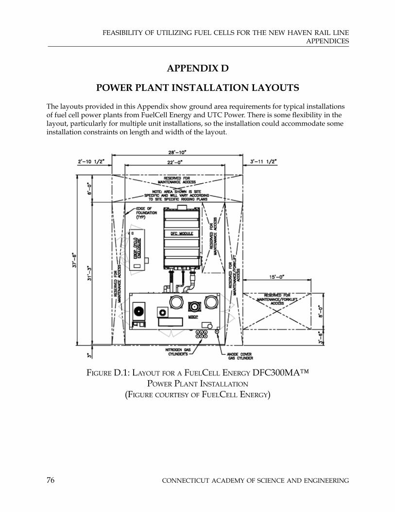
COnneCtiCut aCaDemy Of sCienCe anD engineering76
feasibility Of utilizing fuel Cells fOr the new haven rail lineappenDiCes
APPENDIX D
POWER PLANT INSTALLATION LAYOUTS
The layouts provided in this Appendix show ground area requirements for typical installations of fuel cell power plants from FuelCell Energy and UTC Power. There is some flexibility in the layout, particularly for multiple unit installations, so the installation could accommodate some installation constraints on length and width of the layout.
figure D.1: layOut fOr a fuelCell energy DfC300ma™ pOwer plant installatiOn
(figure COurtesy Of fuelCell energy)

feasibility Of utilizing fuel Cells fOr the new haven rail lineappenDiCes
COnneCtiCut aCaDemy Of sCienCe anD engineering 77
figure D.2: layOut fOr a fuelCell energy DfC1500™ pOwer plant installatiOn
(figure COurtesy Of fuelCell energy)

COnneCtiCut aCaDemy Of sCienCe anD engineering78
feasibility Of utilizing fuel Cells fOr the new haven rail lineappenDiCes
figure D.3: layOut fOr a fuelCell energy DfC3000™ pOwer plant installatiOn (
figure COurtesy Of fuelCell energy)

feasibility Of utilizing fuel Cells fOr the new haven rail lineappenDiCes
COnneCtiCut aCaDemy Of sCienCe anD engineering 79
figure D.4: layOut fOr a utC pureCell™ 200 pOwer plant installatiOn (figure COurtesy Of utC pOwer)
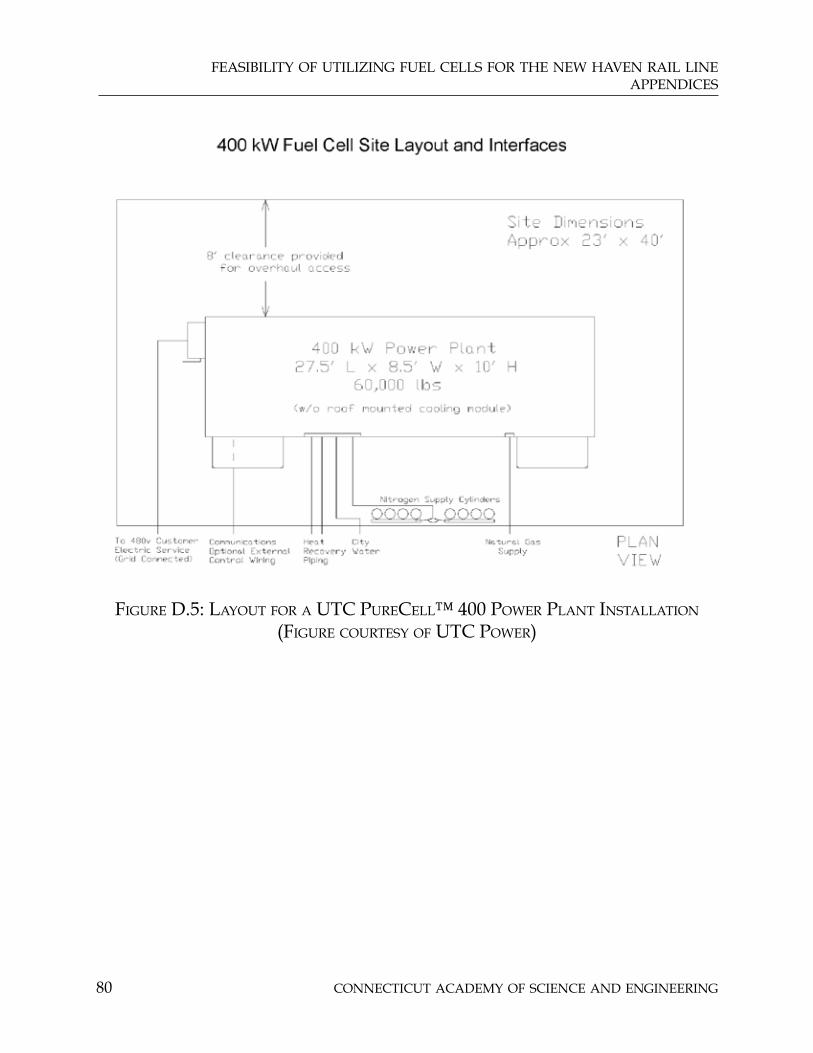
COnneCtiCut aCaDemy Of sCienCe anD engineering80
feasibility Of utilizing fuel Cells fOr the new haven rail lineappenDiCes
figure D.5: layOut fOr a utC pureCell™ 400 pOwer plant installatiOn (figure COurtesy Of utC pOwer)

feasibility Of utilizing fuel Cells fOr the new haven rail lineappenDiCes
COnneCtiCut aCaDemy Of sCienCe anD engineering 81
figure D.6: layOut fOr a 12 mw installatiOn Of five fuelCell energy DfC3000™ pOwer plants
(figure COurtesy Of fuelCell energy)
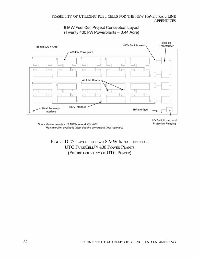
COnneCtiCut aCaDemy Of sCienCe anD engineering82
feasibility Of utilizing fuel Cells fOr the new haven rail lineappenDiCes
figure D. 7: layOut fOr an 8 mw installatiOn Of utC pureCell™ 400 pOwer plants
(figure COurtesy Of utC pOwer)

feasibility Of utilizing fuel Cells fOr the new haven rail lineappenDiCes
COnneCtiCut aCaDemy Of sCienCe anD engineering 83
APPENDIX E
SUMMARY OF SOLID OXIDE FUEL CELL ACTIVITY
A number of private SOFC development efforts are underway in the United States and other countries. The US Department of Energy has a significant SOFC effort under a program entitled Solid State Energy Conversion Alliance (SECA). The SECA program is managed at the National Energy Technology Laboratory (NETL) in Morgantown, West Virginia. This program includes an effort by six industry teams to develop fuel cell stacks in the 3 kW - 10 kW range, with design studies to evaluate efficiency, endurance, availability and production cost. The six industry teams include Acumentrics (Westwood, MA), Cummins Power Generation (Minneapolis, MN with partner SOFCo), Delphi Automotive Systems (Rochester, NY), FuelCell Energy (Danbury CT), General Electric Power Systems (Torrance, CA), and Siemens Power Generation (Pittsburgh, PA). Application targets range from auxiliary power generators for trucks to distributed generators operating on natural gas and large coal gasifier central stations with steam and gas turbine bottoming cycles.
Recently, the six SECA industry teams met SECA Phase I goals for efficiency, power degradation, system availability and projected system cost. Teams are now being selected to conduct phase II efforts; Siemens and FuelCell Energy are the first two teams to be selected (presentation by Wayne Surdoval, NETL Fuel Cells Technology Manager at the ASME Fifth International Fuel Cell Science, Engineering and Technology Conference, June 18 - 20, 2007, Brooklyn, New York).
In addition to the integrated efforts associated with the six industry teams, SECA includes a Core Technology Program involving other industry and academic participants and addressing the fundamental technology problems. Three Connecticut organizations (Connecticut Global Fuel Cell Center, UCONN (Storrs), R&D Dynamics (Bloomfield) and United Technologies Research Center (East Hartford)) are among these core technology program participants (www.netl.doe.gov).

COnneCtiCut aCaDemy Of sCienCe anD engineering84
feasibility Of utilizing fuel Cells fOr the new haven rail lineappenDiCes
appenDix f
COst Of eleCtriCity CalCulatiOns
A simplified calculation of the cost of electricity was made for the purposes of initial screening of potential New Haven Line fuel cell applications. The calculation involved the following assumptions:
Capital cost historically is $5,000 per kW and the capital cost goal is $2,000 per kW. It is • assumed that this capital cost is for the installed fuel cell power plant.
The historic maintenance costs for fuel cells are 2.5 cents per kWh and the maintenance • cost for fuel cells meeting the cost goal of $2,000 per kW are projected at 1.5 cents per kWh.
The contribution of capital cost to electricity cost is determined assuming a five-year • simple payback and 8,760 hours per year operation. This is equivalent to an annual capital charge rate of 20% of capital cost, representing depreciation, cost of money and taxes on capital.
Fuel cell electrical efficiency is the net plant efficiency and is based on the lower heating • value of the fuel consumed.
The total amount of electricity and heat which is available from any fuel cell is 80% of • the lower heating value of fuel consumed. In other words, total Combined Heat and Power efficiency if all the fuel cell output is used is 80%.
Heat supplied by the fuel cell displaces natural gas, which is burned to supply that heat, • at an efficiency of 85%.
The cost of natural gas for the fuel cell is $12.6 per million BTU which is equivalent to $12.6 per thousand cubic feet of natural gas. The cost of gas which the fuel cell heat displaces is $14.6 per million BTU. This reflects the fact that gas companies provide gas at lower cost for distributed generators because they represent a constant year-round load instead of the widely varying loads associated with heating.
Table F-1 shows the results of the cost of electricity calculation for a number of combinations of fuel cell cost, electrical efficiency, electrical load factor (in this case the same as capacity factor, heat utilization and maintenance cost.

feasibility Of utilizing fuel Cells fOr the new haven rail lineappenDiCes
COnneCtiCut aCaDemy Of sCienCe anD engineering 85
Capital Cost
($/kW)
Capital COE at 100 % LF note
1
Capital COE at 50% LF
Fuel Cost
$/MBTU Note 2
Electrical Efficiency
(%)
FUEL COE Contrib
(cents/kwh)
Use of available heat (%)
Fuel Cost for heating
($/MBTU)Note3
Heat Use
Credit (cents /kwh)
Maint COE
Raw COE
(cents /kwh) 100%
LF
Raw COE
(cents /kwh)
50% LF
2000 4.57 9.13 12.6 40 11.9455 100.00 14.60 5.86 1.5 12.15 16.72 2000 4.57 9.13 12.6 40 11.9455 50.00 14.60 2.93 1.5 15.08 19.65 2000 4.57 9.13 12.6 40 11.9455 25.00 14.60 1.47 1.5 16.55 21.11 2000 4.57 9.13 12.6 40 11.9455 0.00 14.60 0.00 1.5 18.01 22.58 2000 4.57 9.13 12.6 50 9.5564 100 14.60 4.40 1.5 11.23 15.79 2000 4.57 9.13 12.6 50 9.5564 50.00 14.60 2.20 1.50 13.42 17.99 2000 4.57 9.13 12.6 50 9.5564 25.00 14.60 1.10 1.5 14.52 19.09 2000 4.57 9.13 12.6 50 9.5564 0.00 14.60 0.00 1.5 15.62 20.19 5000 11.42 22.83 12.6 40 11.9455 100.00 14.60 5.86 2.5 20.00 31.41 5000 11.42 22.83 12.6 40 11.9455 50.00 14.60 2.93 2.5 22.93 34.35 5000 11.42 22.83 12.6 40 11.9455 25.00 14.60 1.47 2.5 24.40 35.81 5000 11.42 22.83 12.6 40 11.9455 0.00 14.60 0.00 2.5 25.86 34.89 5000 11.42 22.83 12.6 50 9.5564 100 14.60 4.40 2.5 19.08 30.49 5000 11.42 22.83 12.6 50 9.5564 50.00 14.60 2.20 2.5 21.27 32.69 5000 11.42 22.83 12.6 50 9.5564 25.00 14.60 1.10 2.5 22.37 33.79 5000 11.42 22.83 12.6 50 9.5564 0 14.60 0.00 2.5 23.47 34.89
Notes
1. Assume five year payback for Capital contribution to COE
2. Assume average of NH and Stamford Yard Gas Cost minus $2/MBTU
3 Assume average of NH and Stamford Yard Gas Cost
4 Assume 85% boiler efficiency
Reference COE for traction power is 11.29 Reference COE for Yard Power is 15.77 cents per kwh in Stamford and 11.2 cents per kwh in the New Haven yard.
table f-1: COst Of eleCtriCity frOm a fuel Cell pOwer plant baseD On a number Of simplifying assumptiOns

COnneCtiCut aCaDemy Of sCienCe anD engineering86
feasibility Of utilizing fuel Cells fOr the new haven rail lineappenDiCes
APPENDIX G
POSSIBLE LOCATIONS FOR FUEL CELL POWER PLANTS SERVING THE TRACTION POWER SYSTEM
A significant issue associated with the traction power application is finding suitable space for installation of fuel cell power plants along the track. An initial review of land availability for fuel cell installations was conducted as discussed. A Summary of the Results of this review follows and details of the review are then discussed. Further investigation, beginning with site visits to confirm possibilities of available land, is suggested in order to narrow the candidate sites.
SUMMARY OF RESULTS
Seven sites which may be suitable were identified. These sites are in Cos Cob, Devon, Green Farms, Bridgeport and at or near three I-95 service plazas.
Some of these sites involve land owned by the state and acquisition of space should not be a problem. For sites other than those owned by the state, land and access to the current wayside substations is limited and negotiations with owners may be difficult. Some flexibility could be gained by considering installation of the fuel cells at some distance from the substations and running connections along the track to the substation, or by adding additional substations where land is available. All of these approaches would entail additional equipment costs and possibly land acquisition costs. Land acquisition effort and expense, together with added expense for electrical connections, indicates that higher-rated applications should be considered for traction power, since these costs are not proportionally higher for larger amounts of power.
DETAILS OF REVIEW
A survey of available land along the New Haven Line in Connecticut involved three different types of available land:
Land near the wayside substations identified in Figure 3 of this report1.
Brownfields sites identified in the inventory of Brownfields sites available from the 2. Connecticut Department of Environmental Protection website (www.ct.gov/dep/lib/dep/site_clean_up/brownfields/brownfieldsinventory.pdf)
Industrial Zoned land or buildings available from Connecticut Economic Resource 3. Center Site Finder (www.cerc.com/)
Street locations for each site identified from these sources were entered into Mapquest and maps and aerial photographs from Mapquest were used to identify proximity to the rail Line and potential availability for locating fuel cells. The results of this approach were provided separately to ConnDOT.

ConneCtiCut ACAdemy of SCienCe And engineering179 Allyn Street, Suite 512, Hartford, CT 06103
Phone or Fax: 860-527-2161e-mail: [email protected]
web: www.ctcase.org
MAjor STudieS oF THe ACAdeMy
2007• GuidelinesforDevelopingaStrategicPlan
forConnecticut’sStemCellResearchProgram
2006• EnergyAlternativesandConservation• EvaluatingtheImpactofSupplementary
Science,Technology,EngineeringandMathematicsEducationalPrograms
• AdvancedCommunicationsTechnologies• PreparingfortheHydrogenEconomy:
Transportation• ImprovingWinterHighwayMaintenance:
CaseStudiesforConnecticut’sConsideration
• InformationTechnologySystemsforUseinIncidentManagementandWorkZones
• AnEvaluationoftheGeotechnicalEngineeringandLimitedEnvironmentalAssessmentoftheBeverlyHillsDevelopment,NewHaven,Connecticut
2005• AssessmentofaConnecticutTechnology
SeedCapitalFund/Program• DemonstrationandEvaluationofHybrid
Diesel-ElectricTransitBuses• AnEvaluationofAsbestosExposuresin
OccupiedSpaces
2004• LongIslandSoundSymposium:AStudyof
BenthicHabitats• AStudyofRailcarLavatoriesandWaste
ManagementSystems
2003• AnAnalysisofEnergyAvailablefrom
AgriculturalByproducts,PhaseII:AssessingtheEnergyProductionProcesses
• StudyUpdate:BusPropulsionTechnologiesAvailableinConnecticut
2002• AStudyofFuelCellSystems• TransportationInvestmentEvaluation
MethodsandTools• AnAnalysisofEnergyAvailablefrom
AgriculturalByproducts,Phase1:DefiningtheLatentEnergyAvailable
2001• AStudyofBusPropulsionTechnologiesin
Connecticut
2000• EfficacyoftheConnecticutMotorVehicle
EmissionsTestingProgram• IndoorAirQualityinConnecticutSchools• StudyofRadiationExposurefromthe
ConnecticutYankeeNuclearPowerPlant
1999• EvaluationofMTBEasaGasolineAdditive• StrategicPlanforCASE
1998• RadoninDrinkingWater
1997• AgriculturalBiotechnology• ConnecticutCriticalTechnologies
1996• EvaluationofCriticalTechnologyCenters• AdvancedTechnologyCenterEvaluation• BiotechnologyinConnecticut
1994• ScienceandTechnologyPolicy:Lessons
fromSixAmericanStates

ConneCtiCut ACAdemy of SCienCe And engineering
The Connecticut Academy is a non-profit institution patterned after the National Academy of Sciences to identify and study issues and technological advancements that are or should be of concern to the state of Connecticut. It was founded in 1976 by Special Act of the Connecticut General Assembly.
ViSion
The Connecticut Academy will foster an environment in Connecticut where scientific and technological creativity can thrive and contribute to Connecticut becoming a leading place in the country to live, work and produce for all its citizens, who will continue to enjoy economic well- being and a high quality of life.
miSSion StAtement
The Connecticut Academy will provide expert guidance on science and technology to the people and to the State of Connecticut, and promote its application to human welfare and economic well being.
goAlS
• Provide information and advice on science and technology to the government, industry and people of Connecticut.
• Initiate activities that foster science and engineering education of the highest quality, and promote interest in science and engineering on the part of the public, especially young people.
• Provide opportunities for both specialized and interdisciplinary discourse among its own members, members of the broader technical community, and the community at large.
ConneCtiCut ACAdemy of SCienCe And engineering179 Allyn Street, Suite 512, Hartford, CT 06103
Phone or Fax: 860-527-2161e-mail: [email protected]
web: www.ctcase.org