ELP-OA: status report of the setup of the demonstrator of the Polychromatic Laser Guide Star at...
22
1 ELP-OA : status report of the setup of the demonstrator of the Polychromatic Laser Guide Star at Observatoire de Haute-Provence Renaud Foy 1,2 , Nicolas Meilard 1 , Michel Tallon 1 , ´ Eric Thi´ ebaut 1 , Pierre- ´ Eric Blanc 2 , Michel Bo¨ er 2 , Andr´ ee Laloge 2 , Auguste Le Van Suu 2 , Sandrine Perruchot 2 , Pierre Richaud 2 , Alain Petit 3 , Thierry Fusco 4 1 CRAL - Observatoire de Lyon, France 2 Observatoire de Haute-Provence, France 3 Laboratoire de Spectroscopie et de l’Interaction laser-mati` ere, DEN/DPC, CEA, France 4 DOTA - ONERA, France
-
Upload
independent -
Category
Documents
-
view
0 -
download
0
Transcript of ELP-OA: status report of the setup of the demonstrator of the Polychromatic Laser Guide Star at...
1
ELP-OA : status report of the setup
of the demonstrator of the
Polychromatic Laser Guide Star at
Observatoire de Haute-Provence
Renaud Foy1,2, Nicolas Meilard1, Michel Tallon1, EricThiebaut1, Pierre-Eric Blanc2, Michel Boer2, Andree Laloge2,Auguste Le Van Suu2, Sandrine Perruchot2, Pierre Richaud2,
Alain Petit3, Thierry Fusco4
1CRAL - Observatoire de Lyon, France
2Observatoire de Haute-Provence, France
3Laboratoire de Spectroscopie et de l’Interaction laser-matiere,DEN/DPC, CEA, France
4DOTA - ONERA, France
2
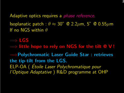
Adaptive optics requires a phase reference.
Isoplanatic patch : θ ≈ 30” @ 2.2µm, 5” @ 0.55µmIf no NGS within θ
=⇒ LGS=⇒ little hope to rely on NGS for the tilt @ V !
=⇒Polychromatic Laser Guide Star : retrievesthe tip-tilt from the LGS.ELP-OA ( Etoile Laser Polychromatique pourl’Optique Adaptative ) R&D programme at OHP
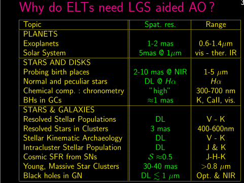
3Why do ELTs need LGS aided AO ?Topic Spat. res. RangePLANETSExoplanets 1-2 mas 0.6-1.4µmSolar System 5mas @ 1µm vis - ther. IRSTARS AND DISKSProbing birth places 2-10 mas @ NIR 1-5 µmNormal and peculiar stars DL @ Hα HαChemical comp. : chronometry ”high” 300-700 nmBHs in GCs ≈1 mas K, CaII, vis.STARS & GALAXIESResolved Stellar Populations DL V - KResolved Stars in Clusters 3 mas 400-600nmStellar Kinematic Archaeology DL V - KIntracluster Stellar Population DL J & KCosmic SFR from SNs S ≈0.5 J-H-KYoung, Massive Star Clusters 30-40 mas >0.8 µmBlack holes in GN DL . 1 µm Opt. & NIR
4
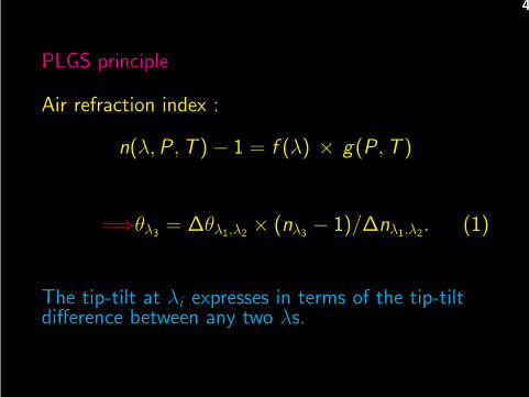
PLGS principle
Air refraction index :
n(λ, P , T ) − 1 = f (λ) × g(P , T )
=⇒θλ3= ∆θλ1,λ2
× (nλ3− 1)/∆nλ1,λ2
. (1)
The tip-tilt at λi expresses in terms of the tip-tiltdifference between any two λs.
5
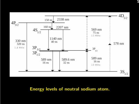
4D5/2
578 nm
3S1/2
569 nm 75 ns
3P3/2
150 ns 2338 nm4P3/2
4S1/2
589 nm 16 ns
1140 nm 40 ns
2207 nm160 ns
1/23P3P3/2
330 nm 320 ns1.6 M Hz
589 nm 16 ns10 M Hz
13 M Hz
589.6 nm 32 ns
Energy levels of neutral sodium atom.
6
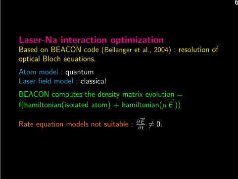
Laser-Na interaction optimizationBased on BEACON code (Bellanger et al., 2004) : resolution ofoptical Bloch equations.
Atom model : quantumLaser field model : classical
BEACON computes the density matrix evolution =
f(hamiltonian(isolated atom) + hamiltonian(µ−→E ))
Rate equation models not suitable : ∂−→
E
∂t6= 0.
7
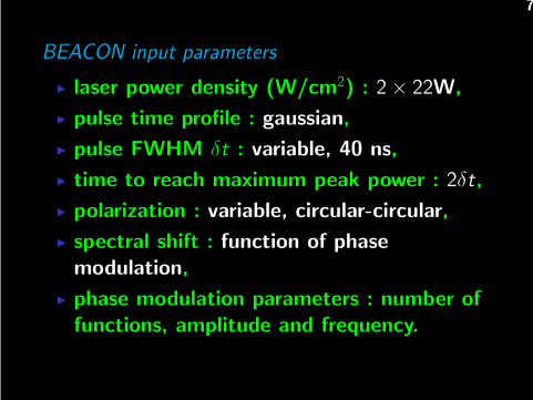
BEACON input parameters
◮ laser power density (W/cm2) : 2 × 22W,
◮ pulse time profile : gaussian,
◮ pulse FWHM δt : variable, 40 ns,
◮ time to reach maximum peak power : 2δt,
◮ polarization : variable, circular-circular,
◮ spectral shift : function of phase
modulation,
◮ phase modulation parameters : number of
functions, amplitude and frequency.
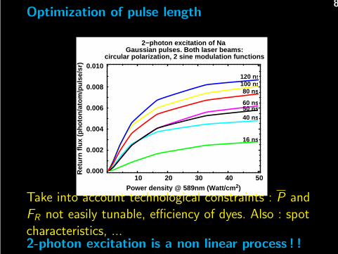
8Optimization of pulse length
120 ns
80 ns100 ns
60 ns50 ns40 ns
16 ns
10 20 30 40 500.000
0.002
0.004
0.006
0.008
0.010
Power density @ 589nm (Watt/cm 2)
Ret
urn
flux
(pho
ton/
atom
/pul
se/s
r)
2−photon excitation of Na Gaussian pulses. Both laser beams:
circular polarization, 2 sine modulation functions
Take into account technological constraints : P andFR not easily tunable, efficiency of dyes. Also : spotcharacteristics, ...2-photon excitation is a non linear process ! !
9
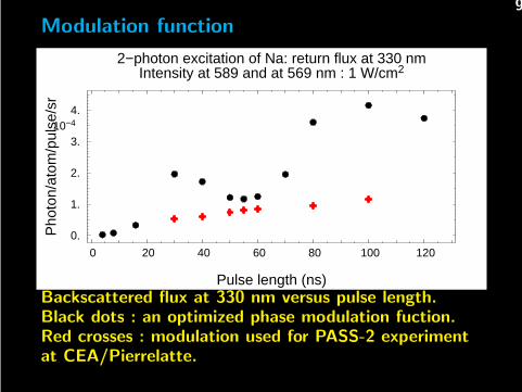
Modulation function
0 20 40 60 80 100 120
0.
1.
2.
3.
4.10−4
Pulse length (ns)
Pho
ton/
atom
/pul
se/s
r2−photon excitation of Na: return flux at 330 nm
Intensity at 589 and at 569 nm : 1 W/cm2
Backscattered flux at 330 nm versus pulse length.Black dots : an optimized phase modulation fuction.Red crosses : modulation used for PASS-2 experimentat CEA/Pierrelatte.
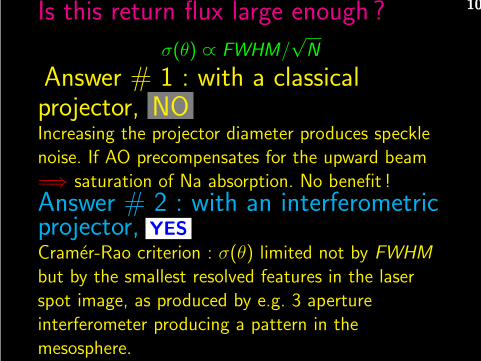
10Is this return flux large enough ?
σ(θ) ∝ FWHM/√
N
Answer # 1 : with a classicalprojector, NOIncreasing the projector diameter produces specklenoise. If AO precompensates for the upward beam=⇒ saturation of Na absorption. No benefit !Answer # 2 : with an interferometricprojector, YES
Cramer-Rao criterion : σ(θ) limited not by FWHM
but by the smallest resolved features in the laserspot image, as produced by e.g. 3 apertureinterferometer producing a pattern in themesosphere.
11
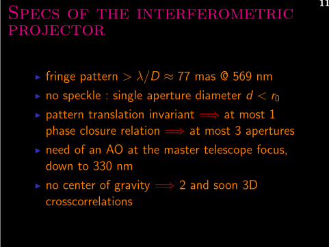
Specs of the interferometricprojector
◮ fringe pattern > λ/D ≈ 77 mas @ 569 nm
◮ no speckle : single aperture diameter d < r0
◮ pattern translation invariant =⇒ at most 1phase closure relation =⇒ at most 3 apertures
◮ need of an AO at the master telescope focus,down to 330 nm
◮ no center of gravity =⇒ 2 and soon 3Dcrosscorrelations
12
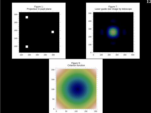
220 240 260 280 300
220
240
260
280
300
Figure 1 :Projecteur in pupil plane
pli, pup_proj_569
0 100 200 300 400 500 0
100
200
300
400
500
Figure 7 :Laser guide star image by telescope
pli, tel_569_tab(1,,)
0 50 100 150 200 0
50
100
150
200
Figure 9 :Criterion function
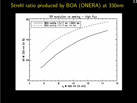
13Strehl ratio produced by BOA (ONERA) at 330nm
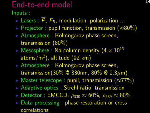
14End-to-end modelInputs :
◮ Lasers : P , FR , modulation, polarization ...◮ Projector : pupil function, transmission (≈80%)◮ Atmosphere : Kolmogorov phase screen,
transmission (80%)◮ Mesosphere : Na column density (4 × 10¹³
atoms/m2), altitude (92 km)◮ Atmosphere : Kolmogorov phase screen,
transmission(30% @ 330nm, 80% @ 2.3µm)◮ Master telescope : pupil, transmission (≈77%)◮ Adaptive optics : Strehl ratio, transmission◮ Detector : EMCCD, ρ330 ≈ 60%, ρ589 ≈ 80%◮ Data processing : phase restoration or cross
correlations
15
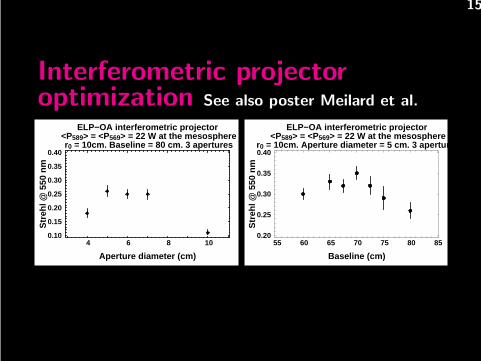
Interferometric projectoroptimization See also poster Meilard et al.
4 6 8 100.10
0.15
0.20
0.25
0.30
0.35
0.40
Aperture diameter (cm)
Str
ehl @
550
nm
ELP−OA interferometric projector <P589> = <P569> = 22 W at the mesosphere r0 = 10cm. Baseline = 80 cm. 3 apertures
55 60 65 70 75 80 850.20
0.25
0.30
0.35
0.40
Baseline (cm)S
treh
l @ 5
50 n
m
ELP−OA interferometric projector <P589> = <P569> = 22 W at the mesosphere
r0 = 10cm. Aperture diameter = 5 cm. 3 apertures
16
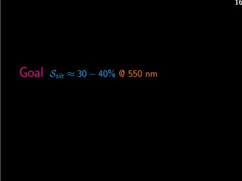
Goal Stilt ≈ 30 − 40% @ 550 nm
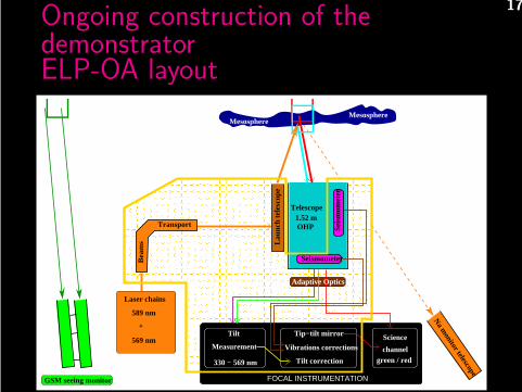
17Ongoing construction of thedemonstratorELP-OA layout
����������������������������������������������������������������������������������������������������������������������������������������������������������������������������������������������������������������������������������������������������������������������������������������������������������������������������������������������������������������������������������������������������������������������������������������������������������������������������������������������������������������������������������������������������������������������������������������������������������������������������������������������������������������������������������������������������������������������������������������������������������������������������������������������������������������������������������������������������������������������������������������������������������������������������������������������������������������������������������������������������������������������������������������������������������������������������������������������������������������������������������������������������������������������������������������������������������������������������������������������������������������������������������������
����������������������������������������������������������������������������������������������������������������������������������������������������������������������������������������������������������������������������������������������������������������������������������������������������������������������������������������������������������������������������������������������������������������������������������������������������������������������������������������������������������������������������������������������������������������������������������������������������������������������������������������������������������������������������������������������������������������������������������������������������������������������������������������������������������������������������������������������������������������������������������������������������������������������������������������������������������������������������������������������������������������������������������������������������������������������������������������������������������������������������������������������������������������������������������������������������������������������������������������������������������������������������������������
Seismometer
Telescope
OHP1.52 m
330 − 569 nm
Measurement
Tilt
FOCAL INSTRUMENTATION
Tip−tilt mirror
Vibrations corrections
Tilt correction green / red
Science
channel
Adaptive Optics
GSM seeing monitor
Sei
smom
eter
Bea
ms
Transport
Laser chains
589 nm
+
569 nm
MesosphereMesosphere ∗∗
Laun
ch te
lesc
ope
Na m
onitor telescope
∗
18
19
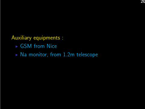
20
Auxiliary equipments :
◮ GSM from Nice
◮ Na monitor, from 1.2m telescope
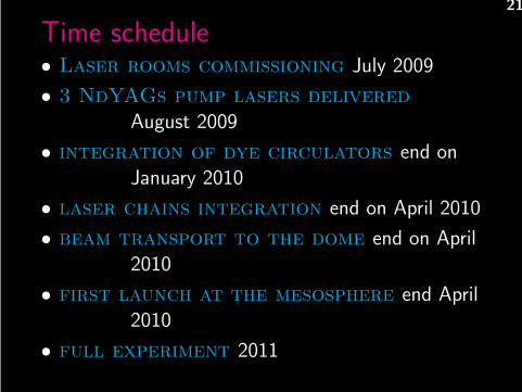
21
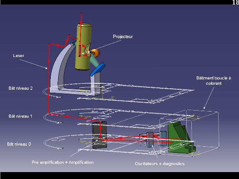
Time schedule• Laser rooms commissioning July 2009
• 3 NdYAGs pump lasers delivered
August 2009
• integration of dye circulators end onJanuary 2010
• laser chains integration end on April 2010
• beam transport to the dome end on April2010
• first launch at the mesosphere end April2010
• full experiment 2011

22
Analysis and roadmap from the ELT AdaptiveOptics Working Group (2006)
... the polychromatic LGS development should bemonitored and as for other novel concepts proposedin this document encouraged. Should the pendingtheoretical issues and simulations be positive, itshould be encouraged for on-sky demonstration.
Acknowledgments : ANR, PACA Region, DGA, CNRS/INSU