Electronics and Electrical Engineering Laboratory: technical ...
Upload
khangminh22Category
view
5download
0
# Student Centered Activities will comprise of various co-curricular activities like games, hobby clubs, seminars, declamation contests, extension lectures, NCC, NSS and cultural activities and discipline etc.
+ Industrial visit compulsory at minimum 2 Industries or Department.
Note: 1- Each period will be 50 minutes. 2- Each session will be of 16 weeks. 3- Effective teaching will be at least 12.5 weeks.
Subject
L T P T
O
T
EVALUATION SCHEME
Theory Practical Period/Weeks Max
MarksMax
Marks
Theory
MaxMarks
Hrs.
Practical
MaxMarks
UTTARAKHAND BOARD OF TECHNICAL EDUCATION
JOINT ENTRANCE EXAMINATION AND TRAINING, RESEARCH DEVELOPMENT CELL, DEHRADUN
STUDY AND EVALUATION SCHEME FOR DIPLOMA PROGRAMME
BRANCH NAME – ELECTRONICS ENGINEERING
Internal External
Electronics Circuits
Microprocessor and its Applications
Electronic Measuring Instruments
Network Filters and Transmission Lines
Signal Sensing and Conditioning
Electronics Workshop Cum-Minor Project
Industrial Exposure (Assessment at Inst. Level)+
Total
4
3
4
4
4
-
19
4
4
4
4
2
5
27
8
8
8
9
6
5
48
25
25
25
25
25
-
125
20
20
20
20
20
20
170
75
75
75
75
75
-
375
2.5
2.5
2.5
2.5
2.5
-
-
50
50
50
50
50
80
330
-
1
-
1
-
-
2
Hrs.
kk{k. vzf 'ia ulo q, /a kk kk u{ ]h j foi dk
ks' lzoi idzr Dq k"s;a Bl
3.0
3.0
3.0
3.0
3.0
3.0
-
-Industrial Training Industrial Training of 30 days done after 4th Semester would be evaluated in 5th Semester
through Report and Viva-voce.094053
General Proficiency # - 4 4 - 25 - - -- - 25 1014054
- - - - 25 - - -- -
SEMESTER – IV
Branch Code - 09
Total
Marks
Subject
Code
Credit
Point
170
170
170
170
170
100
1000
5
5
5
5
5
3
30
094002
094005
094001
094003
094004
094006
25 1094052
20

FOURTH SEMESTER
ELECTRONICS ENGINEERING
45
RATIONALE
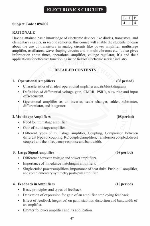
Having attained basic knowledge of electronic devices like diodes, transistors, and elementary circuits, in second semester, this course will enable the students to learn about the use of transistors in analog circuits like power amplifier, multistage amplifier, oscillators, wave shaping circuits and in multivibrators etc. It also gives information about timer, operational amplifier, voltage regulator, ICs and their applications for effective functioning in the field of electronic service industry.
DETAILED CONTENTS
1. Operational Amplifiers (08 period)
?Characteristics of an ideal operational amplifier and its block diagram.
?Definition of differential voltage gain, CMRR, PSRR, slew rate and input offset current.
?Operational amplifier as an inverter, scale changer, adder, subtractor, differentiator, and integrator.
2. Multistage Amplifiers (08 period)
?Need for multistage amplifier.
?Gain of multistage amplifier.
?Different types of multistage amplifier, Coupling, Comparison between different types of coupling, RC coupled amplifier, transformer coupled, direct coupled and their frequency response and bandwidth.
3. Large Signal Amplifier (08 period)
?Difference between voltage and power amplifiers.
?Importance of impedance matching in amplifiers.
?Single ended power amplifiers, importance of heat sinks. Push-pull amplifier, and complementary symmetry push-pull amplifier.
4. Feedback in Amplifiers (10 period)
?Basic principles and types of feedback.
?Derivation of expression for gain of an amplifier employing feedback.
?Effect of feedback (negative) on gain, stability, distortion and bandwidth of an amplifier.
?Emitter follower amplifier and its application.
ELECTRONICS CIRCUITS
L T P
4 - 4Subject Code : 094002
47

5. Sinusoidal Oscillators (08 period)
?Barkhausen criterion for oscillations.
?Tank Circuits.
?Use of positive feedback.
?Classification of oscillators.
?Hartley, Colpitt, phase shift, Wien bridge oscillator (Their working principle only).
6. Tuned Voltage Amplifiers (06 period)
?Series and parallel resonant circuits and bandwidth of resonant circuits.
7. Wave Shaping Circuits (08 period)
?General idea about different wave shapers.
?RC and RL integrating and differentiating circuits.
?Introduction to Diode clipping and clamping circuits.
8. Multivibrator Circuits (08 period)
?Concept of multi-vibrator: astable, monostable, and bistable and their applications.
?Block diagram of IC555 and its working and applications.
?IC555 as monostable and astable multi-vibrator.
LIST OF PRACTICALS
1. Plot the frequency response of two stage RC coupled amplifier and calculate the bandwidth.
2. To measure the gain of push-pull amplifier at 1KHz.
3. To measure the voltage gain of emitter follower circuit and plot its frequency response.
4. Plot the frequency response curve of Hartley and Colpitts Oscillator.
5. Plot the frequency response curve of phase shift and Wein bridge Oscillator.
6. To observe the output waveforms of series and shunt clipping circuits.
7. To observe the output for clamping circuits.
8. Use of IC 555 as monostable multivibrator and observe the output for different values of RC.
9. To use IC 741 (op-amplifier) as i) Inverter, ii) Adder, iii) Subtractor iv) Integrator.
48

Topic
1
2
3
4
5
6
7
8
Total
Marks Allocation
12
12
13
16
13
09
12
13
100
Time Allotted (period)
08
08
08
10
08
06
08
08
64
RECOMMENDED BOOKS
1. Basic Electronics and Linear Circuits by NN Bhargava, Tata McGraw Hill, New Delhi
2. Electronic Principles by Sahdev, DhanpatRai and Sons, New Delhi.
3. Electronics Principles by Malvino, Tata McGraw Hill, New Delhi
4. Electronic Devices and Circuits by Millman and Halkias, McGraw Hill, New Delhi
5. Electronics Devices and Circuits by Bhupinderjit Kaur, modern Publishers, Jalandhar
6. Basic Electronics by Grob, Tata McGraw Hill, New Delhi
7. Art of Electronics by Horowitz
8. Electronic Circuit Theory by Boylestad
9. Electronic Devices and Circuits by BL Theraja, S Chand and Co Ltd. New Delhi
10. Operational Amplifiers and Linear Integrated Circuits by Ramakant A. Gaykwad
11. Electronics Devices and Circuits by Rama Reddy, Narosa Publishing House Pvt. Ltd., New Delhi
12. Electronics Devices and Circuits-II by Rajesh Kumar, Eagle Prakashan, Jalandhar
SUGGESTED DISTRIBUTION OF MARKS
49

RATIONALE
The study of microprocessors in terms of architecture, software and interfacing techniques leads to the understanding of working of CPU in a microcomputer. The development in microprocessors of 32 bit architecture brings them face-to-face with mainframe finding employment in R&D, assembly, repair and maintenance of hardware of microprocessors and computers. Microprocessors find application in process control industry. They also form a part of the electronic switching system between source and destination in long distance telecommunications. Thus the microprocessor is an area of specialization. Students of electronics and related engineering branches often use microprocessors to introduce programmable control in their projects, in industrial training.
DETAILED CONTENTS
1. Evolution and Architecture of a Microprocessor (10 period) + (02)T
Functional block diagram of 8085 and function of each block, Concept of Bus, bus organization of 8085 ,Pin details of 8085 and related signals, Demultiplexing of address/data bus, generation of read/write control signals.
2. Programming (with respect to 8085 microprocessor) (16period) + (06)T
Brief idea of machine and assembly languages, Machines and Mnemonic codes, Instruction format and Addressing modes Classification of Instruction set.. Programming exercises in assembly language (Examples can be taken from the list of experiments),Concept of stack & subroutine (PUSH & POP ,CALL & RETURN instruction),Instruction cycle, machine cycle & T-states, Op-code Fetch and Execute cycle.
3. Memory Mapping and I/O interfacing (08 period) + (02)T
Concept of memory mapping, concept of I/O mapped I/O and memory mapped I/O and their Interfacing.
4. Interrupts (04 period) + (02)T
Concept of interrupt, Maskable and non-maskable, Edge triggered and level triggered interrupts, Software interrupt, Restart interrupts and its use, Various hardware interrupts of 8085.
MICROPROCESSOR AND ITS APPLICATIONS
L T P
3 1 4Subject Code : 094005
50

5. Data transfer techniques (04 period) + (02)T
Concept of programmed I/O operations, sync data transfer, async data transfer (hand shaking), Interrupt driven data transfer, DMA, Serial output data, Serial input data.
6. Peripheral devices (04 period) + (02)T
8255 PPI , 8257 DMA controller, 8279 Programmable KB/Display Interface.
7. Introduction to 8086: (02 period)
Block diagram & its main features.
LIST OF PRACTICALS
1. Familiarization with different keys of 8085 microprocessor kit and its memory map.
2. Steps to enter, modify data/program and to execute a programme on 8085 kit.
3. Writing and execution of ALP for addition and subtraction of two 8 bit numbers.
4. Writing and execution of ALP for addition of two 16 bit numbers.
5. Writing and execution of ALP to find out smallest and greatest no. out of 10 numbers.
6. Writing and execution of ALP for arranging 10 numbers in ascending/descending order.
7. Interfacing exercise on 8255 like LED display control.
8. Study and use of interfacing 8 bit A/D card and D/A card in sampling, wave generation, multiplexer, de-multiplexer and counter.
RECOMMENDED BOOKS
1. Microprocessor Architecture, Programming and Applications with 8080/8085 by Ramesh S Gaonkar, Willey Eastern Ltd. New Delhi
2. Introduction to Microprocessor by Mathur, Tata McGraw Hill Education Pvt. Ltd. New Delhi
3. Microprocessor and Microcontrollers by Dr B P Singh, Galgotia Publications, New Delhi
4. Microprocessor and Applications by Badri Ram: Tata McGraw Hill Education Pvt Ltd , New Delhi
5. Microprocessor and Microcomputers by Refiquzzaman, Prentice Hall of India Ltd., New Delhi
6. Digital Logic and Computer Design by Mano, M Morris; Prentice Hall of India, New Delhi
7. Digital Electronics and Applications by Malvino Leach; Publishers McGraw Hill, New Delhi
51

Topic
1
2
3
4
5
6
7
Total
Marks Allotted (%)
19
34
16
9
9
9
4
100
Time Allotted (period)+ Tutorial
12
22
10
06
06
06
02
64
8. Digital Integrated Electronics by Herbert Taub and DonalsSachilling; Prentice Hall of India Ltd., New Delhi
9. Digital Electronics by Rajaraman; Prentice Hall of India Ltd., New Delhi
10. Digital Electronics and Microprocessor by Rajiv Sapra, Ishan Publication, Ambala
SUGGESTED DISTRIBUTION OF MARKS
52

RATIONALE
In the real world of work the technician is required to handle wide variety of instruments while testing, trouble shooting, calibration etc. the study of this subject will help students to gain the knowledge of working principles and operation of different instruments. During practical sessions, he will acquire the requisite skills.
DETAILED CONTENTS
1. Basics of Measurements (06 period)
Definition of Measurement, Accuracy, precision, sensitivity, resolution, range, errors in measurement, sources of errors, loading effect.
2. Voltage, Current and Resistance Measurement (12 period)
?Principles of operation and construction of permanent magnet moving coil (PMMC) instruments.
?Moving iron type instruments, measurement of d.c voltage and current.
?Measurement of voltage, current and resistance using multimeter.
3. Cathode Ray Oscilloscope (10 period)
?Construction and working of Cathode Ray Tube (CRT).
?Time base operation, synchronization.
?Block diagram, description of a basic CRO and triggered sweep oscilloscope, Measurement of voltage, current, frequency, time period and phase using CRO.
?Special features of Dual Beam, Dual trace.
?Digital storage oscilloscope (DSO) : block diagram and working principle.
4. Signal Generators and Analytical Instruments (08 period)
?Explanation of block diagram, specifications of low frequency and RF generators, pulse generator, function generator.
?Wave analyzer.
ELECTRONICS MEASURING INSTRUMENTS
L T P
4 - 4Subject Code : 094001
53

5. Impedance Bridges and Q Meters (14period)
?Wheat stone bridge
?AC bridges: Maxwell’s induction bridge, Hay’s bridge, De-Sauty’s bridge, Schering bridge
?RLC bridge
?Block diagram and working principle of Q meter.
6. Digital Instruments (14 period)
?Working principle of ramp, dual slope and integration type digital voltmeter.
?Block diagram and working of a digital multimeter.
?Measurement of time interval, time period and frequency using frequency counter.
?Working principle of logic probe, logic pulser.
LIST OF PRACTICALS
1. Measurement of voltage, frequency, time period and phase using CRO.
2. Measurement of rise time and fall time using CRO.
3. Measurement of Q of a coil and its dependence on frequency.
4. Measurement of voltage, frequency, time and phase using DSO.
5. Measurement of resistance and inductance of coil using RLC Bridge.
6. To study the logic pulser and logic probe.
RECOMMENDED BOOKS
1. Electronics Measurement and Instrumentation by AK Sawhney, DhanpatRai and Sons, New Delhi
2. Electronics Measurement and Instrumentation by Oliver, Tata McGraw Hill Education Pvt Ltd, New Delhi
3. Electronics Instrumentation by Cooper, Prentice Hall of India, New Delhi
4. Electronics Test and Instrumentation by Rajiv Sapra, Ishan Publications, Ambala
5. Electronics Instrumentation by JB Gupta, SatyaPrakashan, New Delhi
54

Topic
1
2
3
4
5
6
Total
Marks Allocation (%)
05
20
15
10
25
25
100
Time Allotted (Period)
6
12
10
08
14
14
64
SUGGESTED DISTRIBUTION OF MARKS
55

RATIONALE
The study of networks, filters and transmission lines leads to understanding of line communication, audio and video communication, and microwave communication. Particularly the study of networks takes off from principles of a.c. theory and introduces the student to parameters and characteristics of various networks, including filters. Also the study of transmission lines becomes important as its analogy is used in study of transmission of plane electromagnetic waves in bounded media.
DETAILED CONTENTS
1. Circuit Theory &Networks (20period) + 06 (T)
a) Elements of Networks and its type, Current Source, Voltage Source and their conversion, Dependent and Independent Sources.
b) Two port (four terminals) network: Basic idea of Z ,Y ,H ,ABCD parameter(no numerical problem).
Definition of Symmetrical and asymmetrical networks: Balanced and unbalanced network, T-network, Ë network, Ladder network; L-network and Bridge T-network.
c) Symmetrical Network:
Concept and significance of the terms characteristic impedance, propagation constant of T-network and Ë Network.
d) Asymmetrical Network:
Concept and significance of iterative impedance, image impedance of Asymmetrical T network.
The half section (L-section); symmetrical T and Ë sections into half sections , iterative image impedance.
2. Attenuators (08period) + 02 (T)
?Units of attenuation (Decibels and Nepers): General characteristics of attenuators.
?Analysis and design of simple attenuator : Symmetrical T type.
3. Filters (16period) + 04 (T)
a) Brief idea of the use of filter networks in different communication systems, concept of low pass, high pass, band pass and band stop filters.
NETWORK, FILTERS AND TRANSMISSION LINES
L T P
4 1 4Subject Code : 094003
56

b) Crystal Filters - Crystal and its equivalent circuits, special properties of piezoelectric filters and their use.
c) Active Filters - Basic concept of active filters.
4. Transmission Lines (20period) + 04 (T)
?Transmission Lines, their types and applications.
?Distributed constants, T-representation of transmission line section.
?Definition of characteristic impedance, propagation constant, attenuation constant and phase shift constant.
?Concept of infinite line
?Condition for minimum distortion, Concept of reflection and standing waves, definition of reflection coefficient, VSWR and their relation (no derivation).
LIST OF PRACTICALS
1. To measure the characteristic impedance of symmetrical T and ? networks.
2. To measure the image impedance of a given asymmetrical T and ? networks.
3. For a prototype low pass filter find out the cut off frequency.
determine the characteristic impedance experimentally and
plot the attenuation characteristic.
4. To design and measure the attenuation of a symmetrical T type attenuator.
5. For a high pass filter:
determine the characteristic impedance experimentally and
plot the attenuation characteristics.
6. a) To plot the Impedance characteristic of a prototype band-pass filter.
b) To plot the attenuation characteristic of a prototype band pass filter.
7. To observe the information of standing waves on a transmission line and measurement of SWR and characteristic impedance of the line.
8. Draw the attenuation characteristics of a crystal filter.
RECOMMENDED BOOKS
1. Network Lines and Fields by John D Ryder; Prentice Hall of India, New Delhi
2. Network Filters and Transmission Lines by AK Chakarvorty; DhanpatRai and Co. Publication, New Delhi
3. Network Analysis by Van Valkenburg: Prentice Hall of India, New Delhi
4. Network Analysis by Soni and Gupta; DhanpatRai and Co. Publication, New Delhi
57

5. Network Theory and Filter Design by Vasudev K. Aatre
6. Network Filters and Transmission line by Umesh Sinha
7. Electrical and Electronics Measuring instrumentation, A.K. Sawhney, Dhanpat Rai and Co. Publication, New Delhi
8. Network Analysis by G.K. Mithal
9. Network Filters and Transmission line by Nardeep Goyal, Rajneesh Kumari, Tech. Max Publication, Pune.
Topic
1
2
3
4
Total
Marks Allocation (%)
32
12
24
32
100
Time Allotted (period)
26
10
20
24
80
SUGGESTED DISTRIBUTION OF MARKS
58

RATIONALE
This subject provides knowledge about signals, sensing of signals, signal transmission, conditioning and recording.
DETAILED CONTENTS
1. Introduction (04 Periods)
• Signal & its types
• Functional Elements of System
2. Sensing Elements (24 Periods)
?Resistive sensing elements: resistance thermometers, strain gauges, Load cell/Pressure cell.
?Capacitive sensing elements: variable separation, area and dielectric.
?Inductive sensing elements: variable reluctance and LVDT displacement sensors.
?Thermoelectric sensing elements: laws, thermocouple characteristics.
?Piezoelectric sensing elements.
?Photo sensing elements : Basic principle and characteristics of photo sources and photo detector, photo resistors, photo diodes, photo transistors, photo electric cell, LDR.
?Introduction to photo detector.
3. Signal Transmission (16 Periods)
?Introduction.
?Methods of Data Transmission.
?General Telemetry System.
?Types of Telemetry Systems.
?Land Line Telemetering System.
?Voltage Telemetering Systems.
SIGNAL SENSING AND CONDITIONING
L T P
4 - 2Subject Code : 094004
59

?Current Telemetering System.
?Position Telemetering System.
?Radio Frequency (R.F.) Telemetry.
.
4. Signal Conditioning (08 Periods)
• Basic Instrumentation Amplifier.
• Applications of Instrumentation Amplifiers (Specific Bridge).
5. Signal Recording and Display ( 12 Periods)
?Analog Recorders.
?Graphics Recorders.
?Strip Chart Recorders.
?Galvanometer Type Recorders.
?Digital Display Methods.
?Digital Display Units.
?Rear Projection Display.
LIST OF PRACTICALS
1. Measurement of Displacement using LVDT.
2. Measurement of Temperature using Thermocouple &Thermistor.
3. Measurement of Strain using strain gauge.
4. Application of Load Cell/Pressure Cell.
5. Application and use of LDR, Photocell.
6. Application and use of graphic and strip chart recorder.
7. Study of Telemetry System.
RECOMMENDED BOOKS
1. Electronic Instrumentation; by H.S. Kalsi; McGraw-Hill Education India
Pvt.Ltd.
2. Principles of Measurement Systems by John P.Bently (Pearson)
3. Electrical and Electronic Measurements and Instrumentation by A.K. Sawhney;
Dhanpat Rai & Co.
4. Instrumentation measurement and Analysis by B.C. Nakra, K.K.Chaudhary
60

5. Optoelectronics An Introduction to Materials and Devices by Singh Jasprit;
McGraw Hill
6. Instrumentation Devices and Systems by C.S.Ranjan; Tata McGraw Hill
SUGGESTED DISTRIBUTION OF MARKS
Topic
1
2
3
4
5
Total
Marks Allocation (%)
07
38
25
12
18
100
Time Allotted (Period)
04
24
16
08
12
64
61

DETAILED CONTENTS
1. Laboratory Experiences (06 period)
?Identification of components.
?Practice for color coding of resistance.
?Practice for identification of various components such as diode, capacitors, transistors, SCR, Triac and different ICs.
?Understand the use of data book for transistors, Diodes, SCR and Triac.
?Understand the use of data book for TTL and CMOS ICs.
?Testing of different components using multi-meter.
2. Use of electronic instruments (08 period)
?Practice for the use of multi-meter.
?Practice for the use of signal generator.
?Practice for the use of power supply.
?Practice for the use of oscilloscope.
3. Designing the PCB layout using computer software (12 period)
?Understanding the use of printed circuit board in electronics.
?Designing practice of PCB layout for a simple electronics circuit such as rectifier, transistor, amplifier etc.
?Use of software --Work bench and PSPICE.
4. Soldering the PCB (10 period)
?Soldering practice for PCB.
?Soldering the PCB design in layout topic.
?Desoldering practice.
5. Testing of PCB (10period)
After soldering the component on given PCB, testing the continuity and input / output result of given circuit.
ELECTRONIC WORKSHOP CUM-MINOR PROJECT
L T P
- - 5Subject Code : 094006
62

6. Fault finding of electronic circuit (10 period)
Basic idea of fault finding procedure.
7. Minor Project Work (24 Period)
Minimum 02 Project to be fabricated by each student.
Students can also select any other project with the advice of teacher
1. Regulated power supply
2. Timers using 555 and other oscillators
3. Touch plate switches – transistorized or 555 based
4. Door bell/cordless bell
5. Clapping switch and IR switch
6. Blinkers
7. Sirens and hooters
8. FM Transmitter and Receiver
9. Electronic toy gun, walker, blinkers
10. Electronic dice
11. Cell charger, battery charger, mobile charger
12. Fire/smoke/intruder alarm
13. Liquid level controller
14. Counters
15. Combination locks
16. Electronics musical instruments
17. Telephone handset
18. Audio amplifiers
19. Tape recorders
20. Automatic stabilizer/CVT
21. Emergency light
22. Design and manufacture of transformer
23. Fan regulator
24. Triac using Fan Regulator
25. 555 using lighting delay Circuits
26. Temperature sensor based fabrication
27. Design and fabricate transistor switch to operate an LED.
28. Design and Fabricate a single stage Amplifier for 1
63

RECOMMENDED BOOKS
1. Data books for transistors Diodes & SCR
2. Data book for TTL and CMOS ICs
3. PCB designing Books
Topic
1
2
3
4
5
6
7
Total
Time Allotted (period Practical )
06
08
12
10
10
10
24
80
SUGGESTED DISTRIBUTION OF MARKS
64

Industrial training provides an opportunity to students to experience the
environment and culture of industrial production units and commercial
activities undertaken in field organizations. It prepares student for their future
role as diploma engineers in the world of work and enables them to integrate
theory with practice.
For this purpose, students at the end of fourth semester need to be sent for
industrial training for a minimum of 4 weeks duration to be organized during
the semester break starting after IV Semester examinations. The concerned
HODs along with other teachers will guide and help students in arranging
appropriate training places relevant to their specific branch. It is suggested
that a training schedule may be drawn for each student before starting of the
training in consultation with the training providers. Students should also be
briefed in advance about the organizational setup, product range,
manufacturing process, important machines and materials used in the training
organization.
Equally important with the guidance is supervision of students training in the
industry/organization by the teachers. A teacher may guide a group of 4-5
students. A minimum of one visit by the teacher is recommended. Students
should be encouraged to write daily report in their diary to enable them to
write final report and its presentation later on.
Internal assessment and external assessment have been provided in the study
and evaluation scheme of V Semester. Evaluation of professional industrial
training report through viva-voce/presentation aims at assessing students
understanding of materials, industrial process, practices in industry/field
organization and their ability to engage in activities related to problem solving
in industrial setup as well as understanding of application of knowledge and
skills learnt in real life situations. The formative and summative evaluation
may comprise of weightage to performance in testing, general behavior,
quality of report and presentation during viva-voce examination. It is
recommended that such evaluations may be carried out by a team comprising
of concerned HOD, teachers and representative from industry, if any. The
components of evaluation will include the following:
INDUSTRIAL TRAINING
Subject Code : 094053
65

Sr. No
1
2
3
4
Performance Criteria.
Punctuality and regularity
Initiative in learning new things
Relationship with workers
Industrial training report
Total
Weightage (%)
15
15
15
55
100
66
Copyright © 2022 FDOKUMEN