Department of Electronics and Communication Engineering
31
Department of Electronics and Communication Engineering Birla Institute of Technology, Mesra, Ranchi - 835215 (India) Institute Vision To become a Globally Recognized Academic Institution in consonance with the social, economic and ecological environment, striving continuously for excellence in education, research and technological service to the National needs. Institute Mission To educate students at Undergraduate, Post Graduate Doctoral and Post-Doctoral levels to perform challenging engineering and managerial jobs in industry. To provide excellent research and development facilities to take up Ph.D. programmes and research projects. To develop effective teaching and learning skills and state of art research potential of the faculty. To build national capabilities in technology, education and research in emerging areas. To provide excellent technological services to satisfy the requirements of the industry and overall academic needs of society. Department Vision To become a centre of excellence in teaching and research for creating technical manpower to meet the technological needs of the country in the field of Electronics and Communications Engineering. Department Mission To facilitate state of the art Education and Research at Undergraduate, Post Graduate and Doctoral levels to enable to perform challenging engineering and managerial jobs in the field of Electronics and Communication Engineering. To build national capabilities in Technology, Education and Research in emerging areas in the field of Electronics and Communication Engineering. To create an environment to provide excellent Research and Development facilities to strengthen Ph.D. Programmes and Research Projects. To provide excellent Technological Services to bridge the gap between Academics and Industry in order to fulfil the overall academic needs of the society. To provide high quality Course Structure in order to turn out qualified professionals to meet the engineering needs of the country. To develop effective Teaching Skills and the Research Potentials of the faculty members. To ensure All Round Development of the students and to create a platform for turning out engineering professionals who can assume leadership position in society.
-
Upload
khangminh22 -
Category
Documents
-
view
3 -
download
0
Transcript of Department of Electronics and Communication Engineering
Department of Electronics and Communication Engineering Birla Institute of Technology, Mesra, Ranchi - 835215 (India)
Institute Vision
To become a Globally Recognized Academic Institution in consonance with the social, economic and ecological environment, striving continuously for excellence in education, research and technological service to the National needs.
Institute Mission
To educate students at Undergraduate, Post Graduate Doctoral and Post-Doctoral levels to perform challenging engineering and managerial jobs in industry.
To provide excellent research and development facilities to take up Ph.D. programmes and research projects.
To develop effective teaching and learning skills and state of art research potential of the faculty.
To build national capabilities in technology, education and research in emerging areas.
To provide excellent technological services to satisfy the requirements of the industry and overall academic needs of society.
Department Vision
To become a centre of excellence in teaching and research for creating technical manpower to meet the technological needs of the country in the field of Electronics and Communications Engineering.
Department Mission
To facilitate state of the art Education and Research at Undergraduate, Post Graduate and Doctoral levels to enable to perform challenging engineering and managerial jobs in the field of Electronics and Communication Engineering.
To build national capabilities in Technology, Education and Research in emerging areas in the field of Electronics and Communication Engineering.
To create an environment to provide excellent Research and Development facilities to strengthen Ph.D. Programmes and Research Projects.
To provide excellent Technological Services to bridge the gap between Academics and Industry in order to fulfil the overall academic needs of the society.
To provide high quality Course Structure in order to turn out qualified professionals to meet the engineering needs of the country.
To develop effective Teaching Skills and the Research Potentials of the faculty members.
To ensure All Round Development of the students and to create a platform for turning out engineering professionals who can assume leadership position in society.

M. Tech. In Microwave Engineering
PROGRAM EDUCATIONAL OBJECTIVES (PEO) PEO1 To enable students in Microwave Engineering with expert and professionals in the
present generation of Advanced communication techniques. PEO2 To develop the capability of independent research project in Microwave Engineering
applying research principles and methods PEO3 To train the postgraduate in Microwave Communication with the depth knowledge of
various subject of present day interest like Advanced Electromagnetics, EMI/EMC, Microwave material, Microwave Imaging, Smart Antennas, Satellite& mobile Communication
PEO4 To train the postgraduate having the knowledge of different simulation tools used for measure the performance and diagnose the RF and communication signals and systems
PEO5 To prepare students for Compiling and interpreting research data and presenting them in an appropriate format with scientific presentation, taking into consideration scientific principles and methodology, as well as practical applicability.
PEO6 To train students a high level of autonomy, accountability, credibility, ethics, and responsibility for all personal work outputs in the advanced RF field.
PROGRAM OUTCOMES (POs)
After completion of the programme, students will be able to demonstrate PO1 An ability to independently carry out research /investigation and development
work to solve practical problems. PO2 An ability to write and present a substantial technical report/document. PO3 A degree of mastery in Microwave Engineering technology at a level higher than
the requirements in the appropriate bachelor program. PO4 Recognise the need for life- long -learning and will prepare oneself to understand,
select and apply appropriate techniques and modern engineering and IT tools to solve complex Microwave Engineering for environment and society context.
PO5 Design and implement an independent research project in Microwave Engineering applying research principles and methods.
PO6 Acquire skills in handling instruments, tools, techniques and modelling using advanced software & tools.

COURSE INFORMATION SHEET Course code: EC501 Course title: Microwave Semiconductor devices Pre-requisite(s): EC201 Electronics Devices Co- requisite(s): Credits: L: 3 T: 0 P: 0 C: 3 Class schedule per week: 03 Class: M. Tech. Semester / Level: I/05 Branch: ECE Name of Teacher: Course Objectives:
This course enables the students to: 1. Understand the Material Properties of Semiconductors. 2. Grasp the characteristics of Microwave Transistors and Tunnel Diodes. 3. Apprehend the characteristics of Microwave Field Effect Transistors. 4. Perceive the characteristics of Transferred Electron Devices (TEDs). 5. Comprehend the characteristics of Avalanche Transit-Time Devices.
Course Outcomes:
At the end of the course, a student should be able to: CO1 Explain the Material Properties of Semiconductors. CO2 Articulate the Microwave Transistors and Tunnel Diodes CO3 Analyse Microwave Field Effect Transistors. CO4 Appraise the principle of operation of Transferred Electron Devices (TEDs) CO5 Design Avalanche Transit-Time Devices to observe high frequency response.
SYLLABUS
Module -1: Material Properties of Semiconductors: Frequency range for semiconductor materials, Crystalline structure of Si, Strain of SiGe films grown on Si, Crystalline structure of GaAs, wafer orientation for semi-insulating GaAs, Orientation-dependent etching profiles of GaAs, Energy bandgaps of GaAs, Si, and Ge as a function of temperature, Electron velocity for Si, InP and GaAs, Relative dielectric constant of GaAs, Thermal conductivity of various materials, II-V heterostructures used for Microwave and RF Applications, Energy bandgap and associated lattice constants for II-V heterostructures, Double pulsed doped pseudomorphic HEMT layer structure, InP, SiC, GaN, Comparison of conventional and wide bandgap materials.
(8L)
Module -2: Microwave Transistors and Tunnel Diodes: Microwave Bipolar Transistors: Physical Structures, Bipolar Transistor Configurations, Principles of Operation, Amplification Phenomena, Power-Frequency Limitations; Heterojunction Bipolar Transistors (HBTs): Physical Structures, Operational Mechanism,

Electronic Applications; Microwave Tunnel Diodes: Principles of Operation, Microwave Characteristics.
(8L)
Module -3: Microwave Field Effect Transistors: Junction Field-Effect Transistors (JFETs): Physical Structure, Principles of Operation, Current-Voltage (1-V) Characteristics; Metal-Semiconductor Field-Effect Transistors (MESFETs): Physical Structures, Principles of Operation, Small-Signal Equivalent Circuit, Drain Current Id, Cutoff Frequency fco and Maximum Oscillation Frequency fmax; High Electron Mobility Transistors (HEMTs): Physical Structure, Operational Mechanism, Performance Characteristics, Electronic Applications; Metal-Oxide-Semiconductor Field-Effect Transistors (MOSFETs): Physical Structure, Electronic Mechanism, Modes of Operation, Drain Current and Transconductance, Maximum Operating Frequency, Electronic Applications.
(8L)
Module -4: Transferred Electron Devices (TEDs): Gunn-Effect Diodes-GaAs Diode: Background, Gunn Effect; Ridley-Watkins--Hilsum (RWH) Theory: Differential Negative Resistance, Two-Valley Model Theory, High-Field Domain; Modes of Operation: Gunn Oscillation Modes, Limited-Space-Charge Accumulation (LSA) Mode, Stable Amplification Mode; LSA Diodes, InP Diodes, CdTe Diodes; Microwave Generation and Amplification.
(8L)
Module -5: Avalanche Transit-Time Devices: Read Diode: Physical Description, Avalanche Multiplication, Carrier Current l0(t) and External Current Ie(t), Output Power and Quality Factor Q; IMPATT Diodes: Physical Structures, Negative Resistance, Power Output and Efficiency; TRAPATT Diodes: Physical Structures, Principles of Operation, Power Output and Efficiency; BARITT Diodes: Physical Description, Principles of Operation, Microwave Performance; Parametric Devices: Physical Structures, Applications.
(8L)
Books recommended:
TEXT BOOKS:
1. Mike Golio, The RF and Microwave Handbook, 2e, CRC Press, 2008. 2. Samuel Y. Liao, Microwave Devices and Circuits, 3e, Prentice-Hall of India, 2003.
REFERENCE BOOK: 1. S. M. Sze, Kwok K. Ng, Physics of Semiconductor Devices, 3e, Wiley-Interscience,
2006.

2. Stephen A. Campbell, The Science and Engineering of Microelectronic Fabrication, 2/e, Oxford University Press, 2001.
3. I. A. Glover, S. R. Pennock and P. R. Shepherd, Microwave Devices, Circuits and Subsystems for Communications Engineering, John Wiley & Sons, 2005.
Course Evaluation: Individual assignment, Theory (Quiz and End semester) examinations
Gaps in the syllabus (to meet Industry/Profession requirements): Hands-on-practical for Microwave Device fabrication.
POs met through Gaps in the Syllabus: PO6 will be met though Microwave Device design-based assignment, which involves handling of TCAD tools.
Topics beyond syllabus/Advanced topics/Design: Topics beyond syllabus/advanced topics will be covered through the allotment of assignment requiring handling of TCAD tools and simulations. POs met through Topics beyond syllabus/Advanced topics/Design: PO6 Course Delivery Methods CD1 Lecture by use of boards/LCD projectors/OHP projectors CD2 Assignments/Seminars CD3 Laboratory experiments/teaching aids CD4 Industrial/guest lectures CD5 Industrial visits/in-plant training CD6 Self- learning such as use of NPTEL materials and internets CD7 Simulation
MAPPING BETWEEN COURSE OUTCOMES AND PROGRAM OUTCOMES
CO PO1 PO2 PO3 PO4 PO5 PO6 CO1 3 3 3 3 2 1 CO2 3 3 3 3 2 1 CO3 3 3 1 3 2 1 CO4 2 2 2 2 3 1 CO5 2 2 2 2 3 1
< 34% = 1, 34-66% = 2, > 66% = 3
MAPPING BETWEEN COURSE OUTCOMES AND COURSE DELIVERY METHOD
Course Outcomes Course Delivery Method
CO1 CD1, CD2, CD3, CD7 CO2 CD1, CD2, CD3, CD7 CO3 CD1, CD2, CD3, CD7 CO4 CD1, CD2, CD3, CD6, CD7 CO5 CD1, CD2, CD3, CD6, CD7

COURSE INFORMATION SHEET
Course code: EC503 Course title: Antennas and Diversity Pre-requisite(s): EC257 Electromagnetic Fields and Waves, EC323 Microwave Theory &Techniques Co- requisite(s): Credits: L: 3 T: 0 P: 0 C: 3 Class schedule per week: 03 Class: M. Tech. Semester / Level: I/05 Branch: ECE (Microwave Engineering / Wireless Communication) Name of Teacher: Course Objectives:
This course enables the students to: 1. Develop and apply the mathematical tools to analyse radiation characteristics of
aperture antennas. 2. Design and analyse various broadband, high gain, planar antennas for wireless
applications. 3. Design and analyse the dielectric resonator antenna 4. Understand the concept of smart antenna and beam forming techniques by using
cellular radio system and its evolution 5. Explain the need of different diversity schemes used in wireless communication
Course Outcomes: At the end of the course, a student should be able to: CO1 Understand the concept of aperture antennas, dielectric resonator antennas and their
applications CO2 Develop the mathematical tool to analyse radiation characteristics of antennas for
wireless applications CO3 Design the various types of aperture, dielectric resonator antennas to evaluate its
performance CO4 Explain and compare different diversity scheme, smart antennas and algorithms. CO5 Combine different diversity scheme to enhance system performance
SYLLABUS
Module I: Aperture Antennas: Radiation Equations, Rectangular Apertures: Uniform Distribution on an infinite ground plane, Uniform distribution in Space, Circular Apertures: Uniform Distribution on an infinite ground plane, Design Considerations.
(8L)
Module II: Antennas for Wireless Communication: Helical, Normal mode, Axial mode, Design procedure, feed design for helical antenna, Horn Antenna; E-Plane, H-Plane, Pyramidal horn, Whip antenna, Discone antenna.

(8L)
Module III: Dielectric Resonator Antenna: Introduction to Dielectric Resonator Antennas. Major Characteristics, Simple-Shaped Dielectric Resonator Antennas - The Hemispherical DRA. The Cylindrical DRA. The Rectangular DRA, Coupling to DRAs, Hybrid DRAs Bandwidth Enhancement of DRAs, Low Profile and Compact DRAs, DRAs with High Dielectric Constants, Circular-Polarized and Dual-Polarized DRAs, Ferrite Resonator Antennas.
(8L) Module IV: Smart Antenna: Introduction, Cellular Radio Systems Evolution, Signal propagation, Diversity and Combining Techniques, Smart Antenna System, Benefits and drawbacks of Smart Antennas, Antenna beamforming.
(8L) Module V: Diversity Schemes: Macroscopic diversity scheme, Microscopic diversity scheme – Space diversity, Field diversity, Polarization diversity, Angle diversity, Frequency diversity and time diversity scheme. Combining techniques for Macroscopic diversity, Combining techniques for Microscopic diversity.
(8L) Books recommended: TEXT BOOKS
1. Antenna Theory, Analysis and Design, 3/E, A. Balanis, John Wiley. 2. Antennas, J. D. Kraus, TMH 3. Wireless Communications, Principles and Practices, Rappaport, PHI
REFERENCE BOOKS
1. Software Radio A Modern Approach to Radio Engineering, J. H. Reed, Pearson Education.
2. Wireless and Cellular Communications, William C. Y. Lee, McGraw-Hill. 3. Wireless Communications, Principles and Practices, Rappaport, PHI. 4. Smart Antenna, T. K. Sarkar.
Course Evaluation: Individual assignment, Theory (Quiz and End semester) examinations
Gaps in the syllabus (to meet Industry/Profession requirements): Design and Development of real-time industrial projects. POs met through Gaps in the Syllabus: PO4 & PO5 Topics beyond syllabus/Advanced topics/Design: Design optimization for industrial and Research projects. POs met through Topics beyond syllabus/Advanced topics/Design: PO4 & PO5

Course Delivery Methods CD1 Lecture by use of boards/LCD projectors/OHP projectors CD2 Assignments/Seminars CD3 Laboratory experiments/teaching aids CD4 Industrial/guest lectures CD5 Industrial visits/in-plant training CD6 Self- learning such as use of NPTEL materials and internets CD7 Simulation
MAPPING BETWEEN COURSE OUTCOMES AND PROGRAM OUTCOMES
CO PO1 PO2 PO3 PO4 PO5 PO6 CO1 3 2 1 3 1 2 CO2 3 2 1 3 2 1 CO3 3 1 2 3 2 1 CO4 3 2 2 3 2 2 CO5 3 3 3 3 3 3
< 34% = 1, 34-66% = 2, > 66% = 3
MAPPING BETWEEN COURSE OUTCOMES AND COURSE DELIVERY METHOD
Course Outcomes Course Delivery Method
CO1 CD1, CD6 CO2 CD1, CD2, CD3, CD7 CO3 CD1, CD2, CD3, CD6, CD7 CO4 CD1, CD3, CD6, CD7 CO5 CD1, CD2, CD3, CD4, CD5, CD7

COURSE INFORMATION SHEET Course code: EC505 Course title: Advanced Electromagnetic Engineering Pre-requisite(s): Electromagnetic Theory and Microwave Engineering Co- requisite(s): Credits: L: 3 T: 0 P: 0 C: 3 Class schedule per week: 03 Class: M. Tech. Semester / Level: I Branch: ECE Course Objectives:
This course enables the students to: 1. To develop an ability to analyse the plane waves functions and various rectangular
shaped microwave components and their properties for different modes in rectangular coordinate system.
2. To develop an ability to analyse the cylinder wave functions and various cylindrical shaped microwave components and their properties for different modes in cylindrical coordinate systems.
3. To develop an ability to evaluate the spherical wave functions and various spherical shaped microwave components and their properties for different modes in spherical coordinate systems
4. To develop and ability to evaluate different parameters of microwave components using perturbational and variational techniques.
5. To develop and ability to analyse the various microwave networks Course Outcomes: At the end of the course, a student should be able to: CO1 Demonstrate understanding on the plane waves functions and calculation of various
performance parameters of different kinds of rectangular microwave components such as; rectangular waveguide, rectangular cavity, partially filled waveguide and dielectric slab waveguide apart from the concepts of surface guided waves and modal expansion of fields
CO2 Have an ability to analyse the cylindrical wave functions and calculation of various performance parameters of different kinds of cylindrical microwave components such as; circular waveguide, circular cavity, parallel plate, partially filled, dielectric slab coated and corrugated radial waveguides apart from the concepts of sources of cylindrical waves, two-dimensional radiation and wave transformations.
CO3 Have an ability to understand the spherical wave functions and evaluation of various performance parameters of spherical cavities, Conical Shaped Spherically Radial Waveguide, Hemispherical Resonator apart from the concepts of orthogonality relationship, space as a waveguide, waveform transformation techniques and scattering by spheres.
CO4 Demonstrate insight to use the perturbational and variational techniques to evaluate the different parameters due to perturbations on cavity walls, cavity materials and waveguide apart from the knowledge of stationary formulas for cavity.
CO5 Have an ability to understand the concepts of various microwave networks

SYLLABUS Module-I: The Wave Functions, Plane Waves, Rectangular Waveguide, Alternative Mode Sets, The Rectangular Cavity. Partially Filled Waveguide, Surface Guided Waves, Modal Expansion of Fields. Currents in Waveguides.
(8L)
Module-II: Cylindrical Wave Functions: The Wave Functions, Circular Waveguide, Radial Waveguides, Partially Filled Radial Waveguide, Sources of Cylindrical Waves, Two-Dimensional Radiation, Wave Transformations, Scattering by Cylinders.
(8L) Module-III:
Spherical Wave Functions: The Wave Functions, Spherical Cavity, Orthogonality Relationships, Sources of Spherical Waves, Wave Transformations, Scattering by Spheres, Maximum Antenna Gain.
(8L) Module-IV:
Perturbational and Variational Techniques: Perturbation of Cavity Walls, Cavity Material Perturbations, Waveguide Perturbations,
Stationary Formulas for Cavities, The Reaction Concept, Stationary Formulas for Waveguide, Spectral Domain Analysis
(8L) Module-V: Microwave Networks: Cylindrical Waveguide, Model expansion of waveguides, the network Concept, One-port Network, Two-port Network, Obstacles in waveguide, Posts in waveguide, Waveguide Junctions, Probes in Cavities, Aperture Coupling in Cavities.
(8L) Books recommended: TEXT BOOKS:
1. Time Harmonic Electromagnetic Fields; By Roger F. Harrington; McGraw Hill Book Company; 1961. (T1)
REFERENCE BOOKS: 1. Foundations for Microwave Engineering; Second Edition; By Robert E. Collin;
McGraw Hill International Edition; 1992. (R1) 2. Microwave Engineering; Second Edition; by David M. Pozar; John Wiley & Sons;
Inc. Copyright 2001, (R2)
Course Evaluation: Individual assignment, Theory (Quiz and End semester) examinations
Gaps in the syllabus (to meet Industry/Profession requirements): Design of advanced microwave components for industrial projects.

POs met through Gaps in the Syllabus: PO5 & PO6 Topics beyond syllabus/Advanced topics/Design: Analysis, design and optimization of advanced microwave components for industrial projects. POs met through Topics beyond syllabus/Advanced topics/Design: PO5 & PO6 Course Delivery Methods
CD1 Lecture by use of boards/LCD projectors/OHP projectors CD2 Assignments/Seminars CD3 Laboratory experiments/teaching aids CD4 Industrial/guest lectures CD5 Industrial visits/in-plant training CD6 Self- learning such as use of NPTEL materials and internets CD7 Simulation
MAPPING BETWEEN COURSE OUTCOMES AND PROGRAM OUTCOMES
CO PO1 PO2 PO3 PO4 PO5 PO6 CO1 2 2 3 3 2 - CO2 2 2 3 3 2 - CO3 2 2 3 3 2 - CO4 2 2 3 3 2 - CO5 2 2 3 3 2 -
< 34% = 1, 34-66% = 2, > 66% = 3
MAPPING BETWEEN COURSE OUTCOMES AND COURSE DELIVERY METHOD
Course Outcomes Course Delivery Method
CO1 CD1, CD6 CO2 CD1, CD6 CO3 CD1, CD2, CD6 CO4 CD1, CD2, CD6 CO5 CD1, CD2, CD6

COURSE INFORMATION SHEET Course code: EC506 Course title: Electromagnetic Interference and Electromagnetic Compatibility Pre-requisite(s): Electromagnetic Theory Co- requisite(s): Credits: L: 3 T: 0 P: 0 C: 3 Class schedule per week: 03 Class: M. Tech. Semester / Level: I/5 Branch: ECE Name of Teacher:
Course Objectives This course enables the students:
1. To explain requirement of EMI & EMC concept and impart knowledge on
different units and standards used for Electromagnetic compatibility in electronic/electric system.
2. To develop an ability to analyse, measure and evaluate the radiated and conducted emissions to examine the compatibility.
3. To develop an ability to analyse and evaluate the impact of EMI mitigation techniques such as shielding and grounding.
4. To develop an ability to explain the impact of EMI on system design. 5. To review the literature related to EMI & EMC to report it ethically.
Course Outcomes After the completion of this course, students will be:
CO1 Able to explain the requirement of EMI & EMC concept and impart knowledge
on different units and standards used for Electromagnetic compatibility in electronic/electric system.
CO2 Able to analyze, measure and evaluate radiated and conducted emissions to examine the electromagnetic compatibility.
CO3 Able to analyze and evaluate the impact of EMI mitigation techniques such as shielding and grounding.
CO4 Able to explain the impact of EMI on system design. CO5 To review and write the literature related to EMI & EMC to report it ethically.
SYLLABUS Module -1: Introduction: A brief history of EMI/EMC, Analysis of EMI, Type of Noise and Interference, Electromagnetic Compatibility, Radiated Emission and susceptibility, Conducted Emission and Susceptibility, Benefits of good EMC Design, Brief description of EMC regulations, Examples of EMC related problems. EMC requirements for Electronic Systems: Government regulations, Requirement for Commercial products and Military products, Radiated Emission limits for Class A, Class B, FCC and CISPR, measurement of Emissions

for verification of compliance: Radiated Emission and Conducted Emissions, Typical product emissions, Additional product requirements, design constraints for products, Advantages of EMC Design.
(8L) Module -2: Conducted Emission and Susceptibility: Measurement of Conducted emission: LISN, Common and Differential mode currents, Power supply filters: Basic properties of filters, A generic power supply filter topology, Effect of filter elements on common and differential mode currents, Separation of conducted emissions into common and differential mode components for diagnostic purpose, Power supplies: Linear and SMPS, Effect of Power Supply Components on Conducted emissions, Power Supply and Filter placement, Conducted Susceptibility.
(8L) Module -3: Radiated Emission and Susceptibility: Simple Emission models for wires and PCB lands: Differential mode versus Common mode currents, Differential mode current emission model Common mode current emission model, Current probes, Simple susceptibility models for wires and PCB lands: Shielded cables and surface transfer impedance.
(8L) Module -4: Cross talk: Three conductor transmission lines and crosstalk, Transmission line equations for lossless lines, The per unit length parameters: Homogeneous versus Inhomogeneous media, Wide separation approximation for wires, Numerical methods for other structures, The Inductive-Capacitive Coupling Approximation model: Frequency domain Inductive-Capacitive coupling model, Time domain Inductive-Capacitive coupling model, Lumped circuit approximate models. Shielded Wires: Per unit length parameters, Inductive and Capacitive Coupling, Effect of Shield grounding, Effect of pigtails, Effects of Multiple shields, MTL model predictions, Twisted wires: Per unit length parameters, Inductive and Capacitive Coupling, Effects of Twist, Effects of Balancing.
(8L) Module -5: Shielding: Shielding Effectiveness, Far field Sources: Exact solution, Approximate solution, Near field sources: Near field versus far field, Electric sources, Magnetic sources, Low frequency, magnetic field shielding, Effect of Apertures. System Design for EMC: Shielding and Grounding, PCB Design, System configuration and design, Electrostatic Discharge, Diagnostic tools.
(8L) Books recommended: TEXT BOOKS:
1. Paul, C., Introduction to Electromagnetic Compatibility, John Wiley & Sons, 1992. REFERENCE BOOKS:
1. Ott, W. Henry, Electromagnetic Compatibility Engineering, John Wiley & Sons, 2009. RB1

Course Evaluation: Individual assignment, Theory (Quiz and End semester) examinations
Gaps in the syllabus (to meet Industry/Profession requirements): Design of real-time industrial projects. POs met through Gaps in the Syllabus: PO5 & PO6 Topics beyond syllabus/Advanced topics/Design: Design optimization for industrial projects. POs met through Topics beyond syllabus/Advanced topics/Design: PO5 & PO6 Course Delivery Methods
CD1 Lecture by use of boards/LCD projectors/OHP projectors CD2 Assignments/Seminars CD3 Laboratory experiments/teaching aids CD4 Industrial/guest lectures CD5 Industrial visits/in-plant training CD6 Self- learning such as use of NPTEL materials and internets CD7 Simulation
MAPPING BETWEEN COURSE OUTCOMES AND PROGRAM OUTCOMES
CO PO1 PO2 PO3 PO4 PO5 PO6 CO1 2 1 1 2 1 3 CO2 2 1 1 1 1 1 CO3 2 1 2 2 3 - CO4 2 2 2 2 2 2 CO5 1 2 2 3 2 2
< 34% = 1, 34-66% = 2, > 66% = 3
MAPPING BETWEEN COURSE OUTCOMES AND COURSE DELIVERY METHOD
Course Outcomes Course Delivery Method
CO1 CD1, CD6 CO2 CD1, CD6, CD7 CO3 CD1, CD2, CD3, CD6, CD7 CO4 CD1, CD3, CD6, CD7 CO5 CD1, CD2, CD3, CD4, CD7

COURSE INFORMATION SHEET Course code: EC507 Course title: Electromagnetic and Microwave Applications of Metamaterials Pre-requisite(s): Electromagnetic Theory and Microwave Engineering Co- requisite(s): Credits: L: 3 T: 0 P: 0 C: 3 Class schedule per week: 03 Class: M. Tech. Semester / Level: I/5 Branch: ECE Course Objectives:
This course enables the students to: 1. To develop an ability to understand about left-handed metamaterial and its
characteristics and properties 2. To develop an ability to analyse the physical realization of left-handed
metamaterials using the resonant approach. 3. To develop an ability to analyse the physical realization of left-handed
metamaterials using the non-resonant approach 4. To develop and ability to understand the guided-wave applications of left-handed
metamaterials 5. To develop and ability to understand the radiated-wave applications of left-handed
metamaterials Course Outcomes: At the end of the course, a student should be able to: CO1 Demonstrate understanding of left-handed metamaterial and its characteristics and
properties CO2 Have an ability to design the left-handed metamaterials using the resonant approach. CO3 Have an ability to design the left-handed metamaterials using the non-resonant
approach CO4 Demonstrate insight the guided-wave applications of left-handed metamaterials. CO5 Demonstrate insight the radiated-wave applications of left-handed metamaterials.
SYLLABUS
Module 1: Introduction to Metamaterials: Definition of Metamaterials and left-handed Metamaterials. Theoretical speculation by Viktor Veselago.Wave Propagation in Left-Handed Media, Energy Density and Group Velocity, Negative Refraction, Fermat Principle, Inverse Doppler Effect, Backward Cerenkov Radiation, Negative Goos–Hanchen Shift, Waves at interfaces,Waves through left-handed slabs, Phase Compensation and Amplification of Evanescent Modes , Perfect Tunneling, The Perfect Lens , Losses and Dispersion.
(8L) Module 2: Realization of Metamaterials using Resonant Approach:

Scaling Plasmas at Microwave Frequencies, Metallic Waveguides and Plates as One- and Two-Dimensional Plasmas, Wire Media, Spatial Dispersion in Wire Media, Synthesis of Negative Magnetic Permeability, Design and Analysis of the Edge and Broad Coupled SRR, The Double and Multiple Split SRR, Spirals Resonators, Higher-Order Resonances in SRRs, Isotropic SRRs, Scaling Down SRRs to Infrared and Optical Frequencies , 1/2/3 Dimensional SRR-Based Left-Handed Metamaterials, Ferrite Metamaterials, Chiral Metamaterials.
(8L) Module 3: Realization of Metamaterials using Non-Resonant Approach: Ideal homogeneous CRLH TLs, Fundamental TL Characteristics, Equivalent MTM Constitutive Parameters, Balanced and Unbalanced Resonances, lossy CRLH TL model, LC Network Implementation, Difference with Conventional Filters, Transmission Matrix Analysis, Input Impedance, Cutoff Frequencies, Analytical Dispersion Relation, Bloch Impedance, Real Distributed 1D CRLH Structures, General Design Guidelines, Microstrip Implementation, Parameters Extraction. (8L) Module 4: Guided-Waves Applications of Metamaterials: Dual-Band Components, Dual-Band Property of CRLH TLs, Quarter-Wavelength TL and Stubs, Quadrature Hybrid and Wilkinson Power Divider, Enhanced-Bandwidth Components, Principle of Bandwidth Enhancement, Rat-Race Coupler, Tight Edge-Coupled Coupled-Line Couplers, Generalities on Coupled-Line Couplers, Symmetric Impedance Coupler, Asymmetric Phase Coupler, Negative and Zeroth-Order Resonator. SRRs based Filters and Diplexers Design.
(8L) Module 5: Radiated-Wave Applications of Metamaterials: Fundamental aspects of Leaky-Wave Structures, Principle of Leakage Radiation, Uniform and Periodic LW Structures, Backfire-to-Endfire (BE) leaky-wave (LW) antenna, electronically scanned LW antenna, Passive Retro-Directive Reflector, Two-Dimensional LW Radiation, Conical-Beam Antenna, Full-Space Scanning Antenna, Zeroth Order Resonating Antenna, Dual-Band CRLH-TL Resonating Ring Antenna, Heterodyne Phased Array, Non-uniform Leaky-Wave Radiator, The Future of MTMs.
(8L)
Books recommended: TEXT BOOKS:
1. “Metamaterials with Negative Parameters, Theory, Design and Microwave Applications,” by Ricardo Marques, Ferran Martin, and Mario Sorolla “Wiley Series in Microwave and Optical Engineering, Wiley Interscinces 2007” (T1)
2. “Electromagnetic Metamaterials: Transmission Line Theory and Microwave Applications, The Engineering Approach,” Christophe Caloz and Tatsuo Itoh, John Wiley & Sons, Inc., Hoboken, New Jersey 2006. (T2)
REFERENCE BOOKS:

1. Foundations for Microwave Engineering; Second Edition; By Robert E. Collin; McGraw Hill International Edition; 1992. (R1)
2. Microwave Engineering; Second Edition; by David M. Pozar; John Wiley & Sons; Inc. Copyright 2001. (R2)
Course Evaluation: Individual assignment, Theory (Quiz and End semester) examinations
Gaps in the syllabus (to meet Industry/Profession requirements): Design of advanced microwave components using left handed metamaterial. POs met through Gaps in the Syllabus: PO2 Topics beyond syllabus/Advanced topics/Design: Analysis, design and optimization of advanced microwave components using left handed metamaterial for industrial projects. POs met through Topics beyond syllabus/Advanced topics/Design: PO5 & PO6 Course Delivery Methods
CD1 Lecture by use of boards/LCD projectors/OHP projectors CD2 Assignments/Seminars CD3 Laboratory experiments/teaching aids CD4 Industrial/guest lectures CD5 Industrial visits/in-plant training CD6 Self- learning such as use of NPTEL materials and internets CD7 Simulation
MAPPING BETWEEN COURSE OUTCOMES AND PROGRAM OUTCOMES
CO PO1 PO2 PO3 PO4 PO5 PO6 CO1 2 2 3 3 3 2 CO2 3 2 3 3 3 2 CO3 3 2 3 3 3 2 CO4 3 2 3 3 3 2 CO5 3 2 3 3 3 2
< 34% = 1, 34-66% = 2, > 66% = 3
MAPPING BETWEEN COURSE OUTCOMES AND COURSE DELIVERY METHOD
Course Outcomes Course Delivery Method
CO1 CD1, CD6 CO2 CD1, CD6, CD7 CO3 CD1, CD2, CD6, CD7 CO4 CD1, CD2, CD6, CD7 CO5 CD1, CD2, CD6, CD7
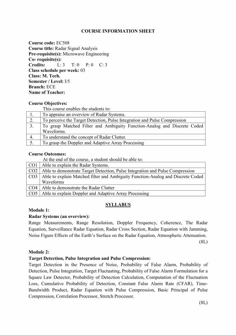
COURSE INFORMATION SHEET Course code: EC508 Course title: Radar Signal Analysis Pre-requisite(s): Microwave Engineering Co- requisite(s): Credits: L: 3 T: 0 P: 0 C: 3 Class schedule per week: 03 Class: M. Tech. Semester / Level: I/5 Branch: ECE Name of Teacher: Course Objectives:
This course enables the students to: 1. To appraise an overview of Radar Systems. 2. To perceive the Target Detection, Pulse Integration and Pulse Compression 3. To grasp Matched Filter and Ambiguity Function-Analog and Discrete Coded
Waveforms. 4. To understand the concept of Radar Clutter. 5. To grasp the Doppler and Adaptive Array Processing
Course Outcomes:
At the end of the course, a student should be able to: CO1 Able to explain the Radar Systems. CO2 Able to demonstrate Target Detection, Pulse Integration and Pulse Compression CO3 Able to explain Matched filter and Ambiguity Function-Analog and Discrete Coded
Waveforms CO4 Able to demonstrate the Radar Clutter CO5 Able to explain Doppler and Adaptive Array Processing
SYLLABUS
Module 1: Radar Systems (an overview): Range Measurements, Range Resolution, Doppler Frequency, Coherence, The Radar Equation, Surveillance Radar Equation, Radar Cross Section, Radar Equation with Jamming, Noise Figure Effects of the Earth’s Surface on the Radar Equation, Atmospheric Attenuation.
(8L)
Module 2: Target Detection, Pulse Integration and Pulse Compression: Target Detection in the Presence of Noise, Probability of False Alarm, Probability of Detection, Pulse Integration, Target Fluctuating, Probability of False Alarm Formulation for a Square Law Detector, Probability of Detection Calculation, Computation of the Fluctuation Loss, Cumulative Probability of Detection, Constant False Alarm Rate (CFAR), Time-Bandwidth Product, Radar Equation with Pulse Compression, Basic Principal of Pulse Compression, Correlation Processor, Stretch Processor.
(8L)

Module 3: Matched Filter and Ambiguity Function: The Matched Filter SNR, Mean and Variance of the Matched Filter Output, General Formula for the Output of the Matched Filter, Waveform Resolution and Ambiguity, Range and Doppler Uncertainty, Target Parameter Estimation, Examples of the Ambiguity Function, Stepped Frequency Waveforms, Nonlinear FM Ambiguity Diagram Contours, Interpretation of Range-Doppler Coupling in LFM Signals, Discrete Code Signal Representation, Pulse-Train Codes, Phase Coding, Frequency Codes, Ambiguity Plots for Discrete Coded Waveforms
(8L)
Module 4: Radar Clutter: Clutter Cross Section Density, Surface Clutter, Volume Clutter, Clutter RCS, Clutter Spectrum, Moving Target Indicator (MTI), PRF Staggering, MTI Improvement Factor, Subclutter Visibility, Delay Line Cancelers with Optimal Weights
(8L)
Module 5: Doppler and Adaptive Array Processing: CW Radar Functional Block Diagram, Pulsed Radars, Introduction to Adaptive Array Processing, General Arrays, Linear Arrays, Nonadaptive Beamforming, Adaptive Array Processing.
(8L)
Books recommended: TEXT BOOKS:
1. Bassem R. Mahafza, Radar Signal Analysis and Processing Using MATLAB, Chapman and Hall/CRC, 2008.
REFERENCE BOOKS: 1. M.I. Skolnik, “Introduction to Radar Systems”, 3/e, TMH, New Delhi, 2001 2. Nathanson, F. E., Radar Design Principles, New York, McGraw-Hill, 2nd Edition,
1991 3. Toomay, J. C., Radar Principles for the Non-Specialist, New York, Van Nostrand,
Reinhold, 1989 4. Buderi R., The Invention That Changed the World, New York, Simon and Schuster,
1996 5. R.J Sullivan, Radar foundation for imaging & advanced concepts, PHI, 2004. 6. Mark A Richards, Fundamentals of Radar Signal Processing,McGrah -Hill Company,
2005
Course Evaluation: Individual assignment, Theory (Quiz and End semester) examinations
Gaps in the syllabus (to meet Industry/Profession requirements): Design of real-time industrial projects.

POs met through Gaps in the Syllabus: PO2 Topics beyond syllabus/Advanced topics/Design: Design of real-time industrial projects. POs met through Topics beyond syllabus/Advanced topics/Design: PO5 & PO6 Course Delivery Methods
CD1 Lecture by use of boards/LCD projectors/OHP projectors CD2 Assignments/Seminars CD3 Laboratory experiments/teaching aids CD4 Industrial/guest lectures CD5 Industrial visits/in-plant training CD6 Self- learning such as use of NPTEL materials and internets CD7 Simulation
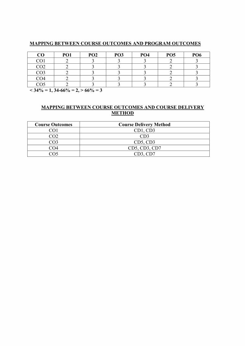
MAPPING BETWEEN COURSE OUTCOMES AND PROGRAM OUTCOMES
CO PO1 PO2 PO3 PO4 PO5 PO6 CO1 2 2 3 3 2 - CO2 2 2 3 3 2 - CO3 2 2 3 3 2 - CO4 2 2 3 3 2 - CO5 2 2 3 3 2 -
< 34% = 1, 34-66% = 2, > 66% = 3
MAPPING BETWEEN COURSE OUTCOMES AND COURSE DELIVERY METHOD
Course Outcomes Course Delivery Method
CO1 CD1, CD6, CD7 CO2 CD1, CD6, CD7 CO3 CD1, CD2, CD6, CD7 CO4 CD1, CD2, CD6, CD7 CO5 CD1, CD2, CD6, CD7

COURSE INFORMATION SHEET Course code: EC509 Course title: RF Microelectronics Circuit Design Pre-requisite(s): EC201 Electronic Devices, EC253 Analog Circuits Co- requisite(s): Credits: L: 3 T: 0 P: 0 C: 3 Class period per week: 03 Class: M. Tech. Semester / Level: I/5 Branch: ECE Name of Teacher:
Course Objectives:
This course enables the students to: 1. Understand RF frequency response of MOSFET. 2. Grasp the RF technology and basic concepts in RF design. 3. Apprehend Communication concepts and transceiver architectures. 4. Perceive Basic blocks in RF systems such as LNA, Mixer and VCO and their VLSI
implementations. 5. Comprehend Radio Frequency Synthesizers and Power Amplifiers.
Course Outcomes:
At the end of the course, a student should be able to: CO1 Interpret RF frequency response of MOSFET. CO2 Articulate the RF technology and basic concepts in RF design. CO3 Explain communication concepts in transceiver architectures. CO4 Appraise basic blocks in RF systems such as LNA, Mixer and VCO CO5 Design basic blocks in RF systems such as RF Synthesizer and Power Amplifiers
SYLLABUS
Module -1: RF frequency response of MOSFET: Derivation and estimation of MOS capacitor, MOS capacitor in cutoff, linear and saturation region, derivation and estimation of MOSFET’s long-channel model including threshold voltage, body effect, transconductance (gm), output conductance (gds), small-signal output resistance (ro), A Medium-Frequency Small-Signal Model for the Intrinsic Part, Intrinsic Transition Frequency, Noise in MOSFET: white noise, flicker noise, High frequency Small-Signal Model, Transition Frequency (fT) and Maximum oscillation (fmax) of MOSFET.
(8L) Module -2: RF technology and basic concepts in RF design: Introduction to RF and Wireless Technology: Challenges in RF Design, Complexity Comparison, Design Bottleneck, Applications, Choice of Technology; Basic concepts in RF Design: Units in RF Design, Time Variance, Nonlinearity, Effects of nonlinearity; Noise as Random Process, effect of transfer function on noise, device Noise, Representation of Noise in Circuits. Sensitivity and Dynamic Range.
(8L) Module -3: Communication concepts and transceiver architectures:

Analog modulation, Digital modulation, Spectral Regrowth, Mobile RF Communications, Multiple Access techniques Wireless standards; Receiver Architectures: Basic Heterodyne Receivers, Modern Heterodyne Receivers, Direct-Conversion Receivers, Image Reject Receivers, Low-IF Receivers; Transmitter Architectures: Direct-Conversion Transmitters, Modern Direct-Conversion Transmitters, Heterodyne Transmitters.
(8L) Module -4: Basic blocks in RF systems and their VLSI implementation: Low Noise Amplifier Design in various technologies, Design of Mixers at GHz frequency range; Various Mixers, their working and implementations; Oscillators: Basic topologies of VCO and definition of phase noise. Noise Power tradeoff. Resonatorless VCO design; Quadrature and single-sideband generators.
(8L) Module -5: Radio Frequency Synthesizer and Power Amplifiers: Radio Frequency Synthesizes: Phase Detector, Various types of PLLs, Various RF synthesizer architectures and frequency dividers; Power Amplifiers: Classification of Power Amplifiers, High-Efficiency Power Amplifiers, Linearization techniques, Design issues in integrated RF filters.
(8L) Books recommended: TEXT BOOK:
1. John W. M. Rogers, Calvin Plett, Radio Frequency Integrated Circuit Design, Artech House, 2010.
2. Yannis Tsividis, Colin McAndrew, Operation and Modeling of MOS Transistor, Oxford University Press, 3rd edition, 2011.
3. Behzad Razavi, RF Microelectronics, 2e, Prentice Hall, 2011.
REFERENCE BOOK: 1. Samuel Y. Liao, Microwave Devices and Circuits, 3e, Prentice-Hall of India, 2003. 2. Paul R. Gray, Paul J. Hurst, Stephen H. Lewis and Roberst G. Meyer, Analysis and
Design of Analog Integrated Circuits, 5/e, Wiley, 2009. 3. The Design of CMOS Radio-Frequency Integrated Circuits by Thomas H. Lee.
Cambridge University Press, 2004. Course Evaluation: Individual assignment, Theory (Quiz and End semester) examinations Gaps in the syllabus (to meet Industry/Profession requirements): Hands-on-practical for RF IC (Radio Frequency Integrated Circuit) fabrication.
POs met through Gaps in the Syllabus: PO6 will be met though RF circuit design-based assignment, which involves handling of RF equipments and CAD tools.
Topics beyond syllabus/Advanced topics/Design: Microelectronic Circuit Designs related to Digital, Analog and Mixed-Signal (such as ADC and DAC). POs met through Topics beyond syllabus/Advanced topics/Design: PO6

Course Delivery Methods CD1 Lecture by use of boards/LCD projectors/OHP projectors CD2 Assignments/Seminars CD3 Laboratory experiments/teaching aids CD4 Industrial/guest lectures CD5 Industrial visits/in-plant training CD6 Self- learning such as use of NPTEL materials and internets CD7 Simulation
MAPPING BETWEEN COURSE OUTCOMES AND PROGRAM OUTCOMES CO PO1 PO2 PO3 PO4 PO5 PO6 CO1 3 3 3 3 2 1 CO2 3 3 3 3 2 1 CO3 3 3 1 3 2 1 CO4 2 2 2 2 3 2 CO5 2 2 2 2 3 2
< 34% = 1, 34-66% = 2, > 66% = 3
MAPPING BETWEEN COURSE OUTCOMES AND COURSE DELIVERY METHOD
Course Outcomes Course Delivery Method
CO1 CD1, CD2, CD3, CD6 CO2 CD1, CD2, CD3, CD6, CD7 CO3 CD1, CD2, CD3, CD6, CD7 CO4 CD1, CD2, CD3, CD6, CD7 CO5 CD1, CD2, CD3, CD6, CD7

COURSE INFORMATION SHEET Course code: EC547 Course title: Fundamentals of MEMS Pre-requisite(s): Any Branch in UG Engg/Applied Science Co-requisite(s): Credits: L: 3 T: 0 P: 0 C:3 Class schedule per week: 03 Class: M. Tech. Semester / Level: I/05 Branch: ECE Name of Teacher: Course Objectives: This course enables the students: 1. Introduction to MEMS and micro fabrication to develop an ability, enthusiasm
critical thinking in microengineering process, materials and design issues 2. To study the essential material properties and understanding of microscale
physics for use in designing MEMS devices 3. To study various sensing and transduction technique to develop an ability and
understanding of microscale physics for use in designing MEMS devices 4. To develop an inclination towards electronics system design and manufacturing 5. To develop the fundamental concepts of MEMS technology& their applications
in different areas
Course Outcomes: After the completion of this course, students will be: CO1 Demonstrate knowledge on fundamental principles and concepts of MEMS
Technology CO2 Have an ability to analyze various techniques for building micro-devices in
silicon, polymer, metal and other materials CO3 Correlate micro-systems technology for technical feasibility as well as
practicality using modern tools and relevant simulation software to perform design and analysis.
CO4 Have an ability to compare physical, chemical, biological, and engineering principles involved in the design and operation of current and future micro-devices
CO5 Be fluent with the design, simulation and development MEMS Devices.
SYLLABUS Module-1: Introduction: The History of MEMS Development, Intrinsic characteristics of MEMS, MEMS sensors and actuators, Sensor noise and Design complexity. Introduction to Microfabrication Essential overview of frequently used micro fabrication processes. Thin film deposition techniques, wafer bonding Silicon Based MEMS processes, MEMS Materials.
(8L)

Module-2: Essential Electrical and Mechanical Concepts: Crystal planes & orientations, General Scalar relation between Tensile stress and strain, Mechanical properties of silicon and related thin films, Flexural Beam bending Analysis, Dynamic System, Resonant Frequency and quality factor, Electromechanical and Direct Analogy in Electrical and Mechanical domain.
(8L) Module -3: Sensing and Actuation schemes: Electrostatic Sensors and Actuators, Thermal sensors and actuators, Piezoresistive Sensors, Piezoelectric Sensors and Actuators, Magnetic Actuators. Comparison of Major Sensing and Actuation Methods and their Applications.
(8L) Module 4: MEMS Packaging and Integration. Role of MEMS packages. Mechanical support Electrical interface Protection from the environment Thermal considerations Types of MEMS packages Metal packages Ceramic packages Plastic packages 368, Multilayer packages Embedded overlay Wafer-level packaging, Microshielding and self-packaging, Flip-chip assembly Multichip module packaging, Wafer bonding.
(8L) Module 5: Case studies for selected MEMS Products: Blood Pressure Sensor, Microphone, Accelerometer, Performance and Accuracy.
(8L) Books recommended: Text Books: 1. Foundations of MEMS by Chang Liu, Second Edition, Pearson, ISBN 978-81-317-6475-
6. 2. RF MEMS and Their Applications, Vijay K.Varadan, K.J.Vinoy and K.A.Jose, Wiley
India Pvt Ltd.,Wiley India Edition, ISBN 978-81-265-2991-9.
Reference Books: 1. MarcMadou, Fundamentals of Microfabrication by, CRC Press, 1997.Gregory Kovacs,
Micromachined Transducers Sourcebook WCB McGraw-Hill, Boston, 1998. 2. M.-H. Bao, Micromechanical Transducers: Pressure sensors, accelerometers,and
gyroscopes by Elsevier, New York, 2000. 3. RF MEMS and Their Applications,Vijay K. Varadan K.J. Vinoy K.A. Jose Pennsylvania
State University, USA, John Wiley & Sons Ltd -2003.
Course Evaluation: Individual assignment, Theory (Quiz and End semester) examinations
Gaps in the syllabus (to meet Industry/Profession requirements): Design of real-time industrial /Research projects. POs met through Gaps in the Syllabus: PO3 & PO6 Topics beyond syllabus/Advanced topics/Design: Design optimization for industrial projects, Micro-fabrication techniques and MEMS devices.

POs met through Topics beyond syllabus/Advanced topics/Design: PO3 & PO4 Course Delivery Methods
CD1 Lecture by use of boards/LCD projectors/OHP projectors CD2 Assignments/Seminars CD3 Laboratory experiments/teaching aids CD4 Industrial/guest lectures CD5 Industrial visits/in-plant training CD6 Self- learning such as use of NPTEL materials and internets CD7 Simulation
MAPPING BETWEEN COURSE OUTCOMES AND PROGRAM OUTCOMES
CO PO1 PO2 PO3 PO4 PO5 PO6 CO1 3 2 2 3 2 1 CO2 3 3 3 3 2 1 CO3 3 3 1 3 2 1 CO4 2 2 2 2 3 2 CO5 2 2 2 2 3 2
< 34% = 1, 34-66% = 2, > 66% = 3
MAPPING BETWEEN COURSE OUTCOMES AND COURSE DELIVERY METHOD
Course Outcomes Course Delivery Method
CO1 CD1, CD2, CD3, CD6 CO2 CD1, CD2, CD3, CD6 CO3 CD1, CD2, CD3, CD4, CD6, CO4 CD1, CD2, CD3, CD6, CD7 CO5 CD1, CD2, CD3, CD4, CD6, CD7
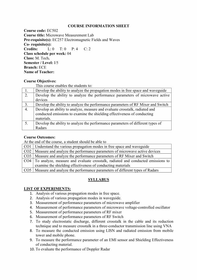
COURSE INFORMATION SHEET Course code: EC502 Course title: Microwave Measurement Lab Pre-requisite(s): EC257 Electromagnetic Fields and Waves Co- requisite(s): Credits: L: 0 T: 0 P: 4 C: 2 Class schedule per week: 04 Class: M. Tech. Semester / Level: I/5 Branch: ECE Name of Teacher: Course Objectives:
This course enables the students to: 1. Develop the ability to analyze the propagation modes in free space and waveguide 2. Develop the ability to analyze the performance parameters of microwave active
devices 3. Develop the ability to analyze the performance parameters of RF Mixer and Switch 4. Develop an ability to analyze, measure and evaluate crosstalk, radiated and
conducted emissions to examine the shielding effectiveness of conducting materials.
5. Develop the ability to analyze the performance parameters of different types of Radars
Course Outcomes: At the end of the course, a student should be able to CO1 Understand the various propagation modes in free space and waveguide CO2 Measure and analyze the performance parameters of microwave active devices CO3 Measure and analyze the performance parameters of RF Mixer and Switch CO4 To analyze, measure and evaluate crosstalk, radiated and conducted emissions to
examine the shielding effectiveness of conducting materials CO5 Measure and analyze the performance parameters of different types of Radars
SYLLABUS
LIST OF EXPERIMENTS:
1. Analysis of various propagation modes in free space. 2. Analysis of various propagation modes in waveguide. 3. Measurement of performance parameters of microwave amplifier 4. Measurement of performance parameters of microwave voltage-controlled oscillator 5. Measurement of performance parameters of RF mixer 6. Measurement of performance parameters of RF Switch 7. To study electrostatic discharge, different crosstalk in the cable and its reduction
technique and to measure crosstalk in a three-conductor transmission line using VNA 8. To measure the conducted emission using LISN and radiated emission from mobile
tower and mobile phone. 9. To measure the performance parameter of an EMI sensor and Shielding Effectiveness
of conducting material. 10. To evaluate the performance of Doppler Radar

11. To evaluate the performance of MTI radar 12. To evaluate the performance of FM CW Radar
Text Book: 1. David M. Pozar, "Microwave Engineering", Third Edition, Wiley India. 2. R. Ludwig and G. Bogdanov, “RF Circuit Design, Theory and Applications”,
Pearson, 2nd Edition. 3. Paul, C., Introduction to Electromagnetic Compatibility, John Wiley & Sons, 1992. 4. M.I. Skolnik, “Introduction to Radar System”,McGraw Hill 2nd Edition
Course Evaluation: Progressive Evaluation and End-Sem. Evaluation Gaps in the syllabus (to meet Industry/Profession requirements): POs met through Gaps in the Syllabus: Topics beyond syllabus/Advanced topics/Design: POs met through Topics beyond syllabus/Advanced topics/Design: Course Delivery Methods
CD1 Lecture by use of boards/LCD projectors/OHP projectors CD2 Assignments/Seminars CD3 Laboratory experiments/teaching aids CD4 Industrial/guest lectures CD5 Industrial visits/in-plant training CD6 Self- learning such as use of NPTEL materials and internets CD7 Simulation
MAPPING BETWEEN COURSE OUTCOMES AND PROGRAM OUTCOMES
CO PO1 PO2 PO3 PO4 PO5 PO6 CO1 2 3 3 3 2 3 CO2 2 3 3 3 2 3 CO3 2 3 3 3 2 3 CO4 2 3 3 3 2 3 CO5 2 3 3 3 2 3
< 34% = 1, 34-66% = 2, > 66% = 3
MAPPING BETWEEN COURSE OUTCOMES AND COURSE DELIVERY METHOD
Course Outcomes Course Delivery Method
CO1 CD3, CD7 CO2 CD3, CD7 CO3 CD3, CD7 CO4 CD3, CD7 CO5 CD3, CD7

COURSE INFORMATION SHEET Course code: EC504 Course title: Antenna Lab Pre-requisite(s): EC257 Electromagnetic Fields and Waves, EC323 Microwave Theory &Techniques Co- requisite(s): Credits: L: 0 T: 0 P: 4 C: 2 Class schedule per week: 04 Class: M. Tech. Semester / Level: I/5 Branch: ECE Name of Teacher: Course Objectives This course enables the students:
1. To understand important and fundamental antenna engineering parameters. 2. To develop the basic skills to learn software and apply in the design of various
antennas. 3. To develop the basic skills necessary to measure antenna performance parameters. 4. To apply the concepts learnt through theory 5. Develop the ability to analyze the performance parameters of different types of
antenna
Course Outcomes After the completion of this course, students will be able to:
CO1 Have the ability to implement the theoretical knowledge and prepare the reports and present the results.
CO2 Apply numerical modelling tools (software) to design antennas, with particular reference to low profile printed antennas.
CO3 Have the ability to perform antenna measurements. CO4 Understand and visualize the radiation characteristics and its limitations and
provide the environment friendly solutions in terms of antenna design. CO5 Have the ability to Practically verify different microwave antenna theories.
SYLLABUS
List of Experiments
1. Design of a rectangular microstrip patch antenna for operating frequency 1.88GHz
with Ԑr =4.4, h=31 mils with inset feed. (IE3D)
2. Design of a rectangular microstrip patch antenna for operating frequency 1.88GHz with Ԑr =4.4, h=31 mils with coaxial feed. (IE3D)

3. Design of a rectangular microstrip patch antenna for operating frequency 5 GHz with Ԑr =3.2, h=0.762mm & transformer coupled microstrip feed. (IE3D)
4. Design of a circular microstrip patch antenna for circular polarization with dual feed. Assume resonant frequency =2.78GHz, Ԑr =2.33, h=2.184mm, tanδ=0.0012. (IE3D)
5. Design of a rectangular microstrip patch antenna for operating frequency 1.88GHz with Ԑr =4.4, h=31 mils & inset feed. (HFSS)
6. Design of a rectangular microstrip patch antenna for operating frequency 1.88GHz with Ԑr =4.4, h=31 mils & transformer coupled microstrip feed. (HFSS)
7. To plot the radiation pattern of a directional antenna.
8. To plot the radiation pattern of an omnidirectional antenna.
9. To calculate the resonant frequency and estimate the VSWR of an antenna. 10. To prove inverse square law for any antenna. 11. Characterization of a linearly polarized and circularly polarized antenna. 12. The gain measurement of an antenna under test.
Course Evaluation: Progressive Evaluation and End-Sem. Evaluation
Gaps in the syllabus (to meet Industry/Profession requirements): POs met through Gaps in the Syllabus: Topics beyond syllabus/Advanced topics/Design: POs met through Topics beyond syllabus/Advanced topics/Design: Course Delivery Methods
CD1 Lecture by use of boards/LCD projectors/OHP projectors CD2 Assignments/Seminars CD3 Laboratory experiments/teaching aids CD4 Industrial/guest lectures CD5 Industrial visits/in-plant training CD6 Self- learning such as use of NPTEL materials and internets CD7 Simulation
MAPPING BETWEEN COURSE OUTCOMES AND PROGRAM OUTCOMES
CO PO1 PO2 PO3 PO4 PO5 PO6 CO1 2 3 3 3 2 3 CO2 2 3 3 3 2 3 CO3 2 3 3 3 2 3 CO4 2 3 3 3 2 3 CO5 2 3 3 3 2 3
< 34% = 1, 34-66% = 2, > 66% = 3
MAPPING BETWEEN COURSE OUTCOMES AND COURSE DELIVERY METHOD
Course Outcomes Course Delivery Method
CO1 CD1, CD3 CO2 CD3 CO3 CD5, CD3 CO4 CD5, CD3, CD7 CO5 CD3, CD7