
Electronics at school beyond the bulb with TI-Innovator
16
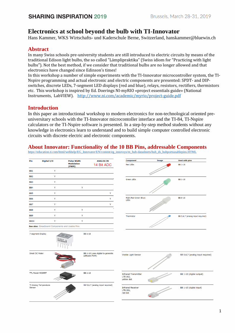
1 Electronics at school beyond the bulb with TI-Innovator Hans Kammer, WKS Wirtschafts- und Kaderschule Berne, Switzerland, [email protected] Abstract In many Swiss schools pre-university students are still introduced to electric circuits by means of the traditional Edison light bulbs, the so called "Lämplipraktika" (Swiss idiom for “Practicing with light bulbs”). Not the best method, if we consider that traditional bulbs are no longer allowed and that electronics have changed since Edinson’s times! In this workshop a number of simple experiments with the TI-Innovator microcontroller system, the TI- Nspire programming and actual electronic and electric components are presented: SPDT- and DIP- switches, discrete LEDs, 7-segment LED displays (red and blue), relays, resistors, rectifiers, thermistors etc. This workshop is inspired by Ed. Doerings NI-myRIO «project essentials guide» (National Instruments, LabVIEW). http://www.ni.com/academic/myrio/project-guide.pdf Introduction In this paper an introductional workshop to modern electronics for non-technological oriented pre- universitary schools with the TI-Innovator microcontoller interface and the TI-84, TI-Nspire calculators or the TI-Nspire software is presented. In a step-by-step method students without any knowledge in electronics learn to understand and to build simple computer controlled electronic circuits with discrete electric and electronic components. About Innovator: Functionality of the 10 BB Pins, addressable Components https://education.ti.com/html/webhelp/EG_Innovator/EN/content/eg_innovsys/m_hub-datasheets/hub_ds_hubportsusablepins.HTML
-
Upload
khangminh22 -
Category
Documents
-
view
1 -
download
0
Transcript of Electronics at school beyond the bulb with TI-Innovator
1
Electronics at school beyond the bulb with TI-Innovator Hans Kammer, WKS Wirtschafts- und Kaderschule Berne, Switzerland, [email protected]
Abstract In many Swiss schools pre-university students are still introduced to electric circuits by means of the traditional Edison light bulbs, the so called "Lämplipraktika" (Swiss idiom for “Practicing with light bulbs”). Not the best method, if we consider that traditional bulbs are no longer allowed and that electronics have changed since Edinson’s times! In this workshop a number of simple experiments with the TI-Innovator microcontroller system, the TI-Nspire programming and actual electronic and electric components are presented: SPDT- and DIP-switches, discrete LEDs, 7-segment LED displays (red and blue), relays, resistors, rectifiers, thermistors etc. This workshop is inspired by Ed. Doerings NI-myRIO «project essentials guide» (National Instruments, LabVIEW). http://www.ni.com/academic/myrio/project-guide.pdf
Introduction In this paper an introductional workshop to modern electronics for non-technological oriented pre-
universitary schools with the TI-Innovator microcontoller interface and the TI-84, TI-Nspire
calculators or the TI-Nspire software is presented. In a step-by-step method students without any
knowledge in electronics learn to understand and to build simple computer controlled electronic
circuits with discrete electric and electronic components.
About Innovator: Functionality of the 10 BB Pins, addressable Components https://education.ti.com/html/webhelp/EG_Innovator/EN/content/eg_innovsys/m_hub-datasheets/hub_ds_hubportsusablepins.HTML

2
1. Discrete LED, introduction and learning objectives 1.1. Introduction
LEDs, or light-emitting diodes, provide simple yet essential visual indicators for system status and
error conditions. Figure 1 shows some typical LEDs; green, red, and RGB-LEDs are included in the
TI-Innovator™ Breadboard Pack, a white LED in the I/O-modules Pack.
Figure 1: Typical LEDs
Figure 2 LED Function and Symbol
1.2 Learning Objectives
After completing this activity you will be able
1. to describe the essential concepts related to LEDs :
(a) A LED is a diode that permits only one-way current,
(b) The LED forward-bias voltage drop varies with color (wavelength of the emitted light),
(c) The interface circuit design depends on knowledge of the TI-Innovator’s Breadboard (BB1
to BB10) output resistance and source voltage (3.3 V or 5 V).
(d) blue LEDs may be direct-connected to the TI-Innovator’s Breadboard (BB1 to BB10) outputs.
2. to select a suitable current-limiting resistor (or no resistor) based on the LED type.
3. to create a LED variable-intensity dimmer with one of the Innovators PWM Pins (BB4, BB8,
BB9 or BB10) to create a pulse-width modulated digital output
1.2. Component Demonstration
Follow these steps to demonstrate
correct operation of the discrete LED
compo-nent :
Select these parts from the TI Inno-
vator Breadboard Pack:
• one 100 Ohm resistor
• a two-terminal LED
• Innovators breadboard
• Jumper wires
Figure 3 schematic diagram and wiring

3
Program : Blinking 10 times (TI-Nspire CX CAS-Software / PC)
Preparation
Innovator Program BB 1
Define blinkbb()=
Prgm
Send "CONNECT LED 1 TO
BB 1 "
For n,1,10
Send "SET LED 1 OFF"
Wait 1
Send "SET LED 1 ON"
Wait 0.1
EndFor
Send "DISCONNECT LED 1"
EndPrgm
Innovator Program OUT 1
Define white_led()=
Prgm
Send "CONNECT LED 1 TO
OUT 1"
For n,1,10
Send "SET LED 1 OFF"
Wait 1
Send "SET LED 1 ON"
Wait 0.1
EndFor
Send "DISCONNECT LED 1"
EndPrgm
Syntax Check and Execution
All of the LEDs in the Breadboard Pack have clear plastic lenses with a wide variety of colors. You
may wish to try multiple LEDs to investigate your color options.
Because this interface circuit is the current sourcing form the LED is active when the digital output
is in the high state, i.e., this is an active-high LED interface circuit.
Try the current sinking (active low) circuit (Fig. 5).
Figure 4 current sourcing
(active high, left) and current
sinking (active low, right)
Figure 5 current sinking (active low) circuit

4
Troubleshooting tips:
Not seeing the expected results? Confirm the following points:
• Correct LED orientation — the diode conducts current in one direction only; remove the LED and
reinsert it in the opposite direction
• Correct resistor value — use an ohmmeter to verify that the resistance is near 100 ohms.
1.4. Basic Modifications
1. Add an input control to adjust the blink frequency specified in Hertz; at what frequency does the
blinking become imperceptible?
Try the instruction Send "SET LED 1 ON TOGGLE 10 TIME 10" or
Send "SET LED 1 ON BLINK 10 TIME 10"
2. Blink two adjacent LEDs to simulate a railroad crossing signal.
3. Blink the green and blue LEDs of the RGB LED
using the same code as the railroad crossing signal;
refer to Figure 5 for the RGB LED pinout diagram.
Use the current-sourcing interface circuit.
Figure 5 RGB LED pinout diagram
4. Create a LED variable-intensity dimmer with one of the PWM Pins (BB4, BB8, BB9 or BB10) to
create a pulse-width modulated digital output (see Figure 5).
Try the instruction Send "SET LED 1 #" where # is a integer between 0 and 255 for the duty-cycle
oft the pulse-width modulated signal, 0 for OFF (0% Duty Cycle), 255 for ON (100% Duty Cycle)
Figure 5 Pulse Width Modulation (PWM): Duty Cycles from 0% to 100%
5
Innovator PWM-Program
with a duty cycle of 191 (0 … 255)
Define blinkbb()=
Prgm
Send "CONNECT LED 1 TO BB 4 "
Send "SET LED 1 eval(191)"
Wait 60
Send "DISCONNECT LED 1"
EndPrgm
Figure 6 25%, 50% and 75% Innovator’s
dutycycle pulse width modulation signal at
500 Hz (measured with Analog Discovery 2,
Digilent)
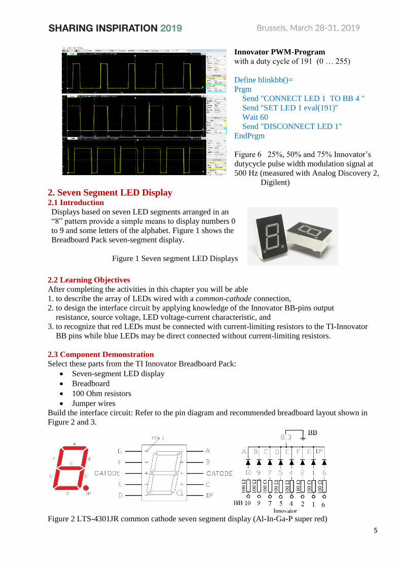
2. Seven Segment LED Display 2.1 Introduction
Displays based on seven LED segments arranged in an
“8” pattern provide a simple means to display numbers 0
to 9 and some letters of the alphabet. Figure 1 shows the
Breadboard Pack seven-segment display.
Figure 1 Seven segment LED Displays
2.2 Learning Objectives
After completing the activities in this chapter you will be able
1. to describe the array of LEDs wired with a common-cathode connection,
2. to design the interface circuit by applying knowledge of the Innovator BB-pins output
resistance, source voltage, LED voltage-current characteristic, and
3. to recognize that red LEDs must be connected with current-limiting resistors to the TI-Innovator
BB pins while blue LEDs may be direct connected without current-limiting resistors.
2.3 Component Demonstration
Select these parts from the TI Innovator Breadboard Pack:
• Seven-segment LED display
• Breadboard
• 100 Ohm resistors
• Jumper wires
Build the interface circuit: Refer to the pin diagram and recommended breadboard layout shown in
Figure 2 and 3.
Figure 2 LTS-4301JR common cathode seven segment display (Al-In-Ga-P super red)
6
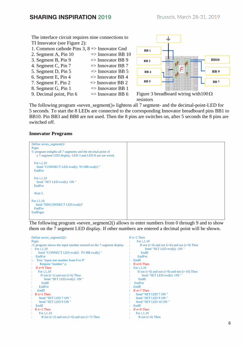
The interface circuit requires nine connections to
TI Innovator (see Figure 2):
1. Common cathode Pins 3, 8 => Innovator Gnd
2. Segment A, Pin 10 => Innovator BB 10
3. Segment B, Pin 9 => Innovator BB 9
4. Segment C, Pin 7 => Innovator BB 7
5. Segment D, Pin 5 => Innovator BB 5
6. Segment E, Pin 4 => Innovator BB 4
7. Segment F, Pin 2 => Innovator BB 2
8. Segment G, Pin 1 => Innovator BB 1
9. Decimal point, Pin 6 => Innovator BB 6
Figure 3 breadboard wiring with100
resistors
The following program «seven_segment()» lightens all 7 segment- and the decimal-point-LED for
5 seconds. To start the 8 LEDs are connected to the corresponding Innovator breadboard pins BB1 to
BB10. Pin BB3 and BB8 are not used. Then the 8 pins are switches on, after 5 seconds the 8 pins are
switched off.
Innovator Programs
Define seven_segment()=
Prgm © program enligths all 7 segments and the decimal point of
a 7-segment LED display. LED 3 and LED 8 are not wired.
For i,1,10
Send "CONNECT LED eval(i) TO BB eval(i) "
EndFor
For i,1,10 Send "SET LED eval(i) ON "
EndFor
Wait 5
For i,1,10 Send "DISCONNECT LED eval(i)"
EndFor
EndPrgm
The following program «seven_segment2() allows to enter numbers from 0 through 9 and to show
them on the 7 segment LED display. If other numbers are entered a decimal point will be shown.
Define seven_segment2()= Prgm
:© program shows the input number entered on the 7-segment display
: For i,1,10 : Send "CONNECT LED eval(i) TO BB eval(i) "
: EndFor
:: Text "input one number from 0 to 9" : Request "number",n
: If n=0 Then
: For i,1,10 : If not (i=1) and not (i=6) Then
: Send "SET LED eval(i) ON "
: EndIf : EndFor
: EndIf
: If n=1 Then
: Send "SET LED 7 ON "
: Send "SET LED 9 ON "
: EndIf : If n=2 Then
: For i,1,10
: If not (i=2) and not (i=6) and not (i=7) Then
If n=5 Then : For i,1,10
: If not (i=4) and not (i=6) and not (i=9) Then
: Send "SET LED eval(i) ON " : EndIf
: EndFor
: EndIf : If n=6 Then
: For i,1,10
: If not (i=6) and not (i=9) and not (i=10) Then : Send "SET LED eval(i) ON "
: EndIf
: EndFor : EndIf
: If n=7 Then
: Send "SET LED 7 ON "
: Send "SET LED 9 ON "
: Send "SET LED 10 ON "
: EndIf : If n=8 Then
: For i,1,10
: If not (i=6) Then

7
: Send "SET LED eval(i) ON "
: EndIf : EndFor
: EndIf
: If n=3 Then : For i,1,10
: If not (i=2) and not (i=4) and not (i=6) Then
: Send "SET LED eval(i) ON " : EndIf
: EndFor
: EndIf : If n=4 Then
: Send "SET LED 1 ON "
: Send "SET LED 2 ON " : Send "SET LED 7 ON "
: Send "SET LED 9 ON "
: EndIf
:
: Send "SET LED eval(i) ON "
: EndIf : EndFor
: EndIf
: If n=9 Then : For i,1,10
: If not (i=4) and not (i=5) and not (i=6) Then
: Send "SET LED eval(i) ON " : EndIf
: EndFor
: EndIf : If not (n=0) and not (n=1) and not (n=2) and not (n=3)
and not (n=4) and not (n=5) and not (n=6) and not (n=7)
and not (n=8) and not (n=9) Then : Send "SET LED 6 ON "
: EndIf
: Wait 5 : For i,1,10
: Send "DISCONNECT LED eval(i)"
: EndFor :EndPrgm
2.4 Interface circuit Theory
Each of the seven line segments as well as
the decimal point is an individual red LED,
each with its own anode and cathode. To
conserve the number of electrical connec-
tions on the display all of the eight cathodes
are tied together an brought out as the “com-
mon cathode” pin 8 and 3. Figure 7 shows
the voltage-current characteristics of LEDs
with colours from infrared to ultraviolet. We
work with red LEDs @ 1.7 V, 16 mA and a
current limiting 100-Ohm resistor with a
voltage drop of 100 0.017 A 1.7 V = .
With a blue 7-segment LED display no
resistors are required at all if we work e.g.
with at 3.3 V and 46 milliamps (Figure 7).
But it must be of a common cathode type,
Figure 4 LED Voltage Current characteristics for
IR-, red-, orange-, green-, yellow-, blue-,
white- and UV-LEDs,
e.g. SC10-21QBWA-D (Kingbright). Seven segment blue LED displays (not included in Innovators
breadboard pack) are better suited for student work than the LTS-4301JR seven segment red LED
display in the breadboard pack because no troublesome wiring of resistors is necessary.
2.4 Twyman Fonts
World’s Simplest Twyman TrueType font for seven-segment displays; use this to quickly translate
your text phrases into suitable segment patterns.
Problems: K vs. H, 9 vs. G, I vs 1, O vs 0, H vs. X, 2 vs. Z
Figure 5 Twymans True Type Font for seven segment displays

8
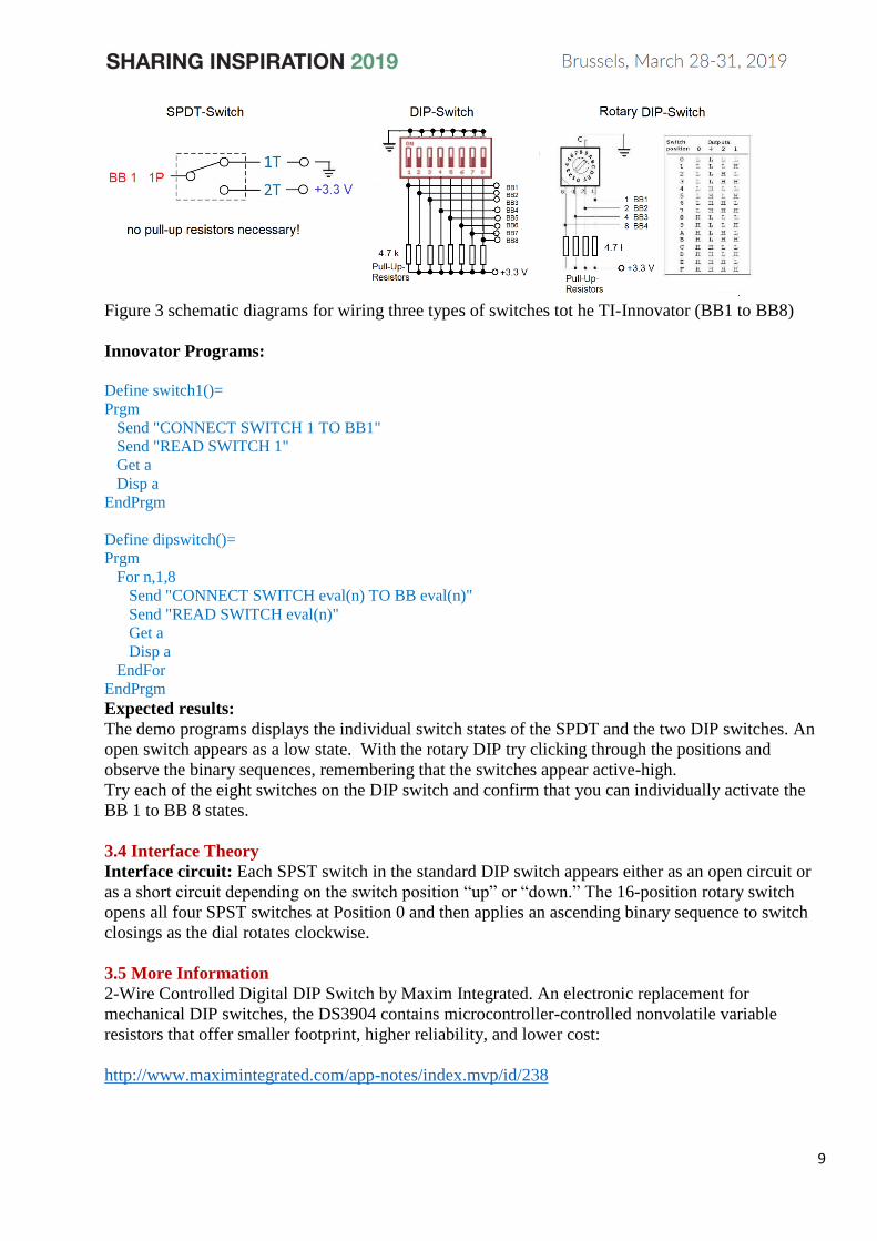
3. Switches and DIP Switches 3.1 Introduction
DIP switches bundle multiple SPST switches together into a single component; “DIP” stands for
“dual in-line package,” the standard IC package style that is breadboard compatible, and “SPST”
means “single pole, single throw,” the simplest possible switch type. Figure 1 pictures two popular
switches, a SPDT-, Single Pole, Double throw-slide-switch and a standard DIP switch containing
eight SPST switches
Figure 1: SPDT-switch and 8-position DIP-switch (8 times SPST)
3.2 Learning Objectives After completing the activities in this chapter you will be able to:
1. Describe the following concepts related to switches and the Innovator interface:
(a) DIP switch bundles N SPST switches into a single component with each switch appearing
as a short circuit in one position and as an open circuit in the other,
(b) 2N-position rotary switch bundles N SPST switches into a single component; rotating the
dial create a binary sequence of open-closed switch states. (igure 2, this switch is not
included in the TI-Innovator Breadboard Kit)
2. Interface a switch on any of the TI Innovator BB connectors without using additional compo-
nents, and explainin the concept of pull up and pull down resistors
3. Interpret the combined switch open-closed patterns as an integer numerical value
Figure 2 Rotary type DIP-Sitch with hexadecimal position code (not included in the Breadboard
Pack)
3.3 Component Demonstration
Select these parts from the TI Innovator Breadboard Pack:
• SPDT Switch
• DIP switch http://www.resonswitch.com/p_rs_rsr.
• Rotary DIP switch, not included => http://www.mantech.co.za/datasheets/products/ERD1-5.pdf
• Breadboard
• Jumper wires
• Small screwdriver
Build the interface circuit: Refer to the schematic diagram shown in Figure 3
9
Figure 3 schematic diagrams for wiring three types of switches tot he TI-Innovator (BB1 to BB8)
Innovator Programs: Define switch1()=
Prgm
Send "CONNECT SWITCH 1 TO BB1"
Send "READ SWITCH 1"
Get a
Disp a
EndPrgm
Define dipswitch()=
Prgm
For n,1,8
Send "CONNECT SWITCH eval(n) TO BB eval(n)"
Send "READ SWITCH eval(n)"
Get a
Disp a
EndFor
EndPrgm
Expected results:
The demo programs displays the individual switch states of the SPDT and the two DIP switches. An
open switch appears as a low state. With the rotary DIP try clicking through the positions and
observe the binary sequences, remembering that the switches appear active-high.
Try each of the eight switches on the DIP switch and confirm that you can individually activate the
BB 1 to BB 8 states.
3.4 Interface Theory
Interface circuit: Each SPST switch in the standard DIP switch appears either as an open circuit or
as a short circuit depending on the switch position “up” or “down.” The 16-position rotary switch
opens all four SPST switches at Position 0 and then applies an ascending binary sequence to switch
closings as the dial rotates clockwise.
3.5 More Information
2-Wire Controlled Digital DIP Switch by Maxim Integrated. An electronic replacement for
mechanical DIP switches, the DS3904 contains microcontroller-controlled nonvolatile variable
resistors that offer smaller footprint, higher reliability, and lower cost:
http://www.maximintegrated.com/app-notes/index.mvp/id/238
10
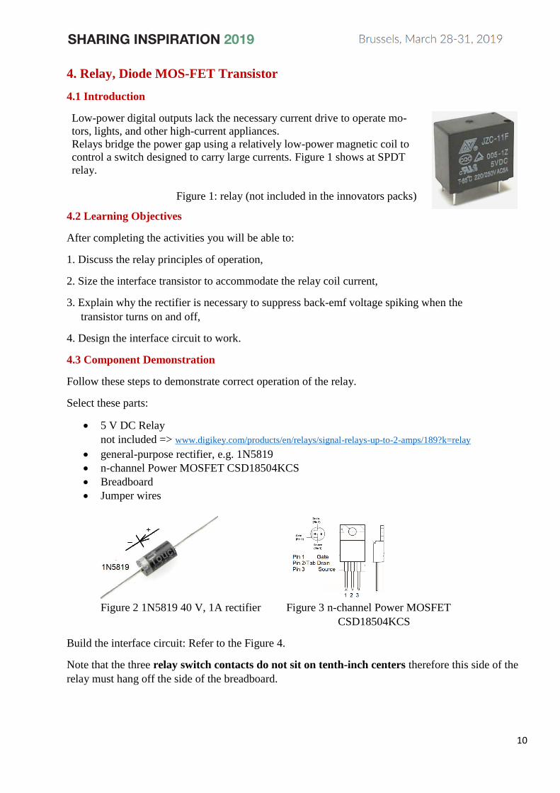
4. Relay, Diode MOS-FET Transistor
4.1 Introduction
Low-power digital outputs lack the necessary current drive to operate mo-
tors, lights, and other high-current appliances.
Relays bridge the power gap using a relatively low-power magnetic coil to
control a switch designed to carry large currents. Figure 1 shows at SPDT
relay.
Figure 1: relay (not included in the innovators packs)
4.2 Learning Objectives
After completing the activities you will be able to:
1. Discuss the relay principles of operation,
2. Size the interface transistor to accommodate the relay coil current,
3. Explain why the rectifier is necessary to suppress back-emf voltage spiking when the
transistor turns on and off,
4. Design the interface circuit to work.
4.3 Component Demonstration
Follow these steps to demonstrate correct operation of the relay.
Select these parts:
• 5 V DC Relay
not included => www.digikey.com/products/en/relays/signal-relays-up-to-2-amps/189?k=relay
• general-purpose rectifier, e.g. 1N5819
• n-channel Power MOSFET CSD18504KCS
• Breadboard
• Jumper wires
Figure 2 1N5819 40 V, 1A rectifier Figure 3 n-channel Power MOSFET
CSD18504KCS
Build the interface circuit: Refer to the Figure 4.
Note that the three relay switch contacts do not sit on tenth-inch centers therefore this side of the
relay must hang off the side of the breadboard.

11
The interface circuit requires three connections to TI
Innovator B
1. 5-volt power supply
2. Ground
3. Relay control BB 1
Troubleshooting tips: Not seeing the expected results?
Confirm the following points:
• Correct transistor orientation and
• Correct rectifier orientation — when the
rectifier is backwards the relay coil will never
reach the voltage level necessary to turn on.
Figure 4 Demonstration circuit for relay
Innovator Program Define relay1()=
Prgm
Send "CONNECT SWITCH 1 TO BB1"
Send "READ SWITCH 1"
Get a
Disp a
Send "DISCONNECT SWITCH 1"
EndPrgm
4.4 Interface Theory
The relay contains an electromagnet coil that operates a spring-loaded switch. The coil current is
approximately 100 mA, well beyond the current drive limits of the TI Innovators output. The
interface circuit uses a n-channel Power MOSFET as a switch to turn the coil current on and off and a
rectifier to protect the transistor from large back-induced voltage when the transistor shuts off the coil
current.
4.5 For More Information
Using Relays (Tips & Tricks) by Jumper One
Learn how to reduce relay switching time and minimize relay current for battery-powered
applications:
http://jumperone.com/2011/10/using-relays

12
5. Potentiometer
5.1 Introduction
A potentiometer is a three-terminal variable resistor. When connected to a power
supply to form a voltage divider a potentiometer acts as a proportional rotation
sensor. Figure 7.1 pictures a potentiometer (not included in Innovators bread-
board pack).
5.2 Learning Objectives
After completing the activities in this chapter you will be able to:
1. Discuss how the potentiometer can be used as either one variable resistor or
two series-connected complementary variable resistors,
2. Connect a potentiometer as a voltage divider to produce a voltage proportional
to rotation angle, and
3. Select the potentiometer resistance to minimize power consumption and to
minimize loading effects.
Figure 1
potentiometer.
5.3 Component Demonstration
Follow these steps to demonstrate correct operation of the potentiometer.
Select these parts:
• Potentiometer, 10 k, not included http://www.supertech.com.tw/electronic/resistors/potentiometers/PDF/rotary3/23/R0904N.pdf
• Breadboard
• Jumper wires
Build the interface circuit: Refer to the schematic diagram and recommended breadboard layout
shown in Figure 5.2
TIP: Flatten the two tabs on either side of the potentiometer so that it sits flush on the breadboard
surface.
The potentiometer interface circuit requires three connections to TI-Innovator
1. Pot Terminal 1 to BB GND
2. Pot Terminal 2 to BB 5 (analog input)
3. Pot Terminal 3 to BB 5 V
Innovator Program
Define potentiometer()=
Prgm
Send "CONNECT POTENTIOMETER 1 TO BB 5 "
Send "READ POTENTIOMETER 1 "
Get p: Disp p
EndPrgm
Figure 2 program and demonstration circuit for
potentiometer
13
Expected results:
The demo program displays the voltage on the analog input BB 5. 0 Volts => 00000, 3.3 Volt =>
15'238, maximum value 16’384 ( )142 1− corresponding to 3.55 Volt. Turn the potentiometer dial
and you should observe a corresponding change in the voltage sensed on the analog input. Because
the potentiometer acts as an ajustable voltage divider between ground and the +5-Volt supply, you
should observe that a full rotation of the potentiometer dial from one extreme to the other causes the
voltage to change from 0 to 5 volts.
5.4 Interface Theory
Interface circuit The potentiometer provides a fixed resistance between the two outer terminals,
while the middle terminal connects to a movable contact point that effectively makes the poten-
tiometer appear as two variable resistors. As one resistor increases in value, the other resistor
decreases by the same amount. Wiring the potentiometer between ground and the power supply
produces a voltage divider with voltage output proportional to the position of the contact. Connecting
this variable voltage to the Innovator analog input BB 5-7 provides a convenient sensing technique
for angular position.
5.5 For More Information
Potentiometer by Resistorguides Describes a variety of potentiometer types and characteristics:
http://www.resistorguide.com/potentiometer
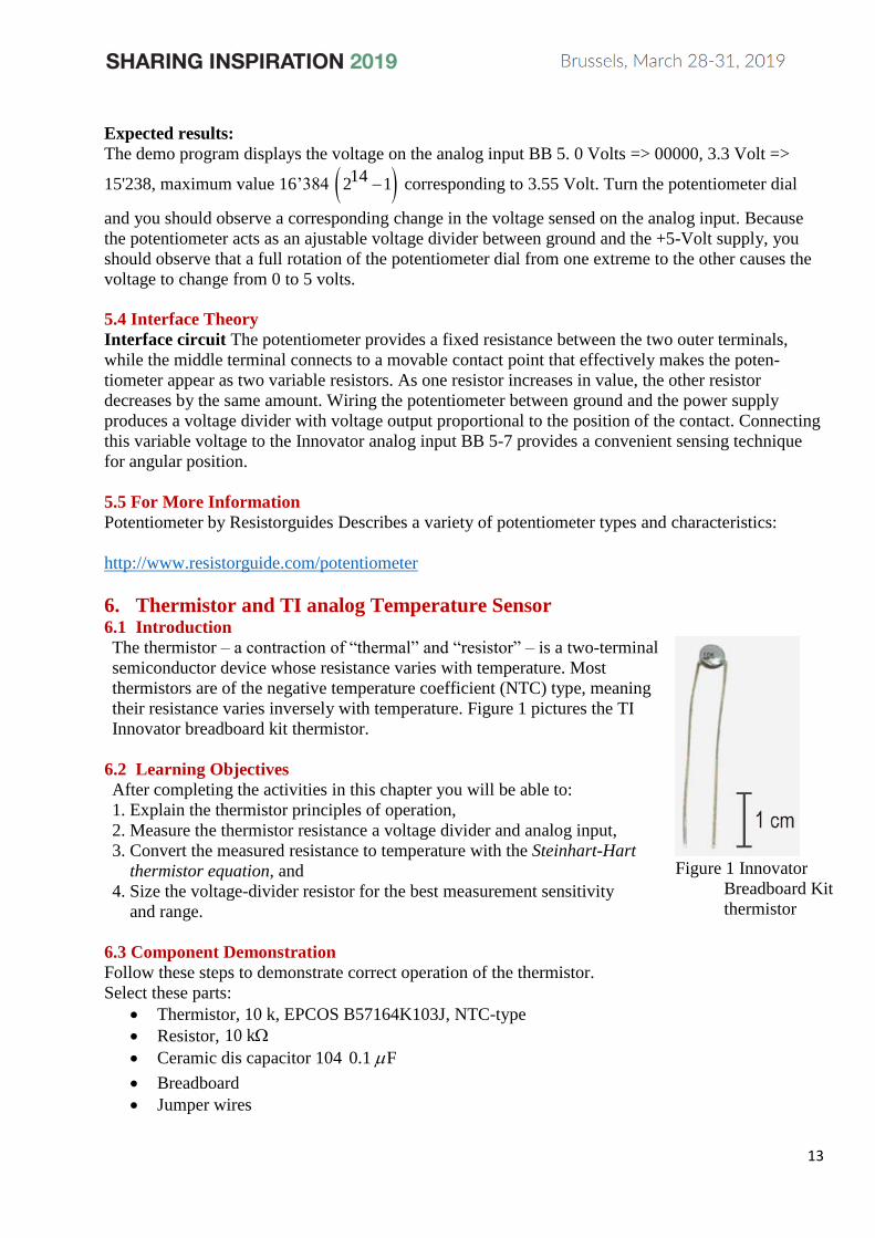
6. Thermistor and TI analog Temperature Sensor 6.1 Introduction
The thermistor – a contraction of “thermal” and “resistor” – is a two-terminal
semiconductor device whose resistance varies with temperature. Most
thermistors are of the negative temperature coefficient (NTC) type, meaning
their resistance varies inversely with temperature. Figure 1 pictures the TI
Innovator breadboard kit thermistor.
6.2 Learning Objectives
After completing the activities in this chapter you will be able to:
1. Explain the thermistor principles of operation,
2. Measure the thermistor resistance a voltage divider and analog input,
3. Convert the measured resistance to temperature with the Steinhart-Hart
thermistor equation, and
4. Size the voltage-divider resistor for the best measurement sensitivity
and range.
Figure 1 Innovator
Breadboard Kit
thermistor
6.3 Component Demonstration
Follow these steps to demonstrate correct operation of the thermistor.
Select these parts:
• Thermistor, 10 k, EPCOS B57164K103J, NTC-type
• Resistor, 10 k
• Ceramic dis capacitor 104 0.1 F
• Breadboard
• Jumper wires

14
Build the interface circuit
Refer to the schematic diagram and recommended breadboard layout shown in Figure 2. The
interface circuit requires four connections to TI Innovator
1. 5-volt power supply!B/+5V (pin 1)
2. Ground!B/GND (pin 6)
3. Temperature measurement BB 5 (analog input)
4. Supply voltage measurement BB 6 (analog input)
Figure 2 Demonstration circuit for thermistor Figure 3 Temperature measurement with
LM19 sensor (Texas Insruments)
Innovator Program
Define thermistor()=
Prgm
Send "CONNECT TEMPERATURE 1 TO BB 5 NTC"
Send "READ TEMPERATURE 1"
Get p: Disp p
Send "DISCONNECT TEMPERATURE 1"
EndPrgm
Expected results:
The program «thermistor» shows the temperature directly in degrees centigrade (Celsius). Refer to
« TI Innovator technology handbook » for more information (e.g. calibration).
From a physical point of view it is more interesting to measure the termistors voltage ThermistorU , the
supply voltage SupplyU and to calculate the resistance of the thermistor by
Thermistor BB 6 BB 5 BB 6Thermistor
BB 5Thermistor BB 5
1U U U U
R RUI U
R
−= = = −
The exact resistance value of the 10 kR = -resistor has to be measured with an ohmmeter.
Expect to see a thermistor value close to 10 k at room temperature, Try heating the thermistor by
gently pinching the thermistor body with your finger tips; you may also use a drinking straw or hair
dryer to blow warm air on the thermistor. You should observe the resistance going down. How low
can you make the resistance? Use a plastic sandwich bag filled with two ice cubes or crushed ice.
Surround the thermistor with ice and you should observe the resistance going up. How high can you
make the resistance?
15
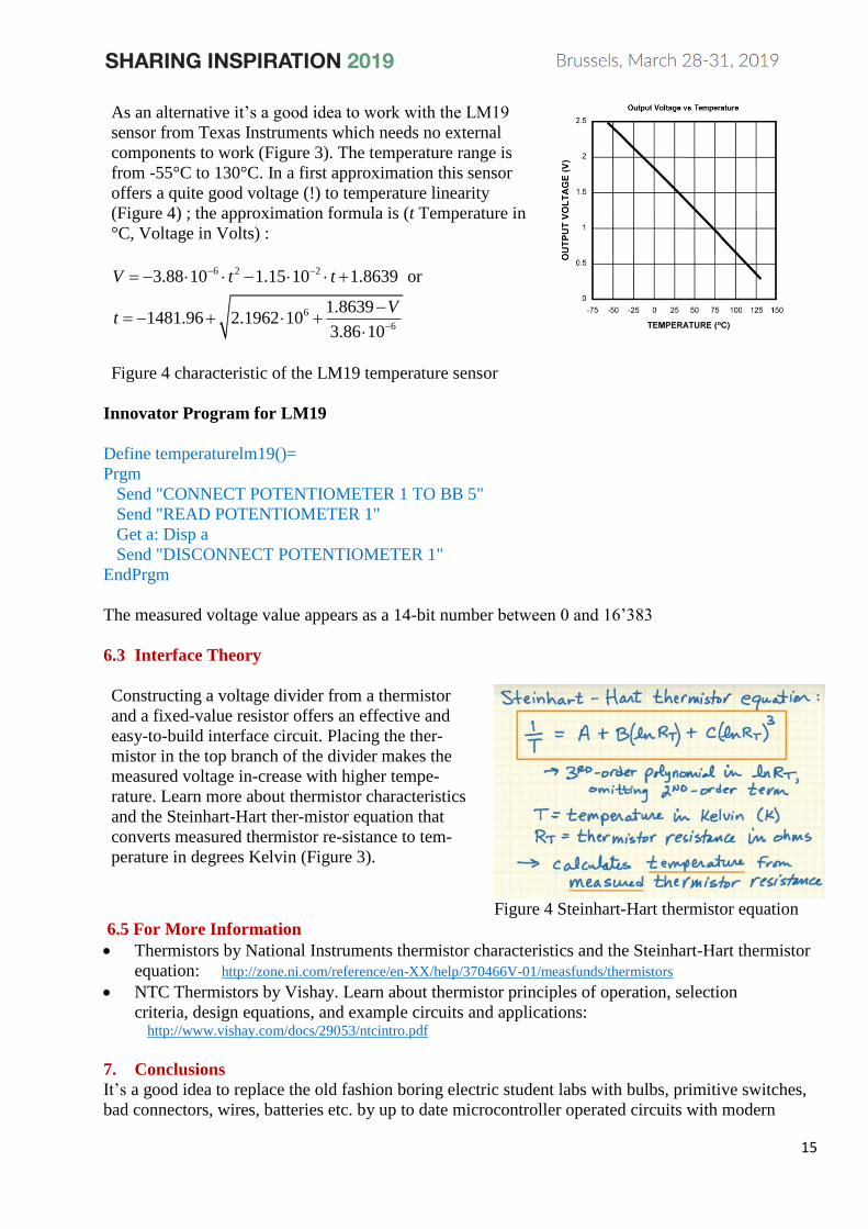
As an alternative it’s a good idea to work with the LM19
sensor from Texas Instruments which needs no external
components to work (Figure 3). The temperature range is
from -55°C to 130°C. In a first approximation this sensor
offers a quite good voltage (!) to temperature linearity
(Figure 4) ; the approximation formula is (t Temperature in
°C, Voltage in Volts) :
6 2 2
6
6
3.88 10 1.15 10 1.8639 or
1.86391481.96 2.1962 10
3.86 10
V t t
Vt
− −
−
= − − +
−= − + +
Figure 4 characteristic of the LM19 temperature sensor
Innovator Program for LM19
Define temperaturelm19()=
Prgm
Send "CONNECT POTENTIOMETER 1 TO BB 5"
Send "READ POTENTIOMETER 1"
Get a: Disp a
Send "DISCONNECT POTENTIOMETER 1"
EndPrgm
The measured voltage value appears as a 14-bit number between 0 and 16’383
6.3 Interface Theory
Constructing a voltage divider from a thermistor
and a fixed-value resistor offers an effective and
easy-to-build interface circuit. Placing the ther-
mistor in the top branch of the divider makes the
measured voltage in-crease with higher tempe-
rature. Learn more about thermistor characteristics
and the Steinhart-Hart ther-mistor equation that
converts measured thermistor re-sistance to tem-
perature in degrees Kelvin (Figure 3).
7
Figure 4 Steinhart-Hart thermistor equation
6.5 For More Information
• Thermistors by National Instruments thermistor characteristics and the Steinhart-Hart thermistor
equation: http://zone.ni.com/reference/en-XX/help/370466V-01/measfunds/thermistors
• NTC Thermistors by Vishay. Learn about thermistor principles of operation, selection
criteria, design equations, and example circuits and applications: http://www.vishay.com/docs/29053/ntcintro.pdf
7. Conclusions
It’s a good idea to replace the old fashion boring electric student labs with bulbs, primitive switches,
bad connectors, wires, batteries etc. by up to date microcontroller operated circuits with modern

16
components, switches, breadboards, jumper wires and so on. By introducing up to date technology
instruction the physics education benefits from the enormous technical progress of the semiconductor
based microelectronics in the last decades. A way to explain some aspects of the today digital world
to our students. They learn basic electricity and electronic concepts in a field between physics and
technology. What is a switch, a LED, a display, a potentiometer, a diode, a transistor etc. How work
these components and how are they wired in the hardware circuit? The list of possible components
can be completed with a lot of other sensors, photo-cells, microphones, motors, buzzers, speakers,
photoelectric and Hall sensors etc. The new appoach : All these components are microcontroller
driven. Under the many existing microcontroller systems the Innovator System is a good choice also
if it is not the cheapest one. It has a professional deign and can be operated by a simple programming
language (Basic) from Computers or handheld calculators.