
Electron Transfer Reactions in Pulping Systems (IV): An Example of a Large Reactivity Difference for...
25
THE INSTITUTE OF PAPER CHEMISTRY, APPLETON, WISCONSIN IPC TECHNICAL PAPER SERIES NUMBER 141 ELECTRON TRANSFER REACTIONS IN PULPING SYSTEMS (II): ELECTROCHEMISTRY OF ANTHRAQUINONE/LIGNIN MODEL QUINONEMETHIDES DONALD R. DIMMEL, LOIS F. PERRY, PETER D. PALASZ, AND HELENA L. CHUM APRIL, 1984
-
Upload
independent -
Category
Documents
-
view
2 -
download
0
Transcript of Electron Transfer Reactions in Pulping Systems (IV): An Example of a Large Reactivity Difference for...
THE INSTITUTE OF PAPER CHEMISTRY, APPLETON, WISCONSIN
IPC TECHNICAL PAPER SERIES
NUMBER 141
ELECTRON TRANSFER REACTIONS IN PULPING SYSTEMS (II):
ELECTROCHEMISTRY OF ANTHRAQUINONE/LIGNIN MODEL QUINONEMETHIDES
DONALD R. DIMMEL, LOIS F. PERRY, PETER D. PALASZ,
AND HELENA L. CHUM
APRIL, 1984
ELECTRON TRANSFER REACTIONS IN PULPING SYSTEMS (II): ELECTRO-CHEMISTRY OF ANTHRAQUINONE/LIGNIN MODEL QUINONEMETHIDES
Donald R. Dimmel and Lois F. PerryThe Institute of Paper ChemistryAppleton, Wisconsin 54912
andPeter D. Palasz and Helena L. Chum
Solar Energy Research Institute1617 Cole Boulevard, Golden, Colorado 80401
GENERAL SUMMARY
Institute Project 3475 has been concerned with developing afundamental understanding of the reactions occurring duringpulping and bleaching. One phase of this project research hasinvolved a detailed investigation of the mechanism of action ofanthraquinone (AQ) as a pulping catalyst. The attached article isthe second of a series; the first was published as IPC TechnicalPaper No. Series 139. The work described herein was a jointresearch effort between us and a group of scientists at the SolarEnergy Research Institute in Colorado. The group at SERI havebeen performing electrochemical experiments on lignin and otherpulping by-products.
By means of electrochemistry, we have generated partially-reduced and fully-reduced forms of anthraquinone and have shownthat these forms can transfer electrons to lignin model quinone-methides, causing the latter to fragment. Direct electron transferfrom an electrode (during electrolysis) to quinonemethides canalso be promoted and again the quinonemethides fragment. Fragmen-tation of lignin quinonemethides is presumed to be a key step inchemical pulping.
Our electrochemical experiments demonstrate a hitherto unknowntype of chemistry, electron transfer reaction, which is probablyoccurring during anthraquinone pulping and possibly in otherpulping systems. Our results suggest that pumping electrons (ofthe right voltage) into pulping systems, by means of additives,electric currents or whatever, should increase pulping rates.
ELECTRON TRANSFER REACTIONS IN PULPING SYSTEMS (II): ELECTRO-CHEMISTRY OF ANTHRAQUINONE/LIGNIN MODEL QUINONEMETHIDES
Donald R. Dimmela and Lois F. PerryThe Institute of Paper ChemistryAppleton, Wisconsin 54912
andPeter D. Palaszb and Helena L. Chuma
Solar Energy Research Institute1617 Cole Boulevard, Golden, Colorado 80401
ABSTRACT
Electron transfer reactions have been observed during the electro-lyses of solutions containing anthraquinone and B-aryl ether ligninmodel quinonemethides. In dry acetonitrile at a reduction poten-tial of -0.9V (vs. Ag/AgCl) electrons are transferred from theelectrode to anthraquinone (AQ) to form stable anthrahydroquinoneradical anions (AHQ-). The lignin model quinonemethides are notreduced directly at the electrode at this potential but arereduced by AHQ- to give quinonemethide radical anions (QM-) andAQ. The QM- species rapidly fragment at their B-aryl ether bondto give phenolate ions and radicals; the latter further reduces toanother phenolate ion. For example, the --methyl lignin model QM1 gives guaiacol and isoeugenol upon electrolysis at -0.9V in thepresence of AQ. In wet acetonitrile, reduction of AQ at -0.9Vleads to both anthrahydroquinone radical anion and dianion; thedianion is formed by direct electrolysis of the radical anion andby disproportionation of the radical anion. Under all conditionsand substrates examined, electron transfer reactions proceeded inpreference to bond formation reactions which would generate"adducts." The implication of these results is that it should bepossible to delignify wood by electron transfer reactions and thatanthraquinone probably functions this way.
aAddress correspondences to either of these authors.bPostdoctoral Fellow under the Director's Development Fund.
ELECTRON TRANSFER REACTIONS IN PULPING SYSTEMS (II): ELECTRO-CHEMISTRY OF ANTHRAQUINONE/LIGNIN MODEL QUINONEMETHIDES
Donald R. Dimmela and Lois F.PerryThe Institute of Paper ChemistryAppleton, Wisconsin 54912
andPeter D. Palaszb and Helena L. Chuma
Solar Energy Research Institute1617 Cole Boulevard, Golden, Colorado 80401
ABSTRACT
Electron transfer reactions have been observed during the electro-lyses of solutions containing anthraquinone and B-aryl ether ligninmodel quinonemethides. In dry acetonitrile at a reduction poten-tial of -0.9V (vs. Ag/AgCl) electrons are transferred from theelectrode to anthraquinone (AQ) to form stable anthrahydroquinoneradical anions (AHQ-). The lignin model quinonemethides are notreduced directly at the electrode at this potential but arereduced by AHQ- to give quinonemethide radical anions (QM-) andAQ. The QM- species rapidly fragment at their B-aryl ether bondto give phenolate ions and radicals; the latter further reduces toanother phenolate ion. For example, the -methyl lignin model QM1 gives guaiacol and isoeugenol upon electrolysis at -0.9V in thepresence of AQ. In wet acetonitrile, reduction of AQ at -0.9Vleads to both anthrahydroquinone radical anion and dianion; thedianion is formed by direct electrolysis of the radical anion andby disproportionation of the radical anion. Under all conditionsand substrates examined, electron transfer reactions proceeded inpreference to bond formation reactions which would generate"adducts." The implication of these results is that it should bepossible to delignify wood by electron transfer reactions and thatanthraquinone probably functions this way.
aAddress correspondences to either of these authors.postdoctoral Fellow under the Director's Development Fund.
linearly at potential scan rates ranging from 0.02 to 100 V/sec in
the cathodic (reduction) direction from zero time (0 volts vs. Ag/
AgCl) to a switch time (for example at -2.0 V), after which the
potential is linearly returned (anodic direction; oxidation) to
the starting(0 .V) potential. The potentials, unless stated
otherwise, are referenced against a Ag/AgCl electrode.
Appreciable current flow is only observed at extreme poten-
tials where the solvent (or supporting electrolyte) is being
reduced or oxidized, and in the vicinity of the formal electrode
potential of an electroactive substance. The electrochemical
domain of the solvent/supporting electrolyte system depends on the
specific nature of the ionic species present in the solvent and on
the nature of the solvent. Background currents exist because of
electrochemical reactions of trace impurities in the system and
because of the double-layer charging current. Typical background
currents are shown by the dotted lines in Fig. 1.
The magnitude of the observed current during cyclic voltammetry
is related to the potential scan rate, the number of electrons
being transferred to (or from) the substrate, the concentration of
the substrate, the area of the electrode, the rate of electron
transfer to (or from) the electrode, and the rate of diffusion of
the substrate to the electrode. The solution is not stirred
during cyclic voltammetric experiments, and thus only a very small
quantity of the substrate, that which is within 10-15 angstroms of
the electrode, is electrolyzed. By stirring between runs, iden-
tical voltammograms can be obtained.
CYCLIC VOLTAMMETRY OF ANTHRAQUINONE
A cyclic voltammogram of anthraquinone (AQ) in DMSO with 0.1M
tetrabutylammonium perchlorate (TBAP) is shown in Fig. 1. The
voltammogram displays two well-separated cathodic (reductive)
current peaks in the range of 0 to -2.0 V. The first current peak
occurs at a cathodic peak potential of -0.78 V and corresponds to
the one-electron, reversible, diffusion controlled, heterogeneous
3
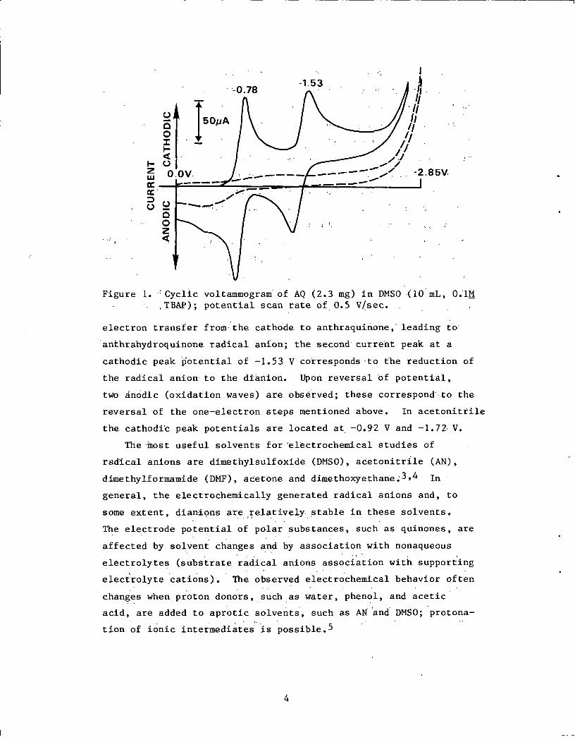
Figure 1. Cyclic voltammogram of AQ (2.3 mg) in DMSO (10 mL, 0.1MTBAP); potential scan rate of 0.5 V/sec.
electron transfer from the cathode to anthraquinone, leading to
anthrahydroquinone radical anion; the second current peak at a
cathodic peak potential of -1.53 V corresponds to the reduction of
the radical anion to the dianion. Upon reversal of potential,
two anodic (oxidation waves) are observed; these correspond to the
reversal of the one-electron steps mentioned above. In acetonitrile
the cathodic peak potentials are located at -0.92 V and -1.72 V.
The most useful solvents for electrochemical studies of
radical anions are dimethylsulfoxide (DMSO), acetonitrile (AN),
dimethylformamide (DMF), acetone and dimethoxyethane 3,4 In
general, the electrochemically generated radical anions and, to
some extent, dianions are relatively stable in these solvents.
The electrode potential of polar substances, such as quinones, are
affected by solvent changes and by association with nonaqueous
electrolytes (substrate radical anions association with supporting
electrolyte cations). The observed electrochemical behavior often
changes when proton donors, such as water, phenol, and acetic
acid, are added to aprotic solvents, such as AN and DMSO; protona-
tion of ionic intermediates is possible.5
4
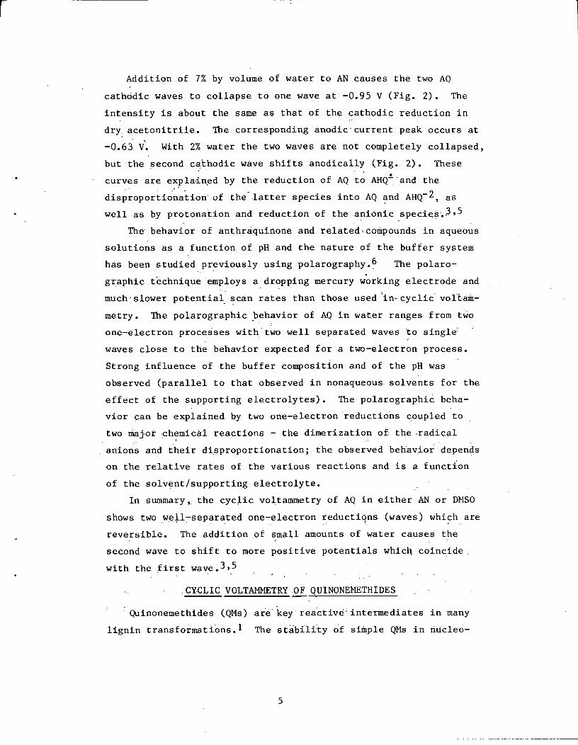
Addition of 7% by volume of water to AN causes the two AQ
cathodic waves to collapse to one wave at -0.95 V (Fig. 2). The
intensity is about the same as that of the cathodic reduction in
dry acetonitrile. The corresponding anodic current peak occurs at
-0.63 V. With 2% water the two waves are not completely collapsed,
but the second cathodic wave shifts anodically (Fig. 2). These
curves are explained by the reduction of AQ to AHQQ and the
disproportionation of the latter species into AQ and AHQ- 2, as
well as by protonation and reduction of the anionic species.3,5
The behavior of anthraquinone and related compounds in aqueous
solutions as a function of pH and the nature of the buffer system
has been studied previously using polarography.6 The polaro-
graphic technique employs a dropping mercury working electrode and
much slower potential scan rates than those used in cyclic voltam-
metry. The polarographic behavior of AQ in water ranges from two
one-electron processes with two well separated waves to single
waves close to the behavior expected for a two-electron process.
Strong influence of the buffer composition and of the pH was
observed (parallel to that observed in nonaqueous solvents for the
effect of the supporting electrolytes). The polarographic beha-
vior can be explained by two one-electron reductions coupled to
two major chemical reactions - the dimerization of the radical
anions and their disproportionation; the observed behavior depends
on the relative rates of the various reactions and is a function
of the solvent/supporting electrolyte.
In summary, the cyclic voltammetry of AQ in either AN or DMSO
shows two well-separated one-electron reductions (waves) which are
reversible. The addition of small amounts of water causes the
second wave to shift to more positive potentials which coincide
with the first wave.3 ,5
CYCLIC VOLTAMMETRY OF QUINONEMETHIDES
Quinonemethides (QMs) are key reactive intermediates in many
lignin transformations. 1 The stability of simple QMs in nucleo-
5
Figure 2. Cyclic voltammogramof AQ (2.5 mg) in AN (10 mL, 0.1MTBAP) in the presence of water(---, 2% v/v; -- , 7% v/v);potential scan rate of 0.2 V/sec.
Figure 3. Cyclic voltammogramof QM 1 (1.5 mg in 0.2 mL CHC1 3)in DMSO (10 mL, 0.1M TBAP) alone(---, A) and in the presence ofAQ (-, B); potential scan rate
of 0.2 V/sec.
philic solvents such as water is extremely short, a matter of
seconds at room temperature.7 However, more highly substituted,
sterically crowded QMs, similar to those found in lignin, have
much longer lifetimes (ca. weeks) in the absence of good nucleo-
philes or water.8 ,9
Starting from compounds 4-6 and following the directions of
Ralph and coworkers,8,9 we have prepared and characterized stable
CHC13 solutions of quinonemethides 1-3. Attempts to prepare stable
solutions of simple QMs 7 and 8 by a similar procedure failed.
6
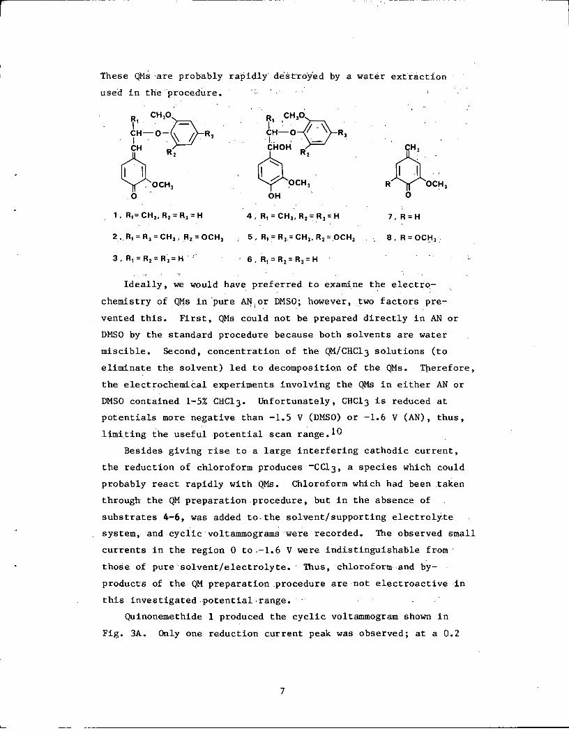
These QMs are probably rapidly' destroyed by a water extraction
used in the procedure.
Ideally, we would have preferred to examine the electro-
chemistry of QMs in pure AN or DMSO; however, two factors pre-
vented this. First, QMs could not be prepared directly in AN or
DMSO by the standard procedure because both solvents are water
miscible. Second, concentration of the QM/CHC13 solutions (to
eliminate the solvent) led to decomposition of the QMs. Therefore,
the electrochemical experiments involving the QMs in either AN or
DMSO contained 1-5% CHC13. Unfortunately, CHC13 is reduced at
potentials more negative than -1.5 V (DMSO) or -1.6 V (AN), thus,
limiting the useful potential scan range. 10
Besides giving rise to a large interfering cathodic current,
the reduction of chloroform produces -CC13, a species which could
probably react rapidly with QMs. Chloroform which had been taken
through the QM preparation procedure, but in the absence of
substrates 4-6, was added to the solvent/supporting electrolyte
system, and cyclic voltammograms were recorded. The observed small
currents in the region 0 to-1.6 V were indistinguishable from
those of pure solvent/electrolyte. Thus, chloroform and by-
products of the QM preparation procedure are not electroactive in
this investigated potential range.
Quinonemethide 1 produced the cyclic voltammogram shown in
Fig. 3A. Only one reduction current peak was observed; at a 0.2
7

V/sec potential scan rate,the peak potential was at 1.13 V in
DMSO and at -1.17 V in AN. [The increase in cathodic current at
roughly -1.8 V in Fig. 3 is due to the chloroform reduction.]
Similarly, QM 2 gave a single reduction wave with a peak at -1.48
V in AN. Quinonemethide 3 gave an irreversible cathodic current
peak at -1.19 V in AN.
The electrochemical behavior of QM 1-3 illustrates that small
changes in the QM structure may lead to large changes in the
reduction potential. Quinonemethides 1 and 3 differ by a B-methyl
group and have similar reduction potentials. However, QMs 1 and 2
differ in the number of substituents on the B-aryl ring and have
large differences in reduction potentials. With both ortho posi-
tions substituted, QM 2 is probably considerably more hindered
than the others and may lack planarity about the a-carbon. Its
peak potential is similar to the cathodic peak potential of steri-
cally hindered QM 9.11
12
The observed QM reduction currents are believed to be due to
an addition of one electron to the QM, leading to a quinonemethide
radical anion (QM-). The lack of an anodic current on going from
-1.6 to OV, even at.very rapid (100 V/sec) scan rates, indicates
that the QM- species are no longer in the vicinity of the electrode
to be reoxidized to starting material. In other words, the QM~
undergoes a rapid chemical reaction prior to the opportunity to be
reoxidized. The nature of these reactions will be addressed in a
later section.
8
The addition of 1% water to a solution of QM 1 in AN caused the
cathodic peak current intensity to increase by roughly 2.5 times.
Further increase in water concentration to about.10% does. not
alter the cathodic current peak within the,experimental error. A
current doubling effect upon addition of proton donors is encoun-
tered frequently in the reduction of hydrocarbons and ketones (or
quinones).3,1 2 It stems from the reduction to the radical anion,
followed by coupled chemical and electrochemical reactions. Pro-
tonation of the radical anion can be fast; the protonated radical
has a higher electron affinity than the parent compound and there-
fore at the applied potentials easily accepts another electron - a
two electron process. Whether current doubling is going to be
observed is a function of the basicity of the radical anion.1 2
Few quinonemethides are stable enough to be examined electro-
chemically; an exception is QM 9. The electrolytic behavior of QM
9 has some similarities to our QMs. Richards and Evans observed a
one-electron irreversible reduction of 9 in AN which increased in
intensity when water was added.ll The main reaction product of
QM 9 was the dimer 11; basic substances added to the electroly-
sis also converted some of 9 to a tautomer 10.
CYCLIC VOLTAMMETRY OF AQ/QM SOLUTIONS
Acetonitrile/chloroform
A solution of AQ in AN was prepared, and its voltammogram was
recorded at 0.2 V/sec (Fig. 4, lower curve). Next, a small amount
of QM 1 in CHC13 was added to the previous solution; another voltam-
mogram was recorded. A second addition of the quinonemethide was
carried out, and the voltammogram was recorded again. It can be
seen from Fig. 4 that the added QM causes the wave at -0.92 V
associated with the reduction of AQ to AHQ, to increase, while the
wave associated with the reverse reaction did not increase in inten-
sity. Another important feature is that even at potential scan
rates as large as 50 V/sec the wave due to the direct reduction of
the QM at the electrode is not observed (no peak at -1.17 V);
9
thus, the lifetime of the QM is shorter than -1 msec.
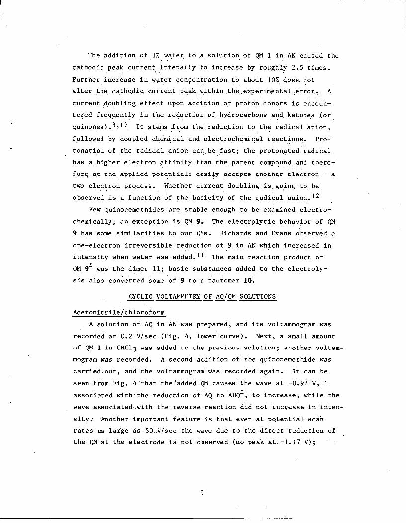
These results indicate that as the AHQ- species are formed,
they react with QM present in solution, regenerating AQ (and
therefore increasing the reduction current) and also depleting QM
in the vicinity of the electrode. The "effective" concentration
of AQ at the surface of the electrode is increased by the QM reac-
tion, but the combined amounts of AQ + AHQ- do not change, and
hence the anodic wave associated with reoxidation of AHQ- to AQ is
independent of QM level. This process is defined as homogeneous
redox catalysis1 3 and has been found in a number of cases
involving radical anions such as the reduction of aromatic halides
catalyzed by perylene and terephthalonitrile.14 These reactions
can be represented by a simplified scheme:
AQ + e- AHQ-
AHQ- + QM Q + QM-
QM- --- decomposition products
Scheme 1
The rate of electron transfer is a function of the difference
in the standard potentials between the anthraquinone and the
quinonemethide redox couples. The absolute value of the latter is
difficult to estimate because the formation of QM- is associated
with chemical reactions. In general, the larger the separation
between the two reduction peaks, the slower the homogeneous
electron transfer step.1 3 The rates of the reactions outlined in
Scheme 1 are being quantitatively determined and will be the sub-
ject of a forthcoming publication.1 5
10
INTRODUCTION
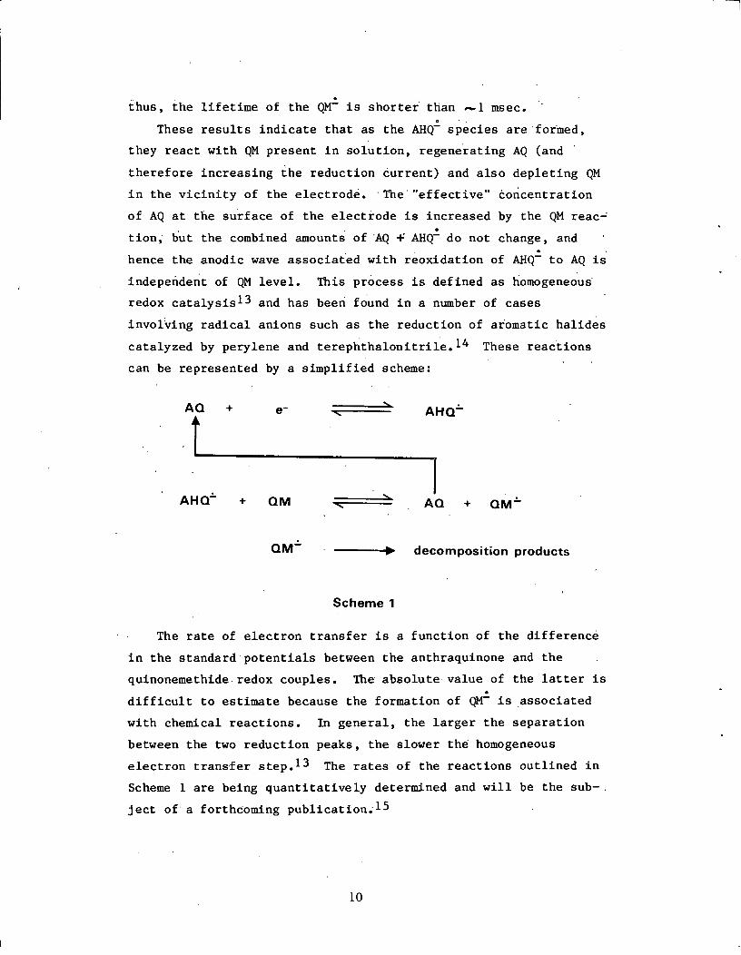
Oxidation and reduction reactions occur during anthraquinone
(AQ) wood pulping which result in the production of anthrahydro-
quinone radical anion (AHQ) and dianion (AHQ- 2) species.1 These
reduced forms of AQ are believed to interact with lignin quinone-
methide (QM) intermediates to cause the lignin to fragment and
thereby dissolve in wood pulping liquors. 1
Two basic mechanisms have been proposed for the AHQ/QM inter-
action. One involves bond formation between the two species to
give "adducts" which, if appropriately substituted, can fragment. 1
The other simply involves a transfer of electrons from the AHQ
species (anion radical or dianion) to the QM, followed by fragmen-
tation of the QM.1 Electrochemical experiments are described here
which show that AHQ and AHQ-2 can interact with quinonemethides
by electron transfer and that appropriately substituted quinone-
methide radical anions (QM-) readily fragment.
CYCLIC VOLTAMMETRY
Cyclic voltammetry is a simple, but powerful, technique for
adding electrons to (reductions) or removing electrons from
(oxidations) certain substrates.2 The apparatus consists of a
cell containing a working electrode and a counter electrode joined
to another compartment containing a reference electrode. A cyclic
voltammogram is a measure of current intensity (electron flow) as
a function of changes in the applied potential of the working
electrode versus the reference electrode. Specifically, in our
studies, the potential of the working electrode was increased
2
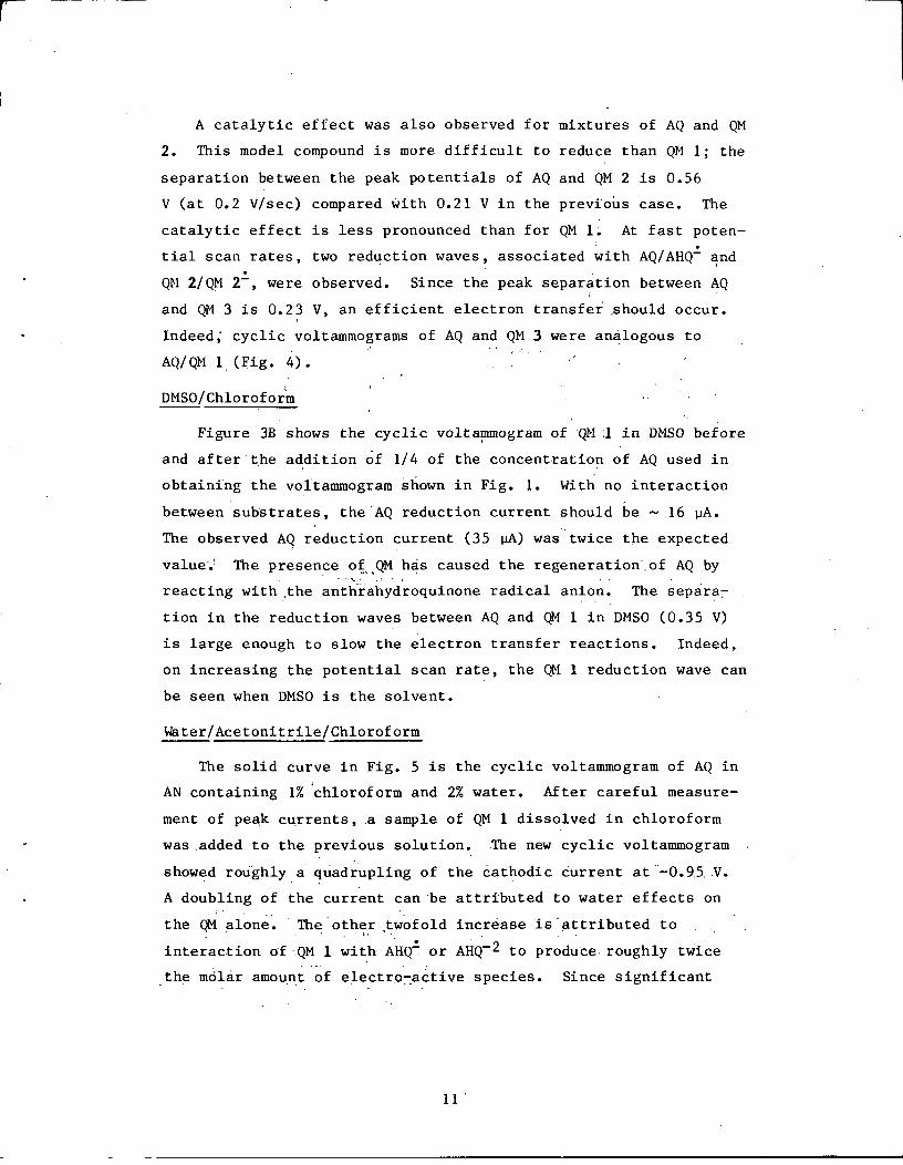
A catalytic effect was also observed for mixtures of AQ and QM
2. This model compound is more difficult to reduce than QM 1; the
separation between the peak potentials of AQ and QM 2 is 0.56
V (at 0.2 V/sec) compared with 0.21 V in the previous case. The
catalytic effect is less pronounced than for QM 1. At fast poten-
tial scan rates, two reduction waves, associated with AQ/AHQ- and
QM 2/QM 2-, were observed. Since the peak separation between AQ
and QM 3 is 0.23 V, an efficient electron transfer should occur.
Indeed; cyclic voltammograms of AQ and QM 3 were analogous to
AQ/QM 1 (Fig. 4).
DMSO/Chloroform
Figure 3B shows the cyclic voltammogram of QM 1 in DMSO before
and after the addition of 1/4 of the concentration of AQ used in
obtaining the voltammogram shown in Fig. 1. With no interaction
between substrates, the AQ reduction current should be ~ 16 pA.
The observed AQ reduction current (35 IA) was twice the expected
value. The presence of QM has caused the regeneration of AQ by
reacting with the anthrahydroquinone radical anion. The separa
tion in the reduction waves between AQ and QM 1 in DMSO (0.35 V)
is large enough to slow the electron transfer reactions. Indeed,
on increasing the potential scan rate, the QM 1 reduction wave can
be seen when DMSO is the solvent.
Water/Acetonitrile/Chloroform
The solid curve in Fig. 5 is the cyclic voltammogram of AQ in
AN containing 1% chloroform and 2% water. After careful measure-
ment of peak currents, a sample of QM 1 dissolved in chloroform
was added to the previous solution. The new cyclic voltammogram
showed roughly a quadrupling of the cathodic current at -0.95 V.
A doubling of the current can be attributed to water effects on
the QM alone. The other twofold increase is attributed to
interaction of QM 1 with AHQa or AHQ- 2 to produce roughly twice
the molar amount of electro-active species. Since significant
11
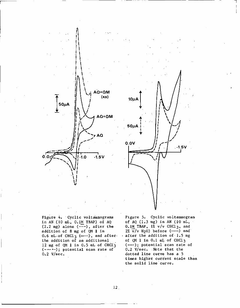
Figure 4. -Cyclic voltammogramsin AN(10 mL, 0.1M TBAP) of AQ(2.2 mg) alone (---), after theaddition of 8 mg of QM 1 in0.6 mL of CHC13 (-), and after.the addition of an additional12 mg of QM 1 in 0.5 mL of CHCI3(-.--); potential scan rate of0.2 V/sec.
Figure 5. Cyclic voltammogramof AQ (1.3 mg) in AN (10 mL,0.1M TBAP, 1% v/v CHC13, and2% v/v H20) before (-) andafter the addition of 1.5 mgof QM 1 in 0.1 mL of CHC13(---); potential scan rate of
0.2 V/sec. Note that thedotted line curve has a 5times higher current scale thanthe solid line curve.
12
50pA
levels of anthrahydroquinone dianion or protonated versions
thereof are present in this case, transfer of electrons from
AHQ- 2 species to QM 1 is probably occurring.
Why Not Formation of Adducts?
The term "adduct" refers to the 1:1 addition product which has
been observed when a QM is mixed with AHQ- 2 in water (or aqueous-
organic solvents) or when a QM is mixed with unionized AHQ in a
pure organic solvent.1 In the cyclic voltammetric experiments
just described, both QMs and AHQ species are present; yet, adducts
did not appear to form to any appreciable extent! If stable
adducts had formed, there would have been (a) no cathodic current
enhancement and (b) a decrease in the anodic, reoxidation wave
(AHQ~ or AHQ- 2 > AQ) because the AHQ species would have been
consumed in adduct formation reactions. However, the cathodic
current was enhanced and the anodic current unaffected.
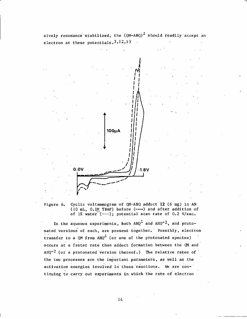
The cyclic voltammograms of several adducts have been recorded
and will be the subject of a future paper. The voltammograms of
the adducts (both with and without B-aryl ether bonds) are quite
similar and resemble that of anthrone.4 As an example, the cyclic
voltammograms of QM-AHQ adduct (12)16 in dry AN and wet AN are
shown in Fig. 6. The reduction (of the C=O) of the adduct occurs
at roughly -1.75 V. The adduct, which is stable for long periods
of time in AN, decomposes slightly at potentials > -1.7 V to afford
a small anodic peak potential at -0.3 V. The cyclic voltammograms
of adducts differ considerably from the cyclic voltammograms of the
AQ/QM mixtures.
Why weren't adducts formed during our electrochemical experi-
ments? The answer is not obvious. In the dry acetonitrile experi-
ments, AHQ- is present and not AHQ- 2 . Possibly, the reaction
between AHQ- and a QM to give a radical anion adduct, (QM-AHQ)-,
is unfavorable. Catalytic currents would have been observed only
if (QM-AHQ)- were to fragment faster than add a second electron to
give (QM-AHQ)- 2, a known stable species. Since it is not exten-
13
sively resonance'stabilized, the (QM-AHQ)- should readily accept an
electron at these potentials3,12,13
Figure 6. Cyclic voltammogram of QM-AHQ adduct 12 (6 mg) in AN(10 mL, 0.1M TBAP) before (-) and after addition ofof 1% water (---); potential scan rate of 0.2 V/sec.
In the aqueous experiments, both AHQ and AHQ-2, and proto-
nated versions of each, are present together. Possibly, electron
transfer to a QM from AHQ- (or one of the protonated species)
occurs at a faster rate than adduct formation between the QM and
AHQ- 2 (or a protonated version thereof.) The relative rates of
the two processes are the important parameters, as well as the
activation energies involved in these reactions. We are con-
tinuing to carry out experiments in which the rate of electron
14
O.OV

transfer reactions can be obtained from a mathematical treatment
of the electrochemical results. They will shed light on the quan-
titative aspects of these reactions and possibly allow extrapola-
tions of the results to higher temperatures.
PREPARATIVE ELECTROLYSES
Micropreparative electrolyses (ca. 40 mg of substrate) were
performed on individual solutions of AQ and QM 1 and a mixture of
AQ and QM 1. In these experiments the solution was stirred during
the electrolysis, the potential was held at some fixed value, and
the electrode had a large surface area. The anolyte and catholyte
were separated by a cation permselective membrane pretreated in
such a way as to allow fast neutralization of base by acid
generated in the anode compartment. It is imperative that the
cathode and anode be separated, but at the same time the pH at the
cathode compartment remains as close to neutral as possible. The
QM lifetime will decrease substantially at high pH values, since
good nucleophiles will be present.
The preparative electrolysis of anthraquinone alone in aceto-
nitrile at -0.9 V produced a strong red color (associated with
AHQ production). However, an identical electrolysis of an
acetonitrile-5% chloroform solution of AQ and QM 1 exhibited no
red color in the initial phase. When the QM had been substan-
tially consumed, the red color appeared. During the coelectroly-
sis the monitored current was constant while QM was present; as
soon as color developed in the solution the current decayed. At
-0.9 V the QM 1 per se is not electroactive.
The preparative coelectrolysis solution was analyzed by gas
chromatography/mass spectroscopy (GC/MS) during the course of the
reaction. In addition to AQ, only two other products were
observed in any appreciable amounts. These products, guaiacol 13
and isoeugenol 14, were identified by direct comparison with authen-
tic samples. Table 1 shows the relative amounts of guaiacol and
isoeugenol formed as a function of time in the coelectrolytic
15
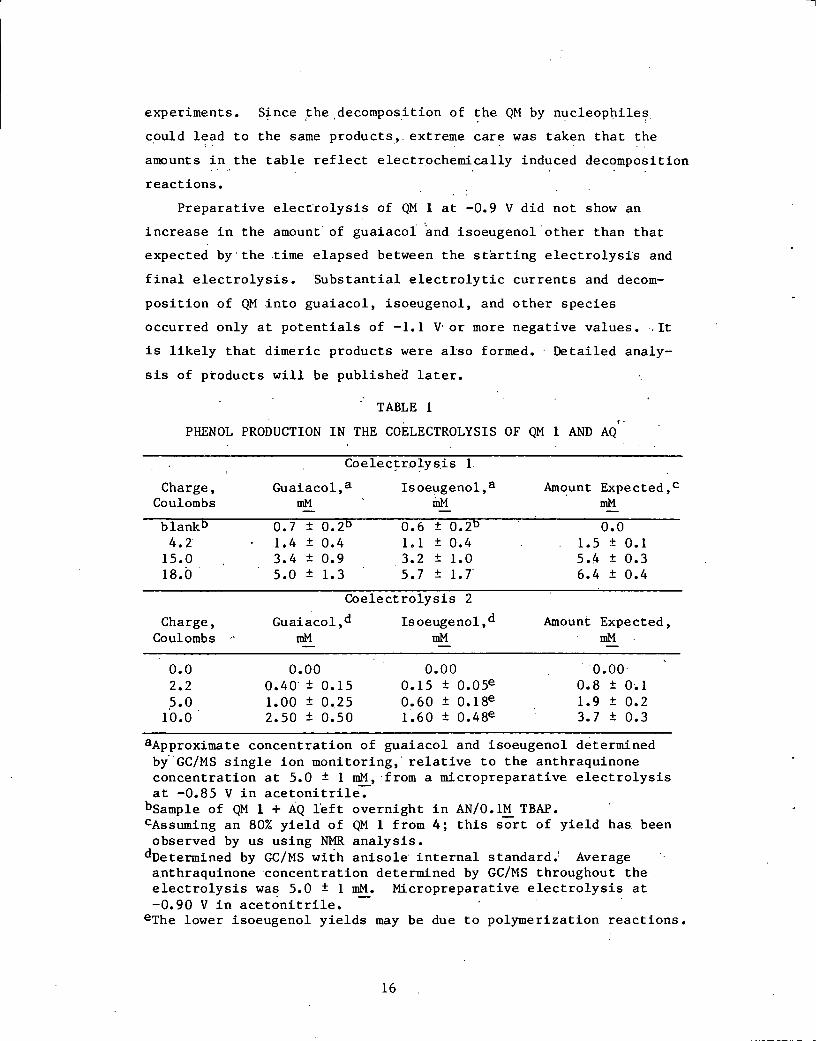
experiments. Since the decomposition of the QM by nucleophiles
could lead to the same products, extreme care was taken that the
amounts in the table reflect electrochemically induced decomposition
reactions.
Preparative electrolysis of QM 1 at -0.9 V did not show an
increase in the amount of guaiacol and isoeugenol other than that
expected by the time elapsed between the starting electrolysis and
final electrolysis. Substantial electrolytic currents and decom-
position of QM into guaiacol, isoeugenol, and other species
occurred only at potentials of -1.1 V or more negative values. It
is likely that dimeric products were also formed. Detailed analy-
sis of products will be published later.
TABLE 1
PHENOL PRODUCTION IN THE COELECTROLYSIS OF QM 1 AND AQ
Coelectrolysis 1
Charge, Guaiacol,a Isoeugenol,a Amount Expected,cCoulombs mM mM mM
blank b 0.7 ± 0 .2b 0.6 ± 0 .2b 0.04.2 1.4 ± 0.4 1.1 ± 0.4 1.5 ± 0.115.0 3.4 ± 0.9 3.2 ± 1.0 5.4 ± 0.318.0 5.0 ± 1.3 5.7 ± 1.7' 6.4 ± 0.4
Coelectrolysis 2
Charge, Guaiacol,d Isoeugenol,d Amount Expected,Coulombs mM mM mM
0.0 0.00 0.00 0.002.2 0.40 ± 0.15 0.15 ± 0 . 0 5 e 0.8 ± O.15.0 1.00 ± 0.25 0.60 ± 0 .18e 1.9 ± 0.2
10.0 2.50 ± 0.50 1.60 ± 0.4 8e 3.7 ± 0.3
aApproximate concentration of guaiacol and isoeugenol determinedby GC/MS single ion monitoring, relative to the anthraquinoneconcentration at 5.0 ± 1 mM, from a micropreparative electrolysisat -0.85 V in acetonitrile.
bSample of QM 1 + AQ left overnight in AN/O.1M TBAP.CAssuming an 80% yield of QM 1 from 4; this sort of yield has beenobserved by us using NMR analysis.
dDetermined by GC/MS with anisole internal standard. Averageanthraquinone concentration determined by GC/MS throughout theelectrolysis was 5.0 ± 1 mM. Micropreparative electrolysis at-0.90 V in acetonitrile.
eThe lower isoeugenol yields may be due to polymerization reactions.
16
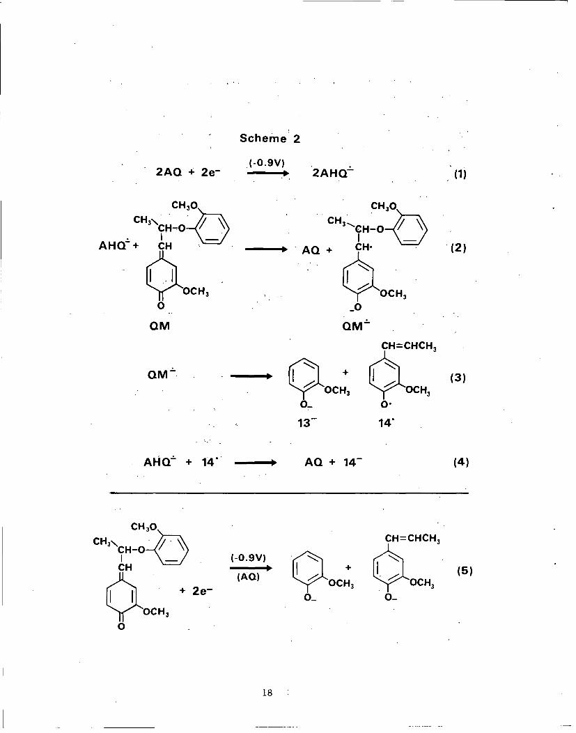
In essence, the proposed chemistry occurring during coelectro-
lysis of AQ/QM 1 is as follows: AHQ, generated by heterogeneous
electron transfer from the electrode to AQ, rapidly transfers an
electron to the QM and the resulting species, QM, fragments to
yield most likely guaiacol anion and the stabilized a-radical,
which is reduced further (probably by AHQ£) to isoeugenol anion
(Scheme 2). The net reaction, which-is summarized in reaction 5,
is not possible (at -0.9 V) without the present of AQ.
The results of the micropreparative electrolysis cannot be
reconciled by an adduct mechanism. An adduct between QM 1 and
AHQ- 2 would be expected to produce guaiacol and isoeugehol upon
warming in aqueous alkali but not in a neutral solution at room
temperature.1 The voltammetric experiments with a stable adduct
(Fig. 6) do not show fast fragmentation of the adduct electro-
chemically. In fact, the anodic scan following the carbonyl reduc-
tion shows very little decomposition to AQ.
CONCLUSIONS
The electrochemical experiments described here demonstrate that
B-aryl ether lignin model quinonemethides accept electrons from
reduced anthraquinone species and then rapidly fragment at the B-
linkage to phenolic products. In the time scale of the voltammetric
experiments the electron transfer reactions appear to occur in
preference to adduct formation reactions. Also, the electron
transfer reactions give products identical to those produced from
"adduct decomposition reactions."
When the two reactants have similar reduction potentials, the
electron transfer step between AHQ and AHQ- 2 with a QM is very
fast and efficient. Reduction potentials appear to vary with the
structure of the QM (and presumably also with AQ structure) and
the solvent. Exactly how efficient electron transfer reactions
might be with actual lignin QMs in water at 170°C is not known.
One must keep in mind that conclusions based on electrochemi-
cal experiments done at room temperature in organic or aqueous-
organic solvents with soluble models may not accurately describe
17
the pulping of wood in water at high temperatures. Even so, the
electrochemical studies do establish that electron transfer reac-
tions of quinonemethides can lead to efficient ligninlike fragmen-
tation, a fact which may change the way wood chemists attack the
problem of improving wood pulping systems. Future studies will
be aimed at establishing the importance of electron transfer reac-
tion under more typical pulping conditions.
EXPERIMENTAL
The NMR spectra were obtained using a JEOL FX 100 spectrom-
eter. A Hewlett-Packard model 5985 GC/MS spectrometer, using an
SP-52 metal column was employed in the quantitation of phenolics
The cyclic voltammetric experiments employed an EG&G Princeton
Applied Research Corp.potentiostat (model 173D) with a universal
programmer (175); slow scan rate results were recorded with a
Hewlett Packard XY recorder model 7046 A. Faster scan rate
experiments were recorded on a Bascom-Turner recorder (model 4120)
and stored on discs.
Quinonemethide 1. Quinonemethide 1 was prepared according to
the method of Ralph and Young,8 starting with model 4.17 A NMR
spectrum of 1 in CDC1 3 agreed with the reported spectrum.9 The
spectrum remained unchanged after weeks in the sealed NMR tube.
Quinonemethide 2. Quinonemethide 2 was prepared according to
the method of Ralph and Young, 8 starting with model 5.18 A NMR
spectrum of 2 in CDC13 showed signals (6 values) at 1.53 (d, J =
6.4 Hz, yA-CH3), 1.55 (d, J = 6.4 Hz, yS-CH3), 2.26 (s, S&A aryl
CH3 ), 3.62 (s, 3S-OCH 3), 3.74 (s, 3A-OCH 3), 3.76 (s,2'/6'S-OCH3),
3.77 (s, 2'/6'A-OCH3), 5.17 (q, J = 6.4 Hz, BA-H), 5.26 (q, J =
6.4 Hz, 8S-H), 6.32 (s, 3'/5'A&S-OCH 3), 6.1-6.6 (m, 2A&S, 5A&S,
aA&S protons), 7.00 (d of d, J = 9.6 and 2.2 Hz, 6S-H) and 7.23 (d
of d, J = 0.6 and 2.4 Hz, 6A-H); the symbols A and S stand for
anti and syn isomers.8 The NMR integration areas match perfectly
for the proposed structure and indicated a 2:1 ratio of syn to
anti isomers.
19
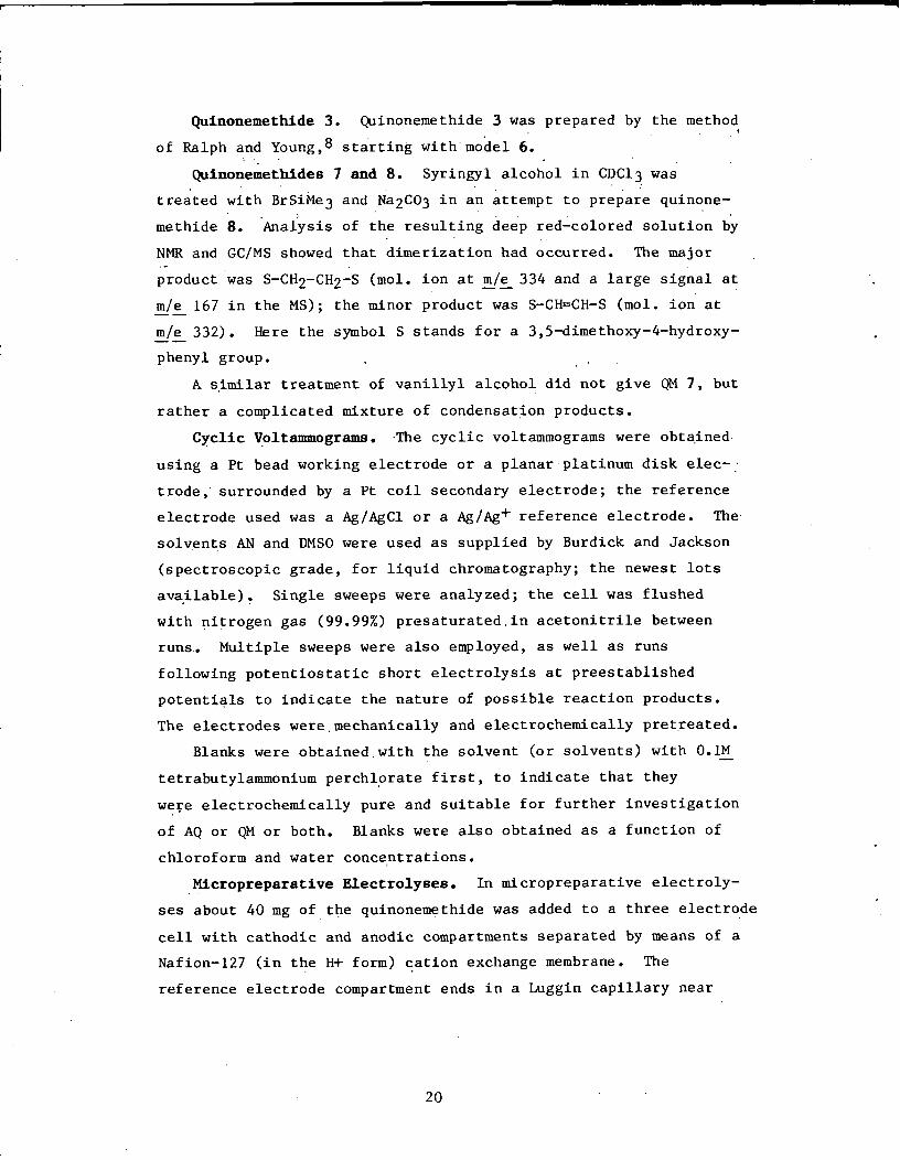
Quinonemethide 3. Quinonemethide 3 was prepared by the method
of Ralph and Young, 8 starting with model 6.
Quinonemethides 7 and 8. Syringyl alcohol in CDC13 was
treated with BrSiMe3 and Na2C03 in an attempt to prepare quinone-
methide 8. Analysis of the resulting deep red-colored solution by
NMR and GC/MS showed that dimerization had occurred. The major
product was S-CH2-CH2-S (mol. ion at m/e 334 and a large signal at
m/e 167 in the MS); the minor product was S-CH=CH-S (mol. ion at
m/e 332). Here the symbol S stands for a 3,5-dimethoxy-4-hydroxy-
phenyl group.
A similar treatment of vanillyl alcohol did not give QM 7, but
rather a complicated mixture of condensation products.
Cyclic Voltammograms. The cyclic voltammograms were obtained
using a Pt bead working electrode or a planar platinum disk elec-
trode, surrounded by a Pt coil secondary electrode; the reference
electrode used was a Ag/AgCl or a Ag/Ag+ reference electrode. The
solvents AN and DMSO were used as supplied by Burdick and Jackson
(spectroscopic grade, for liquid chromatography; the newest lots
available). Single sweeps were analyzed; the cell was flushed
with nitrogen gas (99.99%) presaturated in acetonitrile between
runs. Multiple sweeps were also employed, as well as runs
following potentiostatic short electrolysis at preestablished
potentials to indicate the nature of possible reaction products.
The electrodes were mechanically and electrochemically pretreated.
Blanks were obtained with the solvent (or solvents) with 0.1M
tetrabutylammonium perchlorate first, to indicate that they
were electrochemically pure and suitable for further investigation
of AQ or QM or both. Blanks were also obtained as a function of
chloroform and water concentrations.
Micropreparative Electrolyses. In micropreparative electroly-
ses about 40 mg of the quinonemethide was added to a three electrode
cell with cathodic and anodic compartments separated by means of a
Nafion-127 (in the H+ form) cation exchange membrane. The
reference electrode compartment ends in a Luggin capillary near
20
the working electrode.1 9 The working electrode was a platinum
mesh, and a platinum coil secondary electrode was placed in the
Teflon auxiliary electrode compartment, which ends in the ion
exchange membrane. The pretreatment of the membrane is as
follows: after being placed in the Teflon compartment the
membrane was'soaked for one hour in boiling aqueous acid; the
membrane is then placed in an acetonitrile solution containing the
supporting electrolyte and boiled in the solution for another
hour. The cell was maintained at all times under a nitrogen
atmosphere and was stirred to improve mass transfer. The charge
passed was recorded in a PARC digital coulometer model 179. Small
samples (less than 0.5 mL) were removed at various times for GC/MS
analyses. The total volume of the cell was less than 20 mL.
ACKNOWLEDGMENTS
The authors wish to thank SERI's Directors'Development Fund
(tasks 2713.00 and 0.713.10) and the Office of Alcohol Fuels (,WPA
349) for financial support. Thanks are also due to Ms. F. Posey
and Dr. D. K. Johnson for their cooperation in the experimental
work. Helpful discussions with Professors M. M. Baizer and J. M.
Saveant were greatly appreciated.
REFERENCES
1. D. R. Dimmel, J. Wood Chem. Technol., preceding article inthis issue.
2. G. A. Mabbott, J. Chem. Ed., 60, 697 (1983); P. T. Kissingerand W. R. Heineman, ibid, 702; (and references therein); L. R.Faulkner and A. J. Bard, Electrochemical Methods, Wiley,New York, 1980.
3. M. E. Peover, In Electroanalytical Chemistry, A. J. Bard Ed.,Vol. 2, pp. 1-51, Marcel Dekker, Inc., New York, 1967 andreferences therein.
4. R. C. Prince, M. R. Gunner and P. L. Dutton, In Functionof Quinones in Energy Conserving Systems, pp. 29-33, Academic
Press, Inc., New York, 1982. M. M. Baizer and L. G.Geoktistov, In Organic Electrochemistry, M. M. Baizer andH. Lund Eds., pp. 378-9, Marcel Dekker, Inc., New York, 2nd.Edition, 1983. C. K. Mann and K. K. Barnes, Electrochemical
21
Reactions in Nonaqueous Systems, pp. 190-9, Marcel Dekker,Inc. , New York, 1970.
5. S. Wawzonek, R. Berkey, E. W. Blaha and M. E. Runner, J.Electrochem. Soc., 103, 456 (1956). B. R. Eggins and J. Q.Chambers, Ibid., 117, 186 (1970). L. L. Landucci, Tappi63(7), 95 (1980).
6. I. M. Kolthoff and J. J. Lingane, Polarography, IntersciencePublishers, New York, Vol. I pp. 253-6; Vol. II pp. 699-707,2nd Ed., 1952. B. I. Fleming, G. J. Kubes, J. M. MacLeod, andH. I. Bolker, Tappi, 62(7), 55 (1979).
7. L. J. Filar and S. Winstein, Tetrahedron Lett., 9 (1960).
8. J. Ralph and R. A. Young, J. Wood Chem. Technol., 3, 161(1983).
9. J. Ralph and B. R. Adams, J. Wood Chem. Technol., 3, 183(1983).
10. C. K. Mann and K. K. Barnes, Electrochemical Reactions inNonaqueous Systems, p. 131, Marcel Dekker, Inc., New York,1970.
11. J. A. Richards and D. H. Evans, J. Electroanal. Chem., 87,171 (1977).
12. G. J. Hoijtink, Rec. Trav. Chim., 76, 775 (1957) and referencestherein.
13. C. P. Andrieux, J. M. D.-Bouchiat and J. M. Saveant, J.Electroanal. Chem., 87, 39-53.(1978); 87, 55-65 (1978); 88,43-8 (1978); 113, 1 T1980). C. Andrieux, C. Blocman, J. M.D.-Bouchiat, F. M'Halla and J. M. Saveant, ibid., 113, 19(1980). For a review see J. Simonet In Organic Electro-chemistry, M. M. Baizer and H. Lund Eds., pp. 843-871, MarcelDekker, Inc., New York, 2nd Ed., 1983.
14. H. Lund and J. Simonet, J. Electroanal. Chem., 56, 529(1975); C. P. Andrieux, C. Blocman, J. M. D.-Bouchiat, F.M'Halla and J. M. Saveant, J. Am. Chem. Soc., 102, 3806-13(1980).
15. H. L. Chum, P. Palasz, J. H. Christie, L. Perry and D.
Dimmel, forthcoming publication.
16. D. R. Dimmel and D. Shepard, J. Org. Chem., 47, 22 (1982).
17. D. R. Dimmel and D. Shepard, J. Wood Chem. Technol., 2, 297(1982).
18. P. B. Apfeld, Ph.D. Thesis (in progress), The Institute of
Paper Chemistry
19. For details of experimental cell see H. L. Chum and S. Black,
Electrochemistry Applied to Thermal Conversion, Final Report,SERI-PR-234-1850 (1982). Solar Energy Research Institute,
Golden, Colorado.
22


![Problems with a conformation assignment of aryl-substituted resorc[4]arenes](https://static.fdokumen.com/doc/165x107/6324d12685efe380f30661c8/problems-with-a-conformation-assignment-of-aryl-substituted-resorc4arenes.jpg)

