Electromagnetic Compatibility( EMC) Design Guidelines for ...
74
KAERI/TR-2039/2002 Electromagnetic Compatibility(EMC) Design Guidelines for l&C Systems for Nuclear Power Plants
-
Upload
khangminh22 -
Category
Documents
-
view
1 -
download
0
Transcript of Electromagnetic Compatibility( EMC) Design Guidelines for ...

KAERI/TR-2039/2002
Electromagnetic Compatibility( EMC) Design
Guidelines for l&C Systems for Nuclear Power
Plants

DISCLAIMER
Portions of this document may be illegible in electronic image products. Images are produced from the best available original document.
i
._. . . , . I ..?.
I
2

- -
3

Abstract
This report describes the research results on Electromagnetic Compatibility technologies for I&C(Instrumentation and Control) systems for nuclear power plants. As the nuclear industries are adopting the digital equipment rather than the conventional analog type equipment for safety I&C systems as well as non-safety systems of nuclear power plants(NPPs), it is necessary to secure compatibility against EMI(e1ectromagnetic interference) for the digital safety I&C systems.
EM1 qualification, identified as a regulatory compliance item by US NRC and Korean regulatory body, should be performed in accordance with appropriate standards, because the electromagnetic environment is regarded as one of the environmental factors possible to affect the safety functions. As a technical guide on this EM1 issue, this report includes description of code and starldards scheme, EM1 qualification methods, noise reduction strategies, and survey on noise levels in nuclear power plants.
4

tn 7 I : :
: :
: : : II!
9
2 2
2
o\ 7 i : : :
:
:
:
:
:
:
: :
:
:
:
:
: :
4 2 P
h
o\ :
: : :
Y :
:
:
i : : :
:
i
a
w ;i$
w 8 KJ ;jT
d
y 00 q :
i :
:
:
:
n
R
0
PI 0
." c I 3. 5ir ?T
y

3.4. 4 Tk 3!x)71 31-8 qA1 ................................................................................. 31
3.4.1. A-4l4lS ................................................................................................................. 31
3.4.2. 3l-41 s @ e % ( S h i e l d Discontinuity) .................................................................... 31
3.4.3. 7)&3.!(Gasket) ........................................................................................................ 32
3.4.4. A l O l S 3141 ........................................................................................................... 33
3.5. 3 ~l(Grounding) .......................................................................................................... 34
53% 344 5% ............................................................................................. 34
71aol9 qS4 q+ 3x1 %4 ..................................................................... 35
3.5.1.
3.5.2.
4.0 3 X l - q ?I'l%A1q 7171q 3371u) @3ZlS .................................................. 37
4.1. 4 X l - 7 1 q fFAlAZ! ....................................................................................................... 37
Regulatory 1.180 3 EPRl TR-102323 44 3)01 ................................................ 38
EMVRFIq A 1 3 3-8-715 .................................................................................. 38
4.1.1.
4.1.2.
4.2. 3!x1714 494 $?ll IrqA)%(Basic Principles) ........................................... ... .... 41 4.2.1.
4.2.2.
4.2.3. A1 % %."d 4 ;rd ................................................................................................. 41
4.2.4. EMCsriented Design and Installation .................................................................... 42
4.2.5.
4.2.6. Tailoring ................................................................................................................... 44
4.2.7.
4 2 -i?qlaZ! % 71 $ 3 1 5 @$(Exception of Cut-off Dates) ........................ 41
4@76 4 %3 7s ............................................................................................. 41
$xi71 i$ Site Survey ............................................................................................. 44
H I 3 3 7 1 71 '4l q% EM1 Qualification ................................................................ 44
4 3 . Documentation for EM1 Qualification ..... ........ .. .... .. .................................................... 45
5.0 % ! X ) q %&kq EM1 s97) .................................................................... 46
5.1.
5.2.
EM1 Site Survey ............................. .. .................... ..... .. .............................................. , ... 46
%%si% % %% ................................ .. ............ .. ......................................................... 46 5.2.1. %8%% ................................................................................................................ :46
5.2.2. %a $4714 dl q-% 2 % 8 A l b ........................................................ 48
53 . fa a* 2 ?37) ............................................................................................ ........... 49 5.3.1. 7Ha ......................................................................................................................... 49
0 5.3.2. 4 ?* $SAd @= (CE101) .............................................................................. 49
6

=z 0 5.3.3. 5.3.4.
5.3.5.
3l-q 3SAd ~~(CE102) ................................................................................ 5~
XFq %A) w!e(3!fl S X : Electric Field (RE102)) .................................... 58 q?q %A) %+!?(xt71% %E : Magnetic Field (RElOl)) .............................. 56
-1 6.0 3s g7) ................................................................................................... 69
7

2% 2-1. 3% 2-2.
3% 2-4 3% 2-5
2% 3-1
2% 3-3.
3% 2-3.
2% 2-6
3% 3-2
i
8

9
10

11

Radiated Emission
Culprit equipment
Source Conducted Emission Receptor
12

13

PI

INSTRUMENTATION
0
A i MAGNETIC FLUX COUPLING

Intentional or Unintentional Radiatinn
2% 2-5. %AFZ!;!(Radiative Coupling) 7H 'd 4
2.2.2. A W Z E Z ! (differential mode interference(norma1 mode, transverse
334% 83 45 76Z(legitimate signal path) 313 GI4A-1 -$-7)qt 3 mode)
2t%
16

- __t
INSTRUMENTATION
CM DM CURRENT CURRENT 0
__c f---
1 - Q - l GROUND - GROUND
- POINT2 - - POINT 1
17

18

3.0 ?!
19

"d-44 a(Rise 881 %%(Voltage Time)[ns] Swing) &4 &XI
CMOS 5V 100 5
&/dl [v/nsl
0.05
I T I
CMOS 12V CMOS 15V HCMOS TTL ECL 10k ECL lOOk
20
25 12 50 15 10 5 10 3 2 0.80
0.75 0.80

21

3% 3-4. IC Chip Decoupling Capacitor
22

E 3-2. Sq &X) %%-$ a%-i-dcl-%S logic Family I Noise Margin(mV) TTL I 400 CMOS 5V CMOS 15V ECL 10k ECL lOOk
1,000 4,500 125 100
I T CL
23

Y Enclosure \ Subenclosure Filtered Interfaces
24

Nonsensitive Analog Cards S C H
Digita Card
4 Motherboard
25

Low-Speed Chuits
Medium-Speed Circuits
Connector 1 High-speed ---------
I Medium-Speed
---------
26

v4 ov V+ ov
Vertical Horizontal
x% 3-13. 9 4 3 3!%!Stll+!q OI1](Raised Power Distribution)
27

- n
28

29
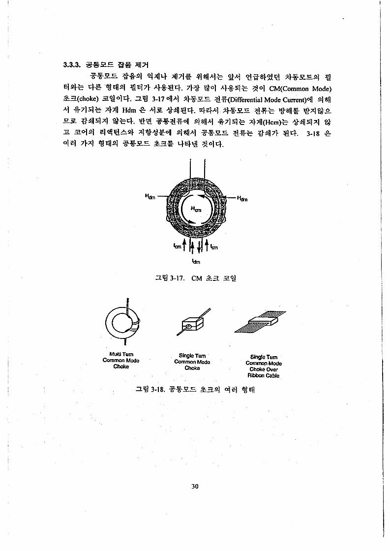
Mutti Turn Common Mode
choke Single Turn Single Turn
common Mode Common Mode Choke Choke Over
Ribon W e
30

31

F d 8 -
I rL--7 I I
32

Endosure Wall
33

Twisted
. TwistedShielded . >
coax I Condudor
34

. .
2% 3-23. Single point star ground
I%? 3-24. Layered single point ground
. .
23 3-25. Multi-point ground
35

Quiet
I 77477
-8
M Y P-r Sensitive Insensitive supptv
4
36

37

38
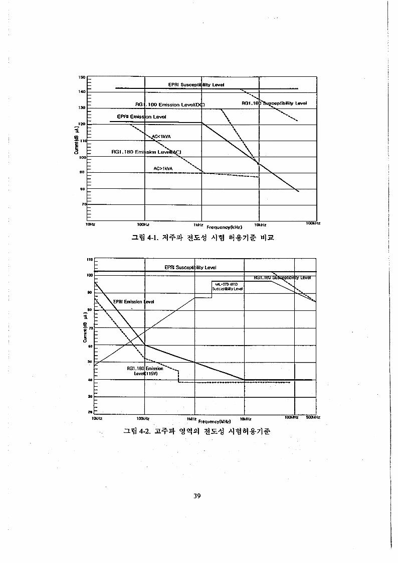
I I I 1
39

40

41

42

43

44

45

46

A1 T4 +*+%9l +% 4%
Conducted 30 H~ - 10 mz Power Leads CEIOl: Emissions CE102: Emissions
REIOI: Radiated Emissions 30Hz- kHz (Magnetic field)
RE102: Radiated Emissions IOkHz- lGHz 01
Conducted 10 kHz - 10 MHz Power Leads
71 71 3 51 41 4 %-2 4q 3 4 41% 4%
%= 4% (Electric Field) %
Equipment U
+?4 9sl
[dBPVI
[dBPTl
[dBpV/m]
EM1 Test Receiver
47

I t I I

49

A t t 10 dB AUTO INPUT 2
Det MA Trd CEl31-2 ResBli 10 H r Ueas T 1 s U n i t %YP.
30 Hz 10 UHr
Date : 2 0 . s P . 2001 09:15 : 42
2% 5-3. %Ad 1 571 DCC(Digita1 Control Computer)q a-8 %E
50

140 1 Conducted Emission, 30 Hz - 50 IcHz PCS, 220 VAC === Differential Mode
Maximum Level
120
100
3 m 80 B
E 60 Y
a 40 L ' . .
20 e,----------.- -...-... ~ . . - I . ~ . . . . ~ . ___ .__
o r ' I I I I I ,&Ill I I I I I I I I I I I I
0.03 0.1 1 .o 10.0 50.0 Frequency (kHz)
- . . . . , . . . . -
2% 5-5. 3 S714 PCS(P1ant Control System) 3% 9 4 4 3% S X
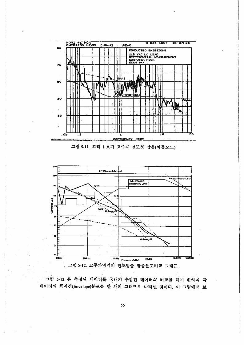
FREQUENCY [HHZl
5 1

30 RZ
Date: 1.nAR.2001 0 2 : 4 5 1 5 1
5 MI32
52

53

Conducted Emission, 10 lcHz - 30 MHz PCS, 220 VAC ===== Common M& KTL - EMC Team
I I 1 I 1 1 1 1 I I , . Maximum Level
140 - - I ,
100 -
I s 40 I:
/ I I I I .
I I I IIIIIl I I I I B $ I I l I I I I I I I I I I
3% 5-9 3*71 PCS 3 ~ ~ 2 ~ ~ S Z ( % ~ Z S )
0.01 0.1 1 .o 10.0 30.0 Frequency (MHz)
54
so
T O
io
. .
I I loo I I
55

@A=* 10 dB AUTO INPUT 2
0922-10-30.WMP ~10SBx932x18( - f I
MA Trd Magneric Der RedBW 1 k H z H w a s T 100 ma Unit dBpT
56

57

*A,, 10 dB AUTO
I N P U T 1
58

e A t t 10 dB AUTO INPUT 2
12J
100-
0 0 .
2 0 0 Mnz
D a t e : 25.SEP.2000 07:05:09
D.Zt M A Trd LogpHorn ResBW 100 k H z M e a s T 100 ms Unit dBYV/rn
1 GHZ
71 8211 %S(200MHz - 1 GHz)
59

@ A t , 10 d B AUTO HA T r d L o g p H o r n D e t
ResBW 100 kHz
I N P U T 1 M e a s T 1 s U n i t dBYV/m
60

19
ZHW 002

A r t 20 dB AUTO
INPUT 2
Det nA Trd RodEicaa ResBW 10 kH: Meas T 1 a U n i t d B Y V l r
10 LHz 200 n m
23 5-23. %Ad 1 s71 %3 901q : IOkHz-200MHz(CDF)
Date : 8.OCT.2001 08:45:59
+ A t , 10 d B AUTO INPUT 1
D e t I4A T r d LogpHorn ResBW 100 k H z Heas T 1 s u n i t dBYV/m
zoo a t
D a t e : 1 6 . 0 C T . 2 0 0 1 02:50:04
1.3 C H Z
62

* A t , 10 dB AUTO I N P U T 2
D e t MA T r d R o d s i c o n R e s e w 10 kHZ - a i T 100 m a u n i t dSuV/m
10 k H z 200 MHz
Date: 1 9 . O C T . 2 0 0 0 0 2 : 3 5 : 2 5
3% 5-25 %Ad 2&71 %gq]gl€l : lOkHz-200MHz(MCR 5!g)
Det MA Trd RsdBicon A t t 10 dB AUTO ResBW 10 kHr
INPUT 2 Heas T 1 s Unit d B W h
10 kH2 200 HHr
Date: 28 .SEP.2001 09:44:48
3% 5-26 34.i 1 271 q ] O ] q : IOkHz-200MHz (MCR 3?q)
63

@ A t , 10 d B AUTO
I N P U T 2
D e t . M A T r d LogpHorn ResBW 100 kHz M e a s T 100 ms U n i t dBYV/m
200 MHZ
D a t e : 10. OCT. 2000 02: 4 6: 33
A t t 10 dB AUTO
INPUT 1
Date: 4.OCT.2001 06:50:24
net MA Trd LogpHorr. ResBB 100 kHr Heas T 1 s u n i t IBYVI::
64

*At , 10 dB AUTO INPUT 1
D e t MA T r d R o d B i s o n R e r B W 100 k H z Heas T 100 m r u n i t d B r V / m
10 k H z
D a t e : 27.SEP. 2000 0 2 : 51: 41
2 0 0 UHZ
3% 5-29 % A i 2 371 G g q1 O1 El : 1 OkHz - 200MHz (Fuel Handling Z$ 3 q)
A t t 10 dB AUTO INPUT 1
D e t HA Tcd Rodeicon
H e a s T 1 s U n i t dBW/r
R e s B m 100 kHz
?YA
IO kHr 200 KE: Date: 24 .SEI.ZGOl 03:OZ :44
3% 5-30 %Ad 1 224 %d fl1 O1 : lOkHz - 200MHz (Fuel Handling
65

*At, 10 dB AUTO INPUT 2
D e t rn Trd LogpHorn ResBW 100 kHz H e a s T 100 llls Unit dBYV/m
200 MHz
D a t e : 28.SEP.2000 0 7 : 2 3 : 0 8
1 GHz
IZg 5-31 %*d 2 3271 %72 Ll101q : 200MHz- lGHz(Fue1 Handling -E!& 3%)
Dot MA Trd LogpHocn A t t 10 dB AUTO ROSE. 100 LBZ
IWPUT 1 near t 1 s U n i t d B Y V h
200 nHZ 1.3 GHr Date: 26.sEP.2001 04:37:09
2% 5-32. 1 3271 48 t?ll*lq : 200MHz- I.3GHz(Fuel Handling Fe 3@)
66

0.01 0.1 1 H) io0 FREQUENCY (Mk)
67

89
1 I I I I I
I I I I
I I I I
I
I I I I I I Il I I 1 I I I -J 081

69

a i l s g [l] IEEE Std 323-1983, “IEEE Standards for Qualifying Class 1E Equipment for Nuclear
Power Generating Stations,” June 1983. [2] Inkoo Hwang, Environmental And EMVRFI Qualification of Electrical Equipment For
Korean Next Generation Reactor, KNGR-MM-GD002-00, Revision 00, KAERI, 1999. [3] Regulatory Guide 1.89, ‘‘Environmental Qualification of Certain Electric Equipment
Important to Safety for Nuclear Power Plants,” US Nuclear Regulatory Commission, June 1984
[4] Eric J. Lee, “Understanding of EMI/RFI and Digital Updates,” Proceedings of 96 ANS Topical Meeting On Nuclear Instrumentation, Control and Human-Machine Interface Technology, 1996.
[SI NUREGKR-5679, ”Digital I&C Systems in Nuclear Power Plants,” NRC, 1998 [6] Regulatory Guide I. 180, “Guidelines for Evaluating Electromagnetic and Radio-frequency
[7] ?!%!-$41~1~ 9.17(3), “ d X l - 7 1 4 %dlq qf& %&71S,” KMS, 2000 [8] NUREGKR-6436, ORNYTM-13 171, “Survey of Ambient Electromagnetic and Radio-
Interference in Safety-related Instrumentation and Control Systems,” NRC, January 2000
Frequency Interference Levels in Nuclear Power Plants,” 1996.
[9] 435, “?3Xl-714- %OllB”d-,” 3.€S-$F&l m71@7d g5%! X i s , 2001 [IO] MIL-STD-46 IC, “Electromagnetic Emission and Susceptibility Requirements for the
Control of Electromagnetic Interference ”, 1980. [ 1 I] MIL-STD-461 D, “Requirements for the Control of Electromagnetic Interference Emissions
and Susceptibility, 1993. [ 123 MIL-STD-461 E, “Requirements for the Control of Electromagnetic Interference
Characteristics of Subsystems and Equipment,” 1999.
in Generating Stations”. [ 131 IEEE Std 1050-1989, “IEEE Guide for Instrumentation and Control Equipment Grounding
[ 141 EPRI TR-102323-R1, “Guidelines for Electromagnetic Interference Testing in Power Plants,” Jan. 1997
[ 151 EPRI-TR-I 02400, “Handbook for Electromagnetic Compatibility of Digital Equipment in
[ 161 T.L. Clark, et. al. “Marshall Space Flight Center Electromagnetic Compatibility Design and Interference Control (MEDIC) Handbook,” CDDF Final Report, Project No. 93-1 5, NASA, June, 1995.
Power Plants,” vol.1, v012, EPRI, June. 1994.
[ 171 10 CFR SO App.A, “General Design Criteria for Nuclear Power Plants,” US NRC. [ 181 Stephen J. Wilkozs, Consulting Report for EMVRFI Qualification, 1998.
70

[ 191 NUREG/CR-5941, “Technical Basis for Evaluating Electromagnetic and Radio- Frequency Interference in Safety-Related I&C Systems,” April 1994
[20] NUREGKR-643 1, ORNL/TM-13 158, “Recommended Electromagnetic Operating Envelopes for Safety-Related I&C Systems in Nuclear Power Plants,” 1997
[21] IEEE Std C62.41-1991, “IEEE Recommended Practice on Surge Voltage in Low-Voltage AC Power Circuits,” Institute of Electrical and Electronics Engineers, 199 1
[22] IEEE Std C62.45-1992, “IEEE Guide on Surge Testing for Equipment Connected to Low-
[23]q@Y!q, 2 9 3 4*&
[24] q%?!Y!q, ?!xl4q *%%-3q 3,4 3
[26]@3-:0,)a7]$$, “ElXl71J4- 844% !?! $q41% :0,)@fZ!o,F,” 41 2 4 -@a 41%
Voltage AC Power Circuits,” Institute of Electrical and Electronics Engineers, 1992
[25] q@Y!q, %.3!.%3?ilA] 1997-41 &, 1997-42 3,1996-78 2,1996-79 2
41q-?!71 “,,?!Ad Workshop, KMS, 2001.9. [27] IEEE Std 1100-1992, “IEEE Recommended Practice for Powering and Grounding Sensitive
Electronic Equipment,” Institute of Electrical and Electronics Engineers, 1992. [28] Stephen W. Kercel, “Survey of EM1 Ambient Levels in Nuclear Power Plants,” The ANS
International Topical Meeting on Nuclear Plant Instrumentation, Control, and Human
Machine Interface Technologies, Pennsylvania State University, USA, Vol. 11, pp. I1 8 1-
11 87,1996. [29]%?!?21, “$8 AlS41~7171Oll q@ [email protected]/EMI 9% ‘417): 71S?$!-XAj
KAERVTR-I089/2001, @%$z)q g?&, 2001.
71

EMVEMC, iY!Ai13lI4 , C I X I I , Site Survey. Susceptibility, 1HS. Xtit.ll. 3x1. iYi1313. A3l3.. 243Ixd8, 71iFIr.t. 2Fr4
72

Performing Org. Report No.
KAERI/TR-2039/2002
Subtitle I I&C Systems for Nuclear Power Plants
Standard Report No. INlS Subject Code Sponsoring Org. Report No.
Project Manager And Department
(or Main Author)
Researchers and Department
~ ~~~~~~
InKoo Hwang(MMIS team)
DongYoung Lee, KyungHo Cha. JooHyun Park, KiYoung Lee
Publication Taejon Place
Page p.73
Publisher KAERI Publication Date 2002.2
Fig. & Tab. Yeso, No ( ) Size 19cm x 26 cm
Note
I I
Sponsoring Org. I Contract No.
Research Result Application Support Project
ibstract (15-20 Lines) I This report describes the research results on Electromagnetic Compatibility technologies for
&C(lnstrumentation and Control) systems for nuclear power plants. As the nuclear industries are adoptins .he digital equipment rather than the conventional analog type equipment for safety I&C systems as well a: ion-safety systems of nuclear power plants(NPPs), it is necessary to secure compatibility againsi ZMl(e1ectromagnetic interference) for the digital safety I&C systems.
EM1 qualification, identified as a regulatory compliance item by US NRC and Korean regulatory body should be performed in accordance with appropriate standards, because the electromagnetic environmeni s regarded as one of the environmental factors possible to affect the safety functions. As a technical guide In this EM1 issue, this report includes description of code and standards scheme, EM1 qualificatior nethods, noise reduction strategies, and survey on noise levels in nuclear power plants.
EMVEMC, Qualification, Magnetic Field, Electric Field, Surge, Digita Equipment, Site Survey, Susceptibility, Electromagnetic Source Grounding, Electric Noise, etc.
Subject Keywords (About 10 words)
Classified
73
Report Type Technical Report Open( V ), Restricted( ), - Class Document


![Ruth Knight presentation.ppt [Compatibility Mode]](https://static.fdokumen.com/doc/165x107/631d5d013ba403638902baaf/ruth-knight-presentationppt-compatibility-mode.jpg)


![Straight Lines Slides [Compatibility Mode]](https://static.fdokumen.com/doc/165x107/6316ee6071e3f2062906978b/straight-lines-slides-compatibility-mode.jpg)