Electrocrystallization of nanocrystallite calcium phosphate coatings on titanium substrate at...
6
Electrocrystallization of nanocrystallite calcium phosphate coatings on titanium substrate at different current densities E.A. Abdel-Aal a, ⁎, D. Dietrich b , S. Steinhaeuser b , B. Wielage b a Central Metallurgical Research and Development Institute, P.O. Box 87 Helwan, Cairo, Egypt b Faculty of Mechanical Engineering, Chemnitz University of Technology, Erfenschlager Str. 73, 09125 Chemnitz, Germany ABSTRACT ARTICLE INFO Article history: Received 13 January 2008 Accepted in revised form 15 June 2008 Available online 19 June 2008 Keywords: Electrocrystallization Electrodeposition Calcium phosphate Brushite Hydroxyapatite Calcium phosphates were electrocrystallized on titanium substrate by electrochemical deposition technique, in which the electrolyte was 0.167 M CaCl 2 and 0.1 M NH 4 H 2 PO 4 . Different current densities (0.375, 1.5, 3, 6 mA/cm 2 ) were applied. The pH of the solution after mixing of equal volumes was 4.6. The surface morphology, chemical composition and phase identification of the coatings were investigated by scanning electron microscopy associated with an energy dispersive spectrometer (SEM-EDXS) and X-ray diffracto- metry (XRD). Effects of the current density on the morphology and the structure of the coating were also discussed. The results showed that at all current densities tested, the coating is brushite (dicalcium phosphate dihydrate CaHPO 4 ·2H 2 O). Furthermore, the results showed that coating thickness and weight gain are increased and the morphology changed with increasing deposition current density (from 0.375 to 6 mA/cm 2 ). On contrary, thickness and weight gain are decreased with sodium hydroxide treatment. NaOH treatment converts brushite of Ca/P ratio 1:1 to hydroxyapatite of Ca/P ratio of 1.667. So, chemical analysis of the solution shows soluble P 2 O 5 content. Coating thickness at 6 mA/cm 2 was about 20 and 30 μm with and without treatment, respectively. It decreased to about 9.5 and 12 μm at 0.375 mA/cm 2 current density, with and without treatment, respectively. However, the formed phase is not changed with increasing current density. In addition, it is found that, even at high current density (6 mA/cm 2 ), no hydroxyapatite was directly electrocrystallized due to low corresponding potential (less than 5 V) and low corresponding voltage (468 mV). © 2008 Elsevier B.V. All rights reserved. 1. Introduction Calcium phosphates have received much attention and have been clinically applied in orthopaedics and dentistry due to their excellent biocompatibility. Among several forms of calcium phosphates, synthetic hydroxyapatite [Ca 10 (PO 4 ) 6 (OH) 2 , hereafter HA], a major inorganic component of natural bone, is particularly attractive. HA is recognized as osteoconductive and able to accelerate bone in growth and attachment to the surface of implant during the early stages after implantation. Furthermore, the fixation and lifetime of the implant are improved. However, the mechanical strength is too poor to be used in load-bearing applications. Therefore, HA coatings on bioinert metallic prostheses were investigated to maintain biocompatibility and to improve mechanical properties [1–5]. Several methods have been reported to deposit HA onto implant surfaces, for example, plasma spraying, sputtering [6–12], pulsed laser deposition [13], sol–gel [14], electrophoretic method [15], and electrochemical deposition [16–18], etc. Plasma spray method has been applied commercially for coating on titanium alloy implant surfaces. However, many issues remain concerning its use. This includes the presence of amorphous material and/or calcium phosphate crystalline phases other than HA such as Ca 2 P 2 O 7 and β-Ca 3 (PO 4 ) 2 resulting from using extremely high temperatures in the plasma spray process [11]. Another issue of greater concern is the poor adhesion of the plasma-sprayed HA coating to titanium substrate due to the delamination of HA coating from the metal implant [12]. In addition, another problem cited with the plasma-sprayed coatings includes difficulty in microstructure control, which limits this approach in achieving optimum fixation with the implant. Surface & Coatings Technology 202 (2008) 5895–5900 ⁎ Corresponding author. Tel.: +20 2 5010642; fax: +20 2 5010639. E-mail addresses: [email protected], [email protected] (E.A. Abdel-Aal). Table 1 Specifications of HA coat Property Value Property Value Thickness Not specific Heavy metals b 50 ppm Crystallinity 62% min Tensile strength N 50.8 MPa Phase purity 95% min Shear strength N 22 MPa Ca/P ratio 1.67–1.76 Abrasion Not specific Density 2.98 g/cm 3 0257-8972/$ – see front matter © 2008 Elsevier B.V. All rights reserved. doi:10.1016/j.surfcoat.2008.06.139 Contents lists available at ScienceDirect Surface & Coatings Technology journal homepage: www.elsevier.com/locate/surfcoat
-
Upload
tu-chemnitz -
Category
Documents
-
view
0 -
download
0
Transcript of Electrocrystallization of nanocrystallite calcium phosphate coatings on titanium substrate at...

Surface & Coatings Technology 202 (2008) 5895–5900
Contents lists available at ScienceDirect
Surface & Coatings Technology
j ourna l homepage: www.e lsev ie r.com/ locate /sur fcoat
Electrocrystallization of nanocrystallite calcium phosphate coatings on titaniumsubstrate at different current densities
E.A. Abdel-Aal a,⁎, D. Dietrich b, S. Steinhaeuser b, B. Wielage b
a Central Metallurgical Research and Development Institute, P.O. Box 87 Helwan, Cairo, Egyptb Faculty of Mechanical Engineering, Chemnitz University of Technology, Erfenschlager Str. 73, 09125 Chemnitz, Germany
⁎ Corresponding author. Tel.: +20 2 5010642; fax: +20E-mail addresses: [email protected], sayedabdelaal@
0257-8972/$ – see front matter © 2008 Elsevier B.V. Aldoi:10.1016/j.surfcoat.2008.06.139
A B S T R A C T
A R T I C L E I N F OArticle history:
Calcium phosphates were e Received 13 January 2008Accepted in revised form 15 June 2008Available online 19 June 2008Keywords:ElectrocrystallizationElectrodepositionCalcium phosphateBrushiteHydroxyapatite
lectrocrystallized on titanium substrate by electrochemical deposition technique,in which the electrolyte was 0.167 M CaCl2 and 0.1 M NH4H2PO4. Different current densities (0.375, 1.5, 3,6 mA/cm2) were applied. The pH of the solution after mixing of equal volumes was 4.6. The surfacemorphology, chemical composition and phase identification of the coatings were investigated by scanningelectron microscopy associated with an energy dispersive spectrometer (SEM-EDXS) and X-ray diffracto-metry (XRD). Effects of the current density on the morphology and the structure of the coating were alsodiscussed.The results showed that at all current densities tested, the coating is brushite (dicalcium phosphate dihydrateCaHPO4 ·2H2O). Furthermore, the results showed that coating thickness and weight gain are increased andthe morphology changed with increasing deposition current density (from 0.375 to 6 mA/cm2). On contrary,thickness and weight gain are decreased with sodium hydroxide treatment. NaOH treatment convertsbrushite of Ca/P ratio 1:1 to hydroxyapatite of Ca/P ratio of 1.667. So, chemical analysis of the solution showssoluble P2O5 content. Coating thickness at 6 mA/cm2 was about 20 and 30 µm with and without treatment,respectively. It decreased to about 9.5 and 12 µm at 0.375 mA/cm2 current density, with and withouttreatment, respectively. However, the formed phase is not changed with increasing current density. Inaddition, it is found that, even at high current density (6 mA/cm2), no hydroxyapatite was directlyelectrocrystallized due to low corresponding potential (less than 5 V) and low corresponding voltage(468 mV).
© 2008 Elsevier B.V. All rights reserved.
1. Introduction
Table 1Specifications of HA coat
Property Value Property Value
Calcium phosphates have received much attention and have beenclinically applied in orthopaedics and dentistry due to their excellentbiocompatibility. Among several forms of calcium phosphates,synthetic hydroxyapatite [Ca10(PO4)6(OH)2, hereafter HA], a majorinorganic component of natural bone, is particularly attractive. HA isrecognized as osteoconductive and able to accelerate bone in growthand attachment to the surface of implant during the early stages afterimplantation. Furthermore, the fixation and lifetime of the implant areimproved. However, the mechanical strength is too poor to be used inload-bearing applications. Therefore, HA coatings on bioinert metallicprostheses were investigated to maintain biocompatibility and toimprove mechanical properties [1–5]. Several methods have beenreported to deposit HA onto implant surfaces, for example, plasmaspraying, sputtering [6–12], pulsed laser deposition [13], sol–gel [14],electrophoretic method [15], and electrochemical deposition [16–18],
2 5010639.cmrdi.sci.eg (E.A. Abdel-Aal).
l rights reserved.
etc. Plasma spray method has been applied commercially for coatingon titanium alloy implant surfaces. However, many issues remainconcerning its use. This includes the presence of amorphous materialand/or calcium phosphate crystalline phases other than HA such asCa2P2O7 and β-Ca3(PO4)2 resulting from using extremely hightemperatures in the plasma spray process [11]. Another issue ofgreater concern is the poor adhesion of the plasma-sprayed HAcoating to titanium substrate due to the delamination of HA coatingfrom the metal implant [12]. In addition, another problem cited withthe plasma-sprayed coatings includes difficulty in microstructurecontrol, which limits this approach in achieving optimum fixationwith the implant.
Thickness Not specific Heavy metals b50 ppmCrystallinity 62% min Tensile strength N50.8 MPaPhase purity 95% min Shear strength N22 MPaCa/P ratio 1.67–1.76 Abrasion Not specificDensity 2.98 g/cm3

Table 2Effect of coating parameters on formed phase of calcium phosphate
Current density/voltage Materials Ca/P ratio pH Tem., °C Time, min Phases Ref.
2–10 mA/cm2 0.042 M Ca(NO3)2 ·4H2O 0.125 M NH4H2PO4 0.336 4.4 60 20 OCP, CadHA [22]1–5 mA/cm2 0.042 M Ca(NO3)2 0.025 M NH4H2PO4 1.68 4.5 60 30 B, OCP, TCP, HA [23]0.3–3.0 mA/cm2 0.042 M Ca(NO3)2 ·4H2O 0.025 M NH4H2PO4 1.68 4.76 65 16.7 MCPhn, MCP, B, OCP, HA [24]1–3 V 0.042 M Ca(NO3)2 0.025 M NH4H2PO4 1.68 4.4 – 120 HA⁎ [25]4–10 V 0.04 M Ca(H2PO4)2 ·H2O 0.5 3.0 0–60 60 B, TCP, HA [26]0.375–6 mA/cm2 0.3–1.2 V 0.167 M CaCl2 0.1 M NH4H2PO4 0.33 – 1.67 4.6 25 60–300 B, HA⁎ This paper
OCP: Octacalcium phosphate Ca8H2(PO4)6 ·5H2O, CadHA: Calcium deficient Hydroxyapatite Ca10(PO4)6(OH)2, B (Brushite): Dicalcium phosphate dihydrate CaHPO4 ·2H2O,TCP: Tricalcium phosphate hydrate Ca3(PO4)2 ·nH2O, CaHPO4 ·2H2O, HA: Hydroxyapatite Ca10(PO4)6(OH)2, MCPhn: Monocalcium phosphonate monohydrate Ca(H2PO3)2 ·H2O,MCP: Monocalcium phosphate monohydrate Ca(H2PO4) ·H2O.⁎After treatment with NaOH.
5896 E.A. Abdel-Aal et al. / Surface & Coatings Technology 202 (2008) 5895–5900
Calcium phosphate coatings have been deposited on metalsubstrates by electrochemical (electrocrystallization) method, whichis an attractive process because highly irregular objects can be coatedrelatively quickly at low temperatures. Additionally, the thickness andchemical composition of coatings can be well controlled throughadequate conditions of the process [2].
The specifications of HA coat (Table 1) have been described in theFood and Drug Administration guidelines as well as in the ISOstandards [6,19,20].
Chu et al. [21] reported that new bone tissues can contact directlywith Ti–40 vol.% HA graded as functionally graded biomaterial (FGB) ator after 4 weeks in vivo. After 8 weeks, the bonding interfaces betweenimplant andnewbones cannot alreadybedistinguished and the implantwas osseointegrated fully with bone tissues into one bony body.
Electrocrystallization method is relatively straightforward and theresulting coatings can be highly porous in nature. However, coatingconditions can affect morphology, structure and coat phase [22–26].Table 2 shows contradictions in some selected papers about type ofelectrodeposited phase. The main reason of contradictions is attrib-uted to both current density and associated deposition voltage whichaffect phase formation.
HA, the most interesting form of calcium phosphates was electro-chemically deposited in several solutions at elevated temperature andorat high current density [12,24,26]. The coat deposited at roomtemperature and/or at low current density was brushite (CaHPO4 2H2O
Fig. 1. Electrochemical cell used in the tests.
DCPD) [12,24,26]. The formed dicalcium phosphate dihydrate(CaHPO4·2H2O, brushite, DCPD) can be easily converted to HA aftersoaking with sodium hydroxide solution at 80 °C for 2 h [18,25].
The novelty of this paper is doing electrodeposition at low voltagefor the first time (less than 1 V) as well as different Ca/P ratio.
The coatings reported here were electrocrystallized at roomtemperature in CaCl2 and NH4H2PO4 aqueous solutions and treatedwith sodium hydroxide solution. The main objective of this paper is tounderstand coating properties as well as the formed calciumphosphate phase(s) on Ti substrate at different current densities.
2. Experimental procedure
2.1. Electrocrystallization of calcium phosphate on titanium
A single compartment electrochemical cell was used (Fig. 1)provided with a computer for recording the correlation betweenpotential and time at each studied current density. Titanium sheetsserved as the cathode and were cut into disks of length 40 mm, width10 mm and thickness 1 mm. After cutting, the specimens werehomogeneously grinded with 600 grit SiC abrasive paper, etched for5 min at room temperature. The etching solution consists of nitric acid(65%) 180ml/l and hydrofluoric acid (42%) 23ml/l in bi-distilledwater.After rinsing with bi-distilled water, and ultrasonically cleaning withacetone for 5 min the specimens were air dried carefully andweighted. A platinum sheet of 4 cm2 was serving as the anode. Itwas ultrasonically cleaned in acetone prior to use. A saturated calomelelectrode (SCE) was used as the reference electrode along with apotentiostat/galvanostat instrument (Model PS6 Meinsberg, Ger-many) for electrochemical measurements.
The electrolyte solution used for the electrocrystallization ofcalcium phosphate consisted of 0.167 M concentration of CaCl2solution and 0.1 M concentration of NH4H2PO4 solution. 150 ml ofeach solution was put into the cell while magnetic stirring. The Ca/Pratio in the mixed solution was equivalent to HA (1.67). The pH of the
Fig. 2. Relation between potential and time at different current densities.
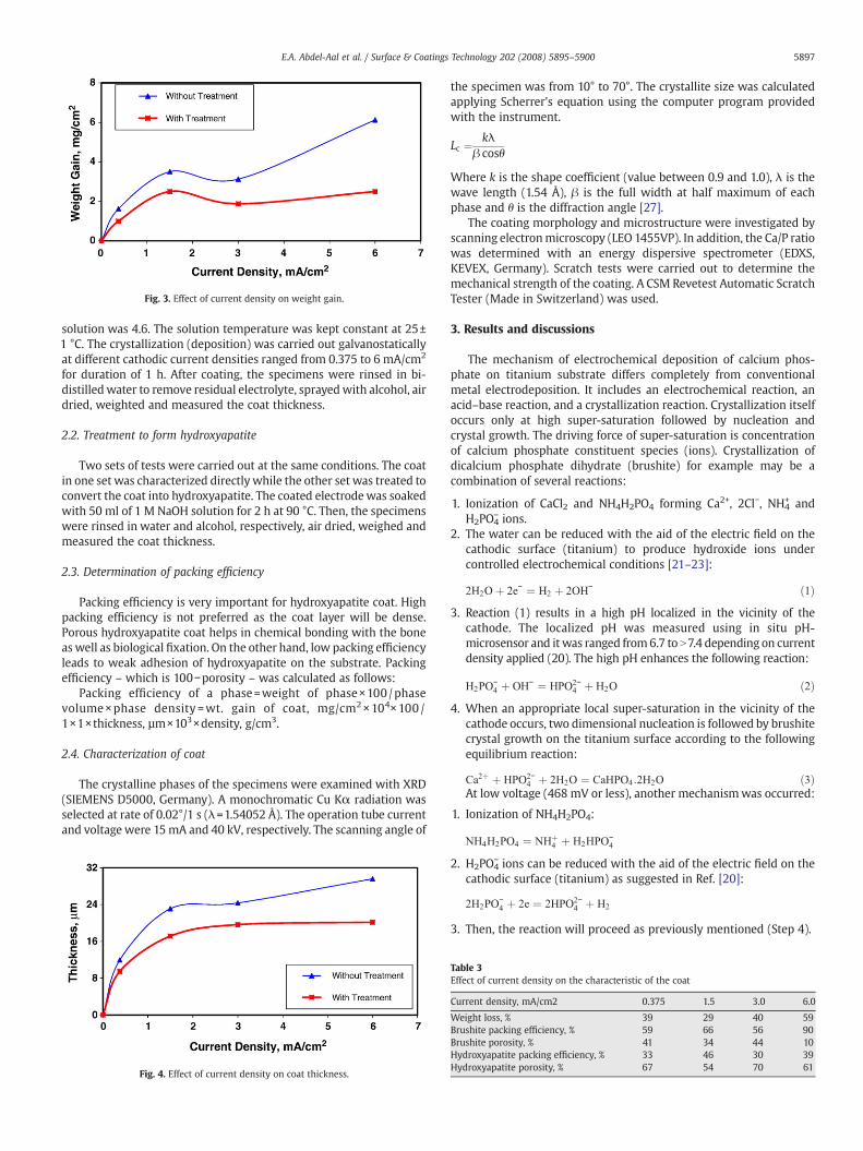
Fig. 3. Effect of current density on weight gain.
5897E.A. Abdel-Aal et al. / Surface & Coatings Technology 202 (2008) 5895–5900
solution was 4.6. The solution temperature was kept constant at 25±1 °C. The crystallization (deposition) was carried out galvanostaticallyat different cathodic current densities ranged from 0.375 to 6 mA/cm2
for duration of 1 h. After coating, the specimens were rinsed in bi-distilledwater to remove residual electrolyte, sprayedwith alcohol, airdried, weighted and measured the coat thickness.
2.2. Treatment to form hydroxyapatite
Two sets of tests were carried out at the same conditions. The coatin one set was characterized directly while the other set was treated toconvert the coat into hydroxyapatite. The coated electrodewas soakedwith 50 ml of 1 M NaOH solution for 2 h at 90 °C. Then, the specimenswere rinsed in water and alcohol, respectively, air dried, weighed andmeasured the coat thickness.
2.3. Determination of packing efficiency
Packing efficiency is very important for hydroxyapatite coat. Highpacking efficiency is not preferred as the coat layer will be dense.Porous hydroxyapatite coat helps in chemical bonding with the boneas well as biological fixation. On the other hand, low packing efficiencyleads to weak adhesion of hydroxyapatite on the substrate. Packingefficiency – which is 100−porosity – was calculated as follows:
Packing efficiency of a phase=weight of phase×100 /phasevolume×phase density =wt. gain of coat, mg/cm2×104×100 /1×1×thickness, µm×103×density, g/cm3.
2.4. Characterization of coat
The crystalline phases of the specimens were examined with XRD(SIEMENS D5000, Germany). A monochromatic Cu Kα radiation wasselected at rate of 0.02°/1 s (λ=1.54052 Å). The operation tube currentand voltage were 15mA and 40 kV, respectively. The scanning angle of
Fig. 4. Effect of current density on coat thickness.
the specimen was from 10° to 70°. The crystallite size was calculatedapplying Scherrer's equation using the computer program providedwith the instrument.
Lc ¼ kλβ cosθ
Where k is the shape coefficient (value between 0.9 and 1.0), λ is thewave length (1.54 Å), β is the full width at half maximum of eachphase and θ is the diffraction angle [27].
The coating morphology and microstructure were investigated byscanning electronmicroscopy (LEO 1455VP). In addition, the Ca/P ratiowas determined with an energy dispersive spectrometer (EDXS,KEVEX, Germany). Scratch tests were carried out to determine themechanical strength of the coating. A CSM Revetest Automatic ScratchTester (Made in Switzerland) was used.
3. Results and discussions
The mechanism of electrochemical deposition of calcium phos-phate on titanium substrate differs completely from conventionalmetal electrodeposition. It includes an electrochemical reaction, anacid–base reaction, and a crystallization reaction. Crystallization itselfoccurs only at high super-saturation followed by nucleation andcrystal growth. The driving force of super-saturation is concentrationof calcium phosphate constituent species (ions). Crystallization ofdicalcium phosphate dihydrate (brushite) for example may be acombination of several reactions:
1. Ionization of CaCl2 and NH4H2PO4 forming Ca2+, 2Cl−, NH4+ and
H2PO4− ions.
2. The water can be reduced with the aid of the electric field on thecathodic surface (titanium) to produce hydroxide ions undercontrolled electrochemical conditions [21–23]:
2H2O þ 2e− ¼ H2 þ 2OH− ð1Þ3. Reaction (1) results in a high pH localized in the vicinity of the
cathode. The localized pH was measured using in situ pH-microsensor and it was ranged from6.7 to N7.4 depending on currentdensity applied (20). The high pH enhances the following reaction:
H2PO−4 þ OH− ¼ HPO2−
4 þ H2O ð2Þ4. When an appropriate local super-saturation in the vicinity of the
cathode occurs, two dimensional nucleation is followed by brushitecrystal growth on the titanium surface according to the followingequilibrium reaction:
Ca2þ þ HPO2−4 þ 2H2O ¼ CaHPO4:2H2O ð3Þ
At low voltage (468 mV or less), another mechanismwas occurred:
1. Ionization of NH4H2PO4:
NH4H2PO4 ¼ NHþ4 þ H2HPO
−4
2. H2PO4− ions can be reduced with the aid of the electric field on the
cathodic surface (titanium) as suggested in Ref. [20]:
2H2PO−4 þ 2e ¼ 2HPO2−
4 þ H2
3. Then, the reaction will proceed as previously mentioned (Step 4).
Table 3Effect of current density on the characteristic of the coat
Current density, mA/cm2 0.375 1.5 3.0 6.0
Weight loss, % 39 29 40 59Brushite packing efficiency, % 59 66 56 90Brushite porosity, % 41 34 44 10Hydroxyapatite packing efficiency, % 33 46 30 39Hydroxyapatite porosity, % 67 54 70 61

Fig. 5. XRD Pattern of crystallized calcium phosphate on titanium substrate at different current densities.
Table 4Effect of current density on the characteristic of crystallized calcium phosphate
Current density, mA/cm2 0.375 1.5 3.0 6.0
Ca/P ratio 0.98 1.06 1.06 1.09Phase Brushite Brushite Brushite BrushiteCrystallite size, nm 72 71 63 68
5898 E.A. Abdel-Aal et al. / Surface & Coatings Technology 202 (2008) 5895–5900
3.1. Relation between potential and current density
Potential difference or p.d. between two points is the amount ofwork that would need to be done on a unit electric charge to move itfrom one point to the other against an electric field. P.d. is synonymouswith voltage and is measured in volts [28]. Voltage (sometimes alsocalled electric or electrical tension) is the difference of electricalpotential between two points of an electrical or electronic circuit,expressed in volts [28].
A series of experiments was carried out using current densitiesranged from 0.375 to 6 mA/cm2 for 1 h deposition duration. Theobtained potential results are given in Fig. 2. It is clear that at the firstminute of operation, high current density gave high potential. Afterthat, from 1 to 15 min, the highest potential obtained at 3 mA/cm2
current density. 1.5 mA/cm2 current density gave the highest potentialfrom about 15 to 30 min, and from about 30 min to end of test, 6 mA/cm2 current density gave the highest potential. This is related to theconductivity, phase type, and deposition rate of calcium phosphateeither on titanium substrate or on the bottom of the cell.
3.2. Effect of current density on coat thickness and weight gain
Two sets of experiments were carried out using current densitiesranged from 0.375 to 6 mA/cm2 for 1 h deposition duration (with andwithout treatment). The obtained results are given in Fig. 3 and 4. Itclearly shows a rapid increase in coat thickness and weight gain untilcurrent density 1.5 mA/cm2, followed by lower increase in coatthickness up to 6 mA/cm2.
The formed coat comprises dicalcium phosphate dihydrate,brushite (CaHPO4 ·2H2O) which was proven by XRD. Brushite waselectrochemically deposited according to the following chemicalequation:
NH4H2PO4 þ CaCl2 þ 2H2O→CaHPO4:2H2O þ NH4Clþ HCl ð4ÞThe formation of HCl dropped the pH of the solution from4.6 at the
beginning to 3.9 at the end of the test. The conversion of brushite tohydroxyapatite was carried out according to the following chemicalequations:
3CaHPO4:2H2O þ 3NaOH→Ca3ðPO4Þ2 þ Na3PO4 þ 9H2O ð5Þ
10Ca3ðPO4Þ2 þ 6NaOH→3Ca10ðPO4Þ6ðOHÞ2 þ 2Na3PO4 ð6ÞTheoretically calculated, brushite weight is decreased by 41.6% for
transformation to hydroxyapatite; correspondingly the weight andthe thickness of the deposited films were decreased (Fig. 3 and 4).
On the other hand, with increasing current density from 3 to 6mA/cm2, a remarkable increase in weight gain before film treatment wasobtained (Fig. 3). The higher increase in weight gain and the smallerincrease in coat thickness at 6 mA/cm2 current density (Fig. 4) indicatethat a higher crystal packing was obtained. High current densityincreases super-saturation and consequently increases both nuclea-tion and crystal growth consequently resulting in high thickness aswell as a high weight gain of the coating. Packing efficiency wascalculated and given in Table 3. Evidently, brushite packing efficiencyat 6 mA/cm2 is very high and reaches 90%.
3.3. Characterization of electrodeposited crystals
3.3.1. Without treatmentXRD, SEM, and EDXS were used for characterization of the
electrodeposited crystalline coatings. XRD results are given in Fig. 5.Peaks of titanium appeared due to the coat thickness below 50 µm.The crystallized phase was confirmed as dicalcium phosphatedihydrate (brushite) at all the studied current densities. The crystallitesize ranged from 63 to 72 nm as shown in Table 4.
Fig. 6 shows SEM images of the coat at different current densities.At 0.375 mA/cm2 current density, the crystallized coat consists ofplate-like crystals, stacking rigidly to the surface of the titaniumsubstrate and with each others. At 1.5 and 3.0 mA/cm2 currentdensities, the crystallized coats consist of needle-like crystals, stackingrigidly with the surface of titanium substrate and with each others.However, at 6.0 mA/cm2 current density, the crystallized coat consistsof agglomerated needle-like crystals, stacking loosely with eachothers forming pores in between.
Table 4 shows Ca/P ratios as obtained by EDXS which confirm thecrystallized phase as brushite. It is clear that even at high currentdensity (6 mA/cm2), no hydroxyapatite was directly electrodeposited.This is due to the corresponding potential (Fig. 2) was low less than 5 Vand the corresponding voltage was also low (468 mV).
3.3.2. With treatmentAfter treatment of the deposited brushite coats the converted
layers were characterized using XRD, SEM, and EDXS. XRD results are

Fig. 6. SEM of crystallized brushite on titanium substrate.
5899E.A. Abdel-Aal et al. / Surface & Coatings Technology 202 (2008) 5895–5900
given in Fig. 7. Likewise the peaks titanium appear due to the coatthickness below 30 µm. The crystallized phase was confirmed ashydroxyapatite at all studied current densities. In addition, the sampleelectrocrystallized at 0.375 mA/cm2 current density contains trical-cium phosphate and brushite. In this sample, the relative ratio ofhydroxyapatite to tricalcium phosphate to brushite is 34.8:5.3:1.0.This was also confirmed by solubility in hydrochloric acid.
The crystallite size ranged from 12 to 18 nm as shown in Table 5.Fig. 8 shows SEM images of the treated coats deposited at different
current densities. For all studied current densities, the crystallizedcoat after treatment consists of needle-like crystals, stacking rigidlywith the surface of titanium substrate and with each others. At0.375 mA/cm2 current density, the crystallized coat additionallycontains some plate-like crystals as the sample it still containingbrushite.
Fig. 7. XRD Pattern of crystallized calcium phosphate on titanium substrate at differentcurrent densities.
Table 5 shows Ca/P ratios obtained by EDXS. At 0.375 mA/cm2
current density, the crystallized coat contains hydroxyapatite, trical-cium phosphate and brushite. It may be the well crystallized brushiteat 0.375 mA/cm2 current density (Fig. 6) needs longer time forcomplete conversion to hydroxyapatite.
The theoretical value for hydroxyapatite is 1.67. The specificationsof applied HA coat range from 1.67 to 1.76. Higher Ca/P ratio than thetheoretical may be due to the hydroxyapatite contains high Ca/P ratioother compounds (such as Ca4P2O9) or it contains calcium carbonateas the purity is N95%. The Ca/P ratio (1.78) of the sample coated at1.5 mA/cm2 is very near to these specifications.
4. Conclusions
Dicalcium phosphate dihydrate was electrocrystallized on tita-nium substrate at different current densities (0.375, 1.5, 3, 6 mA/cm2)using equal volumes of 0.167 M CaCl2 solution and 0.1 M NH4H2PO4
solution. Prior treatment with sodium hydroxide, the surfacemorphology changed from plate-like crystals to needle-like crystalswith increasing the applied current density from 0.375 to 6 mA/cm2.At all current densities tested, the coating is brushite (dicalciumphosphate dihydrate CaHPO4 ·2H2O).
Coating thickness and weight gain are increased and themorphology changed with increasing deposition current density(from 0.375 V to 6 mA/cm2). Thickness and weight gain of theconverted coatings are decreased by sodium hydroxide treatment.Coating thickness at 6 mA/cm2 was about 20 and 30 µm with and
Table 5Effect of current density on the characteristic of treated calcium phosphate with sodiumhydroxide
Current density, mA/cm2 0.375 1.5 3.0 6.0
Ca/P ratio 1.57 1.78 1.59 1.86Phase HA, TCP, B HA HA HACrystallite size, nm 15 14 18 12
HA: Hydroxyapatite, TCP: Tricalcium phosphate, B: Brushite.

Fig. 8. SEM of Crystallized hydroxyapatite on titanium substrate.
5900 E.A. Abdel-Aal et al. / Surface & Coatings Technology 202 (2008) 5895–5900
without treatment, respectively. It decreased to about 9.5 and 12 µm at0.375 mA/cm2 current density, with and without treatment, respec-tively. It was interesting that crystalline phase of hydroxyapatite [Ca10(PO4)6(OH)2] is not directly formed even at high current density(6mA/cm2). This is due to the corresponding potential was low less than 5 Vand the corresponding voltage was also low (468 mV).
Acknowledgements
The authors would like to highly acknowledge DAADOffice at Cairofor granting Prof. E.A. Abdel-Aal scientific mission for 2 Months inChemnitz University of Technology. Without this grant, this paper wasimpossible to be achieved. The authors are acknowledged Dr. G. Alischfor his helpful discussions. Also, the authors are highly appreciated thecooperation of Mrs. E. Benedix for electrodeposition tests, Mrs. G.Fritsche for XRD analyses, and Mrs. Ch. Schmidt for scratch tests. ALUCOLOR Corporation, Germany, we are grateful for providing titanium.
References
[1] L.L. Hench, J. Am. Ceram. Soc. 74 (7) (1991) 1487.[2] M.C. Kuo, S.K. Yen, Mater. Sci. Eng., C 20 (2002) 153.[3] M. Jarcho, Clin Orthop Relat R. 157 (1981) S.259.[4] S.D. Cook, K.A. Thomas, J.F. Kay, M. Jarcho, Clin. Orthop. Relat. Res. 230 (1988) 225.[5] K. De Groot, R. Geesink, C.P. Klein, P. Serekian, J. Biomed. Materi. Res. 21 (1987)
1375.[6] Y. Yang, K.H. Kim, J.L. Ong, Biomaterials 26 (2005) 327.[7] L. Sun, C.C. Berndt, K.A. Gross, A. Kucuk, J Biomed Mater Res (Appl Biomater) 58
(2001) 570.
[8] V. Sergo, O. Sbaizero, D.R. Clarke, Biomaterials 18 (1997) 477.[9] K. Van Dijk, H.G. Schaeken, J.G.G. Wolke, J.A. Jansen, Biomaterials 17 (1998) 159.[10] K. Yamashita, T. Arashi, K. Kitagaki, S. Yamada, T. Umegaki, J. Am. Ceram. Soc. 77 (9)
(1994) 2401.[11] C.F. Feng, K.A. Khor, E.J. Liu, P. Cheang, Scripta Mater. 42 (1) (1999) 103.[12] S.R. Radin, P. Ducheyne, J. Mater. Sci., Mater. Med. 3 (1992) 33.[13] C.K. Wang, J.H. Chern Lin, Biomaterials 18 (1997) 1331.[14] G. Jiang, D. Shi, Coating of Hydroxyapatite on Highly Porous Al2O3 Substrate for
Bone Substituates, Wiley, 1997, p. 77.[15] R. Damodaran, B.M. Moudgil, Colloid. Surf. A 80 (1993).[16] M. Shirkhanzadeh, J. Mater. Sci. Med. 6 (1995) 90.[17] M. Manso, C. Jimenez, C. Morant, P. Herrero, J.M. Martinez-Duart, Biomaterials 21
(2000) 1755.[18] X. Hou, X. Liu, J. Xu, J. Shen, X. Liu, Mater. lett. 50 (2001) 103.[19] FDA, Calcium Phosphate (Ca–P) Coating Draft Guidance for Preparation of FDA
Submissions for Orthopedic and Dental Endosseous Implants, Food and DrugAdministration, Washington, DC, 1992, p. 1.
[20] ISO, Implants for Surgery: Coating for Hydroxyapatite Ceramics, ISO, 1996, p. 1.[21] C. Chu, X. Xue, J. Zhu, Z. Yin, Mater. Sci. Eng. A 429 (2006) 18.[22] N. Dumelie, H. Benhayoune, C. Rousse-Bertrand, S. Bouthors, A. Perchet, L.
Wortham, J. Douglade, D. Laurent-Maquin, G. Balossier, Thin Solid Films 492(2005) 131.
[23] J.M. Zhang, C.J. Lin, Z.D. Feng, Z.W. Tian, J. Electroanal. Chem. 452 (1998) 235.[24] S.K. Yen, C.M. Lin, Mater. Chem. Phys. 77 (2002) 70.[25] Yuan-yuan Zhang, Jie Tao, Ying-chun Pang,WeWang, TaoWang, Trans. Nonferrous
Met. Soc. China 16 (2006) 633.[26] Szu-Hao Wang, Wei-Jen Shih, Wang-Long Li, Min-Hsiung Hon, Moo-Chin Wang,
J. Eur. Ceram. Soc. 25 (2005) 3287.[27] C.C. Silva, A.G. Pinheiro, M.A.R. Miranda, J.C. Góes, A.S.B. Sombra, Solid State Sci. 5
(2003) 553.[28] A Dictionary of Physics. Ed. John Daintith. Oxford University Press, 2000. Oxford
Reference Online. Oxford University Press.