Stimuli-responsive nanoparticles from ionic cellulose derivatives
Upload
khangminh22Category
view
3download
0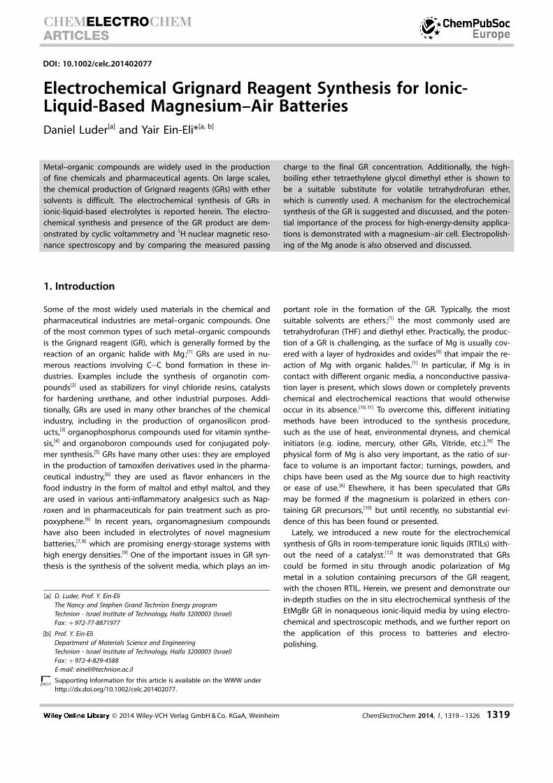
DOI: 10.1002/celc.201402077
Electrochemical Grignard Reagent Synthesis for Ionic-Liquid-Based Magnesium–Air BatteriesDaniel Luder[a] and Yair Ein-Eli*[a, b]
1. Introduction
Some of the most widely used materials in the chemical andpharmaceutical industries are metal–organic compounds. Oneof the most common types of such metal–organic compoundsis the Grignard reagent (GR), which is generally formed by thereaction of an organic halide with Mg;[1] GRs are used in nu-merous reactions involving C�C bond formation in these in-dustries. Examples include the synthesis of organotin com-pounds[2] used as stabilizers for vinyl chloride resins, catalystsfor hardening urethane, and other industrial purposes. Addi-tionally, GRs are used in many other branches of the chemicalindustry, including in the production of organosilicon prod-ucts,[3] organophosphorus compounds used for vitamin synthe-sis,[4] and organoboron compounds used for conjugated poly-mer synthesis.[5] GRs have many other uses: they are employedin the production of tamoxifen derivatives used in the pharma-ceutical industry,[6] they are used as flavor enhancers in thefood industry in the form of maltol and ethyl maltol, and theyare used in various anti-inflammatory analgesics such as Nap-roxen and in pharmaceuticals for pain treatment such as pro-poxyphene.[6] In recent years, organomagnesium compoundshave also been included in electrolytes of novel magnesiumbatteries,[7, 8] which are promising energy-storage systems withhigh energy densities.[9] One of the important issues in GR syn-thesis is the synthesis of the solvent media, which plays an im-
portant role in the formation of the GR. Typically, the mostsuitable solvents are ethers ;[1] the most commonly used aretetrahydrofuran (THF) and diethyl ether. Practically, the produc-tion of a GR is challenging, as the surface of Mg is usually cov-ered with a layer of hydroxides and oxides[6] that impair the re-action of Mg with organic halides.[1] In particular, if Mg is incontact with different organic media, a nonconductive passiva-tion layer is present, which slows down or completely preventschemical and electrochemical reactions that would otherwiseoccur in its absence.[10, 11] To overcome this, different initiatingmethods have been introduced to the synthesis procedure,such as the use of heat, environmental dryness, and chemicalinitiators (e.g. iodine, mercury, other GRs, Vitride, etc.).[6] Thephysical form of Mg is also very important, as the ratio of sur-face to volume is an important factor ; turnings, powders, andchips have been used as the Mg source due to high reactivityor ease of use.[6] Elsewhere, it has been speculated that GRsmay be formed if the magnesium is polarized in ethers con-taining GR precursors,[10] but until recently, no substantial evi-dence of this has been found or presented.
Lately, we introduced a new route for the electrochemicalsynthesis of GRs in room-temperature ionic liquids (RTILs) with-out the need of a catalyst.[12] It was demonstrated that GRscould be formed in situ through anodic polarization of Mgmetal in a solution containing precursors of the GR reagent,with the chosen RTIL. Herein, we present and demonstrate ourin-depth studies on the in situ electrochemical synthesis of theEtMgBr GR in nonaqueous ionic-liquid media by using electro-chemical and spectroscopic methods, and we further report onthe application of this process to batteries and electro-polishing.
Metal–organic compounds are widely used in the productionof fine chemicals and pharmaceutical agents. On large scales,the chemical production of Grignard reagents (GRs) with ethersolvents is difficult. The electrochemical synthesis of GRs inionic-liquid-based electrolytes is reported herein. The electro-chemical synthesis and presence of the GR product are dem-onstrated by cyclic voltammetry and 1H nuclear magnetic reso-nance spectroscopy and by comparing the measured passing
charge to the final GR concentration. Additionally, the high-boiling ether tetraethylene glycol dimethyl ether is shown tobe a suitable substitute for volatile tetrahydrofuran ether,which is currently used. A mechanism for the electrochemicalsynthesis of the GR is suggested and discussed, and the poten-tial importance of the process for high-energy-density applica-tions is demonstrated with a magnesium–air cell. Electropolish-ing of the Mg anode is also observed and discussed.
[a] D. Luder, Prof. Y. Ein-EliThe Nancy and Stephen Grand Technion Energy programTechnion - Israel Institute of Technology, Haifa 3200003 (Israel)Fax: + 972-77-8871977
[b] Prof. Y. Ein-EliDepartment of Materials Science and EngineeringTechnion - Israel Institute of Technology, Haifa 3200003 (Israel)Fax: + 972-4-829-4588E-mail : [email protected]
Supporting Information for this article is available on the WWW underhttp://dx.doi.org/10.1002/celc.201402077.
� 2014 Wiley-VCH Verlag GmbH & Co. KGaA, Weinheim ChemElectroChem 2014, 1, 1319 – 1326 1319
CHEMELECTROCHEMARTICLES
1.1 Room-Temperature Ionic-Liquid-Based Electrolyte
The electrolyte media used is based on RTILs that were re-searched seriously for the past two decades as electrolytemedia.[13–16] Generally, these solvents are liquids at room tem-perature and are purely composed of ions; the positive speciesis typically an organic, bulky, and asymmetric charged cation.Examples include derivatives of pyrrolidinium, imidazolium,pyridinium ammonium, and phosphonium.[17–19] The negativespecies is an organic or inorganic charged anion ranging froma simple halide to the larger and charge-delocalized trifluoro-methanesulfonate (triflate) and bis(trifluoromethylsulfonyl)-imide (TFSI) anions.[17, 18] These liquids are advantageous formany existing and potential applications owing to their charac-teristics, such as chemical and thermal stability, a wide electro-chemical window,[17] high conductivity, low vapor pressure, noflammability, environmental friendliness, general nontoxicity,and the ability to tweak different properties by minutelyadding or subtracting functional groups on the cation.[17]
Thanks to these properties, RTILs have found many applica-tions in diverse areas such as bioscience, CO2 capture, organicsynthesis, and energy management.[20] In particular, a largenumber of uses have been found in electrochemistry for appli-cations such as electrodeposition, batteries, fuel cells, solarcells, and capacitors.[21–24] In the area of Mg electrochemistry,certain nonacidic ionic liquids such as [1-butyl-1-methylpyrroli-dinium bis(trifluoromethylsulfonyl)imide] (BMPTFSI) and [N,N-diethyl-N-methyl-N-(2-methoxyethyl) ammonium bis(trifluoro-methanesulfonyl)imide] (DEMETFSI) have been found to besuitable as cosolvents for externally added GRs such as phenyl-magnesium bromide (PhMgBr) and ethylmagnesium bromide(EtMgBr).[14, 16]
In the current study, an RTIL-based electrolyte is applied forthe electrochemical organic synthesis of the EtMgBr GR. Theelectrolyte is composed of BMPTFSI, bromoethane (EtBr) as theGR precursor, and THF as a product stabilizer, which isa common and less volatile ether than alternatives such as di-ethyl ether. We also show that the high-boiling ether tetraethy-lene glycol dimethyl ether (TEGDME, b.p. 270 8C) can be usedas a substitute for THF. During the reaction, Mg dissolves atthe electrode surface after the application of a positive poten-tial and reacts with EtBr to form the final GR product withoutthe presence of any chemical catalysts.
The potential importance of the process for future high-energy-density applications in research and development isshown by using the electrolyte in the discharge of a magnesi-um–air cell. Additionally, a parallel magnesium electropolishingphenomenon is discussed.
2. Results and Discussion
2.1 Cyclic Voltammetry Studies and Electrochemical WindowEvaluation
For electrochemical processes in general, particularly those re-quiring dryness, it is desirable to use nonaqueous electrolyteswith wide electrochemical windows. Figure 1 a presents the
electrochemical windows of BMPTFSI and an electrolyte com-posed of BMPTFSI + THF (1:1 v/v).
A particularly wide electrochemical window of about 5.5 Vcan be observed for BMPTFSI. This result is in good agreementwith previous studies,[18] which makes it advantageous asa stable electrolyte cosolvent for the synthesis of GRs, togetherwith its other general advantages such chemical and thermalstability and low vapor pressure.[17] The presence of THF in thesolution should stabilize the GR product[6] and increase theconductivity of the electrolyte.[14] It is, however, observablefrom Figure 1 a that the addition of THF in 1:1 volume ratiowith BMPTFSI narrows the electrochemical window of the solu-tion by about 1.9 V.
To synthesize EtMgBr, a cell was assembled with theBMPTFSI + THF + EtBr (1:1:0.3 v/v) electrolyte. Figure 1 b pres-ents the results of two cyclic voltammetry (CV) experimentsconducted with the mentioned cell and electrolyte; the work-ing electrode was Mg, and the counter electrode was Pt andMg in two separate CV experiments (anodic direction first). Theelectrochemical window of the electrolyte is presented forcomparison.
In contrast to expectations with organic electrolytes, uponactivation of the CV experiment no anodic or cathodic reactionoverpotential was observed;[10] the anodic reaction occurredimmediately with the application of a potential and no evi-
Figure 1. A) CV curves illustrating the electrochemical window of the ionicliquid BMPTFSI and of BMPTFSI + THF (1:1 v/v). Pt served as both the work-ing and counter electrodes. B) CV of a cell employing a magnesium workingelectrode in BMPTFSI + THF + EtBr (1:1:0.3 v/v) electrolyte with a platinumcounter electrode (gray) and a magnesium counter electrode (blue).BMPTFSI + THF + EtBr (1:1:0.3 v/v) with Pt as both working and counter elec-trodes (green dashed). Scan rate employed in all CVs was 5 mV s�1.
� 2014 Wiley-VCH Verlag GmbH & Co. KGaA, Weinheim ChemElectroChem 2014, 1, 1319 – 1326 1320
CHEMELECTROCHEMARTICLES www.chemelectrochem.org

dence of any Mg passivation layer was observed despite thefact that the Mg anode was immersed in an organic medium.This is despite the usual characteristic presence of a noncon-ductive passivating layer that inhibits the charge transport,[10]
even if the surface is only exposed to an inert atmospherebefore immersion. This can be explained by interaction of theMg surface with this specific electrolyte, which is different inmanner than that with other organic solvents with or withoutmagnesium salts, mainly through the reactivity of Mg to EtBr,as hypothesized and explained elsewhere.[10]
It can be concluded from the curves presented in Figure 1 bthat chemically reversible dissolution and deposition of Mg inthe electrolyte occurs upon the application of the cyclic scan-ning. The deposition of Mg back onto the working electrodewithout electrolyte decomposition occurs only up to a lowovervoltage of about 300 mV. The dissolution of Mg occurswithout a parallel reaction involving the decomposition of theelectrolyte. The corrosion current is derived from linear fittingof both the anodic and cathodic potentiodynamic profiles (aTafel fit and potentiodynamic curves are shown in Figure 2) byusing the same cell and electrolyte as that described above.
The observed corrosion current was approximately20 mm cm2. It was also found that the corrosion rate did notchange substantially after different time intervals or after con-ducting additional CV experiments.
2.2 Potentiostatic Process and Analysis by using NMRSpectroscopy
To synthesize EtMgBr with a controlled concentration, a contin-uous constant potential of 0.2 V versus Mg was applied toa cell by utilizing Mg working and counter electrodes (electro-lyte: BMPTFSI + THF + EtBr = 1:1:0.3 v/v), whereas the totalcharge passed through was calculated to be 0.805 C. The po-tentiostatic (current transient) curve is presented in Figure 3.
To determine the molecular structure of the species includ-ing the dissolved Mg, 1H NMR spectroscopy was used asa useful analytic tool, as Mg is part of an organometallic struc-ture[25] such as the proposed electrochemical EtMgBr product.
Moreover, this technique offers the possibility to indirectly cal-culate the product concentration.
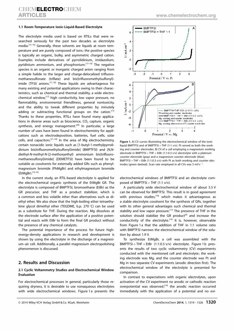
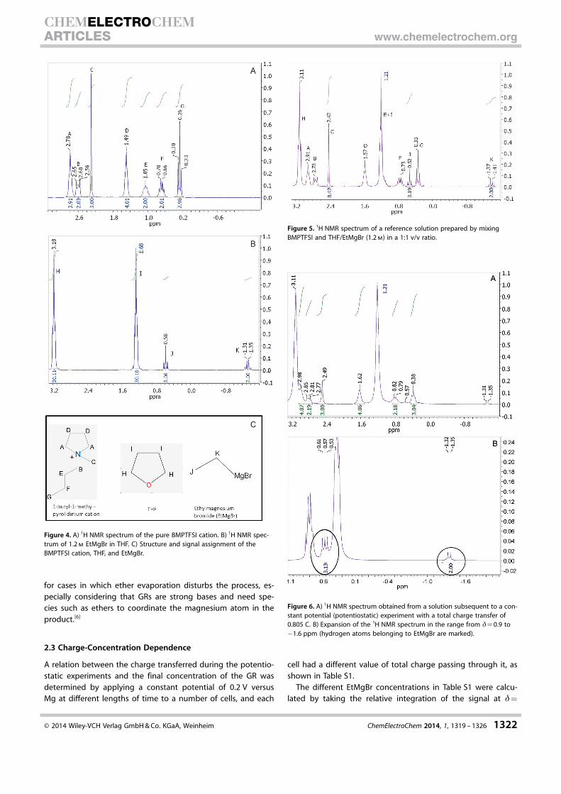
Figure 4 a presents the 1H NMR spectrum of the pyrrolidini-um-based cation (1-butyl-1-methylpyrrolidinium) in the ionicliquid BMPTFSI after drying, and Figure 4 b presents the spec-trum of EtMgBr in THF (1.2 m). The molecular structures andsignal assignments of the mentioned species are presented inFigure 4 c. Once the location of the main signals was estab-lished, an external reference solution was prepared by mixingBMPTFSI with THF/EtMgBr (1.2 m EtMgBr in THF) in a volumetricratio of 1:1. Figure 5 presents the1H NMR spectrum of theabove solution. The structures and signal assignments of themolecules from this graph are also represented in Figure 4 c.
As can clearly be seen, the spectral footprint of EtMgBr isobserved at chemical shifts of d�0.53 (triplet, J) and�1.39 ppm (quartet, K) upon taking into consideration thesignal identities of BMPTFSI, THF, and EtMgBr from Figure 4 a–c. The latter signal is most easily isolated and served as themethod of detection and calculation for the mentioned GR.The 1H NMR spectra of the electrolyte after a constant poten-tial (potentiostatic) experiment (total charge transfer : 0.805 C,see Table S1 in the Supporting Information) are presented inFigure 6. The spectra include the same chemical shifts and Hcoupling as seen with the reference solution sample inFigure 5. More importantly, there is proof of the existence ofEtMgBr in the solution after the potentiostatic experiment. Thiscan be seen at d= 0.57 and �1.33 ppm in Figure 6 a, whichcorrespond to EtMgBr as previously seen for the reference so-lution (signals at d= 0.53 and �1.39 ppm in Figure 5); this canbe seen more clearly in the expansion of the d= 0.9 to�1.6 ppm range in Figure 6 b, in which the spectrum unequiv-ocally belonging to EtMgBr is marked.
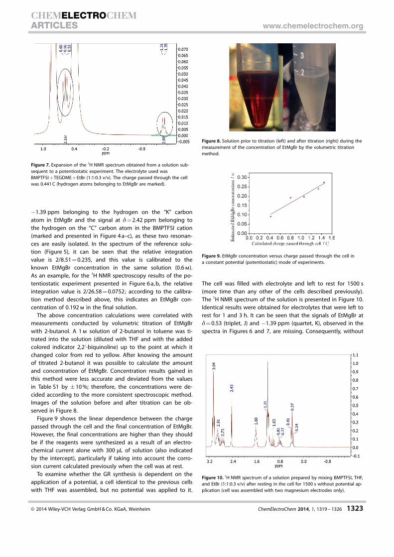
Given that THF is a relatively volatile ether (b.p. 66 8C), an al-ternative high-boiling ether was also considered for this pro-cess. Figure 7 presents the 1H NMR spectrum taken subsequentto a potentiostatic experiment conducted with the same elec-trolyte and cell as presented in Figure 6 a, b; however, this timeTHF was replaced by TEGDME, an ether with a boiling point of270 8C (electrolyte: BMPTFSI + TEGDME + EtBr = 1:1:0.3 v/v,charge passed through cell : 0.441 C). The signal of the hydro-gen atoms belonging to EtMgBr can be observed in the samemanner as that observed in Figure 6 b, for which the support-ing ether was THF. Thus, this ether can be used instead of THF
Figure 2. Anodic and cathodic potentiodynamic polarization profiles and af-filiated linear polarization fitting of Mg working electrode in BMPTFSI +THF + EtBr (1:1:0.3 v/v) electrolyte. Mg metal served as a counter electrodeand the scan rate employed was 5 mV s�1.
Figure 3. Potentiostatic synthesis of EtMgBr with a controlled concentrationat 0.2 V vs. Mg. Electrolyte used was BMPTFSI + THF + EtBr (1:1:0.3 v/v).Magnesium metal serves as both the working and counter electrodes.
� 2014 Wiley-VCH Verlag GmbH & Co. KGaA, Weinheim ChemElectroChem 2014, 1, 1319 – 1326 1321
CHEMELECTROCHEMARTICLES www.chemelectrochem.org
for cases in which ether evaporation disturbs the process, es-pecially considering that GRs are strong bases and need spe-cies such as ethers to coordinate the magnesium atom in theproduct.[6]
2.3 Charge-Concentration Dependence
A relation between the charge transferred during the potentio-static experiments and the final concentration of the GR wasdetermined by applying a constant potential of 0.2 V versusMg at different lengths of time to a number of cells, and each
cell had a different value of total charge passing through it, asshown in Table S1.
The different EtMgBr concentrations in Table S1 were calcu-lated by taking the relative integration of the signal at d=
Figure 4. A) 1H NMR spectrum of the pure BMPTFSI cation. B) 1H NMR spec-trum of 1.2 m EtMgBr in THF. C) Structure and signal assignment of theBMPTFSI cation, THF, and EtMgBr.
Figure 5. 1H NMR spectrum of a reference solution prepared by mixingBMPTFSI and THF/EtMgBr (1.2 m) in a 1:1 v/v ratio.
Figure 6. A) 1H NMR spectrum obtained from a solution subsequent to a con-stant potential (potentiostatic) experiment with a total charge transfer of0.805 C. B) Expansion of the 1H NMR spectrum in the range from d= 0.9 to�1.6 ppm (hydrogen atoms belonging to EtMgBr are marked).
� 2014 Wiley-VCH Verlag GmbH & Co. KGaA, Weinheim ChemElectroChem 2014, 1, 1319 – 1326 1322
CHEMELECTROCHEMARTICLES www.chemelectrochem.org
�1.39 ppm belonging to the hydrogen on the “K” carbonatom in EtMgBr and the signal at d= 2.42 ppm belonging tothe hydrogen on the “C” carbon atom in the BMPTFSI cation(marked and presented in Figure 4 a–c), as these two resonan-ces are easily isolated. In the spectrum of the reference solu-tion (Figure 5), it can be seen that the relative integrationvalue is 2/8.51 = 0.235, and this value is calibrated to theknown EtMgBr concentration in the same solution (0.6 m).As an example, for the 1H NMR spectroscopy results of the po-tentiostatic experiment presented in Figure 6 a, b, the relativeintegration value is 2/26.58 = 0.0752; according to the calibra-tion method described above, this indicates an EtMgBr con-centration of 0.192 m in the final solution.
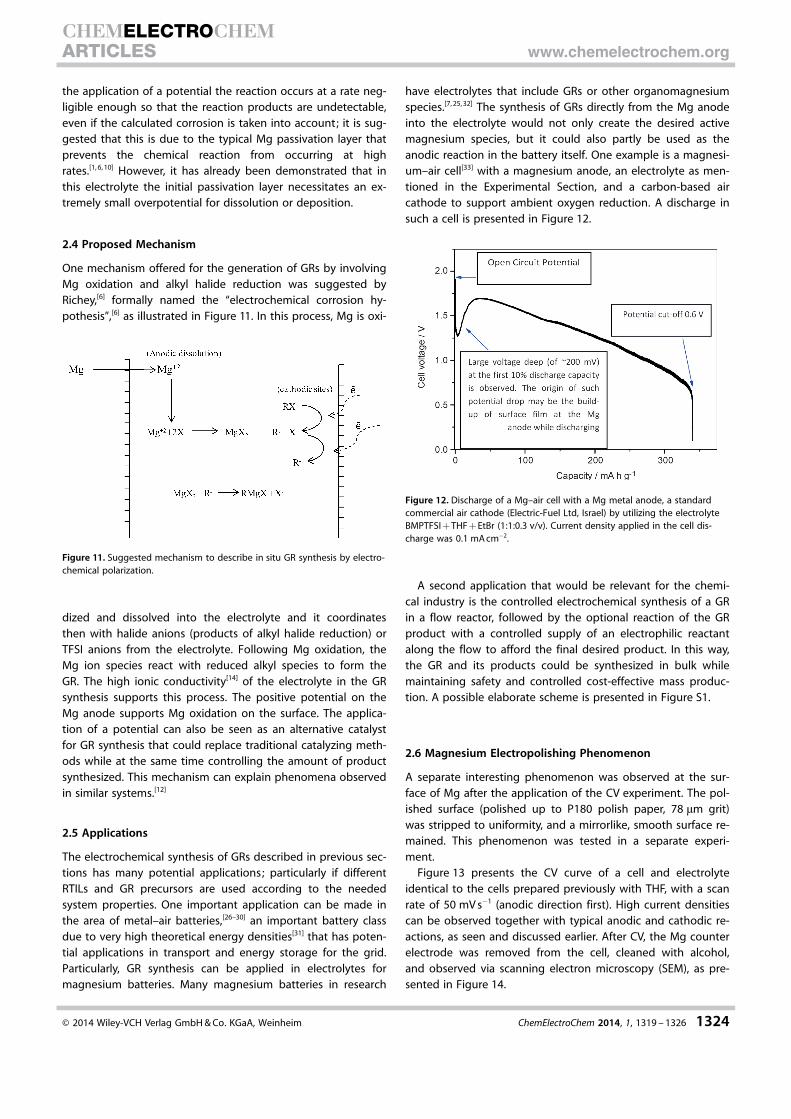
The above concentration calculations were correlated withmeasurements conducted by volumetric titration of EtMgBrwith 2-butanol. A 1 m solution of 2-butanol in toluene was ti-trated into the solution (diluted with THF and with the addedcolored indicator 2,2’-biquinoline) up to the point at which itchanged color from red to yellow. After knowing the amountof titrated 2-butanol it was possible to calculate the amountand concentration of EtMgBr. Concentration results gained inthis method were less accurate and deviated from the valuesin Table S1 by �10 %; therefore, the concentrations were de-cided according to the more consistent spectroscopic method.Images of the solution before and after titration can be ob-served in Figure 8.
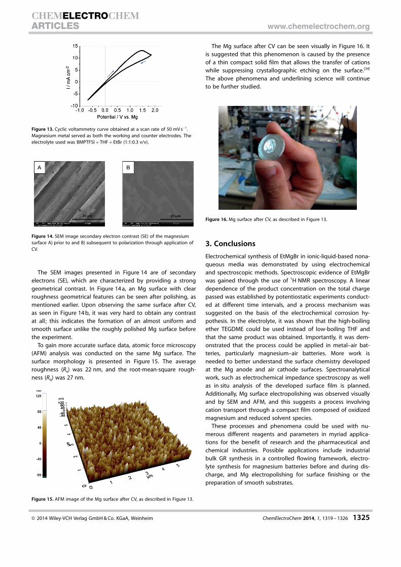
Figure 9 shows the linear dependence between the chargepassed through the cell and the final concentration of EtMgBr.However, the final concentrations are higher than they shouldbe if the reagents were synthesized as a result of an electro-chemical current alone with 300 mL of solution (also indicatedby the intercept), particularly if taking into account the corro-sion current calculated previously when the cell was at rest.
To examine whether the GR synthesis is dependent on theapplication of a potential, a cell identical to the previous cellswith THF was assembled, but no potential was applied to it.
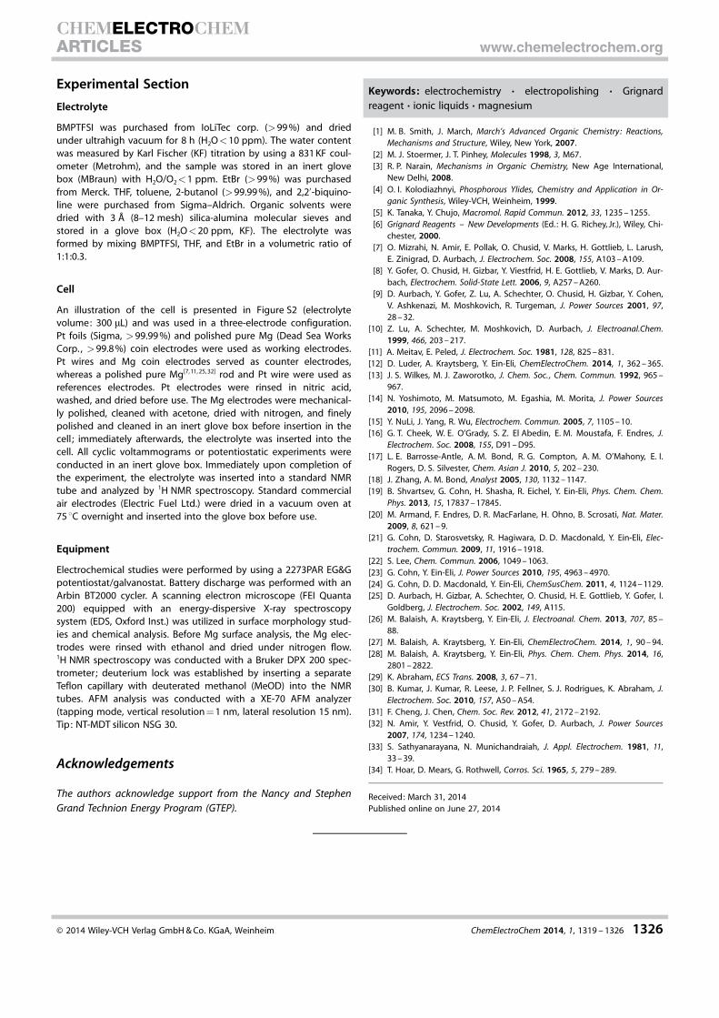
The cell was filled with electrolyte and left to rest for 1500 s(more time than any other of the cells described previously).The 1H NMR spectrum of the solution is presented in Figure 10.Identical results were obtained for electrolytes that were left torest for 1 and 3 h. It can be seen that the signals of EtMgBr atd= 0.53 (triplet, J) and �1.39 ppm (quartet, K), observed in thespectra in Figures 6 and 7, are missing. Consequently, without
Figure 7. Expansion of the 1H NMR spectrum obtained from a solution sub-sequent to a potentiostatic experiment. The electrolyte used wasBMPTFSI + TEGDME + EtBr (1:1:0.3 v/v). The charge passed through the cellwas 0.441 C (hydrogen atoms belonging to EtMgBr are marked).
Figure 8. Solution prior to titration (left) and after titration (right) during themeasurement of the concentration of EtMgBr by the volumetric titrationmethod.
Figure 9. EtMgBr concentration versus charge passed through the cell ina constant potential (potentiostatic) mode of experiments.
Figure 10. 1H NMR spectrum of a solution prepared by mixing BMPTFSI, THF,and EtBr (1:1:0.3 v/v) after resting in the cell for 1500 s without potential ap-plication (cell was assembled with two magnesium electrodes only).
� 2014 Wiley-VCH Verlag GmbH & Co. KGaA, Weinheim ChemElectroChem 2014, 1, 1319 – 1326 1323
CHEMELECTROCHEMARTICLES www.chemelectrochem.org
the application of a potential the reaction occurs at a rate neg-ligible enough so that the reaction products are undetectable,even if the calculated corrosion is taken into account; it is sug-gested that this is due to the typical Mg passivation layer thatprevents the chemical reaction from occurring at highrates.[1, 6, 10] However, it has already been demonstrated that inthis electrolyte the initial passivation layer necessitates an ex-tremely small overpotential for dissolution or deposition.
2.4 Proposed Mechanism
One mechanism offered for the generation of GRs by involvingMg oxidation and alkyl halide reduction was suggested byRichey,[6] formally named the “electrochemical corrosion hy-pothesis”,[6] as illustrated in Figure 11. In this process, Mg is oxi-
dized and dissolved into the electrolyte and it coordinatesthen with halide anions (products of alkyl halide reduction) orTFSI anions from the electrolyte. Following Mg oxidation, theMg ion species react with reduced alkyl species to form theGR. The high ionic conductivity[14] of the electrolyte in the GRsynthesis supports this process. The positive potential on theMg anode supports Mg oxidation on the surface. The applica-tion of a potential can also be seen as an alternative catalystfor GR synthesis that could replace traditional catalyzing meth-ods while at the same time controlling the amount of productsynthesized. This mechanism can explain phenomena observedin similar systems.[12]
2.5 Applications
The electrochemical synthesis of GRs described in previous sec-tions has many potential applications; particularly if differentRTILs and GR precursors are used according to the neededsystem properties. One important application can be made inthe area of metal–air batteries,[26–30] an important battery classdue to very high theoretical energy densities[31] that has poten-tial applications in transport and energy storage for the grid.Particularly, GR synthesis can be applied in electrolytes formagnesium batteries. Many magnesium batteries in research
have electrolytes that include GRs or other organomagnesiumspecies.[7, 25, 32] The synthesis of GRs directly from the Mg anodeinto the electrolyte would not only create the desired activemagnesium species, but it could also partly be used as theanodic reaction in the battery itself. One example is a magnesi-um–air cell[33] with a magnesium anode, an electrolyte as men-tioned in the Experimental Section, and a carbon-based aircathode to support ambient oxygen reduction. A discharge insuch a cell is presented in Figure 12.
A second application that would be relevant for the chemi-cal industry is the controlled electrochemical synthesis of a GRin a flow reactor, followed by the optional reaction of the GRproduct with a controlled supply of an electrophilic reactantalong the flow to afford the final desired product. In this way,the GR and its products could be synthesized in bulk whilemaintaining safety and controlled cost-effective mass produc-tion. A possible elaborate scheme is presented in Figure S1.
2.6 Magnesium Electropolishing Phenomenon
A separate interesting phenomenon was observed at the sur-face of Mg after the application of the CV experiment. The pol-ished surface (polished up to P180 polish paper, 78 mm grit)was stripped to uniformity, and a mirrorlike, smooth surface re-mained. This phenomenon was tested in a separate experi-ment.
Figure 13 presents the CV curve of a cell and electrolyteidentical to the cells prepared previously with THF, with a scanrate of 50 mV s�1 (anodic direction first). High current densitiescan be observed together with typical anodic and cathodic re-actions, as seen and discussed earlier. After CV, the Mg counterelectrode was removed from the cell, cleaned with alcohol,and observed via scanning electron microscopy (SEM), as pre-sented in Figure 14.
Figure 11. Suggested mechanism to describe in situ GR synthesis by electro-chemical polarization.
Figure 12. Discharge of a Mg–air cell with a Mg metal anode, a standardcommercial air cathode (Electric-Fuel Ltd, Israel) by utilizing the electrolyteBMPTFSI + THF + EtBr (1:1:0.3 v/v). Current density applied in the cell dis-charge was 0.1 mA cm�2.
� 2014 Wiley-VCH Verlag GmbH & Co. KGaA, Weinheim ChemElectroChem 2014, 1, 1319 – 1326 1324
CHEMELECTROCHEMARTICLES www.chemelectrochem.org
The SEM images presented in Figure 14 are of secondaryelectrons (SE), which are characterized by providing a stronggeometrical contrast. In Figure 14 a, an Mg surface with clearroughness geometrical features can be seen after polishing, asmentioned earlier. Upon observing the same surface after CV,as seen in Figure 14 b, it was very hard to obtain any contrastat all ; this indicates the formation of an almost uniform andsmooth surface unlike the roughly polished Mg surface beforethe experiment.
To gain more accurate surface data, atomic force microscopy(AFM) analysis was conducted on the same Mg surface. Thesurface morphology is presented in Figure 15. The averageroughness (Ra) was 22 nm, and the root-mean-square rough-ness (Rq) was 27 nm.
The Mg surface after CV can be seen visually in Figure 16. Itis suggested that this phenomenon is caused by the presenceof a thin compact solid film that allows the transfer of cationswhile suppressing crystallographic etching on the surface.[34]
The above phenomena and underlining science will continueto be further studied.
3. Conclusions
Electrochemical synthesis of EtMgBr in ionic-liquid-based nona-queous media was demonstrated by using electrochemicaland spectroscopic methods. Spectroscopic evidence of EtMgBrwas gained through the use of 1H NMR spectroscopy. A lineardependence of the product concentration on the total chargepassed was established by potentiostatic experiments conduct-ed at different time intervals, and a process mechanism wassuggested on the basis of the electrochemical corrosion hy-pothesis. In the electrolyte, it was shown that the high-boilingether TEGDME could be used instead of low-boiling THF andthat the same product was obtained. Importantly, it was dem-onstrated that the process could be applied in metal–air bat-teries, particularly magnesium–air batteries. More work isneeded to better understand the surface chemistry developedat the Mg anode and air cathode surfaces. Spectroanalyticalwork, such as electrochemical impedance spectroscopy as wellas in situ analysis of the developed surface film is planned.Additionally, Mg surface electropolishing was observed visuallyand by SEM and AFM, and this suggests a process involvingcation transport through a compact film composed of oxidizedmagnesium and reduced solvent species.
These processes and phenomena could be used with nu-merous different reagents and parameters in myriad applica-tions for the benefit of research and the pharmaceutical andchemical industries. Possible applications include industrialbulk GR synthesis in a controlled flowing framework, electro-lyte synthesis for magnesium batteries before and during dis-charge, and Mg electropolishing for surface finishing or thepreparation of smooth substrates.
Figure 13. Cyclic voltammetry curve obtained at a scan rate of 50 mV s�1.Magnesium metal served as both the working and counter electrodes. Theelectrolyte used was BMPTFSI + THF + EtBr (1:1:0.3 v/v).
Figure 14. SEM image secondary electron contrast (SE) of the magnesiumsurface A) prior to and B) subsequent to polarization through application ofCV.
Figure 15. AFM image of the Mg surface after CV, as described in Figure 13.
Figure 16. Mg surface after CV, as described in Figure 13.
� 2014 Wiley-VCH Verlag GmbH & Co. KGaA, Weinheim ChemElectroChem 2014, 1, 1319 – 1326 1325
CHEMELECTROCHEMARTICLES www.chemelectrochem.org
Experimental Section
Electrolyte
BMPTFSI was purchased from IoLiTec corp. (>99 %) and driedunder ultrahigh vacuum for 8 h (H2O<10 ppm). The water contentwas measured by Karl Fischer (KF) titration by using a 831 KF coul-ometer (Metrohm), and the sample was stored in an inert glovebox (MBraun) with H2O/O2<1 ppm. EtBr (>99 %) was purchasedfrom Merck. THF, toluene, 2-butanol (>99.99 %), and 2,2’-biquino-line were purchased from Sigma–Aldrich. Organic solvents weredried with 3 � (8–12 mesh) silica-alumina molecular sieves andstored in a glove box (H2O<20 ppm, KF). The electrolyte wasformed by mixing BMPTFSI, THF, and EtBr in a volumetric ratio of1:1:0.3.
Cell
An illustration of the cell is presented in Figure S2 (electrolytevolume: 300 mL) and was used in a three-electrode configuration.Pt foils (Sigma, >99.99 %) and polished pure Mg (Dead Sea WorksCorp., >99.8 %) coin electrodes were used as working electrodes.Pt wires and Mg coin electrodes served as counter electrodes,whereas a polished pure Mg[7, 11, 25, 32] rod and Pt wire were used asreferences electrodes. Pt electrodes were rinsed in nitric acid,washed, and dried before use. The Mg electrodes were mechanical-ly polished, cleaned with acetone, dried with nitrogen, and finelypolished and cleaned in an inert glove box before insertion in thecell ; immediately afterwards, the electrolyte was inserted into thecell. All cyclic voltammograms or potentiostatic experiments wereconducted in an inert glove box. Immediately upon completion ofthe experiment, the electrolyte was inserted into a standard NMRtube and analyzed by 1H NMR spectroscopy. Standard commercialair electrodes (Electric Fuel Ltd.) were dried in a vacuum oven at75 8C overnight and inserted into the glove box before use.
Equipment
Electrochemical studies were performed by using a 2273PAR EG&Gpotentiostat/galvanostat. Battery discharge was performed with anArbin BT2000 cycler. A scanning electron microscope (FEI Quanta200) equipped with an energy-dispersive X-ray spectroscopysystem (EDS, Oxford Inst.) was utilized in surface morphology stud-ies and chemical analysis. Before Mg surface analysis, the Mg elec-trodes were rinsed with ethanol and dried under nitrogen flow.1H NMR spectroscopy was conducted with a Bruker DPX 200 spec-trometer; deuterium lock was established by inserting a separateTeflon capillary with deuterated methanol (MeOD) into the NMRtubes. AFM analysis was conducted with a XE-70 AFM analyzer(tapping mode, vertical resolution = 1 nm, lateral resolution 15 nm).Tip: NT-MDT silicon NSG 30.
Acknowledgements
The authors acknowledge support from the Nancy and StephenGrand Technion Energy Program (GTEP).
Keywords: electrochemistry · electropolishing · Grignardreagent · ionic liquids · magnesium
[1] M. B. Smith, J. March, March’s Advanced Organic Chemistry: Reactions,Mechanisms and Structure, Wiley, New York, 2007.
[2] M. J. Stoermer, J. T. Pinhey, Molecules 1998, 3, M67.[3] R. P. Narain, Mechanisms in Organic Chemistry, New Age International,
New Delhi, 2008.[4] O. I. Kolodiazhnyi, Phosphorous Ylides, Chemistry and Application in Or-
ganic Synthesis, Wiley-VCH, Weinheim, 1999.[5] K. Tanaka, Y. Chujo, Macromol. Rapid Commun. 2012, 33, 1235 – 1255.[6] Grignard Reagents – New Developments (Ed. : H. G. Richey, Jr.), Wiley, Chi-
chester, 2000.[7] O. Mizrahi, N. Amir, E. Pollak, O. Chusid, V. Marks, H. Gottlieb, L. Larush,
E. Zinigrad, D. Aurbach, J. Electrochem. Soc. 2008, 155, A103 – A109.[8] Y. Gofer, O. Chusid, H. Gizbar, Y. Viestfrid, H. E. Gottlieb, V. Marks, D. Aur-
bach, Electrochem. Solid-State Lett. 2006, 9, A257 – A260.[9] D. Aurbach, Y. Gofer, Z. Lu, A. Schechter, O. Chusid, H. Gizbar, Y. Cohen,
V. Ashkenazi, M. Moshkovich, R. Turgeman, J. Power Sources 2001, 97,28 – 32.
[10] Z. Lu, A. Schechter, M. Moshkovich, D. Aurbach, J. Electroanal.Chem.1999, 466, 203 – 217.
[11] A. Meitav, E. Peled, J. Electrochem. Soc. 1981, 128, 825 – 831.[12] D. Luder, A. Kraytsberg, Y. Ein-Eli, ChemElectroChem. 2014, 1, 362 – 365.[13] J. S. Wilkes, M. J. Zaworotko, J. Chem. Soc. , Chem. Commun. 1992, 965 –
967.[14] N. Yoshimoto, M. Matsumoto, M. Egashia, M. Morita, J. Power Sources
2010, 195, 2096 – 2098.[15] Y. NuLi, J. Yang, R. Wu, Electrochem. Commun. 2005, 7, 1105 – 10.[16] G. T. Cheek, W. E. O’Grady, S. Z. El Abedin, E. M. Moustafa, F. Endres, J.
Electrochem. Soc. 2008, 155, D91 – D95.[17] L. E. Barrosse-Antle, A. M. Bond, R. G. Compton, A. M. O’Mahony, E. I.
Rogers, D. S. Silvester, Chem. Asian J. 2010, 5, 202 – 230.[18] J. Zhang, A. M. Bond, Analyst 2005, 130, 1132 – 1147.[19] B. Shvartsev, G. Cohn, H. Shasha, R. Eichel, Y. Ein-Eli, Phys. Chem. Chem.
Phys. 2013, 15, 17837 – 17845.[20] M. Armand, F. Endres, D. R. MacFarlane, H. Ohno, B. Scrosati, Nat. Mater.
2009, 8, 621 – 9.[21] G. Cohn, D. Starosvetsky, R. Hagiwara, D. D. Macdonald, Y. Ein-Eli, Elec-
trochem. Commun. 2009, 11, 1916 – 1918.[22] S. Lee, Chem. Commun. 2006, 1049 – 1063.[23] G. Cohn, Y. Ein-Eli, J. Power Sources 2010, 195, 4963 – 4970.[24] G. Cohn, D. D. Macdonald, Y. Ein-Eli, ChemSusChem. 2011, 4, 1124 – 1129.[25] D. Aurbach, H. Gizbar, A. Schechter, O. Chusid, H. E. Gottlieb, Y. Gofer, I.
Goldberg, J. Electrochem. Soc. 2002, 149, A115.[26] M. Balaish, A. Kraytsberg, Y. Ein-Eli, J. Electroanal. Chem. 2013, 707, 85 –
88.[27] M. Balaish, A. Kraytsberg, Y. Ein-Eli, ChemElectroChem. 2014, 1, 90 – 94.[28] M. Balaish, A. Kraytsberg, Y. Ein-Eli, Phys. Chem. Chem. Phys. 2014, 16,
2801 – 2822.[29] K. Abraham, ECS Trans. 2008, 3, 67 – 71.[30] B. Kumar, J. Kumar, R. Leese, J. P. Fellner, S. J. Rodrigues, K. Abraham, J.
Electrochem. Soc. 2010, 157, A50 – A54.[31] F. Cheng, J. Chen, Chem. Soc. Rev. 2012, 41, 2172 – 2192.[32] N. Amir, Y. Vestfrid, O. Chusid, Y. Gofer, D. Aurbach, J. Power Sources
2007, 174, 1234 – 1240.[33] S. Sathyanarayana, N. Munichandraiah, J. Appl. Electrochem. 1981, 11,
33 – 39.[34] T. Hoar, D. Mears, G. Rothwell, Corros. Sci. 1965, 5, 279 – 289.
Received: March 31, 2014Published online on June 27, 2014
� 2014 Wiley-VCH Verlag GmbH & Co. KGaA, Weinheim ChemElectroChem 2014, 1, 1319 – 1326 1326
CHEMELECTROCHEMARTICLES www.chemelectrochem.org
Copyright © 2022 FDOKUMEN