Towards NFC Payments using a Lightweight Architecture for the Web of Things
Upload
univ-grenoble-alpesCategory
view
4download
0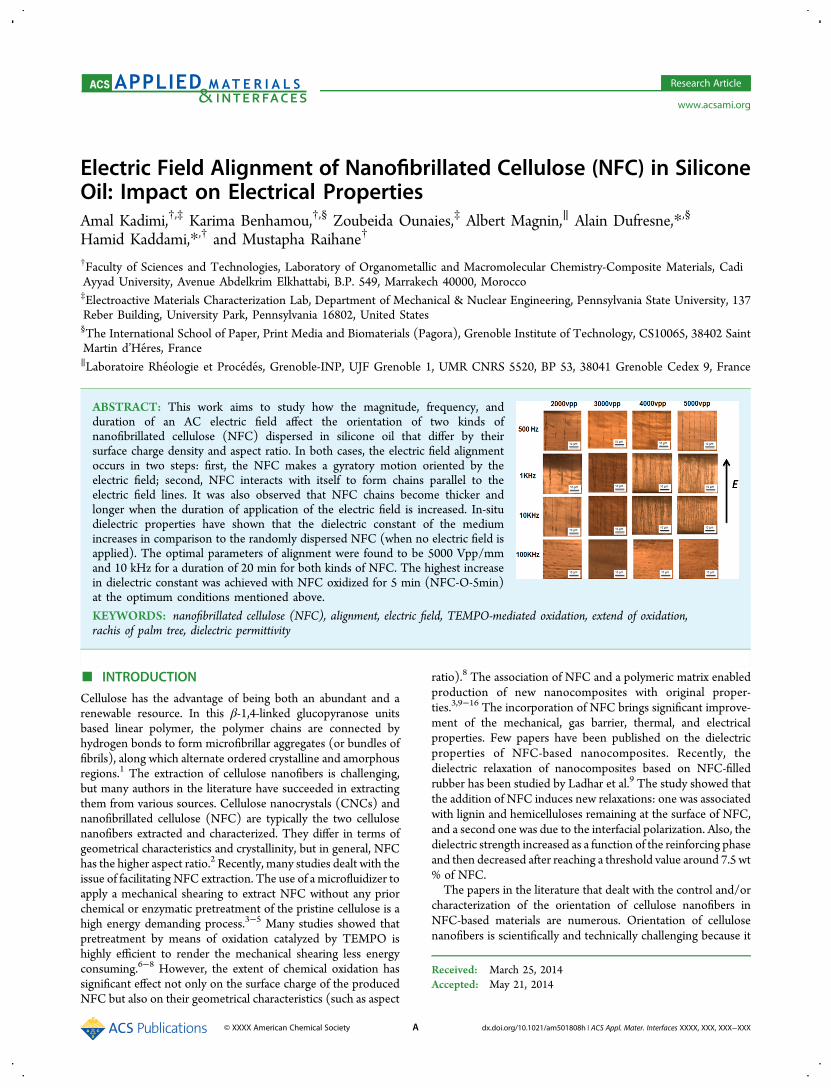
Electric Field Alignment of Nanofibrillated Cellulose (NFC) in SiliconeOil: Impact on Electrical PropertiesAmal Kadimi,†,‡ Karima Benhamou,†,§ Zoubeida Ounaies,‡ Albert Magnin,∥ Alain Dufresne,*,§
Hamid Kaddami,*,† and Mustapha Raihane†
†Faculty of Sciences and Technologies, Laboratory of Organometallic and Macromolecular Chemistry-Composite Materials, CadiAyyad University, Avenue Abdelkrim Elkhattabi, B.P. 549, Marrakech 40000, Morocco‡Electroactive Materials Characterization Lab, Department of Mechanical & Nuclear Engineering, Pennsylvania State University, 137Reber Building, University Park, Pennsylvania 16802, United States§The International School of Paper, Print Media and Biomaterials (Pagora), Grenoble Institute of Technology, CS10065, 38402 SaintMartin d’Heres, France∥Laboratoire Rheologie et Procedes, Grenoble-INP, UJF Grenoble 1, UMR CNRS 5520, BP 53, 38041 Grenoble Cedex 9, France
ABSTRACT: This work aims to study how the magnitude, frequency, andduration of an AC electric field affect the orientation of two kinds ofnanofibrillated cellulose (NFC) dispersed in silicone oil that differ by theirsurface charge density and aspect ratio. In both cases, the electric field alignmentoccurs in two steps: first, the NFC makes a gyratory motion oriented by theelectric field; second, NFC interacts with itself to form chains parallel to theelectric field lines. It was also observed that NFC chains become thicker andlonger when the duration of application of the electric field is increased. In-situdielectric properties have shown that the dielectric constant of the mediumincreases in comparison to the randomly dispersed NFC (when no electric field isapplied). The optimal parameters of alignment were found to be 5000 Vpp/mmand 10 kHz for a duration of 20 min for both kinds of NFC. The highest increasein dielectric constant was achieved with NFC oxidized for 5 min (NFC-O-5min)at the optimum conditions mentioned above.
KEYWORDS: nanofibrillated cellulose (NFC), alignment, electric field, TEMPO-mediated oxidation, extend of oxidation,rachis of palm tree, dielectric permittivity
■ INTRODUCTION
Cellulose has the advantage of being both an abundant and arenewable resource. In this β-1,4-linked glucopyranose unitsbased linear polymer, the polymer chains are connected byhydrogen bonds to form microfibrillar aggregates (or bundles offibrils), along which alternate ordered crystalline and amorphousregions.1 The extraction of cellulose nanofibers is challenging,but many authors in the literature have succeeded in extractingthem from various sources. Cellulose nanocrystals (CNCs) andnanofibrillated cellulose (NFC) are typically the two cellulosenanofibers extracted and characterized. They differ in terms ofgeometrical characteristics and crystallinity, but in general, NFChas the higher aspect ratio.2 Recently, many studies dealt with theissue of facilitating NFC extraction. The use of a microfluidizer toapply a mechanical shearing to extract NFC without any priorchemical or enzymatic pretreatment of the pristine cellulose is ahigh energy demanding process.3−5 Many studies showed thatpretreatment by means of oxidation catalyzed by TEMPO ishighly efficient to render the mechanical shearing less energyconsuming.6−8 However, the extent of chemical oxidation hassignificant effect not only on the surface charge of the producedNFC but also on their geometrical characteristics (such as aspect
ratio).8 The association of NFC and a polymeric matrix enabledproduction of new nanocomposites with original proper-ties.3,9−16 The incorporation of NFC brings significant improve-ment of the mechanical, gas barrier, thermal, and electricalproperties. Few papers have been published on the dielectricproperties of NFC-based nanocomposites. Recently, thedielectric relaxation of nanocomposites based on NFC-filledrubber has been studied by Ladhar et al.9 The study showed thatthe addition of NFC induces new relaxations: one was associatedwith lignin and hemicelluloses remaining at the surface of NFC,and a second one was due to the interfacial polarization. Also, thedielectric strength increased as a function of the reinforcing phaseand then decreased after reaching a threshold value around 7.5 wt% of NFC.The papers in the literature that dealt with the control and/or
characterization of the orientation of cellulose nanofibers inNFC-based materials are numerous. Orientation of cellulosenanofibers is scientifically and technically challenging because it
Received: March 25, 2014Accepted: May 21, 2014
Research Article
www.acsami.org
© XXXX American Chemical Society A dx.doi.org/10.1021/am501808h | ACS Appl. Mater. Interfaces XXXX, XXX, XXX−XXX
offers valuable opportunities to design new nanocomposites byaligning this nanofiller in polymers to improve dielectric andmechanical properties and can also offer new applications forcellulose valorization. Some studies clearly show that cellulosenanofibers have an orientational self-capacity even if no externalsolicitation has been applied to improve their orientation.17−19
Many authors were interested in the control of the orientation ofcellulose nanofibers in cellulose nanofiber based materials. Thetechniques used to orientate NFC were principally mechanicaltechniques such as cold drawing,20 shear-convective assembly,21
electrospinning,22−25 wet spinning,26,27 and wet stretching.28−35
Some papers dealt with the orientation of cellulose nanofibersusinga magnetic field to process composite materials withcontrolled structure.29,36 Although electric field application waswidely used to orientate nanoscale inorganic materials,37−41 onlyfew studies have been dedicated to cellulose nanofibers.42−44 Inorder to align cellulose nanocrystals in silicone oil, Kalidindi etal.42 have used an AC electric field with varying magnitude,frequency, and duration of application. They succeeded inoptimizing the chain formation by applying an AC electric fieldduring 20 min at 3000 Vpp mm−1 and 500 mHz. They observedthat the CNCs rotate before interacting to form chains, and thatthe chain formation was accompanied by a significant increase ofthe dielectric constant of the medium (in comparison to therandomly dispersed case). Csoka et al.30 have succeed inpreparing ultrathin films of CNC by applying a low electric field.The setup consisted of a convective assemblage. Their resultsshowed that the orientation of CNC depends on the electric fieldand frequency. Bordel et al.43 have succeeded, by mean of ACelectric field application, to align native cellulose in organicsolvent (chloroform and cyclohexane). They aligned nativecellulose at 200 V/mm and 1 kHz alignment frequency andobserved rotation of cellulose particles under the electric field.Habibi et al.44 have tried to align CNCs by means of an ACelectric field. They changed the electric field and frequency toinvestigate the ability to align CNCs in water using a surfactant;they studied the behavior of cellulose for a wide range of voltages(2.5−20 V/mm) in a frequency range from 1 kHz to 2 MHz.All of the above studies were dedicated to CNC orientation
under electric field. We did not find any study in the literaturededicated to the orientation of nanofibrillated cellulose. Exceptfor the work of Sanjay et al., no study reported the effect of theorientation of cellulose nanofibers on the electrical properties ofthe obtained composites. However, for carbon nanotube basedmaterials many studies have been conducted. A comprehensivestudy45 has been conducted to align single-walled carbonnanotubes (SWCNT) by mean of an AC electric field into apolymer matrix obtained by photopolymerization. The authorshave shown that it was possible to control the electricalproperties of the composite (electrical conductivity and dielectricconstant) by varying the AC electric field parameters(magnitude, frequency, and duration of application). Anothercomprehensive study has been conducted by Sungryul et al.46 toinvestigate the alignment of carbon nanotubes in covalentlygrafted multiwalled carbon nanotubes (MWCNTs) on acellulose composite. The alignment of MWCNTs contributedto enhance significantly the mechanical and piezoelectricproperties. It also improved actuator performance of thesecomposites. Ma et al.47 have focused on the use of an electric fieldto study the effect of oxidation on the alignment and dispersionof MWCNTs in in situ polymerized poly(methyl methacrylate)(PMMA) based composites. Their results showed that thedispersion quality as well as the alignment stability was
significantly enhanced for oxidized MWCNTs based nano-composites. Oliva-Aviles et al.,48 while studying pristineMWCNTs/thermoplastic polymer based nanocomposites,have shown that the alignment of MWCNTs by mean ofalternative electric field induced 3−5 orders of magnitudeenhancement of the electric conductivity compared to randomlydispersed MWCNTs based nanocomposites.As mentioned above no study in the literature has been
dedicated to the orientation of nanofibrillated cellulose under anelectric field and the study of the physical characteristics of NFCon their orientation under the electric field. Therefore, this paperreports a comprehensive study on the relationship between thedegree of alignment of NFC in silicone oil and the parameters ofthe applied electric field (i.e., magnitude, frequency, as well asduration of application). The effect of NFC microstructure,namely, size (length and width), charge, and crystallinity index,on the alignment conditions and dielectric properties wasstudied.
■ MATERIALS AND METHODSMaterials. Details about the materials and chemicals used for the
TEMPO-catalyzed extraction of NFC can be found in our previouslypublished work.2 Ethanol, acetone, and N,N-dimethylformamide(DMF) of analytical grade were purchased from Sigma-Aldrich andused as solvents to disperse the NFC. Silicone oil, used as a dielectricmedium, had a cinematic viscosity of 10 mm2/s and was supplied bySigma-Aldrich.
Preparation of NFC. The details of the TEMPO-catalyzedoxidation procedure to prepare the oxidized NFC’s colloidalsuspensions in water are reported in the recently published work ofBenhamou et al.8 Two different oxidation times (5 and 120 min) werechosen to prepare NFC with different physical and geometricalcharacteristics. Centrifugation at 8500 rpm for 10 min was performedto remove the reagents. The excess liquid was removed from thecentrifuge vials with a pipet and replaced with distilled water, and themixture was homogenized by probe sonication and then centrifuged at8500 rpm 3 times. After the oxidative pretreatment and reagent removal,a PANDA 2K−GEA-NiroSoaviS laboratory homogenizer was used toperform homogenization. Disintegration by pumping the 2 wt % fibersuspension through the homogenizer was performed up to 15 times at600 MPa.
The twoNFC samples prepared from cellulose oxidized for 5min and2 h will be designated in the following as NFC-O-5min and NFC-O-2h,respectively.
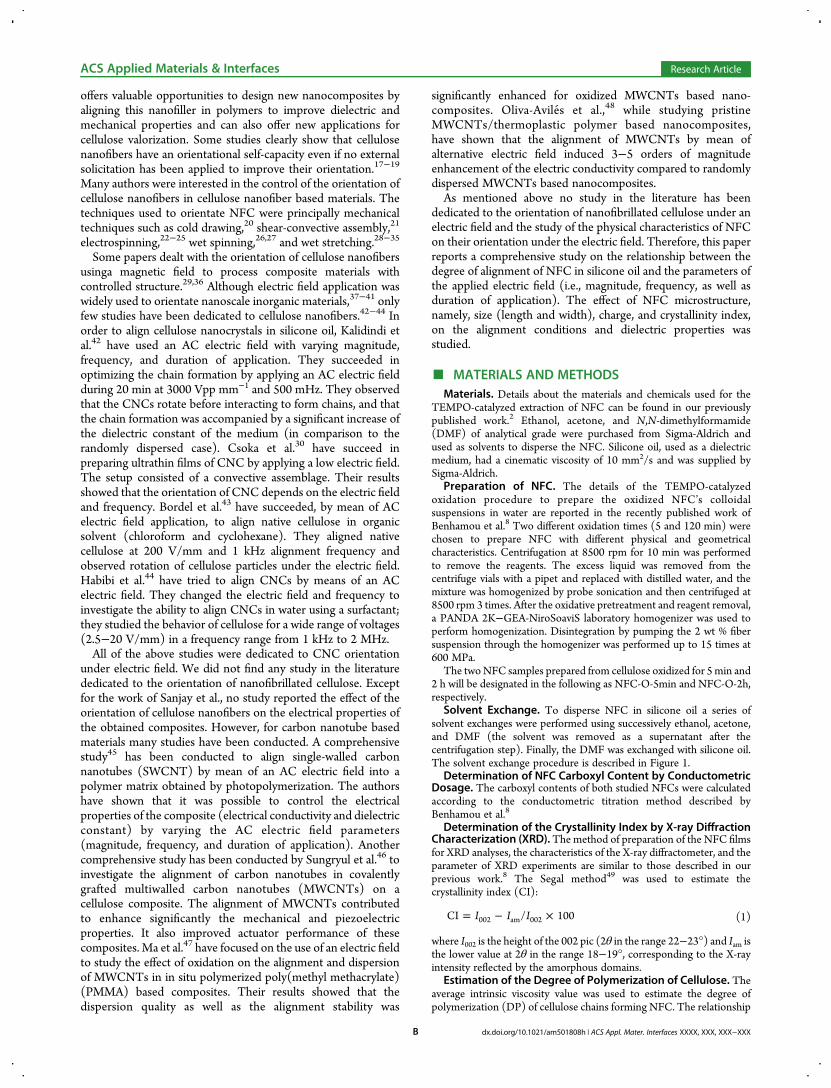
Solvent Exchange. To disperse NFC in silicone oil a series ofsolvent exchanges were performed using successively ethanol, acetone,and DMF (the solvent was removed as a supernatant after thecentrifugation step). Finally, the DMF was exchanged with silicone oil.The solvent exchange procedure is described in Figure 1.
Determination of NFC Carboxyl Content by ConductometricDosage. The carboxyl contents of both studied NFCs were calculatedaccording to the conductometric titration method described byBenhamou et al.8
Determination of the Crystallinity Index by X-ray DiffractionCharacterization (XRD). The method of preparation of the NFC filmsfor XRD analyses, the characteristics of the X-ray diffractometer, and theparameter of XRD experiments are similar to those described in ourprevious work.8 The Segal method49 was used to estimate thecrystallinity index (CI):
= − ×I I ICI / 100002 am 002 (1)
where I002 is the height of the 002 pic (2θ in the range 22−23°) and Iam isthe lower value at 2θ in the range 18−19°, corresponding to the X-rayintensity reflected by the amorphous domains.
Estimation of the Degree of Polymerization of Cellulose. Theaverage intrinsic viscosity value was used to estimate the degree ofpolymerization (DP) of cellulose chains forming NFC. The relationship
ACS Applied Materials & Interfaces Research Article
dx.doi.org/10.1021/am501808h | ACS Appl. Mater. Interfaces XXXX, XXX, XXX−XXXB
between the intrinsic viscosity, [η] (dL/g), and DP proposed forcellulose by Rinaudo50 was used to calculate DP from measurements of[η]:
η =[ ] 0.891DP0.936 (2)
Cupri-ethylendiamine (1 N) was used as the solvent for NFC. At leastthree solutions of different concentrations were prepared to determine[η] (dL/g). The measurements were performed at 25 ± 0.1 °C, and anaverage of three measurements of the flow time was used to calculate theintrinsic viscosity. The intrinsic viscosity of bleached cellulose wascalculated and served as reference.Atomic Force Microscopy (AFM). A Nanoscope III (Veeco Co.
Ltd., USA) was used to perform AFM observations. An aqueoussuspension (0.01 wt %) was sonicated for 30 min to allow betterdispersion of NFC. The samples for AFM characterization wereprepared by depositing drops of the sonicated NFC dispersion onto themica substrates and thereafter air drying the sample at ambientconditions. Silicon cantilevers were used for the in air tapping mode torecord all AFM micrographs. The tapping was performed at thefrequency range of 264−339 kHz and with radius of curvature between10 and 15 nm. The NFC dimensions, including length (L) and width(W), were measured by using Nanoscope software. An average of morethan 100 measurements performed on individual nanofibrils statisticallychosen and analyzed was calculated and used to determine length andwidth distribution (mainly focusing on the images with the scale of 3.3μm × 3.3 μm).Electric Field Processing. A 0.1 wt % solution of NFC was
dispersed in silicone oil (as mentioned above). The dispersion (NFC-silicone oil) was then poured into the gap between the parallelelectrodes glued on a glass microscope slide (shown in Figure 2).The gap size between the electrodes was set to 1 mm. Frequencies
ranging from 500Hz to 100 kHz were used to apply the AC electric field.The AC signal was generated using a HP 33120A. This later wasconnected with a TREK 609D-6 high voltage amplifier to adjust thevoltage. The electric field magnitudes applied for the alignmentexperiments were 2000, 3000, 4000, and 5000 Vpp/mm.Optical Microcopy. The optical microscopy procedure is described
in our earlier published work.42
Dielectric Spectroscopy. The measurement of the in situ dielectricconstant was performed at ambient conditions using a Quadtech LCRmeter. A wide range of frequencies from 500 Hz to 1 MHz wereexplored. This technique yields capacitance, which was then converted
to dielectric permittivity using eq 3, assuming a parallel plateconfiguration:
εε
= CdA0 (3)
where C = capacitance (in F), ε = dielectric constant, ε0 = permittivity offree space (in F m−1), d = distance between electrodes (in m), and A =surface of the electrodes (in m2).
■ RESULTS AND DISCUSIONNFC Characterization. AFM images of the oxidized NFC
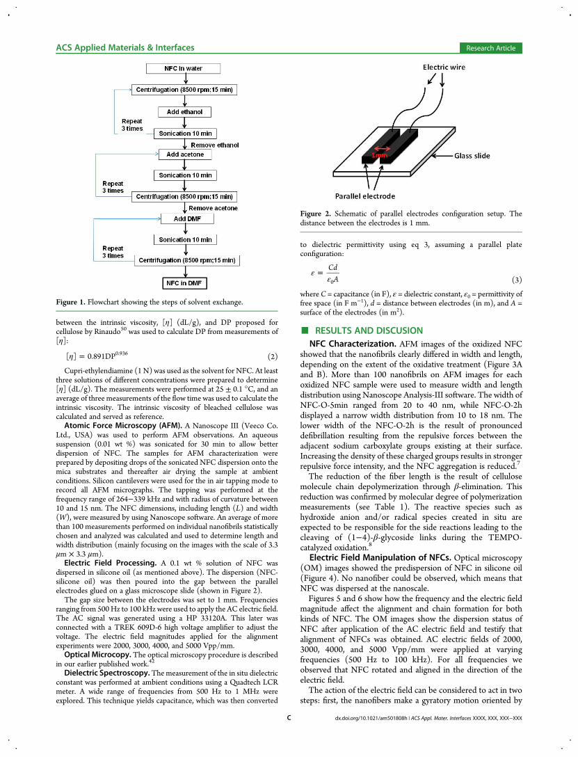
showed that the nanofibrils clearly differed in width and length,depending on the extent of the oxidative treatment (Figure 3Aand B). More than 100 nanofibrils on AFM images for eachoxidized NFC sample were used to measure width and lengthdistribution using Nanoscope Analysis-III software. The width ofNFC-O-5min ranged from 20 to 40 nm, while NFC-O-2hdisplayed a narrow width distribution from 10 to 18 nm. Thelower width of the NFC-O-2h is the result of pronounceddefibrillation resulting from the repulsive forces between theadjacent sodium carboxylate groups existing at their surface.Increasing the density of these charged groups results in strongerrepulsive force intensity, and the NFC aggregation is reduced.7
The reduction of the fiber length is the result of cellulosemolecule chain depolymerization through β-elimination. Thisreduction was confirmed by molecular degree of polymerizationmeasurements (see Table 1). The reactive species such ashydroxide anion and/or radical species created in situ areexpected to be responsible for the side reactions leading to thecleaving of (1−4)-β-glycoside links during the TEMPO-catalyzed oxidation.8
Electric Field Manipulation of NFCs. Optical microscopy(OM) images showed the predispersion of NFC in silicone oil(Figure 4). No nanofiber could be observed, which means thatNFC was dispersed at the nanoscale.Figures 5 and 6 show how the frequency and the electric field
magnitude affect the alignment and chain formation for bothkinds of NFC. The OM images show the dispersion status ofNFC after application of the AC electric field and testify thatalignment of NFCs was obtained. AC electric fields of 2000,3000, 4000, and 5000 Vpp/mm were applied at varyingfrequencies (500 Hz to 100 kHz). For all frequencies weobserved that NFC rotated and aligned in the direction of theelectric field.The action of the electric field can be considered to act in two
steps: first, the nanofibers make a gyratory motion oriented by
Figure 1. Flowchart showing the steps of solvent exchange.
Figure 2. Schematic of parallel electrodes configuration setup. Thedistance between the electrodes is 1 mm.
ACS Applied Materials & Interfaces Research Article
dx.doi.org/10.1021/am501808h | ACS Appl. Mater. Interfaces XXXX, XXX, XXX−XXXC
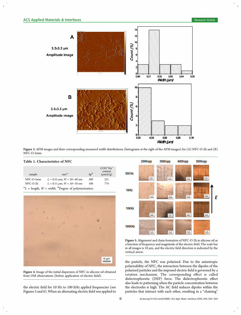
the electric field for 10 Hz to 100 kHz applied frequencies (seeFigures 5 and 6). When an alternating electric field was applied to
the particle, the NFC was polarized. Due to the anisotropicpolarizability of NFC, the interaction between the dipoles of thepolarized particles and the imposed electric field is governed by arotation mechanism. The corresponding effect is calleddielectrophoretic (DEP) force. The dielectrophoretic effectalso leads to patterning when the particle concentration betweenthe electrodes is high. The AC field induces dipoles within theparticles that interact with each other, resulting in a “chaining”
Figure 3. AFM images and their corresponding measured width distributions (histograms at the right of the AFM images) for (A) NFC-O-2h and (B)NFC-O-5min.
Table 1. Characteristics of NFC
sample sizea dpb
COO−Na+
content(μmol/g)
NFC-O-5min L = 0.55 μm; W = 20−40 nm 500 221NFC-O-2h L = 0.11 μm; W = 10−18 nm 100 774
aL = length, W = width. bDegree of polymerization.
Figure 4. Image of the initial dispersion of NFC in silicone oil obtainedfrom OM observations (before application of electric field).
Figure 5. Alignment and chain formation of NFC-O-2h in silicone oil asa function of frequency and magnitude of the electric field. The scale barin all images is 10 μm, and the electric field direction is indicated by thevertical arrow.
ACS Applied Materials & Interfaces Research Article
dx.doi.org/10.1021/am501808h | ACS Appl. Mater. Interfaces XXXX, XXX, XXX−XXXD
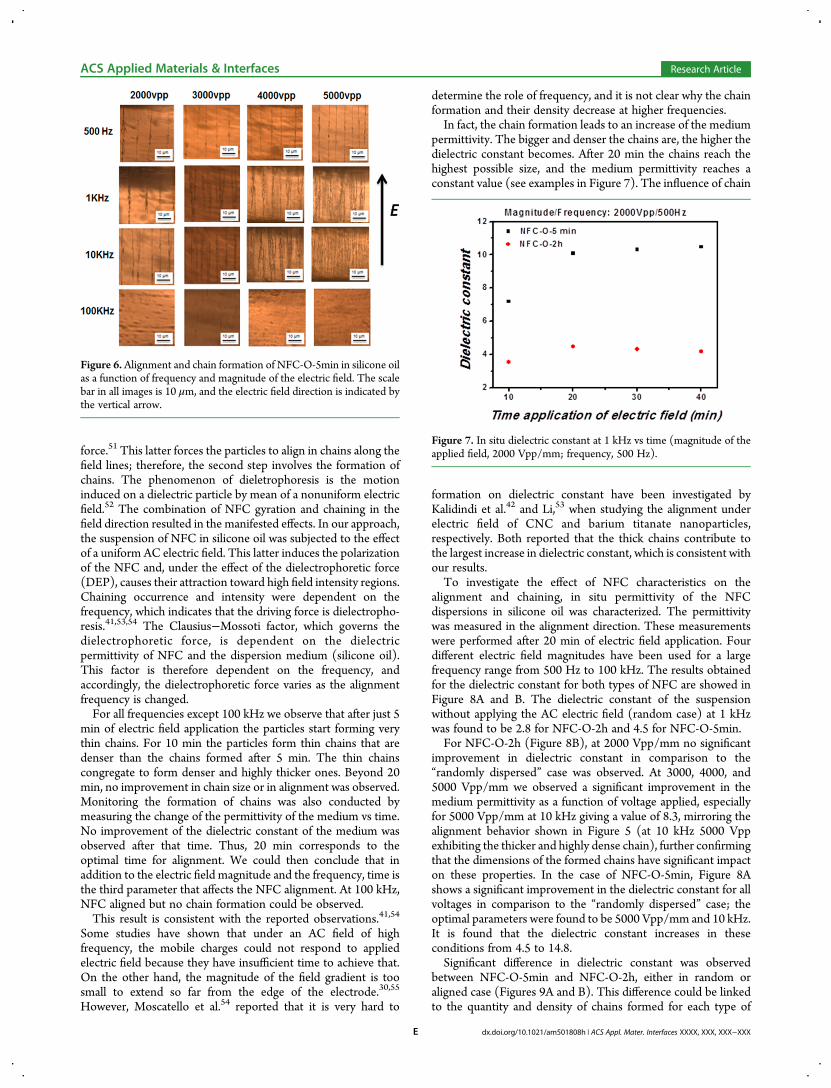
force.51 This latter forces the particles to align in chains along thefield lines; therefore, the second step involves the formation ofchains. The phenomenon of dieletrophoresis is the motioninduced on a dielectric particle by mean of a nonuniform electricfield.52 The combination of NFC gyration and chaining in thefield direction resulted in the manifested effects. In our approach,the suspension of NFC in silicone oil was subjected to the effectof a uniform AC electric field. This latter induces the polarizationof the NFC and, under the effect of the dielectrophoretic force(DEP), causes their attraction toward high field intensity regions.Chaining occurrence and intensity were dependent on thefrequency, which indicates that the driving force is dielectropho-resis.41,53,54 The Clausius−Mossoti factor, which governs thedielectrophoretic force, is dependent on the dielectricpermittivity of NFC and the dispersion medium (silicone oil).This factor is therefore dependent on the frequency, andaccordingly, the dielectrophoretic force varies as the alignmentfrequency is changed.For all frequencies except 100 kHz we observe that after just 5
min of electric field application the particles start forming verythin chains. For 10 min the particles form thin chains that aredenser than the chains formed after 5 min. The thin chainscongregate to form denser and highly thicker ones. Beyond 20min, no improvement in chain size or in alignment was observed.Monitoring the formation of chains was also conducted bymeasuring the change of the permittivity of the medium vs time.No improvement of the dielectric constant of the medium wasobserved after that time. Thus, 20 min corresponds to theoptimal time for alignment. We could then conclude that inaddition to the electric field magnitude and the frequency, time isthe third parameter that affects the NFC alignment. At 100 kHz,NFC aligned but no chain formation could be observed.This result is consistent with the reported observations.41,54
Some studies have shown that under an AC field of highfrequency, the mobile charges could not respond to appliedelectric field because they have insufficient time to achieve that.On the other hand, the magnitude of the field gradient is toosmall to extend so far from the edge of the electrode.30,55
However, Moscatello et al.54 reported that it is very hard to
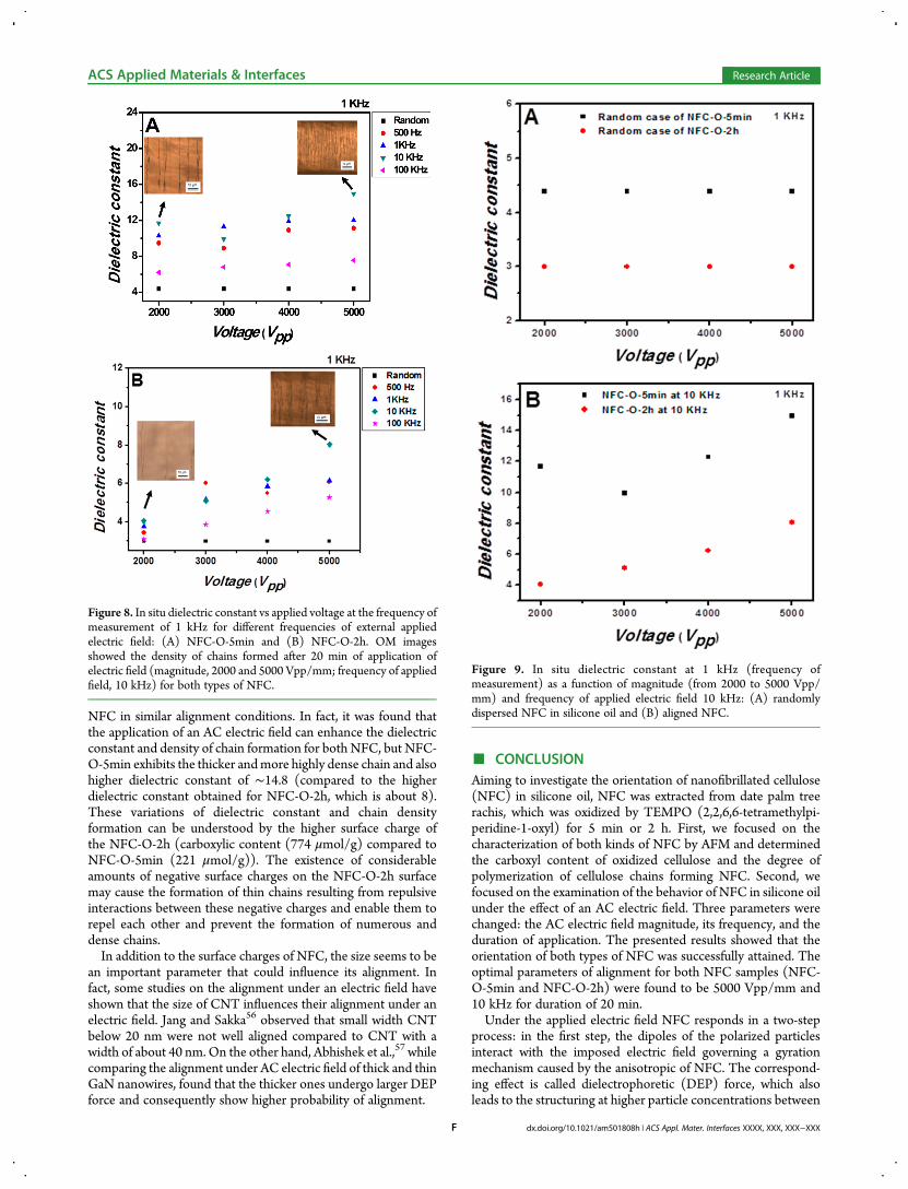
determine the role of frequency, and it is not clear why the chainformation and their density decrease at higher frequencies.In fact, the chain formation leads to an increase of the medium
permittivity. The bigger and denser the chains are, the higher thedielectric constant becomes. After 20 min the chains reach thehighest possible size, and the medium permittivity reaches aconstant value (see examples in Figure 7). The influence of chain
formation on dielectric constant have been investigated byKalidindi et al.42 and Li,53 when studying the alignment underelectric field of CNC and barium titanate nanoparticles,respectively. Both reported that the thick chains contribute tothe largest increase in dielectric constant, which is consistent withour results.To investigate the effect of NFC characteristics on the
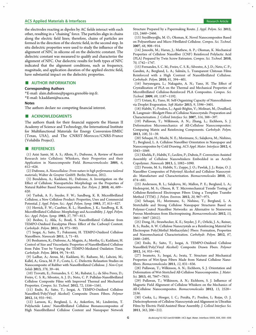
alignment and chaining, in situ permittivity of the NFCdispersions in silicone oil was characterized. The permittivitywas measured in the alignment direction. These measurementswere performed after 20 min of electric field application. Fourdifferent electric field magnitudes have been used for a largefrequency range from 500 Hz to 100 kHz. The results obtainedfor the dielectric constant for both types of NFC are showed inFigure 8A and B. The dielectric constant of the suspensionwithout applying the AC electric field (random case) at 1 kHzwas found to be 2.8 for NFC-O-2h and 4.5 for NFC-O-5min.For NFC-O-2h (Figure 8B), at 2000 Vpp/mm no significant
improvement in dielectric constant in comparison to the“randomly dispersed” case was observed. At 3000, 4000, and5000 Vpp/mm we observed a significant improvement in themedium permittivity as a function of voltage applied, especiallyfor 5000 Vpp/mm at 10 kHz giving a value of 8.3, mirroring thealignment behavior shown in Figure 5 (at 10 kHz 5000 Vppexhibiting the thicker and highly dense chain), further confirmingthat the dimensions of the formed chains have significant impacton these properties. In the case of NFC-O-5min, Figure 8Ashows a significant improvement in the dielectric constant for allvoltages in comparison to the “randomly dispersed” case; theoptimal parameters were found to be 5000 Vpp/mm and 10 kHz.It is found that the dielectric constant increases in theseconditions from 4.5 to 14.8.Significant difference in dielectric constant was observed
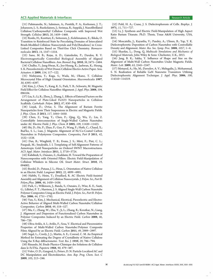
between NFC-O-5min and NFC-O-2h, either in random oraligned case (Figures 9A and B). This difference could be linkedto the quantity and density of chains formed for each type of
Figure 6. Alignment and chain formation of NFC-O-5min in silicone oilas a function of frequency and magnitude of the electric field. The scalebar in all images is 10 μm, and the electric field direction is indicated bythe vertical arrow.
Figure 7. In situ dielectric constant at 1 kHz vs time (magnitude of theapplied field, 2000 Vpp/mm; frequency, 500 Hz).
ACS Applied Materials & Interfaces Research Article
dx.doi.org/10.1021/am501808h | ACS Appl. Mater. Interfaces XXXX, XXX, XXX−XXXE
NFC in similar alignment conditions. In fact, it was found thatthe application of an AC electric field can enhance the dielectricconstant and density of chain formation for both NFC, but NFC-O-5min exhibits the thicker andmore highly dense chain and alsohigher dielectric constant of ∼14.8 (compared to the higherdielectric constant obtained for NFC-O-2h, which is about 8).These variations of dielectric constant and chain densityformation can be understood by the higher surface charge ofthe NFC-O-2h (carboxylic content (774 μmol/g) compared toNFC-O-5min (221 μmol/g)). The existence of considerableamounts of negative surface charges on the NFC-O-2h surfacemay cause the formation of thin chains resulting from repulsiveinteractions between these negative charges and enable them torepel each other and prevent the formation of numerous anddense chains.In addition to the surface charges of NFC, the size seems to be
an important parameter that could influence its alignment. Infact, some studies on the alignment under an electric field haveshown that the size of CNT influences their alignment under anelectric field. Jang and Sakka56 observed that small width CNTbelow 20 nm were not well aligned compared to CNT with awidth of about 40 nm. On the other hand, Abhishek et al.,57 whilecomparing the alignment under AC electric field of thick and thinGaN nanowires, found that the thicker ones undergo larger DEPforce and consequently show higher probability of alignment.
■ CONCLUSIONAiming to investigate the orientation of nanofibrillated cellulose(NFC) in silicone oil, NFC was extracted from date palm treerachis, which was oxidized by TEMPO (2,2,6,6-tetramethylpi-peridine-1-oxyl) for 5 min or 2 h. First, we focused on thecharacterization of both kinds of NFC by AFM and determinedthe carboxyl content of oxidized cellulose and the degree ofpolymerization of cellulose chains forming NFC. Second, wefocused on the examination of the behavior of NFC in silicone oilunder the effect of an AC electric field. Three parameters werechanged: the AC electric field magnitude, its frequency, and theduration of application. The presented results showed that theorientation of both types of NFC was successfully attained. Theoptimal parameters of alignment for both NFC samples (NFC-O-5min and NFC-O-2h) were found to be 5000 Vpp/mm and10 kHz for duration of 20 min.Under the applied electric field NFC responds in a two-step
process: in the first step, the dipoles of the polarized particlesinteract with the imposed electric field governing a gyrationmechanism caused by the anisotropic of NFC. The correspond-ing effect is called dielectrophoretic (DEP) force, which alsoleads to the structuring at higher particle concentrations between
Figure 8. In situ dielectric constant vs applied voltage at the frequency ofmeasurement of 1 kHz for different frequencies of external appliedelectric field: (A) NFC-O-5min and (B) NFC-O-2h. OM imagesshowed the density of chains formed after 20 min of application ofelectric field (magnitude, 2000 and 5000 Vpp/mm; frequency of appliedfield, 10 kHz) for both types of NFC.
Figure 9. In situ dielectric constant at 1 kHz (frequency ofmeasurement) as a function of magnitude (from 2000 to 5000 Vpp/mm) and frequency of applied electric field 10 kHz: (A) randomlydispersed NFC in silicone oil and (B) aligned NFC.
ACS Applied Materials & Interfaces Research Article
dx.doi.org/10.1021/am501808h | ACS Appl. Mater. Interfaces XXXX, XXX, XXX−XXXF
the electrodes reacting as dipoles by AC fields interact with eachother, resulting in a “chaining” force. The particles align in chainsalong the electric field lines; therefore, chains of particles areformed in the direction of the electric field, in the second step. Insitu dielectric properties were used to study the influence of thealignment of NFC in silicone oil on the dielectric constant. Thedielectric constant was measured to qualify and characterize thealignment of NFC. Our dielectric results for both types of NFCindicated that the alignment conditions, such as frequency,magnitude, and application duration of the applied electric field,have substantial impact on the dielectric properties.
■ AUTHOR INFORMATIONCorresponding Authors*E-mail: [email protected].*E-mail: [email protected] authors declare no competing financial interest.
■ ACKNOWLEDGMENTSThe authors thank for their financial supports the Hassan IIAcademy of Science and Technology, the International Institutefor Multifunctional Materials for Energy Conversion-IIMEC(Texas, USA), and The CNRST-Morocco/CNRS-France(Volubilis Project).
■ REFERENCES(1) Azizi Samir, M. A. S.; Alloin, F.; Dufresne, A. Review of RecentResearch into Cellulosic Whiskers, their Properties and theirApplication in Nanocomposite Field. Biomacromolecules 2005, 6,612−626.(2) Dufresne, A.Nanocellulose: From nature to high performance tailoredmaterials; Walter de Gruyter GmbH: Berlin/Boston, 2012.(3) Bendahou, A.; Kaddami, H.; Dufresne, A. Investigation on theEffect of Cellulosic Nanoparticles Morphology on the Properties ofNatural Rubber Based Nanocomposites. Eur. Polym. J. 2010, 46, 609−620.(4) Turbak, A. F.; Snyder, F. W.; Sandberg, K. R. MicrofibrillatedCellulose, a New Cellulose Product: Properties, Uses and CommercialPotential. J. Appl. Polym. Sci.: Appl. Polym. Symp. 1983, 37, 815−827.(5) Herrick, F. W.; Casebier, R. L.; Hamilton, J. K.; Sandberg, K. R.Microfibrillated Cellulose: Morphology and Accessibility. J. Appl. Polym.Sci.: Appl. Polym. Symp. 1983, 37, 797−813.(6) Besbes, I.; Alila, S.; Boufi, S. Nanofibrillated Cellulose fromTEMPO-Oxidized Eucalyptus Fbres: Effect of the Carboxyl Content.Carbohydr. Polym. 2011, 84, 975−983.(7) Isogai, A.; Saito, T.; Fukuzumi, H. TEMPO-Oxidized CelluloseNanofibers. Nanoscale 2011, 3, 71−85.(8) Benhamou, K.; Dufresne, A.; Magnin, A.; Mortha, G.; Kaddami, H.Control of Size and Viscoelastic Properties of Nanofibrillated Cellulosefrom Palm Tree by Varying the TEMPO-Mediated Oxidation Time.Carbohydr. Polym. 2014, 99, 74−83.(9) Ladhar, A.; Arous, M.; Kaddami, H.; Raihane, M.; Lahcini, M.;Kallel, A.; Graca, M. P. F.; Costa, L. C. Dielectric Relaxation Studies onNanocomposite of Rubber with Nanofibrillated Cellulose. J. Non-Cryst.Solids 2013, 378, 39−44.(10) Trovatti, E.; Fernandes, S. C. M.; Rubatat, L.; da Silva Perez, D.;Freire, C. S. R.; Silvestre, A. J. D.; Neto, C. P. Pullulan-NanofibrillatedCellulose Composite Films with Improved Thermal and MechanicalProperties. Compos. Sci. Technol. 2012, 72, 1556−1561.(11) Endo, R.; Saito, T.; Isogai, A. TEMPO-Oxidized CelluloseNanofibril/Poly(Vinyl Alcohol) Composite Drawn Fibers. Polymer2012, 54, 935−941.(12) Larsson, K.; Berglund, L. A.; Ankerfors, M.; Lindstrom, T.Polylactide Latex/ Nanofibrillated Cellulose Bionanocomposites ofHigh Nanofibrillated Cellulose Content and Nanopaper Network
Structure Prepared by a Papermaking Route. J. Appl. Polym. Sci. 2012,125, 2460−2466.(13) Seydibeyog lu, M. O.; Oksman, K. Novel Nanocomposites Basedon Polyurethane and Micro Fibrillated Cellulose. Compos. Sci. Technol.2007, 68, 908−914.(14) Jonoobi, M.; Harun, J.; Mathew, A. P.; Oksman, K. MechanicalProperties of Cellulose Nanofiber (CNF) Reinforced Polylactic Acid(PLA) Prepared by Twin Screw Extrusion. Compos. Sci. Technol. 2010,70, 1742−1747.(15) Fernandes, S. C. M.; Freire, C. S. R.; Silvestre, A. J. D.; Neto, C. P.;Gandini, A.; Berglund, L. A.; Salmen, L. Transparent Chitosan FilmsReinforced with a High Content of Nanofibrillated Cellulose.Carbohydr. Polym. 2010, 81, 394−401.(16) Suryanegara, L.; Nakagaito, A. N.; Yano, H. The Effect ofCrystallization of PLA on the Thermal and Mechanical Properties ofMicrofibrillated Cellulose-Reinforced PLA Composites. Compos. Sci.Technol. 2009, 69, 1187−1192.(17) Uetani, K.; Yano, H. Self-Organizing Capacity of Nanocellulosesvia Droplet Evaporation. Soft Matter 2013, 9, 3396−3401.(18) Habibi, Y.; Foulon, L.; Aguie-Beghin, V.; Molinari, M.; Douillard,R. Langmuir−Blodgett Flms of Cellulose Nanocrystals: Preparation andCharacterization. J. Colloid Interface Sci. 2007, 316, 388−397.(19) Pullawan, T.; Wilkinson, A. N.; Zhang, L.; Eichhorn, S. J.Deformation Micromechanics of All-Cellulose Nanocomposites:Comparing Matrix and Reinforcing Components. Carbohydr. Polym.2013, 100, 31−39.(20) Sehaqui, H.; Mushi, N. E.; Morimune, S.; Salajkova, M.; Nishino,T.; Berglund, L. A. Cellulose Nanofiber Orientation in Nanopaper andNanocomposites by Cold Drawing. ACS Appl. Mater. Interfaces 2012, 4,1043−1049.(21) Khelifa, F.; Habibi, Y.; Leclere, P.; Dubois, P. Convection-AssistedAssembly of Cellulose Nanowhiskers Embedded in an AcrylicCopolymer. Nanoscale 2013, 5, 1082−1090.(22) Peresin, M. S.; Habibi, Y.; Zoppe, J. O.; Pawlak, J. J.; Rojas, O. J.Nanofiber Composites of Polyvinyl Alcohol and Cellulose Nanocryst-als: Manufacture and Characterization. Biomacromolecules 2010, 11,674−681.(23) Andersson, R. L.; Salajkova, M.; Mallon, P. E.; Berglund, L. A.;Hedenqvist, M. S.; Olsson, R. T. Micromechanical Tensile Testing ofCellulose-Reinforced Electrospun Fibers Using a Template TransferMethod (TTM). J. Polym. Environ. 2012, 20, 967−975.(24) Sehaqui, H.; Morimune, S.; Nishino, T.; Berglund, L. A.Stretchable and Strong Cellulose Nanopaper Structures Based onPolymer-Coated Nanofiber Networks: an Alternative to NonwovenPorous Membranes from Electrospinning. Biomacromolecules 2012, 13,3661−3667 (2012).(25) Dong, H.; Strawhecker, K. E.; Snyder, J. F.; Orlicki, J. A.; Reiner,R. S.; Rudie, A. W. Cellulose Nanocrystals as a Reinforcing Material forElectrospun Poly(Methyl Methacrylate) Fbers: Formation, Propertiesand Nanomechanical Characterization. Carbohydr. Polym. 2012, 87,2488−2495.(26) Endo, R.; Saito, T.; Isogai, A. TEMPO-Oxidized CelluloseNanofibril/Poly(Vinyl Alcohol) Composite Drawn Fbers. Polymer2012, 54, 935−941.(27) Iwamoto, S.; Isogai, A.; Iwata, T. Structure and MechanicalProperties of Wet-Spun Fibers Made from Natural Cellulose Nano-fibers. Biomacromolecules 2011, 12, 831−836.(28) Pullawan, T.; Wilkinson, A. N.; Eichhorn, S. J. Orientation andDeformation of Wet-Stretched All-Cellulose Nanocomposites. J. Mater.Sci. 2013, 48, 7847−7855.(29) Pullawan, T.; Wilkinson, A. N.; Eichhorn, S. J. Influence ofMagnetic Field Alignment of Cellulose Whiskers on the Mechanics ofAll-Cellulose Nanocomposites. Biomacromolecules 2012, 13, 2528−2536.(30) Csoka, L.; Hoeger, I. C.; Peralta, P.; Peszlen, I.; Rojas, O. J.Dielectrophoresis of Cellulose Nanocrystals and Alignment in UltrathinFilms by Electric Field-Assisted Shear Assembly. J. Colloid Interface Sci.2011, 363, 206−212.
ACS Applied Materials & Interfaces Research Article
dx.doi.org/10.1021/am501808h | ACS Appl. Mater. Interfaces XXXX, XXX, XXX−XXXG
(31) Pahimanolis, N.; Salminen, A.; Penttila, P. A.; Korhonen, J. T.;Johansson, L. S.; Ruokolainen, J.; Serimaa, R.; Seppala, J. NanofibrillatedCellulose/Carboxymethyl Cellulose Composite with Improved WetStrength. Cellulose 2013, 20, 1459−1468.(32) Rosilo, H.; Kontturi, E.; Seitsonen, J.; Kolehmainen, E.; Ikkala, O.Transition to Reinforced State by Percolating Domains of IntercalatedBrush-Modified Cellulose Nanocrystals and Poly(Butadiene) in Cross-Linked Composites Based on Thiol-Ene Click Chemistry. Biomacro-molecules 2013, 14, 1547−1554.(33) Sano, M. B.; Rojas, A. D.; Gatenholm, P.; Davalos, R. V.Electromagnetically Controlled Biological Assembly of AlignedBacterial Cellulose Nanofibers. Ann. Biomed. Eng. 2010, 38, 2475−2484.(34) Chulho, Y.; Jung-Hwan, K.; Joo-Hyung, K.; Jaehwan, K.; Heung,S. K. Piezoelectricity ofWet Drawn Cellulose Electro-Active Paper. Sens.Actuators A 2009, 154, 117−122.(35) Nishiyama, Y.; Kuga, S.; Wada, M.; Okano, T. CelluloseMicrocrystal Film of High Uniaxial Orientation. Macromolecules 1997,30, 6395−6397.(36) Kim, J.; Chen, Y.; Kang, K. S.; Park, Y. B.; Schwartz, M. MagneticField Effect for Cellulose Nanofiber Alignment. J. Appl. Phys. 2008, 104,096104.(37) Liu, S.; Li, R.; Zhou, J.; Zhang, L. Effects of External Factors on theArrangement of Plate-Liked Fe2O3 Nanoparticles in CelluloseScaffolds. Carbohydr. Polym. 2012, 87, 830−838.(38) Lisjak, D.; Ovtar, S. The Alignment of Barium FerriteNanoparticles from Their Suspensions in Electric and Magnetic Fields.J. Phys. Chem. B 2013, 117, 1644−1650.(39) Chen, Z.; Yang, Y.; Chen, F.; Qing, Q.; Wu, Z.; Liu, Z.Controllable Interconnection of Single-Walled Carbon Nanotubesunder AC Electric Field. J. Phys. Chem. B 2005, 109, 11420−11423.(40) Shi, D.; He, P.; Zhao, P.; Guo, F.; Wang, F.; Huth, C.; Chaud, X.;Bud’ko, S. L.; Lian, J. Magnetic Alignment of Ni/Co-Coated CarbonNanotubes in Polystyrene Composites. Composites, Part B 2011, 42,1532−1538.(41) Dan, B.; Wingfield, T. B.; Evans, J. S.; Mirri, F.; Pint, C. L.;Pasquali, M.; Smalyukh, I. I. Templating of Self-Alignment Patterns ofAnisotropic Gold Nanoparticles on Ordered SWNT Macrostructures.ACS Appl. Mater. Interfaces 2011, 3, 3718−3724.(42) Kalidindi, S.; Ounaies, Z.; Kaddami, H. Toward the Preparation ofNanocomposites with Oriented Fillers: Electric Field-Manipulation ofCellulose Whiskers in Silicone Oil. Smart Mater. Struct. 2010, 19,094002.(43) Bordel, D.; Putaux, J. L.; Heux, L. Orientation of Native Cellulosein an Electric Field. Langmuir 2012, 22, 4899−4901.(44) Habibi, Y.; Heim, T.; Douillard, R. AC Electric Field-AssistedAssembly and Alignment of Cellulose Nanocrystals. J. Polym. Sci., Part B:Polym.,Phys. 2008, 46, 1430−1436.(45) Park, C.; Wilkinson, J.; Banda, S.; Ounaies, Z.; Wise, K. E.; Sauti,G.; Lillehei, P. T.; Harrison, J. S. Aligned Single-Wall Carbon NanotubePolymer Composites Using an Electric Field. J. Polym. Sci., Part B: Polym.Phys. 2006, 44, 1751−1762.(46) Yun, S.; Kim, J. Mechanical, Electrical, Piezoelectric and Electro-Active Behavior of Aligned Multi-Walled Carbon Nanotube/CelluloseComposites. Carbon 2010, 49, 518−527.(47) Ma, C.; Zhang, W.; Zhu, Y.; Ji, L.; Zhang, R.; Koratkar, N.; Liang,J. Alignment and Dispersion of Functionalized Carbon Nanotubes inPolymer Composites Induced by an Electric Field. Carbon 2008, 46,706−720.(48) Oliva-Aviles, A. I.; Aviles, F.; Sosa, V. Electrical and PiezoresistiveProperties of Multi-Walled Carbon Nanotube/Polymer CompositeFilms Aligned by an Electric Field. Carbon 2011, 49, 2989−2997.(49) Segal, L.; Creely, J. J.; Martin, A. E.; Conrad, C. M. An EmpiricalMethod for Estimating the Degree of Crystallinity of Native CelluloseUsing the X-Ray diffractometer. Text. Res. J. 1959, 29, 786−794.(50) Rinaudo, M. Etude Physico-Chimique des Solutions de Cellulosedans le FeTNa. Papeterie 1968, 90, 479−487.(51) Velev, O. D.; Gangwal, S.; Petsev, D. N. Particle-Localized AC andDC Manipulation and Electrokinetics. Ann. Rep. Prog. Chem. Sect. C2009, 105, 213−246.
(52) Pohl, H. A.; Crane, J. S. Dielectrophoresis of Cells. Biophys. J.1971, 11, 711−727.(53) Li, J. Synthesis and Electric Field-Manipulation of High AspectRatio Barium Titanate. Ph.D. Thesis, Texas A&M University, USA,2011.(54) Moscatello, J.; Kayastha, V.; Pandey, A.; Ulmen, B.; Yap, Y. K.Dielectrophoretic Deposition of Carbon Nanotubes with ControllableDensity and Alignment. Mater. Res. Soc. Symp. Proc. 2008, 1057, 1−6.(55) Shaofan, L.; Dong, Q. Multiscale Simulations and Mechanics ofBiological Materials; John Wiley & Sons: Chichester, U.K., 2013.(56) Jang, B. K.; Sakka, Y. Influence of Shape and Size on theAlignment of Multi-Wall Carbon Nanotubes Under Magnetic Fields.Mater. Lett. 2009, 63, 2545−2547.(57) Motayed, A.; He, M.; Davydov, A. V.; Melngailis, J.; Mohammad,S. N. Realization of Reliable GaN Nanowire Transistors UtilizingDielectrophoretic Alignment Technique. J. Appl. Phys. 2006, 100,114310−114319.
ACS Applied Materials & Interfaces Research Article
dx.doi.org/10.1021/am501808h | ACS Appl. Mater. Interfaces XXXX, XXX, XXX−XXXH
Copyright © 2022 FDOKUMEN