
Efficient light duty engine using turbulent jet ignition of lean ...
24
1 Efficient light duty engine using turbulent jet ignition of lean methane mixtures Patrik Soltic 1 , Thomas Hilfiker Empa, Swiss Federal Laboratories for Materials Science and Technology Automotive Powertrain Technologies Laboratory Überlandstrasse 129, 8600 Dübendorf, Switzerland Severin Hänggi ETH Zurich, Swiss Federal Institute of Technology Institute for Dynamic Systems and Control Rämistrasse 101, 8092 Zürich, Switzerland Abstract Diesel engines use diffusion-controlled combustion of a high-reactivity-fuel and offer high efficiencies because they combine lean combustion with a high compression ratio. For low- reactivity-fuels such as gasoline or natural gas, premixed combustion is used which leads to lower efficiency levels as usually stoichiometric combustion is combined with lower compres- sion ratios. Trying to apply diesel-like process parameters to low-reactivity-fuels inevitably leads to problems with classical spark ignition systems as they are not able to establish ro- bust flame propagation for such hard-to-ignite conditions. One possibility to enable fast combustion for diluted mixtures at high pressure levels is to establish ignition in a precham- ber and ignite the charge of the main combustion chamber using the turbulent jets exiting the prechamber. In this study, the experimental results of a prechamber-equipped four cylin- der natural gas engine with two liters displacement are discussed in detail. In the majority of the engine map, auxiliary fueling is used in the prechamber and a global air–fuel equivalence ratio λ is set to 1.7. At full load, a λ of 1.5 is applied without auxiliary prechamber fueling. The experiments show that such a setup is able to achieve brake efficiency levels of above 45% while maintaining peak brake mean effective pressure levels above 20 bar. At high load con- ditions, cylinder pressure levels at ignition timing achieve more than 80 bar and cylinder peak pressures of around 180 bars occur. The technology proved to enable robust and very fast combustion at comparably low NOx levels. A remaining challenge for the on-road use of such a technology is the reduction of the methane emissions at lean conditions. Keywords prechamber, ignition chamber, combustion, emissions, methane, CNG 1 E-mail [email protected], telephone +41 58 765 4624 This document is the accepted manuscript version of the following article: Soltic, P., Hilfiker, T., & Hänggi, S. (2019). Efficient light-duty engine using turbulent jet ignition of lean methane mixtures. International Journal of Engine Research, 146808741988983 (11 pp.). https://doi.org/10.1177/1468087419889833
-
Upload
khangminh22 -
Category
Documents
-
view
2 -
download
0
Transcript of Efficient light duty engine using turbulent jet ignition of lean ...
1
Efficient light duty engine using turbulent jet ignition of lean methane mixtures
Patrik Soltic1, Thomas Hilfiker Empa, Swiss Federal Laboratories for Materials Science and Technology Automotive Powertrain Technologies Laboratory Überlandstrasse 129, 8600 Dübendorf, Switzerland
Severin Hänggi ETH Zurich, Swiss Federal Institute of Technology Institute for Dynamic Systems and Control Rämistrasse 101, 8092 Zürich, Switzerland
Abstract Diesel engines use diffusion-controlled combustion of a high-reactivity-fuel and offer high efficiencies because they combine lean combustion with a high compression ratio. For low-reactivity-fuels such as gasoline or natural gas, premixed combustion is used which leads to lower efficiency levels as usually stoichiometric combustion is combined with lower compres-sion ratios. Trying to apply diesel-like process parameters to low-reactivity-fuels inevitably leads to problems with classical spark ignition systems as they are not able to establish ro-bust flame propagation for such hard-to-ignite conditions. One possibility to enable fast combustion for diluted mixtures at high pressure levels is to establish ignition in a precham-ber and ignite the charge of the main combustion chamber using the turbulent jets exiting the prechamber. In this study, the experimental results of a prechamber-equipped four cylin-der natural gas engine with two liters displacement are discussed in detail. In the majority of the engine map, auxiliary fueling is used in the prechamber and a global air–fuel equivalence ratio λ is set to 1.7. At full load, a λ of 1.5 is applied without auxiliary prechamber fueling. The experiments show that such a setup is able to achieve brake efficiency levels of above 45% while maintaining peak brake mean effective pressure levels above 20 bar. At high load con-ditions, cylinder pressure levels at ignition timing achieve more than 80 bar and cylinder peak pressures of around 180 bars occur. The technology proved to enable robust and very fast combustion at comparably low NOx levels. A remaining challenge for the on-road use of such a technology is the reduction of the methane emissions at lean conditions.
Keywords prechamber, ignition chamber, combustion, emissions, methane, CNG
1 E-mail [email protected], telephone +41 58 765 4624
This document is the accepted manuscript version of the following article: Soltic, P., Hilfiker, T., & Hänggi, S. (2019). Efficient light-duty engine using turbulent jet ignition of lean methane mixtures. International Journal of Engine Research, 146808741988983 (11 pp.). https://doi.org/10.1177/1468087419889833
Accepted for publication (International Journal of Engine Research), 24-Oct-2019
2
Introduction Natural gas is an important primary energy carrier for the power industry since combined-cycle power plants are highly efficient and natural gas is widely available at comparably low costs. Natural gas is also an attractive fuel for decentralized power and heat generation using stationary internal combustion engines as the primary energy converters. For marine applica-tions, liquefied natural gas has become an important fuel in recent years, mainly because it is an ideal fuel to fulfil pollutant emission regulations which are in place in certain sea areas (1) and especially for vessels which transport liquefied natural gas. As natural gas, with its main component methane, has the lowest carbon content of all fossil sources, its CO2 burden is comparably low. Additionally and importantly, natural gas can be blended by any amount with renewable methane which can be produced for example in biogas- or power-to-gas plants (2). This makes natural gas an attractive fuel for all applications which face high pres-sure to reduce CO2. One sector which is strongly affected by increasingly stricter CO2 regula-tions is the highly relevant mobility sector where methane as a fuel in classical or hybrid powertrains can have an ecologic and economic long-term perspective, as pure electrification does not necessarily lead to advantages for all use cases (3)(4). Natural gas as a vehicle fuel is established in many regions and actual statistics indicate that more than 27 million natural gas vehicles are in operation, with strong growth rates worldwide (5). Today’s mass-produced natural gas engines for light-duty applications are adapted gasoline engines. Typical adaptations are increased compression ratios to benefit from the high knock resistance of methane, increased boost pressure levels to compensate for the reduced volu-metric efficiency of gaseous fuel and adapted valves, valve seats and turbine materials to cope with increased temperature levels. Those adaptations do not exploit the full potential of methane as a fuel as for example typical in-cylinder peak pressure limitations of around 100 bar remain from the basic gasoline engines. Additionally, natural gas engines used in mobile applications are operated using strict stoichiometric fueling to enable extremely low pollutant emissions using proven and cost-effective three-way-catalytic after treatment technology (6). Here, we describe efficiency and pollutant emission levels, combustion characteristics as well as the performance potential of methane as a fuel for light duty applications if lean combus-tion and increased peak cylinder pressure levels are allowed. To do so, an engine capable of high cylinder peak pressures and high air flow is build-up as an experimental basis. As me-thane is a knock resistant- and hence a hard-to-ignite fuel, special focus has to be put on the ignition system. To ignite such a mixture, high ignition energies are needed (7) which can typically be provided either by pilot injection of a high-reactivity-fuel (e.g. diesel (8), alterna-tives such as OME (9) or blends (10)), by turbulent jet ignition using a prechamber or by al-ternative ignition concepts such as (11)(12). As pilot injection requires a second fuel in com-bination with a comparably expensive high-pressure injection system and as pilot injection has problems to provide stable ignition with low pilot quantities at low load (13) (14), the use of a prechamber seems to be more attractive for light-duty vehicle use. A prechamber separates the spark discharge process from the conditions in the main com-bustion chamber and can either have auxiliary fueling or not (15)(16). In its simplest form, a prechamber without auxiliary fueling can be directly built to a spark plug (17), in its most complex form air and fuel can be supplied to the prechamber (18). Prechamber ignition sys-
Accepted for publication (International Journal of Engine Research), 24-Oct-2019
3
tems without auxiliary fueling used in homogeneously premixed main chamber operation have the same air-fuel equivalence ratio (λ) in the main combustion chamber and in the pre-chamber and they prove to enable, to a certain extent, fast combustion in diluted mixtures (3). When auxiliary fueling is applied, a new degree of freedom is introduced as λ in the pre-chamber can be lowered by injecting fuel into the prechamber. Literature states that a pre-chamber with auxiliary fueling extends the lean combustion limit and thus increases efficiency while lowering NOx and CO emissions (e.g. (19–22)). Literature states also that NOx is lower with a smaller prechamber and increased orifices, lean limit is higher with a larger precham-ber, ignition delay and burn duration are shorter with larger prechamber and smaller orifices (23) (24). Nowadays, prechamber gas engine technology is commercially established in larger station-ary engines where engines in the 10 MW class with two-stage turbocharging technology achieve peak brake thermal efficiencies of around 50% (25)(26). Prechamber systems have al-so found their way to high-performance race engines (27)(28) and recently gained increasing interest in the research and technology community in terms of numerical modeling in differ-ent fidelity levels (29–35), in fundamental experiments (36–39) or in the implementation to engines (23,27,40,41). In the project described here, a consortium has established fundamental understanding of the processes in a small methane-fueled prechamber using experimental (42)(43) and numer-ical methods (34,44–46) to design and choose an appropriate prechamber with the possibility of auxiliary fueling for a passenger-car sized natural gas engine (47–51). Those findings have been implemented into a four-cylinder engine and this article gives the full engine map char-acterization of the results.
1 Experimental Setup
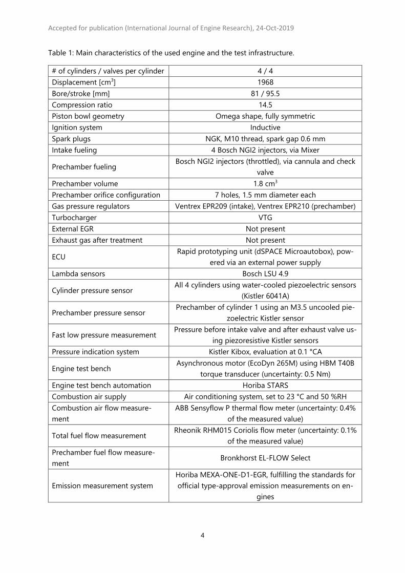
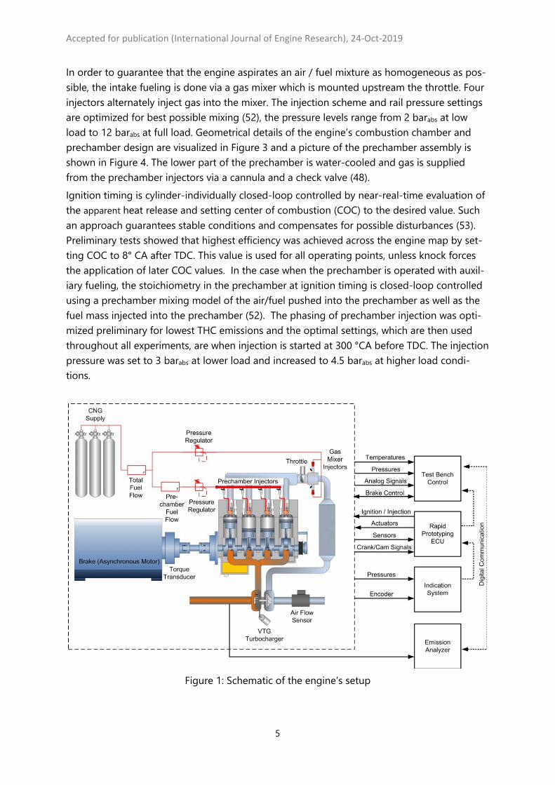
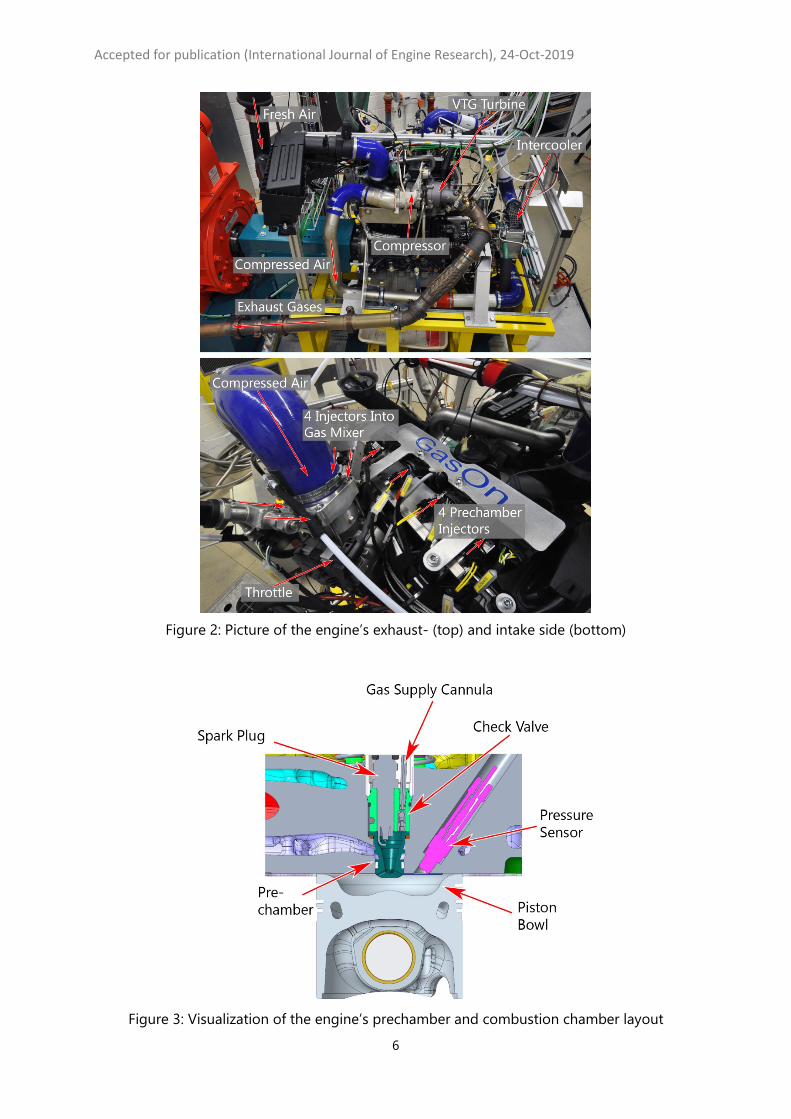
The engine is built on the basis of a Volkswagen EA288 diesel engine with a redesigned cyl-inder head to hold a prechamber with auxiliary fueling as well as a redesigned air path, ex-haust path and turbocharger. In a preliminary test series using pistons which provided different compression ratios, the op-timal compression ratio for lean combustion was found to be 14.5 since it allowed the best compromise between efficiency, cylinder peak pressure level and knock tendency. Table 1 compiles the main characteristics of the experimental setup, Figure 1 and Figure 2 show a schematic and pictures of the engine’s setup.
Accepted for publication (International Journal of Engine Research), 24-Oct-2019
4
Table 1: Main characteristics of the used engine and the test infrastructure.
# of cylinders / valves per cylinder 4 / 4 Displacement [cm3] 1968 Bore/stroke [mm] 81 / 95.5 Compression ratio 14.5 Piston bowl geometry Omega shape, fully symmetric Ignition system Inductive Spark plugs NGK, M10 thread, spark gap 0.6 mm Intake fueling 4 Bosch NGI2 injectors, via Mixer
Prechamber fueling Bosch NGI2 injectors (throttled), via cannula and check
valve Prechamber volume 1.8 cm3 Prechamber orifice configuration 7 holes, 1.5 mm diameter each Gas pressure regulators Ventrex EPR209 (intake), Ventrex EPR210 (prechamber) Turbocharger VTG External EGR Not present Exhaust gas after treatment Not present
ECU Rapid prototyping unit (dSPACE Microautobox), pow-
ered via an external power supply Lambda sensors Bosch LSU 4.9
Cylinder pressure sensor All 4 cylinders using water-cooled piezoelectric sensors
(Kistler 6041A)
Prechamber pressure sensor Prechamber of cylinder 1 using an M3.5 uncooled pie-
zoelectric Kistler sensor
Fast low pressure measurement Pressure before intake valve and after exhaust valve us-
ing piezoresistive Kistler sensors Pressure indication system Kistler Kibox, evaluation at 0.1 °CA
Engine test bench Asynchronous motor (EcoDyn 265M) using HBM T40B
torque transducer (uncertainty: 0.5 Nm) Engine test bench automation Horiba STARS Combustion air supply Air conditioning system, set to 23 °C and 50 %RH Combustion air flow measure-ment
ABB Sensyflow P thermal flow meter (uncertainty: 0.4% of the measured value)
Total fuel flow measurement Rheonik RHM015 Coriolis flow meter (uncertainty: 0.1%
of the measured value) Prechamber fuel flow measure-ment
Bronkhorst EL-FLOW Select
Emission measurement system Horiba MEXA-ONE-D1-EGR, fulfilling the standards for official type-approval emission measurements on en-
gines
Accepted for publication (International Journal of Engine Research), 24-Oct-2019
5
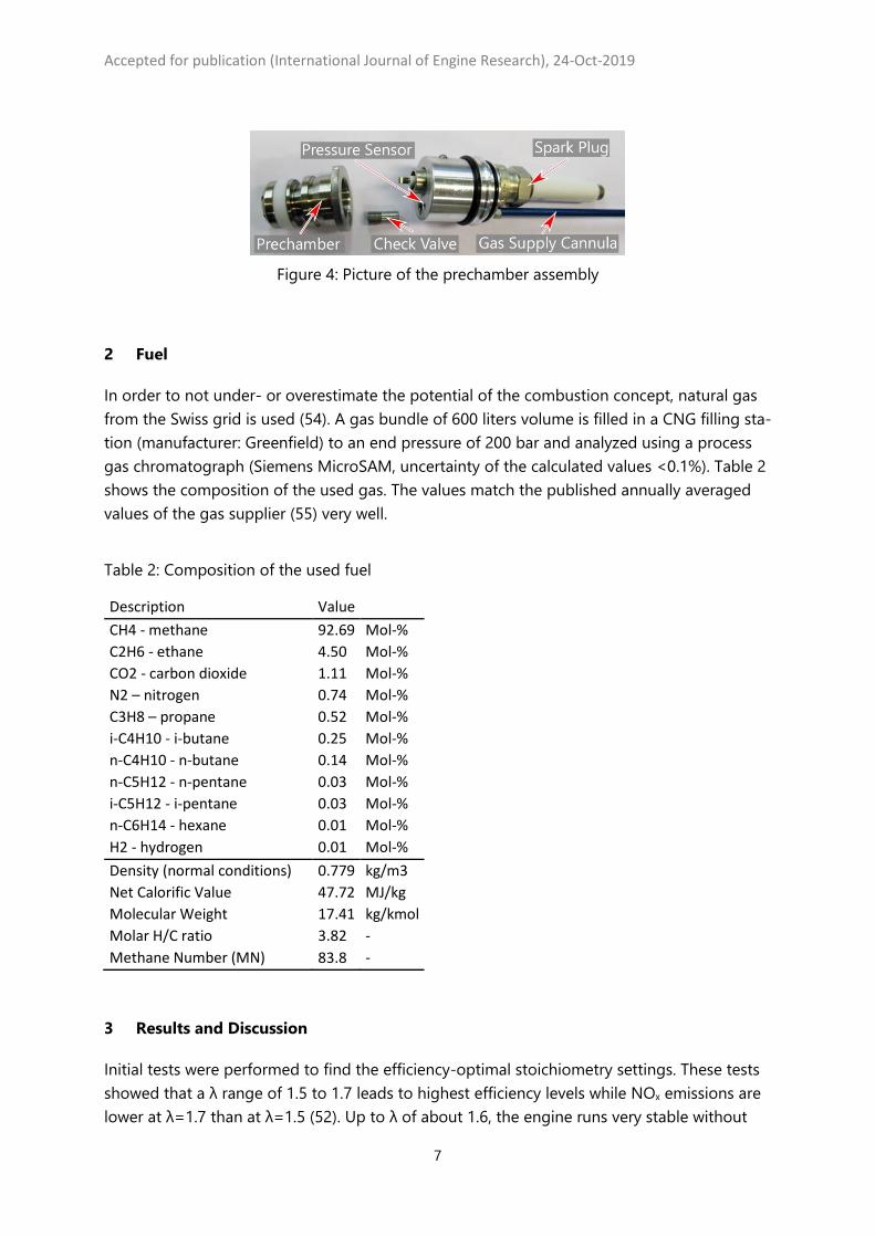
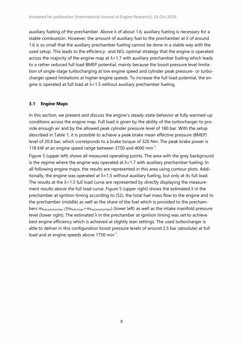
In order to guarantee that the engine aspirates an air / fuel mixture as homogeneous as pos-sible, the intake fueling is done via a gas mixer which is mounted upstream the throttle. Four injectors alternately inject gas into the mixer. The injection scheme and rail pressure settings are optimized for best possible mixing (52), the pressure levels range from 2 barabs at low load to 12 barabs at full load. Geometrical details of the engine’s combustion chamber and prechamber design are visualized in Figure 3 and a picture of the prechamber assembly is shown in Figure 4. The lower part of the prechamber is water-cooled and gas is supplied from the prechamber injectors via a cannula and a check valve (48). Ignition timing is cylinder-individually closed-loop controlled by near-real-time evaluation of the apparent heat release and setting center of combustion (COC) to the desired value. Such an approach guarantees stable conditions and compensates for possible disturbances (53). Preliminary tests showed that highest efficiency was achieved across the engine map by set-ting COC to 8° CA after TDC. This value is used for all operating points, unless knock forces the application of later COC values. In the case when the prechamber is operated with auxil-iary fueling, the stoichiometry in the prechamber at ignition timing is closed-loop controlled using a prechamber mixing model of the air/fuel pushed into the prechamber as well as the fuel mass injected into the prechamber (52). The phasing of prechamber injection was opti-mized preliminary for lowest THC emissions and the optimal settings, which are then used throughout all experiments, are when injection is started at 300 °CA before TDC. The injection pressure was set to 3 barabs at lower load and increased to 4.5 barabs at higher load condi-tions.
Figure 1: Schematic of the engine’s setup
Accepted for publication (International Journal of Engine Research), 24-Oct-2019
6
Figure 2: Picture of the engine’s exhaust- (top) and intake side (bottom)
Figure 3: Visualization of the engine’s prechamber and combustion chamber layout
Accepted for publication (International Journal of Engine Research), 24-Oct-2019
7
Figure 4: Picture of the prechamber assembly
2 Fuel
In order to not under- or overestimate the potential of the combustion concept, natural gas from the Swiss grid is used (54). A gas bundle of 600 liters volume is filled in a CNG filling sta-tion (manufacturer: Greenfield) to an end pressure of 200 bar and analyzed using a process gas chromatograph (Siemens MicroSAM, uncertainty of the calculated values <0.1%). Table 2 shows the composition of the used gas. The values match the published annually averaged values of the gas supplier (55) very well. Table 2: Composition of the used fuel
Description Value CH4 - methane 92.69 Mol-% C2H6 - ethane 4.50 Mol-% CO2 - carbon dioxide 1.11 Mol-% N2 – nitrogen 0.74 Mol-% C3H8 – propane 0.52 Mol-% i-C4H10 - i-butane 0.25 Mol-% n-C4H10 - n-butane 0.14 Mol-% n-C5H12 - n-pentane 0.03 Mol-% i-C5H12 - i-pentane 0.03 Mol-% n-C6H14 - hexane 0.01 Mol-% H2 - hydrogen 0.01 Mol-% Density (normal conditions) 0.779 kg/m3 Net Calorific Value 47.72 MJ/kg Molecular Weight 17.41 kg/kmol Molar H/C ratio 3.82 - Methane Number (MN) 83.8 -
3 Results and Discussion
Initial tests were performed to find the efficiency-optimal stoichiometry settings. These tests showed that a λ range of 1.5 to 1.7 leads to highest efficiency levels while NOx emissions are lower at λ=1.7 than at λ=1.5 (52). Up to λ of about 1.6, the engine runs very stable without
Accepted for publication (International Journal of Engine Research), 24-Oct-2019
8
auxiliary fueling of the prechamber. Above λ of about 1.6, auxiliary fueling is necessary for a stable combustion. However, the amount of auxiliary fuel to the prechamber at λ of around 1.6 is so small that the auxiliary prechamber fueling cannot be done in a stable way with the used setup. This leads to the efficiency- and NOx optimal strategy that the engine is operated across the majority of the engine map at λ=1.7 with auxiliary prechamber fueling which leads to a rather reduced full load BMEP potential, mainly because the boost pressure level limita-tion of single-stage turbocharging at low engine speed and cylinder peak pressure- or turbo-charger speed limitations at higher engine speeds. To increase the full load potential, the en-gine is operated at full load at λ=1.5 without auxiliary prechamber fueling.
3.1 Engine Maps
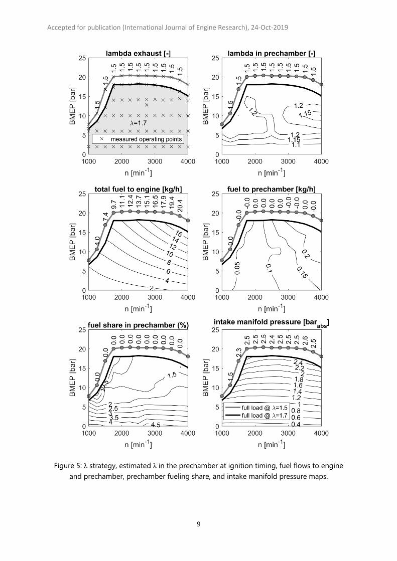
In this section, we present and discuss the engine’s steady-state behavior at fully warmed-up conditions across the engine map. Full load is given by the ability of the turbocharger to pro-vide enough air and by the allowed peak cylinder pressure level of 180 bar. With the setup described in Table 1, it is possible to achieve a peak brake mean effective pressure (BMEP) level of 20.4 bar, which corresponds to a brake torque of 320 Nm. The peak brake power is 118 kW at an engine speed range between 3750 and 4000 min-1. Figure 5 (upper left) shows all measured operating points. The area with the grey background is the regime where the engine was operated at λ=1.7 with auxiliary prechamber fueling. In all following engine maps, the results are represented in this area using contour plots. Addi-tionally, the engine was operated at λ=1.5 without auxiliary fueling, but only at its full load. The results at the λ=1.5 full load curve are represented by directly displaying the measure-ment results above the full load curve. Figure 5 (upper right) shows the estimated λ in the prechamber at ignition timing according to (52), the total fuel mass flow to the engine and to the prechamber (middle) as well as the share of the fuel which is provided to the precham-bers mfuel,prechamber /(mfuel,mixer+mfuel,prechamber) (lower left) as well as the intake manifold pressure level (lower right). The estimated λ in the prechamber at ignition timing was set to achieve best engine efficiency which is achieved at slightly lean settings. The used turbocharger is able to deliver in this configuration boost pressure levels of around 2.5 bar (absolute) at full load and at engine speeds above 1750 min-1.
Accepted for publication (International Journal of Engine Research), 24-Oct-2019
9
Figure 5: λ strategy, estimated λ in the prechamber at ignition timing, fuel flows to engine and prechamber, prechamber fueling share, and intake manifold pressure maps.
Accepted for publication (International Journal of Engine Research), 24-Oct-2019
10
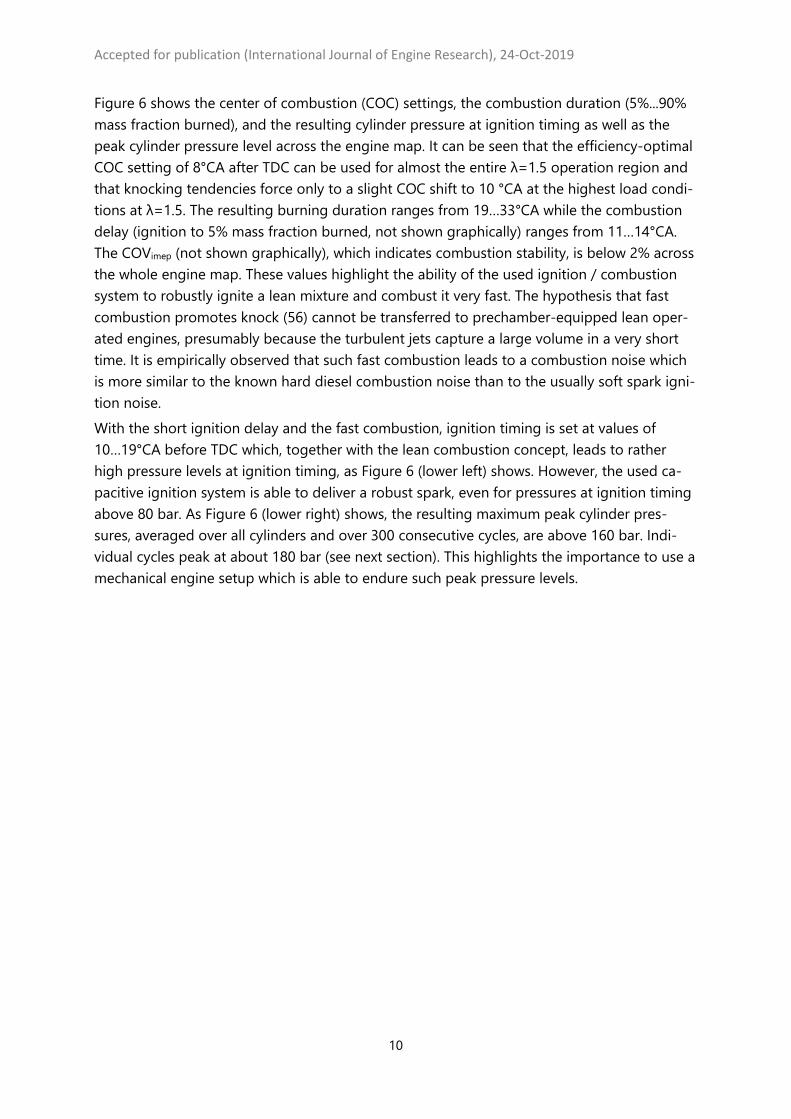
Figure 6 shows the center of combustion (COC) settings, the combustion duration (5%...90% mass fraction burned), and the resulting cylinder pressure at ignition timing as well as the peak cylinder pressure level across the engine map. It can be seen that the efficiency-optimal COC setting of 8°CA after TDC can be used for almost the entire λ=1.5 operation region and that knocking tendencies force only to a slight COC shift to 10 °CA at the highest load condi-tions at λ=1.5. The resulting burning duration ranges from 19…33°CA while the combustion delay (ignition to 5% mass fraction burned, not shown graphically) ranges from 11…14°CA. The COVimep (not shown graphically), which indicates combustion stability, is below 2% across the whole engine map. These values highlight the ability of the used ignition / combustion system to robustly ignite a lean mixture and combust it very fast. The hypothesis that fast combustion promotes knock (56) cannot be transferred to prechamber-equipped lean oper-ated engines, presumably because the turbulent jets capture a large volume in a very short time. It is empirically observed that such fast combustion leads to a combustion noise which is more similar to the known hard diesel combustion noise than to the usually soft spark igni-tion noise. With the short ignition delay and the fast combustion, ignition timing is set at values of 10…19°CA before TDC which, together with the lean combustion concept, leads to rather high pressure levels at ignition timing, as Figure 6 (lower left) shows. However, the used ca-pacitive ignition system is able to deliver a robust spark, even for pressures at ignition timing above 80 bar. As Figure 6 (lower right) shows, the resulting maximum peak cylinder pres-sures, averaged over all cylinders and over 300 consecutive cycles, are above 160 bar. Indi-vidual cycles peak at about 180 bar (see next section). This highlights the importance to use a mechanical engine setup which is able to endure such peak pressure levels.
Accepted for publication (International Journal of Engine Research), 24-Oct-2019
11
Figure 6: Center of combustion, combustion duration 5%…90% MFB, cylinder pressure at ig-
nition timing and peak cylinder pressure maps.
When calculating efficiency or specific fuel consumption, the measurement uncertainties of the individual sensors have to be taken into account. The brake specific fuel consumption is calculated as
𝜂𝜂𝑒𝑒 =𝜔𝜔 ∙ 𝑇𝑇𝑒𝑒
𝑚𝑚∗𝑓𝑓 ∙ 𝑁𝑁𝑁𝑁𝑁𝑁
The fuel mass flow is measured with an uncertainty of 0.1% of the measured value, the uncer-tainty of the Net Calorific Value is 0.1%, the uncertainty of the measured torque is 0.5 Nm and the engine speed is free of uncertainty. Assuming the worst case of linear error propaga-tion, the resulting error is
Accepted for publication (International Journal of Engine Research), 24-Oct-2019
12
Δ𝜂𝜂𝑒𝑒 = ��𝜕𝜕𝜂𝜂𝑒𝑒𝜕𝜕𝜕𝜕� Δx =
𝜔𝜔 ∙ 𝑇𝑇𝑒𝑒𝑚𝑚∗
𝑓𝑓2 ∙ 𝑁𝑁𝑁𝑁𝑁𝑁
Δ𝑚𝑚∗𝑓𝑓 +
𝜔𝜔 ∙ 𝑇𝑇𝑒𝑒𝑚𝑚∗
𝑓𝑓 ∙ 𝑁𝑁𝑁𝑁𝑁𝑁2𝛥𝛥𝑁𝑁𝑁𝑁𝑁𝑁 +
𝜔𝜔𝑚𝑚∗
𝑓𝑓 ∙ 𝑁𝑁𝑁𝑁𝑁𝑁Δ𝑇𝑇𝑒𝑒
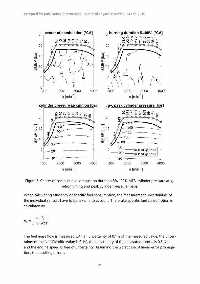
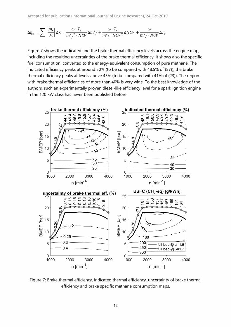
Figure 7 shows the indicated and the brake thermal efficiency levels across the engine map, including the resulting uncertainties of the brake thermal efficiency. It shows also the specific fuel consumption, converted to the energy-equivalent consumption of pure methane. The indicated efficiency peaks at around 50% (to be compared with 48.5% of (57)), the brake thermal efficiency peaks at levels above 45% (to be compared with 41% of (23)). The region with brake thermal efficiencies of more than 40% is very wide. To the best knowledge of the authors, such an experimentally proven diesel-like efficiency level for a spark ignition engine in the 120 kW class has never been published before.
Figure 7: Brake thermal efficiency, indicated thermal efficiency, uncertainty of brake thermal
efficiency and brake specific methane consumption maps.
Accepted for publication (International Journal of Engine Research), 24-Oct-2019
13
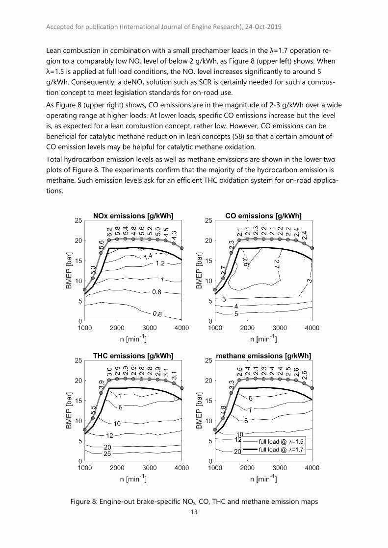
Lean combustion in combination with a small prechamber leads in the λ=1.7 operation re-gion to a comparably low NOx level of below 2 g/kWh, as Figure 8 (upper left) shows. When λ=1.5 is applied at full load conditions, the NOx level increases significantly to around 5 g/kWh. Consequently, a deNOx solution such as SCR is certainly needed for such a combus-tion concept to meet legislation standards for on-road use. As Figure 8 (upper right) shows, CO emissions are in the magnitude of 2-3 g/kWh over a wide operating range at higher loads. At lower loads, specific CO emissions increase but the level is, as expected for a lean combustion concept, rather low. However, CO emissions can be beneficial for catalytic methane reduction in lean concepts (58) so that a certain amount of CO emission levels may be helpful for catalytic methane oxidation. Total hydrocarbon emission levels as well as methane emissions are shown in the lower two plots of Figure 8. The experiments confirm that the majority of the hydrocarbon emission is methane. Such emission levels ask for an efficient THC oxidation system for on-road applica-tions.
Figure 8: Engine-out brake-specific NOx, CO, THC and methane emission maps
Accepted for publication (International Journal of Engine Research), 24-Oct-2019
14
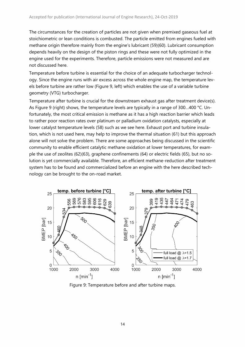
The circumstances for the creation of particles are not given when premixed gaseous fuel at stoichiometric or lean conditions is combusted. The particle emitted from engines fueled with methane origin therefore mainly from the engine’s lubricant (59)(60). Lubricant consumption depends heavily on the design of the piston rings and these were not fully optimized in the engine used for the experiments. Therefore, particle emissions were not measured and are not discussed here. Temperature before turbine is essential for the choice of an adequate turbocharger technol-ogy. Since the engine runs with air excess across the whole engine map, the temperature lev-els before turbine are rather low (Figure 9, left) which enables the use of a variable turbine geometry (VTG) turbocharger. Temperature after turbine is crucial for the downstream exhaust gas after treatment device(s). As Figure 9 (right) shows, the temperature levels are typically in a range of 300…400 °C. Un-fortunately, the most critical emission is methane as it has a high reaction barrier which leads to rather poor reaction rates over platinum or palladium oxidation catalysts, especially at lower catalyst temperature levels (58) such as we see here. Exhaust port and turbine insula-tion, which is not used here, may help to improve the thermal situation (61) but this approach alone will not solve the problem. There are some approaches being discussed in the scientific community to enable efficient catalytic methane oxidation at lower temperatures, for exam-ple the use of zeolites (62)(63), graphene confinements (64) or electric fields (65), but no so-lution is yet commercially available. Therefore, an efficient methane-reduction after treatment system has to be found and commercialized before an engine with the here described tech-nology can be brought to the on-road market.
Figure 9: Temperature before and after turbine maps.
Accepted for publication (International Journal of Engine Research), 24-Oct-2019
15
3.2 Examples of Cylinder Pressure and Heat Release
Cylinder 1 of the engine is fully equipped with in-cylinder, prechamber, intake- and exhaust channel pressure indication. In this section, we describe the pressure traces in the combustion chamber as well as in the prechamber of cylinder 1 and we discuss the heat release charac-teristics for four selected operating points at an engine speed of 2000 min-1. The indication system is set to record, at a resolution of 0.1 °CA, 300 consecutive cycles of 720 °CA which corresponds to 18 seconds engine operation. Figure 10 shows the data for the brake mean effective pressure levels of 2, 10 and 18 bar re-spectively at λ=1.7 (with auxiliary prechamber fueling) and of 20.3 bar at λ=1.5 (without auxil-iary prechamber fueling). In the plots, the moment of ignition is also marked. After ignition in the prechamber, the flame kernel grows and the expansion of the burned zone leads to a fast expansion of the charge in the prechamber. Therefore, during a first phase where the pres-sure equalization between the main combustion chamber and the prechamber is strongly re-stricted by the small orifices, a pressure difference is built up. It can be seen that the pressure buildup in the prechamber starts very quickly after ignition for both cases (with or without auxiliary prechamber fueling). This indicates that the prechamber was properly designed to offer favorable conditions for a fast flame kernel growth. After ignition, the individual pressure traces show a stochastic dispersion which indicates that the combustion velocities in the prechamber as well as in the main chamber are dominated by turbulence. Comparing the pressure data at BMEP of 18 and 20.3 bar it can be seen that the peak pressure levels are very similar, both for individual cycles as well as for the averaged cycle. Some pressure oscillations in the region of peak pressure are visible at the individual pressure traces at BMEP=20.3 bar. Since the amplitude of the oscillations is rather small we believe that these oscillations are neither attributed to hot spot surface-ignition nor to gas phase auto-ignition (66) but are induced by the turbulent jets exciting acoustic resonances (67)(68).

Accepted for publication (International Journal of Engine Research), 24-Oct-2019
16
Figure 10: Individual and averaged pressure traces in the prechamber (pPC) and in the main
chamber pcyl measured at an engine speed of 2000 min-1.
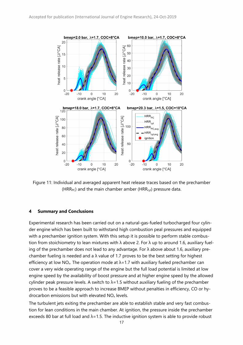
Figure 11 shows the apparent heat releases which are calculated in a window between -30 and 90 °CA with a reduced resolution of 1°CA. The calculation is performed using the pre-chamber- as well as the main chamber pressure data as the measured input but with identical parametrization of the heat release calculation model. As Figure 10 shows, the sensors in the prechamber and in the main chamber measure basically the same pressure with exception shortly after ignition when pressure difference is built up because the prechamber’s outflow is restricted by the small orifices. This phenomenon is not modeled in classical heat release models so the apparent heat release results cannot be used to exactly quantify the amount of heat released in the prechamber. However, Figure 11 gives an indication that the heat is re-leased in two sequential stages: First in the prechamber and directly afterwards in the main chamber.
Accepted for publication (International Journal of Engine Research), 24-Oct-2019
17
Figure 11: Individual and averaged apparent heat release traces based on the prechamber
(HRRPC) and the main chamber amber (HRRcyl) pressure data.
4 Summary and Conclusions
Experimental research has been carried out on a natural-gas-fueled turbocharged four cylin-der engine which has been built to withstand high combustion peal pressures and equipped with a prechamber ignition system. With this setup it is possible to perform stable combus-tion from stoichiometry to lean mixtures with λ above 2. For λ up to around 1.6, auxiliary fuel-ing of the prechamber does not lead to any advantage. For λ above about 1.6, auxiliary pre-chamber fueling is needed and a λ value of 1.7 proves to be the best setting for highest efficiency at low NOx. The operation mode at λ=1.7 with auxiliary fueled prechamber can cover a very wide operating range of the engine but the full load potential is limited at low engine speed by the availability of boost pressure and at higher engine speed by the allowed cylinder peak pressure levels. A switch to λ=1.5 without auxiliary fueling of the prechamber proves to be a feasible approach to increase BMEP without penalties in efficiency, CO or hy-drocarbon emissions but with elevated NOx levels. The turbulent jets exiting the prechamber are able to establish stable and very fast combus-tion for lean conditions in the main chamber. At ignition, the pressure inside the prechamber exceeds 80 bar at full load and λ=1.5. The inductive ignition system is able to provide robust
Accepted for publication (International Journal of Engine Research), 24-Oct-2019
18
ignition, even at such high pressure levels. At full load, brake efficiency levels above 45% are achieved which are unusual high efficiency values for an engine in the 120 kW class. The indi-cated efficiencies reach levels of nearly 50%. As the basic components of the engine are tak-en from a diesel engine capable of higher cylinder peak pressures than used here, the en-gine’s friction is not optimized for the use case described in this article. Consequently, even higher brake mean efficiency levels can be expected when a friction-optimized engine setup is used. While the NOx and CO emissions of such an engine can be efficiently reduced using known after treatment technologies such as SCR, the methane emission are a problem which is not yet solved. An efficient lean methane reduction technology which works at a comparably low temperature level has to be developed before such a combustion concept can be transferred to on-road use. Acknowledgement The authors express their gratitude to the project partners for their invaluable scientific and technical contributions and the collaboration during the GasOn project. Namely the Aero-thermochemistry and Combustion Systems Laboratory of ETH (Zürich, Switzerland) for their fundamental numerical and experimental research on prechamber combustion, the Institute of Combustion Engines and Transport of the Poznan University of Technology (Poznan, Po-land) for single cylinder engine experiments, Ricardo Software (Shoreham-by-Sea, U.K.) for developing their simulation tools for prechamber simulation and Volkswagen Group Re-search (Wolfsburg, Germany) for designing and providing hardware and for leading the work package 5 of the GasOn project. Special thanks go also to the technical staff of Empa (H. Ehrensperger, R. Spühler) who set-up the experiments and modified the engine with great care. Funding The author disclosed receipt of the following financial support for the research, authorship, and/or publication of this article: This work was supported by the EU Horizon2020 project “GasOn” [grant number 652816]. The Swiss partners have been supported by the Swiss State Secretariat for Education, Research and Innovation (SERI) [grant number 15.0145-1].
Accepted for publication (International Journal of Engine Research), 24-Oct-2019
19
Glossary BMEP Brake mean effective pressure BSFC Brake specific fuel consumption CA Crank angle CNG Compressed natural gas CO Carbon monoxide (measured with a non-dispersive infrared detector) COC Center of combustion COVimep Coefficient of variation of IMEP m*
fuel Fuel mass flow mfuel,mixer Fuel mass provided to the mixer mfuel,prechamber Fuel mass provided to the prechamber MFB Mass fraction burned n Engine speed NCV Net calorific value NOx Nitrogen oxides (the sum of NO and NO2, measured with a chemilumines-
cence detector) IMEP Indicated mean effective pressure SCR Selective catalytic reduction TDC Top dead center of the combustion stroke Te Effective torque (measured at the flywheel) THC Total hydrocarbons (hydrocarbons measured using a flame ionization detec-
tor) VTG Variable turbine geometry λ Air-fuel equivalence ratio ω Angular velocity of the engine

Accepted for publication (International Journal of Engine Research), 24-Oct-2019
20
References 1. Chu Van T, Ramirez J, Rainey T, Ristovski Z, Brown RJ. Global impacts of recent IMO
regulations on marine fuel oil refining processes and ship emissions. Transp Res Part D Transp Environ [Internet]. 2019;70(April):123–34. Available from: https://doi.org/10.1016/j.trd.2019.04.001
2. Anghilante R, Müller C, Schmid M, Colomar D, Ortloff F, Spörl R, et al. Innovative power-to-gas plant concepts for upgrading of gasification bio-syngas through steam electrolysis and catalytic methanation. Energy Convers Manag [Internet]. 2019;183(December 2018):462–73. Available from: https://doi.org/10.1016/j.enconman.2018.12.101
3. Kalghatgi G. Is it really the end of internal combustion engines and petroleum in transport? Appl Energy [Internet]. 2018;225(April):965–74. Available from: https://doi.org/10.1016/j.apenergy.2018.05.076
4. Reitz RD, Ogawa H, Payri R, Fansler T, Kokjohn S, Moriyoshi Y, et al. IJER editorial: The future of the internal combustion engine. Int J Engine Res. 2019;146808741987799.
5. NGV Global. Current Natural Gas Vehicle Statistics [Internet]. [cited 2019 Oct 15]. Available from: http://www.iangv.org/current-ngv-stats/
6. Bach C, Lämmle C, Bill R, Soltic P, Dyntar D, Janner P, et al. Clean Engine Vehicle A Natural Gas Driven Euro-4/SULEV with 30% Reduced CO2-Emissions. SAE Tech Pap [Internet]. 2004;(2004-01–0645). Available from: http://dx.doi.org/10.4271/2004-01-0645
7. Tilz A, Meyer G, Kiesling C, Pirker G, Salbrechter S, Wimmer A. Design of a test rig for fundamental investigations of spark characteristics. Int J Engine Res [Internet]. 0(0):1468087419828943. Available from: https://doi.org/10.1177/1468087419828943
8. Rochussen J, Kirchen P. Characterization of reaction zone growth in an optically accessible heavy-duty diesel/methane dual-fuel engine. Int J Engine Res. 2019;20(5):483–500.
9. Iannuzzi SE, Barro C, Boulouchos K, Burger J. POMDME-diesel blends: Evaluation of performance and exhaust emissions in a single cylinder heavy-duty diesel engine. Fuel [Internet]. 2017;203:57–67. Available from: http://dx.doi.org/10.1016/j.fuel.2017.04.089
10. Meng X, Tian H, Long W, Zhou Y, Bi M, Tian J, et al. Experimental study of using additive in the pilot fuel on the performance and emission trade-offs in the diesel/CNG (methane emulated)dual-fuel combustion mode. Appl Therm Eng [Internet]. 2019;157(March):113718. Available from: https://doi.org/10.1016/j.applthermaleng.2019.113718
11. Yontar AA, Doğu Y. Effects of equivalence ratio and CNG addition on engine performance and emissions in a dual sequential ignition engine. Int J Engine Res [Internet]. 0(0):1468087419834190. Available from: https://doi.org/10.1177/1468087419834190
12. Pancheshnyi S V., Lacoste DA, Bourdon A, Laux CO. Ignition of propane-air mixtures by a repetitively pulsed nanosecond discharge. IEEE Trans Plasma Sci. 2006;34(6):2478–87.
Accepted for publication (International Journal of Engine Research), 24-Oct-2019
21
13. Zurbriggen F, Hutter R, Onder C. Diesel-minimal combustion control of a natural gas-diesel engine. Energies. 2016;9(1).
14. Hutter R, Ritzmann J, Elbert P, Onder C. Low-Load Limit in a Diesel-Ignited Gas Engine. Energies. 2017;10(10):1–27.
15. Toulson E, Schock HJ, Attard WP. A Review of Pre-Chamber Initiated Jet Ignition Combustion Systems. SAE Tech Pap Ser. 2010;1.
16. Alvarez CEC, Couto GE, Roso VR, Thiriet AB, Valle RM. A review of prechamber ignition systems as lean combustion technology for SI engines. Appl Therm Eng [Internet]. 2018;128:107–20. Available from: https://doi.org/10.1016/j.applthermaleng.2017.08.118
17. Yamanaka K, Shiraga Y, Nakai S. Development of Pre-chamber Sparkplug for Gas Engine. SAE Tech Pap Ser. 2011;1.
18. Tolou S, Schock H. Experiments and modeling of a dual-mode, turbulent jet ignition engine. Int J Engine Res. 2019;146808741987588.
19. Wimmer DB, Lee RC. An Evaluation of the Performance and Emissions of a CFR Engine Equipped with a Prechamber. SAE Tech Pap Ser. 2010;1:1442–57.
20. Gussak LA, Turkish MC, Siegla DC. High Chemical Activity of Incomplete Combustion Products and a Method of Prechamber Torch Ignition for Avalanche Activation of Combustion in Internal Combustion Engines. SAE Tech Pap Ser. 1975;1.
21. Date T, Yagi S, Ishizuya A, Fujii I. Research and Development of the Honda CVCC Engine. SAE Tech Pap [Internet]. 1974; Available from: https://doi.org/10.4271/740605
22. Brandstetter WR, Decker G. Fundamental studies on the volkswagen stratified charge combustion process. Combust Flame. 1975;25(C):15–23.
23. Bunce M, Blaxill H. Sub-200 g/kWh BSFC on a Light Duty Gasoline Engine. SAE Tech Pap Ser. 2016;1.
24. Shah A, Tunestal P, Johansson B. Effect of Pre-Chamber Volume and Nozzle Diameter on Pre-Chamber Ignition in Heavy Duty Natural Gas Engines. SAE Tech Pap Ser. 2015;1(group 1).
25. Bauer M, Auer M, Stiesch G. Das Brennverfahren des Gasmotors 20V35/44G von MAN. MTZ - Mot Zeitschrift. 2013;74(4):300–7.
26. N/N. Jenbacher J920 FeXtra [Internet]. 2019 [cited 2019 Jun 3]. Available from: https://www.innio.com/en/products/jenbacher/j920-flextra
27. Alvarez CEC, Roso VR, Santos NDSA, Fernandes AT, Valle RM. Combustion analysis in a SI engine with homogeneous and stratified pre-chamber system. SAE Tech Pap Ser. 2019;1.
28. Sassi L, Kitsopanidis I, Lovett G. Evolutions in F1 Engine Technology: Pursuing Performance from Today’s Power Unit Through Efficiency. In: Proceedings of the 37th International Vienna Engine Symposium. 2016.
29. Xu G, Wright YM, Schiliro M, Boulouchos K. Characterization of combustion in a gas engine ignited using a small un-scavenged pre-chamber. Int J Engine Res. 2018;1–22.
Accepted for publication (International Journal of Engine Research), 24-Oct-2019
22
30. Qin F, Shah A, Huang Z wei, Peng L na, Tunestal P, Bai XS. Detailed numerical simulation of transient mixing and combustion of premixed methane/air mixtures in a pre-chamber/main-chamber system relevant to internal combustion engines. Combust Flame [Internet]. 2018;188:357–66. Available from: https://doi.org/10.1016/j.combustflame.2017.10.006
31. XU G, Wright YM, Kyrtatos P, Bardis K, Schiliro M, Boulouchos K. Experimental and Numerical Investigation of the Engine Operational Conditions’ Influences on a Small Un-Scavenged Pre-Chamber’s Behavior. SAE Int J Engines. 2017;10(5):2414–28.
32. Syrovatka Z, Vitek O, Vavra J, Takats M. Scavenged Pre-Chamber Volume Effect on Gas Engine Performance and Emissions. SAE Tech Pap Ser [Internet]. 2019;1–17. Available from: https://www.sae.org/content/2019-01-0258/
33. Gholamisheeri M, Givler S, Toulson E. Large eddy simulation of a homogeneously charged turbulent jet ignition system. Int J Engine Res. 2019;20(2):181–93.
34. Bozza F, Bellis V De, Tufano D. A Quasi-Dimensional Model of Pre-Chamber Spark-Ignition Engines. SAE Tech Pap Ser. 2019;(Mc):1–17.
35. Baumgartner LS, Wohlgemuth S, Zirngibl S, Wachtmeister G. Investigation of a Methane Scavenged Prechamber for Increased Efficiency of a Lean-Burn Natural Gas Engine for Automotive Applications. SAE Int J Engines. 2015;8(2):921–33.
36. Gholamisheeri M, Thelen BC, Gentz GR, Wichman IS, Toulson E. Rapid compression machine study of a premixed, variable inlet density and flow rate, confined turbulent jet. Combust Flame. 2016;169:321–32.
37. Desantes JM, Novella R, De La Morena J, Pagano lng V. Achieving Ultra-Lean Combustion Using a Pre-Chamber Spark Ignition System in a Rapid Compression-Expansion Machine. SAE Tech Pap Ser [Internet]. 2019;1–12. Available from: https://www.sae.org/content/2019-01-0236/
38. Biswas S, Qiao L. Ignition of ultra-lean premixed hydrogen/air by an impinging hot jet. Appl Energy [Internet]. 2018;228(July):954–64. Available from: https://doi.org/10.1016/j.apenergy.2018.06.102
39. Gholamisheeri M, Wichman IS, Toulson E. A study of the turbulent jet flow field in a methane fueled turbulent jet ignition (TJI) system. Combust Flame. 2017;183:194–206.
40. Slefarski R, Golebiewski M, Czyzewski P, Grzymislawski P, Wawrzyniak J. Analysis of combustion process in industrial gas engine with prechamber-based ignition system. Energies. 2018;11(2).
41. Jamrozik A. Lean combustion by a pre-chamber charge stratification in a stationary spark ignited engine. J Mech Sci Technol. 2015;29(5):2269–78.
42. Xu G, Kotzagianni M, Kyrtatos P, Wright YM, Boulouchos K. Experimental and numerical investigations of the unscavenged prechamber combustion in a rapid compression and expansion machine under engine-like conditions. Combust Flame [Internet]. 2019;204:68–84. Available from: https://doi.org/10.1016/j.combustflame.2019.01.025
43. Kotzagianni M, Kyrtatos P, Boulouchos K. Optical investigation of prechamber
Accepted for publication (International Journal of Engine Research), 24-Oct-2019
23
combustion in an RCEM. Combust Engines. 2019;176(1):10–5. 44. Shapiro E, Tiney N, Kyrtatos P, Kotzagianni M, Bolla M, Boulouchos K, et al.
Experimental and Numerical Analysis of Pre-Chamber Combustion Systems for Lean Burn Gas Engines. SAE Tech Pap Ser [Internet]. 2019;1–11. Available from: https://www.sae.org/content/2019-01-0260/
45. Bolla M, Shapiro E, Kotzagianni M, Kyrtatos P, Tiney N, Boulouchos K. Numerical study of fuel and turbulence distributions in an automotive-sized scavenged pre-chamber. Combust Engines. 2019;176(1):61–7.
46. Bolla M, Shapiro E, Tiney N, Kyrtatos P, Kotzagianni M, Boulouchos K. Numerical Study of Turbulence and Fuel-Air Mixing within a Scavenged Pre-Chamber Using RANS and LES. SAE Tech Pap Ser. 2019;1:1–11.
47. Lucas G, Tallu G, Weißner M. CFD-based Development of an Ignition Chamber for a lean and high efficient CNG Combustion. In: THIESEL 2018 Conference on Thermo- and Fluid Dynamic Processes in Direct Injection Engines. 2018.
48. Weissner M, Beger F, Schüttenhelm M, Tallu G. Lean-burn CNG engine with ignition chamber : from the idea to a running engine. Combust Engines. 2019;176(1):3–9.
49. Bueschke W, Skowron M, Wisłocki K, Szwajca F. Comparative study on combustion characteristics of lean premixed CH4/air mixtures in RCM using spark ignition and turbulent jet ignition in terms of orifices angular position change. Combust Engines. 2019;176(1):36–41.
50. Pielecha I, Bueschke W, Skowron M, Fiedkiewicz L, Szwajca F, Cieslik W, et al. Prechamber optimal selection for a two stage turbulent jet ignition type combustion system in CNG-fuelled engine. Combust Engines. 2019;176(1):16–26.
51. Soltic P, Hilfiker T, Hutter R, Hänggi S. Experimental comparison of efficiency and emission levels of four-cylinder lean-burn passenger car-sized CNG engines with different ignition concepts. Combust Engines. 2019;176(1):27–35.
52. Hänggi S, Hilfiker T, Soltic P, Hutter R, Onder C. Control-oriented analysis of a lean-burn light-duty natural gas research engine with scavenged pre-chamber ignition. Combust Engines. 2019;176(1):42–53.
53. Xu Z, Zhang Y, Di H, Shen T. Combustion variation control strategy with thermal efficiency optimization for lean combustion in spark-ignition engines. Appl Energy [Internet]. 2019;251(May):113329. Available from: https://doi.org/10.1016/j.apenergy.2019.113329
54. N/A. Förderländerstatistik 2015 [Internet]. [cited 2019 Jun 12]. Available from: http://www.swissgas.ch/informationen/downloads/
55. Swissgas. Erdgas - Zusammensetzung der Swissgas - Importe im Jahre 2018 [Internet]. 2018 [cited 2019 Jun 12]. Available from: http://www.swissgas.ch/fileadmin/user_upload/swissgas/downloads/Erdgaseigenschaften_2018_SG_D.pdf
56. Chen Y, Raine R. A study on the influence of burning rate on engine knock from empirical data and simulation. Combust Flame [Internet]. 2015;162(5):2108–18.
Accepted for publication (International Journal of Engine Research), 24-Oct-2019
24
Available from: http://dx.doi.org/10.1016/j.combustflame.2015.01.009 57. Yin L, Lundgren M, Wang Z, Stamatoglou P, Richter M, Andersson Ö, et al. High
efficient internal combustion engine using partially premixed combustion with multiple injections. Appl Energy [Internet]. 2019;233–234(September 2018):516–23. Available from: https://doi.org/10.1016/j.apenergy.2018.09.011
58. Hutter R, De Libero L, Elbert P, Onder CH. Catalytic methane oxidation in the exhaust gas aftertreatment of a lean-burn natural gas engine. Chem Eng J [Internet]. 2018;349(January):156–67. Available from: https://doi.org/10.1016/j.cej.2018.05.054
59. Alanen J, Saukko E, Lehtoranta K, Murtonen T, Timonen H, Hillamo R, et al. The formation and physical properties of the particle emissions from a natural gas engine. Fuel [Internet]. 2015;162:155–61. Available from: http://dx.doi.org/10.1016/j.fuel.2015.09.003
60. Amirante R, Distaso E, Napolitano M, Tamburrano P, Iorio S Di, Sementa P, et al. Effects of lubricant oil on particulate emissions from port-fuel and direct-injection spark-ignition engines. Int J Engine Res [Internet]. 2017;18(5–6):606–20. Available from: https://doi.org/10.1177/1468087417706602
61. Luján JM, Serrano JR, Piqueras P, Diesel B. Turbine and exhaust ports thermal insulation impact on the engine efficiency and aftertreatment inlet temperature. Appl Energy [Internet]. 2019;240(February):409–23. Available from: https://doi.org/10.1016/j.apenergy.2019.02.043
62. Petrov AW, Ferri D, Krumeich F, Nachtegaal M, Van Bokhoven JA, Kröcher O. Stable complete methane oxidation over palladium based zeolite catalysts. Nat Commun [Internet]. 2018;9(1). Available from: http://dx.doi.org/10.1038/s41467-018-04748-x
63. Petrov AW, Ferri D, Kröcher O, Van Bokhoven JA. Design of Stable Palladium-Based Zeolite Catalysts for Complete Methane Oxidation by Postsynthesis Zeolite Modification. ACS Catal. 2019;9(3):2303–12.
64. Cui X, Li H, Wang Y, Hu Y, Hua L, Li H, et al. Room-Temperature Methane Conversion by Graphene-Confined Single Iron Atoms. Chem [Internet]. 2018;4(8):1902–10. Available from: https://doi.org/10.1016/j.chempr.2018.05.006
65. Li K, Liu K, Xu D, Ni H, Shen F, Chen T, et al. Lean methane oxidation over Co3O4/Ce0.75Zr0.25 catalysts at low-temperature: Synergetic effect of catalysis and electric field. Chem Eng J. 2019;369(800):660–71.
66. Pischinger S, Günther M, Budak O. Abnormal combustion phenomena with different fuels in a spark ignition engine with direct fuel injection. Combust Flame [Internet]. 2017;175:123–37. Available from: http://dx.doi.org/10.1016/j.combustflame.2016.09.010
67. Gupta HC, Bracco F V. The origin of pressure oscillations in divided chamber engines. Combust Flame. 1982;48(C):33–49.
68. Guardiola C, Pla B, Bares P, Barbier A. An analysis of the in-cylinder pressure resonance excitation in internal combustion engines. Appl Energy [Internet]. 2018;228(July):1272–9. Available from: https://doi.org/10.1016/j.apenergy.2018.06.157