
Efficient and Secure End-to-End Mobility Support in IPv6
268
Efficient and Secure End-to-End Mobility Support in IPv6 zur Erlangung des akademischen Grades eines Doktors der Ingenieurwissenschaften von der Fakultät für Informatik der Universität Fridericiana zu Karlsruhe (TH) genehmigte Dissertation von Christian Vogt aus Bonn Tag der mündlichen Prüfung: 20. Juli 2007 Erste Gutachterin: Zweite Gutachterin: Prof. Dr. Martina Zitterbart Prof. Dr. Carmelita Görg
-
Upload
khangminh22 -
Category
Documents
-
view
0 -
download
0
Transcript of Efficient and Secure End-to-End Mobility Support in IPv6

Efficient and Secure End-to-End Mobility Support in IPv6
zur Erlangung des akademischen Grades eines
Doktors der Ingenieurwissenschaften
von der Fakultät für Informatik der Universität Fridericiana zu Karlsruhe (TH)
genehmigte
Dissertation
von
Christian Vogt
aus Bonn
Tag der mündlichen Prüfung: 20. Juli 2007
Erste Gutachterin: Zweite Gutachterin:
Prof. Dr. Martina Zitterbart Prof. Dr. Carmelita Görg


For my sister Kerstin —for being encouragement and example


Preface
This thesis is the product of my work as a scientific associate at the Institute ofTelematics at Universitat Karlsruhe (TH), Germany. It would not have been possiblewithout the teaching, help, patience, and inspiration of a great number of people,who all deserve more than simple acknowledgment.
Foremost, I wish to thank my doctoral advisor and thesis reviewer, Prof. Dr. Mar-tina Zitterbart. She gave me the opportunity to pursue this thesis, and supportedit with care and outstanding expertise up to its successful completion. She alsoadmitted the funding I needed to present my work at national and internationalconferences and conventions, plus the time that was necessary to standardize majorparts of the work. Additionally, the expensive testing environment that I could useto evaluate my ideas was by no means a matter of course.
For her review of my thesis and participation in the defense committee despite anextremely busy schedule, I want to express my gratitude to Prof. Dr. CarmelitaGorg. Her suggestions as well as our technical discussions were highly valuable.
Many thanks are due to the Konrad-Adenauer-Stiftung for a graduate scholarshipthat included both financial aid and a distinguished seminar program. I am gratefulin particular to Dr. Daniela Tandecki and Dr. Rita Thiele for their help and avail-ability as trusted contact persons. Many thanks also to Dr. Gerd-Dieter Fischer forthe cordial cooperation in organizing and carrying out two of the Konrad-Adenauer-Stiftung’s scientific association’s annual conventions.
I very especially wish to thank my colleagues and friends Mark Doll and Dr. RolandBless for multifold excellent discussions and inspirations that shaped this thesissignificantly. Thanks also for their readiness to listen to and reflect on countlessad-hoc ideas on making the Internet “yet a bit better”.
It was a pleasure to work closely together with Tobias Kufner during the earlyphase of the dissertation, for supervising our first Master student and organizing thefirst student seminars. Thanks also to Marco Liebsch for the marvelous technicalcooperation and friendship. I was delighted by the great collaboration with OliverStanze, Kilian Weniger, Erik-Oliver Blaß, Jidong Wu, Ingmar Baumgart, ChristianHubsch, and Christoph Wehrle on handling several student workshops and seminars.Gratitude is likewise due to Christoph Sorge, Lars Volker, Marc Torrent-Moreno,Peter Baumung, and my other colleagues for the cordial atmosphere at work.
Additional thanks go out to many more researchers for their much appreciated feed-back and ideas: Jari Arkko, Dr. Pekka Nikander, Dr. James Kempf, Charles E.Perkins, Wassim Haddad, Rajeev Koodli, Gonzalo Camarillo, Dr. Lixia Zhang,Gabriel Montenegro, Gregory Daley, Dr. Lars Eggert, and Keiichi Shima.

Special thanks are due to Mrs. Astrid Natzberg, Mrs. Doris Weber, and Mrs.Dorothea Wagner from the institute’s secretariat, and to Mrs. Ines Himpel fromthe Dean’s office for the help on surmounting several administrative hurdles. Manythanks also to Mr. Gentiel Mussgnug, Mr. Detlev Maier, and Mr. Frank Winter fora superb technical support. I am furthermore indebted to my students Daniel Jung-bluth, Constantin Schimmel, Ralf Beck, and Max Laier, all of whom added notablyto the success of this thesis.
Last, but not least, my gratitude is due to my family and friends. Without theirwarmth and unwavering support, this thesis would never have been realized.
Thank you all.

Contents
1 Introduction 1
2 Fundamentals 7
2.1 An Internet for Stationary Nodes . . . . . . . . . . . . . . . . . . . . 7
2.2 Addressing and Routing . . . . . . . . . . . . . . . . . . . . . . . . . 10
2.2.1 Network Attachment and Link Layer Addressing . . . . . . . . 10
2.2.2 IP Layer Addressing . . . . . . . . . . . . . . . . . . . . . . . 12
2.2.3 IP Headers and Extension Headers . . . . . . . . . . . . . . . 13
2.2.4 Routing . . . . . . . . . . . . . . . . . . . . . . . . . . . . . . 15
2.2.5 IP Address Resolution . . . . . . . . . . . . . . . . . . . . . . 15
2.3 Towards a Mobile Internet . . . . . . . . . . . . . . . . . . . . . . . . 16
2.3.1 Packet Redirection Techniques . . . . . . . . . . . . . . . . . . 17
2.3.2 Security Threats Related to IP Mobility . . . . . . . . . . . . 21
2.3.3 Mobility Support in IPv6 . . . . . . . . . . . . . . . . . . . . . 27
2.3.4 Reactive versus Proactive Mobility Management . . . . . . . . 32
2.3.5 Relation to Multi-Homing . . . . . . . . . . . . . . . . . . . . 32
2.4 Protocols Supplementing Mobility . . . . . . . . . . . . . . . . . . . . 33
2.4.1 Router and Subnet Prefix Discovery . . . . . . . . . . . . . . . 34
2.4.2 Movement Detection . . . . . . . . . . . . . . . . . . . . . . . 34
2.4.3 IP Address Configuration . . . . . . . . . . . . . . . . . . . . 35
2.4.4 Neighbor Unreachability Detection . . . . . . . . . . . . . . . 37
2.4.5 Internet Control Message Protocol for IPv6 . . . . . . . . . . 37
2.4.6 Optimizations . . . . . . . . . . . . . . . . . . . . . . . . . . . 37
2.4.7 Media Independent Handover Services . . . . . . . . . . . . . 40
2.5 Transmission Control Protocol . . . . . . . . . . . . . . . . . . . . . . 44
2.5.1 Original Specification . . . . . . . . . . . . . . . . . . . . . . . 44

viii Contents
2.5.2 TCP Tahoe . . . . . . . . . . . . . . . . . . . . . . . . . . . . 45
2.5.3 TCP Reno . . . . . . . . . . . . . . . . . . . . . . . . . . . . . 46
2.5.4 TCP NewReno . . . . . . . . . . . . . . . . . . . . . . . . . . 47
2.5.5 TCP SACK . . . . . . . . . . . . . . . . . . . . . . . . . . . . 48
2.5.6 TCP Limited Transmit . . . . . . . . . . . . . . . . . . . . . . 49
2.5.7 Delayed Acknowledgments . . . . . . . . . . . . . . . . . . . . 49
3 Problem and Solution Space Analysis 51
3.1 Related Work . . . . . . . . . . . . . . . . . . . . . . . . . . . . . . . 51
3.1.1 Assessment Criteria . . . . . . . . . . . . . . . . . . . . . . . . 52
3.1.2 Reducing Signaling Round-Trips . . . . . . . . . . . . . . . . . 53
3.1.3 Localization . . . . . . . . . . . . . . . . . . . . . . . . . . . . 53
3.1.4 Route Repair . . . . . . . . . . . . . . . . . . . . . . . . . . . 55
3.1.5 Packet duplication . . . . . . . . . . . . . . . . . . . . . . . . 56
3.1.6 Dual Network Attachment . . . . . . . . . . . . . . . . . . . . 57
3.1.7 Discussion . . . . . . . . . . . . . . . . . . . . . . . . . . . . . 58
3.2 Significance of Reachability Verification . . . . . . . . . . . . . . . . . 59
3.2.1 Existing Types of Flooding . . . . . . . . . . . . . . . . . . . 60
3.2.2 Utility of Redirection-Based Flooding . . . . . . . . . . . . . . 61
3.3 Protection Alternatives Against Redirection-Based Flooding . . . . . 63
3.3.1 Assessment Criteria . . . . . . . . . . . . . . . . . . . . . . . . 63
3.3.2 Trusted Communities . . . . . . . . . . . . . . . . . . . . . . . 64
3.3.3 Temporary Buffering . . . . . . . . . . . . . . . . . . . . . . . 65
3.3.4 Temporary Redirection to Stable IP Addresses . . . . . . . . . 65
3.3.5 IP Source Address Filtering . . . . . . . . . . . . . . . . . . . 66
3.3.6 Heuristics . . . . . . . . . . . . . . . . . . . . . . . . . . . . . 68
3.4 Proposed Solution . . . . . . . . . . . . . . . . . . . . . . . . . . . . . 68
4 Credit-Based Authorization 71
4.1 Approach . . . . . . . . . . . . . . . . . . . . . . . . . . . . . . . . . 71
4.1.1 Credit Concept . . . . . . . . . . . . . . . . . . . . . . . . . . 73
4.1.2 Credit Aging . . . . . . . . . . . . . . . . . . . . . . . . . . . 76
4.1.3 IP Address States . . . . . . . . . . . . . . . . . . . . . . . . . 76

Contents ix
4.1.4 Packet Loss Estimation . . . . . . . . . . . . . . . . . . . . . . 79
4.1.5 Protection Against Redirection-Based Reflection . . . . . . . . 80
4.1.6 Failure of Reachability Verification . . . . . . . . . . . . . . . 81
4.1.7 Multi-Homing Support . . . . . . . . . . . . . . . . . . . . . . 81
4.2 Credit Management . . . . . . . . . . . . . . . . . . . . . . . . . . . . 82
4.2.1 Initialization . . . . . . . . . . . . . . . . . . . . . . . . . . . . 83
4.2.2 Inbound Mode . . . . . . . . . . . . . . . . . . . . . . . . . . 83
4.2.3 Outbound Mode . . . . . . . . . . . . . . . . . . . . . . . . . 86
4.2.4 Credit Aging . . . . . . . . . . . . . . . . . . . . . . . . . . . 88
4.3 IP Address Spot Checks . . . . . . . . . . . . . . . . . . . . . . . . . 90
4.3.1 Protocol Model . . . . . . . . . . . . . . . . . . . . . . . . . . 90
4.3.2 Generating Spot Check Tokens . . . . . . . . . . . . . . . . . 94
4.3.3 In-Band Transport . . . . . . . . . . . . . . . . . . . . . . . . 97
4.3.4 Protocol Configuration . . . . . . . . . . . . . . . . . . . . . . 99
4.3.5 Conceptual Data Structures . . . . . . . . . . . . . . . . . . . 100
4.3.6 Correspondent Node Operation . . . . . . . . . . . . . . . . . 103
4.3.7 Mobile Node Operation . . . . . . . . . . . . . . . . . . . . . . 106
4.4 Summary . . . . . . . . . . . . . . . . . . . . . . . . . . . . . . . . . 106
5 Early Binding Updates 111
5.1 Technical Approach . . . . . . . . . . . . . . . . . . . . . . . . . . . . 112
5.1.1 Standard-Compliant Optimizations . . . . . . . . . . . . . . . 112
5.1.2 Optimizations Requiring Changes to the Standard . . . . . . . 114
5.2 Reactive Mobility Management . . . . . . . . . . . . . . . . . . . . . 117
5.2.1 Mobility Management Architecture . . . . . . . . . . . . . . . 117
5.2.2 Protocol Operation . . . . . . . . . . . . . . . . . . . . . . . . 119
5.2.3 Initial Correspondent Registration . . . . . . . . . . . . . . . . 125
5.2.4 Message Types . . . . . . . . . . . . . . . . . . . . . . . . . . 126
5.2.5 Discovering Compatibility . . . . . . . . . . . . . . . . . . . . 127
5.3 Proactive Mobility Management . . . . . . . . . . . . . . . . . . . . . 128
5.3.1 Additional Requirements . . . . . . . . . . . . . . . . . . . . . 128
5.3.2 Mobility Management Architecture . . . . . . . . . . . . . . . 131
5.3.3 Protocol Operation . . . . . . . . . . . . . . . . . . . . . . . . 133
5.3.4 Appointing Link Layer Handover Initiation . . . . . . . . . . . 142
5.4 Summary . . . . . . . . . . . . . . . . . . . . . . . . . . . . . . . . . 145

x Contents
6 Evaluation 147
6.1 Testbed Setup . . . . . . . . . . . . . . . . . . . . . . . . . . . . . . . 147
6.1.1 Mobile IPv6 Implementation . . . . . . . . . . . . . . . . . . . 147
6.1.2 Topology . . . . . . . . . . . . . . . . . . . . . . . . . . . . . . 148
6.1.3 TCP Buffers . . . . . . . . . . . . . . . . . . . . . . . . . . . . 150
6.1.4 Applications . . . . . . . . . . . . . . . . . . . . . . . . . . . . 151
6.1.5 IPv6 Auto-Configuration . . . . . . . . . . . . . . . . . . . . . 152
6.1.6 Router Buffers . . . . . . . . . . . . . . . . . . . . . . . . . . 153
6.1.7 Packet Loss . . . . . . . . . . . . . . . . . . . . . . . . . . . . 156
6.2 Internet Telephony . . . . . . . . . . . . . . . . . . . . . . . . . . . . 156
6.2.1 Packet Loss . . . . . . . . . . . . . . . . . . . . . . . . . . . . 157
6.2.2 Handover Delay . . . . . . . . . . . . . . . . . . . . . . . . . . 160
6.2.3 Credit Availability . . . . . . . . . . . . . . . . . . . . . . . . 161
6.3 Internet Telephony with Proactive Mobility Management . . . . . . . 165
6.3.1 Packet Loss . . . . . . . . . . . . . . . . . . . . . . . . . . . . 165
6.3.2 Handover Delay . . . . . . . . . . . . . . . . . . . . . . . . . . 168
6.3.3 Credit Availability . . . . . . . . . . . . . . . . . . . . . . . . 169
6.4 TCP File Transfers . . . . . . . . . . . . . . . . . . . . . . . . . . . . 172
6.4.1 Throughput . . . . . . . . . . . . . . . . . . . . . . . . . . . . 173
6.4.2 Retransmission Timeouts . . . . . . . . . . . . . . . . . . . . . 174
6.4.3 Effect of Delayed Acknowledgments . . . . . . . . . . . . . . . 178
6.4.4 Handover Delay . . . . . . . . . . . . . . . . . . . . . . . . . . 182
6.4.5 Packet Loss . . . . . . . . . . . . . . . . . . . . . . . . . . . . 184
6.4.6 Credit Availability . . . . . . . . . . . . . . . . . . . . . . . . 187
6.5 TCP File Transfers with Proactive Mobility Management . . . . . . . 190
6.5.1 Packet Loss . . . . . . . . . . . . . . . . . . . . . . . . . . . . 190
6.5.2 Packet Loss in an Asymmetric Topology . . . . . . . . . . . . 195
6.5.3 Retransmission Timeouts . . . . . . . . . . . . . . . . . . . . . 199
6.5.4 Retransmission Timeouts in an Asymmetric Topology . . . . . 201
6.5.5 Handover Delay . . . . . . . . . . . . . . . . . . . . . . . . . . 205
6.5.6 Handover Delay in an Asymmetric Topology . . . . . . . . . . 208
6.5.7 Credit Availability . . . . . . . . . . . . . . . . . . . . . . . . 211
6.5.8 Credit Availability in an Asymmetric Topology . . . . . . . . 214
6.6 Summary . . . . . . . . . . . . . . . . . . . . . . . . . . . . . . . . . 217

Contents xi
7 Conclusions 221
A Impact of Link Layer Handover Delays 225
A.1 Internet Telephony . . . . . . . . . . . . . . . . . . . . . . . . . . . . 225
A.2 TCP File Transfers . . . . . . . . . . . . . . . . . . . . . . . . . . . . 226
B Impact of Movement Detection 233
B.1 Internet Telephony . . . . . . . . . . . . . . . . . . . . . . . . . . . . 234
B.2 TCP File Transfers . . . . . . . . . . . . . . . . . . . . . . . . . . . . 234
Bibliography 241
Index 253


1. Introduction
Patterns of Internet use have been evolving rapidly in the recent years, shiftingfrom delay- and bandwidth-tolerant applications like Web browsing, electronic mail,and file transfer towards more delay- and loss-sensitive soft-real-time applications,like audio and video streaming or broadcasts [46], and even hard-real-time servicessuch as Internet telephony or videoconferencing [81, 96]. At the same time, peopleare increasingly expecting these services to be available anywhere, anytime, andthrough any access technology. These developments are the onset of a convergedInternet, embracing wireless home and enterprise networks, hotspots in coffee shopsand airport lounges, just as well as wide-area cellular networks.
The new heterogeneity in access technologies and the increasing mobility of Internetusers calls for an efficient mechanism to hand active communication sessions overbetween different points of attachment to the Internet. Users may change their pointof attachment during movements, for better service quality through a different accesstechnology or provider, to save access costs, or for fail-over or load balancing. Thebase Internet Protocol, IP, does not provide such flexibility. It was mainly designedfor stationary nodes with fixed IP addresses. Much effort has hence recently gone intomechanisms that transfer an active communication session from one IP address toanother when a mobile node changes its point of attachment to the Internet. Figure1.1(a) illustrates such a redirection based on a communication session between amobile node and the correspondent node that it communicates with. The mobilenode in the figure hands over from its current point of attachment to a new pointof attachment. Along with this changes the IP address at which the correspondentnode can reach the mobile node. The mobile node signals the new IP address tothe correspondent node, and the correspondent node redirects the communicationsession to that new IP address. Part of the existing mobility mechanisms augmentapplications so as to survive IP address changes on either side of a connection.Others leave the applications untouched and add the necessary functionality intotransport protocols that applications may use. A third approach is to build mobilitysupport into IP directly. Changes in a mobile node’s IP address are then invisibleto transport protocols and applications. This thesis focuses on mobility support inIP.

2 1. Introduction
mobilenode
Internet
correspondentnode
r e d i r e c t io n
movement
o r i g i n a l p a c k e t p a t hn e w
p a ck e t
path
3
2
1
(a) Packet redirection for a mobile node
Internet
correspondentnodes
victim
floodingattacker
redirectionest ab
l i shc on ne ct io
ns
fl o o d i n g p a c k e t s
1
2
3
(b) Redirection-based flooding
Figure 1.1: Legitimate versus malicious packet redirection
Any mechanism that enables a node to redirect packets from one IP address toanother faces the threat of misuse [94]. Applications and transport protocols tra-ditionally identify a node based on the node’s IP address. Such IP-address-basedidentification is build on a trust on the routing infrastructure to deliver a packet fora particular IP address to exactly that IP address, or to drop the packet. Unless anattacker can compromise the routing infrastructure, it can eavesdrop on or tamperwith packets exchanged between two nodes only if it is located on the communica-tion path between these nodes. However, unless appropriate measures are provided,IP mobility support could give an attacker the ability to change the destination ofpackets that a remote node sends, transparently to applications and transport proto-cols, and without affecting the routing infrastructure. The attacker could so arrangeto receive packets that should actually be delivered to a different node, regardless ofwhere the attacker is located on the Internet. Similarly, the attacker could redirectpackets that it is supposed to receive itself to a different node. This thesis addressesthe latter threat, where the attacker causes a victim to receive unwanted packets.
Misuse of a mobility protocol to cause unwanted traffic is called a redirection-basedflooding attack. A typical invocation of such an attack is shown in figure 1.1(b). Theattacker first requests one or multiple correspondent nodes to transfer some largefiles. This involves a handshake between the attacker and a correspondent node,as indicated in the figure by the dashed arrows. Once a connection is set up, theattacker redirects the packet flow to the IP address of a victim. The attacker therebyclogs the victim’s Internet access with packets that the attacker would actually besupposed to receive itself, impairing the victim’s ability to pursue any reasonablecommunications. Redirection-based flooding attacks are an important threat be-cause they enable the attacker to offload most of the effort it takes to wage theattack onto correspondent nodes. The correspondent nodes thereby unknowinglyamplify the attacker’s own effort: It is sufficient for the attacker to spoof acknowl-edgments for pretendedly received data in order to uphold the packet flows from the

3
correspondent nodes to the victim. The acknowledgments are smaller in both num-ber and size than the packets that the correspondent nodes generate, so the damagecaused to the victim can be much more severe than it could be if the attacker itselfsent all packets to the victim directly. The only conventional type of flooding attackthat provides a similar level of amplification is distributed denial-of-service attacks[79]. However, these imply a higher costs on the attacker side for programming anddistributing viral software that subverts a suitable number of nodes into supportingthe attack. Also conceivable is the use of a redirection-based flooding attack in com-bination with conventional flooding, for example as another layer of amplificationin distributed denial of service. The threat of redirection-based flooding exists forany mechanism that enables a node to redirect packets from one IP address to an-other. This thesis focuses on IP mobility support, but its contributions are likewiseapplicable to mobility support in transport protocols and applications.
A widely accepted technique [94, 63, 88, 10, 45] to mitigate the threat of redirection-based flooding is for a correspondent node to check a mobile node’s presence at aclaimed new IP address by sending thereto an unpredictable token that the mo-bile node must echo back. The way that modern mobility protocols pusue suchreachability verification is to drop packets destined to the new IP address until theverification completes. This has two fundamental disadvantages, however: First, thetoken exchange delays resumed bidirectional packet exchange by one extra round-trip time between the communicating nodes whenever the mobile node changes IPconnectivity. This is additive to other handover-related delays and may thereforenotably impair the quality of both hard- and soft-real-time applications. Second, thetoken exchange does not permit proactive mobility management, where the mobilenode prepares a change in IP connectivity from its old point of attachment so thatit can receive packets without delay once it arrives at the new point of attachment.While the performance of reactive mobility management is limited by a minimumIP layer handover delay of one round-trip time between the mobile node and thecorrespondent node, proactive mobility management permits handover delays to bereduced down to zero depending on the network topology.
The objectives of this thesis is hence to propose a secure mechanism that reduces, ifnot eliminates, the additional handover delay that modern mobility protocols causeduring reachability verification. The mechanism should be end-to-end; it shouldavoid changes to existing network entities or the introduction of new entities, asboth would be expensive to deploy in a single domain, and impossible to establishon a global scope in the short or medium term. The mechanism should also facilitateproactive mobility management. It should be generic enough to integrate smoothlyinto any mobility protocol without significant impacts on protocol design, and itshould be easy to implement.
Related to mobility is multi-homing [37], which addresses the challenge of redirectinga packet flow between alternative IP addresses for the purpose of load balancing orfault tolerance. Mobility and multi-homing are in many aspects akin. In particular,multi-homing protocols face the same threats of illegitimate packet redirection thathave been described above in the context of mobility. Some mobility protocols hencealso support multi-homing [93, 124], which is why care was taken that the mechanismdeveloped in this thesis also interoperates with multi-homing.
This thesis makes the following contributions:

4 1. Introduction
1. An analysis of alternatives to the way modern mobility protocols pursue reach-ability verification, with respect to the objectives set forth above.
2. A mechanism for concurrent reachability verification, which permits bidirec-tional communications to resume in parallel with the token exchange. Thismeets the desired objectives and induces no handover delays on its own.
3. A set of standard-compliant optimizations to the Mobile IPv6 mobility pro-tocol [63] that increase handover performance without compromising security,applicability, or deployability.
4. Modifications to Mobile IPv6 route optimization to facilitate concurrent reach-ability verification. These modifications are not standard-compliant.
5. Extensions to Mobile IPv6 route optimization that permit proactive mobilitymanagement.
6. Methods of integrating Mobile IPv6 with other optimized protocols on a mobilenode to realize efficient reactive as well as proactive mobility management.These methods synchronize mobility-related activities across the mobile node’snetwork protocol stack, and—in the case of proactive mobility management—provide the mobile node with the information necessary to generate a new IPaddress in advance.
7. Patches to the Kame-Shisa [119] Mobile IPv6 implementation for the FreeBSDoperating system for all of the aforementioned optimizations, including supportfor concurrent reachability verification and proactive mobility management.
8. A thorough evaluation of the performance of concurrent reachability verifica-tion in Mobile IPv6 route optimization, demonstrating the benefits that canbe obtained from it. Both optimized reactive and proactive mobility manage-ment are compared to standard Mobile IPv6 and Mobile IPv6 with standard-compliant optimizations. The measurements were obtained in an experimentaltestbed.
The primary reason for choosing Mobile IPv6 route optimization as the mobilityprotocol into which to integrate concurrent reachability verification was that theintegration in this case requires modifications to the standard protocol signaling.Other mobility protocols typically interoperate with concurrent reachability verifi-cation without signaling changes.
The remainder of this thesis is organized as follows: Chapter 2 provides the back-ground information that is necessary to understand the thesis. Chapter 3 startsoff with a survey on related work in the area of optimized mobility support, and itproceeds with an analysis on how significant the threat of redirection-based floodingis compared to other flooding possibilities that traditionally exist in the Internet. Itexplains why the standard way of protecting against these attacks through reacha-bility verification is insufficient. A number of alternative protection mechanisms areevaluated, and concurrent reachability verification is found to be the most promisingamong them. This provides the desired level of efficiency, but it requires an auxiliarymechanism to prevent misuse until reachability verification completes. The designof such a mechanism is the topic of chapter 4.

5
Chapter 5 demonstrates the integration of concurrent reachability verification intoMobile IPv6 route optimization. It is shown how the Mobile IPv6 optimizationscan be used for efficient reactive as well as proactive mobility management. Theoptimizations have been implemented and evaluated in an experimental testbed.Chapter 6 explains measurements obtained for Internet telephony and file transferapplications. Again, reactive and proactive mobility management are both consid-ered. The results evidence a strong performance advantage of optimized Mobile IPv6compared to standard Mobile IPv6. Chapter 7 finally summarizes the contributionsof this thesis and identifies opportunities for further research.

6 1. Introduction

2. Fundamentals
This chapter creates an understanding of the fundamentals that are essential inunderstanding the rest of this thesis. Section 2.1 explains the Internet architectureand some early design decisions that today make IP mobility support very difficult.The difficulties are related to the way addressing works on the Internet, which isexplained in section 2.2. Section 2.3 describes different ways of augmenting theInternet for mobility support a posteriori, as well as the security threats that thisbrings about. The threats limit the solution space for mobility protocol optimizationsand are hence important to understand in view of the remainder of this thesis. Thesection also focuses more specifically on Mobile IPv6, today’s standard mobilityprotocol for the next-generation Internet Protocol, version 6. It also introducesmulti-homing. Section 2.4 gives an overview of other protocols that either play afundamental role in IP mobility management, or are optional, but important to reachthe desired level of efficiency. Many aspects of the performance evaluation at theend of this thesis require a firm understanding of TCP, which hence is provided insection 2.5.
2.1 An Internet for Stationary Nodes
The Internet as we know it originally descended from the “Arpanet”, a network builtas of the late 1960s to connect universities and government institutions for researchpurposes, enabling remote sites to quickly access information from each other and ex-ecute programs on distant computers. The Internet has since evolved into the mostimportant communications medium besides the telephone network, serving morethan a billion users today [122]. The Internet is a collection of routers, intercon-nected by links, that forward data from its source to the destination. Computers, ornodes, exchange data across the Internet by splitting the data into portions, so-calledpackets, that are each forwarded separately by routers.
To enable communications between nodes from different providers, nodes on the In-ternet conform to a set of standardized communication protocols. These protocolsare arranged in layers, where each layer provides an increasingly sophisticated ser-vice based on the functionality of lower layers. Figure 2.1 shows the path of a packet

8 2. Fundamentals
source node
router
linklayer
destination node
Internet
transportlayer
IP layer
applicationlayer
link layer
transportlayer
IP layer
applicationlayer
IP layer
linklayer
phys.layer physical layerphysical layer phys.
layer
link layer
Figure 2.1: Protocol layering in the Internet
through this protocol architecture from its source node on the left to the destinationnode on the right. The physical layer defines the properties of the medium that con-stitutes a link. The actual transmission and reception of packets on a particular linkis handled at the link layer. Link layer protocols are technology-specific, and withoutthe help of upper layers permit communications only between nodes that attach tothe same link. Communications beyond the local link, by help of routers, is providedby the Internet Protocol, IP [106], which resides at the IP layer above. IP harmo-nizes different technologies underneath and enables nodes in one link to send packetsto nodes on a different link. Routers understand IP, and if they receive a packet thatis destined to a node off the link on which it was sent, forward the packet onto a linkcloser to that node. The source and destination node of a packet furthermore passthe packet through a transport layer. This provides a certain level of abstractionfrom the peculiarities of Internet communications such as occasional packet loss, andpossibly protects the Internet from becoming overloaded. One transport protocol,the Transmission Control Protocol, TCP [107], allows programs at the applicationlayer to communicate bidirectionally without worrying about packetization, packetloss, or transmission rates tolerable by the network, but still high enough not towaste bandwidth. The User Datagram Protocol, UDP [105], was designed as analternative transport protocol for those applications that do not require the servicesprovided by TCP.
The fateful conclusion in the design of this protocol suite was that, since nodes werestationary, it would be feasible to identify them by their topological location in theInternet. This overloading of identity and location avoided the extra complexity that

2.1. An Internet for Stationary Nodes 9
accessrouter
accessrouter
access link
access point B
access link
access point C
accessrouter
access link
access point access networkrouters
Internet
movement
access network
access point Amobile node
Figure 2.2: Evolved Internet architecture
an additional level of indirection would bring about, both implementation-wise andin terms of network administration. However, user behavior and expectations havechanged over the years. While the early Internet was used mainly for electronic mail,file transfer, remote login, and later also Web browsing, today’s users increasinglydesire soft-real-time applications, like audio and video streaming or broadcasts [46],as well as hard-real-time services such as Internet telephony or videoconferencing[81, 96]. Such services are of particular benefit if available anytime, anywhere, andvia any technology, and modern users increasingly access them on the go throughwireless technologies. These developments call for an efficient mobility support,enabling a mobile node to continue active communication sessions while movingbetween different points of Internet attachment. The Internet architecture does notnatively support this, however. Instead, a new location implies a new “identity” andmoving there breaks any active communication sessions. This may be acceptablefor short, transaction-based sessions, such as Web browsing or electronic mail, thatcould easily be retried in case of failure. But it defeats any meaningful use of longersessions, like the aforementioned real-time services.
Figure 2.2 shows an example scenario of the evolved Internet architecture. Internetconnectivity is provided by an access network, a collection of access network routersand interconnecting links. Some of the links are access links to which nodes candirectly attach. The access link for a stationary node may be a single physical wire,

10 2. Fundamentals
such as an Ethernet cable or a DSL line. But the node in figure 2.2 is mobile, soit associates with an access point via a wireless access technology, and the accesspoint translates between the wireless medium and the fixed network in a mannerinvisible on the IP layer. An access link may include more than one access point forextended geographical coverage. The first access network router for packets that thenode sends to destinations off-link is an access router. The trajectory of the mobilenode shown in the figure passes three access points. Access points A and B belongto the same access link; they can directly communicate without an intermediaterouter. A switch between access points A and B is called a link layer handover.It occurs unnoticed by the IP layer and normally does not force active sessions toabort. On the other hand, access points B and C belong to different links. Aswitch between them causes the mobile node to change its location in the Internettopology and therefore forces active sessions to abort. This switch is called an IPlayer handover or, for brevity, simply a handover. An IP layer handover includes alink layer handover.
The first IP version was number 4, IPv4 ; smaller version numbers were either re-served or unused. IPv4 has recently been accompanied by its prospective successor,the Internet Protocol, version 6, IPv6 [38]. The major innovation of IPv6 is thatit accommodates a much larger population of Internet nodes. Minor advancementsinclude a revised, now modular packet structure and rebuilds of several auxiliaryIP layer protocols, applying some of the lessons learned with IPv4. Yet the fun-damental concepts of IPv4 still hold for IPv6, and IPv6 has the same deficiencieswith respect to mobility support as IPv4. This thesis focuses on IPv6 due to itsexpected importance in future, so any mentioning of “IP” should be considered tomean “IPv6” unless otherwise noted.
2.2 Addressing and Routing
To allow two nodes on the Internet to communicate with each other, the nodes mustbe able to identify and address each other without ambiguity. The link layer and theIP layer use different addressing schemes for this purpose. These and their mappingare described in the following.
2.2.1 Network Attachment and Link Layer Addressing
The device that a node uses to attach to an access link is called a network interface,or simply interface, and the purpose of a link layer address is to uniquely identifyan interface within the scope of the access link. Nodes that attach to the same linkcan directly communicate via their link layer addresses. Figure 2.3 illustrates a nodewith three built-in interfaces, two Ethernet interfaces and one wireless interface, anda node with a single Ethernet interface. The former node’s interfaces have link layeraddresses A, B, and C, respectively, and the latter node’s interface has link layeraddress D. The nodes can directly communicate using link layer addresses C and D.
Link layer addressing is specific to the access technology that an interface supports,so two interfaces may use link layer addresses from different address families. Twoprevalent types of link layer addresses are IEEE 802 MAC addresses and IEEE EUI-64 identifiers, 48-bit and 64-bit namespaces, respectively, that are administered bythe Institute of Electrical and Electronics Engineers, IEEE. An IEEE 802 MAC

2.2. Addressing and Routing 11
link layeraddress
B
C
A
networkinterface
D
Figure 2.3: Network interfaces and link layer addresses
address is the concatenation of a 24-bit identifier of the interface manufacturer,and a 24-bit manufacturer-allocated product number that uniquely identifies theinterface within the set of interfaces produced by the same manufacturer. Figure2.4(a) depicts this composite structure. Part of the manufacturer identifier are twobits with special meaning: The universal/local bit marks a link layer address asglobally unique if set to “0”, or as locally unique within the scope of an access link ifset to “1”. The individual/group bit is set to “0” if the link layer address belongs toa single interface. It is set to “1” to form a multicast link layer address, which maybe shared by multiple interfaces on the same link.
An IEEE EUI-64 identifier also begins with a 24-bit manufacturer identifier, butthe product number is extended to 40 bits. The semantics of the universal/local andindividual/group bits in an IEEE EUI-64 identifier are the same as those for IEEE
manufacturer identifier
24 bit
product number
24 bit
00000000:00010101:11010010:00000010:01010011:00000100
universal/local individual/group
(a) IEEE 802 MAC address
manufacturer identifier
24 bit
product number
40 bit
individual/group
00000000:00010101:11010010:11111111:11111110:00000010:01010011:00000100
universal/local
(b) IEEE EUI-64 identifier
Figure 2.4: Structure of IEEE 802 MAC address and EUI-64 identifier

12 2. Fundamentals
prefix
64 bit
2 0 0 1 : F D B 8 : 0 0 0 0 : 5 A F E : 0 2 0 E : 0 C F F : F E 2 2 : 5 7 C 1
interface identifier
64 bit
/ 64
(a) Unicast IP address
prefix
16 bit
group identifier
F F 0 E : 0 0 0 0 : 0 0 0 0 : 0 0 5 6 : 2 A 0 A : 1 0 F E : 4 E 2 8 : 9 C 5 A
112 bit
/ 16
(b) Multicast IP address
Figure 2.5: Structure of unicast and multicast IP addresses
802 MAC addresses. An IEEE 802 MAC address can be transferred [57] into anIEEE EUI-64 identifier by inserting the bit string FFFE, given in hexadecimal formhere, between the manufacturer identifier and the product number. Figure 2.4(b)shows the structure of an IEEE EUI-64 identifier that was derived from the IEEE802 MAC address in figure 2.4(a).
2.2.2 IP Layer Addressing
IP addresses are 128-bit numbers that identify a single network interface or a groupof interfaces. In this regard, IP addresses are very similar to link layer addresses.But since IP addresses are used for communications beyond one link, they need tobe technology-independent and more sophisticated in structure so as to support anode in forwarding a packet towards a destination node. Figure 2.5(a) shows thebasic IP address structure based on an example. The leading bits of the IP address,64 bits in the example, form the IP address prefix. This specifies the type of IPaddress and, for some types, also encodes the location of the IP address owner inInternet topology. The remaining bits identify the interface or the group of interfacesto which the IP address belongs. For a given packet that is sent across the Internet,the IP addresses of the source and destination nodes are called IP source addressand IP destination address, respectively.
Figure 2.5(a) also demonstrates the textual representation of an IP address. The128 bits are given in hexadecimal form, with a colon between consecutive blocks of16 bits. This representation can be simplified by replacing one sequence of zero bitsby a double-colon (“::”). The length of the IP address prefix is denoted as a decimalnumber that is separated from the IP address by a slash. The prefix itself can thenbe referred to by setting all non-prefix bits to zero in this notation, that is, the prefixof the IP address in figure 2.5(a) is 2001:FDB8:0000:5AFE::/64.
Unicast IP Addresses
Applications that communicate with a single remote node—such as Web browsing,electronic mail, or conventional Internet telephony—need to address exactly onenetwork interface. This is the purpose of a unicast IP address. A unicast IP address

2.2. Addressing and Routing 13
identifies the link to which it belongs, thereby localizing the IP address owner inInternet topology, and it specifies a particular interface attached to that link.
Link identification is the purpose of the IP address prefix, which in the case of aunicast IP address is 64 bits long. Each link on the Internet is assigned one ormultiple subnet prefixes, globally unique numbers of 64 bits length, which nodesthat attach to a particular link reuse as a prefix for their unicast IP addresses. Theremaining 64 bits in a unicast IP address form an interface identifier, which is uniquewithin the scope of a link and thus distinguishes the interface from others on thesame link. The IP address shown in figure 2.5(a) is a unicast IP address.
For administrative purposes, the scope of a unicast IP address can be limited to thelink to which the respective interface attaches. Such a link-local IP address can onlybe used for packet exchange between nodes on the same link. The subnet prefix of alink-local unicast IP address is set to the prefix FE80:0000:0000:0000::/64, and itdoes not bear any localization semantics. Link-local IP addresses are primarily usedduring auto-configuration when a node gains IP connectivity. To differentiate IPaddresses with global scope from link-local IP addresses, the former are also referredto as global IP addresses.
As with link layer addresses, IP addresses include a universal/local bit and an indi-vidual/group bit, with the distinction that the meaning of the former is reversed tomatch the abovementioned subnet prefix for link-local unicast IP addresses. Thesespecial bits are not explicitly highlighted in figure 2.5, however, due to more simple,hexadecimal format used in the figure.
Multicast IP Addresses
A multicast IP address identifies a group of network interfaces of typically differentnodes. Since the interfaces may attach to multiple links, there is no single subnetprefix that a multicast IP address could use. The interface group is instead solelyidentified by a 112-bit group identifier, which is appended to a 16-bit prefix to forma multicast IP address. The semantics of the universal/local and individual/groupbits are the same for unicast and multicast IP addresses. Figure 2.5(b) displays anexample multicast IP address.
Certain auto-configuration tasks require a node to send a packet to a neighbor ofwhich it does not know the link layer address. The packet can in those cases besent to a so-called solicited-node multicast IP address. This special multicast IPaddress is derived from the unicast IP address of interest, and it addresses all nodeson a link that use an IP address with a particular pattern in the last 24 bits. Thepacket is in this case sent to a multicast link layer address, so the sender doesnot require knowledge of the recipient’s actual unicast link layer address. Given aunicast IP address, the corresponding solicited-node multicast IP address is formedby taking the lower 24 bits of the unicast IP address and prepending to this theprefix FF02:0:0:0:0:1:FF00::/64.
2.2.3 IP Headers and Extension Headers
For a packet to be forwarded across the Internet, routers must be able to determinethe packet’s destination node. Moreover, when the destination node eventually re-ceives the packet, it should be able to identify the source node that originated the

14 2. Fundamentals
Version
16 bit
Traffic Class Flow Label
Payload Length Next Header Hop Limit
Source Address
16 bit
Destination Address
payload or IP extension header
Figure 2.6: Format of IPv6 header
packet. Packets carry this and other related information in an IP header, a 40-byte data structure, depicted in figure 2.6, that is prepended to the packet’s payloadgenerated at the source node’s transport layer. Routing is primarily based on theIP destination address in an IP header’s Destination Address field, and a SourceAddress field holds the packet’s IP source address.
The remaining fields in the IP header either define how routers should handle thepacket, or they facilitate packet parsing. By means of the Hop Limit field, the sourcenode of the packet can define how often the packet may be forwarded at most. Arouter decrements a non-zero value in the Hop Limit field before forwarding thepacket, or drops the packet altogether if the value is already zero. The source nodeor a router may further use the Flow Label and Traffic Class fields, respectively, toclassify the packet for special quality-of-service treatment. The value in the NextHeader field specifies the type of payload that follows the header, and the PayloadLength field indicates the length of that payload. The Version field contains aconstant “6”, indicating that the header format conforms to IPv6.
Some protocols, including mobility protocols, require packets to carry IP layer infor-mation or directives that go beyond what fits in an IP header. Such information canbe transported in the following, optional IP extension headers [38] that are insertedbetween the IP header itself and the payload.
• Various auxiliary IP layer information can be included in a Destination Optionsextension header. This header carries one or more options to be processed bya destination node.
• A packet that is supposed to take a particular path to the destination nodemay include a Routing extension header to specify a sequence of intermediateIP destination addresses that the packet should traverse. These IP destinationaddresses may belong to different nodes, but as will be explained later on inthis chapter, a mobility protocol may also use a Routing extension header toforward a packet virtually between different IP addresses of the same node.

2.2. Addressing and Routing 15
• Packets can be authenticated, integrity protected, and encrypted at the IPlayer through the IP Security protocol, IPsec [67]. Depending on the IPsecmode, a protected packet includes either an Authentication extension headeror an Encapsulating Security Payload extension header.
• Fragmented packets include a Fragmentation extension header to aid reassem-bly at the destination node.
• A packet that requires special handling on each router along its path maycarry a Hop-by-Hop Options extension header including one or more optionsthat each router should process.
2.2.4 Routing
The process of forwarding a packet across the Internet from the source node tothe destination node is called routing. Routing proceeds in a hop-by-hop manner,where each node on the packet’s path from the source node to the destination nodeindependently determines a neighbor closer to the destination node and hands thepacket on to that neighbor. The routing process completes when that neighborhappens to be the destination node itself.
Routers maintain a routing table that maps a packet’s IP destination address ontothe IP address of a neighboring router closer to the destination node, or to deter-mine that the destination node is itself a neighbor. A routing table may be manuallypreconfigured into a router, but in general, routers participate in a routing protocolto exchange the topological information they need to build a routing table auto-matically. Given that the subnet prefix in an IP destination address already locatesthe destination node, it is typically sufficient for a router to perform a routing tablelook-up based on only the subnet prefix. The interface identifier of the IP destina-tion address is needed only when the packet is delivered to the destination node inthe final forwarding step.
2.2.5 IP Address Resolution
A node that wishes to transmit a packet to another node on the same link needsto know the recipient’s link layer address. This link layer address is in many casesnot directly available, however: The packet’s IP header does not bear any link layerinformation. And routers also typically retrieve an IP address when looking up thenext-hop router for a to-be-forwarded packet in their routing table. A sending nodemust therefore be able to map a given IP address onto the corresponding link layeraddress. This process is called IP address resolution.
IP address resolution is accomplished by the Neighbor Discovery protocol with themessage exchange illustrated in figure 2.7. A resolving node generates a NeighborSolicitation message that asks the owner of a specific IP address to return its linklayer address. This message is sent to the solicited-node multicast IP address thatcorresponds to the IP address of interest. The node that uses the IP address ofinterest returns its link layer address in a Neighbor Advertisement message. ResolvedIP addresses are stored in a neighbor cache along with the respective link layeraddress to avoid repeated resolution of the same IP address.

16 2. Fundamentals
mobile node neighborhood
Neighbor Solicitation
Neighbor Advertisement
Who has IP address 2001:DB8:0:0:8:8FF:FE0C:5C1?
I do. Use link layer address 00:19:B9:52:EE:B5.
Figure 2.7: IP address resolution
Internet
mobile nodecorrespondent node
2001:DB8:0:0:8:8FF:FE0C:5C12002:AF02:0:0:8:8FF:FED2:74
30B4:219:D2:0:4A:D2FF:FE02:304
talking to 30B4:219:D2:0:4A:D2FF:FE02:304as 2001:DB8:0:0:8:8FF:FE0C:5C1
talking to 2001:DB8:0:0:8:8FF:FE0C:5C1as 30B4:219:D2:0:4A:D2FF:FE02:304
movement
Figure 2.8: Impact of IP mobility on applications
2.3 Towards a Mobile Internet
As Internet users are becoming increasingly mobile, and delay- and loss-sensitivereal-time applications are getting more and more popular, efficient mobility supportis needed. The architecture of today’s Internet fails to provide such support natively,however—both with IPv4 and with IPv6: When a mobile node moves, it configuresa new IP address with a subnet prefix obtained of the new access link, but thenew “identity” breaks active transport layer connections and applications. Figure2.8 illustrates the adverse effect of mobility. It shows a mobile node that initiates acommunication session with a correspondent node at the time it uses local IP address2001:DB8:0:0:8:8FF:FE0C:5C1. The application and transport protocol on bothnodes thus uses this IP address to identify the mobile-node side of the session. Atsome point, the mobile node hands over to a different point of network attachmentand replaces the existing IP address with 2002:AF02:0:0:8:8FF:FED2:74. Thiscauses the communication session to break because the application and transportprotocol attempt to continue to use the mobile node’s old IP address.
Different packet redirection techniques have been proposed to solve this addressingproblem at the IP layer. Common to all of the mechanisms is that they mask changesin a mobile node’s IP connectivity from protocols at layers above IP, as such called

2.3. Towards a Mobile Internet 17
upper-layer protocols in the following. To differentiate the packets generated byupper-layer protocols from signaling packets used by a mobility protocol, the formerwill henceforth be referred to as payload packet.
2.3.1 Packet Redirection Techniques
Mobility protocols differ in the way they change the routing of a mobile node’spayload packets. Approaches can be classified into host routes, tunneling, and routeoptimization.
Host Routes
One approach towards supporting mobility is to use IP addresses only as node iden-tifiers and to abandon the function of subnet prefixes as locators [110, 132]. A mobilenode then has a stable IP address despite movements across different points of at-tachment. Since packets now can no longer be routed based on the subnet prefixalone, routers on the path from a correspondent node to the mobile node need tomaintain one host route per mobile node in their routing table. An existing hostroute is replaced by a new one when the mobile node changes IP connectivity. Sucha route update affects routers between the mobile node’s new point of attachmentand the correspondent node. It typically takes the form of a route update requestmessage, which is generated either by the mobile node or by the mobile node’s newaccess router, and which propagates in a hop-by-hop manner towards the correspon-dent node. Each router involved sets up a host route for the mobile node pointingtowards the mobile node’s new point of attachment. Where the old and the newhost route merge in one router, the route update is complete because the part of theold host route between that router and the correspondent node is the same for theold and the new host route. That router then simply updates its existing host routeto the new next-hop on the path towards the mobile node, and it does not propagatethe route update request message further upstream. Existing state at routers thatare not on the new host route times out eventually.
The participation of routers in mobility management renders host-route-based tech-niques little scalable and, hence, inappropriate for global use. Another issue witha global deployment of host routes is that it would require external help for corre-spondent nodes that wish to contact a mobile node when a host route to the mobilenode is not yet in place. Host-route-based techniques were therefore proposed onlyfor mobility management within one or a few access networks that would typicallybe administratively contiguous. The subnet prefix of a mobile node’s stable IP ad-dress is selected such that it routes to an access network router that terminates allhost routes to the mobile node. A packet destined to the stable IP address is thenrouted to that access network router based on its subnet prefix, and from there itgets forwarded along a host route towards the mobile node. Routers outside theaccess network can thus continue to rely on subnet prefixes for forwarding. Hostroutes within the access network are maintained proactively, such that mobile nodesare always reachable by correspondent nodes elsewhere on the Internet. Changes ina mobile node’s point of attachment are invisible to correspondent nodes.
Due to the fundamental way in which host-route-based mobility approaches changeclassic routing as well as the scalability issues that go along with this, the techniqueswere never standardized. They eventually lost attention in the research community,mostly in favor of tunneling solutions.

18 2. Fundamentals
mobile node
Internet
correspondentnode
accessrouter
globalmobility anchorstable IP address
on-link IP address
tunnel to mobile node
t u nn el t o
mo bi l e n o
d e
from mobilenode
f r om m
o bi l e
n od e
t o m o bi l e n o d
e
(a) Triangular routing
mobile node
Internet
correspondentnode
accessrouter
on-link IP address
tunnel to/from mobile node
t u nn el t o
/ f ro m
mo bi le n o
d e
t o / f r o m
m o b i l e n o d e
globalmobility anchorstable IP address
(b) Bidirectional tunneling
Figure 2.9: Mobility support through tunneling
Tunneling
Tunneling provides an alternative to host routes that upholds the standard use ofsubnet prefixes for routing, while still providing mobile nodes with a stable IP ad-dress. The stable IP address in this case routes to a stationary proxy of the mobilenode, its global mobility anchor. The global mobility anchor intercepts packets thatcorrespondent nodes send to the stable IP address, encapsulates the packets, andforwards them through a tunnel to the IP address that the mobile node has tem-porarily configured while it stays at a particular access link. To differentiate themobile node’s configured temporary IP address from the stable IP address that lo-cates the global mobility anchor, the former is also called the mobile node’s currenton-link IP address. The on-link IP address changes whenever the mobile node handsover to a different access link, and it is the mobile node’s responsibility to inform itsglobal mobility anchor about the new on-link IP address in such a case. The map-ping between a mobile node and its current on-link IP address is called a binding ;the process of establishing a new binding at a correspondent node or changing anexisting one to a new on-link IP address is a binding update.
Early tunneling approaches were unidirectional from the global mobility anchor tothe mobile node, and packets destined to a correspondent node were sent directlywithout tunneling. This is shown in figure 2.9(a), where the black router with thehome symbol on top denotes the global mobility anchor at the mobile node’s stableIP address. The asymmetric routing coined the term triangular routing. Triangularrouting has substantial disadvantages [85], however. Most importantly, the tech-nique requires a mobile node to use its stable IP address as an IP source addressfor the packets it sends. This is topologically incorrect because the subnet prefixof a stable IP address in general matches none of the subnet prefixes valid on avisited access link. Packets from the mobile node are hence at an increased risk ofgetting erased by IP source address filters [47], which many access network opera-tors deploy to eliminate packets with IP source addresses that are—deliberately or

2.3. Towards a Mobile Internet 19
accidentally—invalid. Other problems with triangular routing are problems with IPmulticast, as well as different hop counts on the forward and reverse paths that maycause packets from a mobile node to get dropped en route. In an effort to accommo-date these difficulties, bidirectional tunneling has replaced triangular routing. Thistechnique differs from triangular routing in that packets sourced at a mobile nodeare reverse-tunneled [85] to the global mobility anchor, which in turn decapsulatesthe packets and sends them, in topologically correct manner, from the mobile node’sstable IP address to the respective correspondent node. Figure 2.9(b) illustrates thisoperation.
The advantage of tunneling in general is that it is compatible with the classic use ofIP addresses in upper-layer protocols, so a correspondent node does not need to bemobility-aware. At the same time, the technique does not change the way in whichpackets are routed through the Internet. Tunneling hence scales well to global useacross the Internet. Mobile IPv4 [99, 85] relies on triangular routing or bidirectionaltunneling for this reason, and Mobile IPv6 uses bidirectional tunneling as a default.Bidirectional tunneling has further been adopted for localized mobility management[121, 50]. The disadvantage of tunneling is that it causes encapsulation overhead andincreased packet propagation times. This is in particular an issue for hard-real-timeapplications such as Internet telephony or videoconferencing, which strongly dependon timely data delivery.
Route Optimization
Route optimization enables mobile and correspondent nodes to exchange packetsalong a direct path rather than to communicate via a global mobility anchor. Thisminimizes propagation latencies and packet overhead, and thus accommodates thegrowing popularity of real-time applications with strict delay requirements. Routeoptimization conceptually establishes a virtual tunnel directly between a pair of com-municating mobile and correspondent nodes. Both end points maintain a bindingthat identifies the mobile node’s current on-link IP address, and the mobile node isresponsible for updating the binding at the correspondent node when its on-link IPaddress changes during a handover.
Upper-layer protocols may again identify the mobile node based on a stable IP ad-dress. This approach is followed by Mobile IPv6, where the stable IP address locatesa roaming mobile node’s global mobility anchor and can be used for both bidirec-tional tunneling or route optimization, depending on the availability of mobilitysupport on the correspondent node. Route optimization per se does not require aglobal mobility anchor, so the mobile node may more generally be identified by aroutable or non-routable binding identifier. The mobility extensions [93] to the HostIdentity Protocol [88] are an example of a mobility protocol that uses pure route op-timization. The binding identifier is in this case non-routable. It is cryptographicallygenerated and bound to a public/private key pair of the mobile node, enabling themobile node to authenticate securely to any correspondent node. The Host IdentityProtocol requires cryptographic protection of all payload packets through IPsec.
Route optimization saves the additional overhead of packet encapsulation by rewrit-ing the IP source and destination addresses in payload packets exchanged betweenmobile and correspondent nodes. Figure 2.10 illustrates this procedure for packetsthat the mobile node sends to the correspondent node. Upper-layer protocols on the

20 2. Fundamentals
Internet
mobile node correspondent node
binding identifiermobile node
IP destination addresscorrespondent node
IP source addressmobile node
IP destination addresscorrespondent node
rewrite
rewrite
binding identifiermobile node
IP destination addresscorrespondent node
IP source addressmobile node
IP destination addresscorrespondent node
Figure 2.10: IP address rewriting in route optimization
mobile node use the binding identifier as an IP source address for outgoing pack-ets, and the mobile node replaces this with its current on-link IP address when apacket reaches the IP layer. Packets received from the correspondent node includethe current on-link IP address as the IP destination address. The mobile node over-writes this with its binding identifier before it hands the packet on to upper-layerprotocols. On the correspondent node side, outgoing packets use the mobile node’sbinding identifier as an IP destination address when generated by upper-layer pro-tocols, and the correspondent node overwrites this with the mobile node’s currenton-link IP address as the packets traverse its IP layer. The correspondent node fur-ther substitutes the mobile node’s binding identifier for the on-link IP address whenprocessing a packet received from the mobile node at the IP layer.
Mobility protocols with support for route optimization further include the bind-ing identifier—or information sufficient to deduce the binding identifier—in route-optimized payload packets before sending the packets through the network. Thisenables both mobile and correspondent nodes to indicate whether an on-link IP ad-dress used in a payload packet is supposed to be replaced by the binding identifier.Payload packets that use the on-link IP address, but do not include the bindingidentifier or equivalent information, are exempt from mobility-specific processing atthe IP layer. For example, route-optimized payload packets in Mobile IPv6 includethe mobile node’s stable IP address as a binding identifier within IPv6 extensionheaders. The mobility extensions for the Host Identity Protocol identify a bindingbased on a security parameter index of the mandatory IPsec security associationbetween the end nodes. This, too, is contained in every payload packet exchanged.
Route optimization is a pure end-to-end mechanism and as such not suited for local-ized mobility management. Its appealing property of reduced propagation latencies,however, comes at the cost of more intractable security challenges. Mobile andcorrespondent nodes usually do not know each other a priori and do not pre-sharecredentials based on which mobility management could be secured. Classic meansfor authentication are hence not applicable. Tunneling approaches are typically eas-ier to secure because a mobile node and its global mobility anchor are supposed tobe from the same administrative domain and can hence be more practicably pre-

2.3. Towards a Mobile Internet 21
configured with the credentials required for mutual authentication. This and othersecurity issues related to mobility in general and route optimization in particularare discussed in section 2.3.2. Another disadvantage of route optimization is thatit requires mobility support on the correspondent node side and may hence not al-ways be applicable. Correspondent node support may eventually become ubiquitous,however, given that it is a recommended feature for all IPv6 nodes as per the IPv6Node Requirements RFC [73].
To enable correspondent nodes to contact a roaming mobile node, route optimizationis typically supplemented with tunneling or some other mechanism that provides astable IP address. Mobile IPv6, for instance, incorporates route optimization, butmobile nodes still continue to be reachable via a stable IP address and bidirectionaltunneling. Route optimization is also used in the mobility extensions of the HostIdentity Protocol, where the binding identifier is cryptographic and non-routable.Mobile nodes can here be reached by help of a stationary rendezvous server. Thismaintains a binding between a mobile node’s binding identifier and current on-linkIP address, and it can so serve as an indirection mechanism when a correspondentnode contacts a mobile node.
2.3.2 Security Threats Related to IP Mobility
Any approach to support mobility at the IP layer modifies the traditional way inwhich packets are routed. This may invalidate assumptions that upper-layer pro-tocols have on IP and thus lead to vulnerabilities to attacks that exploit the as-sumptions. These threats shape the security design of mobility protocols, and theylimit the solution space for mobility protocol optimizations. A solid understandingof them is therefore necessary to assess such optimizations. The following is anoverview of threats that are relevant to this thesis. For simplicity, but without lossof generality, the threats are explained from the perspective of route optimization.Similar threats apply when mobility is realized through tunneling or host routes, al-though they are typically harder to mitigate for route optimization since an a-priorisecurity or trust relationship between an arbitrary pair of mobile and correspondentnodes in general does not exist. An exhaustive synopsis of mobility-related securitythreats is given in [94] in the context of Mobile IPv6.
Impersonation
A classic assumption of upper-layer protocols is that, when a peer is known to“own”aparticular IP address, packets sent to that IP address will eventually reach the peer orthey get lost in the network. This assumption is based on the generally reliable pathselection in the Internet’s routing infrastructure for a given packet’s IP destinationaddress. If an attacker was to change the way packets are routed, it would at leasthave to compromise a router on the legitimate path of the packets so as to divertthe packets from there. On the other hand, IP mobility protocols establish a levelof indirection between a mobile node’s binding identifier at upper-layer protocolsand the on-link IP address that locate the mobile node in the network. By wayof mapping a binding identifier onto an on-link IP address, they thus introduce amechanism through which the routing of packets can be changed at the edge of theInternet. Therefore, for a packet to eventually reach the intended destination, notonly needs the routing infrastructure to be reliable, but also must the respectivebinding be legitimate.

22 2. Fundamentals
Internet
correspondentnodevictim
b i nd in
g up d a
t eo r i g i n a l p
a c k e t f l ow
attacker
bindingIDV › IPV
IPV
IPCN
IPA
( I D V › I P A)
IDV
(a) Original packet flow
Internet
correspondentnodevictim
( b i di r e c
t i o na l )
p a c k e t fl o w
attacker
IPV
IPCN
IPA
IDV
bindingIDV › IPA
u n i d i r e ct i o n a l
p a ck e t
f l o w
new
(b) Redirected packet flow
Figure 2.11: Impersonation attack
A mobility protocol would allow an attacker to circumvent the reliable path selectionof the Internet’s routing infrastructure and launch an impersonation attack againsta victim if it enabled the attacker to establish a binding at a correspondent nodeon behalf of the victim. In a typical impersonation attack, the attacker makesupper-layer protocols on the correspondent node side believe that they communicatewith the victim, although they in fact communicate with the attacker. This attackis illustrated in figure 2.11. Part (a) shows the original packet flow between thevictim’s IP address, IPV, and the IP address of a correspondent node, IPCN. Atsome time, the attacker sends the correspondent node a binding update, tricking itinto associating the victim’s binding identifier, IDV, with the attacker’s on-link IPaddress, IPA. Packets for the victim, which the correspondent node would normallysend to IPV, are now redirected to IPA, as shown in part (b) of the figure. Vice versa,the correspondent node’s IP layer modifies any packets received from IPA such thatthey appear to originate from IDV at upper-layer protocols. The victim may stillsend packets to the correspondent node, but any response from the correspondentnode is directed to the attacker.
The victim shown in figure 2.11 is a mobile node, so it already has a binding identifierwhich the attacker can misuse. In general, the same type of attack is also possibleagainst stationary victims, which do not participate in a mobility protocol. Theattacker must then use its victim’s on-link IP address as a binding identifier whenspoofing a binding update for the correspondent node. This is particularly easy ifthe mobility protocol uses stable IP addresses as binding identifiers, such as MobileIPv6, because binding identifiers and IP addresses are then from the same namespace. The correspondent node would accept such a binding update even if it affectsa stationary peer because it generally does not know whether a peer is mobile orstationary. Mobility protocols that do not allow regular IP addresses to be adoptedas binding identifiers cannot be misused to impersonate stationary victims. Themobility extensions to the Host Identity Protocol belong to this class.

2.3. Towards a Mobile Internet 23
Internet
correspondentnodevictim
attacker
IPCN
IPA
bindingIPV › IPA
p a ck e t
f l ow
newn e w
p ac k e
t f l ow
bindingIPCN › IPA
IPV
(a) Man-in-the-middle attack
Internet
correspondentnode
b i nd in
g up d a
t e
attacker
IPCN
( I D V ›I P Ø
)
p a c k e t fl o wu n i d i r e c
t i o n a l bindingIPV › IPØ
victim
IPV
(b) Denial-of-service attack
Figure 2.12: Related impersonation attacks
The issue with impersonation is actually not new to the Internet. An attacker onthe communication path between two nodes may already be able to eavesdrop onpackets exchanged by the nodes, intercept the packets, and/or modify and eventuallyforward them. Mobility aggravates the problem in that an insecure mobility protocolmay allow even an attacker off the communication path to do this, as it happensin figure 2.11. An attacker may also install a false binding before the victim startsusing the attacked IP address.
The impersonation attack shown in figure 2.11 can be extended into a true man-in-the-middle attack, where the attacker performs a binding update both with thevictim and with the correspondent node. (The roles of the victim and the correspon-dent node are then actually interchangeable.) Figure 2.12(a) illustrates this attackfor the case where both the victim and the correspondent node are stationary. Theattacker here uses the correspondent node’s IP address, IPCN, as a binding identifierin the binding update for the victim, and it uses the victim’s IP address, IPV, as abinding identifier in the binding update for the correspondent node. The on-link IPaddress in both binding updates is the attacker’s own IP address, IPA. Packets thatthe victim and the correspondent node send are now all routed to the attacker. Theattacker can read the packets, and possibly forward them to the original recipient,either modified or as is. The two binding updates are not shown in the figure.
An impersonation attack can further be used for denial of service. The purposeof a denial-of-service attack in general is to compromise a victim in terms of itsability to communicate and to respond to requests from legitimate peers. When thisis accomplished through an impersonation attack, packets that are destined to thevictim by some correspondent node are redirected to a random or non-existing IPaddress so that bidirectional communications become impossible between the victimand the correspondent node. Figure 2.12(b) illustrates this attack, again for the casewhere both the victim and the correspondent node are stationary.

24 2. Fundamentals
Redirection-based Flooding
Appropriate authentication of a mobile node’s binding identifier can mitigate imper-sonation attacks. But a malicious, yet properly authenticated node may still registera false on-link IP address and so redirect packets, that would otherwise be deliveredto the malicious node itself, to a third party. This introduces a vulnerability to a newtype of denial-of-service attack, redirection-based flooding attacks. A flooding attackin general defeats a victim’s ability to communicate by overloading the victim witha high number of needless packets. In the specific case of a redirection-based floodingattack, the flooding packets originate with one or multiple correspondent nodes ofthe attacker. The attacker is supposed to receive the packets itself, but it tricks thecorrespondent nodes, through misuse of a mobility protocol, into substituting thevictim’s on-link IP address for the binding identifier of the attacker. The packetsthus get redirected to the victim. Figure 1.1(b) illustrates a redirection-based flood-ing attack where the attacker establishes TCP connections with two correspondentnodes for downloading some large data files, and then misuses the mobility protocolto make all correspondent nodes redirect outgoing packets to the IP address of thevictim.
A redirection-based flooding attack may target an entire network, rather than asingle node, either by loading the network with packets, or by overwhelming a routeror other critical network device further upstream. The attacker then directs theflooding packets against an arbitrary IP address matching a subnet prefix of thevictim network or, respectively, against the IP address of the network device infocus. An attack against a network potentially impacts a larger number of nodesthan an attack against a specific node, although neighbors of a victim node on abroadcast link typically suffer the same damage as the victim itself.
Possible Solutions
Impersonation attacks can be prevented by authenticating a mobile node to thecorrespondent node during a binding update, and at the same time verifying thatthe mobile node is in fact authorized to add and remove an on-link IP addressfor the claimed binding identifier. One way to authenticate the mobile node iscryptographically based on secret credentials, preconfigured on both nodes [103].Pair-wise preconfiguration is relatively straightforward, but it is inappropriate forglobal use since mobile and correspondent nodes may communicate without priorcontact. The technique also causes significant administrative overhead.
Authentication based on asymmetric public-key cryptography does not require pair-wise preconfiguration and hence involves substantially less administrative labor.Here, the correspondent node tests the mobile node’s knowledge of the private com-ponent of a public/private-key pair given only the public key. The mapping betweenthe mobile node’s binding identifier and its public key, in turn, is attested by acertificate, issued by a public-key infrastructure that both end nodes trust. How-ever, large-scale use of a public-key infrastructure for global mobility managementis considered unsuitable for multiple reasons [136], foremost due to scalability andperformance concerns.
A third technique to protect against impersonation attacks is to tie a mobile node’sbinding identifier cryptographically to the public component of the mobile node’s

2.3. Towards a Mobile Internet 25
correspondentnodemobile node
new IP
addre
ss unv
erified
reachability verifiedregister new IP address
token
link lay
erhan
dover
initiate binding update verify reachability
binding update
return token
globalmobility anchor
(a) Preventing impersonation
correspondentnodemobile node
new IP
addre
ssunv
erified
reachability verifiedstart using new IP address
token
link lay
er han
dover
and pr
ior sig
naling
binding updateregister new IP address
verify reachability
token
return token
(b) Preventing redirection-based flooding
Figure 2.13: Reachability verification for (a) stable and (b) on-link IP address
public/private-key pair, for example, by taking bits for the binding identifier fromthe output of a hash on the public key [84]. The mapping between the bindingidentifier and the public key is then verifiable without a public-key infrastructure.This technique is used in Enhanced Route Optimization for Mobile IPv6 [11] as wellas in the mobility extensions of the Host Identity Protocol.
Mobility protocols that use a stable IP address as a binding identifier, such as MobileIPv6, can further verify the mobile node’s reachability at the stable IP address inorder to validate that the mobile node really owns the binding identifier. Reachabilityverification in general is realized through the exchange of an unpredictable piece ofinformation, which the correspondent node sends to the to-be-verified IP address,and which the node claiming to be reachable at that IP address echoes back. Thenew on-link IP address is called unverified until the correspondent node has receivedthe token back from the mobile node, and it is called verified afterwards.
Figure 2.13(a) illustrates how reachability verification can be used for authenticatinga mobile node. After the link layer handover has completed, the mobile node initiatesthe binding update by sending the correspondent node a message. To be able toauthenticate the mobile node, the correspondent node sends an unpredictable tokento the mobile node’s stable IP address. The global mobility anchor of the mobilenode receives this token and tunnels it to the mobile node. The mobile node canthen use the token to send an authenticated message requesting a binding update. Itshould be noted that the message exchange depicted in figure 2.13(a) is conceputaland abstracts from some of the details of a typical mobility protocol.
Reachability-based authentication is less secure than cryptographic authenticationbecause it does not prevent impersonation attacks initiated from a position on thepath from the correspondent node to the stable IP address. An attacker in sucha position could always pass reachability verification for the stable IP address, soit could use the IP address as a binding identifier in a spoofed binding update forthe correspondent node. Reachability verification further induces potentially longhandover delays due to the end-to-end message exchange. Yet, the appealing prop-

26 2. Fundamentals
erty of reachability-based authentication is that it works without preconfigurationof shared secret credentials and also without a public-key infrastructure.
Redirection-based flooding attacks, too, can be protected against by reachabilityverification. In this case, it is the mobile node’s on-link IP address that is subjectto verification rather than the stable IP address. The way reachability verificationis used for this purpose by existing mobility protocols is that no payload packets aresent to the on-link IP address until it becomes verified. This conservative form ishenceforth referred to as standard reachability verification. Both Mobile IPv6 andthe mobility extensions for the Host Identity Protocol apply it.
Figure 2.13(b) illustrates standard reachability verification conceptually. At somepoint after the link layer handover is complete, the mobile node sends the correspon-dent node a message to initiate the binding update. The message that is shown in thefigure is assumed to already be authenticated, hence some signaling might precedethe message to facilitate the authentication, such as the message exchange shown infigure 2.13(a). When the correspondent node processes the message, it registers themobile node’s new on-link IP address and labels it “unverified” for the time being.The correspondent node then sends an unpredictable token to the new on-link IPaddress, but it refrains from sending any payload packets yet. The mobile nodereturns the token to the correspondent node once it receives it. The correspondentnode, in turn, considers the new on-link IP address legitimate when it receives thetoken and relabels the IP address “verified”. At that point, the correspondent nodebegins sending payload packets to the new on-link IP address. The mobile nodecan send payload packets from the new on-link IP address right after initiating thebinding update; it does not need to wait for the reachability verification to complete.
The aforementioned vulnerability of reachability verification to attackers on the pathfrom a correspondent node to the IP address being verified is acceptable in the caseof flooding attack prevention for three reasons:
1. An attacker on the path towards a victim can trick a correspondent node intosending packets to the victim already in the non-mobile Internet of today.
2. The set of correspondent nodes that an on-path attacker can potentially induceto send packets to the victim is confined to upstream nodes.
3. The attraction of an on-path attack is limited given that the flooding packetsalso pass the attacker.
Some transport protocols already pursue reachability verification during connectionestablishment. A TCP responder, for example, chooses a random 32-bit sequencenumber and sends it to the initiator’s claimed IP address. The initiator must sendthe sequence number back to the responder, allowing the latter to verify the for-mer’s reachability.1 IP mobility protocols defeat the purpose of such transport layerreachability verification because they introduce the ability to redirect packets af-ter connection establishment. An additional reachability verification must hence bepursued at the IP layer whenever a mobile node changes its on-link IP address.
1Truly unpredictable sequence number selection was added to TCP a posteriori [18]. The originalTCP specification suggested initializing sequence numbers from a monotonically increasing clock,thus allowing an attacker to guess an initial sequence number.
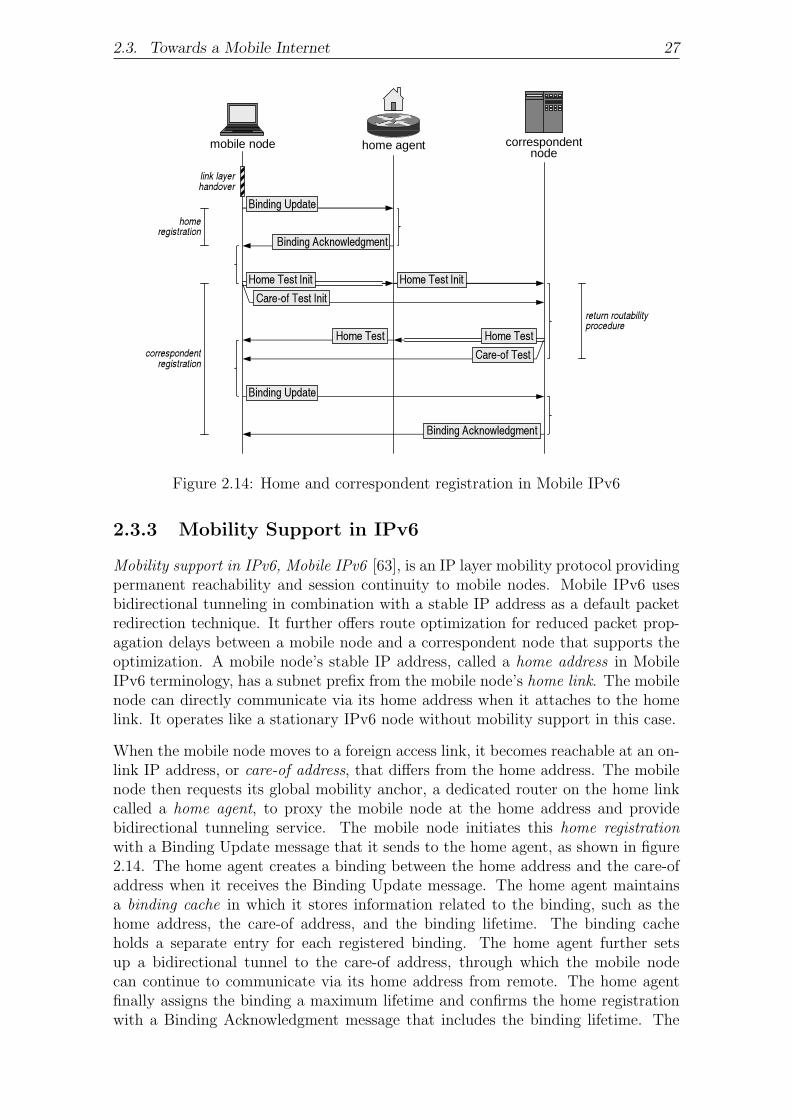
2.3. Towards a Mobile Internet 27
correspondentnode
mobile node
link layerhandover
Binding Update
home agent
Binding Acknowledgment
Home Test Init Home Test InitCare-of Test Init
Care-of TestHome Test
Binding Update
Binding Acknowledgment
Home Test
homeregistration
correspondentregistration
return routabilityprocedure
Figure 2.14: Home and correspondent registration in Mobile IPv6
2.3.3 Mobility Support in IPv6
Mobility support in IPv6, Mobile IPv6 [63], is an IP layer mobility protocol providingpermanent reachability and session continuity to mobile nodes. Mobile IPv6 usesbidirectional tunneling in combination with a stable IP address as a default packetredirection technique. It further offers route optimization for reduced packet prop-agation delays between a mobile node and a correspondent node that supports theoptimization. A mobile node’s stable IP address, called a home address in MobileIPv6 terminology, has a subnet prefix from the mobile node’s home link. The mobilenode can directly communicate via its home address when it attaches to the homelink. It operates like a stationary IPv6 node without mobility support in this case.
When the mobile node moves to a foreign access link, it becomes reachable at an on-link IP address, or care-of address, that differs from the home address. The mobilenode then requests its global mobility anchor, a dedicated router on the home linkcalled a home agent, to proxy the mobile node at the home address and providebidirectional tunneling service. The mobile node initiates this home registrationwith a Binding Update message that it sends to the home agent, as shown in figure2.14. The home agent creates a binding between the home address and the care-ofaddress when it receives the Binding Update message. The home agent maintainsa binding cache in which it stores information related to the binding, such as thehome address, the care-of address, and the binding lifetime. The binding cacheholds a separate entry for each registered binding. The home agent further setsup a bidirectional tunnel to the care-of address, through which the mobile nodecan continue to communicate via its home address from remote. The home agentfinally assigns the binding a maximum lifetime and confirms the home registrationwith a Binding Acknowledgment message that includes the binding lifetime. The

28 2. Fundamentals
mobile node must renew the home registration when the binding lifetime elapses.The Mobile IPv6 RFC does not limit the binding lifetime for home registrations.The mobile node establishes a tunnel from the care-of address to the home agent aspart of the home registration. Information related to the home registration is storedin a new entry of the mobile node’s binding update list. This includes the home andcare-of addresses, the binding lifetime granted by the home agent, and any staterelated to pending retransmissions and re-registrations.
The Binding Update and Binding Acknowledgment messages exchanged during ahome registration are authenticated and integrity-protected based on an IPsec secu-rity association, typically using the IPv6 Encapsulating Security Payload extensionheaders in transport mode. The credentials required to bootstrap the security as-sociations may be preconfigured onto the mobile node and the home agent. Thenodes are assumed to be administered by the same authority, so the preconfig-uration should in general be feasible. Technically, IPsec protection alone cannotprevent redirection-based flooding attacks against a spoofed care-of address since itdoes not incorporate a verification of the mobile node’s reachability at the care-ofaddress. This makes home registrations in general misusable for flooding attacks.The security design of the home registration is instead founded on an assumed trustrelationship between the mobile node and the correspondent node. This permitsthe home agent to accept a care-of address from the mobile node without previousreachability verification.
The mobile node retransmits any messages that it sends to the home agent or a corre-spondent node and for which it does not receive a response within appropriate time.The standard retransmission algorithm calls for the mobile node to wait 1 s beforeit initiates the first retransmission,2 and to double the waiting time for each furtherretransmission. A maximum interval of 32 s is reached after six retransmissions.The mobile node may then continue retransmitting at the same rate.
It is the mobile node’s responsibility to update a binding at the home agent wheneverits care-of address changes due to a handover. The bidirectional tunnel is then movedto the new care-of address. Each such binding update requires another exchange ofIPsec-protected Binding Update and Binding Acknowledgment messages. When themobile node returns to its home link after a period of roaming, it initiates a homederegistration, requesting the home agent to discontinue proxy service, remove anyexisting binding for the mobile node, and tear down the bidirectional tunnel to themobile node.
The increased packet propagation latencies that go along with bidirectional tunnel-ing can be avoided if a correspondent node supports Mobile IPv6 route optimization.The mobile node initiates this through a correspondent registration with the corre-spondent node when it receives an encapsulated payload packet that originates fromthis correspondent node, and no recent indication exists that the correspondentnode does not support route optimization. The purpose of the initial correspondentregistration is to probe whether the correspondent node supports route optimiza-tion and, in case it does, have the correspondent node cache a binding between the
2An initial waiting time of 1.5 s is required before the mobile node retransmits a Binding Updatemessage for its home agent if the home agent does not yet have a binding registered for the mobilenode. The increased waiting time then allows the home agent to complete Duplicate AddressDetection on the mobile node’s home address before it sends a Binding Acknowledgment message.

2.3. Towards a Mobile Internet 29
mobile node’s home and current care-of address. Figure 2.14 depicts the messagesexchanged during a correspondent registration. As with the home registration, theseinclude a Binding Update message and, in this case optionally, a Binding Acknowl-edgment message. The registrations differ in the way they secure this exchange,however. There is generally no a-priori security or trust relationship between anarbitrary pair of mobile and correspondent nodes based on which a correspondentregistration could be protected. So to mitigate the threats described in section 2.3.2,Mobile IPv6 uses a return routability procedure. This is based on a verification ofthe mobile node’s reachability at the home address and the care-of address. Reach-ability at both IP addresses is taken as an indication that the mobile node is thelegitimate owner of these two IP addresses, and hence that it is secure to bind theIP addresses. The home address test weakly authenticates the mobile node becausethe home address identifies the mobile node at upper-layer protocols. The care-ofaddress test validates the mobile node’s liveliness at the claimed point of attachment,so it protects against redirection-based flooding attacks.
The mobile node initiates the home address test with a Home Test Init message,which it reverse-tunnels to the home agent, and which the home agent forwards fromthe home address to the correspondent node. The confidentiality of the Home TestInit message is protected inside the tunnel, typically using the IPv6 EncapsulatingSecurity Payload extension header. But there is no cryptographic protection onthe path between the home agent and the correspondent node. To provide someminimum level of security also on the latter path, the Home Test Init messageincludes a random home init cookie to be returned by the correspondent node. Areturned cookie proves that the message was processed by a node on the path fromthe home agent to the correspondent node, thus protecting against off-path attackersthat cannot see the Home Test Init message. This mechanism is ineffective againsteavesdroppers on the path from the home agent to the correspondent node. Yet,the motivation here is that such attackers could anyway compromise communicationsbetween the mobile node and the correspondent node unless the packets are protectedotherwise.
The correspondent node responds to the Home Test Init message with a Home Testmessage. This is directed to the mobile node’s home address and hence again routesvia home agent. The Home Test message contains a home keygen token, a homenonce index, and the home init cookie copied from the Home Test Init message.The mobile node considers the returned home init cookie a sufficient proof thatthe Home Test message was generated by the right correspondent node. The homekeygen token is a keyed one-way hash on the concatenation of the mobile node’shome address, a random nonce, and a “0” indicating that the token corresponds to ahome address rather than a care-of address. The hash is keyed with a secret knownonly to the correspondent node. The mobile node uses the home keygen tokento prove its reachability at the home address when it eventually sends a BindingUpdate message to the correspondent node. The home nonce index identifies thenonce based on which the correspondent node has computed the home keygen token.The mobile node includes the home nonce index in the Binding Update message toallow the correspondent node to reproduce the home keygen token without havingto store it explicitly. This kind of resource preservation is a precaution againstdenial-of-service attacks that aim at exhausting the correspondent node’s memoryresources. The Home Test message is sent through the same authenticated and

30 2. Fundamentals
encrypted tunnel between the home agent and the mobile node as the Home TestInit message.
The care-of address test consists of a pair of messages directly exchanged betweenthe mobile node and the correspondent node, and it does not involve the mobilenode’s home agent. The mobile node initiates the care-of address test by sending aCare-of Test Init message to the correspondent node, as shown in figure 2.14. Thistypically happens in parallel with the initiation of the home address test. The Care-of Test Init message includes a random care-of init cookie that is to be returned bythe correspondent node. This serves as a proof that the message was processed bya node on the path from the mobile node to the correspondent node.
The correspondent node sends a Care-of Test message directly to the mobile node’scare-of address when it receives the Care-of Test Init message. The Care-of Testmessage contains a care-of keygen token, a care-of nonce index, and the care-of initcookie copied from the Care-of Test Init message. The care-of keygen token is akeyed one-way hash on the concatenation of the mobile node’s care-of address, arandom nonce, and a “1” indicating that the token corresponds to a care-of address.The hash is again keyed with the correspondent node’s secret. The mobile nodeuses the care-of keygen token to prove its reachability at the care-of address. Thecare-of nonce index identifies the nonce based on which the correspondent nodehas computed the care-of keygen token. As with the home nonce index, this iscommunicated in the protocol so that the correspondent node can reproduce thecare-of keygen token without having to explicitly store it.
The return routability procedure enables the mobile node to transact a binding up-date at the correspondent node. Specifically, the mobile node computes a bindingmanagement key as a one-way hash on the concatenation of the home keygen tokenand the care-of keygen token. Knowledge of the right binding management key henceproves the mobile node’s reachability at the home address and at the care-of address.Based on the binding management key, the mobile node calculates a message au-thentication code for a Binding Update message that it subsequently sends to thecorrespondent node. The Binding Update message further includes the home andthe care-of nonce indices received during the return routability procedure. The mo-bile node may request the correspondent node to return a Binding Acknowledgmentmessage by raising a flag in the Binding Update message.
The home and care-of nonce indices included in the Binding Update message allowthe correspondent node to reproduce the home and care-of keygen tokens, respec-tively, on receipt of the Binding Update message. The correspondent node can thencalculate the binding management key in the same way as the mobile node, and usethis to verify the message authentication code of the Binding Update message. If themessage authentication code is correct, the correspondent node knows that the mo-bile node has received the Home Test and Care-of Test messages and, consequently,that the mobile node is reachable at the claimed home and care-of addresses. Acorrect message authentication code also indicates that the message has not beentampered with in flight. The correspondent node can hence assume with reasonablecertainty that the mobile node is the legitimate owner of the home and care-of ad-dresses included in the Binding Update message, and that it is secure to bind thetwo IP addresses. The correspondent node accordingly creates a new entry in itsbinding cache and begins route-optimizing payload packets. The binding cache of

2.3. Towards a Mobile Internet 31
a correspondent node is fundamentally the same as the binding cache of a homeagent. Finally, if requested by the mobile node, the correspondent node confirmsthe successful correspondent registration with a Binding Acknowledgment message.This message also includes the binding lifetime granted by the correspondent node,and it is again authenticated with the binding management key. The Mobile IPv6RFC limits the binding lifetime for correspondent registrations to seven minutes inan attempt to ward off time-shift attacks [94]. A mobile node that does not changeIP connectivity for this period must refresh any active correspondent registrations.This requires another run of the return routability procedure. The mobile nodestores information related to a correspondent registration in its binding update list.
A correspondent node that does not support Mobile IPv6 route optimization sendsan ICMPv6 Parameter Problem message when it receives a Home Test Init, Care-of Test Init, or Binding Update message, indicating that it does not understandthe payload in the received packets. The ICMPv6 Parameter Problem messagesenable the mobile node to determine the lack of support on the correspondent nodeside. The mobile node caches such information in its binding update list to avoidrepeated attempts to initiate route optimization with correspondent nodes that donot support it.
The mobile node updates the binding at each of its correspondent nodes when itscare-of address changes during a handover. This involves another care-of addresstest. The home keygen token from the previous home address test may be reused ifit has been obtained within the last 3.5 minutes. Otherwise, the token has passedits lifetime and the entire return routability procedure must be redone. The lifetimeof a care-of keygen token is 3.5 minutes as well. But since a care-of keygen tokenis bound to the care-of address to which it was sent, it typically cannot be reused.The mobile node may reuse a previously obtained care-of keygen token only in thespecial case where it returns to a previously visited access link and configures an oldcare-of address again.
The mobile node initiates a correspondent deregistration when it eventually returnsto its home link. The correspondent node then removes the existing binding for themobile node, and subsequent payload packets are exchanged via the home address.The binding management key needed to authenticate the Binding Update and Bind-ing Acknowledgment messages exchanged during the correspondent deregistration isa one-way hash on only a home keygen token. The return routability procedurehence reduces to a home address test in the case of a correspondent deregistration.
The Mobile IPv6 specification restricts the scheduling of home and correspondentregistrations. Accordingly, the mobile node must send a Binding Update messageto its home agent before it initiates the return routability procedure with a corre-spondent node. The mobile node must also wait for a positive Binding Acknowledg-ment message from the home agent before it sends a Binding Update message to acorrespondent node. The same message order applies to home and correspondentderegistrations. The purpose of these rules is to establish the mobile node’s abilityto communicate via the home address before a binding for the home address can becached at correspondent nodes.3
3While the a-priori transmission of a Binding Update message to the home agent helps the latterto forward home address test messages correctly, there is technically no reason for requiring the

32 2. Fundamentals
Figure 2.14 illustrates a scenario where the mobile node communicates with onlyone correspondent node that supports Mobile IPv6 route optimization. The figureis therefore limited to a single correspondent registration. More generally, the mo-bile node may communicate with multiple correspondent nodes that support theoptimization. It then pursues a correspondent registration with each of the corre-spondent nodes in parallel.
2.3.4 Reactive versus Proactive Mobility Management
Mobility support at the IP layer has traditionally been considered a response tolink layer handover. Sophisticated protocol optimizations for such reactive mobilitymanagement can reduce handover delays considerably, but a minimum latency forpayload packets to be redirected to the mobile node’s new point of attachment isinherent in all reactive approaches: It always takes a one-way propagation time toregister a new on-link IP address with a global or local mobility anchor, or with acorrespondent node, plus another one-way propagation time for the first redirectedpayload packet to arrive at the new IP address. At the same time, packets in flighttowards the old on-link IP address are lost.
Proactive mobility management can further reduce handover delays and handover-related packet loss. It requires a mobile node to anticipate changes in IP connectivityand, if a handover is imminent, obtain a new IP address from the target access linkand register this with its global or local mobility anchor, or with its correspondentnode, prior to initiating the link layer handover. While efficient reactive mobilitymanagement cannot go without link layer notifications that inform the IP layerabout changes in link layer attachment, proactive mobility management requiresbidirectional interaction between the link and IP layers. The mobility protocolmust now be able to issue commands to the link layer and receive events as wellas anticipatory information from the link layer. The mobile node must further beable to match link layer information from a discovered access link to subnet prefixinformation for that link. This typically requires a mapping between the link layeraddress of a discovered access point and the set of subnet prefixes in use on the linkto which this access point connects.
The requirements of reactive and proactive mobility management in terms of cross-layer interaction and network information retrieval can be satisfied with Media In-dependent Handover Services [3], a to-be standard currently under development bythe IEEE 802.21 working group. [71] specifies an alternative interface between thelink layer and the IP layer, and other approaches to proactive subnet prefix discov-ery are described in [70, 69, 77]. Since Media Independent Handover Services willbe used as a building block in the frameworks for reactive and proactive mobilitymanagement proposed in this thesis, the relevant parts of the draft standard aredescribed in more detail in section 2.4.7.
2.3.5 Relation to Multi-Homing
While mobility concerns redirections to previously unknown IP addresses, multi-homing [37] describes a node’s ability to redirect packets between multiple IP ad-dresses that it has configured simultaneously. This allows the node to split traffic
mobile node to wait for the completion of the home registration before a Binding Update messagecan be sent to a correspondent node. The rule is also not needed from a security standpoint sinceneither the home agent nor a correspondent node can verify that a mobile node conforms to it.

2.4. Protocols Supplementing Mobility 33
across multiple connections to the Internet for increased quality of service, or toto provide for rapid fail-over in the event one of the connections goes down. Onedifferentiates between node multi-homing, where the IP addresses are configured ondifferent network interfaces of the same node, and access network multi-homing,where the IP addresses have subnet prefixes that belong to the same access net-work, but have been allocated from different Internet service providers.4 Althoughthe policies for IP address selection and switching typically differ between node andaccess network multi-homing, from the perspective of this thesis, these differencesare negligible. The techniques will therefore be more generally referred to as “multi-homing” henceforth.
Given the strong technical relationship between mobility and multi-homing, bothtechniques can be combined in one protocol. In fact, the mobility extensions for theHost Identity Protocol also support multi-homing, and the NOMADv6 extensions[72] for Mobile IPv6 enable a mobile node to specify a care-of address per packetflow. These extensions have been developed with a focus on node multi-homing, butprincipally, access network multi-homing could be supported as well.
A side effect of the strong relationship between mobility and multi-homing is thatthe threats described in section 2.3.2 also apply to multi-homing. The specific threatof redirection-based flooding attacks is even more significant in the case of multi-homing because the attacker could send bogus transport layer acknowledgmentswithout spoofing their IP source addresses: The attacker would register both itsown and a victim’s on-link IP addresses, and then send spoofed acknowledgmentsfrom its own IP address while redirecting the correspondent node’s packets to theIP address of the victim. The binding at the correspondent node would then ensurethat the acknowledgments are attributed to the packet flow towards the victim. Anability to avoid spoofing its packets’ IP source address, also called IP spoofing [23], isattractive from an attacker’s perspective because routers may verify the topologicalcorrectness of the IP source addresses in to-be-forwarded packets and drop packetswhere the IP source address is incorrect. (The prevalence of such filtering techniquesand their relation to redirection-based flooding will be discussed later on in section3.3.5.) A mobility protocol without multi-homing functionality permits only a singleon-link IP address per binding and hence does not allow the attacker to use anyother IP source address for the acknowledgments than the registered IP address ofthe victim.
2.4 Protocols Supplementing Mobility
Gaining IP connectivity on a new access link requires a node to discover its neigh-borhood and configure a new IP address. Many of the protocols that need to beexecuted for these tasks pertain to stationary nodes just as well as for mobile nodes.But since mobile nodes are required to gain IP connectivity more frequently andoftentimes with active communication sessions, it is important that this happensefficiently. This section explains what steps a node needs to take in configuring IPconnectivity on a new access link, and it introduces protocols that are used for this
4Another form of access network multi-homing is for an access network to obtain an individualblock of IP addresses that does not belong to any particular Internet service provider. Multi-homingis in this case transparent to the nodes, hence node support is not required.

34 2. Fundamentals
purpose. The section also considers optimized protocols that have been designed tomeet the increased efficiency demands of mobile nodes, and it finally explains howproactive mobility management can be realized.
2.4.1 Router and Subnet Prefix Discovery
A node that attaches to a new access link learns about local access routers and subnetprefixes during router discovery and subnet prefix discovery, respectively. The defaultmechanism for this is defined as part of Neighbor Discovery [92]. This protocol callsfor access routers to multicast Router Advertisement messages onto a local accesslink on a loosely periodic basis. A node may listen for advertisements or, if it isunwilling to wait, actively request one by sending a Router Solicitation message. ARouter Advertisement message identifies the originating access router and containsa set of subnet prefixes that belong to the local link. The node chooses one of theadvertising access routers as a first hop for all packets it sends to destinations offthe local link. Neighboring nodes are identified by an IP address that matches oneof the subnet prefixes advertised on the local link. Packets destined to a neighborcan be transmitted directly to that neighbor without the help of an access router.
2.4.2 Movement Detection
Mobile nodes change their point of attachment as they move. Each such changemay be limited to the link layer, in which case the mobile node simply switchesbetween access points that connect to the same access link. The mobile node can inthis case continue to communicate at the IP layer as before: It keeps any previouslydiscovered subnet prefixes and configured IP addresses, and sticks to the accessrouter selected as a first hop for packets destined off-link. However, when the oldand new access points belong to different access links, the mobile node changes IPconnectivity and needs to re-configure IP: It invalidates its current first-hop accessrouter along with any previously discovered subnet prefixes, and it removes existingglobal IP addresses. The mobile node must also re-run Duplicate Address Detectionon its link-local IP address. This is necessary even though the link-local IP addresskeeps its subnet prefix during handover because a new neighbor may already be usingthe same link-local IP address. New global IP addresses are subsequently configuredas the mobile node learns the subnet prefixes in use on the new access link. At thesame time, the mobile node chooses a new first-hop access router. The change inIP connectivity may further cause the mobile node to initiate signaling for an IPmobility protocol.
Changes in link layer attachment can typically be detected straightforwardly throughnotifications that the link layer may generate when it switches access points. De-tecting changes in IP connectivity, movement detection, is less trivial. Since differentaccess links have disjunct sets of subnet prefixes—barring the link-local prefix thatis valid on every link—movement detection is commonly implemented by analyz-ing the subnet prefixes advertised in Router Advertisement messages and probingreachability of access routers considered off-link. When the subnet prefixes in use bythe mobile node are no longer seen to be advertised, but new subnet prefixes showup instead, the mobile node would typically decide that it has moved to a differentaccess link. On the other hand, received subnet prefixes may also indicate that IPconnectivity did not change in spite of a link layer handover, for example, when the

2.4. Protocols Supplementing Mobility 35
mobile node switches access points that connect to the same link. IP re-configurationshould then be avoided.
Movement detection is complicated by the fact that Router Advertisement messagesmay include incomplete sets of subnet prefixes. Reception of a single advertisementis therefore usually insufficient to decide whether IP connectivity has changed. Mo-bile nodes also get no indications of an access router’s advertising rate. Failure toreceive an expected Router Advertisement message therefore does not imply move-ment either. A typical movement detector would hence draw a possibly prematuredecision based on a small number of received Router Advertisement messages and, ifa change in IP connectivity is assumed, perform Neighbor Unreachability Detectionon the first-hop access router to corroborate this.
2.4.3 IP Address Configuration
A node may be preconfigured with one or more IP addresses, but more typically, thenode auto-configures a link-local IP address and one global IP address per subnetprefix assigned to the access link. The set of on-link subnet prefixes is announcedby local access routers in multicast Router Advertisement messages, which are re-transmitted on a loosely periodic basis. The node may listen for advertisements or,if it is unwilling to wait, actively request one by sending a Router Solicitation mes-sage. IP address auto-configuration can be performed in either stateless or statefulmanner, where the modes supported5 on an access link are indicated in the RouterAdvertisement messages.
Stateless IP Address Auto-Configuration
Stateless Address Autoconfiguration [130] is a protocol that enables a node to auto-configure new IP addresses for received subnet prefixes, or for the link-local subnetprefix, without external help, such as from an IP address server. The node choosesan interface identifier—based on the link layer address of the interface to which theIP address is to be assigned [54], or randomly [91], or cryptographically [9]—, andprepends to this the obtained subnet prefix. Stateless Address Autoconfigurationrequires the node to subscribe to a solicited-node multicast group derived from thedesired IP address [29]. This is necessary to ensure that nodes which simultane-ously attempt to auto-configure the same IP address can recognize the collision.The subscription is handled by Multicast Listener Discovery protocol, MLD [134],a protocol which provides for this purpose a Report message that the node mul-ticasts onto the access link. The node then runs Duplicate Address Detection, asub-protocol of Stateless Address Autoconfiguration, to verify whether the desiredIP address is unique: It sends a Neighbor Solicitation message for the IP addressto the aforementioned solicited-node multicast group, and listens for a defendingNeighbor Advertisement message that any node already using the IP address wouldsend in response. If no responses are received within a period of 1 s, the node as-signs the new IP address to the interface. If it receives a Neighbor Advertisementmessage or another Neighbor Solicitation message for the same IP address, then thenode aborts the IP address auto-configuration process and possibly retries with a
5There is currently disunity in theInternet Engineering Task Force, IETF, on whether the IP ad-dress auto-configuration mode advertised in Router Advertisement messages should be interpretedas mandatory or as optional.
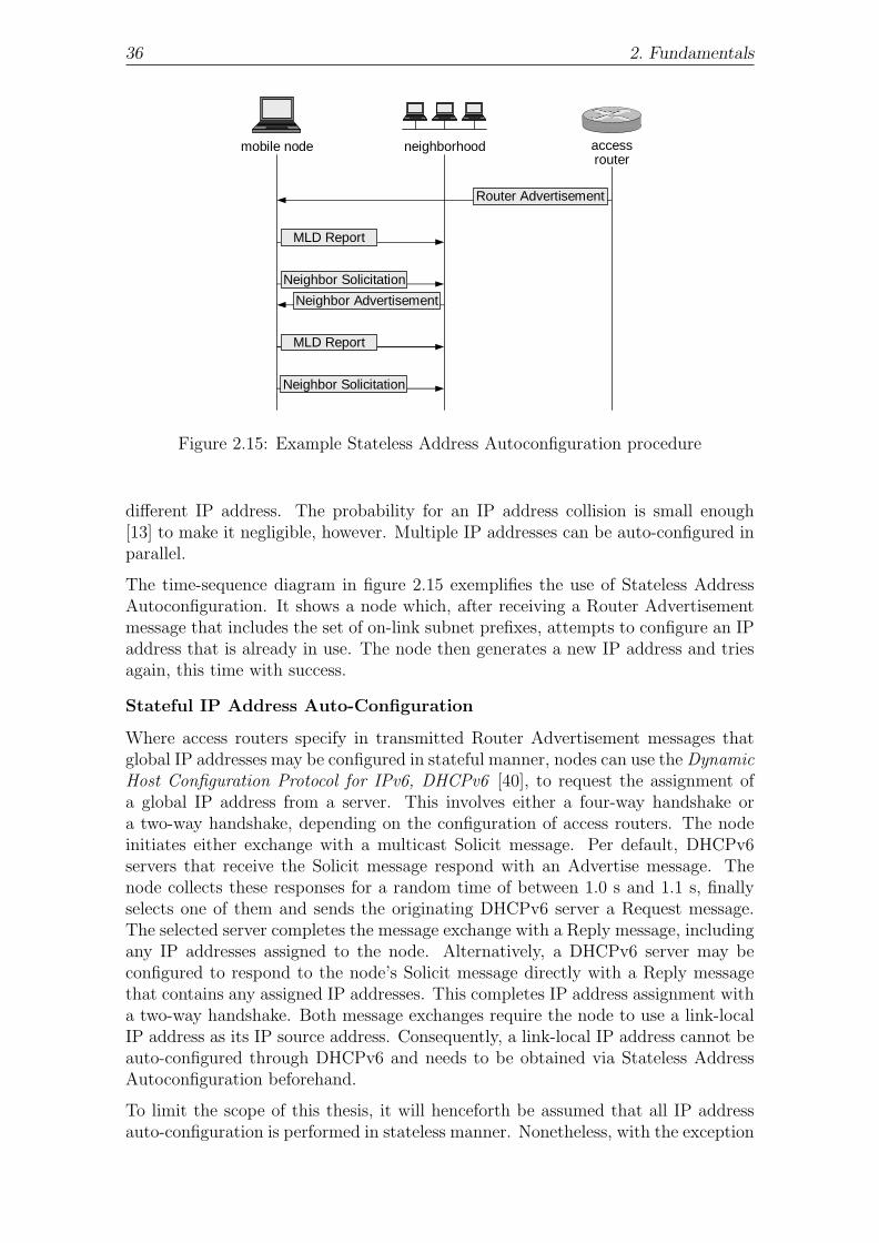
36 2. Fundamentals
mobile node neighborhood accessrouter
MLD Report
Neighbor Solicitation
Neighbor Advertisement
Neighbor Solicitation
Router Advertisement
MLD Report
Figure 2.15: Example Stateless Address Autoconfiguration procedure
different IP address. The probability for an IP address collision is small enough[13] to make it negligible, however. Multiple IP addresses can be auto-configured inparallel.
The time-sequence diagram in figure 2.15 exemplifies the use of Stateless AddressAutoconfiguration. It shows a node which, after receiving a Router Advertisementmessage that includes the set of on-link subnet prefixes, attempts to configure an IPaddress that is already in use. The node then generates a new IP address and triesagain, this time with success.
Stateful IP Address Auto-Configuration
Where access routers specify in transmitted Router Advertisement messages thatglobal IP addresses may be configured in stateful manner, nodes can use the DynamicHost Configuration Protocol for IPv6, DHCPv6 [40], to request the assignment ofa global IP address from a server. This involves either a four-way handshake ora two-way handshake, depending on the configuration of access routers. The nodeinitiates either exchange with a multicast Solicit message. Per default, DHCPv6servers that receive the Solicit message respond with an Advertise message. Thenode collects these responses for a random time of between 1.0 s and 1.1 s, finallyselects one of them and sends the originating DHCPv6 server a Request message.The selected server completes the message exchange with a Reply message, includingany IP addresses assigned to the node. Alternatively, a DHCPv6 server may beconfigured to respond to the node’s Solicit message directly with a Reply messagethat contains any assigned IP addresses. This completes IP address assignment witha two-way handshake. Both message exchanges require the node to use a link-localIP address as its IP source address. Consequently, a link-local IP address cannot beauto-configured through DHCPv6 and needs to be obtained via Stateless AddressAutoconfiguration beforehand.
To limit the scope of this thesis, it will henceforth be assumed that all IP addressauto-configuration is performed in stateless manner. Nonetheless, with the exception

2.4. Protocols Supplementing Mobility 37
of proactive mobility management (see section 2.3.4), the results of this thesis can betransferred to scenarios where IP addresses are auto-configured through DHCPv6.
2.4.4 Neighbor Unreachability Detection
The mapping between IP addresses and link layer addresses may grow stale as nodesshut down or leave the access link, for example, due to mobility. Nodes are recom-mended to take advantage of connectivity indications from protocol layers aboveIP in monitoring a neighbor’s reachability. Such indications include acknowledg-ments received for previously transmitted data. Yet, upper-layer indications maynot always be available. A node can then use Neighbor Unreachability Detectionto actively probe a neighbor’s liveliness. Neighbor Unreachability Detection is asub-protocol of Neighbor Discovery. A node interested in a neighbor’s reachabilitysends up to three Neighbor Solicitation messages directly to the link layer addressknown for that neighbor. Consecutive solicitations are spaced by 1 s during whichthe solicited node is expected to respond with a Neighbor Advertisement message.If such an advertisement is sent, the link layer address known for the neighbor is stillcorrect. If no advertisement is received after three solicitations have been sent, thelink layer address is assumed to be stale and the querying node starts with IP ad-dress resolution anew. The potential for packet loss during Neighbor UnreachabilityDetection is covered by the retransmissions of the Neighbor Solicitation message.
2.4.5 Internet Control Message Protocol for IPv6
The Internet Control Message Protocol for IPv6, ICMPv6 [32], defines error andnotification messages that IPv6 nodes exchange to convey or retrieve informationrelevant at the IP layer. For example, a host that receives a packet it cannot processdue to lack of support for the included payload may return an ICMPv6 Parame-ter Problem message to the sender of the packet. Routers that do not know howto forward a received packet may inform the sender with an ICMPv6 DestinationUnreachable message. Protocols at the IP layer or above use ICMPv6 messagesto detect error conditions. For example, Mobile IPv6 utilizes ICMPv6 ParameterProblem messages to determine when a correspondent node does not support routeoptimization.
2.4.6 Optimizations
The default protocols for router and subnet prefix discovery, IP address auto-configuration, and movement detection were designed for use in environments wherenodes are primarily stationary. Listen times, desynchronization delays, and ratelimitations are hence dimensioned conservatively, precluding race conditions andtransmission collisions at the cost of latency. For stationary nodes, this is typi-cally not a problem since they can run a working IP configuration for a long time.But the extended latencies [141, 135] in standard protocols are highly disadvan-tageous in environments where mobile nodes frequently re-configure IP. Handoverdelays may then be in the order of seconds. This makes it difficult to support non-real-time or soft-real-time services like file transfers or media streaming, and it pre-cludes any meaningful use of hard-real-time applications such as Internet telephony.A multitude of optimizations have therefore recently been put forth to streamlinehandover-related activities and reduce handover delays. Particularly promising arethe following approaches.

38 2. Fundamentals
Router and Subnet Prefix Discovery
Strict rate limitations in the Neighbor Discovery protocol force access routers tospace consecutive Router Advertisement messages by a random time of between 3 sand 4 s at least. This leads to considerable delays for router and subnet prefixdiscovery. Router Solicitation messages may in some cases permit a mobile nodeto obtain an advertisement faster. But on a durable basis, solicited advertisements,too, cannot be sent more rapidly than once per 3.5 s on average. Less rigid ratelimitations make router and subnet prefix discovery more efficient and thereby toalso improve movement detection. Accordingly, average advertising rates of between30 ms and 70 ms were permitted a posteriori for mobile environments [63]. Ratelimitations for solicited Router Advertisement messages were not relaxed at the sametime, so unless access links are only very sparsely populated with mobile nodes andRouter Solicitation messages are transmitted only very infrequently, any solicitedRouter Advertisement messages are highly likely to be substituted by unsolicitedadvertisements that are sent at a high rate anyway. The high advertising rates thus infact redundantize the use of Router Solicitation messages. An obvious disadvantageof this approach to router and subnet prefix discovery is that it comes at the cost ofincreased bandwidth consumption.
More sophisticated scheduling intervals in access routers can improve router and sub-net prefix discovery with respect to both bandwidth consumption and efficiency. FastRouter Advertisement [36] is an optimization for Neighbor Discovery that permitsa mobile node to solicit an immediate Router Advertisement message. Randomizeddesynchronization delays are here replaced by an algorithm that neighboring accessrouters use to determine an order in which they respond to the Router Solicitationmessage without collision, whereby the access router ranked first responds with-out delay. The algorithm is seeded with neighboring access routers’ link-local IPaddresses and the IP source address of the solicitation.
IP Address Auto-Configuration
Stateless Address Autoconfiguration suffers decreased efficiency due to both, themandatory 1-s listen time for nodes that have sent a Neighbor Solicitation message,and a random desynchronization delay of up to 1 s for Multicast Listener Discov-ery Report messages. Optimistic Duplicate Address Detection [87], eliminates bothof these delays. This protocol is tailored to mobile environments in particular, sodesynchronization delays are removed based on the assumption that natural move-ment patterns already provide sufficient randomness to avoid collisions in most cases.Moreover, the protocol enables a node to use an IP address in parallel with verifica-tion. Nodes temporarily change the rules by which they do Neighbor Discovery so asto avoid pollution of neighboring nodes’ IP address resolution state with illegitimateinformation. This implies restrictions on direct packet exchanges with neighboringnodes, but does not impact communications with correspondent nodes off-link.
Movement Detection
Low rates of Router Advertisement messages in combination with the need to ac-quire multiple advertisements for complete subnet prefix information are responsiblefor long movement detection delays in standard IPv6. If Neighbor UnreachabilityDetection on the current access router is performed as part of movement detection,

2.4. Protocols Supplementing Mobility 39
these delays increase even further. Moreover, Neighbor Unreachability Detection inthis case happens at a time at which a change in IP connectivity may have invali-dated all existing IP addresses. So since the mobile node cannot leave its IP sourceaddress unspecified during Neighbor Unreachability Detection, it must re-verify theuniqueness of its link-local IP address before it initiates the procedure. Overall,reliable movement detection may thus easily take up to 10 s and more [135].
One reason for the low movement detection performance is that mobile nodes do notknow in which intervals they can expect to receive Router Advertisement messagesfrom a particular access router, so they cannot efficiently conclude a change in IPconnectivity when such advertisements cease to appear. One important enhancementof Neighbor Discovery was therefore the introduction of an Advertisement Intervaloption [63] that access routers can include in their Router Advertisement messagesto declare an upper bound on the intervals in which they transmit these messages.The advertised upper bound aids mobile nodes in deciding when the absence ofadvertisements from a specific access router indicates a change in IP connectivity.If combined with the increased advertising rates described above, this increases theefficiency of standard movement detection becomes considerably more efficient.
On the other hand, even with increased advertisement rates and the use of Adver-tisement Interval options, standard movement detection still fails to detect a changein IP connectivity on the absence of a single expected advertisement, due to thepotential for packet loss, or on the presence of a single unexpected advertisement,due to the incompleteness of included subnet prefixes. Standard movement detectionhence requires the mobile node to wait for the lack of multiple Router Advertisementmessages until a change in IP connectivity can be concluded with reasonable cer-tainty. To solve this problem, the IETF set about developing mechanisms that couldquickly detect movement based on a single Router Advertisement message from anew access router, rather than waiting for missing advertisements from an old accessrouter. Two mechanisms originated from this. Complete Prefix List [27] works withunmodified legacy access routers. A mobile node maintains a list of learned subnetprefixes, possibly obtained by reception of multiple Router Advertisement messages.After the list has matured for a while, the mobile node can assume a change inIP connectivity with high probability when a newly received Router Advertisementmessage exclusively contains subnet prefixes not in the list. However, such predic-tions are based on potentially incomplete information, so the mobile node mightassert movement even when none actually occurred.
The DNA Protocol [89] integrates Fast Router Advertisement for timely transmis-sions of solicited Router Advertisement messages. Neighboring access routers ad-ditionally choose a certain subnet prefix to serve as a access link identifier and beas such indicated in all transmitted Router Advertisement messages. This allows amobile node to reliably detect changes in IP connectivity based on a single advertise-ment. Alternatively, the mobile node can explicitly check with access routers as partof the solicitation-advertisement exchange whether a subnet prefix used before a linklayer handover, as such called a landmark, is still valid after the link layer handover.The DNA Protocol used to refer to Complete Prefix List as a fall-back mechanismfor access to links with legacy access routers. More recently, the Complete PrefixList algorithms have been fully integrated into the DNA Protocol. They are now nolonger maintained as a separate protocol.

40 2. Fundamentals
2.4.7 Media Independent Handover Services
Efficient IP mobility management requires a mobile node to quickly identify andselect suitable access points prior to handover, and to closely synchronize activitiesat the link and IP layers during handover execution. Both of these prerequisitesare hardly met today, however. Classic access point selection techniques are basedon signal strength alone. They disregard other important aspects such as operator,service provider, and cost; or link layer properties such as security and quality ofservice. A mobile node may further be unable to connect at the IP layer despitea working link layer attachment, for example, due to a mismatch in supported IPaddress configuration mechanisms. The selection of an access point becomes evenmore challenging if multiple access technologies are involved. And proactive mobilitymanagement introduces the additional requirement that mobile nodes must obtainsubnet prefix information for a discovered access link so as to auto-configure newIP addresses for that access link prior to handing over to it. Cross-layer interactionand synchronization is a concept that deviates from the traditional view that theresponsibilities of different layers in a network stack should be cleanly separated[144].
To approach these challenges, the IEEE chartered its 802.21 working group to de-velop a set of Media Independent Handover Services [3] for improved reactive andproactive mobility management. The standard includes a unified interface separat-ing different heterogeneous technologies at the link layer from protocols at the IPlayer or above. This interface defines a set of events and commands that proto-cols at the IP layer or above can read or issue, respectively, to synchronize theirhandover-related activities with the link layer. The standard further enables IPlayer protocols to acquire information that assists them in access link selection andhandover preparations. Overall, the functionality provided by Media IndependentHandover Services is split into three complementary services: an event service, acommand service, and an information service.
Architecture
Pivotal to all Media Independent Handover Services operation is an MIH function,which serves as an intermediary between the handover-related activities at the linklayer and the layers above. (Here, “MIH” denotes “media-independent handover”.)One instance of the MIH function is located between a mobile node’s link and IPlayers, as shown on the left-hand side in figure 2.16. This shim provides an abstrac-tion from the specifics of different access technologies and presents a homogeneousinterface to protocols at the IP layer or above. Interested protocols include mobilityor multi-homing protocols, movement detection mechanisms, as well as protocolsfor neighbor discovery or IP address auto-configuration. For example, the DNAProtocol may send a router solicitation message for renewed router discovery andmovement detection when the mobile node switches to a different access point. TheDNA Protocol may further interface to Stateless Address Autoconfiguration so asto create a new on-link IP address when the link layer handover to the new accesspoint is found to cause a change in IP connectivity. A mobility protocol such asMobile IPv6 may finally initiate a binding update for the new on-link IP address.In the reference architecture in figure 2.16, the MD function implements movementdetection (so “MD” stands for “movement detection”).

2.4. Protocols Supplementing Mobility 41
remoteMIH function
informationserver
Mobile IPv6
localMIH function
MD function
MIHpoint of service
mobile node
event/command serviceinformation service
information service
event/command services
information service
IP and
upper
layers
link layer
IP andupper layers
Figure 2.16: Reference architecture of Media Independent Handover Services
A companion entity of the MIH function is located on an MIH point of service in theaccess network. This is depicted on the right-hand side of figure 2.16. The remoteMIH function on the MIH point of service may assist the MIH function on a mobilenode during handovers that are controlled by the mobile node. It further facilitatesnetwork-controlled handovers, where it is in charge of handover-related activities onthe mobile node. For remote information retrieval, the MIH point of service mayfurther run an MIH information server. Interested mobile nodes can access infor-mation from this database via the remote MIH function. Communications betweenthe MIH functions on the mobile node and on an MIH point of service use the MIHprotocol. This defines a set of packet formats that encapsulate events, commands,and information for transmission via the network.
As a mobile node moves across access links, its peer MIH point of services maychange. Media Independent Handover Services define an MIH function discovery toaid the mobile node in finding another MIH point of service after attaching to a newlink. The draft standard limits the discovery to the link layer, so the mobile nodecan only find MIH points of service within the same broadcast domain. A mobilenode typically discovers new MIH points of service immediately after a handover,but uses the available services only later when preparing for a subsequent handover.This generally provides for a sufficient time frame for MIH function discovery toproceed without delaying handover-related activities.
Event Service
Protocols at the mobile node’s IP layer or above can use the event service to registerwith the local MIH function for notifications about specific events at the link layer,such as changes in link layer attachment or in the quality of a particular connection.

42 2. Fundamentals
The MIH function monitors the mobile node’s interfaces for the respective eventsin a technology-specific manner and generates a technology-independent notificationfor the interested protocols at higher layers as the events occur.
An example for the utility of the event service is movement detection for mobilenodes. Movement detection mechanisms at the IP layer are interested in changesin link layer attachment, so they may subscribe to notifications about these eventsfrom the MIH function. The MIH function monitors interfaces at the link layer forchanges in attachment and accordingly generates technology-independent MIH LinkUp Indication and MIH Link Down Indication messages for the movement detectionmechanism. This allows a movement detection mechanism to quickly review thecurrent IP configuration in case of a link layer attachment change, and to re-configureif need be. In proactive mobility management, the MIH function may anticipatechanges in link layer attachment and notify protocols at the IP layer about this witha Link Going Down Indication message. This facilitates handover preparations andproactive mobility management at the IP layer.
Events may also originate with a remote MIH function on an MIH point of service inthe network. The events are in this case sent via the network using the MIH protocol.For example, an MIH function in the network may send an MIH Link Going DownIndication message to the MIH function on a mobile node when the access point towhich the mobile node attaches is about to be shut down for administrative reasons.The MIH function on the mobile node can then inform IP layer protocols about theforthcoming link break.
Command Service
The command service enables protocols at the IP layer or above to control handover-related activities at the local link layer or remotely in the network. A command ispassed to the local MIH function and is as such technology-independent. If thecommand is directed to the local link layer, the MIH function translates it intotechnology-specific commands and sends these to the respective interfaces. Theinterfaces execute the commands and return a confirmation each, which the MIHfunction aggregates and forwards to the protocol that invoked the command. Aremote command is directed to the MIH function on an MIH point of service in thenetwork. It, too, originates with a protocol at the IP layer or above and traversesthe local MIH function. But from there the command is forwarded to the remoteMIH function by help of the MIH protocol. The remote MIH function may forwardthe command to a protocol at a higher layer, or translate it into technology-specificcommands for the link layer beneath.
The command service can be used by a protocol at the IP layer or above to find asuitable access point and to control a link layer handover thereto. For example, anIP layer movement detection mechanism or mobility protocol on a mobile node mayperiodically send an MIH Get Status Request message to the local MIH functionfor a survey on available points of attachments and their properties such as band-width, packet loss rate, and medium access delays. The MIH function translates thiscommand into technology-specific Get Status Request messages, one for each of themobile node’s interfaces, and receives Get Status Confirm messages containing thedesired information in response. The MIH function aggregates the responses withina technology-independent MIH Get Status Confirm message and relays this to the

2.4. Protocols Supplementing Mobility 43
protocol that asked for it. In a similar manner, the MIH Scan Request message canbe used by protocols at the IP layer or above to measure the received signal strengthof available access points. The local MIH function maps this command onto a set oftechnology-specific Link Scan Request messages, one for each interface, and receivesa set of Link Scan Confirm messages in return. The responses are aggregated andforwarded as an MIH Scan Confirm message to the calling protocol.
Another example for the use of the command service is in proactive mobility man-agement, where the IP layer needs to be in control of link layer detachment andattachment. A movement detection or mobility protocol may here send the localMIH function an MIH Switch Request message identifying the old and selected tar-get access link. The MIH function translates the MIH Switch Request message intoa sequence of commands specific to the one or two involved link layer interfaces:If the link layer technology supports make-before-break handovers, a Link ConnectRequest message for the target access point is sent first, and a Link Disconnect Re-quest message for the old access point is sent second. Where only break-before-makehandovers are possible, the sequence of messages is reverse. The link layer respondsto the requests with Link Disconnect Confirm and Link Connect Confirm messages,and the MIH function finally sends an MIH Switch Confirm message to the protocolthat invoked the handover.
Information Service
The information service enables a mobile node to discover auxiliary informationabout access links within reachability. Such information includes the access technol-ogy; access link, operator, and service provider identification; link layer security andquality-of-service properties; permitted IP configuration methods such as StatelessAddress Autoconfiguration or DHCPv6; the link layer address of the access pointand the channels it is operating on; as well as the IP address of available accessrouters and the set of subnet prefixes in use on the access link. The informationservice thus supports the mobile node in preparing a handover and selecting a suit-able target access point. One particular use case for the information service is inproactive mobility management, where a mobile node must obtain the subnet pre-fixes of a new access link before it actually attaches to that link. The mobile nodecan here use the information service to resolve the link layer address of a discoveredaccess point into a list of subnet prefixes in use on the link to which this access pointattaches.
Retrievable information is organized in information elements. Protocols at the mo-bile node’s IP layer or above may request these either from the local MIH functionor, more generally, via a remote MIH function from an MIH information server inthe network. In either case, an interested protocol sends an MIH Get InformationRequest message to the local MIH function, identifying one or multiple informationelements that are to be retrieved. If the requested information is available locally,the MIH function responds directly with an MIH Get Information Confirm messageincluding the respective information elements.
On the other hand, if the requested information is not available locally, the MIHfunction on the mobile node forwards the MIH Get Information Request messageto the remote MIH function on a previously discovered MIH point of service. Theremote MIH function translates the received MIH Get Information Request message

44 2. Fundamentals
into an MIH Get Information Indication message and sends this to an MIH informa-tion server to retrieve the requested information. The MIH information server looksup the desired information elements and returns them within an MIH Get Informa-tion Response message. The remote MIH function copies the information elementsinto an MIH Get Information Confirm message and sends it to the local MIH func-tion on the mobile node. The latter finally relays the message to the protocol thatrequested the included information elements.
2.5 Transmission Control Protocol
TCP allows applications on remote nodes to create a virtual connection over whichthey can exchange data. The protocol offers an abstraction from the packet-oriented routing substrate, delivering data bidirectionally as reliable and orderedbyte streams. TCP further controls the rate at which data is transmitted to avoidboth buffer overflows at the receiver as well as congestion in the network. As the mostpopular transport protocol providing these features, TCP is used by nearly all ap-plications that require reliability. Real-time applications such as Internet telephonycan cope with sporadic packet losses and hence do not depend on automatic lossrecovery. But a significant part of all real-time applications uses TCP nonethelessin order to take advantage of the other salient feature that TCP provides.
Due to its prevalence amongst existing transport protocols, TCP has been subjectto extensive research efforts since its initial publication in 1981. This developmenthas led to a diversity of different TCP variants that are in use across the Internettoday [78]. The major TCP variants have been standardized by the IETF, but thereare also a number of proprietary spin-offs. The following description explains themilestones in TCP evolution with a focus on those standardized TCP versions whicha clear majority of TCP clients and servers support today.
2.5.1 Original Specification
TCP was originally specified in RFC 793 [107]. The protocol functions entirely sym-metric, modulo the initiator-responder approach during connection establishmentand tear-down, and hence allows for data to be exchanged bidirectionally. Eachbyte of data flowing into a given direction is identified by a sequence number. ATCP receiver cumulatively acknowledges the data that it has received without in-tervening losses. TCP is self-clocking in that a new payload packet, or segment,may be sent only at connection establishment, after a retransmission timeout, or inresponse to an arriving acknowledgment.
To provide for the possibility of packet loss, a TCP sender keeps a copy of the datawhich it has sent to the other end, and for which it still expects an acknowledgment.TCP uses a retransmission timer to estimate when previously dispatched segmentshave been lost and ought to be resent. Specifically, when a TCP sender does not getan acknowledgment from the receiver for the duration of a retransmission timeout,all data sent, but not yet acknowledged, will be retransmitted. TCP attempts toapproximate the retransmission timeout period to the current round-trip time onthe transmission path. It periodically measures the time it takes for a transmitteddata segment to get acknowledged, and calculates a smoothed round-trip time as anexponentially weighted moving average. To accommodate for sudden changes in the

2.5. Transmission Control Protocol 45
round-trip time, TCP adds to this estimate a multiple of the measured round-triptime variation and uses the sum as the retransmission timeout period.
The interface between TCP and the local application provides two buffers. A sendingapplication writes outgoing data into a send buffer. The data is kept in the sendbuffer until it has been transmitted and an acknowledgment indicating its successfuldelivery has been received. Data received from the network is placed into a receivebuffer. TCP uses the receive buffer to sequence the data from incoming out-of-order segments and to finally present this data to the receiving application. Whilean attempt to write data into a full send buffer can be handled via a local errorindication, keeping a remote peer from sending data that might not fit into the receivebuffer requires over-the-network coordination. This is the purpose of flow control,which allows the TCP receiver to advertise to the peer how much additional datait is prepared to receive. The receiver maintains this amount of data as its receivewindow or advertised window, and it communicates this to the peer as part of itsacknowledgments. The TCP sender stores the receiver’s advertised window in a localvariable called the send window, and it ensures that the amount of “outstanding”data—that is, any data sent, but not yet acknowledged—does not exceed the sendwindow.
2.5.2 TCP Tahoe
Early TCP implementations were prone to burden the network by sending too muchdata in a single burst, and they reacted poorly to any resulting congestion. Theoriginal protocol specification was therefore later amended by a technique calledcongestion control. This steadily monitors the throughput capacity on the trans-mission path in an attempt to take advantage of the available bandwidth withoutoverloading the network. The improved protocol version became known as TCPTahoe, named after the first implementation in version 4.3 of the BSD operatingsystem.
Congestion control limits TCP’s transmission rate by means of a congestion window,which dynamically opens as TCP probes the network for additional capacity, andretracts once congestion is detected. A TCP sender can only send a segment if thissegment does not increase the amount of outstanding data to a value higher than thecurrent congestion window size. In conjunction with flow control, this means thatnew data may be sent only as long as it does not increase the amount of transmitted,yet unacknowledged data to more than the minimum of the send window and thecongestion window, that is, the TCP sender’s available window.
Congestion control probes the throughput capacity on the transmission path in ei-ther of two modes: Slow-start mode initially allows TCP to quickly accelerate datatransmission to the point at which the throughput capacity along the transmissionpath becomes saturated. Slow-start mode begins with a congestion window justlarge enough to send a single segment, and it opens by one additional segment sizewith each arriving acknowledgment. This doubles the amount of outstanding dataonce per round-trip time.
The rapid opening of the congestion window in Slow Start mode typically causesnetwork congestion at some point. Network congestion, in turn, results in packetloss. TCP was designed for wired networks, where, reversely, the occurrence of

46 2. Fundamentals
time
throughputcapacity
1
TCP congestionwindowfast retransmit
fast retransmit fast retransmit
Figure 2.17: TCP congestion window progression in TCP Tahoe
packet loss also oftentimes implies network congestion. TCP hence regards packetloss as an indication of congestion. On detecting packet loss, TCP sets a variablecalled the slow-start threshold to half of the current amount of outstanding data,retracts the congestion window to the size of a single segment, and re-enters SlowStart mode. This time, TCP switches to Congestion Avoidance mode when thecongestion window reaches the size of the slow-start threshold. The congestionwindow then opens by the size of one segment during each round-trip time. Thetransmission rate therefore increases more carefully in Congestion Avoidance modethan it does in Slow Start mode, ensuring that at most a single excess segment canbe injected into the network. Slow Start and Congestion Avoidance modes are todaymandatory for all TCP implementations [21].
The discovery of packet loss via the retransmission timer is in many cases inefficientsince the conservative estimation of the retransmission timeout period results in along period during which no data can be sent. TCP Tahoe therefore includes a wayto more efficiently detect packet loss based on the arrival of three continuous du-plicate acknowledgments. A TCP receiver retransmits its previous acknowledgmentwhen it receives a segment of data that it is unable to forward to the applicationdue to missing previous data. Such an out-of-order segment may be due to eitherpacket reordering in the network or the loss of a previous segment. Packet reorder-ing becomes increasingly unlikely as a source of the out-of-order segment as moresegments arrive without filling the gap in the receive buffer, hence packet loss ispresumed after three of these segments have been received. The resulting three du-plicate acknowledgments notify the TCP sender of the segment that the receiver ismissing, so the TCP sender can perform a fast retransmit of this segment withoutwaiting for the expiration of the retransmission timer. It then adjusts the slow-startthreshold and the congestion window as described above, and subsequently entersSlow Start mode. TCP Tahoe retransmits only the segment that apparently got lostand continues with the new segment that was scheduled for transmission right beforethe fast retransmit. Figure 2.17 shows the progression of the congestion window ina typical TCP Tahoe implementation.
2.5.3 TCP Reno
The periodic alternation between Slow Start mode and Congestion Avoidance modethat is characteristic for TCP Tahoe leads to decreased throughput because the con-

2.5. Transmission Control Protocol 47
time
throughputcapacity
1
TCP congestionwindow fastretransmit fastretransmit fastretransmit
fastrecoveryfastrecovery fastrecovery
Figure 2.18: TCP congestion window progression in TCP Reno
gestion window shrinks to a single segment size upon each observed packet loss (seefigure 2.17). Re-entering Slow Start mode is appropriate when a high number ofsegments have been lost from a single window of data because the lack of acknowl-edgments might otherwise impede self-clocking and cause TCP to stall. However, inmost cases, packet loss effects an only small number of segments, typically just theone additional segment that the TCP sender emits into the network at the point itsavailable window grows beyond the capacity of the transmission path in CongestionAvoidance mode. Retracting the congestion window to a single segment size andre-entering Slow Start mode is then in general all too conservative.
The advanced functionality of TCP Reno enables a more efficient recovery fromthe loss of a single segment. This TCP variant introduces a new Fast Recoverymode, which governs congestion control after a fast retransmit until the TCP senderhas assurance that all data outstanding at the time of the fast retransmit has beenreceived at the other end. On entering Fast Recovery mode, TCP Reno sets both thecongestion window and the slow-start threshold to half of the amount of currentlyoutstanding data. It waits until the amount of outstanding data has reduced to thisthreshold and only then continues sending further segments. While in Fast Recoverymode, the amount of outstanding data is limited to the new value of the slow-startthreshold.
Duplicate acknowledgments indicate the delivery of new data at the TCP receiver,but they do not specify which data was received. Data delivered subsequent to thepacket loss hence continues to occupy space in the TCP sender’s congestion win-dow until the arrival of a non-duplicate, full acknowledgment finalizes Fast Recoverymode. To maintain the current amount of outstanding data in Fast Recovery mode,the TCP sender therefore “inflates” the congestion window as duplicate acknowledg-ments arrive. TCP exits Fast Recovery mode and returns to Congestion Avoidancemode when all data outstanding at the time of the fast retransmit has been acknowl-edged by the receiver. The congestion window is then “deflated” back to the sizeit had at the time Fast Recovery mode was entered. Figure 2.18 shows the typicalprogression of the congestion window in TCP Reno.
2.5.4 TCP NewReno
Fast retransmit and Fast Recovery mode allow TCP Reno to quickly retransmita single lost segment, but the algorithms fail to efficiently recover when multiple

48 2. Fundamentals
segments are lost within a single round-trip time. The arrival of a retransmittedsegment in the presence of multiple packet losses causes the TCP receiver to generatea partial acknowledgment, which confirms the retransmitted segment, but does notcover all of the data outstanding at the time of the fast retransmit. A TCP Renosender in Fast Recovery mode ignores partial acknowledgments and continues towait for a full acknowledgment. Since this never arrives when multiple packets werelost, the TCP sender eventually runs into a retransmission timeout and switchesto Slow Start mode. On the other hand, partial acknowledgments carry sufficientinformation for the TCP sender to retransmit the next lost segment from a windowwith multiple packet losses without waiting for the expiry of a retransmission timer.TCP NewReno [49] was the first TCP variant to take advantage of this information.When a TCP NewReno sender receives a partial acknowledgment while in FastRecovery mode, it retransmits the next segment that appears to be missing andcontinues as before in Fast Recovery mode.
The TCP NewReno RFC describes two strategies for resetting the retransmissiontimer in response to partial acknowledgments. A TCP NewReno sender operat-ing the Slow-but-Steady variant resets the retransmission timer after each receivedpartial acknowledgment. This helps to avoid a retransmission timeout while TCPrecovers from the loss of multiple segments in a single window of data. The Slow-but-Steady variant conforms to recommendations in RFC 2988 that call for restartingthe retransmit timer after every packet transmission or retransmission. On the otherhand, a partial acknowledgment can only be generated by the TCP receiver uponthe delivery of a retransmitted segment, so the Slow-but-Steady variant can repaironly one packet loss per round-trip time. It may therefore take a substantial amountof time until all segments lost from a window are retransmitted. The Impatient vari-ant of NewReno resets the retransmission timer in Fast Recovery mode only whenthe first partial acknowledgment arrives. The TCP sender thus eventually falls intoa retransmission timeout when a high number of segments were lost from a singlewindow, and it retransmits the remaining packet losses more quickly in Slow Startmode.
2.5.5 TCP SACK
TCP’s cumulative acknowledgment strategy complicates the recovery from multiplepacket losses in a single window of data. Selective Acknowledgment options extendthe protocol by a means for explicit acknowledgments, allowing a TCP receiver toaugment a cumulative acknowledgment by the specification of one or more continu-ous chunks of successfully received data that cannot be covered by the cumulativeacknowledgment itself due to missing earlier data. Selective acknowledgments facil-itate more efficient loss repair at the TCP sender. The TCP variant that makes useof these options is referred to as TCP SACK.
RFC 3517 [20] proposes one particular algorithm for implementing TCP SACK.The integral part of it is a function that evaluates the information from receivedSelective Acknowledgment options to estimate whether a given piece of outstandingdata was lost. This allows a TCP sender to selectively retransmit the data consideredlost without causing the amount of outstanding, non-lost data to increase beyondthe currently available window. The TCP sender can thus retransmit up to a fullwindow of data per round-trip time, leading to a much shorter recovery phase than

2.5. Transmission Control Protocol 49
comparable packet loss would cause in TCP NewReno. The FreeBSD and Windowsoperating systems support [123, 33] the algorithm in RFC 3517.
2.5.6 TCP Limited Transmit
The fast-retransmit mechanism implicitly relies on the arrival of three consecutiveduplicate acknowledgments at the TCP sender, and hence requires three segmentsfollowing the lost segment to be successfully delivered to the TCP receiver. If lessthan three segments are delivered after the packet loss, the TCP sender does notperform a fast retransmit. Loss recovery is then triggered through the expirationof the retransmission timer, which is typically less efficient. This may happen inparticular when the available window is small.
The Limited Transmit algorithm [5] leverages the fact that the first and secondduplicate acknowledgments each indicate the successful delivery of a segment tothe receiver, hence a reduction in the amount of outstanding data. This allowsthe TCP sender to emit a new segment upon the arrival of each of the first twoduplicate acknowledgments, aiding the TCP receiver to generate additional duplicateacknowledgments and, thus, to eventually trigger a fast retransmit back on the TCPsender side. Limited Transmit can be combined with the TCP variants describedafore.
2.5.7 Delayed Acknowledgments
The initial TCP specification called for a receiver to generate an acknowledgmentfor each incoming segment. This strategy was found to be responsible for significantprocessing overhead on the TCP sender side [30] as well as increased network load[21]. Moreover, some interactive applications like remote login oftentimes generatean immediate response to received data. It would be efficient to piggyback thisresponse onto the acknowledgment that TCP generates for the same data, yet ifthe acknowledgment is generated promptly upon the reception of a segment, anyapplication layer response typically arrives too late to be piggybacked onto the ac-knowledgment.
A more sophisticated acknowledgment strategy, delayed acknowledgments, calls fora TCP receiver to postpone the transmission of acknowledgments for a while inan attempt to cumulatively acknowledge multiple received segments by means ofa single acknowledgment. This reduces the overhead related to the transmissionand processing of acknowledgments, and it gives the application time to respond toincoming data. The algorithm was initially proposed in [30], and a slightly modifiedversion was eventually recommended [21] to all Internet hosts. According to therecommendation, the maximum delay for an acknowledgment must be less than 500ms, although implementations may choose a smaller value, and an acknowledgmentmust be immediately sent when a second segment arrives in the meantime. Also, aduplicate acknowledgment must be sent directly for each out-of-order segment in aneffort to aid a fast retransmit.

50 2. Fundamentals

3. Problem and Solution SpaceAnalysis
Mobility protocols that apply the basic mobility strategies described in section 2.3without further sophistication have been frequently found [60, 83, 7, 82] to performpoorly due to long handover delays and high handover-related packet loss. A largebody of effort on optimizing IP mobility management tackles these problems fromdifferent angles, yet mostly at the cost of increased operational and deployment ex-penses, or in a manner unsuitable for global mobility support. This chapter beginswith an analysis of such related work in section 3.1. It is found that none of theexamined proposals eliminates the need to verify a mobile node’s reachability ata new IP address before packets can be sent to that IP address, and an efficient,secure, and low-cost approach to reducing the adverse impacts of reachability verifi-cation at present does not exist. Given that other flooding attack types are alreadypossible in the non-mobile Internet of today and pose the question of whether theexistence of those might render the introduction of “yet another” type of floodingnegligible, section 3.2 explains the significance of redirection-based flooding with acomparison between existing types of flooding attacks and the potentially new typeof redirection-based flooding attacks. It is found that redirection-based flooding at-tacks would feature a set of properties that classic flooding attacks do not have, andthat would be attractive to an attacker. Section 3.3 discusses more efficient mea-sures against redirection-based flooding attacks, some of which have been proposedin the research community. It thereby turns out that most of these measures haveweaknesses that defeat their suitability for use on a global basis. A new approach,concurrent reachability verification, is therefore finally presented in section 3.4. Thismaintains the simplicity and applicability advantages of reachability verification asused today without causing any handover delays itself.
3.1 Related Work
The following survey discusses and analyzes existing work on IP mobility manage-ment optimizations. At a high level, the optimizations can be split in two maincategories: those which streamline handover signaling, and those which improve a

52 3. Problem and Solution Space Analysis
mobile node’s ability to communicate bidirectionally during a handover. Optimiza-tions that tackle signaling can further be separated into those which decrease thenumber of round-trips required for a binding update, and those which reduce round-trip times. Optimizations that improve the mobile node’s ability to communicatecan be split into route repair locally on the mobile-node side, packet duplication,and dual network attachment.
It should be emphasized that this review of related work focuses on optimizations formobility management at the IP layer and hence covers only a portion of the workin the mobility management area. Mobility protocols that enable a mobile nodeto change IP connectivity without losing active communication sessions have beenbeen proposed (and partly standardized) also for other layers of the network protocolstack. One of the earliest ideas of transport layer mobility management was TCPMigrate [120], an optional extension to TCP that permits an active connection tobe moved to a different pair of IP addresses in case one of the end nodes performs ahandover. More recently, mobility management has been proposed [8, 143, 68, 124]for inclusion in the Stream Control Transmission Protocol [125], a next-generationtransport protocol developed in IETF. Transport layer mobility management hasthe advantage over mobility support at the IP layer that, in case of a handover, ap-propriate adaptation and congestion avoidance techniques can be initiated promptlyto deal with a path change.
Another approach towards a mobile Internet that has recently received much atten-tion is to put mobility support into applications. Several proposals in this realm,including [115, 16, 98], are based on the Session Initiation Protocol [112]. Applica-tion layer mobility support permits fine-tuned, application-specific handover opti-mization because the properties of an application and its behavior in the event ofa handover are best known by the application itself. On the other hand, an impor-tant disadvantage of introducing mobility support at the application layer is thatlegacy applications remain unsupported. At the same time, the cost for developingnew, mobility-aware applications takes extra effort. Moreover, as a performancedrawback, application layer mobility support implies the reestablishment of opentransport protocol connections during handover. This involves additional signalingand is likely to reduce the quality of an application.
3.1.1 Assessment Criteria
The mobility management techniques described subsequently will be evaluated basedon the following criteria:
1. Efficiency — Changes in IP connectivity may entail adverse effects on pro-tocols at transport protocols and applications in terms of handover delaysor handover-related packet loss. These effects reduce application quality andshould therefore be as small as possible.
2. Operational overhead — Many mobile nodes have limited processing resourcesand communicate over low-bandwidth links. Extra transmissions of signalingor payload packets, as well as computationally expensive operations shouldtherefore be limited.

3.1. Related Work 53
3. Deployment costs — Requirements for special network infrastructure—be itfor new devices, or for hardware or software upgrades—, as well as impliedlabor for network administration or configuration should be avoided as muchas possible. They are costly and constitute a deployment obstacle.
4. Applicability — A mobility protocol should be usable for mobile nodes in awide range of scenarios, preferably universally.
3.1.2 Reducing Signaling Round-Trips
One avenue towards more efficient mobility management is a reduction in the numberof signaling round-trips that mobile nodes and their correspondent nodes or mobilityanchors must go through for a binding update. This type of optimization has inparticular been used to replace the long home address test in Mobile IPv6 routeoptimization by cryptographic mobile-node authentication that can be accomplishedin a single round-trip. A natural approach is to accomplish this with a pair of secretkeys that are preconfigured into mobile and correspondent nodes, such as in [103].The mobile node can then send an authenticated Binding Update message directlywithout having to pursue a home address test first. A disadvantage of using sharedkeys is that it is applicable only between nodes with a pre-existing relationship.And for those nodes which do have a relationship, the technique requires someconfiguration for setting up the keys. The existence of shared keys also does notreplace reachability verification, leaving the additional round-trip that this requires.
Crypto-based identifiers [84] allow a mobile node to authenticate itself for a bindingupdate without pre-configured credentials. The technique cryptographically andverifiably ties an identifier of the mobile node to a public/private key pair, thusenabling the mobile node to authenticate by proving its knowledge of the privatekey. Crypto-based identifiers provided the basis for cryptographically generatedIP addresses [12], a technique that endows an IP address with the properties of acrypto-based identifier. Where a cryptographically generated IP address is used asa Mobile IPv6 home address, the mobile node can be efficiently authenticated toan unacquainted correspondent node [97]. Reachability verification is still required,however.
3.1.3 Localization
Another way to speed up binding updates is to reduce the round-trip times forsignaling messages. This can be accomplished by limiting mobility support to ageographical or topological region, and placing the mobility anchor close to mobilenodes. Such localized mobility management [132, 110, 121, 50] reduces handoverdelays and handover-related packet loss. Access links visited by the mobile node areusually part of the same administration, or they belong to different administrationsthat have agreed to provide roaming service to each other’s mobile nodes. Local-ized mobility management is distinguished from global mobility management, whichhandles movements between access networks that may be administratively separate.
Figure 3.1 depicts a scenario where the mobile node moves across four access links,L1 through L4, belonging to three administratively different access networks, A, B,and C. Each access network has its own local mobility anchor, denoted in the figure

54 3. Problem and Solution Space Analysis
correspondentnode
local handovermobile node
accessrouter
accessrouter
accessrouter
handover with roaming support global handover
localmobilityanchor
roaming support
L2
localmobilityanchor
L3
localmobilityanchor
L4L1
access network A access network B access network C
Internet
globalmobility anchor
Figure 3.1: Localized mobility management
by a black router with a small anchor symbol attached to it. The mobile node’shandover from access link L1 to L2 is managed locally because both of these accessnetworks are from domain A. All packets to and from the mobile node go throughthe same mobility anchor. Access link L3 is from a different administrative accessnetwork, B. But the handover to L3 can still be handled on a local basis due toa roaming agreement between A and B. Access link L4 belongs to yet anotheradministrative access network, C, which does not offer roaming service. The mobilenode must hence rely on a separate protocol for global mobility management tohandle this last handover.
The advantage of localized mobility management is that, due to the relatively shortdistance between the mobile node and the mobility anchor, the time it takes themobile node’s signaling messages to reach a mobility anchor in the event of a han-dover, and the latency of the first packet to reach the mobile node’s new point ofattachment, are relatively small compared to what they generally are in global mo-bility management. On the other hand, localized mobility management suffers froma number of disadvantages. Deployment costs are increased since the proximity ofmobility anchors to mobile nodes requires a higher number of mobility anchors tocover a region of similar extent. An additional mechanism is required to hand amobile node over from one mobility anchor to another, with the unfortunate con-sequence of increased protocol overhead. Moreover, due to the close coupling ofmobility anchors and access links, localized mobility support can hardly be expectedto be available universally. This limits its applicability. Local mobility managementper se also does not redundantize reachability verification.

3.1. Related Work 55
3.1.4 Route Repair
The idea of route repair is to enable a mobile node that is in the process of handoverto communicate via both the old and the new access router until the packet flowhas been fully redirected to the new point of attachment. The mobile node canthus update its binding at a correspondent node or mobility anchor while sendingand receiving packets through either the old or the new access router. Typically,the mobile node switches to sending packets from the new IP address once it hasinitiated the binding update. Packets that are still in flight towards the old IPaddress are nonetheless continued to be received through the old access router. Forroute repair to work, the old access router must be informed about the mobilenode’s new IP address. If the mobile node leaves the old access link without tellingits new IP address, it must signal this information back subsequently. Alternatively,the mobile node may be able to proactively determine its new IP address before itmoves.
Route repair is usually combined with packet buffering at the old or new accessrouter. If the mobile node informs the old access router about its new IP addressprior to handover, the old access router can forward incoming packets for the mobilenode directly. Otherwise, the packets must be buffered at the old access router untilthe mobile node’s new IP address is known.
One way to realize route repair is by setting up an individual route for the mobilenode between the old and new access router. However, this approach requires sup-port from all routers on the path between the access routers. A more practicableway to implement route repair is through a bidirectional tunnel between old accessrouter and the mobile node, or between the old access router and the new accessrouter. This is how the route repair extensions for both Mobile IPv6 [70] and MobileIPv4 [69, 77] work. Media Independent Pre-Authentication [41] is a framework fortunnel-based route repair that can be combined with any mobility protocol. It alsoincorporates a means for mobile nodes to authenticate themselves to a new accessrouter in advance.
Figure 3.2 illustrates the concept of route repair for the case where the tunnel isbetween the old access router and the mobile node. The mobile node uses routeoptimization, so it will register its new IP address directly with the correspondentnode. In the meantime, the route repair mechanism enables the mobile node tocommunicate via both the old and the new point of attachment.
Route repair can completely eliminate handover-related packet loss provided thataccess routers are endowed with sufficient buffer space. Handover delays at theIP layer are close to the link layer handover delay. The propagation latency forpackets to pass through the inter-access-router tunnel is subsumed by the link layerhandover delay when the tunnel is set up in proactive manner, but otherwise adds tothe IP layer handover delay. A suitable access network topology can reduce tunnelpropagation latencies.
The shortfalls of route repair are a high operational overhead for access routers interms of packet buffering and forwarding. The repair further causes a temporar-ily prolonged route for regular traffic that leads to higher consumption of networkresources. If forwarded packets from the old access router are delivered in parallelwith packets that arrive directly at the new access router, packet reordering may

56 3. Problem and Solution Space Analysis
new accessrouter
mobile node
movement
old accessrouter
correspondentnode
Internet
access network tunnel
access network
Figure 3.2: Optimizing mobility support with route repair
interact negatively with congestion control algorithms in transport protocols. Thishas in particular been found to happen for TCP [55]. Route repair further requiresthat access routers can trust a mobile node with respect to a claimed new IP ad-dress. A malicious node could otherwise misuse the packet buffering service to wastesubstantial memory in access routers and potentially cause denial of service. For thesame reason, a trust and security relationship is required between access routers.These requirements may be easy to meet within administratively contiguous accessnetworks—as is the case in the example of figure 3.2—, or across cooperating accessnetworks from separate administrations. But they defeat the applicability of routerepair for global mobility management.
3.1.5 Packet duplication
Another mechanism to reduce handover delay and handover-related packet loss isfor a mobile node’s correspondent node or mobility anchor to duplicate payloadpackets temporarily during handover. One copy is sent to the mobile node’s oldIP address, and another copy is sent to the new IP address. This mechanism iscommonly called bicasting [76]. The mobile node requests bicasting with a proactivebinding update for its prospective new IP address prior to leaving its old access link.It stops bicasting with another binding update that it sends when it arrives at thenew access link.
Bicasting is illustrated in figure 3.3, where a global mobility anchor duplicates pack-ets for the mobile node. Packets are in this case sent through two bidirectionaltunnels between the mobile node and the mobility anchor, one to each point of at-tachment. For route optimization, the responsibility for duplicating the packets is

3.1. Related Work 57
Internet
correspondentnode
old accessrouter
globalmobility anchor
1 st tu
n ne l
new accessrouter
2 n d t u n n e l
mobile node
movement
Figure 3.3: Optimizing mobility support with bicasting
with the correspondent node. Bicasting can further be combined with localized mo-bility management, in which case the local mobility anchor is in charge of bicasting.
Bicasting can effectively reduce handover delays and handover-related packet loss.Both metrics become a function of only the link layer handover delay and of the dif-ference between the round-trip times on the old and the new transmission path. Onthe other hand, as with route repair, part of this efficiency benefit may be vitiatedif packet reordering at the mobile node interferes with transport protocol operation.The duplication of packets during handover furthermore causes additional process-ing overhead at the correspondent node or mobility anchor, as well as increasedconsumption of network resources during handover. And finally, a trust relationshipis required between a mobile node and the correspondent node or mobility anchorto allow packet redirection to the new IP address without previous reachability ver-ification.
3.1.6 Dual Network Attachment
An ability to attach to two access points simultaneously enables a mobile node tocontinue communications via its old IP address while at the same time performinga binding update with a correspondent node or mobility anchor to redirect trafficto the new IP address. Provided a sufficiently long period during which the signalstrength of both access points is strong enough, handover-related packet loss can thusbe completely eliminated. A handover delay occurs only if the round-trip time onthe new transmission path is longer than the round-trip time on the old transmissionpath since this would result in a pause in packet delivery. Figure 3.4 shows a mobilenode that temporarily attaches to two wireless access links via separate interfacesas it moves from one point of Internet attachment to another.

58 3. Problem and Solution Space Analysis
correspondentnode
new accessrouter
mobile node
movement
Internet
old accessrouter
1st link
2nd link
Figure 3.4: Optimizing mobility support with multiple interfaces
In some cases, a single physical interface may be multiplexed across different accesspoints [25]. A single interface is then sufficient for dual network attachment. Formost access technologies, however, dual network attachment can be achieved onlywith two interfaces of the same type [14, 22]. This increases hardware costs andenergy consumption, especially when the mobile node has interfaces for differentaccess technologies to support vertical handovers across heterogeneous technologies[1]. Software-defined radios may eventually co-locate multiple access technologieson a single chipset [26], helping to build mobile nodes both cheaper and with bettersupport for heterogeneous handovers. But even then would a mobile node require twosoftware-defined radios if it was to be able to attach to two access link simultaneously.
The full benefit of dual network attachment can be obtained only where the coverageof neighboring access points overlaps to a sufficient extent so that the binding updatecan complete while connectivity with the old access point is still up. Given a trendtowards smaller coverage of any single access point [42], and given that mobile nodesmay move at high velocities in cars or trains [48], protocol optimizations are likelyto be necessary despite multi-attachment capabilities in order to ensure successfulcompletion of handover procedures within the overlap region.
3.1.7 Discussion
The foregoing survey has shown that related work on optimized mobility supportseeks either to reduce the delay for binding updates (by decreasing the number ofsignaling round-trips required, or by reducing the round-trip times of signaling mes-sages through localization), or to salvage payload packets that would otherwise getlost during a handover (through route repair, bicasting, or dual network attach-ment). The increase in handover efficiency that is thereby achieved comes at the

3.2. Significance of Reachability Verification 59
cost of considerable operational overhead or deployment expenses, which is likely tobe a deterrent for global deployment and universal applicability. The new accessnetwork services for localized mobility management and route repair furthermorerequire business relationships between neighboring access network operators. Thisconstitutes yet another hurdle for universal applicability. A low-cost optimizationthat still effectively improves handover efficiency currently does not exist.
Moreover, none of the existing mobility optimizations addresses the adverse impactsof reachability verification. Reachability verification as built into protocols todayexhibits two important disadvantages:
1. The latency involved in the end-to-end token exchange amounts to one round-trip time between the correspondent node and the mobile node. This latency isadditional and cannot be subsumed by other handover-related activities. Thecorrespondent node can start the verification only after it has been informedabout the mobile node’s IP address change, and yet no payload packets maybe sent to the new IP address until it becomes verified.
2. Reachability verification can, by definition, only be performed at a time themobile node is already present at the new IP address. This makes the techniqueincompatible with proactive mobility management.
Some mobility protocols and optimizations [99, 63, 121, 70, 103] simply omit reach-ability verification—perhaps because the research community was not yet aware ofthe threat of redirection-based flooding at the time these proposals were made—,or they circumvent reachability verification by demanding a trust relationship be-tween mobile nodes and their correspondent nodes or mobility anchors. The formeris unacceptable as the analysis in the next section will show, and the latter againlimits the applicability of a mobility protocol. Trust requirements are in particularinappropriate for use on public servers with a broad audience. Even a business rela-tionship is in general insufficient as a basis for trust. For example, a mobile-phoneoperator may be able to configure subscribers with secret keys for authorization toa particular service, but it may not be able to vouch that all subscribers use thisservice in a responsible manner.
An alternative to today’s use of reachability verification that is more efficient, butas simple and suitable for global deployment, does currently not exist. This thesiscontributes such an alternative.
3.2 Significance of Reachability Verification
Given a number of existing avenues to flooding that an attacker can choose from intoday’s non-mobile Internet, one may wonder if the introduction of redirection-basedflooding attacks as one additional possibility makes any difference. The followingelaboration explains that redirection-based flooding attacks are indeed of concerndue to a possibility to substantially amplify the flooding volume at very low costson the attacker side. Existing flooding attack types are either limited to much lessamplification or demand much more substantial investments for the attacker.

60 3. Problem and Solution Space Analysis
3.2.1 Existing Types of Flooding
All types of flooding attacks exploit the Internet’s vulnerability to deliver packets toa destination node without asking whether the destination node is actually willingto receive these packets. Delivered packets consume bandwidth at the destinationnode’s point of attachment as well as processing capacities and memory on thedestination node itself. The victim of a flooding attack is forced to spend theseresources, which may limit its ability to pursue any legitimate communications. Fourbasic types of flooding attacks can be differentiated in today’s non-mobile Internet:
• In a direct flooding attack, the attacker itself generates the flooding packetsand sends them to the victim.
• In a reflection attack [101, 24, 23], the attacker tricks a third node, the reflector,into sending flooding packets to the victim. It achieves this by sending thereflector packets with the IP source address set to the victim’s IP address.
• On-path flooding attacks require the attacker to be on the path from the cor-respondent node to the victim. From this position, the attacker establishes aconnection with the correspondent node on behalf of the victim and initiatesa large data file to be downloaded to the victim.
• The attacker in a distributed denial-of-service attack [79] takes over control ofother nodes by compromising them with viral software, which it distributesby conventional means. It typically exploits an implementation vulnerabilityin the target node’s operating system to inject the software. When it is timeto attack, the infected nodes, as such called zombies, jointly send packets tothe victim. This may be triggered automatically by the zombie software, orremote-controlled by the attacker. The attacker itself usually does not sendflooding packets to the victim.
Existing types of flooding attacks differ in the amount of effort that a floodingattacker has to invest in order to impose a certain damage level upon the victim.Two kinds of effort need to be considered: The effort required to prepare and set upan attack, and the effort to actually produce flooding packets throughout the attack.Much of the first kind of effort goes into the development and distribution of theviral software. The preparation required to launch a direct flooding attack, reflectionattack, or on-path flooding attack is comparably low since a network of zombies isnot required. A metric to measure the second kind of effort is amplification, definedas the ratio between the total flooding volume delivered to the victim and the datavolume that the attacker itself must generate in order to initiate and sustain theattack. There is no amplification for direct flooding attacks, and usually none oronly very limited for reflection attacks. So in order to notably harm the victim,the attacker itself must therefore send more packets than the victim can handle.Bandwidth is an ample resource for many attractive victims [31], however, whichlimits the practicality of direct flooding and reflection attacks. On-path floodingattacks provide more substantial amplification because it is the correspondent noderather than the attacker which generates the flooding packets. The amplificationin distributed denial-of-service attacks depends on the size of the zombie network,which can be substantial [56].

3.2. Significance of Reachability Verification 61
Attacks further vary in whether they require the IP source address in flooding packetsto be spoofed. Such IP spoofing [23] may not be possible if routers on the path fromthe attacker to a correspondent node verify the topological correctness of the IPsource addresses in to-be-forwarded packets and drop packets where the IP sourceaddress is incorrect. Ingress filtering [47, 126] are two techniques that can be usedfor this purpose. IP source address verification provides reasonable protection onlywhen deployed ubiquitously throughout the Internet or at least to a wide extentbecause it must be enforced on the attacker side and fails to protect a potentialvictim. A reasonable level of deployment would make on-path flooding attacks moredifficult because not only would the attacker have to find network access on thepath from a correspondent node to the victim, that network access would also haveto be without IP source address verification. The threat of distributed denial-of-service attacks would be reduced as well because it would become more difficult foran attacker to find zombies with unfiltered network access. Direct flooding attacksand reflection attacks are more robust to partial deployment of IP source addressverification because the attacker can choose an access network that does not filterspoofed IP source addresses. Recent measurements [86] of considerable denial-of-service activity utilizing false IP source addresses indicates that ample opportunityfor IP spoofing remains in today’s Internet.
3.2.2 Utility of Redirection-Based Flooding
Redirection-based flooding attacks are attractive from an attacker’s perspective be-cause they require comparably little preparatory overhead and still have a potentialfor high amplification. There are three indications that corroborate this:
1. The packet flow generated by a correspondent node can be much larger thanthe flow of packets the attacker sends to that correspondent node. The attackermay be required to forge transport layer acknowledgments to uphold a packetflow. But acknowledgments are typically much smaller compared to the packetsthey pertain to. For example, based the common upper packet size limit of1500 byte [35], a packet carrying a TCP segment is 25 times larger than atypical TCP acknowledgment. Besides, an acknowledgment may confirm thereceipt of more than one packet.
2. A correspondent node can be a powerful Web or media server, in which caseits Internet attachment may be broader in bandwidth than the attacker’s.
3. Multiple correspondent nodes can be tricked into flooding a single victim.
To maximize amplification, a flooding attacker may combine redirection-based flood-ing and distributed denial of service. Each zombie is then programmed to redirectone or multiple correspondent nodes’ packet flows to the victim. A zombie itself doesnot necessarily generate any flooding packets. The attacker can thus benefit fromcorrespondent nodes that it was unable to infect with its viral software. This can bean advantage for the attacker if those correspondent nodes have higher-bandwidthInternet attachment than an average zombie. For example, a Web or media servermay be an attractive target for the attacker, but would typically be well protectedby up-to-date anti-virus software. Private desktops may be easier to infect [53], but

62 3. Problem and Solution Space Analysis
they are usually more sparsely attached to the Internet, in particular with respectto upstream bandwidth. Increasingly popular DSL subscriptions [111], for instance,usually offer much smaller upstream than downstream connectivity.
Another advantageous property of redirection-based flooding attacks is that theymake it easy for an attacker to find a point of attachment to launch the attack from,and a set of correspondent nodes that can be gamed into contributing to the attack:
1. The attacker can launch the attack from a location aloof any flow of floodingpackets. This is in particular important when the attacker attaches to a half-duplex link, where downstream flooding packets would compete with packetsthat the attacker sends upstream, such as fake acknowledgments.
2. Redirection-based flooding attacks enable the perpetrator to recruit correspon-dent nodes anywhere in the Internet. The attacker does not have to be on thepath between a correspondent node and the victim. The mobility supportrequired for the attack is expected to be implemented by most mobile andstationary nodes as a standard feature in the future.
A last property of redirection-based flooding attacks that is of potential interest toan attacker is that they may enable the attacker to hide its identity from the floodingpackets despite the deployment of protection mechanisms against IP spoofing on thenetwork side. If the mobility protocol includes multi-homing support and does notidentify the attacker in redirected packets, then the attacker can uphold a flow ofredirected packets through bogus acknowledgments without spoofing IP spoofing asexplained in section 2.3.5. This may be attractive for the attacker in view of ongoingefforts [102] to eliminate IP spoofing through network support on a global basis. Itcould be attractive even if the attack does not yield any amplification because itwould facilitate a sustained reflection attack that does not expose the attacker’sidentity despite network-side IP spoofing prevention.
On the other hand, redirection-based flooding attacks also have their own shortfalls,which may limit their usefulness for an attacker in certain situations:
1. A redirection-based flooding attack is likely to stall unless the attacker sendsacknowledgments on behalf of the victim. This may require the attacker tospoof its IP source address depending on the mobility protocol.
2. Since the attacker is usually not on the path from the victim to a correspondentnode, it cannot intercept error messages that the victim may send to the cor-respondent node in response to receiving flooding packets. The error messagesmay cause the correspondent node to abort the redirected packet flow.
3. As noted above, a mobility protocol may identify the attacker in redirectedpayload packets, keeping the attacker from staying incognito.
4. Direct flooding and distributed denial-of-service attacks may gain additionalleverage if flooding packets mimic legitimate requests and trigger expensiveoperations at the victim. TCP SYN attacks [23], for example, use bogus TCPSYN segments to exhaust memory and processing capacities at a server. No

3.3. Protection Alternatives Against Redirection-Based Flooding 63
similar effect is typically possible for redirection-based flooding attacks, wherethe flooding packets are of no meaning to the victim and hence simply getdropped.
Overall, redirection-based flooding attacks feature properties that are likely to beattractive to a flooding attacker, and that other types of flooding attacks do nothave. It is hence important to preclude redirection-based flooding attacks as a newflooding vehicle through appropriate protection in mobility protocols.
3.3 Protection Alternatives Against
Redirection-Based Flooding
While the previous section has corroborated the need to protect against redirection-based flooding attacks, doing it by standard reachability verification brings aboutundesired performance penalties. These call for more efficient, yet as secure protec-tion against redirection-based flooding. Several solutions are conceivable, some ofwhich have been publicly proposed. This section analyzes the strengths and weak-nesses that these alternatives have. It begins with a definition of the assessmentcriteria to ensure fair comparison.
3.3.1 Assessment Criteria
The first four criteria in assessing the suitability of mechanisms to protect againstredirection-based flooding attacks relate to a mechanism’s security properties:
1. Reliability of IP address verification — It should be impossible, or at leastsufficiently impracticable, for an attacker to pass reachability verification fora spoofed IP address and redirect packets to that IP address.
2. Early availability of new IP address — A mobile node’s new IP address shouldbe available as a destination for payload packets from the correspondent nodeas early as possible. Negative impacts on application quality due to long reach-ability verification delays can thus be avoided. For efficient reactive mobilitymanagement, the new IP address should therefore become available once auto-configured on a new access link.
3. Support for proactive mobility management — Where the mobile node is ableto obtain an IP address for a prospective new access link while still connectedto the old access link, reachability verification for the new IP address shouldnot preclude proactive mobility management. The correspondent node shouldbe allowed to begin using a new IP address already shortly before the mobilenode becomes reachable there.
4. Verifiability for the correspondent node — The correspondent node shouldeither verify the mobile node’s IP address itself, or there should be a way forthe correspondent node to determine whether the IP address has undergoneverification and what the result of that verification was.

64 3. Problem and Solution Space Analysis
A mechanism is further assessed based on its administrative and trust prerequisites,which directly translate into its suitability for global deployment:
5. No relationship between mobile and correspondent node — IP address verifi-cation should function without a special relationship between the mobile nodeand the correspondent node, be it in terms of security, trust, or administration.
6. Independence from special infrastructure — No special infrastructure supportshould be required for the verification of a mobile node’s IP address. Thisincludes third parties trusted for certification purposes, like a public-key in-frastructure.
Finally, each mechanism is rated according to a set of technical criteria:
7. Low overhead — The mechanism should introduce no or only minor extra sig-naling overhead since bandwidth is a sparse resource for many wireless accesstechnologies. Mobile nodes may further be confined to scarce memory andnon-volatile storage, so state requirements should be small as well. Computa-tionally expensive algorithms, such as those involving public-key cryptography,are inappropriate for mobile nodes with limited processing and battery capac-ities and should hence be avoided.
8. Facile integrability into mobility protocols — The mechanism should be genericenough to be easily integrable into different mobility protocols. Changes inprotocol operation should be limited.
9. Easy implementation and deployment — IP address verification should beinexpensive to implement and deploy. Requirements for hard- or softwareupgrades of network entities as well as the introduction of new network entitiesshould be avoided.
The preference to avoid a special relationship between mobile and correspondentnodes, and to also remain independent from special infrastructure, is based on thedesire to permit global use of an IP address verification mechanism. Just as thestandard return routability procedure in Mobile IPv6 does with pure IPv6 supportand a home agent alone, other IP address verification mechanisms, too, should notmake stronger demands that could limit their applicability.
3.3.2 Trusted Communities
One way to avoid the impact of reachability verification is to waive it for a communityof mobile nodes that are trusted not to lie about their on-link IP addresses. Theconcept of trusted communities is applied in Mobile IPv6 home registrations, wherethe home agent never verifies a care-of address during a binding update. There is alsoa Mobile IPv6 extension [103] for use of route optimization in trusted communities.
However, the concept of trusted communities is incompatible with global mobilitymanagement, which implies that mobile nodes may communicate with correspondentnodes without an a-priori relationship. The technique is in particular inappropriatefor use on public servers with a broad audience. But even a trusted communityis not necessarily immune against subversion of some of its members by viral soft-ware. Infected nodes may exploit the correspondent node’s trust for the purpose ofredirection-based flooding.

3.3. Protection Alternatives Against Redirection-Based Flooding 65
3.3.3 Temporary Buffering
Another possible way to reduce the adverse impact of reachability verification isto enable correspondent nodes to buffer payload packets destined to a mobile nodeduring a handover until reachability verification completes. Buffering can reduce thenumber of packets that are lost during the handover. It functions without specialinfrastructure and is conceptually easy to integrate into existing mobility protocols.
One disadvantage of temporary buffering is that communications are still disruptedduring reachability verification. For a reliable transport protocol like TCP, this maycause spurious retransmission timeouts. Real-time applications with a requirementfor timely packet delivery typically operate over unreliable transport protocols suchas UDP, which do not retransmit. But the additional delivery delay for bufferedpackets may render the packets stale when eventually processed by the receivingapplication. A second disadvantage of packet buffering is memory requirements.A correspondent node must devote a potentially significant amount of memory toa mobile node which it may not even trust. This makes the correspondent nodevulnerable to denial-of-service attacks that attempt to exhaust its memory. Theseobservations suggest that packets buffering during reachability verification is infea-sible for global mobility management.
3.3.4 Temporary Redirection to Stable IP Addresses
If the mobility protocol provides a stable IP address for mobile nodes, a correspon-dent node may send payload packets to the stable IP address when verifying themobile node’s reachability at the on-link IP address. The latency of reachability ver-ification can thereby be masked. In Mobile IPv6, for instance, a mobile node couldderegister its binding at the correspondent node shortly before, or immediately aftera handover, and so have the correspondent node direct subsequent payload packetsto the home address until the registration for the new care-of address completes.
On the other hand, the process of redirecting payload packets to the stable IPaddress involves itself some latency. Updating the binding at the global mobilityanchor to the new on-link IP address takes a round-trip time between the mobilenode and the global mobility anchor. And for the mobile node to receive payloadpackets from the correspondent node via its stable IP address, it takes a one-waytime from the mobile node to the correspondent node to inform the correspondentnode that it should divert subsequent payload packets to the stable IP address, plusa one-way time from the correspondent node to the global mobility anchor at thestable IP address and a one-way time from the global mobility anchor to the mobilenode to deliver the first redirected payload packet. The delay this involves may beconsiderable, especially if the global mobility anchor is topologically distant fromthe mobile node and the correspondent node. Finally, once reachability verificationis complete, the correspondent node must be requested to redirect payload packetsfrom the stable IP address to the new on-link IP address. This takes another round-trip time between the mobile node and the correspondent node until the first payloadpacket has arrived at the mobile node via the direct path. Additional signaling maybe necessary to authenticate any of the aforementioned binding updates, such as ahome address test in Mobile IPv6.
Depending on the flexibility permitted by the mobility protocol, it may be possible toparallelize the binding updates for the global mobility anchor and the correspondent

66 3. Problem and Solution Space Analysis
2000:: 3000::
4000::
from 4000::5678to 2000::8765
from 2000::1234to 4000::4321
I2I1
Figure 3.5: Operation of ingress filtering
node. Some mobility protocols require both tasks to be performed in sequence,however. For example, the Mobile IPv6 RFC stipulates that the binding updateduring a correspondent registration or deregistration be deferred until the respectivehome registration has been acknowledged.
Another disadvantage of temporary redirection to a stable IP address is an additionalpropagation latency for payload packets that go via the global mobility anchor sincethis may have an adverse impact on transport protocol performance and applica-tion quality. Transport protocols typically use round-trip time measurements as abasis for their retransmission and congestion control mechanisms, so the increasedpropagation latency of diverted packets may cause spurious retransmission timeoutson the sender side. Round-trip time measurements become subverted already bymobility in general, as the properties of the end-to-end path may change in caseof a handover. But the problem gets aggravated when a packet flow is temporarilyredirected from a direct routing path to a path via a global mobility anchor.
3.3.5 IP Source Address Filtering
A frequently proposed mechanism for reachability verification is to rely on the accessnetwork infrastructure to verify a mobile node’s claimed on-link IP addresses. Ingressfiltering [47] is the currently most widely supported such technique. Routers inspectthe IP source address prefix in each packet they forward, and they drop a packet ifthe subnet prefix has not been allocated to the network where the packet is comingfrom or cannot be reached via that network. In the simplest form, filters are set upmanually. A common automated mechanism is Unicast Reverse Path Forwarding[126]. Given a to-be-forwarded packet, this technique calls for a router to check inits routing table whether the route leading back to the subnet prefix of the packet’sIP source address points to the interface through which the packet arrived. If so, thepacket is forwarded; otherwise, the packet is dropped. The router in the illustrationof figure 3.5 applies Unicast Reverse Path Forwarding. It forwards a packet withIP source address 2000::1234 received from interface I1, but drops a packet with IPsource address 4000::5678 received on interface I2.

3.3. Protection Alternatives Against Redirection-Based Flooding 67
An important advantage of ingress filtering is that it checks IP addresses without thelatency of end-to-end reachability verification. The technique is also stronger in thatit provides protection against attackers on the path between a correspondent nodeand the claimed IP address, where end-to-end reachability verification may wronglyclassify a spoofed IP address as being correct. On the other hand, ingress filteringsuffers from a number of disadvantages that discourage its use as an alternative toreachability verification. These are as follows:
1. Coarse-grained filters — Ingress filtering is most effective on access routers.Routers that use the technique further upstream necessarily apply less andless precise filters as subnet prefixes are aggregated inside the network. Giventhat ingress filtering today is primarily used at the border between an ac-cess network and an Internet service provider [15], it necessarily provides onlycoarse-grained protection.
2. No coverage of packet payload — Some mobility protocols require or permitnew IP addresses to be communicated within the payload of signaling packets.Ingress filtering fails to detect if those IP addresses are spoofed because thetechnique only verifies the IP source addresses in IP headers. This affects, forexample, the mobility extensions of the Host Identity Protocol. Mobile IPv6usually interprets the IP source address of a mobile node’s Binding Updatemessage as the new care-of address, but the presence of an Alternative Care-ofAddress option in the message overwrites this default behavior.
3. Incompatibility with proactive mobility management — Given that ingress fil-tering does not cover the payload of a packet, it may be tempting to changemobility protocols so that new IP addresses are always carried as an IP sourceaddress in the signaling packet’s IP header. This, however, would precludeproactive mobility management, where a registered IP address does not topo-logically belong to the access link from which the binding update is pursued.
4. Need for universal deployment — Ingress filtering can prevent an attacker fromspoofing its IP source addresses from a particular point of attachment. Butsince it must be enforced on the attacker side, the technique cannot protectpotential victims of redirection-based flooding attacks unless it is deployeduniversally, or at least to a wide extent. Correspondent node, too, must relyon the prevalence of ingress filtering given that they receive no feedback onwhether the technique is in use at the mobile-node side.
5. Missing incentives — There is little incentive for access network operators andInternet service providers to deploy ingress filtering other than conscientious-ness [6]. Legal or regulatory prescription as well as financial motivation doesnot exist. On the contrary, deploying ingress filtering for multi-homed accessnetworks complicates network topology design and may hence rather deter anaccess network operator from deploying the technique. A corrupt operator orInternet service provider might even have a financial incentive not to deploythe technique if an attacker is willing to pay for the relay of IP packets withfalse IP source addresses. A similar issue exists with email spam, which alsotypically uses bogus or unreachable source addresses.

68 3. Problem and Solution Space Analysis
This discussion sheds doubt on whether ingress filtering can serve as a feasible re-placement for end-to-end reachability verification. Financial incentives, technicaldifficulties, or administrative hurdles may prevent a large or even universal deploy-ment of the technique and hence undermine its protectiveness.
3.3.6 Heuristics
Another conceivable approach to the verification of on-link IP addresses is to imple-ment a heuristic for misuse detection on the correspondent node side. A heuristiccan prevent, or at least effectually discourage redirection-based flooding attacks.The challenge is to find a reliable heuristic, however: On one hand, the heuristicmust be sufficiently rigid to quickly respond to malicious intents on the mobile-nodeside. On the other hand, it should not have a negative impact on a legitimate mo-bile node’s communications. A legitimate mobile node may at times behave in asuspect manner, changing its on-link IP addresses rapidly when moving at a highspeed or ping-ponging between different points of attachment. This may result in IPaddresses not being successfully verified. It may therefore be hard for a correspon-dent node to determine whether a mobile node’s behavior is legitimate, or whetherit indicates an ongoing or imminent attack.
Another problem with heuristics is that a correspondent node is unable to preventmisbehavior, but can only react to it. If sanctions are imposed quickly, attacks maysimply not be worthwhile. Yet premature measures should be avoided as well. Anattacker may further be able to use multiple identities or exploit multiple corre-spondent nodes for an attack, thus complicating the design of a feasible heuristicfurther.
3.4 Proposed Solution
All of the previously discussed alternatives to reachability verification have beenfound to suffer from disadvantages that make them difficult to use for global mobilitymanagement. This comes as a result of special assumptions on the relationshipbetween mobile and correspondent nodes, prerequisites for special infrastructure thatdoes not exist universally, or increased requirements on memory resources. None ofthe alternatives provides the simplicity of reachability verification that would renderit suitable for global deployment.
This poses the question of whether standard reachability verification could be mod-ified such that it no longer precludes bidirectional packet exchange temporarily.Performing reachability verification proactively prior to handover is possible onlywhen the mobile node has two interfaces, so that it can obtain a new IP addresson the new access link and have the correspondent node verify it while at the sametime continuing communications on the old access link. This again would limitthe optimization to a subset of mobile nodes since some mobile nodes might betoo small, too low-cost, or too low-powered to carry two interfaces per supportednetwork technology.
So if reachability verification is to remain reactive, but still should allow for im-mediate bidirectional communications after a handover, then it must take place inparallel with regular payload packet exchange. Like standard reachability verifica-tion, such concurrent reachability verification calls for a correspondent node to probe

3.4. Proposed Solution 69
correspondentnode
payloadpayload
payload
payload
newoldIP address
new IP
addres
s unv
erified
reachability verifiedresume sending packets
token
link lay
er han
dover
binding updatepayload
register new IP addressverify reachability
tokenexpect arrival of packets
return token
payload
(a) Standard reachability verification
correspondentnode
payloadpayload
payloadpayload
newoldIP address
new IP
addres
s unv
erified
reachability verified
token
link lay
er han
dover
binding updatepayload
register new IP addressverify reachabilityresume sending packets
payload
token
return tokenexpect arrival of packets
(b) Concurrent reachability verification
Figure 3.6: Standard vs. concurrent reachability verification
a mobile node’s new IP address by sending there a piece of unguessable data thatthe mobile node must return. It is different, however, in that the correspondentnode is allowed to send payload packets to the new IP address while that IP addressis still unverified. Concurrent reachability verification permits prompt bidirectionalcommunications after a handover. It also facilitates proactive mobility management.But the technique is secure if and only if the intermediate phase during which thenew IP address is unverified can be protected from misuse for illegitimate packetredirection.
Figure 3.6 juxtaposes standard reachability verification, in part (a), and concur-rent reachability verification, in part (b), in the case where the correspondent nodeinitiates the verification after processing a binding update. In both parts of thefigure, the mobile node initiates a binding update once the link layer handover iscomplete. It also continues transmitting payload packets to the correspondent nodeat that point. When the correspondent node receives the binding update, it startsreachability verification by sending an unguessable token to the mobile node’s newIP address. The correspondent node in (a) of the figure waits until it receives thetoken back from the mobile node before it resumes payload packet transmission.Bidirectional communications resume only then. The correspondent node in part(b) supports concurrent reachability verification. It is able to send payload packetsto the mobile node once it has processed the binding update.
A common misconception is that the phase during which the new IP address is un-verified could be secured by defining a maximum permitted duration, and havingthe correspondent node block the new IP address if it cannot be successfully verified

70 3. Problem and Solution Space Analysis
meanwhile. The problem with this approach is that a malicious node could repeat-edly re-register a spoofed IP address, or toggle between spoofed IP addresses, so asto effectively extend the permitted duration infinitely. Another common misconcep-tion is that concurrent reachability verification could easily be supplemented withsome algorithm for misuse detection on the correspondent node side. This approachsuffers the same problems that have been identified in section 3.3.6.
This thesis proposes the use of concurrent reachability verification in combinationwith the credit-based approach introduced in chapter 4 as a solution for efficientand secure reachability verification in reactive and proactive mobility management.This combination will be shown to uphold the advantages of reachability verificationin terms of universal applicability and deployability, low resource requirements, andeasy integrability into various mobility protocols—and hence to constitute a viablealternative to standard reachability verification for improved handover performance.

4. Credit-Based Authorization
Given the need for a reliable and efficient alternative to standard reachability verifica-tion, which is verifiable by the correspondent node, globally applicable, independentof specialized infrastructure, low in overhead, and easy to implement and integrateinto existing mobility protocols, concurrent reachability verification was proposed inthe previous chapter. It was further shown that concurrent reachability verificationrequires an additional mechanism to prevent malicious packet redirection while acorrespondent node sends payload packets to a new on-link IP address that has notyet been verified. This chapter introduces Credit-Based Authorization, a credit-basedmechanism that serves this purpose. The objectives in the design of Credit-BasedAuthorization directly arise from the assessment criteria listed in section 3.3.1.
4.1 Approach
Rather than denying packet redirection to an unverified IP address altogether—which is what standard reachability verification does—, the goal in designing Credit-Based Authorization is to permit such redirection, and yet to defeat any attractiveproperties that illegitimate redirection might have for a flooding attacker. The dis-cussion in section 3.2 has shown that such attractive properties are a potential foramplification and for sustained reflection without amplification, but with the op-tion of hiding the attacker’s identity in the presence of network-side IP spoofingprevention.
To prevent amplification, Credit-Based Authorization calls for a correspondent nodeto monitor the effort that a mobile node spends in communicating with the corre-spondent node, and to not spend more effort in sending payload packets to anunverified on-link IP address than it has recently seen the mobile node expend. Thepermission for the correspondent node to send a limited amount of payload packetsto an unverified IP address enables immediate resumption of bidirectional commu-nications once the mobile node has registered a new on-link IP address with thecorrespondent node after a handover. However, if what appears to be a mobile nodeis in fact an attacker that tricks the correspondent node into redirecting payload

72 4. Credit-Based Authorization
Internet
correspondentnodes
victim
floodingattacker
amplification
(a) Without Credit-Based Authorization
Internet
correspondentnodes
victim
floodingattacker
balance
(b) With Credit-Based Authorization
Figure 4.1: Effect of Credit-Based Authorization on redirection-based flooding
packets to the IP address of a victim, Credit-Based Authorization limits the corre-spondent node’s effort such that the redirection does not produce amplification. Aflooding attack can therefore be at most as effective as a direct flooding attack.
Figure 4.1 illustrates the effect of Credit-Based Authorization on amplification. Part(a) shows a redirection-based flooding attack in the absence of Credit-Based Autho-rization. The attacker here tricks two correspondent nodes into sending packets tothe same victim, thus producing a flow of flooding packets that is higher in rateand volume than the two packet flows from the attacker to each correspondent nodetaken together. On the other hand, both correspondent nodes in part (b) of the fig-ure perform Credit-Based Authorization, so together they do not spend more effortin sending packets to the victim than the attacker has spent in communicating withthem. The flooding attack in this case hence fails to yield amplification.
To prevent sustained reflection, Credit-Based Authorization calls for a correspon-dent node to determine the maximum effort for sending packets to a mobile node’sunverified IP addresses at the time the mobile node registers such an IP address, andto not increase this limit any more until all of the mobile node’s IP addresses havebecome verified. It so becomes impossible for an attacker to trick a correspondentnode into durably sending packets to a spoofed, unverified IP address.
In consequence, Credit-Based Authorization eliminates the two salient properties ofredirection-based flooding attacks that constitute the attacks’ usefulness from anattacker’s perspective. Credit-Based Authorization thereby ensures that a floodingattack can never be more effective than a direct flooding attack. An attacker canusually1 flood its victim directly anyway, so the additional effort to set up andcoordinate a redirection-based flooding attack no longer pays off for the attacker.
1An exception is the special case where the victim of a flooding attack is inside a firewall-protected intranet, and the correspondent node is in a demilitarized zone. If the correspondentnode can reach the victim, as is the case in one possible firewall configuration, then an attackeron the Internet could trick the correspondent node into redirecting a packet flow to the victim,

4.1. Approach 73
Credit-Based Authorization thereby renders redirection-based flooding attacks futileand eliminates them as a realistic flooding vehicle.
4.1.1 Credit Concept
The measuring and limiting of effort is technically realized through credit, whicha correspondent node maintains to put its own effort in relation to the effort of amobile node. Starting with an initial credit of zero, the correspondent node assignsthe mobile node credit for the effort the mobile node naturally spends by sendingor receiving payload packets to the correspondent node, and it reduces the credit inproportion to its own effort for sending payload packets to an unverified on-link IPaddress of the mobile node. Credit is measured in bytes. The transmission of a bigpayload packet is thus rated higher than the transmission of a small acknowledgment.
Credit cannot be negative. The correspondent node stops sending to an unverifiedIP address if a payload packet queued for transmission would cause the mobilenode’s credit to decrease below zero. By default, such a payload packet is dropped.Although there is no constant upper credit limit, acquired credit reduces over timeaccording to an aging function that will be defined in section 4.1.2.
The credit concept implies two algorithms that a correspondent node mustimplement—one for credit assignment and one for credit deduction. The creditdeduction algorithm is always the same: Whenever the correspondent node sends apayload packet to an unverified IP address, it reduces the recipient mobile node’scredit by the size of this packet in terms of bytes. The correspondent node cancontinue to send payload packets to the unverified IP addresses as long as the pack-ets would not cause the mobile node’s credit to reduce below zero. Meanwhile, themobile node’s reachability at the new IP address is verified. No credit is consumedfor payload packets that are sent to a verified IP address. The credit assignmentalgorithm can be drawn from a much broader solution space. A mobile node expendseffort both for sending packets to the correspondent node as well as for receivingpackets from the correspondent node. So the correspondent node may give the mo-bile node credit for payload packet transmission or for payload packet reception. Thisgives rise to two credit assignment algorithms, which, combined with the commoncredit consumption algorithm, form two Credit-Based Authorization modes:
1. Inbound mode — The correspondent node assigns the mobile node credit foreach payload packet byte received from the mobile node while all of the on-linkIP addresses in the mobile node’s binding are verified. This credit is reducedby each payload packet byte that the correspondent node sends to an unverifiedon-link IP address.
2. Outbound mode — The correspondent node assigns the mobile node credit foreach payload packet byte sent to the mobile node, and assumed to be receivedand processed by the mobile node, while all of the on-link IP addresses in themobile node’s binding are verified. This credit is reduced by each payloadpacket byte that the correspondent node sends to an unverified on-link IPaddress.
even though the attacker could not reach the victim directly. However, the recommended way ofconfiguring a firewall is to deny all traffic from a demilitarized zone into the protected intranet.

74 4. Credit-Based Authorization
correspondentnode
payload
payloadpayload
payload
payloadpayload
payloadpayload
payloadpayloadpayload credit 2
payloadpayloadpayload
credit 1
credit 3
credit 2
credit 3
credit 4
newoldIP address
binding updateIP
addres
s unve
rified
reachability verified
payload
link lay
er han
dover
(a) Inbound mode
correspondentnode
link lay
er han
dover
payload
payloadpayload
payload
payloadpayload
payloadpayloadpayload
payloadpayloadpayload
credit 5
payloadpayloadpayload
newoldIP address
credit 4
credit 5credit 6
credit 3credit 2
binding update
reachability verified
IP add
ress u
nverifie
d
credit 3credit 4
credit 3credit 4
(b) Outbound mode
Figure 4.2: Credit-Based Authorization modes
It is conceivable to apply a trade-off between Inbound mode and Outbound mode,where the correspondent node assigns part of the credit for received packets andpart of the credit for packets it sends. This thesis focuses on Inbound mode andOutbound mode because the study of a trade-off between the modes would notprovide fundamental additional results.
To mitigate the threat of sustained redirection-based reflection attacks, a mobilenode is given credit only when none of its on-link IP addresses is currently undergoingreachability verification. A reflection attacker thus cannot acquire new credit forpackets that go via a verified on-link IP address, owned by the attacker itself, whilethe correspondent node sends packets to a spoofed unverified IP address that routesto a victim.2
Figure 4.2(a) illustrates the operation of Inbound mode with the simplification thateach payload packet is worth exactly one credit. The correspondent node maintainsa binding for the mobile node with an associated credit account. The current amountof credit available is indicated on the snippets on the right side of the figure. Thereis one snippet per change in the credit. The light-shaded snippets show how the
2Limiting credit assignment to traffic exchanged via IP addresses in Verified state would fail tomitigate the problem because the attacker earns credit with its own IP address in the describedscenario and hence could easily pass reachability verification for this IP address.

4.1. Approach 75
credit increases with each payload packet that the correspondent node receives fromthe mobile node while the registered on-link IP address is verified. At some point,the mobile node undergoes a handover and updates the binding at the correspondentnode to a new on-link IP address. The new IP address is initially unverified, so themobile node’s credit reduces by the size of each payload packet that the correspon-dent node sends to the new IP address, as shown on the dark-shaded snippets. Atthe same time, the correspondent node does not increase the credit for any payloadpackets received from the mobile node. The correspondent node would stop sendingto the unverified IP address if a payload packet queued for transmission caused themobile node’s credit to decrease below zero, but this situation does not occur in thefigure. The mobile node’s reachability at the new IP address is meanwhile verified.The mobile node always has an interest in proving its reachability at the IP ad-dresses quickly as the existence of an unverified IP address is costly in the sense thatpayload packets received via such an IP address consume the mobile node’s credit.Once reachability verification completes, the correspondent node again sends pay-load packets to the mobile node without reducing the mobile node’s credit, and thecredit grows again with each payload packets that the correspondent node receivesfrom the mobile node.
The correspondent node shown in figure 4.2(b) uses Credit-Based Authorization inOutbound mode—again with the simplification that each payload packet is worthexactly one credit. It assigns the mobile node credit for each payload packet sent toa verified on-link IP address of the mobile node. This credit is supposed to reflectthe effort that the mobile node spends on receiving and processing the packets. Thecorrespondent node starts to consume the credit when the mobile node performs ahandover and replaces the existing on-link IP address by a new, unverified on-linkIP address. The credit is then reduced with each outgoing payload packet until thenew IP address becomes verified. After reachability verification, the credit growsagain as it did before the handover.
The primary advantage of Inbound mode is that measured effort compares straight-away to the effort that an attacker would have to spend in a direct flooding attackor a reflection attack. Inbound mode is hence the natural approach to protectingagainst redirection-based flooding. The disadvantage of Inbound mode is that itcan limit the performance of applications with asymmetric traffic patterns duringreachability verification. The problem occurs when a mobile node receives muchmore data from the correspondent node than it sends back to the correspondentnode. Streaming applications are a dominant example where content is transferredone-way only, and the reverse path carries only much sparser control traffic and ac-knowledgments. The large data stream typically goes from the correspondent nodeto the mobile node. This leads to excessive credit consumption when the mobilenode’s IP address is unverified. Inbound mode may not allow the mobile node toearn this much credit since new credit is given for the comparably small flow ofpayload packets from the mobile node towards the correspondent node. Outboundmode better accommodates such traffic asymmetry. It works well for applicationswith both symmetric or asymmetric traffic patterns.
A disadvantage of Outbound mode, however, is that it itself does not provide a meansfor the correspondent node to determine which payload packets a mobile node hasreceived and should be credited, and which payload packets were lost and should not

76 4. Credit-Based Authorization
be credited. Outbound mode hence needs to be accompanied with a supplementarymechanism that provides the required feedback, enabling the correspondent nodeto throttle credit assignment in the event of increased packet loss. This leads to ahigher complexity of Outbound mode compared to Inbound mode. (Section 4.1.4introduces a spot-check-based feedback mechanism for the correspondent node.)
4.1.2 Credit Aging
The concept of Credit-Based Authorization requires a mobile node to obtain creditbefore using that credit during a handover, so there is necessarily some time lagbetween credit acquisition and credit consumption. In practice, the time requiredto build up an amount of credit sufficient for a handover may exceed the time ofthe handover itself because credit acquisition may be slower than credit consump-tion. This is in particular the case if the correspondent node runs Credit-BasedAuthorization in Inbound mode and the mobile node sends at a lower rate thanthe correspondent node. The lifetime of acquired credit must therefore be generousenough so that the credit can eventually be turned into value during a subsequenthandover.
On the other hand, the lifetime of credit must be limited so as to prevent a maliciousnode with a slow Internet connection from saving up credit for a while and thusprovisioning for a burst of redirected flooding packets that does not relate to itsown upstream capacity. Bursts of flooding packets can have a severe impact on avictim’s ability to communicate even when they are only short. They can temporarilycompromise the victim’s responsiveness to the requests of legitimate peers, or slowdown ongoing data transfers. Periodic flooding “pulses” [74, 75] have in particularbeen found to cause TCP connections to stall.
The problems with bursts of flooding packets can be mitigated in that correspondentnodes gradually decrease a mobile node’s acquired credit over time according toan exponential aging function. This credit aging prevents an attacker from slowlybuilding up high amounts of credit over a long time, which could eventually beturned into one or multiple high-bandwidth burst of redirected flooding packets.Credit aging is orthogonal to credit assignment and consumption. Any combinationof credit assignment and credit consumption algorithms can be combined with alatitude of credit aging algorithms, ranging from very short-living credit that decaysrapidly to more slowly aging credit which remains available for a longer time.
4.1.3 IP Address States
For a correspondent node to execute Credit-Based Authorization and, when neces-sary, limit the effort it spends in sending packets to a mobile node, the correspondentnode must keep track of whether the mobile node’s registered on-link IP addressesare verified or unverified at a particular point in time. This calls for the correspon-dent node to associate each on-link IP address with an IP address state, which maybe Verified or Unverified. The state of an IP address is solely maintained by thecorrespondent node and does not need to be communicated to the mobile node.
A typical mobility protocol provides for a single on-link IP address per binding, butin general, the mobile node may be enabled to register multiple IP addresses simul-taneously. For example, Mobile IPv6 bicasting [76] enables a mobile node to receive

4.1. Approach 77
the same payload packets via an old and a new care-of address during handover toreduce packet loss. Mobility protocols with multi-homing functionality, such as theNOMADv6 extensions for Mobile IPv6 or the mobility extensions for the Host Iden-tity Protocol, allow a mobile node to register multiple on-link IP addresses with acorrespondent node. And multi-homing protocols in general support multiple on-linkIP addresses per mobile node for the purpose of load balancing and recovery frompath failures. To accommodate the heterogeneity of protocols hat might integrateCredit-Based Authorization, the technique was developed based on an IP addressmodel that permit multiple on-link IP addresses per mobile node. The correspon-dent node links all on-link IP addresses of a mobile node to the same binding. Itmay send all payload packets for the mobile node to a single IP address, or it maydemultiplex the packets across different IP addresses. Similarly, the mobile nodemay send payload packets to the correspondent node from a single IP address orfrom different IP addresses.
Techniques like the NOMADv6 extensions for Mobile IPv6 enable the mobile nodeto partition multiple on-link IP addresses into those at which it is willing to receivepayload packets from the correspondent node and those at which it is not. Thecorrespondent node may accordingly send all payload packets for the mobile node toa single IP address, or it may demultiplex the packets across different IP addresses.Similarly, the mobile node may send payload packets to the correspondent nodefrom a single IP address or from different IP addresses. Since only those on-linkIP addresses to which payload packets are sent require reachability verification,the IP address model chosen for the development of Credit-Based Authorizationdifferentiates two types of on-link IP addresses: A preferred IP address is an on-linkIP address via which payload packets can be exchanged in both directions, and analternative IP address is an on-link IP address that is used only for traffic in thedirection from the mobile node to the correspondent node. Preferred IP addressesrequire reachability verification, so they are in either Unverified or Verified state.Alternative IP addresses do not need to be verified. They are maintained in a thirdIP address state, Alternative state. A belated reachability verification becomesnecessary when a formerly alternative IP address is re-designated as preferred.
While a single preferred IP address is expected to suffice in the majority of use cases,a mobile node may also combine a preferred IP address and an alternative IP addressso as to split traffic over separate, possibly non-duplex paths. For example, the mo-bile node may receive payload packets via a one-way broadband satellite link, anduse a slower UMTS connection for the reverse path. The IP destination address ter-minating the path to the mobile node is then preferred for the correspondent node,while the IP source address for packets on the reverse path is alternative. A multi-homed node may register IP addresses from different Internet service providers, butuse only one of them at a time as a preferred IP address for bidirectional commu-nications with its correspondent node and keep the other, alternative IP addressesas backups. In case of a path failure upstream, the node would re-designate one ofits alternative IP addresses as preferred. Mobile IPv6 is limited to a single care-of address per home address. The care-of address is preferred as it can be usedfor traffic in both directions. However, the NOMADv6 extensions augment MobileIPv6 by support for flow-based multi-addressing. Similarly, the mobility extensionsfor the Host Identity Protocol enable mobile nodes to register multiple preferredand alternative on-link IP addresses per binding. The correspondent node may in

78 4. Credit-Based Authorization
re-verify reachability
Unverified Verified
Alternative
reachability verified
re-designate re-designate
Figure 4.3: IP address states
practice end up sending payload packets to only a subset of the mobile node’s pre-ferred IP addresses. But it is henceforth assumed, without loss of generality, thatexactly those IP addresses to which the correspondent node sends payload packetsare preferred, while all others are alternative.
Figure 4.3 illustrates in a state machine the correspondent node’s modus operandifor managing each of a mobile node’s on-link IP addresses. The machine has threestates—Unverified, Verified, and Alternative—of which Unverified and Alternativeare possible start states. Which state an on-link IP address is initially assigned todepends on its designation at the time the mobile node registers a new on-link IPaddress. If the new IP address is preferred, then the start state is Unverified andconcurrent reachability verification is initiated. The state of the IP address changesfrom Unverified to Verified when the mobile node’s presence at the new IP addressis confirmed. If the new IP address is registered as an alternative IP address, thenthe start state is Alternative and no reachability verification is needed.
A mobility protocol may decide to periodically reverify a mobile node’s reachabilityat an on-link IP address that has already been verified previously, and it may useCredit-Based Authorization to secure the intermediate phase during which this IPaddress is again in Unverified state. If the correspondent node is to initiate theverification procedure, it sets the state of the IP address to Unverified when the pro-cedure begins, and back to Verified when the verification completes. Alternatively,the responsibility for initiating the verification procedure may be with the mobilenode, in which case the mobile node implements a timer indicating when a newreachability verification is due. An identical timer causes the correspondent node toset the IP address state to Unverified at roughly the same time. The correspondentnode moves the state back to Verified when reachability has been verified.

4.1. Approach 79
A preferred IP address may be re-designated alternative, in which case the IP ad-dress moves from Unverified or Verified state to Alternative state. Any pendingreachability verification then becomes obsolete. An alternative IP address may fur-ther be re-designated preferred. The IP address then moves from Alternative stateto Unverified state, and the mobility protocol initiates concurrent reachability ver-ification. Mobility protocols which do not support multiple on-link IP addressesper binding, and those which are limited to only preferred IP addresses, use a statemachine with only Unverified and Verified states. The Alternative state as well asits ingress and egress transitions are then absent.
4.1.4 Packet Loss Estimation
A correspondent node operating in Inbound mode approximates a mobile node’s ef-fort for sending payload packets on the basis of the payload packets that it receivesfrom the mobile node. Packet loss on the path from the mobile node to the cor-respondent node will therefore cause the correspondent node to underestimate themobile node’s effort. Modulo the typically negligible probability of packet duplica-tion along the path, Inbound mode thus ensures that the credit assigned to a mobilenode represents a lower bound on the effort that the mobile node has actually spent.
Outbound mode seeks to allot new credit to a mobile node based on the size ofpayload packets that the mobile node has received, but the correspondent node islimited to measuring this on the basis of the payload packets it sends. If a routeralong the path from the correspondent node to the mobile node drops packets dueto congestion, the mobile node receives less packets than the correspondent nodehas originally sent. This leads the correspondent node to assign the mobile nodecredit for packets that were lost and that have never been delivered, independentlyof whether the packets were sent to an IP address in Verified state or in Unveri-fied state. The correspondent node hence tends to overestimate the mobile node’seffort in the presence of packet loss. This constitutes a vulnerability: An attackercould deliberately position itself behind a bottleneck router or bottleneck link, andobtain credit for packets from the correspondent node that are in fact lost at thebottleneck. The attacker could eventually convert this credit into a flooding attackagainst a victim. Outbound mode is hence in this study combined with an IP layerfeedback mechanism, IP address spot checks. Through the periodic exchange of ran-dom numbers unpredictable for the mobile node, IP address spot checks enable thecorrespondent node to probabilistically determine how many of the packets sent tothe mobile node are actually received and processed at the other end. This, in turn,permits more accurate credit assignment.
It should be noted that there is an argument that supports the suitability of Out-bound mode even without IP address spot checks and as such questions the need forIP address spot checks. The argument is as follows: Packet loss is a result of con-gestion, and congestion at the bottleneck would alert the administrator in charge,who may be able to trace the attacker down quickly. An obvious first step for theadministrator would be to contact a representative at the correspondent node do-main, where the flooding packets originate, and demand the packets to be stopped.Since the attacker must authenticate to the correspondent node during registration,it should further be possible to track the attacker down from the correspondent nodesite. The mobility protocol may also identify the attacker or the attacker’s mobility

80 4. Credit-Based Authorization
provider in all flooding packets, in which case the administrator could take actionagainst the attacker directly. For example, Mobile IPv6 includes the authenticatedhome address of a mobile node in an IPv6 Routing extension header in all redirectedpackets. Measures against the attacker are in general easier to put through the closerthe congested bottleneck is to the attacker. Chances that the bottleneck is near theedge of the Internet and therefore close to the attacker’s point of attachment areactually high, as bandwidth is typically less an issue in the core of the Internet thanit is at the edge. Beyond that, a bottleneck further towards the core of the Inter-net would make it more difficult for the attacker to involve multiple correspondentnodes in its attack. A suitable bottleneck router or link would then have to be lo-cated such that all paths from a correspondent node to the attacker go through thebottleneck. This argument is founded on the existence of reactive countermeasuresagainst deliberate congestion and packet loss caused by an attacker. On the otherhand, any reactive strategy fails to satisfy the objective of Credit-Based Authoriza-tion to preclude amplified, redirection-based flooding attacks. The use of IP addressspot checks is a proactive measure and thus prevents these attacks up front.
4.1.5 Protection Against Redirection-Based Reflection
The ability for a mobile node to simultaneously register multiple on-link IP addresseswith a correspondent node may introduce a vulnerability to sustained redirection-based reflection attacks, as explained in section 3.2.2. Standard reachability verifi-cation solves this problem. But the combination of concurrent reachability verifica-tion with Credit-Based Authorization may re-introduce a vulnerability if an attackercould replenish its credit while the credit was at the same time consumed for packetsillegitimately redirected towards a victim. This is specifically the case if a correspon-dent node assigns a mobile node (or an attacker taking the role of a mobile node)credit for its effort in communicating via one on-link IP address in Verified state,and uses the credit for sending payload packets to a different on-link IP address inUnverified state. An attacker can then register with the correspondent node bothits own IP address and the IP address of a victim, send packets to the correspondentnode from its own IP address, and direct the correspondent node to send packets tothe victim’s IP address. Due to the credit concept, the attacker would be unable toamplify the flood against the victim. But it could wage a sustained reflection attackwithout having to spoof its IP source address. This can be an attractive propertyfrom the attacker’s perspective where IP source address filtering is performed on thenetwork side, or where an alternative measure against the use of spoofed IP sourceaddresses is in place.
Since the attacker is unable to pass reachability verification for the victim’s IPaddress, this IP address will always remain in Unverified state. Any packets thatthe correspondent node sends to the victim hence consume the attacker’s credit.However, if designed without caution, both Inbound mode and Outbound modemight enable the attacker to replenish the credit while the correspondent node usesthe credit. In Inbound mode, this would happen if the correspondent node assignsnew credit for payload packets received from the attacker via the attacker’s own IPaddress, and in Outbound mode it would happen if the correspondent node assignsnew credit for payload packets it sends to the attacker’s own IP address. This threat

4.1. Approach 81
of sustained redirection-based reflection attacks can be eliminated if a mobile node isgiven credit only when all of the mobile node’s preferred IP addresses are verified.3
Redirection-based reflection attacks are not a problem in mobility protocols whichlimit the number of on-link IP addresses per binding to one. A reflection attacker isthen required to register the IP address of its victim, for which it is unable to passreachability verification (unless it is located on the path from the correspondentnode to the victim). The registered IP address hence remains in Unverified state,and the attacker cannot replenish its credit at the correspondent node.
4.1.6 Failure of Reachability Verification
Reachability verification may fail due to lack of cooperativeness on the mobile-nodeside, or for reasons outside the influence of the mobile node, for example, due topacket loss on the path between the mobile node and the correspondent node. Thecorrespondent node is in general unable to distinguish between accidental and de-liberate reachability verification failures. However, this does not give an attackeran advantage because the resulting deferral of reachability verification does not in-crease the amount of data the correspondent node can send to the unverified IPaddress that the attacker has registered at the correspondent node. A flooding at-tack against an spoofed IP address hence cannot be extended through deferred orrepeatedly unsuccessful reachability verification.
4.1.7 Multi-Homing Support
The generic IP address model based on which Credit-Based Authorization was de-signed facilitates its use in multi-homing protocols. IP address changes for thepurpose of multi-homing may not be as critical as those for mobility support be-cause multi-homed nodes are in general reachable through multiple IP addressessimultaneously. A handover from one IP address to another can therefore be pre-pared through proactive reachability verification. However, it may not always bedesired for a multi-homed node to register all available IP addresses with a corre-spondent node in advance. A handover from a failing IP address to an alternativeone then becomes technically identical to a mobility-related handover. The multi-homing protocol can in this case improve handover performance through the supportof concurrent reachability verification and Credit-Based Authorization.
Figure 4.4 illustrates the operation of Credit-Based Authorization Inbound mode fora node that is both mobile and multi-homed. In both parts of the figure, the mobilenode has initially registered two IP addresses, A and B, with the correspondent node.The IP addresses are from different network interfaces, so the replacement of the IPaddress on one network interface after a handover does not imply that the IP addresson the other network interface changes as well. The mobile node has requested thecorrespondent node to send any payload packets to IP address A; IP address B onlyserves as the source of the payload packets that the mobile node sends. The mobilenode acquires credit for each of its payload packets that the correspondent nodereceives as long as both IP addresses are verified. At some point, one of the mobile
3Limiting credit assignment to traffic exchanged via IP addresses in Verified state would fail tomitigate the problem because the attacker earns credit with its own IP address in the describedscenario and hence could easily pass reachability verification for this IP address.

82 4. Credit-Based Authorization
correspondentnode
payload
payloadpayload
payload
payloadpayload
payloadpayload
payloadpayloadpayload credit 2
payloadpayloadpayload
credit 1
credit 3
credit 2
credit 3
credit 4IP
addre
ss C
unve
rified
payload
BAIP address
hand
off
C binding update for C
reachability at C verified
(a) Single-homed mobile node
correspondentnode
hand
off
payload
payloadpayload
payload
payloadpayload
payloadpayloadpayload
payloadpayloadpayload
credit 5
payloadpayloadpayload
BAIP address
credit 4
credit 5credit 6
credit 3credit 2
binding update for C
reachability at C verified
IP ad
dress
Cun
verifi
ed
credit 3credit 4
credit 3credit 4
C
(b) Multi-homed mobile node
Figure 4.4: Credit concept in Credit-Based Authorization
node’s network interfaces hands over to a different link. In figure 4.4(a), this is theinterface where the mobile node receives packets at, so IP address A gets replacedwith a new IP address C. The binding at the correspondent node then containsone verified IP address and one unverified IP address after the binding update, andthe mobile node no longer gets any credit for received payload packets. In part4.4(b) of the figure, the mobile node’s outbound interface undergoes handover, andit adopts IP address C in replacement for IP address B. The correspondent nodeagain stops assigning new credit to the mobile node. But in this case, the creditdoes not decrease either because no payload packets are sent to IP address C. Thecredit hence remains indifferent until the mobile node’s reachability at IP addressC becomes verified, at which point it begins to increase again based on the payloadpackets the correspondent node receives from the mobile node.
4.2 Credit Management
A correspondent node with support for Credit-Based Authorization associates eachbinding that it maintains for a mobile node with a credit counter. This counter isused for all on-link IP addresses that the mobile node has registered with the cor-respondent node. The following sections explain how a credit counter is initialized,

4.2. Credit Management 83
and how it increases and reduces depending on the state of the IP addresses and onthe Credit-Based Authorization mode.
4.2.1 Initialization
A correspondent node initializes the credit counter to zero when it creates a newbinding cache entry. This is most reasonable given the implications that positive ornegative initialization values would have. Initialization with a positive value wouldcertainly accommodate a legitimate mobile node whose first handover happens earlyafter initialization. Such a mobile node may otherwise be unable to save enoughcredit for the entire phase of reachability verification. Yet initializing the creditcounter to a positive value would also allow an attacker to redirect data worth theadvance in credit without spending comparable effort, which in turn would constitutea serious security flaw. On the other hand, initialization with a negative value wouldbring about an additional hurdle for an attacker, but would impede concurrentreachability verification for a legitimate mobile node before the credit disadvantagehas been made up for. A negative offset also does not have any strong advantage froma security perspective because it would not contribute to the objective of Credit-Based Authorization to preclude amplification in redirection-based flooding.
4.2.2 Inbound Mode
A correspondent node operating in Inbound mode credits a mobile node’s effortbased on the size of the packets that it receives from the mobile node while all of themobile node’s preferred IP addresses are in Verified state. The credit is consumedaccording to the size of the packets that the correspondent node sends to one of themobile node’s preferred IP addresses in Unverified state.
The activity diagram in figure 4.5 illustrates the actions that the correspondent nodeperforms when it receives a packet from the mobile node. The correspondent nodefirst locates the binding cache entry maintained for the mobile node and verifiesthat the IP source address of the received packet is currently registered as an on-link IP address. The correspondent node then determines whether all preferred IPaddresses listed in the binding cache entry are in Verified state. If this is so, thecorrespondent node increases the credit counter associated with the binding by thesize of the received packet, measured in bytes. This procedure is independent ofwhether the packet’s IP source address is in Verified or in Unverified state.
The steps that the correspondent node takes when it has a packet to send to a mobilenode are illustrated in the activity diagram in figure 4.6. The correspondent nodefirst locates the binding cache entry maintained for the mobile node and choosesa preferred IP address to which the packet is to be sent. The selection of the IPdestination address for the outgoing packet occurs according to rules set forth bythe mobility protocol. It is assumed that these rules favor preferred IP addresses inVerified state over those in Unverified state so that credit is consumed only if thereis no on-link IP address in Verified state to which packets for the mobile node couldbe sent. If the outgoing packet is a signaling packet of the mobility protocol itself, orthe selected IP destination address is in Verified state, the correspondent node sendsthe packet without changing the mobile node’s credit. Otherwise, the correspondentnode proceeds depending on the current value of the credit counter relative to size

84 4. Credit-Based Authorization
Locate bindingcache entry forpacket sender
Credit +=packet size
Forward packetto upper layer
Inbound packet
no
yesAll preferredIP addresses in
VERIFIED state?
Figure 4.5: Correspondent node operation for packet reception in Inbound mode
of the packet: The packet can be sent if its size, measured in bytes, is smaller thanor equal to the value of the credit counter. The correspondent node then reducesthe credit counter by the packet size and sends the packet. Otherwise, the creditcounter is too low for the packet to be sent to an on-link IP address. The packet maythen be salvaged if the mobility protocol supports an IP address to which packetsfor the mobile node can be sent, but which is not an on-link IP address of the mobilenode itself. This may be a stable IP address that the mobile node is permanentlyreachable at, like a Mobile IPv6 home address. The correspondent node may sendthe packet to such an IP address if one is available. If none exists, the correspondentnode discards the packet or buffers it until reachability verification succeeds.
It is a matter of policy in which way the correspondent node handles outgoing pack-ets in case insufficient credit prohibits their direct transmission to one of the mobilenode’s on-link IP addresses. One natural input for the correspondent node in decid-ing how to handle outgoing packets are the requirements of active communicationsapplications. For example, stable IP addresses typically imply longer packet propa-gation delays due to a sub-optimal routing path, which can have negative impactson applications with stringent delay and jitter requirements. The correspondentnode may hence conclude that sending the packets to a stable IP address is not anoption given the application through which it communicates with the mobile node.The correspondent node may instead choose to discard or buffer the packets. Packetbuffering, in turn, makes the correspondent node susceptible to memory-overflowattacks and should hence be avoided in general, as explained in section 3.3.3.

4.2. Credit Management 85
Locate bindingcache entry forpacket receiver
Credit ≥ packet size? Credit −=packet size
Outbound packet
no
SelectIP destination
address
yes
Drop packet Buffer packetSend packet to
permanentIP address
Forward packetto lower layer
no
yesIP destinationaddress in VERIFIED
state?
Policy
Figure 4.6: Correspondent node operation for packet transmission in Inbound mode

86 4. Credit-Based Authorization
4.2.3 Outbound Mode
A correspondent node operating in Outbound mode credits a mobile node’s effortbased on the size of the packets that the correspondent node sends to the mobilenode, and that the mobile node successfully receives and processes, while all of themobile node’s preferred IP addresses are in Verified state. The credit is consumedaccording to the size of the packets that the correspondent node sends to any of themobile node’s preferred IP addresses in Unverified state. The credit counter doesnot change when the correspondent node receives packets from the mobile node.
Figure 4.7 shows an activity diagram specifying the procedure that the correspondentnode goes through when it sends a packet to the mobile node. This resembles theprocedure for outgoing packets in Inbound mode, but includes the assignment ofnew credit when all preferred IP addresses are in Verified state. The correspondentnode first locates the binding cache entry maintained for the mobile node and selectsan IP destination address based on rules set forth by the mobility protocol. As inInbound mode, preferred IP addresses in Verified state should be favored over thosein Unverified state. Then, if all preferred IP addresses are in Verified state, thecorrespondent node increments the credit counter associated with the binding bythe size of the outgoing packet, measured in bytes, and sends the packet.
The correspondent node does not increment the credit, but still sends the packet, ifone or more preferred IP addresses are in Unverified state, yet the one IP destinationaddress selected for the outgoing packet is in Verified state. In the event that theselected IP destination address is currently in Unverified state, the correspondentnode behaves as follows: The outgoing packet can then be sent if and only if its size,measured in bytes, is smaller than or equal to the current value of the credit counter.Provided this is the case, the correspondent node reduces the credit by the packetsize and sends the packet. If the credit counter is too low for the packet to be sentto an on-link IP address, the correspondent node may be able to send the packetto a stable IP address through which the mobile node is permanently reachable,or it may drop the packet or buffer it until reachability verification succeeds. Thisdemands the same performance and security considerations as those described insection 4.2.2.
Figure 4.8 summarizes the activities due when the correspondent node receives apacket from the mobile node. No actions specific to credit management are requiredin this case. The inbound packet is normally processed by the mobility protocol andpassed to the upper layer subsequently.
According to the findings of section 4.1.4, it is recommended to combine Outboundmode with a mechanism that enables the correspondent node to account for packetloss on the path to the mobile node. Packet loss on the path from the correspondentnode to the mobile node may otherwise cause the correspondent node to assign themobile node credit for data that was lost and that has never been delivered, leadingto inappropriate credit assignment in favor of the mobile node. A mechanism thatprovides this functionality is introduced in section 4.3. It detects packet loss onthe path from the correspondent node to the mobile node in a probabilistic mannerand provides the correspondent node with reliable feedback of how much effort themobile node has spent on packet reception.

4.2. Credit Management 87
Locate bindingcache entry forpacket receiver
All preferredIP addresses in
VERIFIED state?Credit +=
packet size
Credit ≥ packet size? Credit −=packet size
Outbound packet
no
SelectIP destination
address
yes
Drop packet Buffer packetSend packet to
permanentIP address
Forward packetto lower layer
no
yes
IP destinationaddress in VERIFIED
state?
no
yes
Policy
Figure 4.7: Correspondent node operation for packet transmission in Outboundmode
Regular processingaccording to
mobility protocolForward packetto upper layerInbound packet
Figure 4.8: Correspondent node operation for packet reception in Outbound mode

88 4. Credit-Based Authorization
4.2.4 Credit Aging
If credit had an infinite lifetime, a malicious node with poor up-link capacity couldbuild up credit at a very slow speed and over a long period, and spend this creditduring a much shorter period on redirecting a burst of payload packets to the IPaddress of a victim. To avoid this possibility to create bursts of redirected packets,a correspondent node ensures that all credit counters that it maintains graduallydecrease over time. Each credit counter is multiplied with a credit aging factor,less than one, once per credit aging interval. Credit aging limits the total creditthat a mobile node can earn relative to the rate at which the mobile node canreplenish its credit. It thereby enforces an upper bound on the data volume that thecorrespondent node can send at once to an IP address in Unverified state.
Choosing appropriate values for the credit aging factor and interval is important forthree reasons:
1. From a security perspective, credit aging should be frequent and rigid, so thatacquired credit can be kept only for a short period.
2. From a performance perspective, credit aging should be lax enough to enable amobile node to acquire the amount of credit it needs during a handover. Creditthat is lost due to aging reduces the mobile node’s ability to receive payloadpackets at an unverified IP address, which may lead to reduced applicationquality during handover.
3. Credit aging should be computationally efficient. The constant values for thecredit aging factor and interval should preferably be powers of two, or comple-ments of a power of two, because integer or floating-point arithmetic can thusbe replaced by more efficient bit shifting operations.
Obviously, security and performance are conflicting targets and a trade-off betweenthem needs to be effected. The right trade-off, in turn, depends on the Credit-BasedAuthorization mode. In Outbound mode, new credit can be acquired as quickly asit is consumed, so building up an amount of credit that is large enough to permitcontinued communications throughout the entire phase of concurrent reachabilityverification takes the same time as the phase of concurrent reachability verificationtakes itself. On the other hand, credit acquisition may be slower than credit con-sumption if the correspondent node operates in Inbound mode. Credit aging mustthen be tailored in special care of asymmetric application traffic patterns. This callsfor laxer credit aging in Inbound mode.
In the following, credit aging factor and interval values will be defined for Inboundmode and Outbound mode. These definitions are based on three assumptions:
1. The minimum time between subsequent handovers is 60 s. (More frequenthandovers can typically better be handled at the link layer directly, in whichcase IP connectivity does not change.)
2. The maximum time that the mobile node’s IP address is in Unverified stateduring one handover is 1 s. (The length of the phase of concurrent reachability

4.2. Credit Management 89
verification is given by the round-trip time between the mobile node and thecorrespondent node. Global round-trip times in today’s Internet are typicallymuch less than 1 s [34].)
3. The traffic patterns of an application run between the mobile node and thecorrespondent node is no more asymmetric than a TCP-based file transfer fromthe correspondent node to the mobile node. The ratio between the correspon-dent node’s transmission rate and that of the mobile node is here calculated tobe 35.7. This is based on the common upper packet size limit of 1500 byte [35]for TCP segments, and a TCP acknowledgment size of 84 byte, comprisingan IPv6 header, an IPv6 Destination Options extension header with a MobileIPv6 Home Address option, and a TCP header. The usual policy of a TCPreceiver to acknowledge every other segment then leads to an asymmetry offactor 84
2·1500= 35.7.
The actual asymmetry of TCP may be different if a mobility protocol other thanMobile IPv6 is used.
The following function C(t) expresses the amount of credit that a mobile node hasacquired during credit aging intervals that precede t, if F is the credit aging factor,I is the credit aging interval, and R is the rate at which the mobile node obtainsnew credit. That is, R is the mobile node’s sending rate if the correspondent nodeoperates in Inbound mode, and it is the mobile node’s reception rate if the corre-spondent node operates in Outbound mode. The auxiliary variable n is the numberof full credit aging intervals that fit into the time period t. Credit that was acquiredduring the current aging interval, and that was not yet aged at time t, is not re-flected in C(t). It would lead to a zigzag curve inappropriate to indicate the amountof credit available throughout a handover in case that handover spanned more thanone credit aging interval.
C(t) = IRn∑
i=1
F i
= IF1− F n
1− FR
n(t) :=⌊
t
I
⌋
For Inbound mode, the mobile node acquires credit at a slower rate than it consumesthe credit. Based on the assumed maximum asymmetry of a TCP-based file transfer,the ratio between credit consumption rate and credit acquisition rate would be 35.7 s·R at most. A feasible pair of values for the credit aging factor and interval thenwould satisfy the approximation C(60 s) ≈ 35.7 s·R. The approximation used here isdue to the additional objective to choose values that facilitate efficient computation.The actual value of C(60 s) is hence expected to be slightly different than 35.7 s ·R.
In the case of Outbound mode, the mobile node acquires credit at the same rate asit consumes the credit during a handover. The values for the credit aging factor andinterval could therefore in principal be chosen such that C(60 s) = 1 s ·R. However,

90 4. Credit-Based Authorization
thus rigid credit aging was found to lead to credit shortages when the application runbetween the mobile node and the correspondent node is TCP-based. The reductionsin the available credit during aging then cannot be repaired at a reasonable speedwhen TCP throughput, hence credit acquisition, decreases temporarily due to packetloss. For this reason, the credit aging factor and interval values chosen for Outboundmode should be such that C(60 s) is slightly higher.
The following table lists the values for the credit aging factor and interval thatare used in this thesis. These values satisfy the aforementioned requirements. ForInbound mode, the mobile node’s available credit after 1 minute is C(60 s) = 37.0 R,which is slightly more than the 35.7 R that the mobile node would requires perhandover. For Outbound mode, C(60 s) = 4.0 R, a value that was found to providethe amount of credit a mobile node needs during a handover, even if credit acquisitiontemporarily decreases in the event a TCP-based application experiences packet loss.
Inbound mode Outbound mode
Credit aging factor (F ) 7/8 1/2
Credit aging interval (I) 16 s 4 s
4.3 IP Address Spot Checks
IP address spot checks are a mechanism for correspondent nodes to probabilisti-cally estimate the packet delivery ratio on the path to a particular mobile node.Spot checks supplement the Outbound mode of Credit-Based Authorization. Theyprovide the correspondent node with the information necessary to reliably assign amobile node credit for its effort in receiving packets from the correspondent node.The model underlying IP address spot check is described next; a functional descrip-tion follows in the sections thereafter.
4.3.1 Protocol Model
IP address spot checks are a natural generalization of reachability tests. To success-fully pass a spot check, a mobile node must receive an unknown, usually random orpseudo-random spot check token from a correspondent node and send it back to thecorrespondent node. The unpredictiveness of the tokens makes spot checks robustto spoofing. IP address spot checks are initiated by the correspondent node. Theyare executed periodically, once per spot check interval. At any one time, the mobilenode’s effort for receiving a packet from the correspondent node is attributed to thelast spot check initiated before the packet was sent. Whether or not the mobilenode receives credit for this effort hinges upon its ability to return the respectivespot check token back to the correspondent node within a predefined spot check tokenlifetime. Each spot check token is consequently worth the effort expended duringone spot check interval: If the mobile node returns the token in time, it will receivecredit for the effort spent during the respective spot check interval. If it fails to doso, no credit will be given. Provided that the spot check interval is reasonably small,IP address spot checks thus facilitate a probabilistic credit assignment proportionalto the amount of data the mobile node has actually received.
The correspondent node temporarily keeps track of the effort that the mobile nodehas supposedly expended during a particular spot check interval in the form of a

4.3. IP Address Spot Checks 91
deposit. Conceptually, a separate deposit is opened for each new spot check, andit is turned into credit when the respective spot check token returns back at thecorrespondent node in time. Packets sent to the mobile node before the token fromthe most recently initiated spot check has returned are accounted for by incrementingthe deposit that was opened for that spot check. A deposit increases by the sizeof each packet sent to the mobile node until either the spot check token from therespective spot check is received back from the mobile node, in which case the depositis turned into credit, or until the next spot check is initiated and a new deposit isopened. Packets sent to the mobile node after the token from the most recentlyinitiated spot check has returned are accounted for by incrementing the mobile node’scredit directly. In general, the correspondent node maintains multiple deposits at thesame time, but only the one opened most recently may be incremented. A deposit islost if the mobile node fails to return the spot check token within a predefined period.This period is longer than the default rate at which spot checks are initiated, so thecorrespondent node generally keeps multiple deposits for a particular mobile nodeat any given time. Only the most recently opened deposit can increase, however.Older deposits remain constant either until the respective spot check token returnsand the deposit can be added to the credit counter, or until the spot check tokenexpires and the deposit is forfeited before the token is returned.
The correspondent node caches a copy of each token that it sends. This allowsthe correspondent node to validate a token when it later returns from the mobilenode. The mobile node buffers a received spot check token until a local applicationdelivers the next outgoing packet for the correspondent node. When this happens,the mobile node inserts the token, and possibly other tokens to be returned to thecorrespondent node, into the packet and sends it. The ability to return multipletokens in one packet absorbs a potentially lower rate of outgoing packets at themobile node compared to the rate of outgoing packets at the correspondent node.As the correspondent node receives from the mobile node packets with included spotcheck tokens, it checks the tokens against the copies stored locally. Each valid tokenthen causes the deposit corresponding to it to be turned into credit.
Figure 4.9 shows a time line of spot-check-related events that occur on the corre-spondent node side. The captured time window includes the initiation of five spotchecks, numbered #1 through #4. The respective spot check intervals, tokens, anddeposits are numbered accordingly for the benefit of easier reference. The corre-spondent node initializes deposit #1 at the time it sends the first spot check token.This also marks the beginning of spot check interval #1. Deposit #1 increases bythe size of each packet that the correspondent node sends to the mobile during thisinterval. For one reason or other, the mobile node does not manage to deliver spotcheck token #1 back to the correspondent node before the first spot check intervalends. This may be due to long propagation delays on the path to the mobile node,on the path back to the correspondent, or on both paths; or it may be due to cachingdelays inside the mobile node. Fortunately, the lifetime of token #1 is longer thanthe spot check interval, so when spot check token #2 is sent out, deposit #1 will stillbe kept for a while. The dispatch of spot check token #2 marks the onset of spotcheck interval #2, for which the correspondent node now opens a new deposit. Eachoutgoing packet’s size is now added to deposit #2. A bit later, the correspondentnode receives spot check token #1 back from the mobile node, whereupon it addsdeposit #1 to the mobile node’s credit counter. Deposit #2 continues to increase

92 4. Credit-Based Authorization
Incrementdeposit #1
Sendspot checktoken #1
Initializedeposit #1
Sendspot checktoken #2
Initializedeposit #2
Sendspot checktoken #3
Initializedeposit #3
Spot checktoken #1returns
Credit +=deposit #1
Spot checktoken #2expires
Dropdeposit #2
Sendspot checktoken #4
Initializedeposit #4
Spot checktoken #3returns
Credit +=deposit #3
Incrementdeposit #4
Incrementcredit
Incrementdeposit #2
Incrementdeposit #3
Lifetime of spot check token #2Spot check interval #1
Figure 4.9: Time line of spot-check-related events on the correspondent node side
until the correspondent node sends out spot check token #3. This is when the thirdspot check interval begins. From then on, new deposit #3 will be incremented, whiledeposit #2 remains as is. Spot check token #3 returns to the correspondent nodealready during the same spot check interval in which it was sent, even though token#2 is still missing at this point. The correspondent node may take this as evidencethat token #2 was lost—a projection which would later turn out to be true in thiscase. The correspondent node now turns deposit #3 into credit. Since the thirdspot check interval is still unfinished, but spot check token #3 did already return,the correspondent node now begins to increase the mobile node’s credit, rather thana deposit, for each packet it sends to the mobile node. This continues until spotcheck interval #4 begins, at which time a new deposit will be created. Spot checktoken #2 never comes back to the correspondent node, so the correspondent nodedeletes deposit #2 when the lifetime of token #2 is eventually over.
Spot checks are executed separately for each preferred IP address of the mobile node,although they all eventually contribute to the increasing the single credit counter inthe mobile node’s binding. The spot checks pause while an IP address is in Unverifiedstate because no credit is then assigned to the mobile node anyway. Given that IPaddress spot checks are executed in parallel with regular communications, they canbe piggybacked onto other signaling or data packets that mobile and correspondentnodes exchange as part of their regular communications. This reduces the bandwidthoverhead required for spot checks, which is a paramount objective given the generallymuch higher frequency of spot checks compared to reachability verification. In-bandspot checks are further guaranteed to take the same routing path as regular datapackets, whereas separate signaling packets used for out-of-band spot checks mightbe routed differently, in which case the spot checks would fail to probe packet lossrates on the actual data path.

4.3. IP Address Spot Checks 93
correspondentnode
mobile node
deposit[1] = 1credit = 0
1
(a)
correspondentnode
mobile node
deposit[1] = 3credit = 0
1
(b)
correspondentnode
mobile node
1deposit[1] = 5credit = 0
(c)
correspondentnode
mobile node
deposit[1] = 6credit = 01
(d)
correspondentnode
mobile node
deposit[2] = 1deposit[1] = 6credit = 0
12
(e)
correspondentnode
mobile node
deposit[2] = 4deposit[1] = 6credit = 0
12
(f)
correspondentnode
mobile node
deposit[2] = 5credit = 62
(g)
correspondentnode
mobile node
deposit[3] = 1deposit[2] = 6credit = 6
23
(h)
correspondentnode
mobile node
deposit[3] = 4deposit[2] = 6credit = 6
32
(i)
correspondentnode
mobile node
deposit[3] = 5credit = 123
(j)
Figure 4.10: Spot check token exchange between mobile and correspondent node

94 4. Credit-Based Authorization
Figure 4.10 illustrates the exchange of spot check tokens between a mobile node anda correspondent node. The correspondent node sends packets to the mobile nodeat a constant rate, and the mobile node returns an acknowledgment for every thirdpacket received from the correspondent node. The correspondent node initiatesthe first spot check in figure 4.10(a), where it attaches token #1 to one of thepackets it sends. A deposit is opened at this time to account for the mobile node’spotential effort in receiving the packets from and including this spot check up toand excluding the forthcoming spot check. The deposit is simplified in the examplein that it shows the number of packets sent rather than the sum of the packet sizes.It hence accounts for only the packet that includes token #1 at the time spot checkis initiated. The deposit increases as the correspondent node sends more packets tothe mobile node, as shown in the snap shot of figure 4.10(b). In figure 4.10(c), spotcheck token #1 reaches the mobile node, which caches the token until it sends thenext acknowledgment to the correspondent node. The correspondent node has nowsent 4 packets following the one that included token #1, so the deposit associatedwith this token equals 5 by this time and grows to 6 in figure 4.10(d). It takesuntil figure 4.10(e) for the mobile node to send an acknowledgment to which itattaches the cached token. The correspondent node initiates the next spot checkat the same time, inserting spot check token #2 into its next packet. This causesthe correspondent node to open a second deposit. From now on, deposit #2 will beincreased for each packet the correspondent node sends, and deposit #1 will remainconstant at 6. Token #2 approaches the mobile node in figure 4.10(f) and is receivedand cached by the mobile node in figure 4.10(g). Simultaneously, token #1 returnsto the correspondent node. The correspondent node compares the received tokenagainst the token it originally sent to the mobile node and, since the tokens match,adds deposit #1 to the mobile node’s credit. After sending two more packets, thecorrespondent node generates the next spot check, as shown in figure 4.10(h). Themobile node returns token #2 along with the next acknowledgment at the sametime. The packets make their way in figure 4.10(i) and arrive at their respectiverecipient in figure 4.10(j). The correspondent node finally adds deposit #2 to themobile node’s credit after having verified that token #2 is correct.
4.3.2 Generating Spot Check Tokens
It is important that mobile nodes cannot derive a spot check token other than froma received Spot Check option that contains the token. A correspondent node mustensure this by complying to the following rules in generating spot check tokens:
1. Spot check tokens must be unguessable to mobile nodes, preferably random orpseudo-random.
2. Spot check tokens sent to a particular IP address of a mobile node must beindependent of other tokens sent to the same IP address.
3. Spot check tokens sent to one IP address of a mobile node must be independentof tokens sent to a different IP address of the same mobile node.
4. Separate token name spaces must be used for different mobile nodes.

4.3. IP Address Spot Checks 95
Failure to comply with any of these rules would enable an attacker to pass multiplespot checks without receiving tokens for all of them. This is obvious if the attackercould derive a missing spot check token based on tokens received earlier or shortlyafterwards at the same or at different IP addresses. Similarly, the attacker and multi-ple other mobile nodes simultaneously communicating with the same correspondentnode may be located on a common routing path, for example, when they attachto the same broadcast access link. If the spot check tokens that the correspondentnode uses for different mobile nodes would interdepend, the attacker could eaves-drop on neighboring mobile node’s spot check tokens and infer the tokens that it wassupposed to receive itself from the correspondent node. In both cases, the attackercould cause the correspondent node to believe that it received packets which in factit did not. The correspondent node would then assign the attacker more credit thanappropriate.
A simple correspondent node implementation could satisfy the above rules by gen-erating a new pseudo-random token whenever a spot check is due. However, thecomputation of numbers with good pseudo-random properties is non-trivial [2]. Theassociated requirement for processing resources may be delicate not only for cor-respondent nodes with sparse processing capacities, such as handheld devices withcorrespondent node functionality, but also for well-provisioned servers which cannotafford to dedicate part of their resources on tasks other than the transmission ofdata packets. It is hence advisable to optimize the generation of spot check tokensas much as possible.
A more sophisticated token generation technique is the one Mobile IPv6 uses forhome and care-of address tests. This allows a correspondent node to recycle pseudo-random nonces for the generation of multiple home or care-of address tokens. Theapproach in addition has the appealing property that it does not require the corre-spondent node to explicitly store the tokens sent to mobile nodes. Given an indexto the appropriate nonce, a token can simply be recalculated on demand. This is anadvantage in Mobile IPv6, where the correspondent node would otherwise have toallocate new memory for unauthenticated4 mobile nodes. A high number of Homeor Care-of Test Init messages, sent from different IP addresses by one or multipleattackers, could then exhaust the correspondent node’s memory capacities and ren-der it incapable to continue regular communications. On the other hand, the abilityto recalculate a token is rather subordinate in the context of IP address spot checksbecause spot checks are executed only after a mobile node has authenticated. Also,the amount of memory the correspondent node must devote to spot checks for a par-ticular mobile node only depends on the number of preferred IP addresses that themobile node has registered. The memory required for a single preferred IP addressis constant as it only depends on the spot check interval and the spot check tokenlifetime. The correspondent node may hence bound the memory it may need for aparticular mobile node by posing a limit on the number of preferred IP addresses perbinding. This facilitates explicit storage of spot check tokens at the correspondentnode.
Extending binding cache entries to each include the spot check tokens recently sentto the respective mobile node allows the correspondent node to efficiently verify
4An exception are binding refreshes, which require a return routability procedure for mobilenodes that have already been authenticated.

96 4. Credit-Based Authorization
returned tokens. Incorrect, possibly bogus tokens can thus be discarded withoutmuch effort. The approach has another advantage: While recalculating tokens ondemand can protect a correspondent node against denial-of-service attacks againstits memory resources, at the same time it makes the correspondent node vulnerableto attacks against its processing capacities. An attacker could keep a correspondentnode busy by sending it a high number of bogus packets, each requiring the cor-respondent node to recalculate a token before the packet can be identified as fake.The attacker could so impede the correspondent node in serving legitimate peers.Such an effect can be attained in Mobile IPv6 through high volumes of incorrectlyauthenticated Binding Update messages. During the security design of Mobile IPv6,this vulnerability was traded against the memory exhaustion attack described above,and it was eventually found to be the lesser evil. Spot checks do not introduce avulnerability to memory exhaustion attacks, however, so it is wise to store spot checktokens explicitly and thus avoid waste of processing resources in recalculating them.Furthermore, reachability verification occurs much less frequently for an IP addressthan spot checks do. Computational efficiency for spot checks is hence also in theabsence of an attack more important than storage efficiency.
Nonetheless, the Mobile IPv6 concept of reusing pseudo-random nonces in the gen-eration of home or care-of keygen tokens for multiple mobile nodes makes sense alsoin the case of IP address spot checks as it reduces the processing resources requiredfor pseudo-random number computations. Transferred to spot checks, the conceptrequires a correspondent node to generate a fresh pseudo-random spot check nonce of64 bit length every spot check interval. When it is time for the next spot check, thecorrespondent node calculates a spot check token based on the current spot checknonce and the on-link IP address to which the spot check is sent:
spot check token = first 64 (SHA-1 (on-link IP address | spot check nonce))
Here, first 64 returns the first 64 bits of the SHA-1 hash, and the pipe symbol (“|”)denotes the concatenation of the strings to its left and right. For the correspondentnode to quickly retrieve its local copy of the respective spot check token when atoken is received back from the mobile node, each token is tagged by a runningspot check token index. The token index is sent along with the token itself, both tothe mobile node and from there back to the correspondent node. The absence ofthe token index would require the correspondent node to compare a received spotcheck token against its local copies of multiple tokens recently sent to the mobilenode. An attacker could take advantage of this by sending the correspondent nodehigh volumes of packets with incorrect tokens, each of which would require thecorrespondent node to perform a number of comparisons, and finally conclude thatthe received token is fake.
Generating a new nonce every spot check interval further ensures that the same spotcheck nonce is not used more than once for the same IP address. The mobile nodemay otherwise receive two or more equal spot check tokens in a row. As a spot checktoken further depends on the IP address to which the token is sent, a mobile nodewith multiple IP addresses receives independent tokens at each of those. Tokensreceived at one IP address hence cannot compensate for tokens missed at a different

4.3. IP Address Spot Checks 97
Next Header Extension HeaderLength (1)
Spot Check RequestOption Type (TBD)
Spot Check RequestOption Length (10)
Spot Check Token
Padding OptionType (1)
Padding OptionLength (0)
Spot Check Token Index
Figure 4.11: Spot Check Request option within an IPv6 Destination Options exten-sion header
IP address. Spot check tokens sent to different mobile nodes are taken from separatename spaces for the same reason. Tokens of neighboring mobile nodes are thereforeunusable for an eavesdropper.
Given that the mobile node may cache a received spot check token for a while untilit returns the token to the correspondent node, the IP address from which the tokenis returned may be different than the IP address for which the token was generated.This may happen if the mobile node receives the token shortly before a handoverand caches it until after the handover. For example, delayed acknowledgments inTCP may hold the last acknowledgment for an uneven number of segments, receivedbefore a handover, until after the handover. If the last segment received before thehandover contains a spot check token, then the mobile node is likely to return thetoken after the handover. However, the correspondent node can still validate thetoken independent of the IP address from which the token was returned because itdoes not need to recalculate the token.
4.3.3 In-Band Transport
The Destination Options extension header from the IPv6 protocol specification pro-vides a suitable transport for spot checks. Two new options are defined for thispurpose. The correspondent node sends a spot check token and the associated to-ken index to the mobile node in a Spot Check Request option. This is depicted infigure 4.11 together with the containing extension header and a leading Paddingoption. Padding is needed to align the Spot Check Token field on its natural 64-bit boundary [54]. The Spot Check Request option includes the token index in a16-bit Spot Check Token Index field that follows the mandatory Option Type andOption Length fields, as well as the token generated by the correspondent node ina 64-bit Spot Check Token field. The mobile node returns one or multiple cachedtokens along with the respective indices in a Spot Check Reply option. This option,illustrated in figure 4.12, has a similar structure as the Spot Check Request option,but it may have more than one pair of Spot Check Token Index and Spot CheckToken fields, depending on how many tokens are waiting for return at the mobilenode. The Spot Check Token Index fields are grouped together, and so are the SpotCheck Token fields. All fields can thus be aligned on their natural 16-bit or 64-bitboundaries, respectively, without requiring padding inside the option. A Paddingoption may still have to precede the Spot Check Reply option, depending on thepresence of other options in the same Destination Options extension header as well

98 4. Credit-Based Authorization
Next Header Extension HeaderLength (1)
Padding OptionType (1)
Padding OptionLength (4)
Spot Check ReplyOption Type (TBD)
Spot Check ReplyOption Length (30) Spot Check Token Index #1
Spot Check Token #1
Spot Check Token #2
Spot Check Token #3
Spot Check Token Index #2 Spot Check Token Index #3
0
Figure 4.12: Spot Check Reply option including 3 spot check tokens and their indiceswithin an IPv6 Destination Options extension header
as the number of tokens included in the Spot Check Reply option. For example, aPadding option of two bytes length is needed in figure 4.12. The number of tokens,N , included in a Spot Check Reply option can be derived by dividing the value inthe Option Length field by the sum of the Spot Check Token Index field length andthe Spot Check Token field length:
N =value in Option Length field
10
The Spot Check Request option has an alignment requirement of 8n + 4, assuringthat the Spot Check Token Index and Spot Check Token fields fall on their natural 2-byte and 8-byte boundaries, respectively, for efficient processing in 64-bit machines.This requires padding in most cases. E.g., if the Spot Check Request option is thefirst non-padding option in the Destination Options extension header, as in figure4.11, a 2-byte Padding option must be inserted between the extension header fieldsand the option itself. The alignment requirement for a Spot Check Reply optiondepends on the number of tokens contained in the option. If a multiple of 4 tokensis included, the option has an alignment requirement of 8n + 6, and it must bepreceded by 4 bytes of padding in the absence of a foregoing non-padding optionwithin the same extension header. If the number of included tokens is 4k+1, 4k+2,or 4k + 3, then the alignment requirement amounts to 8n + 4, 8n + 2, and 8n,respectively. Padding of length 2 bytes, zero, and 6 bytes is accordingly neededunless another non-padding option within the same extension header necessitates a

4.3. IP Address Spot Checks 99
different quantity. Figure 4.12 shows a Spot Check Reply option with three includedspot check tokens. An implementation can dynamically calculate the offset m bywhich a given Spot Check Reply option should be aligned based on the number ofspot check tokens, N , included in the option as
m(N) = 6− 2 (N mod 4)
The alignment requirement for the option is then 8n + m. The number of paddingbytes, p, to be prepended to the option in case there is no foregoing non-paddingoption then amounts to
p(m) = (m− 2)mod 8
An IPv6 Destination Options extension header including a Spot Check Request orReply option must be the last extension header in the packet. This ensures that theoptions are only evaluated by the end nodes.
Option type values for Spot Check Request or Reply options must be registered atthe Internet Assigned Numbers Authority, IANA [58]. Both options are non-critical,i.e., a packet including an option should not be discarded if the receiving end nodedoes not recognize the option. The first two bits of both Option Type values musttherefore be 00 so as to encode these semantics. Furthermore, Spot Check Requestor Reply options do not change en-route, and their contents need not be masked inthe calculation or verification of an IPsec Authentication extension header’s integritycheck value [66]. The third bit in the Option Type values must hence be 0.
4.3.4 Protocol Configuration
The preciseness of credit assignment with IP address spot checks can be traded withoverhead through the interval, SpotCheckInterval, between the initiation of the pre-vious spot check of a particular mobile node and the due time for the next spotcheck. Thus, spot checks for a particular mobile node occur once per SpotCheck-Interval at most. A spot check may be initiated later than its due time if lack ofoutgoing packets defers spot check initiation, or one of the mobile node’s preferredIP addresses is in Unverified state. Independent of the spot check frequency is themaximum time, MAX SPOT CHECK DURATION, which the correspondent nodemay wait for a specific spot check token to be returned by the mobile node. Thepurpose of MAX SPOT CHECK DURATION is to account for potential delaysthat it might take the mobile node to return a received spot check token. Gen-erally, a mobile node cannot return a received spot check token immediately tothe correspondent node. It rather depends on the application or transport pro-tocol when the next packet, to which the token can be attached, is sent to thecorrespondent node. Depending on the asymmetry of traffic, the rate at whichthe mobile node sends packets to the correspondent node may also be much lowerthan the rate at which the correspondent node sends into the reverse direction.The correspondent node does not accept a returned token that was sent more than

100 4. Credit-Based Authorization
MAX SPOT CHECK DURATION time ago. If the mobile node fails to return atoken within this time, the correspondent node may delete its locally stored copyof the token, freeing the memory allocated for it. While SpotCheckInterval is avariable that the correspondent node can choose, possibly in consideration of theservices it provides to mobile nodes, MAX SPOT CHECK DURATION is a con-stant. Fixing the value allows a mobile node to discard any stale spot check tokenswhich it was unable to return to the correspondent node in time. Moreover, a lowerbound of MIN SPOT CHECK INTERVAL is defined for SpotCheckInterval. Themobile node can use this in conjunction with MAX SPOT CHECK DURATION todetermine the maximum number of spot check tokens that it may have to memorize.The following values are suggested for the described protocol configuration variablesand constants:
SpotCheckInterval 0.2 s
MIN SPOT CHECK INTERVAL 0.02 s
MAX SPOT CHECK DURATION 4 s
The minimum spot check interval of MIN SPOT CHECK INTERVAL implies avery aggressive spot checking behavior. The interval is short enough to add spotcheck tokens to all packets transmitted in a typical Internet telephony application. Alonger spot check interval should be sufficient in most cases, however. The selectionof an appropriate default value for the SpotCheckInterval configuration variable isan important design choice. The higher the frequency of spot checks, the fine thegranularity by which the correspondent node can determine the level of congestionon the path towards the mobile node. A low value for SpotCheckInterval wouldtherefore be advantageous. On the other hand, each spot check implies an associatedprocessing and storage overhead both at the mobile node and at the correspondentnode. The frequency of the spot checks should therefore be limited in order tocontain this overhead. The proposed default value for SpotCheckInterval was chosenin consideration of this trade-off.
The value of the MAX SPOT CHECK DURATION parameter must be sufficientlyhigh so that a mobile node does not fail a spot check due to time constraints. How-ever, the optimum limit on the spot check duration not only depends on the round-trip time between the correspondent node and the mobile node, but also on theavailability of packets which can carry a spot check token both from the correspon-dent node to the mobile node and vice versa. Neither the round-trip time nor theavailability of packets is known in advance, so MAX SPOT CHECK DURATIONshould be set to a value high enough to accommodate most situations. At the sametime, the longer MAX SPOT CHECK DURATION, the more tokens the correspon-dent node may have to memorize for any given value of SpotCheckInterval. Thiscalls for a low value of the parameter. MAX SPOT CHECK DURATION also gov-erns the window within which tokens sent to one IP address can be returned from adifferent IP address, for which the tokens are then turned into credit. The parametershould be low also from this perspective. The proposed value was selected so as toeffect a suitable compromise.
4.3.5 Conceptual Data Structures
A correspondent node keeps the spot check tokens that it has recently sent to a par-ticular mobile node in a spot check token list, which is integrated with the binding

4.3. IP Address Spot Checks 101
775c3d53643f5c5f5c67595b7127203a3e64353e474e2727433c7c275925383e
16:23:54.59316:23:54.37516:23:54.12416:23:53.901
1088217601632019584
Spot Check Token Time Stamp Deposit
current time: 16:23:54.602
f920584b725f6936 16:23:53.669 141442f6f67139329662d 16:23:53.447 17408
174304f72465f763 16:23:50.238 1849668305c2350242143 16:23:49.996 15232
01
Returned000400050006000700080009
00220023
Spot CheckToken Index
111000
Figure 4.13: Spot check token list
cache entry that the correspondent node maintains for the mobile node. A new spotcheck token is added to the token list whenever the correspondent node initiates aspot check of the mobile node. This may happen up to every SpotCheckInterval, pro-vided that packets are promptly available to carry the tokens. Each spot check tokenmay have to be memorized for a maximum of MAX SPOT CHECK DURATIONtime, so the token list must hold a number of N tokens, where
N =
⌈MAX SPOT CHECK DURATION
SpotCheckInterval
⌉
Entries of the spot check token list are 5-tuples. Besides a Spot Check Token fieldfor the token itself, an entry contains a Spot Check Token Index field with a runningtoken index for efficient access to a particular token received back from the mobilenode, a Time Stamp field with a time stamp of when the token was sent to the mobilenode, a Deposit field counting the credit that the mobile node will be given providedthat it successfully returns the token to the correspondent node, and a Returnedflag indicating whether or not this has already happened. The due time for the nextspot check of the same mobile node can be derived by adding SpotCheckInterval tothe value in the Time Stamp field of the currently newest entry in the spot checktoken list. A spot check is typically initiated a bit later than its due time, however,since applications may not promptly deliver a packet which could carry a spot checktoken. Figure 4.13 shows an exemplifying spot check token list. A value of 0.2 s isassumed for SpotCheckInterval, which is the period suggested and justified in section4.3.4. The token list holds 20 entries to accommodate the selected rate of spot checksover a period of MAX SPOT CHECK DURATION time. The entries are stored inthe order of increasing age, but implementations may use different list managementstrategies. In the example, the most recent spot check was already due at time16:23:54.575—that is, SpotCheckInterval plus the time stamp of the entry with index

102 4. Credit-Based Authorization
5—, but only at time 16:23:54.593 became an outgoing packet available into whicha spot check token could be inserted. The spot check token with index 22 wasnot returned to the correspondent node within MAX SPOT CHECK DURATIONtime, so the deposit worth 18496 bytes will not be turned into credit.
A token list entry’s Deposit field is initialized to zero when the entry is created, andits Returned flag is cleared. Whenever a packet is sent to the mobile node while theReturned flag in the currently newest entry in the token list is cleared, the valuein the Deposit field of that entry is incremented by the size of the outgoing packetin bytes. Once the token is received back from the mobile node, the correspondentnode adds the value of the Deposit field to the credit counter in the same bindingcache entry and sets the Returned flag. Packets sent to the mobile node while theReturned flag in the currently newest token list entry is set are accounted for byadding their size to the credit counter directly.
At any given point in time, the correspondent node generates spot check tokens forall mobile nodes it communicates with based on a spot check nonce, which it keeps,along with a time stamp of when the nonce was created, in a spot check nonce cache.Accordingly, the nonce cache has a Nonce field and a Time Stamp field, and it isglobal to the entire binding cache. A spot check nonce is valid for SpotCheckIntervaltime since it may be used only once per mobile node. An expired nonce gets renewedon demand when the next token is to be generated. Mobile IPv6 implementationswith support for spot checks may colocate the caches for spot checks nonces and thenonces used for the return routability procedure. However, given that spot checknonces are generally renewed much more frequently than the nonces used for thereturn routability procedure, it is advisable to separate the caches.
A mobile node buffers the spot check tokens received from a correspondent nodein a spot check token buffer, which is integrated with the binding update list entrymaintained for the respective correspondent node. A cached token is removed fromthe cache once a local application delivers a packet with which the token can be re-turned to the correspondent node. Entries of the spot check token buffer comprise aSpot Check Token field for the buffered token itself, a Spot Check Token Index fieldwith the corresponding token index, and a Time Stamp field with the time the tokenwas received. Tokens older than MAX SPOT CHECK DURATION time are purgedfrom the token buffer. They need not be sent back to the correspondent node as theywould no longer be accepted anyway. Spot check token buffer entries may grow staleif there is lack of packets with which the tokens could be returned to the correspon-dent node. In general, however, the period of MAX SPOT CHECK DURATIONshould be sufficiently long to return all received tokens even in the presence of verysparse traffic in the direction from the mobile node to the correspondent node.
The maximum size of the spot check token buffer depends on the frequency atwhich the correspondent node initiates spot checks. This may be as high as onetoken every MIN SPOT CHECK INTERVAL time. Since tokens are buffered forup to MAX SPOT CHECK DURATION time, a conservative approach would beto dimension the spot check token buffer to hold a number of N ′ entries, where
N ′ =
⌈MAX SPOT CHECK DURATION
MIN SPOT CHECK INTERVAL
⌉

4.3. IP Address Spot Checks 103
On the other hand, the actual usage of a spot check token buffer is likely tobe less than N ′ entries. For one reason, packets that can carry a buffered to-ken back to the respective correspondent node are generally available earlier thanMAX SPOT CHECK DURATION time after the token was received. The defaultspot check interval of SpotCheckInterval is also significantly larger than the min-imum value. So a token buffer smaller than N ′ entries may still prove sufficient.Even the unlikely case of a buffer overflow would have no serious consequences as itwould simply cause the mobile node to drop some of the credit that it might oth-erwise earn. Mobile nodes are therefore rather flexible with respect to the amountof memory they allocate to spot check token buffers, a property that facilitates de-ployment of IP address spot checks on mobile nodes with limited memory resources.A sophisticated approach would be to learn the arrival rate of spot check tokensfrom a particular correspondent node on the fly and redimension the token bufferaccordingly. A constant upper limit of N ′ entries should be placed on the size of thetoken buffer nonetheless, so as to fend off memory exhaustion attacks through largequantities of bogus packets that include arbitrary spot check tokens and appear tobe originating with the legitimate correspondent node.
4.3.6 Correspondent Node Operation
All spotcheck-related activities of a correspondent node are triggered by either thearrival of an outgoing packet from an upper-layer protocol, or the reception of apacket from the network. Figure 4.14 shows an activity diagram for the procedureanchored at the arrival of an outgoing packet. Given such a packet, the correspondentnode first locates the binding cache entry for the mobile node that is to receive thepacket and verifies whether a spot check is due for the mobile node. A spot checkis due if and only if both the mobile node’s preferred IP address is in Verified state,and the time stamp of the currently newest entry in the spot check token list is atleast SpotCheckInterval time old. If any of these conditions remain unsatisfied, thepacket will be sent as is. The correspondent node accounts for the mobile node’s(potential) effort in receiving the packet by adding the size of the outgoing packet,measured in bytes, either directly to the credit counter in the binding cache entrymaintained for the mobile node, or to the value in the Deposit field in the currentlynewest entry in the spot check token list. The credit counter is incremented if thespot check token most recently sent to the mobile node has already been receivedback. This condition is indicated by the Returned flag in the currently newest tokenlist entry being set. If the token has not been returned so far, the value in theDeposit field is incremented. The correspondent node will transfer the deposit tothe credit counter once the spot check token from the newest entry in the token listreturns back from the mobile node.
If the correspondent node determines that a spot check is due, it takes the followingsteps. It first checks to see whether the current spot check nonce needs to be renewed.If the difference between the value of Time Stamp field in the nonce cache andthe current time is smaller than SpotCheckInterval time, no action needs to betaken. Yet a difference equal to or greater than SpotCheckInterval indicates thatthe correspondent node must replace the existing nonce in the nonce cache by a newrandom 64-bit value. Second, the correspondent node generates a fresh token forthe mobile node according to the formula described in section 4.3.2. It then createsa new entry in the spot check token list, thereby possibly replacing the currently

104 4. Credit-Based Authorization
Locate bindingcache entry forpacket recipient
Generate newspot check nonce
Forward packetto lower protocol
handler
Outbounddata packet
Spot check noncestale?
Generate newspot check token
Insert Spot CheckRequest option
into packet
Spot check due?
Deposit +=packet size
Create newspot check token
list entry
Returned = 1in newest spot check
token list entry?
Credit +=packet size
no
yes
yes
no
no yes
Figure 4.14: Correspondent node operation for packet transmission
oldest entry in the list, and populates the Spot Check Token field with the generatedtoken and the Time Stamp field with the current time. In order to be able to accessthe entry efficiently, the entry is assigned a token index which is kept in the SpotCheck Token Index field. The entry’s Deposit field is initialized to the size of theoutgoing packet in bytes. This accounts for the mobile node’s expected effort for

4.3. IP Address Spot Checks 105
Locate bindingcache entry forpacket sender
Inbounddata packet
Spot checktokens from packetand from token list
identical?
Extract spot checktoken and index
from packet
Forward packetto upper protocol
handler
Packet includesSpot Check Reply
option?
Retrieve originalspot check token
from token list
Credit += Deposit
no
yes
no
yes
1
1Returned = 1
Figure 4.15: Correspondent node operation for packet reception
receiving the packet. Again, the deposit will be turned into credit when the token isreceived back from the mobile node. The Returned flag in the new entry is cleared.Finally, the correspondent node inserts into the packet an IPv6 Destination Optionsextension header with a Spot Check Request option containing the generated token,and forwards the packet to the link layer for transmission.
Since the correspondent node must determine for each outgoing packet whetheror not a spot check is due, it is important to arrive at this decision efficiently. Themobility protocol must accomplish a binding cache lookup anyway in order to obtainthe mobile node’s preferred IP address. The procedure described above requires anadditional integer comparison of two time stamps—the current time and the valuestored in the Time Stamp field in the newest token list entry. This should beacceptable even on resource-constrained correspondent nodes.

106 4. Credit-Based Authorization
The procedure for handling inbound packets that include an IPv6 Destination Op-tions extension header with a Spot Check Reply option is shown in figure 4.15. Thecorrespondent node first locates the binding cache entry maintained for the mobilenode that originates the received packet and extracts the spot check token as well asits index from the Spot Check Reply option. Based on the token index, the corre-spondent node retrieves the original token from the token list and compares it to thetoken extracted from the received packet. If the two tokens match, the effort thatthe mobile node has spent since the initiation of that spot check and the initiationof the next spot check can be turned into credit. For this, the correspondent nodeadds the value of the Deposit field in the token list entry to the credit counter in thebinding cache entry and sets the Returned flag in the token list entry. The packet isthen forwarded either to the handler of the next option in the Destination Optionsextension header, if any, or to the upper-layer protocol. Incoming packets withoutan included Spot Check Reply option do not receive spotcheck-specific treatment.
4.3.7 Mobile Node Operation
As with the correspondent node operation, spotcheck-related activities at the mobilenode are also triggered by either the reception of a packet that contains an IPv6Destination Options extension header with an included Spot Check Request option,or the arrival of an outgoing packet from an upper-layer protocol. Figure 4.16 showsan activity diagram for the procedure anchored at the reception of a packet witha Spot Check Request option from a correspondent node. The mobile node firstlocates the binding update list entry that it maintains for the correspondent node.It then creates a new entry in the spot check token buffer, extracts the spot checktoken and its associated index from the received packet, and copies these valuesto the new buffer entry’s Spot Check Token and Spot Check Token Index fields,respectively. The Time Stamp field in the entry is set to the current time. Finally,the mobile node forwards the packet to the upper protocol layer.
Figure 4.17 shows the steps that the mobile node follows when it has a packetto send to the correspondent node. The mobile node first locates the respec-tive binding update list entry and purges the spot check token buffer of anystale entries. A token buffer entry is stale if and only if the difference betweenthe current time and the value in the entry’s Time Stamp field is greater thanMAX SPOT CHECK DURATION. If the spot check token buffer is empty at thispoint—be it due to the removal of stale entries, or because it did not contain anyentries in the first place—, the outgoing packet is forwarded to the lower protocollayer as is. In case one or more tokens remain in the buffer, the mobile node insertsinto the packet an IPv6 Destination Options extension header with a Spot CheckReply option, to which it copies all tokens from the buffer along with the respec-tive indices. The mobile node finally flushes the entries from the token buffer andforwards the packet to the lower-layer protocol.
4.4 Summary
Credit-Based Authorization was designed as a mechanism that protects concurrentreachability verification against misuse for redirection-based flooding attacks or en-dured redirection-based reflection attacks. As these attacks attempt to trick a cor-respondent node into sending a large amount of data to an unverified on-link IP

4.4. Summary 107
Locate bindingupdate list entry for
packet senderInbound
data packet
Extract spot checktoken and index
from packet
Forward packetto upper protocol
handler
Packet includesSpot Check Request
option?
Create newspot check token
buffer entry
no
yes
Copy spot checktoken and index totoken buffer entry
Figure 4.16: Mobile node operation for packet reception
address, Credit-Based Authorization counters the attacks by limiting that amountof data. The limit is determined dynamically such that the effort that a correspon-dent node can spend on sending payload packets to a mobile node’s unverified IPaddress is at most as high as the effort that the correspondent node has recentlyseen the mobile node spend in communicating with the correspondent node. Withamplification being the single most important property of redirection-based flooding,Credit-Based Authorization thus effectively defeats this type of flooding attack. Thelimit is furthermore reevaluated only when all of the mobile node’s IP addresses areverified. Payload packets hence cannot be redirected to an unverified IP address onan endured basis, which precludes endured redirection-based reflection attacks.
A node’s effort is practically measured in terms of sent or received payload packetbytes, depending on the mode of Credit-Based Authorization: In Inbound mode, themobile node earns one credit for each payload packet byte it sends, and one acquiredcredit can be turned into one payload packet byte sent by the correspondent nodeto an unverified IP address. In Outbound mode, the correspondent node gives the

108 4. Credit-Based Authorization
Locate bindingupdate list entry for
packet recipientOutbound
data packet
Forward packetto lower layer
Purge stale entriesfrom spot check
token buffer
Copy tokens andindices from token
buffer to packet
Insert Spot CheckRequest option
into packet
Spot check tokenbuffer empty?
Flush spot checktoken buffer
yes
no
Figure 4.17: Mobile node operation for packet transmission
mobile node one credit for each received payload packet byte, and the credit can beredeemed as in Inbound mode. The actual delivery of payload packets to the mobilenode is spot-checked periodically by the correspondent node through the exchangeof an unpredictable token. Tokens are piggybacked onto payload packets to limitthe extra protocol overhead they cause. The two Credit-Based Authorization modesreflect the trade-off between simplicity and suitability to different application types.Inbound mode is simple and easy to implement, yet the need for a mobile node toobtain credit by sending payload packets may lead to a shortage in credit duringhandover if application traffic patterns are asymmetric. Outbound mode works with

4.4. Summary 109
any application type, but it is more complex to implement and requires in-bandsignaling for spot-checking.
The credit that a mobile node acquires ages gradually over time so that it repre-sents only the mobile node’s recent effort. This prevents an attacker from slowlyaccumulating a high amount of credit.

110 4. Credit-Based Authorization

5. Early Binding Updates
For a correspondent node to execute Credit-Based Authorization and send a mobilenode payload packets early on after a change in IP connectivity, it must accept abinding update from the mobile node on a tentative basis before obtaining insurancethat the mobile node is reachable at the claimed, new on-link IP address. Mobilityprotocols which execute binding update and reachability verification in this orderallow for easy integrability of Credit-Based Authorization. For example, correspon-dent nodes with support for the mobility extensions of the Host Identity Protocolprobe a mobile node’s new on-link IP address after the binding update. Credit-BasedAuthorization allows them to send payload packets to the new IP address alreadybefore reachability verification completes. On the other hand, the requirement for anearly binding update and a subsequent reachability verification calls for changes tothose mobility protocols that integrate the reachability verification with the bindingupdate. This is the case for Mobile IPv6, where the mobile node must first obtainhome and care-of keygen tokens via the return routability procedure before it caninitiate a binding update.
Given the anticipated importance of Mobile IPv6 in the next-generation Internet,the compatibility of Credit-Based Authorization and Mobile IPv6 would be of truebenefit. This chapter is hence dedicated to the integration of Credit-Based Autho-rization and Mobile IPv6. It introduces Early Binding Updates for Mobile IPv6, anoptional and fully backward-compatible extension to Mobile IPv6, which separatesthe processes of binding update and reachability verification. Correspondent nodesregister a new care-of address and send payload packets thereto in parallel withreachability verification. Early Binding Updates also facilitate proactive mobilitymanagement for those scenarios where mobile nodes can foresee a change in IP con-nectivity. This chapter proposes a framework that allows a mobile node to obtainthe set of subnet prefixes in use on a prospective new access link and configure anew care-of address before actually handing over to that access link. As with Credit-Based Authorization itself, the objectives for Early Binding Updates again derivedirectly from the criteria that were used in the assessment of candidate mechanismsfor IP address verification in section 3.3.1.

112 5. Early Binding Updates
5.1 Technical Approach
Early Binding Updates are composed of a number of constituent Mobile IPv6 op-timizations that together enable a mobile node to quickly continue bidirectionalcommunications after a change in IP connectivity. Some of the optimizations tuneprotocol behavior within the boundaries of the base specification. A Mobile IPv6implementation that supports these optimizations is still standard-compliant. Theremaining optimizations require modifications to the specification, but are designedto be backwards-compatible. Since Early Binding Updates include a concurrentcare-of address test, they also incorporate Credit-Based Authorization.
5.1.1 Standard-Compliant Optimizations
Standard Mobile IPv6 leaves mobile nodes liberties with respect to scheduling sig-naling and payload packets. Mobile nodes can leverage this freedom to reduce thehandover delay of a correspondent registration without special support on the corre-spondent node side. They obtain the highest benefit through support of the followingthree standard-compliant optimizations:
1. Parallel home registration and reverse tunneling — A mobile node that com-municates with a correspondent node by means of bidirectional tunneling mayresume payload packet transmission after a handover once it has sent a BindingUpdate message to the home agent. It does not necessarily have to wait untilit receives a Binding Acknowledgment message from the home agent. Suchparallelization reduces the handover delay for payload packets from the mobilenode by one round-trip time between the mobile node and the home agent.
2. Parallel home registration and return routability procedure — A mobile nodethat uses route optimization may initiate the return routability procedure rightafter it has sent the Binding Update message to the home agent. The homeregistration and the return routability procedure can then proceed in parallel.This reduces the handover delay for traffic in either direction by a round-triptime between the mobile node and the home agent because the latency of thehome registration is subsumed by that of the return routability procedure.
3. Parallel correspondent registration and route optimization — A mobile nodethat uses route optimization may resume the transmission of payload packetsto a correspondent node as soon as it has sent a Binding Update message tothe correspondent node. It does not necessarily need to wait for a BindingAcknowledgment message from the correspondent node if it requests one bysetting the Acknowledge flag in the Binding Update message. The handoverdelay for the payload packets that the mobile node sends can thus be reducedby the latency of the correspondent registration, which amounts to one round-trip time between the mobile node and the correspondent node.
The above Mobile IPv6 optimizations are mutually independent and hence allow fora variety of standard-compliant implementations. To reasonably represent the di-versity within the scope of this thesis, considerations will be focused to two protocol

5.1. Technical Approach 113
mobile node correspondentnode
home agent
Binding Update
Binding Update
Home Test Init
Home Test
Care-of Test Init
Care-of Test
1st payloadBinding Ack
1st payload
1st payload
1st payloadBinding Ack
binding update
expect arrival of tunneled packets
expect arrival of route-optimized packets
resume sending route-optimized packets
resume sending tunneled packets
binding update
link layerhandover
(a) Conservative Mobile IPv6
mobile node correspondentnode
home agent
Binding Update
Home Test Init
Binding Update
Care-of Test
Binding Ack
Home Test
1st payload
1st payloadBinding Ack
1st payload
1st payload
binding update
expect arrival of tunneled packets
resume sending tunneled packets
expect arrival of route-optimized packets
resume sending route-optimized packets
Care-of Test Init
binding update
link layerhandover
(b) Optimistic Mobile IPv6
Figure 5.1: Conservative Mobile IPv6 vs. optimistic Mobile IPv6
variants: Optimistic Mobile IPv6 includes all of the standard-compliant optimiza-tions defined above, and conservative Mobile IPv6 includes none of them. Analo-gously, an optimistic mobile node uses optimistic Mobile IPv6, and a conservativemobile node sticks to conservative Mobile IPv6.
Figure 5.1 juxtaposes home and correspondent registrations of conservative MobileIPv6 with those of optimistic Mobile IPv6, and it indicates the times at which pay-load packets can again be sent or received via a particular path. A conservativemobile node resumes sending reverse-tunneled payload packets when it receives aBinding Acknowledgment message from the home agent, whereas an optimistic mo-bile node begins reverse tunneling already after dispatching the Binding Updatemessage to the home agent. The home agent updates its binding and the remoteendpoint of the tunnel to the mobile node’s new care-of address upon the recep-tion of the Binding Update message. Payload packets from correspondent nodes,intercepted at the mobile node’s home address, are tunneled to the new care-of ad-dress as of then. The operation of the home agent is independent of whether themobile node is conservative or optimistic. In either case, the mobile node may re-ceive encapsulated payload packets roughly at the time the home agent’s BindingAcknowledgment message is received.

114 5. Early Binding Updates
Route-optimized payload packets are not transmitted by a conservative mobile nodeuntil it receives a Binding Acknowledgment message from the correspondent node,while an optimistic mobile node starts sending route-optimized payload packets di-rectly after it has dispatched the Binding Update message for the correspondentnode. The correspondent node updates its binding to the mobile node’s new care-ofaddress upon the reception of the Binding Update message and redirects subsequentpayload packets to the mobile node as of then. Since the operation of the correspon-dent node is independent of the Mobile IPv6 variant on the mobile node, the mobilenode can in any case expect to receive route-optimized payload packets as of thereception of the correspondent node’s Binding Acknowledgment message, providedthat it has set the Acknowledge flag in the Binding Update message.
Overall, optimistic Mobile IPv6 fully reestablishes communications via bidirectionaltunneling one round-trip time between the mobile node and the home agent earlierthan conservative Mobile IPv6 does. Route-optimized traffic is restored two round-trip times sooner with optimistic Mobile IPv6 than with conservative Mobile IPv6:one round-trip time between the mobile node and the home agent plus anotherround-trip time between the mobile node and the correspondent node.
Unfortunately, neither of the two most popular open-source Mobile IPv6 imple-mentations currently fully supports optimistic Mobile IPv6: Kame-Shisa [119], theimplementation for FreeBSD, provides only conservative Mobile IPv6. Mobile IPv6for Linux (MIPL) [95] allows a mobile node to initiate the home registration and thecare-of address test in parallel, and is therefore not strictly conservative. But it doesnot go as far as permitting the entire return routability procedure to concur with thehome registration. The mobile node must still wait for a Binding Acknowledgmentmessage from the home agent until it can send a Home Test Init message. Thisapproach in most cases does not improve handover delays because the latency of thehome address test typically subsumes the latency of the care-of address test anyway.The behavior of MIPL is of benefit only when a previously acquired, still valid homekeygen token allows the mobile node to skip the home address test.
5.1.2 Optimizations Requiring Changes to the Standard
The optimizations possible within the boundaries of the Mobile IPv6 RFC allowan optimistic mobile node to obtain significantly higher performance than a con-servative mobile node in the general case. Yet, even with optimistic Mobile IPv6,it still takes a total of three round-trip times—one between the mobile node andthe home agent, one between the home agent and the correspondent node, and an-other one between the mobile node and the correspondent node—until both endnodes have resumed bidirectional, route-optimized communications. The minimumhandover delay for reactive end-to-end mobility management, however, is zero forpayload packets which the mobile node sends, and one round-trip time between themobile node and the correspondent node until the mobile node has informed thecorrespondent node about its new care-of address and the first route-optimized pay-load packet has propagated to the new care-of address. Besides, optimistic MobileIPv6 does not permit proactive mobility management. Minimum handover delayand, optionally, support for proactive mobility management can be facilitated onlythrough modifications to the Mobile IPv6 specification. The following is a list offour such optimizations, which in conjunction with the optimizations for optimisticMobile IPv6 constitute Early Binding Updates:

5.1. Technical Approach 115
1. Proactive home address test — A mobile node performs a proactive homeaddress test to acquire a home keygen token for a future handover ahead.Proactive home address tests save a potentially costly message exchange viathe home agent during the critical handover period. The mobile node invokesproactive home address tests on a just-in-time basis if its link layer can an-nounce a forthcoming handover to the IP layer. In the absence of adequatelink layer functionality, the mobile node pursues a proactive home address testwhenever the most recently obtained home keygen token is about to expire.
2. Tentative binding — The mobile node registers a tentative binding between itshome address and a new care-of address as soon as it has generated the newcare-of address. The mobile node does not provide evidence of its reachabilityat the new care-of address for this tentative binding update. The correspon-dent node accepts an early Binding Update message, which the mobile nodeauthenticates only with a proactively acquired home keygen token. (Recallfrom section 2.3.3 that a standard Binding Update message is authenticatedwith home and care-of keygen tokens.) This facilitates a subsequent, con-current care-of address test. In reactive mobility management, the tentativebinding update happens from the new access link right after the mobile nodehas configured the new care-of address. In proactive mobility management,the tentative binding update happens already from the old access link, afterthe mobile node has anticipated the link layer handover and configured a newcare-of address.
3. Concurrent care-of address test — Once a correspondent node has registereda tentative binding, it redirects payload packets for the mobile node to thenew care-of address, although it has not yet verified at that time whether themobile node is indeed reachable at the new care-of address. The care-of addresstest proceeds concurrently with regular communications. In conjunction witha proactive home address test, the return routability procedure can so becompletely removed from the critical handover period. The correspondentnode utilizes Credit-Based Authorization to prevent misuse of the concurrentcare-of address tests for redirection-based flooding attacks.
4. Parallel home and correspondent registrations — A mobile node may registera tentative binding despite a pending home registration. This in particularapplies to tentative bindings, which should happen in parallel with the corre-sponding home registration.
Figure 5.2 visualizes the differences between optimistic Mobile IPv6 and MobileIPv6 with Early Binding Updates. Optimistic Mobile IPv6 already provides optimalhandover delays for the home registration, so it does not differ from Mobile IPv6 withEarly Binding Updates in this respect. The mobile node can in both cases resumesending reverse-tunneled payload packets once it has dispatched the Binding Updatemessage for the home agent. And the home agent redirects tunneled payload packetsfor the mobile node to the new care-of address when it receives the Binding Updatemessage, so that the first tunneled payload packet may arrive at the new care-ofaddress just after the home agent’s acknowledgment. However, while an optimisticmobile node must wait for both the home registration and the return routabilityprocedure to complete before it can initiate the correspondent registration, a mobile

116 5. Early Binding Updates
mobile node correspondentnode
home agent
Binding Update
Home Test Init
Binding Update
link layerhandover
Care-of Test
Binding Ack
Home Test
1st payload
1st payloadBinding Ack
1st payload
1st payload
expect arrival of tunneled packets
resume sending tunneled packets
expect arrival of route-optimized packets
resume sending route-optimized packets
binding update
Care-of Test Init
binding update
(a) Optimistic Mobile IPv6
1st payload
mobile node correspondentnode
home agent
Care-of Test
Binding Ack
Binding Update
Binding Ack
Binding Update
Home Test
Home Test Init
1st payload
early Binding Ack1st payload
resume sending tunneled packets
expect arrival of tunneled packets
expect arrival of route-optimized packets
binding update
Care-of Test Init1st payloadearly Binding Update binding update
link layerhandover
(b) Mobile IPv6 with Early Binding Updates
Figure 5.2: Optimistic Mobile IPv6 vs. Mobile IPv6 with Early Binding Updates
node using Early Binding Updates can register a tentative binding already in parallelwith the home registration. The mobile node can then send the first route-optimizedpayload packet to the correspondent node right after it has sent the early BindingUpdate message. The correspondent node tentatively updates its binding for themobile node upon the reception of the early Binding Update message, and it redirectspayload packets to the mobile node’s new care-of address from then on. Route-optimized communications are reestablished, when the mobile node receives thefirst route-optimized payload packet from the correspondent node at the new care-of address. This is likely to happen one round-trip time, measured between themobile node and the correspondent node, after the transmission of the early BindingUpdate message, which is the minimum handover delay for end-to-end mobilitymanagement. The Care-of Test Init and Care-of Test messages are exchanged afterthe mobile node has dispatched the early Binding Update message, hence whileregular communications are already being resumed.
A mobile node may perform proactive home address tests also when it stays on itshome link in order to provision for an optimized future handover onto a foreignlink. The proactively obtained home keygen token must in this case be remembered

5.2. Reactive Mobility Management 117
without a binding at the respective correspondent node. However, mobile nodesnormally store a home keygen token as part of a binding update list entry, whichthey are not required to keep without an active correspondent registration accordingto the Mobile IPv6 specification. Mobile IPv6 implementations hence usually removethe binding update list from memory once the mobile node connects to its home link.To support proactive home address tests on the home link, an implementation wouldhave to retain existing and create new binding update list entries while the mobilenode is at home, just as it does when the mobile node roams away from home.
The Mobile IPv6 specification recommends that a mobile node should always beable to communicate via its home address while a binding is cached at a correspon-dent node. The specification accordingly stipulates that the lifetime requested ina Binding Update message for a correspondent node should always be less than orequal to the remaining lifetime of the current binding at the home agent. A con-servative or optimistic mobile node learns about the binding lifetime at the homeagent with the home agent’s Binding Acknowledgment message. However, a mo-bile node using Early Binding Updates pursues a tentative binding update at thecorrespondent node in parallel with the home registration, so it does not know howlong the binding lifetime at the home agent is at the time it sends an early BindingUpdate message. The home registration may even be rejected by the home agent foradministrative reasons. In order to bound the duration that a binding may exist atthe correspondent node in the absence of an equivalent binding at the home agent,Early Binding Updates limit the lifetime for tentative bindings to 10 s. The tentativebinding thus times out quickly in case the home registration is unsuccessful. If theBinding Update message for the home agent needs to be retransmitted due to packetloss, the tentative binding can be refreshed periodically in the meantime. Finally,the mobile node defers the transmission of the standard Binding Update message forthe correspondent node until it has received the Binding Acknowledgment messagefrom the home agent. The binding lifetime requested from the correspondent nodecan then be bound by the binding lifetime at the home agent.
5.2 Reactive Mobility Management
This section specifies the operation of a Mobile IPv6 variant that supports the previ-ously introduced optimizations for Early Binding Updates and Credit-Based Autho-rization. Since the link and IP layer requirements of proactive mobility managementgo well beyond those of reactive mobility management, only reactive mobility man-agement is considered here, and a description of proactive mobility management isleft to section 5.3.
5.2.1 Mobility Management Architecture
Reactive mobility management can conceptually be combined with any mechanismfor router discovery, movement detection, and IP address auto-configuration; theselection of a specific set of protocols does not affect Mobile IPv6 signaling. Themobility management architecture and protocol operation specified in the followingare nonetheless limited to the particular combination of the DNA Protocol and Opti-mistic Duplicate Address Detection for the sake of manageability and clearness. TheDNA Protocol requires the mobile node’s IP layer to be notified when the underly-ing link layer attachment changes so that it can promptly initiate handover-related

118 5. Early Binding Updates
MIH point of serviceaccess router
access pointmobile node
home agent
correspondentnode
access networkrouter
Internet
access pointaccess router
(for proactive mobilitymanagement only)
movement direction
Figure 5.3: Network entities in reactive and proactive mobility management
activities. The architecture set forth in the following assumes that this notifica-tion is provided by Media Independent Handover Services. It is straightforwardto integrate reactive mobility management with alternative mechanisms for routerdiscovery, movement detection, and IP address auto-configuration, however.
Figure 5.3 depicts the network entities involved in the architecture for reactive mo-bility management in an example scenario. All of these are standard or optimizedIPv6 or Mobile IPv6 entities. The MIH point of service shown in the bottom leftcorner of the figure is not part of the reactive mobility management architecture. Itis needed only for proactive mobility management and should hence be ignored untillater in this thesis.
Figure 5.4 details the functional components on the mobile node’s network stack. Itilluminates how the components interact with each other as well as with IPv6 entitiesin the access network and Mobile IPv6 entities elsewhere in the Internet. An MIHfunction serves as an abstraction shim layer between the link layer and the IP layer.The reactive mobility management architecture uses the MIH function simply as arelay for event notifications about handovers to a different access point from the linklayer to the IP layer. One or multiple network interfaces, potentially for differentaccess technologies, connect to the MIH function on the link layer side. The soleuser of the MIH function at the IP layer is the movement detection function, orMD function. The MD function evaluates the events from the link layer, performsmovement detection, and coordinates the handover-related activities of NeighborDiscovery, Stateless Address Autoconfiguration, and Multicast Listener Discoveryaccordingly.
No standardized protocol exists for the interaction between the MD function andMobile IPv6. There is also lack of a widely accepted interface through which the

5.2. Reactive Mobility Management 119
StatelessAddress
Autoconfig.
NeighborDiscovery
MulticastListener
Discovery
MobileIPv6
MobileIPv6
NeighborDiscovery
StatelessAddress
Autoconfig.MulticastListener
Discovery
localMIH function
MD function
mobile node correspondentnode
home agentneighborhood accessrouter
event service
router discoveryaddress resolution
event service
Optimistic Duplicate Address Detection
return routability procedure
MobileIPv6
home registration, return routability procedurecorrespondent registration
Figure 5.4: Functional network stack components in reactive mobility management
MD function could initiate activities of Neighbor Discovery, Stateless Address Auto-configuration, and Multicast Listener Discovery. All of this intra-IP-layer signalingtypically encompasses a set of proprietary messages or function calls specific to thenetwork stack software.
5.2.2 Protocol Operation
Figure 5.5 depicts Mobile IPv6 and other IP layer signaling exchanged between themobile node, its access router, home agent, and correspondent node when reactivemobility management is realized through Mobile IPv6 with Early Binding Updates.The figure also shows the implementation-specific signaling messages exchanged be-tween the MD function and Mobile IPv6 internal to the mobile node. The circlednumbers in the figure mark important steps in the handover procedure that arereferenced in the text. A mobile node may in general communicate with multiplecorrespondent nodes in parallel, but for the purpose of clarity, the ensuing explana-tion is limited to a single correspondent node.

120 5. Early Binding Updates
correspondentnode
previousaccess router
Binding Ack
Binding Update
home agent
Care-of Test Initearly Binding Update
Care-of Testearly Binding Ack
MD function Mobile IPv6
link layer handover
5
6
movement detection;
c/o address
Router Solicitation
Router Advertisement
Neighbor Solicit
Binding Update
Binding Ack
4
Link-Up Indicationmsg. from link layer
Home Test Init
Home Test
1
2
3
auto-config.
target access router
RegisterReport
Figure 5.5: Protocol operation for reactive mobility management

5.2. Reactive Mobility Management 121
Proactive Home Address Test
The Mobile IPv6 instance on the mobile node sends a Home Test Init message prior tohandover in order to proactively elicit a Home Test message from the correspondentnode with a fresh home keygen token. The mobile node’s link layer may provide atrigger announcing imminent handover so that the mobile node can initiate homeaddress tests right in time. Alternatively, a proactive home address test may beinitiated periodically whenever the home keygen token previously acquired fromthe correspondent node is about to expire. The validity of tokens is limited to 3.5minutes to protect against time-shift attacks [94], so the interval between successivehome address tests should be a little less. The home address test, beginning at (1)in the figure, delivers the home keygen token that is subsequently used during thehandover. The Home Test Init and Home Test messages have the same syntax, andare processed in the same way, as specified in the Mobile IPv6 base specification,except that they are exchanged prior to handover and possibly on a periodic basis.
Link Layer Handover
The handover phase begins with the link layer handover from the old access point tothe target access point (2). Reactive mobility management does not require the linklayer handover to be triggered by the IP layer or to be synchronized with any IP layeractivities. The link layer handover time may hence be autonomously determined bythe link layer itself. Once the connectivity with the target access point has beenestablished, the link layer sends a Link Up Indication message to the MD function.
Router Discovery
The Link Up Indication message from the link layer prompts the MD function totransmit a Router Solicitation message for router discovery (3). Neighboring accessrouters implement the DNA Protocol. So one of them sends a Router Advertise-ment message immediately, and additional routers send their advertisements eachincrementally displaced by 20 ms. The MD function selects one of these candidateaccess routers as a target access router for handover. This is typically the accessrouter from which the first Router Advertisement message is received.
Movement Detection
The DNA Protocol enables reliable movement detection through the exchange of aRouter Solicitation message and a single Router Advertisement message. The MDfunction hence performs movement detection once the first Router Advertisementmessage has been received. If the MD function thereby finds that IP connectivitydid not change during the handover to the target access point, it skips any further IPlayer handover activities. The mobile node can then continue to communicate via itscurrent care-of address without Mobile IPv6 home and correspondent registrations.On the other hand, a new care-of address must be generated and registered with thehome agent and the correspondent node in case IP connectivity has changed duringthe handover to the target access point.1
1There is a small chance that messages sent for IP address auto-configuration and MobileIPv6 registrations collide with later Router Advertisement messages that other access routers maytransmit. This chance is negligible, though, given the relatively generous spacing of successiveRouter Advertisement messages.

122 5. Early Binding Updates
IP Address Auto-Configuration
If the received Router Advertisement message indicates a change in IP connectivity,the MD function selects one or multiple of the new subnet prefixes, and generatesnew IP addresses from those based on Stateless Address Autoconfiguration and Op-timistic Duplicate Address Detection. The new IP addresses are put into Optimisticstate and are available for immediate use as a care-of address in Mobile IPv6 homeand correspondent registrations, even though their uniqueness has not yet been de-termined. The mobile node must subscribe to the solicited-node multicast addressesthat correspond to the new care-of addresses in order to conduct Optimistic Du-plicate Address Detection, so the MD function transmits one or multiple MulticastListener Discovery Report messages, depending on how many solicited-node multi-cast addresses must be subscribed to. Care-of addresses that match in the lower 24bits map to the same solicited-node multicast address. A single Report message mayhence be sufficient for multiple IP addresses, for example, if the interface identifiersin the IP addresses are all derived from the link layer address of the same networkinterface. The MD function then selects one of the new IP addresses as a new care-ofaddress and triggers Mobile IPv6 home and correspondent registrations by sending aRegister message to Mobile IPv6 (4). The Register message contains the new care-ofaddress and the old care-of address that is to be replaced.
The normal procedure for a node to verify the uniqueness of a new IP address is toperform standard or Optimistic Duplicate Address Detection right after the new IPaddress has been generated and after the corresponding solicited-node multicast ad-dress has been subscribed to. A mobile node following the common behavior wouldthus send the Report and Neighbor Solicitation messages for the new care-of addressbefore it initiates Mobile IPv6 home and correspondent registrations. The disadvan-tage of this signaling order is that any defending Neighbor Advertisement message,sent in response to one of the Neighbor Solicitation messages, is at risk of collidingwith the Mobile IPv6 messages that the mobile node transmits at around the sametime. The consequence of such a collision would be detrimental as the duplicated IPaddress would continue to be used by both the original owner and the mobile node.One of the nodes may then be unable to communicate with correspondent nodesoff the local link, depending on which link layer address access routers associate theduplicate IP address with. The mobile node is likely to be able to communicate firstbecause the access router memorizes the mobile node’s link layer address duringrouter discovery. However, Neighbor Advertisement messages sent for the duplicateIP address during later neighbor unreachability detection usually have the Overrideflag set, so they might cause the access router to replace the mobile node’s link layeraddress with the original IP address owner’s.
To reduce the collision probability during Optimistic Duplicate Address Detectionsignaling, the mobile node defers the uniqueness verification of any new IP addressuntil the Mobile IPv6 home and correspondent registrations have been initiated.Mobile IPv6 messages return only after a round-trip time to the topologically closesthome agent or correspondent node. This pause should be sufficient for any IPaddress duplicates to be discovered. The Optimistic Duplicate Address Detectionspecification facilitates the deferral as it allows a new IP address to be used beforethe transmission of a Neighbor Advertisement message commences the uniquenessverification. Multicast Listener Discovery Report messages are transmitted as soon

5.2. Reactive Mobility Management 123
as the new IP addresses have been generated, but they do not solicit a response thatmay lead to collisions.
Mobile IPv6 Registrations
Mobile IPv6 initiates the home and correspondent registrations necessary to updateexisting bindings to the new care-of address as it receives the Register message fromthe MD function (4). Early Binding Updates do not modify the procedure for thehome registration, except that it is parallelized with the correspondent registration.It consists of the standard Binding Update and Binding Acknowledgment messagesexchanged between the mobile node and the home agent, as shown in figure 5.5.The correspondent registration is augmented to include an initial tentative bindingupdate when a received Register message indicates that the binding at a correspon-dent node has become stale, but the mobile node lacks a valid care-of keygen tokenwith which it could authenticate a standard Binding Update message for the cor-respondent node. A valid care-of keygen token is typically known only when themobile node returns to an access link that it has already recently visited and it endsup auto-configuring a previous care-of address again. A tentative binding update istherefore needed in most cases. It is initiated with an early Binding Update mes-sage, as shown in figure 5.5. The early Binding Update message is directly followedby a Care-of Test Init message to begin the concurrent care-of address test rightaway. The transmission of payload packets through the reverse tunnel to the homeagent may resume once the Binding Update message for the home agent has beendispatched, and route-optimized payload packets can be sent via the new care-ofaddress right after the early Binding Update message.
The Binding Update message for the home agent has the same contents and seman-tics as in standard Mobile IPv6, and it is likewise protected through IPsec transportmode. The home agent updates the remote endpoint of the forward tunnel to themobile node’s new care-of address when it receives the message. Outgoing payloadpackets for the mobile node are thus delivered to the new care-of address. The homeagent completes the home registration by sending the mobile node an IPsec-protectedBinding Acknowledgment message.
The early Binding Update message for the correspondent node. It has the samesyntax as a standard Binding Update message, but its message authentication code iscalculated with a binding management key that is a one-way hash on a home keygentoken only. This allows the mobile node to authenticate the early Binding Updatemessage with the home keygen token most recently acquired through a proactivehome address test, and to obtain a care-of keygen token through a concurrent care-of address test afterwards.
The care-of nonce index in an early Binding Update message is set to zero since themessage authentication code as defined above does not incorporate a care-of keygentoken. In this respect, the early Binding Update message is similar to a standardBinding Update message that the mobile node sends to a correspondent node for thepurpose of deregistration when it returns to the home link after a period of roaming.The lack of a care-of keygen token received at the new care-of address further impliesthat an early Binding Update message does not verify the mobile node’s reachabilityat the care-of address. The mobile node hence follows up with a proof of reachabilitywhen it sends to the correspondent node a standard Binding Update message at a

124 5. Early Binding Updates
later stage during the correspondent registration. This will be explained below. Thelifetime that the mobile node may request in an early Binding Update message islimited to 10 s.
When the correspondent node receives the early Binding Update message, it ten-tatively binds the mobile node’s home address to the new care-of address, therebyredirecting outgoing payload packets for the mobile node to the new care-of address.The new care-of address is set to Unverified state due to the absence of a proofof the mobile node’s reachability at the care-of address. The lifetime granted forthe tentative binding must not exceed 10 s. It may theoretically be lower, yet thealready low requested lifetime renders any further reduction unreasonable. If theAcknowledge flag is set in the early Binding Update message, the correspondentnode sends an early Binding Acknowledgment message back to the mobile node.The message authentication code in the early Binding Acknowledgment message iscalculated analogously to the message authentication code for the early Binding Up-date message; the binding management key is again a one-way hash on the homekeygen token only. The correspondent node further generates a fresh care-of keygentoken for the mobile node when it receives the Care-of Test Init message and sendsthis back to the mobile node with a Care-of Test message. The Care-of Test Init andCare-of Test messages have the same syntax, and are processed in the same way, asin base Mobile IPv6.
After a Binding Acknowledgment message indicating a successful home registrationhas been received from the home agent, and after a fresh care-of keygen token hasbeen obtained from the correspondent node, the mobile node sets about replacingthe tentative binding at the correspondent node with a standard binding (5). It thussends a standard Binding Update message to the correspondent node. The messageauthentication code is now calculated as defined in the Mobile IPv6 RFC, namelywith a binding management key that is a one-way hash on the concatenation of thecare-of keygen token from the received Care-of Test message and the home keygentoken from the most recently received Home Test message. The home and care-ofnonce indices are set accordingly. The binding lifetime requested by the mobile nodein the standard Binding Update message can be as high as 7 minutes, the maximumthat the Mobile IPv6 RFC permits for correspondent registrations. However, therequested binding lifetime should not exceed the lifetime granted for the home regis-tration, which the mobile node can read from the Binding Acknowledgment messagereceived from the home agent.
The correspondent node verifies the validity of the message authentication code asspecified in the Mobile IPv6 RFC when it receives the standard Binding Updatemessage and, provided the message authentication code is correct, changes the stateof the mobile node’s care-of address from Unverified to Verified. The correspondentnode extends the lifetime of the mobile node’s binding from its tentative value tothe value requested in the standard Binding Update message, although a limit of 7minutes is applied. If the Acknowledge flag in the message is set, the correspondentnode returns a standard Binding Acknowledgment message to the mobile node (6).
Should the mobile node set the Acknowledge flag in the early Binding Update mes-sage, but fail to receive a corresponding Binding Acknowledgment message withinappropriate time, it may retransmit the early Binding Update message every 1 s upto 3 times until it either receives an acknowledgment for the early Binding Update

5.2. Reactive Mobility Management 125
message or meets the preconditions to send a standard Binding Update message. Theretransmission algorithm for early Binding Update messages deviates from the stan-dard retransmission algorithm specified in the Mobile IPv6 RFC in that it performsthree retransmissions without exponential back-off and then ceases to send any fur-ther early Binding Update messages. (The standard retransmission algorithm usesexponentially increasing intervals between successive retransmissions, but may con-tinue indefinitely.) This shorter, yet more aggressive behavior aims to acceleratethe recovery from the loss of an early Binding Update message without causing toomuch additional signaling overhead.
When the mobile node can be sure that the correspondent node has received its earlyBinding Update message, it may periodically refresh the tentative binding until it cansend a standard Binding Update message. This may be necessary if packet loss andextensive buffering delays in the network increase the latency of the care-of addresstest. The refresh of the tentative binding prevents the correspondent node fromdeleting the binding prematurely and falling back to bidirectional tunneling via themobile node’s home address. Lack of a binding would also cause the correspondentnode to drop any route-optimized payload packets that it subsequently receives fromthe mobile node. The mobile node resends the standard Binding Update message—be it in case of a missing acknowledgment or in order to refresh an existing binding—according to the rules of standard Mobile IPv6.
Optimistic Duplicate Address Detection
The MD function initiates Optimistic Duplicate Address Detection for the new care-of address once the initial standard and early Binding Update messages as well as anyCare-of Test Init messages have been sent. It transmits one Neighbor Solicitationmessages per new IP address in order to solicit a Neighbor Advertisement messagefrom any neighboring nodes that happen to use the same IP address. An IP addressis transferred from Optimistic state to Preferred state when no defending NeighborAdvertisement message has been received after a period of 1 s.
In the unlikely case that a new IP address turns out to be already in use by a nodeon the new link, the mobile node receives a Neighbor Advertisement message fromthe true owner of the IP address in response to the respective Neighbor Solicitationmessage. The mobile node must then invalidate any previous home and correspon-dent registrations for which the duplicate IP address was used. It generates a newIP address and registers this as a new care-of address as specified above. The mo-bile node may in particular again begin correspondent registrations with a tentativebinding update since the change of the care-of address has invalidated any previ-ously obtained care-of keygen tokens. Once the initial Mobile IPv6 messages havebeen dispatched, the mobile node invokes Optimistic Duplicate Address Detectionsignaling to verify uniqueness of the new care-of address. The handover phase endswhen all pending home and correspondent registrations are complete and all newcare-of addresses have been transferred from Optimistic state to Preferred state.
5.2.3 Initial Correspondent Registration
The transmission of an early Binding Update message early on during a correspon-dent registration requires a mobile node to know a valid home keygen token. Themobile node obtains the home keygen token by means of proactive home address

126 5. Early Binding Updates
tests, which it performs for each correspondent node registered in its binding updatelist. The mobile node is thus prepared to quickly initiate tentative binding updatesin the event of a handover. On the other hand, the mobile node generally does nothave a valid home keygen token when it contacts a new correspondent node. Anearly Binding Update message hence cannot be sent when a new session is estab-lished from a visited access link. The mobile node must then execute a full returnroutability procedure and subsequently send a standard Binding Update message, asdefined in the Mobile IPv6 RFC. The mobile node initiates proactive home addresstests after this initial correspondent registration so that Early Binding Updates canbe applied during all subsequent handovers.
5.2.4 Message Types
Mobile IPv6 messages include a number that identifies them. These message typevalues are controlled by IANA. Mobile IPv6 extensions that introduce new messagesmay request type values for them from IANA. Different request and assignment pro-cedures exist. In the special case of Mobile IPv6, new message type values areassigned [63, 90] for upcoming standards track RFCs or with the approval of theInternet Engineering Steering Group, which comprises the IETF chair and area di-rectors. Assigning messages individual type values is technically convenient becauseit enables easy identification in the nodes that process them. On the other hand,it may not always be possible to obtain new message type values from IANA, as isthe case for non-standards-track RFCs and experimental protocol deployment. It isthen advantageous if the Mobile IPv6 extension at hand can do without new messagetype values.
Early Binding Updates for Mobile IPv6 use two special messages—early BindingUpdate and early Binding Acknowledgment messages—, but they function with andwithout individual type values for these messages. Individual message type valuesenable a correspondent node to directly determine for a received Binding Updatemessage how to verify the included message authentication code. The same holdsfor a mobile node that receives a Binding Acknowledgment message. The latter isparticularly helpful when both an early and a standard Binding Acknowledgmentmessage are outstanding because the messages may potentially return in any order.Such a situation arises when the mobile node receives a Care-of Test message froma particular correspondent node, and accordingly sends a standard Binding Updatemessage, before the early Binding Acknowledgment message arrives from the samecorrespondent node.
Message processing is slightly more complex if no individual mobility header typevalues are available for early Binding Update and early Binding Acknowledgmentmessages. Mobile and correspondent nodes supporting Early Binding Updates mustthen reserve the special care-of nonce index of zero for indicating that a message wasauthenticated without a care-of keygen token. When a mobile node sends an earlyBinding Update message, it sets the care-of nonce index included in the message tozero. When it sends a standard Binding Update message, the care-of nonce indexis set to the non-zero value obtained from the correspondent node in a Care-of Testmessage. The correspondent node reads the care-of nonce index from a receivedBinding Update message in order to determine if the message is early or standard,and puts the new care-of address into Unverified or Verified state accordingly. The

5.2. Reactive Mobility Management 127
mobile node must use a different method to identify a received Binding Acknowl-edgment message as early or standard because acknowledgments do not include anonce indices. The mobile node hence matches a received Binding Acknowledgmentmessage with the corresponding Binding Update message based on the sequencenumber. The sequence numbers are the same if the messages belong together, andthey differ otherwise.
5.2.5 Discovering Compatibility
When a mobile node contacts a correspondent node for the first time, it usuallydoes not know whether the correspondent node supports Early Binding Updates. Itdiscovers this during the initial or the first few correspondent registrations. If thecorrespondent node turns out to not support Early Binding Updates, the mobilenode records this information in the binding update list entry maintained for thecorrespondent node.
Compatibility discovery for Early Binding Updates functions differently than how amobile node detects a correspondent node’s standard Mobile IPv6 capability. LegacyIPv6 nodes without support for standard Mobile IPv6 do not understand the BindingUpdate message and return an ICMPv6 Parameter Problem message with a codeindicating that the value in the Next Header field of the received packet’s IP headeris unknown. A mobile node that gets such a message from a correspondent node inresponse to a Binding Update message knows that the correspondent node does notsupport Mobile IPv6.
The procedure for detecting support for Early Binding Updates depends on whetherseparate message type values are used for early and standard Binding Update mes-sages. If this is so, a correspondent node without support for Early Binding Updatesdoes not recognize the new message type value of an early Binding Update messageand sends a Binding Error message with a status code that indicates this. A mobilenode that receives such a Binding Error message in response to an early BindingUpdate message knows that the respective correspondent node supports standardMobile IPv6, but not Early Binding Updates.
Compatibility discovery is more complex if standard and early Binding Update mes-sages share the same message type value. Correspondent nodes without support forEarly Binding Updates do not reserve the care-of nonce index value of zero, butmay use this value for normal nonce indexing. So when such a correspondent nodereads the zero care-of nonce index from a received early Binding Update message, itsresponse depends on whether it currently has a nonce with this nonce index. If allcurrent nonces of the correspondent node have non-zero indices, the correspondentnode does not attempt to verify the message authentication code in the early Bind-ing Update message, but sends a Binding Acknowledgment message with a statuscode notifying the mobile node that the nonce it attempts to use has expired. Thismessage tells the mobile node that the correspondent node does not support EarlyBinding Updates.
If the index of one of the correspondent node’s current nonces is zero, the corre-spondent node erroneously attempts to verify the message authentication code ofthe received early Binding Update message, using the nonce pointed to by the zeroindex as a care-of nonce. The verification necessarily fails because the authenti-cator in the early Binding Update message was computed with a different binding

128 5. Early Binding Updates
management key. The correspondent node silently discards the apparently improp-erly authenticated message and does not send a negative Binding Acknowledgmentmessage. This makes it difficult for the mobile node to determine whether the regis-tration fell victim to packet loss or if the correspondent node does not support EarlyBinding Updates. The mobile node may in such a case follow the normal algorithmfor retransmitting early Binding Update messages, and possibly try again upon alater handover if this turns out to be unsuccessful. This also gives the correspondentnode time to replace some of its nonces and eventually remove the nonce with indexzero. When a zero nonce index is no longer in use, the correspondent node sendsa negative Binding Acknowledgment message upon the receipt of an early BindingUpdate message, thus helping the mobile node to detect that it does not supportEarly Binding Updates. The Mobile IPv6 RFC recommends a nonce cache size ofeight nonces and a nonce generation interval of 30 s. It therefore takes 4 minutes atthe most until a nonce with index zero gets replaced by a new value.
The probability that a correspondent node has a nonce with index zero, and hencemisinterprets a received early Binding Update message, is generally low: Nonceindices are 16 bits long, so there is room for 65536 different values. With a noncecache size of eight nonces, chances are 8/65536 = 0.000122 that a nonce index valueof zero is in use at the time of a given correspondent registration. Correspondentnodes should hence in most situations send a negative Binding Acknowledgmentmessage upon receipt of an unrecognized early Binding Update message and therebyfacilitate straightforward compatibility discovery on the mobile-node side.
5.3 Proactive Mobility Management
Optimized reactive mobility management can eliminate the handover delay for pay-load packets that a mobile node sends, but a minimum black-out period of oneround-trip delay between the mobile node and the correspondent node remains forpayload packets that the mobile node receives: It always takes a one-way delay fora mobile node to register a new care-of address at a correspondent node, plus an-other one-way delay for the first payload packet to arrive at the new care-of address.Proactive mobility management can further reduce this residual delay.
5.3.1 Additional Requirements
Proactive mobility management requires advanced functionality at the link layer andthe IP layer of a mobile node that goes beyond the unidirectional notification serviceused by the DNA protocol in reactive mobility management. It works best wherethe access network in addition provides a mechanism for the mobile node to retrievehandover-related information about geographically nearby points of attachment towhich the mobile node may wish to hand over. The prerequisites are as follows:
1. Handover anticipation — A mobile node must be able to anticipate a forth-coming handover to a different access point so that it can initiate preparatoryhandover activities, including proactive Mobile IPv6 home and correspondentregistrations. This requires special functionality at the link layer.
2. Candidate access point discovery — In order to select a suitable target accesspoint for handover, the mobile node must be enabled to scan for available

5.3. Proactive Mobility Management 129
candidate access points and measure their signal strengths. The selection of acandidate access point as a handover target may also be determined by other,possibly user-defined parameters such as available bandwidth, access latency,connection cost, or access provider.
3. Cross-layer interaction and synchronization — The mobile node’s link and IPlayers must interact and synchronize their respective handover-related activi-ties. At a minimum, the link layer must notify the IP layer when a handoverto a different access point is imminent, and the IP layer must be able to triggerthe link layer handover to that access point when it decides that it is time tomove.
4. Proactive care-of address generation — The mobile node must be able to gen-erate a new care-of address prior to handover and use it for proactive homeand correspondent registrations from the old link, while it must at the sametime be able to defer any signaling necessary to verify the uniqueness of thecare-of address until it arrives at the new link. Classic Stateless Address Au-toconfiguration does not support this.
5. Off-link subnet prefix discovery — For the mobile node to generate a care-ofaddress for a new link before it actually attaches to that link, the mobile nodemust be able to retrieve from the old link the set of subnet prefixes in use onthe new link. The standard Neighbor Discovery protocol requires the mobilenode to be on the new link in order to retrieve the subnet prefixes.
6. Temporarily accepting payload packets from old care-of address — The mobilenode continues to send payload packets from its old care-of address via theold link after it has proactively initiated home and correspondent registrationsfor a new care-of address, and only switches to the new link after receiving anacknowledgment. The home agent and correspondent node may hence receiveup to a round-trip time’s worth of payload packets from the old care-of addresseven after the new care-of address has been registered. Both nodes wouldnormally drop these packets, as described in section 5.1.1, and would thusdefeat the objective of proactive mobility management for low handover delayand packet loss. The behavior of the home agent and the correspondent nodemust therefore be changed so that the nodes continue to accept packets fromthe old care-of address for while after a home or correspondent registration.
A variety of techniques are conceivable to satisfy the above requirements. Handoveranticipation, candidate access point discovery, as well as cross-layer interaction andsynchronization between the mobile node’s link and IP layers could technically berealized through a proprietary mechanism. On the other hand, a standardized, uni-form interface through which the IP layer can interoperate with any type of linklayer can ease the development of network stack software substantially, in particularsince the diversity of link layer technologies is high and is expected to further in-crease. The IEEE 802.21 Media Independent Event and Command Services providesuch an interface. A proposal [128] from the IRTF MobOpts research group definesan alternative mechanism. Recent discussions indicate that this will eventually bemerged into IEEE 802.21, however.

130 5. Early Binding Updates
Optimistic Duplicate Address Detection is a standardized optimization for State-less Address Autoconfiguration which permits proactive care-of address generation,and thus makes Stateless Address Autoconfiguration applicable to proactive mobil-ity management. This is viable given that IPv6 nodes are required [73] to supportStateless Address Autoconfiguration and Duplicate Address Detection. DuplicateAddress Detection must be performed for all unicast, non-anycast IPv6 addresses re-gardless of whether they are obtained through Stateless Address Autoconfiguration,DHCPv6, or manual configuration [130]. (Implementations must nonetheless be con-figurable to disable Duplicate Address Detection for particular network interfaces.)Optimistic Duplicate Address Detection provides the required interoperability andwas hence chosen as a basis for the specification of proactive mobility managementin this document.
Optimistic Duplicate Address Detection was not suited for proactive mobility man-agement from the beginning, however. An initial version of the protocol hinderedproactive mobility management in that it required a mobile node to send MLD Re-port and Neighbor Solicitation messages on the new link before the new IP addresscould be put to use. The protocol further suffered from a random desynchronizationdelay of between zero and 1 s for the MLD Report message [134]. Both deficienciescould, however, be resolved after they had been identified and discussed in the IETFIPv6 working group [138]. The version of Optimistic Duplicate Address Detectionthat was eventually published as RFC allows a mobile node to use an optimisticallyauto-configured care-of address prior to sending any messages on the new link. Ithence facilitates proactive mobility management.
Different mechanisms have been proposed for off-link subnet prefix discovery, basedon proxy router advertisements [70], information proliferated by roaming mobilenodes [131, 117], or formatted IEEE 802.11 service set identifiers [127]. However, allof these techniques are either not widely deployed, or integrated into a particular pro-tocol, or both, while Mobile IPv6 was designed to function without special networkinfrastructure unless it is available ubiquitously. This contradiction makes it infea-sible to prerequire any of the techniques for Mobile-IPv6-based proactive mobilitymanagement. The need for a widely deployed, generically applicable infrastructurefor off-link subnet prefix discovery is to be satisfied by the IEEE 802.21 Media Inde-pendent Information Service. This standard can be expected to eventually providea reasonable basis for proactive mobility management.
Regardless which mechanism the mobile node implements for off-link subnet prefixdiscovery, any required support required on the network side may at times notbe provided by an access network to which the mobile node attaches. This holdsall the more given that the Media Independent Information Service is still underdevelopment and it will likely take some time until the mechanism becomes deployedto the extent that it can be fully relied upon. It is therefore reasonable to define abackup solution with which proactive mobility management becomes applicable alsoin environments where neither the Media Independent Information Service, nor anycomparable mechanism is available. The mobile node may then fall back to eitheror both of the following two autonomic approaches:
1. Preconfiguration — The mobile node provides an interface through which itcan be preconfigured with mappings between the link layer addresses of access

5.3. Proactive Mobility Management 131
points that it is likely to attach to and the sets of subnet prefixes in use onthe links to which those access points connect.
2. Caching — The mobile node maintains a least-recently-used cache to map thelink layer addresses of visited access points onto the sets of subnet prefixeslearned at those access points.
Prefix preconfiguration and caching perform well in scenarios where mobile nodestend to revisit a rather stable set of links, for example, at home or office environ-ments, campuses, conferences, and local shopping centers. But there is obviously nobenefit whenever a mobile node encounters an unknown access point.
5.3.2 Mobility Management Architecture
The requirements for proactive mobility management expounded in section 5.3.1call for auxiliary mechanisms in the mobility management architecture, both on themobile node and in the access network. A variety of techniques have been identifiedas suitable. Any of those, and possibly other techniques as well, could in principalbe used for proactive mobility management as long as the given requirements aresatisfied. Nonetheless, the architecture set forth herein narrows the solution spacedown to a particular set of mechanisms for the benefit of reasonably containingthe complexity of the architecture itself and of the forthcoming protocol specifica-tion. These mechanisms comprise the IEEE 802.21 Media Independent Event andCommand Services for handover anticipation, candidate access point discovery, aswell as cross-layer interaction and synchronization2, Optimistic Duplicate AddressDetection for proactive care-of address generation, and the IEEE 802.21 Media In-dependent Information Service for off-link subnet prefix discovery. However, it isstraightforward to adapt the architecture and protocol specification in this docu-ment so as to interoperate with alternative mechanisms.
Figure 5.3 depicts the network entities involved in the architecture for proactivemobility management in an example scenario. While reactive mobility managementis solely based on standard IPv6 and Mobile IPv6 network entities, the architecturefor proactive mobility management requires an additional IEEE 802.21 MIH pointof service located in the mobile node’s access network. The MIH point of serviceis the Media Independent Information Services peer that the mobile node contactsduring off-link subnet prefix discovery. It may be colocated with the mobile node’scurrent access point or access router, but in general it can be anywhere in the accessnetwork.
Figure 5.6 details the functional components on the mobile node and how theyinteract with each other as well as with standard IPv6 and IEEE 802.21 entities in theaccess network and Mobile IPv6 entities elsewhere in the Internet. An MIH functionconstitutes the mobile node’s pivotal interface to all IEEE 802.21 services. One ormultiple network interfaces, potentially for different access technologies, connect tothe MIH function on the link layer side. The sole user of the MIH function at the
2Handover anticipation and candidate access point discovery belong to the Media IndependentEvent and Command Services at the time of this writing, but recent developments [59] within theIEEE 802.21 working group indicate a willingness to move both processes to the Media IndependentInformation Service.

132 5. Early Binding Updates
I/FI/F
StatelessAddress
Autoconfig.
NeighborDiscovery
MulticastListener
Discovery
MobileIPv6
remoteMIH function
informationserver
MobileIPv6
NeighborDiscovery
StatelessAddress
Autoconfig.MulticastListener
Discovery
localMIH function
MD function
MIHpoint of servicemobile node correspondent
nodehome agentneighborhood access
router
Event/Command ServicesInformation Service
Information Service
router discoveryaddress resolution
Event/Command Services
Information Service
Optimistic Duplicate Address Detection
return routability procedure
MobileIPv6
home registration, return routability procedurecorrespondent registration
Figure 5.6: Network entities and architectural components involved in proactivemobility management
IP layer is the movement detection function, or MD function. The MD functionconducts handover anticipation, candidate access point discovery, and subnet prefixdiscovery by help of the services of the MIH function, and it implements movementdetection based on proactively retrieved subnet prefixes. The MD function furtherembodies the central control logic that coordinates the handover-related activities ofthe Neighbor Discovery, Stateless Address Autoconfiguration, and Multicast ListenerDiscovery protocols.
When a handover has been anticipated and a target access point has been selected,the MD function retrieves the subnet prefixes in use on the target access point’s linkthrough the local MIH function, which in turn fetches the subnet prefixes from aremote MIH function on the MIH point of service. The remote MIH function looksthe requested subnet prefixes up in an information server. The information servermay be realized as an additional process on the MIH point of service itself or asa separate entity elsewhere in the access network. For simplicity, it is colocatedon the MIH point of service in figure 5.6. In case movement detection confirms

5.3. Proactive Mobility Management 133
that the intended handover to the target access point brings about a change inIP connectivity, the MD function triggers the Stateless Address Autoconfigurationprotocol to proactively generate one or multiple care-of addresses, and subsequentlyinitiates Mobile IPv6 signaling through an interface to the Mobile IPv6 protocol.The MD function eventually initiates the actual link layer handover to the targetaccess point through the Media Independent Command Service.
The MD function interfaces to the Neighbor Discovery protocol to advertise themobile node’s link layer address and initiate router discovery once the mobile nodearrives on the new link. It also triggers Optimistic Duplicate Address Detectionsignaling in order to verify uniqueness of the new care-of addresses. There is nostandardized protocol for the coordination between the MD function and the State-less Address Autoconfiguration, Mobile IPv6, and Neighbor Discovery protocols.The coordination typically encompasses a set of proprietary messages or functioncalls specific to the network stack software.
The mobile node must generally discover a MIH point of service when it enters anaccess network for the first time, unless the information which MIH point of serviceto use is preconfigured into the mobile node. MIH point of service discovery mayfurther be necessary after the mobile node has switched links within the same accessnetwork. Proactive mobility management requires the mobile node to contact theMIH point of service only when it is about to leave a particular access point, sothe mobile node may discover the MIH point of service at any time while it residesat this access point. It would theoretically be sufficient for the mobile node toprompt the discovery in an ad-hoc manner after the MD function on the mobilenode has arrived at the decision to move to a different access point. This approachwould delay subnet prefix discovery, movement detection and, if needed, proactivecare-of address generation and Mobile IPv6 signaling, however. As a consequence,the mobile node may at times lose connectivity to the serving access point prior tocompleting proactive handover preparations. To avoid such premature handovers,the mobile node should discover a MIH point of service well in advance, preferablyalready when it arrives at a target access point. The mobile node can then accessthe remote MIH function immediately when it again anticipates a handover to adifferent access point.
Media Independent Event and Command Services may also be used to realizenetwork-controlled handovers. Handover anticipation and candidate access pointdiscovery in the MD function on the mobile node is then replaced with a handoverdecision logic in the access network through which the MD function on the mobilenode can be remote-controlled via IEEE 802.21 signaling with the mobile node’sMIH function. The proactive mobility management developed in this document islimited to mobile-node-initiated handovers, however.
5.3.3 Protocol Operation
While reactive mobility management solely operates on the new link after a mobilenode has moved, proactive mobility management operates from both the old and thenew link. This naturally divides the proactive handover procedure in a preparatorypre-handover phase, which is initiated by and fully executed via the old link priorto changing the access point, and a follow-up post-handover phase, which beginsonce the mobile node arrives on the new link. The pre-handover phase includes

134 5. Early Binding Updates
handover anticipation, the discovery of candidate access points and the electionof one of those as a handover target, the discovery of the set of subnet prefixesin use at the target access point, movement detection and proactive IP addressgeneration, as well as proactive Mobile IPv6 home and correspondent registrations.Uniqueness verification for the new IP addresses requires signaling local to the newlink and is hence deferred until after the handover. The post-handover phase includesOptimistic Duplicate Address Detection signaling for the new care-of address as wellas reactive Mobile IPv6 signaling for any home or correspondent registrations thatcould not complete during the pre-handover phase.
An illustration of the entire proactive handover procedure is, for the purpose of clar-ity, split across two figures. Figure 5.7 shows the IEEE 802.21 messages exchangedeither within the mobile node—between the link layer, the local MIH function, andthe MD function—, as well as between the local MIH function on the mobile nodeand a remote MIH function on an MIH point of service in the access network. Thefigure does not explicitly show the information server with which the MIH functionon the MIH point of service interacts. The information server may run as a localprocess on the MIH point of service, or it may be realized as a separate networkentity. Figure 5.8 depicts Mobile IPv6 and other IP layer signaling. It also showsthe implementation-specific signaling messages between the MD function and MobileIPv6 internal to the mobile node. The circled numbers in both figures denote im-portant steps in the handover procedure and are referenced in the text that follows.They increase chronologically and cover all handover-related activities, which is whythe numbers representing activities not shown in either of the figure are skipped.It is assumed that the mobile node discovers the MIH point of service well beforethe actual handover. The discovery is hence not shown in the figures. It is furtherassumed that the MD function has preconfigured the local MIH function with a setof threshold parameters appropriate for the link layer technologies in use and theexpected movement patterns of the mobile node. The configuration is therefore notshown in the figures as well.
Handover Anticipation
The pre-handover phase begins when the mobile node’s MIH function decides tohand over to a different access point (1), be it because the signal strength at thecurrent access point has dropped below the preconfigured threshold, or because anaccess point with higher available bandwidth, lower access latency, lower connectioncost, or a preferred access provider has been detected. The handover reason infigure 5.7 is decreasing signal quality at the current access point, announced by aLink Going Down Indication message which the link layer sends to the local MIHfunction. The MIH function forwards the information as an MIH Link Going DownIndication message to the MD function.
Candidate Access Point Discovery
The MD function initiates candidate access point discovery when it receives theMIH Link Going Down Indication message and sends an MIH Get Status Requestmessage to the local MIH function (2). The local MIH function translates the MIHGet Status Request message into a sequence of Get Status Request messages forthe different network interfaces, aggregates the responses from received Get StatusConfirm messages, and relays the result back to the MD function within an MIH

5.3. Proactive Mobility Management 135
link layerremote MIH function local MIH function
Get Status Confirm3
MD function
Link Going Down Indhandoffanticipation 1
2
4
disconnect from previous access point
MIH Link Going Down Ind
MIH Get Status RequestGet Status Request
MIH Get Status Confirm
MIH Get Info Request
MIH Get Info ResponseMIH Get Info Response
MIH Get Info Request
MIH Switch RequestLink Disconnect Req
Link Disconnect Conf
MIH Switch Confirm
Link Connect Request
Link Connect Conf
Link Down Indication MIH Link Down Ind
MIH Link Up IndicationLink Up Indication
candidate point of attachment discovery
subnet prefix discovery
connect totarget access point
reactive Mobile IPv6 signaling
movement detect-ion, c/o address auto-configuration, proactive Mobile IPv6 signaling
retrievesubnet
prefixes from
information server
8
9
10
pre-handoff phasepost-handoff phase
Figure 5.7: IEEE 802.21 signaling during proactive mobility management
Get Status Confirm message. The status information retrieved per candidate accesspoint includes the current signal quality, the link speed, and the operational mode ofthe corresponding network interface, which could be active, shut-down, or in powersaving mode. The MD function selects one of the discovered candidate access pointsas a handover target.
Proactive Subnet Prefix Discovery
Once the target access point has been determined, the MD function proceeds todiscover the set of subnet prefixes in use on the link to which the target access pointconnects (3). It first checks to see whether the subnet prefix information has beenpreconfigured for the link layer address of the target access point, or whether such amapping has been cached from a previous handover. If neither is the case, the MDfunction acquires the subnet prefixes by means of the Media Independent InformationService as shown in figure 5.8. It sends an MIH Get Information Request messageincluding a Subnet Information information element to the local MIH function, whichforwards the message to the remote MIH function on the MIH point of service. The

136 5. Early Binding Updates
remote MIH function retrieves the desired prefix information from the informationserver and sends the results back to the MIH function on the mobile node within anMIH Get Information Response message. The MIH function forwards the messageto the MD function.
Movement Detection
The MD function subsequently performs movement detection on the retrieved subnetprefixes (4). Proactive movement detection is based on the same algorithms that theDNA protocol defines for reactive movement detection: A handover between accesspoints involves a change in IP connectivity if and only if none of the prefixes thatwere in use at the old access point are still valid at the target access point. However,to prevent the mobile node from erroneously considering a node with an IP addressfrom one of the proactively obtained subnet prefixes to be a neighbor on the current,old link, the new prefixes are not added to the prefix list before the mobile node hasactually attached to the target access point.
If the MD function finds that IP connectivity will not change during the handover tothe target access point, it directly initiates the link layer handover (5), skipping anyIP layer handover activities. The mobile node can then continue to communicatevia its current care-of address without Mobile IPv6 home and correspondent regis-trations. Some of the retrieved prefixes may still be unknown to the mobile node,but it is sufficient to configure new IP addresses from those in reactive manner afterthe handover, according to the standard Stateless Address Autoconfiguration andOptimistic Duplicate Address Detection protocols. On the other hand, proactivecare-of address generation and Mobile IPv6 home and correspondent registrationsbecome necessary in case IP connectivity will change during the handover to thetarget access point.
Proactive Care-of Address Generation
If movement detection determines that IP connectivity will change during the han-dover to the target access point, the MD function selects one or multiple of the newsubnet prefixes and generates care-of addresses for each of those. The new care-ofaddresses are put into Optimistic state as they would with the standard, reactiveStateless Address Autoconfiguration and Optimistic Duplicate Address Detectionprotocols. However, the new care-of addresses are not configured on a network in-terface until the mobile node has actually switched over to the target access point.This prevents the mobile node from sending from the old link packets with an IPsource address that topologically belongs to the new link. Optimistic DuplicateAddress Detection permits a care-of address to be generated on the old link andproactively registered with the home agent and any correspondent nodes, while al-lowing any signaling necessary to verify the uniqueness of the care-of address tobe deferred until the mobile node has moved to the new link. The MD functionthen sends one Register message per new care-of address to Mobile IPv6 in order totrigger the necessary home and correspondent registrations. Each Register messagecontains a new care-of address and the respective old care-of address that is to bereplaced by the new one.

5.3. Proactive Mobility Management 137
correspondentnode
previousaccess router
early Binding UpdateBinding Update
Binding Ack
Binding Update
home agent
Home Test Init
Binding Ack
Care-of Test Initearly Binding Update
Care-of Testearly Binding Ack
Neighbor Advert
MD function Mobile IPv6
Register4
Home Test
L2 Handoff Init
link layer handoff
8 early Binding Ack
10
5
67
12
11
13
handoff anticipation;
candidate point of
attachment discovery
subnet prefix discovery; movement detection;c/o address auto-config.
Router Solicitation
Router Advertisement
pre-ha
ndoff p
hase
post-h
andoff
phase
Neighbor Solicit
target access router
Register
MLD Report
Figure 5.8: IP connectivity change signaling in proactive mobility management
Proactive Mobile IPv6 Registrations
Mobile IPv6 conducts home and correspondent registrations as needed when it re-ceives the Register messages from the MD function. Specifically, a binding at thehome agent or a correspondent node must be updated if and only if one of the re-ceived Register messages replaces the care-of address in use for this binding. Figure5.8 depicts the standard case where the same care-of address is used for the homeagent and a single correspondent node. Mobile IPv6 first initiates a proactive homeaddress test for the correspondent registration by sending a Home Test Init message.

138 5. Early Binding Updates
The correspondent node generates a new home keygen token when it receives thismessage, and sends the token back to the mobile node within a Home Test message.
The home keygen token allows the mobile node to authenticate an early BindingUpdate message for the correspondent node. Mobile IPv6 then sends a BindingUpdate message to the home agent and an early Binding Update message to thecorrespondent node (5). These messages are still sent from the old link and hencefrom the mobile node’s old care-of address. A correspondent node consequentlycannot read the new care-of address from the Source Address field of the IP header,as it usually does, so Alternate Care-of Address mobility options [63] are addedto the Binding Update messages to hold the new care-of address. An interest in anacknowledgment is indicated by setting the Acknowledge flag in both messages. Themobile node continues to send payload packets from its old care-of address until itactually moves to the new link.
The home agent registers the new care-of address when it receives the Binding Up-date message (6), but temporarily continues to also accept payload packets that themobile node may send from the old care-of address before moving to the new link[104]. Likewise, the correspondent node registers the new care-of address upon re-ceipt of the early Binding Update message (7), but continues to also accept payloadpackets from the old care-of address for a while.
Standard Mobile IPv6 rules cause the home agent and the correspondent node toacknowledge Binding Update and early Binding Update messages to the old care-ofaddress, and to direct subsequent payload packets to the new care-of address. Oneof these acknowledgments will cause the mobile node to instruct its link layer toswitch to the target access point. The mobile node implements its own policy as towhich acknowledgment it uses for this purpose. Possible solutions are discussed insection 5.3.4. In figure 5.8, the mobile node initiates the link layer handover uponreception of the home agent’s Binding Acknowledgment message (8). The earlyBinding Acknowledgment message from the correspondent node arrives at the oldlink a bit later and is therefore lost.
Link Layer Handover
Mobile IPv6 sends an L2 Handover Init message to the MD function when theBinding Acknowledgment message that determines the time of handover is receivedand thus turns control back over to the MD function. The MD function then sendsan MIH Switch Request message to the local MIH function. The request containsthe link layer address of the target access point and specifies whether the link layershould associate with the target access point after or before it disassociates fromthe old access point, resulting in a break-before-make handover or a make-before-break handover, respectively. The MIH function translates the MIH Switch Requestmessage into a sequence of commands specific to the involved network interfaces: Ifthe desired handover mode is break-before-make, a Link Disconnect Request messagefor the old access point is sent first, and a Link Connect Request message for thetarget access point is sent second. This is the order shown in figure 5.7. If thehandover is make-before-break, the sequence of messages would be reverse. Thelink layer responds to the requests by sending Link Disconnect Confirm and LinkConnect Confirm messages, respectively. The link layer also generates Link DownIndication and Link Up Indication messages, which the MIH function forwards to the

5.3. Proactive Mobility Management 139
MD function as MIH Link Down Indication and MIH Link Up Indication messages,respectively.
The pre-handover phase ends when the MIH Link Down Indication message for theold access point is received by the MD function (9), and the post-handover phasebegins when the MD function receives the MIH Link Up Indication message showingthat the link layer has reassociated with the target access point (10). There is usuallya small pause between the pre- and post-handover phases if the handover mode isbreak-before-make, due to the time it takes the link layer to tune into the frequencyof the target access point, authenticate, and associate. If the handover mode ismake-before-break, the two handover phases typically overlap shortly.
Link Layer Address Announcement
Incoming payload packets may already be queued at the new access router when themobile node arrives on the new link, or they arrive shortly, as the home agent andthe correspondent node should already be using the new care-of addresses. For thenew access router to deliver these packets to the mobile node, it must resolve themobile node’s link layer address. The MD function accelerates the delivery in that ittransmits an unsolicited Neighbor Advertisement message (10) when the receptionof the MIH Link Up Indication message from the local MIH function tells that themobile node has arrived on the new link. The unsolicited advertisement inserts themobile node’s link layer address directly into the neighbor caches of the new accessrouter. This is an optimization that conforms to the standard Neighbor Discoveryprotocol.
The access router would in the absence of the unsolicited Neighbor Advertisementmessage transmit a Neighbor Solicitation message and thereby trigger the mobilenode to respond with a solicited Neighbor Advertisement message. This behaviorcould be a source of increased handover delay and packet loss, however: The accessrouter sends a Neighbor Solicitation message for the mobile node’s new care-of ad-dress already when it receives the first payload packet for the mobile node. It maywell be that the mobile node is still on the old link, or in the process of handing overto the new link, when this message is sent, so the mobile node necessarily missesthe message. Rate limitations require the correspondent node to retransmit theNeighbor Solicitation message only every 1 s, even if payload packets for the mobilenode arrive much faster. Consequently, if the first or first few solicitations were lost,the delivery of payload packets queued at the access router would be delayed forup to 1 s. Part of the payload packets may furthermore get lost because the bufferspace that access routers reserve for packets awaiting link layer address resolutionare limited in size and typically do not hold more than three packets.3 While mostoperating systems provide an application programming interface through which thebuffer size can be increased, large buffers can potentially be exploited for denial-of-service attacks, so it is generally wise for security reasons to keep them small.Link layer address announcement through an unsolicited Neighbor Advertisementmessage hence forms an important part of proactive mobility management.
The unsolicited Neighbor Advertisement message also has the purpose of advertisingthe mobile node’s link layer IP address to any correspondent nodes that happen to
3The Linux operating system defaults to three packets, while the FreeBSD operating systemgoes with the minimum of one packet, which the IPv6 Neighbor Discovery RFC stipulates.

140 5. Early Binding Updates
connect to the same link to which the mobile node has handed over. Such correspon-dent nodes do not relay payload packets for the mobile node to the access router,but attempt to transmit them directly to the mobile node. The correspondent nodesthus perform link layer address resolution like the mobile node’s new access router,and they must comply to the same rate limitations for sending Neighbor Solicitationmessages. The unsolicited Neighbor Advertisement message avoids increased han-dover delay and packet loss, which may result from the rate limitations, in that itinserts the mobile node’s link layer address into the correspondent nodes’ neighborcaches directly.
Since the mobile node sends the unsolicited Neighbor Advertisement message for acare-of address in Optimistic state, the Override flag in the message must be cleared.This does not prevent the access router and any correspondent nodes to accept thelink layer address specified in the message, however.4 They typically create a newneighbor cache entry in Incomplete state for the mobile node’s care-of address whenthey begin link layer address resolution. The Override flag in unsolicited NeighborAdvertisement messages is ignored if it pertains to such a neighbor cache entry.
The unsolicited Neighbor Advertisement message may be retransmitted up to 2times for increased reliability in the presence of packet loss. However, the minimumtime between successive advertisements is defined by the RetransTimer variable thataccess routers announce in their Router Advertisement messages. The mobile nodedoes not know the value of the RetransTimer variable effective on the new link untilit has received at least one Router Advertisement message. It therefore must defersetting the timer for any retransmission of the unsolicited Neighbor Advertisementmessage until it has performed router discovery. Figure 5.8 shows only a singletransmission of the advertisement for simplicity. Unsolicited Neighbor Advertise-ment messages are sent to the all-nodes multicast address. The mobile node hencedoes not need to know the new access router’s IP or link layer address at the time itsends the messages, which enables it to send the first advertisement prior to routerdiscovery.
Router Discovery
The Media Independent Information Service enables a mobile node to proactivelyretrieve the set of subnet prefixes in use on the link to which an elected targetaccess point connects, but the current IEEE 802.21 specification does not include amechanism with which the mobile node can retrieve the IP or link layer addressesof an access router on the new link.5 The MD function therefore initiates reactiverouter discovery by sending a Router Solicitation message once the mobile node’s linklayer address has been announced through the unsolicited Neighbor Advertisementmessage.
4The access router and the correspondent nodes would reject the unsolicited Neighbor Adver-tisement message only if they already have a neighbor cache entry for the same care-of address anda different link layer address. This can happen only if the mobile node’s care-of address is a dupli-cate, in which case the mobile must anyway transition to a different care-of address as describednext.
5The inability to learn about new access routers available at the target access point calls foran amendment to the current IEEE 802.21 specification. Mobile nodes are at present required toperform router discovery on the new link in reactive manner in order to update their default routerlist and send packets to the Internet. This implies additional handover delays.

5.3. Proactive Mobility Management 141
On-link access routers that implement the DNA protocol calculate a delay afterwhich they send a Router Advertisement message based on their own link-local IPaddress and the link-local IP addresses of the mobile node and other access routers.This behavior desynchronizes the transmissions of Router Advertisement messagesfrom multiple routers and thus prevents collisions. The DNA protocol enables oneof the routers to send its advertisement immediately; additional routers send theiradvertisements each incrementally displaced by 20 ms. The MD function initiatesreactive Mobile IPv6 registrations by sending another set of Register messages toMobile IPv6 after the first Router Advertisement message has been received. EachRegister message includes one new care-of address along with the old care-of addressthat it replaces. The 20-ms interval between the first and the second advertisementshould be sufficient for the initial Mobile IPv6 messages to be transmitted withoutgetting exposed to a collision with subsequent Router Advertisement messages.
Reactive Mobile IPv6 Registrations
Some of the Binding Acknowledgment messages from the home agent and corre-spondent nodes are usually lost on the old link, so Mobile IPv6 cannot tell whetherall registrations were successful. It hence retransmits standard and early BindingUpdate messages for any unacknowledged registrations when it receives the secondset of Register messages from the MD function (11). In figure 5.8, the registrationwith the only correspondent node remains unacknowledged on the old link, so themobile node resends the early Binding Update message from the new link. ReactiveMobile IPv6 registrations executed during the post-handover phase follow the sameprocedure as in reactive mobility management. They cannot occur until router dis-covery has been completed on the new link because the mobile node must know thelink layer and IP addresses of an access router to which it can relay the BindingUpdate messages.
The mobile node may send payload packets from the new care-of addresses as soon asall standard and early Binding Update messages have been transmitted. The mobilenode then also initiates a concurrent care-of address test for each correspondentnode by sending a Care-of Test Init message. After a Care-of Test message with afresh care-of keygen token has been received (12), the mobile node sends a standardBinding Update message to the respective correspondent node. It finally receivesa standard Binding Acknowledgment message (13), provided that the Acknowledgeflag in the Binding Update message was set.
Optimistic Duplicate Address Detection
The MD function initiates Stateless Address Autoconfiguration and Optimistic Du-plicate Address Detection signaling after the standard and early Binding Updatemessages have been sent (11). It first transmits one or multiple MLD Report mes-sages in order to subscribe to the solicited node multicast addresses corresponding tothe new care-of addresses. A single MLD Report message is sufficient if the care-ofaddresses deviate only in the subnet prefix—which they likely do—because the so-licited node multicast address is the same for all IP addresses that differ only in theupper 104 bits. The MD function then initiates the transmissions of one NeighborSolicitation messages per new care-of address in order to verify the uniqueness of thecare-of addresses according to the rules of Optimistic Duplicate Address Detection.

142 5. Early Binding Updates
A care-of address is transferred from Optimistic state to Preferred state when nodefending Neighbor Advertisement message has been received within a period of 1 s.
In the unlikely case that a proactively generated care-of address turns out to bealready in use by a node on the new link, the mobile node receives a NeighborAdvertisement message from the true owner of the care-of address in response toone of the Neighbor Solicitation messages. The mobile node must then invalidateany previous home and correspondent registrations for which the duplicate care-ofaddress was used. It generates a new care-of address and registers anew. All follow-up registrations proceed as has been specified for reactive mobility management. Themobile node subsequently invokes Optimistic Duplicate Address Detection signalingto verify uniqueness of the new care-of address. The post-handover phase endswhen all pending home and correspondent registrations are complete and all care-ofaddresses have been transferred from Optimistic state to Preferred state.
5.3.4 Appointing Link Layer Handover Initiation
A mobile node that prepares a change in IP connectivity through the proactivetransmission of standard and early Binding Update messages considers one of thereturning Binding Acknowledgment messages as a trigger to initiate the link layerhandover to the target access point. Which acknowledgment to select is up to thepolicy of the mobile node. The actual time of the link layer handover is therefore notuniquely determined when the mobile node updates multiple bindings and expectsto receive multiple acknowledgments. The acknowledgments are likely to arriveat the mobile node at different times because the round-trip delays to the homeagent and to the correspondent nodes usually differ. There is hence a span of timewithin which the link layer handover may be initiated. Even if the mobile nodecommunicates with only a single correspondent node, it must still decide betweenthe home agent’s and the correspondent node’s Binding Acknowledgment messageupon which it initiates the link layer handover. The time for link layer handoverinitiation is well-defined only when the mobile node communicates exclusively bymeans of bidirectional tunneling through the home agent.
Yet the decision of when to initiate the link layer handover has a strong impact onhandover delay and packet loss. If the mobile node moves too early, it may losepayload packets at the old care-of address and end up waiting for payload packetsto arrive at the new care-of address. If the mobile node switches too late, it mayhave to communicate at high power levels via the old access point due to fadingsignal strength, while packets arriving in its absence at the new care-of address arebound to be lost. Figure 5.9 exemplifies this problem with a scenario where themobile node registers with its home agent and two correspondent nodes, A and B.The round-trip delay to correspondent node A is 50 ms, and the round-trip delay tocorrespondent node B is 100 ms. The 150-ms round-trip delay to the home agentis highest, as it may be the case when the mobile node roams away from home.The mobile node sends the Binding Update messages for all three peers at the sametime. The respective Binding Acknowledgment messages arrive at the old care-ofaddress after 50 ms, 100 ms, and 150 ms. The mobile node may initiate the linklayer handover upon the reception of any of those.
An analysis of the IP layer handover delay and packet loss is simplified by the as-sumption that the link layer handover delay approaches zero, and that the round-trip

5.3. Proactive Mobility Management 143
Binding Update
correspondent nodeA
correspondent nodeB
mobile node home agent
early Binding Updateearly Binding Update
early Binding Ack
early Binding Ack
option 1: link layer handoff after 50 ms
option 2: link layer handoff after 100 ms
option 3: link layer handoff after 150 ms early Binding Ack
50 ms round-trip delay 100 ms round-trip delay 150 ms round-trip delay
Figure 5.9: Possibilities of when to initiate the link layer handover
delays from the mobile node’s old care-of address to correspondent nodes A and Bequal the respective round-trip delays from the new care-of address to correspondentnodes A and B. Then, if the mobile node decides to initiate the link layer handoverupon receipt of correspondent node A’s Binding Acknowledgment message, it willlose 50 ms worth of payload packets from correspondent node B at the old care-ofaddress, and even 100 ms worth of payload packets that the home agent continuesforwarding to the old care-of address. If the mobile node defers the link layer han-dover until it receives correspondent node B’s Binding Acknowledgment message,it is likely to miss 50 ms worth of packets that correspondent node A sends to thenew care-of address in the meantime. The new access router may be able to hold alimited number of these packets in its link layer address resolution buffer. But suchbuffers are usually small and hence unlikely to provide a feasible cushion (see alsosection 5.3.3).
In general, the IP layer handover delay LIP for a communication session with a par-ticular correspondent node is a function of the link layer handover delay Llink , thetime Dlink between the reception of the correspondent node’s Binding Acknowledg-ment message at the old care-of address and the link layer handover initiation, aswell as the difference between the round-trip delay Rnew from the new care-of ad-dress to the correspondent node and the round-trip delay Rold from the old care-ofaddress to the correspondent node. This function given by the following equation:
LIP = Dlink + Llink − (Rnew − Rold)
Figure 5.10 illustrates the impact that each of these four parameters has on the IPlayer handover delay.

144 5. Early Binding Updates
correspondent nodeA
correspondent nodeB
new c/oaddress
home agent
early Binding Ack
early Binding Ack
early Binding Ack
old c/oaddress
early Binding Updateearly Binding Update
Binding Update
1st payload
deferlink-layer handoff
early Binding Update
early Binding Ack
Llink
Rnew − RoldDlink
initiatelink-layer handoff
post-handoff phase begins
Figure 5.10: Impact of link layer handover initiation time
There are multiple approaches to this problem. A simple heuristic would be to initi-ate the link layer handover when the home registration is acknowledged. The MobileIPv6 RFC prioritizes home registrations higher than correspondent registration, sothis strategy falls in line with the base specification. Earlier reception of an earlyBinding Acknowledgment message from a correspondent node would be registered assuch to avoid an unnecessary retransmission of the respective early Binding Updatemessage on the new link, but further communications with that correspondent nodewould be deferred until the mobile node arrives on the new link. This technique isadequate when the mobile node does not frequently use route optimization, or whenprioritized communications are tunneled via the home agent.
On the other hand, prioritizing home registrations may be a source of decreasedhandover performance when route optimization is in use. Given that a typical usecase for route optimization is real-time applications, the heuristic is in fact likely topenalize highly delay-sensitive communications. Circumstances are worst in the TwoJapanese in America scenario. Better handover performance can then be obtainedif the link layer handover is tied to the arrival of an early Binding Acknowledgmentmessage, provided that the mobile node uses route optimization with at least onecorrespondent node. A rudimentary implementation might prompt the link layerhandover when the first early Binding Acknowledgment message arrives; a more so-phisticated algorithm could choose an acknowledgment based on real-time propertiesof active applications.
A third strategy launches the link layer handover upon the first acknowledgmentreceived, whether it originates with the home agent or with a correspondent node.

5.4. Summary 145
This approach seeks to combine the advantages of the two previous techniques:When no route optimization is used, the home agent’s Binding Acknowledgmentmessage is the only one, and the time for link layer handover is chosen well. Theresult is similar if the home agent is closer to the mobile node compared to thecorrespondent nodes, as it is likely to be the case in environments where homeagents are dynamically assigned based on the logical position of the mobile node [62].However, when a correspondent node’s early Binding Acknowledgment message isreceived first, a possibly long wait for the home agent’s acknowledgment is abortedin favor of route-optimized communications.
Dynamic techniques where the Binding Acknowledgment message that determinesthe time of link layer handover is selected based on application characteristics arecertainly superior to algorithms that handle acknowledgments in the order they arereceived. Humans are limited in the number of concurrent activities they can handleor perceive. This may justify the assumption that at most one, possibly two real-time applications take place at a time. If insight in the nature of active applicationsis available, the mobile node could identify the peer for which to schedule link layerhandover would maximize user satisfaction.
Similarly, a handover decision could be drawn from the ratio between the numberof communication sessions for which the mobile node uses route optimization andthe number of communication sessions for which it does not. If most data flowsare routed via the home agent—be it because the bigger part of all correspondentnodes does not support route optimization or for other reasons—, it may be wiseto give precedence to the home agent’s Binding Acknowledgment message. On theother hand, an acknowledgment from a correspondent node would trigger the linklayer handover when most communication sessions use route optimization. MobileIPv6 implementations keep anyway state about correspondent nodes that do notsupport route optimization so as to reasonably limit attempts to establish a binding.This information could aid in calculating the ratio between route-optimized andbidirectionally tunneled communication sessions
The protocol specification in section 5.3.3 does not define a particular policy enginefor a mobile node to use for scheduling link layer handovers in proactive mobilitymanagement. Which strategy is optimum depends on the number of correspon-dent nodes communicating with the mobile node, the topological properties of theinvolved routing paths, and the requirements of the applications in use. The perfor-mance evaluation in chapter 6 is based on three different strategies which reasonablyrepresent the choices implementors have: Initiating the link layer handover upon re-ceipt of the home agent’s Binding Acknowledgment message, the first early BindingAcknowledgment message from a correspondent node, or the first acknowledgmentin general, independent of whether it originates from the home agent or from acorrespondent node. These modes of operation are called Home Priority mode, Cor-respondent Priority mode, and Impatient mode.
5.4 Summary
This section has demonstrated the integrability of concurrent reachability verifica-tion and Credit-Based Authorization into Mobile IPv6 route optimization. MobileIPv6 belongs to those mobility protocols that do not inform a correspondent node

146 5. Early Binding Updates
about a mobile node’s new IP address before the mobile node’s reachability at thatIP address is proven. So for reachability verification to take place concurrently, thecorrespondent node must be enabled to learn a new IP address early on after a han-dover. This has been achieved with a set of standard-compliant optimizations and aset of optimizations that require changes to the Mobile IPv6 protocol specification.The implementation of all changes together yields the highest benefits for reactivemobility management, and it also facilitates proactive mobility management. Thevalue of the standard-compliant optimizations alone is that they can be used as aguideline for implementors to produce Mobile IPv6 software for efficient, reactivemobility management, which still complies with today’s standard.
As important as the Mobile IPv6 signaling itself is its interoperation with otherhandover-related activities on the IP layer. This interoperation was hence speci-fied along with the modified Mobile IPv6 signaling. Existing optimizations of theprotocols for router and prefix discovery, movement detection, and IP address auto-configuration were exploited as much as possible for this. Moreover, to avoid needlesssignaling, it is important for a mobile node to discover a correspondent node’s EarlyBinding Updates capability. A method for Early Binding Updates to be deactivatedon the mobile-node side when a correspondent node turns out to not support it washence devised.
Proactive mobility management requires a mobile node to anticipate and prepare ahandover to a particular new link while still residing on its old link—two tasks thatcommon network protocol stacks do not support. In this section, Mobile IPv6 wascoupled with Media-Independent Handover Services to achieve these tasks. Anothercharacteristic of proactive mobility management is that its performance dependsstrongly on the appointment of the link layer handover, yet the optimal link layerhandover time is peculiar to the scenario. Three Mobile IPv6 modes for proactivemobility management were hence devised, to be applied selectively by a mobile nodedepending on current needs.

6. Evaluation
Credit-Based Authorization has been designed to protect against amplifiedredirection-based flooding attacks and sustained redirection-based reflection attacks.Since this protection is based on a limitation of the data that can be sent to a mobilenode early on after a handover, the performance benefits that concurrent reachabilityverification and Credit-Based Authorization have on the communication sessions oflegitimately behaving nodes remains to be evaluated. For this purpose, Early Bind-ing Updates and Credit-Based Authorization have been implemented [17, 65, 113, 64]based on the Kame-Shisa Mobile IPv6 software, and an experimental testbed wasbuilt to measure the performance of Mobile IPv6 with Early Binding Updates rela-tive to that of conservative and optimistic Mobile IPv6. This chapter demonstratesand evaluates measurements that have been obtained for UDP-based Internet tele-phony sessions as well as for TCP-based file transfers.
6.1 Testbed Setup
The objective for the setup and configuration of the experimental testbed was toreflect the properties of real deployment scenarios as faithfully as possible. Thisinvolved conceptual decisions while constructing the testbed as well as the selectionof a number of configuration variables. Below is a description of the testbed; ex-perimentation parameters are explained as far as they are relevant to the ensuingperformance evaluation.
6.1.1 Mobile IPv6 Implementation
All testbed nodes run the FreeBSD operating system version 5.4. Mobile IPv6functionality for this release is available separately with Kame-Shisa, a two-partimplementation of RFC 3775 including a kernel patch for performance-critical packetprocessing as well as userspace daemons for control and signaling. The userspacedaemon for the mobile node comprises two state machines. One state machinehandles return routability signaling for all binding update list entries, the other isresponsible for pending home or correspondent registrations. The userspace daemonsfor the home agent and the correspondent node function without state machines.

148 6. Evaluation
Mobile nodes can be configured with respect to whether they request a BindingAcknowledgment message for a correspondent registration. If an acknowledgmentis requested, the mobile node waits for it before it starts route-optimizing payloadpackets from the care-of address being registered.
The original Kame-Shisa software provides only conservative Mobile IPv6, so thesoftware has been modified to also support optimistic Mobile IPv6 as well as EarlyBinding Updates and Credit-Based Authorization. Early Binding Updates can beused for reactive and proactive mobility management, where proactive mobility man-agement can be operated in Impatient mode, Home Priority mode, or CorrespondentPriority mode. Mobile nodes running optimistic Mobile IPv6 can again be config-ured with respect to whether they request a Binding Acknowledgment message whileregistering a new care-of address with a correspondent node, in which case they waitfor the acknowledgment before route-optimizing any payload packets from the newcare-of address. Standard and early Binding Acknowledgment messages can also berequested in Mobile IPv6 with Early Binding Updates, yet the mobile node in thiscase begins route optimization already when it has sent the early Binding Updatemessage. Binding Acknowledgment messages are always requested during proactivemobility management where they are used to trigger the link layer handover on themobile-node side. Performance-wise, the way in which Binding Acknowledgmentmessages are handled is relevant only for conservative and optimistic Mobile IPv6.Where these protocol variants are represented in measurement diagrams, a suffix“+Ack”attached to the protocol name in the diagram legend is used to indicate thatthe mobile node requests and waits for a Binding Acknowledgment message duringcorrespondent registrations.
The implementation of Credit-Based Authorization supports Inbound mode andOutbound mode, and Outbound mode may or may not be combined with care-ofaddress spot checks. Credit aging uses the default parameters proposed in sections4.2 and 4.3.
6.1.2 Topology
The experimental testbed consists of five nodes taking the roles of the mobile node,the correspondent node, and three access routers, as illustrated in figure 6.1. One ofthe access routers—the one shaded black in the figure—serves as the mobile node’shome agent; its local link constitutes the mobile node’s home link. The two gray-shaded access routers attach to foreign access links which the mobile node may visitwhen away from home. The exterior interfaces of the three access routers and thecorrespondent node connect to the “Internet”.
Routing paths
Physically, the testbed nodes are connected by two Ethernet cables, one connectingthe correspondent node and the external interfaces of the three access routers, andanother one connecting the mobile node and the three access routers’ internal inter-faces. The mobile node’s connectivity to either access router can be selectively en-and disabled through FreeBSD’s IPFW2 link layer filter. The properties of globalroutes across the Internet are reproduced by FreeBSD’s DummyNet bandwidth man-ager and delay emulator. This limits bandwidth to 1024 kbps and imitates end-to-end round-trip times of between 25 ms and 400 ms, depending on the experiment.

6.1. Testbed Setup 149
foreign network
mobile node
home network foreign network
correspondentnode
home agent
Internet
access router access router
Figure 6.1: Testbed setup
Propagation delays on a given path are the same in both directions. DummyNet isnot configured on the access links between the mobile node and an access router,so link-local packet propagation delays are negligible. The correspondent node andthe three access routers are preconfigured with static neighbor cache entries of eachother’s external IP addresses so as to avoid IP address resolution over the Internet.
Most experiments use a common round-trip time, x, between all node pairs amongstthe three access routers and the correspondent node as depicted in figure 6.2(a). Thistopology is referred to as the symmetric network topology throughout the followingperformance evaluation. The study of proactive mobility management is furtherbased on the asymmetric network topology shown in figure 6.2(b). The round-triptime x on paths between the correspondent node and either access router is hereindependent of the round-trip time y on paths between the home agent and eitheraccess router. The round-trip time between the home agent and the correspondentnode is always the maximum of x and y.
Movement pattern
The mobile node’s experiment itinerary begins on a foreign access link after homeand correspondent registrations have been completed. An experiment starts withthe communication session between the mobile node and the correspondent node.The mobile node then pursues five handovers between the two foreign access links.The average pause time between successive handovers is 30 s. The pause time israndomized by ±15 s to avoid synchronization of a series of handovers with TCP’ssaw-tooth-like congestion window dimensioning.
Link layer
Much contemporary, experimental work on IP mobility focuses on a particular datalink and medium access technology, frequently adopting the IEEE 802.11 standard.Results from such experiments have the convenient property that they shed lighton performance achievable in a certain real-life environment. On the other hand, it

150 6. Evaluation
access router
mobile node
access router
home agentcorrespondent
nodex
x x xx
(a)
access router
mobile node
access router
home agent
correspondentnode
m ax ( x , y )y
x x
y
(b)
Figure 6.2: Symmetric (a) and asymmetric (b) network topologies
is generally infeasible to convey the results to different technologies. And althoughIEEE 802.11 prevails today, it is questionable whether this standard can accom-modate the rigid requirements of delay-sensitive applications [80][133]. Sufficientperformance may be achievable only through further technological improvements[42]. Research also shows that link layer characteristics may vary strongly evenfor a specific technology, given different cell loads or user application and mobilitypatterns [83]. While focusing experiments on a certain technology is a must forresearch on cross-layer interactions, it might unintendedly narrow down the results’representativity otherwise. In this study, a deliberate decision was therefore madeto abstract from the properties of a specific wireless link layer technology in favor ofan all-wired testbed where handovers are realized based on link layer packet filters.
6.1.3 TCP Buffers
The amount of data that a TCP sender can transmit without receiving an acknowl-edgment is, besides flow and congestion control, also limited by TCP’s send andreceive buffers. Since the amount of outstanding data at the time of a handoveris closely related to handover-related packet loss, the capacity of these buffers canhave a significant impact on the handover performance. Wise buffer dimensioning istherefore a prerequisite for meaningful experimentation results. A send buffer typ-ically contains one window worth of unacknowledged data during periods withoutpacket loss, while the receive buffer is mostly empty provided that the receiving ap-plication fetches arriving data eagerly. Packet loss leads to a gap in the received dataand hence requires the TCP receiver to buffer up to one window worth of data untila retransmitted segment closes the gap. At the same time, the send buffer shouldhold the one window of data in which packet loss was suffered plus another windowof new data injected while the lost segment is being resent and acknowledged. Sincethe minimum of both buffers limits the amount of outstanding data, a common rule

6.1. Testbed Setup 151
of thumb for manually configuring the TCP buffers is to set both buffers to twicethe bandwidth-delay product of the transmission path [116].1
The bandwidth-delay product of the transmission path is seldom known in advance,however. So unless TCP buffers scale dynamically [116] with the bandwidth-delayproduct observed during a particular session, they need to be configured to a fixedvalue which may prove suboptimal for some TCP sessions. [78] provides statistics ofcommon receive buffer sizes based on the receive windows that TCP clients advertise.The study shows that by far most clients use receive buffers of either 8 KB, 16 KB,or 64 KB, with 32 KB being the median receive buffer size. Based on an earlieranalysis [4] where the median was as low as 8 KB, the authors conclude that thereis a trend towards larger receive buffers. The experiments conducted in this studyuse TCP send and receive buffers of 64 KB as a trade-off between accordance to theaforementioned statistics, and the higher buffer size of 100 KB that would be requiredto hold twice the bandwidth-delay product on a path with a 400-ms round-trip timeand a 1024-kbps bandwidth. It should be noted that interactive applications mayintentionally configure receive buffers smaller than 64 KB in an attempt to reducebuffering delays and increase responsiveness. Non-interactive file transfers benefitfrom larger receive buffers, however, rendering the chosen size of 64 KB appropriate.
6.1.4 Applications
The performance of the different Mobile IPv6 variants has been evaluated with twoinherently dissimilar communication applications—UDP-based Internet telephonyand TCP-based file transfers. Internet telephony is an interactive real-time applica-tion with stringent requirements for low propagation latencies and jitter. Excessivepacket loss, which may occur when one end node changes IP connectivity, becomesnoticeable as annoying disruptions and thus curtails the quality of a conversation.TCP-based file transfers are more adaptive to long or variable propagation latencies,but may suffer substantial throughput degradations when a high number of packetsis lost due to a handover of an end node.
A common misconception is that the non-real-time character of TCP-based file trans-fers would render any mobility-related performance optimizations redundant. Thisis frequently untrue as the ensuing evaluation shows. In fact, the negative impact ofmobility on TCP performance can be strong enough to be perceptible to the user,and the proposed Mobile IPv6 optimizations can yield substantial improvement.The importance of TCP in today’s Internet therefore mandates a thorough analysisof the protocol’s behavior in combination with different Mobile IPv6 variants.
Internet telephony
Internet telephony traffic is modeled on the bidirectional 64-kbps constant-bit-ratedata stream generated by a G.711 PCM codec [52]. The data stream is split intochunks of 10 ms length, each holding 80 G.711 frames of 0.125 ms length. A chunkis prepended by IPv6, UDP, and Real-time Transport Protocol [114] headers to forma packet of 164 bytes length, including the IPv6 Destination Options and Routing
1Reserving send buffer space amounting to two times the transmission path’s bandwidth-delayproduct might be more than necessary because the sender’s congestion window is reduced to half itsprevious size at the time the loss is detected. The rule of thumb does not consider this reduction. Asend buffer of slightly more than 1.5 times the bandwidth-delay product should hence be sufficient.

152 6. Evaluation
extension headers required for Mobile IPv6 route optimization. The size increasesfor packets that contain a Spot Check option. Packets that the mobile node sendsalready include a Destination Options extension header, thus only the Spot Checkoption itself must be added. This increases the packet size to 188 B, assumingthat only a single spot check token is returned to the correspondent node at a time.Packets that the correspondent node sends require an additional Destination Optionsextension header, so in this case the packet size increases to 212 B.
While not unrealistic, the chosen rate of one packet per 10 ms may appear aggressivecompared to the widespread use [52] of only one packet per 20 ms. However, as thegranularity of handover performance measurements is limited by the inter-packetarrival time, the higher rate has the practical advantage that the measurements aretwice as precise as they would be with the lower rate. No silence compression wasperformed in the experiments for the same reason. Internet telephony applicationsmay incorporate voice activity detectors to suppress or reduce the transmission ofpayload packets during phases of silence in conversation.
File transfers
The performance of file transfers in a mobile environment has been measured basedon different TCP variants so as to reflect the heterogeneity in deployment that theevolution of TCP has incurred. Recent investigations [78] indicate that a growingmajority of Web servers (about two thirds) and clients (nine tenths) support TCPSACK, while a shrinking population of Web servers and clients is restricted to TCPTahoe, TCP Reno, or TCP NewReno. Independent of these base variants is theapplication of the Limited Transmit algorithm, which some of the deployed imple-mentations execute. The diversity of deployed TCP variants calls for an analysisof multiple variants in the performance evaluation that follows. TCP SACK wasused in most experiments due to its dominating role on today’s Internet landscape;additional experiments compare the handover performance of TCP SACK with thatof TCP Reno or TCP NewReno. The Limited Transmit algorithm was disabled bydefault and selectively enabled to evaluate its impact.2
6.1.5 IPv6 Auto-Configuration
Router discovery, movement detection, and IP address auto-configuration are sub-stantial factors in handover performance. A large amount of effort has hence goneinto developing optimized protocols for these tasks. This effort still continues [39],and it signifies that mechanisms of different performance are likely to coexist duringa transition phase in the medium term. The set of IPv6 auto-configuration protocolsfor use in the testbed hence needs to be carefully selected.
2An earlier publication [140] claimed that the impact of different TCP variants is mostly neg-ligible. This holds in most cases where mobility is managed reactively, which was the focus of[140]. The typically high packet loss during reactive mobility management causes TCP to run intoa retransmission timeout in most cases and thus repair the loss in Slow Start mode. DifferentTCP variants behave mostly the same in such an event. On the other hand, proactive mobilitymanagement may reduce handover-related packet loss to a level where TCP attempts to recoverin Fast Recovery mode. The selection of a specific TCP variant is then of more substantial impactbecause the variants differ mostly in the way they enter and behave in Fast Recovery mode. Moresophisticated router discovery, movement detection mechanisms, and IP address auto-configurationmechanisms further contribute to reducing packet loss and hence increase the likelihood that TCPenters Fast Recovery mode upon loss detection.

6.1. Testbed Setup 153
Router discovery and movement detection
Three distinct router discovery and movement detection protocols were modeled andinstalled on the access routers in the testbed to account for the expected heterogene-ity in deployed protocols:
1. Standard router discovery and movement detection, where access routers mul-ticast Router Advertisement messages in intervals of between 30 ms and 70 ms,and three advertisements are required for the mobile node to reliably detect achange in IP connectivity.
2. Complete Prefix List, where sophisticated logic on the mobile node facilitatesreliable router discovery and movement detection based on only a single RouterAdvertisement message in the majority of cases, despite standard protocols onthe access router.
3. DNA protocol, which enables the mobile node to solicit an immediate RouterAdvertisement message that allows it to review its current IP configuration.
The DNA protocol was configured as a default in the conducted experiments sinceit promises to eventually prevail amongst router discovery and movement detectiontechniques. Other modes were used only where this is explicitly stated.
IP address auto-configuration
After a mobile node has performed router discovery upon the receipt of the firstRouter Advertisement message subsequent to a handover, the mobile node proceedsto configure a global IP address for each new subnet prefix which the advertisementcontains. The standard Stateless Address Autoconfiguration protocol [129, 130],which most stationary IPv6 nodes use for this purpose, was recently supplementedby Optimistic Duplicate Address Detection [87], which allows stateless IP addressauto-configuration without incurring any delays at the IP layer. Since OptimisticDuplicate Address Detection is expected to be the protocol of choice of mobile nodes,it was used throughout all conducted experiments.
6.1.6 Router Buffers
Routers use forward buffers to cache arriving packets which they cannot forwardimmediately due to limitations in the outbound bandwidth. The buffers provide acushion for short-term throughput peaks of bursty traffic, reducing packet loss atthe cost of buffering delays. Access routers are in addition endowed with IP addressresolution buffers for packets that wait for the IP destination address to be resolvedinto the recipient node’s link layer address. The routers in the testbed, all of whichare access routers, further incorporate a propagation buffer to store the packets thatare artificially delayed according to the transmission path’s round-trip time. Figure6.3 illustrates the interaction between the three buffers. The figure depicts an accessrouter on a foreign link, yet the buffers in the home agent are the same.
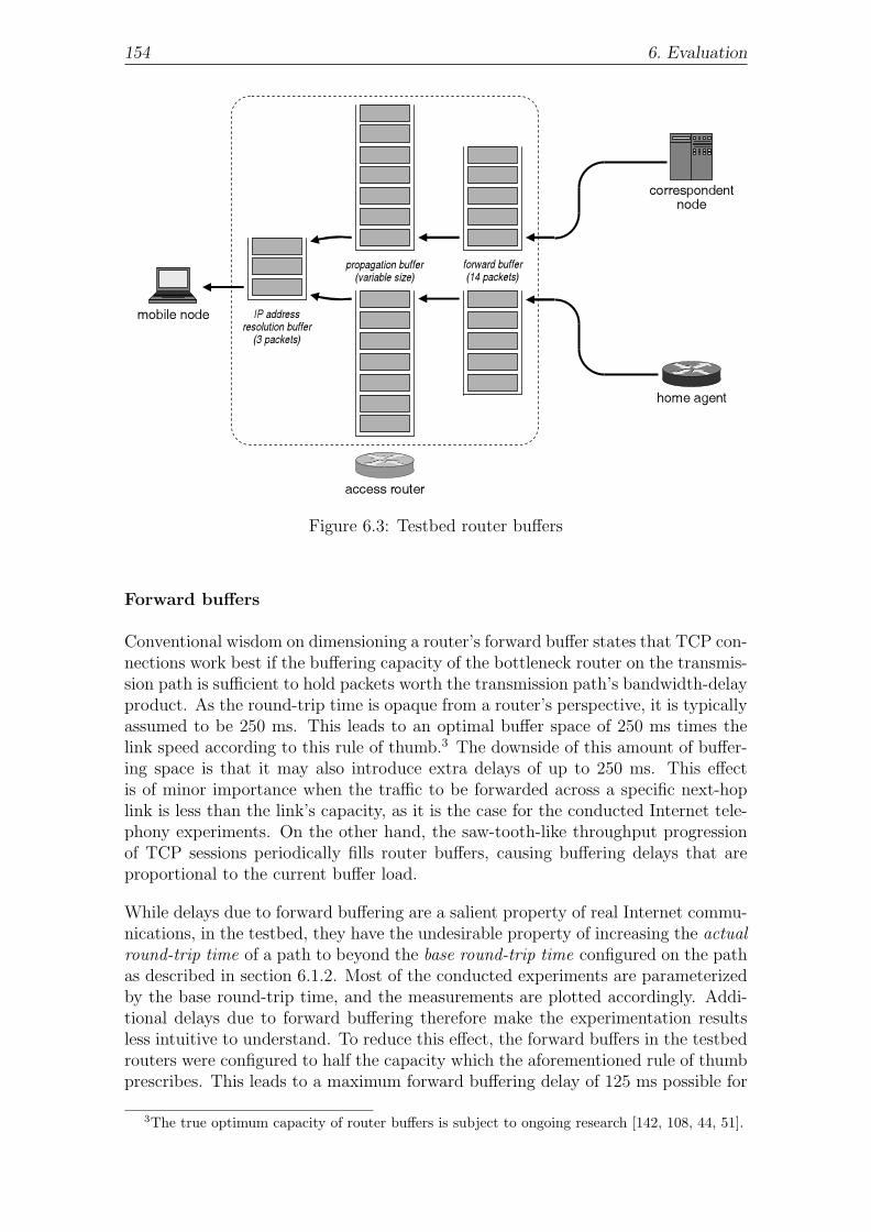
154 6. Evaluation
mobile node
correspondentnode
access router
home agent
propagation buffer(variable size)
forward buffer(14 packets)
IP addressresolution buffer
(3 packets)
Figure 6.3: Testbed router buffers
Forward buffers
Conventional wisdom on dimensioning a router’s forward buffer states that TCP con-nections work best if the buffering capacity of the bottleneck router on the transmis-sion path is sufficient to hold packets worth the transmission path’s bandwidth-delayproduct. As the round-trip time is opaque from a router’s perspective, it is typicallyassumed to be 250 ms. This leads to an optimal buffer space of 250 ms times thelink speed according to this rule of thumb.3 The downside of this amount of buffer-ing space is that it may also introduce extra delays of up to 250 ms. This effectis of minor importance when the traffic to be forwarded across a specific next-hoplink is less than the link’s capacity, as it is the case for the conducted Internet tele-phony experiments. On the other hand, the saw-tooth-like throughput progressionof TCP sessions periodically fills router buffers, causing buffering delays that areproportional to the current buffer load.
While delays due to forward buffering are a salient property of real Internet commu-nications, in the testbed, they have the undesirable property of increasing the actualround-trip time of a path to beyond the base round-trip time configured on the pathas described in section 6.1.2. Most of the conducted experiments are parameterizedby the base round-trip time, and the measurements are plotted accordingly. Addi-tional delays due to forward buffering therefore make the experimentation resultsless intuitive to understand. To reduce this effect, the forward buffers in the testbedrouters were configured to half the capacity which the aforementioned rule of thumbprescribes. This leads to a maximum forward buffering delay of 125 ms possible for
3The true optimum capacity of router buffers is subject to ongoing research [142, 108, 44, 51].

6.1. Testbed Setup 155
TCP-based file transfers. Given the bandwidth of 1024 kbps, the buffer space ishence sufficient to hold a number of
⌊bandwidth · delay
packet size
⌋=
⌊128 000 Bps · 125 ms
1108 B
⌋= b14.440c = 14
full-sized TCP segments. It should be noted that the additional buffer space that istruncated in this formula is large enough to accommodate the increased packet sizewhich the presence of a Spot Check option in some of the packets may imply.
The differentiation between the base and the actual round-trip time requires a con-cretization of what a path’s bandwidth-delay product is. The term is hence definedin this study as the product of the path’s bandwidth times its base round-trip time.Accordingly, the bandwidth-delay product is the amount of data which the path candurably transport once per base round-trip time. The existence of forward bufferson the path may allow a sender to temporarily inject new data at a higher rate ontothe path without packet loss.
Propagation buffers
The propagation buffer scales with the bandwidth-delay product of the respectivetransmission path. No manual configuration is required.
The simplified topology of the testbed differs from that of a real-life scenario in thatthe routes between the mobile node on one side and the home agent or correspon-dent node on the other side both pass through the same single access router. Thissetup would introduce unrealistic interferences between packet forwarding on thetwo transmission paths if an access router had just one forward buffer, or the band-width of 1024 kbps was shared by the packets on both paths. However, in order toreproduce the characteristics of truly separate transmission paths, the three accessrouters are endowed with separate forward and propagation buffers for each adjacenttransmission path, and packets in one buffer do not delay any packets in a differentbuffer. So from the perspective of the end nodes, it seems as if each transmissionpath had its own bottleneck router.
IP address resolution buffers
A small IP address resolution buffer may cause increased loss of packets when theaccess router does not know the recipient mobile node’s link layer address and hencecannot immediately deliver the packets that arrive for the mobile node. This is typ-ically not an issue with reactive mobility management because IP address resolutionthen takes place well before any payload packets for the mobile node arrive at theaccess router. However, proactive mobility management may cause the delivery ofpayload packets to a target access router already before the mobile node attachesto the target link. Insufficient capacity of the IP address resolution buffer may thenbe responsible for these packets being lost. The Neighbor Discovery RFC prescribesa minimum IP address resolution buffer size of one packet, which is the value thatFreeBSD defaults to. Since the IP address resolution buffer of the Linux operatingsystem is large enough for three packets, and since this increased buffer size canimprove the packet delivery ratio during proactive mobility management, the IP ad-dress resolution buffer size was increased to three packets also in the FreeBSD-basedtestbed.

156 6. Evaluation
6.1.7 Packet Loss
Packet loss in the testbed may happen due to overflows in forward buffers or IPaddress resolution buffers. With TCP file transfers, such handover-unrelated packetloss has been found to occur at rates of between 0.1% and 0.3% in the experiments.The loss rate is higher in topologies with small round-trip times because the fre-quency of TCP filling the bandwidth-delay product on the transmission path, andhence the interval between successive forward buffer overflows, is then smaller. Theobserved packet loss rates are commensurate with findings in [34] for paths betweenNorth America, Europe, East Asia, and Oceania. They also can be handled byTCP’s fast retransmit and recovery mechanisms quite well [100], and so should oc-cur unnoticable to the user in most cases. Handover-unrelated packet losses canhave a significant impact on handover performance as they influence the size of theTCP sender’s congestion window at the time of the handover.
Loss of Mobile IPv6 messages can cause handover signaling to fail and significantlydegrade handover performance. This may occur when such a message cannot beenqueued into an access router’s forward buffer due to the buffer being occupied byTCP segments. Lost Mobile IPv6 messages are eventually retransmitted, but thecost in terms of handover delay and packet loss can be tremendous. The efficiency ofMobile IPv6’s retransmission mechanisms, as well as its interaction with NeighborDiscovery signaling on the mobile node’s access link, is still a subject for furtherresearch. Due to the complexity involved, it is clearly out of scope of this study.The ensuing performance evaluation hence focuses on handovers during which lossof Mobile IPv6 messages does not happen. In an effort to avoid scanning experimen-tation logs for Mobile IPv6 retransmissions and removing those logs that match, apacket classifier was added to the DummyNet code which implements the forwardbuffer in access routers. This limits packet loss to payload packets, avoiding thedistractive influence that the loss of signaling packets would have on experimentresults. Theoretically, signaling packets may still fall victim to overflows in an IPaddress resolution buffer, but this did not happen in the conducted experiments.
The sending rate of an Internet telephony application never exceeds the 1024 kbps ofbandwidth available on a transmission path, so handover-unrelated packet losses donot occur in Internet telephony experiments. This does not reduce the realisticness ofthese experiments, however, because the application does not adapt its throughputin the event of congestion, and the amount of outstanding data at the time of ahandover would be the same even in the presence of preceding packet loss.
6.2 Internet Telephony
Interactive real-time applications have gained in importance tremendously duringthe recent past, and this trend is expected to continue [81]. Yet the stringent re-quirements that these applications have in terms of delay and packet loss make itdifficult to support them in mobile environments as even short interruptions duringhandover can lead to perceptible degradations in speech quality. Route optimiza-tion in standard Mobile IPv6 reduces packet propagation delays to a minimum andthus accommodates real-time applications while a mobile node stays at one point ofattachment without moving. But extended handover delays and handover-relatedpacket losses have been found to adversely impact these same applications when the

6.2. Internet Telephony 157
mobile node changes IP connectivity. This section evaluates the handover perfor-mance benefits that can be obtained for interactive, real-time applications throughthe use of Early Binding Updates and Credit Based Authorization, and it puts theresult in relation to the performance of standard Mobile IPv6. The measurementswere conducted with IP telephony. Given the similar needs of interactive real-timeapplications in general, it is expected that experiments with other such applicationswill yield comparable results.
6.2.1 Packet Loss
Changes in IP connectivity are typically responsible for the loss of payload packetsthat a correspondent node sends to a mobile node, and possibly also for the loss ofpayload packets that the mobile node sends to the correspondent node. In reactivemobility management, lost packets from the correspondent node are all sent to themobile node’s old care-of address, but fail to be delivered because the mobile nodeis no longer reachable at the old point of attachment. In proactive mobility man-agement, loss may also affect packets that the correspondent node directs to themobile node’s new care-of address, and that fail to be delivered because the mobilenode is not yet present at the new point of attachment. Payload packets that themobile node sends may be dropped locally in the mobile node’s network stack, be itduring the link layer handover, during subsequent IPv6 auto-configuration, or dueto a conservative mobile node’s policy not to send any payload packets until thehome registration is complete.
Most codecs used in Internet telephony applications incorporate algorithms to con-ceal the loss of a small amount of payload data, which is typically equivalent to oneor two payload packets [52, 61] depending on the codec and the packet size. Thegoal of such loss concealment is to mask the properties of lossy environments suchas wireless access links, where transmissions may sporadically fail due to collision,interference, or obstruction. On the other hand, loss concealment algorithms arepoor in repairing loss bursts, and they fall short of hiding the erasure of multiplepayload packets that typically occurs when a mobile node changes IP connectivity.Handover-related packet loss consequently translates into moments of blackout inspeech, causing annoying disruption during conversation. The Internet telephonyapplication [137] used in these experiments produces a constant-bit-rate payloaddata stream which does not undergo silent suppression, so the number of payloadpackets lost during handover is proportional to the length of the blackout that resultsfrom it.
Handover-related packet loss, or simply packet loss, is here defined as the numberof payload packets that the correspondent node sends to the mobile node and thatcannot be delivered due to the mobile node’s move between two points of attachment.The loss of packets in this traffic direction is generally higher than the loss affectingthe packets that the mobile node sends. The correspondent node can redirect itspackets to the new care-of address only when it receives a standard or early BindingUpdate message from the mobile node, and the transmission of this message mayrequire an a-priori home registration and return routability procedure depending onthe Mobile IPv6 variant. The length of the packet loss phase in reactive mobilitymanagement is hence in the order of round-trip times. The mobile node, on the otherhand, knows about its current care-of address being stale already when movement

158 6. Evaluation
0
20
40
60
80
100
120
140
160
180
400 ms200 ms150 ms100 ms75 ms50 ms25 ms
pack
et lo
ss
base round-trip time (ms)
Conservative Mobile IPv6Optimistic Mobile IPv6Mobile IPv6+EBU, CBA Inbound
Figure 6.4: Mean packet loss for Internet telephony and reactive mobility manage-ment
detection completes. The immediate availability of a new care-of address, whichOptimistic Duplicate Address Detection permits, then enables the mobile node tosend subsequent packets with a topologically correct IP source address. The loss ofpackets that the correspondent node sends is consequently at least as high as theloss of packets that the mobile node sends. The chosen packet loss metric is basedon the former traffic direction and hence accommodates Internet telephony’s naturaldependency on bidirectional packet delivery.
Furthermore, some Mobile IPv6 variants require the mobile node to temporarilysend its payload packets via the home agent after a handover, so as to ensure thedelivery of these packets despite an out-of-date binding at the correspondent node.Reverse-tunneled packets experience increased propagation latencies and are henceat risk of not being delivered in time to the receiving Internet telephony application.They may get dropped eventually even though the correspondent node receives them.The chosen packet loss metric accommodates this need for timeliness. The measuredpacket loss in the direction from the correspondent node to the mobile node is alwaysat least as much as the packet loss in the opposite direction, so the metric coversany period of reverse-tunneling and potentially late packet delivery. The metric alsoimplies that it makes no difference whether the mobile node begins route-optimizingits payload packets for the correspondent node once it has sent the Binding Updatemessage to the correspondent node, or whether it continues reverse-tunneling untilit receives the responding Binding Acknowledgment message. The period of reverse-tunneling is covered by the metric in any case.
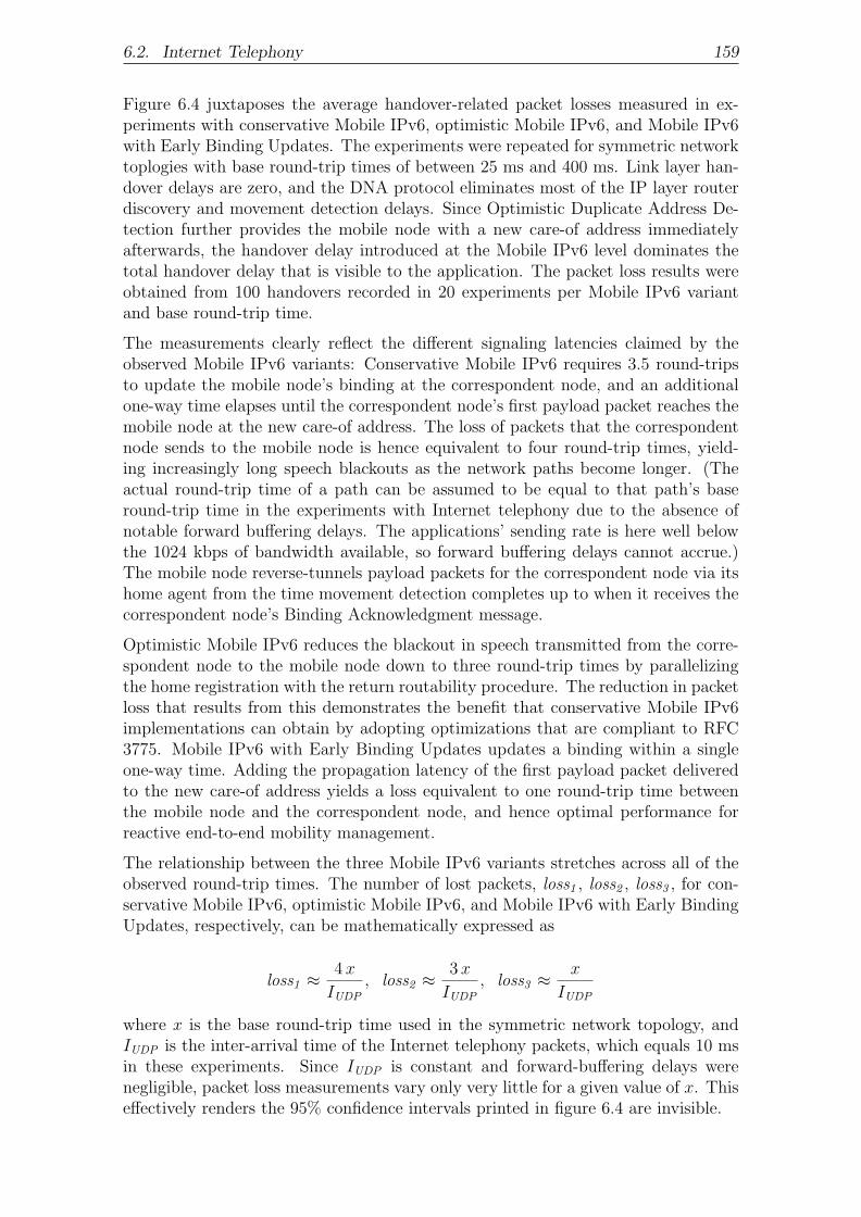
6.2. Internet Telephony 159
Figure 6.4 juxtaposes the average handover-related packet losses measured in ex-periments with conservative Mobile IPv6, optimistic Mobile IPv6, and Mobile IPv6with Early Binding Updates. The experiments were repeated for symmetric networktoplogies with base round-trip times of between 25 ms and 400 ms. Link layer han-dover delays are zero, and the DNA protocol eliminates most of the IP layer routerdiscovery and movement detection delays. Since Optimistic Duplicate Address De-tection further provides the mobile node with a new care-of address immediatelyafterwards, the handover delay introduced at the Mobile IPv6 level dominates thetotal handover delay that is visible to the application. The packet loss results wereobtained from 100 handovers recorded in 20 experiments per Mobile IPv6 variantand base round-trip time.
The measurements clearly reflect the different signaling latencies claimed by theobserved Mobile IPv6 variants: Conservative Mobile IPv6 requires 3.5 round-tripsto update the mobile node’s binding at the correspondent node, and an additionalone-way time elapses until the correspondent node’s first payload packet reaches themobile node at the new care-of address. The loss of packets that the correspondentnode sends to the mobile node is hence equivalent to four round-trip times, yield-ing increasingly long speech blackouts as the network paths become longer. (Theactual round-trip time of a path can be assumed to be equal to that path’s baseround-trip time in the experiments with Internet telephony due to the absence ofnotable forward buffering delays. The applications’ sending rate is here well belowthe 1024 kbps of bandwidth available, so forward buffering delays cannot accrue.)The mobile node reverse-tunnels payload packets for the correspondent node via itshome agent from the time movement detection completes up to when it receives thecorrespondent node’s Binding Acknowledgment message.
Optimistic Mobile IPv6 reduces the blackout in speech transmitted from the corre-spondent node to the mobile node down to three round-trip times by parallelizingthe home registration with the return routability procedure. The reduction in packetloss that results from this demonstrates the benefit that conservative Mobile IPv6implementations can obtain by adopting optimizations that are compliant to RFC3775. Mobile IPv6 with Early Binding Updates updates a binding within a singleone-way time. Adding the propagation latency of the first payload packet deliveredto the new care-of address yields a loss equivalent to one round-trip time betweenthe mobile node and the correspondent node, and hence optimal performance forreactive end-to-end mobility management.
The relationship between the three Mobile IPv6 variants stretches across all of theobserved round-trip times. The number of lost packets, loss1 , loss2 , loss3 , for con-servative Mobile IPv6, optimistic Mobile IPv6, and Mobile IPv6 with Early BindingUpdates, respectively, can be mathematically expressed as
loss1 ≈ 4 x
IUDP
, loss2 ≈ 3 x
IUDP
, loss3 ≈ x
IUDP
where x is the base round-trip time used in the symmetric network topology, andIUDP is the inter-arrival time of the Internet telephony packets, which equals 10 msin these experiments. Since IUDP is constant and forward-buffering delays werenegligible, packet loss measurements vary only very little for a given value of x. Thiseffectively renders the 95% confidence intervals printed in figure 6.4 are invisible.

160 6. Evaluation
correspondentnode
new c/oaddress
old c/oaddress
handover phase
link-layerhandover
reactiveMobile IPv6
signaling
payloadpayload
payloadpayload
payloadpayloadpayloadpayloadpayload
(a) Reactive mobility management
correspondentnode
new c/oaddress
old c/oaddress
handover phase
payloadpayload
payloadpayload
payloadpayloadpayloadpayloadpayload
link-layerhandover
proactiveMobile IPv6
signaling
reactiveMobile IPv6
signaling
(b) Proactive mobility management
Figure 6.5: Composition of handover phase in Internet telephony
6.2.2 Handover Delay
Changes in IP connectivity on the mobile-node side may disrupt Internet telephonysessions through packet loss or temporary unidirectional packet delivery. Undis-turbed conversations are then delayed until bidirectional packet delivery has beenrestored. These circumstances suggest the definition of the handover phase as theperiod between the correspondent node’s transmission of the payload packet that im-mediately follows the last payload packet successfully received by the mobile nodeat the old care-of address up to the point at which the correspondent node transmitsthe first payload packet that the mobile node again successfully receives at the newcare-of address. Figure 6.5 illustrates this definition.
The handover delay is defined as the length of the handover phase and hence ap-proximates the time span during which speech transmission from the correspondentnode to the mobile node intermits. The silence observed by the correspondent nodeitself may be shorter if reverse-tunneled payload packets from the mobile node reachthe correspondent node in time, or if the mobile node resumes route optimizationat the time it sends the Binding Update message to the correspondent node ratherthan waiting for the reception of a Binding Acknowledgment message. The silenceat both peers is equally long if the mobile node continues reverse-tunneling payloadpackets up to the reception of the correspondent node’s Binding Acknowledgmentmessage, and the reverse-tunneled packets are dropped by the receiving applicationas stale. So as in the case of handover-related packet loss, the handover delay islonger in the traffic direction from the correspondent node to the mobile node thanit is in the reverse direction. The interactiveness of Internet telephony applicationshence justifies the definition of the handover phase and latency from the perspectiveof the correspondent node. For a handover without any packet losses, the defini-tions imply that the beginning and the end of the handover phase coincide with thetransmission of the first payload packet directed to the new care-of address, and thehandover delay reduces to zero.

6.2. Internet Telephony 161
0
0.2
0.4
0.6
0.8
1
1.2
1.4
1.6
1.8
400 ms200 ms150 ms100 ms75 ms50 ms25 ms
UD
P h
ando
ver
dela
y (s
)
base round-trip time (ms)
Conservative Mobile IPv6Optimistic Mobile IPv6Mobile IPv6+EBU, CBA Inbound
Figure 6.6: Mean handover delay for Internet telephony and reactive mobility man-agement
Figure 6.6 shows the average handover delays measured in the experiments that wereintroduced in section 6.2.1. Handover delays match the signaling latencies consumedby the respective Mobile IPv6 variants, and they are proportional to packet lossdue to the constant bit rate at which the observed Internet telephony applicationssend. So if latency1 , latency2 , and latency3 are the handover delays of conservativeMobile IPv6, optimistic Mobile IPv6, and Mobile IPv6 with Early Binding Updates,respectively, then these can be mathematically expressed as
latency1 ≈ 4 x, latency2 ≈ 3 x, latency3 ≈ x
where x is the base round-trip time used in the symmetric network topology. The op-timizations of optimistic Mobile IPv6 and Mobile IPv6 with Early Binding Updatesyield an increasing benefit as round-trip times grow across the network topologiesshown. With a handover delay of one round-trip time, the performance of EarlyBinding Updates is optimal for reactive end-to-end mobility management.
The small variation in measured packet loss implies a similarly small variation inmeasured handover delays. The 95% confidence intervals printed in figure 6.6 thusbecome invisible.
6.2.3 Credit Availability
One of the benefits of Early Binding Updates and Credit-Based Authorization is thatthe techniques enable mobile and correspondent nodes to continue communications

162 6. Evaluation
0
500
1000
1500
2000
0 20 40 60 80 100 120 140 160 180
avai
labl
e cr
edit
(KB
)
experiment time (s)
Mobile IPv6+EBU, CBA Inbound, UDPbase round-trip time: 25 ms
0
500
1000
1500
2000
0 20 40 60 80 100 120 140 160 180
avai
labl
e cr
edit
(KB
)
experiment time (s)
Mobile IPv6+EBU, CBA Inbound, UDPbase round-trip time: 400 ms
Figure 6.7: Credit availability in CBA Inbound mode
early on after a handover while the mobile node’s new care-of address is still inUnverified state. This feature, however, hinges on the mobile node’s available creditnot running out until the new care-of address moves to Verified state. Lack of creditmay be due to a long reachability verification latency. It may also happen if themobile node changes IP connectivity more frequently than would allow it to refillthe consumed credit during the time between successive handovers. Finally, creditcould be insufficient if credit aging eliminates the credit faster than it can be turnedinto data sent to an unverified care-of address.
Figure 6.7 shows the amount of credit the mobile node earns and consumes over timein two Internet telephony experiments where Credit Based Authorization is used inInbound mode. The experiments were conducted in symmetric network topologies.The base round-trip time on all paths is 25 ms in the top chart and 400 ms in thebottom chart. Credit aging leads to a drop in the available credit by 1/8 every 16 s,giving rise to the zigzag curves in the figure. Yet despite the periodic reductions,the credit continually grows until it reaches a point at which the new credit earnedwithin a period of one crediting interval equals 1/8 of the total credit, and is henceeliminated by aging at the end of the crediting interval. The upper credit limit isthereby determined by the mobile node’s sending rate. This is constant, so creditacquisition is independent of the base round-trip time.
The vertical lines in both charts of the figure mark the times at which the mobilenode pursues a handover. Payload packets that the correspondent node sends to acare-of address in Unverified state at around this time each consume credit worth

6.2. Internet Telephony 163
0
50
100
150
200
0 20 40 60 80 100 120 140 160 180
avai
labl
e cr
edit
(KB
)
experiment time (s)
Mobile IPv6+EBU, CBA Outbound, UDPbase round-trip time: 25 ms
0
50
100
150
200
0 20 40 60 80 100 120 140 160 180
avai
labl
e cr
edit
(KB
)
experiment time (s)
Mobile IPv6+EBU, CBA Outbound, UDPbase round-trip time: 400 ms
Figure 6.8: Credit availability in CBA Outbound mode without spot check support
164 B. The correspondent node sends at a constant rate, so credit consumption in-creases with the round-trip time on the new transmission path. However, the chartsindicate that the consumed credit is negligible compared to the amount of creditavailable even if the base round-trip time between the mobile node and the corre-spondent node is 400 ms. This is due to the fact that the credit aging functionhas been designed to accommodate the asymmetric traffic properties of TCP, wherecredit collection proceeds at a much lower rate than credit consumption does duringhandover. However, the traffic patterns of UDP-based Internet telephony applica-tions are symmetric, so the mobile node ends up gathering a multiple of the creditthat it may actually require. This high availability of credit does not limit the se-curity that Credit-Based Authorization provides against redirection-based floodingattacks, however. After all, the mobile node still cannot earn more credit than isequivalent to the data it sends, and due to aging, this credit can only be kept for acertain amount of time.
Credit aging is more rigid in Outbound mode, and the amount of credit available isconsequently lower. Figure 6.8 demonstrates this with two charts from experimentswith Outbound mode. Like in figure 6.7, these experiments were obtained from asymmetric network topology with base round-trip times of 25 ms and 400 ms inthe top and bottom charts, respectively. Evidently, the lower credit availabilityin Outbound mode does not lead to a credit shortage during handover, avoidingnegative performance implications.

164 6. Evaluation
0
50 100
150
200
250 300
350
400
0 20 40 60 80 100 120 140 160 180
avai
labl
e cr
edit
(KB
)
experiment time (s)
Mobile IPv6+EBU, CBA Outbound+Spot Checks, UDPbase round-trip time: 25 ms
0
50 100
150
200
250 300
350
400
0 20 40 60 80 100 120 140 160 180
avai
labl
e cr
edit
(KB
)
experiment time (s)
Mobile IPv6+EBU, CBA Outbound+Spot Checks, UDPbase round-trip time: 400 ms
Figure 6.9: Credit availability in CBA Outbound mode with spot check support
The use of spot checks in conjunction with Credit-Based Authorization Outboundmode is conceptually of little importance with respect to credit availability. TheInternet telephony applications used in the experiments provide a steady flow ofpackets onto which the mobile node can piggyback any spot check tokens receivedfrom the correspondent node. Deposit on the correspondent node side is there-fore in most cases turned into credit eventually. One exception holds for spo-radic, handover-unrelated packet loss. When this affects a packet including a SpotCheck option, newly assigned credit is temporarily less. Overall however, handover-unrelated packet loss has a minor impact given that it only occurs at rates of between0.1% and 0.3%. The mobile node’s available credit is hence on average at most 0.3%less if spot checks are used. The only more substantial difference which the use ofspot checks makes regards the payload packets that the correspondent node sendsto the mobile node’s old care-of address while the mobile node is handing over to anew point of attachment, assuming that the old care-of is in Verified state at thattime. Unless spot checks are used, these packets are fully turned into credit eventhough they are not received by the mobile node. Spot checks can unveil such packetloss, thus reducing the credit available during the handover. The number of packetsthat the correspondent node sends to the old care-of address in vain, and hencethe amount of credit these packets are worth, depends on the latency of the mobilenode’s link layer handover, any delays for IPv6 auto-configuration on the new link,as well as the actual round-trip time on the new transmission path accounting forthe propagation of the mobile node’s early Binding Update message and the corre-spondent node’s first payload packet directed to the new care-of address. The top

6.3. Internet Telephony with Proactive Mobility Management 165
and bottom charts in figure 6.9 represent scenarios with the same parameters asbefore with the exception that the correspondent node now applies Outbound modewith spot checks in order to estimate the delivery ratio of the payload packets itsends. The charts notably differ from the previous ones in that credit aging nowis no longer visible in the form of periodic drops in the available credit. This isbecause the spot check implementation that was used for these experiments differsfrom the specification in section 4.3 in that the correspondent node keeps credit asdeposit for an entire aging interval, even after the corresponding spot check tokenshave been successfully returned. The deposit is then aged right before it is turnedinto credit—a behavior that is based on an earlier specification which was revisedin the meantime. The charts in figure 6.9 hence underestimate the mobile node’savailable credit slightly, because the assignment of new credit may happen up to onecrediting interval later than according to the specification in section 4.3. Given thatno credit shortage occurs in the conducted experiments, it can be concluded thatnone would happen with an implementation that turns deposit into credit directlywhen a spot check token has been successfully returned.
6.3 Internet Telephony
with Proactive Mobility Management
The preceding sections corroborate the improvements in handover performance thatoptimizations for Mobile IPv6 can have if mobility is managed reactively. Be-yond this, the possibility to defer reachability verification for new care-of addresses,which Early Binding Updates and Credit-Based Authorization permit, enables mo-bile nodes that can anticipate changes in IP connectivity to handle mobility in aproactive manner. This facilitates additional performance improvements.
6.3.1 Packet Loss
The theoretic elaboration in section 5.3 shows that proactive mobility managementbased on Mobile IPv6 with Early Binding Updates can eliminate packet loss providedthat a suitable network topology and sufficiently small handover delays at the linklayer or outside Mobile IPv6 at the IP layer enable the mobile node to leave theold point of attachment after it has received the last payload packet destined tothe old care-of address, and to arrive at the new point of attachment early enoughto receive the first payload packet sent to the new care-of address. This claimhas been verified based on Internet telephony experiments with proactive mobilitymanagement in Home Priority mode, Correspondent Priority mode, and Impatientmode, both in symmetric and asymmetric network topologies. The DNA protocolis used for router discovery and movement detection, and link layer handover delaysare zero.
In the symmetric network topologies, the common base round-trip time on all pathsranges from 25 ms to 400 ms. The expected elimination of packet losses turned out tooccur for all measured handovers without a single exception. This unambiguousnessand reproducibility is mostly due to the regular sending patterns of the monitoredInternet telephony applications. Another contributing factor is the absence of round-trip time variations, which forward buffering delays on the transmission path mayinduce: Furthermore, since the actual round-trip times are on all path the same,

166 6. Evaluation
0
5
10
15
20
25
30
35
40
45
400 ms200 ms150 ms100 ms75 ms50 ms25 ms
pack
et lo
ss
round-trip time* (ms)
* round-trip time between home agentand mobile node fixed at 25 ms
EBU pro ImpatientEBU pro Home PriorityEBU pro Correspondent Priority
Figure 6.10: Mean packet loss for Internet telephony and proactive mobility man-agement
the home agent’s and the correspondent node’s Binding Acknowledgment messagesalways arrive at the mobile node at about the same time, which means that HomePriority mode, Correspondent Priority mode, and Impatient mode end up perform-ing equally. The initiation of the link layer handover thus follows the delivery of thelast payload packet at the old point of attachment in all of the three modes, escapingany loss at the old point of attachment. At the same time, loss of early packets atthe new point of attachment is unlikely as well because packet delivery at the oldand new points of attachment does not overlap. Moreover, the new access router’sIP address resolution buffer could salvage up to three packets that arrive at the newpoint of attachment before the mobile node does. Given that packet loss was zerowithout exception in each of the three modes of proactive mobility management, theresults are not displayed in a separate diagram here.
The effect that an asymmetric network topology has on handover-related packetloss has been studied based on two further sets of experiments. Figure 6.10 showspacket loss averages and 95% confidence intervals from topologies with a constantround-trip time of 25 ms between the home agent and any other node, and varyinground-trip times of between 25 ms and 400 ms between either access router in thevisited networks and the correspondent node. Consistent with the foregoing analysisfor symmetric network topologies, the datum on the left-hand side of the diagramshows that packet loss is zero in the special case where the base round-trip timesis 25 ms on all paths. Packet loss in Correspondent Priority mode continues tobe minimum also as the network topologies become more and more asymmetricbecause the time at which the mobile node pursues the link layer handover is in this

6.3. Internet Telephony with Proactive Mobility Management 167
0
5
10
15
20
25
30
35
40
45
400 ms200 ms150 ms100 ms75 ms50 ms25 ms
pack
et lo
ss
round-trip time* (ms)
* round-trip time between home agentand mobile node fixed at 400 ms
EBU pro ImpatientEBU pro Home PriorityEBU pro Correspondent Priority
Figure 6.11: Mean packet loss for Internet telephony and proactive mobility man-agement
mode always synchronized with the redirection of the correspondent node’s payloadpackets from the old care-of address to the new one. The low round-trip time on thepaths to the home agent hence has no influence. However, the increasing asymmetrycauses packet loss to grow where Home Priority mode is used because the mobilenode then changes links before the last payload packet destined to the old care-ofaddress has been delived. If x is the base round-trip time between the mobile nodeand the correspondent node, y is the shorter or equal base round-trip time on thepaths incident to the home agent, and IUDP is the inter-arrival time of the Internettelephony packets, then the number of lost packets generally amounts to
lossp1 ≈ x− y
IUDP
=x− 25 ms
10 ms
The results for Impatient mode are similar to those of Home Priority mode becausethe home registration latency is always less than or equal to the correspondentregistration latency in these experiments, rendering Home Priority mode equivalentto Impatient mode.
Figure 6.11 summarizes the average packet losses and 95% confidence intervals in ex-periments where the home registration is longer than the correspondent registration.The round-trip between the home agent and any other node now takes a constant400 ms, while the round-trip time between the mobile node and the correspondentnode varies as before from 25 ms to 400 ms. Again, the results for CorrespondentPriority mode are not affected by the new asymmetry. But Home Priority mode re-quires the mobile node to stay longer than optimum at the old point of attachment

168 6. Evaluation
so that packets already arrive at the new point of attachment in the mobile node’sabsence. The IP address resolution buffer in the target access router can salvage upto three of these packets, averting packet loss if the mobile node arrives on the newlink before the fourth packet is delivered. The number of packets lost then equals
lossp2 ≈ max(
0,y − x
IUDP
− 3)
= max(
0,400 ms − x
10 ms− 3
)
where x is again the round-trip time between the mobile node and the correspon-dent node, and y is the round-trip time on all paths incident to the home agent.Packet loss at the new point of attachment accordingly becomes inevitable if theround-trip time difference, y − x, reaches 3 IUDP . Since the correspondent node’sBinding Acknowledgment message arrives before the home agent’s in these experi-ments, Impatient mode becomes equivalent to Correspondent Priority mode.
6.3.2 Handover Delay
The definition of handover delay in section 6.2.2 implies a delay of zero for handoverswithout packet loss. This is reasonable since such handovers are invisible from anapplication’s perspective.4 Handovers that do not cause packet loss may happenif either the mobile node runs in Correspondent Priority mode and thus initiatesthe link layer handover at a time that is optimal with respect to the redirection ofthe correspondent node’s payload packets from the old care-of address to the newone, or if the network topology is symmetric and the mode of proactive mobilitymanagement does not make a difference. These scenarios have been discussed insection 6.3.1, and zero packet loss has been found to occur predictably across all ofthem. The handover delays in the same scenarios are consequently zero as well, andhence not plotted in a separate diagram here.
On the other hand, asymmetric network topologies do cause handover delays in casethe mobile node operates in Home Priority mode or, if the home registration latencyis shorter than the correspondent registration latency, in Impatient mode. Figure6.12 summarizes the average handover delays and 95% confidence intervals for thoseexperiments from section 6.3.1 where the base round-trip time between the homeagent and any other node is fixed at 25 ms, and the base round-trip time betweenthe mobile node and the correspondent node varies from 25 ms to 400 ms. Theleft-hand side datum of the figure relates to a network topology where the pathsbetween all pairs of nodes are equally long, so the handover delay is here still zerofor all modes of proactive mobility management. The handover delay continues tobe zero also for more asymmetric network topologies if the mobile node operatesin Correspondent Priority mode. However, loss of payload packets at the old pointof attachment leads to handover delays in Home Priority mode as the difference inround-trip times grows. The same holds for Impatient mode, which in this case isequivalent to Home Priority mode due to the small home registration latency.
Overall, it can be seen that handover delays are proportional to packet loss. Theregular sending pattern of the correspondent node and the absence of forward buffer-
4Buffering of packets in a new access router during IP address resolution may introduce somedelays even for handovers without packet loss. This delay is not captured by the definition ofhandover delay used in this thesis.

6.3. Internet Telephony with Proactive Mobility Management 169
0
0.05
0.1
0.15
0.2
0.25
0.3
0.35
0.4
0.45
400 ms200 ms150 ms100 ms75 ms50 ms25 ms
han
do
ver
de
lay (
s)
round-trip time* (ms)
* round-trip time between home agentand mobile node fixed at 25 ms
EBU pro ImpatientEBU pro Home PriorityEBU pro Correspondent Priority
Figure 6.12: Mean handover delay for Internet telephony and proactive mobilitymanagement
ing delays on the transmission path give rise to the following theoretic derivation ofthe handover delay as a function of the number of packets lost during handover:
handover delay = IUDP · loss
Figure 6.13 shows the average handover delays and 95% confidence intervals forexperiments where the round-trip time on the paths incident to the home agent isfixed at 400 ms and the common round-trip time on all other paths again variesbetween 25 ms and 400 ms. The measurements for Correspondent Priority modereveal the absence of handover delays across all topologies as before. The sameholds for the measurements for Impatient mode, since the correspondent registrationlatency is never longer than the latency of a home registration. Handover delays dooccur if the mobile node operates in Home Priority mode. They are highest in thescenario represented by the left-most datum in the figure due to the large differencebetween the home and correspondent registration latencies, and they shrink as thedifference becomes less across the scenarios further to the right. The handover delaysof all three modes of proactive mobility management are zero on the right-mostdatum in the figure since the latencies of the home and correspondent registrationsare the same in this case.
6.3.3 Credit Availability
Credit consumption during a handover is higher in proactive mobility managementthan it is in reactive mobility management due to a longer time during which the

170 6. Evaluation
0
0.05
0.1
0.15
0.2
0.25
0.3
0.35
0.4
0.45
400 ms200 ms150 ms100 ms75 ms50 ms25 ms
han
do
ver
de
lay (
s)
round-trip time* (ms)
* round-trip time between home agentand mobile node fixed at 400 ms
EBU pro ImpatientEBU pro Home PriorityEBU pro Correspondent Priority
Figure 6.13: Mean handover delay for Internet telephony and proactive mobilitymanagement
mobile node’ new care-of address is in Unverified state. In reactive mobility man-agement, a new care-of address is typically in Unverified state for not more thanone round-trip time between the mobile node and the correspondent node becausereachability verification is already initiated in parallel with the binding update. Onthe other hand, the reachability of a care-of address that is proactively registeredprior to handover can be verified only after the handover, so the time during whichthe care-of address remains in Unverified state is necessarily longer. The phase maybe further prolonged by additional handover delays at the link layer or the IP layerother than those of Mobile IPv6 itself. Credit consumption is proportional to thelength of this phase given that the Internet telephony application at the correspon-dent node sends at a constant rate without disruption.
The amount of credit consumed in proactive mobility management is particularlyhigh when both, the mobile node’s stay at the old point of attachment after sendingthe Binding Update messages, and the verification of the mobile node’s reachabilityat the new point of attachment, takes long. Amongst the experiments evaluated sofar, maximum credit consumption can consequently be expected from those whereround-trip times of 400 ms are used on all paths. Figure 6.14 illustrates the mobilenode’s available credit over the course of two such experiments. The top chart inthe figure shows an experiment with Credit-Based Authorization running in Inboundmode, and Outbound mode was used in the experiment shown in the bottom chart.Both curves decrease when a handover takes place at the times marked by a verticalline, and as expected, the declines here are more pronounced than those in reactivemobility management. Relatively speaking, the declines in Outbound mode are moresubstantial than the ones in Inbound mode given a lower amount of credit available,

6.3. Internet Telephony with Proactive Mobility Management 171
0
500
1000
1500
2000
0 20 40 60 80 100 120 140 160 180
avai
labl
e cr
edit
(KB
)
experiment time (s)
Mobile IPv6+EBU pro Impatient, CBA Inbound, UDPbase round-trip time: 400 ms
0
50
100
150
200
0 20 40 60 80 100 120 140 160 180
avai
labl
e cr
edit
(KB
)
experiment time (s)
Mobile IPv6+EBU pro Impatient, CBA Outbound, UDPbase round-trip time: 400 ms
Figure 6.14: Credit availability in CBA Inbound mode for proactive mobility man-agement
which in turn is due to the more rigid credit aging in Outbound mode. But neither inInbound mode nor in Outbound mode does the handover-related credit consumptionjeopardize the availability of credit during handover.
It should be emphasized that the amount of credit consumed during a handover issolely a function of the time that passes between the correspondent node’s receptionof the proactive early Binding Update message, sent by the mobile node from theold point of attachment, and the delivery of the mobile node’s standard Binding Up-date message which completes reachability verification after the handover. On theother hand, differences between the latencies of proactive home and correspondentregistrations do not further influence the amount of credit consumed. Credit con-sumption is therefore orthogonal to packet loss, which does increase with differencesin home and correspondent registration latencies, but which may actually be zero inthe presence of long, yet equal registration latencies.
Figure 6.15 corroborates the foregoing observation with charts of the mobile node’savailable credit in asymmetric network topologies when Credit-Based Authorizationis operated in Outbound mode. The round-trip time on paths incident to the homeagent is 25 ms in the top chart and 400 ms in the bottom chart, while the round-trip time between the mobile node and the correspondent node is 400 ms in thetop chart and 25 ms in the bottom chart. The mobile node uses Home Prioritymode, so the initiation time of the link layer handover is never synchronized withthe redirection of the correspondent node’s payload packets from the old to the new

172 6. Evaluation
0
20 40
60
80
100 120
140
160
0 20 40 60 80 100 120 140 160 180
cred
it (K
iB)
experiment time (s)
EBU pro Home Priority, CBA OutboundRTT = 400 ms mobile node/corresp. node, 25 ms mobile node/home agent
0
20 40
60
80
100 120
140
160
0 20 40 60 80 100 120 140 160 180
cred
it (K
iB)
experiment time (s)
EBU pro Home Priority, CBA OutboundRTT = 25 ms mobile node/corresp. node, 400 ms mobile node/home agent
Figure 6.15: Credit availability in CBA Outbound mode for proactive mobility man-agement
care-of address. While this causes increased packet loss compared to a symmetricnetwork topology where all paths have a round-trip time of 400 ms, it actuallyreduces credit consumption: In the top chart, the mobile node initiates the linklayer handover already when it receives the home agent’s Binding Acknowledgmentmessage, although it takes significantly longer for the correspondent node’s BindingAcknowledgment message to arrive. This shortens the phase during which the newcare-of address is in Unverified state, leading to reduced credit consumption duringhandovers at the cost of packet loss at the old care-of address. The higher homeregistration latency in the bottom chart causes more credit consumption before themobile node initiates the link layer handover (in addition to increased packet lossat the new care-of address). But the comparably low round-trip time between themobile node’s new point of attachment and the correspondent node compensates thiseffect. The consumption of credit is the same when Credit-Based Authorization isoperated in Inbound mode. Yet its relative impact is then lower considering the lessrigid credit aging and, consequently, higher amount of available credit. A companiondiagram for Inbound mode in addition to figure 6.15 is therefore omitted here.
6.4 TCP File Transfers
Although real-time applications like Internet telephony are expected to become sig-nificantly more prevalent in the short term, the majority of Internet applications iscurrently still based on TCP. Beyond the classic use of TCP for Web browsing, file

6.4. TCP File Transfers 173
0
20
40
60
80
100
120
400 ms200 ms150 ms100 ms75 ms50 ms25 ms
TC
P th
roug
hput
(K
B)
base round-trip time (ms)
Conservative Mobile IPv6Optimistic Mobile IPv6
Mobile IPv6+EBU, CBA Inbound
Figure 6.16: Mean payload throughput in TCP SACK file transfers
transfer, and email, the protocol has also been adopted for multi-media applicationssuch as streaming, or even real-time Internet telephony. Modern TCP implemen-tations incorporate a number of sophisticated congestion control and loss recoverymechanisms that are sensitive to IP connectivity changes at either end node. Thissection evaluates how mobile nodes can benefit from Early Binding Updates andCredit-Based Authorization when downloading a file from a stationary TCP server.
6.4.1 Throughput
Mobile users who conduct a file transfer over TCP are mostly interested in the speedof the download. Payload throughput in a mobile scenario is hence an appropriatemetric to estimate the benefit of mobility management optimizations. Figure 6.16compares the performance of TCP SACK over conservative Mobile IPv6, optimisticMobile IPv6, and Mobile IPv6 with Early Binding Updates regarding the amount ofdata the Mobile IPv6 variants deliver during a 360-s file transfer that spans 5 han-dovers. The experiments were repeated for different symmetric network topologieswith base round-trip times of between 25 ms and 400 ms on all paths. The figureshows averages and 95% confidence intervals from 20 experiments per Mobile IPv6variant and network topology.
The measurements evidence a dependency of TCP throughput on the round-triptime across all Mobile IPv6 variants. There are mainly three reasons for this: First,Mobile IPv6 signaling latencies grow with the round-trip time and constitute anincreasingly long period during which a file transfer must pause. Second, a longerround-trip time on the transmission path implies a higher bandwidth-delay product.Since TCP attempts to send as much data per round-trip time as fits into the

174 6. Evaluation
bandwidth-delay product, handover-related packet loss is higher on average whenthe round-trip time is long, and the time it takes TCP to repair this loss increasesas well. Third, the speed at which TCP recovers from packet loss and adapts tothe bandwidth available on the new transmission path, both in Slow Start modeand in Fast Recovery mode, is directly proportional to the path’s round-trip time.The longer the round-trip time, the more sluggish TCP consequently reacts to ahandover.
On the other hand, the measurements also show that the impact of the round-triptime on TCP throughput is lowest for Mobile IPv6 with Early Binding Updates.What is striking is that Early Binding Updates can more than double the through-put compared to conservative Mobile IPv6 when the base round-trip time on thetransmission path is 400 ms. The deployment of optimistic Mobile IPv6 in replace-ment for conservative Mobile IPv6 still leads to a performance gain of more than onethird. The benefit of optimistic Mobile IPv6 and Mobile IPv6 with Early BindingUpdates decreases notably as round-trip times become smaller. None of the opti-mizations provides any substantial improvement with round-trip times of 100 ms andbelow. What makes the optimizations perform so much better over long distances,and what causes the benefit to vanish completely when round-trip times are small?The answers to these questions are found in TCP’s loss-recovery mechanisms, asexplained next.
6.4.2 Retransmission Timeouts
Of the two mechanisms through which TCP recovers from packet loss—that is,Slow Start mode after a retransmission timeout or Fast Recovery mode after a fastretransmit—, it is typically the combination of a retransmission timeout and SlowStart mode which a handover triggers in case mobility is managed reactively. A fastretransmit would require three duplicate acknowledgments to be generated by themobile node and hence three segments to be delivered to the new care-of address.This seldom happens in reactive mobility management for the following reason:When the mobile node changes IP connectivity, all packets currently in flight to theold care-of address are lost, and an additional one-way worth of packets is lost untilthe mobile node’s Binding Update message is delivered to the correspondent node.The total loss is worth a round-trip time between the correspondent node and themobile node, and therefore roughly corresponds to the correspondent node’s availablewindow. The correspondent node cannot send more segments than permitted by theavailable window without receiving an acknowledgment. It consequently stalls andruns into a retransmission timeout.
The number of successive retransmission timeouts that the correspondent node goesthrough during a handover depends on when the correspondent node receives theBinding Update message from the mobile node. If the Binding Update messagearrives before the retransmission timer expires for the first time, the correspondentnode resends the lost segments the new care-of address. This reestablishes thedata transfer. However, if the Binding Update message arrives later than the firstretransmission timeout, the correspondent node directs the lost segments to theold care-of address and times out yet again. The timeout period doubles for eachsuccessive retransmission, up to an implementation-specific limit which must be 60 s

6.4. TCP File Transfers 175
450
500
550
600
21 22 23 24 25 26 27 28
sequ
ence
num
ber
(KiB
)
experiment time (s)
segmentacknowledgment
(a) Two retransmission timeouts
450
500
550
600
21 22 23 24 25 26 27 28
sequ
ence
num
ber
(KiB
)
experiment time (s)
segmentacknowledgment
(b) Single retransmission timeout
Figure 6.17: Impact of the retransmission timeout count on TCP SACK throughput
at least.5 Two successive retransmission timeouts are hence three times as long asa single retransmission timeout. What determines the delay that TCP traffic issubjected to during a handover is consequently this overall timeout period at theTCP layer rather than Mobile IPv6 signaling latency alone.
The incidence of two successive retransmission timeouts as a result of a handoverhas an adverse impact on TCP’s adaptivity to the bandwidth available on the newtransmission path. Specifically, TCP does not exponentially ramp up its transmis-sion rate in Slow Start mode after the second retransmission timeout as it usuallydoes after a single timeout. Instead, TCP switches to Congestion Avoidance modewithin a single round-trip time, accelerating transmission by only one segment perround-trip time. This happens because, after each retransmission timeout, the con-gestion window is reduced to a single segment size, and the slow-start thresholdis set to half of the current amount of outstanding, unacknowledged data. Withthis configuration, the amount of outstanding data is just a single segment whenthe retransmission timer expires the second time. The slow-start threshold is thenset to its minimum value of two segments and effectively causes the correspondentnode to operate in congestion avoidance mode from the very beginning. The typicalaccelerated growth of the congestion window in Slow Start mode is thus inhibited.Figure 6.17 illustrates this effect with two exemplifying TCP SACK traces from ascenario with 400-ms base round-trip times. The traces show the sequence num-bers of transmitted segments and received acknowledgments at the correspondentnode when TCP operates over conservative Mobile IPv6 and Mobile IPv6 with EarlyBinding Updates, respectively. Link layer handover delays on the mobile-node sideare zero, and the DNA protocol is used for router discovery and movement detec-tion. The figure clearly shows the more cumbersome throughput acceleration after
5The FreeBSD operating system uses a maximum timeout period of 64 s.

176 6. Evaluation
0
0.5
1
1.5
2
400 ms200 ms150 ms100 ms75 ms50 ms25 ms
TC
P r
etra
nsm
issi
on ti
meo
uts
(#)
base round-trip time (ms)
Conservative Mobile IPv6Optimistic Mobile IPv6Mobile IPv6+EBU, CBA Inbound
Figure 6.18: Mean retransmission timeout counts during handover in TCP SACK
two successive retransmission timeouts compared to the typical exponential growthafter a single retransmission timeout.
These findings highlight the grave impact that repeated retransmission timeoutsmay have on the performance of TCP, and they demand a closer investigation intothe actual number of retransmission timeouts that TCP SACK goes through aftera handover in the experiments discussed in section 6.4.1. Figure 6.18 displays theaverages and 95% confidence intervals of the retransmission timeout counts in thoseexperiments. Given TCP’s dynamic adaptation of the retransmission timeout periodto the actual round-trip time on the transmission path, one may expect that theretransmission timeout counts are invariant with respect to the actual round-triptime on the transmission path, and that they only depend on the Mobile IPv6variant in use beneath TCP. However, the actual measurements indicate that thereis a dependency on the round-trip time when TCP operates over conservative oroptimistic Mobile IPv6. The number of retransmission timeouts then grows fromone to two as the base round-trip time increases from 25 ms to 400 ms. Only MobileIPv6 with Early Binding Updates keeps the retranmission timeout count stable atone across all topologies.
The reason why the round-trip time may impact the number of retransmission time-outs in the wake of a handover can be found in forward buffering delays of congestedaccess routers. Access routers in the testbed have forward buffering space worth125 ms of the link bandwidth and may hence delay traffic up to 125 ms in timesof congestion. Periodic congestion, in turn, is an immediate consequence of TCP’ssaw-tooth-like congestion window dimensioning, which steadily probes the networkfor additional capacity and eventually fills the forward buffer space in a bottleneck

6.4. TCP File Transfers 177
0
200
400
600
800
0 20 40
estim
atio
n at
cor
resp
onde
nt n
ode
(ms)
experiment time (s)
retransmission timeoutsmoothed RTTRTT variance
(a) RTT = 25 ms
0
200
400
600
800
0 20 40
estim
atio
n at
cor
resp
onde
nt n
ode
(ms)
experiment time (s)
retransmission timeoutsmoothed RTTRTT variance
(b) RTT = 400 ms
Figure 6.19: Retransmission timeout estimation at the correspondent node in TCPSACK
router. Forward buffering delays on the old transmission path increase the actualround-trip time on this path to beyond the base round-trip time and thereby en-large TCP’s estimated retransmission timeout period. As the size of a forward bufferis constant, the effect of forward buffering delays is relatively stronger the smallerthe base round-trip time is, and it may inflate TCP’s round-trip time estimatesto several multiples of the base round-trip time. On the other hand, Mobile IPv6messages are not notably affected by forward buffering delays in reactive mobilitymanagement where the messages are exchanged via a new path which TCP did notyet congest. Forward buffering delays hence increase the probability for Mobile IPv6signaling to complete within one retransmission timeout period, especially when thebase round-trip time is small. This leads to the lower retransmission timeout countsfor conservative and optimistic Mobile IPv6 in network topologies with small baseround-trip times.
The two traces in figure 6.19 illustrate the impact that router buffering delays haveon the correspondent node’s estimated retransmission timeout period in experimentswith TCP SACK and a base round-trip time on the transmission path of 25 ms and400 ms, respectively. The traces show the smoothed round-trip time estimate, thevariation in round-trip time measurements, and the derived retransmission timeoutperiod, but they do not reflect any back-offs in the retransmission timeout. Thefigure clearly demonstrates that the retransmission timeout period almost alwaysexceeds the base round-trip time by a factor of four or higher when the base round-trip time is small. In contrast, in the scenario with a 400-ms base round-trip time, the

178 6. Evaluation
retransmission timeout period is usually below 700 ms. The signaling of conservativeMobile IPv6 is then long enough to always force TCP into a second retransmissiontimeout. A third retransmission timeout is generally not required given that thesecond timeout is already twice as long as the first.
The advantage of Mobile IPv6 with Early Binding Updates compared to conservativeand optimistic Mobile IPv6 is that it always updates the binding at the correspon-dent node before the correspondent node’s retransmission timer expires for the firsttime. A second, backed-off retransmission timeout can then be avoided. The expe-dited binding update hence helps to quickly resume the data transfer and also aidsan accelerated adaptation of TCP’s transmission rate to the capacity of the newtransmission path as the foregoing discussion has shown.
6.4.3 Effect of Delayed Acknowledgments
TCP implementations with support for delayed acknowledgments attempt to piggy-back acknowledgments for received data onto outgoing segments. A due acknowledg-ment may for this purpose be delayed until either some maximum delay is reached—which is 100 ms by default in FreeBSD—, or another segment arrives so that twosegments can be cumulatively confirmed with a single acknowledgment. The mobilenode in the conducted file transfer experiments supports delayed acknowledgments.But since data flows unidirectionally from the correspondent node to the mobilenode, the local application on the mobile-node side never delivers any data ontowhich an acknowledgment could be piggybacked. The mobile node consequentlyends up generating an acknowledgment for every other segment that it receives fromthe correspondent node, or after a delay of 100 ms if no second segment arrives.Chances are in general fifty-fifty that the last segment delivered to the mobile nodebefore a handover triggers a delayed acknowledgment: If the second-to-last segmenthas already been acknowledged, the mobile node transmits an immediate cumulativeacknowledgment once the last segment arrives. Otherwise, the last acknowledgmentis delayed.
The effect of a delayed acknowledgment during handover can be momentous: Sincethe correspondent node resets its retransmission timer whenever it receives an ac-knowledgment that covers new data, the late arrival of a delayed acknowledgmentdefers the expiration of the retransmission timer, and it may thus reduce the numberof consecutive retransmission timeouts that TCP goes through until communicationsfinally resume via the mobile node’s new care-of address. Figure 6.20 visualizes thiseffect with traces from TCP SACK experiments conducted in a symmetric networktopology with base round-trip times of 100 ms. The use of conservative Mobile IPv6in figure 6.20(a) is responsible for the premature expiration of the retransmissiontimer and forces the correspondent node into a second retransmission timeout. Theretransmission timer is initially scheduled to expire prior to the binding update alsoin figure 6.20(b), which again shows a trace for conservative Mobile IPv6. But inthis case, the late arrival of a delayed acknowledgment causes the correspondentnode to reschedule the retransmission timeout to a time after the binding update.The second retransmission timeout is thereby avoided, and communications resumealready with the first retransmission timeout.
The exact interval by which the retransmission timeout is postponed on the receiptof a delayed acknowledgment depends on the arrival times of the delayed acknowl-edgment and the immediately preceding undelayed acknowledgment, as well as on

6.4. TCP File Transfers 179
8830
8840
8850
8860
82.6 83 83.4
sequ
ence
num
ber
(KiB
)
experiment time (s)
binding update
1st retrans-mission t’out
2nd retrans-mission t’out
segmentacknowledgment
(a) Immediate acknowledgment
13000
13010
13020
13030
13040
123 123.4 123.8
sequ
ence
num
ber
(KiB
)
experiment time (s)
binding update
delayed ack
initial retransmission timeout
actual retransmission timeout
segmentacknowledgment
(b) Delayed acknowledgment
4450
4460
4470
4480
4490
42.1 42.5 42.9
sequ
ence
num
ber
(KiB
)
experiment time (s)
binding update
delayed ack
initial retransmission timeout
segmentacknowledgment
(c) Delayed acknowledgment via home agent
15360
15370
15380
15390
15400
143.3 143.7 144.1
sequ
ence
num
ber
(KiB
)
experiment time (s)
binding update
delayed ack
segmentacknowledgment
(d) Limited Transmit algorithm
Figure 6.20: Impact of delayed acknowledgment on handover performance in TCPSACK
the correspondent node’s retransmission timeout intervals at those times. Let theretransmission timeout interval at time t be rto(t). If, according to the illustrationin figure 6.21, the correspondent node receives the undelayed acknowledgment attime T1, then the retransmission timer is initially set to T1 + rto(T1). This timeoutgets amended when the correspondent node receives the delayed acknowledgment,say, at time T2. The retransmission timer is then rescheduled to expire at timeT2 + rto(T2). Note that the correspondent node’s estimated round-trip time maychange between T1 and T2, hence rto(T2) may be different than rto(T1). The de-layed acknowledgment reduces the number of retransmission timeouts from two toone if and only if the binding update completes within the period between time

180 6. Evaluation
T1 T2 T1 + rto(T1) T2 + rto(T2)
rto(T2)
rto(T1)
arrival of delayedacknowledgment
arrival of 2nd-to-lastacknowledgment
delayed acknowledgment reducesretransmission timeout count
if binding update occurs within this period
Figure 6.21: Reduced retransmission timeout counts due to delayed acknowledgment
T1 + rto(T1) and time T2 + rto(T2). Communications always resume with the firstretransmission timeout if the binding update completes earlier than this. The de-layed acknowledgment then does not change the number of retransmission timeoutsthat TCP goes through, although it does increase the time until the retransmissiontimer expires for the first time. Similarly, at least two retransmission timeouts arerequired irrespective of the delayed acknowledgment if the binding update completeslater than time T2+rto(T2). TCP’s continuous round-trip time measurements incor-porate delayed acknowledgments, so the retransmission timer seldom expires beforea delayed acknowledgment arrives. The equation T2 < T1 + rto(T1), which figure6.21 satisfies, consequently holds in in general.
Delayed acknowledgments that reduce the number of retransmission timeouts fromtwo to one lessen handover delay and provide for a faster throughput adaptation tothe available path bandwidth afterwards, as explained in section 6.4.2. The downsideof delayed acknowledgments is that they increase the handover delay whenever theyfail to change the number of consecutive retransmission timeouts.
The arrival of a delayed acknowledgment at the correspondent node is further de-ferred when the acknowledgment is routed via the home agent. This may happenwith conservative or optimistic Mobile IPv6, where the mobile node cannot up-date the binding at the correspondent node before the respective home registrationis complete. Since the correspondent node would discard route-optimized packetsfrom the mobile node’s new care-of address until its binding is up to date, the mo-bile node may either drop these packets by itself, or temporarily switch to reversetunneling until the correspondent node has been informed about the new care-ofaddress. Both the conservative and the optimistic Mobile IPv6 implementationsthat were used in the experiments pursue reverse tunneling while the correspondentnode’s binding for the mobile node is out of date. The conservative Mobile IPv6implementation switches to route optimization once the mobile node has receiveda Binding Acknowledgment message from the correspondent node, whereas the op-timistic Mobile IPv6 implementation switches with the transmission of a BindingUpdate message. A delayed acknowledgment may therefore be routed via the home

6.4. TCP File Transfers 181
agent and thus arrive at the correspondent node with an even larger delay than itwould had it been route-optimized. The trace in figure 6.20(c) shows such a situ-ation for TCP SACK over optimistic Mobile IPv6: The mobile node transmits thedelayed acknowledgment after it has sent a Binding Update message to the homeagent, but before it could send a Binding Update message to the correspondent node.The mobile node therefore directs the delayed acknowledgment via the home agent,increasing the propagation latency of the acknowledgment to about twice as muchas it would normally be. In the particular case shown in figure 6.20(c), the corre-spondent node also updates its round-trip time estimate when it receives the delayedacknowledgment, leading to a higher derived retransmission timeout period. In fact,the retransmission timeout period increases from 179 ms to 357 ms at the time thedelayed acknowledgment is processed by the correspondent node. The consequenceis that the time between the arrival of the delayed acknowledgment and the actualexpiration of the retransmission timer is longer than the initial retransmission time-out period that was scheduled when the last acknowledgment preceding the delayedacknowledgment was received.
Delays can further enable the correspondent node to recover from handover-relatedpacket loss without a retransmission timeout at all in case the correspondent nodesupports the Limited Transmit algorithm. Since duplicate acknowledgments mustbe transmitted immediately, delayed acknowledgments by definition cover new dataand hence permit the correspondent node to transmit one further segment. Thisadditional segment typically arrives at the mobile node out of order due to previous,handover-related packet loss, and it consequently triggers a duplicate acknowledg-ment. The Limited Transmit algorithm then enables the correspondent node to sendanother segment on the receipt of the duplicate acknowledgment. This segment againtriggers a duplicate acknowledgment on the mobile-node side, which in turn elicitsthe transmission of another segment. The correspondent node thus eventually re-ceives three duplicate acknowledgments, performs a fast retransmit, and enters FastRecovery mode. Provided that it supports TCP NewReno or TCP SACK, the cor-respondent node can then recover from handover-related packet loss without anyretransmission timeouts. The trace in figure 6.20(d) captures this procedure froman experiment with TCP SACK, Mobile IPv6 with Early Binding Updates, and baseround-trip times of 100 ms.
The segment that the correspondent node sends after receiving the delayed acknowl-edgment has no effect if the correspondent node does not support the Limited Trans-mit algorithm because the single duplicate acknowledgment that the mobile nodesends in response to this segment then does not solicit another segment from thecorrespondent node. Instead, the packet exchange stalls and the correspondent nodeeventually falls into a retransmission timeout. Moreover, if the correspondent noderuns TCP Reno and more than one segment is lost during the handover, the corre-spondent node eventually falls into a retransmission timeout despite the use of theLimited Transmit algorithm. This is because TCP Reno fails to retransmit morethan a single lost segment while in Fast Recovery mode.
The performance of loss recovery in Fast Recovery mode strongly depends on theTCP implementation. TCP NewReno is limited to retransmit only a single lostsegment per round-trip time. Loss recovery may then consume considerable timebecause handover-related packet loss in reactive mobility management usually spans

182 6. Evaluation
an entire window worth of data. Since TCP approximates its congestion windowto the bandwidth-delay product of the transmission path, the recovery latency isespecially long if the round-trip time on the old the transmission path is high. TCPSelective Acknowledgment options communicate the information that the correspon-dent node needs to recover more efficiently, but the actual recovery performance de-pends on the correspondent node’s TCP SACK implementation. The network stackin FreeBSD retransmits one lost segment per arriving acknowledgment. This allowsfor expedited loss recovery when multiple segments escape packet loss and generateacknowledgments. But the loss of an entire window of data during handover leavesthe correspondent node with either no acknowledgment or just a single delayed ac-knowledgment. The amount of retransmitted data then does not increase beyond asingle segment per round-trip time while the correspondent node is in Fast Recoverymode. The recovery performance of TCP SACK is in this case no better than thatof TCP NewReno, as shown in figure 6.20(d) for Mobile IPv6 with Early BindingUpdates. The sluggish recovery of TCP NewReno and possibly also TCP SACKis responsible for a significant performance degradation compared to a recovery inSlow Start mode. In fact, the overall performance is higher without any Mobile IPv6optimizations since TCP then recovers more efficiently in Slow Start mode.
6.4.4 Handover Delay
TCP is a reliable transport protocol that guarantees to deliver data in sequence to areceiving application. A mobile node receiving new data after a series of handover-related packet losses may therefore be unable to pass this data on to the applicationdue missing preceding data. This may happen if the correspondent node’s availablewindow is large enough so that some of the segments from the window are redirectedto the new care-of address. Previous packet loss then renders these segments out-of-order. Data transfer resumes only when the correspondent node sends a segmentthat arrives in order at the mobile node. Such a segment is either triggered by aretransmission timeout at the correspondent node, or it is a fast retransmit after thearrival of three consecutive duplicate acknowledgments.
Changes in IP connectivity on the mobile-node side may consequently disrupt TCPconnections due to both packet loss and the subsequent arrival of out-of-order data atthe mobile node. Yet the handover phase as defined in section 6.2.2 for the foregoingInternet telephony evaluation covers only packet loss since it is tailored to unreliableUDP. This calls for a refinement of what the handover phase is with respect to aTCP connection: The TCP handover phase is defined as the period between thecorrespondent node’s transmission of the segment that immediately follows the lastsegment successfully received by the mobile node at the old care-of address up to thepoint at which the correspondent node transmits the first segment that the mobilenode again successfully receives at the new care-of address and that causes newdata to be delivered to the application. The TCP handover delay is accordinglydefined as the duration of the TCP handover phase. In the absence of out-of-ordersegments, and in the special case where no packet loss occurs during a handover atall, these definitions are equivalent to the previous ones. “TCP handover phase” and“TCP handover delay”may be referred to simply as “handover phase” and“handoverdelay”, respectively, provided that the context resolves ambiguity.
It should be noted that, in the rare event that the segment immediately precedingthe first handover-related packet loss is dropped by an access router due to a forward

6.4. TCP File Transfers 183
0
0.5
1
1.5
2
2.5
400 ms200 ms150 ms100 ms75 ms50 ms25 ms
TC
P h
ando
ver
dela
y (s
)
base round-trip time (ms)
Conservative Mobile IPv6Optimistic Mobile IPv6Mobile IPv6+EBU, CBA Inbound
Figure 6.22: Mean handover delays in TCP SACK
buffer overflow, the original transmission and the retransmission of the dropped seg-ment are considered the beginning and the end of the handover phase, respectively.The handover phase then includes handover-unrelated packet loss, causing the han-dover delay that is due to only handover-related packet loss to be overestimated.The error is generally close to the inter-packet arrival time, ITCP , for transmittingpackets of 1108 B across a testbed path with an available bandwidth of 1024 kbps:
ITCP =1108 B
1024 kbps=
1108 B
128 000 Bps= 8.7 ms
However, the probability of a packet to get dropped due to congestion on the trans-mission path has been found to be between 0.1% and 0.3% in all experiments. Theprobability that the handover delay is incorrectly determined is hence very low.
Figure 6.22 compares the handover delays of TCP SACK observed in experimentswith conservative Mobile IPv6, optimistic Mobile IPv6, and Mobile IPv6 with EarlyBinding Updates. The conservative mobile node was configured to wait for a Bind-ing Acknowledgment message from the correspondent node before route-optimizingany payload packets from a new care-of address, whereas the optimistic mobile noderesumes route optimization right after sending an early Binding Update message tothe correspondent node. The experiments were conducted with a symmetric net-work topology using base round-trip times of between 25 ms and 400 ms. The figureshows averages and 95% confidence intervals from 100 handovers per Mobile IPv6variant and network topology. The measurements verify an expected dependency ofthe handover delay on the round-trip times across all three Mobile IPv6 variants,

184 6. Evaluation
and this dependency is highest for conservative Mobile IPv6 and lowest for MobileIPv6 with Early Binding Updates. This is due to the impact the round-trip timeand the Mobile IPv6 variant have on the duration and number of retransmissiontimeouts that TCP goes through on the correspondent node side, as discussed insections 6.4.2 and 6.4.3. Round-trip times as small as 25 ms enable all three MobileIPv6 variants to complete a correspondent registration before the retransmissiontimer expires for the first time. This leads to very similar handover delays amongstthe Mobile IPv6 variants. The somewhat higher handover delay of conservative Mo-bile IPv6 is due to a different routing of delayed acknowledgments: Both optimisticMobile IPv6 and Mobile IPv6 with Early Binding Updates transmit a Binding Up-date message to the correspondent node before the 100-ms hold time for delayedacknowledgments elapses at the transport layer. Any delayed acknowledgment istherefore route-optimized. In contrast, a conservative mobile node always sendsa delayed acknowledgment via its home agent, because it does not perform routeoptimization before it receives a Binding Acknowledgment message from the corre-spondent node, and this happens only shortly after the delayed acknowledgment hasbeen dispatched. The deferring impact on the correspondent node’s retransmissiontimeout, which a delayed acknowledgment that goes through the home agent has,is stronger than that of a route-optimized delayed acknowledgment. This leads tothe minor disadvantage of conservative Mobile IPv6 relative to the other two MobileIPv6 variants when round-trip times are low.
With base round-trip times of 50 ms and beyond, optimistic Mobile IPv6 can nolonger complete the return-routability procedure within the 100-ms hold time fordelayed acknowledgments, so it then reverse-tunnels any delayed acknowledgmentsas well. Mobile IPv6 with Early Binding Updates route-optimizes delayed acknowl-edgments irrespective of the base round-trip time since it does not need to wait forthe return routability procedure.
The performance benefit of optimistic Mobile IPv6 and Mobile IPv6 with EarlyBinding Updates increases as round-trip times grow to 50 ms and beyond. The higherhandover delay of conservative Mobile IPv6 is then due to a higher average number ofconsecutive retransmission timeouts, as visualized in figure 6.18. In these scenarios,optimistic Mobile IPv6 can no longer complete the return-routability procedure andsend a Binding Update message to the correspondent node within the 100-ms holdtime for delayed acknowledgments, so it reverse-tunnels any delayed acknowledgmentjust like conservative Mobile IPv6. On the other hand, Mobile IPv6 with EarlyBinding Updates route-optimizes delayed acknowledgments irrespective of the baseround-trip time since it does not need to wait for the return routability procedure.Route-optimized delayed acknowledgments are the primary reason for the betterperformance of Mobile IPv6 with Early Binding Updates compared to optimisticMobile IPv6 in the experiments with base round-trip times of 50 ms or 75 ms. Theycontinue to be a contributing factor also in the scenarios with higher base round-trip times, but the primary reason for the better performance of Mobile IPv6 withEarly Binding Updates is then a lower average number of retransmission timeouts,as shown in figure 6.18.
6.4.5 Packet Loss
Subsequent to the handover phase, TCP sets about retransmitting the segments thatwere lost during the handover. Handover-related packet loss in reactive, end-to-end

6.4. TCP File Transfers 185
0
10
20
30
40
400 ms200 ms150 ms100 ms75 ms50 ms25 ms
TC
P p
acke
t los
s
base round-trip time (ms)
Conservative Mobile IPv6Optimistic Mobile IPv6Mobile IPv6+EBU, CBA Inbound
Figure 6.23: Mean packet loss in TCP SACK file transfers
mobility management is relatively stable across different Mobile IPv6 variants. Thelatency of a binding update is always long enough to cause the minimum loss ofa full window worth of data, and any additional packet loss is solely due to vainretransmissions, which the correspondent node may pursue prior to receiving thebinding update. Figure 6.23 shows the average number of handover-related packetlosses along with the respective 95% confidence intervals in TCP SACK experimentswith conservative Mobile IPv6, optimistic Mobile IPv6, and Mobile IPv6 with EarlyBinding Updates. The experiments were conducted in symmetric network topologieswith base round-trip times of between 25 ms and 400 ms. The values in the figureare based on 100 handovers per Mobile IPv6 variant and topology.
The relationship between the number of segments lost during a handover and thecorrespondent node’s available window right before the handover gets corroboratedin figure 6.24. This shows averages and 95% confidence intervals of the correspondentnode’s congestion window size in terms of the maximum TCP segment size (MSS) atthe time the correspondent node sends the last segment to the mobile node’s old care-of address, hence right before packet loss is detected. The congestion window usuallydefines the correspondent node’s available window in these experiments because itis usually smaller than the send and receive windows. As expected, the measuredcongestion window sizes are roughly consistent with the mean packet loss countsacross all topologies, indicating that about one window worth of data is lost duringhandover.
The correspondent node’s congestion window differs from the available window onlyin the rare event of handover-unrelated packet loss shortly before a handover. Oper-ation in Fast Recovery mode requires the correspondent node to buffer two windows

186 6. Evaluation
0
10
20
30
40
400 ms200 ms150 ms100 ms75 ms50 ms25 ms
TC
P c
onge
stio
n w
indo
w s
ize
(MS
S)
base round-trip time (ms)
Conservative Mobile IPv6Optimistic Mobile IPv6Mobile IPv6+EBU, CBA Inbound
Figure 6.24: Mean TCP congestion window size right before handover
worth of data while the loss is being retransmitted and acknowledged, loading thesend buffer to a level which may narrow the available window to less than the con-gestion window. At the same time, the mobile node must hold one window worthof data until it receives the retransmitted segment that fills the gap in the receivebuffer. Depending on the size of the receive buffer, the mobile node may hence limitthe correspondent node’s available window through a small advertised window. Thecongestion window, in turn, may inflate to a very large size in Fast Recovery mode,and it may easily grow beyond the available window. However, as explained in sec-tion 6.1.7, the probability for handover-unrelated packet loss is small, and so is thelikelihood for the available window to be less than the congestion window at thetime the handover phase begins.
The are multiple reasons for the conceivable small differences between the congestionwindow size and the actual packet loss that can be found by comparing figures 6.23and 6.24. First of all, the congestion window grows in steps smaller than one maxi-mum segment size when the correspondent node is in Congestion Avoidance mode.The congestion window therefore typically exceeds the amount of outstanding databy some fraction of the maximum segment size. Packet loss, however, primarily de-pends on the amount of outstanding data and therefore differs from the congestionwindow size. Second, when Mobile IPv6 with Early Binding Updates is used beneathTCP, the earlier binding update at the correspondent node causes the correspondentnode to redirect one, sometimes two segments to the new care-of address after thebulk of the window has been sent to the old care-of address. These segments escapepacket loss and therefore lead to a smaller packet loss than the available window.This happens mostly due to a delayed acknowledgment, which causes the correspon-

6.4. TCP File Transfers 187
dent node to transmit the last segment after the deferred delivery of the delayedacknowledgment, and hence with an increased probability to the mobile node’s newcare-of address. Delayed acknowledgments may have the same effect with optimisticMobile IPv6, provided the involved round-trip times are sufficiently small so thatthe binding update at the correspondent node happens before the delayed acknowl-edgment arrives. Such occurrences are limited to smaller round-trip times, however,since the constant deferment of the delayed acknowledgment is higher relative tothe required Mobile IPv6 signaling latency then. Packet loss beyond one windowworth of data may be due to the occurrence of more than one retransmission timeoutduring handover. Third, on each premature timeout, TCP retransmits one segmentto the old care-of address in vain. The additional packet loss adds to the windowworth of data that was already lost previously.
The increased confidence intervals for the experiments with a base round-trip time of400 ms are due to larger deviations in the correspondent node’s congestion windowacross different experiments. In normal operation, the congestion window growsbeyond the bandwidth-delay product of the transmission path until the forwardbuffer in a bottleneck router overflows, and it is then cut in half. This saw tooth islarger when the base round-trip time, hence the bandwidth-delay product is high. Ahandover may happen independently of the current congestion window size, so thelonger the base round-trip time is the stronger gets the deviation in the congestionwindow size at the time of a handover.
6.4.6 Credit Availability
The amount of credit that a mobile node has available at any given point in time isless apparent for TCP-based file transfers than it is for UDP-based Internet telephonyapplications due to TCP’s congestion avoidance mechanisms. The saw-tooth behav-ior in throughput that goes along with TCP’s additive-increase, multiple-decreasecongestion window sizing policy may lead to a low credit acquisition rate priorto handover and, consequently, to limited credit during the handover. Handover-unrelated packet loss shortly before a handover may further contribute to reducedcredit acquisition due to the contraction of the congestion window that follows it.Moreover, the unidirectionality of the file transfers from the correspondent node tothe mobile node implies that the mobile node sends at an average rate that is muchlower than that of the correspondent node. The time it takes to consume a certainamount of credit during handover is therefore less than the time it takes to acquirethe same amount of credit.
Figure 6.25 shows the amount of credit the mobile node accumulates over timein experiments where Credit-Based Authorization is operated in Inbound mode.The experiments in both charts where conducted in a symmetric network topology,whereby the base round-trip time was set to 25 ms in the top chart and to 400 msin the bottom chart. Credit is aged by 1/8 every 16 s according to the defaultaging parameters defined in section 4.2.4. Both charts evidence that, despite theperiodic aging, the credit continually grows until it reaches a point at which the newcredit earned within a period of one crediting interval equals the amount of creditsubtracted due to aging. The upper credit limit is thereby determined by the mobilenode’s sending rate. While this is constant for Internet telephony, the throughputof TCP-based file transfers shrinks with higher round-trip times as shown in section

188 6. Evaluation
0
100
200
300
400
500
600
700
0 20 40 60 80 100 120 140 160 180
avai
labl
e cr
edit
(KB
)
experiment time (s)
Mobile IPv6+EBU, CBA Inbound, TCPbase round-trip time: 25 ms
0
100
200
300
400
500
600
700
0 20 40 60 80 100 120 140 160 180
avai
labl
e cr
edit
(KB
)
experiment time (s)
Mobile IPv6+EBU, CBA Inbound, TCPbase round-trip time: 400 ms
Figure 6.25: Credit availability in CBA Inbound mode
6.4.1. This leads to the less aggressive credit acquisition in the bottom chart offigure 6.25 compared to top chart. The lower amount of credit available matches alower demand for credit in the same scenarios.
The vertical lines in the charts mark the times at which the mobile node pursues ahandover. Handover-related credit consumption is in general low for TCP connec-tions if mobility is management in reactive manner. It is typically equivalent to thesingle segment that the correspondent node retransmits upon the expiration of itsretransmission timer, that is, 1108 B. One round-trip time passes until this segmentis acknowledged and the correspondent node sends another segment. Reachabilityverification is then already complete and the new care-of address has been movedto Verified state. This procedure alone is independent of the round-trip time on thetransmission path. On the other hand, figure 6.25 indicates that the reduction ofthe available credit at around the time of a handover is still more substantial in theexperiment with a base round-trip time of 400 ms than it is in the experiment witha base round-trip time of only 25 ms. The reason here is that the longer the baseround-trip time is, the longer it takes TCP to ramp its throughput up to the band-width available on the new transmission path. This holds for both Slow Start modeand Congestion Avoidance mode, since in both cases the throughput increment perround-trip time does not depend on the round-trip time itself. It hence takes muchlonger to fill the transmission path’s available bandwidth-delay product when theround-trip time is long. Since the mobile node’s acquisition of new credit is propor-tional to throughput at any given point in time, longer round-trip times inevitably

6.4. TCP File Transfers 189
0
200
400
600
800
1000
1200
1400
0 20 40 60 80 100 120 140 160 180
avai
labl
e cr
edit
(KB
)
experiment time (s)
Mobile IPv6+EBU, CBA Outbound, TCPbase round-trip time: 25 ms
0
200
400
600
800
1000
1200
1400
0 20 40 60 80 100 120 140 160 180
avai
labl
e cr
edit
(KB
)
experiment time (s)
Mobile IPv6+EBU, CBA Outbound, TCPbase round-trip time: 400 ms
Figure 6.26: Credit availability in CBA Outbound mode
lead to lower credit acquisition after a handover. The effect of credit aging may thenannihilate any newly earned credit, or it may even lead to a temporary decrease inthe available credit as is visible in the bottom chart of figure 6.25.
Delayed acknowledgments may further contribute to credit consumption during ahandover when the round-trip time between the mobile node and the correspondentnode is 100 ms or higher. A delayed acknowledgment then reaches the correspondentnode before reachability verification for the new care-of address completes—and alsobefore the retransmission timer expires—so that the solicited new segment consumescredit. On the other hand, if the base round-trip time between the mobile node andthe correspondent node is less than 100 ms, the delayed acknowledgment arrivesat the correspondent node at a time reachability detection has already completedand the new care-of address has been moved to Verified state. Very occasionally, adelayed acknowledgment might cause the correspondent node to transmit two newsegments. This happens when the congestion window size, which the correspondentnode successively increases for each received acknowledgment, reaches the point atwhich the correspondent node can increase the amount of in-flight data by onesegment.
The more rigid credit aging in Credit-Based Authorization Outbound mode leads tostronger fluctuations in credit availability, although the fundamental characteristicsremain the same as those in Inbound mode. The two charts in figure 6.26 showthe progression of the mobile node’s available credit in experiments that differ fromthose discussed before only in the Credit-Based Authorization mode. As expected,

190 6. Evaluation
the credit now grows much faster since it is accumulated based on the correspondentnode’s transmission rate rather than on the mobile node’s. The stronger credit agingcompensates this effect, however, since it leads to sharper periodic reductions. Sincethe aging functions of Inbound mode and Outbound mode are optimized for lowprocessing overhead rather than for enforcing comparable credit availability in bothmodes, the amount of credit that actually ends up being available on a durable basisis not exactly the same in Outbound mode as it is in Inbound mode.
The bottom chart in figure 6.26 also illustrates the impact that handover-unrelatedretransmission timeouts may have on the available credit. A retransmission timeoutoccasionally occurs even in the absence of a handover on the mobile-node side whenpackets are lost on a path with a bandwidth-delay product that is close to the mobilenode’s receive buffer capacity. The mobile node may in such a situation be forced todrop data that was previously received out of order and selectively acknowledged.A bug in the TCP implementation of FreeBSD in this case causes the mobile nodeto continue selectively acknowledging the dropped data. The correspondent nodehence does not retransmit the dropped data until after a retransmission timeout.
As in the context of Internet telephony, the use of spot checks in conjunction with theOutbound mode of Credit-Based Authorization does not lead to a shortage of creditduring handover. Again, the only major difference which spot checks make pertainsto the loss of one round-trip time worth of segments that the correspondent nodesends to the mobile node’s old care-of address at a time the mobile node has alreadyleft the old point of attachment. This loss can be detected by the correspondentnode only through the use of spot checks. For a TCP connection, an upper boundfor this amount of lost data is the 64 KB of send buffer space on the correspondentnode side because the correspondent node can never send more than this withoutgetting an acknowledgment. The foregoing discussion has shown that the amount ofcredit available during a handover is high enough to spare another 64 KB, so the useof spot checks does not become a performance-limiting factor. A separate discussionof Outbound mode with spot checks is hence omitted at this place.
6.5 TCP File Transfers
with Proactive Mobility ManagementThe classic approach of handling end-to-end mobility in reactive manner has beenfound to force TCP into at least one retransmission timeout due to the loss of anentire window of data. Mobility optimizations can reduce the number of consecutiveretransmission timeouts from two to one, but a single timeout always remains. Onthe other hand, proactive mobility management facilitates post-handover TCP re-covery in Fast Recovery mode, provided that the network topology is adequate andhandover-related latencies except those of Mobile IPv6 itself are sufficiently small.The long delays that come along with one, possibly two consecutive retransmissiontimeout can then be avoided. The following analysis shows in which scenarios re-transmission timeouts can be avoided, and how this impacts TCP’s responsivenessto packet loss and loss recovery performance .
6.5.1 Packet Loss
The theoretic elaboration in section 5.3 shows that proactive mobility managementbased on Mobile IPv6 with Early Binding Updates can eliminate packet loss when the

6.5. TCP File Transfers with Proactive Mobility Management 191
0
10
20
30
40
400 ms200 ms150 ms100 ms75 ms50 ms25 ms
TC
P p
acke
t los
s
base round-trip time (ms)
Mobile IPv6+EBU pro Impatient, CBA InboundMobile IPv6+EBU pro Home Priority, CBA InboundMobile IPv6+EBU pro Correspondent Priority, CBA Inbound
Figure 6.27: Mean packet loss in TCP SACK
actual propagation latency on the path from the correspondent node to the mobilenode’s old care-of address equals the actual propagation latency on the path fromthe correspondent node to the mobile node’s new care-of address. (The assumptionhere is that additional handover delays at the link layer and elsewhere at the IPlayer are negligible.) In reality however, propagation latencies on two paths seldommatch exactly. Propagation latencies are variable even on a specific path since theydepend to a significant degree on forward buffering delays in routers.
The first set of experiments demonstrate how forward buffering delays in routersdetermine the amount of handover-related packet loss for proactive mobility man-agement with Impatient mode, Home Priority mode, and Correspondent Prioritymode. The network topology examined are symmetric, so differences in the actualround-trip times of any two paths are solely due to higher forward buffering delaysin congested routers. The link layer handover delays are zero, and the use of theDNA protocol and Optimistic Duplicate Address Detection eliminates the delays ofrouter discovery, movement detection, and IP address auto-configuration. Figure6.27 displays the mean number of packet losses measured in these experiments. Theresults are fundamentally different from those gained for reactive mobility manage-ment (see section 6.4.5): While packet losses increase with the round-trip time inreactive mobility management, losses actually shrink as the round-trip time growswhen proactive mobility management is used in the observed topology. This circum-stance is more closely illuminated in the following.
TCP’s continuous probing for additional available bandwidth fills the forward bufferin the bottleneck router on the transmission path. In the testbed, this bottleneckrouter is the mobile node’s serving access router. Figure 6.28 illustrates the origin

192 6. Evaluation
mobile node correspondentnode
access router
forward buffer
Figure 6.28: Forward buffering delays in opposite traffic directions
and impact of forward buffering. The dark-shaded rectangles symbolize the full-sized TCP segments that the correspondent node sends. These fill the forwardbuffer in the access router, increasing the actual propagation latency on the pathfrom the correspondent node to the mobile node to beyond the base propagationlatency. In contrast, the mobile node sends only one small acknowledgment per eachtwo received segments, denoted in the figure by the thinner rectangles. The accessrouter can easily forward these packets as they arrive, so forward buffering delayson the reverse path are negligible and the actual propagation latency on this pathmore or less equals the base propagation latency.
The low forward buffering delays on the path from the mobile node to the corre-spondent node are similar to those on the path from the mobile node to the homeagent because the workload on both paths is essentially equally low. This affordssimultaneous delivery of the mobile node’s Binding Update messages to the homeagent and to the correspondent node. Yet, forward buffering on the path fromthe correspondent node to the mobile node delays the correspondent node’s Bind-ing Acknowledgment message vis-a-vis the home agent’s Binding Acknowledgmentmessage. Figure 6.29 illustrates the situation in the testbed at the time the Bind-ing Acknowledgment messages from the home agent and the correspondent node—symbolized by the thin, light-shaded rectangles—arrive at the mobile node’s servingaccess router. The two Binding Acknowledgment messages are enqueued in separateforward buffers as they come via different paths. The buffer for the path from thehome agent is empty because no packets were received via this path recently. Butthe Binding Acknowledgment message from the correspondent node follows half awindow worth of TCP segments, so it gets delayed by forward buffering until thesesegments have been forwarded. The time lag between the arrival of the home agent’sand the correspondent node’s Binding Acknowledgment messages discriminates themodes of proactive mobility management. In Home Priority mode, the mobile nodeinitiates the link layer handover already when it receives the Binding Acknowledg-

6.5. TCP File Transfers with Proactive Mobility Management 193
mobile node
access router
forward buffer
correspondentnode
home agent
Figure 6.29: Forward buffering delays on different signaling paths
ment message from the home agent, so it never receives the correspondent node’sBinding Acknowledgment message at the old point of attachment. The same hap-pens with Impatient mode, where the mobile node initiates the link layer handoveron the first received Binding Acknowledgment message, independent of whether theacknowledgment pertains to the home registration or to the correspondent registra-tion. The mobile node waits for the correspondent node’s Binding Acknowledgmentmessage only if it runs in Correspondent Priority mode.
Forward buffering is also responsible for an overlap in the delivery of TCP segmentsat the mobile node’s old and new point of attachment. Proactive mobility manage-ment enables the correspondent node to send without interruption while redirectingthe mobile node’s packets from the old to the new care-of address. The new trans-mission path is much less loaded than the old one, so the first packets sent to thenew care-of address do not experience the forward buffering delays that packets sentto the old care-of address may be subject to.6 Packets buffered on the old trans-mission path at the time of the handover therefore arrive at the mobile node’s oldaccess router while packets already appear at the new access router. This inevitablyleads to packet loss. In fact, as the base round-trip times on the old and the newtransmission path are identical in the observed experiments, any packet losses aresolely due to forward buffering in an access router.
It depends on the mode of proactive mobility management whether the mobile nodemoves to the target access point early and consequently misses part of the segmentsin flight on the old transmission path, or if it collects these segments at the cost of
6It should be acknowledged that the properties of real Internet paths are in most cases lesspredictable than the properties of paths in the testbed due to the coexistence of other packetflows. However, the testbed conditions clearly demonstrate how forward buffering delays canincrease the actual propagation latency for packets on congested paths and how this interferes withproactive mobility management. The findings are thus important in understanding the behaviorand performance that proactive mobility management would exhibit in the real Internet.

194 6. Evaluation
0
10
20
30
40
50
10 20 30 40
cong
estio
n w
indo
w (
MS
S)
experiment time (s)
EBU pro ImpatientRTT = 50 ms
0
10
20
30
40
50
10 20 30 40
cong
estio
n w
indo
w (
MS
S)
experiment time (s)
EBU pro ImpatientRTT = 200 ms
Figure 6.30: Evolution of TCP’s congestion window with proactive mobility man-agement in Impatient mode and round-trip times of 50 ms as well as 200 ms
losing packets that meanwhile arrive at the target access router. In the experimentswith Home Priority mode or Impatient mode, the mobile node misses any packetsthat routers on the old transmission path may have queued at the time the homeagent’s Binding Acknowledgment message is delivered. Segments in flight on the oldtransmission path are collected by the mobile node only in Correspondent Prioritymode. On the other hand, a mobile node operating in Home Priority or Impatientmode typically arrives in time at the target access point to receive all segmentstransmitted to the new care-of address, whereas the mobile node typically missessegments at the new transmission path when it uses Correspondent Priority mode.
The number of segments buffered and therefore lost during a handover depends onthe size of the correspondent node’s TCP congestion window, at the time the cor-respondent node receives the Binding Update message, relative to the transmissionpath’s bandwidth-delay product: An access router’s forward buffer is empty until thecongestion window reaches the bandwidth-delay product of the transmission path.So in a symmetric network topology, packet loss is usually zero if the handover occursbefore this point. However, if the handover happens at a time the congestion win-dow exceeds the transmission path’s bandwidth-delay product, forward buffer spacewill be occupied, causing simultaneous packet delivery and packet loss as explainedbefore. The load of the forward buffer is then given by the congestion window sizeminus the bandwidth-delay product. Forward buffers in testbed routers can hold amaximum of 14 packets, and packet loss cannot be more than this when mobility ishandled in proactive manner in a symmetric network topology.
What causes the packet loss rates shown in figure 6.27 to shrink with increasingbase round-trip times is that the probability for the congestion window to be largeenough to load a forward buffer at the time of the handover decreases as the round-trip time grows. The number of packets that fit into the bandwidth-delay productof the transmission path is proportional to the path’s base round-trip time. It is

6.5. TCP File Transfers with Proactive Mobility Management 195
hence relatively higher compared to the fixed capacity of the forward buffer whenthe base round-trip time is large. Therefore, the longer the base round-trip time, thehigher the number of round-trips it takes for the congestion window to saturate thebandwidth-delay product, whereas the number of additional round-trips requiredto fill a forward buffer is constant. A lower average forward buffer load thus leadsto fewer handover-related packet losses on average. The left and right charts offigure 6.30 show the evolution of the congestion window in terms of the numberof maximum TCP segment sizes for transmission paths with 50 ms and 200 ms,respectively. The horizontal lines in the traces demarcate the number of packetsthat fit into the bandwidth-delay product and hence can be sent without forwardbuffering. The forward buffer becomes loaded as the congestion window size passesthis threshold. Clearly, the integral of the part of the congestion window curve abovethe horizontal line is smaller for the long transmission path than it is for the shorttransmission path.
6.5.2 Packet Loss in an Asymmetric Topology
While the experiments discussed in the previous section were obtained in scenarioswhere the symmetric network topology accommodates an efficient proactive mobilitymanagement, the experiments observed in the following illuminate the performanceof proactive mobility management when the network topology is asymmetric. Theexperiments hence reproduce situations in which the mobile node’s link layer han-dover cannot be optimally synchronized with the redirection of segments betweentwo care-of addresses. Experiments were conducted for scenarios where the baseround-trip time between the mobile node and the home agent is fixed at either25 ms or 400 ms, while the round-trip time between the mobile node and the corre-spondent node varies from 25 ms to 400 ms 6.5.1. All experiment parameters exceptthe base round-trip time are the same as in the experiments from section 6.5.1.
Figure 6.31 shows the average packet losses obtained from the experiments with afixed base round-trip time of 25 ms on all paths incident to the home agent. The x-axis in the figure is labeled by the common base round-trip time between the mobilenode and the correspondent node. As one would expect, packet losses grow withthe difference between the two base round-trip times if the mobile node operates inHome Priority mode because the initiation time for the link layer handover is thenincreasingly premature relative to the redirection of TCP segments from the old tothe new care-of address. The early link layer handover leads to loss of segments inflight on the old transmission path, including those kept in the old access router’sforward buffer. Where the round-trip time between the mobile node and the cor-respondent node is more than 50 ms, the correspondent node does not receive themobile node’s Binding Update message until the home agent’s Binding Acknowledg-ment message has already been delivered to the mobile node. The correspondentnode consequently continues sending segments to the old care-of address even afterthe mobile node has left the old point of attachment, increasing packet loss fur-ther. Barring some experimentation variations, Impatient mode performs identicalto Home Priority mode in these experiments because the home registration latencyis always less than or equal to the correspondent registration latency.
The asymmetric network topology is of no impact if the mobile node operates inCorrespondent Priority mode because the initiation time of the link layer handover

196 6. Evaluation
0
5
10
15
20
25
30
35
400 ms200 ms150 ms100 ms75 ms50 ms25 ms
pack
et lo
ss
round-trip time* (ms)
* round-trip time between home agentand mobile node fixed at 25 ms
EBU pro ImpatientEBU pro Home PriorityEBU pro Correspondent Priority
Figure 6.31: Mean packet loss in TCP SACK
is then optimized for the correspondent registration. The packet loss measurementsfor Correspondent Priority mode in these experiments are therefore comparable tothose obtained in section 6.5.1.
Figure 6.32 shows the packet loss measurements for experiments where the baseround-trip time on all paths incident to the home agent is fixed at 400 ms. Again,Correspondent Priority mode performs similar in these experiments as it does in theexperiments from section 6.5.1 because the longer home registration latency thendoes not influence the initiation time for the link layer handover. The behavior ofCorrespondent Priority mode and Impatient mode is now akin because a correspon-dent registration never completes later than the home registration. The followingdiscussion therefore focuses on Home Priority mode. With this mode, for a baseround-trip time of up to 150 ms, packet loss increases with the base round-triptime between the mobile node and the correspondent node as it does when the baseround-trip time between the home agent and any other node in the testbed is lim-ited to 25 ms. This is because the difference between the round-trip times on thepaths between the mobile node on one side and the home agent or correspondentnode on the other side is large enough to keep the mobile node at the old point ofattachment until a full window of data has been delivered to the new point of at-tachment. These segments are generally lost except the last three, which the targetaccess router keeps in its IP address resolution buffer until the mobile node arrivesat the new attachment point and fetches them. The correspondent node’s availablewindow is statistically larger with a higher bandwidth-delay product on the trans-mission path, which explains why the number of packet losses grows with the baseround-trip time.

6.5. TCP File Transfers with Proactive Mobility Management 197
0
5
10
15
20
25
30
35
400 ms200 ms150 ms100 ms75 ms50 ms25 ms
pack
et lo
ss
round-trip time* (ms)
* round-trip time between home agentand mobile node fixed at 400 ms
EBU pro ImpatientEBU pro Home PriorityEBU pro Correspondent Priority
Figure 6.32: Mean packet loss in TCP SACK
Packet loss for Home Priority mode is lower when the base round-trip time betweenthe mobile node and the correspondent node reaches 200 ms because some of thepackets that the correspondent node sends to the new care-of address prior to lossdetection are then received by the mobile node without the help of the target accessrouter’s IP address resolution buffer, increasing the number of received packets tomore than three. The improved packet delivery can be derived mathematicallyas follows: Let x be the base round-trip time between the mobile node and thecorrespondent node. In the absence of forward buffering delays on the path from themobile node to the correspondent node, the correspondent node then receives themobile node’s Binding Update message x/2 time after the message was sent. TCPsegments that the correspondent node sends before this time are destined to themobile node’s old care-of address, whereas segments sent subsequently are directedto the new care-of address. The stream of segments to the new care-of address isinitially driven by acknowledgments that the correspondent node still receives fromthe old care-of address. The correspondent node dispatches new segments wheneverit receives a non-duplicate acknowledgment from the mobile node, and the mobilenode continues sending such acknowledgments from the old point of attachment aslong as segments are delivered to the old care-of address. The stream of segments tothe old care-of address typically terminates with the correspondent node’s BindingAcknowledgment message, which the mobile node receives x + n ITCP time afterit has sent the Binding Update message, assuming that n out of the 14 slots inthe old access s router’s forward buffer hold full-sized TCP segments at the timethe Binding Acknowledgment message is enqueued. (Recall from section 6.4.4 thatITCP is the inter-arrival time in a continuous stream of full-sized TCP segments.) Thelast acknowledgment that the mobile node sends from the old point of attachment

198 6. Evaluation
hence arrives at the correspondent node 1.5 x+n ITCP time after the Binding Updatemessage was sent. This triggers the last segment that the correspondent node sendsto the new care-of address prior to loss detection, which, in turn, arrives at themobile node’s new point of attachment a maximum of 2 x + n ITCP time after themobile node has sent the Binding Update message.7 Up to three of the segmentsthat arrive at the mobile node’s new point of attachment before the mobile nodeconnects can be stored in the target access router’s IP address resolution bufferuntil the mobile node fetches them. These are always delivered to the mobile nodeeventually. Additional segments that arrive in the absence of the mobile node arelost. Packet delivery can hence be increased only if the mobile node arrives at thenew point of attachment early enough to catch some of the initial segments which thecorrespondent node sends to the new care-of address prior to loss detection, beyondthe three segments in the access router’s IP address resolution buffer. Specifically,the mobile node receives these segments for a period of
max (0, 2 x + n ITCP − 400 ms)
because it initiates the link layer handover only upon the receipt of the home agent’sBinding Update message when operating in Home Priority mode, that is, 400 msafter it has sent the Binding Update messages. The formula shows that, if x is 150 msor less, the mobile node does not receive any of the aforementioned segments exceptthe ones that the target access router’s IP address resolution buffer would salvageanyway. On the other hand, if x is 200 ms or higher, the mobile node typicallyreceives at least some of these initial segments as they arrive. This explains whypacket losses are lower with a round-trip time of 200 ms between the mobile nodeand the correspondent node than they are if the round-trip time is 150 ms.
One property of the discussed experiments is that the mobile node communicateswith a single correspondent node only. Any conflicts in scheduling the link layerhandover hence always arise because the link layer handover time that is optimal forbidirectionally tunneled communication sessions does not match the link layer han-dover time that is optimal for route-optimized communication sessions. A similarsituation occurs when the mobile node communicates with multiple correspondentnodes, and there is a conflict between the optimal link layer handover times forcommunication sessions with different correspondent nodes. Synchronizing the linklayer handover with the redirection of one route-optimized session then implies de-creased performance of route-optimized sessions that the mobile node pursues withother correspondent nodes. All of these situations have in common that the timeof the link layer handover is sub-optimal for a particular communication session.The experiments discussed in this section reflect this property, even though theyonly incorporate a single correspondent node, so the obtained measurements can betransferred also to situations where the mobile node communicates with more thanone correspondent node.
7This formula is based on the observation that forward buffering delays on the path from thecorrespondent node to the mobile node’s new point of attachment are still negligible when the lastsegment sent prior to loss detection meets the target access router.

6.5. TCP File Transfers with Proactive Mobility Management 199
0
0.5
1
1.5
2
400 ms200 ms150 ms100 ms75 ms50 ms25 ms
TC
P r
etra
nsm
issi
on ti
meo
uts
(#)
base round-trip time (ms)
Mobile IPv6+EBU pro Impatient, CBA InboundMobile IPv6+EBU pro Home Priority, CBA InboundMobile IPv6+EBU pro Correspondent Priority, CBA Inbound
Figure 6.33: Mean retransmission timeout count in TCP SACK
6.5.3 Retransmission Timeouts
The benefits of proactive mobility management in the absence of link layer han-dover delays and other handover-related delays outside Mobile IPv6 are strongest ina symmetric network topology. Figure 6.33 shows how this influences the averagenumber of retransmission timeouts that the correspondent node goes through duringa handover on the mobile-node side. It juxtaposes averages and 95% confidence in-tervals for Home Priority mode, Correspondent Priority mode, and Impatient modemeasured in the same experiments that are used in section 6.5.1. The measurementsindicate that loss recovery usually proceeds without a retransmission timeout unlessthe base round-trip time is only 25 ms and the mobile node runs in either HomePriority mode or Impatient mode. The low probability for a retransmission timeoutis because the number of out-of-order segments, which the mobile node typicallyreceives at the new point of attachment after a handover involving packet loss, issufficient to prompt three or more duplicate acknowledgments. The duplicate ac-knowledgments, in turn, trigger a fast retransmit at the correspondent node prior tothe expiration of the retransmission timer, and the included Selective Acknowledg-ment options permit the correspondent node to quickly retransmit the lost segments.The delivery of at least three of the early segments that the correspondent node sendsto the new care-of address is thereby aided by the target access router’s IP addressresolution buffer. This temporarily holds the last three segments that the accessrouter has received before the mobile node arrives at the new point of attachment.
Loss recovery through a retransmission timeout is in most cases due to the mobilenode receiving less than three out-of-order segments after arriving at the new pointof attachment. Since the correspondent node does not support the Limited Transmit

200 6. Evaluation
algorithm in the observed experiments, the mobile node is then unable to generatethe threshold of three duplicate acknowledgments required to trigger a fast retrans-mit on the correspondent node side. This primarily happens in the experimentswith Home Priority mode or Impatient mode when the base round-trip time is only25 ms, as explained next.
Segments that the correspondent node sends to a new care-of address are clockedby the reception of non-duplicate acknowledgments after the mobile node’s BindingUpdate message has been processed. How many of these segments the correspondentnode sends before it detects handover-related packet loss thus depends on the amountof data that is covered by the acknowledgments it receives up to that point. Theseacknowledgments comprise the ones in flight at the time the Binding Update mes-sage arrives at the correspondent node as well as the additional acknowledgmentsthat the mobile node generates before it initiates the link layer handover to thenew attachment point. Consequently, if the mobile node operates in Home Prioritymode or—equivalent in these experiments—in Impatient mode, the relevant non-duplicate acknowledgments are those which the mobile node generates between thetransmission of the Binding Update messages and the reception of the home agent’sBinding Acknowledgment message. This period is close to the base round-trip timebetween the mobile node and the home agent due to the lack of any substantialforward buffering delays. it is slightly longer given some processing delays in bothend nodes. So with a base round-trip time of only 25 ms and an inter-arrival timefor full-sized segments of ITCP = 8.7 ms, the number of segments received betweenthe transmission of the Binding Update messages and the reception of the homeagent’s Binding Acknowledgment message is usually three or four. It may be less if,for instance, recent packet loss has led to a reduction in the correspondent node’scongestion window, causing less segments to be in flight simultaneously.
The segments call for the transmission of up to three cumulative acknowledgments.Each of these acknowledgments except the last one covers exactly two segments,which in the case of the first acknowledgment may include a segment received beforethe Binding Update messages were sent. The last acknowledgment may cover eitherone or two segments, and it is delayed if it covers one. Together, the acknowledg-ments hence confirm the receipt of up to five segments. A retransmission timeoutoccurs if the acknowledgments cover only three segments and the last acknowledg-ment is delayed. The last acknowledgment is in this case held until the mobile nodereceives the first out-of-order segment on the new link, at which point it is sent inreplacement for the first duplicate acknowledgment. The number of duplicate ac-knowledgments that the correspondent node receives is then less than three as well,foiling a fast retransmit. The measurements for a base round-trip time of 25 msin figure 6.33 indicate that chances are slightly lower for a retransmission timeoutto occur than they are for a fast retransmit if the mobile node operates in HomePriority mode or Impatient mode.
A handover-related retransmission timeout may occasionally also occur—independently of any round-trip time or the mode of proactive mobilitymanagement—when the correspondent node’s congestion window is small at thetime of the handover. This leads to a reduced amount of in-flight data and causesthe mobile node to receive less than three segments between the transmission ofthe Binding Update messages and the initiation of the link layer handover. The

6.5. TCP File Transfers with Proactive Mobility Management 201
amount of data for which the correspondent node receives an acknowledgment afterprocessing the mobile node’s Binding Update message may then be less than threesegments, meaning that the number of segments the correspondent node sends tothe new care-of address prior to loss detection is less than three, too. The mobilenode thus cannot generate the three duplicate acknowledgments necessary to trig-ger a fast retransmit and to preempt the expiration of the correspondent node’sretransmission timer.
Use of the Limited Transmit algorithm on the correspondent node side can facilitateloss recovery in Fast Recovery mode also in cases where lack of three duplicateacknowledgments would otherwise cause the expiration of the correspondent node’sretransmission timer. The new segments which the correspondent node then sendsupon the receipt of the first and second duplicate acknowledgment eventually permitthe mobile node to generate a third duplicate acknowledgment. This triggers afast retransmit on the correspondent node side, affording loss recovery without aretransmission timeout.
The probability for a retransmission timeout to occur is low despite a base round-triptime of only 25 ms and irrespective of lack of support for the Limited Transmit algo-rithm on the correspondent node side if the mobile node operates in CorrespondentPriority mode. This mode requires the mobile node to rest at the old attachmentpoint until it receives the correspondent node’s Binding Acknowledgment message,so any segments delayed in the old access router’s forward buffer are successfullydelivered to the mobile node during this time. The additional non-duplicate ac-knowledgments that the mobile node thereby generates cause the correspondentnode to send a higher number of segments to the new care-of address. These seg-ments typically fill the three slots that the IP address resolution buffer in the targetaccess router provides. The buffered segments are eventually delivered to the mobilenode when the mobile node arrives on the new link, facilitating the transmission ofat least three duplicate acknowledgments and, consequently, the circumvention of aretransmission timeout.
Neither the Limited Transmit algorithm on the correspondent node side nor the useof Correspondent Priority mode on the mobile-node side helps to avoid a retrans-mission timeout if the correspondent node performs a fast retransmit shortly beforethe mobile node pursues a handover and the retransmitted segment gets lost duringthe handover. Most TCP SACK implementations are unable to detect the loss ofretransmitted segments, including the implementation that was used in the testbed.This also hold also true for the TCP SACK algorithm proposed in [20].
6.5.4 Retransmission Timeouts in an Asymmetric Topology
The number of handover-related retransmission timeouts that a correspondent nodegoes through in an asymmetric network topology was studied based on the same ex-periments that were used in section 6.5.2. Figure 6.34 shows the averages and 95%confidence intervals measured in a network topology where the base round-trip timeon any path incident to the home agent is fixed at 25 ms, and the base round-triptime between the mobile node and the correspondent node varies between 25 ms and400 ms. In line with the packet loss measurements for the same experiments, theperformance of Correspondent Priority mode is again not affected by the relativelyshort latency of the home registration because the mobile node here optimizes the

202 6. Evaluation
0
0.2
0.4
0.6
0.8
1
300 ms200 ms150 ms100 ms75 ms50 ms25 ms
retr
ansm
issi
on ti
meo
uts
(#)
round-trip time* (ms)
* round-trip time between home agentand mobile node fixed at 25 ms
EBU pro ImpatientEBU pro Home PriorityEBU pro Correspondent Priority
Figure 6.34: Mean retransmission timeout count in TCP SACK
link layer handover initiation time for the communication session with the corre-spondent node. The situation is different if the mobile node runs in Home Prioritymode and hence already initiates the link layer handover when it receives the homeagent’s Binding Acknowledgment message after a round-trip time of 25 ms. Thismay lead to a retransmission timeout in the scenarios where the base round-triptime between the mobile node and the correspondent node is 75 ms or less, or whereit is 400 ms, as explained below. Impatient mode is not considered separately heregiven that it is equivalent to Home Priority mode in these experiments due the homeagent’s Binding Acknowledgment message always arriving before the correspondentnode’s.
The reason for the increased number of handover-related retransmission timeoutswith Home Priority mode or Impatient mode, when the base round-trip time betweenthe mobile node and the correspondent node is 75 ms or less, turns out to be thesame as the one observed in section 6.5.3 for the symmetric network topology inwhich all paths have a base round-trip time of 25 ms. In both cases, the early linklayer handover effected by the small base round-trip time between the mobile nodeand the home agent limits to usually three or four the number of TCP segments thatthe mobile node receives at the old point of attachment after it has sent the BindingUpdate messages. When there are only three segments and the last acknowledgmentgenerated for these segments is delayed to a time after the mobile node receives thefirst out-of-order segment on the new link, the delayed acknowledgment replaces thefirst duplicate acknowledgment. The number of duplicate acknowledgments thatthe correspondent node then receives is less than three, foiling a fast retransmit andhence leading to a retransmission timeout. This situation may arise only if the base

6.5. TCP File Transfers with Proactive Mobility Management 203
round-trip time between the mobile node and the correspondent node is below themaximum hold time of 100 ms for delayed acknowledgments, yielding the increasedretransmission timeout probabilities for base round-trip times between the mobilenode and the correspondent node of 75 ms or less.
Handover-related retransmission timeouts are an exception when the base round-triptime between the mobile node and the correspondent node takes a value of between100 ms and 200 ms. In these cases, out-of-order segments do not arrive at the newlink until after the mobile node has dispatched any delayed acknowledgment, so adelayed acknowledgment is never merged with a subsequent duplicate acknowledg-ment. This yields an additional acknowledgment, which in turn helps to reach thethreshold of three duplicate acknowledgments and, thus, to avert the expiration ofthe correspondent node’s retransmission timer.
The minimum base round-trip time between the mobile node and the correspondentnode as of which the described effect of delayed acknowledgments becomes negligi-ble can be derived more specifically as follows: The correspondent node sends thefirst segment to the mobile node’s new care-of address when it receives the firstacknowledgment following the Binding Update message. The latency between thetransmission of this acknowledgment and the delivery of the first segment to the newcare-of address equals the sum of the actual one-way time from the mobile node’sold care-of address to the correspondent node and the actual one-way time fromthe correspondent node to the mobile node’s new care-of address. Since this doesnot include any forward buffering delays except for the segment itself, the latencyamounts to x + ITCP = x + 8.7 ms, where x is the base round-trip time between themobile node and the correspondent node. On the other hand, the time gap betweenthe transmissions of the second-to-last and the last acknowledgments following theBinding Update message from the old link is 108.7 ms, which in this case comprisesthe inter-arrival time for full-sized TCP segments, ITCP , plus the 100 ms of holdtime for delayed acknowledgments. If x takes a value of 100 ms and more, TCP hasalready generated the delayed acknowledgment when the first out-of-order segmentarrives at the mobile node.
The probability for a handover-related retransmission timeout is again higher with a400-ms base round-trip time between the mobile node and the correspondent node,as shown in figure 6.34. Similar to the scenarios with short round-trip times, atimeout happens when the mobile node receives less than three out-of-order segmentsafter a handover involving packet loss, and consequently fails to generate the threeduplicate acknowledgments required to trigger a fast retransmit on the correspondentnode side. However, the lack of segments arriving at the new point of attachmentis in this case abetted by a lower average TCP throughput, which in turn comesas a result of the TCP send and receive buffers being relatively small comparedto the bandwidth-delay product of the transmission path. Specifically, the buffersbecome a throughput-limiting factor when the correspondent node, after detectingpacket loss which may or may not be handover-related, has one window worth ofoutstanding data. The small buffers then force the correspondent node to stopsending new data shortly after having retransmitted the lost data. Transmission ofnew data can continue only when the receipt of a non-duplicate acknowledgment,typically covering the retransmitted data plus the one window worth of new datareceived prior to the delivery of the retransmission, advances the left edge of the

204 6. Evaluation
0
0.2
0.4
0.6
0.8
1
400 ms200 ms150 ms100 ms75 ms50 ms25 ms
retr
ansm
issi
on ti
meo
uts
(#)
round-trip time* (ms)
* round-trip time between home agentand mobile node fixed at 400 ms
EBU pro ImpatientEBU pro Home PriorityEBU pro Correspondent Priority
Figure 6.35: Mean retransmission timeout count in TCP SACK
send window. The result of the transmission pause, which happens whenever thecorrespondent node enters Fast Recovery mode after detecting packet loss, is a drainin the amount of outstanding data down to a few segments only. Compared to thenormal TCP throughput behavior on paths with a lower bandwidth-delay product,where the amount of outstanding data is reduced to half in the event of packet loss,this leads to a very low utilization of the capacity available on the transmissionpath and hence to an increased chance that the mobile node receives less than threeout-of-order segments subsequent to a handover.
Figure 6.35 shows the mean number of retransmission timeouts on the correspon-dent node side when the base round-trip times on the paths incident to the homeagent are fixed at 400 ms. The figure demonstrates a high probability for the cor-respondent node’s retransmission timer to expire when the mobile node operates inHome Priority mode and the base round-trip time between the mobile node and thecorrespondent node is 150 ms or less. This is because the time gap between the ar-rival of the last non-duplicate acknowledgment from the old point of attachment atthe correspondent node and the arrival of the third duplicate acknowledgment fromthe new point of attachment is in these cases larger than the correspondent node’sretransmission timeout period. The correspondent node thus falls into a retransmis-sion timeout, even though it eventually receives three duplicate acknowledgmentsfrom the mobile node.
The probability for the three acknowledgments to reach the correspondent nodeprior to the expiration of the retransmission timer is slightly higher in the scenariowhere the base round-trip time between the mobile node and the correspondentnode is 150 ms than it is for shorter round-trip times, as indicated in figure 6.35.

6.5. TCP File Transfers with Proactive Mobility Management 205
Whether or not a retransmission timeout happens depends on the time the mobilenode generates the last non-duplicate acknowledgment on the old link relative tothe transmission of the Binding Update messages, as well as on the correspondentnode’s estimated retransmission timeout period at the time the correspondent nodereceives this last acknowledgment and resets the retransmission timer for the lasttime prior to loss detection.
Handover-related retransmission timeouts become very seldom in Home Prioritymode if the actual round-trip times between the mobile node on one side and thehome agent or correspondent node on the other side differ by less than the correspon-dent node’s estimated retransmission timeout period. This is the case when the baseround-trip time between the mobile node and the correspondent node is 200 ms ormore. The phase during which the mobile node does not send any acknowledgmentwhile waiting for the home agent’s Binding Acknowledgment message on the old linkis then shorter than the correspondent node’s retransmission timeout period, whichin turn is always longer than or equal to the actual round-trip time between themobile node and the correspondent node.
As with the experiments discussed in section 6.5.3, a different cause for the corre-spondent node to fall into a retransmission timeout is that the correspondent nodeis in Fast Recovery mode at the time the mobile node pursues the handover, and aretransmitted segment falls victim to packet loss. This may happen independentlyof the round-trip times involved or the mode of proactive mobility management, andit explains why a retransmission timeout may occasionally occur across all scenariosshown in figures 6.34 and 6.35.
6.5.5 Handover Delay
In section 6.5.1, the amount of handover-related packet loss caused by proactivemobility management in a symmetric network topology has been found to dependprimarily on forward buffering delays on a transmission path, while the actual round-trip times in the topology turn out to be of minor impact only. In contrast, thecorrespondent node’s detection of this loss is based on the delivery of three duplicateacknowledgments or the expiration of the retransmission timer, which both is afunction of the actual round-trip time between the correspondent node and themobile node. Since the end of the handover phase coincides with packet loss detectionat the correspondent node, the handover delay, too, is round-trip-time-dependent.
Figure 6.36 shows the average handover delays and 95% confidence intervals forproactive mobility managmenet in a symmetric network topology. The measure-ments were obtained from the experiments used in sections 6.5.1 and 6.5.3. Theinfluence that the round-trip time has on the handover delay more than compen-sates the trend towards lower packet losses on paths with high round-trip times,which was found in section 6.5.1. This is why handover delays increase slightly asthe propagation latency gets higher.
The measurements for Impatient mode and Home Priority mode at a base round-triptime of 25 ms fall slightly out of line since they actually exceed the correspondingmeasurements at a base round-trip time of 50 ms. The reason is a higher proba-bility for a handover-related retransmission timeout in the experiments with a baseround-trip time of 25 ms, as explained in section 6.5.3. The retransmission timeout

206 6. Evaluation
0
0.5
1
1.5
2
400 ms200 ms150 ms100 ms75 ms50 ms25 ms
TC
P h
ando
ver
dela
y (s
)
base round-trip time (ms)
Mobile IPv6+EBU pro Impatient, CBA InboundMobile IPv6+EBU pro Home Priority, CBA InboundMobile IPv6+EBU pro Correspondent Priority, CBA Inbound
Figure 6.36: Mean handover delays in TCP SACK
period incorporates forward buffering delays on the old transmission path as well asa considerable cushion for round-trip time variations and so leads to higher expectedhandover delays. Handover delays tend to be lower when the base round-trip timebetween the mobile node and the correspondent node is 50 ms or higher because lossrecovery is then typically triggered by the delivery of three duplicate acknowledg-ments to the correspondent node. Another point that requires explanation is thatthe depicted handover delay averages are smaller than the base round-trip time whenthe latter is 400 ms, or when it is 200 ms and the mobile node runs in Correspon-dent Priority mode. This is due to an increased probability of handovers withoutany packet losses in these scenarios, and hence with zero handover delay.
Figure 6.37(a) depicts the composition of the handover phase when the correspon-dent node detects packet loss through the receipt of three duplicate acknowledgmentsfrom the mobile node. The handover delay here consists of two parts: First, the timeit takes the correspondent node to transmit the lost segments and three more seg-ments that are received by the mobile node and prompt duplicate acknowledgments.These are segments C through I in the figure. Second, an actual round-trip timebetween the correspondent node and the mobile node’s new point of attachmentduring which the last of the aforementioned segments, I, gets delivered to the mo-bile node and the third duplicate acknowledgment, the one for segment I, reachesthe correspondent node. This round-trip time might include some delay in the newaccess router’s IP address resolution buffer, which segments G, H, and I may ex-perience.8 It does not include any substantial forward buffering delays, however,
8If the IP address resolution buffering delay exceeds the inter-arrival time, ITCP , for full-sizedTCP segments, then segment G would be replaced by segment J in the buffer.

6.5. TCP File Transfers with Proactive Mobility Management 207
correspondentnode
new c/oaddress
old c/oaddress
link layerhandover
proactiveMobile IPv6
signaling
ABCDEFGHIJ
CD
buffer
ing +
round-
trip tim
ehan
dover
phase
(a) in Fast Recovery mode
correspondentnode
new c/oaddress
old c/oaddress
link layerhandover
proactiveMobile IPv6
signaling
ABCDEFGHIJ
C
retran
smiss
iontim
eout
handov
er pha
se
(b) with retransmission timeout
Figure 6.37: Composition of handover phase in TCP SACK
given that traffic on the new transmission path is initially low in the experiments.Once the correspondent node has received the three duplicate acknowledgments, itperforms a fast retransmit of the first lost segment, C, and enters Fast Recoverymode. This marks the end of the handover phase. Packet loss occurs exclusively atthe new care-of address in figure 6.37(a), but in general, packets may also get lostat the old care-of address.
On the other hand, if the correspondent node fails to receive three duplicate acknowl-edgments from the mobile node prior to the expiration of the retransmission timer,the handover delay consists of the following two parts, as illustrated in figure 6.37(b):First, the period between the transmission of the first segment, C, that falls victimto handover-related packet loss and the reception of the last non-duplicate acknowl-edgment from the old care-of address, which is the acknowledgment for segment Bin the figure. Second, the length of the estimated retransmission timeout period atthe time the correspondent node receives this last acknowledgment and resets theretransmission timer for the last time prior to the expiration of the timer. Forwardbuffering delays on the old transmission path as well as a considerable cushion forround-trip time variations are incorporated into the correspondent node’s estimatedretransmission timeout period, so loss recovery through the retransmission timertakes usually longer than loss recovery through three duplicate acknowledgments.Note that the mobile node acknowledges the retransmitted segment C immediately,whereas it normally delays an acknowledgment for a the single segment. This isbecause the retransmission fills a gap in the mobile node’s receive buffer space.

208 6. Evaluation
0
0.1
0.2
0.3
0.4
0.5
0.6
0.7
0.8
0.9
1
1.1
400 ms200 ms150 ms100 ms75 ms50 ms25 ms
ha
ndove
r dela
y (
s)
round-trip time* (ms)
* round-trip time between home agentand mobile node fixed at 25 ms
EBU pro ImpatientEBU pro Home PriorityEBU pro Correspondent Priority
Figure 6.38: Mean handover delays in TCP SACK
6.5.6 Handover Delay in an Asymmetric Topology
The composition of the handover delay as described in section 6.5.5 for symmetrictopologies still holds for asymmetric network topologies. Yet higher packet loss oran increased probability for handover-related retransmission timeouts may then leadto longer handover delays. Figure 6.38 summarizes the mean handover delays and95% confidence intervals measured in an asymmetric network topology with basea round-trip time of 25 ms on all paths incident to the home agent, and a baseround-trip time between the mobile node and the correspondent node varying from25 ms to 400 ms. These measurements were obtained from the same experiments asthose used in sections 6.5.2 and 6.5.4.
The asymmetry in the network topology leads to higher handover delays comparedto a symmetric network topology when the mobile node runs Home Priority modeor—equivalent in this case—Impatient mode. In the experiments with base round-trip times of 75 ms or less between the mobile node and the correspondent node,this is primarily due to an increased probability for handover-related retransmissiontimeouts (compare figures 6.33 and 6.34). Retransmission timeouts typically go handin hand with a delayed acknowledgment in these scenarios, as explained in section6.5.4. A delayed acknowledgment, in turn, causes the correspondent node to resetits retransmission timer and possibly also to update its estimated retransmissiontimeout period to a higher value. Both increases the handover delay. Packet loss,too, is higher in asymmetric network topologies when the base round-trip time onthe transmission path is 75 ms or less (see figures 6.27 and 6.31). But the impactof packet loss on the handover delay is then small compared to the impact of thehigher retransmission timeout probability.

6.5. TCP File Transfers with Proactive Mobility Management 209
0
0.1
0.2
0.3
0.4
0.5
0.6
0.7
0.8
0.9
1
400 ms200 ms150 ms100 ms75 ms50 ms25 ms
ha
ndove
r dela
y (
s)
round-trip time* (ms)
* round-trip time between home agentand mobile node fixed at 400 ms
EBU pro ImpatientEBU pro Home PriorityEBU pro Correspondent Priority
Figure 6.39: Mean handover delays in TCP SACK
Higher packet loss becomes the dominating reason for the observably longer handoverdelays in asymmetric network topologies compared to symmetric topologies as thebase round-trip time between the mobile node and the correspondent node reaches100 ms and beyond. The influence of packet loss thereby increases with the baseround-trip time due to a growing discrepancy in packet loss in symmetric versusasymmetric network topologies. Handover-related retransmission timeouts have noeffect on handover delays when the base round-trip time between the mobile nodeand the correspondent node is between 100 ms and 200 ms because the probabilityfor them to occur is then negligible in both symmetric and asymmetric networktopologies. The probability for a retransmission timeout is slightly higher in anasymmetric scenario where the base round-trip time is 400 ms. A timeout is herenot necessarily accompanied by a delayed acknowledgments, but if it is, the delayedacknowledgment further contributes to the higher mean handover delay.
The relatively short home registration latency compared to the round-trip timesbetween the mobile node and the correspondent node has no influence on the han-dover delay when the mobile node operates in Correspondent Priority mode sincethe initiation of the link layer handover is then always optimum for the redirectionof segments from the old care-of address to the new one.
Figure 6.39 summarizes the average handover delays and 95% confidence intervalsin experiments with asymmetric network topologies where the base round-trip timeon the paths incident to the home agent is fixed at 400 ms, and the base round-triptime between the mobile node and the correspondent node ranges from 25 ms to400 ms. The measurements indicate hat, with the exception of the scenarios with abase round-trip time of 400 ms on all paths, handover delays are very stable in face

210 6. Evaluation
of different base round-trip times between the mobile node and the correspondentnode. This may surprise for the scenarios with Home Priority mode, because packetloss and retransmission timeout counts in the same experiments have been found todepend strongly on the round-trip time between the mobile node and the correspon-dent node (compare figures 6.32 and 6.35). The reason for the homogeneity acrossthe measurements is that the handover delay is in Home Priority mode always givenby the 400-ms latency of the home registration, as explained in the following.
Let x be the base round-trip time between the mobile node and the correspondentnode and t0 the time at which the mobile node dispatches the Binding Updatemessages for the home agent and the correspondent node from the old link. Thecorrespondent node then receives the Binding Update message at time t0 +x/2 sinceno notable forward buffering delays exist on the transmission path in the directiontowards the correspondent node. After the Binding Update message has been pro-cessed, the first TCP acknowledgment that the correspondent node receives triggersthe transmission of the first segment to the mobile node’s new care-of address. TCPacknowledgments for a steady stream of segments arrive at the correspondent noderoughly every 2 ITCP , so the correspondent node normally sends the first segmentto the new care-of address at a time between t0 + x/2 and t0 + x/2 + 2 ITCP . Thisfirst segment gets lost since Home Priority mode forces the mobile node to stay onthe old link until the home agent’s Binding Acknowledgment message arrives. Thetransmission of the first segment therefore defines the beginning of the handoverphase.
In the absence of forward buffering delays on the path between the mobile node andthe home agent, the mobile node receives the home agent’s Binding Acknowledgmentmessage at time t0 + 400 ms, at which point it initiates the link layer handovertowards the new link. After attaching to the new link, the mobile node receivesthe three segments cached in the new access router’s IP address resolution buffer.These segments arrive out of order and hence solicit one duplicate acknowledgmenteach. The three duplicate acknowledgments, in turn, trigger a fast retransmit at thecorrespondent node half a round-trip time later, at time t0 + x/2 + 400 ms. Thismarks the end of the handover phase, leading to a rather constant handover delayof between 400 ms and 400 ms − 2 ITCP for Home Priority mode.
Retransmission timeouts enable the correspondent node to retransmit lost packetsmore efficiently in these scenarios. This may happen when the round-trip time be-tween the mobile node and the correspondent node—and with it the correspondentnode’s estimated retransmission timeout period—is small enough to cause a retrans-mission timeout before the mobile node arrives at the new link. The correspondentnode then already retransmits the first loss before it receives the mobile node’s threeduplicate acknowledgments, which in most cases happens at a time the mobile nodeis still on the old link. Since the correspondent node has reduced its congestion win-dow down to a single segment after the retransmission timeout, the retransmittedsegment cannot be dropped from the new access router’s IP address resolution bufferdue to segments that succeed it. The segment is hence delivered once the mobilenode arrives on the new link. Compared to fast-retransmit-based loss recovery, thisspares the one round-trip time of handover delay during which the mobile node’sthree duplicate acknowledgments would otherwise propagate to the correspondentnode and the retransmitted segment would be delivered to the mobile node. Loss

6.5. TCP File Transfers with Proactive Mobility Management 211
recovery after the handover generally proceeds efficiently as well because forwardbuffering delays on the old transmission path increase the correspondent node’sestimated retransmission timeout period to a value long enough to prevent the cor-respondent node from falling into two consecutive retransmission timeouts after ahandover. (Recall from section 6.4.2 that two consecutive retransmission timeoutswould reduce TCP’s slow-start threshold to the minimum of 2 full-sized segmentsand thereby cause the congestion window to open only very slowly in CongestionAvoidance mode.)
The smaller handover delays for Home Priority mode and Correspondent Prioritymode in the experiments with a round-trip time of 400 ms are due to some handoverswithout any packet losses and, hence, zero handover delay.
Impatient mode is equivalent to Correspondent Priority mode in all experimentswhere the base round-trip time between the mobile node and the correspondentnode is 200 ms or less. The latency of a correspondent registration is then alwayssmaller than the latency of a home registration. On the other hand, forward bufferingdelays on the path from the correspondent node to the mobile node lead to a latercompletion of the correspondent registration when the base round-trip time on allpaths is 400 ms. Impatient mode then becomes equivalent to Home Priority mode.
6.5.7 Credit Availability
A TCP session’s demand for credit during a handover may be much higher in proac-tive mobility management than it is in reactive mobility management due to a highernumber of segments that the correspondent node sends to a new care-of address inUnverified state. A proactive early Binding Update message enables the correspon-dent node to direct segments to the new care-of address at a time these segmentsare still clocked by acknowledgments received from the old care-of address. Thecorrespondent node thus initially continues to send at the same rate as it did priorto processing the early Binding Update message. In contrast, with reactive mobilitymanagement, the amount of credit consumed during a handover is typically equiva-lent to the single segment which the correspondent node sends when entering SlowStart mode after a retransmission timeout.
The amount of credit that a mobile node has available over time is studied below fora symmetric network topology. The study thereby focuses on the use of proactivemobility management in Correspondent Priority mode. This mode provides a reason-able basis for evaluating whether Credit-Based Authorization can ensure sufficientcredit availability also for proactive mobility management because handover-relatedcredit consumption in a symmetric network topology is typically highest in thismode. Correspondent Priority mode ensures that all segments in flight towards anold care-of address are received by the mobile node prior to the link layer handover,so the acknowledgments that the mobile node thereby sends from the old point ofattachment clock the segments that the correspondent node sends to the new care-ofaddress while this is in Unverified state. Since the mobile node receives all segmentsat the old care-of address, a maximum number of segments is sent to the new care-ofaddress before it moves to Verified state, and a maximum amount of credit is con-sumed. A separate evaluation of Home Priority mode is left to section 6.5.8, wherethe effect of different home and correspondent registration latencies are emphasizedby different asymmetric network topologies.

212 6. Evaluation
0
100
200
300
400
500
600
700
0 20 40 60 80 100 120 140 160 180
avai
labl
e cr
edit
(KB
)
experiment time (s)
Mobile IPv6+EBU pro Correspondent Priority, CBA Inbound, TCPbase round-trip time: 25 ms
0
100
200
300
400
500
600
700
0 20 40 60 80 100 120 140 160 180
avai
labl
e cr
edit
(KB
)
experiment time (s)
Mobile IPv6+EBU pro Correspondent Priority, CBA Inbound, TCPbase round-trip time: 200 ms
0
100
200
300
400
500
600
700
0 20 40 60 80 100 120 140 160 180
avai
labl
e cr
edit
(KB
)
experiment time (s)
Mobile IPv6+EBU pro Correspondent Priority, CBA Inbound, TCPbase round-trip time: 400 ms
Figure 6.40: Credit availability in Inbound mode for TCP SACK
Figure 6.40 shows the mobile node’s available credit as a function of time from threeexperiments with Credit-Based Authorization in Inbound mode. The experimentswere conducted in symmetric network topologies with base round-trip times of 25 msin the top chart, 200 ms in the middle chart, and 400 ms in the bottom chart. Themeasurements clearly indicate that the higher the base round-trip time, the lowerthe amount of credit available to the mobile node over time. When the base round-trip time is as high as 400 ms, lack of credit may even cause the correspondent nodeto drop some payload packets which it could otherwise send to the mobile node’sunverified care-of address.
There are multiple reasons for the low amount of available credit in the experimentswith long base round-trip times. For one, the period between the time the cor-

6.5. TCP File Transfers with Proactive Mobility Management 213
0
10 20
30
40
50 60
70
80
0 20 40 60 80 100 120 140 160 180TC
P c
onge
stio
n w
indo
w (
MS
S)
experiment time (s)
Mobile IPv6+EBU pro Correspondent Priority, CBA Inbound, TCPbase round-trip time: 400 ms
Figure 6.41: Progression of the TCP congestion window size over time in the sameexperiment as shown in the bottom chart of figure 6.40
respondent node registers the mobile node’s new care-of address and the time thecorrespondent node receives the mobile node’s standard Binding Update message,which confirms the mobile node’s reachability at the new care-of address, grows withthe base round-trip time. Each of the segments that the correspondent node sendsthroughout this time takes up some of the credit available, so the amount of creditconsumed per handover grows with the base round-trip time. Second, the bug inFreeBSD’s implementation of TCP selective acknowledgments that was mentionedin section 6.4.6 leads to sporadic handover-unrelated retransmission timeouts whenthe bandwidth-delay product on the transmission path is close to the mobile node’sreceive buffer capacity. Each retransmission timeout causes a pause in TCP through-put and, consequently, a temporary stalling in credit acquisition. This leads to themore sluggish credit acquisition in the scenario with 400-ms base round-trip times.
A third reason for the observed shortage in credit when the base round-trip timeon the transmission path is long are the mobile node’s relatively frequent handoversin the experiments under consideration. The time between successive handoversis randomly distributed between 15 s and 45 s, so there are only 30 s on averageduring which the mobile node can replenish its credit in preparation for the nexthandover. Moreover, the long base round-trip time increases the time TCP needsto fill the bandwidth available on the new transmission path to beyond the pausetime between successive handovers. TCP therefore never reaches the throughputthat would theoretically be possible on the transmission path, reducing the rate atwhich credit can be acquired.9 Figure 6.41 illustrates this observation with a traceof TCP’s congestion window size that was taken from the same experiment shownin the bottom chart of figure 6.40. The vertical lines across the trace indicate thetimes at which the mobile node changes IP connectivity. Obviously, the increase ofthe congestion window spans the entire time between two handovers. Packet lossthen terminates any further growth so that throughput never reaches the maximumpossible. Additional experiments where the mean pause time between successive
9Recall that the mobile node sends a cumulative acknowledgment for every second segment, sothe correspondent node’s congestion window grows only by one segment size per twice the actualround-trip time. The actual round-trip time, in turn, may include up to 14 ITCP = 121.2 ms offorward buffering delay in addition to the base round-trip time.

214 6. Evaluation
0
200
400
600
800
1000
1200
1400
0 20 40 60 80 100 120 140 160 180
avai
labl
e cr
edit
(KB
)
experiment time (s)
Mobile IPv6+EBU pro Correspondent Priority, CBA Outbound, TCPbase round-trip time: 25 ms
0
200
400
600
800
1000
1200
1400
0 20 40 60 80 100 120 140 160 180
avai
labl
e cr
edit
(KB
)
experiment time (s)
Mobile IPv6+EBU pro Correspondent Priority, CBA Outbound, TCPbase round-trip time: 400 ms
Figure 6.42: Credit availability in Outbound mode for TCP SACK
handovers was increased from 30 s to 60 s have shown that the mobile node maythen obtain sufficient credit even when the base round-trip time is 400 ms.
Figure 6.42 shows the credit availability in the same symmetric network topologies asabove when Credit-Based Authorization is operated in Outbound mode. The mobilenode again uses proactive mobility management in Correspondent Priority mode.Credit is now acquired more quickly than it is with Inbound mode. The more rigidaging compensates this effect partly, but overall, the mobile node’s available creditnow proves sufficient even for a base round-trip time of 400 ms on the transmissionpath. This demonstrates the advantage of Outbound mode over Inbound mode inscenarios that impede.
6.5.8 Credit Availability in an Asymmetric Topology
The amount of credit a mobile node consumes during a handover is partly deter-mined by the time the mobile node remains on the old link while segments fromthe correspondent node already arrive at the new, unverified care-of address. In-ternet telephony applications continue to send throughout this entire period, so theamount of credit meanwhile consumed is proportional to the length of the period.On the other hand, for TCP connections, the amount of credit consumed is boundby the correspondent node’s available window at the time of the handover since thislimits the amount of data that the correspondent node can send without receivingan acknowledgment. The available window, in turn, depends on the bandwidth-delay product and forward buffering capacity of the old transmission path. Credit

6.5. TCP File Transfers with Proactive Mobility Management 215
0
100
200
300
400
500
0 50 100 150 200 250 300 350
cred
it (K
iB)
experiment time (s)
EBU pro Home Priority, CBA Inbound, TCP SACKRTT = 25 ms mobile node/corresp. node, 400 ms mobile node/home agent
0
100
200
300
400
500
0 50 100 150 200 250 300 350
cred
it (K
iB)
experiment time (s)
EBU pro Home Priority, CBA Inbound, TCP SACKRTT = 400 ms mobile node/corresp. node, 25 ms mobile node/home agent
Figure 6.43: Credit availability in Inbound mode for TCP SACK
consumption due to network asymmetry in TCP connections hence cannot growto the same extent as it can for UDP-based Internet telephony sessions, where notransport-layer limitation exists on the amount of data the correspondent node sendsto a care-of address in Unverified state. The following evaluation studies the impactthat differences between the home and correspondent registration latencies have onthe mobile node’s available credit during a TCP-based file transfer from the corre-spondent node to the mobile node. The evaluation focuses on Home Priority mode.The initiation time of the mobile node’s link layer handover is hence always de-termined by the home registration latency, which leads to an increasingly adverseimpact on the TCP connection between the mobile node and the correspondent nodeas the asymmetry in the network topology grows.
Figure 6.43 shows a mobile node’s available credit as a function of time from twoexperiments with Credit-Based Authorization in Inbound mode. The chart at thetop was obtained from an asymmetric network topology where the base round-triptime between the mobile node and the correspondent node is 25 ms, and the baseround-trip time on all paths incident to the home agent is 400 ms. Although handoverdelays are in this example increased by the mobile node’s long stay on the old linkrelative to the redirection of segments from the old care-of address to the new one,handover-related credit consumption is actually low for two reasons. First, the smallbandwidth-delay product on the transmission path limits the correspondent node’scongestion window and thus the amount of data the correspondent node can send tothe new care-of address without getting an acknowledgment. Second, the long time

216 6. Evaluation
that the mobile node stays on the old link after it has received the last segment atthe old care-of address causes the correspondent node to fall into a retransmissiontimeout. Data transfer subsequently resumes with only one segment per round-triptime, so the amount of data that the correspondent node can send to the new care-of address shortly after the retransmission timeout is low as well. The downsideof the low throughput in terms of credit availability is that new credit can only beacquired at a reduced rate after the new care-of address has moved to Verified state.In fact, the acquisition of new credit initially stalls after the handover due to theretransmission timeout. Credit may then actually reduce slightly at the end of anaging interval. This is not a problem on the longer term, however. The exponentialcongestion window growth in Slow Start mode facilitates an expedited throughputresumption, especially with the short round-trip time between the mobile node andthe correspondent node. This allows the mobile node to eventually renew the creditconsumed previously.
The credit consumed during a handover is also low in the reverse network topology,where the base round-trip time between the mobile node and the correspondentnode is 400 ms, and the base round-trip time on all paths incident to the homeagent is 25 ms. Since the mobile node pursues the link layer handover alreadywhen it receives the home agent’s Binding Acknowledgment message, it here loses asignificant part of the segments which the correspondent node sends to the old care-of address until it receives the mobile node’s Binding Update message. This reducesthe number of non-duplicate acknowledgments that the mobile node sends fromthe old link after having dispatched the Binding Update messages, and hence thenumber of new segments that the correspondent node can proactively direct to thenew care-of address. The consequence is only moderate credit consumption duringthe handover, as can be seen in the bottom chart of figure 6.43. The amount of datasent to the new care-of address while in Unverified state may further reduce whenthe correspondent node contracts its congestion window upon receiving the threeduplicate acknowledgments that the mobile node typically transmits from the newpoint of attachment for received out-of-order segments. On the longer term, TCPthroughput in this case recovers more slowly from the handover-related reductionthan it does in the scenario shown in the top chart of the figure due to a longer round-trip time on the transmission path. This and the lower average TCP throughput onpaths with long round-trip times (see section 6.4.1) lead to a lower amount of creditavailable.
Figure 6.44 shows the evolution of the mobile node’s available credit as a function oftime when Credit-Based Authorization is operated in Outbound mode. The networktopologies in which the two charts were generated are the same as above, and themobile node again runs proactive mobility management in Home Priority mode.Credit lost during handover is replenished faster with Outbound mode than it iswith Inbound mode due to the higher transmission rate of the correspondent nodecompared to the mobile node’s. On the other hand, credit aging in Outbound modeis more rigid as well, leading to a notable credit reduction when the acquisition ofnew credit pauses while the mobile node’s care-of address is in Unverified state. Thisdoes not have a serious impact when the round-trip time on the transmission path issmall, as shown in the top chart of figure 6.44. Credit acquisition then usually picksup quickly after the handover due to a rapid opening of the correspondent node’scongestion window. However, the longer the round-trip time on the transmission

6.6. Summary 217
0
200
400
600
800
1000
1200
0 50 100 150 200 250 300 350
cred
it (K
iB)
experiment time (s)
EBU pro Home Priority, CBA Outbound, TCP SACKRTT = 25 ms mobile node/corresp. node, 400 ms mobile node/home agent
0
200
400
600
800
1000
1200
0 50 100 150 200 250 300 350
cred
it (K
iB)
experiment time (s)
EBU pro Home Priority, CBA Outbound, TCP SACKRTT = 400 ms mobile node/corresp. node, 25 ms mobile node/home agent
Figure 6.44: Credit availability in Outbound mode for TCP SACK
path gets, the longer it takes for TCP to ramp up its throughput again after ahandover. The acquisition of new credit then accelerates more slowly as well so thatthe impact of credit aging is stronger. The deeper cuts in the available credit in thebottom chart of figure 6.44 evidence this behavior.
Asymmetry in the network topology has no effect if the mobile node operates inCorrespondent Priority mode as the round-trip time between the mobile node andthe correspondent node then does not affect the timing of the mobile node’s linklayer handover. The performance of Impatient mode is equivalent to that of eitherHome Priority mode or Correspondent Priority mode, depending on whether thehome registration latency is shorter than the correspondent registration latency, orvice versa, respectively. Correspondent Priority mode and Impatient mode are hencenot discussed separately in this section.
6.6 Summary
The Internet telephony applications used in the conducted experiments generatepayload packets in equidistant intervals. Measurements for reactive mobility man-agement with conservative Mobile IPv6, optimistic Mobile IPv6, and Mobile IPv6with Early Binding Updates accordingly demonstrate a direct impact that MobileIPv6 optimizations at the IP layer have on application layer handover delays andhandover-related packet loss. Since the traffic volume sent in either direction is thesame, a mobile node acquires credit at the same rate as it consumes credit during

218 6. Evaluation
a handover. Available credit was therefore found to be sufficient in both Inboundmode and Outbound mode during all measured handovers, although the amountof credit actually available at any given time was usually lower in Outbound modethan in Inbound mode due to more rigid credit aging.
Proactive mobility management can eliminate handover delays and handover-relatedpacket loss entirely for Internet telephony if the actual round-trip times are the sameon the old and the new transmission path, and the time for the link layer handoveris chosen well. Packet delivery via the new care-of address then begins just when itceases via the old care-of address. Mobile IPv6 Correspondent Priority mode enablesthe mobile node to pursue the link layer handover at this optimum time. Handoverdelays and packet loss increase when the link layer handover occurs sooner or laterthan the optimum time, as was demonstrated by the measurements with HomePriority mode.
TCP-based file transfers always suffer the loss of about one window worth of dataduring handover, and hence experience the expiration of the retransmission timer. Itis the number of consecutive retransmission timeouts that determines the handoverdelay and, more importantly, the pace at which TCP repairs this loss and adapts tothe bandwidth available on the new transmission path afterwards. If transmissionresumes after a single retransmission timeout, then throughput begins to increaseexponentially after the handover. This permits quick utilization of available band-width. However, TCP throughput increases only linearly after two consecutive re-transmission timeouts, which leads to sluggish loss repair and long underutilizationof the available bandwidth.
Mobile IPv6 optimizations may fail to improve the handover performance of TCPin scenarios where the actual round-trip time on the old transmission path prior tohandover is substantially longer than the actual round-trip time on the new trans-mission path. Since TCP estimates the retransmission timeout period based on theactual round-trip time of the old transmission path, but reactive Mobile IPv6 signal-ing latencies depend on the actual round-trip time of the new transmission path, allMobile IPv6 variants may then complete the binding update before the retransmis-sion timer expires for the first time. This effect was observed in experiments whereforward buffering delays extended the actual round-trip time on the old transmissionpath to beyond the actual round-trip time on the yet-uncongested new transmissionpath.
Sufficient credit has been found to be available during handover in all measuredscenarios. Credit acquisition is slower in the scenarios with long round-trip times,however, because the speed at which TCP adapts to the bandwidth available on anew transmission path—both in Slow Start mode and Congestion Avoidance mode—decreases as the round-trip time grows.
Compared to reactive mobility management, proactive mobility management usuallyaverts the loss of a full window of data. This enables TCP to recover from packet lossin Fast Recovery mode, hence without waiting for the expiration of a retransmissiontimer. Zero packet loss was hardly ever observed, however, due to forward bufferingon the old transmission path causing an overlap between the delivery of payloadpackets on the old and new transmission paths. A full window worth of data islost only when the mobile node leaves the old access link very early after sending

6.6. Summary 219
an early Binding Update message. Lack of acknowledgments from the mobile nodethen causes the correspondent node to stall data transmission and eventually runinto a retransmission timeout.
Credit consumption is higher for proactive mobility management than it is for reac-tive mobility management because the mobile node initiates the binding update fora new, unverified care-of address now already while the mobile node is still on theold link.

220 6. Evaluation

7. Conclusions
New applications and changing needs of Internet users call for an efficient and securemobility management in an increasingly heterogeneous networking environment, anda lot of effort has recently gone into suitable solutions. One of the challenges en-countered in this context is a potential for unprecedented redirection-based floodingattacks, for which the ability to redirect packets from one IP address to anothercould be misused if appropriate protection is not in place. An unprotected mobilityprotocol would enable an attacker to trick any correspondent node supporting theprotocol into participating in a redirection-based flooding attack against an arbitraryvictim. The attacker could make a correspondent node send a much larger amountof data to the victim than the attacker sends itself. Among the flooding attacktypes that exist today, only distributed denial-of-service attacks can compare to thelevel of amplification that redirection-based flooding attacks could provide, and eventhose bring the extra cost for the attacker to develop and distribute viral software.The threat of redirection-based flooding pertains to any type of mobility protocol atany protocol layer, and more generally, it also affects multi-homing protocols.
A widely accepted technique that modern mobility protocols use to preventredirection-based flooding attacks is to verify a mobile node’s reachability at a newIP address before permitting payload packets to be sent to that IP address. Thisapproach, standard reachability verification, provides the desired level of security,yet it introduces new handover delays and thus has an adverse impact on applicationquality. Besides, the need to be reachable at a new IP address before packets canbe sent to that IP address prevents more efficient proactive mobility management.
The goal of this thesis was to find an alternative to standard reachability verificationthat is as secure, but without extra handover delays. The alternative was further-more required to be inexpensive to deploy, universally applicable without specialinfrastructural requirements, generic enough to be easily integrable into any mo-bility protocol, and suitable for proactive mobility management. An analysis hasshown that concurrent reachability verification is most suitable according to theseobjectives, provided that it be supplemented by a reliable mechanism to secure theperiod during which packets are sent to a yet-to-be-verified IP address. This thesishas developed Credit-Based Authorization for this purpose, a mechanism that ac-

222 7. Conclusions
companies concurrent reachability verification without compromising it in terms ofthe aforementioned objectives.
Complementary to the development of Credit-Based Authorization are the enhance-ments of Mobile IPv6 route optimization, which this thesis has contributed. Theanalysis of Mobile IPv6 with respect to tuning opportunities within the boundariesof the protocol specification is of immediate practical value for implementors, helpingthem produce more efficient, but still standard-compliant software. This work origi-nated with the observation that popular Mobile IPv6 implementations unnecessarilyincrease handover delays through all-too-conservative behavior. Since standard Mo-bile IPv6 route optimization as such is incompatible with concurrent reachabilityverification, Early Binding Updates have been designed as a set of modifications tothe standard protocol signaling that facilitate the integration of concurrent reachabil-ity verification and Credit-Based Authorization. All optimizations together reducethe IP layer handover delay of Mobile IPv6 route optimization to the minimumpossible for reactive, end-to-end mobility management. Extensions of Early Bind-ing Updates for proactive mobility management help reduce handover delays evenfurther.
An effort that went hand in hand with the work on Early Binding Updates andCredit-Based Authorization was the continued participation in related IETF work-ing groups with an objective to help eliminate handover-related re-configurationlatencies in the IPv6 protocol suite. This effort was driven by the objective fora more efficient reactive mobility management and to also afford proactive mobil-ity management [139, 138, 141]. On the basis of completed and ongoing activitieswithin the IETF, this thesis has shown how the proposed Mobile IPv6 optimizationsintegrate with optimizations for Neighbor Discovery and Stateless Address Auto-configuration. The thesis has further proposed a way of using IEEE 802.21 MediaIndependent Handover Services to synchronize handover-related activities at a mo-bile node’s link and IP layers, a prerequisite for efficient mobility management. Theresult is a comprehensive protocol set-up which, driven by events at the link layer,enables IP layer handovers with minimum delays.
The thesis has further demonstrated how Mobile IPv6 with Early Binding Updatescan be used to support proactive mobility management. The proposed proactivemobility management procedure builds on Media Independent Handover Servicesfor cross-layer synchronization, the anticipation of changes in link layer attachment,and the proactive auto-configuration of an IP address for use on a potential targetaccess link. Since Media Independent Handover Services require network support tofacilitate proactive IP address auto-configuration, an additional, autonomous fall-back mechanism was devised for mobile nodes to apply in scenarios where suchnetwork support is unavailable. The thesis also shows that the handover performanceof proactive mobility management depends substantially on the link layer handoverinitiation time chosen by the mobile node. Selection of the right time can notablyimprove the performance relative to reactive mobility management.
All proposed Mobile IPv6 enhancements were implemented for the FreeBSD op-erating system and thoroughly evaluated in an experimental testbed. The resultshave evidenced a strong advantage of concurrent reachability verification over stan-dard reachability verification, both for delay- and loss-sensitive UDP-based Internettelephony applications, as well as for classic TCP-based file transfers. Additional

223
experiments have demonstrated the benefits of proactive over reactive mobility man-agement in a variety of network topologies.
This thesis concludes with some recommendations for further research in the areaof efficient and secure mobility support. One interesting topic would be to followup on the work presented herein by evaluating the security and the performance ofalternative credit assignment, consumption, or aging algorithms. Are there securealgorithms that offer better credit availability to mobile nodes that behave legit-imately, preferably for a large set of application layer traffic patterns? Could acorrespondent node use statistics on incoming and outgoing data to tune its creditaging function dynamically? Could a variation of Inbound mode for credit assign-ment, combined with a novel credit aging algorithm, replace Outbound mode as asecure algorithm for credit assignment and interoperate well with various kinds ofapplication layer traffic patterns? And finally, what maximum handover rate dothese credit assignment, consumption, and aging functions support without causinglack of credit during a handover?
Given that a typical network protocol stack may include multiple mobility or multi-homing protocols at different layers, it would be interesting to prototype, and eval-uate the benefits of, an operating system service that centrally provides the func-tionality of Credit-Based Authorization for all of these protocols. This could reduceimplementation complexity as well as signaling overhead when multiple protocolsuse spot checks. The Credit-Based Authorization service would require an interfacefor mobility and multi-homing protocols to associate a remote node’s on-link IP ad-dress with a binding identifier, to update a binding identifier to a different on-linkIP address, and to toggle an on-link IP address between Unverified and Verifiedstates. The service would independently maintain a credit account for each bindingidentifier, change the credit as packets are sent to or received from the remote nodeto which this binding identifier belongs, or drop packets that cannot be sent to anunverified on-link IP address due to lack of credit.
Beyond these opportunities for continued work on Credit-Based Authorization it-self, further research is necessary in other parts of the network stack, so as to realizesmooth handover operations from the link layer all the way up to the application.This foremost includes reductions in the link layer handover delay. It also encom-passes handover indications to upper-layer protocols and the appropriate actions inresponse to them [43]. For proactive mobility management, more work is necessaryon handover prediction so that proactive signaling can be initiated in time. Yetanother challenge is the optimization and, probably more importantly, harmoniza-tion of authentication and authorization mechanisms for network access, which areof fundamental importance in many real-life deployments. Any efficient and securemobility solution is of limited use if mobile nodes are required to go through a time-consuming reauthentication process whenever they move between administrativelydiscontiguous access networks—especially if this process involves human interaction.Automated, fast, and widely deployed mechanisms are needed. Certainly, the pathtowards truly efficient mobility management continues to bear challenging opportu-nities for further research.

224 7. Conclusions

A. Impact of Link Layer HandoverDelays
An important assumption underlying the evaluation in chapter 6 is that the linklayer can switch between different points of attachment instantaneously. No extrahandover delay was therefore added at the link layer beyond the latency of filterreconfigurations (see section 6.1.2). The effective link layer handover delays wereconsequently negligible. The motivation for this was that sufficiently small link layerhandover delays are prerequisite for true support of interactive real-time applicationsin mobile environments, and research efforts are under way to make them a reality,for example [118, 28]. On the other hand, link layer handover delays today arestill considerable for many access technologies [80, 19, 28], limiting instantaneousaccess point switches to dual-interfaced mobile nodes [109, 22]. The purpose ofthis appendix is to shed light on the impact of link layer handover delays on theapplication performance, helping to assess the benefit of Mobile IPv6 optimizationsin the presence of non-zero link layer handover delays.
For the purpose of brevity, this appendix only considers reactive mobility manage-ment. The amount of credit available during a handover is likewise not consideredbecause the evaluation in chapter 6 has shown that the mobile node in general hasa sufficient amount of credit available during handover anyway.
A.1 Internet Telephony
Figure A.1 juxtaposes UDP handover delay averages and 95% confidence intervalsof an Internet telephony application that were measured in experiments with con-servative Mobile IPv6, optimistic Mobile IPv6, and Mobile IPv6 with Early BindingUpdates, where the link layer handover delay was varied from 0 ms to 400 ms. Theexperiments were conducted in a symmetric network topology with a fixed baseround-trip time of 100 ms. The measurements demonstrate that, for the constant-bit-rate Internet telephony traffic, an additional link layer handover delay directlytranslates into an increment in UDP handover delays of the same size. As theround-trip time remains constant in the figure, signaling latencies for each Mobile

226 A. Impact of Link Layer Handover Delays
0
0.2
0.4
0.6
0.8
1
1.2
1.4
400 ms300 ms200 ms150 ms100 ms50 ms0 ms
UD
P h
ando
ver
dela
y (s
)
link layer handover delay (ms)
base round-trip time: 100 msConservative Mobile IPv6Optimistic Mobile IPv6Mobile IPv6+EBU, CBA Inbound
Figure A.1: Mean UDP handover delay as a function of link layer handover delay ina symmetric network topology with 100-ms base round-trip times
IPv6 variant do not change as well. The difference in UDP handover delays betweenany two Mobile IPv6 variants is hence the same for all link layer handover delays.
Figure A.2 compares the above UDP handover delay measurements with resultsfrom experiments where the base round-trip time was increased to 200 ms. MobileIPv6 signaling latencies are now longer, leading to a greater benefit of Mobile IPv6optimizations. The impact of link layer handover delays on the overall UDP handoverdelay is independent of the round-trip time, however.
A.2 TCP File Transfers
Figure A.3 illustrates the composition of the TCP handover delay in the presence oflink layer handover delays. The mobile node in part (a) of the figure runs conser-vative Mobile IPv6, so it takes the link layer handover delay plus a few round-tripsof Mobile IPv6 signaling until the mobile node can inform the correspondent nodeabout its new care-of address. The TCP handover delay is then likely to span morethan one retransmission timeout period. The mobile and correspondent nodes inpart (b) of the figure support Mobile IPv6 with Early Binding Updates so that themobile node can send an early Binding Update message immediately after it hasattached to the new access link. The TCP handover delay thus depends on the linklayer handover delay only. And provided that the link layer handover delay doesnot exceed the correspondent node’s estimated retransmission timeout period, thebinding update completes before the retransmission timer expires for the first time.
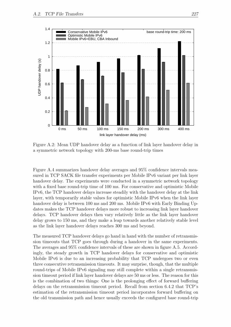
A.2. TCP File Transfers 227
0
0.2
0.4
0.6
0.8
1
1.2
1.4
400 ms300 ms200 ms150 ms100 ms50 ms0 ms
UD
P h
ando
ver
dela
y (s
)
link layer handover delay (ms)
base round-trip time: 200 msConservative Mobile IPv6Optimistic Mobile IPv6Mobile IPv6+EBU, CBA Inbound
Figure A.2: Mean UDP handover delay as a function of link layer handover delay ina symmetric network topology with 200-ms base round-trip times
Figure A.4 summarizes handover delay averages and 95% confidence intervals mea-sured in TCP SACK file transfer experiments per Mobile IPv6 variant per link layerhandover delay. The experiments were conducted in a symmetric network topologywith a fixed base round-trip time of 100 ms. For conservative and optimistic MobileIPv6, the TCP handover delays increase steadily with the handover delay at the linklayer, with temporarily stable values for optimistic Mobile IPv6 when the link layerhandover delay is between 100 ms and 200 ms. Mobile IPv6 with Early Binding Up-dates makes the TCP handover delays more robust to increasing link layer handoverdelays. TCP handover delays then vary relatively little as the link layer handoverdelay grows to 150 ms, and they make a leap towards another relatively stable levelas the link layer handover delays reaches 300 ms and beyond.
The measured TCP handover delays go hand in hand with the number of retransmis-sion timeouts that TCP goes through during a handover in the same experiments.The averages and 95% confidence intervals of these are shown in figure A.5. Accord-ingly, the steady growth in TCP handover delays for conservative and optimisticMobile IPv6 is due to an increasing probability that TCP undergoes two or eventhree consecutive retransmission timeouts. It may surprise, though, that the multipleround-trips of Mobile IPv6 signaling may still complete within a single retransmis-sion timeout period if link layer handover delays are 50 ms or less. The reason for thisis the combination of two things: One is the prolonging effect of forward bufferingdelays on the retransmission timeout period. Recall from section 6.4.2 that TCP’sestimation of the retransmission timeout period incorporates forward buffering onthe old transmission path and hence usually exceeds the configured base round-trip

228 A. Impact of Link Layer Handover Delays
old/newc/o address
correspondentnode
acknowledgment
Binding Update
segment
multiple TCP retransmission timeout periods
Binding Ack
Care-of Test InitHome Test Init
Home Test
Care-of Test
home agent
Binding Update
Binding Ack
link layer handover(a) Conservative Mobile IPv6
acknowledgment
Early Binding Update
TCP retransmission timeout periodcorrespondent
nodeold/new
c/o address
segment
Early Binding Acklink layer handover
(b) Mobile IPv6 with Early Binding Updates
Figure A.3: Impact of link layer handover delay on TCP handover delay
time. The retransmission timeout period may thus actually reach a multiple of thebase round-trip time if the latter is small. In contrast, Mobile IPv6 signaling takesan uncongested new transmission path, so it experiences none or only minor forward-ing delays. This effect reduces the number of consecutive retransmission timeoutsper handover. If, in addition, the mobile node delays its acknowledgment for thelast segment received before the handover, then the binding update may actuallycomplete within one retransmission timeout despite the link layer handover delayand the several round-trips of Mobile IPv6 signaling.
Since the maximum delay for acknowledgments was set to 100 ms in these exper-iments, delayed acknowledgments end up being dropped at the mobile node’s linklayer when the link layer handover delay is 100 ms or longer. This is why a single re-transmission timeout is then insufficient for both conservative and optimistic MobileIPv6. It should be noted that delayed acknowledgments are dropped even when themaximum acknowledgment delay and the link layer handover delay are both 100 mslong because the acknowledgment delay begins already when the mobile node re-

A.2. TCP File Transfers 229
0
0.5
1
1.5
2
2.5
400 ms300 ms200 ms150 ms100 ms50 ms0 ms
TC
P h
ando
ver
dela
y (s
)
link layer handover delay (ms)
base round-trip time: 100 msConservative Mobile IPv6Optimistic Mobile IPv6Mobile IPv6+EBU, CBA Inbound
Figure A.4: Mean TCP handover delay as a function of link layer handover delay ina symmetric network topology with 100-ms base round-trip times
ceives the last segment prior to handover and therefore usually a bit earlier than thelink layer handover.
Conservative Mobile IPv6 is sporadically responsible for three consecutive retrans-mission timeouts per handover when the link layer handover delay is between 150 msand 200 ms. This was found to happen exactly in those cases where packet loss occursa few round-trip times before the handover. TCP contracts its congestion windowwhen it detects the packet loss, reducing the amount of outstanding data and, con-sequently, forward buffering delays on the transmission path. The correspondentnode’s round-trip time measurements then shrink as well, and so does the estimatedretransmission timeout period. The retransmission timer hence expires earlier dur-ing handover, and more consecutive retransmission timeouts set in before the mobilenode has updated the binding at the correspondent node. The same occasionallyhappens for optimistic Mobile IPv6 in the experiments with link layer handoverdelays of 300 ms. Three consecutive retransmission timeouts become increasinglylikely for conservative and optimistic Mobile IPv6 as the link layer handover delayreaches 300 ms and beyond. The total TCP handover delay is then seven times aslong as a single retransmission timeout period due to the exponential back-off.
For Mobile IPv6 with support for Early Binding Updates, a single retransmissiontimeout is always sufficient if the link layer handover delay is 100 ms or less, and it isstill sufficient in most cases if the link layer handover delay is 150 ms. This is againbecause forward buffering delays on the old transmission path increase TCP’s esti-mated retransmission timeout period to beyond the link layer handover delay. Themobile node’s early Binding Update message then reaches the correspondent node

230 A. Impact of Link Layer Handover Delays
0
0.5
1
1.5
2
2.5
3
400 ms300 ms200 ms150 ms100 ms50 ms0 ms
TC
P r
etra
nsm
issi
on ti
meo
uts
(#)
link layer handover delay (ms)
base round-trip time: 100 msConservative Mobile IPv6Optimistic Mobile IPv6Mobile IPv6+EBU, CBA Inbound
Figure A.5: Mean TCP retransmission timeout count by link layer handover delayin a symmetric network topology with 100-ms base round-trip times
before the retransmission timer expires for the first time. However, link layer han-dover delays of more than 150 ms generally cause the retransmission timer to expirebefore the early Binding Update reaches the correspondent node. The retransmis-sion timer then expires two times consecutively in these cases. Two retransmissiontimeouts are always sufficient for Mobile IPv6 with Early Binding Updates even ifthe link layer handover delay is 400 ms. This is a considerable advantage given thatthe total TCP handover delay is then only three times of what a single retransmis-sion timeout period would be, compared to seven times in the case of conservativeor optimistic Mobile IPv6.
Delayed acknowledgments are responsible for the small decrease in the TCP han-dover delay which figure A.4 shows for Mobile IPv6 with Early Binding Updates ata link layer handover delay of 100 ms. The number of retransmission timeouts forMobile IPv6 with Early Binding Updates is never higher than one if the link layerhandover delay is 100 ms or lower, and delayed acknowledgments cannot reduce thenumber of retransmission timeouts. The belated arrival of delayed acknowledgmentsat the correspondent node then only increases the TCP handover delay, as explainedin section 6.4.3. This effect discontinues once the link layer handover delay reaches100 ms because delayed acknowledgments are then dropped, producing the smalldecrease in TCP handover delays shown in the figure.
Increased Round-Trip Times
In an effort to determine the impact that the round-trip time has on TCP handoverperformance in the presence of link layer handover delays, the experiments discussed

A.2. TCP File Transfers 231
0
0.5
1
1.5
2
2.5
400 ms300 ms200 ms150 ms100 ms50 ms0 ms
TC
P h
ando
ver
dela
y (s
)
link layer handover delay (ms)
base round-trip time: 200 msConservative Mobile IPv6Optimistic Mobile IPv6Mobile IPv6+EBU, CBA Inbound
Figure A.6: Mean TCP handover delay as a function of link layer handover delay ina symmetric network topology with 200-ms base round-trip times
above were repeated with a higher base round-trip time of 200 ms. The TCP han-dover delays and retransmission timeout counts measured therein are summarized infigures A.6 and A.7. The figures again show averages and 95% confidence intervalsfor different link layer handover delays and the three Mobile IPv6 variants underconsideration.
The impact of the higher base round-trip time can best be evaluated based onthe measured number of consecutive retransmission timeouts per handover. Forconservative Mobile IPv6, this number increases with the base round-trip time acrossall observed link layer handover delays. The reason for this is that forward bufferingdelays on the transmission path consume a smaller portion of the actual round-triptimes when the base round-trip time is high. This gives Mobile IPv6 signaling,which takes the new transmission path without much forward buffering, a smalleradvantage over the retransmission timeout period, which does incorporate forwardbuffering. The increase in the mean number of retransmission timeouts is strongestfor small link layer handover delays, simply because the contribution of the round-trip time to the TCP handover delay is then highest according to figure A.3(a).
Optimistic Mobile IPv6 profits slightly from the higher base round-trip time if thelink layer handover delay is 400 ms. The longer retransmission timeout period thenfacilitates a smaller number of consecutive retransmission timeouts per handover onaverage. In all other cases, the longer base round-trip time does not change the meannumber of retransmission timeouts that TCP goes through during a handover.

232 A. Impact of Link Layer Handover Delays
0
0.5
1
1.5
2
2.5
3
400 ms300 ms200 ms150 ms100 ms50 ms0 ms
TC
P r
etra
nsm
issi
on ti
meo
uts
(#)
link layer handover delay (ms)
base round-trip time: 200 msConservative Mobile IPv6Optimistic Mobile IPv6Mobile IPv6+EBU, CBA Inbound
Figure A.7: Mean TCP retransmission timeout counts by link layer handover delayin a symmetric network topology with 200-ms base round-trip times
The mean TCP handover delays of Mobile IPv6 with Early Binding Updates aremore stable to the increase in the base round-trip time because they solely dependon the link layer handover according to figure A.3(b). The longer base round-triptime may even reduce the mean number of retransmission timeouts per handover.This happens in the experiments with link layer handover delays of 150 ms or 200 ms,which now actually fit within the increased retransmission timeout period.
The small drop in TCP handover delays for a link layer handover delay of 100 ms,which was observed in figure A.4 for Mobile IPv6 with Early Binding Updates,does not appear in figure A.6 due to the compensating effect of a small number ofexperiments where TCP goes through two consecutive retransmission timeouts. Themuch longer TCP handover delay in those few experiments then compensates theeffect that the sudden lack of delayed acknowledgments would otherwise have.

B. Impact of Movement Detection
Mobility management involves protocols in different parts of the network stack; themobility protocol itself is only one of these. A brief overview of handover-related ac-tivities at the IP layer was given in section 2.4, and this has shown that the standardIPv6 protocol suite is inappropriate to provide the efficiency needed for interactive,real-time applications. IP layer handover delays other than those produced by themobility protocol itself are mainly due to router discovery, movement detection, andIP address auto-configuration.
In the experiments discussed so far, the delays of Stateless Address Autoconfigura-tion were eliminated by help of Optimistic Duplicate Address Detection, and opti-mum router discovery and movement detection was achieved with the DNA Protocol.A nice property of Optimistic Duplicate Address Detection is that it functions with-out support in the network, so a mobile node can use it as a replacement for standardDuplicate Address Detection independent of its environment. The DNA Protocol,however, requires the cooperation of access routes and this may not always be avail-able. The purpose of this appendix is hence to illuminate how much the handoverperformance may degrade in situations where the application of the DNA Protocolis impossible due to nonexistent access router support. Two alternative movementdetection mechanisms are considered for this purpose:
1. Standard movement detection — Access routers run the standard NeighborDiscovery protocol with the recommended extensions for mobile environments(see section 2.4.6). They multicast unsolicited Router Advertisement messagesin intervals of between 30 ms and 70 ms, each including an Advertisement In-terval option with an upper bound on the interval between consecutive adver-tisements. In this case, the advertised upper bound is 90 ms, which includesan extra 20 ms in order to account for scheduling granularities in mobile nodesand access routers. This increment is required whenever the actual maximumadvertisement interval is smaller than 200 ms. Accordingly, a mobile node ex-pects to receive a Router Advertisement message every 90 ms from a particularaccess router. If advertisements from the access router fail to be received forthree times this period, the mobile node can conclude with high confidentiality,despite a potential for packet loss, that it has changed IP connectivity.

234 B. Impact of Movement Detection
2. Complete Prefix List — Access routers behave as described above for standardmovement detection. However, sophisticated logic on the mobile node nowfacilitates expedited movement detection based on the reception of a singleRouter Advertisement message from a new access router.
B.1 Internet Telephony
Figure B.1 juxtaposes UDP handover delay averages and 95% confidence intervals ofan Internet telephony application that were measured for each of the three movementdetection protocols. The experiments were repeated for conservative Mobile IPv6,optimistic Mobile IPv6, and Mobile IPv6 with Early Binding Updates. All of themwere conducted in a symmetric network topology with a fixed base round-trip timeof 100 ms. The mobile node’s link layer handover delay is zero. The results clearlyreflect the different performance of the three movement detection mechanisms. Forthe DNA Protocol, the measured handover delays depend only on the round-triptime between the mobile node and the correspondent node. Router discovery andmovement detection happen without delay based on a single Router Advertisementmessage which the mobile node can obtain from an access router instantaneously.Complete Prefix List usually does with a single Router Advertisement message aswell, but the mobile node must wait for an unsolicited multicast advertisement. Thewait time until the mobile node receives the first multicast advertisement after ahandover ranges between 0 and 70 ms: In the best case, the new access router sendsa Router Advertisement message right after the mobile node has arrived on thenew link. In the worst case, the new access router has sent an advertisement justbefore the mobile node arrives, and the time until it sends the next advertisementis maximum. The mean interval between successive advertisement transmissions is50 ms, so the mobile node can expect to receive the first message subsequent tohandover after 25 ms. This wait time is responsible for the slightly longer handoverdelays for Complete Prefix List compared to the DNA Protocol.
Handover delays are longest with standard movement detection. The mobile nodehere waits three times the interval advertised in Advertisement Interval options inRouter Advertisement messages until it considers a previous access router unreach-able due to a handover. Changes in IP connectivity are therefore detected 270 msafter the last advertisement was received from the old access router. Since this lastadvertisement may have been sent up to 70 ms prior to the actual link layer han-dover, the latency of movement detection ranges between 200 ms and 270 ms. Onaverage, the period between reception of the last advertisement from the old accessrouter and the link layer handover is 25 ms, yielding a mean movement detectiondelay of 245 ms.
B.2 TCP File Transfers
Figure B.2 shows averages and 95% confidence intervals of the handover delays mea-sured in TCP SACK file transfer experiments per movement detection mechanismand Mobile IPv6 variant. The experiments were conducted in a symmetric networktopology with a fixed base round-trip time of 100 ms; the link layer handover de-lay was again zero. The results indicate that Complete Prefix List and the DNAProtocol are very similar with respect to their impact on the TCP handover delay.

B.2. TCP File Transfers 235
0
0.5
1
1.5
2
DNA ProtocolComplete Prefix Liststandard movement detection
UD
P h
ando
ver
dela
y (s
)
movement detection mechanism
base round-trip time: 100 ms Conservative Mobile IPv6Optimistic Mobile IPv6
Mobile IPv6+EBU, CBA Inbound
Figure B.1: Mean UDP handover delay as a function of link layer handover delay ina symmetric network topology with 100-ms base round-trip times
Both mechanisms detect movement based on a single Router Advertisement mes-sage. They differ only in the amount of time it takes the mobile node to obtainthe first advertisement subsequent to handover. The ability of a mobile node to so-licit an immediate Router Advertisement message gives the DNA Protocol a slightadvantage over Complete Prefix List, where the expected time to receive the firstadvertisement after a handover is 25 ms. This additional delay in most cases doesnot increase the number of retransmission timeouts that TCP goes through duringa handover, so it only occasionally has an effect on the TCP handover delay. Onthe other hand, the average movement detection delay of 245 ms in standard move-ment detection is a multiple of the retransmission timeout period and hence causesnotably longer TCP handover delays.
Figure B.3 corroborates the above results with averages and 95% confidence inter-vals of the number of consecutive retransmission timeouts that the correspondentnode goes through during a handover on the mobile-node side. In line with thesimilar TCP handover delays for Complete Prefix List and the DNA Protocol, themean number of consecutive retransmission timeouts for Complete Prefix List isonly slightly higher than it is for the DNA Protocol. More consecutive retransmis-sion timeouts are on average required across all Mobile IPv6 variants if standardmovement detection is used. This explains the relatively long TCP handover delaysfor standard movement detection compared to Complete Prefix List and the DNAProtocol.
The impact that standard movement detection has on the TCP handover perfor-mance is illustrated in figure B.4 for conservative Mobile IPv6 and Mobile IPv6

236 B. Impact of Movement Detection
0
0.5
1
1.5
2
DNA ProtocolComplete Prefix Liststandard movement detection
TC
P h
ando
ver
dela
y (s
)
movement detection mechanism
base round-trip time: 100 ms Conservative Mobile IPv6Optimistic Mobile IPv6
Mobile IPv6+EBU, CBA Inbound
Figure B.2: Mean TCP handover delay as a function of link layer handover delay ina symmetric network topology with 100-ms base round-trip times
with Early Binding Updates. In both cases, the mobile node waits between 200 msand 270 ms after the link layer handover before it decides that it has changed IPconnectivity, even though it typically receives multiple Router Advertisement mes-sages from the new access router in the meantime. Signaling for conservative MobileIPv6 spans several round-trips as shown in part (a) of the figure, so it may takemultiple retransmission timeout periods until the binding update completes on thecorrespondent node. Part (b) of the figure shows a binding update for Mobile IPv6with Early Binding Updates. The time difference between the mobile node’s trans-mission of the last TCP acknowledgment prior to handover and the transmission ofthe early Binding Update message after the handover is now only determined bythe movement detection delay. The time gap between the arrival of the last TCPacknowledgment from the old care-of address and the arrival of the early BindingUpdate message is generally the same because forward buffering delays on the pathsfrom the mobile node to the correspondent node are negligible. The binding updatemay thus already complete within a single retransmission timeout period despite theuse of a slow movement detection mechanism.
The positive effect on handover performance that optimizations to the mobility pro-tocol have independent of the movement detection mechanism is further evidencedby the measurements in figures B.2 and B.3. For standard movement detection,conservative Mobile IPv6 causes three consecutive retransmission timeouts on aboutone third of all handovers. The overall TCP handover delay then increases to seventimes of what a single retransmission timeout period would be. Optimistic MobileIPv6 completes a binding update before the second retransmission timeout with only

B.2. TCP File Transfers 237
0
0.5
1
1.5
2
2.5
3
DNA ProtocolComplete Prefix Liststandard movement detection
TC
P r
etra
nsm
issi
on ti
meo
uts
(#)
movement detection mechanism
base round-trip time: 100 ms Conservative Mobile IPv6Optimistic Mobile IPv6
Mobile IPv6+EBU, CBA Inbound
Figure B.3: Mean TCP retransmission timeout count by link layer handover delayin a symmetric network topology with 100-ms base round-trip times
very few exceptions, and Mobile IPv6 with Early Binding Updates may occasionallydo with a single retransmission timeout. For Complete Prefix List or the DNA Pro-tocol in conjunction with conservative or optimistic Mobile IPv6, chances are aboutequal that a binding update completes before the first or only before the secondretransmission timeout. Two retransmission timeouts are slightly more probable forthe combination of Complete Prefix List and conservative Mobile IPv6, and one re-transmission timeout is a bit more likely for the combination of the DNA Protocoland optimistic Mobile IPv6. A binding update of Mobile IPv6 with Early BindingUpdates always completes within a single retransmission timeout, both for CompletePrefix List and for the DNA Protocol.
Increased Round-Trip Times
The impact that different movement detection mechanisms have on the TCP han-dover performance changes as the base round-trip time on the transmission pathincreases. There are mainly two reasons for this. First, the movement detectiondelay becomes relatively smaller compared to TCP’s estimated retransmission time-out period, because the former is constant, while the latter scales with the actualround-trip time on the transmission path. Second, the impact of forward bufferingdelays on the old transmission path reduces as well given that the capacity of for-ward buffers is constant. Mobile IPv6 signaling, which takes the new transmissionpath and hence experiences only negligible forward buffering delays, may thereforespan more retransmission timeout periods smaller when the base round-trip time ishigher, as explained in section 6.4.2. In an effort to illuminate the consequences of

238 B. Impact of Movement Detection
correspondentnode
acknowledgmentRouter Advertise
Router AdvertiseRouter Advertise
Router Advertise
Router AdvertiseBinding Update
segment
multiple TCP retransmission timeout periodsBinding Ack
Care-of Test InitHome Test Init
Home Test
Care-of Test
home agent
old/newaccess router
old/newc/o address
Binding Update
Binding Acklink layerhandover
movem
ent de
tection
delay
(a) Conservative Mobile IPv6
link layerhandover
acknowledgment
Router AdvertiseRouter Advertise
Router Advertise
Router AdvertiseEarly Binding Update
TCP retransmission timeout period
movem
ent de
tection
delay
correspondentnode
old/newaccess router
old/newc/o address
segment
Early Binding Ack
Router Advertise
(b) Mobile IPv6 with Early Binding Updates
Figure B.4: Impact of standard movement detection on TCP handover delay
an increased base round-trip time, additional experiments were run for a symmet-ric network topology with a higher base round-trip time of 200 ms. Average TCPhandover delays and retransmission timeout counts, along with their 95% confidenceintervals, are shown in figures B.5 and B.6, respectively.
One impact of the higher round-trip time is that, for each movement detection mech-anism, the TCP handover delays measured for the three Mobile IPv6 variants arenow further apart. This is most apparent for standard movement detection: MobileIPv6 with Early Binding Updates causes an average of 1.9 retransmission timeoutsat the correspondent node when the base round-trip time between the mobile nodeand the correspondent node is 100 ms, but the retransmission timeout count goesdown to 1.2 for a round-trip time of 200 ms. The reason for the reduced number of

B.2. TCP File Transfers 239
0
0.5
1
1.5
2
DNA ProtocolComplete Prefix Liststandard movement detection
TC
P h
ando
ver
dela
y (s
)
movement detection mechanism
base round-trip time: 200 ms Conservative Mobile IPv6Optimistic Mobile IPv6
Mobile IPv6+EBU, CBA Inbound
Figure B.5: Mean TCP handover delay as a function of link layer handover delay ina symmetric network topology with 200-ms base round-trip times
retransmission timeouts is that the longer round-trip times increase the retransmis-sion timeout period to beyond the average movement detection delay of 245 ms. Thebinding update now happens within a single retransmission timeout period with highprobability. The consequence of the reduced number of retransmission timeouts isthat, although the retransmission timeout period increases with the round-trip time,TCP handover delays for Mobile IPv6 with Early Binding Updates turn out to beabout the same for base round-trip times of both 100 ms and 200 ms.
The situation is different for the combination of standard movement detection withconservative Mobile IPv6 where, according to figure B.4, several round-trips of Mo-bile IPv6 signaling cause additional handover delays. The smaller effect of forwardbuffering delays in the presence of a higher base round-trip time now reduces theratio between the retransmission timeout period and the base round-trip time. Thisleads to an increase in the mean number of retransmission timeouts as the baseround-trip time grows from 100 ms to 200 ms and, consequently, to higher TCPhandover delays.

240 B. Impact of Movement Detection
0
0.5
1
1.5
2
2.5
3
DNA ProtocolComplete Prefix Liststandard movement detection
TC
P r
etra
nsm
issi
on ti
meo
uts
(#)
movement detection mechanism
base round-trip time: 200 ms Conservative Mobile IPv6Optimistic Mobile IPv6
Mobile IPv6+EBU, CBA Inbound
Figure B.6: Mean TCP retransmission timeout count by link layer handover delayin a symmetric network topology with 200-ms base round-trip times

Bibliography
[1] 3GPP System to Wireless Local Area Network (WLAN) Interworking; SystemDescription (Release 6). 3GPP Technical Specification Group Services andSystem Aspects, technical specification 23.234, version 6.6.0, September 2005.
[2] Donald E. Eastlake 3rd, Stephen D. Crocker, and Jeffrey I. Schiller. Ran-domness Recommendations for Security. IETF Request for Comments 1750,December 1994.
[3] Draft IEEE Standard for Local and Metropolitan Area Networks: Media In-dependent Handover Services. Draft IEEE Standard P802.21/D01.00, March2006.
[4] Mark Allman. A Web Server’s View of the Transport Layer. ACM SIGCOMMComputer Communication Review, 30(5):10–20, October 2000.
[5] Mark Allman, Hari Balakrishnan, and Sally Floyd. Enhancing TCP’s LossRecovery Using Limited Transmit. IETF Request for Comments 3042, January2001.
[6] Ross Anderson. Why Information Security is Hard – An Economic Perspective.In Proceedings of the Computer Security Applications Conference, pages 358–365, December 2001.
[7] Stephane Antoine, Ming Wei, and A. H. Aghvami. Impact of Mobile IPv6 Han-dover on the Performance of TCP: an Experimental Testbed. ACM SIGMO-BILE Mobile Computing and Communications Review, 7(1):31–33, January2003.
[8] Antonios Argyriou and Vijay Madisetti. The Design and Evaluation of an End-to-End Handoff Management Protocol. Kluwer Academic Publishers WirelessNetworks, 13(1):61–75, January 2007.
[9] Jari Arkko, James Kempf, Brian Zill, and Pekka Nikander. SEcure NeighborDiscovery (SEND). IETF Request for Comments 3971, March 2005.
[10] Jari Arkko and Iljitsch van Beijnum. Failure Detection and Locator Pair Explo-ration Protocol for IPv6 Multihoming. IETF Internet Draft draft-ietf-shim6-failure-detection-07.txt (work in progress), December 2006.
[11] Jari Arkko, Christian Vogt, and Wassim Haddad. Enhanced route optimizationfor mobile ipv6. IETF Internet Draft draft-ietf-mipshop-cga-cba-03.txt (workin progress), February 2007.

242 Bibliography
[12] Tuomas Aura. Cryptographically Generated Addresses (CGA). Lecture Notesin Computer Science, 2851/2003:29–43, December 2003.
[13] Marcelo Bagnulo, Ignacio Soto, Alberto Garcia-Martinez, and Arturo Azcorra.Random Generation of Interface Identifiers. IETF Internet Draft draft-soto-mobileip-random-iids-00.txt (work in progress), January 2002.
[14] Paramvir Bahl, Atul Adya, Jitendra Padhye, and Alec Walman. Reconsid-ering Wireless Systems with Multiple Radios. ACM SIGCOMM ComputerCommunication Review, 34(5):39–46, October 2004.
[15] F. Baker and P. Savola. Ingress Filtering for Multihomed Networks. IETFRequest for Comments 3704, March 2004.
[16] Nilanjan Banerjee, Arup Acharya, and Sajal K. Das. Seamless SIP-BasedMobility for Multimedia Applications. IEEE Network, 20(2):6–13, March 2006.
[17] Ralf Beck. Proaktives Mobilitatsmanagement auf Ende-zu-Ende-Basis.Diploma Thesis, Institute of Telematics, Universitaet Karlsruhe (TH), Ger-many, June 2006.
[18] Steven M. Bellovin. Defending Against Sequence Number Attacks. IETFRequest for Comments 1948, May 1996.
[19] Massimo Bernaschi, Filippo Cacace, Giulio Iannello, Stefano Za, and AntonioPescape. Seamless Internetworking of WLANs and Cellular Networks: Archi-tecture and Performance Issues in a Mobile IPv6 Scenario. IEEE WirelessCommunications, 12(3):73–80, June 2005.
[20] Ethan Blanton, Mark Allman, Kevin Fall, and Lili Wang. A ConservativeSelective Acknowledgment (SACK)-based Loss Recovery Algorithm for TCP.IETF Request for Comments 3517, April 2003.
[21] Robert Braden. Requirements for Internet Hosts – Communication Layers.IETF Request for Comments 1122, October 1989.
[22] Vladimir Brik, Arunesh Mishra, and Suman Banerjee. Eliminating HandoffLatencies in 802.11 WLANs Using Multiple Radios: Applications, Experience,and Evaluation. In Proceedings of the ACM/USENIX Internet MeasurementConference, October 2005.
[23] CERT Coordination Center. CERT Advisory CA-1996-21 TCP SYN Floodingand IP Spoofing Attacks. http://www.cert.org/advisories/CA-1996-21.html,September 1996.
[24] CERT Coordination Center. CERT Advisory CA-1998-01 Smurf IP Denial-of-Service Attacks. http://www.cert.org/advisories/CA-1998-01.html, January1998.
[25] Ranveer Chandra, Paramvir Bahl, and Pradeep Bahl. MultiNet: Connecting toMultiple IEEE 802.11 Networks Using a Single Wireless Card. In Proceedingsof the IEEE INFOCOM, volume 2, pages 882–893, March 2004.

Bibliography 243
[26] John Chapin and Alok Shah. Software Radio Technology and Challenges. InProceedings of the International Telemetering Conference, October 2002.
[27] JinHyeock Choi and Erik Nordmark. DNA with Unmodified Routers: PrefixList Based Approach. IETF Internet Draft draft-ietf-dna-cpl-01.txt (work inprogress), April 2005.
[28] Sik Choi, Gyung-Ho Hwang, Taesoo Kwon, Ae-Ri Lim, and Dong-Ho Cho. FastHandover Scheme for Real-Time Downlink Services in IEEE 802.16e BWASystem. In Proceedings of the Vehicular Technology Conference, volume 3,pages 2028–2032, May 2005.
[29] Morten Jagd Christensen, Karen Kimball, and Frank Solensky. Considera-tions for IGMP and MLD Snooping Switches. IETF Internet Draft draft-ietf-magma-snoop-12.txt (work in progress), February 2005.
[30] David D. Clark. Window and Acknowledgement Strategy in TCP. IETFRequest for Comments 813, July 1982.
[31] Richard Comerford. No Longer in Denial. IEEE Spectrum, 38(1):59–61, Jan-uary 2001.
[32] Alex Conta, Stephen Deering, and Mukesh Gupta. Internet Control MessageProtocol (ICMPv6) for the Internet Protocol Version 6 (IPv6) Specification.IETF Request for Comments 4443, March 2006.
[33] Microsoft Corporation. New Networking Features in Windows Server 2008 andWindows Vista, April 2007.
[34] Les Cottrell. ICFA SCIC Network Monitoring Report.http://www.slac.stanford.edu/xorg/icfa/icfa-net-paper-jan05/, January2005.
[35] Matt Crawford. Transmission of IPv6 Packets over Ethernet Networks. IETFRequest for Comments 2464, December 1998.
[36] Greg Daley, Brett Pentland, and Richard Nelson. Movement Detection Opti-mizations in Mobile IPv6. In Proceedings of the IEEE International Conferenceon Networks, pages 687–692, September 2003.
[37] Cedric de Launois and Marcelo Bagnulo. The Paths Towards IPv6 Multihom-ing. IEEE Communications Surveys & Tutorials, 8(2):38–51, April 2006.
[38] Stephen E. Deering and Robert M. Hinden. Internet Protocol, Version 6 (IPv6)– Specification. IETF Request for Comments 2460, December 1998.
[39] Detecting Network Attachment (dna). IETF Working Group,http://www.ietf.org/html.charters/dna-charter.html, July 2007.
[40] Ralph Droms, Jim Bound, Bernie Volz, Ted Lemon, Charles E. Perkins, andMike Carney. Dynamic Host Configuration Protocol for IPv6 (DHCPv6).IETF Request for Comments 3315, July 2003.

244 Bibliography
[41] Ashutosh Dutta, Tao Zhang, Yoshihiro Ohba Kenichi Taniuchi, and HenningSchulzrinne. MPA assisted Optimized Proactive Handoff Scheme. In Pro-ceedings of the ACM Conference on Mobile and Ubiquitous Systems, pages155–165, July 2005.
[42] Jean-Pierre Ebert, Eckhard Grass, Ralf Irmer, Rolf Kraemer, Gerhard Fet-tweis, Karl Strom, Guenther Traenkle, Walter Wirnitzer, Reimund Witmann,Hans-Jurgen Reumerman, Egon Schulz, Martin Weckerle, Peter Egner, and Ul-rich Barth. Paving the Way for Gigabit Networking. IEEE CommunicationsMagazine, 43(4):27–30, April 2005.
[43] Lars Eggert and Wesley M. Eddy. Towards More Expressive Transport-LayerInterfaces. In Proceedings of the ACM/IEEE Workshop on Mobility in theEvolving Internet Architecture, pages 71–74, December 2006.
[44] Mihaela Enachescu, Yashar Ganjali, Ashish Goel, Nick McKeown, and TimRoughgarden. Part III: Routers With Very Small Buffers. ACM SIGCOMMComputer Communication Review, 35(3):83–90, July 2005.
[45] Pasi Eronen (Ed.). IKEv2 Mobility and Multihoming Protocol (MOBIKE).IETF Request for Comments 4555, June 2006.
[46] Minoruo Etoh and Takeshi Yoshimura. Wireless Video Applications in 3G andBeyond. IEEE Wireless Communications, 12(4):66–72, August 2005.
[47] Paul Ferguson and Daniel Senie. Network Ingress Filtering: Defeating Denialof Service Attacks which employ IP Source Address Spoofing. IETF Requestfor Comments 2827, May 2000.
[48] Gerhard Fettweis, Tim Hentschel, and Ernesto Zimmermann. WIGWAM – AWireless Gigabit System with Advanced Multimedia Support. In Proceedingsof the VDE Kongress, October 2004.
[49] Sally Floyd, Thomas Henderson, and Andrei Gurtov. The NewReno Modifi-cation to TCP’s Fast Recovery Algorithm. IETF Request for Comments 3782,April 2004.
[50] Eva Fogelstroem, Annika Jonsson, and Charles E. Perkins. Mobile IPv4Regional Registration. IETF Internet Draft draft-ietf-mip4-reg-tunnel-04.txt(work in progress), October 2006.
[51] Yashar Ganjali and Nick McKeown. Update on Buffer Sizing in InternetRouters. ACM SIGCOMM Computer Communication Review, 36(5):67–70,October 2006.
[52] Bur Goode. Voice Over Internet Protocol (VoIP). Proceedings of the IEEE,90(9):1495–1517, September 2002.
[53] Joshua B. Gross and Mary Beth Rosson. Looking for Trouble: UnderstandingEnd-User Security Management. In Proceedings of the Conference On HumanFactors And Computing Systems, March 2007.

Bibliography 245
[54] Robert M. Hinden and Stephen E. Deering. Internet Protocol Version 6 (IPv6)Addressing Architecture. IETF Request for Comments 4291, February 2006.
[55] Robert Hsieh, Aruna Seneviratne, Hesham Soliman, and Karim El-Malki. Per-formance Analysis on Hierarchical Mobile IPv6 with Fast-Handoff over End-to-End TCP. In Proceedings of the IEEE Global Telecommunications Conference,November 2002.
[56] Alefiya Hussain, John Heidemann, and Christos Papadopoulos. A Frameworkfor Classifying Denial of Service Attacks. In Proceedings of the Conference onApplications, Technologies, Architectures, and Protocols for Computer Com-munications, pages 99–110, August 2003.
[57] IEEE. Guidelines for 64-bit Global Identifier (EUI-64) Registration Authority,May 2007.
[58] Internet Assigned Numbers Authority. IP Version 6 Parameters.http://www.iana.org/assignments/ipv6-parameters.
[59] Kentaro Ishizu, Yoshia Saito, and Masahiro Kuroda. Additional InformationReports and IEs to Clarify Functionalities of CS and IS. IEEE 802.21 Draft21-06-0657-00-0000, May 2006.
[60] Suraj Jaiswal and Sukumar Nandi. Simulation-Based Performance Compari-son of TCP-Variants over Mobile IPv6-Based Mobility Management Schemes.In Proceedings of the IEEE Conference on Local Computer Networks, pages284–291, November 2004.
[61] Jim H. James, Bing Chen, and Laurie Garrison. Implementing VoIP: A VoiceTransmission Performance Progress Report. IEEE Communications Magazine,42(7):36–41, July 2004.
[62] Hee-Jin Jang, Alper Yegin, JinHyeock Choi, and Kuntal Chowdhury. DHCPOption for Home Information Discovery in MIPv6. IETF Internet Draft draft-ietf-mip6-hiopt-00.txt (work in progress), August 2006.
[63] David Johnson, Charles E. Perkins, and Jari Arkko. Mobility Support in IPv6.IETF Request for Comments 3775, June 2004.
[64] Daniel Jungbluth. Software Design and Analysis of an End-to-End Optimiza-tion for Mobile IPv6 Route Optimization. Student Thesis, Institute of Telem-atics, Universitaet Karlsruhe (TH), Germany, July 2005.
[65] Daniel Jungbluth. Anticipation and Optimization of Home-to-Roaming Han-dovers in Mobile IPv6. Diploma Thesis, Institute of Telematics, UniversitaetKarlsruhe (TH), Germany, May 2006.
[66] Stephen Kent. IP Authentication Header. IETF Request for Comments 4302,December 2005.
[67] Stephen Kent and Karen Seo. Security Architecture for the Internet Protocol.IETF Request for Comments 4301, December 2005.

246 Bibliography
[68] Seok Joo Koh, Moon Jeong Chang, and Meejeong Lee. mSCTP for Soft Han-dover in Transport Layer. IEEE Communications Letters, 8(3):189–191, March2004.
[69] Rajeev Koodli and Charles Perkins. Mobile IPv4 Fast Handovers. IETFInternet Draft draft-ietf-mip4-fmipv4-03.txt (work in progress), February 2007.
[70] Rajeev Koodli (Ed.). Fast Handovers for Mobile IPv6. IETF Request forComments 4068, July 2005.
[71] Suresh Krishnan, Nicolas Montavont, Eric Njedjou, Siva Veerepalli, and AlperYegin. Link-Layer Event Notifications for Detecting Network Attachments.IETF Internet Draft draft-ietf-dna-link-information-06.txt (work in progress),February 2007.
[72] Koojana Kuladinithi, Niko A. Fikouras, Carmelita Goerg, Koltsidas Georgios,and Fotini-Niovi Pavlidou. Filters for Mobile IPv6 Bindings (NOMADv6).IETF Internet Draft draft-nomadv6-mobileip-filters-03.txt (work in progress),October 2005.
[73] John Loughney (Ed.), Jari Arkko, Marc Blanchet, Samita Chakrabarti, AlainDurand, Gerard Gastaud, Jun-ichiro itojun Hagino, Atsushi Inoue, MasahiroIshiyama, Rajiv Raghunarayan, Shoichi Sakane, Dave Thaler, and Juha Wil-jakka. IPv6 Node Requirements. IETF Request for Comments 4294, April2006.
[74] Xiapu Luo and Rocky K. C. Chang. On a New Class of Pulsing Denial-of-Service Attacks and the Defense. In Proceedings of the Network and DistributedSystem Security Symposium, February 2005.
[75] Xiapu Luo and Rocky K. C. Chang. Optimizing the Pulsing Denial-of-ServiceAttacks. In Proceedings of the IEEE International Conference on DependableSystems and Networks, pages 582–591, June 2005.
[76] Karim Malki and Hesham Soliman. Simultaneous Bindings for Mobile IPv6Fast Handovers. IETF Internet Draft draft-elmalki-mobileip-bicasting-v6-06.txt (work in progress), July 2005.
[77] Karim Malki (Ed.). Low Latency Handoffs in Mobile IPv4. IETF Inter-net Draft draft-ietf-mobileip-lowlatency-handoffs-v4-11.txt (work in progress),October 2005.
[78] Alberto Medina, Mark Allman, and Sally Floyd. Measuring the Evolution ofTransport Protocols in the Internet. ACM SIGCOMM Computer Communi-cation Review, 35(2):37–52, April 2005.
[79] Jelena Mirkovic and Peter Reiher. A Taxonomy of DDoS Attack and DDoSDefense Mechanisms. ACM SIGCOMM Computer Communication Review,34(2):39–53, April 2004.
[80] Arunesh Mishra, Minho Shin, and William Arbaugh. An empirical analysisof the IEEE 802.11 MAC layer handoff process. ACM SIGCOMM ComputerCommunication Review, 33(2):93–102, April 2003.

Bibliography 247
[81] Paul V. Mockapetris. Telephony’s Next Act. IEEE Spectrum, 43(4):28–32,April 2006.
[82] Nicolas Montavont and Thomas Noel. Handover Management for MobileNodes in IPv6 Networks. IEEE Communications Magazine, 40(8):38–43, Au-gust 2002.
[83] Nicolas Montavont and Thomas Noel. Analysis and evaluation of mobile IPv6handovers over wireless LAN. Kluwer Academic Publishers Mobile Networksand Applications, 8(6):643–653, December 2003.
[84] Gabriel Montenegro and Claude Castelluccia. Crypto-based Identifiers(CBIDs): Concepts and Applications. ACM Transactions on Information andSystem Security, 7(1):97–127, February 2004.
[85] Gabriel Montenegro, Ed. Reverse Tunneling for Mobile IP, Revised. IETFRequest for Comments 3024, January 2001.
[86] David Moore, Colleen Shannon, Doug Brown, Geoffrey M. Voelker, and StefanSavage. Inferring Internet Denial-of-Service Activity. ACM Transactions onComputer Systems, 24(2):115–139, May 2006.
[87] Nick ’Sharkey’ Moore. Optimistic Duplicate Address Detection (DAD) forIPv6. IETF Request for Comments 4429, April 2006.
[88] Robert Moskowitz and Pekka Nikander. Host Identity Protocol (HIP) Archi-tecture. IETF Request for Comments 4423, May 2006.
[89] Sathya Narayanan, James Kempf, Erik Nordmark, Brett Pentland, JinHyeockChoi, Greg Daley, Nicolas Montavont, and Nick ’Sharkey’ Moore. DetectingNetwork Attachment in IPv6 Networks (DNAv6). IETF Internet Draft draft-ietf-dna-protocol-03.txt (work in progress), October 2006.
[90] Thomas Narten and Harald Tveit Alvestrand. Guidelines for Writing an IANAConsiderations Section in RFCs. IETF Request for Comments 2434, October1998.
[91] Thomas Narten and Richard Draves. Privacy Extensions for Stateless AddressAutoconfiguration in IPv6. IETF Request for Comments 3041, January 2001.
[92] Thomas Narten, Erik Nordmark, William A. Simpson, and Hesham Soliman.Neighbor Discovery for IP version 6 (IPv6). IETF Internet Draft draft-ietf-ipv6-2461bis-05.txt (work in progress), October 2005.
[93] Pekka Nikander. End-Host Mobility and Multihoming with the Host IdentityProtocol. IETF Internet Draft draft-ietf-hip-mm-04.txt (work in progress),June 2006.
[94] Pekka Nikander, Jari Arkko, Tuomas Aura, Gabriel Montenegro, and ErikNordmark. Mobile IP Version 6 Route Optimization Security Design Back-ground. IETF Request for Comments 4225, December 2005.
[95] Ville Nuorvala, Henrik Petander, and Antti Tuominen. Mobile IPv6 for Linux(MIPL), July 2007.

248 Bibliography
[96] Sixto Ortiz Jr. Internet Telephony Jumps off the Wires. IEEE Computer,37(12):16–19, December 2004.
[97] Greg O’Shea and Michael Roe. Child-Proof Authentication for MIPv6 (CAM).ACM SIGCOMM Computer Communication Review, 31(2):4–8, April 2001.
[98] Sangheon Pack, Kunwoo Park, Taekyoung Kwon, and Yanghee Choi. SAMP:Scalable Application-Layer Mobility Protocol. IEEE Communications Maga-zine, 44(6):86–92, June 2006.
[99] Basavaraj Patil, Phil Roberts, and Charles E. Perkins. IP Mobility Supportfor IPv4. IETF Request for Comments 3344, August 2002.
[100] Vern Paxson. Measurements and Analysis of End-to-End Internet Dynamics.Ph.D. Thesis UCB//CSD-97-945, Computer Science Division, University ofCalifornia, Berkeley, Berkeley, CA, USA, April 1977.
[101] Vern Paxson. An Analysis of Using Reflectors for Distributed Denial-of-ServiceAttacks. ACM SIGCOMM Computer Communication Review, 31(3), July2001.
[102] Tao Peng, Christopher Leckie, and Kotagiri Ramamohanarao. Survey ofNetwork-Based Defense Mechanisms Countering the DoS and DDoS Problems.ACM Computing Surveys, 39(1), April 2007.
[103] Charles E. Perkins. Securing Mobile IPv6 Route Optimization Using a StaticShared Key. IETF Request for Comments 4449, June 2006.
[104] Henrik Petander and Eranga Perera. Improved Binding Management for MakeBefore Break Handoffs in Mobile IPv6. IETF Internet Draft draft-petander-mip6-mbb-00.txt (work in progress), October 2005.
[105] John Postel. User Datagram Protocol. IETF Request for Comments 768,August 1980.
[106] Jon Postel. Internet Protocol. IETF Request for Comments 791, September1981.
[107] Jon Postel. Transmission Control Protocol. IETF Request for Comments 793,September 1981.
[108] Gaurav Raina, Don Towsley, and Damon Wischik. Part II: Control Theory forBuffer Sizing. ACM SIGCOMM Computer Communication Review, 35(3):79–82, July 2005.
[109] Kishore Ramachandran, Sampath Rangarajan, and John C. Lin. Make-Before-Break MAC Layer Handoff in 802.11 Wireless Networks. In Proceedings of theIEEE International Conference on Communications, volume 10, pages 4818–4823, June 2006.
[110] Ramachandran Ramjee, Kannan Varadhan, Luca Salgarelli, Sandra R. Thuel,Shie-Yuan Wang, and Thomas La Porta. HAWAII: A Domain-based Approachfor Supporting Mobility in Wide-Area Wireless Networks. IEEE/ACM Trans-actions on Networking, 10(3):396–410, June 2002.

Bibliography 249
[111] Michael J. Riezenman. Extending Broadband’s Reach. IEEE Spectrum,40(3):20–21, March 2003.
[112] Jonathan Rosenberg, Henning Schulzrinne, Gonzalo Camarillo, Alan Johnston,Jon Peterson, Robert Sparks, Mark Handley, and Eve Schooler. SIP: SessionInitiation Protocol. IETF Request for Comments 3261, June 2002.
[113] Constantin Schimmel. Implementierung und Analyse eines Mechanismus zursicheren und effizienten Bestimmung des empfangenen Datenvolumens einesKommunikationspartners. Student Thesis, Institute of Telematics, Universi-taet Karlsruhe (TH), Germany, September 2005.
[114] Henning Schulzrinne, Stephen L. Casner, Ron Frederick, and Van Jacobson.RTP: A Transport Protocol for Real-Time Applications. IETF Request forComments 3550, July 2003.
[115] Henning Schulzrinne and Elin Wedlund. Application-Layer Mobility Us-ing SIP. ACM SIGCOMM Mobile Computing and Communications Review,4(3):47–57, July 2000.
[116] Jeffrey Semke, Jamshid Mahdavi, and Matthew Mathis. AutomaticTCP Buffer Tuning. ACM SIGCOMM Computer Communication Review,28(4):315–323, October 1998.
[117] Eunsoo Shim and Richard D. Gitlin. Fast Handoff Using Neighbor Information.IETF Internet Draft draft-shim-mobileip-neighbor-00.txt (work in progress),November 2000.
[118] Sangho Shin, Andrea G. Forte, Anshuman Singh Rawat, and HenningSchulzrinne. Reducing MAC Layer Handoff Latency in IEEE 802.11 WirelessLANs. In Proceedings of the International Workshop on Mobility Managementand Wireless Access Protocols, volume VOLUME, pages 19–26, October 2004.
[119] Kame-Shisa. Mobile IPv6 for FreeBSD 5.4, November 2005.
[120] Alex C. Snoeren and Hari Balakrishnan. An End-to-End Approach to HostMobility. In Proceedings of the International Conference on Mobile Computingand Networking, pages 155–166, August 2000.
[121] Hesham Soliman, Claude Castelluccia, Karim El Malki, and Ludovic Bellier.Hierarchical Mobile IPv6 Mobility Management (HMIPv6). IETF Request forComments 4140, August 2005.
[122] Miniwatts Marketing GroupInternet World Stats. World Internet Users andPopulation Statistics. http://www.internetworldstats.com/stats.htm, July2007.
[123] Lawrence Stewart and James Healy. Tuning and Testing the FreeBSD 6 TCPStack. Technical Report 070717B, Centre for Advanced Internet Architectures,Faculty of Information and Communication Technologies, Swinburne Univer-sity, Melbourne, Australia, July 2007.

250 Bibliography
[124] Randall Stewart, Qiaobing Xie, Michael Tuexen, Shin Maruyama, andMasahiro Kozuka. Stream Control Transmission Protocol (SCTP) DynamicAddress Reconfiguration. IETF Internet Draft draft-ietf-tsvwg-addip-sctp-20.txt (work in progress), April 2007.
[125] Randall R. Stewart, Qiaobing Xie, Ken Morneault, Chip Sharp, Hanns Juer-gen Schwarzbauer, Tom Taylor, Ian Rytina, Malleswar Kalla, Lixia Zhang,and Vern Paxson. Stream Control Transmission Protocol. IETF Request forComments 2960, October 2000.
[126] Cisco Systems. Unicast Reverse Path Forwarding. Cisco IOS Documentation,May 1999.
[127] Paul Tan. Recommendations for Achieving Seamless IPv6 Handover in IEEE802.11 Networks. IETF Internet Draft draft-paultan-seamless-ipv6-handoff-802-00.txt (work in progress), February 2003.
[128] Fumio Teraoka, Kazutaka Gogo, Koshiro Mitsuya, Rie Shibui, and Koki Mi-tani. Unified L2 Abstractions for L3-Driven Fast Handover. IETF InternetDraft draft-irtf-mobopts-l2-abstractions-01.txt (work in progress), September2006.
[129] Susan Thomson and Thomas Narten. IPv6 Stateless Address Autoconfigura-tion. IETF Request for Comments 2462, December 1998.
[130] Susan Thomson, Thomas Narten, and Tatuya Jinmei. IPv6 Stateless AddressAutoconfiguration. IETF Internet Draft draft-ietf-ipv6-rfc2462bis-08.txt (workin progress), May 2005.
[131] Dirk Trossen, Govind Krishnamurthi, Hemant Chaskar, Robert C. Chalmers,and Eunsoo Shim. A Dynamic Protocol for Candidate Access-Router Dis-covery. IETF Internet Draft draft-trossen-seamoby-dycard-01.txt (work inprogress), March 2003.
[132] Andras G. Valko. Cellular IP: A New Approach to Internet Host Mobility.ACM SIGCOMM Computer Communication Review, 29(1):50–65, January1999.
[133] Jon-Olov Vatn. An Experimental Study of IEEE 802.11b Handover Perfor-mance and Its Effect on Voice Traffic. Technical Report TRITA-IMIT-TSLABR 03:01, Telecommunication Systems Laboratory, Department of Microelec-tronics and Information Technology, KTH, Royal Institute of Technology,Stockholm, Sweden, July 2003.
[134] Rolland Vida, Luis Henrique Maciel Kosmalski Costa, Serge Fdida, Steve Deer-ing, Bill Fenner, Isidor Kouvelas, and Brian Haberman. Multicast ListenerDiscovery Version 2 (MLDv2) for IPv6. IETF Request for Comments 3810,June 2004.
[135] Christian Vogt. A Comprehensive Delay Analysis for Reactive and ProactiveHandoffs with Mobile IPv6 Route Optimization. Technical Report TM-2006-1,Institute of Telematics, Universitaet Karlsruhe (TH), Germany, January 2006.

Bibliography 251
[136] Christian Vogt and Jari Arkko. A Taxonomy and Analysis of Enhancements toMobile IPv6 Route Optimization. IETF Request for Comments 4651, February2007.
[137] Christian Vogt, Ralf Beck, Daniel Jungbluth, Max Laier, and ConstantinSchimmel. Early Binding Updates and Credit-Based Authorization for theKame-Shisa Mobile IPv6 Software. http://www.tm.uka.de/∼chvogt/ebucba/,July 2007.
[138] Christian Vogt, Roland Bless, Mark Doll, and Gregory Daley. Analysis ofIPv6 Relocation Delays. Technical Report TM-2005-4, Institute of Telematics,Universitaet Karlsruhe (TH), Germany, April 2005.
[139] Christian Vogt, Roland Bless, Mark Doll, and Gregory Daley. Analysis ofIPv6 Relocation Delays. Presentation at the 63th Meeting of the InternetEngineering Task Force, DNA Working Group Session, August 2005.
[140] Christian Vogt and Mark Doll. Efficient End-to-End Mobility Support inIPv6. In Proceedings of the IEEE Wireless Communications and NetworkingConference, volume 1, pages 575–580, April 2006.
[141] Christian Vogt and Martina Zitterbart. Efficient and Scalable, End-to-EndMobility Support for Reactive and Proactive Handoffs in IPv6. IEEE Com-munications Magazine, 44(6):74–82, June 2006.
[142] Damon Wischik and Nick McKeown. Part I: Buffer Sizes for Core Routers.ACM SIGCOMM Computer Communication Review, 35(3):75–78, July 2005.
[143] Wei Xing, Holger Karl, Adam Wolisz, and Harald Muller. M-SCTP: De-sign and Prototypical Implementation of an End-to-End Mobility Concept.In Proceedings of the Workshop on the Internet Challenge: Technology andApplications, October 2002.
[144] Hubert Zimmermann. OSI Reference Model – The ISO Model of Architecturefor Open Systems Interconnection. IEEE Transactions on Communications,28(4):425–432, April 1980.

252 Bibliography

Index 253
Index
access link, 9access link identifier, 39access network, 9access network routers, 9access point, 10access router, 10acknowledgment
delayed, 49duplicate, 46full, 47partial, 48
amplification, 60application layer, 8
bandwidth-delay product, 155bicasting, 56bidirectional tunneling, 19binding, 18binding cache, 27binding identifier, 19binding management key, 30binding update, 18binding update list, 28
care-of address, 27care-of address test, 29care-of init cookie, 30care-of keygen token, 30care-of nonce index, 30certificate, 24Complete Prefix List, 39congestion control, 45congestion window, 45correspondent deregistration, 31correspondent registration, 28credit, 73credit aging, 76
factor, 88interval, 88
Credit-Based Authorization, 71Inbound mode, 73
denial-of-service attack, 23
distributed, 60deposit, 91DHCPv6, see Dynamic Host
Configuration Protocol forIPv6
DNA Protocol, 39Duplicate Address Detection, 35Dynamic Host Configuration Protocol
for IPv6, 36
Early Binding Updates, 111
Fast Recovery mode, 47fast retransmit, 46Fast Router Advertisement, 38flooding attack, 24
direct, 60on-path, 60redirection-based, 24
flow control, 45forward buffer, 153
group identifier, 13
handover delay, 160TCP handover delay, 182
handover phase, 160post-handover phase, 133pre-handover phase, 133TCP handover phase, 182
home address, 27home address test, 29home agent, 27home deregistration, 28home init cookie, 29home keygen token, 29home link, 27home nonce index, 29home registration, 27Host Identity Protocol, 19host route, 17
IANA, see Internet AssignedNumbers Authority

254 Index
ICMPv6, see Internet ControlMessage Protocol for IPv6
IEEE, see Institute of Electrical andElectronics Engineers
IEEE 802 MAC address, 10IEEE EUI-64 identifier, 11IETF, see Internet Engineering Task
Forceimpersonation attack, 22individual/group bit, 11information elements, 43ingress filtering, 66Institute of Electrical and Electronics
Engineers, 10interface, see network interfaceinterface identifier, 13Internet Assigned Numbers
Authority, 99Internet Control Message Protocol for
IPv6, 37Internet Engineering Task Force, 35Internet Protocol, 8
version 4, 10version 6, 10
IP, see Internet ProtocolIP address
alternative, 77global, 13link-local, 13multicast, 13
solicited-node, 13on-link, 18preferred, 77stable, 17unicast, 12unverified, 25verified, 25
IP address prefix, 12IP address resolution, 15IP address resolution buffer, 153IP address spot checks, 79IP address state, 76
Alternative, 77Unverified, 76Verified, 76
IP destination address, 12IP extension header, 14
Authentication, 15Destination Options, 14
Encapsulating Security Payload,15
Fragmentation, 15Hop-by-Hop Options, 15Routing, 14
IP header, 14IP layer, 8IP Security, 15IP source address, 12IP spoofing, 33, 61IPsec, see IP SecurityIPv4, see Internet Protocol, version 4IPv6, see Internet Protocol, version 6
Kame-Shisa, 147
landmark, 39Limited Transmit algorithm, 49link layer, 8link layer address, 10
multicast, 11links, 7loss concealment, 157
MD function, 118, 132Media Independent Handover
Services, 40message type value, 126MIH function, 40MIH function discovery, 41MIH information server, 41MIH point of service, 40MIH protocol, 41Mobile IPv6, see Mobility support in
IPv6conservative, 113optimistic, 113
mobile nodeconservative, 113optimistic, 113
mobility anchorglobal, 18
mobility managementglobal, 53localized, 53
Mobility support in IPv6, 27Correspondent Priority mode, 145Home Priority mode, 145Impatient mode, 145
movement detection, 34

Index 255
movement detection function, 118,132
multi-homingaccess network, 33node, 33
Multicast Listener Discovery protocol,35
neighbor cache, 15Neighbor Discovery, 15, 34Neighbor Unreachability Detection,
37network interface, 10network topology
asymmetric, 149symmetric, 149
node, 7nonce, 29nonce cache, 102
Optimistic Duplicate AddressDetection, 38
packet, 7packet loss, 157
handover-related, 157handover-unrelated, 156
payload, 14payload packet, 17physical layer, 8proactive mobility management, 32propagation buffer, 153public-key infrastructure, 24
reachability verification, 25concurrent, 68standard, 26
reactive mobility management, 32receive buffer, 45reflection attack, 60reflector, 60rendezvous server, 21retransmission timeout, 44retransmission timeout period, 44retransmission timer, 44return routability procedure, 29reverse-tunneling, 19round-trip time
actual, 154base, 154
router, 7router discovery, 34routing, 15routing table, 15
segment, 44self-clocking, 44send buffer, 45slow-start threshold, 46smoothed round-trip time, 44solicited-node multicast group, 35spot check interval, 90spot check nonce, 96spot check nonce cache, 102Spot Check Reply option, 97Spot Check Request option, 97spot check token, 90spot check token buffer, 102Spot Check Token field, 97spot check token index, 96Spot Check Token Index field, 97spot check token lifetime, 90spot check token list, 100spot checks, see IP address spot
checksStateless Address Autoconfiguration,
35subnet prefix, 13subnet prefix discovery, 34
TCP, see Transmission ControlProtocol
TCP Migrate, 52tentative binding, 115tentative binding update, 115token buffer, 102token index, 96token lifetime, 90token list, 100Transmission Control Protocol, 8
Congestion Avoidance mode, 46NewReno, 48
Impatient variant, 48Slow-but-Steady variant, 48
Reno, 47SACK, 48Slow Start mode, 45Tahoe, 45
transport layer, 8

256 Index
triangular routing, 18
UDP, see User Datagram ProtocolUnicast Reverse Path Forwarding, 66universal/local bit, 11upper-layer protocol, 17User Datagram Protocol, 8
windowadvertised, 45available, 45receive, 45send, 45
zombie, 60