Effects of martensite morphology and tempering on dynamic deformation behavior of dual-phase steels
12
Effects of Martensite Morphology and Tempering on Dynamic Deformation Behavior of Dual-Phase Steels HAN SANG LEE, BYOUNGCHUL HWANG, SUNGHAK LEE, CHANG GIL LEE, and SUNG-JOON KIM The effects of martensite morphology and tempering on the quasistatic and dynamic deformation behavior of dual-phase steels were investigated in this study. Dynamic torsional tests were conducted on six steel specimens, which had different martensite morphologies and tempering conditions, using a torsional Kolsky bar, and then the test data were compared via microstructures, tensile properties, and fracture mode. Bulky martensites were mixed with ferrites in the step-quenched (SQ) specimens, but small martensites were well distributed in the ferrite matrix in the intermediate-annealed (IA) specimens. Under a dynamic loading condition, the fracture mode of the SQ specimens was changed from cleavage to ductile fracture as the tempering temperature increased, whereas the IA specimens showed a ductile fracture mode, irrespective of tempering. These phenomena were analyzed in terms of a rule of mixtures applied to composites, microstructural variation, martensite softening and carbon diffusion due to tempering, and adiabatic shear-band formation. I. INTRODUCTION I N strategic industrial fields such as the defense, automotive, precision machinery, and space aircraft industries, demands for structural materials that can be used under severe conditions like dynamic loading have been increasing. [1–10] The resistance to deformation and fracture under dynamic loading is generally lower than under quasistatic loading, which can fatally affect the overall fracture toughness of structural materials. Thus, detailed studies employing effective and quantitative evaluation should be made to determine how to maintain the deformation and fracture resistance of the materials so that they can be widely applied to various industrial fields. Dual-phase steels composed of ferrite and martensite have a better deformability than other high-strength low-alloy (HSLA) steels with similar strength. [11–15] Under quasistatic loading, they are also characterized as having a continuous yielding during plastic deformation, whose strength increases with increasing martensite volume fraction, in accordance with a rule of mixtures like in composite materials. [12] These studies on dual-phase steels have been primarily concerned with phenomena occurring only under either static or quasi- static loading, but very few studies have been done on the their dynamic deformation and fracture behavior. Particularly in dual-phase steels containing brittle martensites, resistance to deformation and fracture can abruptly drop under dynamic loading rather than under quasistatic loading, and, thus, the dynamic deformation and fracture behavior should be closely examined and evaluated before the steels are applied to deformation processing. Kim and Lee [5] conducted quasistatic and dynamic tor- sional tests on dual-phase steels having a step-quenched (SQ) microstructure composed of coarse martensites and an intermediate-quenched (IQ) microstructure composed of fine martensites and reported that fracture was proceeded by cleavage fracture of ferrite in the SQ microstructure under quasistatic loading, whereas fracture occurred by void initi- ation and growth at martensite/ferrite interfaces in the IQ microstructure. Under dynamic loading, on the other hand, ductile fracture dominated in both the SQ and IQ microstruc- tures, since the ferrite deformation constrained by martensite was released as martensite softened by the deformation heat during dynamic deformation. In order to improve ductility while maintaining the high tensile and yield strengths of dual-phase steels, thus, it is required to strengthen martensite/ ferrite interfaces, to control the crack propagation by soften- ing martensite, and to relieve the deformation constraint of ferrite by martensite. As a means for that, tempering was applied to two kinds of dual-phase steels having different martensite morphologies but the same volume fraction (about 50 vol pct) in this study. Dynamic torsional tests were con- ducted on them using a torsional Kolsky bar, and the deformed microstructure and fractured surface were observed to investigate various microstructural factors affecting dynamic deformation behavior. II. EXPERIMENTAL A HSLA steel bar (diameter: 23 mm) with a tensile-strength level of 500 MPa was used in this study, and its chemical composition was 0.22C-0.22Si-0.77Mn-0.017P-0.011S- 0.02Ni-1.06Cr-0.015Cu-Fe (wt pct). In order to obtain dual- phase steels with different martensite morphologies, two kinds of heat treatments were used, as shown in Figures 1(a) and (b). For the step quenching treatment (referred to as “SQ” hereafter), specimens were quenched directly into in the ( ) region after the austenitization and were subsequently quenched into METALLURGICAL AND MATERIALS TRANSACTIONS A VOLUME 35A, AUGUST 2004—2371 HAN SANG LEE, formerly Research Assistant, with the Center for Advanced Aerospace Materials, Pohang University of Science and Technology, is Junior Researcher with Device and BYOUNGCHUL HWANG, Research Assistant, is with the Center for Advanced Aerospace Materials, Pohang Uni- versity of Science and Technology, Pohang 790-784, Korea. SUNGHAK LEE, Professor, Center for Advanced Aerospace Materials, Pohang University of Science and Technology, is jointly appointed with the Materials Science and Engineering Department, Pohang University of Science and Technology. CHANG GIL LEE and SUNG-JOON KIM, Principal Researchers, are with the Materials Processing Department, Korea Institute of Machinery and Materials, Changwon 641-010, Korea. Contact e-mail: [email protected] Manuscript submitted October 13, 2003.
-
Upload
independent -
Category
Documents
-
view
3 -
download
0
Transcript of Effects of martensite morphology and tempering on dynamic deformation behavior of dual-phase steels
Effects of Martensite Morphology and Tempering on DynamicDeformation Behavior of Dual-Phase Steels
HAN SANG LEE, BYOUNGCHUL HWANG, SUNGHAK LEE, CHANG GIL LEE,and SUNG-JOON KIM
The effects of martensite morphology and tempering on the quasistatic and dynamic deformationbehavior of dual-phase steels were investigated in this study. Dynamic torsional tests were conductedon six steel specimens, which had different martensite morphologies and tempering conditions, usinga torsional Kolsky bar, and then the test data were compared via microstructures, tensile properties,and fracture mode. Bulky martensites were mixed with ferrites in the step-quenched (SQ) specimens,but small martensites were well distributed in the ferrite matrix in the intermediate-annealed (IA)specimens. Under a dynamic loading condition, the fracture mode of the SQ specimens was changedfrom cleavage to ductile fracture as the tempering temperature increased, whereas the IA specimensshowed a ductile fracture mode, irrespective of tempering. These phenomena were analyzed in termsof a rule of mixtures applied to composites, microstructural variation, martensite softening and carbondiffusion due to tempering, and adiabatic shear-band formation.
I. INTRODUCTION
IN strategic industrial fields such as the defense, automotive,precision machinery, and space aircraft industries, demands forstructural materials that can be used under severe conditionslike dynamic loading have been increasing.[1–10] The resistanceto deformation and fracture under dynamic loading is generallylower than under quasistatic loading, which can fatally affectthe overall fracture toughness of structural materials. Thus,detailed studies employing effective and quantitative evaluationshould be made to determine how to maintain the deformationand fracture resistance of the materials so that they can bewidely applied to various industrial fields.
Dual-phase steels composed of ferrite and martensite havea better deformability than other high-strength low-alloy(HSLA) steels with similar strength.[11–15] Under quasistaticloading, they are also characterized as having a continuousyielding during plastic deformation, whose strength increaseswith increasing martensite volume fraction, in accordancewith a rule of mixtures like in composite materials.[12] Thesestudies on dual-phase steels have been primarily concernedwith phenomena occurring only under either static or quasi-static loading, but very few studies have been done on thetheir dynamic deformation and fracture behavior. Particularlyin dual-phase steels containing brittle martensites, resistanceto deformation and fracture can abruptly drop under dynamicloading rather than under quasistatic loading, and, thus, thedynamic deformation and fracture behavior should be closely
examined and evaluated before the steels are applied todeformation processing.
Kim and Lee[5] conducted quasistatic and dynamic tor-sional tests on dual-phase steels having a step-quenched (SQ)microstructure composed of coarse martensites and anintermediate-quenched (IQ) microstructure composed of finemartensites and reported that fracture was proceeded bycleavage fracture of ferrite in the SQ microstructure underquasistatic loading, whereas fracture occurred by void initi-ation and growth at martensite/ferrite interfaces in the IQmicrostructure. Under dynamic loading, on the other hand,ductile fracture dominated in both the SQ and IQ microstruc-tures, since the ferrite deformation constrained by martensitewas released as martensite softened by the deformation heatduring dynamic deformation. In order to improve ductilitywhile maintaining the high tensile and yield strengths ofdual-phase steels, thus, it is required to strengthen martensite/ferrite interfaces, to control the crack propagation by soften-ing martensite, and to relieve the deformation constraint offerrite by martensite. As a means for that, tempering wasapplied to two kinds of dual-phase steels having differentmartensite morphologies but the same volume fraction (about50 vol pct) in this study. Dynamic torsional tests were con-ducted on them using a torsional Kolsky bar, and thedeformed microstructure and fractured surface were observedto investigate various microstructural factors affectingdynamic deformation behavior.
II. EXPERIMENTAL
A HSLA steel bar (diameter: 23 mm) with a tensile-strengthlevel of 500 MPa was used in this study, and its chemicalcomposition was 0.22C-0.22Si-0.77Mn-0.017P-0.011S-0.02Ni-1.06Cr-0.015Cu-Fe (wt pct). In order to obtain dual-phase steels with different martensite morphologies, two kindsof heat treatments were used, as shown in Figures 1(a) and (b).For the step quenching treatment (referred to as “SQ” hereafter),specimens were quenched directly into in the (� � �) regionafter the austenitization and were subsequently quenched into
METALLURGICAL AND MATERIALS TRANSACTIONS A VOLUME 35A, AUGUST 2004—2371
HAN SANG LEE, formerly Research Assistant, with the Center forAdvanced Aerospace Materials, Pohang University of Science and Technology,is Junior Researcher with Device and BYOUNGCHUL HWANG, ResearchAssistant, is with the Center for Advanced Aerospace Materials, Pohang Uni-versity of Science and Technology, Pohang 790-784, Korea. SUNGHAK LEE,Professor, Center for Advanced Aerospace Materials, Pohang University ofScience and Technology, is jointly appointed with the Materials Science andEngineering Department, Pohang University of Science and Technology.CHANG GIL LEE and SUNG-JOON KIM, Principal Researchers, are with theMaterials Processing Department, Korea Institute of Machinery and Materials,Changwon 641-010, Korea. Contact e-mail: [email protected]
Manuscript submitted October 13, 2003.
19-03-452A-4.qxd 9/27/04 9:06 PM Page 2371
2372—VOLUME 35A, AUGUST 2004 METALLURGICAL AND MATERIALS TRANSACTIONS A
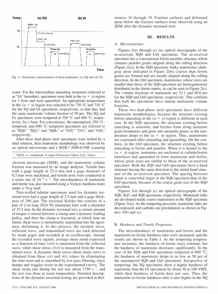
water. For the intermediate annealing treatment (referred toas “IA” hereafter), specimens were held in the (� � �) regionfor 1 hour and were quenched. An appropriate temperaturein the (� � �) region was selected to be 730 °C and 710 °Cfor the SQ and IA specimens, respectively, so that they hadthe same martensite volume fraction of 50 pct. The SQ andIA specimens were tempered at 350 °C and 600 °C, respec-tively, for 1 hour. For convenience, the untempered, 350 °C–tempered, and 600 °C–tempered specimens are referred toas “SQ0,” “SQ3,” and “SQ6,” or “IA0,” “IA3,” and “IA6,”respectively.
After these dual-phase steel specimens were etched by anital solution, their martensite morphology was observed byan optical microscope and a JEOL* JSM-6330F scanning
*JEOL is a trademark of Japan Electronics Optics Ltd., Tokyo.
electron microscope (SEM), and the martensite volumefraction was measured by an image analyzer. Tensile barswith a gage length of 25.4 mm and a gage diameter of6.3 mm were machined, and tensile tests were conducted ata strain rate of 10�4 s�1. The microhardness of martensiteand ferrite was also measured using a Vickers hardness testerunder a 10-g load.
Thin-walled tubular specimens used for dynamic tor-sional tests had a gage length of 2.5 mm and a gage thick-ness of 280 �m. The torsional Kolsky bar consists of apair of 2-m-long 2024-T6 aluminum bars with a diameterof 25.4 mm. In the dynamic torsional test, a certain amountof torque is stored between a clamp and a dynamic loadingpulley, and then the clamp is fractured, at which time anelastic shear wave is momentarily transmitted into the speci-men, deforming it. In this process, the incident wave,reflected wave, and transmitted wave are each detectedby strain gages and recorded at an oscilloscope. Amongthe recorded wave signals, average shear strain expressedas a function of time (v(t)) is measured from the reflectedwave, while shear stress (� (t)) is measured from the trans-mitted wave. A dynamic shear stress–shear strain curve isobtained from these v(t) and �(t) values by eliminatingthe time term and is smoothed by low-pass filtering, sincebumps and wiggles occur in the experimental curves. Theshear strain rate during the test was about 1750 s�1, andthe test was done at room temperature. Detailed descrip-tions of the dynamic torsional testing are provided in Ref-
Fig. 1—Schematic representation of heat treatments: (a) SQ and (b) IA.
erences 16 through 19. Fracture surfaces and deformedareas below the fracture surfaces were observed using anSEM after the dynamic torsional tests.
III. RESULTS
A. Microstructure
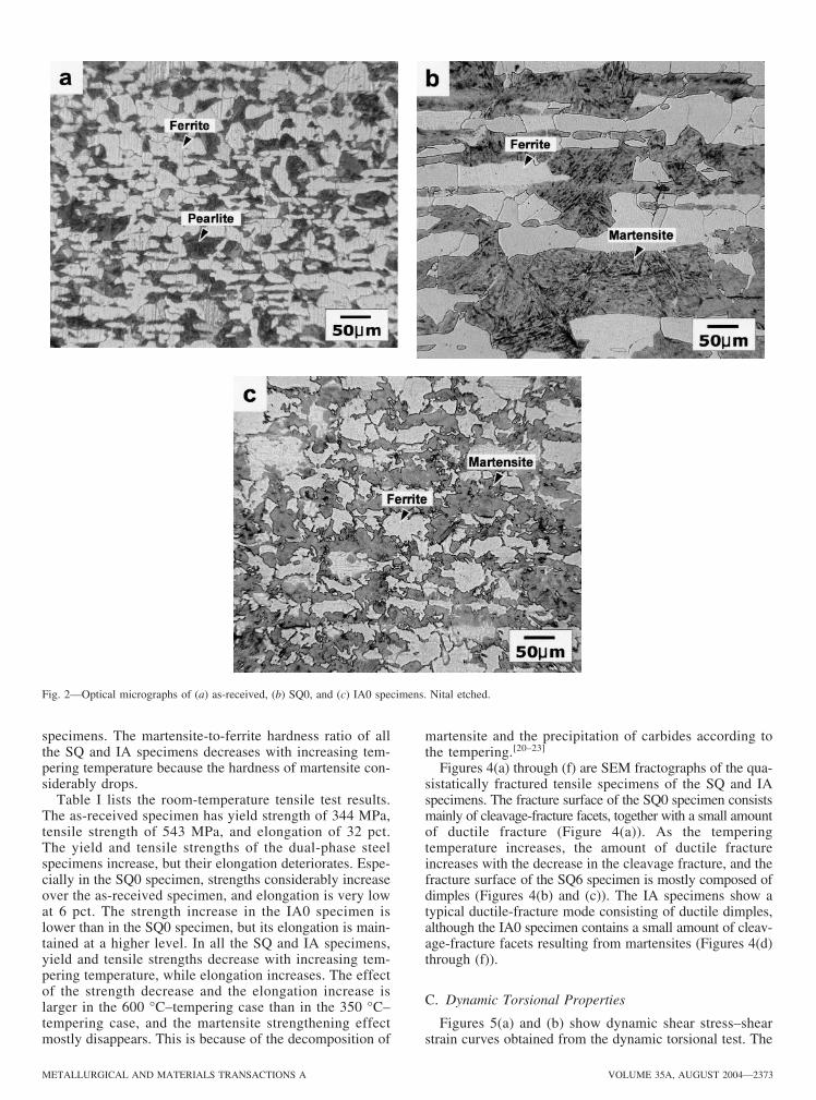
Figures 2(a) through (c) are optical micrographs of theas-received, SQ0 and IA0 specimens. The as-receivedspecimen has a conventional ferrite-pearlite structure whichcontains pearlite grains aligned along the rolling direction(Figure 2(a)). In the SQ0 specimen, bulky martensites (dark-gray areas indicated in Figure 2(b)) coarser than ferritegrains are formed and are mostly aligned along the rollingdirection. In the IA0 specimen, martensites whose sizes aresmaller than those of the SQ0 specimen are homogeneouslydistributed in the ferrite matrix, as can be seen in Figure 2(c).The volume fractions of martensite are 52.1 and 49.6 pctfor the SQ0 and IA0 specimens, respectively. This confirmsthat both the specimens have similar martensite volumefractions.
These two dual-phase steel specimens have differentmartensite morphologies, because the structure existingbefore annealing in the (� � �) region is different in eachcase. In the SQ0 specimen, the structure existing beforeannealing is austenite, and ferrites form along austenitegrain boundaries and grow into austenite grains as the tem-perature drops to the (� � �) region. Thus, martensitesare coarsened after annealing and quenching. On the con-trary, in the IA0 specimen, the structure existing beforeannealing is ferrite and pearlite. When it is heated to the(� � �) region, austenites are nucleated at carbide/ferriteinterfaces and quenched to form martensite and ferrite,whose grain sizes are similar to those of the as-receivedspecimen. Both the SQ0 and IA0 specimens have a bandstructure having the same direction to the initial band struc-ture of the as-received specimen. The spacing betweenbands is somewhat larger in the SQ0 specimen than in theIA0 specimen, because of the coarse grain size in the SQ0specimen.
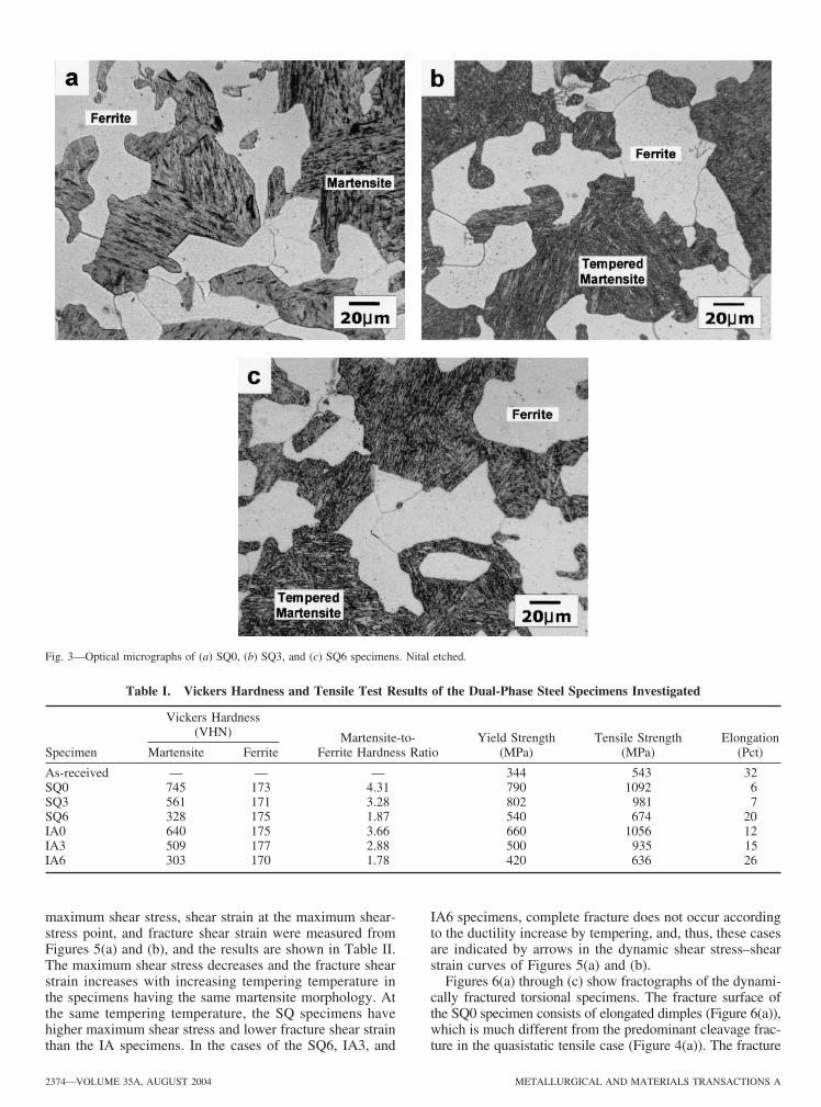
Figures 3(a) through (c) are optical micrographs of theSQ0, SQ3, and SQ6 specimens, respectively. Martensite lathsare developed inside coarse martensites in the SQ0 specimen(Figure 3(a)). As the tempering proceeds, martensite laths aredecomposed, and carbides are precipitated, as shown in Fig-ures 3(b) and (c).
B. Hardness and Tensile Properties
The microhardness of martensite and ferrite and themartensite-to-ferrite hardness ratio were measured, and theresults are shown in Table I. As the tempering tempera-ture increases, the hardness of ferrite stays constant, butthe hardness of martensite decreases significantly. In thecase of the SQ6 and IA6 specimens tempered at 600 °C,the hardness of martensite drops to as low as 50 pct ofthe untempered SQ0 and IA0 specimens. Irrespective oftempering, the SQ specimens show a higher hardness ofmartensite than the IA specimens by about 30 to 100 VHN,while their hardness of ferrite does not vary. Thus, themartensite-to-ferrite hardness ratio is also higher in the SQ
19-03-452A-4.qxd 9/27/04 9:06 PM Page 2372
METALLURGICAL AND MATERIALS TRANSACTIONS A VOLUME 35A, AUGUST 2004—2373
Fig. 2—Optical micrographs of (a) as-received, (b) SQ0, and (c) IA0 specimens. Nital etched.
specimens. The martensite-to-ferrite hardness ratio of allthe SQ and IA specimens decreases with increasing tem-pering temperature because the hardness of martensite con-siderably drops.
Table I lists the room-temperature tensile test results.The as-received specimen has yield strength of 344 MPa,tensile strength of 543 MPa, and elongation of 32 pct.The yield and tensile strengths of the dual-phase steelspecimens increase, but their elongation deteriorates. Espe-cially in the SQ0 specimen, strengths considerably increaseover the as-received specimen, and elongation is very lowat 6 pct. The strength increase in the IA0 specimen islower than in the SQ0 specimen, but its elongation is main-tained at a higher level. In all the SQ and IA specimens,yield and tensile strengths decrease with increasing tem-pering temperature, while elongation increases. The effectof the strength decrease and the elongation increase islarger in the 600 °C–tempering case than in the 350 °C–tempering case, and the martensite strengthening effectmostly disappears. This is because of the decomposition of
martensite and the precipitation of carbides according tothe tempering.[20–23]
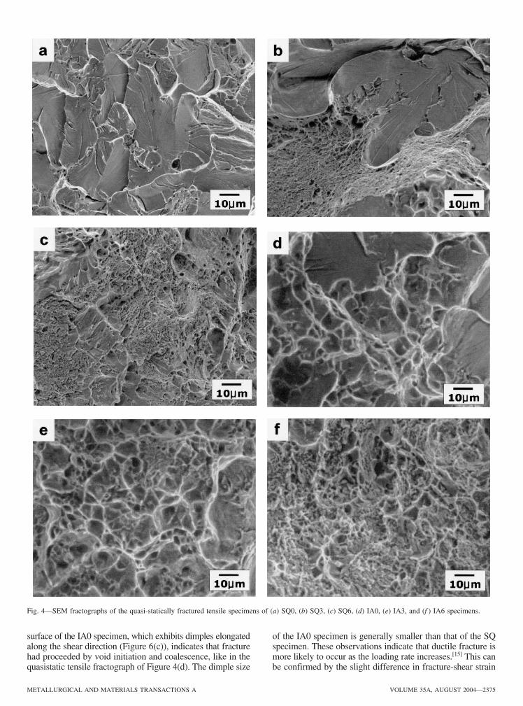
Figures 4(a) through (f) are SEM fractographs of the qua-sistatically fractured tensile specimens of the SQ and IAspecimens. The fracture surface of the SQ0 specimen consistsmainly of cleavage-fracture facets, together with a small amountof ductile fracture (Figure 4(a)). As the temperingtemperature increases, the amount of ductile fractureincreases with the decrease in the cleavage fracture, and thefracture surface of the SQ6 specimen is mostly composed ofdimples (Figures 4(b) and (c)). The IA specimens show atypical ductile-fracture mode consisting of ductile dimples,although the IA0 specimen contains a small amount of cleav-age-fracture facets resulting from martensites (Figures 4(d)through (f)).
C. Dynamic Torsional Properties
Figures 5(a) and (b) show dynamic shear stress–shearstrain curves obtained from the dynamic torsional test. The
19-03-452A-4.qxd 9/27/04 9:06 PM Page 2373
2374—VOLUME 35A, AUGUST 2004 METALLURGICAL AND MATERIALS TRANSACTIONS A
maximum shear stress, shear strain at the maximum shear-stress point, and fracture shear strain were measured fromFigures 5(a) and (b), and the results are shown in Table II.The maximum shear stress decreases and the fracture shearstrain increases with increasing tempering temperature inthe specimens having the same martensite morphology. Atthe same tempering temperature, the SQ specimens havehigher maximum shear stress and lower fracture shear strainthan the IA specimens. In the cases of the SQ6, IA3, and
IA6 specimens, complete fracture does not occur accordingto the ductility increase by tempering, and, thus, these casesare indicated by arrows in the dynamic shear stress–shearstrain curves of Figures 5(a) and (b).
Figures 6(a) through (c) show fractographs of the dynami-cally fractured torsional specimens. The fracture surface ofthe SQ0 specimen consists of elongated dimples (Figure 6(a)),which is much different from the predominant cleavage frac-ture in the quasistatic tensile case (Figure 4(a)). The fracture
Fig. 3—Optical micrographs of (a) SQ0, (b) SQ3, and (c) SQ6 specimens. Nital etched.
Table I. Vickers Hardness and Tensile Test Results of the Dual-Phase Steel Specimens Investigated
Vickers Hardness(VHN) Martensite-to- Yield Strength Tensile Strength Elongation
Specimen Martensite Ferrite Ferrite Hardness Ratio (MPa) (MPa) (Pct)
As-received — — — 344 543 32SQ0 745 173 4.31 790 1092 6SQ3 561 171 3.28 802 981 7SQ6 328 175 1.87 540 674 20IA0 640 175 3.66 660 1056 12IA3 509 177 2.88 500 935 15IA6 303 170 1.78 420 636 26
19-03-452A-4.qxd 9/27/04 9:06 PM Page 2374
METALLURGICAL AND MATERIALS TRANSACTIONS A VOLUME 35A, AUGUST 2004—2375
Fig. 4—SEM fractographs of the quasi-statically fractured tensile specimens of (a) SQ0, (b) SQ3, (c) SQ6, (d) IA0, (e) IA3, and (f ) IA6 specimens.
surface of the IA0 specimen, which exhibits dimples elongatedalong the shear direction (Figure 6(c)), indicates that fracturehad proceeded by void initiation and coalescence, like in thequasistatic tensile fractograph of Figure 4(d). The dimple size
of the IA0 specimen is generally smaller than that of the SQspecimen. These observations indicate that ductile fracture ismore likely to occur as the loading rate increases.[15] This canbe confirmed by the slight difference in fracture-shear strain
19-03-452A-4.qxd 9/27/04 9:06 PM Page 2375
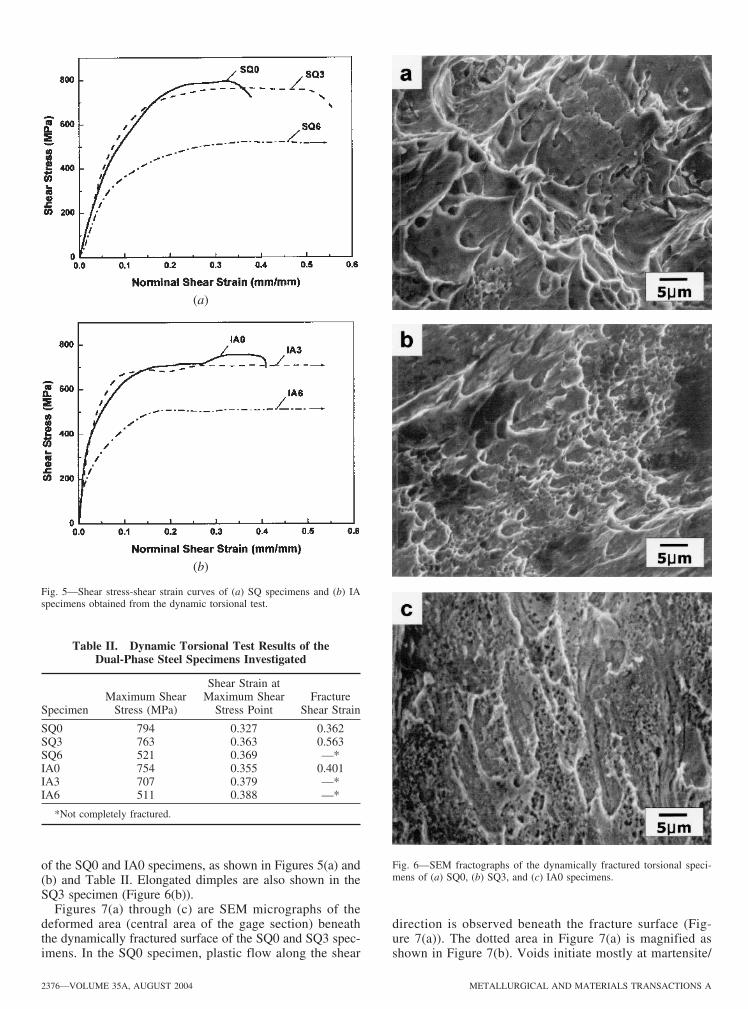
Fig. 6—SEM fractographs of the dynamically fractured torsional speci-mens of (a) SQ0, (b) SQ3, and (c) IA0 specimens.
(a)
(b)
Fig. 5—Shear stress-shear strain curves of (a) SQ specimens and (b) IAspecimens obtained from the dynamic torsional test.
2376—VOLUME 35A, AUGUST 2004 METALLURGICAL AND MATERIALS TRANSACTIONS A
of the SQ0 and IA0 specimens, as shown in Figures 5(a) and(b) and Table II. Elongated dimples are also shown in theSQ3 specimen (Figure 6(b)).
Figures 7(a) through (c) are SEM micrographs of thedeformed area (central area of the gage section) beneaththe dynamically fractured surface of the SQ0 and SQ3 spec-imens. In the SQ0 specimen, plastic flow along the shear
Table II. Dynamic Torsional Test Results of theDual-Phase Steel Specimens Investigated
Shear Strain atMaximum Shear Maximum Shear Fracture
Specimen Stress (MPa) Stress Point Shear Strain
SQ0 794 0.327 0.362SQ3 763 0.363 0.563SQ6 521 0.369 —*IA0 754 0.355 0.401IA3 707 0.379 —*IA6 511 0.388 —*
*Not completely fractured.
direction is observed beneath the fracture surface (Fig-ure 7(a)). The dotted area in Figure 7(a) is magnified asshown in Figure 7(b). Voids initiate mostly at martensite/
19-03-452A-4.qxd 9/27/04 9:06 PM Page 2376
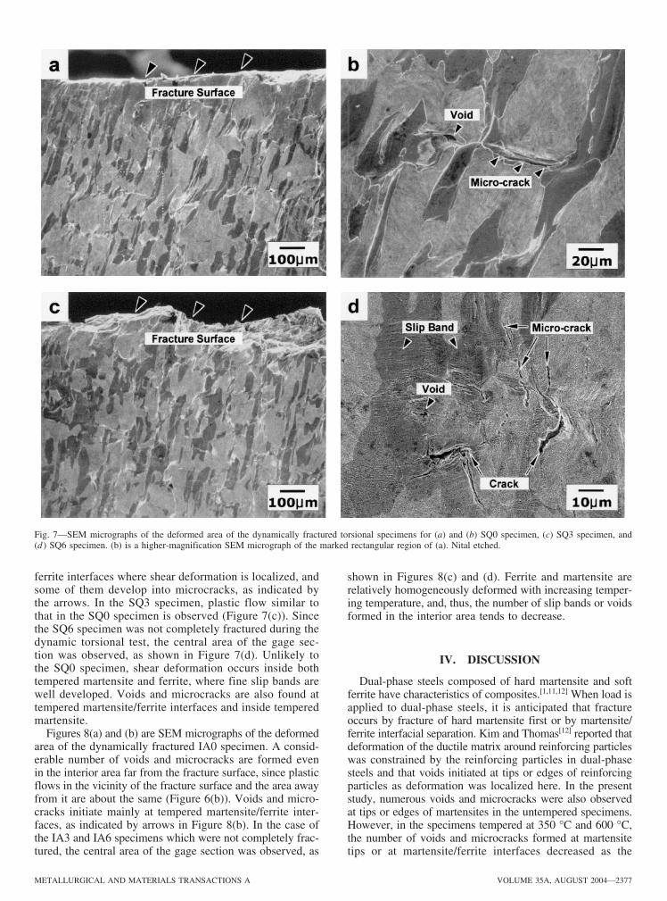
ferrite interfaces where shear deformation is localized, andsome of them develop into microcracks, as indicated bythe arrows. In the SQ3 specimen, plastic flow similar tothat in the SQ0 specimen is observed (Figure 7(c)). Sincethe SQ6 specimen was not completely fractured during thedynamic torsional test, the central area of the gage sec-tion was observed, as shown in Figure 7(d). Unlikely tothe SQ0 specimen, shear deformation occurs inside bothtempered martensite and ferrite, where fine slip bands arewell developed. Voids and microcracks are also found attempered martensite/ferrite interfaces and inside temperedmartensite.
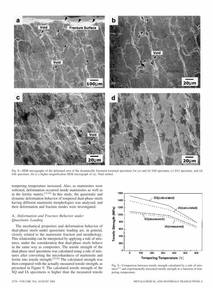
Figures 8(a) and (b) are SEM micrographs of the deformedarea of the dynamically fractured IA0 specimen. A consid-erable number of voids and microcracks are formed evenin the interior area far from the fracture surface, since plasticflows in the vicinity of the fracture surface and the area awayfrom it are about the same (Figure 6(b)). Voids and micro-cracks initiate mainly at tempered martensite/ferrite inter-faces, as indicated by arrows in Figure 8(b). In the case ofthe IA3 and IA6 specimens which were not completely frac-tured, the central area of the gage section was observed, as
shown in Figures 8(c) and (d). Ferrite and martensite arerelatively homogeneously deformed with increasing temper-ing temperature, and, thus, the number of slip bands or voidsformed in the interior area tends to decrease.
IV. DISCUSSION
Dual-phase steels composed of hard martensite and softferrite have characteristics of composites.[1,11,12] When load isapplied to dual-phase steels, it is anticipated that fractureoccurs by fracture of hard martensite first or by martensite/ferrite interfacial separation. Kim and Thomas[12] reported thatdeformation of the ductile matrix around reinforcing particleswas constrained by the reinforcing particles in dual-phasesteels and that voids initiated at tips or edges of reinforcingparticles as deformation was localized here. In the presentstudy, numerous voids and microcracks were also observedat tips or edges of martensites in the untempered specimens.However, in the specimens tempered at 350 °C and 600 °C,the number of voids and microcracks formed at martensitetips or at martensite/ferrite interfaces decreased as the
METALLURGICAL AND MATERIALS TRANSACTIONS A VOLUME 35A, AUGUST 2004—2377
Fig. 7—SEM micrographs of the deformed area of the dynamically fractured torsional specimens for (a) and (b) SQ0 specimen, (c) SQ3 specimen, and(d ) SQ6 specimen. (b) is a higher-magnification SEM micrograph of the marked rectangular region of (a). Nital etched.
19-03-452A-4.qxd 9/27/04 9:06 PM Page 2377
tempering temperature increased. Also, as martensites weresoftened, deformation occurred inside martensites as well asin the ferritic matrix.[12,24] In this study, the quasistatic anddynamic deformation behavior of tempered dual-phase steelshaving different martensite morphologies was analyzed, andtheir deformation and fracture modes were investigated.
A. Deformation and Fracture Behavior underQuasistatic Loading
The mechanical properties and deformation behavior ofdual-phase steels under quasistatic loading are, in general,closely related to the martensite fraction and morphology.This relationship can be interpreted by applying a rule of mix-tures, under the consideration that dual-phase steels behavein the same way as composites. The tensile strength of thedual-phase steel specimens was calculated using a rule of mix-tures after converting the microhardness of martensite andferrite into tensile strength.[25,26] The calculated strength wasthen compared with the actually measured tensile strength, aspresented in Figure 9. The calculated tensile strength of theSQ and IA specimens is higher than the measured tensile
2378—VOLUME 35A, AUGUST 2004 METALLURGICAL AND MATERIALS TRANSACTIONS A
Fig. 8—SEM micrographs of the deformed area of the dynamically fractured torsional specimens for (a) and (b) IA0 specimen, (c) IA3 specimen, and (d)IA6 specimen. (b) is a higher-magnification SEM micrograph of (a). Nital etched.
Fig. 9—Comparison between tensile strength calculated by a rule of mix-tures[27] and experimentally measured tensile strength as a function of tem-pering temperature.
19-03-452A-4.qxd 9/27/04 9:06 PM Page 2378
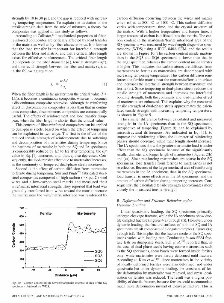
strength by 10 to 30 pct, and the gap is reduced with increas-ing tempering temperature. To explain the deviation of thetensile-strength data from the rule of mixtures, a theory forcomposites was applied in this study as follows.
According to Callister,[27] mechanical properties of fiber-reinforced composites are critically affected by load transferof the matrix as well as by fiber characteristics. It is knownthat the load transfer is important for interfacial strengthbetween the fiber and matrix, and that a critical fiber lengthexists for effective reinforcement. The critical fiber length(lc) depends on the fiber diameter (d ), tensile strength (�f*),and interfacial strength between the fiber and matrix (�c), asin the following equation:
[1]
When the fiber length is far greater than the critical value (l 15lc), it becomes a continuous composite, whereas it becomesa discontinuous composite otherwise. Although the reinforcingeffect in discontinuous composites is less than that in contin-uous composites, discontinuous composites are commerciallyuseful. The effects of reinforcement and load transfer disap-pear, when the fiber length is shorter than the critical value.
This concept of fiber-reinforced composites can be appliedto dual-phase steels, based on which the effect of temperingcan be explained in two ways. The first is the effect of thereduced tensile strength of reinforcements due to softeningand decomposition of martensites during tempering. Sincethe hardness of martensite in both the SQ and IA specimensis considerably reduced by 1/3 to 1/2 after tempering, the �f*value in Eq. [1] decreases, and, thus, lc also decreases. Con-sequently, the load-transfer effect due to martensites increases,as the continuity of tempered dual-phase steels increases.
Second is the effect of carbon diffusion from martensiteto ferrite during tempering. Sun and Pugh[28] fabricated steel-steel composites composed of high-carbon (0.8 pct C) steelwires and a low-carbon steel matrix and measured theirwire/matrix interfacial strength. They reported that load wasgradually transferred from wires toward the matrix, becausethe matrix near the wire/matrix interface was reinforced by
lc sf*d
2 tc
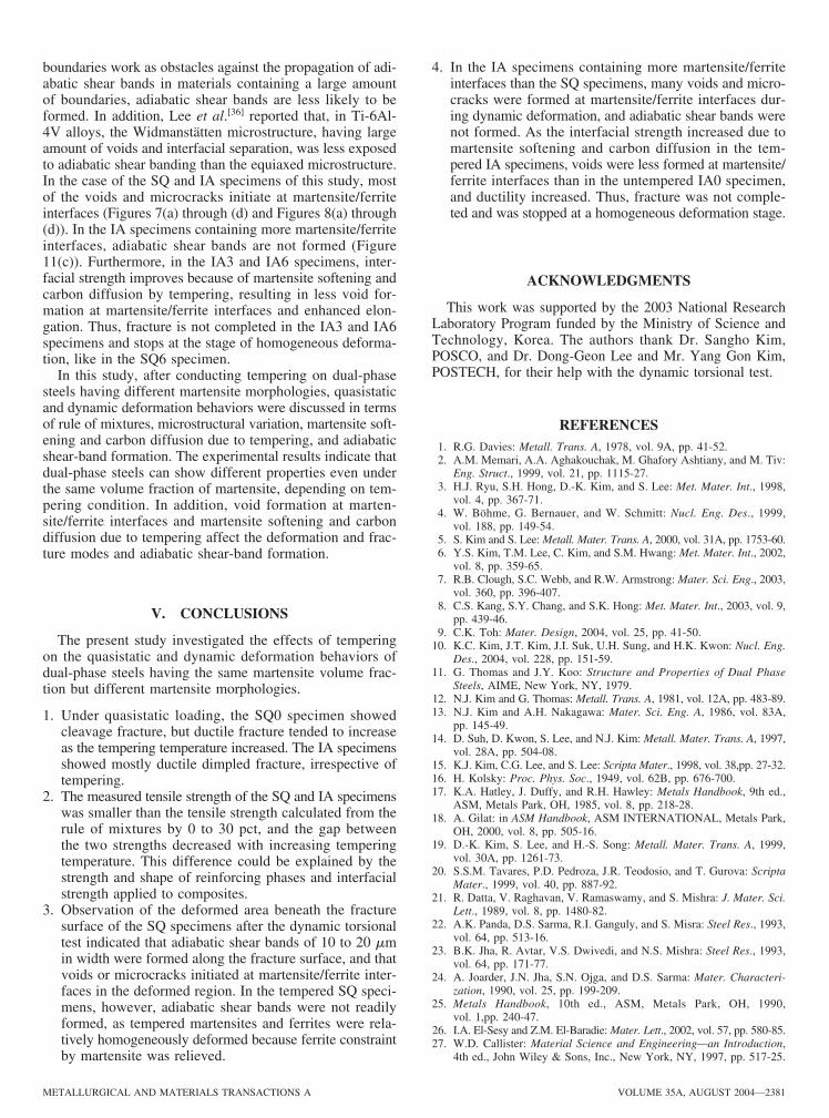
carbon diffusion occurring between the wires and matrixwhen rolled at 800 °C to 1100 °C. This carbon diffusionvaries with temperature, time, and the crystal structure ofthe matrix. With a higher temperature and longer time, alarger amount of carbon is diffused into the matrix. The car-bon content in the martensite/ferrite interfacial area of theSQ specimens was measured by wavelength-dispersive spec-troscopy (WDS) using a JEOL 840A SEM, and the resultsare shown in Figure 10. The carbon content inside marten-sites in the SQ3 and SQ6 specimens is lower than that inthe SQ0 specimen, whereas the carbon content inside ferritesis higher. This indicates that carbon atoms are diffused frommartensites to ferrites as martensites are decomposed withincreasing tempering temperature. This carbon diffusion rein-forces the ferritic matrix near the martensite/ferrite interfaceand increases the interfacial strength between martensite andferrite (�c). Since tempering in dual-phase steels reduces thetensile strength of martensite and increases the interfacialbonding strength, both the continuity and load-transfer effectof martensite are enhanced. This explains why the measuredtensile strength of dual-phase steels approximates the calcu-lated tensile strength with increasing tempering temperature,as shown in Figure 9.
The smaller difference between calculated and measuredstrengths in the IA specimens than in the SQ specimens,irrespective of tempering (Figure 9), can be explained bymicrostructural differences. As indicated in Eq. [1], toimprove the reinforcing effect, the diameter of reinforcingphases should decrease, while their length should increase.The IA specimens show the greater martensite load-transfereffect than the SQ specimens because of the significantlysmaller diameter and longer length of martensites (Figures 2(b)and (c)). Since reinforcing martensites are coarse in the SQspecimens, load transfer from ferrites to martensites is notso effective. Because of the larger interfacial area of reinforcingmartensites in the IA specimens than in the SQ specimens,load transfer is more effective in the IA specimens, and theamount of carbon diffusion during tempering increases. Con-sequently, the calculated tensile strength approximates moreclosely the measured tensile strength.
B. Deformation and Fracture Behavior underDynamic Loading
Under quasistatic loading, the SQ specimens primarilyundergo cleavage fracture, while the IA specimens show duc-tile dimpled fracture (Figures 4(a) through (f)). However, underdynamic loading, the fracture surfaces of both the SQ and IAspecimens are all composed of elongated dimples (Figures 6(a)through (c)). This implies that the fracture mode of the SQ spec-imens varies with loading rate. Conducting in-situ SEM frac-ture tests on dual-phase steels, Suh et al.[14] reported that, inthe case of dual-phase steels having coarse martensites suchas the SQ specimens, shear bands were formed inside ferritesonly, while martensites were hardly deformed until fracture.According to Kim et al.,[15] since martensites in the vicinityof locally deformed ferrites were also deformed, not underquasistatic but under dynamic loading, the constraint of fer-rite deformation by martensite was relieved, and stress local-ization on ferrites was reduced. The result was a higher pos-sibility of ductile fracture, because ferrites could accommodatemuch more deformation instead of cleavage fracture. This is
METALLURGICAL AND MATERIALS TRANSACTIONS A VOLUME 35A, AUGUST 2004—2379
Fig. 10—Carbon content in the ferrite/martensite interfacial area of the SQspecimens obtained by WDS.
19-03-452A-4.qxd 9/27/04 9:06 PM Page 2379

because materials show considerably different deformationbehavior under dynamic loading from that under quasistaticloading, depending on the plastic-deformation behavior.
Another characteristic phenomenon of the dynamic defor-mation behavior is the formation of adiabatic shear bandsdue to the plastic instability.[30–33] An adiabatic shear bandis a narrow area at which plastic deformation is localizedunder a dynamic loading condition. When an adiabatic shearband is formed under dynamic loading, the load-carryingcapacity is drastically dropped at the band area, thereby lead-ing to final failure of structures or parts. Cho et al.[34] pho-tographed the formation stages of the adiabatic shear bandduring the dynamic torsional test and observed that the adi-abatic shear band initiated at the final dynamic deformationstage, along which the crack propagated. In general, themechanical-thermal instability effect increases as the shearstrain rate increases, resulting in shear deformation in a nar-row area. When the deformation is completed in an extremelyshort period of time (tens to hundreds of microseconds) underdynamic loading, as with the thin-walled tubular specimenused in this study, the temperature in the central area of thegage section rises. This temperature rise is associated withthe lack of time for the heat generated by the initiation ofplastic deformation to be transferred from the edge of thespecimen to the flange and induces material softening, whichincreases the amount of local plastic deformation. Such aninhomogeneous deformation is accompanied by mechanicalinstability. The thermal instability caused by the abrupttemperature rise further accelerates the inhomogeneous defor-mation and causes concentration of shear deformation in thecentral area of the specimen.
Figures 11(a) through (c) are SEM micrographs of thedeformed cross-sectional area vertical to the dynamically frac-tured surface of the SQ0, SQ3, and IA0 specimens. At highstrain rates, adiabatic shear bands are formed where shear defor-mation is localized by local softening due to the heat gener-ated inside the material.[32,33] As indicated by arrows in the SQ0and SQ3 specimens, adiabatic shear bands were formed alongthe shear-stress direction, whereas they were not formed inthe IA0 specimen. Inside the shear-band area, shear deforma-tion is so serious as not to identify its microstructure, and cracksinitiate here and propagate to final fracture. In the SQ speci-mens, shear deformation is concentrated along the center of thegage section of the specimen, and the shear band is formed ina 10 to 20 �m width along the fracture surface (Figures 11(a)and (b)). The width of the adiabatic shear band corresponds tohalf of the width of the overall adiabatic shear band formed atthe center of the gage. In the SQ3 specimen, the adiabatic shearband formed is twice as wide as that in the SQ0 specimen,and martensites beneath the band are observed to be seriouslydeformed. Due to martensite softening and carbon diffusionsubsequent to tempering in the SQ3 specimen, ferrite constraintby martensite is relieved, and, thus, martensites and ferrites aremore homogeneously deformed under dynamic loading, therebyleading to less formation of adiabatic shear bands.
Microstructural variations are important factors affectingthe formation of adiabatic shear bands. Even in the samemicrostructure, the morphology, size, volume fraction, andinterfacial properties of phases determine the presence orabsence of adiabatic shear bands and the extent of the bandformation. According to research results by Lee et al.[35] andKim et al.,[19] cracks propagating along adiabatic shear bandschanged the path into grain boundaries in the case of 2090Al-Li alloys, while cracks detoured into tungsten-tungstenparticle boundaries in tungsten heavy alloys. Since these
2380—VOLUME 35A, AUGUST 2004 METALLURGICAL AND MATERIALS TRANSACTIONS A
Fig. 11—SEM micrographs of the sectioned interior region of the deformedarea of the dynamically fractured torsional specimens for (a) SQ0, (b) SQ3,and (c) IA0 specimens. These samples were prepared by sectioning, mounting,polishing, and etching the deformed area.
19-03-452A-4.qxd 9/27/04 9:06 PM Page 2380
boundaries work as obstacles against the propagation of adi-abatic shear bands in materials containing a large amountof boundaries, adiabatic shear bands are less likely to beformed. In addition, Lee et al.[36] reported that, in Ti-6Al-4V alloys, the Widmanstätten microstructure, having largeamount of voids and interfacial separation, was less exposedto adiabatic shear banding than the equiaxed microstructure.In the case of the SQ and IA specimens of this study, mostof the voids and microcracks initiate at martensite/ferriteinterfaces (Figures 7(a) through (d) and Figures 8(a) through(d)). In the IA specimens containing more martensite/ferriteinterfaces, adiabatic shear bands are not formed (Figure11(c)). Furthermore, in the IA3 and IA6 specimens, inter-facial strength improves because of martensite softening andcarbon diffusion by tempering, resulting in less void for-mation at martensite/ferrite interfaces and enhanced elon-gation. Thus, fracture is not completed in the IA3 and IA6specimens and stops at the stage of homogeneous deforma-tion, like in the SQ6 specimen.
In this study, after conducting tempering on dual-phasesteels having different martensite morphologies, quasistaticand dynamic deformation behaviors were discussed in termsof rule of mixtures, microstructural variation, martensite soft-ening and carbon diffusion due to tempering, and adiabaticshear-band formation. The experimental results indicate thatdual-phase steels can show different properties even underthe same volume fraction of martensite, depending on tem-pering condition. In addition, void formation at marten-site/ferrite interfaces and martensite softening and carbondiffusion due to tempering affect the deformation and frac-ture modes and adiabatic shear-band formation.
V. CONCLUSIONS
The present study investigated the effects of temperingon the quasistatic and dynamic deformation behaviors ofdual-phase steels having the same martensite volume frac-tion but different martensite morphologies.
1. Under quasistatic loading, the SQ0 specimen showedcleavage fracture, but ductile fracture tended to increaseas the tempering temperature increased. The IA specimensshowed mostly ductile dimpled fracture, irrespective oftempering.
2. The measured tensile strength of the SQ and IA specimenswas smaller than the tensile strength calculated from therule of mixtures by 0 to 30 pct, and the gap betweenthe two strengths decreased with increasing temperingtemperature. This difference could be explained by thestrength and shape of reinforcing phases and interfacialstrength applied to composites.
3. Observation of the deformed area beneath the fracturesurface of the SQ specimens after the dynamic torsionaltest indicated that adiabatic shear bands of 10 to 20 �min width were formed along the fracture surface, and thatvoids or microcracks initiated at martensite/ferrite inter-faces in the deformed region. In the tempered SQ speci-mens, however, adiabatic shear bands were not readilyformed, as tempered martensites and ferrites were rela-tively homogeneously deformed because ferrite constraintby martensite was relieved.
4. In the IA specimens containing more martensite/ferriteinterfaces than the SQ specimens, many voids and micro-cracks were formed at martensite/ferrite interfaces dur-ing dynamic deformation, and adiabatic shear bands werenot formed. As the interfacial strength increased due tomartensite softening and carbon diffusion in the tem-pered IA specimens, voids were less formed at martensite/ferrite interfaces than in the untempered IA0 specimen,and ductility increased. Thus, fracture was not comple-ted and was stopped at a homogeneous deformation stage.
ACKNOWLEDGMENTS
This work was supported by the 2003 National ResearchLaboratory Program funded by the Ministry of Science andTechnology, Korea. The authors thank Dr. Sangho Kim,POSCO, and Dr. Dong-Geon Lee and Mr. Yang Gon Kim,POSTECH, for their help with the dynamic torsional test.
REFERENCES1. R.G. Davies: Metall. Trans. A, 1978, vol. 9A, pp. 41-52.2. A.M. Memari, A.A. Aghakouchak, M. Ghafory Ashtiany, and M. Tiv:
Eng. Struct., 1999, vol. 21, pp. 1115-27.3. H.J. Ryu, S.H. Hong, D.-K. Kim, and S. Lee: Met. Mater. Int., 1998,
vol. 4, pp. 367-71.4. W. Böhme, G. Bernauer, and W. Schmitt: Nucl. Eng. Des., 1999,
vol. 188, pp. 149-54.5. S. Kim and S. Lee: Metall. Mater. Trans. A, 2000, vol. 31A, pp. 1753-60.6. Y.S. Kim, T.M. Lee, C. Kim, and S.M. Hwang: Met. Mater. Int., 2002,
vol. 8, pp. 359-65.7. R.B. Clough, S.C. Webb, and R.W. Armstrong: Mater. Sci. Eng., 2003,
vol. 360, pp. 396-407.8. C.S. Kang, S.Y. Chang, and S.K. Hong: Met. Mater. Int., 2003, vol. 9,
pp. 439-46.9. C.K. Toh: Mater. Design, 2004, vol. 25, pp. 41-50.
10. K.C. Kim, J.T. Kim, J.I. Suk, U.H. Sung, and H.K. Kwon: Nucl. Eng.Des., 2004, vol. 228, pp. 151-59.
11. G. Thomas and J.Y. Koo: Structure and Properties of Dual PhaseSteels, AIME, New York, NY, 1979.
12. N.J. Kim and G. Thomas: Metall. Trans. A, 1981, vol. 12A, pp. 483-89.13. N.J. Kim and A.H. Nakagawa: Mater. Sci. Eng. A, 1986, vol. 83A,
pp. 145-49.14. D. Suh, D. Kwon, S. Lee, and N.J. Kim: Metall. Mater. Trans. A, 1997,
vol. 28A, pp. 504-08.15. K.J. Kim, C.G. Lee, and S. Lee: Scripta Mater., 1998, vol. 38,pp. 27-32.16. H. Kolsky: Proc. Phys. Soc., 1949, vol. 62B, pp. 676-700.17. K.A. Hatley, J. Duffy, and R.H. Hawley: Metals Handbook, 9th ed.,
ASM, Metals Park, OH, 1985, vol. 8, pp. 218-28.18. A. Gilat: in ASM Handbook, ASM INTERNATIONAL, Metals Park,
OH, 2000, vol. 8, pp. 505-16.19. D.-K. Kim, S. Lee, and H.-S. Song: Metall. Mater. Trans. A, 1999,
vol. 30A, pp. 1261-73.20. S.S.M. Tavares, P.D. Pedroza, J.R. Teodosio, and T. Gurova: Scripta
Mater., 1999, vol. 40, pp. 887-92.21. R. Datta, V. Raghavan, V. Ramaswamy, and S. Mishra: J. Mater. Sci.
Lett., 1989, vol. 8, pp. 1480-82.22. A.K. Panda, D.S. Sarma, R.I. Ganguly, and S. Misra: Steel Res., 1993,
vol. 64, pp. 513-16.23. B.K. Jha, R. Avtar, V.S. Dwivedi, and N.S. Mishra: Steel Res., 1993,
vol. 64, pp. 171-77.24. A. Joarder, J.N. Jha, S.N. Ojga, and D.S. Sarma: Mater. Characteri-
zation, 1990, vol. 25, pp. 199-209.25. Metals Handbook, 10th ed., ASM, Metals Park, OH, 1990,
vol. 1,pp. 240-47.26. I.A. El-Sesy and Z.M. El-Baradie: Mater. Lett., 2002, vol. 57, pp. 580-85.27. W.D. Callister: Material Science and Engineering—an Introduction,
4th ed., John Wiley & Sons, Inc., New York, NY, 1997, pp. 517-25.
METALLURGICAL AND MATERIALS TRANSACTIONS A VOLUME 35A, AUGUST 2004—2381
19-03-452A-4.qxd 9/27/04 9:06 PM Page 2381
28. S. Sun and M. Pugh: Mater. Sci. Eng., 2001, vol. A318, pp. 320-27.29. D. Suh, D. Kwon, S. Lee, and N.J. Kim: Metall. Mater. Trans. A, 1997,
vol. 28A, pp. 504-08.30. S. Lee, K. Cho, C.S. Lee, and W.Y. Choo: Metall. Trans. A, 1993,
vol. 24A, pp. 2217-24.31. K. Cho, S. Lee, J. Duffy, and S.R. Nutt: Acta Metall., 1993, vol. 41,
pp. 923-32.
32. J.W. Huchinson: Scripta Metall., 1984, vol. 18, pp. 421-58.33. H.C. Rogers: Ann. Rev. Mater. Sci., 1979, vol. 9, pp. 283-311.34. K. Cho, Y.C. Chi, and J. Duffy: Metall. Trans. A, 1990, vol. 21A,
pp. 1161-75.35. C.G. Lee, Y.J. Lee, and S. Lee: Scripta Metall., 1995, vol. 32, pp. 821-26.36. D.-G. Lee, S. Kim, S. Lee, and C.S. Lee: Metall. Mater. Trans. A,
2001, vol. 32A, pp. 315-24.
2382—VOLUME 35A, AUGUST 2004 METALLURGICAL AND MATERIALS TRANSACTIONS A
19-03-452A-4.qxd 9/27/04 9:06 PM Page 2382