Effect of the Quasi-Petal Heat Transfer Tube on the ... - MDPI
22
sustainability Article Effect of the Quasi-Petal Heat Transfer Tube on the Melting Process of the Nano-Enhanced Phase Change Substance in a Thermal Energy Storage Unit Mohammad Ghalambaz 1,2 , Seyed Abdollah Mansouri Mehryan 3 , Reza Kalantar Feeoj 4 , Ahmad Hajjar 5 , Obai Younis 6,7 , Pouyan Talebizadehsardari 1,2, * and Wahiba Yaïci 8, * Citation: Ghalambaz, M.; Mehryan, S.A.M.; Feeoj, R.K.; Hajjar, A.; Younis, O.; Talebizadehsardari, P.; Yaïci, W. Effect of the Quasi-Petal Heat Transfer Tube on the Melting Process of the Nano-Enhanced Phase Change Substance in a Thermal Energy Storage Unit. Sustainability 2021, 13, 2871. https://doi.org/10.3390/ su13052871 Academic Editor: Vasileios C. Kapsalis Received: 26 January 2021 Accepted: 1 March 2021 Published: 7 March 2021 Publisher’s Note: MDPI stays neutral with regard to jurisdictional claims in published maps and institutional affil- iations. Copyright: © 2021 by the authors. Licensee MDPI, Basel, Switzerland. This article is an open access article distributed under the terms and conditions of the Creative Commons Attribution (CC BY) license (https:// creativecommons.org/licenses/by/ 4.0/). 1 Metamaterials for Mechanical, Biomechanical and Multiphysical Applications Research Group, Ton Duc Thang University, Ho Chi Minh City 758307, Vietnam; [email protected] 2 Faculty of Applied Sciences, Ton Duc Thang University, Ho Chi Minh City 758307, Vietnam 3 Young Researchers and Elite Club, Yasooj Branch, Islamic Azad University, Yasooj 75914-93686, Iran; [email protected] 4 Department of Mechanical Engineering, Shahrekord University, Shahrekord 88186-34141, Iran; [email protected] 5 ECAM Lyon, LabECAM, Université de Lyon, 69005 Lyon, France; [email protected] 6 Department of Mechanical Engineering, College of Engineering at Wadi Addwaser, Prince Sattam Bin Abdulaziz University, Wadi Addwaser 11991, Saudi Arabia; [email protected] 7 Department of Mechanical Engineering, Faculty of Engineering, University of Khartoum, Khartoum 11111, Sudan 8 CanmetENERGY Research Centre, Natural Resources Canada, 1 Haanel Drive, Ottawa, ON K1A 1M1, Canada * Correspondence: [email protected] (P.T.); [email protected] (W.Y.); Tel.: +1-613-996-3734 (W.Y.) Abstract: The melting heat transfer of nano-enhanced phase change materials was addressed in a thermal energy storage unit. A heated U-shape tube was placed in a cylindrical shell. The cross- section of the tube is a petal-shape, which can have different amplitudes and wave numbers. The shell is filled with capric acid with a fusion temperature of 32 ◦ C. The copper (Cu)/graphene oxide (GO) type nanoparticles were added to capric acid to improve its heat transfer properties. The enthalpy-porosity approach was used to model the phase change heat transfer in the presence of natural convection heat transfer effects. A novel mesh adaptation method was used to track the phase change melting front and produce high-quality mesh at the phase change region. The impacts of the volume fraction of nanoparticles, the amplitude and number of petals, the distance between tubes, and the angle of tube placements were investigated on the thermal energy rate and melting-time in the thermal energy storage unit. An average charging power can be raised by up to 45% by using petal shape tubes compared to a plain tube. The nanoadditives could improve the heat transfer by 7% for Cu and 11% for GO nanoparticles compared to the pure phase change material. Keywords: quasi-petal heat transfer tube; thermal energy storage; nano-enhanced phase change materials 1. Introduction Thermal energy storage systems have attracted numerous researchers due to their economic and environmental benefits. As the phase change materials can absorb and release latent heat during solidification and melting, they are widely used in thermal energy storage systems. The thermal energy storage adds a buffer to thermal systems to dampen their peak thermal loads or shift their thermal loads. The phase change materials are capable of storing a significant amount of latent energy in a small mass. For example, by using latent heat thermal energy storage, the solar heat can be stored during the daytime and later released during the night times [1]. Two major benefits of latent heat thermal energy storage are the high specific heat of phase change and low-temperature variation during thermal storage [2]. The latent thermal energy storage can also be used to cool Sustainability 2021, 13, 2871. https://doi.org/10.3390/su13052871 https://www.mdpi.com/journal/sustainability
-
Upload
khangminh22 -
Category
Documents
-
view
5 -
download
0
Transcript of Effect of the Quasi-Petal Heat Transfer Tube on the ... - MDPI
sustainability
Article
Effect of the Quasi-Petal Heat Transfer Tube on the MeltingProcess of the Nano-Enhanced Phase Change Substance in aThermal Energy Storage Unit
Mohammad Ghalambaz 1,2 , Seyed Abdollah Mansouri Mehryan 3 , Reza Kalantar Feeoj 4 , Ahmad Hajjar 5,Obai Younis 6,7 , Pouyan Talebizadehsardari 1,2,* and Wahiba Yaïci 8,*
�����������������
Citation: Ghalambaz, M.; Mehryan,
S.A.M.; Feeoj, R.K.; Hajjar, A.; Younis,
O.; Talebizadehsardari, P.; Yaïci, W.
Effect of the Quasi-Petal Heat
Transfer Tube on the Melting Process
of the Nano-Enhanced Phase Change
Substance in a Thermal Energy
Storage Unit. Sustainability 2021, 13,
2871. https://doi.org/10.3390/
su13052871
Academic Editor: Vasileios
C. Kapsalis
Received: 26 January 2021
Accepted: 1 March 2021
Published: 7 March 2021
Publisher’s Note: MDPI stays neutral
with regard to jurisdictional claims in
published maps and institutional affil-
iations.
Copyright: © 2021 by the authors.
Licensee MDPI, Basel, Switzerland.
This article is an open access article
distributed under the terms and
conditions of the Creative Commons
Attribution (CC BY) license (https://
creativecommons.org/licenses/by/
4.0/).
1 Metamaterials for Mechanical, Biomechanical and Multiphysical Applications Research Group, Ton DucThang University, Ho Chi Minh City 758307, Vietnam; [email protected]
2 Faculty of Applied Sciences, Ton Duc Thang University, Ho Chi Minh City 758307, Vietnam3 Young Researchers and Elite Club, Yasooj Branch, Islamic Azad University, Yasooj 75914-93686, Iran;
[email protected] Department of Mechanical Engineering, Shahrekord University, Shahrekord 88186-34141, Iran;
[email protected] ECAM Lyon, LabECAM, Université de Lyon, 69005 Lyon, France; [email protected] Department of Mechanical Engineering, College of Engineering at Wadi Addwaser, Prince Sattam Bin
Abdulaziz University, Wadi Addwaser 11991, Saudi Arabia; [email protected] Department of Mechanical Engineering, Faculty of Engineering, University of Khartoum,
Khartoum 11111, Sudan8 CanmetENERGY Research Centre, Natural Resources Canada, 1 Haanel Drive,
Ottawa, ON K1A 1M1, Canada* Correspondence: [email protected] (P.T.); [email protected] (W.Y.); Tel.: +1-613-996-3734 (W.Y.)
Abstract: The melting heat transfer of nano-enhanced phase change materials was addressed in athermal energy storage unit. A heated U-shape tube was placed in a cylindrical shell. The cross-section of the tube is a petal-shape, which can have different amplitudes and wave numbers. Theshell is filled with capric acid with a fusion temperature of 32 ◦C. The copper (Cu)/graphene oxide(GO) type nanoparticles were added to capric acid to improve its heat transfer properties. Theenthalpy-porosity approach was used to model the phase change heat transfer in the presence ofnatural convection heat transfer effects. A novel mesh adaptation method was used to track the phasechange melting front and produce high-quality mesh at the phase change region. The impacts of thevolume fraction of nanoparticles, the amplitude and number of petals, the distance between tubes,and the angle of tube placements were investigated on the thermal energy rate and melting-time inthe thermal energy storage unit. An average charging power can be raised by up to 45% by usingpetal shape tubes compared to a plain tube. The nanoadditives could improve the heat transfer by7% for Cu and 11% for GO nanoparticles compared to the pure phase change material.
Keywords: quasi-petal heat transfer tube; thermal energy storage; nano-enhanced phase change materials
1. Introduction
Thermal energy storage systems have attracted numerous researchers due to theireconomic and environmental benefits. As the phase change materials can absorb andrelease latent heat during solidification and melting, they are widely used in thermalenergy storage systems. The thermal energy storage adds a buffer to thermal systems todampen their peak thermal loads or shift their thermal loads. The phase change materialsare capable of storing a significant amount of latent energy in a small mass. For example,by using latent heat thermal energy storage, the solar heat can be stored during the daytimeand later released during the night times [1]. Two major benefits of latent heat thermalenergy storage are the high specific heat of phase change and low-temperature variationduring thermal storage [2]. The latent thermal energy storage can also be used to cool
Sustainability 2021, 13, 2871. https://doi.org/10.3390/su13052871 https://www.mdpi.com/journal/sustainability
Sustainability 2021, 13, 2871 2 of 22
photovoltaic panels [3] or load shift in buildings [4]. Various applications of phase changematerials have been reviewed in the studies of Cui et al. [5], Kong et al. [6], and Abdolmalekiet al. [7].
The phase change materials (PCMs) are capable of storing a huge amount of thermalenergy. However, one of the main drawbacks of PCMs is their low value of thermal con-ductivity. One way to enhance PCM’s thermal conductivity is to produce nano-enhancedPCMs (NePCMs) by simply adding nanoparticles to the base PCM. Many innovationsregarding NePCM [8–11] and thermal storage system design [12,13] are patented.
Considering NePCMs, Ho and Gao [14] tested the influence of adding nanoparticlesof Al2O3 to PCM (paraffin) on melting heat transfer experimentally. Different nanoparticlemass fractions were studied under different Rayleigh and Stefan numbers. The resultsindicated that natural convection in the melting region is obviously degraded when thenanoparticle mass fraction increased. Dhaidan et al. [15] studied the melting of NePCMinside a square cavity by means of experimental work and numerical simulation. Theirresults indicated that dispersing CuO nanoparticles into PCM effectively increased boththe thermal conductivity and temperature of NePCM, and most importantly, the chargingtime was reduced. Zeng et al. [16] experimentally researched the melting of NePCMin a cylindrical enclosure. NePCM was prepared by dispersing different loading of thecarbon nanotubes (CNTs) in 1-dodecanol. They reported that the addition of CNTs ledto a significant increase in the viscosity and thermal conductivity, and hence the meltingrate was decelerated. Recently, Li et al. [17] used thermochromic liquid crystal to studythe melting of NePCM in rectangular enclosures. Their findings were consistent with theliterature, that melting rate was decelerated due to the significant increase of viscositycaused by using the NePCM.
Parsazadeh and Duan [18] numerically investigated the melting of NeCPM in athermal storage unit. One of the main factors of the study was the influence of addingCuO particles to paraffin. The authors concluded that the addition of CuO nanoparticles toparaffin significantly improved heat transfer, however exceeding the critical nanoparticleconcentration would result in an adverse effect. Hosseinizadeh et al. [19] explored themelting of NePCM inside a spherical container numerically. They employed RT27 andcopper particles as nanoadditives. Their results confirmed that the melting rate of NePCMwas enhanced when compared with PCM. Zhang et al. [20] conducted experimental workto investigate the characteristics of NePCM. They covered different nanoadditives, such asFe2O3 and Cu. They observed an increment in the thermal conductivity and a reduction inthe thermal storage time.
The performance of the thermal energy system is significantly affected by the geo-metrical design and parameters. Some of the literature works investigated the influenceof adding fins to enhance the conductive heat transfer inside the system. For example, Jiet al. [21] attempted to improve PCM’s melting rate by introducing fins with a tilting angle.They reported that the fin with a downward angle of −15◦ accelerated the melting of PCMand resulted in 23.8% melting time-saving. Jinlong et al. [22] presented a numerical studyon thermal optimization of a tree-shaped metal structure to enhance heat transfer in thePCM cavity. Their results indicated that the proposed optimized structure enhanced themelting fraction of PCM.
Mostafavi et al. [23] analytically modeled PCM melting in a cylinder containingtransverse and longitudinal fins. It was reported that thin fins resulted in significantenhancement of heat transfer; however, further increment in fin size led to adverse effects.Pourakabar et al. [24] numerically investigated the influence of shell geometry (circularand elliptical cylinders) and tube arrangement on the phase change rate of PCM inside thecylinder. In total, nine different study cases were considered. The maximum melting ratewas achieved by a circular cylinder with two tubes vertically aligned.
Some recent researchers used a combination of fins and NePCMs to improve heat trans-fer further and accelerate thermal energy storage and release process. Sheikholeslami [25]presented a numerical simulation of NePCM solidification in a cavity containing metallic
Sustainability 2021, 13, 2871 3 of 22
fins. Nguyen-Thoi et al. [26] analyzed the solidification of NePCM in a thermal storagesystem with Y-shaped fins. Sheikholeslami et al. [27] numerically simulated melting ofNePCM in a finned cavity. The results of all these studies showed that using longer finsreduced both the solidification time and total energy. Mahdi et al. [28] numerically com-pared the thermal performance of a triplex tube when loaded with NePCM to the samesystem loaded with PCM and containing inner fins. Considering charging and dischargingthe system, it was clearly observed that incorporating inner fins is much better than thedispersion of nanoparticles in base PCM.
Another possible effective solution to enhance the solidification and melting rates ofthe thermal storage system is to increase the surface area of the inner tube. Zhang et al. [29]investigated the discharging of NePCM in a thermal storage system with a triplex tubewith different values of sinusoidal amplitudes. They concluded that using higher valuesinusoidal amplitude resulted in reducing the discharge time by 7.58%. Alizadeh et al. [30]numerically explored the influence of Koch snowflake fractal-shaped tube on the thermalperformance of NePCM thermal storage systems. The study considered four differentcross-sectional shapes, where Koch-snowflake-iteration ranges from zero to 3. Their resultsindicated that using higher values of Koch-snowflake-iteration increased the penetrationdepth, which consequentially accelerated the solidification process.
Sheikholeslami et al. [31] numerically studied heat transfer of NePCM inside sinu-soidal enclosure contacting V-shaped fins. One of the main studied parameters was theeffect of the V-shaped angle on the solidification rate. The results indicated that the dis-charging rate was augmented for high values of fin angle. Li et al. [32] attempted toaccelerate the solidification of NePCM in a circular cylindrical thermal energy storageunit by optimizing the shape of the wall of the inner tube. The study considered differentshapes of inner tubes that have a different number of undulations (ranges from 3 to 5) anddifferent amplitude values (ranges from 0.1 to 0.5). The research outcome indicated thatdecreasing the amplitude resulted in increasing the solidification time, whereas increasingthe number of petals has a favorable effect. In another investigation, Sheikholeslami [33]numerically investigated the effect of inner tube geometry on NePCM solidification in anelliptic cylindrical thermal storage system. The main geometrical parameters of the innertube were the number of undulations (3, 4, and 5) and the amplitude (0.1. 0.3, and 0.5). Itwas observed that solid fraction was directly proportional to the number of undulations,while total energy profiles were inversely proportional to the number of undulations.
Indeed, many researchers are preparing various types of novel NePCMs with im-proved thermophysical properties with the aim of better thermal energy storage and heattransfer. Tariq et al. [34] and Nižetic [1] have reviewed some of the NePCM materialsand applications. However, the NePCMs add mixed impacts on a thermal energy storagedesign. For example, the presence of nanoparticles improves the thermal conductivity ofPCM, which consequently enhances the conduction and convection heat transfer. Thisis while the presence of nanoparticles could also increase the dynamic viscosity, whichweakens the natural convection flows in a molten PCM. Moreover, the latent heat ofphase change, heat capacity, and other properties could be changed in the presence of thenanoadditives. These aspects impose complex effects on thermal performance of a thermalenergy storage unit. Thus, these nanomaterials should be applied in thermal energy storagesystems, and then their benefit can be judged.
The literature studies confirm that the undulating shape of the heat transfer tubecould increase the heat transfer surface and the natural convection flows. Thus, the wavyenclosures and petal tubes could be promising candidates for the improvement of heattransfer and enhance the rate of energy storage in thermal energy storage units. The presentstudy, for the first time, aims to investigate the impact of using petal heat transfer tubesand NePCMs on the heat transfer performance and energy storage rate of thermal energystorage units. The number and amplitude of the undulations and location of tubes areinvestigated.

Sustainability 2021, 13, 2871 4 of 22
2. Methodology2.1. Physical Model
Figure 1 depicts the schematic configuration of a heat exchanger energy storage system.As the schematic view in Figure 1a illustrates, the system includes a shell and a U-shapedtube containing the hot heat transfer fluid (HTF). As can be seen in Figure 1b, the cross-section of the tube is a quasi-petal and the line passing the centers of the heat transfer tubewith respect to the x-axis is η.
Figure 1. The configuration of the problem physics: (a) a 3D view of the energy storage unit withpetal heat transfer fluid (HTF); (b) a 2D cross-section of the unit; (c) geometrical details of a petal tube.
Since the tube material is thermally high conductive, its thickness is negligible com-pared to the radius. The void space between the U-shaped tube and the shell is occupiedwith the NePCM in which the host PCM is capric acid with a nominal melting point ofTm = 32 ◦C. The shell of the heat exchanger storage system is well insulated, while initially(t = 0), the temperatures of the NePCM and quasi-petal heat transfer tube are Tc = 22 ◦C. Att = 24 s, the temperature of the heat transfer tube linearly rises so that it reaches Th = 42 ◦Cat t = 25 s. It is worth noting that the temperature of the heat transfer tube is considered tobe constant at Th during the charging process.
The dispersed nano-additives can be copper (Cu) or graphene oxide (GO) ones. Thethermophysical properties of the components of the NePCM are listed in Table 1.
Table 1. Thermophysical properties of the paraffin wax and the nano-additives [35,36].
Properties Cu GO Capric Acid
Density (kg m−3) 8933 1800 Solid: 1018Liquid: 888
Latent heat (kJ kg−1) NA NA 152.7Thermal expansion coefficient (K−1) 1.67 × 10⁻⁵ 28.4 × 10⁻⁵ 1 × 10⁻³
Fusion temperature (◦C) NA NA 32
Thermal conductivity (Wm−1 K−1) 401 5000 Solid: 0.372Liquid: 0.153
Specific heat (kJ kg−1 K−1) 0.385 0.717 Solid: 1.9Liquid: 2.4
Kinematic viscosity (m2 s−1) NA NA 3 × 10⁻⁶
NA: Not applicable.
Herein, the density variations of the NePCM during phase change are considered tobe zero, and the reference densities are selected to simulate the process. The Boussinesqapproximation is valid to model the buoyancy-driven convection of the melted NePCM.The radius of the sinusoidal cross-section of the quasi-petal heat transfer tube is defined byusing the following relation:
r = rb + A× sin(Λs), (1)
As shown in Figure 1c, rb and A are the radius of the base circle and the sinusoidalamplitude of the quasi-petal heat transfer tube. Λ is the number of petals and s is the angle
Sustainability 2021, 13, 2871 5 of 22
of the quasi-petal heat transfer tube. The cross-section surface area of the quasi-petal tube(Ap) is calculated as follows:
Ap =∫ 2π
0
12
r2dφ =π
2
(A2 + 2r2
b
)− A2
8Λsin(4πΛ) +
A rbΛ
(cos(2πΛ)− 1), (2)
When Λ ∈ N then:Ap =
π
2
(A2 + 2r2
b
), (3)
which is independent of Λ. It worth noting that Ap is considered to be constant so thatAp = πr2
s /20. The radius of the shell, i.e., rs, is 20 mm, and rb, i.e., the radius of the basecircle, is defined by using Equation (3).
2.2. Governing Equations
The governing equations for conservation of mass, flow, and energy in the heatexchanger can be written as [37–39]:
∂u∂x
+∂v∂y
= 0, (4)
ρNePCM,l
(∂u∂t
+ u∂u∂x
+ v∂u∂y
)= −∂p
∂x+ µNePCM
(∂2u∂x2 +
∂2u∂y2
)− f (T)u, (5)
ρNePCM,l
(∂v∂t
+ u∂v∂x
+ v∂v∂y
)= −∂p
∂y+ µNePCM
(∂2v∂x2 +
∂2v∂y2
)− f (T)v + (ρβ)NePCM,l g(T − Tm), (6)
(ρCp)NePCM
(∂T∂t + u ∂T
∂x + v ∂T∂y
)= ∂
∂x
(κNePCM
∂T∂x
)+ ∂
∂y
(κNePCM
∂T∂y
)−(
1−ωv f
)ρPCM,lhs f ,PCM
∂χ(T)∂t
(7)
where Equation (4) is the conservation of mass for an incompressible liquid. Equations (5)and (6) are the momentum equations in the x-direction (u) and y-direction (v), respectively.In the y-momentum equation, the buoyancy forces are modeled using the Boussinesqapproximation by considering the liquid’s volume expansion coefficient (β). Equation (7)denotes the conservation of energy, including the phase change latent heat and temperaturefield (T). The phase change is modeled using a temperature-dependent latent heat term,χ(T). The symbols κ, hsf, Cp, ρ, µ, and ωvf represent the thermal conductivity, latent heat,heat capacity, density, dynamic viscosity, and volume fraction of nanoparticles. Thesubscripts, NePCM, PCM, and l show the nano-enhanced phase change material, the basephase change material, and the molten state. Here, f (T), as a function of the liquid fractionof the NePCM, i.e., χ, is the momentum sink term, is defined by using the Kozeny-Carmanmodel.
f (T) = ε(1− χ(T))2
χ(T)3 + ξ, (8)
It is evident this term is zero and infinity for the completely melted and solid zones. ε,the mushy zone constant, shows the approximate magnitude of damping in the momentumequations. This constant is set to 105. Likewise, ξ is set to a very low value to preventdivision by zero at the melted zone. The liquid fraction of the NePCM, which is definedbased on the temperature, is:
χ(T) =
0 T < Tm − δT
2T−Tm
δT + 12 Tm − δT
2 < T < Tm + δT2
1 T > Tm + δT2
, (9)
Sustainability 2021, 13, 2871 6 of 22
which Tm is the melting temperature, and δT is the melting temperature window. Thedensity of NePCM is:
ρNePCM =(
1−ωv f
)ρPCM + ωv f ρna, (10)
ρPCM(T) = ρPCM,lχ(T) + (1− χ(T))ρPCM,s, (11)
The dynamic viscosity of the composite can be estimated by Brinkman’s model as:
µNePCM =µPCM(
1−ωv f
)2.5 , (12)
The thermal-volume expansion coefficient of the composite is:
(ρβ)NePCM,l =[(
1−ωv f
)(ρβ)PCM,l + ωv f (ρβ)na
], (13)
Furthermore, the effective thermal conductivity of the composite is estimated as thefollowing:
κNePCM(T) = κNePCM,lχ(T) + (1− χ(T))κNePCM,s, (14)
in which [40]κNePCM,i
κPCM,i=
(κna + 2κPCM,i)− 2ωv f (κPCM,i − κna)
(κna + 2κPCM,i) + ωv f (κPCM,i − κna), (15)
i = l, s in the above equation denotes the liquid and solid phase of the PCM, respectively.Additionally, the effective heat capacity of the NePCM was computed by:
(ρC)p,NePCM =[(
1−ωv f
)(ρCp
)PCM + ωv f
(ρCp
)na
], (16)(
ρCp)
PCM(T) =(ρCp
)PCM,lχ(T) + (1− χ(T))
(ρCp
)PCM,s, (17)
The energy stored in the composite is calculated as the following:
ES =∫A
Ts∫Tin
(ρCp
)NePCM,sdTdA +
∫A
(ρhs f
)NePCM
dA +∫A
T∫Tl
(ρCp
)NePCM,ldTdA. (18)
3. Numerical Method and Model Verification3.1. Numerical Approach
The parameters can be studied in this work are rd, A, Λ, ωv f , and η with the followingranges: 0.4rs, ≤ rd ≤ 0.6rs, 0 ≤ A ≤ 0.15rs, 2 ≤ Λ ≤ 8, 0.0 % ≤ ωv f ≤ 8%, and 0 ≤ η ≤ π/2.Moreover φ0, i.e., the angle of the first petal with respect to the horizontal direction canbe varied based on the number of petals. In this simulation, we calculate all the data for75% of the melting volume fraction (MVF). The models were computed for 2000 s of phasechange heat transfer. It should be considered that total energy stored is the summation ofthe sensible and latent energies. Therefore, the average charging power was computed asthe total energy over melting time related when MVF reaches 75% of the total melting.
In order to model the melting procedure, the source terms of momentum and energyconservation equations depended on the formulas of NePCM mentioned above are used.f (T) source term is applied to control the velocity field. Three different areas can beconsidered for the domain study, solid, liquid, and the mushy zone. The mushy zone helpsto separate the two other areas. These three areas are separated by the melting temperaturewindow, δT, and fusion temperature. There is a high-velocity gradient area within theporous part of the mushy zone, including solid and liquid materials. The heat-source ofthe mushy zone,
(ρhs f
)NePCM
(∂χ(T)/∂t), that is the energy source term, contributes to ahigh-gradient temperature zone and also controls the melting area. To capture the mushy
Sustainability 2021, 13, 2871 7 of 22
zone from the high-gradient parameters viewpoint completely, the mesh adoption processas a progressive technique inside the mushy zone is utilized to achieve a quality grid.
Galerkin finite element method [41,42] by using user-defined codes is applied tosolve the nonlinear differential equations written above. In this method, a weak form ofequations and corresponding initial and boundary conditions are made and are solvedafterward. The dependent variables of the study u, v, p, and T are expanded by a shape set,{bv}I
v = 1.
(T, p, v, u) ≈I
∑v = 1
(Tv, pv, vv, uv)bv(x, y), (19)
Based on Galerkin finite element method, the residual functions, expressed below, are:
Q1t ≈
I
∑v = 1
vv
∫∂bv
∂ybtdxdy +
I
∑v = 1
uv
∫∂bv
∂xbtdxdy, , (20)
Q2t ≈ ρNePCM,l
I∑
v = 1uv∫
∂bv∂t btdxdy + ρNePCM,l
I∑
v = 1uv∫ [( M
∑v = 1
uvbv
)∂bv∂x +
(I
∑z = 1
vv bv
)∂bv∂y
]btdxdy
+I
∑v = 1
∫ (−
I∑
v = 1pvbv
)∂bv∂x btdxdy + µNePCM
I∑
v = 1uv∫
∂bv∂x
∂bt∂x dxdy
+µNePCMI
∑v = 1
uv∫ [
∂bv∂y
∂bt∂y
]dxdy− µNePCM
∫ ( I∑
v = 1uvbv
)btdxdy− f (T)
∫ ( I∑
v = 1uvbv
)btdxdy
(21)
Q3t ≈ ρNePCM,l
I∑
v = 1vv∫
∂bv∂t btdxdy + ρNePCM,l
I∑
v = 1vv∫ [( M
∑v = 1
uvbv
)∂bv∂x +
(M∑
z = 1vv bv
)∂bv∂y
]btdxdy
+I
∑v = 1
∫ (−
I∑
v = 1pvbv
)∂bv∂y btdxdy + µNePCM
I∑
v = 1vv∫
∂bv∂x
∂bt∂x dxdy
+µNePCMI
∑v = 1
vv∫ [
∂bv∂y
∂bt∂y
]dxdy− µNePCM
∫ ( I∑
v = 1vvbv
)btdxdy
− f (T)∫ ( M
∑v = 1
vvbv
)btdxdy + (ρβ)NePCM,l g
(∫ ( I∑
v = 1Tvbv
)btdxdy− Tm
)(22)
Q4t ≈
(ρCp
)NePCM
I∑
v = 1Tv∫
∂bv∂t btdxdy
+(ρCp)NePCM
I∑
v = 1Tv∫ [( I
∑v = 1
uvbv
)∂bv∂x +
(I
∑v = 1
vvbv
)∂bv∂y
]btdxdy
+kNePCMI
∑v = 1
Tv∫ [
∂bv∂x
∂bt∂x + ∂bv
∂y∂bt∂y
]dxdy− (ρh)NePCM
I∑
v = 1
∂χ(T)∂T
∫ ∂bb∂t btdxdy
(23)
where
∂χ(T)∂T
=
0 T ≤ Tm − 1
2 δT1
δT Tm − 12 δT < T < Tm + 1
2 δT0 T ≥ Tm + 1
2 δT, (24)
The second-order Gaussian-quadrature approach is employed to integrate residualformulas written above. In the above equations, Q is the residual equations correspondingto the governing equations. The subscript t denotes the time, and the superscript numbersindicate the equation numbers. Integrating each of the residual equations over the domainof solution produces an algebraic equation for each of the domain elements. Then, the setof algebraic equations should be solved numerically to provide the numeric values of thedependent variables. More information around the Galerkin finite element technique isexplained in Refs. [41,42]. A phase-field term, χ0, is a limit for the mesh adoption and χ0,shows the space-domain for grid adoption. In comparison to the temperature gradient δT,the phase change phenomenon happens at a thicker gradient, 3δT/2. According to thisthicker temperature field, known as fusion bond, a smoother transient of the grid around
Sustainability 2021, 13, 2871 8 of 22
the interface area is achieved due to the wider domain around the melting or solidificationinterface. The phase-field term, i.e., χ0(T), is as the following:
χ0(T) =
0 T ≤ Tm − 3
2 δT1 Tm − 3
2 δT < T < Tm + 32 δT
0 T ≥ Tm + 32 δT
, (25)
Moreover, by locating the interface inside the grid adoption domain, the elements ofmesh will be sufficient. In this regard, the bigger grid adoption zone around the interfaceleads to a lower adoption procedure. The time step is controlled by employing an automaticapproach named backward differentiation formula (BDF) [43]. The residual error O(10−6)and a Newtonian damping factor of 0.8 in parallel direct solver (PARDISO) [44–46] arechosen for solving the residual relations of Equations (20)–(23), iteratively.
3.2. Grid-Independency Test
To achieve accurate results, four various meshes of different element numbers, shownin Table 2, are chosen to perform the grid-independency test. The variable of comparisonamong the different grid cases is the melted volume fraction for η = π/4, ωCu = 0.04,Λ = 8, A = 0.15, rd = 0.6rs.
Table 2. Specifics of the utilized meshes for the grid dependency test.
Grid Case 1 2 * 3 4
elements 7926 12,385 17,761 23,854computing time 118 184 215 247
* The second column was adopted for computations.
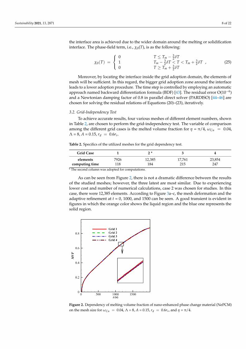
As can be seen from Figure 2, there is not a dramatic difference between the resultsof the studied meshes; however, the three latest are most similar. Due to experiencinglower cost and number of numerical calculations, case 2 was chosen for studies. In thiscase, there were 12,385 elements. According to Figure 3a–c, the mesh deformation and theadaptive refinement at t = 0, 1000, and 1500 can be seen. A good transient is evident infigures in which the orange color shows the liquid region and the blue one represents thesolid region.
Figure 2. Dependency of melting volume fraction of nano-enhanced phase change material (NePCM)on the mesh size for ωCu = 0.04, Λ = 8, A = 0.15, rd = 0.6rs, and η = π/4.

Sustainability 2021, 13, 2871 9 of 22
Figure 3. The adopted meshes and the mesh adaptations, corresponding to the grid case 2 when t isequal to (a): 0 s, (b): 1000 s, and (c): 1500 s.
3.3. Model Verification
It is necessary to examine the accuracy of the results of this study by comparing themwith the results of related literature. This includes both numerical and experimental investi-gations. The research of Kumar et al. [47] done experimentally is the first case of validation.The vertical walls of their study were imposed on the constant heat flux, and horizontalwalls were adiabatic. The present study’s results and those of [47] around the meltingfront at Ra = 1.4 × 10⁷, Pr = 0.0236, and Ste = 0.4 are demonstrated in Figure 4a. Here,Ra = ρgβ
(Th − Tf
)H3/αµ, Ste = CP
(Th − Tf
)/hs f , Pr = µ/ρα, and Fo = tα/H2
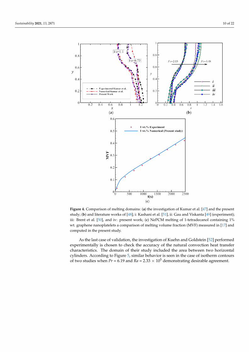
where H is the characteristic size, and α = k/(ρCp). A good agreement is seen between thegraphs of the melting front of both studies. Afterward, the study of Ref. [48] is anothercase of validation. The melting front of a base PCM (without any particle) and its meltingprocess inside a square cavity were the cases of their superior investigations. Two ver-tical walls with different constant temperatures (Th > Tc), and two adiabatic horizontalwalls were their main boundary conditions. The case of validation was selected for thenon-dimensional parameters of Fo. Ste = 0.002 and 0.01 when Ra = 1.25 × 10⁵ and Pr = 50.Moreover, as depicted in Figure 4b, the melting fronts obtained by the current model arecompared to the numerical results reported in [49,50]. According to Figure 4b, acceptableagreements are seen between the results of the current study and [49–51].
Li et al. [17] examined the melting of graphene nanoparticles-1-tetradecanol NePCMin a rectangular enclosure of height 2.5 cm and width 2.0 cm. The enclosure walls wereinsulated except a vertical wall which was heated with an isothermal temperature of47 ◦C. The initial NePCM temperature and the melting temperature were 36 ◦C and 37 ◦C,respectively. The melting process was investigated for 1% wt. Figure 4c compares thevariation of MVF during the melting process obtained numerically in the present studyand those measured in [17], which shows a good agreement.
Sustainability 2021, 13, 2871 10 of 22
Figure 4. Comparison of melting domains: (a) the investigation of Kumar et al. [47] and the presentstudy; (b) and literature works of [48]; i: Kashani et al. [51], ii: Gau and Viskanta [49] (experiment);iii: Brent et al. [50], and iv: present work; (c) NePCM melting of 1-tetradecanol containing 1%wt. graphene nanoplatelets a comparison of melting volume fraction (MVF) measured in [17] andcomputed in the present study.
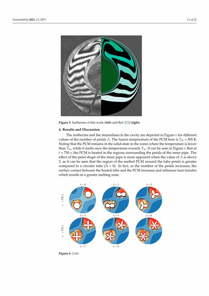
As the last case of validation, the investigation of Kuehn and Goldstein [52] performedexperimentally is chosen to check the accuracy of the natural convection heat transfercharacteristics. The domain of their study included the area between two horizontalcylinders. According to Figure 5, similar behavior is seen in the case of isotherm contoursof two studies when Pr = 6.19 and Ra = 2.33 × 10⁵ demonstrating desirable agreement.
Sustainability 2021, 13, 2871 11 of 22
Figure 5. Isotherms of this work (left) and Ref. [52] (right).
4. Results and Discussion
The isotherms and the streamlines in the cavity are depicted in Figure 6 for differentvalues of the number of petals Λ. The fusion temperature of the PCM here is Tm = 305 K.Noting that the PCM remains in the solid-state in the zones where the temperature is lowerthan Tm, while it melts once the temperature exceeds Tm. It can be seen in Figure 6 that att = 750 s, the PCM is heated in the regions surrounding the petals of the inner pipe. Theeffect of the petal shape of the inner pipe is more apparent when the value of Λ is above2, as it can be seen that the region of the melted PCM around the tube petals is greatercompared to a circular tube (Λ = 0). In fact, as the number of the petals increases, thesurface contact between the heated tube and the PCM increases and enhances heat transfer,which results in a greater melting zone.
Figure 6. Cont.

Sustainability 2021, 13, 2871 12 of 22
Figure 6. Effect of Λ on the isotherms at t = 750 s and when rd = 0.6rs, ωCu = 0.04, η = π/4,A = 0.15rs.
Figure 7 depicts the variations of the melted volume fraction MVF and the total storedenergy ES as functions of time. The trend of variation is the same for all the values of Λ,and a rise in both MVF and ES can be observed when Λ is increased. The case of an innercircular tube (Λ = 0) represents the minimum melted volume and stored energy, which isdue to the reduced heat transfer in that case compared to a petal cross-section.
Figure 7. The variation of melting volume fraction (MVF) (a) and ES (J/m) (b) based on the changein Λ when rd = 0.6rs, ωCu = 0.04, η = π/4, and A = 0.15rs.
The variation of the average charging power (ACP) as a function of the number ofpetals Λ is plotted in Figure 8. The ACP is the ratio of the stored energy to the time requiredfor full melting. It is, thus, a combination of the effects of MVF and ES. As MVF increaseswith Λ, the full melting time decreases. For this reason, it is clear that ACP increases with Λdue to the higher values of ES in that case, as discussed in Figure 7. Moreover, the increaseof ACP is for both latent and sensible heat, indicating that raising the number of petalsenhances heat transfer and PCM melting. A 45% increase in the total charging power canbe obtained when using an inner tube with 8 petals compared to a circular tube.
The effect of the petal amplitude A on the time evolution of the isotherms and thestreamlines is illustrated in Figure 9. At t = 500 s, the PCM heating is limited to the zonesurrounding the inner tube. As time goes, the zone of PCM melting increases in size, and itcan be seen that this zone is greater when A is raised. At t = 1500 s, around half of the cavityremains filled with solid PCM in the case of a circular tube (A = 0), while the amount ofmelted PCM is greater in the case of a petal-shaped cross-section. Similar to the effect of Λ,increasing A enlarges the contact zone between the inner heated-tube and the surroundingPCM, which intensifies heat transfer and boosts PCM melting.

Sustainability 2021, 13, 2871 13 of 22
Figure 8. The average charging power (kW/m) based on the change in Λ when rd = 0.6rs,ωCu = 0.04, η = π/4, and A = 0.15rs.
Figure 9. The effect of A on the isotherms at various charging times (rd = 0.6rs, ωCu = 0.04, η = π/4, Λ = 6).
The variations of MVF and ES as functions of time for various values of A are shown inFigure 10. It can be seen that at every instant, MVF and ES are greater when A is increasedand are minimum for A = 0. This indicates that the use of a petal-shaped inner tubeimproved PCM melting and increased the stored energy compared to a circular tube, andthat such improvement can be further augmented by employing a higher petal amplitude.Figure 11 depicts the variation of ACP for different values of A. The energy stored riseswhen A is increased. Simultaneously, the time required for full melting is reduced for

Sustainability 2021, 13, 2871 14 of 22
higher values of A. For this reason, the ACP shows greater values when A is increased.This result is due, as mentioned earlier, to the increased contact area between the PCMand the inner tube for higher A, which promotes heat transfer and enhances PCM melting.Raising A from 0.05rd to 0.15rd can increase the total ACP by 26%. Furthermore, the highestaverage charging power in latent and sensible heat power corresponds to 0.15rd.
Figure 10. The variation of melting volume fraction (MVF) (a) and ES (J/m) (b) based on the changein A when rd = 0.6rs, ωCu = 0.04, η = π/4, and Λ = 6.
Figure 11. The average charging power (ACP) (kW/m) based on the change in A when rd = 0.6rs,ωCu = 0.04, η = π/4, and Λ = 6.
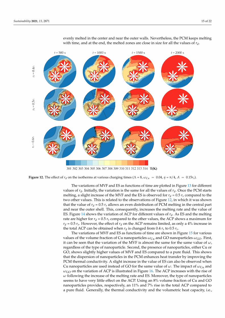
Figure 12 illustrates the streamlines and the isothermal contours for various values ofthe distance between the two branches of the inner pipe rd. A higher value of rd shifts theinner pipe branches toward the shell of the exchanger, while a lower value moves themtowards the center. For this reason, it can be seen that for lower rd, PCM melting startsmainly in the central region of the cavity, while melting occurs mostly near the outer wallwhen rd is increased. As time goes, the zone of PCM melting increases in size in all thecases while remaining relatively away from the shell for low rd. For t = 1000 s, it can be seenthat for rd = 0.4 rs, some PCM remains in the solid-state near the shell, while for rd = 0.6 rs,the PCM melts near the shell, but relatively more solid PCM remains in the central zone.The value of rd = 0.5 rs represents a balance between the two previous cases, as the PCM is
Sustainability 2021, 13, 2871 15 of 22
evenly melted in the center and near the outer walls. Nevertheless, the PCM keeps meltingwith time, and at the end, the melted zones are close in size for all the values of rd.
Figure 12. The effect of rd on the isotherms at various charging times (Λ = 8, ωCu = 0.04, η = π/4, A = 0.15rs).
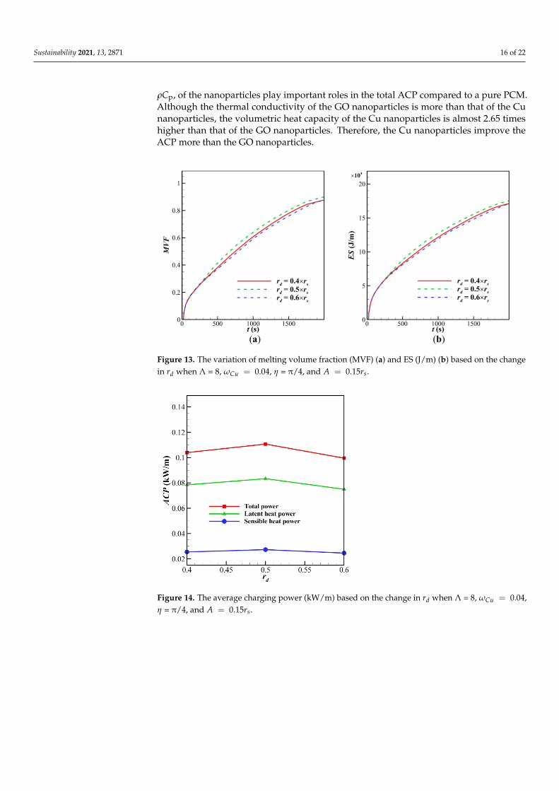
The variations of MVF and ES as functions of time are plotted in Figure 13 for differentvalues of rd. Initially, the variation is the same for all the values of rd. Once the PCM startsmelting, a slight increase of the MVF and the ES is observed for rd = 0.5 rs compared to thetwo other values. This is related to the observations of Figure 12, in which it was shownthat the value of rd = 0.5 rs allows an even distribution of PCM melting in the central partand near the outer shell. This, consequently, increases the melting rate and the value ofES. Figure 14 shows the variation of ACP for different values of rd. As ES and the meltingrate are higher for rd = 0.5 rs compared to the other values, the ACP shows a maximum forrd = 0.5 rs. However, the effect of rd on the ACP remains limited, as only a 4% increase inthe total ACP can be obtained when rd is changed from 0.4 rs to 0.5 rs.
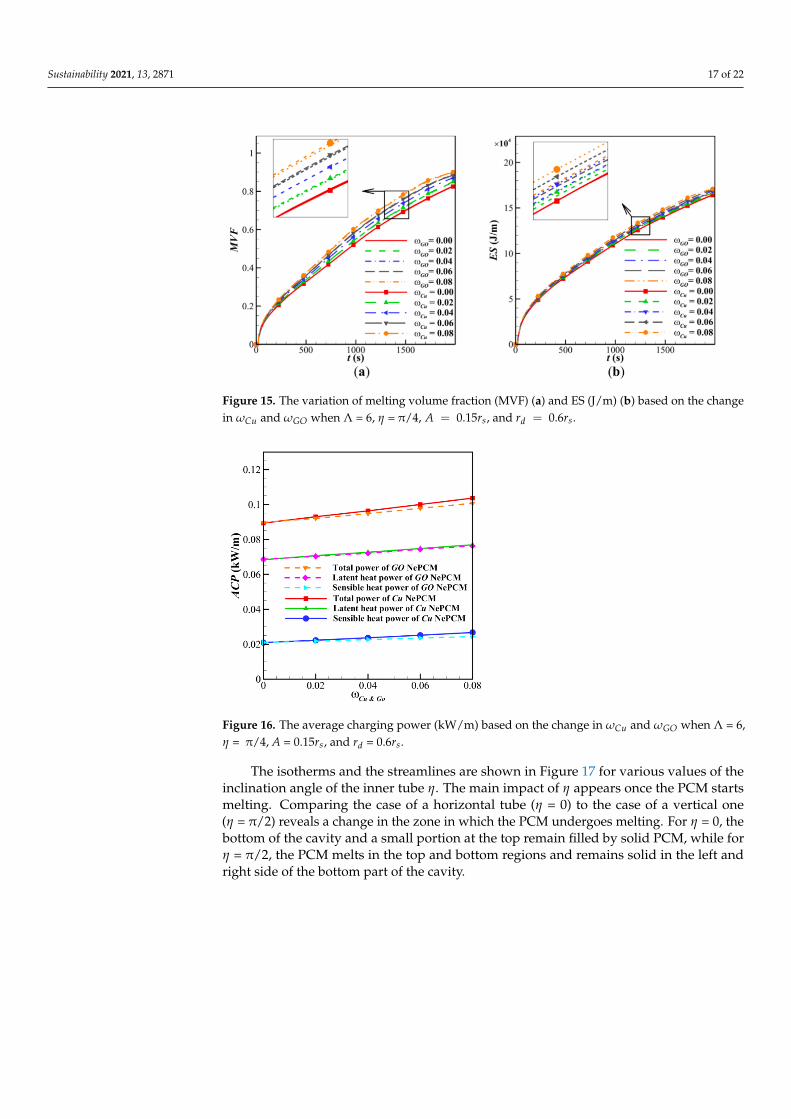
The variations of MVF and ES as functions of time are shown in Figure 15 for variousvalues of the volume fraction of Cu nanoparticles ωCu and GO nanoparticles ωGO. First,it can be seen that the variation of the MVF is almost the same for the same value of ω,regardless of the type of nanoparticle. Second, the presence of nanoparticles, either Cu orGO, shows slightly higher values of MVF and ES compared to a pure fluid. This showsthat the dispersion of nanoparticles in the PCM enhances heat transfer by improving thePCM thermal conductivity. A slight increase in the value of ES can also be observed whenCu nanoparticles are used instead of GO for the same value of ω. The impact of ωCu andωGO on the variation of ACP is illustrated in Figure 16. The ACP increases with the rise ofω following the increase of the melting rate and ES. Moreover, the type of nanoparticlesseems to have very little effect on the ACP. Using an 8% volume fraction of Cu and GOnanoparticles provides, respectively, an 11% and 7% rise in the total ACP compared toa pure fluid. Generally, the thermal conductivity and the volumetric heat capacity, i.e.,
Sustainability 2021, 13, 2871 16 of 22
ρCp, of the nanoparticles play important roles in the total ACP compared to a pure PCM.Although the thermal conductivity of the GO nanoparticles is more than that of the Cunanoparticles, the volumetric heat capacity of the Cu nanoparticles is almost 2.65 timeshigher than that of the GO nanoparticles. Therefore, the Cu nanoparticles improve theACP more than the GO nanoparticles.
Figure 13. The variation of melting volume fraction (MVF) (a) and ES (J/m) (b) based on the changein rd when Λ = 8, ωCu = 0.04, η = π/4, and A = 0.15rs.
Figure 14. The average charging power (kW/m) based on the change in rd when Λ = 8, ωCu = 0.04,η = π/4, and A = 0.15rs.
Sustainability 2021, 13, 2871 17 of 22
Figure 15. The variation of melting volume fraction (MVF) (a) and ES (J/m) (b) based on the changein ωCu and ωGO when Λ = 6, η = π/4, A = 0.15rs, and rd = 0.6rs.
Figure 16. The average charging power (kW/m) based on the change in ωCu and ωGO when Λ = 6,η = π/4, A = 0.15rs, and rd = 0.6rs.
The isotherms and the streamlines are shown in Figure 17 for various values of theinclination angle of the inner tube η. The main impact of η appears once the PCM startsmelting. Comparing the case of a horizontal tube (η = 0) to the case of a vertical one(η = π/2) reveals a change in the zone in which the PCM undergoes melting. For η = 0, thebottom of the cavity and a small portion at the top remain filled by solid PCM, while forη = π/2, the PCM melts in the top and bottom regions and remains solid in the left andright side of the bottom part of the cavity.

Sustainability 2021, 13, 2871 18 of 22
Figure 17. Effect of η on the isotherms at various charging times (Λ = 8, rd = 0.6rs, ωCu = 0.04, A = 0.15rs).
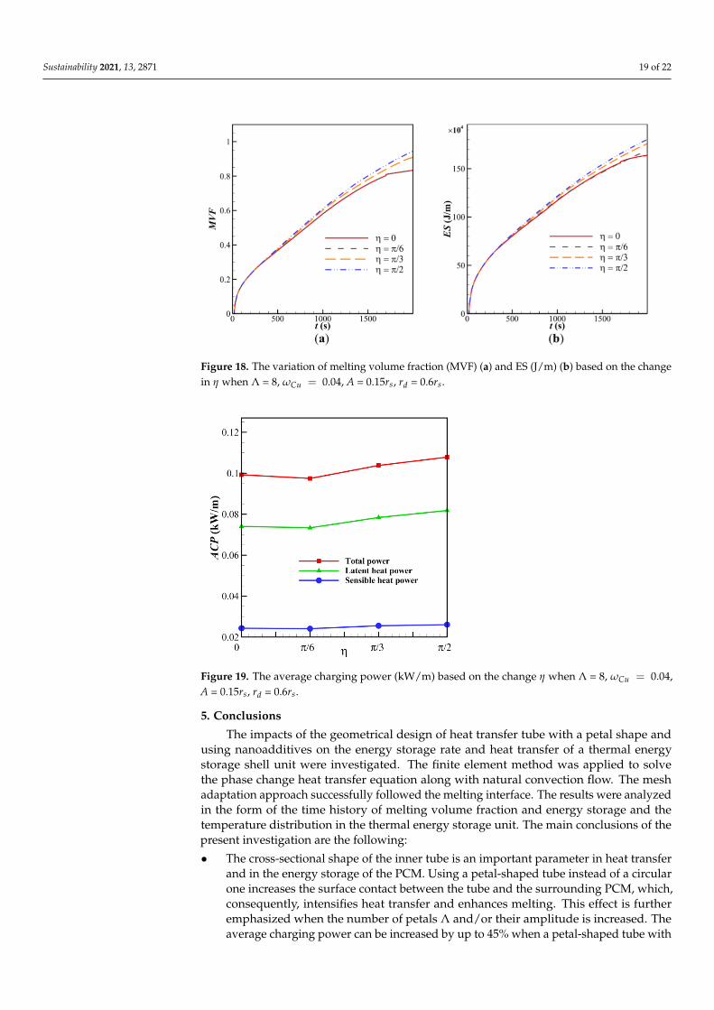
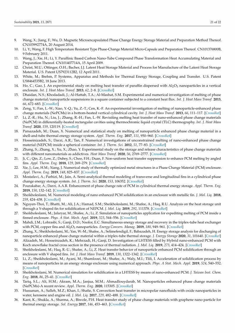
Figure 18 depicts the variations of MVF and ES as functions of time for differentvalues of η. It is shown that as time goes, the values of MVF and ES increase with η andare maximum for η = π/2. The gap between MVF and ES for η = π/2 and η = 0 becomesmore important in the last stages when an important amount of PCM is already melted. Inthat case, the convective effects are more intensified in the case of a vertical tube wherethe heated PCM at the bottom moves upwards. This aspect is not present in the case of ahorizontal tube as no PCM is heated in the bottom of the cavity and the convective effectsare relatively diminished. The variation of ACP is plotted in Figure 19 for various valuesof η. A higher ACP is obtained when η is raised, due to the increased melting rate andstored energy in that case. Using a vertical tube increases the total ACP by 5% compared toa horizontal one.
Sustainability 2021, 13, 2871 19 of 22
Figure 18. The variation of melting volume fraction (MVF) (a) and ES (J/m) (b) based on the changein η when Λ = 8, ωCu = 0.04, A = 0.15rs, rd = 0.6rs.
Figure 19. The average charging power (kW/m) based on the change η when Λ = 8, ωCu = 0.04,A = 0.15rs, rd = 0.6rs.
5. Conclusions
The impacts of the geometrical design of heat transfer tube with a petal shape andusing nanoadditives on the energy storage rate and heat transfer of a thermal energystorage shell unit were investigated. The finite element method was applied to solvethe phase change heat transfer equation along with natural convection flow. The meshadaptation approach successfully followed the melting interface. The results were analyzedin the form of the time history of melting volume fraction and energy storage and thetemperature distribution in the thermal energy storage unit. The main conclusions of thepresent investigation are the following:
• The cross-sectional shape of the inner tube is an important parameter in heat transferand in the energy storage of the PCM. Using a petal-shaped tube instead of a circularone increases the surface contact between the tube and the surrounding PCM, which,consequently, intensifies heat transfer and enhances melting. This effect is furtheremphasized when the number of petals Λ and/or their amplitude is increased. Theaverage charging power can be increased by up to 45% when a petal-shaped tube with

Sustainability 2021, 13, 2871 20 of 22
Λ = 8 is used instead of a circular one, and by 26% when the amplitude of the petals isincreased by 3 times.
• The distance between the two branches of the inner tube rd has a slight effect on thethermal and flow behaviors in the heat exchanger. Shifting the inner tube towardsthe center by reducing rd or towards the outer shell by raising rd limits the zone ofPCM melting and diminishes energy storage. The optimal value for PCM meltingand energy storage is rd = 0.4 rs. Nonetheless, the impact of 0.4 rd remains relativelylimited. A 4% reduction in the charging power is observed when rd is increased from0.4 rs to 0.5 rs.
• The inclination angle of the inner tube impacts the convective effects in the cavity.Using a vertical tube instead of a horizontal one intensifies the convection of the meltand increases the stored energy. As a consequence, a vertical inner tube leads to a 5%increase in the charging power compared to a horizontal one.
• Dispersing conductive nanoparticles in the PCM increases its thermal conductivity,which improves its thermal transfer properties. However, the type of nanoparticlesdispersed in the PCM has little effect on the melted volume and the stored energy, assimilar results are obtained when either Cu or GO nanoparticles are used, with a littleadvantage for Cu. On the other hand, raising the concentration of the nanoparticlesenhances PCM melting and the corresponding stored energy. Using an 8% nanopar-ticle, the charging power can be raised by 7% for GO and 11% for Cu nanoparticlesthan a pure PCM.
The present study aimed to provide a means to model and investigate the thermalperformance of NePCMs in a thermal energy storage design. The focus was mainly onthe thermal aspect of NePCMs. However, there are many unknowns and uncertainties inapplying NePCMs, such as durability, homogeneity, cost, and environmental aspects, thatcould be subject to future research.
Author Contributions: Conceptualization, S.A.M.M. and M.G.; methodology, S.A.M.M., A.H., O.Y.,P.T., W.Y., and M.G.; software, R.K.F., S.A.M.M., and M.G.; validation, S.A.M.M. and M.G.; formalanalysis, S.A.M.M., A.H., R.K.F., and O.Y.; investigation, S.A.M.M., R.K.F., A.H., P.T., O.Y., and W.Y.;resources, W.Y. and O.Y.; writing—original draft preparation, S.A.M.M., A.H., R.K.F., O.Y., P.T., W.Y.,and M.G.; writing—review and editing, S.A.M.M., A.H., O.Y., P.T., W.Y., and M.G.; visualization,R.K.F. and S.A.M.M.; supervision, M.G.; funding acquisition, W.Y., O.Y., and M.G. All authors haveread and agreed to the published version of the manuscript.
Funding: This research received no external funding.
Data Availability Statement: The data will be available on request.
Conflicts of Interest: The authors declare no conflict of interest.
References1. Nižetic, S.; Jurcevic, M.; Arıcı, M.; Arasu, A.V.; Xie, G. Nano-enhanced phase change materials and fluids in energy applications:
A review. Renew. Sustain. Energy Rev. 2020, 129, 109931. [CrossRef]2. Reddy, K.; Mudgal, V.; Mallick, T. Review of latent heat thermal energy storage for improved material stability and effective load
management. J. Energy Storage 2018, 15, 205–227. [CrossRef]3. Li, Z.; Ma, T.; Zhao, J.; Song, A.; Cheng, Y. Experimental study and performance analysis on solar photovoltaic panel integrated
with phase change material. Energy 2019, 178, 471–486. [CrossRef]4. Zhang, Y.; Zhou, G.; Lin, K.; Zhang, Q.; Di, H. Application of latent heat thermal energy storage in buildings: State-of-the-art and
outlook. Build. Environ. 2007, 42, 2197–2209. [CrossRef]5. Cui, Y.; Xie, J.; Liu, J.; Wang, J.; Chen, S. A review on phase change material application in building. Adv. Mech. Eng. 2017, 9.
[CrossRef]6. Kong, X.; Jie, P.; Yao, C.; Liu, Y. Experimental study on thermal performance of phase change material passive and active
combined using for building application in winter. Appl. Energy 2017, 206, 293–302. [CrossRef]7. Abdolmaleki, L.; Sadrameli, S.; Pirvaram, A. Application of environmental friendly and eutectic phase change materials for the
efficiency enhancement of household freezers. Renew. Energy 2020, 145, 233–241. [CrossRef]8. Liang, S.; Tian, C.; Zhu, Y.; Gu, Y.; Chen, K.; Wang, J. Phase-Change Energy-Storage Material Nanocapsule and Preparation
Method Thereof. CN104449590A, 25 March 2015.
Sustainability 2021, 13, 2871 21 of 22
9. Wang, X.; Jiang, F.; Wu, D. Magnetic Microencapsulated Phase Change Energy Storage Material and Preparation Method Thereof.CN103992774A, 20 August 2014.
10. Li, Y.; Wang, F. High Temperature Resistant Type Phase-Change Material Micro-Capsule and Preparation Thereof. CN101376800B,9 February 2011.
11. Wang, J.; Xie, H.; Li, Y. Paraffinic Based Carbon Nano-Tube Compound Phase Transformation Heat Accumulating Material andPreparation Thereof. CN101407714A, 15 April 2009.
12. Christ, M.U.; Ottinger, O.H.; Bacher, J.J. Latent Heat Storage Material and Process for Manufacture of the Latent Heat StorageMaterial. U.S. Patent US7923112B2, 12 April 2011.
13. White, M.; Brehm, P. Systems, Apparatus and Methods for Thermal Energy Storage, Coupling and Transfer. U.S. PatentUS8464535B2, 18 June 2013.
14. Ho, C.; Gao, J. An experimental study on melting heat transfer of paraffin dispersed with Al2O3 nanoparticles in a verticalenclosure. Int. J. Heat Mass Transf. 2013, 62, 2–8. [CrossRef]
15. Dhaidan, N.S.; Khodadadi, J.; Al-Hattab, T.A.; Al-Mashat, S.M. Experimental and numerical investigation of melting of phasechange material/nanoparticle suspensions in a square container subjected to a constant heat flux. Int. J. Heat Mass Transf. 2013,66, 672–683. [CrossRef]
16. Zeng, Y.; Fan, L.-W.; Xiao, Y.-Q.; Yu, Z.-T.; Cen, K.-F. An experimental investigation of melting of nanoparticle-enhanced phasechange materials (NePCMs) in a bottom-heated vertical cylindrical cavity. Int. J. Heat Mass Transf. 2013, 66, 111–117. [CrossRef]
17. Li, Z.-R.; Hu, N.; Liu, J.; Zhang, R.-H.; Fan, L.-W. Revisiting melting heat transfer of nano-enhanced phase change materials(NePCM) in differentially-heated rectangular cavities using thermochromic liquid crystal (TLC) thermography. Int. J. Heat MassTransf. 2020, 159, 120119. [CrossRef]
18. Parsazadeh, M.; Duan, X. Numerical and statistical study on melting of nanoparticle enhanced phase change material in ashell-and-tube thermal energy storage system. Appl. Therm. Eng. 2017, 111, 950–960. [CrossRef]
19. Hosseinizadeh, S.; Darzi, A.R.; Tan, F. Numerical investigations of unconstrained melting of nano-enhanced phase changematerial (NEPCM) inside a spherical container. Int. J. Therm. Sci. 2012, 51, 77–83. [CrossRef]
20. Zhang, S.; Zhang, X.; Xu, X.; Zhao, Y. Experimental study on the storage and release characteristics of phase change materialswith different nanomaterials as addictives. Heat Mass Transf. 2020, 56, 2769–2777. [CrossRef]
21. Ji, C.; Qin, Z.; Low, Z.; Dubey, S.; Choo, F.H.; Duan, F. Non-uniform heat transfer suppression to enhance PCM melting by angledfins. Appl. Therm. Eng. 2018, 129, 269–279. [CrossRef]
22. Xie, J.; Lee, H.M.; Xiang, J. Numerical study of thermally optimized metal structures in a Phase Change Material (PCM) enclosure.Appl. Therm. Eng. 2019, 148, 825–837. [CrossRef]
23. Mostafavi, A.; Parhizi, M.; Jain, A. Semi-analytical thermal modeling of transverse and longitudinal fins in a cylindrical phasechange energy storage system. Int. J. Therm. Sci. 2020, 153, 106352. [CrossRef]
24. Pourakabar, A.; Darzi, A.A.R. Enhancement of phase change rate of PCM in cylindrical thermal energy storage. Appl. Therm. Eng.2019, 150, 132–142. [CrossRef]
25. Sheikholeslami, M. Numerical modeling of nano enhanced PCM solidification in an enclosure with metallic fin. J. Mol. Liq. 2018,259, 424–438. [CrossRef]
26. Nguyen-Thoi, T.; Bhatti, M.; Ali, J.A.; Hamad, S.M.; Sheikholeslami, M.; Shafee, A.; Haq, R.U. Analysis on the heat storage unitthrough a Y-shaped fin for solidification of NEPCM. J. Mol. Liq. 2019, 292, 111378. [CrossRef]
27. Sheikholeslami, M.; Jafaryar, M.; Shafee, A.; Li, Z. Simulation of nanoparticles application for expediting melting of PCM inside afinned enclosure. Phys. A Stat. Mech. Appl. 2019, 523, 544–556. [CrossRef]
28. Mahdi, J.M.; Lohrasbi, S.; Ganji, D.D.; Nsofor, E.C. Simultaneous energy storage and recovery in the triplex-tube heat exchangerwith PCM, copper fins and Al2O3 nanoparticles. Energy Convers. Manag. 2019, 180, 949–961. [CrossRef]
29. Zhang, X.; Sheikholeslami, M.; Yan, W.-M.; Shafee, A.; Selimefendigil, F.; Babazadeh, H. Energy storage analysis for discharging ofnanoparticle enhanced phase change material within a triplex-tube thermal storage. J. Energy Storage 2020, 31, 101640. [CrossRef]
30. Alizadeh, M.; Hosseinzadeh, K.; Mehrzadi, H.; Ganji, D. Investigation of LHTESS filled by Hybrid nano-enhanced PCM withKoch snowflake fractal cross section in the presence of thermal radiation. J. Mol. Liq. 2019, 273, 414–424. [CrossRef]
31. Sheikholeslami, M.; Haq, R.-U.; Shafee, A.; Li, Z. Heat transfer behavior of nanoparticle enhanced PCM solidification through anenclosure with V shaped fins. Int. J. Heat Mass Transf. 2019, 130, 1322–1342. [CrossRef]
32. Li, Z.; Sheikholeslami, M.; Ayani, M.; Shamlooei, M.; Shafee, A.; Waly, M.I.; Tlili, I. Acceleration of solidification process bymeans of nanoparticles in an energy storage enclosure using numerical approach. Phys. A Stat. Mech. Appl. 2019, 524, 540–552.[CrossRef]
33. Sheikholeslami, M. Numerical simulation for solidification in a LHTESS by means of nano-enhanced PCM. J. Taiwan Inst. Chem.Eng. 2018, 86, 25–41. [CrossRef]
34. Tariq, S.L.; Ali, H.M.; Akram, M.A.; Janjua, M.M.; Ahmadlouydarab, M. Nanoparticles enhanced phase change materials(NePCMs)-A recent review. Appl. Therm. Eng. 2020, 115305. [CrossRef]
35. Hussanan, A.; Salleh, M.Z.; Khan, I.; Shafie, S. Convection heat transfer in micropolar nanofluids with oxide nanoparticles inwater, kerosene and engine oil. J. Mol. Liq. 2017, 229, 482–488. [CrossRef]
36. Kant, K.; Shukla, A.; Sharma, A.; Biwole, P.H. Heat transfer study of phase change materials with graphene nano particle forthermal energy storage. Sol. Energy 2017, 146, 453–463. [CrossRef]
Sustainability 2021, 13, 2871 22 of 22
37. Nield, D.A.; Bejan, A. Convection in Porous Media; Springer Science & Business Media: Berlin, Germany, 2006.38. Buongiorno, J. Convective transport in nanofluids. J. Heat Transf. 2006, 128, 240–250. [CrossRef]39. Sheikholeslami, M.; Shamlooei, M.; Moradi, R. Fe3O4-Ethylene glycol nanofluid forced convection inside a porous enclosure in
existence of Coulomb force. J. Mol. Liq. 2018, 249, 429–437. [CrossRef]40. Selvaraj, V.; Morri, B.; Nair, L.M.; Krishnan, H. Experimental investigation on the thermophysical properties of beryllium
oxide-based nanofluid and nano-enhanced phase change material. J. Therm. Anal. Calorim. 2019, 137, 1527–1536. [CrossRef]41. Reddy, J.N.; Gartling, D.K. The Finite Element Method in Heat Transfer and Fluid Dynamics; CRC Press: Boca Raton, FL, USA, 2010.42. Zienkiewicz, O.C.; Taylor, R.L.; Nithiarasu, P. The Finite Element Method for Fluid Dynamics; Elsevier: Amsterdam, The Netherlands,
2015; Volume 6.43. De Los Reyes, J.C.; González Andrade, S. A combined BDF-semismooth Newton approach for time-dependent Bingham flow.
Numer. Methods Partial Differ. Equ. 2012, 28, 834–860. [CrossRef]44. Schenk, O.; Gärtner, K. Solving unsymmetric sparse systems of linear equations with PARDISO. Future Gener. Comput. Syst. 2004,
20, 475–487. [CrossRef]45. Wriggers, P. Nonlinear Finite Element Methods; Springer Science & Business Media: Berlin, Germany, 2008.46. Verbosio, F.; De Coninck, A.; Kourounis, D.; Schenk, O. Enhancing the scalability of selected inversion factorization algorithms in
genomic prediction. J. Comput. Sci. 2017, 22, 99–108. [CrossRef]47. Kumar, L.; Manjunath, B.S.; Patel, R.J.; Markandeya, S.G.; Agrawal, R.G.; Agrawal, A.; Kashyap, Y.; Sarkar, P.S.; Sinha, A.; Iyer,
K.N.; et al. Experimental investigations on melting of lead in a cuboid with constant heat flux boundary condition using thermalneutron radiography. Int. J. Therm. Sci. 2012, 61, 15–27. [CrossRef]
48. Bertrand, O.; Binet, B.; Combeau, H.; Couturier, S.; Delannoy, Y.; Gobin, D.; Lacroix, M.; Le Quéré, P.; Médale, M.; Mencinger, J.;et al. Melting driven by natural convection A comparison exercise: First results. Int. J. Therm. Sci. 1999, 38, 5–26. [CrossRef]
49. Gau, C.; Viskanta, R. Melting and solidification of a pure metal on a vertical wall. J. Heat Transfer. 1986, 108, 174–181. [CrossRef]50. Brent, A.; Voller, V.R.; Reid, K. Enthalpy-porosity technique for modeling convection-diffusion phase change: Application to the
melting of a pure metal. Numer. Heat Transf. Part A Appl. 1988, 13, 297–318.51. Kashani, S.; Ranjbar, A.; Abdollahzadeh, M.; Sebti, S. Solidification of nano-enhanced phase change material (NEPCM) in a wavy
cavity. Heat Mass Transf. 2012, 48, 1155–1166. [CrossRef]52. Kuehn, T.H.; Goldstein, R.J. An experimental and theoretical study of natural convection in the annulus between horizontal
concentric cylinders. J. Fluid Mech. 1976, 74, 695. [CrossRef]