Refrigerator - Freezer Kühlschrank - Gefrierschrank Frigorifer
Upload
khangminh22Category
view
0download
0
www.ijsetr.com
ISSN 2319-8885
Vol.04,Issue.40,
October-2015,
Pages:8763-8769
Copyright @ 2015 IJSETR. All rights reserved.
Effect of Sub-cooling on Domestic Refrigerator Operated with LPG As Refrigerant K. NEELAKANTA
1, G. MARUTHI PRASAD YADAV
2
Abstract: Now-a-days R134a is used as a replacement for R12 in Domestic Refrigerators. Because it is a globally accepted
refrigerant with Zero Ozone Depletion Potential (ODP) and Global Warming Potential (GWP) of 1300. Recent investigations
shows that Liquefied Petroleum Gas (LPG) which is inexpensive, readily available in the market with Zero ODP and Negligible
GWP can be used an alternative refrigerant to R134a in Domestic Refrigerators. In the present work performance comparison
between R134a and LPG has been carried out. For this purpose the Domestic Refrigerator which is originally manufactured to
work with R134a is used. In addition to this, sub-cooling of Vapour Compression Refrigeration System (VCRS) also has been
carried out by providing small shell and tube heat exchanger in the suction line of Refrigerator. Here, sub-cooling of liquid
refrigerant at the condenser outlet is done with the help of vapour refrigerant coming from the evaporator. The experimental data
so obtained has been analysed and results are presented in the project.
Keywords:Vapour Compression Refrigeration System(VCRS), Ozone DepletionPotential(ODP), Liquefied Petroleum Gas(LPG).
I. INTRODUCTION
A. Introduction to Refrigeration
Refrigeration is defined as “the process of cooling of
bodies or fluids to temperatures lower than those available in
the surroundings at a particular time and place”. It should be
kept in mind that refrigeration is not same as “cooling”, even
though both the terms imply a decrease in temperature. In
general, cooling is a heat transfer process down a temperature
gradient; it can be a natural, spontaneous process or an
artificial process. However, refrigeration is not a spontaneous
process, as it requires expenditure of energy (or availability).
Thus cooling of a hot cup of coffee is a spontaneous cooling
process (not a refrigeration process), while converting a glass
of water from room temperature to say, a block of ice, is a
refrigeration process (non-spontaneous). “All refrigeration
processes involve cooling, but all cooling processes need not
involve refrigeration”. Refrigeration is a much more difficult
process than heating; this is in accordance with the second
law of thermodynamics. According to second law of
Thermodynamics, Removal of heat from a body at lower
temperature is possible only with the help of an external
agency. A refrigerator as shown in Fig.1 is a reversed heat
engine which either cool or maintain the temperature of a
body (T1) lower than the atmospheric temperature (Ta).This is
done by extracting the heat (Q1) from a cold body and
delivering it to a hot body (Q2). In doing so, work WR is
required to be done on the system. According to First Law of
Thermodynamics,
(1)
The Performance of a refrigerator is expressed by the ratio
of amount of heat taken from the cold body (Q1) to the
amount of work required to be done on the system(WR).This
ratio is called as coefficient of performance. Mathematically,
coefficient of performance of a refrigerator,
(2)
Fig.1. Refrigerator.
II. REFRIGERANTS
R134a is also known as Tetrafluoroethane (CF3CH2F)
from the family of HFC refrigerant. With the discovery of the
damaging effect of CFCs and HCFCs refrigerants to the
ozone layer, the HFC family of refrigerant has been widely
used as their replacement. It is now being used as a
replacement for R-12 CFC refrigerant in the area of
centrifugal, rotary screw, scroll and reciprocating
compressors. It is safe for normal handling as it is non-toxic,
non-flammable and non-corrosive. Currently it is also being
widely used in the air conditioning system in newer
automotive vehicles. The manufacturing industry uses it in
plastic foam blowing. Pharmaceuticals industry uses it as a
propellant. It exists in gas form when expose to the
environment as the boiling temperature is -14.9°F or -26.1°C.
K. NEELAKANTA, G. MARUTHI PRASAD YADAV
International Journal of Scientific Engineering and Technology Research
Volume.04, IssueNo.40, October-2015, Pages: 8763--8769
This refrigerant is not 100% compatible with the lubricants
and mineral-based refrigerant currently used in R-12. Design
changes to the condenser and evaporator need to be done to
use this refrigerant. The use of smaller hoses and 30%
increase in control pressure regulations also have to be done
to the system.
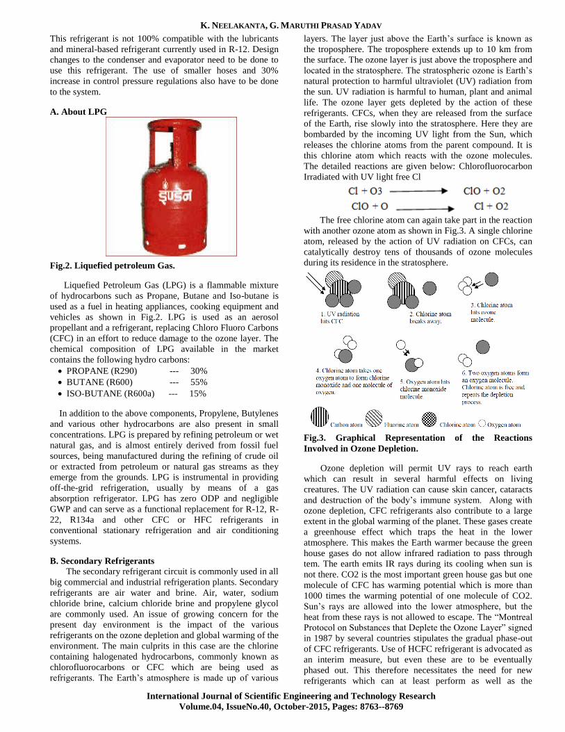
A. About LPG
Fig.2. Liquefied petroleum Gas.
Liquefied Petroleum Gas (LPG) is a flammable mixture
of hydrocarbons such as Propane, Butane and Iso-butane is
used as a fuel in heating appliances, cooking equipment and
vehicles as shown in Fig.2. LPG is used as an aerosol
propellant and a refrigerant, replacing Chloro Fluoro Carbons
(CFC) in an effort to reduce damage to the ozone layer. The
chemical composition of LPG available in the market
contains the following hydro carbons:
PROPANE (R290) --- 30%
BUTANE (R600) --- 55%
ISO-BUTANE (R600a) --- 15%
In addition to the above components, Propylene, Butylenes
and various other hydrocarbons are also present in small
concentrations. LPG is prepared by refining petroleum or wet
natural gas, and is almost entirely derived from fossil fuel
sources, being manufactured during the refining of crude oil
or extracted from petroleum or natural gas streams as they
emerge from the grounds. LPG is instrumental in providing
off-the-grid refrigeration, usually by means of a gas
absorption refrigerator. LPG has zero ODP and negligible
GWP and can serve as a functional replacement for R-12, R-
22, R134a and other CFC or HFC refrigerants in
conventional stationary refrigeration and air conditioning
systems.
B. Secondary Refrigerants
The secondary refrigerant circuit is commonly used in all
big commercial and industrial refrigeration plants. Secondary
refrigerants are air water and brine. Air, water, sodium
chloride brine, calcium chloride brine and propylene glycol
are commonly used. An issue of growing concern for the
present day environment is the impact of the various
refrigerants on the ozone depletion and global warming of the
environment. The main culprits in this case are the chlorine
containing halogenated hydrocarbons, commonly known as
chlorofluorocarbons or CFC which are being used as
refrigerants. The Earth‟s atmosphere is made up of various
layers. The layer just above the Earth‟s surface is known as
the troposphere. The troposphere extends up to 10 km from
the surface. The ozone layer is just above the troposphere and
located in the stratosphere. The stratospheric ozone is Earth‟s
natural protection to harmful ultraviolet (UV) radiation from
the sun. UV radiation is harmful to human, plant and animal
life. The ozone layer gets depleted by the action of these
refrigerants. CFCs, when they are released from the surface
of the Earth, rise slowly into the stratosphere. Here they are
bombarded by the incoming UV light from the Sun, which
releases the chlorine atoms from the parent compound. It is
this chlorine atom which reacts with the ozone molecules.
The detailed reactions are given below: Chlorofluorocarbon Irradiated with UV light free Cl
The free chlorine atom can again take part in the reaction
with another ozone atom as shown in Fig.3. A single chlorine
atom, released by the action of UV radiation on CFCs, can
catalytically destroy tens of thousands of ozone molecules
during its residence in the stratosphere.
Fig.3. Graphical Representation of the Reactions
Involved in Ozone Depletion.
Ozone depletion will permit UV rays to reach earth
which can result in several harmful effects on living
creatures. The UV radiation can cause skin cancer, cataracts
and destruction of the body‟s immune system. Along with
ozone depletion, CFC refrigerants also contribute to a large
extent in the global warming of the planet. These gases create
a greenhouse effect which traps the heat in the lower
atmosphere. This makes the Earth warmer because the green
house gases do not allow infrared radiation to pass through
tem. The earth emits IR rays during its cooling when sun is
not there. CO2 is the most important green house gas but one
molecule of CFC has warming potential which is more than
1000 times the warming potential of one molecule of CO2.
Sun‟s rays are allowed into the lower atmosphere, but the
heat from these rays is not allowed to escape. The “Montreal
Protocol on Substances that Deplete the Ozone Layer” signed
in 1987 by several countries stipulates the gradual phase-out
of CFC refrigerants. Use of HCFC refrigerant is advocated as
an interim measure, but even these are to be eventually
phased out. This therefore necessitates the need for new
refrigerants which can at least perform as well as the
Effect of Sub-cooling on Domestic Refrigerator Operated with LPG as Refrigerant
International Journal of Scientific Engineering and Technology Research
Volume.04, IssueNo.40, October-2015, Pages: 8763-8769
refrigerants they replace without harming the atmosphere.
Based on this requirement, R134a emerges as the refrigerant
of the future.
III. SUB-COOLING OF VCRS
In actual refrigeration cycles, the temperature of the heat
sink will be several degrees lower than the condensing
temperature to facilitate heat transfer. Hence it is possible to
cool the refrigerant liquid in the condenser to a few degrees
lower than the condensing temperature by adding extra area
for heat transfer. In such a case, the exit condition of the
condenser will be in the sub cooled liquid region. Hence this
process is known as subcooling. Similarly, the temperature of
heat source will be a few degrees higher than the evaporator
temperature; hence the vapour at the exit of the evaporator
can be superheated by a few degrees. If the superheating of
refrigerant takes place due to heat transfer with the
refrigerated space (low temperature heat source) then it is
called as useful superheating as it increases the refrigeration
effect. On the other hand, it is possible for the refrigerant
vapour to become superheated by exchanging heat with the
surroundings as it flows through the connecting pipelines.
Such a superheating is called as useless superheating as it
does not increase refrigeration effect. Sub cooling is
beneficial as it increases the refrigeration effect by reducing
the throttling loss at no additional specific work input. Also
subcooling ensures that only liquid enters into the throttling
device leading to its efficient operation. The following are
the methods of Sub-Cooling the liquid refrigerant in Vapour
Compression Refrigeration System:
Sub-Cooling of Liquid Refrigerant by using Vapour
Refrigerant
Sub-Cooling of Liquid Refrigerant by using Low
Temperature Liquid Refrigerant
Sub-Cooling of Liquid Refrigerant by External Source.
IV. EXPERIMENTAL SETUP & PROCEDURE
A. Pressure Gauges
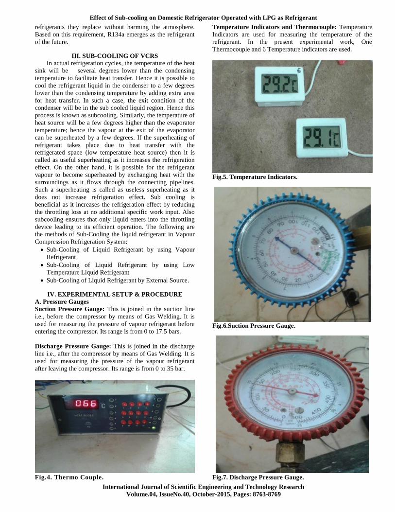
Suction Pressure Gauge: This is joined in the suction line
i.e., before the compressor by means of Gas Welding. It is
used for measuring the pressure of vapour refrigerant before
entering the compressor. Its range is from 0 to 17.5 bars.
Discharge Pressure Gauge: This is joined in the discharge
line i.e., after the compressor by means of Gas Welding. It is
used for measuring the pressure of the vapour refrigerant
after leaving the compressor. Its range is from 0 to 35 bar.
Fig.4. Thermo Couple.
Temperature Indicators and Thermocouple: Temperature
Indicators are used for measuring the temperature of the
refrigerant. In the present experimental work, One
Thermocouple and 6 Temperature indicators are used.
Fig.5. Temperature Indicators.
Fig.6.Suction Pressure Gauge.
Fig.7. Discharge Pressure Gauge.

K. NEELAKANTA, G. MARUTHI PRASAD YADAV
International Journal of Scientific Engineering and Technology Research
Volume.04, IssueNo.40, October-2015, Pages: 8763--8769
The schematic line diagram for charging is shown in the
figure. It is necessary to remove the air from the refrigeration
unit before charging. First the valve V2 is closed and pressure
gauges P2, vacuum gauge V are fitted as shown in the figure.
The valve V5 is also closed and valves V1 and V3 are opened,
the motor is started. Thus the air from the condenser, receiver
and evaporator is sucked through the valve V1 and it is
discharged in to the atmosphere through the valve V6 after
compressing in to the compressor. The vacuum gauge V
indicates sufficiently low vacuum when most of the air is
removed from the system. The vacuum reading should be 74
to 75 cm of Hg. If the vacuum is retained for above an hour it
may be concluded that the system is free from air. After
removing the air, the compressor is stopped and the valves
V1 and V6 are closed and valves V5, V2 and V7 of the
refrigerant cylinder are opened and then the compressor is
started. Whenever sufficient quantity of refrigerant is taken in
to system which will be noted on the spring balance as shown
in the figure, the compressor is stopped. The valves V7 and
V5 are closed and valve V1 is opened. The refrigerant
cylinder is disconnected from the system. The Pressure
gauges fitted are used to note the pressure during charging
the system as shown in Fig.8.
Fig.8. Charging of Refrigeration System.
B. Charging of Liquefied Petroleum Gas (LPG) in to
Domestic Refrigerator
After flushing the system with pressurized nitrogen gas, it
is charged with Liquefied Petroleum Gas (LPG) following
the same procedure as that of R134a. Here, LPG is first
transferred from Cylinder used in houses to small cylinder
(empty refrigerant cylinder) as shown in the fig.9.
With the help of weighing machine it is then
transferred from small cylinder in to the refrigerator
as shown in the fig.10.
With the help of Temperature Indicators and
Pressure gauges, readings are noted and tabulated.
Fig.9. Transfer of LPG.
Fig.10. Charging of LPG.
Preparation of Heat Exchanger: In Vapour Compression
Refrigeration System, Sub Cooling of liquid refrigerant by
Vapour Refrigerant has been carried out by providing a small
heat exchanger at the condenser outlet. In the present
experimental work, a small shell and tube heat exchanger is
provided for attaining the sub cooling. A Heat Exchanger is a
device used to exchange heat from one fluid to the another
fluid. A small shell and tube heat exchanger is prepared with
the following dimensions:
Diameter of the shell = 1/2” = 12.7 mm
Length of the shell = 1 ft = 12” = 304.8 mm
Diameter of the tube = 6.5 mm
Length of the tube = 315 mm
Material used for Heat Exchanger = Copper
Effect of Sub-cooling on Domestic Refrigerator Operated with LPG as Refrigerant
International Journal of Scientific Engineering and Technology Research
Volume.04, IssueNo.40, October-2015, Pages: 8763-8769
By using 1/4” Drill bit two holes are provided at the top
and bottom of the shell near the ends. These holes are welded
with two pipes (tubes of 6.5mm dia and 5mm length) by
means of Gas Welding. Tube is inserted in to the shell by
means of gas welding process. The actual diagram of the heat
exchanger prepared above is shown in the fig.11.
Fig.11. Shell and Tube Heat Exchanger.
Fixation of Heat Exchanger in to the Refrigerator: The
Heat Exchanger prepared above is fitted to the Domestic
Refrigerator of capacity 165 liters. By means of gas welding
i.e., with the help of Butane Gas, Heat Exchanger is
incorporated at the junction of evaporator and condenser
outlets as shown in the fig.12.
Fig.12. Heat Exchanger Fitted to the Refrigerator.
After fixation of Heat Exchanger to the Refrigerator,
Foam Insulation is provided to the heat exchanger to
reduce the heat losses to the environment.
Again LPG is charged in to the Refrigerator
following the same procedure as that of R134a
charging.
With the help of Temperature Indicators and
Pressure Gauges readings are noted and tabulated.
The calculations have been carried out for the values
noted from the above experiments under No Load
and Load conditions.
V. RESULTS AND DISCUSSIONS
An Experimental Investigation has been carried out with
the experimental setup fabricated for the present project work
and the data has been systematically recorded by operating
the Vapour Compression Refrigeration System (VCRS) first
with R134a and later with Liquefied Petroleum Gas (LPG)
without subcooling and with subcooling. The temperature of
Refrigerant at 7 different locations and pressures at two
points (before and after the compressor) in the system has
been recorded.
A. Graphs The data shown in the tabular columns has been carefully
analyzed and the important calculated parameters are
presented in the following graphs:
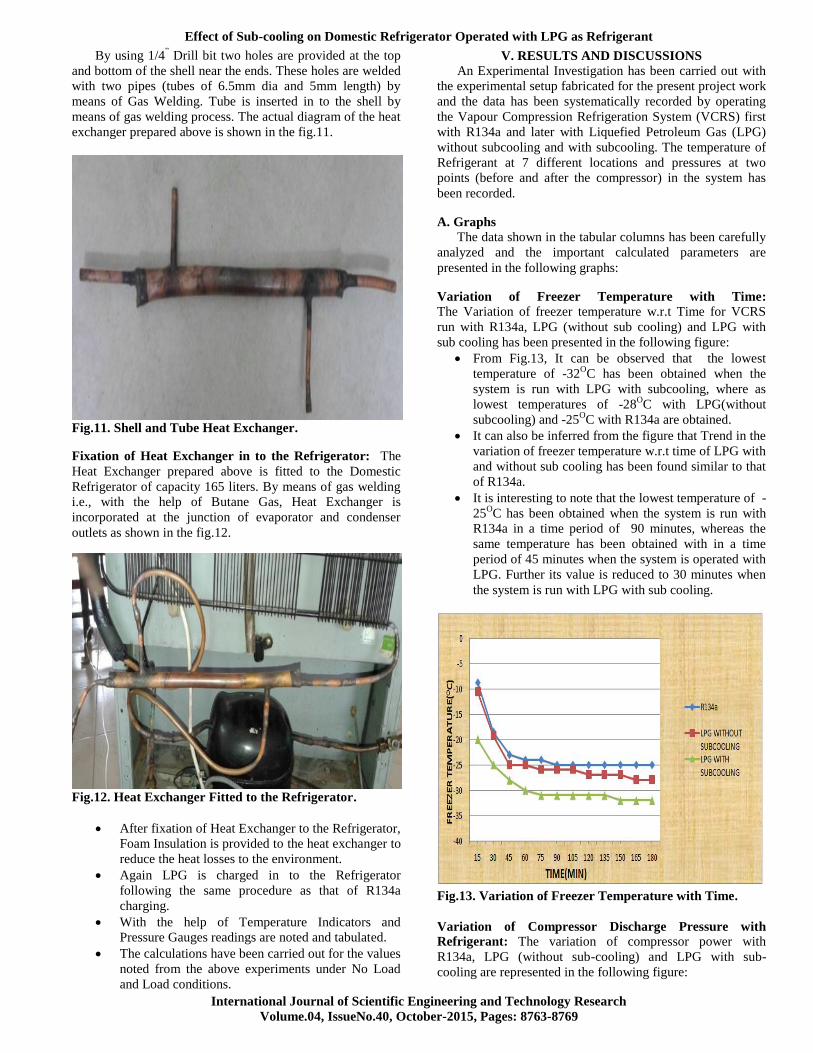
Variation of Freezer Temperature with Time: The Variation of freezer temperature w.r.t Time for VCRS
run with R134a, LPG (without sub cooling) and LPG with
sub cooling has been presented in the following figure:
From Fig.13, It can be observed that the lowest
temperature of -32OC has been obtained when the
system is run with LPG with subcooling, where as
lowest temperatures of -28OC with LPG(without
subcooling) and -25OC with R134a are obtained.
It can also be inferred from the figure that Trend in the
variation of freezer temperature w.r.t time of LPG with
and without sub cooling has been found similar to that
of R134a.
It is interesting to note that the lowest temperature of -
25OC has been obtained when the system is run with
R134a in a time period of 90 minutes, whereas the
same temperature has been obtained with in a time
period of 45 minutes when the system is operated with
LPG. Further its value is reduced to 30 minutes when
the system is run with LPG with sub cooling.
Fig.13. Variation of Freezer Temperature with Time.
Variation of Compressor Discharge Pressure with
Refrigerant: The variation of compressor power with
R134a, LPG (without sub-cooling) and LPG with sub-
cooling are represented in the following figure:

K. NEELAKANTA, G. MARUTHI PRASAD YADAV
International Journal of Scientific Engineering and Technology Research
Volume.04, IssueNo.40, October-2015, Pages: 8763--8769
Fig.14. Variation of Compressor Discharge Pressure with
R134a, LPG and LPG with Sub Cooling.
From fig.14, it can be found that Compressor Discharge
Pressure of the system run with LPG is 5% less than that
of with R134a.This is because of more specific volume
of LPG as compared to that of R134a.
It can also be seen that there is 17% drop in Compressor
Discharge Pressure of the system operated with LPG
with Sub Cooling.
Variation of COP of the system with Load and No Load
Conditions: The variation of COP of the system run with
R134a, LPG and LPG with sub cooling under Load and No
Load conditions has been presented in the following
figure:
Fig.15. Variation of COP with Load & No Load
conditions.
From fig.15, it can be inferred that COP of the system
run with LPG is 20% more than that of with R134a.This
is because of increase in Refrigerating Effect for LPG as
compared to that of R134a.
It can also be seen that there is 1.6% increase in COP of
the system operated with LPG with Sub Cooling.
It can be also be inferred that there is a slight increase in
the value of COP of the system under Load as compared
to that with No Load for all the above three cases
(R134a, LPG & LPG with Sub Cooling). This increase
in COP is due to the increase in Refrigerating Effect with
Load.
It can also be concluded that along with Refrigerating
Effect there is increase in Work of Compression,
because of increase in discharge pressure. But increase
in Refrigerating Effect is slightly more as compared to
increase in Work of Compression.
Comparison of mass flow rates for R134a, LPG and LPG
with Sub Cooling: The comparison of mass flow rates of
VCRS operated with R134a, LPG (without sub cooling) and
LPG with sub cooling are represented in the following figure:
1.288
0.652 0.627
0
0.2
0.4
0.6
0.8
1
1.2
1.4
REFRIGERANT
MA
SS F
LOW
RA
TE(k
g/m
in)
R134a
LPG WITHOUT SUBCOOLING
LPG WITH SUBCOOLING
Fig.16. Comparison of mass flow rates for R134a, LPG
and LPG with Sub Cooling.
From fig.16, it can be observed that mass flow rate of the
refrigerant is reduced to approximately 50% when the
system is operated with LPG as compared to that of
R134a.This reduction is due to increase in Refrigerating
Effect as the latent heat of vaporization of LPG is more
than that of R134a.
It can also be seen from the above graph that mass flow
rate of the refrigerant is nearly same when the system is
operated with LPG without sub cooling and LPG with
sub cooling.
Variation of Compressor Power with R134a, LPG and
LPG with Sub Cooling: The variation of compressor power
with R134a, LPG (without subcooling) and LPG with
subcooling are represented in the following figure:
From fig.17, it can be concluded that Compressor Power
is reduced by 17% when the System is operated with
LPG as compared to that of R134a. This is because of
decrease in mass flow rate of the refrigerant.
It can also be seen from the above graph that compressor
power is still reduced by 1.4% when the system is
operated with LPG with subcooling.

Effect of Sub-cooling on Domestic Refrigerator Operated with LPG as Refrigerant
International Journal of Scientific Engineering and Technology Research
Volume.04, IssueNo.40, October-2015, Pages: 8763-8769
Fig.17. Variation of Compressor Power with R134a, LPG
and LPG with sub cooling.
Variation of Pull Down Time with R134a, LPG and LPG
with Sub Cooling: The variation of Pull down Time with
R134a, LPG (without subcooling) and LPG with subcooling
are represented in the following fig.18:
26
22 20
0
5
10
15
20
25
30
REFRIGERANT
PU
LL D
OW
N T
IME(
MIN
)
R134a
LPG WITHOUT SUBCOOLING
LPG WITH SUBCOOLING
Fig.18. Variation of Pull Down Time with R134a, LPG
and LPG with Sub Cooling.
The time taken by the Refrigerator Cabinet to reach +70C
from atmospheric temperature.
VI. CONCLUSION
The following conclusions are obtained from the present
experimental work carried out: The Coefficient of
Performance (COP) of Vapour Compression Refrigeration
System (VCRS) run with Liquefied Petroleum Gas (LPG) is
20% more than that of the system run with R134a. Further an
additional improvement in COP of 1.6%, when the system is
operated with LPG with Sub Cooling. The present project
work has successfully retrofitted in the VCRS (R134a) run
with LPG. The lowest freezer temperature has been lowered
from -25OC (with R134a) to -32
OC by operating the system
with LPG with sub-cooling. The time taken for achieving the
lowest freezer temperature of -25OC is 90 minutes in case of
R134a, whereas with LPG with sub-cooling it has taken only
30min to achieve this temperature.
VII. REFERENCES
[1]. A Text book of Refrigeration and Air Conditioning by
Domkundwar and Domkundwar.
[2]. A Text book of Refrigeration and Air Conditioning by
R.S. Khurmi and J.K.Gupta.
[3]. C.P.Arora, „Refrigeration and Air Conditioning‟. Tata
McGraw Hill Publishing Company Ltd.,1981.
[4]. W.F. Stoecker, „Refrigeration and Air Conditioning‟.
McGraw Hill Book Company, 1982.
[5]. Bilal A. Akash, Salem A. Said, ―Assessment of LPG as
a possible alternative to R-12 in domestic refrigerators/,
Energy Conversion and Management, Volume 44, Issue 3,
February 2003, Pages 381-388.
[6]. M.A. Hammad, M.A. Alsaad, The Application of
propane/butane mixture for domestic refrigerators, Applied
Thermal Engineering 18 (1998) 911–918.
[7]. Fatouh, M., Kafafy, M.E., Experimental Evaluation of a
Domestic Refrigerator Working with LPG, Applied Thermal
Engineering, 26 (2006), pp. 1593-1603.
[8]. Sanjeev singh punia & Jagdev singh, Experimental
investigation on the performance of coiled adiabatic
Capillary tube with lpg as refrigerant, Department of
Mechanical Engineering, Beant College of Engineering
and Technology, Gurdaspur, Punjab 143521, India.
[9]. Ankush Sharma & Jagdev Singh, Experimental
Investigation of Refrigerant Flow rate with spirally coiled
adiabatic capillary tube in vapour compression refrigeration
cycle using eco friendly refrigerant/International Journal of
Mechanical and Production Engineering Research &
Development (IJMPERD), ISSN 2249-6890 Vol.3,Issue 1,
Mar 2013,85-94.
[10]. Mohanraj, S. Jayaraj, C. Muraleedharan and P.
Chandrasekar Experimental investigation of R290/R600a
mixture as an alternative to R134a in a domestic
refrigerator/, International Journal of Thermal Sciences,
Volume 48, Issue 5, May 2009, Pages 1036-1042.
Author’s Profile:
K.Neelakanta presently pursuing M.Tech in department of
Mechanical Engineering from St. Johns College of
Engineering & Technology Yerrakota, Yemmiganur,
Kurnool, Andhra Pradesh, India.
Email: [email protected].
G.Maruthi Prasad Yadav Currently Working as Associate
Professor in department of Mechanical Engineering from St.
Johns College of Engineering & Technology Yerrakota,
Yemmiganur, Kurnool, Andhra Pradesh, India. Email:
Copyright © 2022 FDOKUMEN