
Effect of Sub-cooling on Domestic Refrigerator Operated with ...
Upload
khangminh22Category
view
0download
0
energies
Article
Real Air-Conditioning Performance of Ejector Refrigerator BasedAir-Conditioner Powered by Low Temperature Heat Source
Tongchana Thongtip 1 and Natthawut Ruangtrakoon 2,*
�����������������
Citation: Thongtip, T.; Ruangtrakoon,
N. Real Air-Conditioning Performance
of Ejector Refrigerator Based
Air-Conditioner Powered by Low
Temperature Heat Source. Energies
2021, 14, 711. https://doi.org/
10.3390/en14030711
Received: 8 December 2020
Accepted: 8 January 2021
Published: 30 January 2021
Publisher’s Note: MDPI stays neu-
tral with regard to jurisdictional clai-
ms in published maps and institutio-
nal affiliations.
Copyright: © 2021 by the authors. Li-
censee MDPI, Basel, Switzerland.
This article is an open access article
distributed under the terms and con-
ditions of the Creative Commons At-
tribution (CC BY) license (https://
creativecommons.org/licenses/by/
4.0/).
1 Thermal and Fluid Laboratory (TFL), Department of Teacher Training in Mechanical Engineering,King Mongkut’s University of Technology North Bangkok, 1518, Bang Sue, Bangkok 10800, Thailand;[email protected]
2 Department of Mechanical Engineering, School of Engineering, King Mongkut’s Institute of TechnologyLadkrabang, Bangkok 10520, Thailand
* Correspondence: [email protected]; Tel.: +66-2329-8350#1
Abstract: In this present work, the air-conditioning test performance of an ejector refrigerator-basedair-conditioner (ERAC) was proposed. The ERAC was operated as the water chiller to produce thecooling load up to 4.5 kW. The chilled water temperature was later supplied to the fan-coil unit forproducing the thermal comfort condition. The cooling water used to cool the condenser was achievedfrom the cooling tower which was operated under the hot and humid ambient. This is to demonstratethe feasibility of using the ERAC in real working conditions. The cooling load supplied to the air-conditioned space was applied by the air heater. The ERAC could efficiently be operated to producethe thermal comfort condition which was driven by the hot water temperature (Thot) of 90–98 ◦C.The system performance could vary with the heat source temperatures, cooling load, primary nozzle,and air-conditioned space temperature. The optimal performance was determined when varying theThot, and, hence, the optimal Thot was indicated. The optimal Thot varied significantly with variationsin the working condition. The test results demonstrated high potential to further using the ejectorrefrigeration system in the actual air conditioning application.
Keywords: ejector refrigeration system; air-conditioning; thermal comfort; low grade heat utilization
1. Introduction
For many years, the topic of energy savings, especially for electricity consumption inbuildings, industries or even households, has been widely discussed in many aspects. Oneof the major sources of energy consumption (in the form of electricity) is air conditioningand refrigeration systems. Additionally, such systems are widely used in many coolingapplications from large scale to small scale in industries. Currently, many solutions havebeen proposed to reduce the electricity consumption in air-conditioning applications Zhuand Jiang [1], Fong et al. [2], Sánchez et al. [3], Xia et al. [4]. Most of them concentratedon the performance improvement of the vapour compression refrigeration system (VCR)which is the most extensively used refrigeration method to produce the cooling produc-tion under various applications. However, even though many advancement researches,Lin et al. [5], Jeon et al. [6], Pottker et al. [7], Jeon et al. [8], have demonstrated the feasi-bility to reduce the electricity consumption for VCR, an air-conditioning application orother cooling applications are still the part that highly consumes the electricity. Therefore,many researchers have proposes an alternative refrigeration machine which can be drivenby alternative energy as proposed by Lillo et al. [9], Bai et al. [10], Hamzaoui et al. [11].Their interpretations indicated that the thermally driven refrigeration machine (TDR) isa promising machine. This is because it can produce the refrigeration effect by means ofa low grade heat source (available from waste heat from industrial process, solar waterheater, flue gas of combustion, geothermal, etc.).
Energies 2021, 14, 711. https://doi.org/10.3390/en14030711 https://www.mdpi.com/journal/energies

Energies 2021, 14, 711 2 of 20
A kind of thermally driven refrigeration machine, which has recently been gainingpopularity in this research field, is the ejector refrigeration machine. This is because of itssimplicity of construction and operation compared to the other types of TDR (absorptionor adsorption machine). Additionally, it has almost no moving parts, low corrosion and nochemical reaction for producing refrigerating effects, unlike the case of the absorption oradsorption machine. The major equipment used for the ejector refrigeration system andstate of the refrigerant on pressure-enthalpy chart (P-h diagram) are depicted in Figure 1.
Energies 2021, 14, x FOR PEER REVIEW 2 of 22
interpretations indicated that the thermally driven refrigeration machine (TDR) is a prom-ising machine. This is because it can produce the refrigeration effect by means of a low grade heat source (available from waste heat from industrial process, solar water heater, flue gas of combustion, geothermal, etc.).
A kind of thermally driven refrigeration machine, which has recently been gaining popularity in this research field, is the ejector refrigeration machine. This is because of its simplicity of construction and operation compared to the other types of TDR (absorption or adsorption machine). Additionally, it has almost no moving parts, low corrosion and no chemical reaction for producing refrigerating effects, unlike the case of the absorption or adsorption machine. The major equipment used for the ejector refrigeration system and state of the refrigerant on pressure-enthalpy chart (P-h diagram) are depicted in Figure 1.
Figure 1. The ejector refrigeration cycle and its refrigerant flow state.
From the ejector refrigeration system (seen in Figure 1), the ejector is the key equip-ment to produce the refrigeration effect. It uses the high pressure refrigerant called “pri-mary fluid” to produce a low pressure region inside the mixing chamber which is con-nected to the evaporator. When the primary fluid is accelerated through the primary noz-zle, the low pressure and low temperature fluid from the evaporator (called the “second-ary fluid”) can entrain into the mixing chamber. This results in the production of refriger-ation effect. The mass entrainment ratio (Rm) which is the ratio of the secondary mass flow rate to the primary mass flow rate is used to indicate the ejector performance. This Rm indicates the overall system performance of the ejector refrigeration system under
Figure 1. The ejector refrigeration cycle and its refrigerant flow state.
From the ejector refrigeration system (seen in Figure 1), the ejector is the key equipmentto produce the refrigeration effect. It uses the high pressure refrigerant called “primaryfluid” to produce a low pressure region inside the mixing chamber which is connectedto the evaporator. When the primary fluid is accelerated through the primary nozzle,the low pressure and low temperature fluid from the evaporator (called the “secondaryfluid”) can entrain into the mixing chamber. This results in the production of refrigerationeffect. The mass entrainment ratio (Rm) which is the ratio of the secondary mass flowrate to the primary mass flow rate is used to indicate the ejector performance. ThisRm indicates the overall system performance of the ejector refrigeration system undervarious working conditions. Therefore, the ejector refrigeration system has been extensivelyinvestigated and discussed based on the variation in the Rm under various operatingconditions. Some researchers have investigated the ejector refrigerator in an attempt toproduce the maximum Rm. The main aims were to determine the optimal operating

Energies 2021, 14, 711 3 of 20
condition, Hamzaoui et al. [11], Narimani et al. [12], Fang et al. [13], Dong et al. [14],and to enhance the system performance via the careful design of the ejector geometries,Van Nguyen et al. [15], Thongtip and Aphornratana [16], Chen et al. [17]. In addition,due to the advantage of the CFD simulation technique, it has been extensively usedto design and to optimize the ejector geometries. Besagni et al. [18], Zhang et al. [19],Allouche et al. [20], Zhang et al. [21] and Mahmoudian et al. [22] have implemented theCFD simulation to discuss the ejector performance influenced by the operatiing conditions.Their findings could support some phenomenon found from the experiments. This canhelp the researchers to explore the flow characteristics of the supersonic stream inside theejector which is quite complicated.
For a certain operating temperature of the generator, evaporator and condenser,Van Nguyen et al. [15], Thongtip and Aphornratana [16], Chen et al. [17], have foundexperimentally that the key parameters to dominate the entire ejector performance are theejector area ratio and primary nozzle area ratio. These parameters are the key to producethe Rm and the critical condensation temperature. Therefore, the ejector area ratio andprimary nozzle area ratio were then optimized for a certain operating condition.
Another interesting point of the ejector refrigeration system is that many kinds of theworking fluids (various refrigerants) or even water (steam-water) can be used to producethe refrigeration effect. Thus, many researchers have attempted to demonstrate the influ-ence of the working fluid used on the entire system performance for a particular workingcondition. Some researchers, Chen et al. [23], Besagni et al. [24], Galindo et al. [25] havescreened the working fluids for operating the ejector refrigeration system. Their interpre-tations were that the refrigerant types, HCFC (R141b, R123, R142b), HFO (R1233zd(E),R245fa, R1234yf) and hydrocarbon (R600a or propane) could be used for powering theejector refrigerator with a heat source temperature of below 90 ◦C. More interestingly,a new kind of refrigerant, HFO-1234ze(E) was used as the working fluid for the ejectorrefrigeration system as proposed by Smierciew et al. [26]. It was found experimentally thatthe heat source of below 75 ◦C could be used to drive the ejector refrigerator and providean acceptable performance.
As mentioned above, the previous researches, both experiments and simulations, havedemonstrated that the ejector refrigeration system has high potential to further develop forreal air-conditioning applications. This is so that a reduction in the electrical energy for therefrigeration system is achieved while the cooling need or thermal comfort are still satisfied.Hence, to make the ejector refrigerator for commercial purposes, the practical performance,especially for demonstrating its ability to produce the thermal comfort conditions (anair-conditioning test performance), is highly required for performance assessments andeconomic assessment. This is to show whether the ejector refrigeration system is worthyof installation and to ensure that the payback period from installing refrigeration plantis as short as possible. This has encouraged some researchers to demonstrate the air-conditioning test performance of the ejector refrigerator.
Eames et al. [27], proposed the R245fa ejector refrigerator to produce the chilled water(temperature of 8–15 ◦C) for further use in the air conditioning application. Its nominalcooling load is 40 kW. It was driven by industrial waste heat (temperature of 90–100 ◦C).Varga et al. [28] constructed the prototype solar–driven ejector air conditioner. The pro-totype machine working with R600a was studied for the climate conditions of Portugal.It was operated as an air conditioner for a tested room (floor area 16 m2). Ruangtrakoonand Aphornratana [29] have proposed the ejector refrigeration system working as the airconditioner under Thailand’s climate (quite hot and humid). The working fluid used issteam. The condenser was cooled by cooling water produced by a cooling tower. Thechilled water was produced. It was supplied to a fan-coil unit installed within the testroom (floor area of 15 m2). The aim is to produce the thermal comfort condition undervarious operating conditions. However, for the warm ambient, the refrigerator requiresa relatively high heat source temperature (110–120 ◦C) for overcoming the condensationpressure which is quite high. Hence, it may not be practical when the real heat source is

Energies 2021, 14, 711 4 of 20
applied to operate the air-conditioning plant. To fix such a problem, Thongtip and Aphorn-ratana [30] have proposed the ejector refrigerator working with R141b to demonstratethe air-conditioning performance under various working conditions. It could be drivenby hot water (temperature of 90–95 ◦C). It was found that the ejector refrigerator couldefficiently operate as the air conditioner to produce the thermal comfort under Thailand’senvironment. It provided an acceptable system COP which is up to 0.45.
The existing research has shown the feasibility of an ejector refrigerator in an actualair conditioning application. The prototype refrigeration machine could operate efficientlyunder various operating conditions while a reasonable system COP was achieved. Moreinterestingly, the system COP of around 0.45–0.62 was achieved under the optimal workingcondition. Such the system COP is as high as that produced by the single effect absorptionrefrigerator (another type of TDR). The overall test results provided by the previous workshave indicated the high potential of ejector refrigerator for practical use in air conditioningapplication. However, from the literatures, there are very few researches using the ejectorrefrigeration system as the air conditioner.
From the previous work of the authors [30], the prototype thermally driven ejec-tor refrigerator working as air conditioner has been developed and the preliminary testbased on the air-conditioning application has also been demonstrated. The feasibility ofit in a real air-conditioning test under the warm ambient was proposed practically. Theair-conditioned space temperature (Tair-cond) varied with the cooling load applied whichranged from 11 to 27 ◦C associated with the cooling load of 500 to 4500 W, respectively.However, the preliminary test has not yet considered how the variation in the heat sourcetemperature and nozzle geometries will affect the ability to produce thermal comfort condi-tions. It is useful for being a reference case to assess the air conditioning performance whenthe ejector air conditioner is integrated with the real heat source such as a solar water heater,flue gas of combustion, industrial waste heat, etc. Such heat sources are available with thevariation in the temperature which results in the overall air conditioning performance.
Furthermore, according to the author’s knowledge, the real air conditioning test ofthe ejector working as air conditioner which concentrates on the thermal comfort conditionpowered by various heat source temperatures has not been available from open literature.This indicates that there is still a lack of experimental work to investigate the real airconditioning performance of the ejector air conditioner. Even though there are severalpublished papers in this research field, most of them focus on the cycle improvement viaoptimization of the ejector geometries by means of the experimental test bench and CFDsimulation technique.
This paper proposes the air-conditioning performance of the ejector refrigerator-basedair- conditioner (ERAC) under the actual working condition. The impacts of the heat sourcetemperature, primary nozzle size and cooling load on the ability to produce the thermalcomfort condition are discussed. The ERAC with the cooling capacity up to 4.5 kW is testedunder various working conditions. It is operated as the water chiller to produce the chilledwater temperature under various cooling loads. The produced chilled water is suppliedto the fan-coil unit installed in the tested room (air-conditioned space) for producingthermal comfort conditions. The ERAC is driven by hot water whose temperature can beregulated precisely. This is to demonstrate the system performance under various heatsource temperatures.
To demonstrate the actual working condition of the ERAC, the cooling water which isprovided by the cooling tower under Thailand ambient is used to cool the condenser. Thecooling load applied to the test room (air-conditioned space) is supplied by the air heater.Hence, the cooling load can be varied precisely for demonstrating the cooling performance.The results have shown that the ERAC operates efficiently which is driven by the hotwater temperature of 90–98 ◦C and rejecting unwanted heat under the warm ambient. Thesystem performance can vary significantly with the heat source temperatures, cooling load,primary nozzle sizes, and air-conditioned space temperature. By varying the hot watertemperatures, the optimal performance (maximum system COP) is determined for a certain

Energies 2021, 14, 711 5 of 20
operating condition. Hence, the optimal hot water temperature is indicated based on thereal operation. It is also found that the change in the working condition causes the optimalhot water temperature to be varied significantly. The air conditioning test results havedemonstrated high potential to further using the ejector refrigeration system in the actualair conditioning application under the warm ambient driven by relatively low temperatureheat source.
2. Ejector Refrigerator–Based Air Conditioner
The air-conditioning performance of an ejector refrigeration system working as realair conditioner which is driven by relatively low heat source temperature is demonstratedand impact of the operating conditions on the system performance is also assessed. Hence,the ejector refrigerator-based air conditioner (ERAC) is designed and constructed. TheERAC which has been developed by the previous work of the authors [30], was used tocarry out the tests for discussions. The working fluid used in the refrigeration cycle isR141b. The reasons why R141b is still used for investigations are: it is a type of dry fluidwhich gives dry expansion process; it is available in Thailand at moderate cost; and itis a type of high boiling point substances at atmospheric pressure, therefore, it requiremoderate construction of the pressure vessels (cost savings). Even though new generationrefrigerants such as R245fa and R1233zd(E) are currently available in Western countriesthey were not available in Thailand at the time of the investigations. According to thethermodynamic properties of R245fa and R1233zd(E), the feasibility of drop-in replacementfor the R141b is possible. If the new generation refrigerants is made available in Thailand,drop-in replacement of R141b will be implemented by the authors. In this study, theERAC was operated as the water chiller to produce the chilled water for operating thefan-coil unit to produce thermal comfort. This is so that the real air conditioning test canbe investigated. Therefore, the system setup is divided into two main sections which arethe refrigeration setup and air conditioning system setup. The details are later provided inSections 2.1 and 2.2, respectively.
2.1. The Details of an Ejector Refrigerator—Based Air Conditioner
The photograph and schematic view of the ERAC are presented in Figure 2a,b. It com-prises a generator, an evaporator, an ejector, a condenser, a receiver tank, a hot water storagetank, a chilled water tank and a refrigerant feed pump. The ERAC is designed so that theejector and other necessary equipment to be easily changed with each other. This allowsthe performance of ERAC under various ejector geometries to be investigated clearly.
The generator was the water–heated type. Its vessel was modified from a plateheat exchanger. The generator was powered by the hot water under various temperatures.In this case, the hot water was produced by the heaters with the rate power up to 15 kW. Therefrigerant was heated when the hot water was pumped through the generator vessel bythe hot water circulating pump (model SCX40–80N, SALMSON). This pump can producethe flow rate up to 850 L·min−1. Under the designed working condition, the differentialtemperature of hot water between inlet and outlet port of 2–3 ◦C is made possible while theheat rate up to 15 kW is achieved. This indicates the efficient heat transfer at the generator.The hot water storage tank was made of SUS-304 and well–insulated with polystyrenefoam. Its capacity is 40 L. Three immersion heaters with maximum power of 27 kW wasused to generate heat for investigations. The hot water was pumped through the generatorat the bottom for ensuring that the generator was flooded with the hot water. This is toprovide an efficient heat transfer process.
The evaporator comprises a plate heat exchanger and a liquid-vapour separator whichaims to produce natural circulation (Thermo-syphon). The evaporator was connected withthe insulated box which is considered as the cold storage tank for further use in the airconditioning test. The heat exchanger (model B12H, SWEP) was used to exchange heatbetween refrigerant and water. Hence, the chilled water under various working conditionscan be produced for air conditioning purposes. The liquid-vapour separator was located

Energies 2021, 14, 711 6 of 20
over the plate heat exchanger of 1.2 m to enhance the natural circulation when producingthe refrigerating effect. The liquid-vapour separator was made of a 3-inch SUS-304 tube. Itslength is 45 cm. Three baffle plates were installed at the upper part to separate the liquidbeing carried over with vapour.
Energies 2021, 14, x FOR PEER REVIEW 6 of 22
(a) The ejector refrigerator– based air conditioner
(b) A schematic view of the ejector refrigerator—based air conditioner
Figure 2. Photograph and schematic diagram of the ejector refrigerator—based air conditioner.
The generator was the water–heated type. Its vessel was modified from a plate heat exchanger. The generator was powered by the hot water under various temperatures. In this case, the hot water was produced by the heaters with the rate power up to 15 kW. The refrigerant was heated when the hot water was pumped through the generator vessel by the hot water circulating pump (model SCX40–80N, SALMSON). This pump can produce the flow rate up to 850 L·min–1. Under the designed working condition, the differential temperature of hot water between inlet and outlet port of 2–3 °C is made possible while the heat rate up to 15 kW is achieved. This indicates the efficient heat transfer at the gen-erator. The hot water storage tank was made of SUS-304 and well–insulated with polysty-rene foam. Its capacity is 40 L. Three immersion heaters with maximum power of 27 kW was used to generate heat for investigations. The hot water was pumped through the gen-erator at the bottom for ensuring that the generator was flooded with the hot water. This is to provide an efficient heat transfer process.
The evaporator comprises a plate heat exchanger and a liquid-vapour separator which aims to produce natural circulation (Thermo-syphon). The evaporator was con-nected with the insulated box which is considered as the cold storage tank for further use
Figure 2. Photograph and schematic diagram of the ejector refrigerator—based air conditioner.
The condenser was modified from a plate heat exchanger (SWEP model CBE–B8fx64).It was cooled by the cooling water which was produced by a cooling tower. Under theThailand ambient, the cooling water temperature varies ranging from 27 ◦C to 33 ◦C. Thecooling water was circulated to the condenser at the bottom part so that the condenserwas flooded by the cooling water. This make the condensation pressure as low as possible.The liquefied refrigerant was accumulated within the receiver tank. The refrigerant levelinside the receiver tank was observed by the sight glass. This allows the refrigerant flowrate to be controlled easily and efficiently. Part of the liquefied refrigerant was pumpedinto the generator via a refrigerant feed pump which was driven by a 24VDC–motor(250 W). Meanwhile, the remainder expanded through the adjustable expansion valveinto the evaporator to produce a refrigerating effect. The metering valve manufactured

Energies 2021, 14, 711 7 of 20
by SWAGELOK (Solon, OH, USA) was used as the expansion valve in which the precisecontrol of the refrigerant flow rate is achieved.
The type–k thermocouples with an uncertainty of ±0.25 ◦C was used to measurethe temperature value at the relevant points. The digital temperature controller with PIDcontroller was used to regulate the hot water temperature so that the desired value isobtained during the tests. The pressure at points of interest are measured by the pressuretransducers and pressure gauges. The uncertainty of the pressure transducer is 1.0% of fullscale. The liquid refrigerant levels contained within the evaporator, generator and receivertank were monitored by the sight glass. Therefore, the balancing of the refrigerant flowrate through the cycle can be easily controlled.
2.2. The Air Conditioning Test Setup
As explained earlier, the chilled water produced by the refrigerator is later used asthe heat transfer medium to produce the cold air for air conditioning purposes. The re-quirements and setup for the air conditioning test are provided in this section. A schematicdiagram of the air conditioning test is depicted in Figure 3. The equipment used for thistest includes a test room, a fan–coil unit, an air heater, and an air blower. The test room hasa floor area of 15.3 m2. All wall surfaces, floor and ceiling are the double wall type. Thepolystyrene insulator was inserted between the outer surface and inner surface to preventheat loss and gain of the test room.
Energies 2021, 14, x FOR PEER REVIEW 8 of 22
Figure 3. A schematic view of the air-conditioning test.
The fan–coil unit was a ceiling type. The chilled water produced by the ERAC was circulated to the fan–coil unit via the magnetic–coupling centrifugal pump (SANSO, model PMD 1511). The volume flow rate of around 0.167 kg s–1 was achieved. The chilled water temperature at inlet and outlet of the fan–coil was observed.
The cooling load was generated by an air heater which was later applied to the air–conditioned space. The heat load (cooling load) was supplied to the air–conditioned space by circulating air passing through the air heater. The circulation of air is applied via an air blower. The cooling load is adjusted precisely by means of the variable transformer (0–220 VAC). Therefore, during the test, thermal load (cooling load) is initially transferred to the chilled water as the air passing through the fan-coil unit, and later, the thermal load transferred to the evaporator of the ERAC. Hence, the steady state operation is required for a particular test case so that the heat balance of the test system is achieved. Therefore, the heat load applied to the test room (air-conditioned space) is exactly identical to the cooling load absorbed by the refrigerator. Hence, the cooling load applied for investiga-tions can be controlled precisely by controlling the heater power.
In this present work, the heat balance of the tested system was implemented for en-suring that the steady state operation is reached. This is so that the tested results was rec-orded accurately. For a particular test, the heat balance of the test system is indicated by comparison of the cooling load applied by air heater with the heat absorbed by the fan-coil unit. It must be balanced with each other. In addition, the temperature at points of interest are observed simultaneously. At the steady state operation, the temperature at points of interest are kept constant (independent of time).
2.3. The Ejector and Primary Nozzle Geometries The ejector and primary nozzles geometries were designed based on one-dimen-
sional compressible flow theory (1-D model) which was proposed by Keenan [31]. It was designed to produce the cooling load of 4.5 kW. Two primary nozzles were tested with
Figure 3. A schematic view of the air-conditioning test.
The fan–coil unit was a ceiling type. The chilled water produced by the ERAC wascirculated to the fan–coil unit via the magnetic–coupling centrifugal pump (SANSO, modelPMD 1511). The volume flow rate of around 0.167 kg s−1 was achieved. The chilled watertemperature at inlet and outlet of the fan–coil was observed.
The cooling load was generated by an air heater which was later applied to the air–conditioned space. The heat load (cooling load) was supplied to the air–conditioned space

Energies 2021, 14, 711 8 of 20
by circulating air passing through the air heater. The circulation of air is applied via anair blower. The cooling load is adjusted precisely by means of the variable transformer(0–220 VAC). Therefore, during the test, thermal load (cooling load) is initially transferredto the chilled water as the air passing through the fan-coil unit, and later, the thermal loadtransferred to the evaporator of the ERAC. Hence, the steady state operation is required fora particular test case so that the heat balance of the test system is achieved. Therefore, theheat load applied to the test room (air-conditioned space) is exactly identical to the coolingload absorbed by the refrigerator. Hence, the cooling load applied for investigations can becontrolled precisely by controlling the heater power.
In this present work, the heat balance of the tested system was implemented forensuring that the steady state operation is reached. This is so that the tested results wasrecorded accurately. For a particular test, the heat balance of the test system is indicated bycomparison of the cooling load applied by air heater with the heat absorbed by the fan-coilunit. It must be balanced with each other. In addition, the temperature at points of interestare observed simultaneously. At the steady state operation, the temperature at points ofinterest are kept constant (independent of time).
2.3. The Ejector and Primary Nozzle Geometries
The ejector and primary nozzles geometries were designed based on one-dimensionalcompressible flow theory (1-D model) which was proposed by Keenan [31]. It was de-signed to produce the cooling load of 4.5 kW. Two primary nozzles were tested with onefixed mixing chamber geometry. The optimization of the ejector geometries (ejector arearatio and primary nozzle area ratio) to obtain its best performance has previously beenimplemented by the authors as seen in Thongtip and Aphornratana [16] and Thongtip andAphornratana [30]. The geometrical drawing of the ejector including a mixing chamber,an ejector throat, a subsonic diffuser and the primary nozzles is shown in Figure 4.
Energies 2021, 14, x FOR PEER REVIEW 9 of 22
one fixed mixing chamber geometry. The optimization of the ejector geometries (ejector area ratio and primary nozzle area ratio) to obtain its best performance has previously been im-plemented by the authors as seen in Thongtip and Aphornratana [16] and Thongtip and Aphornratana [30]. The geometrical drawing of the ejector including a mixing chamber, an ejector throat, a subsonic diffuser and the primary nozzles is shown in Figure 4.
Figure 4. The geometrical drawing of the ejector and primary nozzles.
Two primary nozzles were designed based on the ARnozz of 4.66 which aims to create the nozzle exit Mach number of 2.5. This ARnozz value has been proven to be consistent with the generator working temperature of 90–98 °C and with the cooling temperature of 8–16 °C. This is because the ejector refrigerator can work stably under a relatively low temperature heat source while the cooling temperature is consistent with the air condi-tioning application. The theoretical primary nozzle area ratio under various nozzle’s exit Mach numbers can be estimated as:
1)(k21)(k
2
th
exit M2
1k11k
2M1
AA −⋅
+
⋅−+
+= (1)
In this case, two primary nozzles which had different throat diameters of 5.3 and 5.5 mm, respectively were manufactured. However, they had identical primary nozzle area ratios which means their ability to produce the evaporator temperature is identical. Two such primary nozzles were investigated with one ejector’s mixing chamber with throat diameter of 14.5 mm. Hence, the ejector area ratio of 6.3 and 7.9 were considered for per-formance assessments. Such value of the ejector area ratio has been proven to be consistent with the required operating condition.
2.4. Data Analysis and Instrumentation The overall system performance of the ERAC is indicated by the system COP. It is
able to be calculated when the parameters of interest such as temperature, pressure, flow rate, and electricity consumption are known. The system COP of the ERAC is calculated by Equation (2):
cool
gen pump
QCOPQ W
=+
(2)
The cooling load can be calculated by Equation (3)
( )cool chill p chill in chill outQ m c T T- -= - (3)
Figure 4. The geometrical drawing of the ejector and primary nozzles.
Two primary nozzles were designed based on the ARnozz of 4.66 which aims to createthe nozzle exit Mach number of 2.5. This ARnozz value has been proven to be consistentwith the generator working temperature of 90–98 ◦C and with the cooling temperatureof 8–16 ◦C. This is because the ejector refrigerator can work stably under a relativelylow temperature heat source while the cooling temperature is consistent with the airconditioning application. The theoretical primary nozzle area ratio under various nozzle’sexit Mach numbers can be estimated as:
Aexit
Ath=
1M
[(2
k + 1
)(1 +
k − 12
· M2)] (k+1)
2·(k−1)(1)

Energies 2021, 14, 711 9 of 20
In this case, two primary nozzles which had different throat diameters of 5.3 and5.5 mm, respectively were manufactured. However, they had identical primary nozzlearea ratios which means their ability to produce the evaporator temperature is identical.Two such primary nozzles were investigated with one ejector’s mixing chamber withthroat diameter of 14.5 mm. Hence, the ejector area ratio of 6.3 and 7.9 were consideredfor performance assessments. Such value of the ejector area ratio has been proven to beconsistent with the required operating condition.
2.4. Data Analysis and Instrumentation
The overall system performance of the ERAC is indicated by the system COP. It isable to be calculated when the parameters of interest such as temperature, pressure, flowrate, and electricity consumption are known. The system COP of the ERAC is calculatedby Equation (2):
COP =
.Qcool
.Qgen + Wpump
(2)
The cooling load can be calculated by Equation (3)
.Qcool =
.mchillcp(Tchill−in − Tchill−out) (3)
Alternatively, the cooling load can be estimated by electricity consumption at the airheater (simulating the cooling load) as stated by Equation (4).
.Qcool = VI cos φ (4)
The heat rate required for operating the generator under various working conditionsis calculated by Equation (5)
.Qgen =
.mhotcp(Thot−in − Thot−out) (5)
The electricity consumption for all liquid pumped can be calculated by Equation (6).
.Wpump = VI cos φ (6)
To obtain the reasonable accurate temperature values, a type-k thermocouple wascalibrated carefully before implementing the tests. The accurate value of the temperaturewas achieved by comparing it with a high precision mercury thermometer. The uncertaintyof the thermocouple obtained from the temperature calibrations is ±1.5% of the read value.
All pressure transducers were calibrated precisely before implementing the tests. Thecorrect value of the vacuum pressure was referenced by absolute zero pressure reference.This was made possible by using the double stage liquid ring vacuum pump. The positivepressure reference was referenced by using the dead weight tester. The atmospheric pres-sure reference was achieved by using a high precision mercury barometer. The uncertaintyof the pressure transducers was ±1.0% of full scale.
The volume flow rate of the chilled water flowing through the fan-coil unit wasmonitored by the rotameter with the uncertainty of 1.0% of full scale. The cooling loadwhich is applied by the air heater was measured precisely by a power meter manufacturedby HIOKI, model PQ3100 with uncertainty of ±0.2% of full scale. A variable transformerwas used to regulate the voltage supplied to the heater; hence, the cooling load could bevaried precisely during the tests.
During the operation, data acquisition (model GP10-1-E-F/UC20, Yokokawa) withuncertainty of ±0.15% of the read values was used to monitor and to record the temperaturevalues at the point of interest. The transient operation and steady operation of the systemare made possible by monitoring this data acquisition. This makes the system operationand the collecting of data reliable.

Energies 2021, 14, 711 10 of 20
The uncertainty of the system COP are determined by the uncertainty analysis inwhich the uncertainty of the relevant parameters affect the read value of the system COP.It can be calculated by Equation (7) which is supported by [32].
%Uncer − COP =
√√√√√( ∂COP
∂.
Qcool
∆.
Qcool
)2
+
∂COP
∂.
Qgen
∆.
Qgen
2
+
(∂COP
∂.
Wpump∆
.Wpump
)2
(7)
From the uncertainty analysis, the uncertainty of the system COP is ±3.25%.
3. Results and Discussion3.1. Performance of the Ejector Refrigerator—Based Air Conditioner3.1.1. Heat Rate and Electricity Consumption Required for Operation
The ejector refrigeration system is the thermally driven machine which mainly con-sumes heat to produce useful refrigeration. This section demonstrates the heat rate andelectricity consumption of the necessary equipment required for operating the ERACwhen working with different hot water temperatures and primary nozzle sizes. To demon-strate this, the primary nozzles D5.3 and 5.5 were tested. The hot water temperature wasincreased from 86 to 100 ◦C.
Figure 5 depicts the heat rate required for operating the generator under various hotwater temperatures (Thot) when using two primary nozzles. The electricity consumptionrequired for the chilled water pump, the hot water pump, refrigerant pump, cooling towerfan and cooling tower pump is presented in Table 1. It is found from Figure 5 and Table1 that for a particular primary nozzle, the heat rate increases with increasing Thot whilethe electricity consumption required of the other equipment is approximately constant(due to almost all the pumps and fan being operated at the constant speed except for therefrigerant pump which increases slightly with increasing Thot). Based on the compressibleflow theory which is used to design the primary nozzle, increasing the generator pressure(increasing Thot) causes producing a higher primary mass flow rate. Hence, a higher heatsupplied is required for operating the generator at the same Thot. It is also found thatfor a certain value of Thot, a bigger primary nozzle throat requires a higher heat rate foroperation. In this case, using a bigger primary nozzle throat provides a larger flow area forthe primary stream, resulting in producing a higher mass flow rate at identical Thot.
Energies 2021, 14, x FOR PEER REVIEW 12 of 22
Figure 5. The heat rate required for operation influenced by different primary nozzles.
It is interesting to see that as the cooling water temperature increases from 27 to 31 °C, there is no impact on the heat rate required for operation as seen in Figure 5. This is because the heat rate under various Thot does not depend on the variation in the condenser pressure. The change in the cooling water temperature causes the condensation tempera-ture to be changed significantly. This causes the ejector’s discharge pressure to vary sig-nificantly. However, the heat rate required for operation is maintained constant. This im-plies that the variation of the condensation pressure has no influence on the heat rate re-quired for operation. This phenomenon is consistent with the designed theory of the con-verging-diverging nozzle. The downstream condition of the converging-diverging nozzle does not give impact on the critical mass flow rate when the primary nozzle is always choked. The mass flow rate is only varied when the stagnation condition (Thot) and throat diameter are changed.
The results proposed in this section have shown that when the ejector refrigerator based air conditioner is operated at higher Thot or a larger primary nozzle throat size, it requires a higher heat rate for operation. However, the cooling performance (cooling tem-perature and cooling) has not been discussed. This will be detailed in the next section.
3.1.2. The Air-Conditioned Space Temperature Against the Cooling Loads The cooling performance of the ERAC is demonstrated and performance assessment
is provided in this section. The test was implemented by fixing the Thot at 94 °C while the cooling water temperature supplied to cool the condenser was around 30 °C. Two primary nozzles, D5.3 and D5.5, were investigated. The cooling loads were varied ranging from 1500 to 4500 W. The room temperature or air-conditioned space temperature under vari-ous cooling loads was observed. The tested results were collected under the steady state operation. The results are depicted in Figure 5 and Table 2.
Figure 5. The heat rate required for operation influenced by different primary nozzles.

Energies 2021, 14, 711 11 of 20
Table 1. Electricity and thermal energy consumption under various hot water temperatures.
(a) Using nozzle D5.3
Thot(◦C)
Energy consumption for ERAC operation.
Wp−chill(kW)
.Wp−hot(kW)
.Wp−re f(kW)
.W f an−cool
(kW)
.Wp−cool
(kW)Total
.W
(kW)Thermal energy
.Qgen, (kW)
88 0.18 0.62 0.09 0.33 0.55 1.77 6.33
90 0.16 0.63 0.10 0.34 0.56 1.79 6.64
92 0.17 0.62 0.11 0.33 0.55 1.78 7.05
94 0.18 0.63 0.11 0.34 0.56 1.82 7.27
96 0.17 0.62 0.12 0.35 0.57 1.83 7.51
98 0.16 0.64 0.13 0.34 0.56 1.83 8.02
100 0.17 0.65 0.14 0.34 0.57 1.87 8.33
(b) Using nozzle D5.5
Thot(◦C)
Energy consumption for ERAC operation.
Wp−chill(kW)
.Wp−hot(kW)
.Wp−re f(kW)
.W f an−cool
(kW)
.Wp−cool
(kW)Total
.W
(kW)Thermal energy
.Qgen, (kW)
88 0.18 0.62 0.11 0.33 0.55 1.79 6.83
90 0.16 0.63 0.12 0.34 0.56 1.81 7.11
92 0.17 0.62 0.13 0.33 0.55 1.82 7.46
94 0.18 0.63 0.15 0.34 0.56 1.86 7.79
96 0.17 0.62 0.16 0.35 0.57 1.87 8.05
98 0.16 0.64 0.17 0.34 0.56 1.87 8.48
100 0.17 0.65 0.18 0.34 0.57 1.91 8.93
It is interesting to see that as the cooling water temperature increases from 27 to 31 ◦C,there is no impact on the heat rate required for operation as seen in Figure 5. This is becausethe heat rate under various Thot does not depend on the variation in the condenser pressure.The change in the cooling water temperature causes the condensation temperature to bechanged significantly. This causes the ejector’s discharge pressure to vary significantly.However, the heat rate required for operation is maintained constant. This implies thatthe variation of the condensation pressure has no influence on the heat rate required foroperation. This phenomenon is consistent with the designed theory of the converging-diverging nozzle. The downstream condition of the converging-diverging nozzle does notgive impact on the critical mass flow rate when the primary nozzle is always choked. Themass flow rate is only varied when the stagnation condition (Thot) and throat diameterare changed.
The results proposed in this section have shown that when the ejector refrigeratorbased air conditioner is operated at higher Thot or a larger primary nozzle throat size,it requires a higher heat rate for operation. However, the cooling performance (coolingtemperature and cooling) has not been discussed. This will be detailed in the next section.
3.1.2. The Air-Conditioned Space Temperature Against the Cooling Loads
The cooling performance of the ERAC is demonstrated and performance assessmentis provided in this section. The test was implemented by fixing the Thot at 94 ◦C whilethe cooling water temperature supplied to cool the condenser was around 30 ◦C. Twoprimary nozzles, D5.3 and D5.5, were investigated. The cooling loads were varied rangingfrom 1500 to 4500 W. The room temperature or air-conditioned space temperature under

Energies 2021, 14, 711 12 of 20
various cooling loads was observed. The tested results were collected under the steadystate operation. The results are depicted in Figure 5 and Table 2.
Table 2. The temperature and pressure at points of interest.
(a) Using nozzle D5.3
Cooling load(W)
Tair−cond(◦C)
Tchill(◦C)
Tevap(◦C)
Pcon(kPa)
1500 16.3 9.8 8.1 98.2
2000 18.8 10.5 10.2 98.3
2500 20.7 12.6 11.5 99.1
3000 22.2 14.8 13.6 99.2
3500 24.5 16.2 15.8 101.1
4000 26.8 19.5 17.7 101.2
4500 29.1 25.2 21.2 101.2
(b) Using nozzle D5.5
Cooling load(W)
Tair−cond(◦C)
Tchill(◦C)
Tevap(◦C)
Pcon(kPa)
1500 14.3 9.8 5.1 98.5
2000 16.4 10.5 7.8 98.7
2500 18.8 12.6 9.5 99.6
3000 20.2 14.8 11.6 99.6
3500 21.5 15.8 13.8 101.3
4000 23.2 18.8 16.7 101.4
4500 24.7 20.2 18.4 101.7
In this present work, the tested method is aimed to demonstrate the performanceof the ERAC based on the real operation. It is evident that for a particular workingcondition, the condensation pressure always reaches a certain value because the coolingwater temperature supplied to cool the condenser is limited to a certain value associatedwith the ambient. Therefore, the parameter of interest during the test is the coolingtemperature under various cooling loads. This will produce different Tair-cond (coolingtemperature). This test method is called “alternative test method” as proposed by Thongtipand Aphornratana [33].
The performance curve proposed in this present work is significantly different fromthe traditional performance curve (COP or Rm is plotted against the condensation pressure)which is extensively used by many researchers. This is one of the new information of thispresent work which has not been available from the open literatures. For the traditionalperformance curve, the choked flow of secondary fluid stream (on-design) can be indicatedwhen the condensation pressure is below its critical value while the unchoked flow of thesecondary fluid stream (off-design) is also indicated when the condensation pressure isbetween critical value and breakdown value. It is seen that both on-design and off-designoperations must be indicated by the change in the condenser pressure. This is possible onlywhen using experimental test bench in Laboratory which is not consistent with the realoperation in which the condensation pressure is limited to a certain value depending on theambient condition. Thus, the lowest possible cooling temperature at a certain cooling loadis the main parameters of interest which is to demonstrate the real operation of the ERAC.Hence, this present work does not consider both on-design and off-design operations due tothe different perspectives of problems based on the different test methods. The refrigerationmachine is considered to be workable as long as it still produces the refrigerating effect at

Energies 2021, 14, 711 13 of 20
lowest possible evaporator temperature. Therefore, performance of the ERAC focuses onthe capability to produce the cooling temperature under a certain cooling load.
It is found from Figure 6 that for a particular primary nozzle, the Tair-cond increaseswhen increasing the cooling load. It is also found that the Tair-cond under a certain coolingload reduces when a larger primary nozzle throat is used. It can be seen from Table 2that the evaporating temperature (Tevap) increases with increasing the cooling load whichis consistent with the Tair-cond and Tchill. This is because they are operated together as asingle unit to produce the cold air (or Tair-cond) for air-conditioning test. However, thereare two stages of the heat transfer processes during the air-conditioning test: first, it occursat the fan-coil unit in which air is cooled by the chilled water; and second, it occurs at theevaporator in which the chilled water is cooled by the refrigerant within the evaporator.These two heat transfer processes are the cause of producing the difference in temperaturebetween evaporator and air-conditioned space. For the condensation pressure, it increasesslightly when increasing the cooling load as seen in Table 2. This is because a higherunwanted heat is being rejected at the condenser while the cooling water is supplied at theconstant temperature.
Energies 2021, 14, x FOR PEER REVIEW 14 of 22
test methods. The refrigeration machine is considered to be workable as long as it still produces the refrigerating effect at lowest possible evaporator temperature. Therefore, performance of the ERAC focuses on the capability to produce the cooling temperature under a certain cooling load.
It is found from Figure 6 that for a particular primary nozzle, the Tair-cond increases when increasing the cooling load. It is also found that the Tair-cond under a certain cooling load reduces when a larger primary nozzle throat is used. It can be seen from Table 2 that the evaporating temperature (Tevap) increases with increasing the cooling load which is consistent with the Tair-cond and Tchill. This is because they are operated together as a single unit to produce the cold air (or Tair-cond) for air-conditioning test. However, there are two stages of the heat transfer processes during the air-conditioning test: first, it occurs at the fan-coil unit in which air is cooled by the chilled water; and second, it occurs at the evap-orator in which the chilled water is cooled by the refrigerant within the evaporator. These two heat transfer processes are the cause of producing the difference in temperature be-tween evaporator and air-conditioned space. For the condensation pressure, it increases slightly when increasing the cooling load as seen in Table 2. This is because a higher un-wanted heat is being rejected at the condenser while the cooling water is supplied at the constant temperature.
Figure 6. Variations of the Tair-cond with the cooling load.
According to the thermal comfort condition in which the Tair-cond is required at around 25 °C, the ERAC equipped with the primary nozzle D5.5 can absorb the cooling load at around 4500 W (point B) while that equipped with D5.3 can absorb the cooling load at around 3600 W (point A). This is shown by the dashed line in Figure 6. Therefore, it seems a larger primary nozzle throat provides a better performance. Hence, the primary nozzle D5.5 is preferable in which it is flexible for real operation. The reason why the nozzle D5.3 produces a relatively high Tair-cond is that at the same cooling load, the primary stream mo-mentum produced by a smaller primary nozzle is less than that produced by a larger pri-mary nozzle. Therefore, the primary momentum (operating at the same hot water tem-perature) is inadequate to create its best shear mixing layer development between primary and secondary fluid. As a result, the secondary fluid pressure (corresponding to the evap-orator pressure) becomes higher as compared with that using a larger nozzle. Therefore, the evaporator temperature produced by nozzle D5.3 is higher than that produced by nozzle D5.5.
Figure 6. Variations of the Tair-cond with the cooling load.
According to the thermal comfort condition in which the Tair-cond is required at around25 ◦C, the ERAC equipped with the primary nozzle D5.5 can absorb the cooling load ataround 4500 W (point B) while that equipped with D5.3 can absorb the cooling load ataround 3600 W (point A). This is shown by the dashed line in Figure 6. Therefore, it seemsa larger primary nozzle throat provides a better performance. Hence, the primary nozzleD5.5 is preferable in which it is flexible for real operation. The reason why the nozzle D5.3produces a relatively high Tair-cond is that at the same cooling load, the primary streammomentum produced by a smaller primary nozzle is less than that produced by a largerprimary nozzle. Therefore, the primary momentum (operating at the same hot watertemperature) is inadequate to create its best shear mixing layer development betweenprimary and secondary fluid. As a result, the secondary fluid pressure (correspondingto the evaporator pressure) becomes higher as compared with that using a larger noz-zle. Therefore, the evaporator temperature produced by nozzle D5.3 is higher than thatproduced by nozzle D5.5.
As discussed previously in Section 3.1, using a bigger primary nozzle throat mustrequire a higher heat rate for operating the generator at identical Thot. This results inproducing a lower system COP. Figure 7 shows the system COP against cooling load asworking with two primary nozzles. It can be seen that at the same cooling loads, the systemCOP produced by nozzle D5.3 is slightly higher than that produced by D5.5. This is becausethe heat rate required for operating the nozzle D5.3 is lower than that required for nozzleD5.5. However, for the air conditioning application in which the cooling temperature

Energies 2021, 14, 711 14 of 20
(Tair-cond) is the main purpose, the system working with nozzle D5.5 is preferable forpractical use. This is due to it providing a much lower air-conditioned space temperatureat identical cooling load as shown in Figure 5 while the system COP is not much different.
Energies 2021, 14, x FOR PEER REVIEW 15 of 22
As discussed previously in Section 3.1, using a bigger primary nozzle throat must require a higher heat rate for operating the generator at identical Thot. This results in pro-ducing a lower system COP. Figure 7 shows the system COP against cooling load as work-ing with two primary nozzles. It can be seen that at the same cooling loads, the system COP produced by nozzle D5.3 is slightly higher than that produced by D5.5. This is be-cause the heat rate required for operating the nozzle D5.3 is lower than that required for nozzle D5.5. However, for the air conditioning application in which the cooling tempera-ture (Tair-cond) is the main purpose, the system working with nozzle D5.5 is preferable for practical use. This is due to it providing a much lower air-conditioned space temperature at identical cooling load as shown in Figure 5 while the system COP is not much different.
Figure 7. The system COP against cooling loads influenced by primary nozzles.
Overall, this section has shown the cooling performance at identical Thot. The ERAC could operate stably and provided an acceptable performance. The Tair-cond increases when increasing cooling loads. However, at the thermal comfort condition (Tair-cond = 25 °C), which is the main achievement for any air conditioners in real applications, it is demon-strated at fixing Thot = 94 °C. In other words, the performance of the ERAC is specifically provided at a certain value of the hot water temperature. The performance of the ERAC under a wider range of the heat source will be provided in the next section.
3.2. Optimal Performance of the Ejector Refrigerator Based Air-Conditioner Operated at Thermal Comfort Condition 3.2.1. Impact of the Hot Water Temperature on System Performance
In this test, the Tair-cond is maintained at 25 °C which is consistent with the thermal comfort condition. In practice, the cooling load can vary with the daytime period and the number of occupants. Hence, it will affect the cooling performance of the ERAC. This sec-tion proposes the optimal performance for producing the thermal comfort condition of the ERAC when the Thot is varied.
During the test, the Thot was varied from 86 to 100 °C. The cooling water used to cool the condenser was supplied at around 31 °C. The primary nozzle, D5.5, was used for demonstration. For a certain value of the Thot, the cooling load was varied precisely to obtain the desired air-conditioned space temperature (Tair-cond = 25 °C). The results are il-lustrated in Figure 8.
Figure 7. The system COP against cooling loads influenced by primary nozzles.
Overall, this section has shown the cooling performance at identical Thot. The ERACcould operate stably and provided an acceptable performance. The Tair-cond increases whenincreasing cooling loads. However, at the thermal comfort condition (Tair-cond = 25 ◦C),which is the main achievement for any air conditioners in real applications, it is demon-strated at fixing Thot = 94 ◦C. In other words, the performance of the ERAC is specificallyprovided at a certain value of the hot water temperature. The performance of the ERACunder a wider range of the heat source will be provided in the next section.
3.2. Optimal Performance of the Ejector Refrigerator Based Air-Conditioner Operated at ThermalComfort Condition3.2.1. Impact of the Hot Water Temperature on System Performance
In this test, the Tair-cond is maintained at 25 ◦C which is consistent with the thermalcomfort condition. In practice, the cooling load can vary with the daytime period andthe number of occupants. Hence, it will affect the cooling performance of the ERAC. Thissection proposes the optimal performance for producing the thermal comfort condition ofthe ERAC when the Thot is varied.
During the test, the Thot was varied from 86 to 100 ◦C. The cooling water used tocool the condenser was supplied at around 31 ◦C. The primary nozzle, D5.5, was used fordemonstration. For a certain value of the Thot, the cooling load was varied precisely toobtain the desired air-conditioned space temperature (Tair-cond = 25 ◦C). The results areillustrated in Figure 8.
It is evident from Figure 8 that when the Tair-cond is held constant at 25 ◦C, an increasein the cooling load is found as the hot water temperature is increased continuously, untilit reaches its maximum value. Later, an increase in the Thot is the result of producing alower cooling load. However, increasing the Thot causes to produce a higher primary fluidflow rate which must require a higher heat rate for the generator operation. Thus, thesystem COP is initially increased as the hot water temperature increases until it reachesits maximum value. It is obviously seen from Figure 8 that when the hot water reaches94 ◦C, the ERAC can produce a maximum system COP of 0.487 and cooling load of 4850 W.Therefore, this hot water temperature can be considered as the optimal value for theERAC. This means there is no advantage in using a too high heat source temperature. Thisphenomenon indicates that the ERAC should be operated at the optimal Thot for achievingits best performance.

Energies 2021, 14, 711 15 of 20Energies 2021, 14, x FOR PEER REVIEW 16 of 22
Figure 8. The cooling load and system COP against the hot water temperature.
It is evident from Figure 8 that when the Tair-cond is held constant at 25 °C, an increase in the cooling load is found as the hot water temperature is increased continuously, until it reaches its maximum value. Later, an increase in the Thot is the result of producing a lower cooling load. However, increasing the Thot causes to produce a higher primary fluid flow rate which must require a higher heat rate for the generator operation. Thus, the system COP is initially increased as the hot water temperature increases until it reaches its maximum value. It is obviously seen from Figure 8 that when the hot water reaches 94 °C, the ERAC can produce a maximum system COP of 0.487 and cooling load of 4850 W. Therefore, this hot water temperature can be considered as the optimal value for the ERAC. This means there is no advantage in using a too high heat source temperature. This phenomenon indicates that the ERAC should be operated at the optimal Thot for achieving its best performance.
At the Thot below the optimal value, it is believed that the secondary stream is no-longer choked. This is due to the momentum of the primary stream being inadequate to produce its best mixing process of the two fluid streams. Therefore, the secondary stream cannot perform the choked flow condition. On the other hand, when the Thot reaches the
Figure 8. The cooling load and system COP against the hot water temperature.
At the Thot below the optimal value, it is believed that the secondary stream is no-longer choked. This is due to the momentum of the primary stream being inadequate toproduce its best mixing process of the two fluid streams. Therefore, the secondary streamcannot perform the choked flow condition. On the other hand, when the Thot reaches theoptimal value, the primary stream momentum is adequate to make its best mixing process,causing it to produce a maximum secondary flow rate. This is because the secondary fluidstream is being choked at the minimum required primary flow rate.
If the Thot is higher than the optimal value, a decrease in the cooling load is found evenwhen the primary stream momentum continues to increase. In such a case, the secondarystream is still choked as supported by Ruangtrakoon and Thongtip [34] and Yapici [35].A reduction in the secondary flow rate is due to a smaller flow area for the secondary fluidstream. This is due to the fact that a higher primary fluid flow rate occupies a larger flowarea within the mixing chamber. As a result, the secondary mass flow rate decreases evenwhen the primary stream momentum is higher than the minimum required value.
As discussed above, it has been shown that the heat source temperature is importantto the ability to produce the cooling load of the ERAC. It has also been shown that using atoo high heat source temperature is not desirable for operation because it has a negativeimpact on the system COP. This indicates that the ERAC working on the actual scenarioshould be powered by the optimal heat source temperature. Since the air conditioningtest of the ERAC under hot climate has not been available from the open literature thispresent work first demonstrates the actual performance of the ERAC. However, for a wider
Energies 2021, 14, 711 16 of 20
range of operating conditions, further investigation is required. This will be proposed inthe next section.
3.2.2. The Optimal Performance Influenced by the Primary Nozzle
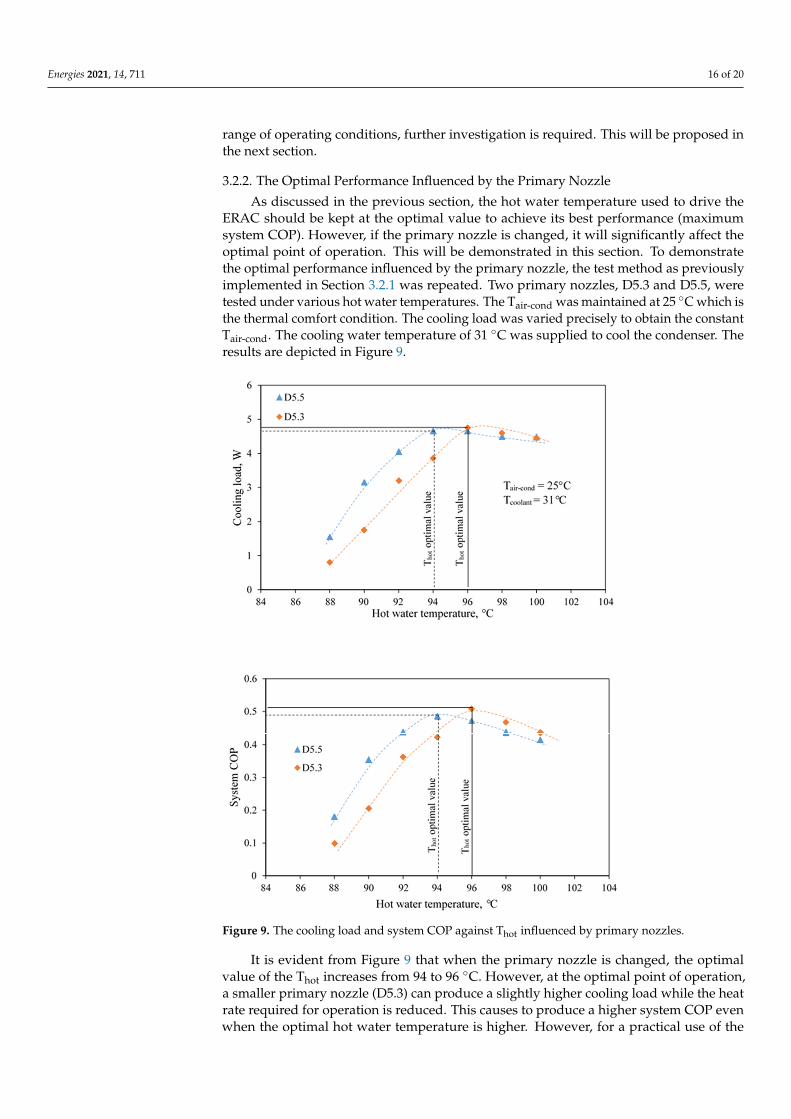
As discussed in the previous section, the hot water temperature used to drive theERAC should be kept at the optimal value to achieve its best performance (maximumsystem COP). However, if the primary nozzle is changed, it will significantly affect theoptimal point of operation. This will be demonstrated in this section. To demonstratethe optimal performance influenced by the primary nozzle, the test method as previouslyimplemented in Section 3.2.1 was repeated. Two primary nozzles, D5.3 and D5.5, weretested under various hot water temperatures. The Tair-cond was maintained at 25 ◦C which isthe thermal comfort condition. The cooling load was varied precisely to obtain the constantTair-cond. The cooling water temperature of 31 ◦C was supplied to cool the condenser. Theresults are depicted in Figure 9.
Energies 2021, 14, x FOR PEER REVIEW 18 of 22
Figure 9. The cooling load and system COP against Thot influenced by primary nozzles.
It is evident from Figure 9 that when the primary nozzle is changed, the optimal value of the Thot increases from 94 to 96 °C. However, at the optimal point of operation, a smaller primary nozzle (D5.3) can produce a slightly higher cooling load while the heat rate re-quired for operation is reduced. This causes to produce a higher system COP even when the optimal hot water temperature is higher. However, for a practical use of the ERAC, the heat source temperature should be as low as possible while the cooling purpose is still satisfied. This implies that using the primary nozzle with a bigger throat seems to be the most promising primary nozzle for operation.
The reason why the smaller primary nozzle needs a higher Thot to produce the opti-mal performance is that a lower primary flow rate is generated at identical Thot, resulting in a lower primary stream momentum. This lower momentum is inadequate for produc-ing the best mixing process at lower hot water temperature which results in producing a lower secondary flow rate. This will mitigate the ability to produce the cooling load. Therefore, a smaller nozzle requires a higher hot water temperature to produce its optimal performance. This phenomenon indicates that the primary nozzle should be designed
Figure 9. The cooling load and system COP against Thot influenced by primary nozzles.
It is evident from Figure 9 that when the primary nozzle is changed, the optimalvalue of the Thot increases from 94 to 96 ◦C. However, at the optimal point of operation,a smaller primary nozzle (D5.3) can produce a slightly higher cooling load while the heatrate required for operation is reduced. This causes to produce a higher system COP evenwhen the optimal hot water temperature is higher. However, for a practical use of the

Energies 2021, 14, 711 17 of 20
ERAC, the heat source temperature should be as low as possible while the cooling purposeis still satisfied. This implies that using the primary nozzle with a bigger throat seems to bethe most promising primary nozzle for operation.
The reason why the smaller primary nozzle needs a higher Thot to produce the optimalperformance is that a lower primary flow rate is generated at identical Thot, resulting ina lower primary stream momentum. This lower momentum is inadequate for producingthe best mixing process at lower hot water temperature which results in producing a lowersecondary flow rate. This will mitigate the ability to produce the cooling load. Therefore,a smaller nozzle requires a higher hot water temperature to produce its optimal performance.This phenomenon indicates that the primary nozzle should be designed carefully associatedwith the temperature of the heat source in order to achieve the optimal performance.
3.2.3. The Optimal Performance Influenced by the Air-Conditioned Space Temperature
In this section, the optimal hot water temperature under various Tair-cond is determined.This is to demonstrate the flexible use of the ERAC in real operation in which the coolingtemperature is required at different levels. In some situations, the Tair-cond must varyassociated with the cooling purposes. Therefore, the optimal value of the Thot undervarious cooling loads should be studied for discussion. To demonstrate this impact, theTair-cond was held constant at different values while the Thot was varied to determine theoptimal Thot. The primary nozzle D5.5 was used for demonstration. The cooling load wasvaried to obtain the thermal comfort. The results are presented in Figure 10.
Energies 2021, 14, x FOR PEER REVIEW 19 of 22
carefully associated with the temperature of the heat source in order to achieve the opti-mal performance.
3.2.3. The Optimal Performance Influenced by the Air-Conditioned Space Temperature In this section, the optimal hot water temperature under various Tair-cond is deter-
mined. This is to demonstrate the flexible use of the ERAC in real operation in which the cooling temperature is required at different levels. In some situations, the Tair-cond must vary associated with the cooling purposes. Therefore, the optimal value of the Thot under various cooling loads should be studied for discussion. To demonstrate this impact, the Tair-cond was held constant at different values while the Thot was varied to determine the optimal Thot. The primary nozzle D5.5 was used for demonstration. The cooling load was varied to obtain the thermal comfort. The results are presented in Figure 10.
Figure 10. The cooling load and system against Thot influenced by the air-conditioned temperatures.
It is seen that an increase in the Tair-cond requires a lower Thot to produce the best per-formance. At the optimal operation, the cooling load and system COP increase when the Tair-cond is increased. The reason is that at a higher Tair-cond, the evaporating pressure, which
Figure 10. The cooling load and system against Thot influenced by the air-conditioned temperatures.

Energies 2021, 14, 711 18 of 20
It is seen that an increase in the Tair-cond requires a lower Thot to produce the bestperformance. At the optimal operation, the cooling load and system COP increase whenthe Tair-cond is increased. The reason is that at a higher Tair-cond, the evaporating pressure,which is the stagnation state of the secondary fluid stream, is increased. Thus, a lowerprimary stream momentum is required to produce the choked flow of the secondary fluid.Therefore, a lower Thot is required for producing the optimal performance which results inthe system COP being increased.
As discussed above, the ERAC can work efficiently under a range of cooling tempera-tures (various air-conditioned temperatures). However, the Thot must vary simultaneouslyto achieve the optimal performance for a certain Tair-cond. This is to achieve the efficientenergy use. The results have also shown that the use of improper Thot provides a negativeimpact to the system operation. Thus, the hot water temperature should be varied preciselyto achieve the optimal performance when the Tair-con is varied.
4. Conclusions
The air-conditioning test performance of the ejector refrigerator based air-conditioner(ERAC) was proposed under various hot water temperatures, primary nozzle sizes, coolingloads and air-conditioned space temperatures. This was to demonstrate the practical use ofthe ERAC in a real air-conditioning application under the warm ambient while the systemwas driven by a relatively low temperature heat sources. The optimal performance of theERAC working under the thermal comfort condition (Tair-con = 25 ◦C) was demonstrated.This was achieved when the hot water temperature was varied. It was evident that theoptimal performance varied significantly with variations in the working conditions. Thefindings of this present work are summarized as follows:
• For a certain hot water temperature and primary nozzle used, an increase in the coolingload caused the air-conditioned space temperature to be increased. However, thecooling load must not be too high when the thermal comfort condition is considered.
• For a certain hot water temperature, when the primary nozzle throat was enlarged,a decrease in the Tair-con was found at identical cooling load. However, using a biggerprimary nozzle caused a decrease in the system COP.
• For operating at the thermal comfort condition, initially, increasing the hot waterresulted in increasing the system COP until it reached its maximum value (optimalperformance). Later, the system COP decreased when the hot water continued toincrease. Therefore, the optimal heat source for this particular working conditionwas determined.
• When operating at the thermal comfort condition, enlarging the primary nozzle throatrequired a lower Thot to produce the optimal point of operation. However, a slightdecrease in the system COP was found.
• A change in the air-conditioned space temperature significantly affected the optimalperformance. It was evident that the optimal performance of the ERAC was achievedwith a lower Thot and vice versa.
The air-conditioning tests indicated the high potential of the ERAC for real operation.The results is useful for being a reference case to further develop the ejector refrigerationsystem for practical use. Hopefully, the information provided in this present work willbe useful for the researchers who attempt to develop the ejector based air conditioner forpractical use.
Author Contributions: Conceptualization, T.T. and N.R.; methodology, T.T. and N.R.; formal analysis,T.T. and N.R.; investigation, T.T.; resources, T.T.; data curation, T.T. and N.R.; writing—original draftpreparation, T.T. and N.R.; writing—review and editing, T.T. and N.R. Both authors have read andagreed to the published version of the manuscript.
Funding: This research was funded by King Mongkut’s University of Technology North Bangkok.Contract no. KMUTNB-64-KNOW-38.
Institutional Review Board Statement: Not applicable.

Energies 2021, 14, 711 19 of 20
Informed Consent Statement: Not applicable.
Data Availability Statement: Not applicable.
Conflicts of Interest: The authors declare no conflict of interest.
NomenclaturesSymbolARejector The area ratio of the ejectorARnozzle The area ratio of the primary nozzleCOP Coefficient of PerformanceD Diameter of the relevant parameters (mm)L Length of the relevant parameters.
m The mass flow rate of the relevant parameters (kg s−1, kg min−1)NXP The Nozzle Exit Position (mm)P The pressure value of the relevant parameters (kPa)Qcon Condensation heat rejected at the condenser (kW)Qcool Cooling load produced at the evaporator (kW)Qgen Heat required for the generator operation (kW)Rm The mass entrainment ratio of the ejectorT The temperature value of the relevant parameters (◦C)Subscriptsair-cond Relevant parameter for the air-conditioned spacechill Relevant parameter for the chilled watercool Relevant parameter at the cooling towercon Relevant parameter at the condenserdiff Relevant parameter at the subsonic diffuserfan Relevant parameter at the cooling tower fanej-th Relevant parameter at the ejector throatevap Relevant parameter at the evaporatorgen Relevant parameter at the generatorhot Relevant parameter at the hot waternozz-exit Relevant parameter the primary nozzle exitnozz-th Relevant parameter at the primary nozzle throatp Relevant parameter for mechanical pumpref Relevant parameter for the refrigerant
References1. Yinhai, Z.; Jiang, P. Hybrid vapor compression refrigeration system with an integrated ejector cooling cycle. Int. J. Refrig. 2012, 35,
68–78.2. Fong, K.F.; Lee, C.K.; Chow, T.T. Improvement of solar-electric compression refrigeration system through ejector-assisted vapour
compression chiller for space conditioning in subtropical climate. Energy Build. 2011, 43, 3383–3390. [CrossRef]3. Sánchez, D.; Catalán-Gil, J.; Cabello, R.; Calleja-Anta, D.; Llopis, R.; Nebot-Andrés, L. Experimental analysis and optimization of
an R744 transcritical cycle working with a mechanical subcooling system. Energies 2020, 13, 3204. [CrossRef]4. Xia, Y.; Jiangzhou, S.; Zhang, X.; Zhang, Z. Steady-State Performance Prediction for a Variable Speed Direct Expansion Air
Conditioning System Using a White-Box Based Modeling Approach. Energies 2020, 13, 4757. [CrossRef]5. Lin, C.; Xu, C.; Yue, B.; Jiang, C.; Omori, H.; Deng, J. Experimental study on the separator in ejector-expansion refrigeration
system. Int. J. Refrig. 2019, 100, 307–314. [CrossRef]6. Jeon, Y.; Jung, J.; Kim, D.; Kim, S.; Kim, Y. Effects of ejector geometries on performance of ejector-expansion R410A air conditioner
considering cooling seasonal performance factor. Appl. Energy 2017, 205, 761–768. [CrossRef]7. Pottker, G.; Hrnjak, P. Ejector in R410A vapor compression systems with experimental quantification of two major mechanisms of
performance improvement: Work recovery and liquid feeding. Int. J. Refrig. 2015, 50, 184–192. [CrossRef]8. Jeon, Y.; Kim, H.; Ahn, J.H.; Kim, S. Effects of Nozzle Exit Position on Condenser Outlet Split Ejector-Based R600a Household
Refrigeration Cycle. Energies 2020, 13, 5160. [CrossRef]9. Lillo, G.; Mastrullo, R.; Mauro, A.W.; Trinchieri, R.; Viscito, L. Thermo-economic analysis of a hybrid ejector refrigerating system
based on a low grade heat source. Energies 2020, 13, 562. [CrossRef]10. Bai, L.; Liu, S.; Ye, Z.; He, M. Investigation on the performance of R1234ze (E) in absorption refrigeration and ejection refrigeration
systems. Appl. Therm. Eng. 2019, 161, 114120. [CrossRef]11. Hamzaoui, M.; Nesreddine, H.; Aidoun, Z.; Balistrou, M. Experimental study of a low grade heat driven ejector cooling system
using the working fluid R245fa. Int. J. Refrig. 2018, 86, 388–400. [CrossRef]

Energies 2021, 14, 711 20 of 20
12. Narimani, E.; Sorin, M.; Micheau, P.; Nesreddine, H. Numerical and experimental investigation of the influence of generatingpressure on the performance of a one-phase ejector installed within an R245fa refrigeration cycle. Appl. Therm. Eng. 2019,157, 113654. [CrossRef]
13. Fang, Y.; Croquer, S.; Poncet, S.; Aidoun, Z.; Bartosiewicz, Y. Drop-in replacement in a R134 ejector refrigeration cycle by HFOrefrigerants. Int. J. Refrig. 2017, 77, 87–98. [CrossRef]
14. Dong, J.; Wang, W.; Han, Z.; Ma, H.; Deng, Y.; Su, F.; Pan, X. Experimental investigation of the steam ejector in a single-effectthermal vapor compression desalination system driven by a low-temperature heat source. Energies 2018, 11, 2282. [CrossRef]
15. Van Nguyen, V.; Varga, S.; Soares, J.; Dvorak, V.; Oliveira, A.C. Applying a variable geometry ejector in a solar ejector refrigerationsystem. Int. J. Refrig. 2020, 113, 187–195. [CrossRef]
16. Thongtip, T.; Aphornratana, S. An experimental analysis of the impact of primary nozzle geometries on the ejector performanceused in R141b ejector refrigerator. Appl. Therm. Eng. 2017, 110, 89–101. [CrossRef]
17. Chen, J.; Havtun, H.; Palm, B. Investigation of ejectors in refrigeration system: Optimum performance evaluation and ejector arearatios perspectives. Appl. Therm. Eng. 2014, 64, 182–191. [CrossRef]
18. Besagni, G.; Mereu, R.; Chiesa, P.; Inzoli, F. An Integrated Lumped Parameter-CFD approach for off-design ejector performanceevaluation. Energy Convers. Manag. 2015, 105, 697–715. [CrossRef]
19. Zhang, G.; Dykas, S.; Li, P.; Li, H.; Wang, J. Accurate condensing steam flow modeling in the ejector of the solar-drivenrefrigeration system. Energy 2020, 212, 118690. [CrossRef]
20. Allouche, Y.; Bouden, C.; Varga, S. A CFD analysis of the flow structure inside a steam ejector to identify the suitable experimentaloperating conditions for a solar-driven refrigeration system. Int. J. Refrig. 2014, 39, 186–195. [CrossRef]
21. Zhang, G.; Dykas, S.; Yang, S.; Zhang, X.; Li, H.; Wang, J. Optimization of the primary nozzle based on a modified condensationmodel in a steam ejector. Appl. Therm. Eng. 2020, 171, 115090. [CrossRef]
22. Mahmoudian, J.; Mazzelli, F.; Rocchetti, A.; Milazzo, A. A heat-powered ejector chiller working with low-GWP fluid R1233zd(E)(Part2: Numerical analysis). Int. J. Refrig. 2020, 121, 216–227. [CrossRef]
23. Chen, J.; Havtun, H.; Palm, B. Screening of working fluids for the ejector refrigeration system. Int. J. Refrig. 2014, 47, 1–14.[CrossRef]
24. Besagni, G.; Mereu, R.; Di Leo, G.; Inzoli, F. A study of working fluids for heat driven ejector refrigeration using lumped parametermodels. Int. J. Refrig. 2015, 58, 154–171. [CrossRef]
25. Galindo, J.; Dolz, V.; García-Cuevas, L.M.; Ponce-Mora, A. Numerical evaluation of a solar-assisted jet-ejector refrigeration system:Screening of environmentally friendly refrigerants. Energy Convers. Manag. 2020, 210, 112681. [CrossRef]
26. Smierciew, K.; Gagan, J.; Butrymowicz, D.; Łukaszuk, M.; Kubiczek, H. Experimental investigation of the first prototype ejectorrefrigeration system with HFO-1234ze (E). Appl. Therm. Eng. 2017, 110, 115–125. [CrossRef]
27. Eames, I.W.; Milazzo, A.; Paganini, D.; Livi, M. The design, manufacture and testing of a jet-pump chiller for air conditioning andindustrial application. Appl. Therm. Eng. 2013, 58, 234–240. [CrossRef]
28. Varga, S.; Oliveira, A.C.; Palmero-Marrero, A.; Vrba, J. Preliminary experimental results with a solar driven ejector air conditionerin Portugal. Renew. Energy 2017, 109, 83–92. [CrossRef]
29. Ruangtrakoon, N.; Aphornratana, S. Development and performance of steam ejector refrigeration system operated in realapplication in Thailand. Int. J. Refrig. 2014, 48, 142–152. [CrossRef]
30. Thongtip, T.; Aphornratana, S. Development and performance of a heat driven R141b ejector air conditioner: Application in hotclimate country. Energy 2018, 160, 556–572. [CrossRef]
31. Keenan, J.H. An investigation of ejector design by analysis and experiment. J. Appl. Mech. 1950, 17, 299.32. Thongtip, T.; Aphornratana, S. An alternative analysis applied to investigate the ejector performance used in R141b jet-pump
refrigeration system. Int. J. Refrig. 2015, 53, 20–33. [CrossRef]33. Coleman, H.W.; Steele, W.G. Experimentation, Validation, and Uncertainty Analysis for Engineers, 4th ed.; John Wiley Sons: Hoboken,
NJ, USA, 2018.34. Ruangtrakoon, N.; Thongtip, T. An experimental investigation to determine the optimal heat source temperature for R141b ejector
operation in refrigeration cycle. Appl. Therm. Eng. 2020, 170, 114841. [CrossRef]35. Yapici, R. Experimental investigation of performance of vapor ejector refrigeration system using refrigerant R123. Energy Convers.
Manag. 2008, 49, 953–961. [CrossRef]
Copyright © 2022 FDOKUMEN