Effect of a finite ground plane on radiated emissions from a circular loop antenna
8
IEEE TRANSACTIONS ON ELECTROMAGNETIC COMPATIBILITY, VOL. 36, NO. 4, NOVEMBER 1994 C. E. Baum, T. H. Shumpert, and L. S. Riggs, “Perturbation of the SEM-pole parameters of an object by a mirror object,” Electromagn., J. E. Ross, E. J. Rothwell, D. P. Nyquist, and K. M. Chen, “Approximate integral-operator methods for estimating the natural frequencies of coupled objects,” Radio Sei., vol. 29, pp. 677-684, 1994. M. A. Morgan, “Singularity expansion representations of fields and currents in transient scattering,” IEEE Trans. Antennas Propagar., vol. AP-32, no. 5, pp. 466473, May 1984. -, “Response to comments regarding SEM representations,” IEEE Trans. Antennas Propagat., vol. AP-33, no. 1, p. 120, Jan. 1985. L. W. Pearson, “A note on the representation of scattered fields as a singularity expansion,” IEEE Trans. Antennas Propagat., vol. AP-32, no. 5, pp. 520-524, May 1984. L. B. Felson, “Comments on early time SEM,” IEEE Trans. Antennas Propagat., vol. AP-33, no. 1, pp. 118-119, Jan. 1985. D. G. Dudley, “Comments on SEM and the parametric inverse problem,” IEEE Trans. Antennas Propagat., vol. AP-33, no. 1, pp. 119-120, Jan. 1985. C. E. Baum, “Representation of surface current density and far scattering in EEM and SEM with entire functions,” Interaction Notes, note 486, Feb. 1992. -, “On the singularity expansion method for the solution of electro- magnetic interaction problems,” Interaction Notes, note 88, 1971. F. M. Tesche, “On the analysis of scattering and antenna problems using the singularity expansion technique,” IEEE Trans. Antennas Propagat., vol. AP-21, no. 1, pp. 53062, Jan. 1973. VO~. 8, pp. 169-186, 1989. Effect of a Finite Ground Plane on Radiated Emissions from a Circular Loop Antenna Hassan A. N. Hejase, Stephen D. Gedney, and Keith W. Whites Abstract-A thin-wire circular loop antenna located above a perfectly conducting square plate is analyzed by a Physical Optics (PO) method. The Electric Field Integral Equation (EFIE) is solved using the method of moments to compute the current on the loop in the presence of an infinite ground plane whereby the edge effects of the plate on the loop current are neglected. The current distribution on the loop is obtained from a full-wave Fourier series analysis which requires no matrix inversion. We then use Physical Optics to compute the current induced on the plate in terms of the incident magnetic-field intensity. Our aim is to compare the PO solution with results obtained from a mixed wire-patch MOM code and explore its accuracy as a function of plate size and loop height. The benefits are considerable reduction in analytical and computational efforts and much less CPU time. I. INTRODUCTION The loop antenna is one of the most widely used types of antennas besides the dipole antenna. It has been the subject of numerous experimental and theoretical studies with previous work concentrating on using loop antennas to improve the directivity and gain as compared to the dipole-antenna structure. The characteristics of a perfectly conducting circular loop as a transmitting antenna have been studied extensively in free space [1]-[7] and above a conducting or Manuscript received June 9, 1993; revised April 6, 1994. H. A. N. Hejase is with the Department of Electrical Engineering, Istituto Tecnologico y De Estudios Superiores De Monterrey, Campus Estado De Mexico, Mexico. S. D. Gedney and K. W. Whites are with the Department of Electrical Engineering, University of Kentucky, 453 Anderson Hall, Lexington, KY 40506-0046 USA. IEEE Log Number 9404480. dielectric interface [8]-[lo]. The effect of loading the loop has also been considered by Iizukia [ 111, Harrington and Ryerson [ 121, Kanda [13], and Esselle and Stuchly [14]. Tesche [15] analyzed the behavior of linear wire antennas between two parallel conducting plates as a function of plate separation and antenna size as well as the resonance interaction between the loop and the parallel-plate structure. Work has also been done on linear antennas placed perpendicular to the plates [16]-[18]. It0 et al. [19], [20] and Kosugi et al. [21] did extensive research on circular-loop antenna arrays and noted a significant gain and directivity improvement in comparison with a loop in free space and over a perfectly conducting plane. Analysis of a circular loop with a finite reflector structure has also been done by Rojarayanont and Sekiguchi [22] and Iwashige [23]. The effect of a finite reflector on radiated emissions from electric source lines and strip lines has been recently studied by Jerse et al. [24] and Fessler et nl. [25]. In this short paper we study the radiation characteristics of a circular-loop antenna above a finite square metallic plate when the loop is excited as a transmitting antenna. We use efficient Fourier series and FFT algorithms to compute the loop and reflector currents, respectively. Our goal is to assess the effect of the plate size on the maximum radiated power gain and establish the bounds over which the plate effects may be approximated by those of an infinite ground plane. The geometry of the problem is shown in Fig. 1. The loop has radius b and wire radius a, and is placed at a distance d above the perfectly electrically conducting (PEC) plate. The global origin is taken on the plate along the loop axis. The loop is excited by a delta-gap voltage source V, (at q5 = 0”) with zero source impedance. The thin-wire approximation, wherein the loop wire radius is much smaller than the loop radius and wavelength, is used such that the current is assumed to be filamentary and located along the loop circumferencial axis. The current on the loop is determined by assuming an infinitely large plate. An integro- differential Pocklington-type equation is obtained and solved for the unknown loop current using a Fourier series interpolation of loop current. Assuming that the plate is large enough compared to the loop dimensions, we use the Physical Optics (PO) solution to compute the current induced on the plate. The far-zone field radiated from the loopplate system is then computed as the superposition of the field radiated due to loop current in the absence of the plate plus the field radiated due to the induced plate currents in the absence of the loop. The maximum radiation power gain (along loop axis) will then be computed and compared to computed results obtained by a mixed wire-patch MOM code which takes into account the effect of the plate edges. For a loop one-wavelength in circumference, very good agreement is obtained betwen the PO and exact-MOM codes for plate sizes as small as 0.75 free-space wavelengths (XO). II. THEORY The Pocklington equation for the current on the loop of radius b and wire radius a (see Fig. 1) can be written in the form [8], [19], [20] where 0018-9375/94$04.00 0 1994 IEEE
Transcript of Effect of a finite ground plane on radiated emissions from a circular loop antenna

IEEE TRANSACTIONS ON ELECTROMAGNETIC COMPATIBILITY, VOL. 36, NO. 4, NOVEMBER 1994
C. E. Baum, T. H. Shumpert, and L. S. Riggs, “Perturbation of the SEM-pole parameters of an object by a mirror object,” Electromagn.,
J. E. Ross, E. J. Rothwell, D. P. Nyquist, and K. M. Chen, “Approximate integral-operator methods for estimating the natural frequencies of coupled objects,” Radio Sei., vol. 29, pp. 677-684, 1994. M. A. Morgan, “Singularity expansion representations of fields and currents in transient scattering,” IEEE Trans. Antennas Propagar., vol. AP-32, no. 5, pp. 466473, May 1984. -, “Response to comments regarding SEM representations,” IEEE Trans. Antennas Propagat., vol. AP-33, no. 1, p. 120, Jan. 1985. L. W. Pearson, “A note on the representation of scattered fields as a singularity expansion,” IEEE Trans. Antennas Propagat., vol. AP-32, no. 5, pp. 520-524, May 1984. L. B. Felson, “Comments on early time SEM,” IEEE Trans. Antennas Propagat., vol. AP-33, no. 1, pp. 118-119, Jan. 1985. D. G. Dudley, “Comments on SEM and the parametric inverse problem,” IEEE Trans. Antennas Propagat., vol. AP-33, no. 1, pp. 119-120, Jan. 1985. C. E. Baum, “Representation of surface current density and far scattering in EEM and SEM with entire functions,” Interaction Notes, note 486, Feb. 1992. -, “On the singularity expansion method for the solution of electro- magnetic interaction problems,” Interaction Notes, note 88, 1971. F. M. Tesche, “On the analysis of scattering and antenna problems using the singularity expansion technique,” IEEE Trans. Antennas Propagat., vol. AP-21, no. 1, pp. 53062, Jan. 1973.
VO~. 8, pp. 169-186, 1989.
Effect of a Finite Ground Plane on Radiated Emissions from a Circular Loop Antenna
Hassan A. N. Hejase, Stephen D. Gedney, and Keith W. Whites
Abstract-A thin-wire circular loop antenna located above a perfectly conducting square plate is analyzed by a Physical Optics (PO) method. The Electric Field Integral Equation (EFIE) is solved using the method of moments to compute the current on the loop in the presence of an infinite ground plane whereby the edge effects of the plate on the loop current are neglected. The current distribution on the loop is obtained from a full-wave Fourier series analysis which requires no matrix inversion. We then use Physical Optics to compute the current induced on the plate in terms of the incident magnetic-field intensity. Our aim is to compare the PO solution with results obtained from a mixed wire-patch MOM code and explore its accuracy as a function of plate size and loop height. The benefits are considerable reduction in analytical and computational efforts and much less CPU time.
I. INTRODUCTION
The loop antenna is one of the most widely used types of antennas besides the dipole antenna. It has been the subject of numerous experimental and theoretical studies with previous work concentrating on using loop antennas to improve the directivity and gain as compared to the dipole-antenna structure. The characteristics of a perfectly conducting circular loop as a transmitting antenna have been studied extensively in free space [1]-[7] and above a conducting or
Manuscript received June 9, 1993; revised April 6, 1994. H. A. N. Hejase is with the Department of Electrical Engineering, Istituto
Tecnologico y De Estudios Superiores De Monterrey, Campus Estado De Mexico, Mexico.
S. D. Gedney and K. W. Whites are with the Department of Electrical Engineering, University of Kentucky, 453 Anderson Hall, Lexington, KY 40506-0046 USA.
IEEE Log Number 9404480.
dielectric interface [8]-[lo]. The effect of loading the loop has also been considered by Iizukia [ 111, Harrington and Ryerson [ 121, Kanda [13], and Esselle and Stuchly [14]. Tesche [15] analyzed the behavior of linear wire antennas between two parallel conducting plates as a function of plate separation and antenna size as well as the resonance interaction between the loop and the parallel-plate structure. Work has also been done on linear antennas placed perpendicular to the plates [16]-[18]. It0 et al. [19], [20] and Kosugi et al. [21] did extensive research on circular-loop antenna arrays and noted a significant gain and directivity improvement in comparison with a loop in free space and over a perfectly conducting plane. Analysis of a circular loop with a finite reflector structure has also been done by Rojarayanont and Sekiguchi [22] and Iwashige [23]. The effect of a finite reflector on radiated emissions from electric source lines and strip lines has been recently studied by Jerse et al. [24] and Fessler et nl. [25].
In this short paper we study the radiation characteristics of a circular-loop antenna above a finite square metallic plate when the loop is excited as a transmitting antenna. We use efficient Fourier series and FFT algorithms to compute the loop and reflector currents, respectively. Our goal is to assess the effect of the plate size on the maximum radiated power gain and establish the bounds over which the plate effects may be approximated by those of an infinite ground plane.
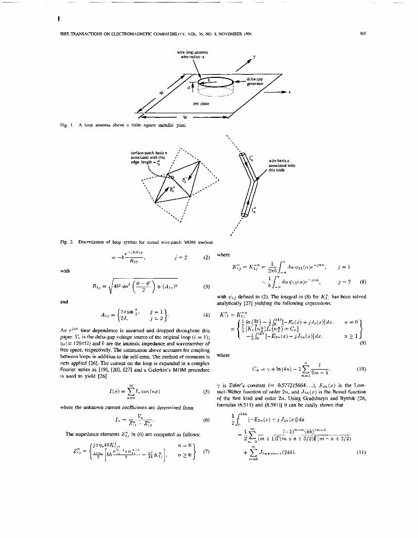
The geometry of the problem is shown in Fig. 1. The loop has radius b and wire radius a, and is placed at a distance d above the perfectly electrically conducting (PEC) plate. The global origin is taken on the plate along the loop axis. The loop is excited by a delta-gap voltage source V, (at q5 = 0”) with zero source impedance. The thin-wire approximation, wherein the loop wire radius is much smaller than the loop radius and wavelength, is used such that the current is assumed to be filamentary and located along the loop circumferencial axis. The current on the loop is determined by assuming an infinitely large plate. An integro- differential Pocklington-type equation is obtained and solved for the unknown loop current using a Fourier series interpolation of loop current. Assuming that the plate is large enough compared to the loop dimensions, we use the Physical Optics (PO) solution to compute the current induced on the plate. The far-zone field radiated from the loopplate system is then computed as the superposition of the field radiated due to loop current in the absence of the plate plus the field radiated due to the induced plate currents in the absence of the loop. The maximum radiation power gain (along loop axis) will then be computed and compared to computed results obtained by a mixed wire-patch MOM code which takes into account the effect of the plate edges. For a loop one-wavelength in circumference, very good agreement is obtained betwen the PO and exact-MOM codes for plate sizes as small as 0.75 free-space wavelengths (XO).
II. THEORY
The Pocklington equation for the current on the loop of radius b and wire radius a (see Fig. 1) can be written in the form [8], [19], [20]
where
0018-9375/94$04.00 0 1994 IEEE
I
IEEE TRANSACTIONS ON ELECTROMAGNETIC COMPATIBILITY, VOL. 36, NO. 4, NOVEMBER 1994
Fig. 1. A loop antenna above a
wire-loop antenna wire radiusa
\ f Y
/- w u finite square metallic plate.
. , , \
, ~
wire basis n associated with
' this node
Fig. 2. Discretizaton of loop system for mixed wire-patch MOM method.
with
R I , = J4h"w (3)
and
365
with +l3 defined in (2). The integral in (8) for A-Fl has been solved analytically [27] yielding the following expressions:
(4) K:1 = K," j = 2 .
n > l n=ol $In ($) - $J:kb[-Eo(z) + j J o ( z ) ] d z ,
[KO (.:)Io ( n t ) + Cn]
I 2 a s i n g , j = 1 Ai, = { 2 d ,
[-&n(z) + j J ~ n ( ~ ) ] d z , (9)
An e J d f time dependence is assumed and dropped throughout this paper. Vo is the delta-gap voltage source of the original loop (i = 1); V,(M 1 2 0 ~ 0 ) and k: are the intrinsic impedance and wavenumber of free space, respectively. The summation above accounts for coupling between loops in addition to the self-term. The method of moments is next applied [26). The current on the loop is expanded in a complex
where
" 1 Fourier series as [19], [20], [27] and a Galerkin's MOM procedure is used to yield [26]
Cn = y + l n ( 4 n ) - 2 x - 2 m - 1 ' (10) m = l
co
n = O
y is Euler's constant (= 0.577215664.. .), Ezn(z) is the Lom- mel-Weber function of order 2n, and J z n ( z ) is the Bessel function of the first kind and order 2n. Using Gradshteyn and Ryzhik [28, formulas (6.511) and (8.581)] it can be easily shown that
~ ( 4 ) = X I n COS (n4) ( 5 )
where the unknown current coefficients are determined from 2 k b
In = L. (6) i l [ - ~ % n ( z ) + j J ~ n ( z ) ] d z ZFl - ZF2
1 366 IEEE TRANSACTIONS ON ELECTROMAGNETIC COMPATIBILITY, VOL. 36, NO. 4, NOVEMBER 1994
(C) (d)
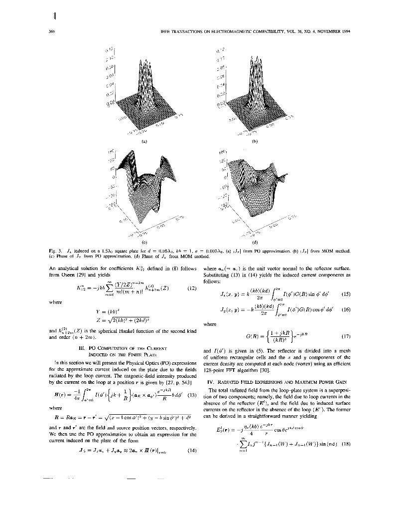
Fig. 3. (c) Phase of J , from PO approximation. (d) Phase of J , from MOM method.
J , induced on a 1.5xo square plate for d = 0.05x0, kb = 1, a = 0.005xo. (a) IJ,I from PO approximation. (b) (J,l from MOM method.
An analytical solution for coefficients h-& defined in (8) follows from Oseen [29] and yields
where
Y = (kb)' 2 = 42(kb)2 + (2kd)2
and h ~ ~ 2 m ( Z ) is the spherical Hankel function of the second kind and order ( n + 2m).
111. PO COMPUTATION OF THE CURRENT INDUCED ON THE FINITE PLATE
In this section we will present the Physical Optics (PO) expressions for the approximate current induced on the plate due to the fields radiated by the loop current. The magnetic-field intensity produced by the current on the loop at a position r is given by [27, p. 5431
where
R = RaR = r - r' = J(z - bcos@)2 + (y - bsin@)2 + d2
and r and r' are the field and source position vectors, respectively. We then use the PO approximation to obtain an expression for the current induced on the plate of the form
(14) J s = Jza, + Jyay M 2an x H(r)le=o
where an(= a,) is the unit vector normal to the reflector surface. Substituting (13) in (14) yields the induced current components as follows:
where
and I ( 4 ' ) is given in (5). The reflector is divided into a mesh of uniform rectangular cells and the z and y components of the current density are computed at each node (vertex) using an efficient 128-point FFT algorithm [30].
I v . RADIATED FIELD EXPRESSIONS AND MAXIMUM POWER GAIN The total radiated field from the loopplate system is a superposi-
tion of two components; namely, the field due to loop currents in the absence of the reflector (E'), and the field due to induced surface currents on the reflector in the absence of the loop ( E T ) . The former can be derived in a straightforward manner yielding

IEEE TRANSACTIONS ON ELECTROMAGNETIC COMPATIBILITY, VOL. 36, NO. 4, NOVEMBER 1994 367
0 40°
0 3331
ooob41- ,ol:o+
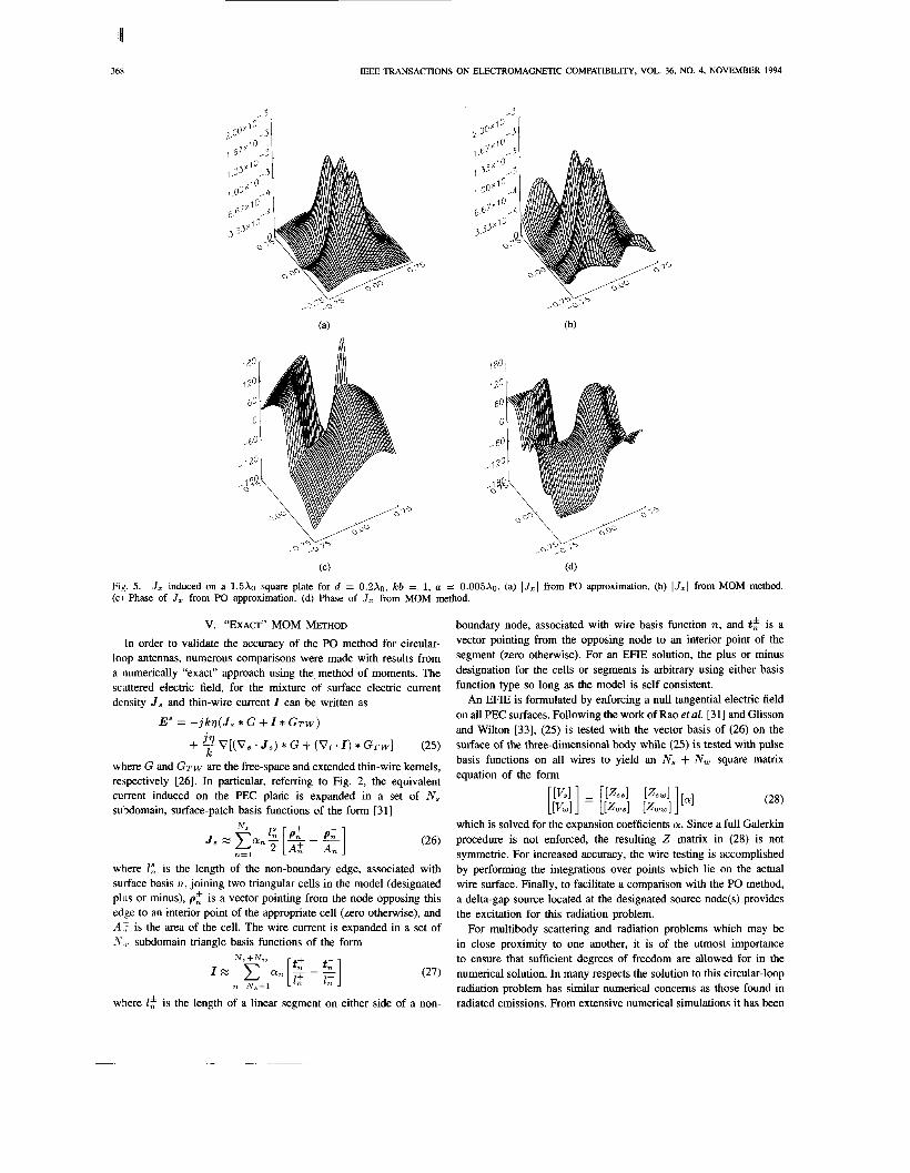
(C) (4 Fig. 4. (c) Phase of Jy from PO approximation. (d) Phase of Jy from MOM method.
J , induced on a 1.5Xo square plate for d = 0.05X0, kb = 1, a = 0.005Xo. (a) lJyl from PO approximation. (b) IJ,I from MOM method.
m
. x I n j n - ’ { J n - l ( W ) - Jn+l(W)}cos(n4) (19) n = O
where J , is a Bessel function of the first kind and nth order and 14’ = kbsin8.
The far-zone magnetic-field intensity radiated due to induced reflector currents in the absence of the loop is of the form [27, p. 8081
* *
where the integration is performed over the plate surface S (ds‘ = ‘fx‘ dy’). In a straightforward analysis, and with the help of (3, (15), and (16), the radiated electric field components can be written as
e - j k r E r ( r ) = j F ( k b ) ( k d ) -
47r r
where
00
and * c
where G(R) is given in (17) and integration is over the plate surface S. The integration in (23) is evaluated by discretizing the plate into uniform rectangular cells and transforming from the global coordinate system to a local system of coordinates defined within each cell [31]. The integral over the plate surface is then the sum of integrals over each cell. The integral over each cell is evaluated by first dividing the cell into two triangular elements, and then taking the average of the integrals over the two triangular subdomains. The integration over a triangle surface is evaluated by using the normalized area (simplex) coordinates [3 11 and computing the transformed simplex double integral using a Gauss-Legendre quadrature for triangles [32].
The total radiated field is computed by adding (18) and (19) to (21), i.e., E, = Ef + E: (i = 0 , 4). The z-directed (maximum) power gain (along the loop axis or 6’ = 0”) is then computed using the expression
where
En = - 1 Re(V,I*(d = 0)) 2
(22) is the input power calculated with the assumption of an infinite plate.
-
I 368 IEEE TRANSACTIONS ON ELECTROMAGNETIC COMPATIBILITY, VOL. 36, NO. 4, NOVEMBER 1994
(C) (d)
Fig. 5. (CI Phase of J , from PO approximation. (d) Phase of J , from MOM method.
J , induced on a 1.5xo square plate for d = 0.2X0, kb = 1, a = 0.005xo. (a) IJ,I from PO approximation. (b) IJzI from MOM method.
V. “EXACT” MOM METHOD In order to validate the accuracy of the PO method for circular-
loop antennas, numerous comparisons were made with results from a numerically “exact” approach using the, method of moments. The scattered electric field, for the mixture of surface electric current density J , and thin-wire current I can be written as
E” = - j k v ( J , * G + I * G T W )
+ 9 V[(V, . J , ) * G + (Vi . I ) * GTW] (25)
where G and GTW are the free-space and extended thin-wire kernels, re5pectively [26]. In particular, refemng to Fig. 2, the equivalent current induced on the PEC plane is expanded in a set of N , subdomain, surface-patch basis functions of the form [31]
where I : is the length of the non-boundary edge, associated with surface basis n, joining two triangular cells in the model (designated plus or minus), p: is a vector pointing from the node opposing this edge to an interior point of the appropriate cell (zero otherwise), and A $ is the area of the cell. The wire current is expanded in a set of AV,L. subdomain triangle basis functions of the form
where 2: is the length of a linear segment on either side of a non-
boundary node, associated with wire basis function n, and t: is a vector pointing from the opposing node to an interior point of the segment (zero otherwise). For an EFIE solution, the plus or minus designation for the cells or segments is arbitrary using either basis function type so long as the model is self consistent.
An EFIE is formulated by enforcing a null tangential electric field on all PEC surfaces. Following the work of Rao et al. [31] and Glisson and Wilton [33], (25) is tested with the vector basis of (26) on the surface of the three-dimensional body while (25) is tested with pulse basis functions on all wires to yield an N , + N, square matrix equation of the form
which is solved for the expansion coefficients a. Since a full Galerkin procedure is not enforced, the resulting 2 matrix in (28) is not symmetric. For increased accuracy, the wire testing is accomplished by performing the integrations over points which lie on the actual wire surface. Finally, to facilitate a comparison with the PO method, a delta-gap source located at the designated source node(s) provides the excitation for this radiation problem.
For multibody scattering and radiation problems which may be in close proximity to one another, it is of the utmost importance to ensure that sufficient degrees of freedom are allowed for in the numerical solution. In many respects the solution to this circular-loop radiation problem has similar numerical concerns as those found in radiated emissions. From extensive numerical simulations it has been
IEEE TRANSACTIONS ON ELECTROMAGNETIC COMPATIBILITY, VOL. 36, NO. 4, NOVEMBER 1994 369
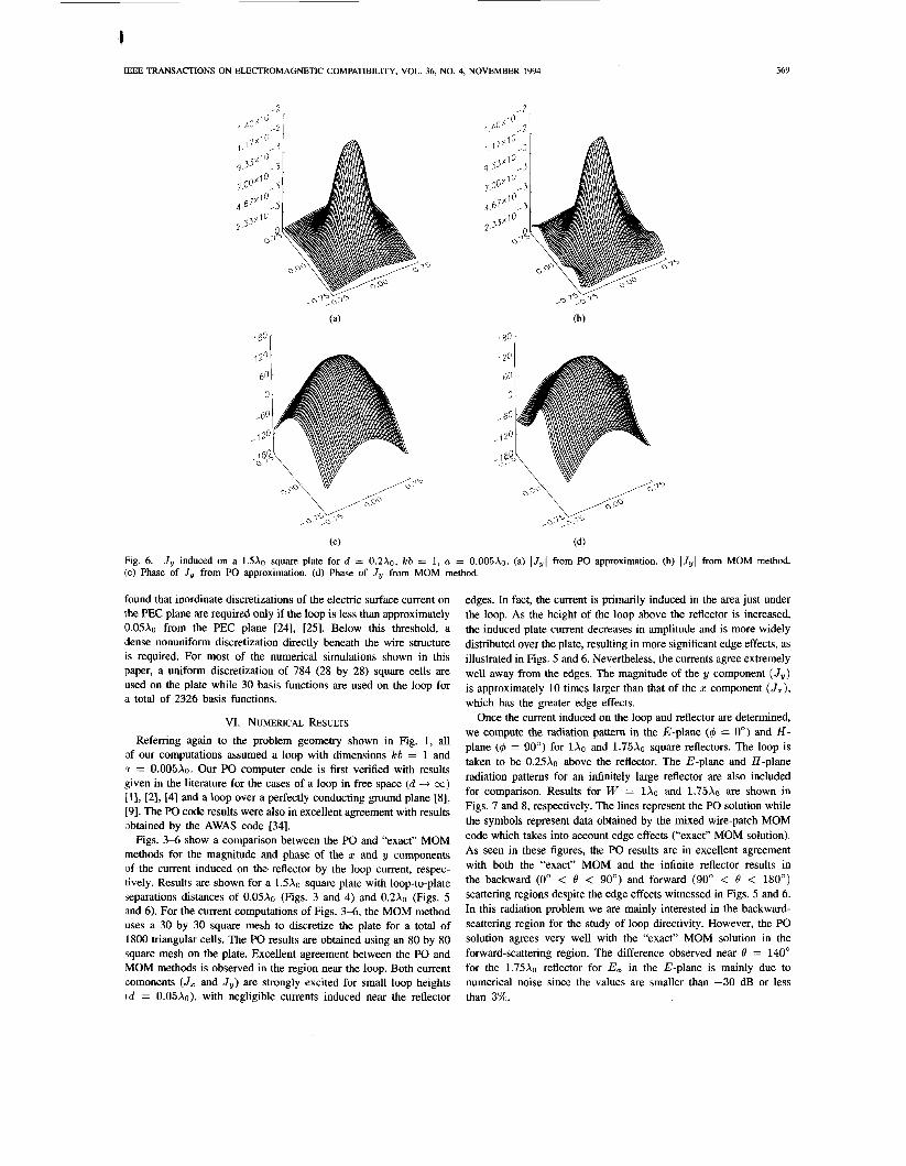
(C) (4 Fig. 6. (c) Phase of Jy from PO approximation. (d) Phase of J1, from MOM method.
Jy induced on a 1.5Xo square plate for d = 0.2X0, kb = 1, a = 0.005Xo. (a) l J y l from PO approximation. (b) lJyl from MOM method.
found that inordinate discretizations of the electric surface current on the PEC plane are required only if the loop is less than approximately 0.05X0 from the PEC plane [24], [25]. Below this threshold, a dense nonuniform discretization directly beneath the wire structure IS required. For most of the numerical simulations shown in this paper, a uniform discretization of 784 (28 by 28) square cells are used on the plate while 30 basis functions are used on the loop for a total of 2326 basis functions.
VI. NUMERICAL RESULTS Referring again to the problem geometry shown in Fig. 1, all
of our computations assumed a loop with dimensions kb = 1 and n = 0.005~0. Our PO computer code is first verified with results given in the literature for the cases of a loop in free space (d 4 co) [l], [2], [4] and a loop over a perfectly conducting ground plane [8], [9]. The PO code results were also in excellent agreement with results obtained by the AWAS code [34].
Figs. 3 4 show a comparison between the PO and "exact" MOM methods for the magnitude and phase of the z and y components of the current induced on the reflector by the loop current, respec- tively. Results are shown for a 15x0 square plate with loop-to-plate separations distances of 0.05x0 (Figs. 3 and 4) and 0.2X0 (Figs. 5 and 6). For the current computations of Figs. 3 4 , the MOM method uses a 30 by 30 square mesh to discretize the plate for a total of 1800 triangular cells. The PO results are obtained using an 80 by 80 square mesh on the plate. Excellent agreement between the PO and MOM methods is observed in the region near the loop. Both current comonents (Jz and Jy) are strongly excited for small loop heights cd = o.o5X0), with negligible currents induced near the reflector
edges. In fact, the current is primarily induced in the area just under the loop. As the height of the loop above the reflector is increased, the induced plate current decreases in amplitude and is more widely distributed over the plate, resulting in more significant edge effects, as illustrated in Figs. 5 and 6. Nevertheless, the currents agree extremely well away from the edges. The magnitude of the y component (Jy) is approximately 10 times larger than that of the z component (Jz), which has the greater edge effects.
Once the current induced on the loop and reflector are determined, we compute the radiation pattern in the E-plane (6 = 0") and H- plane (4 = 90') for 1x0 and 1.75x0 square reflectors. The loop is taken to be 0.25X0 above the reflector. The E-plane and H-plane radiation patterns for an infinitely large reflector are also included for comparison. Results for W = 1x0 and 1.75x0 are shown in Figs. 7 and 8, respectively. The lines represent the PO solution while the symbols represent data obtained by the mixed wire-patch MOM code which takes into account edge effects ("exact" MOM solution). As seen in these figures, the PO results are in excellent agreement with both the "exact" MOM and the infinite reflector results in the backward (0" < 6' < 90") and forward (90' < 6' < 180') scattering regions despite the edge effects witnessed in Figs. 5 and 6. In this radiation problem we are mainly interested in the backward- scattering region for the study of loop directivity. However, the PO solution agrees very well with the "exact" MOM solution in the forward-scattering region. The difference observed near 0 = 140" for the 1.75& reflector for E+ in the E-plane is mainly due to numerical noise since the values are smaller than -30 dB or less than 3%.

'1 370
E-Plane (CO, 90
270
(a)
H-Plane ($-go') 90
IEEE TRANSACTIONS
= e
= e
ON ELECTROMAGNETIC COMPATIBILITY, VOL. 36, NO.
E-Plane (+d) 90
270
= e
0 - -10 I -20 ,,,* -30
-40
Y
: -50 - - -0 L c - : : 2 I
270
(a)
H-Plane ($-go') 90
270
4, NOVEMBER
e
= e
= e
1994
Flz. 7. Radiation pattern for a Xo X Xo reflector (d/Xo = 0.25, kb = 1, and a / & = 0.005). (a) E+ in theE-plane (d = 0'). (b) Eo in the H-Plane (c, = 90"). (c) E, in the H-plane (6 = 90').
~ i ~ , 8, Radiation pattern for a 1.75X0 x 1.75Xo reflector ( d / X o = 0.25, kb = 1, a / ~ . = 0.05). (a) E+ in the E-plane (4 = 0'). (b) Eo in the H-plane (4 = 90'). (c) E d in the H-plane (4 = 90').
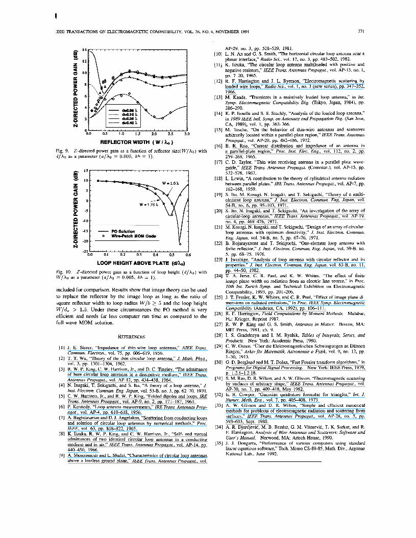
Fig. 9 shows a plot of the z-directed power gain as a function of the reflector size (W/Xo) with the loop height (d /Xo) as a parameter. These results show excellent agreement between the PO and "exact" MOM solutions for reflector sizes larger than 0.75Xo (W > 0.75Xo). In other words, the loop is blind to reflector edges and sees it as an infinitely large reflector as long as the ratio of reflector size to loop radius is better than 5 to 1. Therefore, image theory can be used to replace the reflector by the loop image (neglect edge effects) for W / b 2 5 and W/d > 1.5. If the loop axis is shifted closer to the reflector edge, then it is important to maintain the 5.1 ratio. When the loop is close to the edges, the edge effects have to be considered and the PO solution fails to provide accurate results. Perhaps a PTD solution which uses equivalent edge currents to model edge effects will improve the PO solution.
Fig. 10 shows the effect of the loop height ( d / X o ) on the z-directed power gain with the reflector size as a parameter. Results are obtained with square reflectors 1x0 and 1.75Xo in dimension. Both the PO and MOM solutions are in excellent agreement in the range of d/Xo considered.
To give an idea about the computation time we will consider the CPU time spent by each code for each data point of Fig. IO. The PO codes needed ahout 6 s per data point on a single processor (scalar mode) IBM 3090 rated at 16 Mflops [35], while the "exact" MOM code was run on an HP 9000 series 720 rated at 18 Mflops [35], with a CPU time of 5.5 h per data point. Considering the accuracy of the PO method and the run time comparisons, when applicable, the PO method is a far more efficient method than the full-wave MOM solution.
VII. CONCLUSIONS
In this short paper, the problem of a circular-loop antenna placed above a square metallic plate is studied using a Physical Optics (PO) method. We computed the induced reflector currents versus the loop height using a computationally efficient FFT algorithm. We also computed the radiation pattern and the z-directed power gain as a function of plate dimensions and loop height using two different methods; namely, the PO method and a mixed wire-patch MOM method. The case of a loop above an infinite reflector was
I
LEEE TRANSACTIONS ON ELECTROMAGNETIC COMPATIBILITY, VOL. 36, NO. 4, NOVEMBER 1994 37 1
L . . . , . . . , . . . , . . . , . . . , . . . I ‘0.0 0.5 1.0 1.5 2.0 2.S 3.0
REFLECTOR WIDTH ( W I ho ) Fig. 9. d /Xo as a parameter ( a / & = 0.005, kb = 1).
Z-directed power gain as a function of reflector size(W/Xo) with
I
= 0 -
4 5 - 0
5 2 -5
p -10 -
g -1s -
-
k
E 9 -20 - N
I \ I 4
LOOP HEIGHT ABOVE PLATE ( d k )
Z-directed power gain as a function of loop height ( d / X o ) with Fig. 10. IV/Xo as a parameter ( a / & = 0.005, kb = 1).
included for comparison. Results show that image theory can be used to replace the reflector by the image loop as long as the ratio of square reflector width to loop radius W/b 2 5 and the loop height W/& > 1.5. Under these circumstances the PO method is very efficient and needs far less computer run time as compared to the full-wave MOM solution.
REFERENCES
[l] J. E. Storer, “Impedance of thin-wire loop antennas,” AIEE Trans.
[2] T. T. Wu, “Theory of the thin circular loop antenna,” J. Math. Phys.,
[3] R. W. P. King, C. W. Harrison, Jr., and D. C. Tingley, “The admittance of bare circular loop antennas in a dissipative medium,” IEEE Trans. Antennas Propagat., vol. AP-12, pp. 434-438, 1964.
[4] N. Inagaki, T. Sekiguchi, and S. Ito, “A theory of a loop antenna,” J. Inst. Electron. Commun. Eng. Japan, vol. 53-B, no. 3, pp. 62-70, 1970.
[5] C. W. Harrison, Jr., and R. W. P. King, “Folded dipoles and loops, IRE Trans. Antennas Proapgat., vol. AP-9, no. 2, pp. 171-187, 1961.
[6] P. Kennedy, “Loop antenna measurements,” IRE Trans. Antennas Prop- agar., vol. AP-4, pp. 610-618, 1956.
[7] A. Baghdasarian and D. J. Angelakos, “Scattering from conducting loops and solution of circular loop antennas by numerical methods,” Proc. IEEE, vol. 63, pp. 818-822, 1965.
[8] K. Iizuka, R. W. P. King, and C. W. Harrison, Jr., “Self- and mutual admittances of two identical circular loop antennas in a conducting medium and in air,’’ IEEE Trans. Antennas Propagat., vol. AP-14, pp. 44W50, 1966.
[9] A. Shoamanesh and L. Shafai, “Characteristics of circular loop antennas above a lossless ground plane,” IEEE Trans. Antennas Propagat., vol.
Commun. Electron., vol. 75, pp. 606-619, 1956.
VOI. 3, pp. 1301-1304, 1962.
AP-29, no. 3, pp. 528-529, 1981. [lo] L. N. An and G. S. Smith, “The horizontal circular loop antenna near a
planar interface,” Radio Sci., vol. 17, no. 3, pp. 483-502, 1982. [ I l l K. Iizuka, “The circular loop antenna multiloaded with positive and
negative resistors,” IEEE Trans. Antennas Propagat., vol. AP-13, no. 1, pp. 7-20, 1965.
1121 R. F. Harrington and J. L. Ryerson, “Electromagnetic scattering by loaded wire loops,” Radio Sci., vol. I, no. 3 (new series), pp. 347-352, 1966.
[13] M. Kanda, “Transients in a resistively loaded loop antenna,” in Int. Symp. Electromagnetic Compatibility Dig. (Tokyo, Japan, 1984), pp. 286-290.
1141 K. P. Esselle and S. S. Stuchly, “Analysis of the loaded loop antenna,” in 1989 IEEE Intl. Symp. on Antennas and Propagation Dig. (San Jose,
1151 M. Tesche, “On the behavior of thin-wire antennas and scatterers arbitrarily located within a parallel-plate region,” IEEE Trans. Antennas Proapgat., vol. AP-20, pp. 482-486, 1972.
1161 B. R. Rao, “Current distribution and impedance of an antenna in a parallel-plate region,” Proc. Inst. Elec. Eng., vol. 112, no. 2, pp.
[I71 C. D. Taylor, “Thin wire receiving antenna in a parallel plate wave- guide,” IEEE Trans. Antennas Propagat. (Commun.), vol. AP-15, pp.
[I81 L. Lewin, “A contribution to the theory of cylindrical antenna radiation between parallel plates,” IRE Trans. Antennas Propagat., vol. AP-7, pp. 162-168, 1959.
1191 S. Ito, M. Kosugi, N. Inagaki, and T. Sekiguchi, “Theory of a multi- element loop antenna,” J. Inst. Electron. Commun. Eng. Japan, vol. 54-B, no. 6, pp. 95-103, 1971.
1201 S. Ito, N. Inagaki, and T. Sekiguchi, “An investigation of the array of circular-loop antennas,” IEEE Trans. Antennas Propagat., vol. AP- 19, no. 4, pp. 469-476, 1971.
1211 M. Kosugi, N. Inagaki, and T. Sekiguchi, “Design of an array of circular- loop antennas with optimum directivity,” J. Inst. Electron. Commun. Eng. Japan, vol. 54-B, no. 5, pp. 67-76, 1971.
[22] B. Rojarayanont and T. Sekiguchi, “One-element loop antenna with finite reflector,” J. Inst. Electron. Commun. Eng. Japan, vol. 59-B, no. 5, pp. 68-75, 1976.
[23] J. Iwashige, “Analysis of loop antenna with circular reflector and its properties,” J. Inst. Electron. Commun. Eng. Japan, vol. 63-B, no. 11, pp. 44-50, 1982.
1241 T. A. Jerse, C. R. Paul, and K. W. Whites, “The effect of finite image plane width on radiation from an electric line source,” in Proc. loth Int. Zurich Symp. and Technical Exhibition on Electromagnetic Compatibility, 1993, pp. 201-206.
1251 J. T. Fessler, K. W. Whites, and C. R. Paul, “Effect of image plane di- mensions on radiated emissions,” in Proc. IEEE Symp. Electromagnetic Compatibility (Anaheim, CA, 1992), pp. 1 0 6 1 11.
1261 R. F. Harrington, Field Computations by Moment Methods. Malabar, FL: Krieger, Reprint 1987.
1271 R. W. P. King and G. S. Smith, Antennas in Matter. Boston, MA: M U Press, 1981, ch. 9.
1281 I. S. Gradshteyn and I. M. Ryzhik, Tables of Integrals, Series, and Products. New York Academic Press, 1980.
[29] C. W. Oseen, “Uber die Elektromagnetischen Schwingungen an Dunnen Ringen,” Arkiv for Matematik, Astronomie o Fysik, vol. 9, no. 12, pp. 1-30, 1913.
1301 G. D. Bergland and M. T. Dolan, “Fast Fourier transform algorithms,’’ in Programs for Digital Signal Processing. New York IEEE Press, 1979, p. 1.2.1-1.2.18.
[31] S. M. Rao, D. R. Wilton, and A. W. Glisson, “Electromagnetic scattering by surfaces of arbitrary shape,” IEEE Trans. Antennas Propagat., vol. AI-30, no. 3, pp. 409418, May 1982.
1321 E. R. Cowper, “Gaussian quadrature formulae for triangles,” Int. J . Numer. Meth. Eng., vol. 7, pp. 405408, 1973.
[33] A. W. Glisson and D. R. Wilton, “Simple and efficient numerical methods for problems of electromagnetic radiation and scattering from surfaces,” IEEE Trans. Antennas Propagat., vol. AP-28, no. 5, pp. 593-603, Sept. 1980.
1341 A. R. DjordjeviC, M. B. Bazdar, G. M. VitoseviC, T. K. Sarkar, and R. F. Harrington, Analysis of Wire Antennas and Scatterers: Sofrware and User’s Manual. Nonvood, MA: Artech House, 1990.
1351 J. J. Dongarra, “Performance of various computers using standard linear equations software,” Tech. Memo CS-89-85, Math. Div., Argonne National Lab., June 1992.
CA, 1989), VOI. 1, pp. 363-366.
259-268, 1965.
572-576, 1967.