EEG6500 Enhanced Electronic Governor
13
1 Governors America Corp. © 2020 Copyright All Rights Reserved EEG6500 Series Enhanced Electronic Governor 6-2020-A3 PIB5010 EEG6500 Enhanced Electronic Governor 1 2 INTRODUCTION SPECIFICATIONS PERFORMANCE Isochronous Operation ± 0.25 % Speed Range / Governor 100 Hz - 12 KHz (200-6000 RPM w/120 tooth flywheel) cont. Idle Adjust Full Range Droop Range 1 - 25 % regulation Speed Trim Programmable ±120 Hz INPUT / OUTPUT Supply 12-24 V DC Battery Systems (7.0 to 32 V DC) Polarity Negative Ground (Case isolated) Power Consumption 70 mA mAx continuous plus actuator current Speed Sensor Signal 1.0 - 60.0 V RMS Actuator Current @ 77 °F (25 °C) mAx 10 A Load Share/ Synchronizer Input 0-10 V DC (5 V nominal, reversed polarity, 145 Hz / V ) Reverse Power Protection Yes Transient Voltage Protection 60 V With Quikset Display GAC’s EEG6500 Series digital governor is designed to regulate engine speed on diesel and gasoline reciprocating engines. With flexibility, pre- cision, and accurate control of governed speed, the EEG is designed for industrial engine applications from generator sets and mechanical drives, to pumps or compressors. The EEG6500 Series Quikset Display allows its operator to monitor and configure parameters without needing configuration software or a PC. Improved, simple LCD User Interface Fast setup with 5 pushbuttons, no potentiometers Rated, Idle Speed, and Variable Speed Selectable Isochronous, Droop, & Variable Governing Built-In Fault Protection With Overcurrent Sensing Adjustable Starting Fuel Strategy (Black Smoke Reduction) Extended Speed Range to 12KHz or 6000 RPm with Frequency Display Speed Ramping (Idle to Rated or any Speed Setting) Includes Standard GAC AUx Input for Synchronizing and Load Sharing J1939 Engine Data and Speed Output Overspeed Sensing & Protection Compatible with all GAC actuators and ATB’s, except the ATB T4 Series, ADB335 and ACB2001. ENVIRONMENTAL Ambient Temperature -40 to 85 °C (-40 to 185 °F) Relative Humidity up to 95 % All Surface Finishes Fungus Proof and Corrosion Resistant PHYSICAL Dimension See Section 3 , Installation Weight 1.8 lbf (820 gf) Mounting Any position, Vertical Preferred RELIABILITY Vibration 7 g, 20-100 Hz Shock 20 g Peak Testing 100 % Functional Test COMPLIANCE / STANDARDS Agency CE, (EN55011, EN50081-2 and EN50082-2) Communications SAE J1939 (Optional)
-
Upload
khangminh22 -
Category
Documents
-
view
0 -
download
0
Transcript of EEG6500 Enhanced Electronic Governor
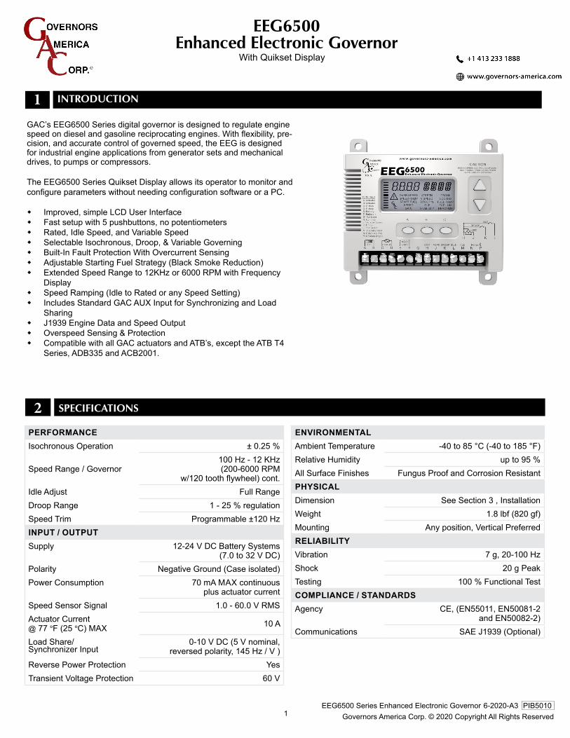
1 Governors America Corp. © 2020 Copyright All Rights ReservedEEG6500 Series Enhanced Electronic Governor 6-2020-A3 PIB5010
EEG6500Enhanced Electronic Governor
1
2
INTRODUCTION
SPECIFICATIONS
PerformanceIsochronous Operation ± 0.25 %
Speed Range / Governor100 Hz - 12 KHz(200-6000 RPM
w/120 tooth flywheel) cont.Idle Adjust Full RangeDroop Range 1 - 25 % regulationSpeed Trim Programmable ±120 HzInPUT / oUTPUTSupply 12-24 V DC Battery Systems
(7.0 to 32 V DC)Polarity Negative Ground (Case isolated)Power Consumption 70 mA mAx continuous
plus actuator currentSpeed Sensor Signal 1.0 - 60.0 V RMSActuator Current @ 77 °F (25 °C) mAx 10 A
Load Share/Synchronizer Input
0-10 V DC (5 V nominal, reversed polarity, 145 Hz / V )
Reverse Power Protection YesTransient Voltage Protection 60 V
With Quikset Display
GAC’s EEG6500 Series digital governor is designed to regulate engine speed on diesel and gasoline reciprocating engines. With flexibility, pre-cision, and accurate control of governed speed, the EEG is designed for industrial engine applications from generator sets and mechanical drives, to pumps or compressors.
The EEG6500 Series Quikset Display allows its operator to monitor and configure parameters without needing configuration software or a PC.
Improved, simple LCD User Interface Fast setup with 5 pushbuttons, no potentiometers Rated, Idle Speed, and Variable Speed Selectable Isochronous, Droop, & Variable Governing Built-In Fault Protection With Overcurrent Sensing Adjustable Starting Fuel Strategy (Black Smoke Reduction) Extended Speed Range to 12KHz or 6000 RPm with Frequency
Display Speed Ramping (Idle to Rated or any Speed Setting) Includes Standard GAC AUx Input for Synchronizing and Load
Sharing J1939 Engine Data and Speed Output Overspeed Sensing & Protection Compatible with all GAC actuators and ATB’s, except the ATB T4
Series, ADB335 and ACB2001.
envIronmenTalAmbient Temperature -40 to 85 °C (-40 to 185 °F)Relative Humidity up to 95 %All Surface Finishes Fungus Proof and Corrosion ResistantPHYSIcalDimension See Section 3 , InstallationWeight 1.8 lbf (820 gf)Mounting Any position, Vertical PreferredrelIaBIlITYVibration 7 g, 20-100 HzShock 20 g PeakTesting 100 % Functional TestcomPlIance / STanDarDSAgency CE, (EN55011, EN50081-2
and EN50082-2) Communications SAE J1939 (Optional)
2 Governors America Corp. © 2020 Copyright All Rights ReservedEEG6500 Series Enhanced Electronic Governor 6-2020-A3 PIB5010
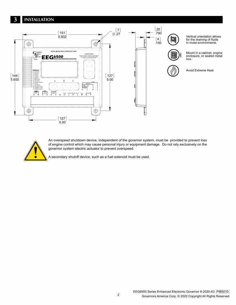
3
mount in a cabinet, engine enclosure, or sealed metal box.
Vertical orientation allows for the draining of fluids in moist environments.
Avoid Extreme Heat
[mm]inDimensions:
COM VSPD
EEGEnhanced Electronic Governor6500
www.governors-america.com
- CAUTION -ENGINE SPEED CONTROL COMPONENT
SEE PRODUCT PUBLICATION WHEN INSTALLING OR SERVICING
N PCAN
MAUXIDLE
LDROOP
KJHGBATT
FE
H J K L
V.SPD
IDLE
DROOP
A: ActuatorB: ActuatorC: PickupD: PickupE: Battery -F: Battery +G: Not UsedH: CommonJ: Variable SpeedK: DroopL: Idle SelectM: Auxiliary InputN: CANbus (Low)P: CANbus (High)
TERMINALS
L H- +
PICKUP
DCACT
BA
u.s.a.
CBA
An overspeed shutdown device, independent of the governor system, must be provided to prevent loss of engine control which may cause personal injury or equipment damage. Do not rely exclusively on the governor system electric actuator to prevent overspeed.
A secondary shutoff device, such as a fuel solenoid must be used.
INSTALLATION

3 Governors America Corp. © 2020 Copyright All Rights ReservedEEG6500 Series Enhanced Electronic Governor 6-2020-A3 PIB5010
A DCB E F N P
Actuator
Battery- +
MagneticSpeed Pickup
Fuse 15A Max
Ground to Case
(12V or 24V)
A NDCB E HGF LKJ M PA NDCB E HGF LKJ M P
CAN J1939( Optional )
AccessoryInput
Droop
Idle
Variable Speed / TrimPotentiometer 120 Ohms
( End of CAN bus)
Ground to Case
Ground to Case
5KΩ
COM
VSPD
4 WIRING
TermInal DefInITIon GaUGe / mm2 noTeSA Actuator (+) #16 / 1.31
B Actuator (-) #16 / 1.31
C Magnetic Pickup (+) #20 / 0.52
* Twisted wires 14 turns per foot. 0.02 in (.51 mm) gap between sensor and gear teeth.D Magnetic Pickup
(-) #20 / 0.52
E Battery (-) #16 / 1.31
F Battery (+) #16 / 1.31 A 15 A fuse must be installed in the positive battery lead to protect against any overload or short circuit
H Ground Signal #16 / 1.31 Reference for variable speed/trim input & switches
J Variable Speed Input #20 / 0.52 5K Ω Resistive, 0 - 2.5 V DC or 4-20 mA. Increasing voltage or resistance of current
increases speed
K Droop Select #16 / 1.31 Active when connected to Terminal H
L Idle Select #16 / 1.31 Active when connected to Terminal H
M Aux Input #20 / 0.52 Load sharing / synchronizing, 5 V nominal (0-10 V), reverse ramp
N CAN L #20 / 0.52Twist wires 14 turns per foot.
P CAN H #20 / 0.52
recommenDaTIonS1. Shielded cable should be used for all external connections to the EEG control. One end of each shield, including the speed sensor shield, should
be grounded to a single point on the EEG case.
2. Case should be grounded
5K Ω reSISTIve SPeeD TrIm PoT0-2.5 v or 4-20 ma* varIaBle SPeeD InPUT
When installing controller be sure there’s a good connection between the case of the EEG6500 and the chassis / battery ground.
If EEG detects no input from the magnetic pickup, the EEG will set the actuator to 0V and set the speed to 0 RPm. The display will flash the RPm along with the Warning Indicator. Parameters will be unchangeable.
* 4-20mA input requires an external 200 Ω resistor across Terminals H & J
ImPorTanT

4 Governors America Corp. © 2020 Copyright All Rights ReservedEEG6500 Series Enhanced Electronic Governor 6-2020-A3 PIB5010
5 DISPLAY & CONTROLS
One row of parameters is displayed at a time.
Row 2 Column 3locking/Unlocking the Display Press and hold both the UP and DOWN arrows si-multaneously for 3 seconds to UNLOCK or to LOCK the display.
OVER SPEED will blink when the unit is in over-speed. (Cycle power to restart)
Once the LOCK parameter on the main menu is en-abled (ON), the display can be manually unlocked.
If the EEG detects an actuator overcurrent it will terminate power to the actuator, the display will flash Actuator Current along with the warning indicator. (Cycle power to restart)
Displays the units for the parameter (e.g. RPm)
ParameTer UnITS
Displays the value of a selected parameter or live running parameter. This area will blink if a system shutdown and restart is required.
ParameTer valUe
Pressing UP or DOWN arrow toggles through the five secondary parameters: Engine Speed (RPm), Duty Cycle (%), Actuator Current (Amps), Engine Speed (Hz) and Variable Speed (%)
SeconDarY ParameTerS
overcUrrenT
QUIKSeT menU
fUel lImITIf the EEG detects that the FUEL LImIT setting has been exceeded, the display will flash the FUEL LImIT along with the warning indicator. Parameters will be unchanged.
over SPeeD
locK
21 3
Tap any
For: SPEEDFor: IDLEFor: FUEL LIm
Hold
To change the displayed row of parameters:
To view a parameter value in a selected row:
Hold: Button 1Hold: Button 2Hold: Button 3
colUmn SelecT BUTTonS
Parameter Adjust Up
Parameter AdjustDown
Increment a Parameter value:HOLD and TAP or
rapidly Increment a value:
HOLD and HOLD or
lock the Display:
HOLD and for 2 seconds
ParameTer aDjUST
enD USer InTerface
acTUaTor DUTY cYcle100%= 11 Bars90-99% = 10 bars...10-19% = 2 bars1-95% = 1 bar0% = 0 bars
PrImarY ParameTer valUe (Blinks if restart required) PrImarY ParameTer UnITS
Pressing either UP or DOWN arrow moves the primary and secondary parameters to the next parameter set. The list is always traversed in one direction.
PrImarY ParameTer (UnITS) Engine Speed (RPm) Duty Cycle (%)Actuator Current (A)Engine Speed (Hz)V-Speed (%)
SeconDarY ParameTer Actuator Duty CycleEngine Speed relative to set point
enGIne SPeeDmiddle bar = set pointTop bar = Set point + 10 RPmBottom bar = set point - 10 RPM
SeconDarY ParameTer

5 Governors America Corp. © 2020 Copyright All Rights ReservedEEG6500 Series Enhanced Electronic Governor 6-2020-A3 PIB5010
6 FEATURES
SPecIal menU ParameTer
QUIKSeT menU ParameTerS
vSPD moDe SPeeD v. SPeeD
OFF Trim (Default)
Application Rated Speed (e.g., 1500 RPm) Speed Trim (10 = ±10 Hz)
ON Variable Speed
Minimum speed when potentiometer is at lowest resistance (e.g.,1000 RPm)
maximum Speed when potentiometer is at the highest resistance(e.g., 2000 RPm)
TrIm or varIaBle SPeeD oPeraTIonTrim function - Performs finer adjustments (e.g. generator frequency) The resistive input speed function is active when the VSPD (Variable Speed) parameter is OFF (default value is OFF). 5K Ω potentiometer typical.variable Speed function - Operates over a larger RPm range. Variable speed 0 - 2.5 volt input to terminal J is active when VSPD (Variable Speed) parameter is ON.
The optional external switch must be connected between Terminals H and L. A pressure switch may also be used as a method of en-abling. When enabled, IDLE has an independent Gain adjustment.
Increasing voltage, resistance or current increases speed.
reSISTIve, volTaGe or cUrrenT InPUT To TermInal j
COM
A DCB E HGF LKJ MH J
5KΩ
CCW
Terminal J Utilizes A CCW Potentiometer
VSPDconversion formulas: HertzmAG PICKUP = (RPm x # Teeth) 60sec RPM = (HertzmAG PICKUP x 60sec) # Teeth
4-20mA input requires an external 200 Ohm resistor across H & J
IDle SPeeD
aUXIlIarY InPUT
The Auxiliary (Aux) input, terminal m, accepts signals from auto synchronizers, load sharing units, and other GAC accessories.

6 Governors America Corp. © 2020 Copyright All Rights ReservedEEG6500 Series Enhanced Electronic Governor 6-2020-A3 PIB5010
7Set the following parameters before starting the engine:
#TeeTH Input the Number of Teeth on the Flywheel. This can not be changed while engine is running.
cranK Input the Crank Termination (RPm)SPeeD Input the Fixed Speed of the Engine (RPm)
aDjUSTaBle QUIKSeT ParameTerS
over SPeeD * #TeeTH cranK *Range: 400 - 6000 RPM
Default: 2000 RPmRange: 60 - 250
Default: 120Range: 100 - 1000 RPM
Default: 400 RPm
RPm to automatically shutoff the actuator Number of teeth on flywheel RPm which EEG switches from starting fuel limit to fuel limit
SPeeD ramP v.SPeeD * locKeDRange: 25 - 2000
Default: 300Range: 0-6000 RPm (vspd) 0-120 Hz (trim)
Default: 1800 RPm (vspd) : 0 Hz (trim)Range: OFF, ON
Default: OFF
Rate at which speed changes from idle to set speed and back, or rate change in
variable speed mode.maximum speed change allowed from trim input
Enables manual/Auto locking of display. Press and hold UP and DOWN arrows simultaneously for 3
seconds to UNLOCK or LOCK the display.
STarT fUel DrooP% fUel ramPRange: 0 - 100%
Default: 100%Range: 0 - 25.0%
Default: 5.0%Range: 1 - 100% / Sec.
Default: 10%
Initial actuator position at the start of cranking
Droop to apply under maximum load (based on current of actuator)
Actuator position increase in percent per second from cranking to low idle speed, starting from the
Start Fuel position
SPeeD * IDle * fUel lImRange: 0-6000 RPm(fixed)
0-6000 RPm(droop)Default: 1500 RPm(fixed)
50 RPm(droop)
Range: 150 - 1500 RPMDefault: 900 RPm
Range: 0 - 100%Default: 100%
Operating speed of engine Speed of engine when IDLE input is closed maximum actuator percentage allowed
GaIn STaBIlITY DeaDTImeRange: 1 - 100, 100 = max Gain
Default: 50 (rated) : 10 (idle)
Range: 1 - 100, 100 = fastest responseDefault: 50
Range: LOW, HIDefault: HI
Proportional (P) set point of the PID con-trol at operating SPEED and IDLE Integral (I) set point of the PID control Derivative (D) set point of the PID control
* 12 KHz mAx
PRE-START SET-UP & qUICkSET PARAmETERS

7 Governors America Corp. © 2020 Copyright All Rights ReservedEEG6500 Series Enhanced Electronic Governor 6-2020-A3 PIB5010
8 ADJUSTING FOR STABILITY
GaIn - raTeD SPeeD & IDle SPeeD
Once the engine is running at operating speed and at no load, the following governor performance adjustments can be made to in-crease engine stability.
GaIn TYPe aDjUSTmenT ProceDUreRATED SPEED
1. Selected when IDLE input is disconnected.
IDLE SPEED
1.2.3.
Connect the idle input to ground.Change GAIN value.Disconnect Idle input from ground to switch back to Rated.Idle icon will blink.
The EEG6500 is equipped with two separate gains, one for rated speed, the other for idle speed. Both are set using the GAIN setting on the Quikset Menu.
QUIKSeT menUParameTer aDjUSTmenT ProceDUre
A. GAIN
1.2.3.4.
Increase this parameter until instability develops. Then, gradually decrease this parameter until stability returns.Finally, decrease this parameter one increment further to ensure stable performance. If instability persists, adjust the next parameter.
B. STABILITY 1.2.
Follow the same adjustment procedure as the GAIN parameter.If instability persists, adjust the next parameter.
C. DEADTImE 1. If fast instability occurs, switch DEADTImE to low and repeat steps A & B.
Normally, adjustments made at no load achieve satisfactory performance. For further performance see the System Troubleshooting section.noTe
9 ADJUSTING FOR DROOP
eXamPle
After the initial set up is completed and the # of Teeth, Crank Termination Speed and Rated Speed are set, position the external switch connecting Terminals H and K on to activate the DROOP mode following these sequence steps.
1. Go to the Advanced menu: Press and hold all three buttons simultaneously for two seconds to switch to Advanced menu.2. Confirm that the VSPD (Variable Speed / Fixed Speed Control) is OFF. Default position is off. 3. Confirm that the LEAD circuit is OFF. Default position is on.4. Set the NLCU (No Load Current) to the measured / displayed current value when operating at no load rated speed (default value
is 0.5 amps.)5. Set the FLCU (Full Load Current) to the measured / displayed current value when operating at full load rated speed (default
value is 4.0 amps.)6. Return to the main menu: Press and hold all three buttons simultaneously for two seconds to switch to the main menu.7. Select and set DROOP to the desired percentage.8. Change the Speed parameter, which turns into the DROOP OFFSET.9. This sets the RPm, above operating speed, to which the system will be commanded when DROOP is enabled. This is an offset
value.
1500 RPm operating speed x 0.05 (5.0% droop) = 75 RPm Input 75 RPm, this is the offset value.
The nlcU entered must be less than the flcU and the difference between the two must be at least 0.5 A. If an invalid combination is entered a warning will be flagged and the parameters will be default to 0.5 A and 4.0 A.

8 Governors America Corp. © 2020 Copyright All Rights ReservedEEG6500 Series Enhanced Electronic Governor 6-2020-A3 PIB5010
10 ADVANCED PARAmETERS mENU
aDvanceD menU ParameTerS (confIGUraBle)Parameter Definition range Default
AUx auxiliary Input Enable145 Hz/volt, 5 volt nominal Range: 1-9 V Off, On Off
VSPD variable Speed or Trim Select(On=Variable Speed, Off=Trim) Off, On Off
LFG light force Governor Off, On Off
LEADlead circuit - For Increased Governor Response / Increased GAIN Adjustment Authority.
Off, On On
NLCU no load current - Amps 0.0 - 9.5 0.5
FLCU full load current - Amps 0.5 - 10.0 4.0
aDvanceD menU ParameTerS (reaD onlY)Parameter Definition
SREV Software revision number
BID Software build identifier
AREV Assembly revision: Identifies board hardware configuration, not software.
FLTH Highest fault code since power up. Aids in trouble shooting.
DATL Supplemental data associated with last fault code. Aides in troubleshooting.
FLTL Last fault code detected. Associated data is DATL and aids in trouble shooting.
PreviousParameter
NextParameter
Selecting Parameters:
Display Specialmenu Parameters:
return to Quikset menu:
adjust Parameters:
1. After 3 minutes of no user input, EEG switches to Quikset Menu.
2. Lock is displayed when attempt to change a Read-Only parameter.
EEG6500 - Variable Speed Response to External Voltage Input Variable Speed Parameter (VSPD) - ON
IncreaseParameter
DecreaseParameter
Hold ALL 3 untilAUx appears in display
Hold ALL 3 for 2 seconds

9 Governors America Corp. © 2020 Copyright All Rights ReservedEEG6500 Series Enhanced Electronic Governor 6-2020-A3 PIB5010
lIGHT force Governor
Turning the Light Force Governor (LFG) feature ON (default is OFF) scales the governor’s proportional response (GAIN) for the best resolution when controlling small actuators, like the T1 ATB, ALR/ALN, 100/103/104 series and normally closed Cummins EFC actuators. Turn the LFG feature ON for use with these low current actuators.
The letters LFG display in place of the Primary Parameter Units when adjusting GAIN and STABILITY to indicate the feature is ON. The LFG Feature can only be be turned ON or OFF when the engine is not running.
leaD cIrcUIT
Turning the Lead Circuit (LEAD) ON (default is ON) enables the governor to be more responsive and typically increases the range of GAIN adjustment. Turn Lead Circuit ON when there is slow or moderate hunting at higher GAIN settings.
oem Save SeTTInGS
oem Save
OEm SAVE copies the currently active settings into separate OEm configuration area that can be restored at a later date.
OEm RESTORE copies the settings stored from the OEm configuration area into the current settings and saves them for next power up. After restoration, unit must be repowered to start engine. OEm Restore can only be done during power up.
oem reSTore
oem reSTore
10 ADVANCED PARAmETERS mENU (CONTINUED)

10 Governors America Corp. © 2020 Copyright All Rights ReservedEEG6500 Series Enhanced Electronic Governor 6-2020-A3 PIB5010
facTorY reSTore
facTorY reSTore
Factory Restore loads the default settings as shipped from GAC into the current settings and saves them for next power up. After resto-ration, unit must be repowered to start engine. Factory Restore can only be done during power up.
10 ADVANCED PARAmETERS mENU (CONTINUED)
For all other codes, note the condition and contact GAC. The WARNING indicator will blink and failures will cause a system shut down.
11 FAULT CODES
aDvanceD menU ParameTerS (confIGUraBle)coDe caUSe effecT cUSTomer acTIon
1 Actuator over current (continuous) Actuator turned off for 30 s. Check actuator wiring.
2 Loss of speed signal (inc/dec in speed by more than 64 Hz in 4 ms, 16 K Hz/s) WARNING indicator blinks then system shutdown Check speed pickup.
3 Over speed (speed exceeds OVER SPEED setting for 12 ms)
WARNING and OVER SPEED indicators blink then system shutdown.
Check fuel system, OVER SPEED, SPEED, and V.SPEED
203 Variable Speed settings are reversed. V.SPEED is lower than SPEED.
WARNING indicator blinks, speed set to V.SPEED setting, variable speed input unresponsive.
Flip V.SPEED and SPEED settings.
206 No potentiometer/signal detected on variable speed input when VSPD enabled.
WARNING indicator blinks, speed set to SPEED setting. Check potentiometer wiring.
241 New software loaded. Configuration not compatible. Default configuration used. Reset configuration.
251 Software loaded on incompatible hardware. WARNING indicator blinks then System shut-down. Return unit to GAC
307 FLCU / NLCU Setting invalid Load calculation done with 0.5 and 4.0 A values Adjust NLCU / FLCU
ImPorTanT
12 J1939 CAN INFO
j1939 address: 26
PGn DefInITIon noTeS61444 Engine Speed Engine speed in RPm

11 Governors America Corp. © 2020 Copyright All Rights ReservedEEG6500 Series Enhanced Electronic Governor 6-2020-A3 PIB5010
InSTaBIlITY
InSTaBIlITY SYmPTom ProBaBle caUSe
Fast PeriodicThe engine seems to jitter with a 3Hz or faster irregularity of
speed.1.2.
Readjust the GAIN and STABILITY for optimum control.In extreme cases, change the DEADTImE parameter.
Slow Periodic Speed irregularity below 3Hz. (Sometimes severe)
1.
2.
Check fuel system linkage during engine operation for: a. binding b. high friction c. poor linkageDEADTImE Parameter set too high.
Non-Periodic Erratic Engine Behavior
1. Increasing the GAIN should reduce the instability but not totally correct it. If this is the case, there is most likely a problem with the engine itself. Check for: a. engine mis-firings b. an erratic fuel system c. load changes on the generator set voltage regulator.
If unsuccessful in solving instability, contact GAC for [email protected] or call: 1-413-233-1888
13 SYSTEm TROUBLESHOOTING
If the engine governing system does not function, the fault may be determined by performing the voltage tests described in Steps 1 through 3. Positive (+) and negative (-) refer to meter polarity. Should normal values be indicated during troubleshooting steps, then the fault may be with the actuator or the wiring to the actuator. Tests are performed with battery power on and the engine off, except where noted. See actuator publication for testing procedure on the actuator.
SYSTem InoPeraTIve
STeP WIreS normal reaDInG ProBaBle caUSe
1 F(+) & E(-)Battery Supply
Voltage (12 or 24V DC)
1.2.3.
DC battery power not connected. Check for blown fuseLow battery voltageWiring error
2 C & D 1.0V AC RmS min. While Cranking
1.2.3.4.
Gap between speed sensor and gear teeth too great Improper or defective wiring to the speed sensorResistance between D and C should be 130 to 1200 Ω. Defective speed sensor.
3 F(+) & A(-) 1.0 - 2.0V DC While Cranking
1.2.3.4.5.
SPEED or IDLE parameter set incorrectlyCRANK or START FUEL set incorrectlyShort/open in actuator wiringDefective speed controlDefective actuator, see Actuator Troubleshooting
SYmPTom normal reaDInG ProBaBle caUSe
Engine Over Speeds
1. Do Not Crank. Apply DC power to the governor system.
1. If the actuator is at minimum fuel position and there exists an erroneous speed signal, then check speed sensor.
2. manually hold the engine at the desired running speed. measure the DC voltage between Termi-nals A(-) & F(+) on the speed control unit.
1.
2.
3.
If the voltage reading is 1.0 to 2.0 V DC: a. SPEED parameter set above desired speed b. Defective speed control unitIf voltage reading is > 2.0 V DC then check for: a. actuator binding b. linkage bindingIf the voltage reading is below 1.0 V DC check for defective speed control unit
3. Check #TEETH parameter. 1. Incorrect tooth count entered.
Over Speed shuts down engine after running
speed is reached1. Examine the SPEED and OVER SPEED oper-
ating parameters for the engine
1.2.3.4.5.6.
SPEED parameter set too high.OVER SPEED set too close to SPEED.Check SPEED RAmP parameter.Actuator or linkage binding.Speed Control unit defective.Gain too low.
Over Speed shuts downengine before running
speed is reached
1. Check resistance between Terminals C&D. Should be 130 to 1200 Ω. See specific magnet-ic Pick-up data for resistance.
1.2.
OVER SPEED set too lowIf the speed sensor signal is erroneous, then check the wiring.
UnSaTISfacTorY Performance

12 Governors America Corp. © 2020 Copyright All Rights ReservedEEG6500 Series Enhanced Electronic Governor 6-2020-A3 PIB5010
720 Silver Street, Agawam, mA 01001 USA
UnSaTISfacTorY Performance
SYmPTom normal reaDInG ProBaBle caUSe
Actuator does not energize fully
1. measure the voltage at thebattery while cranking.
1. If the voltage is less than: a. 7 V for a 12 V DC system, or b. 14 V for a 24 V DC system, Then: 1. Check wiring 2. Check circuit protection/relay 3. Check charging system 4. Check battery
2. momentarily connect Terminals A and F. The actuator should move to the full fuel position.
1.2.3.4.5.
Actuator or battery wiring in errorActuator or linkage bindingDefective actuatorFuse open. Check for short in actuator or harness.Check START FUEL and CRANK
Engine remains below desired governed speed
1. measure the actuator output, Terminals A & B, while running under governor control.
1.
2.
If voltage measurement is within 2V DC of the battery supply voltage level, then fuel control is restricted from reaching full fuel position, possibly due to mechanical governor, carburetor spring, or linkage interference.Check SPEED, IDLE, GAIN, START FUEL, and CRANK
13 SYSTEm TROUBLESHOOTING (CONTINUED)

13 Governors America Corp. © 2020 Copyright All Rights ReservedEEG6500 Series Enhanced Electronic Governor 6-2020-A3 PIB5010
eeG6500 Technical assistance WorksheetPlease provide the following information so we assist you with timely, technical recommendations:
Date:
Company Name:
Contact Info: E-mail Address: Phone Number:
Reported Problem:
Engine make, model & Application:
Controller model and Serial Number:
Actuator model and Serial Number:
eeG6500 Governor SeTTInGS
Parameter factory Settings customer SettingsGain 50 (Rated) 10 (Idle)
Stability 50
Deadtime HI
Speed 1500RPM
Idle 900 RPM
Fuel Limit % 100
Start Fuel % 100
Droop % 5.0
Fuel Ramp % 10
Speed Ramp 300 RPM/sec
V. Speed 1800 RPm (VSPD) 0 Hz (Trim)
Overspeed 2000 RPM
# of Teeth 120
Crank 400 RPM
aDvanceD SeTTInGS
Parameter factory Settings customer SettingsAUx Off
VSPD Off
LFG Off
LEAD Off
NLCU 0.5
FLCU 4.0
JADR 0
FLTL ------
DATL ------
FLTL ------
elecTrIcal cHecKS
F(+) & E (-) 12 or 24 Volts DC
C & D 1.0 VAC RmS min. at Cranking
F (+) & A (-) 1.0 to 2.0 VDC While Cranking
aDvanceD menU ParameTerS (reaD onlY)
Parameter factory Settings Software revision number
SREV ------