Educational software for teaching drawing-based conceptual design skills
12
Educational Software for Teaching Drawing-Based Conceptual Design Skills PEDRO COMPANY, 1 MANUEL CONTERO, 2 ANA PIQUER, 1 NURIA ALEIXOS, 1 JULIAN CONESA, 3 FERRAN NAYA 2 1 Technology Department, Universitat Jaume I, Campus del Riu Sec, E-12071 Castellon, Spain 2 Departmento de Expresio´n Gra´fica enla Ingenierı´a,Universidad Polite´cnica de Valencia, Caminode Vera S/N, E-46022 Valencia, Spain 3 Departmento de Expresio´n Gra´fica, Universidad Polite´cnica de Cartagena, Paseo Alfonso XIII,48, E-30203, Cartagena, Spain Received 10 October 2003; accepted 30 May 2004 ABSTRACT: An education-oriented computer application to draw sketches of polyhedrons that are automatically recognized to reconstructs the suitable three-dimensional (3D) models is presented. The users can modify the sketches and see the reaction their modifications have on the models. Earliest classroom tests show that the capacity for spatial vision is improved. A copy of the software may be obtained from the website of our research group at http:// www.tec.uji.es/d/regeo/index_eng.html. ß 2004 Wiley Periodicals, Inc. Comput Appl Eng Educ 12: 257268, 2004; Published online in Wiley InterScience (www.interscience.wiley.com); DOI 10.1002/cae.20023 Keywords: teaching methodology; innovative teaching-experiences; educational software; engineering graphics; computer-aided sketching INTRODUCTION One important objective of basic courses in engineer- ing graphics is the acquisition of spatial vision. This capability can be described as the ability to picture three-dimensional (3D) shapes in the mind’s eye. Acquiring this skill is important for the future engineer [1], but the process becomes very complex when 3D shapes are manipulated through 2D draw- ings, which have the added drawback of being static. It is far better to deal with models, even though they are ‘‘virtual’’ or computerized models and are dis- played just by means of 2D representations. Indeed, such representations have two great advantages. First, they can achieve a greater degree of realism (by using shadows, textures, and so on) with a lower execution cost. They can also be varied dynamically, that is to say, the object can be rotated ‘‘as if we were holding it in our hand.’’ Correspondence to P. Company ([email protected]). Contract grant sponsor: Fundacio ´ Caixa Castello ´-Bancaixa; contract grant number: P1-1B2002-08. ß 2004 Wiley Periodicals Inc. 257
Transcript of Educational software for teaching drawing-based conceptual design skills

Educational Software forTeaching Drawing-BasedConceptual Design Skills
PEDRO COMPANY,1 MANUEL CONTERO,2 ANA PIQUER,1 NURIA ALEIXOS,1
JULIAN CONESA,3 FERRAN NAYA2
1Technology Department, Universitat Jaume I, Campus del Riu Sec, E-12071 Castellon, Spain
2Departmento de Expresion Grafica en la Ingenierıa, Universidad Politecnica de Valencia, Camino de Vera S/N,
E-46022 Valencia, Spain
3Departmento de Expresion Grafica, Universidad Politecnica de Cartagena, Paseo Alfonso XIII, 48, E-30203,
Cartagena, Spain
Received 10 October 2003; accepted 30 May 2004
ABSTRACT: An education-oriented computer application to draw sketches of polyhedrons
that are automatically recognized to reconstructs the suitable three-dimensional (3D) models
is presented. The users can modify the sketches and see the reaction their modifications have
on the models. Earliest classroom tests show that the capacity for spatial vision is improved.
A copy of the software may be obtained from the website of our research group at http://
www.tec.uji.es/d/regeo/index_eng.html. � 2004 Wiley Periodicals, Inc. Comput Appl Eng Educ 12:
257�268, 2004; Published online in Wiley InterScience (www.interscience.wiley.com); DOI 10.1002/cae.20023
Keywords: teaching methodology; innovative teaching-experiences; educational software;
engineering graphics; computer-aided sketching
INTRODUCTION
One important objective of basic courses in engineer-
ing graphics is the acquisition of spatial vision. This
capability can be described as the ability to picture
three-dimensional (3D) shapes in the mind’s eye.
Acquiring this skill is important for the future
engineer [1], but the process becomes very complex
when 3D shapes are manipulated through 2D draw-
ings, which have the added drawback of being static.
It is far better to deal with models, even though they
are ‘‘virtual’’ or computerized models and are dis-
played just by means of 2D representations. Indeed,
such representations have two great advantages. First,
they can achieve a greater degree of realism (by using
shadows, textures, and so on) with a lower execution
cost. They can also be varied dynamically, that is to
say, the object can be rotated ‘‘as if we were holding it
in our hand.’’
Correspondence to P. Company ([email protected]).Contract grant sponsor: Fundacio Caixa Castello-Bancaixa;
contract grant number: P1-1B2002-08.
� 2004 Wiley Periodicals Inc.
257

In spite of these advantages and although design-
by-virtual-prototypes is being introduced in advanc-
ed courses, design-by-drawings is still used in basic
courses (but with the introduction of the new
computer-aided drafting (CAD) tools). The conse-
quence of this is that these courses attempt to combine
learning the essentials of representation systems with
the acquisition and/or consolidation of spatial vision.
CAD modeling applications are not used for this
purpose because their interfaces are not very user-
friendly.
The interfaces of CAD modeling applications, in
addition to being not user-friendly for those who have
not acquired spatial vision, they are of no use in the
conceptual design phase, where incomplete and ambi-
guous ideas are being handled. Sketches have tradi-
tionally allowed designers to deal with this process
in an efficient way. Yet, the ‘‘straightjacketed’’
commands and work schedules of present-day CAD
modeling systems are aimed at enabling complete and
consistent models to be created, and at preventing the
generation of ambiguous models. The ideal situation
is very different and has been described in very pro-
minent studies [2]. Consequently, at present rough
drafts and sketches are used to handle ambiguous or
inconsistent designs. Here, it is understood that rough
drafts allow geometrical shapes to be expressed
without being confined to the strict criteria of geo-
metry (since they are drawings that are imperfect or
inconsistent from a geometrical point of view), and
sketches allow partial or unfinished ideas to be
expressed (incomplete drawings). It is for this re-
ason that rough drafts and sketches are often said to
constitute the ‘‘natural’’ language that engineers and
designers use to synthesize new designs. This short-
coming of CAD systems results in teaching students
to sketch with ‘‘classical’’ instruments (pencil and
paper) to become an even more important objective in
engineering graphics courses. One undesirable con-
sequence is that the current situation prepares the
designer to generate the design by means of rough
drafts and sketches and later to construct the model on
a CAD system, once the process of drawing the rough
draft has finished. In short, the designer must read the
final draft and guide the CAD system in order to
construct the corresponding model, which obviously
creates a sensation of ‘‘repeating the same work’’ and
gives rise to the mistaken idea that sketching is
pointless.
In this paper, we present computer software that
attempts to put an end to the situation we have des-
cribed above. The application provides the user with a
virtual pencil with which to draw freehand on a sheet
of virtual paper. The sketch introduced by the user is a
(pseudo-axonometric) pictorial representation of a
polyhedral shape. The application includes an analy-
zer that automatically recognizes and reconstructs the
3D model sketched by the user. If the sketch contains
very important imperfections, a second module is
activated which ‘‘repairs’’ the sketch before analyzing
it in order to reconstruct the model. The graphical user
interface (GUI) is obtained through a calligraphic
interface that implements a very elementary set of
gestures (draw segment and erase segment). The
interface has vertex snap-tolerance, segment snap-
tolerance (so that very short segments are rejected),
and parallelism snap-tolerance (which places the
segments that form an angle below the tolerance level
parallel to one another). Three-dimensional visualiza-
tion is accomplished using OpenGL and consists of a
window that displays the model as a wireframe
representation or with solid faces. The visualization
of the model can be freely rotated and scaled. Other
complementary tasks are menu driven.
This application helps to develop the capacity for
spatial vision because the 3D model can be seen and
manipulated by the user at any time. For this reason,
any mistakes made while the axonometric representa-
tion is being sketched (such as the common errors that
involve ‘‘forgetting’’ certain edges) are quickly shown
up when the analyzer warns the user that no valid
geometrical 3D model can be generated or when the
analyzer generates a model that is perfectly coherent
with the sketch, but differs from the mental image the
user has of the object that he or she is attempting to
sketch.
The application forces the user to acquire skill in
sketching (since, it is the only way to draw), and
removes the feeling of repeating the same work that
occurs when, after sketching on paper, modeling must
be performed with a conventional modeling tool.
BACKGROUND
Following classical models like Hohenberg’s [3]
course in constructive geometry, most engineering
graphics courses do not emphasize learning descrip-
tive geometry as a body of fundamental doctrine
(knowledge) but rather they introduce its most
practical aspects directly and then use them to solve
problems in designing products (know how) [4,5]. The
traditional procedure in this approach has been to
combine learning the foundations of systems of
representation with the acquisition and/or consolida-
tion of spatial vision.
Today, it is feasible to teach design-by-virtual-
prototypes (based on 3D geometry) instead of design-
258 COMPANY ET AL.
by-drawings (based on 2D geometry), as there are 3D
CAD modeling applications at reasonable academic
prices and which work in a user-friendly manner that
favors the learning process. Although quite a number
of ways of carrying out the transition have already
been put forward (see, e.g. Ref. 6). For our purpose,
we must simply state that it seems that most of the
academic community understands that the transition
must be slow, since in certain industrial sectors and in
small and medium-sized industries design-by-draw-
ings will survive for some time to come (a simple
search on the Internet for courses on ‘‘Engineering
Design Graphics’’ is enough to show that the objec-
tives of most courses are aimed at teaching design-by-
drawing [7�11]). This justifies the need to train future
engineers in working in design-by-drawing environ-
ments. It is also the reason why design-by-virtual
prototypes is usually introduced in advanced and spe-
cific courses, while basic teaching syllabuses (which
are generic and included in the earlier courses) have
opted to carry on with design-by-drawing but at the
same time accepting the introduction of the latest
CAD tools.
With the introduction of drafting applications to
replace the classical tools the acquisition of spatial
vision has been put off until students attain elemen-
tary/intermediate skill in handling computerized
drafting applications. To a certain extent, this means
that the future engineer will have less capacity to
conceive new ideas from ‘‘mental images,’’ i.e., what
is seen in his or her mind’s eye [1]. In other words, the
emphasis that teaching projects place on CAD tools
leads to a poorer capacity to express the incomplete
and/or badly organized ideas that are so common
during the conceptual design phase, and which engi-
neers have always put into a concrete form by means
of sketches. Moreover, the capacity to sketch also
tends to diminish because of the unavoidable cutbacks
in teaching syllabuses.
The most frequently used solution to this dilemma
consists in making students use a sketch to work out
the answer to the problem and then asking them to
reproduce a perfectly drafted version of that same
piece of work. Although, this strategy does indeed
enable students to acquire skill in expressing them-
selves both through sketches and through technical
drawings, it also produces a certain feeling that time is
being wasted, since the student is aware that the same
task is being performed twice.
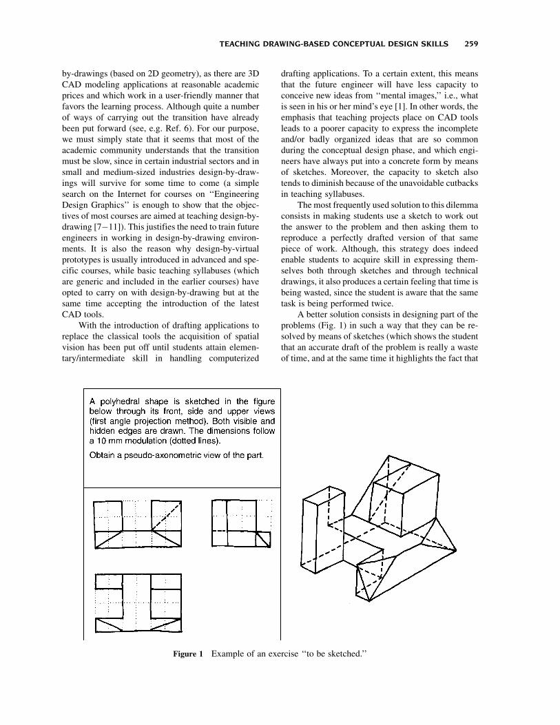
A better solution consists in designing part of the
problems (Fig. 1) in such a way that they can be re-
solved by means of sketches (which shows the student
that an accurate draft of the problem is really a waste
of time, and at the same time it highlights the fact that
Figure 1 Example of an exercise ‘‘to be sketched.’’
TEACHING DRAWING-BASED CONCEPTUAL DESIGN SKILLS 259
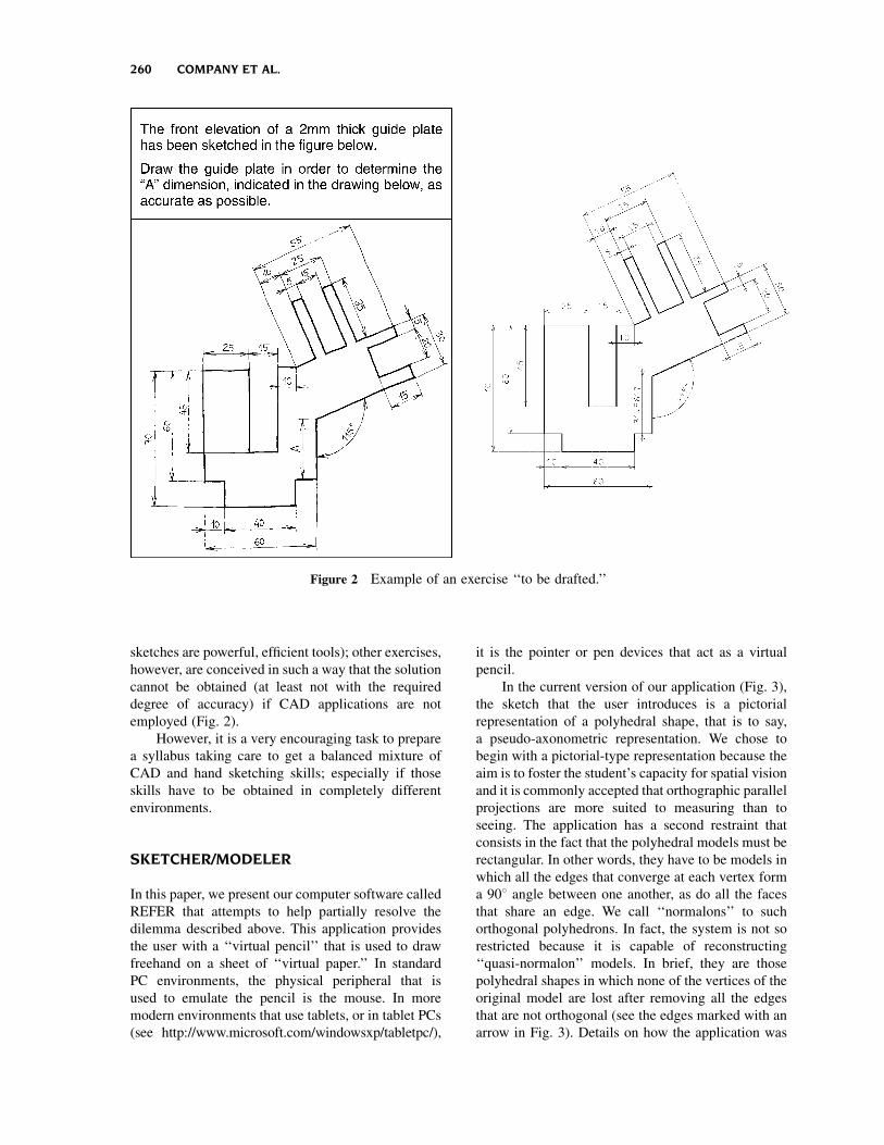
sketches are powerful, efficient tools); other exercises,
however, are conceived in such a way that the solution
cannot be obtained (at least not with the required
degree of accuracy) if CAD applications are not
employed (Fig. 2).
However, it is a very encouraging task to prepare
a syllabus taking care to get a balanced mixture of
CAD and hand sketching skills; especially if those
skills have to be obtained in completely different
environments.
SKETCHER/MODELER
In this paper, we present our computer software called
REFER that attempts to help partially resolve the
dilemma described above. This application provides
the user with a ‘‘virtual pencil’’ that is used to draw
freehand on a sheet of ‘‘virtual paper.’’ In standard
PC environments, the physical peripheral that is
used to emulate the pencil is the mouse. In more
modern environments that use tablets, or in tablet PCs
(see http://www.microsoft.com/windowsxp/tabletpc/),
it is the pointer or pen devices that act as a virtual
pencil.
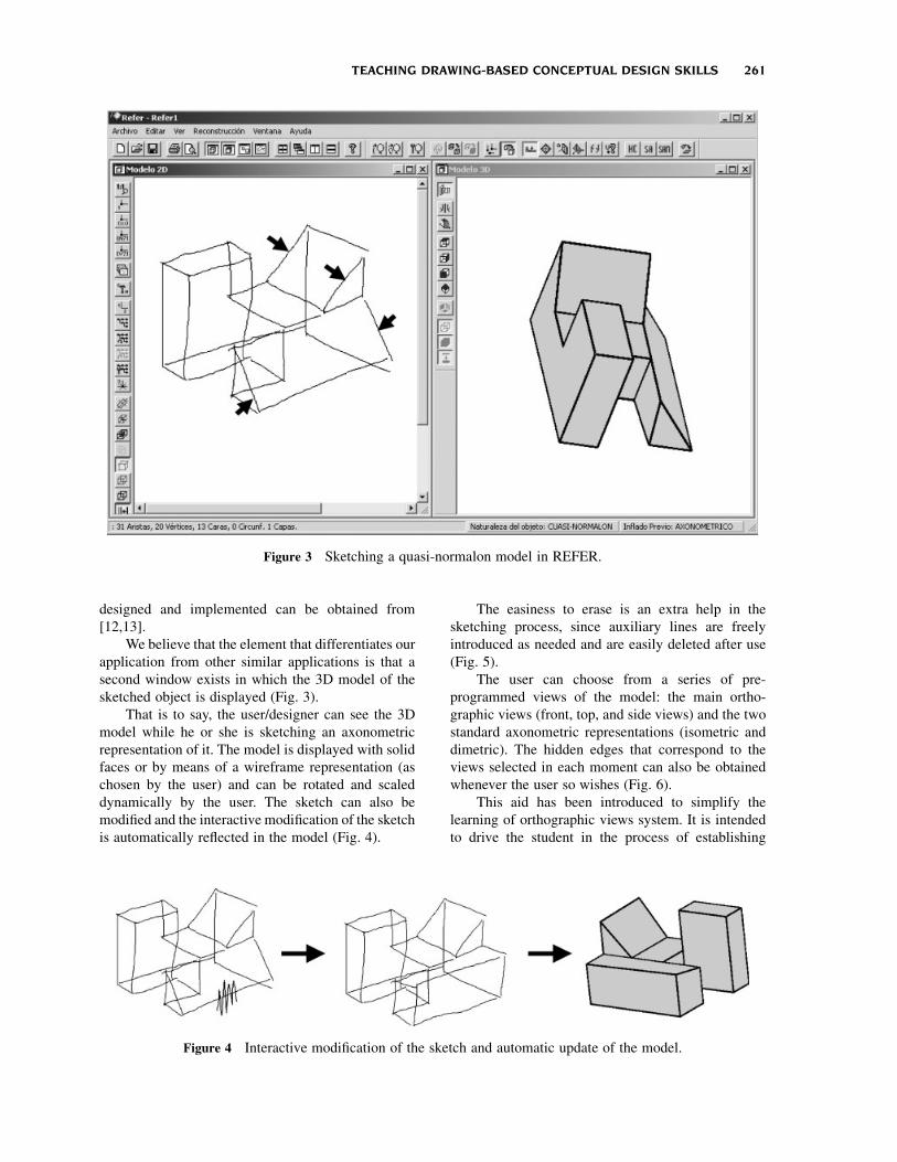
In the current version of our application (Fig. 3),
the sketch that the user introduces is a pictorial
representation of a polyhedral shape, that is to say,
a pseudo-axonometric representation. We chose to
begin with a pictorial-type representation because the
aim is to foster the student’s capacity for spatial vision
and it is commonly accepted that orthographic parallel
projections are more suited to measuring than to
seeing. The application has a second restraint that
consists in the fact that the polyhedral models must be
rectangular. In other words, they have to be models in
which all the edges that converge at each vertex form
a 908 angle between one another, as do all the faces
that share an edge. We call ‘‘normalons’’ to such
orthogonal polyhedrons. In fact, the system is not so
restricted because it is capable of reconstructing
‘‘quasi-normalon’’ models. In brief, they are those
polyhedral shapes in which none of the vertices of the
original model are lost after removing all the edges
that are not orthogonal (see the edges marked with an
arrow in Fig. 3). Details on how the application was
Figure 2 Example of an exercise ‘‘to be drafted.’’
260 COMPANY ET AL.
designed and implemented can be obtained from
[12,13].
We believe that the element that differentiates our
application from other similar applications is that a
second window exists in which the 3D model of the
sketched object is displayed (Fig. 3).
That is to say, the user/designer can see the 3D
model while he or she is sketching an axonometric
representation of it. The model is displayed with solid
faces or by means of a wireframe representation (as
chosen by the user) and can be rotated and scaled
dynamically by the user. The sketch can also be
modified and the interactive modification of the sketch
is automatically reflected in the model (Fig. 4).
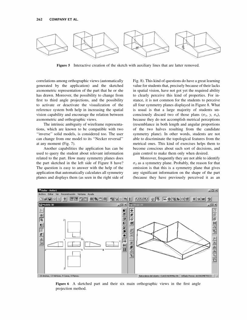
The easiness to erase is an extra help in the
sketching process, since auxiliary lines are freely
introduced as needed and are easily deleted after use
(Fig. 5).
The user can choose from a series of pre-
programmed views of the model: the main ortho-
graphic views (front, top, and side views) and the two
standard axonometric representations (isometric and
dimetric). The hidden edges that correspond to the
views selected in each moment can also be obtained
whenever the user so wishes (Fig. 6).
This aid has been introduced to simplify the
learning of orthographic views system. It is intended
to drive the student in the process of establishing
Figure 3 Sketching a quasi-normalon model in REFER.
Figure 4 Interactive modification of the sketch and automatic update of the model.
TEACHING DRAWING-BASED CONCEPTUAL DESIGN SKILLS 261
correlations among orthographic views (automatically
generated by the application) and the sketched
axonometric representation of the part that he or she
has drawn. Moreover, the possibility to change from
first to third angle projections, and the possibility
to activate or deactivate the visualization of the
reference system both help in increasing the spatial
vision capability and encourage the relation between
axonometric and orthographic views.
The intrinsic ambiguity of wireframe representa-
tions, which are known to be compatible with two
‘‘inverse’’ solid models, is considered too. The user
can change from one model to its ‘‘Necker reversal’’
at any moment (Fig. 7).
Another capabilities the application has can be
used to query the student about relevant information
related to the part. How many symmetry planes does
the part sketched in the left side of Figure 8 have?
The question is easy to answer with the help of the
application that automatically calculates all symmetry
planes and displays them (as seen in the right side of
Fig. 8). This kind of questions do have a great learning
value for students that, precisely because of their lacks
in spatial vision, have not got yet the required ability
to clearly perceive this kind of properties. For in-
stance, it is not common for the students to perceive
all four symmetry planes displayed in Figure 8. What
is usual is that a large majority of students un-
consciously discard two of those plans (s3, y, s4),
because they do not accomplish metrical perceptions
(resemblance in both length and angular proportions
of the two halves resulting from the candidate
symmetry plane). In other words, students are not
able to discriminate the topological features from the
metrical ones. This kind of exercises helps them to
become conscious about such sort of decisions, and
gain control to make them only when desired.
Moreover, frequently they are not able to identify
s2 as a symmetry plane. Probably, the reason for that
omission is that this is a symmetry plane that gives
any significant information on the shape of the part
(because they have previously perceived it as an
Figure 5 Interactive creation of the sketch with auxiliary lines that are latter removed.
Figure 6 A sketched part and their six main orthographic views in the first angle
projection method.
262 COMPANY ET AL.

‘‘extruded’’ shape, and hence, this symmetry plane is
seen as a consequence of that feature). In other words,
the freshman students are not able to analyze the
object to extract all it topological information. They
just extract the part of topological information that is
relevant for them.
DISCUSSION
The first thing to be highlighted is that the sketcher
allows the user to generate axonometric representa-
tions in a more user-friendly manner than can be done
with current CAD software (2D CAD applications).
Employing an axonometric sketcher instead of
the virtual instruments that aid the drafting of axo-
nometric projections included in commercial CAD
applications fosters creativity; this is because these
tools are focused on enabling the user to draft rigo-
rously geometric axonometric representations (that is
to say, representations with longitudinal and angular
measurements that satisfy the laws of projective geo-
metry that correspond to axonometric projections).
The isometric grid in AutoCAD (Fig. 9) and the
isometric locks in Microstation (Fig. 10) are typical
examples of these instruments. Indeed AutoCAD has
a tool that makes it easier to draft a particular type
of axonometric projections: isometric SNAP. The tool
combines with a switch that activates one of the
three main work planes (upper, left, and right). This
‘‘isometric parallax’’ makes it easier to construct
isometric representations but has some serious draw-
backs, such as not allowing the user to vary the angles
in order to obtain other axonometric projections.
Another serious shortcoming is that it does not modify
the behavior of some transformations that could help
construct the isometric figures. This is the case of
parallelism, which builds lines parallel to the original
one but measures the separation in a direction that is
orthogonal to the original line instead of measuring
in the isometric direction (see Fig. 10). Something
similar happens with Microstation’s isometric grid
block and its three isometric planes.
Unlike commercial CAD applications, the ske-
tcher focuses on controlling the topology of the
object that has been designed and ignores its final
dimensions.
Secondly, and this is perhaps the most important
advantage, the feeling that sketching is a waste of
time disappears when using this application since the
student sees that, after sketching the object he or she
has conceived, both a 3D model and different 2D
representations of the same object are automatically
displayed. In other words, after using a sketch to con-
ceive the object, it is automatically generated and
there is no need to construct it a second time.
The capacity for spatial vision is obviously also
reinforced because the student can see and manipul-
ate the 3D model. Furthermore, any mistakes made
while sketching (such as the common errors that
involve ‘‘forgetting’’ certain edges) are quickly shown
up when the analyzer warns the user that no valid
geometrical 3D model can be generated or when the
analyzer generates a model that is perfectly coherent
with the sketch, but differs from the mental image the
user has of the object that he or she is attempting to
sketch.
The sketcher is very simple and intuitive to use
when the objects being represented are low or medium
complexity polyhedrons. However, a lot of skill in
drafting and a great capacity for spatial vision are
required when it comes to generating complex shapes.
Examples such as the one in Figures 11 and 12 show
that only an expert can accomplish such sophisticated
representations, which amounts to saying that the tool
is of no practical use to an expert designer who
conceives sophisticated shapes. In Figure 11, only the
faces and edges that are completely visible are re-
presented. The rest of the polyhedral model has not
Figure 7 A wireframe of a part and the orthographic
main views of their two ‘‘Necker reversal’’ models.
Figure 8 A wireframe of a part and their four
topollogically valid symmetry planes.
TEACHING DRAWING-BASED CONCEPTUAL DESIGN SKILLS 263

been represented. For this reason, the model is suc-
cessful, but what is constructed is a ‘‘bent sheet’’ or
‘‘origami’’ type model.
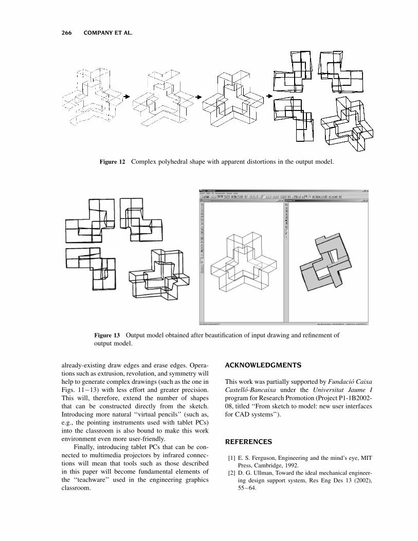
Figure 12 shows the complete model and its re-
construction. It can clearly be seen how difficult it is to
achieve parallel, collinear, and convergent edges
because the model generated is quite distorted.
Figure 13 shows the result that is obtained if an anal-
yzer module is run to ‘‘repair’’ the original drawing by
‘‘parallelizing’’ the edges that are badly drawn. The
result obtained after applying this parallelization
function is shown on the left, but it is has an un-
acceptable computational cost for an interactive
system (several minutes). The image on the right
shows the result after touching up the drawing a little
by hand (i.e., redrawing the edges that are obviously
not parallel) and then also running the analyzer before
reconstructing. In both cases, the model that is finally
generated still contains some distortions.
Although, as described above, the system is still
not easy to use when it comes to sketching complex
shapes, the initial aims of this work have been more
than fulfilled. The experimental results show that
the percentage of success obtained from introduc-
ing this application into a classroom full of students
who are beginning their training in axonometric
representations and who are also expected to acquire
a certain degree of mastery of spatial vision is very
high. Students quickly got used to using the sketcher.
Furthermore, when they learn to export axonometric
views in DXF, they prefer to do the sketch in REFER
and export the axonometric view rather than draw
directly with the isometric tools provided by com-
mercial 2D CAD applications.
CONCLUSIONS AND FUTURE RESEARCH
The sketcher is a simple tool and it is easy to in-
corporate into a design-by-drawing syllabus. Its main
value lies in its being able to reinforce the capacity for
spatial vision at the beginning of the course. It is
especially appealing because in that moment the
student still does not have enough skill in handling
Figure 9 Drawing with isometric locks and Accudraw compass in Microstation.
264 COMPANY ET AL.

commercial 2D CAD applications, and also because
the tools for drafting axonometric projections in-
cluded in these applications are very limited and force
the user to work in a way that is not particularly
natural and not at all user-friendly.
Secondly, the sketcher makes learning the ab-
solutely necessary skill of sketching more attractive to
the student because, since the final model is generated
automatically, the feeling that sketching is ‘‘pointless
work’’ disappears.
The system has been tested in the classroom and
very promising results were obtained. The applica-
tion will become more powerful and user-friendly if
some of the more usual operations are added to the
Figure 10 ‘‘Unnatural’’ functioning of parallelism.
Figure 11 Origami model.
TEACHING DRAWING-BASED CONCEPTUAL DESIGN SKILLS 265
already-existing draw edges and erase edges. Opera-
tions such as extrusion, revolution, and symmetry will
help to generate complex drawings (such as the one in
Figs. 11�13) with less effort and greater precision.
This will, therefore, extend the number of shapes
that can be constructed directly from the sketch.
Introducing more natural ‘‘virtual pencils’’ (such as,
e.g., the pointing instruments used with tablet PCs)
into the classroom is also bound to make this work
environment even more user-friendly.
Finally, introducing tablet PCs that can be con-
nected to multimedia projectors by infrared connec-
tions will mean that tools such as those described
in this paper will become fundamental elements of
the ‘‘teachware’’ used in the engineering graphics
classroom.
ACKNOWLEDGMENTS
This work was partially supported by Fundacio Caixa
Castello-Bancaixa under the Universitat Jaume I
program for Research Promotion (Project P1-1B2002-
08, titled ‘‘From sketch to model: new user interfaces
for CAD systems’’).
REFERENCES
[1] E. S. Ferguson, Engineering and the mind’s eye, MIT
Press, Cambridge, 1992.
[2] D. G. Ullman, Toward the ideal mechanical engineer-
ing design support system, Res Eng Des 13 (2002),
55�64.
Figure 12 Complex polyhedral shape with apparent distortions in the output model.
Figure 13 Output model obtained after beautification of input drawing and refinement of
output model.
266 COMPANY ET AL.

[3] F. Hohenberg, Konstruktive geometrie fur techniker,
Springer, Wien, 1956.
[4] G. R. Bertoline, E. N. Wiebe, C. L. Miller, and L. O.
Nasman, Fundamentals of graphics communication,
Richard D. Irwin, Burr Ridge, IL, 1996.
[5] K. Holliday-Darr, Applied descriptive geometry, 2nd
ed., Delmar Publishers, 1998.
[6] R. O. Bucal, Incorporating solid modeling and team-
based design into freshman Engineering Graphics, Eng
Des Graph J 65 (2001), 19�29.
[7] S. McMains, E28—Basic engineering design
graphics. Retrieved September 20, 2003, from
University of California at Berkely, Mechanical
Engineering Web site: http://www.me.berkeley.edu/
e28/E28syllabus.pdf
[8] Engineering design and graphics 100. Retrieved
September 20, 2003, from Penn State University,
College of Engineering Web site: http://www.cede.
psu.edu/edg100
[9] Engineering design graphics. Retrieved September 20,
2003, from Austin Community College Web site:
http://www2.austincc.edu/edg
[10] R. Barr, ME210 engineering design graphics. Retrieved
September 20, 2003 from University of Texas at Austin
Web site: http://www.me.utexas.edu/�rbarr
[11] H. Fulmer, EGR 1610—Engineering design graphics.
Retrieved September 20, 2003 from Villanova Uni-
versity, Department of Mechanical Engineering Web
site: http://www99.homepage.villanova.edu/howard.-
fulmer/1610.html
[12] P. Company, J. M. Gomis, and M. Contero, Geome-
trical reconstruction from single line drawings using
optimization-based approaches, WSCG’99 Confer-
ence Proceedings, Vaclav Skala, Ed., Vol. II, 1999,
pp 361�368.
[13] A. Piquer, P. Company, R. R. Martin, and R. R.
Skewed, Mirror symmetry in the 3D reconstruction of
polyhedral models, J WSCG 11 (2003), 504�511.
BIOGRAPHIES
Pedro Company earned his PhD degree
in mechanical engineering at Polytechnic
University of Valencia in 1989. He joined
the Department of Technology of Jaume I
University, Castellon, Spain in 1994, where
he has been a full professor (catedratico)
in engineering graphics since 1996 and
head of Department of Technology since
1995. He teaches undergraduate students
(in industrial, chemical, and industrial-
design engineering) and also at the graduate
(doctorate) level, and he has authored textbooks on geometrical
design and normalized drawings. His fields of interest include
technical drawings, computer-aided design, and computer graphics.
He has been recently the main researcher in a project aimed at the
‘‘implemention, design, and manufacture of advanced technologies
in a concurrent engineering environment, applied to an automotive
components manufacturing company,’’ and is currently the main
researcher in a project titled ‘‘From Sketch to Model: New User
Interfaces for CAD Systems.’’
Manuel Contero is an associate professor of
engineering graphics at the Polytechnic
University of Valencia, Spain. His research
interests include calligraphic interfaces and
new modeling methodologies for CAD
applications, concurrent engineering, and
product data quality models. He received
his MS and PhD degrees in electrical
engineering from Polytechnic University of
Valencia.
Nuria Aleixos received an MS (1992) and
PhD (1999) degrees in computer science at
Polytechnic University of Valencia, Spain.
She worked for private companies since
1990 developing applications for commer-
cial CAD systems, and she worked for
2 years at the Public Research Institute IVIA
(Instituto Valenciano de Investigaciones
Agrarias) developing machine vision sys-
tems for automatic fruit inspection. She joined the Department of
Technology at Jaume I University, Castellon, Spain in 1996, where
she is an associate professor of engineering graphics. Her fields of
interest include modeling methodologies for CAD applications,
computer-aided design, image processing, and calligraphic interfaces.
Ana Piquer is an assistant professor of
engineering graphics at Jaume I University,
Castellon, Spain. Her research interest
focuses on three-dimensional reconstruction,
computer graphics, computer-aided design,
and technical drawing. She received an MSc
degree in manufacturing engineering from
the Polytechnic University of Valencia and a
PhD degree in mechanical engineering from
the Jaume I University.
TEACHING DRAWING-BASED CONCEPTUAL DESIGN SKILLS 267

Julian Conesa received an MS (1992) and
PhD (2001) degrees in mechanical engineer-
ing at Polytechnic University of Cartagena.
He joined the Department of Engineering
Graphics at Polytechnic University of Car-
tagena, Spain, in 1998, where he is an
associate professor. His research interests
include computer graphics, computer-aided
design, geometrical reconstruction, calli-
graphic interfaces, and sketch-based modeling applications.
Ferran Naya is an assistant professor of
engineering graphics at the Polytechnic
University of Valencia, Spain. His research
interests include calligraphic interfaces and
sketch-based modeling applications. He
received his MS degree in mechanical
engineering from Polytechnic University of
Valencia. Currently, he is completing his
PhD in sketch-based modeling in the De-
partment of Engineering Graphics at the
Polytechnic University of Valencia.
268 COMPANY ET AL.