EDR1 removal and replacement procedures - Bull On-line ...
62
EDR1 removal and replacement procedures ESCALA Power7 REFERENCE 86 A1 26FK 01
-
Upload
khangminh22 -
Category
Documents
-
view
0 -
download
0
Transcript of EDR1 removal and replacement procedures - Bull On-line ...
EDR1 removal and replacement procedures
ESC
ALA
Pow
er7
REFERENCE 86 A1 26FK 01

EDR1 removal and replacement procedures The ESCALA Power7 publications concern the following models: - Bull Escala E1-700 (Power 710 / 8231-E2B) - Bull Escala E1-705 (Power 710 / 8231-E1C) - Bull Escala E2-700 / E2-700T (Power 720 / 8202-E4B) - Bull Escala E2-705 / E2-705T (Power 720 / 8202-E4C) - Bull Escala E3-700 (Power 730 / 8231-E2B) - Bull Escala E3-705 (Power 730 / 8231-E2C) - Bull Escala E4-700 / E4-700T (Power 740 / 8205-E6B) - Bull Escala E4-705 (Power 740 / 8205-E6C) - Bull Escala E5-700 (Power 750 / 8233-E8B) - Bull Escala M6-700 (Power 770 / 9117-MMB) - Bull Escala M6-705 (Power 770 / 9117-MMC) - Bull Escala M6-715 (Power 770 / 9117-MMD) - Bull Escala M7-700 (Power 780 / 9179-MHB) - Bull Escala M7-705 (Power 780 / 9179-MHC) - Bull Escala M7-715 (Power 780 / 9179-MHD)
References to Power 755 / 8236-E8C models are irrelevant.
Hardware November 2012
BULL CEDOC
357 AVENUE PATTON
B.P.20845
49008 ANGERS CEDEX 01
FRANCE
REFERENCE 86 A1 26FK 01
The following copyright notice protects this book under Copyright laws which prohibit such actions as, but not limited to, copying, distributing, modifying, and making derivative works.
Copyright © Bull SAS 2012
Printed in France
Trademarks and Acknowledgements
We acknowledge the rights of the proprietors of the trademarks mentioned in this manual.
All brand names and software and hardware product names are subject to trademark and/or patent protection.
Quoting of brand and product names is for information purposes only and does not represent trademark misuse.
The information in this document is subject to change without notice. Bull will not be liable for errors contained herein, or for incidental or consequential damages in connection with the use of this material.
Contents
Safety notices . . . . . . . . . . . . . . . . . . . . . . . . . . . . . . . . . v
EDR1 PCIe storage enclosure removal and replacement procedures . . . . . . . . . 1Removing and installing a fan assembly for an EDR1 PCIe storage enclosure . . . . . . . . . . . . . . 3Removing and installing a midplane for an EDR1 PCIe storage enclosure . . . . . . . . . . . . . . . 4Removing and installing a power supply for an EDR1 PCIe storage enclosure . . . . . . . . . . . . . 17Removing and installing a PCIe cable for an EDR1 PCIe storage enclosure . . . . . . . . . . . . . . 19
Removing and installing a PCIe cable with the power off . . . . . . . . . . . . . . . . . . . 20Removing and installing a PCIe cable with the power on . . . . . . . . . . . . . . . . . . . 21
Removing and installing a solid-state drive for an EDR1 PCIe storage enclosure . . . . . . . . . . . . 26Removing and installing an enclosure RAID module assembly for an EDR1 PCIe storage enclosure . . . . . . 26
Removing and installing an enclosure RAID module assembly with the power off. . . . . . . . . . . 26Removing and installing an enclosure RAID module assembly with the power on in the AIX environment . . 28Removing and installing an enclosure RAID module assembly with the power on in the Linux environment . . 34
Notices . . . . . . . . . . . . . . . . . . . . . . . . . . . . . . . . . . . 39Trademarks . . . . . . . . . . . . . . . . . . . . . . . . . . . . . . . . . . . 40Electronic emission notices . . . . . . . . . . . . . . . . . . . . . . . . . . . . . . 40
Class A Notices . . . . . . . . . . . . . . . . . . . . . . . . . . . . . . . . . 40Class B Notices . . . . . . . . . . . . . . . . . . . . . . . . . . . . . . . . . 44
Terms and conditions . . . . . . . . . . . . . . . . . . . . . . . . . . . . . . . . 46
iii

iv EDR1 removal and replacement procedures
Safety notices
Safety notices may be printed throughout this guide.v DANGER notices call attention to a situation that is potentially lethal or extremely hazardous to
people.v CAUTION notices call attention to a situation that is potentially hazardous to people because of some
existing condition.v Attention notices call attention to the possibility of damage to a program, device, system, or data.
World Trade safety information
Several countries require the safety information contained in product publications to be presented in theirnational languages. If this requirement applies to your country, a safety information booklet is includedin the publications package shipped with the product. The booklet contains the safety information inyour national language with references to the U.S. English source. Before using a U.S. English publicationto install, operate, or service this product, you must first become familiar with the related safetyinformation in the booklet. You should also refer to the booklet any time you do not clearly understandany safety information in the U.S. English publications.
Laser safety information
The servers can use I/O cards or features that are fiber-optic based and that utilize lasers or LEDs.
Laser compliance
The servers may be installed inside or outside of an IT equipment rack.
v
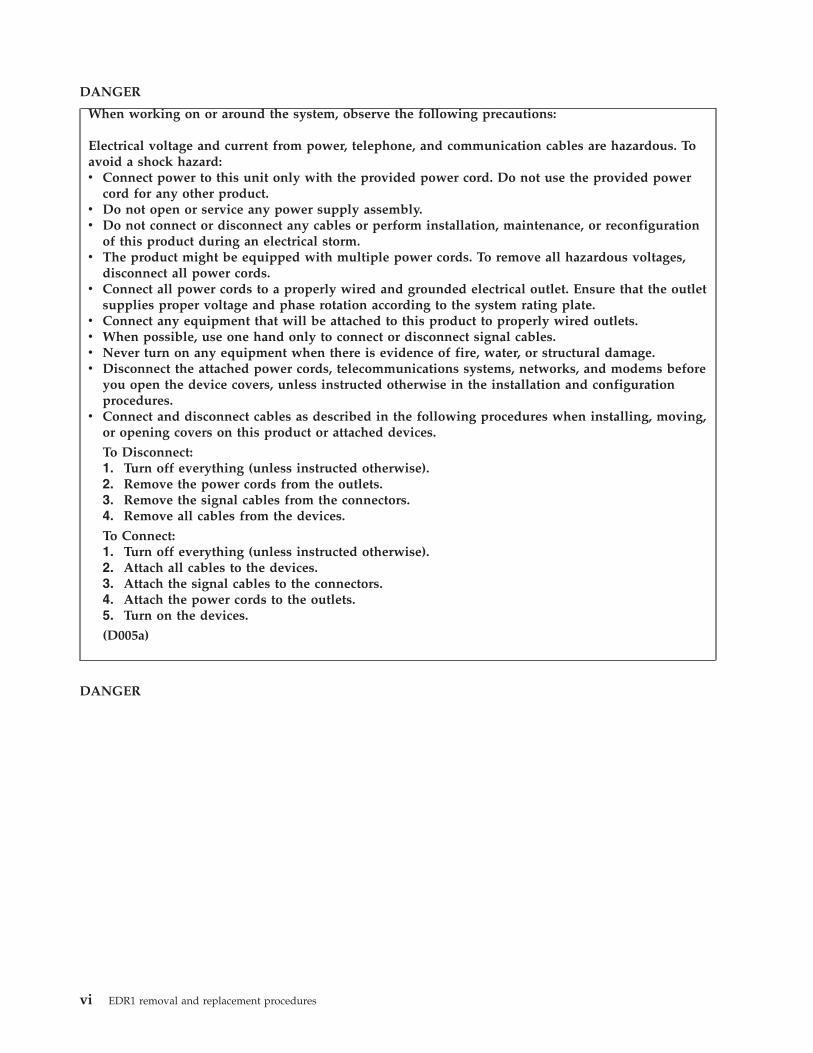
DANGER
When working on or around the system, observe the following precautions:
Electrical voltage and current from power, telephone, and communication cables are hazardous. Toavoid a shock hazard:v Connect power to this unit only with the provided power cord. Do not use the provided power
cord for any other product.v Do not open or service any power supply assembly.v Do not connect or disconnect any cables or perform installation, maintenance, or reconfiguration
of this product during an electrical storm.v The product might be equipped with multiple power cords. To remove all hazardous voltages,
disconnect all power cords.v Connect all power cords to a properly wired and grounded electrical outlet. Ensure that the outlet
supplies proper voltage and phase rotation according to the system rating plate.v Connect any equipment that will be attached to this product to properly wired outlets.v When possible, use one hand only to connect or disconnect signal cables.v Never turn on any equipment when there is evidence of fire, water, or structural damage.v Disconnect the attached power cords, telecommunications systems, networks, and modems before
you open the device covers, unless instructed otherwise in the installation and configurationprocedures.
v Connect and disconnect cables as described in the following procedures when installing, moving,or opening covers on this product or attached devices.
To Disconnect:1. Turn off everything (unless instructed otherwise).2. Remove the power cords from the outlets.3. Remove the signal cables from the connectors.4. Remove all cables from the devices.
To Connect:1. Turn off everything (unless instructed otherwise).2. Attach all cables to the devices.3. Attach the signal cables to the connectors.4. Attach the power cords to the outlets.5. Turn on the devices.
(D005a)
DANGER
vi EDR1 removal and replacement procedures
Observe the following precautions when working on or around your IT rack system:
v Heavy equipment–personal injury or equipment damage might result if mishandled.
v Always lower the leveling pads on the rack cabinet.
v Always install stabilizer brackets on the rack cabinet.
v To avoid hazardous conditions due to uneven mechanical loading, always install the heaviestdevices in the bottom of the rack cabinet. Always install servers and optional devices startingfrom the bottom of the rack cabinet.
v Rack-mounted devices are not to be used as shelves or work spaces. Do not place objects on topof rack-mounted devices.
v Each rack cabinet might have more than one power cord. Be sure to disconnect all power cords inthe rack cabinet when directed to disconnect power during servicing.
v Connect all devices installed in a rack cabinet to power devices installed in the same rackcabinet. Do not plug a power cord from a device installed in one rack cabinet into a powerdevice installed in a different rack cabinet.
v An electrical outlet that is not correctly wired could place hazardous voltage on the metal parts ofthe system or the devices that attach to the system. It is the responsibility of the customer toensure that the outlet is correctly wired and grounded to prevent an electrical shock.
CAUTION
v Do not install a unit in a rack where the internal rack ambient temperatures will exceed themanufacturer's recommended ambient temperature for all your rack-mounted devices.
v Do not install a unit in a rack where the air flow is compromised. Ensure that air flow is notblocked or reduced on any side, front, or back of a unit used for air flow through the unit.
v Consideration should be given to the connection of the equipment to the supply circuit so thatoverloading of the circuits does not compromise the supply wiring or overcurrent protection. Toprovide the correct power connection to a rack, refer to the rating labels located on theequipment in the rack to determine the total power requirement of the supply circuit.
v (For sliding drawers.) Do not pull out or install any drawer or feature if the rack stabilizer bracketsare not attached to the rack. Do not pull out more than one drawer at a time. The rack mightbecome unstable if you pull out more than one drawer at a time.
v (For fixed drawers.) This drawer is a fixed drawer and must not be moved for servicing unlessspecified by the manufacturer. Attempting to move the drawer partially or completely out of therack might cause the rack to become unstable or cause the drawer to fall out of the rack.
(R001)
Safety notices vii
CAUTION:Removing components from the upper positions in the rack cabinet improves rack stability duringrelocation. Follow these general guidelines whenever you relocate a populated rack cabinet within aroom or building:
v Reduce the weight of the rack cabinet by removing equipment starting at the top of the rackcabinet. When possible, restore the rack cabinet to the configuration of the rack cabinet as youreceived it. If this configuration is not known, you must observe the following precautions:
– Remove all devices in the 32U position and above.
– Ensure that the heaviest devices are installed in the bottom of the rack cabinet.
– Ensure that there are no empty U-levels between devices installed in the rack cabinet below the32U level.
v If the rack cabinet you are relocating is part of a suite of rack cabinets, detach the rack cabinet fromthe suite.
v Inspect the route that you plan to take to eliminate potential hazards.
v Verify that the route that you choose can support the weight of the loaded rack cabinet. Refer to thedocumentation that comes with your rack cabinet for the weight of a loaded rack cabinet.
v Verify that all door openings are at least 760 x 230 mm (30 x 80 in.).
v Ensure that all devices, shelves, drawers, doors, and cables are secure.
v Ensure that the four leveling pads are raised to their highest position.
v Ensure that there is no stabilizer bracket installed on the rack cabinet during movement.
v Do not use a ramp inclined at more than 10 degrees.
v When the rack cabinet is in the new location, complete the following steps:
– Lower the four leveling pads.
– Install stabilizer brackets on the rack cabinet.
– If you removed any devices from the rack cabinet, repopulate the rack cabinet from the lowestposition to the highest position.
v If a long-distance relocation is required, restore the rack cabinet to the configuration of the rackcabinet as you received it. Pack the rack cabinet in the original packaging material, or equivalent.Also lower the leveling pads to raise the casters off of the pallet and bolt the rack cabinet to thepallet.
(R002)
(L001)
(L002)
viii EDR1 removal and replacement procedures
(L003)
or
All lasers are certified in the U.S. to conform to the requirements of DHHS 21 CFR Subchapter J for class1 laser products. Outside the U.S., they are certified to be in compliance with IEC 60825 as a class 1 laserproduct. Consult the label on each part for laser certification numbers and approval information.
CAUTION:This product might contain one or more of the following devices: CD-ROM drive, DVD-ROM drive,DVD-RAM drive, or laser module, which are Class 1 laser products. Note the following information:
v Do not remove the covers. Removing the covers of the laser product could result in exposure tohazardous laser radiation. There are no serviceable parts inside the device.
v Use of the controls or adjustments or performance of procedures other than those specified hereinmight result in hazardous radiation exposure.
(C026)
Safety notices ix
CAUTION:Data processing environments can contain equipment transmitting on system links with laser modulesthat operate at greater than Class 1 power levels. For this reason, never look into the end of an opticalfiber cable or open receptacle. (C027)
CAUTION:This product contains a Class 1M laser. Do not view directly with optical instruments. (C028)
CAUTION:Some laser products contain an embedded Class 3A or Class 3B laser diode. Note the followinginformation: laser radiation when open. Do not stare into the beam, do not view directly with opticalinstruments, and avoid direct exposure to the beam. (C030)
CAUTION:The battery contains lithium. To avoid possible explosion, do not burn or charge the battery.
Do Not:v ___ Throw or immerse into waterv ___ Heat to more than 100°C (212°F)v ___ Repair or disassemble
Exchange only with the approved part. Recycle or discard the battery as instructed by localregulations. (C003a)
Power and cabling information for NEBS (Network Equipment-Building System)GR-1089-CORE
The following comments apply to the servers that have been designated as conforming to NEBS(Network Equipment-Building System) GR-1089-CORE:
The equipment is suitable for installation in the following:v Network telecommunications facilitiesv Locations where the NEC (National Electrical Code) applies
The intrabuilding ports of this equipment are suitable for connection to intrabuilding or unexposedwiring or cabling only. The intrabuilding ports of this equipment must not be metallically connected to theinterfaces that connect to the OSP (outside plant) or its wiring. These interfaces are designed for use asintrabuilding interfaces only (Type 2 or Type 4 ports as described in GR-1089-CORE) and require isolationfrom the exposed OSP cabling. The addition of primary protectors is not sufficient protection to connectthese interfaces metallically to OSP wiring.
Note: All Ethernet cables must be shielded and grounded at both ends.
The ac-powered system does not require the use of an external surge protection device (SPD).
The dc-powered system employs an isolated DC return (DC-I) design. The DC battery return terminalshall not be connected to the chassis or frame ground.
x EDR1 removal and replacement procedures
EDR1 PCIe storage enclosure removal and replacementprocedures
Use the removal and replacement procedures when you repair, maintain, or exchange parts for the EDR1PCI Express (PCIe) storage enclosure (EXP30 Ultra SSD I/O Drawer).
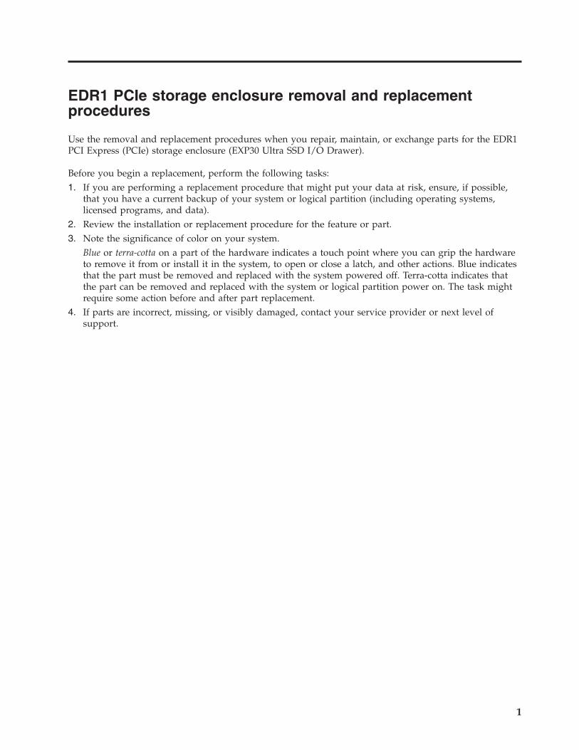
Before you begin a replacement, perform the following tasks:1. If you are performing a replacement procedure that might put your data at risk, ensure, if possible,
that you have a current backup of your system or logical partition (including operating systems,licensed programs, and data).
2. Review the installation or replacement procedure for the feature or part.3. Note the significance of color on your system.
Blue or terra-cotta on a part of the hardware indicates a touch point where you can grip the hardwareto remove it from or install it in the system, to open or close a latch, and other actions. Blue indicatesthat the part must be removed and replaced with the system powered off. Terra-cotta indicates thatthe part can be removed and replaced with the system or logical partition power on. The task mightrequire some action before and after part replacement.
4. If parts are incorrect, missing, or visibly damaged, contact your service provider or next level ofsupport.
1
DANGER
When working on or around the system, observe the following precautions:
Electrical voltage and current from power, telephone, and communication cables are hazardous. Toavoid a shock hazard:v Connect power to this unit only with the provided power cord. Do not use the provided power
cord for any other product.v Do not open or service any power supply assembly.v Do not connect or disconnect any cables or perform installation, maintenance, or reconfiguration
of this product during an electrical storm.v The product might be equipped with multiple power cords. To remove all hazardous voltages,
disconnect all power cords.v Connect all power cords to a properly wired and grounded electrical outlet. Ensure that the outlet
supplies proper voltage and phase rotation according to the system rating plate.v Connect any equipment that will be attached to this product to properly wired outlets.v When possible, use one hand only to connect or disconnect signal cables.v Never turn on any equipment when there is evidence of fire, water, or structural damage.v Disconnect the attached power cords, telecommunications systems, networks, and modems before
you open the device covers, unless instructed otherwise in the installation and configurationprocedures.
v Connect and disconnect cables as described in the following procedures when installing, moving,or opening covers on this product or attached devices.
To Disconnect:1. Turn off everything (unless instructed otherwise).2. Remove the power cords from the outlets.3. Remove the signal cables from the connectors.4. Remove all cables from the devices.
To Connect:1. Turn off everything (unless instructed otherwise).2. Attach all cables to the devices.3. Attach the signal cables to the connectors.4. Attach the power cords to the outlets.5. Turn on the devices.
(D005a)
Attention: Failure to follow the steps sequentially for field-replaceable unit (FRU) removal orinstallation might result in FRU or system damage.
Use the following precautions whenever you handle electronic components or cables:v The electrostatic discharge (ESD) kit and the ESD wrist strap must be used when handling logic cards,
single chip modules (SCMs), multiple chip modules (MCMs), electronic boards, and disk drives.v Keep all electronic components in the shipping container or envelope until you are ready to install
them.v If you remove and reinstall an electronic component, temporarily place the component on an ESD pad
or blanket.
2 EDR1 removal and replacement procedures

Removing and installing a fan assembly for an EDR1 PCIe storageenclosureUse this procedure to service a fan assembly concurrently or nonconcurrently for the EDR1 PCIe storageenclosure (EXP30 Ultra SSD I/O Drawer).
Attention: Failure to follow the steps sequentially for this field replaceable unit (FRU) removal orinstallation might result in damage to the FRU or system.
Use the following precautions whenever you handle electronic components or cables:v Attach a wrist strap to an unpainted metal surface of your hardware to prevent electrostatic discharge
(ESD) from damaging your hardware.v If you do not have a wrist strap, before removing the product from ESD packaging and installing or
replacing hardware, touch an unpainted metal surface of the system for a minimum of 5 seconds.v Keep all electronic components in the shipping container or envelope until you are ready to install
them.v If you remove and reinstall an electronic component, temporarily place the component on an ESD pad
or blanket, if available.
To remove and install a fan assembly, complete the following steps:1. Use the service indicator light-emitting diodes (LEDs) to help identify the part. See Identifying a part.2. Remove the enclosure RAID module (ERM) assembly from the PCIe storage enclosure. See
“Removing and installing an enclosure RAID module assembly for an EDR1 PCIe storage enclosure”on page 26.
3. Remove the fan assembly from the ERM assembly:a. Place the ERM assembly on a flat surface.b. Press the release button (A), as shown in the following figure, to raise the fan assembly out of the
ERM assembly.c. Grasp the fan assembly (B) and remove it from the ERM assembly.
EDR1 PCIe storage enclosure removal and replacement procedures 3
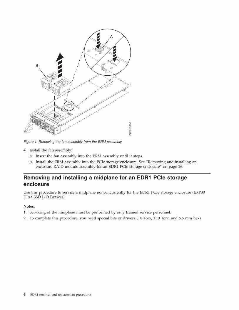
4. Install the fan assembly:a. Insert the fan assembly into the ERM assembly until it stops.b. Install the ERM assembly into the PCIe storage enclosure. See “Removing and installing an
enclosure RAID module assembly for an EDR1 PCIe storage enclosure” on page 26.
Removing and installing a midplane for an EDR1 PCIe storageenclosureUse this procedure to service a midplane nonconcurrently for the EDR1 PCIe storage enclosure (EXP30Ultra SSD I/O Drawer).
Notes:
1. Servicing of the midplane must be performed by only trained service personnel.2. To complete this procedure, you need special bits or drivers (T8 Torx, T10 Torx, and 5.5 mm hex).
Figure 1. Removing the fan assembly from the ERM assembly
4 EDR1 removal and replacement procedures
Attention:
1. Failure to follow the steps sequentially for this field replaceable unit (FRU) removal or installationmight result in damage to the FRU or system.
2. The failed midplane must only be replaced with a new midplane that has not yet been installed inanother PCIe storage enclosure. If the midplane was previously installed in a different PCIe storageenclosure, the enclosure serial number will not be properly updated during power on.
3. After a midplane is installed and the PCIe storage enclosure is powered on, the midplane cannot beused in a different PCIe storage enclosure.
4. Replace only the midplane FRU in this procedure until power has been applied to the PCIe storageenclosure with the new midplane installed. The original enclosure RAID module (ERM) assembliesmust be used in this procedure to preserve the serial number.
Use the following precautions whenever you handle electronic components or cables:v Attach a wrist strap to an unpainted metal surface of your hardware to prevent electrostatic discharge
(ESD) from damaging your hardware.v If you do not have a wrist strap, before removing the product from ESD packaging and installing or
replacing hardware, touch an unpainted metal surface of the system for a minimum of 5 seconds.v Keep all electronic components in the shipping container or envelope until you are ready to install
them.v If you remove and reinstall an electronic component, temporarily place the component on an ESD pad
or blanket, if available.
To remove a midplane, complete the following steps:1. Use the service indicator light-emitting diodes (LEDs) to help identify the part. See Identifying a
part.2. Power off the system or systems that are using the PCIe storage enclosure. See Powering on and
powering off the system.3. Label and remove all PCIe cables and serial-attached SCSI (SAS) cables (if present) from the ERM
assemblies. Disconnect the power cables from the power supplies.Attention: After the midplane is replaced, the PCIe cables must be installed back into the sameconnectors from which they were removed. Incorrect cable placement might result in data loss.
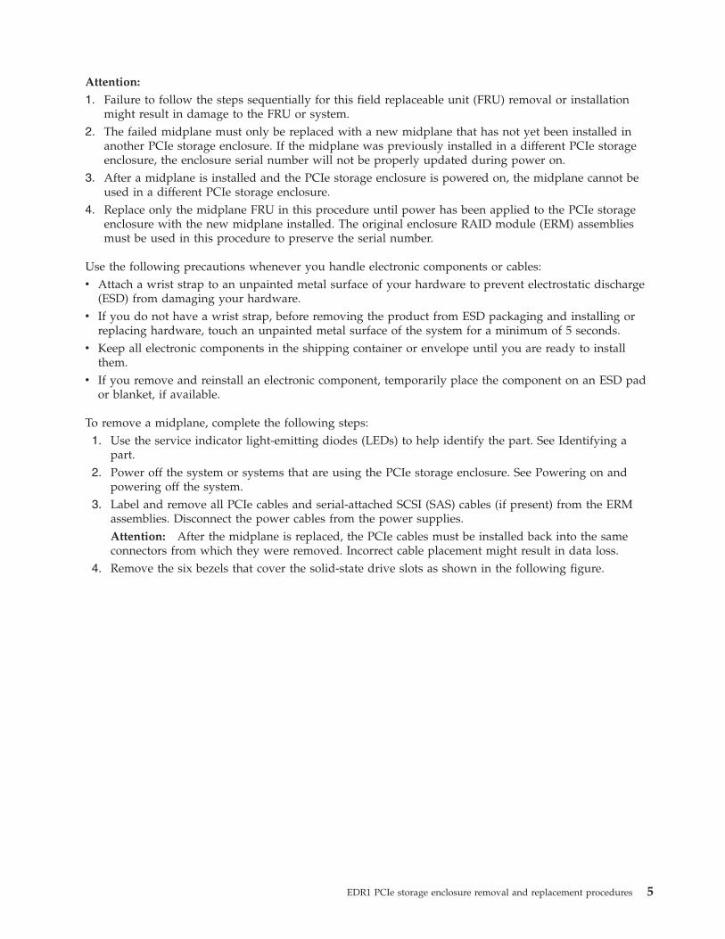
4. Remove the six bezels that cover the solid-state drive slots as shown in the following figure.
EDR1 PCIe storage enclosure removal and replacement procedures 5
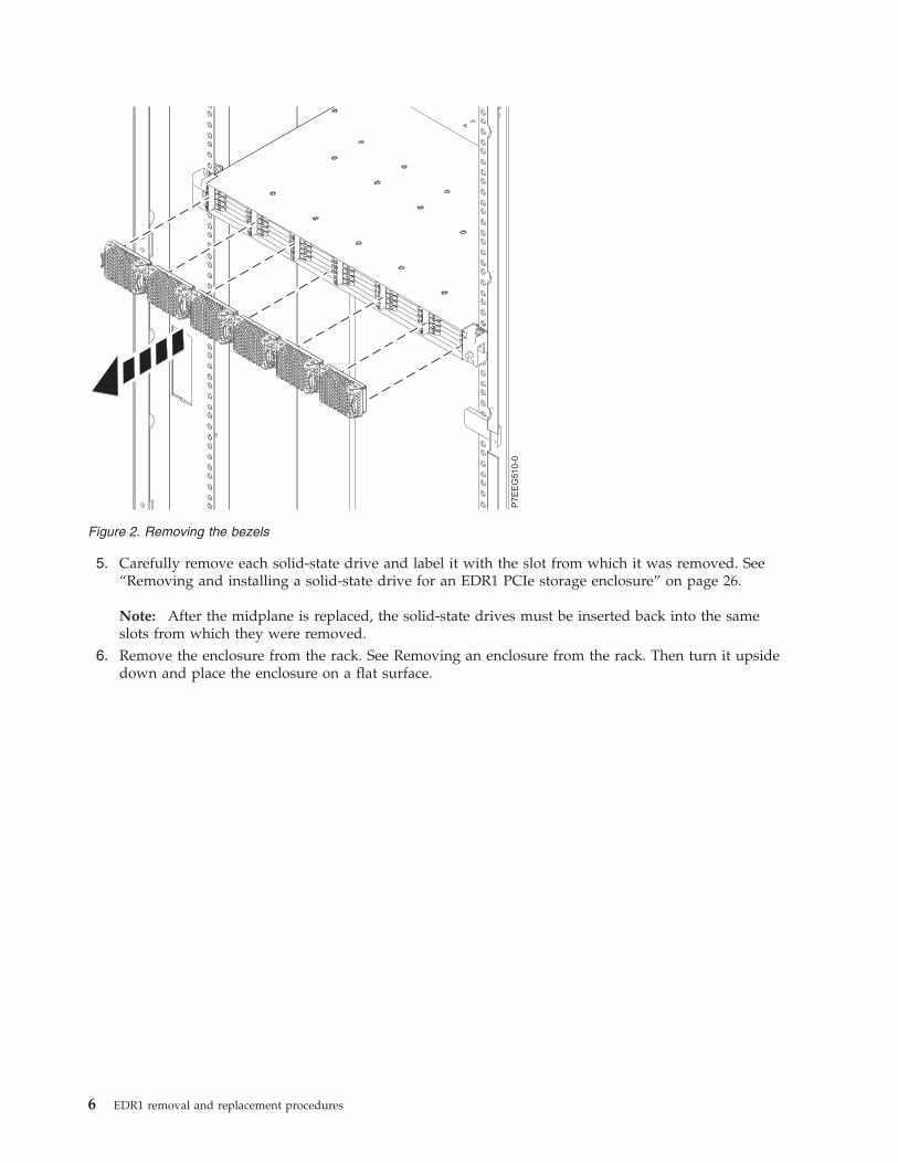
5. Carefully remove each solid-state drive and label it with the slot from which it was removed. See“Removing and installing a solid-state drive for an EDR1 PCIe storage enclosure” on page 26.
Note: After the midplane is replaced, the solid-state drives must be inserted back into the sameslots from which they were removed.
6. Remove the enclosure from the rack. See Removing an enclosure from the rack. Then turn it upsidedown and place the enclosure on a flat surface.
Figure 2. Removing the bezels
6 EDR1 removal and replacement procedures
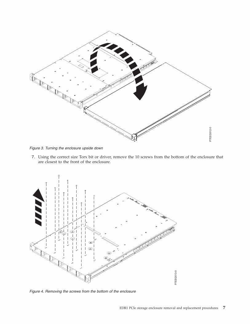
7. Using the correct size Torx bit or driver, remove the 10 screws from the bottom of the enclosure thatare closest to the front of the enclosure.
Figure 3. Turning the enclosure upside down
Figure 4. Removing the screws from the bottom of the enclosure
EDR1 PCIe storage enclosure removal and replacement procedures 7
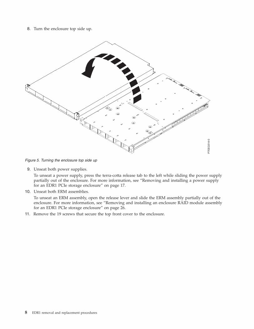
8. Turn the enclosure top side up.
9. Unseat both power supplies.To unseat a power supply, press the terra-cotta release tab to the left while sliding the power supplypartially out of the enclosure. For more information, see “Removing and installing a power supplyfor an EDR1 PCIe storage enclosure” on page 17.
10. Unseat both ERM assemblies.To unseat an ERM assembly, open the release lever and slide the ERM assembly partially out of theenclosure. For more information, see “Removing and installing an enclosure RAID module assemblyfor an EDR1 PCIe storage enclosure” on page 26.
11. Remove the 19 screws that secure the top front cover to the enclosure.
Figure 5. Turning the enclosure top side up
8 EDR1 removal and replacement procedures
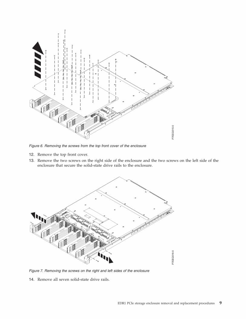
12. Remove the top front cover.13. Remove the two screws on the right side of the enclosure and the two screws on the left side of the
enclosure that secure the solid-state drive rails to the enclosure.
14. Remove all seven solid-state drive rails.
Figure 6. Removing the screws from the top front cover of the enclosure
Figure 7. Removing the screws on the right and left sides of the enclosure
EDR1 PCIe storage enclosure removal and replacement procedures 9
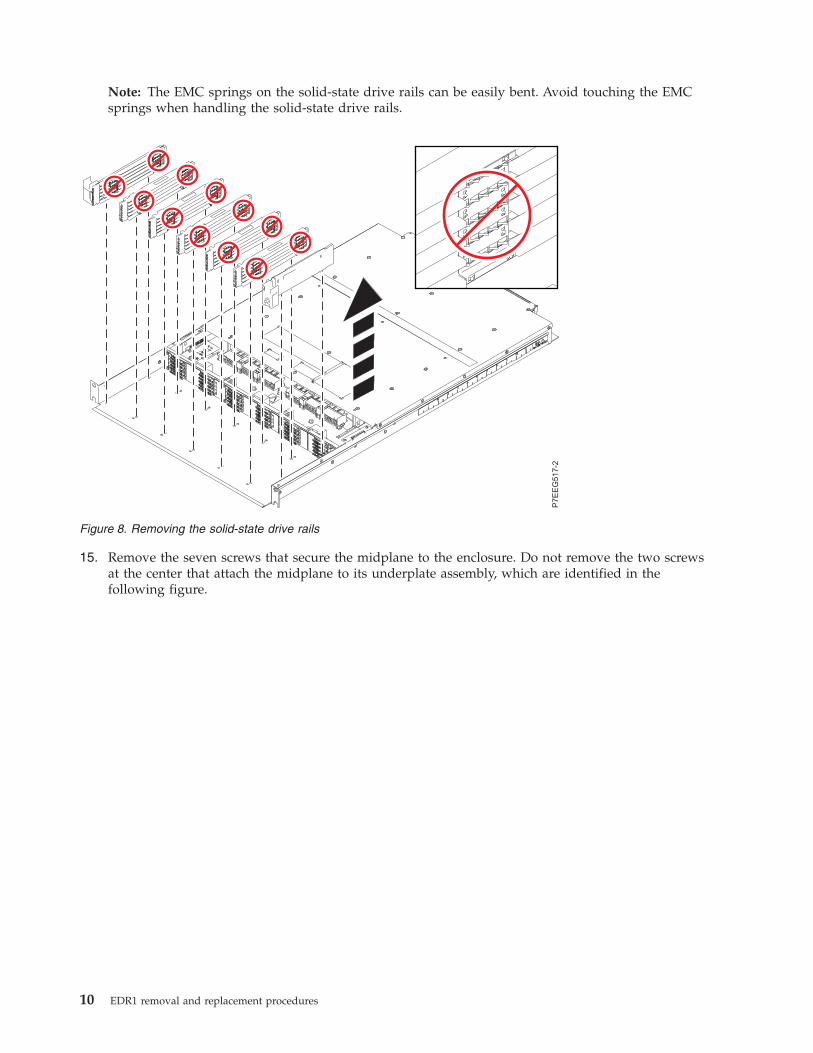
Note: The EMC springs on the solid-state drive rails can be easily bent. Avoid touching the EMCsprings when handling the solid-state drive rails.
15. Remove the seven screws that secure the midplane to the enclosure. Do not remove the two screwsat the center that attach the midplane to its underplate assembly, which are identified in thefollowing figure.
Figure 8. Removing the solid-state drive rails
10 EDR1 removal and replacement procedures
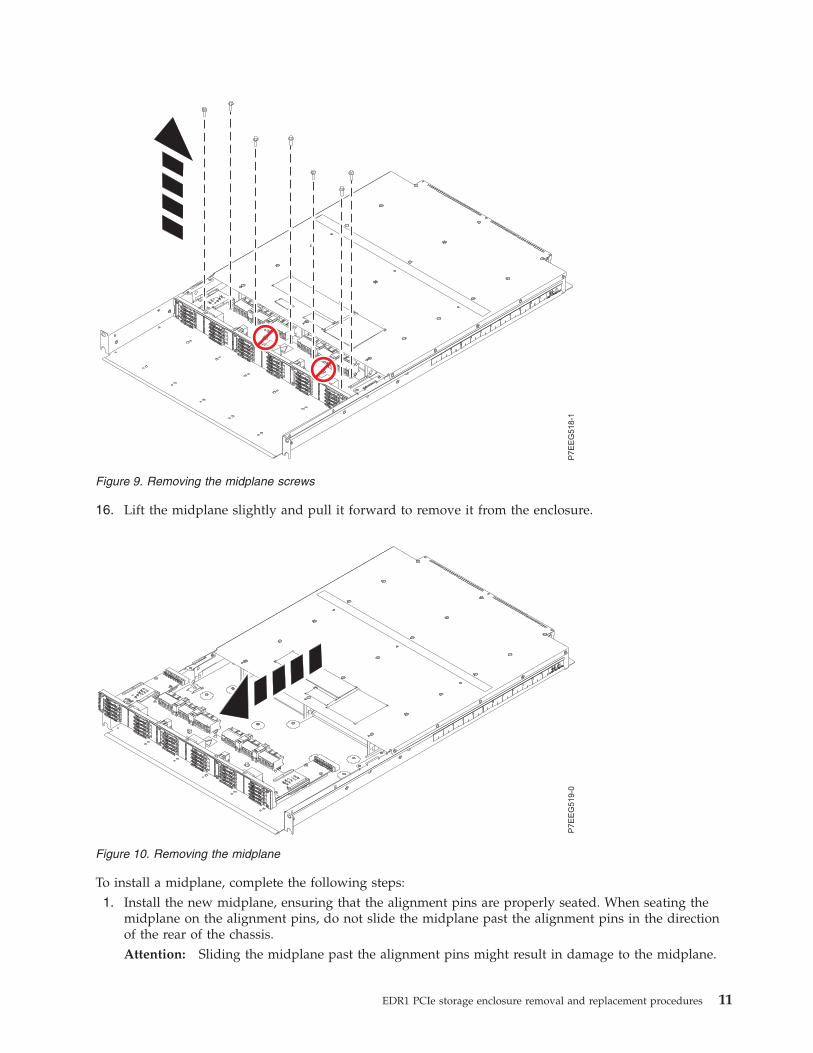
16. Lift the midplane slightly and pull it forward to remove it from the enclosure.
To install a midplane, complete the following steps:1. Install the new midplane, ensuring that the alignment pins are properly seated. When seating the
midplane on the alignment pins, do not slide the midplane past the alignment pins in the directionof the rear of the chassis.Attention: Sliding the midplane past the alignment pins might result in damage to the midplane.
Figure 9. Removing the midplane screws
Figure 10. Removing the midplane
EDR1 PCIe storage enclosure removal and replacement procedures 11
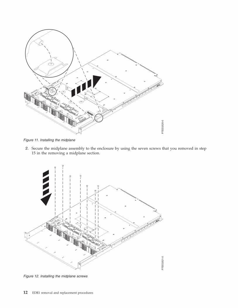
2. Secure the midplane assembly to the enclosure by using the seven screws that you removed in step15 in the removing a midplane section.
Figure 11. Installing the midplane
Figure 12. Installing the midplane screws
12 EDR1 removal and replacement procedures
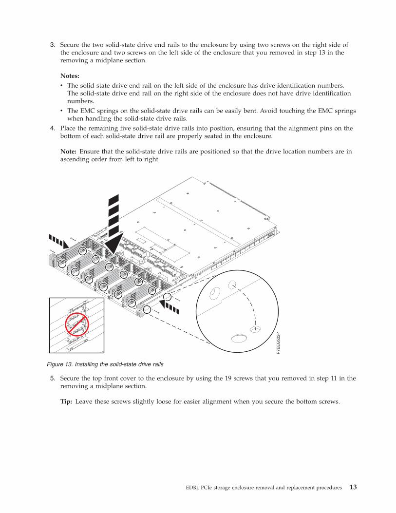
3. Secure the two solid-state drive end rails to the enclosure by using two screws on the right side ofthe enclosure and two screws on the left side of the enclosure that you removed in step 13 in theremoving a midplane section.
Notes:
v The solid-state drive end rail on the left side of the enclosure has drive identification numbers.The solid-state drive end rail on the right side of the enclosure does not have drive identificationnumbers.
v The EMC springs on the solid-state drive rails can be easily bent. Avoid touching the EMC springswhen handling the solid-state drive rails.
4. Place the remaining five solid-state drive rails into position, ensuring that the alignment pins on thebottom of each solid-state drive rail are properly seated in the enclosure.
Note: Ensure that the solid-state drive rails are positioned so that the drive location numbers are inascending order from left to right.
5. Secure the top front cover to the enclosure by using the 19 screws that you removed in step 11 in theremoving a midplane section.
Tip: Leave these screws slightly loose for easier alignment when you secure the bottom screws.
Figure 13. Installing the solid-state drive rails
EDR1 PCIe storage enclosure removal and replacement procedures 13
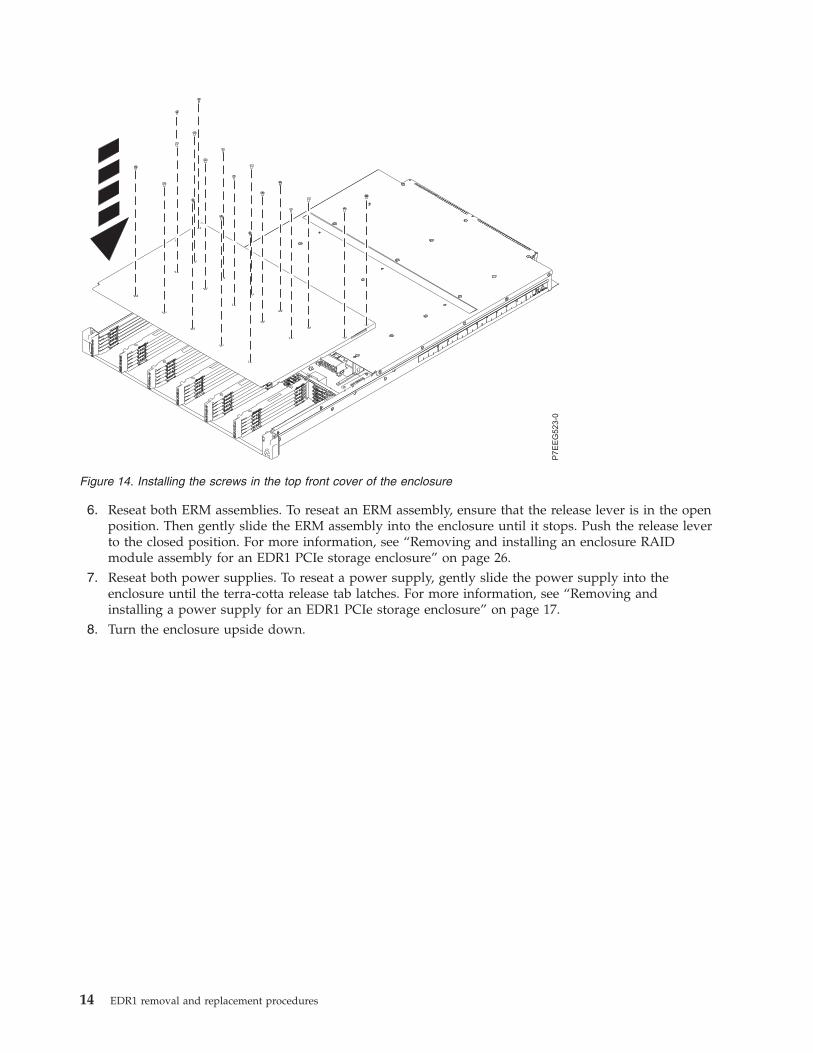
6. Reseat both ERM assemblies. To reseat an ERM assembly, ensure that the release lever is in the openposition. Then gently slide the ERM assembly into the enclosure until it stops. Push the release leverto the closed position. For more information, see “Removing and installing an enclosure RAIDmodule assembly for an EDR1 PCIe storage enclosure” on page 26.
7. Reseat both power supplies. To reseat a power supply, gently slide the power supply into theenclosure until the terra-cotta release tab latches. For more information, see “Removing andinstalling a power supply for an EDR1 PCIe storage enclosure” on page 17.
8. Turn the enclosure upside down.
Figure 14. Installing the screws in the top front cover of the enclosure
14 EDR1 removal and replacement procedures
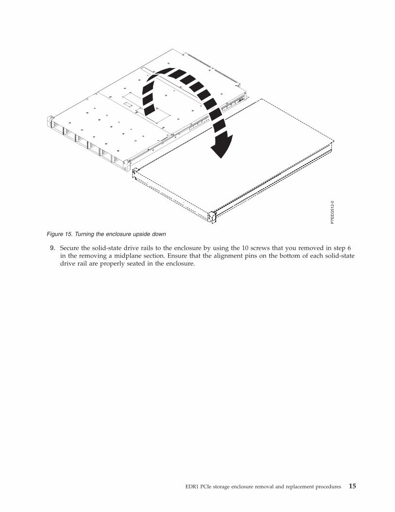
9. Secure the solid-state drive rails to the enclosure by using the 10 screws that you removed in step 6in the removing a midplane section. Ensure that the alignment pins on the bottom of each solid-statedrive rail are properly seated in the enclosure.
Figure 15. Turning the enclosure upside down
EDR1 PCIe storage enclosure removal and replacement procedures 15
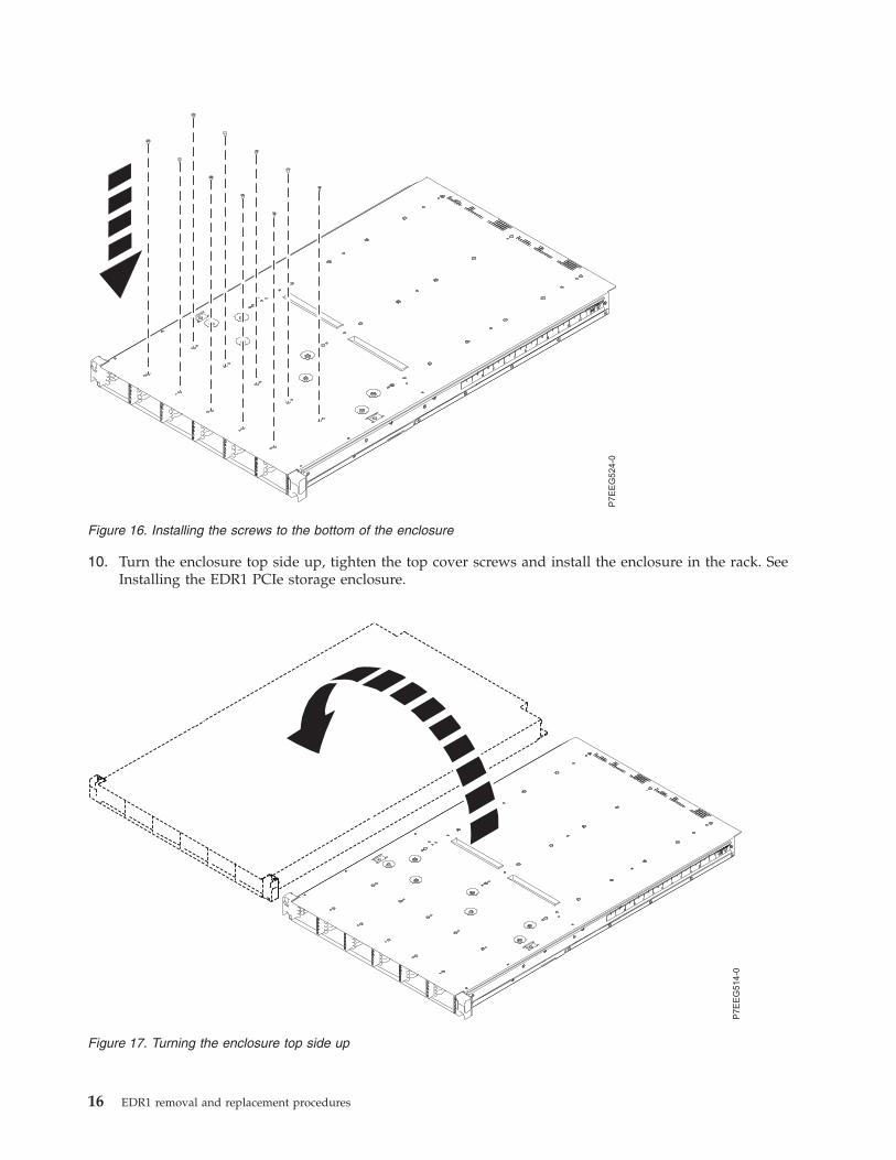
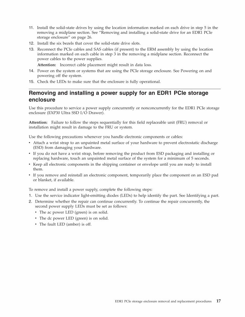
10. Turn the enclosure top side up, tighten the top cover screws and install the enclosure in the rack. SeeInstalling the EDR1 PCIe storage enclosure.
Figure 16. Installing the screws to the bottom of the enclosure
Figure 17. Turning the enclosure top side up
16 EDR1 removal and replacement procedures
11. Install the solid-state drives by using the location information marked on each drive in step 5 in theremoving a midplane section. See “Removing and installing a solid-state drive for an EDR1 PCIestorage enclosure” on page 26.
12. Install the six bezels that cover the solid-state drive slots.13. Reconnect the PCIe cables and SAS cables (if present) to the ERM assembly by using the location
information marked on each cable in step 3 in the removing a midplane section. Reconnect thepower cables to the power supplies.Attention: Incorrect cable placement might result in data loss.
14. Power on the system or systems that are using the PCIe storage enclosure. See Powering on andpowering off the system.
15. Check the LEDs to make sure that the enclosure is fully operational.
Removing and installing a power supply for an EDR1 PCIe storageenclosureUse this procedure to service a power supply concurrently or nonconcurrently for the EDR1 PCIe storageenclosure (EXP30 Ultra SSD I/O Drawer).
Attention: Failure to follow the steps sequentially for this field replaceable unit (FRU) removal orinstallation might result in damage to the FRU or system.
Use the following precautions whenever you handle electronic components or cables:v Attach a wrist strap to an unpainted metal surface of your hardware to prevent electrostatic discharge
(ESD) from damaging your hardware.v If you do not have a wrist strap, before removing the product from ESD packaging and installing or
replacing hardware, touch an unpainted metal surface of the system for a minimum of 5 seconds.v Keep all electronic components in the shipping container or envelope until you are ready to install
them.v If you remove and reinstall an electronic component, temporarily place the component on an ESD pad
or blanket, if available.
To remove and install a power supply, complete the following steps:1. Use the service indicator light-emitting diodes (LEDs) to help identify the part. See Identifying a part.2. Determine whether the repair can continue concurrently. To continue the repair concurrently, the
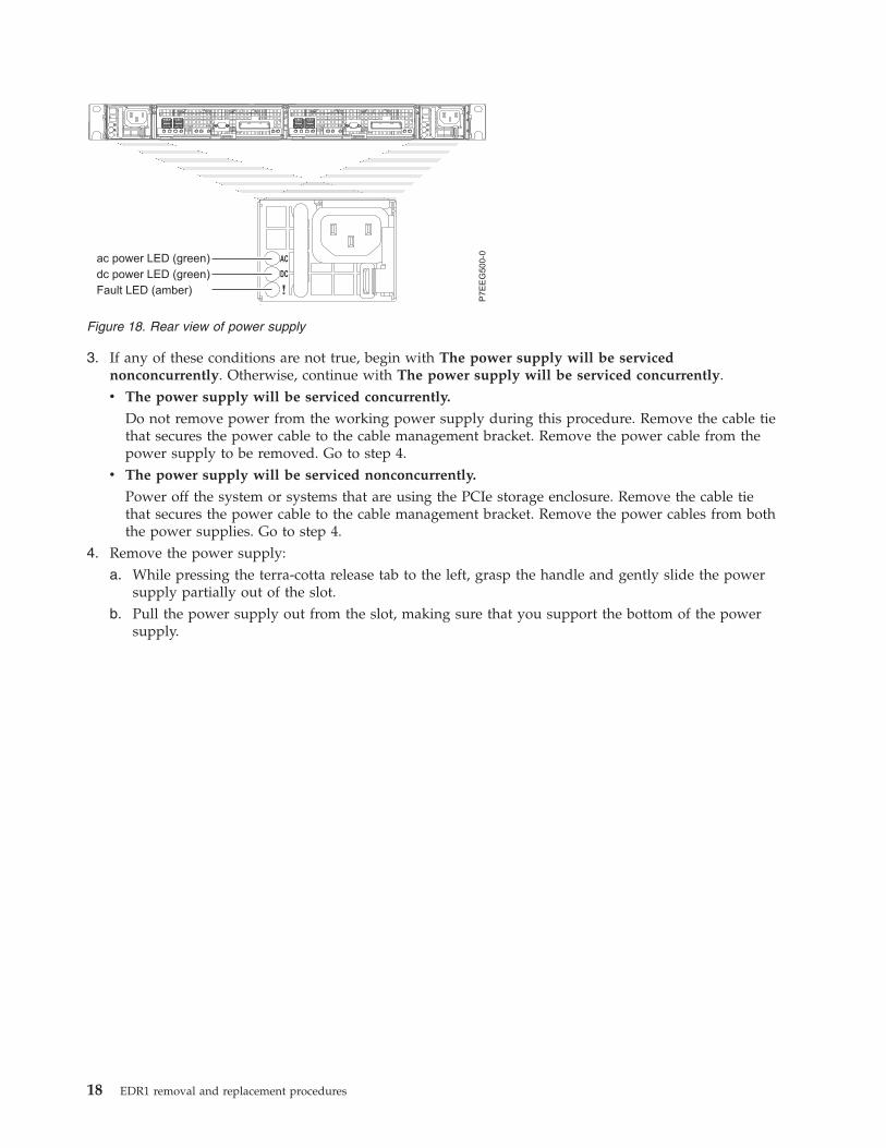
second power supply LEDs must be set as follows:v The ac power LED (green) is on solid.v The dc power LED (green) is on solid.v The fault LED (amber) is off.
EDR1 PCIe storage enclosure removal and replacement procedures 17
3. If any of these conditions are not true, begin with The power supply will be servicednonconcurrently. Otherwise, continue with The power supply will be serviced concurrently.v The power supply will be serviced concurrently.
Do not remove power from the working power supply during this procedure. Remove the cable tiethat secures the power cable to the cable management bracket. Remove the power cable from thepower supply to be removed. Go to step 4.
v The power supply will be serviced nonconcurrently.
Power off the system or systems that are using the PCIe storage enclosure. Remove the cable tiethat secures the power cable to the cable management bracket. Remove the power cables from boththe power supplies. Go to step 4.
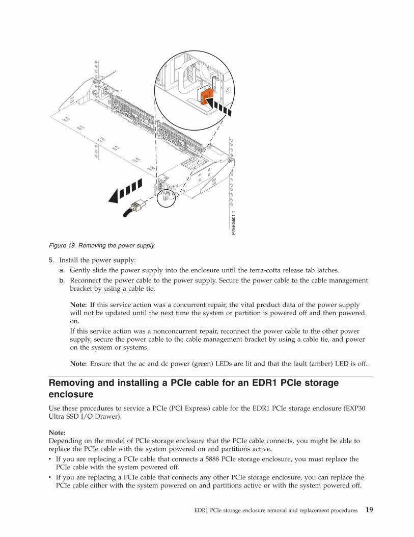
4. Remove the power supply:a. While pressing the terra-cotta release tab to the left, grasp the handle and gently slide the power
supply partially out of the slot.b. Pull the power supply out from the slot, making sure that you support the bottom of the power
supply.
Figure 18. Rear view of power supply
18 EDR1 removal and replacement procedures
5. Install the power supply:a. Gently slide the power supply into the enclosure until the terra-cotta release tab latches.b. Reconnect the power cable to the power supply. Secure the power cable to the cable management
bracket by using a cable tie.
Note: If this service action was a concurrent repair, the vital product data of the power supplywill not be updated until the next time the system or partition is powered off and then poweredon.If this service action was a nonconcurrent repair, reconnect the power cable to the other powersupply, secure the power cable to the cable management bracket by using a cable tie, and poweron the system or systems.
Note: Ensure that the ac and dc power (green) LEDs are lit and that the fault (amber) LED is off.
Removing and installing a PCIe cable for an EDR1 PCIe storageenclosureUse these procedures to service a PCIe (PCI Express) cable for the EDR1 PCIe storage enclosure (EXP30Ultra SSD I/O Drawer).
Note:Depending on the model of PCIe storage enclosure that the PCIe cable connects, you might be able toreplace the PCIe cable with the system powered on and partitions active.v If you are replacing a PCIe cable that connects a 5888 PCIe storage enclosure, you must replace the
PCIe cable with the system powered off.v If you are replacing a PCIe cable that connects any other PCIe storage enclosure, you can replace the
PCIe cable either with the system powered on and partitions active or with the system powered off.
Figure 19. Removing the power supply
EDR1 PCIe storage enclosure removal and replacement procedures 19
Removing and installing a PCIe cable with the power offUse this procedure to service a PCIe (PCI Express) cable for the EDR1 PCIe storage enclosure (EXP30Ultra SSD I/O Drawer) with the power off.
Attention: Failure to follow the steps sequentially for this field replaceable unit (FRU) removal orinstallation might result in damage to the FRU or system.
Use the following precautions whenever you handle electronic components or cables:v Attach a wrist strap to an unpainted metal surface of your hardware to prevent electrostatic discharge
(ESD) from damaging your hardware.v If you do not have a wrist strap, before removing the product from ESD packaging and installing or
replacing hardware, touch an unpainted metal surface of the system for a minimum of 5 seconds.v Keep all electronic components in the shipping container or envelope until you are ready to install
them.v If you remove and reinstall an electronic component, temporarily place the component on an ESD pad
or blanket, if available.
To remove and install a PCIe cable, complete the following steps:1. If the system is not already powered off, power off the system but do not unplug any power cables.
For information, see Stopping a system or logical partition.2. To activate the identify indicator for the PCIe connector on the system enclosure to which the PCIe
cable is connected, complete the following steps:a. Choose one of the following options to determine the location code of the PCIe connector on the
system:v Find the PCIe cable location code from a serviceable event or error log.
Note: The PCIe cable location code will look similar to Utttt.mmm.sssssss-Px-Cy-Tz. Where ttttis the feature code, mmm is the sequence, sssssss is the serial number of the PCIe storageenclosure connected by the PCIe cable, x is a number representing the planar position in thesystem enclosure to which the cable is connected, y is a number representing the card positionin the planar, and z is a number representing the PCIe connector position on the card. Anexample of an actual PCIe cable location code is U2C4B.001.DBJ7805-P1-C2-T1.
v Find the PCIe cable location code from the location code of an I/O slot that connects a PCIestorage enclosure from a serviceable event or error log.
Note: The I/O slot location code will look similar to Utttt.mmm.sssssss-Px-Cy-Tz-L1. Wheretttt is the feature code, mmm is the sequence, sssssss is the serial number of the PCIe storageenclosure connected by the PCIe cable, x is a number representing the planar position in thesystem enclosure to which the cable is connected, y is a number representing the card positionin the planar, and z is a number representing the PCIe connector position on the card. Anexample of an actual PCIe cable location code is U2C4B.001.DBJ7805-P1-C2-T1-L1.Remove the L label from the I/O slot location code and continue with the next step.
Note: The L label is the part of the location code consisting of the letter L and including thenumber that follows it and the dash (-) that precedes it.
v If you know which PCIe cable you want to repair but do not have the PCIe connector or I/Oslot location code.Determine the location code of the PCIe connector on the system to which the cable isconnected. To identify the location code, see Connector locations.
b. Activate the identify indicator for the PCIe connector location found in the step 2. For informationabout activating the identify indicators, see Using identify indicators to locate hardwarecomponents.
20 EDR1 removal and replacement procedures
3. If the system has a rear cover, remove or open it.4. Remove and install the PCIe cable:
a. Locate the PCIe connector on the system with the active identify indicator and disconnect the PCIecable from this located PCIe connector.
b. Disconnect the other end of the PCIe cable from the PCIe storage enclosure.c. Connect the replacement PCIe cable to the PCIe connector from which the faulty PCIe cable was
removed in step 4a.d. Connect the other end of the replacement PCIe cable to the PCIe storage enclosure from which the
faulty PCIe cable was removed in step 4b.5. If the system has a rear cover, close it.6. Record the current date and time for use later in the procedure when checking for serviceable events.7. Power on the system. For information, see Starting the system or logical partition.8. Verify the PCIe hardware topology by completing the steps in Verifying the PCIe hardware topology.
All PCIe hardware topology problems that are discovered in this step must be corrected beforecontinuing with this procedure.
9. Check for and handle new serviceable events that were generated during the procedure bycompleting the steps in Checking for new serviceable events. Use the date and time information thatyou recorded in step 6 as the start time for searching for new serviceable events.
Removing and installing a PCIe cable with the power onUse this procedure to service a PCIe (PCI Express) cable for the EDR1 PCIe storage enclosure (EXP30Ultra SSD I/O Drawer) with the power on.
Attention: Failure to follow the steps sequentially for this field replaceable unit (FRU) removal orinstallation might result in damage to the FRU or system.
Use the following precautions whenever you handle electronic components or cables:v Attach a wrist strap to an unpainted metal surface of your hardware to prevent electrostatic discharge
(ESD) from damaging your hardware.v If you do not have a wrist strap, before removing the product from ESD packaging and installing or
replacing hardware, touch an unpainted metal surface of the system for a minimum of 5 seconds.v Keep all electronic components in the shipping container or envelope until you are ready to install
them.v If you remove and reinstall an electronic component, temporarily place the component on an ESD pad
or blanket, if available.
Important:
v In order to use this procedure to replace a PCIe cable, the PCIe storage enclosure connected by thecable must be a model that supports hardware maintenance with the system powered on.
v If you are replacing a PCIe cable that connects to a 5888 PCIe storage enclosure, you must follow thesteps in “Removing and installing a PCIe cable with the power off” on page 20.
v If you are replacing a PCIe cable that connects to any other PCIe storage enclosure, you can replace itwith the system powered on using this procedure.
To remove and install a PCIe cable, complete the following steps:1. Record the current date and time for use later in the procedure when checking for serviceable
events.2. Determine the identifier string and link identifier for the I/O slot associated with the PCIe cable
being replaced by completing the following steps:a. Choose one of the following steps:
EDR1 PCIe storage enclosure removal and replacement procedures 21
v If your system is managed by an Hardware Management Console (HMC), complete thefollowing steps:1) From the navigation bar, expand Systems Management.2) Click Servers and select the server you are working with.3) In the Tasks area, expand Hardware Information.4) Click PCIe Hardware Topology.
v If your system is not managed by an HMC, complete the following steps:1) Access the ASMI by using an authority level of administrator or authorized service
provider. For details about using the ASMI, see Managing the Advanced SystemManagement Interface.
2) In the ASMI navigation area, expand System Configuration.3) Click PCIe Hardware Topology.
b. Choose one of the following options:v Find the PCIe cable location code from a serviceable event or error log, by completing the
following steps:
Note: The PCIe cable location code will look similar to Utttt.mmm.sssssss-Px-Cy-Tz. Wheretttt is the feature code, mmm is the sequence, sssssss is the serial number of the systemenclosure connected by the PCIe cable, x is a number representing the planar position in thesystem enclosure to which the cable is connected, y is a number representing the card positionin the planar, and z is a number representing the PCIe connector position on the card. Anexample of an actual PCIe cable location code is U2C4B.001.DBJ7805-P1-C2-T1.1) Scan the PCIe Hardware Topology data for the entry with a Host Port column value that
matches the PCIe cable location code.2) Record the link identifier and the I/O slot identifier string found in the entry located in the
previous step. The link identifier is in the Link ID column, and the I/O slot identifierstring in the I/O Slots column.
v Find the PCIe cable location code from the location code of an I/O slot that connects a PCIestorage enclosure from a serviceable event or error log.
Note: The I/O slot location code will look similar to Utttt.mmm.sssssss-Px-Cy-Tz-L1. Wheretttt is the feature code, mmm is the sequence, sssssss is the serial number of the PCIe storageenclosure connected by the PCIe cable, x is a number representing the planar position in thesystem enclosure to which the cable is connected, y is a number representing the card positionin the planar, and z is a number representing the PCIe connector position on the card. Anexample of an actual PCIe cable location code is U2C4B.001.DBJ7805-P1-C2-T1-L1.1) Scan the PCIe Hardware Topology data for the entry with an I/O Slot column value that
matches the I/O slot location code.2) Record the link identifier and the I/O slot identifier string found in the entry located in
the previous step. The link identifier is in the Link ID column, and the I/O slot identifierstring in the I/O Slots column.
v If you know which PCIe cable you want to repair but do not have the PCIe connector or I/Oslot location code.1) Determine the location code of the PCIe connector on the system to which the cable is
connected. To identify the location code, see Connector locations.2) Scan the PCIe Hardware Topology data for the entry with a Host Port column value that
matches the location code of the PCIe connector determined in the previous step.3) Record the link identifier and the I/O slot identifier string found in the entry located in the
previous step. The link identifier is in the Link ID column, and the I/O slot identifier stringin the I/O Slots column.
3. Power off the I/O slot identified in the step 2 on page 21 by completing one of the follow steps:
22 EDR1 removal and replacement procedures
v If the I/O slot is assigned to a logical partition that is powered on and running the Virtual I/OServer (VIOS) or AIX operating system, complete the following steps:a. Log in to the operating system with admin or service level authority. If you need assistance,
contact the system administrator.b. Choose one of the following options:
– If the partition is running the VIOS operating system, type diagmenu at the VIOS commandprompt and press Enter.
– If the partition is running the AIX® operating system, type diag at the AIX commandprompt and press Enter.
c. On the DIAGNOSTIC OPERATING INSTRUCTIONS display press Enter to continue.d. On the FUNCTION SELECTION display, use the arrow keys to select Task Selection
(Diagnostics, Advanced Diagnostics, Service Aids, etc.) and press Enter.e. On the TASKS SELECTION LIST display, use the arrow keys to select Hot Plug Task and press
Enter.f. On the Hot Plug Task display, use the arrow keys to select PCI Hot Plug Manager and press
Enter.g. On the PCI Hot Plug Manager display, use the arrow keys to select List PCI Hot Plug Slots
and press Enter.h. On the COMMAND STATUS display, locate the entry with the identifier string of the I/O slot
in the Slot column, and record the logical device name in the Devices column.i. Press F3 (Exit).
Note: If your terminal emulation does not support F3 to exit, press ESC then type 3 to exit.j. On the PCI Hot Plug Manager display, use the arrow keys to select Unconfigure a device, and
press Enter.k. On the Unconfigure a device display, complete the following steps:
1) Enter the logical device name recorded in step 3h for the Device Name field.2) Use the Tab key to select yes for the Unconfigure any Child Devices field.3) Use the Tab key to select no for the KEEP definition in database field.4) Press Enter.
l. On the ARE YOU SURE dialog, press Enter.m. On the COMMAND STATUS display, wait for processing to complete and then press F3 twice
to return to the PCI Hot Plug Manager display.n. On the PCI Hot Plug Manager display, use the arrow keys to select Replace/Remove a PCI
Hot Plug Adapter, and press Enter.o. On the Replace/Remove a PCI Hot Plug Adapter dialog, use the arrow keys to select the entry
with the identifier string of the I/O slot in the Slot column, and press Enter.p. On the Replace/Remove a PCI Hot Plug Adapter display, use the Tab key to select the
Remove operation, and press Enter.q. Follow the online instructions to complete the remove operation. However, do not complete
the steps to physically remove the adapter.v If the I/O slot is assigned to a logical partition that is powered on and running the Linux
operating system, complete the following steps:a. Log in to the operating system with admin or service level authority. If you need assistance,
contact the system administrator.b. At the Linux command prompt, type drslot_chrp_pci -r -s io_slot_identifier (where
io_slot_identifier is the identifier string of the I/O slot), and press Enter.c. Follow the online instructions to complete the remove operation. However, do not complete
the steps to physically remove the adapter.
EDR1 PCIe storage enclosure removal and replacement procedures 23
v If the I/O slot is not assigned to a logical partition that is powered on, continue to the next step.4. Activate the identify indicator for the PCIe connector to which the PCIe cable is connected by
completing the following steps:a. Choose one of the following options:
v If your system is managed by an HMC, complete the following steps:1) From the navigation bar, expand Systems Management.2) Click Servers and select the server you are working with.3) In the Tasks area, expand Hardware Information.4) Click PCIe Hardware Topology.
v If your system is not managed by an HMC, complete the following steps:1) Access the ASMI by using an authority level of administrator or authorized service
provider. For details about using the ASMI, see Managing the Advanced SystemManagement Interface.
2) In the ASMI navigation area, expand System Configuration.3) Click PCIe Hardware Topology.
b. Scan the PCIe Hardware Topology data for the entry with the link identifier and I/O slotidentifier recorded in step 2 on page 21.
c. Select the PCIe link and click Identify Indicators.d. On the Identify Indicators display, select both locations and click Activate LED.
5. If the system has a rear cover, remove or open it.6. Remove and replace the PCIe cable by completing the following steps:
a. Locate the PCIe connector on the system with the active identify indicator and disconnect thePCIe cable from this located PCIe connector.
b. Disconnect the other end of the PCIe cable from the PCIe storage enclosure.c. Connect the replacement PCIe cable to the PCIe connector from which the faulty PCIe cable was
removed in step 6a.d. Connect the other end of the replacement PCIe cable to the PCIe storage enclosure from which
the faulty PCIe cable was removed in step 6b.7. If the system has a rear cover, close it.8. Deactivate the identify indicator that you activated in step 4 by repeating step 4 as specified, except
to click Deactivate LED.9. Power on the I/O slot identified in the step 2 on page 21 by completing the follow steps:
Choose one of the following options:v If the I/O slot is assigned to a logical partition that is powered onv If the I/O slot is not assigned to a logical partition that is powered onIf the I/O slot is assigned to a logical partition that is powered on
Note: If your system is not managed by an HMC and is powered on to firmware running state,choose this option.v If the I/O slot is assigned to a logical partition that is powered on and running the Virtual I/O
Server (VIOS) or AIX operating system, complete the following steps:a. Log in to the operating system with admin or service level authority. If you need assistance,
contact the system administrator.b. Choose one of the following options:
– If the logical partition is running the VIOS operating system type diagmenu at the VIOScommand prompt, and press Enter.
– If the logical partition is running the AIX operating system type diag at the AIX commandprompt, and press Enter.
24 EDR1 removal and replacement procedures
c. On the DIAGNOSTIC OPERATING INSTRUCTIONS display, press Enter to continue.d. On the FUNCTION SELECTION display, use the arrow keys to select Task Selection
(Diagnostics, Advanced Diagnostics, Service Aids, etc.), and press Enter.e. On the TASKS SELECTION LIST display, use the arrow keys to select Hot Plug Task, and
press Enter.f. On the Hot Plug Task display, use the arrow keys to select PCI Hot Plug Manager, and press
Enter.g. On the PCI Hot Plug Manager display, use the arrow keys to select Add a PCI Hot Plug
Adapter, and press Enter.h. On the Add a PCI Hot Plug Adapter dialogue, use the arrow keys to select the entry with the
identifier string of the I/O slot in the Slot column, and press Enter.i. Follow the instructions that display to complete the add operation. However, do not complete
the steps to physically add the adapter.j. Press F10 twice to return to the AIX command prompt.k. For an AIX logical partition: At the command prompt type cfgmgr -l logical_device_name,
where logical_device_name is the logical resource name of the I/O slot recorded in step 3h onpage 23.For a VIOS logical partition: At the command prompt type cfgdev-dev logical_device_name,where logical_device_name is the logical resource name of the I/O slot recorded in step 3h onpage 23.
v If the I/O slot is assigned to a logical partition that is powered on and running the Linuxoperating system, complete the following steps:a. Log in to the operating system with admin or service level authority. If you need assistance,
contact the system administrator.b. At the Linux command prompt, type drslot_chrp_pci -a -s io_slot_identifier (where
io_slot_identifier is the identifier string of the I/O slot), and press Enter.c. Follow the online instructions to complete the add operation. However, do not complete the
steps to physically add the adapter.If the I/O slot is not assigned to a logical partition that is powered on
Note: If your system is not managed by an HMC and is powered on to firmware standby state,choose this option.Choose one of the following options:v If your system is managed by an HMC, complete the following steps:
a. From the navigation bar, expand Systems Management.b. Click Servers and select the server you are working with.c. In the Tasks area, expand Hardware Information.d. Click PCIe Hardware Topology.
v If your system is not managed by an HMC, complete the following steps:a. Access the ASMI by using an authority level of administrator or authorized service provider.
For details about using the ASMI, see Managing the Advanced System Management Interface.b. In the ASMI navigation area, expand System Configuration.c. Click PCIe Hardware Topology.d. Scan the PCIe Hardware Topology data for a value in the I/O Slots column that matches the
identifier string of the I/O slot, and select the entry.e. Click Probe Link.
Important: If the Probe Link function fails, verify that the I/O slot is not owned by a partitionthat is powered on. Then choose from the following options:
EDR1 PCIe storage enclosure removal and replacement procedures 25
– If you determine that the I/O slot is owned by a partition that is powered on, return to step9 on page 24 and choose the alternative option that supports an I/O slot assigned to apartition that is powered on.
– If you are certain the I/O slot is not owned by a partition that is powered on, contact yournext level of support for assistance.
10. Verify the PCIe hardware topology by completing the steps in Verifying the PCIe hardware topology.All PCIe hardware topology problems that are discovered in this step must be corrected beforecontinuing with this procedure.
11. Check for and handle new serviceable events that were generated during the procedure bycompleting the steps in Checking for new serviceable events. Use the date and time information thatyou recorded in step 1 on page 21 as the start time for searching for new serviceable events.
Removing and installing a solid-state drive for an EDR1 PCIe storageenclosureUse this procedure to service a solid-state drive concurrently for the EDR1 PCIe storage enclosure (EXP30Ultra SSD I/O Drawer).
To perform a service action on a solid-state drive, see the following procedures for the machine type andmodel to which the PCIe storage enclosure is attached:v Installing a disk drive or solid-state drive in the 9117-MMD and 9179-MHD.v Removing a disk drive or solid-state drive from the 9117-MMD and 9179-MHD.v Replacing a disk drive or solid-state drive in the 9117-MMD and 9179-MHD.
Removing and installing an enclosure RAID module assembly for anEDR1 PCIe storage enclosureUse these procedures to service an enclosure RAID module (ERM) assembly for the EDR1 PCIe storageenclosure (EXP30 Ultra SSD I/O Drawer).
Removing and installing an enclosure RAID module assembly with thepower offUse this procedure to service an enclosure RAID module (ERM) assembly for the EDR1 PCIe storageenclosure (EXP30 Ultra SSD I/O Drawer) with the power off.
Attention: Failure to follow the steps sequentially for this field replaceable unit (FRU) removal orinstallation might result in damage to the FRU or system.
Use the following precautions whenever you handle electronic components or cables:v Attach a wrist strap to an unpainted metal surface of your hardware to prevent electrostatic discharge
(ESD) from damaging your hardware.v If you do not have a wrist strap, before removing the product from ESD packaging and installing or
replacing hardware, touch an unpainted metal surface of the system for a minimum of 5 seconds.v Keep all electronic components in the shipping container or envelope until you are ready to install
them.v If you remove and reinstall an electronic component, temporarily place the component on an ESD pad
or blanket, if available.v To prevent loss of enclosure information, do not replace both ERM assemblies at the same time. To
replace the second ERM, complete the removal and installation procedures for the first ERM assemblyand then replace the second ERM assembly.
26 EDR1 removal and replacement procedures
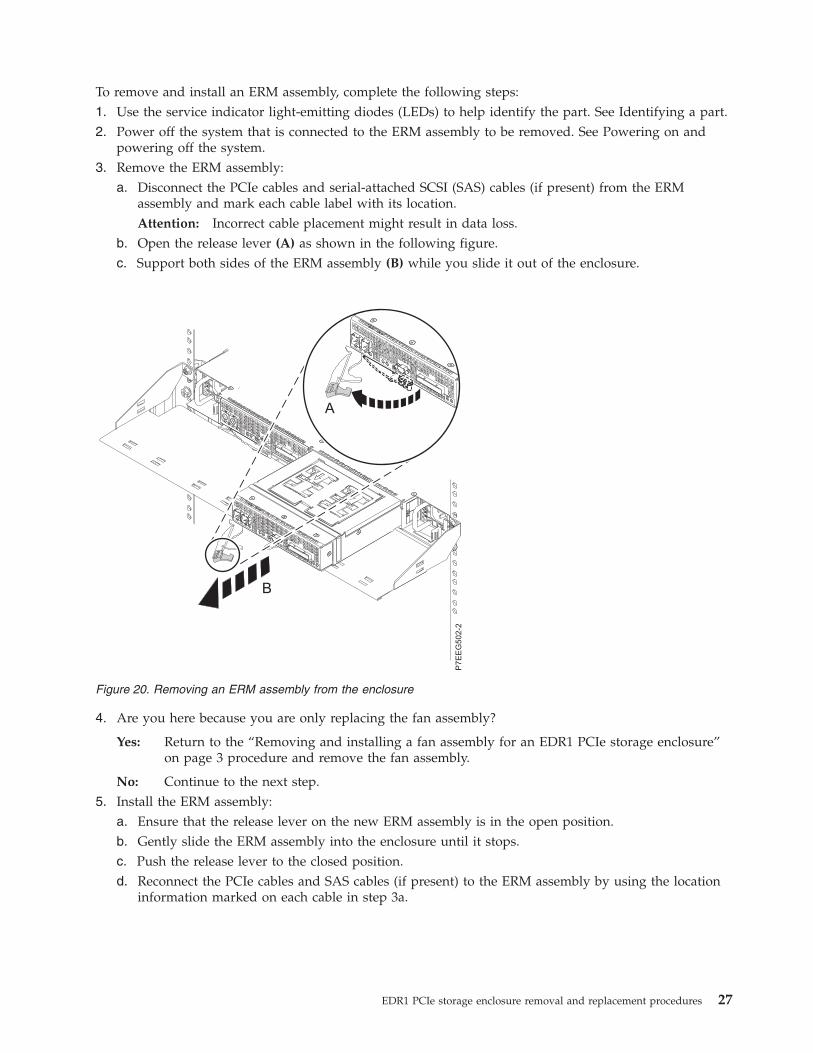
To remove and install an ERM assembly, complete the following steps:1. Use the service indicator light-emitting diodes (LEDs) to help identify the part. See Identifying a part.2. Power off the system that is connected to the ERM assembly to be removed. See Powering on and
powering off the system.3. Remove the ERM assembly:
a. Disconnect the PCIe cables and serial-attached SCSI (SAS) cables (if present) from the ERMassembly and mark each cable label with its location.Attention: Incorrect cable placement might result in data loss.
b. Open the release lever (A) as shown in the following figure.c. Support both sides of the ERM assembly (B) while you slide it out of the enclosure.
4. Are you here because you are only replacing the fan assembly?
Yes: Return to the “Removing and installing a fan assembly for an EDR1 PCIe storage enclosure”on page 3 procedure and remove the fan assembly.
No: Continue to the next step.5. Install the ERM assembly:
a. Ensure that the release lever on the new ERM assembly is in the open position.b. Gently slide the ERM assembly into the enclosure until it stops.c. Push the release lever to the closed position.d. Reconnect the PCIe cables and SAS cables (if present) to the ERM assembly by using the location
information marked on each cable in step 3a.
Figure 20. Removing an ERM assembly from the enclosure
EDR1 PCIe storage enclosure removal and replacement procedures 27
Attention:
v Incorrect cable placement might result in data loss.v To prevent loss of enclosure information, do not replace both ERM assemblies at the same time.
To replace the second ERM, power on the system and the partition that is connected to the ERMassembly that you replaced first. Then power off the system that is connected to the secondERM assembly.
6. Are you here because you are only replacing the fan assembly?
Yes: Power on the system that is connected to the ERM assembly. See Powering on and poweringoff the system. This ends the procedure.
No: Power on the partition that owns the ERM assembly. Then continue with “Updating the vitalproduct data.”
Updating the vital product data
The vital product data (VPD) must be updated after installing the ERM. To update the VPD, complete thefollowing steps:1. Power off the partition that owns the ERM assembly.2. Power on the partition that owns the ERM assembly.
Removing and installing an enclosure RAID module assembly with thepower on in the AIX environmentUse this procedure to service an enclosure RAID module (ERM) assembly for the EDR1 PCIe storageenclosure (EXP30 Ultra SSD I/O Drawer) with the power on in the AIX environment.
Attention:
v Failure to follow the steps sequentially for this field replaceable unit (FRU) removal or installationmight result in damage to the FRU or system.
v The ERM can only be replaced with the power on if the other ERM in the PCIe storage enclosure isoperational. If the fault LED on the other ERM is on solid, go to “Removing and installing an enclosureRAID module assembly with the power off” on page 26.
Use the following precautions whenever you handle electronic components or cables:v Attach a wrist strap to an unpainted metal surface of your hardware to prevent electrostatic discharge
(ESD) from damaging your hardware.v If you do not have a wrist strap, before removing the product from ESD packaging and installing or
replacing hardware, touch an unpainted metal surface of the system for a minimum of 5 seconds.v Keep all electronic components in the shipping container or envelope until you are ready to install
them.v If you remove and reinstall an electronic component, temporarily place the component on an ESD pad
or blanket, if available.v To prevent loss of enclosure information, do not replace both ERM assemblies at the same time. To
replace the second ERM, complete the removing, installing, and updating the vital product dataprocedures for the first ERM assembly and then replace the second ERM assembly.
The following sections provide information about servicing an ERM:v “Removing an ERM assembly” on page 29v “Installing an ERM assembly” on page 31v “Updating the vital product data” on page 33v “Completing the procedure” on page 33
28 EDR1 removal and replacement procedures
Removing an ERM assembly
To remove an ERM assembly, complete the following steps:1. Go to the AIX system diagnostics by logging in as the root user or the CE login user, and enter diag
at the command line.2. When the DIAGNOSTIC OPERATING INSTRUCTIONS menu is displayed, press Enter.3. From the FUNCTION SELECTION menu, select Task Selection, and then press Enter.4. Select Display Previous Diagnostic Results, and then press Enter5. From the Display Previous Diagnostic Results display, select Display Diagnostic Log Summary. The
Display Diagnostic Log display shows a chronological list of events.6. Look in the T column for the most recent S entry for the ERM (resource name sissasX or sesX) that
you are servicing. Select the row with the most recent S entry in the table, and then press Enter.7. Select Commit. The details of this log entry are displayed.8. Are you here because you are replacing only the fan assembly or is the ERM resource name sesX
and not sissasX?
Yes: Complete the following steps:a. Record the sesX resource name and the location of the failing ERM fan.b. Press F3 or Esc+3 to return to the Tasks Selection list.c. From the Tasks Selection list, select Hot Plug Task and press Enter.d. Select Expander Suspend and Resume Manager and press Enter.e. Find the sesX entry with the same Un-Px-Cy location and record the corresponding serial
number for that entry.f. Find the sissasX entry with the serial number you recorded in the previous step. Record
the location, the sissasX resource name, and the serial number associated with this entry.g. Press F3 or Esc+3 to return to the Tasks Selection list. Then continue with the next step.
No: Complete the following steps:a. Record the location and the sissasX resource name.b. Is the serial number available in the details of the log entry?
Yes: Record the serial number. Press F3 or Esc+3 to return to the Tasks Selection list,and then continue with the next step.
No: Complete the following steps:1) Press enter to exit the log entry display, then press F3 or Esc+3 two times to
return to the Tasks Selection List.2) From the Tasks Selection list, select Display Hardware Vital Product Data
and press Enter.3) Select the sissasX resource name of the failing ERM that you are replacing
and press Enter.4) Press F7 (Commit) or Esc+7, and then press Enter.5) Record the serial number. Press F3 or Esc+3 to return to the Tasks Selection
list, and then continue with the next step.9. From the Tasks Selection list, select Hot Plug Task and press Enter.
10. Select PCI Hot Plug Manager and press Enter.11. Select Unconfigure a Device and press Enter.12. Press F4 or Esc+4.13. From the Device Names menu, select the sissasX resource name of the ERM that you are removing,
and then press Enter.
EDR1 PCIe storage enclosure removal and replacement procedures 29
Attention: Ensure that the correct ERM is selected, and that the fault LED on the other ERM in thePCIe storage enclosure is not on solid. If the incorrect ERM is selected, complete this procedure tophysically remove and install the ERM to reset the fault condition. If the correct ERM is selected, butthe other ERM in the PCIe storage enclosure has a fault LED on solid, the procedure must becompleted with the power off. For instructions, see “Removing and installing an enclosure RAIDmodule assembly with the power off” on page 26.
14. In the Unconfigure Child Devices field, use Tab or ESC+4 to answer YES.15. In the Keep Definition field, use Tab or ESC+4 to answer YES, and press Enter.
The ARE YOU SURE display is shown.16. Press Enter to verify the information. A successful deconfiguration is indicated by the message OK,
which is shown next to the Command field at the top of the window.17. Press F3 or Esc+3 three times to return to the Tasks Selection list.18. Is the failing ERM part of a high availability (HA) configuration in which the second ERM is located
in a different system or partition?
Yes: Work with the customer to determine the system or partition that has the second ERM. Fromthe partition that has the second ERM, complete the following steps:a. Go to the AIX system diagnostics by logging in as the root user or the CE login user, and
enter diag at the command line.b. When the DIAGNOSTIC OPERATING INSTRUCTIONS menu is displayed, press Enter.c. From the FUNCTION SELECTION menu, select Task Selection and press Enter.d. Continue with the next step.
No: Continue with the next step.19. From the Tasks Selection list, select Hot Plug Task and press Enter.20. Wait one minute to ensure that the configuration data has been updated. Then select Expander
Suspend and Resume Manager and press Enter.21. Select the ses entry with the same serial number as the ERM that you are replacing, and press Enter.
A warning message is displayed.22. Select YES and press Enter.23. Ensure that the ses entry shows a status of suspended, and then continue with the next step.24. Press F3 or Esc+3 to return to the Tasks Selection list. If the ERM is part of a high availability (HA)
configuration, return to the partition that has the failing ERM and continue with the next step.25. From the Tasks Selection list, select Hot plug task and press Enter.26. Select PCI Hot Plug Manager and press Enter.27. Select replace/remove PCI Hot Plug adapter and press Enter.28. Select the slot with the location of the ERM to be removed from the enclosure, and press Enter.
Attention: Ensure that the correct ERM is selected, and that the fault LED on the other ERM in thePCIe storage enclosure is not on solid. If the incorrect ERM is selected, complete this procedure tophysically remove and install the ERM to reset the fault condition. If the correct ERM is selected, butthe other ERM in the PCIe storage enclosure has a fault LED on solid, the procedure must becompleted with the power off. For instructions, see “Removing and installing an enclosure RAIDmodule assembly with the power off” on page 26.
29. Select Replace and press Enter.
Note: The blue chassis identify LED located at the front of the PCIe storage enclosure turns on solidto identify the enclosure. A fast-blinking amber LED located at the rear of the ERM indicates that theslot is identified.
30. Press Enter. This action places the ERM assembly in the action state, and the ERM assembly is readyto be removed from the enclosure.
31. Remove the ERM assembly:
30 EDR1 removal and replacement procedures
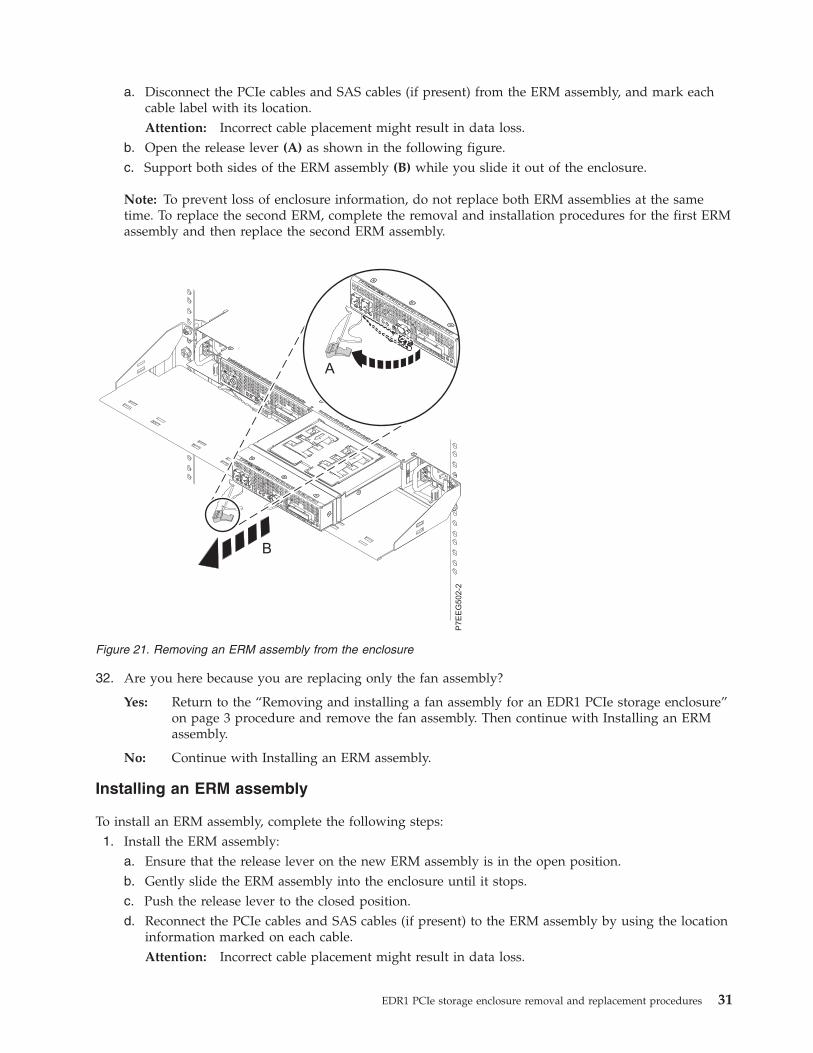
a. Disconnect the PCIe cables and SAS cables (if present) from the ERM assembly, and mark eachcable label with its location.Attention: Incorrect cable placement might result in data loss.
b. Open the release lever (A) as shown in the following figure.c. Support both sides of the ERM assembly (B) while you slide it out of the enclosure.
Note: To prevent loss of enclosure information, do not replace both ERM assemblies at the sametime. To replace the second ERM, complete the removal and installation procedures for the first ERMassembly and then replace the second ERM assembly.
32. Are you here because you are replacing only the fan assembly?
Yes: Return to the “Removing and installing a fan assembly for an EDR1 PCIe storage enclosure”on page 3 procedure and remove the fan assembly. Then continue with Installing an ERMassembly.
No: Continue with Installing an ERM assembly.
Installing an ERM assembly
To install an ERM assembly, complete the following steps:1. Install the ERM assembly:
a. Ensure that the release lever on the new ERM assembly is in the open position.b. Gently slide the ERM assembly into the enclosure until it stops.c. Push the release lever to the closed position.d. Reconnect the PCIe cables and SAS cables (if present) to the ERM assembly by using the location
information marked on each cable.Attention: Incorrect cable placement might result in data loss.
Figure 21. Removing an ERM assembly from the enclosure
EDR1 PCIe storage enclosure removal and replacement procedures 31
e. Wait 2 minutes, and then continue with the next step.2. Press Enter, and then continue to follow the displayed instructions until you receive a message that
the replacement is successful. A successful replacement is indicated by the message OK, which isshown next to the Command field at the top of the window.
3. Press F3 or Esc+3 to return to the PCI Hot-Plug Manager menu.4. Select Configure a Defined Device and press Enter.5. Press F4 or Esc+4.6. From the Device Names menu, select from the list the sissasX resource name of the ERM that you
just replaced, and press Enter.7. On the Configure a Defined Device display, press Enter. When the Command status changes to OK,
the device is now configured.8. Press F3 or Esc+3 three times to return to the Tasks Selection list.9. Is the failing ERM part of a high availability (HA) configuration in which the second ERM is located
in a different system or partition?
Yes: From the partition with the second ERM, continue with the next step.
No: Continue with the next step.10. From the Tasks Selection list, select Hot Plug Task and press Enter.11. Wait one minute to ensure that the configuration data has been updated. Then select Expander
Suspend and Resume Manager and press Enter.12. Verify the status of the ses entry that has the same serial number as the ERM you just replaced. Is
the status Active?
Yes: Continue with the next step.
No: Complete the following steps:a. Select the ses entry that has the same serial number as the ERM you just replaced, and
press Enter.b. Ensure that the ses entry shows a status of active. Then continue with the next step.
13. Ensure that the ses entry shows a status of active, and then continue with the next step.14. Are you here because you are replacing only the fan assembly?
Yes: Complete the following steps:a. Press F3 or Esc+3 to return to the Tasks Selection list.b. From the Tasks Selection list, select Log Repair Action.c. Select the sesX resource name of the failing ERM fan that you replaced and press Enter.d. Press F7 (Commit) or Esc+7, and then press Enter.e. Press F10 or Esc+0 to exit the diagnostic program.f. At the command line, type cfgmgr -l sissasX, where sissasX is the resource name of the
ERM contains the replaced fan. Press Enter.This ends the procedure.
No: Continue with the next step.15. Press F3 or Esc+3 to return to the Tasks Selection list. If the ERM is part of a high availability (HA)
configuration, return to the partition that has the failing ERM and continue with the next step.16. From the Tasks Selection list, select Hot Plug Task and press Enter.17. Select PCI Hot Plug Manager and press Enter.18. Continue with Updating the vital product data.
32 EDR1 removal and replacement procedures
Updating the vital product data
The vital product data (VPD) must be updated after installing the ERM. To update the VPD, complete thefollowing steps:1. From the PCI Hot-Plug Manager menu, select Unconfigure a Device and press Enter.2. Press F4 or Esc+4.3. From the Device Names menu, select the sissasX resource name of the ERM that you are servicing
and press Enter.4. In the Unconfigure Child Devices field, use Tab or ESC+4 to answer YES.5. In the Keep Definition field, use Tab or ESC+4 to answer YES and press Enter.
The ARE YOU SURE message is displayed.6. Press Enter to verify the information. A successful deconfiguration is indicated by the message OK,
which is shown next to the Command field at the top of the window7. Press F3 or Esc+3 twice to return to the Hot Plug Manager menu.8. Select replace/remove PCI Hot Plug adapter and press Enter.9. Select the slot that has the location of the ERM you replaced and press Enter.
10. Select Replace and press Enter.
Note: A fast-blinking amber LED located at the rear of the ERM indicates that the slot is identified.11. Press Enter. This places the ERM assembly in the action state. Do not remove the ERM from the
enclosure.12. Press Enter, and then continue to follow the displayed instructions until you receive a message that
the operation is successful. A successful operation is indicated by the message OK, which is shownnext to the Command field at the top of the window.
13. Press F3 or Esc+3 to return to the PCI Hot-Plug Manager menu.14. Select Configure a Defined Device and then press Enter.15. Press F4 or Esc+4.16. From the list on the Device Names menu, select the sissasX resource name of the ERM that you
were working with and press Enter.17. On the Configure a Defined Device display, press Enter. When the Command status changes to OK,
the device is now configured.18. Continue with Completing the procedure.
Completing the procedure
Complete the following steps:1. If you replaced the ERM, complete the following steps:
a. Press F3 or Esc+3 three times to return to the Tasks Selection List.b. Select Log Repair Action.c. Select the sissasX resource name of the ERM assembly that you replaced and press Enter.d. Press F7 (Commit) or Esc+7 and press Enter.e. Press F10 or Esc+0 to exit the diagnostic program.
2. At the command line, type cfgmgr -l sissasX, where sissasX is the resource name of the ERM that wasreplaced. Press Enter.
3. Verify the ERM assembly by using the following instructions:a. Go to the AIX system diagnostics by logging in as the root user or the CE login user, and enter
diag at the command line.b. When the DIAGNOSTIC OPERATING INSTRUCTIONS menu is displayed, press Enter.
EDR1 PCIe storage enclosure removal and replacement procedures 33
c. From the FUNCTION SELECTION menu, select Advance Diagnostic Routines, and press Enter.d. Select Problem Determination and press Enter.e. Is the Previous Diagnostics Results window displayed?
Yes: Select YES and press Enter to view errors. Ignore any errors of type xxxx-9070 orxxxx-9076. For any other errors, contact your next level of support if necessary. Press Enterto continue with the next step.
No: Continue with the next step.f. From the Advanced Diagnostics Selection menu, select the name of the resource that you
replaced. If the resource that you replaced is not shown, select the resource associated with it. PressEnter, and then press Commit (F7 or Esc+7).
g. Did the problem determination identify any problems?
Yes: Contact your next level of support. This ends the procedure.
No: Continue with the next step.4. Press F10 or Esc+0 to exit the diagnostic program. This ends the procedure.
Removing and installing an enclosure RAID module assembly with thepower on in the Linux environmentUse this procedure to service an enclosure RAID module (ERM) assembly for the EDR1 PCIe storageenclosure (EXP30 Ultra SSD I/O Drawer) with the power on in the Linux environment.
Attention: Failure to follow the steps sequentially for this field-replaceable unit (FRU) removal orinstallation might result in damage to the FRU or system.
Use the following precautions whenever you handle electronic components or cables:v Attach a wrist strap to an unpainted metal surface of your hardware to prevent electrostatic discharge
(ESD) from damaging your hardware.v If you do not have a wrist strap, before removing the product from ESD packaging and installing or
replacing hardware, touch an unpainted metal surface of the system for a minimum of 5 seconds.v Keep all electronic components in the shipping container or envelope until you are ready to install
them.v If you remove and reinstall an electronic component, temporarily place the component on an ESD pad
or blanket, if available.v To prevent loss of enclosure information, do not replace both ERM assemblies at the same time. To
replace the second ERM, complete the removal and installation procedures for the first ERM assemblyand then replace the second ERM assembly.
To remove and install an ERM assembly, complete the following steps:1. Use the service indicator light-emitting diodes (LEDs) to help identify the part. See Identifying a
part.2. To remove and install the ERM with the power on, iprutils version 2.3.12 or later is required. To
update iprutils, see Updating the iprutils package.Is iprutils version 2.3.12 or later installed?
Yes: Continue with the next step.
No: The ERM cannot be replaced with the power on. Go to “Removing and installing anenclosure RAID module assembly with the power off” on page 26. This ends the procedure.
3. On the Linux command line, type the iprconfig command.4. From the IBM® Power RAID Configuration Utility display, select Analyze Log, and press Enter.5. From the Kernel Messages Log display, select View ipr error messages, and press Enter.
34 EDR1 removal and replacement procedures
6. View the error message that indicates an adapter in a PCIe storage enclosure must be replaced.Record the location of the adapter.
7. Exit the Kernel Messages Log display by using the appropriate command for the editor that you areusing.
8. Type e and press Enter to exit the Kernel Messages Log display.9. From the IBM Power RAID Configuration Utility display, select Display hardware status, and press
Enter.10. From the Display Hardware Status display, find the entry with the location of the adapter identified
in step 5 on page 34. Does the adapter have a status of Operational?
Yes: Complete the following steps:a. Type 1 (Display hardware resource information details) next to the entry.b. Record the serial number shown on the IOA hardware Resource Information Details
display.c. Type e to exit the display. Then continue with the next step.
No: Use 00000000 as the serial number. Continue with the next step.11. From the Display Hardware Status window, find the PCI-E SAS RAID Adapter with a machine type
and model of 57C3001SISIOA and a remote adapter serial number that matches the serial numberidentified in step 9. Type 1 (Display hardware resource information details) next to each PCI-E SASRAID Adapter until the matching remote adapter serial number is found. Ensure that the MachineType and Model on the IOA Hardware Resource Information Details display is 57C3001SISIOA.Record the PCI Address of the adapter.
12. Return to the IBM Power RAID Configuration Utility display.13. From the IBM Power RAID Configuration Utility display, select Work with disk unit recovery, and
press Enter.14. From the Work with Disk Unit Recovery display, select Work with disk enclosures, and press Enter.15. From the Work with disk enclosures display, find the adapter entry with the PCI address identified
in step 11.16. Expander entries are located directly under adapter entries and have their PCI/Host/Resource Path
information indented. Type 2 (Suspend disk enclosure path) next to the expander entry that is underthe adapter entry identified in step 15, but has a different serial number than the adapter identifiedin step 15.
17. From the Suspend Disk Enclosure display, type c to continue. Then type e two times to exit to thecommand line.
18. On the Linux command line, type the drslot_chrp_pci command to enable an ERM assembly to bereplaced.For example, to replace the ERM assembly in slot UEDR1.001.DQD014E-P1-C3, enter the followingcommand:drslot_chrp_pci -R -s UEDR1.001.sssssss
Follow the instructions on the display to complete the task.19. Remove the ERM assembly:
a. Disconnect the PCIe cables and serial-attached SCSI (SAS) cables (if present) from the ERMassembly, and mark each cable label with its location.Attention: Incorrect cable placement might result in data loss.
b. Open the release lever (A) as shown in the following figure.c. Support both sides of the ERM assembly (B) while you slide it out of the enclosure.
EDR1 PCIe storage enclosure removal and replacement procedures 35
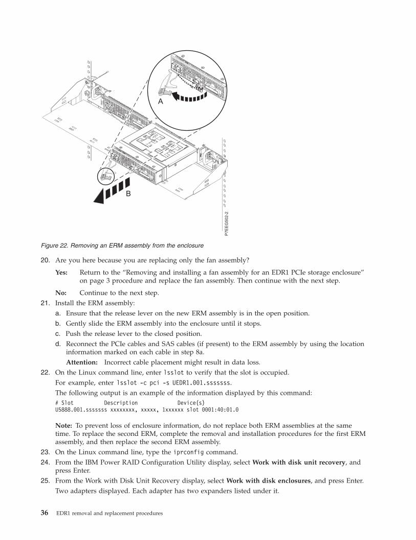
20. Are you here because you are replacing only the fan assembly?
Yes: Return to the “Removing and installing a fan assembly for an EDR1 PCIe storage enclosure”on page 3 procedure and replace the fan assembly. Then continue with the next step.
No: Continue to the next step.21. Install the ERM assembly:
a. Ensure that the release lever on the new ERM assembly is in the open position.b. Gently slide the ERM assembly into the enclosure until it stops.c. Push the release lever to the closed position.d. Reconnect the PCIe cables and SAS cables (if present) to the ERM assembly by using the location
information marked on each cable in step 8a.Attention: Incorrect cable placement might result in data loss.
22. On the Linux command line, enter lsslot to verify that the slot is occupied.For example, enter lsslot -c pci -s UEDR1.001.sssssss.The following output is an example of the information displayed by this command:# Slot Description Device(s)U5888.001.sssssss xxxxxxxx, xxxxx, 1xxxxxx slot 0001:40:01.0
Note: To prevent loss of enclosure information, do not replace both ERM assemblies at the sametime. To replace the second ERM, complete the removal and installation procedures for the first ERMassembly, and then replace the second ERM assembly.
23. On the Linux command line, type the iprconfig command.24. From the IBM Power RAID Configuration Utility display, select Work with disk unit recovery, and
press Enter.25. From the Work with Disk Unit Recovery display, select Work with disk enclosures, and press Enter.
Two adapters displayed. Each adapter has two expanders listed under it.
Figure 22. Removing an ERM assembly from the enclosure
36 EDR1 removal and replacement procedures
26. Type 3 (Resume disk enclosure path) next to the expander entry that you identified in step 16 onpage 35.
27. From the Resume Display Enclosure display, type c to continue. Then type e to exit the IBM PowerRAID Configuration Utility.
28. Are you here because you are replacing only the fan assembly?
Yes: This ends the procedure.
No: Continue with Updating the vital product data.
Updating the vital product data
The vital product data (VPD) must be updated after installing the ERM.
To update the VPD, complete the following steps:1. On the Linux command line, enter drslot_chrp_pci to enable an ERM assembly to be replaced.
For example, to replace the ERM assembly in slot UEDR1.001.DQD014E-P1-C3, enter the followingcommand:drslot_chrp_pci -R -s UEDR1.001.sssssss
Follow the instructions on the display to complete the task.2. Do not remove the ERM assembly. Continue with the next step.3. From the Linux command line, enter lsslot to verify that the slot is occupied.
For example, enter lsslot -c pci -s UEDR1.001.sssssss.The following output is an example of the information displayed by this command:# Slot Description Device(s)U5888.001.sssssss xxxxxxxx, xxxxx, 1xxxxxx slot 0001:40:01.0
This ends the procedure.
EDR1 PCIe storage enclosure removal and replacement procedures 37

38 EDR1 removal and replacement procedures
Notices
This information was developed for products and services offered in the U.S.A.
The manufacturer may not offer the products, services, or features discussed in this document in othercountries. Consult the manufacturer's representative for information on the products and servicescurrently available in your area. Any reference to the manufacturer's product, program, or service is notintended to state or imply that only that product, program, or service may be used. Any functionallyequivalent product, program, or service that does not infringe any intellectual property right of themanufacturer may be used instead. However, it is the user's responsibility to evaluate and verify theoperation of any product, program, or service.
The manufacturer may have patents or pending patent applications covering subject matter described inthis document. The furnishing of this document does not grant you any license to these patents. You cansend license inquiries, in writing, to the manufacturer.
The following paragraph does not apply to the United Kingdom or any other country where suchprovisions are inconsistent with local law: THIS PUBLICATION IS PROVIDED “AS IS” WITHOUTWARRANTY OF ANY KIND, EITHER EXPRESS OR IMPLIED, INCLUDING, BUT NOT LIMITED TO,THE IMPLIED WARRANTIES OF NON-INFRINGEMENT, MERCHANTABILITY OR FITNESS FOR APARTICULAR PURPOSE. Some states do not allow disclaimer of express or implied warranties in certaintransactions, therefore, this statement may not apply to you.
This information could include technical inaccuracies or typographical errors. Changes are periodicallymade to the information herein; these changes will be incorporated in new editions of the publication.The manufacturer may make improvements and/or changes in the product(s) and/or the program(s)described in this publication at any time without notice.
Any references in this information to websites not owned by the manufacturer are provided forconvenience only and do not in any manner serve as an endorsement of those websites. The materials atthose websites are not part of the materials for this product and use of those websites is at your own risk.
The manufacturer may use or distribute any of the information you supply in any way it believesappropriate without incurring any obligation to you.
Any performance data contained herein was determined in a controlled environment. Therefore, theresults obtained in other operating environments may vary significantly. Some measurements may havebeen made on development-level systems and there is no guarantee that these measurements will be thesame on generally available systems. Furthermore, some measurements may have been estimated throughextrapolation. Actual results may vary. Users of this document should verify the applicable data for theirspecific environment.
Information concerning products not produced by this manufacturer was obtained from the suppliers ofthose products, their published announcements or other publicly available sources. This manufacturer hasnot tested those products and cannot confirm the accuracy of performance, compatibility or any otherclaims related to products not produced by this manufacturer. Questions on the capabilities of productsnot produced by this manufacturer should be addressed to the suppliers of those products.
All statements regarding the manufacturer's future direction or intent are subject to change or withdrawalwithout notice, and represent goals and objectives only.
The manufacturer's prices shown are the manufacturer's suggested retail prices, are current and aresubject to change without notice. Dealer prices may vary.
39
This information is for planning purposes only. The information herein is subject to change before theproducts described become available.
This information contains examples of data and reports used in daily business operations. To illustratethem as completely as possible, the examples include the names of individuals, companies, brands, andproducts. All of these names are fictitious and any similarity to the names and addresses used by anactual business enterprise is entirely coincidental.
If you are viewing this information in softcopy, the photographs and color illustrations may not appear.
The drawings and specifications contained herein shall not be reproduced in whole or in part without thewritten permission of the manufacturer.
The manufacturer has prepared this information for use with the specific machines indicated. Themanufacturer makes no representations that it is suitable for any other purpose.
The manufacturer's computer systems contain mechanisms designed to reduce the possibility ofundetected data corruption or loss. This risk, however, cannot be eliminated. Users who experienceunplanned outages, system failures, power fluctuations or outages, or component failures must verify theaccuracy of operations performed and data saved or transmitted by the system at or near the time of theoutage or failure. In addition, users must establish procedures to ensure that there is independent dataverification before relying on such data in sensitive or critical operations. Users should periodically checkthe manufacturer's support websites for updated information and fixes applicable to the system andrelated software.
Homologation statement
This product may not be certified in your country for connection by any means whatsoever to interfacesof public telecommunications networks. Further certification may be required by law prior to making anysuch connection. Contact an IBM representative or reseller for any questions.
TrademarksIBM, the IBM logo, and ibm.com are trademarks or registered trademarks of International BusinessMachines Corp., registered in many jurisdictions worldwide. Other product and service names might betrademarks of IBM or other companies. A current list of IBM trademarks is available on the web atCopyright and trademark information at www.ibm.com/legal/copytrade.shtml.
Linux is a registered trademark of Linus Torvalds in the United States, other countries, or both.
Electronic emission noticesWhen attaching a monitor to the equipment, you must use the designated monitor cable and anyinterference suppression devices supplied with the monitor.
Class A NoticesThe following Class A statements apply to the servers.
Federal Communications Commission (FCC) statement
Note: This equipment has been tested and found to comply with the limits for a Class A digital device,pursuant to Part 15 of the FCC Rules. These limits are designed to provide reasonable protection againstharmful interference when the equipment is operated in a commercial environment. This equipmentgenerates, uses, and can radiate radio frequency energy and, if not installed and used in accordance withthe instruction manual, may cause harmful interference to radio communications. Operation of this
40 EDR1 removal and replacement procedures

equipment in a residential area is likely to cause harmful interference, in which case the user will berequired to correct the interference at his own expense.
Properly shielded and grounded cables and connectors must be used in order to meet FCC emissionlimits. IBM is not responsible for any radio or television interference caused by using other thanrecommended cables and connectors or by unauthorized changes or modifications to this equipment.Unauthorized changes or modifications could void the user's authority to operate the equipment.
This device complies with Part 15 of the FCC rules. Operation is subject to the following two conditions:(1) this device may not cause harmful interference, and (2) this device must accept any interferencereceived, including interference that may cause undesired operation.
Industry Canada Compliance Statement
This Class A digital apparatus complies with Canadian ICES-003.
Avis de conformité à la réglementation d'Industrie Canada
Cet appareil numérique de la classe A est conforme à la norme NMB-003 du Canada.
European Community Compliance Statement
This product is in conformity with the protection requirements of EU Council Directive 2004/108/EC onthe approximation of the laws of the Member States relating to electromagnetic compatibility. IBM cannotaccept responsibility for any failure to satisfy the protection requirements resulting from anon-recommended modification of the product, including the fitting of non-IBM option cards.
This product has been tested and found to comply with the limits for Class A Information TechnologyEquipment according to European Standard EN 55022. The limits for Class A equipment were derived forcommercial and industrial environments to provide reasonable protection against interference withlicensed communication equipment.
European Community contact:IBM Deutschland GmbHTechnical Regulations, Department M372IBM-Allee 1, 71139 Ehningen, GermanyTele: +49 7032 15 2941email: [email protected]
Warning: This is a Class A product. In a domestic environment, this product may cause radiointerference, in which case the user may be required to take adequate measures.
VCCI Statement - Japan
The following is a summary of the VCCI Japanese statement in the box above:
This is a Class A product based on the standard of the VCCI Council. If this equipment is used in adomestic environment, radio interference may occur, in which case, the user may be required to takecorrective actions.
Notices 41
Japanese Electronics and Information Technology Industries Association (JEITA)Confirmed Harmonics Guideline (products less than or equal to 20 A per phase)
Japanese Electronics and Information Technology Industries Association (JEITA)Confirmed Harmonics Guideline with Modifications (products greater than 20 A perphase)
Electromagnetic Interference (EMI) Statement - People's Republic of China
Declaration: This is a Class A product. In a domestic environment this product may cause radiointerference in which case the user may need to perform practical action.
Electromagnetic Interference (EMI) Statement - Taiwan
The following is a summary of the EMI Taiwan statement above.
Warning: This is a Class A product. In a domestic environment this product may cause radio interferencein which case the user will be required to take adequate measures.
42 EDR1 removal and replacement procedures
Electromagnetic Interference (EMI) Statement - Korea
Germany Compliance Statement
Deutschsprachiger EU Hinweis: Hinweis für Geräte der Klasse A EU-Richtlinie zurElektromagnetischen Verträglichkeit
Dieses Produkt entspricht den Schutzanforderungen der EU-Richtlinie 2004/108/EG zur Angleichung derRechtsvorschriften über die elektromagnetische Verträglichkeit in den EU-Mitgliedsstaaten und hält dieGrenzwerte der EN 55022 Klasse A ein.
Um dieses sicherzustellen, sind die Geräte wie in den Handbüchern beschrieben zu installieren und zubetreiben. Des Weiteren dürfen auch nur von der IBM empfohlene Kabel angeschlossen werden. IBMübernimmt keine Verantwortung für die Einhaltung der Schutzanforderungen, wenn das Produkt ohneZustimmung von IBM verändert bzw. wenn Erweiterungskomponenten von Fremdherstellern ohneEmpfehlung von IBM gesteckt/eingebaut werden.
EN 55022 Klasse A Geräte müssen mit folgendem Warnhinweis versehen werden:"Warnung: Dieses ist eine Einrichtung der Klasse A. Diese Einrichtung kann im WohnbereichFunk-Störungen verursachen; in diesem Fall kann vom Betreiber verlangt werden, angemesseneMaßnahmen zu ergreifen und dafür aufzukommen."
Deutschland: Einhaltung des Gesetzes über die elektromagnetische Verträglichkeit von Geräten
Dieses Produkt entspricht dem “Gesetz über die elektromagnetische Verträglichkeit von Geräten(EMVG)“. Dies ist die Umsetzung der EU-Richtlinie 2004/108/EG in der Bundesrepublik Deutschland.
Zulassungsbescheinigung laut dem Deutschen Gesetz über die elektromagnetische Verträglichkeit vonGeräten (EMVG) (bzw. der EMC EG Richtlinie 2004/108/EG) für Geräte der Klasse A
Dieses Gerät ist berechtigt, in Übereinstimmung mit dem Deutschen EMVG das EG-Konformitätszeichen- CE - zu führen.
Verantwortlich für die Einhaltung der EMV Vorschriften ist der Hersteller:International Business Machines Corp.New Orchard RoadArmonk, New York 10504Tel: 914-499-1900
Der verantwortliche Ansprechpartner des Herstellers in der EU ist:IBM Deutschland GmbHTechnical Regulations, Abteilung M372IBM-Allee 1, 71139 Ehningen, GermanyTel: +49 7032 15 2941email: [email protected]
Notices 43

Generelle Informationen:
Das Gerät erfüllt die Schutzanforderungen nach EN 55024 und EN 55022 Klasse A.
Electromagnetic Interference (EMI) Statement - Russia
Class B NoticesThe following Class B statements apply to features designated as electromagnetic compatibility (EMC)Class B in the feature installation information.
Federal Communications Commission (FCC) statement
This equipment has been tested and found to comply with the limits for a Class B digital device,pursuant to Part 15 of the FCC Rules. These limits are designed to provide reasonable protection againstharmful interference in a residential installation.
This equipment generates, uses, and can radiate radio frequency energy and, if not installed and used inaccordance with the instructions, may cause harmful interference to radio communications. However,there is no guarantee that interference will not occur in a particular installation.
If this equipment does cause harmful interference to radio or television reception, which can bedetermined by turning the equipment off and on, the user is encouraged to try to correct the interferenceby one or more of the following measures:v Reorient or relocate the receiving antenna.v Increase the separation between the equipment and receiver.v Connect the equipment into an outlet on a circuit different from that to which the receiver is
connected.v Consult an IBM-authorized dealer or service representative for help.
Properly shielded and grounded cables and connectors must be used in order to meet FCC emissionlimits. Proper cables and connectors are available from IBM-authorized dealers. IBM is not responsible forany radio or television interference caused by unauthorized changes or modifications to this equipment.Unauthorized changes or modifications could void the user's authority to operate this equipment.
This device complies with Part 15 of the FCC rules. Operation is subject to the following two conditions:(1) this device may not cause harmful interference, and (2) this device must accept any interferencereceived, including interference that may cause undesired operation.
Industry Canada Compliance Statement
This Class B digital apparatus complies with Canadian ICES-003.
Avis de conformité à la réglementation d'Industrie Canada
Cet appareil numérique de la classe B est conforme à la norme NMB-003 du Canada.
44 EDR1 removal and replacement procedures
European Community Compliance Statement
This product is in conformity with the protection requirements of EU Council Directive 2004/108/EC onthe approximation of the laws of the Member States relating to electromagnetic compatibility. IBM cannotaccept responsibility for any failure to satisfy the protection requirements resulting from anon-recommended modification of the product, including the fitting of non-IBM option cards.
This product has been tested and found to comply with the limits for Class B Information TechnologyEquipment according to European Standard EN 55022. The limits for Class B equipment were derived fortypical residential environments to provide reasonable protection against interference with licensedcommunication equipment.
European Community contact:IBM Deutschland GmbHTechnical Regulations, Department M372IBM-Allee 1, 71139 Ehningen, GermanyTele: +49 7032 15 2941email: [email protected]
VCCI Statement - Japan
Japanese Electronics and Information Technology Industries Association (JEITA)Confirmed Harmonics Guideline (products less than or equal to 20 A per phase)
Japanese Electronics and Information Technology Industries Association (JEITA)Confirmed Harmonics Guideline with Modifications (products greater than 20 A perphase)
Electromagnetic Interference (EMI) Statement - Korea
Notices 45
Germany Compliance Statement
Deutschsprachiger EU Hinweis: Hinweis für Geräte der Klasse B EU-Richtlinie zurElektromagnetischen Verträglichkeit
Dieses Produkt entspricht den Schutzanforderungen der EU-Richtlinie 2004/108/EG zur Angleichung derRechtsvorschriften über die elektromagnetische Verträglichkeit in den EU-Mitgliedsstaaten und hält dieGrenzwerte der EN 55022 Klasse B ein.
Um dieses sicherzustellen, sind die Geräte wie in den Handbüchern beschrieben zu installieren und zubetreiben. Des Weiteren dürfen auch nur von der IBM empfohlene Kabel angeschlossen werden. IBMübernimmt keine Verantwortung für die Einhaltung der Schutzanforderungen, wenn das Produkt ohneZustimmung von IBM verändert bzw. wenn Erweiterungskomponenten von Fremdherstellern ohneEmpfehlung von IBM gesteckt/eingebaut werden.
Deutschland: Einhaltung des Gesetzes über die elektromagnetische Verträglichkeit von Geräten
Dieses Produkt entspricht dem “Gesetz über die elektromagnetische Verträglichkeit von Geräten(EMVG)“. Dies ist die Umsetzung der EU-Richtlinie 2004/108/EG in der Bundesrepublik Deutschland.
Zulassungsbescheinigung laut dem Deutschen Gesetz über die elektromagnetische Verträglichkeit vonGeräten (EMVG) (bzw. der EMC EG Richtlinie 2004/108/EG) für Geräte der Klasse B
Dieses Gerät ist berechtigt, in Übereinstimmung mit dem Deutschen EMVG das EG-Konformitätszeichen- CE - zu führen.
Verantwortlich für die Einhaltung der EMV Vorschriften ist der Hersteller:International Business Machines Corp.New Orchard RoadArmonk, New York 10504Tel: 914-499-1900
Der verantwortliche Ansprechpartner des Herstellers in der EU ist:IBM Deutschland GmbHTechnical Regulations, Abteilung M372IBM-Allee 1, 71139 Ehningen, GermanyTel: +49 7032 15 2941email: [email protected]
Generelle Informationen:
Das Gerät erfüllt die Schutzanforderungen nach EN 55024 und EN 55022 Klasse B.
Terms and conditionsPermissions for the use of these publications are granted subject to the following terms and conditions.
Applicability: These terms and conditions are in addition to any terms of use for the the manufacturerwebsite.
Personal Use: You may reproduce these publications for your personal, noncommercial use provided thatall proprietary notices are preserved. You may not distribute, display or make derivative works of thesepublications, or any portion thereof, without the express consent of the manufacturer.
Commercial Use: You may reproduce, distribute and display these publications solely within yourenterprise provided that all proprietary notices are preserved. You may not make derivative works of
46 EDR1 removal and replacement procedures
these publications, or reproduce, distribute or display these publications or any portion thereof outsideyour enterprise, without the express consent of the manufacturer.
Rights: Except as expressly granted in this permission, no other permissions, licenses or rights aregranted, either express or implied, to the Publications or any information, data, software or otherintellectual property contained therein.
The manufacturer reserves the right to withdraw the permissions granted herein whenever, in itsdiscretion, the use of the publications is detrimental to its interest or, as determined by the manufacturer,the above instructions are not being properly followed.
You may not download, export or re-export this information except in full compliance with all applicablelaws and regulations, including all United States export laws and regulations.
THE MANUFACTURER MAKES NO GUARANTEE ABOUT THE CONTENT OF THESEPUBLICATIONS. THE PUBLICATIONS ARE PROVIDED "AS-IS" AND WITHOUT WARRANTY OF ANYKIND, EITHER EXPRESSED OR IMPLIED, INCLUDING BUT NOT LIMITED TO IMPLIEDWARRANTIES OF MERCHANTABILITY, NON-INFRINGEMENT, AND FITNESS FOR A PARTICULARPURPOSE.
Notices 47

48 EDR1 removal and replacement procedures


Printed in USA