


DIAGNÓSTICO COMUNITARIO DE LA CIUDAD DE LAS PALMAS DE GRAN CANARIA
Upload
khangminh22Category
view
0download
0
Nº 38 Marzo | March 2017 | 15 e Español | Inglés | Spanish | English
REPORTAJE | PLANT REPORT: ECOPARQUE GRAN CANARIA SUR GUÍAS TÉCNICAS | TECHNICAL GUIDES
PRE-TRITURADORES ESTACIONARIOS Y MÓVILES | STATIONARY & MOBILE PRIMARY SHREDDERSSEPARADORES DE CORRIENTE DE FOUCAULT Y SEPARADORES MAGNÉTICOS
EDDY CURRENT SEPARATORS & MAGNETIC SEPARATORSSEPARADORES ÓPTICOS | OPTICAL SORTERS
ENVIROFuturENVIROPROYECTOS, TECNOLOGÍA Y ACTUALIDAD MEDIOAMBIENTALP RO J E C T S , TE C H N O L O G I E S A N D E N V I RO N M E N T A L N E W S
marron E pantone 1545 Cnaranja N pantone 1525 Callo V pantone 129 Cazul I pantone 291 Cazul R pantone 298 Cazul O pantone 2945 CFuture 100 negro
Nº
38 |
Mar
zo M
arch
201
7Fu
turE
NV
IRO
PR
OY
EC
TO
S,
TEC
NO
LO
GÍA
Y A
CT
UA
LID
AD
ME
DIO
AM
BIE
NT
AL
PR
OJ
EC
TS
, T
EC
HN
OL
OG
IES
AN
D E
NV
IRO
NM
EN
TA
L N
EW
S
mar
ron
E pa
nton
e 154
5 C
nara
nja N
pan
tone
152
5 C
allo
V p
anto
ne 1
29 C
azul
I pa
nton
e 291
Caz
ul R
pan
tone
298
Caz
ul O
pan
tone
294
5 C
Futu
re 1
00 n
egro
Gu
ía d
el C
om
pra
do
r |
Bu
yer’
s G
uid
eFu
turE
nvi
ro |
Mar
zo M
arch
201
7
www.futurenviro.es 99
Gestión Medioambiental Environmental management

Distribución especial en ferias | Special distribution at trade fairsXXIV Jornadas AEAS (Spain, 24-26/05)IV Forum SusChem-España (Spain, 1-2/03)XVI IWRA World Water Congress (Mexico, 29/05– 2/06)PUMPS&VALVES (Spain, 6-8/06)WATER INDUSTRY (Chile, 7-9/06)
GESTIÓN DEL AGUA II | WATER MANAGEMENT IIDesalación y depuración. Proyectos internacionales Desalination and treatment. International projectsPretratamientos y reactivos químicos | Pretreatment and chemical reagentsRedes de saneamiento y abastecimiento | Sewage and supply networksReutilización | ReuseDesodorización | Odour controlMaquinaria auxiliar: instrumentación, bombeo, valvulería... Auxiliary machinery: instrumentation, pumping, valves...
NÚMERO 39 ABRIL 2017 | NUMBER 39 APRIL 2017
Distribución especial en ferias Special distribution at trade fairs
EUBCE 2017 (Sweden, 12-15/06)15 CONGRESO FER (Spain, 15-16/06)RWM 2017 (UK, 12-14/09)
GESTIÓN DE RESIDUOS II | WASTE MANAGEMENT IIGUÍA TÉCNICA: Prensas y compactadoras TECHNICAL GUIDE: Balers & CompactorsGUÍA TÉCNICA II: Separadores balísticos TECHNICAL GUIDE II: Ballistic separatorsRECICLAJE. Reingeniería y mantenimiento de plantas RECYCLING. Plant upgrades & maintenanceCIUDADES INTELIGENTES. Recogida y transporte de residuos. SMART CITIES. Waste collection & transportation.ESPECIAL: Movilidad sostenible. Barredoras. SPECIAL SECTION: Sustainable Mobility. Sweeping machines.
NÚMERO 40 MAYO 2017 | NUMBER 40 MAY 2017
Editorial5
7 En portada | Cover Story
Futu
rEn
viro
| M
arzo
Mar
ch 2
017
www.futurenviro.es 3
SumarioSu
mm
ary
13 A Fondo: Análisis 2016 In Depth: Analysis Of 2016
AEVERSU ASPAPEL
FER RECYCLIA
ASEGRE
ECOVIDRIO
REPACAR SIGAUS
49 Reportaje | Plant ReportEcoparque Gran Canaria Sur
61 Gestión y Tratamiento de Residuos Waste Management & Treatment
Caso de éxito de prensado de briquetas de PET Successful PET briquetting case studyCombustibles de sustitución para hornos rotatorios Alternative fuels for rotary kilns
65 Tablas Comparativas y Guías Técnicas Comparative Tables & Technical Guides
Pre-Trituradores estacionarios y móviles Stationary & Mobile primary shredders
Separadores de corriente de Foucault Eddy current separators
Separadores magnéticos | Magnetic separators
Separadores ópticos | Optical Sorters
66
74
8286
www.futurenviro.es
Futu
rEn
viro
| M
arzo
Mar
ch 2
017
5
EditorialEd
ito
rial Escuchamos al sector y ampliamos nuestras Guías Técnicas
Comenzamos este primer número de residuos de 2017 con un número de análisis y reflexión con nuestra sección “A fondo”, en la que contamos como cada año con la colaboración especial de destacadas figuras del sector de la gestión y tratamiento de residuos. En esta sección especial, los presidentes y/o directores de las asociaciones y SIGs comparten en estas páginas sus impresiones sobre 2016, así como sus previsiones para este año.
Además de nuestra ya asentada y muy consultada Guía de pre-trituradores estacionarios y móviles para plantas de gestión de residuos y reciclaje, este número lo completamos con tres Guías Técnicas nuevas que nos venían demandando las ingenierías, desarrolladores de plantas de tratamiento y gestión de residuos, así como recuperadores: Guía de Separadores de corriente de Foucault, Guía de separadores magnéticos y Guía de separadores ópticos.
Unas actualizadas, completas, sencillas y útiles guías que recogen las principales características de los diferentes equipos ofrecidos por los principales fabricantes nacionales e internacionales. Estas guías se presentan en forma de tabla de datos, en la que de un simple vistazo se conozcan y comparen las principales características técnicas de todas ellas.Unas guías dirigida especialmente a ingenierías, desarrolladores “llave en mano” de plantas de reciclaje, recuperadores, administraciones públicas de carácter provincial, autonómico y nacional, y en definitiva cualquier ente dedicado a la gestión, tratamiento y valorización de residuos.
Como guinda de este número contamos con un extenso y detallado Plant Report de una planta de gestión y tratamiento de residuos de vanguardia, el Ecoparque Gran Canaria Sur.
Extended Technical Guides at request of sectorWe begin this first waste treatment and management issue of 2017 with analysis and reflection in our annual “In Depth” section, which, as usual, features the collaboration of leading figures in the sector. In this special section, the presidents and/or directors of trade associations and Integrated Management Systems share their impressions of 2016 and their forecasts for the current year.
In addition to our consolidated and much-consulted Guide to Stationary & Mobile Primary Shredders for waste management and recycling plants, this issue also features three new Technical Guides that engineering companies, developers of turnkey waste treatment & management plants, and material recovery facilities have being requesting us to include for some time now: a Guide to Eddy Current Separators, a Guide to Magnetic Separators and a Guide to Optical Sorters.
Simple, comprehensive, useful, up-to-the-minute technical guides to the main features of the different equipment offered by leading national and international manufacturers. These guides are presented in the form of a data table to enable the main technical features of all the equipment to be examined and compared at a glance. These guides are particularly aimed at engineering companies, developers of turnkey recycling plants, material recovery plants, national, provincial and regional public authorities, and ultimately all organisations involved in waste management, treatment and recovery.
A further highlight of this issue comes in the form of an extensive, in-depth Plant Report on a state-of-the-art waste management and treatment facility, the Ecoparque Gran Canaria Sur.
Esperanza Rico Directora
staff
FuturENVIROProyectos, Tecnología y Actualidad MedioambientalNúmero 38 - Marzo | Number 38 - March 2017
Directora | Managing Director Esperanza [email protected] Comercial | Sales Manager Yago Bellido - [email protected] Jefe y Community Manager Editor-in-Chief & Community Manager Moisés Menéndez - [email protected] | Editor Puri Ortiz - [email protected]. Comercial | Sales Dept. Conchi Centeno | [email protected] José María Vázquez | [email protected] Internacionales | International Relations Javier Riello | [email protected]
DELEGACIÓN MÉXICO | MEXICO BRANCH Graciela Ortiz Mariscal [email protected] Celular: (52) 1 55 43 48 51 52
CONSEJO ASESOR | ADVISORY COUNCIL
Francisco Repullo Presidente de AEBIG | President of the AEBIGDomingo Zarzo Presidente de AEDYR | President of the AEDYRÁngel Fernández Homar Presidente de AEVERSU | President of the AEVERSUSergi Martí Presidente de Aqua España | President of Aqua EspañaAntolín Aldonza Presidente de la PTEA | President of the PTEALuis Palomino Secretario General de ASEGRE | Secretary General of ASEGREAlicia Castro Vicepresidenta de Transferencia e Internacionalización del CSIC Vice President of Transfer and Internationalisation at the CSICAlicia García-Franco Directora General de la FER | Director General of the FERSebastián Solís Presidente de REPACAR | President of REPACAR
Edita | Published by: Saguenay, S.L.Zorzal, 1C, bajo C - 28019 Madrid (Spain)T: +34 91 472 32 30 / +34 91 471 92 25
Traducción | Translation: Seamus [email protected]ño y Producción | Design & Production: Diseñopar Publicidad S.L.U.Impresión | Printing: GrafoprintDepósito Legal / Legal Deposit: M-15915-2013ISSN: 2340-2628Otras publicaciones | Other publications
© Prohibida la reproducción total o parcial por cualquier medio sin autorización previa y escrita del editor. Los artículos firmados (imágenes incluidas) son de exclusiva responsabilidad del autor, sin que FuturENVIRO comparta necesariamente las opiniones vertidas en los mismos.
© Partial or total reproduction by any means withour previous written authorisation by the Publisher is forbidden. Signed articles (including pictures) are their respective authors´ exclusive responsability. FuturENVIRO does not necesarily agree with the opinions included in them.
FuturENERGYP R O Y E C T O S , T E C N O L O G Í A Y A C T U A L I D A D E N E R G É T I C AP R O J E C T S , T E C H N O L O G I E S A N D E N E R G Y N E W S
verde E pantone 356 Cverde N pantone 362 Cverde E pantone 368 Callo R pantone 3945 Cnaranja G pantone 716 Crojo Y pantone 485 C
Síguenos en | Follow us on:
En P
ort
ada
| Co
ver
Sto
ryFu
turE
nvi
ro |
Mar
zo M
arch
201
7
www.futurenviro.es 7
La empresa PELLENC Selective Technologies diseña, fabrica y comercializa equipos de clasi-ficación óptica para la clasificación de residuos domésticos e industriales. Los productos clasi-ficados proceden de los residuos de los merca-dos del embalaje, la industria, la electrónica, la informática, la automoción y la construcción. Las tecnologías utilizadas en la clasificación de estos materiales son el infrarrojo cercano, la visión y la inducción. PELLENC cuenta con má-quinas instaladas en más de 40 países.
La Mistral+ es el resultado de un desarrollo de 4 años en el que han participado más de 30 ingenieros de Pellenc ST. Hemos tenido en cuenta una enorme cantidad de comentarios que hemos recogido de nuestros clientes, nuestro equipo de atención al cliente y nuestros em-pleados para diseñar esta máquina.
La Mistral+ está fabricada basándonos en la experiencia de más de 1.200 máquinas Mis-tral instaladas en todo el mundo, a lo largo de los últimos 15 años. Además, se han realizado impor-tantes inversiones para garantizar la cualificación de cada com-ponente y subsistema: se han realizado más de 10 tipos de prue-bas de resistencia y se han dedicado miles de horas de pruebas de laboratorio y de campo para garantizar la mejor fiabilidad y el mejor rendimiento.
Hay pendientes varias patentes para proteger nuestra innovación. Toda la empresa está detrás de este proyecto y continuará traba-jando duro para lograr que sea la mejor máquina de clasificación óptica disponible en el mercado.
Todas las tecnologías utilizadas son propiedad de Pellenc ST, desa-rrolladas por la compañía y protegidas por patentes. Toda la compa-ñía se ha comprometido y volcado con este proyecto con el objetivo de obtener la mejor máquina de clasificación óptica disponible en el mercado.
Con el objeto de ayudar a nuestros clientes a beneficiarse de las ventajas de la Mistral+, Pellenc ST ha puesto en marcha un plan Renove en condiciones muy ventajosas para poder sustituir las máquinas Mistral en servicio por Mistral+. Para más información pueden contactar con el equipo comercial.
PELLENC Selective Technologies designs, manufactures and sells optical sorting equipment for domestic and industrial waste. The sorted products come from waste from the packaging, industrial, electronics, IT, automotive and construction sectors. These machines implement near infrared, vision and induction material sorting technologies. PELLENC machines are currently installed in over 40 countries worldwide.
Mistral + is the result of 4 years of development work featuring the participation of over 30 Pellenc ST
engineers. Moreover, an enormous number of customer comments were taken on board, along with the opinions of the company’s customer service team and employees,
in order to optimise the design of the machine.
MISTRAL + is manufactured based on the experience gained through
the installation of more than 1,200 Mistral units throughout the world over
the last 15 years. Significant investment has been made to ensure the quality of all components and subsystems. More than 10 different types of resistance tests were carried out and thousands of hours were spent testing in the laboratory and in the field to guarantee greater reliability and enhanced performance.
Several patents are pending for the protection of our innovation. The entire company is behind this project and will continue working hard to make this the best optical sorter on the market.
All technologies implemented by Pellenc ST are proprietary, developed in-house and protected by patents. The entire company has committed to this project for the purpose of obtaining the best optical sorting machine on the market.
To help clients benefit from the advantages of the Mistral+, Pellenc ST has put a Renewal Plan into operation to enable Mistral machines in service to be replaced by the Mistral +, with very advantageous conditions. Our sales team can be contacted for further information on this plan.
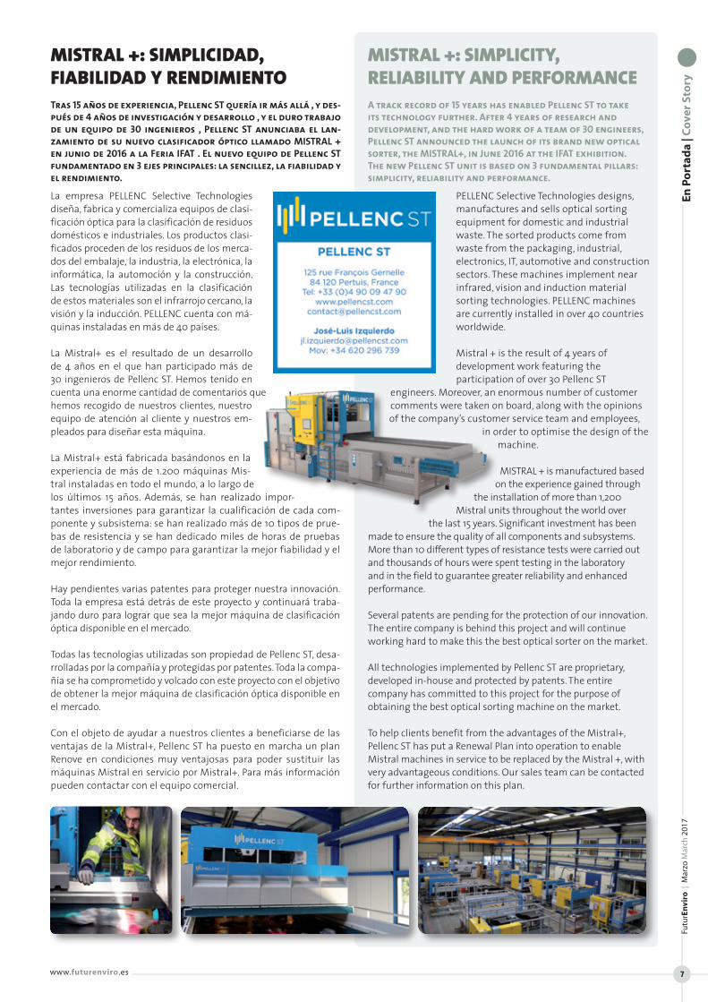
MISTRAL +: SIMPLICITY, RELIABILITY AND PERFORMANCE A track record of 15 years has enabled Pellenc ST to take its technology further. After 4 years of research and development, and the hard work of a team of 30 engineers, Pellenc ST announced the launch of its brand new optical sorter, the MISTRAL+, in June 2016 at the IFAT exhibition. The new Pellenc ST unit is based on 3 fundamental pillars: simplicity, reliability and performance.
MISTRAL +: SIMPLICIDAD, FIABILIDAD Y RENDIMIENTO Tras 15 años de experiencia, Pellenc ST quería ir más allá , y des-pués de 4 años de investigación y desarrollo , y el duro trabajo de un equipo de 30 ingenieros , Pellenc ST anunciaba el lan-zamiento de su nuevo clasificador óptico llamado MISTRAL + en junio de 2016 a la Feria IFAT . El nuevo equipo de Pellenc ST fundamentado en 3 ejes principales: la sencillez, la fiabilidad y el rendimiento.
Even
tos
| Eve
nts
Futu
rEn
viro
| M
arzo
Mar
ch 2
017
www.futurenviro.es 11
Waste-to-Resources ha llegado a ser la conferencia de TMB más grande del mundo, con participantes de hasta 41 países. La com-binacion de conferencias de alto nivel y exhibicion hará de Waste-to-Resources 2017 el evento mas importante para las autoridades y proveedores de tecnologia del sector de los residuos.
La conferencia se dedicará a asuntos sobre TMB e instalaciones de MRF y como aspectos clave del programa, en esta edicción destacan los siguientes:
Estrategias de gestión de residuos, nuevas tecnologías de trata-miento de residuos
• Uso de residuos plásticos, minerales y orgánicos• Digestión anaeróbica de la fracción orgánica de residuos sólidos
orgánicos.• Experiencia práctica, optimización y nuevos desarrollos.• Reducción de emisiones.• Análisis de residuos, pronóstico de residuos.• Recuperación de energía por centrales eléctricas RDF y hornos de
cemento, licuefacción• Acondicionamiento, uso y venta de fracciones de producción de
tratamientos mecánicos y biológicos• Nuevas regulaciones legales en la UE• Gestión de residuos en países emergentes
La conferencia se llevará a cabo del 16 al 18 de mayo de 2017. El día antes a la celebración de la conferencia tendra lugar un seminario de introducción al tratamiento mecánico-biológico en inglés.
Waste-to-Resources tendrá lugar en Hanóver, Alemania. El evento se celebra con el apoyo de la ministra alemana de medio ambien-te, Barbara Hendricks. El evento está organizado por Wasteconsult International y la asociación de operadores alemanes ASA. Puede consultar el programa y más información sobre conferencias, expo-siciones y alojamiento en www.waste-to-resources.eu
En los 3 días de la conferencia habrá traducción simultánea conti-nua proporcionada en la primera sesión. Por lo tanto, será posible escuchar todas las presentaciones en inglés, francés y alemán.
La exposición paralela reúne a una audiencia altamente cualificada y líderes del mercado en tecnologías avanzadas de residuos y reci-claje. Encontrará todos los detalles para la reserva de una superficie de exposición, packs de patrocinio y otras posibilidades de publici-dad en: www.waste-to-resources.eu/exhibition.html.
Waste-to-Resources has become the world’s biggest MBT conference, with participants from up to 41 countries. The combination of high-level conference and parallel exhibition will make Waste-to-Resources 2017 the most important event of the year for public authorities and technology providers in the waste sector.
The programme for this year’s leading MBT and MRF event includes the following key areas:
• Waste management strategies, new waste treatment technologies
• Utilisation of plastic, mineral and organic waste• Anaerobic digestion of organic waste fractions• Practical experience, optimisation and new developments• Reduction of emissions• Waste analytics, waste prognosis• Energy recovery by RDF power plants and cement kilns,
liquefaction• Conditioning, use and sale of output fractions from mechanical
and biological treatment• New and upcoming legal regulations in the EU• Waste management in emerging nations
The conference will be held from the 16th to the 18th of May 2017. An introduction seminar on MBT will be held on the day prior to the commencement of the conference. This seminar will be held in English.
Waste-to-Resources takes place in Hanover, Germany. It is held under the patronage of the German minister of the environment, Barbara Hendricks. The event is organised by Wasteconsult International and the Association of German MBT operators (ASA). The conference programme and further information on the conference, exhibition and accommodation can be found at www.waste-to-resources.eu
Continuous simultaneous translation will be provided in session one of the 3 days of the conference, enabling all these presentations to be enjoyed in English, French and German
The parallel exhibition brings together highly qualified professional visitors and market leaders in advanced waste and recycling technology. Details of exhibition space reservations, sponsor packages and further advertising possibilities are available at http://www.waste-to-resources.eu/exhibition.html .
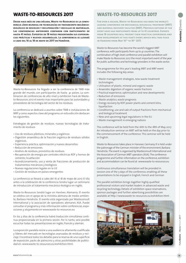
WASTE-TO-RESOURCES 2017Desde hace más de una década, Waste-to-Resources es la confe-rencia líder mundial en tecnologías de tratamiento mecánico-biológico de residuos y recuperación y reciclaje de materiales. Las conferencias anteriores contaron con participantes de hasta 41 países. Expertos de 18 países presentarán sus experien-cias prácticas y nuevos desarrollos. La conferencia se llevará a cabo del 16 al 18 de mayo de 2017 en Hanóver.
WASTE-TO-RESOURCES 2017For over a decade, Waste-to-Resources has been the world’s leading conference on mechanical biological treatment (MBT) and material recovery facilities (MRF). Previous editions of the event have had participants from up to 41 countries. Experts from 18 countries will present their practical experiences and new developments at this year’s event, which will take place in Hanover from May 16th to 18th 2017.
A fo
nd
o: A
nál
isis
20
16
| I
n d
epth
: An
alys
is o
f 20
16
FuturEnviro | Marzo March 2017
ww
w.fu
ture
nvi
ro.e
s
12
La economía circular se erige hoy como la princi-pal apuesta por un modelo de desarrollo sosteni-ble real, capaz de garantizar la supervivencia del planeta y al que, sin dilación, debemos contribuir desde el compromiso y la responsabilidad com-partida Los límites naturales a los que estamos llevando a la Tierra (superando ya los límites de no retorno en muchos casos), exigen compor-tamientos más sostenibles por parte de las em-presas, las administraciones y la sociedad en su conjunto. En este escenario, el diseño inteligente y ecológico de los productos para reducir las ma-teria primas utilizadas en ellos y facilitar su reuti-lización y reciclado, cobra especial protagonismo, al igual que el consumo racional y consecuente por parte de una población casa vez más expuesta a una presión de consumo de productos que buscan la satisfacción inmediata y la co-modidad, pero con una limitada vida útil en muchos casos.
La Unión Europeaestá marcandolas pautas a seguir en la transfor-mación productiva necesaria para hacer nuestra economía más circular, con unos exigentes objetivos de reciclado y recuperación que, inevitablemente, van a implicar un cambio de mentalidades, políticas e infraestructuras. Y en ese tránsito que debemos iniciar desde una economía lineal, caracterizada por el producir-usar-tirar, hacia una circular, la valorización energética de la fracción no recicla-ble de los residuos desempeña un papel importantedel que incluso se ha hecho eco el propio paquete europeo de economía circular. El documento recoge de forma explícitaque “cuando los residuos no se puedan evitar ni reciclar, resulta preferible, en la mayoría de los casos, tanto en términos medioambientales como económicos, re-cuperar su contenido energético en lugar de eliminarlos en vertede-ro”. Y es precisamente el menor depósito en vertedero la prueba más palpable y evidente del grado de éxito o fracaso de las estrategias de gestión de residuosen un nuevo escenario en el que la Comisión Europea contempla un vertido máximo del 10% para el año 2030.
En el caso de España, y tomando como referencia los últimos datos disponibles, nos queda un largo camino por recorrer en el que, re-ducir la cantidad de residuos enviados a vertedero, bien por medio de impuestos o por prohibición directa,debe jugar un papel rele-vante para cumplir con los preceptos europeos.
El vertedero supone todavía en nuestro país el destino del 55% de los residuos domiciliarios, una tasa muy alejada de la registrada en los Estados del norte y centro de Europa, donde el depósito en ver-tedero se mueve entre el 1 y el 4%.
Y es también en estos Estados donde el reciclado alcanza su máxi-ma expresión, sirviendo la valorización energética como comple-mento al mismo y relegando el vertido a valores testimoniales, evitando sus negativas consecuencias sobre el entorno natural y la salud pública. Esta circunstancia es la demostración práctica de que la valorización energética no es un fin en sí misma, sino que es una parte más de un correcto sistema de tratamiento de residuos y que tiene por objeto tratar sólo los residuos no reciclables para producir energía y reducir el vertido.
Además, los avances tecnológicos nos permiten encontrarnos ante una generación evolucionada de instalaciones modernas y vanguar-distas, capaces de compatibilizar su operativa con el respeto medioam-
The circular economy today constitutes the main pillar of a truly sustainable development model capable of guaranteeing the survival of the planet. We must contribute to this model with shared commitment and responsibility, and we must do so without delay. The natural limits to which we are taking the Earth (in some cases, we have passed the point of no return) demand more sustainable behaviour from companies, public authorities and society as a whole. In this scenario, intelligent, ecological product design, for the purpose of reducing consumption of raw materials and facilitating reuse and recycling, plays a leading role. So
too does rational consumption on the part of a population increasingly under pressure to consume products that seek to provide immediate satisfaction of needs and comfort, products that often have a limited lifecycle.
The European Union is setting out guidelines for the production transformation needed to make our economy more circular. It has set demanding recovery and recycling targets that will inevitably involve a change of mentality, policies and infrastructure. And in this transition from a linear economy, characterised by a philosophy of produce, use and throw away, to a circular economy, energy recovery of the unrecyclable fraction plays an important role, a fact that has been underlined in the European circular economy package. The document explicitly says that “when waste cannot be prevented or recycled, recovering its energy content is in most cases preferable to landfilling it, in both environmental and economic terms”. And a reduction in the quantity of waste sent to landfill is the most palpable and obvious proof of the degree of success or failure of waste management strategies in a new scenario in which the European Commission envisages maximum landfilling rates of 10% by 2030.
The latest available figures indicate that Spain has a long way to go. Reducing the quantity of waste sent to landfill, whether by means of taxes or direct prohibition, will play an important role if European targets are to be met.
55% of our domestic waste still goes to landfill, a rate much higher than northern and central European states, where landfilling rates stand at between 1% and 4%.
And these are also the States with the highest recycling rates. In these countries, energy recovery serves as a complementary waste management alternative, thus relegating landfilling to merely testimonial rates and preventing its adverse effects on the natural environment and public health. This fact provides a practical demonstration that energy recovery is not an end in itself, but rather forms part of a correct waste treatment system and has the objective of treating only unrecyclable materials to produce energy and reduce landfilling.
Moreover, technological breakthroughs mean that we now have a generation of modern, cutting edge facilities that combine operating efficiency with respect for the environment. These facilities are governed by the most stringent legislation applied
LA VALORIZACIÓN ENERGÉTICA: SOLUCIÓN Y RECURSORafael Guinea Mairlot, presidente de Asociación de Empresas de Valorización Energética de Residuos Urbanos (AEVERSU)
ENERGY RECOVERY: SOLUTION AND RESOURCE Rafael Guinea Mairlot, president of the Spanish Association of Energy Recovery from Municipal Solid Waste (AEVERSU)
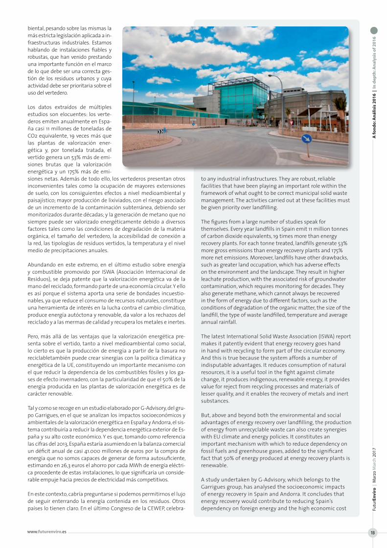
biental, pesando sobre las mismas la más estricta legislación aplicada a in-fraestructuras industriales. Estamos hablando de instalaciones fiables y robustas, que han venido prestando una importante función en el marco de lo que debe ser una correcta ges-tión de los residuos urbanos y cuya actividad debe ser prioritaria sobre el uso del vertedero.
Los datos extraídos de múltiples estudios son elocuentes: los verte-deros emiten anualmente en Espa-ña casi 11 millones de toneladas de CO2 equivalente, 19 veces más que las plantas de valorización ener-gética y, por tonelada tratada, el vertido genera un 53% más de emi-siones brutas que la valorización energética y un 175% más de emi-siones netas. Además de todo ello, los vertederos presentan otros inconvenientes tales como la ocupación de mayores extensiones de suelo, con los consiguientes efectos a nivel medioambiental y paisajístico; mayor producción de lixiviados, con el riesgo asociado de un incremento de la contaminación subterránea, debiendo ser monitorizados durante décadas; y la generación de metano que no siempre puede ser valorizado energéticamente debido a diversos factores tales como las condiciones de degradación de la materia orgánica, el tamaño del vertedero, la accesibilidad de conexión a la red, las tipologías de residuos vertidos, la temperatura y el nivel medio de precipitaciones anuales.
Abundando en este extremo, en el último estudio sobre energía y combustible promovido por ISWA (Asociación Internacional de Residuos), se deja patente que la valorización energética va de la mano del reciclado, formando parte de una economía circular. Y ello es así porque el sistema aporta una serie de bondades incuestio-nables, ya que reduce el consumo de recursos naturales, constituye una herramienta de interés en la lucha contra el cambio climático, produce energía autóctona y renovable, da valor a los rechazos del reciclado y a las mermas de calidad y recupera los metales e inertes.
Pero, más allá de las ventajas que la valorización energética pre-senta sobre el vertido, tanto a nivel medioambiental como social, lo cierto es que la producción de energía a partir de la basura no reciclabletambién puede crear sinergias con la política climática y energética de la UE, constituyendo un importante mecanismo con el que reducir la dependencia de los combustibles fósiles y los ga-ses de efecto invernadero, con la particularidad de que el 50% de la energía producida en las plantas de valorización energética es de carácter renovable.
Tal y como se recoge en un estudio elaborado por G-Advisory, del gru-po Garrigues, en el que se analizan los impactos socioeconómicos y ambientales de la valorización energética en España y Andorra, el sis-tema contribuiría a reducir la dependencia energética exterior de Es-paña y su alto coste económico. Y es que, tomando como referencia las cifras del 2013, España estaría asumiendo en la balanza comercial un déficit anual de casi 41.000 millones de euros por la compra de energía que no somos capaces de generar de forma autosuficiente, estimando en 26,3 euros el ahorro por cada MWh de energía eléctri-ca procedente de estas instalaciones, lo que significaría un conside-rable empuje hacia precios de electricidad más competitivos.
En este contexto, cabría preguntarse si podemos permitirnos el lujo de seguir enterrando la energía contenida en los residuos. Otros países lo tienen claro. En el último Congreso de la CEWEP, celebra-
to any industrial infrastructures. They are robust, reliable facilities that have been playing an important role within the framework of what ought to be correct municipal solid waste management. The activities carried out at these facilities must be given priority over landfilling.
The figures from a large number of studies speak for themselves. Every year landfills in Spain emit 11 million tonnes of carbon dioxide equivalents, 19 times more than energy recovery plants. For each tonne treated, landfills generate 53% more gross emissions than energy recovery plants and 175% more net emissions. Moreover, landfills have other drawbacks, such as greater land occupation, which has adverse effects on the environment and the landscape. They result in higher leachate production, with the associated risk of groundwater contamination, which requires monitoring for decades. They also generate methane, which cannot always be recovered in the form of energy due to different factors, such as the conditions of degradation of the organic matter, the size of the landfill, the type of waste landfilled, temperature and average annual rainfall.
The latest International Solid Waste Association (ISWA) report makes it patently evident that energy recovery goes hand in hand with recycling to form part of the circular economy. And this is true because the system affords a number of indisputable advantages. It reduces consumption of natural resources, it is a useful tool in the fight against climate change, it produces indigenous, renewable energy, it provides value for reject from recycling processes and materials of lesser quality, and it enables the recovery of metals and inert substances.
But, above and beyond both the environmental and social advantages of energy recovery over landfilling, the production of energy from unrecyclable waste can also create synergies with EU climate and energy policies. It constitutes an important mechanism with which to reduce dependency on fossil fuels and greenhouse gases, added to the significant fact that 50% of energy produced at energy recovery plants is renewable.
A study undertaken by G-Advisory, which belongs to the Garrigues group, has analysed the socioeconomic impacts of energy recovery in Spain and Andorra. It concludes that energy recovery would contribute to reducing Spain’s dependency on foreign energy and the high economic cost
A fo
nd
o: A
nál
isis
20
16
| I
n d
epth
: An
alys
is o
f 20
16
Futu
rEn
viro
| M
arzo
Mar
ch 2
017
www.futurenviro.es 13

do en Rotterdam, representantes de Dinamarca y Holanda pusie-ron de manifiesto los beneficios de la valorización energéticadesde diferentes dimensiones por su capacidad de producir energía re-novable, abastecer de calefacción barata a áreas densamente po-bladas y sustituir el vertido. No es de extrañar que en estos países, sus instalaciones se encuentren emplazadas en zonas altamente pobladas, circunstancia que permite suministrar electricidad y ca-lor a un buen número de habitantes.
Desde CEWEP también se calcula que cerca de 70 millones de ciu-dadanos europeos podrían abastecerse de energía gracias a la va-lorización energética de la fracción no reciclable, pudiendo evitar la emisión de 92 millones de toneladas de CO2, cerca de un 8% del total de las emisiones de la UE.
A falta de cerrar los datos de 2016, en España y Andorra, las 11 plan-tas existentes trataron en el año 2015 un total de 2.538.092 tone-ladas, produciendo 1.879,3 GWh o, lo que es lo mismo, la energía equivalente al consumo de 450.000 viviendas.
Reducir el vertido en nuestro país significaría incrementar de ma-nera muy importante el reciclaje, y en paralelo también el número de plantas de valorización energética. Se calcula que para conse-guir superar el 70% del reciclaje con un vertido cero, sería necesa-rio adicionalmente 17 plantas nuevas de estas características, que supondrían una inversión de 4.000 millones de euros y que permi-tirían generar un importante volumen de empleo (local, fijo y de calidad), contribuyendo también a la reindustrialización dispersa.
Para poder abordar la necesaria evolución en el tratamiento de los residuos domiciliarios, es necesario derrumbar falsos mitos y pre-juicios arcaicos en torno a la valorización energética. Desde la Aso-ciación Española de Empresas de Valorización Energética (AEVER-SU) intentamos llevar a cabo una labor pedagógica para explicar a los ciudadanos en qué consiste el cometido de las plantas que integran esta organización y cuál es su fin último: tratar en con-diciones óptimas los residuos que no se pueden reciclar, evitando su vertido, y aprovechar la energía contenida en los mismos como recurso de trascendental interés en nuestro escenario energético, caracterizado por la alta dependencia de los combustibles fósiles y sus elevados precios.
La vocación de servicio público, aportando una solución moderna y limpia a la gestión de los residuos, y transformarlos en un impor-tante recurso, constituyen los principales atributos de un sistema, la valorización energética, que a lo largo de estos años ha venido acreditando su gran potencial y que pretende hacerse un hueco en nuestro país, homologándolo con los más avanzados de nuestro entorno, con un único objetivo: la sostenibilidad de los recursos.
of this dependency. According to 2013 figures, Spain has an annual trade deficit of almost €40 billion associated with the purchase of energy that we are unable to generate ourselves. The estimated savings per MWh of electricity produced at waste-to-energy facilities is €26.30, which would significantly contribute to more competitive power prices.
It is worth asking if we can allow ourselves the luxury of continuing to bury the energy contained in waste. Other countries are very clear about this. At the last CEWEP congress in Rotterdam, representatives from Denmark and the Netherlands highlighted the benefits of energy recovery from different perspectives, focusing on its capacity to produce renewable energy,
to provide densely populated areas with economical heating and the fact that it provides an alternative to landfilling of waste. It is not surprising that in these countries, waste-to-energy facilities are located in highly populated areas, which enables the supply of heat and power to a large number of residents.
The CEWEP calculates that almost 70 million European citizens could be supplied with energy by means of energy recovery from the unrecyclable fraction. Moreover, it would be possible to prevent the emission of 92 million tonnes of CO2, almost 8% of total EU emissions.
As we await the 2016 figures, figures from 2015 indicate that the 11 plants located in Spain and Andorra treated a total of 2,538,092 tonnes, producing 1,879.3 GWh of electricity, the equivalent of the consumption of 450,000 households.
Reducing the quantity of waste sent to landfill in Spain would mean significantly increasing recycling rates and, in parallel to this, also significantly increasing the number of waste-to-energy plants. Calculations show that in order to achieve a recycling rate of over 70%, with zero waste to landfill, a further 17 new energy recovery plants would be needed. This would imply investment of €4 billion and would enable the creation of a significant number of local, permanent, quality jobs. It would also contribute to widespread reindustrialisation.
To address the necessary evolution in the treatment of domestic waste, it is necessary to explode false myths and prejudices. At the Spanish Association of Energy Recovery from Municipal Solid Waste (AEVERSU), we are seeking to explain to citizens the work carried out at our member plants and the ultimate aim of these facilities: to treat unrecyclable waste in the best possible conditions, to prevent it from going to landfill, and to avail of the energy contained in this waste as a resource of vital importance in our energy scenario, which is characterised by great dependency on expensive fossil fuels.
A vocation of public service, the provision of a modern, clean solution to waste management and transforming waste into an important resource are the main features of the energy recovery system. Down the years, energy recovery has been demonstrating its great potential and has been seeking to assume its rightful place in our country, in order to bring it onto the same level as our most advanced neighbouring countries. And it has done so with a single objective: achieving the sustainability of resources.
A fo
nd
o: A
nál
isis
20
16
| I
n d
epth
: An
alys
is o
f 20
16
Futu
rEn
viro
| M
arzo
Mar
ch 2
017
www.futurenviro.es 15
A fo
nd
o: A
nál
isis
20
16
| I
n d
epth
: An
alys
is o
f 20
16
FuturEnviro | Marzo March 2017
ww
w.fu
ture
nvi
ro.e
s
16
El Paquete de Economía Circular (PEC) busca ex-traer el máximo valor y uso de todas las mate-rias primas, productos y residuos, fomentando el ahorro energético y reduciendo las emisiones de gases de efecto invernadero. Desde ASEGRE re-pasamos el año de trayectoria de esta iniciativa y analizamos los aspectos más relevantes, así como el impacto que supone en las directivas de residuos y vertederos.
El pasado año, la Unión Europea comenzó su andadura hacia una nueva concepción de la economía, ya que la Comisión presentó su pro-puesta de economía circular. La economía circu-lar que se está promoviendo en la UE supone un cambio de paradigma porque acaba con el principio de usar y tirar. El ciclo de vida de los productos se extiende gracias a la reuti-lización y el reciclaje, y su vida útil también se alarga por un mejor gestión del tratamiento de residuos.
El Paquete de Economía Circular (PEC) busca extraer el máximo valor y uso de todas las materias primas, productos y residuos, fo-mentando el ahorro energético y reduciendo las emisiones de ga-ses de efecto invernadero. Además, incluye un plan de acción con 51 medidas dirigidas al sector manufacturero, consumo, gestión de residuos, materias primas secundarias, innovación, y a cuestiones específicas como materias primas críticas, construcción y demoli-ción, y biomasa.
Un año después de que Bruselas pusiera en marcha este paquete de medidas sobre la economía circular, la Comisión Europea pre-sentó a finales de enero de 2017 un informe sobre los resultados y los avances de las principales iniciativas de su plan de acción. El in-forme ofrece a los Estados miembro orientaciones para alcanzar un equilibrio adecuado en lo que respecta a la capacidad de produc-ción de energía a partir de residuos, destacando el papel de la je-rarquía de residuos, que clasifica las opciones de gestión según su sostenibilidad y da la máxima prioridad a su prevención y reciclado.
Asimismo, nos parece muy relevante el hecho de que la Comisión haya instado al Parlamento Europeo y al Consejo a avanzar en el proceso de adopción de las propuestas legislativas en materia de residuos. Además, la Comisión se ha comprometido a seguir cum-pliendo lo previsto en el plan de acción para una economía circular.
The Circular Economy Package (CEP) seeks to extract the maximum value and utility from all raw materials, products and waste, whilst fostering energy efficiency and reducing greenhouse gas emissions. We at the ASEGRE take this opportunity to review the first year of this initiative, analyse the most relevant aspects of it and look at the impact it has on the waste and landfill directives.
Last year, the European Union embarked on the journey towards a new type of economy, with the presentation of the Commission’s circular economy proposal. The circular economy currently being promoted in the
EU represents a change of model because it does away with the practice of use and disposal. The lifecycle of products is extended thanks to reuse and recycling. Product service life is also prolonged due to better waste management.
The Circular Economy Package (CEP) seeks to extract the maximum value and utility from all raw materials, products and waste, as well as fostering energy efficiency and reducing greenhouse gas emissions. It also includes a plan of action with 51 measures in areas such as manufacturing, consumption, waste management, secondary raw materials and innovation, in addition to some specific areas such as critical raw materials, construction & demolition, and biomass.
At the end of January 2017, one year after implementing this package of circular economy measures, the European Commission presented a report on the results and progress of the main initiatives in its action plan. The report offers Member States guidelines to achieve a suitable balance in terms of the capacity to produce energy from waste, and it underlines the role of the waste hierarchy, which classifies waste management alternatives in accordance with sustainability and gives the maximum priority to prevention and recycling.
We also believe it to be of great relevance that the Commission has called on the European Parliament and the Council to make progress in the process of adopting the legislative proposals in the area of waste. Moreover,
the Commission has given a commitment to continue implementing the initiatives set out in the circular economy action plan.
Positive impact of CEP on waste and landfill directives
The CEP has resulted in the review of the waste directive and the landfill directive. The circular economy legislative package still has to go through decisive procedural stages. However, following its ratification by the Environment Commission of the European Parliament in February, it is beginning to take form. Amongst the
UN AÑO DE ECONOMÍA CIRCULAR PARA LOS GESTORES DE RESIDUOSLuis Palomino, secretario general de la Asociación de Empresas Gestoras de Residuos y Recursos Especiales (ASEGRE)
A YEAR OF CIRCULAR ECONOMY FOR WASTE MANAGERS Luis Palomino, Secretary General of the Spanish Association of Hazardous Wastes and Soil Recovery Companies (ASEGRE)
Impacto positivo del PEC en las directivas de residuos y vertederos
En el camino, el PEC ha supuesto la revisión de la directiva de re-siduos y también la de vertederos. A este paquete legislativo de economía circular aún le quedan fases decisivas en su tramitación, pero tras la aprobación por la Comisión de Medio Ambiente del Parlamento Europeo, el pasado mes de febrero, va tomando forma. Entre las novedades que consideramos más acertadas son las re-lativas a la recogida separada de los residuos peligrosos de origen domiciliario, de forma que se asegure que reciben un tratamiento adecuado y no contaminan los residuos municipales. Además, se reconoce que persisten los problemas en la gestión de los residuos peligrosos y en la falta de datos, de ahí la insistencia en reforzar la trazabilidad de estos residuos. También se alerta del riesgo que su-ponen los residuos peligrosos que se depositan en vertederos junto con los residuos urbanos, industriales no peligrosos e inertes.
Otro elemento destacable es el relativo a la descontaminación de los residuos peligrosos como paso previo a su valorización, que se-ría aplicable a casos como el tratamiento de RAEE, los envases que han contenido productos fitosanitarios, o los envases industriales (bidones y contenedores de 1.000 l) a los que se les retira las sus-tancias peligrosas que contienen.
Además, se plantea la realización de informes previos a los trabajos de demolición, de modo que se detecten los contaminantes y otras sustancias que puedan afectar negativamente a las fracciones de residuos recuperados de los trabajos de demolición.
El PEC trata de desincentivar la eliminación y en concreto plantea ob-jetivos extraordinariamente ambiciosos en la reducción del depósito de residuos para reducir la deposición en vertedero e incrementar las otras opciones de la jerarquía de residuos. La propuesta aprobada para la directiva de vertederos es que para 2030 menos del 5 % de los residuos municipales producidos se deposite en vertedero. En el caso de los residuos peligrosos se prima la seguridad del tratamiento y, por ello, no se establecen objetivos para reducir su eliminación.
La seria amenaza que suponen las operaciones de relleno con residuos
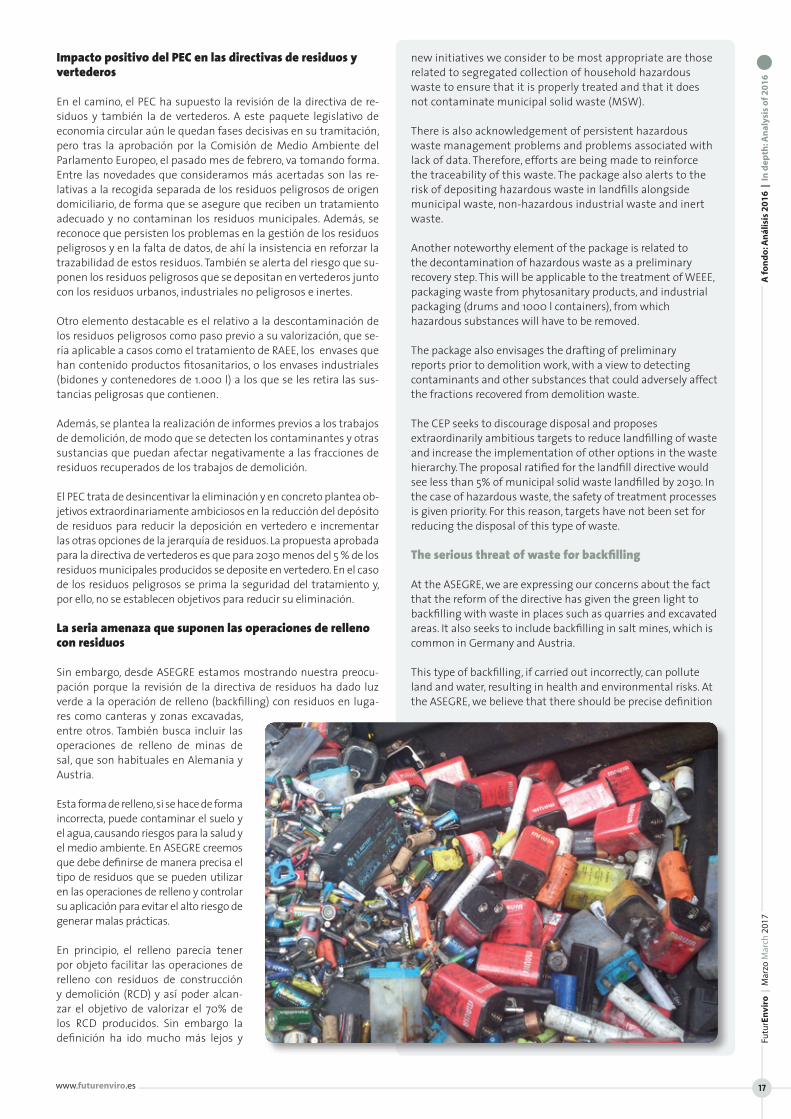
Sin embargo, desde ASEGRE estamos mostrando nuestra preocu-pación porque la revisión de la directiva de residuos ha dado luz verde a la operación de relleno (backfilling) con residuos en luga-res como canteras y zonas excavadas, entre otros. También busca incluir las operaciones de relleno de minas de sal, que son habituales en Alemania y Austria.
Esta forma de relleno, si se hace de forma incorrecta, puede contaminar el suelo y el agua, causando riesgos para la salud y el medio ambiente. En ASEGRE creemos que debe definirse de manera precisa el tipo de residuos que se pueden utilizar en las operaciones de relleno y controlar su aplicación para evitar el alto riesgo de generar malas prácticas.
En principio, el relleno parecía tener por objeto facilitar las operaciones de relleno con residuos de construcción y demolición (RCD) y así poder alcan-zar el objetivo de valorizar el 70% de los RCD producidos. Sin embargo la definición ha ido mucho más lejos y
new initiatives we consider to be most appropriate are those related to segregated collection of household hazardous waste to ensure that it is properly treated and that it does not contaminate municipal solid waste (MSW).
There is also acknowledgement of persistent hazardous waste management problems and problems associated with lack of data. Therefore, efforts are being made to reinforce the traceability of this waste. The package also alerts to the risk of depositing hazardous waste in landfills alongside municipal waste, non-hazardous industrial waste and inert waste.
Another noteworthy element of the package is related to the decontamination of hazardous waste as a preliminary recovery step. This will be applicable to the treatment of WEEE, packaging waste from phytosanitary products, and industrial packaging (drums and 1000 l containers), from which hazardous substances will have to be removed.
The package also envisages the drafting of preliminary reports prior to demolition work, with a view to detecting contaminants and other substances that could adversely affect the fractions recovered from demolition waste.
The CEP seeks to discourage disposal and proposes extraordinarily ambitious targets to reduce landfilling of waste and increase the implementation of other options in the waste hierarchy. The proposal ratified for the landfill directive would see less than 5% of municipal solid waste landfilled by 2030. In the case of hazardous waste, the safety of treatment processes is given priority. For this reason, targets have not been set for reducing the disposal of this type of waste.
The serious threat of waste for backfilling
At the ASEGRE, we are expressing our concerns about the fact that the reform of the directive has given the green light to backfilling with waste in places such as quarries and excavated areas. It also seeks to include backfilling in salt mines, which is common in Germany and Austria.
This type of backfilling, if carried out incorrectly, can pollute land and water, resulting in health and environmental risks. At the ASEGRE, we believe that there should be precise definition
A fo
nd
o: A
nál
isis
20
16
| I
n d
epth
: An
alys
is o
f 20
16
Futu
rEn
viro
| M
arzo
Mar
ch 2
017
www.futurenviro.es 17

parece dar cobertura al relleno de huecos en el suelo con residuos no peligrosos con fines paisajísticos, de construcción, y de recupe-ración de zonas excavadas. Cabe significar que esta operación se calificaría como valorización. El que un residuo sea no peligroso, no significa que no pueda transmitir contaminación alguna al sue-lo. Buen ejemplo de ello son los residuos municipales que, en su mayoría, son los que los ciudadanos depositamos diariamente en los contenedores de basura. Tienen la clasificación de no peligro-sos, pero también pueden transmitir la contaminación al suelo y al agua. Esta es la razón por la que uno de sus tratamientos es la deposición en vertederos que, como no puede ser de otra forma, aíslan estos residuos del suelo y le protegen de cualquier transmi-sión de contaminación, recogiendo sus lixiviados.
No podemos olvidar que uno de los principios de la legislación de residuos es el tratamiento de los residuos sin afectar a la salud de las personas y al medio ambiente. Desde ASEGRE consideramos que la definición actual de relleno no considera suficientemente estas cuestiones y permitirá la deposición de residuos no peligro-sos de forma directa en el suelo, sin contemplar la recogida de la contaminación producida por los residuos.
El Parlamento Europeo, en su obsesión por el reciclaje y la valoriza-ción, elimina prácticamente los vertederos tradicionales, pero crea esta nueva figura en la que los residuos se depositan directamente en el suelo, sin control alguno de la contaminación. El hecho de querer mejorar la estadística de valorización frente a eliminación no debería abrir la puerta a los vertidos incontrolados. En España ya tenemos experiencia en esta materia y todavía estamos pagan-do el elevado coste que supone descontaminar suelos producto de deposición ilegal de residuos.
EL PEC como oportunidad para los gestores de residuos
Todo lo descrito anteriormente supone una oportunidad para po-ner en valor los servicios de los gestores de residuos. En contexto nacional, los miembros de ASEGRE tienen una alta representativi-dad en las capacidades de tratamiento de residuos peligrosos, re-siduos industriales no peligrosos y en los trabajos de recuperación de suelos contaminados.
La proporción de residuos peligrosos reciclados y valorizados supe-ra el 40%, gracias a unos tratamientos que se realizan con todas las garantías de seguridad y calidad ambiental asegurando, además, la trazabilidad de esos tratamientos. Algunos ejemplos de estos ser-vicios son los que se aplican a los RAEE o a los envases industriales que se preparan para la reutilización, así como metales, disolventes, aceites y plásticos que se reciclan, o hidrocarburos y residuos con contenido energético que se valorizan energética.
of the type of waste that can be used in backfilling and that its application should be controlled to avoid the great risk of malpractices.
At first, the reform seemed to have the objective of facilitating backfilling with construction and demolition (C&D) waste to enable the target of recovering 70% of C&D waste to be achieved. However, the definition has gone much further and seems to cover
backfilling with non-hazardous waste for the purposes of landscaping, construction and recovery of excavated areas. This operation would be classified as recovery. The fact that waste is not hazardous does not mean that it cannot contaminate land in any way. A good example of this is MSW, which mainly consists of the refuse citizens deposit in bins every day. This waste is classified as non-hazardous but it can also cause pollution to land and water. This is why landfilling is one of the treatment processes implemented for this waste. In landfills, measures are taken to ensure that there is no contact between the MSW and the soil and that there is no transmission of contamination. Moreover, the leachate produced must be collected.
It cannot be forgotten that one of the principles of waste legislation is to ensure treatment without affecting human health or the environment. At the ASEGRE, we believe that the current definition of backfilling does not take sufficient account of these issues and will permit the direct disposal of non-hazardous waste on land, without providing for the collection of pollution produced by this waste.
The European Parliament, in its fixation with recycling and recovery, will practically eliminate traditional landfills but will also create this new concept whereby waste is deposited directly on land without any control of pollution. The desire to improve recovery statistics and reduce disposal should not open the door to uncontrolled disposal. We already have experience of this in Spain and we are still paying the price associated with decontamination of lands polluted as a result of illegal waste disposal.
The CEP as an opportunity for waste managers
All of the above represents an opportunity to highlight the value of the services provided by waste managers. In the context of Spain, ASEGRE members are highly qualified in the treatment of hazardous waste, non-hazardous industrial waste and the recovery of contaminated soil.
Over 40% of hazardous waste is recovered and recycled, thanks to the treatment it is given with all the necessary safety and environmental guarantees. Moreover, the traceability of this treatment is also ensured. Some examples of these services include the treatment of WEEE and industrial packaging, which are prepared for reuse; the treatment of metals, solvents, oils and plastics, which are recycled; and the treatment of waste hydrocarbons and waste with energy content, which is recovered for energy purposes.
A fo
nd
o: A
nál
isis
20
16
| I
n d
epth
: An
alys
is o
f 20
16
Futu
rEn
viro
| M
arzo
Mar
ch 2
017
www.futurenviro.es 19
A fo
nd
o: A
nál
isis
20
16
| I
n d
epth
: An
alys
is o
f 20
16
FuturEnviro | Marzo March 2017
ww
w.fu
ture
nvi
ro.e
s
20
La industria papelera española, que retornó al crecimiento en 2015, creciendo el 2,6%, mantu-vo su producción en niveles similares en 2016, con un incremento de la producción de papel más modesto (0,4%), aunque por encima de la media europea que descendió el 0,1%. También la producción de celulosa, que creció el 2,2% en 2016 lo hizo por encima de la media europea que se situó en el 1,4%.
El sector inició en 2014 un nuevo ciclo inversor, enfocado a incrementar la capacidad, a mejorar la eficiencia y los costes y a la renovación tec-nológica de las instalaciones y la innovación. Las inversiones del sector en 2016 ascendieron a 228 millones con un incremento del 29% con respecto al año an-terior. En los últimos diez años, pese a la crisis, el sector invirtió casi de 2.200 millones de euros.
En sus 81 fábricas, nuestra industria produjo 1,7 millones de tone-ladas de celulosa y 6,2 millones de toneladas de papel en 2016. So-mos el sexto productor de papel de la UE, tras Alemania, Finlandia, Suecia, Italia y Francia y el sexto productor de celulosa, tras Suecia, Finlandia, Portugal, Alemania y Francia. Exportamos el 55% de la ce-lulosa y el 46% del papel que fabricamos. La UE supone el 60% de nuestras exportaciones de papel y el 90% de las de celulosa.
Materias primas locales: las plantaciones y “el bosque urbano” oportunidad para una bioindustria de vanguardia
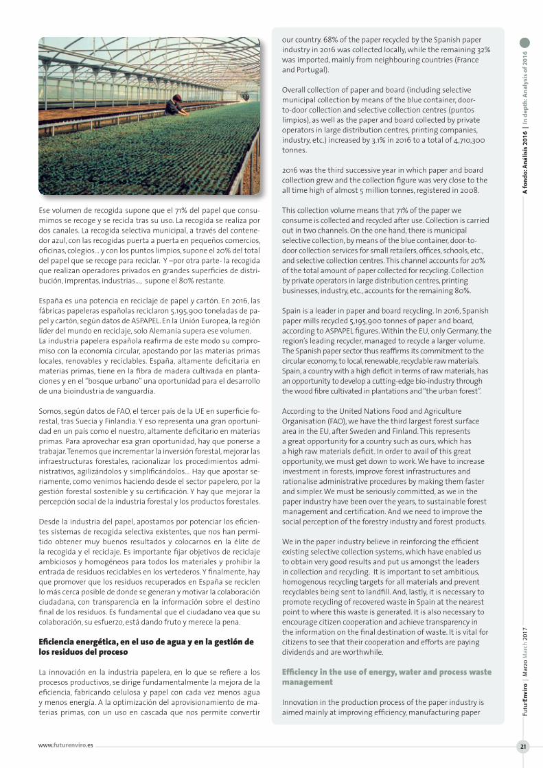
La industria papelera española utiliza materias primas locales. El 97% de la madera procede de plantaciones locales de pinos y euca-liptos. Esas plantaciones, que se están continuamente replantando y regenerando, son motor de la economía rural. Ocupan 450.000 hectáreas (el 2,4% de la superficie total de bosques de nuestro país). Dan empleo directo a 5.200 personas en tareas de repoblación y silvicultura, además de generar casi 17.000 empleos indirectos en maquinaria, transporte, talleres… Y son eficientes sumideros de CO2, que almacenan 31 millones de toneladas de CO2 equivalente.
También es importante destacar la apuesta de la industria pape-lera por la certificación forestal. Actualmente está certificado el 54,4% del papel de fabricación nacional puesto en el mercado.
Y en cuanto a la otra materia prima básica del sector, el papel que tras su uso se recoge para reciclar, la capacidad recicladora de nuestra in-dustria papelera permite garantizar el reciclaje de todo el papel y cartón que se recoge en España, cerrando el ciclo en nuestro país. El 68% del papel que recicló en 2016 la industria papelera española era de procedencia local y el 32% restante se importó fundamentalmente de países limítrofes (Francia y Portugal).
La recogida global de papel y cartón (incluida la reco-gida selectiva municipal a través del contenedor azul, puerta a puerta y puntos limpios, más la recogida de operadores privados en grandes superficies de distri-bución, imprentas, industrias…) creció en 2016 el 3,1% hasta las 4.710.300 toneladas. Crece por tercer año consecutivo y se sitúa muy cerca del máximo histórico de 2008, cuando se rozaron los 5 millones de toneladas.
The Spanish paper industry returned to a situation of growth in 2015, when production increased by 2.6%. Output levels were similar in 2016, with a more modest increase of 0.4%. This was, however, above average for Europe, where production decreased by 0.1%. Pulp production in Spain also increased by 2.2% in 2016, above the European average of 1.4%.
The sector commenced a new cycle of investment in 2014, with the focus on increasing capacity, improving efficiency, reducing costs, updating technology and innovation. Investment in 2016 amounted to €228 million, up 29% on the previous year.
Despite the economic crisis, the sector has invested almost €2,200 million in the last ten years.
Our industry produced 1.7 million tonnes of pulp and 6.2 million tonnes of paper at 81 mills in 2016. Spain is the sixth largest producer of paper in the EU, behind Germany, Finland, Sweden, Italy and France, and the sixth largest producer of pulp, behind Sweden, Finland, Portugal, Germany and France. We export 55% of our pulp and 46% of the paper we produce. The EU accounts for 60% of our paper and 90% of our pulp exports.
Local raw materials: plantations and “urban forest” afford opportunities for cutting-edge bio-industry
The Spanish paper industry uses local raw materials. 97% of the wood is from local pine and eucalyptus plantations. These plantations are continuously replanted and regenerated and provide an engine for local economies. They occupy a surface area of 450,000 hectares (2.4% of the total surface area of forests in Spain). They provide 5,200 direct jobs in replanting and forestry, as well as generating almost 17,000 indirect jobs in machinery, transport, workshops, etc. They are also efficient CO2 sinks, storing a total of 31 million tonnes of CO2 equivalents.
It is also important to underline the paper industry’s commitment to forest certification. 54.4% of domestically produced paper placed on the market is now certified.As regards the other main source of raw material used in the sector, i.e., used paper collected for recycling, the recycling capacity of our paper industry ensures that all paper and board collected in Spain is recycled, thus closing the loop in
LA INDUSTRIA DEL PAPEL, MOTOR DE UNA POTENTE CADENA DE VALORCarlos Reinoso, director general de ASPAPEL (Asociación Española de Fabricantes de Pasta, Papel y Cartón)
THE PAPER INDUSTRY, DRIVING FORCE OF POWERFUL VALUE CHAIN Carlos Reinoso, CEO at ASPAPEL (Spanish Association of Paper and Pulp Manufacturers)
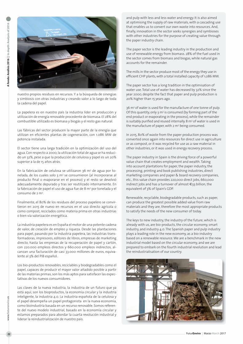
Ese volumen de recogida supone que el 71% del papel que consu-mimos se recoge y se recicla tras su uso. La recogida se realiza por dos canales. La recogida selectiva municipal, a través del contene-dor azul, con las recogidas puerta a puerta en pequeños comercios, oficinas, colegios… y con los puntos limpios, supone el 20% del total del papel que se recoge para reciclar. Y –por otra parte- la recogida que realizan operadores privados en grandes superficies de distri-bución, imprentas, industrias…, supone el 80% restante.
España es una potencia en reciclaje de papel y cartón. En 2016, las fábricas papeleras españolas reciclaron 5.195.900 toneladas de pa-pel y cartón, según datos de ASPAPEL. En la Unión Europea, la región líder del mundo en reciclaje, solo Alemania supera ese volumen. La industria papelera española reafirma de este modo su compro-miso con la economía circular, apostando por las materias primas locales, renovables y reciclables. España, altamente deficitaria en materias primas, tiene en la fibra de madera cultivada en planta-ciones y en el “bosque urbano” una oportunidad para el desarrollo de una bioindustria de vanguardia.
Somos, según datos de FAO, el tercer país de la UE en superficie fo-restal, tras Suecia y Finlandia. Y eso representa una gran oportuni-dad en un país como el nuestro, altamente deficitario en materias primas. Para aprovechar esa gran oportunidad, hay que ponerse a trabajar. Tenemos que incrementar la inversión forestal, mejorar las infraestructuras forestales, racionalizar los procedimientos admi-nistrativos, agilizándolos y simplificándolos… Hay que apostar se-riamente, como venimos haciendo desde el sector papelero, por la gestión forestal sostenible y su certificación. Y hay que mejorar la percepción social de la industria forestal y los productos forestales.
Desde la industria del papel, apostamos por potenciar los eficien-tes sistemas de recogida selectiva existentes, que nos han permi-tido obtener muy buenos resultados y colocarnos en la élite de la recogida y el reciclaje. Es importante fijar objetivos de reciclaje ambiciosos y homogéneos para todos los materiales y prohibir la entrada de residuos reciclables en los vertederos. Y finalmente, hay que promover que los residuos recuperados en España se reciclen lo más cerca posible de donde se generan y motivar la colaboración ciudadana, con transparencia en la información sobre el destino final de los residuos. Es fundamental que el ciudadano vea que su colaboración, su esfuerzo, está dando fruto y merece la pena.
Eficiencia energética, en el uso de agua y en la gestión de los residuos del proceso
La innovación en la industria papelera, en lo que se refiere a los procesos productivos, se dirige fundamentalmente la mejora de la eficiencia, fabricando celulosa y papel con cada vez menos agua y menos energía. A la optimización del aprovisionamiento de ma-terias primas, con un uso en cascada que nos permite convertir
our country. 68% of the paper recycled by the Spanish paper industry in 2016 was collected locally, while the remaining 32% was imported, mainly from neighbouring countries (France and Portugal).
Overall collection of paper and board (including selective municipal collection by means of the blue container, door-to-door collection and selective collection centres (puntos limpios), as well as the paper and board collected by private operators in large distribution centres, printing companies, industry, etc.) increased by 3.1% in 2016 to a total of 4,710,300 tonnes.
2016 was the third successive year in which paper and board collection grew and the collection figure was very close to the all time high of almost 5 million tonnes, registered in 2008.
This collection volume means that 71% of the paper we consume is collected and recycled after use. Collection is carried out in two channels. On the one hand, there is municipal selective collection, by means of the blue container, door-to-door collection services for small retailers, offices, schools, etc., and selective collection centres. This channel accounts for 20% of the total amount of paper collected for recycling. Collection by private operators in large distribution centres, printing businesses, industry, etc., accounts for the remaining 80%.
Spain is a leader in paper and board recycling. In 2016, Spanish paper mills recycled 5,195,900 tonnes of paper and board, according to ASPAPEL figures. Within the EU, only Germany, the region’s leading recycler, managed to recycle a larger volume. The Spanish paper sector thus reaffirms its commitment to the circular economy, to local, renewable, recyclable raw materials. Spain, a country with a high deficit in terms of raw materials, has an opportunity to develop a cutting-edge bio-industry through the wood fibre cultivated in plantations and “the urban forest”.
According to the United Nations Food and Agriculture Organisation (FAO), we have the third largest forest surface area in the EU, after Sweden and Finland. This represents a great opportunity for a country such as ours, which has a high raw materials deficit. In order to avail of this great opportunity, we must get down to work. We have to increase investment in forests, improve forest infrastructures and rationalise administrative procedures by making them faster and simpler. We must be seriously committed, as we in the paper industry have been over the years, to sustainable forest management and certification. And we need to improve the social perception of the forestry industry and forest products.
We in the paper industry believe in reinforcing the efficient existing selective collection systems, which have enabled us to obtain very good results and put us amongst the leaders in collection and recycling. It is important to set ambitious, homogenous recycling targets for all materials and prevent recyclables being sent to landfill. And, lastly, it is necessary to promote recycling of recovered waste in Spain at the nearest point to where this waste is generated. It is also necessary to encourage citizen cooperation and achieve transparency in the information on the final destination of waste. It is vital for citizens to see that their cooperation and efforts are paying dividends and are worthwhile.
Efficiency in the use of energy, water and process waste management
Innovation in the production process of the paper industry is aimed mainly at improving efficiency, manufacturing paper
A fo
nd
o: A
nál
isis
20
16
| I
n d
epth
: An
alys
is o
f 20
16
Futu
rEn
viro
| M
arzo
Mar
ch 2
017
www.futurenviro.es 21
A fo
nd
o: A
nál
isis
20
16
| I
n d
epth
: An
alys
is o
f 20
16
FuturEnviro | Marzo March 2017
ww
w.fu
ture
nvi
ro.e
s
22
nuestro propios residuos en recursos. Y a la búsqueda de sinergias y simbiosis con otras industrias y creando valor a lo largo de toda la cadena del papel.
La papelera es en nuestro país la industria líder en producción y utilización de energía renovable procedente de biomasa. El 28% del combustible utilizado es biomasa y biogás y el resto gas natural.
Las fábricas del sector producen la mayor parte de la energía que utilizan en eficientes plantas de cogeneración, con 1.086 MW de potencia instalada.
El sector tiene una larga tradición en la optimización del uso del agua. Con respecto a 2000, la utilización total de agua se ha reduci-do un 32%, pese a que la producción de celulosa y papel es un 20% superior a la de 15 años atrás.
En la fabricación de celulosa se utilizaron 36 m3 de agua por to-nelada, de los cuales solo 3 m3 se consumieron (al incorporarse al producto final o evaporarse en el proceso) y el resto se devolvió adecuadamente depurado y tras ser reutilizado internamente. En la fabricación de papel el uso de agua fue de 8 m3 por tonelada y el consumo de 2 m3.
Finalmente, el 80% de los residuos del proceso papelero se convir-tieron en 2015 de nuevo en recursos en el uso directo agrícola o como compost, reciclados como materia prima en otras industrias o bien vía valorización energética.
La industria papelera es en España el motor de una potente cadena de valor, de creación de empleo y riqueza. Desde las plantaciones para papel, pasando por la industria papelera, las industrias trans-formadoras, impresores, editores de libros, empresas de marketing directo, hasta las empresas de la recuperación de papel y cartón, con 220.000 empleos directos y 660.000 empleos indirectos, al-canzan una facturación de casi 33.000 millones de euros, equiva-lente al 3% del PIB español.
Los bio-productos renovables, reciclables y biodegradables como el papel, capaces de producir el mayor valor añadido posible a partir de las materias primas, son los más aptos para satisfacer las expec-tativas de los nuevos consumidores.
Las claves de la nueva industria, la industria de un futuro que ya está aquí, son los bioproductos, la economía circular y la industria inteligente, la industria 4.0. La industria española de la celulosa y el papel desempeña un papel protagonista en la nueva economía, como bioindustria basada en un recurso renovable. Somos referen-te del nuevo modelo industrial, basado en la economía circular y estamos preparados para abordar la cuarta revolución industrial y liderar la reindustrialización de nuestro país.
and pulp with less and less water and energy. It is also aimed at optimising the supply of raw materials, with a cascading use that enables us to convert our own waste into resources. And, finally, innovation in the sector seeks synergies and symbioses with other industries for the purpose of creating value through the paper industry chain.
The paper sector is the leading industry in the production and use of renewable energy from biomass. 28% of the fuel used in the sector comes from biomass and biogas, while natural gas accounts for the remainder.
The mills in the sector produce most of the energy they use in efficient CHP plants, with a total installed capacity of 1,086 MW.
The paper sector has a long tradition in the optimisation of water use. Total use of water has decreased by 32% since the year 2000, despite the fact that paper and pulp production is 20% higher than 15 years ago.
36 m3 of water is used for the manufacture of one tonne of pulp. Of this quantity, only 3 m3 is consumed (by forming part of the end product or evaporating in the process), while the remainder is suitably purified and reused internally. 8 m3 of water is used in the manufacture of paper, with 2 m3 being consumed.
In 2015, 80% of waste from the paper production process was converted once again into resources for direct use in agriculture or as compost, or it was recycled for use as a raw material in other industries, or it was used in energy recovery process.
The paper industry in Spain is the driving force of a powerful value chain that creates employment and wealth. Taking into account plantations for paper, the paper industry, the processing, printing and book publishing industries, direct marketing companies and paper & board recovery companies, etc., this value chain provides 220,000 direct jobs, 660,000 indirect jobs and has a turnover of almost €33 billion, the equivalent of 3% of Spain’s GDP.
Renewable, recyclable, biodegradable products, such as paper, can produce the greatest possible added value from raw materials and they are, therefore the most appropriate products to satisfy the needs of the new consumer of today.
The keys to new industry, the industry of the future, which is already with us, are bio-products, the circular economy, smart industry, and industry 4.0. The Spanish paper and pulp industry plays a leading role in the new economy, as a bio-industry based on a renewable resource. We are a benchmark in the new industrial model based on the circular economy, and we are prepared to embark on the fourth industrial revolution and lead the reindustrialisation of our country.
www.futurenviro.es
Futu
rEn
viro
| M
arzo
Mar
ch 2
017
23
A fo
nd
o: A
nál
isis
20
16
| I
n d
epth
: An
alys
is o
f 20
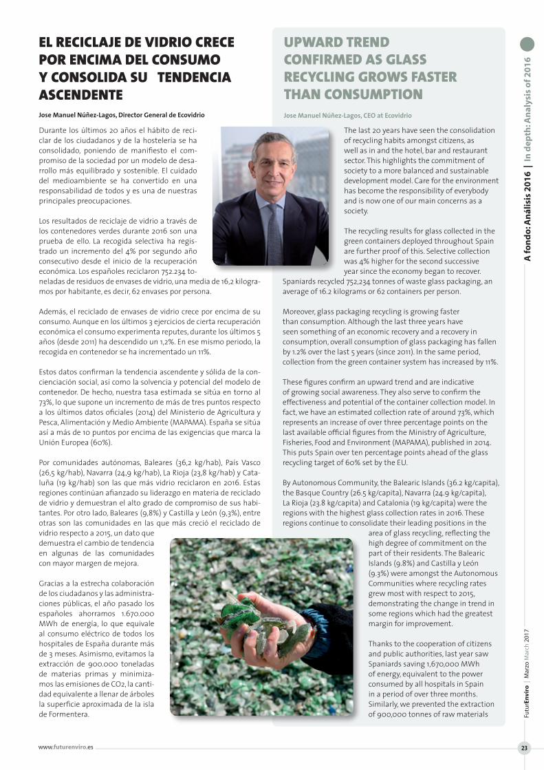
16
Durante los últimos 20 años el hábito de reci-clar de los ciudadanos y de la hostelería se ha consolidado, poniendo de manifiesto el com-promiso de la sociedad por un modelo de desa-rrollo más equilibrado y sostenible. El cuidado del medioambiente se ha convertido en una responsabilidad de todos y es una de nuestras principales preocupaciones.
Los resultados de reciclaje de vidrio a través de los contenedores verdes durante 2016 son una prueba de ello. La recogida selectiva ha regis-trado un incremento del 4% por segundo año consecutivo desde el inicio de la recuperación económica. Los españoles reciclaron 752.234 to-neladas de residuos de envases de vidrio, una media de 16,2 kilogra-mos por habitante, es decir, 62 envases por persona.
Además, el reciclado de envases de vidrio crece por encima de su consumo. Aunque en los últimos 3 ejercicios de cierta recuperación económica el consumo experimenta reputes, durante los últimos 5 años (desde 2011) ha descendido un 1,2%. En ese mismo periodo, la recogida en contenedor se ha incrementado un 11%.
Estos datos confirman la tendencia ascendente y sólida de la con-cienciación social, así como la solvencia y potencial del modelo de contenedor. De hecho, nuestra tasa estimada se sitúa en torno al 73%, lo que supone un incremento de más de tres puntos respecto a los últimos datos oficiales (2014) del Ministerio de Agricultura y Pesca, Alimentación y Medio Ambiente (MAPAMA). España se sitúa así a más de 10 puntos por encima de las exigencias que marca la Unión Europea (60%).
Por comunidades autónomas, Baleares (36,2 kg/hab), País Vasco (26,5 kg/hab), Navarra (24,9 kg/hab), La Rioja (23,8 kg/hab) y Cata-luña (19 kg/hab) son las que más vidrio reciclaron en 2016. Estas regiones continúan afianzado su liderazgo en materia de reciclado de vidrio y demuestran el alto grado de compromiso de sus habi-tantes. Por otro lado, Baleares (9,8%) y Castilla y León (9,3%), entre otras son las comunidades en las que más creció el reciclado de vidrio respecto a 2015, un dato que demuestra el cambio de tendencia en algunas de las comunidades con mayor margen de mejora.
Gracias a la estrecha colaboración de los ciudadanos y las administra-ciones públicas, el año pasado los españoles ahorramos 1.670.000 MWh de energía, lo que equivale al consumo eléctrico de todos los hospitales de España durante más de 3 meses. Asimismo, evitamos la extracción de 900.000 toneladas de materias primas y minimiza-mos las emisiones de CO2, la canti-dad equivalente a llenar de árboles la superficie aproximada de la isla de Formentera.
The last 20 years have seen the consolidation of recycling habits amongst citizens, as well as in and the hotel, bar and restaurant sector. This highlights the commitment of society to a more balanced and sustainable development model. Care for the environment has become the responsibility of everybody and is now one of our main concerns as a society.
The recycling results for glass collected in the green containers deployed throughout Spain are further proof of this. Selective collection was 4% higher for the second successive year since the economy began to recover.
Spaniards recycled 752,234 tonnes of waste glass packaging, an average of 16.2 kilograms or 62 containers per person.
Moreover, glass packaging recycling is growing faster than consumption. Although the last three years have seen something of an economic recovery and a recovery in consumption, overall consumption of glass packaging has fallen by 1.2% over the last 5 years (since 2011). In the same period, collection from the green container system has increased by 11%.
These figures confirm an upward trend and are indicative of growing social awareness. They also serve to confirm the effectiveness and potential of the container collection model. In fact, we have an estimated collection rate of around 73%, which represents an increase of over three percentage points on the last available official figures from the Ministry of Agriculture, Fisheries, Food and Environment (MAPAMA), published in 2014. This puts Spain over ten percentage points ahead of the glass recycling target of 60% set by the EU.
By Autonomous Community, the Balearic Islands (36.2 kg/capita), the Basque Country (26.5 kg/capita), Navarra (24.9 kg/capita), La Rioja (23.8 kg/capita) and Catalonia (19 kg/capita) were the regions with the highest glass collection rates in 2016. These regions continue to consolidate their leading positions in the
area of glass recycling, reflecting the high degree of commitment on the part of their residents. The Balearic Islands (9.8%) and Castilla y León (9.3%) were amongst the Autonomous Communities where recycling rates grew most with respect to 2015, demonstrating the change in trend in some regions which had the greatest margin for improvement.
Thanks to the cooperation of citizens and public authorities, last year saw Spaniards saving 1,670,000 MWh of energy, equivalent to the power consumed by all hospitals in Spain in a period of over three months. Similarly, we prevented the extraction of 900,000 tonnes of raw materials
EL RECICLAJE DE VIDRIO CRECE POR ENCIMA DEL CONSUMO Y CONSOLIDA SU TENDENCIA ASCENDENTEJose Manuel Núñez-Lagos, Director General de Ecovidrio
UPWARD TREND CONFIRMED AS GLASS RECYCLING GROWS FASTER THAN CONSUMPTION Jose Manuel Núñez-Lagos, CEO at Ecovidrio
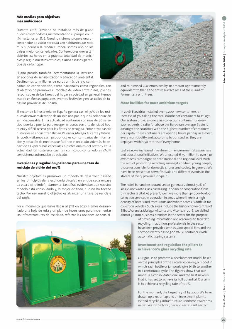
Más medios para objetivos más ambiciosos
Durante 2016, Ecovidrio ha instalado más de 9.200 nuevos contenedores, incrementando el parque en un 5% hasta los 211.876. Nuestro sistema proporciona un contenedor de vidrio por cada 220 habitantes, un ratio muy superior a la media europea, somos uno de los países mejor contenerizados. Contenedores que están abiertos 24 horas en la práctica totalidad de munici-pios y, según nuestros estudios, a unos escasos 50 me-tros de cada hogar.
El año pasado también incrementamos la inversión en acciones de sensibilización y educación ambiental. Destinamos 7,5 millones de euros a más de 330 cam-pañas de concienciación, tanto nacionales como regionales, con el objetivo de promover el reciclaje de vidrio entre niños, jóvenes, responsables de las tareas del hogar y sociedad en general. Hemos estado en fiestas populares, eventos, festivales y en las calles de to-das las provincias de España.
El sector de la hostelería en España genera casi el 50% de los resi-duos de envases de vidrio de un solo uso, por lo que su colaboración es indispensable. En la actualidad contamos con más de 40 servi-cios ‘puerta a puerta’ para recoger en zonas con alta densidad hos-telera y difícil acceso para las flotas de recogida. Entre otros cascos históricos se encuentran Bilbao, Valencia, Málaga Alicante y Vitoria. En 2016, visitamos casi 30.000 locales con campañas de informa-ción y dotación de medios que faciliten el reciclado. Además, ha re-partido 22.400 cubos especiales a profesionales del sector y en la actualidad los hosteleros cuentan con 10.300 contenedores VACRI con sistema automático de volcado.
Inversiones y regulación, palancas para una tasa de reciclaje de vidrio del 100%
Nuestro objetivo es promover un modelo de desarrollo basado en los principios de la economía circular, en el que cada envase da vida a otro indefinidamente. Las cifras evidencian que nuestro modelo está consolidado y, lo mejor de todo, que no ha tocado techo. Por eso nuestro objetivo es alcanzar una tasa de reciclaje del 100%.
Por el momento, queremos llegar al 77% en 2020. Hemos desarro-llado una hoja de ruta y un plan de inversiones para incrementar las infraestructuras de reciclado, reforzar las acciones de sensibi-
and minimised CO2 emissions by an amount approximately equivalent to filling the entire surface area of the island of Formentera with trees.
More facilities for more ambitious targets
In 2016, Ecovidrio installed over 9,200 new containers, an increase of 5%, taking the total number of containers to 211,876. Our system provides one glass collection container for every 220 residents, a ratio far above the European average. Spain is amongst the countries with the highest number of containers per capita. These containers are open 24 hours per day in almost every municipality and, according to our studies, they are deployed within 50 metres of every home.
Last year, we increased investment in environmental awareness and educational initiatives. We allocated €7.5 million to over 330 awareness campaigns at both national and regional level, with the aim of promoting recycling amongst children, young people, those responsible for domestic chores and society in general. We have been present at town festivals and different events in the streets of every province in Spain.
The hotel, bar and restaurant sector generates almost 50% of single-use waste glass packaging in Spain, so cooperation from this sector is vital. At present, we have more than 40 door-to-door collection services in operation in areas where there is a high density of hotels and restaurants and where access is difficult for collection vehicles. Such areas include the historic town centres of Bilbao, Valencia, Malaga, Alicante and Vitoria. In 2016, we visited almost 30,000 business premises in the sector for the purpose
of providing information and resources to facilitate recycling. In addition, professionals in the sector have been provided with 22,400 special bins and the sector currently has 10,300 VACRI containers with automatic tipping systems.
Investment and regulation the pillars to achieve 100% glass recycling rate
Our goal is to promote a development model based on the principles of the circular economy, a model in which each bottle or jar would give birth to another in a continuous cycle. The figures show that our model is a consolidated one. And the best news is that it has yet to achieve its full potential. Our aim is to achieve a recycling rate of 100%.
For the moment, the target is 77% by 2020. We have drawn up a roadmap and an investment plan to extend recycling infrastructure, reinforce awareness initiatives in the hotel, bar and restaurant sector
A fo
nd
o: A
nál
isis
20
16
| I
n d
epth
: An
alys
is o
f 20
16
Futu
rEn
viro
| M
arzo
Mar
ch 2
017
www.futurenviro.es 25
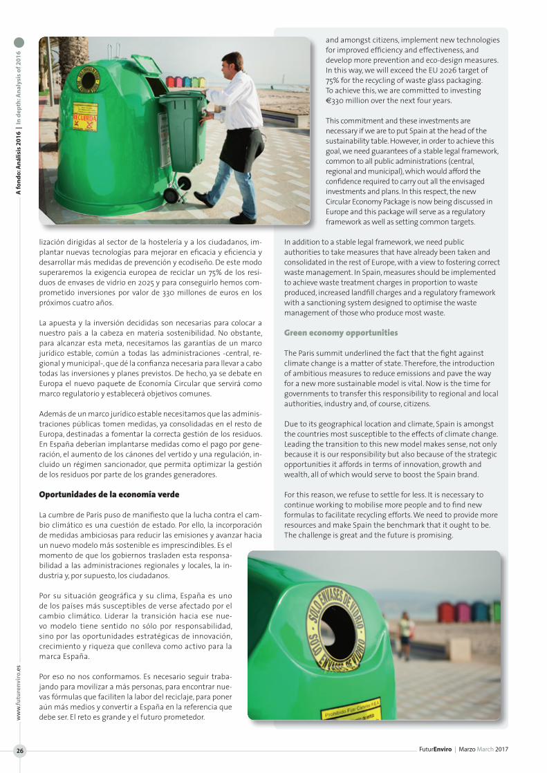
A fo
nd
o: A
nál
isis
20
16
| I
n d
epth
: An
alys
is o
f 20
16
FuturEnviro | Marzo March 2017
ww
w.fu
ture
nvi
ro.e
s
26
lización dirigidas al sector de la hostelería y a los ciudadanos, im-plantar nuevas tecnologías para mejorar en eficacia y eficiencia y desarrollar más medidas de prevención y ecodiseño. De este modo superaremos la exigencia europea de reciclar un 75% de los resi-duos de envases de vidrio en 2025 y para conseguirlo hemos com-prometido inversiones por valor de 330 millones de euros en los próximos cuatro años.
La apuesta y la inversión decididas son necesarias para colocar a nuestro país a la cabeza en materia sostenibilidad. No obstante, para alcanzar esta meta, necesitamos las garantías de un marco jurídico estable, común a todas las administraciones -central, re-gional y municipal-, que dé la confianza necesaria para llevar a cabo todas las inversiones y planes previstos. De hecho, ya se debate en Europa el nuevo paquete de Economía Circular que servirá como marco regulatorio y establecerá objetivos comunes.
Además de un marco jurídico estable necesitamos que las adminis-traciones públicas tomen medidas, ya consolidadas en el resto de Europa, destinadas a fomentar la correcta gestión de los residuos. En España deberían implantarse medidas como el pago por gene-ración, el aumento de los cánones del vertido y una regulación, in-cluido un régimen sancionador, que permita optimizar la gestión de los residuos por parte de los grandes generadores.
Oportunidades de la economía verde
La cumbre de París puso de manifiesto que la lucha contra el cam-bio climático es una cuestión de estado. Por ello, la incorporación de medidas ambiciosas para reducir las emisiones y avanzar hacia un nuevo modelo más sostenible es imprescindibles. Es el momento de que los gobiernos trasladen esta responsa-bilidad a las administraciones regionales y locales, la in-dustria y, por supuesto, los ciudadanos.
Por su situación geográfica y su clima, España es uno de los países más susceptibles de verse afectado por el cambio climático. Liderar la transición hacia ese nue-vo modelo tiene sentido no sólo por responsabilidad, sino por las oportunidades estratégicas de innovación, crecimiento y riqueza que conlleva como activo para la marca España.
Por eso no nos conformamos. Es necesario seguir traba-jando para movilizar a más personas, para encontrar nue-vas fórmulas que faciliten la labor del reciclaje, para poner aún más medios y convertir a España en la referencia que debe ser. El reto es grande y el futuro prometedor.
and amongst citizens, implement new technologies for improved efficiency and effectiveness, and develop more prevention and eco-design measures. In this way, we will exceed the EU 2026 target of 75% for the recycling of waste glass packaging. To achieve this, we are committed to investing €330 million over the next four years.
This commitment and these investments are necessary if we are to put Spain at the head of the sustainability table. However, in order to achieve this goal, we need guarantees of a stable legal framework, common to all public administrations (central, regional and municipal), which would afford the confidence required to carry out all the envisaged investments and plans. In this respect, the new Circular Economy Package is now being discussed in Europe and this package will serve as a regulatory framework as well as setting common targets.
In addition to a stable legal framework, we need public authorities to take measures that have already been taken and consolidated in the rest of Europe, with a view to fostering correct waste management. In Spain, measures should be implemented to achieve waste treatment charges in proportion to waste produced, increased landfill charges and a regulatory framework with a sanctioning system designed to optimise the waste management of those who produce most waste.
Green economy opportunities
The Paris summit underlined the fact that the fight against climate change is a matter of state. Therefore, the introduction of ambitious measures to reduce emissions and pave the way for a new more sustainable model is vital. Now is the time for governments to transfer this responsibility to regional and local authorities, industry and, of course, citizens.
Due to its geographical location and climate, Spain is amongst the countries most susceptible to the effects of climate change. Leading the transition to this new model makes sense, not only because it is our responsibility but also because of the strategic opportunities it affords in terms of innovation, growth and wealth, all of which would serve to boost the Spain brand.
For this reason, we refuse to settle for less. It is necessary to continue working to mobilise more people and to find new formulas to facilitate recycling efforts. We need to provide more resources and make Spain the benchmark that it ought to be. The challenge is great and the future is promising.
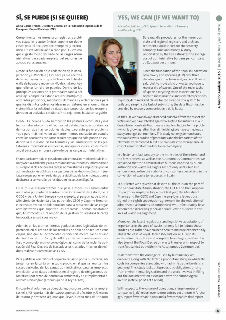
www.futurenviro.es
Futu
rEn
viro
| M
arzo
Mar
ch 2
017
27
A fo
nd
o: A
nál
isis
20
16
| I
n d
epth
: An
alys
is o
f 20
16
Cumplimentar los numerosos registros y archi-vos estatales y autonómicos supone un doble coste para el recuperador: temporal y econó-mico. Un estudio llevado a cabo por FER estima que el gasto medio derivado de las cargas admi-nistrativas para cada empresa del sector es de 20.000 euros anuales.
Desde la fundación de la Federación de la Recu-peración y el Reciclaje (FER), hace ya más de tres décadas, hay un dicho que ha trascendido hasta el día de hoy: para mover un kilo de chatarra, hay que rellenar un kilo de papeles. Dentro de las principales acciones de la patronal española del reciclaje siempre ha estado realizar múltiples y reiteradas peticiones, solicitudes, demandas y reclamaciones para que los distintos gobiernos idearan un sistema en el que unificar y simplificar la solicitud de datos que proporcionan los recupera-dores en su actividad cotidiana. Y no cejaremos hasta conseguirlo.
Desde FER hemos huido siempre de las posturas victimistas y nos hemos rebelado contra el recurso del pataleo. En nuestro afán por demostrar que hay soluciones viables para este grave problema –que para más inri va en aumento– hemos realizado un estudio entre los asociados con unos resultados que no sólo ponen en evi-dencia la duplicidad en los trámites y las limitaciones de las pla-taformas informáticas empleadas, sino que calcula el coste medio anual para cada empresa derivado de las cargas administrativas.
En una carta remitida el pasado mes de enero a los ministerios de Inte-rior y Medio Ambiente y a las comunidades autónomas, informamos a sus responsables de que las cargas administrativas impuestas por las administraciones públicas a los gestores de residuos no sólo son injus-tas, sino que ponen en serio riesgo la viabilidad de las empresas que se dedican a la conversión de residuos en recursos en España.
En la misiva argumentamos que pese a todos los llamamientos realizados por parte de la Administración General del Estado, de la OCDE y de la Unión Europea –por ejemplo, el pasado 14 de julio el Ministerio de Hacienda y las patronales CEOE y Cepyme firmaron el octavo convenio de colaboración para la reducción de las cargas administrativas que soportan las empresas–, hemos constatado que, tristemente, en el ámbito de la gestión de residuos la carga burocrática es cada vez mayor.
Además, en las últimas normas y adaptaciones legislativas de im-portancia en el ámbito de los residuos no solo no se reducen esas cargas, sino que se incrementan exponencialmente. Tal es el caso del Real Decreto 110/2015 de RAEE y su extraordinariamente pro-fuso y complejo archivo cronológico, así como de la reciente apli-cación del Real Decreto de traslado a los traslados internos de resi-duos realizados dentro de las CCAA.
Para justificar con datos el perjuicio causado por la burocracia, ad-juntamos en la carta un estudio propio en el que se analizan los costes derivados de las cargas administrativas para las empresas, en relación a los datos obtenidos en el registro de obligaciones bu-rocráticas por razón de normativa ambiental y en cumplimentar el archivo cronológico (artículo 40 de la Ley 22/2011). En cuanto al volumen de operaciones, una gran parte de las empre-sas (el 33%) reporta más de 10.000 apuntes al año, otro 35% menos de 10.000 y destacan algunas que llevan a cabo más de 100.000.
Bureaucratic procedures for the numerous state and regional registers and archives represent a double cost for the recovery company: time and money. A study undertaken by the FER estimates the average cost of administrative burdens per company at €20,000 per annum.
Since the foundation of the Spanish Federation of Recovery and Recycling (FER) over three decades ago, it has been said, and is still being said, that to move a kilo of waste, you have to move a kilo of papers. One of the main tasks of Spanish recycling trade associations has been to make multiple and reiterated petitions,
requests, demands and claims for the creation of a system to unify and simplify the task of submitting the data that must be provided by recovery companies on a daily basis.
At the FER, we have always distanced ourselves from the role of the victim and we have rebelled against resorting to tantrums. In our desire to demonstrate that there are viable solutions to this problem (which is growing rather than diminishing), we have carried out a study amongst our members. This study not only demonstrates the double work burden of procedures and the limitations of the IT platforms implemented, but it also calculates the average annual cost of administrative burdens for each company.
In a letter sent last January to the ministries of the Interior and the Environment, as well as the Autonomous Communities, we explained that the administrative burdens imposed by public authorities on waste managers are not only unfair but also seriously jeopardise the viability of companies specialising in the conversion of waste to resources in Spain.
In our letter, we argued that despite all the calls on the part of the General State Administration, the OECD and the European Union (for example, on July 14th of last year, the Ministry of Finance and the CEOE and Cepyme employers federations signed the eighth cooperation agreement for the reduction of administrative burdens on companies), we, unfortunately, have experienced increasingly heavier bureaucratic burdens in the area of waste management.
Moreover, the latest regulations and legislative adaptations of importance in the area of waste not only fail to reduce these burdens but rather have caused them to increase exponentially. This is the case of Royal Decree 110/2015 on WEEE and its extraordinarily profuse and complex chronological archive. It is also true of the Royal Decree on waste transfer with respect to transfers carried out within the Autonomous Communities.
To demonstrate the damage caused by bureaucracy, we enclosed, along with the letter, a proprietary study, in which the costs for companies associated with administrative burdens is analysed. This study looks at bureaucratic obligations arising from environmental legislation and the work involved in filling out the documentation associated with the chronological archive (article 40 of Act 22/2011). With respect to the volume of operations, a large number of companies (33%) report over 10,000 entries per annum. A further 35% report fewer than 10,000 and a few companies that report
SÍ, SE PUEDE (SI SE QUIERE)Alicia García-Franco, Directora General de la Federación Española de la Recuperación y el Reciclaje (FER)
YES, WE CAN (IF WE WANT TO) Alicia García-Franco, CEO, Spanish Federation of Recovery and Recycling (FER)
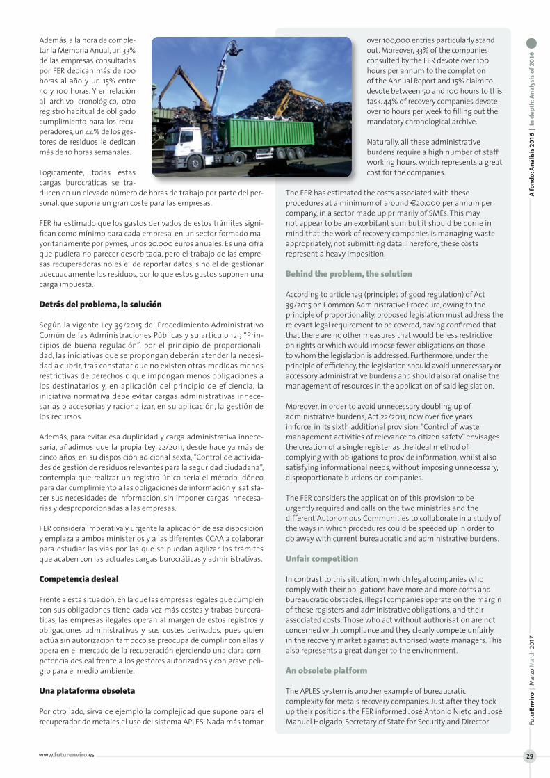
Además, a la hora de comple-tar la Memoria Anual, un 33% de las empresas consultadas por FER dedican más de 100 horas al año y un 15% entre 50 y 100 horas. Y en relación al archivo cronológico, otro registro habitual de obligado cumplimiento para los recu-peradores, un 44% de los ges-tores de residuos le dedican más de 10 horas semanales.
Lógicamente, todas estas cargas burocráticas se tra-ducen en un elevado número de horas de trabajo por parte del per-sonal, que supone un gran coste para las empresas.
FER ha estimado que los gastos derivados de estos trámites signi-fican como mínimo para cada empresa, en un sector formado ma-yoritariamente por pymes, unos 20.000 euros anuales. Es una cifra que pudiera no parecer desorbitada, pero el trabajo de las empre-sas recuperadoras no es el de reportar datos, sino el de gestionar adecuadamente los residuos, por lo que estos gastos suponen una carga impuesta.
Detrás del problema, la solución
Según la vigente Ley 39/2015 del Procedimiento Administrativo Común de las Administraciones Públicas y su artículo 129 “Prin-cipios de buena regulación”, por el principio de proporcionali-dad, las iniciativas que se propongan deberán atender la necesi-dad a cubrir, tras constatar que no existen otras medidas menos restrictivas de derechos o que impongan menos obligaciones a los destinatarios y, en aplicación del principio de eficiencia, la iniciativa normativa debe evitar cargas administrativas innece-sarias o accesorias y racionalizar, en su aplicación, la gestión de los recursos.
Además, para evitar esa duplicidad y carga administrativa innece-saria, añadimos que la propia Ley 22/2011, desde hace ya más de cinco años, en su disposición adicional sexta, “Control de activida-des de gestión de residuos relevantes para la seguridad ciudadana”, contempla que realizar un registro único sería el método idóneo para dar cumplimiento a las obligaciones de información y satisfa-cer sus necesidades de información, sin imponer cargas innecesa-rias y desproporcionadas a las empresas.
FER considera imperativa y urgente la aplicación de esa disposición y emplaza a ambos ministerios y a las diferentes CCAA a colaborar para estudiar las vías por las que se puedan agilizar los trámites que acaben con las actuales cargas burocráticas y administrativas.
Competencia desleal
Frente a esta situación, en la que las empresas legales que cumplen con sus obligaciones tiene cada vez más costes y trabas burocrá-ticas, las empresas ilegales operan al margen de estos registros y obligaciones administrativas y sus costes derivados, pues quien actúa sin autorización tampoco se preocupa de cumplir con ellas y opera en el mercado de la recuperación ejerciendo una clara com-petencia desleal frente a los gestores autorizados y con grave peli-gro para el medio ambiente.
Una plataforma obsoleta
Por otro lado, sirva de ejemplo la complejidad que supone para el recuperador de metales el uso del sistema APLES. Nada más tomar
over 100,000 entries particularly stand out. Moreover, 33% of the companies consulted by the FER devote over 100 hours per annum to the completion of the Annual Report and 15% claim to devote between 50 and 100 hours to this task. 44% of recovery companies devote over 10 hours per week to filling out the mandatory chronological archive.
Naturally, all these administrative burdens require a high number of staff working hours, which represents a great cost for the companies.
The FER has estimated the costs associated with these procedures at a minimum of around €20,000 per annum per company, in a sector made up primarily of SMEs. This may not appear to be an exorbitant sum but it should be borne in mind that the work of recovery companies is managing waste appropriately, not submitting data. Therefore, these costs represent a heavy imposition.
Behind the problem, the solution
According to article 129 (principles of good regulation) of Act 39/2015 on Common Administrative Procedure, owing to the principle of proportionality, proposed legislation must address the relevant legal requirement to be covered, having confirmed that that there are no other measures that would be less restrictive on rights or which would impose fewer obligations on those to whom the legislation is addressed. Furthermore, under the principle of efficiency, the legislation should avoid unnecessary or accessory administrative burdens and should also rationalise the management of resources in the application of said legislation.
Moreover, in order to avoid unnecessary doubling up of administrative burdens, Act 22/2011, now over five years in force, in its sixth additional provision, “Control of waste management activities of relevance to citizen safety” envisages the creation of a single register as the ideal method of complying with obligations to provide information, whilst also satisfying informational needs, without imposing unnecessary, disproportionate burdens on companies.
The FER considers the application of this provision to be urgently required and calls on the two ministries and the different Autonomous Communities to collaborate in a study of the ways in which procedures could be speeded up in order to do away with current bureaucratic and administrative burdens.
Unfair competition
In contrast to this situation, in which legal companies who comply with their obligations have more and more costs and bureaucratic obstacles, illegal companies operate on the margin of these registers and administrative obligations, and their associated costs. Those who act without authorisation are not concerned with compliance and they clearly compete unfairly in the recovery market against authorised waste managers. This also represents a great danger to the environment.
An obsolete platform
The APLES system is another example of bureaucratic complexity for metals recovery companies. Just after they took up their positions, the FER informed José Antonio Nieto and José Manuel Holgado, Secretary of State for Security and Director
A fo
nd
o: A
nál
isis
20
16
| I
n d
epth
: An
alys
is o
f 20
16
Futu
rEn
viro
| M
arzo
Mar
ch 2
017
www.futurenviro.es 29
A fo
nd
o: A
nál
isis
20
16
| I
n d
epth
: An
alys
is o
f 20
16
FuturEnviro | Marzo March 2017
ww
w.fu
ture
nvi
ro.e
s
30
posesiones de sus nuevos cargos, FER transmitió a José Antonio Nieto y José Manuel Holgado, secretario de Estado de Seguridad y director general de la Guardia Civil, respectivamente, las numero-sas quejas recibidas por la pesada carga burocrática derivada del uso del sistema APLES.
Esta plataforma telemática fue puesta en marcha por la Guardia Civil con objeto de “facilitar” el cumplimiento de la Orden Minis-terial INT/1920/2011, relativa al “control respecto al comercio del cobre para los centros gestores de residuos metálicos y estable-cimientos de comercio al por mayor de chatarra y productos de desecho”.
La federación siempre ha mostrado su disposición a colaborar con las Fuerzas y Cuerpos de Seguridad del Estado para frenar el comer-cio de metales de dudosa procedencia, pero estamos en contra del uso de la Plataforma APLES tal y como está implantada.
Afortunadamente, tras estas últimas acciones desde la dirección general de la Guardia Civil nos han comunicado que atenderán nuestras peticiones. Ahora hay que ver cuando se materializa.
En las numerosas quejas recibidas por FER por parte de sus asocia-dos, es recurrente la que señala que APLES no permite las cargas masivas de datos, por lo que hace necesario rellenar uno a uno los campos por cada compra. Esto se traduce en que, en términos ge-nerales, se tarda aproximadamente tres minutos en cada una de estas operaciones individuales, que podría considerarse un tiempo exiguo, si no se explicara que son operaciones repetitivas que im-plican una carga burocrática inasumible y que podría solventarse si la aplicación permitiera extrapolar los datos.
Según una encuesta de elaboración propia entre nuestros asocia-dos para saber cuántos apuntes realizan de forma diaria, semanal o mensual en esta plataforma el resultado es elocuente: el 21% rea-liza más de 100 apuntes diarios; es decir, más de 22.000 anuales.
Peor todavía es el agravio comparativo en función de la demar-cación territorial y de la actividad ejercida. De esta manera, como el cumplimiento de las obligaciones de la Orden INT 1920 depen-de de la demarcación territorial, aquellas empresas que están en el ámbito de la Policía Nacional cumplen sus obligaciones utili-zando los programas informáticos propios, enviando los ficheros generados por estos sin costes ni cargas burocráticas añadidas. Más difícil de entender y uno de los motivos de enviar la carta con carácter urgente es que, además de existir sistemas de car-ga de datos masivos para establecimientos hoteleros, desde FER hemos conocido que los establecimientos dedicados a la venta de objetos de segunda mano tienen la obligación de rellenar un libro registro digital, que es una hoja de Excel, y enviarlo por co-rreo electrónico, que es una operación muchas más sencilla que el uso de APLES.
Este sistema es sólo un ejemplo, hay muchos otros para diversos flujos de residuos, de hasta qué punto las cargas administrativas suponen un quebradero de cabeza en la actividad cotidiana del recuperador. Por ello y para ahondar mas en todos estos proble-mas, FER junto con el Gremi de la Recuperació de Catalunya, van a desarrollar un estudio en profundidad realizado por el Colegio de Ingenieros de Catalunya sobre la sobrecarga administrativa que tienen que soportar las empresas de gestión de residuos, especialmente la que se recoge en el Real Decreto 110/2015 sobre RAEE.
Es hora de que los responsables políticos impulsen las medidas necesarias a su alcance para solucionar este grave problema que resta competitividad a nuestras empresas y pone en peligro su via-bilidad económica.
General of the Civil Guard, respectively, of the numerous complaints received because of the heavy bureaucratic burden associated with the APLES system.
This digital platform was put into operation by the Civil Guard in order to “facilitate” compliance with Ministerial Order INT/1920/2011 on “control with respect to copper trading for metal waste management centres and establishments engaging in wholesale trading of scrap metal and waste products”.
The FER has always expressed its willingness to cooperate with the judiciary and law enforcement bodies in order to stop the trading of metals of dubious origin, but we are against the use of the APLES Platform as it is now implemented.
Fortunately, following these latest initiatives, the General Directorate of the Civil Guard has conveyed to us that they will accept our requests. It now remains to be seen when this will actually materialise.
A recurring theme in the numerous complaints received by the FER from its members is that APLES does not permit bulk data upload, meaning that fields must be filled in one by one for each purchase. This means that, in general terms, each individual operation takes around three minutes. This might be seen as very little time but these operations have to be repeated over and over again, implying an excessive bureaucratic burden which could be alleviated if it were possible to extrapolate data.
A survey designed by the FER and issued to its members in order to know how many APLES platform operations they have to carry out on a daily, weekly and monthly basis produced very eloquent results. 21% of those surveyed carry out more than 100 entries per day, in other words, over 22,000 per annum.
Worse still are the differences in administrative burdens depending on territorial demarcation and the activity being carried out. As compliance with the obligations of Order INT 1920 depends on territorial demarcation, companies operating in the area controlled by the National Police comply with their obligations using their own software programs. They submit the files created by these programs without additional costs or bureaucratic burdens. What is more difficult to understand and one of the reasons for sending this urgent letter is that, in addition to the existence of systems with bulk data upload options for establishments in the hotel sector, the FER has also discovered that establishments selling second-hand products have the obligation to fill out a digital logbook, which takes the form of an Excel sheet submitted by email. This is a far simpler operation than the use of APLES.
This system is merely an example. There are many others for different waste streams and the result is that administrative burdens represent a great headache in the day-to-day activity of the recovery company. For this reason and to examine these problems in greater depth, the FER, in cooperation with the Gremi de la Recuperació de Catalunya (Catalonian Recovery Guild), will undertake an in-depth study, to be carried out by the Colegio de Ingenieros de Catalunya (Catalonian Engineers Association), on the excessive administrative burdens borne by waste management companies. The study will focus particularly on administrative burdens associated with Royal Decree 110/2015 on WEEE.
It is high time that politicians with responsibility in this area took the necessary measures within their power to solve this serious problem, a problem that makes our companies less competitive and jeopardises their economic viability.
www.futurenviro.es
Futu
rEn
viro
| M
arzo
Mar
ch 2
017
31
A fo
nd
o: A
nál
isis
20
16
| I
n d
epth
: An
alys
is o
f 20
16
2016 podría haber representado un punto de inflexión para el sector del reciclaje de aparatos electrónicos en nuestro país, tras la entrada en vigor, en febrero de 2015, del nuevo Real Decreto que regula la gestión de este tipo de residuos. Sin embargo, la interinidad del Gobierno, hasta el pasado noviembre, ha bloqueado cualquier avance en el desarrollo normativo y ejecución de la nueva norma, con los consiguientes per-juicios para todos los actores del sector.
En 2015, el sector coincidió en valorar el nuevo RD como un marco jurídico estable para afron-tar el gran reto que plantea la Directiva europea de 2012: reciclar el 85% de los residuos de apa-ratos eléctricos y electrónicos (RAEE) generados, en 2019. Una cifra nada desdeñable, dado que el volumen de residuos eléctricos euro-peos podría alcanzar los 12,3 millones de toneladas en 2020, según la Unión Europea.
En aquel momento, numerosos actores del sector llamamos a la adopción urgente de medidas que permitieran proteger y consoli-dar un sector complejo y con grandes deficiencias, pero vital para progresar en la implantación de un modelo productivo de econo-mía circular, impulsado por la Comisión Europea, a través de su am-bicioso Programa Horizonte 2020.
Reciclaje, barómetro de competitividad y oportunidad para el fraude
Reciclar más y mejor es esencial para la implantación eficaz de la economía circular. El correcto cierre del ciclo de vida de cualquier producto garantiza el máximo reaprovechamiento de materias primas, desacelerando el agotamiento de los recursos naturales y energéticos, así como el menor impacto en el medio ambiente. Por poner un ejemplo, según la UE, si se reco-gieran el 95% de los teléfonos móviles en desuso, sería posible ahorrar más de mil millones de euros en los costes del mate-rial de fabricación.
En este sentido, el reciclaje de residuos electrónicos es ya un barómetro capaz de definir el grado de competitividad y bien-estar de un país, por lo que debe figurar en-tre las prioridades de cualquier gobierno. Lo que sucede es que, como en cualquier otro gran sector económico, el reciclaje electrónico también crea oportunidades para las actividades ilegales en diferentes niveles de la cadena de valor.
Esta situación se debe, principalmente, a que los RAEE contienen materias valiosas,
2016 could have been a turning point for the recycling of electronic appliances in Spain, following the entry into force of the new Royal Decree governing the management of this waste type in February 2015. However, the fact that the country was administered by a caretaker government until November blocked any progress in terms of regulatory development and the application of the new legislation. This situation adversely affected all actors in the sector.
In 2015, the sector coincided in welcoming the new Royal Decree as a stable legal framework to address the great challenge posed by
the EU Directive of 2012: to recycle 85% of waste electrical and electronic equipment (WEEE) by 2019. A considerable recycling rate, given that the volume of electrical waste in Europe could be as high as 12.3 million tonnes in 2020, according to EU estimates.
At that time, many actors in the sector called for the adoption of urgent measures to protect and consolidate a complex sector with great deficiencies, but a vital one in terms of implementing the circular economy production model being promoted by the European Commission through its ambitious Horizon 2020 Programme.
Recycling – a barometer of competitiveness and an opportunity for fraud
Recycling more and better is vital for the implementation of the circular economy. Correctly closing the lifecycle of any product ensures maximum reuse of raw materials and deceleration of the depletion of natural and energy resources. It also results in a lower environmental impact. By way of example,
LOS SISTEMAS COLECTIVOS DE GESTIÓN DE RESIDUOS ELECTRÓNICOS RECLAMAN MAYOR SEGURIDAD JURÍDICAJosé Pérez, consejero delegado de Recyclia* y delegado general de la Fundación Ecolum*
ELECTRONIC WASTE COLLECTIVE MANAGEMENT SYSTEMS CALL FOR GREATER LEGAL SECURITY José Pérez, CEO at Recyclia* and General Delegate of the Fundación Ecolum*
* Recyclia es la plataforma que gestiona a cuatro SIG: Ecopilas, Ecofimática, Ecoasimelec y Ecolum, fundaciones dedicadas a la recogida selectiva y el reciclaje de pilas usadas y RAEE.. | Recyclia is a platform that manages four Integrated Management Systems (IMS): Ecopilas, Ecofimática, Ecoasimelec and Tragamóvil, foundations devoted to the selective collection and recycling of used batteries and WEEE.
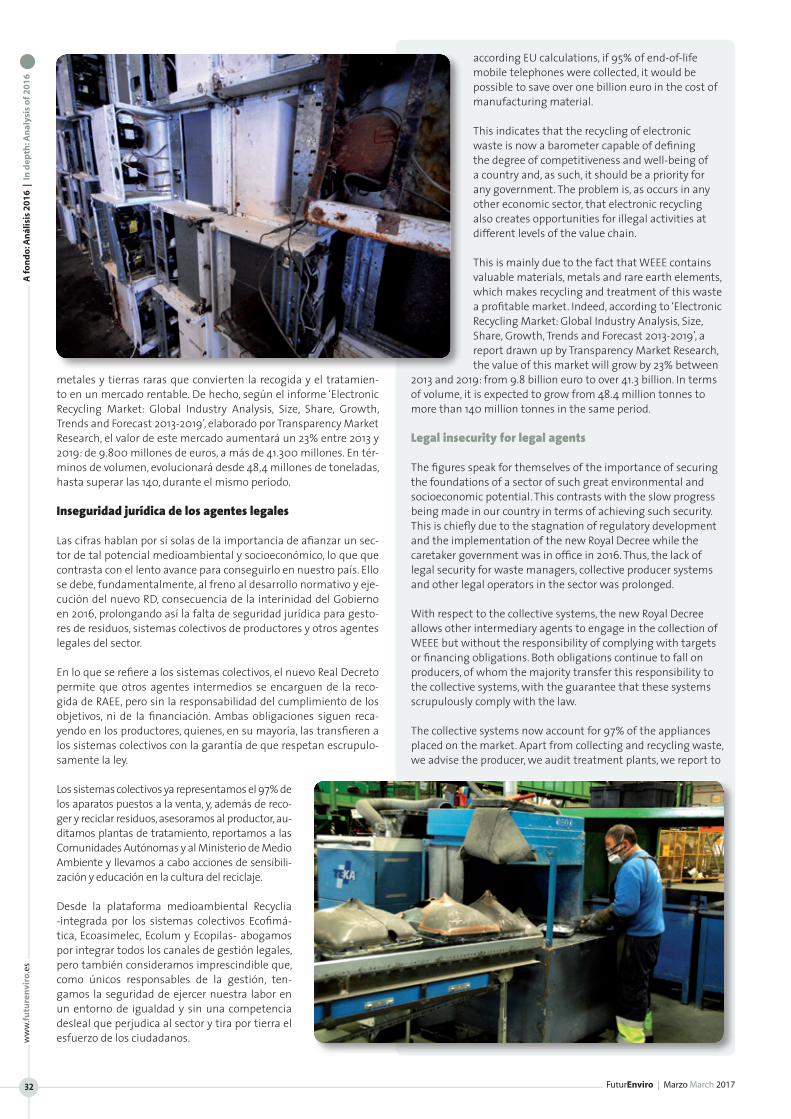
A fo
nd
o: A
nál
isis
20
16
| I
n d
epth
: An
alys
is o
f 20
16
FuturEnviro | Marzo March 2017
ww
w.fu
ture
nvi
ro.e
s
32
metales y tierras raras que convierten la recogida y el tratamien-to en un mercado rentable. De hecho, según el informe ‘Electronic Recycling Market: Global Industry Analysis, Size, Share, Growth, Trends and Forecast 2013-2019’, elaborado por Transparency Market Research, el valor de este mercado aumentará un 23% entre 2013 y 2019: de 9.800 millones de euros, a más de 41.300 millones. En tér-minos de volumen, evolucionará desde 48,4 millones de toneladas, hasta superar las 140, durante el mismo periodo.
Inseguridad jurídica de los agentes legales
Las cifras hablan por sí solas de la importancia de afianzar un sec-tor de tal potencial medioambiental y socioeconómico, lo que que contrasta con el lento avance para conseguirlo en nuestro país. Ello se debe, fundamentalmente, al freno al desarrollo normativo y eje-cución del nuevo RD, consecuencia de la interinidad del Gobierno en 2016, prolongando así la falta de seguridad jurídica para gesto-res de residuos, sistemas colectivos de productores y otros agentes legales del sector.
En lo que se refiere a los sistemas colectivos, el nuevo Real Decreto permite que otros agentes intermedios se encarguen de la reco-gida de RAEE, pero sin la responsabilidad del cumplimiento de los objetivos, ni de la financiación. Ambas obligaciones siguen reca-yendo en los productores, quienes, en su mayoría, las transfieren a los sistemas colectivos con la garantía de que respetan escrupulo-samente la ley.
Los sistemas colectivos ya representamos el 97% de los aparatos puestos a la venta, y, además de reco-ger y reciclar residuos, asesoramos al productor, au-ditamos plantas de tratamiento, reportamos a las Comunidades Autónomas y al Ministerio de Medio Ambiente y llevamos a cabo acciones de sensibili-zación y educación en la cultura del reciclaje.
Desde la plataforma medioambiental Recyclia -integrada por los sistemas colectivos Ecofimá-tica, Ecoasimelec, Ecolum y Ecopilas- abogamos por integrar todos los canales de gestión legales, pero también consideramos imprescindible que, como únicos responsables de la gestión, ten-gamos la seguridad de ejercer nuestra labor en un entorno de igualdad y sin una competencia desleal que perjudica al sector y tira por tierra el esfuerzo de los ciudadanos.
according EU calculations, if 95% of end-of-life mobile telephones were collected, it would be possible to save over one billion euro in the cost of manufacturing material.
This indicates that the recycling of electronic waste is now a barometer capable of defining the degree of competitiveness and well-being of a country and, as such, it should be a priority for any government. The problem is, as occurs in any other economic sector, that electronic recycling also creates opportunities for illegal activities at different levels of the value chain.
This is mainly due to the fact that WEEE contains valuable materials, metals and rare earth elements, which makes recycling and treatment of this waste a profitable market. Indeed, according to ‘Electronic Recycling Market: Global Industry Analysis, Size, Share, Growth, Trends and Forecast 2013-2019’, a report drawn up by Transparency Market Research, the value of this market will grow by 23% between
2013 and 2019: from 9.8 billion euro to over 41.3 billion. In terms of volume, it is expected to grow from 48.4 million tonnes to more than 140 million tonnes in the same period.
Legal insecurity for legal agents
The figures speak for themselves of the importance of securing the foundations of a sector of such great environmental and socioeconomic potential. This contrasts with the slow progress being made in our country in terms of achieving such security. This is chiefly due to the stagnation of regulatory development and the implementation of the new Royal Decree while the caretaker government was in office in 2016. Thus, the lack of legal security for waste managers, collective producer systems and other legal operators in the sector was prolonged.
With respect to the collective systems, the new Royal Decree allows other intermediary agents to engage in the collection of WEEE but without the responsibility of complying with targets or financing obligations. Both obligations continue to fall on producers, of whom the majority transfer this responsibility to the collective systems, with the guarantee that these systems scrupulously comply with the law.
The collective systems now account for 97% of the appliances placed on the market. Apart from collecting and recycling waste, we advise the producer, we audit treatment plants, we report to

Me refiero a los robos en los puntos autori-zados de recogida y los canales de gestión ilegales, tales como instalaciones de ges-tión fraudulenta, mercado negro y venta y exportación a países carentes de normati-va. Por poner un ejemplo, según denuncia Recybérica Ambiental, el 80% de las 1.200 toneladas de RAEE, recogidas anualmente a través de la red de puntos limpios de Ma-drid, es robado antes de que llegue a una planta de reciclaje. Una situación que, ade-más de tener consecuencias negativas para el medio ambiente, amenaza la rentabili-dad de las plantas de tratamiento e impide la creación de empleo.
En este sentido, dos años después de la entrada en vigor del RD, sigue urgiendo au-mentar el control de los flujos nacionales y transfronterizos de residuos electrónicos, así como de la venta online, en cuanto al cumplimiento de las mismas obligaciones que la física, en materia de reciclaje sobre los equipos que ponen en el mercado.
Es necesario armonizar los criterios de contabilización y trazabilidad de los diferentes flujos y simplificar los trámites administrativos para facilitar este control. Asimismo, es prioritario definir los requisitos técnicos para la valoración de los aparatos que pueden ser reutili-zados, ya que, a partir de 2017, el 3% de los productos informáticos y pequeños electrodomésticos y el 2% de los grandes aparatos des-echados, deberán ser reacondicionados para su reutilización.
Igual de importante es el hecho de que la actividad ilegal y frau-dulenta contribuye a destruir lo logrado hasta el momento en ma-teria de sensibilización medioambiental. Reciclar se ha convertido en un acto cotidiano para muchos ciudadanos concienciados de la importancia de contribuir al cuidado del medio ambiente, y cada vez más empresas entienden que esta “etiqueta verde” es más una ventaja competitiva que una obligación, por lo que no podemos permitirnos perder lo ganado a causa de un sistema deficiente.
Precisamente, porque aún queda mucho trabajo por hacer para consolidar el sector de la gestión de RAEE en nuestro país y para alcanzar el desarrollo sostenible que promueve la economía circu-lar, es urgente no dejar pasar más tiempo y adoptar las medidas e invertir los recursos necesarios para poner fin a las deficiencias de una actividad que es sinónimo de salud medioambiental y desarro-llo socioeconómico.
the regional authorities and the Ministry of the Environment, and we carry out awareness and educational initiatives to promote the culture of recycling.
At the Recyclia environmental platform –which comprises the Ecofimática, Ecoasimelec, Ecolum and Ecopilas collective systems- we advocate integrating all legal management channels but we also consider it vital, as the only actors with actual management responsibilities, that we have the security of carrying out our work in an environment of equality, without the unfair competition that damages the sector and thwarts the efforts of citizens.
I am referring to the robberies at authorised collection points and illegal management channels, as well as fraudulent management facilities, the black market, and sale and exportation to countries without regulation. For
example, according to Recybérica Ambiental, 80% of the 1,200 tonnes of WEEE collected annually by the network of clean collection points in Madrid is stolen before it reaches the recycling plant. This situation, in addition to having grave environmental consequences, threatens the profitability of the treatment plants and jeopardises job creation.
In this respect, two years after the entry into force of the Royal Decree, there is still an urgent need to increase control of national and cross-border flows of electronic waste, as well as online sales, where the same obligations exist as for physical sales in terms of recycling equipment placed on the market. It is necessary to harmonise accounting and traceability criteria for the different streams and simplify administrative procedures to facilitate this control. Similarly, defining the technical requisites for the recovery of appliances that can be reused is a priority, because from 2017, 3% of IT products and small household electrical appliances will have to be reconditioned for reuse.
Equally important is the fact that illegal and fraudulent activity is contributing to the destruction of what has been achieved thus far in the area of environmental awareness. Recycling has become a day-to-day concern of many citizens, who are
aware of the importance of caring for the environment. This is also true of businesses, as more and more companies understand that the “green label” is more of a competitive advantage than an obligation. For these reason, we cannot afford to lose what has been gained due to a deficient system.
Precisely because there is still much work to be done to consolidate the WEEE management sector in our country and to achieve the sustainable development that promotes the circular economy, it is urgent not to delay in adopting the measures and investing in the resources necessary to put an end to the deficiencies of an activity that is synonymous with environmental health and socioeconomic development.
A fo
nd
o: A
nál
isis
20
16
| I
n d
epth
: An
alys
is o
f 20
16
Futu
rEn
viro
| M
arzo
Mar
ch 2
017
www.futurenviro.es 33

A fo
nd
o: A
nál
isis
20
16
| I
n d
epth
: An
alys
is o
f 20
16
FuturEnviro | Marzo March 2017
ww
w.fu
ture
nvi
ro.e
s
34
Diagnóstico actual de un sector que suele to-marse como ejemplo a la hora de gestionar re-siduos, pero que se encuentra amenazado por cuestiones como la limitación al libre comercio o a la competencia de gestión de las empresas recuperadoras, poniéndose en serio riesgo la consecución de los objetivos fijados por la Co-misión Europea para desarrollar el paradigma de la economía circular.
Que España forma parte del grupo de cabeza de países europeos que más y mejor papel y cartón recicla está fuera de toda duda. Así lo dicen los últimos datos de 2016. Recogemos y reciclamos el 71% del papel que consumimos ese año, con cifras de recogida de 4,7 millones de toneladas, un 3% más que en el año 2015.
Ahora bien, sin conocer la idiosincrasia de este sector en nuestro país, será difícil entender si estos datos satisfactorios podrán seguir la hoja de ruta marcada por el Paquete de Economía Circular de la Comisión Europea (CE), o lamentablemente marcan el tope de la tasa de recogida según los medios disponibles y las actuales condi-ciones legislativas y empresariales.
Como único representante de un sector mayoritariamente formado por pymes y empresas familiares, la Asociación Española de Recicla-dores Recuperadores de Papel y Cartón (REPACAR) comparte y cana-liza las inquietudes de sus socios, más de un centenar de empresas, con las que hacer frente a los grandes desafíos a los que se encaran a corto y a medio plazo, en una coyuntura que marcará el devenir de una materia prima secundaria que suele tomarse como ejemplo para otros residuos en el nuevo modelo de economía circular.
El primer paso para cumplir con los objetivos que nos marcan desde Europa, será asegurar un mercado de materias primas se-cundarias, que permita reintroducir los residuos en el sistema, de forma que se evite el vertido. Este mercado deberá competir e incluso superar al de las materias vírgenes. Sin embargo, en la actualidad estamos ante una utopía: este último es un mercado donde la libre competencia está asegurada y los precios los fija la oferta y la demanda, mientras que el mercado de papel recu-perado en España, se dirige hacia la concentración empresarial, limitaciones al libre comercio y a una excesiva regulación legisla-tiva que genera costes añadidos a los gestores de estos residuos, reduciéndose su competitividad.
Peor aún, los intentos de municipalizar los servicios de gestión de residuos de papel y cartón que hemos visto en los últimos años, si persisten podrían poner en serio riesgo la viabilidad de las em-presas de nuestro sector y, por tanto, su capacidad para invertir en empleo verde, maquinaria y tecnología que permita, lógicamente, aumentar las tasas de reciclaje que exige la Eurocámara, así como en la generación de riqueza y empleo local.
Cargas administrativas
Pese a las recientes declaraciones de Dª Isabel García Tejerina, Ministra de Agricultura y Pesca, Alimentación y Medio Ambiente
Current diagnosis of a sector that tends to be taken as an example in terms of waste management shows that it is threatened by issues such as constraints on free trade and the management competences of recovery companies. This is seriously jeopardising the achievement of targets set by the European Commission in order to develop the circular economy model.
There is no doubt whatsoever that Spain is amongst the leading European paper and board recycling countries, in terms of quantity and quality. The latest figures for 2016 confirm this. We collected and
recycled 71% of the paper we consumed last year. The collection figure of 4.7 million tonnes was 3% higher than in 2015.
However, without knowledge of the idiosyncrasies of this sector in Spain, it would be difficult to understand how, despite these satisfactory figures, there is uncertainty regarding whether Spain will be able to follow the road map set out in the European Commission’s Circular Economy Package or if we have reached the limit of the collection rate, given the resources available and current legislative and business conditions.
As the sole representative of a sector primarily made up of SMEs and family businesses, the Spanish Recycling Recovered Paper Association (REPACAR) shares and channels the concerns of more than 100 member companies. Together with its members, the association will address the great short and medium term challenges facing the sector, in a context that will determine the future of a secondary raw material that tends to be taken as an example for other wastes in the framework of the new circular economy model.
The first step in meeting European targets will be to secure a secondary raw materials market to enable the reintroduction of waste into the system, thereby ensuring that it is not sent to landfill. This market must compete with and even outperform the market for virgin raw materials. As of now, this is merely utopia because free competition is guaranteed in the latter market and prices are fixed by the laws of supply and demand. In contrast, the recovered paper market in Spain is moving towards corporate concentration, constraints on free trade and excessive legislative regulation, which generates added costs for the managers of this waste and reduces their competitiveness.
Worse still, persistence in the attempts to re-municipalise paper & board management services that we have witnessed in recent years could seriously jeopardise the viability of companies in our sector and, therefore, their capacity to invest in the green jobs, machinery and technology that would, logically, bring us nearer the recycling rates demanded by the European Commission, as well as creating wealth and local employment.
LOS DESAFÍOS DEL PAPEL RECICLADO: DE LO GLOBAL A LO LOCALManuel Domínguez Domínguez, Director general de REPACAR (Asociación Española de Recicladores Recuperadores de Papel y Cartón)
THE CHALLENGES OF RECYCLED PAPER: FROM GLOBAL TO LOCAL Manuel Domínguez Domínguez, CEO at REPACAR (Spanish Recycling Recovered Paper Association)
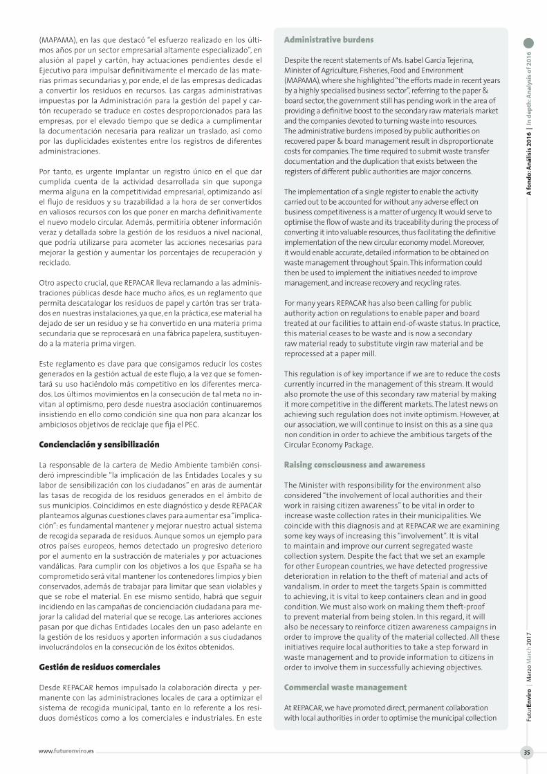
(MAPAMA), en las que destacó “el esfuerzo realizado en los últi-mos años por un sector empresarial altamente especializado”, en alusión al papel y cartón, hay actuaciones pendientes desde el Ejecutivo para impulsar definitivamente el mercado de las mate-rias primas secundarias y, por ende, el de las empresas dedicadas a convertir los residuos en recursos. Las cargas administrativas impuestas por la Administración para la gestión del papel y car-tón recuperado se traduce en costes desproporcionados para las empresas, por el elevado tiempo que se dedica a cumplimentar la documentación necesaria para realizar un traslado, así como por las duplicidades existentes entre los registros de diferentes administraciones.
Por tanto, es urgente implantar un registro único en el que dar cumplida cuenta de la actividad desarrollada sin que suponga merma alguna en la competitividad empresarial, optimizando así el flujo de residuos y su trazabilidad a la hora de ser convertidos en valiosos recursos con los que poner en marcha definitivamente el nuevo modelo circular. Además, permitiría obtener información veraz y detallada sobre la gestión de los residuos a nivel nacional, que podría utilizarse para acometer las acciones necesarias para mejorar la gestión y aumentar los porcentajes de recuperación y reciclado.
Otro aspecto crucial, que REPACAR lleva reclamando a las adminis-traciones públicas desde hace mucho años, es un reglamento que permita descatalogar los residuos de papel y cartón tras ser trata-dos en nuestras instalaciones, ya que, en la práctica, ese material ha dejado de ser un residuo y se ha convertido en una materia prima secundaria que se reprocesará en una fábrica papelera, sustituyen-do a la materia prima virgen.
Este reglamento es clave para que consigamos reducir los costes generados en la gestión actual de este flujo, a la vez que se fomen-tará su uso haciéndolo más competitivo en los diferentes merca-dos. Los últimos movimientos en la consecución de tal meta no in-vitan al optimismo, pero desde nuestra asociación continuaremos insistiendo en ello como condición sine qua non para alcanzar los ambiciosos objetivos de reciclaje que fija el PEC.
Concienciación y sensibilización
La responsable de la cartera de Medio Ambiente también consi-deró imprescindible “la implicación de las Entidades Locales y su labor de sensibilización con los ciudadanos” en aras de aumentar las tasas de recogida de los residuos generados en el ámbito de sus municipios. Coincidimos en este diagnóstico y desde REPACAR planteamos algunas cuestiones claves para aumentar esa “implica-ción”: es fundamental mantener y mejorar nuestro actual sistema de recogida separada de residuos. Aunque somos un ejemplo para otros países europeos, hemos detectado un progresivo deterioro por el aumento en la sustracción de materiales y por actuaciones vandálicas. Para cumplir con los objetivos a los que España se ha comprometido será vital mantener los contenedores limpios y bien conservados, además de trabajar para limitar que sean violables y que se robe el material. En ese mismo sentido, habrá que seguir incidiendo en las campañas de concienciación ciudadana para me-jorar la calidad del material que se recoge. Las anteriores acciones pasan por que dichas Entidades Locales den un paso adelante en la gestión de los residuos y aporten información a sus ciudadanos involucrándolos en la consecución de los éxitos obtenidos.
Gestión de residuos comerciales
Desde REPACAR hemos impulsado la colaboración directa y per-manente con las administraciones locales de cara a optimizar el sistema de recogida municipal, tanto en lo referente a los resi-duos domésticos como a los comerciales e industriales. En este
Administrative burdens
Despite the recent statements of Ms. Isabel García Tejerina, Minister of Agriculture, Fisheries, Food and Environment (MAPAMA), where she highlighted “the efforts made in recent years by a highly specialised business sector”, referring to the paper & board sector, the government still has pending work in the area of providing a definitive boost to the secondary raw materials market and the companies devoted to turning waste into resources. The administrative burdens imposed by public authorities on recovered paper & board management result in disproportionate costs for companies. The time required to submit waste transfer documentation and the duplication that exists between the registers of different public authorities are major concerns.
The implementation of a single register to enable the activity carried out to be accounted for without any adverse effect on business competitiveness is a matter of urgency. It would serve to optimise the flow of waste and its traceability during the process of converting it into valuable resources, thus facilitating the definitive implementation of the new circular economy model. Moreover, it would enable accurate, detailed information to be obtained on waste management throughout Spain. This information could then be used to implement the initiatives needed to improve management, and increase recovery and recycling rates.
For many years REPACAR has also been calling for public authority action on regulations to enable paper and board treated at our facilities to attain end-of-waste status. In practice, this material ceases to be waste and is now a secondary raw material ready to substitute virgin raw material and be reprocessed at a paper mill.
This regulation is of key importance if we are to reduce the costs currently incurred in the management of this stream. It would also promote the use of this secondary raw material by making it more competitive in the different markets. The latest news on achieving such regulation does not invite optimism. However, at our association, we will continue to insist on this as a sine qua non condition in order to achieve the ambitious targets of the Circular Economy Package.
Raising consciousness and awareness
The Minister with responsibility for the environment also considered “the involvement of local authorities and their work in raising citizen awareness” to be vital in order to increase waste collection rates in their municipalities. We coincide with this diagnosis and at REPACAR we are examining some key ways of increasing this “involvement”. It is vital to maintain and improve our current segregated waste collection system. Despite the fact that we set an example for other European countries, we have detected progressive deterioration in relation to the theft of material and acts of vandalism. In order to meet the targets Spain is committed to achieving, it is vital to keep containers clean and in good condition. We must also work on making them theft-proof to prevent material from being stolen. In this regard, it will also be necessary to reinforce citizen awareness campaigns in order to improve the quality of the material collected. All these initiatives require local authorities to take a step forward in waste management and to provide information to citizens in order to involve them in successfully achieving objectives.
Commercial waste management
At REPACAR, we have promoted direct, permanent collaboration with local authorities in order to optimise the municipal collection
A fo
nd
o: A
nál
isis
20
16
| I
n d
epth
: An
alys
is o
f 20
16
Futu
rEn
viro
| M
arzo
Mar
ch 2
017
www.futurenviro.es 35

A fo
nd
o: A
nál
isis
20
16
| I
n d
epth
: An
alys
is o
f 20
16
FuturEnviro | Marzo March 2017
ww
w.fu
ture
nvi
ro.e
s
36
sentido, existen modelos de gestión que nacen de la colaboración público - privada, que han permitido subir las tasas de recogida sin coste alguno para el ciudadano. Una vez más, se demuestra que garantizar la seguridad jurídica de las empresas recuperado-ras, limitando los ataques a la competencia en la gestión de los residuos comerciales, supone una apuesta ganadora por parte de los ayuntamientos para garantizar un sistema óptimo de gestión de residuos.
Desgraciadamente, el sistema actual de recogida se pone en riesgo cuando, por limitaciones al libre comercio enmascaradas de falsos argumentos medioambientales, el precio del papel recuperado en nuestro país no atiende a la cotización mundial. La consecuencia es una inminente subida de las tasas de gestión a la que deberán hacer frente los consistorios y, lógicamente, costeada por los ciuda-danos a través de sus impuestos.
Decisiones globales, repercusiones locales
Por tanto, no conviene desligar la parte municipal de la estatal. Y menos aún ésta de la global. Actualmente, toda decisión o acto tie-ne una repercusión a escala local. El ejemplo de no traducir a nues-tro país el aumento de precios del papel recuperado del resto del mundo, ha provocado que se ponga riesgo en el trabajo de muchos y, más grave aún, un sistema municipal de recogida ejemplar para nuestros países vecinos, en el que los ciudadanos sólo deben cum-plir con su parte de depositar correctamente los residuos en cada contenedor. De tal forma que los recuperadores de papel y cartón puedan asegurar un coste nulo para los ayuntamientos y por ende para los ciudadanos.
system, for domestic as well as industrial and commercial waste. In this context, there are management models based on public-private partnership that have enabled collection rates to be increased without any cost to citizens. Once again, it has been demonstrated that guaranteeing legal security for recovery companies and limiting attacks on competition in commercial waste management is a winning formula for municipal councils in order to guarantee optimum waste management systems.
Unfortunately, the current collection system is put at risk when, due to constraints on free trade, based on false environmental arguments, the price of recovered paper in our country is not in line with the price worldwide. The result is an imminent increase in management charges, which will have to be borne by municipal councils and, in turn, by citizens in the form of taxes.
Global decisions, local repercussions
It would be unwise to sever the link between local and state levels, and even more unwise to separate the state situation from the worldwide context. Nowadays, every decision or act has repercussions on a local scale. Not bringing higher worldwide recovered paper prices to our country has put the work of many at risk and, even more seriously, is jeopardising a municipal collection system that sets an example to our neighbouring countries. A system in which citizens only have to fulfil their role of depositing waste correctly in the corresponding containers, in such a way that paper & board recovery companies can ensure a cost-free service to public authorities and citizens.
www.futurenviro.es
Futu
rEn
viro
| M
arzo
Mar
ch 2
017
37
A fo
nd
o: A
nál
isis
20
16
| I
n d
epth
: An
alys
is o
f 20
16
Esta cantidad de residuo se recuperó en más de 68.000 establecimientos productores dise-minados por toda España, a los que se atendió en 166.000 operaciones de recogida distintas gracias a la red de gestión de SIGAUS. La totali-dad del aceite usado recuperado fue valorizado mediante distintos tratamientos, permitiendo devolver el residuo al mercado convertido en un nuevo producto y evitando su impacto negativo en el medio ambiente.
2016 ha sido un año en el que la economía ha crecido un 3,2% encadenando, tras años conse-cutivos al alza, un crecimiento en sintonía con el experimentado por el mercado de aceites lubricantes correspondiente a las empresas adheridas a SIGAUS, que a cierre del año pasado ascendían a 216 compañías que repre-sentan el 87,15% del mercado español de aceites industriales. Esta tendencia positiva del mercado quedó reflejada en las 299.000 to-neladas de aceites lubricantes que estas empresas comercializaron en nuestro país durante 2016, suponiendo un incremento de más de 7.000 toneladas respecto a 2015.
Dichos lubricantes generaron, en el pasado ejercicio, cerca de 122.000 toneladas de aceite industrial usado, que fueron recogidas y valorizadas en su totalidad. De hecho, gracias a la financiación que SIGAUS aporta a una red de más de 150 empresas gestoras au-torizadas que tienen un acuerdo con el SIG, en 2016 se atendieron más de 68.000 establecimientos productores de aceite usado en toda España en 166.000 operaciones de recogida distintas, sin im-portar su ubicación geográfica ni el volumen de aceite usado que hubieran generado.
Cumplimiento de objetivos ecológicos
Además de responsabilizarse de la gestión del aceite industrial usado en nombre de sus empresas adheridas, la normativa que regula este residuo establece que cada año deben cumplirse una serie de objetivos ecológicos relacionados con la gestión del aceite usado y que son asumidos por SIGAUS.
Volviendo a los datos de 2016, las casi 122.000 toneladas de residuo recuperadas y tratadas supusieron un 40,81% del volumen de acei-
122,000 tonnes of waste oil was collected from over 68,000 establishments throughout Spain in 2016. These establishments were served by 166,000 separate collection operations, thanks to the SIGAUS management network. All the used oil collected was recovered, by means of different treatments, enabling it to be returned to the market as a new product and preventing negative environmental impacts.
2016 saw economic growth of 3.2%, the second consecutive year with an upward trend. This has brought with it
corresponding growth in the lubricating oil market and for SIGAUS member companies. At the end of the year, SIGAUS had a total of 216 members, accounting for 87.15% of the Spanish industrial oils market. The positive market trend was reflected in the 299,000 tonnes of lubricating oils sold by these companies in 2016, an increase of over 7,000 tonnes on the previous year.
Last year, these lubricants generated 122,000 tonnes of used industrial oil, all of which was collected and recovered. In fact, thanks to the funding which SIGAUS provides to a network of over 150 authorised management companies, over 68,000 used oil producers were served in 2016 throughout Spain. This oil was collected in 166,000 separate operations, regardless of the geographical location of the used oil or the volume thereof.
Compliance with environmental targets
In addition to taking responsibility for used industrial oil management on behalf of its member companies, the legislation governing this waste sets a number of environmental targets every year related to used oil management and SIGAUS undertakes to meet these targets.
The almost 122,000 tonnes of waste recovered and treated in 2016 represented 40.81% of the volume of lubricating oil placed on the market. Thus the recovery target of 95% of
used oils set out in the legislation was met, given that the quantity collected through SIGAUS last year represented over 40% of what the environmental authorities have traditionally acknowledged as the average generation of used oil with respect to new oil.
100% of the volume of used oil collected was sent for different types of recovery treatment, thereby enabling all of the waste to have a new life on the market. The regulations stipulate that at least 65% of the waste oil collected
EN 2016 SE RECOGIERON Y TRATARON 122.000 TONELADAS DE ACEITE INDUSTRIAL USADO EN ESPAÑAEduardo de Lecea, Director General de SIGAUS
122,000 TONNES OF USED INDUSTRIAL OIL COLLECTED AND TREATED IN 2016 Eduardo de Lecea, CEO at SIGAUS

A fo
nd
o: A
nál
isis
20
16
| I
n d
epth
: An
alys
is o
f 20
16
FuturEnviro | Marzo March 2017
ww
w.fu
ture
nvi
ro.e
s
38
te lubricante puesto en el mercado, por lo que la Entidad cumplió el objetivo de recuperación del 95% de los aceites usados estable-cido por la normativa, dado que la cantidad recogida a través de SIGAUS el pasado año representa más del 40% que las autoridades ambientales han reconocido tradicionalmente como promedio de generación de aceite usado respecto al aceite nuevo.
Por otro lado, el 100% del volumen de aceite usado recogido fue destinado a diferentes tratamientos para su valorización, permi-tiendo así que todo el residuo pueda tener una nueva vida en el mercado. La normativa establece que al menos un 65% del residuo recogido debe ser destinado a regeneración, tratamiento priorita-rio por ley ya que permite reaprovechar el aceite usado al máximo, devolviéndolo al mercado convertido en bases con las que se puede producir de nuevo aceite lubricante. Cumpliendo con el objetivo de regeneración, en 2016 se destinaron a este tratamiento cerca de 88.000 toneladas, lo que supone un 73,68% del total de los acei-tes usados regenerables, que permitieron reducir la emisión de 265.000 toneladas de CO2, cantidad equivalente a lo que absorbe-ría un bosque de 50.000 hectáreas.
El aceite usado que por su composición no pudo regenerarse se destinó a un tratamiento de valorización energética mediante el que se obtiene un combustible de uso industrial similar al fuel óleo. Gracias al aceite usado valorizado energéticamente en 2016 se generó una energía de 333 GWh, equivalente al consumo anual de 78.000 hogares. Estas cifras reflejan el compromiso de SIGAUS en el cuidado de nuestro entorno y por evitar el impacto ambiental negativo de este residuo.
Financiación de las operaciones de recogida
Para recuperar el aceite usado que se genera en España, SIGAUS ofrece un servicio gratuito de recogida que cubre todo el territorio nacional y que permite proteger el medio ambiente de los efectos nocivos de este residuo peligroso, especialmente en zonas rurales y alejadas de grandes núcleos urbanos y próximas a espacios prote-gidos, ya que es en estas zonas donde las operaciones de recogida del residuo conllevan un mayor coste, por lo que no se llevarían a cabo sin la financiación que las empresas gestoras reciben por par-te de SIGAUS.
Para mantener este nivel de recogida y protección ambiental, SI-GAUS monitoriza los mercados derivados del petróleo que afectan directamente al valor del residuo como materia prima y, por tan-to, al coste neto de su gestión. Por ello, en 2016 la Entidad anunció un nuevo sistema de financiación con el objetivo de compensar la evolución a la baja del principal mercado de los aceites usados procesados, las bases lubricantes, y seguir garantizando que todo
must be reclaimed. This is the priority treatment by law because it enables the used oil to be availed of to the utmost by returning it to the market as base oil with which to produce new lubricating oil. Almost 88,000 tonnes was sent for reclamation in 2016, thereby achieving compliance with the legislation. This accounted for 73,68% of the total of reclaimable used oil and enabled a reduction in CO2 emissions of 265,000 tonnes, the equivalent of what would be absorbed by a forest of 50,000 hectares.
The used oil which, due to its composition, could not be reclaimed was sent to energy recovery treatment from which a fuel for industrial use,
similar to fuel oil, was obtained. In 2016, energy recovery from used oil enabled the generation of 333 GWh of power, the equivalent of the annual consumption of 78,000 homes. These figures reflect the commitment of SIGAUS to the protection of our environment and the prevention of the adverse environmental impact of this waste.
Financing of collection operations
In order to recover the used oil generated in Spain, SIGAUS offers a free-of-charge collection service throughout Spain. This enables the environment to be protected from the negative effects of this hazardous waste, particularly in rural areas far from large urban centres and close to protected spaces. These are the areas in which collection of the waste is most costly and would therefore not be carried out without the financing provided by SIGAUS to the management companies.
In order to maintain this level of collection and environmental protection, SIGAUS monitors petroleum products markets, which have a direct effect on the value of the waste as a raw material and, in consequence, on the net cost of managing the waste. For this reason, in 2016, SIGAUS announced a new financing scheme to offset the downward trend in the main processed used oil market (the lubricants base oils market) and continue guaranteeing that all used oil is collected and treated without environmental impacts.
This financing system is based on a compensation mechanism which is index-linked to international lubricant prices, thereby enabling collection financing to be adapted on a monthly basis to price fluctuations throughout the year. The ultimate aim of the scheme is to ensure the provision of a “universal service” at all times. The system guarantees management companies that as lubricant base oil prices go down, they will receive proportionately more financing from SIGAUS. Moreover, this financing system takes account of the location of Spanish municipalities based on variables of distance and volume of waste oil generated, thereby placing great emphasis on ensuring collection in areas where the provision of the service is more costly.
Environmental awareness
In addition to its work in the area of used oil management and environmental protection, a key SIGAUS objective is to raise awareness amongst citizens of the environmental
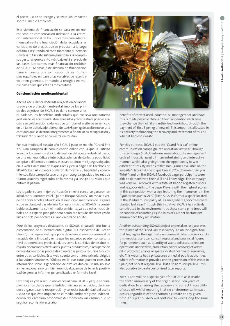
el aceite usado se recoge y se trata sin impactar sobre el medio ambiente.
Este sistema de financiación se basa en un me-canismo de compensación indexado a la cotiza-ción internacional de los lubricantes para adaptar mensualmente la financiación de la recogida a las variaciones de precios que se producen a lo largo del año, asegurando en todo momento el “servicio universal”. Así, este sistema garantiza a las empre-sas gestoras que cuanto más bajo esté el precio de las bases lubricantes, más financiación recibirán de SIGAUS. Además, este sistema de financiación tiene en cuenta una zonificación de los munici-pios españoles en base a las variables de lejanía y volumen generado, primando la recogida en mu-nicipios en los que ésta es más costosa.
Concienciación medioambiental
Además de su labor dedicada a la gestión del aceite usado y de protección ambiental, uno de los prin-cipales objetivos de SIGAUS es dar a conocer a los ciudadanos los beneficios ambientales que conlleva una correcta gestión de los aceites industriales usados y cómo esta es posible gra-cias a su colaboración cada vez que cambian el aceite de su vehículo en un taller autorizado, abonando 0,06 € por kg de aceite nuevo, una cantidad que se destina íntegramente a financiar su recuperación y tratamiento cuando se convierta en residuo.
Por este motivo, el pasado año SIGAUS puso en marcha “Grand Prix 2.0”, una campaña de comunicación online con la que la Entidad acercó a los usuarios el ciclo de gestión del aceite industrial usado de una manera lúdica e interactiva, además de darles la posibilidad de optar a diferentes premios. A través de cinco mini juegos alojados en la web ‘Haces más de lo que Crees’ y en la página de Facebook de SIGAUS, los participantes pudieron demostrar su habilidad y conoci-mientos. Esta campaña tuvo una gran acogida, gracias a los más de 10.000 usuarios registrados en la misma y a las 142.000 visitas que obtuvo la página.
Los jugadores con mejor puntuación en este concurso ganaron un árbol con su nombre en el “Quinto Bosque SIGAUS”, un espacio ver-de de 1.000 árboles situado en el municipio madrileño de Leganés y que se plantó el pasado año. Con esta iniciativa SIGAUS ha contri-buido activamente con el medio ambiente, ya que estos 1.000 ár-boles de la especie pino piñonero, serán capaces de absorber 27.180 kilos de CO2 por hectárea al año en estado adulto.
Otro de los proyectos destacados de SIGAUS el pasado año fue la presentación de su herramienta digital “El Observatorio del Aceite Usado”, una página web que pone de relieve el servicio universal de recogida de la Entidad y en la que los usuarios pueden consultar a nivel autonómico o provincial datos como la cantidad de residuo re-cogido, operaciones efectuadas, puntos productores, o recuperación del residuo en zonas protegidas o ubicadas junto a recursos hídricos, entre otras variables. Esta web cuenta con un área privada dirigida a las Administraciones Públicas en la que éstas pueden consultar información sobre la generación de este residuo en España, no sólo a nivel regional sino también municipal, además de tener la posibili-dad de generar informes personalizados en formato Excel.
Este 2017 es y va a ser un año especial para SIGAUS ya que se cum-plen 10 años desde que la Entidad iniciara su actividad, dedicán-dose a garantizar la recuperación y correcta trazabilidad del aceite usado sin que éste impacte en el medio ambiente y con indepen-dencia del escenario económico del momento, un camino que se seguirá recorriendo este año.
benefits of correct used industrial oil management and how this is made possible through their cooperation each time they change their oil at an authorised workshop, through the payment of €0.06 per kg of new oil. This amount is allocated in its entirety to financing the recovery and treatment of this oil when it becomes waste.
For this purpose, SIGAUS put the “Grand Prix 2.0” online communication campaign into operation last year. Through this campaign, SIGAUS informs users about the management cycle of industrial used oil in an entertaining and interactive manner, whilst also giving them the opportunity to win different prizes. By means of five mini-games available on the website “Haces más de lo que Crees” (“You do more than you Think”) and on the SIGAUS Facebook page, participants were able to demonstrate their skill and knowledge. This campaign was very well received, with a total of 10,000 registered users and 142,000 visits to the page. Players with the highest scores in this competition won a tree featuring their name on it in the “Quinto Bosque SIGAUS” (Fifth SIGAUS Forest), a space located in the Madrid municipality of Leganés, where 1,000 trees were planted last year. Through this initiative, SIGAUS has actively contributed to the environment, as these stone pine trees will be capable of absorbing 27,180 kilos of CO2 per hectare per annum once they are mature.
Another outstanding SIGAUS project undertaken last year was the launch of the “Used Oil Observatory” an online digital tool that highlights the organisation’s universal collection service. On this website, users can consult regional and provincial figures for parameters such as quantity of waste collected, collection operations undertaken, production points, recovery of waste oil in protected spaces or spaces located near water resources, etc. This website has a private area aimed at public authorities, where information is provided on the generation of this waste in Spain, not only at regional level but also at municipal level. It is also possible to create customised Excel reports.
2017 is and will be a special year for SIGAUS as it marks the tenth anniversary of the organisation. Ten years of dedication to ensuring the recovery and correct traceability of used oil, whilst ensuring that no environmental impact occurs, regardless of the economic climate at any given time. This year, SIGAUS will continue to work along the same lines.
A fo
nd
o: A
nál
isis
20
16
| I
n d
epth
: An
alys
is o
f 20
16
Futu
rEn
viro
| M
arzo
Mar
ch 2
017
www.futurenviro.es 39
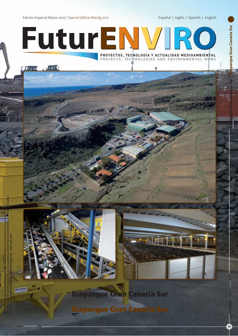
© P
rohi
bida
la re
prod
ucci
ón to
tal o
par
cial
por
cual
quie
r med
io si
n au
toriz
ació
n pr
evia
y e
scrit
a de
l edi
tor.
Th
e to
tal o
r par
tial r
epro
duct
ion
by a
ny m
eans
is p
rohi
bite
d w
ithou
t the
prio
r aut
horis
atio
n in
writ
ing
of th
e ed
itor.
Depó
sito
Lega
l | Le
gal D
epos
it: M
-“Se
p-M
arzo
17“1
5915
-201
3 I
SSN
: 234
0-26
28
Edición Especial Marzo 2017 | Special Edition March 2017 Español | Inglés | Spanish | English
ENVIROFuturENVIROPROYECTOS, TECNOLOGÍA Y ACTUALIDAD MEDIOAMBIENTALP RO J E C T S , TE C H N O L O G I E S A N D E N V I RO N M E N T A L N E W S
marron E pantone 1545 Cnaranja N pantone 1525 Callo V pantone 129 Cazul I pantone 291 Cazul R pantone 298 Cazul O pantone 2945 CFuture 100 negro
Ecoparque Gran Canaria Sur
Ecoparque Gran Canaria Sur
Eco
par
qu
e G
ran
Can
aria
Su
r |
Eco
par
qu
e G
ran
Can
aria
Su
rFu
turE
nvi
ro |
Mar
zo M
arch
201
7
www.futurenviro.es 41
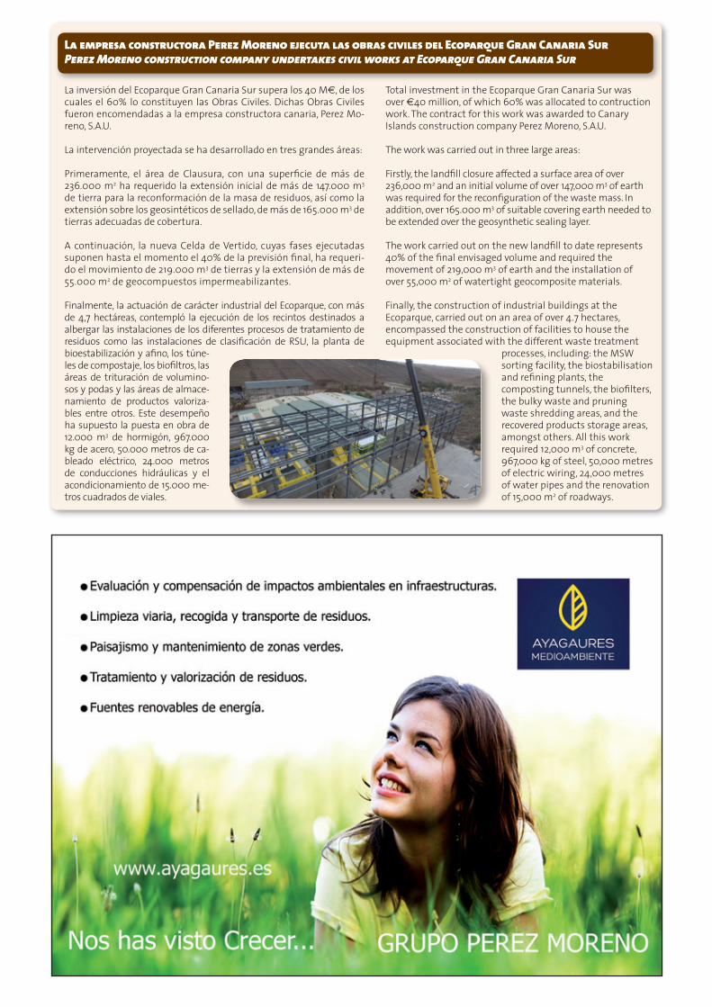
La empresa constructora Perez Moreno ejecuta las obras civiles del Ecoparque Gran Canaria Sur Perez Moreno construction company undertakes civil works at Ecoparque Gran Canaria Sur
La inversión del Ecoparque Gran Canaria Sur supera los 40 M€, de los cuales el 60% lo constituyen las Obras Civiles. Dichas Obras Civiles fueron encomendadas a la empresa constructora canaria, Perez Mo-reno, S.A.U.
La intervención proyectada se ha desarrollado en tres grandes áreas:
Primeramente, el área de Clausura, con una superficie de más de 236.000 m2 ha requerido la extensión inicial de más de 147.000 m3 de tierra para la reconformación de la masa de residuos, así como la extensión sobre los geosintéticos de sellado, de más de 165.000 m3 de tierras adecuadas de cobertura.
A continuación, la nueva Celda de Vertido, cuyas fases ejecutadas suponen hasta el momento el 40% de la previsión final, ha requeri-do el movi miento de 219.000 m3 de tierras y la extensión de más de 55.000 m2 de geocompuestos impermeabilizantes.
Finalmente, la actuación de carácter industrial del Ecoparque, con más de 4,7 hectáreas, contempló la ejecución de los recintos destinados a albergar las instalaciones de los diferentes procesos de tratamiento de residuos como las instalaciones de clasificación de RSU, la planta de bioestabilización y afino, los túne-les de compostaje, los biofiltros, las áreas de trituración de volumino-sos y podas y las áreas de almace-namiento de productos valoriza-bles entre otros. Este desempeño ha supuesto la puesta en obra de 12.000 m3 de hormigón, 967.000 kg de acero, 50.000 metros de ca-bleado eléctrico, 24.000 metros de conducciones hidráulicas y el acondicionamiento de 15.000 me-tros cuadrados de viales.
Total investment in the Ecoparque Gran Canaria Sur was over €40 million, of which 60% was allocated to contruction work. The contract for this work was awarded to Canary Islands construction company Perez Moreno, S.A.U.
The work was carried out in three large areas:
Firstly, the landfill closure affected a surface area of over 236,000 m2 and an initial volume of over 147,000 m3 of earth was required for the reconfiguration of the waste mass. In addition, over 165.000 m3 of suitable covering earth needed to be extended over the geosynthetic sealing layer.
The work carried out on the new landfill to date represents 40% of the final envisaged volume and required the movement of 219,000 m3 of earth and the installation of over 55,000 m2 of watertight geocomposite materials.
Finally, the construction of industrial buildings at the Ecoparque, carried out on an area of over 4.7 hectares, encompassed the construction of facilities to house the equipment associated with the different waste treatment
processes, including: the MSW sorting facility, the biostabilisation and refining plants, the composting tunnels, the biofilters, the bulky waste and pruning waste shredding areas, and the recovered products storage areas, amongst others. All this work required 12,000 m3 of concrete, 967,000 kg of steel, 50,000 metres of electric wiring, 24,000 metres of water pipes and the renovation of 15,000 m2 of roadways.
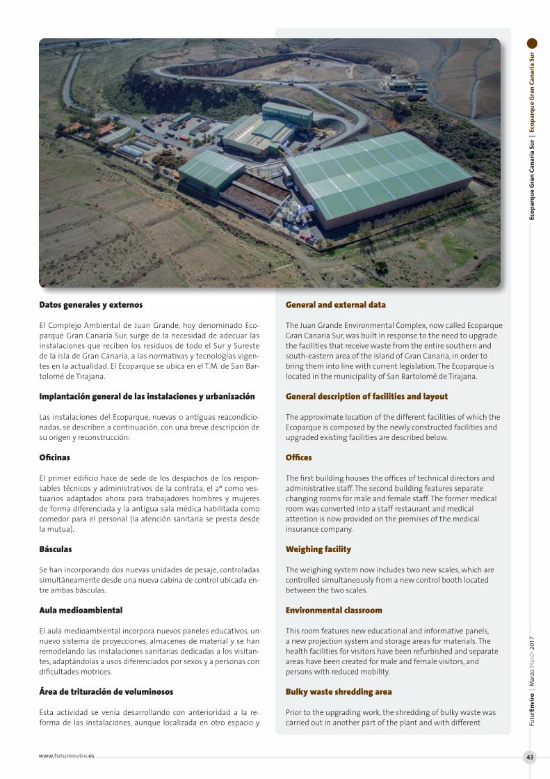
Eco
par
qu
e G
ran
Can
aria
Su
r |
Eco
par
qu
e G
ran
Can
aria
Su
rFu
turE
nvi
ro |
Mar
zo M
arch
201
7
www.futurenviro.es 43
Datos generales y externos
El Complejo Ambiental de Juan Grande, hoy denominado Eco-parque Gran Canaria Sur, surge de la necesidad de adecuar las instalaciones que reciben los residuos de todo el Sur y Sureste de la isla de Gran Canaria, a las normativas y tecnologías vigen-tes en la actualidad. El Ecoparque se ubica en el T.M. de San Bar-tolomé de Tirajana.
Implantación general de las instalaciones y urbanización
Las instalaciones del Ecoparque, nuevas o antiguas reacondicio-nadas, se describen a continuación, con una breve descripción de su origen y reconstrucción:
Oficinas
El primer edificio hace de sede de los despachos de los respon-sables técnicos y administrativos de la contrata, el 2º como ves-tuarios adaptados ahora para trabajadores hombres y mujeres de forma diferenciada y la antigua sala médica habilitada como comedor para el personal (la atención sanitaria se presta desde la mutua).
Básculas
Se han incorporando dos nuevas unidades de pesaje, controladas simultáneamente desde una nueva cabina de control ubicada en-tre ambas básculas.
Aula medioambiental
El aula medioambiental incorpora nuevos paneles educativos, un nuevo sistema de proyecciones, almacenes de material y se han remodelando las instalaciones sanitarias dedicadas a los visitan-tes, adaptándolas a usos diferenciados por sexos y a personas con dificultades motrices.
Área de trituración de voluminosos
Esta actividad se venía desarrollando con anterioridad a la re-forma de las instalaciones, aunque localizada en otro espacio y
General and external data
The Juan Grande Environmental Complex, now called Ecoparque Gran Canaria Sur, was built in response to the need to upgrade the facilities that receive waste from the entire southern and south-eastern area of the island of Gran Canaria, in order to bring them into line with current legislation. The Ecoparque is located in the municipality of San Bartolomé de Tirajana.
General description of facilities and layout
The approximate location of the different facilities of which the Ecoparque is composed by the newly constructed facilities and upgraded existing facilities are described below.
Offices
The first building houses the offices of technical directors and administrative staff. The second building features separate changing rooms for male and female staff. The former medical room was converted into a staff restaurant and medical attention is now provided on the premises of the medical insurance company.
Weighing facility
The weighing system now includes two new scales, which are controlled simultaneously from a new control booth located between the two scales.
Environmental classroom
This room features new educational and informative panels, a new projection system and storage areas for materials. The health facilities for visitors have been refurbished and separate areas have been created for male and female visitors, and persons with reduced mobility.
Bulky waste shredding area
Prior to the upgrading work, the shredding of bulky waste was carried out in another part of the plant and with different
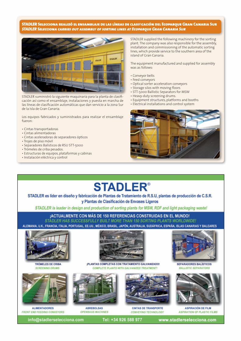
STADLER Selecciona realizó el ensamblaje de las líneas de clasificación del Ecoparque Gran Canaria Sur STADLER Selecciona carries out assembly of sorting lines at Ecoparque Gran Canaria Sur
STADLER suministró la siguiente maquinaria para la planta de clasifi-cación así como el ensamblaje, instalaciones y puesta en marcha de las líneas de clasificación automáticas que dan servicio a la zona Sur de la Isla de Gran Canaria.
Los equipos fabricados y suministrados para realizar el ensamblaje fueron:
• Cintas transportadoras• Cintas alimentadoras• Cintas aceleradoras de separadores ópticos• Trojes de piso móvil• Separadores Balísticos de RSU STT-5000• Trómeles de criba pesados.• Estructuras de equipos, plataformas y cabinas• Instalación eléctrica y control
STADLER supplied the following machinery for the sorting plant. The company was also responsible for the assembly, installation and commissioning of the automatic sorting lines, which provide service to the southern area of the island of Gran Canaria.
The equipment manufactured and supplied for assembly was as follows:
• Conveyor belts• Feed conveyors• Optical sorter acceleration conveyors• Storage silos with moving floors• STT-5000 Ballistic Separators for MSW• Heavy-duty screening drums.• Equipment structures, platforms and booths• Electrical installations and control system
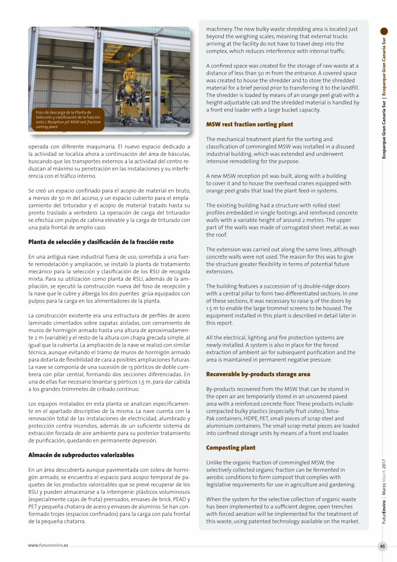
operada con diferente maquinaria. El nuevo espacio dedicado a la actividad se localiza ahora a continuación del área de básculas, buscando que los transportes externos a la actividad del centro re-duzcan al máximo su penetración en las instalaciones y su interfe-rencia con el tráfico interno.
Se creó un espacio confinado para el acopio de material en bruto, a menos de 50 m del acceso, y un espacio cubierto para el empla-zamiento del triturador y el acopio de material tratado hasta su pronto traslado a vertedero. La operación de carga del triturador se efectúa con pulpo de cabina elevable y la carga de triturado con una pala frontal de amplio cazo.
Planta de selección y clasificación de la fracción resto
En una antigua nave industrial fuera de uso, sometida a una fuer-te remodelación y ampliación, se instaló la planta de tratamiento mecánico para la selección y clasificación de los RSU de recogida mixta. Para su utilización como planta de RSU, además de la am-pliación, se ejecutó la construcción nueva del foso de recepción y la nave que le cubre y alberga los dos puentes‐grúa equipados con pulpos para la carga en los alimentadores de la planta.
La construcción existente era una estructura de perfiles de acero laminado cimentados sobre zapatas aisladas, con cerramiento de muros de hormigón armado hasta una altura de aproximadamen-te 2 m (variable) y el resto de la altura con chapa grecada simple, al igual que la cubierta. La ampliación de la nave se realizó con similar técnica, aunque evitando el tramo de muros de hormigón armado para dotarla de flexibilidad de cara a posibles ampliaciones futuras. La nave se componía de una sucesión de 13 pórticos de doble cum-brera con pilar central, formando dos secciones diferenciadas. En una de ellas fue necesario levantar 9 pórticos 1,5 m, para dar cabida a los grandes trómmeles de cribado continuo.
Los equipos instalados en esta planta se analizan específicamen-te en el apartado descriptivo de la misma. La nave cuenta con la renovación total de las instalaciones de electricidad, alumbrado y protección contra incendios, además de un suficiente sistema de extracción forzada de aire ambiente para su posterior tratamiento de purificación, quedando en permanente depresión.
Almacén de subproductos valorizables
En un área descubierta aunque pavimentada con solera de hormi-gón armado, se encuentra el espacio para acopio temporal de pa-quetes de los productos valorizables que se prevé recuperar de los RSU y pueden almacenarse a la intemperie: plásticos voluminosos (especialmente cajas de fruta) prensados, envases de brick, PEAD y PET y pequeña chatarra de acero y envases de aluminio. Se han con-formado trojes (espacios confinados) para la carga con pala frontal de la pequeña chatarra.
machinery. The new bulky waste shredding area is located just beyond the weighing scales, meaning that external trucks arriving at the facility do not have to travel deep into the complex, which reduces interference with internal traffic.
A confined space was created for the storage of raw waste at a distance of less than 50 m from the entrance. A covered space was created to house the shredder and to store the shredded material for a brief period prior to transferring it to the landfill. The shredder is loaded by means of an orange peel grab with a height-adjustable cab and the shredded material is handled by a front end loader with a large bucket capacity.
MSW rest fraction sorting plant
The mechanical treatment plant for the sorting and classification of commingled MSW was installed in a disused industrial building, which was extended and underwent intensive remodelling for the purpose.
A new MSW reception pit was built, along with a building to cover it and to house the overhead cranes equipped with orange peel grabs that load the plant feed-in systems.
The existing building had a structure with rolled steel profiles embedded in single footings and reinforced concrete walls with a variable height of around 2 metres. The upper part of the walls was made of corrugated sheet metal, as was the roof.
The extension was carried out along the same lines, although concrete walls were not used. The reason for this was to give the structure greater flexibility in terms of potential future extensions.
The building features a succession of 13 double-ridge doors with a central pillar to form two differentiated sections. In one of these sections, it was necessary to raise 9 of the doors by 1.5 m to enable the large trommel screens to be housed. The equipment installed in this plant is described in detail later in this report.
All the electrical, lighting and fire protection systems are newly installed. A system is also in place for the forced extraction of ambient air for subsequent purification and the area is maintained in permanent negative pressure.
Recoverable by-products storage area
By-products recovered from the MSW that can be stored in the open air are temporarily stored in an uncovered paved area with a reinforced concrete floor. These products include: compacted bulky plastics (especially fruit crates), Tetra-Pak containers, HDPE, PET, small pieces of scrap steel and aluminium containers. The small scrap metal pieces are loaded into confined storage units by means of a front end loader.
Composting plant
Unlike the organic fraction of commingled MSW, the selectively collected organic fraction can be fermented in aerobic conditions to form compost that complies with legislative requirements for use in agriculture and gardening.
When the system for the selective collection of organic waste has been implemented to a sufficient degree, open trenches with forced aeration will be implemented for the treatment of this waste, using patented technology available on the market.
Eco
par
qu
e G
ran
Can
aria
Su
r |
Eco
par
qu
e G
ran
Can
aria
Su
rFu
turE
nvi
ro |
Mar
zo M
arch
201
7
www.futurenviro.es 45
Foso de descarga de la Planta de Selección y clasificación de la fracción resto | Reception pit MSW rest fraction sorting plant
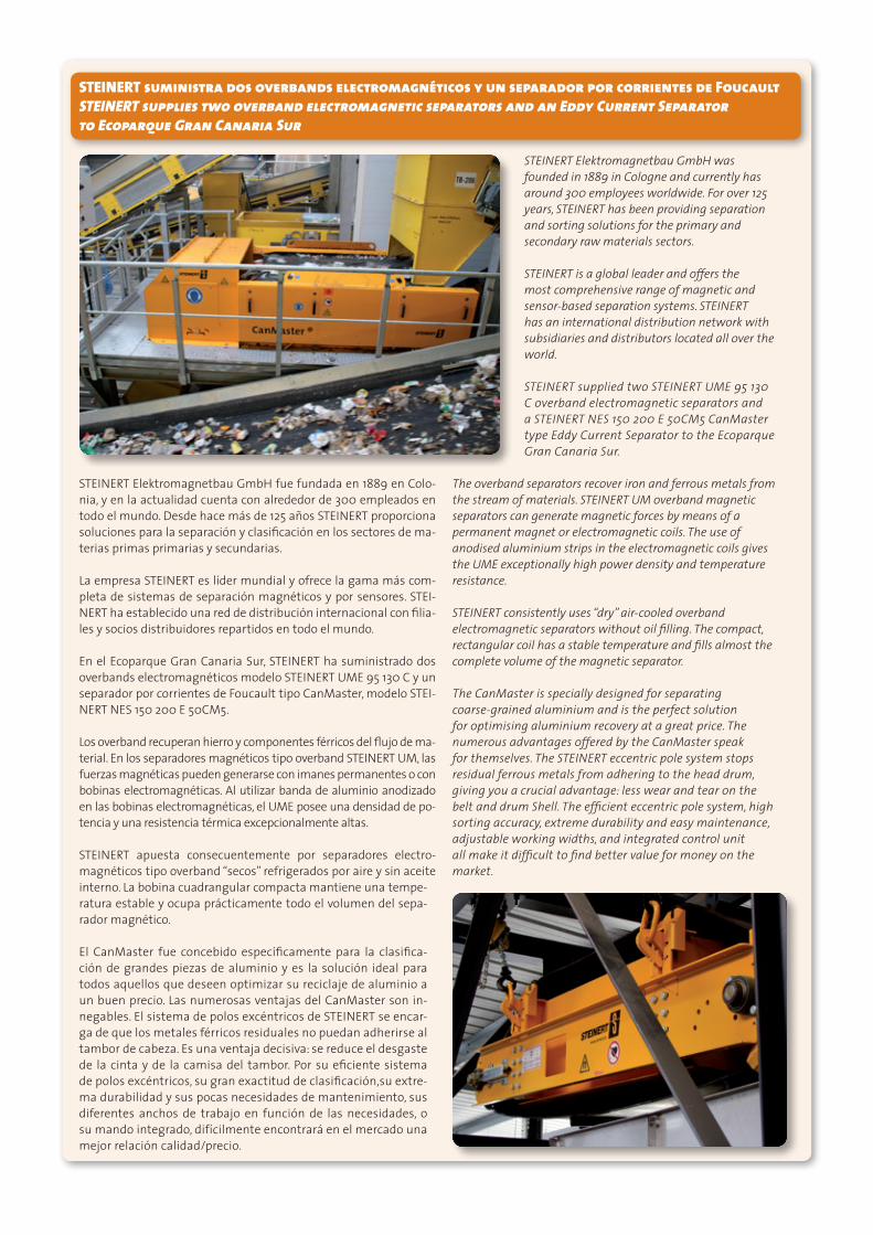
STEINERT suministra dos overbands electromagnéticos y un separador por corrientes de Foucault STEINERT supplies two overband electromagnetic separators and an Eddy Current Separator to Ecoparque Gran Canaria Sur
STEINERT Elektromagnetbau GmbH fue fundada en 1889 en Colo-nia, y en la actualidad cuenta con alrededor de 300 empleados en todo el mundo. Desde hace más de 125 años STEINERT proporciona soluciones para la separación y clasificación en los sectores de ma-terias primas primarias y secundarias.
La empresa STEINERT es líder mundial y ofrece la gama más com-pleta de sistemas de separación magnéticos y por sensores. STEI-NERT ha establecido una red de distribución internacional con filia-les y socios distribuidores repartidos en todo el mundo.
En el Ecoparque Gran Canaria Sur, STEINERT ha suministrado dos overbands electromagnéticos modelo STEINERT UME 95 130 C y un separador por corrientes de Foucault tipo CanMaster, modelo STEI-NERT NES 150 200 E 50CM5.
Los overband recuperan hierro y componentes férricos del flujo de ma-terial. En los separadores magnéticos tipo overband STEINERT UM, las fuerzas magnéticas pueden generarse con imanes permanentes o con bobinas electromagnéticas. Al utilizar banda de aluminio anodizado en las bobinas electromagnéticas, el UME posee una densidad de po-tencia y una resistencia térmica excepcionalmente altas.
STEINERT apuesta consecuentemente por separadores electro-magnéticos tipo overband “secos” refrigerados por aire y sin aceite interno. La bobina cuadrangular compacta mantiene una tempe-ratura estable y ocupa prácticamente todo el volumen del sepa-rador magnético.
El CanMaster fue concebido específicamente para la clasifica-ción de grandes piezas de aluminio y es la solución ideal para todos aquellos que deseen optimizar su reciclaje de aluminio a un buen precio. Las numerosas ventajas del CanMaster son in-negables. El sistema de polos excéntricos de STEINERT se encar-ga de que los metales férricos residuales no puedan adherirse al tambor de cabeza. Es una ventaja decisiva: se reduce el desgaste de la cinta y de la camisa del tambor. Por su eficiente sistema de polos excéntricos, su gran exactitud de clasificación,su extre-ma durabilidad y sus pocas necesidades de mantenimiento, sus diferentes anchos de trabajo en función de las necesidades, o su mando integrado, difícilmente encontrará en el mercado una mejor relación calidad/precio.
STEINERT Elektromagnetbau GmbH was founded in 1889 in Cologne and currently has around 300 employees worldwide. For over 125 years, STEINERT has been providing separation and sorting solutions for the primary and secondary raw materials sectors.
STEINERT is a global leader and offers the most comprehensive range of magnetic and sensor-based separation systems. STEINERT has an international distribution network with subsidiaries and distributors located all over the world.
STEINERT supplied two STEINERT UME 95 130 C overband electromagnetic separators and a STEINERT NES 150 200 E 50CM5 CanMaster type Eddy Current Separator to the Ecoparque Gran Canaria Sur.
The overband separators recover iron and ferrous metals from the stream of materials. STEINERT UM overband magnetic separators can generate magnetic forces by means of a permanent magnet or electromagnetic coils. The use of anodised aluminium strips in the electromagnetic coils gives the UME exceptionally high power density and temperature resistance. STEINERT consistently uses “dry” air-cooled overband electromagnetic separators without oil filling. The compact, rectangular coil has a stable temperature and fills almost the complete volume of the magnetic separator.
The CanMaster is specially designed for separating coarse-grained aluminium and is the perfect solution for optimising aluminium recovery at a great price. The numerous advantages offered by the CanMaster speak for themselves. The STEINERT eccentric pole system stops residual ferrous metals from adhering to the head drum, giving you a crucial advantage: less wear and tear on the belt and drum Shell. The efficient eccentric pole system, high sorting accuracy, extreme durability and easy maintenance, adjustable working widths, and integrated control unit all make it difficult to find better value for money on the market.
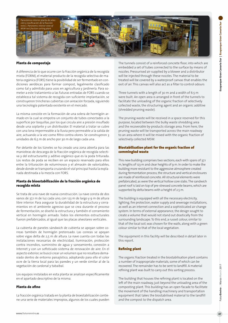
Planta de compostaje
A diferencia de lo que ocurre con la fracción orgánica de la recogida mixta (FORM), el material producto de la recogida selectiva de ma-teria orgánica (FORS) tiene la posibilidad de ser fermentado en con-diciones aeróbicas para formar compost, legalmente clasificado como tal y admitido para usos en agricultura y jardinería. Para so-meter a este tratamiento a las futuras entradas de FORS cuando se establezca tal sistema de recogida con suficiente implantación, se construyeron trincheras cubiertas con aireación forzada, siguiendo una tecnología patentada existente en el mercado.
La misma consiste en la formación de una solera de hormigón ar-mado en la cual se empotra un conjunto de tubos conectados a la superficie por boquillas, por los que circula aire a presión insuflado desde una soplante y un distribuidor. El material a tratar se cubre con una lona impermeable a la lluvia pero permeable a la salida de aire, actuando a la vez como filtro contra olores. Se construyeron 3 unidades de 6,5 m de ancho por 30 m de largo cada una.
Por delante de los túneles se ha creado una zona abierta para las maniobras de descarga de la fracción orgánica de recogida selecti-va y del estructurante y aditivo orgánico que es la poda triturada. Los restos de poda se reciben en un espacio reservado para ellos entre la trituración de voluminosos y el almacén de valorizables, desde donde se transporta cruzando el vial principal hasta la expla-nada destinada a la mezcla con FORS.
Planta de bioestabilización de la fracción orgánica de recogida mixta
Se trata de una nave de nueva construcción. La nave consta de dos vanos de 37,1 m de luz cada uno, con 123 m de largo y 9 m de altura libre interior. Para asegurar la durabilidad de la estructura y cerra-mientos en el ambiente agresivo que se crea durante el proceso de fermentación, se diseñó la estructura y también el cerramiento vertical en hormigón armado. Todos los elementos estructurales fueron prefabricados, al igual que las placas alveolares verticales.
La cubierta de paneles sándwich de cubierta se apoyan sobre co-rreas también de hormigón pretensado. Las correas se apoyan sobre vigas delta de 2,5 m de altura. La nave cuenta con todas las instalaciones necesarias de electricidad, iluminación, protección contra incendios, suministro de agua y saneamiento, conexión a Internet y con un sofisticado sistema de renovación de aire. En el aspecto exterior, se buscó crear un volumen que no resaltara dema-siado dentro de entorno paisajístico, adoptando para ello el color ocre de la tierra local para las paredes y un verde similar al de la vegetación de cardonal y tabaibal.
Los equipos instalados en esta planta se analizan específicamen te en el apartado descriptivo de la misma.
Planta de afino
La fracción orgánica tratada en la planta de bioestabilización contie-ne una serie de materiales impropios, algunos de los cuales pueden
The tunnels consist of a reinforced concrete floor, into which are embedded a set of tubes connected to the surface by means of nozzles. Pressurised air supplied by a blower and a distributor will be injected through these nozzles. The material to be treated will be covered by a waterproof canvas that enables the exit of air. This canvas will also act as a filter to control odours
Three tunnels with a length of 30 m and a width of 6.5 m were built. An open area is arranged in front of the tunnels to facilitate the unloading of the organic fraction of selectively collected waste, the structuring agent and an organic additive (shredded pruning waste).
The pruning waste will be received in a space reserved for this purpose, located between the bulky waste shredding area and the recoverable by-products storage area. From here, the pruning waste will be transported across the main roadway to an area where it will be mixed with the organic fraction of selectively collected MSW.
Biostabilisation plant for the organic fraction of commingled waste
This new building comprises two sections, each with spans of 37.1 m, lengths of 123 m and clear heights of 9 m. In order to make the building more resistant to the aggressive atmosphere created during fermentation process, the structure and vertical enclosures are made of reinforced concrete. All structural elements were prefabricated, as were the vertical hollow core slabs. The sandwich panel roof is laid on top of pre-stressed concrete beams, which are supported by delta beams with a height of 2.5 m.
The building is equipped with all the necessary electricity, lighting, fire protection, water supply and sewerage installations, as well as an internet connection and a sophisticated air change system. In terms of external appearance, the design sought to create a volume that would not stand out drastically from the surrounding landscape. To this end, a russet colour, similar to that of the local soil, was chosen for the walls, along with a green colour similar to that of the local vegetation.
The equipment in this facility will be described in detail later in this report.
Refining plant
The organic fraction treated in the biostabilisation plant contains a number of inappropriate materials, some of which can be recovered. The remainder has to be sent to landfill. A material refining plant was built to carry out this sorting process.
The building that houses the refining plant is located on the left of the main roadway, just beyond the unloading area of the composting plant. This building has an open facade to facilitate the movement of the handling machinery and transportation equipment that takes the biostabilised material to the landfill and the compost to the dispatch area.
Eco
par
qu
e G
ran
Can
aria
Su
r |
Eco
par
qu
e G
ran
Can
aria
Su
rFu
turE
nvi
ro |
Mar
zo M
arch
201
7
www.futurenviro.es 47
Panorámica interior planta de selec-ción y clasificación de la fracción resto. | Panoramic interior view of MSW rest fraction sorting plant
Traco Iberia suministra dos robustos alimentadores primarios modelo Panzer Traco Iberia supplies two robust Panzer primary feeders
Traco Iberia S.L. suministra dos unidades de alimentadores primarios Panzer para 40 ton/h en la Planta de Juan Grande, Isla de Gran Cana-ria para Ferrovial Servicios.
En el curso del pasado año 2016, se ha incorporado a Traco Iberia el Know-How de ingeniería y fabricación de plantas de tratamientos de RSU para dar aún un mejor servicio a sus clientes.
Fruto de esta incorporación es el suministro en esta planta de Juan Grande de las dos unidades de los robustos alimentadores primarios modelo Panzer.
Numerosas referencias avalan el comportamiento de estos alimenta-dores con R.S.U., demostrando su gran robustez, fiabilidad y fácil man-tenimiento, así como su estanqueidad a la hora de gestionar residuos muy conflictivos
El fondo metálico esta forrado de chapa de acero, fácilmente recam-biable, sobre un robusto bastidor capaz de soportar grandes esfuer-zos que dota al conjunto de una gran rigidez y estanqueidad, sus dos características fundamentales.
La simplicidad de su diseño permi-te a la máquina una ejecución es-tanca, incorporando un sistema de reenvió de cola que no permite re-siduos en el retorno inferior, ya que al pasar las racletas incorporan de nuevo al ramal superior de trans-porte cualquier elemento extraño.
Traco Iberia S.L. supplied two Panzer primary feeding units with a capacity of 40 ton/h to the Ecoparque Gran Canaria Sur for Ferrovial Servicios.
During 2016, Traco Iberia further developed its expertise in the field of engineering and manufacture of MSW treatment plants, in order to improve the service offered to clients.
This has resulted in the supply of two robust Panzer primary feeding units to the Ecoparque Gran Canaria Sur.
These feeders have numerous references in MSW treatment plants, where they have demonstrated their great robustness, reliability, easy maintenance and watertightness in the handling of very difficult waste.
The metal floor is lined with easy-to-replace steel plating and is supported by a robust frame capable of resisting great stresses, giving the unit great rigidity and watertightness, its two main features.
The simple, enclosed design enables easy operation. The PANZER features a “tail-return” system which does not permit the accumulation of waste on the lower return conveyer because, as the poling plates pass, they drag the waste back to the top conveyer, enabling it to be fed into the production line once again.
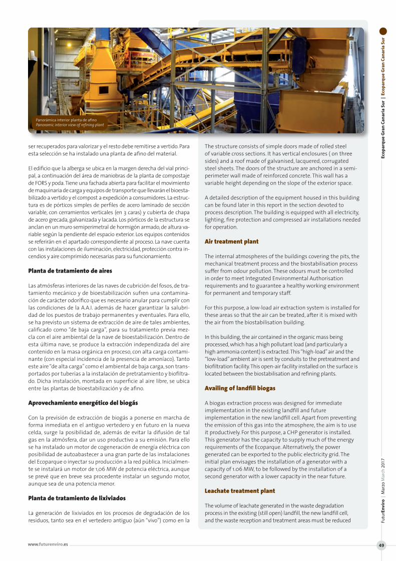
ser recuperados para valorizar y el resto debe remitirse a vertido. Para esta selección se ha instalado una planta de afino del material.
El edificio que la alberga se ubica en la margen derecha del vial princi-pal, a continuación del área de maniobras de la planta de compostaje de FORS y poda. Tiene una fachada abierta para facilitar el movimiento de maquinaria de carga y equipos de transporte que llevarán el bioesta-bilizado a vertido y el compost a expedición a consumidores. La estruc-tura es de pórticos simples de perfiles de acero laminado de sección variable, con cerramientos verticales (en 3 caras) y cubierta de chapa de acero grecada, galvanizada y lacada. Los pórticos de la estructura se anclan en un muro semiperimetral de hormigón armado, de altura va-riable según la pendiente del espacio exterior. Los equipos contenidos se referirán en el apartado correspondiente al proceso. La nave cuenta con las instalaciones de iluminación, electricidad, protección contra in-cendios y aire comprimido necesarias para su funcionamiento.
Planta de tratamiento de aires
Las atmósferas interiores de las naves de cubrición del fosos, de tra-tamiento mecánico y de bioestabilización sufren una contamina-ción de carácter odorífico que es necesario anular para cumplir con las condiciones de la A.A.I. además de hacer garantizar la salubri-dad de los puestos de trabajo permanentes y eventuales. Para ello, se ha previsto un sistema de extracción de aire de tales ambientes, calificado como “de baja carga”, para su tratamiento previa mez-cla con el aire ambiental de la nave de bioestabilización. Dentro de esta última nave, se produce la extracción independizada del aire contenido en la masa orgánica en proceso, con alta carga contami-nante (con especial incidencia de la presencia de amoníaco). Tanto este aire “de alta carga” como el ambiental de baja carga, son trans-portados por tuberías a la instalación de pretratamiento y biofiltra-do. Dicha instalación, montada en superficie al aire libre, se ubica entre las plantas de bioestabilización y de afino.
Aprovechamiento energético del biogás
Con la previsión de extracción de biogás a ponerse en marcha de forma inmediata en el antiguo vertedero y en futuro en la nueva celda, surge la posibilidad de, además de evitar la difusión de tal gas en la atmósfera, dar un uso productivo a su emisión. Para ello se ha instalado un motor de cogeneración de energía eléctrica con posibilidad de autoabastecer a una gran parte de las instalaciones del Ecoparque o inyectar su producción a la red pública. Inicialmen-te se instalará un motor de 1,06 MW de potencia eléctrica, aunque se prevé que en breve sea procedente instalar un segundo motor, aunque sea de una potencia menor.
Planta de tratamiento de lixiviados
La generación de lixiviados en los procesos de degradación de los residuos, tanto sea en el vertedero antiguo (aún “vivo”) como en la
The structure consists of simple doors made of rolled steel of variable cross sections. It has vertical enclosures ( on three sides) and a roof made of galvanised, lacquered, corrugated steel sheets. The doors of the structure are anchored in a semi-perimeter wall made of reinforced concrete. This wall has a variable height depending on the slope of the exterior space.
A detailed description of the equipment housed in this building can be found later in this report in the section devoted to process description. The building is equipped with all electricity, lighting, fire protection and compressed air installations needed for operation.
Air treatment plant
The internal atmospheres of the buildings covering the pits, the mechanical treatment process and the biostabilisation process suffer from odour pollution. These odours must be controlled in order to meet Integrated Environmental Authorisation requirements and to guarantee a healthy working environment for permanent and temporary staff.
For this purpose, a low-load air extraction system is installed for these areas so that the air can be treated, after it is mixed with the air from the biostabilisation building.
In this building, the air contained in the organic mass being processed, which has a high pollutant load (and particularly a high ammonia content) is extracted. This “high-load” air and the “low-load” ambient air is sent by conduits to the pretreatment and biofiltration facility. This open-air facility installed on the surface is located between the biostabilisation and refining plants.
Availing of landfill biogas
A biogas extraction process was designed for immediate implementation in the existing landfill and future implementation in the new landfill cell. Apart from preventing the emission of this gas into the atmosphere, the aim is to use it productively. For this purpose, a CHP generator is installed. This generator has the capacity to supply much of the energy requirements of the Ecoparque. Alternatively, the power generated can be exported to the public electricity grid. The initial plan envisages the installation of a generator with a capacity of 1.06 MW, to be followed by the installation of a second generator with a lower capacity in the near future.
Leachate treatment plant
The volume of leachate generated in the waste degradation process in the existing (still open) landfill, the new landfill cell, and the waste reception and treatment areas must be reduced
Eco
par
qu
e G
ran
Can
aria
Su
r |
Eco
par
qu
e G
ran
Can
aria
Su
rFu
turE
nvi
ro |
Mar
zo M
arch
201
7
www.futurenviro.es 49
Panorámica interior planta de afino Panoramic interior view of refining plant
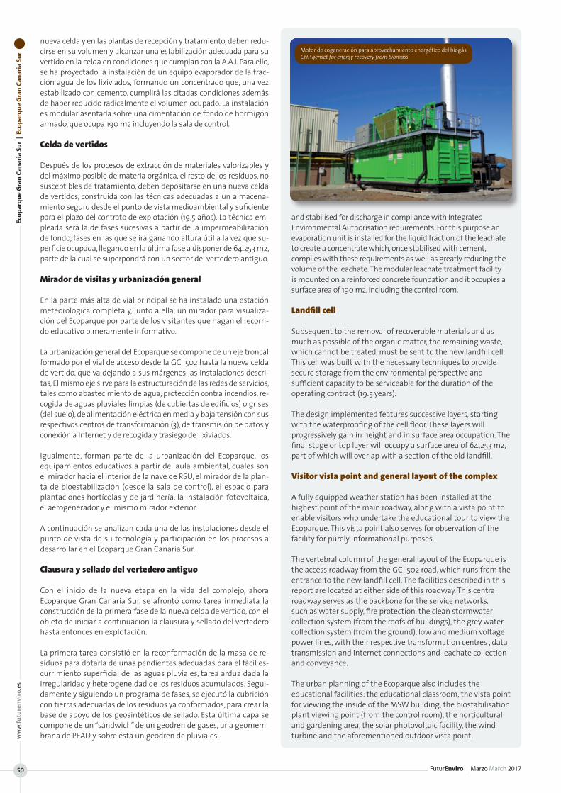
Eco
par
qu
e G
ran
Can
aria
Su
r |
Eco
par
qu
e G
ran
Can
aria
Su
r
FuturEnviro | Marzo March 2017
ww
w.fu
ture
nvi
ro.e
s
50
nueva celda y en las plantas de recepción y tratamiento, deben redu-cirse en su volumen y alcanzar una estabilización adecuada para su vertido en la celda en condiciones que cumplan con la A.A.I. Para ello, se ha proyectado la instalación de un equipo evaporador de la frac-ción agua de los lixiviados, formando un concentrado que, una vez estabilizado con cemento, cumplirá las citadas condiciones además de haber reducido radicalmente el volumen ocupado. La instalación es modular asentada sobre una cimentación de fondo de hormigón armado, que ocupa 190 m2 incluyendo la sala de control.
Celda de vertidos
Después de los procesos de extracción de materiales valorizables y del máximo posible de materia orgánica, el resto de los residuos, no susceptibles de tratamiento, deben depositarse en una nueva celda de vertidos, construida con las técnicas adecuadas a un almacena-miento seguro desde el punto de vista medioambiental y suficiente para el plazo del contrato de explotación (19,5 años). La técnica em-pleada será la de fases sucesivas a partir de la impermeabilización de fondo, fases en las que se irá ganando altura útil a la vez que su-perficie ocupada, llegando en la última fase a disponer de 64.253 m2, parte de la cual se superpondrá con un sector del vertedero antiguo.
Mirador de visitas y urbanización general
En la parte más alta de vial principal se ha instalado una estación meteorológica completa y, junto a ella, un mirador para visualiza-ción del Ecoparque por parte de los visitantes que hagan el recorri-do educativo o meramente informativo.
La urbanización general del Ecoparque se compone de un eje troncal formado por el vial de acceso desde la GC‐502 hasta la nueva celda de vertido, que va dejando a sus márgenes las instalaciones descri-tas, El mismo eje sirve para la estructuración de las redes de servicios, tales como abastecimiento de agua, protección contra incendios, re-cogida de aguas pluviales limpias (de cubiertas de edificios) o grises (del suelo), de alimentación eléctrica en media y baja tensión con sus respectivos centros de transformación (3), de transmisión de datos y conexión a Internet y de recogida y trasiego de lixiviados.
Igualmente, forman parte de la urbanización del Ecoparque, los equipamientos educativos a partir del aula ambiental, cuales son el mirador hacia el interior de la nave de RSU, el mirador de la plan-ta de bioestabilización (desde la sala de control), el espacio para plantaciones hortícolas y de jardinería, la instalación fotovoltaica, el aerogenerador y el mismo mirador exterior.
A continuación se analizan cada una de las instalaciones desde el punto de vista de su tecnología y participación en los procesos a desarrollar en el Ecoparque Gran Canaria Sur.
Clausura y sellado del vertedero antiguo
Con el inicio de la nueva etapa en la vida del complejo, ahora Ecoparque Gran Canaria Sur, se afrontó como tarea inmediata la construcción de la primera fase de la nueva celda de vertido, con el objeto de iniciar a continuación la clausura y sellado del vertedero hasta entonces en explotación.
La primera tarea consistió en la reconformación de la masa de re-siduos para dotarla de unas pendientes adecuadas para el fácil es-currimiento superficial de las aguas pluviales, tarea ardua dada la irregularidad y heterogeneidad de los residuos acumulados. Segui-damente y siguiendo un programa de fases, se ejecutó la cubrición con tierras adecuadas de los residuos ya conformados, para crear la base de apoyo de los geosintéticos de sellado. Esta última capa se compone de un “sándwich” de un geodren de gases, una geomem-brana de PEAD y sobre ésta un geodren de pluviales.
and stabilised for discharge in compliance with Integrated Environmental Authorisation requirements. For this purpose an evaporation unit is installed for the liquid fraction of the leachate to create a concentrate which, once stabilised with cement, complies with these requirements as well as greatly reducing the volume of the leachate. The modular leachate treatment facility is mounted on a reinforced concrete foundation and it occupies a surface area of 190 m2, including the control room.
Landfill cell
Subsequent to the removal of recoverable materials and as much as possible of the organic matter, the remaining waste, which cannot be treated, must be sent to the new landfill cell. This cell was built with the necessary techniques to provide secure storage from the environmental perspective and sufficient capacity to be serviceable for the duration of the operating contract (19.5 years).
The design implemented features successive layers, starting with the waterproofing of the cell floor. These layers will progressively gain in height and in surface area occupation. The final stage or top layer will occupy a surface area of 64,253 m2, part of which will overlap with a section of the old landfill.
Visitor vista point and general layout of the complex
A fully equipped weather station has been installed at the highest point of the main roadway, along with a vista point to enable visitors who undertake the educational tour to view the Ecoparque. This vista point also serves for observation of the facility for purely informational purposes.
The vertebral column of the general layout of the Ecoparque is the access roadway from the GC‐502 road, which runs from the entrance to the new landfill cell. The facilities described in this report are located at either side of this roadway. This central roadway serves as the backbone for the service networks, such as water supply, fire protection, the clean stormwater collection system (from the roofs of buildings), the grey water collection system (from the ground), low and medium voltage power lines, with their respective transformation centres , data transmission and internet connections and leachate collection and conveyance.
The urban planning of the Ecoparque also includes the educational facilities: the educational classroom, the vista point for viewing the inside of the MSW building, the biostabilisation plant viewing point (from the control room), the horticultural and gardening area, the solar photovoltaic facility, the wind turbine and the aforementioned outdoor vista point.
Motor de cogeneración para aprovechamiento energético del biogás CHP genset for energy recovery from biomass
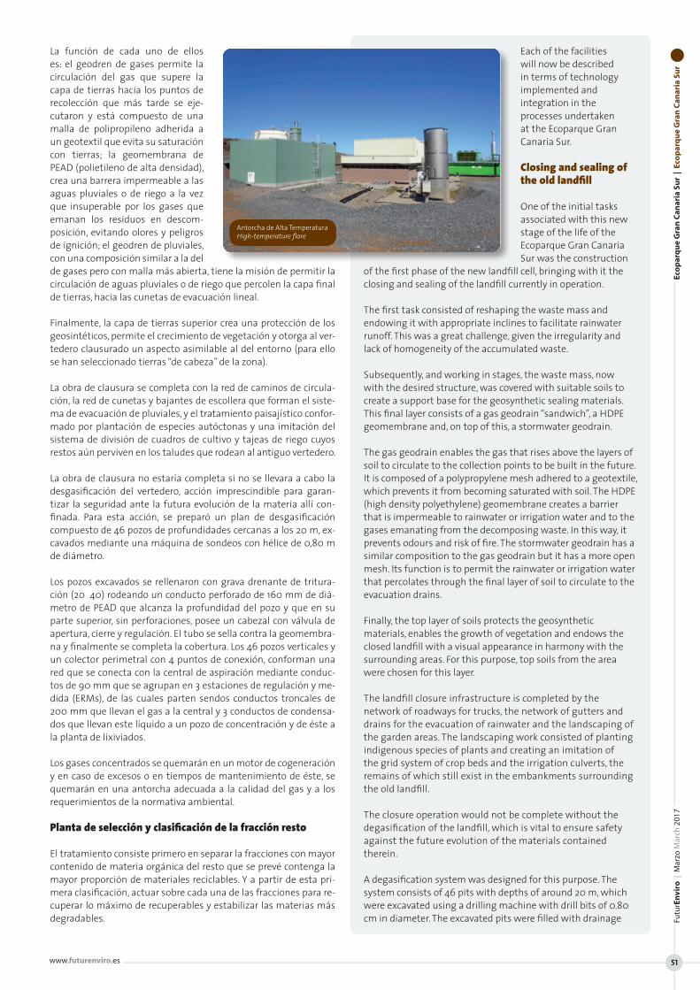
La función de cada uno de ellos es: el geodren de gases permite la circulación del gas que supere la capa de tierras hacia los puntos de recolección que más tarde se eje-cutaron y está compuesto de una malla de polipropileno adherida a un geotextil que evita su saturación con tierras; la geomembrana de PEAD (polietileno de alta densidad), crea una barrera impermeable a las aguas pluviales o de riego a la vez que insuperable por los gases que emanan los residuos en descom-posición, evitando olores y peligros de ignición; el geodren de pluviales, con una composición similar a la del de gases pero con malla más abierta, tiene la misión de permitir la circulación de aguas pluviales o de riego que percolen la capa final de tierras, hacia las cunetas de evacuación lineal.
Finalmente, la capa de tierras superior crea una protección de los geosintéticos, permite el crecimiento de vegetación y otorga al ver-tedero clausurado un aspecto asimilable al del entorno (para ello se han seleccionado tierras “de cabeza” de la zona).
La obra de clausura se completa con la red de caminos de circula-ción, la red de cunetas y bajantes de escollera que forman el siste-ma de evacuación de pluviales, y el tratamiento paisajístico confor-mado por plantación de especies autóctonas y una imitación del sistema de división de cuadros de cultivo y tajeas de riego cuyos restos aún perviven en los taludes que rodean al antiguo vertedero.
La obra de clausura no estaría completa si no se llevara a cabo la desgasificación del vertedero, acción imprescindible para garan-tizar la seguridad ante la futura evolución de la materia allí con-finada. Para esta acción, se preparó un plan de desgasificación compuesto de 46 pozos de profundidades cercanas a los 20 m, ex-cavados mediante una máquina de sondeos con hélice de 0,80 m de diámetro.
Los pozos excavados se rellenaron con grava drenante de tritura-ción (20‐40) rodeando un conducto perforado de 160 mm de diá-metro de PEAD que alcanza la profundidad del pozo y que en su parte superior, sin perforaciones, posee un cabezal con válvula de apertura, cierre y regulación. El tubo se sella contra la geomembra-na y finalmente se completa la cobertura. Los 46 pozos verticales y un colector perimetral con 4 puntos de conexión, conforman una red que se conecta con la central de aspiración mediante conduc-tos de 90 mm que se agrupan en 3 estaciones de regulación y me-dida (ERMs), de las cuales parten sendos conductos troncales de 200 mm que llevan el gas a la central y 3 conductos de condensa-dos que llevan este líquido a un pozo de concentración y de éste a la planta de lixiviados.
Los gases concentrados se quemarán en un motor de cogeneración y en caso de excesos o en tiempos de mantenimiento de éste, se quemarán en una antorcha adecuada a la calidad del gas y a los requerimientos de la normativa ambiental.
Planta de selección y clasificación de la fracción resto
El tratamiento consiste primero en separar la fracciones con mayor contenido de materia orgánica del resto que se prevé contenga la mayor proporción de materiales reciclables. Y a partir de esta pri-mera clasificación, actuar sobre cada una de las fracciones para re-cuperar lo máximo de recuperables y estabilizar las materias más degradables.
Each of the facilities will now be described in terms of technology implemented and integration in the processes undertaken at the Ecoparque Gran Canaria Sur.
Closing and sealing of the old landfill
One of the initial tasks associated with this new stage of the life of the Ecoparque Gran Canaria Sur was the construction
of the first phase of the new landfill cell, bringing with it the closing and sealing of the landfill currently in operation.
The first task consisted of reshaping the waste mass and endowing it with appropriate inclines to facilitate rainwater runoff. This was a great challenge, given the irregularity and lack of homogeneity of the accumulated waste.
Subsequently, and working in stages, the waste mass, now with the desired structure, was covered with suitable soils to create a support base for the geosynthetic sealing materials. This final layer consists of a gas geodrain “sandwich”, a HDPE geomembrane and, on top of this, a stormwater geodrain.
The gas geodrain enables the gas that rises above the layers of soil to circulate to the collection points to be built in the future. It is composed of a polypropylene mesh adhered to a geotextile, which prevents it from becoming saturated with soil. The HDPE (high density polyethylene) geomembrane creates a barrier that is impermeable to rainwater or irrigation water and to the gases emanating from the decomposing waste. In this way, it prevents odours and risk of fire. The stormwater geodrain has a similar composition to the gas geodrain but it has a more open mesh. Its function is to permit the rainwater or irrigation water that percolates through the final layer of soil to circulate to the evacuation drains.
Finally, the top layer of soils protects the geosynthetic materials, enables the growth of vegetation and endows the closed landfill with a visual appearance in harmony with the surrounding areas. For this purpose, top soils from the area were chosen for this layer.
The landfill closure infrastructure is completed by the network of roadways for trucks, the network of gutters and drains for the evacuation of rainwater and the landscaping of the garden areas. The landscaping work consisted of planting indigenous species of plants and creating an imitation of the grid system of crop beds and the irrigation culverts, the remains of which still exist in the embankments surrounding the old landfill.
The closure operation would not be complete without the degasification of the landfill, which is vital to ensure safety against the future evolution of the materials contained therein.
A degasification system was designed for this purpose. The system consists of 46 pits with depths of around 20 m, which were excavated using a drilling machine with drill bits of 0.80 cm in diameter. The excavated pits were filled with drainage
Eco
par
qu
e G
ran
Can
aria
Su
r |
Eco
par
qu
e G
ran
Can
aria
Su
rFu
turE
nvi
ro |
Mar
zo M
arch
201
7
www.futurenviro.es 51
Antorcha de Alta Temperatura High-temperature flare
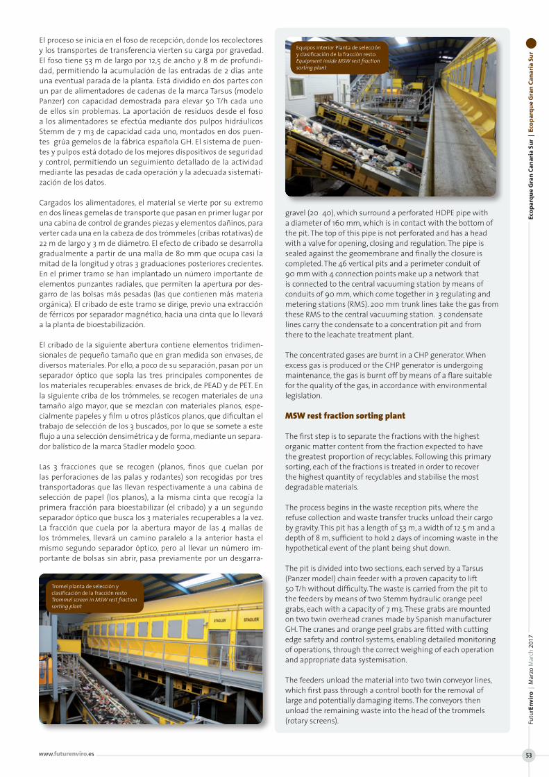
El proceso se inicia en el foso de recepción, donde los recolectores y los transportes de transferencia vierten su carga por gravedad. El foso tiene 53 m de largo por 12,5 de ancho y 8 m de profundi-dad, permitiendo la acumulación de las entradas de 2 días ante una eventual parada de la planta. Está dividido en dos partes con un par de alimentadores de cadenas de la marca Tarsus (modelo Panzer) con capacidad demostrada para elevar 50 T/h cada uno de ellos sin problemas. La aportación de residuos desde el foso a los alimentadores se efectúa mediante dos pulpos hidráulicos Stemm de 7 m3 de capacidad cada uno, montados en dos puen-tes‐grúa gemelos de la fábrica española GH. El sistema de puen-tes y pulpos está dotado de los mejores dispositivos de seguridad y control, permitiendo un seguimiento detallado de la actividad mediante las pesadas de cada operación y la adecuada sistemati-zación de los datos.
Cargados los alimentadores, el material se vierte por su extremo en dos líneas gemelas de transporte que pasan en primer lugar por una cabina de control de grandes piezas y elementos dañinos, para verter cada una en la cabeza de dos trómmeles (cribas rotativas) de 22 m de largo y 3 m de diámetro. El efecto de cribado se desarrolla gradualmente a partir de una malla de 80 mm que ocupa casi la mitad de la longitud y otras 3 graduaciones posteriores crecientes. En el primer tramo se han implantado un número importante de elementos punzantes radiales, que permiten la apertura por des-garro de las bolsas más pesadas (las que contienen más materia orgánica). El cribado de este tramo se dirige, previo una extracción de férricos por separador magnético, hacia una cinta que lo llevará a la planta de bioestabilización.
El cribado de la siguiente abertura contiene elementos tridimen-sionales de pequeño tamaño que en gran medida son envases, de diversos materiales. Por ello, a poco de su separación, pasan por un separador óptico que sopla las tres principales componentes de los materiales recuperables: envases de brick, de PEAD y de PET. En la siguiente criba de los trómmeles, se recogen materiales de una tamaño algo mayor, que se mezclan con materiales planos, espe-cialmente papeles y film u otros plásticos planos, que dificultan el trabajo de selección de los 3 buscados, por lo que se somete a este flujo a una selección densimétrica y de forma, mediante un separa-dor balístico de la marca Stadler modelo 5000.
Las 3 fracciones que se recogen (planos, finos que cuelan por las perforaciones de las palas y rodantes) son recogidas por tres transportadoras que las llevan respectivamente a una cabina de selección de papel (los planos), a la misma cinta que recogía la primera fracción para bioestabilizar (el cribado) y a un segundo separador óptico que busca los 3 materiales recuperables a la vez. La fracción que cuela por la abertura mayor de las 4 mallas de los trómmeles, llevará un camino paralelo a la anterior hasta el mismo segundo separador óptico, pero al llevar un número im-portante de bolsas sin abrir, pasa previamente por un desgarra-
gravel (20‐40), which surround a perforated HDPE pipe with a diameter of 160 mm, which is in contact with the bottom of the pit. The top of this pipe is not perforated and has a head with a valve for opening, closing and regulation. The pipe is sealed against the geomembrane and finally the closure is completed. The 46 vertical pits and a perimeter conduit of 90 mm with 4 connection points make up a network that is connected to the central vacuuming station by means of conduits of 90 mm, which come together in 3 regulating and metering stations (RMS). 200 mm trunk lines take the gas from these RMS to the central vacuuming station. 3 condensate lines carry the condensate to a concentration pit and from there to the leachate treatment plant.
The concentrated gases are burnt in a CHP generator. When excess gas is produced or the CHP generator is undergoing maintenance, the gas is burnt off by means of a flare suitable for the quality of the gas, in accordance with environmental legislation.
MSW rest fraction sorting plant
The first step is to separate the fractions with the highest organic matter content from the fraction expected to have the greatest proportion of recyclables. Following this primary sorting, each of the fractions is treated in order to recover the highest quantity of recyclables and stabilise the most degradable materials.
The process begins in the waste reception pits, where the refuse collection and waste transfer trucks unload their cargo by gravity. This pit has a length of 53 m, a width of 12.5 m and a depth of 8 m, sufficient to hold 2 days of incoming waste in the hypothetical event of the plant being shut down.
The pit is divided into two sections, each served by a Tarsus (Panzer model) chain feeder with a proven capacity to lift 50 T/h without difficulty. The waste is carried from the pit to the feeders by means of two Stemm hydraulic orange peel grabs, each with a capacity of 7 m3. These grabs are mounted on two twin overhead cranes made by Spanish manufacturer GH. The cranes and orange peel grabs are fitted with cutting edge safety and control systems, enabling detailed monitoring of operations, through the correct weighing of each operation and appropriate data systemisation.
The feeders unload the material into two twin conveyor lines, which first pass through a control booth for the removal of large and potentially damaging items. The conveyors then unload the remaining waste into the head of the trommels (rotary screens).
Eco
par
qu
e G
ran
Can
aria
Su
r |
Eco
par
qu
e G
ran
Can
aria
Su
rFu
turE
nvi
ro |
Mar
zo M
arch
201
7
www.futurenviro.es 53
Equipos interior Planta de selección y clasificación de la fracción resto. Equipment inside MSW rest fraction sorting plant
Tromel planta de selección y clasificación de la fracción resto Trommel screen in MSW rest fraction sorting plant

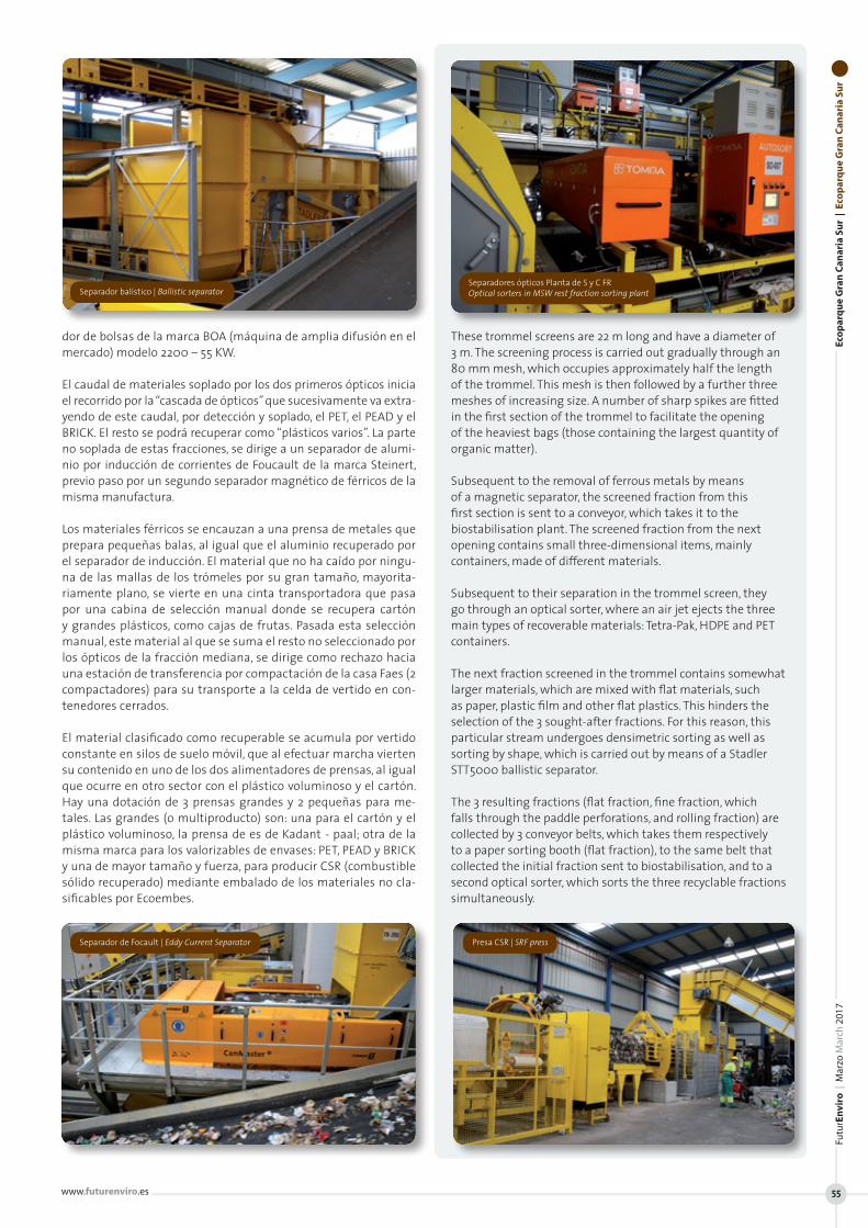
dor de bolsas de la marca BOA (máquina de amplia difusión en el mercado) modelo 2200 – 55 KW.
El caudal de materiales soplado por los dos primeros ópticos inicia el recorrido por la “cascada de ópticos” que sucesivamente va extra-yendo de este caudal, por detección y soplado, el PET, el PEAD y el BRICK. El resto se podrá recuperar como “plásticos varios”. La parte no soplada de estas fracciones, se dirige a un separador de alumi-nio por inducción de corrientes de Foucault de la marca Steinert, previo paso por un segundo separador magnético de férricos de la misma manufactura.
Los materiales férricos se encauzan a una prensa de metales que prepara pequeñas balas, al igual que el aluminio recuperado por el separador de inducción. El material que no ha caído por ningu-na de las mallas de los trómeles por su gran tamaño, mayorita-riamente plano, se vierte en una cinta transportadora que pasa por una cabina de selección manual donde se recupera cartón y grandes plásticos, como cajas de frutas. Pasada esta selección manual, este material al que se suma el resto no seleccionado por los ópticos de la fracción mediana, se dirige como rechazo hacia una estación de transferencia por compactación de la casa Faes (2 compactadores) para su transporte a la celda de vertido en con-tenedores cerrados.
El material clasificado como recuperable se acumula por vertido constante en silos de suelo móvil, que al efectuar marcha vierten su contenido en uno de los dos alimentadores de prensas, al igual que ocurre en otro sector con el plástico voluminoso y el cartón. Hay una dotación de 3 prensas grandes y 2 pequeñas para me-tales. Las grandes (o multiproducto) son: una para el cartón y el plástico voluminoso, la prensa de es de Kadant - paal; otra de la misma marca para los valorizables de envases: PET, PEAD y BRICK y una de mayor tamaño y fuerza, para producir CSR (combustible sólido recuperado) mediante embalado de los materiales no cla-sificables por Ecoembes.
These trommel screens are 22 m long and have a diameter of 3 m. The screening process is carried out gradually through an 80 mm mesh, which occupies approximately half the length of the trommel. This mesh is then followed by a further three meshes of increasing size. A number of sharp spikes are fitted in the first section of the trommel to facilitate the opening of the heaviest bags (those containing the largest quantity of organic matter).
Subsequent to the removal of ferrous metals by means of a magnetic separator, the screened fraction from this first section is sent to a conveyor, which takes it to the biostabilisation plant. The screened fraction from the next opening contains small three-dimensional items, mainly containers, made of different materials.
Subsequent to their separation in the trommel screen, they go through an optical sorter, where an air jet ejects the three main types of recoverable materials: Tetra-Pak, HDPE and PET containers.
The next fraction screened in the trommel contains somewhat larger materials, which are mixed with flat materials, such as paper, plastic film and other flat plastics. This hinders the selection of the 3 sought-after fractions. For this reason, this particular stream undergoes densimetric sorting as well as sorting by shape, which is carried out by means of a Stadler STT5000 ballistic separator.
The 3 resulting fractions (flat fraction, fine fraction, which falls through the paddle perforations, and rolling fraction) are collected by 3 conveyor belts, which takes them respectively to a paper sorting booth (flat fraction), to the same belt that collected the initial fraction sent to biostabilisation, and to a second optical sorter, which sorts the three recyclable fractions simultaneously.
Eco
par
qu
e G
ran
Can
aria
Su
r |
Eco
par
qu
e G
ran
Can
aria
Su
rFu
turE
nvi
ro |
Mar
zo M
arch
201
7
www.futurenviro.es 55
Separador balístico | Ballistic separator
Separador de Focault | Eddy Current Separator Presa CSR | SRF press
Separadores ópticos Planta de S y C FR Optical sorters in MSW rest fraction sorting plant
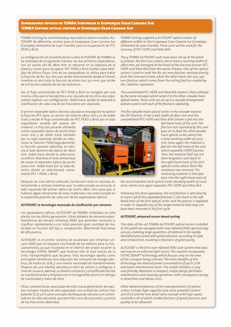
Separadores ópticos de TOMRA Sortingen el Ecoparque Gran Canaria Sur TOMRA Sorting optical sorters at Ecoparque Gran Canaria Sur
TOMRA Sorting ha suministrado4 separadores ópticos modelo AU-TOSORT de diferentes anchos para el Ecoparque Gran Canaria Sur (Complejo Ambiental de Juan Grande), para la recuperación de PET, PEAD y Brick
La configuración en la planta de los cuatro AUTOSORT de TOMRA se ha realizado de la siguiente manera: los dos primeros separadores, con un ancho útil de 2800 mm se ubicaron en la cabecera de la planta y sirven para recuperar PET, PEAD y Brick (cartón para bebi-das) de dichos flujos. Uno de los separadores se utiliza para tratar la fracción de 80-150 mm que recibe directamente desde el trómel, mientras el otro trata la fracción de entre 200-350 mm, que recibe de la fracción rodante de los dos balísticos.
Así, el flujo concentrado de PET, PEAD y Brick es recogido por una misma cinta que lo transporta a una cascada de los otros dos sepa-radores ópticos con configuración doble track, donde se realizará la clasificación de cada una de las fracciones por separado.
El primer separador óptico de esta cascada se encarga de recuperar la fracción PET, tiene un ancho útil total de 2800 mm y es de doble track y recibe el flujo concentrado de PET, PEAD y Brick por el lado izquierdoen sentido del avance del material. La fracción pasante alimenta al otro separador óptico de ancho total 2000 mm y de doble track, también por su lado izquierdo donde se selec-ciona la fracción PEAD.Seguidamente, la fracción pasante obtenida, se reen-vía al lado derecho del óptico de 2800 mm doble track, donde se selecciona-rá el Brick. Mientras el resto alimentará de nuevo al separador óptico de ancho 2000 mm doble track por su lado de-recho, donde se seleccionará nueva-mente PET + PEAD + Brick.
Después de esta última selección, la fracción resto es enviada di-rectamente a rechazo mientras que la seleccionada se recircula al lado izquierdo del primer óptico de ancho 2800 mm para que, si hubiera algún remanente de estos materiales, sea seleccionado en la respectiva posición de cada uno de los separadores ópticos.
AUTOSORT, la tecnología avanzada de clasificación por sensores Los separadores ópticos AUTOSORT de TOMRA instalados en esta planta son de última generación. Están dotados de sensores espec-trométricos de cercano infrarrojo (NIR), que permiten reconocer y clasificar rápidamente y con total precisión gran cantidad de ma-teriales en función del tipo y composición, obteniendo fracciones de alta pureza.
AUTOSORT es el primer sistema de escaneado por infrarrojo cer-cano (NIR) que no requiere una fuente de luz externa para su fun-cionamiento, ya que incorpora en el interior del propio escáner la tecnología FLYING BEAM®, que ilumina sólo el área exacta de la cinta transportadora que escanea. Esta tecnología aporta como principales beneficios una reducción del consumo de energía eléc-trica, de hasta un 70%, y una menor necesidad de mantenimiento. Dispone de una interfaz sencilla y es fácil de utilizar y configurar a nivel de usuario; además, su diseño compacto y simplificado facilita su mantenimiento y limpieza con el consiguiente ahorro en tiempo de inactividad y mano de obra.
Otras características avanzadas de esta nueva generación de equi-pos incluyen: tarjeta de alta capacidad, una unidad de control más potente (CU) y el nuevo concepto de bloque de válvulas con contro-ladores de alta velocidad, que permiten una alta precisión y pureza de las fracciones obtenidas.
TOMRA Sorting supplied 4 AUTOSORT optical sorters of different widths to the Ecoparque Gran Canaria Sur (Complejo Ambiental de Juan Grande). These units will be used for the recovery of PET, HDPE and Tetra-Brik.
The 4 TOMRA AUTOSORT units have been set up at the plant as follows: the first two sorters, which have a working width of 2800 mm, are arranged at the head of the line and recover PET, HDPE and Tetra-Brik from the waste streams. One of the optical sorters is used to treat the 80-150 mm fraction, received directly from the trommel screen, while the other treats the 200-350 mm fraction, which comes from the rolling fraction created by the 2 ballistic separators.
The concentrated PET, HDPE and Tetra-Brik stream is then collected by the same conveyor, which sends it to the other 2 double-track optical sorters. These units are set up in a cascade arrangement and are used to sort each of the fractions separately.
The first double-track optical sorter in the cascade recovers the PET fraction. It has a belt width of 2800 mm and the concentrated PET, HDPE and Tetra-Brik stream is fed into the
left-hand track of the unit. The fraction not separated by this unit goes on to feed the other double-track optical sorter, which has a total working width of 2000 mm. Once again the material is fed into the left track of the unit, which separates HDPE fraction. Then the material that has not been targeted is sent back to the right-hand track of the first optical sorter, where Tetra-Pak containers are removed. The remaining material is then fed back into the right-hand track of
the second double-track optical sorter (working width of 2000 mm), which once again separates PET, HDPE and Tetra-Brik.
Following this final separation, the rest fraction is sent directly to reject, while the separated fraction is sent back to the left-hand track of the first optical sorter and the process is repeated in order to separate any of the target material that may not have been removed in the first cycle.
AUTOSORT, advanced sensor-based sorting
The state-of-the-art TOMRA AUTOSORT optical sorters installed at this plant are equipped with near infrared (NIR) spectroscopy sensors, enabling large quantities of material to be rapidly identified and sorted with great precision, according to type and composition, resulting in fractions of great purity.
AUTOSORT is the first near infrared (NIR) scan system that does not require an external light source. The scanner incorporates FLYING BEAM® technology, which focuses only on the area of the conveyor being scanned. The main benefits of this technology are reduced power consumption of up to 70% and lower maintenance levels. The simple interface is very user-friendly. Moreover, a compact, simple design facilitates maintenance and cleaning operations, with consequent savings in downtime and labour costs.
Other advanced features of this new generation of optical sorters include: high-capacity card, more powerful control unit (CU) and the new block valve concept with high-speed controllers, all of which enable fractions of great precision and quality to be obtained.

Planta de bioestabilización
Como se ha explicado, la fracción separada por los trómmeles se dirige hacia la nave de bioestabilización, donde mediante un pro-ceso de fermentación aeróbica se consigue estabilizar el material, dotándole de las condiciones necesarias para poder ser utilizado para aplicaciones en jardinería pudiendo, por tanto, sustituir a los habituales fertilizantes y abonos químicos y como material de re-lleno (en canteras, taludes...)
El proceso se consigue mediante la formación de una masa de for-ma aproximadamente prismática rectangular, de 110 m de largo, 32 de ancho y 2 de altura aproximada, formada por “renglones” (o caballones) de residuos con alto contenido de materia orgánica, a la que se somete a un proceso de ventilación forzada mediante ex-tracción de aire de su seno por aspiración desde el suelo. Tal suelo se forma por una capa de grava no calcárea, altamente drenante, en cuyo seno se ubica una batería de 400 tubos de polietileno con perforaciones por las cuales mediante depresión, se extrae el aire de la materia en proceso a la vez.
Los citados renglones son desplazados de forma alternada desde un lado del “reactor” hacia el opuesto, mediante el efecto del paso de un doble tornillo suspendido de un puente grúa. Tal puente grúa puede desplazarse por todo el largo del reactor mediante raíles ex-teriores y, los tornillos desplazarse por la viga transversal que une los extremos del puente, para trabajar secuencialmente en todos los renglones.
En su último desplazamiento, un renglón llega a caer sobre la pared opuesta a la del lado de carga del reactor que posee menor altura e inclinación, permitiendo que una rueda (o “fresa”) integrada en el puente, desplace este material hacia el exterior donde lo recibe una cinta de descarga que lo transporta a otra colector destinada a llevar el material estabilizado a su afinado.
Queda por aclarar que la carga de los reactores se realiza alternati-vamente entre uno u otro de los dos “gemelos” existentes, mediante cinta reversible que vierte en otras cintas que recorren todo el largo del reactor con un dispositivo transportable que hace una desviación transversal del flujo vertiendo al interior y formado de esta manera el primer renglón.
El material tratado se vierte en una cinta ascendente que aporta el material en otra exterior para su transporte al afino. El aire aspira-do por colectores desde los tubos incorporados en la masa de gra-va drenante mediante dos potentes ventiladores por cada reactor, cargado de amoníaco y otros contaminantes, se impulsa hacia una planta de limpieza del aire.
El aire de la atmósfera de esta planta tiene un nivel bajo de conta-minación, pero igualmente necesita de un tratamiento de limpieza antes de ser emitido a la atmósfera. Para ello se ha establecido un sistema de aspiración desde toda la superficie de la planta, con dos colectores ubicados uno en el ámbito de cada reactor, los que ge-neran depresión por la aspiración de sendos ventiladores axiales interpuestos en el tramo de conducción hacia la planta de trata-miento de aires.
Con el fin de que no haya un exceso de depresión en el ambiente de la nave que dificultara la entrada de éste en el seno de la masa de residuos en proceso, se cuenta con la aportación de aire aspirado desde el interior de las naves de la planta de RSU (foso y tratamien-to mecánico) y eventualmente con la actuación de ventiladores de pared distribuidos en la fachada.
Completado el ciclo de estabilización, el material debe conseguir las características físicas similares a las del compost, a la vez que ser so-
The fraction which falls through the largest opening of the 4 trommel meshes follows the same path as the previous fraction to the second optical sorter. However, because it still contains a significant number of unopened bags, it first goes through a BOA 2200, 55-kW bag opener (BOA is a well known brand of bag opener).
The stream of materials removed by the first two optical sorters begins a route through a waterfall arrangement of optical sorters, which successively removes, PET, HDPE and Tetra-Pak items from the stream through detection and ejection by means of air jets. The remainder of this stream can be recovered as a “miscellaneous plastics” fraction.
The fraction that is not ejected from the optical sorters is sent to a Steinert Eddy Current separator, subsequent to passing through a second magnetic separator made by the same manufacturer.
The ferrous metals are sent to a metals baling press and compacted into small bales. The aluminium recovered by the Eddy Current Separator is compacted in the same way.
The material that does not fall through any of the trommel meshes due to its size is primarily a flat fraction. It is unloaded onto a conveyor, which takes it through a manual sorting booth in which cardboard and large plastic items, such as fruit crates, are removed.
Subsequent to manual sorting, the remaining material, along with the materials from the medium-sized fraction not sorted by the optical sorters, is sent as reject to a transfer station, where it is compacted by means of 2 FAES baling presses prior to being sent to the landfill cell in closed containers.
The material classified as recoverable is continually discharged into silos with moving floors, from where it is sent to one of the two baling press feeders, in the same way as happens in the other sector with bulky plastics and cardboard.
The plant is equipped with 3 large baling presses and 2 smaller baling presses for metals. One of the large baling presses is a JOVISA model for cardboard and bulky plastics. Another JOVISA unit compacts recoverable PET, HDPE and Tetra-Pak containers. The largest and most powerful of the baling presses is used to produce SRF (solid recovered fuel) by baling the materials that cannot be classified by Ecoembes.
BIOSTABILISATION PLANT
As has been explained, the fraction separated by the trommel screens is sent to the biostabilisation building. The material is stabilised by means of an aerobic fermentation process to endow it with the conditions necessary to substitute
Eco
par
qu
e G
ran
Can
aria
Su
r |
Eco
par
qu
e G
ran
Can
aria
Su
rFu
turE
nvi
ro |
Mar
zo M
arch
201
7
www.futurenviro.es 57
Reactores planta de bioestabilización Reactors in the biostabilisation plant
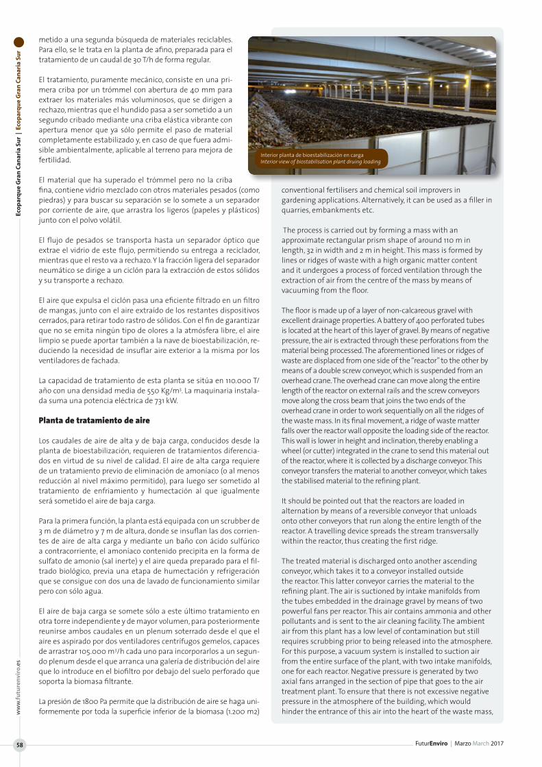
Eco
par
qu
e G
ran
Can
aria
Su
r |
Eco
par
qu
e G
ran
Can
aria
Su
r
FuturEnviro | Marzo March 2017
ww
w.fu
ture
nvi
ro.e
s
58
metido a una segunda búsqueda de materiales reciclables. Para ello, se le trata en la planta de afino, preparada para el tratamiento de un caudal de 30 T/h de forma regular.
El tratamiento, puramente mecánico, consiste en una pri-mera criba por un trómmel con abertura de 40 mm para extraer los materiales más voluminosos, que se dirigen a rechazo, mientras que el hundido pasa a ser sometido a un segundo cribado mediante una criba elástica vibrante con apertura menor que ya sólo permite el paso de material completamente estabilizado y, en caso de que fuera admi-sible ambientalmente, aplicable al terreno para mejora de fertilidad.
El material que ha superado el trómmel pero no la criba fina, contiene vidrio mezclado con otros materiales pesados (como piedras) y para buscar su separación se lo somete a un separador por corriente de aire, que arrastra los ligeros (papeles y plásticos) junto con el polvo volátil.
El flujo de pesados se transporta hasta un separador óptico que extrae el vidrio de este flujo, permitiendo su entrega a reciclador, mientras que el resto va a rechazo. Y la fracción ligera del separador neumático se dirige a un ciclón para la extracción de estos sólidos y su transporte a rechazo.
El aire que expulsa el ciclón pasa una eficiente filtrado en un filtro de mangas, junto con el aire extraído de los restantes dispositivos cerrados, para retirar todo rastro de sólidos. Con el fin de garantizar que no se emita ningún tipo de olores a la atmósfera libre, el aire limpio se puede aportar también a la nave de bioestabilización, re-duciendo la necesidad de insuflar aire exterior a la misma por los ventiladores de fachada.
La capacidad de tratamiento de esta planta se sitúa en 110.000 T/año con una densidad media de 550 Kg/m3. La maquinaria instala-da suma una potencia eléctrica de 731 kW.
Planta de tratamiento de aire
Los caudales de aire de alta y de baja carga, conducidos desde la planta de bioestabilización, requieren de tratamientos diferencia-dos en virtud de su nivel de calidad. El aire de alta carga requiere de un tratamiento previo de eliminación de amoníaco (o al menos reducción al nivel máximo permitido), para luego ser sometido al tratamiento de enfriamiento y humectación al que igualmente será sometido el aire de baja carga.
Para la primera función, la planta está equipada con un scrubber de 3 m de diámetro y 7 m de altura, donde se insuflan las dos corrien-tes de aire de alta carga y mediante un baño con ácido sulfúrico a contracorriente, el amoníaco contenido precipita en la forma de sulfato de amonio (sal inerte) y el aire queda preparado para el fil-trado biológico, previa una etapa de humectación y refrigeración que se consigue con dos una de lavado de funcionamiento similar pero con sólo agua.
El aire de baja carga se somete sólo a este último tratamiento en otra torre independiente y de mayor volumen, para posteriormente reunirse ambos caudales en un plenum soterrado desde el que el aire es aspirado por dos ventiladores centrífugos gemelos, capaces de arrastrar 105.000 m3/h cada uno para incorporarlos a un segun-do plenum desde el que arranca una galería de distribución del aire que lo introduce en el biofiltro por debajo del suelo perforado que soporta la biomasa filtrante.
La presión de 1800 Pa permite que la distribución de aire se haga uni-formemente por toda la superficie inferior de la biomasa (1.200 m2)
conventional fertilisers and chemical soil improvers in gardening applications. Alternatively, it can be used as a filler in quarries, embankments etc.
The process is carried out by forming a mass with an approximate rectangular prism shape of around 110 m in length, 32 in width and 2 m in height. This mass is formed by lines or ridges of waste with a high organic matter content and it undergoes a process of forced ventilation through the extraction of air from the centre of the mass by means of vacuuming from the floor.
The floor is made up of a layer of non-calcareous gravel with excellent drainage properties. A battery of 400 perforated tubes is located at the heart of this layer of gravel. By means of negative pressure, the air is extracted through these perforations from the material being processed. The aforementioned lines or ridges of waste are displaced from one side of the “reactor” to the other by means of a double screw conveyor, which is suspended from an overhead crane. The overhead crane can move along the entire length of the reactor on external rails and the screw conveyors move along the cross beam that joins the two ends of the overhead crane in order to work sequentially on all the ridges of the waste mass. In its final movement, a ridge of waste matter falls over the reactor wall opposite the loading side of the reactor. This wall is lower in height and inclination, thereby enabling a wheel (or cutter) integrated in the crane to send this material out of the reactor, where it is collected by a discharge conveyor. This conveyor transfers the material to another conveyor, which takes the stabilised material to the refining plant.
It should be pointed out that the reactors are loaded in alternation by means of a reversible conveyor that unloads onto other conveyors that run along the entire length of the reactor. A travelling device spreads the stream transversally within the reactor, thus creating the first ridge.
The treated material is discharged onto another ascending conveyor, which takes it to a conveyor installed outside the reactor. This latter conveyor carries the material to the refining plant. The air is suctioned by intake manifolds from the tubes embedded in the drainage gravel by means of two powerful fans per reactor. This air contains ammonia and other pollutants and is sent to the air cleaning facility. The ambient air from this plant has a low level of contamination but still requires scrubbing prior to being released into the atmosphere. For this purpose, a vacuum system is installed to suction air from the entire surface of the plant, with two intake manifolds, one for each reactor. Negative pressure is generated by two axial fans arranged in the section of pipe that goes to the air treatment plant. To ensure that there is not excessive negative pressure in the atmosphere of the building, which would hinder the entrance of this air into the heart of the waste mass,
Interior planta de bioestabilización en carga Interior view of biostabilisation plant druing loading
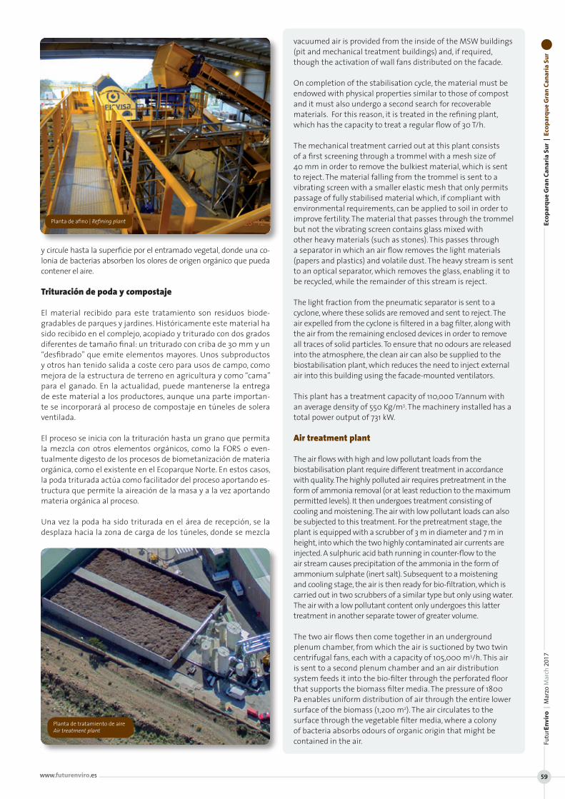
y circule hasta la superficie por el entramado vegetal, donde una co-lonia de bacterias absorben los olores de origen orgánico que pueda contener el aire.
Trituración de poda y compostaje
El material recibido para este tratamiento son residuos biode-gradables de parques y jardines. Históricamente este material ha sido recibido en el complejo, acopiado y triturado con dos grados diferentes de tamaño final: un triturado con criba de 30 mm y un “desfibrado” que emite elementos mayores. Unos subproductos y otros han tenido salida a coste cero para usos de campo, como mejora de la estructura de terreno en agricultura y como “cama” para el ganado. En la actualidad, puede mantenerse la entrega de este material a los productores, aunque una parte importan-te se incorporará al proceso de compostaje en túneles de solera ventilada.
El proceso se inicia con la trituración hasta un grano que permita la mezcla con otros elementos orgánicos, como la FORS o even-tualmente digesto de los procesos de biometanización de materia orgánica, como el existente en el Ecoparque Norte. En estos casos, la poda triturada actúa como facilitador del proceso aportando es-tructura que permite la aireación de la masa y a la vez aportando materia orgánica al proceso.
Una vez la poda ha sido triturada en el área de recepción, se la desplaza hacia la zona de carga de los túneles, donde se mezcla
vacuumed air is provided from the inside of the MSW buildings (pit and mechanical treatment buildings) and, if required, though the activation of wall fans distributed on the facade.
On completion of the stabilisation cycle, the material must be endowed with physical properties similar to those of compost and it must also undergo a second search for recoverable materials. For this reason, it is treated in the refining plant, which has the capacity to treat a regular flow of 30 T/h.
The mechanical treatment carried out at this plant consists of a first screening through a trommel with a mesh size of 40 mm in order to remove the bulkiest material, which is sent to reject. The material falling from the trommel is sent to a vibrating screen with a smaller elastic mesh that only permits passage of fully stabilised material which, if compliant with environmental requirements, can be applied to soil in order to improve fertility. The material that passes through the trommel but not the vibrating screen contains glass mixed with other heavy materials (such as stones). This passes through a separator in which an air flow removes the light materials (papers and plastics) and volatile dust. The heavy stream is sent to an optical separator, which removes the glass, enabling it to be recycled, while the remainder of this stream is reject.
The light fraction from the pneumatic separator is sent to a cyclone, where these solids are removed and sent to reject. The air expelled from the cyclone is filtered in a bag filter, along with the air from the remaining enclosed devices in order to remove all traces of solid particles. To ensure that no odours are released into the atmosphere, the clean air can also be supplied to the biostabilisation plant, which reduces the need to inject external air into this building using the facade-mounted ventilators.
This plant has a treatment capacity of 110,000 T/annum with an average density of 550 Kg/m3. The machinery installed has a total power output of 731 kW.
Air treatment plant
The air flows with high and low pollutant loads from the biostabilisation plant require different treatment in accordance with quality. The highly polluted air requires pretreatment in the form of ammonia removal (or at least reduction to the maximum permitted levels). It then undergoes treatment consisting of cooling and moistening. The air with low pollutant loads can also be subjected to this treatment. For the pretreatment stage, the plant is equipped with a scrubber of 3 m in diameter and 7 m in height, into which the two highly contaminated air currents are injected. A sulphuric acid bath running in counter-flow to the air stream causes precipitation of the ammonia in the form of ammonium sulphate (inert salt). Subsequent to a moistening and cooling stage, the air is then ready for bio-filtration, which is carried out in two scrubbers of a similar type but only using water. The air with a low pollutant content only undergoes this latter treatment in another separate tower of greater volume.
The two air flows then come together in an underground plenum chamber, from which the air is suctioned by two twin centrifugal fans, each with a capacity of 105,000 m3/h. This air is sent to a second plenum chamber and an air distribution system feeds it into the bio-filter through the perforated floor that supports the biomass filter media. The pressure of 1800 Pa enables uniform distribution of air through the entire lower surface of the biomass (1,200 m2). The air circulates to the surface through the vegetable filter media, where a colony of bacteria absorbs odours of organic origin that might be contained in the air.
Eco
par
qu
e G
ran
Can
aria
Su
r |
Eco
par
qu
e G
ran
Can
aria
Su
rFu
turE
nvi
ro |
Mar
zo M
arch
201
7
www.futurenviro.es 59
Planta de afino | Refining plant
Planta de tratamiento de aire Air treatment plant
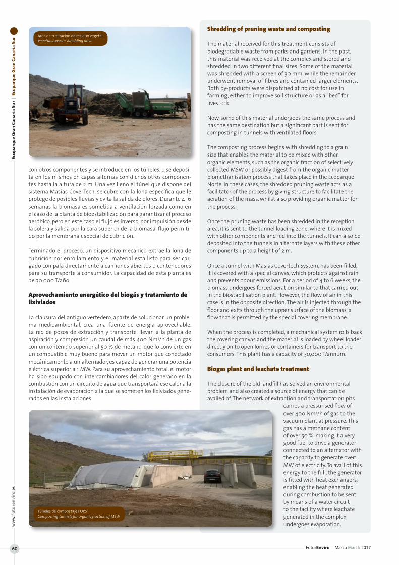
Eco
par
qu
e G
ran
Can
aria
Su
r |
Eco
par
qu
e G
ran
Can
aria
Su
r
FuturEnviro | Marzo March 2017
ww
w.fu
ture
nvi
ro.e
s
60
con otros componentes y se introduce en los túneles, o se deposi-ta en los mismos en capas alternas con dichos otros componen-tes hasta la altura de 2 m. Una vez lleno el túnel que dispone del sistema Masias CoverTech, se cubre con la lona específica que le protege de posibles lluvias y evita la salida de olores. Durante 4‐6 semanas la biomasa es sometida a ventilación forzada como en el caso de la planta de bioestabilización para garantizar el proceso aeróbico, pero en este caso el flujo es inverso, por impulsión desde la solera y salida por la cara superior de la biomasa, flujo permiti-do por la membrana especial de cubrición.
Terminado el proceso, un dispositivo mecánico extrae la lona de cubrición por enrollamiento y el material está listo para ser car-gado con pala directamente a camiones abiertos o contenedores para su transporte a consumidor. La capacidad de esta planta es de 30.000 T/año.
Aprovechamiento energético del biogás y tratamiento de lixiviados
La clausura del antiguo vertedero, aparte de solucionar un proble-ma medioambiental, crea una fuente de energía aprovechable. La red de pozos de extracción y transporte, llevan a la planta de aspiración y compresión un caudal de más 400 Nm3/h de un gas con un contenido superior al 50 % de metano, que lo convierte en un combustible muy bueno para mover un motor que conectado mecánicamente a un alternador, es capaz de generar una potencia eléctrica superior a 1 MW. Para su aprovechamiento total, el motor ha sido equipado con intercambiadores del calor generado en la combustión con un circuito de agua que transportará ese calor a la instalación de evaporación a la que se someten los lixiviados gene-rados en las instalaciones.
Shredding of pruning waste and composting
The material received for this treatment consists of biodegradable waste from parks and gardens. In the past, this material was received at the complex and stored and shredded in two different final sizes. Some of the material was shredded with a screen of 30 mm, while the remainder underwent removal of fibres and contained larger elements. Both by-products were dispatched at no cost for use in farming, either to improve soil structure or as a “bed” for livestock.
Now, some of this material undergoes the same process and has the same destination but a significant part is sent for composting in tunnels with ventilated floors.
The composting process begins with shredding to a grain size that enables the material to be mixed with other organic elements, such as the organic fraction of selectively collected MSW or possibly digest from the organic matter biomethanisation process that takes place in the Ecoparque Norte. In these cases, the shredded pruning waste acts as a facilitator of the process by giving structure to facilitate the aeration of the mass, whilst also providing organic matter for the process.
Once the pruning waste has been shredded in the reception area, it is sent to the tunnel loading zone, where it is mixed with other components and fed into the tunnels. It can also be deposited into the tunnels in alternate layers with these other components up to a height of 2 m.
Once a tunnel with Masias Covertech System, has been filled, it is covered with a special canvas, which protects against rain and prevents odour emissions. For a period of 4 to 6 weeks, the biomass undergoes forced aeration similar to that carried out in the biostabilisation plant. However, the flow of air in this case is in the opposite direction. The air is injected through the floor and exits through the upper surface of the biomass, a flow that is permitted by the special covering membrane.
When the process is completed, a mechanical system rolls back the covering canvas and the material is loaded by wheel loader directly on to open lorries or containers for transport to the consumers. This plant has a capacity of 30,000 T/annum.
Biogas plant and leachate treatment
The closure of the old landfill has solved an environmental problem and also created a source of energy that can be availed of. The network of extraction and transportation pits
carries a pressurised flow of over 400 Nm3/h of gas to the vacuum plant at pressure. This gas has a methane content of over 50 %, making it a very good fuel to drive a generator connected to an alternator with the capacity to generate over1 MW of electricity. To avail of this energy to the full, the generator is fitted with heat exchangers, enabling the heat generated during combustion to be sent by means of a water circuit to the facility where leachate generated in the complex undergoes evaporation.
Área de trituración de residuo vegetal Vegetable waste shredding area
Túneles de compostaje FORS Composting tunnels for organic fraction of MSW
Ges
tió
n y
tra
tam
ien
to d
e re
sid
uo
s |
Was
te M
anag
emen
t &
Tre
atm
ent
Futu
rEn
viro
| M
arzo
Mar
ch 2
017
www.futurenviro.es 61
La empresa Repasack, en Oberhausen (Alemania) instaló una prensa de briquetas HSM BRP 4810: una prensa el doble de rápida que su pre-decesora, que compacta a una trigésima parte el volumen de salida y hasta la fecha no ha mostrado ningún defecto en el funcionamiento.En el centro de recepción de envases no retornables de PET, aluminio y hojalata, se ha obtenido un resultado muy positivo en la primera aplicación de la nueva prensa para briquetas HSM. Y eso a pesar de que hasta conseguirlo tuvieron que salvarse algunas dificultades.
La nueva máquina sorprendió al completar el primer contenedor lleno de briquetas extraídas de la nueva HSM también resultó ser demasiado pesado, lo cual no es extraño, teniendo en cuenta que las briquetas de la nueva prensa pesaban el doble que el de la anti-gua. La primera tarea encomendada a la prensa HSM BRP 4810 fue el dificil prensado de envases no retornables y para ello el equipo de HSM en estrecha colaboración con expertos en reciclaje de Re-pasack en Oberhausen desarrollaron la pimera prensa de briquetas para aplicaciones exigentes en un centro de recepción de envases.
Las ventajas de las briquetas al ser pequeñas y pesadas, aprove-chan óptimamente la capacidad de transporte y no necesitan ma-teriales de fleje, como el alambre.
Las exigencias a las que se ve sometida una prensa dentro del sector de bebidas son extremas, ya que el PET es un material muy abrasivo que desgasta enormemente las máquinas. Por ello, es im-prescindible utilizar chapas gruesas y aceros de la mayor calidad y mucho más resistentes al desgaste. Además para el PET se tuvo que colocar una chapa de guía adicional, ya que las botellas PET se comprimían continuamente entre las chapas y salían por donde no debían. Esto no puede permitirse, dado que la función obligatoria y prácticamente de ley de la máquina es prensar botellas y latas de la manera adecuada, puesto que solo se considera que un envase no retornable se ha eliminado cuando ha sido destruido de la forma prescrita. Se trata de un criterio de calidad al que cada año debe someterse el centro de recepción para obtener la certificación de la asociación alemana de devolución de envases retornables.
El centro de recepción de Oberhausen es uno de los diez centros con que cuenta Alemania y uno de los más grandes de su clase con 55 mi-llones de envases reciclados al año (2014). En noviembre del mismo año ya se había logrado alcanzar el rendimiento total en el antiguo al-macén de abonos, con la asombrosa cifra de 500 millones de envases.
La empresa explotadora Repasack es una filial de Interseroh, un pro-veedor de servicios medioambientales que opera en 100 instalaciones repartidas por toda Europa. En Oberhausen, Repasack lleva recepcio-nando envases retornables desde 2006. La nave cuenta con cuatro prensas, una de las cuales ya mostraba en 2014 señales evidentes de envejecimiento. El fabricante descartó una reparación y adquirió una nueva. En Interseroh y Repasack se daba la situación ideal, ya que las cuatro prensas provenían del mismo fabricante. En la búsqueda de al-ternativas, los expertos en reciclaje seleccionaron la prensa HSM BRP 4810. La prensa HSM BRP 4810 se puso a prueba con 300 sacos de material de reciclaje. La primera prueba de funcionamiento de la máquina e HSM fue positiva y no aparecieron botellas completas
Repasack in Oberhausen (Germany) installed a HSM BRP 4810 briquetting press. The machine presses twice as fast as its predecessor, compresses the material to a thirtieth of its initial volume and to date has not had any operational faults. The first new HSM briquetting press has had very positive results at the large counting centre for disposable packaging made from PET, aluminium and tin, despite some difficulties that had to be overcome along the way.
The new machine in Oberhausen also gave the employees a few surprises: the very first roll-off container, filled with briquettes from the new HSM machine, was too heavy. No wonder, as the briquettes from the new press were twice as heavy as the old ones.
The installation of the HSM BRP 4810 represented the first time this type of machine had been used for the difficult task of pressing disposable packaging. HSM developed the first briquetting press for heavy-duty work in a counting house in close cooperation with the recycling experts from Repasack in Oberhausen.
Because the briquettes are small and heavy, transport capacity is optimized and strapping materials, such as wire, are not required.
There is a very high demand for a press of this type in the drinks industry. PET is a very abrasive substance, which can wear machines down badly. Thicker, premium quality types of sheet metal and steel are therefore essential, which is why the developers were delighted that HSM installs particularly wear-resistant steels as standard. PET can, moreover, be rather stubborn. An additional guide plate must be installed, because PET bottles manage to force themselves again and again between the plates and then pop up in places where they don’t belong. This cannot be allowed to happen, because pressing bottles and cans properly is practically a legal obligation for the machine, since disposable packaging is only regarded as correctly disposed of when it has been properly destroyed. A quality criterion, for which the counting centre must be certified once a year by the German Deposit Association.
The counting centre in Oberhausen is one of ten centres in Germany and is one of the largest of its kind, with 55 million containers per year (2014). In November 2014, in the former fertilizer warehouse, a milestone was reached of a total output of 500 million containers.
Repasack is a subsidiary of Interseroh, an environmental services provider with 100 facilities throughout Europe. Repasack in Oberhausen has been receiving disposable packaging waste since 2006. One of the four presses installed in the hall was showing clear signs of ageing in 2014. The manufacturer ruled out of the possibility of repair and recommended buying a new model. No one at Interseroh and Repasack thought that it was an ideal situation that all four presses came from the same manufacturer. During the search for alternatives, the recycling experts opted for the HSM
CASO DE ÉXITO DE PRENSANDO DE BRIQUETAS DE PET Repasack buscaba una prensa para briquetas para PET, aluminio y hojalata que fuera durable, potente y fiable. Además, la máquina debía prensar optimamente un material exigente como es el PET. HSM desarrolló en colaboración con Repasack la nueva prensa para briquetas BRP 4810. La máquina resiste al abrasivo material PET, además de prensar y comprimir con rapidez.
SUCCESSFUL PET BRIQUETTING CASE STUDY Repasack was looking for a durable, powerful, reliable briquetting press for PET, aluminium and tin. Moreover, the machine had to be capable of optimally baling PET, which is a very demanding material. In cooperation with Repasack, HSM developed the new BRP 4810 briquetting press. The machine is resistant to PET materials and affords rapid baling and compression.

Ges
tió
n y
tra
tam
ien
to d
e re
sid
uo
s |
Was
te M
anag
emen
t &
Tre
atm
ent
FuturEnviro | Marzo March 2017
ww
w.fu
ture
nvi
ro.e
s
62
en las briquetas. De todas formas, se realizaron adaptaciones a la máquina de HSM para tratar el nuevo material a prensar.
Durante los seis meses de funcionamiento de prueba realizado in situ en Oberhausen, el operador y el fabricante optimizaron con-juntamente la prensa. Así, se dotó a la HSM de chapas más grue-sas, se redujo la dimensión de la hendidura y se mejoró el software, entre otras cosas. La respuesta de los operarios fue muy positiva a las adaptaciones que se realizaron a la nueva máquina de HSM cumpliéndose los requisitos de las briquetas de PET y destacaron su facilidad de mantenimiento.
La tercera fase de comprensión del material, que es la de prensado principal y con ello la parte de mayor desgaste. Gracias a la poten-cia adicional de la máquina de HSM se consiguen briquetas con una densidad de hasta 400 kg/m3 en el caso del PET y de hasta 760 kg/m3 en el de latas.
Ventajas:
• Las briquetas son pequeñas y compactas y salen sin material de embalaje
• Reduce los gastos de transporte• Permite la carga de forma continua • El PET y las latas pueden prensarse en una sola máquina• La unidad de accionamiento está montada en un bloque de ali-
mentación aparte• Su compresión triple y exclusiva le permite alcanzar una densidad
de briquetas de hasta 400 kg/m3 en el PET• Puede sustituir porcompleto a la tercera fase de compresión• Gran seguridad en el funcionamiento
BRP 4810. The HSM BRP 4810 was put to the test with 300 sacks of recycling material. This first test run went well and whole bottles did not appear in the briquettes. In any case, the HSM machine was modified for the new press material.
During a six month on-site trial at Oberhausen, the operators and the manufacturers optimised the press together. As a result of this, thicker plates were inserted, the gap dimensions were reduced and the software was enhanced. The operators were very positive in their feedback as HSM tailored the machine to their requirements, and they also highlighted the ease of maintenance.
The third stage of compression is the main pressing stage and, therefore, the part during which the most wear and tear occurs. Thanks to the power of the HSM machine, PET briquettes with a density of up to 400 kg/m3 and tin can briquettes of up to 760 kg/m3 are obtained.
Advantages
• The briquettes are small and dense and do not need to be packaged
• Lower transport costs• Continuous output is possible• PET and cans can be pressed by one machine• The drive unit is installed in a separate power pack• Unique threefold compression produces a PET briquette
density of up to 400 kg/m3
• The third stage of briquetting is completely interchangeable• High level of operational safety
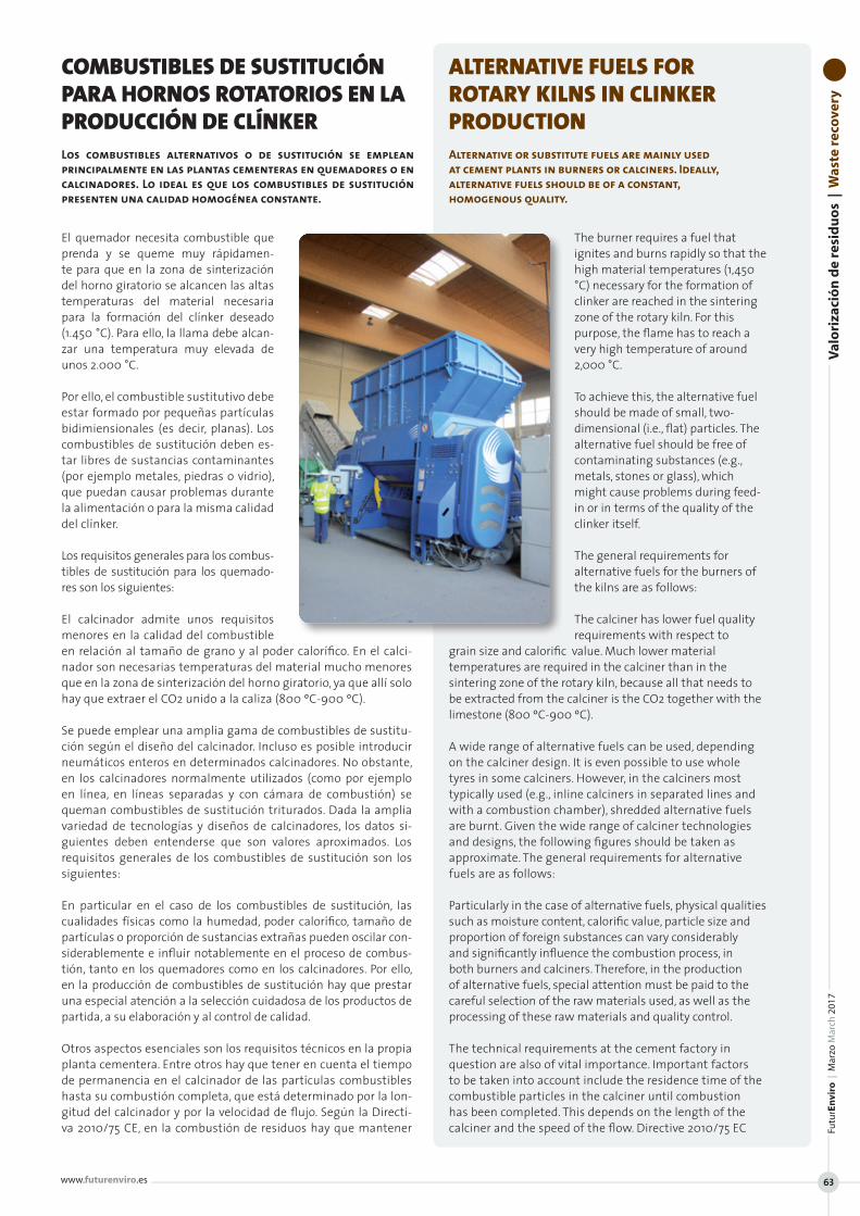
Val
ori
zaci
ón
de
resi
du
os
| W
aste
rec
ove
ryFu
turE
nvi
ro |
Mar
zo M
arch
201
7
www.futurenviro.es 63
El quemador necesita combustible que prenda y se queme muy rápidamen-te para que en la zona de sinterización del horno giratorio se alcancen las altas temperaturas del material necesaria para la formación del clínker deseado (1.450 °C). Para ello, la llama debe alcan-zar una temperatura muy elevada de unos 2.000 °C.
Por ello, el combustible sustitutivo debe estar formado por pequeñas partículas bidimiensionales (es decir, planas). Los combustibles de sustitución deben es-tar libres de sustancias contaminantes (por ejemplo metales, piedras o vidrio), que puedan causar problemas durante la alimentación o para la misma calidad del clínker.
Los requisitos generales para los combus-tibles de sustitución para los quemado-res son los siguientes:
El calcinador admite unos requisitos menores en la calidad del combustible en relación al tamaño de grano y al poder calorífico. En el calci-nador son necesarias temperaturas del material mucho menores que en la zona de sinterización del horno giratorio, ya que allí solo hay que extraer el CO2 unido a la caliza (800 ºC-900 ºC).
Se puede emplear una amplia gama de combustibles de sustitu-ción según el diseño del calcinador. Incluso es posible introducir neumáticos enteros en determinados calcinadores. No obstante, en los calcinadores normalmente utilizados (como por ejemplo en línea, en líneas separadas y con cámara de combustión) se queman combustibles de sustitución triturados. Dada la amplia variedad de tecnologías y diseños de calcinadores, los datos si-guientes deben entenderse que son valores aproximados. Los requisitos generales de los combustibles de sustitución son los siguientes:
En particular en el caso de los combustibles de sustitución, las cualidades físicas como la humedad, poder calorífico, tamaño de partículas o proporción de sustancias extrañas pueden oscilar con-siderablemente e influir notablemente en el proceso de combus-tión, tanto en los quemadores como en los calcinadores. Por ello, en la producción de combustibles de sustitución hay que prestar una especial atención a la selección cuidadosa de los productos de partida, a su elaboración y al control de calidad.
Otros aspectos esenciales son los requisitos técnicos en la propia planta cementera. Entre otros hay que tener en cuenta el tiempo de permanencia en el calcinador de las partículas combustibles hasta su combustión completa, que está determinado por la lon-gitud del calcinador y por la velocidad de flujo. Según la Directi-va 2010/75 CE, en la combustión de residuos hay que mantener
The burner requires a fuel that ignites and burns rapidly so that the high material temperatures (1,450 °C) necessary for the formation of clinker are reached in the sintering zone of the rotary kiln. For this purpose, the flame has to reach a very high temperature of around 2,000 °C.
To achieve this, the alternative fuel should be made of small, two-dimensional (i.e., flat) particles. The alternative fuel should be free of contaminating substances (e.g., metals, stones or glass), which might cause problems during feed-in or in terms of the quality of the clinker itself.
The general requirements for alternative fuels for the burners of the kilns are as follows:
The calciner has lower fuel quality requirements with respect to
grain size and calorific value. Much lower material temperatures are required in the calciner than in the sintering zone of the rotary kiln, because all that needs to be extracted from the calciner is the CO2 together with the limestone (800 ºC-900 ºC).
A wide range of alternative fuels can be used, depending on the calciner design. It is even possible to use whole tyres in some calciners. However, in the calciners most typically used (e.g., inline calciners in separated lines and with a combustion chamber), shredded alternative fuels are burnt. Given the wide range of calciner technologies and designs, the following figures should be taken as approximate. The general requirements for alternative fuels are as follows:
Particularly in the case of alternative fuels, physical qualities such as moisture content, calorific value, particle size and proportion of foreign substances can vary considerably and significantly influence the combustion process, in both burners and calciners. Therefore, in the production of alternative fuels, special attention must be paid to the careful selection of the raw materials used, as well as the processing of these raw materials and quality control.
The technical requirements at the cement factory in question are also of vital importance. Important factors to be taken into account include the residence time of the combustible particles in the calciner until combustion has been completed. This depends on the length of the calciner and the speed of the flow. Directive 2010/75 EC
COMBUSTIBLES DE SUSTITUCIÓN PARA HORNOS ROTATORIOS EN LA PRODUCCIÓN DE CLÍNKER Los combustibles alternativos o de sustitución se emplean principalmente en las plantas cementeras en quemadores o en calcinadores. Lo ideal es que los combustibles de sustitución presenten una calidad homogénea constante.
ALTERNATIVE FUELS FOR ROTARY KILNS IN CLINKER PRODUCTION Alternative or substitute fuels are mainly used at cement plants in burners or calciners. Ideally, alternative fuels should be of a constant, homogenous quality.

Val
ori
zaci
ón
de
resi
du
os
| W
aste
rec
ove
ry
FuturEnviro | Marzo March 2017
ww
w.fu
ture
nvi
ro.e
s
64
una temperatura de combus-tión mínima de 850 ºC duran-te al menos 2 segundos, lo que debe garantizarse mediante la correspondiente estructura del calcinador, así como por el tamaño de grano y demás pro-piedades físicas del combusti-ble sustitutivo.
La experiencia de las plantas ce-menteras indica que es posible el funcionamiento con calcina-dor con prácticamente el 100 % de combustibles de sustitución y también con composiciones diferentes. De hecho pueden utilizarse eficazmente la celulosa en fibras (fluff), harina animal, tela asfáltica triturada, restos de destilación e incluso pellets de combustible sustitutivo.
La introducción de los combustibles en el calcinador se realiza neu-máticamente para combustibles de sustitución que puedan ser impulsados por aire, como el fluff o la harina animal, y mecánica-mente mediante un sistema de dosificación, para el resto de los materiales citados.
sets out that a minimum combustion temperature of 850 ºC must be maintained for at least 2 seconds when combusting waste. This must be guaranteed by means of the corresponding calciner structure, the grain size and other physical properties of the alternative fuel.
Experience at cement factories has shown that it is possible to operate a calciner using practically 100% alternative fuels
and with fuels of different composition. In fact the following materials can be used effectively: cellulose fluff pulp, animal meal, shredded asphalt fabric, distillation residue and even alternative fuel pellets.
The fuels are fed into the calciner pneumatically in the case of alternative fuels that can be transported using air, such as fluff or animal meal, and mechanically for the remaining fuels mentioned above.
Propiedades del combustible para quemador Properties of the fuel for the burner
Tamaño de grano <35mm, non-3-dimensional Grain size <35mm, non-3-dimensional
Poder calorífico m >4,500 kcal/kg | Calorific value m >4,500 kcal/kgDensity >60 kg/m3 <200 kg/m3 | Density >60 kg/m3 <200 kg/m3
Porcentaje de humedad <15% | Moisture content <15%
Propiedades del combustible para quemador Properties of the fuel for the burner
Tamaño de grano <100mm, | Grain size <100mm,Poder calorífico m >3,500 kcal/kg | Calorific value m >3,500 kcal/kg
Densidad >100 kg/m3 <200 kg/m3 | Density d >100 kg/m3 <200 kg/m3
Porcentaje de humedad <20% | Moisture content <20%
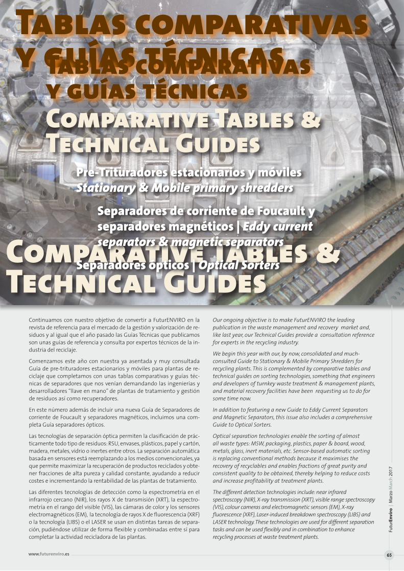
Continuamos con nuestro objetivo de convertir a FuturENVIRO en la revista de referencia para el mercado de la gestión y valorización de re-siduos y al igual que el año pasado las Guías Técnicas que publicamos son unas guías de referencia y consulta por expertos técnicos de la in-dustria del reciclaje.
Comenzamos este año con nuestra ya asentada y muy consultada Guía de pre-trituradores estacionarios y móviles para plantas de re-ciclaje que completamos con unas tablas comparativas y guías téc-nicas de separadores que nos venían demandando las ingenierías y desarrolladores “llave en mano” de plantas de tratamiento y gestión de residuos así como recuperadores.
En este número además de incluir una nueva Guía de Separadores de corriente de Foucault y separadores magnéticos, incluimos una com-pleta Guía separadores ópticos.
Las tecnologías de separación óptica permiten la clasificación de prác-ticamente todo tipo de residuos: RSU, envases, plásticos, papel y cartón, madera, metales, vidrio o inertes entre otros. La separación automática basada en sensores está reemplazando a los medios convencionales, ya que permite maximizar la recuperación de productos reciclados y obte-ner fracciones de alta pureza y calidad constante, ayudando a reducir costes e incrementando la rentabilidad de las plantas de tratamiento.
Las diferentes tecnologías de detección como la espectrometría en el infrarrojo cercano (NIR), los rayos X de transmisión (XRT), la espectro-metría en el rango del visible (VIS), las cámaras de color y los sensores electromagnéticos (EM), la tecnología de rayos X de fluorescencia (XRF) o la tecnología (LIBS) o el LASER se usan en distintas tareas de separa-ción, pudiéndose utilizar de forma flexible y combinadas entre sí para completar la actividad recicladora de las plantas.
Our ongoing objective is to make FuturENVIRO the leading publication in the waste management and recovery market and, like last year, our Technical Guides provide a consultation reference for experts in the recycling industry.
We begin this year with our, by now, consolidated and much-consulted Guide to Stationary & Mobile Primary Shredders for recycling plants. This is complemented by comparative tables and technical guides on sorting technologies, something that engineers and developers of turnkey waste treatment & management plants, and material recovery facilities have been requesting us to do for some time now.
In addition to featuring a new Guide to Eddy Current Separators and Magnetic Separators, this issue also includes a comprehensive Guide to Optical Sorters.
Optical separation technologies enable the sorting of almost all waste types: MSW, packaging, plastics, paper & board, wood, metals, glass, inert materials, etc. Sensor-based automatic sorting is replacing conventional methods because it maximises the recovery of recyclables and enables fractions of great purity and consistent quality to be obtained, thereby helping to reduce costs and increase profitability at treatment plants.
The different detection technologies include: near infrared spectroscopy (NIR), X-ray transmission (XRT), visible range spectroscopy (VIS), colour cameras and electromagnetic sensors (EM), X-ray fluorescence (XRF), Laser-induced breakdown spectroscopy (LIBS) and LASER technology. These technologies are used for different separation tasks and can be used flexibly and in combination to enhance recycling processes at waste treatment plants.
Tablas comparativas y guías técnicas
Comparative Tables & Technical Guides
Comparative Tables & Technical Guides
Tablas comparativas y guías técnicas
Pre-Trituradores estacionarios y móviles Stationary & Mobile primary shredders
Separadores de corriente de Foucault y separadores magnéticos | Eddy current separators & magnetic separators
Separadores ópticos | Optical Sorters
Futu
rEn
viro
| M
arzo
Mar
ch 2
017
www.futurenviro.es 65
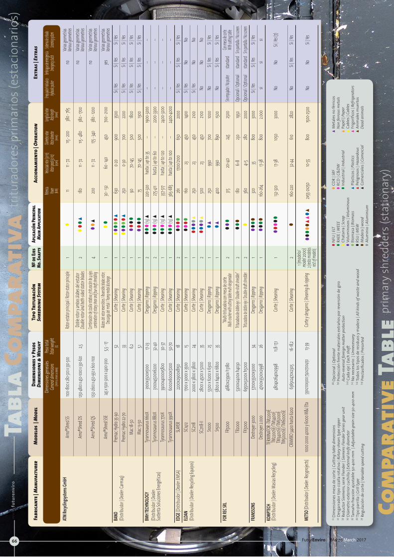
Com
para
tive
Tabl
epr
imar
y sh
redd
ers (
stat
iona
ry)
Tabl
a Co
mpa
rati
vatr
itura
dore
s prim
ario
s (es
taci
onar
ios)
FuturEnviro | Marzo March 2017
ww
w.f
utu
ren
vir
o.e
s
66
Fabr
icant
e | M
anuf
actu
rer
Mod
elos
| M
odel
Di
men
sione
s y P
esos
Ti
po Tr
itura
ción
Nº
de Ej
es
Aplic
ació
n Prin
cipal
Ac
ciona
mie
nto
| Ope
ratio
nEx
tras
|Ext
ras
Dim
ensio
ns&
Weig
ht
Shre
ddin
gSy
stem
No
.Sha
fts
Main
Appl
icatio
n
Dimens
iones
genera
les
Peso t
otal
Potencia
Velo
cidad rot
or (50 Hz
) Diám
etro roto
r Long
itud roto
r Emp
ujador h
idráulico
Embragu
e de eme
rgencia
Sistema d
e cribado
Ge
neral d
imensi
ons
Total w
eight
Power
Rotor spe
ed (50 Hz
) Roto
r diamet
er Roto
r length
Hydrauli
c pusher
Eme
rgency cl
utch
Screening
system
(m
m x mm
x mm)
(t)
(kW)
(rpm)
(m
m)
(mm)
ATM Re
cyclin
gsyste
ms Gm
bH
Arno®
Shred
SS
1100-1
800 x 2
80-500
x 330-
500
Rot
or-esta
tor pri
ncipal
/ Roto
r-stato
r princ
iple
1 l
11 11 -
72
115 - 2
00
380 - 7
65
no
Var
ias geo
metría
s
Var
ious ge
ometri
es
Arno®
Shred
DS
1250-4
800 x 4
50-100
0 x 330
-620
2,5
Doble
rotor
y amb
os ála
bes de
l estat
or 2
l l
ls
180
11 -
72
115 - 4
80
380 - 1
700
no
Var
ias geo
metría
s
Do
uble r
otor a
nd bo
th-sid
ed sta
tor bla
des
Variou
s geom
etries
Arn
o®Sh
red QS
125
0-2600
x 450-
950 x 6
00-110
0
Combina
ción de
cizalla r
otativa
y tritur
ación de
4 ejes
4 ll
s
200
11 - 72
175
- 340
380
- 120
0
no
Varias
geome
trías
combina
tion of r
otary sh
ear and
four-sh
aft shre
dding
Variou
s geom
etries
Arn
o®Sh
red SS
E 245
x 1500
-3200
x 2400
-3100
5,5 - 1
7 Alab
es del ro
tor reve
rsibles
/ Revers
ible bla
des roto
r; 1
l l
30
- 132
60 - 1
40
450
700 -
2100
yes
Var
ias geo
metría
s
Descarg
a del me
tal / Tra
mp met
al disch
arge
Variou
s geom
etries
BANO
Pre
mac H
ydro 3
5-90
52
Corte
| Shea
ring
1 l
l l
ll
s
630
0-20
900
3500
Si | Ye
s Si |
Yes
Si | Ye
s(Di
stribu
idor |
Deale
r: Carm
aq)
Prema
c Hydr
o 22-7
0
33 Co
rte | S
hearin
g 1
l l
l l
l s
250
0-3
0 70
0 220
0 Si |
Yes
Si | Ye
s Si |
Yes
Ma
c 18-50
6,2
Corte
| Shea
ring
1 l
ll
l
90
70-14
5 50
0 180
0 Si |
Yes
Si | Ye
s Si |
Yes
Ma
c 13-50
5,1 Co
rte | S
hearin
g 1
ll
ll
75
70-14
5 50
0 130
0 Si |
Yes
Si | Ye
s Si |
Yes
BMH T
ECHN
OLOG
Y Tyr
anno
saurus
660X
310
0x350
0x510
0 17-
23 De
sgarro
| Ripp
ing
2 l
l l(13
) s
220-32
0 ha
sta | u
p to: 3
5 --
1900-3
200
-- --
--(Di
stribu
idor |
Deale
r: Tyr
anno
saurus
880X
310
0x450
0x62
00
32-40
De
sgarro
| Ripp
ing
2 l
l l(13
) s
275-41
1 ha
sta | u
p to: 6
0 --
2200-3
300
-- --
--Su
stenta
Soluc
iones
Energ
éticas
) Tyr
anno
saurus
770X
39
00x4
000x
5800
30-37
Co
rte | S
hearin
g 1
l l
l(13
) s
357-51
7 ha
sta | u
p to: 1
20
-- 240
0-320
0 --
-- --
Tyr
anno
saurus
990X
60
00x6
000x
7200
50-70
Co
rte | S
hearin
g 1
l l
l(13
) s
365-6
85 ha
sta | u
p to: 1
00
-- 240
0-400
0 --
-- --
EDGE
(Dist
ribuid
or | D
ealer:
EMSA
) SLA
YER
2200x
2900
x8150
18
Corte
| Shea
ring
2 l
l l
l 26
1 170
0/2100
65
0 20
00
Si | Ye
s Si |
Yes
Si | Ye
sELD
AN
SC141
2 170
0 x 30
00 x 3
500
15 Co
rte | S
hearin
g 1
l l
l l
160
23 450
140
0 Si |
Yes
No
No(Di
stribu
idor |
Deale
r: Recy
cling E
quipo
s) SC
2118
2000
x 380
0 x 38
00
24 Co
rte | S
hearin
g 1
l l
l l
s
250
23 450
210
0 Si |
Yes
No
No
SC211
8-II
2800 x
4500
x 500
0 35
Corte
| Shea
ring
2 l
l l
l s
50
0 23
450
2100
No
No
No
S1000
550
0 x 62
00 x 6
300
25 De
sgarro
| Ripp
ing
1 l
s
250
990
700
1000
No
Si | Ye
s Si |
Yes
S15
00
5800 x
6400
x 680
0 35
Desga
rro | R
ipping
1
l s
40
0 99
0 89
0 150
0 No
Si |
Yes
Si | Ye
sFO
R REC
SRL
FR500
0 46
80x23
90x h
3180
“M
ulti-tri
turado
ra con
mesa d
e corte
2
ll
l
315
20÷4
0 245
250
0 Sin e
mpujado
r / No pu
sher
stand
ard
Con me
sa de co
rte
Mu
lti-crush
er with c
utting t
able mu
lti-desga
rrador
With cu
tting ta
ble
TB20
00
5300x
2400x
h403
0
Tritura
dora de
doble e
je / Do
uble-sh
aft shre
dder”
2 ll
l180
6÷
8 230
195
0 Op
cional
/ Opti
onal
stand
ard S
in pant
alla / N
o screen
FX5
000
6950
x3200
x h50
00
Trit
urador
a de dob
le eje /
Doubl
e-shaft
shredde
r 2
l
360
4÷5
280
2000
Op
cional
/ Opti
onal
stand
ard S
in pant
alla / N
o screen
FRANS
SONS
De
stroye
r 3000
570
0x350
0x30
00
34 De
sgarro
| Ripp
ing
1 l
l l
l 320
35
800
3000
Si |
Yes
Si | Ye
s Si |
Yes
De
stroye
r 2.00
0 470
0x350
0x29
98
26
Desga
rro | R
ipping
1
l l
l l
160-26
4 17-
38 80
0 2.0
00
si si
siKO
MPTEC
H TER
MINA
TOR -T
M220
0E
(Distr
ibuido
r | De
aler: M
asias
Recycl
ing)
TM220
0SE/T
M340
0E
TM
3400S
E/TM5
000E
TM50
00SE/
TM60
00SE
4804
x2640
x2998
11,8
-17,1
Corte
| Shea
ring
1 l
l l
l l
132
-320
17-38
1050
3000
No
No
Si |
Yes (7
)
CR
AMBO
3400
hasta
6200
63
65x24
70x23
05
16-18,
2 Co
rte | S
hearin
g 2
l
160-22
0 32-
44
610
2820
No
Si | Ye
s Si |
Yes
METSO
(Distr
ibuido
r | Deal
er: Re
cyproj
ects)
1000 2
000 4
000 y
6000
M&J
Eta
5391x21
00x300
0-7740x
2700x4
150 13-
39
Corte
y desg
arro |
Shear
ing &
rippin
g 1 (m
odelo
/
model
2000
)
2 (rest
o mode
los
rest
of mo
dels)
l l
l l
l s
s l
s
2x55-2
x250
10-55
800
1500-2
500
No
No
Si | Ye
s
lN
FU |
ELT
l R
AEE
| WEE
E lC
hata
rra
| Scr
ap
lV
olum
inos
os |
Volu
min
ous
lB
iom
asa
| Bio
mas
s lR
SU |
MSW
lM
ader
a | w
ood
lA
lum
inio
| Al
umin
ium
lC
DR
| SRF
lR
CD |
C&DW
lIn
dust
rial |
Indu
stria
l
sP
lást
icos
| Pl
astic
ssP
elig
roso
s | H
azar
dous
sC
omer
cial
es |
Com
ercia
l
sM
etal
es n
o fé
rric
os
N
on fe
rrou
s met
als
sP
apel
| Pa
per
sC
able
s | C
able
ssF
rigor
ífico
s | R
efrig
erat
ors
sA
nim
ales
mue
rtos
Dead
ani
mal
s
(1) D
imen
sion
es m
esa
de co
rte
| Cut
ting
tabl
e di
men
sions
(2) D
esga
rrad
or ti
po ci
zalla
rota
tiva
| Rot
ary
shea
rs ty
pe ri
pper
(3) R
educ
tor S
iem
ens,
serie
Fle
nder
| Si
emen
s Fle
nder
Serie
s gea
r uni
t(4
) Diá
met
ro e
xter
ior c
uchi
lla |
Exte
rnal
knife
dia
met
er(5
) Tam
año
frac
ción
aju
stab
le 5
0-40
0 m
m |
Adj
usta
ble
grai
n siz
e 50
-400
mm
(6) Ti
po p
arril
la |
Grill
type
(7) R
egul
ació
n de
cort
e | V
aria
ble
spee
d cu
ttin
g
(8) O
pcio
nal |
Opt
iona
l(9
) Pro
tecc
ión
fren
te m
ater
iale
s ext
raño
s por
reve
rsió
n de
giro
Auto
-reve
rsal
fore
ign
mat
ter p
rote
ctio
n(10
) Cad
a ej
e | E
ach
shaf
t(11
) No
nece
sario
| U
nnec
essa
ry(12
) Todo
s los
tipo
s de
resi
duos
y m
ader
a | A
ll ki
nds o
f was
te a
nd w
ood
(13) P
recl
asifi
cado
s | P
reso
rted
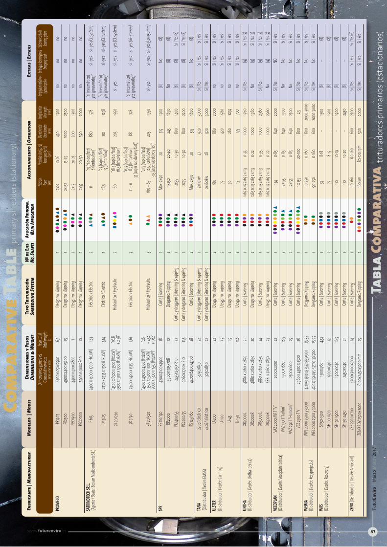
Com
para
tive
Tabl
epr
imar
y sh
redd
ers (
stat
iona
ry)
Tabl
a Co
mpa
rati
vatr
itura
dore
s prim
ario
s (es
taci
onar
ios)
Fabr
icant
e | M
anuf
actu
rer
Mod
elos
| M
odel
Di
men
sione
s y P
esos
Ti
po Tr
itura
ción
Nº
de Ej
es
Aplic
ació
n Prin
cipal
Ac
ciona
mie
nto
| Ope
ratio
nEx
tras
|Ext
ras
Dim
ensio
ns&
Weig
ht
Shre
ddin
gSy
stem
No
.Sha
fts
Main
Appl
icatio
n
Dimens
iones
genera
les
Peso t
otal
Potencia
Velo
cidad rot
or (50 Hz
) Diám
etro roto
r Long
itud roto
r Emp
ujador h
idráulico
Embragu
e de eme
rgencia
Sistema d
e cribado
Ge
neral d
imensi
ons
Total w
eight
Power
Rotor spe
ed (50 Hz
) Roto
r diamet
er Roto
r length
Hydrauli
c pusher
Eme
rgency cl
utch
Screening
system
(m
m x mm
x mm)
(t)
(kW)
(rpm)
(m
m)
(mm)
PROM
ECO
PR130
7 44
00x10
50x25
00
6,5
Desga
rro | R
ipping
2
ll
ls
ls
l
2x22
10-
16 430
130
0 no
no
no
PR
2500
4900
x440
0x520
0 25
Desga
rro | R
ipping
2
ll
ll
sl
2x1
32 13-
45 100
0 250
0 no
no
no
PB
O130
0 44
00x14
00x28
00
7 De
sgarro
| Ripp
ing
2 ll
ls
2x1
5 20
-25
200
1300
no
no
no
PBO2
000
5500
x1400
x2800
10
Desga
rro | R
ipping
2
ll
ls
2x3
7 20
-50
590
2000
no
no
no
SATR
INDTEC
H SR.L
. F 6
15 240
0 x 14
00 x 1
700 (
HxLxW
) 1,4
3 Elé
ctrico
/ Elec
tric
2 s
l l
s
11 “15
(rápid
o/fast
) 88
0 578
“sí
(neu
mátic
o)
sí - ye
s sí -
yes (C
L syste
m)
(Agent
e / De
aler: B
ossen
Medio
ambie
nte S.L
.)
8 (len
to/slo
w)”
yes (p
neuma
tic)”
K13
/25
2730 x
2335
x 1510
(HxLx
W)
3,14
Eéctric
o / Ele
ctric
2 s
ls
l 18,
5 “23
(rápid
o/fast
) 110
125
8 “sí
(neu
mátic
o)
sí - ye
s sí -
yes (C
L syste
m)
15 (len
to/slo
w)”
yes (p
neuma
tic)”
2R
20/22
0 “45
00 x 6
500 x 3
300 (H
xLxW)
“16
,8
“18
,5 (ráp
ido/fa
st)
3300 x
1500 x
1700 (
HxLxW
)” + 2
,58”
Hidráu
lico / H
ydrau
lic
2 l
l l
s l
160
16,5 (l
ento/
slow)
” 20
5 195
0 sí -
yes
sí - ye
s sí -
yes (C
L syst
em)
“15,5 (
rápido
/fast)
3K 7/3
0 234
0 x 14
20 x 1
575 (H
xLxW)
2,6
1 Elé
ctrico
/ Elec
tric
3 sl
l
11 + 11
8,5 (le
nto/sl
ow)
88
728
“sí (n
eumá
tico)
sí - ye
s sí -
yes (1
6÷50
mm)
37 (su
per ráp
ido/ve
ry fast
)”
yes
(pneu
matic)
”
“43
00 x 4
900 x
4700
(HxLx
W)
“26
“21,5 (
rápido
/fast)
3R 20
/320
3300 x
1500 x
1700 (
HxLxW
) + 2
,58
Hidráu
lico / H
ydrau
lic
3 l
ss
160
+ 65
18,5 (l
ento/
slow)
20
5 195
0 sí -
yes
sí - ye
s sí -
yes (5
0÷150
mm)
2000 x
1300 x
1550 (
HxLxW
)” + 1
,62”
31,5 (su
per ráp
ido/ve
ry fast
)” SPR
RS
110/13
0 420
0x510
0x49
00
18 Co
rte | S
hearin
g 2
l l
l l
Max. 2
x90
20
515
1300
(8)
No
(8)
RR20
00
3900
x1705
x708
10 De
sgarro
/Ripp
ing
2 l
l l
s
1x250
20
-40
245
1890
No
(8)
(8)
PC140
0/55
2455x2
315x18
10 7,7
Corte
y desg
arro |
Shear
ing &
rippin
g 1
l l
l s
2x5
5 10-
30
800
1400
(8)
(8)
Si | Ye
s (8)
PC
2200/5
5 30
60x27
00x18
10
11,5
Corte
y desg
arro |
Shear
ing &
rippin
g 1
l l
l s
2x5
5 10-
30
800
2200
(8)
(8)
Si | Ye
s (8)
RS
125/16
0 44
00x6
400x
4700
28 Co
rte | S
hearin
g 2
l l
l l
Max. 2
x90
20
515
1600
(8)
No
(8)TA
NA
220E/
eléctr
ico
3050
x850
22
Corte
y desg
arro |
Shear
ing &
rippin
g 1
2x1
10kw
27 92
0 30
00
Si | Ye
s Si |
Yes
Si | Ye
s (D
istrib
uidor
| Deal
er: EM
SA)
440E
/ eléc
trico
3050
x850
22
Corte
y desg
arro |
Shear
ing &
rippin
g 1
2x1
60kw
28
920
3000
Si |
Yes
Si | Ye
s Si |
Yes
ULSTE
R U-2
00
22
Desga
rro | R
ipping
2
l l
l l
180
88
0 20
00
no
Si | Ye
s Si |
Yes
(Distr
ibuido
r | De
aler: C
armaq
) U-
100
7,5
De
sgarro
| Ripp
ing
2 l
l l
l 75
420
158
0 no
Si |
Yes
Si | Ye
s
U-45
1,5
Desga
rro | R
ipping
2
l l
l l
30
26
0 107
4 no
Si |
Yes
Si | Ye
s
U-150
0,8
Desga
rro | R
ipping
2
l l
l l
15
175
700
no
Si | Ye
s Si |
Yes
UNTH
A XR
2000
C 48
80 x 2
160 x 2
850
21 Co
rte | S
hearin
g 1
l l
l l
1x65 1x
113 2x
65 2 x
113
0-35
1000
1960
Si | Ye
s (9)
Si |
Yes (5
)(Di
stribu
idor |
Deale
r: Unth
a Iberi
ca)
XR20
00R
4880
x 2160
x 2850
20
De
sgarro
| Ripp
ing
2 l
l l
l 1x6
5 1x113
2x65
2 x 113
0-2
2 100
0 196
0 No
(9)
Si |
Yes (5
)
XR30
00C
5880 x
2160 x
2850
24
Corte
| Shea
ring
1 l
l l
l 1x6
5 1x113
2x65
2 x 113
0-3
5 100
0 29
60
Si | Ye
s (9)
Si |
Yes (5
)
XR30
00R
5881 x
2160 x
2850
23
Desga
rro | R
ipping
1
l l
l l
1x65 1x
113 2x
65 2 x
113
0-22
1000
2960
No
(9)
Si |
Yes (5
)VE
COPLA
N VA
Z 200
0 MF T
“V”
2000
x2000
22
Corte
| Shea
ring
1 ll
lll
ll
s
134
0-85
640
2000
Si |
Yes
NO
Si | Ye
s (Di
stribu
idor |
Deale
r: Veco
plan I
béric
a) VV
Z 190
T “Tai
fun”
1900x
1680
18,5
Corte
| Shea
ring
2 ll
lll
s
2x155
0-85
640
1900
No
No
Si | Ye
s
VVZ 2
50 T “
Hurac
an”
2500x
1600
25 Co
rte | S
hearin
g 2
ll
lll
s
2x155
0-85
640
2500
No
No
Si | Ye
s
VEZ 2
500 T
V 29
60 x 4
300 x
2300
26
Co
rte | S
hearin
g 1
ll
lll
ll
s
1 x 155
20
-100
800
2,5
Si | Ye
s No
Si |
Yes
WEIM
A WP
L 200
0 250
0 y 30
00
4220x3
135x41
45-555
7x3135
x5100
25-
35 De
sgarro
/Ripp
ing
1 l
l l
110
-250
0-160
80
0 20
00-30
00
Si | Ye
s No
Si |
Yes
(Distr
ibuido
r | De
aler: R
ecypro
jects)
WE
L 200
0 250
0 y 30
00
4220x3
135x41
45 -555
7x3135
x5100
25-
35 De
sgarro
/Ripp
ing
1 l
l l
90
-250
0-160
60
0 20
00-30
00
Si | Ye
s No
Si |
Yes
WRS
SH50
-1300
130
0x76
0 4,5
7 Co
rte | S
hearin
g 2
l l
l l
l
37 8-1
8 --
1300
(8)
-- (8)
(Distr
ibuido
r | De
aler: R
ecover
y) SH
100-15
00
1500x
1040
12 Co
rte | S
hearin
g 2
l l
l l
l
75 8-1
5 --
1500
(8)
-- (8)
SH
150-19
00
1900x
1040
16,5
Corte
| Shea
ring
2 l
l l
l l
110
10-
19 --
1900
(8)
-- (8)
SH
150-24
50
2450x
1040
21 Co
rte | S
hearin
g 2
l l
l l
l
110
10-20
--
2450
(8)
-- (8)
ZENO (
Distrib
uidor
| Deal
er: Am
bisort
) ZE
Z 250
0x170
0 49
00x30
00x30
00
24 Co
rte | S
hearin
g 1
l l
110-16
0 120
-160
600
2500
Si | Ye
s Si |
Yes
Si | Ye
s (6)
ZE
NO ZD
V 250
0x20
00
6100x
2450x
3200 m
m 25
Desga
rro/Ri
pping
2
l l
ll
ll
l
160 kw
80
-120 r
pm
500
2000
Si |
Yes
Si | Ye
s Si |
Yes
Futu
rEn
viro
| M
arzo
Mar
ch 2
017
www.futurenviro.es 67

Forrec SRLViale dell‘Artigianato, 24 • 35010 Santa Giustina in Colle • (Padova) - ItaliaTel: +39 049 099 0015 • [email protected] www.forrec.eu
Un gran paso adelante en la evolución tecnológica: multi-desgarrador FR
Forrec ha diseñado una linea de máquinas para responder concretamente a la demanda de instrumentos más y más versátiles y capaces de adap-tarse a los cambios en los flujos de trabajo y a las necesidades de produc-ción, sino también dirigido a múltiples aplicaciones. De ahí la definición de multi-desgarradores, máquinas realizadas para el tratamiento de residuos sólidos urbanos, de los residuos voluminosos y residuos industriales en fardos y en sacos, capaz de operar en diversas áreas tales como:
Antes de un incinerador, para operar la reducción del volumen; Antes de la selección orgánica y no orgánica; En caso de necesidad de una reduc-ción de volumen antes del suministro en balas; En vertedero, para la re-ducción del volumen cuando es necesaria la separación y recuperación de la fracción combustible. Presente en el mercado desde hace varios años y con distintas marcas, en la cara de ciertas ventajas innegables, los multi-desgarradores han mostrado también algunos defectos que, lamentablemente, han influido fuertemente la difusión.
El potencial de este tipo de máquina ha presionado Forrec a iniciar una reconfiguración seria y completa. La contribución clave de un departa-mento de investigación y desarrollo experto y dinámico como aquello de Forrec, ha llevado a la resolución de algunos problemas presentes en las máquinas de otros fabricantes y ahora se manifiesta en la serie FR. Gracias a algunas innovaciones importantes, actualmente en fase de patente, Forrec ha resuelto los principales problemas que restringen el uso de multi-desgarradores hasta ahora en el mercado y ha creado una máquina versátil, fiable y conveniente.
Pero vemos en detalle las principales soluciones desarrolladas por Forrec y que, como hemos dicho, se encuentran pendientes de patente:
Primera patente: el tamaño del material de salida se obtiene a través de una mesa de corte separada de la estructura de la máquina, una so-lución que tiene una doble ventaja: la velocidad y la simplicidad en el mantenimiento y la alta capacidad de adaptación a las necesidades de producción porque se puede reemplazar fácilmente la mesa de corte para obtener un tamaño diferente del material de salida.
El objeto de la segunda patente es la estructura de las contra-cuchillas que están instaladas en ambos lados de la cuchilla, asegurando el des-gaste uniforme y la duplicación de la vida de las cuchillas. Esta tecnología también tiene la ventaja de reducir la carga axial de los cojinetes.
Forrec también a decidido de implementar en los multi-desgarradores FR algunas soluciones tecnológicas particulares que ya han tenido mu-cho éxito en trituradoras producidos por la Empresa. En detalle:
- La caja de cojinete es fuerte y rígida. Siendo instalada en las bridas de la cámara de corte impide la deformación de los cojinetes.
- Los cojinetes están diseñados con una cámara doble, así ponerlos lejos de la infiltración de residuos que puedan dañarlos
A step forward in technological evolution: multi-crusher FR
Always attentive to the evolution of the market and sensitive to the real needs of customers, Forrec has designed a machine which concretely responds to the demand for more and more versatile instruments and able to adapt to the changes in the workflows and high production needs, but also aimed to multiple applications. Hence the definition of multi-crusher, machines made for the treatment of urban solid waste, bulky waste and industrial waste in bales and sacks, capable of operating in various areas such as:
Before an incinerator, to operate the volume reduction; Before organic and non-organic selection; In case of need of a reduction of volume before baling; In landfill, to reduce the volume when separation and recovery of the fuel fraction is necessary. Present in the market for several years and with different brands, in the face of certain undeniable advantages, the multi-crushers have also shown some defects that, unfortunately, have strongly influenced the diffusion.
The potential of this type of machine has pressed Forrec to initiate serious and complete reconfiguration. The key contribution of an expert and dynamic research and development department such as that of Forrec has led to the resolution of some problems present in the machines of other manufacturers and is now manifested in the FR series. Thanks to some major innovations, currently under patent, Forrec has solved the main problems that restrict the use of multi-crushers so far in the market and has created a versatile, reliable and convenient machine.
But we see in detail the main solutions developed by Forrec and, as we have said, are pending patent:
First patent: the size of the output material is obtained through a cutting table separated from the structure of the machine, a solution that has a double advantage: speed and simplicity in maintenance and high adaptability to the Production requirements because the cutting table can be easily replaced to obtain a different size of the output material.
The object of the second patent is the structure of the counter-blades that are installed on both sides of the blade, ensuring uniform wear and duplication of blade life. This technology also has the advantage of reducing the axial load of the bearings. Forrec also decided to implement in the multi-crushers FR some particular technological solutions that have already been very successful in crushers produced by the Company. In detail:- The bearing housing is strong and rigid. Being installed in the
flanges of the cutting chamber prevents the deformation of the bearings.
- The bearings are designed with a double chamber, thus putting them away from infiltration of residues that could damage them
Technical Guide
Stationary & M
obile primary shredders
Guía Tecnica
Pre-Trituradores estacionarios y móviles
FuturEnviro | Marzo March 2017
ww
w.fu
ture
nvi
ro.e
s
68
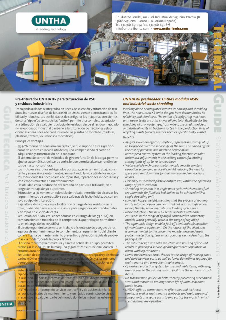
Pre-triturador UNTHA XR para trituración de RSU y residuos industrialesTrabajando aislados o integrados en líneas de selección y trituración de resi-duos, los nuevos diseños de la serie XR de Untha vienen demostrando su fia-bilidad y robustez. Las posibilidades de configurar las máquinas con dientes de corte “ripper”, o con cuchillas “cutter”, permite una completa adaptación a la trituración de cualquier tipología de residuos, desde el residuo mezclado no seleccionado industrial o urbano, a la trituración de fracciones selec-cionadas en las líneas de producción de las plantas de reciclado (maderas, plásticos, textiles, voluminosos específicos). Principales Ventajas:• 45-50% menos de consumo energético, lo que supone hasta 690.000
euros de ahorro en la vida útil del equipo, compensando el coste de adquisición y amortización de la máquina.
• El sistema de control de velocidad de giro en función de la carga, permite ajustes automáticos del par de corte, lo que permite alcanzar rendimien-tos de hasta 70 ton/hora.
• Los motores síncronos refrigerados por agua, permiten un trabajo cons-tante y suave sin calentamientos, aumentando la vida útil de los moto-res, reduciendo las necesidades de repuestos, reparaciones innecesarias y los tiempos muertos en mantenimientos.
• Flexibilidad en la producción del tamaño de partícula triturada, en el rango de trabajo de 50 a 400 mm.
• Trituración a 50 mm en un solo ciclo de trabajo, permitiendo alcanzar los requerimientos de combustible para calderas de lecho fluidizado, con un solo equipo de trituración.
• Baja altura de la tolva carga, facilitando la carga de los residuos en la tolva, pudiendo hacerse con una única pala cargadora, ahorrando costes y tiempos en el ciclo de carga.
• Reducción del ruido: emisiones sónicas en el rango de los 75 dB(A), en comparación con modelos de la competencia, que trabajan normalmen-te en el rango de los 105 dB(A)
• El diseño ergonómico permite un trabajo eficiente rápido y seguro de los equipos de mantenimiento. Se complementa a requerimiento del cliente con el sistema de mantenimiento preventivo y detección rápida de proble-mas vía módem, desde la propia fábrica.
• El diseño robusto y la estructura y carcasa sólida del equipo, permiten prolongar la vida útil de la máquina, y garantizar su funcionalidad en un entorno duro de trabajo.
• Reducción de costes de mantenimiento gracias a la concepción y diseño de partes móviles y de desgaste sólidas y de larga duración, y a los menores tiempos de parada necesarios para mantenimientos y sustituciones de piezas.
• Sistema optimizado de protección frente a materiales no triturables, con un rápido y fácil acceso a la cámara de corte para facilitar su retirada.
• La ausencia de poleas y correas de transmisión en el diseño, evitan es-fuerzos y tensiones mecánicas en los equipos y prolongan la vida útil y la duración de la maquinaria. Equipos hechos para durar.
• UNTHA ofrece un completo servicio post-venta y de asistencia técnica, así como contratos de mantenimiento y un rápido suministro de piezas y repuestos a cualquier parte del mundo donde las máquinas estén en operación.
UNTHA XR preshredder: Untha’s modular MSW and industrial waste shreddingWorking alone or integrated into waste sorting and shredding lines, the new Untha XR series designs have demonstrated its reliability and sturdiness. The option of configuring machines with ripper teeth or cutter knives allows total flexibility for the shredding of any waste type, from mixed, unsorted municipal or industrial waste to fractions sorted in the production lines of recycling plants (woods, plastics, textiles, specific bulky waste).Benefits:• 45-50% lower energy consumption, representing savings of up
to €690,000 over the service life of the unit. This saving offsets the cost of purchase and machine depreciation.
• Rotor speed control system in the loading function enables automatic adjustments in the cutting torque, facilitating throughputs of up to 70 tonnes/hour.
• Water-cooled synchronous motors enable smooth, constant operation, prolonging service life, whilst reducing the need for spare parts and downtime for maintenance and unnecessary repairs.
• Flexibility in shredded particle output size, within the operating range of 50 to 400 mm.
• Shredding to 50 mm in a single work cycle, which enables fuel requirements for fluidised bed boilers to be achieved with a single shredding unit.
• Low feed hopper height, meaning that the process of loading waste into the hopper can be carried out with a single wheel loader, thereby reducing costs and loading cycle times.
• Noise reduction– the new XR series operates with noise emissions in the range of 75 dB(A), compared to competing models which generally work in the range of 105 dB(A)
• The ergonomic design enables fast, efficient and safe operation of maintenance equipment. On the request of the client, this is complemented by the preventive maintenance and rapid problem-detection system, which operates via modem from the factory itself.
• The robust design and solid structure and housing of the unit results in prolonged service life and guarantees operation in harsh working conditions.
• Lower maintenance costs, thanks to the design of moving parts and durable wear parts, as well as lower downtimes required for maintenance and component replacement.
• Optimised protection system for unshreddable items, with easy, rapid access to the cutting area to facilitate the removal of such items.
• No transmission pulleys or belts, thereby preventing mechanical stress and tension to prolong service life of units. Machines made to last.
• UNTHA offers a comprehensive after sales and technical service, as well as maintenance contracts and rapid supply of components and spare parts to any part of the world in which the machines are operating.
C/ Eduardo Pondal, s/n • Pol. Industrial de Sigüeiro, Parcela 5815688 Sigüeiro – Oroso • La Coruña (España)Tel. +34 981 691054 Fax. +34 981 [email protected] • www.untha-iberica.com
Technical Guide
Stationary & M
obile primary shredders
Guía Tecnica
Pre-Trituradores estacionarios y móviles
Futu
rEn
viro
| M
arzo
Mar
ch 2
017
www.futurenviro.es 69

Com
para
tive
Tabl
eprim
ary
shre
dder
s (m
obile
)
Tabl
a Co
mpa
rati
vatr
itura
dore
s prim
ario
s (m
óvile
s)
Fabr
icant
e M
odel
os
Dim
ensio
nes y
Pes
os
Tipo
Tritu
ració
n Nº
de Ej
es Ap
licac
ión Pr
incip
al
Prod
ucció
n Ta
mañ
o M
ínim
o de
Red
ucció
nM
anuf
actu
rer
Mod
el
Dim
ensio
ns&
Weig
ht
Shre
ddin
gSy
stem
No
.Sha
fts
Main
Appl
icatio
nTh
roug
hput
M
inim
umR
educ
tion
Size
Dim
ensio
nes
Peso t
otal
Tamañ
o Alt
ura
Band
a
ge
neral
es Tot
al weig
ht alim
entac
ión
de ca
rga
evacua
ción
Ge
neral d
imens
ions
(t) en
trada
Inf
eed
Outpu
t
(m
m x m
m x m
m)
Inp
ut siz
e hei
ght
convey
er
EDGE
SLA
YER
11200
x250
0x320
0 22
0-
800
3200
1400
Corte
| She
aring
2
l l
l l
(2)
0-
40 m
m(D
istrib
uidor/
Deale
r: EMS
A) SLA
YER X
L 130
00x2
500x
3200
24
0-100
0 320
0 160
0 Co
rte | S
heari
ng
2 l
l l
l
(2)
0-40
mm
ELDAN
SC
1412 M
170
0x30
00x3
500
15 (3)
20
00
4500
100
0 Co
rte | S
heari
ng
1 l
sl
l l
ha
sta/up
to 12
<2
00 m
m
(Distr
ibuido
r/Deal
er: Rec
ycling
Equip
os)HA
AS Gm
bH
TYRO
N 150
0 101
55x254
0x315
0 21
n.n.
3150
Hasta /
Up to
6760
Corte
/ Shre
dding
2
<150 m
m
TYRO
N 150
0 XL
10155x
2540x
3150
21 n.n
. 315
0 Has
ta / Up
to 676
0 Co
rte / S
hredd
ing
2
<15
0 mm
TY
RON 2
000
10665
x254
0x315
0 24
,5 n.n
. 315
0 Has
ta / Up
to 676
0 Co
rte / S
hredd
ing
2
<15
0 mm
TY
RON 2
000 X
L 106
65x2
540x
3150
24,5
n.n.
3150
Hasta /
Up to
6760
Corte
/ Shre
dding
2
<150 m
m
TYRO
N 250
0 112
90x3
000x
3625
40
n.n.
3625
Hasta /
Up to
6760
Corte
/ Shre
dding
2
<150 m
mKO
MPTE
CH
TM34
00,TM
3400
SD,
9120 x
2550
x 336
0 mm
23,9-2
4,9
3020
x 180
0 mm
3005
42
50 m
m De
sgarr
o | Ri
pping
1
ll
l l
ll
l
45/30
- 100
/90
desd
e 10 a
100 m
m (Di
stribu
idor/D
ealer:
Masia
s Recy
cling)
TM50
00,TM
6000
SD
CRA
MBO 3
400,50
00, 60
00, 420
0, 912
0 x 25
50 x 3
360 m
m 24
-25,4
30
00 x 1
800 m
m 30
05
4250
mm
Desg
arro |
Ripp
ing
2 ll
l l
ll
l
45/35
-120/
100
desd
e 10 a
100 m
m
5200, 6
200
ME
TSO
1000, 4
000 y
6000
M&J
Eta
6465
x2100
x264
3 15-
63
-- 24
08 -3
519 (8
) 100
0 o/or
1200
Co
rte y d
esgarr
o 2
ll
l l
s s
ls
10
-150 (
RSU/
MSW)
; (D
istrib
uidor/
Deale
r: Recy
projec
ts)
114
10x271
0x40
60
Shea
ring &
rippin
g
5-8
0 (Vo
lumino
sos
Volum
inous
) <12
5 mm
SPR
RS110
/130
4200
x5100
x490
0 18
1100x
1300
-- 120
0 Co
rte | S
heari
ng
2 ll
l l
ha
sta/up
to 30
30
0 mm
RR
2000
39
00x17
05x7
08
10 189
0x124
5 --
1200
Desg
arro |
Ripp
ing
2 ll
l s
20
30
0 mm
PC
2200
/55
3060
x270
0x181
0 11,5
22
00x15
00
-- 120
0 Co
rte y d
esgarr
o 1
ll
l s
10
-15
300 m
m (7)
Shea
ring &
rippin
g TA
NA
220D
eco
10530
x2520
x403
0 24
tn 50
0 40
00
1000
corte y
desga
rro | Sh
earing
& rip
ping
1 l
l l
l
15 T/h
RS
U 50
t/h
50 m
m(Di
stribu
idor/D
ealer:
EMSA)
22
0DTec
o 105
30x2
8300
x403
0 26
tn 50
0 40
00
1000
corte y
desga
rro | Sh
earing
& rip
ping
1 l
l l
l
15 T/h
RS
U 50
t/h
50 m
m
440D
eco
10530
x2520
x403
0 27t
n 50
0 40
00
1000
corte y
desga
rro | Sh
earing
& rip
ping
1 l
l l
l
20 T/
h R
SU 6
0 t/h
50
mm
44
0DTec
o 105
30x2
8300
x403
0 29
tn 50
0 40
00
1000
corte y
desga
rro | Sh
earing
& rip
ping
1 l
l l
l
20 T/
h R
SU 6
0 t/h
50
mm
TERE
X TD
S 820
--
27
3200
1400
Desg
arro |
Ripp
ing
2 l
l l
ll
en
func
ion de
mate
rial
100 m
m(Di
stribu
idor/D
ealer:
Carma
q) TD
S V20
--
37
3200
1400
Corte
| She
aring
2
l l
l l
l
en fu
ncion
de m
ateria
l 30
mm
TS
S 390
--
30
320
0 120
0 De
sgarr
o | Ri
pping
1
l l
l l
l
en fu
ncion
de m
ateria
l 100
mm
VECO
PLAN
VM
Z 180
0 68
10x24
40x2
800
-- 170
0x150
0 28
00
1300
Desg
arro |
Ripp
ing
2 ll
l
5-15
<200
mm
VM
Z 360
0 910
0x370
0x250
0 --
1700x
1500
2500
1300
Desg
arro |
Ripp
ing
2 ll
l
15-60
<2
00 m
m
VMZ 7
700
10000
x370
0x250
0 --
2100x
1500
2500
1300
Desg
arro |
Ripp
ing
2 ll
l
30-10
0 <2
00 m
m UN
THA
XR M
OBILE
E 38
05 X
2950
X 12
710
37 29
60
2640
SI
AMBA
S VER
SIONE
S 1
l l
l l
ll
en
func
ión de
l mate
rial
35 mm
CD
R 15T/
h A 50
mm
Bioma
sa 35T
/h A
100 m
m
(1) Im
án m
alla
deb
ajo
de lo
s eje
s | M
esh
mag
net u
nder
shaf
ts(2
) En
func
ión
del m
ater
ial |
In a
ccor
danc
e w
ith m
ater
ial
(3) P
lata
form
a +
cam
ión
| Pla
tform
+ tr
uck
(4) To
dos l
os ti
pos d
e re
sidu
os y
mad
era/
All k
inds
of w
aste
and
woo
d | A
ll ki
nds o
f was
te a
nd w
ood
(5) A
sper
sor, f
aldo
nes |
Sprin
kler
s, gu
ards
(6) O
pcio
nal |
Opt
iona
l (7
) Var
iabl
e | V
aria
ble
(8) S
in to
lva
| With
out h
oppe
r
lN
FU |
ELT
l R
AEE
| WEE
E lC
hata
rra
| Scr
ap
lV
olum
inos
os |
Volu
min
ous
lB
iom
asa
| Bio
mas
s lR
SU |
MSW
lM
ader
a | w
ood
lA
lum
inio
| Al
umin
ium
lC
DR
| SRF
lR
CD |
C&DW
lIn
dust
rial |
Indu
stria
lsP
lást
icos
| Pl
astic
ssV
FU |
ELT
sC
omer
cial
es |
Com
ercia
l
sM
etal
es n
o fé
rric
os
N
on fe
rrou
s met
als
sP
apel
| Pa
per
sC
able
s | C
able
ssC
artó
n | P
aper
boar
dsT
extil
| Te
xtile
sV
idrio
| Gl
ass
FuturEnviro | Marzo March 2017
ww
w.fu
ture
nvi
ro.e
s
70
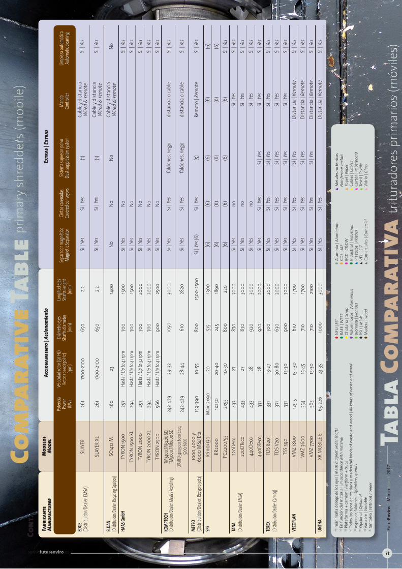
Com
para
tive
Tabl
eprim
ary
shre
dder
s (m
obile
)
Tabl
a Co
mpa
rati
vatr
itura
dore
s prim
ario
s (m
óvile
s)
Cont
.Fa
brica
nte
Mod
elos
Ac
ciona
mie
nto
| Acc
iona
mie
nto
Extr
as | E
xtra
s M
anuf
actu
rer
Mod
el
Po
tencia
Ve
locida
d roto
r (50 H
z) Diá
metro
ejes
Longit
ud ej
es Se
parad
or ma
gnéti
co
Cintas
caren
adas
Sistem
a sup
resor
polvo
Ma
ndo
Limpie
za au
tomáti
ca
Powe
r Ro
tor sp
eed (
50 Hz
) Sh
afts d
iamete
r Sh
afts le
nght
Magn
etic S
epara
tor
Cover
ed co
nveyo
rs Du
st su
ppres
sion s
ystem
Co
ntroll
er Au
tomati
c clea
ning
(kW
) (rp
m)
(mm)
(m
m)
EDGE
SL
AYER
26
1 17
00-2
100
650
2,2
Si | Y
es
Si | Y
es
(1)
Cabl
e y d
istan
cia
Si | Y
es
(Dist
ribuid
or/De
aler: E
MSA)
Wire
d &
rem
ote
SL
AYER
XL
261
1700
-210
0 65
0 2,2
Si
| Yes
Si
| Yes
(1)
Ca
ble y
dist
ancia
Si
| Yes
Wire
d &
rem
ote
ELDAN
SC
1412
M
160
23
14
00
No
No
No
Cabl
e y d
istan
cia
No
(Distr
ibuido
r/Deal
er: Rec
ycling
Equip
os)
Wire
d &
rem
ote
HAAS
GmbH
TY
RON
1500
25
7 Ha
sta / U
p to 4
1 rpm
70
0 15
00
Si | Y
es
No
Si | Y
es
TYRO
N 15
00 X
L 29
4 Ha
sta / U
p to 4
1 rpm
70
0 15
00
Si | Y
es
No
Si | Y
es
TYRO
N 20
00
257
Hasta
/ Up t
o 32 r
pm
700
2000
Si
| Yes
No
Si
| Yes
TY
RON
2000
XL
294
Hasta
/ Up t
o 41 r
pm
700
2000
Si
| Yes
No
Si
| Yes
TY
RON
2500
56
6 Ha
sta / U
p to 4
1 rpm
90
0 25
00
Si | Y
es
No
Si | Y
esKO
MPTE
CH
TM34
00,TM
3400
SD,
242-
429
29-3
2 10
50
3000
Si
| Yes
Si
| Yes
fa
ldon
es, ri
ego
dist
ancia
o ca
ble
Si | Y
es
(Distr
ibuido
r/Deal
er: Ma
sias R
ecyclin
g) TM
5000
,TM60
00 SD
CRA
MBO 3
400,50
00, 60
00, 420
0, 24
2-42
9 28
-44
610
2820
Si
| Yes
Si
| Yes
fa
ldon
es, ri
ego
dist
ancia
o ca
ble
Si | Y
es
520
0, 6200
ME
TSO
1000
, 400
0 y
(Dist
ribuid
or/De
aler: R
ecypro
jects)
60
00 M
&J E
ta
159-
390
10-5
5 80
0 15
00-2
500
Si | Y
es (6
) Si
| Yes
(5
) Re
mot
o | R
emot
e Si
| Yes
SPR
RS110
/130
M
ax. 2
x90
20
515
1300
(6
) (6
) (6
) (6
) (6
)
RR20
00
1x25
0 20
-40
245
1890
(6
) (6
) (6
) (6
) (6
)
PC22
00/5
5 2x
55
10-3
0 80
0 22
0 (6
) (6
) (6
) (6
) Si
| Yes
TANA
22
0Dec
o 43
3 27
87
0 30
00
Si | Y
es
no
Si
| Yes
Si
| Yes
(Di
stribu
idor/D
ealer:
EMSA)
22
0DTe
co
433
27
870
3000
Si
| Yes
no
Si | Y
es
Si | Y
es
44
0Dec
o 43
3 28
92
0 30
00
Si | Y
es
no
Si
| Yes
Si
| Yes
440D
Teco
33
1 28
92
0 20
00
Si | Y
es
Si | Y
es
Si | Y
es
Si | Y
es
Si | Y
es
TERE
X TD
S 820
33
1 13
-27
700
2000
Si
| Yes
Si
| Yes
Si
| Yes
Si
| Yes
Si
| Yes
(Distr
ibuido
r/Deal
er: Car
maq)
TDS V
20
371
30-8
0 63
0 20
00
Si | Y
es
Si | Y
es
Si | Y
es
Si | Y
es
Si | Y
es
TSS 3
90
331
13-3
0 90
0 30
00
Si | Y
es
Si | Y
es
Si | Y
es
Si | Y
es
Si | Y
esVE
COPL
AN
VMZ
1800
12
9,5
15 -
30
610
1700
Si
| Yes
Si
| Yes
Si
| Yes
Di
stan
cia | R
emot
e Si
| Yes
VM
Z 36
00
354
15-4
5 71
0 17
00
Si | Y
es
Si | Y
es
Si | Y
es
Dist
ancia
| Rem
ote
Si | Y
es
VMZ
7700
56
3 15
-30
710
2100
Si
| Yes
Si
| Yes
Si
| Yes
Di
stan
cia | R
emot
e Si
| Yes
UNTH
A XR
MOB
ILE E
65
-226
23
-35
1000
30
00
SI | Y
es
SI | Y
es
Di
stan
cia | R
emot
e SI
| Yes
(1) Im
án m
alla
deb
ajo
de lo
s eje
s | M
esh
mag
net u
nder
shaf
ts(2
) En
func
ión
del m
ater
ial |
In a
ccor
danc
e w
ith m
ater
ial
(3) P
lata
form
a +
cam
ión
| Pla
tfor
m +
truc
k(4
) Todo
s los
tipo
s de
resi
duos
y m
ader
a/Al
l kin
ds o
f was
te a
nd w
ood
| All
kind
s of w
aste
and
woo
d(5
) Asp
erso
r, fal
done
s | Sp
rinkl
ers,
guar
ds(6
) Opc
iona
l | O
ptio
nal
(7) V
aria
ble
| Var
iabl
e(8
) Sin
tolv
a | W
ithou
t hop
per
lN
FU |
ELT
l R
AEE
| WEE
E lC
hata
rra
| Scr
ap
lV
olum
inos
os |
Volu
min
ous
lB
iom
asa
| Bio
mas
s lR
SU |
MSW
lM
ader
a | w
ood
lA
lum
inio
| Al
umin
ium
lC
DR
| SRF
lR
CD |
C&DW
lIn
dust
rial |
Indu
stria
lsP
lást
icos
| Pl
astic
ssV
FU |
ELT
sC
omer
cial
es |
Com
ercia
l
sM
etal
es n
o fé
rric
os
N
on fe
rrou
s met
als
sP
apel
| Pa
per
sC
able
s | C
able
ssC
artó
n | P
aper
boar
dsT
extil
| Te
xtile
sV
idrio
| Gl
ass
Futu
rEn
viro
| M
arzo
Mar
ch 2
017
www.futurenviro.es 71


Trituradoras de residuos Tanashark: Versatilidad única: Elegir Tana Shark, implica disponer de una amplia variedad de posibilidades ya que puede utilizar en trituración previa, secundaria para neumáticos, residuos indus-triales , RCD, CDR, RSU, plásticos, madera , pallets, traviesas de ferrocarril, colchones , cables y otros materiales especiales. Las trituradoras de resi-duos Tana Shark, es una de las trituradoras de residuos más versátil del mercado, incluso para los materiales más complicados Tana Shark utiliza una transmisión motopropulsora hidroestática idéntica a la que utilizan los compactadores de residuos de Tana. Además, introduce una estructura patentada de chasis oscilante.
Fácil operatividad: El Sistema de Control de Tana (TCS) supervisa y contro-la todas las funciones de la máquina. Hay 12 programas de funcionamien-to pre-programados para diferentes tipos de materiales y operaciones de trituración. Además, se pueden añadir programas específicos según el cliente para conseguir el resultado deseado. Si un objeto no triturable blo-quea el rotor, el TCS hace que la máquina funcione marcha atrás y lo inten-ta varias veces hasta que el objeto pasa o la máquina se detiene. El objeto no triturable se puede retirar de forma rápida y segura por la pared lateral.
Tana ProTrack® evita paradas imprevistas: Tana Shark cuenta con caracterís-ticas inteligentes integradas denominadas Tana ProTrack®. Permite que tanto el Centro de Servicio Técnico de Tana, el representante local de Tana y el cliente puedan acceder a internet y ver los datos de la máquina en tiempo real.
Fácil de utilizar y mantener: Una de las características inteligentes para el funcionamiento diario es la pared lateral con apertura. Esta caracterís-tica proporciona un acceso fácil y seguro a la hora de limpiar y eliminar objetos no triturables que se atascan en el eje del rotor; Así como para cambiar y sustituir las cuchillas y las contracuchillas del rotor.
Ajuste del tamaño del producto final con contracuchillas: Para conseguir reducir los volúmenes y para la trituración previa se pueden sustituir dos tercios de las contracuchillas con mitades de cuchillas, lo que permite un mayor tamaño del producto final y mayor capacidad. El uso de cribas del rotor permite ajustar la homogeneidad del tamaño de partículas pequeñas.
Producir tamaños de partículas desde 50 hasta 500 mm: El tamaño y la calidad del producto final pueden determinarse y finalizarse utilizando una criba del rotor con el tamaño de malla adecuado entre los cinco dis-ponibles. El tamaño adecuado lo definen las características del material y el tamaño deseado del producto final.
Espacio ajustable entre el rotor y la criba: El espacio entre el rotor y la criba se puede estrechar hasta un milímetro. El hueco opcional depende del material y del tamaño de malla utilizado en la criba. Para añadir o quitar la criba del motor se necesitan tan solo 10 minutos.
Cuchillas universales: Misma cuchilla para todo tipo de material La con-figuración del rotor y el diseño de las cuchillas dan como resultado un efecto de corte a mitad, que permite que Tana Shark triture práctica-mente cualquier fracción de residuo sólido.
Tana shark waste shredders: Unique versatility: Choosing Tana Shark opens up a wide variety of options. Tana Shark shredders can be used for primary shredding, secondary shredding of tyres, industrial waste, C&D waste, RDF, MSW, plastics, wood, pallets, railway sleepers, mattresses, cables and other special materials. Tana Shark waste shredders are amongst the most versatile on the market, even for the toughest of materials. Tana Shark shredders use a hydrostatic power transmission identical to that used in Tana waste compactors. They also feature a patented swing frame structure.
Easy operation: The Tana Control System (TCS) monitors and controls all the functions of the machine. There are 12 pre-programmable cycles for different material types and shredding operations. And further client-specified programmes can be added to to achieve the desired results. If a non-crushable material blocks the rotor, the TCS automatically implements reverse mode until the object in question passes or the machine stops. The non-crushable material can be removed quickly and safely through the side wall.
Tana ProTrack® prevents unforeseen downtime: Tana Shark shredders feature the Tana ProTrack® series of integrated smart features, which enables the Tana Technical Service Centre, Tana’s local agent and the customer to see machine data online in real time.
Easy to use and repair: One of the smart features of the shredder is the opening side wall, which provides easy, safe access for cleaning and removal of non-crushable objects that might block the rotor shaft. It also facilitates knife and counter knife replacement.
Adjustment of end product size with counter knives: For volume reducing and primary shredding purposes, two thirds of the counter knives can be replaced with half knives, which enables larger end product size and higher capacity. The use of rotor screens facilitates the homogeneity of small particle sizes.
Produce particles sizes ranging from 50 to 500 mm: End product size and quality can be determined and finalised by using a rotor screen with the most appropriate of five available mesh sizes. The most suitable size is defined by the characteristics of the material and the desired end product size.
Adjustable rotor to screen clearance: Rotor to screen clearance can be reduced right down to to one millimetre. The optimal clearance depends on the material and the mesh size of the screen. The screen can be fitted or removed in just 10 minutes.
Universal knives: The same knife can be used for any material. The rotor configuration and knife design result in a half cutting effect, which allows the TANA Shark to shred practically any solid waste fraction.
EMSAA-4 salida 20 • PintoTel.: +34 913 078 133 • E-mail: [email protected]
ical GuideStationary &
Mobile prim
ary shredders
Guía Tecnica
Pre-Trituradores estacionarios y móviles
Futu
rEn
viro
| M
arzo
Mar
ch 2
017
www.futurenviro.es 73
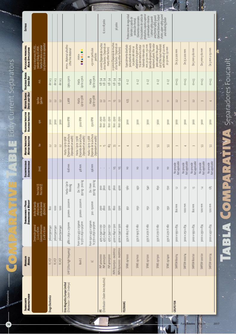
Com
para
tive
Tabl
eEddy
Cur
rent
Sep
arat
ors
Tabl
a Co
mpa
rati
vaSe
para
dore
s Fou
caul
t
Fabr
icant
e M
odel
os
Dime
nsio
nes y
Peso
s Ex
cent
ricid
ad
Mot
or In
duct
or
Velo
cidad
Indu
ctor
Mot
or Ba
nda
Velo
cidad
Band
a Ap
licac
ión
prin
cipal
Ex
tras
M
anuf
actu
rer
Mod
els
Dime
nsio
ns&
Weig
ht
Exce
ntric
idad
M
otor
Indu
ctor
Ve
locid
adIn
ducto
rDr
iveun
itBe
ltSp
eedBe
ltM
ain
Appl
icatio
n
Dim
ensió
n gen
eral
Ancho
de ba
nda
Indicar
si: Vol
umino
sos, NF
U, RSU,
….
(L x
A x H
) mm
efecti
vo (m
m)
Peso t
otal (t
)
tipo/k
w
Indica
te if B
ulky, E
LT, MS
W…
Gener
al dim
ension
s An
cho de
band
a Pes
o tota
l (t)
(mm)
kw
rpm
typ
e/kw
m/s
Tamañ
o de p
ieza a
sepa
rar
(L x W
x H) m
m efe
ctivo
(mm)
Siz
e of el
ement
s to be
sepa
rated
Drag
o Elec
tronic
a FC
-FCF
3160x
1390x
1340
800
2,2
3000
2,2
de
1 a 3
FC
-FCF
3160x
1590x
1340
1000
2,2
3000
2,2
de
1 a 3
FC
-FCF
3160x
1790x
1340
1200
2,2
3000
2,2
de
1 a 3
Eri
ez Ma
gneti
cs Eu
rope L
imite
d
Hasta
/ Up t
o
Hasta
/ Up t
o 15K
W
1mm+
. Mate
rial u
ltrafin
o
(Dist
ribuid
or / D
ealer
: Sind
erya)
UHF (
Ultra
High F
reque
ncy)
4880
x 263
0 x 27
91mm
300m
m - 2
000m
m 66
00kg
60
8 mm
(Dep
ende
de la
anch
ura
6000
RPM
2.2KW
Up
to 2.5
m/s
Ultra
Fine M
ateria
l
De
pend
ant o
n widt
h)
Fro
m 132
0 x 45
5 x 12
59mm
De / F
rom
Ha
sta / U
p to
7.5KW
Hasta
Ha
sta
1mm+
RevX
-E to
3170
x 263
0 x 90
3mm
300m
m - 2
000m
m 95
0 kg -
3100
kg
418 m
m (D
epen
de de
la an
chura
30
00 RP
M Up
to 1.5
KW
Up to
2.5m/
s ll
sl
sl
l
Depe
ndan
t on w
idth)
From
1320 x
455 x
1259
mm
De
/ From
Hasta
/ Up t
o 5.5
KW
Ha
sta
Hasta
l
LC
to 317
0 x 26
30 x 9
03mm
30
0 - 15
00mm
95
0 kg -
3100
kg
296 m
m (D
epen
de de
la an
chura
250
0 RPM
Up
to 1.5
KW
Up to
2.5m/
s +5
0 mm
partí
culas
Depe
ndan
t on w
idth)
pa
rticle
s
IFE
INP 4
00x2
000
4315
x 234
0 x 12
50
2300
3100
- 11
600 -
2500
2,2
0,8
- 3,4
(Di
stribu
idor /
Deale
r: Arie
s Indu
strial
) IN
P 400
x250
0 43
15 x 2
840 x
1250
28
00
3600
-
15 60
0 - 25
00
2,2
0,8 - 3
,4
6, 10 o
18 po
los
IN
P 400
x300
0 43
15 x 3
340 x
1250
330
0 410
0 -
18,5
600 -
2500
3
0,8 - 3
,4
INPX
650x
1500 -
excén
trico
42
00 x 1
840 x
1300
180
0 36
00
125
7,5
600 -
2500
1,5
0,8
- 3,4
IN
PX 65
0x20
00 - e
xcéntr
ico
4200
x 234
0 x 13
00
2300
4200
125
11
600 -
2500
2,2
0,8
- 3,4
36
polos
FELEM
AMG
SF
ME-29
/1000
337
0 X 18
05 X
1180
950
1360
110
4 30
00
0,75
0- 2,7
SF
ME-29
/1100
337
0 X 19
05 X
1180
1050
1450
110
4 30
00
1,1 0-
2,7
SF
ME-29
/1200
337
0 X 20
70 X
1180
1150
1540
110
5,5
3000
1,1
0- 2,7
SFME
-29/13
00
3370 X
2170
X 118
0 125
0 163
0 110
5,5
30
00
1,1 0-
2,7
SF
ME-29
/1400
337
0 X 22
70 X
1180
1350
1720
110
5,5
3000
1,1
0- 2,7
GR
UPO F
EM
SMFE
M 80
0/14
3000
x 195
0 x 87
4 80
0 mm
1,2
No pr
oced
e 3
3000
2,2
0>
=2,5
De 25
a 200
mm
No
t app
licable
SM
FEM
1000/
14 30
00 x 2
150 x 8
74 100
0 mm
1,3
No pr
oced
e 4
3000
3
0>=2
,5 De
25 a 2
00 m
m
Not a
pplica
ble
SMFE
M 80
0/20
30
00 x 1
950 x
874
800 m
m 1,5
No
proc
ede
3 30
00
2,2
0>=2
,5 De
3 mm
y 60 m
m
Not a
pplica
ble
SMFE
M 120
0/20
30
00 x 2
350 x 8
74 120
0 mm
1,4
No pr
oced
e 5,5
30
00
3 0>
=2,5
De 3 m
m y 6
0 mm
No
t app
licable
SM
FEM
1200/
24
3000
x 245
0 x 87
4 120
0 mm
1,8
5 No
proc
ede
5,5
3000
4
0>=2
,5 De
3 mm
a 150
mm
Not a
pplica
ble
Especi
almen
te dis
eñad
o pa
ra pla
nta de
resid
uos.
Los po
los de
l rotor
se
adap
tarán
a la g
ranulo
me-
tría de
l mate
rial a
tratar
ha
biend
o inte
rvalos
<20
mm; 20
-50 m
m; >5
0 mm
Spe
cially
desig
ned f
or wa
ste
treatm
ent p
lants.
The r
otor
poles
adap
t to th
e grai
n siz
e of th
e inpu
t mate
rials
with
interv
als of
<20 m
m;
20-50
mm;
>50 m
m
Protec
cione
s de s
eguri
dad
latera
les y c
apota
de
protec
ción f
rontal
. Ele
mento
s opc
ionale
s: En
cauzad
ores d
e sali
da de
pro
ducto
s, cap
ota su
perio
r y a
limen
tador
vibran
te / L
ateral
safet
y gua
rds
and f
rontal
safet
y gua
rd.
Optio
nal fe
atures
: Outp
ut ch
utes, u
pper
safety
guard
an
d vibr
ating
feed
er
0-50m
m (De
pend
e de m
uchos
otros
facto
res / D
epen
ds on
ma
ny ot
her fa
ctors)
0-xmm
(Dep
ende
de m
uchos
otros
facto
res / D
epen
ds on
ma
ny ot
her fa
ctors)
FuturEnviro | Marzo March 2017
ww
w.fu
ture
nvi
ro.e
s
74
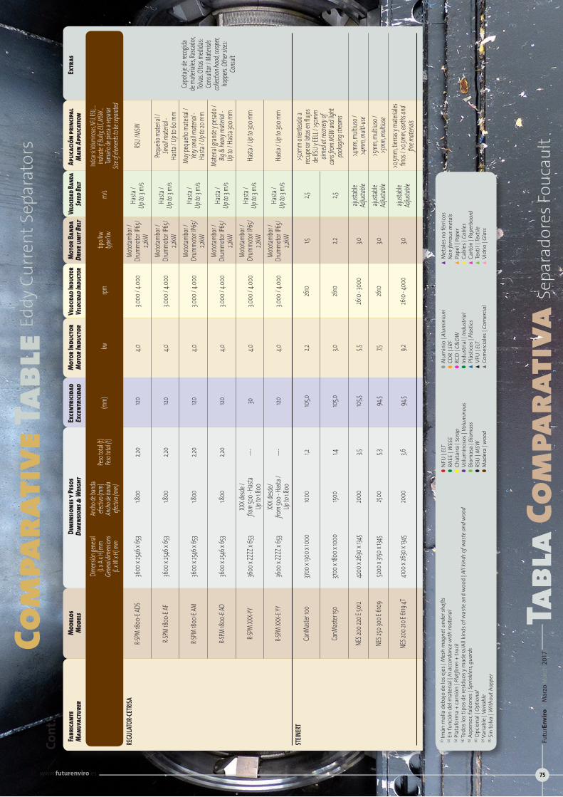
Com
para
tive
Tabl
eEddy
Cur
rent
Sep
arat
ors
Tabl
a Co
mpa
rati
vaSe
para
dore
s Fou
caul
t
Fabr
icant
e M
odel
os
Dime
nsio
nes y
Peso
s Ex
cent
ricid
ad
Mot
or In
duct
or
Velo
cidad
Indu
ctor
Mot
or Ba
nda
Velo
cidad
Band
a Ap
licac
ión
prin
cipal
Ex
tras
M
anuf
actu
rer
Mod
els
Dime
nsio
ns&
Weig
ht
Exce
ntric
idad
M
otor
Indu
ctor
Ve
locid
adIn
ducto
rDr
iveun
itBe
ltSp
eedBe
ltM
ain
Appl
icatio
n
Dim
ensió
n gen
eral
Ancho
de ba
nda
Indicar
si: Vol
umino
sos, NF
U, RSU,
….
(L x
A x H
) mm
efecti
vo (m
m)
Peso t
otal (t
)
tipo/k
w
Indica
te if B
ulky, E
LT, MS
W…
Gener
al dim
ension
s An
cho de
band
a Pes
o tota
l (t)
(mm)
kw
rpm
typ
e/kw
m/s
Tamañ
o de p
ieza a
sepa
rar
(L x W
x H) m
m efe
ctivo
(mm)
Siz
e of el
ement
s to be
sepa
rated
REGU
LATO
R-CET
RISA
Mo
totam
bor /
Ha
sta /
R-SPM
1800
-E AD
S 36
00 x 2
546 x
653
1.800
2,2
0 120
4,0
3.0
00 / 4
.000
Drum
motor
IP65
/ Up
to 3 m
/s RS
U /MS
W
2,2
kW
Motot
ambo
r /
Hasta
/ Pe
queñ
o mate
rial /
R-SPM
1800
-E AF
36
00 x 2
546 x
653
1.800
2,2
0 120
4,0
3.0
00 / 4
.000
Drum
motor
IP65
/ Up
to 3 m
/s Sm
all m
ateria
l -
2,2
kW
Ha
sta / U
p to 6
0 mm
Motot
ambo
r /
Hasta
/ Mu
y peq
ueño
mate
rial /
R-SPM
1800
-E AM
36
00 x 2
546 x
653
1.800
2,2
0 120
4,0
3.0
00 / 4
.000
Drum
motor
IP65
/ Up
to 3 m
/s Ve
ry sm
all m
ateria
l -
2,2kW
Hasta
/ Up t
o 20 m
m
Mo
totam
bor /
Ha
sta /
Mater
ial gr
ande
y pesa
do /
R-S
PM 18
00-E
AD
3600
x 254
6 x 65
3 1.8
00
2,20
120
4,0
3.000
/ 4.00
0 Dr
ummo
tor IP
65/
Up to
3 m/s
Big &
heav
y mate
rial -
2,2
kW
Up
to / H
asta 3
00 m
m
XXX d
esde /
Mo
totam
bor /
Ha
sta /
R-S
PM XX
X-YY
3600
x ZZZ
Z x 65
3 fro
m 50
0 - Ha
sta
----
30
4,0
3.000
/ 4.00
0 Dr
ummo
tor IP
65/
Up to
3 m/s
Hasta
/ Up t
o 300
mm
Up
to 1.8
00
2,2kW
XX
X desd
e/
Mo
totam
bor /
Ha
sta /
R-S
PM XX
X-E YY
36
00 x Z
ZZZ x
653
from
500 -
Hasta
/ ---
- 120
4,0
3.0
00 / 4
.000
Drum
motor
IP65
/ Up
to 3 m
/s Ha
sta / U
p to 3
00 m
m
Up to
1.800
2,2
kW
STEIN
ERT
Ca
nMast
er 100
370
0 x 13
00 x 1
000
1000
1,2
105,0
2,2
2610
1,5
2,5
Ca
nMast
er 150
370
0 x 18
00 x 1
000
1500
1,4
105,0
3,0
2610
2,2
2,5
NES 2
00 22
0 E 50
12 42
00 x 2
630 x
1345
20
00
3,5
105,5
5,5
2610
- 300
0 3,0
aju
stable
>4
mm, m
ultius
o /
Ad
justab
le >4
mm, m
ulti-u
se
NE
S 250
300 E
6109
520
0 x 31
50 x 1
345
2500
5,3
94,5
7,5
2610
3,0
ajusta
ble
>5mm
, mult
iuso /
Adjus
table
>5mm
, mult
iuse
>0
,5mm,
tierra
s y m
ateria
les
NE
S 200
210 E
6119
4T
4100 x
2630
x 134
5 20
00
3,6
94,5
9,2
2610
- 400
0 3,0
aju
stable
fin
os / >
0.5mm
, earth
s and
Adjus
table
fine m
ateria
ls
Capo
taje d
e reco
gida
de m
ateria
les, Ra
scado
r, Tol
vas. O
tras m
edida
s: Co
nsult
ar / M
ateria
ls col
lectio
n hoo
d, scra
per,
hopp
ers. O
ther si
zes:
Consu
lt
>50m
m ori
entea
do a
recup
erar la
tas en
flujos
de
RSU y
EELL
/ >50
mm
aimed
at re
covery
of
cans fr
om M
SW an
d ligh
t pa
ckagin
g stre
ams
Cont
.
(1) Im
án m
alla
deb
ajo
de lo
s eje
s | M
esh
mag
net u
nder
shaf
ts(2
) En
func
ión
del m
ater
ial |
In a
ccor
danc
e w
ith m
ater
ial
(3) P
lata
form
a +
cam
ión
| Pla
tform
+ tr
uck
(4) To
dos l
os ti
pos d
e re
sidu
os y
mad
era/
All k
inds
of w
aste
and
woo
d | A
ll ki
nds o
f was
te a
nd w
ood
(5) A
sper
sor, f
aldo
nes |
Sprin
kler
s, gu
ards
(6) O
pcio
nal |
Opt
iona
l (7
) Var
iabl
e | V
aria
ble
(8) S
in to
lva
| With
out h
oppe
r
lN
FU |
ELT
l R
AEE
| WEE
E lC
hata
rra
| Scr
ap
lV
olum
inos
os |
Volu
min
ous
lB
iom
asa
| Bio
mas
s lR
SU |
MSW
lM
ader
a | w
ood
lA
lum
inio
| Al
umin
ium
lC
DR
| SRF
lR
CD |
C&DW
lIn
dust
rial |
Indu
stria
lsP
lást
icos
| Pl
astic
ssV
FU |
ELT
sC
omer
cial
es |
Com
ercia
l
sM
etal
es n
o fé
rric
os
N
on fe
rrou
s met
als
sP
apel
| Pa
per
sC
able
s | C
able
ssC
artó
n | P
aper
boar
dsT
extil
| Te
xtile
sV
idrio
| Gl
ass
Futu
rEn
viro
| M
arzo
Mar
ch 2
017
www.futurenviro.es 75
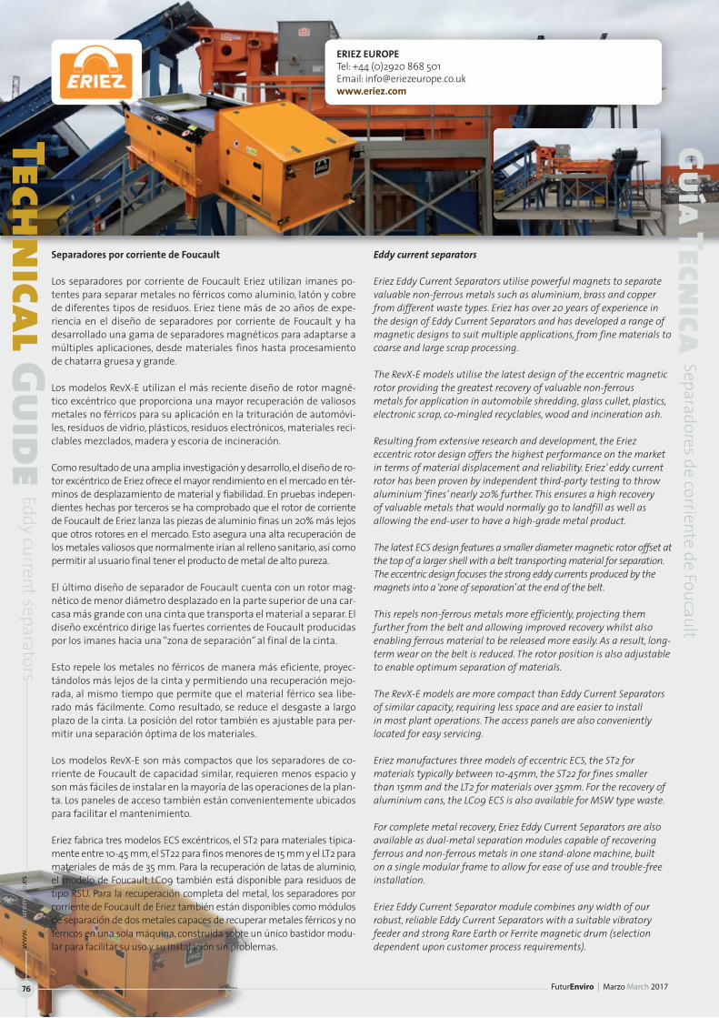
ERIEZ EUROPETel: +44 (0)2920 868 501Email: [email protected]
Separadores por corriente de Foucault
Los separadores por corriente de Foucault Eriez utilizan imanes po-tentes para separar metales no férricos como aluminio, latón y cobre de diferentes tipos de residuos. Eriez tiene más de 20 años de expe-riencia en el diseño de separadores por corriente de Foucault y ha desarrollado una gama de separadores magnéticos para adaptarse a múltiples aplicaciones, desde materiales finos hasta procesamiento de chatarra gruesa y grande.
Los modelos RevX-E utilizan el más reciente diseño de rotor magné-tico excéntrico que proporciona una mayor recuperación de valiosos metales no férricos para su aplicación en la trituración de automóvi-les, residuos de vidrio, plásticos, residuos electrónicos, materiales reci-clables mezclados, madera y escoria de incineración.
Como resultado de una amplia investigación y desarrollo, el diseño de ro-tor excéntrico de Eriez ofrece el mayor rendimiento en el mercado en tér-minos de desplazamiento de material y fiabilidad. En pruebas indepen-dientes hechas por terceros se ha comprobado que el rotor de corriente de Foucault de Eriez lanza las piezas de aluminio finas un 20% más lejos que otros rotores en el mercado. Esto asegura una alta recuperación de los metales valiosos que normalmente irían al relleno sanitario, así como permitir al usuario final tener el producto de metal de alto pureza.
El último diseño de separador de Foucault cuenta con un rotor mag-nético de menor diámetro desplazado en la parte superior de una car-casa más grande con una cinta que transporta el material a separar. El diseño excéntrico dirige las fuertes corrientes de Foucault producidas por los imanes hacia una “zona de separación” al final de la cinta.
Esto repele los metales no férricos de manera más eficiente, proyec-tándolos más lejos de la cinta y permitiendo una recuperación mejo-rada, al mismo tiempo que permite que el material férrico sea libe-rado más fácilmente. Como resultado, se reduce el desgaste a largo plazo de la cinta. La posición del rotor también es ajustable para per-mitir una separación óptima de los materiales.
Los modelos RevX-E son más compactos que los separadores de co-rriente de Foucault de capacidad similar, requieren menos espacio y son más fáciles de instalar en la mayoría de las operaciones de la plan-ta. Los paneles de acceso también están convenientemente ubicados para facilitar el mantenimiento.
Eriez fabrica tres modelos ECS excéntricos, el ST2 para materiales típica-mente entre 10-45 mm, el ST22 para finos menores de 15 mm y el LT2 para materiales de más de 35 mm. Para la recuperación de latas de aluminio, el modelo de Foucault LC09 también está disponible para residuos de tipo RSU. Para la recuperación completa del metal, los separadores por corriente de Foucault de Eriez también están disponibles como módulos de separación de dos metales capaces de recuperar metales férricos y no férricos en una sola máquina, construida sobre un único bastidor modu-lar para facilitar su uso y su instalación sin problemas.
Eddy current separators
Eriez Eddy Current Separators utilise powerful magnets to separate valuable non-ferrous metals such as aluminium, brass and copper from different waste types. Eriez has over 20 years of experience in the design of Eddy Current Separators and has developed a range of magnetic designs to suit multiple applications, from fine materials to coarse and large scrap processing.
The RevX-E models utilise the latest design of the eccentric magnetic rotor providing the greatest recovery of valuable non-ferrous metals for application in automobile shredding, glass cullet, plastics, electronic scrap, co-mingled recyclables, wood and incineration ash.
Resulting from extensive research and development, the Eriez eccentric rotor design offers the highest performance on the market in terms of material displacement and reliability. Eriez’ eddy current rotor has been proven by independent third-party testing to throw aluminium ‘fines’ nearly 20% further. This ensures a high recovery of valuable metals that would normally go to landfill as well as allowing the end-user to have a high-grade metal product.
The latest ECS design features a smaller diameter magnetic rotor offset at the top of a larger shell with a belt transporting material for separation. The eccentric design focuses the strong eddy currents produced by the magnets into a ‘zone of separation’ at the end of the belt.
This repels non-ferrous metals more efficiently, projecting them further from the belt and allowing improved recovery whilst also enabling ferrous material to be released more easily. As a result, long-term wear on the belt is reduced. The rotor position is also adjustable to enable optimum separation of materials.
The RevX-E models are more compact than Eddy Current Separators of similar capacity, requiring less space and are easier to install in most plant operations. The access panels are also conveniently located for easy servicing.
Eriez manufactures three models of eccentric ECS, the ST2 for materials typically between 10-45mm, the ST22 for fines smaller than 15mm and the LT2 for materials over 35mm. For the recovery of aluminium cans, the LC09 ECS is also available for MSW type waste.
For complete metal recovery, Eriez Eddy Current Separators are also available as dual-metal separation modules capable of recovering ferrous and non-ferrous metals in one stand-alone machine, built on a single modular frame to allow for ease of use and trouble-free installation.
Eriez Eddy Current Separator module combines any width of our robust, reliable Eddy Current Separators with a suitable vibratory feeder and strong Rare Earth or Ferrite magnetic drum (selection dependent upon customer process requirements).
Technical Guide
Eddy current separators
Guía Tecnica
Separadores de corriente de Foucault
FuturEnviro | Marzo March 2017
ww
w.fu
ture
nvi
ro.e
s
76
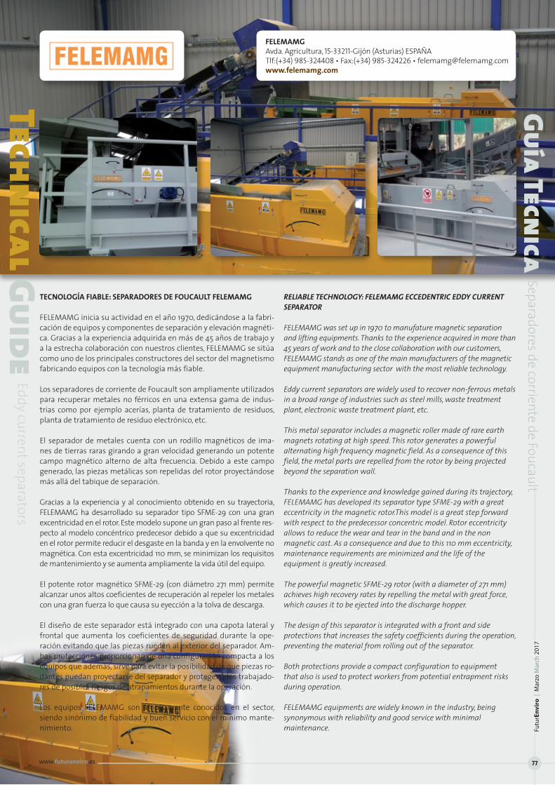
TECNOLOGÍA FIABLE: SEPARADORES DE FOUCAULT FELEMAMG
FELEMAMG inicia su actividad en el año 1970, dedicándose a la fabri-cación de equipos y componentes de separación y elevación magnéti-ca. Gracias a la experiencia adquirida en más de 45 años de trabajo y a la estrecha colaboración con nuestros clientes, FELEMAMG se sitúa como uno de los principales constructores del sector del magnetismo fabricando equipos con la tecnología más fiable.
Los separadores de corriente de Foucault son ampliamente utilizados para recuperar metales no férricos en una extensa gama de indus-trias como por ejemplo acerías, planta de tratamiento de residuos, planta de tratamiento de residuo electrónico, etc.
El separador de metales cuenta con un rodillo magnéticos de ima-nes de tierras raras girando a gran velocidad generando un potente campo magnético alterno de alta frecuencia. Debido a este campo generado, las piezas metálicas son repelidas del rotor proyectándose más allá del tabique de separación.
Gracias a la experiencia y al conocimiento obtenido en su trayectoria, FELEMAMG ha desarrollado su separador tipo SFME-29 con una gran excentricidad en el rotor. Este modelo supone un gran paso al frente res-pecto al modelo concéntrico predecesor debido a que su excentricidad en el rotor permite reducir el desgaste en la banda y en la envolvente no magnética. Con esta excentricidad 110 mm, se minimizan los requisitos de mantenimiento y se aumenta ampliamente la vida útil del equipo.
El potente rotor magnético SFME-29 (con diámetro 271 mm) permite alcanzar unos altos coeficientes de recuperación al repeler los metales con una gran fuerza lo que causa su eyección a la tolva de descarga.
El diseño de este separador está integrado con una capota lateral y frontal que aumenta los coeficientes de seguridad durante la ope-ración evitando que las piezas rueden al exterior del separador. Am-bas protecciones proporcionan de una configuración compacta a los equipos que además, sirve para evitar la posibilidad de que piezas ro-dantes puedan proyectarse del separador y proteger a los trabajado-res de posibles riesgos de atrapamientos durante la operación.
Los equipos FELEMAMG son ampliamente conocidos en el sector, siendo sinónimo de fiabilidad y buen servicio con el mínimo mante-nimiento.
RELIABLE TECHNOLOGY: FELEMAMG ECCEDENTRIC EDDY CURRENT SEPARATOR
FELEMAMG was set up in 1970 to manufature magnetic separation and lifting equipments. Thanks to the experience acquired in more than 45 years of work and to the close collaboration with our customers, FELEMAMG stands as one of the main manufacturers of the magnetic equipment manufacturing sector with the most reliable technology.
Eddy current separators are widely used to recover non-ferrous metals in a broad range of industries such as steel mills, waste treatment plant, electronic waste treatment plant, etc.
This metal separator includes a magnetic roller made of rare earth magnets rotating at high speed. This rotor generates a powerful alternating high frequency magnetic field. As a consequence of this field, the metal parts are repelled from the rotor by being projected beyond the separation wall.
Thanks to the experience and knowledge gained during its trajectory, FELEMAMG has developed its separator type SFME-29 with a great eccentricity in the magnetic rotor.This model is a great step forward with respect to the predecessor concentric model. Rotor eccentricity allows to reduce the wear and tear in the band and in the non magnetic cast. As a consequence and due to this 110 mm eccentricity, maintenance requirements are minimized and the life of the equipment is greatly increased.
The powerful magnetic SFME-29 rotor (with a diameter of 271 mm) achieves high recovery rates by repelling the metal with great force, which causes it to be ejected into the discharge hopper.
The design of this separator is integrated with a front and side protections that increases the safety coefficients during the operation, preventing the material from rolling out of the separator.
Both protections provide a compact configuration to equipment that also is used to protect workers from potential entrapment risks during operation.
FELEMAMG equipments are widely known in the industry, being synonymous with reliability and good service with minimal maintenance.
FELEMAMGAvda. Agricultura, 15-33211-Gijón (Asturias) ESPAÑATlf:(+34) 985-324408 • Fax:(+34) 985-324226 • [email protected]
Technical Guide
Eddy current separators
Guía Tecnica
Separadores de corriente de Foucault
Futu
rEn
viro
| M
arzo
Mar
ch 2
017
www.futurenviro.es 77
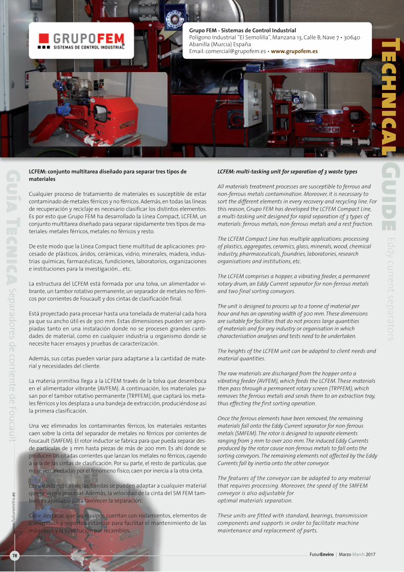
Grupo FEM - Sistemas de Control IndustrialPolígono Industrial ”El Semolilla”, Manzana 13, Calle B, Nave 7 • 30640 Abanilla (Murcia) EspañaEmail: [email protected] • www.grupofem.es
LCFEM: conjunto multitarea diseñado para separar tres tipos de materiales
Cualquier proceso de tratamiento de materiales es susceptible de estar contaminado de metales férricos y no férricos. Además, en todas las líneas de recuperación y reciclaje es necesario clasificar los distintos elementos. Es por esto que Grupo FEM ha desarrollado la Línea Compact, LCFEM, un conjunto multitarea diseñado para separar rápidamente tres tipos de ma-teriales: metales férricos, metales no férricos y resto.
De este modo que la Línea Compact tiene multitud de aplicaciones: pro-cesado de plásticos, áridos, cerámicas, vidrio, minerales, madera, indus-trias químicas, farmacéuticas, fundiciones, laboratorios, organizaciones e instituciones para la investigación… etc.
La estructura del LCFEM está formada por una tolva, un alimentador vi-brante, un tambor rotativo permanente, un separador de metales no férri-cos por corrientes de Foucault y dos cintas de clasificación final.
Está proyectado para procesar hasta una tonelada de material cada hora ya que su ancho útil es de 300 mm. Estas dimensiones pueden ser apro-piadas tanto en una instalación donde no se procesen grandes canti-dades de material, como en cualquier industria u organismo donde se necesite hacer ensayos y pruebas de caracterización.
Además, sus cotas pueden variar para adaptarse a la cantidad de mate-rial y necesidades del cliente.
La materia primitiva llega a la LCFEM través de la tolva que desemboca en el alimentador vibrante (AVFEM). A continuación, los materiales pa-san por el tambor rotativo permanente (TRPFEM), que captará los meta-les férricos y los desplaza a una bandeja de extracción, produciéndose así la primera clasificación.
Una vez eliminados los contaminantes férricos, los materiales restantes caen sobre la cinta del separador de metales no férricos por corrientes de Foucault (SMFEM). El rotor inductor se fabrica para que pueda separar des-de partículas de 3 mm hasta piezas de más de 200 mm. Es ahí donde se producen las citadas corrientes que lanzan los metales no férricos, cayendo a una de las cintas de clasificación. Por su parte, el resto de partículas, que no se ven afectadas por el fenómeno físico, caen por inercia a la otra cinta.
Las características de las bandas se pueden adaptar a cualquier material que se vaya a procesar. Además, la velocidad de la cinta del SM FEM tam-bién es ajustable para favorecer la separación.
Cabe destacar que los equipos cuentan con rodamientos, elementos de transmisión y soportes estándar para facilitar el mantenimiento de las máquinas y la sustitución por recambios.
LCFEM: multi-tasking unit for separation of 3 waste types
All materials treatment processes are susceptible to ferrous and non-ferrous metals contamination. Moreover, it is necessary to sort the different elements in every recovery and recycling line. For this reason, Grupo FEM has developed the LCFEM Compact Line, a multi-tasking unit designed for rapid separation of 3 types of materials: ferrous metals, non-ferrous metals and a rest fraction.
The LCFEM Compact Line has multiple applications: processing of plastics, aggregates, ceramics, glass, minerals, wood, chemical industry, pharmaceuticals, foundries, laboratories, research organisations and institutions, etc.
The LCFEM comprises a hopper, a vibrating feeder, a permanent rotary drum, an Eddy Current separator for non-ferrous metals and two final sorting conveyors.
The unit is designed to process up to a tonne of material per hour and has an operating width of 300 mm. These dimensions are suitable for facilities that do not process large quantities of materials and for any industry or organisation in which characterisation analyses and tests need to be undertaken.
The heights of the LCFEM unit can be adapted to client needs and material quantities.
The raw materials are discharged from the hopper onto a vibrating feeder (AVFEM), which feeds the LCFEM. These materials then pass through a permanent rotary screen (TRPFEM), which removes the ferrous metals and sends them to an extraction tray, thus effecting the first sorting operation.
Once the ferrous elements have been removed, the remaining materials fall onto the Eddy Current separator for non-ferrous metals (SMFEM). The rotor is designed to separate elements ranging from 3 mm to over 200 mm. The induced Eddy Currents produced by the rotor cause non-ferrous metals to fall onto the sorting conveyors. The remaining elements not affected by the Eddy Currents fall by inertia onto the other conveyor.
The features of the conveyor can be adapted to any material that requires processing. Moreover, the speed of the SMFEM conveyor is also adjustable for optimal materials separation.
These units are fitted with standard, bearings, transmission components and supports in order to facilitate machine maintenance and replacement of parts.
Technical Guide
Eddy current separators
Guía Tecnica
Separadores de corriente de Foucault
FuturEnviro | Marzo March 2017
ww
w.fu
ture
nvi
ro.e
s
78
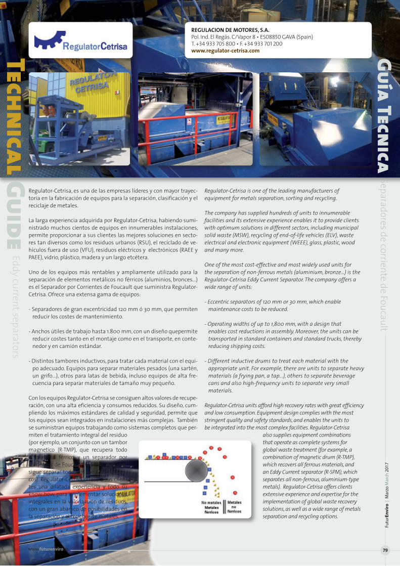
Regulator-Cetrisa, es una de las empresas líderes y con mayor trayec-toria en la fabricación de equipos para la separación, clasificación y el reciclaje de metales.
La larga experiencia adquirida por Regulator-Cetrisa, habiendo sumi-nistrado muchos cientos de equipos en innumerables instalaciones, permite proporcionar a sus clientes las mejores soluciones en secto-res tan diversos como los residuos urbanos (RSU), el reciclado de ve-hículos fuera de uso (VFU), residuos eléctricos y electrónicos (RAEE y PAEE), vidrio, plástico, madera y un largo etcétera.
Uno de los equipos más rentables y ampliamente utilizado para la separación de elementos metálicos no férricos (aluminios, bronces…) es el Separador por Corrientes de Foucault que suministra Regulator-Cetrisa. Ofrece una extensa gama de equipos:
- Separadores de gran excentricidad 120 mm ó 30 mm, que permiten reducir los costes de mantenimiento.
- Anchos útiles de trabajo hasta 1.800 mm, con un diseño quepermite reducir costes tanto en el montaje como en el transporte, en conte-nedor y en camión estándar.
- Distintos tambores inductivos, para tratar cada material con el equi-po adecuado. Equipos para separar materiales pesados (una sartén, un grifo…), otros para latas de bebida, incluso equipos de alta fre-cuencia para separar materiales de tamaño muy pequeño.
Con los equipos Regulator-Cetrisa se consiguen altos valores de recupe-ración, con una alta eficiencia y consumos reducidos. Su diseño, cum-pliendo los máximos estándares de calidad y seguridad, permite que los equipos sean integrados en instalaciones más complejas. También se suministran equipos trabajando como sistemas completos que per-miten el tratamiento integral del residuo (por ejemplo, un conjunto con un tambor magnetico (R-TMP), que recupera todo el material férrico, y un separador por corrientes de Foucault (R-SPM), que con-sigue separar todos los metales no férri-cos). Regulator-Cetrisa ofrece a sus clien-tes una dilatada experiencia y todo su know-how, para implementar soluciones integrales en la valorización de residuos, con un gran abanico de posibilidades en la separación y el reciclaje de metales.
Regulator-Cetrisa is one of the leading manufacturers of equipment for metals separation, sorting and recycling.
The company has supplied hundreds of units to innumerable facilities and its extensive experience enables it to provide clients with optimum solutions in different sectors, including municipal solid waste (MSW), recycling of end-of-life vehicles (ELV), waste electrical and electronic equipment (WEEE), glass, plastic, wood and many more.
One of the most cost-effective and most widely used units for the separation of non-ferrous metals (aluminium, bronze…) is the Regulator-Cetrisa Eddy Current Separator. The company offers a wide range of units:
- Eccentric separators of 120 mm or 30 mm, which enable maintenance costs to be reduced.
- Operating widths of up to 1,800 mm, with a design that enables cost reductions in assembly. Moreover, the units can be transported in standard containers and standard trucks, thereby reducing shipping costs.
- Different inductive drums to treat each material with the appropriate unit. For example, there are units to separate heavy materials (a frying pan, a tap...), others to separate beverage cans and also high-frequency units to separate very small materials.
Regulator-Cetrisa units afford high recovery rates with great efficiency and low consumption. Equipment design complies with the most stringent quality and safety standards, and enables the units to be integrated into the most complex facilities. Regulator-Cetrisa
also supplies equipment combinations that operate as complete systems for global waste treatment (for example, a combination of magnetic drum (R-TMP), which recovers all ferrous materials, and an Eddy Current separator (R-SPM), which separates all non-ferrous, aluminium-type metals). Regulator-Cetrisa offers clients extensive experience and expertise for the implementation of global waste recovery solutions, as well as a wide range of metals separation and recycling options.
REGULACION DE MOTORES, S.A.Pol. Ind. El Regás. C/Vapor 8 • ES08850 GAVA (Spain)T. +34 933 705 800 • F. +34 933 701 200www.regulator-cetrisa.comTechn
ical GuideEddy current separators
Guía Tecnica
Separadores de corriente de Foucault
Futu
rEn
viro
| M
arzo
Mar
ch 2
017
www.futurenviro.es 79

STEINERT Elektromagnetbau GmbHWiddersdorfer Str. 329-331 • 50933 Köln | GermanyPhone: +49 221 4984-0 • Fax: +49 221 4984-102 • Email: [email protected]
STEINERT NES: Separador de metales no ferrosos
La recuperación de metales no ferrosos constituye la base econó-mica de todo reciclado: El separador por corriente de Foucault STEI-NERT con sistema excéntrico de polos aporta precisamente los re-querimientos para dicha base de forma óptima. El alto rendimiento y la larga vida útil conforman así el fundamento para un resultado operativo de solidez garantizada. El campo de aplicación del separa-dor de metales no ferrosos se encontrará dondequiera sea necesario recuperar o separar este tipo de metales, como p. ej. en el tratamien-to de material triturado, residuos domésticos, escorias de incinera-ción, chatarra electrónica, astillas de madera, vidrio, pilas o arena de moldeo.
El separador de metales no ferrosos está compuesto, básicamente, por una cinta de tramo corto que se acciona en el lado de alimenta-ción. En el tambor de cabeza se encuentra un sistema magnético per-manente de rotación rápida —el sistema de polos que crea campos magnéticos alternos de alta frecuencia—. Estos producen corrientes de Foucault en las piezas de metal no ferroso que, por su parte, ge-neran campos magnéticos propios opuestos al campo exterior. Las piezas de metal no ferroso se desvían entonces del flujo de materiales restante. El sistema excéntrico de polos STEINERT patentado garanti-za en esta tarea una rentabilidad máxima, es decir, la mejor selección y funcionamiento permanente.
El sistema excéntrico de polos magnéticos patentado; El sistema de polos magnéticos instalado de forma excéntrica en el tambor de ca-beza del separador STEINERT de metales no ferrosos posibilita que la acción de los campos magnéticos alternos se concentre exactamente en la zona donde el material experimenta la mayor aplicación de fuer-za. Con la capacidad de ajuste del sistema de polos, en tanto, es posi-ble definir y cambiar dicha posición de forma óptima, a fin de ajustar al máximo la curva de descarga y aumentar así la acción de la fuerza.
En los sistemas concéntricos de polos ofrecidos por la competencia, la acción del campo magnético a menudo comienza demasiado pronto, de modo que las piezas de metal no ferroso se separan anticipada-mente del campo magnético y no se desvían adecuadamente. El sis-tema excéntrico de polos, por el contrario, asegura que la mencionada acción alcance un nivel máximo solo en el momento de la separación y que no se genere ningún campo magnético en otros puntos del tambor de la cinta. Los metales ferrosos residuales no se adhieren al tambor de cabeza, lo que reduce a un mínimo absoluto el desgaste de la cinta y de la camisa del tambor, conformando así otra diferencia fundamental con el sistema concéntrico.
STEINERT ofrece la gama de separadores de metales no ferrosos más amplia del mercado. Ello garantiza la solución más rentable para cada aplicación. La variedad de modelos se basa en tres series de productos con sistemas especiales de polos magnéticos y anchuras de trabajo de 500 a 2500 mm.
Non-Ferrous Metal Separator
The mechanical recovery of non-ferrous metals is the economic basis of all recycling – and the STEINERT NES Eddy Current Separator with Eccentric Pole System fulfils the associated requirements perfectly! High yield and long life are the qualities. That make for assured, long-term operating result. The non-ferrous metal separator can be used wherever non-ferrous metals have to be recovered or separated, e.g. where shredder material, municipal waste, WTE bottom ash, electronic scrap, wood chips, glass, batteries or foundry sand are processed.
A non-ferrous metal separator basically consists of a short conveyor driven from the feed end. A rapidly rotating system of permanent magnets – the pole system – which generates high-frequency changing magnetic fields, is incorporated in the head drum. These fields create strong eddy currents in the non-ferrous metal parts, in which their own magnetic fields, opposing the external fields, now build up. The NF-metal parts jump out of the remaining material flow. STEINERT’s patented eccentric pole system guarantees the maximum efficiency in this process, delivering top-quality separation and longterm operation!
The patented, eccentric magnetic pole system! Thanks to the magnetic pole system mounted eccentrically in the head drum of the STEINERT non-ferrous separators, the effect of the changing magnetic fields is concentrated exactly on an area within which the material is most effectively subject to the forces. The pole system can be adjusted so that this position can be changed in order to have the maximum effect on the discharge parabola, and so to further amplify the effect of the forces.
In the concentric pole systems offered by our competitors, the effect of the magnetic field is frequently felt too early, with the consequence that the non-ferrous metals are prematurely ejected from the magnetic field, thus resulting in their not being adequately deflected. The eccentric pole system, in contrast, ensures that the influence of the magnetic field is only at a maximum at the moment of separation, and that no magnetic field is generated at other positions on the belt drum. Residual ferrous metals cannot adhere to the head drum, which means that wear on the belt and the self-cleaning drum shell are reduced to an absolute minimum – another important difference from the concentric system.
STEINERT offers by far the widest range of non-ferrous metal separators. This guarantees finding the most cost-effective solution for every application! The wide range of models is based on three series of units with special magnetic pole systems and working widths ranging from 500 to 2500 mm
Technical Guide
Eddy current separators
Guía Tecnica
Separadores de corriente de Foucault
FuturEnviro | Marzo March 2017
ww
w.fu
ture
nvi
ro.e
s
80
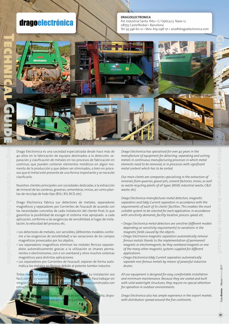
Drago Electronica es una sociedad especializada desde hace más de 40 años en la fabricación de equipos destinados a la detección, se-paración y clasificación de metales en los procesos de fabricación en continuo, que pueden contener elementos metálicos en algún mo-mento de la producción y que deben ser eliminados, o bien en proce-sos que el metal esté presente de una forma importante y se necesite clasificarlo.
Nuestros clientes principales son sociedades dedicadas a la extracción de mineral de las canteras, graveras, cementeras, minas, así como plan-tas de reciclaje de todo tipo (RSU, RSI, RCD, etc).
Drago Electronica fabrica sus detectores de metales, separadores magnéticos y separadores por Corrientes de Foucault de acuerdo con las necesidades concretas de cada instalación del cliente final, lo que garantiza la posibilidad de escoger el sistema más apropiado a cada aplicación, conforme a las exigencias de sensibilidad, el lugar de insta-lación, la velocidad del proceso, etc.
• Los detectores de metales, son sensibles, (diferentes modelos confor-me a las exigencias de sensibilidad) a las variaciones de los campos magnéticos provocados por los objetos.
• Los separadores magnéticos eliminan los metales férricos separán-dolos automáticamente gracias a la utilización se imanes perma-nentes o electroimanes, con o sin overband y otros muchos sistemas magnéticos para distintas aplicaciones.
• Los separadores por Corrientes de Foucault, separan de forma auto-mática los metales no férricos debido al potente tambor inductor.
Todos nuestros equipos están diseñados para que su instalación sea fácil, cómoda y supongan un mantenimiento mínimo. Para trabajar sin ningún tipo de atención y a la intemperie, herméticos, construidos con estructuras sólidas y estancas.
Nuestra experiencia en la exportación es también muy amplia, dispo-nemos de distribuidores propios en los 5 continentes.
Drago Electronica has specialised for over 40 years in the manufacture of equipment for detecting, separating and sorting metals in continuous manufacturing processes in which metal elements need to be removed, or in processes with significant metal content which has to be sorted.
Our main clients are companies specialising in the extraction of minerals from quarries, gravel pits, cement factories, mines, as well as waste recycling plants of all types (MSW, industrial waste, C&D waste, etc).
Drago Electronica manufactures metal detectors, magnetic separators and Eddy Current separators in accordance with the requirements of each of its clients’ facilities. This enables the most suitable system to be selected for each application, in accordance with sensitivity demands, facility location, process speed, etc.
• Drago Electronica metal detectors are sensitive (different models depending on sensitivity requirements) to variations in the magnetic fields caused by the objects.
• Drago Electronica magnetic separators automatically remove ferrous metals thanks to the implementation of permanent magnets or electromagnets, be they overband magnets or one of the many other magnetic systems supplied for different applications.
• Drago Electronica Eddy Current separators automatically separate non-ferrous metals by means of powerful inductive drums.
All our equipment is designed for easy, comfortable installation and minimum maintenance. Because they are sealed and built with solid watertight structures, they require no special attention for operation in outdoor environments.
Drago Electronica also has ample experience in the export market, with distributors spread around the five continents.
Technical Guide
Magnetic separators &
Eddy current separators
Guía Tecnica
Separadores magnéticos y separadores de corriente de Foucault
DRAGOELECTRONICAPol. Industrial Santa Rita • C/ Optica,13 Nave-12 08755 Castellbisbal • BarcelonaTel: 93 346 60 12 • Mov: 619 098 171 • [email protected]
Futu
rEn
viro
| M
arzo
Mar
ch 2
017
www.futurenviro.es 81

Com
para
tive
Tabl
eMag
netic
Sep
arat
ors
Tabl
a Co
mpa
rati
vaSe
para
dore
s Mag
nétic
os
Dimesi
on ge
neral
gen
eral di
mensi
ons
(largo
x anch
o x alt
o len
gth x w
idth x
heigh
t) mm
Ancho
Mag
netic
o Ma
gneti
c Widt
hmm
Largo
Mag
netic
Magn
etic L
ength
mm
Peso t
otal
Total w
eight
(t)
KwKw
m/s
mm
Fabr
icant
e Tip
o Sep
arad
or
Mod
elo
Dime
nsio
nes Y
Peso
s Po
tencia
Elect
rica P
ower
Outpu
t M
otor
Ve
locid
ad Ba
nda
Dista
ncia
de tr
abajo
Ex
tras
M
anuf
actu
rer
Sepa
rato
rTyp
eM
odel
Di
mens
ions
&W
eight
sEle
ctroim
an/E
lectr
omag
net
Drive
unit
Belt
speed
op
erat
ingdi
stanc
eop
tiona
lext
ras
Eriez
Magn
etics
Europ
e Lim
ited
Perm
anen
te | P
erman
ent
CP20
/80 SC
2 215
0 x 12
08 x 3
91 83
2 526
0,8
3
1,5
2,2
250
(D
istrib
uidor
/ Dea
ler: Si
ndery
a) Pe
rman
ente
| Perm
anen
t CP
25/80
SC2
2500 x
1300
x 455
836
520
1,35
1,5
2,2
30
0
Ele
ctroim
án | E
lectro
magn
et SE
740 SC
2 276
8 x 16
60 x 1
132
1048
1048
2,5
4,5
2,2
2,2
350
Electr
oimán
| Elec
troma
gnet
SE750
SC2
2920
x 182
1 x 114
5 119
9 119
9 3,6
5,6
2,2
2,2
42
5
DRAG
OELEC
TRON
ICA
OD
EP-7
1105 x
2320
x 665
90
0 90
0 120
0 4
2,2
2 350
ODEP
-8 130
4 x 27
38 x 6
65
1000
1000
1600
5,5
2,2
2 40
0
ODEP
-9 130
4 x 27
20 x 6
65
1300
1300
2000
7
4 2
450
FEL
EMAM
G Ele
ctroim
án | E
lectro
magn
et SF
1-100
-RC/10
0 258
0 X 14
95 X
575
970
1000
2450
6,2
5 2,2
2,3
320
-400
Electr
oimán
| Elec
troma
gnet
SF1-1
20-RC
/120
2946
X 170
5 X 59
0 116
0 120
0 355
0 8,5
2,3
2,3
38
5-400
Electr
oimán
| Elec
troma
gnet
SF2-1
00-RC
/100
2420
x 149
5 x 66
5 97
0 100
0 235
0 4,3
2,2
2,3
320
-400
Ele
ctroim
án | E
lectro
magn
et SF
2-120
-RC/12
0 278
5 x 17
05 x 6
80
1160
1200
3450
5,9
4
2,3
385-4
00
REGU
LATO
R-CET
RISA
Overb
and E
lectro
magn
etico
| Elect
romagn
etic Ov
erban
d R-S
KM 9.
11 251
0 x 14
75 x 6
70
900
1100
2,4
4,4
2,2
Hasta
/ Up t
o 3,7
370
Ov
erban
d Elec
troma
gneti
co | El
ectrom
agnetic
Overb
and
R-SKM
10.12
279
0 x 16
00 x 6
70
1000
1200
2,8
6,1
3 Ha
sta / U
p to 3
,7 42
0
Overb
and E
lectro
magn
etico
| Elect
romagn
etic Ov
erban
d R-S
KM 12
.13
3050
x 1815
x 760
120
0 130
0 4,2
7,6
3
Hasta
/ Up t
o 3,7
530
Ove
rband
magné
tico per
manen
te | Per
manen
t magn
et overb
and
R-OMP
75.10
0 22
60 x 1
300 x
400
750
1000
1,4
Imanes
perma
nentes
/ Perm
anent m
agnets
2,2
Hasta
/ Up t
o 2,7
280
Ove
rband
magné
tico per
manen
te | Per
manen
t magn
et overb
and
R-OMP
95.12
0 24
50 x 1
500 x
400
950
1200
2,1
Imanes
perma
nentes
/ Perm
anent m
agnets
3 Ha
sta / U
p to2
,7 34
0 IFE
Ele
ctroim
án | E
lectro
magn
et ME
QL 12
01 Q
2664
x 139
0 x 90
0 120
0 120
0 3,1
4,7
4 2,2
vari
able, dep
ende req
uerimie
ntos
~400
(D
istrib
uidor
/ Dea
ler:
Electr
oimán
| Elec
troma
gnet
MEQL
1401
S 315
6 x 16
34 x 9
81 140
0 140
0 4,5
6,0
6 4
variable
, depend
e requeri
mientos
~4
50
Aries
Ingen
iería
y Sist
emas)
Ele
ctroim
án | E
lectro
magn
et ME
QL 16
01 T
3300 x
2400
x 990
160
0 160
0 5,7
7,5
6 4
variable
, depend
e requeri
mientos
~4
50
Ele
ctroim
án | E
lectro
magn
et ME
QL 22
01 V
3900
x 305
0 x 10
30
2200
22
00
10,8
12,77
7,5
variable
, depend
e requeri
mientos
~4
50
STEIN
ERT
OVERB
AND d
e imán
perma
nente |
Perma
nent m
agnet O
verban
d UM
P 90 1
00 W
G 24
89 x 1
504 x
586
950
1126
1,76
- 2,2
1,7
36
0
OVERB
AND d
e imán
perma
nente |
Perma
nent m
agnet O
verban
d UM
P 130
200 W
G 372
8 x 19
04 x 7
16 135
0 212
6 5,8
7 -
3 1,7
46
0
OVERB
AND e
lectro
magn
ético |
Electro
magn
etic Ov
erban
d UM
E 75 9
0 C
1986 x
1364
x 760
750
90
0 1,5
5 3,1
3
2,1
350
OV
ERBAN
D elec
troma
gnétic
o | Ele
ctroma
gnetic
Overb
and
UME 9
5 110
C 218
6 x 15
64 x 7
70
950
1100
2,05
4,1
3 2,1
42
0
OVERB
AND e
lectro
magn
ético |
Electro
magn
etic Ov
erban
d UM
E 135
170 C
3246 x
2006
x 850
135
0 170
0 5,9
8,3
4
2,1
560
GRUP
O FEM
Ov
erban
d mag
nétic
o | M
agne
tic Ov
erban
d OP
FEM
8.6
2300 x
1390
x 440
63
0 103
0 1,3
5 No
proc
ede /
Not a
pplica
ble
3 1,5
22
0 mm
máxim
o
Ov
erban
d mag
nétic
o | M
agne
tic Ov
erban
d OP
FEM
12.1
2350 x
2060
x 550
130
0 108
5 1,5
No
proc
ede /
Not a
pplica
ble
4 1,5
320
mm
máxim
o
Ov
erban
d Elec
troma
gneti
co | El
ectrom
agnetic
Overb
and
OFEM
13.2
2865
x 185
0 x 79
0 100
0 131
0 3,9
7,6
5,5
1,5
250
mm
máxim
o
Ov
erban
d Elec
troma
gneti
co | El
ectrom
agnetic
Overb
and
OFEM
14.2
2880
x 2100
x 790
140
0 140
0 4,7
12
5,5
1,5
300 m
m má
ximo
Ov
erban
d Elec
troma
gneti
co | El
ectrom
agnetic
Overb
and
OFEM
20.1
3200 x
2300
x 790
160
0 20
00
5,5
18 5,5
1,5
30
0 mm
máxim
o
Protec
ciones
de seg
uridad
late
rales su
periore
s e infe
riores
de cha
pa. Op
cional
: Eleme
ntos
de sus
pensió
n / Up
per an
d low
er shee
t meta
l safety
guard
s. Op
tional: S
uspens
ion ele
ments
Banda
de cau
cho an
tigrasa
con
tacos
/ Rubbe
r, greas
e resist
ant
belt w
ith ribs
. Rodill
os vel
a para
evi
tar el d
esplaz
amien
to de la
ban
da / Pu
lleys to
preven
t belt
displac
ement
. Embel
lecedo
res
Acero I
noxida
ble / S
tainless
ste
el trim
. Sujeta
bandas
de
Acero I
noxida
ble / S
tainless
steel
convey
or supp
orts
Tenso
res de
regu
lación
. Ot
ras di
mens
iones
y po
tencia
s: Con
sulta
r Tu
rnbuc
kles t
o heig
ht reg
ulatio
n. Othe
r sizes
an
d pow
er ou
tputs:
Consu
lt
contro
l de rot
ación,
distin
tos
tipos
de ban
da en
funció
n de
la aplic
ación,
accio
namien
to con
motor
hidráu
lico
Rotatio
n cont
rol, dif
ferent
belt ty
pes ac
cordin
g to
applica
tion, hy
draulic
motor
FuturEnviro | Marzo March 2017
ww
w.fu
ture
nvi
ro.e
s
82
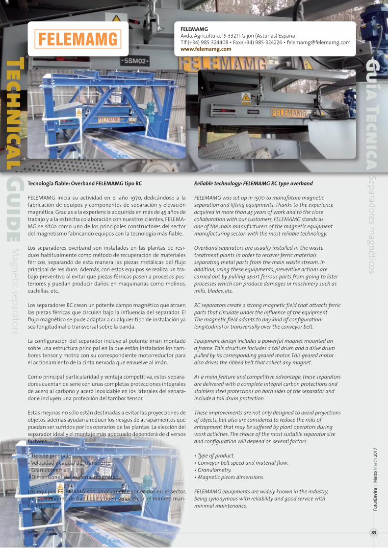
Tecnología fiable: Overband FELEMAMG tipo RC
FELEMAMG inicia su actividad en el año 1970, dedicándose a la fabricación de equipos y componentes de separación y elevación magnética. Gracias a la experiencia adquirida en más de 45 años de trabajo y a la estrecha colaboración con nuestros clientes, FELEMA-MG se sitúa como uno de los principales constructores del sector del magnetismo fabricando equipos con la tecnología más fiable.
Los separadores overband son instalados en las plantas de resi-duos habitualmente como método de recuperación de materiales férricos, separando de esta manera las piezas metálicas del flujo principal de residuos. Además, con estos equipos se realiza un tra-bajo preventivo al evitar que piezas férricas pasen a procesos pos-teriores y puedan producir daños en maquinarias como molinos, cuchillas, etc.
Los separadores RC crean un potente campo magnético que atraen las piezas férricas que circulen bajo la influencia del separador. El flujo magnético se pude adaptar a cualquier tipo de instalación ya sea longitudinal o transversal sobre la banda.
La configuración del separador incluye al potente imán montado sobre una estructura principal en la que están instalados los tam-bores tensor y motriz con su correspondiente motorreductor para el accionamiento de la cinta nervada que envuelve al imán.
Como principal particularidad y ventaja competitiva, estos separa-dores cuentan de serie con unas completas protecciones integrales de acero al carbono y acero inoxidable en los laterales del separa-dor e incluyen una protección del tambor tensor.
Estas mejoras no sólo están destinadas a evitar las proyecciones de objetos, además ayudan a reducir los riesgos de atrapamientos que puedan ser sufridos por los operarios de las plantas. La elección del separador ideal y el montaje más adecuado dependerá de diversos factores:
• Tipo de producto.• Velocidad y caudal del transporte. • Granulometría.• Dimensiones del material magnético.
Los equipos FELEMAMG son ampliamente conocidos en el sector, siendo sinónimo de fiabilidad y buen servicio con el mínimo man-tenimiento.
Reliable technology: FELEMAMG RC type overband
FELEMAMG was set up in 1970 to manufature magnetic separation and lifting equipments. Thanks to the experience acquired in more than 45 years of work and to the close collaboration with our customers, FELEMAMG stands as one of the main manufacturers of the magnetic equipment manufacturing sector with the most reliable technology.
Overband separators are usually installed in the waste treatment plants in order to recover ferric materials separating metal parts from the main waste stream. In addition, using these equipments, preventive actions are carried out by pulling apart ferrous parts from going to later processes which can produce damages in machinery such as mills, blades, etc.
RC separators create a strong magnetic field that attracts ferric parts that circulate under the influence of the equipment. The magnetic field adapts to any kind of configuration: longitudinal or transversally over the conveyor belt.
Equipment design includes a powerful magnet mounted on a frame. This structure includes a tail drum and a drive drum pulled by its corresponding geared motor. This geared motor also drives the ribbed belt that collect any magnet.
As a main feature and competitive advantage, these separators are delivered with a complete integral carbon protections and stainless steel protections on both sides of the separator and include a tail drum protection.
These improvements are not only designed to avoid projections of objects, but also are considered to reduce the risks of entrapment that may be suffered by plant operators during work activities. The choice of the most suitable separator size and configuration will depend on several factors:
• Type of product.• Conveyor belt speed and material flow.• Granulometry.• Magnetic pieces dimensions.
FELEMAMG equipments are widely known in the industry, being synonymous with reliability and good service with minimal maintenance.
FELEMAMGAvda. Agricultura, 15-33211-Gijón (Asturias) EspañaTlf:(+34) 985-324408 • Fax:(+34) 985-324226 • [email protected]
ical GuideM
agnetic separators
Guía Tecnica
Separadores magnéticos
Futu
rEn
viro
| M
arzo
Mar
ch 2
017
www.futurenviro.es 83
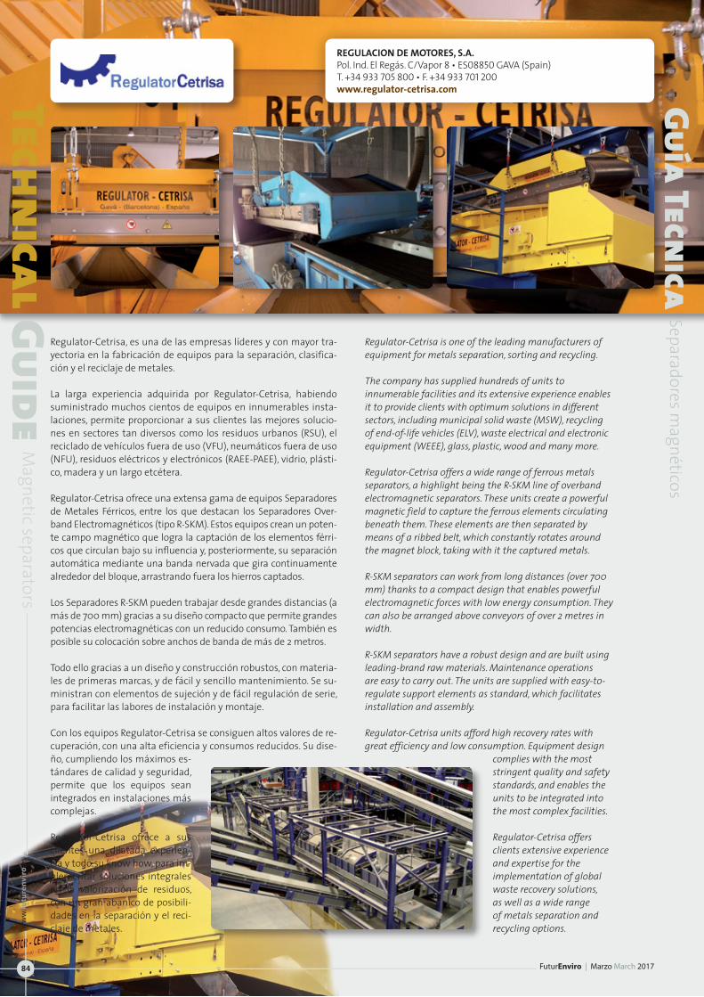
Regulator-Cetrisa, es una de las empresas líderes y con mayor tra-yectoria en la fabricación de equipos para la separación, clasifica-ción y el reciclaje de metales.
La larga experiencia adquirida por Regulator-Cetrisa, habiendo suministrado muchos cientos de equipos en innumerables insta-laciones, permite proporcionar a sus clientes las mejores solucio-nes en sectores tan diversos como los residuos urbanos (RSU), el reciclado de vehículos fuera de uso (VFU), neumáticos fuera de uso (NFU), residuos eléctricos y electrónicos (RAEE-PAEE), vidrio, plásti-co, madera y un largo etcétera.
Regulator-Cetrisa ofrece una extensa gama de equipos Separadores de Metales Férricos, entre los que destacan los Separadores Over-band Electromagnéticos (tipo R-SKM). Estos equipos crean un poten-te campo magnético que logra la captación de los elementos férri-cos que circulan bajo su influencia y, posteriormente, su separación automática mediante una banda nervada que gira continuamente alrededor del bloque, arrastrando fuera los hierros captados.
Los Separadores R-SKM pueden trabajar desde grandes distancias (a más de 700 mm) gracias a su diseño compacto que permite grandes potencias electromagnéticas con un reducido consumo. También es posible su colocación sobre anchos de banda de más de 2 metros.
Todo ello gracias a un diseño y construcción robustos, con materia-les de primeras marcas, y de fácil y sencillo mantenimiento. Se su-ministran con elementos de sujeción y de fácil regulación de serie, para facilitar las labores de instalación y montaje.
Con los equipos Regulator-Cetrisa se consiguen altos valores de re-cuperación, con una alta eficiencia y consumos reducidos. Su dise-ño, cumpliendo los máximos es-tándares de calidad y seguridad, permite que los equipos sean integrados en instalaciones más complejas.
Regulator-Cetrisa ofrece a sus clientes una dilatada experien-cia y todo su know how, para im-plementar soluciones integrales en la valorización de residuos, con un gran abanico de posibili-dades en la separación y el reci-claje de metales.
Regulator-Cetrisa is one of the leading manufacturers of equipment for metals separation, sorting and recycling.
The company has supplied hundreds of units to innumerable facilities and its extensive experience enables it to provide clients with optimum solutions in different sectors, including municipal solid waste (MSW), recycling of end-of-life vehicles (ELV), waste electrical and electronic equipment (WEEE), glass, plastic, wood and many more.
Regulator-Cetrisa offers a wide range of ferrous metals separators, a highlight being the R-SKM line of overband electromagnetic separators. These units create a powerful magnetic field to capture the ferrous elements circulating beneath them. These elements are then separated by means of a ribbed belt, which constantly rotates around the magnet block, taking with it the captured metals.
R-SKM separators can work from long distances (over 700 mm) thanks to a compact design that enables powerful electromagnetic forces with low energy consumption. They can also be arranged above conveyors of over 2 metres in width.
R-SKM separators have a robust design and are built using leading-brand raw materials. Maintenance operations are easy to carry out. The units are supplied with easy-to-regulate support elements as standard, which facilitates installation and assembly.
Regulator-Cetrisa units afford high recovery rates with great efficiency and low consumption. Equipment design
complies with the most stringent quality and safety standards, and enables the units to be integrated into the most complex facilities.
Regulator-Cetrisa offers clients extensive experience and expertise for the implementation of global waste recovery solutions, as well as a wide range of metals separation and recycling options.
Technical Guide
Magnetic separators
Guía Tecnica
Separadores magnéticos
REGULACION DE MOTORES, S.A.Pol. Ind. El Regás. C/Vapor 8 • ES08850 GAVA (Spain)T. +34 933 705 800 • F. +34 933 701 200www.regulator-cetrisa.com
FuturEnviro | Marzo March 2017
ww
w.fu
ture
nvi
ro.e
s
84
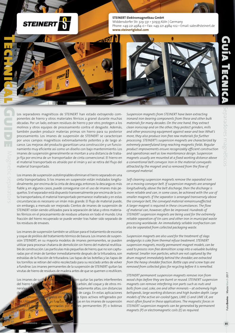
Los separadores magnéticos de STEINERT han estado extrayendo com-ponentes de hierro y otros materiales férricos a granel durante muchas décadas. Por un lado, extraen residuos de hierro y por otro, protegen a los molinos y otros equipos de procesamiento contra el desgaste. Además, también pueden producir materias primas sin hierro para su posterior procesamiento. Los imanes de suspensión de STEINERT se caracterizan por unos campos magnéticos extremadamente potentes y de largo al-cance. Las mejoras del producto garantizan una construcción y un funcio-namiento muy eficiente así como un diseño con bajo mantenimiento. Los imanes de suspensión generalmente se montan a una distancia de traba-jo fija por encima de un transportador de cinta convencional. El hierro en el material transportado es atraído por el imán y así se retira del flujo del material transportado.
Los imanes de suspensión autolimpiables eliminan el hierro separado en una cinta transportadora. Si los imanes en suspensión están instalados longitu-dinalmente, por encima de la cinta de descarga, entonces la descarga es más fiable y, en algunos casos, puede conseguirse con el uso de imanes más pe-queños. Si el separador está dispuesto transversalmente por encima de la cin-ta transportadora, el material transportado permanece inalterado y en estas circunstancias es necesario un imán más grande. El flujo de material puede, sin embargo, a menudo ser mejorado. Cientos de imanes de suspensión de STEINERT están siendo utilizados para la separación de latas y otros materia-les férricos en el procesamiento de residuos urbanos en todo el mundo. Una fracción del hierro recuperado se puede vender tras haber sido separado de los residuos de envases.
Los imanes de suspensión también se utilizan para el tratamiento de escorias y coque de pirólisis del tratamiento térmico de basura. Los imanes de suspen-sión STEINERT, en su mayoría modelos de imanes permanentes, se pueden utilizar para procesar chatarra de demolición sin hierro del material reutiliza-ble de construcción. Las partículas más pequeñas de hierro, que no son captu-radas por el imán de tambor inmediatamente después de la trituradora, son estraídas de la fracción de trituradora. Las tapas de las botellas y las tapas de los tornillos se retiran del vidrio recolectado para su reciclado antes de volver a fundirse. Los imanes permanentes de la suspensión de STEINERT quitan las virutas de hierro de residuos de madera antes de que se quemen o reutilicen.
Los imanes de suspensión STEINERT pueden quitar las partes interferentes del hierro tales como tuercas y pernos del carbón, del coque y de otros mi-nerales – con velocidades de la cinta extremadamente altas, con distancias de trabajo grandes y con altas capacidades de carga. En estas aplicaciones suelen encontrarse modelos en serie de los tipos activos refrigerados por aire, UME LS y UME LR. Las fuerzas magnéticas en los imanes de suspensión STEINERT pueden ser generadas por imanes permanentes (P) o bobinas electromagnéticas (E) según se requiera.
Suspension magnets from STEINERT have been extracting ironand iron-bearing components from these and other bulk materials for many decades. On the one hand, they extract clean ironscrap and on the other, they protect grinders, mills and other processing equipment against wear and tear. What’s more, they also produce iron-free raw materials for further processing. STEINERT’s suspension magnets are characterized by extremely powerfuland long-reaching magnetic fields. Regular product improvements ensure recognizably efficient construction and operationas well as low maintenance design. Suspension magnets usually are mounted at a fixed working distance above a conventional belt conveyor. Iron in the material conveyedis attracted by the magnet and so removed from the flow of conveyed material.
Self-cleaning suspension magnets remove the separated iron on a moving conveyor belt. If suspension magnets are arranged longitudinally, above the belt discharge, then the discharge is more reliable and can, in some cases, be achieved with the use of smaller magnets. If the separator is arranged transversely above the conveyor belt, the conveyed material remainsunaffected. A larger magnet is required in these circumstances. The flow of material can, however, often be improved. Hundreds of STEINERT suspension magnets are being used for the extremely reliable separation of tin cans and other iron in municipal waste processing worldwide. An immediately sellable ironfraction can also be separated from collected packaging waste.
Suspension magnets are also used for the treatment of slags andpyrolys is coke from thermal refuse treatment. STEINERT suspension magnets, mostly permanent magnet models, can be used to process iron-free demolition scrap into a valuable building material. Smaller iron particles, which are not captured by the drum magnet immediately behind the shredder, are extracted from the heavy shredder fraction. Bottle caps and screw tops are removed from collected glass for recycling before it is remelted.
STEINERT permanent suspension magnets remove iron from wood chips before they are burnt or reused. STEINERT suspension magnets can remove interfering iron parts such as nuts and bolts from coal, coke, ore and other minerals – at extremely high beltspeeds, large working distances and high burden depth. Large models of the active air-cooled types, UME LS and UME LR, are most often found in these applications. The magnetic forces in STEINERT suspension magnets can be generated by permanent magnets (P) or electromagnetic coils (E) as required.
Technical Guide
Magnetic separators
Guía Tecnica
Separadores magnéticos
STEINERT Elektromagnetbau GmbHWiddersdorfer Str. 329-331 • 50933 Köln | GermanyPhone: +49 221 4984-0 • Fax: +49 221 4984-102 • Email: [email protected]
Futu
rEn
viro
| M
arzo
Mar
ch 2
017
www.futurenviro.es 85
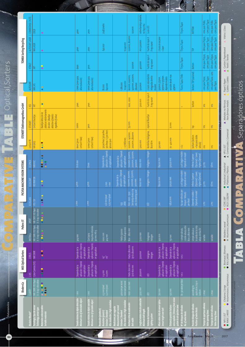
Com
para
tive
Tabl
eOpt
ical
Sor
ters
Tabl
a Co
mpa
rati
vaSe
para
dore
s ópt
icos
* Con
sultar
más
equip
os y m
odelo
s | Co
nsult o
ther u
nits a
nd m
odels
l
NFU
| EL
T l R
AEE
| WEE
E l
Biom
asa
| Bio
mas
s l
RSU
| M
SWl
Mad
era
| woo
d l
Alum
inio
| Al
umin
ium
l
CDR
| SRF
l
RCD
| C&
DWl
Indu
stria
l | In
dust
rial
s
Plás
ticos
| Pl
astic
ss
VFU
| EL
Ts
Com
erci
ales
| Co
mer
cial
s
Met
ales
no
férr
icos
Non
ferr
ous m
etal
ss
Pape
l | P
aper
s
Cabl
es |
Cabl
ess
Cart
ón |
Pape
rboa
rd
s
Text
il | T
extil
es
Vidr
io |
Glas
sl
Chat
arra
| Sc
rap
l
Volu
min
osos
| Vo
lum
inou
s
Mode
lo/Mo
del*
Tecno
logía,
tipo d
e sen
sor
Techn
ology,
senso
r type
Mater
iales
selecc
ionab
les
Sortab
le mate
rials
Tamaño
mínim
o de o
bjeto
detect
able
Minim
um siz
e of d
etecta
ble ob
ject
Tamaño
mínim
o de o
bjeto
eyecta
ble
Minim
um siz
e of e
jectab
le obje
ct
Resol
ución
(pixe
les/s)
Re
soluti
on (p
ixels/s
)Est
ánda
r | Sta
ndard
Alta r
esoluc
ión | H
igh re
soluti
onMe
dicion
es po
r segu
ndo
Measu
remen
ts per
secon
dEst
ánda
r | Sta
ndard
Alta r
esoluc
ión | H
igh re
soluti
onAn
chura
cinta
de ac
elerac
ión
Belt w
idth
Longit
ud mín
ima cin
ta de a
celera
ción
Minim
um be
lt len
gthSis
tema d
e ilum
inació
nLig
hting
syste
m
Altura
sobre
cinta
de sen
sor óp
tico
Sensor
heigh
t over
belt
Distan
cia po
sición
lectur
a -
zona s
oplad
o | Di
stance
from
vision
sys
tem to
air eje
ction
zone
Nº de
bloq
ues d
e válv
ulas
No. of
valve
blocks
Posic
ión bl
oque
de vá
lvulas
Po
sition
of va
lve blo
cks
Tiemp
o de a
pertu
ra vál
vulas
Va
lve op
ening
times
Tiemp
o de c
ierre
válvu
las
Valve
closin
g tim
es
CLAR
ITYNIR
/ SWI
R / VIS
/ Rayos
X -
X-ray
/ otro
-othe
rss
sl
ll
ll
sl
1 mm
1 mm
0,5 m
m/pix
el0,2
mm/
pixel
4000 sc
ans per
second
10000
scans p
er seco
nd100
0 - 20
00 m
m
3000
mm
LED 700 m
m
500 m
m
80 - 32
0 valve
s per bl
ock
accord
ing to
ap
plicat
ion, to
p or
botto
m 2 m
sec
2 msec
L-VIS
Color
Came
ra (VI
S)
sl
sl
Depe
nde d
e la
aplica
ción /
Depen
ds on
appli
cation
Depe
nde d
e la
aplica
ción /
Depen
ds on
appli
cation
0.4 m
m0.2
mm
Hasta
1,600
mm /
Up to
1600 m
m
3600
mm
LED Depe
nde d
e la
aplica
ción /
Depen
ds
on ap
plicat
ionDe
pend
e de la
apl
icació
n / De
pends
on ap
plicat
ion1 o
r 2
MISTR
AL+
NIR / S
WIR /
VIS/ Ra
yos
X - X-
ray / o
tro-ot
her
sl
ss
s
4x4 m
m
Con b
arra
boqu
illas e
stand
ar,
30 m
m, HR
15
10x10
mm4x
4 mm
Hasta
13500
00Ha
sta 8.4
00.00
080
0 - 28
00 m
m
5.000
mm
Halog
enos
Halog
en
900 m
m
150 m
m
1 simp
le válv
ula,
2 dobl
e válv
ula, en
tre
800 y
2800
mm
simple
válvu
la a
la sali
da de
la cin
ta
abajo
. Arrib
a DV
variab
le
variab
le
ECOG
LASS
VIS / U
V
ss
ll
s
2 mm
2 mm
0,6 m
m/pix
el0,2
5 mm/
pixel
1333
2666
600 -
1000 -
1500
Sobre b
andeja v
ibrante,
no hay
cint
a / On vib
rant tray
, no belt
LED 700
128,00
mm
64-24
0 válv
ulas p
or blo
que /
Valvu
les
per blo
ckDe
pend
e mod
elo /
Depen
ds on
mod
el
2 ms
2 ms
ECOS
CRAP
VIS/N
IR/EM
sl
l
4 mm
4 mm
5 mm
1 mm
Depe
nde d
e la
aplica
ción /
Depen
ds on
appli
cation
1000m
m, 150
0mm,
20
00mm
, 2500
mm,
3000
mm60
00 m
m
Halóg
eno /
Halog
en
890,0
0 mm
500,0
0 mm
2 a 6 S
egún
mod
elo
Depen
ds on
mod
el
Inferi
or, Su
perio
r (Op
ciona
l) / Lo
wer,
Highe
r (Opti
onal)
3,2 m
s
1,8 m
s
ECOP
ACK
NIR/H
SC
ll
l l
ss
ss
l
8-16 m
m
8 mm
Depe
nde d
e la
aplica
ción /
Depen
ds on
appli
cation
Depe
nde d
e la
aplica
ción /
Depen
ds on
appli
cation
1000m
m, 150
0mm,
20
00mm
, 2500
mm,
3000
mm60
00 m
m
Halóg
eno /
Halog
en
890,0
0 mm
500,0
0 mm
2 a 6 S
egún
mod
elo
Depen
ds on
mod
el
Inferi
or, Su
perio
r (Op
ciona
l) / Lo
wer,
Highe
r (Opti
onal)
3,2 m
s
1,8 m
s
UniSo
rt PR
NIR (H
SI)
ss
ll
6mm
(3mm
Un
iSort F
lake)
10mm
(3mm
Un
iSort F
lake)
- 320 px
/linea
| 320 p
x/line
300
líneas
/ s | 30
0 line/
s - 96
.000 p
x/s
- > 27 M
illone
s100
0mm
, 1400
mm ,
2000
mm, 28
00mm
5000
mm
Bomb
illas H
alóge
nas,
800 W
/m
500 m
m
70 - 4
00 m
m
1 ó 2
botto
m (bo
ttom
+ t
op pa
ra do
ble
válvu
la)1m
s
1ms
STEINE
RTUn
iSort B
lackEy
e
BlackE
ye det
ección
de
plástic
os ind
istinta
mente
del
color
| Blac
kEye
detect
ion of
plastic
s reg
ardless
of col
our,
10mm
3mm
750 m
m
especi
al Blac
kEye
70 m
m
1 top 1ms
1ms
XSS
XRT
ls 5m
m
3mm
1000,
2000
5000
mm
Fuen
te de
rayos
XX-r
ay sou
rce
1 botto
m
1ms
1ms
XPERT
NIR / S
WIR / V
IS/ Ray
os X -
X-ray /
otro-o
ther
sl
ss
s
1200 m
m
CIRRU
SNIR
/SWIR
ss
ll
Depe
nde d
e la
aplica
ción /
Depen
ds
on ap
plicat
ionDe
pend
e de la
apl
icació
n / De
pends
on
appli
cation
1/4”
1/6”
Hasta
2,800
mm
Up to
2800
mm
5000
mm
Halóg
eno
Halog
en
Depe
nde d
e la
aplica
ción /
Depen
ds
on ap
plicat
ionDe
pend
e de la
apl
icació
n / De
pends
on
appli
cation
1 or 2
AUTO
SORT
NIR1, V
IS
ss 17m
m (2m
m pa
ra
alta r
esoluc
ión)
11mm
(2mm
para
alt
a reso
lución
)
80.00
0
640.0
00
1.280.0
00
10.24
0.000
60
0mm,
1000
mm,
1400m
m, 20
00mm
, 28
00mm
50
00mm
2 luces
redu
ndan
tes
integ
radas
dentr
o esc
aner
500m
m, 57
5mm,
915
mm o 1
375mm
de
pend
e mod
elovar
iable d
esde m
ax
479mm
TS200
, TS40
0, TS18
0
Botto
m, TO
P (op
ciona
l)
<1ms p
ara TS
200,
<2ms p
ara TS
400
<1ms p
ara TS
200, <
2ms
para
TS400
XTRA
CTXR
T
sl 6m
m
3mm
1200m
m
4000
mm
Fuen
te de
rayos
XX-r
ay sou
rce
TS150
0, TS4
00
Botto
m
<8ms
para
TS150
0, <2m
s para
TS40
0<6
ms pa
ra TS1
500,
<2ms p
ara TS
400
AUTO
SORT
LASER
NIR-LA
SER
s 4mm
2mm
640.0
00
10.240
.000
120
0mm,
1800
mm
min 5
000m
m
Fuen
te de
rayos
XX-r
ay sou
rce
2 luces
en es
caner
+ lase
r
TS150
0, TS4
00
TOP
<8ms
para
TS150
0, <2m
s para
TS40
0<6
ms pa
ra TS1
500,
<2ms p
ara TS
400
COMB
ISENS
E CHU
TECR
GB
s 4mm
2mm
2048
pixel
es
1200m
m
sobre
band
eja vib
rante,
no
hay c
inta
Luces
LED
TS150
0, TS4
00
BOTTO
M
<1ms p
ara TS
180,
<2ms p
ara TS
400
<1ms p
ara TS
180,
<2ms p
ara TS
400
TOMR
A Sort
ing Re
cyclin
g ST
EINER
T Elek
troma
gnetb
au Gm
bHPIC
VISA M
ACHI
NE VI
SION S
YSTE
MSPe
llenc
STMS
S Opti
cal So
rters
Bind
er+Co
FuturEnviro | Marzo March 2017
ww
w.fu
ture
nvi
ro.e
s
86
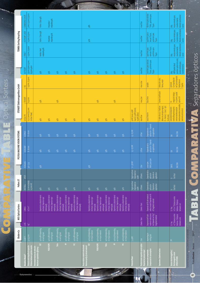
Com
para
tive
Tabl
eOpt
ical
Sor
ters
Tabl
a Co
mpa
rati
vaSe
para
dore
s ópt
icos
Mode
lo/Mo
del*
Distan
cia ent
re boqu
illas de
eyecció
n Dis
tance b
etween
ejectio
n nozz
lesEfe
ctivida
d máxi
ma de
selec
ción
Maxim
um sep
aratio
n effic
iency
PET
PEAD/H
DPE
Tetra PP P/C
Pureza
máxim
a mate
rial sel
eccion
ado
Maxim
um pu
rity of
selecte
d mate
rialPET
PEAD/H
DPE
Tetra PP P/C
Potenc
ia/Pow
er
Presió
n de a
ire req
uerida
a pie d
e óptic
o Req
uired
air pre
ssure i
nput
Consum
o aire
comp
rimido
Com
presse
d air c
onsum
ption
Opcio
nales
| Opti
onal e
xtras
Sensor
electr
omagn
ético
| Ele
ctrom
agneti
c senso
rOT
ROS/O
THERS
CLARIT
Y3,1-
12,5 mm
up to 9
8% de
pendin
g on
sortin
g task
up to 9
8% de
pendin
g on
sortin
g task
up to 9
8% de
pendin
g on
sortin
g task
up to 9
8% de
pendin
g on
sortin
g task
up to 9
8% de
pendin
g on
sortin
g task
up to 9
5% de
pendin
g on
imput
mater
ial
up to 9
5% de
pendin
g on
imput
mater
ial
up to 9
5% de
pendin
g on
imput
mater
ial
up to 9
5% de
pendin
g on
imput
mater
ial
up to 9
5% de
pendin
g on
imput
mater
ial
3 - 4 k
W
7 bar
depend
ing on
sortin
g task
yes
L-VIS
1/4”
7 bare
s / bar
s
Depen
de del
% del
ma
terial
selecc
iona-
do De
pends
on % o
f tar
geted
mater
ial
Sí / Ye
s1/2
” Dista
ncia e
ntre
bobina
s / Dis
tance
betwe
en coi
ls
MISTR
AL+25
mm est
ándar,
12.5 mm
HR
95% 95% 95% 95% 90%
95% 95% 95% 95% 90%
Según
anchu
raDep
endant
on
width
7-8 ba
res
Depen
de de
la apl
icació
nDep
ends on
app
lication
SI Stat Pa
ck
ECOGL
ASS4,1
1 - 5,14
95% 95% 1,1 - 3,8
kW
7 bar
2000 lp
m. MA
X:300
0 lpm
EM/FL
RAC/D
M
ECOSC
RAP
8 - 16
mm
95% 95% 95% 95% 95% 95% 95% 95% 95% 95% 2,5 - 6
,7 kW
7-8 ba
r
Depen
de de
la apl
icació
n / De
pends
on app
licatio
n
EM RAC/D
M
ECOPAC
K 8 -
16 mm
95% 95% 95% 95% 95% 95% 95% 95% 95% 95% 2,5 - 6
,7 kW
7-8 ba
r
Depen
de de
la apl
icació
n / De
pends
on app
licatio
n
EM RAC/D
M
UniSo
rt PR
12,5 ó 3
1mm (
6,25 m
m Un
iSort F
lake)
95% 95% 95% 95% 95% 95% 95% 95% 95% 95% 9 kW
(1000
), 10kW
(14
00), 13
,5kW
(2000
), 15,5
kW (28
00)
max 8
bar
1000 l/
min/m
X - dobl
e válvul
a, B - Bl
ackSca
n (det
ección
, de obj
etos ne
gros),
FS - Film
Sort, C
- Color,
S - Split
(mu
lti cana
l), opcio
nal, siemp
re incluido
: desplazam
iento
neumático
del bloque
de válvula
s, punto de
conex
ión aire co
mprimido
con pistola
, Aire
Acondicion
ado, bases
de datos st
andard co
mpletas,
conexión re
mota, ench
ufes servici
o, etc
STEINE
RT6,2
5 mm
95% 95% 95% 95% max 5
bar
800 l/
min
bunke
r dosi
ficador
no rango
de tra
bajo:
10-30m
m, cau
dal
aprox
1t/h
XSS 12,5mm
, 6,25
mm
max 12
bar
variab
le
detecc
ión co
lor,
forma
, meta
l
opcion
alCo
n Apro
bación
de
Tipo d
e Apar
ato
Radiac
tivo en
Esp
aña
XPERT
Según
anchu
raDep
endant
on
width
7-8 ba
res
Depen
de de
la apl
icació
nDep
ends on
app
lication
SI Stat Pa
ck
CIRRU
S1/2
” or 1”
Depend
e de la c
alidad d
el mater
ial de e
ntrada |
Depen
ds on in
put
materia
l quality
Depend
e de la c
alidad d
el mater
ial de e
ntrada |
Depen
ds on in
put
materia
l quality
Depend
e de la c
alidad d
el mater
ial de e
ntrada |
Depen
ds on in
put
materia
l quality
Depend
e de la c
alidad d
el mater
ial de e
ntrada |
Depen
ds on in
put
materia
l quality
Depend
e de la c
alidad d
el mater
ial de e
ntrada |
Depen
ds on in
put
materia
l quality
Depend
e de la c
alidad d
el mater
ial de e
ntrada |
Depen
ds on in
put
materia
l quality
Depend
e de la c
alidad d
el mater
ial de e
ntrada |
Depen
ds on in
put
materia
l quality
Depend
e de la c
alidad d
el mater
ial de e
ntrada |
Depen
ds on in
put
materia
l quality
Depend
e de la c
alidad d
el mater
ial de e
ntrada |
Depen
ds on in
put
materia
l quality
Depend
e de la c
alidad d
el mater
ial de e
ntrada |
Depen
ds on in
put
materia
l quality
7 bare
s / bar
s
Depen
de del
% del
mater
ial sel
eccion
ado De
pends
on %
of tar
geted
mater
ial
Sí / Ye
s1/2
” or 1” D
istanci
a entr
e bob
inas /
Distan
ce bet
ween
coil
AUTO
SORT
37,5mm
, 25mm
, 12,5m
m, 6,2
5mm,
4mm
95% 95% 95% 95% 95% 95% 95% 95% 95% 95% max 8
bar
200l/m
in para
valvu
las
TS200
, 400
l/min p
ara
TS400
EM3
VBPS(
valvle
block
positio
n syst
em de
serie
), acc
eso rem
oto pa
ra ma
ntenim
iento
XTRAC
T12,5
mm, 6,
25mm
Inerte
s / Ine
rtma
terials
90%
max 8
bar
930l/m
in para
val
vulas
TS1500
, 40
0l/mi
n para
TS4
00
EM3
Acceso
remoto
para
mante
nimien
toRem
ote ma
intena
nce
access
AUTO
SORT
LASER
12,5mm
, 6,25m
m
Vidrio
/ Glas
s 95%
Impur
ezas
Impurit
ies 90
%
90%
max 8
bar
930l/m
in para
v alv
ulas TS
1500,
40
0l/mi
n para
TS4
00
EM3
Acceso
remoto
para
mante
nimien
toRem
ote ma
intena
nce
access
COMB
ISENS
E CHU
TE4m
m, 12,5
mm, 6,
25mm
Vidrio
/ Glas
s 95%
Impur
ezas /
Impurit
ies 90
%
98%
max 8
bar
180l/m
in para
valvu
las
TS180
, 400
l/min p
ara
TS400
EM3
Acceso
remoto
para
mante
nimien
toRem
ote ma
intena
nce
access
TOMR
A Sort
ing Re
cyclin
g ST
EINER
T Elek
troma
gnetb
au Gm
bHPIC
VISA M
ACHI
NE VI
SION S
YSTE
MSPe
llenc
STMS
S Opti
cal So
rters
Bind
er+Co
* Con
sultar
más
equip
os y m
odelo
s | Co
nsult o
ther u
nits a
nd m
odels
Futu
rEn
viro
| M
arzo
Mar
ch 2
017
www.futurenviro.es 87

MISTRAL +: Simplicidad, fiabilidad y rendimiento
Tras 15 años de experiencia , Pellenc ST quería ir más allá , y después de 4 años de investigación y desarrollo , y el duro trabajo de un equipo de 30 ingenieros , Pellenc ST anunciaba el lanzamiento de su nuevo clasificador óptico llamado MISTRAL + en junio de 2016 a la Feria IFAT. MISTRAL + se basa en 3 ejes principales: la simplicidad, la fiabilidad y el rendimiento:
+ Simplicidad
Con Mistral + el acceso a la máquina se ha reinventado. Una plataforma superior para facilitar las tareas de limpieza de lámparas y escáneres, sin la necesidad de parar la máquina. Ayuda a tener una visión directa del proceso de expulsión para su inspección durante el funcionamiento.
Hay un nuevo acceso a la caja de salida para las tareas de mantenimien-to y limpieza más fácil, junto con un nuevo interruptor para bloquear las válvulas.
+ Fiabilidad
Alta fiabilidad en condiciones extremas. MISTRAL+ usa la probada arqui-tectura 2G integrada en un armario robusto. Un PC industrial que me-jora sustancialmente el Tiempo Medio Entre Fallos ( MBTF ) y un nuevo diseño de la refrigeración se basa en un sistema de tubos vorticiales que no requieren mantenimiento.
La gran mejora de las electroválvulas , con un nuevo bloque de válvulas que ha superado las pruebas de choque y un diseño impermeable al pol-vo y al agua. Se incluye un deshumificador
+ Rendimiento
Mejora el rendimiento de detección y eyección. MISTRAL + incluye un sis-tema de detección mejorado (resolución doble en comparación con la Mistral anterior) . La mitad de la demanda de potencia para el sistema de iluminación con la misma calidad de la señal, obteniendo una mejor eficiencia energética y un 50 % de mejora en el tiempo de respuesta de las electroválvulas para una eyección más rápida y potente. Los inyecto-res eléctricos tienen ahora un 35 % más de potencia
Las opciones disponibles incluyen eyección doble, multicanal , sensor in-ductivo para metales, TurboSorter© y Stat Pack©.
Igual que la gama anterior, el nuevo MISTRAL + sigue siendo muy versátil. Este equipo óptico satisface las necesidades más exigentes de cualquier MRF (reciclables, RSU, C&I .. ) o instalación de reciclaje (PET, HDPE, films...)
MISTRAL +: Simplicity, reliability and performance
A track record of 15 years has enabled Pellenc ST to take its technology further. After 4 years of research and development, and the hard work of a team of 30 engineers, Pellenc ST announced the launch of its brand new optical sorter, the MISTRAL+, in June 2016 at the IFAT exhibition.
The new Pellenc ST unit, which is based on 3 fundamental pillars: simplicity, reliability and performance.
+ Simplicity
With MISTRAL+, access to the machine has been reinvented. An upper platform makes the cleaning of reflectors and scanners much easier, without requiring the machine to be stopped. A direct view of the ejection process facilitates inspection during operation. A new access to the output box makes for easier maintenance and cleaning, and a new switch is implemented to block the nozzles
+ Reliability
High reliability under extreme conditions. The MISTRAL+ uses proven 2G architecture in a robust housing. An industrial PC substantially improves the Mean Time Between Failure (MBTF), while a new cooling system design based on vortex tubes requires no maintenance.
+ Performance
Improved detection and ejection performance. The new MISTRAL+ includes an improved detection system (double resolution compared with the previous Mistral). The lighting system has half the power requirement with the same signal quality, energy efficiency has been enhanced and the response time of the electrical nozzles has been improved by 50% for faster and more powerful ejection. The electrical nozzles now have 35% more.
Available options include dual ejection, multichannel, inductive metal sensor, TurboSorter© and Stat Pack©.
Like the previous range, the new MISTRAL+ is highly versatile. This optical sorter will meet the most demanding requirements of any MRF (recyclables, MSW, C&I..) or recycling plant (PET, HDPE, plastic film, ...)
Technical Guide
Optical sorters
Guía Tecnica
Separadores ópticos
PELLENC selective technologies125 rue François Gernelle • BP 124-84124 Pertuis • Cedex 4 - [email protected] • Tel: +33(0)4 90 09 47 90www.pellencst.com
PELLENC ST IBÉRICAJosé Luis Izquierdo • [email protected] • Mov: +34 620 296 739
FuturEnviro | Marzo March 2017
ww
w.fu
ture
nvi
ro.e
s
88
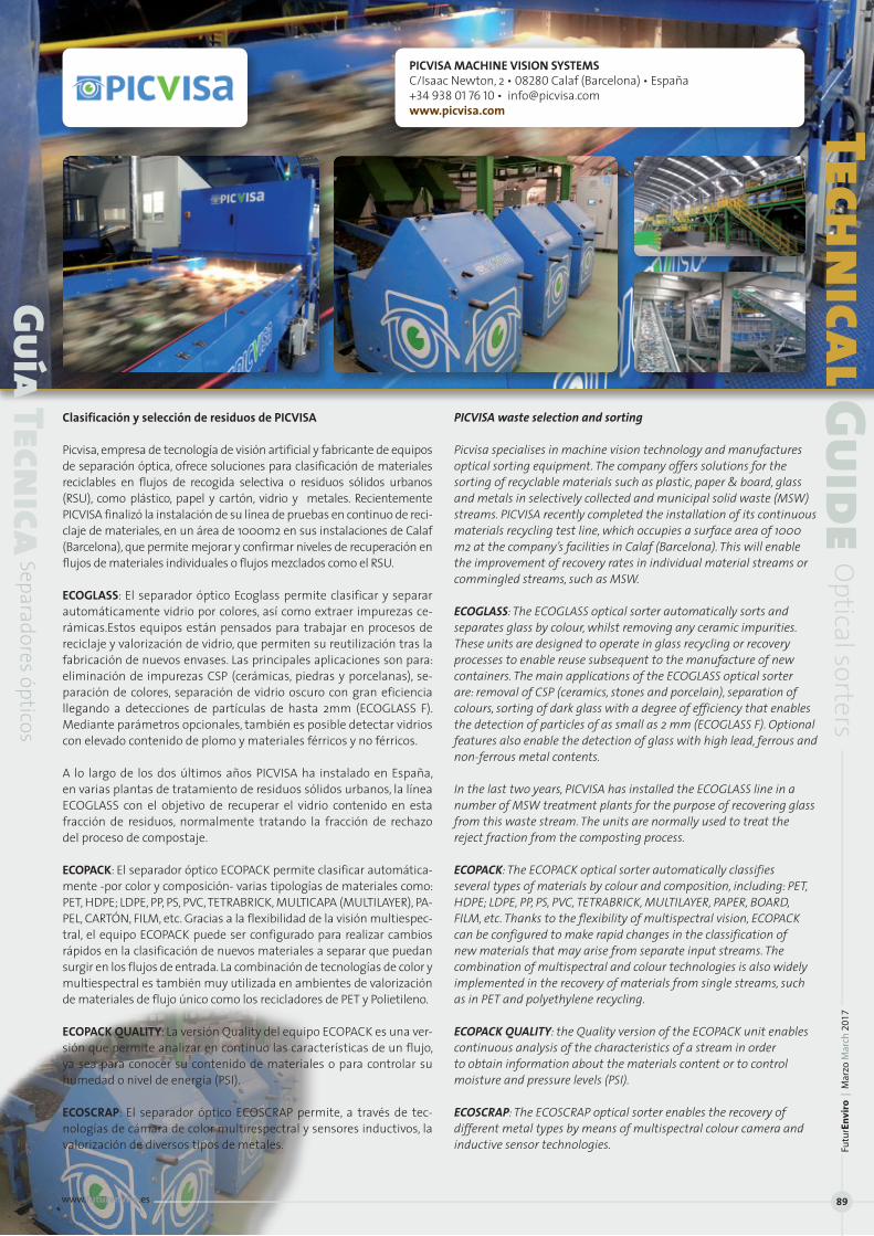
PICVISA MACHINE VISION SYSTEMSC/Isaac Newton, 2 • 08280 Calaf (Barcelona) • España+34 938 01 76 10 • [email protected]
Clasificación y selección de residuos de PICVISA
Picvisa, empresa de tecnología de visión artificial y fabricante de equipos de separación óptica, ofrece soluciones para clasificación de materiales reciclables en flujos de recogida selectiva o residuos sólidos urbanos (RSU), como plástico, papel y cartón, vidrio y metales. Recientemente PICVISA finalizó la instalación de su línea de pruebas en continuo de reci-claje de materiales, en un área de 1000m2 en sus instalaciones de Calaf (Barcelona), que permite mejorar y confirmar niveles de recuperación en flujos de materiales individuales o flujos mezclados como el RSU.
ECOGLASS: El separador óptico Ecoglass permite clasificar y separar automáticamente vidrio por colores, así como extraer impurezas ce-rámicas.Estos equipos están pensados para trabajar en procesos de reciclaje y valorización de vidrio, que permiten su reutilización tras la fabricación de nuevos envases. Las principales aplicaciones son para: eliminación de impurezas CSP (cerámicas, piedras y porcelanas), se-paración de colores, separación de vidrio oscuro con gran eficiencia llegando a detecciones de partículas de hasta 2mm (ECOGLASS F). Mediante parámetros opcionales, también es posible detectar vidrios con elevado contenido de plomo y materiales férricos y no férricos.
A lo largo de los dos últimos años PICVISA ha instalado en España, en varias plantas de tratamiento de residuos sólidos urbanos, la línea ECOGLASS con el objetivo de recuperar el vidrio contenido en esta fracción de residuos, normalmente tratando la fracción de rechazo del proceso de compostaje.
ECOPACK: El separador óptico ECOPACK permite clasificar automática-mente -por color y composición- varias tipologías de materiales como: PET, HDPE; LDPE, PP, PS, PVC, TETRABRICK, MULTICAPA (MULTILAYER), PA-PEL, CARTÓN, FILM, etc. Gracias a la flexibilidad de la visión multiespec-tral, el equipo ECOPACK puede ser configurado para realizar cambios rápidos en la clasificación de nuevos materiales a separar que puedan surgir en los flujos de entrada. La combinación de tecnologías de color y multiespectral es también muy utilizada en ambientes de valorización de materiales de flujo único como los recicladores de PET y Polietileno.
ECOPACK QUALITY: La versión Quality del equipo ECOPACK es una ver-sión que permite analizar en continuo las características de un flujo, ya sea para conocer su contenido de materiales o para controlar su humedad o nivel de energía (PSI).
ECOSCRAP: El separador óptico ECOSCRAP permite, a través de tec-nologías de cámara de color multirespectral y sensores inductivos, la valorización de diversos tipos de metales.
PICVISA waste selection and sorting
Picvisa specialises in machine vision technology and manufactures optical sorting equipment. The company offers solutions for the sorting of recyclable materials such as plastic, paper & board, glass and metals in selectively collected and municipal solid waste (MSW) streams. PICVISA recently completed the installation of its continuous materials recycling test line, which occupies a surface area of 1000 m2 at the company’s facilities in Calaf (Barcelona). This will enable the improvement of recovery rates in individual material streams or commingled streams, such as MSW.
ECOGLASS: The ECOGLASS optical sorter automatically sorts and separates glass by colour, whilst removing any ceramic impurities. These units are designed to operate in glass recycling or recovery processes to enable reuse subsequent to the manufacture of new containers. The main applications of the ECOGLASS optical sorter are: removal of CSP (ceramics, stones and porcelain), separation of colours, sorting of dark glass with a degree of efficiency that enables the detection of particles of as small as 2 mm (ECOGLASS F). Optional features also enable the detection of glass with high lead, ferrous and non-ferrous metal contents.
In the last two years, PICVISA has installed the ECOGLASS line in a number of MSW treatment plants for the purpose of recovering glass from this waste stream. The units are normally used to treat the reject fraction from the composting process.
ECOPACK: The ECOPACK optical sorter automatically classifies several types of materials by colour and composition, including: PET, HDPE; LDPE, PP, PS, PVC, TETRABRICK, MULTILAYER, PAPER, BOARD, FILM, etc. Thanks to the flexibility of multispectral vision, ECOPACK can be configured to make rapid changes in the classification of new materials that may arise from separate input streams. The combination of multispectral and colour technologies is also widely implemented in the recovery of materials from single streams, such as in PET and polyethylene recycling.
ECOPACK QUALITY: the Quality version of the ECOPACK unit enables continuous analysis of the characteristics of a stream in order to obtain information about the materials content or to control moisture and pressure levels (PSI).
ECOSCRAP: The ECOSCRAP optical sorter enables the recovery of different metal types by means of multispectral colour camera and inductive sensor technologies.
Technical Guide
Optical sorters
Guía Tecnica
Separadores ópticosFu
turE
nvi
ro |
Mar
zo M
arch
201
7
www.futurenviro.es 89
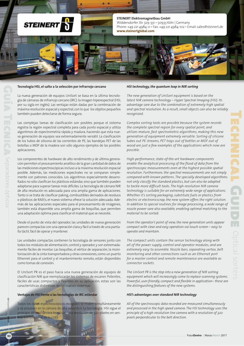
Tecnología HSI, el salto a la selección por infrarrojo cercano
La nueva generación de equipos UniSort se basa en la última tecnolo-gía de cámaras de infrarrojo cercano (IRC): la imagen hiperespectral (HSI, por su sigla en inglés). Las ventajas están dadas por la combinación de máxima resolución espacial y espectral, con lo que los objetos pequeños también pueden detectarse de forma segura.
Las complejas tareas de clasificación son posibles porque el sistema registra la región espectral completa para cada punto espacial y utiliza algoritmos de espectrometría rápida y madura, haciendo que esta nue-va generación de equipos sea extremadamente versátil. La clasificación de los tubos de silicona de las corrientes de PE, las bandejas PET de las botellas o MDF de la madera son sólo algunos ejemplos de las posibles aplicaciones.
Los componentes de hardware de alto rendimiento y de última genera-ción permiten el procesamiento analítico de la gran cantidad de datos de las mediciones espectroscópicas incluso a la máxima resolución espacial posible. Además, las mediciones espectrales no se comparan simple-mente con patrones conocidos. Los algoritmos especialmente desarro-llados no sólo clasifican los plásticos estándar, sino que también pueden adaptarse para superar tareas más difíciles. La tecnología de cámara NIR de alta resolución es adecuada para una amplia gama de aplicaciones. Tanto si se trata de clasificar paking, combustibles derivados de residuos o plásticos de RAEEs, el nuevo sistema ofrece la solución adecuada. Ade-más de las aplicaciones especiales para el procesamiento de imágenes, también está disponible una amplia gama de boquillas, que permiten una adaptación óptima para clasificar el material que se necesite.
Desde el punto de vista del operador, las unidades de nueva generación parecen compactas con una operación clara y fácil a través de una panta-lla táctil, fácil de operar y mantener.
Las unidades compactas contienen la tecnología de sensores junto con todos los módulos de alimentación, control y operador, y son extremada-mente fáciles de montar. Las boquillas, el vértice de separación, la moni-torización de la cinta transportadora y otras conexiones, como un puerto Ethernet para el control y el mantenimiento remoto, están disponibles como tomas de conexión.
El UniSort PR es el paso hacia una nueva generación de equipos de clasificación NIR que reemplazarán los sistemas de escaner. Potentes, fáciles de usar, compactos y flexibles en su aplicación, estas son las características distintivas de los nuevos sistemas.
Ventajas de HSI frente a las tecnologías de IRC estándar
Todos los datos espectroscópicos recogidos se miden simultáneamente y se procesan en la cámara de alta velocidad. La tecnología HSI sigue el principio de una cámara lineal con una resolución de 320 píxeles en sen-tido transversal al de la cinta.
HSI technology, the quantum leap in NIR sorting
The new generation of UniSort equipment is based on the latest NIR camera technology – Hyper Spectral Imaging (HSI). Its advantage sare due to the combination of extremely high spatial and spectral resolution. As a result, small objects can also be reliably recognized.
Complex sorting tasks are possible because the system records the complete spectral region for every spatial point, and utilizes mature, fast spectrometric algorithms, making this new generation of equipment extremely versatile. Sorting of silicone tubes out PE streams, PET trays out of bottles or MDF out of wood are just a few examples of the applications which now are possible.
High-performance, state-of-the-art hardware components enable the analytical processing of the flood of data from the spectroscopic measurements even at the highest possible spatial resolution. Furthermore, the spectral measurements are not simply compared with known patterns. The specially developed algorithms not only classify the standard plastics, but can also be adapted to tackle more difficult tasks. The high-resolution NIR camera technology is suitable for an extremely wide range of applications. Whether it’s sorting packaging, substitute fuels or plastics from electric or electronicscrap, the new system offers the right solution. In addition to special routines for image processing, a wide range of nozzle power sare also available, enabling optimal matching to the material to be sorted.
From the operator’s point of view, the new generation units appear compact with clear and easy operation via touch screen – easy to operate and maintain.
The compact units contain the sensor technology along with all of the power supply, control and operator modules, and are extremely easy to assemble. Nozzle bars, separating vertex, belt monitoring and other connections such as an Ethernet port for a master control and remote maintenance are available as connector sockets.
The UniSort PR is the step into a new generation of NIR sorting equipment which will increasingly come to replace scanning systems. Powerful, user-friendly, compact and flexible in application– these are the distinguishing features of the new systems.
HSI’s advantages over standard NIR technology
All of the spectroscopic data recorded are measured simultaneously and processed in the high speed camera. The HSI technology uses the principle of a high-resolution line camera with a resolution of 320 pixels perpendicular to the belt direction.
Technical Guide
Optical sorters
Guía Tecnica
Separadores ópticos
STEINERT Elektromagnetbau GmbHWiddersdorfer Str. 329-331 • 50933 Köln | GermanyPhone: +49 221 4984-0 • Fax: +49 221 4984-102 • Email: [email protected]
FuturEnviro | Marzo March 2017
ww
w.fu
ture
nvi
ro.e
s
90
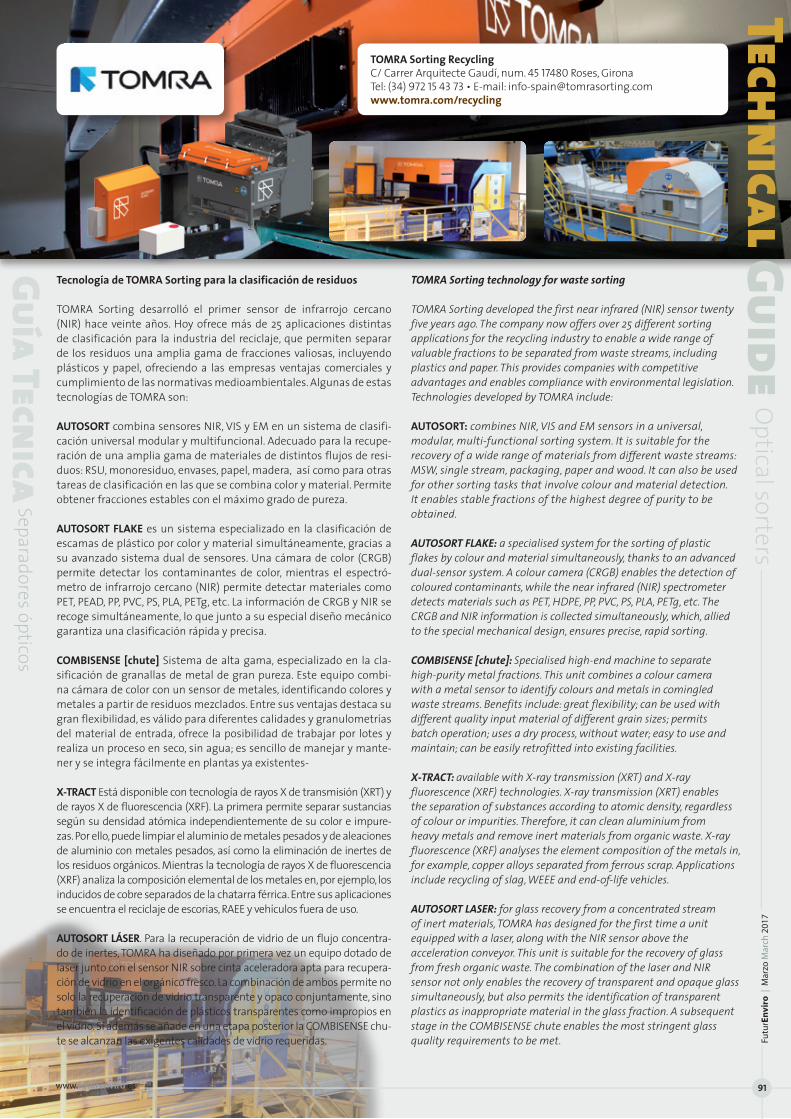
TOMRA Sorting RecyclingC/ Carrer Arquitecte Gaudí, num. 45 17480 Roses, Girona Tel: (34) 972 15 43 73 • E-mail: [email protected]/recycling
Tecnología de TOMRA Sorting para la clasificación de residuos
TOMRA Sorting desarrolló el primer sensor de infrarrojo cercano (NIR) hace veinte años. Hoy ofrece más de 25 aplicaciones distintas de clasificación para la industria del reciclaje, que permiten separar de los residuos una amplia gama de fracciones valiosas, incluyendo plásticos y papel, ofreciendo a las empresas ventajas comerciales y cumplimiento de las normativas medioambientales. Algunas de estas tecnologías de TOMRA son:
AUTOSORT combina sensores NIR, VIS y EM en un sistema de clasifi-cación universal modular y multifuncional. Adecuado para la recupe-ración de una amplia gama de materiales de distintos flujos de resi-duos: RSU, monoresiduo, envases, papel, madera, así como para otras tareas de clasificación en las que se combina color y material. Permite obtener fracciones estables con el máximo grado de pureza.
AUTOSORT FLAKE es un sistema especializado en la clasificación de escamas de plástico por color y material simultáneamente, gracias a su avanzado sistema dual de sensores. Una cámara de color (CRGB) permite detectar los contaminantes de color, mientras el espectró-metro de infrarrojo cercano (NIR) permite detectar materiales como PET, PEAD, PP, PVC, PS, PLA, PETg, etc. La información de CRGB y NIR se recoge simultáneamente, lo que junto a su especial diseño mecánico garantiza una clasificación rápida y precisa.
COMBISENSE [chute] Sistema de alta gama, especializado en la cla-sificación de granallas de metal de gran pureza. Este equipo combi-na cámara de color con un sensor de metales, identificando colores y metales a partir de residuos mezclados. Entre sus ventajas destaca su gran flexibilidad, es válido para diferentes calidades y granulometrías del material de entrada, ofrece la posibilidad de trabajar por lotes y realiza un proceso en seco, sin agua; es sencillo de manejar y mante-ner y se integra fácilmente en plantas ya existentes-
X-TRACT Está disponible con tecnología de rayos X de transmisión (XRT) y de rayos X de fluorescencia (XRF). La primera permite separar sustancias según su densidad atómica independientemente de su color e impure-zas. Por ello, puede limpiar el aluminio de metales pesados y de aleaciones de aluminio con metales pesados, así como la eliminación de inertes de los residuos orgánicos. Mientras la tecnología de rayos X de fluorescencia (XRF) analiza la composición elemental de los metales en, por ejemplo, los inducidos de cobre separados de la chatarra férrica. Entre sus aplicaciones se encuentra el reciclaje de escorias, RAEE y vehículos fuera de uso.
AUTOSORT LÁSER. Para la recuperación de vidrio de un flujo concentra-do de inertes, TOMRA ha diseñado por primera vez un equipo dotado de laser junto con el sensor NIR sobre cinta aceleradora apta para recupera-ción de vidrio en el orgánico fresco. La combinación de ambos permite no solo la recuperación de vidrio transparente y opaco conjuntamente, sino también la identificación de plásticos transparentes como impropios en el vidrio. Si además se añade en una etapa posterior la COMBISENSE chu-te se alcanzan las exigentes calidades de vidrio requeridas.
TOMRA Sorting technology for waste sorting
TOMRA Sorting developed the first near infrared (NIR) sensor twenty five years ago. The company now offers over 25 different sorting applications for the recycling industry to enable a wide range of valuable fractions to be separated from waste streams, including plastics and paper. This provides companies with competitive advantages and enables compliance with environmental legislation. Technologies developed by TOMRA include:
AUTOSORT: combines NIR, VIS and EM sensors in a universal, modular, multi-functional sorting system. It is suitable for the recovery of a wide range of materials from different waste streams: MSW, single stream, packaging, paper and wood. It can also be used for other sorting tasks that involve colour and material detection. It enables stable fractions of the highest degree of purity to be obtained.
AUTOSORT FLAKE: a specialised system for the sorting of plastic flakes by colour and material simultaneously, thanks to an advanced dual-sensor system. A colour camera (CRGB) enables the detection of coloured contaminants, while the near infrared (NIR) spectrometer detects materials such as PET, HDPE, PP, PVC, PS, PLA, PETg, etc. The CRGB and NIR information is collected simultaneously, which, allied to the special mechanical design, ensures precise, rapid sorting.
COMBISENSE [chute]: Specialised high-end machine to separate high-purity metal fractions. This unit combines a colour camera with a metal sensor to identify colours and metals in comingled waste streams. Benefits include: great flexibility; can be used with different quality input material of different grain sizes; permits batch operation; uses a dry process, without water; easy to use and maintain; can be easily retrofitted into existing facilities.
X-TRACT: available with X-ray transmission (XRT) and X-ray fluorescence (XRF) technologies. X-ray transmission (XRT) enables the separation of substances according to atomic density, regardless of colour or impurities. Therefore, it can clean aluminium from heavy metals and remove inert materials from organic waste. X-ray fluorescence (XRF) analyses the element composition of the metals in, for example, copper alloys separated from ferrous scrap. Applications include recycling of slag, WEEE and end-of-life vehicles.
AUTOSORT LASER: for glass recovery from a concentrated stream of inert materials, TOMRA has designed for the first time a unit equipped with a laser, along with the NIR sensor above the acceleration conveyor. This unit is suitable for the recovery of glass from fresh organic waste. The combination of the laser and NIR sensor not only enables the recovery of transparent and opaque glass simultaneously, but also permits the identification of transparent plastics as inappropriate material in the glass fraction. A subsequent stage in the COMBISENSE chute enables the most stringent glass quality requirements to be met.
Technical Guide
Optical sorters
Guía Tecnica
Separadores ópticosFu
turE
nvi
ro |
Mar
zo M
arch
201
7
www.futurenviro.es 91
Ges
tió
n y
tra
tam
ien
to d
e re
sid
uo
s |
Was
te M
anag
emen
t &
Tre
atm
ent
FuturEnviro | Marzo March 2017
ww
w.fu
ture
nvi
ro.e
s
92
Después de un estudio completo, el sistema de ventilación de la lí-nea de lodos fue completamente modificado y ahora la emisión se trata en un Biofiltro de Altas Prestaciones (BAP), compuesto por un lecho mixto orgánico e inorgánico. Desde entonces no ha habido más quejas vecinales causadas por malos olores.
El principal objetivo de éste artículo es explicar por completo el pro-yecto llevado a cabo, incluyendo:
• Toma de muestras y análisis de todos los puntos de emisión foca-lizados, así como de los focos de emisión sin cubrir de las líneas de agua y lodos.
• Modelización del impacto odorífero de las emisiones en el escenario actual y con el nuevo sistema de ventilación y emisiones tratadas.
• Comparación total de la diferencia entre las distintas tecnologías de reducción de olores (teniendo en cuenta, entre otros factores, la eficiencia de depuración de olores, necesidad de productos quí-micos, espacio disponible, CAPEX y OPEX).
• Selección de la tecnología para la reducción de olor (el BAP fue la elegida).
• Descripción del diseño, entrega, instalación y eficiencia del Biofil-tro de Altas Prestaciones.
Introducción
La EDAR Galindo, situada en Bilbao, España, es una EDAR que tra-ta cerca de 350.000 m3 de aguas residuales municipales cada día. Esta EDAR fue construida en 1985, en las afueras de la ciudad, pero debido al crecimiento urbano, esta planta ha quedado completa-mente rodeada por áreas residenciales y comerciales en tan sólo unos años y las molestias y quejas por olores fueron apareciendo y creciendo año tras año.
En 2007 la propiedad de la EDAR decidió iniciar un proyecto exhaus-tivo con el objetivo de reducir el impacto odorífero de dicha actividad en las inmediaciones de la planta. Éste proyecto se dividió en dife-rentes fases, la primera consistió en una detallada caracterización odorífera y química de las distintas emisiones de aire de la planta, seguida por una modelización que permitió calcular el impacto odo-rífero de la misma sobre su entorno y así se identificaron cuáles eran las emisiones que principalmente provocaban los problemas de olor. Finalmente el estudio de ingenieríarealizado permitió elegir cuál de las tecnologías disponibles actualmente en el mercado era la más adecuada para el presente caso, en el que se buscaba mejor eficien-cia en cuanto a eliminación de olor se refiere, y que al mismo tiempo tuviera los menores costes de operación y mantenimiento.
Metodología
Medida e impacto odoríferos
En 2007 se realizó un análisis olfatométrico completo en los si-guientes puntos de la EDAR:
• Las emisiones de entrada y salida de los scrubber llamados “Olo-res 1” diseñados para tratar 197.000 m3/h y que estaban tratando
Following a comprehensive study, the ventilation system was completely modified and emissions are now treated in a High-Efficiency Advanced Biofilter (HEAB) with a mixed organic and inorganic bed. Since that time, there have been no further complaints from residents about foul odours.
The main objective of this article is to provide a comprehensive description of the project undertaken, including:
• Sample-taking and analysis of all targeted emission points, as well as uncovered emission sources in the water and sludge lines.
• Modelling of odour emissions impact in the existing scenario, and with the new ventilation system and treated emissions.
• Complete comparison of the differences between the different odour reduction technologies (taking into account, amongst other factors, efficiency of odour treatment, need for chemical products, available space, CAPEX and OPEX).
• Selection of the odour reduction technology (The HEAB was selected).
• Description of the design, delivery, installation and efficiency of the High Efficiency Advanced Biofilter.
Introduction
The Galindo sewage treatment works (STW) in Bilbao, northern Spain, treats nearly 350,000 m3 of domestic sewage per day. When it was built in 1985, the STW was on the outskirts of the city, but within only a few years, it was surrounded by residential and commercial developments, and complaints about odours increased year after year.
In 2007, the owners of the STW decided to begin an exhaustive project for the purpose of reducing the odour impact in the vicinity of the plant. The project was divided into different phases. The first consisted of a detailed chemical and odour characterisation of the different air emissions from the plant. This was followed by a modelling phase to calculate the odour impact on the surrounding areas, and in this way the emissions mainly responsible for the odour problems were identified. Finally, the engineering study undertaken enabled a decision to be taken as to which of the technologies currently available on the market was the most suitable for this case. This decision would be based on the highest efficiency in terms of odour removal, whilst taking operating and maintenance costs into account.
Methodology
Odour measurement and impact
In 2007, a comprehensive olfactometric analysis was carried out at the following points of the STW:
• Inlet and outlet emissions of the scrubbers called “ODOURS 1”. These scrubbers were designed to treat 197,000 m3/h and were
TRATAMIENTO DE OLOR CON UN BIOFILTRO DE ALTAS PRESTACIONES EN LA EDAR GALINDO Este artículo describe un estudio que se centra en una gran Estación Depuradora de Aguas Residuales (EDAR) situada en el Norte de España. A pesar de tratar las emisiones generadas en el sistema de pretratamiento de aguas mediante un scrubber químico de dos etapas, los gases emitidos por la instalación causaban una importante molestia a los vecinos que viven cerca de la planta.
ODOUR TREATMENT WITH HIGH-EFFICIENCY ADVANCED BIOFILTER AT GALINDO STW This article describes a study carried out at a large Sewage Treatment Works (STW) in the north of Spain. Despite the fact that emissions generated in the pretreatment stage were treated by means of a two-stage chemical scrubber, the gases emitted from the facility caused considerable inconvenience to residents living nearby.
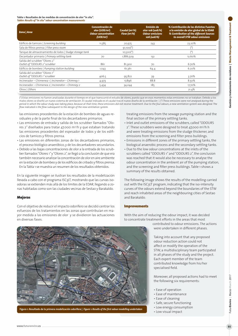
las emisiones procedentes de la estación de bombeo de aguas re-siduales y de la parte final de los decantadores primarios.
• Las emisiones de entrada y salida de los scrubber llamados “Olo-res 2” diseñados para tratar 47.000 m3/h y que estaban tratando las emisiones procedentes del espesador de lodos y de los edifi-cios de tamices y filtros prensa.
• Las emisiones en diferentes zonas de los decantadores primarios, el proceso biológico anaeróbico, y de los decantadores secundarios.
• Debido a las bajas concentraciones de olor a la entrada de los scrub-ber llamados “Olores 1” y “Olores 2”, se llegó a la conclusión de que era también necesario analizar la concentración de olor en aire ambiente en la estación de bombeo y de los edificios de cribado y filtros prensa. En la Tabla 1 se muestra un resumen de los resultados obtenidos.
En la siguiente imagen se ilustran los resultados de la modelización llevada a cabo con el programa ISC3LT, mostrando que las curvas iso-odoras se extienden más allá de los límites de la EDAR, llegando a zo-nas habitadas como son las ciudades vecinas de Sestao y Barakaldo.
Mejoras
Con el objetivo de reducir el impacto odorífero se decidió centrar los esfuerzos de los tratamientos en las zonas que contribuían en ma-yor medida a las emisiones de olor y se dividieron las actuaciones en diversas fases.
treating emissions from the sewage pumping station and the final section of the primary settling tanks.
• Inlet and outlet emissions of the scrubbers, called “ODOURS 2”. These scrubbers were designed to treat 47,000 m3/h h and were treating emissions from the sludge thickener, and emissions from the screening and filter press buildings.
• Emissions in different zones of the primary settling tanks, the biological anaerobic process and the secondary settling tanks.
• Due to the low odour concentrations at the inlets of the scrubbers called “ODOURS 1” and “ODOURS 2”, the conclusion was reached that it would also be necessary to analyse the odour concentration in the ambient air of the pumping station, and the screening and filter press buildings. Table 1 shows a summary of the results obtained.
The following image shows the results of the modelling carried out with the ISC3LT program, indicating that the iso-intensity curves of the odours extend beyond the boundaries of the STW and reach inhabited areas of the neighbouring cities of Sestao and Barakaldo.
Improvements
With the aim of reducing the odour impact, it was decided to concentrate treatment efforts in the areas that most
contributed to odour emissions. The actions were undertaken in different phases.
Taking into account that any proposed odour reduction action could not affect or modify the operation of the STW, a multidisciplinary team participated in all phases of the study and the project. Each expert member of the team contributed knowledge from his/her specialised field.
Moreover, all proposed actions had to meet the following six requirements:
• Ease of operation • Ease of maintenance• Ease of cleaning• Safe, secure functioning • Low energy consumption• Low visual impact
Figura 1: Resultado de la primera modelización odorífera | Figure 1: Results of the first odour modelling undertaken
Concentraciónde Emisiónde %ContribucióndelasdistintasFuentes olor(UOE/m3) Caudal(m3/h) olor106(uoE/h) alaemisióndeolorglobaldelaEDARZona|Area Odour concentration Flow (m3/h) Odour emissions % Contribution of the different Sources (UOE/m3) 106 (uoE/h) to overall STW odour emissions Edificio de tamices | Screening building 11,585 20,975 243 23.20%Sala de filtros prensa | Filter press room 91,100(*) (*)Tanque de almacenamiento de lodos | Sludge storage tank 10,500(*) (*)Decantador primario | Primary settling tank 70 1,886,509 132 12.60%Salida del scrubber “Olores 2” Outlet of “ODOURS 2” scrubber 861 81,300 70 6.70%Edificio de bombeo | Pumping station building 1,043 61,361 64.4 6.20%Salida del scrubber “Olores 1” Outlet of “ODOURS 1” scrubber 406.5 95,822 39 3.70%Incinerador – Chimenea 1 | Incinerator – Chimney 1 4,973 17,896 88.8 8.50%Incinerador – Chimenea 2 | Incinerator – Chimney 2 5,434 34,044 185 17.70%Otros | Others 21.4%
Tabla 1: Resultados de las medidas de concentración de olor “in situ”. Table1: Results of “in situ” odour concentration measurements
(*) Estas emisiones no fueron analizadas durante el tiempo en el que transcurrió el estudio de olores, puesto que en esos momentos estas emisiones no se trataban. Debido a los malos olores se diseñó un nuevo sistema de ventilación. El caudal indicado es el caudal tras el nuevo diseño de la ventilación | (*) These emissions were not analysed during the period in which the odour study was taking place, because at that time, these emissions did not receive treatment. Due to the foul odours, a new ventilation system was designed. The flow indicated is the flow subsequent to the design of the new ventilation system. G
esti
ón
y t
rata
mie
nto
de
resi
du
os
| W
aste
Man
agem
ent
& T
reat
men
tFu
turE
nvi
ro |
Mar
zo M
arch
201
7
www.futurenviro.es 93

Ges
tió
n y
tra
tam
ien
to d
e re
sid
uo
s |
Was
te M
anag
emen
t &
Tre
atm
ent
FuturEnviro | Marzo March 2017
ww
w.fu
ture
nvi
ro.e
s
94
Teniendo en cuenta que cualquier acción propuesta para reducir el olor no podía ni afectar ni modificar la operatividad de la de-puradora, en la realización de todas las fases de estudio y del proyecto participó un equipo multidisciplinar en el que cada experto con-tribuía en su campo de especialidad.
Además, todas las actuaciones propuestas debían cumplir los siguientes seis requisitos:
• Facilidad de operación, • Facilidad de mantenimiento• Facilidad de limpieza• Funcionamiento seguro, • Bajo consumo de energía• y cuidado impacto visual.
El estudio concluyó en que se debían realizar una serie de actuaciones repartidas en cua-tro fases, de mayor a menor prioridad.
• Primera Fase: Tratamiento de las emisiones de la línea de fangos• Fase dos: Remodelación de la decantación primaria• Fase 3: Optimización del pretratamiento• Fase 4: Disminución del impacto generado por los reactores bio-
lógicos
Primera fase
En estos momentos, de las 4 fases de actuaciones propuestas se ha realizado y finalizado la primera Fase que es el objeto de este artículo. En esta fase se realizó:
• La mejora la ventilación del edificio de tamices• El rediseño de la cubierta de los tanques de espesado de lodos• La mejora de la ventilación del edificio de filtros prensa• Y finalmente centralización y vehiculación de todas las emi-
siones generadas en la línea de lodos hacia un nuevo sistema de tratamiento de olor que como requisito imprescindible debía garantizar una concentración final de olor inferior a 1.000 uoE/ m3
La Figura 2 muestra la reducción del impacto odorífero esperada tras la aplicación de la primera fase, que reduce en gran medida el impacto odorífero de los alrededores de la EDAR. Segunda Fase
Como segunda fase, se decidió modificar los decantadores primarios existentes a decanta-dores lamelares y así poder cubrirlos, extraer las emisiones de aire y dirigirlas al scrubber “OLO-RES 1”. En la Figura 3 se muestra la reducción de impacto odorífero adicional esperada. Esta se-gunda fase no ha sido ejecutada todavía. Discusión sobre el tratamiento de olores a seleccionar para la Fase 1.
Con el objetivo de seleccionar la mejor tec-nología disponible para tratar las emisiones de la línea de lodos (fase 1 del estudio), se estudiaron la eficiencia de eliminación de olor, los costes iniciales (CAPEX) y los costes de operación y mantenimiento (OPEX) de las tecnologías normalmente aplicadas en tra-tamientos de olores listadas a continuación:
The conclusion of the study was that a number of actions should be taken in four phases, from highest to lowest priority.
• Phase 1: Treatment of emissions from sludge line• Phase 2: Remodelling of primary settling• Phase 3: Optimisation of pretreatment• Phase 4: Reduction of impact generated by bioreactors
Phase 1
Of the 4 phases of proposed actions, Phase 1, which is the subject of this article, has been completed. The following actions were carried out in this phase:
• The ventilation system in the screening building was improved
• The cover of the sludge thickening tanks was redesigned• The ventilation of the filter press building was improved• All emissions generated in the sludge line were centralised
and sent to a new odour treatment system which had to fulfil the essential requirement of guaranteeing a final odour concentration of less than 1,000 uoE/ m3
Figure 2 shows the expected reduction in odour impact following the completion of Phase 1, which significantly
Figura 2: Resultado de la modelización de olor tras la Fase 1 | Figure 2: Results of odour modelling after Phase 1
Figura 3: Resultado de la modelización del impacto odorífero tras la Fase 2 | Figure3: Result of modelling of odour impact after Phase 2
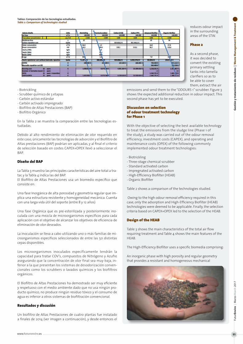
- Biotrickling- Scrubber químico de 3 etapas- Carbón activo estándar- Carbón activado impregnado- Biofiltro de Altas Prestaciones (BAP)- Biofiltro Orgánico
En la Tabla 2 se muestra la comparación entre las tecnologías es-tudiadas. Debido al alto rendimiento de eliminación de olor requerido en este caso, únicamente las tecnologías de adsorción y el Biofiltro de Altas prestaciones (BAP) podrían ser aplicadas, y al final el criterio de selección basado en costes CAPEX+OPEX llevó a seleccionar el BAP.
Diseño del BAP
La Tabla 3 muestra las principales características del aire total a tra-tar, y la Tabla 4 indica las del BAP.El Biofiltro de Altas Prestaciones usa un biomedio específico que consiste en:
Una fase Inorgánica de alta porosidad y geometría regular que im-plica una estructura resistente y homogeneidad mecánica. Cuenta con una larga vida útil del soporte (entre 8 y 12 años)
Una fase Orgánica que es pre-esterilizada y posteriormente ino-culada con una mezcla de microorganismos específicos para cada aplicación con el objetivo de alcanzar los objetivos de eficiencia de eliminación de olor deseados.
La inoculación se lleva a cabo utilizando uno o más familias de mi-croorganismos específicos seleccionados de entre las 50 distintas cepas disponibles.
Los microorganismos inoculados específicamente tendrán la capacidad para tratar COV’s, compuestos de Nitrógeno y Azufre asegurando que la concentración de olor final sea muy baja, in-ferior a la que presentan los sistemas de desodorización conven-cionales como los scrubbers o lavados químicos y los biofiltros orgánicos.
El Biofiltro de Altas Prestaciones ha demostrado ser muy eficiente y respetuoso con el medio ambiente dado que no usa ningún pro-ducto químico, no produce ningún residuo tóxico y el consumo de agua es inferior a otros sistemas de biofiltración convencional.
Resultados y discusión
Un biofiltro de Altas Prestaciones de cuatro plantas fue instalado a finales de 2014 (ver imagen a continuación), y desde entonces el
reduces odour impact in the surrounding areas of the STW. Phase 2
As a second phase, it was decided to convert the existing primary settling tanks into lamella clarifiers so as to be able to cover them, extract the air
emissions and send them to the “ODOURS 1” scrubber. Figure 3 shows the expected additional reduction in odour impact. This second phase has yet to be executed. Discussion on selection of odour treatment technology for Phase 1
With the objective of selecting the best available technology to treat the emissions from the sludge line (Phase 1 of the study), a study was carried out of the odour removal efficiency, investment costs (CAPEX), and operating and maintenance costs (OPEX) of the following commonly implemented odour treatment technologies:
- Biotrickling- Three-stage chemical scrubber- Standard activated carbon- Impregnated activated carbon- High-Efficiency Biofilter (HEAB)- Organic Biofilter
Table 2 shows a comparison of the technologies studied. Owing to the high odour removal efficiency required in this case, only the adsorption and High-Efficiency Biofilter (HEAB) technologies were deemed to be applicable. Finally, the selection criteria based on CAPEX+OPEX led to the selection of the HEAB.
Design of the HEAB
Table 3 shows the main characteristics of the total air flow requiring treatment and Table 4 shows the main features of the HEAB.
The High-Efficiency Biofilter uses a specific biomedia comprising:
An inorganic phase with high porosity and regular geometry that provides a resistant and homogeneous mechanical
Tabla2: Comparación de las tecnologías estudiadas. Table 2: Comparison of technologies studied
Ges
tió
n y
tra
tam
ien
to d
e re
sid
uo
s |
Was
te M
anag
emen
t &
Tre
atm
ent
Futu
rEn
viro
| M
arzo
Mar
ch 2
017
www.futurenviro.es 95
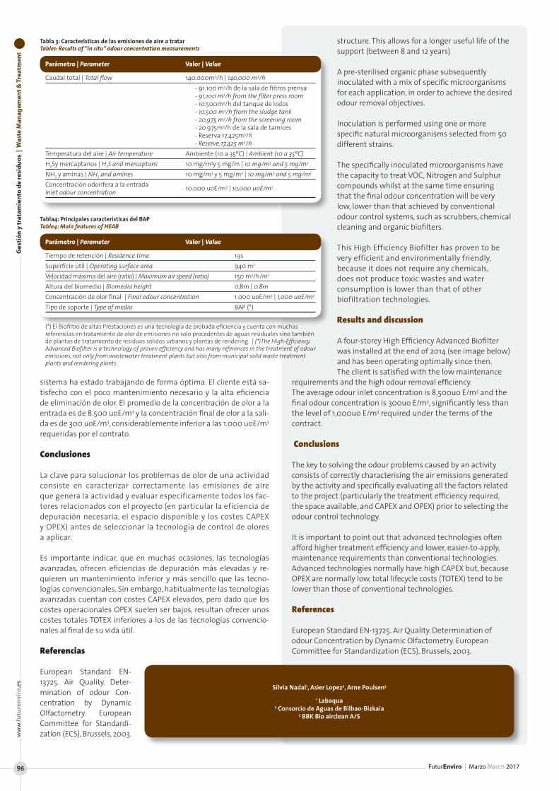
Ges
tió
n y
tra
tam
ien
to d
e re
sid
uo
s |
Was
te M
anag
emen
t &
Tre
atm
ent
FuturEnviro | Marzo March 2017
ww
w.fu
ture
nvi
ro.e
s
96
sistema ha estado trabajando de forma óptima. El cliente está sa-tisfecho con el poco mantenimiento necesario y la alta eficiencia de eliminación de olor. El promedio de la concentración de olor a la entrada es de 8.500 uoE/m3 y la concentración final de olor a la sali-da es de 300 uoE/m3, considerablemente inferior a las 1.000 uoE/m3 requeridas por el contrato.
Conclusiones
La clave para solucionar los problemas de olor de una actividad consiste en caracterizar correctamente las emisiones de aire que genera la actividad y evaluar específicamente todos los fac-tores relacionados con el proyecto (en particular la eficiencia de depuración necesaria, el espacio disponible y los costes CAPEX y OPEX) antes de seleccionar la tecnología de control de olores a aplicar.
Es importante indicar, que en muchas ocasiones, las tecnologías avanzadas, ofrecen eficiencias de depuración más elevadas y re-quieren un mantenimiento inferior y más sencillo que las tecno-logías convencionales. Sin embargo, habitualmente las tecnologías avanzadas cuentan con costes CAPEX elevados, pero dado que los costes operacionales OPEX suelen ser bajos, resultan ofrecer unos costes totales TOTEX inferiores a los de las tecnologías convencio-nales al final de su vida útil.
Referencias
European Standard EN-13725. Air Quality. Deter-mination of odour Con-centration by Dynamic Olfactometry. European Committee for Standardi-zation (ECS), Brussels, 2003.
structure. This allows for a longer useful life of the support (between 8 and 12 years)
A pre-sterilised organic phase subsequently inoculated with a mix of specific microorganisms for each application, in order to achieve the desired odour removal objectives.
Inoculation is performed using one or more specific natural microorganisms selected from 50 different strains.
The specifically inoculated microorganisms have the capacity to treat VOC, Nitrogen and Sulphur compounds whilst at the same time ensuring that the final odour concentration will be very low, lower than that achieved by conventional odour control systems, such as scrubbers, chemical cleaning and organic biofilters.
This High Efficiency Biofilter has proven to be very efficient and environmentally friendly, because it does not require any chemicals, does not produce toxic wastes and water consumption is lower than that of other biofiltration technologies.
Results and discussion
A four-storey High Efficiency Advanced Biofilter was installed at the end of 2014 (see image below) and has been operating optimally since then. The client is satisfied with the low maintenance
requirements and the high odour removal efficiency. The average odour inlet concentration is 8,500uo E/m3 and the final odour concentration is 300uo E/m3, significantly less than the level of 1,000uo E/m3 required under the terms of the contract.
Conclusions
The key to solving the odour problems caused by an activity consists of correctly characterising the air emissions generated by the activity and specifically evaluating all the factors related to the project (particularly the treatment efficiency required, the space available, and CAPEX and OPEX) prior to selecting the odour control technology.
It is important to point out that advanced technologies often afford higher treatment efficiency and lower, easier-to-apply, maintenance requirements than conventional technologies. Advanced technologies normally have high CAPEX but, because OPEX are normally low, total lifecycle costs (TOTEX) tend to be lower than those of conventional technologies.
References
European Standard EN-13725. Air Quality. Determination of odour Concentration by Dynamic Olfactometry. European Committee for Standardization (ECS), Brussels, 2003.
Parámetro|Parameter Valor|Value
Caudal total | Total flow 140.000m3/h | 140,000 m3/h - 91.100 m3/h de la sala de filtros prensa - 91,100 m3/h from the filter press room - 10.500m3/h del tanque de lodos - 10,500 m3/h from the sludge tank - 20,975 m3/h from the screening room - 20.975m3/h de la sala de tamices - Reserva:17.425m3/h - Reserve:17,425 m3/hTemperatura del aire | Air temperature Ambiente (10 a 35ºC) | Ambient (10 a 35ºC)H2Sy mercaptanos | H2S and mercaptans 10 mg/m3y 5 mg/m | 10 mg/m3 and 5 mg/m3
NH3 y aminas | NH3 and amines 10 mg/m3 y 5 mg/m3 | 10 mg/m3 and 5 mg/m3
Concentración odorífera a la entrada 10.000 uoE/m3 | 10,000 uoE/m3
Inlet odour concentration
Tabla 3: Características de las emisiones de aire a tratar Table1: Results of “in situ” odour concentration measurements
Parámetro|Parameter Valor|Value
Tiempo de retención | Residence time 19sSuperficie útil | Operating surface area 940 m2
Velocidad máxima del aire (ratio) | Maximum air speed (ratio) 150 m3/h/m2
Altura del biomedio | Biomedia height 0,8m | 0.8mConcentración de olor final | Final odour concentration 1.000 uoE/m3 | 1,000 uoE/m3
Tipo de soporte | Type of media BAP (*)
Tabla4: Principales características del BAP Table4: Main features of HEAB
(*) El Biofiltro de altas Prestaciones es una tecnología de probada eficiencia y cuenta con muchas referencias en tratamiento de olor de emisiones no solo procedentes de aguas residuales sino también de plantas de tratamiento de residuos sólidos urbanos y plantas de rendering. | (*)The High-Efficiency Advanced Biofilter is a technology of proven efficiency and has many references in the treatment of odour emissions, not only from wastewater treatment plants but also from municipal solid waste treatment plants and rendering plants.
Sílvia Nadal1, Asier Lopez2, Arne Poulsen3 1 Labaqua
2 Consorcio de Aguas de Bilbao-Bizkaia 3 BBK Bio airclean A/S
Gu
ía d
el C
om
pra
do
r |
Bu
yer’
s G
uid
e
FuturEnviro | Marzo March 2017
ww
w.fu
ture
nvi
ro.e
s
97
Guía del compradorB
uye
r’s
Gu
ide
Nº 38 Marzo | March 2017
Directorio de Empresas | Company DirectoryTambién On-line | also on-lineLocaliza de forma rápida a los mejores proveedoresFind your suppliers quickly
FuturENVIROPROYECTOS, TECNOLOGÍA Y ACTUALIDAD MEDIOAMBIENTALP RO J E C T S , TE C H N O L O G I E S A N D E N V I RO N M E N T A L N E W S
marron E pantone 1545 Cnaranja N pantone 1525 Callo V pantone 129 Cazul I pantone 291 Cazul R pantone 298 Cazul O pantone 2945 CFuture 100 negro
Residuos | Waste
Futu
rEn
viro
| M
arzo
Mar
ch 2
017
www.futurenviro.es 97
Gu
ía d
el C
om
pra
do
r |
Bu
yer’
s G
uid
e
FuturEnviro | Marzo March 2017
ww
w.fu
ture
nvi
ro.e
s
98
Agua | Water
Gu
ía d
el C
om
pra
do
r |
Bu
yer’
s G
uid
eFu
turE
nvi
ro |
Mar
zo M
arch
201
7
www.futurenviro.es 99
Gestión Medioambiental Environmental management
Nº 38 Marzo | March 2017 | 15 e Español | Inglés | Spanish | English
REPORTAJE | PLANT REPORT: ECOPARQUE GRAN CANARIA SUR GUÍAS TÉCNICAS | TECHNICAL GUIDES
PRE-TRITURADORES ESTACIONARIOS Y MÓVILES | STATIONARY & MOBILE PRIMARY SHREDDERSSEPARADORES DE CORRIENTE DE FOUCAULT Y SEPARADORES MAGNÉTICOS
EDDY CURRENT SEPARATORS & MAGNETIC SEPARATORSSEPARADORES ÓPTICOS | OPTICAL SORTERS
ENVIROFuturENVIROPROYECTOS, TECNOLOGÍA Y ACTUALIDAD MEDIOAMBIENTALP RO J E C T S , TE C H N O L O G I E S A N D E N V I RO N M E N T A L N E W S
marron E pantone 1545 Cnaranja N pantone 1525 Callo V pantone 129 Cazul I pantone 291 Cazul R pantone 298 Cazul O pantone 2945 CFuture 100 negro
Nº
38 |
Mar
zo M
arch
201
7Fu
turE
NV
IRO
PR
OY
EC
TO
S,
TEC
NO
LO
GÍA
Y A
CT
UA
LID
AD
ME
DIO
AM
BIE
NT
AL
PR
OJ
EC
TS
, T
EC
HN
OL
OG
IES
AN
D E
NV
IRO
NM
EN
TA
L N
EW
S
mar
ron
E pa
nton
e 154
5 C
nara
nja N
pan
tone
152
5 C
allo
V p
anto
ne 1
29 C
azul
I pa
nton
e 291
Caz
ul R
pan
tone
298
Caz
ul O
pan
tone
294
5 C
Futu
re 1
00 n
egro
Copyright © 2022 FDOKUMEN