EC Type-Approval Certificate - Cardinal Scale
23
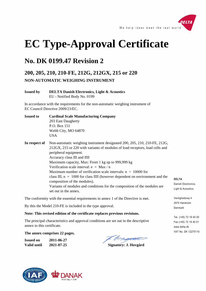
DELTA Danish Electronics, Light & Acoustics Venlighedsvej 4 2970 Hørsholm Denmark Tel. (+45) 72 19 40 00 Fax (+45) 72 19 40 01 www.delta.dk VAT No. DK 12275110 EC Type-Approval Certificate No. DK 0199.47 Revision 2 200, 205, 210, 210-FE, 212G, 212GX, 215 or 220 NON-AUTOMATIC WEIGHING INSTRUMENT Issued by DELTA Danish Electronics, Light & Acoustics EU - Notified Body No. 0199 In accordance with the requirements for the non-automatic weighing instrument of EC Council Directive 2009/23/EC. Issued to Cardinal Scale Manufacturing Company 203 East Daugherty P.O. Box 151 Webb City, MO 64870 USA In respect of Non-automatic weighing instrument designated 200, 205, 210, 210-FE, 212G, 212GX, 215 or 220 with variants of modules of load receptors, load cells and peripheral equipment. Accuracy class III and IIII Maximum capacity, Max: From 1 kg up to 999,999 kg Verification scale interval: e = Max / n Maximum number of verification scale intervals: n = 10000 for class III, n = 1000 for class IIII (however dependent on environment and the composition of the modules). Variants of modules and conditions for the composition of the modules are set out in the annex. The conformity with the essential requirements in annex 1 of the Directive is met. By this the Model 210-FE is included in the type approval. Note: This revised edition of the certificate replaces previous revisions. The principal characteristics and approval conditions are set out in the descriptive annex to this certificate. The annex comprises 22 pages. Issued on 2011-06-27 Valid until 2021-07-25 Signatory: J. Hovgård
-
Upload
khangminh22 -
Category
Documents
-
view
0 -
download
0
Transcript of EC Type-Approval Certificate - Cardinal Scale
DELTA
Danish Electronics,
Light & Acoustics
Venlighedsvej 4
2970 Hørsholm
Denmark
Tel. (+45) 72 19 40 00
Fax (+45) 72 19 40 01
www.delta.dk
VAT No. DK 12275110
EC Type-Approval Certificate
No. DK 0199.47 Revision 2
200, 205, 210, 210-FE, 212G, 212GX, 215 or 220
NON-AUTOMATIC WEIGHING INSTRUMENT
Issued by DELTA Danish Electronics, Light & AcousticsEU - Notified Body No. 0199
In accordance with the requirements for the non-automatic weighing instrument of
EC Council Directive 2009/23/EC.
Issued to Cardinal Scale Manufacturing Company203 East Daugherty
P.O. Box 151
Webb City, MO 64870
USA
In respect of Non-automatic weighing instrument designated 200, 205, 210, 210-FE, 212G,
212GX, 215 or 220 with variants of modules of load receptors, load cells and
peripheral equipment.
Accuracy class III and IIII
Maximum capacity, Max: From 1 kg up to 999,999 kg
Verification scale interval: e = Max / n
Maximum number of verification scale intervals: n = 10000 for
class III, n = 1000 for class IIII (however dependent on environment and the
composition of the modules).
Variants of modules and conditions for the composition of the modules are
set out in the annex.
The conformity with the essential requirements in annex 1 of the Directive is met.
By this the Model 210-FE is included in the type approval.
Note: This revised edition of the certificate replaces previous revisions.
The principal characteristics and approval conditions are set out in the descriptive
annex to this certificate.
The annex comprises 22 pages.
Issued on 2011-06-27
Valid until 2021-07-25 Signatory: J. Hovgård

Annex page 1 of 22Certificate of EU type-approval No. DK 0199.47 rev.2
Issued by DELTA
Descriptive annex
Contents Page
1. Name and type of instrument and modules 2
2. Description of the construction and function 2
2.1 Construction 2
2.2 Function 4
2.3 Available options 7
3. Technical data 8
3.1 Indicator 8
3.2 Load receptors, load cells and load receptor supports 8
3.3 Composition of modules 9
4. Interfaces and peripheral equipment 10
4.1 Interfaces 10
4.2 Peripheral equipment 10
5. Approval conditions 11
5.1 Measurement functions other than non-automatic functions 11
5.2 Piece counting 11
5.3 Compatibility of modules 11
6. Special conditions for verification 12
6.1 Composition of modules 12
7. Securing and location of seals and verification marks 12
7.1 Securing and sealing 12
7.2 Verification marks 12
8. Location of CE mark of conformity and inscriptions 13
8.1 Indicator 13
8.2 Load receptors 13
9. Pictures 14
10. Composition of modules – exemplified 22

Annex page 2 of 22Certificate of EU type-approval No. DK 0199.47 rev.2
Issued by DELTA
1. Name and type of instrument and modules
The weighing instrument is designated the 200 series which is a system of modules consisting of an
electronic indicator, connected to a separate load receptor and peripheral equipment such as printers or
other devices, as appropriate. The instrument is a Class III or IIII, self-indicating weighing instrument
with single-interval (multi-interval for Model 220 only) and an internal AC mains power supply. The
weight indicating instrument is available in one of eight models:
Model 200 a panel-mount instrument with basic keyboard (see figure 9 and 10)
Model 205 a desk or wall mount instrument with basic keyboard (see figure 7 and 8)
Model 210 a desk or wall mount instrument with full function keyboard (see figure 5 and 6)
Model 210-FE a wall mount instrument with basic keyboard (see figure 11 and 12)
Model 212G a wall mounted instrument with full function keyboard (see figure 13 and 15)Model 212GX a wall mounted instrument with full function keyboard (see figure 14 and 15)Model 215 a desk or wall mount instrument with full function keyboard (see figure 3 and 4)
Model 220 a desk or wall mount instrument with extended full function keyboard (see figure 1 and 2)
The indicators consist of analogue to digital conversion circuitry, microprocessor control circuitry,
power supply, keyboard, non-volatile memory for storage of calibration and weight data, and a weight
display contained within a single enclosure.
The modules appear from the sections 3.1, 3.2.1 and 3.2.2; the principle of composition of the modules
is set out in the sections 6.1 and 10.
2. Description of the construction and function
2.1 Construction
2.1.1 Indicator
The indicator is specified in section 3.1.
Different versions may be found in the following.
2.1.2 Enclosures and keyboard
The Models 205, 210 and Model 215 are housed in stainless steel enclosures 229 mm wide x 178 mm
high x 70 mm deep, the Model 210-FE is housed in stainless steel enclosures 381 mm wide x 246 mm
high x 79 mm deep, while the Models 212G and 212GX are housed in a polycarbonate enclosure 287
mm wide x 229 mm high x 108 mm deep and the Model 220 is housed in a stainless steel enclosure
276 mm wide x 208 mm high x 79 mm deep. These enclosures can be mounted either on a vertical or
horizontal surface and are designed to meet an IP 66 rating and can be exposed to water and dust.
They are designed primarily for industrial use but may also be used in an office environment. The
Model 200 is housed in a 3/16 DIN panel mount 144 mm wide x 72 mm high x 200 mm deep.
* Models 200 and 205 keyboard
The Model 200 and 205 keyboards contain 7 membrane keys used to control the functions of the in-
strument.
** Model 210, 210-FE and 215 keyboards
The Model 210, 210-FE and 215 keyboards contain 22 membrane keys used to enter data into the in-
dicator and to control its functions.
*** Model 212G and 212GX keyboard

Annex page 3 of 22Certificate of EU type-approval No. DK 0199.47 rev.2
Issued by DELTA
The Model 212G and 212GX keyboards contain 24 membrane keys used to enter data into the indica-tor and to control its functions
**** Model 220 keyboard
The Model 220 keyboard contains 27 membrane keys used to enter data into the indicator and to con-
trol its functions.
The front panels of the indicators comprise:
A 7-segment red LED display 14.2 mm in height with a total of six digits and appropriate status
indicators (Models 200, 205 and 210), or
a 7-segment red LED display 63.5 mm height with a total of six digits and a three digit sixteen
segment LED display 20 mm in height used for annunciators (Model 210-FE), or
a 15-segment LCD display 20.3 mm high with a total of 12 digits and appropriate status indica-
tors (Model 212G) or
a 15-segment LCD display 50.4 mm high with a total of 6 digits and appropriate status indica-
tors (Model 212GX) or
a 7-segment back-lit LCD display 25.4 mm in height with a total of six digits and appropriate
status indicators (Model 215), or
a 14-segment back-lit LCD display 20 mm in height with a total of 12 digits and appropriate sta-
tus indicators (Model 220 only).
A keyboard containing either 7 keys (Models 200 and 205) or 22 keys (Models 210, 210-FE and
215) or 24 keys (Model 212G and 212GX) or 27 keys (Model 220) used to enter commands or
data to the weight indicator. Each key is identified with a name and / or pictograph.
The rear panel of the Models 205 (see figure 8), 210 (see figure 6), 210-FE (see figure 12), 212G and
212GX (see figure 15), 215 (see figure 4) and 220 (see figure 2) enclosure contain the following:
A mains voltage power cord, detachable except for Model 210-FE.
A gland connector for access to the load cell input terminal block located inside the enclosure.
A gland connector for cable access to the two serial data interfaces (RS232).
A gland connector for cable access to the optional analogue output board or optional data inter-
face.
A gland connector for cable access to the command input terminal block and / or preset weight
comparator logic-level output.
The rear panel of the Model 215 (see figure 4) contains the following:
Access panel for the battery.
The rear panel of the Model 220 (see figure 2) contains the following:
A detachable mains voltage power cord.
A load cell input terminal block.
A terminal block for the serial interfaces.
A terminal block for the command input.
Electronics
Models 205, 210, 210-FE and 215 weight indicating instruments use a single printed circuit board,
which contains all of the instrument circuitry. The Model 212G and 212GX use the same printed cir-
cuit board used in the Models 205, 210 and 215 and have a second printed circuit board to hold the

Annex page 4 of 22Certificate of EU type-approval No. DK 0199.47 rev.2
Issued by DELTA
display. The Model 215 contains a separate board for the battery charging circuitry. Model 200 uses
two printed circuit boards; one for the controller and analogue circuitry and the other for the display.
The metrological circuitry for all eight models of weight indicator is identical. Two options boards are
available. One option board provides an analogue output while the second option board provides a da-
ta interface. The weight-indicating instrument will accept only one option board.
The weight indicating instruments use an Atmel Atmega 103 8-bit microcontroller which has 128 kb
of flash program memory, 4 kb of static RAM and 4 kb of EEPROM. The Model 220 has a total of
128 kb of RAM for data storage. All instrument calibration and metrological setup data is contained in
non-volatile memory. The power supply is a universal switching type and can accept an input voltage
of from 90 to 264 VAC 50 or 60 Hz. The indicator produces a load cell excitation voltage of 12 VDC
when powered from the power mains or, if configured for battery operation, a load cell excitation volt-
age of 8 VDC.
2.1.3 Load receptors, load cells and load receptor supports
Set out in section 3.2.
2.1.4 Interfaces and peripheral equipment
Set out in section 4.
2.2 Function
The Model 200, 205, 210, 210-FE, 212G, 212GX, 215 and 220 weight indicating instruments are mi-
crocontroller based electronic weight indicators that require the external connection of strain gauge
load cells. The weight information appears in the digital display located on the front panel and may be
transmitted to peripheral equipment for recording, processing or display. All eight weight indicating
instruments are available for operation from mains at 90 to 264 VAC 50 or 60 Hz. Model 215 may be
operated from ten AA size 2300 mAH NiMh cells contained within the indicator enclosure or from the
power mains.
The primary functions provided are detailed below.
2.2.1 Power-up
On power-up, the weight indicator will perform a display test, then show the instrument model number
followed by the software revision level for three seconds. After that it will display the current weight
using either the previously established zero reference or, if configured to do so, will automatically es-
tablish the current weight as a new zero reference.
2.2.2 Test function
On power-up of Models 200, 205, 210, 210-FE 212G, 212GX, and 215, the indicator will test all
memory functions followed by a display test. The display test consists of turning on all horizontal
segments followed by turning on all vertical segments and decimal points then turning on all annun-
ciators. On power-up of the Model 220 weight indicator, the display will show both the upper and
lower case letters A through Z followed by numerals 0 through 9. Each test segment takes about one
second.
At the conclusion of the display test, the indicator displays the model number and software version.
The test sequence, including the display of “C” numbers, may be manually initiated by pressing the
ASTERISK key followed by pressing the UNITS key.

Annex page 5 of 22Certificate of EU type-approval No. DK 0199.47 rev.2
Issued by DELTA
2.2.3 Display range
The weight indicators will display weight from -99,999e to Max +9e (gross weight) within the limits
of the display capacity.
2.2.4 Zero-setting
Pressing the ZERO key causes a new zero reference to be established and the ZERO (0 or ZERO)
annunciator to turn on indicating the display is at the centre of zero.
Zero-setting range: 4 % of Max.
Initial zero-setting range: 4 % of Max.
Zero-setting can only take place when the weight display is not in motion.
2.2.5 Zero-tracking
The Models 200, 205, 210, 210-FE, 212G, 212GX, 215 and 220 weight indicators are equipped with a
zero-tacking feature which operates over a range of 4 % of Max and only when the indicator is at
gross zero and there is no motion in the weight display.
2.2.6 Units
The UNITS key may be used to select the units in which the weight is displayed. The selected unit of
measure is indicated in the weight display. The models 200, 205, 210, 210-FE, 212G, 212GX, 215 and
220 can be configured to display in units of pounds, kilograms, grams, ounces, and tons. Models 200,
205, 210, 212G, 212GX and 215 can also be configured to display weight in pounds and ounces while
a custom unit of measure can be selected for the Model 220 only.
2.2.7 Tare
All eight instrument models are provided with a semi-automatic subtractive tare while only Models
210, 210-FE, 212G, 212GX, 215 and 220 have a keyboard preset tare feature.
2.2.7.1 Semi-automatic tare
When the semi-automatic tare feature has been selected, pressing the TARE key will enter the current-
ly displayed weight value as the new tare weight value. The weight display will automatically change
to the net weight display mode and turn the NET annunciator on. This tare value can be cleared by
pressing the TARE key when there is no load on the load receptor. This tare entry can not take place if
the load receptor is in motion or if a print operation is taking place.
2.2.7.2 Preset (numeric) tare
Only the Models 210, 210-FE, 212G, 212GX, 215 and 220 have a preset or numeric tare feature,
which allows the manual entry of a known tare value. Press the appropriate numeric keys to enter the
known tare weight, then press the TARE key. When the TARE key is pressed, the numeric value en-
tered will be accepted as the new tare weight and the display will automatically enter the net weight
display mode as indicated by turning the NET annunciator on. The tare value entered must agree with
the verification scale interval, e.
2.2.8 Net / gross indication
Once a valid tare weight, other than zero, has been stored, the weight display can be switched from a
gross weight only display to a net weight display mode by pressing the NET / GROSS key. Each time
the key is pressed, the display will alternate between the net and gross display modes.

Annex page 6 of 22Certificate of EU type-approval No. DK 0199.47 rev.2
Issued by DELTA
2.2.9 Printing
A printer may be connected to the selected serial data port. In the net display mode, all eight models of
weight indicators will transmit the gross, tare and net weights to the printer each time the PRINT key
is pressed. In the gross mode, only the gross weight is transmitted. The Models 210, 210-FE, 212G,
212GX, 215 and 220 will also transmit the time and date and identification if configured to do so. All
eight models of weight indicators can be programmed to include additional data in the form of cus-
tomer name or number on the printed record. The print will not take place if the load receptor is not
stable, if the gross weight is less than zero, if the weight exceeds Max or during data entry from the
keyboard.
2.2.10 Display test
A self-test routine is initiated by pressing the ON/OFF key to turn the instrument off, then pressing it
again to turn the instrument ON or by pressing the ASTERISK key then pressing the UNITS/TEST
key. In the Models 200, 205, 210, 210-FE, 212G, 212GX and 215 weight indicators, the test routine
consists of turning on all display elements to verify that the display is fully functional. In the Model
220 weight indicator, the test routine consists of displaying both the upper case and lower case charac-
ters for letters “A” through “Z” followed by the numerals 0 through 9 and then the four “C” numbers.
2.2.11 Time and date
Only the Models 210, 210-FE, 212G, 212GX, 215 and 220 weight indicators have a time and date fea-
ture. To view and / or reset the time and date, press the TIME/DATE key. The time and date settings
can be viewed and / or reset using the numeric and ENTER keys. The time and date information are
retained in battery-backed memory and will continue to be stored during power outages.
2.2.12 Operator information messages
All eight models of weight indicator have a number of general and diagnostic messages which are de-
scribed in detail in the 200 Series Owner’s Manual and in the Model 220 Owner’s Manual.
2.2.13 Software version
The software revision level is displayed during the power-up sequence of the instrument.
2.2.14 Multi-interval feature
Only the Model 220 weight indicator may be configured during setup for operation as a multi-interval
indicator. The weight indicator allows a maximum of two ranges.
2.2.15 Multi-point calibration feature
Only the Model 220 weight indictor may be calibrated with a multi-point calibration feature. A maxi-
mum of three calibration points (one of which is at no-load or Min) may be used with the Model 220
to compensate for non-linearity within the system.
2.2.16 Electronic tally roll
Only the Model 220 weight indicator is provided with an electronic tally roll feature to store weight
and consecutive number for each transaction transmitted to an external computing peripheral. This da-
ta is stored in non-volatile memory and has a capacity of 7000 transactions. Once capacity has been
reached, subsequent transactions will replace the earliest transactions. The contents of the file can be
displayed on the indictor’s display screen.
Annex page 7 of 22Certificate of EU type-approval No. DK 0199.47 rev.2
Issued by DELTA
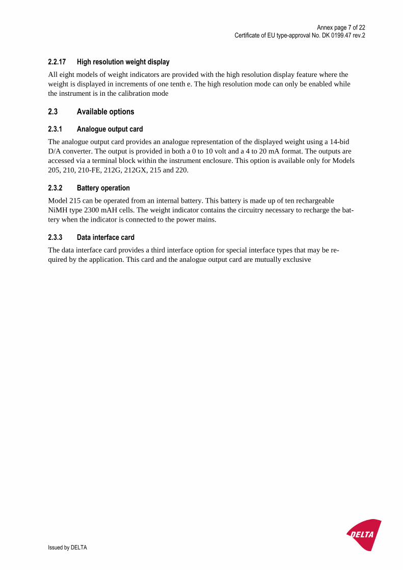
2.2.17 High resolution weight display
All eight models of weight indicators are provided with the high resolution display feature where the
weight is displayed in increments of one tenth e. The high resolution mode can only be enabled while
the instrument is in the calibration mode
2.3 Available options
2.3.1 Analogue output card
The analogue output card provides an analogue representation of the displayed weight using a 14-bid
D/A converter. The output is provided in both a 0 to 10 volt and a 4 to 20 mA format. The outputs are
accessed via a terminal block within the instrument enclosure. This option is available only for Models
205, 210, 210-FE, 212G, 212GX, 215 and 220.
2.3.2 Battery operation
Model 215 can be operated from an internal battery. This battery is made up of ten rechargeable
NiMH type 2300 mAH cells. The weight indicator contains the circuitry necessary to recharge the bat-
tery when the indicator is connected to the power mains.
2.3.3 Data interface card
The data interface card provides a third interface option for special interface types that may be re-
quired by the application. This card and the analogue output card are mutually exclusive

Annex page 8 of 22Certificate of EU type-approval No. DK 0199.47 rev.2
Issued by DELTA
3. Technical data
The weighing instrument is composed of separate modules, which are set out as follows:
3.1 Indicator
The indicator has the following characteristics:
Type: 200 Series (Models 200, 205, 210, 210-FE,
212G, 212GX, 215 and 220)
Accuracy class: III and IIII
Weighing range: Single-interval (Models 200, 205, 210 210-FE,
212G, 212GX and 215)
Dual-interval (Model 220)
Maximum number of Verification Scale Intervals: 10000 (class III). 1000 (class IIII)
Internal resolution: > 100,000 counts
Maximum tare effect: -Max
Factional factor: p’I = 0.5
Minimum input voltage per VSI: 0.7 µV
Minimum signal voltage for dead load: 1 mV
Excitation voltage: 12 VDC when operated from power mains
8 VDC, battery operation (215 only)
Maximum analogue range: 1 to 40 mV
Circuit for remote sense: Active
Minimum input impedance: 44 ohm (25 ohm for Model 220 only)
Maximum input impedance: 1000 ohm
Mains power supply: 90 to 260 VAC (50 or 60 Hz)
Peripheral interface: Set out in section 4
3.1.1 Connecting cable between the indicator and a junction box for load cell(s), if any
Cable between Indicator and load cell(s): 6 wires (sense), shielded
Maximum cable length between indicator and junction box (J-box) for load cell(s), if any:
Option 1: 385 m/mm2
In the case (n) for the weighing instrument is less than (n) mentioned above, the following applies:
Option 2:
Coefficient of temperature of the span error of the indicator: Es = 0.001 [% / 25K ]
Coefficient of resistance for the wires in the J-box cable: Sx = 0.005 [ % / ohm ]
L/Amax = 295.86 / Sx * (emp / n – Es ) [ m / mm2 ] in which emp = p’I * mpe * 100 / e
From this, the maximum cable length for the weighing instrument may be calculated with regard to (n)
for the actual configuration of the instrument.
Reference: See section 10
The calculation program is obtainable by downloading at www.delta.dk/weighing.
3.2 Load receptors, load cells and load receptor supports
Removable platforms shall be equipped with level indicators.

Annex page 9 of 22Certificate of EU type-approval No. DK 0199.47 rev.2
Issued by DELTA
3.2.1 General acceptance of modules
Any load cell(s) may be used for instruments under this certificate of type approval provided the fol-
lowing conditions are met:
1) There is a OIML Certificate of Conformity (R60) or a test certificate (EN 45501) issued for
the load cell by a Notified Body responsible for type examination under the Directive
2009/23/EC.
2) The certificate contains the load cell types and the necessary load cell data required for the
manufacturer’s declaration of compatibility of modules (WELMEC 2, Issue 5, 2009, No.
11), and any particular installation requirements. A load cell marked HN is allowed only if
humidity testing to EN 45501 has been conducted on this load cell.
3) The compatibility of load cells and indicator is established by the manufacturer by means of
the compatibility of modules form, contained in the above WELMEC 2 document, or the
like, at the time of EC verification or declaration of EC conformity of type.
4) The load transmission must conform to one of the examples shown in the WELMEC 2.4
Guide for load cells.
3.2.2 Load cells
The load cells, which are listed below are certified as modules in the weighing instrument.
Manufacturer Load cell type
Cardinal SCA
Cardinal CB6
Cardinal TSP
Cardinal SB
Cardinal TB
Cardinal LFB
Cardinal DB
3.2.3 Weigh bridge platforms
Construction in brief All-steel or steel-reinforced concrete construction, surface or pit mounted
Reduction ratio 1
Junction box Mounted in or on the platform
Load cells Cardinal SCA, DB or other authorised alternative
Drawings no. 3500-B089-0A and no. 3500-B018-0A (50,000 lb)
no. 3500-B094-0A (100,000 lb)
3.2.4 Bin, Tank, Hopper and non-standard systems
Construction in brief Load cell assemblies each consisting of a load cell stand assembly to
support one of the mounting feet bin, tank or hopper
Reduction ratio 1
Junction box Mounted on dead structure
Load cell Any R60 certified load cell according to section 3.3
Drawings Various
3.3 Composition of modules
In case of composition of modules, EN 45501 paragraph 3.5 and 4.12 shall be satisfied.

Annex page 10 of 22Certificate of EU type-approval No. DK 0199.47 rev.2
Issued by DELTA
4. Interfaces and peripheral equipment
4.1 Interfaces
The interfaces are characterised "Protective interfaces" according to paragraph 8.4 in the Directive.
4.1.1 Load cell interface
A 7-terminal connector for the load cell is positioned on the instrument circuit board and is accessed
through a gland connector on the rear panel of the instrument enclosure. The load cell interface on the
Model 200 panel mount weight indicator is a 7-terminal connector accessible from the rear of the en-
closure.
4.1.2 Printer interface
A 3-terminal connector for the printer is positioned on the instrument circuit board and is accessed
through a gland connector on the rear panel of the instrument enclosure. The printer interface on the
Model 200 panel mount weight indicator is a 3-terminal connector accessible from the rear of the en-
closure.
4.1.3 Serial I/O interface
A 4-terminal connector providing a bi-directional RS232 compatible interface is positioned on the in-
strument circuit board and is accessed through a gland connector on the rear panel of the instrument
enclosure. The serial I/O on the Model 200 panel mount weight indicator is a 4-terminal connector ac-
cessible from the rear of the enclosure.
4.1.4 Logic-level inputs
A 5-terminal connector providing logic-level inputs for the Zero, Tare, Gross and Print functions is
positioned on the instrument circuit board and is accessed through a gland connector on the rear panel
of the instrument enclosure. The logic-level inputs on the Model 200 panel mount weight indicator are
accessible via a 5-terminal connector on the rear of the enclosure. On the Model 220, a 10-terminal
connector providing logic-level inputs for Zero, Tare, Gross/Net, Print, Start, Stop and Dump is posi-
tioned on the instrument circuit board and is accessed through a gland connector on the rear panel of
the Model 220 instrument enclosure
4.1.5 Logic level outputs
A multi-terminal connector providing logic-level outputs for either the check-weigher feature (Over,
Under and Accept) or for three preset weight comparators (Models 210 and 215 only) or for eight pre-
set weight comparators (Model 220 only). A 4-terminal connector is used for the Models 215 and 210
while a 10-terminal connector is used for the Model 220. Access to the connector is made through a
gland connector located on the rear panel of the instrument enclosure.
4.1.6 Analogue output
When provided with the optional analogue output, a 3-terminal connector provides both 0 to 10 volts
and 4 to 20 mA analogue representations of the displayed weight. These terminals are positioned on
the option card connected to the main printed circuit board and accessed through a gland connector on
the rear panel of the instrument enclosure. The optional analogue output in the Model 200 panel mount
weight indicator is accessed through a 3-terminal connector accessible from the rear of the enclosure
4.2 Peripheral equipment
Connection between the indicator and peripheral equipment is allowed by screened cable.
Annex page 11 of 22Certificate of EU type-approval No. DK 0199.47 rev.2
Issued by DELTA
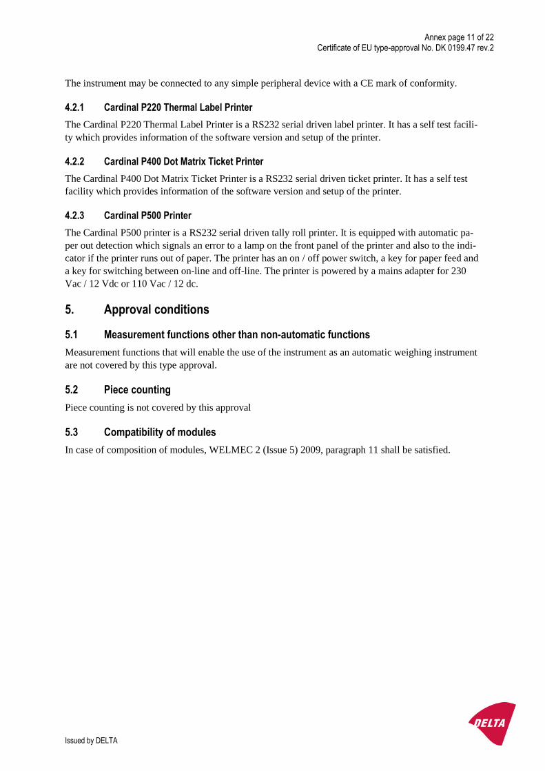
The instrument may be connected to any simple peripheral device with a CE mark of conformity.
4.2.1 Cardinal P220 Thermal Label Printer
The Cardinal P220 Thermal Label Printer is a RS232 serial driven label printer. It has a self test facili-
ty which provides information of the software version and setup of the printer.
4.2.2 Cardinal P400 Dot Matrix Ticket Printer
The Cardinal P400 Dot Matrix Ticket Printer is a RS232 serial driven ticket printer. It has a self test
facility which provides information of the software version and setup of the printer.
4.2.3 Cardinal P500 Printer
The Cardinal P500 printer is a RS232 serial driven tally roll printer. It is equipped with automatic pa-
per out detection which signals an error to a lamp on the front panel of the printer and also to the indi-
cator if the printer runs out of paper. The printer has an on / off power switch, a key for paper feed and
a key for switching between on-line and off-line. The printer is powered by a mains adapter for 230
Vac / 12 Vdc or 110 Vac / 12 dc.
5. Approval conditions
5.1 Measurement functions other than non-automatic functions
Measurement functions that will enable the use of the instrument as an automatic weighing instrument
are not covered by this type approval.
5.2 Piece counting
Piece counting is not covered by this approval
5.3 Compatibility of modules
In case of composition of modules, WELMEC 2 (Issue 5) 2009, paragraph 11 shall be satisfied.
Annex page 12 of 22Certificate of EU type-approval No. DK 0199.47 rev.2
Issued by DELTA
6. Special conditions for verification
6.1 Composition of modules
The environmental conditions should be taken into consideration by the composition of modules for a
complete weighing instrument, for example instruments with load receptors placed outdoors and hav-
ing no special protection against the weather.
The composition of modules shall agree with section 5.3.
An example of a declaration of conformity document is shown in section 10.
7. Securing and location of seals and verification marks
7.1 Securing and sealing
Seals shall bear the verification mark of a notified body or alternative mark of the manufacturer ac-
cording to ANNEX II, section 2.3 of the Directive 2009/23/EC.
7.1.1 Indicator
Access to the configuration and calibration facility is achieved by pressing and releasing the internal
calibration switch (located on the enclosure rear panel). This is accomplished by removing the calibra-
tion switch screw from the rear panel on the instrument enclosure and inserting a small screwdriver or
similar device into the opening and pressing the calibration switch button. Sealing of the access to the
switch is accomplished with a lead wire seal. The wire is passed through the hole in the head of the
calibration switch screw and an adjacent fixed hole.
7.1.2 Indicator - load cell connector - load receptor
Securing of the indicator, load receptor and load cell combined is done by one of the following ways:
sealing of the load cell connector / cable by a lead wire seal
inserting the serial number of the load receptor as part of the principal inscriptions contained
on the indicator identification label
the load receptor bears the serial number of the indicator on its data plate.
7.1.3 Junction box for load cells
Access to the junction box, if any, is prevented by the use of lead wire seals or by sealing it with brittle
plastic stickers.
7.1.4 Peripheral interfaces
All peripheral interfaces are "protective"; they neither allow manipulation with weighing data or Legal
Setup, nor change of the performance of the weighing instrument in any way that would alter the le-
gality of the weighing.
7.2 Verification marks
7.2.1 Indicator
A green M-sticker and a sticker with verification marks may be placed on the front of the indicator.
Annex page 13 of 22Certificate of EU type-approval No. DK 0199.47 rev.2
Issued by DELTA
7.2.2 Remote display
A remote display shall bear a green M-sticker, if used for trade purposes.
7.2.3 Printers used for legal transactions
Printers covered by this type of approval and other printers according to section 4.2 shall bear a green
M-sticker, if they are used for legal transactions.
7.2.4 Non-verified peripheral equipment
If such equipment is connected to the weighing instrument, it shall bear a red M-sticker
8. Location of CE mark of conformity and inscriptions
8.1 Indicator
8.1.1 CE mark
A sticker with the CE mark of conformity and year of production is located on the identification plate
which is located on the back of the enclosure for the Model 205, 210, 210-FE, 212G, 212GX, 215 and
220 weight indicators. The sticker is located on the front panel of the panel-mounted Model 200
weight indicator.
8.1.2 Inscriptions
Manufacturer’s trademark and name and the type designation is located on the front panel overlay.
On a single brittle plastic sticker located on the back of the Models 205, 210, 210-FE, 212G, 212GX,
215 and 220 weight indicator enclosures and on the front panel of the Model 200 weight indicator:
Certificate No. and the accuracy class
Indelibly printed on a brittle plastic sticker located on the front panel overlay:
Max, Min, e=
On a label located on the back of the Model 205, 210, 210-FE, 212G, 212GX, 215 and 220 weight in-
dicator enclosures and on the front panel of the panel-mounted Model 200 weight indicator enclosure:
Model No., Serial No., electrical data and other inscriptions
8.2 Load receptors
On a data plate:
Manufacturer’s name, type, serial number, capacity
Left to the manufacturer’s choice as provided in section 7.1.2:
Serial no. of the indicator.

Annex page 14 of 22Certificate of EU type-approval No. DK 0199.47 rev.2
Issued by DELTA
9. Pictures
Figure 1Model 220 Front Panel
Figure 2Model 220 Rear Panel

Annex page 15 of 22Certificate of EU type-approval No. DK 0199.47 rev.2
Issued by DELTA
Figure 3Model 215 Front Panel
Figure 4Model 215 Rear Panel

Annex page 16 of 22Certificate of EU type-approval No. DK 0199.47 rev.2
Issued by DELTA
Figure 5Model 210 Front Panel
Figure 6Model 210 Rear Panel
Annex page 17 of 22Certificate of EU type-approval No. DK 0199.47 rev.2
Issued by DELTA
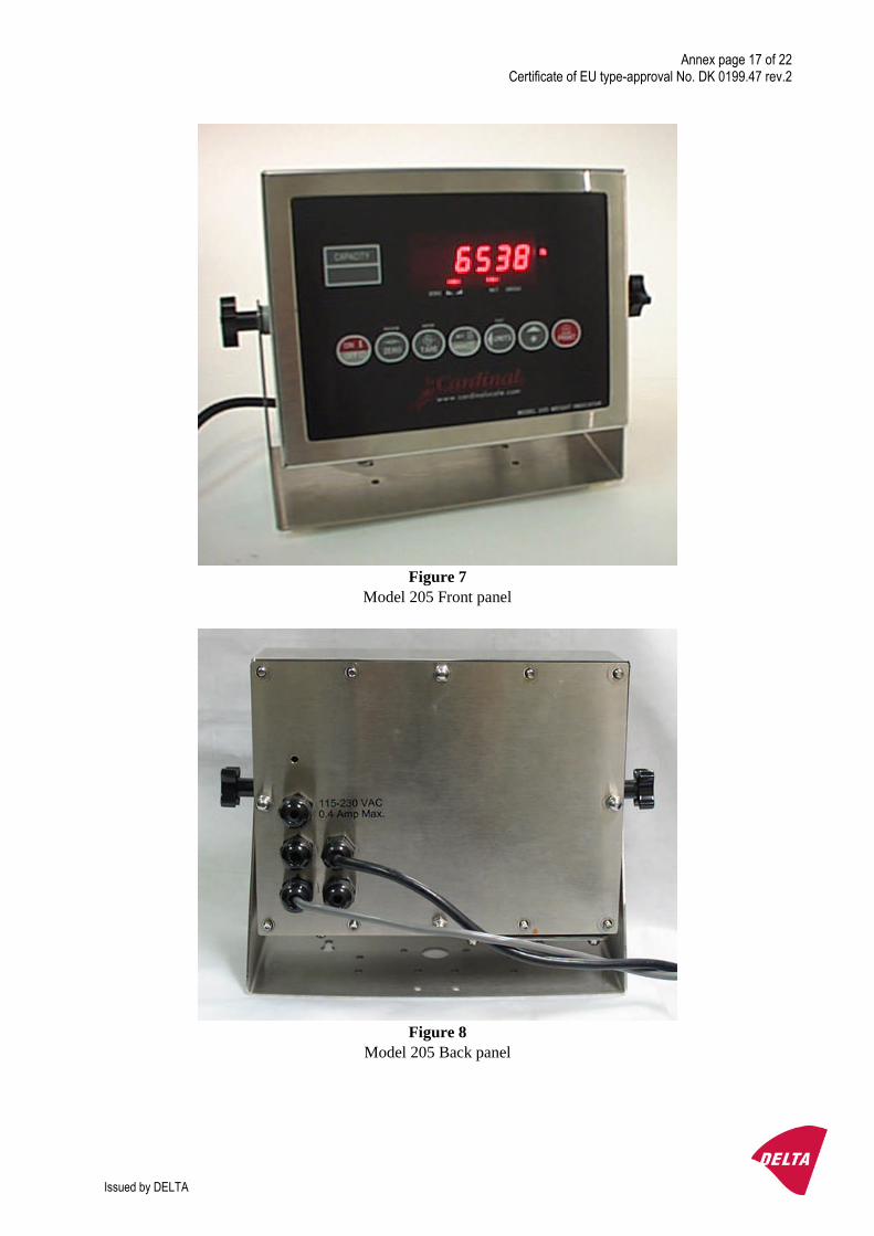
Figure 7Model 205 Front panel
Figure 8Model 205 Back panel
Annex page 18 of 22Certificate of EU type-approval No. DK 0199.47 rev.2
Issued by DELTA
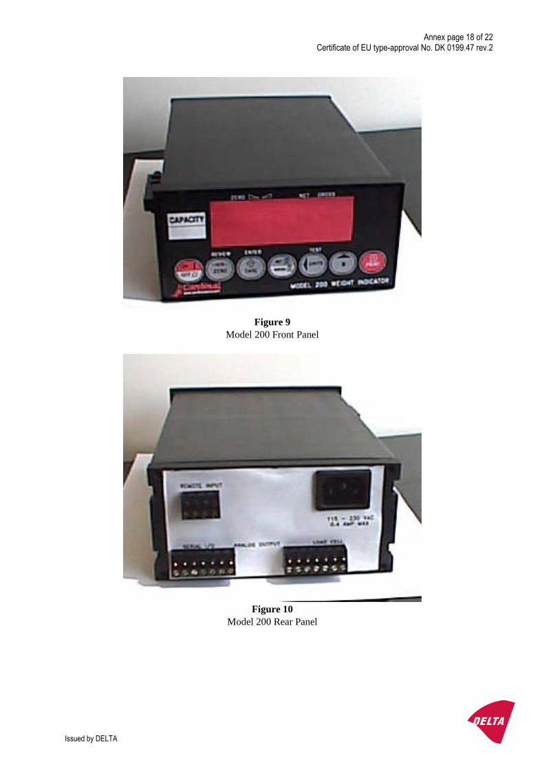
Figure 9Model 200 Front Panel
Figure 10Model 200 Rear Panel
Annex page 19 of 22Certificate of EU type-approval No. DK 0199.47 rev.2
Issued by DELTA
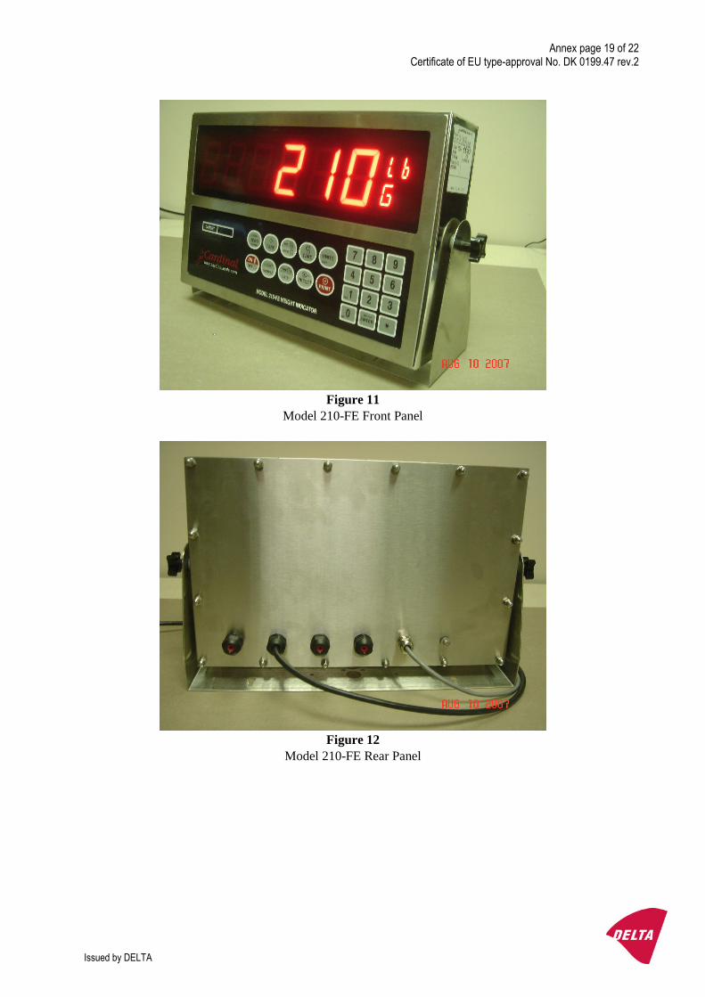
Figure 11Model 210-FE Front Panel
Figure 12Model 210-FE Rear Panel

Annex page 20 of 22Certificate of EU type-approval No. DK 0199.47 rev.2
Issued by DELTA
Figure 13Model 212G Front Panel
Figure 14Model 212GX Front Panel
Annex page 21 of 22Certificate of EU type-approval No. DK 0199.47 rev.2
Issued by DELTA
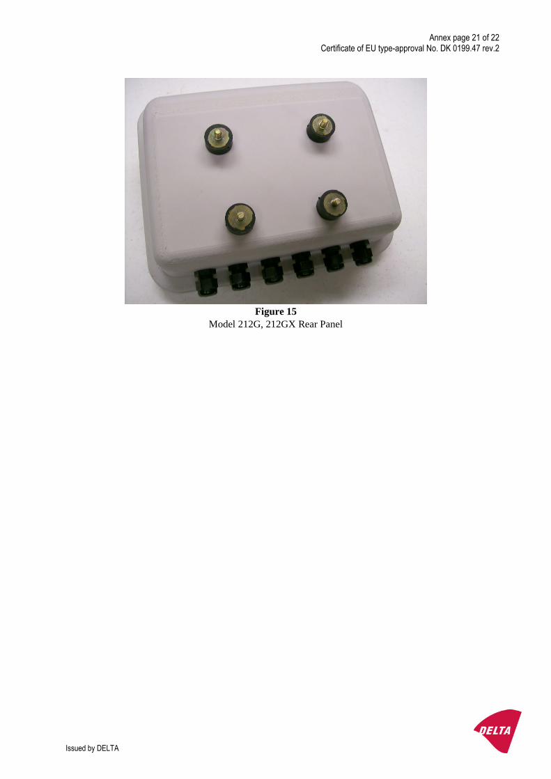
Figure 15Model 212G, 212GX Rear Panel

Annex page 22 of 22Certificate of EU type-approval No. DK 0199.47 rev.2
Issued by DELTA
10. Composition of modules – exemplified