EBARA Submersible Pumps Instruction Manual
18
CF006U-H002 REV.0 - 1 - EBARA Corporation EBARA Submersible Pumps Model DML (sewage pump) Model DMLV (vortex pump) Instruction Manual Request Welcome to the EBARA submersible pump. EBARA fabricated the pump with special care for assuring safe handling. Since, however, mal-operation of the pump may induce accident, correct use of the pump referring to the instruction manual is requested. The Instruction Manual shall be stored at a place allowing ready reference. To the personnel of installation works The Instruction Manual shall be handed to the user who conducts operation, maintenance, and inspection of the pump. Contents (page) (page) 1 Warning indication .......................................2 7 Maintenance .............................................. 12 2 Precautions of safety ...................................3 1. Daily inspection ................................... 12 3 Introduction ..................................................5 2. Regular inspection ............................... 12 1. Confirmation of pump and accessories 5 3. Precautions during stop-operation ...... 13 2. Confirmation of nameplate .....................5 4. When motor protection activated ..... 13 4 Product specification ....................................6 5. Consumables ...................................... 13 5 Installation ..................................................7 8 Troubleshooting ........................................ 14 1. Confirmation before installation .............7 9 Construction................................................... 16 2. Installation ..............................................7 1. Sectional view ........................................... 16 3. Electric wiring .........................................9 2. Accessory .................................................. 17 10 Disassembling and Assembling ................ 17 6 Operation ...................................................11 11 Limited Warranty ....................................... 17 1. Before starting ......................................11 12 Repair and after-sale service .................... 18 2. Test operation ......................................11 3. Operation .............................................11 This operational instruction manual shall be handed to the user. D8
-
Upload
khangminh22 -
Category
Documents
-
view
0 -
download
0
Transcript of EBARA Submersible Pumps Instruction Manual

CF006U-H002 REV.0
- 1 - EBARA Corporation
EBARA Submersible Pumps Model DML (sewage pump) Model DMLV (vortex pump)
Instruction Manual
Request
Welcome to the EBARA submersible pump. EBARA fabricated the pump with special care for assuring safe handling. Since, however, mal-operation of the pump may induce accident, correct use of the pump referring to the instruction manual is requested.
The Instruction Manual shall be stored at a place allowing ready reference.
To the personnel of installation works
The Instruction Manual shall be handed to the user who conducts operation, maintenance, and inspection of the pump.
Contents (page) (page)
1 Warning indication ....................................... 2 7 Maintenance .............................................. 12
2 Precautions of safety ................................... 3 1. Daily inspection ................................... 12
3 Introduction .................................................. 5 2. Regular inspection ............................... 12
1. Confirmation of pump and accessories 5 3. Precautions during stop-operation ...... 13
2. Confirmation of nameplate ..................... 5 4. When motor protection activated ..... 13
4 Product specification .................................... 6 5. Consumables ...................................... 13
5 Installation .................................................. 7 8 Troubleshooting ........................................ 14
1. Confirmation before installation ............. 7 9 Construction ................................................... 16
2. Installation .............................................. 7 1. Sectional view ........................................... 16
3. Electric wiring ......................................... 9 2. Accessory .................................................. 17
10 Disassembling and Assembling ................ 17
6 Operation ...................................................11 11 Limited Warranty ....................................... 17
1. Before starting ......................................11 12 Repair and after-sale service .................... 18
2. Test operation ......................................11
3. Operation .............................................11
This operational instruction manual
shall be handed to the user.
D8

- 2 - EBARA Corporation
1 Warning indication The precautions given here are to assure safe and correct operation of the pump and to prevent injury of you and other people, and damage of facilities. The precautions are classified to "Warning" and "Caution" for the details of danger and damage expected to arise in case of mal-handling of the pump in terms of the magnitude and the urgency of injury and damage. Since both the "Warning" and the "Caution" describe serious matter relating to safety, the contents shall be observed in any case. Description of the indication
Terms of warning Description
Warning Wrong handling expects to raise a danger resulting in death or serious injury of
the operator.
Caution Wrong handling expects to raise a danger resulting in slight injury of the
operator or sole physical damage.
Note Providing specific precautions or specifically emphasizing information.
Description of symbol
Forbidden (not allowed to execute)matter.
Detail forbidding contents are instructed in or near the symbol by a sketch or a
sentence.
Compulsory (forceful execution) matter.
Detail compulsory contents are instructed by a sketch of a sentence given near
the symbol.
Bla
ck

- 3 - EBARA Corporation
2 Precautions of safety
Warning
On handling and installation work of the pump, assure safety by confirming the mass and
the shape of the pump referring to the appearance this instruction manual, drawing, the
catalogue, and other materials. There are dangers of dropping the pump and the injury of
worker.
Never execute the operation of the pump and the mounting work of parts in a lifted
position. That type of work is dangerous causing dropping of the pump and injury of
worker.
Do not damage, break, machine, forcefully bend, stretch, or twist the power cable, bind
the power cable into a bundle, or place a heavy load on the power cable. Those kinds of
handling cause fire and electric shock.
Execute correct wiring work by a qualified technician conforming to the appropriate legal
standards. Wrong wiring by non-qualified worker is illegal and may induce electric shock
and fire.
Do apply grounding wiring. The Green and Yellow stripe cord or the Green cord is the
grounding line. Never connect the Green and Yellow stripe cord to the power source
because there is a possibility of electric shock in case of trouble or electric leak.
To prevent electric shock, install an exclusive use ground fault breaker. The electric leak
may cause electric shock and fire.
If any dust is attached to a blade or blade-attaching face of the power source plug, fully
wipe the dust off with a dry-cloth. The attached dust may cause fire.
During operation of the pump, do not insert hand or foot in the suction opening of the
pump to avoid injury at the rotary section.
Never operate the pump in water in the presence of personnel.
If electric leak occurs, the personnel may suffer electric shock.
Disassembling, repairing, and modifying the pump shall be limited to a repair technician.
There is a possibility of injury caused by electric shock, ignition, abnormal functioning,
trouble, etc.
Before entering inspection and repair, cut OFF a power source at a main disconnect
device which is equipped with an operating handle which is lockable in OFF position.
There is a possibility of electric shock and of injury caused by sudden start of the pump in
automatic operation mode.
To stop operation for a certain period, cut OFF the power switch.
Deterioration of insulation may cause electric shock, electric leak, and fire.
The user of a standard model shall refer to the columns of standard specification. Do not
use the pump at outside the range of the specification in terms of handling liquid,
installing site, power source, etc. Operation at outside the specification may cause pump
trouble, injury, electric shock, electric leak, and fire.
Do not execute dry operation in air. That type of operation causes deterioration in
insulation to lead to electric shock and electric leak.
If the insulation resistance decreases to 1MΩ or less, immediately cut OFF the power
switch, and request the inspection and repair of the pump to the supplier or EBARA
There is a possibility of motor burn out, electric shock, and fire.
Confirm non-loosening at the wirings of motor, at the primary and secondary terminals of
control panel, and at the connection and wiring terminals of the power devices in the
control panel. Remove dust from these sections. Imperfect connection of wiring caused
by loosening and attached dust may cause ignition resulting in fire.
Do not attach parts other than EBARA's standard products, and do not modify EBARA's
products. There is a possibility of electric shock and ignition, or injury caused by abnormal
functioning, break, etc. Furthermore, there may fail in performing normal functioning.

- 4 - EBARA Corporation
Warning
The handling and installation work of the pump shall be done only by a qualified
technician in accordance with the applicable legal standards. Unless follow the rule, the
work becomes illegal and there is a possibility of inducing accident such as fire and injury.
Mount a ground fault breaker exclusive to the pump. Recommended one is a wiring
ground fault breaker equipped with an electric leak alarm. There is a possibility of electric
shock and fire.
This submersible pump must be equipped with a main disconnect device in accordance
with requirements of appropriate legal standard (EN60204-1, clause 5.3.2). A suitable
rating over current protective device also needs to be provided in the final installation.
It is recommended to use a circuit breaker as main breaker that is suitable for isolation
according to appropriate legal standard (EN60947-2) and is equipped with an operating
handle which is lockable in OFF position and complies with the other requirements of
appropriate legal standard (EN60204-1, clause 5.3).
Caution
Do not operate a pump of 50Hz at 60Hz. The operation at wrong frequency induces break
of pump and other devices caused by excess pressure and motor burn-out caused by
overload.
Do not operate a pump of 60Hz at 50Hz. The pump performance deteriorates.
The pump cannot be used for food processing, food transportation, and other food-
relating uses. There is a possibility of generation of various bacteria and of inclusion of
foreign matter.
Do not use the pump at facilities for organisms (fish farm, fish preserve, aquarium, etc.)
There is a possibility of extinction of organisms caused by leak current or by leakage of
enclosed liquid from mechanical seal.
Do not use the pump at an important facility (computer cooling apparatus, cooling
apparatus for refrigerator, etc.)
Since machining oil, rubber-releasing agent, and foreign matter, used in pump-production
line, enter the handling liquid, operation of the pump shall be done after fully flushing the
pump to confirm the absence of foreign matter, depending on the facility.
Limit the handling liquid to water. Do not handle oil, seawater, organic solvent, etc. other
than water because these liquids cause trouble of pump to result in electric leak and
electric shock.
The pump is a submersible sewage (DML) or vortex (DMLV) pump. Do not operate the
pump for a long period of time or under vigorous startup-shutdown conditions. Such
operations may lead to liquid leak from mechanical seal to induce trouble of the pump
within a short period of operation.
If the pump failed to operate or if there occurred abnormality, immediately cut OFF the
power switch to prevent accident, and give request to the supplier or EBARA for
inspection and repair. Wrong operation and work may induce accident.
Install a stand-by pump preparing for an accidental stop of the operating pump. There is a
possibility of suspension of water supply to stop the facilities.
Consumable parts shall be regularly replaced. If the deteriorated or worn parts are used,
they may lead to serious troubles of water leak, seizing, and break of pump parts. For
regular inspection, parts replacement, and related works, request the work to the supplier
or EBARA.
Do not lay the water level signal cable and the power cable in a single conduit. There is a
possibility of mal-functioning resulting from noise.
Assure the tightening of connection screws at the electric-conduction section. There is a
possibility of heat generation, trouble, and burn-out.

- 5 - EBARA Corporation
3 Introduction
On receiving the pump, promptly check the following items.
1. Confirmation of pump and accessories
1) Confirm non-occurrence of damages and of loosening of bolts and nuts, which may be generated
during transportation.
2) Confirm the presence of full-set of accessories.
(For the standard auxiliaries, refer to the section of 10 "Structure". )
2.Confirmation of nameplate
1) The nameplate gives basic specification of the pump. Confirm the specification of your pump on the
nameplate. Specifically, care shall be paid on the frequency (50 Hz or 60 Hz).
Caution
Do not operate a pump of 50Hz at 60Hz. The operation at wrong frequency
induces pump break caused by excess pressure and motor burn-out caused by
overload.
Do not operate a pump of 60Hz at 50Hz. The pump performance deteriorates.
.
Fig. 1 Name plate
Name plate description
Model of motor
Pump name
Capacity (Unit: L/min)
Number of phases of Motor
Total head (Unit: m)
Rated output (Unit: kW)
Rated frequency (Unit:Hz)
Rated voltage (Unit: V)
Number of motor poles
Rated current (Unit:A)
Class of insulation
Maximum ambient temperature
(Unit: °C)
Company name
Manufacturing date
Code number
Discharge Diameter Degree of protection
Maximum operating depth
- 6 - EBARA Corporation
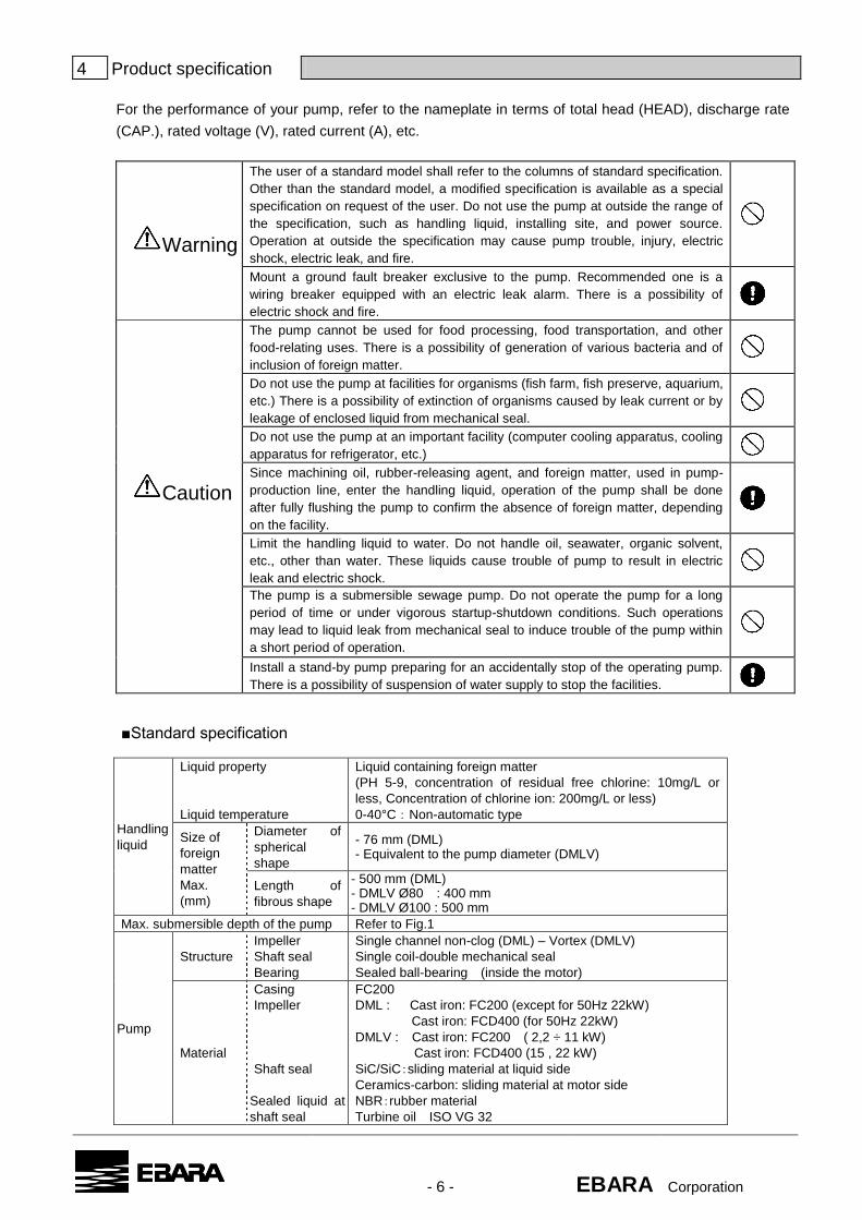
4 Product specification
For the performance of your pump, refer to the nameplate in terms of total head (HEAD), discharge rate
(CAP.), rated voltage (V), rated current (A), etc.
Warning
The user of a standard model shall refer to the columns of standard specification.
Other than the standard model, a modified specification is available as a special
specification on request of the user. Do not use the pump at outside the range of
the specification, such as handling liquid, installing site, and power source.
Operation at outside the specification may cause pump trouble, injury, electric
shock, electric leak, and fire.
Mount a ground fault breaker exclusive to the pump. Recommended one is a
wiring breaker equipped with an electric leak alarm. There is a possibility of
electric shock and fire.
Caution
The pump cannot be used for food processing, food transportation, and other
food-relating uses. There is a possibility of generation of various bacteria and of
inclusion of foreign matter.
Do not use the pump at facilities for organisms (fish farm, fish preserve, aquarium,
etc.) There is a possibility of extinction of organisms caused by leak current or by
leakage of enclosed liquid from mechanical seal.
Do not use the pump at an important facility (computer cooling apparatus, cooling
apparatus for refrigerator, etc.)
Since machining oil, rubber-releasing agent, and foreign matter, used in pump-
production line, enter the handling liquid, operation of the pump shall be done
after fully flushing the pump to confirm the absence of foreign matter, depending
on the facility.
Limit the handling liquid to water. Do not handle oil, seawater, organic solvent,
etc., other than water. These liquids cause trouble of pump to result in electric
leak and electric shock.
The pump is a submersible sewage pump. Do not operate the pump for a long
period of time or under vigorous startup-shutdown conditions. Such operations
may lead to liquid leak from mechanical seal to induce trouble of the pump within
a short period of operation.
Install a stand-by pump preparing for an accidentally stop of the operating pump.
There is a possibility of suspension of water supply to stop the facilities.
■Standard specification
Handling
liquid
Liquid property
Liquid temperature
Liquid containing foreign matter
(PH 5-9, concentration of residual free chlorine: 10mg/L or
less, Concentration of chlorine ion: 200mg/L or less)
0-40°C:Non-automatic type
Size of
foreign
matter
Max.
(mm)
Diameter of
spherical
shape
- 76 mm (DML) - Equivalent to the pump diameter (DMLV)
Length of
fibrous shape
- 500 mm (DML) - DMLV Ø80 : 400 mm - DMLV Ø100 : 500 mm
Max. submersible depth of the pump Refer to Fig.1
Pump
Structure
Impeller
Shaft seal
Bearing
Single channel non-clog (DML) – Vortex (DMLV)
Single coil-double mechanical seal
Sealed ball-bearing (inside the motor)
Material
Casing
Impeller
Shaft seal
Sealed liquid at
shaft seal
FC200
DML : Cast iron: FC200 (except for 50Hz 22kW)
Cast iron: FCD400 (for 50Hz 22kW)
DMLV : Cast iron: FC200 ( 2,2 ÷ 11 kW)
Cast iron: FCD400 (15 , 22 kW)
SiC/SiC:sliding material at liquid side
Ceramics-carbon: sliding material at motor side
NBR:rubber material
Turbine oil ISO VG 32

- 7 - EBARA Corporation
Motor
*1,*2
Model, number of poles,
Thermal class
Phase, frequency, voltage,
current
Built-in protective device
Refer to Fig.1
Refer to Fig.1
Auto-cut (2.2kW)
Thermal protector (3.7kW~22kW)
Material
Frame
Main shaft
Cable
FC200
SUS403
200V:VCT
400V:H07RN-F
Connection with piping Flange
Environment of installation site Free from corrosive gas and vapor
Installation method Vertical position
Direction of rotation Clock wise from top of motor
Temperature of shipping, store
keeping -5~40°C
*1 Cannot be driven by the inverter.
*2 Allowable range of voltage fluctuation is 2.2kW; -10 to 6%, 3.7kW to 22kW; ±10%.
Allowable range of frequency fluctuation is ±1%. Allowable simultaneous fluctuation of
voltage and frequency is 10% as the sum of the absolute values of them. For both
cases, however, the characteristics and the temperature rise of motor are independent
of the rated values.
5 Installation
1. Confirmation before installation
Measurement of insulation resistance
Measure the insulation resistance between the ground and the grounding wire and between
phases using a megger in a state that the motor and the cables (excluding the power source
connection section) are immersed in water. If the insulation resistance at the respective sections
is 20MΩ or more, there is no problem. During the measurement, keep the power source
connection section of cables distant from the ground.
2. Installation
Warning
On handling and installation work of the pump, assure safety by confirming the mass and the shape of the pump referring to the appearance this instruction manual, drawing, the catalogue, and other materials. There are dangers of dropping the pump and the injury of worker.
Never execute the operation of the pump and the mounting work of parts in a
lifted position. That type of work is dangerous causing dropping the pump and
injury of workers.
Do not damage, break, machine, forcefully bend, stretch, or twist the power cable, bind the power cable into a bundle, or place a heavy load on the power cable. Those kinds of handling cause fire and electric shock
The handling and installation work of the pump shall be done only by a qualified technician in accordance with the applicable legal standards. Unless follow the rule, the work becomes illegal and there is a possibility of inducing accident such as fire and injury.
Note Apply repair painting at an interval depending on the use environment. Depending on the use environment, there may be generated rust at threaded sections, machined sections with rust-proof coating, rust-proofing sections, etc.

- 8 - EBARA Corporation
(1) Under no circumstances should the cable be pulled while the pump is being transported or installed. Attach a chain or rope to the grip and install the pump.
(2) This pump must not be installed horizontally. Ensure that it is installed upright on a secure base.
(3) Install the pump at a location in the tank where there is the least turbulence.
(4) If there is a flow of liquid inside the tank, support the piping to prevent abnormal vibration. (See Fig.2)
(5) Install piping so that air will not stagnate (6) Do not permit end of discharge piping to be
submerged. A backflow will result when the pump is stopped.
(7) Manual type pumps do not have an automatic operating system based on built-in floats. Do not operate the pump more than ten minutes with the water level near the minimum operating level as the automatic cut-off switch incorporated inside the motor will be activated. To avoid dry operation, install an automatic operating system, as shown in Fig.3. Water levels H1 and H2 are shown in the following table.
(8) When using electrodes for automatic operating system, incorrect actuation may occur caused by scum and oil attached on the electrodes.
Frequency 2.2kW 3.7kW 5.5kW 7.5kW 11kW 15kW 22kW
DML
50Hz
H2(mm) 547 627 724 724 778 778 841
H1(mm) 279 279 310 310 329 329 342
DML
60Hz
H2(mm) 547 627 707 707 771 771 828
H1(mm) 279 279 294 294 322 322 329
Frequency 2.2kW 3.7kW 5.5kW 7.5kW 11kW 15kW 22kW
DMLV
50 Hz
H2(mm) 560 620 760 760 810 810 865
H1(mm) 200 200 250 250 250 250 250
(9) Installation of the pump with quick discharge connector shall be performed according to the
manual ”Quick Discharge Connector “
Note Packing materials after installation, and wasted lubricant oil and grease, and parts after
inspection and repair shall be transferred to a qualified waste-treatment contractor observing
the applicable laws and the regional regulations.
Caution Install a stand-by pump preparing for an accidental stop of the operating pump. There is a possibility of suspension of water supply to stop the facilities.
Fig.2
Pipe
support
Fig.3

- 9 - EBARA Corporation
3. Electric wiring
Warning
Execute correct wiring work by a qualified technician conforming to the
applicable legal standards. Wrong wiring by non-qualified worker is illegal and
may induce electric shock and fire.
Do apply grounding wiring. The Green and Yellow stripe cord or the Green
cord is the grounding line. Never connect the Green and Yellow stripe cord or
the Green cord to the power source because there is a possibility of electric
shock in case of trouble or electric leak.
To prevent electric shock, install an exclusive use ground fault breaker. The
electric leak may cause electric shock and fire.
If any dust is attached to a blade or blade-attaching face of the power source
plug, fully wipe the dust off with a dry-cloth. The attached dust may cause fire.
Confirm non-loosening at the wirings of motor, at the primary and secondary
terminals of control panel, and at the connection and wiring terminals of the
power devices in the control panel. Remove dust from these sections.
Imperfect connection of wiring caused by loosening and attached dust may
cause ignition resulting in fire.
This submersible pump must be equipped with a main disconnect device in
accordance with requirements of appropriate legal standard (EN60204-1,
clause 5.3.2). A suitable rating over current protective device also needs to
be provided in the final installation.
It is recommended to use a circuit breaker as main breaker that is suitable for
isolation according to appropriate legal standard (EN60947-2) and is equipped
with an operating handle which is lockable in OFF position and complies with
the other requirements of appropriate legal standard (EN60204-1, clause 5.3).
Caution
Assure the tightening of connection screws at the electric-connection section.
There is a possibility of heat generation trouble and burn-out.
Do not lay the water level signal cable and the power cable in a single conduit.
There is a possibility of mal-functioning resulting from noise.
Execute correct power source work of motor and wiring work by a qualified technician conforming to the
applicable legal standards. Wrong wiring and grounding work by non-qualified worker is illegal and very
dangerous. To prevent electric shock, install a ground-fault breaker exclusively for this product.
MOTOR
L1
PE
Yello
w/G
reen
Blac
k1
Blac
k2
Blac
k3
PE L2 L3
U1 V1 W1
0
L1PE L2 L3
PE
2Yel
low
/Gre
en
Blac
k1
Blac
k2
Blac
k3
Blac
k2
Blac
k3
Blac
k1
Brow
n
Ther
mal
prot
ecto
r ca
ble
Ligh
tbl
ue
U1 V1 W1 W2 U2 V2
MOTOR
L1PE L2 L3
PE
02Yel
low
/Gre
en
Blac
k1
Blac
k2
Blac
k3
Blac
k2
Blac
k3
Blac
k1
Brow
n
Ther
mal
prot
ecto
r ca
ble
Ligh
tbl
ue
U1 V1 W1 W2 U2 V2
MOTOR
ELECTRICAL WIRING FOR PUMP UP 7.5kW
(Cable for 4wirees)
400V Class
ELECTRICAL WIRING FOR PUMP FROM 11kW TO 22kW (2 Cable for 4wirees + Cable for 2wirees)
DELTA STARTING STAR/DELTA STRATING
400V Class

- 10 - EBARA Corporation
3-phase
Grounding
Green
EBlack
WWhite
V
Red
U
3-phase
Black
YWhite
X
Red
Z
200V
3-phase
Grounding
Green/Yellow
PEBlack 3
W1Black 2
V1
Black 1
U1
3-phase
Grounding
Green/Yellow
PEBlack 3
U2Black 2
W2
Black 1
V2
400V
1) Wiring
Wiring should be performed as indicated for the appropriate start system as shown in Fig 4
2)Cable
a) Never immerse the cable end in water.
b) If a cable is extended by connecting other cable, do not immerse the connected section in water.
c) Support the cable by the discharge pipe using an adhesive tape, a PVC band, etc.
d) Lay the cables with care to avoid overheating. Overlap winding or direct exposure to sunray
may cause overheating.
3)Grounding
a) For 3-phase, grounding shall be done using Green and Yellow stripe cord (Label PE) or the Green
cord (Label E) among the four lines, as shown in Fig. 5. Never connect the Green and Yellow stripe
cord or the Green cord to the power source. The grinding shall be surely conducted conforming to
the Technology Standard of Electric Facilities.
b) For the cases of long cable or other situations, the ground fault breaker is actuated in spite of
fully grounding of motor, checked by a megger. The phenomenon occurs from an electrostatic
capacity between the cable and the ground. Specifically, a rush current at start of pump likely
induces the actuation of the ground fault breaker. In that case, the ground fault breaker shall be
the one having low sensitivity of sensitive current. On adopting the ground fault breaker with low
sensitivity of sensitive current, care shall be given to electrical safety by assuring grounding, etc.
4)Motor Protection
(a) Auto-cut (Built-in in 2.2kW motor)
Auto-cut will be activated when motor is operated in abnormal conditions such as locked rotor or
single phase that result in excess over heating.
Fig.4
MOTOR
L1
PE
Gre
en
Red
Whi
te
Blac
k
PE L2 L3
UE V W
MOTOR
0
L1PE L2 L3
PE
Gre
en
U V W Z X Y
Ther
mal
prot
ecto
r ca
ble
Re
d
Whi
te
Bla
ck
Re
d
Whi
te
Bla
ck
Wh
ite
Bla
ck
0
L1PE L2 L3
PE
Ther
mal
pro
tect
or
cab
le
MOTOR
Gre
en
Red
Whi
te
Bla
ck
Red
Wh
ite
Blac
k
Wh
ite
Blac
k
U V W Z X Y
200V Class 200V Class
Fig.5

- 11 - EBARA Corporation
(b) Thermal protector (Built-in in 3.7kW to 22kW motor)
When temperature of the winding raises and reaches the thermal protector acting point, the motor
protection circuit is activated to protect motor from over heat.
Connect to the control panel in accordance with the following specifications.
Be sure to install a thermal relay on the control panel, since the thermal protector is not capable of
detecting sudden temperature rises caused by single phase or locked rotor.
Contact rating: AC230V, 13A (Max.)
Contact type: break contact (normal close)
Cable: 2 cores chloroprene cabtyre cable -200V:1.25 mm2/400V :1.00mm
2 (non-polarity)
6 Operation
Warning
During the operation of the pump, do not insert hand or foot in the suction opening of the pump to avoid injury at the rotary section.
Never operate the pump in water in the presence of personnel.
If electric leak occurs, the personnel may suffer electric shock.
Do not execute dry operation in air. That type of operation causes deterioration in insulation to lead to electric shock and electric leak.
1. Before starting
1) After completing the installation work, measure again the insulation resistance in accordance with
5 -1 "Confirmation before installation".
2) Confirm that the water level is satisfactory. If the pump is operated for a long period of time under dry
condition or at near the operable minimum water level, the Auto-cut in the motor is actuated. If the
situation is repeated, the pump life becomes short. Once the Auto-cut is actuated, the motor does not
start until it is cooled. (Even during the period of Auto-cut functioning, the power is supplied up to the
pump. Since the pump will restart without indication, the inspection shall be given after cut OFF the
power source.)
3) Operate the pump within the range given in the chart.
4) Frequent start-stop operations damage the pump in early stage of life. Limit the starting frequencies
as beloW
Output The number of starting times per hour
up to 7.5kW 10
from 11 to 22kW 7 2. Test operation
1) Confirm the absence of abnormal starting by ON and OFF the
switch for once or twice in a state of slightly opened gate valve.
2) Then, confirm the rotational direction. After starting the pump,
if the discharge rate is small and if an abnormal sound is
generated, the rotational direction is reverse. In that case,
replace two-phases from each other among three of them,
(refer to Fig. 6).
3) Once the correct rotational direction is established, gradually open the gate valve, and confirm the
absence of abnormality in pressure, discharge rate, current, etc. (refer to 8 "Troubleshooting"). If
the current exceeds the rated current without using the gate valve, the design plan shall be reviewed.
3. Operation After completing the test operation, the operation can immediately be started. Do not operate the pump
in a state of full-opening of gate valve.
Note
Operate the pump at a discharge rate suitable for the facilities.
(Operation at excessively small or large capacity causes noise and vibration, and
consumes unnecessary power.)
Fig. 5
Switch box Switch box
Motor Motor
U1 V1 W1 W1 V1 U1
Fig. 6

- 12 - EBARA Corporation
7 Maintenance
Warning
Disassembling, repairing, and modifying the pump shall be done only by a repair
technician.
There is a possibility of electric shock, ignition, or injury caused by abnormal
functioning, break, etc.
Do not attach parts other than EBARA's standard parts, and do not modify
EBARA's standard products. Use of other than the standard parts may result in
electric shock, ignition, or injury caused by abnormal functioning or break, or may
fail to perform normal functioning.
Before entering inspection and repair, cut OFF a power source at a main
disconnect device which is equipped with an operating handle which is lockable in
OFF position. There is a possibility of electric shock and of injury caused by
sudden start of the pump in automatic operation mode.
To stop operation for a certain period, cut OFF the power switch.
Deterioration of insulation may cause electric shock, electric leak, and fire.
If the insulation resistance decreases to 1MΩ or less, cut immediately OFF the
power switch, and request the inspection and repair of the pump to the supplier or
EBARA There is a possibility of motor burn-out, electric shock, and fire.
Caution
If there occurred abnormality such as failing in starting, immediately cut OFF the
power switch to prevent accident, and request the inspection and repair to the
supplier or EBARA Mal-operation or wrong work may induce accident.
Consumable parts shall be regularly replaced. If the deteriorated or worn parts
are used, they may lead to serious failures of water leak, seizing, and break of
pump parts. For regular inspection, parts replacement, and related works, request
the matter to the supplier or EBARA
If inspection of pressure, discharge rate, voltage, current, etc. finds any difference from those of normal
state, the phenomenon is a sign of accident. Therefore, it is important to give quick action to the matter
referring to 8 "Troubleshooting". To do this, keep daily operational record. Preparation of a standby
pump is recommended to respond to an accident.
Note The table of standard pump performance is available from EBARA
1. Daily inspection
1) Check current and ammeter fluctuation every day. If ammeter fluctuation is significant even it is
within the limit of pump rating, the pump may have caught foreign matter.
2) If the discharge rate showed a sudden decrease, foreign matter may have clogged the suction
opening.
2. Regular inspection
1) Once a month
Measure the insulation resistance. If the insulation resistance is 1MΩ or more, there occurs no
problem on operating the pump. If, however, a sudden drop appeared in the insulation resistance
even if the value is at or above 1MΩ, the phenomenon is abnormal, and repair of the pump is
required.
2) Once every six months
Replace oil in the mechanical seal chamber at every six months. If
water enters the oil to give significant cloudiness, replace the
mechanical seal. As illustrated in Fig. 7 oiling shall be done at a
specified quantity while the oiling plug faces upright and the pump is
positioned horizontally. After the oiling, fully tighten the plug with a
seal washer.
Fig. 7
Fully tighten the plug after oiling at a specified quantity.

- 13 - EBARA Corporation
3) Once a year
Replace mechanical seal at an interval of one year or 6000 hours of total operating hours, either
shorter one. By the replacement, the pump life extends.
4) Once every two to five years
Overhaul of the pump assures safe and long period of operation. For the case of high frequency of
operations, early overhaul is requested.
5) Check that there is no leakage from the joint of pump and piping. When there is leakage, tighten the
connecting bolts.
6) In order to avoid the fire accident by the contact failure caused by the slack of wiring, check whether
motor connections and panel connections are not loosened.
3. Precautions during stop operation
1) When the pump is left underwater in stop-operating state, measure the insulation resistance of motor
intermittently. If there is no abnormality in the insulation resistance, operate the pump to prevent the
sliding section of the pump from rusting. When the pump is entered restarting, the procedure shall
conform to 6 "Operation".
2) When the pump is stored on ground, clean the pump and then store it at a dry site. (temperature of
storage: -5~40°C) On reusing the pump, follow the instructions of 5 "Installation" and 6
"Operation".
4. When motor protection is activated. Check causes that motor protection is activated. After removing the causes, start the operation again.
5. Consumables
1) Replace the parts when they enter the following-described condition.
Consumable
parts
Mechanical
seal
Sheet
packing
Seal washer Lubricant oil O-ring Bearing
Symptoms
or
approximate
period for
replacement
Oil in the
mechanical
seal
chamber
becomes
cloudy.
At every
disassembly
for
inspection.
At every oil
replacement.
Lubricant
becomes
cloudy or
blackish.
At every
disassembly
for
inspection
Expected
replacement
time
One year or
6000 hours
of total
operating
hours, either
of shorter
one.
Once every
six months.
Every 6000
hours
The above-given replacement time is a standard under normal operation.
2.2kW 3.7kW 5.5kW 7.5kW 11kW 15kW 22kW
Mechanical seal < mm > Φ30 Φ40 Φ45
Seal washer (W12 SUS) < mm > Φ22×Φ11.8×1.2( Outer diameter × Inner diameter × thickness)
Lubrication oil < mL >
(Turbine oil ISO VG32)
DML 1100 1600 2900 3000
DMLV 1100 1780 3380 3550
O-ring < mm > φ170×φ3.1 φ180×φ3.1 φ220×φ3.1
For detail of Model, etc. of individual parts, inquiry shall be given to the supplier or EBARA CORP.
OUTPUT
Parts name

- 14 - EBARA Corporation
8 Troubleshooting
Trouble Cause Action
The pump does not start.
The pump starts, but it
immediately stops.
○ Obstacle inhibits the float movement.
○ Power is failed.
○ Large fluctuation of power voltage.
○ Large drop in voltage.
○ Phase is lost.
○ Insufficient connection of power source
circuit.
○ Wrong wiring of control circuit.
○ Fuse is blown.
○ Defective magnet switch.
○ Mal-functioning or defects of float switch,
etc.
○ Actuation of ground fault breaker.
○ Pump catches foreign matter.
○ Motor is burnt out.
○ Break of motor bearing.
○ Mechanical seal stuck.
○ Remove the obstacle.
○ Request the electric power company for
action.
○ Request the electric power company for
action.
○ Request the electric power company for
action.
○ Inspect the connection section and the
magnet switch.
○ Inspect the power source circuit.
○ Wire in correct state.
○ Replace with adequate fuse.
○ Replace with adequate magnet.
○ Repair or replace the level switch, etc..
○ Repair the electric-leak section.
○ Remove the foreign matter.
○ Repair or replace the motor.
○ Repair or replace the bearing.
○ Repair or replace the mechanical seal.
The pump can be operated,
but it stops after a while.
○ Prolonged dry operation induced the
functioning of Auto-cut.
○ High liquid temperature induced the
functioning of Auto-cut.
○ Raise the water level.
○ Lower the water level.
Thermal protector is actuated.
○ High liquid temperature.
○ Long dry operation.
○ Eddy current.
○ Lower the liquid temperature.
○ Raise the stopping water level.
○ Refer to the section of eddy current.
Does not pump.
Insufficient pumping rate.
○ Reverse rotation.
○ Broken gate valve.
○ Large voltage drop.
○ Operating the 60Hz pump at 50Hz.
○ High discharge head.
○ Large piping loss.
○ Low operating water level causes air
suction.
○ Liquid leaking from discharge pipe.
○ Clogging of discharge pipe.
○ Adhesion of foreign matter in suction
opening.
○ Foreign matter clogs the pump.
○ Worn impeller.
○ Establish correct rotational direction, (refer
to 6 -2-2).
○ Repair or replace the gate valve.
○ Request the electric power company for
action.
○ Check the nameplate.
○ Review the plan.
○ Review the plan.
○ Raise the water level or lower the pump
position.
○ Inspect and repair the discharge pipe.
○ Remove the foreign matter.
○ Remove the foreign matter.
○ Disassemble the pump to remove the
foreign matter.
○ Replace the impeller.

- 15 - EBARA Corporation
Over current ○ Large fluctuations of power source
voltage.
○ Significant voltage drop.
○Phase is lost.
○ Operating the 50Hz pump at 60H.
○ Operating the pump in reverse rotation
state.
○ Low head resulting in excess flow rate.
○ Pump caches foreign matter.
○ Motor bearing is broken.
○ Request the electric power company for
action.
○ Request the electric power company for
action.
○ Inspect the connection section and the
magnet switch.
○ Check the nameplate.
○ Establish the correct rotational direction,
(refer to 6 -2-2).
○ Narrow the opening of the gate valve. If no
gate valve is used, replace the pump with
the one having lower head.
○ Disassemble the pump to remove the
foreign matter.
○ Repair or replace the bearing.
Pump vibrates,
generating large noise.
○ Pump is in reverse rotational direction.
○ Pump catches foreign matter.
○ Piping is in resonance mode.
○ Establish the correct rotational direction,
(refer to 6 -2-2).
○ Disassemble the pump to remove the
foreign matter.
○ Modify the piping.

- 16 - EBARA Corporation
9 Construction
1. Section drawing : Typical model
907 BEARING COVER 1 904 LIFTING HANGER 1 856 THERMAL PROTECTOR 2※3 849-2 BALL BEARING 1 849-1 BALL BEARING 1 830 SHAFT 1 817 OPPOSITE SIDE BRACKET 1 816 POWER SIDE BRACKET 1 814 MOTOR FRAME 1 811-2 SUBMERSIBLE CABLE 1※2 811-1 SUBMERSIBLE CABLE 2※1 802 STATOR 1 801 ROTOR 1 275 IMPELLER BOLT 1 211 AIR VENT VALVE 1 193 OIL PLUG 1 174 DISCHARGE PIPE 1 135 WASHER 1 135-2 WASHER 4 135-1 WASHER 1 120-7 BOLT 4 120-6 BOLT 3 120-5 BOLT 2
120-4 BOLT 4or6 120-3 BOLT 4 120-2 BOLT 8 120-1 BOLT 4 117-2 SEAL WASHER 1 117-1 FLANGE GASKET 1 115-4 O-RING 1 115-3 O-RING 1 115-2 O-RING 1 115-1 O-RING 1 111 MECHANICAL SEAL 1 107 WEARING RING 1 080 BUSHING 1 039 KEY 1 021 IMPELLER 1 016 MECHANICAL SEAL COVER 1 001 CASING 1 No. NAME QUANT
※1 2.2 kw : 1
※2 2.2 kw : 0
※3 2.2 kw : AUTO-CUT : 1
100 DML 57.5
100 DMLV55.5

- 17 - EBARA Corporation
2.Accessory
(1)Nameplate for ground installation : 1
(2)Discharge pipe : 1 set
Pump might be performed design change for improvement without prior notice
Note Drawings indicating the materials of individual parts are available from EBARA
10 Disassembly and Reassembly
Refer to the cross sectional drawing.
1. Disassembly
(1) Unscrew and remove the bolts (120-2),and lift up the motor part. Then lay it down carefully..
(2) Unscrew and remove the impeller bolt (275), Pull the impeller (021) out.
(3) Unscrew and remove the oil plug (193), Withdraw oil
(4) Unscrew and remove the bolts (120-1), and remove the mechanical seal cover (016) carefully.
(Care for flowing out oil remainder.)
(5) Detach the mechanical seal with care lest the seal surfaces and shaft should be hurt.
2. Reassembly
Perform reassembly in a reverse order. Then exchange gasket, seal washer, o-ring for new ones.
(Note 1) Screw adhesive (LOCKTITE #638) shall be applied to bolt (120-1) to prevent loosening, after
degreasing a screw hole and screw part of bolts enough.
(Note 2) After reassembly procedure (2), turn the impeller by hand to check that it rotates smoothly.
When the rotating condition is not smooth, do over again according to the procedure (3) to (5).
(Note 3) Apply the adhesive (LOCKTITE #262) to the impeller bolt in the following way for looseness
prevention.
1) Install the motor so that the shaft end serves as facing up from the level a little. After degreasing
a screw hole enough, pour out the adhesive (LOCKTITE #262) until it is full of a screw hole.
2) An impeller bolt (275) should also degrease enough and should apply the adhesives
(LOCKTITE #262) for screws to the whole screw part.
(Note 4) After reassembly is completed, turn the impeller by hand through suction inlet to check that
it rotates smoothly without rubbing against wearing ring.
11 Limited Warranty
EBARA warrants to the original retail purchaser (“Customer”) the followings.
(1) During the warranty period, EBARA will repair the pump free of charge provided that:
the trouble is due to shortcomings in design, workmanship, etc., that can be attributed to EBARA,
and that the pump was being operated correctly and in a normal manner in accordance with the
Instruction Manual when the trouble occurred.
EBARA takes full responsibility to repair the pump including parts necessary for replacement,
however, EBARA do not take any other damages caused by the trouble.
(2) Fees will be charged for repair and consumable items in the following circumstances:
(a) If the trouble occurs after the warranty has expired.
(b) If the trouble is caused by mal-operation, and/or caused during storage.

- 18 - EBARA Corporation
(c) If the trouble is caused by fire, flood, earthquake or other circumstances beyond EBARA’s
control.
(d) If the trouble is caused by use of parts other than those recommended by EBARA.
(e) If the trouble is caused by repair or remodeling of the pump carried out by a party other than
EBARA or agent specified by EBARA.
(f) “Consumable items” refer to lubrication oil, gasket, seal washer, O-ring, mechanical seal,
and other parts that will eventually require replacement.
(3) EBARA’s liability shall not extend to any other costs beyond the above.
(4) The storage period of consumable items is 7 years after manufacturing stop.
12 Repair and After-sale service
If any abnormality is detected during the operation of the product, immediately stop the operation, and
inspect to identify whether the abnormality is defective or not. (Refer to 8 "Troubleshooting"). If the
abnormality is defective one, promptly notify the matter to EBARA or related agencies which contact
addresses are listed at the end of this Instruction Manual, with the information about the description given
on the nameplate and the condition of the failure (abnormality).
Note
Packing materials after installation, and wasted lubricant oil and grease, and parts after
inspection and repair shall be transferred to a qualified waste-treatment contractor
observing the applicable laws and the regional regulations.
For any question about your pump, please inquire the matter to EBARA CORP. without hesitation.
<Singapore>
Ebara Engineering Singapore Pte. Ltd. Website: www.ebara.com.sg
E-mail: [email protected]
<Malaysia>
Ebara Pumps Malaysia Sdn. Bhd. Website: www.ebara.com.my
E-mail: [email protected]
<Indonesia>
P.T. Ebara Indonesia Website: www.ebaraindonesia.com
E-mail: [email protected]
<Thailand>
Ebara (Thailand) Limited Website: www.ebara.co.th
E-mail: [email protected]
<Philippines>
Ebara Pumps Philippines,inc. Website: www.ebaraphilippines.com
E-mail: [email protected]
<China>
Ebara Machinery (China) Co., Ltd. Website: www.ebara.cn
E-mail: [email protected]
<Other countries>
Ebara Corporation (Japan)
Standard Products Business Office Website: www.ebara.co.jp/en