Eastey EM L-Sealers Performance Series User Guide
40
EM Performance Series Semi-Automatic L-Sealers User Guide EM1622T, EM1622TK, EM1636T & EM1636TK
-
Upload
khangminh22 -
Category
Documents
-
view
1 -
download
0
Transcript of Eastey EM L-Sealers Performance Series User Guide

EM Performance Series Semi-Automatic L-Sealers
User Guide
EM1622T, EM1622TK, EM1636T & EM1636TK


EM Performance Series Semi-Automatic L-Sealers User Guide Revised 07/10/2017 P/N EM000900 Rev A Copyright and Trademarks Copyright ©2017 Eastey Enterprises, Inc. All rights reserved. All trademarks and brand names are the property of their respective owners. Eastey Enterprises 7041 Boone Ave. N. Brooklyn Park, MN 55428 Phone: (763) 428-4846; Fax (763) 795-8867; 1-800-835-9344 www.eastey.com
EM1622T, EM1622TK, EM1636T & EM1636TK


Contents Safety ............................................................................................................................. 6
General Safety Precautions .......................................................................................... 6
Introduction ................................................................................................................... 8 General System Description .......................................................................................... 8 Specifications ................................................................................................................ 9 Dimensions ................................................................................................................. 11
Unpacking .................................................................................................................... 12
Installation ................................................................................................................... 13 Location Requirements ............................................................................................... 13
Operation ..................................................................................................................... 15 Control Panel .............................................................................................................. 15 Film Unwinder ............................................................................................................. 16 Mounting Film .............................................................................................................. 16 Sequence of Operation ............................................................................................... 17
Adjustments ................................................................................................................ 19 Element Pulse Switch Adjustment ............................................................................... 19 Electromagnet Position Adjustment ............................................................................ 19 Seal Pad Pressure Adjustment for Head Return Cylinder ........................................... 19 Timers and Temperature Controls ............................................................................... 20
Maintenance ................................................................................................................ 21 Silicone Rubber and Felt Seal Pad Replacement ....................................................... 21 Changing Hot Knife Inserts and Cutting Rules ............................................................ 22 Takeaway Conveyor Maintenance and Replacement ................................................. 22 Wire Belt Repair Splicing............................................................................................. 23 Film Roll Support Rollers............................................................................................. 28
Troubleshooting .......................................................................................................... 29
Parts List ...................................................................................................................... 31
Appendix A: Electrical Schematics ........................................................................... 32 Panel Layout ............................................................................................................... 32 Electrical Schematic .................................................................................................... 33
Appendix B: Temperature Setting Specifications for Shrink-Wrap Plastics .......... 34 Mushroom Insert ......................................................................................................... 34
Appendix C: L-Sealer Size Estimating ....................................................................... 35 L-Sealer Center-Folded Film Size Estimating Table ................................................... 35 16-inch Side Seal Package Size Estimation................................................................ 36
Warranty Statement .................................................................................................... 37
Customer Support ....................................................................................................... 39

6 Introduction
Safety
Read this manual carefully and make it available to everyone connected with the supervision, maintenance, or operation of this machine. Additional copies are available on request (Eastey.com/contact-us).
The development of a good safety program that is rigidly enforced is absolutely imperative when involved in the operation of industrial equipment. Our machinery is well designed and includes extremely important safety features. Proper installation, safe operation, and regular maintenance and upkeep are of far greater importance than our design. Only properly-trained individuals following rigidly enforced safety rules, as recommended by ANSI and OSHA should be allowed to operate these machines.
Be very careful when operating, adjusting, or servicing this equipment. If in doubt, stop and obtain qualified help before proceeding.
General Safety Precautions
Before installing, operating or servicing this equipment, please read the following precautions carefully:
• Always disconnect electrical power before attempting maintenance for any electrical or moving parts. Do not place hands, head, or any part of the body inside the confines of the machine unless the mechanism is securely fastened and the electrical supply is shut off.
• Do not tamper with electrical wiring. Use only the specified power-supply cable. Use only licensed electricians to check or repair electrical wiring.
• In order to prevent damage to the machinery or injury to personnel, do not increase the factory settings on either the electrical or mechanical overload safety devices. Do not operate a machine if such modifications have been made.
• Keep hands away from moving conveyors and moving parts. Conveyor belts that have become worn or frayed can be hazardous and should be replaced promptly.
• Never operate this or any moving equipment without all covers and guards in place. The internal mechanism of most packaging machinery contains numerous shear, pinch, and in-running nip points, many of which are capable of causing severe injury and permanent disfiguration.
• To minimize the potential for personal injury, always be sure that the machine operators and others working on the machinery are properly trained in the correct usage of the equipment and properly instructed regarding the safety procedures for operation.
Introduction 7
• Heat sealing arms and jaws on packaging machinery can become very hot after a period of use. Keep hands away while in operation and use caution if the machine has been running recently. If optional cutting blades have been installed, these can be very sharp. Exercise caution.
• Do not make any modifications to either the electrical circuitry or the mechanical assemblies of this machinery. Such modifications may introduce hazards that would not otherwise be associated with this machinery. Eastey will not be responsible for any consequences resulting from such unauthorized modification. Do not operate a machine if any modification has been made
• This equipment is designed for indoor operation in a typical clean, dry factory environment. Do not operate the machine in any extremely wet or oily environment that may exceed operating specifications.
• The use of certain types of plastic films in sealing and/or shrink-wrapping equipment may result in the release of hazardous fumes due to degradation of the film at high temperatures. Before using any plastic film in this equipment, the manufacturer or supplier of the film should be contacted for specific information concerning the potential release of hazardous fumes. Adequate ventilation should be provided at all times.
• Keep combustible materials away from this equipment. The equipment may be a source of ignition.
• Do not wear loose clothing such as ties, scarves, jewelry, etc. Long hair should be pulled back and/or covered while operating this machine.

8 Introduction
Introduction
General System Description
Hot Knife or Hot Wire Sealer
Magnetic Disks
Seal Head
Product Tray
Frame
Front Seal and Side Seal Temperature Controls
Seal Dwell Timer and Conveyor Timer
Casters
Takeaway Conveyor with Height Adjustment
On / Off Toggle
Film Roll Support Rollers
Pin Perforator
Electro Magnets
Introduction 9
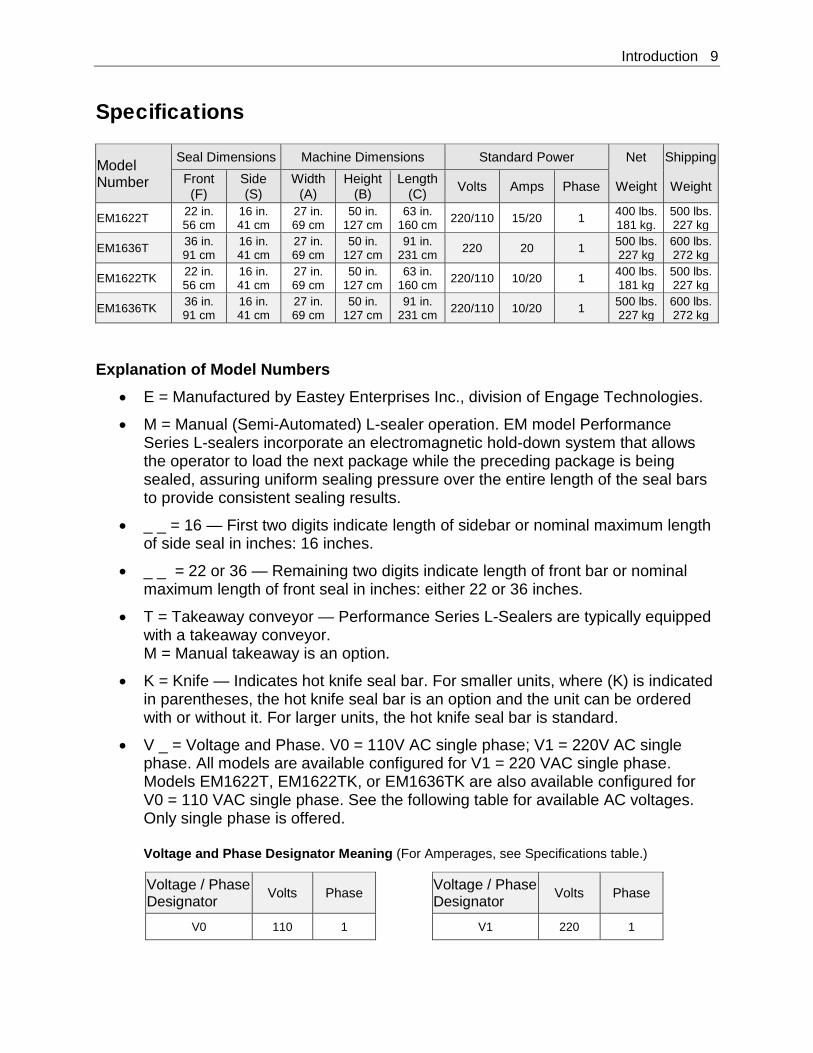
Specifications
Model Number
Seal Dimensions Machine Dimensions Standard Power Net Shipping Front (F)
Side (S)
Width (A)
Height (B)
Length (C) Volts Amps Phase Weight Weight
EM1622T 22 in. 56 cm
16 in. 41 cm
27 in. 69 cm
50 in. 127 cm
63 in. 160 cm 220/110 15/20 1 400 lbs.
181 kg. 500 lbs. 227 kg
EM1636T 36 in. 91 cm
16 in. 41 cm
27 in. 69 cm
50 in. 127 cm
91 in. 231 cm 220 20 1 500 lbs.
227 kg 600 lbs. 272 kg
EM1622TK 22 in. 56 cm
16 in. 41 cm
27 in. 69 cm
50 in. 127 cm
63 in. 160 cm 220/110 10/20 1 400 lbs.
181 kg 500 lbs. 227 kg
EM1636TK 36 in. 91 cm
16 in. 41 cm
27 in. 69 cm
50 in. 127 cm
91 in. 231 cm 220/110 10/20 1 500 lbs.
227 kg 600 lbs. 272 kg
Explanation of Model Numbers
• E = Manufactured by Eastey Enterprises Inc., division of Engage Technologies.
• M = Manual (Semi-Automated) L-sealer operation. EM model Performance Series L-sealers incorporate an electromagnetic hold-down system that allows the operator to load the next package while the preceding package is being sealed, assuring uniform sealing pressure over the entire length of the seal bars to provide consistent sealing results.
• _ _ = 16 — First two digits indicate length of sidebar or nominal maximum length of side seal in inches: 16 inches.
• _ _ = 22 or 36 — Remaining two digits indicate length of front bar or nominal maximum length of front seal in inches: either 22 or 36 inches.
• T = Takeaway conveyor — Performance Series L-Sealers are typically equipped with a takeaway conveyor. M = Manual takeaway is an option.
• K = Knife — Indicates hot knife seal bar. For smaller units, where (K) is indicated in parentheses, the hot knife seal bar is an option and the unit can be ordered with or without it. For larger units, the hot knife seal bar is standard.
• V _ = Voltage and Phase. V0 = 110V AC single phase; V1 = 220V AC single phase. All models are available configured for V1 = 220 VAC single phase. Models EM1622T, EM1622TK, or EM1636TK are also available configured for V0 = 110 VAC single phase. See the following table for available AC voltages. Only single phase is offered.
Voltage and Phase Designator Meaning (For Amperages, see Specifications table.)
Voltage / Phase Designator Volts Phase Voltage / Phase
Designator Volts Phase
V0 110 1 V1 220 1
10 Introduction
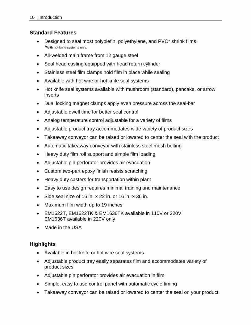
Standard Features • Designed to seal most polyolefin, polyethylene, and PVC* shrink films
*With hot knife systems only.
• All-welded main frame from 12 gauge steel
• Seal head casting equipped with head return cylinder
• Stainless steel film clamps hold film in place while sealing
• Available with hot wire or hot knife seal systems
• Hot knife seal systems available with mushroom (standard), pancake, or arrow inserts
• Dual locking magnet clamps apply even pressure across the seal-bar
• Adjustable dwell time for better seal control
• Analog temperature control adjustable for a variety of films
• Adjustable product tray accommodates wide variety of product sizes
• Takeaway conveyor can be raised or lowered to center the seal with the product
• Automatic takeaway conveyor with stainless steel mesh belting
• Heavy duty film roll support and simple film loading
• Adjustable pin perforator provides air evacuation
• Custom two-part epoxy finish resists scratching
• Heavy duty casters for transportation within plant
• Easy to use design requires minimal training and maintenance
• Side seal size of 16 in. × 22 in. or 16 in. × 36 in.
• Maximum film width up to 19 inches
• EM1622T, EM1622TK & EM1636TK available in 110V or 220V EM1636T available in 220V only
• Made in the USA
Highlights • Available in hot knife or hot wire seal systems
• Adjustable product tray easily separates film and accommodates variety of product sizes
• Adjustable pin perforator provides air evacuation in film
• Simple, easy to use control panel with automatic cycle timing
• Takeaway conveyor can be raised or lowered to center the seal on your product.
Introduction 11
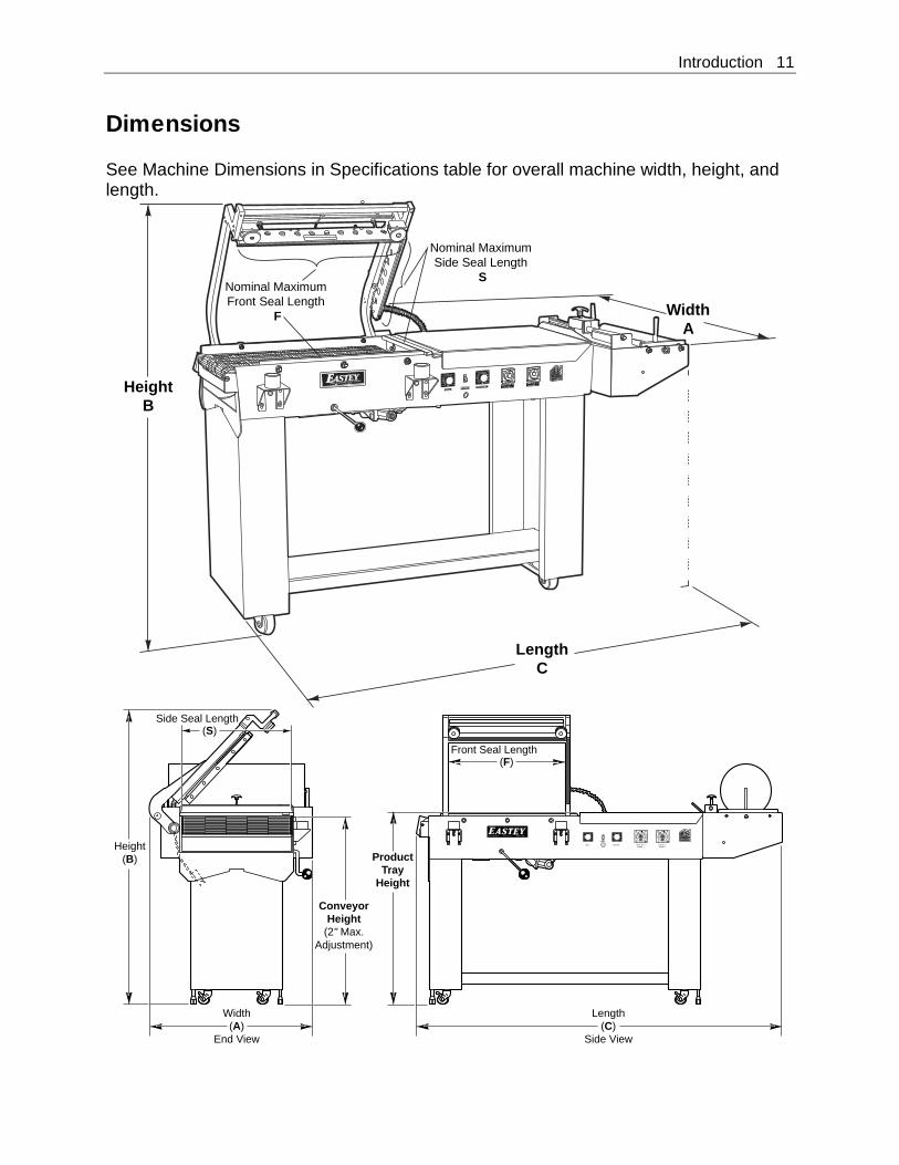
Dimensions See Machine Dimensions in Specifications table for overall machine width, height, and length.
HeightB
WidthA
LengthC
Nominal MaximumFront Seal Length
F
Nominal MaximumSide Seal Length
S
0
10
20
30
4050
60
70
80
90
100 0
10
20
30
4050
60
70
80
90
100
POWER
0
12 3
4
5
POWER OU T
MODE
AT 11DN
RUN
A
0
12 3
4
5
POWER OU T
MODE
AT 11DN
RUN
A
FRONT TEM P.CONTRO L
SIDE TEM P.CONTRO L
DWEL L
First in Quality. www.eastey.com Built to Last.
CONVEYOR
sec. sec.
Side Seal Length
Front Seal Length
(S)
(F)
Height(B)
Width(A)
End View
Length(C)
Side View
ConveyorHeight
(2" Max.Adjustment)
ProductTray
Height

12 Installation
Unpacking Thoroughly inspect the equipment and packaging immediately on arrival. Carefully remove the outer protective shipping wrapper. Inspect the machine for any damage that may have occurred during transit. If goods are received short or in damaged condition, it is important that you notify the carrier’s driver before they leave your company and insist on a notation of the loss or damage across the bill of lading. Otherwise no claim can be enforced against the transportation company. Please note that a copy of this document is attached to the outside of every crate. If concealed loss or damage is discovered, notify your carrier at once and request, insist, on an inspection. This is absolutely necessary. A concealed damage report must be made within ten (10) days of delivery of shipment. Unless you do this, the carrier will not entertain any claim for loss or damage. The agent will make an inspection and grant a concealed damage notation. If you give the transportation company a clear receipt for the goods that have been damaged or lost in transit, you do so at your own risk and expense. All claims must be filled within five (5) months of the delivery date or the carrier will not accept them. We are willing to assist you in every reasonable manner to help you collect claims for loss or damage. However, this willingness on Eastey’s part does not make Eastey or its parent or related companies responsible for collections or claims or replacement of equipment damaged or lost in transit.
Loading and Unloading Instructions Air-Ride suspension and shipping straps are required for transportation of sealers.
When transporting the sealer, roll the machine into the truck or trailer, and then when the machine is in position for shipping, lock the locking casters.
Use shipping straps to restrain the sealer securely so it will not shift in transit.
Installation 13
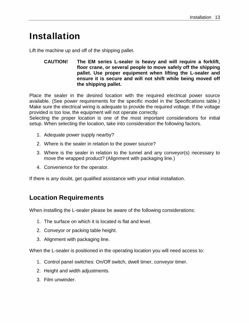
Installation Lift the machine up and off of the shipping pallet.
CAUTION! The EM series L-sealer is heavy and will require a forklift, floor crane, or several people to move safely off the shipping pallet. Use proper equipment when lifting the L-sealer and ensure it is secure and will not shift while being moved off the shipping pallet.
Place the sealer in the desired location with the required electrical power source available. (See power requirements for the specific model in the Specifications table.) Make sure the electrical wiring is adequate to provide the required voltage. If the voltage provided is too low, the equipment will not operate correctly. Selecting the proper location is one of the most important considerations for initial setup. When selecting the location, take into consideration the following factors.
1. Adequate power supply nearby?
2. Where is the sealer in relation to the power source?
3. Where is the sealer in relation to the tunnel and any conveyor(s) necessary to move the wrapped product? (Alignment with packaging line.)
4. Convenience for the operator. If there is any doubt, get qualified assistance with your initial installation.
Location Requirements When installing the L-sealer please be aware of the following considerations:
1. The surface on which it is located is flat and level.
2. Conveyor or packing table height.
3. Alignment with packaging line. When the L-sealer is positioned in the operating location you will need access to:
1. Control panel switches: On/Off switch, dwell timer, conveyor timer.
2. Height and width adjustments.
3. Film unwinder.

14 Installation
For units equipped with a takeaway conveyor at the exit of the L-sealer, provision should be made for exiting packages. For example, a table or bin where packages that have been sealed will be placed until they can be picked up, or a conveyor that will move them to the tunnel. If the L-sealer is part of a longer packaging line, take into consideration the table and conveyor height in relation to adjacent machinery. The machine should be placed on a flat, level floor so that it does not rock or move. We recommend that the machine be securely locked in place when used. Set up the L-sealer and move it to its location. The casters allow easy movement over smooth flat surfaces. If you need to lift the unit to move it, you will need to use a pallet jack, floor crane, or fork lift to move it to its location.
CAUTION! If the L-sealer must be lifted for moving, use proper equipment when lifting and moving it to ensure it is secure and will not shift.
When the L-sealer has been moved to its location, use the levers on the casters to lock the wheels to prevent rolling and keep the unit in place. A power cord (with optional electrical plug) should be installed by a licensed electrician.
CAUTION! Before operating, ensure the following. 1. All shipping ties are removed. 2. All personnel are clear of the equipment. 3. Electrician has stated that all electrical work is complete. 4. Adjust all controls according to the settings sheet.
Refer to instructions in the Operation section for instructions to power up or shut down the machine.

Operation 15
Operation
Control Panel
Controls for the L-sealer are located along the front side of the frame under the product tray. Controls from left to right are listed below. Dwell — Timer setting for seal. (Duration of activation of seal arm electromagnets).
Power — Toggle switch to toggle L-Sealer power on or off.
Conveyor — Timer setting for conveyor. (Length of time the conveyor will run for each item.)
Front Temperature Control — Setting for temperature of front seal.
Side Temperature Control — Setting for temperature of side seal.
CAUTION! When the power is turned on be aware of sealer hot surfaces and moving belts and rollers.
Product Tray
Film Roll Support Rollers
Pin Perforator
Control Panel
Cast Seal Head
0
10
20
30
40 50 60
70
80
90
100 0
10
20
30
40 50 60
70
80
90
100POWER
Front TemperatureCONTROL
Side TemperatureCONTROL
DWELL CONVEYOR
0
1
2 3
4
5
UP PW
×100°F0
1
2 3
4
5
UP PW
×100°F24v24v

16 Operation
Film Unwinder Product Tray
The product tray is the adjustable metal platform used to separate the film and to facilitate insertion of the product between the bottom and top layers of film.
The product tray is adjustable to achieve proper depth equal to the total width of the package, thereby allowing the product to be placed precisely at the center-fold of the film each time. Film Support Rollers
The film support rollers are positioned at the front end to cradle the film roll as film is dispensed. Vertical rods, one at each end of the film roll, help keep the film aligned with the product tray. Pin Perforator
The pin perforator is located at the exit of the film unwind. It creates holes in the film (to allow air to escape during shrinking). The pin perforator allows some adjustment and must be properly located with relation to the depth of packages to be sealed. The position of the pin perforator should always be reviewed when changing the machine for a different size package or different film size. It is adjusted by the adjustment knob at the top of the film unwind and located to avoid dropping or damaging and so it is mounted out of the way.
Mounting Film Select the proper width of center-fold film for the product being packaged, taking into account the width and height of the package. With the package properly positioned within the film in the sealing area, allow sufficient film to overlap the sealing bars so that a seal can easily be made without possibility of openings due to insufficient film coverage. Place the film roll on the support rollers so they cradle the film. (See the illustration on the following page.) Place the center-fold away from the operator, to the back of the machine. Position the film roll on the rollers and tighten the bolts on the film rack collars to hold the film roll in position. Decide whether the film is an A or B wind, and then thread it straight across and through the pin perforator. (See the following illustration.) When threading the film, make sure to pull excess film across the product tray and into the sealing area to ensure sufficient film to begin. When you have threaded the film, separate the top film from the bottom and insert the product tray between the film top and bottom. Make sure that the center-fold of the film is at the back of the product tray. This allows the operator to insert product on the product tray between the top and bottom layers of film to prepare to move the

Operation 17
product and film into the sealing area. Do not place product in the first few bags formed by the sealer: they will not have any perforation holes in them (because the sealer and pin perforator work together). Perforation is required to allow air to vacate when the product passes through the shrink tunnel.
Cradle-Mount Film Unwinder
Begin inserting product into the film as soon as the film reaching the seal area has perforations in it. Place the product against the back of the film separator tray and then move product into the seal area. Be sure to leave the bag loose around the product when making the seal. This helps keep the seals from blowing out in the shrink tunnel. See Sequence of Operation, which follows, for more detailed instructions for operating the L-sealer.
Sequence of Operation
1. Place the product on the product tray.
• The product tray separates the film, allowing you to place the product between the upper and lower layers of film.
2. Move the product into the seal head area, pushing it to the left.
3. Move hands out of the seal head area and pull the seal head down. Let go of the
handle as soon as the magnets activate.
• The magnets hold the seal head down for the amount of time required to make the seal. The amount of time is adjustable by turning the Dwell timer knob, which is located to the left of the Power switch under the product tray, to increase or decrease the amount of time.
FilmRoll
A-WindB-Wind
SupportRollers
Pin Perf.

18 Operation
• While the magnets are holding the seal head down, it is not necessary to wait. Prepare the next item to be sealed, placing it on the product tray between upper and lower layers of film.
4. Once the seal is formed completely, the seal head automatically releases. The
sealed product is removed by the takeaway conveyor, and the next item can be moved into position for sealing.
• The takeaway conveyor runs for the specified amount of time required to move the sealed product onward out of the sealing area. The amount of time the conveyor runs is adjustable by turning the Conveyor Timer knob, which is located to the right of the Power Switch under the product tray.
NOTE: If there is too much tension on the film while the bag is being sealed, the seals will be more likely to be weak or blow out in the seal area while moving through the shrink tunnel.

Adjustments 19
Adjustments
Element Pulse Switch Adjustment The sealing cycle should not begin until the seal head is within one-quarter-inch (¼”) or less of the film to be sealed. If the magnets energize before the head is within one-quarter-inch of the film, loosen the locknut and turn the screw (located at the rear of the side seal bar) up slightly (counter-clockwise as viewed from above). Adjustment has been set correctly when the magnets are energizing just as the seal bar comes into contact with the lower magnet pads.
Electromagnet Position Adjustment All magnets have been factory adjusted for equal sealing pressure throughout the length of both the front and the side seal bars. If an adjustment is required, however, use the following procedure.
1. Disconnect the L-sealer power plug from the electrical power source.
2. Loosen the lower magnet screws on all of the lower magnets so the magnets settle to the lowest position in the mounting slots.
3. Lower the L-sealer operating handle fully and lift the lower magnets to within the thickness of a dime from the holders.
4. Re-tighten the mounting screws securely to retain the proper adjustment.
Seal Pad Pressure Adjustment for Head Return Cylinder Uniform pressure between the sealing elements and the sealing pads must always be maintained in order to obtain an even seal and to prevent heating-element hotspots and premature burnout. The adjustment should be checked periodically and should always be checked when sealing gaps occur.
1. Disconnect the sealer power plug from the electrical power source.
2. Supporting the seal head in the up position, loosen the four set screws for the head return cylinder. Gently lower the seal head to rest on the lower seal pads.
3. With the seal head resting on the lower pads, shim up the film clamps so that the inserts are resting on the lower pads. Make sure there are no air gaps, and then tighten the head casting bolts.
4. Adjust magnets. (See Electromagnet Position Adjustment above.)

20 Adjustments
5. Go to the rear of the L-sealer. Make sure the head cylinder is straight from front to back. Pull the air cylinder bracket the full length of the air cylinder. Tighten the 5/16-inch set screws.
6. Cycle the seal head up and down. Adjust set screws on head return cylinders for proper head speed and cushion.
Timers and Temperature Controls Check dwell and conveyor-run timing, and temperature of front and side seals after making adjustments or after performing maintenance, such as replacing seal pads, cutting rules or hot knife inserts. Adjust as required using the adjustment provided through the control panel.

Maintenance 21
Maintenance The Eastey EM Performance Series Semi-Automatic L-Sealer will provide many hours of maintenance-free operation. There are a few items that may require attention from time to time.
Daily
Clean the sealing areas: hot knives or cutting rules and silicone rubber or felt pads.
Ensure no parts are torn or missing on upper and lower seal areas. Replace as needed.
Check wire takeaway belt for material stuck on or in belt. Clean if necessary.
Inspect film cradle rollers. Repair or replace as needed.
Check conveyor height adjustment.
Check power cord and wiring for wear and loose connections.
Check for any loose fasteners.
Monthly
Check and adjust conveyor tension if required.
Check wire belt and replace worn links or belt if required.
Silicone Rubber and Felt Seal Pad Replacement Occasionally it will be necessary to replace the silicone rubber or felt sealing pads. Seal pads are designed with a channel to make them easy to install and replace. Seal pads should be replaced if the following symptoms are observed.
• Gaps in the seal • Weak seals • Improper film cutoff • Excessive sealing pressure required
To replace a silicone rubber or felt pad, pull the old pad out of the channel and replace with the new silicone rubber or felt pad, pressing it into place in the channel.
NOTE: Some silicone rubber pads come covered in talcum powder. If so, clean the pads with a mild solvent.

22 Maintenance
Changing Hot Knife Inserts and Cutting Rules
1. Disconnect the L-sealer power plug from the electrical power source.
CAUTION! Always be aware of the cutting edges while replacing the knife edges. Handle the knife blades carefully.
2. Remove the #10-32 screws holding the inner side film clamp and remove the
#10-32 screws holding the outer front film clamp.
NOTE: One #10-32 screw is behind the aluminum arm casting. This does not need to be removed. Push the product tray in all the way. Swing the film clamp down and to the right over the product tray, then pull it out and rest the film clamp on the product tray.
3. Remove the #8-32 flat head screw on both side-seal and front-seal bars.
4. Remove the insert and cutting rule, both at the same time.
5. Place the replacement cutting rules into the new inserts, both at the same time,
ensuring that the beveled edge is in the corner.
6. Push the beveled edges together.
NOTE: The inside beveled edges of the cutting rule need to come together. The outsides do not. Be sure the cutting rules are touching.
7. Install the #8-32 flat head screws, but do not tighten them at this point.
8. Heat the seal bar up to the set point.
9. Adjust insert and cutting rule if they separate at the corner.
10. Tighten the #8-32 flat head screws while the seal bars are hot.
11. Turn off heat and allow the sealer to cool down, and then reinstall film clamps.
Takeaway Conveyor Maintenance and Replacement From time to time it will be necessary to disassemble the conveyor when it requires an adjustment for a different product size or if worn parts need to be replaced or for general maintenance. Instructions provided in this user guide are very general. If these generalized instructions do not address your specific conveyor issue, contact a certified representative of Eastey or contact Eastey Enterprises directly (Eastey.com/contact-us).

Maintenance 23
Replacing the Takeaway Conveyor Motor
NOTE: This procedure requires an Allen or hex wrench, and a 7/16-inch box-end wrench.
1. Disconnect the L-sealer power plug from the electrical power source.
2. Disconnect wires # 14 and # 16 from inside the panel and pull them out. Note the
color of wires and where they are connected.
NOTE: Wiring color connections to the conveyor motor. • Red and yellow are together and capped. • Brown, purple, and orange are together and capped. • Black is connected to black for power. • White is connected to white for power. • Green is connected to green to ground or motor ground.
3. Loosen the ¼-20 drive roller adjustment bolts and remove the timing belt.
Remove the timing pulley from the motor (requires an Allen or hex wrench).
4. Remove the three ¼-20 bolts. These hold the motor in place. As the last bolt is removed, hold onto the motor so it does not fall. (Bolt removal requires 7/16-inch box end wrench.)
5. Place the new conveyor motor in place of the conveyor motor removed, and
install the ¼-20 bolts.
6. Re-install the timing pulley. Make sure it is not rubbing against the conveyor frame, and then tighten both set screws.
7. Reinstall the timing belt. Tighten the ¼-20 drive roller adjustment bolts.
Reconnect the power wires #14 and # 16. Refer to the wiring color connections note on the preceding page to complete motor wiring connections.
8. Refer to the instructions for Wire Belt Repair Splicing.
Caution! Disconnect main power to the conveyor before attempting to
repair or adjust belt.
Wire Belt Repair Splicing
Caution! Disconnect main power to the conveyor before attempting to repair or adjust belt.

24 Maintenance
Before you begin splicing
• Release all belt tensioning mechanisms.
• If installing a new belt, thread the belt onto the conveyor. - Check to be sure that the smooth side is “up.” - Check to be sure that the edge loops curve back in the direction opposite the
direction of belt travel. - Remove a strand or two from the new belt to keep in reserve to splice the belt or
in case it may be needed to repair the belt in the future. - Tie both ends of the belt together with cord, twine, or wire ties.
• If repairing a belt - Tie two undamaged strands at the end to be spliced together with cord, twine, or
wire ties. - Cut out the damaged wire(s) with a wire cutters — pick out and dispose of wire
pieces immediately.
Important! If a belt has damage in more than one place or if the belt has been previously repaired, do not try to repair it. Install a new belt. Also, never save used belting to use for repairs because it has already been weakened by use. Purchase several extra feet of new belting to use exclusively for repairs.
Step 1 – Begin splicing in the center
1. Move the two ends of the belt to be spliced to the exit end of the conveyor.
2. Confirm that the edge loops curve back, away from the direction of belt travel as shown in the following illustration. If not, check to make sure that the belt is not positioned backwards on the conveyor.
3. Lay the strand down between the two belt ends and check to see that the edge loops are going in the same direction as the belt edge loops. (The strand must also be right-side-up for it to lay flat. You will know immediately if you have installed the splice strand wrong-side-up and you will need to start over.)
4. Bend the strand from each side enough to insert the ends into the two spaces next to the center space. (Spaces B and D in the following illustration.)

Maintenance 25
5. Insert the strand ends into the center space of the opposite edge. (Space 3 in the
illustration below.)
6. Pull the ends of the strand through until the center section “pops” or “locks” into
place. (You should be pulling the strands toward you.)
7. Use pliers or the wire belt straightening tool to straighten the wire in the center space. (Once the center is connected, you may remove the ties holding the belt ends together.)
A EB DC
1 52 43
Direction of
Belt Travel
Far Edge
Near Edge
A ECB D
2 41 53

26 Maintenance
Step 2 – Weave the strand to one side
1. Bend one end of the wire up and insert it around the z-bend in the next space on the edge of the wire closest to you. (Space 5 in the following illustration.) Always try to avoid bending the wire in the z-bend.
2. Bend the wire toward the center and insert it around the z-bend next to the center
space. (Space D in the following illustration.)
3. Pull the strand wire through the mesh and straighten it with pliers.
4. Repeat the above three moves until you reach the side edge of the belt.
5. Using the pliers, connect the strand’s edge loop to the belt’s edge loop on the far
edge. 6. Connect the edge loop on the near edge of the belt to the strand’s edge loop.
7. Straighten the strand with the pliers.
A ECB D
1 532 4
Far Edge
Near Edge
A C EB D
1 3 52 4

Maintenance 27
Step 3 – Weave the strand to the other side
1. Repeat the steps in Step 2, going in the opposite direction, weaving to the other side edge of the belt as shown in the following illustrations.
2. If you are installing a new belt, you are finished splicing.
Step 4 – Check Drive Shaft Sprocket Alignment
• Check to ensure 3/16-inch clearance between all sprockets (and/or blanks) and the Z-bends next to them.
• Check alignment of sprocket teeth with a straight-edge. (Only necessary if the sprockets are not keyed to the drive shaft.)
A C EB D
1 3 52 4
A EB DC
1 52 43
A ECB D
2 41 53

28 Maintenance
Step 5 – Check Entire Belt Circuit
• Z-bends should not come into contact with any conveyor component (including end rolls, wear strips, transfer support rails, nose bars, etc.)
• Adjust as needed.
Step 6 – Adjust Tension
• The wire belt used is a low-tension belt. Use minimal tension — only enough so the sprockets properly engage the belt.
• Run the conveyor and check to make sure it runs smoothly.
Note: Too much tension will cause premature belt failure.
Film Roll Support Rollers Make sure rollers stay clean and grease free. If you should have to clean the rollers, simply wipe them down with a clean lint free cloth. If a more thorough cleaning is necessary wipe the rollers down with a mild detergent and water and let dry. Never use harsh or abrasive cleaners or chemical agents when cleaning the rollers.

Troubleshooting 29
Troubleshooting
Problem Solution
No Element Heat • Check to be sure sealer is plugged in and electrical power is present at the outlet.
• Is the temperature control dial for the heat element, Front or Side set greater than zero? If not, check main fuses - Heat element temperature control must be
set to a number greater than zero (0). The greater the number the dial is set to, the higher the heat setting for the element.
Conveyor Does Not Run • Is the conveyor speed dial, set to zero (0)? - Conveyor speed dial must be set to a
number greater than zero (0). The greater the number the dial is set to, the longer the conveyor will run each cycle, with zero indicating the very minimum, in which case it may not run for any time at all.
• Is the limit switch on the back of the machine being fully actuated (pressed in)? - Press the limit switch in by hand, and then
let it go. - Refer to Magnet Hold Down Not Operating
on Magnet Sealers, below.
Magnet Hold Down Magnets Not Operating on Magnet Sealers (Sealing head will not stay down, but sealer operates normally otherwise.)
• Is timer working properly? - The timer is identical to the timer used for
the Conveyor. See items to check on the conveyor timer for Conveyor Does Not Run troubleshooting on previous page.
• Turn off power and put the seal head down. With power off and the seal head down, there should be about a dime’s-thickness of space between the upper and lower magnets. - Is there dime-sized space between upper
and lower magnets? • Press the limit switch to activate it by hand.
- Does the limit switch work properly when operated by hand?
30 Troubleshooting
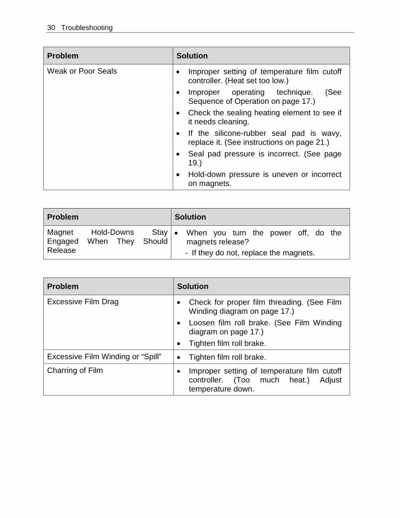
Problem Solution
Weak or Poor Seals • Improper setting of temperature film cutoff controller. (Heat set too low.)
• Improper operating technique. (See Sequence of Operation on page 17.)
• Check the sealing heating element to see if it needs cleaning.
• If the silicone-rubber seal pad is wavy, replace it. (See instructions on page 21.)
• Seal pad pressure is incorrect. (See page 19.)
• Hold-down pressure is uneven or incorrect on magnets.
Problem Solution
Magnet Hold-Downs Stay Engaged When They Should Release
• When you turn the power off, do the magnets release? - If they do not, replace the magnets.
Problem Solution
Excessive Film Drag • Check for proper film threading. (See Film Winding diagram on page 17.)
• Loosen film roll brake. (See Film Winding diagram on page 17.)
• Tighten film roll brake.
Excessive Film Winding or “Spill” • Tighten film roll brake.
Charring of Film • Improper setting of temperature film cutoff controller. (Too much heat.) Adjust temperature down.

Parts List 31
Parts List

32 Appendix A: Electrical Schematic
Appendix A: Electrical Schematics
Panel Layout

Appendix A: Electrical Schematic 33
Electrical Schematic
EASTEYENTERPRISES
Title
Tolerance Scale Material
Drafter Part Numbers
CHK By Date Part sizeTROY,S
HOT KNIFE EM16 "SEALERS"
NONE NONE
EL16HOT2
12-2-97 REV A - 3-3-16
CR3
TMR-1
SSR-1
253
25
2
2
21
T-3
AC
-DC
AC
+DC23
2022
L.S.218TMR-1
3 CR3-2
CR3-1 2
40
41 42
POWERON/OFF
F1
F2
L1
L2220V
42
GRD
40
41
TMR-2 L.S.3
TMR-2M1
14 23
16 143
MAG
2TT1
TT22
2
3
3
3
23 SSR-23
3
3
3
39
24
HEATER
HEATER
SSR-2
SSR-126
27 29
28+DC
+DC
-DC
-DC
PIN 12ON TT1
ON TT2PIN 12
ON TT2PIN 13
PIN 13ON TT1
220V
24V
FRONT
SIDE
FRONT
SIDE
FRONT
SIDE
24V D.C.
PIN-3
PIN-2
+
-THERMOCOUPLE TO TTI, TT2, TT3
30 32
3TT3
FRONT 23
ON TT3PIN 13
+DCFRONTSSR-3
-DCPIN 12ON TT3
3 3 SSR-3 31 FRONTHEATER 2
OPTIONA L 3RD HEATER CARTRIDGE
PIN-10 PIN-11
PIN-11PIN-10
PIN-11PIN-10
23CR2
ALARMTT1 TT2
ALARM
PIN-9 PIN-8 PIN-933 34
CR2-2
CR2-1
36
35
PIN-9
ALARMTT3
PIN-8OPTIONAL 3RD
38
CR2-3 37

34 Appendix B: Temperature Setting Specifications
Appendix B: Temperature Setting Specifications for Shrink-Wrap Plastics
Mushroom Insert PVC (Poly-Vinyl Chloride) Temperature settings:
Pad type: Dwell Time:
325° F front bar; 325° F side bar Felt Approximately 1 second
Polyolefin Temperature settings: Pad type: Dwell Time:
335° F front bar; 335° F side bar Sponge rubber Approximately 1 second
Polyethylene Temperature settings: Pad type: Dwell Time:
360° F front bar; 360° F side bar Sponge rubber Approximately 1.5 second

L-Sealer Size Estimating 35
Appendix C: L-Sealer Size Estimating
L-Sealer Center-Folded Film Size Estimating Table
To calculate estimated per-package cost for manual and semi-automatic L-sealers, use the following formulas.
1) Center-Folded film – width of roll of film = 2) Cutoff Film length – film going across front seal bar = 3) Film usage – to calculate the amount of film used per package = 4) Per package cost

36 L-Sealer Size Estimating
16-inch Side Seal Package Size Estimation The following Eastey Enterprises side seal bar size dimensions are provided to make sure your product will fit under the side seal bar. You will need to know your product height and width to use these figures effectively.
Hot Knife Hot Wire
Warranty Statement 37
Warranty Statement
EM Performance Series Semi-Automatic L-Sealers
Warranty Statement Eastey Enterprises warrants that all of the products it ships will be in good working order and free from defects in material and workmanship for a period of two (2) years from the date of shipment by Eastey and will conform to the published specifications for that product. Spare parts that are manufactured in house by Eastey will be warranted for two (2) years. Bought out parts will be warranted for one (1) year.
Warranty Period – Specific Items Drive motor(s): 1 year Gear reducer: 1 year Termination Post 30 days Conveyor Belt 30 days Hole Punches 30 days (ball and die) Knurled Nut 30 days
The following parts are considered to be consumable items and not under warranty: fuses, ¼ " × ¾ " sponge rubber, copper heat sinks, 036 Nichrome wire, ¾ " PTFE tape, and ½ " PTFE tape.
All other parts: 1 year (Except for moving parts which are subject to normal wear, tear and replacement which are warranted to be free from defects in material and workmanship.)
Sealing Quality Sealing quality achieved in a given application is dependent on the installation, the material handling, and the maintenance provided. Eastey makes no warranty that the sealing quality achieved in an application will be the same as that achieved on a test piece in our demo facility.
Shipping Policy Customer pays all incoming shipping. If the item is defective and under warranty, Eastey pays return shipping charges for least costly method. If expedited shipping is desired, customer must furnish his shipping account and shipping fees will be charged to that account.
Warranty Verification If you conclude that a product may be defective and may be covered by warranty, obtain a Return Material Authorization number by calling our technical support number (toll free at 1-800-835-9344, or 763-428-4846 or Fax: 763-795-8867) or e-mail: [email protected]. Based on the recommendation from Eastey technical support, replacement components may be shipped out via UPS Ground or similar method. If expedited shipping is desired, customer must furnish their shipping account and shipping fees will be charged to that account. Customer is required to return the

38 L-Sealer Size Estimating
defective component to Eastey. If, after 30 days, Eastey hasn’t received the defective component, the customer will be invoiced for the replacement component. If the returned component is found to not be elegible for warranty, Easty will contact the customer and the customer will be invoiced for the replacement component. Warranty Eligibility The warranty provided by Eastey Enterprises, Inc. is only to the original buyer. Limited Warranty THE ABOVE WARRANTY IS EXCLUSIVE AND IN LIEU OF ALL OTHER WARRANTIES, WHETHER EXPRESSED OR IMPLIED, INCLUDING THE IMPLIED WARRANTIES OF MERCHANTABILITY, FITNESS FOR A PARTICULAR PURPOSE AND NONINFRINGEMENT. Disclaimer of Damages REGARDLESS OF WHETHER ANY REMEDY SET FORTH HEREIN FAILS OF ITS ESSENTIAL PURPOSE, IN NO EVENT WILL EASTEY ENTERPRISES, INC. BE LIABLE FOR ANY SPECIAL, CONSEQUENTIAL, INDIRECT OR SIMILAR DAMAGES, INCLUDING LOST PROFIT OR LOST OPPORTUNITIES OF ANY TYPE ARISING OUT OF THE USE OR INABILITY TO USE THESE PRODUCTS EVEN IF EASTEY ENTERPRISES, INC. HAS BEEN ADVISED OF THE POSSIBILITY OF SUCH DAMAGES.

Customer Support 39
Customer Support
Eastey Technical Service For help setting up or operating the EM Performance Series L-Sealer, please contact Eastey Technical Service at one of the numbers listed below. Toll-Free Phone 800-835-9344 Phone 763-428-4846 Fax 763-795-8867 E-mail [email protected] Web www.eastey.com Thank you again for your purchase of Eastey products. We are pleased to be a part of your packaging needs.

![XC series PLC User manual[Instruction] - KALATEC](https://static.fdokumen.com/doc/165x107/6316c313f68b807f880362ed/xc-series-plc-user-manualinstruction-kalatec.jpg)