GP, LP Series (user manual for communication) - Autonics
294
© Copyright Reserved Autonics Co., Ltd. iii USER MANUAL For COMMUNICATION
-
Upload
khangminh22 -
Category
Documents
-
view
0 -
download
0
Transcript of GP, LP Series (user manual for communication) - Autonics
© Copyright Reserved Autonics Co., Ltd. iii
USER MANUAL For COMMUNICATION

iv © Copyright Reserved Autonics Co., Ltd.
Preface
© Copyright Reserved Autonics Co., Ltd. iii
Preface
Thank you very much for selecting Autonics products.
Please familiarize yourself with the information contained in the Safety Precautions section before using this product.
This user manual contains information about the product and its proper use, and should be kept in a place where it will be easy to access.
User Manual Guide
iv © Copyright Reserved Autonics Co., Ltd.
User Manual Guide
Please familiarize yourself with the information in this manual before using the product.
This manual provides detailed information on the product's features. It does not offer any guarantee concerning matters beyond the scope of this manual.
This manual may not be edited or reproduced in either part or whole without permission.
A user manual is not provided as part of the product package. Please visit our home-page (www.autonics.com) to download a copy.
The manual's content may vary depending on changes to the product's software and other unforeseen developments within Autonics, and is subject to change without prior notice. Upgrade notice is provided through our homepage.
We contrived to describe this manual more easily and correctly. However, if there are any corrections or questions, please notify us these on our homepage.
User Manual Symbols
© Copyright Reserved Autonics Co., Ltd. v
User Manual Symbols
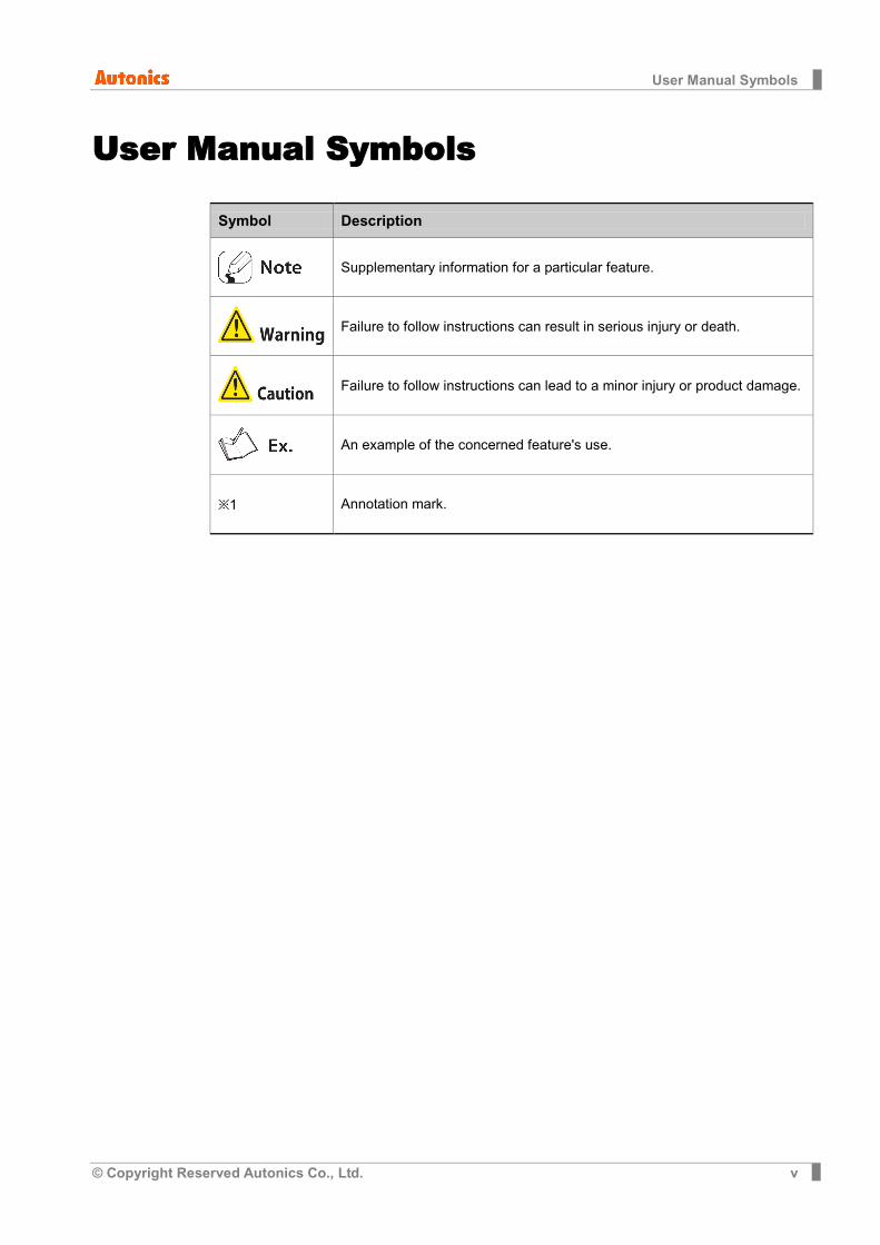
Symbol Description
Supplementary information for a particular feature.
Failure to follow instructions can result in serious injury or death.
Failure to follow instructions can lead to a minor injury or product damage.
An example of the concerned feature's use.
※1 Annotation mark.

Safety Precautions
vi © Copyright Reserved Autonics Co., Ltd.
Safety Precautions
Following these safety precautions will ensure the safe and proper use of the product and help prevent accidents and minimize hazards.
Safety precautions are categorized as Warnings and Cautions, as defined below:
Warning Cases that may cause serious injury or fatal accident if
instructions are not followed.
Caution Cases that may cause minor injury or product damage
if instructions are not followed.
In case of using this unit with machinery (Ex: nuclear power control, medical equipment,
ship, vehicle, train, airplane, combustion apparatus, safety device, crime/disaster prevention equipment, etc) which may cause damages to human life or property, it is required to install fail-safe device. It may cause a fire, human injury or property loss.
In case using the GP, LP touch switch for controlling, do not use the switch as emergency switches or those related to safety that may cause physical injury or property damage in the event of a malfunction. It may cause a fire, human injury or property loss.
In the event of defect or malfunction in GP, LP an alternative circuit must be constructed on the exterior. It may cause a fire, human injury or property loss.
Construct an emergency power-off circuit, safety circuit, or interlock circuit on the exterior of GP,LP. It may cause a fire, human injury or property loss.
If an error occurs on the watchdog timer of LP, the logic program will shut down automatically, so an alternative circuit must be constructed on the exterior. It may cause a fire, human injury or property loss.
The overall system operation may malfunction due to an input error resulting from a failure in input signal detection; so an alternative circuit must be constructed on the exterior. It may cause a fire, human injury or property loss.
For output signals that may cause a serious accident if the output section is damaged, a detection circuit and alternative circuit must be constructed on the exterior. It may cause a fire, human injury or property loss.
In case controlling other devices through GP, LP communication, and there is a possibility of malfunction due to communication error, an alternative circuit must be constructed. It may cause a fire, human injury or property loss.
When switching the mode to RUN mode please make sure that supply power to LP, I/O unit and load first. If not, output error or malfunction may be caused. It may cause a fire, human injury or property loss.
Before supplying power to LP, configure the circuit which is for supplying power to I/O unit and load at first. After starting LP program, if power is supplied to I/O unit and load, it may
Safety Precautions
© Copyright Reserved Autonics Co., Ltd. vii
cause malfunction and output error. It may cause a fire, human injury or property loss.
Do not use the product in an area or an environment not specified in the manual. It may cause a fire, human injury or property loss.
Do not connect, inspect or repair when power is on. It may cause a fire or give an electric shock.
Do not disassemble the product. Please contact us if it is required. It may cause a fire or give an electric shock.
Please use the rectified power with insulation trans. It may cause a fire or give an electric shock.
Do not use the power exceeded the rated voltage. It may cause a fire or give an electric shock.
This product uses lithium battery, do not disassemble or burn up. It may cause an explosion or a fire.
Wire properly after checking power terminal polarity. It may cause a fire or a malfunction.
Please read all notes and cautions related to installation and wiring in the manual.
If this is not observed, electrical shock or malfunction may occur.
Make sure the ground wire of Graphic Panel is wired separately from the ground wires of
other devices. Ground resistance must be less than 100Ω, and a lead wire of which
sectional area is over 1.25mm2 should be used. If this is not observed, electrical shock or malfunction may occur.
When connecting GP, LP ports and constructing input/output, check the pin number and terminal block before connecting. It may cause a fire or a malfunction.
Please tighten bolt on terminal block with specified tightening torque. It may cause a short circuit, fire or a malfunction.
Do not press the surface of the touch panel with sharp or hard objects. The touch panel may be damaged.
Keep GP, LP at the specified temperature. If stored at a temperature beyond the specification, damage may occur.
Do not inflow dust or wire dregs into the unit. It may cause a fire or a malfunction.
Do not use in an area with excessive humidity or temperature. It may cause malfunction, or its useful life may be shortened.
Do not close ventilating opening of this product. Malfunction may occur due to temperature increase.
Keep the product out of direct sunlight or excessive dust. It may cause malfunction, or its useful life may be shortened.
Do not use or store in a place with shock or vibration. It may cause malfunction, or its useful life may be shortened.
Safety Precautions
viii © Copyright Reserved Autonics Co., Ltd.
When liquid crystal from the broken LCD is smeared with skin, wash it for 15 minutes. If it is gotten in the eye, wash it for 15 minutes and contact with the medical specialist for more information.
In cleaning unit, do not use water or an oil-based detergent and use dry towels. It may cause an electric shock or a fire.
Please separate as an industrial waste when disuse this unit.
To change the battery, contact the store or an authorized technician.
The manufacturer is not liable for damages that occur due to causes for which the manufacturer is not responsible, damages that occur due to an extraordinary situation, secondary damages, compensation for accidents, damages occurring on other products, compensation for other processes, and damage and loss of opportunity to the user due a malfunction of the product, regardless of the predictability of the accident.
※The specifications and dimensions of this manual are subject to change without any notice.
※This inner device of user manual for communication is based on GP. If you use LP,
refer to “LP user manual” for inner device of LP.

Safety Precautions
© Copyright Reserved Autonics Co., Ltd. ix
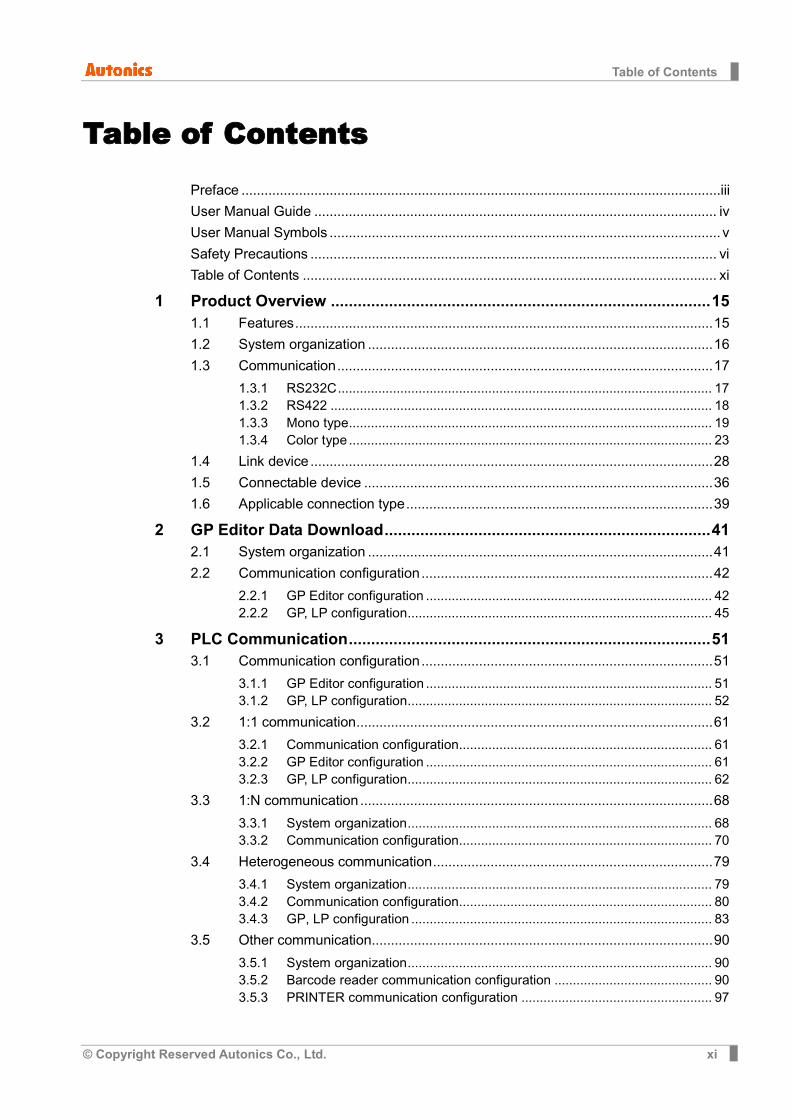
Table of Contents
© Copyright Reserved Autonics Co., Ltd. xi
Table of Contents
Preface .............................................................................................................................iii
User Manual Guide ......................................................................................................... iv
User Manual Symbols ...................................................................................................... v
Safety Precautions .......................................................................................................... vi
Table of Contents ............................................................................................................ xi
1 Product Overview ..................................................................................... 151.1 Features ............................................................................................................. 15
1.2 System organization .......................................................................................... 16
1.3 Communication .................................................................................................. 17
1.3.1 RS232C ...................................................................................................... 171.3.2 RS422 ........................................................................................................ 181.3.3 Mono type ................................................................................................... 191.3.4 Color type ................................................................................................... 23
1.4 Link device ......................................................................................................... 28
1.5 Connectable device ........................................................................................... 36
1.6 Applicable connection type ................................................................................ 39
2 GP Editor Data Download ......................................................................... 412.1 System organization .......................................................................................... 41
2.2 Communication configuration ............................................................................ 42
2.2.1 GP Editor configuration .............................................................................. 422.2.2 GP, LP configuration ................................................................................... 45
3 PLC Communication ................................................................................. 513.1 Communication configuration ............................................................................ 51
3.1.1 GP Editor configuration .............................................................................. 513.1.2 GP, LP configuration ................................................................................... 52
3.2 1:1 communication ............................................................................................. 61
3.2.1 Communication configuration ..................................................................... 613.2.2 GP Editor configuration .............................................................................. 613.2.3 GP, LP configuration ................................................................................... 62
3.3 1:N communication ............................................................................................ 68
3.3.1 System organization ................................................................................... 683.3.2 Communication configuration ..................................................................... 70
3.4 Heterogeneous communication ......................................................................... 79
3.4.1 System organization ................................................................................... 793.4.2 Communication configuration ..................................................................... 803.4.3 GP, LP configuration .................................................................................. 83
3.5 Other communication ......................................................................................... 90
3.5.1 System organization ................................................................................... 903.5.2 Barcode reader communication configuration ........................................... 903.5.3 PRINTER communication configuration .................................................... 97
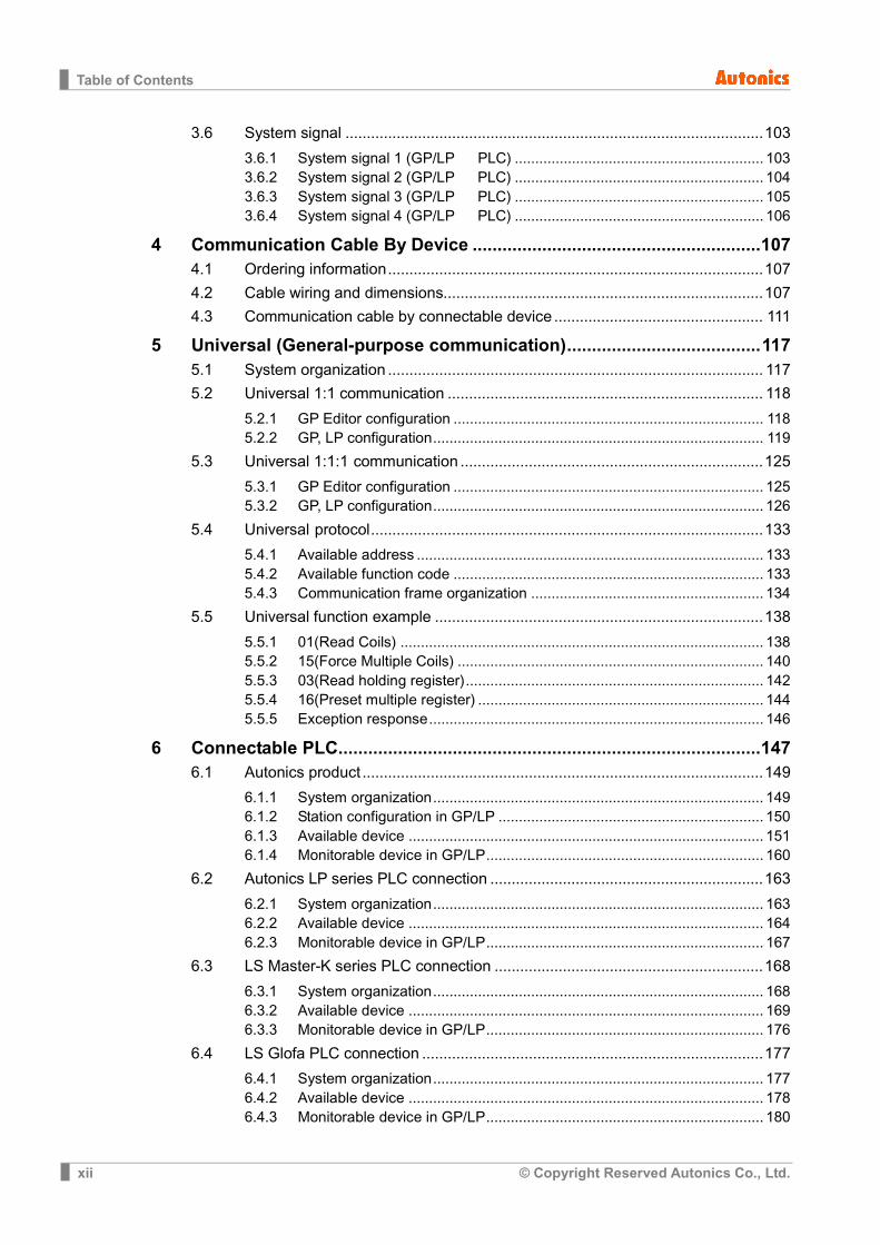
Table of Contents
xii © Copyright Reserved Autonics Co., Ltd.
3.6 System signal .................................................................................................. 103
3.6.1 System signal 1 (GP/LP ← PLC) ............................................................. 1033.6.2 System signal 2 (GP/LP ← PLC) ............................................................. 1043.6.3 System signal 3 (GP/LP ← PLC) ............................................................. 1053.6.4 System signal 4 (GP/LP ← PLC) ............................................................. 106
4 Communication Cable By Device .......................................................... 1074.1 Ordering information ........................................................................................ 107
4.2 Cable wiring and dimensions ........................................................................... 107
4.3 Communication cable by connectable device ................................................. 111
5 Universal (General-purpose communication) ....................................... 1175.1 System organization ........................................................................................ 117
5.2 Universal 1:1 communication .......................................................................... 118
5.2.1 GP Editor configuration ............................................................................ 1185.2.2 GP, LP configuration ................................................................................. 119
5.3 Universal 1:1:1 communication ....................................................................... 125
5.3.1 GP Editor configuration ............................................................................ 1255.3.2 GP, LP configuration ................................................................................. 126
5.4 Universal protocol ............................................................................................ 133
5.4.1 Available address ..................................................................................... 1335.4.2 Available function code ............................................................................ 1335.4.3 Communication frame organization ......................................................... 134
5.5 Universal function example ............................................................................. 138
5.5.1 01(Read Coils) ......................................................................................... 1385.5.2 15(Force Multiple Coils) ........................................................................... 1405.5.3 03(Read holding register) ......................................................................... 1425.5.4 16(Preset multiple register) ...................................................................... 1445.5.5 Exception response .................................................................................. 146
6 Connectable PLC ..................................................................................... 1476.1 Autonics product .............................................................................................. 149
6.1.1 System organization ................................................................................. 1496.1.2 Station configuration in GP/LP ................................................................. 1506.1.3 Available device ....................................................................................... 1516.1.4 Monitorable device in GP/LP .................................................................... 160
6.2 Autonics LP series PLC connection ................................................................ 163
6.2.1 System organization ................................................................................. 1636.2.2 Available device ....................................................................................... 1646.2.3 Monitorable device in GP/LP .................................................................... 167
6.3 LS Master-K series PLC connection ............................................................... 168
6.3.1 System organization ................................................................................. 1686.3.2 Available device ....................................................................................... 1696.3.3 Monitorable device in GP/LP .................................................................... 176
6.4 LS Glofa PLC connection ................................................................................ 177
6.4.1 System organization ................................................................................. 1776.4.2 Available device ....................................................................................... 1786.4.3 Monitorable device in GP/LP .................................................................... 180
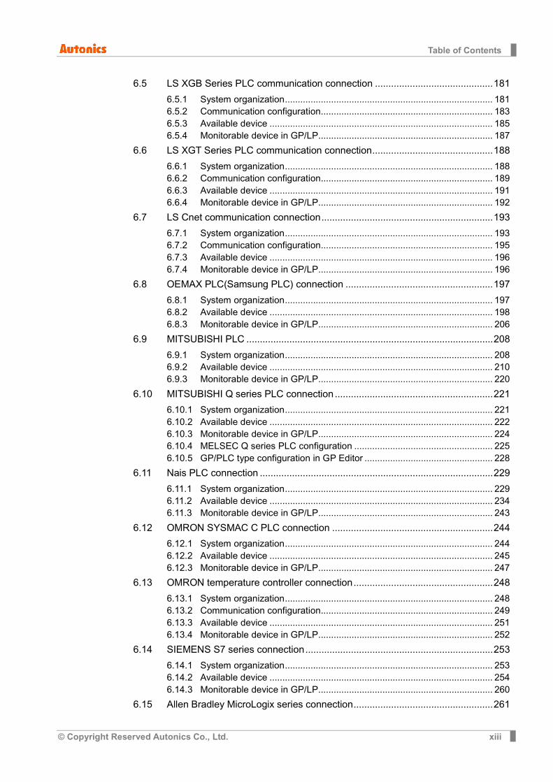
Table of Contents
© Copyright Reserved Autonics Co., Ltd. xiii
6.5 LS XGB Series PLC communication connection ............................................ 181
6.5.1 System organization ................................................................................. 1816.5.2 Communication configuration ................................................................... 1836.5.3 Available device ....................................................................................... 1856.5.4 Monitorable device in GP/LP .................................................................... 187
6.6 LS XGT Series PLC communication connection ............................................. 188
6.6.1 System organization ................................................................................. 1886.6.2 Communication configuration ................................................................... 1896.6.3 Available device ....................................................................................... 1916.6.4 Monitorable device in GP/LP .................................................................... 192
6.7 LS Cnet communication connection ................................................................ 193
6.7.1 System organization ................................................................................. 1936.7.2 Communication configuration ................................................................... 1956.7.3 Available device ....................................................................................... 1966.7.4 Monitorable device in GP/LP .................................................................... 196
6.8 OEMAX PLC(Samsung PLC) connection ....................................................... 197
6.8.1 System organization ................................................................................. 1976.8.2 Available device ....................................................................................... 1986.8.3 Monitorable device in GP/LP .................................................................... 206
6.9 MITSUBISHI PLC ............................................................................................ 208
6.9.1 System organization ................................................................................. 2086.9.2 Available device ....................................................................................... 2106.9.3 Monitorable device in GP/LP .................................................................... 220
6.10 MITSUBISHI Q series PLC connection ........................................................... 221
6.10.1 System organization ................................................................................. 2216.10.2 Available device ....................................................................................... 2226.10.3 Monitorable device in GP/LP .................................................................... 2246.10.4 MELSEC Q series PLC configuration ...................................................... 2256.10.5 GP/PLC type configuration in GP Editor .................................................. 228
6.11 Nais PLC connection ....................................................................................... 229
6.11.1 System organization ................................................................................. 2296.11.2 Available device ....................................................................................... 2346.11.3 Monitorable device in GP/LP .................................................................... 243
6.12 OMRON SYSMAC C PLC connection ............................................................ 244
6.12.1 System organization ................................................................................. 2446.12.2 Available device ....................................................................................... 2456.12.3 Monitorable device in GP/LP .................................................................... 247
6.13 OMRON temperature controller connection .................................................... 248
6.13.1 System organization ................................................................................. 2486.13.2 Communication configuration ................................................................... 2496.13.3 Available device ....................................................................................... 2516.13.4 Monitorable device in GP/LP .................................................................... 252
6.14 SIEMENS S7 series connection ...................................................................... 253
6.14.1 System organization ................................................................................. 2536.14.2 Available device ....................................................................................... 2546.14.3 Monitorable device in GP/LP .................................................................... 260
6.15 Allen Bradley MicroLogix series connection .................................................... 261

Table of Contents
xiv © Copyright Reserved Autonics Co., Ltd.
6.15.1 System organization ................................................................................. 2616.15.2 Available device ....................................................................................... 2626.15.3 Monitorable device in GP/LP .................................................................... 265
6.16 KONICS Product connection ........................................................................... 266
6.16.1 System organization ................................................................................. 2666.16.2 Available device ....................................................................................... 2686.16.3 Monitorable device in GP/LP .................................................................... 282
6.17 DELTA temperature controller connection ....................................................... 283
6.17.1 System organization ................................................................................. 2836.17.2 Available device ....................................................................................... 2856.17.3 Monitorable device in GP/LP .................................................................... 286
6.18 DANFOS FC Series ......................................................................................... 288
6.18.1 System organization ................................................................................. 2886.18.2 Available device ....................................................................................... 2906.18.3 Monitorable device in GP/LP .................................................................... 290
6.19 Modbus Master ................................................................................................ 291
6.19.1 System organization ................................................................................. 2916.19.2 Available device ....................................................................................... 2926.19.3 Monitorable device in GP/LP .................................................................... 293

1 Product Overview
© Copyright Reserved Autonics Co., Ltd. 15
1 Product Overview GP and LP series which is connected with various controllers including PLC, temperature controller displays and monitors the operation of control variable by LCD screen visually as grahpic interface device. You can switch the screen and set or edit the variable value by touching LCD screen. The variable value with various data type is displayed by graphic object(tag) drawn from GP Editor which is dedicated software for GP, LP screen. Connected with barcode reader and printer, etc. GP, LP realize numerous application by utilizing interface.
1.1 Features Responds to various connection type
It supports to connect with several PLCs and controllers.
It supports to connect with barcode reader for product lines or on-site that use barcodes.
It supports to print for alarm history.
Friendly compatible with controller
High compatibility monitoring function with PLC including monitoring device, changing device value, multi monitoring function between heterogeneous controllers.
Easy to display the cause of PLC system alarm including alarm history, total number of alarm, history printing, detail indication of alarm.

1 Product Overview
16 © Copyright Reserved Autonics Co., Ltd.
1.2 System organization GP, LP is able to communicate with various controllers including PLC, multi meter, pulse meter, temperature & humidity sensor and temperature controller.
GP,LP and controllers can execute RS-232C/RS-422(RS-485) communication, and please refer to the each controller section for more information about module or adapter to convert communication.
The following is the system organization for connecting with GP, LP.
※1. Printer supports serial communication. Printer is able to directly connect with GP/LP to be available serial communication both RS232C, RS422.You can print only alarm history by GP, LP. For more details, refer to ‘3.5 Other communication’.
※2. Personal Computer transmits written data to GP, LP. It is required to use dedicated transmitting cable(sold separately) to transmit the data(User can create.). GP Editor which is dedicated drawing software program creates data. Visit our homepage (www.autonics.com) to download GP Editor.

1 Product Overview
© Copyright Reserved Autonics Co., Ltd. 17
The below is computer specification requried to use software. Operating system: Windows98/NT/XP
Item Minimum specifications Recommended specification
CPU Pentium 4 or above Pentium Dual Core
Memory 512 MB 1GB
Hard disk 1 GB (Free space) 5GB (Free space)
Resolution 1024 × 768 1280 × 1024
1.3 Communication
1.3.1 RS232C (1) Transmission standard
No. Item Description
1 Communication method Full Duplex
2 Synchronous method Asynchronous
3 Communication distance Approx. 15m
4 Connection type 1:1
5 Baud rate 300/600/1200/3200/4800/9600/19200/38400/57600bps
6 Data format
Data length 7, 8 bit
Parity None, Odd, Even
Stop bit 1, 2 bit
(2) Connector pin number and signal name
No Signal name No Signal name
1 - 6 DSR
2 RXD 7 -
3 TXD 8 -
4 DTR 9 -
5 SG
1 Product Overview
18 © Copyright Reserved Autonics Co., Ltd.
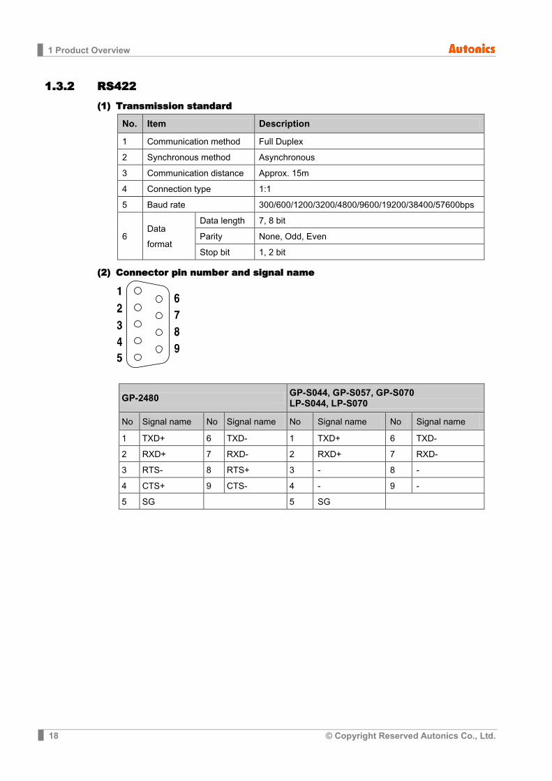
1.3.2 RS422 (1) Transmission standard
No. Item Description
1 Communication method Full Duplex
2 Synchronous method Asynchronous
3 Communication distance Approx. 15m
4 Connection type 1:1
5 Baud rate 300/600/1200/3200/4800/9600/19200/38400/57600bps
6 Data format
Data length 7, 8 bit
Parity None, Odd, Even
Stop bit 1, 2 bit
(2) Connector pin number and signal name
GP-2480 GP-S044, GP-S057, GP-S070 LP-S044, LP-S070
No Signal name No Signal name No Signal name No Signal name
1 TXD+ 6 TXD- 1 TXD+ 6 TXD-
2 RXD+ 7 RXD- 2 RXD+ 7 RXD-
3 RTS- 8 RTS+ 3 - 8 -
4 CTS+ 9 CTS- 4 - 9 -
5 SG
5 SG
1 Product Overview
© Copyright Reserved Autonics Co., Ltd. 19
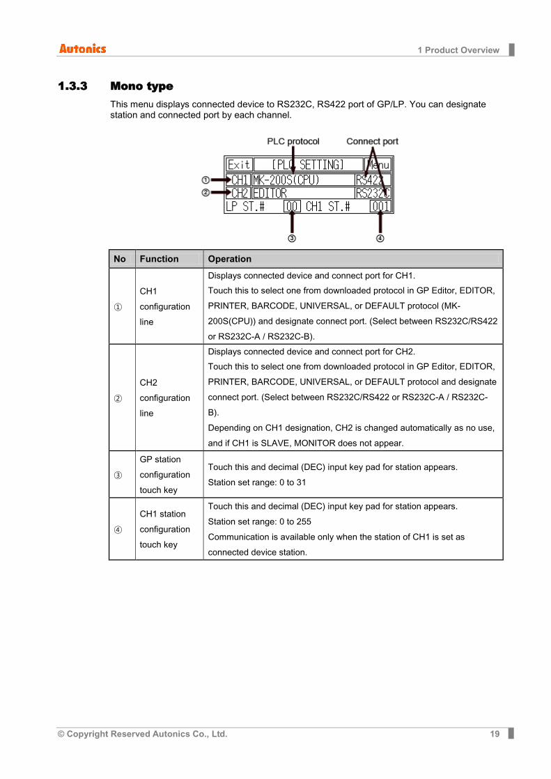
1.3.3 Mono type This menu displays connected device to RS232C, RS422 port of GP/LP. You can designate station and connected port by each channel.
No Function Operation
① CH1 configuration line
Displays connected device and connect port for CH1.
Touch this to select one from downloaded protocol in GP Editor, EDITOR, PRINTER, BARCODE, UNIVERSAL, or DEFAULT protocol (MK-200S(CPU)) and designate connect port. (Select between RS232C/RS422 or RS232C-A / RS232C-B).
② CH2 configuration line
Displays connected device and connect port for CH2.
Touch this to select one from downloaded protocol in GP Editor, EDITOR, PRINTER, BARCODE, UNIVERSAL, or DEFAULT protocol and designate connect port. (Select between RS232C/RS422 or RS232C-A / RS232C-B). Depending on CH1 designation, CH2 is changed automatically as no use, and if CH1 is SLAVE, MONITOR does not appear.
③ GP station configuration touch key
Touch this and decimal (DEC) input key pad for station appears. Station set range: 0 to 31
④ CH1 station configuration touch key
Touch this and decimal (DEC) input key pad for station appears. Station set range: 0 to 255 Communication is available only when the station of CH1 is set as connected device station.
1 Product Overview
20 © Copyright Reserved Autonics Co., Ltd.
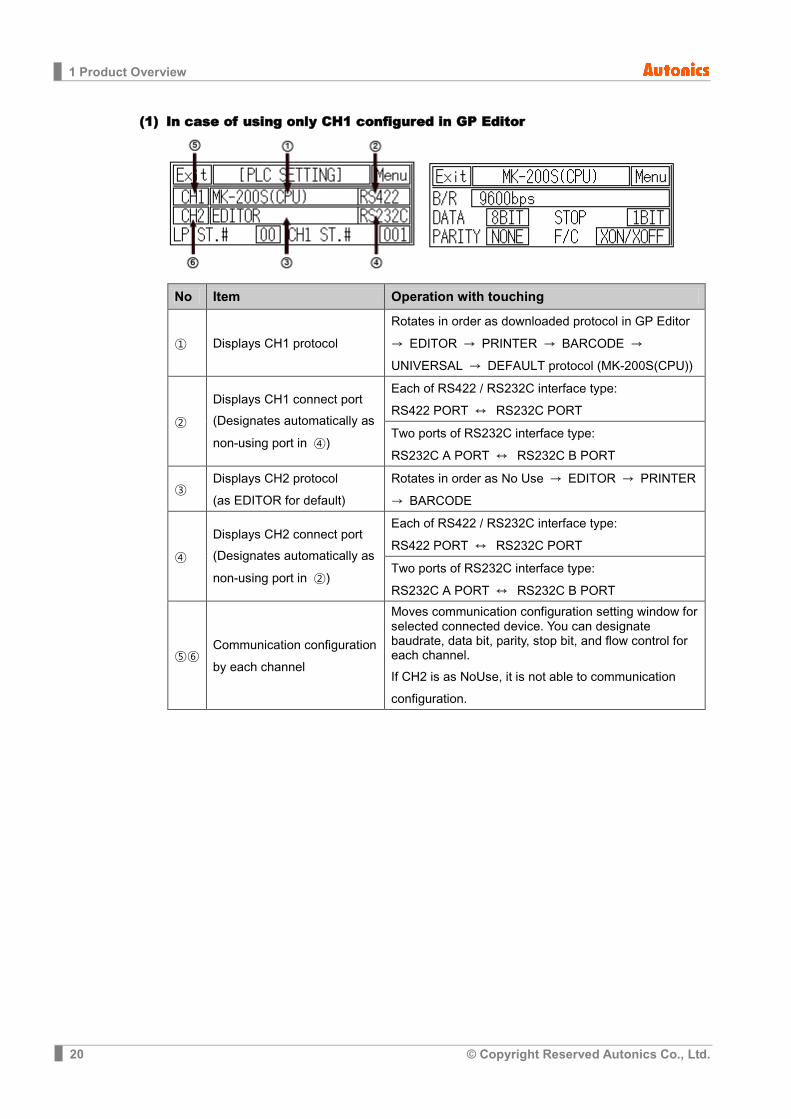
(1) In case of using only CH1 configured in GP Editor
No Item Operation with touching
① Displays CH1 protocol Rotates in order as downloaded protocol in GP Editor
→ EDITOR → PRINTER → BARCODE → UNIVERSAL → DEFAULT protocol (MK-200S(CPU))
② Displays CH1 connect port
(Designates automatically as
non-using port in ④)
Each of RS422 / RS232C interface type: RS422 PORT ↔ RS232C PORT Two ports of RS232C interface type:
RS232C A PORT ↔ RS232C B PORT
③ Displays CH2 protocol (as EDITOR for default)
Rotates in order as No Use → EDITOR → PRINTER
→ BARCODE
④ Displays CH2 connect port
(Designates automatically as
non-using port in ②)
Each of RS422 / RS232C interface type:
RS422 PORT ↔ RS232C PORT Two ports of RS232C interface type:
RS232C A PORT ↔ RS232C B PORT
⑤⑥ Communication configuration by each channel
Moves communication configuration setting window for selected connected device. You can designate baudrate, data bit, parity, stop bit, and flow control for each channel.
If CH2 is as NoUse, it is not able to communication configuration.
1 Product Overview
© Copyright Reserved Autonics Co., Ltd. 21
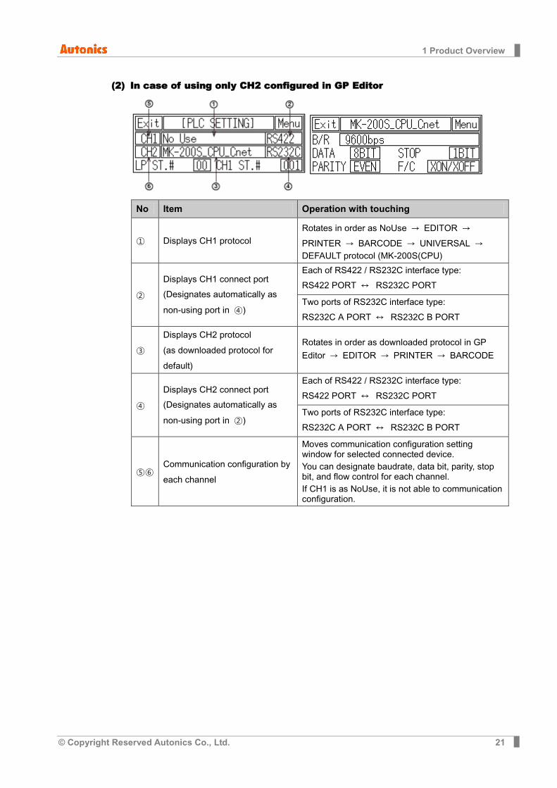
(2) In case of using only CH2 configured in GP Editor
No Item Operation with touching
① Displays CH1 protocol Rotates in order as NoUse → EDITOR →
PRINTER → BARCODE → UNIVERSAL → DEFAULT protocol (MK-200S(CPU)
② Displays CH1 connect port
(Designates automatically as
non-using port in ④)
Each of RS422 / RS232C interface type: RS422 PORT ↔ RS232C PORT
Two ports of RS232C interface type:
RS232C A PORT ↔ RS232C B PORT
③ Displays CH2 protocol (as downloaded protocol for default)
Rotates in order as downloaded protocol in GP
Editor → EDITOR → PRINTER → BARCODE
④ Displays CH2 connect port
(Designates automatically as
non-using port in ②)
Each of RS422 / RS232C interface type: RS422 PORT ↔ RS232C PORT
Two ports of RS232C interface type:
RS232C A PORT ↔ RS232C B PORT
⑤⑥ Communication configuration by each channel
Moves communication configuration setting window for selected connected device. You can designate baudrate, data bit, parity, stop bit, and flow control for each channel. If CH1 is as NoUse, it is not able to communication configuration.
1 Product Overview
22 © Copyright Reserved Autonics Co., Ltd.
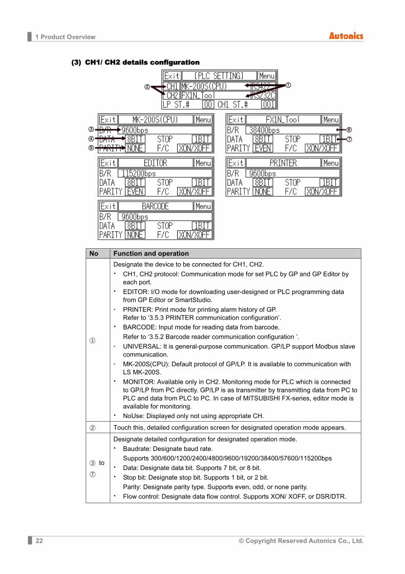
(3) CH1/ CH2 details configuration
No Function and operation
①
Designate the device to be connected for CH1, CH2. CH1, CH2 protocol: Communication mode for set PLC by GP and GP Editor by
each port. EDITOR: I/O mode for downloading user-designed or PLC programming data
from GP Editor or SmartStudio. PRINTER: Print mode for printing alarm history of GP.
Refer to ‘3.5.3 PRINTER communication configuration’.
BARCODE: Input mode for reading data from barcode. Refer to ‘3.5.2 Barcode reader communication configuration ’.
UNIVERSAL: It is general-purpose communication. GP/LP support Modbus slave communication.
MK-200S(CPU): Default protocol of GP/LP. It is available to communication with LS MK-200S.
MONITOR: Available only in CH2. Monitoring mode for PLC which is connected to GP/LP from PC directly. GP/LP is as transmitter by transmitting data from PC to PLC and data from PLC to PC. In case of MITSUBISHI FX-series, editor mode is available for monitoring.
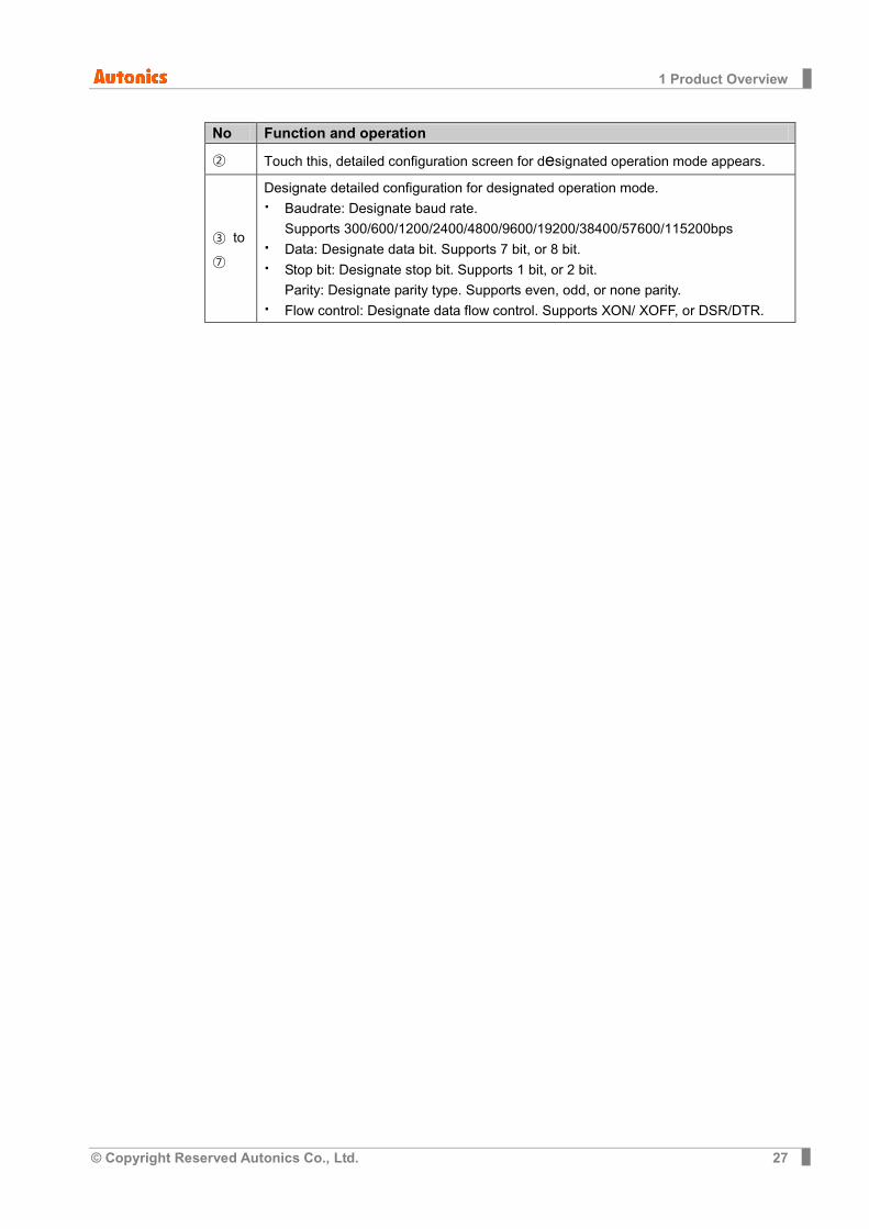
NoUse: Displayed only not using appropriate CH. ② Touch this, detailed configuration screen for designated operation mode appears.
③ to ⑦
Designate detailed configuration for designated operation mode. Baudrate: Designate baud rate.
Supports 300/600/1200/2400/4800/9600/19200/38400/57600/115200bps Data: Designate data bit. Supports 7 bit, or 8 bit. Stop bit: Designate stop bit. Supports 1 bit, or 2 bit.
Parity: Designate parity type. Supports even, odd, or none parity. Flow control: Designate data flow control. Supports XON/ XOFF, or DSR/DTR.

1 Product Overview
© Copyright Reserved Autonics Co., Ltd. 23
1.3.4 Color type This menu displays connected device to RS232C, RS422 port of GP/LP. You can designate station and connected port by each channel.
No Function Operation
① CH1 configuration
Displays connected device and connect port for CH1. Touch this to select one from downloaded protocol in GP Editor, EDITOR, PRINTER, BARCODE, UNIVERSAL, or DEFAULT protocol and designate connect port. (Select between RS232C/RS422 or RS232C-A / RS232C-B). Depending on CH1 setting, CH2 may be changed as ‘No Use’.
② CH2 configuration
Displays connected device and connect port for CH2. Touch this to select one from downloaded protocol in GP Editor, EDITOR, PRINTER, BARCODE, UNIVERSAL, or DEFAULT protocol and designate connect port. (Select between RS232C/RS422 or RS232C-A / RS232C-B). If CH1 is SLAVE, MONITOR does not appear.
③ GP station configuration touch key
Touch this and input key pad for station appears. Station set range: 0 to 31

1 Product Overview
24 © Copyright Reserved Autonics Co., Ltd.
(1) In case of using only CH1 configured in GP Editor
No Item Operation with touching
① Displays CH1 protocol Rotates in order as downloaded protocol in GP Editor →
EDITOR → PRINTER → BARCODE → UNIVERSAL
→ DEFAULT protocol
② Displays CH1 connect port
(Designates automatically
as non-using port in ④)
Each of RS422 / RS232C interface type: RS422 PORT ↔ RS232C PORT
Two ports of RS232C interface type:
RS232C A PORT ↔ RS232C B PORT
③ Displays CH2 protocol (as EDITOR for default)
Rotates in order as EDITOR → PRINTER → BARCODE
→ MONITOR → UNIVERSAL → No Use
④ Displays CH2 connect port
(Designates automatically as non-using port in ②)
Each of RS422 / RS232C interface type: RS422 PORT ↔ RS232C PORT
Two ports of RS232C interface type:
RS232C A PORT ↔ RS232C B PORT
⑤⑥ Communication configuration by each channel
Moves communication configuration setting window for selected connected device. You can designate baudrate, data bit, parity, stop bit, and flow control for each channel. If CH1 is as NoUse, it is not able to communication configuration.

1 Product Overview
© Copyright Reserved Autonics Co., Ltd. 25
(2) In case of using only CH2 configured in GP Editor
No Item Operation with touching
① Displays CH1 protocol Rotates in order as NoUse → EDITOR →
PRINTER → BARCODE → UNIVERSAL → DEFAULT protocol.
② Displays CH1 connect port
(Designates automatically as
non-using port in ④)
Each of RS422 / RS232C interface type: RS422 PORT ↔ RS232C PORT
Two ports of RS232C interface type:
RS232C A PORT ↔ RS232C B PORT
③ Displays CH2 protocol (as downloaded protocol for default)
Rotates in order as downloaded protocol in GP
Editor → EDITOR → PRINTER → BARCODE
④ Displays CH2 connect port
(Designates automatically as
non-using port in ②)
Each of RS422 / RS232C interface type: RS422 PORT ↔ RS232C PORT
Two ports of RS232C interface type:
RS232C A PORT ↔ RS232C B PORT
⑤⑥ Communication configuration by each channel
Moves communication configuration setting window for selected connected device. You can designate baudrate, data bit, parity, stop bit, and flow control for each channel. If CH1 is as NoUse, it is not able to communication configuration.

1 Product Overview
26 © Copyright Reserved Autonics Co., Ltd.
(3) CH1/ CH2 details configuration
No Function and operation
①
Designate the device to be connected for CH1, CH2. CH1, CH2 protocol: Communication mode for set PLC by GP and GP Editor by
each port. EDITOR: I/O mode for downloading user-designed data from GP Editor PRINTER: Print mode for printing alarm history of GP
Refer to ‘3.5.3 PRINTER communication configuration’.
BARCODE: Input mode for reading data from barcode Refer to ‘3.5.2 Barcode reader communication configuration ’.
MONITOR: Available only in CH2. Monitoring mode for PLC which is connected to GP from PC directly. GP is as transmitter by transmitting data from PC to PLC and data from PLC to PC. In case of MITSUBISHI FX-series, editor mode is available for monitoring.
NoUse: Displayed only not using appropriate CH.
1 Product Overview
© Copyright Reserved Autonics Co., Ltd. 27
No Function and operation
② Touch this, detailed configuration screen for designated operation mode appears.
③ to ⑦
Designate detailed configuration for designated operation mode. Baudrate: Designate baud rate.
Supports 300/600/1200/2400/4800/9600/19200/38400/57600/115200bps Data: Designate data bit. Supports 7 bit, or 8 bit. Stop bit: Designate stop bit. Supports 1 bit, or 2 bit.
Parity: Designate parity type. Supports even, odd, or none parity. Flow control: Designate data flow control. Supports XON/ XOFF, or DSR/DTR.
1 Product Overview
28 © Copyright Reserved Autonics Co., Ltd.
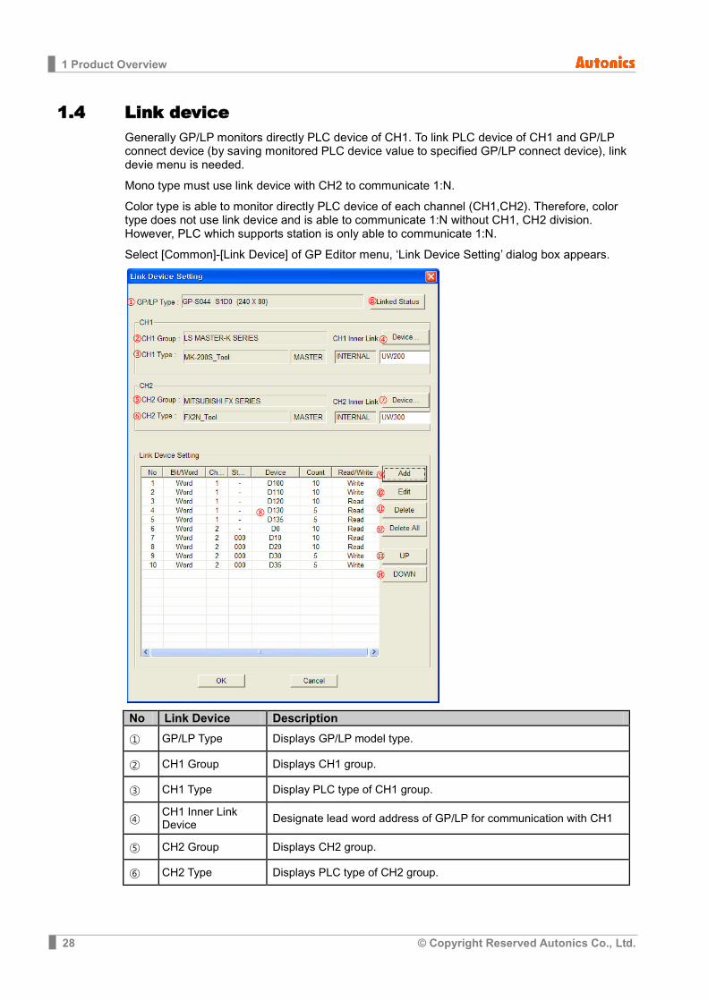
1.4 Link device Generally GP/LP monitors directly PLC device of CH1. To link PLC device of CH1 and GP/LP connect device (by saving monitored PLC device value to specified GP/LP connect device), link devie menu is needed.
Mono type must use link device with CH2 to communicate 1:N.
Color type is able to monitor directly PLC device of each channel (CH1,CH2). Therefore, color type does not use link device and is able to communicate 1:N without CH1, CH2 division. However, PLC which supports station is only able to communicate 1:N.
Select [Common]-[Link Device] of GP Editor menu, ‘Link Device Setting’ dialog box appears.
No Link Device Description ① GP/LP Type Displays GP/LP model type.
② CH1 Group Displays CH1 group.
③ CH1 Type Display PLC type of CH1 group.
④ CH1 Inner Link Device Designate lead word address of GP/LP for communication with CH1
⑤ CH2 Group Displays CH2 group.
⑥ CH2 Type Displays PLC type of CH2 group.
1 Product Overview
© Copyright Reserved Autonics Co., Ltd. 29
No Link Device Description
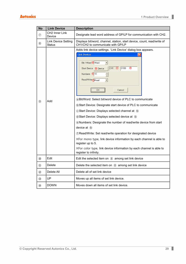
⑦ CH2 Inner Link Device Designate lead word address of GP/LP for communication with CH2.
⑧ Link Device Setting Status
Displays bit/word, channel, station, start device, count, read/write of CH1/CH2 to communicate with GP/LP
⑨ Add
Adds link device settings. ‘Link Device’ dialog box appears.
Bit/Word: Select bit/word device of PLC to communicate
Start Device: Designate start device of PLC to communicate
Start Device: Displays selected channel at
Start Device: Displays selected device at
Numbers: Designate the number of read/write device from start
device at
Read/Write: Set read/write operation for designated device
※For mono type, link device information by each channel is able to register up to 5.
※For color type, link device information by each channel is able to register to infinity.
⑩ Edit Edit the selected item on ⑧ among set link device
⑪ Delete Delete the selected item on ⑧ among set link device
⑫ Delete All Delete all of set link device
⑬ UP Moves up all items of set link device.
⑭ DOWN Moves down all items of set link device.
1 Product Overview
30 © Copyright Reserved Autonics Co., Ltd.
No Link Device Description
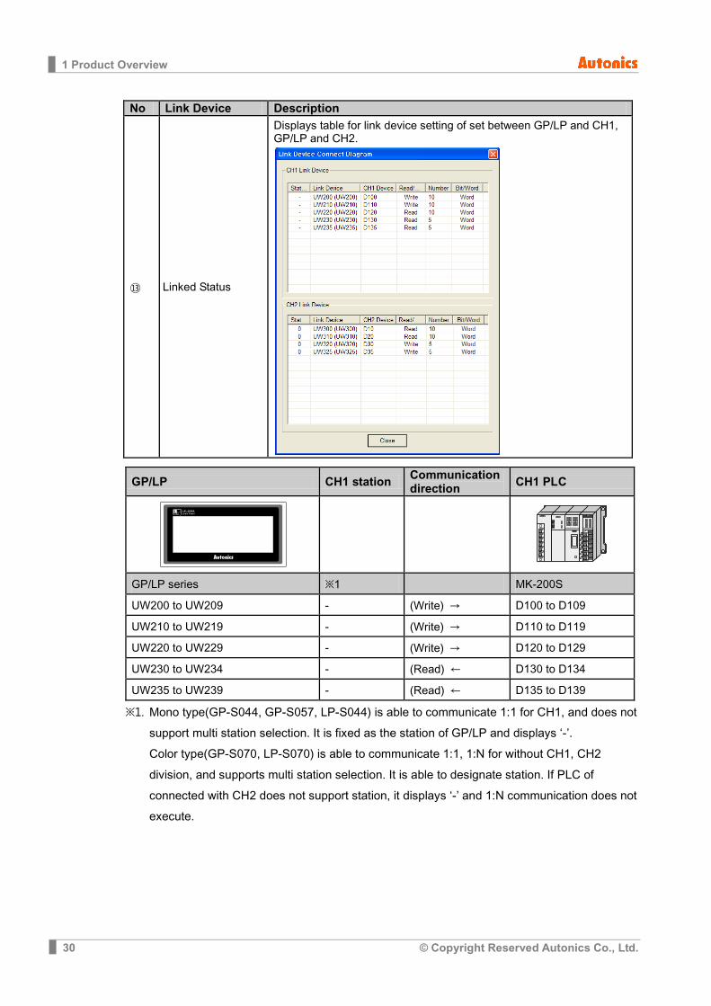
⑬ Linked Status
Displays table for link device setting of set between GP/LP and CH1, GP/LP and CH2.
GP/LP CH1 station Communication direction CH1 PLC
GP/LP series ※1 MK-200S
UW200 to UW209 - (Write) → D100 to D109
UW210 to UW219 - (Write) → D110 to D119
UW220 to UW229 - (Write) → D120 to D129
UW230 to UW234 - (Read) ← D130 to D134
UW235 to UW239 - (Read) ← D135 to D139
※1. Mono type(GP-S044, GP-S057, LP-S044) is able to communicate 1:1 for CH1, and does not support multi station selection. It is fixed as the station of GP/LP and displays ‘-’. Color type(GP-S070, LP-S070) is able to communicate 1:1, 1:N for without CH1, CH2 division, and supports multi station selection. It is able to designate station. If PLC of connected with CH2 does not support station, it displays ‘-’ and 1:N communication does not execute.
1 Product Overview
© Copyright Reserved Autonics Co., Ltd. 31
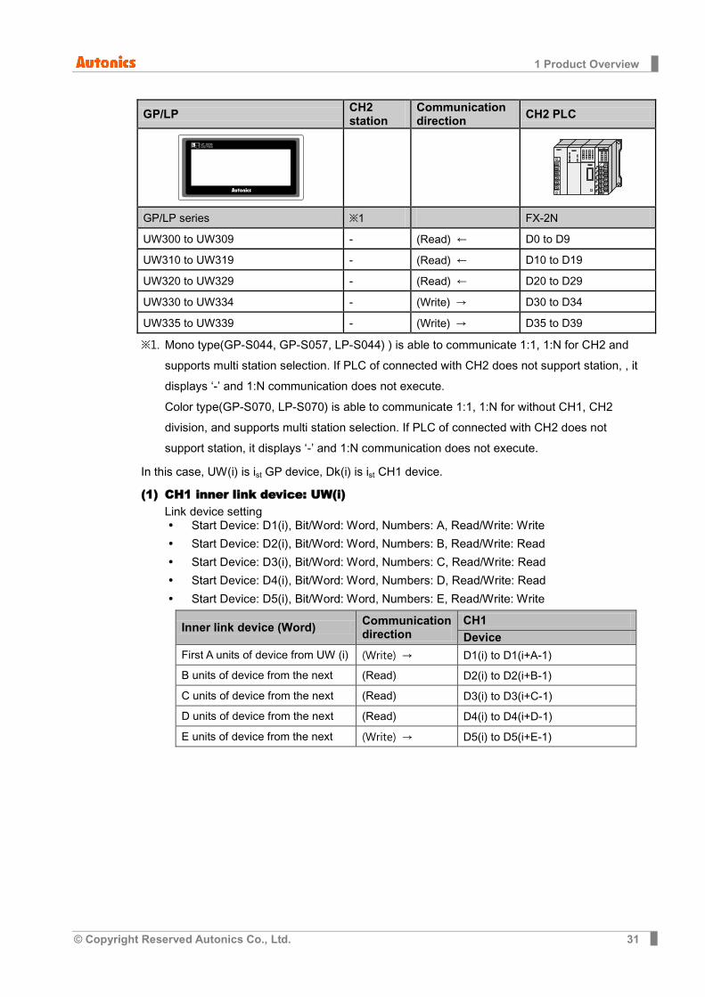
GP/LP CH2 station
Communication direction CH2 PLC
GP/LP series ※1 FX-2N
UW300 to UW309 - (Read) ← D0 to D9
UW310 to UW319 - (Read) ← D10 to D19
UW320 to UW329 - (Read) ← D20 to D29
UW330 to UW334 - (Write) → D30 to D34
UW335 to UW339 - (Write) → D35 to D39
※1. Mono type(GP-S044, GP-S057, LP-S044) ) is able to communicate 1:1, 1:N for CH2 and supports multi station selection. If PLC of connected with CH2 does not support station, , it displays ‘-’ and 1:N communication does not execute. Color type(GP-S070, LP-S070) is able to communicate 1:1, 1:N for without CH1, CH2 division, and supports multi station selection. If PLC of connected with CH2 does not support station, it displays ‘-’ and 1:N communication does not execute.
In this case, UW(i) is ist GP device, Dk(i) is ist CH1 device.
(1) CH1 inner link device: UW(i) Link device setting Start Device: D1(i), Bit/Word: Word, Numbers: A, Read/Write: Write
Start Device: D2(i), Bit/Word: Word, Numbers: B, Read/Write: Read
Start Device: D3(i), Bit/Word: Word, Numbers: C, Read/Write: Read
Start Device: D4(i), Bit/Word: Word, Numbers: D, Read/Write: Read
Start Device: D5(i), Bit/Word: Word, Numbers: E, Read/Write: Write
Inner link device (Word) Communication direction
CH1 Device
First A units of device from UW (i) (Write) → D1(i) to D1(i+A-1)
B units of device from the next (Read) ← D2(i) to D2(i+B-1)
C units of device from the next (Read) ← D3(i) to D3(i+C-1)
D units of device from the next (Read) ← D4(i) to D4(i+D-1)
E units of device from the next (Write) → D5(i) to D5(i+E-1)
1 Product Overview
32 © Copyright Reserved Autonics Co., Ltd.
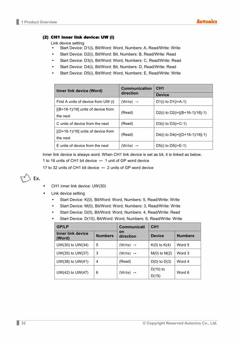
(2) CH1 inner link device: UW (i) Link device setting Start Device: D1(i), Bit/Word: Word, Numbers: A, Read/Write: Write
Start Device: D2(i), Bit/Word: Bit, Numbers: B, Read/Write: Read
Start Device: D3(i), Bit/Word: Word, Numbers: C, Read/Write: Read
Start Device: D4(i), Bit/Word: Bit, Numbers: D, Read/Write: Read
Start Device: D5(i), Bit/Word: Word, Numbers: E, Read/Write: Write
Inner link device (Word) Communication direction
CH1
Device
First A units of device from UW (i) (Write) → D1(i) to D1(i+A-1)
[(B+16-1)/16] units of device from the next
(Read) ← D2(i) to D2(i+[(B+16-1)/16]-1)
C units of device from the next (Read) ← D3(i) to D3(i+C-1)
[(D+16-1)/16] units of device from the next
(Read) ← D4(i) to D4(i+[(D+16-1)/16]-1)
E units of device from the next (Write) → D5(i) to D5(i+E-1)
Inner link device is always word. When CH1 link device is set as bit, it is linked as below.
1 to 16 units of CH1 bit device ↔ 1 unit of GP word device
17 to 32 units of CH1 bit device ↔ 2 units of GP word device
CH1 inner link device: UW(30)
Link device setting
Start Device: K(0), Bit/Word: Word, Numbers: 5, Read/Write: Write
Start Device: M(0), Bit/Word: Word, Numbers: 3, Read/Write: Write
Start Device: D(0), Bit/Word: Word, Numbers: 4, Read/Write: Read
Start Device: D(10), Bit/Word: Word, Numbers: 6, Read/Write: Write
GP/LP Communication direction
CH1
Inner link device (Word) Numbers Device Numbers
UW(30) to UW(34) 5 (Write) → K(0) to K(4) Word 5
UW(35) to UW(37) 3 (Write) → M(0) to M(2) Word 3
UW(38) to UW(41) 4 (Read) ← D(0) to D(3) Word 4
UW(42) to UW(47) 6 (Write) → D(10) to D(15)
Word 6
1 Product Overview
© Copyright Reserved Autonics Co., Ltd. 33
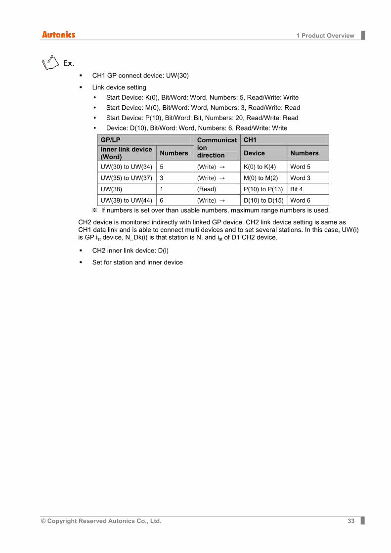
CH1 GP connect device: UW(30)
Link device setting
Start Device: K(0), Bit/Word: Word, Numbers: 5, Read/Write: Write
Start Device: M(0), Bit/Word: Word, Numbers: 3, Read/Write: Read
Start Device: P(10), Bit/Word: Bit, Numbers: 20, Read/Write: Read
Device: D(10), Bit/Word: Word, Numbers: 6, Read/Write: Write
GP/LP Communication direction
CH1 Inner link device (Word) Numbers Device Numbers
UW(30) to UW(34) 5 (Write) → K(0) to K(4) Word 5
UW(35) to UW(37) 3 (Write) → M(0) to M(2) Word 3
UW(38) 1 (Read) ← P(10) to P(13) Bit 4
UW(39) to UW(44) 6 (Write) → D(10) to D(15) Word 6 ※ If numbers is set over than usable numbers, maximum range numbers is used.
CH2 device is monitored indirectly with linked GP device. CH2 link device setting is same as CH1 data link and is able to connect multi devices and to set several stations. In this case, UW(i) is GP ist device, N_Dk(i) is that station is N, and ist of D1 CH2 device.
CH2 inner link device: D(i)
Set for station and inner device

1 Product Overview
34 © Copyright Reserved Autonics Co., Ltd.
(3) Station N Start Device: N_D1(i), Bit/Word: Word, Numbers: AN
Start Device: N-D2(i), Bit/Word: Word, Numbers: BN
Start Device: N-D3(i), Bit/Word: Word, Numbers: CN
Start Device: N-D4(i), Bit/Word: Word, Numbers: DN
Start Device: N-D5(i), Bit/Word: Word, Numbers: EN
GP/LP Communication direction
CH2
Inner link device (Word) Station Device
First A0 units of device from D(i) Read/Write
0
0_D1(i) to 0_D1(i+A0-1)
B0 units of device from the next Read/Write 0_D2(i) to 0_D2(i+B0-1)
C0 units of device from the next Read/Write 0_D3(i) to 0_D3(i+C0-1)
D0 units of device from the next Read/Write 0_D4(i) to 0_D4(i+D0-1)
E0 units of device from the next Read/Write 0_D5(i) to 0_D5(i+E0-1)
A1units of device from the next Read/Write
1
1_D1(i) to 1_D1(i+A1-1)
B1units of device from the next Read/Write 1_D2(i) to 1_D2(i+B1-1)
C1units of device from the next Read/Write 1_D3(i) to 1_D3(i+C1-1)
D1units of device from the next Read/Write 1_D4(i) to 1_D4(i+D1-1)
E1units of device from the next Read/Write 1_D5(i) to 1_D5(i+E1-1)
… … … …
A31units of device from the next Read/Write
31
31_D1(i) to 31_D1(i+A31-1)
B31units of device from the next Read/Write 31_D2(i) to 31_D2(i+B31-1)
C31units of device from the next Read/Write 31_D3(i) to 31_D3(i+C31-1)
D31units of device from the next Read/Write 31_D4(i) to 31_D4(i+D31-1)
E31units of device from the next Read/Write 31_D5(i) to 31_D5(i+E31-1)
If Bit/Word setting is Bit, CH1 link device has same link structure as bit’s and communicates with GP/LP.
- CH2 inner link device:UW(30)
- Set for station and link device
1 Product Overview
© Copyright Reserved Autonics Co., Ltd. 35
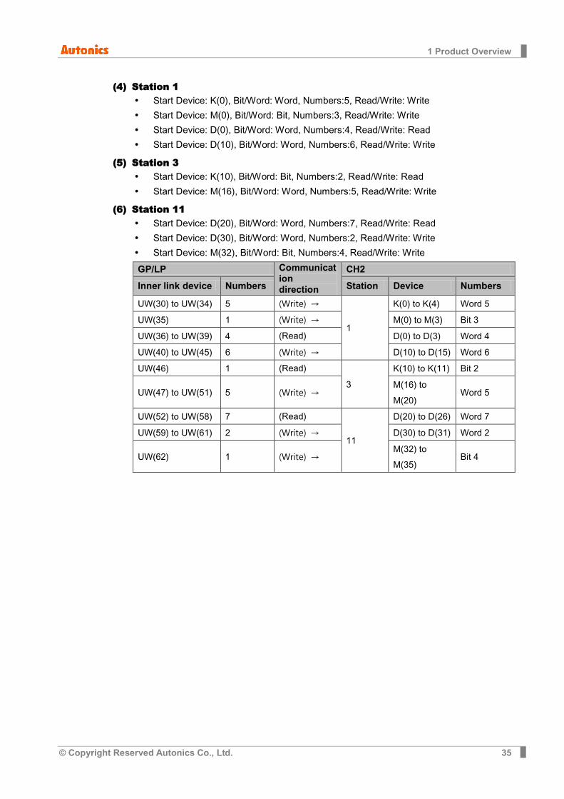
(4) Station 1 Start Device: K(0), Bit/Word: Word, Numbers:5, Read/Write: Write
Start Device: M(0), Bit/Word: Bit, Numbers:3, Read/Write: Write
Start Device: D(0), Bit/Word: Word, Numbers:4, Read/Write: Read
Start Device: D(10), Bit/Word: Word, Numbers:6, Read/Write: Write
(5) Station 3 Start Device: K(10), Bit/Word: Bit, Numbers:2, Read/Write: Read
Start Device: M(16), Bit/Word: Word, Numbers:5, Read/Write: Write
(6) Station 11 Start Device: D(20), Bit/Word: Word, Numbers:7, Read/Write: Read
Start Device: D(30), Bit/Word: Word, Numbers:2, Read/Write: Write
Start Device: M(32), Bit/Word: Bit, Numbers:4, Read/Write: Write
GP/LP Communication direction
CH2
Inner link device Numbers Station Device Numbers
UW(30) to UW(34) 5 (Write) →
1
K(0) to K(4) Word 5
UW(35) 1 (Write) → M(0) to M(3) Bit 3
UW(36) to UW(39) 4 (Read) ← D(0) to D(3) Word 4
UW(40) to UW(45) 6 (Write) → D(10) to D(15) Word 6
UW(46) 1 (Read) ←
3
K(10) to K(11) Bit 2
UW(47) to UW(51) 5 (Write) → M(16) to M(20)
Word 5
UW(52) to UW(58) 7 (Read) ←
11
D(20) to D(26) Word 7
UW(59) to UW(61) 2 (Write) → D(30) to D(31) Word 2
UW(62) 1 (Write) → M(32) to M(35)
Bit 4
1 Product Overview
36 © Copyright Reserved Autonics Co., Ltd.
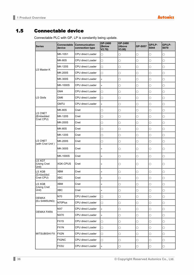
1.5 Connectable device Connectable PLC with GP, LP is constantly being update.
Series Connectable device
Communication connection type
GP-2480 (Below V2.70)
GP-2480 (Above V3.00)
GP-S057 GP/LP-S044
GP/LP-S070
LS Master-K
MK-10S1 CPU direct Loader
MK-80S CPU direct Loader
MK-120S CPU direct Loader
MK-200S CPU direct Loader
MK-300S CPU direct Loader ×
MK-1000S CPU direct Loader ×
LS Glofa
GM4 CPU direct Loader
GM6 CPU direct Loader
GM7U CPU direct Loader ×
LS CNET (Embedded Cnet CPU)
MK-80S Cnet
MK-120S Cnet
MK-200S Cnet
LS CNET (with Cnet Unit )
MK-80S Cnet
MK-120S Cnet
MK-200S Cnet
MK-300S Cnet ×
MK-1000S Cnet ×
LS XGT (Using Cnet Unit)
XGK-CPUS Cnet ×
LS XGB (Embedded Cnet CPU)
XBM Cnet ×
XBC Cnet ×
LS XGB (Using Cnet Unit)
XBM Cnet ×
XBC Cnet ×
OEMAX (Ex SAMSUNG)
N70 CPU direct Loader
N70Plus CPU direct Loader
OEMAX FARA NX7 CPU direct Loader ×
NX70 CPU direct Loader ×
MITSUBISHI FX
FX1S CPU direct Loader
FX1N CPU direct Loader
FX2N CPU direct Loader
FX2NC CPU direct Loader
FX3U CPU direct Loader ×

1 Product Overview
© Copyright Reserved Autonics Co., Ltd. 37
Series Connectable device
Communication connection type
GP-2480 (Below V2.70)
GP-2480 (Above V3.00)
GP-S057 GP/LP-S044
GP/LP-S070
MITSUBISHI Q(with Cnet Unit)
Q00J Cnet ×
Q00 Cnet ×
Q01 Cnet ×
Q02 Cnet ×
Q02H Cnet ×
Q06H Cnet ×
Q12H Cnet ×
Q25H Cnet ×
NAIS FP
FP0-C10 CPU direct Loader
FP0-C14 CPU direct Loader
FP0-C16 CPU direct Loader
FP0-C32 CPU direct Loader
FPG-C24R2 CPU direct Loader
FPG-C32T CPU direct Loader
FPG-C32T2 CPU direct Loader
FP0R-C10 CPU direct Loader ×
FP0R-C14 CPU direct Loader ×
FP0R-C16 CPU direct Loader ×
FP0R-C32 CPU direct Loader ×
FP0R-T32 CPU direct Loader ×
FP0R-F32 CPU direct Loader ×
SIEMENS SIMATIC S7-200
CPU221 CPU direct Loader ×
CPU222 CPU direct Loader ×
CPU224 CPU direct Loader ×
CPU224XP CPU direct Loader ×
CPU224XPsi CPU direct Loader ×
CPU226 CPU direct Loader ×
SIEMENS SIMATIC S7-300
CPU312 CPU direct Loader × ×
CPU312C CPU direct Loader × ×
CPU313C CPU direct Loader × ×
CPU313C-2 CPU direct Loader × ×
CPU314 CPU direct Loader × ×
CPU314C-2 CPU direct Loader × ×
CPU315-2 CPU direct Loader × ×

1 Product Overview
38 © Copyright Reserved Autonics Co., Ltd.
Series Connectable device
Communication connection type
GP-2480 (Below V2.70)
GP-2480 (Above V3.00)
GP-S057 GP/LP-S044
GP/LP-S070
CPU317-2 CPU direct Loader × ×
CPU319-3 CPU direct Loader × ×
Allen-Bradley
MicroLogix 1000 CPU direct Loader ×
MicroLogix 1200 CPU direct Loader ×
MicroLogix 1500 CPU direct Loader ×
OMRON SYSMAC C CPM1A CPU direct Loader
OMRON temperature controller
E5AN Modbus
E5AR Modbus
E5CN Modbus
E5EN Modbus
E5ER Modbus
AUTONICS
MT Series
Dedicated communication
Modbus × ×
Modbus(TYPE A)※1 × ×
MP Series Dedicated communication
THD Series Modbus ×
Modbus(TYPE A)※1 × ×
TZ Series Dedicated communication
TK Series Modbus × ×
Modbus(TYPE A)※1 × ×
TM Series Modbus × ×
Modbus(TYPE A)※1 × ×
CT Series Modbus × ×
Modbus(TYPE A)※1 × ×
DS/DA Series Modbus(TYPEA) × ×
ARM Seriese Modbus(TYPEA) × ×
LP-S044, LP-S070 CPU ×
KONICS
DPU Series Modbus × ×
Modbus(TYPE A)※1 × ×
KRN50 Modbus × ×
Modbus(TYPE A)※1 × ×
DELTA DTB Series Modbus ×
Modbus(TYPE A)※1 × ×
DANFOSS FC Series Modbus × × × × ×
1 Product Overview
© Copyright Reserved Autonics Co., Ltd. 39
Series Connectable device
Communication connection type
GP-2480 (Below V2.70)
GP-2480 (Above V3.00)
GP-S057 GP/LP-S044
GP/LP-S070
Modbus(TYPE A)※1 × ×
UNIVERSAL UNIVERSAL Modbus(Slave)
MODBUS MASTER
MODBUS MASTER Modbus(Master)※1 × ×
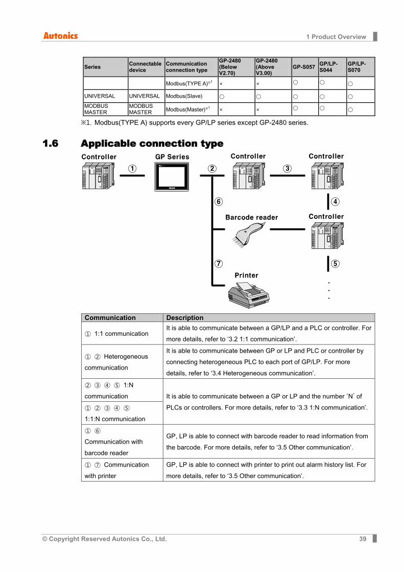
※1. Modbus(TYPE A) supports every GP/LP series except GP-2480 series.
1.6 Applicable connection type
Communication Description
① 1:1 communication It is able to communicate between a GP/LP and a PLC or controller. For more details, refer to ‘3.2 1:1 communication’.
① ② Heterogeneous communication
It is able to communicate between GP or LP and PLC or controller by connecting heterogeneous PLC to each port of GP/LP. For more details, refer to ‘3.4 Heterogeneous communication’.
② ③ ④ ⑤ 1:N communication It is able to communicate between a GP or LP and the number ‘N’ of
PLCs or controllers. For more details, refer to ‘3.3 1:N communication’. ① ② ③ ④ ⑤ 1:1:N communication
① ⑥ Communication with barcode reader
GP, LP is able to connect with barcode reader to read information from the barcode. For more details, refer to ‘3.5 Other communication’.
① ⑦ Communication with printer
GP, LP is able to connect with printer to print out alarm history list. For more details, refer to ‘3.5 Other communication’.

1 Product Overview
40 © Copyright Reserved Autonics Co., Ltd.
2 GP Editor Data Download
© Copyright Reserved Autonics Co., Ltd. 41
2 GP Editor Data Download You can download created data from GP Editor which is drawing software in PC to GP, LP.
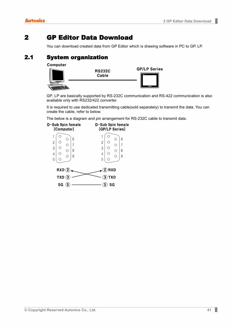
2.1 System organization
GP, LP are basically supported by RS-232C communication and RS-422 communication is also available only with RS232/422 converter.
It is required to use dedicated transmitting cable(sold separately) to transmit the data. You can create the cable, refer to below.
The below is a diagram and pin arrangement for RS-232C cable to transmit data.
2 GP Editor Data Download
42 © Copyright Reserved Autonics Co., Ltd.
2.2 Communication configuration There are two configurations to transmitting data. First is GP Editor configuration, and second is GP, LP configuration.
2.2.1 GP Editor configuration This manual describes basic communication configuraion of GP Editor and serial communication. For more details, refer to ‘GP Editor user manual’.
Through GP Editor which is dedicated drawn software, you can download the data to GP/LP.
To download data editing in GP Editor to PLC, you should designate as following.
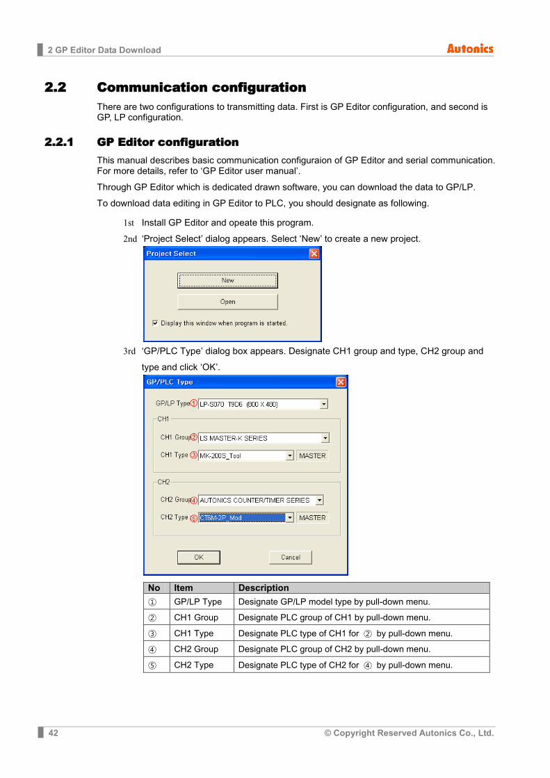
1st Install GP Editor and opeate this program. 2nd ‘Project Select’ dialog appears. Select ‘New’ to create a new project.
3rd ‘GP/PLC Type’ dialog box appears. Designate CH1 group and type, CH2 group and
type and click ‘OK’.
No Item Description
① GP/LP Type Designate GP/LP model type by pull-down menu.
② CH1 Group Designate PLC group of CH1 by pull-down menu.
③ CH1 Type Designate PLC type of CH1 for ② by pull-down menu.
④ CH2 Group Designate PLC group of CH2 by pull-down menu.
⑤ CH2 Type Designate PLC type of CH2 for ④ by pull-down menu.
2 GP Editor Data Download
© Copyright Reserved Autonics Co., Ltd. 43
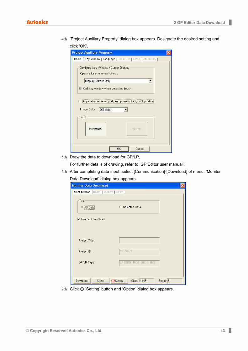
4th ‘Project Auxiliary Property’ dialog box appears. Designate the desired setting and click ‘OK’.
5th Draw the data to download for GP/LP.
For further details of drawing, refer to ‘GP Editor user manual’.
6th After completing data input, select [Communication]-[Download] of menu. ‘Monitor Data Download’ dialog box appears.
7th Click ① ‘Setting’ button and ‘Option’ dialog box appears.

2 GP Editor Data Download
44 © Copyright Reserved Autonics Co., Ltd.
8th Designate the connected communication port of PC to GP/LP and synchronize baud rate between GP/LP and GP Editor. Click ‘OK’.
Baudrate default is 115200 bps at GP/LP and GP Editor.
9th Click ‘Download’ and ‘Data Transmission’ dialog box appears and displays download processing statues when communication configuration is correctly synchronized.
10th After completing download, ‘Success to download’ message appears.
If there is communication setting error or other error, communication is not available. After the time, GP Editor displays communication error message.

2 GP Editor Data Download
© Copyright Reserved Autonics Co., Ltd. 45
2.2.2 GP, LP configuration This chaper is described by each of RS422/RS232C serial interface type.
For more details, refer to ‘GP Editor user manual’.
2.2.2.1 Mono type
1st Enter system setting menu.
Touch left-upper point as default position of system setting menu.
2nd Select [SET ENVIRONMENT]-[PLC SETTING].
3rd CH2 protocol is set as ‘EDITOR’ and CH2 connection port is set as ‘RS232C’ as default. (For donwloading drawn data of GP Editor to GP/LP, use ‘RS232C’ port. In case of using RS232/422 converter, you can download it with RS422 port.)
4th If it is not configured as ‘EDITOR’ for CH2 protocol, touch protocol display item to set ‘EDITOR’ as following figure.
Protocol display rotates in order as No Use→EDITOR→PRINTER→BARCODE→ MONITOR with touching.

2 GP Editor Data Download
46 © Copyright Reserved Autonics Co., Ltd.
5th If it is not configured as ‘RS232C’ for CH2 connect port even though ‘EDITOR’ for CH2 protocol is configured, touch connect port display item to set ‘RS232C’ as following figure. Connect port display rotates in order as RS422↔RS232C with touching.
6th After completing communication configuration, you should exit system setting menu and switch user screen to communicate GP Editor. Touch ‘Menu’, current setting values are saved and it returns to previous menu.
Touch ‘Exit’, current setting values are saved and it returns to user screen.
2 GP Editor Data Download
© Copyright Reserved Autonics Co., Ltd. 47
2.2.2.2 Color type
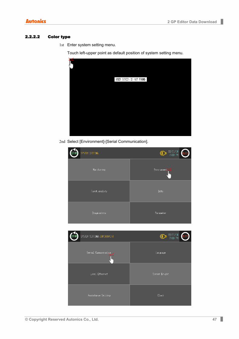
1st Enter system setting menu.
Touch left-upper point as default position of system setting menu.
2nd Select [Environment]-[Serial Communication].

2 GP Editor Data Download
48 © Copyright Reserved Autonics Co., Ltd.
3rd CH2 protocol is set as ‘EDITOR’ and CH2 connection port is set as ‘RS232C’ as default. (For donwloading drawn data of GP Editor to GP/LP, use ‘RS232C’ port. In case of using RS232/422 converter, you can download it with RS422 port.)

2 GP Editor Data Download
© Copyright Reserved Autonics Co., Ltd. 49
4th If it is not configured as ‘EDITOR’ for CH2 protocol, touch protocol display item to set ‘EDITOR’ as following figure. Protocol display rotates in order as No Use→EDITOR→
PRINTER→BARCODE→MONITOR with touching.
2 GP Editor Data Download
50 © Copyright Reserved Autonics Co., Ltd.
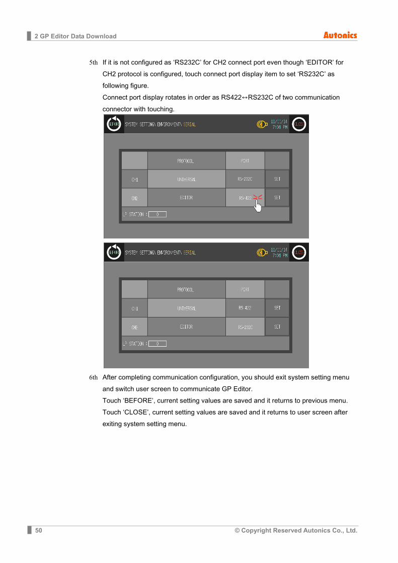
5th If it is not configured as ‘RS232C’ for CH2 connect port even though ‘EDITOR’ for CH2 protocol is configured, touch connect port display item to set ‘RS232C’ as following figure. Connect port display rotates in order as RS422↔RS232C of two communication connector with touching.
6th After completing communication configuration, you should exit system setting menu and switch user screen to communicate GP Editor. Touch ‘BEFORE’, current setting values are saved and it returns to previous menu. Touch ‘CLOSE’, current setting values are saved and it returns to user screen after exiting system setting menu.
3 PLC Communication
© Copyright Reserved Autonics Co., Ltd. 51
3 PLC Communication
3.1 Communication configuration For communicating GP/LP with PLC, you should designate detail configuration as following before communicating. This chapter is described by LS Master-K200 and Autonics CT6M-2P as example.
3.1.1 GP Editor configuration Through GP Editor which is dedicated drawn software, you can download the data to GP/LP.
To download data editing in GP Editor to PLC, you should designate connected PLC group, type, and communication type.
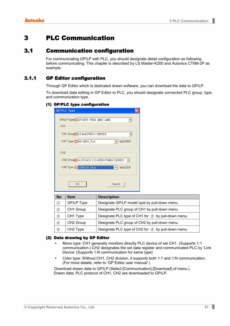
(1) GP/PLC type configuration
No Item Description
① GP/LP Type Designate GP/LP model type by pull-down menu.
② CH1 Group Designate PLC group of CH1 by pull-down menu.
③ CH1 Type Designate PLC type of CH1 for ② by pull-down menu.
④ CH2 Group Designate PLC group of CH2 by pull-down menu.
⑤ CH2 Type Designate PLC type of CH2 for ④ by pull-down menu.
(2) Data drawing by GP Editor Mono type: CH1 generally monitors directly PLC device of set CH1. (Supports 1:1
communication.) CH2 designates the set data register and communicated PLC by ‘Link Device’ (Supports 1:N communication for same type)
Color type: Without CH1, CH2 division, it supports both 1:1 and 1:N communication. (For more details, refer to ‘GP Editor user manual'.)
Download drawn data to GP/LP (Select [Communication]-[Download] of menu.). Drawn data, PLC protocol of CH1, CH2 are downloaded to GP/LP.

3 PLC Communication
52 © Copyright Reserved Autonics Co., Ltd.
3.1.2 GP, LP configuration 3.1.2.1 Mono type
Before downloading drawn data from GP Editor: Synchronize communication configurations of between GP/LP and GP Editor.
After downloading drawn data from GP Editor: After downloading PLC protocol of CH1, CH2 which is designated from GP Editor to GP/LP, it starts communication between the specified PLC and GP/LP through communication configuration.
1st Enter system setting menu. Touch left-upper point as default position of system setting menu.
2nd Select [SET ENVIRONMENT]-[PLC SETTING].
3rd CH1 protocol is set as following the designated PLC from GP Editor. CH1 is designated as LS MASTER-K200 and CH2 is designated as AUTONICS CT6M-2P from GP Editor.

3 PLC Communication
© Copyright Reserved Autonics Co., Ltd. 53
4th After downloading CH1 protocol is set as downloaded protocol ‘LS MASTER K200’ and CH2 protocol is set as ‘EDITOR’. Touch protocol display item of CH2 to set as downloaded protocol ‘AUTONICS CT6M-2P’.
5th To communicate between GP/LP and LS Master-K200 for CH1, desigante the
connect port for the specific PLC and use the dedicated cable. (Refer to ‘4 Communication Cable By Device’) In case of LS Master-K200, it uses CPU module RS232C port. Set connect port item of CH1 as ‘RS232C’. Connect port display rotates in order as RS422↔RS232C with touching.
6th Synchronize the station of between GP/LP and LS Master-K200. Touch CH1 station
item and input key pad appears. Enter the same station of LS Master-K200.
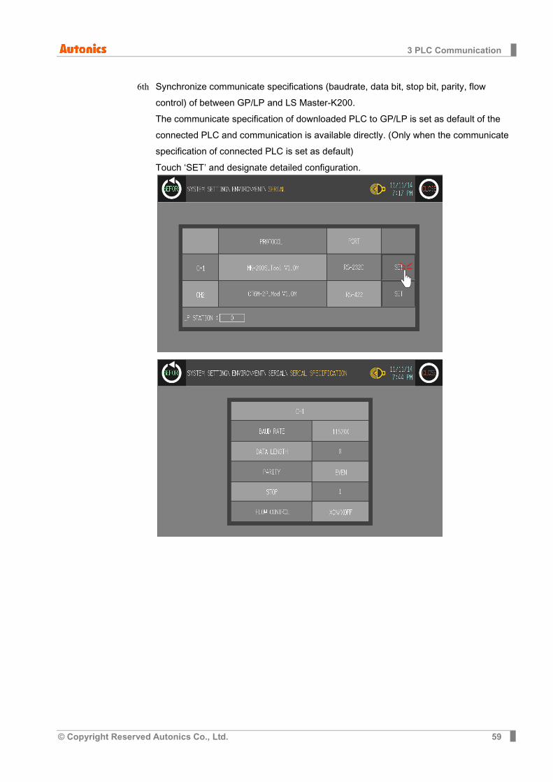
7th Synchronize communicate specifications (baudrate, data bit, stop bit, parity, flow
control) of between GP/LP and LS Master-K200. The communicate specification of downloaded PLC to GP/LP is set as default of the connected PLC and communication is available directly. (Only when the communicate specification of connected PLC is set as default) Touch ‘CH1’ and detailed configuration screen is switched. Designate detailed configuration.
3 PLC Communication
54 © Copyright Reserved Autonics Co., Ltd.
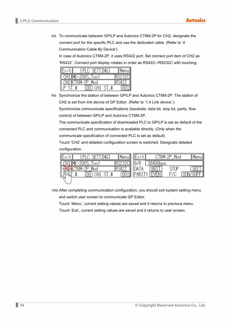
8th To communicate between GP/LP and Autonics CT6M-2P for CH2, designate the connect port for the specific PLC and use the dedicated cable. (Refer to ‘4 Communication Cable By Device’) In case of Autonics CT6M-2P, it uses RS422 port. Set connect port item of CH2 as ‘RS422’. Connect port display rotates in order as RS422↔RS232C with touching.
9th Synchronize the station of between GP/LP and Autonics CT6M-2P. The station of
CH2 is set from link device of GP Editor. (Refer to ‘1.4 Link device’.) Synchronize communicate specifications (baudrate, data bit, stop bit, parity, flow control) of between GP/LP and Autonics CT6M-2P. The communicate specification of downloaded PLC to GP/LP is set as default of the connected PLC and communication is available directly. (Only when the communicate specification of connected PLC is set as default) Touch ‘CH2’ and detailed configuration screen is switched. Designate detailed configuration.
10th After completing communication configuration, you should exit system setting menu
and switch user screen to communicate GP Editor. Touch ‘Menu’, current setting values are saved and it returns to previous menu.
Touch ‘Exit’, current setting values are saved and it returns to user screen.

3 PLC Communication
© Copyright Reserved Autonics Co., Ltd. 55
3.1.2.2 Color type
Before downloading drawn data from GP Editor: Synchronize communication configurations of between GP/LP and GP Editor.
After downloading drawn data from GP Editor: After downloading PLC protocol of CH1, CH2 which is designated from GP Editor to GP/LP, it starts communication between the specified PLC and GP/LP through communication configuration.
1st Enter system setting menu. Touch left-upper point as default position of system setting menu.
2nd Select [Environment]-[Serial Communication].
3 PLC Communication
56 © Copyright Reserved Autonics Co., Ltd.
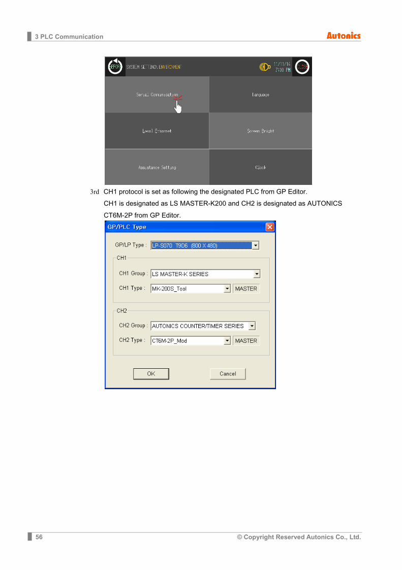
3rd CH1 protocol is set as following the designated PLC from GP Editor.
CH1 is designated as LS MASTER-K200 and CH2 is designated as AUTONICS CT6M-2P from GP Editor.
3 PLC Communication
© Copyright Reserved Autonics Co., Ltd. 57
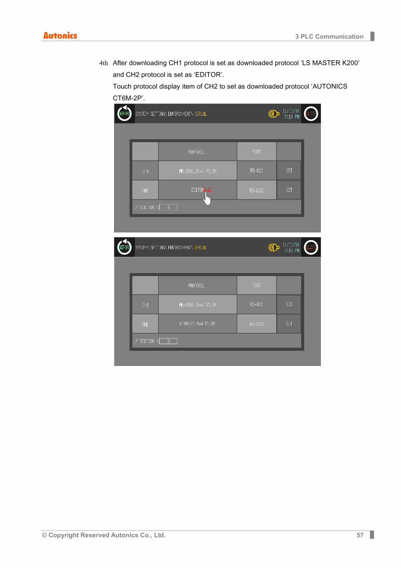
4th After downloading CH1 protocol is set as downloaded protocol ‘LS MASTER K200’ and CH2 protocol is set as ‘EDITOR’. Touch protocol display item of CH2 to set as downloaded protocol ‘AUTONICS CT6M-2P’.
3 PLC Communication
58 © Copyright Reserved Autonics Co., Ltd.
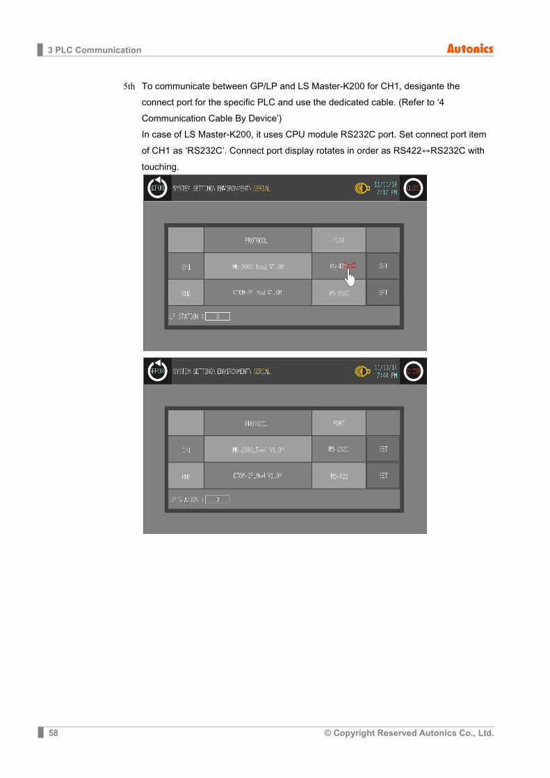
5th To communicate between GP/LP and LS Master-K200 for CH1, desigante the connect port for the specific PLC and use the dedicated cable. (Refer to ‘4 Communication Cable By Device’) In case of LS Master-K200, it uses CPU module RS232C port. Set connect port item of CH1 as ‘RS232C’. Connect port display rotates in order as RS422↔RS232C with touching.
3 PLC Communication
© Copyright Reserved Autonics Co., Ltd. 59
6th Synchronize communicate specifications (baudrate, data bit, stop bit, parity, flow control) of between GP/LP and LS Master-K200. The communicate specification of downloaded PLC to GP/LP is set as default of the connected PLC and communication is available directly. (Only when the communicate specification of connected PLC is set as default) Touch ‘SET’ and designate detailed configuration.

3 PLC Communication
60 © Copyright Reserved Autonics Co., Ltd.
7th To communicate between GP/LP and Autonics CT6M-2P for CH2, designate the connect port for the specific PLC and use the dedicated cable. (Refer to ‘4 Communication Cable By Device’) In case of Autonics CT6M-2P, it uses RS422 port. Set connect port item of CH2 as ‘RS422’. Connect port display rotates in order as RS422↔RS232C with touching.
8th Synchronize communicate specifications (baudrate, data bit, stop bit, parity, flow
control) of between GP/LP and Autonics CT6M-2P. The communicate specification of downloaded PLC to GP/LP is set as default of the connected PLC and communication is available directly. (Only when the communicate specification of connected PLC is set as default) Touch ‘SET’ and designate detailed configuration.
9th After completing communication configuration, you should exit system setting menu and switch user screen to communicate GP Editor. Touch ‘BEFORE’, current setting values are saved and it returns to previous menu. Touch ‘CLOSE’, current setting values are saved and it returns to user screen after exiting system setting menu.
3 PLC Communication
© Copyright Reserved Autonics Co., Ltd. 61
3.2 1:1 communication It is able to communicate between a GP/LP and a PLC or controller. Mono type, 1:1 communication is available from both CH1, and CH2. Tags (numeral input/display, ASCII input/display) are available to communicate from only CH1, CH2 is available from link device. (Refer to ‘GP Editor user manual’ or ‘1.4 Link device’ of this manual.) Color type, 1:1 communication is available from both CH1, and CH2. Tags (numeral input/display, ASCII input/display) are available to communicate from both CH1 and CH2 as different from mono type.
This chapter is described 1:1 communication by LS Master-K200 as example.
3.2.1 Communication configuration
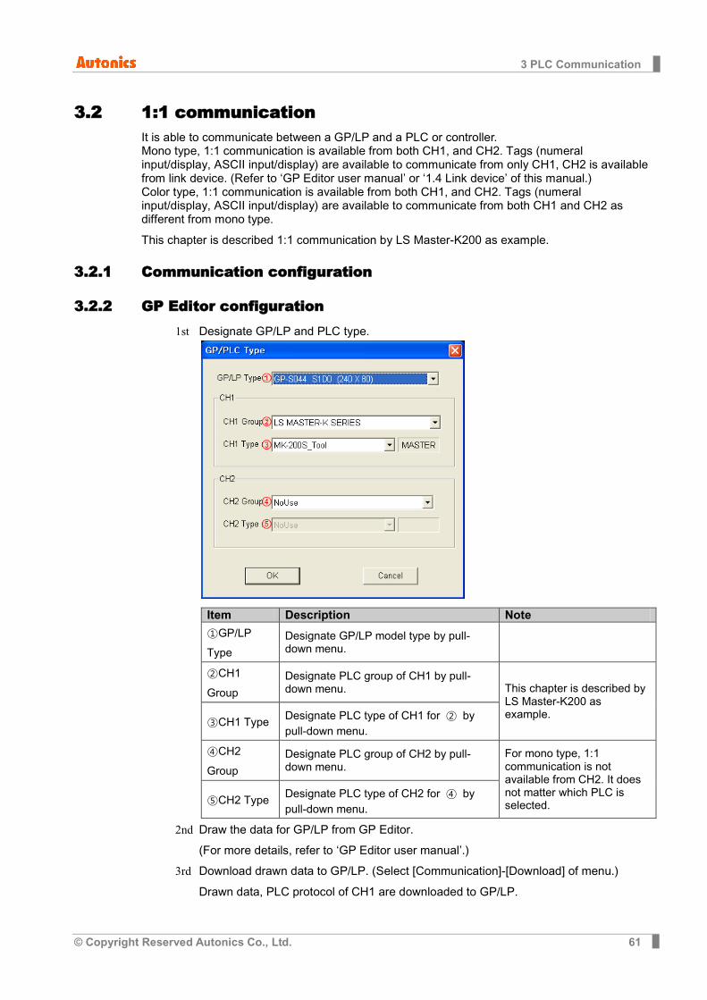
3.2.2 GP Editor configuration 1st Designate GP/LP and PLC type.
Item Description Note
①GP/LP Type
Designate GP/LP model type by pull-down menu.
②CH1 Group
Designate PLC group of CH1 by pull-down menu. This chapter is described by
LS Master-K200 as example.
③CH1 Type Designate PLC type of CH1 for ② by pull-down menu.
④CH2 Group
Designate PLC group of CH2 by pull-down menu.
For mono type, 1:1 communication is not available from CH2. It does not matter which PLC is selected. ⑤CH2 Type Designate PLC type of CH2 for ④ by
pull-down menu.
2nd Draw the data for GP/LP from GP Editor. (For more details, refer to ‘GP Editor user manual’.)
3rd Download drawn data to GP/LP. (Select [Communication]-[Download] of menu.) Drawn data, PLC protocol of CH1 are downloaded to GP/LP.
3 PLC Communication
62 © Copyright Reserved Autonics Co., Ltd.
3.2.3 GP, LP configuration 3.2.3.1 Mono type
Before downloading drawn data from GP Editor: Synchronize communication configurations of between GP/LP and GP Editor. After downloading drawn data from GP Editor: After downloading PLC protocol of CH1, CH2 which is designated from GP Editor to GP/LP, it starts communication between the specified PLC and GP/LP through communication configuration.
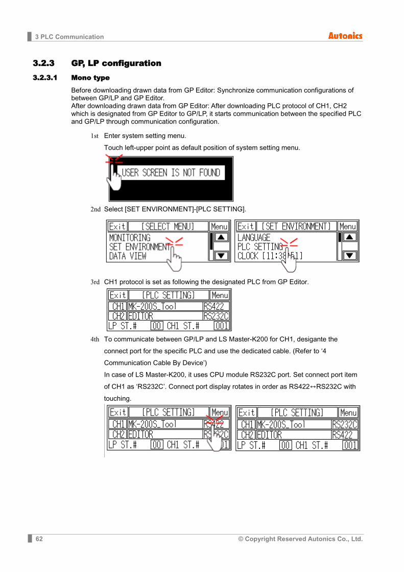
1st Enter system setting menu. Touch left-upper point as default position of system setting menu.
2nd Select [SET ENVIRONMENT]-[PLC SETTING].
3rd CH1 protocol is set as following the designated PLC from GP Editor.
4th To communicate between GP/LP and LS Master-K200 for CH1, desigante the
connect port for the specific PLC and use the dedicated cable. (Refer to ‘4 Communication Cable By Device’) In case of LS Master-K200, it uses CPU module RS232C port. Set connect port item of CH1 as ‘RS232C’. Connect port display rotates in order as RS422↔RS232C with touching.

3 PLC Communication
© Copyright Reserved Autonics Co., Ltd. 63
5th Synchronize the station of between GP/LP and LS Master-K200. Touch CH1 station item and input key pad appears. Enter the same station of LS Master-K200.
6th Synchronize communicate specifications (baudrate, data bit, stop bit, parity, flow
control) of between GP/LP and LS Master-K200. The communicate specification of downloaded PLC to GP/LP is set as default of the connected PLC and communication is available directly. (Only when the communicate specification of connected PLC is set as default.) Touch ‘CH1’ and detailed configuration screen is switched. Designate detailed configuration.
7th After completing communication configuration, you should exit system setting menu
and switch user screen to communicate GP Editor to communicate with LS Master-K200. Touch ‘Menu’, current setting values are saved and it returns to previous menu.
Touch ‘Exit’, current setting values are saved and it returns to user screen.
3 PLC Communication
64 © Copyright Reserved Autonics Co., Ltd.
3.2.3.2 Color type
Before downloading drawn data from GP Editor: Synchronize communication configurations of between GP/LP and GP Editor. After downloading drawn data from GP Editor: After downloading PLC protocol of CH1, CH2 which is designated from GP Editor to GP/LP, it starts communication between the specified PLC and GP/LP through communication configuration.
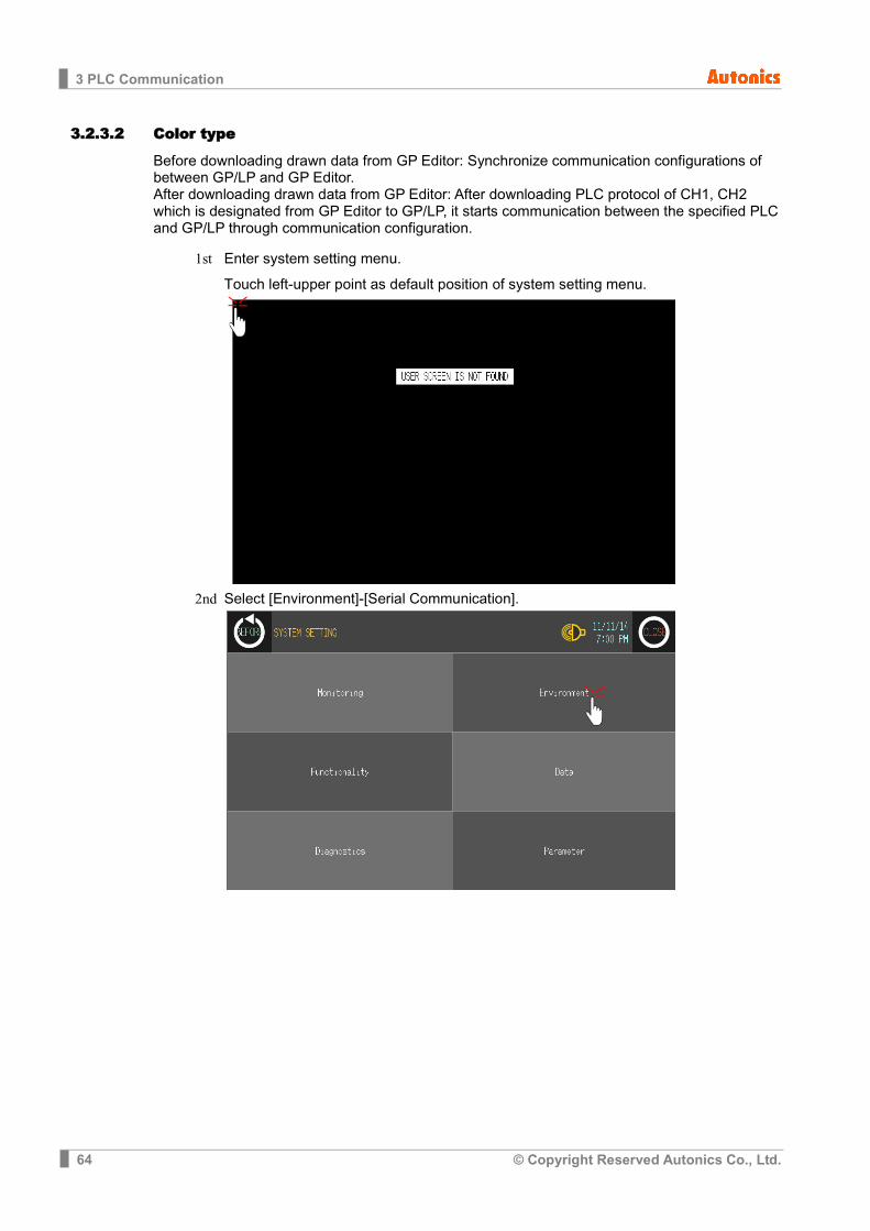
1st Enter system setting menu. Touch left-upper point as default position of system setting menu.
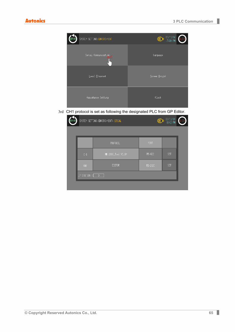
2nd Select [Environment]-[Serial Communication].
3 PLC Communication
© Copyright Reserved Autonics Co., Ltd. 65
3rd CH1 protocol is set as following the designated PLC from GP Editor.
3 PLC Communication
66 © Copyright Reserved Autonics Co., Ltd.
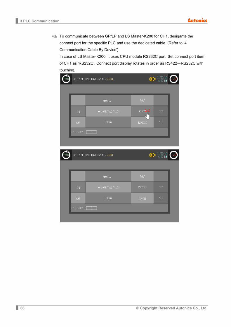
4th To communicate between GP/LP and LS Master-K200 for CH1, desigante the connect port for the specific PLC and use the dedicated cable. (Refer to ‘4 Communication Cable By Device’) In case of LS Master-K200, it uses CPU module RS232C port. Set connect port item of CH1 as ‘RS232C’. Connect port display rotates in order as RS422↔RS232C with touching.

3 PLC Communication
© Copyright Reserved Autonics Co., Ltd. 67
5th Synchronize communicate specifications (baudrate, data bit, stop bit, parity, flow control) of between GP/LP and LS Master-K200. The communicate specification of downloaded PLC to GP/LP is set as default of the connected PLC and communication is available directly. (Only when the communicate specification of connected PLC is set as default) Touch ‘SET’ and designate detailed configuration.
6th After completing communication configuration, you should exit system setting menu
and switch user screen to communicate GP Editor to communicate with LS Master-K200. Touch ‘BEFORE’, current setting values are saved and it returns to previous menu. Touch ‘CLOSE’, current setting values are saved and it returns to user screen after exiting system setting menu.
3 PLC Communication
68 © Copyright Reserved Autonics Co., Ltd.
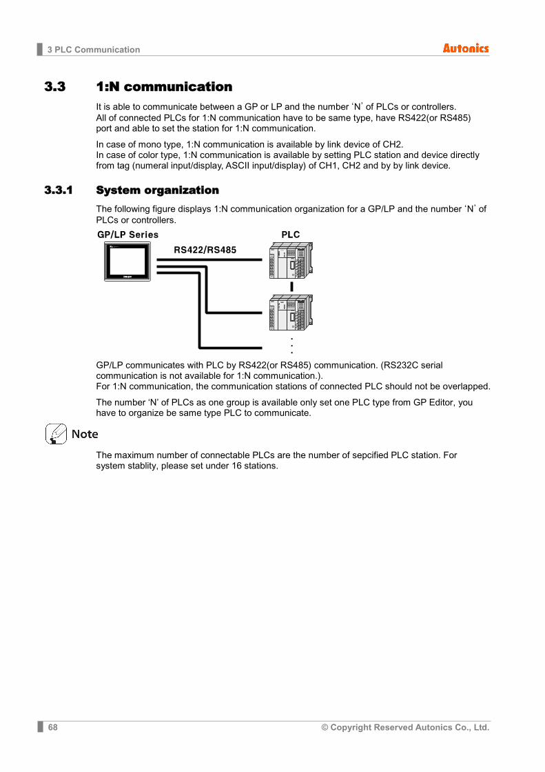
3.3 1:N communication It is able to communicate between a GP or LP and the number ‘N’ of PLCs or controllers. All of connected PLCs for 1:N communication have to be same type, have RS422(or RS485) port and able to set the station for 1:N communication.
In case of mono type, 1:N communication is available by link device of CH2. In case of color type, 1:N communication is available by setting PLC station and device directly from tag (numeral input/display, ASCII input/display) of CH1, CH2 and by by link device.
3.3.1 System organization The following figure displays 1:N communication organization for a GP/LP and the number ‘N’ of PLCs or controllers.
GP/LP communicates with PLC by RS422(or RS485) communication. (RS232C serial communication is not available for 1:N communication.). For 1:N communication, the communication stations of connected PLC should not be overlapped.
The number ‘N’ of PLCs as one group is available only set one PLC type from GP Editor, you have to organize be same type PLC to communicate.
The maximum number of connectable PLCs are the number of sepcified PLC station. For system stablity, please set under 16 stations.
3 PLC Communication
© Copyright Reserved Autonics Co., Ltd. 69
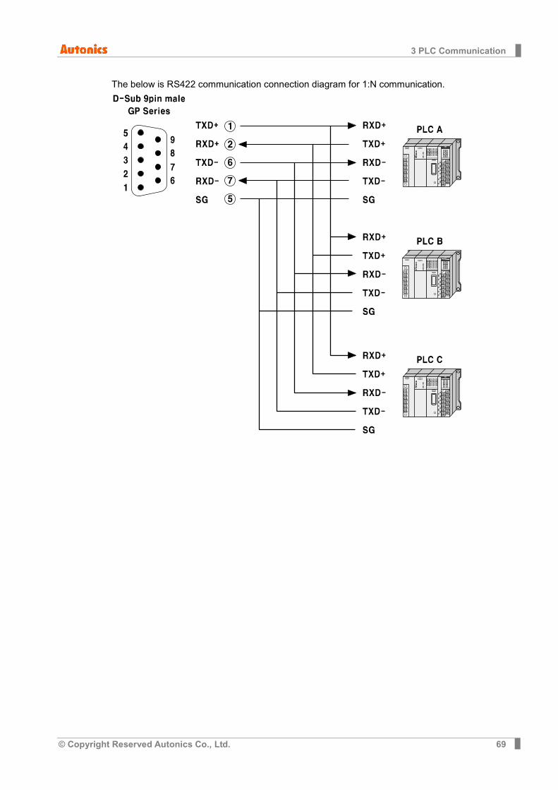
The below is RS422 communication connection diagram for 1:N communication.
3 PLC Communication
70 © Copyright Reserved Autonics Co., Ltd.
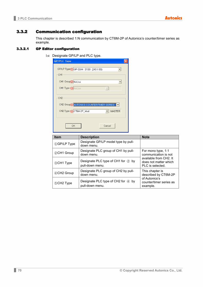
3.3.2 Communication configuration This chapter is described 1:N communication by CT6M-2P of Autonics’s counter/timer series as example.
3.3.2.1 GP Editor configuration
1st Designate GP/LP and PLC type.
Item Description Note
①GP/LP Type Designate GP/LP model type by pull-down menu.
②CH1 Group Designate PLC group of CH1 by pull-down menu.
For mono type, 1:1 communication is not available from CH2. It does not matter which PLC is selected.
③CH1 Type Designate PLC type of CH1 for ② by pull-down menu.
④CH2 Group Designate PLC group of CH2 by pull-down menu.
This chapter is described by CT6M-2P of Autonics’s counter/timer series as example.
⑤CH2 Type Designate PLC type of CH2 for ④ by pull-down menu.

3 PLC Communication
© Copyright Reserved Autonics Co., Ltd. 71
2nd Select [Common]-[Link Deivce] and ‘Link Device Setting’ dialog box appears. Designate the station of connected PLC to CH2 and connect device.
Communication operates as below table.
GP/LP Communication direction
CH2 PLC station CH2 PLC
GP/LP series CT6M-2P
UW200 to UW209 (Read) ← 1 CT30105 to CT30114
UW210 to UW219 (Read) ← 9 CT31001 to CT31010
UW220 to UW224 (Read) ← 10 CT40151 to CT40156
UW225 to UW229 (Write) → 31 CT40001 to CT40010
UW230 to UW239 (Write) → 16 CT40054 to CT40063
3 PLC Communication
72 © Copyright Reserved Autonics Co., Ltd.
In case of mono type, 1:N communication configuration is available only from link device. For more details, refer to ‘1.4 Link device’. In case of color type, it is available by setting PLC station and device directly from tag (numeral input/display, ASCII input/display) of CH1, CH2 and by by link device.
3rd Draw the data to download for GP/LP from GP Editor. In case of mono type: Supports 1:N communication by CH2.
In case of color type: Supports 1:N communication by CH1, CH2 without division. (For more details, refer to ‘GP Editor user manual’.)
4th Download drawn data to GP/LP (Select [Communication]-[Download] of menu.). Drawn data, PLC protocol of CH1 are downloaded to GP/LP.

3 PLC Communication
© Copyright Reserved Autonics Co., Ltd. 73
3.3.2.2 GP, LP configuration
(1) Mono type Before downloading drawn data from GP Editor: Synchronize communication configurations of between GP/LP and GP Editor. After downloading drawn data from GP Editor: After downloading PLC protocol (CT6M-2P) of CH2, it starts communication between the specified PLC and GP/LP through communication configuration.
1st Enter system setting menu. Touch left-upper point as default position of system setting menu.
2nd Select [SET ENVIRONMENT]-[PLC SETTING].
3rd CH2 protocol is set as CT6M-2P as PLC type from GP Editor but downloaded CT6M-2P protocol is not applied directly. (Communicates with EDITOR from CH2). Touch protocol display item of CH2 to set CT6M-2P.
4th To communicate between GP/LP and CT6M-2P for CH2, desigante the connect port
for the specific PLC and use the dedicated cable. (Refer to ‘4 Communication Cable By Device’.) In case of CT6M-2P, it uses Modbus RS485(RS422) port. Set connect port item of CH2 as ‘RS422’. Connect port display rotates in order as RS422↔RS232C with touching.

3 PLC Communication
74 © Copyright Reserved Autonics Co., Ltd.
5th Synchronize the station of between GP/LP and CT6M-2P. The station of CH1 is available to set from GP/LP. CH2 is set from link device of GP Editor. (Refer to ‘1.4 Link device’.) Enter the same station of CT6M-2P. For more details, refer to ‘GP Editor user manual’.
6th Synchronize communicate specifications (baudrate, data bit, stop bit, parity, flow control) of between GP/LP and CT6M-2P. The communicate specification of downloaded PLC to GP/LP is set as default of the connected PLC and communication is available directly. (Only when the communicate specification of connected PLC is set as default) Touch ‘CH2’ and detailed configuration screen is switched. Designate detailed configuration.
7th After completing communication configuration, you should exit system setting menu
and switch user screen to communicate GP Editor with CT6M-2P. Touch ‘Menu’, current setting values are saved and it returns to previous menu.
Touch ‘Exit’, current setting values are saved and it returns to user
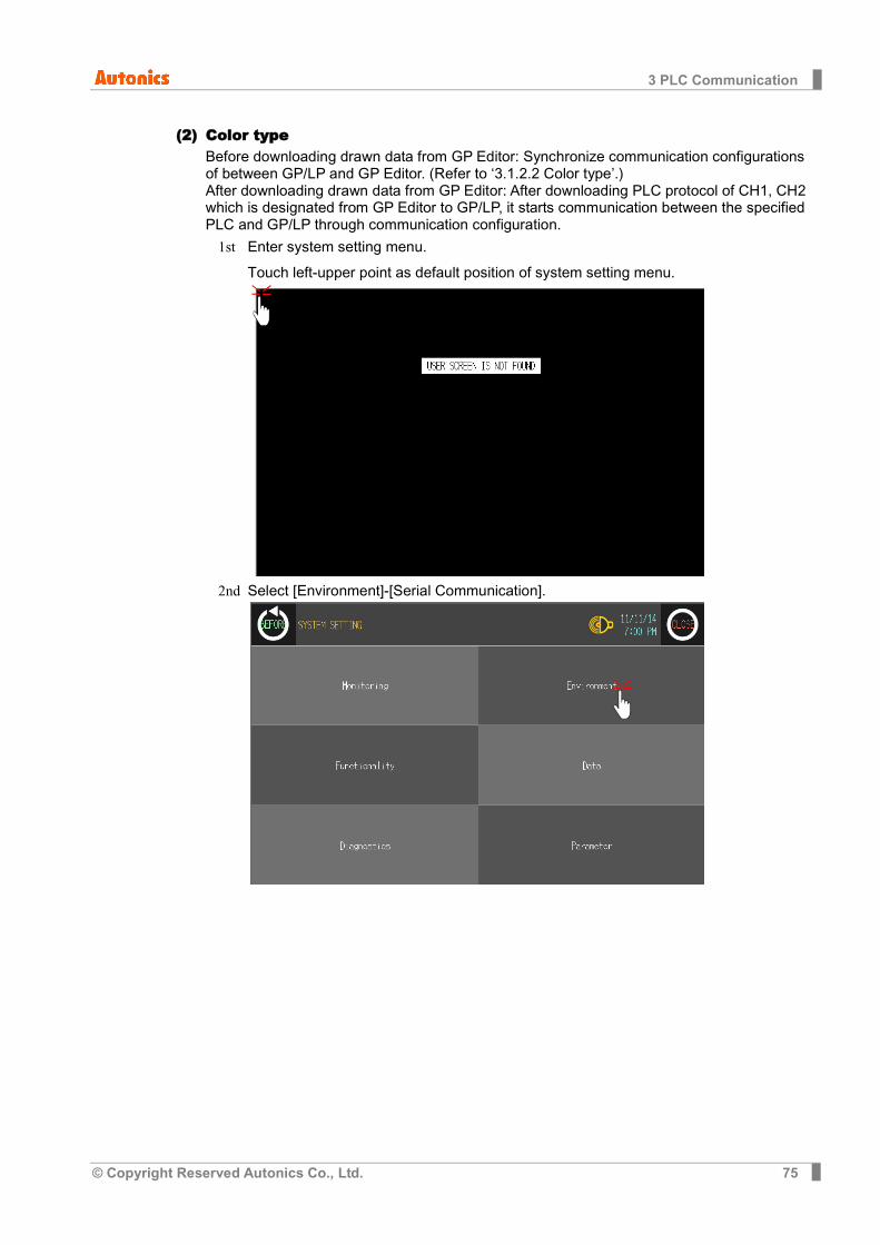
3 PLC Communication
© Copyright Reserved Autonics Co., Ltd. 75
(2) Color type Before downloading drawn data from GP Editor: Synchronize communication configurations of between GP/LP and GP Editor. (Refer to ‘3.1.2.2 Color type’.) After downloading drawn data from GP Editor: After downloading PLC protocol of CH1, CH2 which is designated from GP Editor to GP/LP, it starts communication between the specified PLC and GP/LP through communication configuration.
1st Enter system setting menu. Touch left-upper point as default position of system setting menu.
2nd Select [Environment]-[Serial Communication].
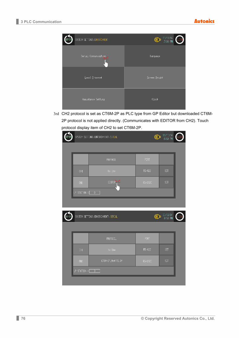
3 PLC Communication
76 © Copyright Reserved Autonics Co., Ltd.
3rd CH2 protocol is set as CT6M-2P as PLC type from GP Editor but downloaded CT6M-
2P protocol is not applied directly. (Communicates with EDITOR from CH2). Touch protocol display item of CH2 to set CT6M-2P.

3 PLC Communication
© Copyright Reserved Autonics Co., Ltd. 77
4th To communicate between GP/LP and CT6M-2P, desigante the connect port for the specific PLC and use the dedicated cable.(Refer to ‘4 Communication Cable By Device’.) In case of CT6M-2P, it uses Modbus RS485(RS422) port. Set connect port item of CH2 as ‘RS422’. Connect port display rotates in order as RS422↔RS232C with touching.
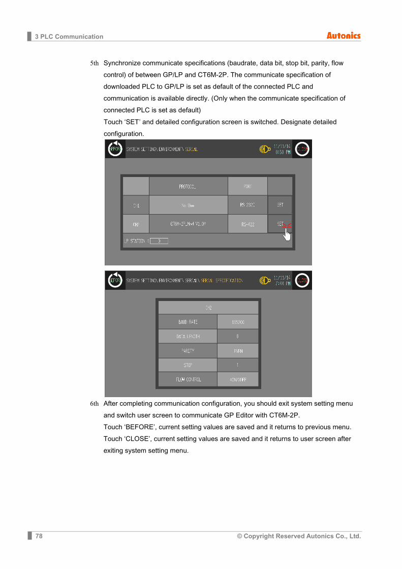
3 PLC Communication
78 © Copyright Reserved Autonics Co., Ltd.
5th Synchronize communicate specifications (baudrate, data bit, stop bit, parity, flow control) of between GP/LP and CT6M-2P. The communicate specification of downloaded PLC to GP/LP is set as default of the connected PLC and communication is available directly. (Only when the communicate specification of connected PLC is set as default) Touch ‘SET’ and detailed configuration screen is switched. Designate detailed configuration.
6th After completing communication configuration, you should exit system setting menu
and switch user screen to communicate GP Editor with CT6M-2P. Touch ‘BEFORE’, current setting values are saved and it returns to previous menu. Touch ‘CLOSE’, current setting values are saved and it returns to user screen after exiting system setting menu.
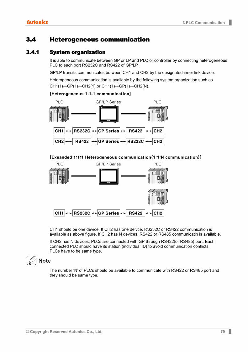
3 PLC Communication
© Copyright Reserved Autonics Co., Ltd. 79
3.4 Heterogeneous communication
3.4.1 System organization It is able to communicate between GP or LP and PLC or controller by connecting heterogeneous PLC to each port RS232C and RS422 of GP/LP.
GP/LP transits communicates between CH1 and CH2 by the designated inner link device.
Heterogeneous communication is available by the following system organization such as
CH1(1)↔GP(1)↔CH2(1) or CH1(1)↔GP(1)↔CH2(N).
CH1 should be one device. If CH2 has one deivce, RS232C or RS422 communication is available as above figure. If CH2 has N devices, RS422 or RS485 communicatin is available.
If CH2 has N devices, PLCs are connected with GP through RS422(or RS485) port. Each connected PLC should have its station (individual ID) to avoid communication conflicts. PLCs have to be same type.
The number ‘N’ of PLCs should be available to communicate with RS422 or RS485 port and they should be same type.
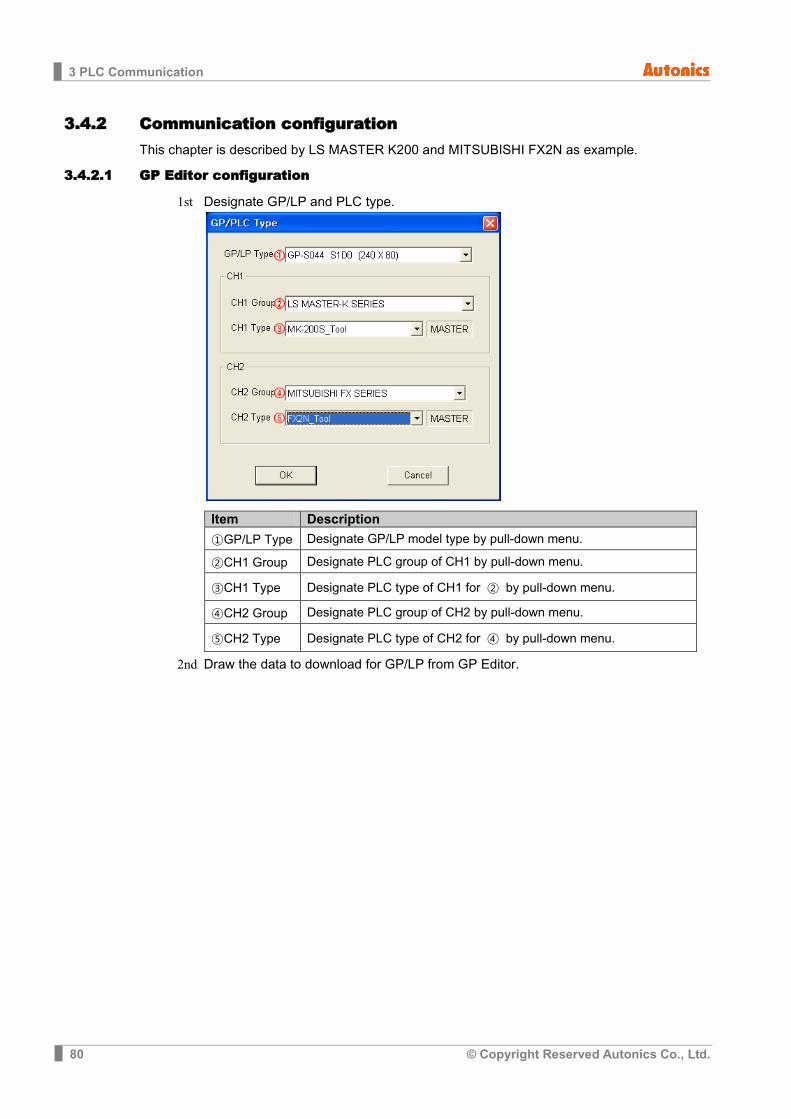
3 PLC Communication
80 © Copyright Reserved Autonics Co., Ltd.
3.4.2 Communication configuration This chapter is described by LS MASTER K200 and MITSUBISHI FX2N as example.
3.4.2.1 GP Editor configuration
1st Designate GP/LP and PLC type.
Item Description
①GP/LP Type Designate GP/LP model type by pull-down menu.
②CH1 Group Designate PLC group of CH1 by pull-down menu.
③CH1 Type Designate PLC type of CH1 for ② by pull-down menu.
④CH2 Group Designate PLC group of CH2 by pull-down menu.
⑤CH2 Type Designate PLC type of CH2 for ④ by pull-down menu.
2nd Draw the data to download for GP/LP from GP Editor.

3 PLC Communication
© Copyright Reserved Autonics Co., Ltd. 81
3rd Designate each link device of CH1, CH2. For heterogeneous communication, you should designated ① CH1 inner link device and ② CH2 inner link device as same. Click ③Add and desigante CH1, CH2 connect device to communicate. Desiganted link devices are displayed on ④ as list.

3 PLC Communication
82 © Copyright Reserved Autonics Co., Ltd.
Communication operates as below table. (For more details, refer to ‘1.4 Link device’)
CH1 PLC Communication direction
GP/LP Communication direction
CH2 PLC
MK-200S GP/LP series FX2N
D100 to D109 (Write) ← UW200 to UW209 (Read) ← D0 to D9
D110 to D119 (Write) ← UW210 to UW219 (Read) ← D10 to D19
D120 to D129 (Write) ← UW220 to UW229 (Read) ← D20 to D29
D130 to D134 (Read) → UW230 to UW234 (Write) → D30 to D34
D135 to D139 (Read) → UW235 to UW239 (Write) → D35 to D39
4th Download drawn data to GP/LP (Select [Communication]-[Download] of menu.). Drawn data, PLC protocol of CH1, CH2 are downloaded to GP/LP.
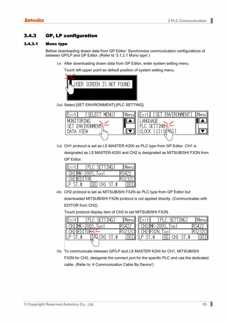
3 PLC Communication
© Copyright Reserved Autonics Co., Ltd. 83
3.4.3 GP, LP configuration 3.4.3.1 Mono type
Before downloading drawn data from GP Editor: Synchronize communication configurations of between GP/LP and GP Editor. (Refer to ‘3.1.2.1 Mono type’.)
1st After downloading drawn data from GP Editor, enter system setting menu. Touch left-upper point as default position of system setting menu.
2nd Select [SET ENVIRONMENT]-[PLC SETTING].
3rd CH1 protocol is set as LS MASTER K200 as PLC type from GP Editor. CH1 is designated as LS MASTER-K200 and CH2 is designated as MITSUBISHI FX2N from GP Editor.
4th CH2 protocol is set as MITSUBISHI FX2N as PLC type from GP Editor but
downloaded MITSUBISHI FX2N protocol is not applied directly. (Communicates with EDITOR from CH2). Touch protocol display item of CH2 to set MITSUBISHI FX2N.
5th To communicate between GP/LP and LS MASTER K200 for CH1, MITSUBISHI FX2N for CH2, desigante the connect port for the specific PLC and use the dedicated cable. (Refer to ‘4 Communication Cable By Device’)

3 PLC Communication
84 © Copyright Reserved Autonics Co., Ltd.
In case of LS MASTER K200 of CH1, it uses CPU module RS422 port. In case of MITSUBISHI FX2N for CH2, it uses CPU module RS232 and RS232/422 converter should be used. If two of RS232C serial interface type, connect RS232/422 converter at each RS232C A, or RS232C B port.
6th Synchronize the station of between GP/LP and connected devices.
The station of CH1 is available to set from GP/LP. CH2 is set from link device of GP Editor. (Refer to ‘1.4 Link device’.) For more details, refer to ‘GP Editor user manual’.
7th Synchronize communicate specifications (baudrate, data bit, stop bit, parity, flow
control) of between GP/LP and connected devices by each CH1, CH2. The communicate specification of downloaded PLC to GP/LP is set as default of the connected PLC and communication is available directly. (Only when the communicate specification of connected PLC is set as default) Touch ‘CH1’ or ‘CH2’ and detailed configuration screen is switched. Designate detailed configuration by each channel.
8th After completing communication configuration, you should exit system setting menu and switch user screen to communicate GP Editor with connected devices. Touch ‘Menu’, current setting values are saved and it returns to previous menu.
Touch ‘Exit’, current setting values are saved and it returns to user

3 PLC Communication
© Copyright Reserved Autonics Co., Ltd. 85
3.4.3.2 Color type
Before downloading drawn data from GP Editor: Synchronize communication configurations of between GP/LP and GP Editor.
1st After downloading drawn data from GP Editor, enter system setting menu. Touch left-upper point as default position of system setting menu.
2nd Select [Environment]-[Serial Communication].

3 PLC Communication
86 © Copyright Reserved Autonics Co., Ltd.
3rd CH1 protocol is set as LS MASTER K200 as PLC type from GP Editor. CH1 is
designated as LS MASTER-K200 and CH2 is designated as MITSUBISHI FX2N from GP Editor.
CH2 protocol is set as MITSUBISHI FX2N as PLC type from GP Editor but downloaded MITSUBISHI FX2N protocol is not applied directly. (Communicates with EDITOR from CH2). Touch protocol display item of CH2 to set MITSUBISHI FX2N.

3 PLC Communication
© Copyright Reserved Autonics Co., Ltd. 87
4th To communicate between GP/LP and LS MASTER K200 for CH1, MITSUBISHI
FX2N for CH2, desigante the connect port for the specific PLC and use the dedicated cable. (Refer to ‘4 Communication Cable By Device’) In case of LS MASTER K200 of CH1, it uses CPU module RS232 port. In case of MITSUBISHI FX2N for CH2, it uses CPU module RS232 and RS232/422 converter should be used. If two of RS232C serial interface type, connect each RS232C A, or RS232C B port.

3 PLC Communication
88 © Copyright Reserved Autonics Co., Ltd.
5th Synchronize communicate specifications (baudrate, data bit, stop bit, parity, flow control) of between GP/LP and connected devices by each CH1, CH2. The communicate specification of downloaded PLC to GP/LP is set as default of the connected PLC and communication is available directly. (Only when the communicate specification of connected PLC is set as default) Touch ‘SET’ of CH1 or CH2 and detailed configuration screen is switched. Designate detailed configuration by each channel.
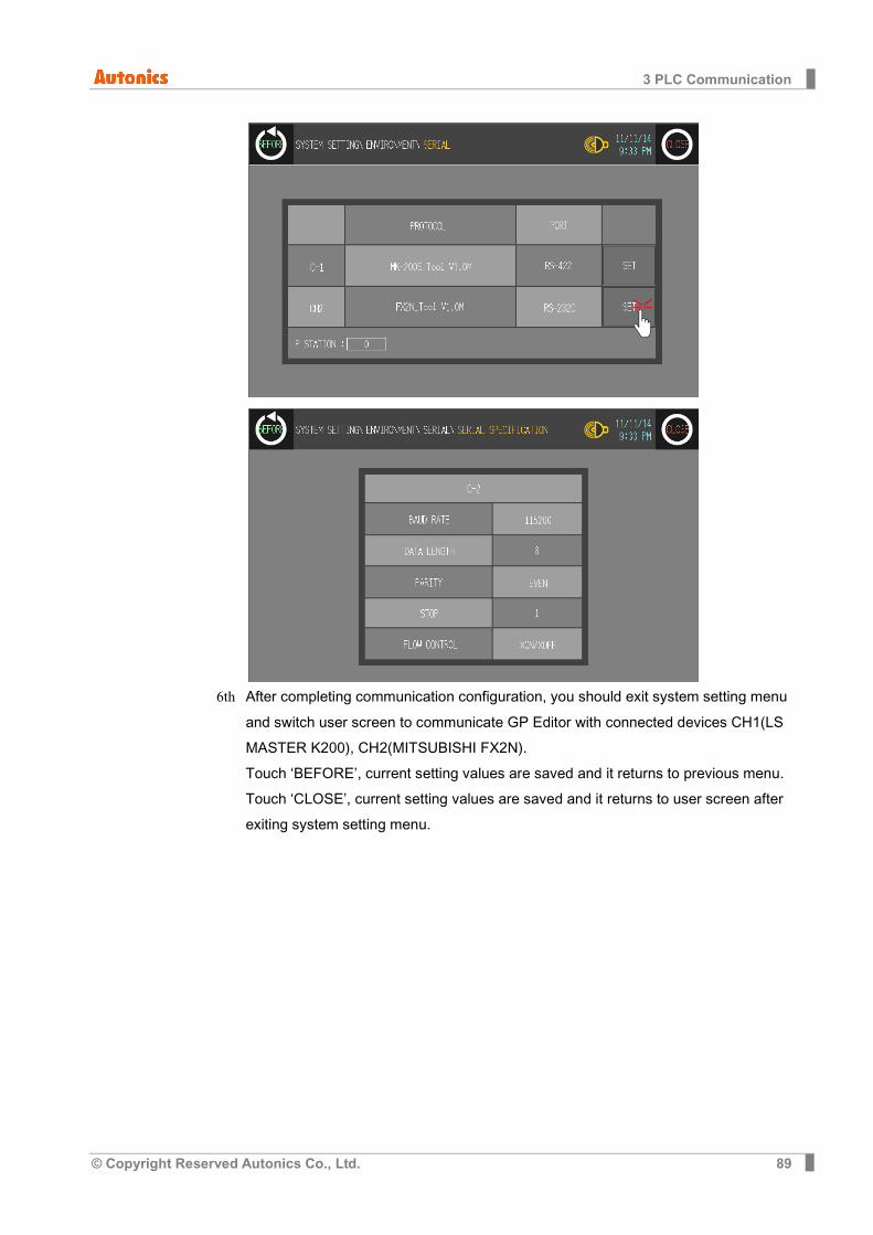
3 PLC Communication
© Copyright Reserved Autonics Co., Ltd. 89
6th After completing communication configuration, you should exit system setting menu
and switch user screen to communicate GP Editor with connected devices CH1(LS MASTER K200), CH2(MITSUBISHI FX2N). Touch ‘BEFORE’, current setting values are saved and it returns to previous menu. Touch ‘CLOSE’, current setting values are saved and it returns to user screen after exiting system setting menu.
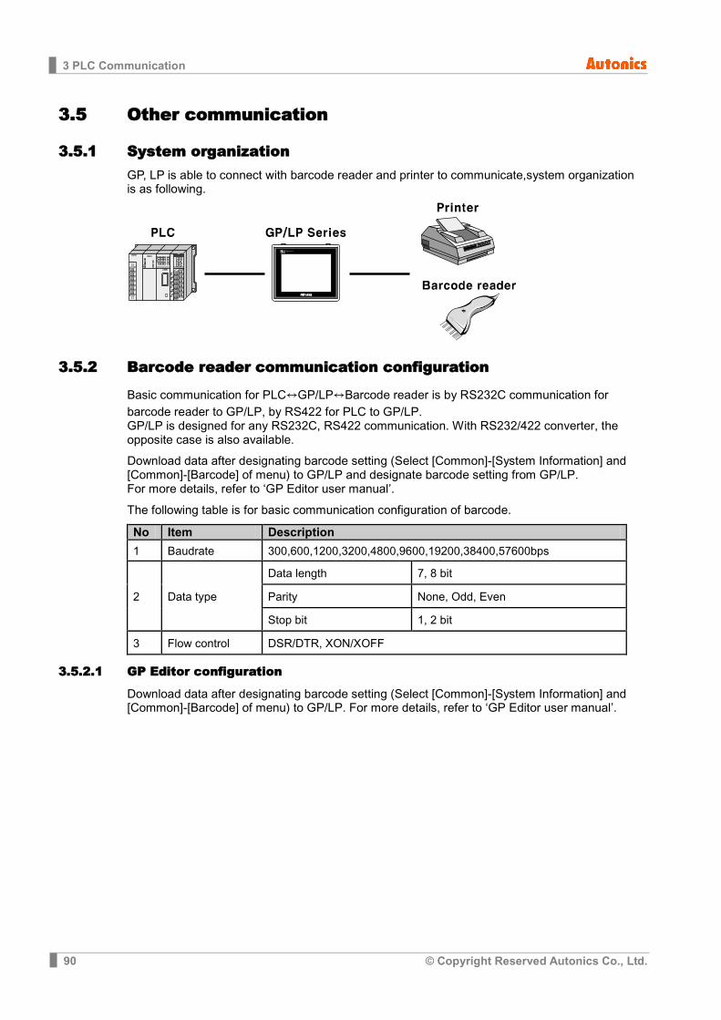
3 PLC Communication
90 © Copyright Reserved Autonics Co., Ltd.
3.5 Other communication
3.5.1 System organization GP, LP is able to connect with barcode reader and printer to communicate,system organization is as following.
3.5.2 Barcode reader communication configuration
Basic communication for PLC↔GP/LP↔Barcode reader is by RS232C communication for barcode reader to GP/LP, by RS422 for PLC to GP/LP. GP/LP is designed for any RS232C, RS422 communication. With RS232/422 converter, the opposite case is also available.
Download data after designating barcode setting (Select [Common]-[System Information] and [Common]-[Barcode] of menu) to GP/LP and designate barcode setting from GP/LP. For more details, refer to ‘GP Editor user manual’.
The following table is for basic communication configuration of barcode.
No Item Description 1 Baudrate 300,600,1200,3200,4800,9600,19200,38400,57600bps
2 Data type Data length 7, 8 bit Parity None, Odd, Even Stop bit 1, 2 bit
3 Flow control DSR/DTR, XON/XOFF
3.5.2.1 GP Editor configuration
Download data after designating barcode setting (Select [Common]-[System Information] and [Common]-[Barcode] of menu) to GP/LP. For more details, refer to ‘GP Editor user manual’.

3 PLC Communication
© Copyright Reserved Autonics Co., Ltd. 91
3.5.2.2 GP, LP configuration
(1) Mono type Before downloading drawn data from GP Editor: Synchronize communication configurations of between GP/LP and GP Editor.
1st After downloading drawn data from GP Editor, enter system setting menu. Touch left-upper point as default position of system setting menu.
2nd Select [SET ENVIRONMENT]-[PLC SETTING].
3rd CH2 protocol is set as ‘EDITOR’ as basic configuration.
4th Touch protocol display item to set ‘BARCODE’ as following figure.
Protocol display rotates in order as EDITOR→PRINTER→BARCODE→MONITOR with touching.
5th Designate connect port for communicating GP/LP and barcode reader. Connect port
display rotates in order as RS422↔RS232C with touching.
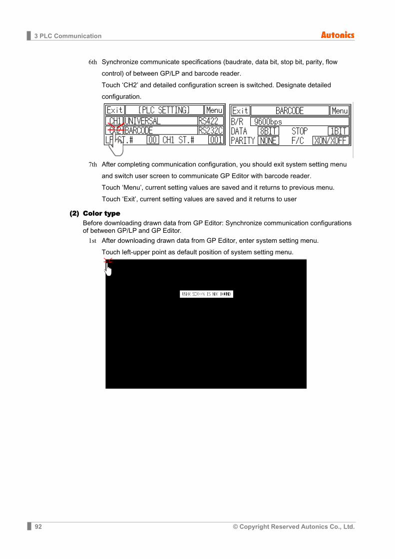
3 PLC Communication
92 © Copyright Reserved Autonics Co., Ltd.
6th Synchronize communicate specifications (baudrate, data bit, stop bit, parity, flow control) of between GP/LP and barcode reader. Touch ‘CH2’ and detailed configuration screen is switched. Designate detailed configuration.
7th After completing communication configuration, you should exit system setting menu
and switch user screen to communicate GP Editor with barcode reader. Touch ‘Menu’, current setting values are saved and it returns to previous menu.
Touch ‘Exit’, current setting values are saved and it returns to user
(2) Color type Before downloading drawn data from GP Editor: Synchronize communication configurations of between GP/LP and GP Editor.
1st After downloading drawn data from GP Editor, enter system setting menu. Touch left-upper point as default position of system setting menu.
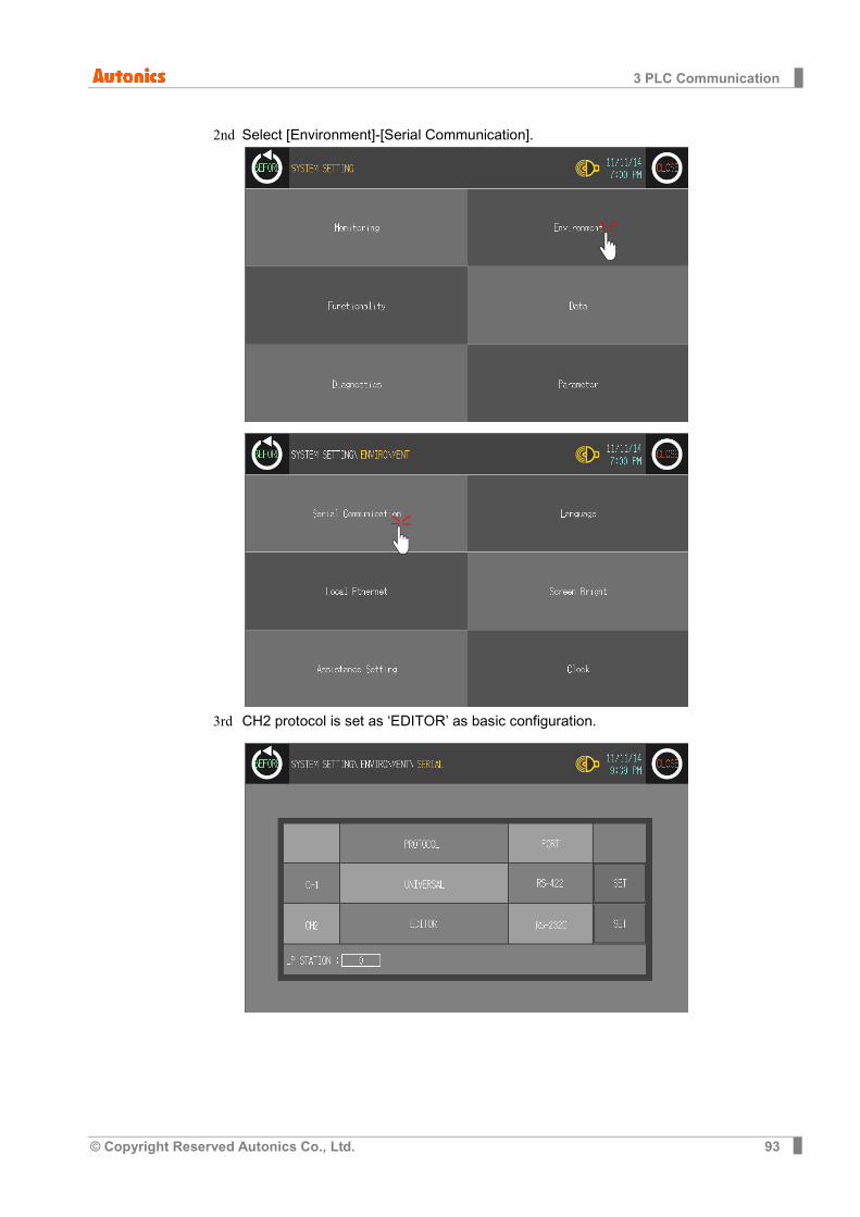
3 PLC Communication
© Copyright Reserved Autonics Co., Ltd. 93
2nd Select [Environment]-[Serial Communication].
3rd CH2 protocol is set as ‘EDITOR’ as basic configuration.
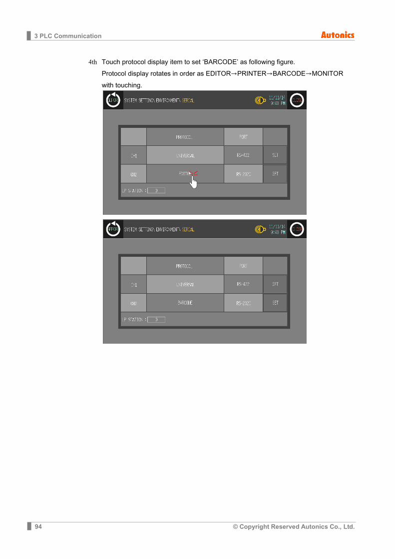
3 PLC Communication
94 © Copyright Reserved Autonics Co., Ltd.
4th Touch protocol display item to set ‘BARCODE’ as following figure. Protocol display rotates in order as EDITOR→PRINTER→BARCODE→MONITOR with touching.

3 PLC Communication
© Copyright Reserved Autonics Co., Ltd. 95
5th Designate connect port for communicating GP/LP and barcode reader. Connect port display rotates in order as RS422↔RS232C with touching.

3 PLC Communication
96 © Copyright Reserved Autonics Co., Ltd.
6th Synchronize communicate specifications (baudrate, data bit, stop bit, parity, flow control) of between GP/LP and barcode reader. Touch ‘SET’ and detailed configuration screen is switched. Designate detailed configuration.
7th After completing communication configuration, you should exit system setting menu and switch user screen to communicate GP Editor with barcode reader. Touch ‘BEFORE’, current setting values are saved and it returns to previous menu. Touch ‘CLOSE’, current setting values are saved and it returns to user screen after exiting system setting menu.

3 PLC Communication
© Copyright Reserved Autonics Co., Ltd. 97
3.5.3 PRINTER communication configuration
Basic communication for PLC ↔ GP/LP ↔ PRINTER is same as barcode reader communication’s. PLC and PRINTER are available to both RS232C and RS422 communication and printer through GP/LP is able to print alarm history. The other words, if there are alarm history in downloaded data from GP Editor, and saved alarm history by communicating GP/LP and PLC, you can print out alarm history through GP/LP and printer.
3.5.3.1 GP, LP configuration for printer
Without printer configuration in GP Editor, download data and designate printer in GP/LP. The following table is for basic communication configuration of printer.
No Item Description 1 Baudrate 300,600,1200,3200,4800,9600,19200,38400,57600 bps
2 Data type Data length 7, 8 bit Parity None, Odd, Even Stop bit 1, 2 bit
3 Flow control DSR/DTR, XON/XOFF
3.5.3.2 GP, LP configuration
(1) Mono type Before downloading drawn data from GP Editor: Synchronize communication configurations of between GP/LP and GP Editor.
1st After downloading drawn data from GP Editor, enter system setting menu. Touch left-upper point as default position of system setting menu.
2nd Select [SET ENVIRONMENT]-[PLC SETTING].
3rd CH2 protocol is set as ‘EDITOR’ as basic configuration.
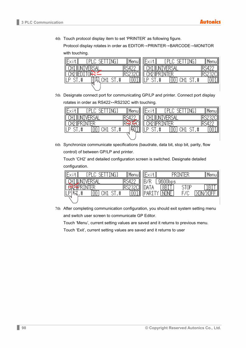
3 PLC Communication
98 © Copyright Reserved Autonics Co., Ltd.
4th Touch protocol display item to set ‘PRINTER’ as following figure. Protocol display rotates in order as EDITOR→PRINTER→BARCODE→MONITOR with touching.
5th Designate connect port for communicating GP/LP and printer. Connect port display
rotates in order as RS422↔RS232C with touching.
6th Synchronize communicate specifications (baudrate, data bit, stop bit, parity, flow control) of between GP/LP and printer. Touch ‘CH2’ and detailed configuration screen is switched. Designate detailed configuration.
7th After completing communication configuration, you should exit system setting menu
and switch user screen to communicate GP Editor. Touch ‘Menu’, current setting values are saved and it returns to previous menu.
Touch ‘Exit’, current setting values are saved and it returns to user
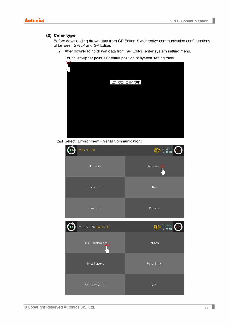
3 PLC Communication
© Copyright Reserved Autonics Co., Ltd. 99
(2) Color type Before downloading drawn data from GP Editor: Synchronize communication configurations of between GP/LP and GP Editor.
1st After downloading drawn data from GP Editor, enter system setting menu. Touch left-upper point as default position of system setting menu.
2nd Select [Environment]-[Serial Communication].
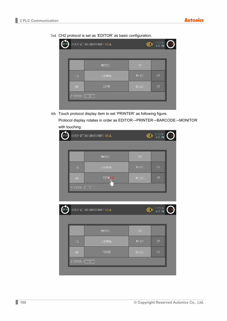
3 PLC Communication
100 © Copyright Reserved Autonics Co., Ltd.
3rd CH2 protocol is set as ‘EDITOR’ as basic configuration.
4th Touch protocol display item to set ‘PRINTER’ as following figure.
Protocol display rotates in order as EDITOR→PRINTER→BARCODE→MONITOR with touching.

3 PLC Communication
© Copyright Reserved Autonics Co., Ltd. 101
5th Designate connect port for communicating GP/LP and printer. Connect port display rotates in order as RS422↔RS232C with touching.
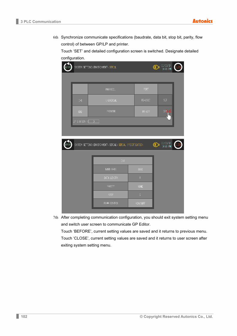
3 PLC Communication
102 © Copyright Reserved Autonics Co., Ltd.
6th Synchronize communicate specifications (baudrate, data bit, stop bit, parity, flow control) of between GP/LP and printer. Touch ‘SET’ and detailed configuration screen is switched. Designate detailed configuration.
7th After completing communication configuration, you should exit system setting menu
and switch user screen to communicate GP Editor. Touch ‘BEFORE’, current setting values are saved and it returns to previous menu. Touch ‘CLOSE’, current setting values are saved and it returns to user screen after exiting system setting menu.
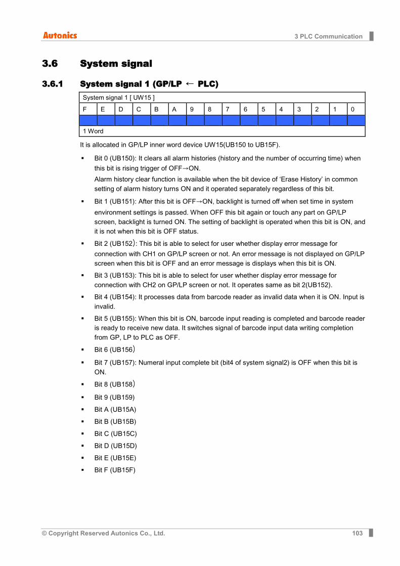
3 PLC Communication
© Copyright Reserved Autonics Co., Ltd. 103
3.6 System signal
3.6.1 System signal 1 (GP/LP ← PLC) System signal 1 [ UW15 ] F E D C B A 9 8 7 6 5 4 3 2 1 0
1 Word
It is allocated in GP/LP inner word device UW15(UB150 to UB15F).
Bit 0 (UB150): It clears all alarm histories (history and the number of occurring time) when
this bit is rising trigger of OFF→ON.
Alarm history clear function is available when the bit device of ‘Erase History’ in common setting of alarm history turns ON and it operated separately regardless of this bit.
Bit 1 (UB151): After this bit is OFF→ON, backlight is turned off when set time in system
environment settings is passed. When OFF this bit again or touch any part on GP/LP screen, backlight is turned ON. The setting of backlight is operated when this bit is ON, and it is not when this bit is OFF status.
Bit 2 (UB152): This bit is able to select for user whether display error message for
connection with CH1 on GP/LP screen or not. An error message is not displayed on GP/LP screen when this bit is OFF and an error message is displays when this bit is ON.
Bit 3 (UB153): This bit is able to select for user whether display error message for connection with CH2 on GP/LP screen or not. It operates same as bit 2(UB152).
Bit 4 (UB154): It processes data from barcode reader as invalid data when it is ON. Input is invalid.
Bit 5 (UB155): When this bit is ON, barcode input reading is completed and barcode reader is ready to receive new data. It switches signal of barcode input data writing completion from GP, LP to PLC as OFF.
Bit 6 (UB156)
Bit 7 (UB157): Numeral input complete bit (bit4 of system signal2) is OFF when this bit is ON.
Bit 8 (UB158)
Bit 9 (UB159)
Bit A (UB15A)
Bit B (UB15B)
Bit C (UB15C)
Bit D (UB15D)
Bit E (UB15E)
Bit F (UB15F)
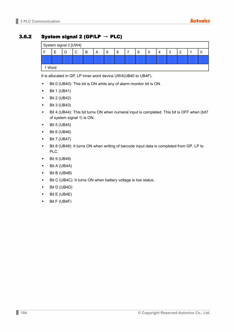
3 PLC Communication
104 © Copyright Reserved Autonics Co., Ltd.
3.6.2 System signal 2 (GP/LP → PLC) System signal 2 [UW4] F E D C B A 9 8 7 6 5 4 3 2 1 0 1 Word
It is allocated in GP, LP inner word device UW4(UB40 to UB4F).
Bit 0 (UB40): This bit is ON while any of alarm monitor bit is ON.
Bit 1 (UB41)
Bit 2 (UB42)
Bit 3 (UB43)
Bit 4 (UB44): This bit turns ON when numeral input is completed. This bit is OFF when (bit7 of system signal 1) is ON.
Bit 5 (UB45)
Bit 6 (UB46)
Bit 7 (UB47)
Bit 8 (UB48): It turns ON when writing of barcode input data is completed from GP, LP to PLC.
Bit 9 (UB49)
Bit A (UB4A)
Bit B (UB4B)
Bit C (UB4C): It turns ON when battery voltage is low status.
Bit D (UB4D)
Bit E (UB4E)
Bit F (UB4F)
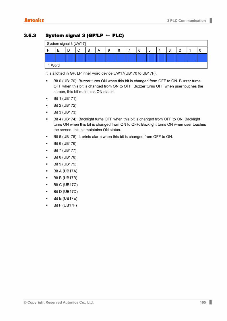
3 PLC Communication
© Copyright Reserved Autonics Co., Ltd. 105
3.6.3 System signal 3 (GP/LP ← PLC) System signal 3 [UW17] F E D C B A 9 8 7 6 5 4 3 2 1 0 1 Word
It is allotted in GP, LP inner word device UW17(UB170 to UB17F).
Bit 0 (UB170): Buzzer turns ON when this bit is changed from OFF to ON. Buzzer turns OFF when this bit is changed from ON to OFF. Buzzer turns OFF when user touches the screen, this bit maintains ON status.
Bit 1 (UB171)
Bit 2 (UB172)
Bit 3 (UB173)
Bit 4 (UB174): Backlight turns OFF when this bit is changed from OFF to ON. Backlight turns ON when this bit is changed from ON to OFF. Backlight turns ON when user touches the screen, this bit maintains ON status.
Bit 5 (UB175): It prints alarm when this bit is changed from OFF to ON.
Bit 6 (UB176)
Bit 7 (UB177)
Bit 8 (UB178)
Bit 9 (UB179)
Bit A (UB17A)
Bit B (UB17B)
Bit C (UB17C)
Bit D (UB17D)
Bit E (UB17E)
Bit F (UB17F)
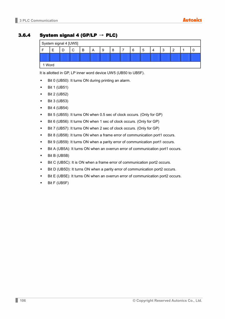
3 PLC Communication
106 © Copyright Reserved Autonics Co., Ltd.
3.6.4 System signal 4 (GP/LP → PLC) System signal 4 [UW5] F E D C B A 9 8 7 6 5 4 3 2 1 0 1 Word
It is allotted in GP, LP inner word device UW5 (UB50 to UB5F).
Bit 0 (UB50): It turns ON during printing an alarm.
Bit 1 (UB51)
Bit 2 (UB52)
Bit 3 (UB53)
Bit 4 (UB54)
Bit 5 (UB55): It turns ON when 0.5 sec of clock occurs. (Only for GP)
Bit 6 (UB56): It turns ON when 1 sec of clock occurs. (Only for GP)
Bit 7 (UB57): It turns ON when 2 sec of clock occurs. (Only for GP)
Bit 8 (UB58): It turns ON when a frame error of communication port1 occurs.
Bit 9 (UB59): It turns ON when a parity error of communication port1 occurs.
Bit A (UB5A): It turns ON when an overrun error of communication port1 occurs.
Bit B (UB5B)
Bit C (UB5C): It is ON when a frame error of communication port2 occurs.
Bit D (UB5D): It turns ON when a parity error of communication port2 occurs.
Bit E (UB5E): It turns ON when an overrun error of communication port2 occurs.
Bit F (UB5F)

4 Communication Cable By Device
© Copyright Reserved Autonics Co., Ltd. 107
4 Communication Cable By Device
4.1 Ordering information
4.2 Cable wiring and dimensions (1) C3M5P00-D9F0-M6MO
(2) C3M5P01-D9F0-D9M0
(3) C3M5P02-D9F0-D9M0
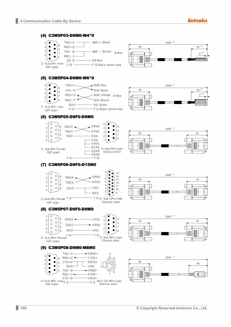
4 Communication Cable By Device
108 © Copyright Reserved Autonics Co., Ltd.
(4) C3M5P03-D9M0-W4*0
(5) C3M5P04-D9M0-W6*0
(6) C3M5P05-D9F0-D9M0
(7) C3M5P06-D9F0-D15M0
(8) C3M5P07-D9F0-D9M0
(9) C3M5P08-D9M0-M8M0
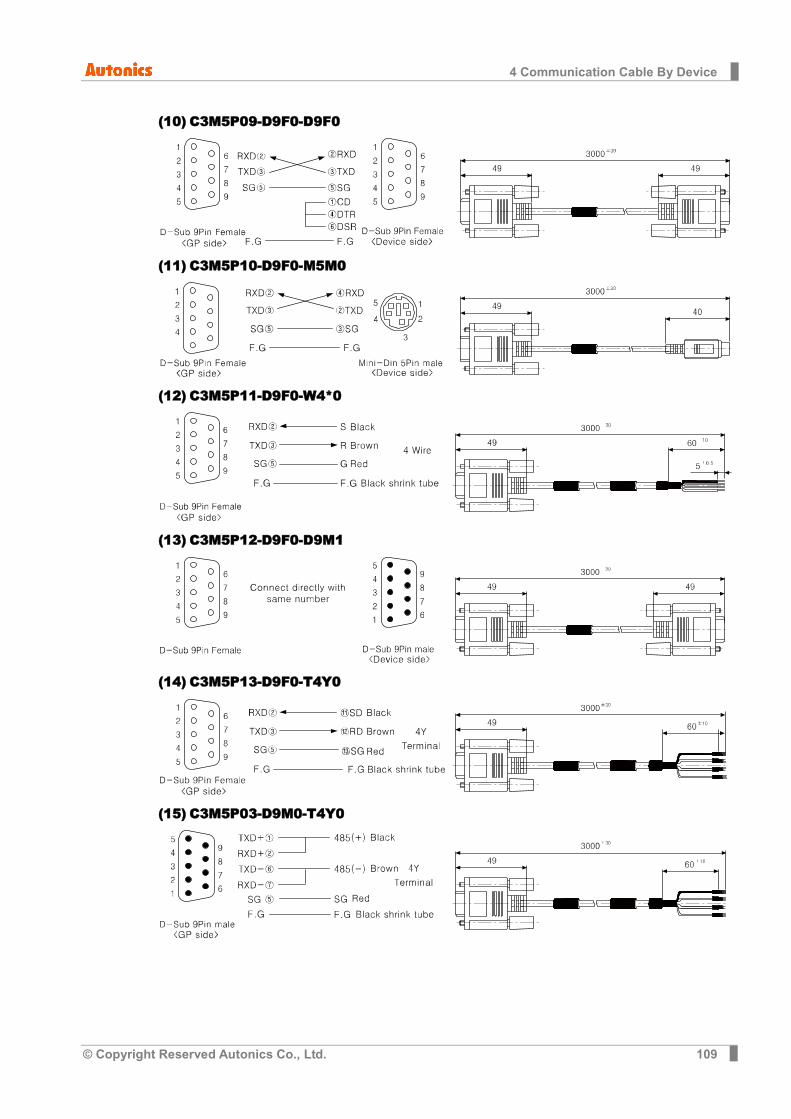
4 Communication Cable By Device
© Copyright Reserved Autonics Co., Ltd. 109
(10) C3M5P09-D9F0-D9F0
(11) C3M5P10-D9F0-M5M0
(12) C3M5P11-D9F0-W4*0
(13) C3M5P12-D9F0-D9M1
(14) C3M5P13-D9F0-T4Y0
(15) C3M5P03-D9M0-T4Y0

4 Communication Cable By Device
110 © Copyright Reserved Autonics Co., Ltd.
(16) C3M5P04-D9M0-T6Y0
(17) C3M5P03-D9F0-D9F0
(18) C3M5P03-D9M0-D9M0
(19) C3M5P08-D9M0-M8M1
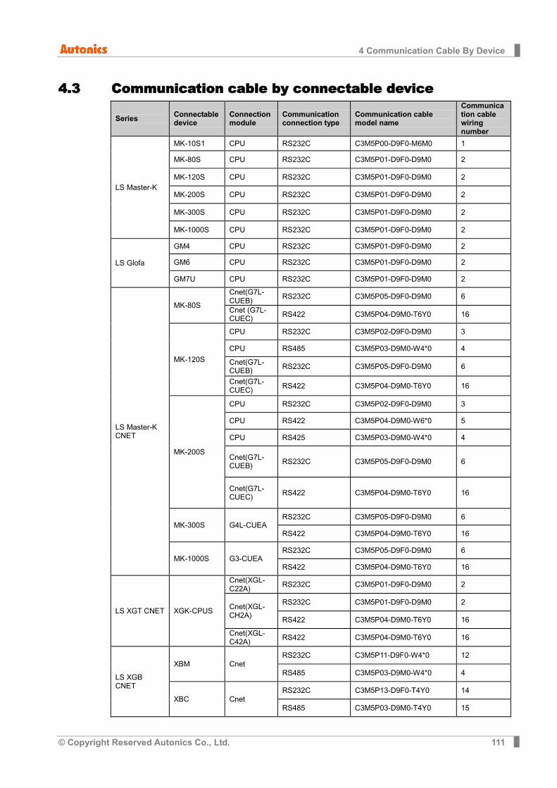
4 Communication Cable By Device
© Copyright Reserved Autonics Co., Ltd. 111
4.3 Communication cable by connectable device
Series Connectable device
Connection module
Communication connection type
Communication cable model name
Communication cable wiring number
LS Master-K
MK-10S1 CPU RS232C C3M5P00-D9F0-M6M0 1
MK-80S CPU RS232C C3M5P01-D9F0-D9M0 2
MK-120S CPU RS232C C3M5P01-D9F0-D9M0 2
MK-200S CPU RS232C C3M5P01-D9F0-D9M0 2
MK-300S CPU RS232C C3M5P01-D9F0-D9M0 2
MK-1000S CPU RS232C C3M5P01-D9F0-D9M0 2
LS Glofa
GM4 CPU RS232C C3M5P01-D9F0-D9M0 2
GM6 CPU RS232C C3M5P01-D9F0-D9M0 2
GM7U CPU RS232C C3M5P01-D9F0-D9M0 2
LS Master-K CNET
MK-80S
Cnet(G7L-CUEB) RS232C C3M5P05-D9F0-D9M0 6
Cnet (G7L-CUEC) RS422 C3M5P04-D9M0-T6Y0 16
MK-120S
CPU RS232C C3M5P02-D9F0-D9M0 3
CPU RS485 C3M5P03-D9M0-W4*0 4
Cnet(G7L-CUEB) RS232C C3M5P05-D9F0-D9M0 6
Cnet(G7L-CUEC) RS422 C3M5P04-D9M0-T6Y0 16
MK-200S
CPU RS232C C3M5P02-D9F0-D9M0 3
CPU RS422 C3M5P04-D9M0-W6*0 5
CPU RS425 C3M5P03-D9M0-W4*0 4
Cnet(G7L-CUEB) RS232C C3M5P05-D9F0-D9M0 6
Cnet(G7L-CUEC) RS422 C3M5P04-D9M0-T6Y0 16
MK-300S G4L-CUEA RS232C C3M5P05-D9F0-D9M0 6
RS422 C3M5P04-D9M0-T6Y0 16
MK-1000S G3-CUEA RS232C C3M5P05-D9F0-D9M0 6
RS422 C3M5P04-D9M0-T6Y0 16
LS XGT CNET XGK-CPUS
Cnet(XGL-C22A) RS232C C3M5P01-D9F0-D9M0 2
Cnet(XGL-CH2A)
RS232C C3M5P01-D9F0-D9M0 2
RS422 C3M5P04-D9M0-T6Y0 16
Cnet(XGL-C42A) RS422 C3M5P04-D9M0-T6Y0 16
LS XGB CNET
XBM Cnet RS232C C3M5P11-D9F0-W4*0 12
RS485 C3M5P03-D9M0-W4*0 4
XBC Cnet RS232C C3M5P13-D9F0-T4Y0 14
RS485 C3M5P03-D9M0-T4Y0 15
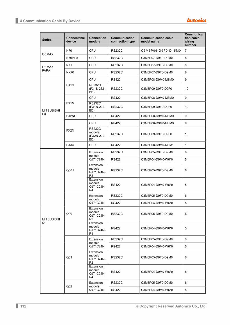
4 Communication Cable By Device
112 © Copyright Reserved Autonics Co., Ltd.
Series Connectable device
Connection module
Communication connection type
Communication cable model name
Communication cable wiring number
OEMAX N70 CPU RS232C C3M5P06-D9F0-D15M0 7
N70Plus CPU RS232C C3M5P07-D9F0-D9M0 8
OEMAX FARA
NX7 CPU RS232C C3M5P07-D9F0-D9M0 8
NX70 CPU RS232C C3M5P07-D9F0-D9M0 8
MITSUBISHI FX
FX1S
CPU RS422 C3M5P08-D9M0-M8M0 9
RS232C (FX1S-232-BD)
RS232C C3M5P09-D9F0-D9F0 10
FX1N
CPU RS422 C3M5P08-D9M0-M8M0 9
RS232C (FX1N-232-BD)
RS232C C3M5P09-D9F0-D9F0 10
FX2NC CPU RS422 C3M5P08-D9M0-M8M0 9
FX2N
CPU RS422 C3M5P08-D9M0-M8M0 9
RS232C module (FX2N-232-BD)
RS232C C3M5P09-D9F0-D9F0 10
FX3U CPU RS422 C3M5P08-D9M0-M8M1 19
MITSUBISHI Q
Q00J
Extension module QJ71C24N
RS232C C3M5P05-D9F0-D9M0 6
RS422 C3M5P04-D9M0-W6*0 5
Extension module QJ71C24N-R2
RS232C C3M5P05-D9F0-D9M0 6
Extension module QJ71C24N-R4
RS422 C3M5P04-D9M0-W6*0 5
Q00
Extension module QJ71C24N
RS232C C3M5P05-D9F0-D9M0 6
RS422 C3M5P04-D9M0-W6*0 5
Extension module QJ71C24N-R2
RS232C C3M5P05-D9F0-D9M0 6
Extension module QJ71C24N-R4
RS422 C3M5P04-D9M0-W6*0 5
Q01
Extension module QJ71C24N
RS232C C3M5P05-D9F0-D9M0 6
RS422 C3M5P04-D9M0-W6*0 5
Extension module QJ71C24N-R2
RS232C C3M5P05-D9F0-D9M0 6
Extension module QJ71C24N-R4
RS422 C3M5P04-D9M0-W6*0 5
Q02 Extension module QJ71C24N
RS232C C3M5P05-D9F0-D9M0 6
RS422 C3M5P04-D9M0-W6*0 5
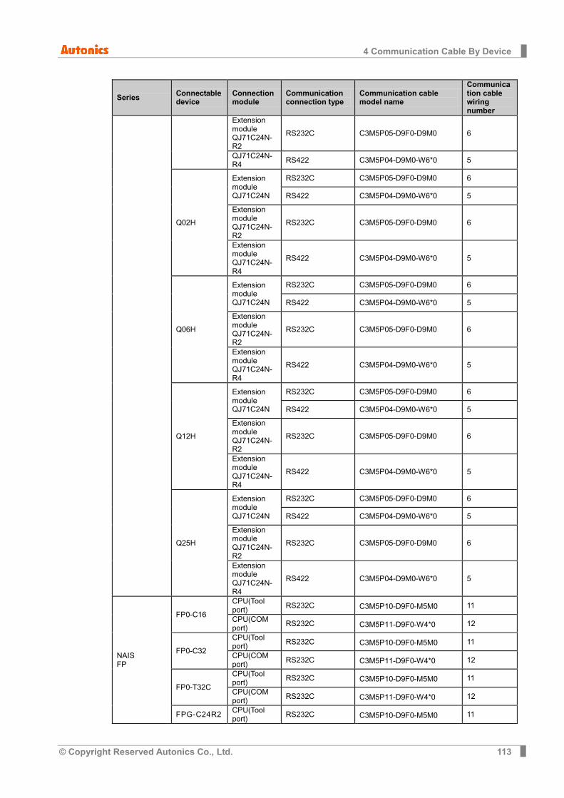
4 Communication Cable By Device
© Copyright Reserved Autonics Co., Ltd. 113
Series Connectable device
Connection module
Communication connection type
Communication cable model name
Communication cable wiring number
Extension module QJ71C24N-R2
RS232C C3M5P05-D9F0-D9M0 6
QJ71C24N-R4 RS422 C3M5P04-D9M0-W6*0 5
Q02H
Extension module QJ71C24N
RS232C C3M5P05-D9F0-D9M0 6
RS422 C3M5P04-D9M0-W6*0 5
Extension module QJ71C24N-R2
RS232C C3M5P05-D9F0-D9M0 6
Extension module QJ71C24N-R4
RS422 C3M5P04-D9M0-W6*0 5
Q06H
Extension module QJ71C24N
RS232C C3M5P05-D9F0-D9M0 6
RS422 C3M5P04-D9M0-W6*0 5
Extension module QJ71C24N-R2
RS232C C3M5P05-D9F0-D9M0 6
Extension module QJ71C24N-R4
RS422 C3M5P04-D9M0-W6*0 5
Q12H
Extension module QJ71C24N
RS232C C3M5P05-D9F0-D9M0 6
RS422 C3M5P04-D9M0-W6*0 5
Extension module QJ71C24N-R2
RS232C C3M5P05-D9F0-D9M0 6
Extension module QJ71C24N-R4
RS422 C3M5P04-D9M0-W6*0 5
Q25H
Extension module QJ71C24N
RS232C C3M5P05-D9F0-D9M0 6
RS422 C3M5P04-D9M0-W6*0 5
Extension module QJ71C24N-R2
RS232C C3M5P05-D9F0-D9M0 6
Extension module QJ71C24N-R4
RS422 C3M5P04-D9M0-W6*0 5
NAIS FP
FP0-C16
CPU(Tool port) RS232C C3M5P10-D9F0-M5M0 11
CPU(COM port) RS232C C3M5P11-D9F0-W4*0 12
FP0-C32
CPU(Tool port) RS232C C3M5P10-D9F0-M5M0 11
CPU(COM port) RS232C C3M5P11-D9F0-W4*0 12
FP0-T32C
CPU(Tool port) RS232C C3M5P10-D9F0-M5M0 11
CPU(COM port) RS232C C3M5P11-D9F0-W4*0 12
FPG-C24R2 CPU(Tool port) RS232C C3M5P10-D9F0-M5M0 11
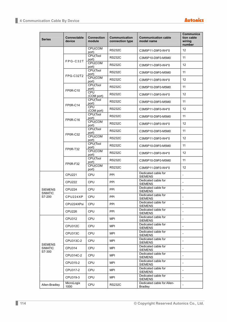
4 Communication Cable By Device
114 © Copyright Reserved Autonics Co., Ltd.
Series Connectable device
Connection module
Communication connection type
Communication cable model name
Communication cable wiring number
CPU(COM port) RS232C C3M5P11-D9F0-W4*0 12
F P G - C 3 2 T
CPU(Tool port) RS232C C3M5P10-D9F0-M5M0 11
CPU(COM port) RS232C C3M5P11-D9F0-W4*0 12
FPG-C32T2
CPU(Tool port) RS232C C3M5P10-D9F0-M5M0 11
CPU(COM port) RS232C C3M5P11-D9F0-W4*0 12
FP0R-C10
CPU(Tool port) RS232C C3M5P10-D9F0-M5M0 11
CPU (COM port) RS232C C3M5P11-D9F0-W4*0 12
FP0R-C14
CPU(Tool port) RS232C C3M5P10-D9F0-M5M0 11
CPU (COM port) RS232C C3M5P11-D9F0-W4*0 12
FP0R-C16
CPU(Tool port) RS232C C3M5P10-D9F0-M5M0 11
CPU(COM port) RS232C C3M5P11-D9F0-W4*0 12
FP0R-C32
CPU(Tool port) RS232C C3M5P10-D9F0-M5M0 11
CPU(COM port) RS232C C3M5P11-D9F0-W4*0 12
FP0R-T32
CPU(Tool port) RS232C C3M5P10-D9F0-M5M0 11
CPU(COM port) RS232C C3M5P11-D9F0-W4*0 12
FP0R-F32
CPU(Tool port) RS232C C3M5P10-D9F0-M5M0 11
CPU(COM port) RS232C C3M5P11-D9F0-W4*0 12
SIEMENS SIMATIC S7-200
CPU221 CPU PPI Dedicated cable for SIEMENS -
CPU222 CPU PPI Dedicated cable for SIEMENS -
CPU224 CPU PPI Dedicated cable for SIEMENS -
CPU224XP CPU PPI Dedicated cable for SIEMENS -
CPU224XPsi CPU PPI Dedicated cable for SIEMENS -
CPU226 CPU PPI Dedicated cable for SIEMENS -
SIEMENS SIMATIC S7-300
CPU312 CPU MPI Dedicated cable for SIEMENS -
CPU312C CPU MPI Dedicated cable for SIEMENS -
CPU313C CPU MPI Dedicated cable for SIEMENS -
CPU313C-2 CPU MPI Dedicated cable for SIEMENS -
CPU314 CPU MPI Dedicated cable for SIEMENS -
CPU314C-2 CPU MPI Dedicated cable for SIEMENS -
CPU315-2 CPU MPI Dedicated cable for SIEMENS -
CPU317-2 CPU MPI Dedicated cable for SIEMENS -
CPU319-3 CPU MPI Dedicated cable for SIEMENS -
Allen-Bradley MicroLogix 1000 CPU RS232C Dedicated cable for Allen-
Bradley -
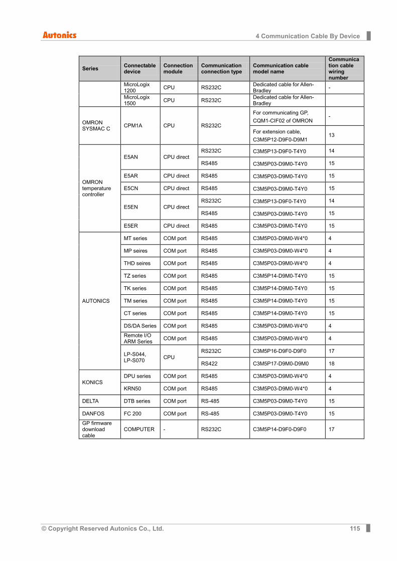
4 Communication Cable By Device
© Copyright Reserved Autonics Co., Ltd. 115
Series Connectable device
Connection module
Communication connection type
Communication cable model name
Communication cable wiring number
MicroLogix 1200 CPU RS232C Dedicated cable for Allen-
Bradley -
MicroLogix 1500 CPU RS232C Dedicated cable for Allen-
Bradley
OMRON SYSMAC C CPM1A CPU RS232C
For communicating GP,
CQM1-CIF02 of OMRON -
For extension cable,
C3M5P12-D9F0-D9M1 13
OMRON temperature controller
E5AN CPU direct RS232C C3M5P13-D9F0-T4Y0 14
RS485 C3M5P03-D9M0-T4Y0 15
E5AR CPU direct RS485 C3M5P03-D9M0-T4Y0 15
E5CN CPU direct RS485 C3M5P03-D9M0-T4Y0 15
E5EN CPU direct RS232C C3M5P13-D9F0-T4Y0 14
RS485 C3M5P03-D9M0-T4Y0 15
E5ER CPU direct RS485 C3M5P03-D9M0-T4Y0 15
AUTONICS
MT series COM port RS485 C3M5P03-D9M0-W4*0 4
MP seires COM port RS485 C3M5P03-D9M0-W4*0 4
THD seires COM port RS485 C3M5P03-D9M0-W4*0 4
TZ series COM port RS485 C3M5P14-D9M0-T4Y0 15
TK series COM port RS485 C3M5P14-D9M0-T4Y0 15
TM series COM port RS485 C3M5P14-D9M0-T4Y0 15
CT series COM port RS485 C3M5P14-D9M0-T4Y0 15
DS/DA Series COM port RS485 C3M5P03-D9M0-W4*0 4
Remote I/O ARM Series COM port RS485 C3M5P03-D9M0-W4*0 4
LP-S044, LP-S070 CPU
RS232C C3M5P16-D9F0-D9F0 17
RS422 C3M5P17-D9M0-D9M0 18
KONICS DPU series COM port RS485 C3M5P03-D9M0-W4*0 4
KRN50 COM port RS485 C3M5P03-D9M0-W4*0 4
DELTA DTB series COM port RS-485 C3M5P03-D9M0-T4Y0 15
DANFOS FC 200 COM port RS-485 C3M5P03-D9M0-T4Y0 15
GP firmware download cable
COMPUTER - RS232C C3M5P14-D9F0-D9F0 17

4 Communication Cable By Device
116 © Copyright Reserved Autonics Co., Ltd.

5 Universal (General-purpose communication)
© Copyright Reserved Autonics Co., Ltd. 117
5 Universal (General-purpose communication) Universal indicates general purpose of communication, Modbus Slave communication is supported in GP/LP.
5.1 System organization Microcomputer using as host unit is able to execute slave communicate with GP/LP through RS-232C or RS-422(RS-485) communication port. Host unit read and write inner register(UB, UW) of GP/LP as communication commander. Host unit as master transmits command to GP/LP and GP/LP as slave executes designated operation according to transmitted command and sends respond message.
The following is the system organization for connecting with GP/LP and host unit.
※For connect cable information, refer to ‘1.3 Communication’.
The following table is for basic communication configuration of host unit.
No Item Description Note
1 Communication mode
RTU Not used
2 Baudrate 38400 bps Fixed
3 Data type
Data length 8 bit Fixed
Parity None Fixed
Stop bit 1 bit Fixed
4 Station 1 to 31 Designate this in GP/LP

5 Universal (General-purpose communication)
118 © Copyright Reserved Autonics Co., Ltd.
5.2 Universal 1:1 communication Universal 1:1 indicates communication between one host unit and one GP/LP to monitor GP/LP status.(It is able to extend.)
5.2.1 GP Editor configuration Universal communication is available only by CH1.
1st Designate GP/LP and PLC type.
Item Description
①GP/LP Type Designate GP/LP model type by pull-down menu.
②CH1 Group Designate PLC group of CH1 by pull-down menu.
③CH1 Type Designate PLC type of CH1 for ② by pull-down menu.
④CH2 Group Designate PLC group of CH2 by pull-down menu.
⑤CH2 Type Designate PLC type of CH2 for ④ by pull-down menu.
2nd Select [Communication]-[Download] of menu and download data.
UNIVERSAL communication is executed by configuration of GP/LP download after additional configuration in EDITOR, because “UNIVERSAL” is saved in GP/LP.

5 Universal (General-purpose communication)
© Copyright Reserved Autonics Co., Ltd. 119
5.2.2 GP, LP configuration 5.2.2.1 Mono type
You should desigante CH1 protocol as ‘UNIVERSAL’ and set communication configuration for CH1 in GP/LP.
1st Enter system setting menu. Touch left-upper point as default position of system setting menu.
2nd Select [SET ENVIRONMENT]-[PLC SETTING].
3rd CH1 protocol is set as ‘UNIVERSAL’ and CH1 connection port is set as ‘RS422’ as default.
4th If it is not configured as ‘UNIVERSAL’ for CH1 protocol, touch protocol display item to
set ‘UNIVERSAL’ as following figure. Protocol display rotates in order as UNIVERSAL→MK-200S(CPU)→No Use→
PRINTER→BARCODE with touching.
5th Synchronize CH1 connect port display item with touching.
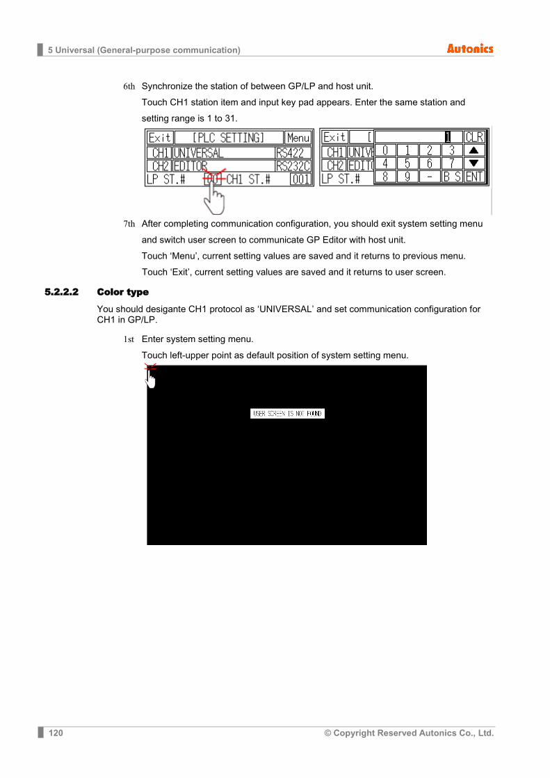
5 Universal (General-purpose communication)
120 © Copyright Reserved Autonics Co., Ltd.
6th Synchronize the station of between GP/LP and host unit. Touch CH1 station item and input key pad appears. Enter the same station and setting range is 1 to 31.
7th After completing communication configuration, you should exit system setting menu
and switch user screen to communicate GP Editor with host unit.
Touch ‘Menu’, current setting values are saved and it returns to previous menu.
Touch ‘Exit’, current setting values are saved and it returns to user screen.
5.2.2.2 Color type
You should desigante CH1 protocol as ‘UNIVERSAL’ and set communication configuration for CH1 in GP/LP.
1st Enter system setting menu. Touch left-upper point as default position of system setting menu.

5 Universal (General-purpose communication)
© Copyright Reserved Autonics Co., Ltd. 121
2nd Select [Environment]-[Serial Communication].
3rd CH1 protocol is set as ‘UNIVERSAL’ and CH1 connection port is set as ‘RS422’ as
default.
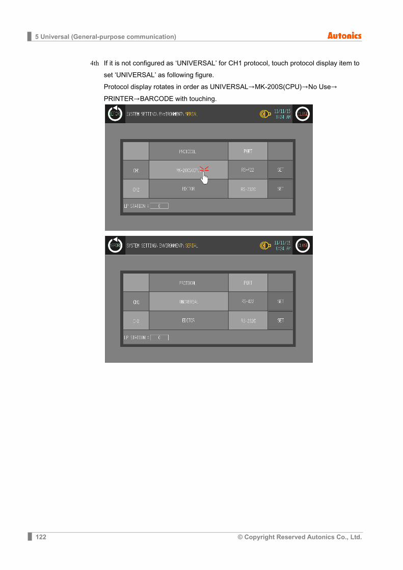
5 Universal (General-purpose communication)
122 © Copyright Reserved Autonics Co., Ltd.
4th If it is not configured as ‘UNIVERSAL’ for CH1 protocol, touch protocol display item to set ‘UNIVERSAL’ as following figure. Protocol display rotates in order as UNIVERSAL→MK-200S(CPU)→No Use→
PRINTER→BARCODE with touching.

5 Universal (General-purpose communication)
© Copyright Reserved Autonics Co., Ltd. 123
5th Synchronize CH1 connect port display item with touching.
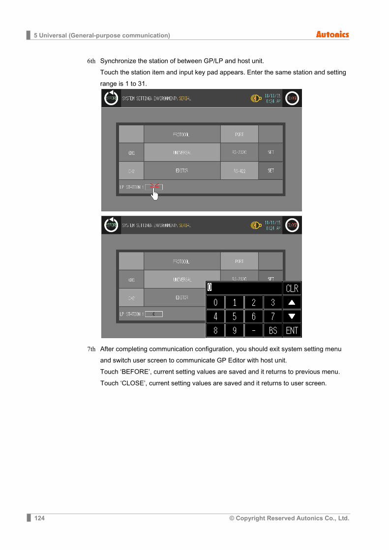
5 Universal (General-purpose communication)
124 © Copyright Reserved Autonics Co., Ltd.
6th Synchronize the station of between GP/LP and host unit. Touch the station item and input key pad appears. Enter the same station and setting range is 1 to 31.
7th After completing communication configuration, you should exit system setting menu and switch user screen to communicate GP Editor with host unit.
Touch ‘BEFORE’, current setting values are saved and it returns to previous menu.
Touch ‘CLOSE’, current setting values are saved and it returns to user screen.
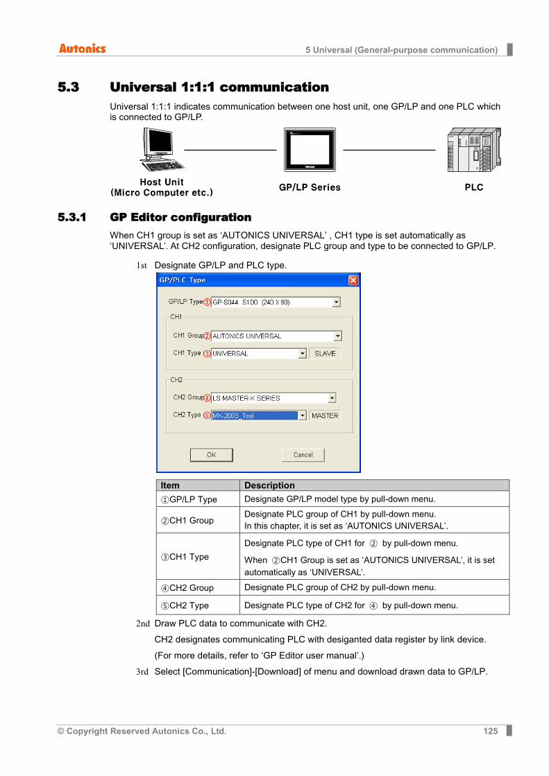
5 Universal (General-purpose communication)
© Copyright Reserved Autonics Co., Ltd. 125
5.3 Universal 1:1:1 communication Universal 1:1:1 indicates communication between one host unit, one GP/LP and one PLC which is connected to GP/LP.
5.3.1 GP Editor configuration When CH1 group is set as ‘AUTONICS UNIVERSAL’ , CH1 type is set automatically as ‘UNIVERSAL’. At CH2 configuration, designate PLC group and type to be connected to GP/LP.
1st Designate GP/LP and PLC type.
Item Description
①GP/LP Type Designate GP/LP model type by pull-down menu.
②CH1 Group Designate PLC group of CH1 by pull-down menu. In this chapter, it is set as ‘AUTONICS UNIVERSAL’.
③CH1 Type Designate PLC type of CH1 for ② by pull-down menu.
When ②CH1 Group is set as ‘AUTONICS UNIVERSAL’, it is set automatically as ‘UNIVERSAL’.
④CH2 Group Designate PLC group of CH2 by pull-down menu.
⑤CH2 Type Designate PLC type of CH2 for ④ by pull-down menu.
2nd Draw PLC data to communicate with CH2. CH2 designates communicating PLC with desiganted data register by link device. (For more details, refer to ‘GP Editor user manual’.)
3rd Select [Communication]-[Download] of menu and download drawn data to GP/LP.
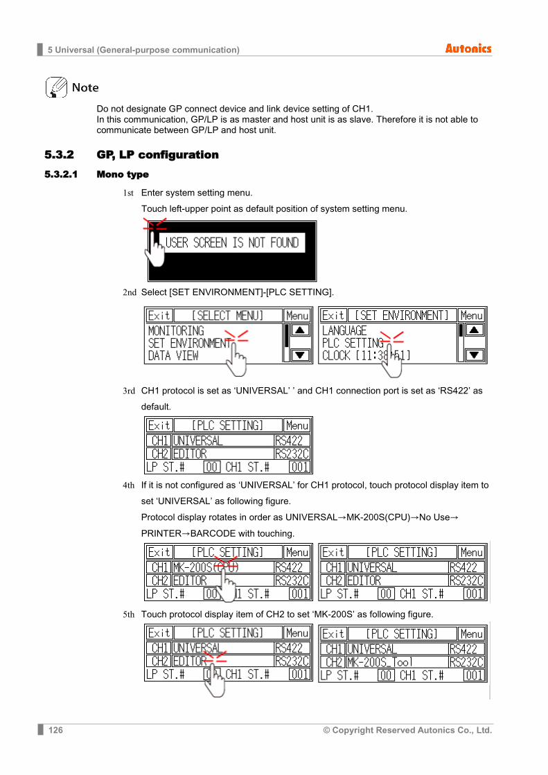
5 Universal (General-purpose communication)
126 © Copyright Reserved Autonics Co., Ltd.
Do not designate GP connect device and link device setting of CH1. In this communication, GP/LP is as master and host unit is as slave. Therefore it is not able to communicate between GP/LP and host unit.
5.3.2 GP, LP configuration 5.3.2.1 Mono type
1st Enter system setting menu. Touch left-upper point as default position of system setting menu.
2nd Select [SET ENVIRONMENT]-[PLC SETTING].
3rd CH1 protocol is set as ‘UNIVERSAL’ ’ and CH1 connection port is set as ‘RS422’ as default.
4th If it is not configured as ‘UNIVERSAL’ for CH1 protocol, touch protocol display item to
set ‘UNIVERSAL’ as following figure. Protocol display rotates in order as UNIVERSAL→MK-200S(CPU)→No Use→
PRINTER→BARCODE with touching.
5th Touch protocol display item of CH2 to set ‘MK-200S’ as following figure.
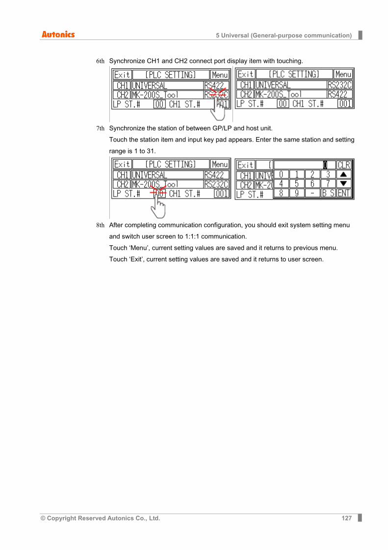
5 Universal (General-purpose communication)
© Copyright Reserved Autonics Co., Ltd. 127
6th Synchronize CH1 and CH2 connect port display item with touching.
7th Synchronize the station of between GP/LP and host unit. Touch the station item and input key pad appears. Enter the same station and setting range is 1 to 31.
8th After completing communication configuration, you should exit system setting menu
and switch user screen to 1:1:1 communication.
Touch ‘Menu’, current setting values are saved and it returns to previous menu.
Touch ‘Exit’, current setting values are saved and it returns to user screen.

5 Universal (General-purpose communication)
128 © Copyright Reserved Autonics Co., Ltd.
5.3.2.2 Color type
1st Enter system setting menu. Touch left-upper point as default position of system setting menu.
2nd Select [Environment]-[Serial Communication].

5 Universal (General-purpose communication)
© Copyright Reserved Autonics Co., Ltd. 129
3rd CH1 protocol is set as ‘UNIVERSAL’ and CH1 connection port is set as ‘RS422’ as default.
4th If it is not configured as ‘UNIVERSAL’ for CH1 protocol, touch protocol display item to set ‘UNIVERSAL’ as following figure. Protocol display rotates in order as UNIVERSAL→MK-200S(CPU)→No Use→
PRINTER→BARCODE with touching.
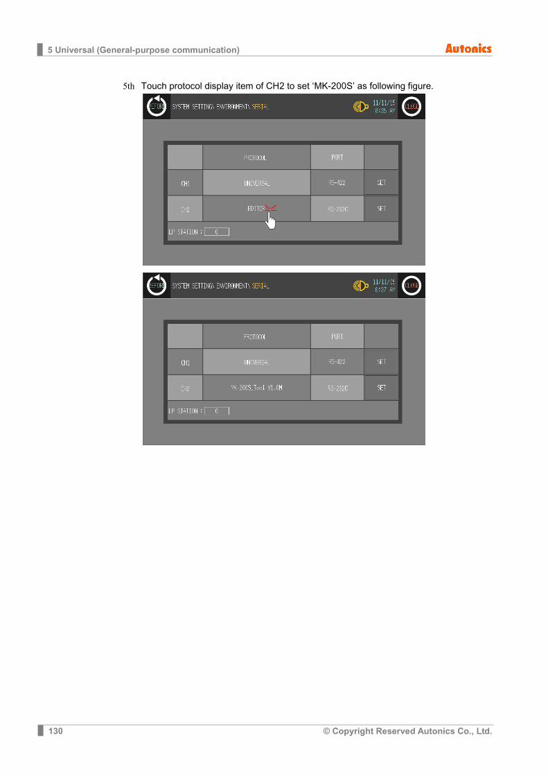
5 Universal (General-purpose communication)
130 © Copyright Reserved Autonics Co., Ltd.
5th Touch protocol display item of CH2 to set ‘MK-200S’ as following figure.
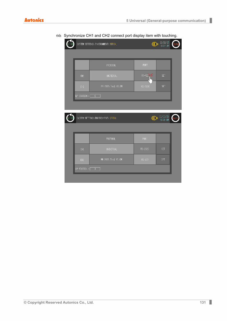
5 Universal (General-purpose communication)
© Copyright Reserved Autonics Co., Ltd. 131
6th Synchronize CH1 and CH2 connect port display item with touching.
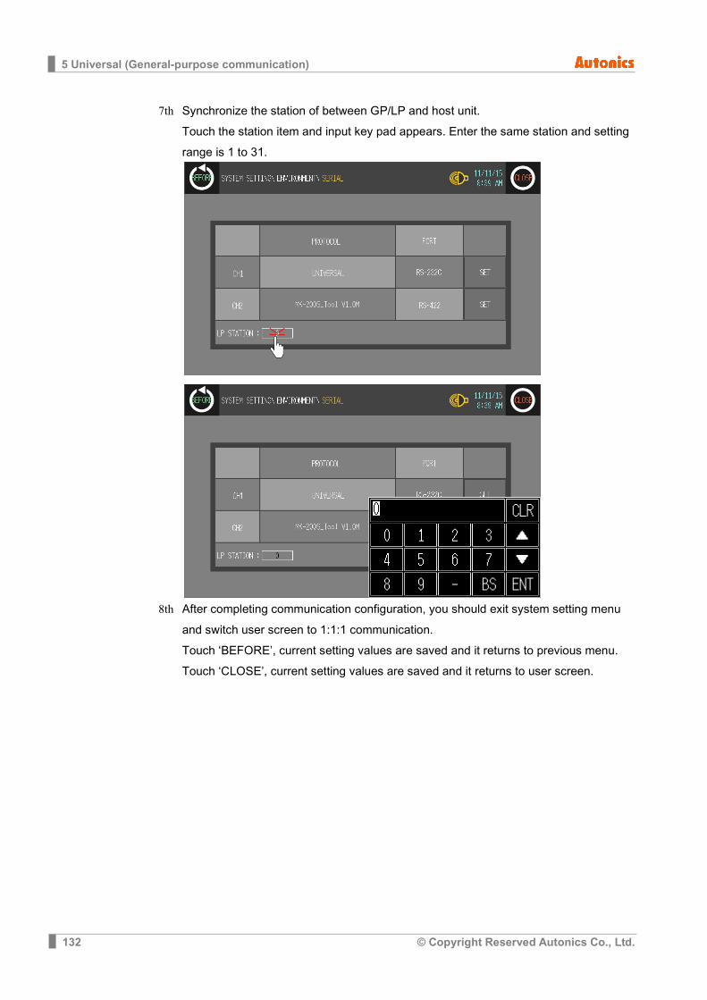
5 Universal (General-purpose communication)
132 © Copyright Reserved Autonics Co., Ltd.
7th Synchronize the station of between GP/LP and host unit. Touch the station item and input key pad appears. Enter the same station and setting range is 1 to 31.
8th After completing communication configuration, you should exit system setting menu
and switch user screen to 1:1:1 communication. Touch ‘BEFORE’, current setting values are saved and it returns to previous menu.
Touch ‘CLOSE’, current setting values are saved and it returns to user screen.
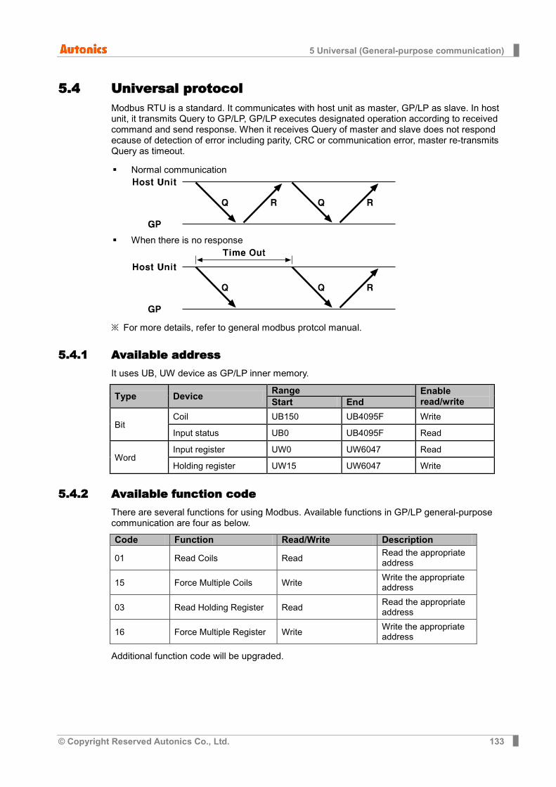
5 Universal (General-purpose communication)
© Copyright Reserved Autonics Co., Ltd. 133
5.4 Universal protocol Modbus RTU is a standard. It communicates with host unit as master, GP/LP as slave. In host unit, it transmits Query to GP/LP, GP/LP executes designated operation according to received command and send response. When it receives Query of master and slave does not respond ecause of detection of error including parity, CRC or communication error, master re-transmits Query as timeout.
Normal communication
When there is no response
※ For more details, refer to general modbus protcol manual.
5.4.1 Available address It uses UB, UW device as GP/LP inner memory.
Type Device Range Enable read/write Start End
Bit Coil UB150 UB4095F Write Input status UB0 UB4095F Read
Word Input register UW0 UW6047 Read Holding register UW15 UW6047 Write
5.4.2 Available function code There are several functions for using Modbus. Available functions in GP/LP general-purpose communication are four as below.
Code Function Read/Write Description
01 Read Coils Read Read the appropriate address
15 Force Multiple Coils Write Write the appropriate address
03 Read Holding Register Read Read the appropriate address
16 Force Multiple Register Write Write the appropriate address
Additional function code will be upgraded.

5 Universal (General-purpose communication)
134 © Copyright Reserved Autonics Co., Ltd.
5.4.3 Communication frame organization 5.4.3.1 Query master part
Station Function code Data area CRC
L H
① ② ③ ④
Item Description
①Station It is slave station (HEX) receiving a message from master. Setting range is 0 to 255. If it is 0, it is broadcast query which sends message to every slave.
②Function code (HEX) Slave executes designated function according to function code. Available set code is 01(Read Coils), 15(Force Multiple Coils), 03(Read Holding Register) and 16(Force Multiple Register).
③Data area (HEX) Transmit data related with function code. Data organization consists of (Upper 1byte) + (Lower 1byte) of the appropriate address. The length of area is variable and it is able to communicate without data.
④CRC(HEX) It is error check area. It calculates using CRC-16 code. It consists of 2btye. (Lower 1byte of CRC) + (Upper 1byte of CRC)
(1) Read Coils(Func01-01H)
Slave Address (station)
Function (command)
Starting Address (starting address)
No. of Points (the number of data)
Error Check (CRC16)
Hi(upper) Lo(lower) Hi(upper) Lo(lower) Lo(lower) Hi(upper)
1Byte 1Byte 1Byte 1Byte 1Byte 1Byte 1Byte 1Byte
(2) Force Multiple Coils(Func15-0FH)
Slave Address (station)
Function (command)
Starting Address (starting address)
No. of Coils (the number of data)
Byte Count (the number of data
byte) Hi(upper) Lo(lower) Hi(upper) Lo(lower)
1Byte 1Byte 1Byte 1Byte 1Byte 1Byte 1Byte
Data (data)
Data (data)
Data (data)
Data (data)
Error Check (CRC16)
Lo(lower) Hi(upper)
1Byte 1Byte 1Byte 1Byte 1Byte 1Byte
(3) Read Holding Registers(Func03-03H)
Slave Address (station)
Function (command)
Starting Address (starting address)
No. of Points (the number of data)
Error Check (CRC16)
Hi(upper) Lo(lower) Hi(upper) Lo(lower) Lo(lower) Hi(upper)
1Byte 1Byte 1Byte 1Byte 1Byte 1Byte 1Byte 1Byte
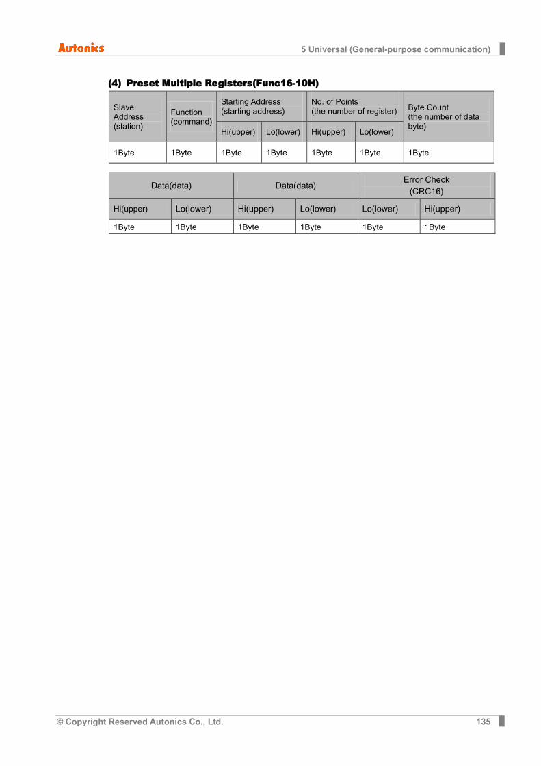
5 Universal (General-purpose communication)
© Copyright Reserved Autonics Co., Ltd. 135
(4) Preset Multiple Registers(Func16-10H)
Slave Address (station)
Function (command)
Starting Address (starting address)
No. of Points (the number of register) Byte Count
(the number of data byte)
Hi(upper) Lo(lower) Hi(upper) Lo(lower)
1Byte 1Byte 1Byte 1Byte 1Byte 1Byte 1Byte
Data(data) Data(data) Error Check
(CRC16)
Hi(upper) Lo(lower) Hi(upper) Lo(lower) Lo(lower) Hi(upper)
1Byte 1Byte 1Byte 1Byte 1Byte 1Byte
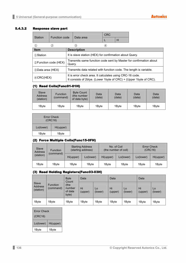
5 Universal (General-purpose communication)
136 © Copyright Reserved Autonics Co., Ltd.
5.4.3.2 Response slave part
Station Function code Data area CRC
L H
① ② ③ ④ Item Description
①Station It is slave station (HEX) for confirmation about Query.
②Function code (HEX) Transmits same function code sent by Master for confirmation about Query.
③Data area (HEX) Transmits data related with function code. The length is variable.
④CRC(HEX) It is error check area. It calculates using CRC-16 code. It consists of 2btye. (Lower 1byte of CRC) + (Upper 1byte of CRC).
(1) Read Coils(Func01-01H)
Slave Address (station)
Function (command)
Byte Count (the number of data byte)
Data (data)
Data (data)
Data (data)
Data (data)
1Byte 1Byte 1Byte 1Byte 1Byte 1Byte 1Byte
Error Check (CRC16)
Lo(lower) Hi(upper)
1Byte 1Byte
(2) Force Multiple Coils(Func15-0FH)
Slave Address (station)
Function (command)
Starting Address (starting address)
No. of Coil (the number of coil)
Error Check (CRC16)
Hi(upper) Lo(lower) Hi(upper) Lo(lower) Lo(lower) Hi(upper)
1Byte 1Byte 1Byte 1Byte 1Byte 1Byte 1Byte 1Byte
(3) Read Holding Registers(Func03-03H)
Slave Address (station)
Function (command)
Byte Count (the number of data byte)
Data Data Data
Hi (upper)
Lo (lower)
Hi (upper)
Lo (lower)
Hi (upper)
Lo (lower)
1Byte 1Byte 1Byte 1Byte 1Byte 1Byte 1Byte 1Byte 1Byte
Error Check
(CRC16)
Lo(lower) Hi(upper)
1Byte 1Byte
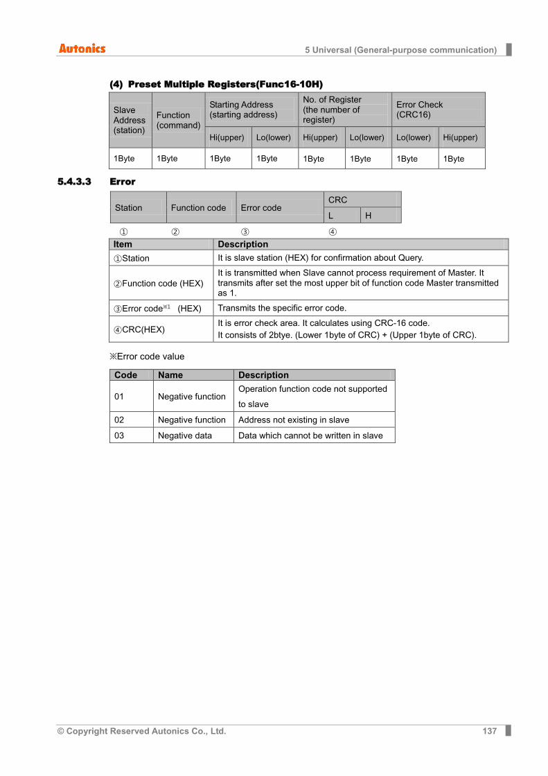
5 Universal (General-purpose communication)
© Copyright Reserved Autonics Co., Ltd. 137
(4) Preset Multiple Registers(Func16-10H)
Slave Address (station)
Function (command)
Starting Address (starting address)
No. of Register (the number of register)
Error Check (CRC16)
Hi(upper) Lo(lower) Hi(upper) Lo(lower) Lo(lower) Hi(upper)
1Byte 1Byte 1Byte 1Byte 1Byte 1Byte 1Byte 1Byte
5.4.3.3 Error
Station Function code Error code CRC
L H
① ② ③ ④ Item Description
①Station It is slave station (HEX) for confirmation about Query.
②Function code (HEX) It is transmitted when Slave cannot process requirement of Master. It transmits after set the most upper bit of function code Master transmitted as 1.
③Error code※1 (HEX) Transmits the specific error code.
④CRC(HEX) It is error check area. It calculates using CRC-16 code. It consists of 2btye. (Lower 1byte of CRC) + (Upper 1byte of CRC).
※Error code value
Code Name Description
01 Negative function Operation function code not supported to slave
02 Negative function Address not existing in slave
03 Negative data Data which cannot be written in slave
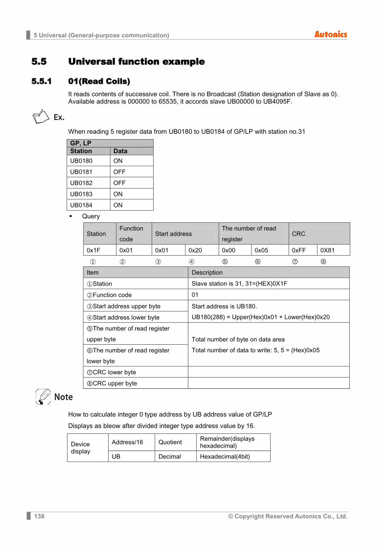
5 Universal (General-purpose communication)
138 © Copyright Reserved Autonics Co., Ltd.
5.5 Universal function example
5.5.1 01(Read Coils) It reads contents of successive coil. There is no Broadcast (Station designation of Slave as 0). Available address is 000000 to 65535, it accords slave UB00000 to UB4095F.
When reading 5 register data from UB0180 to UB0184 of GP/LP with station no.31
GP, LP Station Data UB0180 ON
UB0181 OFF
UB0182 OFF
UB0183 ON
UB0184 ON
Query
Station Function code
Start address The number of read register
CRC
0x1F 0x01 0x01 0x20 0x00 0x05 0xFF 0X81
① ② ③ ④ ⑤ ⑥ ⑦ ⑧
Item Description
①Station Slave station is 31, 31=(HEX)0X1F
②Function code 01
③Start address upper byte Start address is UB180. UB180(288) = Upper(Hex)0x01 + Lower(Hex)0x20 ④Start address lower byte
⑤The number of read register upper byte Total number of byte on data area
Total number of data to write: 5, 5 = (Hex)0x05 ⑥The number of read register lower byte
⑦CRC lower byte
⑧CRC upper byte
How to calculate integer 0 type address by UB address value of GP/LP
Displays as bleow after divided integer type address value by 16.
Device display
Address/16 Quotient Remainder(displays hexadecimal)
UB Decimal Hexadecimal(4bit)
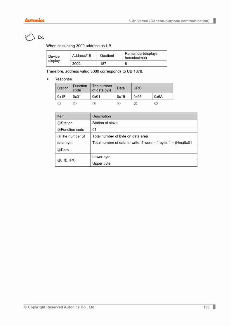
5 Universal (General-purpose communication)
© Copyright Reserved Autonics Co., Ltd. 139
When calcuating 3000 address as UB
Device display
Address/16 Quotient Remainder(displays hexadecimal)
3000 187 8
Therefore, address valud 3000 corresponds to UB 1878.
Response
Station Function code
The number of data byte Data CRC
0x1F 0x01 0x01 0x19 0x96 0x6A
① ② ③ ④ ⑤ ⑦
Item Description
①Station Station of slave
②Function code 01
③The number of data byte
Total number of byte on data area Total number of data to write: 5 word = 1 byte. 1 = (Hex)0x01
④Data
⑤, ⑦CRC Lower byte
Upper byte
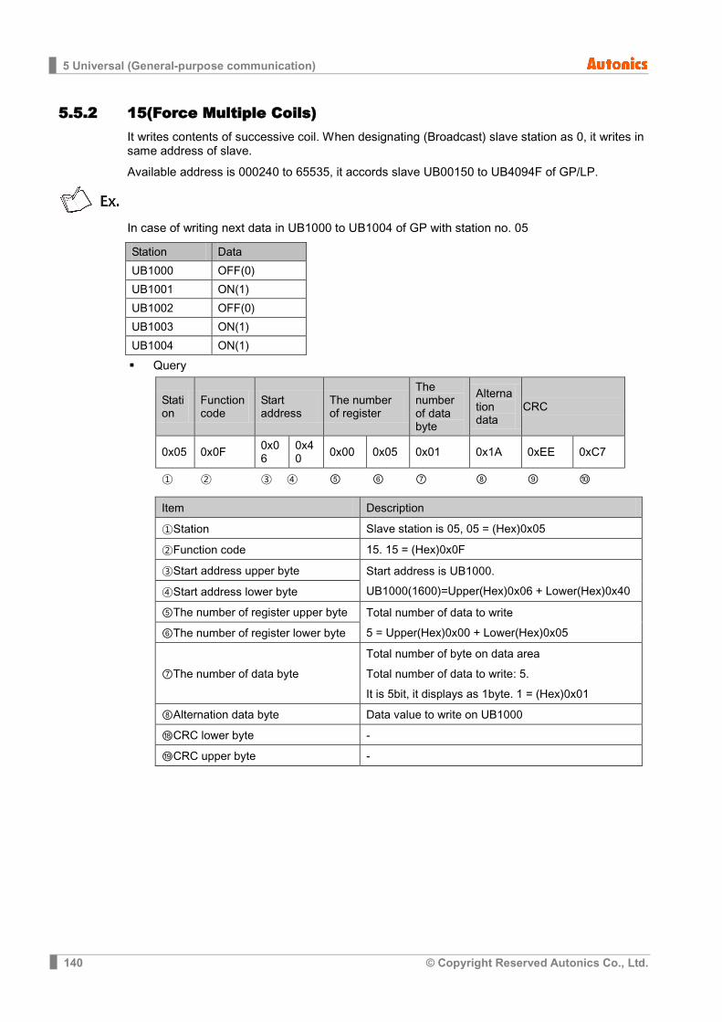
5 Universal (General-purpose communication)
140 © Copyright Reserved Autonics Co., Ltd.
5.5.2 15(Force Multiple Coils) It writes contents of successive coil. When designating (Broadcast) slave station as 0, it writes in same address of slave.
Available address is 000240 to 65535, it accords slave UB00150 to UB4094F of GP/LP.
In case of writing next data in UB1000 to UB1004 of GP with station no. 05
Station Data
UB1000 OFF(0)
UB1001 ON(1)
UB1002 OFF(0)
UB1003 ON(1)
UB1004 ON(1)
Query
Station
Function code
Start address
The number of register
The number of data byte
Alternation data
CRC
0x05 0x0F 0x06
0x40 0x00 0x05 0x01 0x1A 0xEE 0xC7
① ② ③ ④ ⑤ ⑥ ⑦ ⑧ ⑨ ⑩
Item Description
①Station Slave station is 05, 05 = (Hex)0x05
②Function code 15. 15 = (Hex)0x0F
③Start address upper byte Start address is UB1000. UB1000(1600)=Upper(Hex)0x06 + Lower(Hex)0x40 ④Start address lower byte
⑤The number of register upper byte Total number of data to write 5 = Upper(Hex)0x00 + Lower(Hex)0x05 ⑥The number of register lower byte
⑦The number of data byte Total number of byte on data area Total number of data to write: 5. It is 5bit, it displays as 1byte. 1 = (Hex)0x01
⑧Alternation data byte Data value to write on UB1000
⑱CRC lower byte -
⑲CRC upper byte -
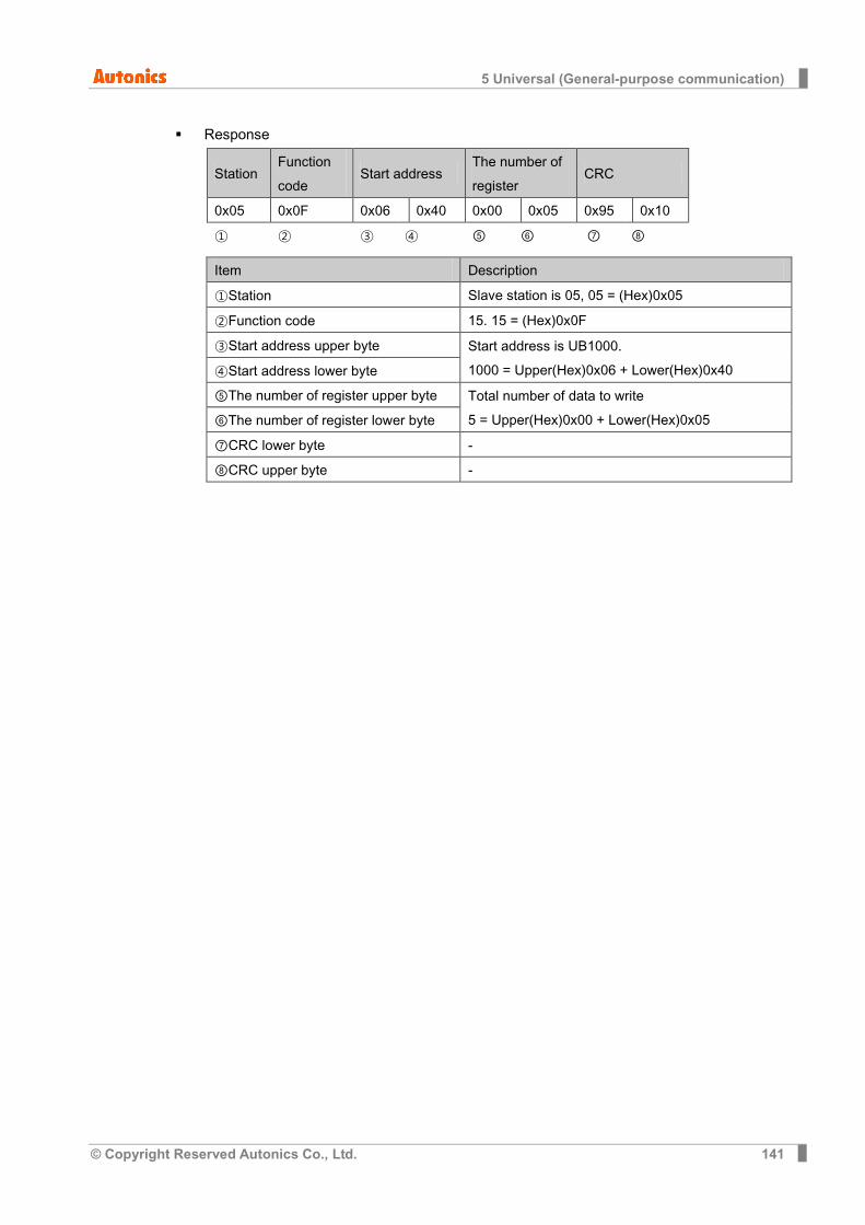
5 Universal (General-purpose communication)
© Copyright Reserved Autonics Co., Ltd. 141
Response
Station Function code
Start address The number of register
CRC
0x05 0x0F 0x06 0x40 0x00 0x05 0x95 0x10
① ② ③ ④ ⑤ ⑥ ⑦ ⑧
Item Description
①Station Slave station is 05, 05 = (Hex)0x05
②Function code 15. 15 = (Hex)0x0F
③Start address upper byte Start address is UB1000. 1000 = Upper(Hex)0x06 + Lower(Hex)0x40 ④Start address lower byte
⑤The number of register upper byte Total number of data to write 5 = Upper(Hex)0x00 + Lower(Hex)0x05 ⑥The number of register lower byte
⑦CRC lower byte -
⑧CRC upper byte -
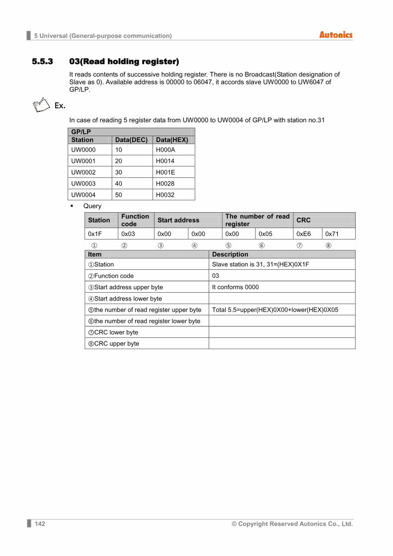
5 Universal (General-purpose communication)
142 © Copyright Reserved Autonics Co., Ltd.
5.5.3 03(Read holding register) It reads contents of successive holding register. There is no Broadcast(Station designation of Slave as 0). Available address is 00000 to 06047, it accords slave UW0000 to UW6047 of GP/LP.
In case of reading 5 register data from UW0000 to UW0004 of GP/LP with station no.31
GP/LP Station Data(DEC) Data(HEX) UW0000 10 H000A
UW0001 20 H0014
UW0002 30 H001E
UW0003 40 H0028
UW0004 50 H0032
Query
Station Function code Start address The number of read
register CRC
0x1F 0x03 0x00 0x00 0x00 0x05 0xE6 0x71
① ② ③ ④ ⑤ ⑥ ⑦ ⑧ Item Description
①Station Slave station is 31, 31=(HEX)0X1F
②Function code 03
③Start address upper byte It conforms 0000
④Start address lower byte
⑤the number of read register upper byte Total 5.5=upper(HEX)0X00+lower(HEX)0X05
⑥the number of read register lower byte
⑦CRC lower byte
⑧CRC upper byte
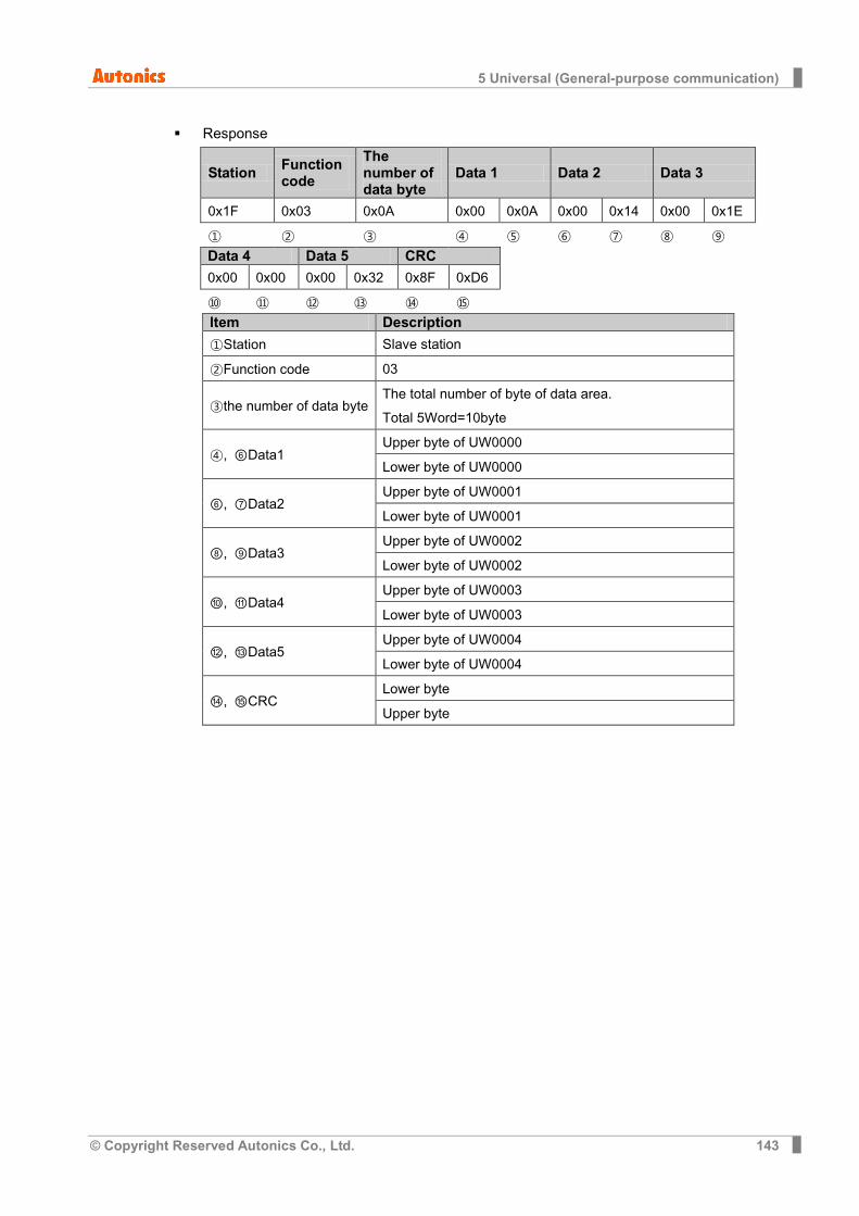
5 Universal (General-purpose communication)
© Copyright Reserved Autonics Co., Ltd. 143
Response
Station Function code
The number of data byte
Data 1 Data 2 Data 3
0x1F 0x03 0x0A 0x00 0x0A 0x00 0x14 0x00 0x1E
① ② ③ ④ ⑤ ⑥ ⑦ ⑧ ⑨ Data 4 Data 5 CRC
0x00 0x00 0x00 0x32 0x8F 0xD6
⑩ ⑪ ⑫ ⑬ ⑭ ⑮ Item Description
①Station Slave station
②Function code 03
③the number of data byte The total number of byte of data area. Total 5Word=10byte
④, ⑥Data1 Upper byte of UW0000
Lower byte of UW0000
⑥, ⑦Data2 Upper byte of UW0001
Lower byte of UW0001
⑧, ⑨Data3 Upper byte of UW0002
Lower byte of UW0002
⑩, ⑪Data4 Upper byte of UW0003
Lower byte of UW0003
⑫, ⑬Data5 Upper byte of UW0004
Lower byte of UW0004
⑭, ⑮CRC Lower byte
Upper byte

5 Universal (General-purpose communication)
144 © Copyright Reserved Autonics Co., Ltd.
5.5.4 16(Preset multiple register) It writes contents of successive holding register. When designating(Broadcast) slave station as 0, it writes in same address of slave.
Available address is 00015 to 06047, it accords slave UW0015 to UW6047 of GP/LP.
In case of writing next data in UW100 to UW104 of GP/LP with station no.05.
Data(DEC) Data(HEX)
123 H007B
234 H00EA
345 H0159
456 H01C8
567 H0237
Query
Station
Function code
Start address
The number of register
The number of data byte
Alternation data 1
0x05 0x10 0x00 0x64 0x00 0x05 0x0A 0x00 0x7B
① ② ③ ④ ⑤ ⑥ ⑦ ⑧ ⑨
Alternation data 2
Alternation data 3
Alternation data 4
Alternation data 5 CRC
0x00 0xEA 0x01 0x59 0x01 0xC8 0x02 0x37 0xA6 0xC9
⑩ ⑪ ⑫ ⑬ ⑭ ⑮ ⑯ ⑰ ⑱ ⑲
Item Description
①Station Slave station is 05, 05 = (Hex)0x05
②Function code 16. 16 = (Hex)0x10
③Start address upper byte Start address is UW100. 100 = upper (Hex)0x00 + lower (Hex)0x64
④Start address lower byte
⑤The number of register upper byte The total number of data to write.
5 = upper (Hex)0x00 + lower (Hex)0x05
⑥The number of register lower byte
⑦The number of data byte The total number of byte of data area. The total number of data to write: 5 Word = 10 byte. 10 = (Hex)0x0A
⑧Alternation data 1 upper byte Upper byte value of data to write in UW100
⑨Alternation data 1 lower byte Lower byte value of data to write in UW100
⑩Alternation data 2 upper byte Upper byte value of data to write in UW101
⑪Alternation data 2 lower byte Lower byte value of data to write in UW101
⑫Alternation data 3 upper byte Upper byte value of data to write in UW102
⑬Alternation data 3 lower byte Lower byte value of data to write in UW102

5 Universal (General-purpose communication)
© Copyright Reserved Autonics Co., Ltd. 145
Item Description
⑭Alternation data 4 upper byte Upper byte value of data to write in UW103
⑮Alternation data 4 lower byte Lower byte value of data to write in UW103
⑯Alternation data 5 upper byte Upper byte value of data to write in UW104
⑰Alternation data 5 lower byte Lower byte value of data to write in UW104
⑱CRC lower byte
⑲CRC upper byte
Response
Station
Function code Start address The number
of register CRC
0x05 0x10 0x00 0x64 0x00 0x05 0x40 0x51
① ② ③ ④ ⑤ ⑥ ⑦ ⑧
Item Description
①Station Slave station is 05, 05 = (Hex)0x05
②Function code 16. 16 = (Hex)0x10
③Start address upper byte Start address is UW100. 100 = upper (Hex)0x00 + lower (Hex)0x64
④Start address lower byte
⑤The number of register upper byte The total number of data to write. 5 = upper (Hex)0x00 + lower (Hex)0x05
⑥The number of register lower byte
⑦CRC lower byte
⑧CRC upper byte
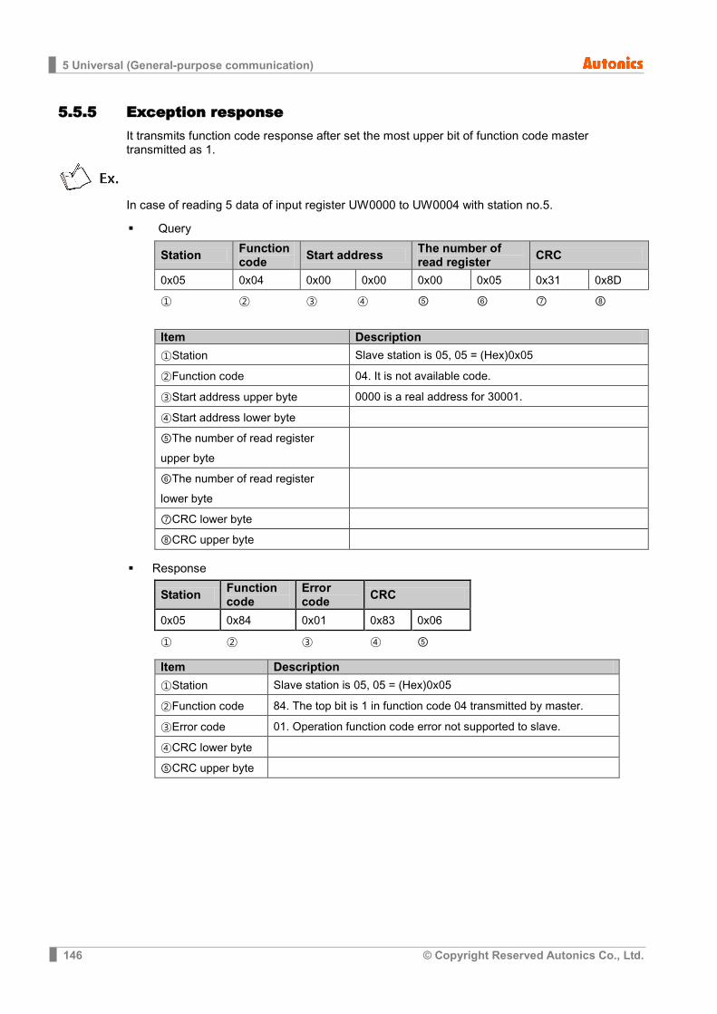
5 Universal (General-purpose communication)
146 © Copyright Reserved Autonics Co., Ltd.
5.5.5 Exception response It transmits function code response after set the most upper bit of function code master transmitted as 1.
In case of reading 5 data of input register UW0000 to UW0004 with station no.5.
Query
Station Function code Start address The number of
read register CRC
0x05 0x04 0x00 0x00 0x00 0x05 0x31 0x8D
① ② ③ ④ ⑤ ⑥ ⑦ ⑧
Item Description
①Station Slave station is 05, 05 = (Hex)0x05
②Function code 04. It is not available code.
③Start address upper byte 0000 is a real address for 30001.
④Start address lower byte
⑤The number of read register upper byte
⑥The number of read register lower byte
⑦CRC lower byte
⑧CRC upper byte
Response
Station Function code
Error code CRC
0x05 0x84 0x01 0x83 0x06
① ② ③ ④ ⑤
Item Description
①Station Slave station is 05, 05 = (Hex)0x05
②Function code 84. The top bit is 1 in function code 04 transmitted by master.
③Error code 01. Operation function code error not supported to slave.
④CRC lower byte
⑤CRC upper byte
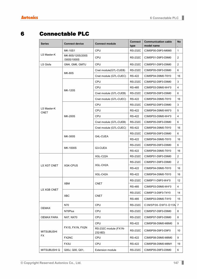
6 Connectable PLC
© Copyright Reserved Autonics Co., Ltd. 147
6 Connectable PLC Series Connect device Connect module
Connect
type
Communication cable
model name
No
.
LS Master-K
MK-10S1 CPU RS-232C C3M5P00-D9F0-M6M0 1
MK-80S/120S/200S
/300S/1000S CPU RS-232C C3M5P01-D9F0-D9M0 2
LS Glofa GM4, GM6, GM7U CPU RS-232C C3M5P01-D9F0-D9M0 2
LS Master-K
CNET
MK-80S Cnet module(G7L-CUEB) RS-232C C3M5P05-D9F0-D9M0 6
Cnet module (G7L-CUEC) RS-422 C3M5P04-D9M0-T6Y0 16
MK-120S
CPU RS-232C C3M5P02-D9F0-D9M0 3
CPU RS-485 C3M5P03-D9M0-W4*0 4
Cnet module (G7L-CUEB) RS-232C C3M5P05-D9F0-D9M0 6
Cnet module (G7L-CUEC) RS-422 C3M5P04-D9M0-T6Y0 16
MK-200S
CPU RS-232C C3M5P02-D9F0-D9M0 3
CPU RS-422 C3M5P04-D9M0-W6*0 5
CPU RS-422 C3M5P03-D9M0-W4*0 4
Cnet module (G7L-CUEB) RS-232C C3M5P05-D9F0-D9M0 6
Cnet module (G7L-CUEC) RS-422 C3M5P04-D9M0-T6Y0 16
MK-300S G4L-CUEA RS-232C C3M5P05-D9F0-D9M0 6
RS-422 C3M5P04-D9M0-T6Y0 16
MK-1000S G3-CUEA RS-232C C3M5P05-D9F0-D9M0 6
RS-422 C3M5P04-D9M0-T6Y0 16
LS XGT CNET XGK-CPUS
XGL-C22A RS-232C C3M5P01-D9F0-D9M0 2
XGL-CH2A RS-232C C3M5P01-D9F0-D9M0 2
RS-422 C3M5P04-D9M0-T6Y0 16
XGL-C42A RS-422 C3M5P04-D9M0-T6Y0 16
LS XGB CNET
XBM CNET RS-232C C3M5P11-D9F0-W4*0 12
RS-485 C3M5P03-D9M0-W4*0 4
XBC CNET RS-232C C3M5P13-D9F0-T4Y0 14
RS-485 C3M5P03-D9M0-T4Y0 15
OEMAX N70 CPU RS-232C C3M5P06-D9F0-D15M 7
N70Plus CPU RS-232C C3M5P07-D9F0-D9M0 8
OEMAX FARA NX7, NX70 CPU RS-232C C3M5P07-D9F0-D9M0 8
MITSUBUSHI
FX
FX1S, FX1N, FX2N
CPU RS-422 C3M5P08-D9M0-M8M0 9
RS-232C module (FX1N-
232-BD) RS-232C C3M5P09-D9F0-D9F0 10
FX2NC CPU RS-422 C3M5P08-D9M0-M8M0 9
FX3U CPU RS-422 C3M5P08-D9M0-M8M1 19
MITSUBUSHI Q Q00J, Q00, Q01, Extension module RS-232C C3M5P05-D9F0-D9M0 6
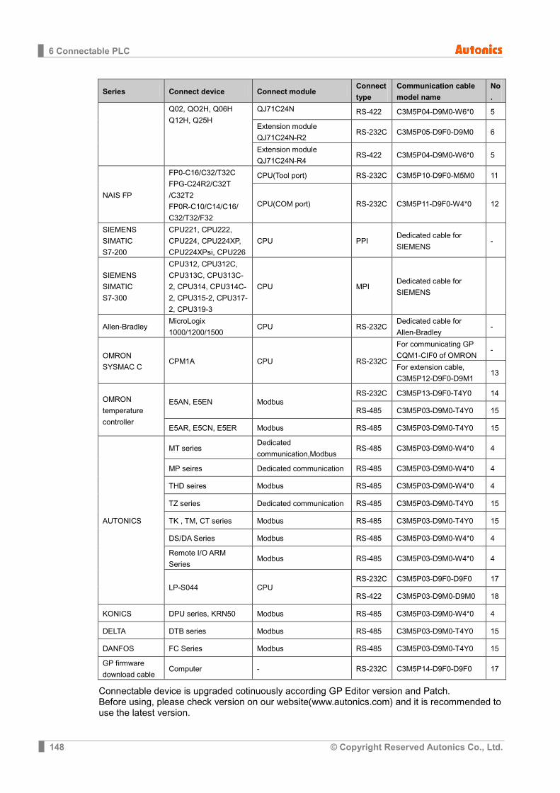
6 Connectable PLC
148 © Copyright Reserved Autonics Co., Ltd.
Series Connect device Connect module Connect
type
Communication cable
model name
No
.
Q02, QO2H, Q06H
Q12H, Q25H
QJ71C24N RS-422 C3M5P04-D9M0-W6*0 5
Extension module
QJ71C24N-R2 RS-232C C3M5P05-D9F0-D9M0 6
Extension module
QJ71C24N-R4 RS-422 C3M5P04-D9M0-W6*0 5
NAIS FP
FP0-C16/C32/T32C
FPG-C24R2/C32T
/C32T2
FP0R-C10/C14/C16/
C32/T32/F32
CPU(Tool port) RS-232C C3M5P10-D9F0-M5M0 11
CPU(COM port) RS-232C C3M5P11-D9F0-W4*0 12
SIEMENS
SIMATIC
S7-200
CPU221, CPU222,
CPU224, CPU224XP,
CPU224XPsi, CPU226
CPU PPI Dedicated cable for
SIEMENS -
SIEMENS
SIMATIC
S7-300
CPU312, CPU312C,
CPU313C, CPU313C-
2, CPU314, CPU314C-
2, CPU315-2, CPU317-
2, CPU319-3
CPU MPI Dedicated cable for
SIEMENS
Allen-Bradley MicroLogix
1000/1200/1500 CPU RS-232C
Dedicated cable for
Allen-Bradley -
OMRON
SYSMAC C CPM1A CPU RS-232C
For communicating GP
CQM1-CIF0 of OMRON -
For extension cable,
C3M5P12-D9F0-D9M1 13
OMRON
temperature
controller
E5AN, E5EN Modbus RS-232C C3M5P13-D9F0-T4Y0 14
RS-485 C3M5P03-D9M0-T4Y0 15
E5AR, E5CN, E5ER Modbus RS-485 C3M5P03-D9M0-T4Y0 15
AUTONICS
MT series Dedicated
communication,Modbus RS-485 C3M5P03-D9M0-W4*0 4
MP seires Dedicated communication RS-485 C3M5P03-D9M0-W4*0 4
THD seires Modbus RS-485 C3M5P03-D9M0-W4*0 4
TZ series Dedicated communication RS-485 C3M5P03-D9M0-T4Y0 15
TK , TM, CT series Modbus RS-485 C3M5P03-D9M0-T4Y0 15
DS/DA Series Modbus RS-485 C3M5P03-D9M0-W4*0 4
Remote I/O ARM
Series Modbus RS-485 C3M5P03-D9M0-W4*0 4
LP-S044 CPU RS-232C C3M5P03-D9F0-D9F0 17
RS-422 C3M5P03-D9M0-D9M0 18
KONICS DPU series, KRN50 Modbus RS-485 C3M5P03-D9M0-W4*0 4
DELTA DTB series Modbus RS-485 C3M5P03-D9M0-T4Y0 15
DANFOS FC Series Modbus RS-485 C3M5P03-D9M0-T4Y0 15
GP firmware
download cable Computer - RS-232C C3M5P14-D9F0-D9F0 17
Connectable device is upgraded cotinuously according GP Editor version and Patch. Before using, please check version on our website(www.autonics.com) and it is recommended to use the latest version.
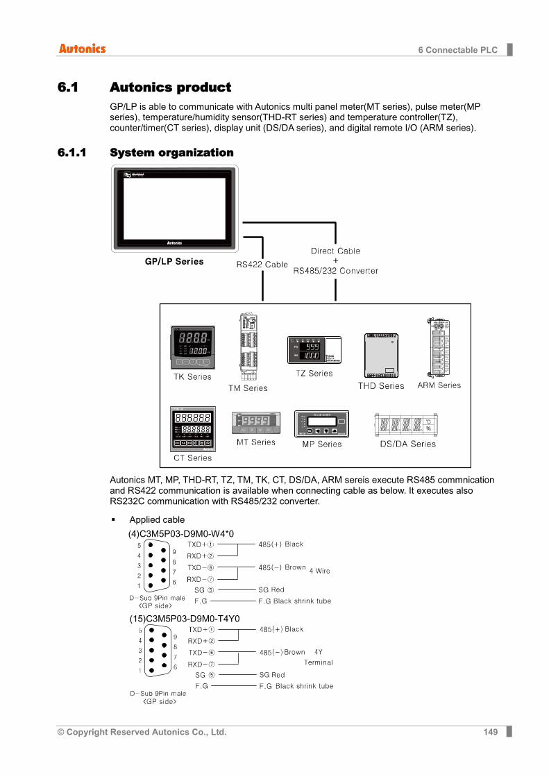
6 Connectable PLC
© Copyright Reserved Autonics Co., Ltd. 149
6.1 Autonics product GP/LP is able to communicate with Autonics multi panel meter(MT series), pulse meter(MP series), temperature/humidity sensor(THD-RT series) and temperature controller(TZ), counter/timer(CT series), display unit (DS/DA series), and digital remote I/O (ARM series).
6.1.1 System organization
Autonics MT, MP, THD-RT, TZ, TM, TK, CT, DS/DA, ARM sereis execute RS485 commnication and RS422 communication is available when connecting cable as below. It executes also RS232C communication with RS485/232 converter.
Applied cable
(4)C3M5P03-D9M0-W4*0
(15)C3M5P03-D9M0-T4Y0

6 Connectable PLC
150 © Copyright Reserved Autonics Co., Ltd.
PLC type Communication method
Default baudrate(bps)
Autonics
MT
RS485/422 9600
MT(MODBUS)
MP
THD-RT(MODBUS)
TZ
TM(MODBUS)
TK(MODBUS)
CT(MODBUS)
DS/DA(MODBUS)
Remote I/O ARM(MODBUS)
It should be set same between baudrate, station of Autonics controllers and the baudrate, station of GP/LP. Refer to each product’s user manual for communication configuration and station of each product.
Be sure that Autonics controller has devided read/write device for using device. Especially in the case of using CH2, refer to ‘3.3 1:N communication’.
6.1.2 Station configuration in GP/LP 1st Enter system setting menu.
Touch left-upper point as default position of system setting menu.
2nd Select [SET ENVIRONMENT]-[PLC SETTING].
3rd Touch CH1 station, station input key pad appears. Enter the same station of the
station which is set from MP(MT, THD, TZ, TM, TK, CT, DS/DA, ARM).
4th Touch ‘ENT’ to save the station and touch ‘Menu’ or ‘Exit’ to exit system setting meun.

6 Connectable PLC
© Copyright Reserved Autonics Co., Ltd. 151
6.1.3 Available device 6.1.3.1 MT series
Available device and displayed parameter of Autonics MT series are as following. Available device is only for MT series.
(1) Not Modbus communication type in MT series
Type Device Mark Range Start End
Bit GP/LP inner bit memory UB UB0 UB6047F
Word Word device area MT MT0 MT0
GP/LP inner word memory UW UW0 UW6047
Device Description Enable read/write
MT0 Present value Read
(2) Modbus communication type in MT series (MT4N)
1) Modbus (MT4N_Mod)
Type Device Mark Range Start End
Bit Bit device area MT MT10001 MT10001
Bit GP/LP inner bit memory UB UB0 UB6047F
Word
Word device area MT MT30001 MT30004
Word device area MT MT30101 MT30109
Word device area MT MT30118 MT30125
GP/LP inner word memory UW UW0 UW6047
Device Description Enable Read/Write MT30001 Present value Read
MT30002 Dot setting value Read
MT30003 Max. signal input Read
MT30004 Min. signal input Read
MT30101 Product number H Read
MT30102 Product number L Read
MT30103 Hardware version Read
MT30104 Software version Read
MT30105 Model name1 Read
MT30106 Model name2 Read
MT30107 Model name3 Read
MT30108 Model name4 Read
MT30109 Model name5 Read
MT30118 Coil start address Read
MT30119 Coil quantity Read
MT30120 Input start address Read
MT30121 Input quantity Read
MT30122 Holding REG start Read
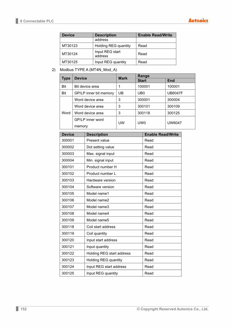
6 Connectable PLC
152 © Copyright Reserved Autonics Co., Ltd.
Device Description Enable Read/Write address
MT30123 Holding REG quantity Read
MT30124 Input REG start address Read
MT30125 Input REG quantity Read
2) Modbus TYPE A (MT4N_Mod_A)
Type Device Mark Range Start End
Bit Bit device area 1 100001 100001
Bit GP/LP inner bit memory UB UB0 UB6047F
Word
Word device area 3 300001 300004
Word device area 3 300101 300109
Word device area 3 300118 300125
GP/LP inner word memory
UW UW0 UW6047
Device Description Enable Read/Write
300001 Present value Read
300002 Dot setting value Read
300003 Max. signal input Read
300004 Min. signal input Read
300101 Product number H Read
300102 Product number L Read
300103 Hardware version Read
300104 Software version Read
300105 Model name1 Read
300106 Model name2 Read
300107 Model name3 Read
300108 Model name4 Read
300109 Model name5 Read
300118 Coil start address Read
300119 Coil quantity Read
300120 Input start address Read
300121 Input quantity Read
300122 Holding REG start address Read
300123 Holding REG quantity Read
300124 Input REG start address Read
300125 Input REG quantity Read
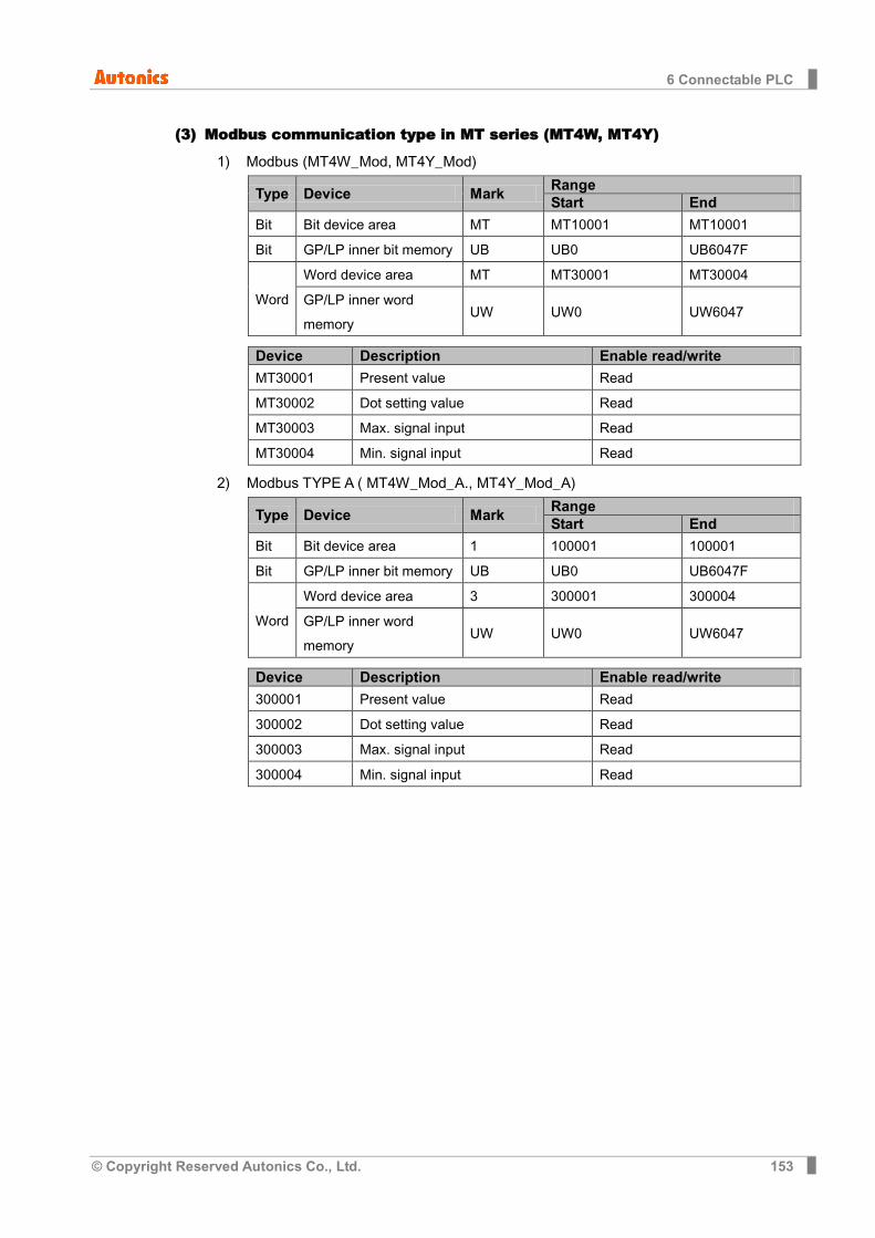
6 Connectable PLC
© Copyright Reserved Autonics Co., Ltd. 153
(3) Modbus communication type in MT series (MT4W, MT4Y)
1) Modbus (MT4W_Mod, MT4Y_Mod)
Type Device Mark Range Start End
Bit Bit device area MT MT10001 MT10001
Bit GP/LP inner bit memory UB UB0 UB6047F
Word
Word device area MT MT30001 MT30004
GP/LP inner word memory
UW UW0 UW6047
Device Description Enable read/write
MT30001 Present value Read
MT30002 Dot setting value Read
MT30003 Max. signal input Read
MT30004 Min. signal input Read
2) Modbus TYPE A ( MT4W_Mod_A., MT4Y_Mod_A)
Type Device Mark Range Start End
Bit Bit device area 1 100001 100001
Bit GP/LP inner bit memory UB UB0 UB6047F
Word
Word device area 3 300001 300004
GP/LP inner word memory
UW UW0 UW6047
Device Description Enable read/write
300001 Present value Read
300002 Dot setting value Read
300003 Max. signal input Read
300004 Min. signal input Read
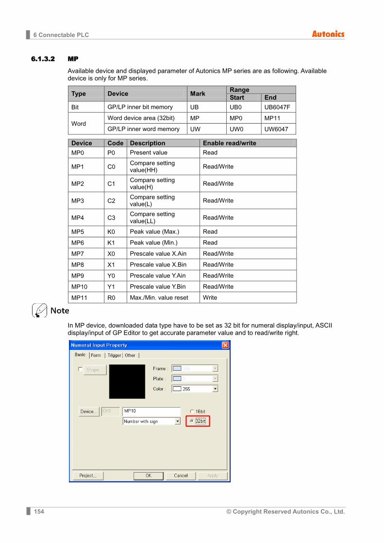
6 Connectable PLC
154 © Copyright Reserved Autonics Co., Ltd.
6.1.3.2 MP
Available device and displayed parameter of Autonics MP series are as following. Available device is only for MP series.
Type Device Mark Range Start End
Bit GP/LP inner bit memory UB UB0 UB6047F
Word Word device area (32bit) MP MP0 MP11 GP/LP inner word memory UW UW0 UW6047
Device Code Description Enable read/write
MP0 P0 Present value Read
MP1 C0 Compare setting value(HH) Read/Write
MP2 C1 Compare setting value(H) Read/Write
MP3 C2 Compare setting value(L) Read/Write
MP4 C3 Compare setting value(LL) Read/Write
MP5 K0 Peak value (Max.) Read
MP6 K1 Peak value (Min.) Read
MP7 X0 Prescale value X.Ain Read/Write
MP8 X1 Prescale value X.Bin Read/Write
MP9 Y0 Prescale value Y.Ain Read/Write
MP10 Y1 Prescale value Y.Bin Read/Write
MP11 R0 Max./Min. value reset Write
In MP device, downloaded data type have to be set as 32 bit for numeral display/input, ASCII display/input of GP Editor to get accurate parameter value and to read/write right.
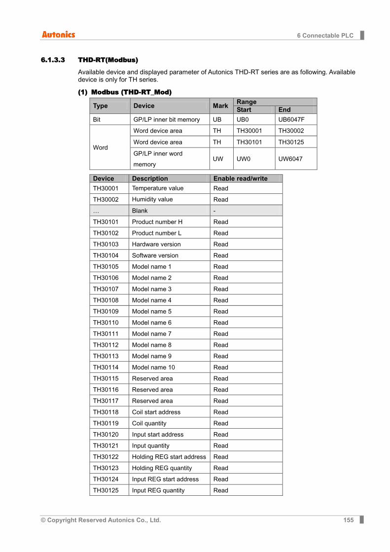
6 Connectable PLC
© Copyright Reserved Autonics Co., Ltd. 155
6.1.3.3 THD-RT(Modbus)
Available device and displayed parameter of Autonics THD-RT series are as following. Available device is only for TH series.
(1) Modbus (THD-RT_Mod)
Type Device Mark Range Start End
Bit GP/LP inner bit memory UB UB0 UB6047F
Word
Word device area TH TH30001 TH30002
Word device area TH TH30101 TH30125
GP/LP inner word memory
UW UW0 UW6047
Device Description Enable read/write
TH30001 Temperature value Read
TH30002 Humidity value Read
… Blank -
TH30101 Product number H Read
TH30102 Product number L Read
TH30103 Hardware version Read
TH30104 Software version Read
TH30105 Model name 1 Read
TH30106 Model name 2 Read
TH30107 Model name 3 Read
TH30108 Model name 4 Read
TH30109 Model name 5 Read
TH30110 Model name 6 Read
TH30111 Model name 7 Read
TH30112 Model name 8 Read
TH30113 Model name 9 Read
TH30114 Model name 10 Read
TH30115 Reserved area Read
TH30116 Reserved area Read
TH30117 Reserved area Read
TH30118 Coil start address Read
TH30119 Coil quantity Read
TH30120 Input start address Read
TH30121 Input quantity Read
TH30122 Holding REG start address Read
TH30123 Holding REG quantity Read
TH30124 Input REG start address Read
TH30125 Input REG quantity Read
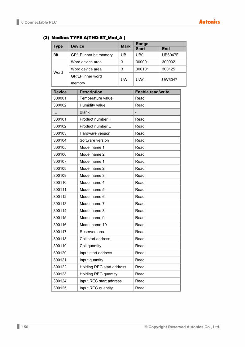
6 Connectable PLC
156 © Copyright Reserved Autonics Co., Ltd.
(2) Modbus TYPE A(THD-RT_Mod_A )
Type Device Mark Range Start End
Bit GP/LP inner bit memory UB UB0 UB6047F
Word
Word device area 3 300001 300002
Word device area 3 300101 300125
GP/LP inner word memory
UW UW0 UW6047
Device Description Enable read/write
300001 Temperature value Read
300002 Humidity value Read
… Blank -
300101 Product number H Read
300102 Product number L Read
300103 Hardware version Read
300104 Software version Read
300105 Model name 1 Read
300106 Model name 2 Read
300107 Model name 1 Read
300108 Model name 2 Read
300109 Model name 3 Read
300110 Model name 4 Read
300111 Model name 5 Read
300112 Model name 6 Read
300113 Model name 7 Read
300114 Model name 8 Read
300115 Model name 9 Read
300116 Model name 10 Read
300117 Reserved area Read
300118 Coil start address Read
300119 Coil quantity Read
300120 Input start address Read
300121 Input quantity Read
300122 Holding REG start address Read
300123 Holding REG quantity Read
300124 Input REG start address Read
300125 Input REG quantity Read

6 Connectable PLC
© Copyright Reserved Autonics Co., Ltd. 157
6.1.3.4 TZ
Available device and displayed parameter of Autonics TZ series are as following. Available device is only for TZ series.
Type Device Mark Range Start End
Bit GP/LP inner bit memory UB UB0 UB6047F
Word Word device area TZ TZ0 TZ1
GP/LP inner word memory UW UW0 UW6047
Device Description Enable read/write
TZ0 Present value Read
TZ1 Setting value Read/Write
6.1.3.5 TM
For available device for Autonics TM, refer to ‘TM user manual for communication’.
(1) Modbus (TM_Mod)
Type Device Mark Range Start End
Bit Bit device area TM Refer to TM device table
GP/LP inner bit memory UB UB0 UB6047F
Word
Word device area TM Refer to TM device table
GP/LP inner word memory
UW UW0 UW6047
(2) Modbus TYPE A(TM_Mod_A)
Type Device Mark Range Start End
Bit
Bit device area 0 Refer to TM device table
Bit device area 1 Refer to TM device table
GP/LP inner bit memory UB UB0 UB6047F
Word
Word device area 3 Refer to TM device table
Word device area 4 Refer to TM device table
GP/LP inner bit memory UW UW0 UW6047
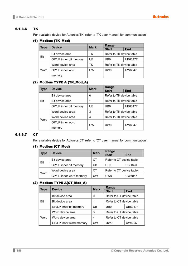
6 Connectable PLC
158 © Copyright Reserved Autonics Co., Ltd.
6.1.3.6 TK
For available device for Autonics TK, refer to ‘TK user manual for communication’.
(1) Modbus (TK_Mod)
Type Device Mark Range Start End
Bit Bit device area TK Refer to TK device table
GP/LP inner bit memory UB UB0 UB6047F
Word
Word device area TK Refer to TK device table
GP/LP inner word memory
UW UW0 UW6047
(2) Modbus TYPE A (TK_Mod_A)
Type Device Mark Range Start End
Bit
Bit device area 0 Refer to TK device table
Bit device area 1 Refer to TK device table
GP/LP inner bit memory UB UB0 UB6047F
Word
Word device area 3 Refer to TK device table
Word device area 4 Refer to TK device table
GP/LP inner word memory
UW UW0 UW6047
6.1.3.7 CT
For available device for Autonics CT, refer to ‘CT user manual for communication’.
(1) Modbus (CT_Mod)
Type Device Mark Range Start End
Bit Bit device area CT Refer to CT device table
GP/LP inner bit memory UB UB0 UB6047F
Word Word device area CT Refer to CT device table
GP/LP inner word memory UW UW0 UW6047
(2) Modbus TYPE A(CT_Mod_A)
Type Device Mark Range Start End
Bit
Bit device area 0 Refer to CT device table
Bit device area 1 Refer to CT device table
GP/LP inner bit memory UB UB0 UB6047F
Word
Word device area 3 Refer to CT device table
Word device area 4 Refer to CT device table
GP/LP inner word memory UW UW0 UW6047
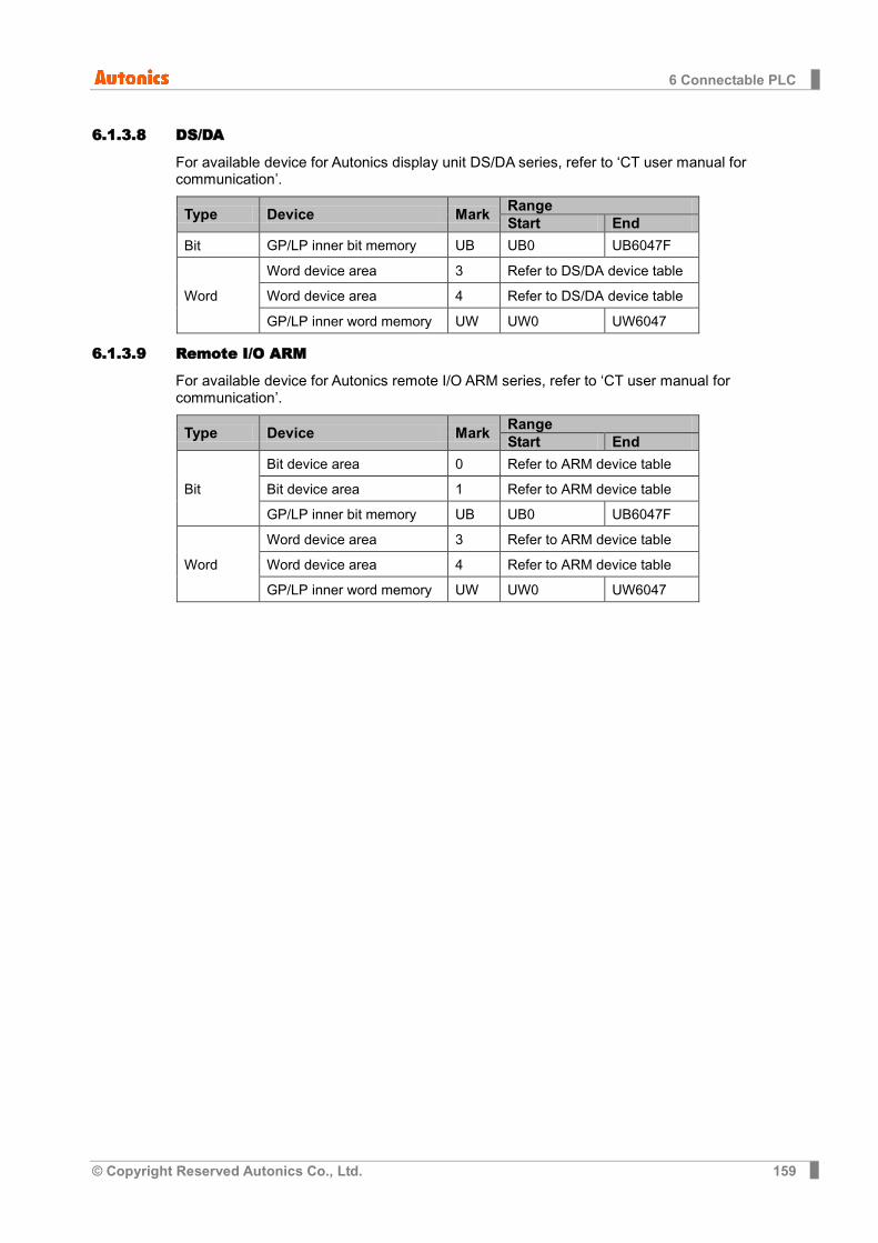
6 Connectable PLC
© Copyright Reserved Autonics Co., Ltd. 159
6.1.3.8 DS/DA
For available device for Autonics display unit DS/DA series, refer to ‘CT user manual for communication’.
Type Device Mark Range Start End
Bit GP/LP inner bit memory UB UB0 UB6047F
Word
Word device area 3 Refer to DS/DA device table
Word device area 4 Refer to DS/DA device table
GP/LP inner word memory UW UW0 UW6047
6.1.3.9 Remote I/O ARM
For available device for Autonics remote I/O ARM series, refer to ‘CT user manual for communication’.
Type Device Mark Range Start End
Bit
Bit device area 0 Refer to ARM device table
Bit device area 1 Refer to ARM device table
GP/LP inner bit memory UB UB0 UB6047F
Word
Word device area 3 Refer to ARM device table
Word device area 4 Refer to ARM device table
GP/LP inner word memory UW UW0 UW6047

6 Connectable PLC
160 © Copyright Reserved Autonics Co., Ltd.
6.1.4 Monitorable device in GP/LP GP/LP is able to monitor PLC device and change the status. Enter system setting menu of GP/LP and select [Monitoring]-[Device Monitor]-[DEVICE]. Select to be monitored device and you can change the status.
The following is avilable device list of this menu, and available range is same as ‘6.1.3 Available device’.
6.1.4.1 MT series
(1) Modbus Type Mark Device Note
Bit UB GP/LP inner bit memory
Word MT Data register
UW GP/LP inner word memory
(2) Modbus TYPE A Type Mark Device Note
Bit 1 Bit device area
UB GP/LP inner bit memory
Word 3 Word device area
UW GP/LP inner word memory
6.1.4.2 MP series Type Mark Device Note
Bit UB GP/LP inner bit memory
Word
MP16 Data register 16bit
MP32 Data register 32bit
UW GP/LP inner word memory
6.1.4.3 THD-RT(MOD)
(1) Modbus Type Mark Device Note
Bit UB GP/LP inner bit memory
Word TH Word device area
UW GP/LP inner word memory
(2) Modbus TYPE A Type Mark Device Note
Bit UB GP/LP inner bit memory
Word 3 Word device area
UW GP/LP inner word memory
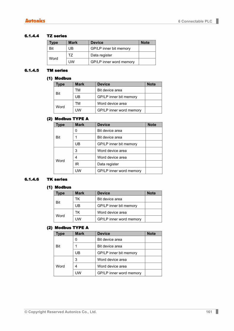
6 Connectable PLC
© Copyright Reserved Autonics Co., Ltd. 161
6.1.4.4 TZ series Type Mark Device Note
Bit UB GP/LP inner bit memory
Word TZ Data register
UW GP/LP inner word memory
6.1.4.5 TM series
(1) Modbus Type Mark Device Note
Bit TM Bit device area
UB GP/LP inner bit memory
Word TM Word device area
UW GP/LP inner word memory
(2) Modbus TYPE A Type Mark Device Note
Bit
0 Bit device area
1 Bit device area
UB GP/LP inner bit memory
Word
3 Word device area
4 Word device area
IR Data register
UW GP/LP inner word memory
6.1.4.6 TK series
(1) Modbus Type Mark Device Note
Bit TK Bit device area
UB GP/LP inner bit memory
Word TK Word device area
UW GP/LP inner word memory
(2) Modbus TYPE A Type Mark Device Note
Bit
0 Bit device area
1 Bit device area
UB GP/LP inner bit memory
Word
3 Word device area
4 Word device area
UW GP/LP inner word memory
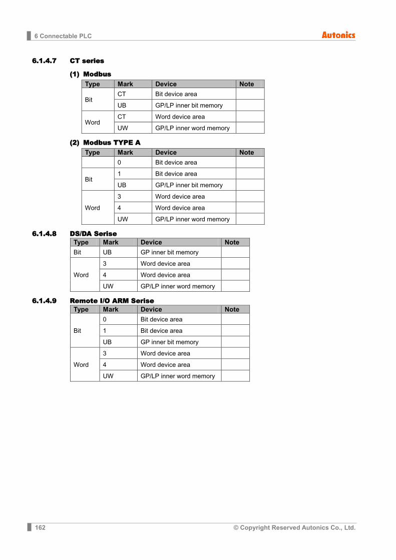
6 Connectable PLC
162 © Copyright Reserved Autonics Co., Ltd.
6.1.4.7 CT series
(1) Modbus Type Mark Device Note
Bit CT Bit device area
UB GP/LP inner bit memory
Word CT Word device area
UW GP/LP inner word memory
(2) Modbus TYPE A Type Mark Device Note
0 Bit device area
Bit 1 Bit device area
UB GP/LP inner bit memory
Word
3 Word device area
4 Word device area
UW GP/LP inner word memory
6.1.4.8 DS/DA Serise Type Mark Device Note
Bit UB GP inner bit memory
Word
3 Word device area
4 Word device area
UW GP/LP inner word memory
6.1.4.9 Remote I/O ARM Serise Type Mark Device Note
Bit
0 Bit device area
1 Bit device area
UB GP inner bit memory
Word
3 Word device area
4 Word device area
UW GP/LP inner word memory
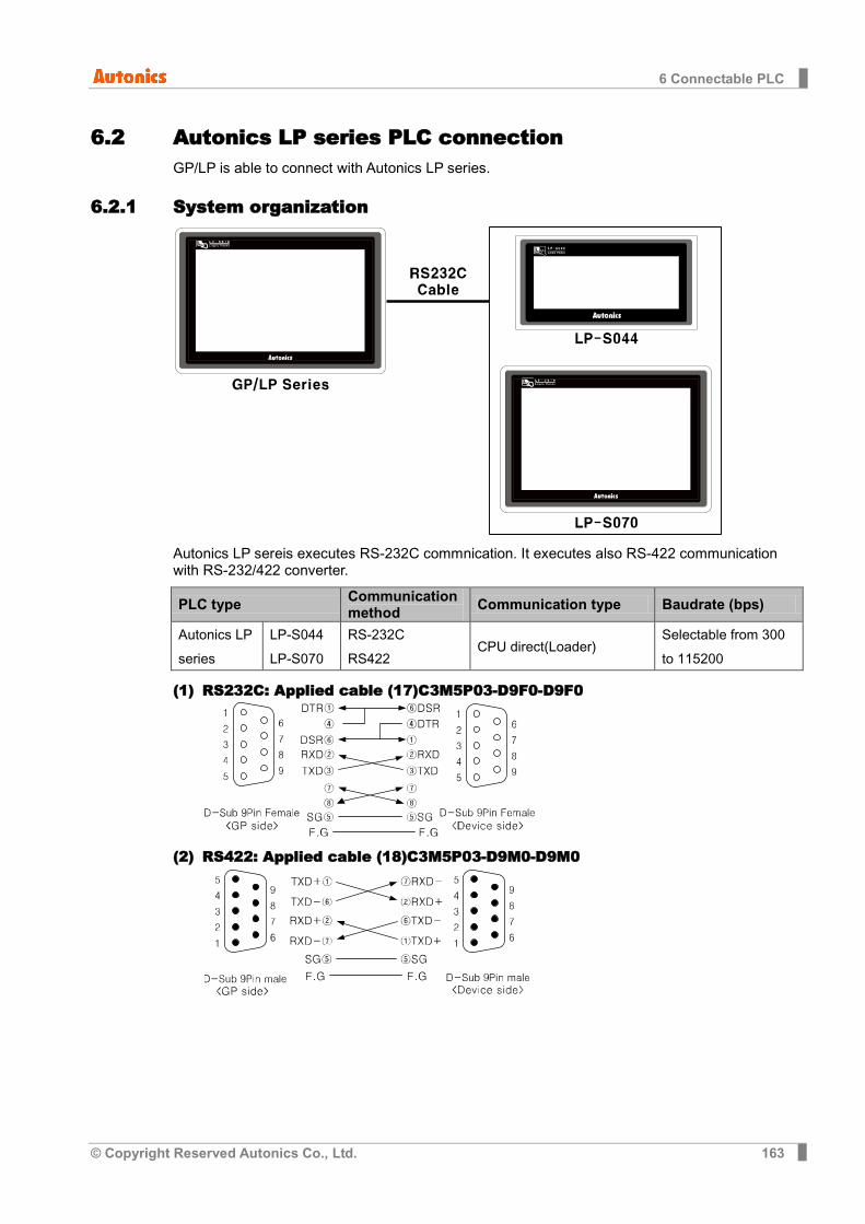
6 Connectable PLC
© Copyright Reserved Autonics Co., Ltd. 163
6.2 Autonics LP series PLC connection GP/LP is able to connect with Autonics LP series.
6.2.1 System organization
Autonics LP sereis executes RS-232C commnication. It executes also RS-422 communication with RS-232/422 converter.
PLC type Communication method Communication type Baudrate (bps)
Autonics LP series
LP-S044 LP-S070
RS-232C RS422
CPU direct(Loader) Selectable from 300 to 115200
(1) RS232C: Applied cable (17)C3M5P03-D9F0-D9F0
(2) RS422: Applied cable (18)C3M5P03-D9M0-D9M0
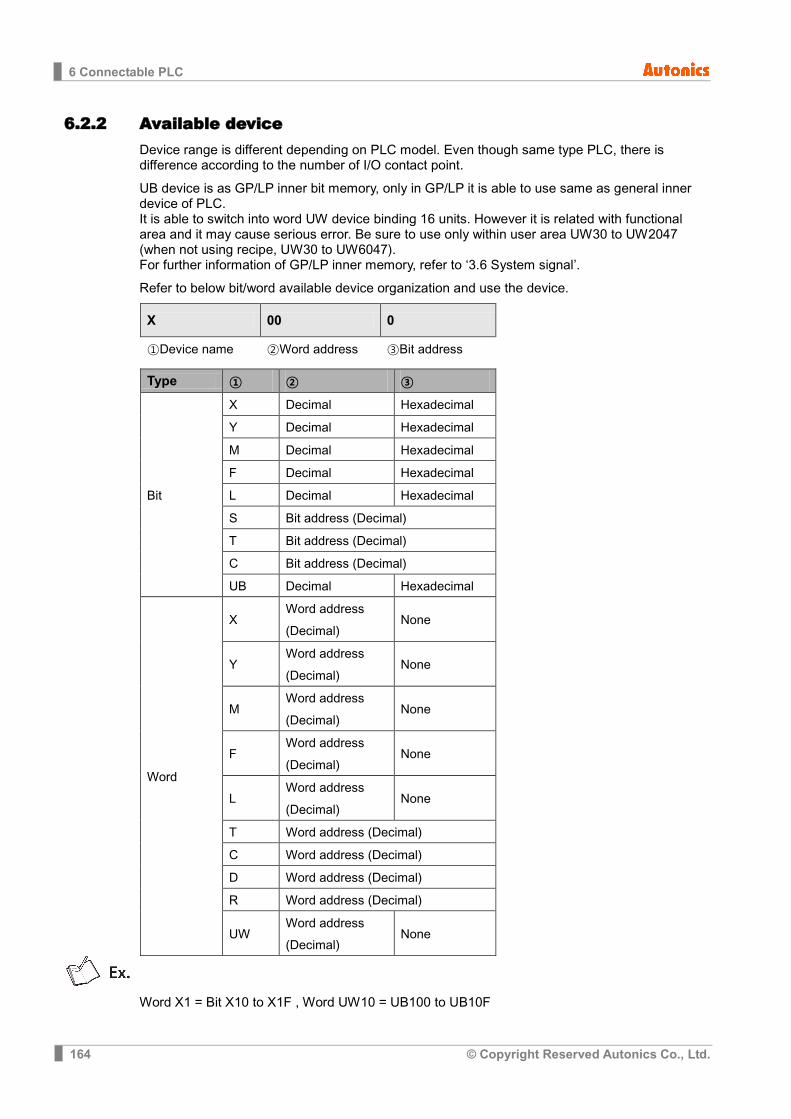
6 Connectable PLC
164 © Copyright Reserved Autonics Co., Ltd.
6.2.2 Available device Device range is different depending on PLC model. Even though same type PLC, there is difference according to the number of I/O contact point.
UB device is as GP/LP inner bit memory, only in GP/LP it is able to use same as general inner device of PLC. It is able to switch into word UW device binding 16 units. However it is related with functional area and it may cause serious error. Be sure to use only within user area UW30 to UW2047 (when not using recipe, UW30 to UW6047). For further information of GP/LP inner memory, refer to ‘3.6 System signal’.
Refer to below bit/word available device organization and use the device.
X 00 0
①Device name ②Word address ③Bit address
Type ① ② ③
Bit
X Decimal Hexadecimal
Y Decimal Hexadecimal
M Decimal Hexadecimal
F Decimal Hexadecimal
L Decimal Hexadecimal
S Bit address (Decimal)
T Bit address (Decimal)
C Bit address (Decimal)
UB Decimal Hexadecimal
Word
X Word address (Decimal)
None
Y Word address (Decimal)
None
M Word address (Decimal)
None
F Word address (Decimal)
None
L Word address (Decimal)
None
T Word address (Decimal)
C Word address (Decimal)
D Word address (Decimal)
R Word address (Decimal)
UW Word address (Decimal)
None
Word X1 = Bit X10 to X1F , Word UW10 = UB100 to UB10F
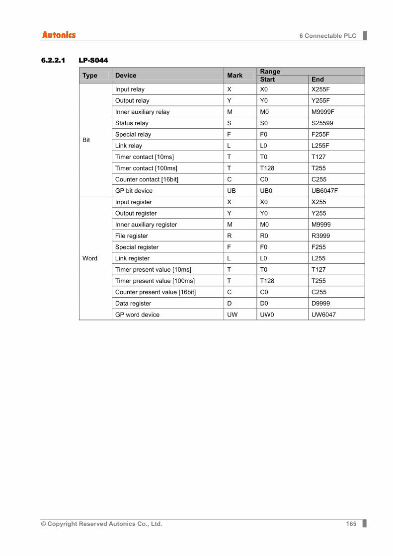
6 Connectable PLC
© Copyright Reserved Autonics Co., Ltd. 165
6.2.2.1 LP-S044
Type Device Mark Range Start End
Bit
Input relay X X0 X255F
Output relay Y Y0 Y255F
Inner auxiliary relay M M0 M9999F
Status relay S S0 S25599
Special relay F F0 F255F
Link relay L L0 L255F
Timer contact [10ms] T T0 T127
Timer contact [100ms] T T128 T255
Counter contact [16bit] C C0 C255
GP bit device UB UB0 UB6047F
Word
Input register X X0 X255
Output register Y Y0 Y255
Inner auxiliary register M M0 M9999
File register R R0 R3999
Special register F F0 F255
Link register L L0 L255
Timer present value [10ms] T T0 T127
Timer present value [100ms] T T128 T255
Counter present value [16bit] C C0 C255
Data register D D0 D9999
GP word device UW UW0 UW6047
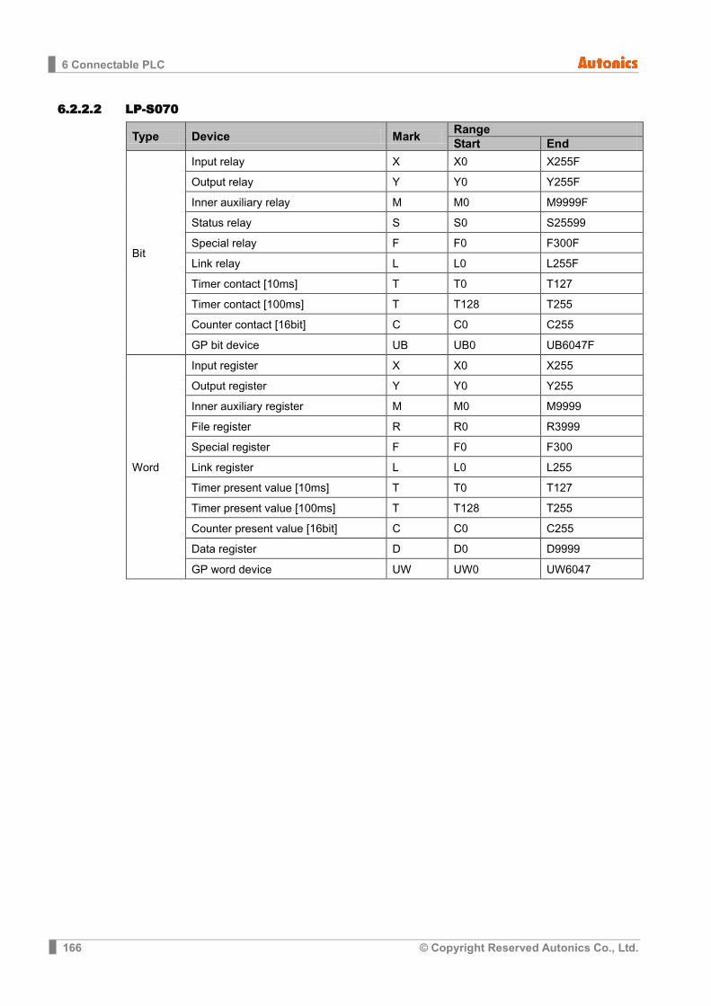
6 Connectable PLC
166 © Copyright Reserved Autonics Co., Ltd.
6.2.2.2 LP-S070
Type Device Mark Range Start End
Bit
Input relay X X0 X255F
Output relay Y Y0 Y255F
Inner auxiliary relay M M0 M9999F
Status relay S S0 S25599
Special relay F F0 F300F
Link relay L L0 L255F
Timer contact [10ms] T T0 T127
Timer contact [100ms] T T128 T255
Counter contact [16bit] C C0 C255
GP bit device UB UB0 UB6047F
Word
Input register X X0 X255
Output register Y Y0 Y255
Inner auxiliary register M M0 M9999
File register R R0 R3999
Special register F F0 F300
Link register L L0 L255
Timer present value [10ms] T T0 T127
Timer present value [100ms] T T128 T255
Counter present value [16bit] C C0 C255
Data register D D0 D9999
GP word device UW UW0 UW6047
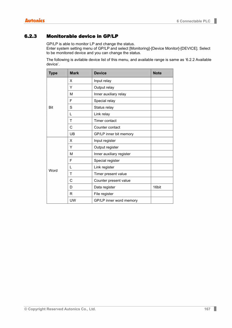
6 Connectable PLC
© Copyright Reserved Autonics Co., Ltd. 167
6.2.3 Monitorable device in GP/LP GP/LP is able to monitor LP and change the status. Enter system setting menu of GP/LP and select [Monitoring]-[Device Monitor]-[DEVICE]. Select to be monitored device and you can change the status.
The following is avilable device list of this menu, and available range is same as ‘6.2.2 Available device’.
Type Mark Device Note
Bit
X Input relay
Y Output relay
M Inner auxiliary relay
F Special relay
S Status relay
L Link relay
T Timer contact
C Counter contact
UB GP/LP inner bit memory
Word
X Input register
Y Output register
M Inner auxiliary register
F Special register
L Link register
T Timer present value
C Counter present value
D Data register 16bit
R File register
UW GP/LP inner word memory
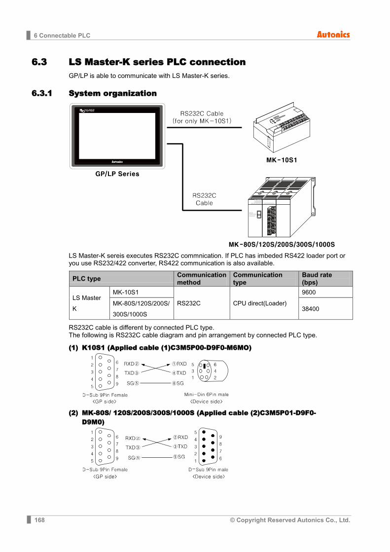
6 Connectable PLC
168 © Copyright Reserved Autonics Co., Ltd.
6.3 LS Master-K series PLC connection GP/LP is able to communicate with LS Master-K series.
6.3.1 System organization
LS Master-K sereis executes RS232C commnication. If PLC has imbeded RS422 loader port or you use RS232/422 converter, RS422 communication is also available.
PLC type Communication method
Communication type
Baud rate (bps)
LS Master K
MK-10S1
RS232C CPU direct(Loader)
9600
MK-80S/120S/200S/ 300S/1000S
38400
RS232C cable is different by connected PLC type. The following is RS232C cable diagram and pin arrangement by connected PLC type.
(1) K10S1 (Applied cable (1)C3M5P00-D9F0-M6MO)
(2) MK-80S/ 120S/200S/300S/1000S (Applied cable (2)C3M5P01-D9F0-D9M0)
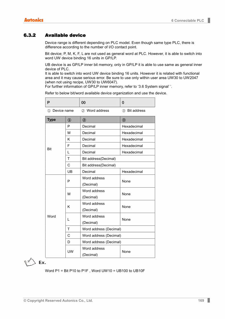
6 Connectable PLC
© Copyright Reserved Autonics Co., Ltd. 169
6.3.2 Available device Device range is different depending on PLC model. Even though same type PLC, there is difference according to the number of I/O contact point.
Bit device; P, M, K, F, L are not used as general word at PLC. However, it is able to switch into word UW device binding 16 units in GP/LP.
UB device is as GP/LP inner bit memory, only in GP/LP it is able to use same as general inner device of PLC. It is able to switch into word UW device binding 16 units. However it is related with functional area and it may cause serious error. Be sure to use only within user area UW30 to UW2047 (when not using recipe, UW30 to UW6047). For further information of GP/LP inner memory, refer to ‘3.6 System signal’ ’.
Refer to below bit/word available device organization and use the device.
P 00 0
① Device name ② Word address ③ Bit address
Type ① ② ③
Bit
P Decimal Hexadecimal
M Decimal Hexadecimal
K Decimal Hexadecimal
F Decimal Hexadecimal
L Decimal Hexadecimal
T Bit address(Decimal)
C Bit address(Decimal)
UB Decimal Hexadecimal
Word
P Word address (Decimal)
None
M Word address (Decimal)
None
K Word address (Decimal)
None
L Word address (Decimal)
None
T Word address (Decimal)
C Word address (Decimal)
D Word address (Decimal)
UW Word address (Decimal)
None
Word P1 = Bit P10 to P1F , Word UW10 = UB100 to UB10F

6 Connectable PLC
170 © Copyright Reserved Autonics Co., Ltd.
6.3.2.1 MK-10S1
Type Device Mark Range Start End
Bit
Input relay P P0 P0F
Output relay P P10 P1F
Inner auxiliary relay M M0 M15F
Memory protection relay K K0 K7F
Special relay F F0 F15F
Link relay L L0 L7F
Timer contact[10ms] T T32 T47
Timer contact[100ms] T T0 T31
Counter contact[16bit] C C0 C15
GP/LP inner bit memory UB UB0 UB6047F
Word
Input relay P P0 -
Output relay P P1 -
Inner auxiliary relay M M0 M15
Memory protection relay K K0 K7
Special relay F F0 F15
Link relay L L0 L7
Timer present value[10ms] T T32 T47
Timer present value[100ms] T T0 T31
Counter present value[16bit] C C0 C15
Data register D D0 D63
GP/LP inner word memory UW UW0 UW6047
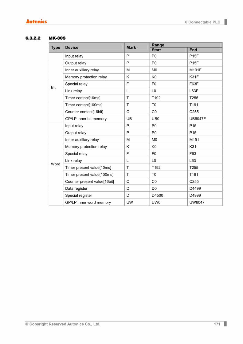
6 Connectable PLC
© Copyright Reserved Autonics Co., Ltd. 171
6.3.2.2 MK-80S
Type Device Mark Range Start End
Bit
Input relay P P0 P15F
Output relay P P0 P15F
Inner auxiliary relay M M0 M191F
Memory protection relay K K0 K31F
Special relay F F0 F63F
Link relay L L0 L63F
Timer contact[10ms] T T192 T255
Timer contact[100ms] T T0 T191
Counter contact[16bit] C C0 C255
GP/LP inner bit memory UB UB0 UB6047F
Word
Input relay P P0 P15
Output relay P P0 P15
Inner auxiliary relay M M0 M191
Memory protection relay K K0 K31
Special relay F F0 F63
Link relay L L0 L63
Timer present value[10ms] T T192 T255
Timer present value[100ms] T T0 T191
Counter present value[16bit] C C0 C255
Data register D D0 D4499
Special register D D4500 D4999
GP/LP inner word memory UW UW0 UW6047
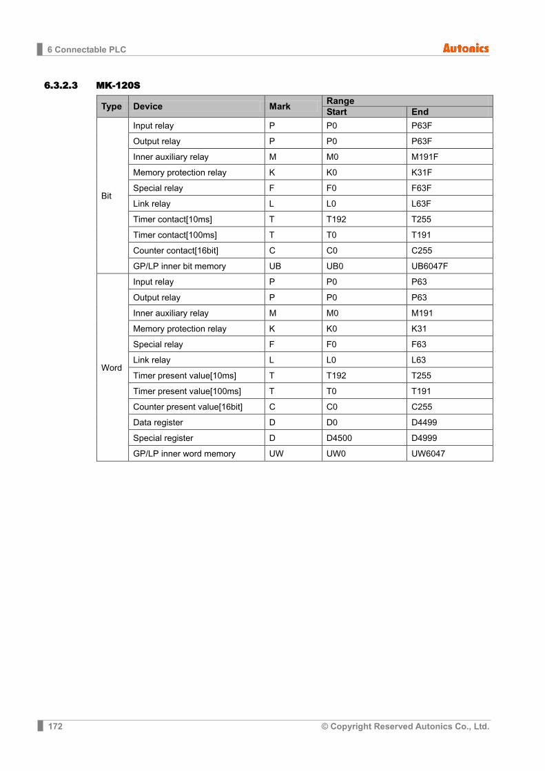
6 Connectable PLC
172 © Copyright Reserved Autonics Co., Ltd.
6.3.2.3 MK-120S
Type Device Mark Range Start End
Bit
Input relay P P0 P63F
Output relay P P0 P63F
Inner auxiliary relay M M0 M191F
Memory protection relay K K0 K31F
Special relay F F0 F63F
Link relay L L0 L63F
Timer contact[10ms] T T192 T255
Timer contact[100ms] T T0 T191
Counter contact[16bit] C C0 C255
GP/LP inner bit memory UB UB0 UB6047F
Word
Input relay P P0 P63
Output relay P P0 P63
Inner auxiliary relay M M0 M191
Memory protection relay K K0 K31
Special relay F F0 F63
Link relay L L0 L63
Timer present value[10ms] T T192 T255
Timer present value[100ms] T T0 T191
Counter present value[16bit] C C0 C255
Data register D D0 D4499
Special register D D4500 D4999
GP/LP inner word memory UW UW0 UW6047

6 Connectable PLC
© Copyright Reserved Autonics Co., Ltd. 173
6.3.2.4 MK-200S
Type Device Mark Range Start End
Bit
Input relay P P0 P31F
Output relay P P0 P31F
Inner auxiliary relay M M0 M191F
Memory protection relay K K0 K31F
Special relay F F0 F63F
Link relay L L0 L63F
Timer contact[10ms] T T192 T255
Timer contact[100ms] T T0 T191
Counter contact[16bit] C C0 C255
GP/LP inner bit memory UB UB0 UB6047F
Word
Input relay P P0 P31
Output relay P P0 P31
Inner auxiliary relay M M0 M191
Memory protection relay K K0 K31
Special relay F F0 F63
Link relay L L0 L63
Timer present value[10ms] T T192 T255
Timer present value[100ms] T T0 T191
Counter present value[16bit] C C0 C255
Data register D D0 D4499
Special register D D4500 D4999
GP/LP inner word memory UW UW0 UW6047
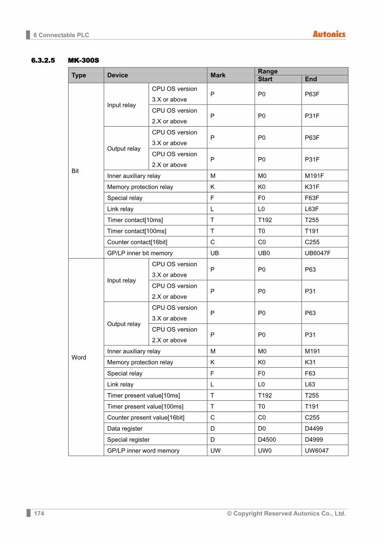
6 Connectable PLC
174 © Copyright Reserved Autonics Co., Ltd.
6.3.2.5 MK-300S
Type Device Mark Range Start End
Bit
Input relay
CPU OS version 3.X or above
P P0 P63F
CPU OS version 2.X or above
P P0 P31F
Output relay
CPU OS version 3.X or above
P P0 P63F
CPU OS version 2.X or above
P P0 P31F
Inner auxiliary relay M M0 M191F
Memory protection relay K K0 K31F
Special relay F F0 F63F
Link relay L L0 L63F
Timer contact[10ms] T T192 T255
Timer contact[100ms] T T0 T191
Counter contact[16bit] C C0 C255
GP/LP inner bit memory UB UB0 UB6047F
Word
Input relay
CPU OS version 3.X or above
P P0 P63
CPU OS version 2.X or above
P P0 P31
Output relay
CPU OS version 3.X or above
P P0 P63
CPU OS version 2.X or above
P P0 P31
Inner auxiliary relay M M0 M191
Memory protection relay K K0 K31
Special relay F F0 F63
Link relay L L0 L63
Timer present value[10ms] T T192 T255
Timer present value[100ms] T T0 T191
Counter present value[16bit] C C0 C255
Data register D D0 D4499
Special register D D4500 D4999
GP/LP inner word memory UW UW0 UW6047

6 Connectable PLC
© Copyright Reserved Autonics Co., Ltd. 175
6.3.2.6 MK-1000S
Type Device Mark Range Start End
Bit
Input relay P P0 P63F
Output relay P P0 P63F
Inner auxiliary relay M M0 M191F
Memory protection relay K K0 K31F
Special relay F F0 F63F
Link relay L L0 L63F
Timer contact[10ms] T T192 T255
Timer contact[100ms] T T0 T191
Counter contact[16bit] C C0 C255
GP/LP inner bit memory UB UB0 UB6047F
Word
Input relay P P0 P63
Output relay P P0 P63
Inner auxiliary relay M M0 M191
Memory protection relay K K0 K31
Special relay F F0 F63
Link relay L L0 L63
Timer present value[10ms] T T192 T255
Timer present value[100ms] T T0 T191
Counter present value[16bit] C C0 C255
Data register D D0 D9499
Special register D D9500 D9999
GP/LP inner word memory UW UW0 UW6047
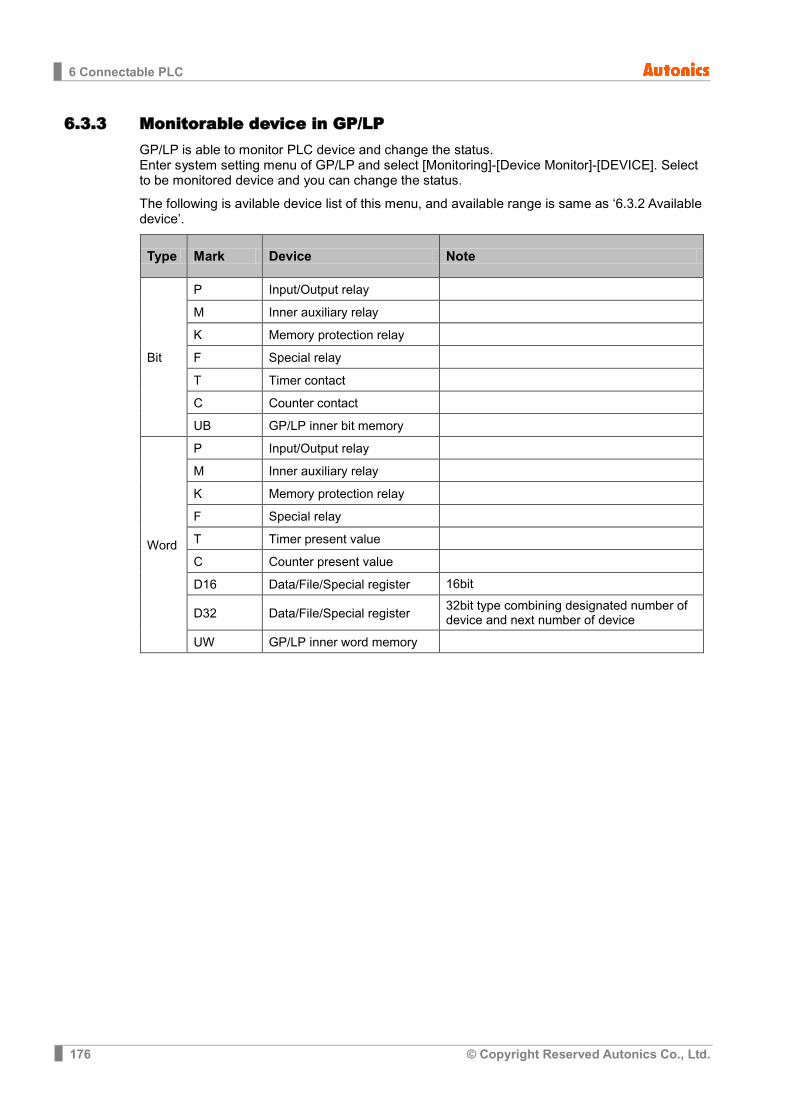
6 Connectable PLC
176 © Copyright Reserved Autonics Co., Ltd.
6.3.3 Monitorable device in GP/LP GP/LP is able to monitor PLC device and change the status. Enter system setting menu of GP/LP and select [Monitoring]-[Device Monitor]-[DEVICE]. Select to be monitored device and you can change the status.
The following is avilable device list of this menu, and available range is same as ‘6.3.2 Available device’.
Type Mark Device Note
Bit
P Input/Output relay
M Inner auxiliary relay
K Memory protection relay
F Special relay
T Timer contact
C Counter contact
UB GP/LP inner bit memory
Word
P Input/Output relay
M Inner auxiliary relay
K Memory protection relay
F Special relay
T Timer present value
C Counter present value
D16 Data/File/Special register 16bit
D32 Data/File/Special register 32bit type combining designated number of device and next number of device
UW GP/LP inner word memory
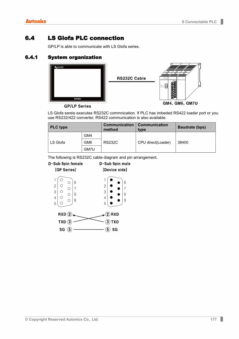
6 Connectable PLC
© Copyright Reserved Autonics Co., Ltd. 177
6.4 LS Glofa PLC connection GP/LP is able to communicate with LS Glofa series.
6.4.1 System organization
LS Glofa sereis executes RS232C commnication. If PLC has imbeded RS422 loader port or you use RS232/422 converter, RS422 communication is also available.
PLC type Communication method
Communication type Baudrate (bps)
LS Glofa
GM4
RS232C CPU direct(Loader) 38400 GM6
GM7U
The following is RS232C cable diagram and pin arrangement.
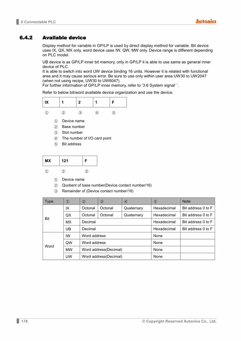
6 Connectable PLC
178 © Copyright Reserved Autonics Co., Ltd.
6.4.2 Available device Display method for variable in GP/LP is used by direct display method for variable. Bit device uses IX, QX, MX only, word device uses IW, QW, MW only. Device range is different depending on PLC model.
UB device is as GP/LP inner bit memory, only in GP/LP it is able to use same as general inner device of PLC. It is able to switch into word UW device binding 16 units. However it is related with functional area and it may cause serious error. Be sure to use only within user area UW30 to UW2047 (when not using recipe, UW30 to UW6047). For further information of GP/LP inner memory, refer to ‘3.6 System signal’ ’.
Refer to below bit/word available device organization and use the device.
IX 1 2 1 F
① ② ③ ④ ⑤
① Device name
② Base number
③ Slot number
④ The number of I/O card point
⑤ Bit address
MX 121 F
① ② ③
① Device name
② Quotient of base number(Device contact number/16)
③ Remainder of (Device contact number/16)
Type ① ② ③ ④ ⑤ Note
Bit
IX Octonal Octonal Quaternary Hexadecimal Bit address 0 to F
QX Octonal Octonal Quaternary Hexadecimal Bit address 0 to F
MX Decimal Hexadecimal Bit address 0 to F
UB Decimal Hexadecimal Bit address 0 to F
Word
IW Word address None
QW Word address None
MW Word address(Decimal) None
UW Word address(Decimal) None
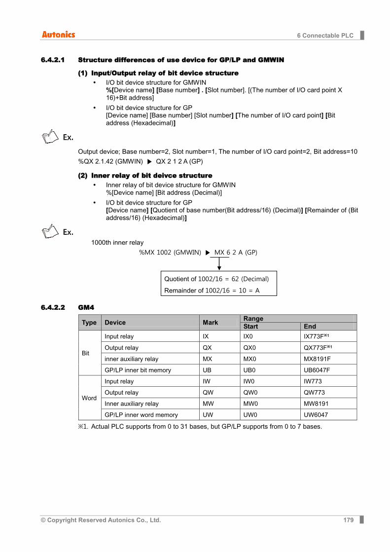
6 Connectable PLC
© Copyright Reserved Autonics Co., Ltd. 179
6.4.2.1 Structure differences of use device for GP/LP and GMWIN
(1) Input/Output relay of bit device structure I/O bit device structure for GMWIN
%[Device name] [Base number] . [Slot number]. [(The number of I/O card point X 16)+Bit address]
I/O bit device structure for GP [Device name] [Base number] [Slot number] [The number of I/O card point] [Bit address (Hexadecimal)]
Output device; Base number=2, Slot number=1, The number of I/O card point=2, Bit address=10
%QX 2.1.42 (GMWIN) QX 2 1 2 A (GP)
(2) Inner relay of bit deivce structure Inner relay of bit device structure for GMWIN
%[Device name] [Bit address (Decimal)]
I/O bit device structure for GP [Device name] [Quotient of base number(Bit address/16) (Decimal)] [Remainder of (Bit address/16) (Hexadecimal)]
1000th inner relay
%MX 1002 (GMWIN) MX 6 2 A (GP)
6.4.2.2 GM4
Type Device Mark Range Start End
Bit
Input relay IX IX0 IX773F※1
Output relay QX QX0 QX773F※1
inner auxiliary relay MX MX0 MX8191F
GP/LP inner bit memory UB UB0 UB6047F
Word
Input relay IW IW0 IW773
Output relay QW QW0 QW773
Inner auxiliary relay MW MW0 MW8191
GP/LP inner word memory UW UW0 UW6047
※1. Actual PLC supports from 0 to 31 bases, but GP/LP supports from 0 to 7 bases.
Quotient of 1002/16 = 62 (Decimal)
Remainder of 1002/16 = 10 = A

6 Connectable PLC
180 © Copyright Reserved Autonics Co., Ltd.
6.4.2.3 GM6
Type Device Mark Range Start End
Bit
Input relay IX IX0 IX173F
Output relay QX QX0 QX173F
Inner auxiliary relay MX MX0 MX4095F
GP/LP inner bit memory UB UB0 UB6047F
Word
Input relay IW IW0 IW173
Output relay QW QW0 QW173
Inner auxiliary relay MW MW0 MW4095
GP/LP inner word memory UW UW0 UW6047
6.4.2.4 GM7U
Type Device Mark Range Start End
Bit
Input relay IX IX0 IX173F
Output relay QX QX0 QX173F
Inner auxiliary relay MX MX0 MX4095F
GP/LP inner bit memory UB UB0 UB6047F
Word
Input relay IW IW0 IW173
Output relay QW QW0 QW173
Inner auxiliary relay MW MW0 MW4095
GP/LP inner word memory UW UW0 UW6047
6.4.3 Monitorable device in GP/LP GP/LP is able to monitor PLC device and change the status. Enter system setting menu of GP/LP and select [Monitoring]-[Device Monitor]-[DEVICE]. Select to be monitored device and you can change the status.
The following is avilable device list of this menu, and available range is same as ‘6.4.2 Available device’.
Type Mark Device
Bit
IX Input relay
QX Output relay
MX Inner auxiliary relay
UB GP/LP inner bit memory
Word
IW Input relay
QW Output relay
MW Inner auxiliary relay
UW GP/LP inner word memory

6 Connectable PLC
© Copyright Reserved Autonics Co., Ltd. 181
6.5 LS XGB Series PLC communication connection GP/LP is able to communicate with LS XGB series PLC and Cnet.
6.5.1 System organization
It executes Cnet communication with GP/LP connecting directly with PLC CPU or using Cnet Unit.
It is able to execute Cnet communication differenting pin number of Loarder port in CPU and connecting Cnet Unit.
6.5.1.1 When using embedded Cnet CPU,
PLC type CPU model name
Communication type
Communication method
Baudrate(bps)
LS XGB XGB
XBC-DRH
CPU direct
RS232C
19200 XBC-DNH
XBM-DNS RS485
XBM-DRS
(1) RS-232C (Applied cable (12)C3M5P11-D9F0-W4*0)
(2) RS-485 (Applied cable (4)C3M5P03-D9M0-W4*0)
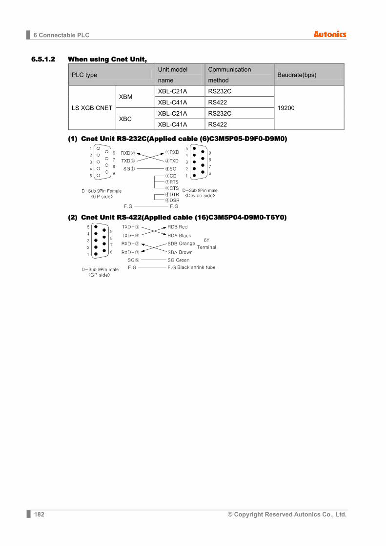
6 Connectable PLC
182 © Copyright Reserved Autonics Co., Ltd.
6.5.1.2 When using Cnet Unit,
PLC type Unit model name
Communication method
Baudrate(bps)
LS XGB CNET
XBM XBL-C21A RS232C
19200 XBL-C41A RS422
XBC XBL-C21A RS232C
XBL-C41A RS422
(1) Cnet Unit RS-232C(Applied cable (6)C3M5P05-D9F0-D9M0)
(2) Cnet Unit RS-422(Applied cable (16)C3M5P04-D9M0-T6Y0)

6 Connectable PLC
© Copyright Reserved Autonics Co., Ltd. 183
6.5.2 Communication configuration Communication configuration when using Cnet,
In XG-PD program, configure Cnet to LS XGB series.
(For more information, please refer to the manual from LSIS.)
1st Select [File]-[New File] and ‘New Project’ dialog box opens. Select the CPU kind.
2nd At the Project window, right-click ‘00: Embedded Cnet’ the last of Test items and click
‘Module Settings’ from pop-up menu. ‘Standard Settings – Cnet’ dialog box appears.
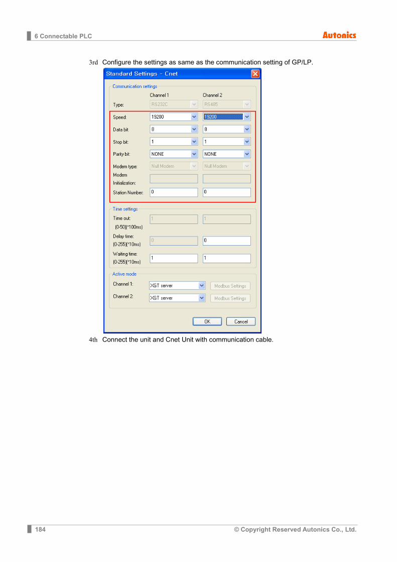
6 Connectable PLC
184 © Copyright Reserved Autonics Co., Ltd.
3rd Configure the settings as same as the communication setting of GP/LP.
4th Connect the unit and Cnet Unit with communication cable.
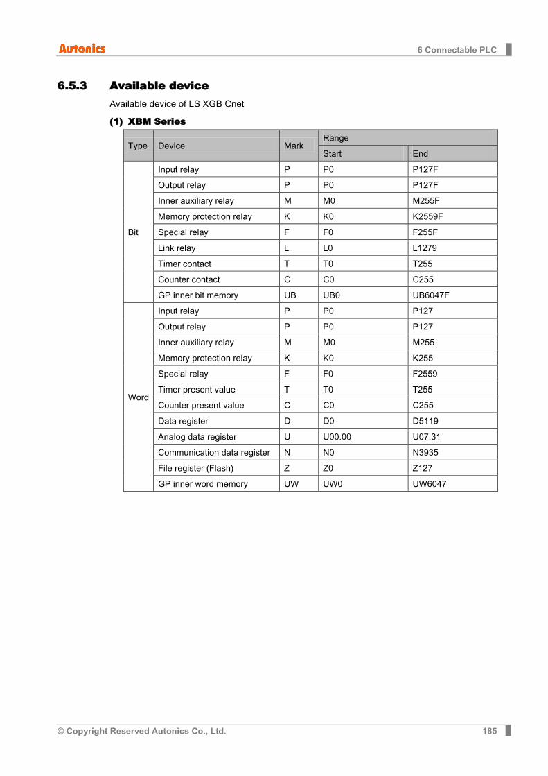
6 Connectable PLC
© Copyright Reserved Autonics Co., Ltd. 185
6.5.3 Available device Available device of LS XGB Cnet
(1) XBM Series
Type Device Mark Range
Start End
Bit
Input relay P P0 P127F
Output relay P P0 P127F
Inner auxiliary relay M M0 M255F
Memory protection relay K K0 K2559F
Special relay F F0 F255F
Link relay L L0 L1279
Timer contact T T0 T255
Counter contact C C0 C255
GP inner bit memory UB UB0 UB6047F
Word
Input relay P P0 P127
Output relay P P0 P127
Inner auxiliary relay M M0 M255
Memory protection relay K K0 K255
Special relay F F0 F2559
Timer present value T T0 T255
Counter present value C C0 C255
Data register D D0 D5119
Analog data register U U00.00 U07.31
Communication data register N N0 N3935
File register (Flash) Z Z0 Z127
GP inner word memory UW UW0 UW6047
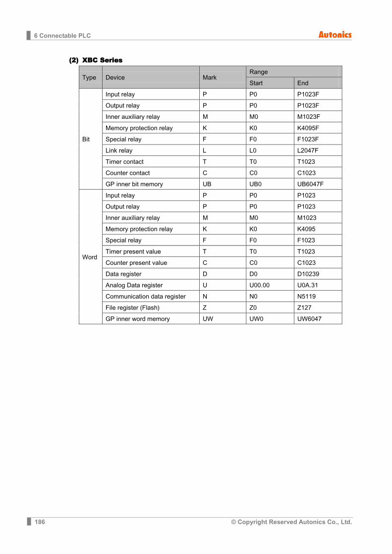
6 Connectable PLC
186 © Copyright Reserved Autonics Co., Ltd.
(2) XBC Series
Type Device Mark Range
Start End
Bit
Input relay P P0 P1023F
Output relay P P0 P1023F
Inner auxiliary relay M M0 M1023F
Memory protection relay K K0 K4095F
Special relay F F0 F1023F
Link relay L L0 L2047F
Timer contact T T0 T1023
Counter contact C C0 C1023
GP inner bit memory UB UB0 UB6047F
Word
Input relay P P0 P1023
Output relay P P0 P1023
Inner auxiliary relay M M0 M1023
Memory protection relay K K0 K4095
Special relay F F0 F1023
Timer present value T T0 T1023
Counter present value C C0 C1023
Data register D D0 D10239
Analog Data register U U00.00 U0A.31
Communication data register N N0 N5119
File register (Flash) Z Z0 Z127
GP inner word memory UW UW0 UW6047
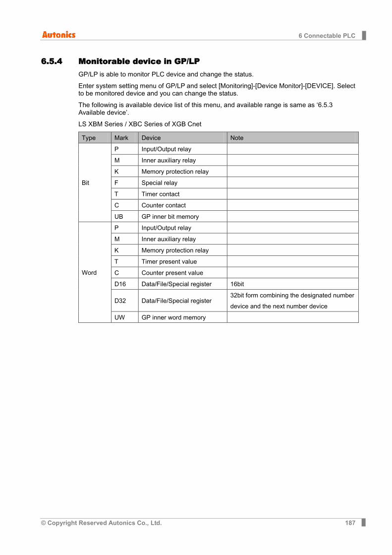
6 Connectable PLC
© Copyright Reserved Autonics Co., Ltd. 187
6.5.4 Monitorable device in GP/LP GP/LP is able to monitor PLC device and change the status.
Enter system setting menu of GP/LP and select [Monitoring]-[Device Monitor]-[DEVICE]. Select to be monitored device and you can change the status.
The following is available device list of this menu, and available range is same as ‘6.5.3 Available device’.
LS XBM Series / XBC Series of XGB Cnet
Type Mark Device Note
Bit
P Input/Output relay
M Inner auxiliary relay
K Memory protection relay
F Special relay
T Timer contact
C Counter contact
UB GP inner bit memory
Word
P Input/Output relay
M Inner auxiliary relay
K Memory protection relay
T Timer present value
C Counter present value
D16 Data/File/Special register 16bit
D32 Data/File/Special register 32bit form combining the designated number device and the next number device
UW GP inner word memory
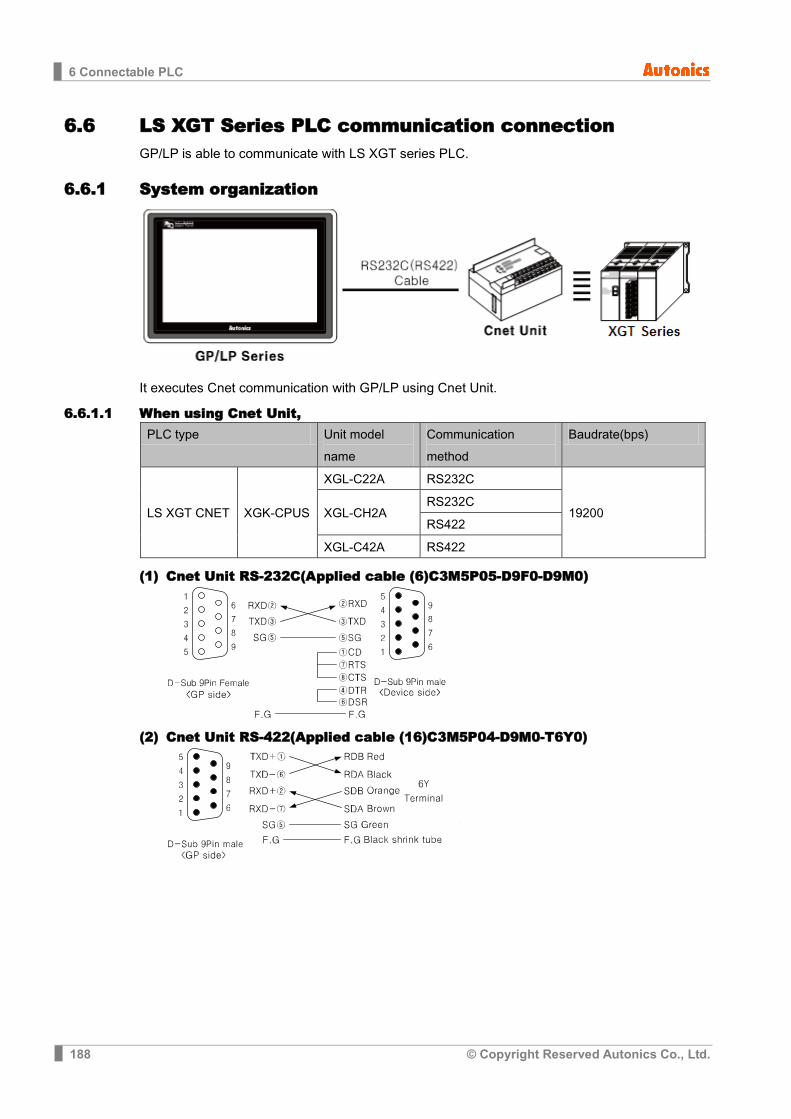
6 Connectable PLC
188 © Copyright Reserved Autonics Co., Ltd.
6.6 LS XGT Series PLC communication connection GP/LP is able to communicate with LS XGT series PLC.
6.6.1 System organization
It executes Cnet communication with GP/LP using Cnet Unit.
6.6.1.1 When using Cnet Unit, PLC type Unit model
name Communication method
Baudrate(bps)
LS XGT CNET XGK-CPUS
XGL-C22A RS232C
19200 XGL-CH2A RS232C
RS422
XGL-C42A RS422
(1) Cnet Unit RS-232C(Applied cable (6)C3M5P05-D9F0-D9M0)
(2) Cnet Unit RS-422(Applied cable (16)C3M5P04-D9M0-T6Y0)

6 Connectable PLC
© Copyright Reserved Autonics Co., Ltd. 189
6.6.2 Communication configuration In XG-PD program, configure Cnet to LS XGT seires. (For more information, please refer to the manual from LSIS.)
1st Select [File]-[New File] and ‘New Project’ dialog box opens. Select the CPU kind.
2nd At the Project window, select the configured PLC and right-click ‘Add Module’ from
pop-up menu.
3rd Communication Module Setting dialog box apperas. Select Type as ‘Cnet’.
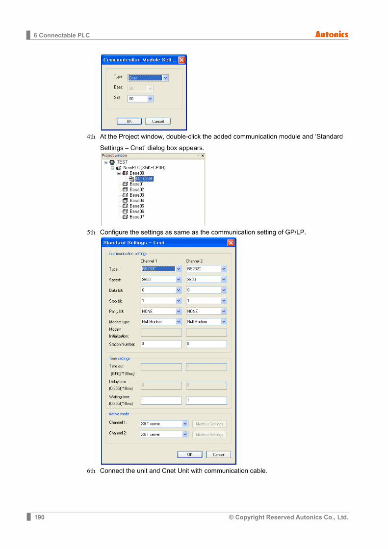
6 Connectable PLC
190 © Copyright Reserved Autonics Co., Ltd.
4th At the Project window, double-click the added communication module and ‘Standard
Settings – Cnet’ dialog box appears.
5th Configure the settings as same as the communication setting of GP/LP.
6th Connect the unit and Cnet Unit with communication cable.
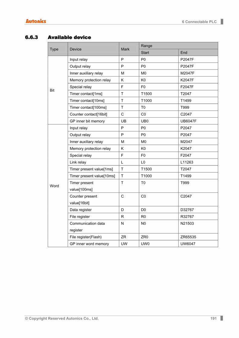
6 Connectable PLC
© Copyright Reserved Autonics Co., Ltd. 191
6.6.3 Available device
Type Device Mark Range
Start End
Bit
Input relay P P0 P2047F
Output relay P P0 P2047F
Inner auxiliary relay M M0 M2047F
Memory protection relay K K0 K2047F
Special relay F F0 F2047F
Timer contact[1ms] T T1500 T2047
Timer contact[10ms] T T1000 T1499
Timer contact[100ms] T T0 T999
Counter contact[16bit] C C0 C2047
GP inner bit memory UB UB0 UB6047F
Word
Input relay P P0 P2047
Output relay P P0 P2047
Inner auxiliary relay M M0 M2047
Memory protection relay K K0 K2047
Special relay F F0 F2047
Link relay L L0 L11263
Timer present value[1ms] T T1500 T2047
Timer present value[10ms] T T1000 T1499
Timer present value[100ms]
T T0 T999
Counter present value[16bit]
C C0 C2047
Data register D D0 D32767
File register R R0 R32767
Communication data register
N N0 N21503
File register(Flash) ZR ZR0 ZR65535
GP inner word memory UW UW0 UW6047
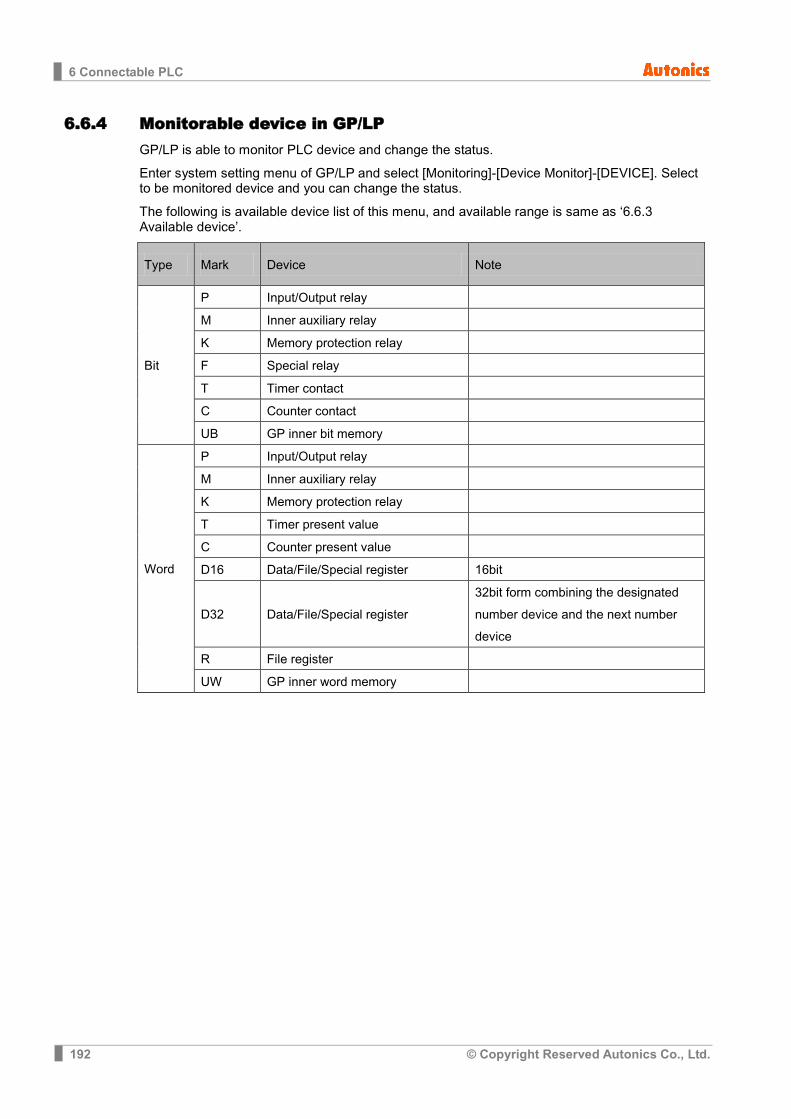
6 Connectable PLC
192 © Copyright Reserved Autonics Co., Ltd.
6.6.4 Monitorable device in GP/LP GP/LP is able to monitor PLC device and change the status.
Enter system setting menu of GP/LP and select [Monitoring]-[Device Monitor]-[DEVICE]. Select to be monitored device and you can change the status.
The following is available device list of this menu, and available range is same as ‘6.6.3 Available device’.
Type Mark Device Note
Bit
P Input/Output relay
M Inner auxiliary relay
K Memory protection relay
F Special relay
T Timer contact
C Counter contact
UB GP inner bit memory
Word
P Input/Output relay
M Inner auxiliary relay
K Memory protection relay
T Timer present value
C Counter present value
D16 Data/File/Special register 16bit
D32 Data/File/Special register 32bit form combining the designated number device and the next number device
R File register
UW GP inner word memory

6 Connectable PLC
© Copyright Reserved Autonics Co., Ltd. 193
6.7 LS Cnet communication connection GP/LP is able to communicate with LS Cnet.
6.7.1 System organization
It executes Cnet communication with GP/LP connecting directly with PLC CPU or using Cnet Unit. It is able to execute Cnet communication differing pin number of Loader port in CPU and connecting Cnet Unit.
6.7.1.1 When using embedded Cnet CPU,
PLC type CPU model name
Communication type
Communication method Baudrate (bps)
LS Master-K
MK-80S
K7M-DR10S
CPU direct
RS232C
19200
K7M-DR20S
K7M-DR30S
K7M-DR40S
K7M-DR60S
MK-120S
K7M-
DRU
RS232C RS485
K7M-
DTU
K7M-
DRTU
MK-200S
K3P-07AS RS232C
K3P-07BS RS422
K3P-07CS RS232C

6 Connectable PLC
194 © Copyright Reserved Autonics Co., Ltd.
(1) RS-232C (Applied cable (3)C3M5P02-D9F0-D9M0)
(2) RS-422(Applied cable (5)C3M5P04-D9M0-W6*0)
(3) RS-485 (Applied cable (4)C3M5P03-D9M0-W4*0)
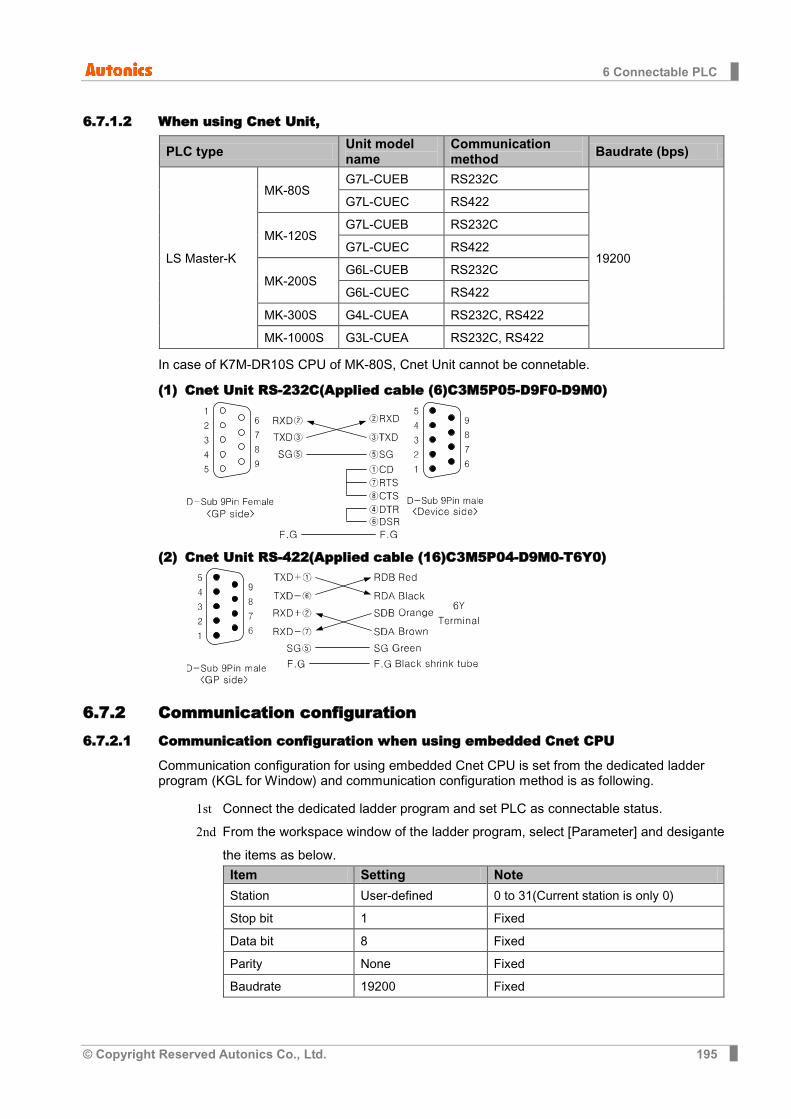
6 Connectable PLC
© Copyright Reserved Autonics Co., Ltd. 195
6.7.1.2 When using Cnet Unit,
PLC type Unit model name
Communication method Baudrate (bps)
LS Master-K
MK-80S G7L-CUEB RS232C
19200
G7L-CUEC RS422
MK-120S G7L-CUEB RS232C
G7L-CUEC RS422
MK-200S G6L-CUEB RS232C
G6L-CUEC RS422
MK-300S G4L-CUEA RS232C, RS422
MK-1000S G3L-CUEA RS232C, RS422
In case of K7M-DR10S CPU of MK-80S, Cnet Unit cannot be connetable.
(1) Cnet Unit RS-232C(Applied cable (6)C3M5P05-D9F0-D9M0)
(2) Cnet Unit RS-422(Applied cable (16)C3M5P04-D9M0-T6Y0)
6.7.2 Communication configuration 6.7.2.1 Communication configuration when using embedded Cnet CPU
Communication configuration for using embedded Cnet CPU is set from the dedicated ladder program (KGL for Window) and communication configuration method is as following.
1st Connect the dedicated ladder program and set PLC as connectable status. 2nd From the workspace window of the ladder program, select [Parameter] and desigante
the items as below. Item Setting Note
Station User-defined 0 to 31(Current station is only 0)
Stop bit 1 Fixed
Data bit 8 Fixed
Parity None Fixed
Baudrate 19200 Fixed
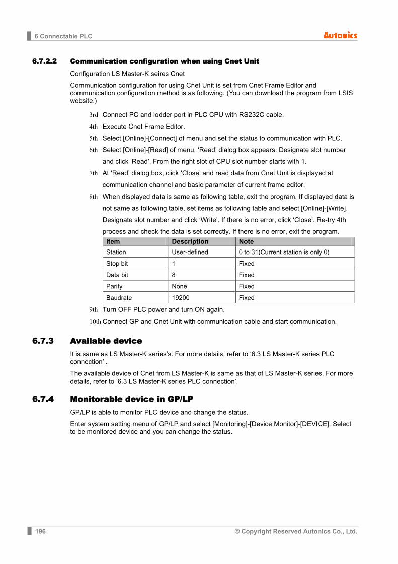
6 Connectable PLC
196 © Copyright Reserved Autonics Co., Ltd.
6.7.2.2 Communication configuration when using Cnet Unit
Configuration LS Master-K seires Cnet
Communication configuration for using Cnet Unit is set from Cnet Frame Editor and communication configuration method is as following. (You can download the program from LSIS website.)
3rd Connect PC and lodder port in PLC CPU with RS232C cable. 4th Execute Cnet Frame Editor. 5th Select [Online]-[Connect] of menu and set the status to communication with PLC. 6th Select [Online]-[Read] of menu, ‘Read’ dialog box appears. Designate slot number
and click ‘Read’. From the right slot of CPU slot number starts with 1. 7th At ‘Read’ dialog box, click ‘Close’ and read data from Cnet Unit is displayed at
communication channel and basic parameter of current frame editor. 8th When displayed data is same as following table, exit the program. If displayed data is
not same as following table, set items as following table and select [Online]-[Write]. Designate slot number and click ‘Write’. If there is no error, click ‘Close’. Re-try 4th process and check the data is set correctly. If there is no error, exit the program.
Item Description Note
Station User-defined 0 to 31(Current station is only 0)
Stop bit 1 Fixed
Data bit 8 Fixed
Parity None Fixed
Baudrate 19200 Fixed
9th Turn OFF PLC power and turn ON again. 10th Connect GP and Cnet Unit with communication cable and start communication.
6.7.3 Available device It is same as LS Master-K series’s. For more details, refer to ‘6.3 LS Master-K series PLC connection’ .
The available device of Cnet from LS Master-K is same as that of LS Master-K series. For more details, refer to ‘6.3 LS Master-K series PLC connection’.
6.7.4 Monitorable device in GP/LP GP/LP is able to monitor PLC device and change the status.
Enter system setting menu of GP/LP and select [Monitoring]-[Device Monitor]-[DEVICE]. Select to be monitored device and you can change the status.
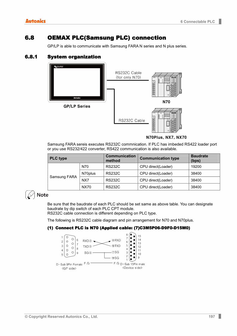
6 Connectable PLC
© Copyright Reserved Autonics Co., Ltd. 197
6.8 OEMAX PLC(Samsung PLC) connection GP/LP is able to communicate with Samsung FARA N series and N plus series.
6.8.1 System organization
Samsung FARA sereis executes RS232C commnication. If PLC has imbeded RS422 loader port or you use RS232/422 converter, RS422 communication is also available.
PLC type Communication method Communication type Baudrate
(bps)
Samsung FARA
N70 RS232C CPU direct(Loader) 19200
N70plus RS232C CPU direct(Loader) 38400
NX7 RS232C CPU direct(Loader) 38400
NX70 RS232C CPU direct(Loader) 38400
Be sure that the baudrate of each PLC should be set same as above table. You can designate baudrate by dip switch of each PLC CPT module. RS232C cable connection is different depending on PLC type.
The following is RS232C cable diagram and pin arrangement for N70 and N70plus.
(1) Connect PLC is N70 (Applied cable: (7)C3M5P06-D9F0-D15M0)

6 Connectable PLC
198 © Copyright Reserved Autonics Co., Ltd.
(2) Connect PLC is N70plus, NX7, NX70 (Applied cable (8)C3M5P07-D9F0-D9M0)
6.8.2 Available device Be sure that device address of N70 and N70plus are different structure.
6.8.2.1 FARA N70
Device range is different depending on PLC model. Even though same type PLC, there is difference according to the number of I/O contact point.
UB device is as GP/LP inner bit memory, only in GP/LP it is able to use same as general inner device of PLC. It is able to switch into word UW device binding 16 units. However it is related with functional area and it may cause serious error. Be sure to use only within user area UW30 to UW2047 (when not using recipe, UW30 to UW6047). For further information of GP/LP inner memory, refer to ‘3.6 System signal’.
Refer to below bit/word available device organization and use the device.
X 00 0
① Device name ② Word address ③ Bit address
Type ① ② ③
Bit
X Decimal Hexadecimal
Y Decimal Hexadecimal
R Decimal Hexadecimal
L Decimal Hexadecimal
T Bit address(Decimal)
C Bit address(Decimal)
UB Decimal Hexadecimal
Word
WX Word address(Decimal) None
WY Word address(Decimal) None
WR Word address(Decimal) None
WL Word address(Decimal) None
EV Word address(Decimal)
SV Word address(Decimal)
DT Word address(Decimal)
Ld Word address(Decimal)
UW Word address(Decimal) None
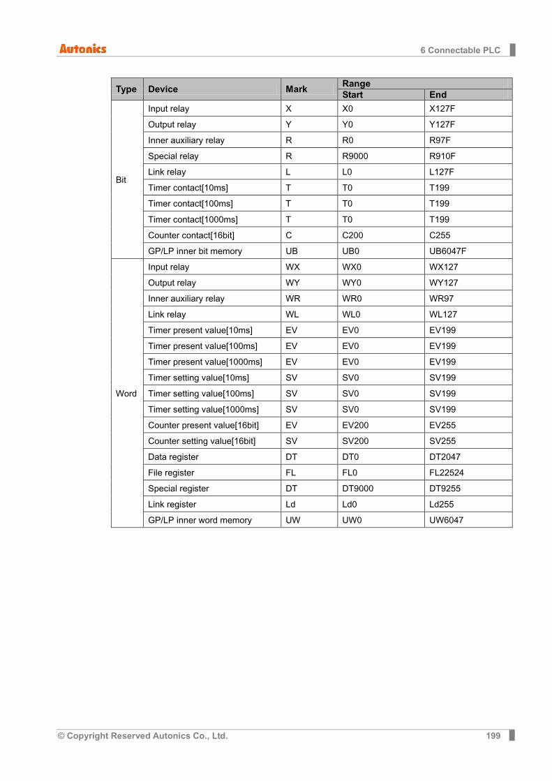
6 Connectable PLC
© Copyright Reserved Autonics Co., Ltd. 199
Type Device Mark Range Start End
Bit
Input relay X X0 X127F
Output relay Y Y0 Y127F
Inner auxiliary relay R R0 R97F
Special relay R R9000 R910F
Link relay L L0 L127F
Timer contact[10ms] T T0 T199
Timer contact[100ms] T T0 T199
Timer contact[1000ms] T T0 T199
Counter contact[16bit] C C200 C255
GP/LP inner bit memory UB UB0 UB6047F
Word
Input relay WX WX0 WX127
Output relay WY WY0 WY127
Inner auxiliary relay WR WR0 WR97
Link relay WL WL0 WL127
Timer present value[10ms] EV EV0 EV199
Timer present value[100ms] EV EV0 EV199
Timer present value[1000ms] EV EV0 EV199
Timer setting value[10ms] SV SV0 SV199
Timer setting value[100ms] SV SV0 SV199
Timer setting value[1000ms] SV SV0 SV199
Counter present value[16bit] EV EV200 EV255
Counter setting value[16bit] SV SV200 SV255
Data register DT DT0 DT2047
File register FL FL0 FL22524
Special register DT DT9000 DT9255
Link register Ld Ld0 Ld255
GP/LP inner word memory UW UW0 UW6047
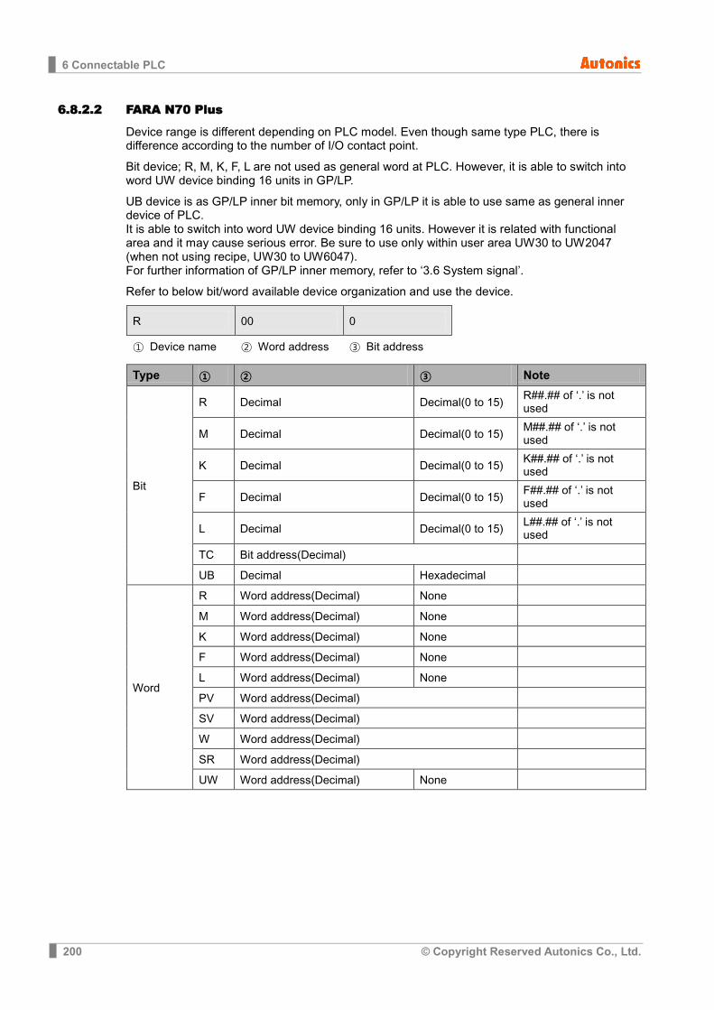
6 Connectable PLC
200 © Copyright Reserved Autonics Co., Ltd.
6.8.2.2 FARA N70 Plus
Device range is different depending on PLC model. Even though same type PLC, there is difference according to the number of I/O contact point.
Bit device; R, M, K, F, L are not used as general word at PLC. However, it is able to switch into word UW device binding 16 units in GP/LP.
UB device is as GP/LP inner bit memory, only in GP/LP it is able to use same as general inner device of PLC. It is able to switch into word UW device binding 16 units. However it is related with functional area and it may cause serious error. Be sure to use only within user area UW30 to UW2047 (when not using recipe, UW30 to UW6047). For further information of GP/LP inner memory, refer to ‘3.6 System signal’.
Refer to below bit/word available device organization and use the device.
R 00 0
① Device name ② Word address ③ Bit address
Type ① ② ③ Note
Bit
R Decimal Decimal(0 to 15) R##.## of ‘.’ is not used
M Decimal Decimal(0 to 15) M##.## of ‘.’ is not used
K Decimal Decimal(0 to 15) K##.## of ‘.’ is not used
F Decimal Decimal(0 to 15) F##.## of ‘.’ is not used
L Decimal Decimal(0 to 15) L##.## of ‘.’ is not used
TC Bit address(Decimal)
UB Decimal Hexadecimal
Word
R Word address(Decimal) None
M Word address(Decimal) None
K Word address(Decimal) None
F Word address(Decimal) None
L Word address(Decimal) None
PV Word address(Decimal)
SV Word address(Decimal)
W Word address(Decimal)
SR Word address(Decimal)
UW Word address(Decimal) None

6 Connectable PLC
© Copyright Reserved Autonics Co., Ltd. 201
Word R1 = Bit R100 to R115 , Word UW10 = UB100 to UB10F
There is difference for mark of bit R, M, K, F, L between general mark and GP/LP mark. General mark is displayed as R##.##, GP/LP mark is displayed without middle of distinguisher. For example, R10.10 is displayed as ‘R1010’ in GP/LP.
Be sure that GP/LP does not use distinguisher, it uses virtual distinguisher cutting two digits from the backward of input bit R, M, K, F, L address.
(Ex) Bit R1 = R0.01 , Bit M10 = M0.10 , Bit K101 = K1.01
Type Device Mark Range Start End
Bit
Input relay R R0 R12715
Output relay R R0 R12715
Inner auxiliary relay M M0 M12715
Memory protection relay K K0 K12715
Special relay F F0 F1515
Link relay L L0 L6315
Timer contact[10ms] TC TC0 TC63
Timer contact[100ms] TC TC64 TC255
Counter contact[16bit] TC TC0 TC255
GP/LP inner bit memory UB UB0 UB6047F
Word
Input relay R R0 R127
Output relay R R0 R127
Inner auxiliary relay M M0 M127
Memory protection relay K K0 K127
Special relay F F0 F15
Link relay L L0 L63
Timer present value[10ms] PV PV0 PV63
Timer present value[100ms] PV PV63 PV255
Timer setting value[10ms] SV SV0 SV63
Timer setting value[100ms] SV SV64 SV255
Counter present value[16bit] PV PV0 PV255
Counter setting value[16bit] SV SV0 SV255
Data register ※1 W W0 W2047
Special register SR SR0 SR511
GP/LP inner word memory UW UW0 UW6047
※1. Depending on CPU type, that range is fluid. In case of CPL9215A, the range is W0 to W2047. In case of CPL9216A, the range is W0 to W4095.

6 Connectable PLC
202 © Copyright Reserved Autonics Co., Ltd.
6.8.2.3 FARA NX7
Device range is different depending on PLC model. Even though same type PLC, there is difference according to the number of I/O contact point.
Bit device; R, M, K, F, L are not used as general word at PLC. However, it is able to switch into word UW device binding 16 units in GP/LP.
UB device is as GP/LP inner bit memory, only in GP/LP it is able to use same as general inner device of PLC. It is able to switch into word UW device binding 16 units. However it is related with functional area and it may cause serious error. Be sure to use only within user area UW30 to UW2047 (when not using recipe, UW30 to UW6047). For further information of GP/LP inner memory, refer to ‘3.6 System signal’’.
Refer to below bit/word available device organization and use the device.
R 00 0
①Device name ②Word address ③Bit address
Type ① ② ③ Note
Bit
R Decimal Decimal(0 to 15) R##.## of ‘.’ is not used
M Decimal Decimal(0 to 15) M##.## of ‘.’ is not used
K Decimal Decimal(0 to 15) K##.## of ‘.’ is not used
F Decimal Decimal(0 to 15) F##.## of ‘.’ is not used
L Decimal Decimal(0 to 15) L##.## of ‘.’ is not used
TC Bit address(Decimal)
UB Decimal Hexadecimal
Word
R Word address(Decimal) None
M Word address(Decimal) None
K Word address(Decimal) None
F Word address(Decimal) None
L Word address(Decimal) None
PV Word address(Decimal)
SV Word address(Decimal)
W Word address(Decimal)
SR Word address(Decimal)
UW Word address(Decimal) None
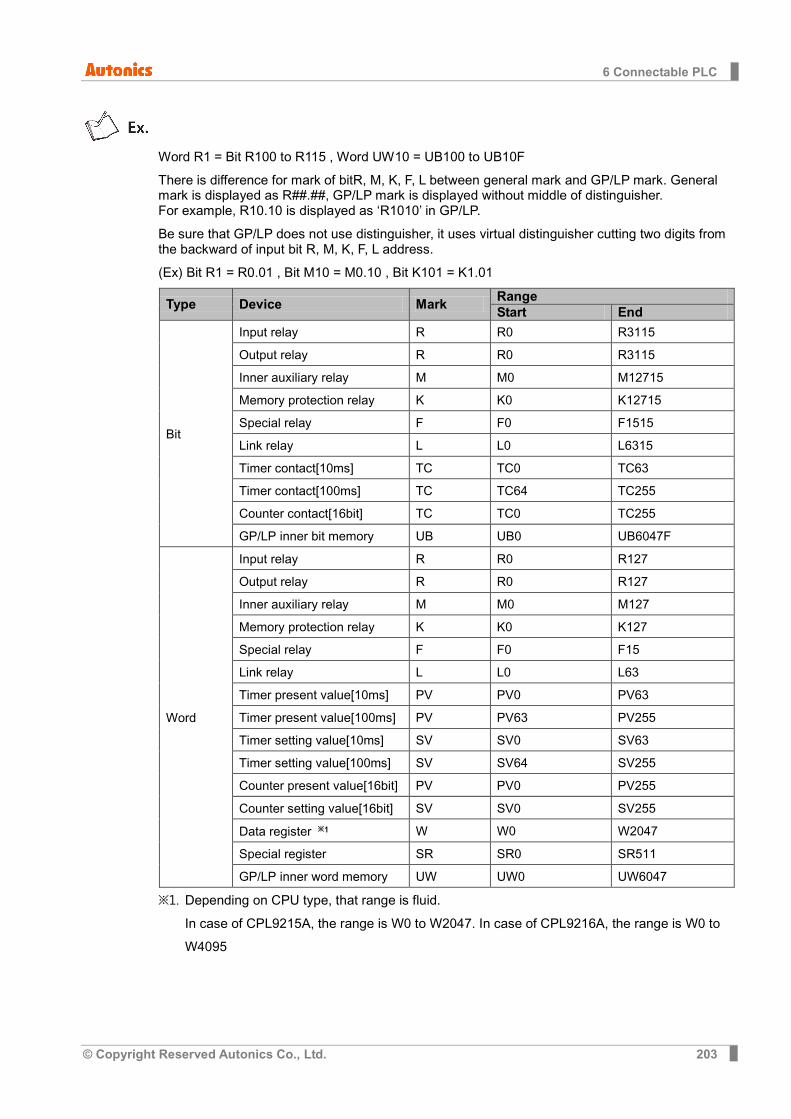
6 Connectable PLC
© Copyright Reserved Autonics Co., Ltd. 203
Word R1 = Bit R100 to R115 , Word UW10 = UB100 to UB10F
There is difference for mark of bitR, M, K, F, L between general mark and GP/LP mark. General mark is displayed as R##.##, GP/LP mark is displayed without middle of distinguisher. For example, R10.10 is displayed as ‘R1010’ in GP/LP.
Be sure that GP/LP does not use distinguisher, it uses virtual distinguisher cutting two digits from the backward of input bit R, M, K, F, L address.
(Ex) Bit R1 = R0.01 , Bit M10 = M0.10 , Bit K101 = K1.01
Type Device Mark Range Start End
Bit
Input relay R R0 R3115
Output relay R R0 R3115
Inner auxiliary relay M M0 M12715
Memory protection relay K K0 K12715
Special relay F F0 F1515
Link relay L L0 L6315
Timer contact[10ms] TC TC0 TC63
Timer contact[100ms] TC TC64 TC255
Counter contact[16bit] TC TC0 TC255
GP/LP inner bit memory UB UB0 UB6047F
Word
Input relay R R0 R127
Output relay R R0 R127
Inner auxiliary relay M M0 M127
Memory protection relay K K0 K127
Special relay F F0 F15
Link relay L L0 L63
Timer present value[10ms] PV PV0 PV63
Timer present value[100ms] PV PV63 PV255
Timer setting value[10ms] SV SV0 SV63
Timer setting value[100ms] SV SV64 SV255
Counter present value[16bit] PV PV0 PV255
Counter setting value[16bit] SV SV0 SV255
Data register ※1 W W0 W2047
Special register SR SR0 SR511
GP/LP inner word memory UW UW0 UW6047
※1. Depending on CPU type, that range is fluid. In case of CPL9215A, the range is W0 to W2047. In case of CPL9216A, the range is W0 to W4095
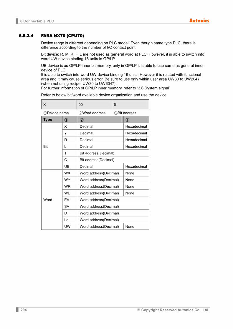
6 Connectable PLC
204 © Copyright Reserved Autonics Co., Ltd.
6.8.2.4 FARA NX70 (CPU70)
Device range is different depending on PLC model. Even though same type PLC, there is difference according to the number of I/O contact point
Bit device; R, M, K, F, L are not used as general word at PLC. However, it is able to switch into word UW device binding 16 units in GP/LP.
UB device is as GP/LP inner bit memory, only in GP/LP it is able to use same as general inner device of PLC. It is able to switch into word UW device binding 16 units. However it is related with functional area and it may cause serious error. Be sure to use only within user area UW30 to UW2047 (when not using recipe, UW30 to UW6047). For further information of GP/LP inner memory, refer to ‘3.6 System signal’
Refer to below bit/word available device organization and use the device.
X 00 0
①Device name ②Word address ③Bit address
Type ① ② ③
Bit
X Decimal Hexadecimal
Y Decimal Hexadecimal
R Decimal Hexadecimal
L Decimal Hexadecimal
T Bit address(Decimal)
C Bit address(Decimal)
UB Decimal Hexadecimal
Word
WX Word address(Decimal) None
WY Word address(Decimal) None
WR Word address(Decimal) None
WL Word address(Decimal) None
EV Word address(Decimal)
SV Word address(Decimal)
DT Word address(Decimal)
Ld Word address(Decimal)
UW Word address(Decimal) None
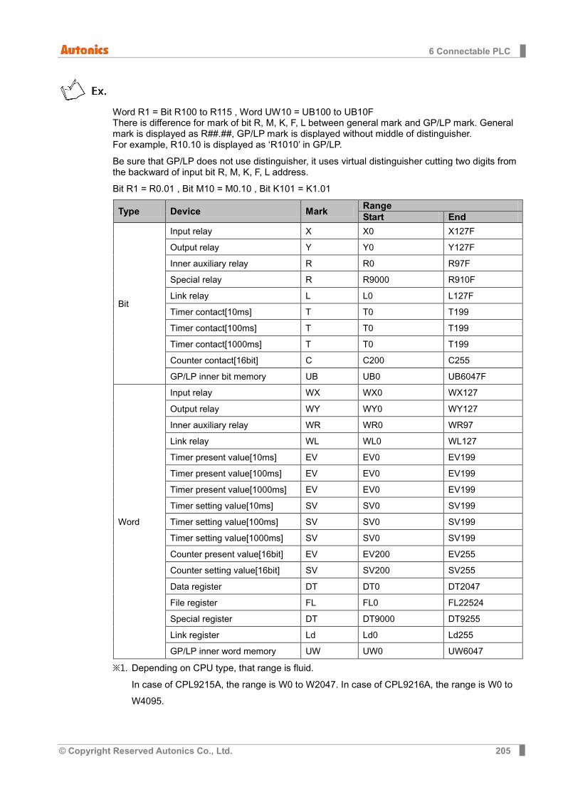
6 Connectable PLC
© Copyright Reserved Autonics Co., Ltd. 205
Word R1 = Bit R100 to R115 , Word UW10 = UB100 to UB10F There is difference for mark of bit R, M, K, F, L between general mark and GP/LP mark. General mark is displayed as R##.##, GP/LP mark is displayed without middle of distinguisher. For example, R10.10 is displayed as ‘R1010’ in GP/LP.
Be sure that GP/LP does not use distinguisher, it uses virtual distinguisher cutting two digits from the backward of input bit R, M, K, F, L address.
Bit R1 = R0.01 , Bit M10 = M0.10 , Bit K101 = K1.01
Type Device Mark Range Start End
Bit
Input relay X X0 X127F
Output relay Y Y0 Y127F
Inner auxiliary relay R R0 R97F
Special relay R R9000 R910F
Link relay L L0 L127F
Timer contact[10ms] T T0 T199
Timer contact[100ms] T T0 T199
Timer contact[1000ms] T T0 T199
Counter contact[16bit] C C200 C255
GP/LP inner bit memory UB UB0 UB6047F
Word
Input relay WX WX0 WX127
Output relay WY WY0 WY127
Inner auxiliary relay WR WR0 WR97
Link relay WL WL0 WL127
Timer present value[10ms] EV EV0 EV199
Timer present value[100ms] EV EV0 EV199
Timer present value[1000ms] EV EV0 EV199
Timer setting value[10ms] SV SV0 SV199
Timer setting value[100ms] SV SV0 SV199
Timer setting value[1000ms] SV SV0 SV199
Counter present value[16bit] EV EV200 EV255
Counter setting value[16bit] SV SV200 SV255
Data register DT DT0 DT2047
File register FL FL0 FL22524
Special register DT DT9000 DT9255
Link register Ld Ld0 Ld255
GP/LP inner word memory UW UW0 UW6047
※1. Depending on CPU type, that range is fluid. In case of CPL9215A, the range is W0 to W2047. In case of CPL9216A, the range is W0 to W4095.
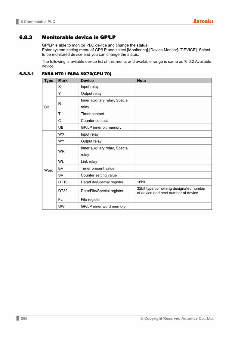
6 Connectable PLC
206 © Copyright Reserved Autonics Co., Ltd.
6.8.3 Monitorable device in GP/LP GP/LP is able to monitor PLC device and change the status. Enter system setting menu of GP/LP and select [Monitoring]-[Device Monitor]-[DEVICE]. Select to be monitored device and you can change the status.
The following is avilable device list of this menu, and available range is same as ‘6.6.2 Available device’.
6.8.3.1 FARA N70 / FARA NX70(CPU 70) Type Mark Device Note
Bit
X Input relay
Y Output relay
R Inner auxiliary relay, Special relay
T Timer contact
C Counter contact
UB GP/LP inner bit memory
Word
WX Input relay
WY Output relay
WR Inner auxiliary relay, Special relay
WL Link relay
EV Timer present value
SV Counter setting value
DT16 Data/File/Special register 16bit
DT32 Data/File/Special register 32bit type combining designated number of device and next number of device
FL File register
UW GP/LP inner word memory

6 Connectable PLC
© Copyright Reserved Autonics Co., Ltd. 207
6.8.3.2 FARA N70 Plus / FARA NX7 Type Mark Device Note
Bit
R Input/Output relay
M Inner auxiliary relay
K Memory protection relay
F Special relay
TC Counter/Counter contact
UB GP/LP inner bit memory
Word
R Input/Output relay
M Inner auxiliary relay
K Memory protection relay
F Special relay
PV Timer/Counter present value
SV Timer/Counter setting value
W16 Data/File/Special register 16bit
W32 Data/File/Special register 32bit type combining designated number of device and next number of device
SR Special register
UW GP/LP inner word memory

6 Connectable PLC
208 © Copyright Reserved Autonics Co., Ltd.
6.9 MITSUBISHI PLC GP/LP is able to communicate with MITSUBISHI FX series.
6.9.1 System organization
FX sereis executes RS422 commnication and it executes also RS232C communication with RS232/422 converter or RS232C communication board (FX1N-232-BD, FX2N-232-BD).
PLC type Communication method Communication type
MITSUBISHI FX
FX1S RS422 CPU direct(Loader)
RS232C Communication board(FX1N-232-BD)
FX1N RS422 CPU direct(Loader)
RS232C Communication board(FX1N-232-BD)
FX2N RS422 CPU direct(Loader)
RS232C Communication board(FX2N-232-BD)
FX2NC RS422 CPU direct(Loader)
FX3U RS422 CPU direct(Loader)

6 Connectable PLC
© Copyright Reserved Autonics Co., Ltd. 209
(1) RS-422: Applied cable (9)C3M5P08-D9M0-M8M0.
(2) RS-232C communication board(FX1N/FX2N-232-BD): Applied cable (10)C3M5P09-D9F0-D9F0.
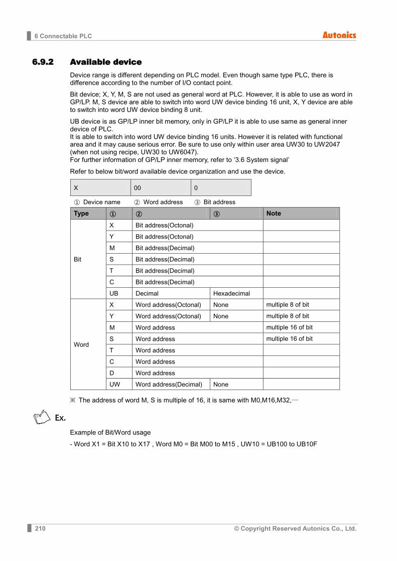
6 Connectable PLC
210 © Copyright Reserved Autonics Co., Ltd.
6.9.2 Available device Device range is different depending on PLC model. Even though same type PLC, there is difference according to the number of I/O contact point.
Bit device; X, Y, M, S are not used as general word at PLC. However, it is able to use as word in GP/LP. M, S device are able to switch into word UW device binding 16 unit, X, Y device are able to switch into word UW device binding 8 unit.
UB device is as GP/LP inner bit memory, only in GP/LP it is able to use same as general inner device of PLC. It is able to switch into word UW device binding 16 units. However it is related with functional area and it may cause serious error. Be sure to use only within user area UW30 to UW2047 (when not using recipe, UW30 to UW6047). For further information of GP/LP inner memory, refer to ‘3.6 System signal’
Refer to below bit/word available device organization and use the device.
X 00 0
① Device name ② Word address ③ Bit address
Type ① ② ③ Note
Bit
X Bit address(Octonal)
Y Bit address(Octonal)
M Bit address(Decimal)
S Bit address(Decimal)
T Bit address(Decimal)
C Bit address(Decimal)
UB Decimal Hexadecimal
Word
X Word address(Octonal) None multiple 8 of bit
Y Word address(Octonal) None multiple 8 of bit
M Word address multiple 16 of bit
S Word address multiple 16 of bit
T Word address
C Word address
D Word address
UW Word address(Decimal) None
※ The address of word M, S is multiple of 16, it is same with M0,M16,M32,…
Example of Bit/Word usage
- Word X1 = Bit X10 to X17 , Word M0 = Bit M00 to M15 , UW10 = UB100 to UB10F

6 Connectable PLC
© Copyright Reserved Autonics Co., Ltd. 211
6.9.2.1 FX1S
Type Device Mark Range Start End
Bit
Input relay X X0 X17
Output relay Y Y0 Y15
Inner auxiliary relay M M0 M383
Memory protection relay M M384 M511
Special relay M M8000 M8255
Status relay S S0 S127
Timer contact[1ms] T T63 -
Timer contact[10ms] T T32 T62
Timer contact[100ms] T T0 T31
Counter contact[16bit] C C0 C31
Counter contact[32b 1 phase 1count] C C235 C245
Counter contact[32b 1 phase 2count] C C246 C250
Counter contact[32b 2 phase 2count] C C251 C255
GP/LP inner bit memory UB UB0 UB6047F
Word
Input relay X X0 X1
Output relay Y Y0 Y1
Inner auxiliary relay M M0 M368
Memory protection relay M M384 M496
Special relay M M8000 M8240
Status relay S S0 S112
Timer present value[1ms] T T63 -
Timer present value[10ms] T T32 T62
Timer present value[100ms] T T0 T31
Counter present value[16bit] C C0 C31
Counter present value[32b 1 phase 1count]
C C235 C245
Counter present value[32b 1 phase 2count]
C C246 C250
Counter present value[32b 2 phase 2count]
C C251 C255
Data register D D0 D255
File register D D1000 D2499
Special register D D8000 D8255
GP/LP inner word memory UW UW0 UW6047
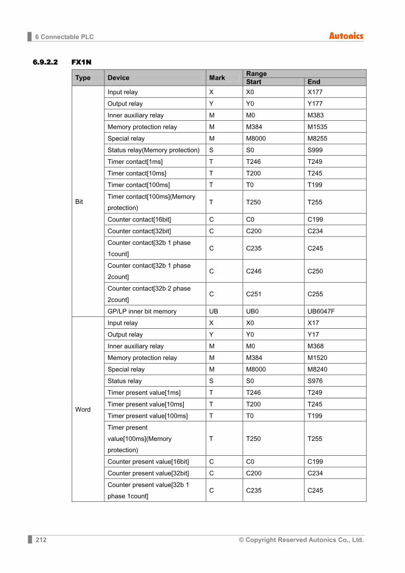
6 Connectable PLC
212 © Copyright Reserved Autonics Co., Ltd.
6.9.2.2 FX1N
Type Device Mark Range Start End
Bit
Input relay X X0 X177
Output relay Y Y0 Y177
Inner auxiliary relay M M0 M383
Memory protection relay M M384 M1535
Special relay M M8000 M8255
Status relay(Memory protection) S S0 S999
Timer contact[1ms] T T246 T249
Timer contact[10ms] T T200 T245
Timer contact[100ms] T T0 T199
Timer contact[100ms](Memory protection)
T T250 T255
Counter contact[16bit] C C0 C199
Counter contact[32bit] C C200 C234
Counter contact[32b 1 phase 1count]
C C235 C245
Counter contact[32b 1 phase 2count]
C C246 C250
Counter contact[32b 2 phase 2count]
C C251 C255
GP/LP inner bit memory UB UB0 UB6047F
Word
Input relay X X0 X17
Output relay Y Y0 Y17
Inner auxiliary relay M M0 M368
Memory protection relay M M384 M1520
Special relay M M8000 M8240
Status relay S S0 S976
Timer present value[1ms] T T246 T249
Timer present value[10ms] T T200 T245
Timer present value[100ms] T T0 T199
Timer present value[100ms](Memory protection)
T T250 T255
Counter present value[16bit] C C0 C199
Counter present value[32bit] C C200 C234
Counter present value[32b 1 phase 1count]
C C235 C245
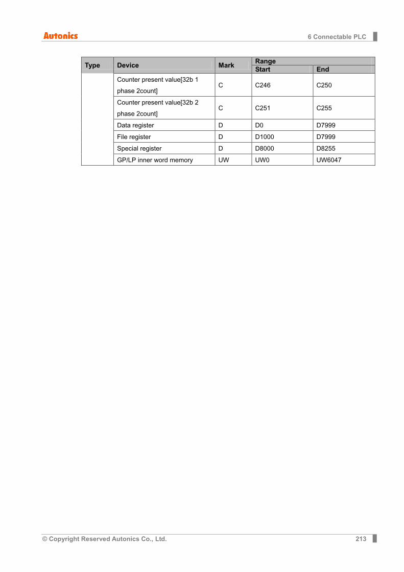
6 Connectable PLC
© Copyright Reserved Autonics Co., Ltd. 213
Type Device Mark Range Start End
Counter present value[32b 1 phase 2count]
C C246 C250
Counter present value[32b 2 phase 2count]
C C251 C255
Data register D D0 D7999
File register D D1000 D7999
Special register D D8000 D8255
GP/LP inner word memory UW UW0 UW6047
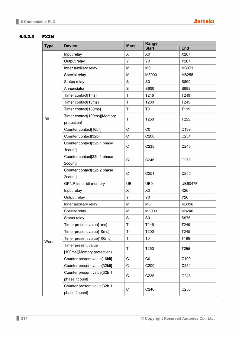
6 Connectable PLC
214 © Copyright Reserved Autonics Co., Ltd.
6.9.2.3 FX2N
Type Device Mark Range Start End
Bit
Input relay X X0 X267
Output relay Y Y0 Y267
Inner auxiliary relay M M0 M3071
Special relay M M8000 M8255
Status relay S S0 S899
Annunciator S S900 S999
Timer contact[1ms] T T246 T249
Timer contact[10ms] T T200 T245
Timer contact[100ms] T T0 T199
Timer contact[100ms](Memory protection)
T T250 T255
Counter contact[16bit] C C0 C199
Counter contact[32bit] C C200 C234
Counter contact[32b 1 phase 1count]
C C235 C245
Counter contact[32b 1 phase 2count]
C C246 C250
Counter contact[32b 2 phase 2count]
C C251 C255
GP/LP inner bit memory UB UB0 UB6047F
Word
Input relay X X0 X26
Output relay Y Y0 Y26
Inner auxiliary relay M M0 M3056
Special relay M M8000 M8240
Status relay S S0 S976
Timer present value[1ms] T T246 T249
Timer present value[10ms] T T200 T245
Timer present value[100ms] T T0 T199
Timer present value [100ms](Memory protection)
T T250 T255
Counter present value[16bit] C C0 C199
Counter present value[32bit] C C200 C234
Counter present value[32b 1 phase 1count]
C C235 C245
Counter present value[32b 1 phase 2count]
C C246 C250

6 Connectable PLC
© Copyright Reserved Autonics Co., Ltd. 215
Type Device Mark Range Start End
Counter present value[32b 2 phase 2count]
C C251 C255
Data register D D0 D7999
File register D D1000 D7999
Special register D D8000 D8255
GP/LP inner word memory UW UW0 UW6047

6 Connectable PLC
216 © Copyright Reserved Autonics Co., Ltd.
6.9.2.4 FX2NC
Type Device Mark Range Start End
Bit
Input relay X X0 X267
Output relay Y Y0 Y267
Inner auxiliary relay M M0 M3071
Special relay M M8000 M8255
Status relay S S0 S899
Annunciator S S900 S999
Timer contact[1ms] T T246 T249
Timer contact[10ms] T T200 T245
Timer contact[100ms] T T0 T199
Timer contact[100ms](Memory protection)
T T250 T255
Counter contact[16bit] C C0 C199
Counter contact[32bit] C C200 C234
Counter contact[32b 1 phase 1count]
C C235 C245
Counter contact[32b 1 phase 2count]
C C246 C250
Counter contact[32b 2 phase 2count]
C C251 C255
GP/LP inner bit memory UB UB0 UB6047F
Word
Input relay X X0 X26
Output relay Y Y0 Y26
Inner auxiliary relay M M0 M3056
Special relay M M8000 M8240
Status relay S S0 S976
Timer present value[1ms] T T246 T249
Timer present value[10ms] T T200 T245
Timer present value[100ms] T T0 T199
Timer present value [100ms](Memory protection)
T T250 T255
Counter present value[16bit] C C0 C199
Counter present value[32bit] C C200 C234
Counter present value[32b 1 phase 1count]
C C235 C245
Counter present value[32b 1 phase 2count]
C C246 C250
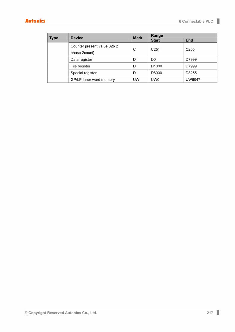
6 Connectable PLC
© Copyright Reserved Autonics Co., Ltd. 217
Type Device Mark Range Start End
Counter present value[32b 2 phase 2count]
C C251 C255
Data register D D0 D7999
File register D D1000 D7999
Special register D D8000 D8255
GP/LP inner word memory UW UW0 UW6047

6 Connectable PLC
218 © Copyright Reserved Autonics Co., Ltd.
6.9.2.5 FX3U
Type Device Mark Range Start End
Bit
Input relay X X0 X367
Output relay Y Y0 Y367
Inner auxiliary relay M M0 M7679
Special relay M M8000 M8511
Status relay S S0 S899
Annunciator S S900 S999
Timer contact[1ms] T T256 T511
Timer contact[1ms] Integration type
T T246 T249
Timer contact[10ms] T T200 T245
Timer contact[100ms] T T0 T199
Timer contact[100ms] Integration type
T T250 T255
Counter contact[16bit] C C0 C199
Counter contact[32bit] C C200 C234
Counter contact[32b 1 phase 1count]
C C235 C245
Counter contact[32b 1 phase 2count]
C C246 C250
Counter contact[32b 2 phase 2count]
C C251 C255
GP/LP inner bit memory UB UB0 UB6047F
Word
Input relay X X0 X36
Output relay Y Y0 Y36
Inner auxiliary relay M M0 M7648
Special relay M M8000 M8496
Status relay S S0 S976
Timer present value[1ms] T T256 T511
Timer present value[10ms] T T200 T245
Timer present value[100ms] T T0 T199
Timer present value [100ms](Memory protection)
T T250 T255
Counter present value[16bit] C C0 C199
Counter present value[32bit] C C200 C234
Counter present value[32b 1 phase 1count]
C C235 C245
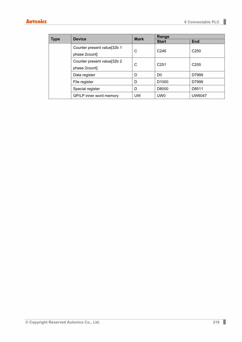
6 Connectable PLC
© Copyright Reserved Autonics Co., Ltd. 219
Type Device Mark Range Start End
Counter present value[32b 1 phase 2count]
C C246 C250
Counter present value[32b 2 phase 2count]
C C251 C255
Data register D D0 D7999
File register D D1000 D7999
Special register D D8000 D8511
GP/LP inner word memory UW UW0 UW6047
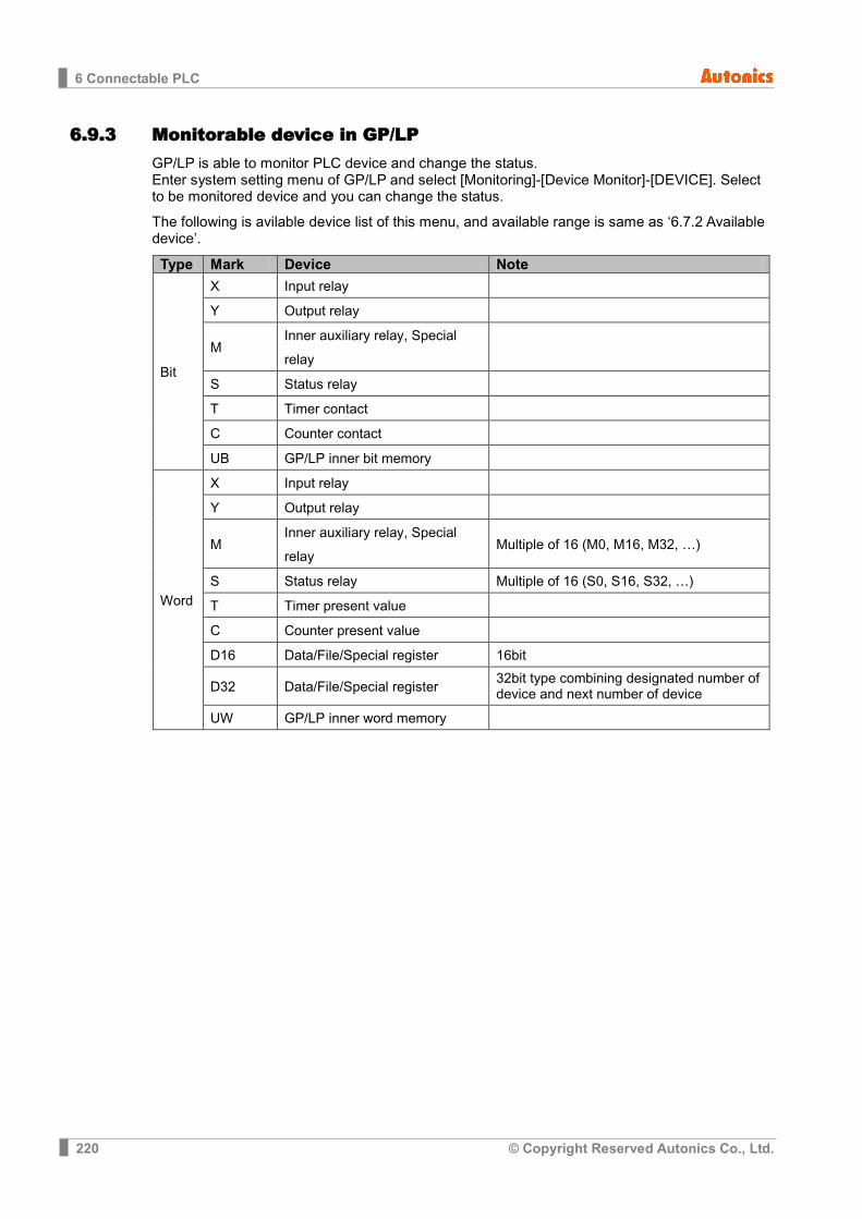
6 Connectable PLC
220 © Copyright Reserved Autonics Co., Ltd.
6.9.3 Monitorable device in GP/LP GP/LP is able to monitor PLC device and change the status. Enter system setting menu of GP/LP and select [Monitoring]-[Device Monitor]-[DEVICE]. Select to be monitored device and you can change the status.
The following is avilable device list of this menu, and available range is same as ‘6.7.2 Available device’.
Type Mark Device Note
Bit
X Input relay
Y Output relay
M Inner auxiliary relay, Special relay
S Status relay
T Timer contact
C Counter contact
UB GP/LP inner bit memory
Word
X Input relay
Y Output relay
M Inner auxiliary relay, Special relay
Multiple of 16 (M0, M16, M32, …)
S Status relay Multiple of 16 (S0, S16, S32, …)
T Timer present value
C Counter present value
D16 Data/File/Special register 16bit
D32 Data/File/Special register 32bit type combining designated number of device and next number of device
UW GP/LP inner word memory

6 Connectable PLC
© Copyright Reserved Autonics Co., Ltd. 221
6.10 MITSUBISHI Q series PLC connection GP/LP is able to communicate with MITSUBISHI Q series.
6.10.1 System organization The following table is for system organization of this protocol.
PLC Communication module Cable GP/LP
↔
Q00J/Q00/Q01 Q02/Q02H/Q06H /Q12H/Q25H
QJ71C24N QJ71C24N-R2 QJ71C24N-R4
RS-232C RS-422 / RS-485
GP/LP series
PLC type Program capacity
The number of I/O point
MITSUBISHI Q
Basic model
Q00J 8K 245 points
Q00 8K 1024 points
Q01 14K 1024 points
High performance model
Q02 28K 4096 points
Q02H 28K 4096 points
Q06H 60K 4096 points
Q12H 124K 4096 points
Q25H 252K 4096 points
Serial communication module type Communication channel
QJ71C24N RS-232 1CH, RS-422/485 1CH
QJ71C24N-R2 RS-232 2CH
QJ71C24N-R4 RS-422/485 2CH
(1) RS-422: Applied cable (5)C3M5P04-D9M0-W6*0
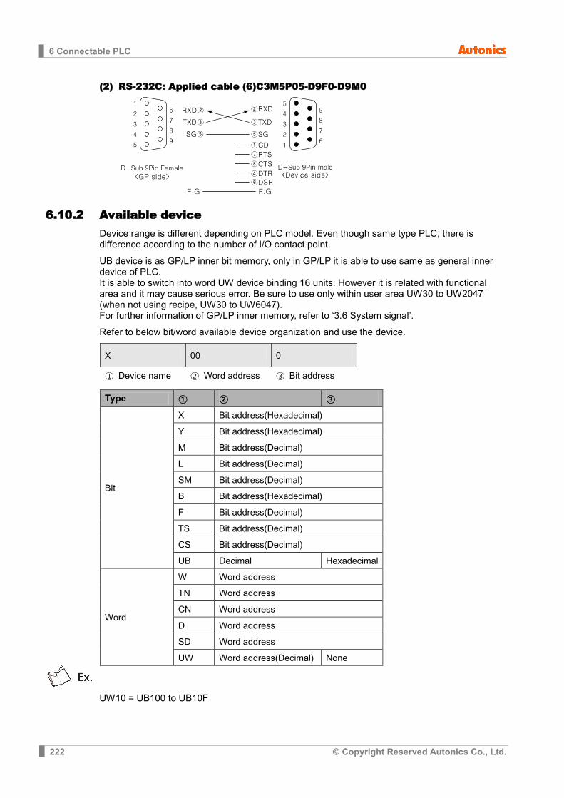
6 Connectable PLC
222 © Copyright Reserved Autonics Co., Ltd.
(2) RS-232C: Applied cable (6)C3M5P05-D9F0-D9M0
6.10.2 Available device Device range is different depending on PLC model. Even though same type PLC, there is difference according to the number of I/O contact point.
UB device is as GP/LP inner bit memory, only in GP/LP it is able to use same as general inner device of PLC. It is able to switch into word UW device binding 16 units. However it is related with functional area and it may cause serious error. Be sure to use only within user area UW30 to UW2047 (when not using recipe, UW30 to UW6047). For further information of GP/LP inner memory, refer to ‘3.6 System signal’.
Refer to below bit/word available device organization and use the device.
X 00 0
① Device name ② Word address ③ Bit address
Type ① ② ③
Bit
X Bit address(Hexadecimal)
Y Bit address(Hexadecimal)
M Bit address(Decimal)
L Bit address(Decimal)
SM Bit address(Decimal)
B Bit address(Hexadecimal)
F Bit address(Decimal)
TS Bit address(Decimal)
CS Bit address(Decimal)
UB Decimal Hexadecimal
Word
W Word address
TN Word address
CN Word address
D Word address
SD Word address
UW Word address(Decimal) None
UW10 = UB100 to UB10F

6 Connectable PLC
© Copyright Reserved Autonics Co., Ltd. 223
6.10.2.1 Q00J / Q00 / Q01
Type Device Mark Range Start End
Bit
Input relay X X0 X7FF
Output relay Y Y0 Y7FF
Auxiliary relay M M0 M8191
Special relay SM SM0 SM1023 Latch relay L L0 L2047 Facility error detecting relay F F0 F1023
Link relay B B0 B07FF
Timer contact TS TS0 TS511
Counter contact CS CS0 CS511
GP/LP inner bit memory UB UB0 UB6047F
Word
Data register D D0 D11135
Special register SD SD0 SD1023
Link register W W0 W7FF
Timer present value TN TN0 TN511
Counter present value CN CN0 CN511
GP/LP inner word memory UW UW0 UW6047
6.10.2.2 Q02 / Q02H / Q06H / Q12H / Q25H
Type Device Mark Range Start End
Bit
Input relay X X0 X1FFF
Output relay Y Y0 Y1FFF
Auxiliary relay M M0 M8191
Special relay SM SM0 SM2047
Latch relay L L0 L8191
Facility error detecting relay F F0 F2047
Link relay B B0 B01FFF
Timer contact TS TS0 TS2047
Counter contact CS CS0 CS2047
GP/LP inner bit memory UB UB0 UB6047F
Word
Data register D D0 D12287
Special register SD SD0 SD2047
Link register W W0 W1FFF
Timer present value TN TN0 TN2047
Counter present value CN CN0 CN2047
GP/LP inner word memory UW UW0 UW6047
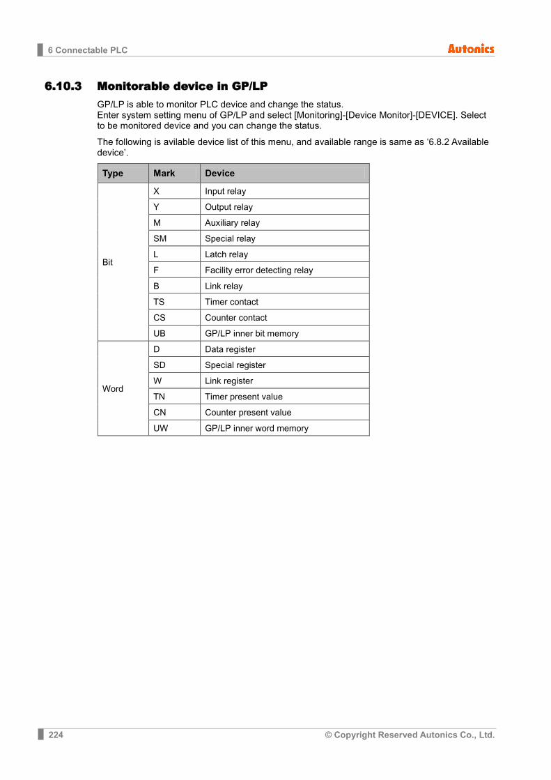
6 Connectable PLC
224 © Copyright Reserved Autonics Co., Ltd.
6.10.3 Monitorable device in GP/LP GP/LP is able to monitor PLC device and change the status. Enter system setting menu of GP/LP and select [Monitoring]-[Device Monitor]-[DEVICE]. Select to be monitored device and you can change the status.
The following is avilable device list of this menu, and available range is same as ‘6.8.2 Available device’.
Type Mark Device
Bit
X Input relay
Y Output relay
M Auxiliary relay
SM Special relay
L Latch relay
F Facility error detecting relay
B Link relay
TS Timer contact
CS Counter contact
UB GP/LP inner bit memory
Word
D Data register
SD Special register
W Link register
TN Timer present value
CN Counter present value
UW GP/LP inner word memory
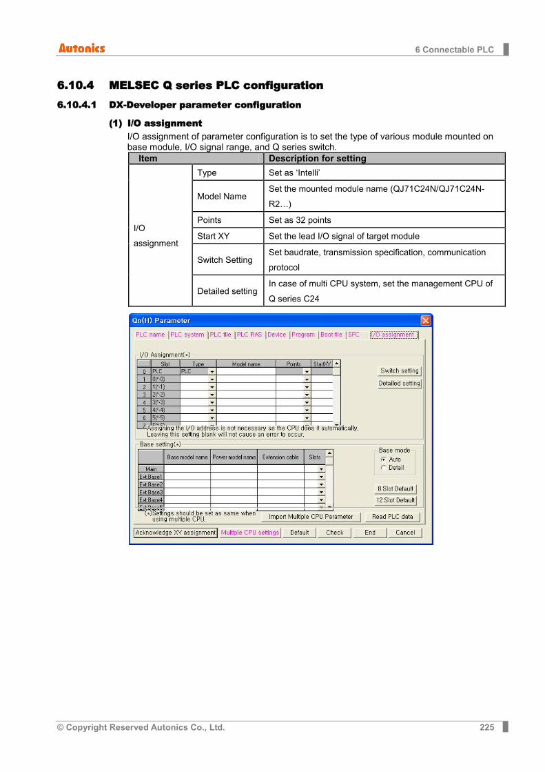
6 Connectable PLC
© Copyright Reserved Autonics Co., Ltd. 225
6.10.4 MELSEC Q series PLC configuration 6.10.4.1 DX-Developer parameter configuration
(1) I/O assignment I/O assignment of parameter configuration is to set the type of various module mounted on base module, I/O signal range, and Q series switch.
Item Description for setting
I/O assignment
Type Set as ‘Intelli’
Model Name Set the mounted module name (QJ71C24N/QJ71C24N-R2…)
Points Set as 32 points
Start XY Set the lead I/O signal of target module
Switch Setting Set baudrate, transmission specification, communication protocol
Detailed setting In case of multi CPU system, set the management CPU of Q series C24
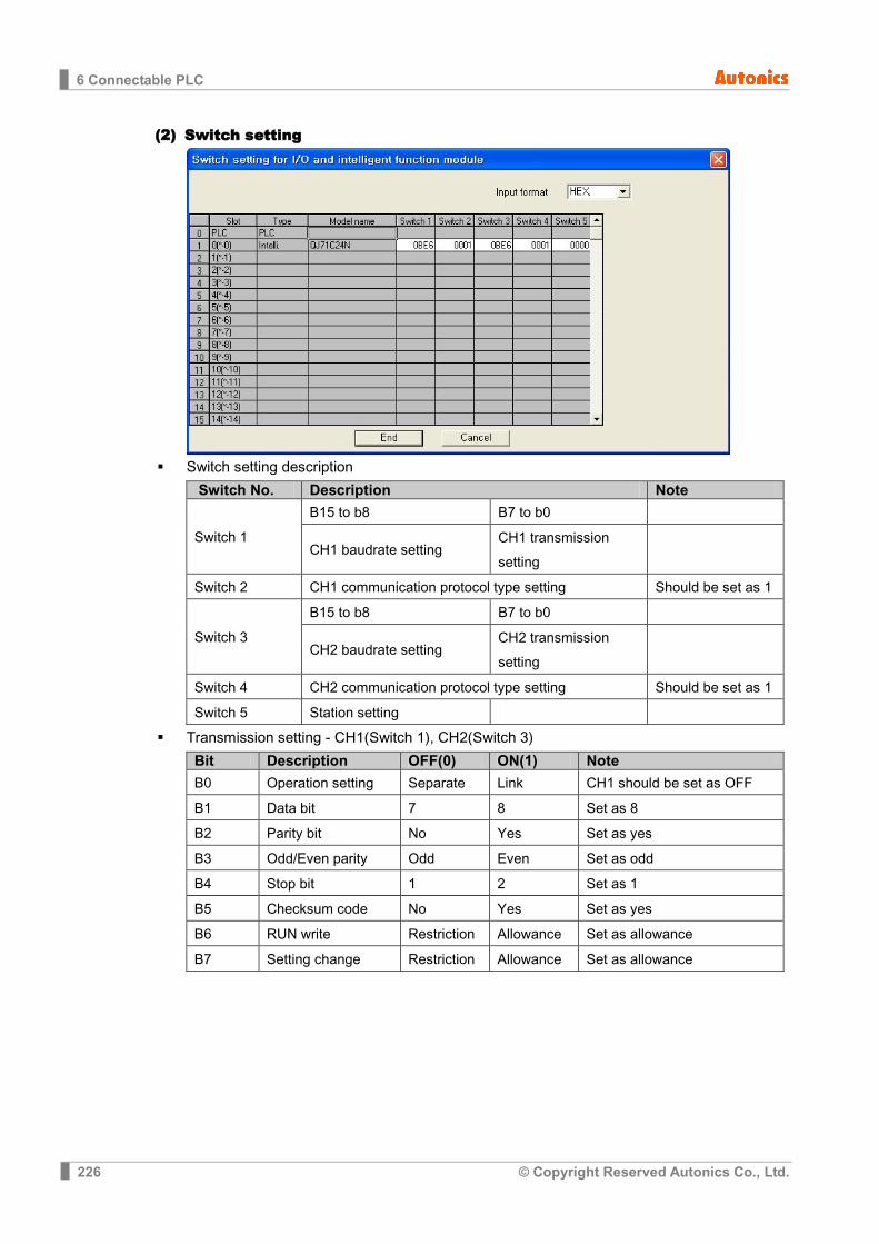
6 Connectable PLC
226 © Copyright Reserved Autonics Co., Ltd.
(2) Switch setting
Switch setting description
Switch No. Description Note
Switch 1
B15 to b8 B7 to b0
CH1 baudrate setting CH1 transmission setting
Switch 2 CH1 communication protocol type setting Should be set as 1
Switch 3
B15 to b8 B7 to b0
CH2 baudrate setting CH2 transmission setting
Switch 4 CH2 communication protocol type setting Should be set as 1
Switch 5 Station setting
Transmission setting - CH1(Switch 1), CH2(Switch 3)
Bit Description OFF(0) ON(1) Note
B0 Operation setting Separate Link CH1 should be set as OFF
B1 Data bit 7 8 Set as 8
B2 Parity bit No Yes Set as yes
B3 Odd/Even parity Odd Even Set as odd
B4 Stop bit 1 2 Set as 1
B5 Checksum code No Yes Set as yes
B6 RUN write Restriction Allowance Set as allowance
B7 Setting change Restriction Allowance Set as allowance

6 Connectable PLC
© Copyright Reserved Autonics Co., Ltd. 227
Transmission speed setting
Baudrate(bps) Bit unit
Baudrate (bps) Bit unit
B15 to B8 B15 to B8
50 0Fh 14400 06h
300 00h 19200 07h
600 01h 28800 08h
1200 02h 38400 09h
2400 03h 57600 0Ah
4800 04h 115200 0Bh
9600 05h 230400 0Ch
If two interfaces connect to correspondence device respectively, the sum of communication speed for both interfaces should be set 115,200bps or less(For QJ71C24N(-R2/R4), 230,400bps or less).
If only one interface connects to correspondence device, the communication speed for this interface can be set the maximum 115,200bps.(For QJ71C24N(-R2/R4), available to set maximum 230400bps). In this case, please set the communication speed for the other interface to 300bps.

6 Connectable PLC
228 © Copyright Reserved Autonics Co., Ltd.
6.10.5 GP/PLC type configuration in GP Editor 6.10.5.1 Basic Model CPU
For using Q00J / Q00 / Q01 CPU, select [MITSUBISHI Q SERIES]–[QBasic_EXT_MC].
6.10.5.2 High Performance Model CPU
For using Q02 / Q02H / Q06H / Q12H / Q25H CPU, select [MITSUBISHI Q SERIES]–[QHighP_EXT_MC].
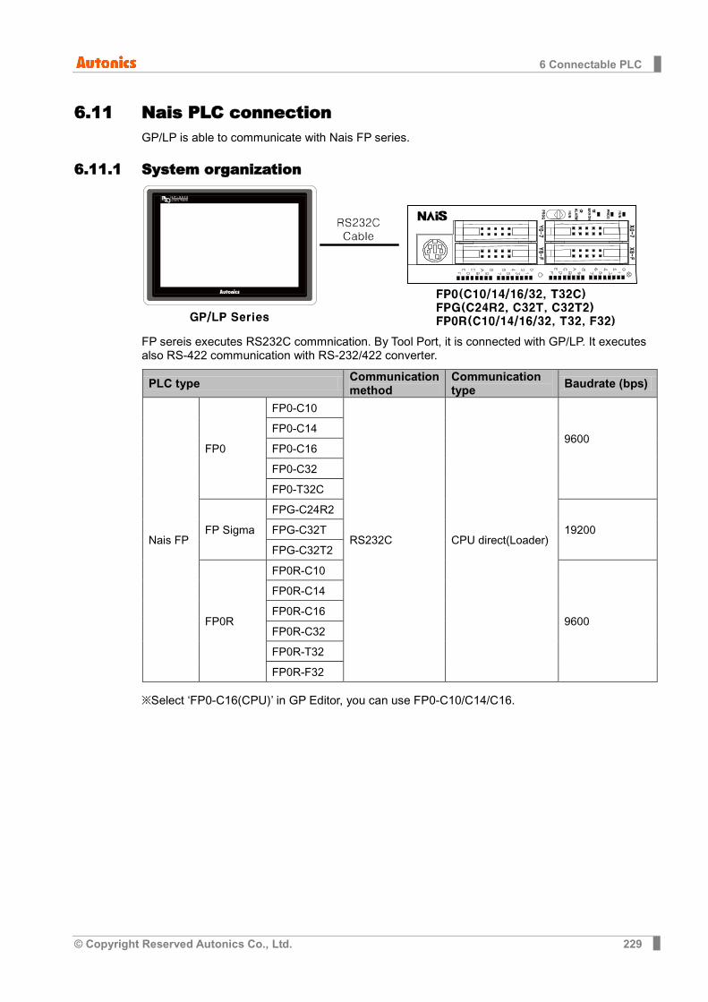
6 Connectable PLC
© Copyright Reserved Autonics Co., Ltd. 229
6.11 Nais PLC connection GP/LP is able to communicate with Nais FP series.
6.11.1 System organization
FP sereis executes RS232C commnication. By Tool Port, it is connected with GP/LP. It executes also RS-422 communication with RS-232/422 converter.
PLC type Communication method
Communication type Baudrate (bps)
Nais FP
FP0
FP0-C10
RS232C CPU direct(Loader)
9600
FP0-C14
FP0-C16
FP0-C32
FP0-T32C
FP Sigma
FPG-C24R2
19200 FPG-C32T
FPG-C32T2
FP0R
FP0R-C10
9600
FP0R-C14
FP0R-C16
FP0R-C32
FP0R-T32
FP0R-F32
※Select ‘FP0-C16(CPU)’ in GP Editor, you can use FP0-C10/C14/C16.
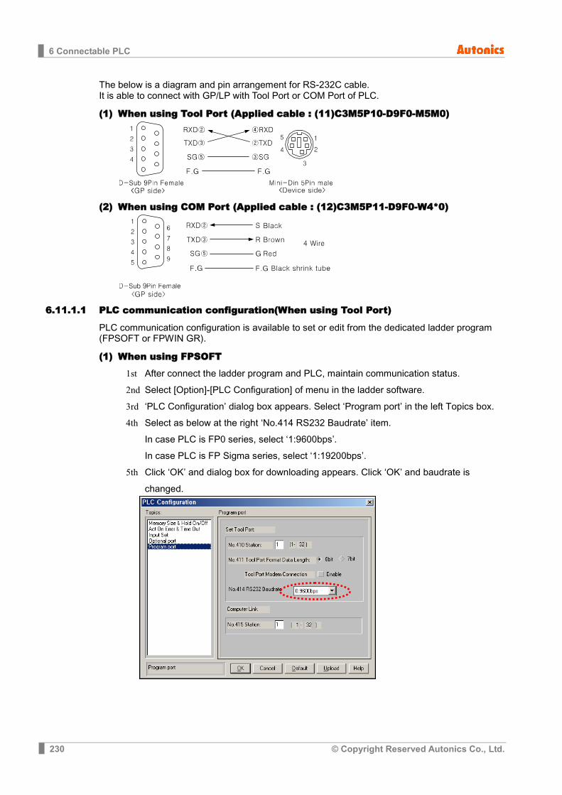
6 Connectable PLC
230 © Copyright Reserved Autonics Co., Ltd.
The below is a diagram and pin arrangement for RS-232C cable. It is able to connect with GP/LP with Tool Port or COM Port of PLC.
(1) When using Tool Port (Applied cable : (11)C3M5P10-D9F0-M5M0)
(2) When using COM Port (Applied cable : (12)C3M5P11-D9F0-W4*0)
6.11.1.1 PLC communication configuration(When using Tool Port)
PLC communication configuration is available to set or edit from the dedicated ladder program (FPSOFT or FPWIN GR).
(1) When using FPSOFT
1st After connect the ladder program and PLC, maintain communication status. 2nd Select [Option]-[PLC Configuration] of menu in the ladder software. 3rd ‘PLC Configuration’ dialog box appears. Select ‘Program port’ in the left Topics box. 4th Select as below at the right ‘No.414 RS232 Baudrate’ item.
In case PLC is FP0 series, select ‘1:9600bps’. In case PLC is FP Sigma series, select ‘1:19200bps’.
5th Click ‘OK’ and dialog box for downloading appears. Click ‘OK’ and baudrate is changed.
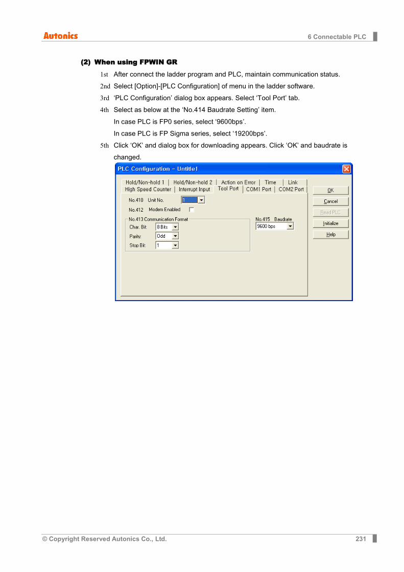
6 Connectable PLC
© Copyright Reserved Autonics Co., Ltd. 231
(2) When using FPWIN GR
1st After connect the ladder program and PLC, maintain communication status. 2nd Select [Option]-[PLC Configuration] of menu in the ladder software. 3rd ‘PLC Configuration’ dialog box appears. Select ‘Tool Port’ tab. 4th Select as below at the ‘No.414 Baudrate Setting’ item.
In case PLC is FP0 series, select ‘9600bps’. In case PLC is FP Sigma series, select ‘19200bps’.
5th Click ‘OK’ and dialog box for downloading appears. Click ‘OK’ and baudrate is changed.
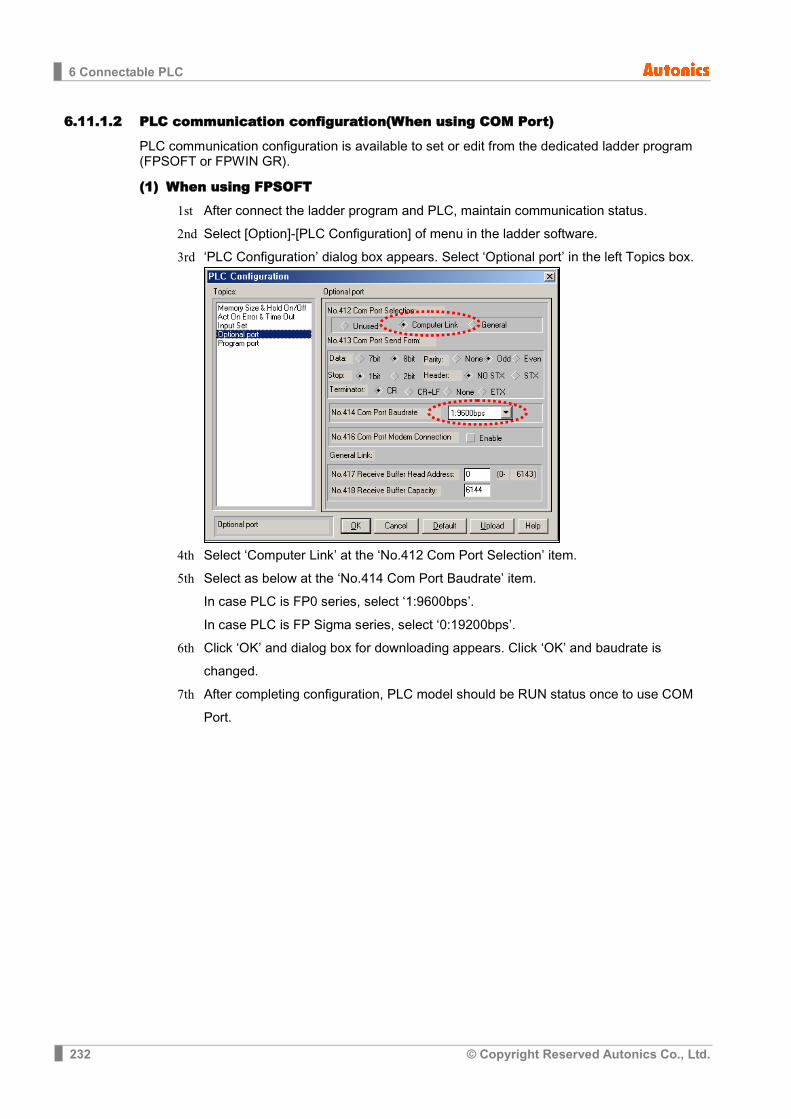
6 Connectable PLC
232 © Copyright Reserved Autonics Co., Ltd.
6.11.1.2 PLC communication configuration(When using COM Port)
PLC communication configuration is available to set or edit from the dedicated ladder program (FPSOFT or FPWIN GR).
(1) When using FPSOFT
1st After connect the ladder program and PLC, maintain communication status. 2nd Select [Option]-[PLC Configuration] of menu in the ladder software. 3rd ‘PLC Configuration’ dialog box appears. Select ‘Optional port’ in the left Topics box.
4th Select ‘Computer Link’ at the ‘No.412 Com Port Selection’ item. 5th Select as below at the ‘No.414 Com Port Baudrate’ item.
In case PLC is FP0 series, select ‘1:9600bps’. In case PLC is FP Sigma series, select ‘0:19200bps’.
6th Click ‘OK’ and dialog box for downloading appears. Click ‘OK’ and baudrate is changed.
7th After completing configuration, PLC model should be RUN status once to use COM Port.

6 Connectable PLC
© Copyright Reserved Autonics Co., Ltd. 233
(2) When using FPWIN GR
1st After connect the ladder program and PLC, maintain communication status. 2nd Select [Option]-[PLC Configuration] of menu in the ladder software. 3rd ‘PLC Configuration’ dialog box appears. Select ‘COM1 Port’ tab. 4th Select ‘Computer Link’ at the ‘No.412 Comm. Mode’. 5th Select as below at the ‘No.414 Baudrate’ item.
In case PLC is FP0 series, select ‘9600bps’. In case PLC is FP Sigma series, select ‘19200bps’.
6th Click ‘OK’ and dialog box for downloading appears. Click ‘OK’ and baudrate is changed.
7th After completing configuration, PLC model should be RUN status once to use COM Port.
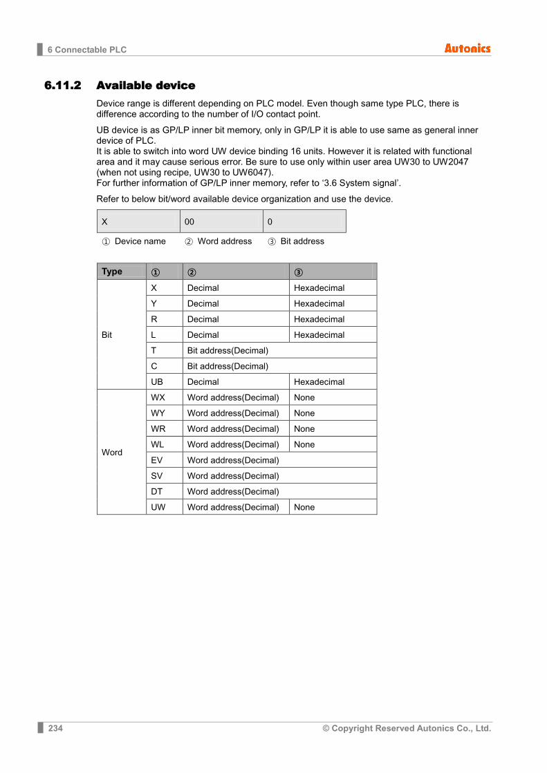
6 Connectable PLC
234 © Copyright Reserved Autonics Co., Ltd.
6.11.2 Available device Device range is different depending on PLC model. Even though same type PLC, there is difference according to the number of I/O contact point.
UB device is as GP/LP inner bit memory, only in GP/LP it is able to use same as general inner device of PLC. It is able to switch into word UW device binding 16 units. However it is related with functional area and it may cause serious error. Be sure to use only within user area UW30 to UW2047 (when not using recipe, UW30 to UW6047). For further information of GP/LP inner memory, refer to ‘3.6 System signal’.
Refer to below bit/word available device organization and use the device.
X 00 0
① Device name ② Word address ③ Bit address
Type ① ② ③
Bit
X Decimal Hexadecimal
Y Decimal Hexadecimal
R Decimal Hexadecimal
L Decimal Hexadecimal
T Bit address(Decimal)
C Bit address(Decimal)
UB Decimal Hexadecimal
Word
WX Word address(Decimal) None
WY Word address(Decimal) None
WR Word address(Decimal) None
WL Word address(Decimal) None
EV Word address(Decimal)
SV Word address(Decimal)
DT Word address(Decimal)
UW Word address(Decimal) None
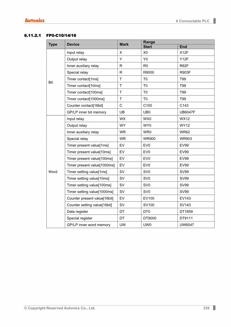
6 Connectable PLC
© Copyright Reserved Autonics Co., Ltd. 235
6.11.2.1 FP0-C10/14/16
Type Device Mark Range Start End
Bit
Input relay X X0 X12F
Output relay Y Y0 Y12F
Inner auxiliary relay R R0 R62F
Special relay R R9000 R903F
Timer contact[1ms] T T0 T99
Timer contact[10ms] T T0 T99
Timer contact[100ms] T T0 T99
Timer contact[1000ms] T T0 T99
Counter contact[16bit] C C100 C143
GP/LP inner bit memory UB UB0 UB6047F
Word
Input relay WX WX0 WX12
Output relay WY WY0 WY12
Inner auxiliary relay WR WR0 WR62
Special relay WR WR900 WR903
Timer present value[1ms] EV EV0 EV99
Timer present value[10ms] EV EV0 EV99
Timer present value[100ms] EV EV0 EV99
Timer present value[1000ms] EV EV0 EV99
Timer setting value[1ms] SV SV0 SV99
Timer setting value[10ms] SV SV0 SV99
Timer setting value[100ms] SV SV0 SV99
Timer setting value[1000ms] SV SV0 SV99
Counter present value[16bit] EV EV100 EV143
Counter setting value[16bit] SV SV100 SV143
Data register DT DT0 DT1659
Special register DT DT9000 DT9111
GP/LP inner word memory UW UW0 UW6047

6 Connectable PLC
236 © Copyright Reserved Autonics Co., Ltd.
6.11.2.2 FP0-C32
Type Device Mark Range Start End
Bit
Input relay X X0 X12F
Output relay Y Y0 Y12F
Inner auxiliary relay R R0 R62F
Special relay R R9000 R903F
Timer contact[1ms] T T0 T99
Timer contact[10ms] T T0 T99
Timer contact[100ms] T T0 T99
Timer contact[1000ms] T T0 T99
Counter contact[16bit] C C100 C143
GP/LP inner bit memory UB UB0 UB6047F
Word
Input relay WX WX0 WX12
Output relay WY WY0 WY12
Inner auxiliary relay WR WR0 WR62
Special relay WR WR900 WR903
Timer present value[1ms] EV EV0 EV99
Timer present value[10ms] EV EV0 EV99
Timer present value[100ms] EV EV0 EV99
Timer present value [1000ms]
EV EV0 EV99
Timer setting value[1ms] SV SV0 SV99
Timer setting value[10ms] SV SV0 SV99
Timer setting value[100ms] SV SV0 SV99
Timer setting value[1000ms] SV SV0 SV99
Counter present value [16bit]
EV EV100 EV143
Counter setting value[16bit] SV SV100 SV143
Data register DT DT0 DT6143
Special register DT DT9000 DT9111
GP/LP inner word memory UW UW0 UW6047

6 Connectable PLC
© Copyright Reserved Autonics Co., Ltd. 237
6.11.2.3 FP0-T32C
Type Device Mark Range Start End
Bit
Input relay X X0 X12F
Output relay Y Y0 Y12F
Inner auxiliary relay R R0 R62F
Special relay R R9000 R903F
Timer contact[1ms] T T0 T99
Timer contact[10ms] T T0 T99
Timer contact[100ms] T T0 T99
Timer contact[1000ms] T T0 T99
Counter contact[16bit] C C100 C143
GP/LP inner bit memory UB UB0 UB6047F
Word
Input relay WX WX0 WX12
Output relay WY WY0 WY12
Inner auxiliary relay WR WR0 WR62
Special relay WR WR900 WR903
Timer present value[1ms] EV EV0 EV99
Timer present value[10ms] EV EV0 EV99
Timer present value[100ms] EV EV0 EV99
Timer present value[1000ms] EV EV0 EV99
Timer setting value[1ms] SV SV0 SV99
Timer setting value[10ms] SV SV0 SV99
Timer setting value[100ms] SV SV0 SV99
Timer setting value[1000ms] SV SV0 SV99
Counter present value[16bit] EV EV100 EV143
Counter setting value[16bit] SV SV100 SV143
Data register DT DT0 DT16382
Special register DT DT90000 DT90111
GP/LP inner word memory UW UW0 UW6047

6 Connectable PLC
238 © Copyright Reserved Autonics Co., Ltd.
6.11.2.4 FPG-C24R2
Type Device Mark Range Start End
Bit
Input relay X X0 X73F
Output relay Y Y0 Y73F
Inner auxiliary relay R R0 R97F
Special relay R R9000 R910F
Link relay L L0 L63F
Timer contact[1ms] T T0 T1007
Timer contact[10ms] T T0 T1007
Timer contact[100ms] T T0 T1007
Timer contact[1000ms] T T0 T1007
Counter contact[16bit] C C1008 C1023
GP/LP inner bit memory UB UB0 UB6047F
Word
Input relay WX WX0 WX73
Output relay WY WY0 WY73
Inner auxiliary relay WR WR0 WR97
Special relay WR WR900 WR910
Link relay WL WL0 WL63
Timer present value[1ms] EV EV0 EV1007
Timer present value[10ms] EV EV0 EV1007
Timer present value[100ms] EV EV0 EV1007
Timer present value [1000ms]
EV EV0 EV1007
Timer setting value[1ms] SV SV0 SV1007
Timer setting value[10ms] SV SV0 SV1007
Timer setting value[100ms] SV SV0 SV1007
Timer setting value[1000ms] SV SV0 SV1007
Counter present value[16bit] EV EV1008 EV1023
Counter setting value[16bit] SV SV1008 SV1023
Data register DT DT0 DT32764
Special register DT DT90000 DT90259
GP/LP inner word memory UW UW0 UW6047
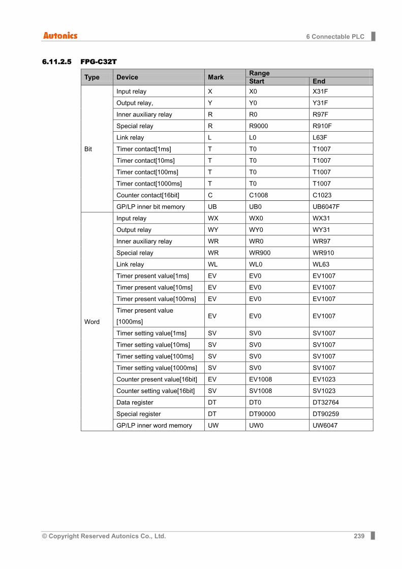
6 Connectable PLC
© Copyright Reserved Autonics Co., Ltd. 239
6.11.2.5 FPG-C32T
Type Device Mark Range Start End
Bit
Input relay X X0 X31F
Output relay, Y Y0 Y31F
Inner auxiliary relay R R0 R97F
Special relay R R9000 R910F
Link relay L L0 L63F
Timer contact[1ms] T T0 T1007
Timer contact[10ms] T T0 T1007
Timer contact[100ms] T T0 T1007
Timer contact[1000ms] T T0 T1007
Counter contact[16bit] C C1008 C1023
GP/LP inner bit memory UB UB0 UB6047F
Word
Input relay WX WX0 WX31
Output relay WY WY0 WY31
Inner auxiliary relay WR WR0 WR97
Special relay WR WR900 WR910
Link relay WL WL0 WL63
Timer present value[1ms] EV EV0 EV1007
Timer present value[10ms] EV EV0 EV1007
Timer present value[100ms] EV EV0 EV1007
Timer present value [1000ms]
EV EV0 EV1007
Timer setting value[1ms] SV SV0 SV1007
Timer setting value[10ms] SV SV0 SV1007
Timer setting value[100ms] SV SV0 SV1007
Timer setting value[1000ms] SV SV0 SV1007
Counter present value[16bit] EV EV1008 EV1023
Counter setting value[16bit] SV SV1008 SV1023
Data register DT DT0 DT32764
Special register DT DT90000 DT90259
GP/LP inner word memory UW UW0 UW6047

6 Connectable PLC
240 © Copyright Reserved Autonics Co., Ltd.
6.11.2.6 FPG-C32T2
Type Device Mark Range Start End
Bit
Input relay X X0 X73F
Output relay Y Y0 Y73F
Inner auxiliary relay R R0 R97F
Special relay R R9000 R910F
Link relay L L0 L63F
Timer contact[1ms] T T0 T1007
Timer contact[10ms] T T0 T1007
Timer contact[100ms] T T0 T1007
Timer contact[1000ms] T T0 T1007
Counter contact[16bit] C C1008 C1023
GP/LP inner bit memory UB UB0 UB6047F
Word
Input relay WX WX0 WX73
Output relay WY WY0 WY73
Inner auxiliary relay WR WR0 WR97
Special relay WR WR900 WR910
Link relay WL WL0 WL63
Timer present value[1ms] EV EV0 EV1007
Timer present value[10ms] EV EV0 EV1007
Timer present value[100ms] EV EV0 EV1007
Timer present value [1000ms]
EV EV0 EV1007
Timer setting value[1ms] SV SV0 SV1007
Timer setting value[10ms] SV SV0 SV1007
Timer setting value[100ms] SV SV0 SV1007
Timer setting value[1000ms] SV SV0 SV1007
Counter present value[16bit] EV EV1008 EV1023
Counter setting value[16bit] SV SV1008 SV1023
Data register DT DT0 DT32764
Special register DT DT90000 DT90259
GP/LP inner word memory UW UW0 UW6047

6 Connectable PLC
© Copyright Reserved Autonics Co., Ltd. 241
6.11.2.7 FP0R-C10/C14/C16
Type Device Mark Range Start End
Bit
Input relay X X0 X109F
Output relay Y Y0 Y109F
Inner auxiliary relay R R0 R255F
Special relay R R9000 R913F
Timer contact[1ms] T T0 T1023
Timer contact[10ms] T T0 T1023
Timer contact[100ms] T T0 T1023
Timer contact[1000ms] T T0 T1023
Counter contact[16bit] C C100 C1023
GP/LP inner bit memory UB UB0 UB6047F
Word
Input relay WX WX0 WX109
Output relay WY WY0 WY109
Inner auxiliary relay WR WR0 WR255
Special relay WR WR900 WR913
Timer present value[1ms] EV EV0 EV1024
Timer present value[10ms] EV EV0 EV1024
Timer present value[100ms] EV EV0 EV1024
Timer present value [1000ms]
EV EV0 EV1024
Timer setting value[1ms] SV SV0 SV1024
Timer setting value[10ms] SV SV0 SV1024
Timer setting value[100ms] SV SV0 SV1024
Timer setting value[1000ms] SV SV0 SV1024
Counter present value[16bit] EV EV100 EV1024
Counter setting value[16bit] SV SV100 SV1024
Data register DT DT0 DT12315
Special register DT DT90000 DT90439
GP/LP inner word memory UW UW0 UW6047

6 Connectable PLC
242 © Copyright Reserved Autonics Co., Ltd.
6.11.2.8 FP0R-C32/F32/T32
Type Device Mark Range Start End
Bit
Input relay X X0 X109F
Output relay Y Y0 Y109F
Inner auxiliary relay R R0 R255F
Special relay R R9000 R913F
Timer contact[1ms] T T0 T1023
Timer contact[10ms] T T0 T1023
Timer contact[100ms] T T0 T1023
Timer contact[1000ms] T T0 T1023
Counter contact[16bit] C C100 C1023
GP/LP inner bit memory UB UB0 UB6047F
Word
Input relay WX WX0 WX109
Output relay WY WY0 WY109
Inner auxiliary relay WR WR0 WR255
Special relay WR WR900 WR913
Timer present value[1ms] EV EV0 EV1024
Timer present value[10ms] EV EV0 EV1024
Timer present value[100ms] EV EV0 EV1024
Timer present value[1000ms] EV EV0 EV1024
Timer setting value[1ms] SV SV0 SV1024
Timer setting value[10ms] SV SV0 SV1024
Timer setting value[100ms] SV SV0 SV1024
Timer setting value[1000ms] SV SV0 SV1024
Counter present value[16bit] EV EV100 EV1024
Counter setting value[16it] SV SV100 SV1024
Data register DT DT0 DT32765
Special register DT DT90000 DT90439
GP/LP inner word memory UW UW0 UW6047
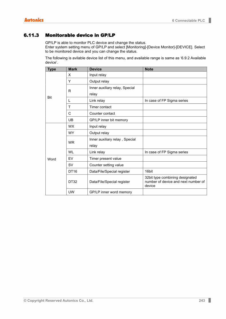
6 Connectable PLC
© Copyright Reserved Autonics Co., Ltd. 243
6.11.3 Monitorable device in GP/LP GP/LP is able to monitor PLC device and change the status. Enter system setting menu of GP/LP and select [Monitoring]-[Device Monitor]-[DEVICE]. Select to be monitored device and you can change the status.
The following is avilable device list of this menu, and available range is same as ‘6.9.2 Available device’.
Type Mark Device Note
Bit
X Input relay
Y Output relay
R Inner auxiliary relay, Special relay
L Link relay In case of FP Sigma series
T Timer contact
C Counter contact
UB GP/LP inner bit memory
Word
WX Input relay
WY Output relay
WR Inner auxiliary relay , Special relay
WL Link relay In case of FP Sigma series
EV Timer present value
SV Counter setting value
DT16 Data/File/Special register 16bit
DT32 Data/File/Special register 32bit type combining designated number of device and next number of device
UW GP/LP inner word memory

6 Connectable PLC
244 © Copyright Reserved Autonics Co., Ltd.
6.12 OMRON SYSMAC C PLC connection GP/LP is able to communicate with Omron SYSMAC C series.
6.12.1 System organization
SYSMAC C sereis executes RS232C commnication with GP/LP by Tool Port. It executes also RS-422 communication with RS-232/422 converter.
PLC type Communication method
Communication type Baudrate (bps)
SYSMAC C CPM1A RS232C CPU direct(Loader) 9600
PLC communication configuration for baudrate is set from the dedicated ladder program (CX-Programmer). Configuration is as below.
1st Connect the dedicated ladder program and set PLC as connectable status. 2nd From the workspace window of the ladder program, select ‘Setting’ item. 3rd ‘PLC Settings’ dialog box appears. Select ‘Peripheral Port’ tab. Click ‘Standard
(9600;1,7,2,E)’ of ‘Communication Settings’ item.
Communication cable connected with GP/LP is loader connection cable(CQM1-CIF02) of OMRON.
If PLC mode is Run, PLC device is available only monitor from GP/LP, and every device status is not able to change. (PLC specification) For changing PLC device status from GP/LP, set PLC mode to Program or Monitor.
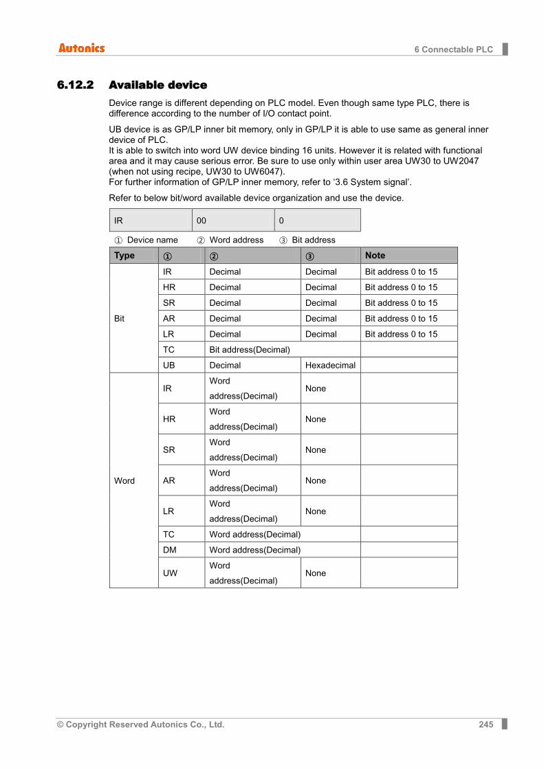
6 Connectable PLC
© Copyright Reserved Autonics Co., Ltd. 245
6.12.2 Available device Device range is different depending on PLC model. Even though same type PLC, there is difference according to the number of I/O contact point.
UB device is as GP/LP inner bit memory, only in GP/LP it is able to use same as general inner device of PLC. It is able to switch into word UW device binding 16 units. However it is related with functional area and it may cause serious error. Be sure to use only within user area UW30 to UW2047 (when not using recipe, UW30 to UW6047). For further information of GP/LP inner memory, refer to ‘3.6 System signal’.
Refer to below bit/word available device organization and use the device.
IR 00 0
① Device name ② Word address ③ Bit address
Type ① ② ③ Note
Bit
IR Decimal Decimal Bit address 0 to 15
HR Decimal Decimal Bit address 0 to 15
SR Decimal Decimal Bit address 0 to 15
AR Decimal Decimal Bit address 0 to 15
LR Decimal Decimal Bit address 0 to 15
TC Bit address(Decimal)
UB Decimal Hexadecimal
Word
IR Word address(Decimal)
None
HR Word address(Decimal)
None
SR Word address(Decimal)
None
AR Word address(Decimal)
None
LR Word address(Decimal)
None
TC Word address(Decimal)
DM Word address(Decimal)
UW Word address(Decimal)
None
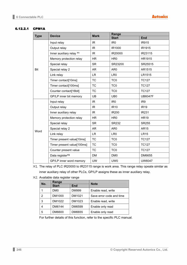
6 Connectable PLC
246 © Copyright Reserved Autonics Co., Ltd.
6.12.2.1 CPM1A
Type Device Mark Range Start End
Bit
Input relay IR IR0 IR915
Output relay IR IR1000 IR1915
Inner auxiliary relay ※1 IR IR20000 IR23115
Memory protection relay HR HR0 HR1915
Special relay SR SR23200 SR25515
Special relay 2 AR AR0 AR1515
Link relay LR LR0 LR1515
Timer contact[10ms] TC TC0 TC127
Timer contact[100ms] TC TC0 TC127
Counter contact[16bit] TC TC0 TC127
GP/LP inner bit memory UB UB0 UB6047F
Word
Input relay IR IR0 IR9
Output relay IR IR10 IR19
Inner auxiliary relay IR IR200 IR231
Memory protection relay HR HR0 HR19
Special relay SR SR232 SR255
Special relay 2 AR AR0 AR15
Link relay LR LR0 LR15
Timer present value[10ms] TC TC0 TC127
Timer present value[100ms] TC TC0 TC127
Counter present value TC TC0 TC127
Data register※2 DM DM0 DM6655
GP/LP inner word memory UW UW0 UW6047
※1. The relay of PLC IR20000 to IR23115 range is work area. This range relay opeate similar as inner auxiliary relay of other PLCs, GP/LP assigns these as inner auxiliary relay.
※2. Available data register range
No. Range
Note Start End
1 DM0 DM999 Enable read, write
2 DM1000 DM1021 Save error code and time
3 DM1022 DM1023 Enable read, write
4 DM6144 DM6599 Enable only read
5 DM6600 DM6655 Enable only read
For further details of this function, refer to the specific PLC manual.

6 Connectable PLC
© Copyright Reserved Autonics Co., Ltd. 247
6.12.3 Monitorable device in GP/LP GP/LP is able to monitor PLC device and change the status. Enter system setting menu of GP/LP and select [Monitoring]-[Device Monitor]-[DEVICE]. Select to be monitored device and you can change the status.
The following is avilable device list of this menu, and available range is same as ‘6.10.2 Available device’.
Type Mark Device Note
Bit
IR Input relay, output relay, inner auxiliary relay
HR Memory protection relay
SR Special relay
AR Special relay
LR Link relay
TC Timer/Counter contact
UB GP/LP inner bit memory
Word
IR Input relay, output relay, inner auxiliary relay
HR Memory protection relay
SR Special relay
AR Special relay
LR Link relay
TC Timer/Counter present value
DM16 Data register 16bit
DM32 Data register
32bit type combining designated number of device and next number of device
UW GP/LP inner word memory

6 Connectable PLC
248 © Copyright Reserved Autonics Co., Ltd.
6.13 OMRON temperature controller connection GP/LP is able to communicate with Omron temperature controller E5XX series.
6.13.1 System organization
Omron E5XX sereis executes RS485 commnication. It executes also RS232C commnication with RS485/232 converter. E5AN and E5EN support RS232C communication without converter depending on the model.
Controller type Communication method Communication type
E5AN RS485, RS232C CPU direct(Loader)
E5AR RS485 CPU direct(Loader)
E5CN RS485 CPU direct(Loader)
E5EN RS485, RS232C CPU direct(Loader)
E5ER RS485 CPU direct(Loader)
(1) RS-485 communication with GP/LP(E5AN, E5AR, E5CN): Applied cable (15) C3M5P03-D9M0-T4Y0
(2) RS-232C communication with GP/LP(E5AN, E5EN): Applied cable (14)C3M5P13-D9F0-T4Y0
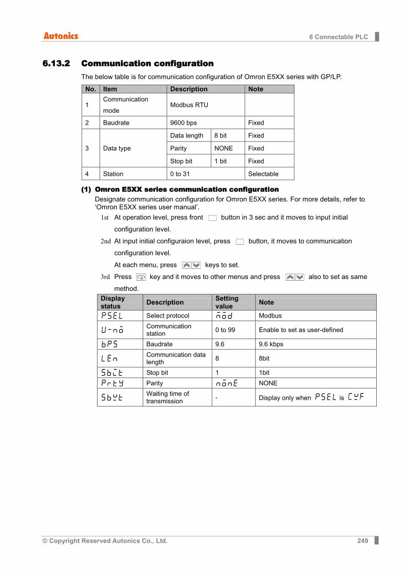
6 Connectable PLC
© Copyright Reserved Autonics Co., Ltd. 249
6.13.2 Communication configuration The below table is for communication configuration of Omron E5XX series with GP/LP.
No. Item Description Note
1 Communication mode
Modbus RTU
2 Baudrate 9600 bps Fixed
3 Data type
Data length 8 bit Fixed
Parity NONE Fixed
Stop bit 1 bit Fixed
4 Station 0 to 31 Selectable
(1) Omron E5XX series communication configuration Designate communication configuration for Omron E5XX series. For more details, refer to ‘Omron E5XX series user manual’.
1st At operation level, press front button in 3 sec and it moves to input initial configuration level.
2nd At input initial configuraion level, press button, it moves to communication configuration level. At each menu, press keys to set.
3rd Press key and it moves to other menus and press also to set as same method.
Display status Description Setting
value Note
Select protocol Modbus
Communication station 0 to 99 Enable to set as user-defined
Baudrate 9.6 9.6 kbps
Communication data length 8 8bit
Stop bit 1 1bit
Parity NONE
Waiting time of transmission - Display only when is
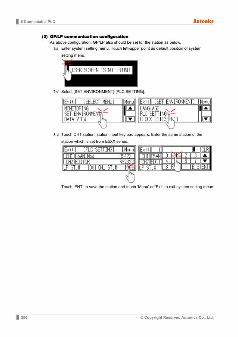
6 Connectable PLC
250 © Copyright Reserved Autonics Co., Ltd.
(2) GP/LP communication configuration As above configuration, GP/LP also should be set for the station as below.
1st Enter system setting menu. Touch left-upper point as default position of system setting menu.
2nd Select [SET ENVIRONMENT]-[PLC SETTING].
3rd Touch CH1 station, station input key pad appears. Enter the same station of the station which is set from E5XX series.
Touch ‘ENT’ to save the station and touch ‘Menu’ or ‘Exit’ to exit system setting meun.
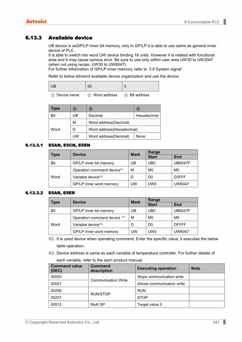
6 Connectable PLC
© Copyright Reserved Autonics Co., Ltd. 251
6.13.3 Available device UB device is as GP/LP inner bit memory, only in GP/LP it is able to use same as general inner device of PLC. It is able to switch into word UW device binding 16 units. However it is related with functional area and it may cause serious error. Be sure to use only within user area UW30 to UW2047 (when not using recipe, UW30 to UW6047). For further information of GP/LP inner memory, refer to ‘3.6 System signal’.
Refer to below bit/word available device organization and use the device.
UB 00 0
① Device name ② Word address ③ Bit address
Type ① ② ③
Bit UB Decimal Hexadecimal
Word
M Word address(Decimal)
D Word address(Hexadecimal)
UW Word address(Decimal) None
6.13.3.1 E5AN, E5CN, E5EN
Type Device Mark Range Start End
Bit GP/LP inner bit memory UB UB0 UB6047F
Word
Operation command device※1 M M0 M0
Variable device※2 D D0 D3FFF
GP/LP inner word memory UW UW0 UW6047
6.13.3.2 E5AR, E5ER
Type Device Mark Range Start End
Bit GP/LP inner bit memory UB UB0 UB6047F
Word
Operation command device ※1 M M0 M0
Variable device※2 D D0 DFFFF
GP/LP inner word memory UW UW0 UW6047
※1. It is used device when operating command. Enter the specific value, it executes the below table operation.
※2. Device address is same as each variable of temperature controller. For further details of each variable, refer to the each product manual.
Command value (DEC)
Command description Executing operation Note
00000 Communication Write
Stops communication write
00001 Allows communication write
00256 RUN/STOP
RUN
00257 STOP
00512 Multi SP Target value 0

6 Connectable PLC
252 © Copyright Reserved Autonics Co., Ltd.
Command value (DEC)
Command description Executing operation Note
00513 Target value 1
00514
Target value 2
00515 Target value 3
00768
AT
Stops AT
00769 Executes AT Available when it is STOP
01024 Write mode
Backup write mode
01025 Write mode RAM
01280 Preserves RAM DATA Preserves RAM DATA
01536 Soft reset Soft reset
01792 Executes setting area 1 Executes setting area 1
02048 Executes protect level Executes protect level
02304 AUTO/ MANUAL
AUTO mode
02305 MANUAL mode
02816 Initializes setting value
Initial default of setting value
02817 Initial setting service value
04352 Starts program
Start reset program
04353 Starts program
6.13.4 Monitorable device in GP/LP GP/LP is able to monitor PLC device and change the status. Enter system setting menu of GP/LP and select [Monitoring]-[Device Monitor]-[DEVICE]. Select to be monitored device and you can change the status.
The following is avilable device list of this menu, and available range is same as ‘6.11.3 Available device’.
Type Mark Device Note
Bit UB GP/LP inner bit memory
Word
M Operation command device
DM16 Variable Device 16bit
DM32 Variable Device 32bit type combining designated number of device and next number of device
UW GP/LP inner word memory
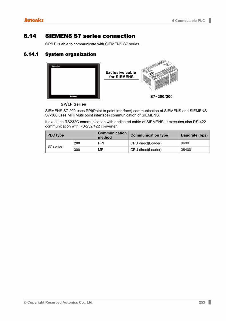
6 Connectable PLC
© Copyright Reserved Autonics Co., Ltd. 253
6.14 SIEMENS S7 series connection GP/LP is able to communicate with SIEMENS S7 series.
6.14.1 System organization
SIEMENS S7-200 uses PPI(Point to point interface) communication of SIEMENS and SIEMENS S7-300 uses MPI(Mutil point interface) communication of SIEMENS.
It executes RS232C communication with dedicated cable of SIEMENS. It executes also RS-422 communication with RS-232/422 converter.
PLC type Communication method Communication type Baudrate (bps)
S7 series 200 PPI CPU direct(Loader) 9600
300 MPI CPU direct(Loader) 38400
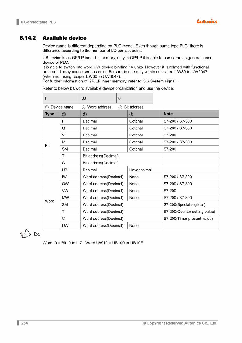
6 Connectable PLC
254 © Copyright Reserved Autonics Co., Ltd.
6.14.2 Available device Device range is different depending on PLC model. Even though same type PLC, there is difference according to the number of I/O contact point.
UB device is as GP/LP inner bit memory, only in GP/LP it is able to use same as general inner device of PLC. It is able to switch into word UW device binding 16 units. However it is related with functional area and it may cause serious error. Be sure to use only within user area UW30 to UW2047 (when not using recipe, UW30 to UW6047). For further information of GP/LP inner memory, refer to ‘3.6 System signal’.
Refer to below bit/word available device organization and use the device.
I 00 0
① Device name ② Word address ③ Bit address
Type ① ② ③ Note
Bit
I Decimal Octonal S7-200 / S7-300
Q Decimal Octonal S7-200 / S7-300
V Decimal Octonal S7-200
M Decimal Octonal S7-200 / S7-300
SM Decimal Octonal S7-200
T Bit address(Decimal)
C Bit address(Decimal)
UB Decimal Hexadecimal
Word
IW Word address(Decimal) None S7-200 / S7-300
QW Word address(Decimal) None S7-200 / S7-300
VW Word address(Decimal) None S7-200
MW Word address(Decimal) None S7-200 / S7-300
SM Word address(Decimal) S7-200(Special register)
T Word address(Decimal) S7-200(Counter setting value)
C Word address(Decimal) S7-200(Timer present value)
UW Word address(Decimal) None
Word I0 = Bit I0 to I17 , Word UW10 = UB100 to UB10F
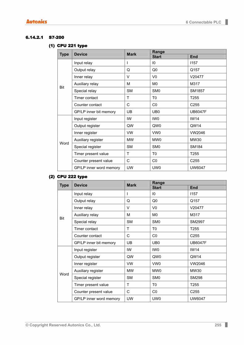
6 Connectable PLC
© Copyright Reserved Autonics Co., Ltd. 255
6.14.2.1 S7-200
(1) CPU 221 type
Type Device Mark Range Start End
Bit
Input relay I I0 I157
Output relay Q Q0 Q157
Inner relay V V0 V20477
Auxiliary relay M M0 M317
Special relay SM SM0 SM1857
Timer contact T T0 T255
Counter contact C C0 C255
GP/LP inner bit memory UB UB0 UB6047F
Word
Input register IW IW0 IW14
Output register QW QW0 QW14
Inner register VW VW0 VW2046
Auxiliary register MW MW0 MW30
Special register SM SM0 SM184
Timer present value T T0 T255
Counter present value C C0 C255
GP/LP inner word memory UW UW0 UW6047
(2) CPU 222 type
Type Device Mark Range Start End
Bit
Input relay I I0 I157
Output relay Q Q0 Q157
Inner relay V V0 V20477
Auxiliary relay M M0 M317
Special relay SM SM0 SM2997
Timer contact T T0 T255
Counter contact C C0 C255
GP/LP inner bit memory UB UB0 UB6047F
Word
Input register IW IW0 IW14
Output register QW QW0 QW14
Inner register VW VW0 VW2046
Auxiliary register MW MW0 MW30
Special register SM SM0 SM298
Timer present value T T0 T255
Counter present value C C0 C255
GP/LP inner word memory UW UW0 UW6047

6 Connectable PLC
256 © Copyright Reserved Autonics Co., Ltd.
(3) CPU 224 type
Type Device Mark Range Start End
Bit
Input relay I I0 I157
Output relay Q Q0 Q157
Inner relay V V0 V81917
Auxiliary relay M M0 M317
Special relay SM SM0 SM5497
Timer contact T T0 T255
Counter contact C C0 C255
GP/LP inner bit memory UB UB0 UB6047F
Word
Input register IW IW0 IW14
Output register QW QW0 QW14
Inner register VW VW0 VW8190
Auxiliary register MW MW0 MW30
Special register SM SM0 SM548
Timer present value T T0 T255
Counter present value C C0 C255
GP/LP inner word memory UW UW0 UW6047
(4) CPU 224XP, 224XPsi, 226 type
Type Device Mark Range Start End
Bit
Input relay I I0 I157
Output relay Q Q0 Q157
Inner relay V V0 V102397
Auxiliary relay M M0 M317
Special relay SM SM0 SM5497
Timer contact T T0 T255
Counter contact C C0 C255
GP/LP inner bit memory UB UB0 UB6047F
Word
Input register IW IW0 IW14
Output register QW QW0 QW14
Inner register VW VW0 VW10238
Auxiliary register MW MW0 MW30
Special register SM SM0 SM548
Timer present value T T0 T255
Counter present value C C0 C255
GP/LP inner word memory
UW UW0 UW6047

6 Connectable PLC
© Copyright Reserved Autonics Co., Ltd. 257
6.14.2.2 S7-300
(1) CPU 312 type
Type Device Mark Range Start End
Bit
Input relay I I0 I10237
Output relay Q Q0 Q10237
Auxiliary relay M M0 M2557
GP/LP INNER BIT MEMORY UB UB0 UB6047F
Word
Input register IW IW0 IW1022
Output register QW QW0 QW1022
Auxiliary register MW MW0 MW254
GP/LP INNER WORD MEMORY
UW UW0 UW6047
(2) CPU 312C type
Type Device Mark Range Start End
Bit
Input relay I I0 I10237
Output relay Q Q0 Q10237
Auxiliary relay M M0 M2557
GP/LP INNER BIT MEMORY UB UB0 UB6047F
Word
Input register IW IW0 IW1022
Output register QW QW0 QW1022
Auxiliary register MW MW0 MW254
GP/LP INNER WORD MEMORY
UW UW0 UW6047
(3) CPU 313C type
Type Device Mark Range Start End
Bit
Input relay I I0 I10237
Output relay Q Q0 Q10237
Auxiliary relay M M0 M2557
GP/LP INNER BIT MEMORY UB UB0 UB6047F
Word
Input register IW IW0 IW1022
Output register QW QW0 QW1022
Auxiliary register MW MW0 MW254
GP/LP INNER WORD MEMORY
UW UW0 UW6047
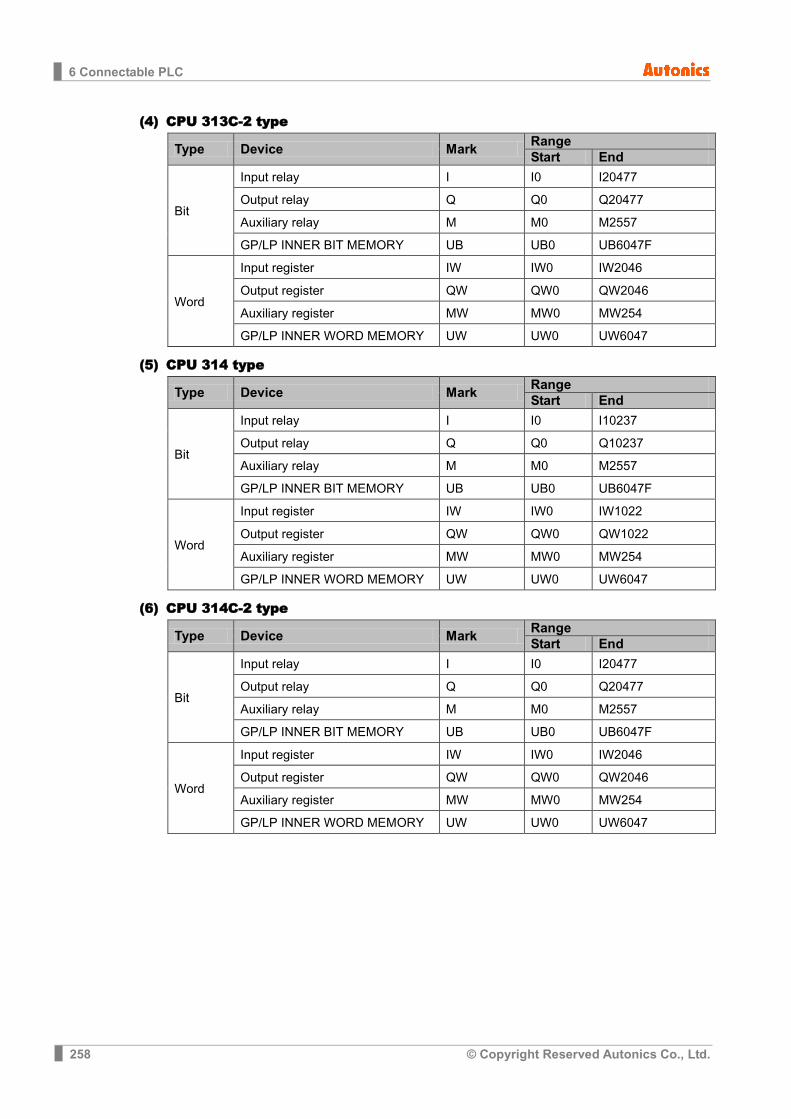
6 Connectable PLC
258 © Copyright Reserved Autonics Co., Ltd.
(4) CPU 313C-2 type
Type Device Mark Range Start End
Bit
Input relay I I0 I20477
Output relay Q Q0 Q20477
Auxiliary relay M M0 M2557
GP/LP INNER BIT MEMORY UB UB0 UB6047F
Word
Input register IW IW0 IW2046
Output register QW QW0 QW2046
Auxiliary register MW MW0 MW254
GP/LP INNER WORD MEMORY UW UW0 UW6047
(5) CPU 314 type
Type Device Mark Range Start End
Bit
Input relay I I0 I10237
Output relay Q Q0 Q10237
Auxiliary relay M M0 M2557
GP/LP INNER BIT MEMORY UB UB0 UB6047F
Word
Input register IW IW0 IW1022
Output register QW QW0 QW1022
Auxiliary register MW MW0 MW254
GP/LP INNER WORD MEMORY UW UW0 UW6047
(6) CPU 314C-2 type
Type Device Mark Range Start End
Bit
Input relay I I0 I20477
Output relay Q Q0 Q20477
Auxiliary relay M M0 M2557
GP/LP INNER BIT MEMORY UB UB0 UB6047F
Word
Input register IW IW0 IW2046
Output register QW QW0 QW2046
Auxiliary register MW MW0 MW254
GP/LP INNER WORD MEMORY UW UW0 UW6047

6 Connectable PLC
© Copyright Reserved Autonics Co., Ltd. 259
(7) CPU 315-2 type
Type Device Mark Range Start End
Bit
Input relay I I0 I20477
Output relay Q Q0 Q20477
Auxiliary relay M M0 M20477
GP/LP INNER BIT MEMORY UB UB0 UB6047F
Word
Input register IW IW0 IW2046
Output register QW QW0 QW2046
Auxiliary register MW MW0 MW2046
GP/LP INNER WORD MEMORY UW UW0 UW6047
(8) CPU 317-2 type
Type Device Mark Range Start End
Bit
Input relay I I0 I81917
Output relay Q Q0 Q81917
Auxiliary relay M M0 M40957
GP/LP INNER BIT MEMORY UB UB0 UB6047F
Word
Input register IW IW0 IW8190
Output register QW QW0 QW8190
Auxiliary register MW MW0 MW4094
GP/LP INNER WORD MEMORY UW UW0 UW6047
(9) CPU 319-3 type
Type Device Mark Range Start End
Bit
Input relay I I0 I81917
Output relay Q Q0 Q81917
Auxiliary relay M M0 M81917
GP/LP INNER BIT MEMORY UB UB0 UB6047F
Word
Input register IW IW0 IW8190
Output register QW QW0 QW8190
Auxiliary register MW MW0 MW8190
GP/LP INNER WORD MEMORY UW UW0 UW6047

6 Connectable PLC
260 © Copyright Reserved Autonics Co., Ltd.
6.14.3 Monitorable device in GP/LP GP/LP is able to monitor PLC device and change the status. Enter system setting menu of GP/LP and select [Monitoring]-[Device Monitor]-[DEVICE]. Select to be monitored device and you can change the status.
The following is avilable device list of this menu, and available range is same as ‘6.12.2 Available device’.
Type Mark Device Note
Bit
I Input relay Read only
Q Output relay Write only
V Inner relay Variable memory
M Auxiliary relay Bit memory
SM Special relay Special memory(Read only)
T Timer contact
C Counter contact
UB GP/LP inner bit memory
Word
IW Input register Read only
QW Output register Write only
VW Inner register Variable memory
MW Auxiliary register Bit memory
SM Special register Special memory(Read only)
T Timer present value
C Counter present value
UW GP/LP inner word memory
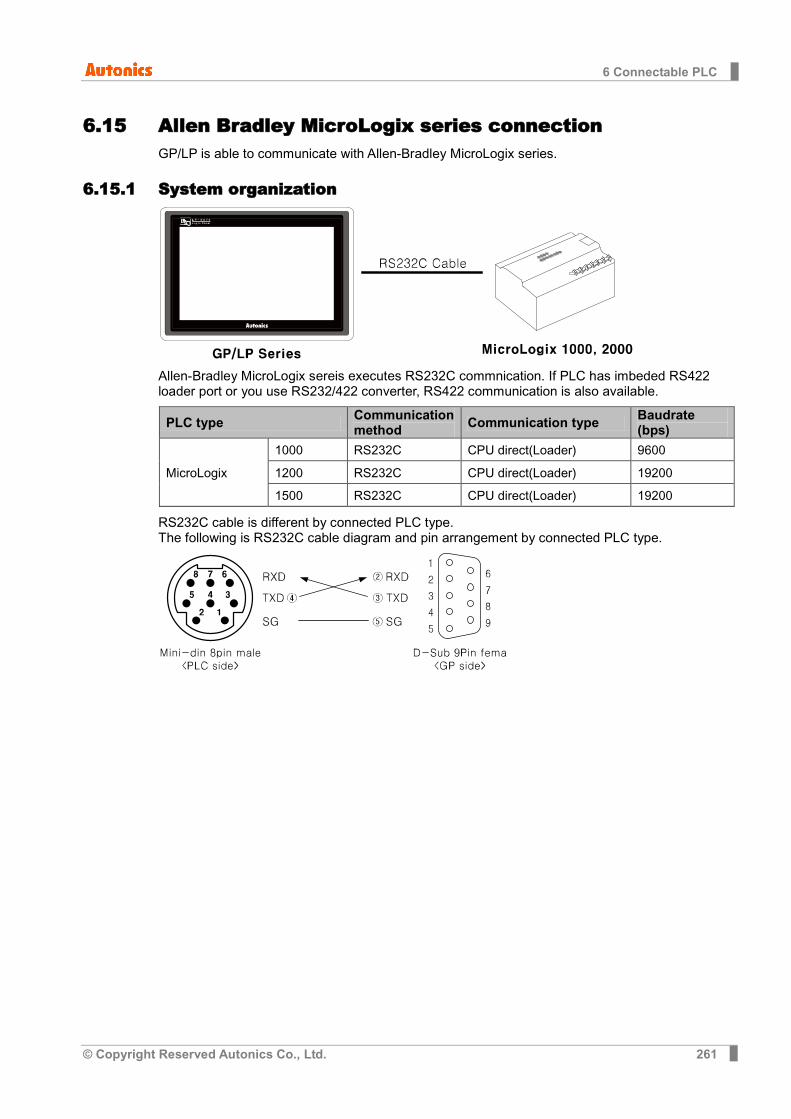
6 Connectable PLC
© Copyright Reserved Autonics Co., Ltd. 261
6.15 Allen Bradley MicroLogix series connection GP/LP is able to communicate with Allen-Bradley MicroLogix series.
6.15.1 System organization
Allen-Bradley MicroLogix sereis executes RS232C commnication. If PLC has imbeded RS422 loader port or you use RS232/422 converter, RS422 communication is also available.
PLC type Communication method Communication type Baudrate
(bps)
MicroLogix
1000 RS232C CPU direct(Loader) 9600
1200 RS232C CPU direct(Loader) 19200
1500 RS232C CPU direct(Loader) 19200
RS232C cable is different by connected PLC type. The following is RS232C cable diagram and pin arrangement by connected PLC type.
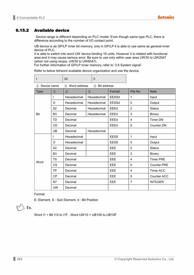
6 Connectable PLC
262 © Copyright Reserved Autonics Co., Ltd.
6.15.2 Available device Device range is different depending on PLC model. Even though same type PLC, there is difference according to the number of I/O contact point.
UB device is as GP/LP inner bit memory, only in GP/LP it is able to use same as general inner device of PLC. It is able to switch into word UW device binding 16 units. However it is related with functional area and it may cause serious error. Be sure to use only within user area UW30 to UW2047 (when not using recipe, UW30 to UW6047). For further information of GP/LP inner memory, refer to ‘3.6 System signal’.
Refer to below bit/word available device organization and use the device.
I 00 0
① Device name ② Word address ③ Bit address
Type ① ② ③ Format File No Note
Bit
I Hexadecimal Hexadecimal EESSd 1 Input
O Hexadecimal Hexadecimal EESSd 0 Output
S2 Decimal Hexadecimal EEEd 2 Status
B3 Decimal Hexadecimal EEEd 3 Binary
TD Decimal EEEd 4 Timer.DN
CD Decimal EEEd 5 Counter.DN
UB Decimal Hexadecimal
Word
I Hexadecimal EESS 1 Input
O Hexadecimal EESS 0 Output
S2 Decimal EEE 2 Status
B3 Decimal EEE 3 Binary
TS Decimal EEE 4 Timer.PRE
CS Decimal EEE 5 Counter.PRE
TP Decimal EEE 4 Timer.ACC
CP Decimal EEE 5 Counter.ACC
N7 Decimal EEE 7 INTEGER
UW Decimal
Format
E: Element, S : Sub Element, d : Bit Position
Word I1 = Bit I10 to I1F , Word UW10 = UB100 to UB10F
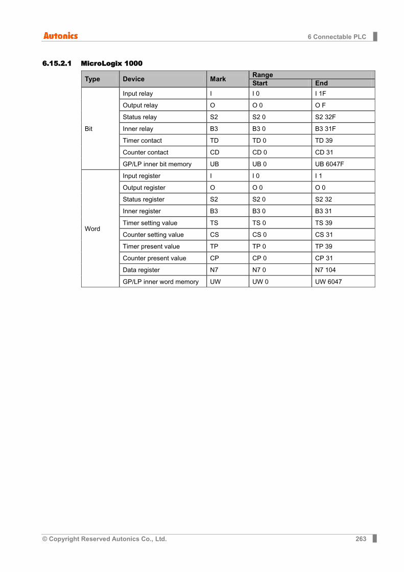
6 Connectable PLC
© Copyright Reserved Autonics Co., Ltd. 263
6.15.2.1 MicroLogix 1000
Type Device Mark Range Start End
Bit
Input relay I I 0 I 1F
Output relay O O 0 O F
Status relay S2 S2 0 S2 32F
Inner relay B3 B3 0 B3 31F
Timer contact TD TD 0 TD 39
Counter contact CD CD 0 CD 31
GP/LP inner bit memory UB UB 0 UB 6047F
Word
Input register I I 0 I 1
Output register O O 0 O 0
Status register S2 S2 0 S2 32
Inner register B3 B3 0 B3 31
Timer setting value TS TS 0 TS 39
Counter setting value CS CS 0 CS 31
Timer present value TP TP 0 TP 39
Counter present value CP CP 0 CP 31
Data register N7 N7 0 N7 104
GP/LP inner word memory UW UW 0 UW 6047
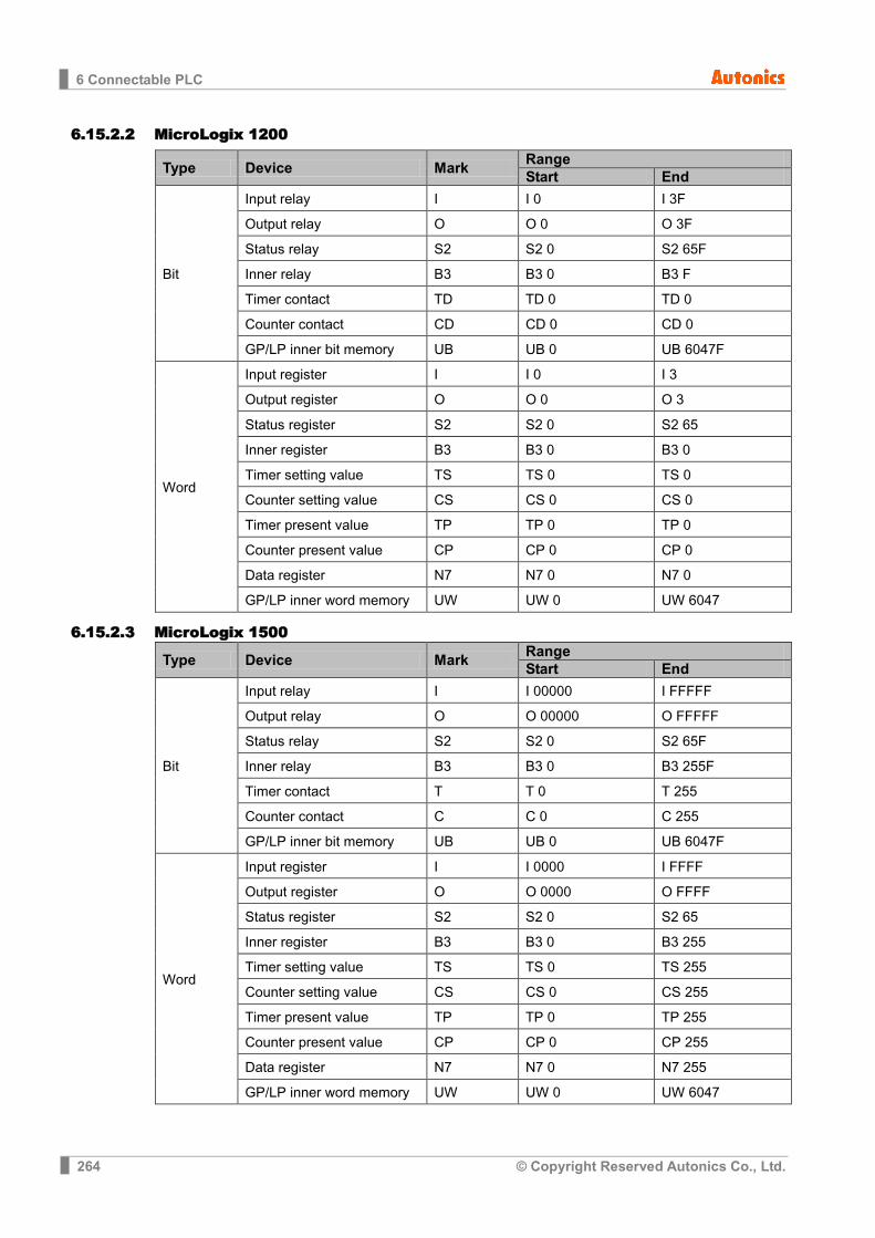
6 Connectable PLC
264 © Copyright Reserved Autonics Co., Ltd.
6.15.2.2 MicroLogix 1200
Type Device Mark Range Start End
Bit
Input relay I I 0 I 3F
Output relay O O 0 O 3F
Status relay S2 S2 0 S2 65F
Inner relay B3 B3 0 B3 F
Timer contact TD TD 0 TD 0
Counter contact CD CD 0 CD 0
GP/LP inner bit memory UB UB 0 UB 6047F
Word
Input register I I 0 I 3
Output register O O 0 O 3
Status register S2 S2 0 S2 65
Inner register B3 B3 0 B3 0
Timer setting value TS TS 0 TS 0
Counter setting value CS CS 0 CS 0
Timer present value TP TP 0 TP 0
Counter present value CP CP 0 CP 0
Data register N7 N7 0 N7 0
GP/LP inner word memory UW UW 0 UW 6047
6.15.2.3 MicroLogix 1500
Type Device Mark Range Start End
Bit
Input relay I I 00000 I FFFFF
Output relay O O 00000 O FFFFF
Status relay S2 S2 0 S2 65F
Inner relay B3 B3 0 B3 255F
Timer contact T T 0 T 255
Counter contact C C 0 C 255
GP/LP inner bit memory UB UB 0 UB 6047F
Word
Input register I I 0000 I FFFF
Output register O O 0000 O FFFF
Status register S2 S2 0 S2 65
Inner register B3 B3 0 B3 255
Timer setting value TS TS 0 TS 255
Counter setting value CS CS 0 CS 255
Timer present value TP TP 0 TP 255
Counter present value CP CP 0 CP 255
Data register N7 N7 0 N7 255
GP/LP inner word memory UW UW 0 UW 6047
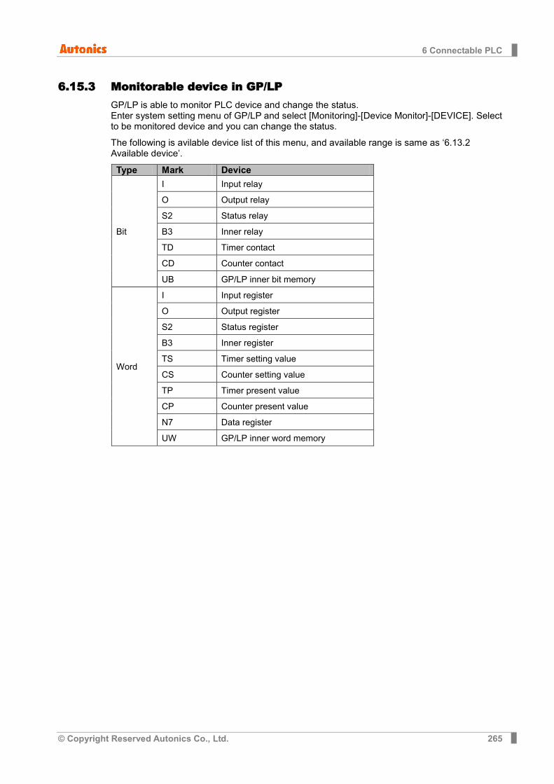
6 Connectable PLC
© Copyright Reserved Autonics Co., Ltd. 265
6.15.3 Monitorable device in GP/LP GP/LP is able to monitor PLC device and change the status. Enter system setting menu of GP/LP and select [Monitoring]-[Device Monitor]-[DEVICE]. Select to be monitored device and you can change the status.
The following is avilable device list of this menu, and available range is same as ‘6.13.2 Available device’.
Type Mark Device
Bit
I Input relay
O Output relay
S2 Status relay
B3 Inner relay
TD Timer contact
CD Counter contact
UB GP/LP inner bit memory
Word
I Input register
O Output register
S2 Status register
B3 Inner register
TS Timer setting value
CS Counter setting value
TP Timer present value
CP Counter present value
N7 Data register
UW GP/LP inner word memory
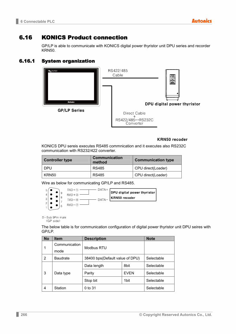
6 Connectable PLC
266 © Copyright Reserved Autonics Co., Ltd.
6.16 KONICS Product connection GP/LP is able to communicate with KONICS digital power thyristor unit DPU series and recorder KRN50.
6.16.1 System organization
KONICS DPU sereis executes RS485 commnication and it executes also RS232C communication with RS232/422 converter.
Controller type Communication method Communication type
DPU RS485 CPU direct(Loader)
KRN50 RS485 CPU direct(Loader)
Wire as below for communicating GP/LP and RS485.
The below table is for communication configuration of digital power thyristor unit DPU seires with GP/LP.
No Item Description Note
1 Communication mode
Modbus RTU
2 Baudrate 38400 bps(Default value of DPU) Selectable
3 Data type
Data length 8bit Selectable
Parity EVEN Selectable
Stop bit 1bit Selectable
4 Station 0 to 31 Selectable

6 Connectable PLC
© Copyright Reserved Autonics Co., Ltd. 267
The below table is for communication configuration of recorder KRN50 with GP/LP.
No Item Description Note
1 Communication mode
Modbus RTU
2 Baudrate 9600 bps (Default value of KRN50) Selectable
3 Data type
Data length 8bit Selectable
Parity None Selectable
Stop bit 2bit Selectable
4 Station 0 to 31 Selectable
As above configuration, GP/LP also should be set for the station as below.
(1) KONICS DPU series
1st Enter system setting menu. Touch left-upper point as default position of system setting menu.
2nd Select [SET ENVIRONMENT]-[PLC SETTING].
3rd Touch CH1 station, station input key pad appears. Enter the same station of the station which is set from DPU series.
4th Touch ‘ENT’ to save the station and touch ‘Menu’ or ‘Exit’ to exit system setting meun. 5th For recorder KRN50, please designate the configuration as same method.
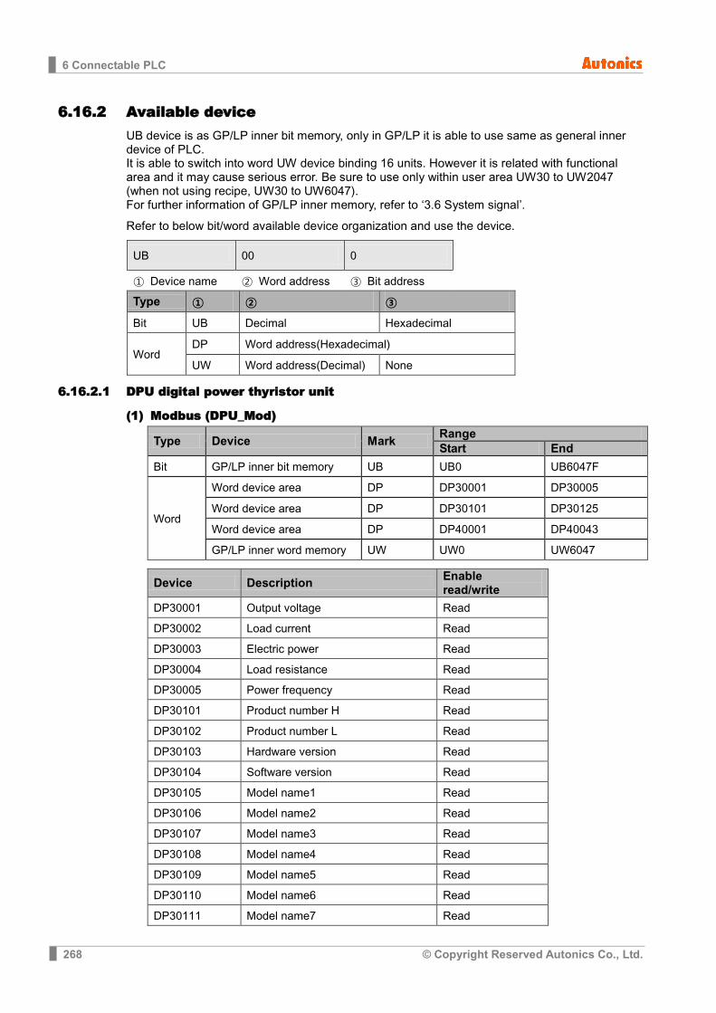
6 Connectable PLC
268 © Copyright Reserved Autonics Co., Ltd.
6.16.2 Available device UB device is as GP/LP inner bit memory, only in GP/LP it is able to use same as general inner device of PLC. It is able to switch into word UW device binding 16 units. However it is related with functional area and it may cause serious error. Be sure to use only within user area UW30 to UW2047 (when not using recipe, UW30 to UW6047). For further information of GP/LP inner memory, refer to ‘3.6 System signal’.
Refer to below bit/word available device organization and use the device.
UB 00 0
① Device name ② Word address ③ Bit address
Type ① ② ③
Bit UB Decimal Hexadecimal
Word DP Word address(Hexadecimal)
UW Word address(Decimal) None
6.16.2.1 DPU digital power thyristor unit
(1) Modbus (DPU_Mod)
Type Device Mark Range Start End
Bit GP/LP inner bit memory UB UB0 UB6047F
Word
Word device area DP DP30001 DP30005
Word device area DP DP30101 DP30125
Word device area DP DP40001 DP40043
GP/LP inner word memory UW UW0 UW6047
Device Description Enable read/write
DP30001 Output voltage Read
DP30002 Load current Read
DP30003 Electric power Read
DP30004 Load resistance Read
DP30005 Power frequency Read
DP30101 Product number H Read
DP30102 Product number L Read
DP30103 Hardware version Read
DP30104 Software version Read
DP30105 Model name1 Read
DP30106 Model name2 Read
DP30107 Model name3 Read
DP30108 Model name4 Read
DP30109 Model name5 Read
DP30110 Model name6 Read
DP30111 Model name7 Read

6 Connectable PLC
© Copyright Reserved Autonics Co., Ltd. 269
Device Description Enable read/write
DP30112 Model name8 Read
DP30113 Model name9 Read
DP30114 Model name10 Read
DP30115 Reserved Read
DP30116 Reserved Read
DP30117 Reserved Read
DP30118 Reserved Read
DP30118 Coil start address Read
DP30119 Coil quantity Read
DP30120 Input start address Read
DP30121 Input quantity Read
DP30122 Holding REG start address Read
DP30123 Holding REG quantity Read
DP30124 Input REG start address Read
DP30125 Input REG quantity Read
Device Description Enable read/write
DP40001 Reference value Read/Write
DP40002 Start time Read/Write
DP40003 Start limit Read/Write
DP40004 Soft start time Read/Write
DP40005 Output high limit Read/Write
DP40006 Output low limit Read/Write
DP40007 Remote Sp1 value Read/Write
DP40008 Remote Sp2 value Read/Write
DP40009 Remote Sp3 value Read/Write
DP40010 Remote Sp4 value Read/Write
DP40011 Remote Sp5 value Read/Write
DP40012 Remote Sp6 value Read/Write
DP40013 Slow up time Read/Write
DP40014 Slow stop time Read/Write
DP40015 CL value Read/Write
DP40016 OC value Read/Write
DP40017 OC time Read/Write
DP40018 OV value Read/Write
DP40019 OV time Read/Write
DP40020 Load detector alarm value Read/Write
DP40021 Select display regular value Read/Write
DP40022 Bar display mode Read/Write

6 Connectable PLC
270 © Copyright Reserved Autonics Co., Ltd.
Device Description Enable read/write
DP40023 Control integer KP value Read/Write
DP40024 Control integer KI value Read/Write
DP40025 Output control mode Read/Write
DP40026 Event input 1 mode Read/Write
DP40027 Event input 2 mode Read/Write
DP40028 Event input 3 mode Read/Write
DP40029 Auto ref input selector Read/Write
DP40030 Select load resistance display direction
Read/Write
DP40031 Operation status 0x000 Read/Write
DP40032 Output gradient setting (%) Read/Write
DP40033 When input is 0%, output quantity setting(%)
Read/Write
DP40034 Input correction Read/Write
DP40035 Input gradient correction Read/Write
DP40036 Overcurrent alarm output setting Read/Write
DP40037 Current alarm output setting Read/Write
DP40038 Overvoltage alarm output setting Read/Write
DP40039 Fuse break alarm output setting Read/Write
DP40040 Frequency error alarm output setting
Read/Write
DP40041 Heatsink overheating alarm output setting
Read/Write
DP40042 Element error alarm output setting Read/Write
DP40043 Heater break alarm output setting Read/Write
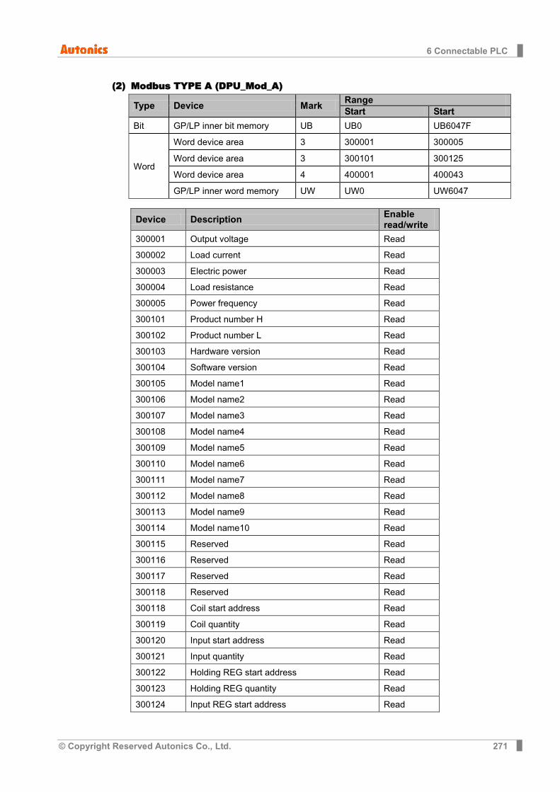
6 Connectable PLC
© Copyright Reserved Autonics Co., Ltd. 271
(2) Modbus TYPE A (DPU_Mod_A)
Type Device Mark Range Start Start
Bit GP/LP inner bit memory UB UB0 UB6047F
Word
Word device area 3 300001 300005
Word device area 3 300101 300125
Word device area 4 400001 400043
GP/LP inner word memory UW UW0 UW6047
Device Description Enable read/write
300001 Output voltage Read
300002 Load current Read
300003 Electric power Read
300004 Load resistance Read
300005 Power frequency Read
300101 Product number H Read
300102 Product number L Read
300103 Hardware version Read
300104 Software version Read
300105 Model name1 Read
300106 Model name2 Read
300107 Model name3 Read
300108 Model name4 Read
300109 Model name5 Read
300110 Model name6 Read
300111 Model name7 Read
300112 Model name8 Read
300113 Model name9 Read
300114 Model name10 Read
300115 Reserved Read
300116 Reserved Read
300117 Reserved Read
300118 Reserved Read
300118 Coil start address Read
300119 Coil quantity Read
300120 Input start address Read
300121 Input quantity Read
300122 Holding REG start address Read
300123 Holding REG quantity Read
300124 Input REG start address Read
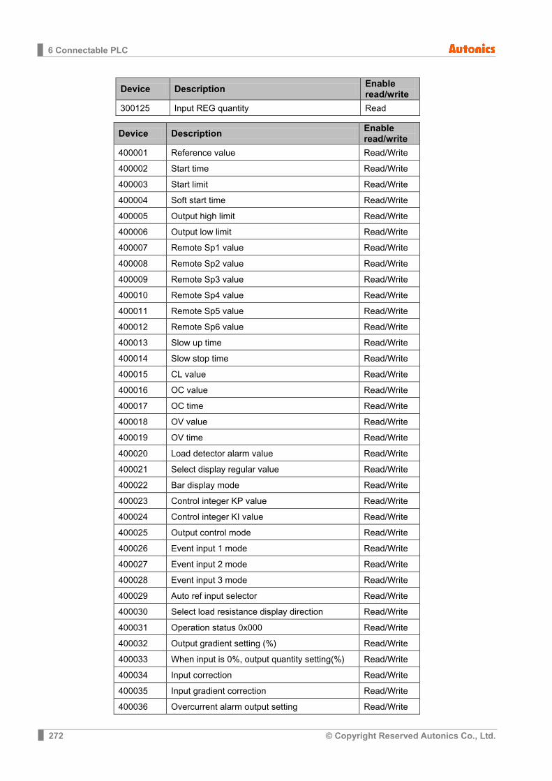
6 Connectable PLC
272 © Copyright Reserved Autonics Co., Ltd.
Device Description Enable read/write
300125 Input REG quantity Read
Device Description Enable read/write
400001 Reference value Read/Write
400002 Start time Read/Write
400003 Start limit Read/Write
400004 Soft start time Read/Write
400005 Output high limit Read/Write
400006 Output low limit Read/Write
400007 Remote Sp1 value Read/Write
400008 Remote Sp2 value Read/Write
400009 Remote Sp3 value Read/Write
400010 Remote Sp4 value Read/Write
400011 Remote Sp5 value Read/Write
400012 Remote Sp6 value Read/Write
400013 Slow up time Read/Write
400014 Slow stop time Read/Write
400015 CL value Read/Write
400016 OC value Read/Write
400017 OC time Read/Write
400018 OV value Read/Write
400019 OV time Read/Write
400020 Load detector alarm value Read/Write
400021 Select display regular value Read/Write
400022 Bar display mode Read/Write
400023 Control integer KP value Read/Write
400024 Control integer KI value Read/Write
400025 Output control mode Read/Write
400026 Event input 1 mode Read/Write
400027 Event input 2 mode Read/Write
400028 Event input 3 mode Read/Write
400029 Auto ref input selector Read/Write
400030 Select load resistance display direction Read/Write
400031 Operation status 0x000 Read/Write
400032 Output gradient setting (%) Read/Write
400033 When input is 0%, output quantity setting(%) Read/Write
400034 Input correction Read/Write
400035 Input gradient correction Read/Write
400036 Overcurrent alarm output setting Read/Write
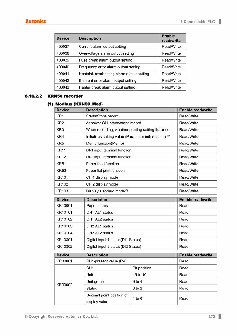
6 Connectable PLC
© Copyright Reserved Autonics Co., Ltd. 273
Device Description Enable read/write
400037 Current alarm output setting Read/Write
400038 Overvoltage alarm output setting Read/Write
400039 Fuse break alarm output setting Read/Write
400040 Frequency error alarm output setting Read/Write
400041 Heatsink overheating alarm output setting Read/Write
400042 Element error alarm output setting Read/Write
400043 Heater break alarm output setting Read/Write
6.16.2.2 KRN50 recorder
(1) Modbus (KRN50_Mod) Device Description Enable read/write
KR1 Starts/Stops record Read/Write
KR2 At power ON, starts/stops record Read/Write
KR3 When recording, whether printing setting list or not Read/Write
KR4 Initializes setting value (Parameter initialization) ※1 Read/Write
KR5 Memo function(Memo) Read/Write
KR11 DI-1 input terminal function Read/Write
KR12 DI-2 input terminal function Read/Write
KR51 Paper feed function Read/Write
KR52 Paper list print function Read/Write
KR101 CH 1 display mode Read/Write
KR102 CH 2 display mode Read/Write
KR103 Display standard mode※1 Read/Write
Device Description Enable read/write
KR10001 Paper status Read
KR10101 CH1 AL1 status Read
KR10102 CH1 AL2 status Read
KR10103 CH2 AL1 status Read
KR10104 CH2 AL2 status Read
KR10301 Digital input 1 status(DI1-Status) Read
KR10302 Digital input 2 status(DI2-Status) Read
Device Description Enable read/write
KR30001 CH1-present value (PV) Read
KR30002
CH1 Bit position Read
Unit 15 to 10 Read
Unit group 9 to 4 Read
Status 3 to 2 Read
Decimal point position of display value
1 to 0 Read
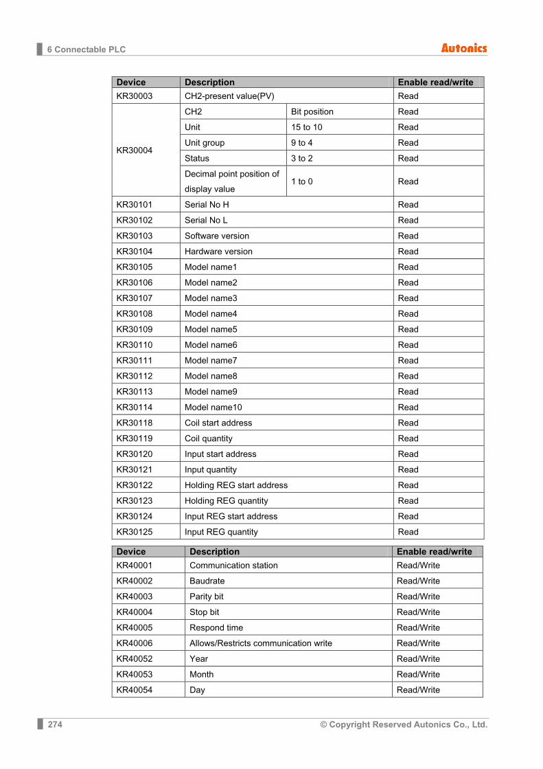
6 Connectable PLC
274 © Copyright Reserved Autonics Co., Ltd.
Device Description Enable read/write
KR30003 CH2-present value(PV) Read
KR30004
CH2 Bit position Read
Unit 15 to 10 Read
Unit group 9 to 4 Read
Status 3 to 2 Read
Decimal point position of display value
1 to 0 Read
KR30101 Serial No H Read
KR30102 Serial No L Read
KR30103 Software version Read
KR30104 Hardware version Read
KR30105 Model name1 Read
KR30106 Model name2 Read
KR30107 Model name3 Read
KR30108 Model name4 Read
KR30109 Model name5 Read
KR30110 Model name6 Read
KR30111 Model name7 Read
KR30112 Model name8 Read
KR30113 Model name9 Read
KR30114 Model name10 Read
KR30118 Coil start address Read
KR30119 Coil quantity Read
KR30120 Input start address Read
KR30121 Input quantity Read
KR30122 Holding REG start address Read
KR30123 Holding REG quantity Read
KR30124 Input REG start address Read
KR30125 Input REG quantity Read
Device Description Enable read/write
KR40001 Communication station Read/Write
KR40002 Baudrate Read/Write
KR40003 Parity bit Read/Write
KR40004 Stop bit Read/Write
KR40005 Respond time Read/Write
KR40006 Allows/Restricts communication write Read/Write
KR40052 Year Read/Write
KR40053 Month Read/Write
KR40054 Day Read/Write
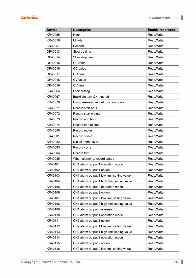
6 Connectable PLC
© Copyright Reserved Autonics Co., Ltd. 275
Device Description Enable read/write
KR40055 Hour Read/Write
KR40056 Minute Read/Write
KR40057 Second Read/Write
DP40013 Slow up time Read/Write
DP40014 Slow stop time Read/Write
DP40015 CL value Read/Write
DP40016 OC value Read/Write
DP40017 OC time Read/Write
DP40018 OV value Read/Write
DP40019 OV time Read/Write
KR40066 Lock setting Read/Write
KR40067 Backlight turn ON method Read/Write
KR40070 Using reserved record function or not Read/Write
KR40071 Record start hour Read/Write
KR40072 Record start minute Read/Write
KR40073 Record end hour Read/Write
KR40074 Record end minute Read/Write
KR40080 Record mode Read/Write
KR40081 Record speed Read/Write
KR40082 Digital memo cycle Read/Write
KR40083 Record cycle Read/Write
KR40084 Record font Read/Write
KR40085 When alarming, record speed Read/Write
KR40101 CH1 alarm output 1 operation mode Read/Write
KR40102 CH1 alarm output 1 option Read/Write
KR40103 CH1 alarm output 1 low limit setting value Read/Write
KR40104 CH1 alarm output 1 high limit setting value Read/Write
KR40105 CH1 alarm output 2 operation mode Read/Write
KR40106 CH1 alarm output 2 option Read/Write
KR40107 CH1 alarm output 2 low limit setting value Read/Write
KR40108 CH1 alarm output 2 high limit setting value Read/Write
KR40109 CH1 alarm output hysteresis Read/Write
KR40110 CH2 alarm output 1 operation mode Read/Write
KR40111 CH2 alarm output 1 option Read/Write
KR40112 CH2 alarm output 1 low limit setting value Read/Write
KR40113 CH2 alarm output 1 high limit setting value Read/Write
KR40114 CH2 alarm output 2 operation mode Read/Write
KR40115 CH2 alarm output 2 option Read/Write
KR40116 CH2 alarm output 2 low limit setting value Read/Write
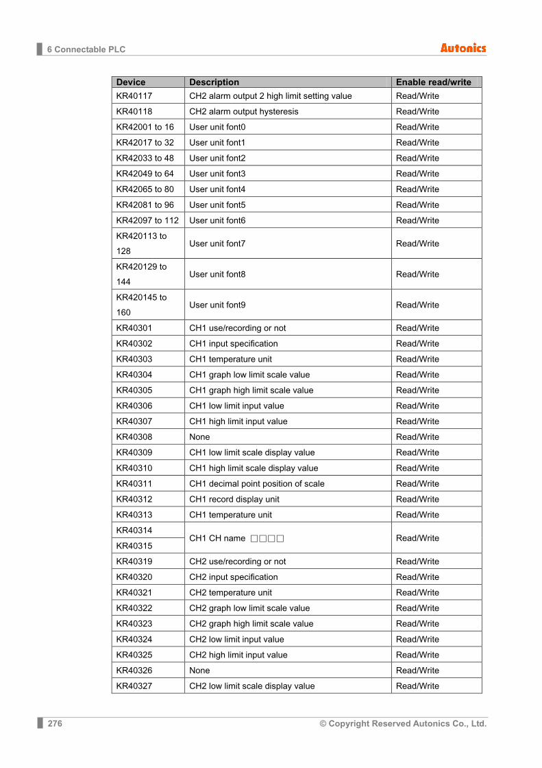
6 Connectable PLC
276 © Copyright Reserved Autonics Co., Ltd.
Device Description Enable read/write
KR40117 CH2 alarm output 2 high limit setting value Read/Write
KR40118 CH2 alarm output hysteresis Read/Write
KR42001 to 16 User unit font0 Read/Write
KR42017 to 32 User unit font1 Read/Write
KR42033 to 48 User unit font2 Read/Write
KR42049 to 64 User unit font3 Read/Write
KR42065 to 80 User unit font4 Read/Write
KR42081 to 96 User unit font5 Read/Write
KR42097 to 112 User unit font6 Read/Write
KR420113 to 128
User unit font7 Read/Write
KR420129 to 144
User unit font8 Read/Write
KR420145 to 160
User unit font9 Read/Write
KR40301 CH1 use/recording or not Read/Write
KR40302 CH1 input specification Read/Write
KR40303 CH1 temperature unit Read/Write
KR40304 CH1 graph low limit scale value Read/Write
KR40305 CH1 graph high limit scale value Read/Write
KR40306 CH1 low limit input value Read/Write
KR40307 CH1 high limit input value Read/Write
KR40308 None Read/Write
KR40309 CH1 low limit scale display value Read/Write
KR40310 CH1 high limit scale display value Read/Write
KR40311 CH1 decimal point position of scale Read/Write
KR40312 CH1 record display unit Read/Write
KR40313 CH1 temperature unit Read/Write
KR40314 CH1 CH name Read/Write
KR40315
KR40319 CH2 use/recording or not Read/Write
KR40320 CH2 input specification Read/Write
KR40321 CH2 temperature unit Read/Write
KR40322 CH2 graph low limit scale value Read/Write
KR40323 CH2 graph high limit scale value Read/Write
KR40324 CH2 low limit input value Read/Write
KR40325 CH2 high limit input value Read/Write
KR40326 None Read/Write
KR40327 CH2 low limit scale display value Read/Write

6 Connectable PLC
© Copyright Reserved Autonics Co., Ltd. 277
Device Description Enable read/write
KR40328 CH2 high limit scale display value Read/Write
KR40329 CH1 decimal point position of scale Read/Write
KR40330 CH2 record display unit Read/Write
KR40331 CH2 input correction Read/Write
KR40332 to 40333
CH2 CH name Read/Write
KR50001 to 52048
User logo
(2) Modbus TYPE A (KRN50_Mod_A) Device Description Enable read/write
000001 Starts/Stops record Read/Write
000002 At power ON, starts/stops record Read/Write
000003 When recording, whether printing setting list or not Read/Write
000004 Initializes setting value (Parameter initialization) ※1 Read/Write
000005 Memo function(Memo) Read/Write
000011 DI-1 input terminal function Read/Write
000012 DI-2 input terminal function Read/Write
000051 Paper feed function Read/Write
000052 Paper list print function Read/Write
000101 CH 1 display mode Read/Write
000102 CH 2 display mode Read/Write
000103 Display standard mode※1 Read/Write
Device Description Enable read/write
100001 Paper status Read/Write
100101 CH1 AL1 status Read/Write
100102 CH1 AL2 status Read/Write
100103 CH2 AL1 status Read/Write
100104 CH2 AL2 status Read/Write
100301 Digital input 1 status(DI1-Status) Read/Write
100302 Digital input 2 status(DI2-Status) Read/Write
Device Description Enable read/write
300001 CH1- present value (PV) Read
300002
CH1 Bit position Read
Unit 15 to 10 Read
Unit group 9 to 4 Read
Status 3 to 2 Read
Decimal point position of display value
1 to 0 Read
300003 CH2- present value (PV) Read
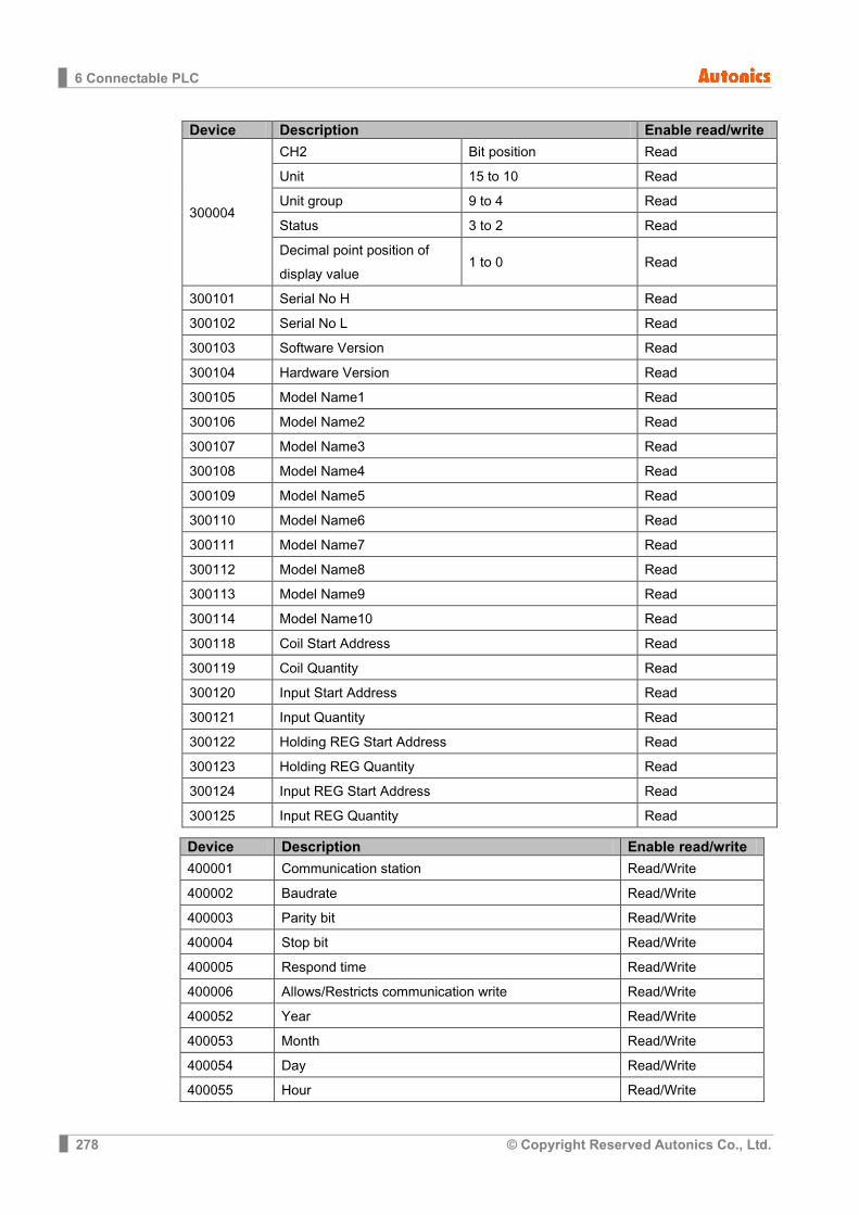
6 Connectable PLC
278 © Copyright Reserved Autonics Co., Ltd.
Device Description Enable read/write
300004
CH2 Bit position Read
Unit 15 to 10 Read
Unit group 9 to 4 Read
Status 3 to 2 Read
Decimal point position of display value
1 to 0 Read
300101 Serial No H Read
300102 Serial No L Read
300103 Software Version Read
300104 Hardware Version Read
300105 Model Name1 Read
300106 Model Name2 Read
300107 Model Name3 Read
300108 Model Name4 Read
300109 Model Name5 Read
300110 Model Name6 Read
300111 Model Name7 Read
300112 Model Name8 Read
300113 Model Name9 Read
300114 Model Name10 Read
300118 Coil Start Address Read
300119 Coil Quantity Read
300120 Input Start Address Read
300121 Input Quantity Read
300122 Holding REG Start Address Read
300123 Holding REG Quantity Read
300124 Input REG Start Address Read
300125 Input REG Quantity Read
Device Description Enable read/write
400001 Communication station Read/Write
400002 Baudrate Read/Write
400003 Parity bit Read/Write
400004 Stop bit Read/Write
400005 Respond time Read/Write
400006 Allows/Restricts communication write Read/Write
400052 Year Read/Write
400053 Month Read/Write
400054 Day Read/Write
400055 Hour Read/Write

6 Connectable PLC
© Copyright Reserved Autonics Co., Ltd. 279
Device Description Enable read/write
400056 Minute Read/Write
400057 Second Read/Write
400066 Lock setting Read/Write
400067 Backlight turn ON method Read/Write
400070 Using reserved record function or not Read/Write
400071 Record start hour Read/Write
400072 Record start minute Read/Write
400073 Record end hour Read/Write
400074 Record end minute Read/Write
400080 Record mode Read/Write
400081 Record speed Read/Write
400082 Digital memo cycle Read/Write
400083 Record cycle Read/Write
400084 Record font Read/Write
400085 When alarming, record speed Read/Write
400101 CH1 alarm output 1 operation mode Read/Write
400102 CH1 alarm output 1 option Read/Write
400103 CH1 alarm output 1 low limit setting value Read/Write
400104 CH1 alarm output 1 high limit setting value Read/Write
400105 CH1 alarm output 2 operation mode Read/Write
400106 CH1 alarm output 2 option Read/Write
400107 CH1 alarm output 2 low limit setting value Read/Write
400108 CH1 alarm output 2 high limit setting value Read/Write
400109 CH1 alarm output hysteresis Read/Write
400110 CH2 alarm output 1 operation mode Read/Write
400111 CH2 alarm output 1 option Read/Write
400112 CH2 alarm output 1 low limit setting value Read/Write
400113 CH2 alarm output 1 high limit setting value Read/Write
400114 CH2 alarm output 2 operation mode Read/Write
400115 CH2 alarm output 2 option Read/Write
400116 CH2 alarm output 2 low limit setting value Read/Write
400117 CH2 alarm output 2 high limit setting value Read/Write
400118 CH2 alarm output hysteresis Read/Write
402001 to 16
User unit font0 Read/Write
402017 to 32
User unit font1 Read/Write
402033 to 48
User unit font2 Read/Write
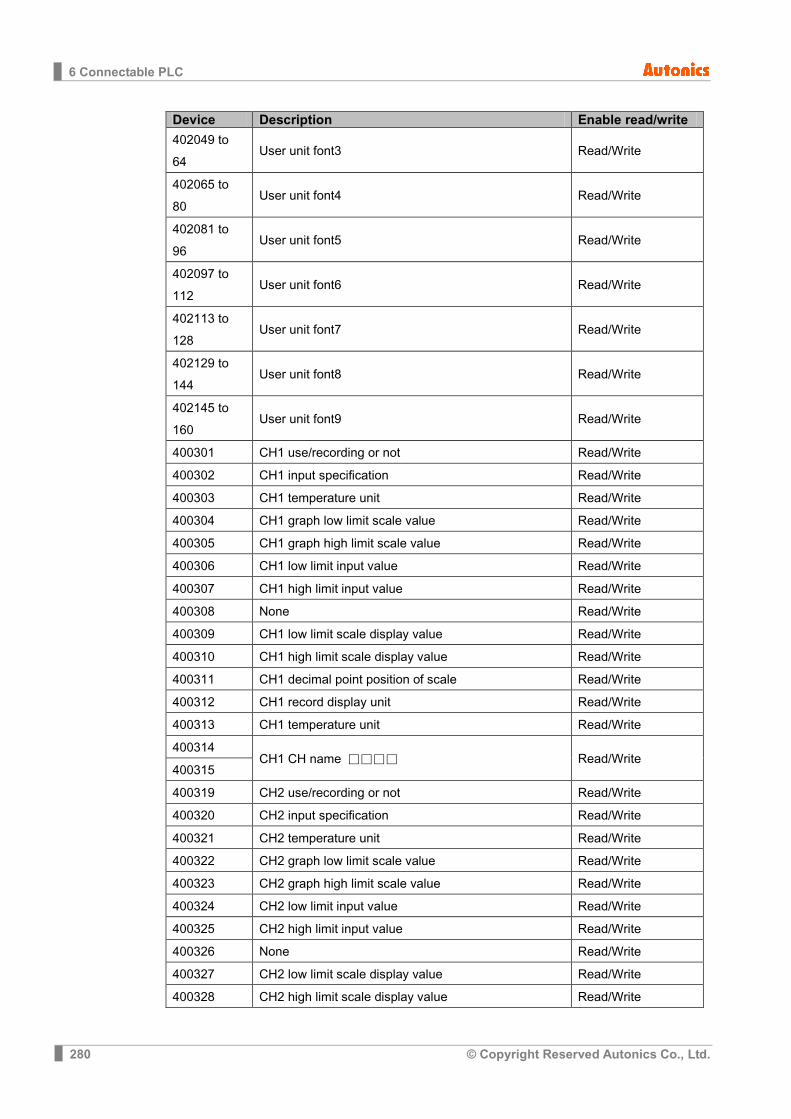
6 Connectable PLC
280 © Copyright Reserved Autonics Co., Ltd.
Device Description Enable read/write
402049 to 64
User unit font3 Read/Write
402065 to 80
User unit font4 Read/Write
402081 to 96
User unit font5 Read/Write
402097 to 112
User unit font6 Read/Write
402113 to 128
User unit font7 Read/Write
402129 to 144
User unit font8 Read/Write
402145 to 160
User unit font9 Read/Write
400301 CH1 use/recording or not Read/Write
400302 CH1 input specification Read/Write
400303 CH1 temperature unit Read/Write
400304 CH1 graph low limit scale value Read/Write
400305 CH1 graph high limit scale value Read/Write
400306 CH1 low limit input value Read/Write
400307 CH1 high limit input value Read/Write
400308 None Read/Write
400309 CH1 low limit scale display value Read/Write
400310 CH1 high limit scale display value Read/Write
400311 CH1 decimal point position of scale Read/Write
400312 CH1 record display unit Read/Write
400313 CH1 temperature unit Read/Write
400314 CH1 CH name Read/Write
400315
400319 CH2 use/recording or not Read/Write
400320 CH2 input specification Read/Write
400321 CH2 temperature unit Read/Write
400322 CH2 graph low limit scale value Read/Write
400323 CH2 graph high limit scale value Read/Write
400324 CH2 low limit input value Read/Write
400325 CH2 high limit input value Read/Write
400326 None Read/Write
400327 CH2 low limit scale display value Read/Write
400328 CH2 high limit scale display value Read/Write
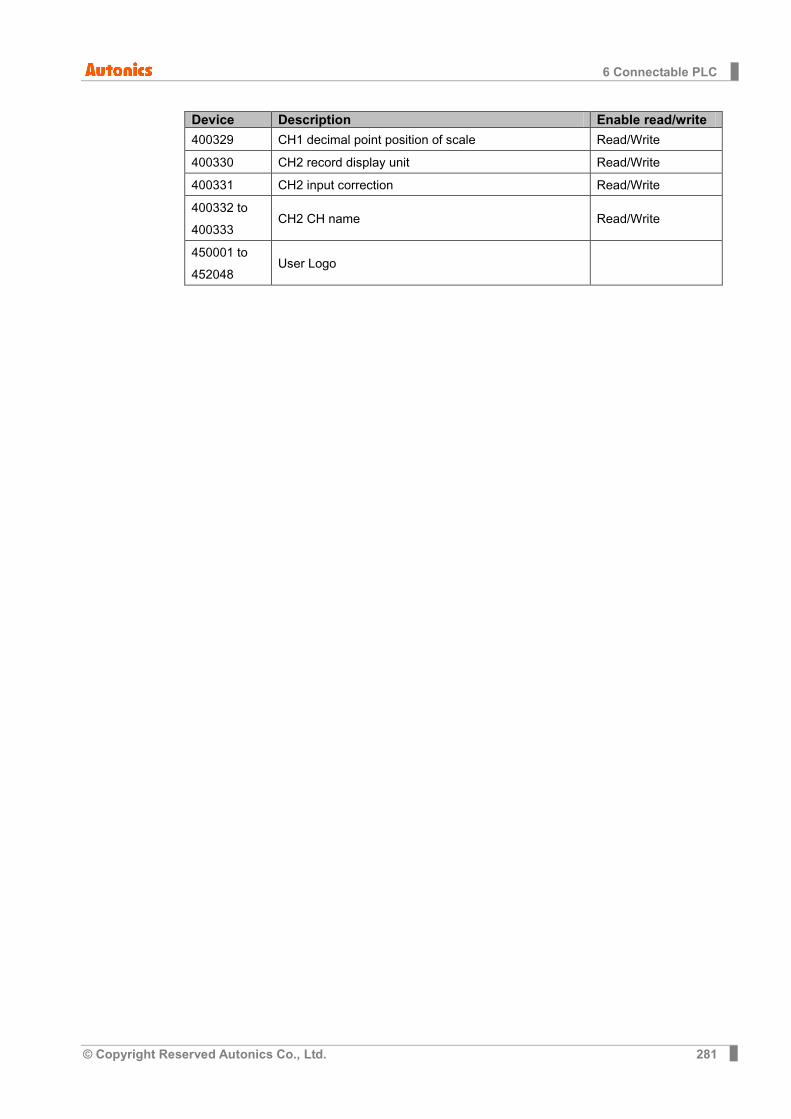
6 Connectable PLC
© Copyright Reserved Autonics Co., Ltd. 281
Device Description Enable read/write
400329 CH1 decimal point position of scale Read/Write
400330 CH2 record display unit Read/Write
400331 CH2 input correction Read/Write
400332 to 400333
CH2 CH name Read/Write
450001 to 452048
User Logo
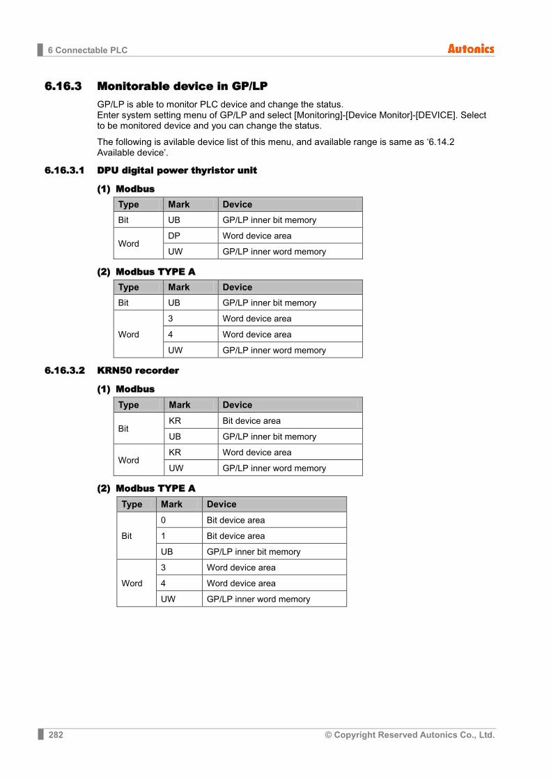
6 Connectable PLC
282 © Copyright Reserved Autonics Co., Ltd.
6.16.3 Monitorable device in GP/LP GP/LP is able to monitor PLC device and change the status. Enter system setting menu of GP/LP and select [Monitoring]-[Device Monitor]-[DEVICE]. Select to be monitored device and you can change the status.
The following is avilable device list of this menu, and available range is same as ‘6.14.2 Available device’.
6.16.3.1 DPU digital power thyristor unit
(1) Modbus Type Mark Device
Bit UB GP/LP inner bit memory
Word DP Word device area
UW GP/LP inner word memory
(2) Modbus TYPE A Type Mark Device
Bit UB GP/LP inner bit memory
Word
3 Word device area
4 Word device area
UW GP/LP inner word memory
6.16.3.2 KRN50 recorder
(1) Modbus Type Mark Device
Bit KR Bit device area
UB GP/LP inner bit memory
Word KR Word device area
UW GP/LP inner word memory
(2) Modbus TYPE A Type Mark Device
Bit
0 Bit device area
1 Bit device area
UB GP/LP inner bit memory
Word
3 Word device area
4 Word device area
UW GP/LP inner word memory
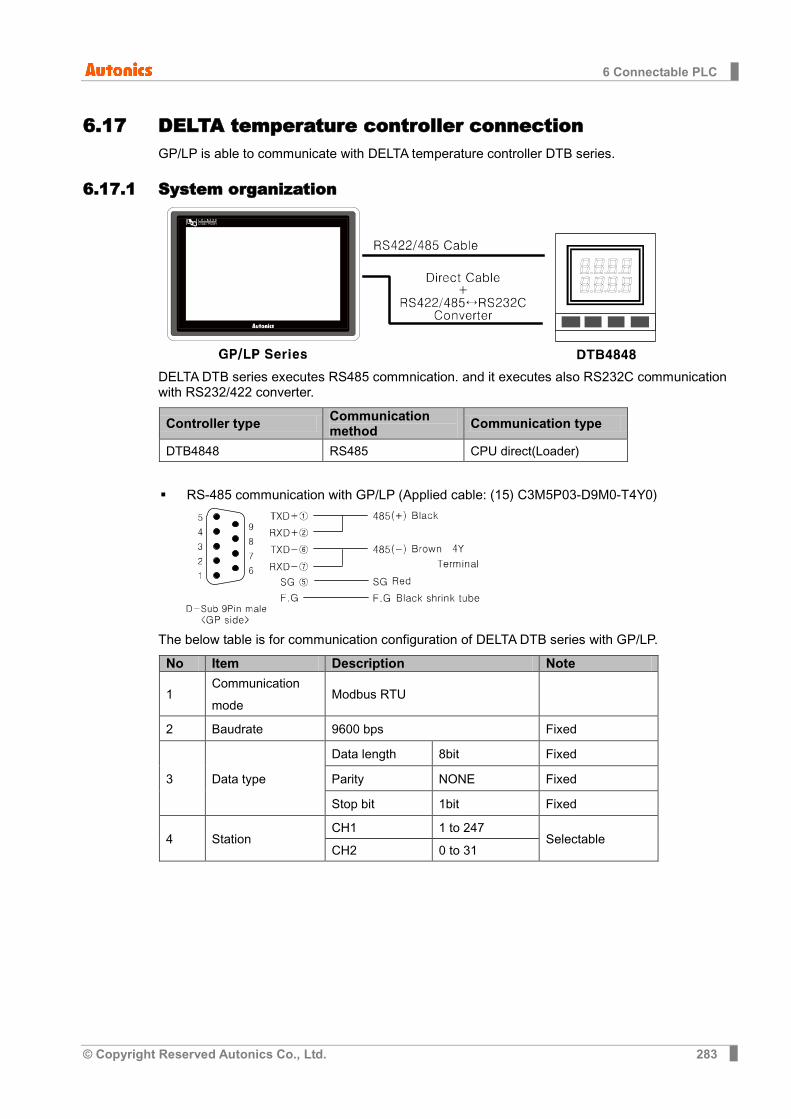
6 Connectable PLC
© Copyright Reserved Autonics Co., Ltd. 283
6.17 DELTA temperature controller connection GP/LP is able to communicate with DELTA temperature controller DTB series.
6.17.1 System organization
DELTA DTB series executes RS485 commnication. and it executes also RS232C communication with RS232/422 converter.
Controller type Communication method Communication type
DTB4848 RS485 CPU direct(Loader)
RS-485 communication with GP/LP (Applied cable: (15) C3M5P03-D9M0-T4Y0)
The below table is for communication configuration of DELTA DTB series with GP/LP.
No Item Description Note
1 Communication mode
Modbus RTU
2 Baudrate 9600 bps Fixed
3 Data type
Data length 8bit Fixed
Parity NONE Fixed
Stop bit 1bit Fixed
4 Station CH1 1 to 247
Selectable CH2 0 to 31
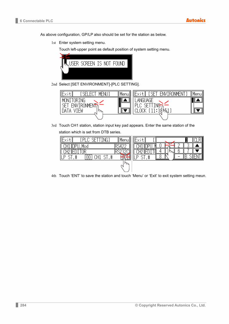
6 Connectable PLC
284 © Copyright Reserved Autonics Co., Ltd.
As above configuration, GP/LP also should be set for the station as below.
1st Enter system setting menu. Touch left-upper point as default position of system setting menu.
2nd Select [SET ENVIRONMENT]-[PLC SETTING].
3rd Touch CH1 station, station input key pad appears. Enter the same station of the station which is set from DTB series.
4th Touch ‘ENT’ to save the station and touch ‘Menu’ or ‘Exit’ to exit system setting meun.
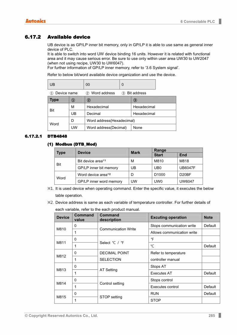
6 Connectable PLC
© Copyright Reserved Autonics Co., Ltd. 285
6.17.2 Available device UB device is as GP/LP inner bit memory, only in GP/LP it is able to use same as general inner device of PLC. It is able to switch into word UW device binding 16 units. However it is related with functional area and it may cause serious error. Be sure to use only within user area UW30 to UW2047 (when not using recipe, UW30 to UW6047). For further information of GP/LP inner memory, refer to ‘3.6 System signal’.
Refer to below bit/word available device organization and use the device.
UB 00 0
① Device name ② Word address ③ Bit address
Type ① ② ③
Bit M Hexadecimal Hexadecimal
UB Decimal Hexadecimal
Word D Word address(Hexadecimal)
UW Word address(Decimal) None
6.17.2.1 DTB4848
(1) Modbus (DTB_Mod)
Type Device Mark Range Start End
Bit Bit device area※1 M M810 M818
GP/LP inner bit memory UB UB0 UB6047F
Word Word device area※2 D D1000 D20BF
GP/LP inner word memory UW UW0 UW6047
※1. It is used device when operating command. Enter the specific value, it executes the below table operation.
※2. Device address is same as each variable of temperature controller. For further details of each variable, refer to the each product manual.
Device Command value
Command description Excuting operation Note
M810 0
Communication Write Stops communication write Default
1 Allows communication write
M811 0
Select /
1 Default
M812 0 DECIMAL POINT
SELECTION Refer to temperature controller manual
1
M813 0
AT Setting Stops AT
1 Executes AT Default
M814 0
Control setting Stops control
1 Executes control Default
M815 0
STOP setting RUN Default
1 STOP
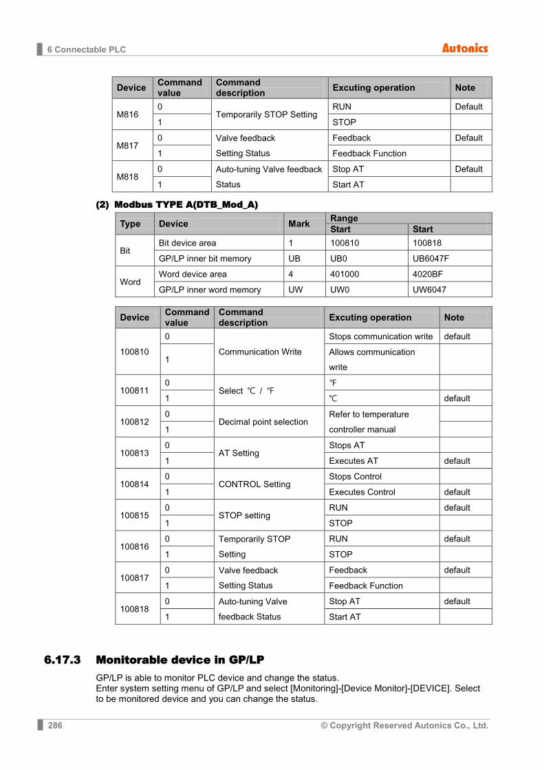
6 Connectable PLC
286 © Copyright Reserved Autonics Co., Ltd.
Device Command value
Command description Excuting operation Note
M816 0
Temporarily STOP Setting RUN Default
1 STOP
M817 0 Valve feedback
Setting Status
Feedback Default
1 Feedback Function
M818 0 Auto-tuning Valve feedback
Status
Stop AT Default
1 Start AT
(2) Modbus TYPE A(DTB_Mod_A)
Type Device Mark Range Start Start
Bit Bit device area 1 100810 100818
GP/LP inner bit memory UB UB0 UB6047F
Word Word device area 4 401000 4020BF
GP/LP inner word memory UW UW0 UW6047
Device Command value
Command description Excuting operation Note
100810
0
Communication Write
Stops communication write default
1 Allows communication write
100811 0
Select /
1 default
100812 0
Decimal point selection Refer to temperature controller manual
1
100813 0
AT Setting Stops AT
1 Executes AT default
100814 0
CONTROL Setting Stops Control
1 Executes Control default
100815 0
STOP setting RUN default
1 STOP
100816 0 Temporarily STOP
Setting
RUN default
1 STOP
100817 0 Valve feedback
Setting Status
Feedback default
1 Feedback Function
100818 0 Auto-tuning Valve
feedback Status
Stop AT default
1 Start AT
6.17.3 Monitorable device in GP/LP GP/LP is able to monitor PLC device and change the status. Enter system setting menu of GP/LP and select [Monitoring]-[Device Monitor]-[DEVICE]. Select to be monitored device and you can change the status.

6 Connectable PLC
© Copyright Reserved Autonics Co., Ltd. 287
The following is avilable device list of this menu, and available range is same as ‘6.15.2 Available device’.
(1) Modbus Type Mark Device Note
Bit M Bit device area
UB GP/LP inner bit memory
Word D Word device area 16bit
UW GP/LP inner word memory
(2) Modbus TYPE A Type Mark Device Note
Bit 1 Bit device area
UB GP/LP inner bit memory
Word 4 Word device area 16bit
UW GP/LP inner word memory
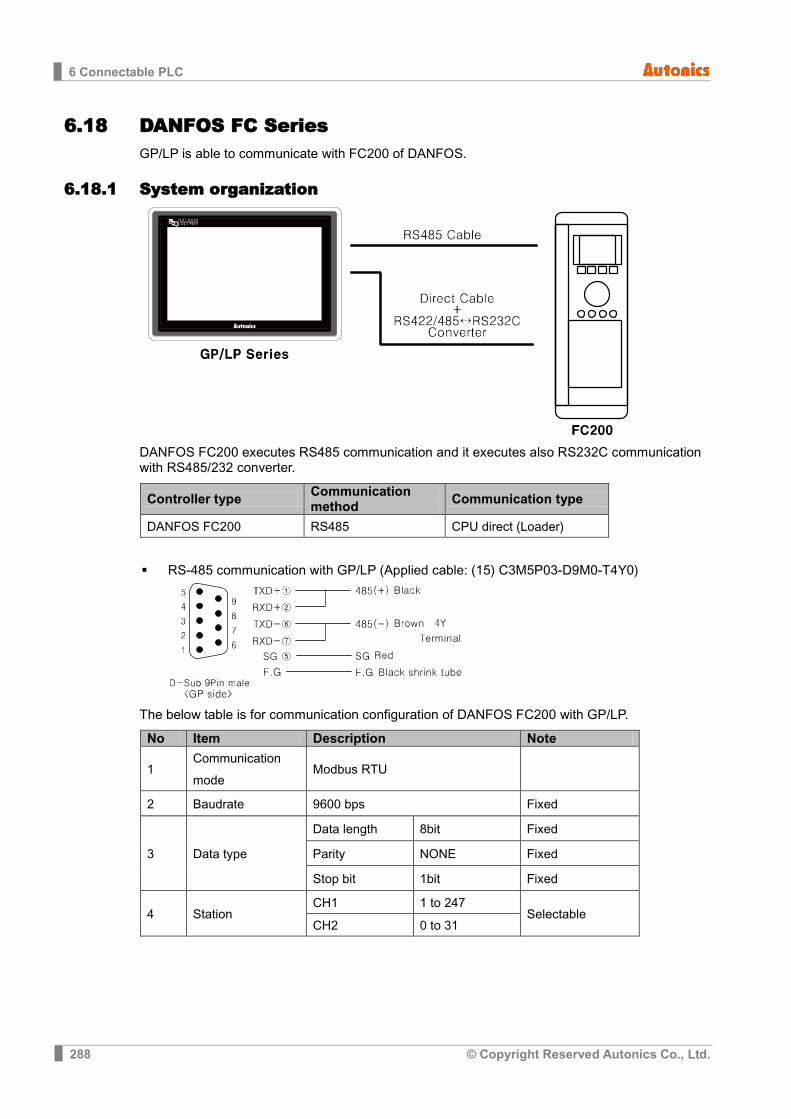
6 Connectable PLC
288 © Copyright Reserved Autonics Co., Ltd.
6.18 DANFOS FC Series GP/LP is able to communicate with FC200 of DANFOS.
6.18.1 System organization
DANFOS FC200 executes RS485 communication and it executes also RS232C communication with RS485/232 converter.
Controller type Communication method Communication type
DANFOS FC200 RS485 CPU direct (Loader)
RS-485 communication with GP/LP (Applied cable: (15) C3M5P03-D9M0-T4Y0)
The below table is for communication configuration of DANFOS FC200 with GP/LP.
No Item Description Note
1 Communication mode
Modbus RTU
2 Baudrate 9600 bps Fixed
3 Data type
Data length 8bit Fixed
Parity NONE Fixed
Stop bit 1bit Fixed
4 Station CH1 1 to 247
Selectable CH2 0 to 31
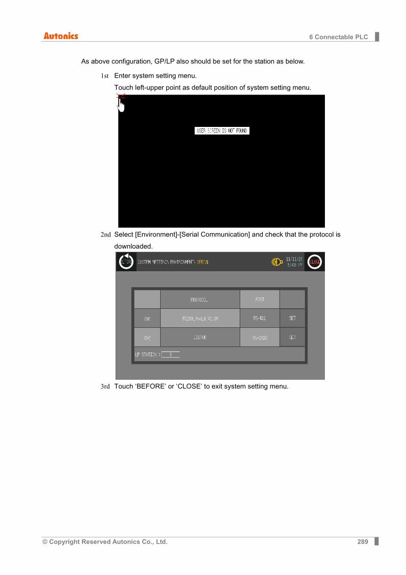
6 Connectable PLC
© Copyright Reserved Autonics Co., Ltd. 289
As above configuration, GP/LP also should be set for the station as below.
1st Enter system setting menu. Touch left-upper point as default position of system setting menu.
2nd Select [Environment]-[Serial Communication] and check that the protocol is downloaded.
3rd Touch ‘BEFORE’ or ‘CLOSE’ to exit system setting menu.
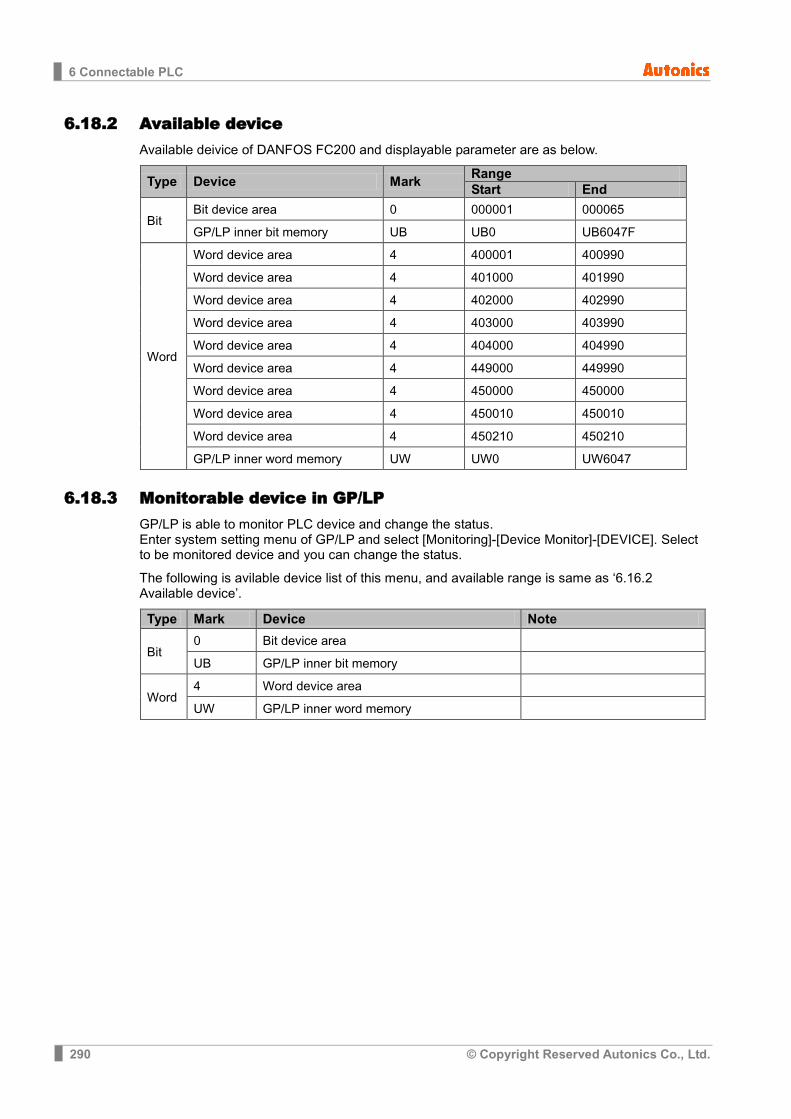
6 Connectable PLC
290 © Copyright Reserved Autonics Co., Ltd.
6.18.2 Available device Available deivice of DANFOS FC200 and displayable parameter are as below.
Type Device Mark Range Start End
Bit Bit device area 0 000001 000065
GP/LP inner bit memory UB UB0 UB6047F
Word
Word device area 4 400001 400990
Word device area 4 401000 401990
Word device area 4 402000 402990
Word device area 4 403000 403990
Word device area 4 404000 404990
Word device area 4 449000 449990
Word device area 4 450000 450000
Word device area 4 450010 450010
Word device area 4 450210 450210
GP/LP inner word memory UW UW0 UW6047
6.18.3 Monitorable device in GP/LP GP/LP is able to monitor PLC device and change the status. Enter system setting menu of GP/LP and select [Monitoring]-[Device Monitor]-[DEVICE]. Select to be monitored device and you can change the status.
The following is avilable device list of this menu, and available range is same as ‘6.16.2 Available device’.
Type Mark Device Note
Bit 0 Bit device area
UB GP/LP inner bit memory
Word 4 Word device area
UW GP/LP inner word memory
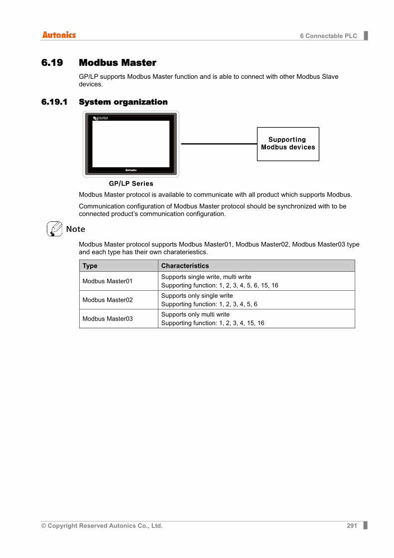
6 Connectable PLC
© Copyright Reserved Autonics Co., Ltd. 291
6.19 Modbus Master GP/LP supports Modbus Master function and is able to connect with other Modbus Slave devices.
6.19.1 System organization
Modbus Master protocol is available to communicate with all product which supports Modbus.
Communication configuration of Modbus Master protocol should be synchronized with to be connected product’s communication configuration.
Modbus Master protocol supports Modbus Master01, Modbus Master02, Modbus Master03 type and each type has their own charateriestics.
Type Characteristics
Modbus Master01 Supports single write, multi write Supporting function: 1, 2, 3, 4, 5, 6, 15, 16
Modbus Master02 Supports only single write Supporting function: 1, 2, 3, 4, 5, 6
Modbus Master03 Supports only multi write Supporting function: 1, 2, 3, 4, 15, 16

6 Connectable PLC
292 © Copyright Reserved Autonics Co., Ltd.
6.19.2 Available device Available devcie of Modbus Master and displayable parameter are as below.
Type Device Mark Range Start End
Bit
Bit device area 0 000001 065536
Bit device area 1 100001 165536
GP/LP inner bit memory UB UB0 UB6047F
Word
Word device area 3 300001 365536
Word device area 4 400001 465536
GP/LP inner bit memory UW UW0 UW6047
Device address is for Modbus Master protocol is 1 based protocol address(Start address: 1). The below example is for TM series of Autonics product. Following table is part of memory map(using 0 based protocol address) for TM series.
No (Address) Parameter Description
TM2 TM4 31001 (03E8) 31001 (03E8) CH1 Present Value Present measured value
31002 (03E9) 31002 (03E9) CH1 Dot Decimal point position of sensor
31003 (03EA) 31003 (03EA) CH1 Unit Sensor temperature unit
31004 (03EB) 31004 (03EB) CH1 Set Value Present controlled temperature setting value
31005 (03EC) 31005 (03EC) CH1 Heating_MV Heating control value
Dot line area is for device address, solid line area is for protocol address.
To read CH1 PresentValue of TM2 from TM2_Mod protocol, it uses device address ( 31001 ). For Modbus Master protocol, it uses protocol address (03E8) plus 1. Device address of Modbus Master protocol is displayed with decimal. Therefore, protocol address value as 0x03E9 which is 0x03E8 plus 1 of CH1 PresentValue is converted decimal value as 1001 and it is used as device address. (Converting description is as below table.)
Use device address Convert address
(Hexadecimal→Decimal) Use protocol address
Protocol TM2_Mod
→
Protocol address [Hexadecimal]+1 →
Protocol address [Decimal]
→
Protocol Modbus Master
Device TM Read word
Read word
Device 3
Address 31001 0x03E8+1 1000 Address 01000
Used device address on Modbus Master protocol uses the value of protocol address (in case of 0 base) plus 1. Device address of Modbus Master protocol uses decimal value.

6 Connectable PLC
© Copyright Reserved Autonics Co., Ltd. 293
6.19.3 Monitorable device in GP/LP GP/LP is able to monitor PLC device and change the status. Enter system setting menu of GP/LP and select [Monitoring]-[Device Monitor]-[DEVICE]. Select to be monitored device and you can change the status.
The following is avilable device list of this menu, and available range is same as ‘6.17.2 Available device’.
Type Mark Device Note
Bit
1 Read-only register Modbus function 0x02
0 Read, write register Modbus function 0x01, 0x05,0x0F
UB GP/LP inner bit memory
Word
3 Read-only register Modbus function 0x03
4 Read, write register Modbus function 0x06, 0x10
UW GP/LP inner word memory
Device monitoring from GP/LP-S070 displays from input start data to 16 data at once. In case of Modbus Master protocol, if the number of devices from connected product is smaller than the number of displayed devices in monitoring, you cannot check the device status by device monitoring. In this case, you should draw data on the user screen and check the data status.

6 Connectable PLC
294 © Copyright Reserved Autonics Co., Ltd.

MTA-GPLPC1-V1.4-1302US


![_P8LPI]P ;LP;LP;LP 5ZL1F DF8[ - WordPress.com](https://static.fdokumen.com/doc/165x107/631d1be4b8a98572c10d3520/p8lpip-lplplp-5zl1f-df8-wordpresscom.jpg)